Smithsonian Design Standards October 2021 Volume 3
269
Smithsonian Design Standards October 2021 VOLUME 3 – APPENDICES SF PROJECT NUMBER: 1699622 EWINGCOLE PROJECT NUMBER: 20160528
-
Upload
khangminh22 -
Category
Documents
-
view
0 -
download
0
Transcript of Smithsonian Design Standards October 2021 Volume 3

Smithsonian Design StandardsOctober 2021
VOLUME 3 – APPENDICES
SF PROJECT NUMBER: 1699622
EWINGCOLE PROJECT NUMBER: 20160528

Smithsonian Design StandardsTable of Contents
October 2021 TOC-1
VOLUME 1:
Design Guidelines & Technical Sections
Design Guidelines:
Chapter 1-Introduction
Chapter 2- About This Document
Chapter 3- General Information
Chapter 4- Design Requirements
Chapter 5- Quality Requirements
Chapter 6- Sustainability
Chapter 7- Planning
Chapter 8- Site
Chapter 9- Space Requirements
Chapter 10- Building Requirements
Chapter 11- Safety and Security Engineering Requirements
Technical Sections:
Division 01 – Supplementary Conditions for Construction
Division 02 – Existing Conditions
Division 03 – Concrete
Division 04 – Masonry
Division 05 – Metals
Division 06 – Wood, Plastics, and Composites
Division 07 – Thermal and Moisture Protection
Division 08 – Openings
Division 09 – Finishes
Division 10 – Specialties
Division 11 – Equipment
Division 12 – Furnishings

Smithsonian Design StandardsTable of Contents
October 2021 TOC-2
Division 13 – Special Construction
Division 14 – Conveying Systems
Division 21 – Fire Suppression
Division 22 – Plumbing
Division 23 – Heating, Ventilation and Air Conditioning
Division 26 – Electrical
Division 27 – Communications
Division 28 – Electronic Safety and Security
Division 31 – Earthwork
Division 32 – Exterior Improvements
Division 33 – Utilities
VOLUME 2:
Smithsonian Specifications:
Section 01 32 50 – Building Information Modeling (BIM) Requirements
Section 01 56 39 – Site Protection
Section 01 78 23 – Operation and Maintenance Data
Section 01 91 13 – Commissioning
Section 02 82 00 – Asbestos Abatement
Section 02 83 00 – Work Activities Impacting Lead-Containing Materials
Section 07 81 00 – Sprayed Fire-Resistant Materials
Section 07 84 13 – Penetration Firestopping
Section 08 11 73 – Rolling Fire Doors
Section 10 44 00 – Fire Extinguishers, Cabinets, and Accessories
Section 14 21 13 – Electric Traction Freight Elevators
Section 14 21 23 – Electric Traction Elevator
Section 14 24 13 – Hydraulic Freight Elevator
Section 14 24 23 – Hydraulic Passenger Elevator

Smithsonian Design StandardsTable of Contents
October 2021 TOC-3
Section 14 31 00 – Escalators
Section 21 13 13 – Wet Pipe Sprinkler Systems
Section 21 13 16 – Dry Pipe and Preaction Sprinkler System
Section 21 31 10 – Fire Pump System
Section 27 05 00 – Common Work Results for Communications
Section 27 05 26 – Grounding and Bonding for Communications Systems
Section 27 11 00 – Communications Equipment Room Fittings
Section 27 13 00 – Communications Backbone Cabling
Section 27 15 00 – Communications Horizontal Cabling
Section 28 31 11 – Addressable Fire Alarm System
Section 32 91 00 – Planting Soil- Template
Section 32 92 00 – Lawns and Grasses
Section 33 16 15 – Water Storage Steel Tanks
VOLUME 3:
Appendices:
Appendix A – Security Design Criteria Matrix
Appendix B – Required Security Drawings
Appendix C – Standard Security Drawings
Appendix D – Collection Storage Risk Levels
Appendix E – Smithsonian Declaration on the Collections Preservation Environment
Appendix F – Exhibit Fabrication Guide
• Appendix F1 – Exhibit Fabrication Guide
• Appendix F2 – Fire and Life Safety Checklist for Exhibit Construction
• Appendix F3 – General Notes for Exhibit Design
• Appendix F4 – Frequently Asked Questions about Exhibits Materials
• Appendix F5 – Approved/Prohibited Exhibit Materials [RESERVED]
Appendix G – Fire Protection Commissioning Standards [RESERVED]

Smithsonian Design StandardsTable of Contents
October 2021 TOC-4
Appendix H – Summary of Enclosure Requirements for Common Use Areas
Appendix I – Compact Storage Units (Mobile Shelving) Design Supplement
Appendix J – Facilities Design Standards: Smithsonian Enterprises Supplement
Appendix K – Smithsonian Enterprises Specialty Specifications
• Section 08 34 73 – Sound Control Door Assemblies
• Section 08 56 73 – Sound Control Windows
• Section 08 81 00 – Interior Glazing
• Section 10 22 13 – Wire Mesh Partitions
• Section 11 61 33 – Rigging, Curtain & Tracks
• Section 12 61 00 – Fixed Audience Seating – Planetarium
• Section 12 61 23 – Fixed Auditorium Seats
Appendix L – OCIO Appendices
• Appendix L1 – Cabling Specifications
• Appendix L2 – Wire Closet Specifications
Appendix M – CPTED Narratives
Appendix N – Fire System Impairment Permit
Appendix O – Laboratory Design Standards

Smithsonian Design StandardsAppendix A – Security Design Criteria Matrix
October 2021 Volume 3- Appendices A-1
APPENDIX A
Security Design Criteria Matrix
NOTE: The matrix in Appendix A categorizes the measures for each space and discipline into
two categories; Existing Facilities/Spaces and New Facilities/Spaces. In some disciplines (i.e.
Electronic Security) the measures are the same for both Existing Facilities/Spaces and New
Facilities/Spaces. However, other disciplines (i.e. wall construction or location within the
Architecture chapter) have different measures for the two categories.
This is intended not to overly burden projects with requirements that may be unreasonable
based on their scope. However, project managers and planners should consider integrating
facility requirements if it is found that security deficiencies must be mitigated in a future
project. In all cases, major renovations and new construction must meet the requirements of
this document.

Appendix - ASecurity Design Criteria Matrix January 1, 2013
Notes:1. Refer to Section 1 for the explanation of "Existing" vs. "New".2. The areas in red are new classifications created by OPS due to security requirements. Page 1 of 9
Existing New Existing New Existing New Existing New Existing New Existing New Existing New Existing New Existing New Existing New Existing NewAncillaryBuilding Common Support
AssemblyConference room 1 1 1 1 1 1 1 1 1 1 2 2 1 1 1 1 - - 1 1General/mixed use 1 1 1 1 1 1 1 1 1 1 2 2 1 1 1 1 - - 1 1Planetarium 1 1 1 1 1 1 1 1 1 1 2 2 1 1 1 1 - - 1 1Screening Area 1 1 1 1 1 1 1 1 1 1 2 2 1 1 1 1 - - 1 1Seating area, fixed 1 1 1 1 1 1 1 1 1 1 2 2 1 1 1 1 - - 1 1Seating area, open 1 1 1 1 1 1 1 1 1 1 2 2 1 1 1 1 - - 1 1Stage 1 1 1 1 1 1 1 1 1 1 2 2 1 1 1 1 - - 1 1Support area 3 3 1 1 1 1 1 1 1 1 2 2 1 1 1 1 - - 1 1
Audio VisualProjection room 3 3 1 1 2 2 1 1 3 3 2 2 1 1 1 1 - - 1 1
Coat RoomCoat room 1 1 1 1 1 1 1 1 1 1 2 2 1 1 1 1 - - 1 1
ExhibitBarrier zone Refer to: SI Exhibit Security Design Criteria - - - - - - - - - - - - - - - - - - - -Flexible Hall 1 1 1 1 1 1 1 1 3 3 2 2 2 2 2,5,6 2,5,6 1,4 1,4 1 1Live animal
Zoo Animal Buildings (Low Risk) New space classification 1 1 1 1 1 1 1 1 3 3 2 2 1 1 1 1 - - 1 1Zoo Animal Buildings (Medium Risk) New space classification 1 1 1 1 1 1 1 1 5 5 3 3 2 2 5 5 1,4 1,4 1 1Zoo Animal Buildings (High Risk) New space classification 1 1 1 1 1 1 1 1 5 5 3 3 2 2 2,5 2,5 1,2,4 1,2,4 1 1
Live plants 1 1 1 1 1 1 1 1 3 3 2 2 1 1 1 1 - - 1 1Object Refer to: SI Exhibit Security Design CriteriaViewing area 1 1 1 1 2 2 1 1 3 3 2 2 2 2 2 5 1,4 1,4 1 1
Exhibit, OutdoorBarrier zone Refer to: SI Exhibit Security Design Criteria - - - - - - - - - - - - - - - - - 1 1Flexible hall 1 1 1 1 1 1 1 1 3 3 2 2 2 2 2,5,6 2,5,6 1,4 1,4 1 1Live animal
Zoo Animal Buildings (Low Risk) New space classification 1 1 1 1 1 1 1 1 3 3 2 2 1 1 1 1 - - 1 1Zoo Animal Buildings (Medium Risk) New space classification 1 1 1 1 1 1 1 1 6 6 3 3 2 2 5 5 1,4 1,4 1 1Zoo Animal Buildings (High Risk) New space classification 1 1 1 1 1 1 1 1 6 6 3 3 2 2 2,5 2,5 1,2,4 1,2,4 1 1
Food servicesBreak room 3 3 1 1 1 1 1 1 1 1 2 2 1 1 1 1 1 0 1 1Dining room 1 1 1 1 1 1 1 1 1 1 2 2 1 1 2,4 2,4 1,3 1,3 1 1Dish room 3 3 1 1 1 1 1 1 1 1 2 2 1 1 1 1 - - 1 1Food booth 1 1 1 1 1 1 1 1 1 1 2 2 1 1 1 1 - - 1 1Food selection area 1 1 1 1 1 1 1 1 1 1 2 2 1 1 1 1 - - 1 1Kitchen 3 3 1 1 1 1 1 1 1 1 2 2 1 1 1 1 - - 1 1Kitchen, Animal Food 3 3 1 1 1 1 1 1 3 3 2 2 1 1 1 1 - - 1 1
LockerMen's 1 1 1 1 2 2 1 1 5 5 3 3 1 1 1 1 - - 1 1Unisex 1 1 1 1 2 2 1 1 5 5 3 3 1 1 1 1 - - 1 1Women's 1 1 1 1 2 2 1 1 5 5 3 3 1 1 1 1 - - 1 1
RetailShop 1 1 1 1 2 2 1 1 5 5 3 3 2 2 2,4,6 2,4,6 1,3 1,3 1 1Souvenir booth 1 1 1 1 2 2 1 1 3 3 2 2 1 1 1 1 - - 1 1Ticket booth 1 1 1 1 2 2 1 1 3 3 2 2 2 2 4 4 1,3 1,3 1 1
IntrusionDetection
10.3.2
Access Control
10.3.1Space Name
Intercom-munications
Intercom-munications
11.3.1
Surveilance &Assessment
Video
VideoRecording &
Storage
Electronic Security
10.3.510.3.3
Refer to respective sections
4.3.5
Door Hardware
4.3.34.3.1
Location Walls
Space Comments & Notes
Windows Door Assembly
4.3.44.3.2
Refer to Section 1.4 Using this Document for instruction on how to applythis Appendix Architecture
Structural, Mechanical, Electrical,Fire Protection, & Elevators
APPENDIX A

Appendix - ASecurity Design Criteria Matrix January 1, 2013
Notes:1. Refer to Section 1 for the explanation of "Existing" vs. "New".2. The areas in red are new classifications created by OPS due to security requirements. Page 2 of 9
Existing New Existing New Existing New Existing New Existing New Existing New Existing New Existing New Existing New Existing New Existing New
IntrusionDetection
10.3.2
Access Control
10.3.1Space Name
Intercom-munications
Intercom-munications
11.3.1
Surveilance &Assessment
Video
VideoRecording &
Storage
Electronic Security
10.3.510.3.3
Refer to respective sections
4.3.5
Door Hardware
4.3.34.3.1
Location Walls
Space Comments & Notes
Windows Door Assembly
4.3.44.3.2
Refer to Section 1.4 Using this Document for instruction on how to applythis Appendix Architecture
Structural, Mechanical, Electrical,Fire Protection, & Elevators
ToiletChildren's 1 1 1 1 2 2 1 1 1 1 2 2 1 1 1 1 - - 1 1Handicapped 1 1 1 1 2 2 1 1 - - 2 2 1 1 1 1 - - 1 1Men's 1 1 1 1 2 2 1 1 - - 2 2 1 1 1 1 - - 1 1Unisex 1 1 1 1 2 2 1 1 1 1 2 2 1 1 1 1 - - 1 1Women's 1 1 1 1 2 2 1 1 - - 2 2 1 1 1 1 - - 1 1
Training/EducationComputer Lab 1 1 1 1 2 2 1 1 1 1 2 2 2 2 1 1 - - 1 1Information booth 1 1 1 1 1 1 1 1 1 1 2 2 1 1 1 1 - - 1 1Multi-use 1 1 1 1 1 1 1 1 1 1 2 2 1 1 1 1 - - 1 1Visitor information 1 1 1 1 1 1 1 1 1 1 2 2 1 1 1 1 - - 1 1
Building Core & Service AreasCirculation
Corridor 1 1 1 1 1 1 1 1 1 1 1 1 1 1 1 1 - - 1 1Lobby 1 1 1 1 1 1 1 1 1 1 1 1 1 1 1 1 - - 1 1Other 1 1 1 1 1 1 1 1 1 1 1 1 1 1 1 1 - - 1 1Tunnel 1 1 1 1 1 1 1 1 1 1 1 1 1 1 1 1 - - 1 1
Control RoomComputer room 5 5 1 3 5 5 3 3 5 5 3 3 2 2 1 1 - - 1 1Security (Unit Control Room) 5 5 3 4 5 5 5,6 5,6 5 5 3 3 2 2 2 2 1 1 3 3Security Equipment Room New space classification 5 5 3 4 5 5 5 5 5 5 3 3 2 2 6 6 1 1 1 1Utility 3 5 1 1 1 1 1 1 3 3 2 2 2 2 1 1 - - 1 1X-ray 6 6 1 1 1 1 1 1 3 3 2 2 1 1 1 1 - - 1 1
LaundryLaundry Room 3 3 1 1 1 1 1 1 1 1 2 2 1 1 1 1 - - 1 1
Mechanical/Electric Major Utility Areas (not Utility Closets)Cooling 3,5,6 3,5,6 1 1 1 1 1 1 3 3 2 2 2 2 1 1 - - 1 1Elevator Equipment 3,5,6 3,5,6 1 1 1 1 1 1 3 3 2 2 2 2 1 1 - - 1 1Filter Room 3,5,6 3,5,6 1 1 1 1 1 1 3 3 2 2 2 2 1 1 - - 1 1General/mixed use 3,5,6 3,5,6 1 1 1 1 1 1 3 3 2 2 2 2 1 1 - - 1 1Heating 3,5,6 3,5,6 1 1 1 1 1 1 3 3 2 2 2 2 1 1 - - 1 1High Voltage 3,5,6 3,5,6 1 1 1 1 1 1 3 3 2 2 2 2 1 1 - - 1 1Steam tunnel 3,5,6 3,5,6 1 1 1 1 1 1 3 3 2 2 2 2 1 1 - - 1 1Utility Tunnel 3,5,6 3,5,6 1 1 1 1 1 1 3 3 2 2 2 2 1 1 - - 1 1
ParkingBooth Manned by non-security personnel 1 1 1 1 1 1 1 1 1 1 2 2 1 1 4 4 1,3 1,3 3 3
Shipping/ReceivingCrating Area 3 3 1 1 1 1 1 1 1 1 2 2 2 2 2,5,6 2,5,6 1,2,4 1,2,4 1 1General/mixed use 3 3 1 1 1 1 1 1 1 1 2 2 2 2 2,5,6 2,5,6 1,2,4 1,2,4 1 1Loading Dock 6 6 1 1 1 1 1 1 1 1 2 2 2 2 2,5,6 2,5,6 1,2,4 1,2,4 1 1
APPENDIX A

Appendix - ASecurity Design Criteria Matrix January 1, 2013
Notes:1. Refer to Section 1 for the explanation of "Existing" vs. "New".2. The areas in red are new classifications created by OPS due to security requirements. Page 3 of 9
Existing New Existing New Existing New Existing New Existing New Existing New Existing New Existing New Existing New Existing New Existing New
IntrusionDetection
10.3.2
Access Control
10.3.1Space Name
Intercom-munications
Intercom-munications
11.3.1
Surveilance &Assessment
Video
VideoRecording &
Storage
Electronic Security
10.3.510.3.3
Refer to respective sections
4.3.5
Door Hardware
4.3.34.3.1
Location Walls
Space Comments & Notes
Windows Door Assembly
4.3.44.3.2
Refer to Section 1.4 Using this Document for instruction on how to applythis Appendix Architecture
Structural, Mechanical, Electrical,Fire Protection, & Elevators
StorageEquipment 3 3 1 1 1 1 1 1 3 3 2 2 1 1 1 1 - - 1 1Freezer 3 3 1 1 1 1 1 1 3 3 2 2 1 1 1 1 - - 1 1General/mixed use 3 3 1 1 1 1 1 1 1 1 2 2 1 1 1 1 - - 1 1Hazardous 3,5 3,6 1 1 1 1 1 1 3 3 2 2 2 2 1 1 - - 3 3Janitor's Closet 3 3 1 1 1 1 1 1 3 3 2 2 1 1 1 1 - - 1 1Other 3 3 1 1 1 1 1 1 1 1 2 2 1 1 1 1 - - 1 1Props/Display 3 3 1 1 1 1 1 1 3 3 2 2 1 1 1 1 - - 1 1Refrigerated 3 3 1 1 1 1 1 1 3 3 2 2 1 1 1 1 - - 1 1Subfreezing 3 3 1 1 1 1 1 1 3 3 2 2 1 1 1 1 - - 1 1Workroom 3 3 1 1 1 1 1 1 3 3 2 2 1 1 1 1 - - 1 1
Utility ClosetATM 3 3 1 1 1 1 1 1 3 3 2 2 2 2 1 1 - - 1 1Data 3 3 3 3 5 5 3 3 3 3 2 2 2 2 1 1 - - 1 1Electrical 3 3 1 1 1 1 1 1 3 3 2 2 1 1 1 1 - - 1 1General 3 3 1 1 1 1 1 1 3 3 2 2 1 1 1 1 - - 1 1General/mixed use 3 3 1 1 1 1 1 1 1 1 2 2 1 1 1 1 - - 1 1HVAC 3 3 1 1 1 1 1 1 3 3 2 2 2 2 1 1 - - 1 1Plumbing 3 3 1 1 1 1 1 1 3 3 2 2 1 1 1 1 - - 1 1Security 3 3 3 3 5 5 3 3 3 3 2 2 2 2 1 1 - - 1 1Telephone (IT Frame Room) 3 3 1 1 1 1 1 1 3 3 2 2 1 1 1 1 - - 1 1
Waste RoomGeneral 3 3 1 1 1 1 1 1 1 1 2 2 1 1 1 1 - - 1 1Hazardous 3 3 1 1 1 1 1 1 3 3 2 2 1 1 1 1 - - 1 1Refrigerated 3 3 1 1 1 1 1 1 1 1 2 2 1 1 1 1 - - 1 1
WorkroomCabinet 3 3 1 1 1 1 1 1 1 1 2 2 2 2 1 1 - - 1 1Crafts/Trade Shop 3 3 1 1 1 1 1 1 1 1 2 2 2 2 1 1 - - 1 1Drying Room 3 3 1 1 1 1 1 1 1 1 2 2 2 2 1 1 - - 1 1Electric/Lamping 3 3 1 1 1 1 1 1 1 1 2 2 2 2 1 1 - - 1 1Fire Alarm 3 3 1 1 1 1 1 1 1 1 2 2 2 1 1 1 - - 1 1General/mixed Use 3 3 1 1 1 1 1 1 1 1 2 2 1 1 1 1 - - 1 1Grounds 3 3 1 1 1 1 1 1 1 1 2 2 1 1 1 1 - - 1 1HVAC 3 3 1 1 1 1 1 1 1 1 2 2 1 1 1 1 - - 1 1Lock Shop 3 3 1 1 1 1 1 1 5 5 3 3 2 2 1 1 - - 1 1Machine 3 3 1 1 1 1 1 1 1 1 2 2 2 2 1 1 - - 1 1Mason 3 3 1 1 1 1 1 1 1 1 2 2 2 2 1 1 - - 1 1Paint 3 3 1 1 1 1 1 1 1 1 2 2 2 2 1 1 - - 1 1Plumbing 3 3 1 1 1 1 1 1 1 1 2 2 1 1 1 1 - - 1 1Restoration 3 3 1 1 1 1 1 1 1 1 2 2 2 2 1 1 - - 1 1Sheet Metal 3 3 1 1 1 1 1 1 1 1 2 2 2 2 1 1 - - 1 1Spray Booth 3 3 1 1 1 1 1 1 1 1 2 2 2 2 1 1 - - 1 1Transportation 3 3 1 1 1 1 1 1 1 1 2 2 2 2 1 1 - - 1 1Welding 3 3 1 1 1 1 1 1 1 1 2 2 2 2 1 1 - - 1 1
Building Shared 1 1 1 1 1 1 1 1 - - 1 1 1 1 1 1 - - 1 1Exterior Walls Refer to: "Building Perimeter"
Exterior Wall Cavity Refer to: "Building Perimeter"Floor Common Support 1 1 1 1 1 1 1 1 - - 1 1 1 1 1 1 1 1 1 1
APPENDIX A
Appendix - ASecurity Design Criteria Matrix January 1, 2013
Notes:1. Refer to Section 1 for the explanation of "Existing" vs. "New".2. The areas in red are new classifications created by OPS due to security requirements. Page 4 of 9
Existing New Existing New Existing New Existing New Existing New Existing New Existing New Existing New Existing New Existing New Existing New
IntrusionDetection
10.3.2
Access Control
10.3.1Space Name
Intercom-munications
Intercom-munications
11.3.1
Surveilance &Assessment
Video
VideoRecording &
Storage
Electronic Security
10.3.510.3.3
Refer to respective sections
4.3.5
Door Hardware
4.3.34.3.1
Location Walls
Space Comments & Notes
Windows Door Assembly
4.3.44.3.2
Refer to Section 1.4 Using this Document for instruction on how to applythis Appendix Architecture
Structural, Mechanical, Electrical,Fire Protection, & Elevators
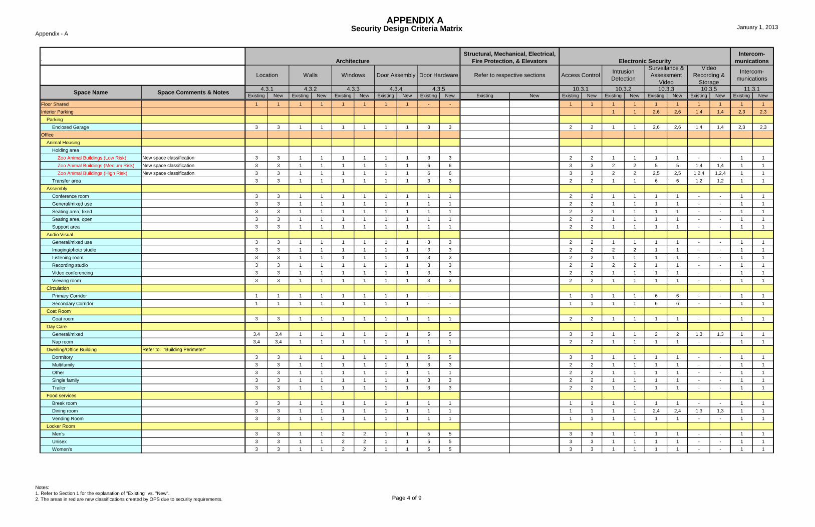
Floor Shared 1 1 1 1 1 1 1 1 - - 1 1 1 1 1 1 1 1 1 1Interior Parking 1 1 2,6 2,6 1,4 1,4 2,3 2,3
ParkingEnclosed Garage 3 3 1 1 1 1 1 1 3 3 2 2 1 1 2,6 2,6 1,4 1,4 2,3 2,3
OfficeAnimal Housing
Holding areaZoo Animal Buildings (Low Risk) New space classification 3 3 1 1 1 1 1 1 3 3 2 2 1 1 1 1 - - 1 1Zoo Animal Buildings (Medium Risk) New space classification 3 3 1 1 1 1 1 1 6 6 3 3 2 2 5 5 1,4 1,4 1 1Zoo Animal Buildings (High Risk) New space classification 3 3 1 1 1 1 1 1 6 6 3 3 2 2 2,5 2,5 1,2,4 1,2,4 1 1
Transfer area 3 3 1 1 1 1 1 1 3 3 2 2 1 1 6 6 1,2 1,2 1 1Assembly
Conference room 3 3 1 1 1 1 1 1 1 1 2 2 1 1 1 1 - - 1 1General/mixed use 3 3 1 1 1 1 1 1 1 1 2 2 1 1 1 1 - - 1 1Seating area, fixed 3 3 1 1 1 1 1 1 1 1 2 2 1 1 1 1 - - 1 1Seating area, open 3 3 1 1 1 1 1 1 1 1 2 2 1 1 1 1 - - 1 1Support area 3 3 1 1 1 1 1 1 1 1 2 2 1 1 1 1 - - 1 1
Audio VisualGeneral/mixed use 3 3 1 1 1 1 1 1 3 3 2 2 1 1 1 1 - - 1 1Imaging/photo studio 3 3 1 1 1 1 1 1 3 3 2 2 2 2 1 1 - - 1 1Listening room 3 3 1 1 1 1 1 1 3 3 2 2 1 1 1 1 - - 1 1Recording studio 3 3 1 1 1 1 1 1 3 3 2 2 2 2 1 1 - - 1 1Video conferencing 3 3 1 1 1 1 1 1 3 3 2 2 1 1 1 1 - - 1 1Viewing room 3 3 1 1 1 1 1 1 3 3 2 2 1 1 1 1 - - 1 1
CirculationPrimary Corridor 1 1 1 1 1 1 1 1 - - 1 1 1 1 6 6 - - 1 1Secondary Corridor 1 1 1 1 1 1 1 1 - - 1 1 1 1 6 6 - - 1 1
Coat RoomCoat room 3 3 1 1 1 1 1 1 1 1 2 2 1 1 1 1 - - 1 1
Day CareGeneral/mixed 3,4 3,4 1 1 1 1 1 1 5 5 3 3 1 1 2 2 1,3 1,3 1 1Nap room 3,4 3,4 1 1 1 1 1 1 1 1 2 2 1 1 1 1 - - 1 1
Dwelling/Office Building Refer to: "Building Perimeter"Dormitory 3 3 1 1 1 1 1 1 5 5 3 3 1 1 1 1 - - 1 1Multifamily 3 3 1 1 1 1 1 1 3 3 2 2 1 1 1 1 - - 1 1Other 3 3 1 1 1 1 1 1 1 1 2 2 1 1 1 1 - - 1 1Single family 3 3 1 1 1 1 1 1 3 3 2 2 1 1 1 1 - - 1 1Trailer 3 3 1 1 1 1 1 1 3 3 2 2 1 1 1 1 - - 1 1
Food servicesBreak room 3 3 1 1 1 1 1 1 1 1 1 1 1 1 1 1 - - 1 1Dining room 3 3 1 1 1 1 1 1 1 1 1 1 1 1 2,4 2,4 1,3 1,3 1 1Vending Room 3 3 1 1 1 1 1 1 1 1 1 1 1 1 1 1 - - 1 1
Locker RoomMen's 3 3 1 1 2 2 1 1 5 5 3 3 1 1 1 1 - - 1 1Unisex 3 3 1 1 2 2 1 1 5 5 3 3 1 1 1 1 - - 1 1Women's 3 3 1 1 2 2 1 1 5 5 3 3 1 1 1 1 - - 1 1
APPENDIX A

Appendix - ASecurity Design Criteria Matrix January 1, 2013
Notes:1. Refer to Section 1 for the explanation of "Existing" vs. "New".2. The areas in red are new classifications created by OPS due to security requirements. Page 5 of 9
Existing New Existing New Existing New Existing New Existing New Existing New Existing New Existing New Existing New Existing New Existing New
IntrusionDetection
10.3.2
Access Control
10.3.1Space Name
Intercom-munications
Intercom-munications
11.3.1
Surveilance &Assessment
Video
VideoRecording &
Storage
Electronic Security
10.3.510.3.3
Refer to respective sections
4.3.5
Door Hardware
4.3.34.3.1
Location Walls
Space Comments & Notes
Windows Door Assembly
4.3.44.3.2
Refer to Section 1.4 Using this Document for instruction on how to applythis Appendix Architecture
Structural, Mechanical, Electrical,Fire Protection, & Elevators
LoungeMen's 3 3 1 1 1 1 1 1 1 1 1 1 1 1 1 1 - - 1 1Unisex 3 3 1 1 1 1 1 1 1 1 1 1 1 1 1 1 - - 1 1Women's 3 3 1 1 1 1 1 1 1 1 1 1 1 1 1 1 - - 1 1
Medical FacilityExam & Treatment 3 3 1 1 1 1 1 1 1 1 2 2 2 2 1 1 - - 1 1
OfficeExecutive New space classification 3 3 1 1 1 1 1 1 1 1 2 2 2 2 1 1 - - 1 1Private 3 3 1 1 1 1 1 1 1 1 2 2 1 1 1 1 - - 1 1Reception area 3 3 1 1 1 1 1 1 1 1 2 2 1 1 1 1 - - 1 1Shared(workstations) 3 3 1 1 1 1 1 1 1 1 2 2 1 1 1 1 - - 1 1
PublicationProduction 3 3 1 1 1 1 1 1 1 1 1 1 1 1 1 1 - - 1 1
RecreationFitness Center 3 3 1 1 1 1 1 1 1 1 2 2 1 1 1 1 - - 1 1General/mixed use 3 3 1 1 1 1 1 1 1 1 2 2 1 1 1 1 - - 1 1Recreation Center 3 3 1 1 1 1 1 1 1 1 2 2 1 1 1 1 - - 1 1
SecurityUnit Security Office (Admin) New space classification 2 2 1 1 2 2 1 1 3 3 2 2 1 1 1 1 - - 1 1Badging 2 2 1 1 2 2 1 1 5 5 3 3 2 2 1 1 - - 1 1Booth Manned by security personnel 1 1 1 1 1 1 1 1 3 3 2 2 2 2 1 1 - - 3 3Detention Area 3 3 3 3 6 6 3,6 3,6 3 3 2 2 1 1 1 1 - - 1 1Guardpost Manned by security personnel 1 1 1 1 1 1 1 1 3 3 2 2 1 1 1 1 - - 3 3Key/Weapons Room 5 5 2 2 5 5 2 2 6 6 3 3 2 2 1 1 - - 1 1
Shipping/ReceivingMail Room Refer to: ISC Security Design Criteria 6 6 2 2 1 1 5 5 3 3 2 2 1 1 - - 1 1Shower 3 3 1 1 2 2 1 1 3 3 2 2 1 1 1 1 - - 1 1Men's 3 3 1 1 2 2 1 1 5 5 3 3 1 1 1 1 - - 1 1Unisex 3 3 1 1 2 2 1 1 5 5 3 3 1 1 1 1 - - 1 1Women's 3 3 1 1 2 2 1 1 5 5 3 3 1 1 1 1 - - 1 1
SiteAnimal Holding
Zoo Animal Buildings (Low Risk) New space classification 3 3 1 1 1 1 3 3 3 3 2 2 1 1 1 1 - - 1 1Zoo Animal Buildings (Medium Risk) New space classification 3 3 1 1 1 1 3 3 6 6 3 3 2 2 5 5 1,4 1,4 1 1Zoo Animal Buildings (High Risk) New space classification 3 3 1 1 1 1 3 3 6 6 3 3 2 2 2,5 2,5 1,2,4 1,2,4 1 1
StorageAudio Visual 1 1 1 1 2 2 3 3 3 3 2 2 2 2 1 1 - - 1 1Medical 1 1 1 1 2 2 3 3 3 3 2 2 2 2 1 1 - - 1 1Props/Display 1 1 1 1 1 1 3 3 3 3 2 2 1 1 1 1 - - 1 1Records, Collections
Collections Storage (Low Risk) New space classification 3 5 1 4 2 5 3 5 6 6 3 3 6 6 3,5 3,5 1,2,4 1,2,4 1 1Collections Storage (Medium Risk) New space classification 3 5 1 4 2 5 3 5 6 6 3 3 7 7 3,5 3,5 1,2,4 1,2,4 1 1Collections Storage (High Risk) New space classification 3 5 3 4 6 5 5 5 6 6 4 4 8 8 3,5,6 3,5,6 1,2,4 1,3,4 1 1
Records, General 1 1 1 1 1 1 3 3 1 1 2 2 1 1 1 1 - - 1 1Retail Goods 1 1 1 1 1 1 3 3 5 5 3 3 2 2 3 3 1,2,4 1,2,4 1 1Supply 1 1 1 1 1 1 3 3 1 1 2 2 1 1 1 1 1 1 1 1
APPENDIX A

Appendix - ASecurity Design Criteria Matrix January 1, 2013
Notes:1. Refer to Section 1 for the explanation of "Existing" vs. "New".2. The areas in red are new classifications created by OPS due to security requirements. Page 6 of 9
Existing New Existing New Existing New Existing New Existing New Existing New Existing New Existing New Existing New Existing New Existing New
IntrusionDetection
10.3.2
Access Control
10.3.1Space Name
Intercom-munications
Intercom-munications
11.3.1
Surveilance &Assessment
Video
VideoRecording &
Storage
Electronic Security
10.3.510.3.3
Refer to respective sections
4.3.5
Door Hardware
4.3.34.3.1
Location Walls
Space Comments & Notes
Windows Door Assembly
4.3.44.3.2
Refer to Section 1.4 Using this Document for instruction on how to applythis Appendix Architecture
Structural, Mechanical, Electrical,Fire Protection, & Elevators
TelemarketingTelephone Room 3 3 1 1 1 1 1 1 3 3 2 2 1 1 1 1 - - 1 1
ToiletChildren's 3 3 1 1 2 2 1 1 1 1 1 1 1 1 1 1 - - 1 1Handicapped 1 1 1 1 2 2 1 1 - - 1 1 1 1 1 1 - - 1 1Men's 1 1 1 1 2 2 1 1 - - 1 1 1 1 1 1 - - 1 1Unisex 1 1 1 1 2 2 1 1 1 1 1 1 1 1 1 1 - - 1 1Women's 1 1 1 1 2 2 1 1 - - 1 1 1 1 1 1 - - 1 1
Training/EducationComputer Lab 3 3 1 1 2 2 3 3 1 1 2 2 1 1 1 1 - - 1 1Multi-use 3 3 1 1 1 1 1 1 1 1 2 2 1 1 1 1 - - 1 1
Veterinary FacilityHolding Enclosure 3 3 1 1 2 2 3 3 3 3 2 2 2 2 1 1 - - 1 1Operating Room 3 3 1 1 2 2 3 3 1 1 2 2 2 2 1 1 - - 1 1Pharmacy 3 3 1 3 2 5 3 3 5 5 3 3 2,4 2,4 2,5 2,5 1,3,4 1,3,4 1 1Scrub Room 3 3 1 1 2 2 3 3 1 1 2 2 2 2 1 1 - - 1 1
WorkroomAdministrative 3 3 1 1 2 2 3 3 1 1 2 2 1 1 1 1 - - 1 1Animal Keeper 3 3 1 1 2 2 3 3 1 1 2 2 1 1 1 1 - - 1 1Armature Shop 3 3 1 1 2 2 3 3 1 1 2 2 1 1 1 1 - - 1 1Design 3 3 1 1 2 2 3 3 1 1 2 2 1 1 1 1 - - 1 1Design Technology 3 3 1 1 2 2 3 3 1 1 2 2 1 1 1 1 - - 1 1Frame Shop 3 3 1 1 2 2 3 3 1 1 2 2 1 1 1 1 - - 1 1Graphics Studio 3 3 1 1 2 2 3 3 1 1 2 2 1 1 1 1 - - 1 1Plaster 3 3 1 1 2 2 3 3 1 1 2 2 1 1 1 1 - - 1 1Plastic 3 3 1 1 2 2 3 3 1 1 2 2 1 1 1 1 - - 1 1
Other TenantCirculation
Corridor 1 1 1 1 1 1 1 1 - - 1 1 1 1 6 6 - - 1 1Lobby 1 1 1 1 1 1 1 1 - - 1 1 1 1 6 6 - - 1 1Other 1 1 1 1 1 1 1 1 - - 1 1 1 1 1 1 - - 1 1
APPENDIX A

Appendix - ASecurity Design Criteria Matrix January 1, 2013
Notes:1. Refer to Section 1 for the explanation of "Existing" vs. "New".2. The areas in red are new classifications created by OPS due to security requirements. Page 7 of 9
Existing New Existing New Existing New Existing New Existing New Existing New Existing New Existing New Existing New Existing New Existing New
IntrusionDetection
10.3.2
Access Control
10.3.1Space Name
Intercom-munications
Intercom-munications
11.3.1
Surveilance &Assessment
Video
VideoRecording &
Storage
Electronic Security
10.3.510.3.3
Refer to respective sections
4.3.5
Door Hardware
4.3.34.3.1
Location Walls
Space Comments & Notes
Windows Door Assembly
4.3.44.3.2
Refer to Section 1.4 Using this Document for instruction on how to applythis Appendix Architecture
Structural, Mechanical, Electrical,Fire Protection, & Elevators
LabAnalytical Equipment 3 3 1 1 2 2 3 3 1 1 2 2 2 2 1 1 - - 1 1Animal Analysis 3 3 1 1 2 2 3 3 1 1 2 2 2 2 1 1 - - 1 1Audio Visual 3 3 1 1 2 2 3 3 1 1 2 2 2 2 1 1 - - 1 1Chemical/Mechanical 3 3 1 1 2 2 3 3 3 3 2 2 2 2 1 1 - - 1 1Clean Room 3 3 1 1 2 2 3 3 1 1 2 2 2 2 1 1 - - 1 1Conservation 3 3 1 1 2 2 3 3 1 1 2 2 2 2 1 1 - - 1 1Fluid 3 3 1 1 2 2 3 3 1 1 2 2 2 2 1 1 - - 1 1General/Mixed Use 3 3 1 1 2 2 3 3 1 1 2 2 2 2 1 1 - - 1 1Histology 3 3 1 1 2 2 3 3 1 1 2 2 2 2 1 1 - - 1 1Objects 3 3 1 1 2 2 3 3 1 1 2 2 2 2 1 1 - - 1 1Observation 3 3 1 1 2 2 3 3 1 1 2 2 2 2 1 1 - - 1 1Paper 3 3 1 1 2 2 3 3 1 1 2 2 2 2 1 1 - - 1 1Photo-chemical 3 3 1 1 2 2 3 3 1 1 2 2 2 2 1 1 - - 1 1Photo-darkroom 3 3 1 1 2 2 3 3 1 1 2 2 2 2 1 1 - - 1 1Photo-research 3 3 1 1 2 2 3 3 1 1 2 2 2 2 1 1 - - 1 1Radioactive 3 3 1 1 2 2 3 3 3 3 2 2 2 2 1 1 - - 1 1Scientific 3 3 1 1 2 2 3 3 1 1 2 2 2 2 1 1 - - 1 1Textile/Costume 3 3 1 1 2 2 3 3 1 1 2 2 2 2 1 1 - - 1 1Veterinary 3 3 1 1 2 2 3 3 1 1 2 2 2 2 1 1 - - 1 1X-ray 3 3 1 1 2 2 3 3 3 3 2 2 2 2 1 1 - - 1 1
Library/archivesCollections Libraries (Low Risk) New space classification 3 5 1 4 2 5 3 5 6 6 3 3 6 6 3,5 3,5 1,2,4 1,2,4 1 1Collections Libraries (Medium Risk) New space classification 3 5 1 4 2 5 3 5 6 6 3 3 7 7 3,5 3,5 1,2,4 1,2,4 1 1Collections Libraries (High Risk) New space classification 3 5 3 4 6 5 5 5 6 6 4 4 8 8 3,5,6 3,5,6 1,3,4 1,3,4 3 3General/mixed useMicrofilm/fiche readMicrofilmingReading Room 3 1 1 2 2 1 1 3 3 2 2 1 1 6 6 1,3 1,3 1 1Slide ViewingSlidesStacks, ActiveStacks, InactiveTechnical, ReferenceUser Control Station
Process,CollectionsDeacidification 3 3 1 3 2 5 3 3 6 6 3 3 2,3 2,3 3,5 3,5 1,2,4 1,2,4 1 1Demestid Chamber 3 3 1 3 2 5 3 3 6 6 3 3 2,3 2,3 3,5 3,5 1,2,4 1,2,4 1 1Environ Transition 3 3 1 3 2 5 3 3 6 6 3 3 2,3 2,3 3,5 3,5 1,2,4 1,2,4 1 1Fumigation 3 3 1 3 2 5 3 3 6 6 3 3 2,3 2,3 3,5 3,5 1,2,4 1,2,4 1 1Large Animal See "Animal Holding"Processing 3 3 1 3 2 5 3 3 6 6 3 3 2,3 2,3 3,5 3,5 1,2,4 1,2,4 1 1Receiving 3 3 1 3 2 5 3 3 6 6 3 3 2,3 2,3 3,5 3,5 1,2,4 1,2,4 1 1Sorting 3 3 1 3 2 5 3 3 6 6 3 3 2,3 2,3 3,5 3,5 1,2,4 1,2,4 1 1
Shipping/ReceivingCollections (clean) 3 3 1 3 2 5 3 3 6 6 3 3 2,3 2,3 3,5 3,5 1,2,4 1,2,4 1 1
APPENDIX A

Appendix - ASecurity Design Criteria Matrix January 1, 2013
Notes:1. Refer to Section 1 for the explanation of "Existing" vs. "New".2. The areas in red are new classifications created by OPS due to security requirements. Page 8 of 9
Existing New Existing New Existing New Existing New Existing New Existing New Existing New Existing New Existing New Existing New Existing New
IntrusionDetection
10.3.2
Access Control
10.3.1Space Name
Intercom-munications
Intercom-munications
11.3.1
Surveilance &Assessment
Video
VideoRecording &
Storage
Electronic Security
10.3.510.3.3
Refer to respective sections
4.3.5
Door Hardware
4.3.34.3.1
Location Walls
Space Comments & Notes
Windows Door Assembly
4.3.44.3.2
Refer to Section 1.4 Using this Document for instruction on how to applythis Appendix Architecture
Structural, Mechanical, Electrical,Fire Protection, & Elevators
Storage, CollectionsCollections Storage (Low Risk) New space classification 3 5 1 4 2 5 3 5 6 6 3 3 6 6 3,5 3,5 1,2,4 1,2,4 4 1Collections Storage (Medium Risk) New space classification 3 5 1 4 2 5 3 5 6 6 3 3 7 7 3,5 3,5 1,2,4 1,2,4 4 1Collections Storage (High Risk) New space classification 3 5 3 4 6 5 5 5 6 6 4 4 8 8 3,5,6 3,5,6 1,2,4 1,2,4 3,4 3Collections Storage (Very High Risk) New space classification 5 5 5 5 5 5 4 4 4,6 4,6 4,5 4,5 9 9 3,5,6 3,5,6 1,2,4 1,3,4 2,3,4 2,3Archives Refer to appropiate Risk Level aboveAudio/Video/Film Refer to appropiate Risk Level aboveClean Room Refer to appropiate Risk Level aboveCold Refer to appropiate Risk Level aboveCompactor Refer to appropiate Risk Level aboveGeneral Collections Refer to appropiate Risk Level aboveHazardous Refer to appropiate Risk Level aboveOpen Refer to appropiate Risk Level aboveOversize Refer to appropiate Risk Level abovePhotographs Refer to appropiate Risk Level aboveSliding Racks Refer to appropiate Risk Level aboveStudy Refer to appropiate Risk Level aboveWet Collections Refer to appropiate Risk Level above
Primary CirculationCirculation
Primary Corridor Public Building Entrance 1 1 1 1 1 1 1 1 - - 1 1 1 1 6 6 1 1 1 1Lobby Public Building Entrance 1 1 1 1 1 1 1 1 - - 1 1 1 1 6 6 1 1 1 1Other 1 1 1 1 1 1 1 1 - - 1 1 1 1 1 1 - - 1 1
Secondary CirculationCirculation
Secondary Corridor 1 1 1 1 1 1 1 1 - - 1 1 1 1 1 1 - - 1 1Lobby 1 1 1 1 1 1 1 1 - - 1 1 1 1 1 1 - - 1 1Other 1 1 1 1 1 1 1 1 - - 1 1 1 1 1 1 - - 1 1
Special Purpose 1 1 1 1 1 1 1 1 1 1 2 2 1 1 1 1 - - 1 1Store 1 1 1 1 2 2 1 1 1 1 3 3 2 2 2,4,6 2,4,6 1,3,4 1,3,4 1 1Vertical Penetrations - -
Architectural Shaft 1 1 1 1 1 1 1 1 1 1 2 2 1 1 1 1 - - 1 1Atrium 1 1 1 1 1 1 1 1 1 1 2 2 1 1 1 1 - - 1 1
CirculationDumbwaiter 3 3 1 1 1 1 1 1 - - 1 1 1 1 1 1 - - 1 1Elevator, freight 3 3 1 1 1 1 1 1 - - 2 2 1 1 6 6 1,3 1,3 1 1Elevator, passenger 1
Public Elevator New space classification 1 1 1 1 1 1 1 1 - - 2 2 1 1 1 1 - - 1 1Staff Elevator New space classification 3 3 1 1 1 1 1 1 - - 3 3 1 1 1 1 - - 1 1
Escalator 1 1 1 1 1 1 1 1 - - 1 1 1 1 1 1 - - 1 1Ramp 1 1 1 1 1 1 1 1 - - 1 1 1 1 1 1 - - 1 1Stairwell - -
Public Stairs New space classification 1 1 1 1 1 1 1 1 - - 1 1 1 1 1 1 - - 1 1Staff Stairs New space classification 3 3 1 1 1 1 1 1 - - 1 1 1 1 1 1 - - 1 1
Elevator Shaft 3 3 1 1 1 1 1 1 - - 1 1 1 1 1 1 - - 1 1
APPENDIX A

Appendix - ASecurity Design Criteria Matrix January 1, 2013
Notes:1. Refer to Section 1 for the explanation of "Existing" vs. "New".2. The areas in red are new classifications created by OPS due to security requirements. Page 9 of 9
Existing New Existing New Existing New Existing New Existing New Existing New Existing New Existing New Existing New Existing New Existing New
IntrusionDetection
10.3.2
Access Control
10.3.1Space Name
Intercom-munications
Intercom-munications
11.3.1
Surveilance &Assessment
Video
VideoRecording &
Storage
Electronic Security
10.3.510.3.3
Refer to respective sections
4.3.5
Door Hardware
4.3.34.3.1
Location Walls
Space Comments & Notes
Windows Door Assembly
4.3.44.3.2
Refer to Section 1.4 Using this Document for instruction on how to applythis Appendix Architecture
Structural, Mechanical, Electrical,Fire Protection, & Elevators
SiteRoad 1 1 1 1 1 1 1 1 - - 1 1 1 1 5,6 5,6 1,2,4 1,2,4 1 1Stairs 1 1 1 1 1 1 1 1 - - 1 1 1 1 5,6 5,6 1,2,4 1,2,4 1 1Crosswalks 1 1 1 1 1 1 1 1 - - 1 1 1 1 5,6 5,6 1,2,4 1,2,4 1 1
Stair 1 1 1 1 1 1 1 1 - - 1 1 1 1 1 1 - - 1 1Utility Shaft 1 1 1 1 1 1 1 1 - - 1 1 1 1 1 1 - - 1 1
Workstation 1 1 1 1 1 1 1 1 - - 1 1 1 1 1 1 - - 1 1Building Perimeters Refer to paragraph 4.2.3 and 4.2.5.a
Museum / Collection Storage Facility Refer to ISC for Anti-terrorism requirments 1 1 1 4 2 6 3,5 5 - - 2 2 2,3 2,3 2,5,6 2,5,6 1,2,4 1,2,4 1 1Office Building Refer to ISC for Anti-terrorism requirments 1 1 1 1 2 2 3 3 - - 2 2 2 2 1 1 - - 1 1Research Facility Refer to ISC for Anti-terrorism requirments 1 1 1 1 2 2 3 3 - - 2 2 2 2 1 1 - - 1 1
Cash Rooms New space classification 3 3 3 4 3 3 3 5 2,3 2,3 3 3 2,4,5 2,4,5 2,4,5 2,4,5 1,3,4 1,3,4 3 3Public / Staff Seperation Portals New space classification 3 3 1 1 2 2 3 3 3 3 3 3 1 1 1 2 1,2,4 1,2,4
APPENDIX A
Smithsonian Design StandardsAppendix B: Required Security Drawings
October 2021 Volume 3- Appendices B-1
APPENDIX B
Required Security Drawings
NOTE: Appendix B contains information and guidance on the type of drawings and other
deliverables required by SI to adequately detail and document the Electronic Security
System design. Also included is guidance about the drawings and other deliverables
required for the various design submission throughout the typical design process.
Smithsonian Design StandardsAppendix B: Required Security Drawings
October 2021 Volume 3- Appendices B-2
APPENDIX B - REQUIRED SECURITY DRAWINGS
1. GENERAL INFORMATION
This appendix contains information and guidance on the type of drawings and
other deliverables required by SI to adequately detail and document the
Electronic Security System design. Also included is guidance about the drawings
and other deliverables required for the various design submissions throughout the
typical design process.
2. GENERAL DRAWINGS
2.1. COVERSHEET
The cover sheet bears general project information. The consultant is
responsible for obtaining specific cover sheet lay out information from
SI. The cover will shall, at a minimum, bear the following information:
Project Name
Project Address
Project Code
Submission Date
Design Team/Firm Information
Project Rendering/Illustration
Project Site Map
Project Area Map
Title Block (Title block shall be on each sheet of the procurement package)
Sheet Number
Project Name
Revision Number
Design Firm Name
Professional Engineer’s Seal (Upon Request)

Smithsonian Design StandardsAppendix B: Required Security Drawings
October 2021 Volume 3- Appendices B-3
2.2. INDEX SHEET
The index sheet shall be used as a general reference for the procurement
package. The index sheet shall convey limited project information in the
form of “General Notes”; for more comprehensive understanding of the
project and design intent the Consultant/Contractor shall reference the
appropriate project specification. The Consultant/Contractor shall use the
index sheet to display the various symbols and abbreviations used within
the drawing set. The index sheet shall also bear a complete listing of the
procurement package’s contents, to include the numbers and material
contained on each sheet.
2.3. SITE DRAWING
The site drawing shall depict the in scope area surrounding the project
building. The Consultant/Contractor shall use site drawings to show utility
routes, topology, and site level equipment.
2.4. FLOOR PLANS
Floor plans shall depict specific project areas. The drawings shall be to scale
and will include rooms w/room names, partitions, elevators, equipment,
conduit etc. The floor plans will be a depiction of current or future
conditions.
2.5. RISER DIAGRAMS
Riser diagrams shall depict the vertical and lateral routing of conduit
systems. A cross section of the specific building is typically used to show
the approximate location of the conduit. Symbols for the project specific
security equipment may be used to provide reference points. Each
subsystem requires a separate riser diagram.
2.6. SYSTEM INTERCONNECT DRAWINGS
System interconnect drawings shall be used as an aide in connecting and
terminating system equipment. Detailed representations of security
equipment enclosures and circuit card assemblies shall be show. Graphical
representations of the prescribed wire types shall be used to depict the
point-to-point connections.

Smithsonian Design StandardsAppendix B: Required Security Drawings
October 2021 Volume 3- Appendices B-4
2.7. ONE-LINE DIAGRAMS (BLOCK DIAGRAMS)
One-line or block diagrams shall be used to provided a general overview
of the interconnections of the electronic security system components.
Each subsystem requires a separate one-line diagram.
2.8. EQUIPMENT SCHEDULE
Equipment Schedules are detailed lists of the electronic security
system’s components. The equipment schedule will include the following at
a minimum:
Component Name
Manufacturer
Part Number
Quantity
2.9. WIRE SCHEDULE
Wire schedules are detailed lists of the wires and cables used to
connect and terminate the electronic components security system.
The wire schedule will include the following at a minimum:
Wire Type
Manufacturer
Part Number
Quantity
Related Electronic Security System Component (a separate table may be
used)
2.10. DOOR SCHEDULE
Door schedules are detailed lists of all doors that have special security
requirements. The door schedule shall include door type
(corresponding with door details), door number, room description,
sheet referred, types of hardware used (door contact with description,

Smithsonian Design StandardsAppendix B: Required Security Drawings
October 2021 Volume 3- Appendices B-5
card reader with description, duress, sounder, locks types, intercom
with description, camera reference), and hardware mounting type
(recessed or surface). Any space that requires a door or access control
measure above Measure 1 (no minimum requirement), shall be listed
in the door schedule with each special security measure
Door schedules are detailed lists of all doors that have special security
and/or fire rating requirements. The door schedule shall include door
type (corresponding with door details), door number, room
description, sheet referred, types of hardware used (door contact with
description, card reader with description, duress, sounder, locks types,
intercom with description, camera reference), and hardware mounting
type (recessed or surface). Any space that requires a door or access
control measure above Measure 1 (no minimum requirement), shall be
listed in the door schedule with each special security measure
identified.
3. STANDARD DETAILS
Standard details are used to show detailed representations of the
electronic security system’s components and the variations of component
configurations.
3.1. DOOR DETAILS
Door details (or door elevations) shall depict the typical
configuration of access control system (ACS) equipment, intrusion
detection system (IDS) devices, and door hardware associated with
a particular door. A separate door detail will be provided for each
variation or special condition. The detail(s) shall include notes that
outline typical mounting instructions, basic connection and
termination instructions, supervision requirements, and other
pertinent information not conveyed by the detail alone.

Smithsonian Design StandardsAppendix B: Required Security Drawings
October 2021 Volume 3- Appendices B-6
Door Details shall include, but are not limited to the following:
3.1.1. Double Door Elevation:
ACS Variation:
Card Reader
Door Contact(s)
Request-To-Exit Device
Electronic Lock/Magnetic Lock
IDS Variation:
Door Contact(s) Only
Fire Door Package:
Door Contact(s)
Delayed Egress Device
Alarm Annunciator
3.1.2. Single Door Elevation:
ACS Variation:
Card Reader
Door Contact(s)
Request-To-Exit Device
Electronic Lock/Magnetic Lock IDS only
IDS Variation:
Door Contact(s) Only
Fire Door Package:
Door Contact(s)
Delayed Egress Device

Smithsonian Design StandardsAppendix B: Required Security Drawings
October 2021 Volume 3- Appendices B-7
Alarm Annunciator
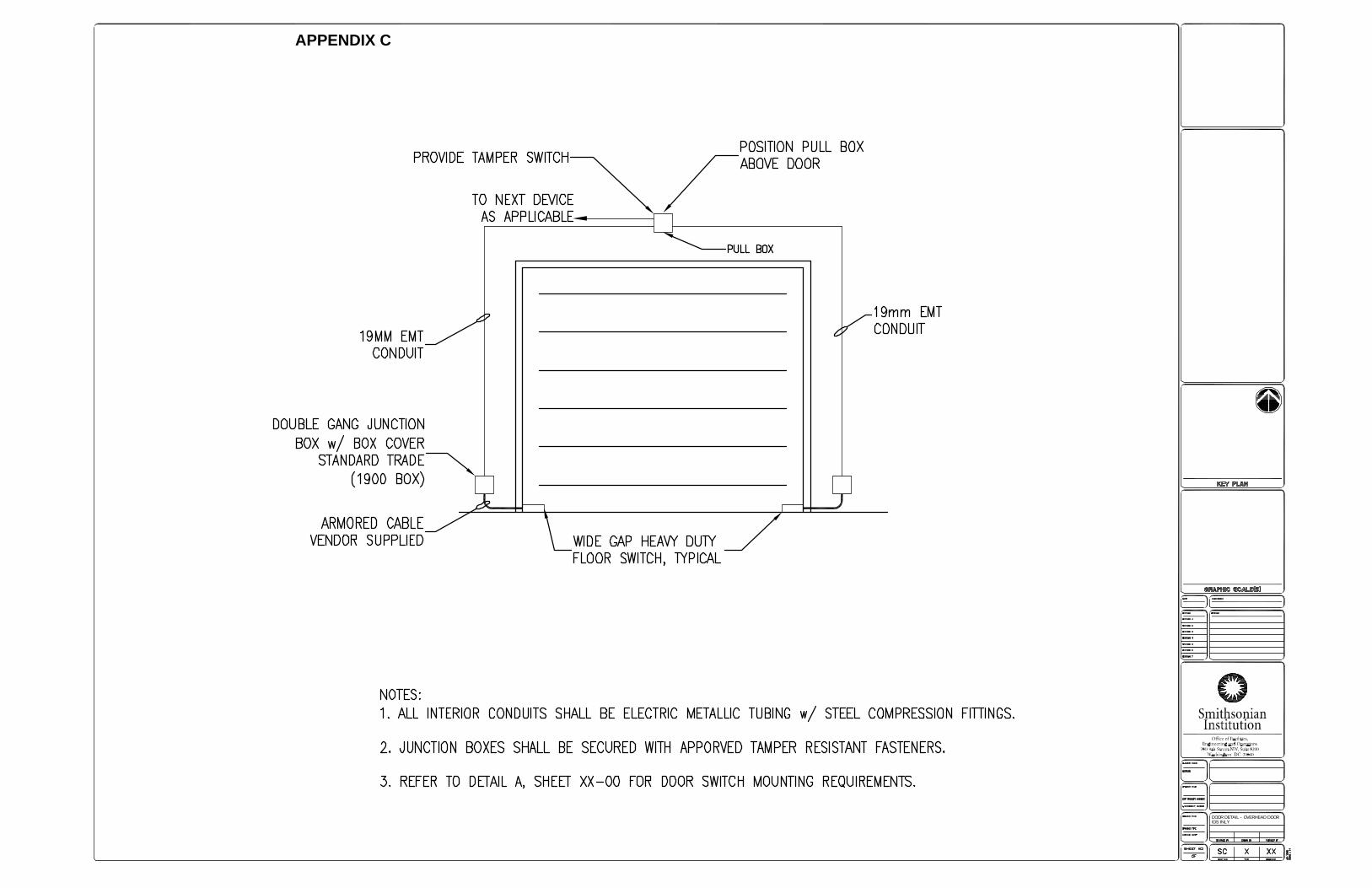
3.1.3. Overhead Door Elevation:
IDS Variation:
Wide Gap Door Contacts
3.1.4. Roof Hatch Elevation
IDS Variation:
Door Contact(s) Only
3.2. CLOSET ASSEMBLY DETAILS
Closet assembly details shall depict the electronic security system
components relative to the electrical or telecoms closet they are mounted in.
The detail(s) shall include notes that outline typical mounting instructions,
basic connection and termination instructions, supervision requirements, and
other pertinent information not conveyed by the detail alone.
A closet assembly detail shall include, but is not limited to the following:
Field Panels
Field Panel and Lock Power Supplies
Camera Power Supplies
Network Switches
Fiber Optic Hubs
Input Board Enclosures
Relay Enclosures
Cable Trays/Wire Ways
Interconnecting Conduit

Smithsonian Design StandardsAppendix B: Required Security Drawings
October 2021 Volume 3- Appendices B-8
3.3. EQUIPMENT DETAILS
Equipment details shall depict detailed graphical representations of the
electronic security system components. The detail(s) shall include notes that
outline typical mounting instructions, basic connection and termination
instructions, supervision requirements, and other pertinent information not
conveyed by the detail alone.
3.3.1 A detail shall be provided for each major component to include, but not
limited to:
Camera
VCR/DVR
Video Matrix/Switcher
Access Control Field Panel
Card Reader
Reader Module
Request-to-Exit Device
Door Contact
3.4. GALLERY DISPLAY DETAILS
Gallery display details shall provide a detailed graphical representation of
the display area. The detail shall depict the security equipment to be used
for securing the display.
3.5. SECURITY CONSOLE DETAILS
Security console details shall provide a detailed graphical representation
of the security console. The detail(s) shall depict console configuration
with measurements. The detail shall include notes on the configuration of
the console and other pertinent information not conveyed by the detail
alone.
Smithsonian Design StandardsAppendix B: Required Security Drawings
October 2021 Volume 3- Appendices B-9
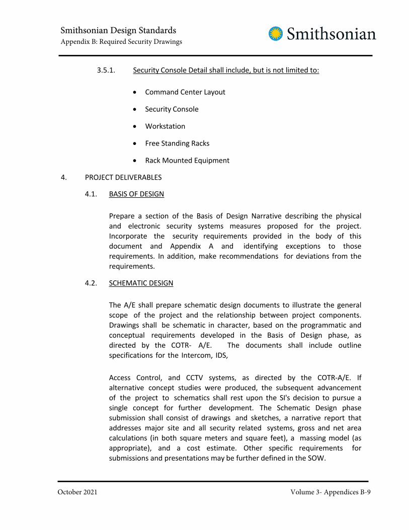
3.5.1. Security Console Detail shall include, but is not limited to:
Command Center Layout
Security Console
Workstation
Free Standing Racks
Rack Mounted Equipment
4. PROJECT DELIVERABLES
4.1. BASIS OF DESIGN
Prepare a section of the Basis of Design Narrative describing the physical
and electronic security systems measures proposed for the project.
Incorporate the security requirements provided in the body of this
document and Appendix A and identifying exceptions to those
requirements. In addition, make recommendations for deviations from the
requirements.
4.2. SCHEMATIC DESIGN
The A/E shall prepare schematic design documents to illustrate the general
scope of the project and the relationship between project components.
Drawings shall be schematic in character, based on the programmatic and
conceptual requirements developed in the Basis of Design phase, as
directed by the COTR- A/E. The documents shall include outline
specifications for the Intercom, IDS,
Access Control, and CCTV systems, as directed by the COTR-A/E. If
alternative concept studies were produced, the subsequent advancement
of the project to schematics shall rest upon the SI's decision to pursue a
single concept for further development. The Schematic Design phase
submission shall consist of drawings and sketches, a narrative report that
addresses major site and all security related systems, gross and net area
calculations (in both square meters and square feet), a massing model (as
appropriate), and a cost estimate. Other specific requirements for
submissions and presentations may be further defined in the SOW.

Smithsonian Design StandardsAppendix B: Required Security Drawings
October 2021 Volume 3- Appendices B-10
4.3. 35% DESIGN DOCUMENTS
At 35% SD the deliverable shall include the following:
Coversheet with Project Title, Site and Vicinity Plan.
Information Sheet containing general notes, abbreviations, symbols
and conventions, index of sheets, and wire and cable schedule.
Floor plans with area classifications and proposed ESS device placements
Preliminary riser and one-line diagrams for ESS
Provide product datasheets of all ESS equipment including the data
transmission system
Outline specifications – based on a customized version of the SI Construction
Specifications for Electronic Security.
Project narrative and description to be included with Outline
specification above.
4.4. 65% DESIGN DEVELOPMENT DOCUMENTS
At 65% DD submission, the design shall include the following:
Includes all documents identified in 35% submission documents
Floor plans improved with reflected ceiling plans, system point numbering,
and sized conduit routing shown. Confirm conduit scope with OPS.
Power/UPS Sources Requirements
Sensor Installation Details/Wiring Block Diagrams
Mounting details for all ESS devices /Wiring Block Diagrams
Door Details /Wiring Block Diagrams
Riser and One-line diagrams with system points and required cabling
types and counts
Door Schedule
Project Specifications– based on a customized version of the SI Construction
Specifications for Electronic Security.

Smithsonian Design StandardsAppendix B: Required Security Drawings
October 2021 Volume 3- Appendices B-11
System Point Loading Sheets (Istar/apC)
4.5. 95% CONSTRUCTION DOCUMENTS
At 95% CD submission, the design shall include the following:
Includes all document identified in 35% and 65% submission documents
Elevator Control Interface Plan Development
Cutover Implementation Schedule
Manufacturers Hardware and Software Data
System Description and Analysis
4.6. 100% FINAL CONSTRUCTION DOCUMENTS
Includes all previous submission content. This submission shall only be minor
corrections and changes by SI.

Smithsonian Design StandardsAppendix C: Standard Security Drawings
October 2021 Volume 3- Appendices C-1
APPENDIX C
Standard Security Drawings
NOTE: When Security Drawings are required, as noted on Appendix B; these standard
drawings should be used to meet the level of detail required by OPS.

Smithsonian Design StandardsAppendix C: Standard Security Drawings
October 2021 Volume 3- Appendices C-2
Appendix C - STANDARD SECURITY DRAWINGS
1. INTRODUCTION
The drawings provided herein are standard drawings to demonstrate the level of
detail required by OPS. The following drawings are included:
• Floor Plans
o Partial First Floor Plan
• Risers
o Access Control Riser Diagram
o CCTV Riser Diagram
o Intercom Riser Diagram
• System Interconnect Drawing
o Reader Interconnect
• Door Details
o Door Detail - Overhead Door - IDS Only
• Equipment Details
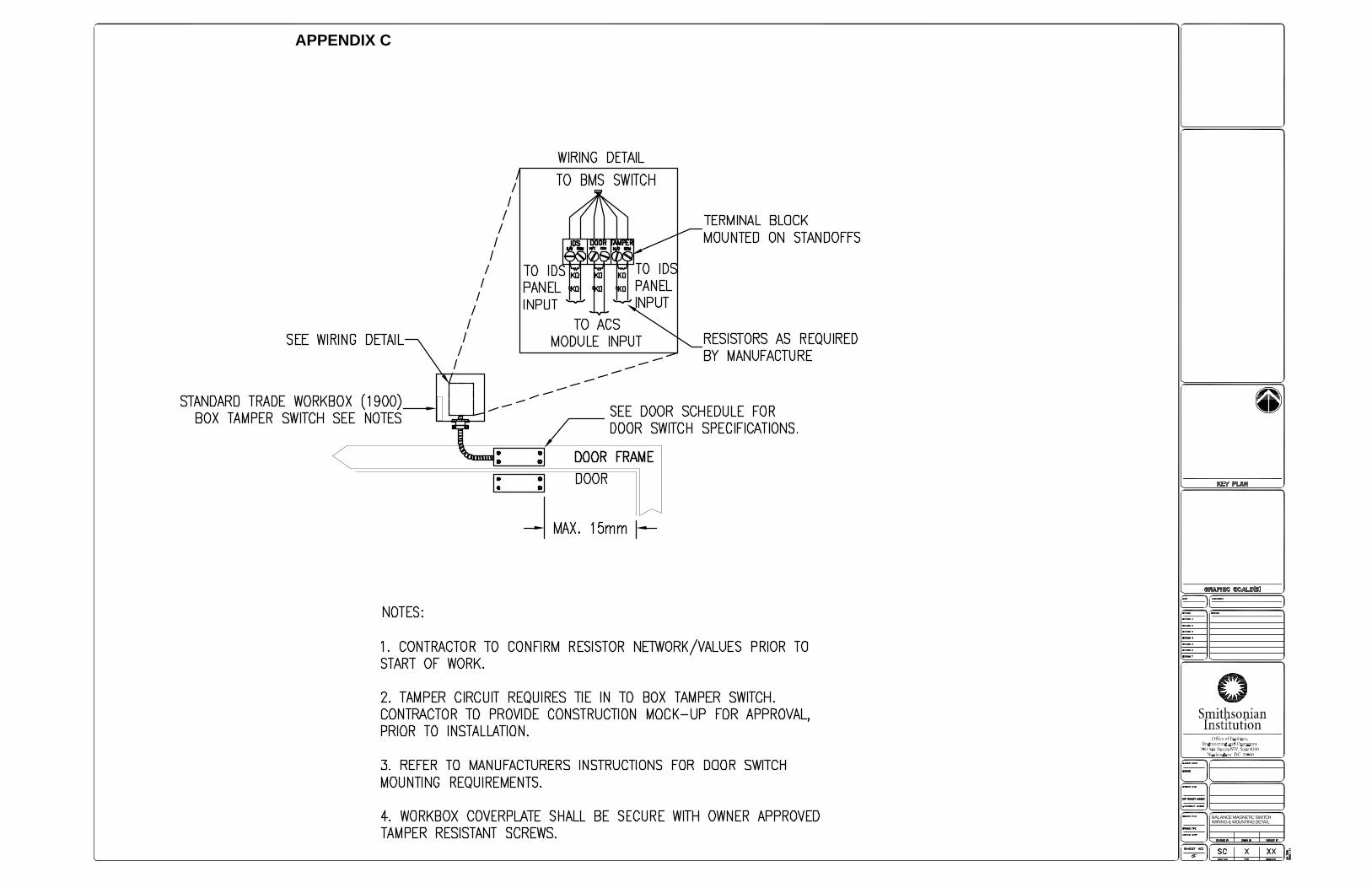
o Balance Magnetic Switch Wiring & Mounting Detail
o Camera Area of Coverage Detail - Cash Handling Location
o Camera Power & DTS Enclosure
o Detail Sheet
o Multi-Sensor Circuit with Tamper
o Power Supply Enclosure - ISTAR Pro
• Security Console Details
o UCR Console
o Unit Control Room & Equipment Room Floor-plan

Smithsonian Design StandardsAppendix C: Standard Security Drawings
October 2021 Volume 3- Appendices C-3
In addition to the drawings listed above, all projects require a code analysis/summary
and life safety plan. This information should be included, at a minimum, on a separate
sheet in the project drawing set.

APPENDIX C

APPENDIX C

APPENDIX C

APPENDIX C

APPENDIX C
READER INTERCONNECT
APPENDIX C
DOOR DETAIL - OVERHEAD DOORIDS INLY
APPENDIX C
BALANCE MAGNETIC SWITCHWIRING & MOUNTING DETAIL
APPENDIX C

APPENDIX C
CAMERA AREA OF COVERAGE DETAIL- CASH HANDLING LOCATION
APPENDIX C

APPENDIX C
CAMERA POER & DTS ENCLOSURE
APPENDIX C

APPENDIX C
DETAIL SHEET

APPENDIX C
MULTI SENSOR CIRCUIT WITHTAMPER
APPENDIX C

APPENDIX C
POWER SUPPLY ENCLOSURE -iSTAR PRO
APPENDIX C

APPENDIX C
SECURITY CONSOLE

APPENDIX C

Smithsonian Design StandardsAppendix D: Collection Storage Risk Levels
October 2021 Volume 3- Appendices D-1
APPENDIX D
Collection Storage Risk Levels

Smithsonian Design StandardsAppendix D: Collection Storage Risk Levels
October 2021 Volume 3- Appendices D-2
APPENDIX D - COLLECTION STORAGE RISK LEVELS
1. INTRODUCTION
This information is offered to guide curatorial staff, OPS, and designers in
establishing levels for Collection Storage spaces.
2. LEVELS OF RISK
The risk to any Smithsonian Institution collection item is the result of a
combination of several factors. The perceived and/or actual value of a collection
item can vary greatly from item to item and is one of those factors that must be
identified by the Smithsonian Institution in order to establish the risk to any
particular collection item. Value and the impact of loss or damage can be
quantified by one or several factors including, but not limited to:
Intrinsic value
Cultural value
Research value
Reputation of the Smithsonian Institution or Federal Government
Mission of the Smithsonian Institution or Federal Government
The mitigation measures appropriate for reducing risk for any particular collection
item should also vary and be in proportion to the perceived or actual value the
item. The physical and technical security measures identified in this section are
divided into four risk categories, based on collection value, that would be
established by the collection management staff, with guidance from OPS. In lieu
of any such designation of risk/value, the default risk level assignment for any
collection would be that of Medium Risk.
Objects on loan may carry conditions that require a level of protection above that
which the museum would normally establish, if the item were in their collections.
These standards should be considered minimum standards and can be increased
if loan requirements or risk justifies such.
All new or renovated collection storage areas or facilities should be planned in
accordance with these minimum standards. Existing collection storage facilities
should strive to meet these standards where and when possible. Temporary,
short-term, or emergency collection storage may be exempt from some of these
standards. However, all exceptions or waivers to these standards can only be

Smithsonian Design StandardsAppendix D: Collection Storage Risk Levels
October 2021 Volume 3- Appendices D-3
approved by the Director, Office of Protection Services, or his/her designee.
3. GENERAL COLLECTION STORAGE
This includes libraries, archives, and zoo (animal) collections.
3.1. LOW RISK
The majority of objects are of low to moderate monetary value, but
predominately low value. Objects are not unique items or one-a-kind, and
do not have significant scientific value. Few or no real artifacts; all or many
models or casts; replaceable; low monetary value. Educational or
informational panels associated with the exhibit. None, or few loaned
objects. No loaner special security requirements. Objects are not of
controversial nature; not identified with any political or religious
attachment. Not easily portable or movable; due to size, weight, etc. The
objects have low marketability, not easy to re-sell. Objects not identified as
having known theft interest; Public interaction; permitted-touchable items
(public curiosity); few exposed items (low risk of damage) little risk to
miscellaneous exhibit support items (audio/visual, flat screens, decorate
lighting, etc); non- accessible or in cases to prohibit theft.
3.2. MEDIUM RISK
The majority of objects are of moderate to high monetary value, but
predominately of moderate value. Objects categorized as having some
unique characteristics (limited in quantity, but not one-a-kind); having
potential scientific value. Exhibit includes a majority of authentic items;
few models or cast items. Several items in the exhibit are identified as
loaned items: some special security requirements. Objects have been
identified as having some notoriety or of controversial nature; limited
political or controversial issues related to items. There are an increased
number of smaller portable items of associated substantial value. There is a
Marketability of object(s). There is an increased theft temptation: objects
are “cool” or “good souvenirs” - unusual in appearance. There are few
permitted-touchable items; increased concern, recognized danger as
public interaction/touching could cause damage. Increased sophistication or
cost of exhibit support items (audio/visual, flat screens, decorative
lighting, etc); non- accessible or in locked cases to prohibit theft.
Smithsonian Design StandardsAppendix D: Collection Storage Risk Levels
October 2021 Volume 3- Appendices D-4
3.3. HIGH RISK
The majority of objects are of high to very high monetary value, but
predominately of high value. Objects are considered rare, extremely limited
numbers known to exist; items have significant scientific value. Majority of
exhibit objects have been identified as authentic artifacts or relics; limited
usage of models or cast items. Several items in the exhibit are identified as
loaned items: requiring special security arrangements. Notoriety of objects
have been identified to be associated with controversy, political, or religious
issues, history of demonstration or other activities. There are an increased
number of smaller highly portable items of associated substantial value.
High marketability of object; increased theft interest (ex. Jewels) There are
fragile items; inaccessibility to public interaction/touch. There are
miscellaneous exhibit support items (audio/visual, flat screens); non-
accessible or in locked cases to prohibit theft
3.4. VERY HIGH RISK
The majority of objects are of very high monetary value. One-of-a-kind,
irreplaceable items; objects identified as having extremely high scientific
value. Exhibit objects have been identified as authentic artifacts or relics.
Special loaned items (national treasures); special security arrangements are
required. Notoriety of objects has been identified to be associated with
controversy, political, or religious issues; history of demonstration or other
activities (high publicity). Easy to remove, highly portable smaller items of
associated extreme value. The objects are extremely high marketability;
increased theft interest; history of thefts of similar items; actual threats of
theft (organized and professional). Extremely fragile items; inaccessibility to
public interaction/touch.

Smithsonian Design StandardsAppendix E: Smithsonian Declaration on the Collections Preservation Environment
October 2021 Volume 3- Appendices E-1
APPENDIX E
Smithsonian Declaration on the Collections Preservation Environment

Smithsonian Design StandardsAppendix E: Smithsonian Declaration on the Collections Preservation Environment
October 2021 Volume 3- Appendices E-2
APPENDIX E- SMITHSONIAN DECLARATION ON THE COLLECTIONS PRESERVATION
ENVIRONMENT
With this Declaration on the Collections Preservation Environment, the Smithsonian Institution
clarifies values, shared by the diverse professional disciplines that directly and indirectly care
for Smithsonian collections, related to the collections preservation environment and likewise
presents a shared vision for implementing environmental policy based on these common
values.1
Collections stewardship is a key component and core priority of the Smithsonian’s Strategic
Plan. Assembled over the course of 168 years, Smithsonian collections are fundamental to
carrying out the Institution’s mission, serving as the intellectual foundation for scholarship,
discovery, exhibition, and education. Smithsonian collections represent a diverse range of
materials and disciplines, including works of art, historical artifacts, natural and physical
science specimens, living animals and plants, images, archives, library volumes, audio and
visual media, digital art and time-based media, and their associated information. Together,
these irreplaceable national icons, examples of everyday life, and scientific material preserve
the past, increase our understanding of society and the natural world in which we live, and
support the research that expands human knowledge in the arts, humanities, and sciences.
The scope, depth, and unparalleled quality of these collections make it imperative to ensure
that they are properly preserved and made accessible for current and future generations to
enjoy and study.
Environment and environmental control are fundamental components of collections
preservation; appropriate environmental conditions provide collections with chemical,
biological, and mechanical stability to extend their life, making them available to future
generations. As described in the American Institute for Conservation’s Guidelines for Practice,
assigning appropriate environmental conditions extends the life of cultural property.2 The
Smithsonian Institution aims to provide and actively manage optimized environments to
promote collections preservation based on a balance of scientific research, engineering
capability, collections management protocols, and environmental impact. The dynamic factors
comprising the preservation environment,3 and to which the common values and shared
vision statements detailed below apply equally, are:
1. Humidity and acceptable ranges for relative humidity
2. Temperature and acceptable ranges for temperature
3. Air quality and ventilation

Smithsonian Design StandardsAppendix E: Smithsonian Declaration on the Collections Preservation Environment
October 2021 Volume 3- Appendices E-3
1 Participants in the “Summit on the Museum Preservation Environment” held in Washington,
D.C. in March 2013 affirmed the goals of this Declaration in a straw poll after discussion and
review of presentations by experts in the fields of preservation, facilities management, and
sustainability.2 Guidelines for Practice of the American Institute for Conservation of Historic & Artistic Works,Section 20,
“Preventive Conservation,” http://www.conservation-us.org/about-us/core-
documents/guidelines-for-practice (accessed 6/20/2014).3 Environmental factors such as Light and Integrated Pest Management, which have aninterrelated role in thepreservation environment, will be specifically addressed in separate policy statements.

Smithsonian Design StandardsAppendix E: Smithsonian Declaration on the Collections Preservation Environment
October 2021 Volume 3- Appendices E-4
Common Values and Shared Vision Matrix
Core
AreaCommon Values Shared Vision
Co
lla
bo
rati
ng
The Smithsonian Institution believes
that collaboration is the foundation for
establishing environmental parameters.
Achieving optimal preservation
environments requires defining
objectives and finding consensus
among all stakeholders. Agreement on
environmental parameters is inherently
challenging because it requires
consideration of a number of factors,
such as evolving material-specific
environmental guidelines, building
fabric, which may be of historic
significance and fragile itself, system
capability, limitations on staff and
resources, and the growing impetus to
reduce energy costs and operate more
sustainably.
The Smithsonian Institution supports a
work force that collaborates across
disciplines to establish, monitor, and
maintain collections environments.
Roles and responsibilities of all
stakeholders across all core areas are
clearly delineated. Responsibilities
include how each stakeholder
contributes to routine planned
discussions.
Architects, curators, conservators,
collections specialists, energy
managers, engineers, facility managers,
scientists, industrial hygienists, IT
specialists, administrators, exhibition
specialists, and others are included in
discussions of the establishment of
collections environmental parameters.
Decisions are made by sharing
information, negotiating positions
based on information, and developing
consensus towards the expressed value
of progress towards an optimized
environment.
Resources such as the National
Collections Program and facility capital
and maintenance planning are available
to collaborators to foster the spirit and
effect of collaboration.

Smithsonian Design StandardsAppendix E: Smithsonian Declaration on the Collections Preservation Environment
October 2021 Volume 3- Appendices E-5
Core
AreaCommon Values Shared Vision
Mo
nit
ori
ng
The Smithsonian Institution
recognizes monitoring as an
essential element of preservation
environment activities.
Monitoring and the data derived from
monitoring are the basis of
conversations between stakeholders;
they provide meaningful information for
attempting diverse preservation
management actions, such as
establishing seasonal adjustments or
rehousing priorities, and aid in the
establishment of priorities for long-term
improvements.
The Smithsonian Institution has a
standard way in which environmental
monitoring data is collected, reported,
and interpreted across the organization.
All collections spaces are designed and
built with monitoring plans and
protocols established and defined at the
outset of design discussions.
All collections spaces are designed and
built with mechanisms for monitoring
environmental conditions for the space
and air handling systems.
Environmental monitoring data is
readily accessible to all stakeholders.
Environmental monitoring of collections
and exhibition spaces is automated and
integrated.
Existing systems and spaces are studied
for action and modeling, especially in
historic or older spaces that may not be
compatible with desired specifications.
The purchase of room- and system-
level environmental monitoring
equipment and associated software is
reliably supported.
Smithsonian Design StandardsAppendix E: Smithsonian Declaration on the Collections Preservation Environment
October 2021 Volume 3- Appendices E-6
Core
AreaCommon Values Shared Vision
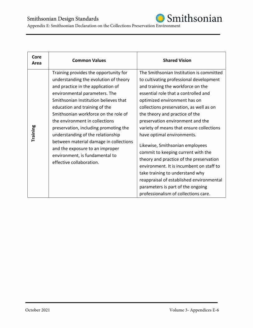
Tra
inin
g
Training provides the opportunity for
understanding the evolution of theory
and practice in the application of
environmental parameters. The
Smithsonian Institution believes that
education and training of the
Smithsonian workforce on the role of
the environment in collections
preservation, including promoting the
understanding of the relationship
between material damage in collections
and the exposure to an improper
environment, is fundamental to
effective collaboration.
The Smithsonian Institution is committed
to cultivating professional development
and training the workforce on the
essential role that a controlled and
optimized environment has on
collections preservation, as well as on
the theory and practice of the
preservation environment and the
variety of means that ensure collections
have optimal environments.
Likewise, Smithsonian employees
commit to keeping current with the
theory and practice of the preservation
environment. It is incumbent on staff to
take training to understand why
reappraisal of established environmental
parameters is part of the ongoing
professionalism of collections care.

Smithsonian Design StandardsAppendix E: Smithsonian Declaration on the Collections Preservation Environment
October 2021 Volume 3- Appendices E-7
Core
AreaCommon Values Shared Vision
Gu
ide
lin
es
an
d B
est
Pra
ctic
es
The Smithsonian Institution believes
that standards, guidelines, and best
practices for establishing, monitoring,
and maintaining the collections
environment form the basis for
reasoned collections environment
decisions, and therefore does not
support a single specification for all
collections. A broad range of choices
may be made with respect to relative
humidity, temperature, and air quality
to provide optimal preservation
environments and to meet operational
and energy sustainability goals.4
Smithsonian scientists are poised to
play a role in the research that leads
to establishing environmental
parameters.
The Smithsonian Institution conducts
research concerning the relationship
between the environment and
collections preservation in order to
continue refining an understanding of
the role of the preservation environment
and the mechanisms for damage to
collections.
Standards are routinely reviewed and
continuing research contributes to the
refinement of existing guidelines and
best practices.
Standards and regulations regarding fire
safety, health, building envelope, and
HVAC are well-understood as part of the
discussion of the preservation
environment.
4 Several guidelines and standards are especially valued for their helpfulness in
formulating a rationale for the specification of relative humidity and temperature for
collections:
Smithsonian Design StandardsAppendix E: Smithsonian Declaration on the Collections Preservation Environment
October 2021 Volume 3- Appendices E-8
British Standards Institute, Publicly Available Specification (PAS) 198: 2012
“Specification for managing environmental conditions for cultural collections”;
American Society for Heating and Air-conditioning Engineers (ASHRAE) Handbook:
HVAC Applications Chapter 23 “Museums, Galleries, Archives, and Libraries”;
Smithsonian Institution Facility Design Standards,
http://www.ofeo.si.edu/ae_center/pdf/SI%20Standards_Jan2012.pdf
(accessed 6/6/2014);
American Institute for Conservation of Historic and Artistic Works, interim
guidelines for loans, http://www.conservation-
wiki.com/wiki/Environmental_Guidelines (accessed 6/19/2014);
Smithsonian Directive 600, Collections Management,
http://prism2.si.edu/SIOrganization/OCFO/OPMB/SD/SD600.pdf
(accessed 3/19/2014)

Smithsonian Design StandardsAppendix E: Smithsonian Declaration on the Collections Preservation Environment
October 2021 Volume 3- Appendices E-9
Core
AreaCommon Values Shared Vision
Ris
k M
an
ag
em
en
t
Some Smithsonian collections are
tolerant of a wide range of
environments because of their robust
physical nature; other collections have
specific requirements and special needs
for long-term preservation.
The Smithsonian recognizes that
different approaches may be used to
characterize the requirements of a
particular collection or facility.
Comprehensive risk management
models used in collections
management have an important role
to play in establishing environmental
parameters. Standards may be used in
tandem with risk management models
to develop reasoned collections
environments.
Smithsonian Institution collections staff
are trained to be knowledgeable about
the profiles of the materials in their
collections and apply modern
approaches to categorizing collections’
fragility and hardiness.
Environmental requirements for a
collection are thoroughly discussed with
stakeholders and the methodologies
used to make decisions, including the
resulting decisions themselves, are well-
documented.
Historic structures are considered
when performing risk management
exercises and are evaluated for building
performance.

Smithsonian Design StandardsAppendix E: Smithsonian Declaration on the Collections Preservation Environment
October 2021 Volume 3- Appendices E-10
Core
AreaCommon Values Shared Vision
Su
sta
ina
bil
ity
The Smithsonian Institution
acknowledges that the preservation
environment, operational
sustainability, and environmental
sustainability are interdependent.
More sustainable preservation
environments and operations also may
extend the lifetime of collections.
Sustainable preventive conservation
methods have the potential to influence
the type of preservation environment
required for collections.
Improving the sustainability of
collections preservation environments
requires implementing strategies to
conserve energy and water and to
ensure the continued operations of
preservation environment systems. The
Smithsonian pursues these strategies
while also fulfilling its responsibility to
preserve, and to make accessible to
present and future generations, the
collections in its care.
Energy and water conservation
measures which may affect the
preservation environment are
developed in collaboration with all
stakeholders.
The process for selecting systems
utilized in the preservation
environment takes into account life-
cycle costs impacting operational and
financial sustainability.

Smithsonian Design StandardsAppendix E: Smithsonian Declaration on the Collections Preservation Environment
October 2021 Volume 3- Appendices E-11
Core
AreaCommon Values Shared Vision
Cu
sto
miz
ed
Sp
eci
fica
tio
ns
The Smithsonian Institution considers
the preservation environment of each
collections space to be one of the
paramount mechanisms for ensuring
the longevity of collections. Therefore,
the preservation environment
specifications of each collections space
are actively defined to meet practical
and sustainable parameters. Because of
the wide variety of collections materials
and collections spaces across the
Smithsonian, and because conservation
research has acknowledged the variety
of approaches to establishing
preservation environment parameters,
there is not a default preservation
environment specification. The space
may be intentionally unconditioned or
may be continually refined based on
new data through a collaborative
process among stakeholders, but tightly
controlled 70° F and 50 percent RH is
no longer considered an appropriate,
practical, sustainable, or useful set-
point for all collections.5
The Smithsonian captures the many
data points of the preservation
environment, allowing stakeholders to
discuss it flexibly and openly, to adapt
to changing information, and to
account for differences of findings on
environmental readings.
At a minimum, all collections spaces
receive pro-active specification of
relative humidity and temperature
allowances and seasonal adjustments.
Several core areas from this document
– monitoring, guidelines and best
practices, risk management, and
sustainability – are factors that
contribute to the collaborative
establishment of the optimal
preservation environment for each
collections space.

Smithsonian Design StandardsAppendix E: Smithsonian Declaration on the Collections Preservation Environment
October 2021 Volume 3- Appendices E-12
5 In recent years, the Smithsonian Institution has actively pursued specifications that reflect
seasonal adjustments, set-backs, and shutdowns calculated to avoid condensation in building
envelopes. Research by the Smithsonian Institution Museum Conservation Institute
demonstrated that a broad RH range can be tolerated by many objects. For exhibition spaces
where the need for human comfort and protection of building structures is frequently cited, a
guideline of 37-53 percent RH and 66-74°Fahrenheit has been developed.
http://www.si.edu/mci/downloads/reports/mecklenburg-part1-RH.pdf (accessed 6/6/2014).
Many spaces for collections at SI have adopted a “cooler and drier” methodology as well.

Smithsonian Design StandardsAppendix F: Exhibit Fabrication Guide
October 2021 Volume 3- Appendices F-1
APPENDIX F
Exhibit FabricationGuide
● Appendix F1 – Exhibit Fabrication Guide
● Appendix F2 – Fire and Life Safety Checklist for Exhibit Construction
● Appendix F3 – General Notes for Exhibit Design
● Appendix F4– Frequently Asked Questions about Exhibits Materials
● Appendix F5 – Approved/Prohibited Exhibit Materials [RESERVED]

Smithsonian Design StandardsAppendix F: Exhibit Fabrication Guide
October 2021 Volume 3- Appendices F-2
EXHIBIT FABRICATION GUIDE
1.1 GENERAL
A. This chapter sets forth the appropriate fire protection and safety requirements
for organizations planning or engaging in exhibit construction, improvement
and alteration projects.
B. The Smithsonian Institution shall ensure that the established fire protection and
life safety requirements outlined in the Smithsonian Safety Manual and this
Design Manual are carried out in the planning and design of all exhibit
construction, improvement, and alteration projects.
1. This consists of the most current edition of the codes and standards
cited in this Design Manual, including, but not limited to:
i. IBC, International Building Code
ii. IFC, International Fire Code
iii. NFPA 101, Life Safety Code
iv. NFPA 13, Installation of Sprinkler Systems
v. NFPA 72, National Fire Alarm and Signaling Code
vi. OSHA Standards Part 1910, Occupational Safety and Health
Standards for General Industry
vii. OSHA Standards Part 1926, Safety and Health Regulations for
Construction
C. Because of the broad scope of concern, the Office of Safety, Health and
Environmental Management (OSHEM) should be consulted in the earliest
stages of planning, and development or design for all projects to ensure
adequate consideration of all necessary requirements within the project time
constraints.
1. The SI office responsible for organizing, planning, or engaging in any
exhibit construction, improvement and alteration project is
responsible for ensuring OSHEM is consulted in the earliest stages of
the exhibit planning.
2. The Office of Safety, Health and Environmental Management (OSHEM)
Director is responsible for directing and implementing fire protection, life
safety, and occupational safety and health functions.
3. OSHEM will provide technical supervision, assistance, review, and
approval during the design and construction process.
APPENDIX F1- EXHIBIT FABRICATION GUIDE

Smithsonian Design StandardsAppendix F: Exhibit Fabrication Guide
October 2021 Volume 3- Appendices F-3
Commentary: Exhibits staff are encouraged to involve OSHEM directly
in the initial stages of a design to ensure fire and life safety issues are
identified and addressed early on.
D. A checklist to aide exhibit design and fabrication with respect to Smithsonian
Institution fire and life safety requirements and standards is provided in
Appendix A of this Design Manual.
E. Please refer to Appendix F, General Notes for Exhibit Design, and
Appendix G, Frequently Asked Questions about Exhibits Materials, for
additional information.
Commentary: These sections are new to this edition of the Manual and contain
information regarding general notes that should be present in every drawing
set, as well as questions and answers about exhibit materials that are
frequently the subject of conversations between OSHEM and exhibit design
personnel.
1.2 EXHIBIT DESIGN DRAWINGS
A. General
1. Exhibit design, construction plans and specifications shall be
submitted for OSHEM for review and approval at all contract
submission milestones.
2. Plans shall be approved by OSHEM prior to the start of any
construction or alteration activities.
3. The general notes found in Appendix F of this Manual shall be included
in each exhibit design drawing set.
B. Key Plan
1. A key plan shall be provided showing the location of the project area in
relation to the building floor plan.
C. Floor Plans
1. Plans shall indicate all new and existing wall, floor, and ceiling construction.
2. Areas where work is to be accomplished shall be labeled and the
occupancy of the areas in close proximity to the project site (e.g.
gallery, office, corridor, exit stair, collection storage) identified.
3. All new, relocated, and existing fire safety equipment on both the
demolition and new work plans must be shown and labeled
appropriately.
i. This equipment includes but is not limited to: sprinkler heads, smoke
detectors, heat detectors, pull stations, standpipes/hose cabinets,
fire extinguishers, bells/horns/speakers, strobe lights, remote
Smithsonian Design StandardsAppendix F: Exhibit Fabrication Guide
October 2021 Volume 3- Appendices F-4
indicator lights, exit signs, emergency lights, air supply and return
ducts, fire-rated partitions, and fire doors.
4. Plans shall indicate exit details such as location, paths of
access/egress, door swing, and width of passageways and doors.
Commentary: The closure of a gallery for exhibit construction may impact
egress from adjacent spaces. Where this occurs, plans should
encompass the impacted areas.
Indicating the exit paths to the nearest stairwell or building exit on the
drawings facilitates the project’s life safety review. This may require
showing more of the building on the plans than just the area of work.
5. Plans shall indicate the hourly rating of new and existing fire doors and
frames, and include details of new fire door assemblies, such as area of
glazing, materials of construction, and types of hardware.
D. Existing Conditions
1. Show locations of all existing fire alarm devices. Indicate make and model
number, and type of existing equipment. Ensure devices will not be
obstructed by new work.
Commentary: A common issue found (especially with cycling exhibit
galleries) is that new walls will obstruct the view of notification
devices. Care should be taken to relocate fire alarm speakers and
strobes if necessary. Ceiling mounted strobes can be used in lieu of
wall-mounted devices to avoid conflicts with exhibit construction.
2. Show locations of all existing automatic sprinkler heads. Indicate height
above the floor (if it varies) and sprinkler type (pendent, upright, or
sidewall).
Commentary: In general, exhibitory should be kept to a height 18” or
more below the level of sprinkler deflectors. This will avoid sprinkler
coverage issues.
3. Show locations of all exit signage.
E. Special Operations and Hazardous Materials
1. Any special operations to be performed, or hazardous materials to be
used, in the work area or nearby spaces shall be noted on the drawings.
Examples include: electrical hazards, use of flammable or toxic materials,
special cleaning operations.
F. Exhibited Objects
1. Drawings shall include adequate information about the objects on
display to assess their impact on the level of fire protection and life

Smithsonian Design StandardsAppendix F: Exhibit Fabrication Guide
October 2021 Volume 3- Appendices F-5
safety. Plans are to include the dimensions, exact location, and
construction materials of large objects not enclosed within vitrines.
Commentary: Advance coordination with OSHEM of fabrication is
critical to ensure fire protection and life safety requirements are met.
The goal of this interaction is to ensure adequate life safety for visitors
and staff, while minimizing impact to the exhibited objects.
2. Objects or exhibit construction shall provide necessary details to
demonstrate that hazards such as sharp edges, tip-over, and moving
parts are properly mitigated.
1.3 EXITS
A. Exit Details
1. All public galleries shall have a minimum of two exits, arranged to be
remote from one another.
Commentary: Large galleries with capacities of more than 500 occupants,
based on the criteria of NFPA 101, require three exits; galleries with
capacities of more than 1000 occupants require four exits.
2. Ensure the clear width along all points on the primary egress path is a
minimum of 5 feet (1524 mm).
Commentary: The wider path compensates for circuitous routes
through an exhibit, and allows occupants room to turn around and
head towards an exit in the event of a fire.
3. Ensure the clear width along all points on the secondary egress paths is a
minimum of 44 inches (1117 mm). (In certain situations, NFPA 101 and
OSHEM may require greater clear width.)
Commentary: Wider egress paths may be required to accommodate
large exhibit spaces with higher occupant load capacities, per NFPA 101.
B. Exit Signs
1. Location
i. Exits shall be properly identified by exit signs. Exit signs shall be listed
or approved, readily visible, and of a distinctive color which
contrasts with the surrounding decor.
ii. No display, object or brightly illuminated signs shall be placed in the
line of vision to distract attention from the exit signs.
2. Lettering
i. Each exit sign shall have the word, "EXIT" in plain, legible letters not
less than 6 inches (150mm) high, with the principal stroke of letters

Smithsonian Design StandardsAppendix F: Exhibit Fabrication Guide
October 2021 Volume 3- Appendices F-6
not less than 3/4 inches (19mm) wide.
ii. An arrow, indicating the direction of exit travel, shall be used
when the direction is not readily apparent. Refer to NFPA 101
for other specific requirements.
3. Illumination
i. Exit signs shall be illuminated by either an integral light source or an
external light source measuring not less than 5 foot-candles (54 lux) at
the illuminated surface under both normal and emergency power.
ii. Internally illuminated signs shall be listed in accordance with ANSI/UL
924.
4. Power Supply
i. The power shall be supplied by continuous power source with
secondary power from an emergency generator or integral
battery.
C. Walking Surfaces
1. Changes in Elevation
Commentary: NFPA 101 recognizes the changes in elevation noted below
as tripping hazards. Any change in excess of the below must be achieved
by a ramp or stair.
i. Abrupt changes in elevation of walking surfaces shall not exceed
1/4 inch (0.63 cm).
ii. Changes in elevation exceeding 1/4 inch (0.63 cm), but not
exceeding 1/2 inch (1.3 cm) shall be beveled with a slope of 1 in 2.
2. Headroom
i. Minimum headroom shall be 6 feet 8 inches (203 cm) at doors or
stairwells.
3. Platforms
i. Platforms protruding into walk spaces present a "strike the ankle"
type hazard. Special lighting, color contrast, padding, or full height
guardrails are recommended.
D. Stairs and Steps
1. Fewer Than Three Risers
i. When fewer than three risers are used, measures shall be taken to
create awareness of the elevation change. Examples include special
lighting, color contrast, change in floor surface, or barriers.

Smithsonian Design StandardsAppendix F: Exhibit Fabrication Guide
October 2021 Volume 3- Appendices F-7
2. Width and Height Requirements
Commentary: The requirements below are taken verbatim from NFPA 101.
i. Minimum width of stairs and steps shall be 44 inches (112 cm) and
clear of all obstructions except handrails. Stair and landings shall
not decrease in width along the direction of exit travel.
ii. Treads shall not be less than 11 inches (27.9 cm).
iii. Risers shall not be less than 4 inches (10.2 cm) nor more than 7
inches (17.8 cm).
iv. Variations in width of adjacent treads and height of adjacent risers
shall not exceed 3/16 inch (.5 cm). Variation between sizes of the
largest and smallest risers or between the largest and smallest tread
depths in a flight of stairs shall not exceed 3/8 inch (0.95 cm).
3. Landings
i. Doors may not open immediately onto stairs without a landing of at
least the width of the door, plus one tread dimension.
Commentary: This configuration removes the risk of tripping or
falling upon opening the door and is an NFPA 101 requirement.
4. Handrail Details
Commentary: The requirements below are taken verbatim from NFPA 101.
i. Stairs and ramps shall have handrails 34 to 38 inches (86 to 96
cm) high measured from the leading edge of the tread to the
top of the rail.
ii. Additional handrails that are lower or higher than the main rail are
permitted. For areas where children are the primary users, it is
recommended that an intermediate handrail be installed.
iii. Handrails shall be installed to provide a clearance of at least 2-1/4
inches (56 mm) from the wall to which it is attached.
iv. Handrails shall offer no obstruction to a smooth handhold surface
along the top and both sides of the rail.
v. Handrails shall have a circular cross section with an outside
diameter of at least 1-1/4 inches (3.2 cm) and not greater than 2
inches (5 cm).
vi. Handrails shall extend horizontally at least 12 inches (30.5 cm)
beyond the top riser and continue to slope for a depth of one tread
beyond the bottom riser.
vii. Ends of handrails shall be turned into the supporting wall, floor

Smithsonian Design StandardsAppendix F: Exhibit Fabrication Guide
October 2021 Volume 3- Appendices F-8
or shall terminate at newel posts.
5. Guardrails
Commentary: The requirements below are taken verbatim from NFPA 101.
i. Guardrails shall be provided at floor openings, open-sided floors,
platforms (30 inches (76 cm) or more above the floor or ground level)
and ramps. All open sides shall be guarded by railings, except where
there is an entrance to a ramp or stairway.
ii. Guardrails shall have a vertical height of 42 inches (107 cm)
measured from the upper surface of the top rail to the floor,
platform, or runway.
iii. Guardrails shall be capable of withstanding a load of at least 200
pounds (90.7 kg) applied in any direction at any point at the top
of the rail.
iv. Provide full-height (42”) guardrails or barriers in lieu of cane rails.
Commentary: Experience with cane rails at SI has shown that they often
present a significant tripping hazard.
1.4 FIRE-RATED CONSTRUCTION
A. Penetrations Through Fire-Rated Construction
1. Penetrations through fire-rated construction (i.e. walls, floors, etc.), not
protected by fire dampers or combination fire/smoke dampers, shall be
sealed with an approved penetration firestop material that maintains
the fire rating.
Commentary: Most foaming insulation is not approved firestop material.
This type of material will still burn in the presence of fire due to its
chemical makeup.
2. All installations shall comply with the manufacturer’s installation
requirements.
1.5 MATERIALS OF CONSTRUCTION
A. General
1. All materials of construction shall be noncombustible or inherently fire
retardant. These requirements typically do not apply to
artifacts/collections to be exhibited, unless the object presents an
appreciable fire risk as evaluated by OSHEM.
Commentary: Extreme care must be exercised in the selection of
interior finish materials. Some veneers and synthetic J wall, ceiling and
floor coverings are dangerously combustible. Flames spread rapidly
Smithsonian Design StandardsAppendix F: Exhibit Fabrication Guide
October 2021 Volume 3- Appendices F-9
over them, generating large amounts of smoke and toxic products of
combustion. The danger to collections and to the lives of visitors and
staff from improperly selected interior finish materials cannot be
overemphasized.
2. Readers are encouraged to reference Appendix F for common
information required on exhibit design drawings.
3. When completed, readers are encouraged to reference Appendix G for
approved materials for exhibit construction.
B. Testing
1. Fire tests for construction materials must be conducted by an
independent, national testing laboratory, such as Underwriters
Laboratories.
Commentary: Such labs follow established test standards to rate the
fire performance of construction materials, including how much fuel a
material contributes to a fire, how quickly flame spreads over its
surface, and how much smoke it generates.
Standardized fire testing is a costly and lengthy process. OSHEM
recommends using products that have been previously tested to the
ASTM standards listed below.
2. Fire performance is to be measured using a standardized test,
recognized by national codes, and appropriate for the material type
and application. Flame spread shall be measured using test standard
ASTM E-84, and critical radiant flux is to be measured using test
standard ASTM E-648.
Commentary: For ASTM E-84, the lower the flame spread the better its
performance in the test. For ASTM E-648 the higher the critical radiant
flux the better its performance in the test.
3. Test results of any materials may be requested by OSHEM for review
prior to approval.
C. Wall and Ceiling Materials
1. Wall and ceiling materials that are used in exhibit spaces or the means of
egress such as paneling or acoustical tiles; shall have a flame spread
rating of 25 or less, and a smoke developed index of 450 or less, as
measured in accordance with ASTM E-84, Surface Burning Characteristic
of Building Materials.
Commentary: The above numerical values equate to a Class A rating in
accordance with ASTM E-84. Common wall materials that meet this

Smithsonian Design StandardsAppendix F: Exhibit Fabrication Guide
October 2021 Volume 3- Appendices F-10
requirement are drywall, fire retardant MDF (e.g. Medite FR), and fire
retardant plywood (e.g. Pyroguard).
The test results of ASTM E-84 are represented by a dimensionless
number. For reference, mineral board has a flame spread of zero, and
red oak has a flame spread of 100 per the test.
2. Materials not appropriate for testing with ASTM E84 shall pass NFPA 286.
Commentary: Materials that are not appropriate for testing with E84
include materials that melt or drip. This includes most plastics and
plastic foams, which are discouraged by this Manual. NFPA 286 is a
more realistic fire test that utilizes a full-scale fire to approximate the
contribution of a given material to a fire scenario in a compartment.
3. For exhibit spaces protected by an automatic sprinkler system, wall and
ceiling materials shall have a flame spread rating of 75 or less.
Commentary: Materials with a numerical flame spread rating from 26 up
to and including 75 are considered to have a Class B rating, in
accordance with ASTM E-84.
4. Wall mounted materials that have an aggregate surface area exceeding
10% of the wall area, and single pieces over 100 sq. ft. (9.3 sq. m) shall
comply with the above requirements for wall and ceiling materials.
Commentary: Wall mounted materials in this size or coverage begin to
perform similarly to a wall finish. This size requirement includes backings
for portraits and other wall-hung materials. Acrylic does not meet Class A
or B ASTM E-84 requirements; therefore, the aggregate quantity of wall-
mounted acrylic must have a surface area less than 10% of the wall area,
and individual panels must have an area less than 100 sq. ft. Materials
such as metal sign blank, fire retardant MDF, or glass are acceptable
alternatives in this situation.
D. Wood
1. Wood used for walls, platforms, dioramas, blocking, furring, cases
over 100 cubic feet (2.8 cubic m), light attics with electric lighting,
and similar applications shall be fire retardant, pressure
impregnated.
i. Fire retardant coatings and intumescent paint are not acceptable in
lieu of fire retardant pressure impregnation treatment.
Commentary: Fire retardant coatings and intumescent paints are not
absorbed/impregnated into the wood, as pressure impregnated fire
retardant treatments are. While paints and similar coatings can
reduce the flame spread across the surface of a material, they do not
Smithsonian Design StandardsAppendix F: Exhibit Fabrication Guide
October 2021 Volume 3- Appendices F-11
alter the combustibility of the entire product. Additionally, such
coatings can flake off or lose their effectiveness over time, leading to
inadequate protection.
ii. This requirement shall not apply to cabinets, showcases or finish trim.
iii. Unenclosed spaces beneath table-style cases shall not contribute
to overall case volume when considering the 100 cubic foot (2.8
cubic m) limit.
E. Carpeting
1. Flooring materials shall have a minimum critical radiant flux of 0.45
watts/cm², when tested in accordance with ASTM E-648, Standard Test
Method for Critical Radiant Flux of Floor Covering Systems Using a
Radiant Heat Energy Source.
Commentary: The numerical value above corresponds to a Class I finish
in accordance with ASTM E-648.
2. Carpeting shall also pass the Methanamine Pill Test, Federal
Flammability Standard FF-1-70 (ASTM D-2859).
Commentary: All carpeting imported, sold, or brought into commerce
within the USA must meet the test above.
3. For installations specifying carpeting on walls the following criteria
shall be used:
i. The room shall be protected by an automatic sprinkler system.
ii. Materials shall have a Class A rating (flame spread 25 or less and
smoke development factor less than 450), as measured by ASTM E-
84.
Commentary: Materials perform differently in a fire when oriented
vertically versus horizontally. Vertical surfaces tend to spread fire
more rapidly than horizontal surfaces; therefore carpeting specified
for wall installation must meet a Class A rating as tested per ASTM E-
84 for wall finishes.
F. Draperies, Bunting or Decorative Textiles
1. All material intended for decorative purposes, such as draperies, scrim or
bunting shall be certified flame resistant in accordance with the criteria
contained in the current edition of NFPA 701, Methods of Fire Tests of
Flame- Resistant Textiles and Films. Samples and fire test data shall be
submitted to OSHEM for evaluation and approval.
Commentary: Every effort should be made to obtain materials that are
factory treated to meet NFPA 701. In the event that a fabric does not
Smithsonian Design StandardsAppendix F: Exhibit Fabrication Guide
October 2021 Volume 3- Appendices F-12
come in a fire retardant variety, it may be treated post-manufacturing
with a fire retardant. The requirements above for test data and samples
still apply.
G. Plastics, fiberglass, exposed foamed plastics, materials containing foamed plastics
1. Plastics, exposed foamed plastics, and materials containing foamed
plastics are prohibited from being used in the exhibit unless the
specific criteria in the Life Safety Code and the IBC for Interior Finish
and Furnishings, Decorations, and Scenery have been met.
Commentary: Plastics are extremely flammable and produce toxic
combustion products when burned. This type of material should not be
selected for an exhibit when non-combustible or fire-retardant materials
could be used.
The documents above refer to ASTM E84 for most materials. However,
plastics used as a wall finish (such as HDPE panels) must pass NFPA 286.
Plastics used as trim (and similar auxiliary uses) must pass NFPA 289/UL
1975.
However, the Codes do not adequately address items found in our
galleries, such as fabricated models. Please see the model-making
section below.
2. Samples and fire test data shall be submitted to OSHEM for
evaluation and approval.
3. Vitrines materials with more than 100 sq. ft. (9.3 sq. m) of exposed
vertical surface area shall comply with the interior finish
requirements for walls and ceiling materials.
Commentary: For vitrines, only the vertical (wall) surface area is
tabulated, as flame spread over the vertical surfaces is of more concern
than that of the horizontal ones. Acrylic use is limited to an aggregate
exposed surface area of 100 sq. ft., since acrylic does not meet Class A
or B ASTM E-84 requirements.
4. Fiberglass must use a fire-retardant resin and pass Class A or B interior
finish requirements when tested in accordance with ASTM E-84 in the
design thickness.
5. Aluminum Composite Materials (ACM) (e.g. di-bond) may be used for
standalone signage and the backing of vitrines when the material does
not exceed 100 sq. ft. in area. This material may not be used to construct
casework. The material must pass ASTM E84 Class A.
Commentary: OSHEM acknowledges that this material is preferred as a

Smithsonian Design StandardsAppendix F: Exhibit Fabrication Guide
October 2021 Volume 3- Appendices F-13
graphics backing material in some instances. While this type of material
passes ASTM E84, it still contains a significant amount of plastic, which
melts, drips, and burns when exposed to heat and flame. Thus, its use is
limited to the above.
6. Desiccant chambers within cases less than 100 ft3 in size may be
constructed of acrylic. ACM may be used in larger cases for this
purpose. The ACM must pass ASTM E84 Class A.
Commentary: The surfaces of desiccant chambers are required to be
inert in terms of object conservation. Acrylic and ACM are two materials
that have been approved by SI conservation staff. Barrier films (e.g.
Marvelseal) are considered a last resort to accomplish separation
between case materials and a specimen.
Given the limited space that desiccant chambers occupy, the above-
specified materials are permitted for this purpose.
H. Glass
1. Glass used in vitrines or displays that exceeds 48 inches (1219 mm)
in any dimension shall be laminated safety glass.
Commentary: The IBC requires safety glass for large panes of glass. The
large number of cases and vitrines and high visitation in our public
spaces, raises the risk of injury due to glass breakage. Thus, the IBC
requirements for safety glass are applied in this situation.
I. Model-Making
1. It is not the intent of this Manual to prohibit the construction of models.
However, models are often fabricated from plastic or foam. As stated in
previous sections of this document, plastics and foam plastics are
prohibited, unless meeting the specific requirements of IBC and the Life
Safety Code.
Commentary: Early collaboration with OSHEM on model design and
fabrication is highly recommended.
2. Refer to Appendix G for guidelines on model fabrication.
1.6 FIRE ALARM AND DETECTION SYSTEMS
A. General
1. Smoke detection shall be installed in all areas and shall meet the
requirements of the current edition of NFPA 72, the SI Fire Protection &
Life Safety Design Manual, SI Standard Specifications, and the
manufacturer's design specifications.

Smithsonian Design StandardsAppendix F: Exhibit Fabrication Guide
October 2021 Volume 3- Appendices F-14
2. When a permanent gallery is closed to install a new exhibit,
potential fire detection and alarm system upgrades must be
evaluated and implemented. Ceiling-mounted notification
appliances are preferred to provide maximum flexibility in
exhibition design.
3. Smoke detectors and notification appliances shall not be field-painted.
Commentary: Devices may be compromised if field-painted. Additionally,
their listing/approval assigned by Underwriter’s Laboratories (UL) or
Factory Mutual (FM) will be invalidated. Field-painted devices can no
longer be used as part of a listed/approved fire alarm system, and must
be replaced.
4. Protective covers for fire detection and suppression devices shall be
provided during dust-creating construction and painting operations.
Protective covers shall be removed at the end of each workday. The SI
Fire System Impairment Permit must be used each time detectors are
covered or taken out of service by some other means.
Commentary: Any work activity that will create dust can clog the
sampling chamber of the smoke detectors and cause them to
malfunction. If air sampling smoke detection (VESDA) is present in the
gallery, the VESDA unit should be deactivated to preserve the filters.
The system must be reactivated at the end of each workday, after dust
has been cleared.
It cannot be emphasized enough that the museums are most
vulnerable to fire while undergoing construction. It is critical to have
fire detection systems operational, except when dust-generating
activities are ongoing.
B. Manual Fire Alarm Stations
1. Manual fire alarm stations shall not be obstructed and shall remain
accessible at all times.
C. Placement of Bells, Horns, and Speakers
1. Audible devices shall be installed so that they are at least 15 dB louder
than the maximum noise level that normally occurs in the area served.
D. Placement of wall and ceiling mounted strobes.
1. Visual devices (strobes) shall be installed per NFPA 72, and not
obstructed from view by exhibit construction.
E. Relocation or Extension of Existing Equipment
Smithsonian Design StandardsAppendix F: Exhibit Fabrication Guide
October 2021 Volume 3- Appendices F-15
1. Determine final location of walls, barriers and ceilings before placing
detection and alarm equipment.
2. New equipment shall be compatible with the existing system.
F. Testing of Devices
1. OSHEM must witness acceptance testing of new or relocated
devices.
1.7 AUTOMATIC SPRINKLER SYSTEMS
A. General
1. Provide automatic sprinklers in all areas. Sprinkler installations shall meet
the requirements of the current edition of NFPA 13, SI Fire Protection &
Life Safety Design Manual, SI Standard Specifications, and the
manufacturer’s design specifications.
Commentary: Care must be taken to ensure that new exhibitry does not
obstruct fire sprinkler discharge. In general, floating ceilings/objects less
than 4 feet in diameter and kept at least 18” below the sprinkler head
will not require sprinkler protection. Mesh/grate-type ceilings less than
70% open will require a separate level of sprinkler protection.
Obstructions may also comply with the cloud ceiling requirements of
NFPA 13 where permitted.
2. When a permanent gallery is closed to install a new exhibit,
potential fire protection system upgrades must be evaluated and
implemented.
B. Relocation or Extension of Existing Equipment
1. Determine final location of walls, barriers and ceilings before
considering changes to the sprinkler system.
2. If existing equipment must be extended or relocated, provide a layout
showing location and size of existing and proposed piping.
3. Sprinkler system additions and modifications shall be per the latest
edition of NFPA 13 and designed for Ordinary Hazard Group II
Occupancies.
Commentary: Providing Ordinary Hazard II sprinkler density allows for
flexibility in future designs.
4. Pipe sizes shall be determined by hydraulic calculation.
5. Obstructions over four feet in width require sprinkler coverage
underneath.

Smithsonian Design StandardsAppendix F: Exhibit Fabrication Guide
October 2021 Volume 3- Appendices F-16
Commentary: This section does not apply to cases, tables, and similar
construction.
C. Sprinkler heads and concealed sprinkler plates shall not be field painted. Any
sprinkler heads or plates coated with paint in the field shall be replaced.
Commentary: When sprinkler heads or plates are painted, their ability to
function is diminished. Care should be taken during painting stages to ensure
that the heads do not need to be replaced. Please note that heads may not be
“cleaned” to remove material if they have been painted; they must be
replaced.
D. Enclosed dioramas/cases greater than 150 square feet in size shall have
sprinkler coverage installed within unless it meets all of the following
requirements and is approved by OSHEM:
1. The exhibitry is constructed of noncombustible materials. Fire retardant
wood is also permitted.
2. Light attics are enclosed in metal and separated from the primary
cavity of the case by glass.
3. All lighting is low voltage.
4. No other line-voltage electrics are present in the case.
Minimal diorama/scenery is present within. Anything in the exhibitry (other
than specimens/objects) must be noncombustible or fire retardant.
Commentary: Sprinkler systems are designed to react to incipient fires and
control them while they are small. Large unsprinklered casework and exhibitry
can delay sprinkler operation, allowing a fire to grow unchecked. This represents
a gap in the sprinkler protection strategy.
Very large objects/artworks will need to be evaluated by OSHEM on a case-by-
case basis. That being said, large exhibits that visitors can enter or walk through
are subject to this section due to the fire/life safety risk that results from a lack
of sprinkler coverage.
1.8 EMERGENCY LIGHTING
A. Location
1. Emergency lighting for exhibits shall be provided for all occupiable
spaces (public and staff) and means of egress, including stairs and
ramps.
2. Facility emergency/maintenance/security lighting shall not be altered
to accommodate exhibitry without approval from OSHEM. Ensure that
relocated fixtures remain on an emergency circuit.
Smithsonian Design StandardsAppendix F: Exhibit Fabrication Guide
October 2021 Volume 3- Appendices F-17
3. If exhibit lighting is utilized for emergency lighting purposes, alterations
shall be reviewed by OSHEM to ensure sufficient lighting is provided.
Commentary: Significant changes to lighting layout in this scenario may
require lighting calculations to ensure that an average of 1 foot-candle
is provided along egress routes.
B. Power
1. The power shall be supplied from a continuous fixed wiring power
source with secondary power from either an emergency generator or
battery pack.
C. Illumination
1. Lights shall be located to provide an average level of illumination of
1 foot- candle (10 lux), measured at the floor.
2. Where lighting dimming control systems are used one of the
following conditions must be met:
i. Separately controlled emergency egress lighting is provided.
ii. Dimming control panel is connected to emergency power circuits
and controlled lighting provides an average level of illumination of 1
foot-candle (10 lux) measured at the floor under both normal and
emergency power.
D. Testing
1. Emergency lighting shall be tested prior to the beneficial occupancy of
each new exhibit.
Commentary: Wiring and lighting controls are often modified during
exhibit construction, potentially affecting the performance of
emergency lighting.
1.9 PORTABLE FIRE EXTINGUISHERS
A. Portable extinguisher coverage in exhibit spaces shall comply with the
Standard for Portable Fire Extinguishers (NFPA 10), and the SI standard
specifications for fire extinguishers.
B. Water-mist extinguishers shall be provided in all exhibit spaces.
Commentary: Of the various types of available portable extinguishing agents
practical for exhibit spaces, water is generally considered the least detrimental
to most collection materials. Water mist extinguishers use deionized water that
is dispersed in droplet form with limited overspray. Dry chemical extinguishers,
on the other hand, discharge a fine powder that can remain suspended in the
air and migrate considerable distances, leaving a difficult to clean chemical
residue on objects remote from the application site.

Smithsonian Design StandardsAppendix F: Exhibit Fabrication Guide
October 2021 Volume 3- Appendices F-18
C. The minimum classification of water mist extinguishers is 2A-C.
D. The maximum travel distance to an extinguisher in an exhibit space is 75 feet
(22.86 m).
E. Extinguishers may be mounted on hangers or brackets, on shelves, or in
cabinets. Extinguishers shall be mounted so that the top is no more than 5
feet (152.4 cm) above the floor and the bottom is at least 4 inches (10.2 cm)
from the floor.
F. Cabinets may be recessed to minimize the aesthetic impact. The door shall
include a clear vertical viewing panel. The cabinet shall be labeled, “FIRE
EXTINGUISHER" with minimum 1-inch (1.91 cm) letters and minimum 1/8-inch
stroke width. At no time shall fire extinguisher cabinets be locked. Break-glass
type cabinets are not permitted.
G. Extinguisher cabinets recessed in fire rated walls must be listed for such purpose.
H. Extinguishers shall be readily accessible and not hidden from view.
Commentary: Locations of extinguishers that are not readily apparent should
have a sign installed above the cabinet to alert occupants as to the presence of
an extinguisher.
1.10 ELECTRICAL REQUIREMENTS (OTHER THAN FIRE ALARM)
A. All new or altered electrical work shall be performed by qualified electricians
and shall comply with the current edition of the NFPA 70, National Electrical
Code as well as existing local electrical codes when specified.
B. All wiring shall be installed in rigid conduit, EMT or flexible conduit. Aluminum
conduit shall not be imbedded in concrete.
Commentary: Wires placed in conduit are less susceptible to damage; damaged
wires are a significant fire hazard.
Aluminum conduit reacts with concrete, which corrodes the aluminum and
forms hydrogen gas. In the long term, the gas can expand and crack the
concrete.
C. Fixed wiring methods shall be metal raceways, nonmetallic raceways encased in
not less than two inches of concrete, mineral insulated metal-sheathed cable or
Type MC cable. Type AC cable (commercial EX) shall not be permitted.
D. All new receptacles, switches and equipment shall be U.L. listed or equivalent.
Where equivalent items are specified, pertinent features must be listed in
the technical specifications and identified in the Specia1 Conditions of the
Contract.
E. The number and placement of receptacles shall be adequate to support

Smithsonian Design StandardsAppendix F: Exhibit Fabrication Guide
October 2021 Volume 3- Appendices F-19
the required electrical loads.
1.11 AUDIO VISUAL EQUIPMENT
A. Open Audio Visual Areas
1. Open Audio Visual Areas shall be defined as those areas constructed
within exhibit areas or structures for the purpose of housing audio
visual support equipment which are open to above and unobstructed in
accordance with NFPA 101 and NFPA 72.
2. All shelves and mounts shall be constructed of noncombustible materials.
3. Clearance from audio-visual equipment to any combustible materia1s
shall be at least one foot horizontally, and two feet (61 cm) vertically.
B. Enclosed Audio Visual Areas
1. Enclosed Audio Visual Areas shall be defined as those areas constructed
within exhibit areas or structures for housing audio-visual support
equipment that are NOT open to above or are obstructed.
2. Enclosures shall be constructed of fire resistant materials subject to the
approval of OSHEM.
3. All shelves and mounts shall be constructed of noncombustible materials.
4. Each enclosure shall be provided with a smoke detector connected to
the facility fire alarm system.
5. Sprinkler protection shall be provided, where applicable.
6. All enclosures housing projection equipment shall be ventilated
mechanically to remove excess heat, unless the design proves that
mechanical ventilation is not required.
C. Audio Visual Control Rooms
1. Audio Visual Control Rooms shall be defined as those rooms within the
facility that house the control equipment for one or more gallery’s
audio visual exhibit components.
2. Rooms shall be constructed with 1-hour fire rated construction with
45-minute opening protectives.
Commentary: While AV rooms do not contain all of the same equipment
as an IT room, the basis for the fire rated construction is the same: loss of
the equipment would result in a high replacement cost and an
interruption of operations.
3. Rooms shall be provided with smoke detectors connected to the
facility fire alarm system.

Smithsonian Design StandardsAppendix F: Exhibit Fabrication Guide
October 2021 Volume 3- Appendices F-20
4. Sprinkler protection shall be provided, where applicable.
D. Audio Visual Equipment Shutdown
1. Upon general fire alarm evacuation, all audio-visual equipment
(including interactive displays) shall be designed to cease operation.
Where hard shutdown of audio visual equipment may damage the
equipment, this requirement may be waived with OSHEM approval
when at least one of the following conditions is met:
Commentary: Recent gallery upgrades have relied upon heavy use of
A/V equipment, television screens, interactive exhibits, and ambient
audio. These items can distract occupants in the event of a fire or
overpower the sound of the fire alarm speakers.
i. Normal audio-visual operation can be demonstrated to not
interfere with or obscure emergency notification systems.
ii. Normal audio-visual operation can be replaced with an emergency
message upon activation of emergency notification systems.
iii. Normal audio-visual operation can be replaced with a black screen.
iv. Other remediation approved by OSHEM.
2. Audio-visual shutdown is normally initiated via a fire alarm relay with a
set of dry contacts (normally open and normally closed are typically
both provided on the relay). The exhibit designer must confirm the
location of existing fire alarm relays or include new relays in their
design as necessary. The use of a shunt circuit breaker tripped by a fire
alarm relay is an acceptable shutdown method, but should be
discussed with the facility exhibit group since the breaker requires
manual resetting.
Commentary: If individual shutdown relays are provided in the gallery,
they should be noted on the plans. If a central shutdown relay is
provided in the building, then this should be indicated on the plans in a
general note.
1.12 INSTALLATION OF EXHIBITS
A. Exit Access
1. Exhibit construction activities shall not block, remove, or otherwise
inhibit exit access from nearby occupied galleries or spaces.
2. Exits shall be unobstructed and adequate in number and size.
3. Consideration shall be given to the orderly circulation of visitors and

Smithsonian Design StandardsAppendix F: Exhibit Fabrication Guide
October 2021 Volume 3- Appendices F-21
avoiding cul-de-sacs or dead ends.
B. Exhibit Installation Barriers
1. Dust barriers shall be constructed of non-combustible or fire retardant
materials that are classified as Class A or B per ASTM E-84, or shall pass
NFPA 701, as applicable.
2. For exhibit installations where sprinkler system outages are required, or
where hot work is needed, a 1-hr fire barrier separating the work area
from the occupied space shall be provided.
3. Construction barriers shall be in accordance with the Standard for
Safeguarding Construction, Alteration and Demolition Operations
(NFPA 241).
C. Access to Equipment
1. Fire protection equipment shall not be obstructed or interfered
with during exhibit installation.
1.13 FINAL ACCEPTANCE AND APPROVAL
A. Upon completion of each project, but prior to issuance of the beneficial
occupancy permit, the COTR or person responsible for the exhibit
construction shall contact OSHEM to conduct a final occupancy
inspection/walkthrough of the space, noting any deficiencies or problems.
B. Prior to beneficial occupancy, any fire protection and life safety system changes
included in the project must pass final acceptance testing by OSHEM. Final
acceptance testing may include any or all of the following:
Commentary: In addition to the mandatory emergency lighting test, the
following tests are required if the associated fire system/equipment has been
modified or impacted during exhibit installation.
1. Hydrostatic Testing of Sprinkler Piping
2. Functional Fire Alarm Testing
3. Functional Fire Damper Testing
4. Exit Door Opening Force Test
C. A provisional occupancy certification may be issued where necessary for the
installation of collection objects by SI staff.

Smithsonian Design StandardsAppendix F: Exhibit Fabrication Guide
October 2021 Volume 3- Appendices F-22
AF2 FIRE AND LIFE SAFETY CHECKLIST FOR EXHIBIT CONSTRUCTION
INTRODUCTION: This checklist is intended to assist exhibit designers and fabricators in
approaching the design and construction of exhibits in SI facilities. It does not replace
or exclude any of the requirements found in this Design Manual.
APPENDIX F2- FIRE AND LIFE SAFETY CHECKLIST FOR EXHIBIT CONSTRUCTION

Smithsonian Design StandardsAppendix F: Exhibit Fabrication Guide
October 2021 Volume 3- Appendices F-23

Smithsonian Design StandardsAppendix F: Exhibit Fabrication Guide
October 2021 Volume 3- Appendices F-24

Smithsonian Design StandardsAppendix F: Exhibit Fabrication Guide
October 2021 Volume 3- Appendices F-25

Smithsonian Design StandardsAppendix F: Exhibit Fabrication Guide
October 2021 Volume 3- Appendices F-26

Smithsonian Design StandardsAppendix F: Exhibit Fabrication Guide
October 2021 Volume 3- Appendices F-27
1. Penetrations through fire-rated construction (i.e. walls, floors, etc.), not
protected by fire dampers or combination fire/smoke dampers, shall be sealed
with an approved penetration firestop material that maintains the fire rating.
2. Wall and Ceiling Materials
A. Wall and ceiling materials that are used in exhibit spaces or the means of
egress such as paneling or acoustical tiles; shall have a flame spread
rating of 25 or less, and a smoke developed index of 450 or less, as
measured in accordance with ASTM E-84, Surface Burning Characteristic
of Building Materials.
B. For exhibit spaces protected by an automatic sprinkler system, these
materials shall have a flame spread rating of 75 or less.
C. Materials that are not appropriate for testing to ASTM E84 (those that
melt or drip) shall be tested to NFPA 286.
D. Wall mounted materials that have a surface area exceeding 10% of the
wall area, and single pieces over 100 sq. ft. (9.3 sq. m) shall comply with
the above requirements for wall and ceiling materials.
3. Wood
A. Wood used for walls, platforms, dioramas, blocking, furring, cases
over 100 cubic feet (2.8 cubic m), light attics with electric lighting,
and similar applications shall be fire retardant, pressure
impregnated.
i. Fire retardant coatings of intumescent paint are not acceptable in
lieu of fire retardant treatment.
ii. This requirement shall not apply to cabinets, showcases or finish trim.
iii. Unenclosed spaces beneath table-style cases shall not contribute
to overall case volume when considering the 100 cubic foot (2.8
cubic m) limit.
4. Carpeting
A. Flooring materials shall have a minimum critical radiant flux of 0.45
watts/ cm², when tested in accordance with ASTM E-648, Standard Test
Method for Critical Radiant Flux of Floor Covering Systems Using a
Radiant Heat Energy Source.
B. Carpeting shall also pass the Methanamine Pill Test, Federal
APPENDIX F3- GENERAL NOTES FOR EXHIBIT DESIGN

Smithsonian Design StandardsAppendix F: Exhibit Fabrication Guide
October 2021 Volume 3- Appendices F-28
Flammability Standard FF-1-70 (ASTM D-2859).
C. For installations specifying carpeting on walls:
i. The room shall be protected by an automatic sprinkler system.
ii. Materials shall have a Class A rating (flame spread 25 or less and
smoke development factor less than 450), as measured by ASTM
E-84.
5. Draperies, Bunting or Decorative Textiles
A. All material intended for decorative purposes, such as draperies, scrim or
bunting shall be certified flame resistant in accordance with the criteria
contained in the current edition of NFPA 701, Methods of Fire Tests of
Flame- Resistant Textiles and Films. Samples and fire test data shall be
submitted to OSHEM for evaluation and approval.
6. Plastics, fiberglass, exposed foamed plastics, materials containing foamed plastics
A. Plastics, exposed foamed plastics, and materials containing foamed
plastics are prohibited from being used in the exhibit unless the
specific criteria in the Life Safety Code and the IBC for Interior Finish
and Furnishings, Decorations, and Scenery have been met.
B. Samples and fire test data shall be submitted to OSHEM for
evaluation and approval.
C. Vitrines materials with more than 100 sq. ft. (9.3 sq. m) of exposed
vertical surface area shall comply with the interior finish
requirements for walls and ceiling materials.
D. Fiberglass must use a fire-retardant resin and pass Class A or B interior
finish requirements when tested in accordance with ASTM E-84 in the
design thickness.
E. Aluminum Composite Materials (ACM) (e.g. di-bond) may be used for
standalone signage and the backing of cases when the material does
not exceed 100 sq. ft. in area. This material may not be used to
construct casework.
F. Desiccant chambers within cases less than 100 ft3 in size may be
constructed of acrylic. Aluminum Composite Material may be used in
larger cases for this purpose.
7. Glass
A. Glass used in vitrines or displays that exceeds 48 inches (1219 mm)
in any dimension shall be laminated safety glass.

Smithsonian Design StandardsAppendix F: Exhibit Fabrication Guide
October 2021 Volume 3- Appendices F-29
F4 - FREQUENTLY ASKED QUESTIONS ABOUT EXHIBITS MATERIALS
Revision 2018
09/27/18
The following questions have been generated from past conversations with exhibits
staff and from previous projects that were approved after collaboration with OSHEM.
They represent suggested paths forward for several types of exhibitry. Exhibits staff
are encouraged to contact their OSHEM representative early when an exhibit will
involve combustible materials of any type.
A. What are the various fire tests used to evaluate construction materials?
1. ASTM E84 – Steiner Tunnel Test
i. This is a test for wall and ceiling finishes. It evaluates how far flames
spread across a surface material and how much smoke is produced
when it is burned.
ii. Results are dimensionless numerical scores. Lower numbers are
better for both flame spread and smoke development. The ratings
are as follows:
(a) Class A – Flame Spread 0-25. Smoke Developed 0-450.
(b) Class B – Flame Spread 26-75. Smoke Developed 0-450.
(c) Class C – Flame Spread 76-200. Smoke Developed 0-450.
iii. Most materials for SI projects must meet Class A for unsprinklered
spaces, and Class B for sprinklered spaces.
iv. Materials that melt and drip cannot be tested to ASTM E84.
2. NFPA 286 – Room Corner Test
i. This is a full-scale test for wall and ceiling finishes. It
evaluates the contribution of a finish to fire growth.
ii. Materials tested to NFPA 286 (like some plastic panels) must pass the
test to be used at SI.
3. ASTM E648 – Floor Covering Test
i. This is a test for floor covering systems such as carpeting and vinyl
flooring.
ii. Results are based on how much radiant heat it takes to ignite a
sample of the material. The ratings are as follows:
(a) Class I – Not less than 0.45 W/cm2.
APPENDIX F4- FREQUENTLY ASKED QUESTIONS ABOUT EXHIBITS MATERIALS

Smithsonian Design StandardsAppendix F: Exhibit Fabrication Guide
October 2021 Volume 3- Appendices F-30
(b) Class II – Not less than 0.22 W/cm2 but less than 0.45 W/cm2.
iii. Flooring materials must meet Class I to be used at SI.
4. NFPA 701 – Textiles and Films
i. This is a test for textiles, fabrics, and films without a solid backing.
ii. Results are based on whether flame spreads across a fabric and
whether flaming drips result from the test.
iii. Fabrics and textiles must pass this test to be used at SI.
B. What documentation do you need for materials of exhibit construction?
1. Product data sheets for the product in question
2. Results for all applicable fire tests. (See below for each type of material)
What OSHEM requires is the fire test report from the independent
testing lab used by manufacturer. A product data sheet stating “Passes
ASTM E84 Class A” or “Fire Retardant” is not enough information to
verify the fire performance of a material.
3. Samples must be provided to OSHEM upon request, in the
configuration and thickness that will be used.
C. Is there a list of approved exhibit fabrication materials?
1. As of the writing of this version (1/29/2018), there is not. OSHEM is
planning to develop such a list and will be polling the exhibits
community on how to best document such information.
D. Can I use plaster/gypsum/sand/concrete?
1. No restrictions are placed on these types of material. While
heavy, these materials are preferable since they are not
combustible.
2. Newer, moldable versions of the above materials allow for construction
of artificial environments. These are preferable to using a foam
substrate to shape scenery.
E. Can I use metal?
1. There are no restrictions on metal. Metal framing for larger models is
preferred over wood.
F. Can I use wood?
1. As stated elsewhere in this manual, casework over 100 ft3 must be
constructed of fire-retardant, pressure impregnated (FRPI) wood.
2. Similarly, wood used in models over 100 ft3 must be fire retardant,

Smithsonian Design StandardsAppendix F: Exhibit Fabrication Guide
October 2021 Volume 3- Appendices F-31
pressure impregnated. Steel or aluminum is preferred, however.
3. Fire retardant, pressure impregnated wood must pass ASTM E84 Class A.
G. Can I use a surface coating (intumescent paint) to make wood fire retardant?
1. No. Surface coatings do not get absorbed into the wood, and hence
fade over time, can be chipped off, and do not offer the same level of
fire performance as FRPI wood.
H. How is the volume of casework calculated?
1. To determine if a case exceeds the 100 ft3 limit, the case length is
multiplied by its width and height. Open space between the
legs/supports is not counted in the volume. The vitrine is not counted in
the volume.
I. Can I install a scrim ceiling as long as the fabric used passes NFPA 701?
1. No. Scrim ceilings will block the fire sprinklers above, which is not
permitted.
J. How is the 100 ft2 surface area limit calculated for restrictions on using
acrylic for vitrines?
1. Only the walls of the vitrine are counted. The lid (top) does not count
towards the 100 ft2.
K. Can I use fiberglass?
1. Fiberglass is permitted so long as the resin component passes ASTM E84
with a Class A rating. Like wood, the fire retardant component must be
mixed/impregnated into the resin. Surface coatings are not permitted.
As they will not absorb into the material.
2. Some plastic resins allow the addition of fiberglass meshes/flakes.
Adding this material provides additional strength to the material as
well as some fire resistance. However, noncombustible materials are
always preferred.
L. Can I use fabrics?
1. Yes. However, the fabric in question must be fire retardant from the
factory and must pass NFPA 701. Fabrics coated in the field with a spray
on fire retardant are generally not an acceptable substitute for long-term
exhibits.
2. Spray-on additives are only acceptable in situations where it is not
possible to obtain fabrics that come with the fire retardant from the
factory. An example would be custom-fabricated artwork.

Smithsonian Design StandardsAppendix F: Exhibit Fabrication Guide
October 2021 Volume 3- Appendices F-32
M. Can I use plastic resin?
1. Plastic resin is a very broad category, and different mixes/products
perform different functions for fabricating artwork, dioramas, and casts.
The majority of these resins do not pass ASTM E84, especially if they are
clear. Even when they are marketed as being fire retardant (Class A),
they produce a large amount of thick, black smoke when burned. Some
varieties can be lit with a household lighter and sustain a fire afterwards.
OSHEM has recently permitted a small number of Class A materials that
classify as plastic resins, but perform more closely to plaster, in that they
do not burn and do not produce much smoke.
2. OSHEM often has a number of questions regarding the use of plastic
resins before proceeding:
i. How large is the model in question?
ii. Have other material options been exhausted? (See above.) The
engineer will want to know any extenuating circumstances as to why
plastic must be used.
iii. Will the casted object/model in question be within an enclosed case?
Smaller objects within a case present less of a fire risk.
iv. Is the model touchable/interactive or otherwise accessible to
visitors? An object out in the open represents an increased risk.
v. Are there electrical sources in the case? The lack of ignition sources
within the case goes a long way to reducing the fire risk.
3. Plastic resins proposed for exhibit installation require fire testing. A
minimum of an ASTM E84 Fire Test Report with a passing score of Class
A is required. E84 test results that indicate melting, dripping, or loss of
structural integrity, are not acceptable, since they do not provide an
accurate measurement of flame spread. Dripping, melting, and residual
flaming at the bottom of the test apparatus is considered a fail,
regardless of the test result. Untested plastics cannot be used.
4. For small cast objects (e.g. shark teeth, a skull) present within an
enclosed case without internal lighting:
i. Confirm with OSHEM before proceeding.
5. For a larger diorama within a case, or larger objects:
i. Ensure that no ignition sources are present within the case.
ii. Minimize the amount of plastic that will be used. Can the cast be
hollow? Is the plastic being used as a thin topcoat?
iii. Can fiberglass mesh or flakes be added to the model?

Smithsonian Design StandardsAppendix F: Exhibit Fabrication Guide
October 2021 Volume 3- Appendices F-33
6. Larger models (e.g. skeletons)
i. Plastic resin is not recommended, even as a topcoat.
N. Can I use plastic foam?
1. The answer to this question is, more often than not, no. Foam is
extremely flammable, and burns more readily than resin due to the air
in its structure. Any project considering the use of this material must be
thoroughly vetted. It is not uncommon for detailed discussions to occur
several times before a solution is reached.
2. Please see item B.2 above for information that will be required by OSHEM.
3. Foam is not permitted to be used as a wall or ceiling finish.
4. Foam use for models is only permitted in rare cases, where the scope
of the project is such that no other materials can be used and an
equivalent level of safety can be achieved. An example is the Right
Whale present in the Oceans Hall of the National Museum of Natural
History. For that model, the following methodology was used:
i. The model was out of reach of the public.
ii. Metal structure was used for stability.
iii. The foam model was not solid. It was hollow to the maximum extent
possible without compromising structural integrity. The extent of
hollowing will depend on the shape and size of the model.
iv. The foam passed ASTM E84, Class A. Having a material that passes
NFPA 286 is preferable.
v. Each piece of the model was encapsulated completely with an
intumescent fire retardant barrier. The barrier was ignition-
resistant for 15 minutes as described in NFPA 286.
vi. The sprinkler system above was not compromised by the
presence of the foam model.
vii. The amount of foam present did not overwhelm the sprinkler
system as installed.
viii.Lighting was not placed directly above the model.

Smithsonian Design StandardsAppendix F: Exhibit Fabrication Guide
October 2021 Volume 3- Appendices F-34
APPENDIX F5 - APPROVED/PROHIBITED EXHIBIT MATERIALS (RESERVED)
OSHEM is in the process of developing a database of approved exhibit materials.
Information will be placed here when it is complete.
NOTE: Database of approved / prohibited materials is forthcoming.
Smithsonian Design StandardsAppendix G: Fire Protection Commissioning Standards [RESERVED]
October 2021 Volume 3- Appendices G-1
APPENDIX G
Fire Protection Commissioning Standards [RESERVED]

Smithsonian Design StandardsAppendix G: Fire Protection Commissioning Standards [RESERVED]
October 2021 Volume 3- Appendices G-2
APPENDIX G- FIRE PROTECTION COMMISSIONING STANDARDS
CLEAN AGENT EXTINGUISHING SYSTEMS EMERGENCY
POWER AND STANDBY SYSTEMS FIRE ALARM
SYSTEMS
FIRE AND SMOKE DAMPERS KITCHEN
SYSTEMS
SMOKE CONTROL SYTSEMS
NOTE: Appendix items listed above are forthcoming.
Smithsonian Design StandardsAppendix H: Summary of Enclosure Requirements for Common Use Areas
October 2021 Volume 3- Appendices H-1
APPENDIX H
Summary of Enclosure Requirements for Common Use Areas

Smithsonian Design StandardsAppendix H: Summary of Enclosure Requirements for Common Use Areas
October 2021 Volume 3- Appendices H-2
APPENDIX H- SUMMARY OF ENCLOSURE REQUIREMENTS FOR COMMON USE AREAS
Area Minimum FireBarrierRequirements1,2
Commentary
Trash storage and recycling rooms 2-hour IBC Table 509 requires 1-hr fire
resistance rated separation or a
smoke partition with sprinkler
protection between rooms used
to store combustible trash
materials and the remainder of
the building. SI requires 2-hr fire
resistance rated separation for
trash storage and recycling rooms
within all occupancies due high
density of trash within these
rooms.
Laundry rooms over 100 sq ft 1-hour IBC Table 509 requires that laundry
and linen collection areas that are
a higher hazard than the general
building occupancy classification
are separated from the building by
fire resistance rated construction
or have sprinkler protection. The
100 sq ft allowance accounts for
the difference in fuel load
between a smaller laundry room
and a larger laundry room. The
larger room has more combustible
material and is therefore a higher
hazard. Accordingly, SI requires
that such laundry rooms are
enclosed by 1-hr construction.

Smithsonian Design StandardsAppendix H: Summary of Enclosure Requirements for Common Use Areas
October 2021 Volume 3- Appendices H-3
Incidental storage rooms over 100sq ft
1-hour IBC Table 509 requires that
storage areas that serve industrial
and ambulatory occupancies are
separated from the building by
fire resistance rated construction.
The 100 sq ft allowance accounts
for the difference in fuel load
between a smaller storage room
and a larger storage room. The
larger room has more
combustible material and is
therefore a higher hazard.
Accordingly, SI requires that such
storage rooms are enclosed by 1-
hr construction.
Collections storage rooms 2-hour rated fire/smoke
barriers
NFPA 909 Section 9.12.23 requires
that collections storage rooms are
enclosed by a minimum of 1-hr
fire resistance rating. Due to the
value and vulnerability of the
Smithsonian’s stored collections,
SI’s collections storage rooms are
required to be 2-hr fire resistance
rated construction for protection
from the remainder of the
building. Additionally, the
separation must be a smoke
barrier to ensure that artifacts are
not damaged by smoke
infiltration if there is an incident
outside of the storage room.

Smithsonian Design StandardsAppendix H: Summary of Enclosure Requirements for Common Use Areas
October 2021 Volume 3- Appendices H-4
Area Minimum FireBarrierRequirements1,2
Commentary
Collections processing areas 1-hour rated fire/smokebarriers
NFPA 909 Section 9.12.23 requires
that collections storage rooms are
enclosed by a minimum of 1-hr
fire resistance rating. Processing
areas have collections that remain
in the space for less than 24 hours.
Although these items are
temporarily located within the
room, these temporarily stored
collections still require protection.
These spaces typically have a
lower collection density than
storage spaces.
Accordingly, SI requires 1-hr fire
resistance rated construction for
protection from the remainder
of the building. Additionally, the
separation must be a smoke
barrier to ensure that artifacts
are not damaged by smoke
infiltration if there is an incident
outside of the processing room.
Wet collections spaces < 500 sq ft Per NFPA 30 NFPA 909 refers to NFPA 30 for
the protection of wet collection
storage. NFPA 30 Table 9.9.1
defines the fire resistance ratings
for liquid storage rooms based on
area of the room. In accordance
with this table, wet collections
spaces greater than 150 sq ft but
less than 500 sq ft are required to
have 2-hr fire resistance rated
enclosure. Wet collections spaces
less than 150 sq ft are required to
have 1- hr fire resistance rated
enclosure.

Smithsonian Design StandardsAppendix H: Summary of Enclosure Requirements for Common Use Areas
October 2021 Volume 3- Appendices H-5
Wet collections space ≥ 500 sq ft 4-hour fire wall In accordance with NFPA 30 Table
9.9.1, a liquid warehouse type
storage area is required for wet
collections spaces greater than
500 sq ft. A 4-hr fire wall
separation from non-liquid
storage areas is required for such
warehouses. The intermediate
floors are required to have a 4-hr
fire rating. NFPA 30 references
NFPA 221, Standard for High
Challenge Fire Walls, Fire Walls,
and Fire Barrier Walls for firewall
design. The design of a firewall is
much more stringent than a fire
barrier enclosure since firewalls
are required to remain stable
after collapse of the structure due
to fire on either side of the wall
[NFPA 221, Section 6.2].

Smithsonian Design StandardsAppendix H: Summary of Enclosure Requirements for Common Use Areas
October 2021 Volume 3- Appendices HVolume 3- Appendices H-6-6
Area Minimum FireBarrierRequirements1,2
Commentary
Bulk alcohol storage for wetcollections
3-hour This requirement originated from
the Recommended Fire
Protection Practices for Distilled
Spirits Beverage Facilities
standard. Section 3-8.4 requires
that storage areas used for
draining and filling bulk amounts
of alcohol exist within a 2- hour
fire resistance rated room
separated from the remainder of
the building. SI staff perform
similar drainage and filling
operations to examine samples
stored in alcohol. Often, drums of
alcohol are stored to complete
this operation. SI recognizes that
these bulk alcohol storage rooms
are a higher level of hazard than
the general occupancy
classification of SI assembly and
business occupancies and
therefore, bulk alcohol storage
rooms are required to be
separated with 3-hour fire
resistance rated construction.
Electric closets 1-hour3NFPA 70 is commonly referred to
as The National Electrical Code
(NEC). NEC Article 450.21 requires
that indoor dry- type transformers
exceeding 112½ kVA must be
installed in a room of 1-hr fire-
resistant construction. Electrical
equipment, such as transformers,
are often added post occupancy to
electrical closets. To provide the
most flexibility for use of these
electrical closets by Smithsonian’s
maintenance staff once the
building is occupied, SI requires
that all electrical closets to have a
1-hr fire resistance rating to
ensure the critical equipment in
these spaces is protected and
remains operational for business
continuity.

Smithsonian Design StandardsAppendix H: Summary of Enclosure Requirements for Common Use Areas
October 2021 Volume 3- Appendices H-7
Mechanical and refrigerant
machinery rooms
1-hour3IBC Table 509 requires that
furnaces and boilers with
equipment over 15 psi and 10 hp
must be installed in a room of 1-hr
fire-resistant construction. IBC
Table 509 also requires 1-hr
construction or a smoke partition
with sprinkler protection for
refrigerant machinery rooms.
Mechanical equipment, such as
furnaces and boilers, are often
added or replaced with larger
versions post occupancy within the
mechanical rooms. To provide the
most flexibility for use of these
rooms by Smithsonian’s
maintenance staff once the
building is occupied, SI requires
that all mechanical and refrigerant
machinery rooms have a 1-hr fire
resistance rating to ensure the
critical equipment in these spaces
is protected and remains
operational for business
continuity.

Smithsonian Design StandardsAppendix H: Summary of Enclosure Requirements for Common Use Areas
October 2021 Volume 3- Appendices H-8
Area Minimum FireBarrierRequirements1,2
Commentary
Communication closets
(telephone and non-mission
critical IT spaces)
1-hour3NFPA 76, Standard for the Fire
Protection of Telecommunications
Facilities, Section 8.3 requires that
telecommunications rooms are
separated from the remainder of
the building by 1-hr fire resistance
rated construction.
Communications closets are
typically single rooms of
dedicated space that are occupied
by a telecommunications service
company to provide voice calls and
internet connectivity for the public
while they are within Smithsonian
buildings.
NFPA 75 Section 5.1.3 requires
that information technology (IT)
equipment rooms are separated
from the remainder of the
building by fire resistance rated
construction. Non-mission critical
IT closets are those that are not
vital to the operation of the
Smithsonian and its ability to
serve the public. Typically, these
non-critical spaces are small
closets distributed on several
floors within the building.

Smithsonian Design StandardsAppendix H: Summary of Enclosure Requirements for Common Use Areas
October 2021 Volume 3- Appendices H-9
IT spaces (mission critical) 2-hour NFPA 75 Section 8.3 requires that
telecommunications rooms are
separated from the remainder of
the building by fire resistance
rated construction. Mission
critical IT spaces are those that
are not able to shut down without
affecting the operations of the
Smithsonian and its ability to
serve the public. Mission critical
IT spaces include rooms housing
equipment, the loss of which
would adversely affect operations
in more than one facility, rooms
housing collection- based servers
not backed up off-site, and rooms
containing the fiber entrance(s)
for the facility.
Maintenance shops 1-hour IBC Table 509 requires that
maintenance shops within
institutional facilities are
separated from the building by
fire resistance rated construction.
SI recognizes that these rooms
are a higher level of hazard than
the general occupancy
classification of SI assembly and
business occupancies and
therefore, maintenance shops
within all SI buildings are required
to be separated with fire
resistance rated construction.

Smithsonian Design StandardsAppendix H: Summary of Enclosure Requirements for Common Use Areas
October 2021 Volume 3- Appendices H-10
Area Minimum FireBarrierRequirements1,2
Commentary
Loading Docks 2-hour NFPA 909 Section 11.4.11 requires
that loading docks are separated
from the remainder of the building
by 2-hr fire rated construction.
Loading docks can be used for
unloading of any type of material
and often contain an interior trash
dumpster. NFPA 909 indicates that
where sprinkler protection is
provided, the loading dock can be
separated from the rest of the
building by 1-hr fire rated
construction; however, SI requires
2-hr construction for all loading
docks to further protect occupants
and our collections.
Fire Pump Room 2-hour IBC 913.2 requires fire resistance
rated fire pump enclosures. High-
rise buildings or buildings that are
not fully sprinkler protected are
required by IBC 913.2 to have a 2-
hr fire resistance rating.
Buildings that are not high-rise
buildings and buildings that are
not fully sprinkler protected are
required by IBC 913.2 to have a
1-hr fire resistance rating;
however, SI requires 2-hr fire
resistance rated enclosures for
fire pump rooms since this is a
critical component of the fire
suppression system.
Notes:
1. This table is not intended to be comprehensive. The Design Engineer/Architect is
required to confirm these ratings and other special requirements based on the

Smithsonian Design StandardsAppendix H: Summary of Enclosure Requirements for Common Use Areas
October 2021 Volume 3- Appendices H-11
applicable codes and standards.
2. The requirements listed here are for fire resistance ratings. Automatic sprinklers or
other type of fire suppression system will be required in accordance with Chapters 5
and 7 of this Fire Protection and Life Safety Design Manual.
3. This assumes that these spaces are not located within a shaft connecting 4 or more stories.

Smithsonian Design StandardsAppendix I: Compact Storage Units (Mobile Shelving) Design Supplement
October 2021 Volume 3- Appendices I-1
APPENDIX I
Compact Storage Units (Mobile Shelving) Design Supplement

Smithsonian Design StandardsAppendix I: Compact Storage Units (Mobile Shelving) Design Supplement
October 2021 Volume 3- Appendices I-2
APPENDIX I- COMPACT STORAGE UNITS (MOBILE SHELVING) DESIGN SUPPLEMENT
This design supplement provides detailed requirements for the design and installation of
compact shelving and automatic sprinkler systems. The information below identifies those
designs which are appropriate for archival and collection storage.
1) Enclosed shelving. Provide fully enclosed metal cabinet-style compact shelving for all
compactors. This effectively eliminates the hazard by compartmentalizing the large,
continuous fuel load. Standard SI sprinkler system water density requirements are
adequate. Clearance between compactors may be reduced to zero.
2) Moderate-density sprinkler system with wide spacing. Provide the following sprinkler
system capability and shelving design
a. Limitations.
i. This arrangement is only suitable for books, files, and other similar
archival paper-type storage.
ii. Minimum clearance of 24” between top of shelving and ceiling (23”
from sprinkler deflector to top of shelving).
b. Sprinkler system
i. Sprinkler density of 0.3 gpm/ft2
over 1500ft2
.
ii. Quick-response, 165°F sprinklers
iii. Maximum 10 ft x 10 ft spacing.
iv. Hose stream allowance of 250gpm
c. Shelving system
i. Steel construction, 18 ga. minimum
ii. Longitudinal vertical divider (18 ga. steel, minimum) along entire length
and height of each compactor. May be at the center of each compactor
(preferred) or along one face, if the entire width of the shelf is needed
for storage. This barrier will slow the progression of fire from one
compactor to the next.
iii. Transverse vertical divider (18 ga. steel, minimum), along the entire
width of each compactor spaced at intervals no greater than 20 ft. If
the length of the shelving unit is less than 20 ft, transverse dividers need
not be provided. Similar to the longitudinal divider, this divider will slow
the progression of fire within a compactor unit.
iv. Solid metal canopy tops on each compactor (18 ga. steel, minimum).
v. Minimum 4” spacing between compactors in the closed
position. Permanent bumpers must be installed to maintain the
spacing.
1. As an alternative to permanent 4” spacing between compactor
units (which usually leads to some loss in storage capacity),
electric compactor units may be provided that are interfaced with
the fire alarm system. When the fire alarm activates, a signal is
sent to the electric compactor units which causes them to

Smithsonian Design StandardsAppendix I: Compact Storage Units (Mobile Shelving) Design Supplement
October 2021 Volume 3- Appendices I-3
automatically space themselves apart (to a minimum of 4”).
Under normal conditions, the clearance between compactors
may be zero.
3) High-density sprinkler system with close spacing. Provide the following sprinkler system
capability and shelving design.
a. Limitations.
i. This arrangement is only suitable for books, files, and other similar
archival paper-type storage.
ii. No loose storage of paper is permitted (e.g. newspaper stacks)
iii. Ceiling height 7 ft to 10.5 ft.
b. Sprinkler system
i. Sprinkler density of 0.7 gpm/ft2
over the shelving area.
ii. Sprinkler density of 0.3 gpm/ft2
over 1500 ft2
(over the aisle area
adjacent to the shelving)
iii. Shelving area must be separated from aisle area at ceiling by a
draft curtain.
iv. Quick-response, 165°F sprinklers
v. Maximum 10 ft x10 ft spacing (with 18 in. of clearance, minimum)
1. For areas of reduced clearance, quick response sidewall sprinklers
may be used (clearance from top of shelving to ceiling greater
than or equal to 7 in.).
a. Distance of sprinkler deflector below ceiling is 4 inches.
b. Maximum width of coverage is 15 ft.
c. Sidewall sprinklers must be spaced at intervals of 8.5 ft
along each side of the protected area. Positioning must
be staggered from one side to another, such that
sprinklers opposite each other do not line up (i.e. offset
by 4.25 ft)
vi. Hose stream allowance of 250gpm
c. Shelving system
i. Steel construction, 18 ga. minimum
ii. Open cantilever-style shelving.
iii. Longitudinal vertical divider (18 ga. steel, minimum) along entire length
and height of each compactor. May be at the center of each compactor
(preferred) or along one face, if the entire width of the shelf is needed
for storage. This barrier will slow the progression of fire from one
compactor to the next.
iv. Transverse vertical divider (18 ga. steel, minimum), along the entire width
of each compactor spaced at no greater than 15 ft intervals. If the length
of the shelving unit is less than 15 ft, transverse dividers need not be
provided. Similar to the longitudinal divider, this divider will slow the
progression of fire within a compactor unit.
v. No canopy tops on each compactor.

Smithsonian Design StandardsAppendix I: Compact Storage Units (Mobile Shelving) Design Supplement
October 2021 Volume 3- Appendices I-4
vi. Minimum 1” spacing between compactors in the closed
position. Permanent bumpers must be installed to maintain the
spacing.
4) Ultra high-density sprinkler system with close spacing and no longitudinal or transverse
dividers in compact shelving.
a. Limitation. This arrangement is only suitable for storage that is not considered
as collections. This arrangement provides only life safety and possibly building
protection. A fire could spread throughout the entire compact shelving array
without longitudinal or transverse dividers in the storage system. This is
unacceptable for collections.
b. Sprinkler system
i. Design sprinkler system according to Factory Mutual Data Sheet 8-9 for
solid-pile storage of the appropriate type.
1. The minimum design criteria shall be for Class 4 commodities.
2. For ceilings less than 15 ft, the minimum design criteria shall be
for cartoned, expanded plastic commodities.
ii. Sprinkler densities will vary depending on conditions, but will be in the
general range of 1 to 2 gpm/ft2
.
iii. Quick-response, 165°F sprinklers
iv. Maximum 10 ft x10 ft spacing.
v. Minimum spacing of 8 ft x 8 ft spacing.
vi. Hose stream allowance of 250gpm
c. Shelving system
i. Steel construction, 18 ga. minimum
ii. No canopy tops on each compactor.
iii. Shelving must be at least 50% open.
iv. Minimum 1” spacing between compactors in the closed
position. Permanent bumpers must be installed to maintain the
spacing.
Smithsonian Design StandardsAppendix J: Facilities Design Standards: Smithsonian Enterprises Supplement
October 2021 Volume 3- Appendices J-1
APPENDIX J
Facilities Design Standards: Smithsonian Enterprises Supplement

Smithsonian Design StandardsAppendix J: Facilities Design Standards: Smithsonian Enterprises Supplement
October 2021 Volume 3- Appendices J-2
APPENDIX J - FACILITY DESIGN STANDARDS: SMITHSONIAN ENTERPRISES SUPPLEMENT
Notations related to size and locations are for general reference only and are subject to
programming of the facility and business opportunity as agreed to by se senior management
and facility director.
I. Retail Stores
A. Retail Back of House:
1. Stockrooms & Storage Spaces:
� Retail stores require properly sized stockrooms and storage areas for
unloading, loading, and storage of merchandise and accessory equipment
such as tobies, pallet jacks, dollys, carts, etc.
� Stockrooms and storage areas should be located with direct access to the
retail store(s) and within close proximity to the building’s loading dock(s)
and freight elevator(s).
� Stockrooms and storage areas should be equipped with card readers for
badge access by SE staff only.
� Fire retardant in-wall blocking is required in areas with wall-
mounted merchandise storage.
� Doors shall be equipped with stainless steel kick plates, manually
fastened.
� Specify heavy-duty, continuous hinges for doors.
� Corners shall have stainless steel corner guards, manually fastened and
not adhered.
� Additional security requirements and hardware are required for
these spaces and are dictated by the SI OPS Security Design
Guidelines.
� HVAC design should account for human occupation including potential
work stations.
� Sufficient lighting is required to provide adequate lighting at the
bottom shelves of merchandise shelving units.
� Fire sprinkler head and lighting layouts should be coordinated
with shelving unit layouts for adequate coverage.
� All pendant fire sprinkler heads should be equipped with a protective cage.

Smithsonian Design StandardsAppendix J: Facilities Design Standards: Smithsonian Enterprises Supplement
October 2021 Volume 3- Appendices J-3
� Wireless (WAP) coverage is required throughout stockrooms and storage
rooms to check in merchandise using RFID guns.
� Reference Division 10 for mobile storage & 105626 mobile storage
shelving used in retail back of house applications.
2. Office Spaces:
� Number and size of offices are dependent on location.
� For each office space, there should be a large conference room/break area
with sufficient electrical outlets for a microwave and small refrigerator.
Depending on number of SE employees.
� Staff shall be supplied with metal lockers to secure their personal
belongings.
� A data jack mounted roughly 52” AFF shall be supplied for a wall-mounted
digital timeclock for clocking in and out.
� Each office computer workstation requires a minimum of (2) electrical
outlets and (2) data jacks.
� Space for a small network rack is required for all locations outside of a
Smithsonian building (leased spaces).
� Electrical and data outlets should be provided for at least (2) all-in-one
printer/copier machines.
� Retail managers must have individual, lockable offices with a door and
enclosed ceiling to conduct personnel discussions and store sensitive
personnel documentation.
3. Cash rooms:
� All museum shops must have a dedicated OPS compliant cash room that
can’t be shared with any other business / operation.
� Minimum security requirements and hardware required for SE cashrooms is
dictated by the SI OPS Security Design Guidelines depending on the
estimated amount of cash handling by the business.
� In lieu of wire mesh reinforced walls, OPS has allowed SE to enclose our
cash safes in wire mesh partitions, bolted to the floor and with the
appropriate security hardware, sensors, and mag locks, etc.
Smithsonian Design StandardsAppendix J: Facilities Design Standards: Smithsonian Enterprises Supplement
October 2021 Volume 3- Appendices J-4
� SE cashrooms are required to be equipped with card readers for badge
access by SE staff only.
� A small table for cash counting near the cash safe is required.
� The main cash transaction door for the cash room should be a Dutch door
with a countertop for transacting. Both leaves should have latch bolts and
striker plates. The Dutch door bolt shall allow the locking of the both the
bottom and top leaves.
B. Retail Front of House:
1. Accessibility and Visibility:
� The main retail shop in each museum facility may be located in close
proximity to the main exit/entrance lobby. Retail stores perform best when
located within a prominent and highly visible and visitor trafficked location
within the museum.
� The location of the museum shop must be coordinated with the unit
director.
� For multi-story retail locations, an escalator or public elevator should be
incorporated to encourage patrons to access all levels.
� Minimum clear aisle width should be maintained at 42”.
� Consideration of the retail store amenity should be included in building
wayfinding, maps, and visitor information.
� Signage in addition to complying with SI standards, must also comply with
landlord design guidelines in leased spaces such as store at DCA (landlord is
MWAA). Reference Division 10.
� Opportunities for seasonal pop-ups should be considered within the
Museum in well lit, high traffic areas—dedicated power outlet and data
drops or WAP for Wi-Fi needed.
2. Security:
� All retail stores should be equipped with a permanent security
enclosure/system approved by SE and OPS. This may consist of
overhead rolling gates, scissor gates, or other lockable enclosures.
� Security enclosures should be easy to maintain, operate, and account for
physical limitations of retail staff.

Smithsonian Design StandardsAppendix J: Facilities Design Standards: Smithsonian Enterprises Supplement
October 2021 Volume 3- Appendices J-5
� All retail overhead coiling doors / grilles must be in compliance with the
requirements detailed in spec sections 083323 and 083326.
3. Point of Sale Units & Cash wraps:
� Point of Sale (POS) units must be on a dedicated, grounded, isolated
circuit to maintain their warranty. Each point of sale (POS) unit draws
roughly (8) amps. No more than (2) POS units can be run on the same
dedicated circuit.
� POS units require a minimum of (2) hard-wired data jacks per unit.
� Per point of sale station, at a minimum there must be one VOIP phone per
(2) POS units. VOIP phones require their own hard-wired data jacks.
� Typical POS units (as of November 2018) cut sheets have been added to this
document for reference.
� Per retail location, there must be at least (1) ADA accessible point of sale
station.
� Each POS station requires security camera coverage of each point of sale
unit with clear view of the cash drawer & cash handling. This is in
addition to any OPS general space coverage requirements.
� Each cash wrap requires an ergonomic floor mat, trash receptacle,
recycling receptacle, folding/boxing counter, and hanger stacker.
� Cash wraps should be mobile, flexible, durable, and merchandisable.
Consideration should be given of casters, modularity, seasonal
expandability & shrinkability, integral storage space, and appropriate
sizing for the equipment and footprint.
4. Retail Lighting:
� All retail lighting shall be LED 3500K color temperature, including
integrated fixture lighting.
� Lighting should allow for the maximum amount of flexibility possible
including a range of ambient wash, spotlights, and specialty fixtures to
highlight merchandise.
� Lighting fixtures, accessories, and bulbs should be easily maintainable and
repairable.

Smithsonian Design StandardsAppendix J: Facilities Design Standards: Smithsonian Enterprises Supplement
October 2021 Volume 3- Appendices J-6
� Replacement components should be readily available from a local
distributor or stock items.
� Mock-ups of lighting and integrated fixture lighting are required for any
retail design.
� All lighting selections should be from a vendor with a U.S. sales division and
through a local lighting distributor.
5. General Power & Data:
� Power & data receptacles may be required every (5) feet on walls—
depending on merchandise programming and strategically located in floor
boxes.
� Electrical panels should be in close proximity or within the retail space with
sufficient capacity for the electrical design and for future expansion.
� SE runs their network off the SI backbone with a logic separation.
� Data should be strategically run for the shortest run lengths necessary
from the closest available network closet.
� Network racks should contain sufficient capacity for the data requirements
and future expansion.
6. General HVAC:
� HVAC design should be for retail/assembly occupancy requirements.
� If commissioning is not within the project scope, the space should at a
minimum be tested and balanced to confirm compliance with minimum
ASHRAE requirements.
� In best practice, retail space should be controllable/programmable in their
own HVAC distribution zone or with their own VAV.
� Permanent Museum shop locations shall be on separate utility meters.
Refer to Section 22113 Facility Water Distribution Piping and Section
262713 Electricity Metering for respective water and electric meter
requirements.
7. Finishes:
� Ceiling, wall, and floor finishes should be selected for their maximum

Smithsonian Design StandardsAppendix J: Facilities Design Standards: Smithsonian Enterprises Supplement
October 2021 Volume 3- Appendices J-7
durability, flexibility, and ease of maintenance.
� Finishes should comply with OSHEM minimum requirements for fire
rating.
� Provide Level 5 finish for gypsum board for all walls schedule to have
applied graphics.
� Acceptable flooring finishes include: epoxy terrazzo, carpet tile, porcelain
ceramic tile, and metal.
8. Fixtures:
� Fixtures should be selected and/or fabricated for maximum durability,
flexibility, mobility, and ease of maintenance.
� All free-standing fixtures should be equipped with heavy duty, lockable
casters.
� Hardware and accessories for fixtures should be a standard finish/vendor so
that they may be easily interchanged, replaced, etc.
� Fixtures should comply with OSHEM minimum requirements for fire rating.
\Fire retardant in-wall blocking is required in walls with wall- mounted
merchandise displays. Interiors of fixture cabinets shall be either black or
white melamine.
� Fixtures shall incorporate in-fixture storage capacity in at least 50% of all
wall-mounted and free-standing fixtures. Storage shall be lockable.
� Specialty fixturing for high value and high volume merchandise should be
accounted for in the design.
� High value fixturing should be supplied with high security locks.
� High volume merchandise fixtures should be easily stockable/refillable.
� All retail fixtures should be keyed alike using SI standard Medeco, non- key
retaining locks suitable to the application.
� If stock fixturing cannot accommodate specific merchandise
needs/requirements, custom fixturing may be required.
� All retail millwork and/or custom fixturing should be in compliance with the
requirements set forth in spec section 062023 Interior Finish Carpentry,
064113 Wood-Veneer Faced Cabinetry, 064116 Plastic Laminate, 064400

Smithsonian Design StandardsAppendix J: Facilities Design Standards: Smithsonian Enterprises Supplement
October 2021 Volume 3- Appendices J-8
Architectural Woodwork, and other relevant spec sections in Division 6.
� Reference Division 10 for demountable partitions used in retail
applications.
9. Queue Lines
� Queue lines should be designed for seasonal expandability/shrinkability in
high-volume locations.
� If feasible, queue lines should incorporate in-queue fixture merchandising.
� Queue lines should be designed with consideration for customer flow
and maximum throughput.
II. Theaters – IMAX & Planetarium
1. Seating:
� Provide a number of wheelchair locations in places of assembly with fixed
seating. These locations shall be dispersed throughout the seating per the
Smithsonian Guidelines for Accessible Design.
� For IMAX theaters, dispersed wheelchairs seating is not appropriate for
accessibility given the varied view angles of dispersed seating. Seating
may be in the same area provided that the viewing area has a preferential
view angle compared to dispersed seating.
� Theater seating with raked flooring shall be cantilever mounted as
opposed to floor mounted for raked seating to allow for efficient
floor cleaning in between screenings.
� Theater seating with level flooring shall be floor mounted, but
consideration should be given for efficient floor cleaning in
between screenings.
� All fixed seating shall have the seat row letter and number identified
on the seats to allow for assigned seating at events.
� Upholstered seating in theaters is preferred.
� Upholstered seating must comply with CAL T133
� Fabric should be durable with the highest number of rub counts possible
� Fabric color/pattern should be selected for least likely to show stains,

Smithsonian Design StandardsAppendix J: Facilities Design Standards: Smithsonian Enterprises Supplement
October 2021 Volume 3- Appendices J-9
easily cleanable, and easily maintainable.
� Theater seating must be equipped with arm rest cup holders
for concessions.
2. Special attention should be paid to the height of seatbacks. They should not be so
high as to interfere with audio dispersion from the sound system to audience
members (current IMAX seats are probably too high).
3. Doors:
� Theater and planetarium doors must be equipped with robust sound and
light controls to prevent audible and visual light transmission during a
performance.
� Theater and planetarium doors must have silent closers and hardware.
� Sample spec provided.
� Comply with spec section 083473 Sound Control Door Assemblies.
� Door finishes should be dark, matte as much as possible.
� Door sides facing the audiences must be clad with sound-absorptive
materials if possible and acoustically recommended.
4. Wayfinding & Signage:
� Consideration of the theater or planetarium amenity should be included in
building wayfinding, maps, and visitor information.
� Consideration of promotional signage (digital or static) and banners of
upcoming programming should be included with every new design or
retrofit.
� Exit signs and safety lighting must not emit light that in any way affects or
distracts from the projected image and as allowable by NFPA / SI OSHEM.
5. Plumbing:
� Neither water nor sanitary waste piping is allowed to run over
auditoriums.
� For theaters or planetariums that utilize 3D projection and 3D glasses, a
plumbed glasses cleaning space is required adequately sized for the
washer, hand sink, plumbing accessories, and glasses rack storage.

Smithsonian Design StandardsAppendix J: Facilities Design Standards: Smithsonian Enterprises Supplement
October 2021 Volume 3- Appendices J-10
� Glasses washing machines require water softeners.
� Supplemental heating may be required if water supply piping cannot
reach minimum equipment water inlet temperature.
� An emergency eyewash station on the hand sink required for theater
support spaces that hold glasses cleaning machine & associated
equipment.
� All plumbing equipment should be equipped with backflow preventers and
local isolation valves for maintenance.
� Water pressure and volume meet minimum values needed for Kooptech
glasses cleaning machines. Note that no hot water supply is needed for the
Kooptech machines (they heat water themselves).
6. Fire Protection
� Theaters and planetariums should be equipped with a dry pre-action fire
sprinkler system as opposed to a wet pipe system.
� Sprinkler piping in theaters should be painted black matte.
� Beam smoke detectors and other building appurtenances must not have
visible status lights (especially blinking status lights) to avoid distracting the
audience during shows and as allowable by NFPA / SI OSHEM
7. Lighting:
� Design of theaters & planetariums must address access to relamping light
fixtures, adjusting audio visual equipment mounted above the stage and
above the sloped floor seating area, and access to fire alarm devices. These
tasks must be accomplished without the use of scaffolding and with the
provision for necessary fall protection.
� Lighting consideration should include theatrical lighting, back of house
lighting, and lighting appropriate for multi-functional uses such as
lectures, etc.
� Remote lighting controls for the theater/planetarium and back of house
spaces should be located within the projection booth / control console.
� For any major renovation or new construction of theaters/planetariums SE
requires a lighting consultant specializing in high performance theaters &
planetariums as part of the design team.

Smithsonian Design StandardsAppendix J: Facilities Design Standards: Smithsonian Enterprises Supplement
October 2021 Volume 3- Appendices J-11
8. Finishes:
� Finishes should be selected for durability, maintainability, ease of cleaning,
non-visually reflective, non-sound reflective, non-shiny, no light or sound
infiltration from adjacent spaces, and dark in color to provide the darkest
space with best acoustic performance possible.
� If acoustical ceiling tile is used, ACT should be black matte finish for both the
tiles and suspended grid systems.
� Acceptable floor finishes include matte broadloom carpeting and acoustic
resilient flooring.
9. Acoustics:
� An acoustical engineer shall review design drawings for a theater or
planetarium in order to evaluate the acoustical properties of the proposed
configuration and interior finishes
� Speakers and sound projection equipment should include vibration
dampening when attached to structure.
� For any major renovation or new construction of theaters/planetariums SE
requires an acoustical consultant specializing in high performance theaters &
planetariums as part of the design team.
� The IMAX Theater and planetarium must be as silent as possible. Noise
interference from MEP & HVAC equipment and attuperances must be
avoided. Confirm maximum allowable limits with system vendor.
10. Projection Room Glass:
� Projection room glass shall be of grade and transmittance value
appropriate for high definitions digital projection.
� Additional glass is required for the projectionist to monitor the performance
/ screen from the projection booth. This glass is not required to be as high of
grade as the projection equipment glass.
� A sample specification has been provided.
11. Cash rooms:

Smithsonian Design StandardsAppendix J: Facilities Design Standards: Smithsonian Enterprises Supplement
October 2021 Volume 3- Appendices J-12
� All museum theater operations must have a dedicated OPS compliant
cash room that can’t be shared with any other business / operation.
� Minimum security requirements and hardware required for SE cashrooms is
dictated by the SI OPS Security Design Guidelines depending on the
estimated amount of cash handling by the business.
� In lieu of wire mesh reinforced walls, OPS has allowed SE to enclose our
cash safes in wire mesh partitions, bolted to the floor and with the
appropriate security hardware, sensors, and mag locks, etc.
� SE cashrooms are required to be equipped with card readers for badge
access by SE staff only.
� A small table for cash counting near the cash safe is required.
� The main cash transaction door for the cash room should be a Dutch door
with a countertop for transacting. Both leaves should have latch bolts and
striker plates. The Dutch door bolt shall allow the locking of the both the
bottom and top leaves.
12. Ticketbooths & POS Stations:
� Each POS station requires security camera coverage of each point of sale
unit with clear view of the cash drawer & cash handling. This is in
addition to any OPS general space coverage requirements.
� Sufficient space consideration should be included in ticketbooth design to
accommodate equipment anc concessions.
� in best practice, ticketbooths should incorporate fresh popcorn popping
and affiliated exhaust.
� Flexibility in the layout and plan should allow for strategic placement of
self-ticketing machines.
� Per ticketbooth location, there must be at least (1) ADA accessible point of
sale station.
13. Queue Lines
� Queue lines should be designed for seasonal expandability/shrinkability in
high-volume locations.
� If feasible, queue lines should incorporate in-queue fixture merchandising.
� Queue lines should be designed with consideration for customer flow and

Smithsonian Design StandardsAppendix J: Facilities Design Standards: Smithsonian Enterprises Supplement
October 2021 Volume 3- Appendices J-13
maximum throughput.
III. Food & Concessions
A. General Requirements:
� All restaurants, operated by Smithsonian Enterprises (SE) and other
vendors, shall be on separate utility meters. Refer to Section 22113
Facility Water Distribution Piping and Section 262713 Electricity Metering
for respective water and electric meter requirements.
� All restaurants operated by Smithsonian Enterprises (SE) and other
vendors are subject to the requirements of WASSA and DCRA
regulations.
B. Food Service Back of House:
1. Location & Accessibility:
� Food service kitchens shall not be located above collection storage areas.
� Back of house spaces should be located with direct access to the food
service and within close proximity to the building’s loading dock(s) and
freight elevator(s).
� Food service requires properly sized cold storage, dry storage, and food
preparation areas for unloading, loading, and storage of food products,
smallwares, and equipment such as rolling storage, pallet jacks, dollys,
carts, etc.
� Cold storage & walk-in refrigeration units should be tied to the
building’s uninterrupted power supply (UPS) to prevent loss of
inventory in the event of power outage.
� Back of house areas should be equipped with card readers for badge
access by food service staff only. Back of house spaces must be fully
compliant with the Health Department requirements of the
Authority Having Jurisdictions.
� Wherever possible, provide a separate, dedicated loading dock for food
service and a separate, dedicated loading dock for collections/exhibitions
receiving.
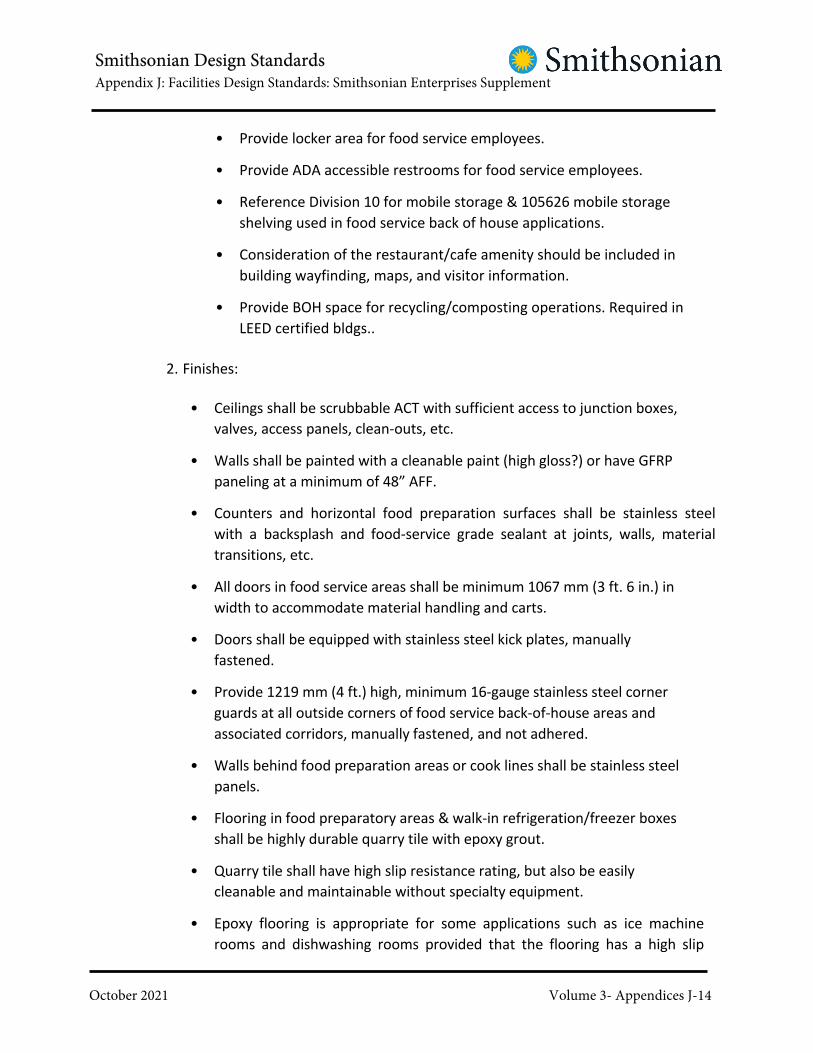
Smithsonian Design StandardsAppendix J: Facilities Design Standards: Smithsonian Enterprises Supplement
October 2021 Volume 3- Appendices J-14
� Provide locker area for food service employees.
� Provide ADA accessible restrooms for food service employees.
� Reference Division 10 for mobile storage & 105626 mobile storage
shelving used in food service back of house applications.
� Consideration of the restaurant/cafe amenity should be included in
building wayfinding, maps, and visitor information.
� Provide BOH space for recycling/composting operations. Required in
LEED certified bldgs..
2. Finishes:
� Ceilings shall be scrubbable ACT with sufficient access to junction boxes,
valves, access panels, clean-outs, etc.
� Walls shall be painted with a cleanable paint (high gloss?) or have GFRP
paneling at a minimum of 48” AFF.
� Counters and horizontal food preparation surfaces shall be stainless steel
with a backsplash and food-service grade sealant at joints, walls, material
transitions, etc.
� All doors in food service areas shall be minimum 1067 mm (3 ft. 6 in.) in
width to accommodate material handling and carts.
� Doors shall be equipped with stainless steel kick plates, manually
fastened.
� Provide 1219 mm (4 ft.) high, minimum 16-gauge stainless steel corner
guards at all outside corners of food service back-of-house areas and
associated corridors, manually fastened, and not adhered.
� Walls behind food preparation areas or cook lines shall be stainless steel
panels.
� Flooring in food preparatory areas & walk-in refrigeration/freezer boxes
shall be highly durable quarry tile with epoxy grout.
� Quarry tile shall have high slip resistance rating, but also be easily
cleanable and maintainable without specialty equipment.
� Epoxy flooring is appropriate for some applications such as ice machine
rooms and dishwashing rooms provided that the flooring has a high slip

Smithsonian Design StandardsAppendix J: Facilities Design Standards: Smithsonian Enterprises Supplement
October 2021 Volume 3- Appendices J-15
resistance.
� Specify mold-resistant gypsum board in all food service areas
� No stretched membrane ceiling systems in food service applications, front or
back of house.
� Additional security requirements and hardware may be required for these
spaces and are dictated by the SI OPS Security Design Guidelines. HVAC
design should account for human occupation, cook line equipment loads,
refrigeration equipment loads, etc.
� All backsplashes at food prep. Counters shall be sealed to vertical
surface with approved silicone sealant.
3. Lighting:
� Sufficient lighting is required to provide adequate lighting at the bottom
shelves of food/dry storage shelving units.
� Lighting covers should be easily cleanable.
4. Fire Protection & Ansul Systems:
� Fire sprinkler head and lighting layouts should be coordinated with
layouts for adequate coverage.
� All pendant fire sprinkler heads should be equipped with a protective
cage.
� Ansul systems are required at cook lines.
� Ansul systems shall be inter-locked with KEVS Hoods/fans as required by
code.
� Fire extinguishers shall be wall-mounted and type for commercial cooking
application.
5. Plumbing:
� Hot water supply should be tested in the space prior to any design work to
determine whether existing supply will be able to maintain minimum hot
water temperatures and flow rates required by the Health Department
having jurisdiction.

Smithsonian Design StandardsAppendix J: Facilities Design Standards: Smithsonian Enterprises Supplement
October 2021 Volume 3- Appendices J-16
� If minimum temperature and flow cannot be maintained additional
intervention will be necessary such as on-demand water heating, flow
valve adjustments, or booster pumps at fixtures.
� In addition to a hand sink, a 3-compartment sink is required for all food
service applications. Bowl sizing shall be coordinated against sheet pan
sizes of cooking equipment.
� 3-compartment sinks must be connected to a grease interceptor.
� If feasible, select food service equipment that can drain to a funnel drain or
a floor sink rather than requiring empting of a condensate pan.
� Provide a filtration system for the water supply to all food service
equipment that requires water service.
� Provide indirect waste drainage as required by DC Health Code. All 3-
compartment sinks, dishmachines, pot washers, etc.
� Provide backflow preventers for the water supply to all food service
equipment requiring water service.
� Provide locally located isolation valves for food service equipment
requiring water service.
� Provide inter-lock disconnect on all gas fired cooking equipment, tied to
Ansul systems.
� Refer to Section 221323 Sanitary Waste Interceptors and DC Health Code
for requirements for grease interceptors in food preparation areas.
6. Warewashing:
� Warewashing types shall not be self venting and should have active
exhaust.
� Warewashers require water softeners.
� Tray accumulator types are preferred in lieu of conveyer belt types.
� Ducts shall be welded stainless steel and pressure tested and pitched
back to equipment.
� Warewashers shall tie into grease interceptors.
� Provide sensor alarms on stainless steel drip pans under mechanical

Smithsonian Design StandardsAppendix J: Facilities Design Standards: Smithsonian Enterprises Supplement
October 2021 Volume 3- Appendices J-17
ductwork in areas of high humidity, such as dishwashing rooms.
7. Waste Management & Hauling:
� Plan waste hauling routes so that waste is never hauled in or through
public spaces.
� Provide for on-site composting and recycling of waste including collection of
oils for biofuels, bottle, can, paper, and plastic recycling.
� Provide signage to encourage recycling in dining areas. Avoid storing waste
near any collections storage or collection receiving/staging spaces.
� Carefully plan composting and recycling areas to minimize attraction of
rodents and other pests.
� Provide water and drainage at composting areas.
� For high volume food service locations, a separate dumpster area and
trash compactor system with electric winch should be provided
8. HVAC:
� Refer to Division 23, HVAC, Part II, Section 2.03F for redundancy
requirements for water-cooled food service equipment.
9. Grease Ducts & Exhaust Hoods:
� Must be installed and maintained in accordance with NFPA 96: Standard for
Ventilation Control and Fire Protection of Commercial Cooking Operations.
� Coordinate requirements with current SOP’s of Smithsonian Institution
and OFMR.
� All access points must be clearly identified and maintained clear. Access
point locations shall be in accordance with NFPA 96.
� TAB reports shall be recorded and reported to OFMR when any
modifications are made to grease duct/hood systems.
� Existing grease ducts must be tested for leaks and NFPA 96 compliance as
part of any major renovation of existing facilities.
10. Cash rooms:

Smithsonian Design StandardsAppendix J: Facilities Design Standards: Smithsonian Enterprises Supplement
October 2021 Volume 3- Appendices J-18
� All museum restaurant operations must have a dedicated OPS compliant
cash room that can’t be shared with any other business / operation.
� Minimum security requirements and hardware required for cashrooms
is dictated by the SI OPS Security Design Guidelines depending on the
estimated amount of cash handling by the business.
� In lieu of wire mesh reinforced walls, OPS has allowed to enclose our cash
safes in wire mesh partitions, bolted to the floor and with the appropriate
security hardware, sensors, and mag locks, etc.
� Cashrooms are required to be equipped with card readers for badge
access by vendor staff only.
� A small table for cash counting near the cash safe is required.
� The main cash transaction door for the cash room should be a Dutch door
with a countertop for transacting. Both leaves should have latch bolts and
striker plates. The Dutch door bolt shall allow the locking of the both the
bottom and top leaves.
C. Front of House
1. Chairs & Seating:
� Non-upholstered seating is preferred over upholstered seating. If seating
is upholstered, fabric should be durable with the highest number of rub
counts possible, of a color/pattern least likely to show stains, easily
cleanable, and easily maintainable.
� Banquette seating should be off the finished floor to prevent
pest infiltration.
� Specify mold-resistant gypsum board in all food service areas
2. Finishes:
� No carpet in the public dining areas. Flooring materials should be durable,
cleanable, and non-staining.
� Division 06116 Solid Surfacing Fabrications no light colored solid surface
for food & beverage applications; must have appropriate finish- polished
and sealed
� No stretched membrane ceiling systems in food service applications.

Smithsonian Design StandardsAppendix J: Facilities Design Standards: Smithsonian Enterprises Supplement
October 2021 Volume 3- Appendices J-19
� No cork flooring in food service applications.
� Flooring materials: epoxy terrazzo (section 096623), quarry tile, resilient
flooring
� For fabric wrapped panels in food service applications, need to have a
cleanable resilient coating applied 097723.
� Reference Division 10 for demountable partitions used in food service
applications.
3. Point of Sale
� Each POS station requires security camera coverage of each point of
sale unit with clear view of the cash drawer & cash handling. This is in
addition to any OPS general space coverage requirements.
� Per POS location, there must be at least (1) ADA accessible point of sale
station.
4. Queue Lines
� Queue lines should be designed for seasonal expandability/shrinkability in
high-volume locations.
� If feasible, queue lines should incorporate in-queue fixture
merchandising for impulse items.
� Queue lines should be designed with consideration for customer flow
and maximum throughput.
D. Vegetation
� No vegetation in food service applications as they can harbor pests.
E. Outdoor Food Service
� Electrical service should be at a minimum 50amp service per location,
with a weather-proof GFCI enclosure.
� Locations should have sufficient signal/access to process transactions
using wireless internet.
� Locations must have water supply piping, waste piping, and sufficient
drainage appropriate for the footprint of the service.

Smithsonian Design StandardsAppendix K: Smithsonian Enterprises Specialty Specifications
October 2021 Volume 3- Appendices K-1
APPENDIX K
Smithsonian Enterprises Specialty Specifications
● 08 34 73 – Sound Control Door Assemblies
● 08 56 73 – Sound Control Windows
● 08 81 00 – Interior Glazing
● 10 22 13 – Wire Mesh Partitions
● 11 61 33 – Rigging, Curtain & Tracks
● 12 61 00 – Fixed Audience Seating
● 12 61 23 – Fixed Auditorium Seats
Planetarium

Smithsonian Design StandardsAppendix K: Smithsonian Enterprises Specialty Specifications
October 2021 Volume 3- Appendices K-2
SECTION 08 34 73
SOUND CONTROL DOOR ASSEMBLIES
January 31, 2018
PART 1 - GENERAL
1.1 RELATED DOCUMENTS
A. Drawings and general provisions of the Contract, including General and
Supplementary Conditions and Division 01 Specification Sections, apply to this Section.
1.2 UNITS OF MEASURE
A. Contractor to Note: Per SI direction units of measure have been listed in both
Metric and Imperial Units, with the metric unit listed first. The metric units are
nominal and may not be in agreement with dimensioning on drawings. In cases of
conflict the Imperial unit of measure shall govern. Contractor to note that for
purposes of the work Imperial refers to United States Customary Units.
1.3 SUMMARY
A. Description of Work: Work of this Section includes, but is not limited to, the following:1. Acoustically rated swinging steel door and frame assemblies.2. Acoustical hardware.
3. Accessories.
1.4 RELATED WORK SPECIFIED ELSEWHERE
A. See Division 01 Section SUSTAINABLE DESIGN REQUIREMENTS for sustainable design
requirements and procedures.
B. See Division 08 Section HOLLOW METAL DOORS AND FRAMES.
C. See Division 08 Section DOOR HARDWARE for hardware requirements, for
hardware not specified in this Section.
D. See Division 09 Section PAINTING AND COATING for field applied finish.
1.5 ACTION SUBMITTALS

Smithsonian Design StandardsAppendix K: Smithsonian Enterprises Specialty Specifications
October 2021 Volume 3- Appendices K-3
A. Product Data:
1. Submit shop drawings of the door, frame, hardware and seals showing major
operating dimensions and cross-sections of doors and seals.
2. Submit manufacturer's specifications and installation instructions for each
component and finish.3. Include catalog cuts for acoustically rated hardware and gaskets.
B. Shop Drawings - Door Schedule:1. Submit Shop Drawings for fabrication and installation of steel door and frame
assemblies.
2. Include locations, configuration, details, elevations, conditions at openings, STC
rating and fire rating.
3. Include hardware locations (including security hardware), mounting details and
anchorage.
1.6 LEED SUBMITTALS
A. Comply with Division 01 Section SUSTAINABLE DESIGN REQUIREMENTS.
B. MR Credit: Building Product Disclosure and Optimization – Sourcing of Raw Materials.
1. For recycled content steel: Documentation indicating percentages by weight
of pre-consumer and post-consumer recycled content. Include material cost
value.
1.7 INFORMATIONAL SUBMITTALS
A. Certifications:
1. Where fire resistance classifications are indicated, certify that construction
complies with requirements of NFPA 80.
2. Written guarantee that the door is constructed in accordance with the laboratory
tested door and free of defects in material and workmanship for a period of
time not less than three years after installation.
B. Test Reports:
1. Submit certified test reports indicating that the acoustical performance of the
door meets the Sound Transmission Class (STC) performance specified in the door
schedule. Test data shall be produced from an accredited independent acoustical
laboratory that is a member of NVLAP (National Volunteer Laboratory
Accreditation Program). Reports shall indicate that the test was performed
on the doors and frames of the type to be supplied in conformance with
the requirements of test method ASTM E 90-09 and have a certified Sound
Transmission Class (STC) rating as determined according to ASTM E 413.

Smithsonian Design StandardsAppendix K: Smithsonian Enterprises Specialty Specifications
October 2021 Volume 3- Appendices K-4
2. Test reports by an independent Acoustical Engineer certifying a Field Sound
Transmission Class (FSTC) or Noise Isolation Class (NIC), in conformance with the
requirements of test method ASTM E336-09, performance of no more than five
points below the laboratory STC performance on similar installations. Results
calculated according to ASTM E4133. Show laboratory name, test report numbers and date of tests.
C. Inspection Reports: Submit copy of manufacturer's technical representative's field
inspection report.
1.8 SYSTEM REQUIREMENTS
A. Fire Resistance Requirements:1. Comply with label requirements of NFPA and applicable local codes.
2. Fabricate door and frame assemblies that comply with NFPA 80, are identical to
door and frame assemblies tested per NFPA 252 and are labeled and listed by
UL or other testing and inspecting agency acceptable to authorities having
jurisdiction.
3. Provide UL plate labels permanently fastened on each door and frame within
size limitations established by NFPA and UL for labeling.
4. Provide anchors for UL labeled frames required by authority having jurisdiction.
B. Acoustic Ratings:
1. Certified test reports indicating that the acoustical performance of the door
meets the Sound Transmission Class (STC) performance specified in the door
schedule. Test data shall be produced from an accredited independent acoustical
laboratory that is a member of NVLAP (National Volunteer Laboratory
Accreditation Program). Reports shall indicate that the test was performed on the
doors and frames of the type to be supplied in conformance with the
requirements of test method ASTM E 90 and have a certified Sound Transmission
Class (STC) rating as determined according to ASTM E 413.
2. Test reports by an independent Acoustical Engineer certifying a Field Sound
Transmission Class (FSTC) or Noise Isolation Class (NIC), in conformance with the
requirements of test method ASTM E336, performance of no more than five
points below the laboratory STC performance on similar installations. Results
calculated according to ASTM E413.
3. Written guarantee that the door is constructed in accordance with the laboratory
tested door and free of defects in material and workmanship for a period of time
not less than three years after installation.
C. Interface With Other Systems:1. Coordinate with Work of other trades affected by Work of this Section.

Smithsonian Design StandardsAppendix K: Smithsonian Enterprises Specialty Specifications
October 2021 Volume 3- Appendices K-5
2. Provide items, such as anchors or supports, in a timely manner so as not to
delay job progress.3. Place items, such as anchors or supports, accurately in relation to final locations.4. Use Contractor's bench marks.
1.9 QUALITY ASSURANCE
A. Installer Qualifications: Not less than 5 years documented, successful experience
with work comparable to Work of this Project, licensed by the manufacturer.
B. Manufacturer Qualifications:
1. Company specializing in acoustically-rated steel doors and frames for fire rated
openings, having minimum of 5 years successful, documented experience with
work comparable to that required for this Project.
2. Company whose units are inspected, tested and listed by UL for single point
hardware and astragal conditions for sizes and profiles indicated.
C. If a door or frame indicated with a fire resistance classification cannot qualify for
appropriate labeling because of its design, hardware or other reason, notify COTR
before beginning fabrication of that item.
D. Manufacturer's Inspections:
1. Provide inspections by manufacturer's technical representative at completion of
installation.
2. Contractor shall be responsible for carrying out recommendations of
manufacturer's representative.
3. Provide written reports of inspection.
E. Reference Standards: Comply with applicable provisions of Steel Door Institute.
1.10 DELIVERY, STORAGE AND HANDLING
A. Protect units from damage during transit, storage and installation.
B. Tool marks, rust, blemishes and any other damage on exposed surfaces will not be
acceptable.
C. Store units in vertical position in dry location, off ground and in such manner as to
prevent deterioration.

Smithsonian Design StandardsAppendix K: Smithsonian Enterprises Specialty Specifications
October 2021 Volume 3- Appendices K-6
PART 2 - PRODUCTS
2.1 PRODUCTS AND MANUFACTURERS
A. Acceptable Products and Manufacturers:1. Overly Manufacturing Company.2. Krieger Specialty Products Co.3. Security Acoustics.
2.2 MATERIALS
A. LEED, General: Recycled Content: Provide steel with minimum 25 percent post-
consumer recycled content.
B. Hot-Rolled Sheet Steel: ASTM A1011 and A568, commercial quality carbon steel,
pickled and oiled.
C. Cold-Rolled Sheet Steel: ASTM A1008 and A568, free from scale, pitting or other
defects; E finish, stretcher leveled for doors.
D. Prime Paint: Rust-inhibitive enamel or paint, compatible with finish paints as
specified in Division 09 Section PAINTING AND COATING.
2.3 SOUND CONTROL DOORS
A. Construction
1. Door thickness shall be as scheduled below, or as required to meet STC rating.
Door leaf shall feature thick, flush design using cold-rolled steel construction not
less than 1.6 mm (16 gauge) in thickness. The core shall be filled with
sound-absorbing and damping elements that are acoustically non-coupling and
non-combustible. Vision panels, where specified, shall comprise glazing
systems that meet the acoustical performance of the tested product and shall
be supplied by the door manufacturer.
2. Frames shall be formed to sizes and shapes indicated and shall have full welded
unit-type construction at corners and other joints. Frames shall be of cold-rolled
steel construction, not less than 2 mm (14 gauge) in thickness. All contact edges
shall be closed tight. Welds on corners and exposed surfaces shall be pressed
flush and smooth. Steel frame members shall be pre-straightened, free of wind or
twist. Frame shall be factory-aligned to a diagonal tolerance of 1.6 mm (± 1/16
inch).
3. Continuously grout-fill frames when installed in masonry or concrete partition
openings, or packed tightly with glass-fiber safing insulation and caulked with

Smithsonian Design StandardsAppendix K: Smithsonian Enterprises Specialty Specifications
October 2021 Volume 3- Appendices K-7
acoustical sealant around the perimeter of both sides of the frame when applied
to drywall and stud partition openings.
4. Doors and frames shall be factory mortised, reinforced and fitted for heavy-duty
locksets, strikes and closers. The door manufacturer is responsible for supplying
and installing all hardware. The door manufacturer is to notify the COTR if
scheduled hardware is incompatible with the operation and performance of
the acoustical door. Manufacturer shall submit for approval by the COTR
alternate hardware as required. Refer to hardware schedule for models and
types.
5. Manufacturer shall supply cam-lift hinges on all acoustical doors. Surface strap
or butt hinges are unacceptable.
6. Where a transom panel is required, that panel shall provide acoustical
performance at least as good as the door STC rating.
7. Door and frame shall be factory finished with a rust inhibiting primer.
B. Door Performance Schedule:
Transmission Loss Values in dB
Octave Band Center Frequencies, Hz.STC
Rating
Thickness
(inches)
Surface
Weight
(lb/ft2)
Metal
Gauge
(ga.) 63 125 250 500 1000 2000 4000
43 1-3/4 8 14 16 21 40 41 43 44 50
49 2-1/2 7 16 22 27 41 46 50 52 54
51 2-1/2 9 14 22 32 45 51 49 55 54
53 2-1/2 11 14 23 30 47 52 54 52 57
54 3-1/2 16 14 23 32 52 53 53 52 62
61 3-1/2 16 14 24 41 53 60 60 62 69
64 5 18 14 26 44 58 62 65 66 68
C. Perimeter Treatment:
1. Clearance between frame and door shall not exceed 3 mm (1/8 inch). All sills shall
be flush and of steel construction to ensure the integrity of the bottom seal.
Raised thresholds will not be permitted.
2. Hinge, lock and head of the door shall close against positive neoprene
compression and/or magnetic seals that are mounted in the frame and/or leaf.
Combination neoprene-felt seals are not acceptable.
3. The door shall be supplied with a bottom neoprene seal covered in non-stick
(Teflon or similar) material to prevent seal erosion. The seal shall be adjustable,
to conform to job site sill conditions. Automatic drop bottoms are not

Smithsonian Design StandardsAppendix K: Smithsonian Enterprises Specialty Specifications
October 2021 Volume 3- Appendices K-8
permitted. All screws shall be flush with the door leaf, no surface exposed
screw heads or bolts are acceptable.
4. Where a double leaf door is specified, the astragal shall be rabbeted or bevelled
and contain neoprene compression and/or magnetic seals for the full height of
the door. There shall be no gaps in the seals at the head and sill of the door.
There shall be continuous pressure applied to the astragal to compress the
seals and prevent the leafs from bowing out and disengaging the astragal
seals. Acoustic test data for double door configurations shall be submitted.
Single leaf test data is not acceptable for double doors.
2.4 DOOR TYPES
A. Door Types:
1. General: Provide door assemblies complete with door frame, mortised cam-lift
hinges, sound seals, retainers and covers, adjustable semi-mortised door
bottoms, and cutouts and reinforcements for other hardware items scheduled
in Division 08 Section DOOR HARDWARE.2. Types:
a. Type 1: Single swinging door.b. Type 2: Pair of swinging doors.
3. STC: As scheduled.4. Thickness: As scheduled5. Weight: 66.4 kg/m5(13.6 psf).
6. Fire ratings: See Door Schedule on Drawings.
7. Hardware:a. Hinges:
1) Equivalent to MCL 500 cam-lift by Overly.
2) Provide electrified hinges for 24 volt power transfer for doors with
electric locks or exit devices.b. Head and jamb seals:
1) Equivalent to Model H by Overly, or other type as recommended
for the application.
2) Provide magnetic sound seals in lieu of compression seals for doors
with exit devices.
c. Door bottom seals: Equivalent to Super H by Overly, or other type
as recommended for the application.d. Other hardware: See Division 08 Section DOOR HARDWARE.
8. Acceptable product and manufacturer: Equivalent to Model 5189106 by Overly.
2.5 ACOUSTIC HARDWARE
A. See Division 08 Section DOOR HARDWARE.

Smithsonian Design StandardsAppendix K: Smithsonian Enterprises Specialty Specifications
October 2021 Volume 3- Appendices K-9
B. General: Sound seals, specified below, shall be fitted to the hinge, lock and head;
and an automatic door bottom shall be installed (either surface mounted, or mortised)
at the bottom edge of the door leaf. All seals shall be continuous and must not be
interrupted by other door hardware such as panic hardware, latches, automatic
closers, etc. Conflicts between sound gasketing and other hardware must be brought
to the immediate attention of the COTR.
C. Automatic Door Bottom:
1. Automatic door bottom shall be surface-mounted, or mortised as called out on
the drawings and schedules. The seal shall be actuated by an adjustable
operating rod that cause the gasket to drop automatically when the door
contacts the hinge jamb. The door bottom mechanism must drop first at the
hinge edge of the door and then continue to drop towards the lock edge of the
door as the door continues to swing shut. This will prevent excessive force
being required to close door, excessive wear to seal and damage to
mechanism. The seal must be self-centering to a flat-plate threshold to ensure a
proper seal across the entire door width if the floor surface is not entirely even.
Automatic door bottom mechanism shall have only one moving part and shall not
utilize any plastic parts.
2. Gasket material shall be a solid-extruded high-grade neoprene bulb. Door
bottom shall utilize neoprene seals inside the mechanism to prevent sound
from “flanking” through mechanism. Housing shall be constructed of extruded
aluminum. Surface mounted housings shall have a minimum wall thickness of
2.4 mm (0.093 inch).3. The following are acceptable:
a. Non-Fire-Rated: #367 (surface mounted) or #369 (mortised) from
Zero International, Inc.
b. Fire-Rated: #365 (surface mounted) or #366 (semi-mortised) from
Zero International.4. Equivalent products by the following may also be acceptable:
a. Reese Enterprises, Inc.b. National Guard Products
D. Tubular Neoprene Adjustable Door Stop
1. Adjustable door stop shall be constructed of extruded aluminum housing with a
minimum wall thickness of 2.4 mm (0.093inches). The dimensions of the door stop
housing shall not exceed 38 mm (1-1/2 inches) in depth or 23.8 mm (15/16
inches) in width. Adjusting screws shall be located 305 mm (12-inches) on center
and shall provide an adjustment range of 7.874 mm (0.310-inches). Adjusting
screws shall be #8 x 38 mm (1-1/2 inches) stainless steel, shall have a special
shoulder for a retaining clip, and shall be held in the assembly by said retaining
clip. Adjusting screws shall engage a solid adjusting channel which has been drilled

Smithsonian Design StandardsAppendix K: Smithsonian Enterprises Specialty Specifications
October 2021 Volume 3- Appendices K-10
and tapped to provide complete circumference engagement for the screw thread.
No spring retainers, self-tapping adjusting screws, or channels without drilled
and tapped holes for the adjusting screws will be allowed.
2. The seal shall be achieved using continuous tubular, solid neoprene. Install the
gasket so that the neoprene engages the face of door for the full length of the seal.
Adjust the seal so that the neoprene is compressed 0.8 mm (1/32 inches) when
the door is closed. Solid neoprene shall fill the inside of the housing to prevent
sound from “flanking” through the mechanism. The assembly must have a weight of
at least 0.374 kg/m (0.825 lbs/ft) in order to ensure durability.
3. Fire rated gaskets usually require mounting to the stop of the door jamb.
Because the gasket thickness adds to the stop dimension, lockset hardware with
lever handles should be used. If knob locksets are required, a 81 mm (3-1/4”)
backset lock should be supplied.4. The following are acceptable:
a. Fire Rated: #770 (applied to stop) or #770SP (applied to frame) from
Zero International, Inc.
b. Non Fire Rated: #870 (applied to stop) or #7770 (applied to frame) from
Zero International, Inc.5. Equivalent products by the following may also be acceptable:
a. Reese Enterprises, Inc.
b. National Guard Products.
E. Meeting Stiles:
1. Meeting stiles for double-doors shall be of the adjustable and spring loaded
mortised astragal type (surface applied for fire rated doors) with a neoprene
seal at the door intersection. The seals should be continuous with no interference
from door hardware such as closures, exit devices, etc. Install seals so they are
compressed against each other by 1.6 mm (1/16 inches). The edge of the door
requires a cutout to receive the mortised seal.2. The following products by Zero International are acceptable:
a. Single Active Door: #140, #322, or #383.b. Mortised-Both Doors Active: #557/#56.c. Surface Mounted-Both Doors Active: #555/ #55.
3. Equivalent products by the following may also be acceptable:a. Reese Enterprises, Inc.
b. National Guard Products.
F. Rabbeted Saddle
1. Rabbeted type floor saddle shall be constructed of aluminum with a built-in
tadpole-type neoprene seal. Width shall not to exceed 94 mm (3-3/4 inches) with a
minimum 25 mm (1 inch) flat horizontal portion. Total clearance above finish floor
shall not exceed 13 mm (1/2 inch) in order to make the saddle compliant with
accessibility requirements.

Smithsonian Design StandardsAppendix K: Smithsonian Enterprises Specialty Specifications
October 2021 Volume 3- Appendices K-11
2. Rabbeted saddles should not be used for spaces in which equipment such as pianos
will be rolled in and out of the space.3. The following are acceptable:
a. #564 from Zero International, Inc.b. #S248DN from Reese Enterprises Inc.c. #8135N from National Guard Products.
G. Exit Devices for Acoustically Gasketed and STC Doors:
1. When using the above exit device, the door bottom must be surface mounted.
Door closers shall be either mounted to the door leaf on the opposite side of
the jamb and head gasket (pull side), or supplied with an offset pivot arm
assembly to avoid interference with the perimeter gaskets.
2. Acceptable product and manufacturer: Equivalent to Von Duprin 99 series
concealed rod type with the sound dampening feature.
2.6 ACCESSORIES
A. Supports and Anchors: Fabricated of not less than 1.3 mm (18 gage) galvanized
sheet steel, unless otherwise indicated.
B. Inserts, Bolts and Fasteners: Manufacturer's standard units.
C. Jamb Anchors:
1. Anchor in masonry walls with adjustable anchors of stirrup-and-strap type,
built into adjoining construction.
2. Fabricate anchors from 1.6 mm (16 gage) steel; minimum 50 mm wide x 250 mm
long (2 inches wide x 10 inches long).
3. Provide 4 anchors per jamb up to 2235 mm (7 feet) high and 1 additional anchor
for each 450 mm (18 inches) or fraction thereof over 2235 mm (7 feet) high.
4. At fire rated frames, comply with fire resistance requirements and provide
UL rated anchors.
D. Floor Anchors:
1. Provide 2.8 mm (12 gauge) clip angles welded inside each jamb for
attachment to structural substrate.2. Where floor fill or setting beds occur, provide adjustable anchors.
E. Provide fasteners, clips, anchors, brackets, adhesives, inserts and other miscellaneous
items as required for a complete installation.
2.7 FABRICATION

Smithsonian Design StandardsAppendix K: Smithsonian Enterprises Specialty Specifications
October 2021 Volume 3- Appendices K-12
A. General Fabrication Requirements:1. Fabricate units rigid, neat, free from defects, warp or buckle.2. Reinforce units as required to prevent twisting or sagging.
3. Shop fabricate units in largest units practicable. If frames require field splices
due to shipping limitations, field weld such splices after installation.4. Assemble Work using all welded construction.
a. Comply with applicable requirements off AWS D1-1.
b. Grind, fill and dress welded joints smooth to provide smooth, seamless
faces and edges.
5. Form exposed surfaces with corners square, unless otherwise indicated. Form
molded members straight and true, with joints coped or mitered.
6. Conceal fastenings, unless otherwise indicated. Countersink exposed screws
using flat, Phillips head screws.
7. Provide assemblies complete with anchors, inserts, fasteners and other
hardware and miscellaneous items as required for complete installations.
B. Doors:1. Provide doors of types and dimensions indicated.
2. Face sheets:a. Minimum 1.6 mm (16 gage) steel face sheets.
3. Construction:
a. Provide welded seamless construction with no visible seams or joints on
faces or vertical edgesb. Join door faces at vertical edges by welding.
c. Internal construction: Manufacturer's standard for the particular model
and rating specified for each door type.4. Swinging doors:
a. Provide flush closure at top and bottom of doors. Spot weld inverted 1.6
mm (16 gage) steel channels to both face sheets and an additional flush
closing channel.b. Bevel lock and hinge edges of doors 3 mm in 50 mm (1/8 inch in 2 inches).c. Fabricate assemblies to provide following edge clearances:
1) Between door and frame at head and jambs: 3 mm (1/8 inch).2) Between door and sill: Per manufacturer's standards.3) Between edges of pairs of doors: 3 mm (1/8 inch).
d. If recommended by manufacturer, install door bottom seal at factory.
C. Frames:1. Provide frames of types, profiles and dimensions indicated.2. Fabricate from minimum 2 mm (14 gage) sheet steel.3. Construction:
a. Fully welded construction with integral trim, with welded, mitered and
reinforced corner joints. Knock-down frames are not acceptable.

Smithsonian Design StandardsAppendix K: Smithsonian Enterprises Specialty Specifications
October 2021 Volume 3- Appendices K-13
b. Provide 1.6 mm (16 gage) steel channel spreaders at bottom of frames to
prevent distortion during shipment.
D. Hardware:
1. Prepare assemblies to receive hardware. Coordinate with Hardware Schedule.
Comply with ANSI A115 "Specifications for Door and Frame Preparation".2. Mortise, reinforce, drill and tap units at factory to receive mortise type hardware.3. Reinforce, drill and tap units to receive surface-applied hardware.4. Security hardware:
a. Prepare doors and frames to receive mortise and surface mounted Owner
furnished security hardware.
b. Door Schedule indicates doors to receive concealed contacts (position
switches). Coordinate with Owner's security contractor.
c. Include fabrication for doors and frames to receive concealed contacts
and concealed associated wiring. Contacts and wiring will be provided
by Owner's security contractor.
5. Provide metal mortar guards for mortise cut-outs and at openings for contacts.
2.8 SHOP FINISH
A. Shop Painting:1. Clean, treat and paint surfaces of fabricated units. Remove grease and oil.2. Chemically treat surfaces with phosphate compound.
3. Provide minimum 2 coats of primer to reinforcement and attachment steel in
contact with concrete or masonry.4. Apply primer with even consistency with a uniformly finished surface.
5. Provide minimum number of coats of dry film thickness recommended
by paint manufacturer.
PART 3 - EXECUTION
3.1 EXAMINATION
A. Examine substrates and adjoining construction, and conditions under which Work
is to be installed. Do not proceed with Work until unsatisfactory conditions are
corrected.
3.2 INSTALLATION
A. General:
1. Install in accordance with final Shop Drawings and manufacturer's accepted
installation procedures and instructions.

Smithsonian Design StandardsAppendix K: Smithsonian Enterprises Specialty Specifications
October 2021 Volume 3- Appendices K-14
2. Door shall be installed by factory-trained or approved representatives or
contractors. Door shall be installed per manufacturer’s instructions to ensure a
tight fit and proper seal at all joints and interfaces.
3. The door manufacturer shall provide factory trained supervision personnel
during the initial frame installation, at regular periods during the acoustic door
installation, and at final inspection. The manufacturer shall issue a letter of
compliance certifying the completion of a successful installation.
4. All frames installed in masonry/concrete partitions shall be grouted solid. All
frames installed in stud partitions shall be filled with high density glass-fiber
insulation.
B. Frame Installation:1. Set frames accurately in position, plumbed, aligned and braced securely.2. Coordinate installation of built-in anchors for wall partition construction.
3. Terminate frames at indicated finished floor level. Where floor fill or setting
beds occur, support frames with adjustable clip angles, anchored to structural
substrate.4. After wall construction is complete, remove temporary braces and spreaders.5. Leave surfaces smooth and undamaged.6. Installation tolerances for swinging door frames:
a. Squareness: ±1.6 mm (±1/16 inch), measured on a line, 90 deg from one
jamb, at upper corner of frame at other jamb.
b. Alignment: ±1.6 mm (±1/16 inch), measured on jambs on horizontal line
parallel to plane of wall.
c. Twist: ±1.6 mm (±1/16 inch), measured at face corners of jambs on
parallel lines perpendicular to plane of wall.
d. Plumbness: ±1.6 mm (±1/16 inch), measured on jamb at floor.
C. Door Installation:
1. Install in accordance with final Shop Drawings, manufacturer's
instructions and recommendations of manufacturer's representative.
2. Install labeled fire doors and frames to meet requirements of cited references
and NFPA Standard No. 80.
D. Hardware Installation:
1. Install hardware in accordance with both acoustical door and hardware
manufacturers' instructions and as specified in Division 08 Section DOOR
HARDWARE.2. Adjust installation to maintain door clearances specified under "Fabrication"
above.
3. Install seals and gaskets, covers and retainers, and adjust to contact head,
jambs and sill uniformly.

Smithsonian Design StandardsAppendix K: Smithsonian Enterprises Specialty Specifications
October 2021 Volume 3- Appendices K-15
3.3 CLEANING AND ADJUSTING
A. Adjusting:1. Before completion of Work, adjust hardware and seals until assemblies operate
properly.2. Test security devices with operation of security system in Owner's presence.3. Replace defective, damaged, missing or stolen hardware.4. Remove and replace defective Work.
B. Cleaning:1. Clean doors and frames.
2. Sand smooth rusted or damaged areas of prime coat and touch-up with
compatible air-drying primer.
3.4 FIELD QUALITY CONTROL
A. Provide the following services by acoustical door manufacturer's technicalrepresentative:1. Inspect completed installation.2. Put each door through at least 10 complete cycles of operation.
a. Verify that each component is properly installed and operating.b. Make adjustments until assemblies operate properly.
3. Use a mechanic's stethoscope and cassette tape of laboratory-recorded noise
furnished by door manufacturer to test sound seals. Coordinate with
Contractor in adjusting sound seals for optimum efficiency.
4. Provide written report stating that Work has been installed in
accordance with requirements of Contract Documents and final Shop Drawings.
B. Field Testing Verification:
1. If required, the Owner will retain the services of an independent acoustical
consultant to conduct an acoustical test at any designated door locations
where noise transmission is suspected of being below the set criteria. The test
shall consist of a Field Sound Transmission Class (FSTC) or Noise Isolation Class
(NIC) test per ASTM E336-09. If such results indicate non-conformance with the
established FSTC or NIC requirements, it shall be the responsibility of the
Contractor and Manufacturer to correct, at their expense, such deficiencies by
methods that shall be approved by the Acoustical Consultant and Owner prior
to incorporation. Acoustical tests shall be repeated at the manufacturer’s cost
and corrective measures devised and incorporated until the set criteria and
performance standards are met. If the Acoustical Consultant or COTR determines
that the materials are not as specified herein, the door shall be replaced at no
cost to the Owner.
3.5 DEMONSTRATION

Smithsonian Design StandardsAppendix K: Smithsonian Enterprises Specialty Specifications
October 2021 Volume 3- Appendices K-16
A. Provide instruction in operation and maintenance of acoustical door systems to
Owner's designated personnel.
3.6 PROTECTION
A. Protect units during construction so that they will be without any evidence of damage
or use at time of acceptance.
END OF SECTION

Smithsonian Design StandardsAppendix K: Smithsonian Enterprises Specialty Specifications
October 2021 Volume 3- Appendices K-17
SECTION 08 56 73
SOUND CONTROL WINDOWS
January 31, 2018
PART 1 - GENERAL
1.1 RELATED DOCUMENTS
A. Drawings and general provisions of the Contract, including General and
Supplementary Conditions and Division 01 Specification Sections, apply to this Section.
1.2 UNITS OF MEASURE
A. Contractor to Note: Per SI direction units of measure have been listed in both
Metric and Imperial Units, with the metric unit listed first. The metric units are
nominal and may not be in agreement with dimensioning on drawings. In cases of
conflict the Imperial unit of measure shall govern. Contractor to note that for
purposes of the work Imperial refers to United States Customary Units.
1.3 SUMMARY
A. Description of Work: Work of this Section includes, but is not limited to, the following:
1. Aluminum-framed, shop-glazed acoustically-rated windows at IMAX, excluding
windows used for projection.2. Aluminum-framed, shop-glazed acoustically-rated window at Production Studio.3. Glass and glazing.4. Sealants and joint fillers.5. Accessories.
1.4 RELATED WORK SPECIFIED ELSEWHERE
A. See Division 07 Section JOINT SEALANTS for perimeter joint fillers and sealants.
B. See Division 08 Section INTERIOR ALUMINUM WINDOWS for glazing at interior
aluminum windows, including transaction windows and IMAX window port frames
(IMAX projection window).
C. See Division 08 Section INTERIOR GLAZING for interior glazing requirements.
1.5 ACTION SUBMITTALS
A. Product Data: Submit manufacturer's specifications and installation instructions for

Smithsonian Design StandardsAppendix K: Smithsonian Enterprises Specialty Specifications
October 2021 Volume 3- Appendices K-18
each component and finish.
B. Shop Drawings: Submit Shop Drawings for windows.
1. Show plans, elevations and typical details of each condition for every
member, joint, anchorage and glazing system.2. Include mounting details and anchorage.
C. Samples:1. Glass:
a. Submit 305 mm (12 inch) square samples of each type of glass.b. Samples shall be typical production run quality and shall be complete with
coatings.2. Aluminum:
a. Submit 305 mm (12 inch) long samples of each type of aluminum framing,
showing color and finish expected in completed Work.
b. Prepare samples on specified alloy, temper and thickness of metal
required for Work.
1.6 LEED SUBMITTALS
A. Comply with Division 01 Section SUSTAINABLE DESIGN REQUIREMENTS.
B. MR Credit: Building Product Disclosure and Optimization – Environmental
Product Declarations.1. For windows: Industry-wide or product-specific EPD.
C. MR Credit: Building Product Disclosure and Optimization – Sourcing of Raw Materials.
1. For recycled content steel or aluminum in windows: Documentation indicating
percentages by weight of pre-consumer and post-consumer recycled content.
Include material cost value.
D. EQ Credit: Low-Emitting Materials.
1. For interior wet-applied sealants and sealant primers: Documentation indicating
compliance with California Department of Public Health (CDPH) Standard
Method v1.1-2010 and VOC content in g/L.
1.7 INFORMATIONAL SUBMITTALS
A. Test Reports:
1. General: Submit certified test reports performed by recognized testing
laboratory verifying that windows have been previously tested and meet or
exceed specified performance requirements.2. Translation Booth windows:
a. General: Show laboratory names, test report numbers, and dates of tests.
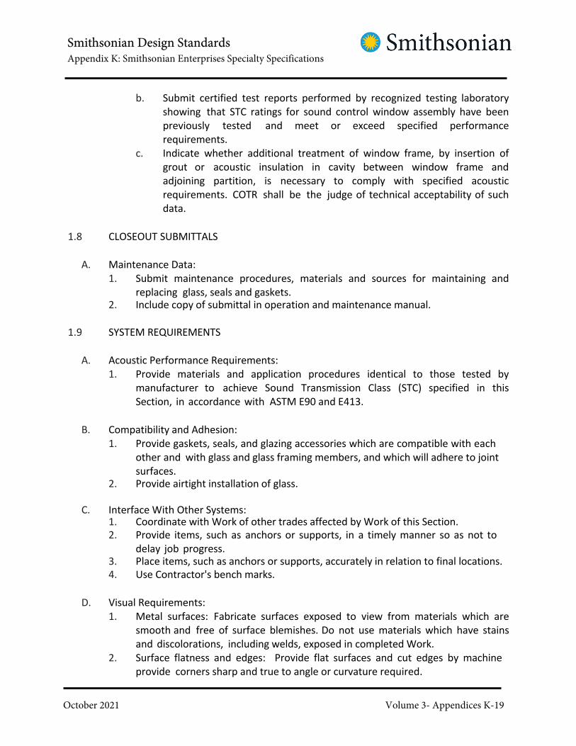
Smithsonian Design StandardsAppendix K: Smithsonian Enterprises Specialty Specifications
October 2021 Volume 3- Appendices K-19
b. Submit certified test reports performed by recognized testing laboratory
showing that STC ratings for sound control window assembly have been
previously tested and meet or exceed specified performance
requirements.
c. Indicate whether additional treatment of window frame, by insertion of
grout or acoustic insulation in cavity between window frame and
adjoining partition, is necessary to comply with specified acoustic
requirements. COTR shall be the judge of technical acceptability of such
data.
1.8 CLOSEOUT SUBMITTALS
A. Maintenance Data:
1. Submit maintenance procedures, materials and sources for maintaining and
replacing glass, seals and gaskets.2. Include copy of submittal in operation and maintenance manual.
1.9 SYSTEM REQUIREMENTS
A. Acoustic Performance Requirements:
1. Provide materials and application procedures identical to those tested by
manufacturer to achieve Sound Transmission Class (STC) specified in this
Section, in accordance with ASTM E90 and E413.
B. Compatibility and Adhesion:
1. Provide gaskets, seals, and glazing accessories which are compatible with each
other and with glass and glass framing members, and which will adhere to joint
surfaces.2. Provide airtight installation of glass.
C. Interface With Other Systems:1. Coordinate with Work of other trades affected by Work of this Section.
2. Provide items, such as anchors or supports, in a timely manner so as not to
delay job progress.3. Place items, such as anchors or supports, accurately in relation to final locations.
4. Use Contractor's bench marks.
D. Visual Requirements:
1. Metal surfaces: Fabricate surfaces exposed to view from materials which are
smooth and free of surface blemishes. Do not use materials which have stains
and discolorations, including welds, exposed in completed Work.
2. Surface flatness and edges: Provide flat surfaces and cut edges by machine
provide corners sharp and true to angle or curvature required.

Smithsonian Design StandardsAppendix K: Smithsonian Enterprises Specialty Specifications
October 2021 Volume 3- Appendices K-20
1.10 QUALITY ASSURANCE
A. Sound control windows shall be installed by sound control window manufacturer, or
by a firm licensed by the manufacturer.
B. Manufacturer Qualifications: Company specializing in sound control windows.
C. Reference Standards: Comply with applicable provisions and recommendations of the
following.1. AAMA/NWWDA 101/I.S.-2 "Voluntary Specifications for Aluminum, Vinyl (PVC)”.2. NAAMM "Metal Finishes Manual".
1.11 PRE-INSTALLATION CONFERENCE
A. Prior to commencing Work, at Contractor's direction, meet at site to review materials,
installation procedures and coordination with other Work.
1.12 DELIVERY, STORAGE AND HANDLING
A. Protect units from damage during transit, storage and installation.
B. Tool marks, rust, blemishes and any other damage on exposed surfaces will not be
acceptable.
C. Store units in vertical position in dry location, off ground and in such manner as to
prevent deterioration.
1.13 PROJECT CONDITIONS
A. Verify dimensions of supporting structure at site by accurate field measurements so
that Work will be accurately designed, fabricated and fitted to structure. Tolerances
for supporting structure are specified in other Sections.
PART 2 - PRODUCTS
2.1 MATERIALS
A. Aluminum Extrusions:
1. Shapes and thicknesses as indicated in Contract Documents and as required
to fulfill performance requirements.
2. Suitable alloy for extruding with adequate structural characteristics and

Smithsonian Design StandardsAppendix K: Smithsonian Enterprises Specialty Specifications
October 2021 Volume 3- Appendices K-21
suitable for finishing as specified.
B. Glass Types:1. Float glass:
a. ASTM C1036, Type I (transparent), Class 1 (clear), Quality q3 (glazing
select); thicknesses as specified below for each window type.b. Provide low-iron float glass as specified.
2. Glass with anti-reflective coating:
a. Low-iron float glass with factory-applied anti-reflective coating, consisting
of multiple-layer, metal oxide interference system.
b. Acceptable products and manufacturers: The following listed products
are provided to establish the standard of quality consistent with the salient
characteristics identified above.1) Amiran; Schott Corp., Technical Glass Division.2) Or approved equal.
3. Laminated glass:
a. Provide laminated glass complying with requirements of ASTM C1172, as
specified below for each window type.b. Adhesive laminating film:
1) Clear polyvinyl butyral plastic sheet.
2) 0.8 mm (0.03 inch) thick, or as required to comply with acoustic
performance requirements.
2.2 SOUND CONTROL WINDOW
A. Description:1. Fixed, double-glazed aluminum-framed window.
2. Fabricate with acoustically-absorptive material, consisting of glass-fiber held in
place by perforated metal pan, placed between glazed lites.3. Designation: Minimum acoustical laboratory rating of STC 48.4. Finish: As selected by COTR from manufacturer’s full range.
B. Glass – Type GL-25:
1. Outside and inside lite: Laminated glass, consisting of 3 mm (1/8 inch) low iron
float glass; laminating film; 3 mm (1/8 inch) low iron float glass; total
thickness of approximately 6 mm (1/4 inch).
C. Glazing System:
1. Separate outside lite and inside lite by minimum 113 mm (4-1/2 inch) wide air
space, or as required to fulfill acoustic performance requirements.
2. Provide manufacturer's standard glazing system as required to fulfill acoustic
performance requirements; shop-glaze units.
3. Provide units complete, including sound-deadening treatments, desiccants, and
full perimeter seals and gaskets.

Smithsonian Design StandardsAppendix K: Smithsonian Enterprises Specialty Specifications
October 2021 Volume 3- Appendices K-22
D. Acceptable Products and Manufacturers: The following listed products are provided to
establish the standard of quality consistent with the salient characteristics identified
above.1. Noise Control View Windows by Krieger Steel Products Company.2. Acoustical Vision Lights by Overly Manufacturing Co.3. Series 6002-6 by Peerless Products, Inc.4. Acoustical Windows by Wausau Metals.5. Series 75 by Window Technologies, Inc.
6. Or approved equal.
2.3 ACCESSORIES
A. Perimeter Sealants and Joint Fillers: See Division 07 Section JOINT SEALANTS.
B. Fasteners:
1. Provide fasteners for attachment of components to structural supports and for
connecting components as recommended by component manufacturers and
selected to prevent galvanic action with components fastened.
2. For embedment in masonry or concrete, provide zinc plated fasteners,
conforming to requirements of ASTM B633 for Class FE/ZN 8, service condition
SC2 (moderate) with Type II finish meeting corrosion resistance requirements
after 96 hour salt spray test, unless otherwise selected by manufacturer.3. For attachment of aluminum components, provide AISI 300 series stainless steel.
4. Provide concealed fasteners, except where indicated on Contract Drawings
or where shown and accepted on final Shop Drawings. Where exposed in
finished surfaces, use oval-head countersunk Phillips heads with color to match
adjacent surfaces.
C. Reinforcing and Joining Materials:
1. Steel angles, plates, bars, rods and other steel accessories: ASTM A36 and
ASTM 83, galvanized or if galvanizing is not compatible with alloy of component
parts, shop painted with zinc chromate primer after cutting to size.
2. Aluminum angles, plates, bars and other aluminum accessories: Alloys as
recommended by manufacturer or fabricator to develop required strength of
assembly.
2.4 FABRICATION
A. Fabricate in accordance with final Shop Drawings and component manufacturers'
instructions. Field check masonry opening dimensions before proceeding with
fabrication of windows.

Smithsonian Design StandardsAppendix K: Smithsonian Enterprises Specialty Specifications
October 2021 Volume 3- Appendices K-23
B. Fit and assemble Work in shop.
C. Complete welding, cutting, drilling and fitting of joints prior to chemical
treatment and application of finishes.
D. Welding:
1. Weld with electrodes and by methods recommended by aluminum
manufacturer and in accordance with applicable recommendations of AWS.2. Use only methods which will avoid distortion or discoloration of exposed faces.3. Grind weld areas smooth and restore finish before proceeding with other
treatment.
E. Reinforce members and joints with steel plates, bars, rods or angles as required for
rigidity and strength and as needed to fulfill performance requirements.1. Use concealed stainless steel fasteners for jointing which cannot be welded.
2. Where fasteners screw anchor into aluminum less than 3 mm (1/8 inch) thick,
reinforce interior of section with aluminum or non-magnetic stainless steel to
receive screw threads.
F. Conceal fasteners unless otherwise indicated on Contract Drawings or otherwise
shown and accepted on final Shop Drawings.
G. Carefully fit and match Work with continuity of line and design, using rigidly secured
joints with hairline contact that will not discolor finish. Miter or cope corners of frames,
and mechanically stake and fasten.
H. Glazing:
1. Provide rabbets and removable stops required for glazing, and which are
reglazable without dismantling of sash framing. Miter or kerf stops to provide
hairline joints at corners of glass and panels.2. Shop glaze windows.
PART 3 - EXECUTION
3.1 EXAMINATION
A. Examine substrates and adjoining construction, and conditions under which Work
is to be installed. Do not proceed with Work until unsatisfactory conditions are
corrected.
3.2 INSTALLATION
A. Comply with final Shop Drawings and manufacturer's instructions and

Smithsonian Design StandardsAppendix K: Smithsonian Enterprises Specialty Specifications
October 2021 Volume 3- Appendices K-24
recommendations for installation of Work.
B. Erection Tolerances:1. Variations from plumb: ± 3 mm (1/8 inch).2. Variations from level: ± 3 mm (1/8 inch).
3. Offsets in end-to-end or edge-to-edge alignment of consecutive members: 1.6
mm (1/16 inch).
C. Set units level, plumb and true to line, with uniform joints. Support units on shims and
anchor to supporting structure.
D. Apply sealants and backer rod around full perimeter of window framing on each side of
framing, in accordance with requirements of Division 07 Section JOINT SEALANTS.
3.3 PROTECTION
A. Protect units during construction so that they will be without evidence of damage or use
at time of acceptance.
END OF SECTION

Smithsonian Design StandardsAppendix K: Smithsonian Enterprises Specialty Specifications
October 2021 Volume 3- Appendices K-25
SECTION 08 81 00
INTERIOR GLAZING
January 31, 2018
PART 1 - GENERAL
1.1 RELATED DOCUMENTS
A. Drawings and general provisions of the Contract, including General and
Supplementary Conditions and Division 01 Specification Sections, apply to this Section.
1.2 UNITS OF MEASURE
A. Contractor to Note: Per SI direction units of measure have been listed in both
Metric and Imperial Units, with the metric unit listed first. The metric units are
nominal and may not be in agreement with dimensioning on drawings. In cases of
conflict the Imperial unit of measure shall govern. Contractor to note that for
purposes of the work Imperial refers to United States Customary Units.
1.3 SUMMARY
A. Description of Work: Work of this Section includes, but is not limited to, the following:
1. Glazing for the following products and applications, including those specified
in other Sections where glazing requirements are specified by reference to this
Section:
a. Glass at revolving doorb. Storefront framing.
c. Railingsd. Interior borrowed lites.e. Unframed mirrors.
f. Glass smoke baffle system.g. Projection booth
2. Glazing materials and accessories.
B. Interior Glazing Schedule: Schedule for interior glazing is attached at the end of this
Section.
1.4 RELATED WORK SPECIFIED ELSEWHERE
A. See Division 01 Section SUSTAINABLE DESIGN REQUIREMENTS for sustainable design
requirements and procedures.

Smithsonian Design StandardsAppendix K: Smithsonian Enterprises Specialty Specifications
October 2021 Volume 3- Appendices K-26
B. See Division 05 Section DECORATIVE METAL for ornamental metal framing systems
and metal railings with glazing.
C. See Division 08 Section HOLLOW METAL DOORS AND FRAMES for hollow metal doors
and hollow metal framing systems.
D. See Division 08 Section REVOLVING DOOR ENTRANCES for glazing system
requirements for revolving doors.
E. See Division 08 Section INTERIOR ALUMINUM WINDOWS for glazing at interior
aluminum windows, including transaction windows and IMAX window port frames
(IMAX projection window).
F. See Division 08 Section SOUND CONTROL WINDOWS for sound control windows
and glazing at IMAX windows (except for projection window) and at Production Studio.
G. See Division 08 Section EXTERIOR GLAZING for glazing at exterior conditions.
H. See Division 08 Section STRUCTURAL GLASS CURTAINWALL.
I. See Division 10 Section TOILET ACCESSORIES for glass and glazing in conjunction
with framed mirrors and shower doors.
1.5 ACTION SUBMITTALS
A. Product Data: Submit manufacturer's specifications and installation instructions for
each type of glass required.
B. Samples:1. Glass:
a. Submit 305 mm (12 inch) square samples of each type of glass (except
clear single lite glass and mirror glass).
b. Samples shall be typical production run quality and, as applicable,
shall be complete with fritted coatings and laminating films.
2. Fire Department label: Submit 305 mm (12 inch) square production run
samples of required glass units finished with label.
1.6 LEED SUBMITTALS
A. Comply with Division 01 Section SUSTAINABLE DESIGN REQUIREMENTS.
A. MR Credit: Building Product Disclosure and Optimization – Environmental

Smithsonian Design StandardsAppendix K: Smithsonian Enterprises Specialty Specifications
October 2021 Volume 3- Appendices K-27
Product Declarations.1. For glass: Industry-wide or product-specific EPD.
B. MR Credit: Building Product Disclosure and Optimization – Material Ingredients
1. For glass, if applicable: Material ingredient report.
C. EQ Credit: Low-Emitting Materials.
1. For interior wet-applied mastics, sealants and sealant primers: Documentation
indicating compliance with California Department of Public Health (CDPH)
Standard Method v1.1- 2010 and VOC content in g/L.
1.7 INFORMATIONAL SUBMITTALS
A. Certificates:
1. Submit certificate from glass manufacturer stating that manufacturer has
reviewed glazing details and each product provided is recommended for
application indicated, and that materials are compatible and will adhere to
specified finish.
2. Submit certificate from glass manufacturer stating that manufacturer has
reviewed application of heat absorbing or reflective glass for effects of
partial or full shading (including locations and types of indicated interior
window treatment) under expected service temperature ranges and that
resulting thermal stresses will not reduce “Glass Statistical Factor” below 2.5.
3. Submit certificate for glass materials at “Hazardous Locations” showing
compliance with requirements of CPSC 16CFR, Part 1201.4. Submit certificate stating that glass units can withstand design loads.
5. Submit certificate for security glass materials and bullet-resistant glass materials
showing compliance with requirements of specified standards.
B. Qualification Data: Submit manufacturer and installer qualifications verifying years of
experience; include list of completed projects having similar scope of work identified
by name, location, date, reference names and phone numbers.
1.8 CLOSEOUT SUBMITTALS
A. Maintenance Data:1. Submit cleaning and maintenance data for materials provided.2. Include copy of submittal in Project information manual.
B. Warranties: Submit signed and dated warranties.
1.9 SYSTEM REQUIREMENTS

Smithsonian Design StandardsAppendix K: Smithsonian Enterprises Specialty Specifications
October 2021 Volume 3- Appendices K-28
A. Design Requirements:
1. Glass thicknesses when indicated (except for ornamental applications) are for
convenience of detailing only and are to be determined by Contractor or
glass manufacturer as required to fulfill performance requirements.
2. Glazing channel dimensions indicated are intended to provide necessary
minimum bite on glass, minimum edge clearances and adequate sealant
and/or gasket thickness within required tolerances.
3. Coordinate glazing systems with glazing channels to assure proper installation
of systems.
B. Performance Requirements:
1. Compatibility and adhesion: Provide glazing sealants, gaskets, and glazing
accessories which are compatible with each other and with glass and glass
framing members, and which will adhere to joint surfaces.
2. Each installation must withstand specified performance requirements including
normal temperature changes, wind loading and impact loading, without failure.
C. Fire-Protection-Rated Glazing Labeling:
1. Permanently mark fire-protection-rated glazing with certification label of a testing
agency acceptable to authorities having jurisdiction. Label shall indicate
manufacturer's name, test standard, whether glazing is for use in fire doors or
other openings, whether or not glazing passes hose-stream test, whether or
not glazing has a temperature rise rating of 232 deg C (450 deg F), and the fire-
resistance rating in minutes.
2. For fire-protection-rated glazing, provide products identical to those tested in
accordance with the following, and labeled and listed by UL or other testing
and inspecting agency acceptable to authorities having jurisdiction.a. Fire-resistant glazing products for door assemblies: NFPA 252.b. Fire-resistant glazing products for window assemblies: NFPA 257.
1.10 QUALITY ASSURANCE
A. Installer Qualifications: Not less than 5 years documented successful experience in
installation of work similar to Work of this Project, licensed or approved by glass
manufacturer.
B. Single Source Responsibility:1. Provide glass and glazing materials from one source for each type of glass.
2. Use same glazing material in each joint system unless material
manufacturer recommends otherwise.
C. Manufacturer Qualifications:
1. Not less than 5 years documented successful experience in production of work

Smithsonian Design StandardsAppendix K: Smithsonian Enterprises Specialty Specifications
October 2021 Volume 3- Appendices K-29
similar to Work of this Project, with sufficient capacity to supply glass in a timely
fashion.
D. Regulatory Requirements:1. Comply with applicable requirements of authorities having jurisdiction over
Project.2. Safety glazing requirements:
a. Provide glass and glazing at “Hazardous Locations” complying with
requirements of CPSC 16CFR, Part 1201, Consumer Product Safety
Commission Standard on Architectural Glazing Materials, including
required tests and labeling.
b. Permanently mark each lite of safety glazing material with certification
label acceptable to authorities having jurisdiction.
E. Reference Standards: Unless otherwise required to comply with regulatory
requirements or otherwise recommended by fabricator to fulfill performance
requirements, comply with the following:1. AAMA “TIR-A Glazing Guidelines”.2. GANA “Glazing Manual”.
1.11 PRE-INSTALLATION CONFERENCE
A. Prior to commencing Work, at Contractor's direction, meet at site and review
installation procedures and coordination with other Work.
B. Attendees: Glass manufacturer's representative, glazier and fabricator of framing
or other supporting structure receiving glass.
C. Agenda:1. Review glazing procedure and application of glazing materials.2. Review coordination with other Work.
1.12 DELIVERY, STORAGE AND HANDLING
A. Deliver glazing materials in manufacturer's unopened packaging.
B. Glass shall bear manufacturer's labels indicating type and quality. Labels shall be left
on glass until final cleaning, unless otherwise directed by COTR.
C. Store in accordance with manufacturer's recommendations.
D. Provide cushions at glass edges to prevent damage during handling or storage.

Smithsonian Design StandardsAppendix K: Smithsonian Enterprises Specialty Specifications
October 2021 Volume 3- Appendices K-30
1.13 PROJECT CONDITIONS
A. Environmental Conditions:
1. Ensure that conditions of temperature, humidity and precipitation are as
recommended by glass manufacturer.
2. Do not proceed with glazing when ambient or substrate temperature conditions
are below 4 deg C (40 deg F).
3. Install glazing sealants only when temperatures are in middle third of
manufacturer's recommended installation temperature range.4. Do not perform any glazing Work when framing members are wet or frosted.
1.14 WARRANTY
A. Provide written 10 year warranties, made out to Owner and signed by glass
manufacturer agreeing to furnish replacements for the following:1. In manufacturer's warranties, “initial purchaser” shall refer to Owner.
2. Laminated glass units which show evidence of delamination, deterioration of
laminating films, loss of transparency or other forms of deterioration including
edge separation due to defective materials or lamination, or breakage due to
edge flaws (such as chips or gouges).
3. Coated or spandrel glass which show evidence of peeling, cracking or
deterioration of coating or opacifier/scrim, or breakage due to edge flaws (such
as chips or gouges).4. Glass units with latent visual defects.5. Mirrors which develop visible silver spoilage defects.
B. Manufacturer's Special Warranty for Laminated Polycarbonate: Manufacturer agrees
to replace laminated polycarbonate that deteriorates within specified warranty
period. Deterioration of laminated polycarbonate is defined as defects developed
from normal use that are not attributed to maintaining and cleaning laminated
polycarbonate contrary to manufacturer's written instructions. Defects include edge
separation, delamination materially obstructing vision through glazing, blemishes
exceeding those allowed by referenced standard, yellowing, and loss of light
transmission.
1. Warranty Period: 10 years from date of Substantial Completion.
PART 2 - PRODUCTS
2.1 GLASS MATERIALS
A. Clear Float Glass:1. ASTM C1036, Type I, Class 1, Quality q3.2. Minimum thickness: 6 mm (1/4 inch).3. Low-iron glass:

Smithsonian Design StandardsAppendix K: Smithsonian Enterprises Specialty Specifications
October 2021 Volume 3- Appendices K-31
a. Where indicated, provide ultra-clear (low-iron) glass, with minimum 91%
visible light transmission and minimum solar heat gain coefficient of 0.87.b. Acceptable products and manufacturers:
1) Krystal Klear by AGC Flat Glass North America2) Optiwhite by Pilkington Building Products North America.3) Starphire by PPG Industries, Inc.4) Amiran Water White by Schott Corporation.
B. Heat-Treated Glass:
1. General:
a. Fabrication process: By horizontal (roller-hearth) process with roll-wave
distortion parallel to bottom edge of glass as installed unless otherwise
indicated.b. For uncoated glass, comply with requirements for Condition A.
c. For coated vision glass, comply with requirements for Condition C (other
coated glass).
d. Adjust temperature settings of heat-treating ovens to suit specific glass
coatings, so as to minimize distortion and discoloration of coatings.2. Fully tempered glass:
a. ASTM C1048, Kind FT, of color and type indicated.
b. Provide fully tempered glass certified by SGCC or other recognized
certification agency, acceptable to authorities having jurisdiction, as
complying with requirements of CPSC 16CFR, Part 1201 for Category II
materials.c. Heat soak glass to comply with the following:
1) Heat-soak test fully tempered glass in compliance with DIN 18516-
4, BS EN 14179 or another recognized international standard acceptable
to glass fabricator to convert nickel sulfide inclusions from the alpha
phase to the beta phase, so that the glass will fracture in the test.
2) Each pane of heat soak tested tempered glass shall be traceable to
individual heat soak test batches, in order that, in the event of
failure, it shall be possible to identify and locate all panels from that
heat soaked test batch.3) Statistical analysis of partial heat soaking is not acceptable.
4) Warranties against nickel sulfide inclusions in lieu of heat soaking will
not be accepted.
d. Roller wave distortion: Limit roller wave distortion to .076 mm (0.003
inches) peak to valley.
e. Wherever possible, locate tong marks along edge which will be concealed
in glazing system.
f. Permanently mark each unit of tempered glass with certification label
acceptable to authorities having jurisdiction. Permanent marking is not
required for tempered spandrel glass.

Smithsonian Design StandardsAppendix K: Smithsonian Enterprises Specialty Specifications
October 2021 Volume 3- Appendices K-32
g. Locations: Provide as indicated and as required to comply with referenced
standards.3. Heat-strengthened glass:
a. ASTM C1048, Kind HS, of color and type indicated.
b. Locations: Provide as indicated, as required to comply with referenced
standards and as required for conditions of glass application and intended
use.
C. Tinted Float Glass:1. ASTM C1036, Type I, Class 2, Quality q3.2. Color: Bronze.
a. Thickness: 6 mm.b. Acceptable product and manufacturer: Equivalent to Glass Dynamics.
D. Fire-Rated Glazing:
1. Fire-protective glazing: Clear fire-rated and impact safety-rated laminated
ceramic, 8 mm (5/16 inch) thick; tested to withstand thermal shock.
a. Provide product certified by SGCC or other recognized certification agency,
acceptable to authorities having jurisdiction, as complying with
requirements of CPSC 16CFR, Part 1201 for Category II materials.b. Acceptable products and manufacturers:
1) FireLite Plus by Technical Glass Products.
2) Pyran Platinum L by Safti First, division of O’Keefe’s.3) Laminated Pyran Crystal by Schott North America, Inc.4) SGG Keralite FR-L by Vetrotech Saint-Gobain.
2. Fire-resistive glazing: Clear fire-rated and impact safety-rated laminated glass
units, consisting of multiple lites of clear float glass and transparent
intumescent interlayer; assembled thickness as required to achieve specified fire
ratinga. Provide products complying with the following:
1) Passed hose stream test portion of referenced fire resistance
tests (withstands thermal shock).2) Complies with 232 deg C (450 deg F) temperature rise limitation.
3) Product certified by SGCC or other recognized certification agency,
acceptable to authorities having jurisdiction, as complying with
requirements of CPSC 16CFR, Part 1201 for Category II materials.
b. Fire rating and products: As indicated in Division 08 Section INTERIOR
GLAZING SCHEDULE.
E. IMAX Projection Glazing: See Division 08 Section INTERIOR ALUMINUM WINDOWS.
F. Sound Control Glazing: See Division 08 Section SOUND CONTROL WINDOWS.

Smithsonian Design StandardsAppendix K: Smithsonian Enterprises Specialty Specifications
October 2021 Volume 3- Appendices K-33
G. Mirror Glass:
1. ASTM C1503, Mirror Select Quality; with silvering, electro-plated copper coating,
and protective organic coating.2. Minimum thickness: 6 mm (1/4 inch).
3. For mirrors in Fitness Center (other than mirrors over countertops), shop-apply
impact- resistant film adhered to entire back surface of mirrors.
a. White polyester scrim-reinforced film, .1 mm (4 mil) thick, with pressure-
sensitive acrylic adhesive, specifically designed as safety backing for mirrors.
Application of film to mirrors shall provide compliance with CPSC 16CFR,
Part 1201 for Category II materials.
b. Provide in widths as required for a single sheet of film to cover full extent of
each mirror.c. Provide with additional adhesives as recommended by film manufacturer.
d. Acceptable product and manufacturer: Equivalent to No. 2MT, Category
Two Mirror Safety Backing, by C.R. Laurence Company, Inc.
H. Laminated Glass Units (LGU):
1. Provide laminated glass units certified by SGCC or other recognized certification
agency, acceptable to authorities having jurisdiction, as complying with
requirements of CPSC 16CFR, Part 1201 for Category II materials.2. Provide laminated glass complying with requirements of ASTM C1172.3. Provide burglar-resistant glass complying with requirements of UL 752, Level 3.4. Interlayer:
a. Polyvinyl butyral plastic (PVB) sheet, unless otherwise required to produce
a successful lamination.
1) Thickness and color: As indicated in Division 08 Section INTERIOR
GLAZING SCHEDULE.b. Ionomeric-extruded polymer.
1) Thickness and color: As indicated in Division 08 Section INTERIOR
GLAZING SCHEDULE.2) Physical properties:
a) Young’s Modulus, when tested in accordance with ASTM
D5026: 43 kpsi.
b) Tensile strength, when tested in accordance with ASTM
D638: 5.0 kpsi.c) Elongation, when tested in accordance with ASTM D638: 400%.d) Flexural modulus, when tested in accordance with D790: 50 kpsi.
e) Heat deflection temperature at 0.46 MPa (145 psi) when
tested in accordance with D648: 43 deg C (110 deg F).
3) Acceptable product and manufacturer: Equivalent to SentryGlas
Plus by DuPont.5. Fabrication:
a. Laminate units at factory using manufacturer's standard heat-plus-pressure

Smithsonian Design StandardsAppendix K: Smithsonian Enterprises Specialty Specifications
October 2021 Volume 3- Appendices K-34
process.b. Exclude dirt and other foreign materials from lamination.c. Eliminate voids and delaminated surfaces from Work.d. Cut units to proper size at factory. Do not cut laminated glass at Project site.e. Cut and treat edges in accordance with glass manufacturer's
recommendations.
f. Arrange each course of laminate in order specified and label exterior (or
interior) face of each completed unit.
g. For laminated glass units with exposed edges, fabricate so that each layer
of glass, and each interlayer, is flush at unit edges.
2.2 PLASTIC MATERIALS
A. Polycarbonate Sheet:
1. Extruded polycarbonate sheet, meeting the requirements of ASTM C1349;
thickness as indicated on Drawings, with flame spread of less than one inch
when tested in accordance with ASTM D635.2. Laminated Polycarbonate:
a. Polycarbonate sheets laminated with clear urethane interlayer that
complies with ASTM C 1349, Appendix X2, and has a proven record of no
tendency to bubble, discolor, or lose physical and mechanical
properties after fabrication and installation.
b. Provide laminated units that comply with requirements of ASTM C
1349 for maximum allowable laminating process blemishes and haze.3. Thickness and color: Refer to Interior Glazing Schedule.4. Locations:
a. Security booths.b. Other locations indicated on Drawings.
2.3 GLAZING MATERIALS
A. General:
1. Comply with manufacturer's recommendation for selection of hardness,
depending on location of application, conditions at time of installation and
performance requirements indicated.
2. Provide materials, and variations or modifications that are compatible with
surfaces contacted in installation.
3. Color: Provide colors selected by COTR from manufacturer's standard colors.
B. Emissions for interior wet-applied sealant: Comply with CDPH and VOC content not to
exceed 250 g/L.
C. Structural Silicone Glazing Sealant:
1. Chemically curing silicone formulation complying with ASTM C1184, that is

Smithsonian Design StandardsAppendix K: Smithsonian Enterprises Specialty Specifications
October 2021 Volume 3- Appendices K-35
compatible with system components with which it comes in contact, specifically
formulated and tested for use as structural sealant and approved by structural
sealant manufacturer for use in assemblies indicated.
2. Color:a. To be selected by COTR from manufacturer's standard colors.b. Provide clear silicone sealant with butt glazing.
3. Acceptable products and manufacturers:a. 995 by Dow Corning Corp.b. Ultraglaze SSG 4000by Momentive Performance Materials, Inc.c. 895 by Pecora.d. Spectrem 2 by Tremco.
D. Glazing Sealant for Fire-Resistant Glazing Products: Products that are approved by
testing agencies that listed and labeled fire-resistant glazing products with which
they are used for applications and fire-protection ratings indicated.
E. Acrylic-Emulsion Glazing Sealant: Emulsion of acrylic, with or without latex rubber
modification; compounded specifically for glazing; nonhardening, nonstaining and
nonbleeding.
F. Butyl Rubber Glazing Tape:
1. Partly-vulcanized, self-adhesive, non-staining, elastomeric tape, 100% solids;
complying with AAMA 800.
2. Provide with or without spacer rod, as recommended by tape and glass
manufacturers to suit applications indicated.
G. Molded Resilient Neoprene Gaskets: Continuous extruded neoprene gaskets
complying with applicable ASTM standards for physical properties including
durometer hardness and tensile strength recommended by framing manufacturer
and tested to demonstrate conformance with Contract Documents.
H. Glazing Felt: Treated wool felt, adhesive backed, non-wicking and non-staining.
I. Emissions for interior wet-applied mastic: Comply with CDPH and VOC content not to
exceed 100 g/L.
J. Mirror Mastic:
1. Adhesive setting compound, produced specifically for setting mirrored glass by spot
application, certified by both mirrored glass manufacturer and mastic manufacturer
as compatible with glass coating and substrates on which mirrored glass will be
installed
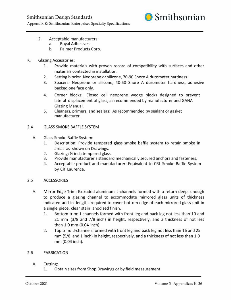
Smithsonian Design StandardsAppendix K: Smithsonian Enterprises Specialty Specifications
October 2021 Volume 3- Appendices K-36
2. Acceptable manufacturers:a. Royal Adhesives.
b. Palmer Products Corp.
K. Glazing Accessories:
1. Provide materials with proven record of compatibility with surfaces and other
materials contacted in installation.
2. Setting blocks: Neoprene or silicone, 70-90 Shore A durometer hardness.
3. Spacers: Neoprene or silicone, 40-50 Shore A durometer hardness, adhesive
backed one face only.
4. Corner blocks: Closed cell neoprene wedge blocks designed to prevent
lateral displacement of glass, as recommended by manufacturer and GANA
Glazing Manual.5. Cleaners, primers, and sealers: As recommended by sealant or gasket
manufacturer.
2.4 GLASS SMOKE BAFFLE SYSTEM
A. Glass Smoke Baffle System:
1. Description: Provide tempered glass smoke baffle system to retain smoke in
areas as shown on Drawings.2. Glazing: ½ inch tempered glass.3. Provide manufacturer’s standard mechanically secured anchors and fasteners.
4. Acceptable product and manufacturer: Equivalent to CRL Smoke Baffle System
by CR Laurence.
2.5 ACCESSORIES
A. Mirror Edge Trim: Extruded aluminum J-channels formed with a return deep enough
to produce a glazing channel to accommodate mirrored glass units of thickness
indicated and in lengths required to cover bottom edge of each mirrored glass unit in
a single piece; clear stain anodized finish.
1. Bottom trim: J-channels formed with front leg and back leg not less than 10 and
21 mm (3/8 and 7/8 inch) in height, respectively, and a thickness of not less
than 1.0 mm (0.04 inch)
2. Top trim: J-channels formed with front leg and back leg not less than 16 and 25
mm (5/8 and 1 inch) in height, respectively, and a thickness of not less than 1.0
mm (0.04 inch).
2.6 FABRICATION
A. Cutting:1. Obtain sizes from Shop Drawings or by field measurement.

Smithsonian Design StandardsAppendix K: Smithsonian Enterprises Specialty Specifications
October 2021 Volume 3- Appendices K-37
2. Cut glass to fit openings with minimum edge clearances and bite on glass
recommended by glass manufacturer. Do not nip glass edges.
3. Factory cut heavy heat absorbing glass (over 10 mm / 0.4 inch) and heavy
float glass (over 13 mm / 0.5 inch).4. Edges:
a. Concealed: Wheel cut or sawed and seamed.b. Exposed: Square edge; ground smooth and polished.
5. Mirrors:
a. Seal edges after treatment to prevent chemical or atmospheric
penetration of glass coating.b. Perform edge treatment and sealing in shop immediately after cutting to
final sizes.6. If glass will be cut in field, fabricate glass 50 mm (2 inches) larger than required.
7. Provide required openings in tempered or heat-strengthened glass before
heat-treating. Do not cut, seam, nip or abrade such glass after heat-treating.
8. When glass is pre-cut to sizes obtained from Shop Drawings, take field
measurements of openings before glazing to verify adequate bite of glass and
minimum edge clearance.
9. If openings do not comply with tolerances for which pre-cut glass was sized,
use new glass specially cut to fit such openings.
B. Fire Department Labels:
1. Provide permanent labels as indicated on Drawings and as required to
comply with requirements of authorities having jurisdiction over Work.
2. Prior to tempering, etch or sandblast label on #2 surface of insulating unit,
unless otherwise required to fulfill performance criteria.
PART 3 - EXECUTION
3.1 EXAMINATION
A. Examine substrates, including framing and glazing channels, and adjoining
construction, and conditions under which Work is to be installed. Do not proceed
with Work until unsatisfactory conditions are corrected.
B. Ensure that frame openings are plumb, level, true to line and otherwise properly
installed.
C. Inspect each piece of glass immediately before installation, and discard pieces which
evidence damage or deterioration including edge damage or face imperfections.
3.2 PREPARATION

Smithsonian Design StandardsAppendix K: Smithsonian Enterprises Specialty Specifications
October 2021 Volume 3- Appendices K-38
A. Clean glazing channel and other framing members to receive glass immediately before
glazing.
B. Remove coatings not firmly bonded to substrate. Remove lacquer from metal surfaces
abutting elastomeric sealants.
C. Apply primer or sealer to joint surfaces where recommended by sealant manufacturer.
3.3 INSTALLATION
A. Comply with combined recommendations of referenced standards, glass manufacturer
and manufacturer of sealants and other materials used in glazing, except where
more stringent requirements are indicated or specified, and except where
manufacturer's technical representatives direct otherwise.
B. Layout:
1. Unify appearance of each series of lites by setting each piece to match others as
nearly as possible.
2. Inspect each piece and set with pattern, draw and bow oriented in same
direction as other pieces.
C. Setting Blocks:
1. Install setting blocks at sill one-quarter in from each end of the glass, unless
otherwise recommended by manufacturer.
2. Use blocks of proper size to support glass.
D. Spacers:
1. Provide spacers for glass sizes larger than 1270 mm (50 inches) united inches to
separate glass from stops except where continuous glazing gaskets or felts are
provided.
2. Locate spacers no farther than 610 mm (24 inches) apart and no closer than 305
mm (12 inches to corners.
3. Place) spacers opposite one another. Make bite of spacer on glass a nominal 6
mm (1/4 inch) or greater.
E. End Blocks: Provide end blocks to comply with requirements of referenced glazing
standards except where otherwise required by glass manufacturer.
F. Backer Rods: Install compressible filler rods or equivalent back-up material, as
recommended by sealant and glass manufacturers.
G. Sealant Glazing:

Smithsonian Design StandardsAppendix K: Smithsonian Enterprises Specialty Specifications
October 2021 Volume 3- Appendices K-39
1. Force sealants into channel to eliminate voids and to ensure complete “wetting” or
bond of sealant to glass and channel surfaces.2. Use masking tape to limit coverage of glazing materials to surfaces intended for
sealants.3. Cure sealants for high early strength and durability.
4. Tool exposed surfaces of glazing materials to provide slight wash away from glass.
H. Gasket Glazing:
1. Vulcanize joints of glazing gaskets in accordance with manufacturer's
instructions to provide continuous watertight and airtight seal at corners and other
locations where joints are required.2. Butt or lap ends of tape.
3. Where wedge-shaped gaskets are driven into one side of channel to pressurize
sealant or gasket on opposite side, provide adequate anchorage to ensure that
gasket will not “walk” out when subjected to movement.
4. Anchor gasket to stop with matching ribs, or by proven adhesives, including
embedment of gasket tail in cured heel bead. Set gaskets in silicone sealant at
corners.
5. Install exposed tapes or gaskets with slight protrusion above stops in final
compressed condition.
I. Structural Sealant Glazing:1. Follow window manufacturer's recommended procedures strictly.2. Clean and prepare components carefully.3. Prime and mask elements that receive structural silicone sealant.4. Fill joints completely before tooling.
5. Unless otherwise recommended, apply silicone to interior joints and allow to cure
for 14 days before applying to exterior joints.
J. Butt Glazing:1. Comply with sealant and glass manufacturer's recommendations for glazing.2. Butt glazing of single thickness glass units:
a. Tape polyethylene rod to one side of joint to act as back up for sealant.b. Install sealant to other side according to manufacturer's instructions.
3. Provide clear silicone sealant with butt glazing.
K. Fire-Resistant Glazing Products: Install in labeled fire doors, frames and windows to
meet requirements of cited references and NFPA Standard No. 80.
L. Plastic Lites:1. Install in accordance with manufacturer’s recommendations.2. Follow procedures for sealant glazing.
M. Mirror Adhesive Installation:
1. Paint back of mirror with additional coat of moisture-resistant paint of type

Smithsonian Design StandardsAppendix K: Smithsonian Enterprises Specialty Specifications
October 2021 Volume 3- Appendices K-40
recommended by mirror manufacturer.
2. Support mirror on setting blocks or continuous glazing gasket.
3. Seal porous substrates as recommended by mastic manufacturer.
4. Apply mirror mastic in spots in accordance with mastic manufacturer's instructions,
and to allow air circulation between back of mirror and face of mounting surface.
3.4 CLEANING
A. Clean excess sealant or compound from glass and framing members
immediately after application.
B. After installation and until final acceptance, clean glass as frequently as required, but
not less than once per month, to remove build-up of dirt, scum, and other
substances. Comply with glass manufacturer's recommendations for cleaning.
C. Wash and polish glass on both faces not more than 4 days prior to final acceptance.
D. Comply with glass manufacturer's recommendations for final cleaning.
3.5 PROTECTION
A. Protect glass from breakage after installation. Do not apply markers to surfaces of glass.
B. Remove non-permanent labels.
C. Remove and replace glass which is broken, chipped, cracked, abraded or damaged.
3.6 INTERIOR GLAZING SCHEDULE
A. See Division 08 Section INTERIOR GLAZING SCHEDULE following this specification.

Smithsonian Design StandardsAppendix J: Smithsonian Enterprises Specialty Specifications
October 2021 Volume 3- Appendices K-41
Desig
natio
n
DIVISION 08 INTERIOR GLAZING SCHEDULE
Product Makeup General Location
GL-20
Laminated Tempered
6 mm ( 1/4" ) Tempered (Heat Soaked) Bronze - 0.060
clear PVB - 6 mm ( 1/4" ) Heat Strengthened Bronze
Existing Guardrail
(Replacement of existing
Concourse), Concorse
Extensions, Missle Pit, Atrium
Stair (#1 & #7)
GL-21Laminated Tempered
6 mm ( 1/4" ) Tempered (Heat Soaked) Clear - 0.060 clear
PVB - 6 mm ( 1/4" ) Heat Strengthened Clear
Stairs (#1, 2, 3, 5, 6, & 7; 3rd
Floor), Launch Pad Stair, Launch
Pad Escalator
GL-22 NOT USED
GL-23 Fire-Rated Glazing (TGP; Pilkington Pyrostop; BOD)
2 1/8" (57 mm) PyrostopGlazed lite in doors at Stairs #1 ,2,
6, & 7; floor 3 only
GL-24 Security Glazing
Glass-Clad PolycarbonateSecurity Booth (P23)
GL-25 Sound Control Laminated Glazing
3 mm ( 1/8" ) Clear Low Iron - 0.080 clear PVB - 3 mm (
1/8" ) Clear Low Iron
Control Studio (P18), IMAX
Projection Booth (215A)
GL-26
Laminated Tempered
5 mm ( 3/16" ) Clear Tempered (Heat Soaked) - .060
clear PVB - 5 mm ( 3/16" ) Clear Tempered (Heat
Soaked)
Non-Rated Door Glazed Panels &
Sidelites, OFMR Reception (P06),
Conference Room (P06B), Offices
(P07D&E), Launch Pad Entrance
Windows (PC03, PC04)
GL-27 Tempered Sliding
1/4" (6 mm) Clear Tempered (Heat Soaked)Reception (P07A)
GL-28 IMAX Projection Glazing (Billington; BOD)
10 mm ( 3/8" ) OptiClear Anti-Reflective 2 sides, Water
White
IMAX Projection Booth (215A)
GL-29
Structural Glazed Partition
1/2" (12mm) Optiwhite Heat Strengthened - 0.030
Ionoplast (Sentryglas) - 1/2" (12mm) Optiwhite Heat
Strengthened
Gallery 206 & 210 Balconies
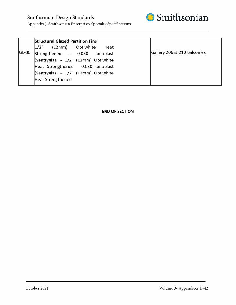
Smithsonian Design StandardsAppendix J: Smithsonian Enterprises Specialty Specifications
October 2021 Volume 3- Appendices K-42
GL-30
Structural Glazed Partition Fins
1/2" (12mm) Optiwhite Heat
Strengthened - 0.030 Ionoplast
(Sentryglas) - 1/2" (12mm) Optiwhite
Heat Strengthened - 0.030 Ionoplast
(Sentryglas) - 1/2" (12mm) Optiwhite
Heat Strengthened
Gallery 206 & 210 Balconies
END OF SECTION

Smithsonian Design StandardsAppendix J: Smithsonian Enterprises Specialty Specifications
October 2021 Volume 3- Appendices K-43
SECTION 10 22 13 WIRE
MESH PARTITIONS
March 1, 2018
PART 1 - GENERAL
1.1 RELATED DOCUMENTS
A. Drawings and general provisions of the Contract, including General and
Supplementary Conditions and Division 01 Specification Sections, apply to this Section.
1.2 UNITS OF MEASURE
A. Contractor to Note: Per SI direction units of measure have been listed in both
Metric and Imperial Units, with the metric unit listed first. The metric units are
nominal and may not be in agreement with dimensioning on drawings. In cases of
conflict the Imperial unit of measure shall govern. Contractor to note that for
purposes of the work Imperial refers to United States Customary Units.
1.3 SUMMARY
A. Description of Work: Work of this Section includes, but is not limited to, the following:1. Wire mesh partitions.2. Gates (doors) and hardware.
3. Accessories.
1.4 RELATED WORK SPECIFIED ELSEWHERE
A. See Division 01 Section SUSTAINABLE DESIGN REQUIREMENTS for sustainable design
requirements and procedures.
B. See Division 08 Section DOOR HARDWARE for cylinders for locks for gates.
1.5 ACTION SUBMITTALS
A. Product Data: Submit manufacturer's specifications and installation instructions
for each component and finish.
B. Shop Drawings:1. Submit Shop Drawings for fabrication and erection of mesh partitions.2. Include plans, elevations and large scale details.3. Indicate anchorage and accessory items.

Smithsonian Design StandardsAppendix J: Smithsonian Enterprises Specialty Specifications
October 2021 Volume 3- Appendices K-44
4. Provide location template drawings for items supported by, or anchored to,
permanent construction.
C. Samples: Submit manufacturer's full standard color range samples for selection by
COTR.
1.6 LEED SUBMITTALS
A. Comply with Division 01 Section SUSTAINABLE DESIGN REQUIREMENTS.
B. MR Credit: Building Product Disclosure and Optimization – Sourcing of Raw Materials.
1. For partitions having recycled content: Industry-wide or product-specific
EPDDocumentation indicating percentages by weight of pre-consumer and
post- consumer recycled content. Include material cost value.
1.7 SYSTEM REQUIREMENTS
A. Interface with Other Systems:1. Coordinate with Work of other trades affected by Work of this Section.
2. Provide items, such as anchors or supports, in a timely manner so as not to
delay job progress.
3. Coordinate with electrical, plumbing and other fixtures or materials mounted
within or adjacent to assemblies, or requiring access.
4. Provide cut-outs as required using manufacturer's templates or security
templates, and field measurements to verify actual installed locations and
dimensions.
1.8 QUALITY ASSURANCE
A. Installer Qualifications: Not less than 5 years documented, successful experience
with work comparable to Work of this Project.
1.9 PRE-INSTALLATION CONFERENCE
A. Prior to commencing Work, meet at site and review installation procedures and
coordination with other Work.
1.10 DELIVERY, STORAGE AND HANDLING
A. Deliver, store, handle and protect products in accordance with manufacturer's
instructions.
B. Store in protected and dry area in manufacturer's unopened protective shipping

Smithsonian Design StandardsAppendix J: Smithsonian Enterprises Specialty Specifications
October 2021 Volume 3- Appendices K-45
packaging.
C. Support as required to prevent any damage to materials.
1.11 PROJECT CONDITIONS
A. Field verify dimensions of supporting structure and other adjoining elements before
fabrication.
B. Provide for erection tolerances corresponding with specified tolerances for other
Work where field measurements cannot be obtained.
C. Remedy unsatisfactory tolerances in adjoining Work.
PART 2 - PRODUCTS
2.1 LEED, GENERAL
A. Recycled content: Provide steel with at least 25 percent post-consumer recycled content.
2.2 PRODUCTS AND MANUFACTURERS
A. Acceptable Products and Manufacturers:
1. Listed products establish standard of quality and are manufactured by
Newark Wireworks.2. Equivalent products by following are acceptable:
a. Acorn Wire and Iron Works, Inc.b. Miller Wire Works, Inc.c. Standard Wire & Steel Works.d. Hartford Wire Works.
e. Amico Security Products.
2.3 WIRE MESH PARTITION
A. General: Provide materials as specified, unless otherwise indicated on Drawings or
required for proper installation of indicated configurations.
B. Fabric:1. Provide 8 gauge, tight wire mesh with ½ inch openings to prevent rodents from
entering.
2. Provide fine screen at inside of wire partition frame to prevent bugs from
entering, as required.
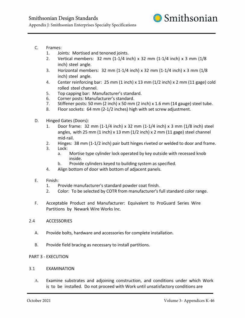
Smithsonian Design StandardsAppendix J: Smithsonian Enterprises Specialty Specifications
October 2021 Volume 3- Appendices K-46
C. Frames:1. Joints: Mortised and tenoned joints.
2. Vertical members: 32 mm (1-1/4 inch) x 32 mm (1-1/4 inch) x 3 mm (1/8
inch) steel angle.
3. Horizontal members: 32 mm (1-1/4 inch) x 32 mm (1-1/4 inch) x 3 mm (1/8
inch) steel angle.
4. Center reinforcing bar: 25 mm (1 inch) x 13 mm (1/2 inch) x 2 mm (11 gage) cold
rolled steel channel.5. Top capping bar: Manufacturer’s standard.6. Corner posts: Manufacturer’s standard.7. Stiffener posts: 50 mm (2 inch) x 50 mm (2 inch) x 1.6 mm (14 gauge) steel tube.
8. Floor sockets: 64 mm (2-1/2 inches) high with set screw adjustment.
D. Hinged Gates (Doors):
1. Door frame: 32 mm (1-1/4 inch) x 32 mm (1-1/4 inch) x 3 mm (1/8 inch) steel
angles, with 25 mm (1 inch) x 13 mm (1/2 inch) x 2 mm (11 gage) steel channel
mid-rail.2. Hinges: 38 mm (1-1/2 inch) pair butt hinges riveted or welded to door and frame.3. Lock:
a. Mortise type cylinder lock operated by key outside with recessed knobinside.
b. Provide cylinders keyed to building system as specified.
4. Align bottom of door with bottom of adjacent panels.
E. Finish:1. Provide manufacturer's standard powder coat finish.
2. Color: To be selected by COTR from manufacturer's full standard color range.
F. Acceptable Product and Manufacturer: Equivalent to ProGuard Series Wire
Partitions by Newark Wire Works Inc.
2.4 ACCESSORIES
A. Provide bolts, hardware and accessories for complete installation.
B. Provide field bracing as necessary to install partitions.
PART 3 - EXECUTION
3.1 EXAMINATION
A. Examine substrates and adjoining construction, and conditions under which Work
is to be installed. Do not proceed with Work until unsatisfactory conditions are

Smithsonian Design StandardsAppendix J: Smithsonian Enterprises Specialty Specifications
October 2021 Volume 3- Appendices K-47
corrected.
3.2 INSTALLATION
A. Install in accordance with final Shop Drawings and manufacturer's instructions.
B. Install plumb, rigid, properly aligned and securely fastened to supporting substrates.
3.3 ADJUSTING AND REPAIR
A. Adjust moving components for smooth operation without binding.
B. Touch-up damaged finish after installation using field-applied paint to match
color of shop-applied finish.
END OF SECTION

Smithsonian Design StandardsAppendix K: Smithsonian Enterprises Specialty Specifications
October 2021 Volume 3- Appendices K-48
SECTION 11 61 33
RIGGING, CURTAIN & TRACKS
PART 1 – GENERAL
1.1 DEFINITIONS
A. The term "Contractor" shall mean the contracting entity, also referred to
herein as Rigging Contractor, as a Manufacturer or Manufacturer’s agent,
responsible for the fabrication, assembly, installation, testing, instruction
and completion of all stage rigging work as covered in these Specifications
and related Drawings.
B. The terms "General Contractor" and "Electrical Contractor" are used herein
to refer to organizations, individuals, and their representatives as typically
defined for construction projects. These terms refer to parties other than
the Rigging Contractor ("Contractor").
C. Contractor to Note: Per SI direction units of measure have been listed in
both Metric and Imperial Units, with the metric unit listed first. The metric
units are nominal and may not be in agreement with dimensioning on
drawings. In cases of conflict the Imperial unit of measure shall govern.
Contractor to note that for purposes of the work Imperial refers to United
States Customary Units.
D. Technical terms unique to stage rigging and related work shall be
construed in the following order, in accordance with:
1. Captions on related Drawings.
2. Relevant usage and definitions of handbooks, guidebooks, or
trade group recommendations by manufacturers' associations or
professional and engineering societies, such as ASTM, ASME,
ASHRAE, etc.
3. Generally recognized theatrical usage.
1.2 SCOPE
All materials, components, and services necessary to provide a complete system
indicated in this Section, as specified herein and shown on related Drawings,
including:
A. Preparation and submission of complete shop drawings and samples for
review prior to fabrication.
B. Verification of dimensions and conditions at the job site.
C. Shipment of equipment to job site and the secured storage of all
non-fixed equipment.

Smithsonian Design StandardsAppendix K: Smithsonian Enterprises Specialty Specifications
October 2021 Volume 3- Appendices K-49
D. Installation and completion, in accordance with these Specifications,
related Drawings, the Equipment Manufacturer's recommendations,
established trade criteria, and all applicable code requirements.
E. The observation, demonstration, and necessary adjustment of the
completed installation.
F. Preparation and submission of complete record drawings and
operational and maintenance data and certificates.
The systems described by this Specification and related Drawings are not designed or
intended for use in human “flying” effects or for suspension of people in any manner.
1.3 WORK INCLUDED
A. IMAX Theatre Door Masking Curtain and Track
The above is for reference only and is not intended to define the limits of the work
for a complete installation.
1.4 WORK NOT INCLUDED
A. Principal structural steel work, except as herein indicated.
B. Electrical wiring, conduit, and connections.
The above is for reference only and is not intended to define the limits of the work
for a complete installation.
1.5 QUALIFICATIONS
A. All equipment and installation shall be the responsibility of a single
contractor. The Contractor shall be responsible for the integration,
operation, and performance of all elements of the systems described in this
Section. This Contractor shall assume complete responsibility for the
engineering, fabrication, transportation, and installation of the work in this
Section, and shall hold the COTR, Architect, Theatre Consultant, and all their
Employees and Consultants harmless for any costs for errors or omissions
associated with the work of this Section and any action arising therefrom.
The Contractor shall provide all warranty work and equipment upgrades as
called for in this Section.
B. Approved contractors may, at their option, arrange for sub-contract field
and special shop work to be done by others. Bid submissions must identify
such subcontractors and indicate the work they are to do.
C. The Contractor shall have at least 10 years' experience in the installation of
similar equipment and systems of a similar scope for professional theatres.
Contractor shall be a current Business member, accredited as a Dealer
Retailer or Manufacturer, of the industry service organization, PLASA.

Smithsonian Design StandardsAppendix K: Smithsonian Enterprises Specialty Specifications
October 2021 Volume 3- Appendices K-50
D. Contractor shall employ only experienced stage riggers to direct the
installation of work of this Section. A competent supervisor shall be
maintained on this Project during the entire installation. The supervisor shall
be certified as a Theater Rigger by the Entertainment Technician Certification
Program. A change of supervisor shall not be acceptable unless by written
authorization of the COTR.
E. Subject to the above requirements, work performed under this Section may
be by one of the following listed contractors:
1. Inter-America Stage, Sanford, Florida, 877-302-4274
2. I. Weiss, Fairview, New Jersey, 888-325-7192
3. Wenger / J. R. Clancy, Inc., Owatonna, Minnesota, 507-774-8863
4. Texas Scenic, San Antonio, Texas, 210-684-0091
as an integral part of their operation shall employ the services of a qualified
and experienced Sewing Sub-contractor for the fabrication of stage
curtains. Sewing Sub-contractor shall have at least 10 years' experience in
the fabrication of curtains for professional theatres. If requested, the
Rigging Contractor shall submit a representative list of professional theatre
projects performed by the Sewing Sub- contractor during the above
period. Subject to the above requirements, work performed under this
Section may be by one of the following Sewing Sub- contractors:
1. Rose Brand, New York, New York
2. Stage Decoration and Supplies, Greensboro, North Carolina
3. Stagecraft Industries, Portland, Oregon
4. Syracuse Scenery and Stage Lighting, Liverpool, New York
5. Tiffin Scenic Studios, Inc., Tiffin, Ohio
6. I. Weiss & Sons, Long Island City, New York
G. Other contractors or sewing rooms may be considered with the prior review
of the Theatre Consultant. Contractors seeking review must submit
qualifications not later than 14 days prior to bid date.
1.7 SUBMITTALS
A. With bid.
1. Proof that the contractor meets the qualification requirements as
outlined in this Section.
2. A list of at least three (3) professional theatre stage rigging and drapery
installations by the bidder comparable to this project in scope and

Smithsonian Design StandardsAppendix K: Smithsonian Enterprises Specialty Specifications
October 2021 Volume 3- Appendices K-51
completed in the past five (5) years.
3. A list of any proposed deviations or exceptions from the Specifications.
Any deviations or exceptions from the Specification proposed after bid
shall not be accepted.
4. A schedule for the anticipated completion of the following:
a. Shop drawings.
b. Delivery of all equipment.
c. Installation of all systems.
B. Shop drawings. Within 60 days of contract award, the Contractor shall
submit at least one set of drawings to the COTR for review prior to
fabrication:
1. Floor plan, in scale equal to 1:20 (1/4" = 1'-0").
2. Elevation curtain set, showing floor, all blocks, , mounting and
arrangement, curtain travel, and curtain storage.
3. Curtain schedule indicating fabric, finished size, fullness and special
sewing requirements.
4. Dimensioned rear Elevation of every curtain to be provided for this
project, showing hem construction and detailing of all edges and
sewing requirements.
5. Complete, fully dimensioned shop drawings of all major components.
6. Requisite plans, sections, schematics, and details indicating
assembly and installation of components.
7. Load ratings of all load bearing components including, but not limited
to, bearings, blocks, trim chains, lift lines, and purchase lines.
8. Complete descriptions, including the manufacturer's catalog data
sheets, of all components including, but not limited to, bearings,
motors, transmissions, and items designated as “Deliver to COTR.”
9. Certification by a recognized independent testing laboratory that all
steel cable and rope meets the ASTM standards referenced in this
Section.
10. Coordination Drawing(s) illustrating requirements for blocking,
provided by others, necessary to support rigging system components.
11. Quantities of each component and sub-assembly.
12. Indication by boxed caption of any and all variations from the contract
Drawings and Specifications, whether or not these variations have been

Smithsonian Design StandardsAppendix K: Smithsonian Enterprises Specialty Specifications
October 2021 Volume 3- Appendices K-52
formally or informally accepted by the COTR and Theatre Consultant.
13. Prepare all shop drawings under the supervision of professional
electrical and structural engineers so licensed by the District of
Columbia. All shop drawings shall be stamped and certified by those
engineers. Structural Engineer's review shall include all elements
provided under the work of this section including the methods of
attachment of said elements to the building. In lieu of an Electrical
Engineer’s stamp, a letter from the installing Electrical Contractor,
verifying that all conductors, conduits and terminations will be installed
in accordance with all applicable local and national codes shall be
acceptable.
14. Submittal Review:
a. All shop drawing information shall be submitted at the same time; no
partial submittals will be reviewed.
b. Review and approval shall not relieve the Contractor of responsibility
for meeting all functional, operational, and safety requirements of
the project as set forth in this Specification and related Sections.
Review does not relieve the Contractor of responsibility to verify field
conditions; nor does it relieve the contractor of responsibility for
errors, omissions, or deviations in submittals.
C. Samples. Within 60 days of contract award, the Contractor shall submit to
the COTR for review prior to fabrication:
1. Color lines for all curtain fabrics, for color selection by COTR.
2. 910 mm (36-inch) long sample of each type of curtain track, complete with
(if applicable) live end pulley, dead end pulley, operating line, one (1) single
carrier, and one (1) master carrier.
3. Samples of any equipment component requested by the Theatre
Consultant.
Samples shall not be considered part of specified quantities but shall be
returned.
D. Final submittal. Within 30 days of final tests, and as a condition for final
review, the Contractor shall submit three (3) sets to the COTR and one (1)
set on electronic media to the Theatre Consultant of the listed items. Format
of sets shall be compliant with Division One of this Specification.
1. Receipts for delivery of all non-installed items, i.e., all items designated,
"Deliver to COTR."

Smithsonian Design StandardsAppendix K: Smithsonian Enterprises Specialty Specifications
October 2021 Volume 3- Appendices K-53
2. "As built and approved" drawings and wiring diagrams showing all systems
and components as installed, including all field modifications. All field
modifications shall be reviewed and stamped by professional engineers so
licensed by the District of Columbia. The scope of this review shall be
subject to the requirements noted above for Shop Drawing Submittals.
3. Operation and service manuals, schematics, and parts lists for each unit of
equipment installed or provided.
4. Certificates of flame resistance.
5. Certificates of warranty, as set forth below.
1.8 TESTING AND INSTRUCTION
A. Upon completion of all installation work, the Contractor shall certify in
writing to the COTR and Theatre Consultant that the work is complete and
ready for final observation. Final observation shall be scheduled by the
COTR, the Architect, and the Theatre Consultant to occur within 14 days
following the Contractor's notice of completion.
B. Final observation shall be conducted by a knowledgeable representative of
the Contractor, in the presence of the COTR, the Architect, and the Theatre
Consultant, and shall include the following:
1. Operation of all components.
2. Visual examination of all components.
C. Necessary adjustments or modifications shall be made as required.
D. As a condition of final completion, Contractor’s representative shall instruct
the COTR's staff or representatives, under the observation of the Architect
and Theatre Consultant, in the operation and maintenance of the system
including the storage and cleaning of all fabrics.
1. Initial Instruction: This instruction session shall be scheduled for a minimum
duration of one (1) hour. While it may be possible to schedule this instruction
session to coincide with the system checkout, such coincidence shall not be
assumed. Instruction shall be scheduled by the COTR, the Architect, and the
Theatre Consultant to occur within 14 days following the Contractor's written
notice.
1.9 GENERAL REQUIREMENTS
A. General Conditions of the project contract, work schedules, and site
regulations apply to this work. Refer to Division One.
B. This work shall comply with local codes and applicable national codes and
standards. All electrical components shall carry pertinent labels from
Nationally Recognized Testing Laboratories.

Smithsonian Design StandardsAppendix K: Smithsonian Enterprises Specialty Specifications
October 2021 Volume 3- Appendices K-54
C. All equipment shall be fully insured against loss or damage during shipment,
job site storage, installation, and testing. The Contractor shall have and
assume full responsibility for the safety of every unit of equipment,
components and wiring during delivery, installation, and testing until
acceptance by COTR. Certification of such coverage shall be furnished to
the COTR within 30 days of award of contract.
D. Warranty
1. The Contractor shall unconditionally warrant all equipment and systems
provided under this Section to be free from defects in materials and
workmanship for a period of at least 12 months from the date of final
acceptance of all work of this Section.
2. All repairs and service during the warranty period shall be performed at the
job site; labor, materials, and transportation of replacement material and
parts and service personnel to and from the job site shall be included
hereunder at the Contractor's expense.
3. Appropriate additional equipment or draperies to replace equipment,
devices, or draperies removed for repair, service, or cleaning shall be
provided at the job site at no expense to the COTR to replace any and all
equipment which must be removed for repair or service.
4. Warranty service shall be performed by personnel in the employ of the
Contractor and shall not be sub-contracted or assigned to another
company, service, or individual unless the COTR has approved such
assignment in writing, in which event the Contractor shall nevertheless be
responsible to the COTR for such work.
PART 2 – PRODUCTS
2.1 GENERAL
A. All components shall be new and of first quality.
B. Machinery and component parts shall comply with applicable trade practice,
industry standards, and code requirements and bear appropriate labels of
conformity and acceptability.
C. All components shall bear labels from a Nationally Recognized Testing
Laboratory and labels identifying the manufacturer, model number, serial
number, and date of flameproofing. All such labels shall be permanently
attached in a conspicuous location.
D. Operating parts of all equipment shall be machine finished, and tolerances,
finishes, fit, etc., where not specified, shall conform to good trade
practices.

Smithsonian Design StandardsAppendix K: Smithsonian Enterprises Specialty Specifications
October 2021 Volume 3- Appendices K-55
E. All items necessary for a complete, operational, and safe system shall be
provided, including bolts, nuts, washers, fittings, anchors, supports, hinges,
and all other items required for completeness and operational safety.
Where not specified elsewhere in this Section, all bolts shall be Grade 5 or
better.
F. Where not specifically called out in this Section, rope and wire rope shall be
selected using a minimum safety factor of 8 to 1. All chain, shackles, and
other hardware shall be selected using a minimum safety factor of 5 to 1.
G. Where specification allows for "approved equal," substitutions shall be
proposed to the Theatre Consultant at least 10 days prior to bid date.
H. Equipment and hardware are specified on the basis of performance and
minimum acceptable quality. Materials manufactured by any of the
following companies that equal or surpass
1. Devices Company (ADC), Allentown, Pennsylvania
2. H & H Specialties, South El Monte, California
3. J. R. Clancy, Syracuse, New York
4. Tiffin Scenic Studios, Tiffin, Ohio
5. Texas Scenic, San Antonio, Texas
2.2 ENGINEERING RESPONSIBILITY
A. The engineering of all equipment, devices, machinery, and systems shall
address the following considerations:
1. Safety to personnel during operation, use, and maintenance.
2. Adequate strength.
3. Proper coordination of all systems and elements, including electrical
insulation levels, interrupting capacities, protective relays, impact
strength, breaking strength, emergency stopping distances,
acceleration and deceleration rates, and normal working stress
capabilities of equipment and all components.
4. Reliability, with consideration for special or unusual requirements of
the unit or installation.
5. Ease of operation and maintenance.
6. Quiet operation.
B. Provide all supplementary structural support necessary for safe and proper
static and dynamic conditions of all systems and components required for
the work of the Specification. Supplementary structural support required
for access, support, enclosure, and service to all motors and motor control

Smithsonian Design StandardsAppendix K: Smithsonian Enterprises Specialty Specifications
October 2021 Volume 3- Appendices K-56
cabinets shall be supplied and installed as part of the work of this Section.
All attachments, anchorages, connections, and miscellaneous steel
additions to accommodate pulleys, blocks, etc., shall be designed, supplied,
and installed by the Contractor and reviewed by the COTR. All methods of
connection and imposed loads resulting from the Contractor's work shall be
submitted to the COTR prior to fabrication.
2.3 EQUIPMENT COMPONENTS
A. Single and Multiple Line Sheaves:
1. Supporting, load bearing, and idler sheaves shall be of materials
indicated. Size and capacity shall be as required for safe and
reliable operation under design loads, but in no instance shall
bearing pressure of the wire rope on a sheave groove exceed:
a. 100 PSI for nylon
b. 250 PSI for Nylatron
c. 250 PSI for cast iron
d. 500 PSI for high tensile cast iron
e. 750 PSI for cast steel
f. 2,000 PSI for turned steel sheaves.
2. Tread diameter of sheaves for wire rope shall be at least 30
times the diameter of the wire rope employed, except minimum
diameter of idler sheaves and mule blocks that divert the cable
direction by less than 45 degrees may be 20 times cable
diameter. Tread diameter of sheaves for textile rope shall be at
least 15 times the diameter of the textile rope employed.
3. All castings shall be designed and detailed for required loads
and cable diameters with safety factors of at least three (3).
4. Provide rigid and accurate shaft and bearing mounting. Shafts shall be
seized to prevent rotation.
5. Cable grooves shall be properly sized for the cable used, with groove
diameter clearances to fit cable closely and prevent cable from
assuming oval or elliptical shape under load. Groove diameter
clearance shall be 8% of cable diameter. Groove depth shall be equal
to the cable diameter. Cast grooves on metallic sheaves are not
acceptable. All grooves on the same casting or billet shall have the
same pitch diameter. All groove sides shall be beveled for required
fleet angle to eliminate rubbing. Fleet angles shall not exceed ± 1.5
degrees.

Smithsonian Design StandardsAppendix K: Smithsonian Enterprises Specialty Specifications
October 2021 Volume 3- Appendices K-57
6. Fleeting, muling, idler, and spacer blocks shall be provided as
necessary to guide, turn, support, and separate lift lines. Load
bearing sheaves shall be of at least the same components and sizes
as required for other sheaves in the set and provided with suitable
swivel bases, slip-shafts, mounting brackets, platforms, and
accessories to satisfy job requirements.
7. Spacers shall be located so as to both retain the cable in the sheave
groove and to retain the sheave within the block in the event of
shaft failure. Clearance between the spacer and the rope shall be not
more than 40 percent of the rope diameter nor less than 20 percent
of the rope diameter.
B. Bearings
1. Unless otherwise noted, all bearings shall be of the tapered roller
type. Precision sealed ball bearings and oil impregnated bronze
bushings, or similar, shall not be used except in specific applications
identified in this Specification, and where guidance or diverting of
wire rope self-weight are the only loads carried. In all cases, such
bearings and bushings may be used only when specifically approved
in advance by the COTR and Theatre Consultant.
2. Selection of bearings or bushings shall meet the following
performance criteria:
a. Silent operation at expected RPM
b. Low maintenance and lubrication
c. Ability to withstand long periods of static disuse under full
design load without affecting performance
3. All bearings shall be pre-lubricated and sealed for life. For bearing
types that cannot be sealed for life, easy means shall be provided for
periodic lubrications via standard and common fittings. Such
lubrication shall not require the disassembly of blocks or other
extraordinary means. In all cases, such bearings may be used only
when specifically approved in advance by the COTR and Theatre
Consultant.
2.4 STRUCTURAL AND MISCELLANEOUS METAL WORK
A. Additional structural steel and other fittings required for installation,
support, bracing, and/or operation of theatrical rigging in all areas of the
Project are the responsibility of this Contractor and shall be in accordance
with related Divisions of the Project Specifications. Excepted are supports
which are erected behind finished surfaces. These supports shall be the
responsibility of the General Contractor. The Rigging Contractor shall

Smithsonian Design StandardsAppendix K: Smithsonian Enterprises Specialty Specifications
October 2021 Volume 3- Appendices K-58
coordinate these locations and requirements with the General Contractor.
B. Patented channel type structural steel shall accommodate the required
load but shall equal Unistrut Series P1000 at minimum.
C. Flame Cutting: Flame cutting is not acceptable, except for
fabrication of counterweight.
D. Miscellaneous steel shall be of suitable types and sizes. All straps, rods,
anchors, clip anchors, clip angles and other hardware necessary for the
attachment shall be supplied.
2.5 ROPE
A. Counterweight set purchase lines
1. Spun polyester:
a. "Multiline II" by New England Ropes, New Bedford,
Massachusetts
b. “Pro-Master” by Samson Rope Technologies, Ferndale,
Washington
c. Approved equal.
2. Rope shall be of domestic manufacture. Contractor shall submit
certification of manufacture with bid.
3. Lines shall be attached to the top of each arbor with a bowline
knot and to the bottom of each arbor with two (2) half hitches.
The rope ends shall be secured back to the standing lines with two
(2) nylon tension ties. Steel thimbles for fiber rope shall be
employed at both top and bottom ties.
4. Color: white with orange or green tracers.
B. Electric cable snatch lines and special rigging lines
1. Braided polyester:
a. "Stage-Set X" by New England Ropes, New Bedford,
Massachusetts
b. “Static Rope” by Samson Rope Technologies, Ferndale,
Washington
c. Approved equal.
2. Lines shall be attached to the cable cradles with bowline knots and
the rope ends secured back to the standing line with two (2) nylon
tension ties.
3. Color: black.
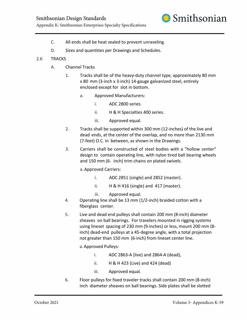
Smithsonian Design StandardsAppendix K: Smithsonian Enterprises Specialty Specifications
October 2021 Volume 3- Appendices K-59
C. All ends shall be heat sealed to prevent unraveling.
D. Sizes and quantities per Drawings and Schedules.
2.6 TRACKS
A. Channel Tracks
1. Tracks shall be of the heavy-duty channel type, approximately 80 mm
x 80 mm (3-inch x 3-inch) 14-gauge galvanized steel, entirely
enclosed except for slot in bottom.
a. Approved Manufacturers:
i. ADC 2800 series
ii. H & H Specialties 400 series.
iii. Approved equal.
2. Tracks shall be supported within 300 mm (12-inches) of the live and
dead ends, at the center of the overlap, and no more than 2130 mm
(7-feet) O.C. in between, as shown in the Drawings.
3. Carriers shall be constructed of steel bodies with a "hollow center"
design to contain operating line, with nylon tired ball bearing wheels
and 150 mm (6- inch) trim chains on plated swivels.
a. Approved Carriers:
i. ADC 2851 (single) and 2852 (master).
ii. H & H 416 (single) and 417 (master).
iii. Approved equal.
4. Operating line shall be 13 mm (1/2-inch) braided cotton with a
fiberglass center.
5. Live and dead end pulleys shall contain 200 mm (8-inch) diameter
sheaves on ball bearings. For travelers mounted in rigging systems
using lineset spacing of 230 mm (9-inches) or less, mount 200 mm (8-
inch) dead-end pulleys at a 45-degree angle, with a total projection
not greater than 150 mm (6-inch) from lineset center line.
a. Approved Pulleys:
i. ADC 2863-A (live) and 2864-A (dead),
ii. H & H 423 (Live) and 424 (dead)
iii. Approved equal.
6. Floor pulleys for fixed traveler tracks shall contain 200 mm (8-inch)
inch diameter sheaves on ball bearings. Side plates shall be slotted

Smithsonian Design StandardsAppendix K: Smithsonian Enterprises Specialty Specifications
October 2021 Volume 3- Appendices K-60
to allow a minimum 200 mm (8-inch) vertical adjustment.
a. ADC 2866-A
b. H&H 422
c. Approved equal.
B. I-Beam Tracks
1. Tracks shall be of the heavy duty I-beam type, approximately60 mm x 25 mm (2-1/2 inch x 1 inch) 11-gauge extruded aluminum.
a. ADC 1400
b. H&H 316 Series
c. Approved equal.
2. Carriers shall be constructed of steel bodies with nylon tired ball bearing
wheels and six (6) inch trim chains on plated swivels. Each carrier shall
include nylon strips inside either side to minimize friction and noise from
the track edges. Each carrier shall be cushioned from the adjacent carrier
by neoprene bumpers.
a. Approved Carriers:
i. ADC 4201
ii. H&H 316 (Single) and 317 (Master)
iii. Approved equal.
3. Tracks shall be supported at both ends and no more than 1220
mm (48- inches) O.C. in between.
C. Finishes
1. All Steel Components shall be painted or powder coated flat black.
2. All Aluminum components shall be anodized flat black.
3. All plastic or nylon components shall be inherently colored black.
4. All operating line and tow ropes shall be black.
D. Every track segment shall be one (1) continuous piece of maximum catalog
length, except where splicing clamps are required. Splicing clamps shall
provide a flush, positive alignment of track sections.
E. Provide and install tow ropes for each end of each walk-draw curtain panel.
Tow ropes shall be 10 mm (3/8 inch) braided cotton rope with 50 mm (2-
inch) diameter wood balls on the operating end, than 1220 mm (48-inches)
above stage level. Ropes and handles shall be black.
F. Quantities, sizes, and locations as per Drawings.

Smithsonian Design StandardsAppendix K: Smithsonian Enterprises Specialty Specifications
October 2021 Volume 3- Appendices K-61
2.7 CURTAINS
A. Fabrics
1. All fabrics not inherently flameproof shall be fully mill flameproofed
by the immersion process to meet or exceed the minimum
requirements set forth by NFPA "Small Scale 701." The Contractor
shall submit certificates so stating.
2. All fabrics shall be produced from one (1) dye lot per color. Color
quality shall be consistent throughout, with no visible streaking,
striping, or spotting.
3. All curtain color selections shall be submitted to the Theatre
Consultant following selection by COTR. Final color approval by
the Theatre Consultant is required prior to ordering fabric.
4. Inherently Flame-Retardant Masking Curtains: 100 percent carded
Inherently Flame Retardant velour, 1,370 mm (54-inches) wide,
weighing 550 gsm (25 ounces per linear yard). "Charisma" as
manufactured by KM Fabrics, Inc., Greenville, South Carolina, or
approved equal by J. L. DeBall Fabrics or J. B. Martin Fabrics. Color:
as shown on the Drawings.
B. Fabrication
1. General
a. Unless otherwise noted, all pile fabrics shall have pile running
up.
b. All seams shall be vertical, unless otherwise specifically
indicated. All fabric widths shall run full height, with no
vertical piecing. All hems shall be sewn for the complete
length of the hem.
c. Thread shall match face fabric in color and material.
d. The center of every curtain shall be indicated by a 13 mm (½-
inch) wide fabric strip sewn to the back of the webbing. In
addition, the center grommet of each border, backdrop,
cyclorama and scrim shall be provided with a tie line in a color
that is obviously different than the rest of the tielines.
e. All grommets shall be black in finish.
f. Every curtain shall contain permanent labels sewn to all
off-stage ends of each curtain. Labels shall be located at the
top webbing for all curtains. For any curtain taller than 3050
mm (10- feet), labels shall also be provided at 1220 mm (48
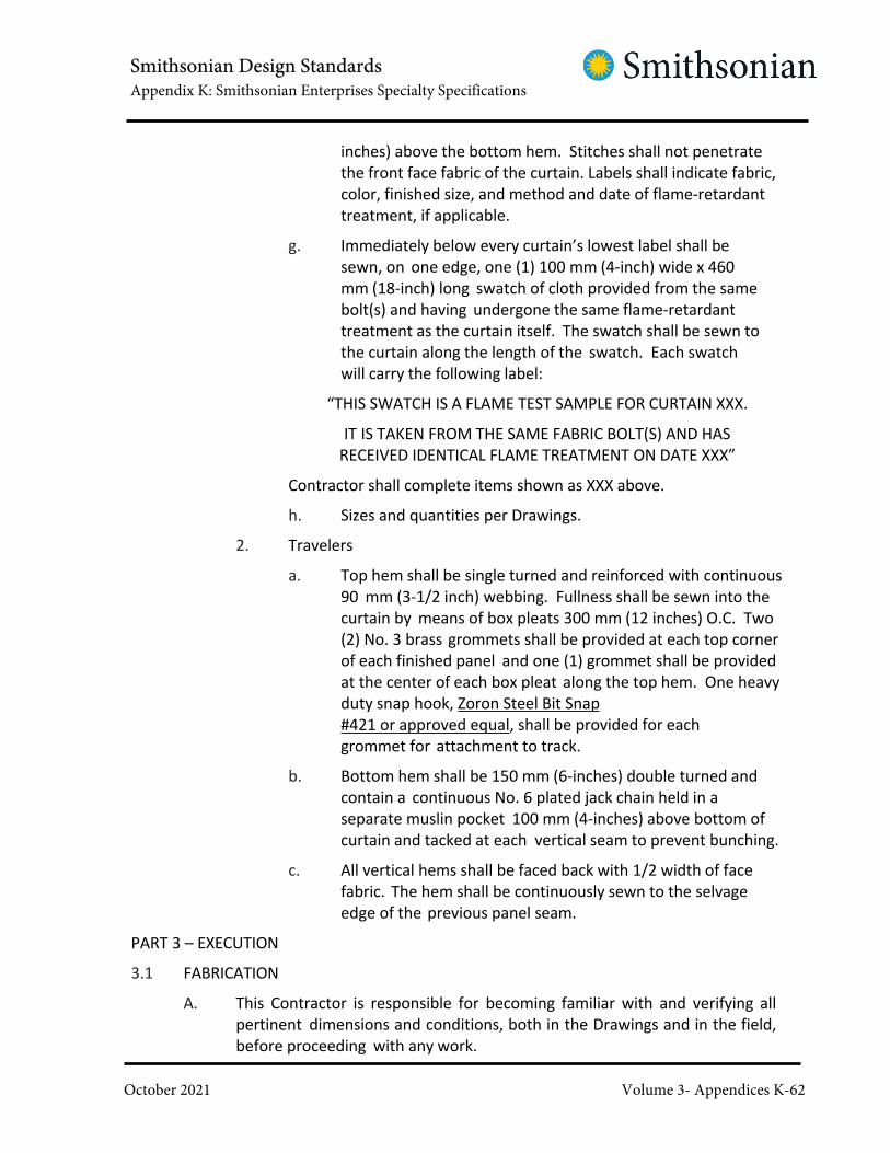
Smithsonian Design StandardsAppendix K: Smithsonian Enterprises Specialty Specifications
October 2021 Volume 3- Appendices K-62
inches) above the bottom hem. Stitches shall not penetrate
the front face fabric of the curtain. Labels shall indicate fabric,
color, finished size, and method and date of flame-retardant
treatment, if applicable.
g. Immediately below every curtain’s lowest label shall be
sewn, on one edge, one (1) 100 mm (4-inch) wide x 460
mm (18-inch) long swatch of cloth provided from the same
bolt(s) and having undergone the same flame-retardant
treatment as the curtain itself. The swatch shall be sewn to
the curtain along the length of the swatch. Each swatch
will carry the following label:
“THIS SWATCH IS A FLAME TEST SAMPLE FOR CURTAIN XXX.
IT IS TAKEN FROM THE SAME FABRIC BOLT(S) AND HAS
RECEIVED IDENTICAL FLAME TREATMENT ON DATE XXX”
Contractor shall complete items shown as XXX above.
h. Sizes and quantities per Drawings.
2. Travelers
a. Top hem shall be single turned and reinforced with continuous
90 mm (3-1/2 inch) webbing. Fullness shall be sewn into the
curtain by means of box pleats 300 mm (12 inches) O.C. Two
(2) No. 3 brass grommets shall be provided at each top corner
of each finished panel and one (1) grommet shall be provided
at the center of each box pleat along the top hem. One heavy
duty snap hook, Zoron Steel Bit Snap
#421 or approved equal, shall be provided for each
grommet for attachment to track.
b. Bottom hem shall be 150 mm (6-inches) double turned and
contain a continuous No. 6 plated jack chain held in a
separate muslin pocket 100 mm (4-inches) above bottom of
curtain and tacked at each vertical seam to prevent bunching.
c. All vertical hems shall be faced back with 1/2 width of face
fabric. The hem shall be continuously sewn to the selvage
edge of the previous panel seam.
PART 3 – EXECUTION
3.1 FABRICATION
A. This Contractor is responsible for becoming familiar with and verifying all
pertinent dimensions and conditions, both in the Drawings and in the field,
before proceeding with any work.

Smithsonian Design StandardsAppendix K: Smithsonian Enterprises Specialty Specifications
October 2021 Volume 3- Appendices K-63
B. Coordinate the design, planning, and scheduling of the work of this Section
with the work of all other trades. Notify the COTR of any difficulties in
coordinating work with other contractors. Failure to do so shall constitute
acceptance of construction as suitable in all ways to receive the work of this
Section.
C. All electrical components shall be fully assembled and internally wired,
with terminals of the proper rating and clearly labeled, provided for
external feeder and control wiring.
D. All metal fabricated items shall be given at least one (1) coat of primer and
one (1) coat of finish paint. Color: flat black.
E. Where not specifically called out in the Drawings and Specifications,
tracks and fittings shall be painted or anodized black.
F. Verify curtain height dimensions after track installation is complete,
prior to fabricating curtains.
G. All curtain color selections shall be submitted to the Theatre Consultant
following selection by COTR. Final color approval by the Theatre Consultant is
required prior to ordering fabric.
H. All equipment shall be fabricated and installed to facilitate maintenance
and future replacement.
3.2 INSTALLATION
A. Contractor shall employ only experienced stage riggers for the installation of
work of this Section. A competent supervisor shall be maintained on this
Project during the entire installation. A change of supervisor shall not be
acceptable unless by written authorization of the COTR.
B. Coordinate installation with all other trades doing adjoining work.
C. Examine all existing conditions at the jobsite prior to beginning installation.
Report to COTR any conditions that vary from the Drawings that could
prevent the correct installation of the specified system, including, but not
limited to, out-of-plumb, out- of-square, out-of-true and out-of-level
conditions. Failure to do so shall constitute acceptance of construction as
suitable in all ways to receive the work of this Section.
D. Blow all accumulated dust from gridiron, using compressed air, prior to
installation of new system.
E. Provide protection for all stage flooring, regardless of whether flooring
has been stained or sealed. Flooring shall be protected from both
structural damage and cosmetic damage.
F. Provide and install all supplementary structural support as required
for the installation and safe operation of equipment and materials

Smithsonian Design StandardsAppendix K: Smithsonian Enterprises Specialty Specifications
October 2021 Volume 3- Appendices K-64
supplied under this Section.
G. Do all required cutting, drilling, tapping, and welding necessary for proper
installation. Cut no structural members unless specifically shown in the
Drawings or indicated in the Contractor's shop drawings, or unless written
approval is obtained from the COTR.
H. Install all items in conformity with standard trade practices and
manufacturers' recommendations. Position all items accurately and true
to plumb line and level. Maintain maximum headroom and clearances at
all locations.
I. Ropes and cables shall enter rigging blocks and drums at a fleet angle not
exceeding ±1.5 degrees.
J. All turnbuckles and screw-pin shackles shall be seized in place with
either wire or standard 23 kg (50-lb capacity) black nylon (UV stabilized)
cable ties after final adjustment. Loose ends of seizing material shall be
trimmed to be no longer than 6 mm (¼-inch) in length.
K. Number all line sets at the Loading Gallery, at the top of the kick plate,
and at the gridiron, at the top flange of the centerline loft well, so as to
facilitate the identification of sets at these locations. Use white enamel
paint and stencils for all numbering. Numerals shall be at least 25 mm
(1-inch) high.
L. Install all traveler tracks with 910 mm (36-inch) overlap at center.
M. No curtains shall be installed until construction and painting are
complete and the building has been cleaned. Any curtains delivered to
the job site prior to their installation shall be stored in a clean area in
dustproof bags.
END OF SECTION

Smithsonian Design StandardsAppendix K: Smithsonian Enterprises Specialty Specifications
October 2021 Volume 3- Appendices K-65
SECTION 12 61 00
FIXED AUDIENCE SEATING -
PLANETARIUM
PART 1 - GENERAL
1.1 RELATED DOCUMENTS
A. Drawings and general provisions of the Contract, including Generaland Supplementary Conditions and Division 01 Specification Sections,apply to this Section.
B. ANSI/BIFMA e3 Future Sustainability Standard.
1.2 UNITS OF MEASURE
A. Contractor to Note: Per SI direction units of measure have been listed
in both Metric and Imperial Units, with the metric unit listed first. The
metric units are nominal and may not be in agreement with dimensioning
on drawings. In cases of conflict the Imperial unit of measure shall
govern. Contractor to note that for purposes of the work Imperial refers
to United States Customary Units.
1.3 SUMMARY
A. Description of Work: Work of this Section includes, but is not limited to, thefollowing:1. Fixed, floor mounted upholstered seating units at Planetarium to match
existing.2. Refurbishment and installation of salvaged existing seating units from
Planetarium.3. All seating will be mounted on new standards.
4. Removable floor-mounted upholstered seating units to allow
wheelchair seating. Additional new seating as required to
match existing seating.5. Accessories.
1.4 RELATED WORK SPECIFIED ELSEWHERE
A. See Division 01 Section SUSTAINABLE DESIGN REQUIREMENTS for
sustainable design requirements and procedures.
B. See DIVISION 26 for aisle lighting electrical connections.
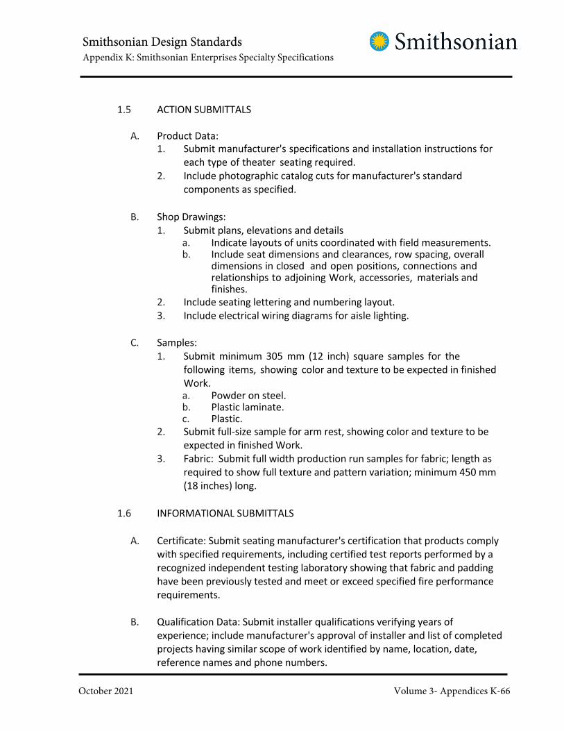
Smithsonian Design StandardsAppendix K: Smithsonian Enterprises Specialty Specifications
October 2021 Volume 3- Appendices K-66
1.5 ACTION SUBMITTALS
A. Product Data:
1. Submit manufacturer's specifications and installation instructions for
each type of theater seating required.
2. Include photographic catalog cuts for manufacturer's standard
components as specified.
B. Shop Drawings:
1. Submit plans, elevations and detailsa. Indicate layouts of units coordinated with field measurements.b. Include seat dimensions and clearances, row spacing, overall
dimensions in closed and open positions, connections andrelationships to adjoining Work, accessories, materials andfinishes.
2. Include seating lettering and numbering layout.
3. Include electrical wiring diagrams for aisle lighting.
C. Samples:
1. Submit minimum 305 mm (12 inch) square samples for the
following items, showing color and texture to be expected in finished
Work.a. Powder on steel.b. Plastic laminate.c. Plastic.
2. Submit full-size sample for arm rest, showing color and texture to be
expected in finished Work.
3. Fabric: Submit full width production run samples for fabric; length as
required to show full texture and pattern variation; minimum 450 mm
(18 inches) long.
1.6 INFORMATIONAL SUBMITTALS
A. Certificate: Submit seating manufacturer's certification that products comply
with specified requirements, including certified test reports performed by a
recognized independent testing laboratory showing that fabric and padding
have been previously tested and meet or exceed specified fire performance
requirements.
B. Qualification Data: Submit installer qualifications verifying years of
experience; include manufacturer's approval of installer and list of completed
projects having similar scope of work identified by name, location, date,
reference names and phone numbers.

Smithsonian Design StandardsAppendix K: Smithsonian Enterprises Specialty Specifications
October 2021 Volume 3- Appendices K-67
C. Location Drawings: Submit Drawings of existing Auditorium seating,
indicating number for each seat to correspond to identification number given
each seat bottom and each seat back, applied on an unexposed surface of
each seat bottom and seat back.
1.7 LEED SUBMITTALS
A. MR Credit: Building Product Disclosure and Optimization – Material
Ingredients.
1. For upholstery fabric and/or seating, if applicable: Material Ingredient
Report.
B. EQ Credit: Low-Emitting Materials.
1. For composite wood: Documentation indicating compliance with
California Air Resources Board (CARB) Airborne Toxic Control
Measures (ATCM) for ultra-low- emitting formaldehyde (ULEF) resins
or no added formaldehyde resins.
2. For furniture evaluations: Documentation indicating compliance with
ANSI.BIFMA M7.1-2011 testing protocols and ANSI/BIFMA e3-2011
Future Sustainability Standard, Sections 7.6.1 and 7.6.2.
1.8 CLOSEOUT SUBMITTALS
A. Maintenance Data:
1. Submit manufacturer's cleaning and maintenance instructions,
including information needed for removal of common stains from
each type of fabric, padding and material.
2. Include list of replacement parts and sources.
3. Include copy of submittal in Project information manual.
B. Warranty: Submit signed and dated warranty.
1.9 SYSTEM REQUIREMENTS
A. Seating Layout:
1. Provide seating layout with seats varied in width to optimize
sightlines, and to maintain minimum aisle width indicated on
Drawings.
B. Fire Performance Requirements:
1. Provide seating which complies with the following, unless
otherwise required by authorities having jurisdiction.a. Finished seating complies with California Technical Bulletin 133.

Smithsonian Design StandardsAppendix K: Smithsonian Enterprises Specialty Specifications
October 2021 Volume 3- Appendices K-68
b. Seat fabric and padding complies with California TechnicalBulletin 117.
C. Electric Wiring:
1. Wiring and electrical interconnections shall comply with governing
codes.
2. Insulated wiring shall have flame retardant and moisture proof outer
covering, and shall be run in conduit, tubing or electrical wireways.
D. Fabric Durability: Fabric must be sturdy enough to withstand 100,000 double
rubs.
E. Visual Requirements: Manufacturer's nameplates, or stamped or printed
markings, shall not be exposed on any item provided for this Work.
F. Interface With Other Systems:
1. Coordinate seating Work with Work of other trades and provide items
to be placed during installation of other Work at proper time so as to
avoid delays in overall Work.
2. Place such items, including inserts and anchors, accurately in relation
to final locations of seating components.
3. Use Contractor's bench marks.
1.10 QUALITY ASSURANCE
A. Single Source Responsibility: Obtain seating from single manufacturer
including accessories, mounting and other installation components.
B. Installer Qualifications:
1. Either seating manufacturer or a licensee of manufacturer, who has
not less than 5 years successful documented experience with
installation of similar seating units.
2. The same firm shall be responsible for removal of seating
components and for reinstallation of seating components.
C. Regulatory Requirements:
1. Conform to applicable requirements of authorities having
jurisdiction over Project, including fire resistance classification
requirements.
2. Except as may be modified by governing authorities, comply
with applicable requirements and provisions of the following:a. ANSI A117.1 "Specifications for Making Buildings and Facilities
Accessible to and Usable by Physically Handicapped People".

Smithsonian Design StandardsAppendix K: Smithsonian Enterprises Specialty Specifications
October 2021 Volume 3- Appendices K-69
b. Americans with Disabilities Act.
1.11 PRE-INSTALLATION CONFERENCE
A. Prior to commencing Work, meet at site and review installation
procedures and coordination with other Work.
1.12 DELIVERY AND STORAGE
A. Deliver seating to building after wetwork, including painting, in areas has
been completed and is dry, work on and above ceilings have been
completed, when areas are ready to receive Work, and only after
temperature and humidity have been stabilized in installation areas at
approximate level which will prevail in building when occupied.
B. Deliver, store and install seating with factory applied protective coverings in
place.
C. Protect seating against damage during handling, transit and storage.
D. Store in dry, clean, well ventilated place, protected from dampness, moisture
and weather.
1.13 SEQUENCING AND SCHEDULING
A. Do not reinstall seating components until:
1. Wet work in Auditorium spaces is complete and dry, and work
above ceilings is complete.
2. Permanent HVAC system is operating and maintaining ambient
temperature and humidity conditions at occupancy levels during the
remainder of the construction period
3. Carpeting installation in Auditorium has been completed.
1.14 WARRANTY
A. Submit written five year warranty signed by Contractor, manufacturer and
installer, agreeing to replace units or unit components which develop
material, workmanship or installation failures.
1.15 EXTRA STOCK
A. Deliver one unopened roll of upholstery for each 100 rolls (or fraction
thereof) installed for each type, pattern and color.

Smithsonian Design StandardsAppendix K: Smithsonian Enterprises Specialty Specifications
October 2021 Volume 3- Appendices K-70
B. Extra stock shall be supplied from same production runs as installed material.
C. Store at Project site where directed. Ensure rolls are identified by
manufacturer, product, pattern and color.
PART 2 - PRODUCTS
2.1 LEED, GENERAL
A. Composite wood: Comply with the California Air Resources Board (CARB)
Airborne Toxic Control Measure (ATCM) for formaldehyde emissions for ultra-low-
emitting formaldehyde (ULEF) resins or containing no added formaldehyde resins.
B. Emissions for Seating: Comply with the testing procedure requirements of
ANSI/BIFMA M7.1- 2011 testing protocols and comply with ANSI/BIFMA e3-2011
Furniture Sustainability Standard, Sections 7.6.1 and 7.6.2 using either the
concentration modeling approach or the emissions factor approach
2.2 PRODUCTS AND MANUFACTURERS
A. Acceptable Products and Manufacturers:1. Listed products establish standard of quality and are manufactured by Irwin
Seating.2. Equivalent products by other manufacturers may be acceptable, provided they
comply with requirements of Contract Documents.
2.3 MATERIALS
A. Steel:1. Plates, shapes and bars: ASTM A36.
2. Steel tubing: Cold formed, ASTM A1008, grade selected by fabricator to suit
Project conditions.
3. Steel sheet and strip: Hot rolled, ASTM A1011.
B. Panel Materials:1. Concealed plywood: Hardwood plywood complying with HPVA HP-1, as standard
with the manufacturer.2. Medium density fiberboard: Comply with ANSI A208.2.3. Mat-formed wood particleboard: 720 kg/cu. m (45 pcf) density, complying with
ANSI A208.1.
C. Plastic Laminate:1. High pressure laminates, complying with NEMA LD3, General Purpose Grade,

Smithsonian Design StandardsAppendix K: Smithsonian Enterprises Specialty Specifications
October 2021 Volume 3- Appendices K-71
minimum nominal 0.762 mm (0.030 inch) thick.2. Adhesive: Clear drying type recommended by laminate manufacturer.3. Colors and products: To match COTR’s sample.
D. Padding:1. Molded polyurethane foam, of density and grade recommended by manufacturer
for seat construction; suitable for specified fabric.
2. Padding shall be resistant to acids, alkalais, oils, graese, soaps, detergents,
moisture, mildew, abrasion and tearing.3. Comply with the following:
a. ASTM D3453, for dynamic fatigue performance Grade AD (heavy dutyuse) for seats and Grade BD (normal duty use) for backs.
E. Fabric: To match COTR’s sample.
1. Fire-retardant treat fabric to comply with specified fire performance
requirements.
2. Treat fabric for stain resistance with manufacturer's recommended treatment.
2.4 SEATING UNITS
A. Description:1. Floor mounted units on standards, with upholstered back and seat cushions in
molded plastic shells, with arm rests.2. Seat widths: As indicated on Drawings.3. Acceptable product and manufacturer:Equivalent to Planetarium Signature
Model 71.12.90.4 by Irwin.
B. Standards:
1. Manufacturer's standard steel tube standards welded to steel bar floor-mounted
bases.
2. Weld seat, back and arm rest connections to standard.
3. Number and letter plates: Manufacturer's standard finish with black letters and
numerals.
4. Finish: Manufacturer's standard powder coat or baked enamel paint finish.
C. Aisle Panel: MDF panel with plastic laminate facing.
D. Arm Rests:
1. One-piece, high-density plastic or self-skinning urethane on manufacturer's
standard metal support, to secure arm rest to standard.
2. Color: To match COTR’s sample.
3. Provide arm rest at aisle side of end seats, and between each seat, for mounting
to standard.
E. Aisle Lights:
1. Manufacturer's standard UL-approved aisle lighting fixtures, installed in ends of

Smithsonian Design StandardsAppendix K: Smithsonian Enterprises Specialty Specifications
October 2021 Volume 3- Appendices K-72
beams at each end of each aisle.
2. Provide each fixture with bulb.
3. Acceptable product and manufacturer: Equivalent to Focal LED Aisle Light by
Irwin.
2.5 ACCESSORIESA. Gaskets and Spacers: Provide as required for installation and as recommended by
manufacturer for each use.
B. Fastenings:
1. Non-corrosive metal which will not cause galvanic action or rusting,
standard commercial items suitable for intended purpose.
2. Provide drilled-in expansion anchors, machine bolts, mechanical fasteners for
adjoining table tops, and other fastenings and fittings of type and size as
selected by manufacturer to suit substrates and installation conditions.
3. Finish exposed fastenings to match adjacent finishes.
C. Provide other materials or accessories as required for complete installation.
2.6 FABRICATIONA. Provide exposed surfaces free from dents, mold or tool marks, warpage, buckle and
open joints, and without pits, holes, cracks, scars and flaws.
B. Accurately fit joints and corners.
1. Provide concealed fastenings unless shown and accepted on Shop Drawings.
2. Smoothly round corners, edges and exposed fasteners to present least possible
snagging and pinching hazards.
C. Provide reinforcing as required to ensure rigid and secure assemblies.
2.7 SHOP FINISHINGFerrous Metal:
1. Surface preparation: Clean surfaces of dirt, grease and other contaminants.
2. Pretreatment: Apply conversion coating compatible with finish.
3. Finish:a. Immediately after cleaning and pretreatment, apply manufacturer's
standard baked enamel finish; minimum 0.053 mm (2.1 mils) dry filmthickness.
b. Color: To match COTR’s sample.c. Provide finish uniform in color, sheen and texture, and free from sags, runs,
skips, scratches and abrasions
PART 3 - EXECUTION
3.1 EXAMINATION

Smithsonian Design StandardsAppendix K: Smithsonian Enterprises Specialty Specifications
October 2021 Volume 3- Appendices K-73
A. Examine substrates and adjoining construction, and conditions under which
Work is to be installed. Do not proceed with Work until unsatisfactory conditions
have been corrected.
3.2 REMOVAL OF EXISTING SEATING COMPONENTS
A. Prior to removal of seating components, apply a unique number to unexposed
surface of each seat bottom and each seat back, corresponding to the number
assigned to each seating unit on Drawings of existing Auditorium seating.
B. Remove seat bottoms and seat backs from seating units. Seat standards shall
remain in place; only seat bottoms and backs are to be removed.
1. Retain removed fasteners and other accessories, for use in
reinstallation of seating components.
2. Wrap removed seat bottoms and seat backs in protective covering as
required to protect components from damage during storage and handling.
C. Store components in conditioned space in building, as specified in Part 1 above.
3.3 INSTALLATION
A. General: Install units as shown and in accordance with final Shop Drawings and
manufacturer's instructions and recommendations.
B. Standards/Floor Bases:1. Install bases in locations conforming to seating layouts.
2. Anchor to floor with not less than 2 anchoring devices, to provide
installation free from rocking or instability under conditions of actual use.3. Leveling:
a. Level assemblies using concealed, adjustable, permanently attached
shims that cannot become dislodged.b. Exposed shims are not acceptable.
4. Coordinate electric wiring for aisle lights with layout of standards.
C. Seats:
1. Secure seats and accessories to standards using manufacturer's
recommended hardware and fasteners.2. Verify that mechanisms operate smoothly and quietly.
D. Take care in handling of seating units to avoid their being scratched or otherwise
defaced during installation.

Smithsonian Design StandardsAppendix K: Smithsonian Enterprises Specialty Specifications
October 2021 Volume 3- Appendices K-74
E. Do not install units which have members that are warped, bowed, deformed
or otherwise damaged. Remove and replace such units as directed.
3.4 REFURBISHING EXISTING SEATS
A. Clean existing seats gently so as not to damage any finishes, in accordance withmanufacturer’srecommendations.
B. Remove existing fabric, and reupholster seats.
3.5 REINSTALLATION
A. Reinstall salvaged and refurbished seat bottoms and seat backs to new standards.
B. Adjust mechanisms to operate smoothly and quietly.
C. Take care in handling of seating components to avoid their being scratched or
otherwise defaced during installation.
D. Repair or replace components which have been damaged or lost.
3.6 ADJUSTING AND CLEANING
A. Adjust self-rising seat mechanisms so that seats in each row are aligned when in
upright position.
B. Remove protective coverings only when construction is complete in seating
areas and when acceptable to COTR.
C. Clean fabric and exposed finishes as recommended by manufacturer, using
care to avoid abrasion of finishes.
D. Repair:
1. Touch-up minor abrasions and imperfections in painted finishes with
coating which matches factory-applied finish.
2. Replace damaged units which cannot be satisfactorily field repaired, as
directed by COTR.
3.7 PROTECTION
A. Protect Work during construction so that it will be without any evidence of
damage or use at time of acceptance.

Smithsonian Design StandardsAppendix K: Smithsonian Enterprises Specialty Specifications
October 2021 Volume 3- Appendices K-75
SECTION 12 61 23
FIXED AUDITORIUM SEATING - IMAX
PART 1 - GENERAL
1.1 RELATED DOCUMENTS
A. Drawings and general provisions of the Contract, including General and
Supplementary Conditions and Division 01 Specification Sections, apply to this
Section.
1.2 UNITS OF MEASURE
A. Contractor to Note: Per SI direction units of measure have been listed in both Metric
and Imperial Units, with the metric unit listed first. The metric units are nominal and
may not be in agreement with dimensioning on drawings. In cases of conflict the
Imperial unit of measure shall
govern. Contractor to note that for purposes of the work Imperial refers to United
States Customary Units.
1.3 DEFINITIONS
A. Technical terms unique to theatre seating and related work shall be construed in
the following order, in accordance with:
1. Captions on related Drawings.
2. Relevant usage and definitions of handbooks, guidebooks, or trade group
recommendations by manufacturers' associations or professional societies.
3. Generally recognized theatrical usage.
1.4 SCOPE
A. All materials, components, and services necessary to provide a complete system
indicated in this Section, as specified herein and shown on related Drawings,
including:
1. Preparation and submission of complete shop drawings and samples for
review prior to fabrication.
2. Verification of dimensions and conditions at the job site.
3. Shipment of equipment to job site and the secured storage of all non-fixed
equipment.
4. Installation and completion, in accordance with these Specifications, related
Drawings, the Equipment Manufacturer's recommendations, established trade

Smithsonian Design StandardsAppendix K: Smithsonian Enterprises Specialty Specifications
October 2021 Volume 3- Appendices K-76
criteria, and all applicable code requirements.
5. The inspection, demonstration, and necessary adjustment of the completed
installation by the Contractor's engineering personnel.
6. Preparation and submission of complete record drawings and operational and
maintenance data and certificates.
7. Seating specified in this Section is long lead. Manufacturer shall
communicate with the General Contractor sufficiently in advance to ensure
no delays in project completion.
B. WORK INCLUDED
1. Furnish and install fixed seating as indicated on the drawings and as specified
herein, in the following location(s):
a. IMAX Theatre Auditorium
2. Furnish Maintenance Materials
3. Coordination of Work
a. Coordinate installation of electrical wiring and transformer quantities and
locations with seating layout. Ensure that junction boxes for aisle lights are
located inboard of aisle light standards as shown in Drawings.
b. Coordinate seating layout as required with under-floor air distribution grille
locations.
The above is for reference only and is not intended to define the limits of the work for
a complete installation.
C. WORK NOT INCLUDED
1. Electrical wiring, conduit, and connections.
2. Concrete or other flooring finishes.
3. Handrails.
The above is for reference only and is not intended to define the limits of the work for
a complete installation.
1.5 QUALIFICATIONS
A. All equipment and installation shall be the responsibility of a single manufacturer
who shall own and operate a full-time, staffed shop for the fabrication and assembly
of fixed theatre seating. This Manufacturer shall assume complete responsibility for
the design, fabrication, transportation, and installation of the work in this Section,
and shall hold the Owner, COTR, and all their Employees and Consultants harmless
for any costs for errors or omissions associated with the work of this Section and any
action arising therefrom.

Smithsonian Design StandardsAppendix K: Smithsonian Enterprises Specialty Specifications
October 2021 Volume 3- Appendices K-77
B. Approved manufacturers may, at their option, arrange for sub-contract field and
special shop work to be done by others. Bid submissions must identify such
subcontractors and indicate the work they are to do.
C. Manufacturer shall engage a manufacturer-approved, locally based, experienced
installer who regularly installs and services auditorium and theatre seating similar in
kind, quality, and extent to that indicated for Project. A competent supervisor shall
be maintained on this Project during the entire installation. A change of supervisor
shall not be acceptable unless by written authorization of the COTR.
D. The Manufacturer and Installer shall have at least 10 years' experience in the
installation of similar equipment and scope for secondary school theatres. If
requested, the Manufacturer shall submit a representative list of comparable
installations during the above period.
E. Subject to the above requirements, work performed under this Section may be
by one of the following listed manufacturers:
1. Irwin Seating, Grand Rapids, Michigan
2. Wenger Corporation, Owatonna, Minnesota
Other manufacturers may be considered with the prior review of the COTR.
Manufacturers seeking review must contact the COTR not later than 14 days prior to
bid date.
1.6 SUBMITTALS
A. General: Submit in accordance with the General Conditions as described in the Project
Manual.
B. Submit Following with bid:
1. Proof that the firm has been continuously engaged in the fabrication and
installation of fixed theatre seating during the past 10 consecutive years.
2. A list of at least three (3) installations by the bidder comparable to this
project in scope including the same installation supervisor.
3. A list of any proposed deviations or exceptions from the Specifications. Any
deviations or exceptions from the Specification proposed after bid shall not be
accepted.
4. A schedule for the anticipated completion of the following:
a. Shop drawings
b. Delivery of all equipment
c. Installation of all systems
5. Samples:

Smithsonian Design StandardsAppendix K: Smithsonian Enterprises Specialty Specifications
October 2021 Volume 3- Appendices K-78
a. Manufacturer's color charts or samples of actual materials showing full
range of standard colors, finishes, patterns, and textures available for each
exposed material.
b. Single fixed seating unit of each type that meets the basic requirements of the
specification.
C. Shop drawings: Within 60 days of receipt of order, the Manufacturer shall submit at
least one set of reproducible shop drawings and equipment data sheets to the COTR
for distribution for review and action prior to fabrication:
1. Plan and section in scale equal to 1/4" = 1'-0".
2. Complete, fully dimensioned shop drawings of all major components.
3. Requisite plans, sections, schematics, and details indicating assembly and
installation of components.
4. Complete counts of every seat feature, including but not limited to:
a. End Standards
b. Aisle Lights
c. Transfer Arms for Designated Aisle Access Seats
d. Row ID
e. Chair ID
f. Cup Holders
5. Quantities of each component and sub-assembly.
6. Indication by boxed caption of any and all variations from the contract Drawings
and Specifications, whether or not these variations have been formally or
informally accepted by the COTR.
7. Product certificates signed by manufacturers certifying that their products
comply with specified fire safety requirements as outlined in this Section.
8. Product certificates signed by manufacturers certifying that their products
comply with specified LEED requirements as outlined in Division One.
1. Finish and fabric samples for COTR selection.
2. Two (2) 76 cm (30-inch) square "quality" sample of seating fabric for approval by
COTR.
3. A sample chair the same as to be supplied in the contract except for finishes and
fabrics.
4. Samples of any equipment component requested.
5. Samples shall not be considered part of specified quantities but shall be returned.

Smithsonian Design StandardsAppendix K: Smithsonian Enterprises Specialty Specifications
October 2021 Volume 3- Appendices K-79
6. Provide acoustical testing data to the COTR. In addition, submit samples of
cushion materials and fabrics used in the tests to the COTR.
D. PROTOTYPES
1. Prior to fabrication of seating, provide for review by Owner and COTR a
prototype as described below:
a. Prototype shall be self-supporting, using support brackets that are proposed
for permanent installation. Prototype base shall be provided to allow seats to
be used for comfort testing.
b. Prototype shall be a two (2) seat unit incorporating the narrowest and widest
seats shown in the layout drawings.
c. Prototype shall incorporate one (1) standard end panel and one (1) ADA transfer
arm.
d. Prototype shall incorporate all finishes as directed by COTR.
2. Deliver prototype to location as directed by COTR.
3. Obtain Owner and COTR written acceptance of prototypes before beginning
production of seating for Project.
4. Prototype shall be retained at the site during construction in undisturbed condition
as a standard for evaluating completed seating.
a. When directed, remove prototype from Project Site.
E. Final submittal. Within 30 days of final tests, and as a condition for final review, the
Contractor shall submit to the COTR:
1. Receipts for delivery of all non-installed items, i.e., all items designated, "Deliver to
Owner."
2. Three (3) sets to the COTR. Format of sets shall be compliant with Division
One of this Specification.
a. "As built and approved" drawings and wiring diagrams showing all
systems and components as installed, including all field
modifications.
b. Operation and service manuals, schematics, and parts lists for each unit of
equipment installed or provided.
c. Certification that all components and assemblies comply with specified
fire safety requirements as outlined in this Section.
d. Certification that all components and assemblies comply with
specified LEED requirements as outlined in Division One.
e. Certificates of warranty, as set forth below.
1.7 DELIVERY, STORAGE, AND HANDLING

Smithsonian Design StandardsAppendix K: Smithsonian Enterprises Specialty Specifications
October 2021 Volume 3- Appendices K-80
A. Comply with requirements of the relevant sections of the General Conditions in the
Project Manual.
B. Deliver seating in manufacturer's unopened cartons clearly labeled with
manufacturer's name and contents.
C. Inspect deliveries upon arrival to verify no items are damaged. Immediately order
replacement of damaged materials at no cost to Owner.
D. Store seating in dry location protected from damage and soiling under
environmental conditions acceptable to manufacturer.
E. Handle seating in a manner to prevent damage.
1.8 TESTING AND INSTRUCTION
A. Upon completion of all installation work, the Manufacturer shall certify in writing to
the COTR that the work is complete and ready for final observation. Final observation
shall be scheduled by the COTR to occur within 14 days following the Contractor's
notice of completion. Costs of additional or repeat tests due to delay or negligence
on the part of the Seating Manufacturer shall be borne by the Seating Manufacturer.
These costs include the COTR at their current hourly rates and the direct expenses
resulting from this delay or negligence.
B. Final observation shall be conducted by a knowledgeable representative of the
Manufacturer, in the presence of the Owner and the COTR and shall include the
following:
1. Operation of all components.
2. Visual examination of all components.
3. Necessary adjustments or modifications shall be made as required.
C. Manufacturer's representative shall instruct Owner's designated staff or
representatives in the safe operation, maintenance and replacement of all
components, including the storage and cleaning of
all fabrics. This instruction session shall be scheduled to last a minimum of two (2)
hours. While it may be possible to schedule this instruction session to coincide with
the system checkout, such coincidence shall not be assumed.
1.9 MAINTENANCE MATERIALS
A. Furnish extra materials described below matching products installed, packaged with
protective covering for storage and identified with labels clearly describing contents.
Provide sufficient material to provide two (2) percent, but not less than one of each
component type and size for each seat back, pan, standard, fastener, aisle light and
cushion.
B. Upholstery fabric in size and quantity required to reupholster two (2) percent
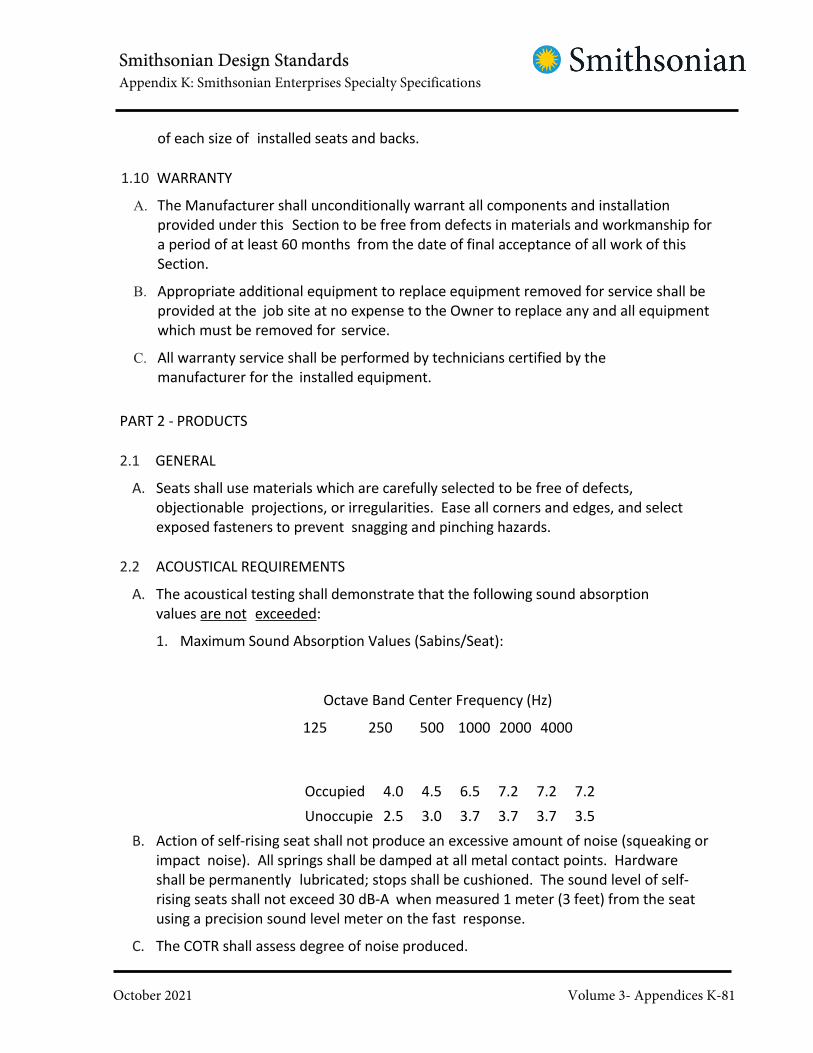
Smithsonian Design StandardsAppendix K: Smithsonian Enterprises Specialty Specifications
October 2021 Volume 3- Appendices K-81
of each size of installed seats and backs.
1.10 WARRANTY
A. The Manufacturer shall unconditionally warrant all components and installation
provided under this Section to be free from defects in materials and workmanship for
a period of at least 60 months from the date of final acceptance of all work of this
Section.
B. Appropriate additional equipment to replace equipment removed for service shall be
provided at the job site at no expense to the Owner to replace any and all equipment
which must be removed for service.
C. All warranty service shall be performed by technicians certified by the
manufacturer for the installed equipment.
PART 2 - PRODUCTS
2.1 GENERAL
A. Seats shall use materials which are carefully selected to be free of defects,
objectionable projections, or irregularities. Ease all corners and edges, and select
exposed fasteners to prevent snagging and pinching hazards.
2.2 ACOUSTICAL REQUIREMENTS
A. The acoustical testing shall demonstrate that the following sound absorption
values are not exceeded:
1. Maximum Sound Absorption Values (Sabins/Seat):
Octave Band Center Frequency (Hz)
125 250 500 1000 2000 4000
Occupied 4.0 4.5 6.5 7.2 7.2 7.2
Unoccupie
d
2.5 3.0 3.7 3.7 3.7 3.5
B. Action of self-rising seat shall not produce an excessive amount of noise (squeaking or
impact noise). All springs shall be damped at all metal contact points. Hardware
shall be permanently lubricated; stops shall be cushioned. The sound level of self-
rising seats shall not exceed 30 dB-A when measured 1 meter (3 feet) from the seat
using a precision sound level meter on the fast response.
C. The COTR shall assess degree of noise produced.
Smithsonian Design StandardsAppendix K: Smithsonian Enterprises Specialty Specifications
October 2021 Volume 3- Appendices K-82
2.3 PERFORMANCE CHARACTERISTICS
A. Chairs provided under this specification shall be compliant with all applicable codes. It
shall be the Manufacturer's responsibility to provide documentation of compliance.
B. Testing and Compliance
1. The seats shall be certified to withstand a 273 kilogram (600 pound) static
load, laterally distributed 7.5 cm (three inches) from the leading edge of the
seat.
2. The seat shall also be certified to pass seat cycle oscillation testing, ASTM
F851-87 and sandbag testing.
C. Fire
1. Such requirements shall include but may not be limited to the following standards:
a. Federal Motor Vehicle Safety Standard No. 302.
b. Class 1 requirements of U.S. Department of Commerce, CS 191-52.
c. California Technical Bulletin CA 133.
2.4 BASIS OF DESIGN
A. "Marquee" by Irwin Seating
2.5 MATERIALS
A. Fabrics:
1. Fabric TBD, provide allowance for $30 per yard.
B. Steel: Provide with smooth surfaces and be of sufficient gauge thickness and designed
to withstand strains of normal use and abuse. ASTM A 36
C. Electrolytic Zinc-Coated Steel Sheet: ASTM A 591, commercial and drawing quality,
Coating Class C, chemically treated for baked-enamel finish and not less than .1 cm
(0.0396 inch) thick.
D. Padding Material: Seat and back padding material shall be of cold molded closed cell
polyurethane foam.
E. Wood
1. Exposed plywood shall be hot press laminated using high frequency process.
Interior plies shall be Class 3 or better. Exposed exterior plies shall be Class 1.
2. Concealed plywood shall be hot press laminated using high frequency process.
All plies shall be Class 3 or better.
3. Exposed solid wood shall be grain matched hardwood, kiln dried, free from knots

Smithsonian Design StandardsAppendix K: Smithsonian Enterprises Specialty Specifications
October 2021 Volume 3- Appendices K-83
and blemishes. Species and appearance shall be consistent within each seat
and from seat to seat.
4. Surface applied wood veneers shall be Class 1.
F. Plastics
1. Plastic Seat backs shall be made of high-density polyethylene. Seat backs shall
be one-piece injection molded shapes. Color: Maroon
2.6 FINISHES
A. Metal Parts: All ferrous metal parts, both exposed and non-exposed, shall be
electrostatic powder coated. All coatings shall be consistent in appearance. All
metal coatings shall have a dry film thickness of at least two millimeters and shall
pass the 2H pencil hardness test.
B. Wood Parts: All exposed surfaces shall be stained to color selected and finished with a
clear plastic sealant of sufficient film depth to afford wear resistance of institutional
quality.
C. Hardware: All assembly hardware shall be rust resistant, black plated.
2.7 STANDARDS
A. The standards shall be manufacturer's standard riser-mount design made from steel or
cast iron.
B. A reinforced bracket for seat pan attachment shall be integrated into the standard.
C. The seat pan shall be anchored to the standard by bolts.
D. A support for attachment of the back shall be provided.
E. The top of the column shall provide for armrest attachment.
F. The standard shall be designed to fasten to the mounting plate.
G. Standards in row 'M' shall be manufacturer standard floor-mount type but shall
otherwise meet the requirements of the specification.
H. Standards shall be manufactured to conform to floor and riser conditions as shown in
Drawings while maintaining seat and back dimensional and angular relationships
throughout.
2.8 MOUNTING PLATE
A. Mounting Pate shall be fabricated from steel of minimum thickness required to
meet strength requirements for seat mounting.
B. Mounting Plate shall be designed to fasten to existing riser-mount seat anchors and
provide a secure surface for mounting the new seats.

Smithsonian Design StandardsAppendix K: Smithsonian Enterprises Specialty Specifications
October 2021 Volume 3- Appendices K-84
C. Mounting Plate shall be designed to allow the new riser-mount-standards to
fasten to the plate securely to maintain strength requirements.
D. Mounting Plate shall be finished to match the surrounding concrete surface,
subject to COTR approval.
2.9 END PANELS
A. Provide end panels, as selected by COTR from Manufacturer's catalog, securely
attached to aisle standards with concealed fasteners.
B. Exposed face shall be wood veneer, stain color as selected by COTR.
C. Edges shall be finished with hardwood matching veneer edge banding.
2.10 SEAT ASSEMBLIES
A. Two-part seat assembly of arch-spring construction indicated below with upper part
removable for reupholstering without removing pan from chair.
B. Cushion shall be molded polyurethane foam padding tapered from 7.5 cm (3 inches)
thick at the leading edge to 4 cm (1-1/2 inches) thick at the rear, over not less than
five serpentine springs attached to reinforced steel frame; with weight-distributing
and abrasion resisting sheeting separating padding from springs; upholstered with
fabric sewn into box construction without welts and securely attached to frame to
produce surfaces free of creases, stretch lines, or wrinkles. Fabric shall be removable
without damaging any component.
C. Seat pan shall be a single piece, sheet steel pan or molded polypropylene. Pan shall
be reinforced at stress points and shall completely enclose the hinges and self-rising
seat mechanisms.
D. The seat shall rotate on two (2) hinge rods. Hinge rods shall be securely engaged in
seat standard pivots. Bearing surfaces shall be low friction and permanently
lubricated, requiring no maintenance. Seat-lift shall be accomplished by
compression springs and self-lubricating plastic cams. All hinge operation elements
shall be shielded and inaccessible to the seated patron. Seat shall automatically
return to a 3/4 fold position. It shall be possible to rotate the seat to full-fold
position with slight additional rearward pressure.
2.11 SEAT BACK ASSEMBLIES
A. Backs shall be of plywood construction with an upholstered front, and shall consist of
two (2) parts; an upholstered panel and an exposed plastic rear panel.
B. Cushion shall be high density closed cell cold cured sculpted non-skinning molded
foam: density 56 kg/cubic meter (3.5 pounds/cubic foot), padding measuring not
more than 5cm (2 inches) thick.

Smithsonian Design StandardsAppendix K: Smithsonian Enterprises Specialty Specifications
October 2021 Volume 3- Appendices K-85
C. Plywood base shall be a minimum of 1.7cm (5/8-inch thick). The cushion shall
be securely cemented to plywood base with no voids occurring between the
base and the foam.
D. The exposed back panel shall be plastic, formed on the same radius as the
upholstered panels. The exposed back panel shall not be less than 66 cm (26 inches)
long and shall protect seat in raised position. Color shall be selected by COTR from
manufacturer's standard colors.
E. Exposed back panel shall be securely connected to the upholstery panel.
F. Backs shall be designed and installed so as to achieve an even and consistent gap
between seat back panels within each row except at aisle locations.
G. Seat Back Assembly shall utilize steel back wings for connection to standards.
Wings shall have provision for 12 degree, 16 degree and 20 degree pitch.
2.12 ARMRESTS
A. Armrests shall be provided at each aisle and between seats.
B. Armrests shall be designed for concealed mounting to standards with all edges well
rounded.
C. Armrests shall be removable for repair or replacement.
D. Armrests shall be at least 6 cm (2-3/8 inches) in width.
E. Armrests shall be solid plastic subject to the requirements noted above.
F. Each interior armrest shall contain a cup holder.
2.13 ACCESSORIES
A. Moveable Bases:
1. Manufacturer's standard steel bases to provide for mobility of seats in multiple
quantities as shown on Drawings.
2. All components of the bases shall have rounded edges. Ends of components
shall be ground smooth and finished to match.
3. No part of the base assembly shall extend beyond the footprint of the seat when
the pan is in the lowered position.
B. Designated Aisle Access Standards: Manufacturer's ADA compliant tilt-up arm aisle
standard in locations as shown on the Drawings. Standard shall include aisle light
where indicated.
C. Seat and Row Identification System:
1. System shall utilize satin finish brass plates with etched characters.

Smithsonian Design StandardsAppendix K: Smithsonian Enterprises Specialty Specifications
October 2021 Volume 3- Appendices K-86
2. Seat identification plates:
a. Mount into vandal-resistant recess at front edge of seat pan, clearly
viewable from above when seat pan is in folded position and secure with
two rivets.
b. Rectangular with black characters not less than 1 cm (3/8-inch) in height.
c. Attachment hardware finish shall match plate faces.
3. Row identification plate
a. Mount at center of end panel in routed recess for flush, non-snagging, finish.
Locate plate to ensure that the aisle lighting system illuminates the plate.
b. Round, 5 cm (2 inch) diameter, with black letters. Letters shall be at least 2.5
cm (1 inch) in height.
c. Attachment hardware finish shall match plate faces.
2.14 SPARE PARTS
A. Provide a quantity of seat and back component parts equal to two percent but not less
than one each of each component in each size of the total amount installed. All spare
components are to be labeled for size, venue and component type.
B. Provide all fixed and removable seating units noted including removable seating
units designed to fill all wheelchair locations.
C. Provide 20 yards of upholstery fabric from the same dye lot as the installed seats.
Extra fabric shall be wrapped, labeled and turned over to owner at completion.
PART 3 - EXECUTION
3.1 PROJECT CONDITIONS
A. Environmental Requirements: Do not install seating until space is enclosed and
weatherproof, wet- work in space is complete and nominally dry, installation of
finishes including painting is complete, other units of Work adjacent or overhead are
complete, and ambient temperature and humidity conditions will be continuously
maintained at values near those indicated for final occupancy.
3.2 EXAMINATION
A. Examine conditions and proceed with work when substrates are ready.
B. Examine substrates and conditions, with installer present, for compliance with
requirements for construction tolerances, material properties as they affect
anchors and fasteners, and location of junction boxes. Do not proceed with
installation until unsatisfactory conditions have been corrected.

Smithsonian Design StandardsAppendix K: Smithsonian Enterprises Specialty Specifications
October 2021 Volume 3- Appendices K-87
3.3 INSTALLATION
Manufacturer shall engage a manufacturer-approved, locally based, experienced
installer who regularly installs and services auditorium and theatre seating similar in
kind, quality, and extent to that indicated for Project. A competent supervisor shall
be maintained on this Project during the entire installation. A change of supervisor
shall not be acceptable unless by written authorization of the COTR.
A. Seating Layout: Install seating to conform with Project Documentation in a manner
that produces seating layouts with standards spaced laterally in each row so that end
standards are in alignment from first to last row, regardless of whether aisles
converge or are of constant width, and with backs and seats varied in width so that
sightlines are optimized.
B. General: Comply with Manufacturer's printed installation instructions applicable to
products and application indicated.
C. Locate all seats in locations indicated on approved shop drawings, with designed
and required clearances, elevations, sight lines, aisles and aisle accessways.
D. Install standards in locations conforming to seating layout, with each standard
attached to substrate by not less than two (2) anchoring devices of size and type
required to produce chairs free from rock or instability under conditions of actual
use.
E. Install chairs by mounting components to standards, or brackets mounted on
standards, using manufacturer's recommended hardware and fasteners. Ensure
that chairs in curved rows are installed at the specified radius, and verify that
moving components operate smoothly and quietly.
F. Installation review for compliance will include, but shall not be limited to the following:
1. All end standards shall be plumb and shall be installed at a constant dimension
from the aisle edge +.5 cm (1/4-inch) variation allowed within a seating section
with no more than .25 cm (1/8-inch) variation allowed between adjacent rows.
2. All seat backs shall be aligned with a consistent back pitch angle. Allowable
variation of not more than 0.25 degrees between adjacent seats and not more
than 0.75 degrees across the length of a row.
3. Gaps between seat backs shall be constant with no more than 3.75 cm (1-1/2-
inch) variation between adjacent seats and no more than 1 cm (1/2-inch)
variation between the largest gap and smallest gap within a seating section.
4. Seat stagger shall be as shown in the drawings. Deviation will not be accepted
without prior approval of the COTR and .
5. Seat pans shall all automatically rise to a consistent position without noise as
outlined in Paragraph 2.2 of this Specification. Position variation of no more
than .25 cm (1/8-inch) between adjacent seats and not more than .5 cm

Smithsonian Design StandardsAppendix K: Smithsonian Enterprises Specialty Specifications
October 2021 Volume 3- Appendices K-88
(1/4-inch) within a row shall be allowed. Dimension shall be measured from
the most projective portion of the seat pan to the front edge of the armrest.
6. Coordination with in-floor electrical and mechanical devices shall be as shown
in Drawings. Deviation shall require prior approval from the COTR. Unless
noted otherwise, all in-floor air grilles shall be centered between seat
standards and shall not project past the edge of the seat pan in its stored
position.
7. Seat and Row Identification plates shall be securely attached and free from
scratches and blemishes. Design, location, font, and alignment shall be
consistent throughout the project.
8. Unless otherwise notified in writing by the General Contractor,
responsibility for the condition of the seat fabric and all other seat finishes
shall be the responsibility of the seating manufacturer until substantial
completion or review of the seating installation, whichever is later. Fabric
and all other finishes shall be smooth, clean and unblemished.
9. All surfaces and edges shall be smooth to the touch and free of protrusions
that will cause injury or damage to clothing.
10. Packaging and protective coverings shall be removed from the site and
disposed of in accordance with jobsite protocol and mandated
requirements.
3.4 ADJUSTING
A. Adjust self-rising seat mechanisms as required to ensure that seats in each row are
aligned when in upright position.
B. Touch-up minor abrasions and imperfections in painted finishes with coating
which matches factory-applied finish.
C. Replace upholstery which has been damaged in installation.
END OF SECTION

Smithsonian Design StandardsAppendix L: OCIO Appendices
October 2021 Volume 3- Appendices L-1
APPENDIX L
OCIO Appendices
● Appendix L1 – Cable Specifications
● Appendix L2 – Wire Closet Specifications

Smithsonian Design StandardsAppendix L: OCIO Appendices
October 2021 Volume 3- Appendices L-2
APPENDIX L1

Smithsonian Design StandardsAppendix L: OCIO Appendices
October 2021 Volume 3- Appendices L-3
Mode
Applicable Specification for Fiber Cable
Connectors & Conduit
New Construction Renovation
Multimode ANSl/EIA!TIA-568-B standard
· for testing, length,plenum
rating,bend radius
50/125 micron OM3
ANSl/EIA!TIA-568-B
standard for testing,
length, plenum rating,
bend radius
50/125 micron
OM3
Multimode
fiber
• Unless otherwise specified it isrecommended that SC type
connectors be used for
terminations and fiber
distribution boxes and panels.
Connectors should be unicam or
polish type connectors.
• All new fiber installationbetween distribution andaccess switches
should be 50/125 micron OM3
• All termination and crossconnect panels will be EIAapproved.
• All panels will besecured and lockable.
• All fiber cable will be armoredjacketed or installed in metalconduit,
and all elbows and boxes will
meet the ANSl/TIA569
standards for bend radius for
the particular cable that is
being installed.
• All non-plenum rated cable willbe placed in conduit, orinstalled to local
code and OFEO
design
specifications.
Single
mode
ANSIJEIA!TIA 568-8
standard for testing,
length, plenum rating,
bend radius
8.3/125 micron OS1/0S2
ANSl/EIA!TIA 568-B
standard for testing,
length, plenum rating,
bend radius
8.3/125 micron
OS1/0S2 Singlemode
fiber

Smithsonian Design StandardsAppendix L: OCIO Appendices
October 2021 Volume 3- Appendices L-4
* Determined on a case by case basis
Cable Type
Specification
Connectors & ConduitNew Construction Renovation
New multi
purpose
antenna
systems for
wireless
Cable
specifications arn
determined by
the design.
Cable
specifications are
determined by
the design.
Cable specifications are
determined by the design.
Armored cable
(outdoor or
hazardous
installations)
Shielded CAT6 or
6A*
Shielded CAT6 or 6A* Shielded CAT6 or 6A*
Wireless Access
Points - ISO/IEC
TR 24704
Information
Technology
Customer
Premises
Cabling
Standard CAT 6 or
6A*
Standard CAT 6 or 6A* Standard CAT6 or 6A*

Smithsonian Design StandardsAppendix L: OCIO Appendices
October 2021 Volume 3- Appendices L-5
APPENDIX L2: WIRE CLOSET SPECIFICATIONS
Closet Requirements
Physical • Minimum floor space of 1O feet by 8 feet.
• Room/closet shall be secured with either a badge readeraccess (preferred) or key access.
• The door to the room/closet should swing out to maximizeusable space.
• Walls shall be slab to slab with a 1 Hour fire rating or a 2Hour fire rating if considered "Mission Critical."
• Floors shall be anti-static or static dissipative tile.
• No drop ceiling shall be installed. Minimum clear heightwithout obstructions shall be 2.4m (8ft).
• Sprinkler mains, plumbing pipes, and hvac ducts not servicingthe Telecom Rooms shall not transit the Telecom
Rooms.
Backer Board • Must have wall mounted fire-rated plywood backer board.
• Two walls should have 21mm (0.75 in.) A-C plywood 2.4m (8ft.) high. Plywood shall be mounted 6" AFF and painted
with 2 coats of fire retardant paint. Leave plywood fire
stamps unpainted.
Environmental • IT spaces must have environmental controls with no HVAC units
in or above these spaces.
• Telecom Room and Equipment Room shall follow ASHRAEThermal Guidelines for Data Processing Environments .
• Provide 20,000 BTU/hr cooling per rack.
• Positive ventilation and air conditioning is required toremove the heat load generated by the equipment.
• HVAC requirements to maintain temperature the same asadjacent office area.A positive pressure shall be maintained
with a minimum of one air change per hour or per code.
• Overhead HVAC units are not to be used in the IT closets. Thepreferred method is that these spaces have their own
thermostat and be served by external HVAC units.
• Lighting shall be a minimum of 500 Ix (50 foot candles) andmounted 2.6m (8.5 ft.) above floor.
• Standard work place lighting is required.

Smithsonian Design StandardsAppendix L: OCIO Appendices
October 2021 Volume 3- Appendices L-6
Closet Requirements
• One or more code-approved ground busbar(s) in eachTelecom Room is required
Electrical • Dedicated grounded electrical feeds.
• Minimum of two dedicated 20 Amp, non-switched, duplexelectrical outlet receptacles (5-20P); two dedicated 20 Amp,
non-switched electrical outlets (L6-20); and one dedicated 30
Amp, non-switched, electrical outlet (L6-30); each on separate
branch circuits.
• Additional convenience duplex outlets placed at 1.8m (6 ft.)intervals around perimeter,150mm (6 in.) above floor.
• The manufacturer's installation site requirements guide foreach device should be used to determine the NEMA outlet
specification,and the voltage and current requirements.
• When equipment has redundant power supplies, the
electrical outlets/supplies for each power supply in the
device should be on a separate dedicated electrical line.
• Unless otherwise specified, electrical receptacles should not beinstalled on or above the IT racks. ·
• The receptacles for IT equipment should be tied toemergency backup power systems.
Uninterruptible • The UPS should be sized to support each piece of Power
Supply equipment located in the wire closet at full load for 30(UPS) minutes.
• One UPS is used per electrical supply line.
• When equipment has redundant power supplies,one powersupply is connected directly to a dedicated electrical outlet
and the other is connected to a UPS on a different dedicated
electrical outlet.
• All equipment properly grounded according to code.
Enclosures (e.g., • The upper part of any wall mounted equipment, racks, or box,
cabinet) cabinets shall not exceed 6' in height from the floor so that
they can be safely managed without the use of ladders or
other means necessary for elevated access.
• All enclosures for cable terminations will comply with theapplicable EIA standard for the type of cable being installed.

Smithsonian Design StandardsAppendix L: OCIO Appendices
October 2021 Volume 3- Appendices L-7
Closet Requirements
• All enclosures for communication equipment will meet EIAstandards, as well as the device site requirements specified
by the equipment manufacturer .
• Enclosures will be attached to a ground bus bar in thecloset.
• If deemed necessary by OCIO, all communication fiber opticpatch panels will be lockable and use the recommended Master
Lock product# 15200 combination lock.The
combination of the lock will be managed, changed, and
maintained by OCIO.
• 7 ft, 2-post open frame 19inch racks are the standard formounting patch panels, fiber enclosures, and equipment.
• In the MDF, provide 4-Post open frame racks for themounting of equipment.
• Rack elevations should follow the guidelines below:
0 Fiber enclosures should be situated at the top of the
rack (2U to 4U depending on fiber quantities).
0 2U RJ45 48-port patch panels should be installed
below the fiber enclosure(s),beginning from the
upper part of the rack and working down.
0 A single 1U RJ45 24-port patch panel should be
installed immediately above the first 2U RJ45 panel
for the termination of a 25 pair cable for analog
lines.
0 2U horizontal cable managers should be installed
below the fiber enclosure, between each RJ45
panel, and one below the last panel.
0 Each side rail should be equipped with vertical
cable managers (6" wide mini"1um).Adjacent
racks can share a single vertical wire manager.
• See Appendix C, Standard Rack Guideline Diagram, for moreinformation.

Smithsonian Design StandardsAppendix L: OCIO Appendices
October 2021 Volume 3- Appendices L-8
Closet Requirements
Labelling of
copper ports &
fiber links
• All copper pairs will be labeled with the wireclosetroom#-room#-[a-z].
• All fiber links will be labeled with wireclosetroom#-[01-99 )-wireclosetroom#-[01-99]

Smithsonian Design StandardsAppendix L: OCIO Appendices
October 2021 Volume 3- Appendices L-9
Fiber Termination Box
-----(-2R-U--or-4-R-U-)----
1U 24 Port RJ45 Patch Panel
48 Port CAT6 Patch Panel
2U Cable Management
48 Port CAT6 Patch Panel
2UCable Man.gement
I... "' 30"
Figure 2·Wire Closet Rack Configuration
"' Units
45
44
43
42
41
40
39
38
37
36
35
34
33 6" 6"32
31 c c30 a 48 Port CAT6 Patch Panel a29 b b
28 I 2U Cable Management I27
e e
2648 Port CAT6 Patch Panel
25
242U Cable Management
23M Ma 48 Port CAT6 Patch Panel a
22n n
"' 7' 21 a 2UCable Management a
20 g g19 e e18 m m17 e e15 n ii
15 t t14
13
12
OCIO11
Network Equipment10
9
8
7
6
5
4
3
2
1

Smithsonian Design StandardsAppendix M: CPTED Narratives
October 2021 Volume 3- Appendices M-1
APPENDIX M
CPTED Narratives
NOTE: This appendix contains excerpts from OPS’s Security Design Criteria document
relating to Crime Prevention Through Environmental Design (CPTED) concepts. The
security planning concepts described herein should be considered early in the design
process.

Smithsonian Design StandardsAppendix M: CPTED Narratives
October 2021 Volume 3- Appendices M-2
2. CRIME PREVENTION THROUGH ENVIRONMENTAL DESIGN (CPTED)
The Smithsonian Institution advocates the integration of Crime Prevention Through
Environmental Design (CPTED) principals and strategies in their site planning and
facility designs. CPTED principals and techniques seek to create a physical and
operational environment which discourages criminal or other wrongdoer activity by
incorporating territorial cues, natural access controls, and natural surveillance.
2.1. CRIME PREVENTION MODEL
The model for crime prevention through environmental design is based
on the theory that action must be taken to counter crime or wrongdoer
activity before it occurs. The critical element in this model is the
environmental-engineering component. It provides both direct and indirect
controls against criminal activity by reducing the opportunity for crime
through science and technology and the use of various urban planning and
design techniques. The model explains what environmental engineering is
and how it supports crime or wrongdoer prevention. With this information,
the design team may be in a better position to understand and respond to
questions and discussions on how site and facility planning can have an
impact on criminal or other wrongdoer elements.
2.2. THE ENVIRONMENTAL INFLUENCE ON CRIMINAL BEHAVIOR
The basic theory that supports crime prevention through environmental
design is that urban environments can influence criminal behavior in two
ways. First, the physical surroundings in which people live have an effect
on each individual. These physical characteristics include noise, pollution,
overcrowding, and the existence and unmonitored spreading of refuse and
other unsightly waste. The second element which must be dealt with in
the environmental-engineering formula concerns the social characteristics of
the site that provide individuals with social relationships to which they
must respond. Characteristics such as alienation, loneliness, anxiety, and
dehumanization are seen as keys to criminal behavior.
In terms of these environmental characteristics, buildings are all too often
constructed to be dangerous, with corridors and passageways hidden from
public view. Elevators, basements, storage, coat rooms and janitor closets
are also laden with danger due to their design.
With regard to altering the social characteristics of the area (museum,
offices, or multi-tenant facilities) and the relationship to wrongdoer
behavior, it should be recognized that behavior is future-oriented, not

Smithsonian Design StandardsAppendix M: CPTED Narratives
October 2021 Volume 3- Appendices M-3
past-oriented. A person steals so that they can have a car or money in
the future, not because in the past he experienced psychic trauma, a
broken home, poverty, or delinquent associates. Criminal behavior can
be explained directly in terms of the consequences of behavior and in
terms of non-criminal variables such as poverty, race, or social class.
Criminal behavior is viewed as a problem to be dealt with and not a
symptom of other problems (such as poverty, mental conflict, class conflict,
unemployment, or under education). To change criminal behavior, it
must be dealt with directly by removing the environmental reinforcement
which maintains the behavior. The approach advocated is to change the
environment to which the individual responds.
2.3. TERRITORIALITY
Historically, a building on its own piece of land and somewhat isolated
from its neighboring buildings (but often by as little as a few feet) has been
considered to be the building’s territory. The building sits on a piece of
land buffered from neighbors and the public street by intervening grounds.
At times, symbolic shrubs or fences reinforce a boundary. The positioning
of lights to look out on the grounds and good natural surveillance act to
reinforce the territorial claim.
A number of concepts have been identified which may be used in new
construction or renovation projects. These mechanisms encourage the
building staff and other tenants to identify more with the ground or
area around their immediate site and to assume responsibility for its
protection.
2.4. NATURAL SURVEILLANCE
Experience has shown the ability to observe criminal or other wrongdoer
activity may not be adequate to stimulate an observer to respond with
assistance to the person or property being victimized. The decision to act
depends on the presence of motivational conditions, including:
The degree to which the observer has developed a sense of
personal and property (ownership like) rights which may or will be
violated by the criminal act.
The degree to which the observer feels the event is within their area of
influence.
The observer’s ability to clearly identify whether the act is unusual for the
particular area.

Smithsonian Design StandardsAppendix M: CPTED Narratives
October 2021 Volume 3- Appendices M-4
The observer’s identification with either the victim or the property being
vandalized.
The degree to which the observer believes he/she can effectively alter the
course of events they are observing.
2.5. DEFENSIBLE SPACE
Defensible space is a term for a range of combined security measures which
brings an environment more under the control of its owners, operators, staff
and/or residents. A defensible space is a building environment which can be
used by inhabitants for the enhancement of their lives while providing
security for themselves, coworkers, and visitors. The physical concepts
suggested to create safety and improve upkeep (as part of the defensible-
space concept) are self-help tools wherein design catalyzes the natural
impulses of staff rather than forcing them to surrender their shared social
responsibilities to any formal authority.
2.6. ACTION PLANNING FOR CRIME PREVENTION THROUGH PHYSICAL PLANNING
Many organization’s security and police activities have become involved in
the physical-planning process and have achieved notable results from their
work. This involvement includes evaluating the accessibility of buildings and
locations of security patrols and posts; pedestrian and vehicle traffic flow;
and off-street parking provisions; and the layout and adjacencies of access
roads, garden areas, utility areas (e.g., generators, transformers,
communications hubs, boilers and chillers), childcare facilities, playgrounds,
common greens, fences, and entrances. There are a number of concerns to
SI’s Office of Protection Services that should be carefully examined from a
security perspective. Some examples of specific concerns:
Building setbacks (front, side, and rear). Includes reduction or elimination
of crevasses around building, interior spaces, and landscaping.
Wall construction, interior and exterior (industrial,
commercial, and residential).
Door construction, building setback and security (industrial, commercial,
and residential) including carports, garages, and sliding-glass doors.
Windows and skylights, building setback, window height (from
ground), show-window displays, and the type of frame or pane.
Stairs (stairwells and staircases).
Utility boxes.

Smithsonian Design StandardsAppendix M: CPTED Narratives
October 2021 Volume 3- Appendices M-5
Fences, walls, hedges, screens, building setback, building height, and
louvers.
Parking (public and private).
Lighting (industrial, commercial, and residential) for walkways, entrances,
and streets.
Streets, sidewalks, and walkways (locations, slopes, curvature, grades, and
the length of a block). When practical eliminate crevasses or hiding areas
by smoothing curves and slopes away from walkways.
Alleys and access ways (well lighted and clear of obstacles).
Visibility of valuables (people, safes, vehicles, cash registers, and personal
property).
Signs (street signs and signals, no trespassing signs, traffic signs and
signals, and advertising signs).
Accessibility; approach, entrance, and exit (pedestrian, vehicular,
services, residential, commercial, and industrial).
Public utilities and easements (gas, water, telephone, and electrical).
Public areas and facilities (public restrooms, parks, bus stops and shelters,
playgrounds, recreation halls, and so forth).
Trees and shrubbery along the boulevard (types, heights, and locations).
2.7. DESIGN TEAM GUIDANCE
The Smithsonian Institution encourages design teams to explore these
CPTED concepts and principles in their projects. To encourage a multi-
disciplinary approach to CPTED, ‘discipline specific strategies’ are
introduced in the following chapters to assist designers in addressing
security concerns. These strategies help prepare the design team in
understanding CPTED and support its benefits in SI facility designs.
3. SITE LAYOUT
This section discusses site-level considerations for development. The intent of this
guidance is to provide concepts for integrating land use planning, landscape
architecture (vegetation, landforms, and water), site planning, and other
strategies to mitigate the design basis threats as identified by OPS via the risk
assessment. Integrating security requirements into a larger, more comprehensive
Smithsonian Design StandardsAppendix M: CPTED Narratives
October 2021 Volume 3- Appendices M-6
approach necessitates achieving a balance among many objectives such as
reducing risk; facilitating proper building function; aesthetics and matching
architecture; hardening of physical structures beyond required building codes and
standards; and maximizing the use of non-structural systems.
The design team must work closely with building owners and operators to
ensure the optimal balance of all the above considerations is achieved; thus,
coordination within the design team is critical. Many asset protection objectives can
be achieved during the early stages of the design process when mitigation is the
least costly and most easily implemented. Planners, architects, and landscape
designers play an important role in identifying and implementing crucial asset
protection measures while considering land use; site selection; the orientation of
buildings on the site; and the integration of vehicle access control points, physical
barriers, landscaping, parking, and the protection of utilities to mitigate threats.
This chapter is broken into three (3) basic sections which are Best Practices,
General Criteria, and Space Specific Criteria. Best Practices are encouraged design
considerations, but some or all considerations may be impractical for the project.
General Criteria and Space Specific Criteria are SI requirements which must be met
in the project design.
3.1. PRINCIPAL BEST PRACTICES
The design team is encouraged to utilize the following best practices when
determining the appropriate and cost-effective measures for incorporation
into the building and site design.
Site Design
Because the economics of development dictate recovering the
largest possible portion of square footage within most urban and
rural sites, security concerns should be evaluated carefully. Conflicts
sometimes arise between security site design and conventional site
design. To maximize safety, security, and sustainability; designers
should implement a holistic approach to site design which
integrates form and function to achieve a balance among the
various design elements and objectives. Even if resources are
limited, significant value can be added to a project by integrating
security considerations into the more traditional design tasks in such
a way that they complement, rather than compete with, the
other elements.
The overall layout of a site (e.g. the placement and form of its buildings,
Smithsonian Design StandardsAppendix M: CPTED Narratives
October 2021 Volume 3- Appendices M-7
infrastructures, and amenities) is the starting point for this integration.
Choices made during this stage of the design process will steer decision-
making for the other elements of the site. A number of aspects of site
layout and building type present security considerations and are discussed
below.
a. Building Placement
The ideal building placement from a security standpoint
incorporates the three basic CPTED principles of Territorial
Reinforcement, Natural Surveillance and Defensible Space. Some
general guidelines for incorporating each element are discussed
below.
i. Territorial Reinforcement
a) Site Design
If the grounds around a set of buildings can be directly
identified with a particular building where building
occupants play a role in protecting it, then strangers are
usually recognized and their activities come under
observation and immediate questioning. Even in public
areas like museums, strangers with wrongdoer intent are
noticed, questioned, and placed under surveillance (either
by staff or by security personnel).
The placement of the building should provide territorial
reinforcement of the ownership by creating a distinction
between the public domain and that of the building. This
can be accomplished through the use of clear space to
separate the two entities. Additional strategies for site design
may be found in the U.S. General Services Administration,
Public Buildings Service, The Site Security Design Guide.
b) Street Design
Research has shown that the placement, enclosure, or
routing of roadways and traffic can change the nature of a
particular area and reduce wrongdoer activity. For example,
a particular portion of a street might be closed to
vehicular traffic, and streetscape equipment (seats, lighting,
planters, etc.) may be added. This same approached is
observed in the National Capital Planning Commission
(NCPC), The National Capital Urban Design & Security Plan.

Smithsonian Design StandardsAppendix M: CPTED Narratives
October 2021 Volume 3- Appendices M-8
In a number of areas where this technique has been utilized,
it has been found that most people know or at least
recognize other people up and down the block and suspicious
activity on the street is identified. Similar approaches which
involve rerouting traffic, using one-way streets, or blocking
off streets has reduced wrongdoer activity.
c) Symbolic Barriers
The types of barriers that planners may use when laying out
an area include open gateways, light standards, low walls,
and plantings. Both physical and symbolic barriers serve the
same purpose—to inform an individual that he/she is passing
from a public to private space. Symbolic barriers identified by
people as boundary lines serve as defining areas of
comparative safety. Many places warrant the use of
symbolic barriers, including transition points between a
public street and the semi-public grounds of a building; an
area between a building’s lobby and its corridors; or hallways
on particular floors of a building.
ii. Natural Surveillance
That same clear space aides the natural surveillance, increasing
the risk to individuals desiring surreptitious entry to the facility.
The building should be oriented in order to eliminate or at least
minimize areas which cannot be seen by a casual observer.
iii. Defensible Space
The clear zone also provides defensible space by providing the
opportunity to have several layers of security before entering
the building. For instance, defining the site through territorial
reinforcement is one layer, the natural surveillance is a
second layer, and the building façade is yet another layer. The
clear space also provides standoff distance which will be discussed
further.
Research has revealed investigative techniques that may be used
to modify existing building areas to make them more secure.
The following methods may require alteration or adaptation to
the particular situation on your design project:
Widening major pathways and using colored decorative paving.

Smithsonian Design StandardsAppendix M: CPTED Narratives
October 2021 Volume 3- Appendices M-9
Differentiating small private areas (gardens, lawns) outside
each building from the public path with low, symbolic walls.
Adding public-seating areas in the center of public paths.
Seating would need to be far enough from buildings to
eliminate conflicts of use but close enough to be easily
seen from building windows or security personnel.
Designing play areas as an integral part of open space.
Adding new and decorative lighting to highlight various paths
and recreation areas at night and extending the occupants’
surveillance potential and feeling of security.
Adding seats and path networks to recreational facilities
where large, central court areas exist. This increases the
interest and usability of the areas.
Redesigning parking and play areas around buildings to
create the illusion the buildings are grouped where natural
surveillance opportunities exist.
b. Building Orientation
The orientation of a building can have a significant impact on its
performance, not only in terms of energy efficiency, but also in
the ability to protect occupants. For this document, the term
“orientation” refers only to the building’s spatial relationship to the
site. A structure’s orientation relative to its surroundings defines
its relationship to that area. The physical positioning of a building
relative to its surroundings may seem subtle, but can be a
greater determinant of this intangible quality than exterior aesthetics.
For example, the proximity of a vulnerable façade to a parking
area, street, adjacent site, or other area which is accessible to
vehicles and/or difficult to observe can greatly contribute to its
vulnerability. A strong, blank wall with no glazing will help to
protect the people, property, and operations within from a blast,
but the lack of windows limits the opportunities for natural
surveillance of activities outside. Designers should consider such
trade-offs early in the design process, in an effort to determine an
acceptable level of risk.
Standoff Distance
Standoff distance is the distance between an asset and a threat.

Smithsonian Design StandardsAppendix M: CPTED Narratives
October 2021 Volume 3- Appendices M-10
Blast energy decreases as the inverse of the cube of the distance from
the position of the explosion, therefore every additional increment of
distance provides increasingly more protection. There is no ideal standoff
distance; it is determined by the type of threat, the type of
construction, and the desired level of protection.
The primary design strategy is to keep threats away from inhabited
buildings. Although sufficient standoff distance is not always possible in
conventional construction, maximizing the distance may be the most
cost- effective solution. Maximizing standoff distance also ensures
there is opportunity in the future to upgrade buildings to meet
increased threats or to accommodate higher levels of protection.
Stand-off distance must be coupled with appropriate building hardening
to provide the necessary level of protection to assets.
One method to attain the appropriate level of protection and ensure
stand- off distance between assets and potential threats is with the
creation of controlled access zones. These zones attempt to limit
access to the area immediately surrounding a building. Although a
controlled access zone is one of the best methods of providing
standoff, such issues as site limitations, building placement, and
property line restrictions do not always allow this zone to be created.
The standoff distance can be separated into two distinct zones known
as the exclusive zone and the nonexclusive zone. The standoff distance
for each zone should be determined based upon the guidance in the ISC
Security Design Criteria for the specific building and the design basis
threats as identified by OPS.
Circulation
The movement of people and materials into, through, and out of a
facility is determined by the design of its circulation system. This system
should be designed to maximize efficiency while minimizing conflicts
between vehicles and pedestrians. Designers should begin with an
understanding of the site’s transportation requirements based on an
analysis of how the facility will be utilized. This includes the parking
volume necessary, pedestrian patterns and the modes of transportation
they will use, and the number and types of access points required.
Several aspects of transportation planning can impact security and are
discussed below.
a. Parking

Smithsonian Design StandardsAppendix M: CPTED Narratives
October 2021 Volume 3- Appendices M-11
There are three primary types of parking facilities, all of which present
security trade-offs. Surface lots can be designed to keep vehicles away
from buildings, but they consume large amounts of land. They can
also be hazardous for pedestrians if dedicated pedestrian pathways
are not provided. In contrast, on-street parking is often
convenient for users but this type of parking may provide little or no
setback. Finally, garage structures can provide revenue and be
convenient for users, but they may require structural measures to
ensure blast resistance as well as crime prevention measures to
prevent street crime. Although the cost of land suggests the
construction of a garage below a building may be the most
economically viable approach for many developments, they can be
highly vulnerable to vehicle-borne weapons, endangering the
building above. If garages must be used, additional security
measures will be necessary to ensure safety.
Parking restrictions can help keep potential threats away from a
building. In urban settings, however, curbside or underground parking
is often necessary and sometimes difficult to control. Mitigating the
risks associated with parking requires creative design measures,
including parking restrictions, perimeter buffer zones, barriers,
structural hardening, and other architectural and engineering
solutions. Operational measures may also be necessary to inspect or
screen vehicles entering parking garages. Reference the OPS
provided risk assessment to determine if vehicle delivered bombs
are a concern for the facility under design. If so, users must
reference the ISC Security Design Criteria for guidance and
requirements for parking, circulation, and other site access
considerations.
b. Where operable bollards are used a speed bump at the top of
the bollard base is preferable. Signage
Way finding is an important function of design which illustrates the
importance of coordination among practitioners and community
planning, public works, transportation, law enforcement, and fire-
rescue organizations. The ability of users to navigate an unfamiliar
environment is important for its success on a day-to-day basis, but
will become critical in an emergency situation. In addition to overt
prompts such as landmarks, architectural elements, and clear,
consistent signage and maps, users will subconsciously rely on cues
from their surroundings to help them select a path to safety. Similarly,
emergency responders will depend in part on these design elements

Smithsonian Design StandardsAppendix M: CPTED Narratives
October 2021 Volume 3- Appendices M-12
in order to navigate the scene.
Signs are an important element of security. Confusion over site
circulation, parking, and entrance locations can contribute to a loss
of site security. Signs should be provided off site and at entrances.
There should be on-site directional, parking, and cautionary signs for
visitors, employees, service vehicles, and pedestrians. Unless
required, signs should not identify sensitive areas.
Lighting
a. General
Lighting shall provide for safety and security without compromising
the quality of the site, the environment (including neighboring
properties), or the architectural character of the buildings. The
following are the basic lighting design criteria.
i. Aesthetic: The site lighting shall provide desired illumination and
enhancement of trees, landscaping, and buildings without
providing dark shadowy areas compromising safety and security.
ii. Pathways: Pedestrian and bicycle pathways and walks, including
bike racks, gates, and other features shall be illuminated in
support of video and visual surveillance while providing for safety
without objectionable spill onto adjacent areas on and off site.
Infrastructures and Lifelines
Providing power, gas, water, wastewater, and communications services
is one of the most basic requirements of any development. At the site
scale, all critical lifelines should have at least one layer of redundancy, or
backup. By eliminating single-point vulnerabilities, designers reduce the
chance that service will be interrupted either intentionally or
unintentionally. It is important to note that collocating a backup lifeline
with its primary lifeline does not eliminate single-point vulnerability; only
physical separation can substantially increase the likelihood of
continuity of service. Designers should be aware that this could create
the need for each type of infrastructure lifeline to cross the site
perimeter at multiple locations, potentially complicating the process of
managing utility easements and rights- of-way. Additionally, all controls,
interconnections, exposed lines, and other vulnerable elements of
infrastructure systems should be protected from access and

Smithsonian Design StandardsAppendix M: CPTED Narratives
October 2021 Volume 3- Appendices M-13
exploitation by surveillance and/or physical countermeasures.
To minimize the possibility of such hazards, apply the following
measures:
Where possible, provide underground, concealed, and protected
utilities.
Provide redundant utility systems to support site security, life
safety, and rescue functions.
Prepare vulnerability assessments for all utility services to the
site, including all utility lines, storm sewers, gas transmission lines,
electricity transmission lines, and other utilities which may cross
the site perimeter.
Locate petroleum, oil, and lubricant storage tanks and operations
buildings at lower elevations from all other buildings. Locate fuel
storage tanks at least 30.5 m (100 ft) from buildings.
Locate the main fuel storage away from loading docks, entrances,
and parking. Access should be restricted and protected (e.g., locks on
caps and seals).
Provide utility systems with redundant or loop service, particularly in
the case of electrical systems. Where more than one source or
service is n o t currently available, provisions should be made
for future connections. In the interim, consider “quick connects” at
the building for portable backup systems.
Place trash receptacles as far away from the building as possible;
trash receptacles should not be placed within 9 m (30 ft) of a building.
Locate utility systems at least 15.25 m (50 ft) from loading docks, front
entrances, and parking areas.
Manhole covers 25.4 cm (10 in) or more in diameter must be
secured to prevent unauthorized opening. They may be secured with
locks and hasps, by welding them shut, or by bolting them to their
frame. Ensure hasps, locks, and bolts are made of materials that
resist corrosion. Keyed bolts (which make removal by
unauthorized personnel more difficult) are also available.
Landscape and Urban Design
For the purposes of this document, these two domains are virtually

Smithsonian Design StandardsAppendix M: CPTED Narratives
October 2021 Volume 3- Appendices M-14
overlapping and will therefore be addressed together.
a. Landscape Design.
The implications of security for landscape design affect everything
from plant species and building material selection to landform
construction and way finding. Elements such as landforms, water
features, and vegetation are among the building blocks of
attractive and welcoming spaces, and they can also be powerful
tools for enhancing security. These features can be used not only
to define or designate a space, but also to deter or prevent hostile
surveillance and unauthorized access. However, landscaping can also
have detrimental impacts for safety and security, and practitioners
should consider the unique requirements of the project to ensure
the landscape design elements they choose will be appropriate and
effective.
With careful selection, placement, and maintenance, landscape
elements can provide visual screening which protects sensitive
operations, gathering areas, and other activities from surveillance
without creating concealment for covert activity. However, dense
vegetation in close proximity to a building can screen illicit activity
and should be avoided. In clear zones, vegetation should be
selected and maintained with eliminating concealment
opportunities in mind. Similarly, measures to screen visually
detractive components such as transformers, trash compactors,
and condensing units should be designed to minimize
concealment opportunities for people and weapons. When
developing landscape designs, ensure the long-term growth plan is
evaluated to ensure vegetation will not interfere with natural
surveillance, create hiding spots, or interfere with CCTV cameras
and lighting.
b. Urban Design
Through urban design, practitioners seek to create vibrant,
inviting, and functional places for people to live, work, and play. To
protect people, property, and operations, and to reduce liability,
security should be considered a necessary aspect of these
characteristics. If people do not feel safe, they will not use a place
and, if a place is not used as intended, it will fail to fulfill its
purpose. This failure can, in turn, result in a net loss to the
community in terms of social, economic, and environmental
sustainability.

Smithsonian Design StandardsAppendix M: CPTED Narratives
October 2021 Volume 3- Appendices M-15
Numerous urban design elements present opportunities to provide
security. The scale of the streetscape should be appropriate to
its primary users, and it can be manipulated to increase the comfort
level of desired users while creating a less inviting atmosphere for
users with malicious intent. However, even at the pedestrian scale,
certain operational requirements must be accommodated. For
example, although efficient pedestrian and vehicle circulation
systems are important for day-to-day living, they are also critical
for emergency response, evacuation, and egress. Furthermore,
despite an emphasis on downsizing the scale of the streetscape, it
is critical to maintain the maximum stand-off distance possible
between vehicles and structures.
At the site perimeter, walls and fences used for space definition may
be hardened to resist the impact of an explosive-laden truck;
however, planters, bollards, or decorative boulders could
accomplish the same objective in a much more aesthetically
pleasing manner. Such an approach also creates permeability,
which would allow pedestrians and cyclists to move more easily
through the space.
Similarly, street furniture (e.g., mailboxes, bus stop shelters, light
poles, works of art, street trees, planters, bicycle racks, seating,
newspaper boxes, kiosks, and trash receptacles) can be used to
enhance security. For example, bus stop shelters can be designed to
allow for easy surveillance and detection of suspicious activity and
objects. Hardened versions of everyday items, such as light poles,
planters, benches, street trees (of appropriate size and type), and
even water fountains can serve as vehicle barriers. These items
maintain stand-off while creating a line of protection that is
virtually transparent and highly permeable at the pedestrian scale.
Note that in-ground installation of bollards, fences, and any other
anti-ram measures should be preceded by an assessment of soil
conditions and underground utilities in the immediate vicinity.
A main challenge for the design community is to reach the
desired level of protection without turning the building or facility into
a bunker or fortress. In other words, they are required to incorporate
subtle and aesthetically pleasing security measures when involved in
urban design projects. Below are some rules of thumb which should
be taken into consideration when designing an urban landscape with
a security component:

Smithsonian Design StandardsAppendix M: CPTED Narratives
October 2021 Volume 3- Appendices M-16
Security measures must not impede access to public entrances
or pedestrian flow on adjacent sidewalks.
Landscape elements in the form of grassed plinths, trees,
plantings, fountains, and pools are appropriate, but must be
designed as integral parts of a building and its setting as much as
possible.
Miscellaneous decorative elements such as flag poles,
fountains, pools, gardens, and similar features may be located
within an access path to slow movement or restrict access.
Trees planted along the inside edge of a public sidewalk and
adjacent to pedestrian and vehicular paths can serve dual
aesthetic and barrier purposes.
The design of bollards, fences, light posts, and other
streetscape and landscape elements should form an urban
ensemble which helps to create a sense of unity and character.
Security devices must be designed and located to establish
consistent, rhythmic patterns along the street, particularly where
a number of elements are used in combination to reduce visual
street clutter.
3.2. GENERAL CRITERIA (MINIMUM REQUIREMENTS)
Existing Facilities
None
New Construction / Major Modernization
Site Layout requirements are based on the ISC Security Design Criteria
and the OPS project specific risk assessment.
3.3. SPACE SPECIFIC CRITERIA (MINIMUM REQUIREMENTS SEE APPENDIX A)
None.
4. ARCHITECTURE
A great deal can be done architecturally to mitigate security risks to a facility or
site. These measures often cost nothing or very little if implemented early in

Smithsonian Design StandardsAppendix M: CPTED Narratives
October 2021 Volume 3- Appendices M-17
the design process. Architectural considerations include building layout and
configuration, space design, and building detailing.
This chapter is broken into three (3) basic sections which are Best Practices,
General Criteria, and Space Specific Criteria. Best Practices are encouraged design
considerations, but some or all considerations may be impractical for the project.
General Criteria and Space Specific Criteria are SI requirements which must be met
in the project design.
4.1. PRINCIPAL BEST PRACTICES
The design team is encouraged to utilize the following best practices when
determining the appropriate and cost-effective measures for incorporation
into the building design.
CPTED - Territoriality
a. Interior Design
Although economics and operational issues may sometimes
alter this practice, a building’s interior spaces may be designed
for specific groupings of security layers to discourage wrongdoer
activity and keep wrongdoers from vital areas. These factors may
cause the occupants to develop a concern for the space
immediately adjacent to their office or area. For example, on
each floor of a museum, two or three offices or collection areas
may share a common corridor area. The office doors would be
grouped around that common corridor, and access to elevators
or stairs might be screened by a glazed partition. The net
effect would be the floor’s occupants would adopt the corridor
as a collective extension of their office (select staff only space)
and therefore take an increased interest in the activities taking
place there, particularly when accessed by a stranger.
b. Facilities and Amenities
The location of particular facilities (such as employee lounge,
employee courtyards, daycare, playgrounds, and sitting areas) will
tend to give an area a high intensity of use and support the
idea of territoriality. The presence of staff involved in various
activities allows for casual surveillance by concerned staff and
screens out possible intruders.
CPTED – Natural Surveillance

Smithsonian Design StandardsAppendix M: CPTED Narratives
October 2021 Volume 3- Appendices M-18
A number of concepts have been identified which can be used to
design the grounds and internal areas around offices, museums, and
other areas to facilitate natural monitoring of activities taking place. By
providing opportunities for surveillance through the positioning of
windows in relation to stairs, corridors, or outside areas, continual
natural observation will be maintained and crime will be deterred. If
such steps are taken, the security of observed areas will be understood
by the potential wrongdoer, making them reluctant to commit a crime at
that location.
The first of these natural surveillance concepts involves the positioning
of service areas and access paths leading to buildings to facilitate
surveillance by staff and security. For example, buildings might be
designed so their entries face and are within 15.25 m (50 ft) of a street,
so well-lit paths lead to the front door or lobby, and the lobby is
arranged to afford good visibility from the street. Other related steps
focus on the strategic placement of windows, fire stairwells, lobby
lights, trash receptacles, and mailboxes so they can be easily viewed
from the street. Elevator waiting areas on each floor can also be
designed so they can be seen from the street level. If steps such as
these are taken, building occupants will be more likely to become
involved with protecting the facility.
A second technique which may be used to increase surveillance is to
design facilities so people within them will naturally view commonly used
paths, entries, and play and seating areas during their normal
activities. This concept also focuses on the strategic placement of
windows, desks, lighting, and open areas so natural surveillance by
building occupants is improved.
Another concept involves the subdivision of building areas into small,
recognizable, and identifiable groupings which improve visual
surveillance possibilities. Research has shown that in office areas where
the surveillance of a neighbor’s office activities was possible, occupants
were found to be very familiar with everyone’s comings and goings. The
overall effect was to cement collective identity and responsibility
through social pressure.
Space Planning & Design
a. The protection of the building interior can be divided into two
categories: functional layout and structural layout. In terms of

Smithsonian Design StandardsAppendix M: CPTED Narratives
October 2021 Volume 3- Appendices M-19
functional layout, public areas such as the lobby, loading dock, mail
room, garage, and retail areas need to be separated from the
more secured areas of the facility. This can be done by creating
internal “hard l ines” or buffer zones, using secondary stairwells,
elevator

Smithsonian Design StandardsAppendix N: Fire System Impairment Permit
October 2021 Volume 3- Appendices N-1
APPENDIX N
Fire System Impairment Permit
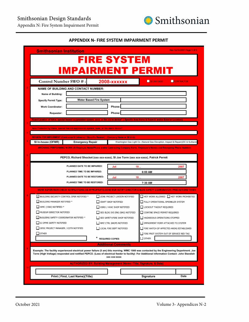
Smithsonian Design StandardsAppendix N: Fire System Impairment Permit
October 2021 Volume 3- Appendices N-2
APPENDIX N- FIRE SYSTEM IMPAIRMENT PERMIT

Smithsonian Design StandardsAppendix N: Fire System Impairment Permit
October 2021 Volume 3- Appendices N-3
FIRE SYSTEM IMPAIRMENT PERMIT FORM
GENERAL INSTRUCTION
Summary:
The Fire System Impairment Permit Form is to be used whenever maintenance, repairs,
modifications or upgrades cause fire detection / alarm systems, life safety systems, or fire
suppression systems within the SI Facilities to be out of service. All work must be authorized
and approved through the Building Manager. Using this form should help prevent miss
communication and assure continuity of work among various shops and departments within
the Office of Facility Engineering and Operation (OFEO). The Work Supervisor / Leader are
responsible for ensuring all codes and regulations are followed during fire/life safety system
repairs.
The Building Manager shall inspect the work area prior to granting a permit. The Building Manager
will verify and sign off on the permit. The permit is void unless copies of the fire system
impairment permit have been posted and properly distributed to the “Fire System Impairment”
Outlook user group (including Building Management, and Work Management Center (WMC)) by
the Building Manager. Upon notification, the security office is to immediately notify the building
control room operator. The Work Supervisor will return the original copy of the permit back to
the Building Manager. The Building Management Office shall retain the original permit for official
record.
Should fire system impairment directly impact the ability of the local fire department to perform
tactical fire fighting operations, the Building Manager shall notify the fire department of the
impairment. Incidents requiring fire department notification may include impairment of water
storage tanks serving hydrants, closure of main sprinkler control valves, shut down of mains
feeding yard hydrants or entire buildings.
Instructions:
1. Tracking Control # / Control Number SWO# – Select the appropriate control number and
enter the tracking number. The Office of Facility Maintenance & Reliability (OFMR) group will
use an SWO for the tracking number. The tracking number will be used for a reference to work
which allows us to pull historical records for labor and material cost. All individuals in OFMR
working on this permit should use the same number.
SI In-House and Contractor – check either or both if work involves in-house and outside contract
work.
Smithsonian Design StandardsAppendix N: Fire System Impairment Permit
October 2021 Volume 3- Appendices N-4
2. Name of Building – select from the drop down list the location of work or type in the building
name.
• Specify Type of Permit – use the drop down to select.
• Work Coordinator & Phone # – specify the individual who will be responsible for coordinating
work. Provide a phone number xxx xxx-xxxx. The Work Co-Coordinator will ensure that this
permit is posted and copies are sent to appropriate shops and/or departments.
• Requester & Phone # – use this block for the requester’s name. Example: Work request may
come from Building Management, Safety Office and / or the Office of Engineering, Design and
Construction.
3. Exact Location of the Valve/Zone – enter the valve location and identification number. Copy of
this permit will be posted at the valve location at a visible site.
4. Area Protected by Valve - provide some detail of the zones and/or areas affected by this work.
5. Reason for Impairment – select from the drop down list the proper reason for impairment.
6. Mechanic Performing Work (SI Employee Name/Phone and/or Contract Company Name,
Employee’s Names and Emergency Phone #)
7. Planned Dates and Time (Impaired & Restored) – use the drop downs to select the dates and
times.
8. Notification - Precautions Taken (check as appropriate) – use the list and check those that
are appropriate. The Work Supervisor / Leader will provide notification to the Building Security
Control Operator, Building Management, and Work Management Center (WMC) by providing a
copy of the permit prior to any work other than extreme emergencies.
9. Additional Comments – use this block to provide more specific information.
10. Authorized By – The Permit Authorized Individual (PAI) shall provide last, first name (print),
sign and date.
Reference Attachments B-2 and B-5 to Ch. 36 (Fire Protection) of the OSHEM Safety Manual,
which provide specific procedures to be followed when impairing water based and fire
alarm/special hazard systems.

Smithsonian Design StandardsAppendix O: Laboratory Design Standards
October 2021 Volume 3- Appendices O-1
APPENDIX O
Laboratory Design Standards
Smithsonian Design StandardsAppendix O: Laboratory Design Standards
October 2021 Volume 3- Appendices O-2
APPENDIX O- LABORATORY DESIGN STANDARDS
1. Regulations, Standards and References
a. Regulations:
i. Virginia Code of Regulations, Ventilation requirements for
laboratory type hood operationsii. Virginia Code of Regulations, Carcinogens
iii. Maryland Code of Regulations, Ventilation requirements for
laboratory type hood operationsiv. Maryland Code of Regulations, Carcinogens
v. New York Code of Regulations Ventilation requirements for
laboratory type hood operationsvi. New York Code of Regulations, Carcinogensvii. CCR Title 8 Section 5154.1(e)(7)viii. SCCo Toxic Gas Ordinance No. NS-517.44ix. Code of Federal Regulations (CFR) 10, Parts 20 and 35
x. Code of Federal Regulations (CFR) 1910.106 page 144,
xi. OSHA 2206, Nov 7, 1987 (OSHA, 1987)xii. National Fire Protection Association (“NFPA”) Handbook 45xiii. Standard on Fire Protection for Laboratories Using Chemicalsxiv. National Fire Protection Association (“NFPA”) 56Cxv. Standard for laboratories in health-related institutions, Chapter 3-3.5:
Fume Hoodsxvi. National Fire Protection Association (NFPA) Handbook 99
xvii. Standard for Health Care Facilities
xviii. 29 CFR 1910.1450 “Occupational Exposures to Hazardous Chemicals in
Laboratories”
b. Consensus Standards and References:i. “ANSI/ISEA Z358.1-2014. American National Standard for Emergency
Eyewash and Shower Equipment”ii. “ANSI/AIHA/ASSP Z9.5-2012 Laboratory Ventilation”iii. American National Standard for Thermal Environmental Conditions for
human Occupancy (ANSI/ASHRAE 55-2004)iv. American Society of Heating and Refrigeration Engineers – ASHRAE
Handbook, Chapter 13v. American Society of Heating and Refrigeration Engineers – ASHRAE
Applications: Chapter 14, Laboratories: Part VIII; Laboratory Fume Hoodsvi. Virginia Disabled Accessibility Guidebookvii. Maryland Disabled Accessibility Guidebookviii. New York Disabled Accessibility Guidebookix. “CRC Handbook of Laboratory Safety, 5th ED. CRC Press 2000”x. Guidelines for Construction and Equipment of Hospital and Medical

Smithsonian Design StandardsAppendix O: Laboratory Design Standards
October 2021 Volume 3- Appendices O-3
Facilities – U.S. Department of Health and Human Services; Chapterxi. 7.29 Mechanical Standards – Sections D(1)(n): Laboratory Hood Special
Standardsxii. SAMA Fume Hood Standards – LF-10, latest editionxiii. USDA: Science and Educational Administration Manual for laboratory
Chemical Fume hoods – Standards – United States Department ofAgriculture
xiv. ACGIH Industrial Ventilation Handbook (22nd edition)xv. “Industrial Ventilation: A Manual of Recommended Practice for Design,
30th Edition”xvi. University of California EH&S Lab Safety Design Guidexvii. Prudent Practices in the Laboratory 8.C, 8.Dxviii. Design and Construction of Inside Storage Rooms, General Industry
Standard 29xix. CDC-NIH Biosafety in Microbiological and Biomedical Laboratoriesxx. NIH Design Policy and Guidelines, Research Laboratory, 1996, D7.7xxi. NFPA 45 Standard on Fire Protection for Laboratories Using Chemicals,
2019 Edition.xxii. “Industrial Ventilation: A Manual of Recommended Practice for Operation
and Maintenance, 2nd Edition”xxiii. “ANSI/ASHRAE 110-2016 Methods of Testing Performance Of Laboratory
Fume Hoods”xxiv. “SEFA 1.2-1996 Laboratory Fume Hoods, Recommended Practices”xxv. “NSF/ANSI 49-2019 Biosafety Cabinetry: Design, Construction,
Performance, And Field Certification”xxvi. ASHRAE 62.1-2019 Ventilation for Acceptable Indoor Air Quality
2. General Ventilation Considerations
a. The room shall have mechanical generated supply air and exhaust air. All lab
rooms shall use 100% outside air and exhaust to the outside. There shall be no
return of fume hood and laboratory exhaust back into the building. The air
balance of the room cannot be adjusted unless the provision of mechanically
generated supply and exhaust is made.
b. Mechanical climate control shall be individually provided for each laboratory.
c. Cabinetry or other structures or equipment must not block or
reduce effectiveness of the supply or exhaust air.
d. Ventilation calculation shall be in accordance with ACGIH Industrial Ventilation
Manual.
e. General laboratories shall have a minimum of 6 air changes per hour or 1 cfm/sf
of exhaust, whichever provides the more stringent ventilation requirement.

Smithsonian Design StandardsAppendix O: Laboratory Design Standards
October 2021 Volume 3- Appendices O-4
During unoccupied hours, laboratory exhaust rates can be reduced to a
minimum of 4 air changes per hour.
f. Laboratories must be maintained under negative pressure in relation to the
corridor or other less hazardous areas. Clean rooms requiring positive pressure
shall have entry vestibules provided with door-closing mechanisms and interlocks
so that both doors are not open at the same time. Consult with the local State
Fire Marshal for additional design requirements.
g. The air velocity volume in each duct shall be sufficient to prevent condensation
or liquid or condensable solids on the walls of the ducts in compliance with
ACGIH Industrial ventilation handbook and ASHRAE Laboratory Design Guide.
h. Fume hoods shall not be the sole means of the room air exhaust. General room
exhaust outlets shall be provided where necessary to maintain minimum air
change rates and temperature control.
i. Operable windows are prohibited in new lab buildings and shall not be used on
modifications to existing buildings.
j. Local exhaust ventilation (e.g. “snorkels”), other than fume hoods shall be
designed to adequately control exposures to hazardous chemicals. An
exhausted manifold or manifolds with connections to local exhaust may be
provided as needed to collect potentially hazardous exhausts from gas
chromatographs, vacuum pumps, excimer lasers, or other equipment which can
produce potentially hazardous air pollutants. The contaminant source needs to
be enclosed as much as possible, consistent with operational needs to maximize
control effectiveness and to minimize air handling challenges and cost. The
development of enclosures to minimize the volume of airflow required to attain
the desired degree of containment control will effectively reduce fan size, motor
horsepower, make up air volume, and make up air conditioning costs.
k. Hoods shall be labeled to show which fan or ventilation system they are
connected to.
l. No laboratory ventilation system ductwork shall be internally insulated.
Sound baffles or external acoustical insulation at the source shall be used for
noise abatement.
m. Air exhausted from laboratory work areas shall not pass un-ducted through
other areas.

Smithsonian Design StandardsAppendix O: Laboratory Design Standards
October 2021 Volume 3- Appendices O-5
n. Biological safety cabinets shall be designed and installed with exhaust systems
or associated exhaust systems as specified by CDC NIOSH BMBL Appendix A
and ANSI/AIHA Z9.5.
3. Negative Pressurization
a. Airflow shall be from low hazard to high hazard zones. Anterooms may be
necessary for certain applications, such as clean rooms or tissue culture rooms.
Potentially harmful aerosols can escape from the containment of the laboratory
room unless the room air pressure is negative to the adjacent non-laboratory
areas. It is recommended that laboratories contain a fully integrated laboratory
control system to control the temperature, ventilation rate and room
pressurization. The control system shall constantly monitor the amount of
supply and exhaust air for the laboratory rooms and regulate the flow to
maintain a net negative pressurization.
b. Provide an adequate supply of makeup air to the laboratory to maintain
target pressurization.
c. An air lock or vestibule may be necessary in certain high-hazard laboratories
to minimize the volume of supply air required for negative pressurization
control. These doors shall be provided with interlocks so that both doors
cannot open at the same time.
d. Corridors shall not be used as plenums.
4. Supply Air Arrangements
a. Room air currents at the fume hood shall not exceed 20% of the average face
velocity to ensure fume hood containment.
b. Make up air shall be introduced to the opposite end of the laboratory room from
the fume hood (s) and the flow paths for the room HVAC system shall be kept
away from the hood locations. Where supply diffusers are located in the vicinity
of fume hoods or biological safety cabinets, laminar flow type diffusers shall be
utilized.
c. Make up air shall be introduced such that negative pressurization is maintained in
all laboratory spaces and does not create a disruptive air pattern
d. Cabinetry or other structures or equipment shall not block or reduce
effectiveness of the supply or exhaust air.

Smithsonian Design StandardsAppendix O: Laboratory Design Standards
October 2021 Volume 3- Appendices O-6
e. Supply system air shall meet the technical requirements of the laboratory work
and the requirements of the latest version of ASHRAE, Standard 62.1,
Ventilation for Acceptable Indoor Air Quality
5. Fume Hood Location
a. Fume hoods shall be located away from activities or facilities which produce air
currents or turbulence. Locate away from high traffic areas, air supply diffusers,
doors, and operable windows.
b. Fume hoods shall not be located adjacent to a single means of access to an exit.
Recommend that hoods be located more than 3 m (10 ft) from any door or
doorway.
c. Fume hood openings shall not be located opposite workstations where
personnel will spend much of their working day (i.e. desks or microscope
benches).
d. An emergency, ADA eyewash/shower station shall be within16 meters (55 feet)
or 10 seconds of each fume hood.
6. Approved Equipment and Submittals
a. All fume hoods shall meet the requirements of:
i. State Code of Regulations specific to project site, including:
1) Virginia Code of Regulations2) Maryland Code of Regulations3) New York Code of Regulations4) Florida Code of Regulations5) Arizona Code of Regulations6) Hawaii Code of Regulations
7) Massachusetts Code of Regulations
ii. NFPA 45, Standard on Fire Protection for Laboratories Using Chemicals
b. The following chemical fume hood manufacturers are currently approved
for installation within the Smithsonian Institution facilities:
i. Fisher/Hamiltonii. Kewaunee

Smithsonian Design StandardsAppendix O: Laboratory Design Standards
October 2021 Volume 3- Appendices O-7
iii. Jamestowniv. Mott Manufacturingv. LabConcovi. H.H. Hawkins, Ltd.
c. Only those fume hoods on the Smithsonian Institution’s approved list may
be used. Fume hood submittals must be reviewed and approved by the
Smithsonian Institution OSHEM prior to selection
d. Fume hoods not on the Smithsonian Institution’s approved list may be added
to the approved list only after the Smithsonian Institution OSHEM review and
approval of the manufacturer’s specifications.
e. Manufacturer’s product literature and data sheets are required
f. Plastic laminate for color selection shall be provided.
g. Submit specifications for size of fume hood, showing dimensions, required
clearances, and finishes; and where necessary, size (especially height above the
floor), and capacity and location of all mechanical and electrical services required
7. Fume Hood and Local Exhaust Ventilation Selection/Types
a. General laboratory design shall be based upon the following factors:
i. Room volume (length x width x height)ii. Number of room air changesiii. Laboratory Heat Loadiv. Types of material usedv. Linear meter (feet) of hood needed based on
a. Number of users/hoodb. Frequency of usec. % of time working at the hoodd. Size of apparatus to be used in the hood, etce. Sash Position
b. A facility designed for intensive chemical use shall have at least 0.8 linear meters
(2.5 linear feet) of hood space per user.
c. An extensive laboratory calculation that evaluates all laboratory equipment
against heat load, recommended air change rates, minimal cooling requirements
for the laboratory, variable volume venturi valve laboratory design or constant
volume venturi valve laboratory design shall be provided to Smithsonian

Smithsonian Design StandardsAppendix O: Laboratory Design Standards
October 2021 Volume 3- Appendices O-8
Institution for review of laboratory development.
d. Fume hoods are to be operated 24 hours a day. No user controlled shut-off
switch is allowed unless necessary to the operation and approved by OSHEM.
e. Constant Volume Fume Hoods
i. Constant Volume fume hoods permit a stable air balance between the
ventilation systems and exhaust by incorporating a full bypass feature within
the hood. If the bypass is 100%, this allows a constant volume of air to be
exhausted through the hood regardless of the sash position. Full by-pass
hoods must be used for constant volume applications.
f. Variable Volume (VAV) Fume Hoods
i. Variable Volume fume hoods (partial bypass) maintain constant face
velocities by varying exhaust volumes in response to changes in sash
position. Because only the amount of air needed to maintain the specified
face velocity is pulled from the room, significant energy savings are possible
when the sash is closed.
g. Supply or Auxiliary Air Hoods
i. This type of hood is not permitted by the Smithsonian Institution, unless
an exception is granted by Smithsonian Institution OSHEM.
h. Ductless Fume Hoods
i. Portable, non-ducted fume hoods are not permitted by the Smithsonian
Institution, unless an exception is granted by Smithsonian Institution OSEHM.
Portable hoods do not typically meet the regulatory airflow requirements.
i. Perchloric / Hot Acid Hoods
i. Heated perchloric acid shall only be used in a laboratory hood specifically
designed for its use and identified as “For Perchloric Acid Operations”.
Perchloric acid and other hot acid digestion hoods must be on a dedicated
system and have an automatic wash down system. High use solvent
extraction and solvent use hoods (ether, other flammable solvents, etc.) must
be on a dedicated system.
ii. Perchloric acid hoods and exhaust duct work shall be constructed of

Smithsonian Design StandardsAppendix O: Laboratory Design Standards
October 2021 Volume 3- Appendices O-9
materials that are acid resistant, nonreactive, and imperious to perchloric
acid.
iii. The exhaust fan shall be acid resistant. The exhaust fan motor shall not be
located within the duct work. Drive belts shall not be located within the
ductwork.
iv. Ductwork for perchloric acid hoods and exhaust systems shall take the
shortest and straightest path to the outside of the building and shall not be
manifolded with other exhaust systems. Horizontal runs shall be as short as
possible, with no sharp turns or bends. The ductwork shall provide a positive
drainage slope back into the hood. Duct shall consist of sealed sections.
Flexible connectors shall not be used.
v. Sealants, gaskets, and lubricants used with perchloric acid hoods, ductwork,
and exhaust systems shall be acid resistant and nonreactive with perchloric
acid.
vi. A water spray system shall be provided for washing down the hood interior
behind the baffle and the entire exhaust system. The hood work surface shall
be watertight with a minimum depression of 15 mm (1/2”) at the front and
the sides. An integral trough shall be provided at the rear of the hood to
collect wash-down water. The work surface shall have a raised lip on all four
sides and be constructed of materials compatible with usage. Union between
work surface and counter shall be coved at a 20 mm (3/4”) radius and sealed
watertight.
vii. Spray wash-down nozzles shall be installed in the ducts not more than 1.5 m
(5 ft) apart. The ductwork shall provide a positive drainage slope back into the
hood. Ductwork shall consist of sealed sections and no flexible connectors
shall be used.
viii. The hood surface shall have an all-welded construction and have accessible
rounded corners for cleaning ease.
ix. The hood baffle shall be removable for inspection and cleaning.
x. Each perchloric acid hood must have an individually designated duct and
exhaust system.
j. American with Disabilities Act (ADA) Hoods
Smithsonian Design StandardsAppendix O: Laboratory Design Standards
October 2021 Volume 3- Appendices O-10
i. The designer shall consult with the Smithsonian Institution’s ADA Compliance
Office regarding the number of laboratory hoods that are required under
each project design. These hoods must provide the appropriate work
surface heights, knee clearances, reach to controls, etc for individuals
requiring use in wheelchairs. Hood and lab design shall comply with the
Accessibility regulations established by the State of installation.
k. Glove Boxes
i. Glove boxes (positive and negative) must meet the type, design, and
construction requirements of ANSI/AIHA Z9.5.
l. Walk-In Fume Hoods
i. Walk-In fume hoods must meet the type, design, and construction
requirements of ANSI/AIHA Z9.5.
8. Fume Hood Construction, Installation and Performance
a. New hoods can be mounted above a chemical storage cabinet, provided that the
cabinet meets the Uniform Fire Code requirements for construction. It is
recommended that solvent storage not be located under the laboratory fume
hoods as this is where fires are most likely to occur in laboratories.
b. All chemical fume hoods must meet the Smithsonian Institution’s review
for approval.
c. All fume hoods must be tested using the most current American National
Standards Institute (ANSI)/ASHRAE 110 method.
d. Type 316 stainless steel shall be used for all parts of the fume hood systems
ventilation duct as long as compatibility is maintained.
e. Fume hood interior surfaces shall be constructed of corrosion resistant, non-
porous, non-combustible materials such as type 316 stainless steel, and shall be
smooth and impermeable, with round corners. These materials shall have a
flame spread index of 25 or less when tested in accordance with NFPA method
255, Standard Method of Test of Surface Burning Characteristics of Building
Materials.
f. Laboratory hoods shall be provided with a means of containing minor spills.

Smithsonian Design StandardsAppendix O: Laboratory Design Standards
October 2021 Volume 3- Appendices O-11
g. There must be a horizontal bottom airfoil inlet at the front of the hood.
h. Operator adjustable baffles are not permitted. Removable fixed slot or
perforated baffles only are acceptable. Slots are to be continuous across the
back of the fume hood.
i. Before a new fume hood can be placed into operation, an adequate supply of
makeup air must be provided to the lab.
j. Face Velocity
i. Laboratory fume hoods shall be designed to provide a minimum average
effective face velocity of 0.5 m/s (100 feet per minute (fpm)) with a minimum
of 0.4 m/s (70 fpm) at any point, unless an exception is approved by OSHEM.
OSHEM is to be consulted on all face velocity/exhaust rate design
parameters for laboratory hood systems.
k. Where the required velocity can be obtained by partly closing the sash, the sash
and/or jamb shall be marked to show the maximum opening at which the hood
face velocity will meet the requirements.
l. An airflow indicator shall be provided and located so that it is visible from the
front of the fume hood. The hood shall be prepared at the factory to receive
the specified alarm/monitor. As a minimum, the alarm shall accommodate the
following:
i. The Safety Monitor/Alarm System shall monitor face velocity and provide
audible and visual alarm if face velocity drops below or rises above a range
set by SI and is to have a flexible range capable of alarms from 0.35 m/s (70
fpm) to 0.76 m/s (150 fpm). Audible alarm shall pulse at 80 dBA
ii. The monitor shall be UL listed with all alarm circuit electric component,
external tubing, restrictors and manifolds furnished complete. Monitor
shall have light emitting diode display, which provides clear indication of
airflow conditions. Safety monitor shall be tamperproof.
iii. Alarm Signal. Audible pulsating signal and a visual, large flashing red light
emitting diode.
iv. Silence push button, which temporarily overrides the audible alarm for a
period of no longer than 5 minutes, shall be accessible on the front of
the Safety Monitor.

Smithsonian Design StandardsAppendix O: Laboratory Design Standards
October 2021 Volume 3- Appendices O-12
v. During temporary silence of the audible alarm, the visual alarm shall remain
activated until the alarm condition is corrected.
vi. After the alarm condition is corrected and the face velocity and volume is
returned to the specified levels, the safety monitor shall automatically
reset and begin routine monitoring.
vii. Test circuit shall be provided to verify proper safety monitor operations
viii. Electrical Rating: Maximum 15 VDC and maximum current rating of 200 MA.
ix. An air monitor or alarm, comparable to ALNOR Airguard 335, or equal is
acceptable
x. Connect between the fume hood and the filter or damper
xi. Flow tube device (floating indicators) or ribbons hanging in the air stream
are not acceptable airflow indicators.
m. For variable volume fume hoods, provide a sash height monitor and exhaust air
valve to permit variable flow operation through the Laboratory Airflow Control
system. Exhaust air valve shall be paired with a supply air valve to permit
constant pressurization in a tracking arrangement.
n. Include a zone presence sensor for all variable volume hoods to alarm when
sash height is not in optimal position when hood is not in use.
o. Exterior construction
i. Chemical Resistant finish
ii. End panels fastened to frame with screws
iii. Unused holes (interior or exterior) shall be plugged or blanked
p. Air Foil that provides an air sweep across the work surface with the sash in the
fully lowered position. Air foils installed over the work surface edge, allowing
for air flow under the air foil are preferred.
q. Interior end panels require an access panel with gas tight gasket.

Smithsonian Design StandardsAppendix O: Laboratory Design Standards
October 2021 Volume 3- Appendices O-13
r. Baffles shall be constructed so that they may not be adjusted to restrict the
volume of air exhausted through the laboratory hood.
s. Fans shall run continuously without local control from the fume hood
location and independently of any time clocks.
t. For new installations or modifications of existing installations, controls for
laboratory hood services (e.g., gas, air, and water), shall be located external to
the hood and within easy reach.
u. Shutoff valves for services, including gas, air, vacuum, and electricity shall be
outside of the hood enclosure in a location where they will be readily accessible
in the event of fire in the hood. The location of such a shut-off shall be legibly
lettered in a related location on the exterior of the hood.
v. Laboratory hoods shall not have an on/off switch located in the laboratory
unless necessary to the operation and approved by OSHEM. Exhaust fans shall
run continuously without direct local control from laboratories.
w. Drying ovens shall not be placed under fume hoods.
9. Power and Electrical
a. Receptacles per National Electrical Manufacturers Association (NEMA) 5-15R: 20A
– 125V AC three-wire duplex polarized receptacles. Receptacles shall be GFI.
Receptacles: Harvey Hubble-Inc.’s No. 5252, Arrow Hart, Leviton, or equal.
b. Plate Covers: Meet usage, Bell or equal
c. Switch for lighting: Hubbel #1221 or equal.
d. Flexible Conduit: 15 mm (½”) complete with wiring as required
e. Light Fixture: Heavy duty fluorescent strip light with 430 Ma rapid start lamps
and 120-volt HPF ballasts. Provide three-foot length for four-foot hoods and
four-foot length for six-foot hoods. Light Fixture: Garcy #RN 9942 – 36H,
Columbia Lighting Inc; Smoot-Holman Company; Benjamin Products of Thomas
Industries, Inc; or equal.
f. Chemical fume hood exhaust fans shall be connected to an emergency power
system in the event of a power failure.

Smithsonian Design StandardsAppendix O: Laboratory Design Standards
October 2021 Volume 3- Appendices O-14
g. Emergency power circuits shall be available for fan service so that fans will
automatically restart upon restoration after a power outage.
h. Momentary or extended losses of power shall not change or affect any of the
control system’s set points, calibration settings, or emergency status. After the
power returns, the system shall continue operation without the need for any
manual intervention. Alarms shall require manual reset; shall they indicate a
potentially hazardous condition.
i. Fume hood ventilating controls shall be arranged so that shutting off the
ventilation of one fume hood will not reduce the exhaust capacity or create
an imbalance between exhaust and supply for any other hood connected to
the same system.
j. In installations where services and controls are within the hood, additional
electrical disconnects shall be located within 15m (50 ft) of the hood and shall be
accessible and clearly marked. (Exception: If the electrical receptacles are
located external to the hood, no additional electrical disconnect shall be
required).
k. Hood lighting shall be provided by UL listed fixtures external to the hood or if
located within the hood interior, the fixtures shall meet the requirements of
NFPA 70, (National Electrical Code).
l. Light fixtures shall be of the fluorescent type and replaceable from outside
the hood. Light fixtures must be displaced or covered by a transparent
impact resistant vapor tight shield to prevent vapor contact.
m. The valves, electrical outlets and switches for utilities serving the hoods shall
be placed at readily accessible locations outside the hood. All shutoff valves
shall be clearly labeled. Plumbing (e.g., vacuum lines) shall exit the sides of
the fume hood and not the bench top.
10. Sashes
a. Hoods shall have transparent movable sashes constructed of shatter-resistance
flame resistant material and be capable of closing the entire front face.
b. Vertical rising sashes are preferred. Consult with the Smithsonian Institution
OSHEM regarding the use of horizontal sashes. If permitted, sash panels
(horizontal sliding) must be 310 to 360 mm (12 to 14 inches) in width.

Smithsonian Design StandardsAppendix O: Laboratory Design Standards
October 2021 Volume 3- Appendices O-15
c. Vertical type: 6 mm (¼”) thick laminated safety glass complete with 6 mm (¼”)
deep stainless-steel metal channels on sides, top and bottom; or frameless.
d. Mechanical stops shall ensure that sash work opening is 450 mm (18”) as
measured from the top of the fume hood work surface to the bottom of the
sash.
e. A manual override shall be provided to allow the vertical sash to be raised above
the maximum opening to allow lab apparatus to be installed or removed.
f. Operating face velocity at 450 mm (18”) shall be set between 0.5-1 m/s (100 –
120 fpm).
g. A force of 2.2 kilograms (5 pounds) shall be sufficient to move vertically and/or
horizontally moving doors and sashes.
11. Ducting
a. Fume hood exhaust shall be manifolded together except for the following:
i. Perchloric/hot acid hood applicationsii. Fume hoods with wash down equipmentiii. Fume hoods that could deposit highly hazardous residues on the ductworkiv. Exhaust requiring HEPA filtration or other special air cleaning
v. Situations where the mixing of exhaust materials many result in a fire,
explosion, or chemical reaction hazard in the duct system
vi. “Exhaust streams containing radioactive materials shall not be
manifolded unless authorized by the Smithsonian Facilities - Office of
Safety Health and Environmental Management (OSHEM)”
b. Manifolded fume hood exhaust ducts shall be joined inside a fire rated shaft
or mechanical room, or outside of the building at the roofline.
c. Airflow control devices shall be installed on each hood when configured in a
manifolded arrangement. Provide proper coating to meet requirements of
the exhaust air stream.
d. Horizontal ducts must slope at least 25 mm per 3 m (1” per 10 ft) downward
in the direction of airflow to a suitable drain or sump.
e. Ducts exhausting air from fume hoods shall be constructed entirely of

Smithsonian Design StandardsAppendix O: Laboratory Design Standards
October 2021 Volume 3- Appendices O-16
noncombustible material. Gaskets shall be resistant to degradation by the
chemicals involved. Gaskets shall be fire resistant.
f. Automatic fire dampers shall not be used in laboratory hood exhaust systems.
Fire detection and alarm systems shall not be interlocked to automatically shut
down laboratory hood exhaust fans.
12. Exhaust
a. New exhaust fans shall be oriented in an up-blast orientation.
b. Hood exhaust stacks shall be coordinated and developed with a wind tunnel
analysis specialist. Refer to section 15.0 Wind Engineering for additional
requirements.
c. Hood exhaust shall be located on the roof as far away from the outside air
intakes as possible to prevent re-circulation of laboratory hood emissions within
a building. For toxic gas applications, the separation distance shall be a
minimum of 23 m (75 ft) from any outside air intake.
d. A minimum 3 meter (10 foot) vertical separation must be established between
the stack discharge and the adjacent roof lines and/or air intakes.
e. Discharge from exhaust stacks must have a velocity of at least 15 m/s (3,000
fpm). Achieving this velocity shall not be done by the installation of a cone type
reducer. The duct may be reduced, but the duct beyond the reduction shall be of
sufficient length to allow the air movement to return to a linear pattern. High
plume, induced dilution type exhaust fans may be used to address exhaust
velocity requirements.
f. Rain caps that divert the exhaust toward the roof are prohibited.
g. Fume hood exhaust may be required to be treated as determined by local codes
and planned operations within the hood.
h. Laboratory ventilation exhaust fans shall be spark-proof and constructed of
materials or coated with corrosion resistant materials for the chemical
being transported. V-belts drives shall be conductive.
i. Vibration isolator shall be used to mount fans. Provide all laboratory exhaust fans
with vibration monitors. Flexible connection sections to ductwork, such as
chemically resistant coated glass fiber cloth, shall be used between the fan and

Smithsonian Design StandardsAppendix O: Laboratory Design Standards
October 2021 Volume 3- Appendices O-17
its intake duct when such material is compatible with hood chemical use.
j. Each exhaust fan assembly shall be individually matched (cfm, static pressures,
brake horsepower, etc.) to each laboratory ventilation system.
k. Exhaust fans shall be located outside the building at the point of final discharge.
Each fan shall be the last element of the system so that the ductwork through
the building is under negative pressure. For multiple risers through a rated
shaft, manifolding ducts to a common plenum through which exhaust fans draw
the laboratory exhaust can be incorporated into the design. Design must be
approved by Smithsonian Institution OSHEM prior to development and
construction.
l. Fans shall be installed so they are readily accessible for maintenance and
inspections without entering the plenum.
13. Plumbing
a. Cup Sink shall be flush with the work surface and shall conform to the usage
requirements, complete with stainless steel tailpiece as required.
b. Make provisions for cold water only for each hood, in accordance with utility
service symbols. Provide vacuum breaker required at each fume hood outlet,
in addition to the main backflow preventer.
c. Run internal electric wiring in conduit. Do not run conduit through hood interior
or across the hood.
d. Utilities controls shall be located outside of hood interior for convenient
access and use.
e. Fixtures shall be Water Saver Faucet Company, Chicago Faucet, T & S, or equal.
The following specifications refer to the Water Saver Faucet Company to
establish quality, utility, and appearances.
i. Gas, air, water, steam, and vacuum fixtures shall be made up of remote
control valves L-3185 (15 mm (1/2”) IPS pipe thread, 10 mm (3/8”) NNPT
outlet pipe threads) with guide bushing “B” with 4-arm handle and color
plastic for index disc, and for service
ii. For gas, air, and vacuum, the remote-control valve shall be connected to a
Water Saver L-14 (or equal) serrated nozzle with 10 mm (3/8”) male threads,

Smithsonian Design StandardsAppendix O: Laboratory Design Standards
October 2021 Volume 3- Appendices O-18
10 serrations, and of dimensions as shown on the drawing. Valve shall have
stainless steel seat and stainless steel renewable floating cone unit.
iii. For water, the remote-control valve shall be connected to a Water Saver
L171-WSA with vacuum breaker (or equal) serrated nozzle with a ½ inch
pipe and elbow. Valves shall have “Water Saver: standardized renewable
operating unit”.
iv. Access panel to service the utilities shall be gasketed with approved gasket
material.
v. Plumbing shall not be run through hood interior or across front of hood.
vi. Water faucets shall have a vacuum breaker.
vii. Pre-plumb all utilities
14. Wind Engineering
a. A wind tunnel evaluation is required for all new construction. Any new
construction project that produces emissions of a hazardous, noxious,
odoriferous, or otherwise nuisance character and that poses a health and safety
risk is to be evaluated using the best available technology for wind tunnel studies.
Common emission sources can include laboratory exhaust, cooling towers,
generators, incinerators, kitchen exhaust, and vent stacks.
b. A wind tunnel evaluation may be required for remodeling projects if new
exhausts are being added that may impact sensitive receptors, when the total
volume of the exhaust is being substantially increased, or when the project may
be affected by nearby existing building. Sensitive receptors can include air
intakes, courtyards, operable windows, or sensitive animal populations that are
either part of the facility being remodeled or that exist nearby.
c. Wind tunnel engineering evaluations shall be conducted for all wind directions
striking all walls of a building where fume hood exhaust is likely to have
significant ground level impact or is likely to affect air intakes for buildings
located nearby.
d. Required Dilution: The required dilution is based on the chemical makeup of the
exhaust and the type of receptors that are affected. Target dilution factors are
1/1,000 at minimum, as measured from the top of the exhaust fan to the
receptor in question. For highly toxic emissions where a 1/1000 dilution factor

Smithsonian Design StandardsAppendix O: Laboratory Design Standards
October 2021 Volume 3- Appendices O-19
is inadequate, the appropriate dilution level shall be calculated for the specific
application.
e. Chemical Parameters: Chemical parameters to be evaluated include but are not
limited to worst case spill releases and modeling with chemicals possessing
highest toxicities, greater volatility and lowest threshold limit values (TLV).
f. Wind tunnel study parameters chosen shall use the best available technology
and the current industry testing standards. The ASHRAE Handbook of
Fundamentals or the Environmental Protection Agency (EPA) Guideline for Fluid
Modeling of Atmospheric Diffusion, EPA – 600/8-81-009 shall be consulted. At a
minimum, the wind tunnel study shall take into account probable evaporation
times based on ventilation rates, exhaust stack height and diameter, exit velocity,
exhaust location, wind speed, and direction, building features and any nearby
features that could influence emission dispersion.
g. Emergency generator exhaust shall be considered in the wind tunnel engineering
study.
15. Noise
a. System design must provide for the control of all exhaust system noise
(combination of fan generated noise and air generated noise) in the
laboratory. Systems must be designed to achieve an acceptable Sound
Pressure Level (SPL) frequency spectrum (room criterion) as described in the
ASHRAE Handbook– HVAC Applications.
16. Lab Hood Commissioning
a. Balance, test, and certify each fume hood in accordance with the latest edition
of ASHRAE 110 Testing Requirements. Fume hood field tests shall be performed
by a qualified independent testing company on each hood to determine face
velocity, containment, and airflow patterns. Proper operation of fume hoods
must be demonstrated by the contractor installing the fume hood prior to
project closeout.
b. Fume hood face velocity to be maintained between 0.5 – 0.6 m/s (100 – 120
fpm) at all times during normal operation.
c. As installed, under the ASHRAE 110 test method, fume hoods must meet the
testing criteria 4.0AI0.05 as specified in the Industrial Ventilation Handbook (4.0
liters/minute release rate of tracer gas, as installed, less than 0.05 ppm of

Smithsonian Design StandardsAppendix O: Laboratory Design Standards
October 2021 Volume 3- Appendices O-20
tracer gas detected).
d. There shall be no visible smoke flow out of the fume hood during the
flow visualization test.
e. Balance, test, and certify each glove box, biosafety cabinet and laminar flow hood
in accordance with the latest edition of ANSI/NSF 49 Testing Requirements. Each
hood test shall be performed by a qualified independent accredited Biological
Cabinet Field Certifier to determine proper containment and certify the
effectiveness of internal filtration.