
Semua Tentang CSS: Mempercantik & Memperindah CSS (Cascading Style Sheet
Upload
independentCategory
view
1download
0
Copyright 2014, Society of Petroleum Engineers This paper was prepared for presentation at the SPE Saudi Arabia Section Annual Technical Symposium and Exhibition held in Al -Khobar, Saudi Arabia, 21-24 April 2014. This paper was selected for presentation by an SPE program committee following review of information contained in an abstract submitted by the author(s). Contents of the paper have not been reviewed by the Society of Petroleum Engineers and are subject to correction by the author(s). The material does not necessar ily reflect any position of the Society of Petroleum Engineers, its officers, or members. Electronic reproduction, distribution, or storage of any part of this paper without the written consent of the Society of Petroleum Engineers is prohibited. Permission to reproduce in print is restricted to an abstract of not more than 300 words; illustrations may not be copied. The abstract must contain conspicuous acknowledgment of SPE copyright.
Abstract In conventional cyclic steam stimulation (CSS), steam is periodically injected at high pressure to the reservoir. After the
steam injection period, the well is soaked for several days then it will be produced. Generally, for the first to the fifth cycle,
the steam can effectively transfer the heat to the reservoir. After that, the CSOR will rise up indicating that the process is
currently ineffective.
This paper aims to improve the CSS performance using modified well completion. The perforation is modified to become
two parts, one part is on the top side (as injection) and the other part is on the bottom side (as production). In this process,
after being injected, the steam will condense, resulting from heat loss, and it will move to lower part because of gravity
drainage. Simultaneously, crude oil was produced through the production perforation. The opening-closing of the injection-
production cycle is managed by interval control valve (ICV). To provide an overview of this phenomenon, a synthetic
reservoir model was built based on Pertama-kedua formation, located in Sumatra Indonesia. Sensitive variables are length of
the injection-production perforation and soaking time. Finally, the heat efficiency was evaluated during 8 years of project
life.
Simulation results show that dividing the perforation into injection and production intervals will reduce CSOR 30% and this
requires shorter soaking time compared to that of conventional processes. Furthermore, if the distance between injection and
production interval is longer the production will be better. However, this gap is limited by reservoir thickness.
Key word: CSS, heat efficiency, ICV, CSOR.
Introduction Total estimated reserve of heavy oil in the world is approximately 3,396 billion barrels of original oil in place, of which 30
billion barrels are included as prospective undiscovered reserve (F. Richard, 2007). To produce these resources, several
methods have been successfully applied such as cyclic steam stimulation (CSS), steam flooding, SAGD process, and non-
thermal recovery.
CSS is a well stimulation method involving the transfer of heat to reservoir by periodical injection of steam into the
production well. This method was first applied in the late 1950s to recover bitumen from the tar sands of Venezuela.
Following the successful field trial, CSS has been applied worldwide to recover heavy oil and bitumen. The process can get
a recovery factor of 3 – 10% of the remaining oil in place (Hong KC, 1994).
In other cases, the ultimate recovery factor could be greater than 20% as reported by Esso, or it could be much lower as is in
some of the projects in Cold Lake. In some cases such as those in Duri Indonesia, it can be switched to steam-flooding after
CSS period is over. However, it also might not be feasible as demonstrated in several cases in Cold Lake, Canada. (Faroug
Ali S.M, 1994).
Furthermore, in good quality reservoirs, CSS is just the initiation of a bigger process. After it is over, the best way is to
continue to steam flooding. In other cases, the complexity of geological structure makes the continuous steam flooding very
difficult due to shale barriers, sealing faults, and discontinued formation. Therefore, improving CSS method plays a very
important role to increasing recovery factor.
In CSS process, the initial oil production rate is usually high due to large reservoir pressure increase, high initial oil
saturation, and reduction of oil viscosity. The well can be produced for several months. After several cycles, the oil
saturation will gradually decrease in the surrounding area near the borehole. Hence, this area should not be the target of
heating but rather the area further away from the borehole due to the fact that, in this area, the heat is only transferred to the
rock not to the oil. This will affect the injection volume of steam. Consequently, the cumulative steam oil ratio (CSOR) will
SPE-172212-MS
Smart Completion Design for Managing Steam Injection in CSS Process
Suranto, W. Bae, Sejong University, AK Permadi, Bandung Institute of Technology, and Son T. Dang, Sejong University
SPE-172212-MS 2
increase. This indicates that the process is inefficient. To overcome this weakness, CSS using smart completion has been
proposed in this paper.
This research, novel method to improving CSS, is based on the modification of the perforation interval. It will consist of two
parts, the first part is at the top and the second part is at the bottom (commingle perforation). The packer is installed between
the injection and production parts. An interval control valve (ICV) is installed in the tubing as a connector between
perforations and the inside of the tubing. In the steam injection period, the injection part is opened by opening the ICV, but
the production part is closed. In the soaking period, both of the 2 parts are closed. Then, in the production period, the ICV in
the injection part is closed and production part is opened correspondingly. The next cycle is repeated similarly. At the end of
well production life, the performance of both types of CSS (conventional and smart completion) will be evaluated and
compared.
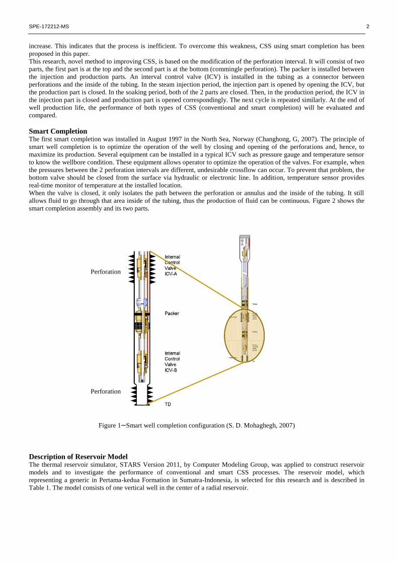
Smart Completion The first smart completion was installed in August 1997 in the North Sea, Norway (Changhong, G, 2007). The principle of
smart well completion is to optimize the operation of the well by closing and opening of the perforations and, hence, to
maximize its production. Several equipment can be installed in a typical ICV such as pressure gauge and temperature sensor
to know the wellbore condition. These equipment allows operator to optimize the operation of the valves. For example, when
the pressures between the 2 perforation intervals are different, undesirable crossflow can occur. To prevent that problem, the
bottom valve should be closed from the surface via hydraulic or electronic line. In addition, temperature sensor provides
real-time monitor of temperature at the installed location.
When the valve is closed, it only isolates the path between the perforation or annulus and the inside of the tubing. It still
allows fluid to go through that area inside of the tubing, thus the production of fluid can be continuous. Figure 2 shows the
smart completion assembly and its two parts.
Figure 1 Smart well completion configuration (S. D. Mohaghegh, 2007)
Description of Reservoir Model The thermal reservoir simulator, STARS Version 2011, by Computer Modeling Group, was applied to construct reservoir
models and to investigate the performance of conventional and smart CSS processes. The reservoir model, which
representing a generic in Pertama-kedua Formation in Sumatra-Indonesia, is selected for this research and is described in
Table 1. The model consists of one vertical well in the center of a radial reservoir.
Perforation
Perforation
SPE-172212-MS 3
TABLE 1 PERTAMA/KEDUA RESERVOIR PROPERTIES (Gael, B.T. 1995)
Reservoir Properties
Value
Average depth, ft
500
Initial reservoir temperature, oF 100
Initial reservoir pressure, psi 100
Average net thickness, ft 120
Average porosity, % 0.34
Average permeability, mD 1500
kv/kh 0.5
Rock compressibility, 1/psi 5.7e-6
Average Oil density, oAPI 20
Oil viscosity at reservoir condition, cp 330
Oil viscosity at 432 oF , cp 8.2
Oil formation Volume factor at reservoir condition, RB/STB 1.02
Solution gas-oil ratio, SCF/STB 14
Residual oil saturation to water,% 0.25
Residual oil saturation to steam, % 0.1
Irreducible water saturation, % 0.40
Three phases relative permeability model Stone’s 2
Reservoir, underburden /overburden Volumetric heat capacity, BTU/ft3-
oF 33.2
Reservoir, underburden/overburden thermal conductivity, BTU/ft-day-oF 27.4
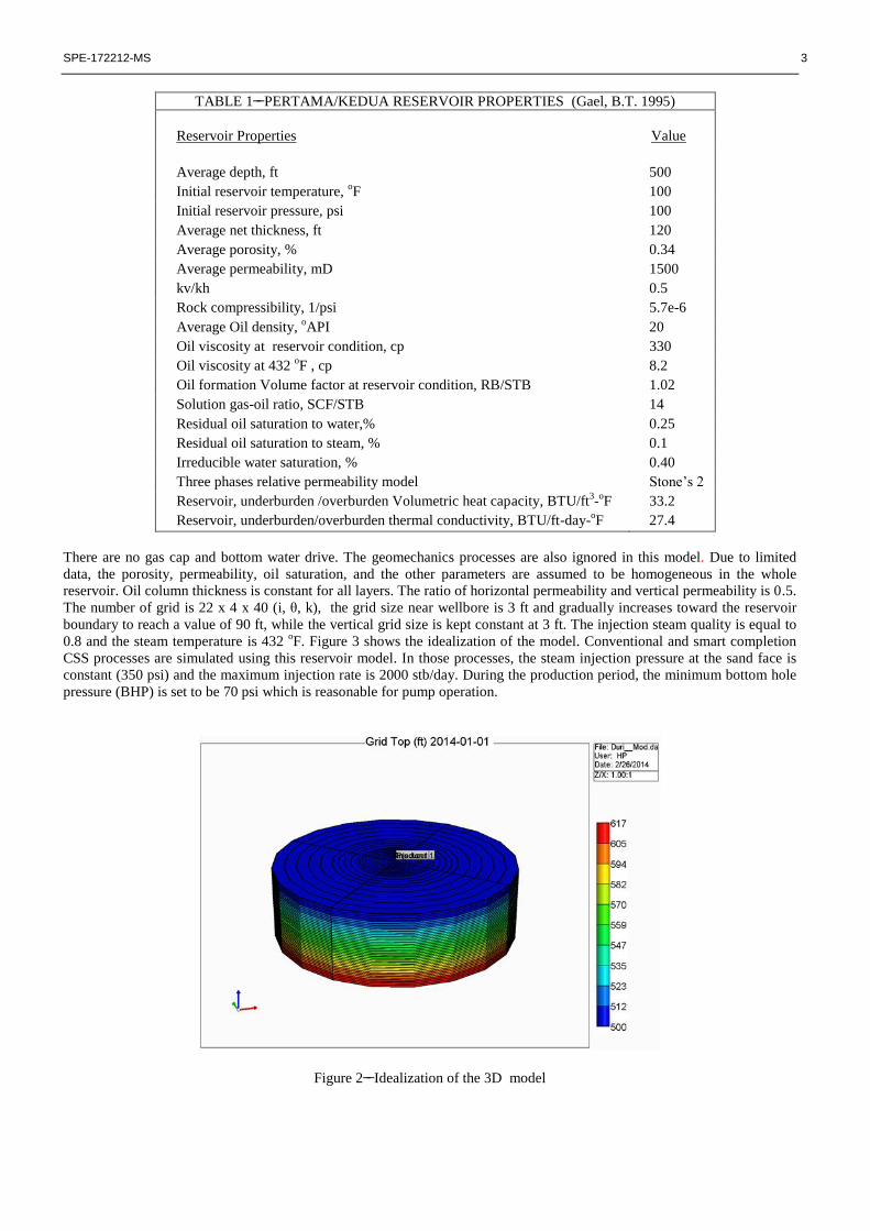
There are no gas cap and bottom water drive. The geomechanics processes are also ignored in this model. Due to limited
data, the porosity, permeability, oil saturation, and the other parameters are assumed to be homogeneous in the whole
reservoir. Oil column thickness is constant for all layers. The ratio of horizontal permeability and vertical permeability is 0.5.
The number of grid is 22 x 4 x 40 (i, θ, k), the grid size near wellbore is 3 ft and gradually increases toward the reservoir
boundary to reach a value of 90 ft, while the vertical grid size is kept constant at 3 ft. The injection steam quality is equal to
0.8 and the steam temperature is 432 oF. Figure 3 shows the idealization of the model. Conventional and smart completion
CSS processes are simulated using this reservoir model. In those processes, the steam injection pressure at the sand face is
constant (350 psi) and the maximum injection rate is 2000 stb/day. During the production period, the minimum bottom hole
pressure (BHP) is set to be 70 psi which is reasonable for pump operation.
Figure 2 Idealization of the 3D model
SPE-172212-MS 4
Result and Discussion
Comparison conventional and smart perforation CSS process
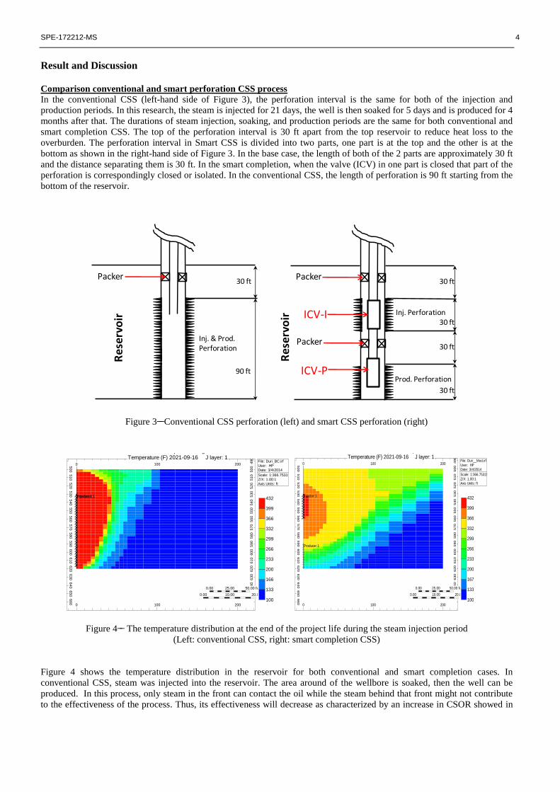
In the conventional CSS (left-hand side of Figure 3), the perforation interval is the same for both of the injection and
production periods. In this research, the steam is injected for 21 days, the well is then soaked for 5 days and is produced for 4
months after that. The durations of steam injection, soaking, and production periods are the same for both conventional and
smart completion CSS. The top of the perforation interval is 30 ft apart from the top reservoir to reduce heat loss to the
overburden. The perforation interval in Smart CSS is divided into two parts, one part is at the top and the other is at the
bottom as shown in the right-hand side of Figure 3. In the base case, the length of both of the 2 parts are approximately 30 ft
and the distance separating them is 30 ft. In the smart completion, when the valve (ICV) in one part is closed that part of the
perforation is correspondingly closed or isolated. In the conventional CSS, the length of perforation is 90 ft starting from the
bottom of the reservoir.
30 ft
90 ft
Reservoir
Packer
Inj. & Prod.Perforation
30 ft
30 ft
30 ft
30 ft
Inj. Perforation
ICV-P
ICV-I
Packer
Packer
Prod. Perforation
Reservoir
Figure 3 Conventional CSS perforation (left) and smart CSS perforation (right)
Injector 1Producer 1
0 100 200
0 100 200500
510
520
530
540
550
560
570
580
590
600
610
620
630
640
650
660
490
500
510
520
530
540
550
560
570
580
590
600
610
620
630
640
650
0.00 25.00 50.00 feet
0.00 10.00 20.00 meters
File: Duri_BC.irfUser: HPDate: 3/4/2014
Scale: 1:366.753153 Z/X: 1.00:1Axis Units: ft
100
133
166
200
233
266
299
332
366
399
432
Smart completion designTemperature (F) 2021-09-16 J layer: 1
Injector 1
Producer 1
0 100 200
0 100 200500
510
520
530
540
550
560
570
580
590
600
610
620
630
640
650
660
490
500
510
520
530
540
550
560
570
580
590
600
610
620
630
640
650
0.00 25.00 50.00 feet
0.00 10.00 20.00 meters
File: Duri__Mod.irfUser: HPDate: 3/4/2014
Scale: 1:366.753153 Z/X: 1.00:1Axis Units: ft
100
133
167
200
233
266
299
332
366
399
432
Smart completion designTemperature (F) 2021-09-16 J layer: 1
Figure 4 The temperature distribution at the end of the project life during the steam injection period
(Left: conventional CSS, right: smart completion CSS)
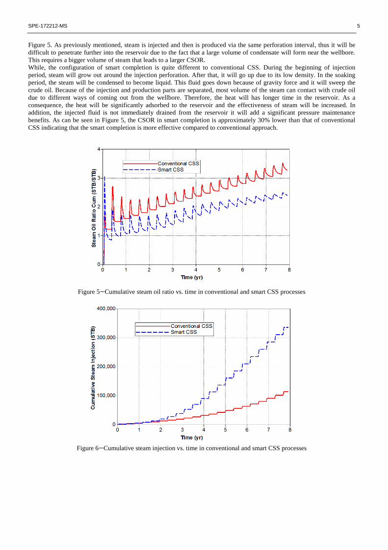
Figure 4 shows the temperature distribution in the reservoir for both conventional and smart completion cases. In
conventional CSS, steam was injected into the reservoir. The area around of the wellbore is soaked, then the well can be
produced. In this process, only steam in the front can contact the oil while the steam behind that front might not contribute
to the effectiveness of the process. Thus, its effectiveness will decrease as characterized by an increase in CSOR showed in
SPE-172212-MS 5
Figure 5. As previously mentioned, steam is injected and then is produced via the same perforation interval, thus it will be
difficult to penetrate further into the reservoir due to the fact that a large volume of condensate will form near the wellbore.
This requires a bigger volume of steam that leads to a larger CSOR.
While, the configuration of smart completion is quite different to conventional CSS. During the beginning of injection
period, steam will grow out around the injection perforation. After that, it will go up due to its low density. In the soaking
period, the steam will be condensed to become liquid. This fluid goes down because of gravity force and it will sweep the
crude oil. Because of the injection and production parts are separated, most volume of the steam can contact with crude oil
due to different ways of coming out from the wellbore. Therefore, the heat will has longer time in the reservoir. As a
consequence, the heat will be significantly adsorbed to the reservoir and the effectiveness of steam will be increased. In
addition, the injected fluid is not immediately drained from the reservoir it will add a significant pressure maintenance
benefits. As can be seen in Figure 5, the CSOR in smart completion is approximately 30% lower than that of conventional
CSS indicating that the smart completion is more effective compared to conventional approach.
Figure 5 Cumulative steam oil ratio vs. time in conventional and smart CSS processes
Figure 6 Cumulative steam injection vs. time in conventional and smart CSS processes
SPE-172212-MS 6
Even though the operation condition such as injection pressure and steam quality was the same, the drainage radius of
conventional CSS and smart perforation are approximately 100 ft and 200 ft (until the boundary of the model) respectively.
Due to the effect of constant pressure injection, the steam injection rate will be difference between conventional and smart
CSS. Figure 6 shows the cumulative steam injection in conventional and smart completion CSS. In the conventional CSS,
after one cycle the steam will follow the similar path to penetrate to the reservoir. In this process, the energy needed will be
slightly the same to the first cycle so that the cumulative steam injection curve will have a straight line characteristic. On the
other hand, the cumulative steam injection of the smart CSS will rapidly increase after 3 years as a result of different paths of
steam injection and oil production. In this process, steam will continue to penetrate further to the reservoir after production
period and it will not follow the same pattern like in conventional CSS. Because of that, the oil cumulative production will
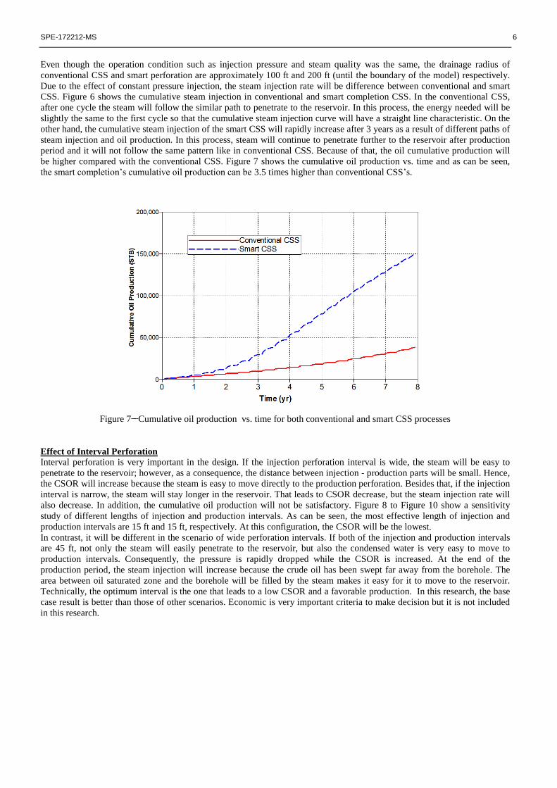
be higher compared with the conventional CSS. Figure 7 shows the cumulative oil production vs. time and as can be seen,
the smart completion’s cumulative oil production can be 3.5 times higher than conventional CSS’s.
Figure 7 Cumulative oil production vs. time for both conventional and smart CSS processes
Effect of Interval Perforation
Interval perforation is very important in the design. If the injection perforation interval is wide, the steam will be easy to
penetrate to the reservoir; however, as a consequence, the distance between injection - production parts will be small. Hence,
the CSOR will increase because the steam is easy to move directly to the production perforation. Besides that, if the injection
interval is narrow, the steam will stay longer in the reservoir. That leads to CSOR decrease, but the steam injection rate will
also decrease. In addition, the cumulative oil production will not be satisfactory. Figure 8 to Figure 10 show a sensitivity
study of different lengths of injection and production intervals. As can be seen, the most effective length of injection and
production intervals are 15 ft and 15 ft, respectively. At this configuration, the CSOR will be the lowest.
In contrast, it will be different in the scenario of wide perforation intervals. If both of the injection and production intervals
are 45 ft, not only the steam will easily penetrate to the reservoir, but also the condensed water is very easy to move to
production intervals. Consequently, the pressure is rapidly dropped while the CSOR is increased. At the end of the
production period, the steam injection will increase because the crude oil has been swept far away from the borehole. The
area between oil saturated zone and the borehole will be filled by the steam makes it easy for it to move to the reservoir.
Technically, the optimum interval is the one that leads to a low CSOR and a favorable production. In this research, the base
case result is better than those of other scenarios. Economic is very important criteria to make decision but it is not included
in this research.

SPE-172212-MS 7
Figure 8 Cumulative oil production vs. time with different lengths of perforation
Figure 9 Effect of perforation length to cumulative steam oil ratio
Figure 10 Effect of perforation length to cumulative steam injection
SPE-172212-MS 8
Effect of soaking time The soaking time is very important because the latent heat must be transferred to the reservoir during this period. As
described above, the steam injection pressure and temperature are 350 psi and 432 oF, respectively. In order to get a good
heat transfer process, the temperature of production fluid should be maintained as low as possible. In this model, because the
minimum BHP is 100 psi, the temperature of production fluid must be less than 295 oF so that the latent heat can be
transferred.
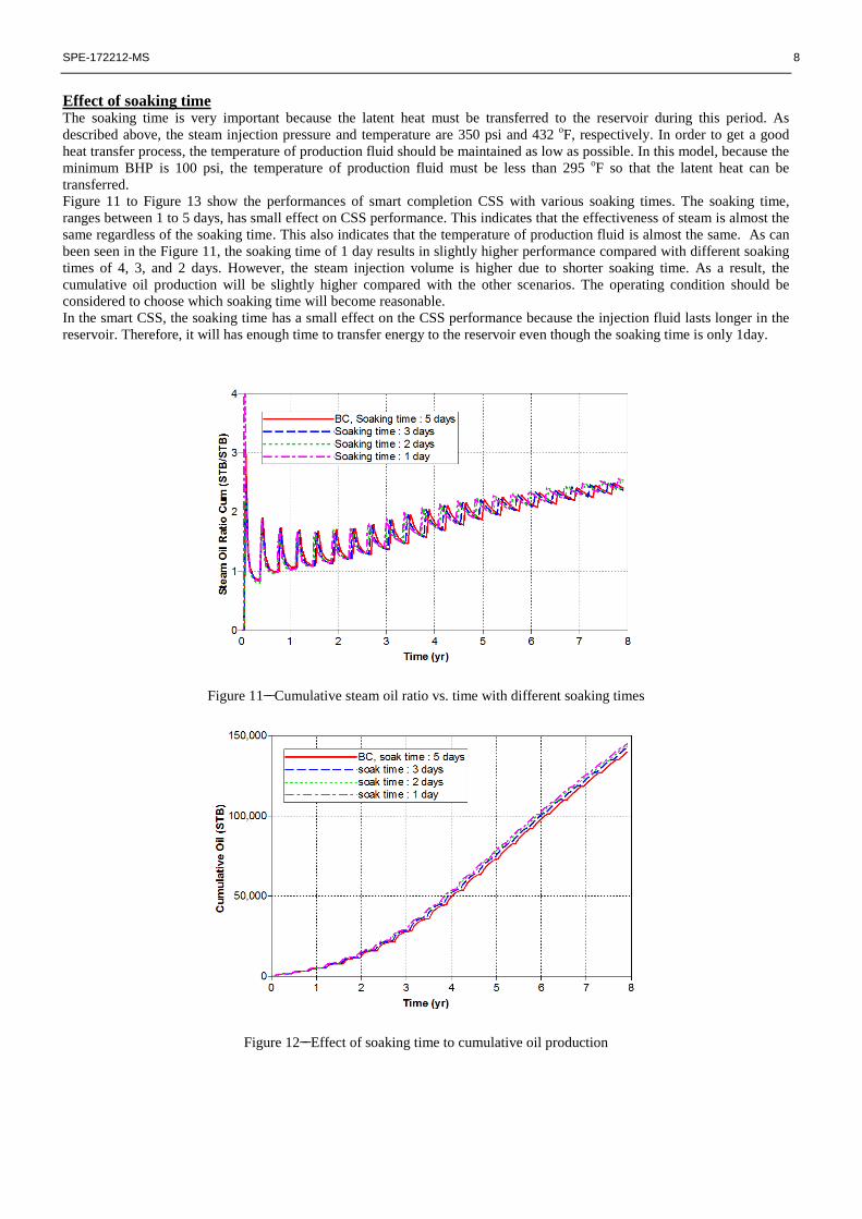
Figure 11 to Figure 13 show the performances of smart completion CSS with various soaking times. The soaking time,
ranges between 1 to 5 days, has small effect on CSS performance. This indicates that the effectiveness of steam is almost the
same regardless of the soaking time. This also indicates that the temperature of production fluid is almost the same. As can
been seen in the Figure 11, the soaking time of 1 day results in slightly higher performance compared with different soaking
times of 4, 3, and 2 days. However, the steam injection volume is higher due to shorter soaking time. As a result, the
cumulative oil production will be slightly higher compared with the other scenarios. The operating condition should be
considered to choose which soaking time will become reasonable.
In the smart CSS, the soaking time has a small effect on the CSS performance because the injection fluid lasts longer in the
reservoir. Therefore, it will has enough time to transfer energy to the reservoir even though the soaking time is only 1day.
Figure 11 Cumulative steam oil ratio vs. time with different soaking times
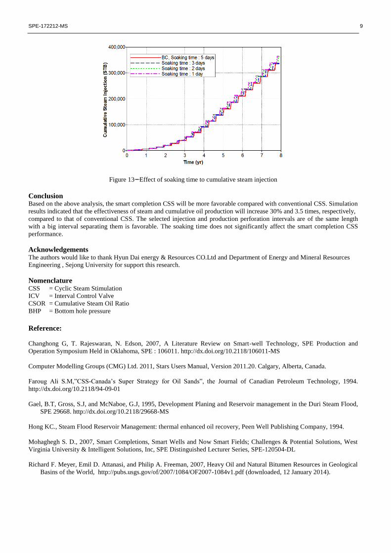
Figure 12 Effect of soaking time to cumulative oil production
SPE-172212-MS 9
Figure 13 Effect of soaking time to cumulative steam injection
Conclusion Based on the above analysis, the smart completion CSS will be more favorable compared with conventional CSS. Simulation
results indicated that the effectiveness of steam and cumulative oil production will increase 30% and 3.5 times, respectively,
compared to that of conventional CSS. The selected injection and production perforation intervals are of the same length
with a big interval separating them is favorable. The soaking time does not significantly affect the smart completion CSS
performance.
Acknowledgements The authors would like to thank Hyun Dai energy & Resources CO.Ltd and Department of Energy and Mineral Resources
Engineering , Sejong University for support this research.
Nomenclature CSS = Cyclic Steam Stimulation
ICV = Interval Control Valve
CSOR = Cumulative Steam Oil Ratio
BHP = Bottom hole pressure
Reference:
Changhong G, T. Rajeswaran, N. Edson, 2007, A Literature Review on Smart-well Technology, SPE Production and
Operation Symposium Held in Oklahoma, SPE : 106011. http://dx.doi.org/10.2118/106011-MS
Computer Modelling Groups (CMG) Ltd. 2011, Stars Users Manual, Version 2011.20. Calgary, Alberta, Canada.
Faroug Ali S.M,”CSS-Canada’s Super Strategy for Oil Sands”, the Journal of Canadian Petroleum Technology, 1994.
http://dx.doi.org/10.2118/94-09-01
Gael, B.T, Gross, S.J, and McNaboe, G.J, 1995, Development Planing and Reservoir management in the Duri Steam Flood,
SPE 29668. http://dx.doi.org/10.2118/29668-MS
Hong KC., Steam Flood Reservoir Management: thermal enhanced oil recovery, Peen Well Publishing Company, 1994.
Mohaghegh S. D., 2007, Smart Completions, Smart Wells and Now Smart Fields; Challenges & Potential Solutions, West
Virginia University & Intelligent Solutions, Inc, SPE Distinguished Lecturer Series, SPE-120504-DL
Richard F. Meyer, Emil D. Attanasi, and Philip A. Freeman, 2007, Heavy Oil and Natural Bitumen Resources in Geological
Basins of the World, http://pubs.usgs.gov/of/2007/1084/OF2007-1084v1.pdf (downloaded, 12 January 2014).
Copyright © 2022 FDOKUMEN