SMALL WASTE INCINERATION PLANT (SWIP) PERMIT ...
189
Prepared by: 360 Environmental Ltd The Oak Business Centre 79 – 93 Ratcliffe Road Sileby Leics LE12 7PU © Copyright 360 Environmental Ltd SMALL WASTE INCINERATION PLANT (SWIP) PERMIT ENVIRONMENTAL PERMITTING (ENGLAND & WALES) REGULATIONS 2010 (as amended) SCHEDULE 13A SITE DETAILS Name of the operator Energy Pyrolysis Ltd Activity address West Factory Bale Store Great Coates Industrial Estate Moody Lane Grimsby DN31 2TT National grid reference TA 241 127 EMISSIONS AND MONITORING REPORT APPENDIX 1 –ENERGY PYROLYSIS REPORT APPENDIX 2 – GAS BURNER APPENDIX 3 – ENERGY PYROLYSIS RESIDENCE TIME CALCULATION
-
Upload
khangminh22 -
Category
Documents
-
view
1 -
download
0
Transcript of SMALL WASTE INCINERATION PLANT (SWIP) PERMIT ...
Prepared by: 360 Environmental Ltd
The Oak Business Centre
79 – 93 Ratcliffe Road
Sileby
Leics
LE12 7PU
© Copyright 360 Environmental Ltd
SMALL WASTE INCINERATION PLANT (SWIP) PERMIT
ENVIRONMENTAL PERMITTING (ENGLAND & WALES) REGULATIONS 2010 (as amended)
SCHEDULE 13A
SITE DETAILS
Name of the operator
Energy Pyrolysis Ltd
Activity address
West Factory Bale Store
Great Coates Industrial Estate
Moody Lane
Grimsby
DN31 2TT
National grid reference
TA 241 127
EMISSIONS AND MONITORING REPORT
APPENDIX 1 –ENERGY PYROLYSIS REPORT
APPENDIX 2 – GAS BURNER
APPENDIX 3 – ENERGY PYROLYSIS RESIDENCE TIME CALCULATION

Prepared by: 360 Environmental Ltd
The Oak Business Centre
79 – 93 Ratcliffe Road
Sileby
Leics
LE12 7PU
© Copyright 360 Environmental Ltd
Monitoring and emissions report
Name of operator Energy Pyrolysis Ltd
Activity address
West Factory Bale Store
Great Coates Industrial Estate
Moody Lane
Grimsby
DN31 2TT
National grid reference
TA 241 127
1 – Monitoring results
The monitoring results, carried out by ESG are given in the attached document, Appendix 1,
and have been carried out under the relevant MCert standards.
2 – Gas incineration
The pyrolysis process in the pyrolysis vessel operates at a far lower temperature than the
850oC required by the Waste Incineration Directive, typically 380
oC – 420
oC, and it is this
primary combustion zone that is not subject to the temperature requirement. The waste
gases that the process produces, however, need to be raised to a temperature of at least
850oC in the secondary combustion zone which is located beneath the vessel.
The pyrolysis process itself requires the heating of the contents, once sealed and loaded, of
the vessel to a point whereby the pyrolysis reaction begins, typically, around 180oC. Once
this point within the vessel is reached the thermal decomposition of the tyres begins and
gas production commences. The process requires that the temperature applied to the
vessel, and therefore the temperature within the furnace, remains stable. Only once the
temperature is stable is the LPG supply stopped and the reaction continues by the
incineration of the waste gases (the gas contains molecules that are too small to condense

Prepared by: 360 Environmental Ltd
The Oak Business Centre
79 – 93 Ratcliffe Road
Sileby
Leics
LE12 7PU
© Copyright 360 Environmental Ltd
and that remain as hydrocarbon gas) alone. Continual temperature monitoring allows for
the LPG supply to be re-introduced at 950oC should the temperature indicate signs of
decline. No waste derived fuels are used in the start-up procedure but are used to maintain
temperatures above the minimum required. This allows for the temperature to be
maintained and the minimum temperature of 850oC to be achieved at all times.
The flow of gases are maintained by two fans, one of which is necessary for the LPG feed
and the second which is necessary for the pyrolysis gas feed, Both can be controlled
individually and ensure that the ingress of waste gases is both controlled and homogeneous.
At such times if the temperature is showing signs of decline then the LPG fan will initiate
when the LPG supply is ignited and the waste gas fan will cease.
This gas production is used to continue the heating process instead of using the LPG supply.
The fuel used initially to commence the pyrolysis reaction is LPG, which burns at a
temperature of approximately 1980oC
1. The gas burner, a Riello RS250/M, maintains the
heat within the vessel and in order for the LPG to ignite, it requires a mixture of LPG and air
in the range of 2% - 10%, it is after this introduction of air and waste gas that the
temperature is to be monitored as specified in Article 6 of Directive 2000/76/EC ‘Waste
Incineration Directive’.
The verification phase has allowed the emissions modelling, residence time and
temperature to be confirmed.
Incineration plants shall be designed, equipped, built and operated in such a way that the
gas resulting from the process is raised, after the last injection of combustion air, in a
controlled and homogeneous fashion and even under the most unfavourable conditions, to a
temperature of 850 °C, as measured near the inner wall or at another representative point of
the combustion chamber as authorised by the competent authority, for two seconds.
Each line of the incineration plant shall be equipped with at least one auxiliary burner. This
burner must be switched on automatically when the temperature of the combustion gases
1 Propane 2,820
oC in oxygen, 1,980
oC in air

Prepared by: 360 Environmental Ltd
The Oak Business Centre
79 – 93 Ratcliffe Road
Sileby
Leics
LE12 7PU
© Copyright 360 Environmental Ltd
after the last injection of combustion air falls below 850 °C or 1100 °C as the case may be. It
shall also be used during plant start-up and shut-down operations in order to ensure that the
temperature of 850 °C or 1100°C as the case may be is maintained at all times during these
operations and as long as unburned waste is in the combustion chamber.
To conclude, the waste gas incineration plant, the furnace, starts up using LPG only and
whilst unburnt waste remains in the combustion chamber, will maintain a temperature of at
least 850oC. During the process, should the temperature show signs of decline, the auxiliary
burner will automatically ignite at 950oC which will ensure that, after the last injection of
combustion air the temperature will be held at the required temperature for at least two
seconds. The burner is set to continue to operate until the temperature reaches 1100oC, at
which point the burner will switch off and combustion will continue using the pyrolysis gas.
The details of the gas burner are given in Appendix 2.
3 – Temperature clarification
The temperature will be measured at a point after the last injection of combustion air or
waste gases as described below in the Defra WID guidance;
Combustion gas temperature should be measured near the inner wall or another
representative point in the combustion chamber as authorised by the regulator. The
temperature measurement point should be located after the last injection of combustion air,
including secondary air and re-circulated flue gases where carried out.
Two temperature monitoring points will be located within the furnace and used to measure
and monitor temperature performance to ensure that the requirement for the minimum
temperature is achieved. During the verification phase, temperature monitoring has been
used to identify the most representative position for the temperature monitoring to take
place.
4 – Waste gas residence time
The residence time of gases in the combustion chamber has been calculated and the report
and calculation is given in Appendix 3.

ESG Job Number:
Report Date:
Version: 2
Report By: Johnathon Orley
MCERTS Number: MM 08 983
MCERTS Level: MCERTS Level 2 - Team Leader
Technical Endorsements: 1, 2, 3 & 4
Report Approved By: Dominic Houghton
MCERTS Number: MM 04 529
Business Title: MCERTS Level 2 - Team Leader
Technical Endorsements: 1, 2, 3 & 4
Signature:
Unit 5 Crown Industrial Estate
Kenwood Road
Stockport
SK5 6PH
Tel: 0161 443 0980
Fax: 0161 443 0989
Your contact at ESG
Permit:
N/A - Investigative Test
Operator & Address:
West Factory Bale Store
Grimsby
DN31 2SS
Great Coates Industrial Estate
Energy Pyrolosis
Moody Lane
Release Point:
Main Process Exhaust
Email: [email protected]
Mark Woodruff
Business Manager - North
Tel: 0161 443 0982
Sampling Date(s):
12,13 ,14th January / 25th February / 31th March 2015
9th April 2015
STACK EMISSIONS MONITORING REPORT
LNO 11967
Report Template Issue 19 (Nov 14) Page 1 of 59

Environmental Scientifics Group
www.esg.co.uk
EXECUTIVE SUMMARY
Stack Emissions Monitoring Objectives
- Plant
- Operator
- Stack Emissions Monitoring Test House
Emissions Summary
Monitoring Times
Process Details
Monitoring Methods
Analytical Methods
- Sampling Methods with Subsequent Analysis
- On-Site Testing
Sampling Location
- Sampling Plane Validation Criteria
- Duct Characteristics
- Sampling Lines & Sample Points
- Sampling Platform
- Sampling Location / Platform Improvement Recommendations
Sampling and Analytical Method Deviations
APPENDICES
APPENDIX 1 - Monitoring Schedule, Calibration Checklist & Monitoring Team
APPENDIX 2 - Summaries, Calculations, Raw Data and Charts
APPENDIX 3 - Measurement Uncertainty Budget Calculations
APPENDIX 4 - Record of Report Amendments
CONTENTS
Page 2 of 59
Energy Pyrolosis
Grimsby
Main Process Exhaust
LNO 11967 / Version 2
12,13 ,14th January / 25th February / 31th March 2015
N/A - Investigative Test

Environmental Scientifics Group
www.esg.co.uk
Plant
Main Process Exhaust
Operator
Energy Pyrolosis
West Factory Bale Store
Great Coates Industrial Estate
Moody Lane
Grimsby
DN31 2SS
Permit: Investigative
Stack Emissions Monitoring Test House
Environmental Scientifics Group Limited - Stockport Laboratory
Unit 5 Crown Industrial Estate
Kenwood Road
Stockport
SK5 6PH
UKAS and MCERTS Accreditation Number: 1015
Opinions and interpretations expressed herein are outside the scope of UKAS accreditation.
MCERTS accredited results will only be claimed where both the sampling and analytical stages are UKAS accredited.
This test report shall not be reproduced, except in full, without written approval of Environmental Scientifics Group Limited.
This test report replaces and supersedes version 1 dated 31st March 2015. Please see APPENDIX 4 for the changes made.
MONITORING OBJECTIVES
Environmental Scientifics Group Limited were commissioned by Mabbett & Associates Ltd to carry out stack emissions monitoring to determine the
release of prescribed pollutants from the following Plant under normal operating conditions.
Energy Pyrolosis operates a rubber recycling process at Grimsby.
EXECUTIVE SUMMARY
Page 3 of 59
Energy Pyrolosis
Grimsby
Main Process Exhaust
LNO 11967 / Version 2
12,13 ,14th January / 25th February / 31th March 2015
N/A - Investigative Test

Environmental Scientifics Group
www.esg.co.uk
Parameter Units Result Calculated
Uncertainty
Limit
+/-Total Particulate Matter mg/m³ 5.0 0.56 30
Particulate Emission Rate g/hr 4.5 0.50 -
Dioxins & Furans (NATO I-TEQ) ng/m³ 0.0013 0.0025 0.1
Dioxins & Furans (NATO I-TEQ) Emission Rate µg/hr 0.0016 0.0032 -
Dioxins & Furans (WHO TEQ Humans / Mammals) ng/m³ 0.0013 0.0026 -
Dioxins & Furans (WHO TEQ H / M) Emission Rate µg/hr 0.0017 0.0033 -
Dioxins & Furans (WHO TEQ Fish) ng/m³ 0.0014 0.0028 -
Dioxins & Furans (WHO TEQ Fish) Emission Rate µg/hr 0.0018 0.0035 -
Dioxins & Furans (WHO TEQ Birds) ng/m³ 0.0024 0.0048 -
Dioxins & Furans (WHO TEQ Birds) Emission Rate µg/hr 0.0030 0.0061 -
Dioxins & Furans (NATO I-TEQ) ng/m³ 0.0000 0.0000 -
Dioxins & Furans (NATO I-TEQ) Emission Rate µg/hr 0.0000 0.0000 -
Dioxins & Furans (WHO TEQ Humans / Mammals) ng/m³ 0.0000 0.0000 -
Dioxins & Furans (WHO TEQ H / M) Emission Rate µg/hr 0.0000 0.0000 -
Dioxins & Furans (WHO TEQ Fish) ng/m³ 0.0000 0.0000 -
Dioxins & Furans (WHO TEQ Fish) Emission Rate µg/hr 0.0000 0.0000 -
Dioxins & Furans (WHO TEQ Birds) ng/m³ 0.0000 0.0000 -
Dioxins & Furans (WHO TEQ Birds) Emission Rate µg/hr 0.0000 0.0000 -
Cadmium & Thallium mg/m³ 0.001 0.0003 0.05
Cadmium & Thallium Emission Rate g/hr 0.001 0.0002 -
Heavy Metals mg/m³ 0.11 0.022 0.5
Heavy Metals Emission Rate g/hr 0.09 0.019 -
mg/m³ 0.0003 0.0001 0.05
g/hr 0.0002 0.00005 -
Hydrogen Fluoride mg/m³ 1.8 0.221 2
Hydrogen Fluoride Emission Rate g/hr 1.7 0.200 -
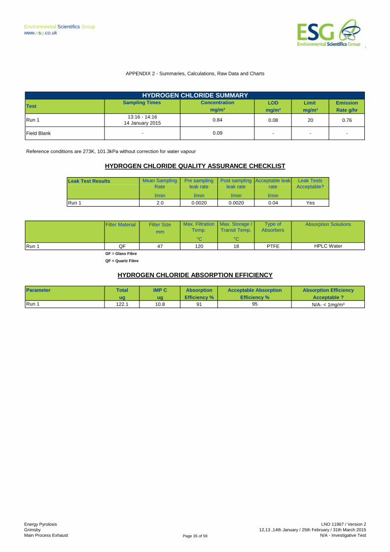
Hydrogen Chloride mg/m³ 0.84 0.100 20
Hydrogen Chloride Emission Rate g/hr 0.76 0.090 -
Sulphur Dioxide mg/m³ 0.41 0.049 100
Sulphur Dioxide Emission Rate g/hr 0.37 0.044 -
Volatile Organic Compounds mg/m³ 3.3 1.4 20
Volatile Organic Compounds Emission Rate g/hr 3.0 1.2 -
Oxides of Nitrogen (as NO2) mg/m³ 0.12 3.5 400
Oxides of Nitrogen (as NO2) Emission Rate g/hr 0.11 3.2 -
Sulphur Dioxide mg/m³ 7.3 3.9 100
Sulphur Dioxide Emission Rate g/hr 6.6 3.5 -
Carbon Monoxide mg/m³ 17.3 1.8 150
Oxygen % v/v 20.9 0.4 - P
Moisture % 17.7 0.54 - P
Stack Gas Temperature oC 53 - -
Stack Gas Velocity m/s 6.2 - -
Gas Volumetric Flow Rate (Actual) m³/hr 1096 - -
Gas Volumetric Flow Rate (STP, Wet) m³/hr 907 - -
Gas Volumetric Flow Rate (STP, Dry) m³/hr 746 - -
Gas Volumetric Flow Rate at Reference Conditions m³/hr 907 - -
Reference conditions are 273K, 101.3kPa without correction for water vapour
P
Mercury
Mercury Emission Rate
Dioxins & Furans - UPPER Limits
Dioxins & Furans - LOWER Limits
P
P
MCERTS
accredited
result
P
P
P
P
P
P
P
P
P
P
P
P
P
P
P
ND = None Detected,
Results at or below the limit of detection are highlighted by bold italic text.
The above volumetric flow rate is calculated using data from the preliminary survey. Mass emissions for non isokinetic tests are calculated using these
values. For all isokinetic testing the mass emission is calculated using test specific flow data and not the above values.
P
P
EXECUTIVE SUMMARY
EMISSIONS SUMMARY
Page 4 of 59
Energy Pyrolosis
Grimsby
Main Process Exhaust
LNO 11967 / Version 2
12,13 ,14th January / 25th February / 31th March 2015
N/A - Investigative Test

Environmental Scientifics Group
www.esg.co.uk
Total Particulate Matter Run 1
Cadmium & Thallium Run 1
Heavy Metals Run 1
Mercury Run 1
Hydrogen Fluoride Run 1
Hydrogen Chloride Run 1
Sulphur Dioxide Run 1
Volatile Organic Compounds Run 1
Combustion Gases
60 minutes14:10 - 15:10
13 January 2014
60 minutes
13:16 - 14:16
14 January 2014
60 minutes
14 January 2014
25 February 2015
14:10 - 15:1013 January 2014
13 January 2014 14:10 - 15:10
60 minutes
120 minutes
14:34 - 15:34
15:40 - 17:40
Dioxins & Furans Run 1 360 minutes14:33 - 20:33
MONITORING TIMES
13 January 2014
60 minutes
12 January 2014 11:25 - 12:25
Sampling TimesSampling Date(s)Parameter
EXECUTIVE SUMMARY
Sampling Duration
14 January 2015
180 minutes
Stack Gas Flow Rate & Temperature Run 1
60 minutes
-12 January 2014
180 minutes14:40 - 17:40
31 March 2015 11:00 - 14:00
12:00
Page 5 of 59
Energy Pyrolosis
Grimsby
Main Process Exhaust
LNO 11967 / Version 2
12,13 ,14th January / 25th February / 31th March 2015
N/A - Investigative Test

Environmental Scientifics Group
www.esg.co.uk
Description of process Rubber recycling
Continuous or batch Batch
Product Details Diesel and Carbon
Part of batch to be monitored (if applicable) When operating at temperature
Normal load, throughput or continuous rating Normal Load
Fuel used during monitoring LPG and recycled process gas
Abatement None
Plume Appearance Plume Visible
PROCESS DETAILS
EXECUTIVE SUMMARY
Process DetailsParameter
Page 6 of 59
Energy Pyrolosis
Grimsby
Main Process Exhaust
LNO 11967 / Version 2
12,13 ,14th January / 25th February / 31th March 2015
N/A - Investigative Test

Environmental Scientifics Group
www.esg.co.uk
Species ESG UKAS Lab MCERTS Limit of Calculated
Technical Number Accredited Detection MU
Procedure Method (LOD) +/- %
TPM AE 104 1015 Yes 0.27 mg/m³ 11.3 %
PCDD/PCDF AE 109 1015 Yes 0.001 ng/m³ 201 %
Cd & Tl AE 108 1015 Yes 0.00003 mg/m³ 20.3 %
Heavy Metals AE 108 1015 Yes 0.001 mg/m³ 20.3 %
Mercury AE 107/AE 108 1015 Yes 0 mg/m³ 20.3 %
Hydrogen Fluoride AE 113 1015 Yes 0.03 mg/m³ 12 %
Hydrogen Chloride AE 111 1015 Yes 0.08 mg/m³ 11.9 %
Sulphur Dioxide AE 112 1015 Yes 0.09 mg/m³ 11.9 %
VOCs AE 102 1015 Yes 0.4 mg/m³ 41.5 %
NOX AE 102 1015 Yes 0.51 mg/m³ 2961%
SO2 AE 102 1015 Yes 0.62 mg/m³ 54%
CO AE 102 1015 Yes 0.35 mg/m³ 10%
O2 AE 102 1015 Yes 0.01% 2%
H2O AE 105 1015 Yes 0.01% 3%
Flow Rate / Temp. AE 122 1015 Yes 5 Pa -
EXECUTIVE SUMMARY
SRM - EN 13284-1
SRM - EN 1911
SRM - EN 14792
SRM - EN 15058
SRM - EN 12619:2013
AM - EN 14789
SRM - EN 1948 - Part 1
MONITORING METHODS
Method
Standard Reference Method /
Alternative Method
AM - M21
SRM - EN 14791
SRM - BS EN 14790
SRM - EN 16911-1
SRM - ISO 15713
SRM - EN 13211 / MID 14385
The selection of standard reference / alternative methods employed by Environmental Scientifics Group Limited is determined, wherever possible by the
hierarchy of method selection outlined in Irish Environment Protection Agency Technical Guidance Note (Monitoring) AG2. i.e. CEN, ISO, BS, US EPA
etc.
SRM - EN 14385
SRM - EN 14385
Monitoring Methods
Page 7 of 59
Energy Pyrolosis
Grimsby
Main Process Exhaust
LNO 11967 / Version 2
12,13 ,14th January / 25th February / 31th March 2015
N/A - Investigative Test

Environmental Scientifics Group
www.esg.co.uk
The following tables list the analytical methods employed together with the custody and archiving details:
Species Analytical UKAS Lab Analysis Lab Sample Archive
Procedure Number Archive Period
Location
TPM AE 106 1015 Yes ESG Stockport ESG Stockport 3 months
PCDD/PCDF ANU/SOP/3007 1549 Yes SAL SAL 3 months
Cd & TlANU/SOP/117,
101,1021015 Yes ESG Bretby ESG Bretby 3 months
Heavy MetalsANU/SOP/117,
101,1021015 Yes ESG Bretby ESG Bretby 3 months
MercuryANU/SOP/117,
101,1021015 Yes ESG Bretby ESG Bretby 3 months
Hydrogen Fluoride ASC/SOP/110/107 1015 Yes ESG Bretby ESG Bretby 3 months
Hydrogen Chloride ASC/SOP/110/107 1015 Yes ESG Bretby ESG Bretby 3 months
Sulphur Dioxide ASC/SOP/110/107 1015 Yes ESG Bretby ESG Bretby 3 months
- - - - - - -
Species Analytical UKAS Lab MCERTS Laboratory Data Archive
Procedure Number Accredited Archive Period
Analysis Location
VOCs AE 102 1015 Yes ESG Stockport ESG Stockport 5 years
NOX AE 102 1015 Yes ESG Stockport ESG Stockport 5 years
SO2 AE 102 1015 Yes ESG Stockport ESG Stockport 5 years
CO AE 102 1015 Yes ESG Stockport ESG Stockport 5 years
O2 AE 102 1015 Yes ESG Stockport ESG Stockport 5 years
H2O AE 105 1015 Yes ESG Stockport - -
Chemiluminescence
Non Dispersive Infra Red
SAMPLING METHODS WITH SUBSEQUENT ANALYSIS
Analytical Technique
Inductively coupled Plasma - Mass
Spectrometry
Inductively coupled Plasma - Mass
Spectrometry
Gravimetric
Flame Ionisation Detection
Non Dispersive Infra Red
EXECUTIVE SUMMARY
Analytical Technique
Gas Chromatography - High
Resolution Mass Spectometry
Ion Chromatography
Inductively coupled Plasma - Mass
Spectrometry
Gravimetric
Analytical Methods
-
Ion Chromatography
(ESG or
Subcontract)
Ion Chromatography
Zirconia Cell
ON-SITE TESTING
UKAS
Accredited Lab
Analysis
Page 8 of 59
Energy Pyrolosis
Grimsby
Main Process Exhaust
LNO 11967 / Version 2
12,13 ,14th January / 25th February / 31th March 2015
N/A - Investigative Test

Environmental Scientifics Group
www.esg.co.uk
Sampling Plane Validation Criteria Value Units Requirement Compliant Method
Lowest Differential Pressure 26 Pa >= 5 Pa Yes EN 16911-1
Lowest Gas Velocity 5.9 m/s - - -
Highest Gas Velocity 6.5 m/s - - -
Ratio of Gas Velocities 1.09 : 1 < 3 : 1 Yes EN 16911-1
Mean Velocity 6.2 m/s - - -
Maximum angle of flow with regard to duct axis <15 o < 15
o Yes EN 16911-1
No local negative flow Yes - - Yes EN 16911-1
Highly homogeneous flow stream / gas velocity Yes - - Yes ISO 10396
Value Units Isokinetic Isokinetic
Shape Circular - (CEN Methods) (ISO Methods)
Depth 0.25 m Sample port size 4 inch BSP - 2 inch BSP
Width - m Number of lines used 1 - 1
Area 0.05 m2 Number of points / line 1 - 1
Port Depth 60 mm Duct orientation Vertical - Vertical
Filtration In Stack - In Stack
In Stack - In Stack
General Platform Information
Permanent / Temporary Platform / Ground level / Floor Level / Roof
Inside / Outside
AG1 Platform requirements
Is there a sufficient working area so work can be performed in a compliant manner
Platform has 2 levels of handrails (approximately 0.5 m & 1.0 m high)
Platform has vertical base boards (approximately 0.25 m high)
Platform has removable chains / self closing gates at the top of ladders
Handrail / obstructions do not hamper insertion of sampling equipment
Depth of Platform = >Stack depth / diameter + wall and port thickness + 1.5m
Sampling Platform Improvement Recommendations (if applicable)
DUCT CHARACTERISTICS SAMPLING LINES & POINTS
SAMPLING PLATFORM
No
Non-Iso &
Gases
Yes
SAMPLING LOCATION
Yes
The platform does not meet the requirements of EA Guidance Note M1.
No
Inside
Filtration for TPM
No
No
EXECUTIVE SUMMARY
Permanent
Page 9 of 59
Energy Pyrolosis
Grimsby
Main Process Exhaust
LNO 11967 / Version 2
12,13 ,14th January / 25th February / 31th March 2015
N/A - Investigative Test

Environmental Scientifics Group
www.esg.co.uk
In this instance there were no deviations from the sampling and analytical methods employed.
Sampling & Analytical Method Deviations
EXECUTIVE SUMMARY
Page 10 of 59
Energy Pyrolosis
Grimsby
Main Process Exhaust
LNO 11967 / Version 2
12,13 ,14th January / 25th February / 31th March 2015
N/A - Investigative Test

Environmental Scientifics Group
www.esg.co.uk
APPENDIX 2 - Summaries, Calculations, Raw Data and Charts
APPENDIX 3 - Measurement Uncertainty Budget Calculations
APPENDIX 4 - Record of Report Amendments
CONTENTS
APPENDIX 1 - Monitoring Schedule, Calibration Checklist & Monitoring Team
APPENDICES
Page 11 of 59
Energy Pyrolosis
Grimsby
Main Process Exhaust
LNO 11967 / Version 2
12,13 ,14th January / 25th February / 31th March 2015
N/A - Investigative Test

Environmental Scientifics Group
www.esg.co.uk
Species ESG UKAS Lab MCERTS
Technical Number Accredited
Procedure Method
TPM AE 104 1015 Yes 1
PCDD/PCDF AE 109 1015 Yes 1
Cd & Tl AE 108 1015 Yes 1
Heavy Metals AE 108 1015 Yes 1
Mercury AE 107/AE 108 1015 Yes 1
Hydrogen Fluoride AE 113 1015 Yes 1
Hydrogen Chloride AE 111 1015 Yes 1
Sulphur Dioxide AE 112 1015 Yes 1
VOCs AE 102 1015 Yes 1
NOx AE 102 1015 Yes 1
SO2 AE 102 1015 Yes 1
CO AE 102 1015 Yes 1
O2 AE 102 1015 Yes 1
H2O AE 105 1015 Yes 1
Flow Rate / Temp. AE 122 1015 Yes 1
AM - EN 14789
SRM - EN 12619:2013
MONITORING SCHEDULE
SRM - EN 14385
SRM - EN 14792
SRM - EN 16911-1
SRM - EN 15058
AM - M21
Standard Reference Method /
Alternative Method
APPENDIX 1 - Monitoring Schedule, Calibration Checklist & Monitoring Team
SRM - ISO 15713
SRM - EN 1911
SRM - EN 13284-1
SRM - EN 14385
SRM - EN 13211 / MID 14385
Number of
Samples
SRM - EN 1948 - Part 1
SRM - BS EN 14790
Method
SRM - EN 14791
Page 12 of 59
Energy Pyrolosis
Grimsby
Main Process Exhaust
LNO 11967 / Version 2
12,13 ,14th January / 25th February / 31th March 2015
N/A - Investigative Test

Environmental Scientifics Group
www.esg.co.uk
Equipment I.D. Equipment I.D. Equipment I.D.
LNO 13-05 LNO 21-15 LNO 00-12/00-13
LNO 03-05 - LNO 24-JO
LNO 03-05 - LNO 17-JO
LNO 03-05 - -
LNO 17-05 - LNO 08-JO
LNO 09-25 - LNO 01-JO
LNO 11-24 - LNO 03-JO
LNO 10-24 LNO 21-06 LNO 10-JO
- - -
- - -
LNO 06-JO - -
- - -
LNO 14-JO LNO 21-39 -
- - -
LNO 10-89 - -
LNO 31-JO - -
- - -
- - LNO 18-86
LNO 23-JO - -
NOTE: If the equipment I.D is represented by a dash (-), then this piece of equipment has not been used for this test.
Cylinder I.D
Number Supplier ppm %
Analytical
Tolerance +/-
%
Propane 242577 BOC 80 - 2
Nitric Oxide HPC 831 BOC 203 - 2
Sulphur Dioxide HPC 801 BOC 160 - 2
Carbon Monoxide HPC 804 BOC 162 - 2
Last Impinger Arm
10m Heated Line (1)
20m Heated Line (1)
L-Pitot Ecophysics NOx Analyser
Control Box DGM
S-Pitot
1m Heated Line (2)
Anemometer 1m Heated Line (1)
Dioxins Cond. Thermocouple
Inclinometer (Swirl Device)
CALIBRATION GASES
Extractive Sampling Instrumental Analyser/s
CALIBRATEABLE EQUIPMENT CHECKLISTMiscellaneous
Laboratory Balance
Meter Out Thermocouple
Gas (traceable to ISO 17025)
Heater Controller
20m Heated Line (2)
MFC Display module
Probe
Probe Thermocouple
Stackmaster
FTIR Heater Box for Heated Line
Equipment
APPENDIX 1 - Monitoring Schedule, Calibration Checklist & Monitoring Team
Control Box Timer
Stack Thermocouple
Equipment
Oven Box
Callipers
Probe JCT Heated Head Filter
Protractor
Digital Micromanometer
FT-IR
Bernath 3006 FID
Signal 3030 FID Barometer
Thermo FID
Digital Temperature Meter
Servomex
Probe Thermocouple
FT-IR Oven BoxMeter In Thermocouple
Horiba PG-250 Analyser
Box Thermocouples Tape Measure
Equipment
Stopwatch
Mass Flow Controller
10m Heated Line (2)
15m Heated Line (1)Small DGM
1m Heated Line (3)Site Balance
5m Heated Line (1)
Chiller (JCT/MAK 10)
Page 13 of 59
Energy Pyrolosis
Grimsby
Main Process Exhaust
LNO 11967 / Version 2
12,13 ,14th January / 25th February / 31th March 2015
N/A - Investigative Test

Environmental Scientifics Group
www.esg.co.uk
Team Leader Johnathon Orley
MCERTS Level 2, Technical Endorsements 1, 2, 3 & 4
MM 08 983
MCERTS Expiry Date - Mar 2015
H&S Expiry Date - Nov 2018
Technician Vic Johnson
MCERTS Level 1, Technical Endorsement 1
MM 10 1085
MCERTS Expiry Date - Dec 2016
H&S Expiry Date - Sep 2015
APPENDIX 1 - Monitoring Schedule, Calibration Checklist & Monitoring Team
STACK EMISSIONS MONITORING TEAM
Page 14 of 59
Energy Pyrolosis
Grimsby
Main Process Exhaust
LNO 11967 / Version 2
12,13 ,14th January / 25th February / 31th March 2015
N/A - Investigative Test

Environmental Scientifics Group
www.esg.co.uk
Uncertainty Limit Emission
mg/m³ mg/m³ Rate g/hr
0.57 30 4.5
Blank - - -
Reference conditions are 273K, 101.3kPa without correction for water vapour
TestFilter & Probe
Rinse Number
Filter Start
WeightFilter End Weight
Mass Gained
on Filter
Probe Rinse
Start Weight
Probe Rinse
End Weight
Mass Gained
on Probe
Combined
Total Mass
Gained
g g g g g g g
Run 1 G2691 0.10900 0.11363 0.00463 187.22470 187.22520 0.00050 0.00513
If total mass gained is less than the LOD then the LOD is reported
TestFilter & Probe
Number
Filter Start
WeightFilter End Weight
Mass Gained
Filter
Probe Start
Weight
Probe End
Weight
Mass Gained
Probe
Combined
Total Mass
Gained
g g g g g g g
Run 1 G2690 0.11028 0.11001 -0.00027 186.01650 186.01620 -0.00030 0.00028
If total mass gained is less than the LOD then the LOD is reported
Concentration
Run 1
Acetone Blank Value
mg/l
FILTER INFORMATION
0.27
mg/m³
-
mg/l
2.0 10
APPENDIX 2 - Summaries, Calculations, Raw Data and Charts
Parameter Sampling Times
5.0
TOTAL PARTICULATE MATTER SUMMARY
11:25 - 12:25
12 January 2014
SAMPLES
Acceptable Value
BLANKS
Page 15 of 59
Energy Pyrolosis
Grimsby
Main Process Exhaust
LNO 11967 / Version 2
12,13 ,14th January / 25th February / 31th March 2015
N/A - Investigative Test

Environmental Scientifics Group
www.esg.co.uk
ISOKINETIC SAMPLING EQUATIONS - RUN 1 TPM
Absolute pressure of stack gas, Ps Molecular weight of dry gas, Md
Barometric pressure, Pb mm Hg 750.01 CO2 % 0.00
Stack static pressure, Pstatic mm H2O 5.10 O2 % 21.00
Ps = Pb + (Pstatic) mm Hg 750.38 Total % 21.00
N2 (100 -Total) % 79.00
Vol. of water vapour collected, Vwstd Md = 0.44(%CO2)+0.32(%O2)+0.28(%N2) 28.84
g 145.9 Molecular weight of wet gas, Ms
Vwstd = (0.001246)(Vlc) m3 0.1817914 Ms = Md(1 - Bwo) + 18(Bwo) g/gmol 26.92
Volume of gas metered dry, Vmstd Actual flow of stack gas, Qa
Volume of gas sample through gas meter, Vm m31.085 Area of stack, As m
2 0.05
Gas meter correction factor, Yd 0.83543 Qa = (60)(As)(Vs) m³/min 18.2
Mean dry gas meter temperature, Tm oC16.731 Total flow of stack gas, Q
19.871 Conversion factor (K/mm.Hg) 0.3592
Vmstd = (0.3592)(Vm)(Pb+(DH/13.6))(Yd) m30.844 Qstd = (Qa)Ps(0.3592)(1-Bwo) Dry 12.3
(Ts) +273
Volume of gas metered wet, Vmstw @O2ref No O2 Ref
Vmstw = Vmstd + Vwstd m3 1.0263 (Ts) +273
Qstw = (Qa)Ps(0.3592) Wet 14.89
(Ts) +273
No Percent isokinetic, %I
Nozzle diameter, Dn mm 8.00
% oxygen measured in gas stream, act%O2 21.0 Nozzle area, An mm2 50.27
% oxygen reference condition 21 Total sampling time, q min 60
No O2 Ref %I = (4.6398E6)(Ts+273)(Vmstd) % 112.2
(Ps)(Vs)(An)(q)(1-Bwo)
Vmstd@X%oxygen = (Vmstd) (O2 Ref) m3 No O2 Ref Acceptable isokinetic range 95% to 115% Yes
Moisture content, Bwo Particulate Concentration, C
Bwo = Vwstd 0.1771 Mass collected on filter, Mf g 0.00463
% 17.71 Mass collected in probe, Mp g 0.00050
Moisture by FTIR % - Total mass collected, Mn g 0.00513
Velocity of stack gas, Vs Cwet = Mn mg/m³ 4.999
Pitot tube velocity constant, Kp 34.97 Vmstw
Velocity pressure coefficient, Cp .84 Cdry = Mn mg/m³ 6.075
Mean of velocity heads, DPavg mm H2O 2.72 Vmstd
Mean square root of velocity heads, DP 1.65 Cdry@X%O2 = Mn mg/m³ No O2 Ref
Mean stack gas temperature, TsoC 57
Vs = (Kp)(Cp)(DP)(Ts + 273)) m/s 6.19 Particulate Emission Rates, E
(Ms)(Ps) E = [(Cwet)(Qstw)(60)] / 1000 4.47
Moisture trap weight increase,Vlc
13.6
O2 Reference
Factor
Is the process burning hazardous waste? (If yes, no
favourable oxygen correction)
Tm + 273
Vol. of gas metered at O2 Ref. Cond., Vmstd@X%O2
Vmstd + Vwstd
Mean pressure drop across orifice, DH mmH2O
QstdO2 = (Qa)Ps(0.3592)(1-Bwo)(O2REF)
APPENDIX 2 - Summaries, Calculations, Raw Data and Charts
O2 Ref = 21.0 - act%O2
21.0 - ref%O2
Vmstd@X%oxygen
Page 16 of 59
Energy Pyrolosis
Grimsby
Main Process Exhaust
LNO 11967 / Version 2
12,13 ,14th January / 25th February / 31th March 2015
N/A - Investigative Test

Environmental Scientifics Group
www.esg.co.uk
litre/min litre/min litre/min mm Hg litre/min
Run 1 15.11 0.2 0.2 -304.8 0.30 Yes
% mg/m³ mg/m³
Run 1 112.16 Yes Run 1 0.27 1.5 Yes
Acceptable isokinetic range 95% to 115% The above is based on both the Filter and rinse uncertainty
mg/m3
mg/m3
mg/m3
mg/m3
mm °C
Run 1 GF 47 58
GF = Glass Fibre
QF = Quartz Fibre
TOTAL PARTICULATE MATTER QUALITY ASSURANCE CHECKLIST
ISOKINETICITY
Leak Tests
Acceptable?
Acceptable
Isokineticity
Pre-sampling
Leak Rate
Mean Sampling
Rate
Result
Blank 1
Pre-use Filter Conditioning
Temperature
3.0
Max Filtration
Temperature
30
APPENDIX 2 - Summaries, Calculations, Raw Data and Charts
LOD < 5%
ELVRun
WEIGHING BALANCE UNCERTAINTY
BLANK VALUE
LEAK RATE
Filter SizeRun
Maximum
Vacuum
Run
Run
Acceptable
Blank Value
Post-use Filter Conditioning
Temperature
Daily Emission
Limit Value
Overall Blank
Acceptable
Overall Blank
Value
Filter Material
Yes
Isokinetic
Variation
FILTERS
°C
180 160
5% ELV
°C
Post-sampling
Leak RateRun
Acceptable
Leak Rate
0.27
Page 17 of 59
Energy Pyrolosis
Grimsby
Main Process Exhaust
LNO 11967 / Version 2
12,13 ,14th January / 25th February / 31th March 2015
N/A - Investigative Test

Environmental Scientifics Group
www.esg.co.uk
LOD Limit Emission
ng/m³ ng/m³ Rate µg/hr
Run 1 0.00125 0.1 0.002
Field Blanks Run 1 - - -
LOD Limit Emission
ng/m³ ng/m³ Rate µg/hr
Run 1 0.00130 - 0.002
Field Blanks Run 1 - - -
LOD Limit Emission
ng/m³ ng/m³ Rate µg/hr
Run 1 0.00137 - 0.002
Field Blanks Run 1 - - -
LOD Limit Emission
ng/m³ ng/m³ Rate µg/hr
Run 1 0.00239 - 0.003
Field Blanks Run 1 - - -
Reference conditions are 273K, 101.3kPa without correction for water vapour
WHO TEQ (Birds)
APPENDIX 2 - Summaries, Calculations, Raw Data and Charts
Sampling Times
0.00156
Sampling Times
0.00130
0.00224-
Test
ng/m³
Sampling Times
-
14:33 - 20:33
25 February 2015
0.00158
ng/m³
Test
0.00239
14:33 - 20:33
25 February 2015
ng/m³
-
14:33 - 20:33
25 February 2015
WHO TEQ (Humans / Mammals)
0.00137
ng/m³
NATO I-TEQ
-
Concentration
ConcentrationTest
DIOXINS & FURANS SUMMARY - UPPER LIMIT
Test
Sampling Times
14:33 - 20:33
25 February 2015
0.00165
Concentration
WHO TEQ (Fish)
Concentration
0.00125
Page 18 of 59
Energy Pyrolosis
Grimsby
Main Process Exhaust
LNO 11967 / Version 2
12,13 ,14th January / 25th February / 31th March 2015
N/A - Investigative Test

Environmental Scientifics Group
www.esg.co.uk
LOD Limit Emission
ng/m³ ng/m³ Rate µg/hr
Run 1 - 0.1 0.0000
Field Blanks Run 1 - - -
LOD Limit Emission
ng/m³ ng/m³ Rate µg/hr
Run 1 - - 0.00
Field Blanks Run 1 - - -
LOD Limit Emission
ng/m³ ng/m³ Rate µg/hr
Run 1 - - 0.00
Field Blanks Run 1 - - -
LOD Limit Emission
ng/m³ ng/m³ Rate µg/hr
Run 1 - - 0.00
Field Blanks Run 1 - - -
Reference conditions are 273K, 101.3kPa without correction for water vapour
0.00156
WHO TEQ (Fish)
WHO TEQ (Birds)
NATO I-TEQ
WHO TEQ (Humans / Mammals)
Sampling Times
Sampling Times
-
ng/m³
-
Test
Test
0.00000000
Test
ng/m³
0.000000
-
0.00000014:33 - 20:33
25 February 2015
Concentration
APPENDIX 2 - Summaries, Calculations, Raw Data and Charts
Concentration
0.00158
14:33 - 20:33
25 February 2015
ng/m³
Test
-
DIOXINS & FURANS SUMMARY - LOWER LIMIT
14:33 - 20:33
25 February 2015
Sampling Times
Concentration
Sampling Times
ng/m³
0.00224
Concentration
0.0000014:33 - 20:33
25 February 2015
0.00165
Page 19 of 59
Energy Pyrolosis
Grimsby
Main Process Exhaust
LNO 11967 / Version 2
12,13 ,14th January / 25th February / 31th March 2015
N/A - Investigative Test

Environmental Scientifics Group
www.esg.co.uk
Congener Result NATO WHO
I-TEQ TEQ Actual Permitted
ng ng ng % %
Dioxins
2378 Tetra CDD < 0.0022 0.0022 0.0022 78 50 - 130
12378 Penta CDD < 0.0032 0.0016 0.0032 99 50 - 130
123478 Hexa CDD < 0.0034 0.00034 0.00034 74 50 - 130
123678 Hexa CDD < 0.0035 0.00035 0.00035 69 50 - 130
123789 Hexa CDD < 0.0035 0.00035 0.00035
1234678 Hepta CDD < 0.048 0.00048 0.00048 96 50 - 130
OCDD Octa CDD < 0.45 0.00045 0.000135 100 20 - 150
Total 2378-Dioxins 0.5138 0.00577 0.007055
Furans
2378 Tetra CDF < 0.0087 0.00087 0.00087 78 50 - 130
12378 Penta CDF < 0.0032 0.00016 0.000096 91 >=50
23478 Penta CDF < 0.0039 0.00195 0.00117 100 50 - 130
123478 Hexa CDF < 0.0038 0.00038 0.00038 69 50 - 130
123678 Hexa CDF < 0.0038 0.00038 0.00038 71 50 - 130
234678 Hexa CDF < 0.0041 0.00041 0.00041 71 50 - 130
123789 Hexa CDF < 0.0045 0.00045 0.00045 113 >=50
1234678 Hepta CDF < 0.014 0.00014 0.00014 88 20 - 150
1234789 Hepta CDF < 0.004 0.00004 0.00004 109 >=50
OCDF Octa CDF < 0.028 0.000028 0.0000084 107 20 - 150
Total 2378-Furans 0.078 0.004808 0.0039444
Mean Recoveries (%) 88
Total 2378 Isomers 0.5918 0.01058 0.01100
Total ITEQ (<LOD = 0) 0.00000 0.00000
NOTE: The Total 2378 Isomers result includes all isomers below the limit of detection. This gives a "worst case" Dioxins & Furans result.
NATO I-TEQ & WHO TEQ (Humans / Mammals)
Humans /
Mammals
Extraction Recovery
DIOXINS & FURANS ANALYSIS SUMMARY - RUN 1
APPENDIX 2 - Summaries, Calculations, Raw Data and Charts
Page 20 of 59
Energy Pyrolosis
Grimsby
Main Process Exhaust
LNO 11967 / Version 2
12,13 ,14th January / 25th February / 31th March 2015
N/A - Investigative Test

Environmental Scientifics Group
www.esg.co.uk
Congener Result WHO WHO
TEQ TEQ Actual Permitted
Fish Birds
ng ng ng % %
Dioxins
2378 Tetra CDD < 0.0022 0.0022 0.0022 78 50 - 130
12378 Penta CDD < 0.0032 0.0032 0.0032 99 50 - 130
123478 Hexa CDD < 0.0034 0.0017 0.00017 74 50 - 130
123678 Hexa CDD < 0.0035 0.000035 0.000035 69 50 - 130
123789 Hexa CDD < 0.0035 0.000035 0.000035
1234678 Hepta CDD < 0.048 0.000048 0.000048 96 50 - 130
OCDD Octa CDD < 0.45 - - 100 20 - 150
Total 2378-Dioxins 0.5138 0.007218 0.005688
Furans
2378 Tetra CDF < 0.0087 0.000435 0.0087 78 50 - 130
12378 Penta CDF < 0.0032 0.00016 0.000032 91 >=50
23478 Penta CDF < 0.0039 0.00195 0.0039 100 50 - 130
123478 Hexa CDF < 0.0038 0.00038 0.00038 69 50 - 130
123678 Hexa CDF < 0.0038 0.00038 0.00038 71 50 - 130
234678 Hexa CDF < 0.0041 0.00041 0.00041 71 50 - 130
123789 Hexa CDF < 0.0045 0.00045 0.00045 113 >=50
1234678 Hepta CDF < 0.014 0.00014 0.00014 88 20 - 150
1234789 Hepta CDF < 0.004 0.00004 0.00004 109 >=50
OCDF Octa CDF < 0.028 0.0000028 0.0000028 107 20 - 150
Total 2378-Furans 0.078 0.0043478 0.0144348
Mean Recoveries (%) 88
Total 2378 Isomers 0.5918 0.0115658 0.0201228
Total ITEQ (<LOD = 0) 0 0
NOTE: The Total 2378 Isomers result includes all isomers below the limit of detection. This gives a "worst case" Dioxins & Furans result.
WHO TEQ (Fish) & WHO TEQ (Birds)
Extraction Recovery
DIOXINS & FURANS ANALYSIS SUMMARY - RUN 1
APPENDIX 2 - Summaries, Calculations, Raw Data and Charts
Page 21 of 59
Energy Pyrolosis
Grimsby
Main Process Exhaust
LNO 11967 / Version 2
12,13 ,14th January / 25th February / 31th March 2015
N/A - Investigative Test

Environmental Scientifics Group
www.esg.co.uk
Congener Result NATO WHO
I-TEQ TEQ Actual Permitted
ng ng ng % %
Dioxins
2378 Tetra CDD 0.0023 0.0023 0.0023 71 50 - 130
12378 Penta CDD 0.0023 0.00115 0.0023 100 50 - 130
123478 Hexa CDD 0.0039 0.00039 0.00039 69 50 - 130
123678 Hexa CDD 0.0048 0.00048 0.00048 63 50 - 130
123789 Hexa CDD 0.0047 0.00047 0.00047
1234678 Hepta CDD 0.055 0.00055 0.00055 77 50 - 130
OCDD Octa CDD 0.43 0.00043 0.000129 71 20 - 150
Total 2378-Dioxins 0.503 0.00577 0.006619
Furans
2378 Tetra CDF 0.005 0.0005 0.0005 76 50 - 130
12378 Penta CDF 0.0042 0.00021 0.000126 90 >=50
23478 Penta CDF 0.0043 0.00215 0.00129 109 50 - 130
123478 Hexa CDF 0.0086 0.00086 0.00086 65 50 - 130
123678 Hexa CDF 0.0083 0.00083 0.00083 67 50 - 130
234678 Hexa CDF 0.014 0.0014 0.0014 68 50 - 130
123789 Hexa CDF 0.0086 0.00086 0.00086 109 >=50
1234678 Hepta CDF 0.053 0.00053 0.00053 79 20 - 150
1234789 Hepta CDF 0.011 0.00011 0.00011 100 >=50
OCDF Octa CDF 0.14 0.00014 0.000042 79 20 - 150
Total 2378-Furans 0.257 0.00759 0.006548
Mean Recoveries (%) 81
Total 2378 Isomers 0.76 0.01336 0.013167
Total ITEQ (<LOD = 0) 0.01336 0.013167
NOTE: The Total 2378 Isomers result includes all isomers below the limit of detection. This gives a "worst case" Dioxins & Furans result.
NATO I-TEQ & WHO TEQ (Humans / Mammals)
APPENDIX 2 - Summaries, Calculations, Raw Data and Charts
Humans /
Mammals
DIOXINS & FURANS ANALYSIS SUMMARY - FIELD BLANK RUN 1
Extraction Recovery
Page 22 of 59
Energy Pyrolosis
Grimsby
Main Process Exhaust
LNO 11967 / Version 2
12,13 ,14th January / 25th February / 31th March 2015
N/A - Investigative Test

Environmental Scientifics Group
www.esg.co.uk
Congener Result WHO WHO
TEQ TEQ Actual Permitted
Fish Birds
ng ng ng % %
Dioxins
2378 Tetra CDD 0.0023 0.0023 0.0023 71 50 - 130
12378 Penta CDD 0.0023 0.0023 0.0023 100 50 - 130
123478 Hexa CDD 0.0039 0.00195 0.000195 69 50 - 130
123678 Hexa CDD 0.0048 0.000048 0.000048 63 50 - 130
123789 Hexa CDD 0.0047 0.000047 0.000047
1234678 Hepta CDD 0.055 0.000055 0.000055 77 50 - 130
OCDD Octa CDD 0.43 - - 71 20 - 150
Total 2378-Dioxins 0.503 0.0067 0.004945
Furans
2378 Tetra CDF 0.005 0.00025 0.005 76 50 - 130
12378 Penta CDF 0.0042 0.00021 0.000042 90 >=50
23478 Penta CDF 0.0043 0.00215 0.0043 109 50 - 130
123478 Hexa CDF 0.0086 0.00086 0.00086 65 50 - 130
123678 Hexa CDF 0.0083 0.00083 0.00083 67 50 - 130
234678 Hexa CDF 0.014 0.0014 0.0014 68 50 - 130
123789 Hexa CDF 0.0086 0.00086 0.00086 109 >=50
1234678 Hepta CDF 0.053 0.00053 0.00053 79 20 - 150
1234789 Hepta CDF 0.011 0.00011 0.00011 100 >=50
OCDF Octa CDF 0.14 0.000014 0.000014 79 20 - 150
Total 2378-Furans 0.257 0.0072 0.0139
Mean Recoveries (%) 81
Total 2378 Isomers 0.76 0.0139 0.0189
Total ITEQ (<LOD = 0) 0.0139 0.0189
NOTE: The Total 2378 Isomers result includes all isomers below the limit of detection. This gives a "worst case" Dioxins & Furans result.
WHO TEQ (Fish) & WHO TEQ (Birds)
APPENDIX 2 - Summaries, Calculations, Raw Data and Charts
Extraction Recovery
DIOXINS & FURANS ANALYSIS SUMMARY - FIELD BLANK RUN 1
Page 23 of 59
Energy Pyrolosis
Grimsby
Main Process Exhaust
LNO 11967 / Version 2
12,13 ,14th January / 25th February / 31th March 2015
N/A - Investigative Test

Environmental Scientifics Group
www.esg.co.uk
Page 24 of 59
Energy Pyrolosis
Grimsby
Main Process Exhaust
LNO 11967 / Version 2
12,13 ,14th January / 25th February / 31th March 2015
N/A - Investigative Test

Environmental Scientifics Group
www.esg.co.uk
ISOKINETIC SAMPLING EQUATIONS - RUN 1 Dioxins & Furans
Absolute pressure of stack gas, Ps Molecular weight of dry gas, Md
Barometric pressure, Pb mm Hg 750.01 CO2 % 0.00
Stack static pressure, Pstatic mm H2O 5.10 O2 % 21.00
Ps = Pb + (Pstatic) mm Hg Total % 21.00
750.38 N2 (100 -Total) % 79.00
Md = 0.44(%CO2)+0.32(%O2)+0.28(%N2) 28.84
Vol. of water vapour collected, Vwstd Molecular weight of wet gas, Ms
g - Ms = Md(1 - Bwo) + 18(Bwo) g/gmol 26.92
Vwstd = (0.001246)(Vlc) m3 - Velocity of stack gas, Vs
Volume of gas metered dry, Vmstd Pitot tube velocity constant, Kp 34.97
Velocity pressure coefficient, Cp 0.84
Volume of gas sample through gas meter, Vm m38.48 Mean of velocity heads, DPavg mm H2O 5.52
Gas meter correction factor, Yd 0.88 Mean square root of velocity heads, DP 2.35
Mean dry gas meter temperature, Tm oC18.22 Mean stack gas temperature, Ts
oC 55
Mean pressure drop across orifice, DH mmH2O 42.93 Vs = (Kp)(Cp)(DP)(Ts + 273)) m/s 8.80
(Ms)(Ps)
Vmstd = (0.3592)(Vm)(Pb+(DH/13.6))(Yd) m36.94 Actual flow of stack gas, Qa
Area of stack, As m2 0.05
Volume of gas metered wet, Vmstw Qa = (60)(As)(Vs) m³/min 25.9
Total flow of stack gas, Q
Vmstw = Vmstd + Vwstd m3 8.4359 Conversion factor (K/mm.Hg)
Qstd = (Qa)Ps(0.3592)(1-Bwo) Dry 17.5
(Ts) +273
No @O2ref No O2 Ref
(Ts) +273
% oxygen measured in gas stream, act%O2 21.00 Qstw = (Qa)Ps(0.3592) Wet 21
% oxygen reference condition 21 (Ts) +273
O2 Ref = 21.0 - act%O2 No O2 Ref Percent isokinetic, %I
21.0 - ref%O2 Nozzle diameter, Dn mm 7.9
Vmstd@X%oxygen = (Vmstd) (O2 Ref) m3 No O2 Ref Nozzle area, An mm
2 49.0
Moisture content, Bwo Total sampling time, q min 360.0
%I = (4.6398E6)(Ts+273)(Vmstd) % 110.2
Bwo = Vwstd 0.1771 (Ps)(Vs)(An)(q)(1-Bwo)
% 17.71
Moisture by FTIR % - Acceptable isokinetic range 95% to 115% Yes
Moisture trap weight increase,Vlc
APPENDIX 2 - Summaries, Calculations, Raw Data and Charts
13.6
Is the process burning hazardous waste? (If yes,
no favourable oxygen correction)
Vmstd + Vwstd
Vol. of gas metered at O2 Ref. Cond., Vmstd@X%O2
Tm + 273
QstdO2 = (Qa)Ps(0.3592)(1-Bwo)(O2REF)
O2 Reference
Factor
Page 25 of 59
Energy Pyrolosis
Grimsby
Main Process Exhaust
LNO 11967 / Version 2
12,13 ,14th January / 25th February / 31th March 2015
N/A - Investigative Test

Environmental Scientifics Group
www.esg.co.uk
litre/min litre/min litre/min mm Hg litre/min litre/min
20.76 0.10 0.10 -279.4 1.04 Yes
Isokinetic Criterion Compliance
mm °C
QF 90 120
GF = Glass Fibre
QF = Quartz Fibre
Critical Sampling Requirement
Run 1 Yes
.
%
Acceptable Isokineticity
Run 1 110.2
Maximum
Filtration
Temperature
Filter Size
Run 1
Yes
Filtration Filter Material
Acceptable isokinetic range 95% to 115%
Acceptable < 25°C
18
Leak Tests
Acceptable
DIOXINS & FURANS QUALITY ASSURANCE CHECKLIST
Acceptable
Leak Rate
Pre-sampling
Leak Rate
Mean Sampling
Rate
Acceptable
Temperature?Maximum Temperature during
storage / transit
°C
14
Isokinetic Variation
Run 1
Post-sampling
Leak RateMaximum
Vacuum
Leak Test Results
Maximum Temperature at
Condenser / Adsorber
°C
APPENDIX 2 - Summaries, Calculations, Raw Data and Charts
Page 26 of 59
Energy Pyrolosis
Grimsby
Main Process Exhaust
LNO 11967 / Version 2
12,13 ,14th January / 25th February / 31th March 2015
N/A - Investigative Test

Environmental Scientifics Group
www.esg.co.uk
LOD Limit Emission
mg/m³ mg/m³ Rate g/hr
0.000026 0.05 0.001
- - -
LOD Limit Emission
mg/m³ mg/m³ Rate g/hr
0.0008 0.50 0.09
- - -
Reference conditions are 273K, 101.3kPa without correction for water vapour
Metals LOD Emission
mg/m³ Rate g/hr
0.00002 0.001018
0.00002 0.000062
0.00003 0.001079717
LOD Emission
mg/m³ Rate g/hr
0.00008 0.000291
0.00001 0.000192
0.00008 0.017375
0.00002 0.000175
0.00012 0.017022
0.00016 0.010146
0.00016 0.006990
0.00013 0.040998
0.00001 0.000142
Total Other Heavy Metals 0.00076 0.093331
Reference conditions are 273K, 101.3kPa without correction for water vapour
mg/m³
HEAVY METALS SOLID & VAPOUR PHASES COMBINED
Run 1
mg/m³
CADMIUM & THALLIUM COMBINED
TOTAL HEAVY METALS COMBINED
Test
0.0013
Field Blank
14:10 - 15:10
13 January 2014
Test
Concentration
0.00016
-
0.00022
Sampling Times
Field Blank
Concentration
0.0017
0.04748
APPENDIX 2 - Summaries, Calculations, Raw Data and Charts
-
Run 1
Chromium
Cobalt
0.00810
Copper
14:10 - 15:10
13 January 2014
0.00125
Metals
Concentration
INDIVIDUAL METALS SUMMARY - SOLID & VAPOUR PHASES COMBINED
Concentration
Sampling Times
0.108
mg/m³
0.00007
0.0002
0.00118
Thallium
Cadmium
0.00034
Manganese
Antimony
mg/m³
Cadmium & Thallium
Nickel
0.00020
Arsenic
0.01175
Vanadium
Lead
0.10809
0.01971
0.02012
Page 27 of 59
Energy Pyrolosis
Grimsby
Main Process Exhaust
LNO 11967 / Version 2
12,13 ,14th January / 25th February / 31th March 2015
N/A - Investigative Test

Environmental Scientifics Group
www.esg.co.uk
Metals
Stack LOD Concentration Stack LOD Concentration
mg/m³ mg/m³
ug mg/m³ ug mg/m³
0.000004 0.5500 0.0006 0.000018 0.5592 0.0006
0.000003 0.0330 0.00004 0.000018 0.0348 0.000037
0.000007 0.5830 0.0006 0.000019 0.5940 0.0006
Volume Sampled m3
Reference conditions are 273K, 101.3kPa without correction for water vapour
Stack LOD Concentration Stack LOD Concentration
mg/m³ mg/m³
ug mg/m³ ug mg/m³
0.0000212 0.2000000 0.0002125 0.0000555 0.1168000 0.0001241
0.0000032 0.1500000 0.0001594 0.0000074 0.0596000 0.0000633
0.0000212 13.0000000 0.0138120 0.0000555 5.9400000 0.0063110
0.0000042 0.1700000 0.0001806 0.0000111 0.0208800 0.0000222
0.0000319 12.0000000 0.0127495 0.0000924 6.5560000 0.0069655
0.0000106 8.5000000 0.0090309 0.0001479 2.5600000 0.0027199
0.0000319 6.8000000 0.0072247 0.0001294 0.8200000 0.0008712
0.0000531 30.0000000 0.0318738 0.0000739 14.6920000 0.0156096
0.0000021 0.1200000 0.0001275 0.0000111 0.0348000 0.0000370
Total Other Heavy Metals 0.0001796 70.9400000 0.0753708 0.0005842 30.8000800 0.0327238
Volume Sampled m3
Reference conditions are 273K, 101.3kPa without correction for water vapour
Arsenic
0.94
PARTICULATE PHASE
Cadmium
Metals
PARTICULATE PHASE
Laboratory
Result
Cadmium & Thallium
Manganese
VAPOUR PHASE
Vanadium
Antimony
0.94
Laboratory
Result
Nickel
Chromium
Thallium
Laboratory
Result
HEAVY METALS - RUN 1 SUMMARY
VAPOUR PHASE
Copper
APPENDIX 2 - Summaries, Calculations, Raw Data and Charts
Lead
0.94120.941
Cobalt
Laboratory
Result
Page 28 of 59
Energy Pyrolosis
Grimsby
Main Process Exhaust
LNO 11967 / Version 2
12,13 ,14th January / 25th February / 31th March 2015
N/A - Investigative Test

Environmental Scientifics Group
www.esg.co.uk
Metals
Stack LOD Concentration Stack LOD Concentration
mg/m³ mg/m³
ug mg/m³ ug mg/m³
0.0000042 0.0770000 0.0000818 0.0000185 0.1313000 0.0001395
0.0000042 0.0030000 0.0000032 0.0000185 0.0101000 0.0000107
0.0000085 0.0800000 0.0000850 0.0000185 0.1414000 0.0001502
Volume Sampled m3
Reference conditions are 273K, 101.3kPa without correction for water vapour
Stack LOD Concentration Stack LOD Concentration
mg/m³ mg/m³
ug mg/m³ ug mg/m³
0.00002 0.02000 0.00002 0.00006 0.03030 0.00003
0.00000 0.01000 0.00001 0.00001 0.00505 0.00001
0.00002 0.26000 0.00028 0.00006 0.03030 0.00003
0.00000 0.01000 0.00001 0.00001 0.00606 0.00001
0.00003 0.06000 0.00006 0.00009 0.10100 0.00011
0.00001 0.37000 0.00039 0.00015 0.08080 0.00009
0.00003 0.30000 0.00032 0.00013 0.20200 0.00021
0.00005 0.07000 0.00007 0.00007 0.04040 0.00004
0.0000021 0.0020000 0.0000021 0.0000111 0.0090900 0.0000097
Total Other Heavy Metals 0.00018 1.10200 0.00117 0.00058 0.50500 0.00054
Volume Sampled m3
Reference conditions are 273K, 101.3kPa without correction for water vapour
Cobalt
Vanadium
HEAVY METALS - BLANK SUMMARY
Nickel
0.9412
Arsenic
Lead
PARTICULATE PHASE
Copper
Manganese
Metals
0.9412 0.9412
Chromium
VAPOUR PHASE
Laboratory
Result
PARTICULATE PHASE
Laboratory
Result
Cadmium & Thallium
Cadmium
VAPOUR PHASE
0.9412
Antimony
APPENDIX 2 - Summaries, Calculations, Raw Data and Charts
Thallium
Laboratory
Result
Laboratory
Result
Page 29 of 59
Energy Pyrolosis
Grimsby
Main Process Exhaust
LNO 11967 / Version 2
12,13 ,14th January / 25th February / 31th March 2015
N/A - Investigative Test

Environmental Scientifics Group
www.esg.co.uk
LOD Limit Emission
mg/m³ mg/m³ Rate g/hr
0.000012 0.05 0.00024
- - -
Stack LOD Lab Result Concentration Stack LOD Lab Result Concentration
mean ug mg/m³ mean ug mg/m³
mg/m³ mg/m³
Run 1 0.0000096 0.0500000 0.0000531 0.0000026 0.2082610 0.0002213
Field Blank - 0.01 0.00001 - 0.03 0.000036
Reference conditions are 273K, 101.3kPa without correction for water vapour
MERCURY SUMMARY - PARTICULATE & VAPOUR PHASES COMBINED
0.9412
Concentration
Run 1 0.00027
Mercury
0.9412
VAPOUR PHASE
0.000045
0.9412
APPENDIX 2 - Summaries, Calculations, Raw Data and Charts
Test Sampling Times
Volume Sampled m3
PARTICULATE PHASE
0.9412
-
14:10 - 15:10
13 January 2014
Field Blank
mg/m³
Volume Sampled m3
Page 30 of 59
Energy Pyrolosis
Grimsby
Main Process Exhaust
LNO 11967 / Version 2
12,13 ,14th January / 25th February / 31th March 2015
N/A - Investigative Test

Environmental Scientifics Group
www.esg.co.uk
ISOKINETIC SAMPLING EQUATIONS RUN 1 Cd, Tl, Heavy Metals & Mercury
Absolute pressure of stack gas, Ps Molecular weight of dry gas, Md
Barometric pressure, Pb mm Hg 750.0 CO2 % 0.00
Stack static pressure, Pstatic mm H2O 5.1 O2 % 21.00
Ps = Pb + (Pstatic) mm Hg Total % 21.00
750.4 N2 (100 -Total) % 79.00
Md = 0.44(%CO2)+0.32(%O2)+0.28(%N2) 28.84
Vol. of water vapour collected, Vwstd Molecular weight of wet gas, Ms
g - Ms = Md(1 - Bwo) + 18(Bwo) g/gmol 26.92
Vwstd = (0.001246)(Vlc)m3 - Velocity of stack gas, Vs
Volume of gas metered dry, Vmstd Pitot tube velocity constant, Kp 34.97
Velocity pressure coefficient, Cp 0.84
Volume of gas sample through gas meter, Vm m31.001 Mean of velocity heads, DPavg mm H2O 2.67
Gas meter correction factor, Yd 0.83543 Mean square root of velocity heads, DP 1.63
Mean dry gas meter temperature, Tm oC18.29 Mean stack gas temperature, Ts
oC 74
Mean pressure drop across orifice, DH mmH2O 14.04 Vs = (Kp)(Cp)(DP)(Ts + 273)) m/s 6.28
(Ms)(Ps)
Vmstd = (0.3592)(Vm)(Pb+(DH/13.6))(Yd) m30.77 Actual flow of stack gas, Qa
Area of stack, As m2 0.05
Volume of gas metered wet, Vmstw Qa = (60)(As)(Vs) m³/min 18.5
Total flow of stack gas, Q
Vmstw = Vmstd + Vwstd m3 0.9412 Conversion factor (K/mm.Hg) 0.3592
Qstd = (Qa)Ps(0.3592)(1-Bwo) Dry 11.8
(Ts) +273
No @O2ref No O2 Ref
(Ts) +273
% oxygen measured in gas stream, act%O2 21.0 Qstw = (Qa)Ps(0.3592) Wet 14.4
% oxygen reference condition 21 (Ts) +273
O2 Ref = 21.0 - act%O2 No O2 Ref Percent isokinetic, %I
21.0 - ref%O2 Nozzle diameter, Dn mm 7.80
Vmstd@X%oxygen = (Vmstd) (O2 Ref) m3 No O2 Ref Nozzle area, An mm
2 47.79
Moisture content, Bwo Total sampling time, q min 60
%I = (4.6398E6)(Ts+273)(Vmstd) % 112.0
Bwo = Vwstd 0.1771 (Ps)(Vs)(An)(q)(1-Bwo)
% 17.71
Moisture by FTIR % - Acceptable isokinetic range 95% to 115% Yes
APPENDIX 2 - Summaries, Calculations, Raw Data and Charts
QstdO2 = (Qa)Ps(0.3592)(1-Bwo)(O2REF)
Moisture trap weight increase,Vlc
13.6
Vmstd + Vwstd
Vol. of gas metered at O2 Ref. Cond., Vmstd@X%O2
Tm + 273
O2 Reference
Factor
Is the process burning hazardous waste? (If yes,
no favourable oxygen correction)
Page 31 of 59
Energy Pyrolosis
Grimsby
Main Process Exhaust
LNO 11967 / Version 2
12,13 ,14th January / 25th February / 31th March 2015
N/A - Investigative Test

Environmental Scientifics Group
www.esg.co.uk
Leak Tests
AcceptableAcceptable
litre/min litre/min litre/min mm Hg litre/min litre/min
13.9 0.24 0.24 -279.4 0.28 Yes
Isokinetic Criterion Compliance
mm °C °C
QF 47 180 18
GF = Glass Fibre
QF = Quartz Fibre
Acceptable
Leak Rate
Acceptable Isokineticity
Run 1
Maximum
Vacuum
APPENDIX 2 - Summaries, Calculations, Raw Data and Charts
Yes
Leak Test Results Mean Sampling
Rate
Pre-sampling
Leak Rate
Absorption Solutions - Mercury
PTFE
Maximum storage
/ transit
Temperature
HEAVY METALS QA CHECKLIST
Post-sampling
Leak Rate
Absorption Solutions - Metals
Run 1
%
PTFE
Run 1
112.0
Filter SizeFilter Material Maximum
Filtration
Temperature
Filtration / Temp
Isokinetic Variation
Run 1
Mercury
Run 1
Type of Absorbers - MetalsMetals
4% Potassium Dichromate, 20% Nitric Acid
3.3% Nitric Acid, 1.5% Hydrogen Peroxide
Type of Absorbers - Mercury
Page 32 of 59
Energy Pyrolosis
Grimsby
Main Process Exhaust
LNO 11967 / Version 2
12,13 ,14th January / 25th February / 31th March 2015
N/A - Investigative Test

Environmental Scientifics Group
www.esg.co.uk
Parameter Total 3rd Absorber Absorption Required Pass / Fail
ug ug Efficiency (%) %
Cadmium Run 1 1.10920 0.34 70 90 N/A <30% ELV
Thallium Run 1 1.17700 0.02 98 90 N/A <30% ELV
Arsenic Run 1 0.31680 0.07 79 90 N/A <30% ELV
Antimony Run 1 0.20960 0.02 89 90 N/A <30% ELV
Chromium Run 1 18.94000 3.58 81 90 N/A <30% ELV
Cobalt Run 1 0.19088 0.01 93 90 N/A <30% ELV
Copper Run 1 18.55600 2.46 87 90 N/A <30% ELV
Lead Run 1 11.06000 1.57 86 90 N/A <30% ELV
Manganese Run 1 7.62000 0.45 94 90 N/A <30% ELV
Nickel Run 1 44.69200 2.91 93 90 N/A <30% ELV
Vanadium Run 1 0.15480 0.02 86 90 N/A <30% ELV
Parameter Total 5th Absorber Absorption Required Pass / Fail
ug ug Efficiency
Mercury Run 1 0.26 0.05 80 95 N/A <30% ELV
HEAVY METALS ABSORBTION EFFICIENCY
APPENDIX 2 - Summaries, Calculations, Raw Data and Charts
Page 33 of 59
Energy Pyrolosis
Grimsby
Main Process Exhaust
LNO 11967 / Version 2
12,13 ,14th January / 25th February / 31th March 2015
N/A - Investigative Test

Environmental Scientifics Group
www.esg.co.uk
LOD Limit Emission
mg/m³ mg/m³ Rate g/hr
0.03 2 1.7
Field Blank - - -
Reference conditions are 273K, 101.3kPa without correction for water vapour
Leak Test Results
l/min l/min l/min l/min
Run 1 3.0 0.002 0.002 0.06 Yes
Filter Material Filter Size
mm
°C °C
Run 1 QF 47 150 18 PE
GF = Glass Fibre
QF = Quartz Fibre
Parameter Total IMP C Absorption
ug ug Efficiency %
805.2 ND 100
mg/m³
ND - None Detected
Max. Filtration
Temp.
Run 115:40 - 17:40
13 January 2014
-
Sodium Hydroxide
Pre sampling
leak rate
HYDROGEN FLUORIDE ABSORPTION EFFICIENCY
HYDROGEN FLUORIDE QUALITY ASSURANCE CHECKLIST
Acceptable ?
Leak Tests
Acceptable?
Yes
TestConcentration
Acceptable Absorption
HYDROGEN FLUORIDE SUMMARY
Absorption Solutions
Post sampling
leak rate
Max. Storage /
Transit Temp.
Efficiency %
1.8
95
0.04
Absorption Efficiency
Acceptable leak
rate
Run 1
Mean Sampling
Rate
Type of
Absorbers
Sampling Times
Page 34 of 59
Energy Pyrolosis
Grimsby
Main Process Exhaust
LNO 11967 / Version 2
12,13 ,14th January / 25th February / 31th March 2015
N/A - Investigative Test
Environmental Scientifics Group
www.esg.co.uk
LOD Limit Emission
mg/m³ mg/m³ Rate g/hr
0.08 20 0.76
Field Blank - - -
Reference conditions are 273K, 101.3kPa without correction for water vapour
Leak Test Results
l/min l/min l/min l/min
Run 1 2.0 0.0020 0.0020 0.04 Yes
Filter Material Filter Size
mm
°C °C
Run 1 QF 47 120 18 PTFE
GF = Glass Fibre
QF = Quartz Fibre
Parameter Total IMP C Absorption
ug ug Efficiency %
122.1 10.8 91
Max. Storage /
Transit Temp.
Type of
Absorbers
Acceptable leak
rate
Mean Sampling
Rate
0.09
TestSampling Times
13:16 - 14:16
14 January 2015
Pre sampling
leak rate
-
Concentration
APPENDIX 2 - Summaries, Calculations, Raw Data and Charts
HYDROGEN CHLORIDE QUALITY ASSURANCE CHECKLIST
Max. Filtration
Temp.
Post sampling
leak rate
Acceptable ?
95
0.84
mg/m³
HPLC Water
HYDROGEN CHLORIDE SUMMARY
Absorption Solutions
Run 1
Acceptable Absorption
HYDROGEN CHLORIDE ABSORPTION EFFICIENCY
N/A- < 1mg/m³
Leak Tests
Acceptable?
Efficiency %
Absorption Efficiency
Run 1
Page 35 of 59
Energy Pyrolosis
Grimsby
Main Process Exhaust
LNO 11967 / Version 2
12,13 ,14th January / 25th February / 31th March 2015
N/A - Investigative Test

Environmental Scientifics Group
www.esg.co.uk
LOD Limit Emission
mg/m³ mg/m³ Rate g/hr
0.09 100 0.37
Field Blank - - -
Reference conditions are 273K, 101.3kPa without correction for water vapour
Leak Test Results
l/min l/min l/min l/min
Run 1 2.0 0.0020 0.0010 0.04 Yes
Filter Material Filter Size
mm
°C °C
Run 1 QF 47 120 18 Glass
GF = Glass Fibre
QF = Quartz Fibre
Parameter Total IMP C Absorption
ug ug Efficiency %
60 24 60
Acceptable Absorption
ND - None Detected
14:34 - 15:34
14 January 2014
Max. Filtration
Temp.
SULPHUR DIOXIDE ABSORPTION EFFICIENCY
SULPHUR DIOXIDE SUMMARY
0.41
-
mg/m³
Concentration
Run 1
Hydrogen Peroxide
0.12
TestSampling Times
Efficiency %
Absorption Solutions
Mean Sampling
Rate
Leak Tests
Acceptable?
SULPHUR DIOXIDE QUALITY ASSURANCE CHECKLIST
Acceptable leak
rate
Post sampling
leak rate
N/A- < 1mg/m³95
Absorption Efficiency
APPENDIX 2 - Summaries, Calculations, Raw Data and Charts
Pre sampling
leak rate
Run 1
Acceptable ?
Type of
Absorbers
Max. Storage /
Transit Temp.
Page 36 of 59
Energy Pyrolosis
Grimsby
Main Process Exhaust
LNO 11967 / Version 2
12,13 ,14th January / 25th February / 31th March 2015
N/A - Investigative Test

Environmental Scientifics Group
www.esg.co.uk
LOD Limit Emission
mg/m³ mg/m³ Rate g/hr
0.40 20 3.0
Reference conditions are 273K, 101.3kPa without correction for water vapour
Date
Start Time
End Time
Gas Gas Conc Range Instrument Instrument Instrument Zero Down Span down Leak Rate
(ppm) Zero Reading Span Reading Zero Reading line reading line reading (%)
Propane 80 100 0.4 80 0.422 0.624 79.8 0.25
Zero and Span gas contained 10% Oxygen
Date
Start Time
End Time
Gas Zero down Span down Zero Drift Span Drift
line reading line reading (%) (%)
Propane 0.422 78.4 -0.25 -1.50
Reference conditions are 273K, 101.3kPa without correction for water vapour
VOLATILE ORGANIC COMPOUNDS SUMMARY
09:50
Sampling Times Test
09:10
APPENDIX 2 - Summaries, Calculations, Raw Data and Charts
3.3
mg/m³
Concentration
Run 111:00 - 14:00
31 March 2015
INSTRUMENTAL SPAN & ZERO CHECKS
POST-SAMPLING CALIBRATION CHECKS RUN 1
31 March 2015
14:00
14:10
VOLATILE ORGANIC COMPOUNDS EMISSIONS CHART
31 March 2015
PRE-SAMPLING CALIBRATION CHECKS RUN 1
0.0
5.0
10.0
15.0
20.0
25.0
11
:00
11
:04
11
:08
11
:12
11
:16
11
:20
11
:24
11
:28
11
:32
11
:36
11
:40
11
:44
11
:48
11
:52
11
:56
12
:00
12
:04
12
:08
12
:12
12
:16
12
:20
12
:24
12
:28
12
:32
12
:36
12
:40
12
:44
12
:48
12
:52
12
:56
13
:00
13
:04
13
:08
13
:12
13
:16
13
:20
13
:24
13
:28
13
:32
13
:36
13
:40
13
:44
13
:48
13
:52
13
:56
14
:00
C
on
cen
trat
ion
mg/
m³
Time
Concentration Limit
Page 37 of 59
Energy Pyrolosis
Grimsby
Main Process Exhaust
LNO 11967 / Version 2
12,13 ,14th January / 25th February / 31th March 2015
N/A - Investigative Test

Environmental Scientifics Group
www.esg.co.uk
LOD Limit Emission
mg/m³ mg/m³ Rate g/hr
0.51 400 0.11
0.62 100 6.6
0.35 150 15.7
LOD
%
0.01
Reference conditions are 273K, 101.3kPa without correction for water vapour
Date Chiller Temperature (°C) 2
Start Time Requirement < 4°C
End Time Compliant Yes
Gas Range Zero Reading Span Reading Zero Check Zero Check Span Check Response Leak Rate
(ppm / %) at analyser at analyser at analyser down line down line Time (Secs) %
NO 250 0 203 0 0.04 201 35 0.99
SO2 200 0 160 0.2 0.22 158.2 35 1.13
CO 200 0 162 0.1 0.21 159.8 35 1.36
O2 25 0 21 0.05 0.04 21.01 25 -0.05
Date Chiller Temperature (°C) 2
Start Time Requirement < 4°C
End Time Compliant Yes
Gas Zero Check Span Check Zero Drift Span Drift
down line down line (%) (%)
NO 0.6 200 0.22 -0.62
SO2 0.3 158.7 0.04 0.21
CO 1.1 160.2 0.45 -0.25
O2 0.05 21.02 0.04 0.00
CO
18:00
Concentration
20.9
APPENDIX 2 - Summaries, Calculations, Raw Data and Charts
14 January 2015
mg/m³
17
O2
Concentration
0.12
Sampling Time and Date
7.3
%Test
14:40 - 17:40
14 January 2015
12:25
PRE-SAMPLING CALIBRATION DATA
POST-SAMPLING CALIBRATION DATA
14:40 - 17:40
14 January 2015
SO2
NOx14:40 - 17:40
14 January 2015
Test
COMBUSTION GASES SUMMARY
14 January 2015
18:20
14:40 - 17:40
14 January 2015
Sampling Time and Date
12:00
Page 38 of 59
Energy Pyrolosis
Grimsby
Main Process Exhaust
LNO 11967 / Version 2
12,13 ,14th January / 25th February / 31th March 2015
N/A - Investigative Test

Environmental Scientifics Group
www.esg.co.uk
APPENDIX 2 - Summaries, Calculations, Raw Data and Charts
OXIDES OF NITROGEN (as NO2) EMISSIONS CHART
SULPHUR DIOXIDE EMISSIONS CHART
0
50
100
150
200
250
300
350
400
450
14
:40
14
:45
14
:50
14
:55
15
:00
15
:05
15
:10
15
:15
15
:20
15
:25
15
:30
15
:35
15
:40
15
:45
15
:50
15
:55
16
:00
16
:05
16
:10
16
:15
16
:20
16
:25
16
:30
16
:35
16
:40
16
:45
16
:50
16
:55
17
:00
17
:05
17
:10
17
:15
17
:20
17
:25
17
:30
17
:35
17
:40
Co
nce
ntr
atio
n m
g/m
³
Time
Oxides of Nitrogen NOx
Limit
0
20
40
60
80
100
120
14
:40
14
:44
14
:48
14
:52
14
:56
15
:00
15
:04
15
:08
15
:12
15
:16
15
:20
15
:24
15
:28
15
:32
15
:36
15
:40
15
:44
15
:48
15
:52
15
:56
16
:00
16
:04
16
:08
16
:12
16
:16
16
:20
16
:24
16
:28
16
:32
16
:36
16
:40
16
:44
16
:48
16
:52
16
:56
17
:00
17
:04
17
:08
17
:12
17
:16
17
:20
17
:24
17
:28
17
:32
17
:36
17
:40
Co
nce
ntr
atio
n m
g/m
³
Time
Sulphur Dioxide SO2
Limit
Page 39 of 59
Energy Pyrolosis
Grimsby
Main Process Exhaust
LNO 11967 / Version 2
12,13 ,14th January / 25th February / 31th March 2015
N/A - Investigative Test

Environmental Scientifics Group
www.esg.co.uk
CARBON MONOXIDE EMISSIONS CHART
OXYGEN EMISSIONS CHART
0
20
40
60
80
100
120
140
160
180
200
14
:40
14
:44
14
:48
14
:52
14
:56
15
:00
15
:04
15
:08
15
:12
15
:16
15
:20
15
:24
15
:28
15
:32
15
:36
15
:40
15
:44
15
:48
15
:52
15
:56
16
:00
16
:04
16
:08
16
:12
16
:16
16
:20
16
:24
16
:28
16
:32
16
:36
16
:40
16
:44
16
:48
16
:52
16
:56
17
:00
17
:04
17
:08
17
:12
17
:16
17
:20
17
:24
17
:28
17
:32
17
:36
17
:40
Co
nce
ntr
atio
n m
g/m
³
Time
Carbon Monoxide CO
Limit
0.0
5.0
10.0
15.0
20.0
25.0
14
:40
14
:44
14
:48
14
:52
14
:56
15
:00
15
:04
15
:08
15
:12
15
:16
15
:20
15
:24
15
:28
15
:32
15
:36
15
:40
15
:44
15
:48
15
:52
15
:56
16
:00
16
:04
16
:08
16
:12
16
:16
16
:20
16
:24
16
:28
16
:32
16
:36
16
:40
16
:44
16
:48
16
:52
16
:56
17
:00
17
:04
17
:08
17
:12
17
:16
17
:20
17
:24
17
:28
17
:32
17
:36
17
:40
Co
nce
ntr
atio
n %
v/v
Time
O2
O2
Page 40 of 59
Energy Pyrolosis
Grimsby
Main Process Exhaust
LNO 11967 / Version 2
12,13 ,14th January / 25th February / 31th March 2015
N/A - Investigative Test

Environmental Scientifics Group
www.esg.co.uk
Test Number Start Weight End Weight Total gain Concentration LOD Uncertainty
kg kg kg % % %
Run 1 3.7673 3.9132 0.1459 17.7 0.012 3.1
Test NumberSampling
Duration
Total Volume
SampledSampling Rate Start Leak Rate End Leak Rate
Acceptable
Leak Rate
mins l l/min l/min l/min l/min
Run 1 60 1026 15.1 0.20 0.20 0.30 Yes
Stack Diameter / Depth, D 0.25 m
Stack Width, W - m
Stack Area, A 0.05 m2
Average stack gas temperature 53oC
Stack static pressure 0.05 kPa
Barometric Pressure 100 kPa
Pitot tube calibration coefficient, Kpt 0.84 -
Component Molar Density Conc Dry Volume Dry Conc Conc Wet Volume Wet Conc
Mass kg/m3
Dry Fraction kg/m3
Wet Fraction kg/m3
M p % Vol r pi % Vol r pi
CO2 44 1.963059 0.000000 0.000000 0.000000 0.000000 0.000000 0.000000
O2 32 1.427679 20.890815 0.208908 0.298254 17.190284 0.171903 0.245422
N2 28 1.249219 79.109185 0.791092 0.988247 65.096041 0.650960 0.813192
H2O 18 0.803070 - - - 17.713674 0.177137 0.142253
Where: p = M / 22.41 pi = r x p
Determinand
Dry Density (STP), P STD
Wet Density (STP), P STW
Dry Density (Actual), P Actual
Average Wet Density (Actual), P ActualW
Where:
P STD = sum of component concentrations, kg/m3 (not including water vapour) P Actual = P STD x (Ts / Ps) x (Pa / Ta)
P STW = (P STD + pi of H2O) / (1 + (pi of H2O / 0.8036)) P ActualW = P STW x (Ts / Ps) x (Pa / Ta)
Sampling Time and Date
APPENDIX 2 - Summaries, Calculations, Raw Data and Charts
PRELIMINARY STACK SURVEY
Leak Tests
Acceptable?
0.993
kg/m3
Units
Moisture Quality Assurance
Result
1.2009
kg/m3
1.2865
1.0641
MOISTURE CALCULATIONS
kg/m3
kg/m3
Calculation of Stack Gas Densities
11:25 - 12:25
12 January 2014
Stack Gas Composition & Molecular Weights
Moisture Determination - Isokinetic
Stack Characteristics
Page 41 of 59
Energy Pyrolosis
Grimsby
Main Process Exhaust
LNO 11967 / Version 2
12,13 ,14th January / 25th February / 31th March 2015
N/A - Investigative Test

Environmental Scientifics Group
www.esg.co.uk
TRAVERSE 1
Traverse Distance DP pt DP pt Temp O2 Angle
Point into mmH2O Pa oC % of Swirl
duct (m) Vol o
1 0.01 2.7 26 53 - <15
2 0.04 2.8 27 53 - <15
3 0.06 3.0 29 53 - <15
4 0.09 3.1 30 53 - <15
5 0.11 3.0 29 53 - <15
6 0.14 3.1 30 53 - <15
7 0.16 3.2 31 53 - <15
8 0.19 3.0 29 53 - <15
9 0.21 2.9 28 53 - <15
10 0.24 2.8 27 53 - <15
Mean - 3.0 29 53 -
Traverse Distance DP pt DP pt Temp O2 Angle
Point into mmH2O Pa oC % of Swirl
duct (m) Vol o
1 - - - - - -
2 - - - - - -
3 - - - - - -
4 - - - - - -
5 - - - - - -
6 - - - - - -
7 - - - - - -
8 - - - - - -
9 - - - - - -
10 - - - - - -
Mean - - - - -
-
Velocity Measurement Device:
-
6.4
6.2
Sampling Line B
12:00Time of Survey
Date of Survey
-
5.9
6.5
12 January 2014
6.2
6.2
6.2
6.0
-
6.0
-
-
m/s
Velocity
-
-
-
-
6.4
6.1
APPENDIX 2 - Summaries, Calculations, Raw Data and Charts
Velocity
-
m/s
Sampling Line A
S-Type
PRELIMINARY STACK SURVEY
Page 42 of 59
Energy Pyrolosis
Grimsby
Main Process Exhaust
LNO 11967 / Version 2
12,13 ,14th January / 25th February / 31th March 2015
N/A - Investigative Test

Environmental Scientifics Group
www.esg.co.uk
EA Technical Guidance Note (Monitoring) M1 Units Requirement Compliant
Lowest Differential Pressure Pa >= 5 Pa Yes
Lowest Gas Velocity m/s - -
Highest Gas Velocity m/s - -
Ratio of Gas Velocities - < 3 : 1 Yes
Maximum angle of flow with regard to duct axis o < 15o
Yes
No local negative flow - - Yes
Velocity at Traverse Point, V = Kpt x (1-e) * 2 * DP pt / P ActualW)
Where:Kpt = Pitot tube calibration coefficient
(1-e) = Compressibility correction factor, assumed at a constant 0.998
Average Stack Gas Velocity, Va 6.2 m/s
Duct gas flow conditions Actual Reference Units
Temperature 53 0oC
Total Pressure 100.05 101.3 kPa
Oxygen 21.0 21 %
Moisture 17.71 17.71 %
Gas Volumetric Flowrate Units
Average Stack Gas Velocity (Va) m/s
Stack Area (A) m2
Gas Volumetric Flowrate (Actual), QActual m3/hr
Gas Volumetric Flowrate (STP, Wet), QSTP m3/hr
Gas Volumetric Flowrate (STP, Dry), QSTP,Dry m3/hr
Gas Volumetric Flowrate (REF), QRef m3/hr
Where:QActual = Va x A x 3600
QSTP = Q (Actual) x (Ts / Ta) x (Pa / Ps) x 3600
QSTP,Dry = Q (STP) / (100 - (100 / Ma)) x 3600
QRef = Q (STP) x ((100 - Ma) / (100 - Ms)) x ((20.9 - O2a) / (20.9 - O2s))
Nomenclature:
Ts = Absolute Temperature, Standard Conditions, 273 K
Ps = Absolute Pressure, Standard Conditions, 101.3 kPa
Ta = Absolute Temperature, Actual Conditions, K
Pa = Absolute Pressure, Actual Conditions, kPa
Ma = Water vapour, Actual Conditions, % Vol
Ms = Water vapour, Reference Conditions, % VolO2a = Oxygen, Actual Conditions, % Vol
O2s = Oxygen, Reference Conditions, % Vol
6.5
Yes
Result
5.9
Result
746
1.09
6.20
0.05
Calculation of Stack Gas Volumetric Flowrate, Q
907
APPENDIX 2 - Summaries, Calculations, Raw Data and Charts
1096
0
PRELIMINARY STACK SURVEY (CONTINUED)
Sampling Plane Validation Criteria
26.46
907
Calculation of Stack Gas Velocity, V
Page 43 of 59
Energy Pyrolosis
Grimsby
Main Process Exhaust
LNO 11967 / Version 2
12,13 ,14th January / 25th February / 31th March 2015
N/A - Investigative Test

Environmental Scientifics Group
www.esg.co.uk
Value Units
Stack Depth 0.25 m Sampling Distance Distance into Units
Stack Width - m Point (% of Depth) Stack
Area 0.05 m2 A 50 0.13 m
Sampling Distance Distance into Swirl
Point (% of Depth) Stack (m) o
1 50.0 0.13 0
- - - -
- - - -
- - - -
- - - -
- - - -
- - - -
- - - -
- - - -
- - - -
- - - -
- - - -
- - - -
- - - -
- - - -
- - - -
Isokinetic sampling point - - - -
Isokinetic sampling points not used - - - -
Non Isokinetic/Gases sampling point - - - -
- - - -
STACK DIAGRAM
APPENDIX 2 - Summaries, Calculations, Raw Data and Charts
SAMPLING LOCATION
Non-Isokinetic/Gases Sampling
Isokinetic Sampling CEN Methods
Sampling Line
A
Page 44 of 59
Energy Pyrolosis
Grimsby
Main Process Exhaust
LNO 11967 / Version 2
12,13 ,14th January / 25th February / 31th March 2015
N/A - Investigative Test

Environmental Scientifics Group
www.esg.co.uk
Run Sampled
Volume
Sampled Gas
Temp
Sampled Gas
Pressure
Sampled Gas
Humidity
Oxygen
Content
Limit of
Detection
Leak Uncollected
Mass
m³ K kPa % by volume % by volume % by mass % mg
MU required < 2% < 2% < 1% < 1% < 10% < 5% of ELV < 2% < 10% of ELV
Run 1 0.001 2.00 0.50 1.00 N/A 0.2800 - -
as a % 0.10 0.69 0.50 1.00 N/A 0.90944 1.32 0.001
compliant? Yes Yes Yes Yes N/A Yes Yes Yes
Run Uncollected
Mass
m³ mg - mg/m³ mg
Run 1 0.96 5.1300 1.00 0.038 0.0002 -
MU as mg/m3
0.07 0.2728 - 0.038 0.0002 0.28
MU as % 1.32 5.4581 - 0.764 0.0032 -
0.57 mg/m³ 11.33 %
(k is a coverage factor which gives a 95% confidence in the quoted figures)
Developed for the STA by R Robinson, NPL
R1 - Uncertainty expressed at a 95% confidence level (where k = 2)
Combined
uncertainty
Volume (STP) Mass of
particulate
LeakO2 Correction
MEASUREMENT UNCERTAINTY BUDGET - TOTAL PARTICULATE MATTER
APPENDIX 3 - Measurement Uncertainty Budget Calculations
Page 45 of 59
Energy Pyrolosis
Grimsby
Main Process Exhaust
LNO 11967 / Version 2
12,13 ,14th January / 25th February / 31th March 2015
N/A - Investigative Test

Environmental Scientifics Group
www.esg.co.uk
Run Sampled
Volume
Sampled Gas
Temp
Sampled Gas
Pressure
Sampled Gas
Humidity
Oxygen
Content
Leak
m³ K kPa % by volume % by volume %
MU required < 2% < 2% < 1% < 1% < 10% < 2%
Run 1 0.001 2.00 0.50 1.00 N/A -
as a % 0.01 0.69 0.50 1.00 N/A 0.48
compliant? Yes Yes Yes Yes N/A Yes
Run Laboratory
analysis
m³ ng - ng/m³ -
Run 1 7.8107 0.5918 1.0000 0.0000035 - -
MU as ng/m3
0.00002 0.0013 - 0.0000035 0.0001 0.0013
MU as % 1.3121 100.0000 - 0.2782 10.00 -
R1 - Uncertainty expressed at a 95% confidence level (where k = 2) 0.003 ng/m³ 201.0 %
(k is a coverage factor which gives a 95% confidence in the quoted figures)
Developed for the STA by R Robinson, NPL
O2 Correction
MEASUREMENT UNCERTAINTY BUDGET - DIOXINS & FURANS
Volume (STP)
APPENDIX 3 - Measurement Uncertainty Budget Calculations
Combined
uncertainty
Mass of Dioxin
& FuranLeak
Page 46 of 59
Energy Pyrolosis
Grimsby
Main Process Exhaust
LNO 11967 / Version 2
12,13 ,14th January / 25th February / 31th March 2015
N/A - Investigative Test

Environmental Scientifics Group
www.esg.co.uk
Run Sampled
Volume
Sampled Gas
Temp
Sampled Gas
Pressure
Sampled Gas
Humidity
Oxygen
Content
Concentration
in impinger
Leak
m³ K kPa % by volume % by volume mg %
MU required <=2% <2.5 k <=1% <=1% <=5% <5% <=2%
Run 1 0.001 2.0000 0.5000 1.0000 0.1000 0.0001 -
as a % 0.11 0.6866 0.4975 1.0000 - 3.0000 1.72
compliant? Yes Yes Yes Yes N/A Yes Yes
Run Lab
Uncertainty
m³ - mg/m³ mg
Run 1 0.875143 - 0.000012 - -
MU as mg 0.000016 - 0.000012 0.000125 0.0001
MU as % 1.316051 - 0.994163 10.000000 -
0.0003 mg/m³ 20.27 %
(k is a coverage factor which gives a 95% confidence in the quoted figures)
Developed for the STA by R Robinson, NPL
R1 - Uncertainty expressed at a 95% confidence level (where k = 2)
Combined
uncertainty
LeakO2 Correction
APPENDIX 3 - Measurement Uncertainty Budget Calculations
Volume (STP)
MEASUREMENT UNCERTAINTY BUDGET - CADMIUM & THALLIUM
Page 47 of 59
Energy Pyrolosis
Grimsby
Main Process Exhaust
LNO 11967 / Version 2
12,13 ,14th January / 25th February / 31th March 2015
N/A - Investigative Test

Environmental Scientifics Group
www.esg.co.uk
Run Sampled
Volume
Sampled Gas
Temp
Sampled Gas
Pressure
Sampled Gas
Humidity
Oxygen
Content
Concentration
in impinger
Leak
m³ K kPa % by volume % by volume mg %
MU required <=2% <2.5 k <=1% <=1% <=5% <5% <=2%
Run 1 0.001 2.00 0.50 1.00 0.10 0.0027 -
as a % 0.11 0.73 0.50 1.00 - 3.00 1.72
compliant? Yes Yes Yes Yes N/A Yes Yes
Run Lab
Uncertainty
m³ - mg/m³ mg
Run 1 0.9338 - 0.0011 - -
MU as mg/m3 0.0014 - 0.0011 0.01081 0.0110
MU as % 1.3400 - 0.9942 10.00000 -
0.02 mg/m³ 20.28 %
(k is a coverage factor which gives a 95% confidence in the quoted figures)
Developed for the STA by R Robinson, NPL
O2 Correction
R1 - Uncertainty expressed at a 95% confidence level (where k = 2)
Volume (STP)
APPENDIX 3 - Measurement Uncertainty Budget Calculations
Leak Combined
uncertainty
MEASUREMENT UNCERTAINTY BUDGET - HEAVY METALS
Page 48 of 59
Energy Pyrolosis
Grimsby
Main Process Exhaust
LNO 11967 / Version 2
12,13 ,14th January / 25th February / 31th March 2015
N/A - Investigative Test

Environmental Scientifics Group
www.esg.co.uk
Run Sampled
Volume
Sampled Gas
Temp
Sampled Gas
Pressure
Sampled Gas
Humidity
Oxygen
Content
Concentration
in impinger
Leak
m³ K kPa % by volume % by volume mg %
MU required <=2% <2.5 k <=1% <=1% <=5% <5% <=2%
Run 1 0.001 2.000 0.500 1.000 0.1 0.000012 -
as a % 0.11 0.69 0.50 1.00 - 3.00 1.72
compliant? Yes Yes Yes Yes N/A Yes Yes
Run Lab
Uncertainty
m³ - mg/m³ mg
Run 1 0.875143 - 0.000003 - -
MU as mg/m3 0.000004 - 0.000003 0.000027 0.000028
MU as % 1.316051 - 0.994163 10.000000 -
0.00006 mg/m³ 20.27 %
(k is a coverage factor which gives a 95% confidence in the quoted figures)
Developed for the STA by R Robinson, NPL
Volume (STP)
R1 - Uncertainty expressed at a 95% confidence level (where k = 2)
MEASUREMENT UNCERTAINTY BUDGET - MERCURY
APPENDIX 3 - Measurement Uncertainty Budget Calculations
Combined
uncertainty
LeakO2 Correction
Page 49 of 59
Energy Pyrolosis
Grimsby
Main Process Exhaust
LNO 11967 / Version 2
12,13 ,14th January / 25th February / 31th March 2015
N/A - Investigative Test

Environmental Scientifics Group
www.esg.co.uk
Run Sampled
Volume
Sampled Gas
Temp
Sampled Gas
Pressure
Sampled Gas
Humidity
Oxygen
Content
Concentration
in impinger
Limit of
Detection
Leak
m³ K kPa % by volume % by volume mg % by mass %
MU required <=2% <2.5 k <=1% <=1% <=5% <5% < 5% of ELV <=2%
Run 1 0.000 2.000 0.500 1.000 0.100 0.067 0.024 -
as a % 0.014 0.692 0.500 1.000 - 3.000 3.013 0.067
compliant? Yes Yes Yes Yes N/A Yes Yes Yes
Run Lab
Uncertainty
m³ mg - mg/m³ mg
Run 1 0.4080 0.8052 - 0.0007 - -
MU as mg/m3 0.0242 0.0555 - 0.0007 0.0920 0.1101
MU as % 1.3150 3.0128 - 0.0385 5.0 -
0.22 mg/m³ 11.97 %
(k is a coverage factor which gives a 95% confidence in the quoted figures)
Developed for the STA by R Robinson, NPL
R1 - Uncertainty expressed at a 95% confidence level (where k = 2)
APPENDIX 3 - Measurement Uncertainty Budget Calculations
Combined
uncertainty
MEASUREMENT UNCERTAINTY BUDGET - NON-ISOKINETIC HYDROGEN FLUORIDE
LeakVolume (STP) Mass of
Hydrogen
Fluoride
O2 Correction
Page 50 of 59
Energy Pyrolosis
Grimsby
Main Process Exhaust
LNO 11967 / Version 2
12,13 ,14th January / 25th February / 31th March 2015
N/A - Investigative Test

Environmental Scientifics Group
www.esg.co.uk
Run Sampled
Volume
Sampled Gas
Temp
Sampled Gas
Pressure
Sampled Gas
Humidity
Oxygen
Content
Concentration
in impinger
Limit of
Detection
Leak
m³ K kPa % by volume % by volume mg % by mass %
MU required <=2% <2.5 k <=1% <=1% <=5% <5% < 5% of ELV <=2%
Run 1 0.000 2.000 0.500 1.000 0.100 0.011 0.004 -
as a % 0.027 0.702 0.067 1.000 - 3.000 3.015 0.100
compliant? Yes Yes Yes Yes N/A Yes Yes Yes
Run Lab
Uncertainty
m³ mg - mg/m³ mg
Run 1 1.0348 0.1221 - 0.0005 - -
MU as mg/m3 0.0102 0.0252 - 0.0005 0.0419 0.0500
MU as % 1.2235 3.0153 - 0.0577 5.0 -
0.10 mg/m³ 11.93 %
(k is a coverage factor which gives a 95% confidence in the quoted figures)
Developed for the STA by R Robinson, NPL
Leak
R1 - Uncertainty expressed at a 95% confidence level (where k = 2)
MEASUREMENT UNCERTAINTY BUDGET - NON-ISOKINETIC HYDROGEN CHLORIDE
Mass of
Hydrogen
Chloride
Volume (STP) O2 Correction
APPENDIX 3 - Measurement Uncertainty Budget Calculations
Combined
uncertainty
Page 51 of 59
Energy Pyrolosis
Grimsby
Main Process Exhaust
LNO 11967 / Version 2
12,13 ,14th January / 25th February / 31th March 2015
N/A - Investigative Test

Environmental Scientifics Group
www.esg.co.uk
Run Sampled
Volume
Sampled Gas
Temp
Sampled Gas
Pressure
Sampled Gas
Humidity
Oxygen
Content
Concentration
in impinger
Limit of
Detection
Leak
m³ K kPa % by volume % by volume mg % by mass %
MU required <=2% <2.5 k <=1% <=1% <=5% <5% < 5% of ELV <=2%
Run 1 0.000 2.000 0.500 1.000 0.100 0.011 0.004 -
as a % 0.027 0.702 0.067 1.000 - 3.000 3.015 0.100
compliant? Yes Yes Yes Yes N/A Yes Yes Yes
Run Lab
Uncertainty
m³ mg - mg/m³ mg
Run 1 1.0348 0.1221 - 0.0005 - -
MU as mg/m3 0.0102 0.0252 - 0.0005 0.0419 0.050
MU as % 1.2235 3.0153 - 0.0577 5.0 -
0.10 mg/m³ 11.93 %
(k is a coverage factor which gives a 95% confidence in the quoted figures)
Developed for the STA by R Robinson, NPL
O2 Correction Combined
uncertainty
R1 - Uncertainty expressed at a 95% confidence level (where k = 2)
APPENDIX 3 - Measurement Uncertainty Budget Calculations
Mass of
Sulphur
Dioxide
LeakVolume (STP)
MEASUREMENT UNCERTAINTY BUDGET - NON-ISOKINETIC SULPHUR DIOXIDE
Page 52 of 59
Energy Pyrolosis
Grimsby
Main Process Exhaust
LNO 11967 / Version 2
12,13 ,14th January / 25th February / 31th March 2015
N/A - Investigative Test

Environmental Scientifics Group
www.esg.co.uk
Run Sampled
Volume
Sampled Gas
Temp
Sampled Gas
Pressure
Sampled Gas
Humidity
Oxygen
Content
Leak
m³ K kPa % by volume % by volume %
MU required < 2% < 2% < 1% < 1% < 10% < 2%
Run 1 0.001 2.00 0.50 1.00 N/A -
as a % 0.10 0.69 0.50 1.00 N/A 1.32
compliant? Yes Yes Yes Yes N/A Yes
Run Uncollected
Mass
m³ mg - mg/m³ mg
Run 1 0.96 145900.00 1.00 1086.60 57.74 -
MU as % v/v 0.24 0.01 - 0.14 0.007 0.27
MU as % 1.32 0.07 - 0.76 0.04 -
0.55 % v/v 3.05 %
MEASUREMENT UNCERTAINTY BUDGET - MOISTURE
O2 CorrectionVolume (STP) Combined
uncertainty
Leak
APPENDIX 3 - Measurement Uncertainty Budget Calculations
Mass Gained
R1 - Uncertainty expressed at a 95% confidence level (where k = 2)
Page 53 of 59
Energy Pyrolosis
Grimsby
Main Process Exhaust
LNO 11967 / Version 2
12,13 ,14th January / 25th February / 31th March 2015
N/A - Investigative Test

Environmental Scientifics Group
www.esg.co.uk
3.3 mg/m3
20 mg/m3
128 mg/m3
160 mg/m3
Performance characteristics Value MU Met?
35 Yes
60 -
180 -
180 -
0.25 Yes
0.15 Yes
0.70 Yes
-0.25 Yes
-1.50 Yes
0.02 Yes
0.80 Yes
0.01 Yes
0.10 Yes
0.25 Yes
2.0 Yes
Uncertainty
ur0
urs
ufit
u0dr
uspres
uapres
utemp
uvolt
uleak
ucalib
uf
3.30 mg/m3
0.68 mg/m3
1.37 mg/m3
6.84 % ELV
1.37 mg/m3
41.48 % value
Developed for the STA by R Robinson, NPL
Standard deviation of repeatability at span level
atmopsheric pressure dependence
0.0006
<2% range / 24hr
- -
Measured Concentration
Range
Calibration Gas Concentration
Limit
specification
APPENDIX 3 - Measurement Uncertainty Budget Calculations
< 0.1%vol /10 volt
Performance characteristic
% full scale/10K
Standard deviation of repeatability at zero
Expanded uncertainty expressed with a level of confidence of 95%
0.01
losses in the line (leak)
Number of readings in measurement
Expanded uncertainty
Dependence on voltage
< 2% of span gas value
Drift
ambient temperature dependence
0.0048
% of value
0.04
Expanded uncertainty expressed with a level of confidence of 95%
Span drift
<1 % range
MEASUREMENT UNCERTAINTY BUDGET - VOLATILE ORGANIC COMPOUNDS RUN 1
% full scale
Repeatability at span level
-
Zero drift
Logger sampling interval seconds
Repeatability at zero
Measurement period
<180seconds
-0.17
0.04
dependence on voltage
-
% of full scale/3 kPa
Expanded uncertainty expressed with a level of confidence of 95%
< 2% of valueUncertainty of calibration gas
0.000005
<2 % / 3 kPa
Uncertainty in factor
<3% / 2 kPa
losses in the line (leak)
0.00
atmospheric pressure dependence
ambient temperature dependence
minutes
% full scale/10V
Units
% of value
Lack of fit
Measurement uncertainty Measured Concentration
Uncertainty of calibration gas
% of full scale/2 kPa
Value of uncertainty quantity
volume or pressure flow dependence
% full scale
volume or pressure flow dependence
Deviation from linearity
<2 % range% full scale
% of value
<2% range / 24hr% full scale
<3% range / 10 K
<2 % range
0.01
0.14
Response time
0.65
Combined uncertainty
Page 54 of 59
Energy Pyrolosis
Grimsby
Main Process Exhaust
LNO 11967 / Version 2
12,13 ,14th January / 25th February / 31th March 2015
N/A - Investigative Test

Environmental Scientifics Group
www.esg.co.uk
400 mg/m3
0.1 mg/m3
416.15 mg/m3
513 mg/m3
Value MU Met?
35 Yes
60 -
180 -
180 -
0.25 Yes
0.15 Yes
0.7 Yes
0.22 Yes
-0.62 Yes
0.02 Yes
0.8 Yes
0.01 Yes
0.1 Yes
0.99 Yes
1 Yes
Uncertainty
ur0
urs
ufit
u0dr
uspres
uapres
utemp
uvolt
uleak
ucalib
uf
0.14 mg/m3
2.13 mg/m3
4.25 mg/m3
1.06 % ELV
4.25 mg/m3
2960.79 % value
<1 % range
180
-
Measurement period
-Number of readings in measurement
Limit value
APPENDIX 3 - Measurement Uncertainty Budget Calculations
Uncertainty in factor
Expanded uncertainty expressed with a level of confidence of 95%
Developed for the STA by R Robinson, NPL
Drift
Uncertainty of calibration gas
MEASUREMENT UNCERTAINTY BUDGET - OXIDES OF NITROGEN
<2 % range
Combined uncertainty
Expanded at a 95% confidence interval
Performance characteristic
0.13
Cal gas conc
Measurement uncertainty (Concentration Measured)
<2 % / 3 kPa
<2% range / 24hr
0.00
Value of uncertainty quantity
0.00
seconds
Uncertainty of calibration gas
Units
0.01
Dependence on voltage
atmopsheric pressure dependence
< 2% of value
% of full scale/3 kPa
Response time
Zero drift
< 0.1%vol /10 volt
0.00
% of value
<3% range / 10 K
% full scale
Expanded uncertainty expressed with a level of confidence of 95%
% full scale/10V
< 2% of value
Span drift
minutes
% of full scale/2 kPa
Performance characteristics
-
losses in the line (leak)
Deviation from linearity
% full scale/10K
atmospheric pressure dependence
Analyser Full Scale
0.00
% full scale
ambient temperature dependence
0.01
% of value
<3% / 2 kPa
% full scale
Repeatability at span level
Logger sampling interval
losses in the line (leak)
<2 % range
% full scale
<2% range/24hr
-
Repeatability at zero
% of value
volume or pressure flow dependence
dependence on voltage
0.44
volume or pressure flow dependence
ambient temperature dependence
Concentration @ Ref conditions
Standard deviation of repeatability at zero
Standard deviation of repeatability at span level
Lack of fit
0.13
2.07
Expanded uncertainty expressed with a level of confidence of 95%
0.00
specification
seconds
Page 55 of 59
Energy Pyrolosis
Grimsby
Main Process Exhaust
LNO 11967 / Version 2
12,13 ,14th January / 25th February / 31th March 2015
N/A - Investigative Test

Environmental Scientifics Group
www.esg.co.uk
100 mg/m3
7.3 mg/m3
454.4 mg/m3
572 mg/m3
Value MU Met?
35 Yes
60 -
180 -
180 -
0.25 Yes
0.15 Yes
0.7 Yes
0.04 Yes
0.21 Yes
0.02 Yes
0.8 Yes
0.01 Yes
0.1 Yes
1.13 Yes
1 Yes
Uncertainty
ur0
urs
ufit
u0dr
uspres
uapres
utemp
uvolt
uleak
ucalib
uf
8.8 mg/m3
2.37 mg/m3
4.7 mg/m3
4.74 % ELV
4.74 mg/m3
53.62 % value
0.49
volume or pressure flow dependence
% full scale/10K
Expanded uncertainty expressed with a level of confidence of 95%
Standard deviation of repeatability at zero
Units
Concentration @ Ref conditions
seconds
< 2% of value
Uncertainty of calibration gas
2.31
% of value
Expanded uncertainty expressed with a level of confidence of 95%
0.07
Dependence on voltage
0.00
APPENDIX 3 - Measurement Uncertainty Budget Calculations
atmospheric pressure dependence
<2 % range
% full scale
Deviation from linearity
Zero drift
% full scale
% full scale
0.03
specification
Standard deviation of repeatability at span level
atmopsheric pressure dependence
ambient temperature dependence
0.01
Repeatability at zero
<3% / 2 kPa
volume or pressure flow dependence
-
-
Expanded uncertainty
0.14
Uncertainty in factor
0.06
Value of uncertainty quantity
% full scale/10V
180
Analyser Full Scale
Performance characteristics
Response time
MEASUREMENT UNCERTAINTY BUDGET - SULPHUR DIOXIDE
seconds
-Logger sampling interval
Span drift
Drift
Lack of fit
% of value
Uncertainty of calibration gas
% full scale
losses in the line (leak)
<2 % / 3 kPa
<2% range/24hr
<1 % range
Number of readings in measurement
minutes
-
<2% range / 24hr
Performance characteristic
< 0.1%vol /10 volt
% of full scale/2 kPa
% of full scale/3 kPa
<3% range / 10 Kambient temperature dependence
dependence on voltage
< 2% of value
losses in the line (leak)
0.00
Developed for the STA by R Robinson, NPL
<2 % range
Measurement period
Repeatability at span level
0.011
Expanded uncertainty expressed with a level of confidence of 95%
Measurement uncertainty (Concentration Measured)
Combined uncertainty
0.05
% of value
Cal gas conc
Limit value
Page 56 of 59
Energy Pyrolosis
Grimsby
Main Process Exhaust
LNO 11967 / Version 2
12,13 ,14th January / 25th February / 31th March 2015
N/A - Investigative Test

Environmental Scientifics Group
www.esg.co.uk
150 mg/m3
17.3 mg/m3
202.5 mg/m3
250 mg/m3
Value MU Met?
35 Yes
60 -
180 -
180 -
0.25 Yes
0.15 Yes
0.7 Yes
0.45 Yes
-0.25 Yes
0.02 Yes
0.80 Yes
0.01 Yes
0.10 Yes
1.36 Yes
1 Yes
Uncertainty
ur0
urs
ufit
u0dr
uspres
uapres
utemp
uvolt
uleak
ucalib
uf
21.0 mg/m3
1.1 mg/m3
2.2 mg/m3
1.46 % ELV
2.19 mg/m3
10.41 % value
Developed for the STA by R Robinson, NPL
Measurement period
0.0010
0.17
0.17
0.12
Zero drift
% of full scale/3 kPa
Span drift
Drift
volume or pressure flow dependence
Expanded uncertainty expressed with a level of confidence of 95%
0.22
% of full scale/2 kPa
Performance characteristic
<2 % / 3 kPavolume or pressure flow dependence
Standard deviation of repeatability at span level
1.01
Measurement uncertainty (Concentration Measured)
% full scale/10V
Dependence on voltage
0.000005
% full scale/10K
Expanded uncertainty expressed with a level of confidence of 95%
dependence on voltage
losses in the line (leak)
Expanded uncertainty
Uncertainty of calibration gas
Combined uncertainty
0.24
atmopsheric pressure dependence
Lack of fit
Uncertainty in factor
% of value
% of value
atmospheric pressure dependence
<2% range / 24hr
-
<1 % range
Response time
APPENDIX 3 - Measurement Uncertainty Budget Calculations
Repeatability at zero
Concentration @ Ref conditions
180seconds
% full scale
< 2% of value
losses in the line (leak)
Uncertainty of calibration gas
ambient temperature dependence
Expanded uncertainty expressed with a level of confidence of 95%
Value of uncertainty quantity
0.01
0.01
0.06
specification
% full scale
% full scale
% of value
-
Repeatability at span level
% full scale
Number of readings in measurement
-
< 2% of value
<3% / 2 kPa
<2 % range
< 0.1%vol /10 volt
ambient temperature dependence <3% range / 10 K
-
MEASUREMENT UNCERTAINTY BUDGET - CARBON MONOXIDE
Deviation from linearity
seconds
<2% range/24hr
Standard deviation of repeatability at zero
<2 % range
Cal gas conc
Analyser Full Scale
minutes
Logger sampling interval
Units
Limit value
Performance characteristics
Page 57 of 59
Energy Pyrolosis
Grimsby
Main Process Exhaust
LNO 11967 / Version 2
12,13 ,14th January / 25th February / 31th March 2015
N/A - Investigative Test

Environmental Scientifics Group
www.esg.co.uk
N/A %vol
20.89 %vol
20.95 %vol
25 %vol
Value MU Met?
25 Yes
60 -
180 -
180 -
0.015 Yes
0.014 Yes
0.13 Yes
0.04 Yes
0.00 Yes
0.02 Yes
0.80 Yes
0.01 Yes
0.14 Yes
0.10 Yes
-0.05 Yes
1.00 Yes
Uncertainty
ur0
urs
ufit
u0dr
uspres
uapres
utemp
-
uvolt
uleak
ucalib
20.89 %vol
0.19 %vol
0.89 %
1.79 % of value
0.373 % vol
% of value < 2% of value
% of value
<2% volume/24hr
% of fs / 10l/h <1% range
% of fs/kPa < 1.5 % range
0.0751
0.0231
0.00003
0.0010
-0.0057
0.1206
Losses in the line (leak)
Uncertainty of calibration gas
Developed for the STA by R Robinson, NPL
Dependence on voltage
0.0122
0.0005
< 2% of value
% vol at span level
Performance characteristic
Standard deviation of repeatability at zero
Standard deviation of repeatability at span level
Expanded uncertainty expressed with a level of confidence of 95%
Measurement uncertainty (Concentration Measured)
Combined uncertainty
Expanded uncertainty expressed with a level of confidence of 95%
Value of uncertainty quantity
-
Drift
Span drift (during measurement period)
volume or pressure flow dependence
atmospheric pressure dependence
ambient temperature dependence
% range <2% range
% by volume /10V < 0.1%vol /10 volt
Response time
Lack of fit
% of value
volume or pressure flow dependence
atmospheric pressure dependence
Performance characteristics
Reported Concentration
Calibration gas
% by volume <0.2 % range
% by volume <0.4 % range
Repeatability at zero
Deviation from linearity
Zero drift (during measurement period)
Repeatability at span level
ambient temperature dependence
Combined interference (from mcerts)
dependence on voltage
losses in the line (leak)
Uncertainty of calibration gas
0.0862
<2% of volume / 24hr
Units
% by volume /10K <0.3% volume 10 K
0.0808
Combined interference
Logger sampling interval
APPENDIX 3 - Measurement Uncertainty Budget Calculations
MEASUREMENT UNCERTAINTY BUDGET - OXYGEN
% vol <0.3 % volume
% vol at zero level
Measurement period
Reference
Analyser Full Scale
-
-minutes
Number of readings in measurement
specification
-
< 200 sseconds
seconds -
Page 58 of 59
Energy Pyrolosis
Grimsby
Main Process Exhaust
LNO 11967 / Version 2
12,13 ,14th January / 25th February / 31th March 2015
N/A - Investigative Test

Environmental Scientifics Group
www.esg.co.uk
Version Issue Date
END OF REPORT
Ammendments to ELV values.
9th April 2015
APPENDIX 4 - Record of Report Amendments
2
Amendments
Page 59 of 59
Energy Pyrolosis
Grimsby
Main Process Exhaust
LNO 11967 / Version 2
12,13 ,14th January / 25th February / 31th March 2015
N/A - Investigative Test

Istruzioni per installazione, uso e manutenzioneAnleitungen für Einbau, Betrieb und WartungInstallation, use and maintenance instructionsInstructions pour installation, utilisation et entretien
Bruciatori di gas ad aria soffiataGas- Gebläsebrenner
Forced draught gas burners
Brûleurs gaz à air soufflé
2916217 (11) - 11/2012
CODICE - CODEMODELLO - MODELL
MODEL - MODELETIPO - TYP
TYPE - TYPE
3788400 - 3788410 RS 250/M MZ 866 T
3788401 - 3788411 RS 250/M MZ 866 T
3788430 - 3788440 RS 250/M MZ 866 T
3788431 - 3788441 RS 250/M MZ 866 T
I
D
GB
F
Funzionamento bistadio progressivo o modulanteZweistufig gleitender oder modulierender BetriebProgressive two-stage or modulating operationFonctionnement à deux allures progressives ou modulant

Dichiarazione del costruttore
RIELLO S.p.A. dichiara che i seguenti prodotti rispettano i valori limite di emissione di NOx imposti dalla normativa tedesca “1. BImSchV revisione 26.01.2010”.
Prodotto Tipo Modello Potenza
Bruciatore di gas ad ariasoffiata
866 T RS 250/M MZ 600-2650 kW
Legnago, 24.10.2012 Direttore EsecutivoRIELLO S.p.A. - Direzione Bruciatori
Direttore Ricerca e SviluppoRIELLO S.p.A. - Direzione Bruciatori
Ing. I. Zinna Ing. R. Cattaneo
Erklärung des Herstellers
Die Firma RIELLO S.p.A. erklärt, dass die folgenden Produkte die vom deutschen Standard "1. BImSchV Fassung 26.01.2010”vorgeschriebenen NOx-Grenzwerte einhalten.
Produkt Typ Modell Leistung
Gas- Gebläsebrenner 866 T RS 250/M MZ 600-2650 kW
Legnago, 24.10.2012 ExekutivdirektorRIELLO S.p.A. - Geschäftsleitung Brenner
Leiter der Abteilung Forschung und Entwicklung
RIELLO S.p.A. - Geschäftsleitung Brenner
Ing. I. Zinna Ing. R. Cattaneo
Manufacturer's Declaration
RIELLO S.p.A. declares that the following products comply with the NOx emission limits specified by German standard “1. BImSchV release 26.01.2010”.
Product Type Model Power
Forced draught gas burners 866 T RS 250/M MZ 600-2650 kW
Legnago, 24.10.2012 Executive DirectorRIELLO S.p.A. - Burner Department
Research & Development DirectorRIELLO S.p.A. - Burner Department
Mr. I. Zinna Mr. R. Cattaneo
Déclaration du constructeur
RIELLO S.p.A. déclare que les produits suivants respectent les valeurs limite d'émission de NOx imposés par la norme alle-mande «1. BImSchV revision 26.01.2010».
Produit Type Modèle Puissance
Brûleurs gaz à air soufflé 866 T RS 250/M MZ 600-2650 kW
Legnago, 24.10.2012 Directeur ExécutifRIELLO S.p.A. - Direction Brûleurs
Directeur Recherche et DéveloppementRIELLO S.p.A. - Direction Brûleurs
Ing. I. Zinna Ing. R. Cattaneo

3
INDICE
DATI TECNICI . . . . . . . . . . . . . . . . . . . . . . . . . . . . . . . . . pagina 4Dati elettrici. . . . . . . . . . . . . . . . . . . . . . . . . . . . . . . . . . . . . . . . . . 4Versioni costruttive . . . . . . . . . . . . . . . . . . . . . . . . . . . . . . . . . . . . 4Descrizione bruciatore . . . . . . . . . . . . . . . . . . . . . . . . . . . . . . . . . 8Imballo - Peso . . . . . . . . . . . . . . . . . . . . . . . . . . . . . . . . . . . . . . . 8Ingombro . . . . . . . . . . . . . . . . . . . . . . . . . . . . . . . . . . . . . . . . . . . 8Corredo . . . . . . . . . . . . . . . . . . . . . . . . . . . . . . . . . . . . . . . . . . . . 8Campo di lavoro . . . . . . . . . . . . . . . . . . . . . . . . . . . . . . . . . . . . . 10Caldaia di prova . . . . . . . . . . . . . . . . . . . . . . . . . . . . . . . . . . . . . 10Caldaie commerciali . . . . . . . . . . . . . . . . . . . . . . . . . . . . . . . . . . 10Pressione gas. . . . . . . . . . . . . . . . . . . . . . . . . . . . . . . . . . . . . . . 12
INSTALLAZIONE. . . . . . . . . . . . . . . . . . . . . . . . . . . . . . . . . . . . 14Piastra caldaia . . . . . . . . . . . . . . . . . . . . . . . . . . . . . . . . . . . . . . 14Lunghezza boccaglio . . . . . . . . . . . . . . . . . . . . . . . . . . . . . . . . . 14Fissaggio del bruciatore alla caldaia . . . . . . . . . . . . . . . . . . . . . 14Regolazione testa di combustione . . . . . . . . . . . . . . . . . . . . . . . 16Linea alimentazione gas. . . . . . . . . . . . . . . . . . . . . . . . . . . . . . . 18Regolazioni prima dell’accensione . . . . . . . . . . . . . . . . . . . . . . . 20Servomotore. . . . . . . . . . . . . . . . . . . . . . . . . . . . . . . . . . . . . . . . 20Avviamento bruciatore . . . . . . . . . . . . . . . . . . . . . . . . . . . . . . . . 20Accensione bruciatore . . . . . . . . . . . . . . . . . . . . . . . . . . . . . . . . 20Regolazione bruciatore: . . . . . . . . . . . . . . . . . . . . . . . . . . . . . . . 221 - Potenza all’accensione . . . . . . . . . . . . . . . . . . . . . . . . . . . . . 222 - Potenza MAX . . . . . . . . . . . . . . . . . . . . . . . . . . . . . . . . . . . . 223 - Potenza MIN . . . . . . . . . . . . . . . . . . . . . . . . . . . . . . . . . . . . . 244 - Potenze intermedie . . . . . . . . . . . . . . . . . . . . . . . . . . . . . . . . 245 - Pressostato aria . . . . . . . . . . . . . . . . . . . . . . . . . . . . . . . . . . 266 - Pressostato gas di massima . . . . . . . . . . . . . . . . . . . . . . . . . 267 - Pressostato gas di minima . . . . . . . . . . . . . . . . . . . . . . . . . . 26Controllo presenza fiamma . . . . . . . . . . . . . . . . . . . . . . . . . . . . 26Funzionamento bruciatore . . . . . . . . . . . . . . . . . . . . . . . . . . . . . 28Controlli finali . . . . . . . . . . . . . . . . . . . . . . . . . . . . . . . . . . . . . . . 30Manutenzione. . . . . . . . . . . . . . . . . . . . . . . . . . . . . . . . . . . . . . . 30Anomalie - Rimedi . . . . . . . . . . . . . . . . . . . . . . . . . . . . . . . . . . . 32Normale funzionamento / Tempo di rilevazione fiamma . . . . . . 40Appendice . . . . . . . . . . . . . . . . . . . . . . . . . . . . . . . . . . . . . . . . . 42Collegamenti elettrici . . . . . . . . . . . . . . . . . . . . . . . . . . . . . . . . . 42Schema quadro elettrico . . . . . . . . . . . . . . . . . . . . . . . . . . . . . . 43Accessori . . . . . . . . . . . . . . . . . . . . . . . . . . . . . . . . . . . . . . . . . . 51
AvvertenzaLe figure richiamate nel testo sono così indicate:1)(A) =Particolare 1 della figura A nella stessa pagina del testo;1)(A)p.8 =Particolare 1 della figura A riportata a pagina 8.
I INHALT
TECHNISCHE ANGABEN . . . . . . . . . . . . . . . . . . . . . . . . . Seite 5Elektrische Daten . . . . . . . . . . . . . . . . . . . . . . . . . . . . . . . . . . . . . 5Bauvarianten . . . . . . . . . . . . . . . . . . . . . . . . . . . . . . . . . . . . . . . . . 5Brennerbeschreibung . . . . . . . . . . . . . . . . . . . . . . . . . . . . . . . . . . 9Verpackung - Gewicht. . . . . . . . . . . . . . . . . . . . . . . . . . . . . . . . . . 9Abmessungen . . . . . . . . . . . . . . . . . . . . . . . . . . . . . . . . . . . . . . . . 9Ausstattung . . . . . . . . . . . . . . . . . . . . . . . . . . . . . . . . . . . . . . . . . . 9Regelbereich . . . . . . . . . . . . . . . . . . . . . . . . . . . . . . . . . . . . . . . . 11Prüfkessel . . . . . . . . . . . . . . . . . . . . . . . . . . . . . . . . . . . . . . . . . . 11Handelsübliche Kessel . . . . . . . . . . . . . . . . . . . . . . . . . . . . . . . . 11Gasdruck. . . . . . . . . . . . . . . . . . . . . . . . . . . . . . . . . . . . . . . . . . . 13
INSTALLATION . . . . . . . . . . . . . . . . . . . . . . . . . . . . . . . . . . . . . 15Kesselplatte. . . . . . . . . . . . . . . . . . . . . . . . . . . . . . . . . . . . . . . . . 15Flammrohrlänge . . . . . . . . . . . . . . . . . . . . . . . . . . . . . . . . . . . . . 15Befestigung des Brenners am Heizkessel . . . . . . . . . . . . . . . . . 15Einstellung des Flammkopfs . . . . . . . . . . . . . . . . . . . . . . . . . . . . 17Gaszuleitung . . . . . . . . . . . . . . . . . . . . . . . . . . . . . . . . . . . . . . . . 19Einstellungen vor der Zündung . . . . . . . . . . . . . . . . . . . . . . . . . . 21Stellantrieb . . . . . . . . . . . . . . . . . . . . . . . . . . . . . . . . . . . . . . . . . 21Anfahren des Brenners . . . . . . . . . . . . . . . . . . . . . . . . . . . . . . . . 21Zündung des Brenners . . . . . . . . . . . . . . . . . . . . . . . . . . . . . . . . 21Brennereinstellung: . . . . . . . . . . . . . . . . . . . . . . . . . . . . . . . . . . . 231 - Zündleistung . . . . . . . . . . . . . . . . . . . . . . . . . . . . . . . . . . . . . 232 - Höchstleistung . . . . . . . . . . . . . . . . . . . . . . . . . . . . . . . . . . . . 233 - Mindestleistung . . . . . . . . . . . . . . . . . . . . . . . . . . . . . . . . . . . 254 - Zwischenleistungen . . . . . . . . . . . . . . . . . . . . . . . . . . . . . . . . 255 - Luft-Druckwächter . . . . . . . . . . . . . . . . . . . . . . . . . . . . . . . . . 276 - Gas-Höchstdruckwächter. . . . . . . . . . . . . . . . . . . . . . . . . . . . 277 - Gas-Mindestdruckwächter . . . . . . . . . . . . . . . . . . . . . . . . . . . 27Flammenüberwachung . . . . . . . . . . . . . . . . . . . . . . . . . . . . . . . . 27Brennerbetrieb . . . . . . . . . . . . . . . . . . . . . . . . . . . . . . . . . . . . . . 29Endkontrollen . . . . . . . . . . . . . . . . . . . . . . . . . . . . . . . . . . . . . . . 30Wartung. . . . . . . . . . . . . . . . . . . . . . . . . . . . . . . . . . . . . . . . . . . . 30Störungen - Abhilfen . . . . . . . . . . . . . . . . . . . . . . . . . . . . . . . . . . 34Normalbetrieb / Flammenfühlzeit . . . . . . . . . . . . . . . . . . . . . . . . 40Anhang. . . . . . . . . . . . . . . . . . . . . . . . . . . . . . . . . . . . . . . . . . . . 42Elektroanschlüsse . . . . . . . . . . . . . . . . . . . . . . . . . . . . . . . . . . . . 42Schaltplan . . . . . . . . . . . . . . . . . . . . . . . . . . . . . . . . . . . . . . . . . . 43Zubehör. . . . . . . . . . . . . . . . . . . . . . . . . . . . . . . . . . . . . . . . . . . . 51
AnmerkungDie Zeichnungen, auf die im Text Bezug genommen wird, werdenfolgendermaßen bezeichnet:1)(A) =Detail 1 der Zeichnung A auf der gleichen Textseite;1)(A)p.8 =Detail 1 der Zeichnung A auf Seite 8.
D
CONTENTS
TECHNICAL DATA . . . . . . . . . . . . . . . . . . . . . . . . . . . . . . page 6Electrical data. . . . . . . . . . . . . . . . . . . . . . . . . . . . . . . . . . . . . . . . 6Variants . . . . . . . . . . . . . . . . . . . . . . . . . . . . . . . . . . . . . . . . . . . . 6Burner description . . . . . . . . . . . . . . . . . . . . . . . . . . . . . . . . . . . . 9Packaging - Weight . . . . . . . . . . . . . . . . . . . . . . . . . . . . . . . . . . . 9Max. dimensions . . . . . . . . . . . . . . . . . . . . . . . . . . . . . . . . . . . . . 9Standard equipment . . . . . . . . . . . . . . . . . . . . . . . . . . . . . . . . . . . 9Firing rate . . . . . . . . . . . . . . . . . . . . . . . . . . . . . . . . . . . . . . . . . . 11Test boiler. . . . . . . . . . . . . . . . . . . . . . . . . . . . . . . . . . . . . . . . . . 11Commercial boilers. . . . . . . . . . . . . . . . . . . . . . . . . . . . . . . . . . . 11Gas pressure . . . . . . . . . . . . . . . . . . . . . . . . . . . . . . . . . . . . . . . 13
INSTALLATION . . . . . . . . . . . . . . . . . . . . . . . . . . . . . . . . . . . . . 15Boiler plate . . . . . . . . . . . . . . . . . . . . . . . . . . . . . . . . . . . . . . . . . 15Blast tube length . . . . . . . . . . . . . . . . . . . . . . . . . . . . . . . . . . . . 15Securing the burner to the boiler . . . . . . . . . . . . . . . . . . . . . . . . 15Combustion head setting . . . . . . . . . . . . . . . . . . . . . . . . . . . . . . 17Gas line . . . . . . . . . . . . . . . . . . . . . . . . . . . . . . . . . . . . . . . . . . . 19Adjustments before firing . . . . . . . . . . . . . . . . . . . . . . . . . . . . . . 21Servomotor. . . . . . . . . . . . . . . . . . . . . . . . . . . . . . . . . . . . . . . . . 21Burner starting . . . . . . . . . . . . . . . . . . . . . . . . . . . . . . . . . . . . . . 21Burner firing . . . . . . . . . . . . . . . . . . . . . . . . . . . . . . . . . . . . . . . . 21Burner calibration: . . . . . . . . . . . . . . . . . . . . . . . . . . . . . . . . . . . 231 - Firing output . . . . . . . . . . . . . . . . . . . . . . . . . . . . . . . . . . . . . 232 - MAX output . . . . . . . . . . . . . . . . . . . . . . . . . . . . . . . . . . . . . . 233 - MIN output. . . . . . . . . . . . . . . . . . . . . . . . . . . . . . . . . . . . . . . 254 - Intermediates outputs . . . . . . . . . . . . . . . . . . . . . . . . . . . . . . 255 - Air pressure switch . . . . . . . . . . . . . . . . . . . . . . . . . . . . . . . . 276 - Maximum gas pressure switch . . . . . . . . . . . . . . . . . . . . . . . 277 - Minimum gas pressure switch. . . . . . . . . . . . . . . . . . . . . . . . 27Flame present check . . . . . . . . . . . . . . . . . . . . . . . . . . . . . . . . . 27Burner operation. . . . . . . . . . . . . . . . . . . . . . . . . . . . . . . . . . . . . 29Final checks . . . . . . . . . . . . . . . . . . . . . . . . . . . . . . . . . . . . . . . . 31Maintenance. . . . . . . . . . . . . . . . . . . . . . . . . . . . . . . . . . . . . . . . 31Faults - Suggested remedies . . . . . . . . . . . . . . . . . . . . . . . . . . . 36Normal operation / Flame sensor timing . . . . . . . . . . . . . . . . . . 41Appendix . . . . . . . . . . . . . . . . . . . . . . . . . . . . . . . . . . . . . . . . . . 42Electrical connections. . . . . . . . . . . . . . . . . . . . . . . . . . . . . . . . . 42Layout of electric panel board . . . . . . . . . . . . . . . . . . . . . . . . . . 43Accessories . . . . . . . . . . . . . . . . . . . . . . . . . . . . . . . . . . . . . . . . 52
N.B.Figures mentioned in the text are identified as follows:1)(A) =part 1 of figure A, same page as text;1)(A)p.8 =part 1 of figure A, page number 8.
GB INDEX
DONNÉES TECHNIQUES . . . . . . . . . . . . . . . . . . . . . . . . . page 7Données électriques . . . . . . . . . . . . . . . . . . . . . . . . . . . . . . . . . . . 7Modèles disponibles . . . . . . . . . . . . . . . . . . . . . . . . . . . . . . . . . . . 7Description brûleur . . . . . . . . . . . . . . . . . . . . . . . . . . . . . . . . . . . . 9Emballage - Poids . . . . . . . . . . . . . . . . . . . . . . . . . . . . . . . . . . . . . 9Encombrement . . . . . . . . . . . . . . . . . . . . . . . . . . . . . . . . . . . . . . . 9Equipement standard . . . . . . . . . . . . . . . . . . . . . . . . . . . . . . . . . . 9Plage de puissance. . . . . . . . . . . . . . . . . . . . . . . . . . . . . . . . . . . 11Chaudière d’essai . . . . . . . . . . . . . . . . . . . . . . . . . . . . . . . . . . . . 11Chaudières commerciales. . . . . . . . . . . . . . . . . . . . . . . . . . . . . . 11Pression du gaz . . . . . . . . . . . . . . . . . . . . . . . . . . . . . . . . . . . . . 13
INSTALLATION . . . . . . . . . . . . . . . . . . . . . . . . . . . . . . . . . . . . . 15Plaque chaudière . . . . . . . . . . . . . . . . . . . . . . . . . . . . . . . . . . . . 15Longueur buse . . . . . . . . . . . . . . . . . . . . . . . . . . . . . . . . . . . . . . 15Fixation du brûleur à la chaudière. . . . . . . . . . . . . . . . . . . . . . . . 15Réglage tête de combustion . . . . . . . . . . . . . . . . . . . . . . . . . . . . 17Ligne alimentation gaz . . . . . . . . . . . . . . . . . . . . . . . . . . . . . . . . 19Réglages avant l’allumage . . . . . . . . . . . . . . . . . . . . . . . . . . . . . 21Servomoteur . . . . . . . . . . . . . . . . . . . . . . . . . . . . . . . . . . . . . . . . 21Démarrage brûleur . . . . . . . . . . . . . . . . . . . . . . . . . . . . . . . . . . . 21Allumage brûleur . . . . . . . . . . . . . . . . . . . . . . . . . . . . . . . . . . . . . 21Réglage brûleur: . . . . . . . . . . . . . . . . . . . . . . . . . . . . . . . . . . . . . 231 - Puissance à l’allumage . . . . . . . . . . . . . . . . . . . . . . . . . . . . . 232 - Puissance maximum . . . . . . . . . . . . . . . . . . . . . . . . . . . . . . . 233 - Puissance minimum. . . . . . . . . . . . . . . . . . . . . . . . . . . . . . . . 254 - Puissances intermédiares . . . . . . . . . . . . . . . . . . . . . . . . . . . 255 - Pressostat de l’air . . . . . . . . . . . . . . . . . . . . . . . . . . . . . . . . . 276 - Pressostat gaz seuil maximum . . . . . . . . . . . . . . . . . . . . . . . 277 - Pressostat gaz seuil minimum . . . . . . . . . . . . . . . . . . . . . . . . 27Contrôle présence flamme . . . . . . . . . . . . . . . . . . . . . . . . . . . . . 27Fonctionnement brûleur . . . . . . . . . . . . . . . . . . . . . . . . . . . . . . . 29Contrôles finaux . . . . . . . . . . . . . . . . . . . . . . . . . . . . . . . . . . . . . 31Entretien . . . . . . . . . . . . . . . . . . . . . . . . . . . . . . . . . . . . . . . . . . . 31Anomalies/ Solutions. . . . . . . . . . . . . . . . . . . . . . . . . . . . . . . . . . 38Fonctionnement normal/ Temps de révélation flamme . . . . . . . . 41Annexe . . . . . . . . . . . . . . . . . . . . . . . . . . . . . . . . . . . . . . . . . . . . 42Branchements électriques. . . . . . . . . . . . . . . . . . . . . . . . . . . . . . 42Schéma tableau électrique . . . . . . . . . . . . . . . . . . . . . . . . . . . . . 43Accesoires. . . . . . . . . . . . . . . . . . . . . . . . . . . . . . . . . . . . . . . . . . 52
AttentionLes figures rappelées dans le texte sont ainsi indiquées:1)(A) =Détail 1 de la figure A dans la même page du texte;1)(A)p.8 =Détail 1 de la figure A page 8.
F

4
DATI TECNICI
(1) Condizioni di riferimento: Temperatura ambiente 20°C - Temperatura gas 15°C - Pressione barometrica 1013 mbar - Altitudine 0 m s.l.m.(2) Pressione alla presa 17)(A)p.8 con pressione zero in camera di combustione, con la ghiera del gas 2)(B)p.12 aperta ed alla potenza massima
del bruciatore(3) Pressione sonora misurata nel laboratorio combustione del costruttore, con bruciatore funzionante su caldaia di prova, alla potenza massima.
DATI ELETTRICIMotore IE1
Motore IE2
MODELLO RS 250/M MZ
TIPO 866 T
POTENZA (1) MAX. kW 1250 - 26501075 - 2279Mcal/h
MIN. kW 600516Mcal/h
COMBUSTIBILE GAS NATURALE: G20 - G21 - G22 - G23 - G25
G20 G25
- potere calorifico inferiore kWh/Sm3
Mcal/Sm3
9,458,2
8,137,0
- densità assoluta kg/Sm3 0,71 0,78
- portata massima Sm3/h 286 332
- pressione alla portata massima (2) mbar 18,7 28,1
FUNZIONAMENTO • Intermittente (min. 1 arresto in 24 ore).• Due stadi progressivi o modulante con kit (vedi ACCESSORI).
IMPIEGO STANDARD Caldaie: ad acqua, a vapore, ad olio diatermico
TEMPERATURA AMBIENTE °C 0 - 40
TEMPERATURA ARIA COMBURENTE °C max 60
CONFORMITÀ DIRETTIVE CEE 90/396 - 2004/108 - 2006/95 - 2006/42
RUMOROSITÀ (3) dBA 83
OMOLOGAZIONE CE 0085BS0114
MODELLO RS 250/M MZ
ALIMENTAZIONE ELETTRICA 3 ~ 400V - 1 ~ 230V +/-10%50 Hz
MOTORE ELETTRICO rpmWV
29005500
230/400Corrente di funzionamento A 19,2 - 11,1Corrente di spunto A 143 - 83TRASFORMATORE D’ACCENSIONE V1 - V2
I1 - I2230 V - 1 x 5 kV
1 A - 20 mAPOTENZA ELETTRICA ASSORBITA W max 6600GRADO DI PROTEZIONE IP 44
MODELLO RS 250/M MZ
ALIMENTAZIONE ELETTRICA 3 ~ 400V - 1 ~ 230V +/-10%50 Hz
MOTORE ELETTRICO rpmWV
29105500
230/400Corrente di funzionamento A 18,2 - 10,5Corrente di spunto A 186 - 107TRASFORMATORE D’ACCENSIONE V1 - V2
I1 - I2230 V - 1 x 5 kV
1 A - 20 mAPOTENZA ELETTRICA ASSORBITA W max 6600GRADO DI PROTEZIONE IP 44
VERSIONI COSTRUTTIVE PAESE CATEGORIA
BruciatoreAlimentazione
elettricaLunghezza boccaglio
AT - CH - CZ - DK - EE - FI - GR - HU - IS - IT - LT - LV - NO - SE - SI - SK
II2H3B/P
ES - GB - IE - PT II2H3P
3788400 - 3788410 400V 370 mm NL II2L3B/P
3788401 - 3788411 400V 520 mm FR II2Er3P
3788430 - 3788440 230V 370 mm DE II2ELL3B/P
3788431 - 3788441 230V 520 mm BE I2E(R)B, I3
CY - MT I3B/P
LU - PL II2E3B/P
I

5
TECHNISCHE ANGABEN
(1) Bezugsbedingungen: Raumtemperatur 20°C - Gastemperatur 15°C - Barometrischer Druck 1013 mbar - Höhe 0 m ü.d.M.(2) Druck am Anschluß 17)(A)S.8 bei druckloser Brennkammer, geöffneter Gasscheibe 2)(B)S.12 und bei Höchstleistung des Brenners(3) Schalldruck, im Brennprüflabor des Herstellers mit Brenner auf Prüfkessel bei Höchstleistung.
ELEKTRISCHE DATENMotor IE1
Motor IE2
MODELL RS 250/M MZ
TYP 866 T
LEISTUNG (1) MAX. kW 1250 - 26501075 - 2279Mcal/h
MIN. kW 600516 Mcal/h
BRENNSTOFF ERDGAS: G20 - G21 - G22 - G23 - G25
G20 G25
- Unterer Heizwert Hu kWh/Sm3
Mcal/Sm3
9,458,2
8,137,0
- Reindichte kg/Sm3 0,71 0,78
- Höchstdurchsatz Sm3/h 286 332
- Druck bei Höchstdurchsatz (2) mbar 18,7 28,1
BETRIEB • Aussetzend (min. 1 Halt in 24 Std).• Gleitend zweistufig (modulierend mit Kit).
STANDARDEINSATZ Heizkessel: mit Wasser, Dampf, diathermischem Öl
RAUMTEMPERATUR °C 0 - 40
TEMPERATUR VERBRENNUNGSLUFT °C max 60
CE-NORMGERECHT 90/396 - 2004/108 - 2006/95 - 2006/42
SCHALLDRUCKPEGEL (3) dBA 83
TYPPRÜFUNG CE 0085BS0114
MODELL RS 250/M MZ
ELEKTRISCHE SPEISUNG VHz
3 ~ 400V - 1 ~ 230V +/-10%50 Hz
ELEKTROMOTOR U/minWV
29005500
230/400
Betriebsstrom A 19,2 - 11,1Anlaßstrom A 143 - 83ZÜNDTRANSFORMATOR V1 - V2
I1 - I2230 V - 1 x 5 kV
1 A - 20 mAELEKTRISCHE LEISTUNGSAUFNAHME W max 6600SCHUTZART IP 44
MODELL RS 250/M MZ
ELEKTRISCHE SPEISUNG VHz
3 ~ 400V - 1 ~ 230V +/-10%50 Hz
ELEKTROMOTOR U/minWV
29105500
230/400
Betriebsstrom A 18,2 - 10,5Anlaßstrom A 186 - 107ZÜNDTRANSFORMATOR V1 - V2
I1 - I2230 V - 1 x 5 kV
1 A - 20 mAELEKTRISCHE LEISTUNGSAUFNAHME W max 6600SCHUTZART IP 44
BAUVARIANTEN LAND KATEGORIE
BrennerElektrische Speisung
FlammrohrLänge
AT - CH - CZ - DK - EE - FI - GR - HU - IS - IT - LT - LV - NO - SE - SI - SK
II2H3B/P
ES - GB - IE - PT II2H3P
3788400 - 3788410 400V 370 mm NL II2L3B/P
3788401 - 3788411 400V 520 mm FR II2Er3P
3788430 - 3788440 230V 370 mm DE II2ELL3B/P
3788431 - 3788441 230V 520 mm BE I2E(R)B, I3
CY - MT I3B/P
LU - PL II2E3B/P
D

6
TECHNICAL DATA
(1) Reference conditions: Ambient temperature 20°C - Gas temperature 15°C - Barometric pressure 1013 mbar - Altitude 0 m a.s.l.(2) Pressure at test point 17)(A)p.8, with zero pressure in the combustion chambre, with open gas ring 2)(B)p.12 an maximum burner output(2) Sound pressure measured in manufacturer’s combustion laboratory, with burner operating on test boiler and at maximum rated output.
ELECTRICAL DATAMotor IE1
Motor IE2
MODEL RS 250/M MZ
TYP 866 T
OUTPUT (1) MAX. kW 1250 - 26501075 - 2279Mcal/h
MIN. kW 600516 Mcal/h
FUEL NATURAL GAS: G20 - G21 - G22 - G23 - G25
G20 G25
- net calorific value kWh/Sm3
Mcal/Sm3
9.458.2
8.137.0
- absolute density kg/Sm3 0.71 0.78
- max. delivery Sm3/h 286 332
- pressure at max. delivery (2) mbar 18.7 28.1
OPERATION • On-Off (1 stop min each 24 hours).• Progressive two-stage or modulating by kit (see ACCESSOIRES).
STANDARD APPLICATIONS Boilers: water, steam, diathermic oil
AMBIENT TEMPERATUR °C 0 - 40
COMBUSTION AIR TEMPERATURE °C max 60
IN CONFORMITY WITH EEC DIRECTIVES 90/396 - 2004/108 - 2006/95 - 2006/42
NOISE LEVELS (3) dBA 83
APPROVAL CE 0085BS0114
MODEL RS 250/M MZ
ELECTRICAL SUPPLY VHz
3 ~ 400V - 1 ~ 230V +/-10%50 Hz
ELECTRIC MOTOR rpmWV
29005500
230/400
Running current A 19.2 - 11.1Start-up current A 143 - 83IGNITION TRANSFORMER V1 - V2
I1 - I2230 V - 1 x 5 kV
1 A - 20 mAELECTRICAL POWER CONSUMPTION W max 6600ELECTRICAL PROTECTION IP 44
MODEL RS 250/M MZ
ELECTRICAL SUPPLY VHz
3 ~ 400V - 1 ~ 230V +/-10%50 Hz
ELECTRIC MOTOR rpmWV
29105500
230/400
Running current A 18.2 - 10.5Start-up current A 186 - 107IGNITION TRANSFORMER V1 - V2
I1 - I2230 V - 1 x 5 kV
1 A - 20 mAELECTRICAL POWER CONSUMPTION W max 6600ELECTRICAL PROTECTION IP 44
VARIANTS COUNTRY CATEGORY
BurnerElectrical
supplyBlast tube
lenght
AT - CH - CZ - DK - EE - FI - GR - HU - IS - IT - LT - LV - NO - SE - SI - SK
II2H3B/P
ES - GB - IE - PT II2H3P
3788400 - 3788410 400V 370 mm NL II2L3B/P
3788401 - 3788411 400V 520 mm FR II2Er3P
3788430 - 3788440 230V 370 mm DE II2ELL3B/P
3788431 - 3788441 230V 520 mm BE I2E(R)B, I3
CY - MT I3B/P
LU - PL II2E3B/P
GB

7
DONNEES TECHNIQUES
(1) Conditions de référence: Température ambiante 20°C - Température gaz 15°C - Pression barométrique 1013 mbar - Altitude 0 m au-dessusdu niveau de la mer.
(2) Pression à la prise 17)(A)p.8, avec une pression nulle dans la chambre de combustion, avec la bague du gaz 2)(B)p.12 ouverte et à la puis-sance maximum du brûleur.
(3) Pression acoustique mesurée dans le laboratoire combustion du constructeur, le brûleur fonctionnant sur une chaudière d’essai à la puis-sance maximum.
DONNÉES ÉLECTRIQUESMoteur IE1
Moteur IE2
MODELE RS 250/M MZ
TYPE 866 T
PUISSANCE (1) MAX. kW 1250 - 26501075 - 2279Mcal/h
MIN. kW 600516 Mcal/h
COMBUSTIBLE GAZ NATUREL: G20 - G21 - G22 - G23 - G25
G20 G25
- pouvoir calorifique inférieur kWh/Sm3
Mcal/Sm3
9,458,2
8,137,0
- densité absolue kg/Sm3 0,71 0,78
- pression au débit max. Sm3/h 286 332
- pression au débit max. (2) mbar 18,7 28,1
FONCTIONNEMENT • Intermittent (1 arrêt min en 24 heures).• Deux allure progressives ou modulant avec kit (voir ACCESSOIRES).
EMPLOI STANDARD Chaudières à eau, à vapeur, à huile diathermique
TEMPERATURE AMBIANTE °C 0 - 40
TEMPERATURE AIR COMBURANT °C max 60
CONFORMÉMENT AUX DIRECTIVES CEE 90/396 - 2004/108 - 2006/95 - 2006/42
NIVEAU DE BRUIT (3) dBA 83
HOMOLOGATION CE 0085BS0114
MODELE RS 250/M MZ
ALIMENTATION ELECTRIQUES VHz
3 ~ 400V - 1 ~ 230V +/-10%50 Hz
MOTEUR ELECTRIQUE tr/minWV
29005500
230/400
Courant de fonctionnement A 19,2 - 11,1Courant de pointe A 143 - 83TRANSFORMATEUR D’ALLUMAGE V1 - V2
I1 - I2230 V - 1 x 5 kV
1 A - 20 mAPUISSANCE ELECTRIQUE ABSORBEE W max 6600DEGRE DE PROTECTION IP 44
MODELE RS 250/M MZ
ALIMENTATION ELECTRIQUES VHz
3 ~ 400V - 1 ~ 230V +/-10%50 Hz
MOTEUR ELECTRIQUE tr/minWV
29105500
230/400
Courant de fonctionnement A 18,2 - 10,5Courant de pointe A 186 - 107TRANSFORMATEUR D’ALLUMAGE V1 - V2
I1 - I2230 V - 1 x 5 kV
1 A - 20 mAPUISSANCE ELECTRIQUE ABSORBEE W max 6600DEGRE DE PROTECTION IP 44
MODELES DISPONIBLES PAYS CATEGORIE
BrûleurAlimentation electriques
Longuerbuse
AT - CH - CZ - DK - EE - FI - GR - HU - IS - IT - LT - LV - NO - SE - SI - SK
II2H3B/P
ES - GB - IE - PT II2H3P
3788400 - 3788410 400V 370 mm NL II2L3B/P
3788401 - 3788411 400V 520 mm FR II2Er3P
3788430 - 3788440 230V 370 mm DE II2ELL3B/P
3788431 - 3788441 230V 520 mm BE I2E(R)B, I3
CY - MT I3B/P
LU - PL II2E3B/P
F

8
DESCRIZIONE BRUCIATORE (A)1 Testa di combustione2 Elettrodo di accensione3 Vite per regolazione testa di combustione4 Pressostato gas di massima5 Manicotto6 Servomotore, comanda la farfalla del gas e,
tramite una camma a profilo variabile, la ser-randa dell’aria.Durante la sosta del bruciatore la serrandadell’aria è completamente chiusa per ridurreal minimo le dispersioni termiche della cal-daia dovute al tiraggio del camino cherichiama l’aria dalla bocca di aspirazione delventilatore
7 Spina-presa sul cavo della sonda di ionizza-zione
8 Prolunghe per guide 16)9 Contattore motore e relè termico con pul-
sante di sblocco10 Un interruttore per:
funzionamento automatico-manuale-spentoUn pulsante per:aumento - diminuzione potenza
11 Morsettiera12 Passacavi per i collegamenti elettrici a cura
dell’installatore13 Apparecchiatura elettrica con avvisatore
luminoso di blocco e pulsante di sblocco14 Visore fiamma15 Pressostato aria di minima
(tipo differenziale)16 Guide per apertura bruciatore ed ispezione
alla testa di combustione17 Presa di pressione gas e vite fissa testa18 Presa di pressione aria19 Sonda per il controllo presenza fiamma20 Serranda aria21 Ingresso aria nel ventilatore22 Viti per il fissaggio ventilatore al manicotto23 Condotto arrivo gas24 Valvola farfalla gas25 Flangia per il fissaggio alla caldaia26 Disco di stabilità fiamma27 Staffa per l’applicazione del kit per funziona-
mento modulante28 Relè contatti puliti29 Spina per il collegamento del kit per funzio-
namento modulante
Vi sono due possibilità di blocco del bruciatore:Blocco apparecchiatura: l’accensione del pul-sante dell’apparecchiatura 13)(A) avverte che ilbruciatore è in blocco.Per sbloccare premere il pulsante.Blocco motore: per sbloccare premere il pul-sante del relè termico 9)(A).
PESO (B)Il peso del bruciatore completo di imballo è indi-cato nella tabella (B).
INGOMBRO (C) - misure indicativeL'ingombro del bruciatore è riportato in fig. (C).Tener presente che per ispezionare la testa dicombustione il bruciatore deve essere apertoarretrandone la parte posteriore sulle guide.L'ingombro del bruciatore aperto è indicato dallaquota I.
CORREDO1 - Flangia per rampa gas1 - Guarnizione per flangia4 - Viti per fissare la flangia M 10 x 351 - Schermo termico4 - Viti per fissare la flangia del bruciatore alla
caldaia: M 12 x 351 - Disco1 - Dischetto1 - Istruzione1 - Catalogo ricambi
(A)
(B)
2120
23 24 25 26
22
1234567
8
9 10
11
12
13 14 15 16 17 18 19
27
29
28
kg
RS 250/M MZ 117
(1) Boccaglio: corto-lungo / Flammenrohr: kurz-langBlast tube: short-long / Buse: courte-longue
mm A B C D E F (1) G H I L M N O
RS 250/M MZ 732 427 305 555 872 370 - 520 222 430 1328 230 150 262 2”
D3806
D731
(C)
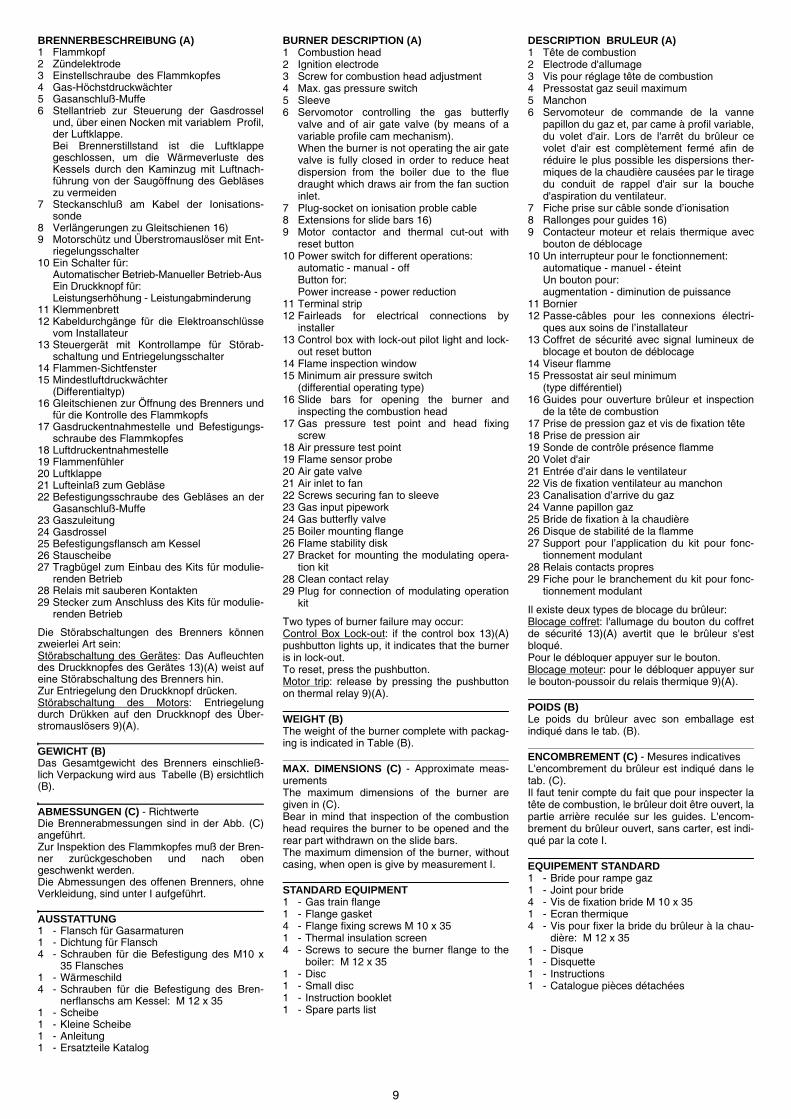
9
BRENNERBESCHREIBUNG (A)1 Flammkopf2 Zündelektrode3 Einstellschraube des Flammkopfes4 Gas-Höchstdruckwächter5 Gasanschluß-Muffe6 Stellantrieb zur Steuerung der Gasdrossel
und, über einen Nocken mit variablem Profil,der Luftklappe.Bei Brennerstillstand ist die Luftklappegeschlossen, um die Wärmeverluste desKessels durch den Kaminzug mit Luftnach-führung von der Saugöffnung des Gebläseszu vermeiden
7 Steckanschluß am Kabel der Ionisations-sonde
8 Verlängerungen zu Gleitschienen 16)9 Motorschütz und Überstromauslöser mit Ent-
riegelungsschalter10 Ein Schalter für:
Automatischer Betrieb-Manueller Betrieb-AusEin Druckknopf für:Leistungserhöhung - Leistungabminderung
11 Klemmenbrett12 Kabeldurchgänge für die Elektroanschlüsse
vom Installateur13 Steuergerät mit Kontrollampe für Störab-
schaltung und Entriegelungsschalter14 Flammen-Sichtfenster15 Mindestluftdruckwächter
(Differentialtyp)16 Gleitschienen zur Öffnung des Brenners und
für die Kontrolle des Flammkopfs17 Gasdruckentnahmestelle und Befestigungs-
schraube des Flammkopfes18 Luftdruckentnahmestelle19 Flammenfühler20 Luftklappe21 Lufteinlaß zum Gebläse22 Befestigungsschraube des Gebläses an der
Gasanschluß-Muffe23 Gaszuleitung24 Gasdrossel25 Befestigungsflansch am Kessel26 Stauscheibe27 Tragbügel zum Einbau des Kits für modulie-
renden Betrieb28 Relais mit sauberen Kontakten29 Stecker zum Anschluss des Kits für modulie-
renden Betrieb
Die Störabschaltungen des Brenners könnenzweierlei Art sein:Störabschaltung des Gerätes: Das Aufleuchtendes Druckknopfes des Gerätes 13)(A) weist aufeine Störabschaltung des Brenners hin.Zur Entriegelung den Druckknopf drücken.Störabschaltung des Motors: Entriegelungdurch Drükken auf den Druckknopf des Über-stromauslösers 9)(A).
GEWICHT (B)Das Gesamtgewicht des Brenners einschließ-lich Verpackung wird aus Tabelle (B) ersichtlich(B).
ABMESSUNGEN (C) - RichtwerteDie Brennerabmessungen sind in der Abb. (C)angeführt.Zur Inspektion des Flammkopfes muß der Bren-ner zurückgeschoben und nach obengeschwenkt werden.Die Abmessungen des offenen Brenners, ohneVerkleidung, sind unter I aufgeführt.
AUSSTATTUNG1 - Flansch für Gasarmaturen1 - Dichtung für Flansch4 - Schrauben für die Befestigung des M10 x
35 Flansches1 - Wärmeschild4 - Schrauben für die Befestigung des Bren-
nerflanschs am Kessel: M 12 x 351 - Scheibe1 - Kleine Scheibe1 - Anleitung1 - Ersatzteile Katalog
BURNER DESCRIPTION (A)1 Combustion head2 Ignition electrode3 Screw for combustion head adjustment4 Max. gas pressure switch5 Sleeve6 Servomotor controlling the gas butterfly
valve and of air gate valve (by means of avariable profile cam mechanism).When the burner is not operating the air gatevalve is fully closed in order to reduce heatdispersion from the boiler due to the fluedraught which draws air from the fan suctioninlet.
7 Plug-socket on ionisation proble cable8 Extensions for slide bars 16)9 Motor contactor and thermal cut-out with
reset button10 Power switch for different operations:
automatic - manual - offButton for:Power increase - power reduction
11 Terminal strip12 Fairleads for electrical connections by
installer13 Control box with lock-out pilot light and lock-
out reset button14 Flame inspection window15 Minimum air pressure switch
(differential operating type)16 Slide bars for opening the burner and
inspecting the combustion head17 Gas pressure test point and head fixing
screw18 Air pressure test point19 Flame sensor probe20 Air gate valve21 Air inlet to fan22 Screws securing fan to sleeve23 Gas input pipework24 Gas butterfly valve25 Boiler mounting flange26 Flame stability disk27 Bracket for mounting the modulating opera-
tion kit28 Clean contact relay29 Plug for connection of modulating operation
kit
Two types of burner failure may occur:Control Box Lock-out: if the control box 13)(A)pushbutton lights up, it indicates that the burneris in lock-out.To reset, press the pushbutton.Motor trip: release by pressing the pushbuttonon thermal relay 9)(A).
WEIGHT (B)The weight of the burner complete with packag-ing is indicated in Table (B).
MAX. DIMENSIONS (C) - Approximate meas-urementsThe maximum dimensions of the burner aregiven in (C).Bear in mind that inspection of the combustionhead requires the burner to be opened and therear part withdrawn on the slide bars.The maximum dimension of the burner, withoutcasing, when open is give by measurement I.
STANDARD EQUIPMENT1 - Gas train flange1 - Flange gasket4 - Flange fixing screws M 10 x 351 - Thermal insulation screen4 - Screws to secure the burner flange to the
boiler: M 12 x 351 - Disc1 - Small disc1 - Instruction booklet1 - Spare parts list
DESCRIPTION BRULEUR (A)1 Tête de combustion2 Electrode d'allumage3 Vis pour réglage tête de combustion4 Pressostat gaz seuil maximum5 Manchon6 Servomoteur de commande de la vanne
papillon du gaz et, par came à profil variable,du volet d'air. Lors de l'arrêt du brûleur cevolet d'air est complètement fermé afin deréduire le plus possible les dispersions ther-miques de la chaudière causées par le tiragedu conduit de rappel d'air sur la bouched'aspiration du ventilateur.
7 Fiche prise sur câble sonde d’ionisation8 Rallonges pour guides 16)9 Contacteur moteur et relais thermique avec
bouton de déblocage10 Un interrupteur pour le fonctionnement:
automatique - manuel - éteintUn bouton pour:augmentation - diminution de puissance
11 Bornier12 Passe-câbles pour les connexions électri-
ques aux soins de l’installateur13 Coffret de sécurité avec signal lumineux de
blocage et bouton de déblocage14 Viseur flamme15 Pressostat air seul minimum
(type différentiel)16 Guides pour ouverture brûleur et inspection
de la tête de combustion17 Prise de pression gaz et vis de fixation tête18 Prise de pression air19 Sonde de contrôle présence flamme20 Volet d'air21 Entrée d’air dans le ventilateur22 Vis de fixation ventilateur au manchon23 Canalisation d’arrive du gaz24 Vanne papillon gaz25 Bride de fixation à la chaudière26 Disque de stabilité de la flamme27 Support pour l’application du kit pour fonc-
tionnement modulant28 Relais contacts propres29 Fiche pour le branchement du kit pour fonc-
tionnement modulant
Il existe deux types de blocage du brûleur:Blocage coffret: l'allumage du bouton du coffretde sécurité 13)(A) avertit que le brûleur s'estbloqué.Pour le débloquer appuyer sur le bouton.Blocage moteur: pour le débloquer appuyer surle bouton-poussoir du relais thermique 9)(A).
POIDS (B) Le poids du brûleur avec son emballage estindiqué dans le tab. (B).
ENCOMBREMENT (C) - Mesures indicativesL'encombrement du brûleur est indiqué dans letab. (C).Il faut tenir compte du fait que pour inspecter latête de combustion, le brûleur doit être ouvert, lapartie arrière reculée sur les guides. L'encom-brement du brûleur ouvert, sans carter, est indi-qué par la cote I.
EQUIPEMENT STANDARD1 - Bride pour rampe gaz1 - Joint pour bride4 - Vis de fixation bride M 10 x 351 - Ecran thermique4 - Vis pour fixer la bride du brûleur à la chau-
dière: M 12 x 351 - Disque1 - Disquette1 - Instructions1 - Catalogue pièces détachées

10
CAMPO DI LAVORO (A)La potenza del bruciatore varia in funziona-mento tra:
• una POTENZA MASSIMA, scelta entro l’ areaA.
• e una POTENZA MINIMA, che non deveessere inferiore al limite minimo del dia-gramma:
RS 250/M MZ= 600 kW
Attenzione: il CAMPO DI LAVORO è stato ricavato alla tem-peratura ambiente di 20 °C, alla pressione baro-metrica di 1013 mbar (circa 0 m s.l.m.) e con latesta di combustione regolata come indicato a p.16.
CALDAIA DI PROVA (B)I campi di lavoro sono stati ricavati in specialicaldaie di prova, secondo la norma EN 676.Riportiamo in (B) diametro e lunghezza dellacamera di combustione di prova.Esempio: Potenza 650 Mcal/h:diametro 60 cm - lunghezza 2 m.
CALDAIE COMMERCIALI (C)L’abbinamento bruciatore-caldaia non pone pro-blemi se la caldaia è omologata CE e le dimen-sioni della sua camera di combustione sonovicine a quelle indicate dal diagramma (B).Se invece il bruciatore deve essere applicato aduna caldaia commerciale non omologata CE e/ocon dimensioni della camera di combustionenettamente più piccole di quelle indicate dal dia-gramma (B), consultare i costruttori.
- 2
Mcal / h
kW
02468
10
500 700 900 1100 1300 1500 1700 1900 2100
600 800 12001000 2000180016001400 24002200
1112
26002800
2300 2500
13141516
1718
(A)
(B)
CA
M. C
OM
B. /
FE
UE
RR
AU
M
m
CO
MB
. CH
AM
BE
R /
CH
AM
B. C
OM
B.
CA
M. C
OM
B. /
FE
UE
RR
AU
M
mb
ar
CO
MB
. CH
AM
BE
R /
CH
AM
B. C
OM
B.
D3807
D715

11
REGELBEREICH (A)Wahrend des Betriebs schwankt die Brenner-leistung zwischen:
• einer HÖCHSTLEISTUNG, innerhalb desFeldes A gewählt,
• und einer MINDESTLEISTUNG, die nicht nie-driger sein darf als die Mindestgrenze des Dia-gramms.
RS 250/M MZ= 600 kW
Achtung: der REGELBEREICH wurde bei einerRaumtemperatur von 20 °C, einem barome-trischen Druck von 1013 mbar (ungefähr 0 mü.d.M.) und einem wie auf Seite 17 eingestell-tem Flammkopf gemessen.
PRÜFKESSEL (B)Die Regelbereiche wurden an speziellenPrüfkesseln entsprechend Norm EN 676 ermit-telt.In (B) sind Durchmesser und Länge der Prüf-Brennkammer angegeben.Beispiel:Leistung 650 Mcal/h:Durchmesser = 60 cm, Länge = 2 m.
HANDELSÜBLICHE KESSEL (C)Die Brenner-Kessel Kombination gibt keineProbleme, falls der Kessel "CE" - typgeprüft istund die Abmessungen seiner Brennkammersich den im Diagramm (B) angegebenennähern.Falls der Brenner dagegen an einem handelsü-blichen Kessel angebracht werden muß, dernicht "CE"-typgeprüft ist und/oder mit Abmes-sungen der Brennkammer, die entschiedenkleiner als jene in Diagramm (B) angegebenensind, sollte der Hersteller zu Rate gezogen wer-den.
FIRING RATE (A)During operation, burner output varies between:
• a MAXIMUM OUTPUT, selected within area A,
• and a MINIMUM OUTPUT, which must not belower than the minimum limit in the diagram.
RS 250/M MZ= 600 kW
Important: The FIRING RATE area values have beenobtained considering a surrounding temperatureof 20 °C, and an atmospheric pressure of 1013mbar (approx. 0 m above sea level) and with thecombustion head adjusted as shown on page17.
TEST BOILER (B)The firing rates were set in relation to specialtest boilers, according to EN 676 regulations.Figure (B) indicates the diameter and length ofthe test combustion chamber.Example:Output 650 Mcal/h:diameter = 60 cm; length
COMMERCIAL BOILERS (C)The burner/boiler combination does not poseany problems if the boiler is CE type-approvedand its combustion chamber dimensions aresimilar to those indicated in diagram (B).If the burner must be combined with a commer-cial boiler that has not been Ce type-approvedand/or its combustion chamber dimensions areclearly smaller than those indicated in diagram(B), consult the manufacturer.
PLAGE DE PUISSANCE (A)La puissance du brûleur en fonctionnementvarie entre:
• une PUISSANCE MAXIMUM, choisie dans laplage A,
• et une PUISSANCE MINIMUM, qui ne doit pasêtre inférieure à la limite minimum du dia-gramme.
RS 250/M MZ= 600 kW
Attention: La PLAGE DE PUISSANCE a été calculée àune température ambiante de 20 °C, à unepression barométrique de 1013 mbar (environ 0m au-dessus du niveau de la mer) et avec latête de combustion réglée comme indique la p.17.
CHAUDIERE D’ESSAI (B)Les plages de puissance ont été établies surdes chaiuières d’essai spéciales, selon la normeEN 676. Nous reportons fig.(B) le diamètre et lalongueur de la chambre de combustion d’essai.Exempe:Puissance 650 Mcal/h:diamètre 60 cm - longueur 2 m.
CHAUDIERES COMMERCIALES (C) L’accouplement brûleur-chaudière ne poseaucun problème si la chaudière est homologuéeCE et si les dimensions de sa chambre de com-bustion sont proches de celles indiquées dansle diagramme (B).Par contre, si le brûleur doit être accouplé à unechaudière commerciale non homologuée CE, et/ou avec des dimensions de chambre de com-bustion plus petites que celles indiquées dans lediagramme (B), consulter le constructeur.

12
PRESSIONE GASLa tabella a lato indica le perdite di carico min-ime lungo la linea di alimentazione del gas infunzione della potenza massima del bruciatore.
Colonna 1Perdita di carico testa di combustione.Pressione del gas misurata alla presa 1)(B),con:• Camera di combustione a 0 mbar;• Bruciatore funzionante alla potenza massima;• Testa di combustione regolata come dia-
gramma (C)p. 16.
Colonna 2Perdita di carico farfalla gas 2)(B) con aperturamassima: 90°.
Colonna 3Perdita di carico rampa 3)(B) comprendente:valvola di regolazione VR, valvola di sicurezzaVS (entrambe con apertura massima), regola-tore di pressione R, filtro F.
I valori riportati nella tabella si riferiscono a:gas naturale G 20 PCI 9,45 kWh/Sm3
(8,2 Mcal/Sm3)Con:gas naturale G 25 PCI 8,13 kWh/Sm3 (7,0Mcal/Sm3) moltiplicare i valori della tabella:- colonna 1 - 2: per 1,5;- colonna 3: per 1,35.
Per conoscere la potenza approssimativa allaquale sta funzionando il bruciatore al MAX:- Sottrarre dalla pressione del gas alla presa
1)(B) la pressione in camera di combustione.- Trovare nella tabella (A), colonna 1, il valore
di pressione più vicino al risultato della sot-trazione.
- Leggere sulla sinistra la potenza corrispond-ente.
Esempio:• Funzionamento alla potenza MAX• Gas naturale G 20 PCI 9,45 kWh/Sm3
• Pressione del gas allapresa 1)(B) = 11,8 mbar
• Pressione in camera di combustione = 3,0 mbar
11,8 - 3,0 = 8,8 mbarAlla pressione 8,8 mbar, colonna 1, corrispondenella tabella (A) una potenza di 1700 kW.Questo valore serve come prima approssimazi-one; la portata effettiva va misurata al contatore.
Per conoscere invece la pressione del gas nec-essaria alla presa 1)(B), fissata la potenza mas-sima alla quale si desidera funzioni il bruciatore:- Trovare nella tabella (A) il valore di potenza
più vicino al valore desiderato.- Leggere sulla destra, colonna 1, la pressione
alla presa 1)(B).- Sommare a questo valore la presunta pres-
sione in camera di combustione.
Esempio:• Potenza MAX desiderata: 1700 kW• Gas naturale G 20 PCI 9,45 kWh/Sm3
• Pressione del gas alla potenza di 1600 kW,dalla tabella (A), colonna 1 = 8,8 mbar
• Pressione in camera dicombustione = 3,0 mbar
8,8 + 3,0 = 11,8 mbarpressione necessaria alla presa 1)(B).
(A)
RS 250/M MZ p (mbar)
kW 1 2
3
39702213970225
39702223970226
39702233970227
1250 5.2 4.4 9.9 7.0 4.7
1400 6.4 5.5 12.1 8.2 5.2
1550 7.6 6.7 14.4 9.4 5.6
1700 8.8 8.1 16.7 10.7 6.1
1850 10.1 9.6 19.0 12.1 6.6
2000 11.3 11.2 21.6 13.6 7.3
2150 13.0 12.9 24.4 15.3 8.0
2300 14.7 14.8 27.3 17.1 8.7
2450 16.4 16.8 30.1 18.9 9.4
2600 18.1 18.9 33.3 20.7 10.2
2650 18.7 19.7 34.8 21.4 10.4
(B) D3734
MBC-700MBC-1200
MBC-1900MBC-3100
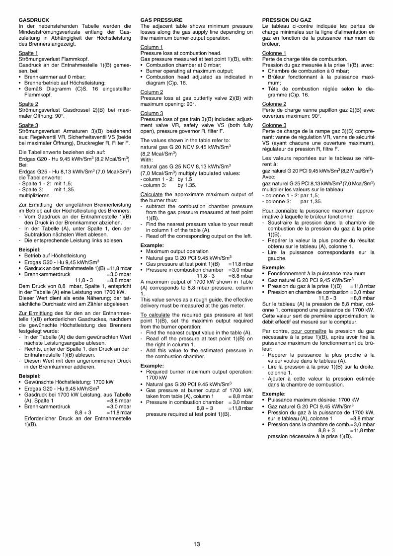
13
GASDRUCKIn der nebenstehenden Tabelle werden dieMindestströmungsverluste entlang der Gas-zuleitung in Abhängigkeit der Höchstleistungdes Brenners angezeigt.
Spalte 1Strömungsverlust Flammkopf.Gasdruck an der Entnahmestelle 1)(B) gemes-sen, bei:• Brennkammer auf 0 mbar;• Brennerbetrieb auf Höchstleistung;• Gemäß Diagramm (C)S. 16 eingestellter
Flammkopf.
Spalte 2Strömungsverlust Gasdrossel 2)(B) bei maxi-maler Öffnung: 90°.
Spalte 3Strömungsverlust Armaturen 3)(B) bestehendaus: Regelventil VR, Sicherheitsventil VS (beidebei maximaler Öffnung), Druckregler R, Filter F.
Die Tabellenwerte beziehen sich auf:Erdgas G20 - Hu 9,45 kWh/Sm3 (8,2 Mcal/Sm3)Bei:Erdgas G25 - Hu 8,13 kWh/Sm3 (7,0 Mcal/Sm3)die Tabellenwerte:- Spalte 1 - 2: mit 1,5;- Spalte 3: mit 1,35.multiplizieren.
Zur Ermittlung der ungefähren Brennerleistungim Betrieb auf der Höchstleistung des Brenners:- Vom Gasdruck an der Entnahmestelle 1)(B)
den Druck in der Brennkammer abziehen.- In der Tabelle (A), unter Spalte 1, den der
Subtraktion nächsten Wert ablesen.- Die entsprechende Leistung links ablesen.
Beispiel:• Betrieb auf Höchstleistung• Erdgas G20 - Hu 9,45 kWh/Sm3
• Gasdruck an der Entnahmestelle 1)(B) =11,8 mbar• Brennkammerdruck =3,0 mbar
11,8 - 3 =8,8 mbarDem Druck von 8,8 mbar, Spalte 1, entsprichtin der Tabelle (A) eine Leistung von 1700 kW.Dieser Wert dient als erste Näherung; der tat-sächliche Durchsatz wird am Zähler abgelesen.
Zur Ermittlung des für den an der Entnahmes-telle 1)(B) erforderlichen Gasdruckes, nachdemdie gewünschte Höchstleistung des Brennersfestgelegt wurde:- In der Tabelle (A) die dem gewünschten Wert
nächste Leistungsangabe ablesen.- Rechts, unter der Spalte 1, den Druck an der
Entnahmestelle 1)(B) ablesen.- Diesen Wert mit dem angenommenen Druck
in der Brennkammer addieren.
Beispiel:• Gewünschte Höchstleistung: 1700 kW• Erdgas G20 - Hu 9,45 kWh/Sm3
• Gasdruck bei 1700 kW Leistung, aus Tabelle(A), Spalte 1 =8,8 mbar
• Brennkammerdruck =3,0 mbar8,8 + 3 =11,8 mbar
Erforderlicher Druck an der Entnahmestelle1)(B).
GAS PRESSUREThe adjacent table shows minimum pressurelosses along the gas supply line depending onthe maximum burner output operation.
Column 1Pressure loss at combustion head.Gas pressure measured at test point 1)(B), with:• Combustion chamber at 0 mbar;• Burner operating at maximum output;• Combustion head adjusted as indicated in
diagram (C)p. 16.
Column 2Pressure loss at gas butterfly valve 2)(B) withmaximum opening: 90°.
Column 3Pressure loss of gas train 3)(B) includes: adjust-ment valve VR, safety valve VS (both fullyopen), pressure governor R, filter F.
The values shown in the table refer to:natural gas G 20 NCV 9.45 kWh/Sm3
(8,2 Mcal/Sm3)With:natural gas G 25 NCV 8,13 kWh/Sm3
(7,0 Mcal/Sm3) multiply tabulated values:- column 1 - 2: by 1.5- column 3: by 1.35.
Calculate the approximate maximum output ofthe burner thus:- subtract the combustion chamber pressure
from the gas pressure measured at test point1)(B).
- Find the nearest pressure value to your resultin column 1 of the table (A).
- Read off the corresponding output on the left.
Example:• Maximum output operation• Natural gas G 20 PCI 9.45 kWh/Sm3
• Gas pressure at test point 1)(B) =11,8 mbar• Pressure in combustion chamber =3,0 mbar
11,8 - 3 =8,8 mbarA maximum output of 1700 kW shown in Table(A) corresponds to 8,8 mbar pressure, column1.This value serves as a rough guide, the effectivedelivery must be measured at the gas meter.
To calculate the required gas pressure at testpoint 1)(B), set the maximim output requiredfrom the burner operation:- Find the nearest output value in the table (A).- Read off the pressure at test point 1)(B) on
the right in column 1.- Add this value to the estimated pressure in
the combustion chamber.
Example:• Required burner maximum output operation:
1700 kW• Natural gas G 20 PCI 9.45 kWh/Sm3
• Gas pressure at burner output of 1700 kW,taken from table (A), column 1 = 8,8 mbar
• Pressure in combustion chamber = 3,0 mbar8,8 + 3 =11,8 mbar
pressure required at test point 1)(B).
PRESSION DU GAZLe tableau ci-contre indiquée les pertes decharge minimales sur la ligne d'alimentation engaz en fonction de la puissance maximum dubrûleur.
Colonne 1Perte de charge tête de combustion.Pression du gaz mesurée à la prise 1)(B), avec:• Chambre de combustion à 0 mbar;• Brûleur fonctionnant à la puissance maxi-
mum;• Tête de combustion réglée selon le dia-
gramme (C)p. 16.
Colonne 2Perte de charge vanne papillon gaz 2)(B) avecouverture maximum: 90°.
Colonne 3Perte de charge de la rampe gaz 3)(B) compre-nant: vanne de régulation VR, vanne de sécuritéVS (ayant chacune une ouverture maximum),régulateur de pression R, filtre F.
Les valeurs reportées sur le tableau se réfè-rent à:gaz naturel G 20 PCI 9,45 kWh/Sm3 (8,2 Mcal/Sm3)Avec:gaz naturel G 25 PCI 8,13 kWh/Sm3 (7,0 Mcal/Sm3)multiplier les valeurs sur le tableau:- colonne 1 - 2: par 1,5;- colonne 3: par 1,35.
Pour connaître la puissance maximum approx-imative à laquelle le brûleur fonctionne:- Soustraire la pression dans la chambre de
combustion de la pression du gaz à la prise1)(B).
- Repérer la valeur la plus proche du résultatobtenu sur le tableau (A), colonne 1.
- Lire la puissance correspondante sur lagauche.
Exemple:• Fonctionnement à la puissance maximum• Gaz naturel G 20 PCI 9,45 kWh/Sm3
• Pression du gaz à la prise 1)(B) =11,8 mbar• Pression en chambre de combustion =3,0 mbar
11,8 - 3 =8,8 mbarSur le tableau (A) la pression de 8,8 mbar, col-onne 1, correspond une puissance de 1700 kW.Cette valeur sert de première approximation; ledébit effectif est mesuré sur le compteur.
Par contre, pour connaître la pression du gaznécessaire à la prise 1)(B), après avoir fixé lapuissance maximum de fonctionnement du brû-leur:- Repérer la puissance la plus proche à la
valeur voulue dans le tableau (A).- Lire la pression à la prise 1)(B) sur la droite,
colonne 1.- Ajouter à cette valeur la pression estimée
dans la chambre de combustion.
Exemple:• Puissance maximum désirée: 1700 kW• Gaz naturel G 20 PCI 9,45 kWh/Sm3
• Pression du gaz à la puissance de 1700 kW,sur le tableau (A), colonne 1 =8,8 mbar
• Pression dans la chambre de comb.=3,0 mbar8,8 + 3 =11,8 mbar
pression nécessaire à la prise 1)(B).

14
INSTALLAZIONE
PIASTRA CALDAIA (A) Forare la piastra di chiusura della camera dicombustione come in (A). La posizione dei forifilettati può essere tracciata utilizzando lo sch-ermo termico a corredo del bruciatore.
LUNGHEZZA BOCCAGLIO (B) La lunghezza del boccaglio va scelta secondo leindicazioni del costruttore della caldaia e, in ognicaso, deve essere maggiore dello spessoredella porta della caldaia, completa di refrattario.La lunghezza, L (mm), disponibile è 370 mm.
Per le caldaie con giro dei fumi anteriore 15), ocon camera ad inversione di fiamma, eseguireuna protezione in materiale refrattario 13), trarefrattario caldaia 14) e boccaglio 12).La protezione deve consentire al boccaglio diessere estratto.Per le caldaie con il frontale raffreddato adacqua non è necessario il rivestimento refratta-rio 13)-14)(B), se non vi è espressa richiesta delcostruttore della caldaia.
FISSAGGIO DEL BRUCIATORE ALLA CALDAIA (B) Prima di fissare il bruciatore alla caldaia, verifi-care dall’apertura del boccaglio se la sonda el’elettrodo sono correttamente posizionati comein (C).
Separare quindi la testa di combustione dalresto del bruciatore, fig. (B).- Allentare le 4 viti 3) e togliere il cofano 1).- Sganciare lo snodo 7) dal settore graduato 8).- Togliere le viti 2) dalle due guide 5).- Togliere le due viti 4) ed arretrare il bruciatore
sulle guide 5) per circa 100 mm.- Disinserire i cavi di sonda ed elettrodo e quindi
sfilare del tutto il bruciatore dalle guide.
Fissare la flangia 11)(B) alla piastra dellacaldaia interponendo lo schermo isolante 9)(B)dato a corredo. Utilizzare le 4 viti pure date acorredo dopo averne protetto la filettatura conprodotti antigrippanti.La tenuta bruciatore-caldaia deve essere ermet-ica.
Se nel controllo precedente il posizionamentodella sonda o dell’elettrodo non è risultato cor-retto, togliere la vite 1)(D), estrarre la parteinterna 2)(D) della testa e provvedere alla lorotaratura.Non ruotare la sonda ma lasciarla come in (C);un suo posizionamento vicino all’elettrodod’accensione potrebbe danneggiare l’amplifica-tore dell’apparecchiatura.
mm mm
mm
2 4 2
3
10
87
6
4311 15
1413
12L
159
521
100 mm
2
1
mm A B C
RS 250/M MZ 230 325-368 M 16
(A)
(B)
(C)
Sonda - FühlerProbe - Sonde Electrode - Electrode
Elettrodo - Elektrode
(D)
D455
D3808
D3809
D3810

15
INSTALLATION
KESSELPLATTE (A) Die Abdeckplatte der Brennkammer wie in (A)gezeigt vorbohren. Die Position der Gewinde-bohrungen kann mit der zur Grundausstattunggehörenden Isolierplatte ermittelt werden.
FLAMMROHRLÄNGE (B) Die Länge des Flammrohrs wird entsprechendder Angaben des Kesselherstellers gewählt undmuß in jedem Fall länger sein, als die Stärke derKesseltür, einschließlich des Schamottesteins.Die verfügbare Länge, L (mm), ist 372 mm.
Für Heizkessel mit vorderem Rauchumlauf 15)oder mit Kammer mit Flammeninversion mußeine Schutzschicht aus feuerfestem Material13), zwischen Schamottestein 14) und Flam-mrohr 12) eingeplant werden.Diese Schutzschicht muß so angelegt sein, daßdas Flammrohr ausbaubar ist.Für die Kessel mit wassergekühlter Frontseiteist die Verkleidung mit feuerfestem Material 13)-14)(B) nicht notwendig, sofern nicht ausdrück-lich vom Kesselhersteller erfordert.
BEFESTIGUNG DES BRENNERS AM HEIZ-KESSEL (B) Vor der Befestigung des Brenners am Heizkes-sel ist von der Öffnung des Flammrohrs aus zuüberprüfen, ob der Fühler und die Elektrodegemäß (C) in der richtigen Stellung sind.
Dann den Flammkopf vom übrigen Brennerabtrennen, Abb (B):- Die 4 Schrauben 3) lockern und die Verklei-
dung 1) abnehmen.- Das Gelenk 7) des Skalensegments 8) aus-
rasten.- Die Schrauben 2) von den beiden Führungen
5) entfernen.- Die zwei Schrauben 4) abnehmen und den
Brenner auf den Gleitschienen 5) ca. 100 mm.nach ninten schieben.
- Die Fuhler- und Elektrodenkabel abtretten unddann den Brenner komplett aus denGleitschienen ziehen.
Den Flansch 11)(B) an der Kesselplatte befesti-gen und den beigestellten Wärmeschild 9)(B)dazwischenlegen. Die 4 ebenfalls beigepacktenSchrauben nach Auftragung von Freßschutzmit-teln verwenden. Es muß die Dichtheit von Bren-ner-Kessel gewährleistet sein.
Falls bei der vorhergehenden Prüfung die Posi-tionierung des Fühlers oder der Elektrode sichals nicht richtig erweist, die Schraube 1)(D)abnehmen, das Innenteil 2)(D) des Kopfs her-ausziehen und eine neue Einstellung vorneh-men.Den Fühler nicht drehen, sondern wie in (C) las-sen; seine Positionierung in der Nähe der Zün-delektrode könnte den Geräteverstärkerbeschädigen.
INSTALLATION
BOILER PLATE (A) Drill the combustion chamber locking plate asshown in (A). The position of the threaded holescan be marked using the thermal screen sup-plied with the burner.
BLAST TUBE LENGTH (B) The length of the blast tube must be selectedaccording to the indications provided by themanufacturer of the boiler, and in any case itmust be greater than the thickness of the boilerdoor complete with its fettling. The length avail-able, L (mm), is 372 mm.
For boilers with front flue passes 15) or flameinversion chambers, protective fettling in refrac-tory material 13), must be inserted between theboiler's fettling 14) and the blast tube 12).This protective fettling must not compromise theextraction of the blast tube.For boilers having a water-cooled front therefractory fettling 13)-14)(B) is not requiredunless it is expressly requested by the boilermanufacturer.
SECURING THE BURNER TO THE BOILER (B) Before securing the burner to the boiler, checkthrough the blast tube opening to make surethat the flame sensor probe and the ignitionelectrode are correctly set in position, as shownin (C).
Now detach the combustion head from theburner, fig. (B):- Loosen the four screws 3) and remove the
cover 1).- Disengage the articulated coupling 7) from the
graduated sector 8)- Remove the screws 2) from the two slide bars
5).- Remove the two screws 4) and pull the burner
back on slide bars 5) by about 100 mm.- Disconnect the wires from the probe and the
electrode and then pull the burner completelyoff the slide bars.
Secure the flange 11)(B) to the boiler plate,interposing the thermal insulating screen 9)(B)supplied with the burner. Use the 4 screws, alsosupplied with the unit, after first protecting thethread with an anti-locking product.The seal between burner and boiler must be air-tight.
If you noticed any irregularities in positions ofthe probe or ignition electrode during the checkmentioned above, remove screw 1)(D), extractthe internal part 2)(D) of the head and proceedto set up the two components correctly. Do not attempt to turn the probe. Leave it in theposition shown in (C) since if it is located tooclose to the ignition electrode the control boxamplifier may be damaged.
INSTALLATION
PLAQUE CHAUDIERE (A) Percer la plaque de fermeture de la chambre decombustion comme sur la fig. (A). La positiondes trous filetés peut être tracée en utilisantl'écran thermique du brûleur.
LONGUEUR BUSE (B) La longueur de la buse doit être choisie selonles indications du constructeur de la chaudière,et elle doit en tout cas être supérieure à l'épais-seur de la porte de la chaudière, matériauréfractaire compris. La longueur, L (mm), dis-ponible est 372 mm.
Pour les chaudières avec circulation desfumées sur l'avant 15), ou avec chambre àinversion de flamme, réaliser une protection enmatériau réfractaire 13), entre réfractairechaudière 14) et buse 12).La protection doit permettre l'extraction de labuse.Pour les chaudières dont la partie frontale estrefroidie par eau, le revêtement réfractaire 13)-14)(B) n'est pas nécessaire, sauf indicationexpresse du constructeur de la chaudière.
FIXATION DU BRULEUR A LA CHAUDIERE (B) Avant de fixer le brûleur à la chaudière, vérifierpar l'ouverture de la buse si la sonde et l'élec-trode sont positionnées correctement commeindiqué en (C).
Séparer ensuite la tête de combustion du restedu brûleur, fig. (B):- Desserrer les 4 vis 3) et retirer le coffret 1).- Décrocher la rotule 7) du secteur gradué 8)- Retirer les vis 2) des deux guides 5).- Retirer les vis 4) et faire reculer le brûleur sur
les guides 5) d'environ 100 mm.- Détacher les câbles de la sonde et de l'élec-
trode, enlever ensuite complètement le brûleurdes guides.
Fixer la bride 11)(B) à la plaque de la chaudièreen interposant l'écran isolant 9)(B) fourni desérie. Utiliser les 4 vis également de série aprèsen avoir protégé le filetage par du produit anti-grippant.L'étanchéité brûleur-chaudière doit être parfaite.
Si, lors du contrôle précédent, le positionnementde la sonde ou de l'électrode n'était pas correct,retirer la vis 1)(D), extraire la partie interne 2)(D)de la tête et tarer celles-ci. Ne pas faire pivoterla sonde mais la laisser en place commeindiqué en (C); son positionnement dans le vois-inage de l'électrode d'allumage pourrait endom-mager l'amplificateur de l'appareil.

16
REGOLAZIONE TESTA DI COMBUSTIONEA questo punto dell’installazione, boccaglio emanicotto sono fissati alla caldaia come in fig.(B). È quindi particolarmente agevole laregolazione delle testa di combustione, regolazi-one che dipende unicamente dalla potenzamassima del bruciatore.Perciò, prima di regolare la testa di combus-tione, bisogna fissare questo valore.Sono previste due regolazioni della testa.
Regolazione aria (B) Vedere diagramma (C).Ruotare la vite 4)(B) fino a far collimare la taccatrovata con il piano anteriore 5)(B) del raccordo.
Regolazione gas (A)Quando il bruciatore viene installato per unapotenzialità massima 1300 Mcal/h (circa 1500kW) montare i dischi 1)-2)(A) dati a corredotogliendo il tubo interno 3)(A). In caso di pocapressione del gas in rete, si può lasciare la testain configurazione standard limitando il minimo dimodulazione a 450 Mcal/h (circa 520 kW).
EsempioPotenza MAX bruciatore = 2650 kW.Dal diagramma (C) risulta che per questa poten-zialità la regolazione dell’aria va effettuata sullatacca 10, come in fig. (B).
Continuando l’esempio precedente, a pag. 12 sivede che per un bruciatore con potenza di 2650kW occorrono 18,7 mbar circa di pressione allapresa 6)(B).
Terminata la regolazione della testa, rimontare ilbruciatore sulle guide 3)(D) a circa 100 mm dalmanicotto 4)(D) - bruciatore nella posizioneillustrata dalla fig. (B)p. 14 - inserire il cavo dellasonda ed il cavo dell’elettrodo e quindi far scor-rere il bruciatore fino al manicotto, bruciatorenella posizione illustrata dalla fig. (D).Rimettere le viti 2) sulle guide 3).Fissare il bruciatore al manicotto con le viti 1).Riagganciare lo snodo 7) al settore graduato 6).
AttenzioneAll’atto della chiusura del bruciatore sulle dueguide, è opportuno tirare delicatamente versol’esterno il cavo d’alta tensione ed il cavettodella sonda di rivelazione fiamma, fino a metterliin leggera tensione.
(A)
(C)
(D)
N° Tacche - Kerben - Notches - Encoches
Potenza massima bruciatore
Maximum burner output
(B)
D3811
D3812
D3813
2
3 1
4
7
6
5
3210
46
31 2
10
1200
9
7
5
3
1
19001700150013001100
8
6
4
2
0
kW
Mcal / h
1400 1600 1800 2000 2200 280026002400
2100 2300 2500
Puissance maximum du brûleur
Höchstbrennerleistung

17
EINSTELLUNG DES FLAMMKOPFSAn dieser Stelle der Installation sind Flammrohrund Muffe gem. Abb. (B) am Kessel befestigt.Die Einstellung des Flammkopfs ist daherbesonders bequem, sie hängt von der Höchst-brennerleistung. Dieser Wert muß daher unbedingt vor der Ein-stellung des Flammkopfs festgelegt werden.Am Flammkopf sind zwei Einstellungen vorges-ehen.
Lufteinstellung (B) Siehe Diagramm (C).Drehen Sie die Schraube 4)(B), bis die gefun-dene Kerbe mit der Vorderfläche 5)(B) desAnschlusses übereinstimmt.
Gaseinstellung (A)Wenn der Brenner für eine Höchstleistung von 1300 Mcal/h (etwa 1500 kW) installiert wird, sinddie mitgelieferten Scheiben 1)-2)(A) zu montierenund das Innenrohr 3)(A) muss entfernt werden.Bei wenig Gasdruck im Netz kann der Kopf in derStandardgestaltung bleiben, und das Modulation-sminimum ist dann auf 450 Mcal/h (etwa 520 kW)zu begrenzen.
BeispielHöchstbrennerleistung = 2650 kW.Dem Diagramm (C) wird entnommen, daß dieLufteinstellung für diesen Leistungsbereich aufder Kerbe 10 auszuführen sind, wie in Abb. (B)gezeigt.
Entsprechend diesem Beispiel ist auf Seite 12ersichtlich, daß ein Brenner mit 2650 kW Leis-tung ca. 18,7 mbar Druck am Anschluß 6)(B)erfordert.
Nach Beendung der Flammkopfeinstellung denBrenner auf die Gleitschienen 3)(D) in ca. 100mm Abstand zur Muffe 4)(D) - einbauen - Bren-nerposition in Abb. (B)S. 14 - das Fühler- undElektrodenkabel einsetzen und anschließendden Brenner bis zur Muffe schieben, Brennerpo-sition in Abb. (D).Die Schrauben 2) auf die Gleitschienen 3) ein-setzen.Den Brenner mit der Schraube 1) an der Muffebefestigen.Das Gelenk 7) wieder am Skalensegment 6)einhängen.
Wichtiger HinweisBeim Schließen des Brenners auf die zweiGleitschienen ist es ratsam, das Hochspan-nungskabel und das Kabel des Flammenfühlersvorsichtig nach außen zu ziehen, bis sie leichtgespannt sind.
SETTING THE COMBUSTION HEADInstallation operations are now at the stagewhere the blast tube and sleeve are secured tothe boiler as shown in fig. (B). It is now a verysimple matter to set up the combustion head, asthis depends solely on the MAX output devel-oped by the burner.It is therefore essential to establish this valuebefore proceeding to set up the combustionhead.There are two adjustments to make on thehead.
Air adjustment (B) See diagram (C).Turn screw 4)(B) until the notch identified isaligned with the front surface 5)(B) of the line.
Gas adjustment (A)When the burner is installed for a maximum out-put 1300 Mcal/h (circa 1500 kW) assemble thesupplied disks 1)-2)(A) removing the inner pipe3)(A). If there is little gas in the network, thehead may be left in standard configuration, limit-ing the minimum modulation to 450 Mcal/h(circa 520 kW).
ExampleMaximum burner output = 2650 kW.If we consult diagram (C) we find that for thisoutput, air must be adjusted using notch 10, asshown in fig. (B).
Continuing with the previous example, page 12indicates that for burner with output of 2650 kWa pressure of approximately 18.7 mbar is neces-sary at test point 6)(B).
Once you have finished setting up the head, refitthe burner to the slide bars 3)(D) at approxi-mately 100 mm from the sleeve 4)(D) - burnerpositioned as shown in fig. (B)p. 14 - insert theflame detection probe cable and the ignitionelectrode cable and then slide the burner up tothe sleeve so that it is positioned as shown infig. (D).Refit screws 2) on slide bars 3).Secure the burner to the sleeve by tighteningscrew 1).Reconnect the articulation 7) to the graduatedsector 6).
ImportantWhen fitting the burner on the two slide bars, itis advisable to gently draw out the high tensioncable and flame detection probe cable until theyare slightly stretched.
REGLAGE TETE DE COMBUSTIONA ce stade de l'installation, buse et manchonsont fixés à la chaudière comme indiqué sur lafig. (B). Le réglage de la tête de combustion estdonc particulièrement facile, et dépend unique-ment de la puissance maximum développée parle brûleur.C'est pourquoi, il faut fixer cette valeur avant derégler la tête de combustion.Deux réglages de la tête sont prévus.
Réglage de l'air (B) Voir diagramme (C).Faire pivoter la vis 4)(B) jusqu'à faire correspon-dre l'encoche trouvée avec le plan antérieur5)(B) du raccord.
Réglage du gaz (A)Quand le brûleur est installé pour une puissancemaximum 1300 Mcal/h (environ 1500 kW),monter les disques 1)-2)(A) fournis de série enenlevant le tuyau interne 3)(A). Si le gaz duréseau a peu de pression, laisser la tête en con-figuration standard en limitant la modulationminimum à 450 Mcal/h (environ 520 kW).
ExemplePuissance maximum du brûleur = 2650 kW.Le diagramme (C) indique que pour cette puis-sance le réglage de l’aie est effectué sur l’enco-che 10, comme indiqué sur la fig. (B).
Pour continuer l'exemple précédent, la page 12indique que pour un brûleur de puissance 2650kW il faut 18,7 mbar environ de pression à laprise 6)(B).
Une fois terminé le réglage de la tête, remonterle brûleur sur les guides 3)(D) à environ 100 mmdu manchon 4)(D) - brûleur dans la positionillustrée fig. (B)p. 14 - insérer les câbles de lasonde et de l'électrode et ensuite faire coulisserle brûleur jusqu'au manchon, brûleur dans laposition illustrée fig. (D).Replacer les vis 2) sur les guides 3).Fixer le brûleur au manchon avec la vis 1).Raccrocher la rotule 7) au secteur gradué 6).
AttentionAu moment de la fermeture du brûleur sur lesdeux guides, il faut tirer délicatement versl'extérieur le câble de haute tension et le petitcâble de la sonde de détection flamme, jusqu'àce qu'ils soient légèrement tendus.

18
LINEA ALIMENTAZIONE GAS• La rampa può arrivare da destra o da sinistra,
secondo comodità.• Le elettrovalvole del gas devono essere il più
vicino possibile al bruciatore in modo da assi-curare l'arrivo del gas alla testa di combus-tione nel tempo di sicurezza di 3 s.
• Assicurarsi che il campo di taratura del regola-tore di pressione (colore della molla) com-prenda la pressione necessaria al bruciatore.
RAMPA GAS (A)E' omologata secondo norma EN 676 e vienefornita separatamente dal bruciatore con ilcodice indicato in tab. (B).
LEGENDA (A)1 - Condotto arrivo del gas2 - Valvola manuale3 - Giunto antivibrante4 - Manometro con rubinetto a pulsante5 - Filtro6A - Multibloc “filettato” comprendente:
- filtro (sostituibile)- valvola di funzionamento- regolatore di pressone
6B - Multibloc “fangiato” comprendente:- valvola di sicurezza- valvola di funzionamento- regolatore di pressone
7 - Pressostato gas di minima8 - Dispositivo di controllo tenuta valvole.
Secondo la norma EN 676 il controllo ditenuta è obbligatorio per i bruciatori conpotenza massima superiore a 1200 kW.
9 - Guarnizione10 - Guarnizione a corredo bruciatore11 - Farfalla regolazione gas (DN80)12 - Pressostato gas di massima13 - Adattatore rampa-bruciatore
- fornito con bruciatore- fornito su richiesta separatamente dalla
rampa gas per le versioni flangiate
P1 - Pressione alla testa di combustioneP2 - Pressione a monte valvole/regolatoreP3 - Pressione a monte del filtro
L - Rampa gas fornita a parte con il codiceindicato in tab. (B).
L1 - A cura dell'installatore
LEGENDA TABELLA (B)C.T.= Dispositivo controllo tenuta valvole gas:
- = Rampa priva del dispositivo di con-trollo tenuta; dispositivo che puòessere ordinato a parte, vedi colonna8, e montato successivamente.
= Rampa con il dispositivo di controllotenuta montato.
8 = Dispositivo di controllo tenuta valvoleVPS.Fornito su richiesta separatamente dallarampa gas.
13 = Adattatore rampa-bruciatore.Fornito su richiesta separatamente dallarampa gas.
NotaPer la regolazione della rampa gas vedere leistruzioni che l'accompagnano.
(B)
P25 6B
8
8
6AP2
P1
P1
13
12
10
12
10
1 2 3
4
7
9
1 2 3
4
7
13
11
11
L1 L
L1 L
P3
RAMPE GAS OMOLOGATE SECONDO EN 676NACH EN 676 TYPGEPRÜFTE GASARMATURENGAS TRAINS APPROVED ACCORDING TO EN 676RAMPES GAZ HOMOLOGUÉES SELON LA NORME EN 676
Rampe gas L - Gasarmaturen LGas trains L - Rampes gaz L
8 13
CodiceCode
Modello - ModellModel - Modèle
Ø C.T. CodiceCode
CodiceCode
3970221 MBC-1200-SE-50 2” - 3010123 -
3970225 MBC-1200-SE-50 CT 2” - -
3970222 MBC-1900-SE-65 FC DN 65 - 3010123 3000825
3970226 MBC-1900-SE-65 FC CT DN 65 - 3000825
3970223 MBC-3100-SE-80 FC DN 80 - 3010123 3000826
3970227 MBC-3100-SE-80 FC CT DN 80 - 3000826
(A)D3735

19
GASZULEITUNG• Die Armatur kann je nach Bedarf von rechts
bzw. links zugeführt werden.• Die Gasmagnetventile sollen so nah wie
möglich am Brenner liegen, damit die Gaszu-fuhr zum Flammkopf innerhalb 3 Sekundensichergestellt ist.
• Überprüfen, ob der Einstellbereich des Druck-reglers (Farbe der Feder) die für den Brennererforderlichen Druckwerte vorsieht.
GASARMATUREN (A)Nach Norm EN 676 typgeprüft, wird gesondertmit dem in Tab. (B) angegebenen Codegeliefert.
ZEICHENERKLÄRUNG (A)1 - Gaszuleitung2 - Handbetätigtes Ventil3 - Kompensator4 - Manometer mit Druckknopfhahn5 - Filter6A - Multibloc “mit Gewinde” umfasst:
- Filter (auswechselbar)- Betriebsventil- Druckregler
6B - Multibloc “mit Flansch” umfasst:- Sicherheitsventil- Betriebsventil- Druckregler
7 - Gas-Minimaldruckwächter8 - Dichtheitskontrolleinrichtung der Gasventile.
Laut Norm EN 676 ist die Dichtheitskon-trolle für Brenner mit Höchstleistung über1200 kW Pflicht.
9 - Dichtung10 - Dichtung Brennergrundausstattung11 - Gas-Einstelldrossel (DN80)12 - Gas-Höchstdruckwächter13 - Passtück Armatur-Brenner
- mit Brenner geliefert- Für die Versionen mit Flansch auf Anfrage
getrennt von der Gasstrecke geliefert.
P1 - Druck am FlammkopfP2 - Druck vor Ventilen/ ReglerP3 - Druck vor dem Filter
L - Gasarmatur gesondert mit dem in Tab. (B)angegebenen Code geliefert.
L1 - Vom Installateur auszuführen
ZEICHENERKLÄRUNG TABELLE (B)C.T.= Dichtheitskontrolleinrichtung der Gasventile:
- = Gasarmatur ohne Dichtheitskontroll-einrichtung; die Einrichtung kann ge-sondert bestellt, siehe Spalte 8, undspäter eingebaut werden.
= Gasarmatur mit der eingebauten Dichtheitskontrolleinrichtung VPS.
8 = Dichtheitskontrolleinrichtung VPS derGasventile.Auf Anfrage gesondert von der Gasarma-tur lieferbar.
13 = Passtück Armatur-Brenner.Auf Anfrage gesondert von der Gasarma-tur lieferbar.
MerkeZur Einstellung der Gasarmaturen siehe die bei-gelegten Anleitungen.
GAS LINE• The gas train can enter the burner from the
right or left side, depending on which is themost convenient.
• Gas solenoids must be as close as possible tothe burner to ensure gas reaches the combus-tion head within the safety time range of 3 s.
• Make sure that the pressure governor calibra-tion range (colour of the spring) comprises thepressure required by the burner.
GAS TRAIN (A)It is type-approved according to EN 676 Stan-dards and is supplied separately from the burnerwith the code indicated in Table (B).
KEY (A)1 - Gas input pipe2 - Manual valve3 - Vibration damping joint4 - Pressure gauge with pushbutton cock5 - Filter6A - Threaded” Multibloc including:
- filter (replaceable)- functioning valve- pressure governor
6B - Flanged” Multibloc including:- safety valve- functioning valve- pressure governor
7 - Minimum gas pressure switch8 - Gas valve leak detection control device.
In accordance with EN 676 Standards,gas valve leak detection control devicesare compulsory for burners with maximumoutputs of more than 1200 kW.
9 - Gasket10 - Standard issue burner gasket11 - Gas adjustment butterfly valve (DN80)12 - Maximum gas pressure switch13 - Gas train/burner adaptor
- supplied with burner- supplied on requested separately with the
gas ramp for flanged versions
P1 - Pressure at combustion headP2 - Up-line pressure valve/adjusterP3 - Pressure up-line from the filter
L - Gas train supplied separately with the codeindicated in Table (B)
L1 - The responsibility of the installer
KEY TO TABLE (B)C.T.= Gas valves eak detection control devices:
- = Gas train without gas valve leak de-tection control device; device that canbe ordered separately and assem-bled subsequently (see column 8).
= Gas train with assembled VPS valveleak detection control device.
8 = VPS valve leak detection control de-vice.Supplied separately from gas train onrequest.
13 = Gas train/burner adaptor.Supplied separately from gas train onrequest.
NoteSee the accompanying instructions for the ad-justment of the gas train.
LIGNE ALIMENTATION GAZ• La rampe peut arriver par la droite ou par la
gauche selon les cas.• Les électrovannes du gaz doivent être le plus
près possible du brûleur de façon à assurerl'arrivée du gaz à la tête de combustion en untemps de sécurité de 3 s.
• Contrôler que la plage de réglage du régula-teur de pression (couleur du ressort) recouvrela pression nécessaire au brûleur.
RAMPE GAZ (A)Elle est homologuée suivant la norme EN 676 etelle est fournie séparément du brûleur avec lecode indiqué dans le tableau (B).
LEGENDE (A)1 - Canalisation d'arrivée du gaz2 - Vanne manuelle3 - Joint anti-vibrations4 - Manomètre avec robinet à bouton poussoir5 - Filtre6A - Multibloc “filetté” comprenant:
- filtre (remplaçable)- electrovanne de fonctionnement- régulateur de pression
6B - Multibloc “bridé” comprenant:- electrovanne de sécurité- electrovanne de fonctionnement- régulateur de pression
7 - Pressostat gaz de minimum8 - Dispositif de contrôle d'étanchéité vannes.
Selon la norme EN 676, le contrôle d'étan-chéité est obligatoire pour les brûleursayant une puissance maximale supérieureà 1200 kW.
9 - Joint10 - Joint fournis avec le brûleur11 - Papillon réglage gaz (DN80)12 - Pressostat gaz maximum13 - Adaptateur rampe-brûleur
- fourni avec brûleur- fourni sur demande séparément de la ram-
pe gaz pour les versions bridées
P1 - Pression à la tête de combustionP2 - Pression en amont vannes/régulateurP3 - Pression en amont du filtre
L - La rampe gaz est fournie à part avec lecode indiqué dans le tab. (B).
L1 - A la charge de l'installateur
LEGENDE TABLEAU (B)C.T.= Dispositif de contrìle d'étanchéité vannes:
- = Rampe sans dispositif de contrôled'étanchéité; dispositif qui peut êtrecommandé à part et monté par lasuite, voir colonne 8.
= Rampe avec dispositif de contrôled'étanchéité VPS monté.
8 = Dispositif VPS de contrôle d'étanchéitéde la vanne.Fourni sur demande séparément de larampe gaz.
13 = Adaptateur rampe-brûleur.Fourni sur demande séparément de larampe gaz.
NotePour le réglage de la rampe gaz voir les instruc-tions qui l'accompagnent.

20
REGOLAZIONI PRIMA DELL'ACCENSIONELa regolazione della testa di combustione, aria egas, è già stata descritta a pag. 16. Altre regolazioni da fare sono:- Aprire le valvole manuali poste a monte della
rampa del gas.- Regolare il pressostato gas di minima
all'inizio scala (A).- Regolare il pressostato gas di massima a
fine scala (B).- Regolare il pressostato aria all'inizio scala
(C).- Sfiatare l'aria dalla tubazione del gas.
E' consigliabile portare all'esterno dell'edifi-cio con un tubo in plastica l'aria sfiatata finoad avvertire l'odore del gas.
- Montare un manometro a U (D) sulla presa dipressione del gas del manicotto.Serve a ricavare approssimativamente lapotenza MAX del bruciatore mediante latabella di pag. 12.
- Collegare in parallelo alle due elettrovalvoledel gas VR e VS due lampadine o tester percontrollare il momento dell'arrivo della ten-sione.Questa operazione non è necessaria seognuna delle due elettrovalvole è munita diuna spia luminosa che segnala la tensioneelettrica.
Prima di accendere il bruciatore, è opportunoregolare la rampa del gas in modo che l'accen-sione avvenga nelle condizioni di massima sicu-rezza e cioè con una piccola portata di gas.
SERVOMOTORE (E)Il servomotore regola contemporaneamente laserranda dell'aria, tramite la camma a profilovariabile, e la farfalla del gas. Il servomotoreruota di 130° in 42 s.Non modificare la regolazione fatta in fabbricaalle 5 camme di cui è dotato; solo controllareche esse siano come sotto riportato:
Camma I : 130°Limita la rotazione verso il massimo.A bruciatore funzionante alla potenza MAX lafarfalla del gas deve risultare tutta aperta: 90°.Camma II : 0°Limita la rotazione verso il minimo.A bruciatore spento la serranda dell'aria e la far-falla del gas devono risultare chiuse: 0°.Camma III : 65°Regola la posizione di accensione e potenzaMIN. Camma V : solidale alla camma III
AVVIAMENTO BRUCIATOREChiudere i termostati/pressostati e metterel’interruttore 1)(F) in posizione “MAN”.Appena il bruciatore si avvia controllare il sensodi rotazione della girante del ventilatore dalvisore fiamma 14)(A)p.8.Verificare che le lampadine o i tester collegatialle elettrovalvole, o le spie luminose sulle elet-trovalvole stesse, indichino assenza di tensione.Se segnalano tensione, fermare immediata-mente il bruciatore e controllare i collegamentielettrici.
ACCENSIONE BRUCIATOREDopo aver fatto quanto descritto al punto prece-dente, il bruciatore dovrebbe accendersi. Seinvece il motore si avvia ma non compare lafiamma e l'apparecchiatura va in blocco, sbloc-care ed attendere un nuovo tentativo d'avvia-mento.Se l'accensione continua a mancare può essereche il gas non arrivi alla testa di combustioneentro il tempo di sicurezza di 3 s. Aumentareallora la portata del gas all'accensione.L'arrivo del gas al manicotto è evidenziato dalmanometro ad U (D).Ad accensione avvenuta, passare alla completaregolazione del bruciatore.
(A)
(D)
(E)
PRESSOSTATO GAS DI MIN.
GAS-MINDESTDRUCKWÄCHTER
MIN GAS PRESSURE SWITCHPRESSOSTAT GAZ MINIMUM
PRESSOSTATO ARIA
LUFT-DRUCKWÄCHTER
AIR PRESSURE SWITCHPRESSOSTAT AIR
SERVOMOTORE - STELLANTRIEB - SERVOMOTOR - SERVOMOTREUR
(B)
(F)
(C)
PRESSOSTATO GAS DI MAX.
GAS-HÖCHSTDRUCKWÄCHTER
MAX GAS PRESSURE SWITCHPRESSOSTAT GAZ MAXIMUM
D3855 D3856 D3854
D3814
D3859
D791
1 2

21
EINSTELLUNGEN VOR DER ZÜNDUNGDie Einstellung des Flammkopfs, von Luft undGas, ist bereits auf Seite 17 beschrieben worden.Weitere Einstellungen sind:- handbetätigte Ventile vor der Gasarmatur öffnen.- Den Gas-Mindestdruckwächter auf den Ska-
lenanfangswert (A) einstellen.- Den Gas-Höchstdruckwächter auf den Ska-
lenanfangwert (B) einstellen.- Den Luft-Druckwächter auf den Skalenan-
fangswert (C) einstellen.- Die Luft aus der Gasleitung entlüften.
Es wird empfohlen, die abgelassene Luftüber einen Kunststoffschlauch ins Freieabzuführen, bis der Gasgeruch wahrnehm-bar ist.
- Ein U Manometer (D) auf den Gasanschlußder Muffe einbauen.Hiermit wird die ungefähre Höchstleistungdes Brenners anhand der Tabelle auf Seite12 ermittelt.
- Parallel zu den beiden Gas-MagnetventilenVR und VS zwei Glühbirnen oder einenTester anschließen, um den Zeitpunkt derSpannungszufuhr zu überprüfen.Dieses Verfahren ist nicht notwendig, fallsdie beiden Magnetventile mit einer Kontroll-lampe ausgestattet sind, die die Elektrospan-nung anzeigt.
Vor dem Zünden des Brenners sind die Gasar-maturen so einzustellen, daß die Zündung unterBedingungen höchster Sicherheit bei einem ger-ingen Gasdurchsatz erfolgt.
STELLANTRIEB (E)Über den Nocken mit variablem Profil steuertder Stellantrieb gleichzeitig die Luftklappe unddie Gasdrossel. Der Stellantrieb führt in 42 seine 130° Drehung aus.Die werkseitige Einstellung seiner 5 Nockennicht verändern; es sollte nur die Entsprechungzu folgenden Angaben überprüft werden:Nocken I : 130°Begrenzt die Drehung zum Höchstwert.Bei Brennerbetrieb auf Höchstleistung muß dieGasdrossel ganz geöffnet sein: 90°.Nocken II : 0°Begrenzt die Drehung zum Mindestwert.Bei ausgeschaltetem Brenner müssen die Luftk-lappe und die Gasdrossel geschlossen sein: 0°.Nocken III : 65°Regelt die Zünd- und Mindestleistungsposition.Nocken V : einteilig mit Nocken III
ANFAHREN DES BRENNERSDie Thermostate/Druckwächter schließen undden Schalter 1)(F) in Stellung “MAN” setzen.Nach Anfahren des Brenners die Drehrichtungdes Gebläserades durch das Sichtfenster14)(A)S. 8 überprüfen.Kontrollieren, daß an den an die Magnetventileangeschlossenen Kontrollampen und Span-nungsmessern, oder an den Kontrollampen aufden Magnetventilen , keine Spannung anliegt.Wenn Spannung vorhanden ist, sofort denBrenner ausschalten und die Elektroanschlüsseüberprüfen.
ZÜNDUNG DES BRENNERSWenn alle vorab angeführten Anleitungenbeachtet worden sind, müßte der Brenneranfahren. Wenn hingegen der Motor läuft, aberdie Flamme nicht erscheint und eine Geräte-Störabschaltung erfolgt, entriegeln und dasAnfahren wiederholen.Sollte die Zündung immer noch nicht stattfinden,könnte dies davon abhängen, daß das Gasnicht innerhalb der vorbestimmten Sicherheit-szeit von 3 s den Flammkopf erreicht. In diesemFall den Gasdurchsatz bei Zündung erhöhen.Das U-Rohr-Manometer (D) zeigt den Gase-intritt an der Muffe an.Nach erfolgter Zündung den Brenner vollständigeinstellen.
ADJUSTMENTS BEFORE FIRST FIRING
Adjustment of the combustion head, and air and gas deliveries has been illustrated on page 17. In addition, the following adjustments must alsobe made: - Open manual valves up-line from the gas
train.- Adjust the minimum gas pressure switch to
the start of the scale (A).- Adjust the maximum gas pressure switch to
the start of the scale (B).- Adjust the air pressure switch to the zero
position of the scale (C).- Purge the air from the gas line.
Continue to purge the air (we recommendusing a plastic tube routed outside the build-ing) until gas is smelt.
- Fit a U-type manometer (D) to the gas pres-sure test point on the sleeve.The manometer readings are used to calcu-late the 2nd MAX. burner power using thetable on page 12.
- Connect two lamps or testers to the two gasline solenoid valves VR and VS to check theexact moment at which voltage is supplied.This operation is unnecessary if each of thetwo solenoid valves is equipped with a pilotlight that signals voltage passing through.
Before starting up the burner it is good practiceto adjust the gas train so that ignition takesplace in conditions of maximum safety, i.e. withgas delivery at the minimum.
SERVOMOTOR (E)The servomotor provides simultaneous adjust-ment of the air gate valve, by means of the vari-able profile cam, and the gas butterfly valve.The servomotor rotates through 130 degrees in42 seconds.Do not alter the factory setting for the 5 cams;simply check that they are set as indicatedbelow:
Cam I : 130°Limits rotation toward maximum position.When the burner is at max output the gas butter-fly valve must be fully open: 90°.Cam II : 0°Limits rotation toward the minimum position.When the burner is shut down the air gate valveand the gas butterfly valve must be closed: 0°. Cam III : 65°Adjusts the ignition position and the MIN output.Cam V : integral with cam III
BURNER STARTINGClose thermostats/pressure switches and setswitch 1)(F) to “MAN”.As soon as the burner starts check the directionof rotation of the fan blade, looking through theflame inspection window 14)(A)p.8.Make sure that the lamps or testers connectedto the solenoids, or pilot lights on the solenoidsthemselves, indicate that no voltage is present.If voltage is present, then immediately stop theburner and check electrical connections.
BURNER FIRINGHaving completed the checks indicated in theprevious heading, the burner should fire. If themotor starts but the flame does not appear andthe control box goes into lock-out, reset and waitfor a new firing attempt.If firing is still not achieved, it may be that gas isnot reaching the combustion head within thesafety time period of 3 seconds. In this caseincrease gas firing delivery.The arrival of gas at the sleeve is indicated bythe U-type manometer (D).Once the burner has fired, now proceed withglobal calibration operations.
REGLAGES AVANT L'ALLUMAGELe réglage de la tête de combustion, air et gaz,a déjà été décrit page 17. Les autres réglages à effectuer sont les suiv-ants:- Ouvrir les vannes manuelles situées en
amont de la rampe du gaz.- Régler le pressostat de seuil minimum gaz
en début d'échelle (A).- Régler le pressostat de seuil maximum gaz
en début d'échelle (B).- Régler le pressostat air en début d'échelle (C).- Purger le conduit gaz de l'air.
Il est conseillé d'évacuer l'air purgé endehors des locaux par un tuyau en plastiquejusqu'à ce que l'on sente l'odeur caractéris-tique du gaz.
- Monter un manomètre en U (D) sur la prisede pression de gaz du manchon.Celui-ci servira à mesurer approximative-ment la puissance maximum du brûleurallure à l'aide du tableau page 12.
- Raccorder en parallèle aux deux électrov-annes de gaz VR et VS deux lampes ou test-eurs pour contröler le moment de la misesous tension.Cette opération n'est pas nécessaire si cha-cune des deux electrovannes est munie d'unvoyant lumineux signalant la tension élec-trique.
Avant d'allumer le brûleur, régler la rampe dugaz afin que l'allumage se fasse dans les condi-tions de sécurité maximum, c'est à dire avec undébit de gaz très faible.
SERVOMOTEUR (E)Le servomoteur règle en même temps le voletd'air par la came à profil variable et la vannepapillon du gaz. Le servomoteur pivote de 130°en 42 secondes.Ne pas modifier le réglage des 5 cames équi-pant l'appareil effectué en usine. Contrôler sim-plement que ces cames soient réglées commesuit:
Came I : 130°Limite la rotation vers le maximum.Le brûleur fonctionnant à la puissance maxi-mum, la vanne papillon doit être ouverte com-plètement: 90°.Came II : 0°Limite la rotation vers le minimum.Brûleur éteint, le volet de l'air et la vanne papil-lon doivent être fermés: 0°. Came III : 65°Règle la position d'allumage et de puissanceminimum. Came V : solidaire de la came III
DEMARRAGE BRULEURFermer les thermostats/ pressostats et placerl’interrupteur 1)(F) en position “MAN”.Dès que le brûleur démarre contrôler le sens derotation du rotor turbine par le viseur flamme14)(A)p.8. Vérifier que les ampoules ou les testeurs rac-cordés aux électrovannes, ou les voyants surles électrovannes, indiquent une absence detension. S'ils signalent une tension, arrêterimmédiatement le brûleur et contrôler les rac-cordements électriques.
ALLUMAGE BRULEURAprès avoir effectué les opérations décrites aupoint précédent, le brûleur devrait s'allumer. Sile moteur démarre mais la flamme n'apparaîtpas et le boîtier de contrôle se bloque, réarmeret faire une nouvelle tentative de démarrage.Si l'allumage ne se fait pas, il se peut que le gazn'arrive pas à la tête de combustion dans letemps de sécurité de 3 s. Dans ce cas aug-menter le débit du gaz à l'allumage. L'arrivée dugaz au manchon est mise en évidence par lemanomètre en U (D). Quand l'allumage est fait, passer au réglagecomplet du brûleur.

22
REGOLAZIONE BRUCIATOREPer ottenere una regolazione ottimale del bru-ciatore è necessario effettuare l'analisi dei gasdi scarico della combustione all'uscita della cal-daia.
Regolare in successione:1 - Potenza all’accensione;2 - Potenza MAX;3 - Potenza MIN;4 - Potenze intermedie tra le due;5 - Pressostato aria;6 - Pressostato gas di massima;7 - Pressostato gas di minima.
1 - POTENZA ALL’ACCENSIONESecondo norma EN 676.
Bruciatori con potenza MAX fino a 120 kWL'accensione può avvenire alla potenza max difunzionamento. Esempio:• Potenza max di funzionamento: 120 kW• Potenza max all'accensione: 120 kW
Bruciatori con potenza MAX oltre i 120 kWL'accensione deve avvenire ad una potenzaridotta rispetto alla potenza max di funziona-mento.Se la potenza all'accensione non supera i 120kW, nessun calcolo è necessario. Se invece lapotenza all'accensione supera i 120 kW, lanorma stabilisce che il suo valore sia definito infunzione del tempo di sicurezza "ts" dell'appa-recchiatura elettrica:• Per ts = 2s la potenza all'accensione deve
essere uguale o inferiore a 1/2 della potenzamassima di funzionamento.
• Per ts = 3s la potenza all'accensione deveessere uguale o inferiore a 1/3 della potenzamassima di funzionamento.
Esempio: potenza MAX di funzionamento 600kW.La potenza all'accensione deve essere uguale oinferiore a:• 300 kW con ts = 2 s;• 200 kW con ts = 3 s.
Per misurare la potenza all'accensione:- Scollegare la spina-presa 7)(A)p.8 sul cavo
della sonda di ionizzazione (il bruciatore siaccende e va in blocco dopo il tempo di sicu-rezza).
- Eseguire 10 accensioni con blocchi consecu-tivi.
- Leggere al contatore la quantità di gas bru-ciata.Questa quantità deve essere uguale o infe-riore a quella data dalla formula:
Esempio per gas G 20 (9,45 kWh/Sm3):Potenza max di funzionamento, 600 kW corri-spondenti a 63,5 Sm3/h.Dopo 10 accensioni con blocco la portata lettaal contatore deve essere uguale o minore di:63,5 : 360 = 0,176 Sm3
2 - POTENZA MAXLa potenza MAX va scelta entro il campo dilavoro riportato a pag. 10.Nella descrizione che precede abbiamo lasciatoil bruciatore acceso, funzionante alla potenzaMIN. Premere ora il pulsante 2)(A) “aumentopotenza” e tenerlo premuto fino a quando il ser-vomotore ha aperto la serranda aria e la farfalladel gas.Regolazione del gasMisurare la portata del gas al contatore.A titolo orientativo può essere ricavata dallatabella di pag. 12, basta leggere la pressionedel gas sul manometro a U, vedi fig. (D) a pag.20, e seguire le indicazioni date a pag. 12.- Se bisogna ridurla, diminuire la pressione del
gas in uscita e, se già al minimo, chiudere unpo' la valvola di regolazione VR.
- Se bisogna aumentarla, incrementare la pres-sione del gas in uscita dal regolatore.
(A)D791
1 2
Sm3/h (portata max. bruciatore)
360

23
BRENNEREINSTELLUNGFür die optimale Einstellung des Brenners soll-ten die Abgase am Kesselausgang analysiertwerden.
Nacheinander einstellen:1 - Zündleistung;2 - Höchstleistung;3 - Mindestleistung;4 - Zwischenleistungen;5 - Luft-Druckwächter;6 - Gas-Höchstdruckwächter;7 - Gas-Mindestdruckwächter.
1 - ZÜNDLEISTUNGNach Norm EN 676.
Brenner mit Höchstleistung bis 120 kWDie Zündung kann bei der höchsten Betrieb-sleistung erfolgen. Beispiel:• höchste Betriebsleistung: 120 kW• höchste Zündleistung: 120 kW
Brenner mit Höchstleistung über 120 kWDie Zündung hat bei einer verringerten Leistungim Vergleich zur höchsten Betriebsleistung zuerfolgen.Falls die Zündleistung 120 kW nicht überschre-itet, ist keine Berechnung erforderlich. Falls dieZündleistung dagegen 120 kW überschreitet,legt die Norm fest, daß ihr Wert in Abhängigkeitvon der Sicherheitszeit "ts" des Steuergerätesdefiniert wird:• Für ts = 2s muß die Zündleistung gleich oder
unter 1/2 der höchsten Betriebsleistung lie-gen.
• Für ts = 3s muß die Zündleistung gleich oderunter 1/3 der höchsten Betriebsleistung lie-gen.
Beispiel: höchste Betriebsleistung 600 kW.Die Zündleistung muß gleich oder unter sein:• 300 kW bei ts = 2 s;• 200 kW bei ts = 3 s.
Zur Messung der Zündleistung:- Den Steckkontakt 7)(A)S.8 vom Kabel der Ion-
isationssonde abtrennen (der Brenner schaltetein und geht nach der Sicherheitszeit inStörabschaltung).
- 10 Zündungen mit darauffolgenden Störab-schaltungen durchführen.
- Am Zähler die verbrennte Gasmenge ablesen.Diese Menge muß gleich oder unter jenersein, die durch die Formel gegeben wird:
Beispiel für Gas G 20 (9,45 kWh/Sm3):Höchste Betriebsleistung, 600 kW gleich 63,5Nm3/h.Nach 10 Zündungen mit Störabschaltung mußder am Zähler abgelesene Durchsatz gleichoder unter:63,5 : 360 = 0,176 Nm3
2 - HÖCHSTLEISTUNGDie Höchsteistung ist im Regelbereich auf Seite10 auszuwählen.In der vorhergehenden Beschreibung ist derBrenner auf der Mindestleistung in Betriebgeblieben. Nun auf die Taste 2)(A) “Leis-tungssteigerung” drücken, bis der Stellantriebgleichzeitig die Luftklappe und die Gasdrosselgeöffnet hat.GaseinstellungDen Gasdurchsatz am Zähler messen.Als Richtwert ist der Durchsatz aus der Tabelleauf Seite 12 zu entnehmen, einfach den Gas-druck am U-Manometer, s. Abb. (D) Seite 20,ablesen und die Hinweise auf Seite 13 befolgen.- Falls er herabgesetzt werden muß, den Aus-
trittsgasdruck verringern, und, wenn er schonauf dem Mindestdruckwert ist, das Regelven-til VR etwas schließen.
- Falls er erhöht werden muß, den Austrittsgas-druck erhöhen.
Sm3/h (Höchstleistung des Brenners)
360
BURNER CALIBRATIONThe optimum calibration of the burner requiresan analysis of the flue gases at the boiler outlet.
Adjust successively:1 - First firing output;2 - MAX burner output;3 - MIN burner output;4 - Intermediate outputs;5 - Air pressure switch;6 - Maximum gas pressure switch;7 - Minimum gas pressure switch.
1 - FIRING OUTPUTAccording to EN 676 Regulations.
Burners with max. output up to 120 kWFiring can be performed at the maximum opera-tion output level. Example:• Max. operation output: 120 kW• Max. firing output: 120 kW
Burners with max. output above 120 kWFiring must be performed at a lower output thanthe max. operation output.If the firing output does not exceed 120 kW, nocalculations are required. If firing outputexceeds 120 kW, the regulations prescribe thatthe value be defined according to the controlbox safety time "ts":• For "ts" = 2s, firing output must be equal to or
lower than 1/2 of max. operation output.• For "ts" = 3s, firing output must be equal to or
lower than 1/3 of max. operation output.
Example: MAX operation output of 600 kW.Firing output must be equal to or lower than:• 300 kW with ts = 2 s;• 200 kW with ts = 3 s.
In order to measure the firing output:- Disconnect the plug-socket 7)(A)p.8 on the
ionization probe cable (the burner will fire andthen go into lock-out after the safety time haselapsed).
- Perform 10 firings with consecutive lock-outs.- On the meter read the quantity of gas burned.
This quantity must be equal to or lower thanthe quantity given by the formula:
Example: for gas G 20 (9.45 kWh/Sm3):Max. operation output: 600 kW corresponding to63.5 Nm3/h.After 10 firings with lock-outs, the delivery readon the meter must be equal to or lower than:63.5 : 360 = 0.176 Sm3
2 - MAX. OUTPUTMax. output of the burner must be set within thefiring rate range shown on page 10.In the above instructions we left the burner run-ning in MIN. output operation. Now press button2)(A) “increase output” and keep it pressed untilthe servomotor has opened the air gate valveand the gas butterfly valve.Gas calibrationMeasure the gas delivery at the meter.A guideline indication can be calculated from thetable on page 12, simply read off the gas pres-sure on the U-type manometer, see fig. (D) onpage 20, and follow the instructions on page 13.- If delivery needs to be reduced, diminish out-
let gas pressure and, if it is already very low,slightly close adjustment valve VR.
- If delivery needs to be increased, increaseoutlet gas pressure.
Sm3/h (max. burner delivery)
360
REGLAGE BRULEURPour obtenir un réglage optimal du brûleur, ilfaut effectuer l'analyse des gaz d'échappementde la combustion à la sortie de la chaudière.
Régler en succession:1 - Puissance à l'allumage;2 - Puissance maximum brûleur;3 - Puissance minimum brûleur;4 - Puissances intermédiaires entre les deux;5 - Pressostat air;6 - Pressostat seuil maximum du gaz;7 - Pressostat seuil minimum du gaz.
1 - PUISSANCE A L'ALLUMAGESelon la norme EN 676.
Brûleurs avec puissance MAX jusqu'à 120 kWL'allumage peut se faire à la puissance maxi-mum de fonctionnement. Exemple:• Puissance maximum de fonctionnement:120 kW• Puissance maximum à l'allumage:120 kW
Brûleurs à puissance MAX au delà des 120 kWL'allumage doit se faire à une puissance réduitepar rapport à la puissance maximum de fonc-tionnement.Si la puissance à l'allumage ne dépasse pas les120 kW, aucun calcul n'est nécessaire. Au con-traire, si la puissance à l'allumage dépasse les120 kW, la norme établit que sa valeur soitdéfinie en fonction du temps de sécurité "ts" ducoffret de sécurité:• Pour ts = 2s la puissance à l'allumage doit
être égale ou inférieure à 1/2 de la puissancemaximum de fonctionnement.
• Pour ts = 3s la puissance à l'allumage doitêtre égale ou inférieure à 1/3 de la puissancemaximum de fonctionnement.
Exemple: puissance MAX de fonctionnement600 kW.La puissance à l'allumage doit être égale ouinférieure à:• 300 kW avec ts = 2 s;• 200 kW avec ts = 3 s.
Pour mesurer la puissance à l'allumage:- Débrancher la fiche-prise 7)(A)p.8 sur le câble
de la sonde d'ionisation (le brûleur s'allume etse bloque après le temps de sécurité).
- Exécuter 10 allumages avec blocages con-sécutifs.
- Lire au compteur la quantité de gaz brûlée.Cette quantité doit être égale ou inférieure àcelle donnée par la formule:
Exemple pour du gaz G 20 (9,45 kWh/Sm3):Puissance maximum de fonctionnement, 600kW correspondants à 63,5 Sm3/h.Après 10 allumages avec blocage le débit lu aucompteur doit être égal ou inférieur à:63,5 : 360 = 0,176 Sm3
2 - PUISSANCE MAXIMUMLa puissance maximum doit être choisie dans laplage indiquée page 10.La description ci-dessus s'entend brûleur alluméfonctionnant à la puissance minimum. Appuyerensuite sur le bouton 2)(A) “augmentation de lapuissance” et continuer à appuyer jusqu’à ceque le servomoteur ouvre le volet d’air et lavanne papillon du gaz.Réglage du gazMesurer le débit du gaz sur le compteur.A titre indicatif, ce débit peut être trouvé sur letableau page 12. Il suffit de lire la pression dugaz sur le manomètre en U, comme indiqué fig.(D) page 20, et de suivre les indications page13.- S'il est nécessaire de la réduire, diminuer la
pression du gaz en sortie et, si elle est déjàau minimum, fermer un peu la vanne deréglage VR.
- S'il est nécessaire de l'augmenter, accroîtrela pression du gaz en sortie.
Sm3/h (débit max. brûleur)
360

24
Regolazione dell'ariaVariare in progressione il profilo finale dellacamma 4)(A) agendo sulle viti 7).- Per aumentare la portata d’aria avvitare le viti.- Per diminuire la portata d’aria svitare le viti.
3 - POTENZA MINLa potenza MIN va scelta entro il campo dilavoro riportato a pag. 10.Premere il pulsante 2)(A)p. 22 “diminuzionepotenza” e tenerlo premuto fino a quando il ser-vomotore ha chiuso la serranda aria e la farfalladel gas a 65° (regolazione fatta in fabbrica).
Regolazione del gasMisurare la portata del gas al contatore.- Se bisogna diminuirla, ridurre un poco
l'angolo della camma III (B) con piccoli spo-stamenti successivi, cioè portarsi dall'angolo65° a 63° - 61°....
- Se bisogna aumentarla, premere un poco ilpulsante “aumento potenza” 2)(A)p. 22 (apriredi 10-15° la farfalla del gas), aumentarel'angolo camma III (B) con piccoli spostamentisuccessivi, cioè portarsi dall'angolo 65° a 67°- 69°....Quindi premere il pulsante “diminuzionepotenza” fino a riportare il servomotore nellaposizione di minima apertura e misurare laportata del gas.
NOTAIl servomotore segue la regolazione dellacamma III solo quando si riduce l'angolo dellacamma. Se invece bisogna aumentare l'angolodella camma, è necessario prima aumentarel’angolo del servomotore con il tasto “aumentopotenza”, poi aumentare l'angolo della cammaIII ed infine riportare il servomotore nella posi-zione di potenza MIN con il tasto “diminuzionepotenza”.
Per l’eventuale regolazione della camma III,specie per i piccoli spostamenti, è possibile uti-lizzare l’apposita chiavetta 10)(B).
Regolazione dell'ariaVariare in progressione il profilo iniziale dellacamma 4)(A) agendo sulle viti 5). Possibilmentenon ruotare la prima vite: è quella che deve por-tare la serranda dell'aria alla totale chiusura.
4 - POTENZE INTERMEDIERegolazione del gasNon occorre alcuna regolazione
Regolazione dell'ariaPremere un poco il pulsante 2)(A)p. 22“aumento potenza” in modo che il servomotoreruoti di circa 15°. Regolare le viti fino ad otte-nere una combustione ottimale. Procedere allostesso modo con le viti successive.Fare attenzione che la variazione del profilodella camma sia progressiva.Spegnere il bruciatore agendo sull'interruttore1)(A)p.22, posizione OFF, svincolare la camma4)(A) dal servomotore, premendo e spostandoverso destra il pulsante 3)(B), e verificare piùvolte ruotando a mano la camma 4) avanti edindietro che il movimento sia morbido e privo diimputamenti.Vincolare nuovamente la camma 4) al servomo-tore spostando verso sinistra il pulsante 2)(B).Per quanto possibile, fare attenzione di non spo-stare le viti alle estremità della camma prece-dentemente regolate per l'apertura dellaserranda alla potenza MAX e MIN.
A regolazione ultimata fissare la stessa agendosulle viti 6)(A).
NOTAUna volta terminata la regolazione delle potenzeMAX - MIN - INTERMEDIE", ricontrollarel'accensione: deve avere una rumorosità pari aquella del funzionamento successivo. Nel casoinvece di pulsazioni, ridurre la portata all'accen-sione.
(A)
(B)
1 Servomotore2 Servomotore 1) - camma 4): vincolati3 Servomotore 1) - camma 4): svincolati4 Camma a profilo variabile5 Viti per la regolazione del profilo iniziale6 Viti per fissaggio regolazione7 Viti per la regolazione del profilo finale8 Settore graduato farfalla gas9 Indice del settore graduato 810 Chiave per la regolazione della camma III
1 Stellantrieb2 Stellantrieb 1) - Nocken 4): gesperrt3 Stellantrieb 1) - Nocken 4): entsperrt4 Nocken mit variablem Profil5 Einstellschrauben für Anfangprofil des Nocken6 Schrauben für Einstellungsbefestigung7 Einstellschrauben für Endprofil des Nocken8 Skalensegment Gasdrossel9 Zeiger des Skalensegments 810 Schlüssel zur Einstellung der Nocken III
1 Servomotor2 Servomotor 1) - Cam 4): engaged3 Servomotor 1) - Cam 4): disengaged4 Adjustable profile cam5 Cam starting profile adjustment screws6 Adjustment fixing screws7 Cam end profile adjustment screws8 Graduated sector for gas butterfly
valve9 Index for graduated sector 810 Key for cam III adjustment
1 Servomoteur2 Servomoteur 1) - Came 4): verrouillés3 Servomoteur 1) - Came 4): déverrouillés4 Came à profil variable5 Vis de régulation du profil initial6 Vis de rétention du réglage7 Vis de régulation du profil final8 Secteur gradué vanne papillon gaz9 Index du secteur gradué 810 Clavette pour le réglage de la came III
D891
D3922
10 2
3

25
Adjusting air deliveryProgressively adjust the end profile of cam 4)(A)by turning the screws 7).- Turn the screws clockwise to increase air
delivery.- Turn the screws counter-clockwise to reduce
air delivery.
3 - MIN OUTPUTMin output must be selected within the firing raterange shown on page 10.Press button 2)(A)p. 22 “output reduction” untilthe servomotor has closed the air gate valveand the gas butterflu valve to 65° (factory setadjustment).
Adjusting gas deliveryMeasure the delivery of gas from the gas meter.- If this value is to be reduced, decrease the
angle of cam III (B) slightly by proceeding alittle at a time until the angle is changed from65° to 63° - 61°....
- If it has to be increased press the button “out-put increase” 2)(A)p. 22 (i.e. open the gasbutterfly valve by 10-15°), increase the cam IIIangle (B) with small successive movements,i.e. take it from angle 65° to 67° - 69°....Then press the button “output decrease” untilthe servomotor is taken to the minimum open-ing position and measure the gas delivery.
NoteThe servomotor follows the adjustment of camIII only when the cam angle is reduced. If it isnecessary to increase the cam angle, firstincrease the servomotor angle with the key “out-put increase”, then increase the cam III angle,and finally bring the servomotor back to the MINoutput position with the key ”output decrease”.
In order to adjust cam III, especially for finemovements, the key 10)(B) can be used.
Adjustment of air deliveryProgressively adjust the starting profile of cam4)(A) by turning the screws 5). It is preferablenot to turn the first screw since this is used to setthe air gate valve to its fully-closed position.
4 - INTERMEDIATE OUTPUTSAdjustment of gas deliveryNo adjustment of gas delivery is required
Adjustment of air deliveryPress the key 2)(A)p. 22 “output increase” a littleso that the servomotor turns by about 15°.Adjust the screws until optimal combustion isobtained. Proceed in the same way with theother screws.Take care that the cam profile variation is pro-gressive.Switch off the burner using switch 1)(A)p.22, atOFF position, disengage the cam 4)(A) from theservomotor, by pressing the button 3)(B) andmoving it to the right, and check more than oncethat the movement is soft and smooth, anddoes not grip, by rotating the cam 4) forwardand backward by hand.Engage the cam 4) to the servomotor again bymoving the button 2)(B) to the left.As far as is possible, try not to move thosescrews at the ends of the cam that were previ-ously adjusted for the opening of the air gate toMAX and MIN output.
Finally fix the adjustment by turning the screws6)(A).
N.B.Once you have finished adjusting outputs MAX -MIN - INTERMEDIATE, check ignition onceagain: noise emission at this stage must beidentical to the following stage of operation. Ifyou notice any sign of pulsations, reduce theignition stage delivery.
Réglage airModifier en progression le profil final de la came4)(A) en agissant sur les vis 7).- Pour augmenter le débit d'air serrer les vis.- Pour diminuer celui-ci, desserrer les vis.
3 - PUISSANCE MINIMUMLa puissance minimum doit être choisie dans laplage indiquée page 10.Appuyer sur le bouton 2)(A)p. 22 “diminution dela puissance” et continuer à appuyer jusqu’à ceque le servomoteur ferme le volet d’air et lavanne papillon du gaz à 65° (réglage effectuéen usine).
Réglage du gazMesurer le débit du gaz au compteur.- S'il faut diminuer ce débit, réduire légèrement
l'angle de la came III (B) par de légersdéplacements successifs, c'est-à-dire aller del'angle 65° à 63° - 61°....
- S'il faut l'augmenter, appuyer légèrement surle bouton “augmentation de la puissance”2)(A)p. 22 (c’est-à-dire ouvrir de 10-15° lavanne-papillon du gaz), augmenter l’angle dela came III (B) par de légers déplacementssuccessifs, c’est-à-dire aller de l’angle 65° à67° - 69°....Appuyer ensuite sur le bouton “diminution dela puissance” afin de reporter le servomoteuren position d’ouverture minimum et mesurerle débit du gaz.
NoteLe servomoteur ne suit le réglage de la came IIIque quand on réduir l'angle de la came. S’il fautaugmenter l’angle de la came, il faut d’abordaugmenter l’angle du servomoteur avec le bou-ton “augmentation de la puissance”, augmenterensuite l’angle de la came III et enfin reporter leservomoteur en position de puissance MIN.avec le bouton “diminution de la puissance”.
Pour le réglage éventuel de la came III, surtoutpour de légers déplacements, on peut utiliser laclavette 10)(B).
Réglage de l'airModifier en progression le profil initial de lacame 4)(A) en agissant sur les vis 5). Si possi-ble, ne pas serrer la première vis: il s'agit de lavis qui ferme complètement le volet de l'air.
4 - PUISSANCES INTERMEDIAIRESRéglage du gazLe réglage n'est pas nécessaire
Réglage de l'airAppuyer légèrement sur le bouton 2)(A)p. 22“augmentation de la puissance” afin que le ser-vomoteur pivote d’environ 15°. Régler les vispour obtenir une combustion perfaite. Procéderde la même façon avec les vis successives.Contrôler que la variation du profil de la camesoit progressive.Eteindre le brûleur en actionnant l'interrupteur1)(A) p.22, position OFF, détacher la came 4)(A)du servomoteur, en appuyant sur le bouton3)(B) et en le déplaçant vers la droite, et con-trôler plusieurs fois, en tournant manuellementla came 4) vers l’avant et vers l’arriere, que lemouvement soit souple et sans accrocs.Raccrocher à nouveau la came 4) au servomo-teur en déplaçant le bouton 2)(B) vers lagauche.Si possible, faire attention de ne pas déplacerles vis aux extrémités de la came, celles-ci ontété réglées au préalable pour l'ouverture duvolet à la puissance MAX. et MIN.
Le réglage fait, retenir le réglage en agissant surles vis 6)(A).
NoteDès que le réglage des puissances MAX - MIN -INTERMEDIAIRES est terminé, contrôlerl'allumage. Celui-ci doit produire un son iden-tique au son du fonctionnement qui s'ensuit. Encas de saccades, réduire le débit à l'allumage.
LufteinstellungÜber die Schrauben 7) das Endprofil desNokken 4) (A) verändern.- Zur Erhöhung des Luftdurchsatzes die
Schrauben zudrehen.- Zur Reduzierung des Luftdurchsatzes die
Schrauben abdrehen.
3 - MINDESTLEISTUNGDie Mindestleistung ist im Regelbereich aufSeite 10 auszuwählen.Auf die Taste 2)(A)s. 22 “-” drücken, bis derStellantrieb gleichzeitig die Luftklappe und dieGasdrossel auf 65° (werkseitig ausgeführt)geschlossen hat.
GaseinstellungDen Gasdurchsatz am Zähler messen.- Zur Abnahme den Nockenwinkel III (B) mit
kleinen Verstellungen progressiv reduzieren,d.h. vom Winkel 65° auf 63° - 61°....
- Zur Erhöhung auf die Taste 2)(A)S. 22 “+”leicht drücken (d.h. die Gasdrossel auf 10-15°öffnen), den Nockenwinkel III (B) mit kleinenVerstellungen progressiv vergrößern, d.h.vom Winkel 65° auf 67° - 69°....Dann auf die Taste “-” drücken, bis der Stel-lantrieb wieder die Stellung der Mindestöff-nung erreicht und dabei den Gasdurchsatzmessen.
MerkeDer Stellantrieb folgt der Einstellung von NockenIII nur bei Reduzierung des Winkels. Zur Ver-größerung des Nockenwinkels zuerst durch dieTaste “+” den Winkel des Stellantriebs ver-größern, dann den Nockenwinkel III vergrößernund schließlich durch die Taste “-” den Stellant-rieb auf Mindestleistungsstellung zurückgehenlassen.
Zur Einstellung des Nocken III ist es besondersfür kleine Verschiebungen möglich, den dazubestimmten Schlüssel 10)(B) zu verwenden.
LufteinstellungDas Anfangsprofil des Nocken 4)(A) über dieSchrauben 5) verändern. Die erste Schraubemöglichst nicht verdrehen, mit dieser wird dieLuftklappe ganz geschlossen.
4 - ZWISCHENLEISTUNGENGaseinstellungKeine Einstellung ist erforderlich
LufteinstellungAuf die Taste 2)(A)s. 22 “+” leicht drücken,damit der Stellantrieb um etwa 15° dreht. DieSchrauben einstellen, bis eine optimale Ver-brennung erreicht wird. Mit den anderenSchrauben gleich verfahren.Daruf achten, daß die Änderung des Nocken-profils progressiv ist.Brenner durch Schalter 1)(A)S.22, StellungOFF, abschalten, den Nocken 4)(A) durchDrucken und Verschieben nach rechts desDruckknopfs 3)(B) vom Stellantrieb entsperren,und den Nokken 4) mehrmals von Hand vor-und zurückdrehen. Die Bewegung muß sanftund ungehindert erfolgen.Den Nocken 4) durch Verschieben nach linksdes Druckknopfs 2)(B) am Stellantrieb wiedersperren.Darauf achten, daß die Schrauben an denEnden des vorab eingestellten Nocken für dieÖffnung der Luftklappe auf der Höchst- undMindestleistung nicht versetzt werden.
Die Einstellung über die Schrauben 6)(A) befes-tigen.
MerkeNach Einstellung der Höchst-, Mindest- undZwischenleistungen ist die Zündung nochmalszu überprüfen. Der Schalldruckpegel muß demder anschließenden Betriebsphaseentsprechen. Bei Verpuffungen sollte der Zünd-durchsatz reduziert werden.

26
5 - PRESSOSTATO ARIA (A)Eseguire la regolazione del pressostato ariadopo aver effettuato tutte le altre regolazioni delbruciatore con il pressostato aria regolato ainizio scala (A).Con il bruciatore funzionante alla potenza MINaumentare la pressione di regolazione girandolentamente in senso orario l'apposita manopo-lina fino al blocco del bruciatore.Girare quindi la manopolina in senso antiorariodi un valore pari a circa il 20% del valoreregolato e verificare successivamente il correttoavviamento del bruciatore.Se il bruciatore blocca nuovamente, girare anc-ora un poco la manopolina in senso antiorario.
Attenzione : per norma, il pressostato aria deveimpedire che la pressione dell’aria scenda al disotto dell’80% del valore di regolazione e che ilCO nei fumi superi l' 1% (10.000 ppm). Per accertarsi di ciò, inserire un analizzatoredella combustione nel camino, chiudere lenta-mente la bocca di aspirazione del ventilatore(per esempio con un cartone) e verificare cheavvenga il blocco del bruciatore prima che il COnei fumi superi l'1%.
Il pressostato aria installato può funzionare inmaniera "differenziale" se collegato con duetubi. Qualora una forte depressione in camera dicombustione, in fase di preventilazione, nonconsenta al pressostato aria di commutare, lacommutazione si può ottenere applicando unsecondo tubicino tra pressostato aria e bocca diaspirazione del ventilatore. In tal modo il pres-sostato funzionerà come pressostato differen-ziale.
6 - PRESSOSTATO GAS DI MASSIMA (B)Eseguire la regolazione del pressostato gas dimassima dopo aver effettuato tutte le altreregolazioni del bruciatore con il pressostatoregolato a fine scala (B).Con il bruciatore funzionante alla potenza MAX,diminuire la pressione di regolazione girandolentamente in senso antiorario l'apposita mano-polina fino al blocco del bruciatore.Girare quindi in senso orario la manopolina di 2mbar e ripetere l'avviamento del bruciatore.Se il bruciatore si arresta nuovamente, girareancora in senso orario di 1 mbar.
7 - PRESSOSTATO GAS DI MINIMA (C)Eseguire la regolazione del pressostato gas diminima dopo aver effettuato tutte le altreregolazioni del bruciatore con il pressostatoregolato a inizio scala (C).Con il bruciatore funzionante alla potenza MAX,aumentare la pressione di regolazione girandolentamente in senso orario l'apposita manopo-lina fino all'arresto del bruciatore.Girare quindi in senso antiorario la manopolinadi 2 mbar e ripetere l'avviamento del bruciatoreper verificarne la regolarità.Se il bruciatore si arresta nuovamente, girareancora in senso antiorario di 1 mbar.
CONTROLLO PRESENZA FIAMMA (C)Il bruciatore è dotato del sistema ad ionizzazi-one per controllare la presenza della fiamma. Lacorrente minima per far funzionare l'apparecchi-atura è di 6 µA. Il bruciatore fornisce una cor-rente nettamente superiore, tale da nonrichiedere normalmente alcun controllo. Qual-ora, tuttavia, si voglia misurare la corrente diionizzazione bisogna disinserire la spina-presa7)(A)p.8 posta sul cavo della sonda di ionizzazi-one ed inserire un microamperometro per cor-rente continua da 100 µA fondo scala.Attenzione alla polarità.
(A)
(C)
PRESSOSTATO ARIA 15)(A)p. 8LUFT-DRUCKWÄCHTER 15)(A)S. 8AIR PRESSURE SWITCH 15)(A)p. 8PRESSOSTAT AIR 15)(A)p. 8
PRESSOSTATO GAS DI MINIMA 7)(B)p. 18GAS-MINDESTDRUCKWÄCHTER 7)(B)S. 18MIN. GAS PRESSURE SWITCH 7)(B)p. 18PRESSOSTAT GAZ MINIMUM 7)(B)p. 18
(D)
PRESSOSTATO GAS DI MASSIMA 12)(A)p. 8GAS-HÖCHSTDRUCKWÄCHTER 12)(A)S. 8MAX. GAS PRESSURE SWITCH 12)(A)p. 8PRESSOSTAT GAZ MAXIMUM 12)(A)p. 8
D3854
D3856
D795
RMG/M
D3855

27
5 - LUFTDRUCKWÄCHTER (A)Die Einstellung des Luftdruckwächters erfolgtnach allen anderen Brennereinstellungen; derDruckwächter wird auf Skalenbeginn (A)eingestellt. Bei Brennerbetrieb auf 1° Stufe den Ein-stelldruck durch Drehen des dafür bestimmtenDrehknopfs im Uhrzeigersinn langsam erhöhenbis eine Störabschaltung erfolgt. Dann den Drehknopf gegen den Uhrzeigersinnum etwa 20% des eingestellten Druckwerteszurückdrehen und den Brenner wiederanfahren, um zu überprüfen, ob dieser ord-nungsgemäß arbeitet. Sollte eine Störabschaltung eintreten, den Dreh-knopf ein bißchen wieder noch zurückdrehen.
Achtung: als Regel gilt, daß der Luftdruck-wächter verhindern muß, daß der Luftdruckunter 80% des eingestellten Wertes sinkt unddaß das CO im Abgas 1% (10.000 ppm) über-schreitet.Um das sicherzustellen, einen Verbrennungsan-alysator in den Kamin einfügen, die Ansaugöff-nung des Gebläses langsam schließen (zumBeispiel mit Pappe) und prüfen, daß die Störab-schaltung des Brenners erfolgt, bevor das CO inden Abgasen 1% überschreitet.
Der eingebaute Luft-Druckwächter ist ein Differ-entialschalter. Falls ein starker Unterdruck inder Brennkammer bei der Vorbelüftung es demLuftdruckwächter nicht gestatten sollte, sich inSchließstellung zu bringen, ein Rohr zwischenLuft-Druckwächter und Ansaugöffnung desGebläses anbringen.
6 - GAS-HÖCHSTDRUCKWÄCHTER (B)Die Einstellung des Gas-Höchstdruckwächterserfolgt nach allen anderen Brennereinstellun-gen, wobei der Wächter auf Skalenende (B)eingestellt wird.Bei Brennerbetrieb auf Höchstleistung den Ein-stelldruck durch langsames Drehen des Dreh-knopfs gegen den Uhrzeigersinn vermindern,bis eine Störabschaltung erfolgt.Darauf den Drehknopf im Uhrzeigersinn um 2mbar vordrehen und den Brenner wiederanfahren. Falls eine Störabschaltung eintretensollte, im Uhrzeigersinn noch um 1 mbar vor-drehen.
7 - GAS-MINIMALDRUCKWÄCHTER (C)Die Einstellung des Gas-Minimaldruckwächterserfolgt nach allen anderen Brennereinstellun-gen, wobei der Wächter auf Skalenbeginn (C)eingestellt wird.Bei Brennerbetrieb auf Höchstleistung den Ein-stelldruck durch Drehen des dafür bestimmtenDrehknopfs im Uhrzeigersinn langsam erhöhen,bis der Brenner ausschaltet.Dann den Drehknopf gegen den Uhrzeigersinnum 2 mbar zurückdrehen und den Brennerwieder anfahren, um zu überprüfen, ob dieserordnungsgemäß arbeitet. Sollte der Brennerwieder ausschalten, den Drehknopf noch einmalgegen den Uhrzeigersinn um 1 mbar drehen.
FLAMMENÜBERWACHUNG (D)Der Brenner ist mit einem Ionisationsgerät zurFlammenüberwachung ausgerüstet. Dererforderliche Mindeststrom beträgt 6 µA. Da derBrenner einen weitaus höheren Strom erreicht,sind normalerweise keine Kontrollen nötig. Willman den Ionisationsstrom messen, muß derSteckanschluß 7)(A)S.8 am Kabel der Ionisa-tionssonde ausgeschaltet und ein Gleichstrom-Mikroamperemeter, Meßbereich 100 µA, einge-schaltet werden. Auf richtige Polung achten!
5 - AIR PRESSURE SWITCH (A)Adjust the air pressure switch after having per-formed all other burner adjustments with the airpressure switch set to the start of the scale (A).With the burner operating in 1st stage, increaseadjustment pressure by slowly turning the rela-tive knob clockwise until the burner locks out.Then turn the knob anti-clockwise by about 20%of the set point and repeat burner starting toensure it is correct.If the burner locks out again, turn the knob anti-clockwise a little bit more.
Attention : as a rule, the air pressure switchmust prevent the air pressure from loweringbelow 80% of the adjustment value as well aspreventing the CO in the fumes from exceeding1% (10,000 ppm).To check this, insert a combustion analyser intothe chimney, slowly close the fan suction inlet(for example with cardboard) and check that theburner locks out, before the CO in the fumesexceeds 1%.
The air pressure switch is of the differential type.If a negative pressure in the combustion cham-ber during pre-purging prevents the air pressureswitch from closing, fit a tube between the airpressure switch and the suction inlet of the fan.
6 - MAXIMUM GAS PRESSURE SWITCH (B)Adjust the maximum gas pressure switch afterhaving performed all the other burner adjust-ments with the maximum gas pressure switchset at the end of the scale (B).
With the burner operating at MAX output,reduce the adjustment pressure by slowly turn-ing the relative knob anticlockwise until theburner locks out.Then turn the knob clockwise by 2 mbar andrepeat burner firing.If the burner locks out again, turn the knob againclockwise by 1 mbar.
7 - MINIMUM GAS PRESSURE SWITCH (C)Adjust the minimum gas pressure switch afterhaving performed all the other burner adjust-ments with the pressure switch set at the start ofthe scale (C).
With the burner operating at MAX output,increase adjustment pressure by slowly turningthe relative knob clockwise until the burnerlocks out.Then turn the knob anti-clockwise by 2 mbarand repeat burner starting to ensure it is uni-form.If the burner locks out again, turn the knob anti-clockwise again by 1 mbar.
FLAME PRESENT CHECK (C)The burner is fitted with an ionisation systemwhich ensures that a flame is present. The mini-mum current for plant operation is 6 µA. Theburner provides a much higher current, so thatcontrols are not normally required. However, if itis necessary to measure the ionisation current,disconnect the plug-socket 7)(A)p.8 on the ioni-sation probe cable and insert a direct currentmicroamperometer with a base scale of 100 µA.Carefully check polarities.
5 - PRESSOSTAT DE L'AIR (A)Effectuer le réglage du pressostat de l'air aprèsavoir effectué tous les autres réglages du brû-leur avec le pressostat de l'air réglé en débutd'échelle (A). Lorsque le brûleur fonctionne en1ère allure, augmenter la pression de réglageen tournant lentement dans le sens des aiguillesd'une montre la petite molette prévue à cet effetjusqu'au blocage du brûleur. Tourner ensuite dans le sens contraire la petitemolette du 20% du valeur reglé et répéter ledémarrage du brûleur pour en vérifier la régular-ité. Si le brûleur se bloque à nouveau, tournerencore un peu la petite molette dans le senscontraire aux aiguilles d'une montre.
Attention : comme le veut la norme, le presso-stat d’air doit empêcher que la pression d’airdescende en dessous de 80% par rapport à lavaleur de réglage et que le CO dans les fuméesdépasse 1% (10.000 ppm).Pour s'en rendre compte, insérer un analyseurde combustion dans le conduit, fermer lente-ment la bouche d'aspiration du ventilateur (parexemple avec un carton) et vérifier qu'il y ait blo-cage du brûleur, avant que le CO dans lesfumées ne dépasse 1%.
Le pressostat de l'air installé est du type dif-férentiel. Lors de la phase de préventilation, siune forte dépression dans la chambre de com-bustion empêche le pressostat de l'air de seplacer en position de fermeture, installer untuyau entre le pressostat de l'air et la bouched'aspiration du ventilateur.
6 - PRESSOSTAT GAZ SEUIL MINIMUM (B)Effectuer le réglage du pressostat gaz seuilmax. après avoir effectué tous les autresréglages du brûleur avec le pressostat gaz max-imum réglé en fin d'échelle (B).Avec le brûleur fonctionnant à la puissanceMAX, diminuer la pression de réglage en tourn-ant lentement dans le sens contraire aux aigu-illes d'une montre la petite molette de réglagejusqu’au blocage du brûleur.Tourner ensuite dans le sens des aiguilles d’unemontre la petite molette de 2 mbar et répéter ledémarrage du brûleur.Si le brûleur s' arrête à nouveau, tourner encoredans le sens inverse aux aiguilles d'une montrede 1 mbar.
7 - PRESSOSTAT GAZ SEUIL MINIMUM (C)Effectuer le réglage du pressostat gaz seuil min.après avoir effectué tous les autres réglages dubrûleur avec le pressostat réglé en débutd'échelle (C).Lorsque le brûleur fonctionne à la puissanceMAX, augmenter la pression de réglage en tour-nant lentement dans le sens des aiguilles d'unemontre la petite molette prévue à cet effetjusqu'à l'arrêt du brûleur.Tourner ensuite dans le sens contraire la petitemolette de 2 mbar et répéter le démarrage dubrûleur pour en vérifier la régularité.Si le brûleur s' arrête à nouveau, tourner encoredans le sens inverse aux aiguilles d'une montrede 1 mbar.
CONTROLE PRESENCE FLAMME (C)Le brûleur est muni d'un système à ionisationpour contrôler la présence de la flamme. Pourfaire fonctionner le boîtier de contrôle le courantminimum est de 6 µA. Le brûleur produit uncourant nettement supérieur qui ne nécessitenormalement d'aucun contrôle. Toutefois, si onveut mesurer le courant d'ionisation, il fautdéconnecter la fiche-prise 7)(A)p.8 placée sur lecâble de la sonde d'ionisation et connecter unmicroampèremètre pour courant continu de 100µA bas d'échelle. Attention à la polarité.

28
FUNZIONAMENTO BRUCIATORE
AVVIAMENTO BRUCIATORE (A)• 0s: Chiusura TL.• 5s: Inizia il programma dell’apparecchia-
tura elettrica. Avvio servomotore: ruotaverso destra di 130°, cioè fino all'inter-vento del contatto sulla camma I (E)p.20.
• 35s: La serranda aria arriva sulla posizionedi potenza MAX.Avvio motore ventilatore.Inizia la fase di preventilazione.
• 75s: Il servomotore ruota verso sinistra finoall'angolo impostato sulla camma III(E)p. 20 per la potenza MIN.
• 95s: La serranda dell'aria e la farfalla delgas si posizionano sulla potenza MIN(con camma III)(E)p.20 a 65°).
• 105s: Scocca la scintilla dall’elettrodod’accensione.Si aprono la valvola di sicurezza VS ela valvola di regolazione VR, aperturarapida. Si accende la fiamma ad unapiccola potenza, punto A.Segue un progressivo aumento dellapotenza, apertura lenta della valvolaVR, fino alla potenza MIN, punto B.
• 108s: Si spegne la scintilla.• 115s: Termina il ciclo di avviamento.
FUNZIONAMENTO A REGIME (A)Bruciatore senza il kit per funzionamentomodulanteTerminato il ciclo di avviamento, il comando delservomotore passa al TR che controlla la pres-sione o la temperatura in caldaia, punto C.(L'apparecchiatura elettrica continua comunquea controllare la presenza della fiamma e la cor-retta posizione deI pressostatI aria e gas dimassima).• Se la temperatura o la pressione è bassa per
cui il TR è chiuso, il bruciatore aumenta pro-gressivamente la potenza fino al valore MAX(tratto C-D).
• Se poi la temperatura o la pressione aumentafino all’apertura di TR, il Bruciatore diminuisceprogressivamente la potenza fino al valoreMIN, (tratto E-F). E così via.
• L'arresto del bruciatore avviene quando larichiesta di calore è minore di quella fornitadal bruciatore alla potenza MIN, tratto G-H. IlTL si apre, il servomotore ritorna all'angolo 0°.La serranda si chiude completamente perridurre al minimo le dispersioni termiche.
Bruciatore con il kit per funzionamentomodulanteVedere il manuale che accompagna il regola-tore.
MANCATA ACCENSIONE (B)Se il bruciatore non si accende si ha il bloccoentro 3 s dall'apertura della valvola gas e 108 sdalla chiusura di TL.
SPEGNIMENTO DEL BRUCIATORE IN FUN-ZIONAMENTO Se la fiamma si spegne accidentalmente in fun-zionamento si ha il blocco del bruciatore entro1s.
(A)
(B)
MAX
MI N
105
105
95
7535
B
950
0
MI N
MAX
5
115
108
0 sec
M
M
A
115
135
C
D E
F G
H
0 sec
0
MI N
MAX
5
105 108
M
M
35 75
95
108
108105
108
108
ACCENSIONE REGOLARE ORDNUNGSGEMÄSSES(n° = secondi dall’istante 0) (n° = Sekunden ab Zeitpunkt 0)
NORMAL FIRING ALLUMAGE REGULIER(n° = seconds from istant 0) (n° = secondes à partir de l’istant 0)
MANCATA ACCENSIONE NICHTZÜNDEN
NO FIRING LE BRULEUR NE S’ALLUME PAS
D3815
D3816

29
BURNER OPERATION
BURNER STARTING (A)• 0s: TL closes.• 5s: The control box starting cycle starts.
Servomotor starts: 130° rotation toright, until contact is made on cam I(E) p.20.
• 35s: The air gate valve is positioned toMAX. output.Fan motor starts.Start of the pre-purging phase.
• 75s: Servomotor rotates to left up to theangle set on cam cam III (E) p.20 forMIN. output.
• 95s: The air gate valve and the gas butter-fly are positioned to MIN. output (withcam III)(E)p. 20 at 65°).
• 105s: Ignition electrode strikes a spark.Safety valve VS and adjustment valveVR (rapid opening) open. The flame isignited at a low output level, point A.Output is then progressivelyincreased, with the valve VR openingslowly up to MIN. output, point B.
• 108s: The spark goes out.• 115s: The control box starting cycle ends.
STEADY STATE OPERATION (A)Burner without modulating operation kitOnce the starting cycle has come to an end,control of the servomotor passes on to the con-trol device TR that controls boiler temperature orpressure, point C.(The control box will continue, however, to mon-itor flame presence and the correct position ofthe air and gas max. pressure switches).• If the temperature or pressure is low (and the
TR is consequently closed), the burner pro-gressively increases its output to the MAX.value, section C-D.
• If subsequently the temperature or pressureincreases until TR opens, the burner progres-sively decreases its output to the MIN. value(section E-F).And so on.
• The burner locks out when the demand forheat is less than the heat supplied by theburner in min. output, section G-H. TL opens.The servomotor returns to the 0° angle. Theair gate valve closes completely to reducethermal dispersion to a minimum.
Burner with modulating operation kitSee the handbook enclosed with the regulator.
FIRING FAILURE (B)If the burner does not fire, it goes into lock-outwithin 3 s of the opening of the gas solenoidvalve and 108 s after the closing of controldevice TL.
BURNER FLAME GOES OUT DURING OPER-ATION If the flame should accidentally go out duringoperation, the burner will lock out within 1s.
FONCTIONNEMENT BRULEUR
DEMARRAGE BRULEUR (A)• 0s: Fermeture TL.• 5s: Le programme de la boîte de contrôle
commence. Démarrage servomoteur:il tourne vers la droite de 130°, c’est àdire jusqu'à l'intervention du contactsur la came I (E) p.20.
• 35s: Le volet d'air se positionne sur la puis-sance MAX.Démarrage moteur ventilateur.La phase de préventilation com-mence.
• 75s: Le servomoteur tourne vers la gauchejusqu'à l'angle réglé sur la came III (E)p.20 pour la puissance MIN.
• 95s: Le volet de l'air et le papillon réglagegaz se positionnent sur la puissanceMIN (avec came III)(E)p. 20 a 65°).
• 105s: L'étincelle jaillit de l'électrode d'allu-mage.La vanne de sécurité VS et la vannede réglage VR, ouverture rapide,s'ouvrent; la flamme s'allume à unepetite puissance, point A.On a ensuite une augmentation pro-gressive du puissance, ouverture lentede la vanne de réglage VR, jusqu'à lapuissance MIN, point B.
• 108s: L'étincelle s'éteint.• 115s: Le cycle de démarrage du boîtier de
contrôle s'achève.
FONCTIONNEMENT DE REGIME (A)Brûleur sans le kit pour fonctionnementmodulantUne fois le cycle de mise en marche terminé, lacommande du servomoteur passe à TR qui con-trôle la température ou la pression dans la chau-dière, point C.(Le coffret de sécurité continue néanmoins àvérifier la présence de la flamme et la positioncorrecte des pressostats air et gaz maximum).• Si la température ou la pressionsont basses
et que par conséquent la télécommande TRest fermée, le brûleur augmente progressive-ment la puissance jusqu’à la valeur MAX,segment C-D.
• Si la température ou la pression augmententensuite jusqu’à l’ouverture de TR, le brûleurréduit progressivement la puissance jusqu’àla valeur MIN, segment E-F.Et ainsi de suite.
• L'arrêt du brûleur a lieu quand la demande dechaleur est inférieure à celle qui est fourniepar le brûleur à la puissance MIN, segmentG-H. TL s'ouvre, le servomoteur retourne àl'angle 0°. Le volet se ferme complètementpour réduire au minimum les dispersions dechaleur.
Brûleur avec le kit pour fonctionnementmodulantVoir le manuel fourni avec le régulateur.
ABSENCE D'ALLUMAGE (B)Si le brûleur ne s'allume pas, on a le blocagedans un délai de 3 s à partir de l'ouverture del'électrovanne gaz et de 108 s après la ferme-ture de TL.
EXTINCTION BRULEUR EN FONCTIONNE-MENT Si la flamme s'éteint accidentellement en coursde fonctionnement, le brûleur se bloque en 1seconde.
BRENNERBETRIEB
ANFAHREN DES BRENNERS (A)• 0s: Einschalten TL.• 5s: Das Programm des elektrischen Steu-
ergerätes wird aufgerufen. AnfahrenStellmotor: dreht um 130° nach rechts,d.h. heißt bis zum Eingriff des Schalt-stücks am Nocken I (E)S. 20.
• 35s: Die Luftklappe positioniert sich aufHöchstleistung.Anfahren Gebläsemotor.Es beginnt die Phase der Vorbelüf-tung.
• 75s: Der Stellmotor dreht nach links, biszum am Nocken III (D) S. 20 einge-stellten Winkel, für die Mindestlei-stung.
• 95s: Die Luftklappe und die Gasdrosselpositionieren sich auf Mindestleistung(mit Nocken I I I (E)S.20 auf 65°).
• 105s: Funkenbildung an der Zündungselek-trode.Das Sicherheitsmagnetventil VS unddas Regelventil VR, schnellöffnend, öff-nen sich und es erfolgt eine Flammen-bildung mit niedriger Leistung, Punkt A.Es erfolgt eine progressive Steigerungdes Durchsatzes, mit langsamer Öff-nung des Ventils VR bis zur Mindest-leistung, Punkt B.
• 108s: Der Funke erlischt.• 115s: Die Anlaufphase ist beendet.
BETRIEBLEISTUNG (A)Brenner ohne Kit für modulierenden Betrieb Nach dem Anfahrzyklus geht die Steuerung desStellmotors an TR über, die Temperatur oderden Druck im Kessel überwacht, Punkt C.(Das Steuergerät überwacht weiterhin dieFlamme und die richtige Stellung der Luft- undGas- Höchstdruckwächter).• Wenn die Temperatur oder der Druck niedrig
und TR geschlossen ist, steigert der Brennerdie Leistung stufenweise bis zur Höchstlei-stung, Strecke C-D.
• Wenn die Temperatur oder der Druck dannbis zur Öffnung von TR steigt, senkt der Bren-ner die Leistung stufenweise bis zur Mindest-leistung, (Strecke E-F), u.s.w.
• Der Brenner schaltet sich auf, wenn der Wär-mebedarf geringer ist, als die vom Brennerauf Mindestleistung gelieferte Wärme(Strecke G-H). TL öffnet sich, der Stellmotorgeht auf 0° Winkel zurück. Die Klappeschließt ganz und beschrankt den Wärmever-lust auf ein Minimum.
Brenner mit Kit für modulierenden BetriebSiehe das dem Leistungsregler beigefugteHandbuch.
MANGELNDE ZÜNDUNG (B)Wenn der Brenner nicht zündet, erfolgt eineStörabschaltung innerhalb von 3 s ab dem Öff-nen des Gasventils und 108 s nach der Ver-schluß des TL.
ABSCHALTUNG WÄHREND DES BRENNER-BETRIEBS Erlischt die Flamme zufällig während des Bren-nerbetriebs, erfolgt nach 1 s die Störabschal-tung des Brenners.
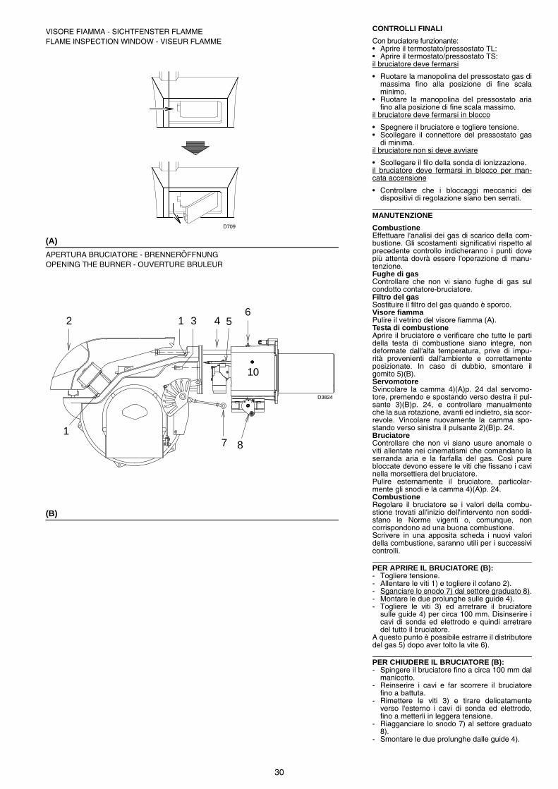
30
CONTROLLI FINALI
Con bruciatore funzionante:• Aprire il termostato/pressostato TL:• Aprire il termostato/pressostato TS:il bruciatore deve fermarsi
• Ruotare la manopolina del pressostato gas dimassima fino alla posizione di fine scalaminimo.
• Ruotare la manopolina del pressostato ariafino alla posizione di fine scala massimo.
il bruciatore deve fermarsi in blocco
• Spegnere il bruciatore e togliere tensione.• Scollegare il connettore del pressostato gas
di minima.il bruciatore non si deve avviare
• Scollegare il filo della sonda di ionizzazione.il bruciatore deve fermarsi in blocco per man-cata accensione
• Controllare che i bloccaggi meccanici deidispositivi di regolazione siano ben serrati.
MANUTENZIONE
CombustioneEffettuare l'analisi dei gas di scarico della com-bustione. Gli scostamenti significativi rispetto alprecedente controllo indicheranno i punti dovepiù attenta dovrà essere l'operazione di manu-tenzione.Fughe di gasControllare che non vi siano fughe di gas sulcondotto contatore-bruciatore.Filtro del gasSostituire il filtro del gas quando è sporco.Visore fiammaPulire il vetrino del visore fiamma (A).Testa di combustioneAprire il bruciatore e verificare che tutte le partidella testa di combustione siano integre, nondeformate dall'alta temperatura, prive di impu-rità provenienti dall'ambiente e correttamenteposizionate. In caso di dubbio, smontare ilgomito 5)(B).ServomotoreSvincolare la camma 4)(A)p. 24 dal servomo-tore, premendo e spostando verso destra il pul-sante 3)(B)p. 24, e controllare manualmenteche la sua rotazione, avanti ed indietro, sia scor-revole. Vincolare nuovamente la camma spo-stando verso sinistra il pulsante 2)(B)p. 24.BruciatoreControllare che non vi siano usure anomale oviti allentate nei cinematismi che comandano laserranda aria e la farfalla del gas. Così purebloccate devono essere le viti che fissano i cavinella morsettiera del bruciatore.Pulire esternamente il bruciatore, particolar-mente gli snodi e la camma 4)(A)p. 24. CombustioneRegolare il bruciatore se i valori della combu-stione trovati all'inizio dell'intervento non soddi-sfano le Norme vigenti o, comunque, noncorrispondono ad una buona combustione.Scrivere in una apposita scheda i nuovi valoridella combustione, saranno utili per i successivicontrolli.
PER APRIRE IL BRUCIATORE (B):- Togliere tensione.- Allentare le viti 1) e togliere il cofano 2).- Sganciare lo snodo 7) dal settore graduato 8).- Montare le due prolunghe sulle guide 4).- Togliere le viti 3) ed arretrare il bruciatore
sulle guide 4) per circa 100 mm. Disinserire icavi di sonda ed elettrodo e quindi arretraredel tutto il bruciatore.
A questo punto è possibile estrarre il distributoredel gas 5) dopo aver tolto la vite 6).
PER CHIUDERE IL BRUCIATORE (B):- Spingere il bruciatore fino a circa 100 mm dal
manicotto. - Reinserire i cavi e far scorrere il bruciatore
fino a battuta.- Rimettere le viti 3) e tirare delicatamente
verso l'esterno i cavi di sonda ed elettrodo,fino a metterli in leggera tensione.
- Riagganciare lo snodo 7) al settore graduato8).
- Smontare le due prolunghe dalle guide 4).
10
87
61 3 4
1
2 5
(A)
(B)
VISORE FIAMMA - SICHTFENSTER FLAMMEFLAME INSPECTION WINDOW - VISEUR FLAMME
APERTURA BRUCIATORE - BRENNERÖFFNUNGOPENING THE BURNER - OUVERTURE BRULEUR
D709
D3824

31
ENDKONTROLLEN
Bei Brenner in Betrieb:• Thermostat / Druckwächter TL öffnen:• Thermostat / Druckwächter TS öffnen:Der Brenner muß anhalten
• Drehen Sie den Schalter des Maximal-Gas-druckwächters bis zur minimalen Skalenend-position.
• Drehen Sie den Schalter des Luftdruckwäch-ters bis zur maximalen Skalenendposition.
Der Brenner muss in Störabschaltung stoppen.
• Schalten Sie den Brenner aus und unterbre-chen Sie die Spannung.
• Lösen Sie den Verbinder des Minimal-Gas-druckwächters.
Der Brenner darf nicht starten
• Lösen Sie den Draht des Ionisationsfühlers.Der Brenner muss auf Grund mangelnder Zün-dung in Störabschaltung stoppen.
• Überprüfen, ob die mechanischen Sperrender Einstellvorrichtungen richtig klemmen.
WARTUNG
VerbrennungDie Abgase der Verbrennung analysieren.Bemerkenswerte Abweichungen im Vergleichzur vorherigen Überprüfung zeigen die Stellean, wo die Wartung aufmerksamer ausgeführtwerden soll.GasundichtigkeitenDie Zähler-Brenner-Leitung auf Gasundichtig-keiten kontrollieren.GasfilterVerschmutzten Gasfilter austauschen.FlammensichtfensterDas Sichtfenster (A) putzen.FlammkopfDen Brenner öffnen und überprüfen, ob alleFlammkopfteile unversehrt, nicht durch hoheTemperatur verformt, ohne Schmutzteile ausder Umgebung und richtig positioniert sind. ImZweifelsfall den Schlitten 5)(B) ausbauen.StellantriebDen Nocken 4)(A)s. 24 durch Drucken und Ver-schieben nach rechts des Druckknopfs3)(B)S.24 vom Stellantrieb entsperren, und vonHand die ungehinderte Drehbewegung vor undzurück überprüfen. Den Nocken durch Verschie-ben nach links des Druckknopfs 2)(B)S. 24 wie-der sperren.BrennerEs ist zu überprüfen, ob ungewöhnlicher Ver-schleiß oder die Lockerung der Schrauben inden Antriebselementen der Luftklappe und Gas-drossel vorliegen. Die Schrauben zur Befesti-gung der Kabel an das Klemmenbrett desBrenners müssen ebenfalls festgezogen sein.Den Brenner, und besonders die Gelenke undden Nocken 4)(A)S. 24, von außen reinigen. VerbrennungFalls die anfänglich festgestellten Verbren-nungswerte nicht mit den geltenden Vorschriftenübereinstimmen, oder jedenfalls nicht einer kor-rekten Verbrennung entsprechen, muß derBrenner neu eingestellt werden.Tragen Sie auf einem geeigneten Formular dieneuen Verbrennungswerte ein, die für spätereKontrollen nützlich sind.
ÖFFNUNG DES BRENNERS (B):- Spannung unterbrechen.- Die Schrauben 1) herausdrehen und die
Brennerverkleidung 2) abnehmen.- Gelenk 7) aus dem Skalensegment 8) aus-
hängen.- Die zwei Verlängerungen auf den Führungen
4) montieren.- Die Schrauben 3) abnehmen und den Bren-
ner auf den Führungen 4) ca. 100 mm nachhinten versetzen. Die Sonden- und Elektro-denkabel abtrennen und anschließend denBrenner ganz nach hinten versetzen.
Nun kann der Gasverteiler 5) nach Entfernungvon Schraube 6) herausgezogen werden.
SCHLIEßEN DES BRENNERS (B):- Den Brenner auf einen Abstand von ca. 100
mm zur Muffe vorschieben. - Die Kabel einsetzen und den Brenner bis zum
Anschlag einschieben.- Die Schrauben 3) wieder einsetzen und die
Sonden- und Elektrodenkabel behutsam nachaußen ziehen, bis sie leicht angespannt sind.
- Gelenk 7) wieder an Skalensegment 8) ein-hängen.
- Die zwei Verlängerungen aus den Führungen4) abmontieren.
FINAL CHECKS
With burner running:• Open the thermostat/pressure switch TL:• Open the thermostat/pressure switch TS:The burner must stop
• Turn the gas maximum pressure switch to theminimum end of scale position.
• Turn the air pressure switch to the maximumend of scale position.
The burner must lock out
• Turn off the burner and switch off the electri-cal power.
• Disconnect the minimum gas pressure switchconnector.
The burner must not start
• Disconnect the ionisation probe wire.The burner must stop in lockout due to firingfailure
• Make sure that the mechanical locking sys-tems on the various adjustment devices arefully tightened.
MAINTENANCE
CombustionThe optimum calibration of the burner requiresan analysis of the flue gases. Significant differ-ences with respect to the previous measure-ments indicate the points where more careshould be exercised during maintenance.Gas leaksMake sure that there are no gas leaks on thepipework between the gas meter and theburner.Gas filterChange the gas filter when it is dirty.Flame inspection windowClean the flame inspection window (A).Combustion headOpen the burner and make sure that all compo-nents of the combustion head are in good condi-tion, not deformed by the high temperatures,free of impurities from the surroundings and cor-rectly positioned. If in doubt, disassemble theelbow fitting 5)(B).ServomotorDisengage the cam 4)(A)p. 24 from the servo-motor, by pressing and moving button 3)(B)p. 24towards the right, and turn it backwards and for-wards by hand to make sure it moves freely.Now engage the cam again by moving the but-ton 2)(B)p. 24 to the left.BurnerCheck for excess wear or loose screws in themechanisms controlling the air gate valve andthe gas butterfly valve. Also make sure that thescrews securing the electrical leads in theburner terminal strip are fully tightened.Clean the outside of the burner, taking specialcare with the transmission joints and cam4)(A)p. 24. CombustionAdjust the burner if the combustion values foundat the beginning of the operation do not complywith the regulations in force, or at any rate, donot correspond to good combustion. Use theappropriate card to record the new combustionvalues; they will be useful for subsequent con-trols.
TO OPEN THE BURNER (B):- Switch off the electrical power.- Loosen screws 1) and withdraw cover 2).- Disengage the articulated coupling 7) from
the graduated sector 8).- Fit the two extensions onto the slide bars 4).- Remove screws 3), and pull the burner back
by about 100 mm on the slide bars 4). Discon-nect the probe and electrode leads and thenpull the burner fully back.
Now extract the gas distributor 5) after havingremoved the screw 6).
TO CLOSE THE BURNER (B):- Push the burner until it is about 100 mm from
the sleeve. - Re-connect the leads and slide in the burner
until it comes to a stop.- Refit screws 3), and pull the probe and elec-
trode leads gently out until they are slightlystretched.
- Re-couple the articulated coupling 7) to thegraduated sector 8).
- Remove the two extensions from the slidebars 4).
CONTROLES FINAUX
Brûleur en fonctionnement:• Ouvrir le thermostat/pressostat TL:• Ouvrir le thermostat/pressostat TS:Le brûleur doit s'arrêter
• Tourner la poignée du pressostat gaz demaximum jusqu'à la position de fin d'échelleminimum.
• Tourner la poignée du pressostat air jusqu'àla position de fin d'échelle maximum.
Le brûleur doit se bloquer
• Eteindre le brûleur et couper la tension
• Débrancher le connecteur du pressostat gazde minimum.
Le brûleur ne doit pas démarrer
• Débrancher le fil de la sonde d'ionisation.Le brûleur doit s'arrêter en se bloquant pourmanque d'allumage
• Contrôler que les blocages mécaniques desdispositifs de réglage soient bien serrés.
ENTRETIEN
CombustionPour obtenir un réglage optimal du brûleur, ilfaut effectuer l'analyse des gaz d'échappementde la combustion à la sortie de la chaudière. Lesdifférences significatives par rapport au contrôleprécédent indiqueront les points où l'opérationd'entretien devra être plus approfondie.Fuites de gazContrôler l'absence de fuites de gaz sur le con-duit compteur-brûleur.Filtre du gazRemplacer le filtre du gaz lorsqu'il est encrassé.Viseur flammeNettoyer la vitre du viseur de flamme (A).Tête de combustionOuvrir le brûleur et contrôler que toutes les par-ties de la tête de combustion soient intactes, nesoient pas déformées par les températures éle-vées, qu'elles soient exemptes d'impuretés pro-venant du milieu ambiant et positionnéescorrectement. En cas de doute, démonter lecoude 5)(B).ServomoteurEnlever la came 4)(A)p. 24 du servomoteur, enappuyant sur le bouton 3)(B)p. 24 et en le dépla-çant vers la droite, et contrôler manuellementque sa rotation en avant et en arrière coulisselibrement. Replacer la came en déplaçant lebouton 2)(B)p. 24 vers la gauche.BrûleurVérifier qu'il n'y ait pas d'usure anormale ou devis desserrée dans les mécanismes qui com-mandent le volet d'air et la vanne papillon degaz. De même, les vis de fixation des câbles auporte-bornes du brûleur doivent être correcte-ment serrées.Nettoyer extérieurement le brûleur, en particu-lier les rotules et la came 4)(A)p. 24. CombustionRégler le brûleur si les valeurs de la combustiontrouvées au début de l'intervention ne satisfontpas les normes en vigueur ou ne correspondentpas à une bonne combustion.Reporter sur une fiche spéciale les nouvellesvaleurs de la combustion; elles seront utilespour les contrôles successifs.
POUR OUVRIR LE BRULEUR (B):- Couper la tension.- Desserrer la vis 1) et extraire le coffret 2).- Décrocher la rotule 7) du secteur gradué 8).- Monter les deux rallonges sur les guides 4).- Retirer la vis 3) et repousser le brûleur sur les
guides 4) d'environ 100 mm. Débrancher lescâbles de la sonde et de l'électrode et fairereculer complètement le brûleur.
On peut alors extraire le distributeur de gaz 5)après en avoir retiré la vis 6).
POUR FERMER LE BRULEUR (B):- Pousser le brûleur jusqu'à environ 100 mm du
manchon. - Réinsérer les câbles et faire coulisser le brû-
leur jusqu'a la butée.- Replacer la vis 3) et tirer délicatement vers
l'extérieur les câbles de la sonde et de l'élec-trode, jusqu'à les mettre légèrement en ten-sion.
- Réinsérer la rotule 7) du secteur gradué 8).- Démonter les deux rallonges des guides 4).

32
ANOMALIE / RIMEDIL’ apparecchiatura in dotazione ha una sua funzione diagnostica attraverso la quale è possibile facilmente individuare le possibili cause di malfunzionamento (segnalazione: LED ROSSO).Per utilizzare tale funzione, bisogna aspettare almeno dieci secondi dall’istante di messa in sicurezza dell’apparecchiatura e premere il pulsantedi sblocco per un tempo minimo di tre secondi.Rilasciato il pulsante il LED ROSSO comincerà a lampeggiare, come illustrato nella seguente figura.
Gli impulsi del LED costituiscono un segnale intervallato da 3 secondi circa.Il numero degli impulsi darà le informazioni sui possibili guasti, secondo la seguente tabella.
LED ROSSO accesoaspettare per almeno 10s
premere pulsanteper > 3s segnale segnale
Intervallo3s
In caso di arresto del bruciatore, per evitare danniall’installazione, non sbloccare il bruciatore più di duevolte di seguito. Se il bruciatore va in blocco per la ter-za volta, contattare il servizio di assistenza.ATTENZIONE
Nel caso in cui si verificassero ulteriori blocchi o ano-malie del bruciatore, gli interventi devono essere effet-tuati esclusivamente da personale abilitato edautorizzato, secondo quanto riportato nel presentemanuale ed in conformità alle norme e disposizioni dilegge vigenti.
PERICOLO
Segnale Inconveniente Causa probabile Rimedio consigliato
2 lampeggi Superata la preventilazione ed il tempo di sicurezza il bru-ciatore va in blocco senza apparizione di fiamma.
1 - L'elettrovalvola di funzionamento fa passare poco gas. Aumentarlo
2 - Una delle due elettrovalvole non si apre.. . . . . . . . . . . . Sostituire
3 - Pressione gas troppo bassa . . . . . . . . . . . . . . . . . . . . . Aumentarla al regolatore
4 - Elettrodo di accensione mal regolato. . . . . . . . . . . . . . . Regolarlo, vedi fig (C) pag. 14
5 - Elettrodo a massa per isolante rotto . . . . . . . . . . . . . . . Sostituirlo
6 - Cavo alta tensione difettoso. . . . . . . . . . . . . . . . . . . . . . Sostituirlo
7 - Cavo alta tensione deformato da alta temperatura . . . . Sostituirlo e proteggerlo
8 - Trasformatore d'accensione difettoso . . . . . . . . . . . . . . Sostituirlo
9 - Collegamenti elettrici valvole o trasformatore errati. . . . Controllarli
10 - Apparecchiatura elettrica difettosa. . . . . . . . . . . . . . . . . Sostituirla
11 - Una valvola a monte della rampa gas, chiusa . . . . . . . . Aprirla
12 - Aria nei condotti . . . . . . . . . . . . . . . . . . . . . . . . . . . . . . . Sfiatarla
13 - Valvole gas non collegate o con bobina interrotta . . . . . Controllare collegamenti o sostituire bobina
3 lampeggi Il bruciatore non si avvia ed appare il blocco
14 - Pressostato aria in posizione di funzionamento. . . . . . . Regorarlo o sostituirlo
Il bruciatore si avvia e poi si arresta in blocco
- Pressostato aria non commuta per pressione ariainsufficiente:
15 - Pressostato aria mal regolato . . . . . . . . . . . . . . . . . . . . Regolarlo o sostituirlo
16 - Tubetto presa pressione del pressostato ostruito . . . . . Pulirlo
17 - Testa mal regolata . . . . . . . . . . . . . . . . . . . . . . . . . . . . . Regolarla
18 - Alta pressione nel focolare. . . . . . . . . . . . . . . . . . . . . . . Collegare pressostato aria all'aspirazione ventilatore
Blocco durante la preventila-zione
19 - Contattore comando motore difettoso . . . . . . . . . . . . . . (solo versione trifase)
Sostituirlo
20 - Motore elettrico difettoso . . . . . . . . . . . . . . . . . . . . . . . . Sostituirlo
21 - Blocco motore (solo versione trifase). . . . . . . . . . . . . . . Sostituirlo
4 lampeggi Il bruciatore si avvia e poi si arresta in blocco
22 - Simulazione di fiamma. . . . . . . . . . . . . . . . . . . . . . . . . . Sostituire l'apparecchiatura
Blocco all'arresto del brucia-tore
23 - Permanenza di fiamma nella testa di combustione . . . . o simulazione fiamma
Eliminare permanenza di fiamma o sostitu-ire apparecchiatura
6 lampeggi Il bruciatore si avvia e poi si arresta in blocco
24 - Servomotore difettoso o mal regolato . . . . . . . . . . . . . . Sostituirlo o regolarlo
7 lampeggi Il bruciatore va in blocco subito dopo l'apparizione di fiamma
25 - -L'elettrovalvola di funzionamento fa passare poco gas Aumentarlo
26 - Sonda di ionizzazione mal regolata . . . . . . . . . . . . . . . . Regolarla, vedi fig. (C) pag. 14
27 - Ionizzazione insufficiente (inferiore a 5 A) . . . . . . . . . . . Controllare posizione sonda
28 - Sonda a massa . . . . . . . . . . . . . . . . . . . . . . . . . . . . . . . Allontanarla o sostituire cavo
29 - Insufficiente messa a terra del bruciatore . . . . . . . . . . . Rivedere messa a terra
30 - Fase e neutro invertiti . . . . . . . . . . . . . . . . . . . . . . . . . . Invertire
31 - Avaria del circuito di rivelazione fiamma . . . . . . . . . . . . Sostituire apparecchiatura
Blocco del bruciatore al pas-saggio tra potenza minima e massima e viceversa
32 - Troppa aria o poco gas . . . . . . . . . . . . . . . . . . . . . . . . . Regolare aria e gas
In funzionamento il bruciatore si ferma in blocco
33 - Sonda o cavo di ionizzazione a massa . . . . . . . . . . . . . Sostituire pezzi deteriorati
10 lampeggi Il bruciatore non si avvia ed appare il blocco
34 - Collegamenti elettrici errati . . . . . . . . . . . . . . . . . . . . . . Controllarli
Il bruciatore va in blocco 35 - Apparecchiatura elettrica difettosa. . . . . . . . . . . . . . . . . Sostituirla
36 - Presenza disturbi elettromagnetici sulle linee termostati Filtrarli o eliminarli
37 - Presenza disturbi elettromagnetici. . . . . . . . . . . . . . . . . Utilizzare kit protezione contro i radiodisturbi

33
Nessun lampeggio Il bruciatore non si avvia 38 - Manca l'energia elettrica . . . . . . . . . . . . . . . . . . . . . . . . Chiudere interruttori Controllare collega-menti
39 - Telecomando limite o di sicurezza aperto . . . . . . . . . . . Regolarlo o sostituirlo
40 - Fusibile di linea interrotto . . . . . . . . . . . . . . . . . . . . . . . . Sostituirlo
41 - Apparecchiatura elettrica difettosa. . . . . . . . . . . . . . . . . Sostituirla
42 - Manca il gas. . . . . . . . . . . . . . . . . . . . . . . . . . . . . . . . . . Aprire valvole manuali tra contattore rampa
43 - Pressione gas in rete insufficiente . . . . . . . . . . . . . . . . . Sentire AZIENDA DEL GAS
44 - Pressostato gas di min non chiude . . . . . . . . . . . . . . . . Regolarlo o sostituirlo
45 - Servomotore non si porta nella posizione di min. . . . . . accensione
Sostituirlo
Il bruciatore continua a ripe-tere il ciclo di avviamento senza blocco
46 - - La pressione del gas in rete è vicina al valore sul quale è regolato il pressostato gas di minima. Il calo di pres-sione repentino che segue l'apertura della valvola pro-voca l'apertura temporanea del pressostato stesso, subito la valvola chiude e si ferma il bruciatore. La pres-sione torna ad aumentare, il pressostato chiude e fa ripetere il ciclo di avviamento. E così via
Ridurre la pressione di intervento del pres-sostato gas di minima. Sostituire la cartuc-cia del filtro gas.
Accensioni con pulsazioni 47 - Testa mal regolata . . . . . . . . . . . . . . . . . . . . . . . . . . . . . Regolare. Vedi pag. 16
48 - Elettrodo di accensione mal regolato. . . . . . . . . . . . . . . Regolarlo, vedi fig (C) pag. 14
49 - Serranda ventilatore mal regolata, troppa aria. . . . . . . . Regolarla
50 - Potenza di accensione troppo elevata . . . . . . . . . . . . . . Ridurla
Il bruciatore non raggiunge la potenza massima
51 - Telecomando TR non chiude. . . . . . . . . . . . . . . . . . . . . Regolarlo o sostituirlo
52 - Apparecchiatura elettrica difettosa. . . . . . . . . . . . . . . . . Sostituirla
53 - Servomotore difettoso . . . . . . . . . . . . . . . . . . . . . . . . . . Sostituirlo
Bruciatore in sosta con ser-randa aria aperta
54 - Servomotore difettoso . . . . . . . . . . . . . . . . . . . . . . . . . . Sostituirlo
Segnale Inconveniente Causa probabile Rimedio consigliato

34
STÖRUNGEN / ABHILFENDas gelieferte Steuergerät hat eine Diagnosefunktion, über die eventuelle Betriebsstörungen leicht festgestellt werden könnenen (Anzeige:ROTE LED).Um diese Funktion zu benützen, muss man mindestens zehn Sekunden ab dem Augenblick warten, ab dem das Gerät in Sicherheitszustand ist,dann mindestens drei Sekunden lang auf den Entriegelungsschalter drücken.Nachdem der Schalter losgelassen ist, wird die ROTE LED zu blinken beginnen, wie in der hier folgenden Abbildung gezeigt.
Die Impulse der LED verursachen ein Signal, das ca. alle 3 Sekunden gegeben wird.Die Anzahl der Impulse wird Informationen über die möglichen Defekte geben, nach der hier folgenden Tabelle.
ROTE LED eingeschaltetMindestens 10 Sek. Warten
Mindestens 3 Sekauf Entriegelungsschalter Signal Signal
3 Sek.Pause
drücken
Im Falle des Abschaltens des Brenners den Brennernicht mehrmals hintereinander entstören, umSchäden an der Installation zu vermeiden. Falls derBrenner zum dritten Mal hintereinander eine Störab-schaltung vornimmt, kontaktieren Sie den Kunden-dienst.
ACHTUNG
Sollten weitere Störabschaltungen oder Anomaliendes Brenners auftreten, dürfen die Eingriffe nur vonbefugtem Fachpersonal entsprechend den Angabenin diesem Handbuch und gemäß den geltenden ge-setzlichen Vorschriften und Normen durchgeführtwerden.
GEFAHR
Signal Störungen Mögliche Ursache Empfohlene Abhilfe
2 Blinken Störabschaltung des Bren-ners nach der Vorbelüftung, und der Sicherheitszeit ohne Flammenbildung.
1 - Ungenügender Gasfluß durch das Magnetventil. . . . . . Steigern
2 - Eines der beiden Magnetventile öffnet sich nicht. . . . . . Austauschen
3 - Gasdruck zu gering . . . . . . . . . . . . . . . . . . . . . . . . . . . . Am Regler erhöhen
4 - Zündelektrode schlecht eingestellt. . . . . . . . . . . . . . . . . Einstellen, s. Abb. (C) S. 14
5 - Erdungselektrode für Isolator kaputt . . . . . . . . . . . . . . . Auswechseln
6 - Hochspannungskabel defekt . . . . . . . . . . . . . . . . . . . . . Auswechseln
7 - Hochspannungskabel durch hohe Temperatur verformt . . Auswechseln und schützen
8 - Defekter Zündtransformator. . . . . . . . . . . . . . . . . . . . . . Auswechseln
9 - Falsche Elektrische Anschlüsse Ventile oder . . . . . . . . . . .Transformator
Kontrollieren
10 - Defektes Steuergerät . . . . . . . . . . . . . . . . . . . . . . . . . . . Auswechseln
11 - Ein Ventil vor der Gasarmatur geschlossen. . . . . . . . . . Öffnen
12 - Luft in den Leitungen . . . . . . . . . . . . . . . . . . . . . . . . . . . Entlüften
13 - Gasventile nicht verbunden oder mit unterbrochener . . Spule
Anschlüsse überprüfen oder Spule aus-wechseln
3 Blinken Brenner geht nicht an und es erfolgt eine Störabschaltung
14 - Luftdruckwächter in Betriebsstellung . . . . . . . . . . . . . . . Einstellen oder auswechseln
Der Brenner fährt an und es erfolgt eine Störabschaltung
- Luftdruckwächter schaltet nicht um, weil Luftdruck nicht ausreichend:
15 - Luftdruckwächter falsch eingestellt . . . . . . . . . . . . . . . . Einstellen oder auswechseln
16 - Leitung der Druckentnahmestelle des Druckwächters. . verstopft
Reinigen
17 - Kopf schlecht eingestellt . . . . . . . . . . . . . . . . . . . . . . . . Einstellen
18 - Hoher Unterdruck im Feuerraum . . . . . . . . . . . . . . . . . . Luft-Druckwächter an Gebläse-Ansaugöff-nung anschließen
Störabschaltung bei Vorbelüf-tung
19 - Schütz zur Motorsteuerung defekt . . . . . . . . . . . . . . . . (nur dreiphasige Ausführung)
Auswechseln
20 - Defekter Elektromotor . . . . . . . . . . . . . . . . . . . . . . . . . . Auswechseln
21 - Motorblock (dreiphasig) . . . . . . . . . . . . . . . . . . . . . . . . . Auswechseln
4 Blinken Der Brenner fährt an und es erfolgt eine Störabschaltung
22 - Flammensimulation . . . . . . . . . . . . . . . . . . . . . . . . . . . . Das Steuergerät austauschen
Störabschaltung bei Brenner-stillstand
23 - Nicht erloschene Flamme im Flammkopf oder . . . . . . . Flammensimulation
Flamme beseitigen oder Steuergerät erset-zen
6 Blinken Der Brenner fährt an und es erfolgt eine Störabschaltung
24 - Stellmotor defekt oder falsch eingestellt . . . . . . . . . . . . Einstellen oder auswechseln
7 Blinken Störabschaltung des Bren-ners sofort nach Bildung der Flamme
25 - Das Betriebsmagnetventil lässt zu wenig Gas . . . . . . . durchfließen.
Steigern
26 - Ionisationsfühler schlecht eingestellt . . . . . . . . . . . . . . . Einstellen, s. Abb. (C) S. 14
27 - Ungenügende Ionisation (unter 5 A) . . . . . . . . . . . . . . . Sondenposition überprüfen
28 - Geerdeter Fühler . . . . . . . . . . . . . . . . . . . . . . . . . . . . . . Beseitigen oder Kabel auswechseln
29 - Ungenügende Brennererdung . . . . . . . . . . . . . . . . . . . . Erdung überprüfen
30 - Phasen- und Nulleiteranschlüsse umgekehrt . . . . . . . . Umkehren
31 - Störung Flammenüberwachung. . . . . . . . . . . . . . . . . . . Das Steuergerät austauschen
Störabschaltung des Bren-ners während des Wechsels zwischen Mindest- und Höchstleistung und umge-kehrt
32 - Zuviel Luft oder wenig Gas . . . . . . . . . . . . . . . . . . . . . . Luft und Gas einstellen
Die Störabschaltung erfolgt während des Brennerbetriebs
33 - Ionisationssonde oder -Kabel geerdet . . . . . . . . . . . . . . Beschädigte Teile auswechseln

35
10 Blinken Brenner geht nicht an und es erfolgt eine Störabschaltung
34 - Falsche Elektrische Anschlüsse Kontrollieren . . . . . . . . Kontrollieren
Störabschaltung des Bren-ners
35 - Defektes Steuergerät . . . . . . . . . . . . . . . . . . . . . . . . . . . Auswechseln
36 - Vorhandensein elektromagnetischer Störungen in . . . . den Thermostatleitungen
Filtern oder beseitigen
37 - Vorhandensein elektromagnetischer Störungen . . . . . . Kit zum Schutz vor Funkstörungen verwen-den
Kein Blinken Brenner geht nicht an 38 - Kein Strom . . . . . . . . . . . . . . . . . . . . . . . . . . . . . . . . . . . Schalter schließen - Anschlüsse kontrollie-ren
39 - Eine Grenz-oder Sicherheitsfernsteuerung offen. . . . . . Einstellen oder auswechseln
40 - Leitungssicherung unterbrochen . . . . . . . . . . . . . . . . . . Auswechseln
41 - Defektes Steuergerät . . . . . . . . . . . . . . . . . . . . . . . . . . . Auswechseln
42 - Kein Gas . . . . . . . . . . . . . . . . . . . . . . . . . . . . . . . . . . . . Die handbetätigten Ventile zwischen Zähler und Armatur öffnen
43 - Netz-Gasdruck nicht ausreichend . . . . . . . . . . . . . . . . . Beim GASWERK nachfragen
44 - Mindestgasdruckwächter schließt nicht . . . . . . . . . . . . . Einstellen oder auswechseln
45 - Der Stellmotor schaltet nicht in die Position für min. . . . Zündung
Auswechseln
Der Brenner wiederholt pau-senlos die Anfahrphase, ohne dass eine Störabschaltung eintritt
46 - Der Gasdruck in der Leitung ist dem am Mindestgas-druckwächter eingestellten Wert sehr nahe. Der plötzli-che Druckabfall beim Öffnen des Ventils bewirkt die Öffnung des Druckwächters. Dadurch schließt sich das Ventil sofort wieder, und der Brenner stellt sich ab. der Druck steigt an, der Druckwächter schließt und setzt eine neue Anfahrphasein Gang, und so weiter.
Den Auslösedruck des Mindestgasdruck-wächters verringern. Den Einsatz des Gas-filters auswechseln.
Zündung mit Verpuffungen 47 - Kopf schlecht eingestellt . . . . . . . . . . . . . . . . . . . . . . . . Einstellen. Siehe Seite 17
48 - Zündelektrode schlecht eingestellt. . . . . . . . . . . . . . . . . Einstellen, s. Abb. (C) S. 14
49 - Gebläseluftklappe falsch eingestellt, zu viel Luft . . . . . . Einstellen
50 - Zu hohe Zündleistung . . . . . . . . . . . . . . . . . . . . . . . . . . Verringern
Der Brenner erreicht die Höchstleistung nicht
51 - TR-Fernsteuerung schließt nicht . . . . . . . . . . . . . . . . . . Einstellen oder auswechseln
52 - Defektes Steuergerät . . . . . . . . . . . . . . . . . . . . . . . . . . . Auswechseln
53 - Defekter Stellmotor . . . . . . . . . . . . . . . . . . . . . . . . . . . . Auswechseln
Bei Brennerstillstand Luft-klappe geöffnet
54 - Defekter Stellmotor . . . . . . . . . . . . . . . . . . . . . . . . . . . . Auswechseln
Signal Störungen Mögliche Ursache Empfohlene Abhilfe

36
FAULTS/SUGGESTED REMEDIESThe control box supplied performs a diagnostic role by means of which it is possible to easily identify the possible causes of any malfunctions(signal: RED LED).In order to use this function, it is necessary to wait at least ten seconds from the moment the control box is put in safety mode and press the lock-out reset button for a minimum of three seconds.Once the button has been released, the RED LED will start to flash, as illustrated in the diagram below.
The pulses of the LED constitute a signal spaced by approximately 3 seconds.The number of pulses will provide the information on the possible faults, according to the table below.
RED LED onwait at least 10 secs
Press buttonfor > 3 secs Signal Signal
Interval3 secs
In the event of a burner lockout, more than two conse-cutive burner reset operations could cause damage tothe installation. On the third lockout, contact the After-sales Service.WARNING
If further lockouts or burner faults occur, interventionsmust only be made by qualified, authorised personnel(as indicated in this manual, and in compliance withthe laws and regulations currently in force).DANGER
Signal Problem Possible cause Recommended remedy
2 blinks Once the pre-purging phase and safety time have passed, the burner goes into lockout without the appearance of the flame
1 - The operation solenoid lets little gas through . . . . . . . . Increase
2 - One of the two solenoid valves does not open. . . . . . . . Replace
3 - Gas pressure too low. . . . . . . . . . . . . . . . . . . . . . . . . . . Increase pressure at governor
4 - Ignition electrode incorrectly adjusted . . . . . . . . . . . . . . Adjust, see fig. (C) page 14
5 - Electrode grounded due to broken insulation . . . . . . . . Replace
6 - High voltage cable defective . . . . . . . . . . . . . . . . . . . . . Replace
7 - High voltage cable deformed by high temperature . . . . Replace and protect
8 - Ignition transformer defective. . . . . . . . . . . . . . . . . . . . . Replace
9 - Incorrect valve or transformer electrical wiring . . . . . . . Check
10 - Defective control box . . . . . . . . . . . . . . . . . . . . . . . . . . . Replace
11 - A closed valve upline the gas train . . . . . . . . . . . . . . . . Open
12 - Air in pipework . . . . . . . . . . . . . . . . . . . . . . . . . . . . . . . . Bleed air
13 - Gas valves unconnected or with interrupted coil . . . . . . Check connections or replace coil
3 blinks The burner does not switch on, and the lockout appears
14 - Air pressure switch in operating position . . . . . . . . . . . . Adjust or replace
The burner switches on, but then stops in lockout
- Air pressure switch inoperative due to insufficient air pressure:
15 - Air pressure switch incorrectly adjusted. . . . . . . . . . . . . Adjust or replace
16 - Pressure switch pressure test point pipe blocked . . . . . Clean
17 - Poorly adjusted head . . . . . . . . . . . . . . . . . . . . . . . . . . . Adjust
18 - High pressure in the furnace . . . . . . . . . . . . . . . . . . . . . Connect air pressure switch to fan suction line
Lockout during pre-purging phase
19 - Defective motor control contactor . . . . . . . . . . . . . . . . . (only three-phase version)
Replace
20 - Defective electrical motor. . . . . . . . . . . . . . . . . . . . . . . . Replace
21 - Motor lockout (defective electrical motor) . . . . . . . . . . . Replace
4 blinks The burner switches on, but then stops in lockout
22 - Flame simulation . . . . . . . . . . . . . . . . . . . . . . . . . . . . . . Replace the control box
Lockout when burner stops 23 - Permanent flame in the combustion head or . . . . . . . . flame simulation
Eliminate persistence of flame or replace control box
6 blinks The burner switches on, but then stops in lockout
24 - Defective or incorrectly adjusted servomotor. . . . . . . . . Adjust or replace
7 blinks The burner goes into lockout immediately following the appearance of the flame
25 - The operation solenoid lets little gas through . . . . . . . . Increase
26 - Ionisation probe incorrectly adjusted . . . . . . . . . . . . . . . Adjust, see fig. (C) page 14
27 - Insufficient ionisation (less than 5 A) . . . . . . . . . . . . . . . Check probe position
28 - Earth probe . . . . . . . . . . . . . . . . . . . . . . . . . . . . . . . . . . Withdraw or replace cable
29 - Burner poorly grounded . . . . . . . . . . . . . . . . . . . . . . . . . Check grounding
30 - Phase and neutral connections inverted . . . . . . . . . . . . Invert them
31 - Defective flame detection circuit . . . . . . . . . . . . . . . . . . Replace the control box
Burner locks out when shift-ing from minimum to maxi-mum output and vice versa
32 - Too much air or too little gas . . . . . . . . . . . . . . . . . . . . . Adjust air and gas
Burner goes into lockout dur-ing operation
33 - Probe or ionisation cable grounded . . . . . . . . . . . . . . . . Replace worn parts
10 blinks The burner does not switch on, and the lockout appears
34 - Incorrect electrical wiring . . . . . . . . . . . . . . . . . . . . . . . . Check
The burner goes into lockout 35 - Defective control box . . . . . . . . . . . . . . . . . . . . . . . . . . . Replace
36 - Presence of electromagnetic disturbances in . . . . . . . . the thermostat lines
Filter or eliminate
37 - Presence of electromagnetic disturbance . . . . . . . . . . . Use the radio disturbance protection kit

37
No blink The burner does not start 38 - No electrical power supply . . . . . . . . . . . . . . . . . . . . . . . Close all switches - Check connections
39 - A limiter or safety control device is open . . . . . . . . . . . . Adjust or replace
40 - Line fuse blocked. . . . . . . . . . . . . . . . . . . . . . . . . . . . . . Replace
41 - Defective control box . . . . . . . . . . . . . . . . . . . . . . . . . . . Replace
42 - No gas supply . . . . . . . . . . . . . . . . . . . . . . . . . . . . . . . . Open the manual valves between contactor and train
43 - Mains gas pressure insufficient . . . . . . . . . . . . . . . . . . . Contact your GAS COMPANY
44 - Minimum gas pressure switch fails to close. . . . . . . . . . Adjust or replace
45 - Servomotor fails to move to min. ignition position . . . . . Replace
The burner continues to repeat the start-up cycle, without lockout
46 - The gas pressure in the gas mains lies very close to the value to which the minimum gas pressure switch has been set. The sudden drop in pressure after valve open-ing causes temporary opening of the pressure switch itself, the valve immediately closes and the burner comes to a halt. Pressure increases again, the pressure switch closes again and the ignition cycle is repeated. And so on
Reduce the minimum gas pressure switch intervention pressure. Replace the gas filter cartridge.
Ignition with pulsations 47 - Poorly adjusted head . . . . . . . . . . . . . . . . . . . . . . . . . . . Adjust. See page 17
48 - Ignition electrode incorrectly adjusted . . . . . . . . . . . . . . Adjust, see fig. (C) page 14
49 - Incorrectly adjusted fan air damper: too much air . . . . . Adjust
50 - Output during ignition phase is too high. . . . . . . . . . . . . Reduce
Burner does not reach maxi-mum output
51 - Remote control device TR fails to close. . . . . . . . . . . . . Adjust or replace
52 - Defective control box . . . . . . . . . . . . . . . . . . . . . . . . . . . Replace
53 - Defective servomotor . . . . . . . . . . . . . . . . . . . . . . . . . . . Replace
Burner stops with air damper open
54 - Defective servomotor . . . . . . . . . . . . . . . . . . . . . . . . . . . Replace
Signal Problem Possible cause Recommended remedy

38
ANOMALIES/ SOLUTIONSLa boîte de contrôle fournie de série a une fonction diagnostic qui permet de localiser facilement les causes possibles de mauvais fonctionne-ment (signalisation: LED ROUGE).Pour utiliser cette fonction, il faut attendre au moins dix secondes après la mise en sécurité de la boîte et appuyer sur le bouton de déblocagependant au moins trois secondes.Après avoir relâché le bouton, le led rouge se met à clignoter comme indiqué sur la figure suivante..
Les impulsions du led constituent un signal espacé d'environ 3 secondes.Le nombre d'impulsions donne des informations sur les pannes possibles, selon le tableau suivant.
LED ROUGE alluméattendre au moins 10 s
Appuyer sur le boutonpendant > 3s signal signal
Intervalle3s
En cas d'arrêt du brûleur, afin d'éviter des dommagesà l'installation, ne pas débloquer le brûleur plus dedeux fois de suite. Si le brûleur se met en sécuritépour la troisième fois, contacter le service d'assistan-ce.
ATTENTION
Si d'autres mises en sécurité ou anomalies du brûleurse manifestent, les interventions doivent être effec-tuées exclusivement par un personnel dûment habilitéet autorisé, selon les dispositions du présent manuelet conformément aux normes et dispositions légalesen vigueur.
DANGER
Signal Inconvénient Cause probable Remède conseillé
2 clignotements Après la préventilation et le temps de sécurité, le brûleur se met en sécurité sans apparition de flamme
1 - L'électrovanne de fonctionnement fait passer . . . . . . . . peu de gaz.
Augmenter
2 - Une des deux électrovannes ne s'ouvre pas. . . . . . . . . Remplacer
3 - Pression gaz trop faible . . . . . . . . . . . . . . . . . . . . . . . . . L'augmenter au régulateur
4 - Électrode d'allumage mal réglée . . . . . . . . . . . . . . . . . . Régler, voir fig. (C) p. 14
5 - Électrode à la masse à cause de la rupture de l'isolant. . . Remplacer
6 - Câble haute tension défectueux . . . . . . . . . . . . . . . . . . Remplacer
7 - Câble haute tension déformé par haute température . . Le remplacer et le protéger
8 - Transformateur d'allumage défectueux . . . . . . . . . . . . . Remplacer
9 - Raccordements électriques vannes ou . . . . . . . . . . . . . transformateur mal faits
Contrôler
10 - Coffret de sécurité défectueux. . . . . . . . . . . . . . . . . . . . Remplacer
11 - Une vanne fermée en amont de la rampe gaz. . . . . . . . Ouvrir
12 - Air dans les conduites . . . . . . . . . . . . . . . . . . . . . . . . . . Purger
13 - Vannes gaz non raccordées ou bobine interrompue . . . Contrôler les raccordements ou remplacer la bobine
3 clignotements Le brûleur ne démarre pas et se met en sécurité.
14 - Pressostat air en position de fonctionnement . . . . . . . . Régler ou remplacer
Le brûleur démarre et se met en sécurité
- Pressostat air ne commute pas parce que pression air insuffisante:
15 - Pressostat air mal réglé . . . . . . . . . . . . . . . . . . . . . . . . . Régler ou remplacer
16 - Tube de prise de pression du pressostat obstrué . . . . . Nettoyer
17 - Tête mal réglée . . . . . . . . . . . . . . . . . . . . . . . . . . . . . . . Régler
18 - Haute pression dans le foyer . . . . . . . . . . . . . . . . . . . . . Raccorder le pressostat air à l'aspiration du ventilateur
Blocage durant la pré-ventila-tion
19 - Contacteur de commande du moteur défectueux . . . . . (uniquement version triphasée)
Remplacer
20 - Moteur électrique défectueux. . . . . . . . . . . . . . . . . . . . . Remplacer
21 - Mise en sécurité du moteur (uniquement version . . . . . triphasée)
Remplacer
4 clignotements Le brûleur démarre et se met en sécurité
22 - Simulation de flamme . . . . . . . . . . . . . . . . . . . . . . . . . . Remplacer le coffret de sécurité
Mise en sécurité à l'arrêt du brûleur
23 - Permanence de flamme ou simulation de flamme. . . . . dans la tête de combustion
Eliminer la permanence de flamme ou rem-placer le coffret de sécurité
6 clignotements Le brûleur démarre et se met en sécurité
24 - Servomoteur défectueux ou mal réglé . . . . . . . . . . . . . . Remplacer ou régler
7 clignotements Le brûleur se met en sécurité tout de suite après l'appari-tion de flamme.
25 - L'électrovanne de fonctionnement fait passer . . . . . . . . peu de gaz
Augmenter
26 - Sonde d'ionisation mal réglée . . . . . . . . . . . . . . . . . . . . Régler, voir fig. (C) p. 14
27 - Ionisation insuffisante (inférieure 5 A) . . . . . . . . . . . . . . Contrôler la position de la sonde
28 - Sonde à la masse . . . . . . . . . . . . . . . . . . . . . . . . . . . . . L'éloigner ou remplacer le câble
29 - La mise à la terre du brûleur n'est pas. . . . . . . . . . . . . . suffisamment efficace
Revoir la mise à la terre
30 - Phase et neutre inversés . . . . . . . . . . . . . . . . . . . . . . . . Inverser
31 - Panne du circuit de détection de flamme. . . . . . . . . . . . Remplacer le coffret de sécurité
Mise en sécurité du brûleur lors du passage de la puis-sance minimale à la maxi-male et vice-versa.
32 - Trop d'air ou peu de gaz . . . . . . . . . . . . . . . . . . . . . . . . Régler air et gaz
En cours du fonctionnement, le brûleur s'arrête, puis se bloque.
33 - Sonde ou câble d'ionisation à la masse. . . . . . . . . . . . . Remplacer pièces endommagées

39
10 clignotements Le brûleur ne démarre pas et se met en sécurité.
34 - Raccordements électriques mal faits . . . . . . . . . . . . . . . Contrôler
Le brûleur se met en sécurité 35 - Coffret de sécurité défectueux. . . . . . . . . . . . . . . . . . . . Remplacer
36 - Présence de perturbations électromagnétiques sur les . . lignes des thermostats
Filtrer ou éliminer
37 - Présence de perturbations électromagnétiques . . . . . . Utiliser le kit de protection contre les pertur-bations radio
Pas de clignotement Le brûleur ne démarre pas 38 - Absence de courant électrique . . . . . . . . . . . . . . . . . . . Fermer interrupteurs Contrôler raccorde-ments
39 - Télécommande de limite ou de sécurité ouverte . . . . . . Régler ou remplacer
40 - Fusible de ligne interrompu . . . . . . . . . . . . . . . . . . . . . . Remplacer
41 - Coffret de sécurité défectueux. . . . . . . . . . . . . . . . . . . . Remplacer
42 - Le gaz manque . . . . . . . . . . . . . . . . . . . . . . . . . . . . . . . Ouvrir les vannes manuelles entre le con-tacteur et la rampe
43 - Pression gaz réseau insuffisante . . . . . . . . . . . . . . . . . . Contacter la SOCIETE DU GAZ
44 - Le pressostat gaz minimum ne ferme pas . . . . . . . . . . . Régler ou remplacer
45 - Le servomoteur ne se porte pas en position . . . . . . . . . minimum d'allumage
Remplacer
Le brûleur continue à répéter le cycle de démarrage sans mise en sécurité
46 - La pression du gaz en réseau est proche de la valeur a laquelle le pressostat gaz minimum est réglé. La chute de pression soudaine suite à l'ouverture de la vanne pro-voque l'ouverture temporaire du pressostat, la vanne se ferme aussitôt et le brûleur s'arrête La pression aug-mente à nouveau, le pressostat se ferme et fait répéter le cycle de démarrage. Et ainsi de suite.
Réduire la pression d'intervention du pres-sostat gaz minimum. Remplacer la cartou-che du filtre à gaz.
Allumages avec saccades. 47 - Tête mal réglée . . . . . . . . . . . . . . . . . . . . . . . . . . . . . . . Régler. Voir page 17
48 - Électrode d'allumage mal réglée . . . . . . . . . . . . . . . . . . Régler, voir fig. (C) p. 14
49 - Volet ventilateur mal réglé, trop d'air . . . . . . . . . . . . . . . Régler
50 - Puissance à l’allumage trop élevée. . . . . . . . . . . . . . . . Réduire
Le brûleur n'atteint pas la puissance maximale.
51 - Télécommande TR ne ferme pas . . . . . . . . . . . . . . . . . Régler ou remplacer
52 - Coffret de sécurité défectueux. . . . . . . . . . . . . . . . . . . . Remplacer
53 - Servomoteur défectueux . . . . . . . . . . . . . . . . . . . . . . . . Remplacer
Brûleur arrêté avec volet d'air ouvert
54 - Servomoteur défectueux . . . . . . . . . . . . . . . . . . . . . . . . Remplacer
Signal Inconvénient Cause probable Remède conseillé

40
NORMALE FUNZIONAMENTO / TEMPO DI RILEVAZIONE FIAMMAL’ apparecchiatura ha una ulteriore funzione attraverso la quale è possibile accertare il corretto funzionamento del bruciatore (seg-nalazione: LED VERDE permanentemente acceso).Per utilizzare tale funzione, bisogna aspettare almeno dieci secondi dall’accensione del bruciatore e premere il pulsante dell’apparecchiatura perun tempo minimo di tre secondi.Rilasciato il pulsante il LED VERDE comincerà a lampeggiare, come illustrato nella figura sottostante.
Gli impulsi del LED costituiscono un segnale intervallato da 3 secondi circa.Il numero degli impulsi individuerà il TEMPO DI RILEVAZIONE della sonda dall’apertura delle valvole gas, secondo la seguente tabella.
KIT INTERFACE ADAPTER RMG TO PC Codice 3002719
NORMALER BETRIEB / FLAMMENDETEKTIONSZEITDas Steuergerät hat eine weitere Funktion, durch die der korrekte Betrieb des Brenners geprüft werden kann (Anzeige: GRÜNE LEDleuchtet ununterbrochen).Um diese Funktion zu nutzen, muss man mindestens zehn Sekunden ab der Inbetriebnahme des Brenners warten, und die Taste des Steuerge-rätes mindestens drei Sekunden lang drücken.Beim Loslassen der Taste beginnt die GRÜNE LED zu blinken, wie auf der Abbildung unten dargestellt.
Die Impulse der LED erzeugen ein Signal mit zirka 3 Sekunden Unterbrechung.Die Anzahl der Impulse zeigt die DETEKTIONSZEIT des Fühlers ab der Öffnung der Gasventile, gemäß folgender Tabelle.
KIT INTERFACE ADAPTER RMG TO PC Code 3002719
SEGNALE TEMPO DI RILEVAZIONE FIAMMA Ad ogni avviamento del bruciatore questo dato viene aggiornato.Eseguita la lettura, premendo brevemente il pulsante dell’apparecchiatura, il bruciatore ripete il ciclo di avviamento.ATTENZIONESe risulta un tempo > 2 s si ha accensione ritardata.Verificare la regolazione del freno idraulico su valvola gas e regolare la serranda aria e la testa di combustione.
1 lampeggio0.4 s
2 lampeggi0.8 s
6 lampeggi2.8 s
SIGNAL FLAMMENDETEKTIONSZEIT Bei jeder Inbetriebnahme des Brenners werden diese Daten aktualisiert.Nach dem Ablesen kurz die Taste des Steuergerätes drücken, und der Brenner wiederholt den Startvorgang.ACHTUNGWenn die Zeit > 2 S. ist, erfolgt eine verspätete Zündung.Prüfen Sie die Einstellung der Hydraulikbremse des Gasventils und die Einstellung der Luftklappe und des Flammkopfes.
1 Blinken0,4 S.
2 Blinken0,8 S.
6 Blinken2,8 S.
I
LED VERDE accesoaspettare per almeno 10s
premere pulsanteper > 3s segnale segnale
Intervallo3s
D
GRÜNE LED leuchtetmindestens 10s warten
Taste drückenfür > 3s signal signal
Pause3 S.

41
NORMAL OPERATION / FLAME DETECTION TIMEThe control box has a further function to guarantee the correct burner operation (signal: GREEN LED permanently on).To use this function, wait at least ten seconds from the burner ignition and then press the control box button for a minimum of 3 sec-onds.After releasing the button, the GREEN LED starts flashing as shown in the figure below.
The pulses of the LED constitute a signal spaced by approximately 3 seconds.The number of pulses will measure the probe DETECTION TIME since the opening of gas valves, according to the following table:
KIT INTERFACE ADAPTER RMG TO PC Code 3002719
FONCTIONNEMENT NORMAL / TEMPS DE DÉTECTION FLAMMELa boîte de contrôle sert également à contrôler le bon fonctionnement du brûleur (signalisation: LED VERTE constamment allumée).Pour utiliser cette fonction il faut attendre dix secondes à partir de l'allumage du brûleur et appuyer sur le bouton du coffret de sécuritépendant au moins trois secondes.Lorsque l'on relâche le bouton, la LED VERTE commence à clignoter, comme illustré dans la figure suivante.
Les impulsions de la LED sont un signal qui se répète environ toutes les 3 secondes.Le nombre des impulsions identifiera le TEMPS DE DÉTECTION de la sonde de l'ouverture des vannes gaz, d'après le tableau suivant.
KIT INTERFACE ADAPTER RMG TO PC Code 3002719
SIGNAL FLAME DETECTION TIME This is updated in every burner start-up.Once read, the burner repeats the start-up cycle by briefly pressing the control box button.WARNINGIf the result is > 2s, ignition will be retarded.Check the adjustment of the hydraulic brake of the gas valve, the air damper and the combustion head adjustment.
1 blink0.4s
2 blinks0.8s
6 blinks2.8s
SIGNAL TEMPS DE DÉTECTION DE LA FLAMME Cette donnée est mise à jour à chaque démarrage du brûleur.Une fois effectuée la lecture, en appuyant légèrement sur le bouton de la boîte de contrôle, le brûleur répète le cycle de démarrage.ATTENTIONSi le temps est de > 2 s l'allumage est retardé.Vérifier le réglage du frein hydraulique sur la vanne gaz et le réglage du volet d'air et de la tête de combustion.
1 clignotement 0.4 s
2 clignotements0.8 s
6 clignotements2.8 s
GB
GREEN LED onwait at least 10s
Press buttonfor > 3s signal signal
Interval3s
F
LED VERTE alluméeattendre au moins 10s
appuyer sur le boutonpendant > 3s signal signal
Intervalle3s

42
Appendice - Anhang - Appendix - Annexe
1
2
3
54
566
D3852
Collegamenti elettriciUsare cavi flessibili secondonorma EN 60 335-1.
Tutti i cavi da collegare al bru-ciatore vanno fatti passare daipassacavi.L'utilizzo dei passacavi puòavvenire in vari modi; a scopoesemplificativo indichiamo ilmodo seguente:
1 - Alimentazione trifase2 - Alimentazione monofase3 - Valvole gas4 - Pressostato gas o disposi-
tivo per il controllo di tenutavalvole
5 - Consensi/sicurezze6 - A disposizione
ElektroanschlüsseGemäß Norm EN 60 335-1biegsame Kabel verwenden.
Alle mit dem Brenner zu verbin-denden Kabel sind durch dieentsprechenden Kabeldurch-gänge zu führen.Die Kabeldurchgänge und dieVorbohrungen können auf ver-schiedene Arten genutzt wer-den. Als Beispiel führen wir diefolgenden Arten auf:
1 - Drehstromspeisung2 - Einphasenspeisung3 - Gasventile4 - Gasdruckwächter oder
Dichtheitskontrolle derGasventile
5 - Zustimmungen / Sicher-heitsvorrichtungen
6 - Zur Verfügung
Electrical connectionsUse flexible cables according toEN 60 335-1 Regulations.
All the wires to connect to theburner must enter through thesupplied fairleads.The fairleads and hole press-outs can be used in variousways; the following lists showone possible solution:
1 - Three-phase power supply2 - Single-phase power supply3 - Gas valves4 - Gas pressure switch or gas
valve leak detection controldevice
5 - Triggering / Safety devices6 - Available
Branchements électri-quesUtiliser des câbles flexiblesselon la norme EN 60 335-1.
Tous les câbles à raccorder aubrûleur doivent passer par lespasse-câbles. L'utilisation despasse-câbles et des trous pré-découpés peut se faire de plu-sieurs façons; à titre d'exemplenous indiquons l'une de cespossibilités.
1 - Alimentation triphasée2 - Alimentation monophasée3 - Vannes gaz4 - Pressostat gaz ou contrôle
d'étanchéité vannes gaz5 - Accords / Sécurités6 - Disponible
NOTEIl bruciatore RS 250/M MZ èstato omologato per funziona-mento intermittente. Ciò signi-fica che deve fermarsi "perNorma" almeno 1 volta ogni 24ore per permettere all'apparec-chiatura elettrica di effettuare uncontrollo della propria efficienzaall'avviamento. Normalmentel'arresto del bruciatore vieneassicurato dal telecomandodella caldaia.Se così non fosse è necessarioapplicare in serie a IN un inter-ruttore orario che provvedaall'arresto del bruciatore almeno1 volta ogni 24 ore.
I collegamenti elettrici devonoessere eseguiti secondo lenorme vigenti del paese didestinazione e da personalequalificato.Riello S.p.a. declina ogniresponsabilità da modifiche ocollegamenti diversi da quellirappresentati in questischemi.
ATTENZIONENon invertire il neutro con lafase nella linea di alimenta-zione elettrica.
In caso di alimentazione fase/fase, è necessario eseguire unponte nella morsettieradell’apparecchiatura tra ilmorsetto 6 e il morsetto di ter-ra.
VERMERKEDer Brenner RS 250/M MZ istfür intermittierenden Betriebbaumustergeprüft. Das bedeu-tet, daß er - laut Vorschrift - min-destens einmal pro 24 Stundenausschalten muß, damit dasSteuergerät eine Kontrolle sei-ner Leistungsfähigkeit beimAnlassen ausführen kann. DasAusschalten des Brenners wirdgewöhnlich durch die Fern-steuerung des Heizkessels ver-sichert.Sollte dies nicht der Fall sein,muß an IN ein Zeitschalter rei-hengeschaltet werden, dereinen Brennerstillstand einmalalle 24 Stunden gewährleistet.
Die elektrischen Anschlüssemüssen durch Fachpersonalnach den imBestimmungsland gültigenVorschriften ausgeführtwerden. Riello S.p.a. überrnimmt kei-nerlei Haftung für Änderun-gen oder Anschlüsse, dieanders als auf diesen Sche-men dargestellt sind.
ACHTUNGDen Nulleiter nicht mit demPhasenleiter in der Leitungder Stromversorgung vertau-schen.
Im Falle einer Phase-Phase-Versorgung muss eine Über-brückung im Stecksockel desSteuergeräts zwischen derKlemme 6 und der Erdklemmeausgeführt werden.
NOTESThe RS 250/M MZ burner hasbeen type- approved for inter-mittent operation. This means itshoulds compulsorily bestopped at least once every 24hours to enable the control boxto perform checks of its own effi-ciency at start-up. Burner haltsare normally provided for auto-matically by the boiler load con-trol system.If this is not the case, a timeswitch should be fitted in seriesto IN to provide for burner shut-down at least once every 24hours.
Wiring must be performed byqualified personnel inaccordance with theregulations in force in thecountry of destination.Riello S.p.a. declines allresponsibility for changes orwiring performed in any wayother than that illustrated inthese diagrams.
WARNINGDo not invert the neutral withthe phase wire in the electricitysupply line.
In the case of phase-phasefeed, a bridge must be fittedon the control box terminalstrip between terminal 6 andthe earth terminal.
NOTESLe brûleur RS 250/M MZ étéhomologué pour fonctionner defaçon intermittente. Ce qui signi-fie qu'il doit s'arrêter selon lesnormes au moins 1 fois toutesles 24 heures pour permettre àle boîtier d'effectuer un contrôlede son efficacité au moment dudémarrage. Normalement l'arrêtdu brûleur est assuré par lethermostat de la chaudière.S'il n'en était pas ainsi, il faudraitappliquer en série au IN uninterrupteur horaire qui com-manderait l'arrêt du brûleur aumoins 1 fois toutes les 24 heu-res.
Les branchementsélectriques doivent êtreeffectués par du personnelqualifié, conformément auxnormes en vigueur dans lepays de destination.Riello S.p.A. décline toute res-ponsabilité en cas de modifi-cations ou de branchementsautres que ceux représentéssur ces schémas.
ATTENTIONDans la ligne d'alimentationélectrique, ne pas inverser leneutre avec la phase.
En cas d’alimentation phase/phase, il est nécessaire de re-lier la borne 6 à la borne de ter-re dans le bornier de le coffretde sécurité.

43
Schema quadro elettrico - SchaltplanLayout of electric panel board - Schéma tableau électrique
2 Indicazione riferimenti - Bezugangabe
N. foglio - Seite - Page
/1.A1
Coordinate - Koordinaten - Coordinates - Coordonnées
1
2 Indicazione riferimenti - Bezugangabe
3
INDICE - INHALT - CONTENTS - INDEX
References layout - Indication références
Schema funzionale RMG/M... - Betriebsschema RMG/M...RMG/M... operational layout - Schéma fonctionnel RMG/M...
4 Schema funzionale RMG/M... - Betriebsschema RMG/M...RMG/M... operational layout - Schéma fonctionnel RMG/M...
5 Collegamenti elettrici a cura dell’installatore - Elektroanschlusse vom Installateur auszuführenElectrical connections set by installer - Raccordements électrique par l’installateur
6 Schema funzionale RWF40... - Betriebsschema RWF40...RWF40... operational layout - Schéma fonctionnel RWF40...
References layout - Indication références

44
RS
250
/M
3
~
230
V

45
RS
250/
M
3 ~
4
00V

46
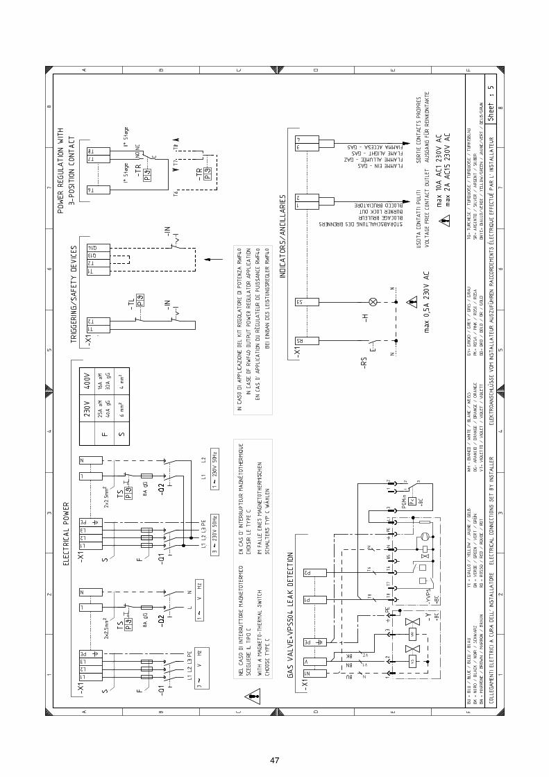
47

48

49
LEGENDA SCHEMI ELETTRICIA - Apparecchiatura elettricaB - Filtro contro radiodisturbiB1 - Regolatore di potenza RWF40BA - Ingresso in corrente DC 4...20 mABA1 - Ingresso in corrente DC 4...20 mA per modifica
setpoint remotoBP - Sonda di pressioneBP1 - Sonda di pressioneBR - Potenziometro setpoint remotoBT1 - Sonda a termocoppiaBT2 - Sonda Pt100 a 2 filiBT3 - Sonda Pt100 a 3 filiBT4 - Sonda Pt100 a 3 filiBTEXT - Sonda esterna per la compensazione climatica del
setpointBV - Ingresso in tensione DC 0...10 VBV1 - Ingresso in tensione DC 0...10 V per modifica
setpoint remotoCN1 - Connettore sonda di ionizzazioneF1 - Relè termico motore ventilatoreH - Segnalazione di blocco a distanzaIN - Interruttore elettrico per arresto manuale bruciatoreION - Sonda di ionizzazioneK1 - Relè uscita contatti puliti bruciatore accesoK2 - Relè uscita contatti puliti blocco bruciatoreKM - Contattore motoreMV - Motore ventilatorePA - Pressostato ariaPE - Terra bruciatorePGMin - Pressostato gas di minimaPGM - Pressostato gas di massimaQ1 - Interruttore sezionatore trifaseQ2 - Interruttore sezionatore monofaseRS - Pulsante di sblocco remotoS1 - Selettore spento / automatico / manualeS2 - Selettore aumento / diminuzione potenzaSM - ServomotoreTA - Trasformatore di accensioneTL - Termostato/pressostato di limiteTR - Termostato/pressostato di regolazioneTS - Termostato/pressostato di sicurezzaY - Valvola di regolazione gas + valvola di sicurezza
gasYVPS - Dispositivo di controllo di tenuta valvole gasX1 - Morsettiera alimentazione principaleXPGM - Connettore pressostato gas di massimaXP1 - Presa per kitXRWF - Morsettiera RWF40
ZEICHENERKLÄRUNG SCHEMENA - SteuergerätB - FunkentstörerB1 - Leistungsregler RWF40BA - Eingang in Gleichstrom DC 4...20 mABA1 - Eingang in Gleichstrom DC 4...20 mA für die Ände-
rung des Fern-SollwertesBP - DruckfühlerBP1 - DruckfühlerBR - Potentiometer für Fern-SollwertBT1 - ThermoelementfühlerBT2 - Fühler Pt100 mit 2 LeiternBT3 - Fühler Pt100 mit 3 LeiternBT4 - Fühler Pt100 mit 3 LeiternBTEXT - Externer Fühler für den klimatischen Sollwert-Aus-
gleichBV - Eingang in Gleichstrom DC 0...10 VBV1 - Eingang in Gleichstrom DC 0...10 V für die Ände-
rung des Fern-SollwertesCN1 - Ionisationfühler-SteckerF1 - Gebläsemotor-WärmerelaisH - Störabschaltung-FernmeldungIN - Schalter für das manuelle Ausschalten des Bren-
nersION - IonisationfühlerK1 - Relais Ausgang für Reinkontakte Brenner einK2 - Relais Ausgang für Reinkontakte Störabschaltung
des BrennersKM - MotorkontaktgeberMV - GebläsemotorPA - LuftdruckwächterPE - BrennererdungPGMin - MinimalgasdruckwächterPGM - HöchstgasdruckwächterQ1 - Trennschalter dreiphasigQ2 - Trennschalter einphasigRS - EntriegelungsschalterS1 - Schalter für: Aus-Automatischer Betrieb-Manueller
BetriebS2 - Schalter für: Leistungserhöhung-Leistungsminde-
rungSM - StellantriebTA - ZündtransformatorTL - Grenzthermostat/GrenzdruckwächterTR - Regelthermostat/RegeldruckwächterTS - Sicherheitsthermostat/SicherheitsdruckwächterY - Gasstellventil + Gas-SicherheitsventilX1 - Klemmenbrett der HauptspeisungXPGM - Höchstgasdruckwächter-SteckerXP1 - Steckanschluß für KitXRWF - RWF40 Klemmenbrett

50
KEY TO ELECTRICAL LAYOUTA - Control boxB - Protection against radio interferenceB1 - Output power regulator RWF40BA - DC input 4...20 mABA1 - DC input 4...20 mA for modifying the remote set-
pointBP - Pressure probeBP1 - Pressure probeBR - Remote setpoint voltage dividerBT1 - Thermocouple probeBT2 - Probe Pt100 with 2 wiresBT3 - Probe Pt100 with 3 wiresBT4 - Probe Pt100 with 3 wiresBTEXT - External probe for the climatic compensation of the
setpointBV - DC voltage input 0...10 VBV1 - DC voltage input 0...10 V for modifying the remote
setpointCN1 - Ionisation probe connectorF1 - Fan motor thermal cut-outH - Remote lock-out signalIN - Burner manual stop switchION - Ionisation probeK1 - Burner on voltage free contact relayK2 - Burner lock-out voltage free contact relayKM - Motor contactorMV - Fan motorPA - Air pressure switchPE - Burner groundPGMin - Minimum gas pressure switchPGM - Maximum gas pressure switchQ1 - Three-phase disconnect switchQ2 - Single-phase disconnect switchRS - Remote lock-out reset buttonS1 - Switch for following operations:
off-automatic-manualS2 - Button for: power increase/reductionSM - ServomotorTA - Ignition transformerTL - Limit pressure switch/thermostatTR - Control pressure switch/thermostatTS - Safety pressure switch/thermostatY - Gas adjustment valve + gas safety valveYVPS - Gas leak detection control deviceX1 - Main supply terminal stripXPGM - Maximum gas pressure switch connection plugXP1 - Socket for kitXRWF - RWF40 terminal strip
LÉGENDE SCHÉMAS ELECTRIQUEA - Coffret de sécuritéB - Protection contre parasites radioB1 - Régulateur de puissance RWF40BA - Entrée avec courant DC 4...20 mABA1 - Entrée avec courant DC 4...20 mA pour décalage
valeur de consigne à distanceBP - Sonde de pressionBP1 - Sonde de pressionBR - Potentiomètre valeur de consigne à distanceBT1 - Sonde avec thermocoupleBT2 - Sonde Pt100 à 2 filsBT3 - Sonde Pt100 à 3 filsBT4 - Sonde Pt100 à 3 filsBTEXT - Sonde externe pour la compensation climatique de
la valeur de consigneBV - Entrée avec tension DC 0...10 VBV1 - Entrée avec tension DC 0...10 V pour décalage
valeur de consigne à distanceCN1 - Connecteur sonde d'ionisationF1 - Relais thermique moteur ventilateurH - Signalisation blocage brûleur à distanceIN - Interrupteur électrique pour arrêt manuel brûleurION - Sonde d'ionisationK1 - Relais sortie contacts propres brûleur alluméK2 - Relais sortie contacts propres blocage brûleurKM - Contacteur moteurMV - Moteur ventilateurPA - Pressostat airPE - Mise à la terre brûleurPGMin - Pressostat gaz miniPGM - Pressostat gaz maxiQ1 - Disjoncteur triphaséeQ2 - Disjoncteur monophaséeRS - Bouton de déblocage à distanceS1 - Sélecteur: éteint / automatique / manuelS2 - Sélecteur: augmentation / diminution puissanceSM - ServomoteurTA - Transformateur d’allumageTL - Thermostat/ Pressostat de limiteTR - Thermostat/ Pressostat de réglageTS - Thermostat/ Pressostat de sécuritéY - Vanne de réglage gaz + vanne de sécurité gazYVPS - Dispositif de contrôle d’étanchéité vannesX1 - Plaque à bornes alimentation principaleXPGM - Connecteur pressostat gaz maxiXP1 - Prise pour kitXRWF - Plaque à bornes RWF40

51
ACCESSORI (su richiesta):
• KIT PER FUNZIONAMENTO A GPL
• KIT PER FUNZIONAMENTO MODULANTE
• KIT TESTA LUNGA: cod. 3010412.
• KIT POTENZIOMETRO PER INDICAZIONE POSIZIONE DI CARICO: cod. 3010416.
• KIT INTERFACE ADAPTER RMG TO PC Codice 3002719
• RAMPE GAS SECONDO NORMA EN 676 (complete di valvole, regolatore di pressione e filtro): vedere a pagina 18.
• KIT PROTEZIONE CONTRO I RADIODISTURBI In caso di installazione del bruciatore in ambienti particolari soggetti a radiodisturbi (emissione di segnali oltre 10 V/m) a causa della presenza diINVERTER o in applicazioni dove le lunghezze dei collegamenti del termostato superano i 20 metri, è disponibile un kit di protezione comeinterfaccia tra l’apparecchiatura e il bruciatore.
ZUBEHÖR (auf Wunsch):
• KIT FÜR FLÜSSIGGAS-BETRIEB.
• KIT FÜR MODULIERENDEN BETRIEB
• KIT LANGER KOPF: Code 3010412.
• KIT POTENTIOMETER ZUR ANZEIGE DER FÜLLPOSITION: Code 3010416.
• KIT INTERFACE ADAPTER RMG TO PC Code 3002719
• GASARMATUREN GEMÄß NORM EN 676 (mit Ventilen, Druckregler und Filter): siehe Seite 18.
• KIT ZUM SCHUTZ VOR FUNKSTÖRUNGEN Bei einer Installation des Brenners in besonderen, auf Grund des Vorhandenseins von INVERTERN Funkstörungen ausgesetzten Räumen(Emission von Signalen über 10 V/m) oder bei Anwendungen, bei denen die Länge der Anschlüsse des Thermostats 20 m überschreiten, stehtein Schutz-Kit als Schnittstelle zwischen dem Steuergerät und dem Brenner zur Verfügung.
Bruciatore RS 250/M MZ
POTENZA kW 600 ÷ 2700CODICE 3010411
Kit regolatore di potenza RWF40 Kit regolatore di potenza con segnale4-20 mA, 0-10V
I componenti da ordinare sono due: • il Regolatore di potenza da installare sul bruciatore;• la Sonda da installare sul generatore di calore
I componenti da ordinare sono due: • il Convertitore di segnale analogico;• il Potenziometro
Parametro da controllare SondaRegolatore di
potenzaPotenziometro
Convertitore di segnale analogico
Campo di regolazione Tipo Codice Tipo Codice Tipo Codice Tipo CodiceTemperatura - 100...+500°C PT 100 3010110
RWF40 3010414 ASZ... 3010416 E5202 3010415Pressione 0...2,5 bar0...16 bar
Sonda con uscita4...20 mA
30102133010214
BRUCIATORE RS 250/M MZ
Codice 3010386
BRENNER RS 250/M MZ
LEISTUNG kW 600 ÷ 2700
CODE 3010411
Leistungsregler Kit RWF40 Leistungsregler Kit mit Signal 4-20 mA, 0-10V
Zwei Komponenten sind zu bestellen: • der am Brenner zu installierende Leistungsregler;• der am Wärmegenerator zu installierende Fühler
Zwei Komponenten sind zu bestellen: • der analogischer Signalwandler;• das Potentiometer
Zu prüfender Parameter Fühler Leistungsregler Potentiometeranalogischer
Analogsignalwandler
Regelbereich Typ Code Typ Code Typ Code Typ CodeTemperatur - 100...+500°C PT 100 3010110
RWF40 3010414 ASZ... 3010416 E5202 3010415Druck 0...2,5 bar
0...16 barFühler mit Ausgang4...20 mA
30102133010214
BRENNER RS 250/M MZ
Code 3010386
I
D

52
ACCESSORIES (optional):
• KIT FOR LPG OPERATION
• KIT FOR MODULATING OPERATION
• LONG HEAD KIT: code 3010412.
• POTENTIOMETER KIT FOR THE INDICATION OF LOAD POSITION: code 3010416.
• KIT INTERFACE ADAPTER RMG TO PC Code 3002719
• GAS TRAIN ACCORDING TO REGULATION EN 676 (with valve, pressure governor and filter): see page 18.
• RADIO DISTURBANCEPROTECTION KIT If the burner is installed in places particularly subject to radio disturbance (emission of signals exceeding 10 V/m) owing to the presence of anINVERTER, or in applications where the length of the thermostat connections exceeds 20 metres, a protection kit is available as an interfacebetween the control box and the burner.
ACCESSOIRES (sur demande):
• KIT POUR FONCTIONNEMENT AU GPL
• KIT POUR FONCTIONNEMENT MODULANT
• KIT TETE LONGUE: code 3010412.
• KIT POTENTIOMETRE POUR INDICATION POSITION DE CHARGEMENT: code 3010416.
• KIT INTERFACE ADAPTER RMG TO PC Code 3002719
• RAMPES GAZ SELON LA NORME EN 676 (avec vannes, regulateur de pression et filtre): voir p. 18.
• KIT DE PROTECTION CONTRE LES PERTURBATIONS RADIO En cas d'installation du brûleur dans des endroits particulièrement soumis à des perturbations radio (émission de signaux au-delà de 10 V/m) àcause de la présence de l'INVERTER, ou bien dans des applications où les longueurs des connexions du thermostat dépassent les 20 mètres, unkit de protection est disponible comme interface entre la boîte de contrôle et le brûleur.
BURNER RS 250/M MZ
OUTPUT kW 600 ÷ 2700CODE 3010411
Output power regulator kit RWF40 Output power regulator with signal 4-20 mA, 0-10V
There are two components to order: • the Output power regulator to install on the burner;• the Probe to install on the heat generator
There are two components to order: • the Analogic signal converter;• the Potentiometer
Parameter to control ProbeOutput power
regulatorPotentiometer
Analogic signal converter
Adjustment field Type Code Type Code Type Code Type CodeTemperature - 100...+500°C PT 100 3010110
RWF40 3010414 ASZ... 3010416 E5202 3010415Pressure 0...2.5 bar0...16 bar
Probe with outlet4...20 mA
30102133010214
BURNER RS 250/M MZ
Code 3010386
BRULEUR RS 250/M MZ
PUISSANCE kW 600 ÷ 2700CODE 3010411
Kit régulateur de puissance RWF40 Kit régulateur de puissance avec signal4-20 mA, 0-10V
Il y a deux composants à commander: • le Régulateur de puissance à installer sur le brûleur;• la Sonde à installer sur le générateur de chaleur
Il y a deux composants à commander: • le Convertisseur de signal analogique;• le Potentiomètre
Paramètre à contrôler SondeRégulateur de
puissancePotentiomètre
Convertisseur de signal analogique
Plage de réglage TYPE CODE TYPE CODE TYPE CODE TYPE CODETempérature - 100...+500°C PT 100 3010110
RWF40 3010414 ASZ... 3010416 E5202 3010415Pression 0...2,5 bars0...16 bars
Sonde avec sortie4...20 mA
30102133010214
BRULEUR RS 250/M MZ
Code 3010386
GB
F


RIELLO S.p.A.
I-37045 Legnago (VR)
Tel.: +39.0442.630111
http:// www.riello.it
http:// www.rielloburners.com
Con riserva di modifiche - Änderungen vorbehalten! - Subject to modifications - Sous réserve de modifications

2915724 (5)
Istruzioni per installazione, uso e manutenzioneAnleitungen für Einbau, Betrieb und WartungInstallation, use and maintenance instructionsManuel d’entretien
Regolatore di potenzaLeistungsreglerPower controllerRégulateur de puissance
CODICECODE
30102103010211301021230102203001074300107830103563010357
I
D
GB
F
RWF40

2
INDICESCHEMA DI PRINCIPIO . . . . . . . . . . . . . . . . . . . . . . . . . . . . . . . 3DATI TECNICI . . . . . . . . . . . . . . . . . . . . . . . . . . . . . . . . . . . . . . . 4Impiego. . . . . . . . . . . . . . . . . . . . . . . . . . . . . . . . . . . . . . . . . . . . . 8Descrizione. . . . . . . . . . . . . . . . . . . . . . . . . . . . . . . . . . . . . . . . . . 8Dimensioni . . . . . . . . . . . . . . . . . . . . . . . . . . . . . . . . . . . . . . . . . . 8INSTALLAZIONE. . . . . . . . . . . . . . . . . . . . . . . . . . . . . . . . . . . . 10Applicazione sul bruciatore . . . . . . . . . . . . . . . . . . . . . . . . . . . . 10Applicazione a quadro . . . . . . . . . . . . . . . . . . . . . . . . . . . . . . . . 10ACCESSO AL REGOLATORE RWF40. . . . . . . . . . . . . . . . . . . 10MODALITÀ DI IMPOSTAZIONE . . . . . . . . . . . . . . . . . . . . . . . . 121° livello: Livello utente . . . . . . . . . . . . . . . . . . . . . . . . . . . . . . 16
Modifica dei setpoints . . . . . . . . . . . . . . . . . . . . . . . . . . . . . . 16Funzionamento manuale di un bruciatore modulante . . . . . . 16Funzionamento manuale di un bruciatore bistadio . . . . . . . . 16Relè k1 - k2 - k3 - k6 . . . . . . . . . . . . . . . . . . . . . . . . . . . . . . . 18
2° livello: Livello parametri. . . . . . . . . . . . . . . . . . . . . . . . . . . . 18Immissione dei parametri . . . . . . . . . . . . . . . . . . . . . . . . . . . 18
MODI OPERATIVI . . . . . . . . . . . . . . . . . . . . . . . . . . . . . . . . . . . 20Funzionamento al minimo . . . . . . . . . . . . . . . . . . . . . . . . . . . . 20Funzionamento in potenza . . . . . . . . . . . . . . . . . . . . . . . . . . . 20Bruciatore modulante, uscita a 3 punti . . . . . . . . . . . . . . . . . . . . 20Bruciatore modulante, uscita modulante . . . . . . . . . . . . . . . . . . 20Bruciatore bistadio, uscita a 3 punti . . . . . . . . . . . . . . . . . . . . . . 22Bruciatore bistadio, uscita modulante . . . . . . . . . . . . . . . . . . . . 22Spegnimento di sicurezza . . . . . . . . . . . . . . . . . . . . . . . . . . . . 22Setpoint predelimitato . . . . . . . . . . . . . . . . . . . . . . . . . . . . . . . 22Avviamento a freddo dell’impianto. . . . . . . . . . . . . . . . . . . . . 22DESCRIZIONE PARAMETRI. . . . . . . . . . . . . . . . . . . . . . . . . . . 243° livello: Livello configurazione . . . . . . . . . . . . . . . . . . . . . . . 30
Modifica del codice di configurazione . . . . . . . . . . . . . . . . . . 30Configurazione C111 . . . . . . . . . . . . . . . . . . . . . . . . . . . . . . . 32Configurazione C112 - C113 . . . . . . . . . . . . . . . . . . . . . . . . . 33
AFFINAMENTO DELLA REGOLAZIONE. . . . . . . . . . . . . . . . . 34FUNZIONE “tunE” . . . . . . . . . . . . . . . . . . . . . . . . . . . . . . . . . . 36COSA FARE SE. . . . . . . . . . . . . . . . . . . . . . . . . . . . . . . . . . . . . 42
I INHALTSTROMLAUFSCHALTPLAN . . . . . . . . . . . . . . . . . . . . . . . . . . . . 3TECHNISCHE ANGABEN . . . . . . . . . . . . . . . . . . . . . . . . . . . . . . 5Einsatz . . . . . . . . . . . . . . . . . . . . . . . . . . . . . . . . . . . . . . . . . . . . . 9Beschreibung . . . . . . . . . . . . . . . . . . . . . . . . . . . . . . . . . . . . . . . . 9Abmessungen . . . . . . . . . . . . . . . . . . . . . . . . . . . . . . . . . . . . . . . . 9INSTALLATION . . . . . . . . . . . . . . . . . . . . . . . . . . . . . . . . . . . . . 11Installation am Brenner . . . . . . . . . . . . . . . . . . . . . . . . . . . . . . . . 11Installation auf Schalttafel . . . . . . . . . . . . . . . . . . . . . . . . . . . . . . 11ZUGRIFF ZUM REGLER RWF40. . . . . . . . . . . . . . . . . . . . . . . . 11EINSTELLUNG DES REGLERS . . . . . . . . . . . . . . . . . . . . . . . . 131° Ebene: Bedienerebene . . . . . . . . . . . . . . . . . . . . . . . . . . . . . 17
Sollwerte ändern . . . . . . . . . . . . . . . . . . . . . . . . . . . . . . . . . . 17Handbetrieb, Brenner modulierend . . . . . . . . . . . . . . . . . . . . 17Handbetrieb, Brenner 2-stufig . . . . . . . . . . . . . . . . . . . . . . . . 17Relais k1 - k2 - k3 - k6 . . . . . . . . . . . . . . . . . . . . . . . . . . . . . . 19
2° Ebene: Parameterebene. . . . . . . . . . . . . . . . . . . . . . . . . . . . 19Parameter eingeben. . . . . . . . . . . . . . . . . . . . . . . . . . . . . . . . 19
BETRIEBSARTEN . . . . . . . . . . . . . . . . . . . . . . . . . . . . . . . . . . . 21Kleinlastbetrieb . . . . . . . . . . . . . . . . . . . . . . . . . . . . . . . . . . . . . 21Grosslastbetrieb . . . . . . . . . . . . . . . . . . . . . . . . . . . . . . . . . . . . 21Brenner modulierend, 3-Punktausgang . . . . . . . . . . . . . . . . . . . 21Brenner modulierend, stetiger Ausgang . . . . . . . . . . . . . . . . . . . 21Brenner 2-stufig, 3-Punktausgang . . . . . . . . . . . . . . . . . . . . . . . 23Brenner 2-stufig, stetiger Ausgang . . . . . . . . . . . . . . . . . . . . . . . 23Sicherheitsabschaltung . . . . . . . . . . . . . . . . . . . . . . . . . . . . . . 23Sollwertvorgabe . . . . . . . . . . . . . . . . . . . . . . . . . . . . . . . . . . . . 23Kaltstart der Anlage . . . . . . . . . . . . . . . . . . . . . . . . . . . . . . . . . 23BESCHREIBUNG DER PARAMETER. . . . . . . . . . . . . . . . . . . . 253° Ebene: KONFIGURATIONSEBENE . . . . . . . . . . . . . . . . . . . 31
Konfigurationscodes ändern . . . . . . . . . . . . . . . . . . . . . . . . . 31Konfiguration C111. . . . . . . . . . . . . . . . . . . . . . . . . . . . . . . . . 32Konfiguration C112 - C113 . . . . . . . . . . . . . . . . . . . . . . . . . . . 33
FEINREGELUNG . . . . . . . . . . . . . . . . . . . . . . . . . . . . . . . . . . . . 35FUNKTION “tunE” . . . . . . . . . . . . . . . . . . . . . . . . . . . . . . . . . . . 37WAS IST, WENN. . . . . . . . . . . . . . . . . . . . . . . . . . . . . . . . . . . . . 43
D
CONTENTSGENERAL WIRING DIAGRAM . . . . . . . . . . . . . . . . . . . . . . . . . . 3TECHNICAL DATA . . . . . . . . . . . . . . . . . . . . . . . . . . . . . . . . . . . 6Use. . . . . . . . . . . . . . . . . . . . . . . . . . . . . . . . . . . . . . . . . . . . . . . . 9Description . . . . . . . . . . . . . . . . . . . . . . . . . . . . . . . . . . . . . . . . . . 9Dimensions. . . . . . . . . . . . . . . . . . . . . . . . . . . . . . . . . . . . . . . . . . 9INSTALLATION . . . . . . . . . . . . . . . . . . . . . . . . . . . . . . . . . . . . . .11Fitting on the burner . . . . . . . . . . . . . . . . . . . . . . . . . . . . . . . . . . .11Mounting on the control panel . . . . . . . . . . . . . . . . . . . . . . . . . . .11ACCESS TO THE RWF40 CONTROLLER . . . . . . . . . . . . . . . . .11SETTING MODE OF THE RWF40 CONTROLLER. . . . . . . . . . 141° level: USER LEVEL . . . . . . . . . . . . . . . . . . . . . . . . . . . . . . . 17
Changing the setpoints . . . . . . . . . . . . . . . . . . . . . . . . . . . . . 17Manual operation of a modulating burner . . . . . . . . . . . . . . . 17Manual operation of a two-stage burner . . . . . . . . . . . . . . . . 17Relays k1 - k2 - k3 - k6 . . . . . . . . . . . . . . . . . . . . . . . . . . . . . 19
2° level: Parameter level . . . . . . . . . . . . . . . . . . . . . . . . . . . . . 19Parameter input. . . . . . . . . . . . . . . . . . . . . . . . . . . . . . . . . . . 19
OPERATING MODES . . . . . . . . . . . . . . . . . . . . . . . . . . . . . . . . 21Low-fire operation . . . . . . . . . . . . . . . . . . . . . . . . . . . . . . . . . . 21High-fire operation . . . . . . . . . . . . . . . . . . . . . . . . . . . . . . . . . . 21Modulating burner, 3-position output . . . . . . . . . . . . . . . . . . . . . 21Modulating burner, modulating output . . . . . . . . . . . . . . . . . . . . 21Two-stage burner, 3-position output . . . . . . . . . . . . . . . . . . . . . . 23Two-stage burner, modulating output . . . . . . . . . . . . . . . . . . . . . 23Safety shutdown. . . . . . . . . . . . . . . . . . . . . . . . . . . . . . . . . . . . 23Predefined setpoint . . . . . . . . . . . . . . . . . . . . . . . . . . . . . . . . . 23Cold start of the plant . . . . . . . . . . . . . . . . . . . . . . . . . . . . . . . 23DESCRIPTION OF THE PARAMETERS. . . . . . . . . . . . . . . . . . 253° level: Configuration level . . . . . . . . . . . . . . . . . . . . . . . . . . 31
Changing the configuration code . . . . . . . . . . . . . . . . . . . . . 31Configuration C111 . . . . . . . . . . . . . . . . . . . . . . . . . . . . . . . . 32Configuration C112 - C113 . . . . . . . . . . . . . . . . . . . . . . . . . . 33
ADJUSTMENT REFINEMENT . . . . . . . . . . . . . . . . . . . . . . . . . 35 “tunE” FUNCTION . . . . . . . . . . . . . . . . . . . . . . . . . . . . . . . . . . 38WHAT TO DO IF . . . . . . . . . . . . . . . . . . . . . . . . . . . . . . . . . . . . 44
GB INDEXSCHEMA DE PRINCIPE. . . . . . . . . . . . . . . . . . . . . . . . . . . . . . . . 3DONNÉES TECHNIQUES . . . . . . . . . . . . . . . . . . . . . . . . . . . . . . 7Emploi . . . . . . . . . . . . . . . . . . . . . . . . . . . . . . . . . . . . . . . . . . . . . . 9Description . . . . . . . . . . . . . . . . . . . . . . . . . . . . . . . . . . . . . . . . . . 9Dimensions . . . . . . . . . . . . . . . . . . . . . . . . . . . . . . . . . . . . . . . . . . 9INSTALLATION . . . . . . . . . . . . . . . . . . . . . . . . . . . . . . . . . . . . . 11Application sur le brûleur. . . . . . . . . . . . . . . . . . . . . . . . . . . . . . . 11Application au tableau. . . . . . . . . . . . . . . . . . . . . . . . . . . . . . . . . 11ACCES AU REGULATEUR RWF40. . . . . . . . . . . . . . . . . . . . . . 11MODALITE POUR LA SAISE DU REGULATEUR RWF40 . . . . 151e niveau: Niveau opérateur . . . . . . . . . . . . . . . . . . . . . . . . . . . 17
Modifier les valeurs de consigne . . . . . . . . . . . . . . . . . . . . . . 17Fonctionnement manuel, brûleur modulant . . . . . . . . . . . . . . 17Fonctionnement manuel, brûleur à 2 allures . . . . . . . . . . . . . 17Relais k1 - k2 - k3 - k6 . . . . . . . . . . . . . . . . . . . . . . . . . . . . . . 19
2e niveau: Niveau paramétrage . . . . . . . . . . . . . . . . . . . . . . . . 19Saisie des paramètres . . . . . . . . . . . . . . . . . . . . . . . . . . . . . . 19
MODES DE FONCTIONNEMENT . . . . . . . . . . . . . . . . . . . . . . . 21Mode faible charge . . . . . . . . . . . . . . . . . . . . . . . . . . . . . . . . . . 21Mode forte charge . . . . . . . . . . . . . . . . . . . . . . . . . . . . . . . . . . . 21Brûleur modulant, sortie 3 points . . . . . . . . . . . . . . . . . . . . . . . . 21Brûleur modulant, sortie progressive . . . . . . . . . . . . . . . . . . . . . 21Brûleur 2 allures, sortie 3 points . . . . . . . . . . . . . . . . . . . . . . . . . 23Brûleur 2 allures, sortie progressive . . . . . . . . . . . . . . . . . . . . . . 23Coupure de sécurité . . . . . . . . . . . . . . . . . . . . . . . . . . . . . . . . . 23Prescription de consigne . . . . . . . . . . . . . . . . . . . . . . . . . . . . . 23Démarrage à froid de l’installation . . . . . . . . . . . . . . . . . . . . . 23DESCRIPTION DES PARAMETRES . . . . . . . . . . . . . . . . . . . . . 253e niveau: Niveau configuration. . . . . . . . . . . . . . . . . . . . . . . . 31
Modification des codes de configuration . . . . . . . . . . . . . . . . 31Configuration C111. . . . . . . . . . . . . . . . . . . . . . . . . . . . . . . . . 32Configuration C112 - C113. . . . . . . . . . . . . . . . . . . . . . . . . . . 33
PERFECTIONNEMENT DU REGLAGE. . . . . . . . . . . . . . . . . . . 35FONCTION “tunE”. . . . . . . . . . . . . . . . . . . . . . . . . . . . . . . . . . . 39QUE SE PASSE-T-IL SI . . . . . . . . . . . . . . . . . . . . . . . . . . . . . . . 45
F

3
SCHEMA DI PRINCIPIO DEI DISPOSITIVI COLLEGABILI AL REGOLATORE DI POTENZA RWF40STROMLAUFSCHALTPLAN DER AN LEISTUNSREGLER RWF40 ANSCHLIEßBAREN VORRICHTUNGEN
GENERAL WIRING DIAGRAM OF THE DEVICES THAT CAN BE CONNECTED TO THE RWF40 POWER CONTROLLERSCHÉMA DE PRINCIPE DES DISPOSITIFS QUI POUVANT ÊTRE RELIÉS AU REGULATEUR DE PUISSANCE RWF40
D1884
B1 Sonda a termocoppiaB2 Sonda di pressione QBE...B3 Sonda Pt100 a 3 filiB4 Termoresistenza a 2 filiB5 Ingresso in corrente DC
0...20 mA, 4...20 mAB6 Ingresso in tensione DC
0...1 V, 0...10 VB7 Potenziometro setpoint
remotoB8 Ingresso in corrente
DC 0...20 mA, 4...20 mAper modifica setpointremoto
B9 Ingresso in tensione DC 0...1 V, 0...10 V permodifica setpoint remoto
B10 Sonda esterna per la com-pensazione climatica delsetpoint
B11 Uscita in corrente 4...20mA (solo versioni HIGH)
B12 Uscita in tensione 0...10 V(solo versioni HIGH)
B13 Interfaccia seriale RS-485(solo versioni HIGH)
BS Commutatore combusti-bile1 = gas (regolazione modulante)2 = olio (regolazione a 2 stadi)
IN Interruttore per arrestomanuale del bruciatore
IN1 Selettore per modifica delsetpoint esterno od interno
TL Telecomando di limiteSA Serranda dell’ariaSC Farfalla del gasSM Servomotore per il
comando serranda aria e farfalla gas
VR Valvola di regolazione delcombustibile
V1 Valvola di 1° stadioV2 Valvola di 2° stadio
B1 ThermoelementfühlerB2 Druckfühler QBE...B3 Fühler Pt100 mit 3 LeiternB4 Thermowiderstand mit 2
LeiternB5 Eingang in Gleichstrom
DC 0...20 mA, 4...20 mAB6 Eingang in Gleichstrom
DC 0...1 V, 0...10 VB7 Potentiometer für Fern-
SollwertB8 Eingang in Gleichstrom
DC 0...20 mA, 4...20 mAfür die Änderung desFern-Sollwertes
B9 Eingang in GleichstromDC 0...1 V, 0...10 V für dieÄnderung des Fern-Soll-wertes
B10 Externer Fühler für den kli-matischen Sollwert-Aus-gleich
B11 Ausgang in Gleichstrom4...20 mA (nur Ausführun-gen HIGH)
B12 Ausgang in Gleichstrom0...10 V (nur Ausführun-gen HIGH)
B13 Serielle Schnittstelle RS-485 (nur AusführungenHIGH)
BS Wählschalter Brennstoff1 = Gas (modulierende Regelung)2 = Öl (2-stufige Regelung)
IN Schalter für manuellesBrenneranhalten
IN1 Wählschalter für die Ände-rung des externen oderinternen Sollwertes
TL Limit-FernsteuerungSA LuftklappeSC GasdrosselSM Stellantrieb für Luftklap-
pen- und Gasdrossel-schaltung
VR Brennstoff RegelventilV1 Ventil 1. StufeV2 Ventil 2. Stufe
B1 Thermocouple probeB2 Pressure probe QBE...B3 Probe Pt100 with 3 wiresB4 Resistance thermometer
with 2 wiresB5 DC input 0...20 mA, 4...20
mAB6 DC voltage input 0...1 V,
0...10 VB7 Remote setpoint voltage
dividerB8 DC input 0...20 mA, 4...20
mA for modifying theremote setpoint
B9 DC voltage input 0...1 V,0...10 V for modifying theremote setpoint
B10 External probe for the cli-matic compensation of thesetpoint
B11 4...20 mA current output(HIGH version only)
B12 0...10 V voltage output(HIGH version only)
B13 RS-485 serial interface(HIGH version only)
BS Fuel selector switch1 = gas (modulating adjustment)2 = oil (2 stage adjustment)
IN Burner manual stop switchIN1 Dial for modifying the
internal or external set-point
TL Limit remote controlSA Air gate valveSC Gas butterfly valveSM Servomotor for air gate
valve and gas butterfly valve
VR Fuel supply control valveV1 1st stage valveV2 2nd stage valve
B1 Sonde avec thermocoupleB2 Sonde de pression QBE...B3 Sonde Pt100 à 3 filsB4 Thermomètre à résis-
tance à 2 filsB5 Entrée avec courant DC
0...20 mA, 4...20 mAB6 Entrée avec tension DC
0...1 V, 0...10 VB7 Potentiomètre valeur de
consigne à distanceB8 Entrée avec courant DC
0...20 mA, 4...20 mA pourdécalage valeur de consi-gne à distance
B9 Entrée avec tension DC0...1 V, 0...10 V pour déca-lage valeur de consigne àdistance
B10 Sonde externe pour lacompensation climatiquede la valeur de consigne
B11 Sortie avec courant 4...20mA (uniquement versionHIGH)
B12 Sortie avec tension 0...10V (uniquement versionHIGH)
B13 Interface séquentielle RS-485 (uniquement versionHIGH)
BS Commutateur combustible1 = gaz (réglage modulant)2 = fioul (réglage à 2 allures)
IN Interrupteur pour arrêtmanuel du brûleur
IN1 Sélecteur pour décalagede la valeur de consigneexterne et interne
TL Télécommande de limiteSA Volet d’airSC Vanne papillon gazSM Servomoteur pour la com-
mande volet d’air et vanne papillon gaz
VR Soupape de réglage ducombustible
V1 Vanne 1ère allureV2 Vanne 2ème allure

4
DATI TECNICIRegolatore di potenza . . . . . . . . . . . . . . . . . . . . . . . . . . . . . RWF40.000.A97 (Versione LOW) - RWF40.002.A97 (Versione HIGH)Tensione di alimentazione . . . . . . . . . . . . . . . . . . . . . . . . . . 110...240 V AC + / - 10 %Frequenza . . . . . . . . . . . . . . . . . . . . . . . . . . . . . . . . . . . . . . 48...63 HzConsumo . . . . . . . . . . . . . . . . . . . . . . . . . . . . . . . . . . . . . . . 5 VAPortata contatti . . . . . . . . . . . . . . . . . . . . . . . . . . . . . . . . . . . AC 24...240 V, 2A a cosϕ >0,6Protezione contro radio disturbi . . . . . . . . . . . . . . . . . . . . . . Conforme alle raccomandazioni NAMUR NE 21, EN 50 081 parte 1, EN 50 082
parte 2Grado di protezione . . . . . . . . . . . . . . . . . . . . . . . . . . . . . . . Frontale: IP 65. . . . . . . . . . . . . . . . . . . . . . . . . . . . . . . . . . . . . . . . . . . . . . . Custodia: IP 20Temperatura ambiente . . . . . . . . . . . . . . . . . . . . . . . . . . . . . – 20...+ 50°Temperatura di magazzinaggio . . . . . . . . . . . . . . . . . . . . . . – 40...+ 70°Umidità relativa max. (media annua) . . . . . . . . . . . . . . . . . . 95 % (evitare la condensazione)Connessione elettrica. . . . . . . . . . . . . . . . . . . . . . . . . . . . . . Sul retro, morsettiere con morsetti a vite, inclinate a 45°Custodia . . . . . . . . . . . . . . . . . . . . . . . . . . . . . . . . . . . . . . . . Profondità di montaggio 130 mmPeso . . . . . . . . . . . . . . . . . . . . . . . . . . . . . . . . . . . . . . . . . . . circa 0,43 kgIl regolatore di potenza RWF40 è conforme alla norma EN 60730.E' disponibile in 6 versioni:
E' un apparecchio universale, configurabile, che può essere collegato alle seguenti sonde:
SONDA (su richiesta)
Versione Applicazione
3010212 (LOW)
3010356 (LOW)3010357 (HIGH)
Bruciatori serie RL ... /M - versione modulanteBruciatori serie RLS ... /M - versione modulanteBruciatori serie RS ... /M - versione modulanteBruciatori serie FG ... M - versione modulanteBruciatori serie FL ... M - versione modulante
RS 300-400
3010210 (LOW)
3010220 (LOW)
3001074 (LOW)
GAS 3-4-5-6-7 P/M
GAS 3-4-5-6-7 P/M (USA)
GS 10 - 20 /M
3010211 (LOW)
GAS 8-9-10 P/MP 140-200-300-450 P/GP 140-200-300-450 P/N
G/M 1400-2000-3000-4500N/M 1400-2000-3000-4500
3001078 (LOW) Bruciatori serie BS ... /M
Parametro da controllare SondaTemperatura Termoresistenza
Pt100, Pt1000 -200... 850 °CNi100, Ni1000 DIN 43760 -60... 250 °CNi1000 Landis & Staefa -50... 160 °C
Termocoppia J -200... 1000 °CK -200... 1372 °CN -100... 1300 °CT -200... 400 °C
Sonda con segnale di uscita0... 1 V0... 10 V0... 20 mA4... 20 mA
Pressione Sonda con segnale di uscita0... 1 V0... 10 V0... 20 mA4... 20 mA
Parametro da controllare Campo di regolazione Tipo di sonda CodiceTemperatura -99,9... +500 °C PT 100 3010110
Pressione 0... 2,5 bar Sonda con uscita 4...20 mA 30102130... 16 bar Sonda con uscita 4...20 mA 3010214
I
D1903
D1901
D1902
D4423

5
TECHNISCHE ANGABENLeistungsregler . . . . . . . . . . . . . . . . . . . . . . . . . . . . . . . . . . . . . . .RWF40.000.A97 (Ausführung LOW) - RWF40.002.A97 (Ausführung HIGH) Speisespannung. . . . . . . . . . . . . . . . . . . . . . . . . . . . . . . . . . . . . .110...240 V AC + / - 10 %Frequenz . . . . . . . . . . . . . . . . . . . . . . . . . . . . . . . . . . . . . . . . . . .48...63 HzVerbrauch. . . . . . . . . . . . . . . . . . . . . . . . . . . . . . . . . . . . . . . . . . .5 VAStromfestigkeit Kontakte . . . . . . . . . . . . . . . . . . . . . . . . . . . . . . .AC 24...240 V, 2A bei cosϕ >0,6Elektromagnatische Verträglichkeit . . . . . . . . . . . . . . . . . . . . . . .Nach NAMUR Empfehlung NE 21, EN 50 081 Teil 1, EN 50 082 Teil 2Schutzgrad . . . . . . . . . . . . . . . . . . . . . . . . . . . . . . . . . . . . . . . . . .Stimteil: IP 65. . . . . . . . . . . . . . . . . . . . . . . . . . . . . . . . . . . . . . . . . . . . . . . . . . .Gehäuse: IP 20Raumtemperatur . . . . . . . . . . . . . . . . . . . . . . . . . . . . . . . . . . . . .– 20...+ 50°Lagertemperatur . . . . . . . . . . . . . . . . . . . . . . . . . . . . . . . . . . . . . .– 40...+ 70°Max. relative Feuchtigkeit (Jahresdurchschnitt) . . . . . . . . . . . . . .95 % (Kondensbildung vermeiden)Elektrischer Anschluß. . . . . . . . . . . . . . . . . . . . . . . . . . . . . . . . . .rückseitig über steckbare Schraubklemmleisten 45° abgewinkeltGehäuse. . . . . . . . . . . . . . . . . . . . . . . . . . . . . . . . . . . . . . . . . . . .Einbautiefe 130 mmGewicht . . . . . . . . . . . . . . . . . . . . . . . . . . . . . . . . . . . . . . . . . . . .ca. 0,43 kg
Der Leistungsregler RWF40 ist mit der Norm EN 60730 konform.Er steht in 6 Ausführungen zur Verfügung:
Es handelt sich um ein konfigurierbares Universalgerät, das an folgende Fühler angeschloßen werden kann:
FÜHLER (auf Wunsch)
Ausführung Anwendung
3010212 (LOW)
3010356 (LOW)3010357 (HIGH)
Brenner RL ... /M - modulierende AusführungBrenner RLS ... /M - modulierende AusführungBrenner RS ... /M - modulierende AusführungBrenner FG ... M - modulierende AusführungBrenner FL ... M - modulierende Ausführung
RS 300-400
3010210 (LOW)
3010220 (LOW)
3001074 (LOW)
GAS 3-4-5-6-7 P/M
GAS 3-4-5-6-7 P/M (USA)
GS 10 - 20 /M
3010211 (LOW)
GAS 8-9-10 P/MP 140-200-300-450 P/GP 140-200-300-450 P/N
G/M 1400-2000-3000-4500N/M 1400-2000-3000-4500
3001078 (LOW) Brenner BS ... /M
Regelparameter FühlerTemperatur Thermowiderstand
Pt100, Pt1000 -200... 850 °CNi100, Ni1000 DIN 43760 -60... 250 °CNi1000 Landis & Staefa -50... 160 °C
Thermoelement J -200... 1000 °CK -200... 1372 °CN -100... 1300 °CT -200... 400 °C
Fühler mit Ausgangssignal0... 1 V0... 10 V0... 20 mA4... 20 mA
Druck Fühler mit Ausgangssignal0... 1 V0... 10 V0... 20 mA4... 20 mA
Regelparameter Regelbereich Fühlertyp CodeTemperatur -99,9... +500 °C PT 100 3010110
Druck 0... 2,5 bar Fühler mit Ausgang 4...20 mA 30102130... 16 bar Fühler mit Ausgang 4...20 mA 3010214
D
D1903
D1901
D1902
D4423

6
TECHNICAL DATAPower controller . . . . . . . . . . . . . . . . . . . . . . . . . . . . . . . . . . . . . .RWF40.000.A97 (LOW version) - RWF40.002.A97 (HIGH version) Power supply . . . . . . . . . . . . . . . . . . . . . . . . . . . . . . . . . . . . . . . .110...240 V AC + / - 10 %Frequency . . . . . . . . . . . . . . . . . . . . . . . . . . . . . . . . . . . . . . . . . .48...63 HzConsumption . . . . . . . . . . . . . . . . . . . . . . . . . . . . . . . . . . . . . . . .5 VAContact capacity . . . . . . . . . . . . . . . . . . . . . . . . . . . . . . . . . . . . . .AC 24...240 V, 2A at p.f. (cosϕ) >0,6Electromagnetic compatibility. . . . . . . . . . . . . . . . . . . . . . . . . . . .To NAMUR recommendation NE 21, EN 50 081 part 1, EN 50 082 part 2Protection rating . . . . . . . . . . . . . . . . . . . . . . . . . . . . . . . . . . . . . .Front: IP 65. . . . . . . . . . . . . . . . . . . . . . . . . . . . . . . . . . . . . . . . . . . . . . . . . . .Case: IP 20Ambient temperature . . . . . . . . . . . . . . . . . . . . . . . . . . . . . . . . . .– 20...+ 50°Storage temperature . . . . . . . . . . . . . . . . . . . . . . . . . . . . . . . . . .– 40...+ 70°Max. relative humidity (annual average) . . . . . . . . . . . . . . . . . . .95 % (avoid condensation)Electrical connection . . . . . . . . . . . . . . . . . . . . . . . . . . . . . . . . . .At the back, via pug-in screw terminal strips, angled at 45°Case . . . . . . . . . . . . . . . . . . . . . . . . . . . . . . . . . . . . . . . . . . . . . . .Mounting depth 130 mmWeight . . . . . . . . . . . . . . . . . . . . . . . . . . . . . . . . . . . . . . . . . . . . .approx. 0,43 kg
The RWF40 power controller conforms to EN 60730 standards.It is available in 6 models:
It is a universal, configurable device and can be connected to the following probes:
PROBE (on request)
Model Application
3010212 (LOW)
3010356 (LOW)3010357 (HIGH)
RL ... /M burners - modulating versionRLS ... /M burners - modulating versionRS ... /M burners - modulating versionFG ... M burners - modulating versionFL ... M burners - modulating version
RS 300-400
3010210 (LOW)
3010220 (LOW)
3001074 (LOW)
GAS 3-4-5-6-7 P/M
GAS 3-4-5-6-7 P/M (USA)
GS 10 - 20 /M
3010211 (LOW)
GAS 8-9-10 P/MP 140-200-300-450 P/GP 140-200-300-450 P/N
G/M 1400-2000-3000-4500N/M 1400-2000-3000-4500
3001078 (LOW) BS ... /M burners
Parameter to be controlled ProbeTemperature Thermal resistance
Pt100, Pt1000 -200... 850 °CNi100, Ni1000 DIN 43760 -60... 250 °CNi1000 Landis & Staefa -50... 160 °C
Thermocouple J -200... 1000 °CK -200... 1372 °CN -100... 1300 °CT -200... 400 °C
Probe with output signal0... 1 V0... 10 V0... 20 mA4... 20 mA
Pressure Probe with output signal0... 1 V0... 10 V0... 20 mA4... 20 mA
Parameter to be controlled Adjustment range Type of probe CodeTemperature -99,9... +500 °C PT 100 3010110
Pressure 0... 2,5 bar Probe with 4...20 mA output 30102130... 16 bar Probe with 4...20 mA output 3010214
GB
D1903
D1901
D1902
D4423

7
DONNÉES TECHNIQUESRégulateur de puissance . . . . . . . . . . . . . . . . . . . . . . . . . . . RWF40.000.A97 (Version LOW) - RWF40.002.A97 (Version HIGH)Tension d’alimentation . . . . . . . . . . . . . . . . . . . . . . . . . . . . . 110...240 V AC + / - 10 %Fréquence . . . . . . . . . . . . . . . . . . . . . . . . . . . . . . . . . . . . . . 48...63 HzConsommation . . . . . . . . . . . . . . . . . . . . . . . . . . . . . . . . . . . 5 VAPortée contacts . . . . . . . . . . . . . . . . . . . . . . . . . . . . . . . . . . AC 24...240 V, 2A à cosϕ >0,6Compatibilité électromagnétique . . . . . . . . . . . . . . . . . . . . . Selon recommandations NAMUR NE 21, EN 50 081 Partie 1, EN 50 082 Partie 2Degré de protection . . . . . . . . . . . . . . . . . . . . . . . . . . . . . . . Partie frontale: IP 65. . . . . . . . . . . . . . . . . . . . . . . . . . . . . . . . . . . . . . . . . . . . . . . Boîtier: IP 20Température ambiante . . . . . . . . . . . . . . . . . . . . . . . . . . . . . – 20...+ 50°Température de stockage . . . . . . . . . . . . . . . . . . . . . . . . . . – 40...+ 70°Humidité relative max. (moyenne annuelle) . . . . . . . . . . . . . 95 % (éviter la condensation)Connexion électrique . . . . . . . . . . . . . . . . . . . . . . . . . . . . . . Au dos de l’appareil, par l’intermédiaire de réglettes à bornes à vis enfichables
formant un angle de 45°Boîtier . . . . . . . . . . . . . . . . . . . . . . . . . . . . . . . . . . . . . . . . . . Profondeur de montage 130 mmPoids . . . . . . . . . . . . . . . . . . . . . . . . . . . . . . . . . . . . . . . . . . env. 0,43 kg
Le régulateur de puissance RWF40 est conforme à la norme EN 60730.Il est disponible en 6 versions:
C’est un appareil universel, configurable, qui peut être relié aux sondes suivantes:
SONDE (sur demande)
Version Application
3010212 (LOW)
3010356 (LOW)3010357 (HIGH)
Brûleurs RL ... /M - version modulantBrûleurs RLS ... /M - version modulantBrûleurs RS ... /M - version modulantBrûleurs FG ... M - version modulantBrûleurs FL ... M - version modulant
RS 300-400
3010210 (LOW)
3010220 (LOW)
3001074 (LOW)
GAS 3-4-5-6-7 P/M
GAS 3-4-5-6-7 P/M (USA)
GS 10 - 20 /M
3010211 (LOW)
GAS 8-9-10 P/MP 140-200-300-450 P/GP 140-200-300-450 P/N
G/M 1400-2000-3000-4500N/M 1400-2000-3000-4500
3001078 (LOW) Brûleurs BS ... /M
Paramètre à contrôler SondeTempérature Thermomètre à résistance
Pt100, Pt1000 -200... 850 °CNi100, Ni1000 DIN 43760 -60... 250 °CNi1000 Landis & Staefa -50... 160 °C
Thermocouple J -200... 1000 °CK -200... 1372 °CN -100... 1300 °CT -200... 400 °C
Sonde avec signal de sortie0... 1 V0... 10 V0... 20 mA4... 20 mA
Pression Sonde avec signal de sortie0... 1 V0... 10 V0... 20 mA4... 20 mA
Paramètre à contrôler Plage de régulation Type de sonde CodeTempérature -99,9... +500 °C PT 100 3010110
Pression 0... 2,5 bar Sonde avec sortie 4...20 mA 30102130... 16 bar Sonde avec sortie 4...20 mA 3010214
F
D1903
D1901
D1902
D4423

8
IMPIEGOIl regolatore di potenza RWF40 viene impiegatonei processi termici in genere e, in particolare,nei bruciatori installati su caldaie a vapore, ac-qua, olio diatermico e forni.Il regolatore serve a convertire il funzionamentobistadio progressivo del bruciatore, in funziona-mento modulante.Nel funzionamento bistadio progressivo (A) ilbruciatore adegua automaticamente la potenzaalla richiesta di calore, variandola tra due valoriprestabiliti.Nel funzionamento modulante (B) invece, il bru-ciatore varia con continuità la potenza. In questo secondo caso si ottiene una maggiorestabilità del parametro controllato: temperatura opressione.
DESCRIZIONE (C)La figura (C) mostra RWF40 nelle condizioni difunzionamento, in cui viene visualizzato il displaydi base, che indica il valore reale ed il setpoint at-tivo al momento. Da questa condizione possonoessere attivati il funzionamento manuale, l’ au-toadattamento ed i livelli utente, parametri econfigurazione.
1 Display del setpoint (verde)2 Display valore reale (rosso)3 Consenso al bruciatore4 Diminuzione potenza CHIUDI/1° stadio5 Aumento potenza APRI/2° stadio6 Funzionamento bistadio7 Funzionamento manuale8 Contatto ausiliario9 Aumenta valore10 Diminuisci valore11 Tasto PGM12 Tasto EXIT
DIMENSIONI (D)Le dimensioni del regolatore RWF40 sono ripor-tate in figura (D).
(A)
(C)
(B)D914
SIEMENS
50.363.9
K6
PGM EXIT
t
t
t
t
MAX
MIN
kW
°Cbar
1
2
3 4 5 6
7
8
9
1211
10
(D)
RWF40
D1885

9
EINSATZDer Leistungsregler RWF40 wird allgemein inThermoprozeßen und insbesondere in Bren-nern, die in Dampf-, Wasser- und Diathermöl-kessel und Öfen eingebaut sind, verwendet.Der Regler dient dazu, den zweistufigen gleiten-den Betrieb des Brenners in modulierenden Be-trieb zu konvertieren.Im zweistufigen gleitenden Betrieb (A) gleichtder Brenner seine Leistung selbsttätig dem Wär-mebedarf an und variiert sie zwischen zwei fest-gelegten Werten.Im modulierenden Betrieb (B) dagegen variiertder Brenner die Leistung andauernd. Im zweiten Fall wird eine größere Stabilität desRegelparameters, Temperatur oder Druck, er-halten.
BESCHREIBUNG (C)Das Bild (C) zeigt den RWF40 nach dem Ein-schalten der Spannungsversorgung. Dieser Zu-stand wird als Normalanzeige bezeichnet. Hierwerden aktueller Istwert und aktiver Sollwert an-gezeigt. Handbetrieb, Selbsteinstellfunktion,Bedienebene, Parameter- und Konfigurations-ebene können von hier aus aktiviert werden.
1 Sollwertanzeige (grün)2 Istwertanzeige (rot)3 Brennerfreigabe4 Stellglied ZU/Stufe 1.5 Stellglied AUF/Stufe 2.6 Betriebsart 2-stufig7 Handbetrieb8 Limitkomparator9 Wert erhöhen10 Wert senken11 Taste PGM12 Taste EXIT
ABMESSUNGEN (D)Die Abmessungen des Reglers RWF40 sind inBild (D) gezeigt.
USEThe RWF40 power controller can be used ingeneral thermal processes and, in particular, onburners installed on steam, water, diathermal oilboilers and ovens.The controller converts the progressive two-stage operation of the burner to modulating op-eration.In the progressive two-stage operation (A) theburner automatically adjusts the output to theheat requirements, varying it between two presetvalues.However, in the modulating operation (B), theburner continuously varies the output. In the latter case greater stability of the control-led parameter is obtained: temperature or pres-sure.
DESCRIPTION (C)Figure (C) shows the RWF40 after switching on,where the basic display is shown indicating theactual value and the current active setpoint.Manual operation, self-setting, the user, pa-rameter and configuration levels can be acti-vated from here.
1 Setpoint display (green)2 Actual value display (rosso)3 Release of burner4 Power reduction CLOSE/1st stage5 Power increase OPEN/2nd stage6 2-stage operation7 Manual operation8 Auxiliary contact9 Increase value10 Decrease value11 PGM button12 EXIT button
DIMENSIONS (D)The dimensions of the RWF40 control unit areshown in figure (D).
EMPLOILe régulateur de puissance RWF40 est utilisé engénéral dans les processus thermiques et sur-tout dans les brûleurs installés sur chaudières àvapeur, à eau, à huile diathermique et dans lesfours.Le régulateur sert à transformer le fonctionne-ment à deux allures progressives du brûleur enfonctionnement modulant.Dans le fonctionnement à deux allures progres-sives (A), le brûleur adapte automatiquement lapuissance à la demande de chaleur en la modi-fiant entre deux valeurs préétablies.Dans le fonctionnement modulant (B), le brûleurmodifie par contre constamment la puissance. Dans ce deuxième cas, on obtient une plus gran-de stabilité du paramètre contrôlé: températureou pression.
DESCRIPTION (C)Le figure (C) montre RWF40 après la mise soustension. Cet état est appelé “affichage normal”.La valeur instantanée et la consigne active sontaffichées à partir de cet affichage. On peut acti-ver à partir de cet affichage le fonctionnementmanuel, la fonction d’auto-réglage, le niveauopérateur, le niveau paramétrage et le niveauconfiguration.
1 Affichage valeur de consigne (vert)2 Affichage valeur instantanée (rouge)3 Libération du brûleur4 Organe de réglage FERME/1ère allure5 Organe de réglage OUVERT/2ème allure6 Mode de fonctionnement 2 allures7 Fonctionnement manuel8 Comparateur de limites9 Augmenter la valeur10 Réduire la valeur11 Touche PGM12 Touche EXIT
DIMENSIONS (D)Les dimensions du régulateur RWF40 sont re-portées sur la figure (D).

10
INSTALLAZIONEIl regolatore può essere installato direttamentesul bruciatore o a quadro separato.� APPLICAZIONE SUL BRUCIATORE (A) - (B) - (C) - (D) - (E)I bruciatori sono già predisposti per accogliere ilregolatore di potenza RWF40. Il codice 3010212 va inserito nella staffa 1)(A)del bruciatore e fissato con le due viti 2)(A) dopoaver inserito le piastrine 3)(A). Collegamento elettrico: collegare i cavi uscentidal regolatore direttamente sulla morsettiera delbruciatore, dal lato dei collegamenti esterni 4),secondo gli schemi elettrici contenuti nel manua-le del bruciatore stesso.I cavi del regolatore hanno la medesima siglatu-ra della morsettiera del bruciatore.Il codice 3010210 - 3010220 va fissato sotto lamensola del bruciatore come in (B) mediante letre viti 1) con rosetta date a corredo da avvitaredirettamente sulla custodia metallica del regola-tore, già predisposta con i tre fori.Il codice 3010211 va fissato a fianco della men-sola del bruciatore come in (C). Bloccare la staf-fa del regolatore alla mensola, già predispostacon i tre fori, mediante le tre viti 1) con dado e ro-setta dati a corredo.Il codice 3001074 va fissato a fianco dello scudoanteriore come in (D) mediante le due viti 1) conrosetta date a corredo da avvitare direttamentesulla custodia metallica del regolatore, già predi-sposta con i due fori.Il codice 3001078 va fissato a fianco del frontonecome in (E) mediante le due viti 1) con rosettadate a corredo.I codici 3010356 e 3010357 vanno inseriti nellastaffa 1)(F) del bruciatore e fissato con le due viti2)(F) dopo aver inserito le piastrine 3)(F). Collegamento elettrico: collegare i cavi uscentidal regolatore sulla morsettiera 4)(F), secondogli schemi elettrici contenuti nel manuale del bru-ciatore stesso.� APPLICAZIONE A QUADRO (G) - (H)• Praticare un'apertura rettangolare delle dimen-
sioni indicate in (G) sul piano frontale del quadro.• Inserire la guarnizione data a corredo sulla cu-
stodia dell’apparecchio.• Inserire il regolatore nell'apertura.• Inserire le staffe di fissaggio nelle apposite fes-
sure presenti sulla custodia del regolatore.• Fissare i tiranti delle staffe di fissaggio contro il
pannello frontale del quadro e avvitare unifor-memente le viti.
Collegamento elettrico, accorgimenti: • Tenere separati i cavi della sonda dagli altri
cavi per evitare interferenze.• Il filo di terra deve essere il più corto possibile.
ACCESSO AL REGOLATORE RWF 40 (I)Il regolatore RWF40 ha tre livelli di accesso:1° : Livello utente
E' il livello di funzionamento. I display 1 e 2, fig. (C) pag.8, visualizzano le informazioni.
2° : Livello parametri3° : Livello configurazione
(B)
D918(G) (H)
D1886
(A)
2
3 23
1
4 cod. 3010212
cod. 3010210
cod. 3010211
Non usare la guarnizione data a corredoMitgelieferte Dichtung nicht aufsetzenDon’t use the seal suppliedNe pas utiliser le joint fourni à la livraison
cod. 3010220
(D)
D2370
cod. 3001074
11
(F)
(C)
cod. 3001078
11
D4425
1
2
3
54
D1904
(E)
cod. 3010356cod. 3010357
Livello utenteBedienerebeneUser levelNiveau opérateurDisplay di base
NormalanzeigeBasic displayAffichage normal
PGMPGM
Livello parametriParameterebeneParameter levelNiveau paramétrage
Livello configurazioneKonfigurationsebeneConfiguration levelNiveau configuration
PGM PGMPGM
min. 2s
PGMmin. 2s
EXIToppure attesa (circa 30 s) - oder Time-Out (ca. 30 s)or time-out (approx. 30 s) - ou temporisation (env. 30 s)
PGMmin. 2s
(I)
PGM 1.PGM 1.PGM 1.

11
INSTALLATIONDer Regler kann direkt in den Brenner oder se-parat auf eine Schalttafel installiert werden.� INSTALLATION AM BRENNER (A) - (B) - (C) - (D) - (E)Die Brenner sind bereits für den Einbau desLeistungsreglers RWF40 vorbereitet. Der Regler Code 3010212 muß nur in den Bren-nertragbügel 1)(A) eingesetzt und mit den zweiSchrauben 2)(A) befestigt werden, nachdem diePlättchen 3)(A) eingefügt wurden. Elektrischer Anschluß: die aus dem Regler tre-tenden Kabel direkt am Klemmenbrett des Bren-ners anschließen, an der Seite derAußenanschlüße 4), nach den Schaltplänen, diein der Bedienungsanleitung des Brenners ent-halten sind.Die Kennzeichnung der Reglerkabel stimmt mitder am Brennerklemmenbrett überein.Der Code 3010210 - 3010220 wird wie in Bild (B)erklärt unter der Brennerauflage mit dreiSchrauben 1) mit Unterlegscheibe direkt amMetallschutzgehäuse des Reglers (drei Vorbo-hrungen sin schon vorhanden) angebracht.Der Code 3010211 wird seitlich der Brennerau-flage angebracht, wie in Bild (C) sichtbar. DasSpanneisen des Reglers wird mit den mitge-lieferten drei Schrauben 1) nebst Mutter und Un-terlegscheibe an der Auflage festgemacht.Der Code 3001074 wird wie in Bild (D) erklärtseitlich des vorderen Schield mit zweiSchrauben 1) mit Unterlegscheibe direkt amMetallschutzgehäuse des Reglers (zwei Vorbo-hrungen sin schon vorhanden) angebracht.Der Code 3001078 wird wie in Bild (E) erklärtseitlich des vorderen Schilds mit den zwei mitge-lieferten Schrauben 1) mit Unterlegscheibe an-gebracht.Die Codes 3010356 und 3010357 müssen in denBrennertragbügel 1)(F) eingesetzt und mit denzwei Schrauben 2)(F) befestigt werden, nach-dem die Plättchen 3)(F) eingefügt wurden. Elektrischer Anschluß: die aus dem Regler tre-tenden Kabel am Klemmenbrett 4)(F) anschlie-ßen, nach den Schaltplänen, die in derBedienungsanleitung des Brenners enthaltensind.� INSTALLATION AUF SCHALTTAFEL (G) - (H)• Ein Rechteck mit Ausmaßen wie in (G) auf der
Vorderseite der Schalttafel anbringen.• Mitgelieferte Dichtung auf Gerätekorpus auf-
setzen.• Den Regler in die Öffnung einsetzen.• Von der Schalttafelrückseite her die Befesti-
gungselemente seitlich oder oben in dieFührungsschlitze einschieben.
• Die Befestigungselemente gegen die Schalt-tafelrückseite setzen und mit einemSchraubendreher gleichmässig festspannen.
Elektrischer Anschluß, sachdienliche Hin-weise: • Das Fühlerkabel von den anderen Kabeln ge-
trennt halten, um Störungen zu vermeiden.• Der Erdleiter muß so kurz als möglich sein.
ZUGRIFF ZUM REGLER RWF40 (I)Der Regler RWF40 hat drei Geräteebenen:1° : Bedienerebene
Das ist die Bedienebene. Die Anzeigezeilen 1 und 2, Bild (C) Seite 8, zeigen die Informationen.
2° : Parameterebene3° : Konfigurationsebene
INSTALLATIONThe controller can be installed directly onto theburner or on a separate panel.� FITTING ON THE BURNER(A) - (B) - (C) - (D) - (E)The burners are preset to accept the RWF40power controller. Insert the controller code 3010212 into thebracket 1(A) of the burner and fasten it with thetwo screws 2)(A) after having inserted theplates 3)(A). Electrical connection: connect the cables fromthe controller directly to the burner terminal board,at the external connections side 4), according tothe wiring diagrams in the burner manual.The controller cables have the same markingsas the burner terminal board.Code 3010210 - 3010220 should be secured un-derneath the burner shelf as shown in (B) usingthe three screws 1) and washers supplied, theseare tightened directly onto the metal casing ofthe regulator, which is predrilled with three holes.Code 3010211 should be secured at the side ofthe burner shelf as shown in (C). Lock the regu-lator shelf bracket, which is predrilled with threeholes, using the three screws 1) with nuts andwashers supplied.Code 3001074 should be secured at the side ofthe burner front shield as shown in (D) using thetwo screws 1) and washers supplied, these aretightened directly onto the metal casing of theregulator, which is predrilled with two holes.Code 3001078 should be secured at the side ofthe burner front part as shown in (E) using thetwo screws 1) and washers supplied.Insert the controller codes 3010356 and3010357 into the bracket 1)(F) of the burner andfasten it with the two screws 2)(F) after havinginserted the plates 3)(F). Electrical connection: connect the cables fromthe controller to the burner terminal board 4)(F),according to the wiring diagrams in the burnermanual.� MOUNTING ON THE CONTROL PANEL (G) - (H)• Make a rectangular opening having the dimen-
sions indicated in (G) on the panel front.• Place the seal supplied onto the controller
housing.• Insert the controller in the opening.• Insert the fixing brackets in the respective
openings in the controller housing.• Place the fixing bracket tie rods against the
front panel and screw evenly in place.Electrical connections, advice: • Keep the probe cables separate from the oth-
ers to prevent interference.• The ground wire must be as short as possible.
ACCESS TO THE RWF40 CONTROLLER (I)The RWF40 controller has three access levels:1° : User level
It is the operation level. Displays 1 and 2, fig. (C) page 8, show the information.
2° : Parameter level3° : Configuration level
INSTALLATIONLe régulateur peut être installé directement sur lebrûleur ou séparément sur le tableau.� APPLICATION SUR LE BRULEUR (A) - (B) - (C) - (D) - (E)Les brûleurs sont déjà conçus pour recevoir lerégulateur de puissance RWF40. Il suffit de placer le régulateur code 3010212dans le support 1)(A) du brûleur et de le fixeravec les deux vis 2)(A) après avoir installé lesplaquettes 3)(A). Branchement électrique: brancher les câblesde sortie du régulateur directement sur la plaqueà bornes du brûleur, du côté des branchementsexternes 4), selon les schémas électriques con-tenus dans le manuel du brûleur.Les câbles du régulateur portent les mêmes si-gles d’identification que la plaque à bornes dubrûleur.Le modèle 3010210 - 3010220 doit être fixé sousle support du brûleur comme indiqué sur la fig.(B) par trois vis 1) fournies avec rondelles à viss-er directement sur le boîtier métallique du régu-lateur sur lequel se trouvent déjà les trous.Le modèle 3010211 doit être fixé sur le côté dusupport du brûleur comme indiqué sur la fig. (C).Bloquer le châssis du régulateur au support déjàprévu avec les trois trous au moyen de trois vis1) fournies avec écrou et rondelle.Le modèle 3001074 doit être fixé sur le côté dubouclier avant du brûleur comme indiqué sur lafig. (D) par deux vis 1) fournies avec rondelles àvisser directement sur le boîtier métallique durégulateur sur lequel se trouvent déjà les deux.Le code 3001078 doit être fixé à côté du boucli-er, comme indiqué sur (E), à l’aide des deux vis(1) avec rondelle fournies de série.Les modèles 3010356 et 3010357 doivent êtreplacés dans le support 1)(F) du brûleur et fixésavec les deux vis 2)(F) après avoir installé lesplaquettes 3)(F). Branchement électrique: brancher les câblesde sortie du régulateur sur la plaque à bornes dubrûleur 4)(F), selon les schémas électriques con-tenus dans le manuel du brûleur.� APPLICATION AU TABLEAU (G) - (H)• Percer une ouverture rectangulaire ayant les
dimensions indiquées en (G) sur la partie fron-tale du tableau.
• Placer le joint fourni à la livraison sur le corpsde l’appareil.
• Placer le régulateur dans l’ouverture.• Introduire les supports de fixation dans les fis-
sures correspondantes sur le boîtier du régula-teur.
• Fixer les tirants des supports de fixation contrele panneau frontal du tableau et visser unifor-mément les vis.
Branchement électrique, précautions à pren-dre: • Séparer les câbles de la sonde des autres câ-
bles pour éviter des interférences.• Le fil de mise à la terre doit être le plus court
possible.
ACCES AU REGULATEUR RWF40 (I)Le régulateur RWF40 a trois niveaux d’accès:1° : Niveau opérateur
C’est le niveau de fonctionnement. Les écrans 1 et 2, fig. (C) page 8, affichent les informations.
2° : Niveau paramétrage3° : Niveau configuration
Dalla visualizzazione di base si possono raggiungere tutti i livelli per mezzo del tasto , come mostrato in fig. (F). Il display rosso 2)(C)pag. 8 indica il valore reale ed il valore dei parametri per i vari livelli. Il setpoint ed il nome del parametro sono indicati sul display verde 1)(C)pag.8.1. Esauriti tutti i parametri di un livello con il tasto , la visualizzazione ritorna automaticamente al livello precedente dopo la conferma dell’ultimo parametro.
I PGM
PGM
Alle Ebenen sind mit der Taste , wie im Bild (F) dargestellt aus der Normalanzeige heraus zu erreichen. Die rote Istwertanzeige 2)(C)S.8 stellt den Istwert und die Parameterwerte der verschiedenen Ebenen dar. In der grünen Sollwertanzeige 1)(C)S.8 werden der Sollwert und die Parameter angezeigt.1. Werden alle Parameter einer Ebene mit durchlaufen, findet beim Betätigen des letzen Parameter ein Rücksprung statt.
D PGM
PGM
All levels can be accessed from the basic display via the button, as shown in fig. (F). The red display 2)(C)pag. 8 indicates the actual value and the parameter values for the various levels. The setpoint and the parameters are indicated in the green display 1)(C)pag.8.1. After using to step through all the parameters of a level, an automatic return occurs after the last parameter has been confirmed.
GB PGM
PGM
Tous les niveaux peuvent être atteints avec la touche , comme indiqué sur la figure (F). L’affichage rouge 2)(C)page 8 indique la valeur instantanée et la valeur des paramètres des différents niveaux. L’affichage vert 1)(C)page 8 indique la valeur de consigne et les paramètres.1. Après avoir parcouru tous les paramètres d’un niveau avec la touche , on retourne automatiquement en arrière dès la confirmation du dernier paramètre.
F PGM
PGM

12
MODALITÀ DI IMPOSTAZIONE DEL REGOLATORE RWF40
Una corretta taratura del regolatore RWF40 richiede una conoscenza approfondita, che può essere acquisita attraverso una attenta let-tura del presente manuale.Il regolatore dispone di una funzione di autoacquisizione dei parametri da controllare “tunE” che determina automaticamente le variabili di processo. SI CONSIGLIA DI UTILIZZARE QUESTA FUNZIONE dopo aver impostato i parametri sottoelencati.
Premere il tasto e portarsi al 1° livello vedi pag. 10, fig. (H).Impostare il setpoint “SP1” (vedi pag. 16) con i tasti ▼ e ▲.Più a lungo si tiene premuto il tasto, più velocemente il valore cambia.Per memorizzare il valore impostato premere oppure attendere almeno 2 secondi per la memorizzazione automatica.Premendo si ritorna al menù precedente.
Portarsi al 2° livello vedi pag. 10, fig. (H).All’interno del livello si passa da un parametro al successivo premendo Impostare il tempo di corsa del servomotore “tt” (vedi pag. 18) con i tasti ▼ e ▲:• 24 s per servomotore mod. SQN90... - SQN91...;• 42 s per tutti gli altri modelli di servomotore e bruciatore;
Portarsi al 3° livello vedi pag. 10, fig. (H).Impostare:� il tipo di sonda
- con PT100, 3 fili impostare il codice 0000 (C111 pag. 32);- con sonda di pressione impostare il codice F000 (C111 pag. 32).
Con segnali all’ingresso 4...20 mA assegnare a:SCL il limite inferiore del campo della sonda;SCH il limite superiore del campo della sonda.Esempio. • Con sonda di pressione con uscita 4...20 mA e scala 0...2,5 bar assegnare a:
SCL = 0SCH = 2,5
• Con sonda di pressione con uscita 4...20 mA e scala 0...16 bar assegnare a:SCL = 0SCH = 16
N.B. Il regolatore lascia la fabbrica impostato per funzionare con sonde di temperatura.Quando si usano sonde di pressione ricordarsi di impostare:
• la banda morta “db”, zona con assenza di comandi al servomotore, Livello parametri
• il differenziale di accensione del bruciatore “HYS1” , Livello parametri
• il differenziale di spegnimento del bruciatore “HYS3”, Livello parametri
Esempio:• Sonde di pressione con scala 0...2,5 bar (caldaie a vapore a bassa pressione), impostare:
db = 1% del valore del setpoint;HYS1 = -0,1;HYS3 = 0,1.
• Sonde di pressione con scala 0...16 bar (caldaie a vapore ad alta pressione), impostare:db = 1% del valore del setpoint;HYS1 = -0,3;HYS3 = 0,3.
� il limite superiore “SPH” e inferiore “SPL” del setpoint (vedi pag. 24) con i tasti ▼ e ▲.
A questo punto avviare la funzione “tunE” (vedi pag. 36).
Nota. Per una corretta acquisizione dei parametri è necessario che la funzione “tunE” venga avviata ad impianto freddo o quando il valore reale (temperatura/pressione) è circa la metà del valore di setpoint impostato.
1 PGM LIVELLO UTENTE
PGM
EXIT
2 LIVELLO PARAMETRIPGM
3 LIVELLO CONFIGURAZIONE
2
2
2

13
EINSTELLUNG DES REGLERS RWF40
Für eine korrekte Eichung des Reglers RWF40 ist eine gründliche Kenntnis erforderlich, zu der man nur durch genaues Lesen der vorlie-genden Anleitung gelangt.Der Regler verfügt über eine Selbsteinstellfunktion der zu überprüfenden Parameter, “tunE” genannt, die das automatische Erfassen der Prozessvariablen bewirkt. ES WIRD EMPFOHLEN, DIESE FUNKTION ZU BENÜTZEN, nachdem die unten verzeichneten Parameter eingegeben worden sind.
Auf die Taste drücken und auf die 1. Ebene gehen, siehe Seite 10, Bild (H).Den Sollwert “SP1” mit den Tasten ▼ und ▲ eingeben (siehe S. 17).Je länger man auf die Taste drückt, desto schneller wird sich der Wert ändern.Zum Speichern des eingegebenen Wertes auf die Taste drücken oder mindestens 2 Sekunden lang warten, so dass er automatisch gespeichert wird.Durch Druck auf kehrt man zum vorherigen Menü zurück.
Auf die 2. Ebene gehen, siehe Seite 10, Bild (H).Innerhalb der Ebene geht man von einem Parameter auf den nächsten durch Druck auf über.Die Laufzeit des Stellantriebs “tt” (siehe S. 18) mit den Tasten ▼ und ▲ eingeben:• 24 s für Stellantrieb Mod. SQN90... - SQN91...;• 42 s für alle anderen Stellantrieb- und Brennermodelle;
Auf die 3. Ebene gehen, siehe Seite 10, Bild (H).Folgendes eingeben:� den Fühlertyp
- mit PT100, 3 Leiter, den Code 0000 eingeben (C111 Seite 32);- mit Druckfühler den Code F000 eingeben (C111 Seite 32).
Mit Signalen 4...20 mA am Eingang,SCL die untere Grenze des Fühlerbereichs zuteilen;SCH die obere Grenze des Fühlerbereichs zuteilen.Beispiel:• Mit Druckfühler mit Ausgang 4...20 mA und Skala 0...2,5 bar:
SCL = 0SCH = 2,5zuteilen.
• Mit Druckfühler mit Ausgang 4...20 mA und Skala 0...16 bar:SCL = 0SCH = 16zuteilen.
N.B. Beim Verlassen des Werks ist der Regler auf den Betrieb mit Temperaturfühlern eingestellt.Wenn man dagegen Druckfühler benützt, muss folgendes eingegeben werden:
• der Todbereich “db”, eine Zone ohne Steuerungen zum Stellantrieb, Parameterebene
• das Zündungsdifferential des Brenners “HYS1” , Parameterebene
• odas Abschaltungsdifferential des Brenners “HYS3”, Parameterebene
Beispiel:• Druckfühler mit Skala 0...2,5 bar (Niederdruck-Dampfheizkessel), wie folgt eingeben:
db = 1% des Sollwertes;HYS1 = -0,1;HYS3 = 0,1.
• Druckfühler mit Skala 0...16 bar (Hochdruck-Dampfheizkessel), wie folgt eingeben:db = 1% des Sollwertes;HYS1 = -0,3;HYS3 = 0,3.
� die obere Grenze “SPH” und die untere Grenze “SPL” des Sollwerts (siehe Seite 25) mit den Tasten ▼ und ▲.
Nun die Funktion “tunE” starten (siehe Seite 37).
Merke. Für eine korrekte Parametererfassung muss die Funktion “tunE” bei kalter Anlage oder wenn der effektive Wert (Temperatur/Druck des Heizkessel) ca. die Häfte des eingegebenen Sollwerts ist, gestartet werden.
1 PGM BEDIENEREBENE
PGM
EXIT
2 PARAMETEREBENEPGM
3 KONFIGURATIONSEBENE
2
2
2

14
SETTING MODE OF THE RWF40 CONTROLLER
The correct setting of the RWF40 controller requires thorough knowledge, which can be acquired by carefully reading this manual.The controller has a facility for the auto-acquisition of the parameters to be controlled “tunE”, which automatically determines the process variables. THE USER IS ADVISED TO USE THIS FUNCTION after having set the parameters listed below.
Press the key and proceed to level 1 see page 10, fig. (H).Set the setpoint “SP1” (see page 17) using the ▼ and ▲ keys.The longer the key is held down, the quicker the value changes.In order to save the value set, press or wait at least 2 seconds for automatic saving to take place.By pressing the user returns to the previous menu.
Proceed to level 2 see page 10, fig. (H).Within this level the user can pass from one parameter to the next by pressing Set the run time of the servomotor “tt” (see page 18) using the ▼ and ▲ keys:• 24 s for the SQN90... - SQN91... model servomotor;• 42 s for all other models of servomotor and burner;
Proceed to level 3 see page 10, fig. (H).Set:� the type of probe
- for PT100 with 3 wires, set the code 0000 (C111 page 32);- for pressure probe, set code F000 (C111 page 32).
With signals at the 4...20 ma input, assign to:SCL, the lower limit of the probe range;SCH, the upper limit of the probe range.Example. • With a pressure probe with a 4...20 ma output and a 0...2.5 bar scale assign to:
SCL = 0SCH = 2,5
• With a pressure probe with a 4...20 ma output and a 0...16 bar scale assign to:SCL = 0SCH = 16
N.B. The controller leaves the factory set to work with the temperature probe.When using the pressure probe, remember to set:
• the dead band “db”, area without commands to the servomotor, Parameters level
• the ignition differential of the burner “HYS1” , Parameters level
• the shut-down differential of the burner “HYS3”, Parameters level
Example:• Pressure probe with 0...2.5 bar scale (low-pressure steam boilers), set:
db = 1% of the setpoint value;HYS1 = -0,1;HYS3 = 0,1.
• Pressure probe with 0...16 bar scale (high-pressure steam boilers), set:db = 1% of the setpoint value;HYS1 = -0,3;HYS3 = 0,3.
� the upper limit “SPH” and lower limit “SPL” of the setpoint (see page 25) using the keys ▼ and ▲.
At this point, start-up the “tunE” function (see page 38).
Note. For the correct acquisition of the parameters, the "tunE" function must be started with the system cold or when the actual value (boiler temperature/pressure) is approximately half the set-point value.
1 PGM USER LEVEL
PGM
EXIT
2 PARAMETERS LEVELPGM
3 CONFIGURATION LEVEL
2
2
2

15
MODALITE POUR LA SAISE DU REGULATEUR RWF40
Le réglage correct du régulateur RWF40 demande une connaissance approfondie qui peut être acquise en lisant attentivement ce manuel.Le régulateur dispose d’une fonction d’autoréglage des paramètres à contrôler “tunE” qui détermine automatiquement les variables de processus. IL EST CONSEILLE D’UTILISER CETTE FONCTION après avoir saisi les paramètres indiqués ci-dessous.
Appuyer sur la touche et aller dans le 1e niveau voir page 10, fig. (H).Saisir la valeur de consigne “SP1” (voir page 17) avec les touches ▼ et ▲.Plus on appuie longtemps sur la touche, plus la valeur change rapidement.Pour mémoriser la valeur saisie, appuyer sur ou attendre au moins 2 secondes pour obtenir la mémorisation automatique.Appuyer sur pour retourner au menu précédent.
Aller dans le 2e niveau voir page 10, fig. (H).Appuyer sur pour passer d’un paramètre à l’autre à l’intérieur de ce niveau.Saisir le temps de course du servomoteur “tt” (voir page 18) avec les touches ▼ et ▲:• 24 s pour le servomoteur mod. SQN90... - SQN91...;• 42 s pour tous les autres modèles de servomoteur et de brûleur;
Aller dans le 3e niveau voir page 10, fig. (H).Saisir:� le type de sonde
- avec PT100 3 fils, taper le code 0000 (C111 page 32);- avec la sonde de pression, taper le code F000 (C111 page 32).
Avec les signaux à l’entrée 4…20mA, attribuer à:SCL la limite inférieure de la plage de la sonde;SCH la limite supérieure de la plage de la sonde.Exemple. • Sonde de pression avec sortie 4…20 mA et plage de mesure 0…2,5 bar, les valeurs sont les suivantes:
SCL = 0SCH = 2,5
• Sonde de pression avec sortie 4…20 mA et plage de mesure 0…16 bar, les valeurs sont les suivantes:SCL = 0SCH = 16
N.B. Le régulateur quitte l’usine pour fonctionner avec des sondes de température.Pour utiliser des sondes de pression, ne pas oublier de saisir:
• l’écartement des contacts “db”, zone avec absence de commandes au servomoteur, Niveau paramétrage
• le seuil d’enclenchement du brûleur “HYS1” , Niveau paramétrage
• le seuil de coupure du brûleur “HYS3”, Niveau paramétrage
Exemple:• Sondes de pression avec plage de mesure 0…2,5 bar (chaudières à vapeur à basse pression), régler comme suit:
db = 1% de la valeur de consigne;HYS1 = -0,1;HYS3 = 0,1.
• Sondes de pression avec plage de mesure 0…16 bar (chaudières à vapeur à haute pression), régler comme suit:db = 1% de la valeur de consigne;HYS1 = -0,3;HYS3 = 0,3.
� les limites supérieure “SPH” et inférieure “SPL” de la valeur de consigne (voir page 25) avec les touches ▼ et ▲.
Activer ensuite la fonction “tunE” (voir page 39).
Note. Pour saisir correctement les paramètres, il est nécessaire que la fonction “tunE” soit activée quand l’installation est froide ou quand la valeur réelle (température/pression chaudière) est environ la moitié de la valeur de réglage saisie.
1 PGM NIVEAU OPERATEUR
PGM
EXIT
2 NIVEAU PARAMETRAGEPGM
3 NIVEAU CONFIGURATION
2
2
2

16
1° livello - A questo livello si accede dal display di base. Sipossono modificare i setpoints "SP1", "SP2 /dSP" e visualizzare gli ingressi analogici "E2"(setpoint esterno / modifica del setpoint) e "E3"(temperatura esterna).
MODIFICA DEI SETPOINTSPer modificare "SP1", "SP2" o "dSP"
� Passare al livello utente con � Modificare il setpoint "SP1" con ▼ e ▲
� Passare al setpoint "SP2" o "dSP" con � Modificare il setpoint "SP2" o "dSP" con ▼ e ▲
� Ritornare al display di base con oppureautomaticamente dopo circa 30 s
Dopo 2 secondi, il valore che è stato impostatoviene automaticamente memorizzato. Il valorepuò essere modificato solo entro il campo per-messo.
FUNZIONAMENTO MANUALE DI UNBRUCIATORE MODULANTE� Premere per 5 sSi accende il LED sopra il simbolo della mano.
� Si può modificare la posizione del servomo-tore con i tasti ▲ e ▼Il relè 2 comanda il servomotore in aumentoquando il tasto ▲ è premuto.Il relè 3 comanda il servomotore in diminuzionequando il tasto ▼ è premuto.I LED sul fronte del regolatore indicano se èattivo il comando "APRI" o "CHIUDI".� Ritorno al funzionamento automatico pre-mendo per 5 s
� Si può modificare la posizione del servomo-tore con i tasti ▲ e ▼L’ uscita modulante porta il servomotore nellaposizione che è stata impostata.� Ritorno alla regolazione automatica pre-mendo per 5 s
Attenzione. Quando si attiva il funzionamentomanuale, la posizione del servomotore è impo-stata a 0 finchè non viene modificata con gliappositi tasti.
Il funzionamento manuale può essere inseritosolo se la funzione termostato ha reso il relè 1attivo.Il funzionamento manuale viene automatica-mente disinserito se la funzione termostatointerviene rendendo il relè 1 inattivo.
FUNZIONAMENTO MANUALE DI UNBRUCIATORE BISTADIO� Premere per 5 s� Premere ▲- Il relè K2 è attivo, il relè K3 è inattivo- L’uscita analogica (opzionale) assume il valoredi DC 10 VIl servomotore apre� Oppure premere ▼- Il relè K2 è inattivo, il relè K3 è attivo- L’uscita analogica (opzionale) assume il valoredi DC 0 VIl servomotore chiude� Ritorno alla regolazione automatica pre-mendo per 5 sNota. La regolazione manuale viene automati-camente disinserita se la funzione termostatointerviene rendendo il relè 1 inattivo.
(A)
60.365.0
PGM
65.0SP 1
PGM
70.0SP 2
10.0dSP
10.0tA
50.0SP.E
PGM
PGM
PGM
EXIT
EXIT
EXIT
Display di baseNormalanzeigeBasic display
Livello utente(il display dipende dalcodice 111)
In base alla configurazionedell’ingresso binario 2:- dSP - Sp2
Misura della temperaturaesterna all’ingressoanalogico 3
Misura del setpoint esternoo della modifica esternadel setpoint all’ingressoanalogico 2
Bedienerebene(Anzeige abhängig vonCode 111)
Je nach Konfiguration vonBinäreingang 2:- dSP - Sp2 o
orou
oder
Messung der Außentemperatur überAnalogeingang 3
Messung des externenSollwertes oder einerSollwertverschiebung überAnalogeingang 2
SIEMENS
10AL
K6
1) Questi parametri sono influenzati dall’impostazione della cifra decimale.1) Die Einstellung der Nachkommastelle wirkt sich auf diesen Parameter aus.1) These parameters are affected by the setting for the decimal place.1) Le réglage de la décimale a une influence sur ce paramètre.
ParametroParemeterParameterParamètres
DisplayAnzeige
Affichage
Campo del valoreWertebereichValue range
Plage de valeurs
Valore di fabbricawerkseitig
Factory settingRéglage en usine
Setpoint 1 1) - Sollwert 1 1)
Setpoint 1 1) - Consigne 1 1) SP1 SPL-SPH 0
Setpoint 2 (opzionale) 1) - Sollwert 2 (Option) 1)
Setpoint 2 (optional) 1) - Consigne 2 (en option) 1) SP2 SPL-SPH 0
Modifica digitale setpoint (opzionale) 1)
Digitale Sollwertverschiebung (Option) 1)
Digital setpoint shift (optional) 1)
Décalage binaire de consigne (en option) 1)
dSP SPL-SPH 0
Temperatura esterna (opzionale)Außentemperatur (Option)Outside temperature (optional)Température externe (en option)
TA Vedere pag. 26“C111 ingressi” –
Setpoint esterno 1) - externer Sollwert 1)
External setpoint 1) - Consigne externe 1) SP.E SPL-SPH –
Depending on theconfiguration of binary
Selon la configuration del’entrée binaire 2:- dSP - Sp2
User level(Display depends oncode 111)
Niveau opérateur(Affichage en fonction ducode 111)
Measurement of theoutside temperature viaanalog imput 3
Mesure de la température externe sur l’entréeanalogique 3
Measurement of the external setpoint or a setpoint shift viaanalog input 2
Mesure de la consigneexterne ou d’un décalagede la consigne surl’entrée analogique 2
DATI DI PROCESSOPROZESSDATENPROCESS DATADONNÉES DU PROCESSUS
Affichage normal
output 2: - dSP - Sp2
LIVELLO UTENTE
PGM
PGM
EXIT
EXIT
Regolatore a 3 puntit 3 ti
EXIT
Regolatore modulantet 3 ti
EXIT
Funzione termostato 3 i
EXIT
EXIT

17
1° Ebene - Diese Ebene wird aus der Normalanzeige herausgestartet. Die Sollwerte "SP1", "SP2 / dSP" kön-nen geändert und die Analogeingänge "E2"(Externer Sollwert/Sollwertverschiebung) und "E3"(Außentemperatur) können angezeigt werden.
SOLLWERTE ÄNDERN "SP1", "SP2" oder "dSP" ändern
� Wechseln in die Bedienerebene mit � Ändern des Sollwerts "SP1" mit ▼ e ▲� Wechseln zu Sollwert "SP2" oder "dSP" mit
� Ändern des Sollwerts "SP2" oder "dSP" mit ▼und ▲
� Rückkehr zur Normalanzeige mit oderautomatisch nach ca. 30 s durch Time-Out
Nach 2 s wird der eingestellte Wert automatischübernommen. Der Wert ändert sich nur inner-halb des zugelassenen Wertebereichs.
HANDBETRIEB, BRENNER MODULIE-REND� Taste 5 s lang drückenDie LED über dem Symbol Hand leuchtet.
� Ändern des Stellgrades mit ▲ und ▼Relais 2 fährt das Stellglied auf, solange Taste▲ gedrückt wird.Relais 3 fährt das Stellglied zu, solange Taste▼ gedrückt wird.Die LEDs für das Stellglied zeigen an, wenn"AUF" oder "ZU" gefahren wird.� Zurück zum Automatikbetrieb, indem 5s lang gedrückt wird
� Ändern des Stellgrades mit ▲ und ▼Der stetige Ausgang gibt den eingegebenenStellgrad aus.� Zurück zum Automatikbetrieb, indem 5s lang gedrückt wird
Merke. Bei Aktivierung des Handbetriebs wirdder Stellgrad zunächst auf 0 gesetzt bis eineweitere Tasteneingabe erfolgt.
Der Handbetrieb kann nur aktiviert werden,wenn über die Thermostatfunktion Relais 1aktiv ist.Schaltet die Thermostatfunktion Relais 1 wäh-rend des Handbetriebs inaktiv, wird der Hand-betrieb beendet.
HANDBETRIEB, BRENNER 2-STUFIG� Taste 5 s lang drücken� Taste ▲ kurz drücken- Relais K2 ist aktiv, Relais K3 inaktiv- Analogausgang (Option) gibt DC 10 V ausStellantrieb fährt auf� Oder Taste ▼ kurz drücken- Relais K2 ist inaktiv, Relais K3 aktiv- Analogausgang (Option) gibt DC 0 V ausStellantrieb fährt zu� Zurück zum Automatikbetrieb, indem 5s lang gedrückt wird
Merke. Schaltet die Thermostatfunktion Relais 1während des Handbetriebs inaktiv, wird derHandbetrieb beendet.
BEDIENEREBENE
PGM
PGM
EXIT
EXIT
3-Punktschrittreglert 3 ti
EXIT
Stetiger Reglert 3 ti
EXIT
Thermostatbetriebt 3 ti
EXIT
EXIT
1° level - This level is started from the basic display. Set-points "SP1", "SP2 / dSP" can be altered, andthe analog inputs "E2" (external setpoint / set-point shift) and "E3" (outside temperature) canbe displayed.
CHANGING THE SETPOINTSTo change "SP1", "SP2" or "dSP"
� Go to the user level with � Change the setpoint "SP1" with ▼ and ▲
� Go to setpoint "SP2" or "dSP" with � Change the setpoint "SP2" or "dSP" with ▼
and ▲
� Return to the basic display with orautomatically by time-out after about 30 s
After 2 seconds, the set value is automaticallymemorised. The value can only be changedwithin the permitted range.
MANUAL OPERATION OF A MODULAT-ING BURNER� Press for 5 sThe LED above the hand symbol lights up.
� Change the servomotor position with ▲ and ▼Relay 2 opens the servomotor as long as ▲ ispressed.Relay 3 closes the servomotor as long as ▼ ispressed.The LEDs on the front panel of the controllerindicate if "OPEN" or "CLOSE" is activated.� Return to automatic operation by pressing
for 5 s
� Change the servomotor position with ▲ and ▼The modulating output takes the servomotor tothe position that was entered.� Return to automatic regulation by pressing
for 5 s
Attention. when manual operation is acti-vated, the servomotor position is set to 0 untilanother entry is made using the relative buttons.
Manual operation can only be activated if thethermostat function has set relay 1 to active.If the thermostat function sets relay 1 to inac-tive during manual operation, manual operationis terminated.
MANUAL OPERATION OF A TWO-STAGE BURNER� Press for 5 s� Press ▲ briefly- Relay K2 is active, relay K3 is inactive- Analog output (optional) delivers DC 10 VThe servomotor opens� Or press ▼ briefly- Relay K2 is inactive, relay K3 is active- Analog output (optional) delivers DC 0 VThe servomotor closes� Return to automatic operation, by pressing
for 5 s
Note. If the thermostat function sets relay 1 toinactive during manual operation, manual oper-ation is terminated.
USER LEVEL
PGM
PGM
EXIT
EXIT
3-position controllert 3 ti
EXIT
Modulating controllert 3 ti
EXIT
Thermostat mode 3 i
EXIT
EXIT
1° niveau - Ce niveau est lancé à partir de l’affichage nor-mal. On peut modifier les valeurs de consigne"SP1", "SP2 / dSP" et visualiser les entréesanalogiques "E2" (consigne externe / décalagede consigne) et "E3" (température externe).
MODIFIER LES VALEURS DE CONSI-GNEModifier "SP1", "SP2" ou "dSP"
� Aller dans le niveau opérateur à l’aide de � Modifier la consigne "SP1" avec ▼ et ▲� Passer à la valeur de consigne "SP2" ou
"dSP" avec � Modifier la consigne "SP2" ou "dSP" avec ▼
et ▲
� Retour à l’affichage normal avec ouautomatiquement au bout de 30 s environgrâce à la temporisation
Au bout de 2 s, la valeur réglée est adoptéeautomatiquement. Cette valeur ne varie quedans les limites de la plage de valeurs autori-sée.
FONCTIONNEMENT MANUEL, BRÛ-LEUR MODULANT� Appuyer pendant 5 s sur la touche La LED au-dessus du symbole de la mains’allume.
� On peut modifier la position du servomoteuravec les touches ▲ et ▼Le relais 2 ouvre il servomoteur tant que la tou-che ▲ est enfoncée.Le relais 2 ouvre il servomoteur tant que la tou-che ▼ est enfoncée.Les LED sur le devant du régulateur indiquent lemouvement d’ ”OUVERTURE” ou de “FERME-TURE”.� Retour au fonctionnement automatique enappuyant sur pendant 5 s
� On peut modifier la position du servomoteuravec les touches ▲ et ▼La sortie progressive met le servomoteur dansla position qui a été saisie.� Retour au fonctionnement automatique enappuyant sur pendant 5 s
Attention. Lorsque le mode manuel est activé,la position du servomoteur est réglée sur 0jusqu’à ce qu’on la modifie avec les touchescorrespondantes.
Le fonctionnement manuel ne peut être activéque si le relais 1 est actif par l’intermédiaire dela fonction, thermostat.Si la fonction thermostat désactive le relais 1pendant le mode manuel, celui-ci prend fin.
FONCTIONNEMENT MANUEL, BRÛ-LEUR À 2 ALLURES� Appuyer sur la touche pendant 5 s� Appuyer brièvement sur la touche ▲- Le relais K2 est actif, le relais K3 inactif- La sortie analogique (option) envoie DC 10 VLe servomoteur s’ouvre� ou appuyer brièvement sur la touche ▼- Le relais K2 est inactif, le relais K3 actif- La sortie analogique (option) envoie DC 0 VLe servomoteur se ferme� Retour au fonctionnement automatique enappuyant sur pendant 5 s
Note. Si la fonction thermostat désactive lerelais 1 pendant le fonctionnement manuel,celui-ci prend fin.
NIVEAU OPÉRATEUR
PGM
PGM
EXIT
EXIT
Régulateur pas à pas 3 pointst 3 ti
EXIT
Régulateur progressift 3 ti
EXIT
Mode thermostatt 3 ti
EXIT
EXIT

18
IL REGOLATORE RWF40 È DOTATO DI 4RELÈ: k1 - k2 - k3 - k6 (vedi schema a pag. 3).La loro funzione è la seguente:k1 :E' un relè che l'installatore può utilizzare in
due modi:• come telecomando di limite TL (vedi sche-
mi elettrici nel manuale del bruciatore) perl'accensione e lo spegnimento del brucia-tore.Quando il relè K1 viene utilizzato in questomodo il telecomando TL, termostato opressostato, non è necessario.
• oppure come comando di un dispositivo diallarme che interviene quando la grandez-za reale X supera i limiti imposti SCH -SCL.In questo caso il telecomando di limite TL,termostato o pressostato, è necessario.
k2 :Comanda il servomotore per aumentare lapotenza del bruciatore.
k3 :Comanda il servomotore per diminuire la po-tenza del bruciatore.
k6 :Contatto ausiliario o contatto d’allarme.
2° livello -
A questo livello si impostano i parametri relativiall’adattamento del regolatore al sistema dacontrollare, dopo che il sistema è stato avviato.
All’interno del livello, si passa da un parametroal successivo premendo
Nota. Il display dei singoli parametri dipende dal tipo di regolatore.
Immissione dei parametriL’immissione e la modifica dei parametriavviene modificandone in modo continuo ivalori. Più a lungo si tiene premuto il tasto, piùvelocemente il valore cambia.� Aumentare il valore premendo ▲� Diminuire il valore premendo ▼
� Confermare il valore premendo
oppure
� Cancellarlo premendo
Nota. Dopo 2 secondi, il valore che è stato impo-stato viene automaticamente confermato. Il valo-re può essere modificato solo entro il campo permesso.
SIEMENS
10AL
K6
1) Questi parametri sono influenzati dall’impostazione della cifra decimale.1) Die Einstellung der Nachkommastelle wirkt sich auf diesen Parameter aus.1) These parameters are affected by the setting for the decimal place.1) Le réglage de la décimale a une influence sur ce paramètre.
ParametroParameterParameterParemètre
DisplayAnzeigeDisplay
Affichage
Campo del valoreWertebereichValue range
Plage de valeurs
Valore di fabbricawerkseitig
Factory settingRéglage en usine
Valore limite del contatto ausiliario 1)
Grenzwert Limitkomparator 1)
Limit value of auxiliary contact 1)
Valeur limite du comparateur de limites 1)
AL -1999...9999 digit 0
Differenziale commutazione contatto ausiliario 1)
Schaltdifferenz für Limitkomparator 1)
Switching differential for auxiliary contact 1)
Différentiel pour comparateur de limites 1)
HYSt 0...999.9 digit 1
Banda proporzionale 1)
Proportionalbereich 1)
Proportional band 1)
Plage proportionnelle 1)
Pb.1 0.1...999.9 digit 10
Tempo dell’azione derivataVorhaltzeitDerivative timeTemps de dérivation
dt 0...9999 s 80
Tempo dell’azione integraleNachstellzeitIntegral action timeTemps d’intégration
rt 0...9999 s 350
Banda morta 1)
Kontaktabstand 1)
Dead band 1)
Ecartement des contacts 1)
db 0...999.9 digit 1
Tempo di corsa del servomotoreStellgliedlaufzeitRunning time of the servomotorTemps de course du servomoteur
tt 10...3000 s 15 s
Differenziale accensione bruciatore / 2° stadio 1)
Einschaltschwelle Brenner / 2. Stufe 1)
Switch-on threshold burner / 2nd stage1)
Seuil d’enclenchement Brûleur / Allure II 1)
H Y S 1 0...-199.9 digit -5
Differenziale di spegnimento del 2° stadio 1)
Ausschaltschwelle 2. Stufe 1)
Switch-off level 2nd stage 1)
Seuil de coupure Allure II 1)
H Y S 2 0...HYS3 digit 3
Differenziale superiore di spegnimento 1)
Ausschaltschwelle oben 1)
Upper switch-off threshold 1)
Seuil de coupure haut 1)
H Y S 3 0...999.9 digit 5
Soglia di reazione - ReaktionschwelleResponse threshold - Seuil de réaction q 0...999.9 0
Pendenza della curva di riscaldamentoHeizkurvensteilheitHeating curve slopePente de la courbe de chauffe
H 0...4 1
Spostamento parallelo 1)
Parallelverschiebung 1)
Parallel displacement 1)
Décalage parallèle 1)
P -90...+90 0
LIVELLO PARAMETRIPARAMETEREBENEPARAMETER LEVELNIVEAU PARAMÉTRAGE
LIVELLO PARAMETRI
PGM
PGM
EXIT

19
DER REGLER RWF40 IST MIT 4 RELAISAUSGERÜSTET: k1 - k2 - k3 - k6 (siehe Schaltplan auf Seite 3).Sie haben folgende Funktion:k1 : ist ein Relais, das der Installateur auf zwei
Arten verwenden kann:• zum Remote-Limitbetrieb TL (siehe Schalt-
pläne in den Brenneranleitungen) für dasEin- und Abschalten des Brenners.Wenn Relais K1 auf diese Art benutzt wird,ist der Remote-Betrieb TL, Thermostatoder Druckwächter, nicht notwendig.
• oder als Schaltung einer Alarmvorrichtung,die eingreift, wenn der Istwert X die Limit-kontakte SCH - SCL überschreitet.In diesem Fall ist der Remote-GrenzbetriebTL, Thermostat oder Druckwächter not-wendig.
k2 :Schaltet den Stellantrieb, um die Brennerlei-stung zu vergrößern.
k3 :Schaltet den Stellantrieb, um die Brennerlei-stung zu verringern.
k6 :Hilfskontakt oder Alarmkontakt.
2° Ebene -
Hier werden die Parameter eingestellt, dieunmittelbar mit der Anpassung des Reglers andie Regelstrecke zu tun haben, nachdem dieAnlage in Betrieb genommen wurde.
Innerhalb der Ebene wird mit zum näch-sten Parameter weitergeschaltet
Merke. Die Anzeige der einzelnen Parameter ist von der Reglerart abhängig.
Parameter eingebenDie Eingabe und Veränderung von Parameternerfolgt durch kontinuierliche Veränderung desWertes. Die Änderungsgeschwindigkeit erhöhtsich mit der Dauer des Tastendruckes.� Wert erhöhen mit ▲� Wert senken mit ▼
� Eingabe übernehmen mit
oder
� Abbruch der Eingabe mit
Merke. Nach 2 s wird der eingestellte Wert auto-matisch übernommen. Der Wert ändert sich nur innerhalb des zugelassenen Wertebereichs.
PARAMETEREBENE
PGM
PGM
EXIT
THE RWF40 CONTROLLER IS EQUIPPEDWITH FOUR RELAYS: k1 - k2 - k3 - k6 (see diagram on page 3).Their function is as follows:k1 : Is a relay that the installer can use in two
ways:• as a limit remote control TL (see wiring di-
agrams in the burner manual) to switch theburner on or off.When the relay K1 is used in this way theremote control TL, thermostat or pressureswitch, is not necessary.
• Or as an alarm device control that triggerswhen the real quantity X exceeds the setrange limits SCH - SCL.In this case the limit remote control TL,thermostat or pressure switch, is neces-sary.
k2 :Controls the servomotor to increase burneroutput.
k3 :Controls the servomotor to reduce burneroutput.
k6 :Auxiliary contact or alarm contact.
2° level -
The parameters involved in the adaptation of thecontroller to the controlled system are set hereafter the system has been started up.
Within the level, you can proceed to the nextparameter by pressing
Note. The display of the individual parameters depends on the type of controller.
Parameter inputParameter input and change is done by continu-ously changing the values. The longer the but-ton is pressed, the faster the value changes.� Increase value by pressing ▲� Reduce value by pressing ▼
� Accept value by pressing
or
� Cancel value by pressing
Note. After 2 seconds the set value is automati-cally accepted. The value can only be changed within the permitted range.
PARAMETER LEVEL
PGM
PGM
EXIT
LE REGULATEUR RWF40 EST MUNI DE 4RELAIS: k1 - k2 - k3 - k6 (voir schéma page 3).Ils ont la fonction suivante:k1 :C’est un relais que l’installateur peut utiliser
de deux façons:• comme télécommande de limite TL (voir
schémas électriques dans le manuel dubrûleur) pour l’allumage et l’extinction dubrûleur.Quand on utilise ainsi le relais K1, la télé-commande TL, thermostat ou pressostatn’est pas nécessaire.
• ou bien comme commande d’un dispositifd’alarme qui intervient quand la grandeurréelle X dépasse les limites fixées SCH -SCL.Dans ce cas. la télécommande de limiteTL, thermostat ou pressostat, est néces-saire.
k2 :Commande le servomoteur pour augmenterla puissance du brûleur.
k3 :Commande le servomoteur pour diminuer lapuissance du brûleur.
k6 :Comparateur de limites ou contact d’alarme.
2e Niveau -
On règle ici les paramètres en relation directeavec l’adaptation du régulateur à la bouche deréglage, après que l’installation a été mise enservice.
A l’intérieur de ce niveau, on passe d’un para-mètre à l’autre avec
Note. L’affichage des différents paramètres dé-pend du type de régulateur.
Saisie des paramètresLes paramètres sont saisis et modifiés par unevariation continue de la valeur. Plus on laisse ledoigt longtemps sur la touche, plus la vitesse devariation augmente.� Augmenter la valeur avec ▲� Diminuer la valeur avec ▼
� Confirmer l’entrée avec
ou
� Interrompre l’entrée avec
Note. Au bout de 2 s, la valeur réglée est adop-tée automatiquement. Elle ne peut varier que dans les limites de la plage autorisée.
NIVEAU PARAMÉTRAGE
PGM
PGM
EXIT

20
MODI OPERATIVI
PremessaSetpoint, valore di consegna della grandezzacontrollataIl regolatore di potenza RWF40 può funzionarein due modi:• funzionamento al minimo;• funzionamento in potenza;
Il funzionamento al minimo si presenta solo incorrispondenza di ridotti fabbisogni energetici. Ilregolatore si comporta come un termostato adue posizioni, accendendo e spegnendo il bru-ciatore per mantenere il setpoint richiesto.
Funzione termostatoIl modo di regolazione è quindi noto come fun-zione termostato. Un differenziale di commuta-zione regolabile consente di stabilire lafrequenza di accensione del bruciatore.
Il funzionamento in potenza avviene quandosono maggiori i fabbisogni energetici ed il bru-ciatore resta costantemente acceso. Se il caricotermico alla riaccensione del bruciatore deter-mina un abbassamento del valore reale al disotto della soglia di accensione "HYS1", il rego-latore non comanda immediatamente l’aumentodi potenza, ma esegue un test dinamico delloscostamento e consente il funzionamento apotenza superiore solo quando viene superatala soglia regolabile "Q", A.
Cambio del modo opearativo• Nel funzionamento in potenza, secondo l’ap-
plicazione, il bruciatore può essere regolato inmodo modulante o bistadio, ad una potenzasuperiore rispetto al funzionamento al minimo.L’ingresso binario "D1" serve a commutare trala regolazione modulante e bistadio
• Quando il contatto è aperto: regolazione mo-dulante
• Quando il contatto è chiuso: regolazione bista-dio
Bruciatore modulante, uscita a 3 punti(B)Nella parte (1) del diagramma (B), è attiva la fun-zione termostato. Il funzionamento modulantedel bruciatore è illustrato nella parte (2). Nel fun-zionamento in potenza, il regolatore a 3 puntiagisce sul servomotore attraverso i relè 2 (apri)e 3 (chiudi).Nella parte (3), il valore reale supera il differen-ziale superiore "HYS3" e il regolatore spegne ilbruciatore, B. Il regolatore avvia il funzionamen-to al minimo solo quando il valore reale scendenuovamente sotto il differenziale inferiore"HYS1". Al superamento di "Q", il regolatorecommuta sul funzionamento in potenza, A.
Bruciatore modulante, uscita modu-lante (C)Nella parte (1) del diagramma (C), è attiva la fun-zione termostato.Nella parte (2), il regolatore modula intorno alsetpoint.L’uscita modulante fornisce un segnale standarddi posizione.Nota. Il regolatore deve essere previsto e confi-gurato per l’uscita continua modulante (opziona-le).
HYS1
HYS3
W
(A)
Regolazione modulante e a 2 stadiValore reale tra HYS1 e HYS3
HYS1
HYS3
W db
B
AqAq
(B)
(3)(2)(1)
B
AqAq
(3)(2)(1)
X1100%
0%
(C)
Modulierender und 2-stufiger BetriebIstwert zwischen HYS1 und HYS3
Modulating and 2-position operationActual value between HYS1 and HYS3
Fonctionnement modulant et à 2 alluresValeur instantanée entre HYS1 et HYS3
HYS1
HYS3
W
Funzionamento al minimo (A)t 3 ti
Funzionamento in potenzat 3 ti

21
BETRIEBSARTEN
Vorausgeschickt, daßder Sollwert der Übergabewert der kontrol-lierten Regelgröße ist,kann der Leistungsregler RWF40 auf zwei Artenfunktionieren. Mit:• Kleinlastbetrieb;• Grosslastbetrieb;
Kleinlastbetrieb bedeutet, dass dem Kessel einegeringe Energie entnommen wird. Ein 2-Punkt-regler, der den Brenner wie ein Thermostat ein-und ausschaltet, regelt auf den Sollwert.
ThermostatfunktionDeshalb wird dieses Regelverhalten als Ther-mostatfunktion bezeichnet. Eine einstellbareSchaltdifferenz sorgt dafür, dass die Einschalt-häufigkeit des Brenners materialschonendgewählt werden kann.
Grosslastbetrieb bedeutet, dass dem Kesseleine grosse Energiemenge entnommen wird,wobei der Brenner ständig eingeschaltet ist.Steigt im Thermostatbetrieb die Heizlast an, sodass der Istwert die Einschaltwelle "HYS1" zuunterschreiten beginnt, geht der Regler nichtsofort zu einer höheren Brennerleistung über,sondern untersucht zunächst die Dynamik die-ser Regelabweichung und schaltet die höhereLeistung erst dann hinzu, wenn eine einstellbareReaktionsschwelle "Q" überschritten wird, A.Betriebsarten-umschaltung• Im Grosslastbetrieb feuert der Brenner je nach
Anwendung modulierend oder 2-stufig miteiner grösseren Brennstoffmenge als imKleinlastbetrieb. Mit dem Binäreingang "D1"kann zwischen modulierend und 2-stufig um-geschaltet werden
• Brenner modulierend, wenn der Kontakt offenist
• Brenner 2-stufig, wenn der Kontakt geschlos-sen ist
Brenner modulierend, 3-Punktausgang(B)Im Bereich (1) des Bildes ( B) ist die Thermostat-funktion aktiv. Die Betriebsart Brenner modulie-rend ist im Bereich (2) dargestellt. Ein 3-Punktschrittregler wirkt im Grosslastbetrieb überRelais 2 (auf) und Relais 3 (zu) auf einen Stellan-trieb.Im Bereich (3) überschreitet der Istwert die obereAusschaltschwelle "HYS3" und der Regler schal-tet den Brenner ab, B. Erst beim erneuten Unter-schreiten der Einschaltschwelle "HYS1" beginntder Regler mit dem Kleinlastbetrieb. Wird "Q"überschritten, schaltet der Regler auf Grosslast-betrieb um, A.
Brenner modulierend, stetiger Aus-gang (C)Im Bereich (1) des Bildes (C) ist die Thermostat-funktion aktiv.Im Bereich (2) regelt das Gerät auf den einge-stellten Sollwert.Der Stellgrad wird über den stetigen Ausgang alsEinheitssignal ausgegeben.Merke. Stetiger Regler muss konfiguriert werdenund im Gerät vorhanden sein (Option).
Kleinlastbetrieb (A)t 3 ti
Grosslastbetriebt 3 ti
OPERATING MODES
IntroductionSet-point, the controlled quantity deliveryvalueThe RWF40 power controller can operate in twoways. With:• Low-fire operation;• High-fire operation;
Low-fire operation means that only smallamounts of heat are drawn from the boiler. Atwo-position controller maintains the setpoint,switching the burner on and off like a thermo-stat.
Thermostat functionThis control mode is therefore also known asthermostat function. An adjustable switchingdifferential ensures that the switching frequencyof the burner can be selected to reduce wear.
High-fire operation means that large amounts ofheat are drawn from the boiler, so that theburner is on all the time. If the heating load dur-ing the thermostat operation rises to a levelwhere the actual value begins to fall below theswitch-on threshold "HYS1", the controller doesnot immediately switch over to a higher burneroutput, but first makes a dynamic test of thecontrol deviation and only switches to the higheroutput when an adjustable threshold "Q" isexceeded, A.
Operating mode changeover• In high-fire operation, depending on the appli-
cation, the burner can be fired in modulatingor two-stage operation, with a larger amountof fuel than in low-fire operation. The binary in-put "D1" can be used to switch between mod-ulating and two-stage operation
• When the contact is open: modulating burneroperation
• When the contact is closed: two-stage burneroperation
Modulating burner, 3-position output(B)In part (1) of diagram (B) the thermostat functionis active. The modulating mode of burner opera-tion is shown in part (2). In high-fire operations, a3 position controller acts on the servomotorthrough relay 2 (open) and relay 3 (close).In part (3), the actual value exceeds the upperswitch-off threshold "HYS3" and the controllerswitches the burner off, B. the controller onlystarts low-fire operation when the actual valuefalls below the switch-on threshold "HYS1". If "Q"is exceeded, the controller switches to high-fireoperation A.
Modulating burner, modulating output(C)In part (1) of diagram (C) the thermostat functionis active.In part (2), the controller modulates around thesetpoint.The modulating output sends a standard positionsignal.Note. The controller must be preset and config-ured for continuous modulating output (optional).
Low-fire operation (A)t 3 ti
High-fire operationt 3 ti
MODES DE FONCTIONNEMENT
IntroductionSet-point, valeur de consigne de la grandeurcontrôléeLe régulateur de puissance RWF40 peut fonc-tionner de deux façons différentes, c’est-à-dire:• mode faible charge;• mode forte charge;
Mode faible charge signifie qu’une quantitéd’energie réduite est prélevée sur la chaudière.Un régulateur tout ou rien qui connecte etdéconnecte le brûleur comme un thermostat,assure la régulation sur la valeur de consigne.
Fonction thermostatC’est pour cette raison que ce mode de régula-tion est appelé fonction thermostat. Un dif-férentiel réglable permet de choisir la fréquenced’enclenchement du brûleur de façon à ména-ger le matériel.
Mode forte charge signifie qu’une grande quan-tité d’energie est prélevée sur la chaudière, lebrûleur étant enclenché en permanence. Si,dans le mode thermostat, la charge de chauffeaugmente au point que la valeur instantanéedescend en dessous du seuil d’enclenchement"HYS1", le régulateur ne passe pas immédiate-ment à une puissance supérieure du brûleur,mais étudie d’abord la dynamique de cet écartde réglage et n’enclenche la puissancesupérieure que lorsqu’un seuil de réaction régla-ble "Q" est dépassé, A.
Commutation du mode de fonctionnement• Dans le mode forte charge, le brûleur fonction-
ne, selon l’application, de façon modulanteou en tout ou rien, avec une quantité de com-bustible plus grande que dans le mode faiblecharge. L’entrée binaire "D1" permet la com-mutation entre le fonctionnement modulant etle mode tout ou rien.
• Brûleur modulant lorsque le contact est ouvert• Brûleur en tout ou rien lorsque le contact est
fermé
Brûleur modulant, sortie 3 points (B)Dans la zone (1) du schéma (B), la fonction ther-mostat est active. Le mode brûleur modulant estreprésenté dans la zone (2). Dans le mode fortecharge, un régulateur pas à pas 3 points agit surun servomoteur par l’intermédiaire du relais 2(ouverture) et du relais 3 (fermeture).Dans la zone (3), la valeur instantanée dépassele seuil supérieur de coupure "HYS3" et le régu-lateur déconnecte le brûleur, B. Ce n’est quelorsque la valeur instantanée retourne en des-sous du seuil d’enclenchement "HYS1" que lerégulateur revient au mode faible charge. Si "Q"est dépassé, le régulateur repasse en mode for-te charge, A.
Brûleur modulant, sortie progressive(C)Dans la zone (1) du schéma (C), la fonction ther-mostat est active.Dans la zone (2), l’appareil assure la régulationsur la consigne réglée.La sortie progressive fournit un signal standardde position.Note. Le régulateur progressif doit être configuréet présent dans l’appareil (option).
Mode faible charge (A)t 3 ti
Mode forte charget 3 ti

22
Bruciatore bistadio, uscita a 3 punti (A)Nella parte (1) del diagramma (A), è attiva la fun-zione termostato.Nella parte (2), un regolatore a due posizioniopera sul secondo stadio, inserendolo al rag-giungimento del differenziale inferiore "HYS1" edisinserendolo al differenziale "HYS2", attraver-so i relè K2 (apri) e K3 (chiudi).Nella parte (3), il valore reale supera il differen-ziale "HYS3" e il regolatore spegne il bruciatore,B. Il regolatore avvia il funzionamento al minimosolo quando il valore reale scende nuovamentesotto il differenziale inferiore "HYS1". Al supera-mento di "Q", il regolatore commuta sul funziona-mento in potenza, A.
Bruciatore bistadio, uscita modulante (B)In questo caso, un segnale standard binario in-serisce il secondo stadio con l’uscita analogica"X1" al raggiungimento del differenziale inferiore"HYS1" e lo disinserisce al differenziale "HYS2".Nota. Il regolatore deve essere previsto e confi-gurato per l’uscita continua modulante (opziona-le).
Nel caso di guasto della sonda, il regolatore nonpuò rilevare il valore reale della grandezza con-trollata (ingresso analogico 1). Ne consegue unospegnimento automatico di sicurezza per preve-nire il surriscaldamento. Ciò avviene anche per l’acquisizione del setpointesterno all’ingresso analogico 2.Funzioni• Bruciatore spento• Uscita a 3 punti in chiusura• Disattivazione dell’ autoadattamento• Disattivazione del funzionamento manuale
Il setpoint è impostato mediante i tasti frontali ocon l’interfaccia, entro i limiti prefissati.Inoltre, è possibile modificare il setpoint, con unsegnale sia analogico che digitale, renderlo di-pendente dalla temperatura esterna o commu-tarlo con un contatto esterno.
Vedere Fig. (C).Dopo un prolungato arresto del sistema di riscal-damento, il valore reale si riduce.Per ottenere una risposta più rapida, il regolatoreattiva immediatamente il funzionamento in po-tenza non appena la deviazione (x-w) scendesotto un determinato limite. Questo limite è cal-colato come segue:
EsempioModo operativo: uscita modulante, 3 puntiHYS1 = -3 KHYS3 = +5 Kw = 60 °C
Valore limite = 2 x (-3 - 5) = 2 x (-8) = -16 K
Per un valore reale inferiore a 44 °C, il processodi riscaldamento comincia immediatamente conil funzionamento in potenza.
Valore limite = 2 x (HYS1-HYS3)
(A)
(B)
(C)
HYS1
HYS3
W
AqAq
(3)(2)(1)
HYS2
HYS3
HYS1 db
x
2 x
(HYS
1 - H
YS3)
t
°C
W
B
I
II
HYS1
HYS3
W
AqAq
(3)(2)(1)
HYS2
B
X1 100%0%
Spegnimento di sicurezzat 3 ti
Setpoint predelimitatot 3 ti
Avviamento a freddo dell’impiantot 3 ti

23
Brenner 2-stufig, 3-Punktausgang (A)Im Bereich (1) des Bildes ist die Thermostatfunk-tion aktiv. Bereich (2) wirkt ein 2-Punktregler über RelaisK2 (auf) und Relais K3 (zu) auf die 2. Leistungs-stufe, indem er gemäss der Einschaltschwelle"HYS1" und der unteren Ausschaltschwelle"HYS2" hinzu- oder abschaltet.Im Bereich (3) überschreitet der Istwert die obereAusschaltschwelle "HYS3", und der Reglerschaltet den Brenner ab, B. Erst beim erneutenUnterschreiten der Einschaltschwelle "HYS1"beginnt der Regler mit dem Kleinlastbetrieb.Wird "Q" überschritten, schaltet der Regler aufGrosslastbetrieb um, A.
Brenner 2-stufig, stetiger Ausgang (B)Hier wird die 2. Leistungsstufe über ein digitalesEinheitssignal am Analogausgang "X1" gemässder Einschaltschwelle "HYS1" und der unterenAusschaltschwelle "HYS2" hinzu- oder abschal-tet.Merke. Stetiger Regler muss konfiguriert werdenund im Gerät vorhanden sein (Option).
Bei einem Fühlerbruch kann der Regler den Ist-wert (Analogeingang 1) nicht überwachen. AusGründen der Sicherheit vor Überhitzung wird au-tomatisch eine Sicherheitsabschaltung durchge-führt. Dasselbe gilt auch für die Erfassung des exter-nen Sollwertes über Analogeingang 2.Funktionen• Brenner aus• 3-Punktausgang für Stellglied zufahren• Selbsteinstellfunktion wird beendet• Handbetrieb wird beendet
Der Sollwert wird über Tastatur oder Schnittstel-le innerhalb der eingestellten Sollwertgrenzenvorgegeben.Es ist möglich, den Sollwert analog oder binärzu verschieben, mit einem externen Kontakt um-zuschalten oder witterungsabhängig zu beein-flussen.
Siehe Bild (C).War eine Heizanlage eine längere Zeit ausserBetrieb, ist der Istwert abgesunken.Für ein schnelleres Anregelverhalten beginnt derRegler sofort mit dem Grosslastbetrieb, sobalddie Regelabweichung (x-w) einen bestimmtenGrenzwert unterschritten hat. Dieser Grenzwertberechnet sich nach der Formel:
BeispielBetriebsart: modulierend 3-PunktausgangHYS1 = -3 KHYS3 = +5 Kw = 60 °C
Grenzwert = 2 x (-3 - 5) = 2 x (-8) = -16 K
Bei einem Istwert unter 44 °C beginnt der Auf-heizvorgang statt dem Thermostatbetrieb sofortmit dem Grosslastbetrieb.
Grenzwert = 2 x (HYS1-HYS3)
Sicherheitsabschaltungt 3 ti
Sollwertvorgabet 3 ti
Kaltstart der Anlaget 3 ti
Two-stage burner, 3-position output (A)In area (1) of diagram (A), the thermostat func-tion is active.In area (2), a two-position controller acts onthe second stage, via relay K2 (open) and relayK3 (close) by switching it into the circuit at theswitch-on threshold "HYS1" / and out of circuit atthe switch-off threshold "HYS2".In area (3), the actual value exceeds the upperswitch-off threshold "HYS3" and the controllershuts down the burner, B. The controller onlystarts low-fire operation when the level falls be-low the switch-on level "HYS1" again. If "Q" is ex-ceeded, the controller switches to high-fireoperation, A.
Two-stage burner, modulating output(B)In this case, a standard binary signal switchesthe second stage into circuit with analog output"X1" on reaching the switch-on threshold "HYS1"and switches it out of circuit at the lower switch-off threshold "HYS2".Note. The modulating controller must be availa-ble and configured in the unit (optional).
In the event of a sensor failure, the controllercannot monitor the actual value of the boiler tem-perature (analog input 1). A safety shutdown isautomatically carried out to guard against over-heating. This also applies to the acquisition of the exter-nal setpoint at analog input 2.Functions• Burner off• 3-position output for closing the regulating unit• Self-setting is ended• Manual operation is ended
The setpoint is fixed using the front buttons orthe interface within preset limits.It is possible to shift the setpoint, by either an an-alog or a binary signal, to influence it accordingto the outside temperature or to change it with anexternal contact.
See Fig. (C).When a heating system is switched off for a longtime, the actual value will fall.To achieve a faster control response, the control-ler starts immediately in high-fire operation assoon as the control deviation (x-w) has droppedbelow a certain limit. This limit is calculated asfollows:
ExampleOperating mode: modulating, 3-position outputHYS1 = -3 KHYS3 = +5 Kw = 60 °C
Limit value = 2 x (-3 - 5) = 2 x (-8) = -16 K
At an actual value below 44 °C, the heating upprocedure starts immediately in high-fire opera-tion.
Limit value = 2 x (HYS1-HYS3)
Safety shutdownt 3 ti
Predefined setpointt 3 ti
Cold start of the plantt 3 ti
Brûleur 2 allures, sortie 3 points (A)Dans la zone (1) du schéma (A), la fonction ther-mostat est active.Dans la zone (2), un régulateur tout ou rienagit sur le deuxième étage de puissance par l’in-termédiaire du relais K2 (ouverture) et du relaisK3 (fermeture), en assurant la connexion ou lacoupure en fonction du seuil d’enclenchement"HYS1" et du seuil inférieur de coupure "HYS2".Dans la zone (3), la valeur instantanée dépassele seuil supérieur de coupure "HYS3" et le régu-lateur déconnecte le brûleur, B. Le régulateur necommence en mode faible charge que lorsque lavaleur instantanée retourne en dessous du seuild’enclenchement "HYS1". Si "Q" est dépassé, lerégulateur commute sur le mode forte charge, A.
Brûleur 2 allures, sortie progressive (B)Ici, le deuxième étage de puissance est enclen-ché ou déconnecté en fonction du seuil d’enclen-chement "HYS1" et du seuil inférieur de coupure"HYS2", par l’intermédiaire d’un signal numéri-que standard sur la sortie analogique.Note. Le régulateur progressif doit être configuréet présent dans l’appareil (option).
En cas de rupture de la sonde, le régulateur nepeut pas surveiller la valeur instantanée (entréeanalogique 1). Afin d’assurer une protection con-tre la surchauffe, une coupure de sécurité est im-médiatement effectuée. Il en va de même pour l’enregistrement de la va-leur de consigne externe sur l’entrée analogique2.Fonctions• Arrêt du brûleur• La sortie 3 points commande la fermeture de
l’organe de réglage• Fin de la fonction d’auto-réglage• Fin du mode manuel
La valeur de consigne est prescrite dans les limi-tes réglées par l’intermédiaire du clavier ou del’interface.Il est possible de décaler la valeur de consignede façon analogique ou binaire, de la commuterà l’aide d’un contact externe ou de l’ajuster enfonction des conditions externes.
Voir Fig. (C).Lorsqu’une installation de chauffage est restéeun certain temps hors service, la valeur instanta-née a baissé.Pour accélérer la régulation, le régulateur dé-marre immédiatement en mode forte charge, dèsque l’écart de réglage (x-w) passe en dessousd’une valeur limite définie. Cette limite se calculeselon la formule:
ExempleMode de fonctionnement: modulant, sortie 3pointsHYS1 = -3 KHYS3 = +5 Kw = 60 °C
Limite = 2 x (-3 - 5) = 2 x (-8) = -16 K
Dans le cas d’une valeur instantanée inférieure à44 °C, le réchauffement commence immédiate-ment en mode forte charge au lieu du mode ther-mostat.
Limite = 2 x (HYS1-HYS3)
Coupure de sécuritét 3 ti
Prescription de consignet 3 ti
Démarrage à froid de l’installationt 3 ti

24
SCL ed SCH sono i limiti inferiore e superiore del campo di regolazione della grandezza regolata X. Quando la grandezza X raggiunge questi limiti interviene il relè K1 che comanda l'accensione e lo spegnimento del bruciatore, oppure comanda un dispositivo di allarme.Il relè K1 è collegato ai morsetti Q13 e Q14 del regolatore, corrispondenti ai morsetti AL e AL1 della morsettiera del bruciatore. Il valore assegnato a SCL-SCH può essere:• Relativo al valore prescritto, set-point W;• Assoluto, cioè indipendente da W.
Esempi:Valore di limite relativo:Valore prescritto W = 150°CLimite inferiore SCL = 50°CLimite superiore SCH = 20°CIl relè K1 interviene quando la grandezza con-trollata X raggiunge il:Limite inferiore = 100 °C (150 - 50)Limite superiore = 170 °C (150 + 20)
Valore di limite assoluto:Limite inferiore LCL = 100°CLimite superiore LCH = 170°C, Il relè K1 interviene quando la grandezza con-trollata X raggiunge il:Limite inferiore di 100 °CLimite superiore di 170 °C indipendentemente dal valore assegnato a W.
La pendenza "H" della curva di riscaldamentoconsente di adattare il setpoint in funzione dellatemperatura esterna, come indicato in figura (A).L’origine comune delle curve di riscaldamento èposta a 20 °C / 20 °C. Il campo effettivo delsetpoint dipendente dalla temperatura esterna èristretto dai limiti "SPH" e "SPL"."HYS1" è il differenziale di accensione del bru-ciatore, e "HYS3" il differenziale di spegnimento.
Vedi “MODI OPERATIVI”, pag. 22.
Sono i parametri che limitano il campo di impo-stazione dei setpoint.
SPL = limite minimoSPH = limite massimo.
Conseguentemente, al 1° livello non è possibileimpostare valori del setpoint mediante i tasti ▼ e▲, inferiori a SPL e superiori a SPH.
(A)
+20 +10 0 -10
+20
HYS3
SPL
SPH
HYS1
Température extérieure (°C)Outside temperature (°C)Außentemperatur (°C)Temperatura esterna (°C)
H inférieurelesser HH kleinerH minore
Valeur de consigne (°C)Setpoint (°C)Sollwert (°C)Setpoint (°C)
H supérieuregreater HH größerH maggiore
DESCRIZIONE PARAMETRIt 3 ti
SCL - SCHt 3 ti
H - HYS1 - HYS3t 3 ti
HYS2t 3 ti
SPL - SPHt 3 ti

25
SCL und SCH sind die Limitkontakte unten undoben des Regelbereichs der Größe X. Wenn dieGröße X diese Grenzen erreicht, greift RelaisK1, das das Ein- und Ausschalten des Brennersoder eine Alarmvorrichtung steuert, ein.Das Relais K1 ist an die Klemmen Q13 und Q14des Reglers angeschloßen. Diese entsprechenden Klemmen AL und AL1 auf dem Brenner-klemmenbrett. Der SCL-SCH zugeteilte Wert kann sein:• Relativ zum festgelegten Wert, Sollwert W;• Absolut, bzw. von W unabhängig.
Beispiele:Relativer Limitwert:vorgeschriebener Wert W = 150°Cunterer Limit SCL = 50°Coberer Limit SCH = 20°CDas Relais greift ein, wenn die Regelgröße X fol-gende Grenzen erreicht:untere Grenze =100 °C(150 - 50)obere Grenze =170 °C(150 + 20)
Absoluter Limitwert:untere Grenze LCL = 100°Cobere Grenze LCH = 170°C, Das Relais K1 greift ein, wenn die Regelgröße Xfolgende Grenzen erreicht:untere Grenze 100 °Cobere Grenze 170 °C unabhängig vom Wert von W.
Mit der Heizkurvensteilheit "H" kann der Sollwertin Abhängigkeit von der Außentemperatur, wieim Bild (A) dargestellt beeinflusst werden. Dergemeinsame Drehpunkt der Heizkurven liegt bei(20 °C / 20 °C). Der Wirkungsbereich für den wit-terungsgesteuerten Sollwert wird von den Soll-wertgrenzen "SPH" und "SPL" beschränkt."HYS1" ist der Einschaltpunkt und "HYS3" derAbschaltpunkt des Brenners.
Siehe “BETRIEBSARTEN”, Seite 23.
Diese Parameter begrenzen den Verstellbereichder Sollwerte.
SPL = untere GrenzeSPH = obere Grenze.
Es ist folglich nicht möglich, in der 1° Ebene Soll-werte mit den Tasten ▼ und ▲ einzustellen, dieunter SPL und über SPH liegen.
BESCHREIBUNG DER PARAMETERt 3 ti
SCL - SCHt 3 ti
H - HYS1 - HYS3t 3 ti
HYS2t 3 ti
SPL - SPHt 3 ti
SCL and SCH are the lower and upper limits ofthe adjustment range of the controlled quantityX. When the quantity X reaches these limits therelay K1, which controls switching the burner onand off or controls an alarm device, triggers.The relay K1 is connected to terminals Q13 andQ14 of the controller, corresponding to terminalsAL and AL1 of the burner terminal strip. The value assigned to SCL-SCH could be:• Relative to the prescribed value, setpoint W;• Absolute, that is independent of W.
Examples:Relative limit value :Prescribed value W = 150°CLower limit SCL = 50°CUpper limit SCH = 20°CRelay K1 triggers when the controlled quantity Xreaches the:Lower limit = 100 °C (150 - 50)Upper limit = 170 °C (150 + 20)
Absolute limit value:Lower limit LCL = 100°CUpper limit LCH = 170°C, Relay K1 triggers when the controlled quantity Xreaches the:Lower limit of 100 °CUpper limit of 170 °C independently of the value assigned to W.
Slope "H" of the heating curve can be used to ad-just the setpoint in response to the outside tem-perature, as shown in Fig. (A). The commonorigin of the heating curves is set at (20 °C / 20°C). The effective range of the range of the out-side temperature setpoint is restricted by the set-point limits "SPH" and "SPL"."HYS1" is the switch-on point for the burner, and"HYS3" is the switch-off point.
See “OPERATING MODES”, page 23.
These are parameters for limiting the range forsetting the set-points.
SPL = minimum limitSPH = maximum limit.
As a consequence, at level 1 it is not possible toset the set-point values with keys ▼ and ▲, lowerthan SPL and higher than SPH.
DESCRIPTION OF THE PARAMETERSt 3 ti
SCL - SCHt 3 ti
H - HYS1 - HYS3t 3 ti
HYS2t 3 ti
SPL - SPHt 3 ti
SCL et SCH sont les limites inférieure et supé-rieure de la plage de régulation de la grandeur Xréglée. Quand la grandeur X atteint ces limites lerelais K1, qui commande l’allumage et l’extinc-tion du brûleur, intervient ou bien commande undispositif d’alarme.Le relais K1 est relié aux bornes Q13 et Q14 durégulateur, qui correspondent aux bornes AL etAL1 de la plaque à bornes du brûleur. La valeur attribuée à SCL-SCH peut être:• Relative à la valeur fixée, set-point W;• Absolue, c’est-à-dire indépendante de W.
Exemples:Valeur de limite relative:Valeur fixée W = 150°CLimite inférieure SCL = 50°CLimite supérieure SCH = 20°CLe relais K1 intervient quand la grandeur contrô-lée X atteint la:Limite inférieure = 100 °C (150 - 50)Limite superiore = 170 °C (150 + 20)
Valeur de limite absolue:Limite inférieure LCL = 100°CLimite supérieure LCH = 170°C, Le relais K1 intervient quand la grandeur contrô-lée X atteint la:Limite inférieure de 100 °CLimite supérieure de 170 °C indépendamment de la valeur attribuée à W.
La pente de la courbe de chauffe "H" permet d’in-fluencer la valeur de consigne en fonction de latempérature externes, comme indiqué sur leschéma (A). Le point de rotation commun descourbes de chauffe se situe à 20 °C / 20 °C. Lazone d’action de la valeur de consigne ajustéeen fonction des conditions externes est limitéepar les limites de consigne "SPH" et "SPL"."HYS1" est le point d’enclenchement et "HYS3"le point de coupure du brûleur.
Voir “MODES DE FONCTIONNEMENT”, page23.
Ce sont les paramètres qui limitent la plage desaisie des set-point.
SPL = limite minimumSPH = limite maximum.
Par conséquent, au 1er niveau on ne peut passaisir des valeurs inférieures à SPL et supérieu-res à SPH pour le set-point avec les touches ▼et ▲.
DESCRIPTION DES PARAMETRESt 3 ti
SCL - SCHt 3 ti
H - HYS1 - HYS3t 3 ti
HYS2t 3 ti
SPL - SPHt 3 ti

26
La soglia di reazione "Q" definisce la durata el’ampiezza dello scostamento del valore reale aldi sotto del differenziale di accensione, primache il regolatore consenta il funzionamento inpotenza.Un calcolo matematico interno di integrazionedetermina la somma di tutte le aree
Qeff = Q1 + Q2 + Q3 ,
come indicato in figura (A). Ciò avviene soloquando la deviazione (x-w) scende sotto il valoredel differenziale inferiore "HYS1". Se il valore re-ale aumenta, l’integrazione si arresta.Se "Qeff" supera la soglia di reazione stabilita"Q" (può essere impostata al livello dei parame-tri), viene automaticamente inserito il secondostadio del bruciatore o, nel caso di regolatore a 3punti / modulante, il funzionamento in potenza.Se il valore reale della temperatura di caldaiaraggiunge il setpoint richiesto, "Qeff" viene riaz-zerato.Questo controllo del valore reale assicura la ridu-zione della frequenza di accensione nel transito-rio tra il funzionamento al minimo ed in potenza per ridurre i consumi.
Nota: - Parametri Pb.1 - rt - dtCon la definizione di questi tre parametri si pre-dispone il funzionamento del bruciatore secondole esigenze dell'impianto.Il regolatore RWF40 attua una regolazione ditipo PID, dove:P = ProporzionaleI = IntegraleD = Derivativo
Banda proporzionaleCon l'azione proporzionale il regolatore adeguain modo proporzionale la potenza del bruciatorealla variazione della grandezza sotto controllo X.L'entità dell'adeguamento è determinata dal va-lore assegnato a “Pb.1”.“Pb.1” è espresso in percentuale del campo diregolazione Xh.
Campo di regolazione XhE' uguale al valore max. X100 della grandezzaregolata (corrispondente al valore di fine scaladella sonda impiegata) meno il valore minimo X0(corrispondente al valore di inizio scala dellasonda impiegata). Esempio:
Grandezza regolata : TemperaturaSonda PT 100 : Valore fine scala = 500 °C
Valore inizio scala = -99,9 °CCampo di regolazione : Xh = 500-(-99,9) = 599,9 °C
Quanto più “Pb.1” è regolato vicino all'inizio sca-la 0,1 %, tanto più aumenta la variazione della potenza del bruciatore, a pari variazione della grandezza X.
(A)
Température (°C)
HYS1
tQeff = 0
w
x
Q1 Q2 Q3
Temperature (°C)Temperatur (°C)Temperatura (°C) Q
t 3 ti
Pb.1t 3 ti

27
Die Reaktionsschwelle "Q" bestimmt, wie langeund wie stark der Istwert absinken darf, bis aufGrosslastbetrieb umgeschaltet wird.Eine interne mathematische Berechnung ermit-telt mit Hilfe der Integralfunktion die Summe allerFlächenstücke
Qeff = Q1 + Q2 + Q3 ,
wie im Bild (A) dargestellt. Dies findet immer nurdann statt, wenn die Regeldifferenz (x-w) denWert für die Schaltschwelle "HYS1" unterschre-itet. Bei steigendem Istwert wird die Integralbil-dung unterbrochen.Überschreitet "Qeff" die vorgegebene Reaktion-sschwelle "Q" (einstellbar in Parameterebene),wird schliesslich die 2. Brennerstufe oder bei 3-Punktschrittregler / stetiger Regler das Stellglied"AUF" angesteuert.Erreicht der Istwert den gewünschten Sollwert,wird "Qeff" = 0 gesetzt.Diese Istwertbeobachtung sorgt im Übergangs-bereich zwischen Kleinlast- und Grosslastbe-trieb für eine materialschonendeEinschalthäufigkeit.
Merke: - Parameter Pb.1 - rt - dtMit der Festlegung dieser drei Parameter wirdder Brennerbetrieb nach dem Bedarf der Anlagevorbereitet.Der Regler RWF40 führt eine PID Regelung aus,wo:P = proportionalI = integralD = differenzierend wirkend (Vorhalt)
ProportionalbandMit der Proportionalwirkung passt der Regler dieBrennerleistung der Änderung der RegelgrößeX proportional an.Das Anpassungsausmaß ist durch den Wert, der“Pb.1” zugeteilt wird, festgelegt.“Pb.1” wird als Prozentsatz des RegelbereichsXh ausgedrückt.
Regelbereich XhIst gleich dem Höchstwert X100 der Regelgröße(stimmt mit dem Meßbereichsendwert verwen-deten Fühlers überein) minus den MindestwertX0 (stimmt mit dem Meßbereichsanfangswertdes verwendeten Fühlers überein). Beispiel:
Regelgröße : TemperaturFühler PT 100 : Meßbereichsendwert = 500 °C
Meßbereichsanfangswert = -99,9 °CRegelbereich : Xh = 500-(-99,9) = 599,9 °C
Je mehr “Pb.1” in der Nähe des Meßbereichs-anfangs 0,1 % geregelt ist, desto mehr steigt dieLeistungsänderung des Brenners, mit gleicherÄnderung der Größe X.
Qt 3 ti
Pb.1 3 i
The response threshold "Q" defines how longand how low the actual value can drop before thesystem switches over to high-fire operation.An internal mathematical calculation using an in-tegration function determines the sum of all theareas
Qeff = Q1 + Q2 + Q3 ,
as shown in Fig. (A). This only takes place whenthe control deviation (x-w) falls below the valuefor the switching threshold "HYS1". If the actualvalue increases, integration is stopped.If "Qeff" exceeds the preset response threshold"Q" (can be adjusted at the parameter level), thiscauses the second stage of the burner to beswitched on or - in the case of a 3-position con-troller / modulating controller – the servomotor toopen.If the actual boiler temperature reaches the re-quired setpoint, "Qeff" is set to 0.Actual value monitoring ensures that the switch-ing frequency is kept low in the transitional rangefrom low- to high-fire operation in order to reducewear.
Note: - Parameters Pb.1 - rt - dtWith the definition of these three parameters theburner operation is set according to the systemrequirements.The RWF40 controller actuates a PID type ad-justment, where:P = ProportionalI = IntegralD = Derivative
Proportional bandWith proportional action the controller adjustsburner output in proportion to the variation of thequantity X under control.The extent of the adjustment is determined bythe value assigned to “Pb.1”.“Pb.1” is expressed as a percentage of the ad-justment range Xh.
Adjustment range XhIt is equal to the maximum value X100 of the ad-justed quantity (corresponding to the end-of-scale value of the probe used) minus the mini-mum value X0 (corresponding to the bottom-of-scale value of the probe used). Example:
Quantity adjusted : TemperatureProbe PT 100 : End of scale value = 500 °C
Bottom of scale value =-99,9 °CAdjustment range : Xh = 500-(-99,9) = 599,9 °C
The more “Pb.1” is adjusted closer to the scalebottom 0.1 %, the more the burner output varia-tion increases, with the same variation of thequantity X.
Qt 3 ti
Pb.1 3 i
Le seuil de réaction "Q" détermine pendant com-bien de temps et dans quelle proportion la valeurinstantanée peut baisser avant qu’il y ait commu-tation sur le mode forte charge.Un calcul mathématique interne détermine àl’aide de la fonction intégrale la somme de toutesles portions de surface
Qeff = Q1 + Q2 + Q3 ,
comme indiqué sur le schéma (A). Ce calcunn’est effectué que lorsque la différence de régla-ge (x-w) descend en dessous de la valeur duseuil de commande "HYS1". La formation de l’in-tégrale est interrompue lorsque la valeur instan-tanée augmente.Si "Qeff" dépasse le seuil de réaction prédéfini"Q" (réglable au niveau paramétrage), c’est fina-lement la deuxième allure du brûleur ou, dans lecas d’un régulateur pas à pas 3 points/régulateurprogressif, l’ouverture du servomoteur qui estenclenchée.Lorsque la valeur instantanée atteint la valeur deconsigne désirée, "Qeff" est remis à zéro.Cette observation de la valeur instantanée per-met de s’assurer que la fréquence d’enclenche-ment ne sollicite pas excessivement le matérieldans la zone de transition entre le mode faiblecharge et le mode forte charge.
Note: - Paramètres Pb.1 - rt - dtEn définissant ces trois paramètres on prévoit lefonctionnement du brûleur selon les exigencesde l’installation.Le régulateur RWF40 effectue un réglage dutype PID, où:P = ProportionnelI = IntégralD = Dérivatif
Bande proportionnelleAvec l’action proportionnelle, le régulateuradapte de façon proportionnelle la puissance dubrûleur à la variation de la grandeur sous con-trôle de X.L'ampleur de l’adaptation est déterminée par lavaleur attribuée à “Pb.1”.“Pb.1” est exprimé en pourcentage de la plagede régulation Xh.
Plage de régulation XhElle est égale à la valeur max. X100 de la gran-deur réglée (correspondant à la valeur de find’échelle de la sonde utilisée) moins la valeur mi-nimum X0 (correspondant à la valeur de débutd’échelle de la sonde utilisée). Exemple:
Grandeur réglée: TempératureSonde PT 100 : Valeur fin d’échelle = 500 °C
Valeur début d’échelle =-99,9 °CPlage de régulation : Xh = 500-(-99,9) = 599,9 °C
Plus “Pb.1” est réglé près du début d’échelle0,1 %, plus la variation de la puissance du brû-leur augmente, pour la même variation de lagrandeur X.
Qt 3 ti
Pb.1t 3 ti

28
Azione integraleCome abbiamo visto, l'azione proporzionalecompensa in breve tempo lo scostamento dellagrandezza regolata X senza però riuscire a ripor-tarla al valore prescritto W. Questo significa cheviene mantenuto uno scostamento permanentefra grandezza regolata X e valore prescritto W.Interviene allora l'azione integrale che agisce solosul residuo scostamento rimasto (scostamentopermanente) per riportare la grandezza regolataal valore prescritto. Con tale azione si intervienesulla velocità di adeguamento del valore X al va-lore W che è legata direttamente (in modo propor-zionale) al valore dello scostamento residuo.L'azione termina quando il valore di X coincidenuovamente con W.Quanto più il valore di rt è piccolo, cioè con valorivicino a 0 s, tanto più rapidamente il valore di Xtorna a coincidere con il valore desiderato W.
Azione derivativaAbbiamo visto che ad una variazione della gran-dezza regolata corrisponde un intervento rapidodella componente proporzionale P che provvedea compensare in modo proporzionale lo scosta-mento, ed un intervento della componente inte-grale I che provvede a mantenere il servomotorenella sua corsa con una entità di correzione pro-porzionale all'entità dello scostamento residuo,riportando la grandezza regolata X al valore pre-scritto W.Entrambe queste azioni avvengono però quandolo scostamento di X rispetto a W è già avvenuto.In alcune applicazioni pratiche le azioni PI (pro-porzionale + integrale) finora esaminate soddi-sfano solo parzialmente l'esigenza di annullaretempestivamente lo scostamento X-W; ciò avvie-ne negli impianti con tempi morti relativamentelunghi o nei processi dove la variazione di X èmolto rapida.Per questo motivo viene inserita l'azione deriva-tiva che interviene con anticipo, rispetto alle altre componenti.La componente derivativa non misura il valoredello scostamento della grandezza regolata, ben-sì la sua velocità di variazione; ne risulta che il co-mando ricevuto dal servomotore è funzione dellavelocità della variazione dello scostamento.
Tempo di corsa del servomotoreE' il tempo che impiega il servomotore a portarsi dalla posizione di zero alla posizione di massima apertura.
rtt 3 ti
dtt 3 ti
ttt 3 ti

29
IntegralwirkungWie untersucht, gleicht die Proportionalwirkungdie Abweichung der Regelgröße X in kurzer Zeitaus, ohne daß sie diese jedoch zum Sollwert Wbringt. Das bedeutet, daß zwischen RegelgrößeX und Sollwert W eine bleibende Abweichung er-halten bleibt.Nun greift die Intgralwirkung nur auf die restlicheAbweichung ein (bleibende Abweichung), umdie Regelgröße auf den Sollwert zu bringen. Mitdieser Wirkung greift man auf die Anpassungs-geschwindigkeit der Regelgröße X an den Soll-wert W ein, welche direkt (proportional) mit demrestlichen Abweichungswert verbunden ist.Die Wirkung ist beendet, wenn der X-Wert wie-der mit W übereinstimmt.Je kleiner der rt-Wert ist, also mit Werten in derNähe von 0 s, um so schneller stimmt der X-Wertwieder mit dem gewünschten W-Wert überein.
Vorhaltwirkung (differenzierend wirkend)Wir haben gesehen, daß einer Änderung der Re-gelgröße ein schneller Eingriff des Proportional-teils P entspricht, das die Abweichungproportional ausgleicht, und ein Eingriff des Inte-gralteils I, das den Lauf des Stellantriebs propor-tional je nach restlicher Abweichung ausgleichtund die Regelgröße X wieder auf den Sollwert Wbringt.Beide Wirkungen erfolgen jedoch, nachdem dieAbweichung von X gegenüber W bereits erfolgtist.In einigen, bisher untersuchten praktischen An-wendungen stellen die PI Wirkungen (proportio-nal + integral) nur teilweise die Notwendigkeitzufrieden, die Abweichung X-W sofort zu annul-lieren; das erfolgt in den Anlagen mit relativ lan-gen Totzeiten oder in den Prozeßen, wo dieÄnderung von X sehr schnell ist.Aus diesem Grund wird die differenzierende Wir-kung eingefügt, die im Vergleich zu anderen Be-standteilen im voraus eingreift.Das differenzierende Teil mißt nicht den Ab-weichwert der Regelgröße, sondern seine Varia-tionsgeschwindigkeit; daraus folgt, daß die vomStellantrieb erhaltene Steuerung Funktion derVariationsgeschwindigkeit der Abweichung ist.
Laufzeit des StellantriebsEs ist die Zeit, die der Stellantrieb braucht, um von der Nullstellung in die Stellung mit der größ-ten Öffnung zu gehen.
rtt 3 ti
dtt 3 ti
ttt 3 ti
Integral actionAs we have seen, proportional action compen-sates the deviation of the controlled quantity X ina short space of time without being able to bringit back to the prescribed value W. This meansthat a permanent deviation between the control-led quantity X and the prescribed value W ismaintained.It is then that the integral action comes in, actingonly on the residual deviation left (permanent de-viation) to take the controlled quantity back to theprescribed value. This acts on the speed atwhich the quantity X adjusts to the value Wwhich is directly linked (proportionately) to thevalue of the residual deviation.The action ends when the value of X again coin-cides with W.The smaller the value of rt, i.e. with values ap-proaching 0 s, the more rapidly the value of X willcoincide with the desired value W.
Derivative actionWe have seen that a variation of the controlledquantity corresponds to a rapid reaction of theproportional component P that proportionallycompensates the deviation, and an action of theintegral component I that maintains the servomo-tor in its stroke with an extent of correction pro-portional to the extent of the residual deviation,taking the controlled quantity X back to the pre-scribed value W.Both these actions come about though, when thedeviation of X compared to W has already oc-curred.In some practical applications the actions PI(proportional + integral) examined so far, onlypartially satisfy the need to rapidly annul the X-Wdeviation, this happens in those systems with rel-atively long dead times or in processes wherethe variation of X is very rapid.For this reason the derivative action is activated that cuts in beforehand, compared to the other components.The derivative component does not measure thedeviation value of the controlled quantity, but itsvariation speed; as a result the command re-ceived by the servomotor is a function of the de-viation variation speed.
Servomotor stroke timeThis is the time the servomotor takes to go from the zero position to maximum opening position.
rtt 3 ti
dtt 3 ti
ttt 3 ti
Action intégraleComme nous l’avons vu, l’action proportionnellecompense rapidement l’écart de la grandeur ré-glée X sans toutefois parvenir à la reporter à lavaleur fixée W. Ce qui signifie qu’un écart per-manent subsiste entre la grandeur réglée X et lavaleur fixée W.C’est alors qu’intervient l’action intégrale quin’agit que sur l’écart restant (écart permanent)pour reporter la grandeur réglée à la valeur fixée.Cette action intervient sur la vitesse d’adaptationde la valeur X à la valeur W qui est liée directe-ment (de façon proportionnelle) à la valeur del’écart restant.Cette action s’achève quand la valeur de X coïn-cide à nouveau avec W.Plus la valeur de rt est petite, c’est-à-dire avecdes valeurs proches de 0 s, plus la valeur de Xcoïncide rapidement avec la valeur W voulue.
Action dérivativeNous avons vu qu’à une variation de la grandeurréglée correspond une intervention rapide de lacomposante proportionnelle P qui doit compen-ser l’écart de façon proportionnelle, et une inter-vention de la composante intégrale I qui doitmaintenir le servomoteur dans sa course avecune ampleur de correction proportionnelle àl’ampleur de l’écart restant, en reportant la gran-deur réglée X à la valeur W fixée.Mais ces deux actions ont lieu quand l’écart deX par rapport à W s’est déjà produit.Dans certaines applications pratiques, les ac-tions PI (proportionnelle + intégrale) examinéesjusqu’ici ne satisfont que partiellement l’exigen-ce d‘annuler en temps utile l’écart X-W; c’est cequi se passe dans les installations avec destemps morts relativement longs et dans les pro-cessus où la variation de X est très rapide.C’est pourquoi on a prévu l’action dérivative qui intervient en avance par rapport aux autres com-posantes.La composante dérivative ne mesure pas la va-leur de l’écart de la grandeur réglée, mais la vi-tesse de variation; il en résulte que la commandereçue du servomoteur dépend de la vitesse devariation de l’écart.
Temps de course du servomoteurC’est le temps que met le servomoteur pour aller de la position zéro à la position d’ouverture maxi-mum.
rtt 3 ti
dtt 3 ti
ttt 3 ti

30
Zona neutraE' la zona con assenza di comandi al servomo-tore. Viene espressa in percentuale del campo di regolazione della sonda impiegata e si colloca a cavallo del valore impostato W.Il campo di regolazione della sonda è uguale al valore di fine scala della sonda meno il valore di inizio scala.
Esempio:Grandezza regolata = TemperaturaSonda = PT 100Valore fine scala = 500 °CValore inizio scala = -99,9 °CCampo di regolazione = 500 - (-99,9) = 599,9 °CSH = 0,5 % = 0,5 % di 599,9 = 3°CSupposto W = 100 °CLa zona neutra è compresa tra 98,5 e 101,5 °C.
Con questo parametro si può scegliere se il va-lore della grandezza fisica da controllare (tempe-ratura o pressione) va espresso con un numerointero, ad esempio 100 °C, oppure con un deci-male, ad esempio 10,5 bar.
3° livello -
Le impostazioni a questo livello sono quelle ne-cessarie ad adattare il regolatore all’installazione specifica e pertanto vanno modificate solo rara-mente.All’interno del livello, si passa da un parametro al successivo premendo
MODIFICA DEL CODICE DI CONFIGU-RAZIONE� Selezionare la posizione premendo ▼ (la
posizione lampeggia!)� Modificare il valore premendo ▲
� Confermare il codice premendo
oppure
� Cancellarlo premendo
SIEMENS
10AL
K6
1) Questi parametri sono influenzati dall’impostazione della cifra decimale.1) Die Einstellung der Nachkommastelle wirkt sich auf diesen Parameter aus.1) These parameters are affected by the setting for the decimal place.1) Le réglage de la décimale a une influence sur ce paramètre.
ParametroParameterParamètre
DisplayAnzeige
Affichage
Valore impostatoFactory setting
Réglage en usine
Ingresso analogico 1, 2 e 3; commutazione/modifica setpointAnalogeingang 1, 2 und 3; Sollwertumschaltung / -verschiebungAnalog input 1, 2 and 3; setpoint changeover/shiftEntrée analogique 1, 2 et 3; commutation/décalage valeur de consigne
C111 0000
Contatto ausiliario; tipo di regolatore; setpoint 1; bloccoLimitkomparator; Reglerart; Sollwert 1; VerriegelungAuxiliary contact; controller type; setpoint 1; lockingComparateur de limite; type de régulateur; valeur de consigne 1; verrouillage
C112 0000
Indirizzo; cifra decimale / unità di misura; segnale per fuori scalaGeräteadresse; Nachkommastelle / Einheit, Signal bei Messbere-ichsüberschreitungUnit address; decimal place / unit of measure; of out of range signalAdresse; décimale / unité; signal en cas de dépassement de la plage de mesure
C113 0001
Inizio scala ingresso analogico 1 1)
Messbereichsanfang Analogeingang 1 1)
Measurement range start analog input 1 1)
Début plage de mesure entrée analogique 1 1)
SCL 0
Fine scala ingresso analogico 1 1)
Messbereichsende Analogeingang 1 1)
Measurement range end analog input 1 1)
Fin plage de mesure entrée analogique 1 1)
SCH 100
Inizio scala ingresso analogico 2 1)
Messbereichsanfang Analogeingang 2 1)
Measurement range start analog input 2 1)
Début plage de mesure entrée analogique 2 1)
SCL2 0
Fine scala ingresso analogico 2 1)
Messbereichsende Analogeingang 2 1)
Measurement range end analog input 2 1)
Fin plage de mesure entrée analogique 2 1)
SCH2 100
Limite inferiore del setpoint 1)
Untere Sollwertgrenze 1)
Lower setpoint limit 1)
Limite inférieure de consigne 1)
SPL 0
Limite superiore del setpoint 1)
Obere Sollwertgrenze 1)
Upper setpoint limit 1)
Limite supérieure de consigne 1)
SPH 100
Correzione del valore reale, ingresso analogico 1 1)
Istwertkorrektur Analogeingang 1 1)
Actual value correction, analog input 1 1)
Correction valeur instantanée entrée analogique 1 1)
OFF1 0
Correzione del valore reale, ingresso analogico 2 1)
Istwertkorrektur Analogeingang 2 1)
Actual value correction, analog input 2 1)
Correction valeur instantanée entrée analogique 2 1)
OFF2 0
Correzione del valore reale, ingresso analogico 3 1)
Istwertkorrektur Analogeingang 3 1)
Actual value correction, analog input 3 1)
Correction valeur instantanée entrée analogique 3 1)
OFF3 0
Costante di tempo del filtro digitale, ingresso analogico 1Filterzeitkonstante für digitales Filter, Analogeingang 1Filter time constant for digital filter, analog input 1Constante temps pour filtre numérique entrée analogique 1
dF1 1
LIVELLO CONFIGURAZIONEKONFIGURATIONSEBENECONFIGURATION LEVELNIVEAU CONFIGURATION
dbt 3 ti
OFF 1t 3 ti
LIVELLO CONFIGURAZIONE
PGM
PGM
EXIT

31
Neutral areaThis area has no controls for the servomotor. It is expressed as a percentage of the adjustment range of the probe used and is placed astride the set value W.The probe adjustment range is equal to the probe end-of-scale value minus the bottom-of-scale value.
Example:Controlled quantity = TemperatureProbe = PT 100End-of-scale value = 500 °CBottom-of-scale value = -99,9 °CAdjustment range = 500 - (-99,9) = 599,9 °CSH = 0,5 % = 0,5 % of 599,9 = 3°CPresumed W = 100 °CThe neutral area is comprised between 98.5 and 101.5 °C.
With this parameter it is possible to choose if thevalue of the physical quantity to be controlled(temperature or pressure) is expressed with aninteger, e.g. 100°C, or with a decimal, e.g. 10.5bar.
3° level -
The settings made here are those required for commissioning a specific installation and there-fore rarely need to be altered.Within the level, you can proceed to the next pa-rameter by pressing
CHANGING THE CONFIGURATIONCODE� Select position by pressing ▼ (position
flashes!)� Change value by pressing ▲
� Accept code by pressing
or
� Cancel entry by pressing
dbt 3 ti
OFF 1t 3 ti
CONFIGURATION LEVEL
PGM
PGM
EXIT
Zone neutreIl s’agit de la zone avec absence de commandes au servomoteur. Elle est exprimée en pourcenta-ge de la plage de régulation de la sonde em-ployée et sa valeur se situe plus ou moins aux alentours de la valeur W saisie.La plage de régulation de la sonde est égale à la valeur de fin d’échelle de la sonde moins la va-leur de début d’échelle.
Exemple:Grandeur réglée = TempératureSonde = PT 100Valeur fin d’échelle = 500 °CValeur début d’échelle = -99,9 °CPlage de régulation = 500 - (-99,9) = 599,9 °CSH = 0,5 % = 0,5 % de 599,9 = 3°CSupposons que W = 100 °CLa zone neutre est comprise entre 98,5 et 101,5 °C.
Avec ce paramètre on peut choisir si la valeur dela grandeur physique à contrôler (températureou pression) doit être exprimée avec un nombreentier, par exemple 100 °C, ou bien avec unnombre décimal, par exemple 10,5 bar.
3e niveau -
On procède ici aux réglages (par ex. enregistre-ment de valeur mesurée et type de régulateur) nécessaires pour la mise en service d’une instal-lation donnée. Ils sont donc très rarement modi-fiésA l’intérieur de ce niveau, on passe d’un para-mètre à l’autre avec
MODIFICATION DES CODES DE CONFI-GURATION� Sélectionner le point avec ▼ (le point cli-
gnote!)� Modifier la valeur avec ▲
� Confirmer les codes avec
ou
� Interrompre l’entrée avec
dbt 3 ti
OFF 1 3 i
NIVEAU CONFIGURATION
PGM
PGM
EXIT
SchaltpunktabstandEs ist die Zone, wo keine Schaltungen zum Stel-lantrieb hin vorhanden sind. Als Prozentsatz desRegelbereichs des verwendeten Fühlers ausge-drückt, wird sie über den Sollwert W eingeord-net.Der Regelbereich des Fühlers ist gleich demMeßbereichsendwert des Fühlers minus denMeßbereichsanfangswert.
Beispiel:Regelgröße = TemperaturFühler = PT 100Meßbereichsendwert = 500 °CMeßbereichsanfangswert= -99,9 °CRegelbereich = 500 - (-99,9) = 599,9 °CSH = 0,5 % = 0,5 % von 599,9 = 3°CAnnahme W = 100 °CDer Schaltpunktabstand liegt zwischen 98,5 und 101,5 °C.
Mit diesem Parameter kann gewählt werden, obder Regelmeßwert (Temperatur oder Druck) alsganze Zahl, zum Beispiel 100°C oder als Dezi-mal, zum Beispiel 10,5 bar, ausgedrückt werdensoll.
3° Ebene -
Hier werden die Einstellungen (z.B. Messwerter-fassung und Reglerart) eingestellt, die unmittel-bar für die Inbetriebnahme einer bestimmtenAnlage benötigt werden und deshalb nur seltengeändert werden müssen.Innerhalb der Ebene wird mit zum näch-sten Parameter weitergeschaltet
KONFIGURATIONSCODES ÄNDERN� Wählen der Stelle mit ▼ (Stelle blinkt!)� Ändern des Wertes mit ▲
� Übernehmen des Codes mit
oder
� Abbruch der Eingabe mit
dbt 3 ti
OFF 1 3 i
KONFIGURATIONSEBENE
PGM
PGM
EXIT

32
Ingresso analogico 1 - Analogeingang 1 - Analog input 1 - Entrée analogique 1
Ingresso analogico 2 - Analogeingang 2 - Analog input 2 - Entrée analogique 2
Ingresso analogico 3 - Analogeingang 3 - Analog input 3 - Entrée analogique 3
Funzione dell’ingresso binario “D2” - Funktion Binäreingang “D2” Function of binary input “D2” - Fonction entrée binaire “D2”
Pt100, 3 fili / 3 Leiter / 3-wire / 3 fils 0Pt100, 2 fili / 2 Leiter / 2-wire / 2 fils 1Ni100, 3 fili / 3 Leiter / 3-wire / 3 fils 2Ni100, 2 fili / 2 Leiter / 2-wire / 2 fils 3Pt1000, 3 fili / 3 Leiter / 3-wire / 3 fils, Landis & Staefa IEC 751 4Pt1000, 2 fili / 2 Leiter / 2-wire / 2 fils, Landis & Staefa IEC 751 5Ni1000, 3 fili / 3 Leiter / 3-wire / 3 fils, DIN 43760 6Ni1000, 2 fili / 2 Leiter / 2-wire / 2 fils, DIN 43760 7Ni1000, 3 fili / 3 Leiter / 3-wire / 3 fils, Landis & Staefa 8Ni1000, 2 fili / 2 Leiter / 2-wire / 2 fils, Landis & Staefa 9NiCr-Ni / K ACu-CuNi / T bNiCroSil-NiSil / N CFe-CuNi / J dSegnale standard / Einheitssignal / Standard signal / Signal standard DC 0...20 mA ESegnale standard / Einheitssignal / Standard signal / Signal standard DC 4...20 mA FSegnale standard / Einheitssignal / Standard signal / Signal standard DC 0...10 V GSegnale standard / Einheitssignal / Standard signal / Signal standard DC 0...1 V H
Nessuna funzione / Ohne Funktion / No function / Sans fonction 0Setpoint esterno, potenziometro con resistenza 1 k¾ / Externer Sollwert Widerstandspotentiometer 1 k¾External setpoint, 1 k¾ resistance potentiometer / Consigne externe potentiomètre à résistance 1 k¾
1
Setpoint esterno / Externer Sollwert / External setpoint / Consigne externe, DC 0...20 mA 2Setpoint esterno / Externer Sollwert / External setpoint / Consigne externe, DC 4...20 mA 3Setpoint esterno / Externer Sollwert / External setpoint / Consigne externe, DC 0...10 V 4Setpoint esterno / Externer Sollwert / External setpoint / Consigne externe, DC 0...1 V 5Modifica analogica del setpoint, potenziometro con resistenza 1 k¾Sollwertverschiebung analog Widerstandspotentiometer 1 k¾Analog setpoint shift, 1 k¾ resistance potentiometerDécalage analogique de la consigne potentiomètre à résistance 1 k¾
6
Modifica analogica del setpoint DC 0...20 mA / Sollwertverschiebung analog DC 0...20 mAAnalog setpoint shift DC 0...20 mA / Décalage analogique de la consigne DC 0...20 mA
7
Modifica analogica del setpoint DC 4...20 mA / Sollwertverschiebung analog DC 4...20 mAAnalog setpoint shift DC 4...20 mA / Décalage analogique de la consigne DC 4...20 mA
8
Modifica analogica del setpoint DC 0...10 V / Sollwertverschiebung analog DC 0...10 VAnalog setpoint shift DC 0...10 V / Décalage analogique de la consigne DC 0...10 V
9
Modifica analogica del setpoint DC 0...1 V / Sollwertverschiebung analog DC 0...1 VAnalog setpoint shift DC 0...1 V / Décalage analogique de la consigne DC 0...1 V
A
Nessuna funzione / Ohne Funktion / No function / Sans fonction 0Sonda esterna / Witterungsfühler / Outside sensor / Sonde externe Pt1000, 2 fili / 2 Leiter / 2 wire / 2 fils 1Sonda esterna / Witterungsfühler / Outside sensor / Sonde externe Ni1000, 2 fili / 2 Leiter / 2 wire / 2 fils, DIN 43760 2Sonda esterna / Witterungsfühler / Outside sensor / Sonde externe Ni1000, 2 fili / 2 Leiter / 2 wire / 2 fils, Landis & Staefa 3
Nessuna funzione / Ohne Funktion / No function / Sans fonction 0Commutazione del setpoint / Sollwertumschaltung / Setpoint changeover / Commutation de valeur de consigne 1Modifica del setpoint (binaria) / Sollwertverschiebung (binär) / Setpoint shift (binary) / Décalage (binaire) de la valeur de consigne 2
Valore di fabbrica / Werkseitig eingestellt / Factory setting / Réglage en usine 0 0 0 0
SIEMENS
0000C111
K6
CONFIGURAZIONE - KONFIGURATION - CONFIGURATION - CONFIGURATION
C111 entréesC111 inputsC111 EingängeC111 ingressi

33
Indirizzo del regolatore / Geräteadresse / Unit address / Adresse de l’appareil
Cifra decimale, unità di misura / Nachkommastellen, Einheit / Decimal places, unit of measure / Décimales, unité
Segnale per fuori scala / Signal bei MessbereichsüberschreitungenOut of range signal / Signal en cas de dépassement de la plage de mesure
Indirizzo / Adresse / Address / Addresse 0 0 0Indirizzo / Adresse / Address / Addresse 1 1 1... ...Indirizzo / Adresse / Address / Addresse 99 9 9
Nessuna cifra decimale, °C / Keine Kommastelle, Grad Celsius / No decimal places / pas de chiffre décimal, degré Celsius 0Una cifra decimale, °C / Eine Kommastelle, Grad Celsius / One decimal place / Un chiffre décimal / degré Celsius 1Nessuna cifra decimale, °F / Keine Kommastelle, Grad Fahrenheit / No decimal places / pas de chiffre décimal, degré °F 2Una cifra decimale, °F / Eine Kommastelle, Grad Fahrenheit / One decimal place / Un chiffre décimal, degré °F 3
Contatto ausiliario CHIUSO / Limitkomparatoren AUS / Auxiliary contact OFF / Comparateur de limites FERME 0Contatto ausiliario APERTO / Limitkomparatoren EIN / Auxiliary contact ON / Comparateur de limites OUVERT 1
Valore di fabbrica / Werkseitig eingestellt / Factory setting / Réglage en usine 0 0 0 1
SIEMENS
0000C113
K6
C113 indirizzo, unità di misura, fuori scalaC113 Geräteadresse, Einheit, MessbereichsüberschreitungC113 instrument address, unit of measure, out-of-rangeC113 adresse, unité, dépassement de plage de mesure
Contatto ausiliario - Limitkomparator - Auxiliary contact - Comparateur de limites
Tipo di regolatore - Reglerart - Controller type - Type de régulateur
Setpoint “SP1” - Sollwert “SP1” - Setpoint “SP1” - Valeur de consigne “SP1”
Blocco - Verriegelung - Locking - Verrouillage
Nessuna funzione (lk off) - Ohne Funktion (lk aus) - No function (lk off) - Sans fonction (lk hors) 0lk1, ingresso / Eingang / input / entrée 1 1lk2, ingresso / Eingang / input / entrée 1 2lk3, ingresso / Eingang / input / entrée 1 3lk4, ingresso / Eingang / input / entrée 1 4lk5, ingresso / Eingang / input / entrée 1 5lk6, ingresso / Eingang / input / entrée 1 6lk7, ingresso / Eingang / input / entrée 1 7lk8, ingresso / Eingang / input / entrée 1 8lk7, ingresso / Eingang / input / entrée 2 9lk8, ingresso / Eingang / input / entrée 2 Alk7, ingresso / Eingang / input / entrée 3 blk8, ingresso / Eingang / input / entrée 3 C
Regolatore a 3 punti / 3-Punktschrittregler / 3-position controller / Régulateur pas à pas 3 points 0Regolatore modulante / Stetiger Regler / Modulating controller / Régulateur progressif DC 0...20 mA 1Regolatore modulante / Stetiger Regler / Modulating controller / Régulateur progressif DC 4...20 mA 2Regolatore modulante / Stetiger Regler / Modulating controller / Régulateur progressif DC 0...10 V 3
“SP1” impostato con i tasti / über Tastatur / via buttons / à l’aide du clavier 0“SP1” dipendente dalla sonda esterna (l’ingresso analogico 3 deve essere configurato) / “SP1” mit Witterungsfühler (Analogeingang 3 muss konfiguriert sein) / “SP1” with outside sensor (analog input 3 must be configured) / “SP1” avec sonde externe (l’entrée analogique 3 doit être configurée)
1
Nessun blocco della tastiera / Keine Verriegelung / No locking / Pas de verrouillage 0Blocco del livello configurazione / Verriegelung KonfigurationsebeneLocking of configuration level / Verrouillage du niveau Configuration
1
Blocco del livello parametri / Verriegelung ParameterebeneLocking of parameter level / Verrouillage du niveau Paramétrage
2
Blocco dei tasti / Verriegelung Parameterebene / Locking of buttons / Verrouillage du clavier 3
Valore di fabbrica / Werkseitig eingestellt / Factory setting / Réglage en usine 0 0 0 0
SIEMENS
0000C112
K6
C112 contatto ausiliario, tipo regolatore, setpoint “SP1”, bloccoC112 Limitkomparator, Reglerart, Sollwert “SP1”, VerriegelungC112 auxiliary contact, controller type, setpoint “SP1”, lockingC112 comparateur de limites, type de régulateur, consigne “SP1”, verrouillage

34
AFFINAMENTO DELLA REGOLAZIONECome abbiamo visto, il regolatore RWF40 ha lacapacità di controllare con continuità la potenzadel bruciatore secondo le più svariate mutazionidel carico della caldaia, o di altro generatore.La difficoltà sta nel saper proporzionare il contri-buto di ognuna delle tre componenti dell'azionePID, Proporzionale - Integrale - Derivativa, se-condo le particolari necessità del processo con-trollato.Se infatti si impostassero tutti e tre i parametriPb1, rt, dt su valori troppo bassi il sistema diver-rebbe troppo sensibile ed entrerebbe in una con-dizione di instabilità o "pendolazione", cioè dicontinuo invio al bruciatore di impulsi per l'au-mento e la diminuzione di potenza, anche concarico della caldaia costanteCosa assolutamente da evitare.
Come modificare le regolazioni consigliate a pagina 12.1 Prendere nota delle regolazioni dei parametri
Pb1, rt, dt effettuate e dei risultati ottenuti, così da poter scegliere tra le combinazioni provate quella migliore.
2 E' molto importante intervenire su un para-metro per volta, con il seguente ordine:- Pb1 azione proporzionale;- rt azione integrale;- dt azione derivativa.Mai intervenire su più di un parametro per volta.
3 Effettuare piccole variazioni successive.4 Non procedere ad una nuova variazione finchè
non viene chiaramente individuato l'effetto di quella precedente.
Qui a lato è riportato l'andamento del carico ad una sua ben definita variazione, nella condizione di correzione troppo elevata troppo bassa e cor-retta dei parametri Pb1, rt, e dt.
REGOLAZIONE DI TIPO:
proporzionale P (A).Effetto alla variazione del parametro Pb:1) variazione di carico;variazione del segnale di comando2) banda proporzionale Pb troppo grande;3) banda proporzionale Pb corretta;4) banda proporzionale Pb troppo stretta.
proporzionale-integrale PI (B).Effetto alla variazione del parametro rt:1) variazione di carico;variazione del segnale di comando2) campo integrale rt troppo grande;3) campo integrale rt corretto;4) campo integrale rt troppo stretto.
proporzionale-integrale-derivativo PID (C).Effetto alla variazione del parametro dt:1) variazione di carico;variazione del segnale di comando2) campo derivativo dt troppo grande;3) campo derivativo dt corretto;4) campo derivativo dt troppo stretto.
(A)
(B)
(C) D930

35
FEINREGELUNGWie bereits gesehen, hat der Regler RWF40 dieFähigkeit, die Brennerleistung kontinuierlich jenach den verschiedensten Laständerungen desKessels oder eines anderen Erzeugers zu re-geln.Die Schwierigkeit ist, den Beitrag eines jeden derdrei Komponenten der PID-Aktion, proportional -integral - differenzierend, in das richtige Verhält-nis zu bringen, je nach dem besonderen Bedarfdes geregelten Prozeßes.Wenn in der Tat alle drei Parameter Pb1, rt, dtauf zu niedrige Werte eingestellt würden, so wür-de das System zu sensibel und in einen Zustandder “Instabilität” oder “Pendelung” geraten, wasbedeutet, das dem Brenner andauernd Impulsefür die Steigerung oder Verringerung der Lei-stung zugesandt werden, auch wenn die Kessel-last konstant ist.Das ist absolut zu vermeiden.
Wie die auf Seite 13 empfohlenen Regelun-gen geändert werden können.1 Die ausgeführten Regelungen der Parameter
Pb1, rt, dt und die erzielten Ergebnisse auf-schreiben, so daß man die beste Kombination unter den bereits ausprobierten wählen kann.
2 Es ist sehr wichtig, auf einen Parameter nach dem andern einzugreifen, in dieser Reihenfol-ge:- Pb1 Proportionalwirkung;- rt Integralwirkung;- dt Vorhaltwirkung (differenzierend).Niemals gleichzeitig auf mehrere Parameter eingreifen.
3 Aufeinanderfolgende, kleine Änderungen du-rchführen.
4 Keine neue Änderung durchführen, solange die Wirkung der vorhergehenden nicht eindeu-tig festgelegt ist.
Hier seitlich ist der Verlauf der Last bei einer fest-gelegten Änderung angeführt, mit einer zu ho-hen oder zu niedrigen Korrektur und durch die Parameter Pb1, rt, e dt korrigiert.
REGELUNGSART:
proportional P (A).Wirkung durch die Änderung von Parameter Pb:1) Laständerung;Steuersignaländerung2) Proportionalbereich Pb zu groß;3) Proportionalbereich Pb richtig;4) Proportionalbereich Pb zu eng.
proportional - integral PI (B).Wirkung durch die Änderung von Parameter rt:1) Laständerung;Steuersignaländerung2) Integralbereich rt zu groß;3) Integralbereich rt richtig;4) Integralbereich rt zu eng.
proportional - integral - differenzierend PID (C).Wirkung durch die Änderung von Parameter dt:1) Laständerung;Steuersignaländerung2) Vorhaltbereich dt zu groß;3) Vorhaltbereich dt richtig;4) Vorhaltbereich dt zu eng.
ADJUSTMENT REFINEMENTAs we have seen, the RWF40 controller can con-tinuously control burner output according to themost varied load changes of the boiler, or of anyother generator.The difficulty lies in how to proportion the contri-bution of each of the three components of thePID action, Proportional – Integral – Derivative,to the particular needs of the process being con-trolled.If all three parameters Pb1, rt, dt were set to val-ues that were too low, the system would be toosensitive and would enter an unstable or “pen-dulum” condition, i.e. a continuous sending of im-pulses to the burner to increase and decreasethe output, even with a constant boiler load.This must be avoided.
How to modify the settings recommended on page 14.1 Note down the settings of the parameters Pb1,
rt, dt carried out and the results obtained so as to be able to choose the best combination among those tried out.
2 It is very important to change only one param-eter at a time, in the following order:- Pb1 proportional action;- rt integral action;- dt derivative action.Never change more than one parameter at a time.
3 Carry out small successive variations.4 Do not proceed to a new variation until the ef-
fect of the previous one has been clearly iden-tified.
Alongside the trend is shown of the load against one of its well-defined variations, in the too high, too low and correct conditions of correction of the parameters Pb1, rt, e dt.
TYPE OF SETTINGS:
proportional P (A).Effect on varying the parameter Pb:1) load variation;variation of the control signal2) Pb proportional band too large;3) Pb proportional band correct;4) Pb proportional band too narrow.
proportional-integral PI (B).Effect on varying the parameter rt:1) load variation;variation of the control signal2) rt integral range too large;3) rt integral range correct;4) rt integral range too narrow.
proportional-integral-derivative PID (C).Effect on varying the parameter dt:1) load variation;variation of the control signal2) dt derivative range too large;3) dt derivative range correct;4) dt derivative range too narrow.
PERFECTIONNEMENT DU REGLAGEComme nous l’avons vu, le régulateur RWF40 ala capacité de contrôler, de façon continue, lapuissance du brûleur selon toutes les modifica-tions de charge possibles de la chaudière oud’un autre générateur.Il est difficile de savoir proportionner l’apport dechacune des trois composantes de l’action PID,Proportionnelle, - Intégrale - Dérivative, selon lesnécessités particulières du processus contrôlé.En effet, si on saisissait les trois paramètresPb1, Ti, Td sur des valeurs trop basses, le systè-me deviendrait trop sensible et entrerait dansune condition d’instabilité ou d’ “oscillation” c’est-à-dire enverrait continuellement au brûleur desimpulsions pour augmenter ou diminuer la puis-sance, même avec une charge constante de lachaudière.Ce qu’il faut absolument éviter.
Comment modifier les réglages conseillés à la page 15.1 Prendre note des réglages des paramètres
Pb1, rt, dt effectués et des résultats obtenus, afin de pouvoir choisir la meilleure combinai-son parmi celles qui ont été essayées.
2 Il est très important d’intervenir sur un para-mètre à la fois, dans l’ordre suivant:- Pb1 action proportionnelle;- rt action intégrale;- dt actione dérivative.Ne jamais intervenir sur plusieurs paramètres à la fois.
3 Effectuer des petites variations successives.4 Ne pas effectuer une nouvelle variation sans
avoir défini clairement l’effet de la variation pré-cédente.
Nous reportons, ci-contre, le comportement de la charge pour une variation bien définie, en cas de correction trop élevée, trop basse et correcte des paramètres Pb1, rt, et dt.
REGLAGE DU TYPE:
proportionnel P (A).Effet sur la variation du paramètre Pb:1) variation de charge;variation du signal de commande2) bande proportionnelle Pb trop grande;3) bande proportionnelle Pb correcte;4) bande proportionnelle Pb trop faible.
proportionnelle-intégrale PI (B).Effet sur la variation du paramètre rt:1) variation de charge;variation du signal de commande2) plage intégrale rt trop grande;3) plage intégrale rt correcte;4) plage intégrale rt trop faible.
proportionnelle-intégrale-dérivative PID (C).Effet sur la variation du paramètre dt:1) variation de charge;variation du signal de commande2) plage dérivative dt trop grande;3) plage dérivative dt correcte;4) plage dérivative dt trop faible.

36
FUNZIONE “tunE”Il regolatore RWF40 è dotato di una funzione di auto-adattamento “tunE" o autoacquisizione dei parametri di regolazione.Questa funzione permette al regolatore di effettuare autonomamente l'acquisizione dei parametri necessari (Pb1 - rt - dt ecc...) per il controllo e laregolazione del processo. E' importante, per un corretto funzionamento del self-tuning, che il processo non abbia brusche oscillazioni, instabilitàe neppure rimanga a valore costante senza alcuna variazione, inoltre non devono esserci caldaie in parallelo.Nota. La funzione “tunE” può essere attivata solo nel funzionamento in potenza, con modo di regolazione per bruciatori modulanti.
� Avviare l’autoadattamento con + ▼
� Annullarlo con ▲
Quando la scritta "tunE" smette di lampeg-giare, l’autoadattamento è terminato.� Confermare i parametri che sono stati determinati premendo ▲ (premere il tasto per
almeno 2 s!)
Nota. Non è possibile avviare "tunE" nel funzionamento manuale o allo spegnimento del bruciatore (funzione termostato).
Autoadattamento nel funzionamento inpotenzaLa funzione di auto-adattamento "tunE" è una pura fun-zione software integrata nel regolatore. Nel funzionamento "modulante", "tunE" esamina la re-azione del processo di regolazione a seguito di varia-zioni del segnale di comando, secondo una propriaprocedura speciale. Dalla risposta del processo di re-golazione (valore reale), mediante un complesso algo-ritmo di controllo, vengono calcolati e memorizzati iparametri PID o PI del regolatore (dt = 0!). La procedura "tunE" può essere ripetuta a piacere.
Due procedureLa funzione "tunE" opera in due modi distinti, che siselezionano in modo automatico all’atto dell’attivazio-ne, in base allo stato dinamico del valore reale ed alsuo scostamento dal setpoint. "tunE" può essere atti-vata con qualsiasi valore dinamico del valore reale.
Se sussiste una grande differenza tra il valore reale e ilsetpoint quando si avvia "tunE", la procedura di autoadat-tamento stabilisce un valore di commutazione intorno alquale il regolatore fa compiere al valore reale una serie dioscillazioni forzate. Il valore di commutazione viene fissatoin modo che il valore reale non superi il setpoint.
Per una piccola differenza tra il valore reale ed il setpoint,per esempio quando il sistema di regolazione si è stabilizza-to, l’oscillazione forzata viene prodotta intorno al setpoint.
In base ai dati memorizzati delle oscillazioni forzate, il rego-latore calcola i parametri "rt, dt, Pb.1" e la costante di tempo del filtro per il valore reale che risultano ottimali per la rego-lazione del processo.
Condizioni• La funzione termostato (relè 1) deve essere costantemen-
te attiva, in caso contrario "tunE" sarà interrotta e non ver-rà acquisito nessun parametro ottimale di regolazione.
• Le oscillazioni del valore reale durante l’autoadattamento sopra indicate, non devono superare il differenziale supe-riore della funzione termostato (se necessario, aumentare il differenziale e diminuire il setpoint).
223.8tunE
PGM +Autoadattamento
PGM
Adattamentodel regolatore
PID
Identificazionedel processodi regolazione
Regolatore Processo diregolazione
W
X Y–
AvvioAutoadattamento
Avvio
Valore dicommutazione
t
X
W
Avvio
t
X
W

37
FUNKTION “tunE”Der Regler ist mit der Selbstoptimierungs- bzw. Selbsteinstellfunktion “tunE” der Regelparameter ausgestattet.Diese Funktion ermöglicht es dem Regler, die Erfassung der für die Kontrolle und Regelung des Prozesses benötigten Parameter (Pb1 - Ti - Tdecc...) autonom durchzuführen. Für eine richtige Selbstoptimierung ist es wichtig, daß der Prozeß keine plötzlichen Schwankungen und Instabilitäthat, er darf auch nicht auf konstantem Wert ohne Änderungen sein, außerdem dürfen keine parallel geschalteten Kessel vorhanden sein.Merke. “tunE” ist nur im Großlastbetrieb in der Betriebsart "Brenner modulierend” möglich.
� Starten der Selbsteinstellfunktion mit + ▼
� Abbruch mit ▲
Blinkt "tunE" nicht mehr, ist die Selbsteinstellfunktionbeendet.� Übernahme der ermittelten Parameter mit ▲ (Taste mindestens 2 s drücken!)
Merke. Ein Starten von "tunE" ist im Handbetrieb und im Thermostatbetrieb nicht möglich.
Selbsteinstellfunktion im GrosslastbetriebDie Selbsteinstellfunktion "tunE" ist eine reine Soft-ware-Funktionseinheit und im Regler integriert. Sie untersucht in der Betriebsart "modulierend" imGrosslastbetrieb nach einem speziellen Verfahren dieReaktion der Regelstrecke auf Stellgradsprünge. Ausder Regelstreckenantwort (Istwert) werden über einenumfangreichen Rechenalgorithmus die Reglerparame-ter für einen PID- oder PI-Regler (dt = 0 einstellen!) be-rechnet und gespeichert. Der "tunE" -Vorgang ist beliebig oft wiederholbar.
Zwei VerfahrenDie "tunE" -Funktion arbeitet nach 2 unterschiedlichenVerfahren, die je nach dynamischem Zustand des Ist-werts und Abstand zum Sollwert beim Start automa-tisch ausgewählt werden. "tunE" kann aus einembeliebigen dynamischen Istwertverlauf heraus gestar-tet werden.
Liegen bei einer Aktivierung Istwert und Sollwert weit aus-einander, so wird eine Schaltgerade ermittelt, um welchedie Regelgrösse im Laufe der Selbsteinstellfunktion eine er-zwungene Schwingung ausführt. Die Schaltgerade wird sofestgelegt, dass der Sollwert möglichst nicht durch den Ist-wert überschritten wird.
Bei einer geringen Regelabweichung zwischen Sollwertund Istwert, z. B. wenn der Regelkreis eingeschwungen ist,wird eine erzwungene Schwingung um den Sollwert er-zeugt.
Aus den aufgezeichneten Streckendaten der erzwungenenSchwingungen werden die Reglerparameter "rt, dt, Pb.1"und eine für diese Regelstrecke optimale Filterzeitkonstantezur Istwertfilterung berechnet.
Bedingungen• Thermostatfunktion (Relais 1) muss permanent aktiv sein,
sonst wird "tunE" abgebrochen und es werden keine op-timierten Reglerparameter übernommen.
• Die bereits erwähnten Istwertschwingungen während der Selbsteinstellfunktion dürfen die obere Ausschaltschwelle der Thermostatfunktion nicht überschreiten (ggf. vergrös-sern und Sollwert niedriger ansetzen).
223.8tunE
PGM +Selbsteinstellfunktion
PGM
PID-ReglerEntwurf
Identifikationder
Regelstrecke
Regler Regel-strecke
W
X Y–
StartSelbsteinstellfunktion
Start
Schaltgerade
t
X
W
Start
t
X
W

38
“tunE” FUNCTIONThe RWF40 controller has a self-tuning or self-acquisition function of the setting parameters “tunE".This function allows the controller to autonomously acquire the necessary parameters (Pb1 - rt - dt etc) for controlling and setting up the process.For the self-tuning to work correctly, it is important that the process is not subject to sudden oscillations or instability, and neither remains at theconstant value without any variation, furthermore there must be no boilers in parallel.Note. “tunE” is only possible in high-fire operation, in the "modulating burner" mode.
� Start self-tuning with + ▼
� Cancel with ▲
When "tunE" stops flashing, self-tuning hasstopped.�Accept the parameters that have been determined by pressing ▲ (press the button for at least 2 s!)
Note. It is not possible to start "tunE" in manual operation or thermostat operation.
Self-tuning function in high-fire operation The self-tuning function "tunE" is a pure software func-tion unit that is integrated into the controller. In the "modulating" mode of operation, "tunE" tests theresponse of the controlled system after variations of theposition signal according to a special procedure. Acomplex control algorithm uses the response of thecontrolled system (actual value) to calculate and storethe control parameters for a PID or PI controller (set dt= 0!). The "tunE" procedure can be repeated as often as re-quired.
Two proceduresThe "tunE" function uses two different methods thatare automatically selected depending on the dynamicstate of the actual value and the difference from the set-point at the start. "tunE" can be started from within anydynamic actual value sequence.
If there is a large difference between actual value andsetpoint when "tunE" is activated, a switching line is estab-lished around which the controlled variable performs forcedoscillations during the self-tuning procedure. The switchingline is set at such a level that the actual value should not ex-ceed the setpoint.
With a small deviation between setpoint and actual value,for instance when the controlled system is stabilized, aforced oscillation is performed around the setpoint.
The controlled system data which are recorded for theforced oscillations are used to calculate the controller pa-rameters "rt, dt, Pb.1" and a filter time constant for actualvalue filtering that is optimized for this controlled system.
Conditions• The thermostat function (relay 1) must be constantly acti-
vated, otherwise "tunE" is interrupted and no optimisedcontroller parameters are acquired.
• The above-mentioned actual value oscillations during self-tuning may not exceed the upper threshold of the thermo-stat function (increase if necessary, and lower the set-point).
223.8tunE
PGM +Self-tuning
PGM
PID controllersettings
Identification ofthe controlled
system
Controller Controlledsystem
W
X Y–
StartSelf-tuning
Start
Switchinglevel
t
X
W
Start
t
X
W

39
FONCTION “tunE”Le régulateur RWF40 est muni d’une fonction d’auto-réglage “tunE" ou d’acquisition automatique des paramètres de réglage.Cette fonction permet au régulateur d’effectuer, de façon autonome, l’acquisition des paramètres nécessaires (Pb1 - rt - dt etc...) pour le contrôle etle réglage du processus. Pour un bon fonctionnement de l’auto-réglage, il est important que le processus n’ait pas d’oscillations brusques, ne soitpas instable et ne reste pas non plus à une valeur constante sans aucune variation. Par ailleurs, il ne doit pas y avoir de chaudières en parallèle.Note. “tunE” n’est possible qu’en mode forte charge dans le fonctionnement “brûleur modulant”.
� Lancement de la fonction d’auto-réglage avec + ▼
� Interruption avec ▲
Lorsque "tunE" ne clignote plus, la fonction d’auto-réglage estterminée.� Confirmation des paramètres définis avec ▲ (appuyer sur la touche pendant 2 s minimum!)
Note. Dans le mode manuel et dans le mode thermostat, il n’est pas possible de lancer "tunE".
Fonction d’auto-réglage dans le mode fortecharge La fonction d’auto-réglage "tunE" est une fonction pu-rement logicielle qui est intégrée dans le régulateur. Elle étudie la réaction de la boucle de réglage auxsauts de taux de réglage, selon une procédure spécia-le, dans le fonctionnement “modulant”, en mode fortecharge. A partir de la réponse de la boucle de réglage(valeur instantanée), les paramètres pour un régulateurPID ou PI (régler dt = 0!) sont calculés et mémoriséspar l’intermédiaire d’un puissant algorighme de calcul. La procédure "tunE" peut être répétée aussi souventqu’on le désire.
Deux procéduresLa fonction "tunE" utilise deux procédures différentesqui sont sélectionnés automatiquement dès le départ,selon l’état dynamique de la valeur instantanée etl’écart par rapport à la valeur de consigne. "tunE" peutêtre lancée à partir d’une allure dynamique quelconquede la valeur instantanée.
Si, au moment de l’activation, la valeur instantanée et lavaleur de consigne sont très éloignées l’une de l’autre, lafonction détermine une droite de commande autour delaquelle la grandeur réglée effectue une oscillation forcée aucours de la fonction d’auto-réglage "tunE". La droite decommande est déterminée de façon à éviter si possible quela consigne ne soit dépassée par la valeur instantanée.
Dans le cas d’un faible écart de réglage entre la consigneet la valeur instantanée, par exemple si la boucle de réglageest équilibrée, une oscillation forcée est générée autour dela valeur de consigne.
A partir des données de boucle enregistrées des oscillations forcées, les paramètres du régulateur "rt, dt, Pb.1", ainsi qu’une constante de temps optimale pour le filtrage de la va-leur instantanée, sont calculés pour cette boucle de réglage.
Conditions• La fonction thermostat (relais 1) doit être activée en per-
manence, sinon "tunE" est interrompue et aucun para-mètre de régulateur optimisé n’est pris en compte.
• Les oscillations de la valeur instantanée pendant la fonc-tion d’auro-réglage ne doivent pas dépasser le seuil supérieur de coupure de la fonction thermostat (l’augmen-ter éventuellement et régler la consigne plus bas).
223.8tunE
PGM +Auto-réglage
PGM
Régulateur PIDProjet
Identificationde la bouclede réglage
Régulateur Boucle deréglage
W
X Y–
DémarrageAuto-réglage
Démarrage
Droite decommande
t
X
W
Démarrage
t
X
W

40
W
X
t
X
W
t
X
W
tt
W
X
X
t
W
Regolazione ottimale - optimale Einstellung
“rt, dt” troppo piccoli - “rt, dt” zu klein “rt, dt” troppo grandi - “rt, dt” zu groß
“PB” troppo piccola - “PB” zu klein “PB” troppo grande - “PB” zu groß
L’adattamento ottimale del regolatore al processo può essere verificatoregistrando un ciclo completo di avviamento. I grafici che seguono evi-denziano i possibili errori di impostazione e le loro azioni di correzione.
EsempioViene mostrata la risposta ad un cambiamento del setpoint, per un re-golatore PID applicato ad un sistema di 3o ordine. La procedura per ot-timizzare i parametri del regolatore può comunque essere applicataanche alla regolazione di altri sistemi.
Un valore consigliato per "dt" è "rt" / 4.
Die optimale Anpassung der Regler an die Regelstrecke kann durchAufzeichnung des Anfahrvorgangs bei geschlossenem Regelkreisüberprüft werden. Die nachfolgenden Diagramme geben Hinweise aufmögliche Fehleinstellungen und deren Beseitigung.
BeispielHier ist das Führungsverhalten einer Regelstrecke 3. Ordnung für ei-nen PID-Regler aufgezeichnet. Die Vorgehensweise bei der Einstel-lung der Reglerparameter ist allerdings auch auf andere Regelstreckenübertragbar.
Ein günstiger Wert für "dt" ist "rt" / 4.
Verifica dei parametri del regolatoret 3 ti
Kontrolle der Reglerparametert 3 ti
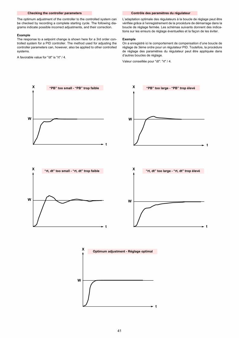
41
W
X
t
X
W
t
X
W
tt
W
X
X
t
W
Optimum adjustment - Réglage optimal
“rt, dt” too small - “rt, dt” trop faible “rt, dt” too large - “rt, dt” trop élevé
“PB” too small - “PB” trop faible “PB” too large - “PB” trop élevé
The optimum adjustment of the controller to the controlled system canbe checked by recording a complete starting cycle. The following dia-grams indicate possible incorrect adjustments, and their correction.
ExampleThe response to a setpoint change is shown here for a 3rd order con-trolled system for a PID controller. The method used for adjusting thecontroller parameters can, however, also be applied to other controlledsystems.
A favorable value for "dt" is "rt" / 4.
L’adaptation optimale des régulateurs à la boucle de réglage peut êtrevérifiée grâce à l’enregistrement de la procédure de démarrage dans laboucle de réglage fermée. Les schémas suivants donnent des indica-tions sur les erreurs de réglage éventuelles et la façon de les éviter.
ExempleOn a enregistré ici le comportement de compensation d’une boucle deréglage de 3ème ordre pour un régulateur PID. Toutefois, la procédurede réglage des paramètres du régulateur peut être appliquée dansd’autres boucles de réglage.
Valeur conseillée pour "dt": "rt" / 4.
Checking the controller parameterst 3 ti
Contrôle des paramètres du régulateurt 3 ti

42
COSA FARE SE ......I NUMERI LAMPEGGIANO SUL DISPLAY
Ciò significa che un valore misurato non è stato acquisito correttamente.
Nota. La rivelazione del superamento del campo di misura dipende dal tipo di sonda impiegato
Display Descrizione Causa / comportamento / rimedio
Il display del valore reale (rosso) indica "1999" lampeggiante.Il display del setpoint indica il setpoint.
Superamento verso l’alto o verso il basso del campo di misura dell’ingresso analogico 1.Il valore reale non è stato misurato.Il regolatore è “in blocco”.
Il contatto ausiliario risponde all’ingresso analo-gico 1 secondo la configurazione (C113).
Verificare i collegamenti elettrici e lo stato della sonda (guasta).
Quando l’ingresso analogico 3 è configurato per la temperatura esterna (C111) e si richiama la sua misura, il display del valore reale (rosso) indica "1999" lam-peggiante.
Superamento verso l’alto o verso il basso del campo di misura dell’ingresso analogico 3.La temperatura esterna non è stata misurata!Il setpoint dipendente dalla temperatura esterna è inattivo!
Verificare i collegamenti elettrici e lo stato della sonda (guasta).
Quando è configurato l’ingresso analogico 2 (C111) e si richiama la sua misura, il display del valore reale (rosso) indica "1999" lam-peggiante.
Superamento verso l’alto o verso il basso del campo di misura dell’ingresso analogico 2.Il setpoint esterno non è stato misurato.Il regolatore è “in blocco”.
Verificare i collegamenti elettrici ed il segnale del setpoint esterno.
Il display del valore reale (rosso) indica "XXXXXX".Il display del setpoint (verde) indica "1999" lampeggiante.
Superamento verso l’alto o verso il basso del campo di misura dell’ingresso analogico 2.La modifica del setpoint non è stata misurata.Il regolatore è “in blocco”.
Verificare i collegamenti elettrici ed il segnale del setpoint esterno.
SIEMENS
199960.0
K6
SIEMENS
1999tA
K6
SIEMENS
1999SP.E
K6
SIEMENS
53.21999
K6

43
WAS IST, WENN ......AUF DEM DISPLAY ZAHLEN BLINKEN
Es ist ein Hinweis dafür, dass ein Messwert nicht korrekt erfasst wird.
Merke. Die Erfassung von Messbereichsüber- / -unterschreitung ist vom angeschlossenen Fühler abhängig.
Anzeige Beschreibung Ursache / Reglerverhalten / Abhilfe
Istwertanzeige (rot) zeigt "1999" blinkend an.Sollwertanzeige zeigt den Sollwert an.
Messbereichsüber- oder -unterschreitung auf Ana-logeingang 1.Der Istwert wird nicht erfasst und der Regler führt eine Sicherheitsabschaltung durch.
Der Limitkomparator mit Bezug auf Analogeingang 1 verhält sich gemäss der Konfiguration (C113).
Elektrischen Anschluss auf Fühlerbruch überprü-fen.
Wenn der Analogeingang 3 auf Außentemperatur konfiguriert ist (C111) und der Messwert aufgeru-fen wird, zeigt die Istwertanzeige (rot) -1999 blinkend.
Messbereichsüber- oder -unterschreitung auf Ana-logeingang 3.Außentemperatur wird nicht erfasst!Die witterungsabhängige Sollwertvorgabe ist inak-tiv!
Elektrischen Anschluss auf Fühlerbruch überprü-fen.
Wenn der Analogeingang 2 konfi-guriert ist (C111) und der Mess-wert aufgerufen wird, zeigt die Istwertanzeige (rot) -1999 blin-kend.
Messbereichsüber- oder -unterschreitung auf Ana-logeingang 2.Der externe Sollwert wird nicht erfasst.Der Regler führt eine Sicherheitsabschaltung durch.
Elektrischen Anschluss auf Fühlerbruch überprü-fen.
Istwertanzeige (rot) zeigt "XXXXXX".Sollwertanzeige (grün) zeigt "1999" blinkend an.
Messbereichsüber- oder -unterschreitungauf Analogeingang 2.Die Sollwertverschiebung wird nicht erfasst.Der Regler führt eine Sicherheitsabschaltung durch.
Elektrischen Anschluss auf Fühlerbruch überprü-fen.
SIEMENS
199960.0
K6
SIEMENS
1999tA
K6
SIEMENS
1999SP.E
K6
SIEMENS
53.21999
K6

44
WHAT TO DO IF ......NUMBERS ARE FLASHING ON THE DISPLAY
This is an indication that a measured value is not being acquired correctly.
Note. The detection of measurement range crossings depends on the type of sensor used.
Display Description Cause / controller behavior / remedy
Actual value display (red) shows "1999" flashing.Setpoint display shows the set-point.
Overrange or underrange on analog input 1.The actual value has not been measured.Controller initiates lockout.
The auxiliary contact responds to analog input 1 according to the configuration (C113).
Check the electrical connections and the probe status (fault).
When analog input 3 is configured for outside temperature (C111) and the measurement is called up, the actual value display (red) shows "1999" flashing.
Overrange or underrange on analog input 3.The outside temperature has not been measured!The outside temperature setpoint is inactive!
Check the electrical connections and the probe status (fault).
When analog input 2 is configured (C111) and the measurement is called up, the process value dis-play (red) shows "1999" flashing.
Overrange or underrange on analog input 2.The external setpoint has not been measured. Controller initiates lockout.
Check the electrical connections and the external setpoint signal.
Actual value display (red) shows "XXXXXX".Setpoint display (green) shows "1999" flashing.
Overrange or underrange on analog input 2.The setpoint shift has not been measured. Con-troller initiates lockout.
Check the electrical connections and the external setpoint signal.
SIEMENS
199960.0
K6
SIEMENS
1999tA
K6
SIEMENS
1999SP.E
K6
SIEMENS
53.21999
K6

45
QUE SE PASSE-T-IL SI ......DES CHIFFRES CLIGNOTENT SUR L’AFFICHAGE
Cela indique qu’une valeur mesurée n’est pas enregistrée correctement.
Note. L’enregistrement d’un dépassement de la plage de mesure (positif ou négatif) dépend de la sonde raccordée.
Affichage Description Cause / comportement / remède
L’affichage de valeur instantanée (rouge) clignote et indique "1999".L’affichage de valeur de consigne indique la consigne.
Dépassement dans un sens ou dans l’autre de la plage de mesure sur l’entrée analogique 1.La valeur instantanée n’est pas enregistrée et le régulateur procède à une coupure de sécurité.
Le comparateur de limites par rapport à l’entrée analogique 1 se comporte selon la configuration (C113).
Vérifier le raccordement électrique pour détecter une éventuelle rupture de la sonde.
Si l’entrée analogique 3 est confi-gurée sur température externe (C111) et si la valeur mesurée est appelée, l’affichage de valeur ins-tantanée (rouge) clignote et indi-que "1999".
Dépassement dans un sens ou dans l’autre de la plage de mesure sur l’entrée analogique 3.La température externe n’est pas enregistrée!La prescription de consigne en fonction des condi-tions externes est inactive!
Vérifier le raccordement électrique pour détecter une éventuelle rupture de la sonde.
Si l’entrée analogique 2 est confi-gurée (C111) et si la valeur mesu-rée est appelée, l’affichage de valeur instantanée (rouge) cli-gnote et indique "1999".
Dépassement dans un sens ou dans l’autre de la plage de mesure sur l’entrée analogique 2.Le décalage de la valeur de consigne n’est pas enregistré.Le régulateur procède à une coupure de sécurité.
Vérifier le raccordement électrique et le signal de la valeur de consigne externe.
L’affichage de valeur instantanée (rouge) indique "XXXXXX".L’affichage de valeur de consigne (vert) clignote et indique "1999".
Dépassement dans un sens ou dans l’autre de la plage de mesure sur l’entrée analogique 2.La décalage de la valeur de consigne n’est pas enregistré.Le régulateur procède à une coupure de sécurité.
Vérifier le raccordement électrique et le signal de la valeur de consigne externe.
SIEMENS
199960.0
K6
SIEMENS
1999tA
K6
SIEMENS
1999SP.E
K6
SIEMENS
53.21999
K6


Con riserva di modifiche - Änderungen vorbehalten! - Subject to modifications - Sous réserve de modifications

Drawing No: 0090.RSMMZ.PT100.1 Sheet: 1 OF 1
RIELLO LTD HUNTINGDON, UK TEL: 01480 432144 FAX: 01480 432191 www.rielloburners.co.uk Rev Detail DateInitial
2 1 3 4 5 6 7 8
1 2 3 4 5 6 7 8
A
B
C
D
E
F
A
B
C
D
E
Drawn by: GB Date: 31.03.09 Scale: NONE
F
RS…/M MZ PT100 TEMPERATURE PROBE WIRING DIAGRAM
WH WH RD RD
G1+ I1 M1 RWF I1 M1
G1+
Pt100
RD
RD
WH
WH
Colour Key: RD - Red WH - White

1
2915727 (2)
LEISTUNGSREGLER RWF40POWER CONTROLLER RWF40RÉGULATEUR DE PUISSANCE RWF40
REGOLATORE DI POTENZA RWF40
3010210 - 30102113010212 - 3010219
REGULADOR DE POTENCIA RWF40
3010220 - 3010231
Allacciamento elettrico regolatore RWF40 e relativa sonda ai bruciatori
Elektroanschluß des Reglers RWF40 und des entsprechenden Fühlers an die Brenner
Connection of controller RWF40 and related probe to burners
Branchement électrique régulateur RWF40 et sonde correspondant aux brûleurs
Conexión del regulador RWF40 y de la sonda de temperatura PT 100 en los quemadores
I
D
GB
F
E
D1910 D1911
RS.../M - RL.../M - FG...M - FL...M P 140 - 200 - 300 - 450 P/GP 140 - 200 - 300 - 450 P/N
Bruciatori predisposti per regolatore KS 40Brenner vorbereitet für Regler KS 40
Burners predisposed for controller KS 40Brûleurs prédisposés pour régulateur KS 40
Quemadores predispuestos para el regulador KS 40
TECNO...LM - TECNO...GM
Bruciatori predisposti per regolatore RWF 32Brenner vorbereitet für Regler RWF 32
Burners predisposed for controller RWF 32Brûleurs prédisposés pour régulateur RWF 32
Quemadores predispuestos para el regulador RWF 32
Legenda schemi
a-b - Rossoc-d - BiancoBT - Sonda di tempera-
turaBP - Sonda di pressioneCN - ConnettoreMB - Morsettiera brucia-
tore
Zeichenerklärung Schemen
a-b - Rotc-d - WeißBT - TemperaturfühlerBP - DruckfühlerCN - VerbinderMB - Klemmenbrett Bren-
ner
Key to layouts
a-b - Redc-d - WhiteBT - Temperature probeBP - Pressure probeCN - ConnectorMB - Burner terminal strip
Légende schémas
a-b - Rougec-d - BlancBT - Sonde de tempéra-
tureBP - Sonde de pressionCN - ConnecteurMB - Porte-bornes brû-
leur
Leyendas esquemas
a-b - Rojoc-d - BlancoBT - Sonda de tempera-
turaBP - Sonda de presiónCN - ConectorMB - Regleta quemador

2
2915727 (2)
LEISTUNGSREGLER RWF40POWER CONTROLLER RWF40RÉGULATEUR DE PUISSANCE RWF40
REGOLATORE DI POTENZA RWF40
3010210 - 30102113010212 - 3010219
REGULADOR DE POTENCIA RWF40
3010220 - 3010231
D1915 D1916
GAS3÷10P/M N/M 1400-2000-3000-4500
Legenda schemi
a-b - Rossoc-d - BiancoBT - Sonda di tempera-
turaBP - Sonda di pressioneCN - ConnettoreMB - Morsettiera brucia-
tore
Zeichenerklärung Schemen
a-b - Rotc-d - WeißBT - TemperaturfühlerBP - DruckfühlerCN - VerbinderMB - Klemmenbrett Bren-
ner
Key to layouts
a-b - Redc-d - WhiteBT - Temperature probeBP - Pressure probeCN - ConnectorMB - Burner terminal strip
Légende schémas
a-b - Rougec-d - BlancBT - Sonde de tempéra-
tureBP - Sonde de pressionCN - ConnecteurMB - Porte-bornes brû-
leur
Leyendas esquemas
a-b - Rojoc-d - BlancoBT - Sonda de tempera-
turaBP - Sonda de presiónCN - ConectorMB - Regleta quemador
Allacciamento elettrico regolatore RWF40 e relativa sonda ai bruciatori
Elektroanschluß des Reglers RWF40 und des entsprechenden Fühlers an die Brenner
Connection of controller RWF40 and related probe to burners
Branchement électrique régulateur RWF40 et sonde correspondant aux brûleurs
Conexión del regulador RWF40 y de la sonda de temperatura PT 100 en los quemadores
I
D
GB
F
E
GI/EMME 1400-2000-3000-4500 GAS 8-9-10 P/M type T80 (Corea - Korea)
Bruciatori predisposti per regolatore RWF 32Brenner vorbereitet für Regler RWF 32
Burners predisposed for controller RWF 32Brûleurs prédisposés pour régulateur RWF 32
Quemadores predispuestos para el regulador RWF 32
Bruciatori predisposti per regolatore RWF 32Brenner vorbereitet für Regler RWF 32
Burners predisposed for controller RWF 32Brûleurs prédisposés pour régulateur RWF 32
Quemadores predispuestos para el regulador RWF 32

Catalogo ricambiSpare parts listCatalogue pièces détachéesErsatzteile KatalogCatálogo recambios
2918535 (4) - 09/2010
Bruciatori di gas ad aria soffiataForced draught gas burnersBrûleurs gaz à air souffléGas-GebläsebrennerQuemadores de gas de aire soplado
Funzionamento bistadio progressivo o modulanteProgressive two-stage or modulating operationFonctionnement à 2 allures progressives ou modulantGleitend-zweistufiger oder modulierender BetriebFuncionamiento a dos llamas progresivas o modulante
I
GB
F
D
E
CODICE - CODECÓDIGO
MODELLO - MODEL - MODELEMODELL - MODELO
TIPO - TYPE - TYP
3788400 - 3788410 RS 250/M MZ 866 T
3788401 - 3788411 RS 250/M MZ 866 T
3788430 - 3788440 RS 250/M MZ 866 T
3788431 - 3788441 RS 250/M MZ 866 T

8535

8535
N. COD.37
8840
0 -
3788
410
3788
401
- 37
8841
1 *
3788
430
- 37
8844
037
8843
1 -
3788
441 *
DESCRIZIONE DESCRIPTION DESCRIPTION BESCHREIBUNG DENOMINACION
MATRICOLA BRUCIATOREBURNER SERIAL NUMBERMATRICULE BRULEURBRENNER KENN-NUMMERMATRICULA QUEMADÓRES
1 3013684 • • • • GRUPPO SERRANDA AIR DAMPER ASSEMBLY GROUPE VOLET AIR LUFTKLAPPE CONJUNTO REGISTRO AIRE
2 3013683 • • • • PROTEZIONE GRID PROTECTION SCHUTZGITTER PROTECCIÓN
3 3013682 • • • • FONOASSORBENTE SOUND DAMPING INSONORISANT GERÄUSCHDÄMMUNG AISLAMIENTO ACÙSTICO C
4 3003763 • • • • VISORE INSPECTION WINDOW VISEUR SICHTFENSTER VISOR
5 3012573 • • • • ANELLO PISTON SEAL JOINT TORIQUE LIPPENDICHTUNG ANILLO
6 3014215 • • • • GIRANTE FAN TURBINE GEBLÄSERAD TURBINA C
7 3013676 • • RELÈ TERMICO OVERLOAD RELAIS THERMIQUE ÜBERSTROMAUSLÖSER RELÉ TÉRMICO C
7 3013700 • • RELÈ TERMICO OVERLOAD RELAIS THERMIQUE ÜBERSTROMAUSLÖSER RELÉ TÉRMICO C
8 3012080 • • • • INTERRUTTORE SWITCH INTERRUPTEUR SCHALTER INTERUCTOR C
9 3003847 • • • • TRASFORMATORE TRANSFORMER TRANSFORMATEUR ZÜNDTRANSFORMATOR TRANSFORMADOR B
10 3003409 • • • • CAVALLOTTO U BOLT CAVALIER BÜGELBOLZEN FIJACION ELECTRODO
11 3013687 • • • • PROLUNGA PERNO BAR EXTENSION RALLONGE DE GLISSIERE VERLÄNGERUNG PROLONGACIÓN PERNO
12 3007444 • • • • PRESSOSTATO ARIA AIR PRESSURE SWITCH PRESSOSTAT AIR LUFTDRUCKWÄCHTER PRESÓSTATO AIRE A
13 3003624 • • CONTATTORE CONTACTOR CONTACTEUR SCHÜTZ CONTADOR C
13 3003625 • • CONTATTORE CONTACTOR CONTACTEUR SCHÜTZ CONTADOR C
14 3013362 • • • • APPARECCHIATURA CONTROL BOX BOITE DE CONTROLE STEUERGERÄT CAJA CONTROL B
15 3003784 • • • • MORSETTIERA CONTROL BOX BASE SOCLE STECKSOCKEL ZÓCALO CAJA CONTROL C
16 3005482 • • • • GUARNIZIONE SEAL RONDELLE METALLDICHTUNG JUNTA B
17 3012748 • • • • SUPPORTO SUPPORT SUPPORT HALTER SOPORTE
18 3012155 • • • • FILTRO ANTIDISTURBO DEGLITCHER FILTRE ENTSTÖRERFILTRO ANTI-INTERFEREN-
CIAC
19 3013678 • • • • MEMBRANA + VETRINOMEMBRANE + VIEWING
PORTMEMBRANE + REGARD
MEMBRAN + VERSCHLUßS-
TOPFENMEMBRANA + MIRILLA
20 3013119 • • • • COFANO COVER COFFRET VERKLEIDUNG ENVOLVENTE
21 3013692 • • • • MOTORE MOTOR MOTEUR MOTOR MOTOR C
22 3012585 • • • • PIASTRA PLATE PLATINE PLATTE PLACA
23 3012916 • • • • SERVOMOTORE SERVOMOTOR SERVOMOTEUR STELLMOTOR SERVOMOTOR B
24 3012349 • • • • ALBERO SHAFT ARBRE WELLE EJE
25 3012012 • • • • GUSCIO HALF-SHELL COUVERCLE HAUBE CÀSCARA
26 3013681 • • • • VITE SCREW VIS SCHRAUBE TORNILLO
**

8535
27 3003891 • • • • RACCORDO CONNECTOR MAMELON NIPPEL RACORD C
28 3013698 • • SQUADRETTA SQUARE EQUERRE-SUPPORT HALTER ESCUADRA
28 3013703 • • SQUADRETTA SQUARE EQUERRE-SUPPORT HALTER ESCUADRA
29 3013693 • • • • DISCO DISC DISQUE SCHEIBE DISCO
30 3003795 • • • •COLLEGAMENTO
ELETTRODOH.T. LEAD
CONNEXION POUR ELEC-
TRODE
VERBINDUNG FÜR
ELEKTRODE
CABLE CONEXIÓN
ELECTRODOA
31 3012016 • • ELETTRODO ELECTRODE ELECTRODE PORCELAINE ELEKTRODE ELECTRODO A
31 3013705 • • ELETTRODO ELECTRODE ELECTRODE PORCELAINE ELEKTRODE ELECTRODO A
32 3012178 • • SONDA PROBE SONDE FÜHLER SONDA A
32 3013704 • • SONDA PROBE SONDE FÜHLER SONDA A
33 3012025 • • • • TUBETTO TUBE TUYAU RÖHRCHEN TUBITO
34 3013695 • • • • DISCO DISC DISQUE SCHEIBE DISCO A
35 3013697 • • • • DISTRIBUTORE GAS HEAD DISTRIBUTEUR GASVERTEILER DISTRIBUIDOR
36 3013696 • • TUBO INTERNO INTERIOR TUBE TUYAU INTERIEUR INNERER ROHR TUBO INTERNO
36 3013706 • • TUBO INTERNO INTERIOR TUBE TUYAU INTERIEUR INNERER ROHR TUBO INTERNO
37 3012193 • • • • SUPPORTO SUPPORT SUPPORT HALTER SOPORTE
38 3012591 • • TUBO ESTERNO EXTERIOR TUBE TUYAU EXTERIEUR AUSSERER ROHR TUBO EXTERNO
38 3013707 • • TUBO ESTERNO EXTERIOR TUBE TUYAU EXTERIEUR AUSSERER ROHR TUBO EXTERNO
39 3012637 • • • • GOMITO ELBOW COUDE SCHLITTEN CODO
40 3012043 • • • • COLLEGAMENTO SONDA PROBE LEAD CONNEXION POUR SONDE VERBINDUNG FÜR SONDE CABLE CONEXIÓN SONDA A
41 3007077 • • • • GUARNIZIONE SEAL RONDELLE METALLDICHTUNG JUNTA B
42 3006615 • • • • RACCORDO CONNECTOR MAMELON NIPPEL RACORD C
43 3003660 • • • • PRESSOSTATO GAS GAS PRESSURE SWITCH PRESSOSTAT GAZ GASDRUCKWÄCHTER PRESOSTATO DEL AIRE B
44 3012638 • • • • PIASTRINA PLATE PLAQUETTE ETRIER PLATTE PLATINA
45 3006096 • • • • REGOLATORE GAS GAS REGULATOR REGULATEUR GAZ GAS REGLER REGULADOR DE GAS C
46 3013685 • • • • GRUPPO PIASTRE PLATES ASSEMBLY GROUPE PLATINES PLATTENGRUPPE CONJUNTO PLACAS
47 3012352 • • • • PERNO SCREW VIS CREUSE HOHLKERNSCHRAUBE PERNO
48 3003841 • • • • CUSCINETTO BEARING ROULEMENT LAGER COJINETE
49 3012356 • • • • MOLLA SPRING RESSORT FEDER MUELLE B
50 3012646 • • • • TIRANTE TIE ROD TIRANT GESTÄNGE TIRANTE C
N. COD.
3788
400
- 37
8841
037
8840
1 -
3788
411 *
3788
430
- 37
8844
037
8843
1 -
3788
441 *
DESCRIZIONE DESCRIPTION DESCRIPTION BESCHREIBUNG DENOMINACION
MATRICOLA BRUCIATOREBURNER SERIAL NUMBERMATRICULE BRULEURBRENNER KENN-NUMMERMATRICULA QUEMADÓRES
**

8535
51 3012594 • • • • PIASTRA PLATE PLATINE PLATTE PLACA
52 3006954 • • • • CONNETTORE CONNECTOR CONNECTEUR VERBINDER CONECTADOR B
53 3012049 • • • • VITE SCREW VIS SCHRAUBE TORNILLO
54 3012639 • • • • GRUPPO REGOLATORE REGULATOR ASSEMBLY GROUPE OBTURATION DRUCKREGULIERUNG GRUPO REGULACION C
55 3013406 • • • • RELÈ + ZOCCOLO RELAY + BASE RELAIS + SOCLE RELAIS + SOCKEL CONECTADOR + ZOCALO C
56 3013407 • • • • RELÈ + ZOCCOLO RELAY + BASE RELAIS + SOCLE RELAIS + SOCKEL CONECTADOR + ZOCALO C
57 3012560 • • • • OTTURATORE SHUTTER OBTURATEUR SCHIEBER OBTURADOR C
58 3013699 • • IMBUTO FIAMMA END CONE EMBOUT GUEULARD FLAMMENROHR TUBO EXTREMO B
58 3013702 • • IMBUTO FIAMMA END CONE EMBOUT GUEULARD FLAMMENROHR TUBO EXTREMO B
59 3012562 • • • • SCHERMO FLANGE GASKET ECRAN THERMIQUE FLANSCHDICHTUNG JUNTA AISLANTE A
60 3003322 • • • • RACCORDO CONNECTOR MAMELON NIPPEL RACORD C
61 3013694 • • • • DISCO DISC DISQUE SCHEIBE DISCO
62 3006132 • • • • ALBERO E ANELLO SHAFT AND RING ARBRE ET ANNEAU WELLE UND RING EJE E ANILLO
63 3012644 • • • • QUADRANTE GRADUATE SECTOR SECTEUR GRADUE SKALENSEGMENT MIRILLA
64 3003543 • • • • TIRANTE TIE ROD TIRANT GESTÄNGE TIRANTE
65 3006098 • • • • SNODO SFERICO PIN JOINT CHAPE A ROTULE KUGELGELENK ARTICOLACION ESFERICA C
66 3012601 • • • • LEVA LEVER LEVIER HEBEL LEVA C
67 3012354 • • • • LEVA LEVER LEVIER HEBEL LEVA C
68 3012358 • • • • CAMMA CAM CAME NOCKEN EXCÉNTRICO C
69 3012350 • • • • LEVA LEVER LEVIER HEBEL LEVA C
70 3012357 • • • • CUSCINETTO BEARING ROULEMENT LAGER COJINETE
71 3012602 • • • • SUPPORTO SUPPORT SUPPORT HALTER SOPORTE
72 3012603 • • • • PERNO SCREW VIS CREUSE HOHLKERNSCHRAUBE PERNO
73 3006097 • • • • MOLLA SPRING RESSORT FEDER MUELLE B
*Versione Testa Lunga - Long Combustion Head Version - Version Tête Longue - Langer Brennkopf Ausführung - Versión alargado de tubo llama
**RICAMBI CONSIGLIATI - ADVISED PARTS - RECHANGE CONSEIL - EMPFOHLENE ERSATZTEILE - RECAMBIOS ACONSEJADOSA = Ricambi per dotazione minima - Spare parts for minimum fittings - Pièces détachées pour équipement mimimum - Erzatzteile für minimale Ausstattung - Recambios para equipamiento mínimoA+B = Ricambi per dotazione base di sicurezza - Spare parts for basic safety fittings - Pièces détachées pour équipement standard de sécrité - Erzatzteile für Sicherheitsgrundausstattung - Recambios para equipamiento básico de seguridadA+B+C = Ricambi per dotazione estesa di sicurezza - Spare parts for extended safety fittings - Pièces détachées pour équipement complet de sécurité - Erzatzteile für erweiterte Sicherheitsausstattung - Recambios para equipamiento general de seguridad
N. COD.37
8840
0 -
378
8410
3788
401
- 3
7884
11 *
3788
430
- 3
7884
4037
8843
1 -
378
8441
*
DESCRIZIONE DESCRIPTION DESCRIPTION BESCHREIBUNG DENOMINACION
MATRICOLA BRUCIATOREBURNER SERIAL NUMBERMATRICULE BRULEURBRENNER KENN-NUMMERMATRICULA QUEMADÓRES
**


RIELLO S.p.A.
I-37045 Legnago (VR)
Tel.: +39.0442.630111
http:// www.riello.it
http:// www.rielloburners.com
Con riserva di modifiche - Subject to modifications - Sous réserve de modifications - Änderungen vorbehalten - Con la posibilidad de modificaciónes 8535

����������������� �����������������������
����
������
����������� ��

1
Overall Operation The unit takes in a 0 – 10 Volt control signal and drives the two internal relays using time proportional control against the 0 – 10 Volt control signal. These relays are used to drive the burner bi-directional servomotor from closed to open or any position between these two as directed by the control signal. Control Operation In order to provide for a full range of motor drive times, 6 option switches are provided on the converter. These are used to provide 32 motor drive times in 1 second increments. The range is from 15 to 46 seconds. The motor travel time is selected using switches 1 to 5 as shown in the table following (NOTE Switch 6 has no function and should be left in the OFF position). The switches are used as a binary counter from the base value of 15 seconds with SW1 = 1s, SW2 = 2s, SW3 = 4s, SW4 = 8s, and SW5 = 16s. Using these switches in conbination the drive time values shown on the table overleaf can be obtained. Within the range of 0.1 to 9.9 Volts the position of the motor will be directly proportional to the voltage input. At 10 Volts and 0 Volts the relevant relay will switch OFF and will remain OFF until the input signal Voltage falls or rises 0.1V, when it will again come into control and track the input signal. Setting the Signal Converter
• Carry out the burner commissioning with the AUTO – OFF – MAN switch in the MAN position
• When commissioning has been completed use a stopwatch to time how long
the servomotor takes to move from low fire to high fire.
• Set the switches on the signal converter to match this time using the chart overleaf

2
Checking Motor Travel Time Setting In order to check that the motor time has been set correctly on the Signal Converter, proceed as follows:
• Select AUTO on the AUTO – OFF – MAN switch.
• When the burner ignition is complete , then at the end of the safety time , control of the burner output is switched to the signal converter.
• This is indicted by illumination of the Red LED on the Signal Converter
• At this time, on first powering up the Signal Converter, the ‘Servomotor
close’ relay (indicated by the Green LED) is also energised.
• The period for which the ‘servomotor close’ relay is energised will be equal to the time that was set on the option switches.
• Again using a stopwatch, check the period for which the Green LED is
illuminated.
• If this is equal to the time period that was measured when timing the servomotor (from maximum to minimum fire position) then the option switches have been set correctly, and the Signal Converter can be left at this setting.
• If the timing is not as expected, this then means that the option switches
have been set incorrectly
• Switch the burner OFF, re-set the option switches and again switch to AUTO and proceed as above to check the Signal Converter seting.
• When is the Signal Converter is correctly set the burner can be left to
operate in AUTO mode.
Input: 0-10V DC Signal Output: Motor Drive Relays Electrical Supply 230 V, 50Hz Relay Carpacity 2A, 230 V AC Code: 3006165
SIGNAL CONVERTER
~
1 2 3 4 5 6
DIP ON
(Green) (Yellow) (Red)

3
Option Switches Set Table
Drive Time (s) SW1 SW2 SW3 SW4 SW5 SW6 15 OFF OFF OFF OFF OFF OFF 16 ON OFF OFF OFF OFF OFF 17 OFF ON OFF OFF OFF OFF 18 ON ON OFF OFF OFF OFF 19 OFF OFF ON OFF OFF OFF 20 ON OFF ON OFF OFF OFF 21 OFF ON ON OFF OFF OFF 22 ON ON ON OFF OFF OFF 23 OFF OFF OFF ON OFF OFF 24 ON OFF OFF ON OFF OFF 25 OFF ON OFF ON OFF OFF 26 ON ON OFF ON OFF OFF 27 OFF OFF ON ON OFF OFF 28 ON OFF ON ON OFF OFF 29 OFF ON ON ON OFF OFF 30 ON ON ON ON OFF OFF 31 OFF OFF OFF OFF ON OFF 32 ON OFF OFF OFF ON OFF 33 OFF ON OFF OFF ON OFF 34 ON ON OFF OFF ON OFF 35 OFF OFF ON OFF ON OFF 36 ON OFF ON OFF ON OFF 37 OFF ON ON OFF ON OFF 38 ON ON ON OFF ON OFF 39 OFF OFF OFF ON ON OFF 40 ON OFF OFF ON ON OFF 41 OFF ON OFF ON ON OFF 42 ON ON OFF ON ON OFF 43 OFF OFF ON ON ON OFF 44 ON OFF ON ON ON OFF 45 OFF ON ON ON ON OFF 46 ON ON ON ON ON OFF
Example Motor Travel Time (Low fire to High fire) 20 seconds.
1 2 3 4 5 6
DIP ON

������������ �������
�
��
����
��
�������� ��������
�� ����� ���� � ����� ��!�
������������������� "������� "����"#
$����������

������������ "������
�
��
����
��
�������� ��������
�� ����� ���� � ����� ��!�
$����������
������������ ��������������� "������� "����"#

������������ "������
�
��
����
���� ����� ���� � ����� ��!�
�������� ��������
$����������
��� ��������� ��������������� "������� "����"#

�����
������
������������ "������
�� ���� �������� ��������������� "������� "����"#
���
�
�� � ��
�� ����� ���� � ����� ��!�
�������� ��������
����������$

Mabbett & Associates Ltd, Corporate and Registered Office:
Mabbett House, 11 Sandyford Place, Glasgow, U.K. G3 7NB
Registered in Scotland No: SC 163378
[email protected] www.mabbett.eu
Belfast | Cardiff | Dunfermline | Glasgow
© 2015, Mabbett & Associates Ltd. All Rights Reserved. The name Mabbett and the Mabbett logo are Trade Marks of Mabbett & Associates Ltd
April 2015 Project No: 2014-013.001
Residence Time Calculation Prepared for:
Energy Pyrolysis Ltd Contents Amendment Record This report has been issued and amended as follows:
Issue Description Date Signed
0.1 Draft 06/04/15 M Lynch

Energy Pyrolysis; Residence Time Calculation (06-04-15) 2014-013.002 © 2015, Mabbett & Associates Ltd Page i
Acknowledgement
This report was prepared by Mabbett & Associates Ltd (Mabbett) for Energy Pyrolysis Ltd (Energy Pyrolysis) in accordance with a scope of work presented on 24 July 2014 (Ref. E150103/ASL/ML/lc). This report is based on data provided to Mabbett by Energy Pyrolysis. Should any of the information be incorrect, incomplete or subject to change, Mabbett may wish to revise the report accordingly.
Mabbett wish to acknowledge the assistance of all persons who contributed in the preparation of this report. This report has been prepared by the following Mabbett personnel: MABBETT & ASSOCIATES LTD ___________________________________ Michael Lynch, CEng, MIChemE, MIEnvSc, MIAQM Manager, Process Engineering

Energy Pyrolysis; Residence Time Calculation (06-04-15) 2014-013.002 © 2015, Mabbett & Associates Ltd Page 1
Section 1.0: Residence Time Calculation
1.1 Introduction Energy Pyrolysis utilise waste rubber, end-of-life tyres and plastic as a feedstock in their pyrolysis reactor to obtain light furnace oil, with the potential of further refinement into high quality diesel oil and carbon black, which can be re-used in various manufacturing activities, as products of their controlled process. As part of an on-going programme of permitting support, Energy Pyrolysis has requested that Mabbett calculate the residence time of the reactor. Mabbett has undertaken this calculation following the methodology outlined in the Environment Agency’s Review of BAT for New Waste Incineration Issues: Part 2 Validation of Combustion Conditions, specifically using the “Plug Flow” approach. 1.2 Residence Time Calculation The average gas volume flow rate (Qc) was recently measured during a programme of air emission monitoring (stack testing) at 1,096 m3/h. Energy Pyrolysis report the volume of the high temperature secondary combustion zone (VQSCZ) is approximately 13.8 m3. The single gas residence time (RT) is therefore calculated as follows: RT = VQSCZ * 3,600 / Qc
= 13.8 * 3,600 / 1,096 = 45.3 seconds 1.3 Conclusion This calculated RT is comfortably above the minimum allowable RT of 2 seconds stated in the site’s permit.