Slurry Recirculation Pump - Bharat Heavy Electricals Limited
42
TD-106 Rev No. 00 Form No. PRODUCT STANDARD PUMPS HYDERABAD FP60320 Rev No. 02 Page 1 of 42 COPYRIGHT AND CONFIDENTIAL The information on this document is the property of BHARAT HEAVY ELECTRICALS LIMITED, It must not be used directly or indirectly in any way detrimental to the interest of the company. Ref. Doc Revisions: Prepared: Approved: Date: Refer record of revisions ASK MSR 05.05.20 HYDERABAD TECHNICAL SPECIFICATION FOR ABSORBER SLURRY RECIRCULATION PUMP 1. Intent of specification This specification is intended to cover the design, engineering, manufacturing, inspection and testing at manufacturer’s works, packing and delivery to site, supervision of erection and commissioning of Slurry Recirculation pump along with its accessories complete in all respects. Each unit of 250/500/660/800MW, is associated with an FGD system. Each FGD system shall have recirculation pumps located inside Recirculation pump & Oxidation blower house. The pumps shall be suitable for outdoor application. The pumps shall be driven by a constant speed motor. The offered pump model shall be proven and must meet the proven-ness criteria indicated at clause 3. The list of deviations/exceptions with respect to the specification shall be submitted as per annexure-4. Deviations not listed in the format shall not be considered. No deviations/exceptions shall be permitted without the approval of purchaser. In case of additional requirement of instrumentation, controls and other accessories/auxiliaries for safe, reliable and trouble-free operation of the pump, necessary reasons for recommendation shall be furnished and the same shall be included in scope of supply with the purchaser’s approval. 2. Applicable codes and standards The design, manufacture and performance testing of the pumps as specified herein shall comply with requirement of all applicable codes in particular the following. 1. ANSI HI 12.1~12.6: Rotodynamic Centrifugal slurry pumps 2. API 682: Shaft sealing system for centrifugal & rotary pump 3. API 670: Machinery protection system 4. ANSI B16.5, B16.47: Pipe flanges and flange fittings 5. ANSI B16.9: Butt weld fittings 6. ANSI B16.11: Forged steel fittings, socket welded and threaded 7. ASTM: For various materials & tests 8. ASME sec VIII div. 1 9. ISO 9906 Rotodynamic pumps hydraulic performance acceptance
-
Upload
khangminh22 -
Category
Documents
-
view
0 -
download
0
Transcript of Slurry Recirculation Pump - Bharat Heavy Electricals Limited

T
D-1
06
Rev
No. 0
0
Fo
rm N
o.
PRODUCT STANDARD
PUMPS HYDERABAD
FP60320
Rev No. 02
Page 1 of 42
CO
PY
RIG
HT
AN
D C
ON
FID
EN
TIA
L
Th
e in
form
atio
n o
n t
his
do
cum
ent
is t
he
pro
per
ty o
f B
HA
RA
T H
EA
VY
EL
EC
TR
ICA
LS
LIM
ITE
D,
It m
ust
no
t b
e u
sed
dir
ectl
y o
r in
dir
ectl
y i
n a
ny
way
det
rim
enta
l to
th
e in
tere
st o
f th
e co
mp
any
.
Ref
. D
oc
Revisions: Prepared:
Approved:
Date:
Refer record of revisions ASK MSR 05.05.20
HYDERABAD
TECHNICAL SPECIFICATION FOR ABSORBER SLURRY RECIRCULATION PUMP
1. Intent of specification
This specification is intended to cover the design, engineering, manufacturing, inspection
and testing at manufacturer’s works, packing and delivery to site, supervision of erection
and commissioning of Slurry Recirculation pump along with its accessories complete in
all respects.
Each unit of 250/500/660/800MW, is associated with an FGD system. Each FGD system
shall have recirculation pumps located inside Recirculation pump & Oxidation blower
house. The pumps shall be suitable for outdoor application. The pumps shall be driven by
a constant speed motor.
The offered pump model shall be proven and must meet the proven-ness criteria indicated
at clause 3. The list of deviations/exceptions with respect to the specification shall be
submitted as per annexure-4. Deviations not listed in the format shall not be considered.
No deviations/exceptions shall be permitted without the approval of purchaser.
In case of additional requirement of instrumentation, controls and other
accessories/auxiliaries for safe, reliable and trouble-free operation of the pump, necessary
reasons for recommendation shall be furnished and the same shall be included in scope of
supply with the purchaser’s approval.
2. Applicable codes and standards
The design, manufacture and performance testing of the pumps as specified herein shall
comply with requirement of all applicable codes in particular the following.
1. ANSI HI 12.1~12.6: Rotodynamic Centrifugal slurry pumps
2. API 682: Shaft sealing system for centrifugal & rotary pump
3. API 670: Machinery protection system
4. ANSI B16.5, B16.47: Pipe flanges and flange fittings
5. ANSI B16.9: Butt weld fittings
6. ANSI B16.11: Forged steel fittings, socket welded and threaded
7. ASTM: For various materials & tests
8. ASME sec VIII div. 1
9. ISO 9906 Rotodynamic pumps hydraulic performance acceptance

TD
-106
Rev
No. 0
0
Fo
rm N
o.
PRODUCT STANDARD
PUMPS HYDERABAD
FP60320
Rev No. 02
Page 2 of 42
CO
PY
RIG
HT
AN
D C
ON
FID
EN
TIA
L
Th
e in
form
atio
n o
n t
his
do
cum
ent
is t
he
pro
per
ty o
f B
HA
RA
T H
EA
VY
EL
EC
TR
ICA
LS
LIM
ITE
D.
It m
ust
no
t b
e u
sed
dir
ectl
y o
r in
dir
ectl
y i
n a
ny
way
det
rim
enta
l to
th
e in
tere
st o
f th
e co
mp
any
.
Ref
. D
oc
HYDERABAD
3. Provenness Criteria
Supplier shall have previous experience of design, manufacturing, supplying, erecting and
commissioning of the recirculation pump for Wet Limestone based FGD system for at
least two (2) no’s of PUMPS, each of capacity 80% or higher, in a pulverized coal fired
power generating units such that the pump should have been in successful operation for a
period of not less than two (2) years prior to January 2020. Documentary evidence as per
annexure-3 at clause 23.3, shall be submitted along with the offer.
In case of NTPC project (end user, NTPC), NTPC QR criteria shall override the above
and shall be considered for qualification and evaluation.
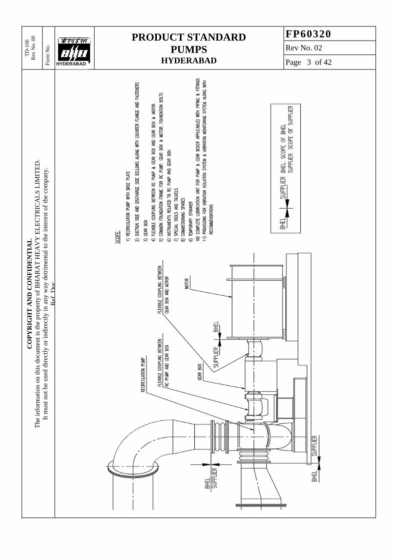
4. Scope of supply
Supplier scope shall include Design, Supply, Engineering Coordination and Supervision
of Erecting & Commissioning of slurry recirculation pump, gear box, connecting
couplings, baseplate, along with instrumentation and associated sub systems. It shall
cover complete recirculation pump unit including sub-systems, start-up spares and special
tools and tackles.
Design includes basic and detail engineering, preparation and submission of engineering
drawings, calculations, datasheets, quality assurance documents, field quality plans and
storage instructions, commissioning procedures, operation & maintenance manuals and
performance guarantee test procedures.
Supply includes manufacturing, shop floor testing, stage inspections, final inspections,
painting, packing & transportation to site, customer clearance/port clearance and any
other statutory clearances/receipts.
Engineering Coordination shall include full responsibility of design integration,
inspection and test, installation/startup supervision, functioning and performance of
equipment and auxiliaries. Analysis of complete driven equipment, gear, driver including
lateral, torsional vibration and train performance. Coordination between driver and driven
equipment, seals, oil system, couplings, guards, control and protection system, connecting
piping, wiring if any. Submitting train drawings such as general arrangement, foundation,
piping, instrumentation etc even if driver is provided by BHEL. The supplier shall
incorporate driver details in all the relevant drawings.
Supervision of Erection & commissioning includes supervision of erection &
commissioning, supervision of trial operation, training of customer’s O&M Personnel
and handing over to customer.
The schematic showing the battery limits of the scope of supply is provided below.
Supplier to clearly specify all terminal points in the GA drawing & P&ID and submit it
during proposal to confirm scope of supply.
TD
-106
Rev
No. 0
0
Fo
rm N
o.
PRODUCT STANDARD
PUMPS HYDERABAD
FP60320
Rev No. 02
Page 3 of 42
CO
PY
RIG
HT
AN
D C
ON
FID
EN
TIA
L
Th
e in
form
atio
n o
n t
his
do
cum
ent
is t
he
pro
per
ty o
f B
HA
RA
T H
EA
VY
EL
EC
TR
ICA
LS
LIM
ITE
D.
It m
ust
no
t b
e u
sed
dir
ectl
y o
r in
dir
ectl
y i
n a
ny
way
det
rim
enta
l to
th
e in
tere
st o
f th
e co
mp
any
.
Ref
. D
oc
HYDERABAD

TD
-106
Rev
No. 0
0
Fo
rm N
o.
PRODUCT STANDARD
PUMPS HYDERABAD
FP60320
Rev No. 02
Page 4 of 42
CO
PY
RIG
HT
AN
D C
ON
FID
EN
TIA
L
Th
e in
form
atio
n o
n t
his
do
cum
ent
is t
he
pro
per
ty o
f B
HA
RA
T H
EA
VY
EL
EC
TR
ICA
LS
LIM
ITE
D.
It m
ust
no
t b
e u
sed
dir
ectl
y o
r in
dir
ectl
y i
n a
ny
way
det
rim
enta
l to
th
e in
tere
st o
f th
e co
mp
any
.
Ref
. D
oc
HYDERABAD
5. Variant table
Project : Ramagundam TPP,
3x200MW
Ramagundam
TPP, 3x500MW
Korba TPP,
3x200MW
Ultimate Customer : NTPC NTPC NTPC
Location : Karimnagar, India Karimnagar, India Chhattisgarh, India
Service : Continuous Continuous Continuous
Installation : In-door In-door In-door
Total number of
units :
3 units of 200MW
(Common absorber)
3 units of 500MW 3 units of 200MW
(Common
absorber)
Total pumps in each
unit :
- 4 -
Stand-by pumps per
unit :
1 1 1
Total number of
working pumps :
4 9 4
Total number of
pumps :
5 12 5
Variant : Var. 01 Var. 02 Var. 03
Material code : FP9760320010 FP9760320029 FP9760320037
Project : Korba TPP,
4x500MW
Ultimate Customer : NTPC
Location : Chhattisgarh, India
Service : Continuous
Installation : In-door
Total number of
units :
4 units of 500MW
Total pumps in each
unit :
4
Stand-by pumps per
unit :
1
Total number of
working pumps :
12
Total number of
pumps :
16
Variant : Var. 04
Material code : FP9760320045

TD
-106
Rev
No. 0
0
Fo
rm N
o.
PRODUCT STANDARD
PUMPS HYDERABAD
FP60320
Rev No. 02
Page 5 of 42
CO
PY
RIG
HT
AN
D C
ON
FID
EN
TIA
L
Th
e in
form
atio
n o
n t
his
do
cum
ent
is t
he
pro
per
ty o
f B
HA
RA
T H
EA
VY
EL
EC
TR
ICA
LS
LIM
ITE
D.
It m
ust
no
t b
e u
sed
dir
ectl
y o
r in
dir
ectl
y i
n a
ny
way
det
rim
enta
l to
th
e in
tere
st o
f th
e co
mp
any
.
Ref
. D
oc
HYDERABAD
6. Design input data
6.1 Pump operating parameters
Discharge flow 11,520 m³/hr 12,915 m³/hr 11,520 m³/hr 12,915 m³/hr
Total Head developed 17.10 m H 18.20 m H 17.10 m H 18.20 m H
Medium to be handled Gypsum slurry Gypsum slurry Gypsum slurry Gypsum slurry
Operating Temperature ~62 deg C ~62 deg C ~62 deg C ~62 deg C
Type of Recirculation
pump
Horizontal, Centrifugal pump
(non-clogging type)
Nozzle Orientation End Suction- Top Discharge
Seal Type Mechanical seal with external flushing
Duty Continuous operation
Location Outdoor
Drive type Motor driven
Acceptable noise level 85 dBA (at 1-meter from pump centreline)
NPSH(A) 9.36 mlc 9.39 mlc 9.36 mlc 9.39 mlc
Variant Var. 01 Var. 02 Var. 03 Var. 04

TD
-106
Rev
No. 0
0
Fo
rm N
o.
PRODUCT STANDARD
PUMPS HYDERABAD
FP60320
Rev No. 02
Page 6 of 42
CO
PY
RIG
HT
AN
D C
ON
FID
EN
TIA
L
Th
e in
form
atio
n o
n t
his
do
cum
ent
is t
he
pro
per
ty o
f B
HA
RA
T H
EA
VY
EL
EC
TR
ICA
LS
LIM
ITE
D.
It m
ust
no
t b
e u
sed
dir
ectl
y o
r in
dir
ectl
y i
n a
ny
way
det
rim
enta
l to
th
e in
tere
st o
f th
e co
mp
any
.
Ref
. D
oc
HYDERABAD
6.2 Slurry Analysis
6.3 Absorber Tank Level & NPSH
HH Bottom + 6,000 6,000 6,000 6,000
NL Bottom + 5,000 5,000 5,000 5,000
LL Bottom + 4,200 4,200 4,200 4,200
CL Bottom + 1,200 1,200 1,200 1,200
Variant Var. 01 Var. 02 Var. 03 Var. 04
NPSH SI Unit Value Value Value Value
NPSH (A). m 9.36 9.39 9.36 9.39
Variant Var. 01 Var. 02 Var. 03 Var. 04
Slurry to be handled Gypsum Slurry
Chloride Content max. (ppm) 27,000 26,000 27,000 26,000
Specific Gravity at pump
suction (t/m3)
1.216 @ design point 1.212 1.216 1.212
1.213 @guarantee
Point. 1.210
1.213 1.210
Vapour Pressure at
Pump(kg/cm2) 0.216 0.216 0.216 0.216
Viscosity of slurry 0.01 Pa.S 0.01 Pa.S 0.01 Pa.S 0.01 Pa.S
Concentration of Solid 30% wt. 30% wt 30% wt 30% wt
SiO2 Content 4 to 6 g/l
pH Normal = 4.0 – 7.0
Design = 4.0 – 8.0
Slurry Temperature ( deg C) 62 (normal)
70 (design)
Maximum solid particle size 150 mesh(140 microns)
Normal solid particle size, d 50 325 mesh(43 microns) & fine particles
Variant Var. 01 Var. 02 Var. 03 Var. 04

TD
-106
Rev
No. 0
0
Fo
rm N
o.
PRODUCT STANDARD
PUMPS HYDERABAD
FP60320
Rev No. 02
Page 7 of 42
CO
PY
RIG
HT
AN
D C
ON
FID
EN
TIA
L
Th
e in
form
atio
n o
n t
his
do
cum
ent
is t
he
pro
per
ty o
f B
HA
RA
T H
EA
VY
EL
EC
TR
ICA
LS
LIM
ITE
D.
It m
ust
no
t b
e u
sed
dir
ectl
y o
r in
dir
ectl
y i
n a
ny
way
det
rim
enta
l to
th
e in
tere
st o
f th
e co
mp
any
.
Ref
. D
oc
HYDERABAD
6.4 Flushing water analysis
Constituents Units Value Value Value
Calcium as CaCO3 ppm 316 316 153.6
Magnesium as CaCO3 ppm 292 292 42
Sodium as CaCO3 ppm 260 260 75
Potassium as CaCO3 ppm 24 24
Iron as Fe ppm 0.48 0.48 1.0
Total dissolved solids ppm 980 980 -
Chlorides as CaCO3 ppm 252 252 45
Sulphate as CaCO3 ppm 160 160 118.5
Silica as SiO2 ppm 60 60 33
pH - 6.5 to 6.9 6.5 to 6.9 7.8 to 8.2
Turbidity NTU 6 6 60
Total Cations, CaCO3 ppm 892 892 270.6
M-Alkalinity ppm 120 120 -
P-Alkalinity ppm 0 0 -
Nitrate of CaCO3 ppm 8.8 8.8 30
Total Anions, CaCO3 ppm 892 892 270.6
Cycles of concentration 4 4 3
Organic matter ppm 0.1 0.1 0.1
Variant Var. 01 Var. 02 Var. 03
&Var. 04
6.5 Cooling water analysis
Description SI Unit Value Value
Cooling water inlet temp DegC 38 38
Cooling water outlet temp DegC < 48 < 48
Allowable increase in temp of cooling water DegC 5 to 10 5 to 10
Inlet pressure of cooling water bar 3 3
Pressure drop of cooling water across pump bar 0.5 (max.) 0.5 (max.)
Variant Var.01&02 Var. 03&04
Clarified water shall be used for CW system and is expected to operate at about COC (mentioned in variant table) with suitable chemical treatment program using acid, scale and corrosion inhibitor dozing. As CW blow down water is tapped from CW system, the water quality of CW blow down shall accordingly be arrived by the bidder.

TD
-106
Rev
No. 0
0
Fo
rm N
o.
PRODUCT STANDARD
PUMPS HYDERABAD
FP60320
Rev No. 02
Page 8 of 42
CO
PY
RIG
HT
AN
D C
ON
FID
EN
TIA
L
Th
e in
form
atio
n o
n t
his
do
cum
ent
is t
he
pro
per
ty o
f B
HA
RA
T H
EA
VY
EL
EC
TR
ICA
LS
LIM
ITE
D.
It m
ust
no
t b
e u
sed
dir
ectl
y o
r in
dir
ectl
y i
n a
ny
way
det
rim
enta
l to
th
e in
tere
st o
f th
e co
mp
any
.
Ref
. D
oc
HYDERABAD
6.6 Operating methodology of pumps
6.6.1 The offered pumps shall be capable of operating satisfactorily in the entire
operating range of the pump. Preferred operating range, 60% to 120% of design.
6.6.2 All pumps of the unit are connected to the common header of the recirculation line.
6.6.3 The individual pump duty conditions are indicated at clause 6.1. The operating media
details are indicated at clause 6.2.
6.6.4 Pumps shall be operated as follows:
6.6.4.1 Pumps shall be sequential started, one after the other.
Variant no. 1
6.6.4.1.1 Four (04) pumps will be in continuous operation.
6.6.4.1.2 In order to optimize power consumption of FGD system at part load operation,
slurry recirculation pump shall be capable of variable speed operation and shall be
driven by Variable frequency drive (VFD). The operating range of the pump shall
be 40 to 120% of duty point and pump shall be capable of operation. S.No Condition Required
total flow
rate m3/hr
Required
Pump
Head m
Each Pump
Capacity
(m3/hr)
Pump
Efficiency
(%)
Shaft Power
consumption
(KW)
Remarks
1 4 Pumps in
Continuous
operation
46,080 17.10 11,520 > 90% ##
Variant no. 2
6.6.4.1.3 Three (03) pumps will be in continuous operation.
6.6.4.1.4 In order to optimize power consumption of FGD system at part load operation,
slurry recirculation pump shall be capable of variable speed operation and shall be
driven by Variable frequency drive (VFD). The operating range of the pump shall
be 40 to 120% of duty point and pump shall be capable of operation. S.No Condition Required
total flow
rate m3/hr
Required
Pump
Head m
Each Pump
Capacity
(m3/hr)
Pump
Efficiency
(%)
Shaft Power
consumption
(KW)
Remarks
1 3 Pumps in
Continuous
operation
38,745 18.20 12,915 > 90% ##
Variant no. 3
6.6.4.1.5 Four (04) pumps will be in continuous operation.
6.6.4.1.6 In order to optimize power consumption of FGD system at part load operation,
slurry recirculation pump shall be capable of variable speed operation and shall be
driven by Variable frequency drive (VFD). The operating range of the pump shall
be 40 to 120% of duty point and pump shall be capable of operation. S.No Condition Required
total flow
rate m3/hr
Required
Pump
Head m
Each Pump
Capacity
(m3/hr)
Pump
Efficiency
(%)
Shaft Power
consumption
(KW)
Remarks
1 4 Pumps in
Continuous
operation
46,080 17.10 11,520 > 90% ##

TD
-106
Rev
No. 0
0
Fo
rm N
o.
PRODUCT STANDARD
PUMPS HYDERABAD
FP60320
Rev No. 02
Page 9 of 42
CO
PY
RIG
HT
AN
D C
ON
FID
EN
TIA
L
Th
e in
form
atio
n o
n t
his
do
cum
ent
is t
he
pro
per
ty o
f B
HA
RA
T H
EA
VY
EL
EC
TR
ICA
LS
LIM
ITE
D.
It m
ust
no
t b
e u
sed
dir
ectl
y o
r in
dir
ectl
y i
n a
ny
way
det
rim
enta
l to
th
e in
tere
st o
f th
e co
mp
any
.
Ref
. D
oc
HYDERABAD
Variant no. 4
6.6.4.1.7 Three (03) pumps will be in continuous operation.
6.6.4.1.8 In order to optimize power consumption of FGD system at part load operation,
slurry recirculation pump shall be capable of variable speed operation and shall be
driven by Variable frequency drive (VFD). The operating range of the pump shall
be 40 to 120% of duty point and pump shall be capable of operation. S.No Condition Required
total flow
rate m3/hr
Required
Pump
Head m
Each Pump
Capacity
(m3/hr)
Pump
Efficiency
(%)
Shaft Power
consumption
(KW)
Remarks
1 3 Pumps in
Continuous
operation
38,745 18.20 12,915 > 90% ##
## To be indicated by supplier & guaranteed by vendor
6.6.5 Pumps shall be sequentially stopped, one after the other.
6.6.6 In the event of power failure, all the running pumps will be shutdown
instantaneously, i.e. at the same time. Pumps discharge valve will close fully in
15 sec. During this time, pump shall be capable of handling the reverse flow.

TD
-106
Rev
No. 0
0
Fo
rm N
o.
PRODUCT STANDARD
PUMPS HYDERABAD
FP60320
Rev No. 02
Page 10 of 42
CO
PY
RIG
HT
AN
D C
ON
FID
EN
TIA
L
Th
e in
form
atio
n o
n t
his
do
cum
ent
is t
he
pro
per
ty o
f B
HA
RA
T H
EA
VY
EL
EC
TR
ICA
LS
LIM
ITE
D.
It m
ust
no
t b
e u
sed
dir
ectl
y o
r in
dir
ectl
y i
n a
ny
way
det
rim
enta
l to
th
e in
tere
st o
f th
e co
mp
any
.
Ref
. D
oc
HYDERABAD
7. Technical Requirements
7.1 All recirculation pumps shall be identical and interchangeable.
7.2 The pumps shall be designed for continuous operation. The pump shall be single stage
centrifugal type, capable of delivering the rated flow at rated head, duty parameters
indicated at clause 6.1.
7.3 The pumps shall circulate the operating liquid from the absorber sump to the spray
nozzles in the absorber.
7.4 The pumps shall be resistant to wear and be equipped with flushing devices to prevent
sedimentation. They shall be designed and installed to allow easy replacements, repair
and maintenance.
7.5 The pump bearing housings shall be equipped with oil level indicators and the collecting
equipment for leakage shall made of corrosion resistant material.
7.6 All the equipment in scope of supply except wearing parts shall be designed and
fabricated/manufactured for a service life of 20 years and at least 18000 hours of un-
interrupted operation.
7.7 Pump shall be driven by the motor with gearbox.
7.8 All the parts coming in contact with the slurry shall be provided with replaceable
rubber/elastomer liners suitable to the media handled. The supplier can also offer a Hi-
chrome alloy lined pump, Carbon steel/CI lined with high alloyed stainless steel, a
Silicon Carbide impeller and SiC lining for casing if the Supplier has supplied a similar
pump for a previous installation for similar service. The material used by the contractor
shall be proven in previous installations.
7.9 The pump casing shall be designed to withstand a pressure of 1.5 times the maximum
possible pump shut off pressure under maximum suction pressure condition.
7.10 Flushing water lines and drains are to be supplied for each pump handling the prevailing
water to avoid corrosion even if the pump is out of operation for extended periods.
7.11 Pumps must be carefully selected to ensure that the net positive suction head available
under all operating conditions will be adequate. The NPSH values are to be referred to
the least favorable operating conditions such as lowest atmospheric pressure, lowest
level of water on the suction side of the pump and highest temperature of the pumped
fluid. An adequate safety margin of normally greater than 1m to the max NPSH required
shall be provided. NPSH(R) at 120% of rated flow shall have margin over NPSH (A).
7.12 The Pump flow & head characteristics shall be such that within the operation range the
head will continuously increase with decreasing flow. Shut off head being at least 20%
higher than the duty point head.
7.13 Pumps shall have stable head-capacity characteristics curve from run-off to shut-off.
Shut-off head should be minimum 125% of Best Efficiency Point (BEP).
7.14 Venting valve shall be fitted to all pumps at suitable points on the pump casing. Drainage
facilities shall be provided on the pump casing or adjacent pipe work to facilitate the
dismantling of pumps.
7.15 Pumps shall be designed such that they are not damaged during reverse rotation at up to
150% of design RPM, at full discharge head in the event where one pump trips while
the other pumps are operational.
7.16 Selection of Duty point should preferably be at BEP (Best Efficiency Point). Selection
point beyond 105% of BEP is not acceptable. It should be noted that head variation is
due to level variation in tank. Pump has to run in the system without compromising the

TD
-106
Rev
No. 0
0
Fo
rm N
o.
PRODUCT STANDARD
PUMPS HYDERABAD
FP60320
Rev No. 02
Page 11 of 42
CO
PY
RIG
HT
AN
D C
ON
FID
EN
TIA
L
Th
e in
form
atio
n o
n t
his
do
cum
ent
is t
he
pro
per
ty o
f B
HA
RA
T H
EA
VY
EL
EC
TR
ICA
LS
LIM
ITE
D.
It m
ust
no
t b
e u
sed
dir
ectl
y o
r in
dir
ectl
y i
n a
ny
way
det
rim
enta
l to
th
e in
tere
st o
f th
e co
mp
any
.
Ref
. D
oc
HYDERABAD
NPSH requirement at lowest water level in tank. Hence, when tanks are filled-up and
is at normal water level, pump will operate at the right of BEP, pump’s operating zone
should be considered accordingly.
7.17 A factor for “Froth” should be taken into account for sizing the pump. Supplier from
their past experience, may specify the froth factor to be taken into account for FGD
pump. Suction size of the pump should be adequate to take this extra capacity and the
same should be reflected in master curve.
7.18 External flushing is required to remove the accumulated particles and all related
information such as flow rate, pressure etc. should be mentioned in data sheet.
7.19 Pump should have provision for adjusting the axial clearance between casing and
impeller for maintaining the performance at best efficiency when there is wear in
between impeller and casing.
7.20 In case rubber or nonmetallic linings are used, these will be two pieces molded under
pressure and adjusted to the screwed metallic clamping which have been welded to the
casting.
7.21 The pump shall be provided with seals of proven type and shall be designed for
minimization of seal water consumption. The shaft shall be supported on heavy duty
ball/roller bearings.
7.22 The Antifriction bearing of the pumps shall be designed for minimum useful life (L-10)
of 25,000 hours of continuous operation (Under the design condition). The thrust
bearing will be selected for twice the operating load.
7.23 Mechanical seal with automatic flushing, and an additional connection for manual
flushing shall be provided.
7.24 The mechanical seals of cartridge type with self-lubrication sliding ring cartridges are
preferable. The static part will be mounted on the seal plate with circumferential ring
(O-ring) or another flexible sealing ring. Built in seal design will not be accepted.
7.25 The sealing areas shall be designed in such a way so that solids do not precipitate in
them and affect the cooling or affect the adjustment and mechanical functioning of the
seals. Seals which do not need jet cleaning are preferred.
7.26 Flow induced vibration due to pressure pulsations shall be avoided by suitable design.
7.27 Material shall be selected considering urea and ammonia constituents in the atmosphere.
7.28 Each rotating equipment shall be first statically balanced and then dynamically balanced
to G2.5 or better grade according to ISO 1940 (in the case of impellers this shall be done
before and after mounting of the service rotor shaft).
7.29 The supplier shall perform lateral and torsional vibration analysis of whole unit
assembly.
7.30 Allowable limits of foundation vibration shall be indicated in foundation drawing and
general arrangement drawings.
7.31 The allowable vibration levels shall be indicated in the inspection procedure at shop
and shall be demonstrated. The maximum vibration level shall be within permissible
level as per the relevant internationally accepted standard.
7.32 Noise and Vibration level shall be specified in test procedure document and supplier
shall be responsible for the values at the shop test as well as site.

TD
-106
Rev
No. 0
0
Fo
rm N
o.
PRODUCT STANDARD
PUMPS HYDERABAD
FP60320
Rev No. 02
Page 12 of 42
CO
PY
RIG
HT
AN
D C
ON
FID
EN
TIA
L
Th
e in
form
atio
n o
n t
his
do
cum
ent
is t
he
pro
per
ty o
f B
HA
RA
T H
EA
VY
EL
EC
TR
ICA
LS
LIM
ITE
D.
It m
ust
no
t b
e u
sed
dir
ectl
y o
r in
dir
ectl
y i
n a
ny
way
det
rim
enta
l to
th
e in
tere
st o
f th
e co
mp
any
.
Ref
. D
oc
HYDERABAD
8. Constructional features
8.1 Casing
8.1.1 The pump casing shall be split type for ease of maintenance and shall be designed such
that the impeller and shaft can be withdrawn from the casing without disturbing the
main pipework and valves carrying the pumped fluid and also without
disturbing/removing the motor.
8.1.2 The casing and flanges shall be designed to withstand the 1.5 times the maximum shut-
off pressure developed by the pump at the pump operating temperature.
8.1.3 Pressure casing shall be designed with a corrosion allowance (ASTM G46 & ASTM
G48) to meet all the technical requirements, taking into account the Operating
Parameters.
8.1.4 Lifting provision of pump as a whole and individual casing halves should be provided.
8.1.5 The casing material shall be Carbon steel / C.I with rubber lining or Silicon carbide or,
Hi chrome or highly alloyed stainless steel or any equivalent. The material used by the
contractor shall be proven in previous installations.
8.1.6 For replaceable rubber liner, hardness of rubber should be of Shore hardness- SA 65
(+/-) 5. Rubber should be of Type and Class as defined by ASTM D-2000 which is
suitable for uninterrupted operation of 5 years (minimum). Guarantee to the affect shall
be provided.
8.1.7 Pump casing shall be provided with a vent connection and piping with valves and
fittings. Casing drain shall be provided with drain valves.
8.1.8 All the wear parts of the pump shall be guaranteed for a minimum wear life of not less
than 25000 hrs.
8.1.9 Renewable wear rings shall be provided at points of minimum running clearances.
8.2 Impeller 8.2.1 Impeller material shall be either Hi Chrome or a Silicon Carbide impeller or
equivalent, guided by operating parameters taking into account the corrosion and
erosion effect of the indicated slurry parameters.
8.2.2 Miller number for the material should be justified for that pumping medium as per
ASTM G75-95 as well as the corrosion effect of pumping medium.
8.2.3 Base material for rubber-lined impeller should be capable of handling speed as
specified in the respective clause without affecting adhesion of lining. Impeller as
rotating assembly along with all elements should be dynamically balanced according
to ISO 1940.
8.2.4 Impeller tip speed shall be as per vendor’s experience. And Impeller shall have air
bleed holes to eliminate any air accumulation around the shaft seal.
8.2.5 Full diameter of the impellers for the pump body shall not be quoted for. By installation
of a new impeller a head increase of minimum 5% shall be possible.
8.2.6 Impeller shall have a mandatory wear life of min. 25000 hours.

TD
-106
Rev
No. 0
0
Fo
rm N
o.
PRODUCT STANDARD
PUMPS HYDERABAD
FP60320
Rev No. 02
Page 13 of 42
CO
PY
RIG
HT
AN
D C
ON
FID
EN
TIA
L
Th
e in
form
atio
n o
n t
his
do
cum
ent
is t
he
pro
per
ty o
f B
HA
RA
T H
EA
VY
EL
EC
TR
ICA
LS
LIM
ITE
D.
It m
ust
no
t b
e u
sed
dir
ectl
y o
r in
dir
ectl
y i
n a
ny
way
det
rim
enta
l to
th
e in
tere
st o
f th
e co
mp
any
.
Ref
. D
oc
HYDERABAD
8.3 Seals 8.3.1 Pump shall be supplied with mechanical seal. All mechanical seals, regardless of type
or arrangement, shall be of the cartridge design.
8.3.2 The Mechanical Seals shall be so arranged that assembly/disassembly of seals can be
carried out without any disruption to plant operation.
8.3.3 Design the mechanical seals chamber to have sufficient room to lubricate and cool the
seal faces with its own slurry.
8.3.4 Seal shall have provision for periodical flushing to rinse the seal face off leaked slurry.
8.3.5 Flushing water requirement, either continuous or intermittent, quantity, pressure &
duration to be indicated in data sheet.
8.3.6 Seal shall have zero visible leakage. However, quantity of leakage, if unavoidable,
pump should have a provision of collecting and draining the same to nearby pit without
corroding the pump frame.
8.3.7 Mechanical seals shall be fitted and installed in the pump before shipment and shall be
clean. Seal shall have provision for locking during transit and when not in operation.
Mechanical seals vent/drain holes shall be plugged during shipping
8.3.8 Intention of the specification is not to specify Type of Seal, Seal design, spring
configuration, Seal configuration, Balanced or Unbalanced type etc. Pump
manufacturer to decide the same along with seal manufacturer.
8.3.9 Seal life has to be guaranteed, taking into consideration all its components for 25000
hrs. If the seals fail before the completion of guaranteed period, the same should be
replaced free of cost by the Supplier.
8.4 Shaft and Shaft Sleeve 8.4.1 Pump shaft shall be sized to transmit the maximum possible output from the motor.
8.4.2 The pump shaft to be so dimensioned that the maximum permissible torque of the shaft
is higher than the maximum transmissible torque.
8.4.3 Pumps shall operate smoothly throughout the speed range up to their operating speeds.
The first coupled critical speed must be at least 20% higher than the maximum
operating speed. The determination of the shaft diameter and the distance between two
consecutive bearings must include a sufficiently large safety margin to satisfy this
condition.
8.4.4 Shafts shall be conservatively designed to transmit maximum power required and to
assure rigidity. Shafts shall be machined and ground to close tolerances and shall be
tapered to permit easy assembly & withdrawal of the seals and bearings.
8.4.5 Shaft shall run in high precision heavy duty roller bearings.
8.4.6 The shaft shall be finished to close tolerance at the rotor, coupling and bearing
diameters.
8.4.7 Shaft shall be made of carbon steel. No exposed part of the shaft shall come in contact
with the medium handled.
8.4.8 Shaft sleeve should be CD4M Cu ASTM A-743 or equivalent. Sleeve should have this
as a guaranteed value/parameter to prevent wear and corrosion of mating surface.
Manufacture to indicate the diameter in data sheet.
8.4.9 Shaft shall have a keyed joint at impeller hub. Threaded connection between impeller
and shaft is not acceptable.

TD
-106
Rev
No. 0
0
Fo
rm N
o.
PRODUCT STANDARD
PUMPS HYDERABAD
FP60320
Rev No. 02
Page 14 of 42
CO
PY
RIG
HT
AN
D C
ON
FID
EN
TIA
L
Th
e in
form
atio
n o
n t
his
do
cum
ent
is t
he
pro
per
ty o
f B
HA
RA
T H
EA
VY
EL
EC
TR
ICA
LS
LIM
ITE
D.
It m
ust
no
t b
e u
sed
dir
ectl
y o
r in
dir
ectl
y i
n a
ny
way
det
rim
enta
l to
th
e in
tere
st o
f th
e co
mp
any
.
Ref
. D
oc
HYDERABAD
8.5 Coupling 8.5.1 The HT drive motor is excluded from the scope of supply. However, the Supplier shall
supply coupling between pump & gear box, coupling between gear box & motor along
with gear box.
8.5.2 Couplings shall be of flexible membrane type and shall not need any lubrication.
8.5.3 Couplings shall be dynamically balanced as per ISO 1940 G2.5. Balancing shall be
done before slotting the key ways.
8.5.4 Couplings shall be suitable for accommodating axial movements and parallel offsets.
The maximum permissible axial and parallel misalignment to be indicated in the
coupling drawings.
8.5.5 Construction of the coupling shall be such that in case of membrane failure, no
component of the coupling shall fly off while the equipment is in rotation
8.5.6 Membrane element shall be independently replaceable without requiring the
replacement of the spacer.
8.5.7 All the nuts and bolts shall be with metric threads.
8.5.8 The Couplings shall be provided with adapter plates on both ends of spacer assembly,
to facilitate removal of spacer assembly without dismantling the membrane packs
8.5.9 Gagging Screws shall be provided for Transportation and Installation of coupling.
These Screws must be accessible from outside when the Coupling is fully assembled.
8.5.10 All the couplings shall be provided with over load washers designed adequately
8.5.11 A notch of 30x15x3 mm shall be provided on the periphery of each coupling hub for
speed measurement.
8.5.12 Coupling halves shall be machine matched to ensure accurate alignment. Couplings
and gears must have a rated capacity of at least 120% of the maximum potential power
transmission requirement.
8.5.13 All rotating parts such as coupling shall be covered with suitable protective guards.
Guards shall be easily removable type. If weight of the coupling is heavy (>40 kgs),
provision of tapped hole should be incorporated in right place of hub to handle the
same effortlessly.
8.6 Base plate 8.6.1 A common base plate shall be provided for pump, gearbox & Motor and the same shall
be rigidly constructed, adequately braced and provided with finish pads for mounting
the equipment.
8.6.2 Common base plate for pump, gearbox and Motor shall be in the scope of the Supplier
and the details of the Motor will be furnished to the Supplier to provide Motor
mounting bolts.
8.6.3 Base plate must have provision for jacking the driver and driven equipment in both
directions of base plate for alignment. Similarly, provision must be provided for
alignment of shaft in vertical plane.
8.6.4 Pump manufacturer is to supply base plate along with Foundation bolt & Nut,
shims/spacers, “Taper wedge” and the necessary fastener for Pump and Motor with

TD
-106
Rev
No. 0
0
Fo
rm N
o.
PRODUCT STANDARD
PUMPS HYDERABAD
FP60320
Rev No. 02
Page 15 of 42
CO
PY
RIG
HT
AN
D C
ON
FID
EN
TIA
L
Th
e in
form
atio
n o
n t
his
do
cum
ent
is t
he
pro
per
ty o
f B
HA
RA
T H
EA
VY
EL
EC
TR
ICA
LS
LIM
ITE
D.
It m
ust
no
t b
e u
sed
dir
ectl
y o
r in
dir
ectl
y i
n a
ny
way
det
rim
enta
l to
th
e in
tere
st o
f th
e co
mp
any
.
Ref
. D
oc
HYDERABAD
Base plate. Even if Motor is excluded from their scope, necessary fastener for motor
foot with base plate will remain in pump scope of supply in order to avoid any problem.
8.6.5 Base plate must be provided with a trough, material of which must be compatible to
pumping liquid. Leaked liquid collected in trough, can be systematically routed to
designated point.
8.6.6 Base plate must be stress-relieved for any residual welding stress and certificate to that
effect is to be submitted as per inspection requirement.
8.7 Bearings 8.7.1 The bearings may be ball, roller or sleeve bearing. The bearings shall be designed to
take the necessary radial load as well as the net axial thrust. Bearings shall be
lubricated properly and sized for an operating life of 25,000 hours on the basis of
maximum load. Bearing lubrication provided shall be such that visual inspection of
lubricant level is possible.
8.7.2 The bearings shall be of automatic oil lubricated type. Bearing Temperature transmitter
shall be provided with local monitoring of the bearing metal temperature. In case,
external cooling water is required, flow, pressure, etc. shall be specified.
8.7.3 Bearing housings shall be designed such that they can be replaced without removing
the pump or motor from its mounting. Supplier shall inform the bearing withdrawal
length for suitable selection of coupling. Bearing housings shall be effectively
protected against the ingress of water, pumped fluid and dust by suitable nonferrous
deflectors.
8.7.4 Bearing temperature transmitter shall be provided with local monitoring of the bearing
metal temperature of pump. Bearing temperature Transmitter shall provide signals to
FGD DCS for continuous monitoring.
8.7.5 Lubricating oil will be the responsibility of pump manufacturer. Hence, manufacturer
has to make arrangement of first fill of oil at installation, and at commissioning stage.
Quantity of oil and its grade is to be indicated in Drawing and Operation Manual.
8.8 Gearbox 8.8.1 Pump shall be driven by a gear box and shall have a service factor of 2 or better.
8.8.2 Gear Box shall be designed for continuous duty.
8.8.3 Gear Box design shall be such that it shall not impose any axial or radial forces either
on pump bearings or on motor bearings.
8.8.4 Gear Box shall be in accordance with AGMA-420 or 421 or any internationally
accepted standard.
8.8.5 Gearing shall be enclosed in an oil and dust proof gear case made of close grained cast
iron or fabricated steel. The gear case shall be horizontally split. The gear case shall
be of rigid construction to provide permanent alignment of rotating parts. The

TD
-106
Rev
No. 0
0
Fo
rm N
o.
PRODUCT STANDARD
PUMPS HYDERABAD
FP60320
Rev No. 02
Page 16 of 42
CO
PY
RIG
HT
AN
D C
ON
FID
EN
TIA
L
Th
e in
form
atio
n o
n t
his
do
cum
ent
is t
he
pro
per
ty o
f B
HA
RA
T H
EA
VY
EL
EC
TR
ICA
LS
LIM
ITE
D.
It m
ust
no
t b
e u
sed
dir
ectl
y o
r in
dir
ectl
y i
n a
ny
way
det
rim
enta
l to
th
e in
tere
st o
f th
e co
mp
any
.
Ref
. D
oc
HYDERABAD
arrangement shall be such that it will be possible to fit gear case cover without
disturbing the alignment of the shaft, gear and pinion
8.8.6 Gear Box shall be provided with integral piping for lubrication and cooling. One
terminal point each for oil inlet and oil return, CW inlet and CW outlet in the form of
ANSI flange, with counter flange bolts, gasket and nuts shall be provided.
8.8.7 If Gearbox requires cooling water, volume and pressure of cooling water is to be
indicated in Technical Data Sheet. Cooling water data for gearbox cooling:
8.8.7.1 Inlet temperature: 38 DegC
8.8.7.2 Maximum Allowable Temperature increase: 10 DegC at the outlet
8.8.7.3 Inlet Pressure: 4 to 6 bar
8.8.7.4 Maximum Allowable Pressure Drop: ≤ 1.0 Kg/cm2.
8.8.8 Cooling water flow switch and sight glass shall be provided to monitor the flow of
cooling water to Gearbox for each pump.
8.8.9 If heat exchanger is provided to cool gearbox then Temperature gauges and pressure
gauges upstream and downstream, tube and shell side to be provided for each pump.
8.8.10 All RTD connections shall be terminated to Junction Box. Junction Box shall be
provided along with Gear Box with 20% spare terminals.
8.8.11 Each bearing shall be provided with one capillary type dial thermometer of 160 mm
dial size suitable for panel mounting with 5 meters capillary length. Thermometers
shall be mounted on gauge board, to be fixed to the gear box by the vendor. Label shall
be provided for each thermometer to indicate the purpose
8.9 Accessories 8.9.1 Expansion Joints
8.9.1.1 Expansion Rubber expansion Joints shall be provided at suction and discharge of
each pump.
8.9.2 Pressure Gauges
8.9.2.1 Pressure Gauges shall be provided at suction & discharge of each pump. Pressure
gauges of class 1.6 or better must be used. Pressure instrument for measurement of
steady pressure at varying conditions shall operate in a band centered on 60% of its
maximum range. Pressure gauges shall have a dial size of 160 mm.
8.9.3 Provision for Vibration Monitoring:
8.9.3.1 Suitable provision/pads for mounting vibration sensors, Key phase sensors shall be
provided on gearbox and pump. For each bearing there shall be provisions for Two
(02) No’s of Vibration sensors (X and Y Axis) for vibration measurement. Provisions
shall be provided in line with API 670 Vth Edition Standard These provisions shall
be covered suitably. Details to be provided along with the offer.
8.9.4 Temperature elements:
8.9.4.1 Temperature elements wherever provided shall be duplex 4 wire type RTDs.
8.9.4.2 All RTD connections along with signal cables shall be terminated to Junction Box.
Junction Box shall be provided along with Gear Box & Pump with 20% spare
terminals.
8.9.4.3 Triple redundancy shall be supplied for parameters concerning the safe operation of
the pump, Double redundancy shall be supplied for interlock and alarm signals.

TD
-106
Rev
No. 0
0
Fo
rm N
o.
PRODUCT STANDARD
PUMPS HYDERABAD
FP60320
Rev No. 02
Page 17 of 42
CO
PY
RIG
HT
AN
D C
ON
FID
EN
TIA
L
Th
e in
form
atio
n o
n t
his
do
cum
ent
is t
he
pro
per
ty o
f B
HA
RA
T H
EA
VY
EL
EC
TR
ICA
LS
LIM
ITE
D.
It m
ust
no
t b
e u
sed
dir
ectl
y o
r in
dir
ectl
y i
n a
ny
way
det
rim
enta
l to
th
e in
tere
st o
f th
e co
mp
any
.
Ref
. D
oc
HYDERABAD
8.10 Pump Control 8.10.1 Each pump shall be provided with required instrumentation and electrical accessory
devices mounted and connected in a control cabinet.
8.10.2 Provisions shall be made for the interface between the local cabinet and the DCS such
that the operation of the pumps can be controlled from the control console in the FGD
Control room.
8.10.2.1 Alarm Signal
8.10.2.1.1 Bearing temperature high
8.10.2.1.2 Gearbox cooling water flow low (if applicable)
8.10.2.1.3 Bearing temperature sensor for alarm when “Bearing Temperature high” shall be
supplied by Supplier.
8.10.2.1.4 Cooling water flow switch for initiating alarm when “Cooling water flow low”
shall be supplied by Supplier (if applicable).
9. General Requirements
9.1 Metric unit shall be used in the drawings and any displays on the equipment. Unit of
pressure shall be in dual scales of kPa and kg/cm2 (G). For instance the pressure gauges
should have dual unit’s indication.
9.2 Descriptions in the drawings, documents and in the displays shall be in English.
9.3 The equipment shall be designed to withstand the corrosive and moist environment in
which these are proposed to operate.
9.4 Noise level produced by the rotating equipment shall not exceed 85 dB measured at a
distance of 1.0 meters from the source in any direction and 1.5m above operating floor.
Predicted sound pressure levels for the pump drive assemblies shall be submitted as part
of the proposal data.
9.5 The overall vibration level shall be as per ISO 10816.
9.6 Suitable drain connections shall be provided.
9.7 The equipment shall be suitable for stable continuous operation.
9.8 Service life: Entire pump except wearing parts shall be designed and fabricated for a
minimum service life of 30 years of operation or 200,000 full load operating hours
whichever is longer.
9.9 Corrosion allowance: Corrosion allowance for entire equipment shall be in accordance
with latest applicable international standard ASTM G46 & ASTM G48.
9.10 Unless otherwise specified, flanges shall be in accordance with ANSI B16.5 Class 150
or ANSI B16.47 Class 150. Counter flanges along with suitable gaskets and fasteners
shall be provided for all terminal points.
9.11 Name plate: All equipment shall be provided with nameplates indicating the item
number and service name. Name plates shall be of 304 Stainless steel plate and placed
at a readily visible location. Nameplate of main equipment shall have enough
information, which will be confirmed during engineering phase. Stainless steel
nameplates for all instruments and valves shall be provided.
9.12 Rotation arrows shall be cast in or attached with stainless steel plate on each item of
rotation equipment at a readily visible location.
9.13 Unless otherwise specified, all equipment items where the weight exceeds 15 kg shall
be provided with suitable lifting lugs, ears or ring bolts or tapped holes for lifting rings.

TD
-106
Rev
No. 0
0
Fo
rm N
o.
PRODUCT STANDARD
PUMPS HYDERABAD
FP60320
Rev No. 02
Page 18 of 42
CO
PY
RIG
HT
AN
D C
ON
FID
EN
TIA
L
Th
e in
form
atio
n o
n t
his
do
cum
ent
is t
he
pro
per
ty o
f B
HA
RA
T H
EA
VY
EL
EC
TR
ICA
LS
LIM
ITE
D.
It m
ust
no
t b
e u
sed
dir
ectl
y o
r in
dir
ectl
y i
n a
ny
way
det
rim
enta
l to
th
e in
tere
st o
f th
e co
mp
any
.
Ref
. D
oc
HYDERABAD
Minimum shock factor for lifting lugs shall be minimum 2.0. The position of lifting lugs
and reference dimension shall be shown on GA and/or outline drawings. NDT shall be
conducted for lifting lugs. When any spreader bars are required for lifting and laydown,
the Supplier shall provide spreader bar with equipment.
9.14 Equipment shall be fabricated as skid mount design as much as practical to minimize
erection at the site.
9.15 The position of earth lugs shall be shown on the GA and/or outline drawing.
9.16 Foundation bolts shall be provided with double nuts.
9.17 Supplier shall provide allowable vibration level on foundation in foundation drawings
and general arrangement drawings.
9.18 If the driver/driven equipment train is in the resonance condition or any vibration
problems occur, the Supplier shall solve the problems in a timely manner.
9.19 The Supplier shall have responsibility for vibration control of the equipment train at the
site and the unit’s satisfactory performance, even if the foundation, driver are provided
by the BHEL.
9.20 Supplier to quote for the Initial Spare parts (Mandatory Spares) for equipment.
9.21 Supplier shall provide the mating flanges with the necessary gaskets.
9.22 All the surfaces of the carbon steel should have rust preventive coating durable for at
least 18 months for storage from day of shipping.
9.23 Supplier to indicate the weights of components for handling.
9.24 The list of all Bought out items with makes and country of origin to be mentioned along
with offer to be submitted.
9.25 Quality Plan to be submitted along with the offer.
9.26 Cost towards the participation in discussions/meetings, providing technical assistance
during technical discussions/meetings with customer for approval of
drawing/documents etc. TA/DA, boarding and lodging to attend these meetings shall be
borne by the Supplier and shall be inclusive in supply portion.
9.27 Supplier shall consider MOC for all equipment/component as per best engineering
practice, global standard and global references.
9.28 The modalities of inspection (Stage, Final, In-process) shall be finalized during detail
engineering after submission of quality assurance plan (QAP). It shall be reviewed by
BHEL/end customer.
9.29 Supplier has to submit the following documents along with inspection call and if any
other documents required as per approved QAP.
9.29.1 Raw material inspection certificate
9.29.2 Internal test reports
9.29.3 Statutory certificates as required.
9.30 All inspection & testing shall be carried out based on the following documents:
9.30.1 Relevant Standards
9.30.2 Specifications
9.30.3 Approved drawings
9.30.4 Data Sheets
9.30.5 Calibration certificate for all the measuring instruments
9.30.6 Supplier should also coordinate in getting the Material Dispatch clearance certificate
and all types of Inspection Certificates from the end customer along with BHEL
TD
-106
Rev
No. 0
0
Fo
rm N
o.
PRODUCT STANDARD
PUMPS HYDERABAD
FP60320
Rev No. 02
Page 19 of 42
CO
PY
RIG
HT
AN
D C
ON
FID
EN
TIA
L
Th
e in
form
atio
n o
n t
his
do
cum
ent
is t
he
pro
per
ty o
f B
HA
RA
T H
EA
VY
EL
EC
TR
ICA
LS
LIM
ITE
D.
It m
ust
no
t b
e u
sed
dir
ectl
y o
r in
dir
ectl
y i
n a
ny
way
det
rim
enta
l to
th
e in
tere
st o
f th
e co
mp
any
.
Ref
. D
oc
HYDERABAD
9.31 Providing shim plates for erection of the pump at site shall be in the scope of Supplier.
9.32 During detail engineering, Supplier to strictly adhere to BHEL drawing formats,
document numbering, quality plan formats.
9.33 The identification and numbering of equipment, systems, items, etc. of supply, as well
as of all documents and drawings shall be in accordance with the VGB guideline RDS-
PP (Reference Designation System for Power Plants - KKS system).
9.34 Complete detail engineering drawings, calculations, selection of components etc. shall
be reviewed & subject to approval of BHEL/end customer during detail engineering.
9.35 Supplier shall furnish necessary inputs & drawings of all equipment in editable Auto
CAD/ MS-Word /Excel format.
9.36 During detail engineering, successful Supplier shall ensure flow of drawings/documents
as per schedule. Any comments from BHEL/end customer should be addressed timely
by the Supplier.
9.37 Supplier shall submit the signed and stamped copy of all the pages which constitutes
this technical enquiry specification signed by authorized signatory and clearly
mentioning each clause under following two categories to avoid any ambiguity in scope
understanding & the scope division along with technical offer.
9.37.1 “Accepted without deviation and considered in scope of work” [or]
9.37.2 “Not considered in scope of work”
10. Packing
10.1 Packing shall be as per relevant product packing specification.
10.2 Cardboard containers shall be enclosed in a solid wooden container
10.3 Equipment and process materials shall be packed and semi-knocked down, to the extent
possible, to facilitate handling and storage and to protect bearings and other machine
surfaces from oxidation. Each container, box, crate or bundle shall be reinforced with
steel strapping in such a manner that breaking of one strap will not cause complete
failure of packaging. The packing shall be of best standard to withstand rough handling
and to provide suitable protection from tropical weather while in transit and while
awaiting erection at the site.
10.4 Equipment and materials in wooden cases or crates shall be properly cushioned to
withstand the abuse of handling, transportation and storage. Packing shall include
preservatives suitable to tropical conditions. All machine surfaces and bearings shall be
coated with oxidation preventive compounds. All parts subject to damage when in
contact with water shall be coated with suitable grease and wrapped in heavy asphalt or
tar impregnated paper.
10.5 Crates and packing material used for shipping will become the property of end customer.
10.6 Packaging or shipping units shall be designed within the limitations of the unloading
facilities of the receiving ports and the ship used. It shall be the Supplier’s responsibility
to investigate these limitations and to provide suitable packaging and shipping to permit
transportation to site.
10.7 Packing (tare) shall be part of the equipment cost and shall not be subject to return. The
packing should ensure integrity and cohesiveness of each delivery batch of equipment
during transportation. In case of equipment assemblies and unit’s delivery in the packing

TD
-106
Rev
No. 0
0
Fo
rm N
o.
PRODUCT STANDARD
PUMPS HYDERABAD
FP60320
Rev No. 02
Page 20 of 42
CO
PY
RIG
HT
AN
D C
ON
FID
EN
TIA
L
Th
e in
form
atio
n o
n t
his
do
cum
ent
is t
he
pro
per
ty o
f B
HA
RA
T H
EA
VY
EL
EC
TR
ICA
LS
LIM
ITE
D.
It m
ust
no
t b
e u
sed
dir
ectl
y o
r in
dir
ectl
y i
n a
ny
way
det
rim
enta
l to
th
e in
tere
st o
f th
e co
mp
any
.
Ref
. D
oc
HYDERABAD
of glass, plastics or paper the specification of packing with the material and weight
characteristics are to be indicated.
10.8 Each package should have the following inscriptions and signs stenciled with an
indelible ink legibly and clearly:
10.8.1 Destination
10.8.2 Package Number
10.8.3 Gross and Net Weight
10.8.4 Dimensions
10.8.5 Lifting places
10.8.6 Handling marks and the following delivery marking
10.9 Each package or shipping units shall be clearly marked or stenciled on at least two
sides as follows.
NAME OF THE PROJECT: ……………………………………………..
AREA: ……………………………………………………………, INDIA
EPC CONTRACTOR: BHARAT HEAVY ELECTRICALS LIMITED, INDIA
10.10 Each case shall contain a packing list in waterproof material or protected by shellac or
varnish to prevent obliteration in transit, showing the detailed contents of the package.
When any technical documents are supplied together with the shipment of materials
no single package shall contain more than one set of such documents. Shipping papers
shall clearly indicate in which packages the technical documents are contained.
10.11 The case number shall be written in the form of a fraction, the numerator of which is
the serial number of the case and the denominator the total number of case in which a
complete unit of equipment is packed.
10.12 Wherever necessary besides usual inscriptions the cases shall bear special indication
such as “Top”, “Do not turn over”, “Care” , “Keep Dry” etc. as well as indication of
the center of gravity (with red vertical lines) and places for attaching slings (with chain
marks)
10.13 Marking for Safe handling: To ensure safe handling, packing case shall be marked to
show the following:
10.13.1 Upright position
10.13.2 Sling position and center of Gravity position
10.13.3 Storage category
10.13.4 Fragile components (to be marked properly with a clear warning for safe handling)

TD
-106
Rev
No. 0
0
Fo
rm N
o.
PRODUCT STANDARD
PUMPS HYDERABAD
FP60320
Rev No. 02
Page 21 of 42
CO
PY
RIG
HT
AN
D C
ON
FID
EN
TIA
L
Th
e in
form
atio
n o
n t
his
do
cum
ent
is t
he
pro
per
ty o
f B
HA
RA
T H
EA
VY
EL
EC
TR
ICA
LS
LIM
ITE
D.
It m
ust
no
t b
e u
sed
dir
ectl
y o
r in
dir
ectl
y i
n a
ny
way
det
rim
enta
l to
th
e in
tere
st o
f th
e co
mp
any
.
Ref
. D
oc
HYDERABAD
11. Supervision of Erection and Commissioning
11.1 The erection of Recirculation Pumps will be done by owner as per Erection &
commissioning Manual and check List. However, the Supplier shall make one visit per
boiler for the supervision of erection, pre-commissioning & post- commissioning check-
up, start-up, testing and trial runs of all the items covered under the scope of supply.
11.2 There will be one visit per boiler. Supplier shall include 10 working days per visit. Per
day cost of visit shall be furnished separately. This shall be considered for evaluation of
offer. Separate service order shall be issued for each visit.
11.3 TA/DA, boarding and lodging shall be borne by the Supplier.
12. Exclusions
The following shall be exclusions in the scope:
12.1 Supply of main drive Motor.
12.2 Civil foundations.
12.3 Vibration monitoring system including sensors.
13. Inspection and Testing
13.1 Minimum Testing requirements to be considered are as below:
13.1.1 Hydrostatic test is to be conducted at 150 % of design pressure for duration of 30
minutes at operating temperature of 60 degC.
13.1.2 Impeller and rotor shall be first statically balanced and then dynamically balanced
according to ISO 1940 (in the case of impellers this shall be done before and after
mounting of the service rotor shaft).
13.1.3 Vibration levels measured on the non-rotating parts shall not exceed the zone limit
“B” as defined in ISO 10816 at steady conditions and shall not exceed the zone limit
“C” as defined in ISO 10816 at transient conditions.
13.1.4 List of Non-Destructive test over and above the material test are as follows:
13.1.4.1 Casing: Material test, Magnetic particle (MPI), DP and Hydro test as applicable
13.1.4.2 Impeller- DPT and MPI as applicable
13.1.4.3 Shaft- Ultrasonic (UT), DPT and MPI
13.1.4.4 Sleeve- DP and Hardness test/ Manufacturer’s recommendation
13.1.4.5 Mechanical Seal- Manufacturer’s recommendation.
13.1.4.6 Base Plate- Stress relieving of weld if applicable.
13.1.4.7 Replaceable Rubber liner- Shore Hardness, Class and Type certificate
13.1.5 Once mounting is finished, performance test will be conducted on each pump to
determine the characteristic curves. The mechanical running & performance testing
shall be performed & witnessed.
13.1.6 NPSH Test, Vibration test and Noise level test shall be witnessed at shop.
13.1.7 For surfaces with rubber lining Welding shall be visually inspected to verify the
absence of rough area and unacceptable transition between surfaces which prevent

TD
-106
Rev
No. 0
0
Fo
rm N
o.
PRODUCT STANDARD
PUMPS HYDERABAD
FP60320
Rev No. 02
Page 22 of 42
CO
PY
RIG
HT
AN
D C
ON
FID
EN
TIA
L
Th
e in
form
atio
n o
n t
his
do
cum
ent
is t
he
pro
per
ty o
f B
HA
RA
T H
EA
VY
EL
EC
TR
ICA
LS
LIM
ITE
D.
It m
ust
no
t b
e u
sed
dir
ectl
y o
r in
dir
ectl
y i
n a
ny
way
det
rim
enta
l to
th
e in
tere
st o
f th
e co
mp
any
.
Ref
. D
oc
HYDERABAD
the adequate adherence of rubber. The acceptance criteria shall be as per latest
standard.
13.1.8 For surfaces with rubber lining, degree of cleaning shall be visually checked before
the application of the coating. There must be no area with oxidation, dirt or partially
or generalized corrosion defects.
13.1.9 Test certificates shall be issued for each lot of raw material used in the coating,
corresponding to specific weight and traction resistance.
13.1.10 For surfaces with rubber lining, adherence test shall be conducted on production
samples. Adherence test shall be conducted on the actual surface through hammering.
In order to verify the absence of air packets (or) surface without adherence.
13.1.11 For surfaces with rubber lining, Coating thickness shall be checked at 100%.A High
voltage porosity test will be conducted on 100 % of the coated surface.
13.2 General Inspection requirements to be considered are as below:
13.2.1 Supplier shall furnish written copies of shop production, fabrication and quality test
procedures and drawings to be used for review by BHEL/end customer prior to
manufacture. Inspection of above mentioned tests by BHEL representative at
Supplier’s works is envisaged.
13.2.2 The Supplier shall furnish performance test procedure along with standard. The test
procedure shall be submitted for approval by BHEL.
13.2.3 Out of total Recirculation Pumps, One Number of Recirculation Pump will be
inspected at the Supplier’s works before dispatch or where the test facilities are
available.
13.2.4 The Supplier shall conduct performance test for the remaining pumps and submit the
reports.
13.2.5 A dynamic balancing certificates stating that the rotating assembly has been balanced
dynamically shall be sent to BHEL within one (1) week of the successful completion
of balancing.
13.2.6 Acceptance tolerance of actual versus guaranteed performance for capacity, head,
efficiency and power absorbed shall be as per applicable standard.
13.2.7 Vibration levels shall be measured during shop running/performance tests.
13.2.8 Contract shaft seals shall be used during shop tests, unless the seal design is
unsuitable for the shop-test condition.
13.2.9 Recirculation pumps shall not be released for shipment, until shop tests data and
performance tests curves have been approved by BHEL/end customer.
13.2.10 Supplier should furnish performance guarantee as per applicable standard, guarantee
for the design, manufacture, material and safe operation of the equipment.
13.2.11 BHEL shall witness the test at Supplier's works and a notice of minimum three (3)
weeks shall be given for attending the inspection.
13.2.12 Supplier to arrange all calibrated gauges, Instruments during inspection.
13.2.13 Mechanical running and the performance test shall be carried out. Supplier to inform
in advance the Motor rating for the shop test and inspection.
13.2.14 The performance test may be carried out using water at shop and shall be converted
to the design condition.
TD
-106
Rev
No. 0
0
Fo
rm N
o.
PRODUCT STANDARD
PUMPS HYDERABAD
FP60320
Rev No. 02
Page 23 of 42
CO
PY
RIG
HT
AN
D C
ON
FID
EN
TIA
L
Th
e in
form
atio
n o
n t
his
do
cum
ent
is t
he
pro
per
ty o
f B
HA
RA
T H
EA
VY
EL
EC
TR
ICA
LS
LIM
ITE
D.
It m
ust
no
t b
e u
sed
dir
ectl
y o
r in
dir
ectl
y i
n a
ny
way
det
rim
enta
l to
th
e in
tere
st o
f th
e co
mp
any
.
Ref
. D
oc
HYDERABAD
14. Painting 14.1 Surface Preparation: Blast Cleaning SA 2.5
14.2 Primer Coat
14.2.1 Zinc Epoxy
14.2.2 DFT= 80micron per coat
14.2.3 No of coats = 1.
14.2.4 Primer coat thickness 80 micron.
14.3 Finish Coat
14.3.1 Epoxy High Solid
14.3.2 DFT= 50micron per coat
14.3.3 No of coats = 2.
14.3.4 Coat thickness 100 micron.
14.3.5 Total DFT : 180 micron.
14.4 Color Code (based on DIN 2403:2007-05 & DIN 5381)
14.4.1 Base: Signal Orange, RAL: 2010
14.4.2 Lettering: Signal Black, RAL: 9004.
14.5 Rust preventive paint after inspection & before dispatch from shop is in Supplier’s scope
14.6 Corrosion protection, coating and galvanizing, painting shall be taken care by the
Supplier. Supplier shall submit the painting scheme during detail Engg and shall be
subject to approval of end customer/BHEL.
15. Spares, Tools & Tackles
15.1 Start-up & Commissioning Spares
Start-up & Commissioning Spares shall be part of the main supply of the Recirculation
pumps. Start-up & commissioning spares are those spares which may be required during
the start- up and commissioning of the equipment/system. Supplier shall provide an
adequate stock of such start up and commissioning spares for the equipment erection
and commissioning. The spares must be available at site before the equipment is
energized. These start-up & commissioning spare part list shall not be included in
"Initial Spare Parts List".
15.2 Recommended Spares
Suppliers shall also furnish the recommended spares list along with the offer. Supplier
shall provide a "Recommended Spare Parts List" which shall comprise of all items of
the Initial Spare Parts List as well as other spares required for long term routine/planned
and breakdown maintenance. Supplier shall indicate all details for each item of aforesaid
Recommended Spare Parts List, such as Supplier’s/ Original equipment manufacturers
(OEM's) name and location, drawings, normal delivery period, quantity, service life,
Supplier's/OEM's serial numbers and price etc. The format and content of the final spare
parts list shall be agreed in the basic/detailed engineering phase. Then the final spare
parts list shall be submitted by the Supplier to BHEL for approval not later than eighteen
(18) months prior to the Scheduled Commercial Operation Date (COD) of the 1st Unit.
The Supplier shall name OEM/ three (3) vendors with complete address for each of the
spare parts.

TD
-106
Rev
No. 0
0
Fo
rm N
o.
PRODUCT STANDARD
PUMPS HYDERABAD
FP60320
Rev No. 02
Page 24 of 42
CO
PY
RIG
HT
AN
D C
ON
FID
EN
TIA
L
Th
e in
form
atio
n o
n t
his
do
cum
ent
is t
he
pro
per
ty o
f B
HA
RA
T H
EA
VY
EL
EC
TR
ICA
LS
LIM
ITE
D.
It m
ust
no
t b
e u
sed
dir
ectl
y o
r in
dir
ectl
y i
n a
ny
way
det
rim
enta
l to
th
e in
tere
st o
f th
e co
mp
any
.
Ref
. D
oc
HYDERABAD
Supplier shall quote for the “Recommended Spare Parts List”, however it shall not be
considered for L1 evaluation, but these spares items shall remain available for order
anytime during the first two (2) years commencing from COD of first unit, at the initial
unit prices quoted in the offer as adjusted pursuant to the indexation mechanism
approved by end customer. However, the end customer shall have the freedom to decide
at its sole discretion to purchase spare parts either from OEM (according to quoted unit
price as stated above) or directly from sub-vendors or from any other source.
15.3 Mandatory Spares:
Supplier to quote for below mentioned mandatory spares with break up price.
15.3.1 Impeller assembly - 1 no. of each type
15.3.2 Casing liners-If applicable – 1 no. of each type
15.3.3 Seals - 1 no. of each type
15.3.4 Bearings - 1 no. of each type
15.3.5 Oil Cups-If applicable – 1 no. of each type
15.3.6 Shafts & Sleeve- 1 no. of each type
15.3.7 Pressure gauge- 1 no. of each type
15.3.8 Bearing Temp Transmitter- 1 no. of each type
Supplier shall quote for the “Mandatory Spares Part List”, and it will be considered for
L1 evaluation. Mandatory spare parts items shall not be mixed with the supply of the
main equipment parts. Spares shall be sent in pre-decided lots in containers/secure
boxes, distinctly marked in red color with boldly written “S” mark on each face of the
containers. The packing shall be sufficient for a minimum of 10 years storage in a dry
weatherproof building.
All spares shall be strictly inter-changeable with the pump parts. All the mandatory
spares shall have same specification and quality plan.
15.4 Special Tools & Tackles
Any special tools & tackles required for disassembly, assembly or maintaining the
pumps, shall be included in the quotation and furnished as part of the initial supply of
the machine. List of special tools & tackles shall be decided by Supplier as per his
proven practice. They shall be packaged in separate boxes with lugs and marked as
“Special Tools”. Moreover levers and eyebolts for the removal of parts to be serviced
shall be included in the supply of each individual equipment.

TD
-106
Rev
No. 0
0
Fo
rm N
o.
PRODUCT STANDARD
PUMPS HYDERABAD
FP60320
Rev No. 02
Page 25 of 42
CO
PY
RIG
HT
AN
D C
ON
FID
EN
TIA
L
Th
e in
form
atio
n o
n t
his
do
cum
ent
is t
he
pro
per
ty o
f B
HA
RA
T H
EA
VY
EL
EC
TR
ICA
LS
LIM
ITE
D.
It m
ust
no
t b
e u
sed
dir
ectl
y o
r in
dir
ectl
y i
n a
ny
way
det
rim
enta
l to
th
e in
tere
st o
f th
e co
mp
any
.
Ref
. D
oc
HYDERABAD
16. Performance Guarantee
All performance tests for Recirculation pumps shall be carried out in accordance with any
latest international codes/standards.
16.1 Supplier shall furnish Performance guarantee for the design, manufacture, material,
safe and trouble-free operation of the Recirculation pump and its accessories.
16.2 Capacity and its associated head of the pump to be guaranteed.
16.3 The Supplier shall ensure a design of the equipment to achieve an average target
availability of 90%.
16.4 All the wear parts of the pump shall be guaranteed for a minimum wear life of not less
than 25000 hrs.
16.5 Scheduled Maintenance (Minor Overhauls): Recommended intervals between
maintenance outages shall be >25000 hours operation.
16.6 Scheduled Maintenance (Major Overhauls): Recommended intervals between
maintenance outages shall be >75000 hours operation.
16.7 Noise level-≤85 dB (A) at 1m horizontal distance from equipment/enclosures and 1.5m
above operating floor is to be guaranteed.
16.8 Vibration levels measured on the non-rotating parts shall not exceed the zone limit “B”
as defined in ISO 10816 at steady conditions and shall not exceed the zone limit “C”
as defined in ISO 10816 at transient conditions.
16.9 Acceptance tests to be carried out as per the procedure defined by the Supplier which
shall be submitted for BHEL/end customer approval.
16.10 In the event of unsuccessful performance test, Supplier shall take necessary remedial
action at his cost and the performance test shall be repeated.
17. Bid Evaluation Criteria for Power Consumption
17.1 Power Guarantee
Supplier to specify the guaranteed Shaft power per Pump operating at the duty point
in their offer
17.2 Bid evaluation criteria for power consumption:
Power consumption quoted by Supplier shall be limited to the ceiling value specified
below.
Ceiling value for Shaft power of Recirculation pump (refer variant table)
In case, Guaranteed Shaft power offered by the Supplier exceeds the ceiling value
specified above, his bid price will be loaded for excess power consumption as per the
formula given below.
Adjustment factor for excess power consumption in USD = (GPC-CV) X PL X No’s
of Working pumps (as per variant table)
GPC- Guaranteed Shaft Power Consumption quoted by Supplier in KW
CV- Ceiling Value for Shaft Power Consumption
PL- Power Loading @ 4060 USD/KW
Exchange rate as applicable on price bid opening date will be considered.
No Price advantage apart from NIL Power Loading will be given if Guaranteed Power
consumption offered is less than the ceiling value.

TD
-106
Rev
No. 0
0
Fo
rm N
o.
PRODUCT STANDARD
PUMPS HYDERABAD
FP60320
Rev No. 02
Page 26 of 42
CO
PY
RIG
HT
AN
D C
ON
FID
EN
TIA
L
Th
e in
form
atio
n o
n t
his
do
cum
ent
is t
he
pro
per
ty o
f B
HA
RA
T H
EA
VY
EL
EC
TR
ICA
LS
LIM
ITE
D.
It m
ust
no
t b
e u
sed
dir
ectl
y o
r in
dir
ectl
y i
n a
ny
way
det
rim
enta
l to
th
e in
tere
st o
f th
e co
mp
any
.
Ref
. D
oc
HYDERABAD
18. Liquidated Damages for Power Consumption
If actual shaft Power Consumption during prove out (or) PG Test operating at the duty
point exceeds the value guaranteed by the Supplier, liquidated damages for shortfall
in performance shall be deducted from contract price as per the formula given below
Liquidated damage deductible in USD per pump = (GPC-APC) X P X No’s of
Working pumps (as per variant table), where
• GPC- Guaranteed Shaft Power Consumption quoted by Supplier in KW
• APC- Actual Shaft Power Consumption in KW
• P- Penalty @ 4060 USD per KW
19. Warranty
19.1 The warranty period shall begin on the date of taking over by end customer or date of
issuance of the provisional acceptance certificate for the unit (whichever occurs first)
and shall end after twenty-four (24) months. Provided that the successful Supplier shall
extend the provisions of this warranty to cover all repaired and replacement parts
furnished under the warranty obligations hereunder, subject to the warranty period for
the same being for a period of 24 months from the date on which replacement or
renewal work is completed.
19.2 In case of failure of the equipment to meet the guarantee, BHEL/end customer reserves
the right to reject the equipment. However, BHEL/end customer reserves the right
to use the equipment until new equipment supplied by Supplier meets the guaranteed
requirement .

TD
-106
Rev
No. 0
0
Fo
rm N
o.
PRODUCT STANDARD
PUMPS HYDERABAD
FP60320
Rev No. 02
Page 27 of 42
CO
PY
RIG
HT
AN
D C
ON
FID
EN
TIA
L
Th
e in
form
atio
n o
n t
his
do
cum
ent
is t
he
pro
per
ty o
f B
HA
RA
T H
EA
VY
EL
EC
TR
ICA
LS
LIM
ITE
D.
It m
ust
no
t b
e u
sed
dir
ectl
y o
r in
dir
ectl
y i
n a
ny
way
det
rim
enta
l to
th
e in
tere
st o
f th
e co
mp
any
.
Ref
. D
oc
HYDERABAD
20. First fill of Consumables
20.1 Supplier’s scope shall also include supply and filling of all consumable items for
operation up to COD including top up requirements at the time of issuance of
PAC/declaration of COD. All lubricants proposed for the plant operation shall be
suitable for all operating and environmental conditions that will be met on site
consistent with good maintenance procedures as instructed in the maintenance
manuals.
20.2 Detailed specifications for the lubricating oil, grease, other consumables if any,
including items qualities and quantities required per month of the plant operation shall
be furnished. On completion of erection, complete list of bearings/equipment giving
their location and identification marks shall be furnished to end customer along with
lubrication requirements. For each type and grade of lubricant recommended, Supplier
shall list at least three equivalent lubricants manufactured by alternative companies.
21. Conflict
Supplier’s equipment shall be designed for and shall meet the service, performance
and minimum level of quality requirements specified. Supplier shall be solely
responsible for advising end customer in writing of any conflicts between the
specifications and Supplier’s design, including performance and levels of quality.
Supplier agrees that its obligations, liabilities and warranties shall not be diminished
or extinguished due to its meeting the requirements of the Specification.

TD
-106
Rev
No. 0
0
Fo
rm N
o.
PRODUCT STANDARD
PUMPS HYDERABAD
FP60320
Rev No. 02
Page 28 of 42
CO
PY
RIG
HT
AN
D C
ON
FID
EN
TIA
L
Th
e in
form
atio
n o
n t
his
do
cum
ent
is t
he
pro
per
ty o
f B
HA
RA
T H
EA
VY
EL
EC
TR
ICA
LS
LIM
ITE
D.
It m
ust
no
t b
e u
sed
dir
ectl
y o
r in
dir
ectl
y i
n a
ny
way
det
rim
enta
l to
th
e in
tere
st o
f th
e co
mp
any
.
Ref
. D
oc
HYDERABAD
22. Documentation
22.1 Documents to be submitted along with the offer The Supplier shall submit all documents, drawings, diagrams and all such information,
which are necessary to fully understand the offer for techno – commercial evaluation.
The following information shall be furnished along with duly filled-in Technical Data
sheets at Annexure I and guarantee schedule furnished at Annexure-II.
22.1.1 Sectional Assembly, P&ID diagram
22.1.2 Performance curve
22.1.3 Terminal point details.
22.1.4 General Arrangement with civil loads and pocket details.
22.1.5 Rotor GD2 (kg-m2)
22.1.6 Connecting coupling technical data.
22.1.7 Torque Vs Speed curve
22.1.8 Calculation of Motor rating, Bearing capacity and coupling selection.
22.1.9 Bill of material along with ASTM or its equivalent materials.
22.1.10 Overall space and headroom requirement during Erection, maintenance of pump.
22.1.11 Erection, Operation & Maintenance manual with lubrication schedule
22.1.12 Procedure for shop / site performance tests
22.1.13 Time schedule for delivery.
22.1.14 Quality Assurance Plan.
22.1.15 Make of all bought out items.
22.1.16 Deviation list
22.1.17 Spares list.
22.1.18 Hoist / Crane requirement.
22.1.19 Reference list of similar projects executed.
22.1.20 List of proposed makes and vendors
22.1.21 Training program and schedule for BHEL & customer personnel
22.1.22 Equipment maintenance schedules

TD
-106
Rev
No. 0
0
Fo
rm N
o.
PRODUCT STANDARD
PUMPS HYDERABAD
FP60320
Rev No. 02
Page 29 of 42
CO
PY
RIG
HT
AN
D C
ON
FID
EN
TIA
L
Th
e in
form
atio
n o
n t
his
do
cum
ent
is t
he
pro
per
ty o
f B
HA
RA
T H
EA
VY
EL
EC
TR
ICA
LS
LIM
ITE
D.
It m
ust
no
t b
e u
sed
dir
ectl
y o
r in
dir
ectl
y i
n a
ny
way
det
rim
enta
l to
th
e in
tere
st o
f th
e co
mp
any
.
Ref
. D
oc
HYDERABAD
22.2 Documents to be submitted after award of contract
The Successful Supplier shall submit necessary data, documents and drawings for
review, approval with requirements specified here under. However as minimum the
following shall be submitted.
22.2.1 Duly filled technical datasheet.
22.2.2 General arrangement drawings indicating dimension and civil loading details.
22.2.3 Motor Data.
22.2.4 Recommended repair procedure etc.
22.2.5 Operation and maintenance manuals.
22.2.6 Assembly & Dis-assembly sequence shall be submitted as a separate document
prior to the submission of the Operation and Maintenance Manual.
22.2.7 Erection schedule and component list.
22.2.8 Successful Supplier shall submit Calculation for HT Motor power requirement for
sizing HT Motor within 2 weeks from the date of ordering.
22.2.9 The following performance curves of the pump shall be submitted:
22.2.9.1 Flow v/s Head
22.2.9.2 Flow v/s NPSH
22.2.9.3 Flow v/s Efficiency
22.2.9.4 Flow v/s power consumption
22.2.9.5 Torque vs. speed curve for Motor selection
22.2.10 The system-resistance point at different loads shall be indicated in the above
performance curves.
Drawings that are reviewed will be returned to Supplier with a transmittal letter with any
comments and / or questions marked on the drawings or noted in the letter. All comments and
questions must be resolved before a resubmission of drawings / documents. BHEL reserves
the right to return drawings unprocessed to Supplier if there exists any evidence that Supplier
has not acknowledged all comments and questions.
All necessary GA drawings, sections, sub-assembly drawings, specifications of main and sub
components and necessary set of operation & maintenance manual as asked by BHEL/end
customer must be furnished by Supplier in soft and hard copy forms. For all documents
softcopy format shall be searchable pdf, however in addition all drawings, diagrams like
P&IDS shall be supplied in ACAD or other editable format and all lists in Excel format.
Further break up of technical documents will be discussed during finalization of the purchase
contract.
Unless agreed otherwise, Ten (10) hard copies and five (05) sets of electronic copies of all
documents are to be submitted in the English language. Electronic Copies shall be submitted
in primary original data format (e.g. DOC, XLS, DWG) as well as in a printable non-
proprietary document format (e.g. PDF). P&IDs & drawings shall be submitted as DWG files
and PDF files. Supplier to ensure submission of hard copies as per end customer requirement
for all engineering drg/doc and for all subsequent revisions along with a soft copy through
email to concerned project team. All the engineering related information shall be furnished in
soft form to BHEL.
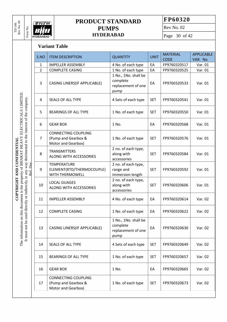
TD
-106
Rev
No. 0
0
Fo
rm N
o.
PRODUCT STANDARD
PUMPS HYDERABAD
FP60320
Rev No. 02
Page 30 of 42
CO
PY
RIG
HT
AN
D C
ON
FID
EN
TIA
L
Th
e in
form
atio
n o
n t
his
do
cum
ent
is t
he
pro
per
ty o
f B
HA
RA
T H
EA
VY
EL
EC
TR
ICA
LS
LIM
ITE
D.
It m
ust
no
t b
e u
sed
dir
ectl
y o
r in
dir
ectl
y i
n a
ny
way
det
rim
enta
l to
th
e in
tere
st o
f th
e co
mp
any
.
Ref
. D
oc
HYDERABAD
Variant Table
S.NO ITEM DESCRIPTION QUANTITY UNIT MATERIAL CODE
APPLICABLE VAR. No
1 IMPELLER ASSEMBLY 4 No. of each type EA FP9760320517 Var. 01
2 COMPLETE CASING 1 No. of each type EA FP9760320525 Var. 01
3 CASING LINERS(IF APPLICABLE)
1 No., 1No. shall be complete replacement of one pump
EA FP9760320533 Var. 01
4 SEALS OF ALL TYPE 4 Sets of each type SET FP9760320541 Var. 01
5 BEARINGS OF ALL TYPE 1 No. of each type SET FP9760320550 Var. 01
6 GEAR BOX 1 No. EA FP9760320568 Var. 01
7 CONNECTING COUPLING (Pump and Gearbox & Motor and Gearbox)
1 No. of each type SET FP9760320576 Var. 01
8 TRANSMITTERS ALONG WITH ACCESSORIES
2 no. of each type, along with accessories
SET FP9760320584 Var. 01
9 TEMPERATURE ELEMENT(RTD/THERMOCOUPLE) WITH THERMOWELL
2 no. of each type, range and immersion length
SET FP9760320592 Var. 01
10 LOCAL GUAGES ALONG WITH ACCESSORIES
2 no. of each type, along with accessories
SET FP9760320606 Var. 01
11 IMPELLER ASSEMBLY 4 No. of each type EA FP9760320614 Var. 02
12 COMPLETE CASING 1 No. of each type EA FP9760320622 Var. 02
13 CASING LINERS(IF APPLICABLE)
1 No., 1No. shall be complete replacement of one pump
EA FP9760320630 Var. 02
14 SEALS OF ALL TYPE 4 Sets of each type SET FP9760320649 Var. 02
15 BEARINGS OF ALL TYPE 1 No. of each type SET FP9760320657 Var. 02
16 GEAR BOX 1 No. EA FP9760320665 Var. 02
17 CONNECTING COUPLING (Pump and Gearbox & Motor and Gearbox)
1 No. of each type SET FP9760320673 Var. 02

TD
-106
Rev
No. 0
0
Fo
rm N
o.
PRODUCT STANDARD
PUMPS HYDERABAD
FP60320
Rev No. 02
Page 31 of 42
CO
PY
RIG
HT
AN
D C
ON
FID
EN
TIA
L
Th
e in
form
atio
n o
n t
his
do
cum
ent
is t
he
pro
per
ty o
f B
HA
RA
T H
EA
VY
EL
EC
TR
ICA
LS
LIM
ITE
D.
It m
ust
no
t b
e u
sed
dir
ectl
y o
r in
dir
ectl
y i
n a
ny
way
det
rim
enta
l to
th
e in
tere
st o
f th
e co
mp
any
.
Ref
. D
oc
HYDERABAD
18 TRANSMITTERS ALONG WITH ACCESSORIES
2 no. of each type, along with accessories
SET FP9760320681 Var. 02
19 TEMPERATURE ELEMENT(RTD/THERMOCOUPLE) WITH THERMOWELL
2 no. of each type, range and immersion length
SET FP9760320690 Var. 02
20 LOCAL GUAGES ALONG WITH ACCESSORIES
2 no. of each type, along with accessories
SET FP9760320703 Var. 02
21 IMPELLER ASSEMBLY 4 No. of each type EA FP9760320711 Var.03
22 COMPLETE CASING 1 No. of each type EA FP9760320720 Var.03
23 CASING LINERS(IF APPLICABLE)
1 No., 1No. shall be complete replacement of one pump
EA FP9760320738 Var.03
24 SEALS OF ALL TYPE 4 Sets of each type SET FP9760320746 Var.03
25 BEARINGS OF ALL TYPE 1 No. of each type SET FP9760320754 Var.03
26 GEAR BOX 1 No. EA FP9760320762 Var.03
27 CONNECTING COUPLING (Pump and Gearbox & Motor and Gearbox)
1 No. of each type SET FP9760320770 Var.03
28 TRANSMITTERS ALONG WITH ACCESSORIES
2 no. of each type, along with accessories
SET FP9760320789 Var.03
29 TEMPERATURE ELEMENT(RTD/THERMOCOUPLE) WITH THERMOWELL
2 no. of each type, range and immersion length
SET FP9760320797 Var.03
30 LOCAL GUAGES ALONG WITH ACCESSORIES
2 no. of each type, along with accessories
SET FP9760320800 Var.03
31 IMPELLER ASSEMBLY 4 No. of each type EA FP9760320819 Var. 04
32 COMPLETE CASING 1 No. of each type EA FP9760320827 Var. 04
33 CASING LINERS(IF APPLICABLE)
1 No., 1No. shall be complete replacement of one pump
EA FP9760320835 Var. 04
34 SEALS OF ALL TYPE 4 Sets of each type SET FP9760320843 Var. 04

TD
-106
Rev
No. 0
0
Fo
rm N
o.
PRODUCT STANDARD
PUMPS HYDERABAD
FP60320
Rev No. 02
Page 32 of 42
CO
PY
RIG
HT
AN
D C
ON
FID
EN
TIA
L
Th
e in
form
atio
n o
n t
his
do
cum
ent
is t
he
pro
per
ty o
f B
HA
RA
T H
EA
VY
EL
EC
TR
ICA
LS
LIM
ITE
D.
It m
ust
no
t b
e u
sed
dir
ectl
y o
r in
dir
ectl
y i
n a
ny
way
det
rim
enta
l to
th
e in
tere
st o
f th
e co
mp
any
.
Ref
. D
oc
HYDERABAD
Note to supplier regarding mandatory spares:
1. Supplier shall clearly indicate with a P&ID, drawings, various instruments used in the
scope of supply and the highlight the mandatory spares diagrammatically to avoid any
ambiguity. Supplier shall contact the purchaser in case of ambiguity, prior to submitting
the offer. Revision/ Alteration after bid submissions shall not be considered.
2. Impeller assembly shall include, impeller, impeller nut & impeller keys.
3. Complete casing shall be one to one replacement of the existing casing.
4. Casing liners shall be a complete replacement of liners in the supplied pump, if applicable.
5. Set of seals shall include Mechanical seal, oil seals, wear rings at impeller location, oil
thrower & oil guards in the entire scope of supply.
6. Bearings shall include journal bearings, thrust bearings in the entire scope of supply.
7. Connecting coupling set shall include couplings between pump & gearbox, gearbox &
motor.
8. Set of Transmitters along with accessories shall include all the transmitters and its
accessories where ever used in the entire scope of supply.
9. Temperature elements with Thermowell shall include all temperature elements where ever
used in the entire scope of supply.
10. Local gauges along with accessories shall include all local gauges where ever used in the
entire scope of supply.
35 BEARINGS OF ALL TYPE 1 No. of each type SET FP9760320851 Var. 04
36 GEAR BOX 1 No. EA FP9760320860 Var. 04
37 CONNECTING COUPLING (Pump and Gearbox & Motor and Gearbox)
1 No. of each type SET FP9760320878 Var. 04
38 TRANSMITTERS ALONG WITH ACCESSORIES
2 no. of each type, along with accessories
SET FP9760320886 Var. 04
39 TEMPERATURE ELEMENT(RTD/THERMOCOUPLE) WITH THERMOWELL
2 no. of each type, range and immersion length
SET FP9760320894 Var. 04
40 LOCAL GUAGES ALONG WITH ACCESSORIES
2 no. of each type, along with accessories
SET FP9760320908 Var. 04

TD
-106
Rev
No. 0
0
Fo
rm N
o.
PRODUCT STANDARD
PUMPS HYDERABAD
FP60320
Rev No. 02
Page 33 of 42
CO
PY
RIG
HT
AN
D C
ON
FID
EN
TIA
L
Th
e in
form
atio
n o
n t
his
do
cum
ent
is t
he
pro
per
ty o
f B
HA
RA
T H
EA
VY
EL
EC
TR
ICA
LS
LIM
ITE
D.
It m
ust
no
t b
e u
sed
dir
ectl
y o
r in
dir
ectl
y i
n a
ny
way
det
rim
enta
l to
th
e in
tere
st o
f th
e co
mp
any
.
Ref
. D
oc
HYDERABAD
23. ANNEXURES
23.1 Annexure-1, Technical Data Sheet
S.No Description Data
1 GENERAL
a. Client : Indicated in variant table.
b. Project : --do--
c. End Customer : --do--
d. Location : --do--
e. Service : --do--
f. Installation : --do--
g. No of pumps for each unit : --do--
h. No of stand-by pumps per unit : --do--
i. Total number of pumps : --do--
2 MANUFACTURER DETAILS
a. Model : *
b. Type : Centrifugal (non- Clogging)
c. Type of Driver : Motor with Gearbox
3 OPERATING CONDITION
a. Medium to be handled : Indicated in variant table.
b. Maximum solid particle size : --do--
c. Normal solid particle size, d 50 : --do--
d. Concentration of chloride : --do--
e. Viscosity of slurry : --do--
f. Concentration of slurry : --do--
g. Specific gravity of slurry : --do--
h. pH of slurry : --do--
4 PERFORMANCE DATA
a. Capacity m3/hr : *
b. Head M : *
c. Pump efficiency % : *
d. BKW Normal / Maximum KW : *
e. Motor rating KW : *
f. Motor Speed rpm : *
g. Gear box Loss % : *
h. Differential pressure (inclusive of losses) Kg/cm2 : *
i. Speed Maximum/ Normal/Minimum rpm : *
j. Noise level dB(A) : *
k. Performance curve : *

TD
-106
Rev
No. 0
0
Fo
rm N
o.
PRODUCT STANDARD
PUMPS HYDERABAD
FP60320
Rev No. 02
Page 34 of 42
CO
PY
RIG
HT
AN
D C
ON
FID
EN
TIA
L
Th
e in
form
atio
n o
n t
his
do
cum
ent
is t
he
pro
per
ty o
f B
HA
RA
T H
EA
VY
EL
EC
TR
ICA
LS
LIM
ITE
D.
It m
ust
no
t b
e u
sed
dir
ectl
y o
r in
dir
ectl
y i
n a
ny
way
det
rim
enta
l to
th
e in
tere
st o
f th
e co
mp
any
.
Ref
. D
oc
HYDERABAD
5 CONSTRUCTION DATA
a. Manufacturer :
b. Model No. : *
c. Suction Rating / Size : *
d. Discharge Rating / Size : *
e. Type of rotor : *
f. Size of rotor Dia mm : *
g. Journal bearing: Type / Size: : *
h. Thrust bearing: Type / Size: : *
i. Bearing cooling required : Yes / No - Supplier to confirm
j. Cooling water required : Supplier to confirm the quantity
k. Type of drive : With Gearbox
l. Shaft seal : Mechanical
m. Size / Code : *
n. Type of coupling : *
o. Service factor : *
p. GD2 at drive shaft end : *
q. Rotation viewed from coupling end : Clock wise / Counter clock wise
r. Coupling type : Yes / No - Supplier to confirm
s. Coupling make : *
t. Base plate common to pump, Gearbox, bearing housing, coupling & Motor
: Yes / No - Supplier to confirm
u. Total weight kg : *
v. Maximum Erection weight kg : *
6 MATERIALS
a. Casing : *
b. Impeller : *
c. Shaft : *
d. Shaft Seal : *
e. Base frame : *

TD
-106
Rev
No. 0
0
Fo
rm N
o.
PRODUCT STANDARD
PUMPS HYDERABAD
FP60320
Rev No. 02
Page 35 of 42
CO
PY
RIG
HT
AN
D C
ON
FID
EN
TIA
L
Th
e in
form
atio
n o
n t
his
do
cum
ent
is t
he
pro
per
ty o
f B
HA
RA
T H
EA
VY
EL
EC
TR
ICA
LS
LIM
ITE
D.
It m
ust
no
t b
e u
sed
dir
ectl
y o
r in
dir
ectl
y i
n a
ny
way
det
rim
enta
l to
th
e in
tere
st o
f th
e co
mp
any
.
Ref
. D
oc
HYDERABAD
7 INSPECTION AND TESTING
a. Material Test certificates required for : Casing, Impeller, shaft, shaft sleeve
: [R] [O]
b. DPT & MPI Test for impeller as applicable : [R] [O]
c. Ultrasonic & Liquid penetrant test for shaft : [R] [O]
d. Dimensional & visual inspection : [R] [W]
e. Mechanical running test for 4 hrs. : [R] [W]
f. Vibration test at rated speed : [R] [W]
g. Performance test : [R] [W]
h. Balancing test of Rotor Assembly : [R] [O]
i. Noise level test : [R] [W]
j. NPSH Test [R] [W]
k. Hydrostatic Test : [R] [W]
[R]: Required, [W]: Witnessed by BHEL/ end customer, [O]: Observed
*: Supplier to provide
SIGNATURE OF SUPPLIER --------------------
NAME --------------------
DESIGNATION --------------------

TD
-106
Rev
No. 0
0
Fo
rm N
o.
PRODUCT STANDARD
PUMPS HYDERABAD
FP60320
Rev No. 02
Page 36 of 42
CO
PY
RIG
HT
AN
D C
ON
FID
EN
TIA
L
Th
e in
form
atio
n o
n t
his
do
cum
ent
is t
he
pro
per
ty o
f B
HA
RA
T H
EA
VY
EL
EC
TR
ICA
LS
LIM
ITE
D.
It m
ust
no
t b
e u
sed
dir
ectl
y o
r in
dir
ectl
y i
n a
ny
way
det
rim
enta
l to
th
e in
tere
st o
f th
e co
mp
any
.
Ref
. D
oc
HYDERABAD
23.2 Annexure-2, Schedule of guarantees
S.No Description Data
1. Rated capacity of pump m3/hr :
2. Total head at design capacity m :
3. Guaranteed shaft power consumption at rated capacity & head
kW :
4. Noise level at a distance of 1.0 meter from the equipment at site and 1.5 m above operating floor
dB(A) :
5. Maximum vibration (peak to peak amplitude at site)
microns :
6. Equipment Availability (%) :
7. Pump Efficiency (%) :
8. Life of Pump wear parts including, Casing liners, bearing etc
Hours : ≥25000 hours operation
9. Scheduled Maintenance (Minor Overhauls): Recommended intervals between maintenance outages
hours : >25000 hours operation.
10. Scheduled Maintenance (Major Overhauls): Recommended intervals between maintenance outages shall be
hours : >75000 hours operation.
SIGNATURE OF SUPPLIER --------------------
NAME --------------------
DESIGNATION --------------------

TD
-106
Rev
No. 0
0
Fo
rm N
o.
PRODUCT STANDARD
PUMPS HYDERABAD
FP60320
Rev No. 02
Page 37 of 42
CO
PY
RIG
HT
AN
D C
ON
FID
EN
TIA
L
Th
e in
form
atio
n o
n t
his
do
cum
ent
is t
he
pro
per
ty o
f B
HA
RA
T H
EA
VY
EL
EC
TR
ICA
LS
LIM
ITE
D.
It m
ust
no
t b
e u
sed
dir
ectl
y o
r in
dir
ectl
y i
n a
ny
way
det
rim
enta
l to
th
e in
tere
st o
f th
e co
mp
any
.
Ref
. D
oc
HYDERABAD
23.3 Annexure-3, Reference list (at least two power plant details)
S.No
Project Name , Customer & Plant capacity
Coal fired Yes/No
Wet Limestone Based FGD Yes/No
Model Capacity Head Speed Year of
Commissioning Qty
m3/hr. m rpm
1
2 3
SIGNATURE OF SUPPLIER --------------------
NAME --------------------
DESIGNATION --------------------

TD
-106
Rev
No. 0
0
Fo
rm N
o.
PRODUCT STANDARD
PUMPS HYDERABAD
FP60320
Rev No. 02
Page 38 of 42
CO
PY
RIG
HT
AN
D C
ON
FID
EN
TIA
L
Th
e in
form
atio
n o
n t
his
do
cum
ent
is t
he
pro
per
ty o
f B
HA
RA
T H
EA
VY
EL
EC
TR
ICA
LS
LIM
ITE
D.
It m
ust
no
t b
e u
sed
dir
ectl
y o
r in
dir
ectl
y i
n a
ny
way
det
rim
enta
l to
th
e in
tere
st o
f th
e co
mp
any
.
Ref
. D
oc
HYDERABAD
23.4 Annexure-4, List of Deviations
S.No Clause No Page No Description of Deviation
SIGNATURE OF SUPPLIER --------------------
NAME --------------------
DESIGNATION --------------------

TD
-106
Rev
No. 0
0
Fo
rm N
o.
PRODUCT STANDARD
PUMPS HYDERABAD
FP60320
Rev No. 02
Page 39 of 42
CO
PY
RIG
HT
AN
D C
ON
FID
EN
TIA
L
Th
e in
form
atio
n o
n t
his
do
cum
ent
is t
he
pro
per
ty o
f B
HA
RA
T H
EA
VY
EL
EC
TR
ICA
LS
LIM
ITE
D.
It m
ust
no
t b
e u
sed
dir
ectl
y o
r in
dir
ectl
y i
n a
ny
way
det
rim
enta
l to
th
e in
tere
st o
f th
e co
mp
any
.
Ref
. D
oc
HYDERABAD
23.5 Annexure-5
23.5.1 Documents to be submitted along with offer
S.No. Description No of copies
With proposal
1. Duly signed Specification 1
2. Price Sheet 1
3. Anchor Plan & Civil foundation Loading details
1
4. Data Sheet 1
5. Performance curve, Motor T-S curve 1
6. Pro-forma Packing List 1
7. Manufacturing Time 1
8. Approximate weight of each skid 1
9. Reference plant details 1
10. Required Electric power & other Utility List 1
11. Deviation List 1
12. General Assembly Drawing 1
13. Pump and Motor Sizing Calculation 1
14. Cross-sectional Drawing 1
15. Sub-Vendor List 1
16. Scope of Supply 1
17. Quality Plan 1
18. Spare List (Mandatory, Recommended) 1
19. Start-up & Commissioning Spares 1
20. List of Special Tools 1
21. Delivery Schedule 1
22. Test Arrangement & Test procedure
1
23. Hoist/Crane requirement 1
24. P & I Diagram 1
25. Catalogue 1
26.
SIGNATURE OF SUPPLIER --------------------
NAME --------------------
DESIGNATION --------------------

TD
-106
Rev
No. 0
0
Fo
rm N
o.
PRODUCT STANDARD
PUMPS HYDERABAD
FP60320
Rev No. 02
Page 40 of 42
CO
PY
RIG
HT
AN
D C
ON
FID
EN
TIA
L
Th
e in
form
atio
n o
n t
his
do
cum
ent
is t
he
pro
per
ty o
f B
HA
RA
T H
EA
VY
EL
EC
TR
ICA
LS
LIM
ITE
D.
It m
ust
no
t b
e u
sed
dir
ectl
y o
r in
dir
ectl
y i
n a
ny
way
det
rim
enta
l to
th
e in
tere
st o
f th
e co
mp
any
.
Ref
. D
oc
HYDERABAD
23.5.2 Documents to be submitted after award of contract
S.No. Description
No of copies
After award
of contract
Delivery Time
1. Utility Consumption 1 2 weeks after contract
2. Foundation Data including Anchor plan 1 2 weeks after contract
3. Performance curve 2 2 weeks after contract
4. General arrangement drawing 1 1 month after contract
5. Cross section detail drawing 1 1 month after contract
6. Data Sheet 1 2 weeks after contract
7. Lubricating oil list 1 2 months after contract
8. Special tools list 1 2 months after contract
9. Installation and assembly procedure 1 4 months after contract
10. Inspection and Test Procedure 1 1 month after contract
11. Inspection & Test record 1 In 2 weeks after test
12. Inspection Certificate 1 In 2 weeks after test
13. Sub vendors List 1 2 weeks after contract
14. Manufacturing Schedule 1 2 weeks after contract
15. Progress report 1 Every month
16. Pro-forma Packing List 1 2 months prior to
shipping
17. Approximate weight of pump 1 2 months after contract
18. Required Electric power 2 2 weeks after contract
19. Pump and Motor Sizing Calculation 1 2 weeks after contract
20. Material Test Certificates 2 In 2 weeks after test
21. Pre Commissioning Check List 2 4 months after contract
22. Scope of Supply 2 2 weeks after contract
23. Quality Plan 4 1 month after contract
24. Operation and Maintenance Manual Hardcopies
and soft
copies as
mentioned
4 months after contract
25. Spare List (Mandatory, Recommended) 1 1 month after contract
26. Start-up & Commissioning Spares 2 1 month after contract
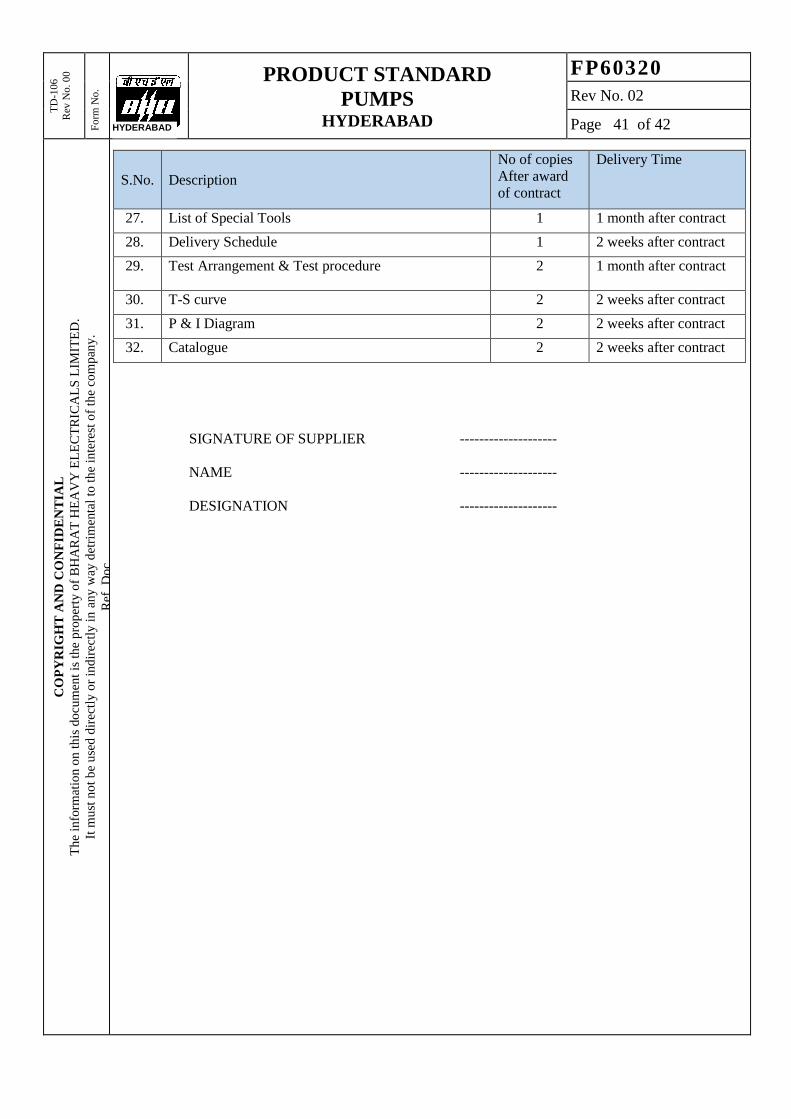
TD
-106
Rev
No. 0
0
Fo
rm N
o.
PRODUCT STANDARD
PUMPS HYDERABAD
FP60320
Rev No. 02
Page 41 of 42
CO
PY
RIG
HT
AN
D C
ON
FID
EN
TIA
L
Th
e in
form
atio
n o
n t
his
do
cum
ent
is t
he
pro
per
ty o
f B
HA
RA
T H
EA
VY
EL
EC
TR
ICA
LS
LIM
ITE
D.
It m
ust
no
t b
e u
sed
dir
ectl
y o
r in
dir
ectl
y i
n a
ny
way
det
rim
enta
l to
th
e in
tere
st o
f th
e co
mp
any
.
Ref
. D
oc
HYDERABAD
S.No. Description
No of copies
After award
of contract
Delivery Time
27. List of Special Tools 1 1 month after contract
28. Delivery Schedule 1 2 weeks after contract
29. Test Arrangement & Test procedure
2 1 month after contract
30. T-S curve 2 2 weeks after contract
31. P & I Diagram 2 2 weeks after contract
32. Catalogue 2 2 weeks after contract
SIGNATURE OF SUPPLIER --------------------
NAME --------------------
DESIGNATION --------------------

T
D-1
06
-3
Rev
No
.
5
Fo
rm N
o.
PRODUCT STANDARD
PUMPS HYDERABAD
FP60320
Rev No. 02
Page 42 of 42
CO
PY
RIG
HT
AN
D C
ON
FID
EN
TIA
L
The
info
rmat
ion o
n t
his
do
cum
ent
is t
he
pro
per
ty o
f B
HA
RA
T H
EA
VY
EL
EC
TR
ICA
LS
LIM
ITE
D,
It m
ust
not
be
use
d d
irec
tly o
r in
dir
ectl
y i
n a
ny w
ay d
etri
men
tal
to t
he
inte
rest
of
the
com
pan
y.
Ref
. D
oc.
RECORD OF REVISIONS
Rev. No. Date Revision Details Revised by Approved By
01 23.05.20
Var. 03 & 04 details added. Var.
71 to 90 added for NTPC Korba
TPP, 2x300MW& 4x500MW.
ASK MSR
02 15.07.20 Specification revised based on
input from Ranipet ASK MSR