SketchML a representation language for novel sketch recognition approach
8
SketchML a Representation Language for Novel Sketch Recognition Approach Danilo Avola Univ. of Rome "La Sapienza" Dept. of Computer Science Via Salaria 113, 00189 Rome, Italy [email protected] Andrea Del Buono National Research Center CSKLab Research Dept. Via Savoia 84, 00196 Rome, Italy [email protected] Giorgio Gianforme Univ. of Rome "Rome 3" Dept. of Computer Science Via Vasca Navale 79, 00146 Rome, Italy [email protected] Stefano Paolozzi Univ. of Rome "Rome 3" Dept. of Computer Science Via Vasca Navale 79, 00146 Rome, Italy [email protected] Rui Wang Univ. of Germany "Saarland" Dept. of Computer Science Saarbrücken, 66041 Saarbrücken, Germany [email protected] ABSTRACT Multimodal interfaces can be profitably used to support in- creasingly complex services in assistive environments. In particular, sketch-based interfaces offer users an effortless and powerful communication way to represent concepts and commands on different devices. Unlike other modalities, sketch-based interaction can be easily fitted according to heterogeneous services. Moreover it can be quickly person- alized according to the user needs. Developing a sketch-based interface for a specific service is a time-consuming operation that requires the re-engineering and/or the re-designing of the whole recognizer framework. This paper describes a definitive framework by which the user, simply by using freehand drawing, can define every kind of sketch-based interface. The definition of the inter- face and its recognition process are performed by using our developed Sketch Modeling Language (SketchML). Categories and Subject Descriptors H.5 [Information Interfaces and Presentation]: Mis- cellaneous; D.2.8 [Pattern Recognition]: Design Method- ology—feature evaluation and selection, pattern analysis. General Terms Algorithms, experimentation. Keywords Sketch-based interfaces, sketch-based interaction, sketch recog- nition, multi-domain, vectorization, segmentation, XML, SVG. Permission to make digital or hard copies of all or part of this work for personal or classroom use is granted without fee provided that copies are not made or distributed for profit or commercial advantage and that copies bear this notice and the full citation on the first page. To copy otherwise, to republish, to post on servers or to redistribute to lists, requires prior specific permission and/or a fee. PETRA ’09, June 09-13, 2009, Corfu, Greece. Copyright 2009 ACM ISBN 978-1-60558-409-6 ...$5.00. 1. INTRODUCTION Multimodal interfaces allow users to interact naturally with any desktop or mobile device using multiple modali- ties (e.g. sketch, gesture, speech, gaze). In assistive envi- ronments these interfaces can be profitably used to support increasingly complex services able to improve the quality of life. In particular, sketch-based interfaces enable users to express concepts, provide commands, and represent ideas in an immediate, intuitive and simple way. In fact, the users can access any kind of device and related services by draw- ing a set of 2D graphical symbols (e.g. arrows, geometric symbols, or more complex shapes). In this context a set of 2D graphical symbols is also called library or application domain. Unlike other modalities, sketch-based interfaces al- low users easier customization and quick personalization of the interaction. The first aspect highlights the simplicity to draw well known standard graphical symbols (e.g. com- mands) to access specific services. The second aspect focuses on the suitability to use drawn symbols (e.g. commands and/or concepts) to access services according to user needs and/or capacities. Developing a sketch-based interface able to distinguish each symbol that makes up a library is a time-consuming opera- tion that requires the re-engineering and/or the re-designing of the whole recognizer framework. This paper describes a definitive framework by which the user, simply by using freehand drawing, can define every kind of sketch-based in- terface based on 2D graphical symbols. The definition of the interface and its recognition process are performed by using our developed Sketch Modeling Language (SketchML). The developed framework, compared to the current proto- types, has three advantageous main features that jointly put it in the vanguard in the sketch-based interfaces area. The first regards the ability to define every kind of library. In fact, several frameworks are designed to properly rec- ognize only a specific set of symbols: they could also rec- ognize other kinds of libraries but this step would involve the arrangement of the recognition engine inside the frame- works. The second feature regards the library definition, simply by using freehand drawing. In fact, there are several
Transcript of SketchML a representation language for novel sketch recognition approach

SketchML a Representation Language for Novel SketchRecognition Approach
Danilo AvolaUniv. of Rome "La Sapienza"Dept. of Computer Science
Via Salaria 113, 00189Rome, Italy
Andrea Del BuonoNational Research CenterCSKLab Research Dept.
Via Savoia 84, 00196Rome, Italy
Giorgio GianformeUniv. of Rome "Rome 3"
Dept. of Computer ScienceVia Vasca Navale 79, 00146
Rome, [email protected]
Stefano PaolozziUniv. of Rome "Rome 3"
Dept. of Computer ScienceVia Vasca Navale 79, 00146
Rome, [email protected]
Rui WangUniv. of Germany "Saarland"Dept. of Computer Science
Saarbrücken, 66041Saarbrücken, Germany
ABSTRACT
Multimodal interfaces can be profitably used to support in-creasingly complex services in assistive environments. Inparticular, sketch-based interfaces offer users an effortlessand powerful communication way to represent concepts andcommands on different devices. Unlike other modalities,sketch-based interaction can be easily fitted according toheterogeneous services. Moreover it can be quickly person-alized according to the user needs.Developing a sketch-based interface for a specific service isa time-consuming operation that requires the re-engineeringand/or the re-designing of the whole recognizer framework.This paper describes a definitive framework by which theuser, simply by using freehand drawing, can define everykind of sketch-based interface. The definition of the inter-face and its recognition process are performed by using ourdeveloped Sketch Modeling Language (SketchML).
Categories and Subject Descriptors
H.5 [Information Interfaces and Presentation]: Mis-cellaneous; D.2.8 [Pattern Recognition]: Design Method-ology—feature evaluation and selection, pattern analysis.
General Terms
Algorithms, experimentation.
Keywords
Sketch-based interfaces, sketch-based interaction, sketch recog-nition, multi-domain, vectorization, segmentation, XML, SVG.
Permission to make digital or hard copies of all or part of this work forpersonal or classroom use is granted without fee provided that copies arenot made or distributed for profit or commercial advantage and that copiesbear this notice and the full citation on the first page. To copy otherwise, torepublish, to post on servers or to redistribute to lists, requires prior specificpermission and/or a fee.PETRA ’09, June 09-13, 2009, Corfu, Greece.Copyright 2009 ACM ISBN 978-1-60558-409-6 ...$5.00.
1. INTRODUCTIONMultimodal interfaces allow users to interact naturally
with any desktop or mobile device using multiple modali-ties (e.g. sketch, gesture, speech, gaze). In assistive envi-ronments these interfaces can be profitably used to supportincreasingly complex services able to improve the quality oflife. In particular, sketch-based interfaces enable users toexpress concepts, provide commands, and represent ideas inan immediate, intuitive and simple way. In fact, the userscan access any kind of device and related services by draw-ing a set of 2D graphical symbols (e.g. arrows, geometricsymbols, or more complex shapes). In this context a setof 2D graphical symbols is also called library or applicationdomain. Unlike other modalities, sketch-based interfaces al-low users easier customization and quick personalization ofthe interaction. The first aspect highlights the simplicityto draw well known standard graphical symbols (e.g. com-mands) to access specific services. The second aspect focuseson the suitability to use drawn symbols (e.g. commandsand/or concepts) to access services according to user needsand/or capacities.Developing a sketch-based interface able to distinguish eachsymbol that makes up a library is a time-consuming opera-tion that requires the re-engineering and/or the re-designingof the whole recognizer framework. This paper describesa definitive framework by which the user, simply by usingfreehand drawing, can define every kind of sketch-based in-terface based on 2D graphical symbols. The definition of theinterface and its recognition process are performed by usingour developed Sketch Modeling Language (SketchML).The developed framework, compared to the current proto-types, has three advantageous main features that jointlyput it in the vanguard in the sketch-based interfaces area.The first regards the ability to define every kind of library.In fact, several frameworks are designed to properly rec-ognize only a specific set of symbols: they could also rec-ognize other kinds of libraries but this step would involvethe arrangement of the recognition engine inside the frame-works. The second feature regards the library definition,simply by using freehand drawing. In fact, there are several

frameworks based on multi-domain concept, but to build anew application domain it is necessary an expert user witha deep knowledge about standards, vectorial applications,programming languages and so on. Using our frameworkthe user, without special knowledge, can create any kind of2D graphical symbols. The last feature concerns the defi-nition of the interface and its recognition process which areperformed by using SketchML, a language based on XML(eXtended Markup Language) standard. This consolidatedW3C (World Wide Web Consortium) standard allows bothcompatibility on different devices and cooperation betweendifferent applications/services.The paper is structured as follows. Section 2 proposes someremarkable related works in multi-domain sketch-based in-terfaces area. Section 3 introduces an overview about thedeveloped framework. Section 4 shows the library editorenvironment. Section 5 describes the sketch recognition en-vironment. Section 6 discusses about the matching betweenthe library symbols and the user-performed sketch. Section7 shows experimental results on a wide application domaindesigned to meet the needs of assistive environments. Fi-nally, Section 8 concludes the paper.
2. RELATED WORKSThis section shows some remarkable works about the multi-
domain sketch recognition frameworks. It is important toobserve, once again, that our further contribution, on thisarea, is to provide a framework able to create every kind oflibrary, simply by using the freehand drawing activity. Inthis way, without theoretical and technical specific knowl-edge a user can build, in real time, every kind of simple orcomplex library. Moreover, all the libraries are representedusing the developed XML-based language (SketchML) whichallows both compatibility on different devices and coopera-tion between different applications/services. In this context,it has to be highlighted that also dedicated devices, in as-sisted living, tend to integrate XML language interpretersin order to allow exchange of information and functionali-ties between different devices and applications and services.An interesting framework about multi-domain sketch recog-nition is presented in [3]. In this work the authors show afree-sketch recognition framework that allows users to drawshapes in natural way. In particular, the framework is ableto recognize a variety of defaults domains by exploiting sev-eral well known techniques able to catch information about:geometric, features, temporal, contextual, multi-modal anddomain. A different approach is provided in [1]. In this workthe authors present a novel form of dynamically constructedBayes net, developed for multi-domain sketch recognition.The proposed sketch recognition engine integrates shape in-formation and domain knowledge to improve recognitionprocess. In [4] the authors show a remarkable agent-basedframework for sketched symbol interpretation that heav-ily exploits contextual information for ambiguity resolution.In particular, in this work the agents manage the activ-ity of low-level hand-drawn symbol recognizers and coor-dinate themselves in order to exchange contextual informa-tion, thus leading to an efficient and precise interpretationof sketches. Another interesting feature-based approach isshown in [7]. In this work the authors present an advancedheuristic based framework that offers the user more libertyfor free-style sketching as well as for grouping the strokes,reducing the complexity for recognizing the sketches. Un-
like previous approaches the authors in [10] introduce aprimitive-based engine. In particular, the authors presenta method for interpreting on-line freehand sketch and de-scribe a human-computer interface prototype system thatis designed to infer designer’s intention and interprets theinput sketch into more exact geometric primitives: straightlines, poly-lines, circles, circular arcs, ellipses, elliptical arcs,and parabolas. An important work, tied to our approach, isexplained in [5]. The authors introduce LADDER, the firstlanguage to describe how sketched diagrams in a domain aredrawn, displayed, and edited. Also in this work the difficul-ties about a suitable choice of a set of predefined entitiesthat is broad enough to support a wide range of domainsare faced. This language consists of predefined shapes, con-straints, editing behaviors, and display methods, as well asa syntax for specifying a domain description sketch gram-mar and extending the language, ensuring that shapes andshape groups from many domains can be described. The justmentioned work has been a real source of inspiration. Ourproposed SketchML has several common points with LAD-DER language, but SketchML is more general and it can beused to represent any application domain. Moreover, ourapproach allows users to build any kind of library, simplyby using freehand drawing activity. A particular example isshown in [11], in this work the authors describe a domain-independent system for sketch recognition. The developedsystem allows users to draw sketches as naturally as they doon paper, and it recognizes the drawing through imprecisestroke approximation which is implemented in a unified andincremental procedure. A different approach is shown in [2],which describes a framework for recognizing of compositegraphic objects, highlighting the important role played bytopological spatial relationships between their components.In this work the authors introduce a ternary relationship,which is a complement to a binary relationship, to describecomposite graphic objects. Another remarkable approach isshown in [9]. In this work the authors describe a statisticalframework based on dynamic Bayesian networks that explic-itly models the fact that objects can be drawn interspersed.We conclude this section showing two approaches based onHMMs (Hidden Markov Models). In fact, a new interestingtendency on sketch recognition approaches is to use HMMto overcome several critical duties, such as: personalization,graphical noise, shape learning, and so on. For example, asimple and innovative approach is proposed in [8]. In thiswork the authors show that it is possible to view sketching asan interactive process in order to use HMM for sketch recog-nition modeling. A different approach is proposed in [6], inthis interesting work the authors describe a framework foron-line multi-stroke sketch recognition. By using the frame-work, user sketches are modeled to HMM chains, and strokesare mapped to different HMM states. The authors have in-troduced a new method to determine HMM state-number,based on which an adaptive HMM sketch recognizer is con-structed.The mentioned approaches depend on a set of default sym-bols and/or primitives that are tied to specific applicationdomains, or they are tied to certain statistical models. More-over, in both cases, the building of a library is a hard taskthat has to be performed by skilled user. Our novel approachovercomes these problems by using very general primitives.Moreover every kind of library can be built simply by usingfreehand sketch activity.

Figure 1: Library Editor Environment.
Figure 2: Sketch Recognition Environment.
3. DEVELOPED FRAMEWORKThe developed framework provides two different environ-
ments. The first is the Library Editor Environment (LEE),where the user can define the libraries by means of freehanddrawing. The second is the Sketch Recognition Environment(SRE), where the system performs the recognition activity,on a user-drawn sketch, after loading the related library. Inorder to explain the functionalities of the two just mentionedenvironments, in this section we will give a simple examplebased on ERD (Entity Relationship Diagram).As shown in Figure 1 the user has sketched the third symbol
belonging to the ERD domain, and the LEE has built the re-lated vectorial representation. The process (shown in section4) for obtaining the vectorial symbol from the sketched sym-bol is the main aspect of our paper. In Figure 2 a recognitionprocess (shown in section 5) about a simple ERD example isgiven. In order to understand the matching process (shownin section 6) it is important to observe that both vectorialrepresentation of the library symbols built in LEE and vecto-rial diagram obtained by recognition process in SRE are ex-pressed by our XML-based developed language: SketchML.The use of sketch-based interfaces allow the users, both inLEE and SRE, to perform several useful activities, such as:deletions, restyling of the whole symbol/object (set of sym-bols) or part of it, and so on.SRE exploits the knowledge of the symbols that make up theloaded library to improve the recognition process. In fact,as just mentioned, the final result of the library definition isan XML file that describes (by SketchML) each and everysymbol. Also the final result of the recognized user sketch
Figure 3: Correct/Incorrect ERD Example.
is an XML file that describes the whole sketch performedby the user. But this last file takes into account only therecognized symbols according to the loaded library. In or-der to explain the just mentioned concepts it is importantto introduce the example in Figure 3, that is based on thefive symbols belonging to the ERD library.In Figure 3-a the user has correctly sketched an ERD ex-
ample. More exactly, the user has sketched the followingsequence of ERD symbols: three primary keys, three enti-ties, two relationships, three attributes and ten associations(twenty one total objects). In Figure 3-b, all the drawnobjects have been recognized and an XML file (described inthe next section by SketchML) that describes each one of thetwenty one objects has been created. Indeed, as explainedin the next sections too, the situation is more complex thanone just mentioned. In fact, taking into account the sym-bols belonging to the loaded library, it is possible to observethat the sketched symbol of association (shown in Figure 3-aby labels 1 and 2) is not a library symbol. It is recognizedas an association symbol because it results from the com-positions of two symbols of the ERD library (that is twoassociation symbols) with a particular constraint (an angleof ninety degrees). In Figure 3-c is shown the matching pro-cess (explained in the relative section) of each symbol. Thisprocess allows the framework to map every object sketchedby the user (in SRE) with a symbol belonging to the relatedlibrary (defined in LEE). Unlike the previous example, inFigure 3-d the user has incorrectly sketched an ERD exam-ple. In fact, as shown in Figure 3-e, seventeen objects havebeen recognized and four objects have not been recognized.In this case the XML file will contain only the descriptionof the seventeen objects. In Figure 3-f is detailed each oneof the matching process between the objects drawing by theuser and the loaded library. This example highlights thatfour objects have not satisfied the matching requirements(in fact the matched objects are seventeen), this means thatthese four objects were not matched with a library symbolby the matching process, and there is no SketchML descrip-tion for these objects.In the next two sections show the approaches and the algo-rithms behind the two just introduced environments, in afurther section the approach used to perform the matchingprocess between a loaded library and the sketch performedby the user is given.

Figure 4: Stroke, Sub-Strokes, Generalized Strokes.
Figure 5: Library Editor Environment Schema.
4. LIBRARY EDITOR ENVIRONMENTThis section details approaches and algorithms that form
the core of the LEE. In order to explain the section content,the following three definition are introduced.
• Stroke: set of pixels obtained during the following penaction: pen down, pen drawing, pen up.
• Sub-Stroke: subpart of a Stroke. When two (or more)strokes are crossed several intersection points are cre-ated. By these points a lot of sub-strokes can be iden-tified.
• Generalized Stroke: it is made up from two (or more)sub-strokes coming from different strokes.
In Figure 4-a an example of stroke is shown. In particular,the circle indicates the start point of the stroke (pen down),and the arrowhead indicates the final point of the stroke (penup). In Figure 4-b, by two start points, two end points, andthe intersection point (shown by the empty circle) four sub-strokes are identified (respectively labeled by: 1, 2, 3 and4). Finally, in Figure 4-c two generalized strokes are shown,more exactly the generalized stroke made up by sub-strokeslabeled with 1 and 2, and that one made up by sub-strokeslabeled with 3 and 4 (other combinations are available).In Figure 5 a simple schema about the basic concepts that
drive the making of a general library is given. The first mod-ule (First Layer Segmentation Algorithm) is used to obtain,from the strokes performed by the user during sketch activ-ity, two kind of objects: closed regions and poly-lines. Inthe second module (Second Layer Segmentation Algorithm)each object is analyzed in order to detect the set of primi-tives that makes it up: ovals and lines. In the third mod-ule (Constraints Determination) the spatial relationships be-tween the discovered primitives are evaluated. The role ofthe fourth module (SketchML Descriptor) is “to translate”all the found information in an XML/SVG structure.Next subsections show each module of the proposed schema.
Besides, the example in Figure 6 will attend each section inorder to explain the involved processes. In particular, Fig-ure 6-a shows a sketched symbol that the user wants to addto the library. Figure 6-b shows the related vectorial rep-resentation added to the library and described inside theframework by SketchML. Figure 6-c will be explained in thenext subsection.
Figure 6: A Library Symbol Example.
Figure 7: Ambiguity Examples.
Figure 8: Algorithm Interpretation.
4.1 First Layer SegmentationThe aim of the first layer segmentation algorithm is to
provide two different set of objects: closed regions and poly-lines. This concept is not so simple as it might appear.In fact, there is not a unique interpretation about the twosketched strokes (S1 and S2) drawn in Figure 7-a. For exam-ple, the two strokes could be interpreted as two overlappedclosed regions (A1 and A2, Figure 7-b), otherwise they couldbe interpreted as two closed regions and a poly-line (A1,A2 and P1, Figure 7-c). In another interpretation the twostrokes could be interpreted as three closed regions (A1, A2
and A3, Figure 7-d). Moreover, there are other availableinterpretations. This kind of issues, defined as ambiguityproblems, are a crucial point of every sketch recognition sys-tem. In order to overcome them, the first layer segmentationalgorithm works taking into account the following two char-acterizations of closed region and poly-line.
• Closed Region: it is the smallest area confined by aset of strokes and/or sub-Strokes and/or generalizedstrokes.
• Poly-Line: it is the smallest stroke or sub-stroke.
With these characterizations, every sketch can be interpretedin a unique way. To highlight the algorithm approach in Fig-ure 8 some examples of developed algorithm interpretationare given. More specifically, the two strokes drawn in Fig-ure 8-a are interpreted, as shown in Figure 8-b, as threeclosed regions (A1, A2, A3). The two strokes drawn in Fig-ure 8-c are interpreted, as shown in Figure 8-d, as two closedregions and two poly-lines (A1, A2, P1, P1). The two strokesdrawn in Figure 8-e are interpreted, as shown in Figure 8-f, as a closed region and a poly-line (A1, P1). Finally, thestroke drawn in Figure 8-g is interpreted, as shown in Fig-ure 8-h, as a closed region and two poly-lines (A1, P1, P2).
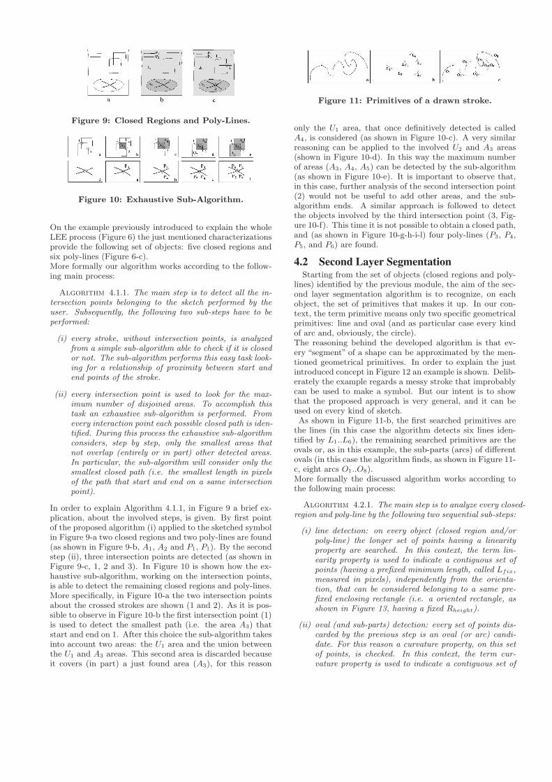
Figure 9: Closed Regions and Poly-Lines.
Figure 10: Exhaustive Sub-Algorithm.
On the example previously introduced to explain the wholeLEE process (Figure 6) the just mentioned characterizationsprovide the following set of objects: five closed regions andsix poly-lines (Figure 6-c).More formally our algorithm works according to the follow-ing main process:
Algorithm 4.1.1. The main step is to detect all the in-tersection points belonging to the sketch performed by theuser. Subsequently, the following two sub-steps have to beperformed:
(i) every stroke, without intersection points, is analyzedfrom a simple sub-algorithm able to check if it is closedor not. The sub-algorithm performs this easy task look-ing for a relationship of proximity between start andend points of the stroke.
(ii) every intersection point is used to look for the max-imum number of disjoined areas. To accomplish thistask an exhaustive sub-algorithm is performed. Fromevery interaction point each possible closed path is iden-tified. During this process the exhaustive sub-algorithmconsiders, step by step, only the smallest areas thatnot overlap (entirely or in part) other detected areas.In particular, the sub-algorithm will consider only thesmallest closed path (i.e. the smallest length in pixelsof the path that start and end on a same intersectionpoint).
In order to explain Algorithm 4.1.1, in Figure 9 a brief ex-plication, about the involved steps, is given. By first pointof the proposed algorithm (i) applied to the sketched symbolin Figure 9-a two closed regions and two poly-lines are found(as shown in Figure 9-b, A1, A2 and P1, P1). By the secondstep (ii), three intersection points are detected (as shown inFigure 9-c, 1, 2 and 3). In Figure 10 is shown how the ex-haustive sub-algorithm, working on the intersection points,is able to detect the remaining closed regions and poly-lines.More specifically, in Figure 10-a the two intersection pointsabout the crossed strokes are shown (1 and 2). As it is pos-sible to observe in Figure 10-b the first intersection point (1)is used to detect the smallest path (i.e. the area A3) thatstart and end on 1. After this choice the sub-algorithm takesinto account two areas: the U1 area and the union betweenthe U1 and A3 areas. This second area is discarded becauseit covers (in part) a just found area (A3), for this reason
Figure 11: Primitives of a drawn stroke.
only the U1 area, that once definitively detected is calledA4, is considered (as shown in Figure 10-c). A very similarreasoning can be applied to the involved U2 and A3 areas(shown in Figure 10-d). In this way the maximum numberof areas (A3, A4, A5) can be detected by the sub-algorithm(as shown in Figure 10-e). It is important to observe that,in this case, further analysis of the second intersection point(2) would not be useful to add other areas, and the sub-algorithm ends. A similar approach is followed to detectthe objects involved by the third intersection point (3, Fig-ure 10-f). This time it is not possible to obtain a closed path,and (as shown in Figure 10-g-h-i-l) four poly-lines (P3, P4,P5, and P6) are found.
4.2 Second Layer SegmentationStarting from the set of objects (closed regions and poly-
lines) identified by the previous module, the aim of the sec-ond layer segmentation algorithm is to recognize, on eachobject, the set of primitives that makes it up. In our con-text, the term primitive means only two specific geometricalprimitives: line and oval (and as particular case every kindof arc and, obviously, the circle).The reasoning behind the developed algorithm is that ev-ery “segment” of a shape can be approximated by the men-tioned geometrical primitives. In order to explain the justintroduced concept in Figure 12 an example is shown. Delib-erately the example regards a messy stroke that improbablycan be used to make a symbol. But our intent is to showthat the proposed approach is very general, and it can beused on every kind of sketch.As shown in Figure 11-b, the first searched primitives are
the lines (in this case the algorithm detects six lines iden-tified by L1..L6), the remaining searched primitives are theovals or, as in this example, the sub-parts (arcs) of differentovals (in this case the algorithm finds, as shown in Figure 11-c, eight arcs O1..O8).More formally the discussed algorithm works according tothe following main process:
Algorithm 4.2.1. The main step is to analyze every closed-region and poly-line by the following two sequential sub-steps:
(i) line detection: on every object (closed region and/orpoly-line) the longer set of points having a linearityproperty are searched. In this context, the term lin-earity property is used to indicate a contiguous set ofpoints (having a prefixed minimum length, called Lfix,measured in pixels), independently from the orienta-tion, that can be considered belonging to a same pre-fixed enclosing rectangle (i.e. a oriented rectangle, asshown in Figure 13, having a fixed Rheight).
(ii) oval (and sub-parts) detection: every set of points dis-carded by the previous step is an oval (or arc) candi-date. For this reason a curvature property, on this setof points, is checked. In this context, the term cur-vature property is used to indicate a contiguous set of

Figure 12: Example of Line and Oval Detection.
points, independently from the orientation, in whichthe linearity property is true but only on contiguoussub-set of points having a length lower than Lfix.
It is important to observe that the main parameters (Lfix
and Rheight) can depend on different factors, including: in-teraction tool, device, pre-processing approach used to ”clean”the user sketch, and so on. Indeed, the two steps work coop-eratively for “progressive refinements”. This means that thealgorithm is applied several times until every set of pointshas found a suitable collocation as line or oval (or part ofit).In order to explain the just mentioned algorithm, in Fig-ure 12 a brief description about the working algorithm isgiven. In Figure 12-a the set of points representing a strokeis given. As shown, the algorithm starts from the first point(Figure 12-b) and tries to approximate the following pointsby a prefixed enclosing rectangle (Figure 12-c, Figure 12-d,Figure 12-e, Figure 12-f and Figure 12-g). When there isnot an orientation of the enclosing rectangle able to contentall the analyzed points (Figure 12-h), the previous enclos-ing rectangle is considered, and a new enclosing rectangle iscreated to analyze the remaining points (Figure 12-i). Thisapproach ends when the set of points is entirely analyzed(Figure 12-l). After this step, all the enclosing rectangleare used to approximate the related points with a vectorialline (Figure 12-m). The set of lines which elements have alength lower (or equal) than a fixed threshold (in this exam-ple Lfix = 4points) are approximated with an oval or partof it (Figure 12-n).Obviously, this kind of reasoning is better applied to realcases, where the strokes are made up from several points.Besides, it has to be taken into account that when the al-gorithm approximates a set of “short” lines with an oval (orarc) there is the possibility to modify also the elements thatsurrounds the oval (the left element and the right element,in this case L1 and L2). The aim of this refinement step isto provide the best approximation to the set of points thatmakes up the oval (or arc). The modification of these ele-ments is a very simple task. It consists in the losing of somepoints and to provide them to the set of points that makesup the oval (or arc). At the end of the developed algorithm afirst step toward the vectorization is accomplished. In fact,the following “substitutions” between the found primitivesand basic SVG (Scalable Vector Graphics, which is an XMLbased language) shapes is performed:
• Primitive Line: defined by Line SVG basic shape hav-ing the following main attributes: x1: the x-axis coor-dinate of the start of the line (default value is 0), y1:the y-axis coordinate of the start of the line (defaultvalue is 0), x2: the x-axis coordinate of the end of theline (default value is 0), and y2: the y-axis coordinateof the end of the line (default value is 0).
Figure 13: Recognition of: Lines and Ovals.
• Primitive Oval: defined by Ellipse SVG basic shape(and as particular case the circle) having the follow-ing main attributes: cx: the x-axis coordinate of thecenter of the ellipse (default value is 0), cy: the y-axiscoordinate of the center of the ellipse (default valueis 0), rx (length): the x-axis radius of the ellipse, ry
(length): the y-axis radius of the ellipse.
• Primitive Part of Oval (every kind of Arc): defined byPath SVG basic shape having the following commands:M = moveto, L = lineto, H = horizontal lineto, V =vertical lineto, C = curveto, S = smooth curveto, Q =quadratic Belzier curve, T = smooth quadratic Belziercurveto, A = elliptical Arc, Z = closepath.
Figure 13 shows the recognition of the primitives on theexample given in Figure 6. It is possible to observe thegeneration of some duplicates lines (for example the line:L11 and L15) during the algorithmic process, this is correctbecause when a line belongs to two different objects (as inthis case that belongs to two different closed regions) thelines have to be considered separately. In fact, this allowsthe general working of the proposed approach.
4.3 Constraints DeterminationStarting from the set of primitives (lines and/or ovals (or
arcs)) that makes up every object (closed region and/orpoly-line), the aim of the constraints determination is todetect, for every object, the spatial relationships betweenthem. More specifically, the constraints are searched on eachone of the just found vectorial primitives: line, ellipse, andpath. The constraints obtained from our recognizer enginecan be subdivided according to the following classification:
• Individual Constraints: evaluated on each single vec-torial primitive.
• Internal Constraints: evaluated between primitives ofthe same object.
• External Constraints: evaluated between primitives ofdifferent objects.
The following specific measures represent some of the mostcommon adopted constraints:
• Individual Constraints: orientation (to indicate thedegree orientation of a primitive), closure (to indi-cate the distance between the start point and the endpoint), etc..
• Internal Constraints: coincident (to indicate the ge-ometrical coincidence (in a point) between two prim-itives), equalLength (to indicate an equal length be-tween two primitives), intersect (to indicate the geo-metrical intersection (in one or more points) between
two primitives), rightAngle (to identify a right angle(90 degrees) between two lines), etc..
• External Constraints: contain (to indicate the geomet-rical containment of a set of primitives in another one);vertical alignment (to identify the vertical alignment ofa set primitives with another), etc..
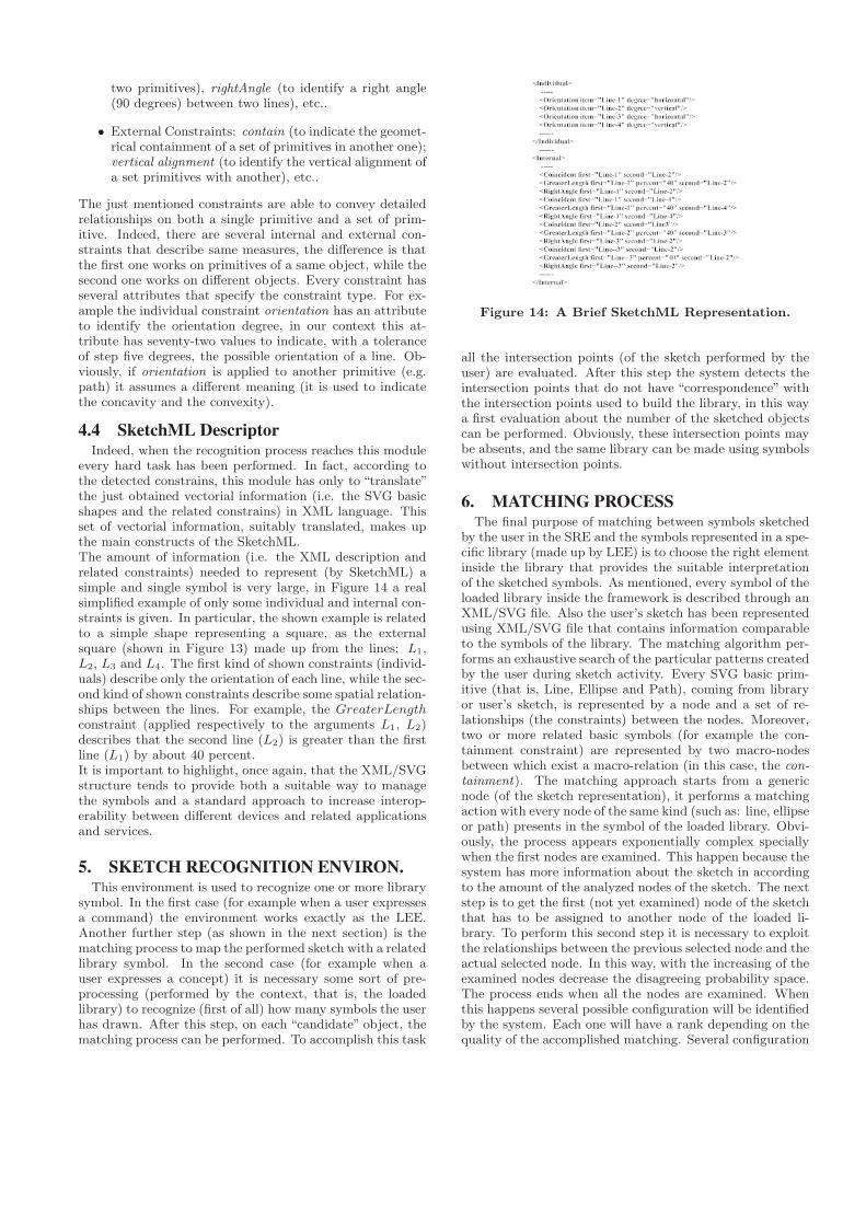
The just mentioned constraints are able to convey detailedrelationships on both a single primitive and a set of prim-itive. Indeed, there are several internal and external con-straints that describe same measures, the difference is thatthe first one works on primitives of a same object, while thesecond one works on different objects. Every constraint hasseveral attributes that specify the constraint type. For ex-ample the individual constraint orientation has an attributeto identify the orientation degree, in our context this at-tribute has seventy-two values to indicate, with a toleranceof step five degrees, the possible orientation of a line. Ob-viously, if orientation is applied to another primitive (e.g.path) it assumes a different meaning (it is used to indicatethe concavity and the convexity).
4.4 SketchML DescriptorIndeed, when the recognition process reaches this module
every hard task has been performed. In fact, according tothe detected constrains, this module has only to “translate”the just obtained vectorial information (i.e. the SVG basicshapes and the related constrains) in XML language. Thisset of vectorial information, suitably translated, makes upthe main constructs of the SketchML.The amount of information (i.e. the XML description andrelated constraints) needed to represent (by SketchML) asimple and single symbol is very large, in Figure 14 a realsimplified example of only some individual and internal con-straints is given. In particular, the shown example is relatedto a simple shape representing a square, as the externalsquare (shown in Figure 13) made up from the lines: L1,L2, L3 and L4. The first kind of shown constraints (individ-uals) describe only the orientation of each line, while the sec-ond kind of shown constraints describe some spatial relation-ships between the lines. For example, the GreaterLength
constraint (applied respectively to the arguments L1, L2)describes that the second line (L2) is greater than the firstline (L1) by about 40 percent.It is important to highlight, once again, that the XML/SVGstructure tends to provide both a suitable way to managethe symbols and a standard approach to increase interop-erability between different devices and related applicationsand services.
5. SKETCH RECOGNITION ENVIRON.This environment is used to recognize one or more library
symbol. In the first case (for example when a user expressesa command) the environment works exactly as the LEE.Another further step (as shown in the next section) is thematching process to map the performed sketch with a relatedlibrary symbol. In the second case (for example when auser expresses a concept) it is necessary some sort of pre-processing (performed by the context, that is, the loadedlibrary) to recognize (first of all) how many symbols the userhas drawn. After this step, on each “candidate” object, thematching process can be performed. To accomplish this task
Figure 14: A Brief SketchML Representation.
all the intersection points (of the sketch performed by theuser) are evaluated. After this step the system detects theintersection points that do not have “correspondence” withthe intersection points used to build the library, in this waya first evaluation about the number of the sketched objectscan be performed. Obviously, these intersection points maybe absents, and the same library can be made using symbolswithout intersection points.
6. MATCHING PROCESSThe final purpose of matching between symbols sketched
by the user in the SRE and the symbols represented in a spe-cific library (made up by LEE) is to choose the right elementinside the library that provides the suitable interpretationof the sketched symbols. As mentioned, every symbol of theloaded library inside the framework is described through anXML/SVG file. Also the user’s sketch has been representedusing XML/SVG file that contains information comparableto the symbols of the library. The matching algorithm per-forms an exhaustive search of the particular patterns createdby the user during sketch activity. Every SVG basic prim-itive (that is, Line, Ellipse and Path), coming from libraryor user’s sketch, is represented by a node and a set of re-lationships (the constraints) between the nodes. Moreover,two or more related basic symbols (for example the con-tainment constraint) are represented by two macro-nodesbetween which exist a macro-relation (in this case, the con-tainment). The matching approach starts from a genericnode (of the sketch representation), it performs a matchingaction with every node of the same kind (such as: line, ellipseor path) presents in the symbol of the loaded library. Obvi-ously, the process appears exponentially complex speciallywhen the first nodes are examined. This happen because thesystem has more information about the sketch in accordingto the amount of the analyzed nodes of the sketch. The nextstep is to get the first (not yet examined) node of the sketchthat has to be assigned to another node of the loaded li-brary. To perform this second step it is necessary to exploitthe relationships between the previous selected node and theactual selected node. In this way, with the increasing of theexamined nodes decrease the disagreeing probability space.The process ends when all the nodes are examined. Whenthis happens several possible configuration will be identifiedby the system. Each one will have a rank depending on thequality of the accomplished matching. Several configuration

will have a very low rank, others will have a suitable rank-ing profitable to identify the right pattern (i.e. the rightsymbol).
7. EXPERIMENTAL RESULTSThis section shows the results obtained on a wide appli-
cation domain designed to meet the needs of heterogeneousassistive environments. In particular, the domain is madeup from several simple and complex symbols able to ex-press commands to drive different devices in any context.As shown in Table 1 the application domain was made upfrom 154 different symbols. Several symbols (e.g. arrow) canhave up to eight different orientations (North, East, South,West, Northeast, Southeast, Southwest, Northwest) each ofwhich is considered a different symbol. For each symbol, anaverage of 75 tracking were performed, for a total of 11.570tests. The involved population was made up from about 80people, of these 65% were university students between 25and 35 years old. The remaining were volunteers (e.g. em-ployees, researchers) with over 56 years old. The populationwas equally divided between males and females and it hada 15% of left-handed. All people have drawn all symbolsaccording to a given schema in which was highlighted thesymbol that had to be drawn and the related number oftimes.
The percentage of recognition on each symbol is almosttotal. Indeed, this percentage tends to be slightly loweraccording to the complexity of the symbol. In fact, for sym-bols made up from more than 7 strokes some constraintsmay be ambiguous and misinterpreted. In order to over-come this problem, it is possible to introduce in the frame-work a more complex personalization concept. This wouldallow the framework to recognize each symbol according onboth the vectorial model created by the framework duringthe user activity in LEE and some similarity criteria tied tothe way in which the user has designed the symbol. More-over, it is possible to consider a new class of constraints (i.e.control constraints) able to oversee ambiguous potentiallysituations. The framework has been also tested on moretraditional domains (i.e. entity relationship diagram, dataflow diagram, electrical schemes, and so on) providing al-ways a total level of reliability. Ultimately it is importantto highlight that the framework builds the symbol accord-ing to the user drawing. For this reason, for example, thesymbols shown in the first and fourth row of the Table 1 areconsidered different. Indeed, this is a huge advantage for
the personalization of the user libraries. Moreover, if neces-sary, can always be introduced equivalence criteria betweensymbols in order to relax the constraints.
8. CONCLUSIONSThe proposed approach provides a pragmatic sketch-based
framework able to build and to recognize every kind of 2Dgraphical library. The key point is that a user, withoutspecial knowledge, can create a personalized library simplysketching the wanted symbols. The simple and versatile lan-guage used to represent the sketch activity (SketchML) al-lows the cooperation of the proposed framework with a largenumber of devices and related applications/services. Theframework can be adapted to support also the 3D libraries(adding another category of 3D-oriented constraints).
9. REFERENCES[1] C. Alvarado and R. Davis. Dynamically constructed
bayes nets for multi-domain sketch understanding. InSIGGRAPH ’07: ACM SIGGRAPH 2007 courses,page 33. ACM, 2007.
[2] L. W. B. Peng, Y. Liu and G. Huang. Sketchrecognition based on topological spatial relationship.In Book Series in LNCS, Structural, Syntactic, andStatistical Pattern Recognition, volume 3138/2004,pages 434–443. Springer Berlin / Heidelberg, 2004.
[3] T. H. et al. Free-sketch recognition: putting the chi insketching. In CHI ’08: CHI ’08 extended abstracts onHuman factors in computing systems, pages3027–3032. ACM, 2008.
[4] V. M. G. C. G. Casella, V. Deufemia and M. Martelli.An agent-based framework for sketched symbolinterpretation. Journal of Visual Languages andComputing, 19(2):225–257, 2008.
[5] T. Hammond and R. Davis. Ladder: a language todescribe drawing, display, and editing in sketchrecognition. In SIGGRAPH ’06: ACM SIGGRAPH2006 Courses, page 27, New York, NY, USA, 2006.ACM.
[6] E. Jiang and Z. Sun. Hmm-based on-line multi-strokesketch recognition. Proceedings of the FourthInternational Conference on Machine Learning andCybernetics, 7:4564–4570, 2005.
[7] G. Sahoo and B. Singh. A new approach to sketchrecognition using heuristic. 8(2):102–108, 2008.
[8] T. Sezgin and R. Davis. Hmm-based efficient sketchrecognition. In IUI ’05: Proceedings of the 10thinternational conference on Intelligent user interfaces,pages 281–283, New York, NY, USA, 2005. ACM.
[9] T. M. Sezgin and R. Davis. Sketch recognition ininterspersed drawings using time-based graphicalmodels. Comput. Graph., 32(5):500–510, 2008.
[10] S. xia Wang, M. tun Gao, and L. hua Qi. Freehandsketching interfaces: early processing for sketchrecognition. 4551/2007:161–170, 2007.
[11] B. Yu and S. Cai. A domain-independent system forsketch recognition. In GRAPHITE ’03: Proc. of the1st intern. conf. on Computer graph. and interactivetech. in Australia and South East Asia, pages 141–146,New York, NY, USA, 2003. ACM.