
Single and Double Window Sight Glasses and Sight Check
20
Single and Double Window Sight Glasses and Sight Check Installation and Maintenance Instructions IM-S32-04 ST Issue 8 0222050/8 1. Safety information 2. General product information 3. Installation 4. Commissioning 5. Operation 6. Maintenance and Spare parts Printed in the UK © Copyright 2010 Single window sight glass Double window sight glass SG13 sight glass SG253 sight glass Sight check
-
Upload
khangminh22 -
Category
Documents
-
view
0 -
download
0
Transcript of Single and Double Window Sight Glasses and Sight Check

IM-S32-04 ST Issue 8 1
Single and Double Window Sight Glassesand Sight Check
Installation and Maintenance Instructions
IM-S32-04ST Issue 8
0222050/8
1. Safety information
2. General product information
3. Installation
4. Commissioning
5. Operation
6. Maintenance and Spare parts
Printed in the UK © Copyright 2010
Single window sight glass
Double window sight glass
SG13 sight glass
SG253sight glass
Sight check

IM-S32-04 ST Issue 82

IM-S32-04 ST Issue 8 3
1. Safety informationSafe operation of these products can only be guaranteed if they are properly installed, commissioned, used and maintained by qualified personnel (seeSection 1.11) in compliance with the operating instructions. General installation and safety instructions for pipeline and plant construction, as well as the proper use of tools and safety equipment must also be complied with.
WarningThe gaskets used in these units (with exception to the SG13) contain thin stainless steel support rings which may cause physical injury if not handled and disposed of carefully.
Under certain conditions corrosive elements in condensate can affect the inside face of the sight tube / window, particularly where caustic alkali and hydrofluoric acid are present. It is recommended that the sight glass / sight check is periodically checked for thinning of the sight tube / window. If there is evidence of thinning or erosion damage then the sight tube / window should be replaced immediately. Always wear eye protection when viewing the contents of the sight glass / sight check.
Reasonable steps should be taken to protect personnel from injury in the unlikely event that the sight tube / window breaks.
1.1 Intended useReferring to the Installation and Maintenance Instructions, name-plate and Technical Information Sheet, check that the product is suitable for the intended use / application. The products listed below comply with the requirements of the European Pressure Equipment Directive 97 / 23 / EC and carry the mark when so required. It should be noted that products rated as 'SEP' are required by the Directive not to carry the mark. The products fall within the following Pressure Equipment Directive categories:
i) These products have been specifically designed for use on steam, air or water / condensate which are in Group 2 of the above mentioned Pressure Equipment Directive. The products’ use on other fluids may be possible but, if this is contemplated, Spirax Sarco should be contacted to confirm the suitability of the product for the application being considered.
ii) Check material suitability, pressure and temperature and their maximum and minimum values. If the maximum operating limits of the product are lower than those of the system in which it is being fitted, or if malfunction of the product could result in a dangerous overpressure or overtemperature occurrence, ensure a safety device is included in the system to prevent such over-limit situations.
iii) Determine the correct installation situation and direction of fluid flow.
Group 1 Group 2 Group 1 Group 2 Product Gases Gases Liquids Liquids
Single window sight glass DN10 - DN25 - SEP - SEP
Double window sight glass DN15 - DN50 - SEP - SEP
SG253 sight glass DN15 - DN40 - SEP - SEP
DN50 - 1 - SEP
SG13 sight glass DN15 - DN25 - SEP - SEP
Spirax Hills sight check DN15 - DN25 - SEP - SEP
IM-S32-04 ST Issue 84
iv) Spirax Sarco products are not intended to withstand external stresses that may be induced by any system to which they are fitted. It is the responsibility of the installer to consider these stresses and take adequate precautions to minimise them.
v) Remove protection covers from all connections and protective film from all name-plates, where appropriate, before installation on steam or other high temperature applications.
1.2 AccessEnsure safe access and if necessary a safe working platform (suitably guarded) before attempting to work on the product. Arrange suitable lifting gear if required.
1.3 LightingEnsure adequate lighting, particularly where detailed or intricate work is required.
1.4 Hazardous liquids or gases in the pipelineConsider what is in the pipeline or what may have been in the pipeline at some previous time. Consider: flammable materials, substances hazardous to health, extremes of temperature.
1.5 Hazardous environment around the productConsider: explosion risk areas, lack of oxygen (e.g. tanks, pits), dangerous gases, extremes of temperature, hot surfaces, fire hazard (e.g. during welding), excessive noise, moving machinery.
1.6 IsolationConsider the effect on the complete system of the work proposed. Will any proposed action (e.g. closing isolation valves, electrical isolation) put any other part of the system or any personnel at risk? Dangers might include isolation of vents or protective devices or the rendering ineffective of controls or alarms. Ensure isolation valves are turned on and off in a gradual way to avoid system shocks.
1.7 Pressure Before attempting any maintenance consider what is or may have been in the pipeline. Ensure that any pressure is isolated and safely vented to atmospheric pressure before attempting to maintain the product, this is easily achieved by fitting Spirax Sarco depressurisation valves type DV (see separate literature for details) and consider double isolation (double block and bleed) and the locking or labelling of closed valves. Do not assume that the system is depressurised even when a pressure gauge indicates zero.

IM-S32-04 ST Issue 8 5
1.8 TemperatureAllow time for temperature to normalise after isolation to avoid the danger of burns and consider whether protective clothing (including safety glasses) is required.
PTFE (SG13 - sight tube gasket):If parts made from PTFE have been subjected to a temperature approaching 260°C (500°F) or higher, they will give off toxic fumes, which if inhaled are likely to cause temporary discomfort. It is essential for a no smoking rule to be enforced in all areas where PTFE is stored, handled or processed as persons inhaling the fumes from burning tobacco contaminated with PTFE particles can develop 'polymer fume fever'.
1.9 Tools and consumablesBefore starting work ensure that you have suitable tools and/or consumables available. Use only genuine Spirax Sarco replacement parts.
1.10 Protective clothingConsider whether you and/or others in the vicinity require any protective clothing to protect against the hazards of, for example, chemicals, high / low temperature, radiation, noise, falling objects, and dangers to eyes and face.
1.11 Permits to workAll work must be carried out or be supervised by a suitably competent person.Installation and operating personnel should be trained in the correct use of the product according to the Installation and Maintenance Instructions.Where a formal 'permit to work' system is in force it must be complied with. Where there is no such system, it is recommended that a responsible person should know what work is going on and, where necessary, arrange to have an assistant whose primary responsibility is safety.Post 'warning notices' if necessary.
1.12 HandlingManual handling of large and/or heavy products may present a risk of injury. Lifting, pushing, pulling, carrying or supporting a load by bodily force can cause injury particularly to the back. You are advised to assess the risks taking into account the task, the individual, the load and the working environment and use the appropriate handling method depending on the circumstances of the work being done.

IM-S32-04 ST Issue 86
1.13 Residual hazardsIn normal use the external surface of the product may be very hot. If used at the maximum permitted operating conditions the surface temperature of some products may reach temperatures of 100°C (212°F).Many products are not self-draining. Take due care when dismantling or removing the product from an installation (refer to 'Maintenance instructions').
1.14 FreezingProvision must be made to protect products which are not self-draining against frost damage in environments where they may be exposed to temperatures below freezing point.
1.15 DisposalUnless otherwise stated in the Installation and Maintenance Instructions, these products are recyclable and no ecological hazard is anticipated with their disposal providing due care is taken, except:
PTFE (SG13 - sight tube gasket):- Waste parts can only be disposed of by approved methods, not incineration.
- Keep PTFE waste in a separate container, do not mix it with other rubbish, and consign it to a landfill site.
1.16 Returning productsCustomers and stockists are reminded that under EC Health, Safety and Environment Law, when returning products to Spirax Sarco they must provide information on any hazards and the precautions to be taken due to contamination residues or mechanical damage which may present a health, safety or environmental risk. This information must be provided in writing includingHealth and Safety data sheets relating to any substances identified as hazardous or potentially hazardous.

IM-S32-04 ST Issue 8 7
�
��
���
���
� � � � � �
���
���
���� ���� �� �� �� �� ��
Pressure bar g
Tem
per
atur
e °C
Steam saturation curve
2. General product information2.1 Single window and double window sight glassesGeneral descriptionA range of single and double window sight glasses having screwed connections available in either brass or bronze depending on size.
Note: For additional information see the following Technical Information Sheet TI-P022-05.
Fig. 1 Single window sight glass
Fig. 2 Double window sight glass
Sizes and pipe connectionsSingle window ", ½", ¾" and 1" screwed BSP or NPT
Double window ½", ¾", 1" 1½" and 2" screwed BSP or NPT
Pressure / temperature limits
The product must not be used in this region.
Body design conditions PN5
PMA Maximum allowable pressure 5 bar g @ 90°C (72.5 psi g @ 194°F)
TMA Maximum allowable temperature 148°C @ 3.5 bar g (298.4°F @ 50.75 psi g)
Minimum allowable temperature -29°C (-20.2°F)
PMO Maximum operating pressure for saturated steam service
3.5 bar g (50.75 psi g)
TMO Maximum operating temperature 148°C @ 3.5 bar g (298.4°F @ 50.75 psi g)
Minimum operating temperature 0°C (32°F)Note: For lower temperatures consult Spirax Sarco.
Designed for a maximum cold hydraulic test pressure of: 7 bar g (101.5 psi g)
PTMX Maximum test pressure (steam service) 3.5 bar g (50.75 psi g)
Pressure psi g
Temp
erature °F

IM-S32-04 ST Issue 88
��
��
���
���
���
� � � � �� �� �� ��
� �� ��� ��� ���
���
���
���
Pressure bar g
Tem
per
atur
e °C
Steam saturation curve
2.2 SG13 sight glass
General descriptionThe SG13 is a maintainable brass multi-window sight glass with a cylindrical viewing window and screwed connections. The sight glass monitors the discharge downstream of steam traps in pressurised condensate return lines. It is screwed directly into the steam trap providing a modular monitoring system, thus eliminating the need for a connecting nipple, minimising joints and potential leak paths.The sight glass can also be installed in process lines to provide a visual indication of flow.Note: For additional information see the following Technical Information Sheet TI-P130-11.
Fig. 3 SG13 sight glass
The product must not be used in this region.
Sizes and pipe connections½", ¾" and 1" screwed BSP male taper / female parallel to BS 21 or ½", ¾" and 1" screwed NPT male / female to ASME (ANSI) B 1.20.1.
Pressure / temperature limits
Body design conditions PN16
PMA Maximum allowable pressure 16 bar g @ 130°C (232 psi g @ 266°F)
TMA Maximum allowable temperature 200°C @ 13.5 bar g (392°F @ 195.8 psi g)
Minimum allowable temperature -20°C (-4°F)
PMO Maximum operating pressure for saturated steam service 13 bar g (188.5 psi g)
TMO Maximum operating temperature 200°C @ 13.5 bar g (392°F @ 195.8 psi g)
Minimum operating temperature 0°C (32°F)Note: For lower temperatures consult Spirax Sarco.
Designed for a maximum cold hydraulic test pressure of: 24 bar g (348 psi g)
PTMX Maximum test pressure (steam service) 13 bar g (188.5 psi g)
Pressure psi g
Temp
erature °F

IM-S32-04 ST Issue 8 9
2.3 SG253 sight glass
General descriptionThe SG253 is an SG iron double window sight glass with flanged connections.Note: For additional information see the following Technical Information Sheet TI-P130-01.
Fig. 4 SG253 sight glass
��
���
���
���
� �� �� �� ��
� ��� ��� ���
���
���
���
���
���
Pressure bar g
Tem
per
atur
e °C
BC
The product must not be used in this region.
A - B Flanged EN 1092 PN25. A - C Flanged BS 1560 ASME (ANSI) Class 150.
Body design conditions PN25 and ASME (ANSI) 150
PMA Maximum allowable PN25 25 bar g @ 100°C (362.5 psi g @ 212°F) pressure ASME 150 17.2 bar g @ 35°C (249.5 psi g @ 95°F)
TMA Maximum PN25 280°C @ 18 bar g (536°F @ 261 psi g) allowable temperature ASME 150 280°C @ 10 bar g (536°F @ 145 psi g)Minimum allowable temperature -10°C (14°F)
PMO Maximum operating pressure PN25 21 bar g (304.5 psi g) for saturated steam service ASME 150 13.8 bar g (200.1 psi g) TMO Maximum operating temperature 280°C @ 18 bar g (536°F @ 261 psi g)
Minimum operating temperature 0°C (32°F)Note: For lower temperatures consult Spirax Sarco.
Designed for a maximum PN25 38 bar g (551 psi g)cold hydraulic test pressure of: ASME 150 30 bar g (435 psi g)
PTMX Maximum test pressure PN25 21 bar g (304.5 psi g)
(steam service) ASME 150 13.8 bar g (200.1 psi g)
A
Steam saturation curve
Sizes and pipe connectionsDN15, DN20, DN25, DN32, DN40 and DN50.Flanged EN 1092 PN25 and BS 1560 ASME (ANSI) B 1.20.1.
Pressure / temperature limitsPressure psi g
Temp
erature °F

IM-S32-04 ST Issue 810
2.4 Sight check
General descriptionA sight check is a combined sight glass and check valve. It is used to observe discharges from steam traps. The position of the ball check indicates whether or not condensate is flowing. Where condensate rises after the trap it eliminates the need for a separate check valve thus simplifying installation.It is particularly useful for commissioning steam traps fitted with a steam lock release (SLR) unit.It can also be used on other liquid lines where the materials of construction are compatible.Note: For additional information see the following Technical Information Sheet TI-P022-01.
Fig. 5 Sight check
�
��
���
���
� � � � ���
� �� �� �� �� ��
���
������
���
��
Pressure bar g
Tem
per
atur
e °C
Steam saturation curve
The product must not be used in this region.
Sizes and pipe connections½", ¾" and 1" screwed BSP or NPT.
Pressure / temperature limits
Body design conditions PN3.6
PMA Maximum allowable pressure 3.5 bar g @ 148°C (50.75 psi g @ 295.6°F)
TMA Maximum allowable temperature 148°C @ 3.5 bar g (294.8°F 50.25 psi g)
Minimum allowable temperature -10°C (14°F)
PMO Maximum operating pressure for saturated steam service 3.5 bar g (50.75 psi g)
TMO Maximum operating temperature 148°C 3.5 bar g (295.6°F @ 50.75 psi g)
Minimum operating temperature 0°C (32°F)Note: For lower temperatures consult Spirax Sarco.
Designed for a maximum cold hydraulic test pressure of: 7 bar g (101.5 psi g)
PTMX Maxiumum test pressure (steam service) 3.5 bar g (50.75 psi g)
Pressure psi g
Temp
erature °F

IM-S32-04 ST Issue 8 11
After installation or maintenance ensure that the system is fully functional. Carry out tests on any alarms or protective devices.
Note: Before actioning any installation observe the 'Safety information' in Section 1.
WarningUnder certain conditions corrosive elements in condensate can affect the inside face of the sight tube / window, particularly where caustic alkali and hydrofluoric acid are present. It is recommended that the sight glass / sight check is periodically checked for thinning of the sight tube / window. If there is evidence of thinning or erosion damage then the sight tube / window should be replaced immediately. Always wear eye protection when viewing the contents of the sight glass / sight check.
Reasonable steps should be taken to protect personnel from injury in the unlikely event that the sight tube / window breaks.
Sight glasses and sight checks can be fitted in either a horizontal or vertical line (flow upwards only for sight check) on the outlet side of a steam trap. Where the trap is a blast discharge type e.g. thermodynamic, the sight glass and sight check must be fitted at least 1 m (3 ft) from the trap. This is to ensure that the glass is not subjected to thermal shock or pressure. Reasonable steps should be taken to protect personnel from injury in the unlikely event that the glass breaks. Ensure access is available for maintenance purposes.
4. Commissioning
3. Installation
5.1 Sight glassesThe sight glass has a smooth concentric reduction in the inlet connection which promotes turbulence in the sight glass when the fluid is passing through it. The turbulent flow inside the sight glass permits any fluid to be detected.Sight glasses can be used to detect blocked valves, strainers, steam traps and other pipeline equipment. Sight glasses can also be used for inspection purposes, i.e. to compare the colour of the fluid at different stages of the process, enabling adjustments to be made quickly and effectively.The SG13 cylinder view can be screwed directly into the steam trap it is monitoring to form a modular steam trap arrangement.
5.2 Sight checksThe sight check is a sight glass and check valve combination in one unit. A ball in the top of the flow tube is lifted off its seat by the fluid as it flows through the cylindrical window to the outlet connection. The ball movement makes the flow easy to see yet provides shut-off on reverse flow.
5. Operation

IM-S32-04 ST Issue 812
6. Maintenance and Spare parts6.1 Single window and double window sight glasses
Note: Before actioning any maintenance programme observe the 'Safety information' in Section 1.
How to renew the window(s) and gaskets:- Isolate the sight glass and allow the pressure and temperature to reduce to ambient conditions.
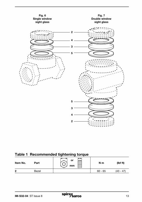
- After isolation unscrew the bezel(s) (2) and remove old gaskets (4 and 5) and window(s) (3).
- Carefully clean the recess.
- Refit new gaskets and window(s), ensuring that a gasket (4) is fitted to either side of each window (3).
- Replace the bezel(s) and tighten to the recommended torque (see Table 1).
- After maintenance has been completed, isolation valves should opened slowly to allow pressure and temperature to build up in a controlled manner.
- Check for leaks.
6.2 Spare parts (for the single window and double window sight glasses) The spare parts available are shown in solid outline. Parts drawn in broken line are not supplied as spares.
Available sparesSet of windows and gaskets 3, 4, 5
Set of gaskets 4, 5
How to order sparesAlways order spares by using the description given in the column headed 'Available spares' and state the size and type of sight glass.
Example: 1 off Set of windows and gaskets for a Spirax Sarco 1" double window sight glass.
IM-S32-04 ST Issue 8 13
Table 1 Recommended tightening torque
Item No. Part or
N m (lbf ft)
mm
2 Bezel 60 - 65 (43 - 47)
Fig. 6Single window
sight glass
Fig. 7Double window
sight glass
4
3
5
2
3
4
2
5

IM-S32-04 ST Issue 814
6.3 SG253 sight glass
Note: Before actioning any maintenance programme observe the 'Safety information' in Section 1.
How to renew the windows and gaskets:- Isolate the sight glass and allow the pressure and temperature to reduce to ambient conditions.
- After isolation unscrew the cover bolts (5) and remove the old gaskets (4) and windows (3).
- Carefully clean the recess.
- Refit new gaskets and windows, ensuring that a gasket (4) is fitted to either side of each window (3).
- Replace the covers (2) and cover bolts (5) and tighten to the recommended torque (see Table 2).
- After maintenance has been completed, isolation valves should opened slowly to allow pressure and temperature to build up in a controlled manner.
- Check for leaks.
6.4 Spare parts (for the SG253 sight glass)The spare parts available are shown in solid outline. Parts drawn in broken line are not supplied as spares.
Available sparesSet of windows and gaskets 3, 4
Please note: For the DN25 and DN32 sizes a set of bolts (16 A/F M10 x 40) is also included due to the increased thickness of the glass.
Set of gaskets 4
How to order sparesAlways order spares by using the description given in the column headed 'Available spares' and state the size and type of the sight glass.
Example: 1 off Set of windows and gaskets for a Spirax Sarco DN15 SG253 sight glass.

IM-S32-04 ST Issue 8 15
5(not an available spare)
4
3
4
4
3
4
Fig. 8SG253 sight glass
2
2
Recommended tightening torques
or
Item Part N m (lbf ft)
mm
DN15 - DN20 17 A / F M10 x 30 12 (8.6)
5
DN25 - DN32 Pre 08-2010: 17 A / F M10 x 35
28 (20.6) Post 08-2010: 16 A / F M10 x 40
DN40 - DN50 19 A / F M12 x 40 38 (28.0)
5(not an available spare)

IM-S32-04 ST Issue 816
6.5 SG13 sight glass
Note: Before actioning any maintenance programme observe the 'Safety information' in Section 1.
How to renew the sight tube and gaskets:- Isolate the sight glass and allow the pressure and temperature to reduce to ambient conditions.
- After isolation remove the SG13 sight glass from the pipeline.
- Unscrew the end connection from the body (2) and remove the sight tube (4).
- Take out the old gaskets (3) taking care not to damage the seating face and carefully clean out the recesses.
- Fit the new gaskets (3) supplied with sight tube (4) (see Section 6.6, Spare parts).
- Ensure the sight tube (4) is aligned correctly within the body. Then tighten the end connection (2) to the recommended torque (see Table 3). Note: Misalignment of the sight tube (4) within the body may cause the edge of the glass to fracture.
- Refit the sight glass into the pipeline.
- After maintenance has been completed, isolation valves should opened slowly to allow pressure and temperature to build up in a controlled manner.
- Check for leaks.
6.6 Spare parts (for the SG13 sight glass)The spare parts available are shown in solid outline. Parts drawn in broken line are not supplied as spares.
Available spare Sight glass assembly 3 (2 off), 4
How to order spares Always order spares by using the description given in the column headed 'Available spare'. Since the sight glass assembly is the same for all three sizes, it will always be:-
Example: 1 off Sight glass assembly for a Spirax Sarco SG13 sight glass.

IM-S32-04 ST Issue 8 17
Table 3 Recommended tightening torques
Item No. Part or
N m (lbf ft)
mm
½" - DN15 32 A/F 35 - 40 (25 - 29)
2 ¾" - DN20 36 A/F 35 - 40 (25 - 29)
1" - DN25 46 A/F 35 - 40 (25 - 29)
3 4 3 2Fig. 9SG13 sight glass

IM-S32-04 ST Issue 818
6.7 Sight check
Note: Before actioning any maintenance programme observe the 'Safety information' in Section 1.
How to renew the sight tube:- Isolate the sight check and allow the pressure and temperature to reduce to ambient conditions.
- After isolation remove the bolt and washers (7 and 8).
- Remove the cover (6).
- Take out the old gaskets (2) and the sight tube (3) and carefully clean out the recesses.
- Fit the new gaskets (2) supplied with sight tube (3) and reassemble. Tighten the bolts evenly to the recommended torque, ensuring the ends of the sight tube are centralised on the gaskets (see Table 4).
- It is advisable to do up the bolts little more than finger tight, retightening as necessary after a period of use to the recommended tightening torque (see Table 4).
- After maintenance has been completed, isolation valves should opened slowly to allow pressure and temperature to build up in a controlled manner.
- Check for leaks.
How to renew the discharge tube:- Remove the cover (6) and the sight tube (3) the same way as 'To renew sight tube' above, and lift out the ball check (5).
- Using the notches, carefully unscrew the old discharge tube (4) and fit a new one.
- Renew the gaskets (2), fit a new ball check (5) and reassemble. Tighten the bolts evenly to the recommended torque, ensuring the ends of the sight tube are centralised on the gaskets (see Table 4).
- After maintenance has been completed, isolation valves should opened slowly to allow pressure and temperature to build up in a controlled manner.
- Check for leaks.

IM-S32-04 ST Issue 8 19
6.8 Spare parts (for the sight check)The spare parts available are shown in solid outline. Parts drawn in broken line are not supplied as spares.
Available spares Sight tube assembly 2 (2 off), 3 (1 off)
Discharge tube assembly (set of 2) 4, 5Set of bolts and washers (set of 4*) 7, 8 Gasket set (packet of 6†) 2
Available spares are common to ½" and ¾" sizes, but not 1".
Note:* Earlier models used studs, nuts and washers and these are contained in the set of bolts pack.† Earlier models used ethylene propylene gaskets which were considerably thicker than graphite laminate.
How to order sparesAlways order spares by using the description given in the column headed 'Available spares' and state the size of the sight check.Example: 1 off Sight tube assembly for a Spirax Sarco ½" sight check.
2
Sight tube assembly
Discharge tube assembly
54
3
8 7
2
Fig. 10Sight check
6
Table 4 Recommended tightening torques
Item No. Part or
N m (lbf ft)
mm
7 ½", ¾" and 1" 10 A/F M6 x 65 1.8 - 2.2 (1.3 - 1.6)
4 ½" and ¼" 9/16" x 26 BSW 5 - 6 (3.6 - 4.3)
1" 7/8" x 20 UNF 5 - 6 (3.6 - 4.3)

IM-S32-04 ST Issue 820