Singer 29K71, 72, 73.pdf - Superior Sewing Machine & Supply ...
52
From the library of: Superior Sewing Machine & Supply LLC
-
Upload
khangminh22 -
Category
Documents
-
view
1 -
download
0
Transcript of Singer 29K71, 72, 73.pdf - Superior Sewing Machine & Supply ...
From the library of: Superior Sewing Machine & Supply LLC
1
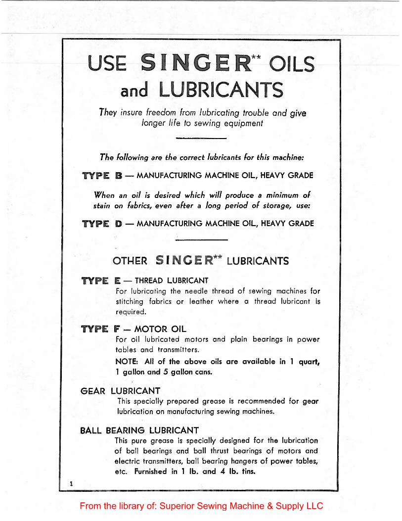
USE SI GER** OILS and LUBRICANTS
They insure freedom from lubricating trouble and give longer life to sewing equipment
The following are the correct lubricants lor this machine:
TYPE B - MANUFACTURING MACHINE OIL, HEAVY GRADE
When an oil is desired which will produce a minimum of stain on fabrics, even alter a long period of storage, use:
TYPE D - MANUFACTURING MACHINE OIL, HEAVY GRADE
OTI-I£:R 5 I N Ci E R** LUBRICANTS
TYPE E - THREAD LUBRICANT For lubricating the needle thread of sewing machines for stitching fabrics or leather where a thread lubricant is required.
TYPE F - MOTOR OIL For oil lubricated motors and plain bearings in power tables and transmitters.
NOTE: All of the above oils are available in 1 quart, 1 gallon and 5 gallon cans.
GEAR LUBRICANT This specially prepared grease is recommended for gear lubrication on manufacturing sewing machines.
BALL BEARING LUBRICANT This pure grease is specially designed for the lubrication of ball bearings and ball thrust bearings of motors and electric transmitters, ball bearing hangers of power tables, etc. Furnished in 1 lb. and 4 lb. tins.
From the library of: Superior Sewing Machine & Supply LLC

Form 20870 ·--(957)
SERVICE MANUAL AND
PARTS LIST FOR
SINGER**
29K71, 29K72 and 29K73
UNIVERSAL UPPER FEED MACHINES
SINCLE NEEDLE LOCK STITCH
THE SINGER MANUFACTURING COMPANY Copyright© 1958 by The Singer Manufacturing Company·
**A Trademark of THE SINGER MANUFACTURING COMPANY
Printed in U.~.S.A"--. _
From the library of: Superior Sewing Machine & Supply LLC
FOREWORD
This book contains complete information covering operation, adjustment,
and parts list, for Machines 29K71, 29K72 and 29K73. Descriptions and exploded
views of all parts assemblies on pages 17 to 44 inclusive, will be found helpful
when ordering any part of the machine requiring renewal.
From the library of: Superior Sewing Machine & Supply LLC
3
DESCRIPTION
Machines 29K71, 29K72 and 29K73, for stitching boots, shoes, and other tubular work in leather and
fabrics, have the following characteristics:
Single Needle, Lock Stitch.
Stop Motion Hand Wheel - releases hand wheel from stitching mechanism for bobbin winding.
Horizontal Oscillating Shuttle.
Eccentric Adjustment for Shuttle Timing.
Cylinder Bed.
Replaceable Steel Horn.
Universal Upper Feed for Stitching in any direction without turning the work.
Stitch Length: 7 to 15 to the inch, depending on material being stitched and operations performed.
Presser Foot rise during feeding action: 1 I 4 inch - (Maximum clearance: 318 inch).
Double End Needle Plate - (two sizes of needle holes at each end for various sizes of needles).
Adjustable Thread Take-up Lever.
Two Speed Machine Pulley.
ACCESSORIES AVAILABLE UPON ORDER
(at additional charge)
Attachment for fitting Hand Wheel on front of machine (Part No. 82121 ).
. . {601405 or 601407 for foot power. Stand for mountmg the mach me
601406 601408 f
1 .
or ore ectnc power.
Detachable Work Table for flat stitching operations (Part No. 83739, 83740, or 83741).
Electric Transmitter S-9.
SPECIAL FEATURES
MACHINE 29K71
End of cylinder bed is 1 inch wide and 7/ 8 inch deep.
Space at right of needle 12-1 I 4 inches.
Diameters of belt grooves 2-718 inches and 4-7/ 8 inches.
MACHINE 29K72
End of cylinder bed is 1-51 32 inches wide and 1-1 I 16 inches deep.
Space at right of needle 17-1 / 2 inches.
Diameters of belt grooves 3-1 I 4 inches and 5-1 / 2 inches.
Large Bobbin.
MACHINE 29K73
End of cylinder bed is 1 inch wide and 7/ 8 inch deep.
Space at right of needle 17-1 12 inches.
Diameters of belt grooves 3-1 I 4 inches and 5-1 1 2 inches.
From the library of: Superior Sewing Machine & Supply LLC
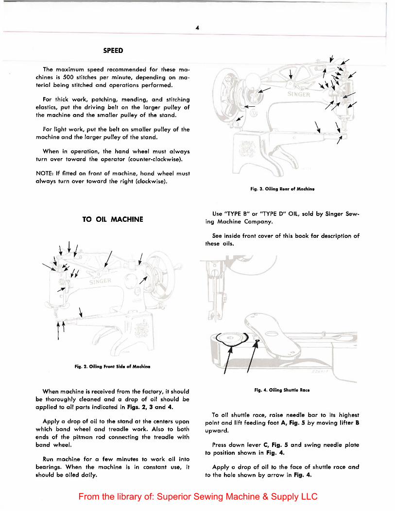
SPEED
The maximum speed recommended for these machines is 500 stitches per minute, depending on material being stitched and operations performed.
For thick work, patching, mending, and stitching elastics, put the driving belt on the larger pulley of the machine and the smaller pulley of the stand.
For light work, put the belt on smaller pulley of the machine and the larger pulley of the stand.
When in operation, the hand wheel must always turn over toward the operator (counter-clockwise).
NOTE: If fitted on front of machine, hand wheel must always turn over toward the right (clockwise).
TO OIL MACHINE
I
Fig. 2. Oiling Front Side of Machine
When machine is received from the factory, it should be thoroughly cleaned and a drop of oil should be applied to all parts indicated in Figs. 2, 3 and 4.
Apply a drop of oil to the stand at the centers upon which band wheel and treadle work. Also to both ends of the pitman rod connecting the treadle with band wheel.
Run machine for a few minutes to work oil into bearings. When the machine is in constant use, it should be oiled daily.
\
Fig. 3. Oiling Rear of Machine
\ I
Use "TYPE B" or "TYPE D" Oil, sold by Singer Sewing Machine Company.
See inside front cover of this book for description of these oils.
Fig. 4. Oiling ShuHie Race
To oil shuttle race, raise needle bar to its highest point and lift feeding foot A, Fig. 5 by moving lifter B upward.
Press down lever C, Fig. 5 and swing needle plate to position shown in Fig. 4.
Apply a drop of oil to the face of shuttle race and to the hole shown by arrow in Fig. 4.
_j
From the library of: Superior Sewing Machine & Supply LLC
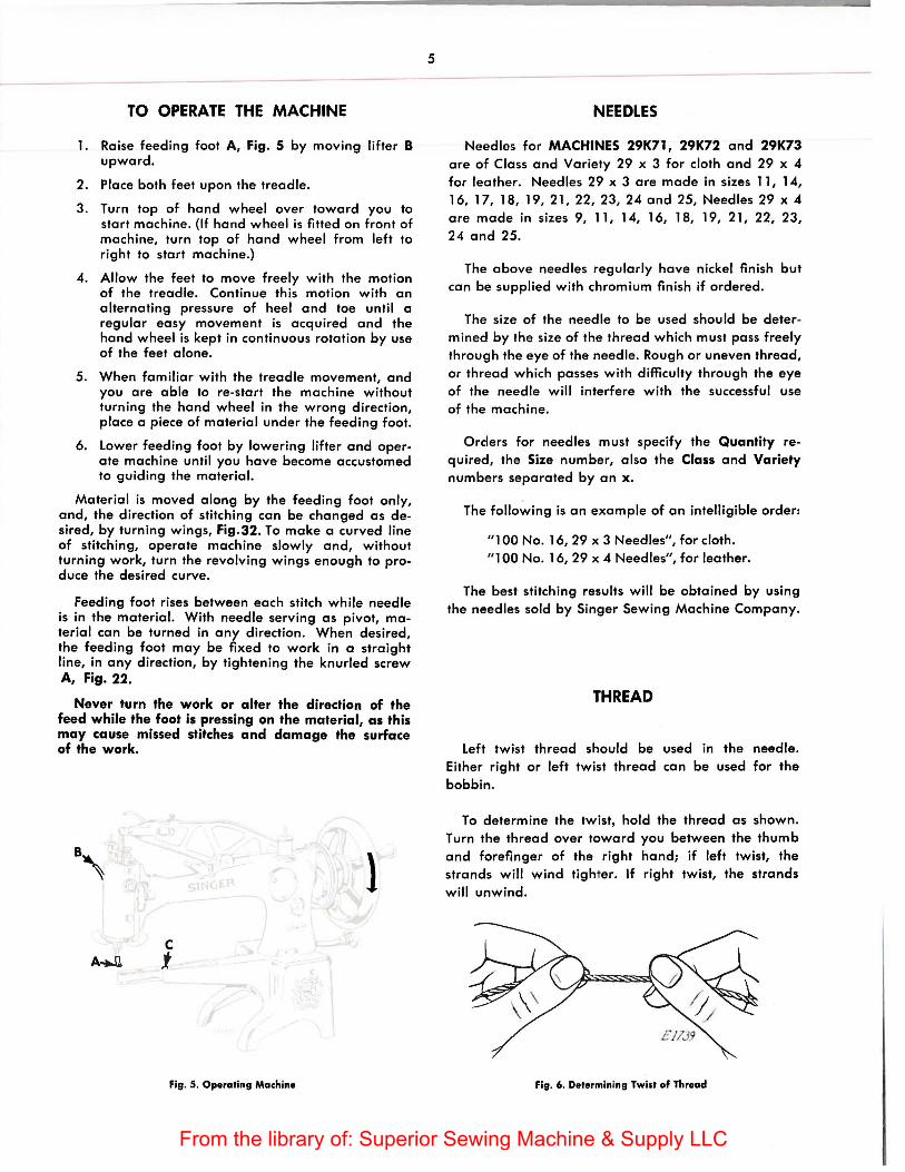
TO OPERATE THE MACHINE
1. Raise feeding foot A, Fig. S by moving lifter B upward.
2. Place both feet upon the treadle.
3. Turn top of hand wheel over toward you to start machine. (If hand wheel is fitted on front of machine, turn top of hand wheel from left to right to start machine.)
4. Allow the feet to move freely with the motion of the treadle. Continue this motion with an alternating pressure of heel and toe until a regular easy movement is acquired and the hand wheel is kept in continuous rotation by use of the feet alone.
5. When familiar with the treadle movement, and you are able to re-start the machine without turning the hand wheel in the wrong direction, place a piece of material under the feeding foot.
6. Lower feeding foot by lowering lifter and operate machine until you have become accustomed to guiding the material.
Material is moved along by the feeding foot only, and, the direction of stitching can be changed as desired, by turning wings, Fig.32. To make a curved line of stitching, operate machine slowly and, without turning work, turn the revolving wings enough to produce the desired curve.
Feeding foot rises between each stitch while needle is in the material. With needle serving as pivot, material can be turned in any direction. When desired, the feeding foot may be fixed to work in a straight line, in any direction, by tightening the knurled screw A, Fig. 22.
Never turn the work or alter the direction of the feed while the foot is pressing on the material, as this may cause missed stitches and damage the surface of the work.
l c
A....U j
Fig. 5. Operating Machine
5
NEEDLES
Needles for MACHINES 29K71, 29K72 and 29K73 are of Class and Variety 29 x 3 for cloth and 29 x 4 for leather. Needles 29 x 3 are made in sizes 11, 14, 16, 17, 18, 19, 21, 22, 23, 24 and 25, Needles 29 x 4 are made in sizes 9, 11, 14, 16, 18, 19, 21, 22, 23, 24 and 25.
The above needles regularly have nickel finish but can be supplied with chromium finish if ordered.
The size of the needle to be used should be determined by the size of the thread which must pass freely through the eye of the needle. Rough or uneven thread, or thread which passes with difficulty through the eye of the needle will interfere with the successful use of the machine.
Orders for needles must specify the Quantity required, the Size number, also the Class and Variety numbers separated by an x.
The following is an example of an intelligible order:
"1 00 No. 16, 29 x 3 Needles", for cloth. "1 00 No. 16, 29 x 4 Needles", for leather.
The best stitching results will be obtained by using the needles sold by Singer Sewing Machine Company.
THREAD
Left twist thread should be used in the needle. Either right or left twist thread can be used for the bobbin.
To determine the twist, hold the thread as shown. Turn the thread over toward you between the thumb and forefinger of the right hand; if left twist, the strands will wind tighter. If right twist, the strands will unwind.
Fig. 6. Determining Twist of Thread
From the library of: Superior Sewing Machine & Supply LLC
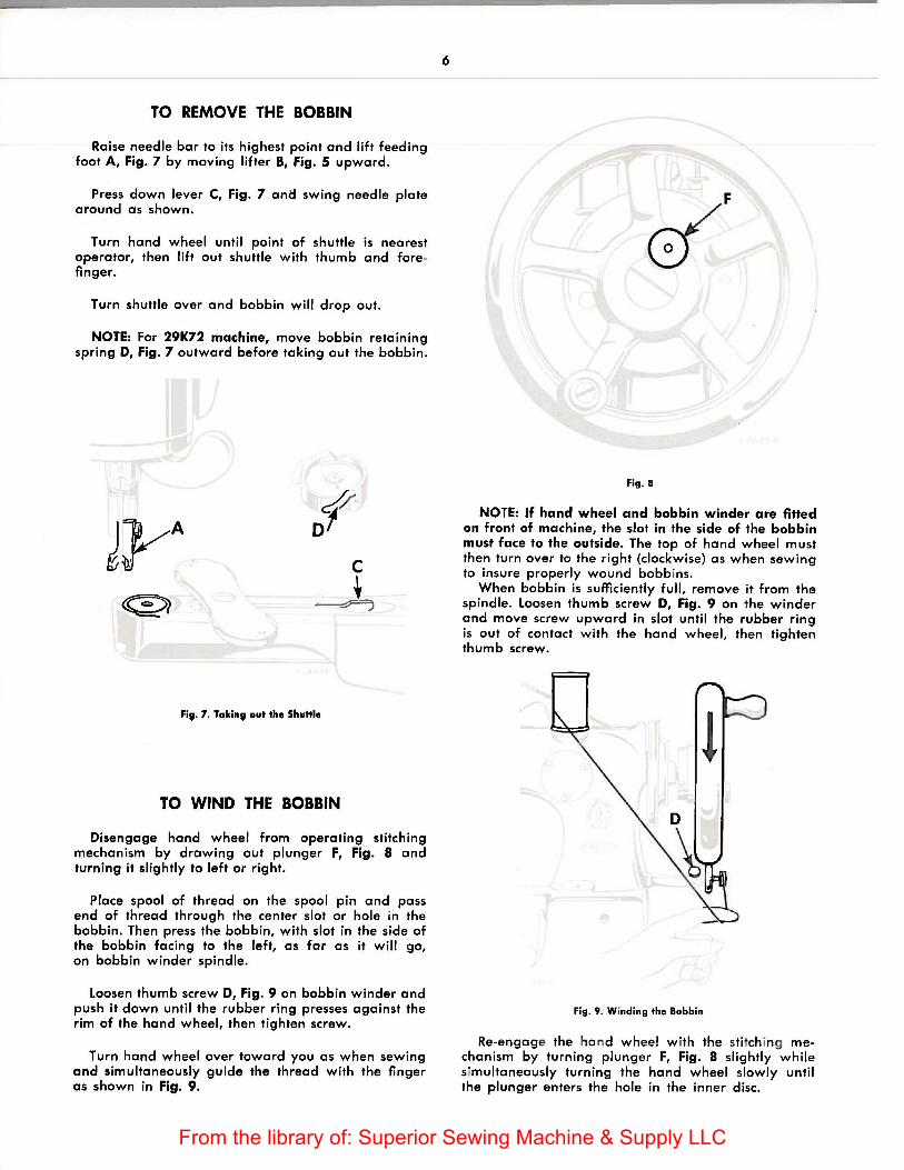
TO REMOVE THE BOBBIN
Raise needle bar to its highest point and lift feeding foot A, Fig. 7 by moving lifter B, Fig. 5 upward.
Press down lever C, Fig. 7 ana swing needle plate around as shown.
Turn hand wheel until point of shuttle is nearest operator, then lift out shuttle with thumb and forefinger.
Turn shuttle over and bobbin will drop out.
NOTE: For 29K72 machine, move bobbin retaining spring D, Fig. 7 outward before taking out the bobbin.
of' c
J,
Fie. 7. Takine out the Shuttle
TO WIND THE BOBBIN
Disengage hand wheel from operating stitching mechanism by drawing out plunger F, Fig. 8 and turning it slightly to left or right.
Place spool of thread on the spool pin and pass end of thread through the center slot or hole in the bobbin. Then press the bobbin, with slot in the side of the bobbin facing to the left, as far as it will go, on bobbin winder spindle.
loosen thumb screw D, Fig. 9 on bobbin winder and push it down until the rubber ring presses against the rim of the hand wheel, then tighten screw.
Turn hand wheel over toward you as when sewing and simultaneously guide the thread with the finger as shown in Fig. 9.
6
if'F
Fig. 8
NOTE: If hand wheel and bobbin winder are fitted on front of machine, the slot in the side of the bobbin must face to the outside. The top of hand wheel must then turn over to the right (clockwise) as when sewing to insure properly wound bobbins.
When bobbin is sufficiently full, remove it from the spindle. loosen thumb screw D, Fig. 9 on the winder and move screw upward in slot until the rubber ring is out of contact with the hand wheel, then tighten thumb screw.
Fig. 9. Winding the Bobbin
Re-engage the ha nd wheel w ith the sti tch ing mechanism by turning plunger F, Fig. 8 slightly while simultaneously turning the hand wheel slowly until the plunger enters the hole in the inne r disc.
From the library of: Superior Sewing Machine & Supply LLC
7
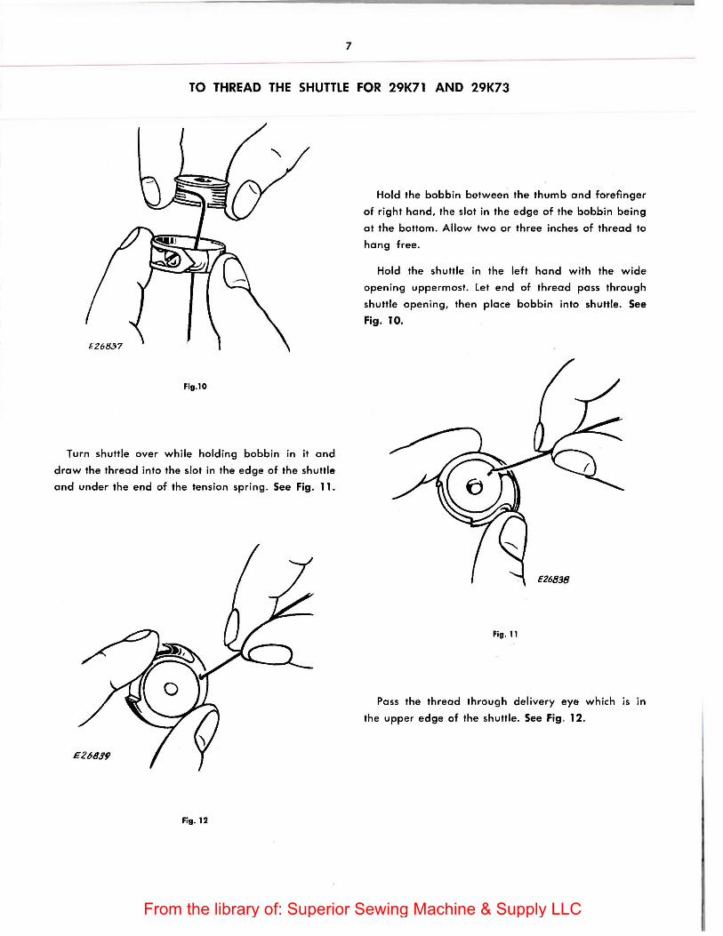
TO THREAD THE SHUTTLE FOR 29K71 AND 29K73
Fig.10
Turn shuttle over wh ile holding bobbin in it end
drew the thread into the slot in the edge of the shuttle
end under the end of the tension spring . See Fig. 11.
Fig. 12
Hold the bobbin between the thumb end forefinger
of right hond, the slot in the edge of the bobbin being
at the bottom. Allow two or three inches of thread to
hong free .
Hold the shuttle in the left hand with the wide
opening uppermost. Let end of thread pass through
shuttle opening, then place bobbin into shuttle. See
Fig. 10.
Fig. 11
Poss the thread through delivery eye which is in
the upper edge of the shuttle. See Fig. 12.
From the library of: Superior Sewing Machine & Supply LLC
8
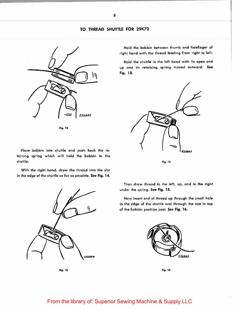
TO THREAD SHUTTLE FOR 29K72
Fig. 13
Place bobbin into shuttle and push back the re
taining spring which will hold the bobbin in the
shuttle.
With the right hand, draw the thread into the slot
in the edge of the shuttle as far as possible. See Fig. 14.
Fig. 15
Hold the bobbin between thumb and forefinger of
right hand with the thread leading from right to left.
Hold the shuttle in the left hand with its open end
up and its retaining spring moved outward. See
Fig. 13.
Fig. 14
Then draw thread to the left, up, and to the right
under the spring. See Fig. 15.
Now insert end of thread up through the small hole
in the edge of the shuttle and through the eye in top
of the bobbin position post. See Fig. 16.
Fig. 16
From the library of: Superior Sewing Machine & Supply LLC
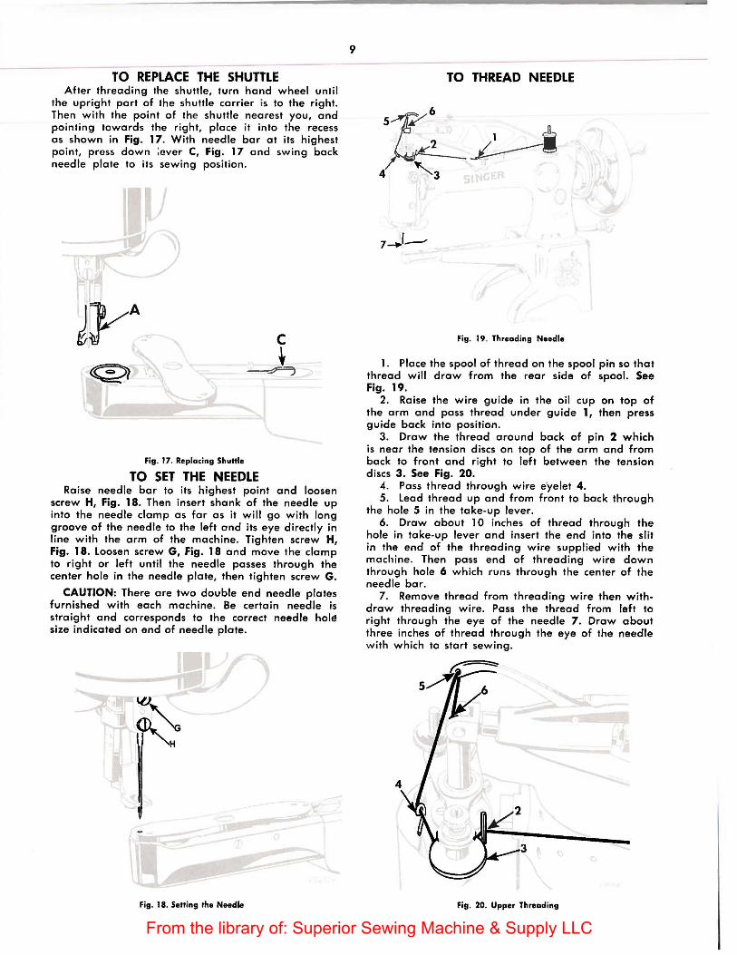
TO REPLACE THE SHUTTLE After threading the shuttle, turn hand wheel until
the upright part of the shuttle carrier is to the right. Then with the point of the shuttle nearest you, and pointing towards the right, place it into the recess as shown in Fig. 17. With needle bar at its highest point, press down :ever C, Fig. 17 and swing back needle plate to its sewing position.
c _J,
Fig. 17. Replacing Shuttle
TO SET THE NEEDLE Raise needle bar to its highest point and loosen
screw H, Fig. 18. Then insert shank of the needle up into the needle clamp as far as it will go with long groove of the needle to the left and its eye directly in line with the arm of the machine. Tighten screw H, Fig. 18. loosen screw G, Fig. 18 and move the clamp to right or left until the needle passes through the center hole in the needle plate, then tighten screw G.
CAUTION: There are two double end needle plates furnished with each machine. Be certain needle is straight and corresponds to the correct needle holE! size indicated on end of needle plate.
Fig. 18. Setting the Needle
9
TO THREAD NEEDLE
Fig. 19. Threading Needle
1. Place the spool of thread on the spool pin so that thread will draw from the rear side of spool. See Fig. 19.
2. Raise the wire guide in the oil cup on top of the arm and pass thread under guide 1, then press guide back into position.
3. Draw the thread around back of pin 2 which is near the tension discs on top of the arm and from back to front and right to left between the tension discs 3. See Fig. 20.
4. Pass thread through wire e'yelet 4. 5. lead thread up and from front to back through
the hole 5 in the take-up lever. 6. Draw about 10 inches of thread through the
hole in take-up lever and insert the end into the slit in the end of the threading wire supplied with the machine . Then pass end of threading wire down through hole 6 which runs through the center of the needle bar.
7. Remove thread from threading wire then withdraw threading wire. Pass the thread from left to right through the eye of the needle 7 . Draw about three inches of thread through the eye of the needle with which to start sewing.
Fig. 20. Upper Threading
From the library of: Superior Sewing Machine & Supply LLC
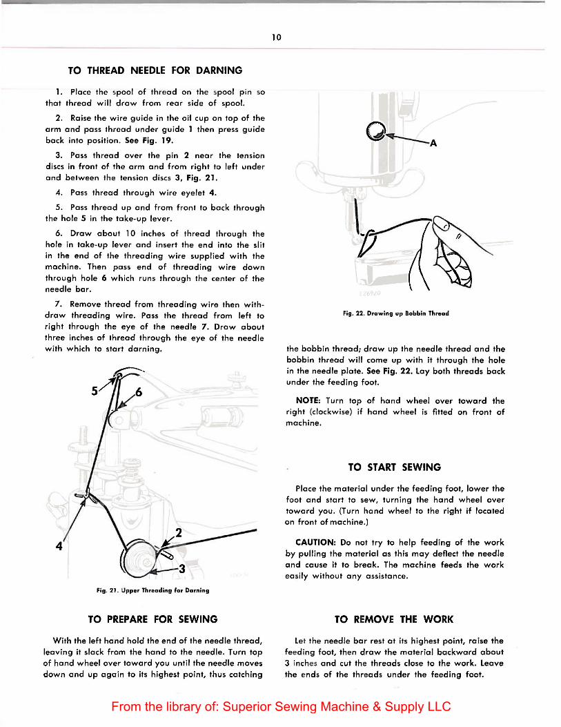
TO THREAD NEEDLE FOR DARNING
1. Place the spool of thread on the spool p in so that thread will draw from rear side of spool.
2. Raise the wire guide in the oii cup on top of the arm and pass thread under guide 1 then press guide back into position. See Fig. 19.
3. Pass thread over the pin 2 near the tension discs in front of the arm and from right to left under and between the tension discs 3, Fig. 21.
4. Pass thread through wire eyelet 4.
5. Pass thread up and from front to back through the hole 5 in the take-up lever.
6. Draw about 10 inches of thread through the hole in take-up lever and insert the end into the sl it in the end of the threading wire supplied with the machine. Then pass end of threading wire down through hole 6 which runs through the center of the needle bar.
7. Remove thread from threading wire then withdraw threading wire. Pass the thread from left to right through the eye of the needle 7. Draw about three inches of thread through the eye of the needle with which to start darning.
4
Fig. 21 . Upper Threading for Darning
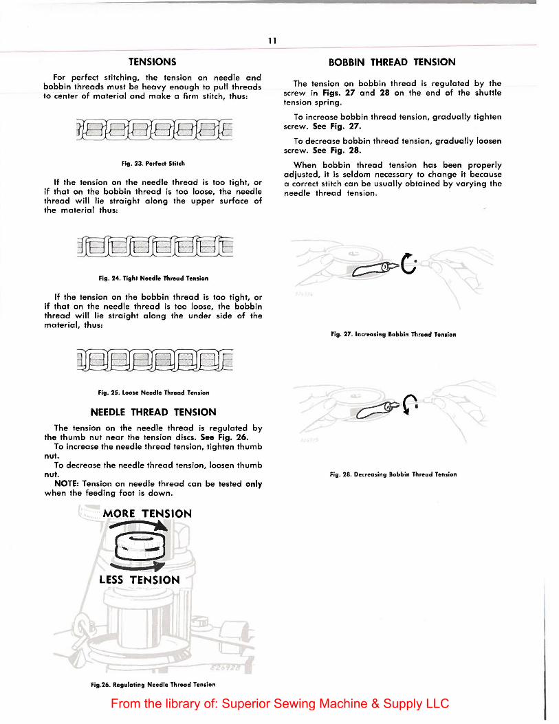
TO PREPARE FOR SEWING
With the left hand hold the end of the needle thread, leaving it slack from the hand to the needle. Turn top of hand wheel over toward you until the needle moves down and up again to its highest point, thus catching
10
o~A
Fig. 22. Drawing up Bobbin Thread
the bobbin thread; draw up the needle thread and the bobbin thread will come up with it through the hole in the needle plate. See Fig. 22. lay both threads back under the feeding foot.
NOTE: Turn top of hand wheel over toward the right (clockwise) if hand wheel is fitted on front of machine.
TO START SEWING
Place the material under the feeding foot, lower the foot and start to sew, turning the hand wheel over toward you. (Turn hand wheel to the right if located on front of machine.)
CAUTION: Do not try to help feeding of the work by pulling the material as this may deflect the needle and cause it to break. The machine feeds the work easily without any assistance.
TO REMOVE THE WORK
let the needle bar rest at its highest point, raise the feeding foot, then draw the material backward about 3 inches and cut the threads close to the work. leave the ends of the threads under the feeding foot.
From the library of: Superior Sewing Machine & Supply LLC
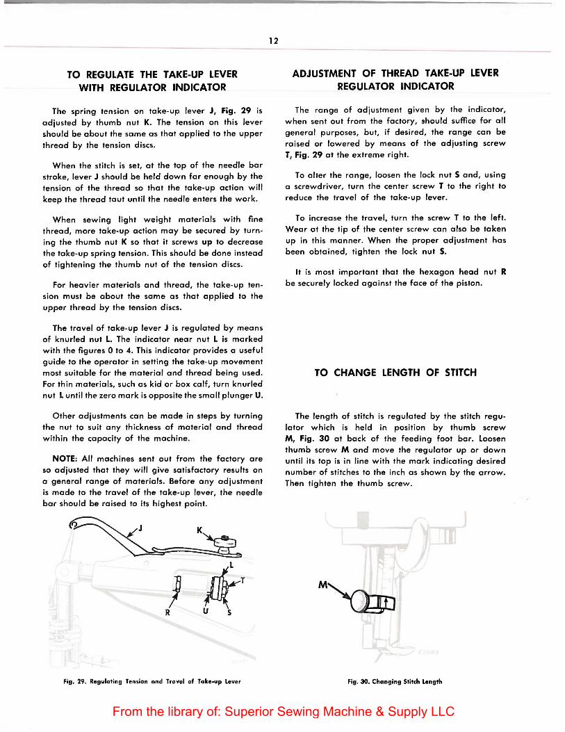
TENSIONS
for perfect stitching, the tension on needle and bobbin threads must be heavy enough to pull threads to center of material and make a firm stitch, thus:
Fig. 23. Perfect Stitch
If the tension on the needle thread is too tight, or if that on the bobbin thread is too loose, the needle thread will lie straight along the upper surface of the material thus:
Fig. 24. Tight Needle Thread Tension
If the tension on the bobbin thread is too tight, or if that on the needle thread is too loose, the bobbin thread will lie straight along the under side of the material, thus:
Fig. 25. Loose Needle Thread Tension
NEEDLE THREAD TENSION
The tension on the needle thread is regulated by the thumb nut near the tension discs. See Fig. 26.
To increase the needle thread tension, tighten thumb nut.
To decrease the needle thread tension, loosen thumb nut.
NOTE: Tension on needle thread can be tested only when the feeding foot is down.
Fig.26. Regulating Needle Thread Tension
11
BOBBIN THREAD TENSION
The tension on bobbin thread is regulated by the screw in Figs. 27 and 28 on the end of the shuttle tension spring.
To increase bobbin thread tension, gradually tighten screw. See Fig. 27.
To decrease bobbin thread tension, gradually loosen screw. See Fig. 28.
When bobbin thread tension has been properly adjusted, it is seldom necessary to change it because a correct stitch can be usually obtained by varying the needle thread tension.
Fig. 27. Increasing Bobbin Thread Tension
Fig. 28. Decreasing Bobbin Thread Tension
From the library of: Superior Sewing Machine & Supply LLC
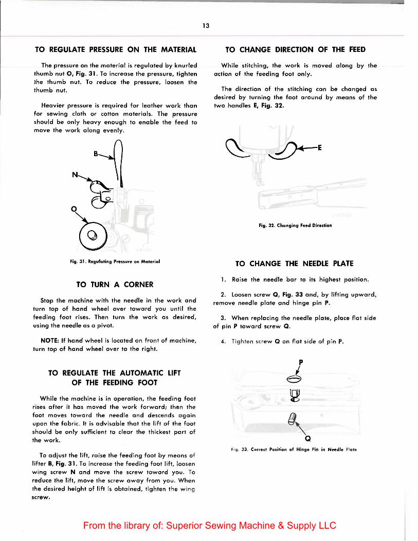
TO REGULATE THE TAKE-UP LEVER WITH REGULATOR INDICATOR
The spring tension on take-up lever J, Fig. 29 is adjusted by thumb nut K. The tension on this lever should be about the same as that applied to the upper thread by the tension discs.
When the stitch is set, at the top of the needle bar stroke, lever J should be held down far enough by the tension of the thread so that the take-up action will keep the thread taut until the needle enters the work.
When sewing light weight materials with fine thread, more take-up action may be secured by turning the thumb nut K so that it screws up to decrease the take-up spring tension. This should be done instead of tightening the thumb nut of the tension discs.
For heavier materials and thread, the take-up tension must be about the same as that applied to the upper thread by the tension discs.
The travel of take-up lever J is regulated by means of knurled nut L. The indicator near nut L is marked with the figures 0 to 4. This indicator provides a useful guide to the operator in setting the take-up movement most suitable for the material and thread being used. For thin materials, such as kid or box calf, turn knurled nut L until the zero mark is opposite the small plunger U.
Other adjustments can be made in steps by turning the nut to suit any thickness of material and thread within the capacity of the machine.
NOTE: All machines sent out from the factory are so adjusted that they will give satisfactory results on a general range of materials. Before any adjustment is made to the travel of the take-up lever, the needle bar should be raised to its highest point.
Fig. 29. Regulating Tensian and Travel of Take-up Leve r
12
ADJUSTMENT OF THREAD TAKE-UP LEVER REGULATOR INDICATOR
The range of adjustment given by the indicator, when sent out from the factory, !thould suffice for all general purposes, but, if desired, the range can be raised or lowered by means of the adjusting screw T, Fig. 29 at the extreme right.
To alter the range, loosen the lock nut S and, using a screwdriver, turn the center screw T to the right to reduce the travel of the take-up lever.
To increase the travel, turn the screw T to the left. Wear at the tip of the center screw can also be taken up in this manner. When the proper adjustment has been obtained, tighten the lock nut S.
It is most important that the hexagon head nut R be securely locked against the face of the piston.
TO CHANGE LENGTH OF STITCH
The length of stitch is regulated by the stitch regulator which is held in position by thumb screw M, Fig. 30 at back of the feeding foot bar. Loosen thumb screw M and move the regulator up or down until its top is in line with the mark indicating desired number of stitches to the inch as shown by the arrow. Then tighten the thumb screw.
Fig. 30. Changing Stitch Length
From the library of: Superior Sewing Machine & Supply LLC
TO REGULATE PRESSURE ON THE MATERIAL
The pressure on the material is regulated by knurled thumb nut 0, Fig. 31. To increase the pressure, tighten lhe thumb nut. To reduce the pressure, loosen the thumb nut.
Heavier pressure is required for leather work than for sewing cloth or cotton materials. The pressure should be only heavy enough to enable the feed to move the work along evenly.
Fig. 31. Regulating Pressure on Material
TO TURN A CORNER
Stop the machine with the needle in the work and turn top of hand wheel over toward you until the feeding foot rises. Then turn the work as desired, using the needle as a pivot.
NOTE: If hand wheel is located on front of machine, turn top of hand wheel over to the right.
TO REGULATE THE AUTOMATIC LIFT OF THE FEEDING FOOT
While the machine is in operation, the feeding foot rises after it has moved the work forward; then the foot moves toward the needle and descends again upon the fabric. It is advisable that the lift of the foot should be only sufficient to clear the th ickest part of the work.
To adjust the lift, raise the feed ing foot by means of lifter 8, Fig. 31. To increase the feeding foot lift, loosen wing screw N and move the screw toward you . To reduce the lift, move the screw away from you. When the desired height of lift is obtained, tighten the w ing screw.
13
TO CHANGE DIRECTION OF THE FEED
While stitching, the work is moved along by the action of the feeding foot only.
The direction of the stitching can be changed as desired by turning the foot around by means of the two handles E, Fig. 32.
~E
Fig. 32. Changing Feed Direction
TO CHANGE THE NEEDLE PLATE
1. Ra ise the needle bar to its highest position.
2. loosen screw Q, Fig. 33 and, by lifting upward, remove needle plate and hinge pin P.
3. When replacing the needle plate, place flat side of pin P toward screw Q.
4. Tig hten sc ew Q on fl at side of p in P.
f ig. 33. Correct Position of Hinge Pin in Needle Plate
From the library of: Superior Sewing Machine & Supply LLC
14
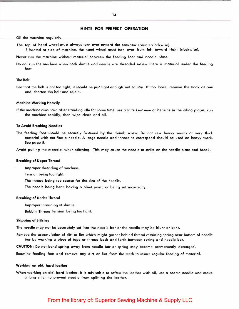
HINTS FOR PERFECT OPERATION
Oil the machine regularly.
The top of hand wheel must always turn over toward the operator (counterclockwise). If located at side of machine, the hand wheel must turn over from left toward right (clockwise).
Never run the machine without material between the feeding fool and needle plate.
Do not run the machine when both shuttle and needle are threaded unless there is material under the feeding foot.
The Belt
See that the belt is not too tight; it should be just tight enough not to slip. If too loose, remove the hook at one end, shorten the belt and rejoin.
Machine Working Heavily
If the machine runs hard after standing idle for some time, use a little kerosene or benzine in the oiling places, run the machine rapidly, then wipe clean and oil.
To Avoid Breaking Needles
The feeding fool should be securely fastened by the thumb screw. Do not sew heavy seams or very thick material with too fine a needle. A large needle and thread to correspond should be used on heavy work. See page 5.
Avoid pulling the material when stitching. Th is may cause the needle to strike on the needle plate and break.
Breaking of Upper Thread
Improper threading of machine.
Tension being too tight.
The thread being too coarse for the size of the needle.
The needle being bent, having a blunt point, or being set incorrectly.
Breaking of Under Thread
Improper threading of shuttle.
Bobbin Thread tension being too tight.
Skipping of Stitches
The needle may not be accurately set into the needle bar or the needle may be blunt or bent.
Remove the accumulation of dirt or lint which might gather behind thread retaining spring near bottom of needle bar by working a piece of tape or thread back and forth between spring and needle bar.
CAUTION: Do not bend spring away from needle bar or spring may become permanently damaged.
Examine feeding foot and remove any dirt or lint from the teeth to insure regular feeding of material.
Working on old, hard leather
When working on old, hard leather, it is advisable to softe n the leather with oil, use a coarse needle and make a long stitch to prevent needle from splitting the leathe r.
From the library of: Superior Sewing Machine & Supply LLC
v
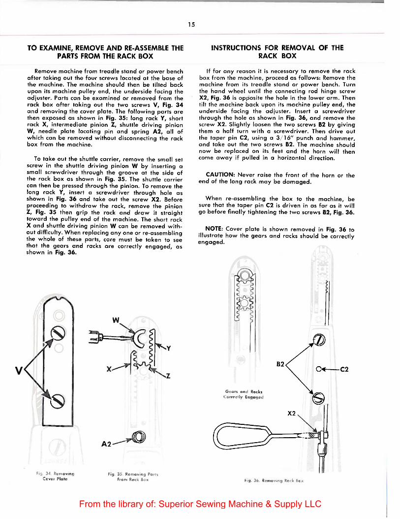
TO EXAMINE, REMOVE AND RE-ASSEMBLE THE PARTS FROM THE RACK BOX
Remove machine from treadle stand or power bench after taking out the four screws located at the bose of the machine. The machine should then be tilted bock upon its machine pulley end, the underside facing the adjuster. Ports con be examined or removed from the rock box after taking out the two screws V, Fig. 34 and removing the cover plate. The following ports ore then exposed as shown in Fig. 35: long rock Y, short rock X, intermediate pinion Z, shuttle driving pinion W, needle plate locating p in and spring A2, all of which can be removed without disconnecting the rack box from the machine.
To toke out the shuttle carrier, remove the small set screw in the shuttle driving pinion W by inserting a small screwdriver through the groove at the side of the rock box as shown in Fig. 35. The shuttle carrier con then be pressed through the pinion. To remove the long rock Y, insert a screwdriver through hole as shown in Fig. 36 and toke out the screw X2. Before proceeding to withdraw the rock, remove the pinion Z, Fig. 35 then grip the rock and draw it straight toward the pulley end of the machine. The short rock X and shuttle driving pinion W can be removed without difficulty. When replacing any one or re-assembling the whole of these ports, care must be token to see that the gears and racks are correctly engaged, as shown in Fig. 36.
fis 34 Rcm ovtn g Cover Pla to
A2~
fi9 35 Re mo vtng Pa th from Ro ck Bo x
15
INSTRUCTIONS FOR REMOVAL OF THE RACK BOX
If for any reason it is necessary to remove the rock box from the machine, proceed as follows: Remove the machine from its treadle stand or power bench. Turn the hand wheel until the connecting rod hinge screw X2, Fig. 36 is opposite the hole in the lower arm. Then tilt the machine back upon its machine pulley end, the underside facing the adjuster. Insert a screwdriver through the hole as shown in Fig. 36, and remove the screw X2. Slightly loosen the two screws 82 by giving them a half turn with a screwdriver. Then drive out the toper pin C2, using o 3 / 16" punch and hammer, and take out the two screws 82. The machine should now be replaced on its . feet and the horn will then come away if pulled in a horizontal direction.
CAUTION: Never raise the front of the horn or the end of the long rack may be damaged.
When re -assembling the box to the machine, be sure that the taper pin C2 is driven in as for as it will go before finally tightening the two screws 82, Fig. 36.
NOTE: Cover plate is shown removed in Fig. 36 to illustrate how the gears and rocks should be correctly engaged.
Gea" and Rocks Co rrrc tly En9a g cd
B2
f ig. Jb . R m o vtng Ro ck Box
C+-C2
From the library of: Superior Sewing Machine & Supply LLC
16
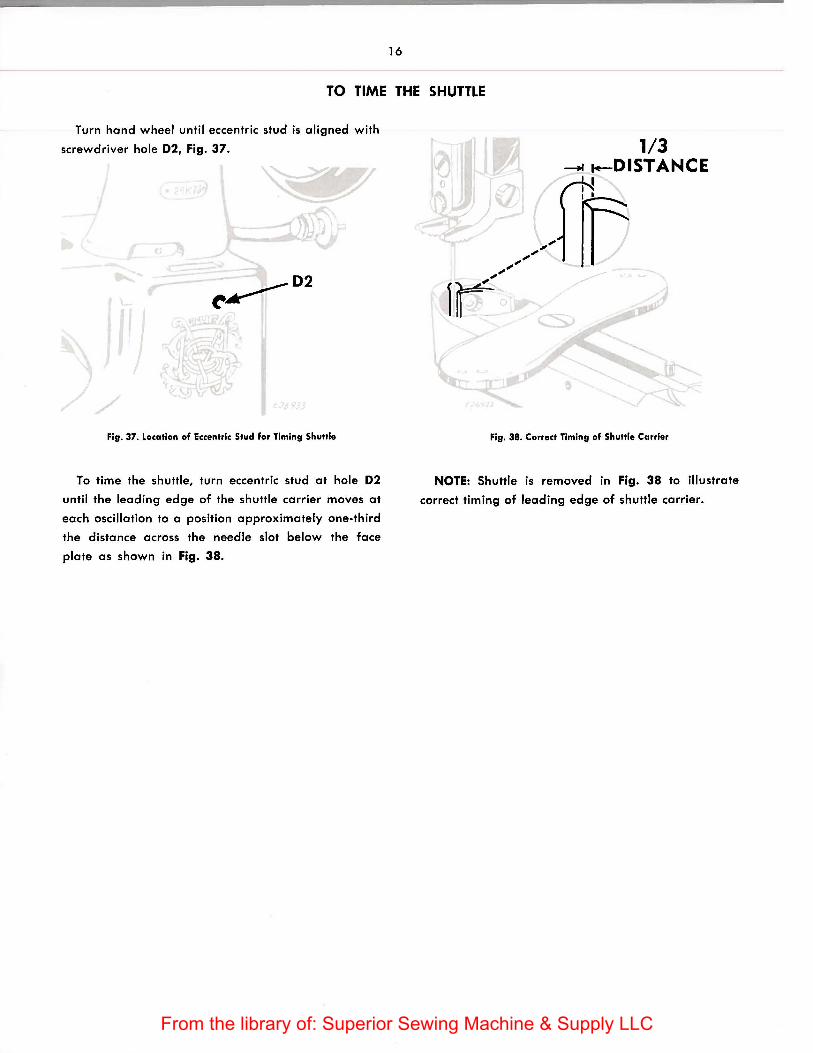
TO TIME THE SHUTTLE
Turn hand wheel until eccentric stud is aligned with
screwdriver hole 02, Fig. 37.
Fig. 37. Location of Eccentric Stud for Timing Shuttle
To time the shuttle, turn eccentric stud at hole 02
until the leading edge of the shuttle carrier moves at
each oscillation to a position approximately one-third
the distance across the needle slot below the face
plate as shown in Fig. 38.
1/3 --+~ .-DISTANCE
[;
Fig. 38. Correct Timing of Shuttle Carrier
NOTE: Shuttle is removed in Fig. 38 to illustrate
correct timing of leading edge of shuttle carrier.
From the library of: Superior Sewing Machine & Supply LLC
PARTS LIST FOR
SINGER .. 29K71, 29K7 2 and 29K73
SINGLE NEEDLE LOCK STITCH
UNIVERSAL UPPER FEED MACHINES
THE SINGER MANUFACTURING COMPANY
From the library of: Superior Sewing Machine & Supply LLC

From the library of: Superior Sewing Machine & Supply LLC
17
PARTS LIST FOR
MACHINES 29 K71 TO 29 K7 3
INSTRUCTIONS FOR ORDERING
To simplify ordering of parts, exploded views of the various sections of the mechanism are shown in the same illustration as the assembly of those parts. On the page opposite the illustration is a list of parts with key or reference numbers to indicate the position of that part in the illustration. These key numbers in the first column are for reference only and are not to be used in ordering parts.
In ordering from this list, use ONLY the PART number in the SECOND column.
The number stamped on a Sewing Machine Part is the number of the single part only.
Every combination of parts sent out has its specific number which, although not stamped on Parts must be used when ordering the combination.
Each number always indicates the SAME PART in whatever list it appears, or for whatever Machine.
The letters after some of the numbers indicate the style of finish only, as follows:
AL Heat Treated for Toughness. C Hardened only. D Polished only. E Soft, Not polished. F Hardened and Polished. H Blued. J Nickel Plated only. K Hardened and Nickel Plated. R Phosphate Coating Formed on Surface of Iron or Steel. W Polished and Nickel Plated.
These letters MUST BE USED when they appear in the list and AFTER the number, as in the list.
Parts marked with an asterisk ( *) are furnished only when repairs are made at the factory.
From the library of: Superior Sewing Machine & Supply LLC

18
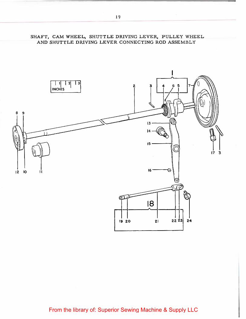
SHAFT, CAM WHEEL, SHUTTLE DRIVING LEVER, PULLEY WHEEL AND SHUTTLE DRIVING LEVER CONNECTING ROD ASSEMBLY
R ef. Part No.
1
2
3 4 5 6
7
8 9 10 11 12 13
14
15 16 17
18
19 20
21
22 23 24
No.
82122 1 82o1o 1 82011
3012 81872 82073 SS235C
{
8661 81941
82149 11663 RR18 4449
81868 1808
{ SS572C SS575C 82184
1520R 361C
82233
82237
82239
82194 8645
{
82232 82236 82238
8569 82186 SS573C
Description
Shuttle Driving Cam and Gear, Nos. 81872 and 82073 Shaft ( 29K71 Machine) Shaft (29K72 and 29K73 Machines) Pin Gear Shuttle Driving Cam with SS235C Screw Needle Bar Cam and Pulley Wheel with .361C (29K71 Machine) Needle Bar Cam and Pulley Wheel with 361C (29K72 and 29K73
Machines) Feed Motion Cam Wheel with RR18 and 81868 Cam Wheel Pin Roller Shaft Bushing Roller Pin Roller and Stud Bearing Screw (29K71 Machine) Bearing Screw (29K72, 29K73 Machines) Shuttle Driving Lever with 1808 Eccentric Stud Nut Cam and Pulley Wheel Set Screw Shuttle Driving Lever Connecting Rod complete, Nos. 8569,
8645, 82186, 82194 and 82232 ( 29K71 Machine) Shuttle Driving Lever Connecting Rod complete, Nos. 8569,
8645, 82186, 82194 and 82236 (29K72 Machine) Shuttle Driving Lever Connecting Rod complete, Nos. 8569,
8645, 82186, 82194 and 82238 (29K73 Machine) Connecting Rod End (front) Pin (front) Connecting Rod ( 29K71 Machine) Connecting Rod (29K72 Machine) Connecting Rod (29K73 Machine) Pin (back) Connecting Rod End (back) Eccentric Stud
From the library of: Superior Sewing Machine & Supply LLC
12 10
19
SHAFT, CAM WHEEL, SHUTTLE DRIVING LEVER, PULLEY WHEEL AND SHUTTLE DRIVING LEVER CONNECTING ROD ASSEMBLY
I I 11 I 21 I 31 . INCHES .
II Is--""'"'@
19 20 21 22 2~ 24
~\ 17 3
From the library of: Superior Sewing Machine & Supply LLC
Ref. Part No. No.
1 193F 2 8620 3 8574 4 1177C 5 82154 6 82153 7 82155 8 515J 9 648J 10 1560W 11 8619 12 668D 13 8617 14 8618 15 84113 16 8575 17 82058 18 82116 19 SS535W 20 * 413D 21 2102
22 { 2103 80548
23 128D 24 NN101J 25 82055 26 8569 27 NN96J 28 82056 29 82059 30 66F
8568
33892 82057
20
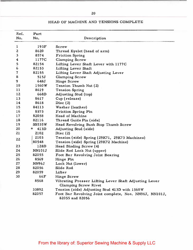
HEAD OF MACHINE AND TENSIONS COMPLETE
Description
Screw Thread Eyelet (head of arm) Friction Spring Clamping Screw Lifting Lever Shaft Lever with 1177C Lifting Lever Shaft Lifting Lever Shaft Adjusting Lever Clamping Screw Hinge Screw Tension Thumb Nut ( 2) Tension Spring Adjusting Stud (top) Cup (release) Disc (2) Washer (leather) Friction Spring Pin Head of Machine Thread Guide Pin (side) Head Revolving Bush Stop Thumb Screw Adjusting Stud (side) Disc (2) Tension (side) Spring (29K71, 29K73 Machines) Tension (side) Spring ( 29K72 Machine) Head Binding Screw ( 4) Slide Rod Lock Nut (upper) Foot Bar Revolving Joint Bearing Hinge Pin Lock Nut (lower) Slide Rod Lifter Hinge Screw Vibrating Presser Lifting Lever Shaft Adjusting Lever
Clamping Screw Rivet Tension (side) Adjusting Stud 413D with 1560W Foot Bar Revolving Joint complete, No s . NN96J, NN101J,
82055 and 82056
From the library of: Superior Sewing Machine & Supply LLC

21
HEAD OF MACHINE AND TENSIONS COMPLETE
10~
"--1 121
24~
2.5 --{,_G
26 ---=:::::~~ 27---@
From the library of: Superior Sewing Machine & Supply LLC

Ref. No.
1 2 3 4 5 6 7 8 9 10 11 12 13 14 15 16 17 18 19
20 21
22 23 24 25
22
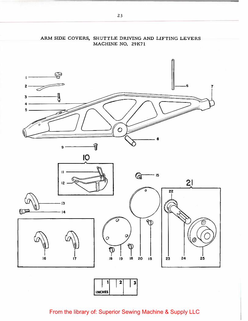
ARM SIDE COVERS, SHUTTLE DRlVING AND LIFTING LEVERS MACHINE NO. 29K71
Part No.
NN105H 82219
418J 82220 82216
8601 1801 8586
327D 8670 8597 8695
82150 41D
51224W 82151 82152 SS 45E 82034
4288 82121
81869 11663 82008 82052
Stud Nut Spring Spring Stud
Description
Needle Bar Driving Lever with 1801 and 82216 Spring Steady Pin Spool Pin Cam Roller and Stud Joint Pin Oil Cup Screw Oil Cup with 8597 and 8695 Spring Oil Pad (cloth) Vibrating Presser Lifting Lever (for medium work) Lifting Lever Screw Thumb Screw Lifting Lever (for light work) Lifting Lever (for heavy work) Hub Screw( 3) Arm Side Cover (front) for use when Machine is fitted with
Hand Wheel on end of shaft Arm Side Cover {back) Hand Wheel Hub complete, Nos. 11663, 81869, 82008 and
82052 Hand Wheel Shaft Gear Gear Pin Shaft Hub
From the library of: Superior Sewing Machine & Supply LLC
23
ARM SIDE COVERS, SHUTTLE DRIVING AND LIFTING LEVERS MACHINE NO. 29 K71
--6
---8
g----~
10
@--15 21
~ l , t;ID
16 17 18 19 20 18 23 24 25
7
From the library of: Superior Sewing Machine & Supply LLC
R e f. No.
1 2 3 4 5 6 7 8 9 10 11 12 13 14 15 16 17 18 19
20 21
22 23 24 25
24
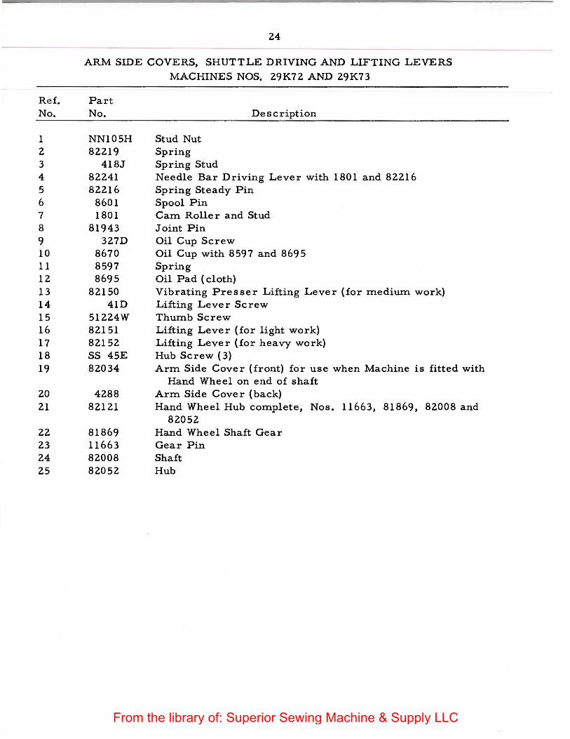
ARM SIDE COVERS, SHUTTLE DRIVING AND LIFTING LEVERS
MACHINES NOS. 29K72 AND 29K73
Part No.
NN105H 82219
418J 82241 82216
8601 1801
81943 327D
8670 8597 8695
82150 41D
51224W 82151 82152 SS 45E 82034
4288 82121
81869 11663 82008 82052
Stud Nut Spring Spring Stud
Description
Needle Bar Driving Lever with 1801 and 82216 Spring Steady Pin Spool Pin Cam Roller and Stud Joint Pin Oil Cup Screw Oil Cup with 8597 and 8695 Spring Oil Pad (cloth) Vibrating Presser Lifting Lever (for medium work) Lifting Lever Screw Thumb Screw Lifting Lever (for light work) Lifting Lever (for heavy work) Hub Screw ( 3) Arm Side Cover (front) for use when Machine is fitted with
Hand Wheel on end of shaft Arm Side Cover (back) Hand Wheel Hub complete, Nos. 11663, 81869, 82008 and
82052 Hand Wheel Shaft Gear Gear Pin Shaft Hub
From the library of: Superior Sewing Machine & Supply LLC
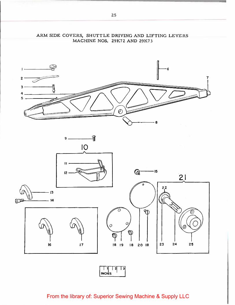
25
ARM SIDE COVERS, SHUTTLE DRIVING AND LIFTING LEVERS MACHINE NOS. 29K72 AND 29K7 3
~ 2 ~ 3 ! 4 5
9----li 10
@,.---15 21
~ 13
~\hl ~ 14
16 17 18 19 18 20 18 23 24
I I tl I 21 I 31 ~NCHES .
7
25
From the library of: Superior Sewing Machine & Supply LLC
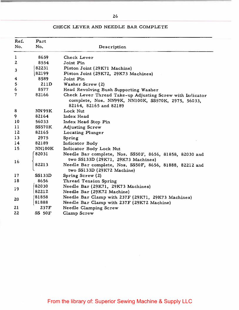
26
CHECK LEVER AND NEEDLE BAR COMPLETE
Ref. Part No. No. Description
1 8659 Check Lever 2 8554 Joint Pin
3 182231 Piston Joint ( 29K71 Machine) ) 82199 Piston Joint (29K72, 29K73 Machines)
4 8589 Joint Pin 5 211D Washer Screw (2) 6 8577 Head Revolving Bush Supporting Washer 7 82166 Check Lever Thread Take-up Adjusting Screw with Indicator
complete, Nos. NN99K, NN100K, SS570K, 2975, 56033, 82164, 82165 and 82189
8 NN99K Lock Nut 9 82164 Index Head 10 56033 Index Head Stop Pin 11 SS570K Adjusting Screw 12 82165 Locating Plunger 13 2975 Spring 14 82189 Indicator Body 15 NNlOOK Indicator Body Lock Nut
{82031 Needle Bar complete, Nos. SS50F, 8656, 81858, 82030 and
16 two SS133D (29K71, 29K73 Machines) 82213 Needle Bar complete, Nos. SS50F, 8656, 81888, 82212 and
two SS133D (29K72 Machine) 17 SS133D Spring Screw ( 2) 18 8656 Thread Tension Spring
19 {82030 Needle Bar (29K71, 29K73 Machines) 82212 Needle Bar (29K72 Machine)
20 {81858 Needle Bar Clamp with 237F (29K71, 29K73 Machines) 81888 Needle Bar Clamp with 237F (29K72 Machine)
21 237F Needle Clamping Screw 22 SS 50F Clamp Screw
From the library of: Superior Sewing Machine & Supply LLC

27
CHECK LEVER AND NEEDLE BAR COMPLETE
7
~or---r--9 ~'t':::,.......--,.---10
£1~---T----IZ 1
1~ ~-------i--14
~---------T---1!5
3----
J
16 18 20 22
From the library of: Superior Sewing Machine & Supply LLC
R e f. No.
1 2 3
4 5 6 7 8
9 10 11 12 13 14 15 16 17 18
Part No.
NN88W 82130 82129 82023
8675 179E
82131 193F
82007
291W 1816
82053 8573
194E 82123
152F 82167 82230 82188
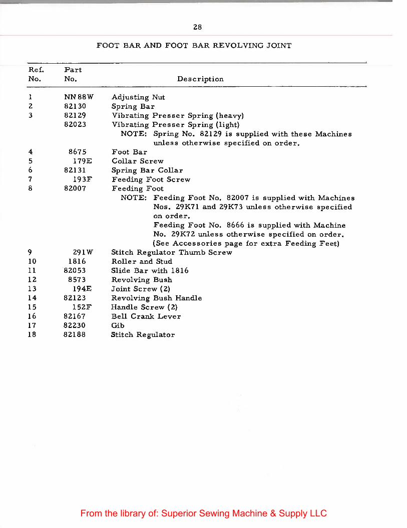
28
FOOT BAR AND FOOT BAR REVOLVING JOINT
Adjusting Nut Spring Bar
Description
Vibrating Presser Spring (heavy) Vibrating Presser Spring (light)
NOTE: Spring No. 82129 is supplied with these Machines unless otherwise specified on order.
Foot Bar Collar Screw Spring Bar Collar Feeding Foot Screw Feeding Foot
NOTE: Feeding Foot No. 82007 is supplied with Machines Nos. 29K71 and 29K73 unless otherwise specified on order. Feeding Foot No. 8666 is supplied with Machine No. 29K72 unless otherwise specified on order. (See Accessories page for extra Feeding Feet)
Stitch Regulator Thwnb Screw Roller and Stud Slide Bar with 1816 Revolving Bush Joint Screw (2) Revolving Bush Handle Handle Screw (2) Bell Crank Lever Gib Stitch Regulator
From the library of: Superior Sewing Machine & Supply LLC

29
FOOT BAR AND FOOT BAR REVOLVING JOINT
~1
4
}15
7
~ 16
• 8
@,~ 17 9 18
From the library of: Superior Sewing Machine & Supply LLC
Ref. No.
1 2 3 4 5 6 7 8 9 10 11 12 13 14 15 16 17 18 19 20 21 22 23 24 25 26 27 28 29
30
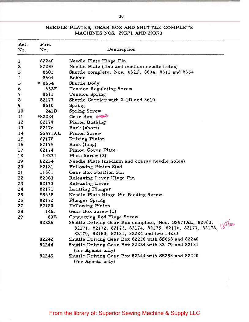
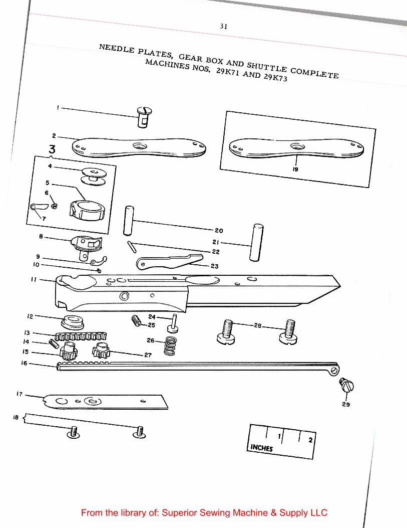
NEEDLE PLATES, GEAR BOX AND SHUTTLE COMPLETE MACHINES NOS. 29K71 AND 29K73
Part No.
82240 82235
8603 8604
* 8654 662F
8611 82177
8610 241D
*82224 82179 82176 SS571AL 82178 82175 82174
1423J 82234 82181 11661 82063 82173 82171 SS658 82172 82180
146J 89E
82226
82242 82244
82245
Description
Needle Plate Hinge Pin Ne·edle Plate (fine and mediwn needle holes) Shuttle complete, Nos. 662F, 8604, 8611 and 8654 Bobbin Shuttle Body Tension Regulating Screw Tension Spring Shuttle Carrier with 241D and 8610 Spring Spring Screw Gear Box ~ Pinion Bushing Rack (short) Pinion Screw Driving Pinion Rack (long) Pinion Cover Plate Plate Screw ( 2) Needle Plate (medium and coarse needle holes) Following Pinion Stud Gear Box Position Pin Releasing Lever Hinge Pin Releasing Lever Locating Plunger Needle Plate Hinge Pin Binding Screw Plunger Spring Following Pinion Gear Box Screw (2) Connecting Rod Hinge Screw
I Shuttle Driving Gear Box complete, Nos. SS571AL, 82063, j1
82171, 82172, 82173, 82174, 82175, 82176, 82177, 82178, \~ p,v 82179, 82180, 82181, 82224 and two 1423.J
Shuttle Driving Gear Box 82226 with SS658 and 82240 Shuttle Driving Gear Box 82224 with 82179 and 82181
(for Agents only) Shuttle Driving Gear Box 82244 with SS258 and 82240
(for Agents only)
From the library of: Superior Sewing Machine & Supply LLC
3 1
NEEDLE PLATEs, GEA..R BOX A.ND SHUTTLE COivfpLETE: M:.A CHINEs NOS. 29I<7 I AND 2 9I<7 3
;~t.::::~==~- -= ---4-~ s __
6
~~
Z$)
' 29
IeL ___ (ft
2 INCHES
From the library of: Superior Sewing Machine & Supply LLC
Ref. No.
1 2 3
4 5 6 7 8 9 10 11 12 13 14 15 16 17 18 19 20 21 22 23 24 25 26 27 28 29 30 31
32
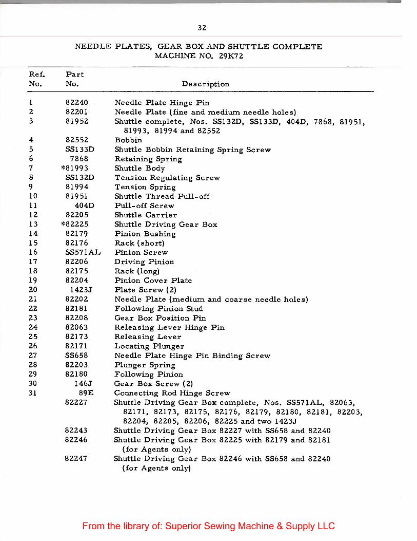
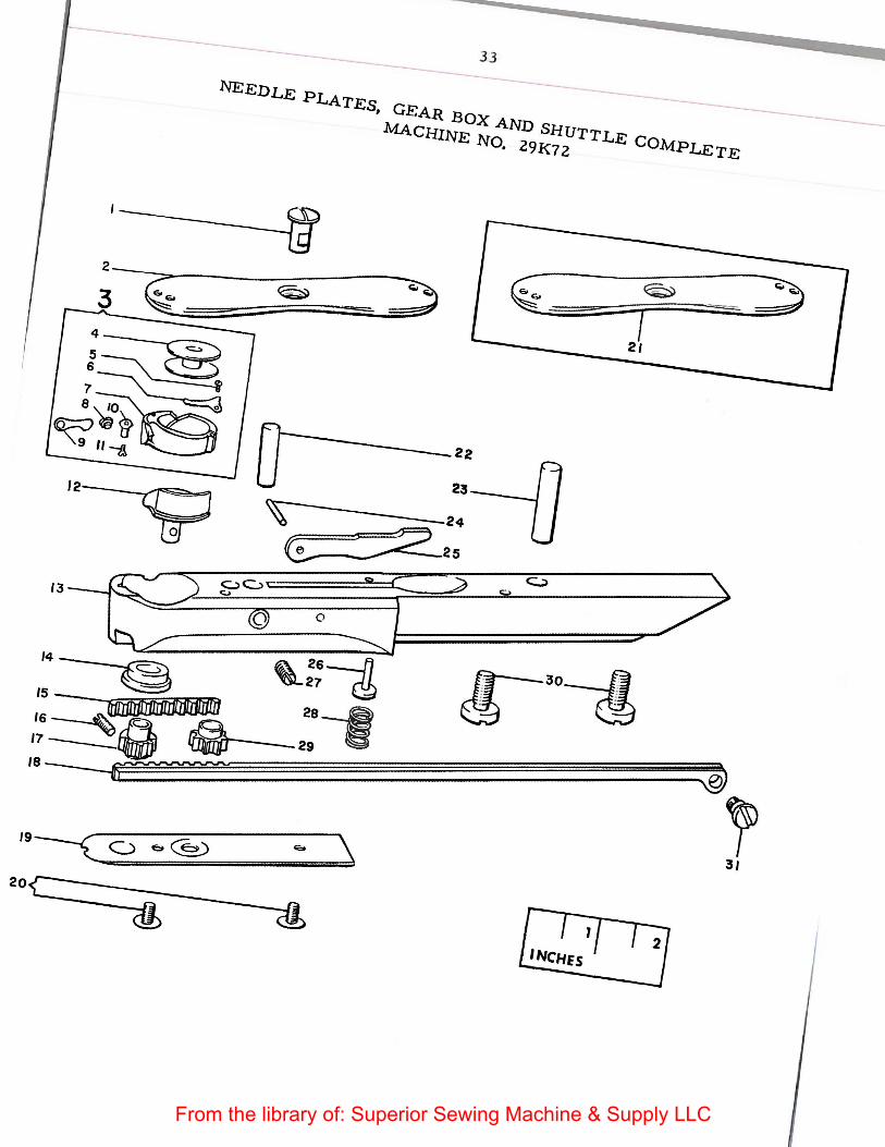
NEEDLE PLATES, GEAR BOX AND SHUTTLE COMPLETE MACHINE NO. 29K72
Part No.
82240 82201 81952
82552 SS133D
7868 *81993
SS132D 81994 81951
404D 82205
*82225 82179 82176 SS571AL 82206 82175 82204
1423J 82202 82181 82208 82063 82173 82171 SS658 82203 82180
146J 89E
82227
82243 82246
82247
Description
Needle Plate Hinge Pin Needle Plate (fine and medium needle holes) Shuttle complete, Nos. SS132D, SS133D, 404D, 7868, 81951,
81993, 81994 and 82552 Bobbin Shuttle Bobbin Retaining Spring Screw Retaining Spring Shuttle Body Tension Regulating Screw Tension Spring Shuttle Thread Pull-of£ Pull-of£ Screw Shuttle Carrier Shuttle Driving Gear Box Pinion Bushing Rack (short) Pinion Screw Driving Pinion Rack (long) Pinion Cover Plate Plate Screw (2) Needle Plate (medium and coarse needle holes) Following Pinion Stud Gear Box Position Pin Releasing Lever Hinge Pin Releasing Lever Locating Plunger Needle Plate Hinge Pin Binding Screw Plunger Spring Following Pinion Gear Box Screw ( 2) Connecting Rod Hinge Screw Shuttle Driving Gear Box complete, Nos. SS571AL, 82063,
82171, 82173, 82175, 82176, 82179, 82180, 82181, 82203, 82204, 82205, 82206, 82225 and two 1423J
Shuttle Driving Gear Box 82227 with SS658 and 82240 Shuttle Driving Gear Box 82225 with 82179 and 82181
(for Agents only) Shuttle Driving Gear B ox 82246 with SS658 and 82240
(for Agents only)
From the library of: Superior Sewing Machine & Supply LLC
-33
NE:EDLE PLATEs, GEAR BOX AND SHUTTLE COMpLETE MACHINE No. 29K72
~~~r,--21
2
From the library of: Superior Sewing Machine & Supply LLC
Ref. No.
1
2 3 4 5 6 7 8 9 10 11 12
Part No.
82163
1519E 434C
82160 82162 82161 82159 NN98R 81866 SS135D SS569C
761C
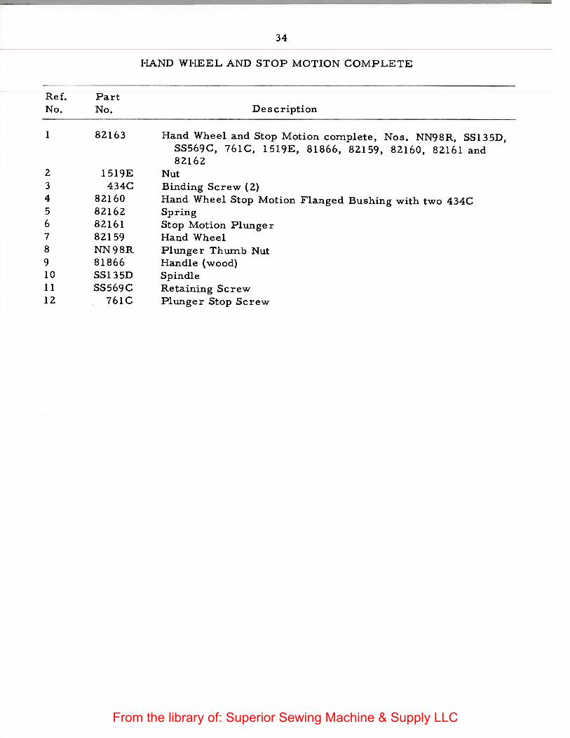
34
HAND WHEEL AND STOP MOTION COMPLETE
Description
Hand Wheel and Stop Motion complete, Nos. NN98R, SS135D, SS569C, 761C, 1519E, 81866, 82159, 82160, 82161 and 82162
Nut Binding Screw ( 2) Hand Wheel Stop Motion Flanged Bushing with two 434C Spring Stop Motion Plunger Hand Wheel Plunger Thumb Nut Handle (wood) Spindle Retaining Screw Plunger Stop Screw
From the library of: Superior Sewing Machine & Supply LLC
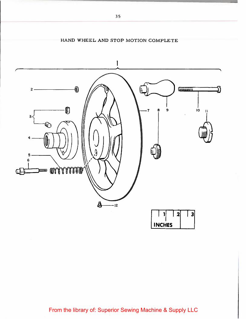
35
HAND WHEEL AND STOP MOTION COMPLETE
2-----
7 8 9 10 11
5----.. 6
Qg_....; I___,__ """"~~~"'
A 12
From the library of: Superior Sewing Machine & Supply LLC
Ref. No.
1
2 3 4 5 6 7 8
Part No.
82087
128D 8651
82086 8684
SS469W 8371 2460
81965
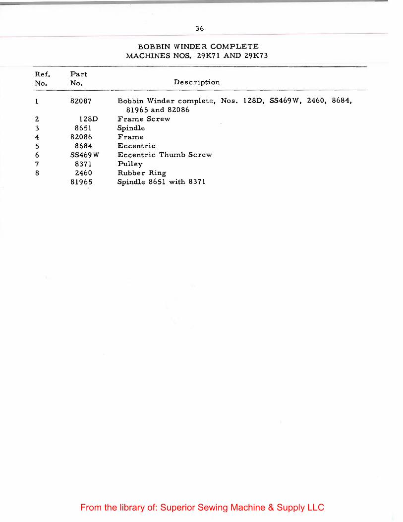
36
BOBBIN WINDER COMPLETE MACHINES NOS. 29K71 AND 29K73
Description
Bobbin Winder complete , Nos. 128D, SS469W, 2460, 8684, 81965 and 82086
Frame Screw Spindle Frame Eccentric Eccentric Thumb Screw Pulley Rubber Ring Spindle 8651 with 8371
From the library of: Superior Sewing Machine & Supply LLC
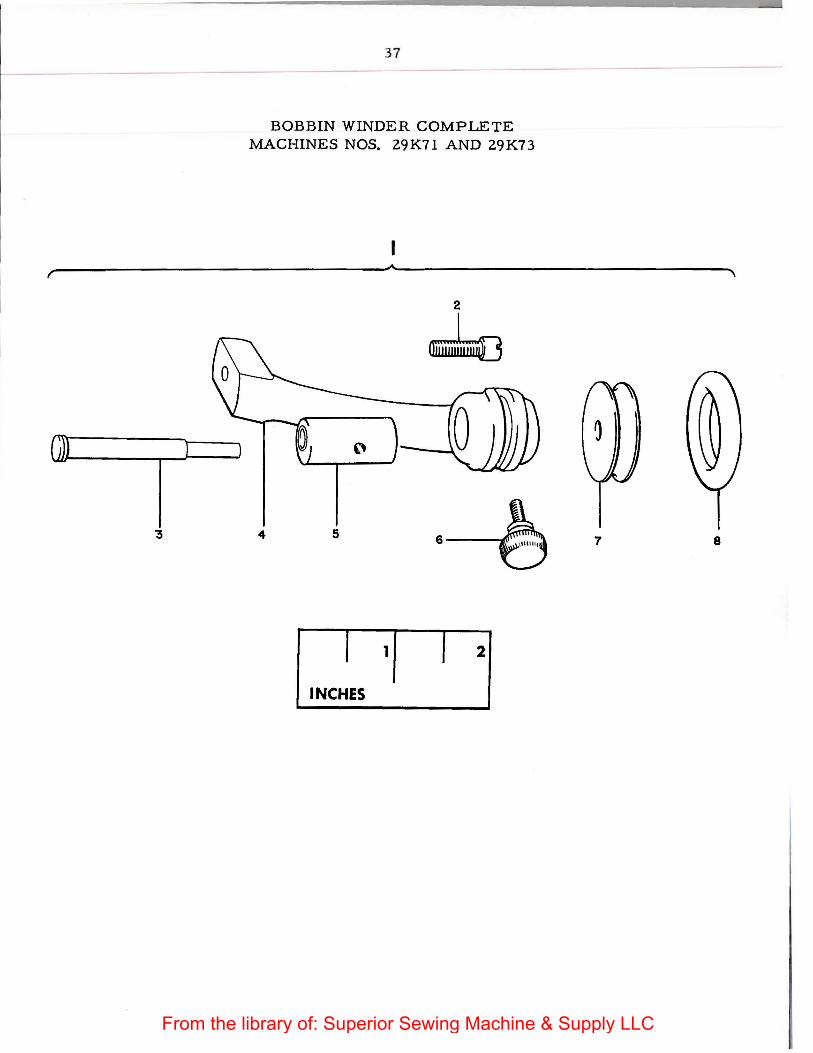
37
BOBBIN WINDER COMPLETE MACHINES NOS. 29 K71 AND 29 K7 3
4 5
1 1 I 2
INCHES
7 8
From the library of: Superior Sewing Machine & Supply LLC

R ef. No.
1
2 3 4 5 6 7 8
Part No.
82090
128D 82088 82086
8684 SS469W
8371 2460
82089
38
BOBBIN WINDER COMPLETE MACHINE NO. 29K72
Description
Bobbin Winder complete, Nos. 128D, SS469 W, 2460, 8684, 82086 and 82089
Frame Screw Spindle Frame Eccentric Eccentric Thumb Screw Pulley Rubber Ring Spindle 82088 with 8371
From the library of: Superior Sewing Machine & Supply LLC

4
39
BOBBIN WINDER COMPLETE MACHINE NO. 29 K7 2
5 6--f3
I 11 21 INCHES .
7 8
From the library of: Superior Sewing Machine & Supply LLC

R e f. No.
1 2 3 4 5 6 7 8 9 10 11 12 13
14 15 16
Part No.
36570 36571 36807 36569 25537
120378 418E
82833 50616
8604 82552
8582 8590
8557 8558 8666
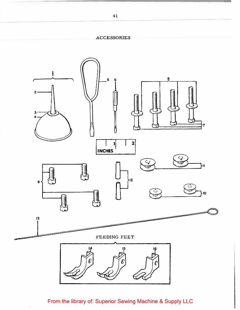
40
ACCESSORIES
Description
Oiler 36569 {filled with oil) Oiler Spout, 1-3/4 inch long with 36807 Washer {leather) Oiler with 36571 Screw Driver {machine) Screw Driver {shuttle tension) Machine Screw {for fastening Machine to Power Table) {4) Machine Screw Washer {4) Machine Screw {for fastening Machine to Stand) ( 4) Bobbin {29K71, 29K73 Machines) {2) Bobbin (29K72 Machine) (2) Steady Pin ( 2) Threading Wire
FEEDING FEET
Feeding Foot {narrow fork, fine) Feeding Foot (narrow fork, coarse) Feeding Foot (for waxed thread)
NOTE: No. 8666 is used on Machine No. 29K72, unless otherwise specified on order.
From the library of: Superior Sewing Machine & Supply LLC
4 1
ACCESSORIES
5 6 8
2----f
I I II 21 .INCHES
@ ® ~II
9 12
@ ~10
13
FEEDING FEET
From the library of: Superior Sewing Machine & Supply LLC
Ref. Part No. No.
82214 82113 50616
42
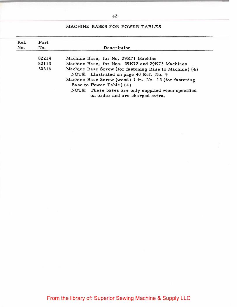
MACHINE BASES FOR POWER TABLES
Description
Machine Base, for No. 29K71 Machine Machine Base, for Nos. 29K72 and 29K73 Machines Machine Base Screw (for fastening Base to Machine) ( 4)
NOTE: illustrated on page 40 Ref. No. 9 Machine Base Screw (wood) 1 in. No. 12 (for fastening
Base to Power Table) (4) NOTE: These bases are only supplied when specified
on order and are charged extra.
From the library of: Superior Sewing Machine & Supply LLC
Part No. Page No.
RR 18 .•••.•. 18 41D ...... 22, 24
SS 45E. . . • . • 22, 24 SS 50F ..•.•• 26
66F .••... 20 NN88W ...... 28
89E •.•... 30, 32 NN96J ..•..• 20 NN98R •••..• 34 NN99K •••..• 26 NN100K ••••• 26 NN101J .•..• 20 NN1 0 5H. • • • • 22, 24
128D .••••. 20, 36, 38 SS132D •••.•. 32 SS133D ••...• 26, 32 SS135D ••.••• 34
146J ••...• 30, 32 152F ••.•.• 28 179E .••.•• 28 193F .••••• 20,28 194E ••...• 28 211D •••••• 26
SS235C •••••• 18 237F •••••• 26 241D •••••• 30 291 w ...... 28 327D •••••• 22, 24 361C ••••.. 18 404D •••••• 32
* 413D •••••• 20 418E ••.••• 40 418J •••••• 22, 24 434C •••••• 34
SS469W .••••• 36,38 515J •••••• 20
SS535W ••.••• 20 SS569C •••••• 34 SS570K ••••.. 26 SS571AL ••••• 30, 32 SS572C •••••• 18 SS573C •••••• 18 SS575C •••••• 18
648J. • • • . • 20
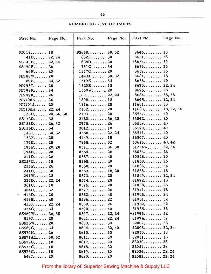
43
NUMERICAL LIST OF PARTS
Part No. Page No. Part No. Page No.
SS658 ..•.••.• 30, 32 662F .•••••• 30 668D ••.•.•. 20 761 c ....... 34
1177C ••••••• 20 1423J ....•.• 30, 32 1519E ••••••• 34 1520R ••.•.•. 18 1560W .•....• 20 1801 •.•.•.•• 22, 24 1808 ..•..... 18 1816 .••••••• 28 2102 ......•• 20 2103 ••••.••• 20 2460 ••.••.•• 36, 38 297 5 ••.••.•• 26 3012 ..•.•••• 18 4288 .•••.•.• 22, 24 4449 .••••.•• 18 7868 ...••••• 32 8371. ..••..• 36, 38 8554 •••••••• 26 8 557 •••••••• 40 8558 ••.••••• 40 8568 •••••••• 20 8569 •••.•••• 18, 20 8573 •.•.•••• 28 8574 •••••••• 20 857.5 •••••••• 20 8577 •••••••• 26 8582 •••••••• 40 8 586. • • • • • • • 22 8589 •..••••• 26 8590 •••••.•• 40 8597 •••••••• 22, 24 8601 •.•••••• 22, 24 8603 ••••.••• 30 8604 •••••••• 30, 40 8610 •••••••• 30 8611 •••••.•• 30 8617 •••••••• 20 8618 •••••••• 20 8619 ••••..•• 20 8620 •••••••• 20
8645 .•••...• 18 8651 ..••••.. 36
*8654 .••..••• 30 8656 .•..•••• 26 8659 ••••.•.. 26 8661. .••••.• 18 8666 .•..•••• 40 8670 .••••••• 22, 24 8675 .•..•••• 28 8684 .••••••• 36, 38 869 5 .••.•••• 22, 24
11661. ••..••• 30 11663 ••.••••• 18, 22, 24 25537 •••..••• 40 3389 2 •.••.••• 20 36569 •••••••• 40 36570 ••.•••.• 40 36571. .•.•••• 40 36807 ••..•••• 40 50616 ••.••..• 40, 42 51224W ••••.• 22,24 56033 .••...•• 26 80 548 .••••••• 20 81858 •••••••• 26 81866 ••..•••• 34 81868 ..•••••• 18 81869 •••••••• 22, 24 81872 •••••••• 18 81888 .••••••• 26 81941. ••••••• 18 81943 •••••••• 24 81951 •••••••• 32 81952 •.•••••• 32 81965 •••••••• 36
*81993 ..•••••• 32 81994 ••••..•• 32 82007 •••.•••• 28 22008 .••••••• 22, 24 82010 •••••••• 18 82011 •••••••• 18 82030 •••••••• 26 82031. ••••••• 26 82034 ••.••••• 22, 24 82052 •••••••• 22, 24
From the library of: Superior Sewing Machine & Supply LLC
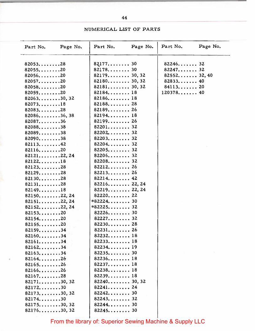
44
NUMERICAL LIST OF PARTS
Part No. Page No. I Part No. Page No. I Part No. Page No.
82053 •.•••.•• 28 820 55 ••••...• 20 82056 •.••••.• 20 82057 •.•••••• 20 820 58 •.••..•• 20 82059 ••••.••• 20 82063 •••••••• 30, 32 82073 ••••.••• 18 82083 •••..••• 28 82086 •••••••. 36, 38 82087 •••..••. 36 82088 •••••••• 38 82089 •••••.•• 38 82090 •••••.•• 38 82113 •.••••.. 42 82116 •••••••• 20 82121. •••..•• 22, 24 82122 .••••••• 18 82123 •••••••• 28 82129 •.•••••• 28 82130 •••••••• 28 82131. ••••••• 28 82149 •••••••. 18 82150 •.•••••• 22, 24 82151. •.••••. 22, 24 82152 •••.•••• 22, 24 82153 •••••••• 20 82154 •••••••• 20 82155 .••••••• 20 82159 •••••••• 34 82160 •••••••• 34 82161. ••••••• 34 82162 •••••••• 34 82163 •••••••. 34 82164 •••••••• 26 82165 •••••••• 26 82166 •••••••• 26 82167 .••••••• 28 82171. ••••••• 30, 32 82172 •••••••• 30 8217 3 •••••••• 30, 32 82174 •••••••• 30 8217 5 ••••.••. 30, 32 82176 •••••••• 30, 32
8~177 ••••..•• 30 82178 .•••...• 30 82179 •.•.••.. 30, 32 82180 .••••••. 30, 32 82181. •••.••• 30, 32 82184 •••••••. 18 82186 ••••••.• 18 82188 •••.••.• 28 82189 •••••••• 26 82194 •••.•••• 18 82199 ..•••••• 26 82201. ••••••• 32 82202.. ••••••• 32 8220 3 •••••••• 32 82204 •••••••• 32 8220 5 •••••••. 32 82206 •••••••• 32 82208 ••••.••• 32 82212 •••.•••• 26 82213 .••••••• 26 82214 •••••••• 42 82216 •••••••• 22, 24 82219 •••.•••• 22,24 82220 •••••••• 22
*82224 ••••••.• 30 *82225 •••••••• 32
82226 •••••••• 30 82227 •••••••• 32 82230 •••••••• 28 82231. ••••••• 26 82232 •••••••• 18 82233 •••••••• 18 82234 •••••••• 19 82235 •••••••• 30 82236 •••.•••• 18 82237 •••••••• 18 82238 •••.•••• 18 82239 •••••••• 18 82240 •••••••• 30, 32 82241 .••••••• 24 82242 •••••••• 30 82243 •••••••• 32 82244 •••.•••• 30 82245 •••••••• 30
82246 .•.•.•• 32 82247 .••.••• 32 82552 ..••••• 32, 40 82833 ••.•••• 40 84113 ••••••• 20
120378 ••••••• 40
From the library of: Superior Sewing Machine & Supply LLC
45
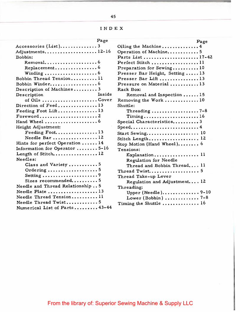
INDEX
Page Accessories (List) •••..•.•••••.• 3 Adjustments ••••.. o •••••• o •••••• 12-16 Bobbin:
Removal. 0 •• 0 ••• D ••••• a ••• 0 0 6 Replacement . ............... 6 Win ding o •• o •••••••••••••••• 6
Bobbin Thread Tension •••••••••• 11 Bobbin Winder ...... o ••••••••••• 6 Description of Machines •.•••.••• 3 Description Inside
of Oils ............•........ Cover Direction of Feed •.•••••.••••••• 13 Feeding Foot Lift ••.•••••..•••.. 13 Foreword . .................. D •• 2 Hand Wheel ..................... 6 Height Adjustment:
Feeding Foot ••••••••••••.••• 13 Needle Bar ................. 12
Hints for perfect Operation ••• o o. 14 Information for Operator •••.•••• 5-16 Length of Stitch •• o ••••••• o ••••• o 12 Needles:
Class and Variety •••••••.• o • 5 Or de rin.g ..•.••....••.•..•.• 5 Setting ..................•.. 9 Sizes recommended •••••••••• 5
Needle and Thread Relationship •• 5 Needle Plate ••••••••••••••••••• 13 Needle Thread Tension •••••••••• 11 Needle Thread Twist •••••••••••• 5 Numerical List of Parts ••••• o. o. 43-44
Page Oiling the Machine •••••••••••••• 4 Operation of Machine •••••••••••• 5 Parts List ••••••••••••••••••••• 17-42 Perfect Stitch • o •••••••••••••••• 11 Preparation for Sewing •••••••••• 10 Presser Bar Height, Setting ••••• 13 Presser Bar Lift ••••••••••••••• 13 Pressure on Material ••••••• o o •• 13 Rack Box:
Removal and Inspection •• o ••• 15 Removing the Work ••••••••••••• 10 Shuttle:
Threading .................. 7-8 Timing ..................... 16
Special Characteristics ••••••••• o 3 Speed . ......................... 4 Start Sewing . ................... 10 Stitch Length ••• o •••••••••••••• o 12 Stop Motion (Hand Wheel). o ••••• o 6 Tensions:
Explanation • • • • • • • • • • • • • . • • • 11 Regulation for Needle Thread and Bobbin Thread. • . • 11
Thread Twist .. o o • o •••••••••••• o 5 Thread Take-up Lever
Regulation and Adjustment ••• • 12 Threading:
Upper (Needle) •••••••••••••. 9-10 Lower (Bobbin) ••••••••.•••• 7-8
Timing the Shuttle ••••••••••••• o 16
From the library of: Superior Sewing Machine & Supply LLC

From the library of: Superior Sewing Machine & Supply LLC
TO ALL WI-IOM IT MAY CONCERN:
The improper placing or renewal of the Trademark 11 S I N Ci E R" or
any other of the Trademarks of The Singer Manufacturing Company
(all of which are duly Registered Trademarks) on any machine that: has
been repaired, rebuilt:, reconditioned, or altered in any way whatsoever
outside a SINGER factory or an authorized SINGER agency is forbidden.
TI-lE IMPORTANCE OF USING
SINGER** PARTS AND NEEDLES
IN SINGER MACI-IINES
The successful operation of SINGER machines can only be assured
if Sl NGER parts and needles are used. Supplies are available at: all
SINGER Shops for t:he Manufacturing Trade, and mail orders will
receive prompt: attention.
SINGER Needles should be used in SINGER Machines
These Needles and their Containers are marked with t:he
Company's Trademark "SIMA N C 0"
Needles in Containers marked
"FOR SINGER MACHINES"
are NOT SINGER made needles 2
From the library of: Superior Sewing Machine & Supply LLC
From the library of: Superior Sewing Machine & Supply LLC