
Molded Case Circuit Breakers & Earth Leakage ... - Kassidiaris
Upload
khangminh22Category
view
0download
0
pISSN 1229-3008 eISSN 2287-6251
Progress in Superconductivity and Cryogenics Vol.22, No.3, (2020), pp.25~30 https://doi.org/10.9714/psac.2020.22.3.025
Nomenclature
D Tank diameter [m]
ei Insulation thickness [m]
L Length of the cylinder [m]
�̇� Heat flux [W/m2]
�̇�1 Cylinder side heat flux [W/m2]
�̇�2 Lateral side heat flux [W/m2]
Sb Tank side surface [m2]
SL Total lateral surface [m2]
Text External temperature [K]
Tcry Liquefaction temperature [K]
i Insulator thermal conductivity [W/(m·K)]
Teq Equivalent thermal gradient [K]
Specific technical financing parameter
[(€·m-1)/(€·m-3)]
Specific technical financing parameter
[(€·m-2)/(€·m-3)]
1. INTRODUCTION
Principles of insulating vessels for the storage and
transportation of liquefied gases were discussed since
the 50s of the previous century. General principles
relating to the thermal design of low-loss vessels and
analyses of methods that can be used to improve the
performance of an insulated vessel by utilizing the
refrigerative effect of the escaping vapor were presented
and discussed [1, 2].
Li et al. [3] contribute significantly in the design,
usage and selection of cryogenic vessels. They analyzed
effects of liquid volume fraction, temperature and work
pressure on the pressure rise rates in cryogenic vessels.
The non-loss storage time was calculated through non-
dimensional criterion such as non-dimensional pressure,
non-dimensional thermal load and primal liquid volume
fraction.
Effective results are obtained for examining the non-
contact cooling of high-temperature superconductors.
Tanaka et al. [4] measured the heat transfer
characteristics in cryogenic and low-pressure
environments, and found out the heat transfer mode
from the comparison between experimental results and
theoretical values.
Li et al. [5] shows the important role that the two-
phase flow plays on thermal stratification in the
cryogenic tank. Experimental and numerical
investigation contribute to the understanding of the
transient process of thermal stratification in liquid
nitrogen (LN2) induced by lose of vacuum in a multi-
layer insulated cryogenic tank.
The influence of a sudden, catastrophic loss of
insulating vacuum on the heat transfer characteristics in
a high-vacuum-multilayer-insulation cryogenic tank has
been researched experimentally. Xie et al. [6] analyzed
and discussed the effects of the insulation and the initial
liquid level on venting rate and heat flux leaking into the
liquid nitrogen (LN2). The maximum value of the heat
flux leaking into the liquid is higher than the steady
value of it. The number of insulation layers is the most
important factor effecting on the heat flux.
Li et al. [7] analyzed the steady state heat leak into
cryogenic vessels with different liquid level height using
a finite element model. A liquid nitrogen boil-off
method was adopted in experiments to validate the result
of numerical simulation. The effect of liquid level on
heat leak into the cryogenic vessel can be considered in
calculation of storage time and structure design.
Rubeli et al. [8] proposed an experimental technique
to precisely measure in real time the temperature and the
heat exchanged to the bath of a quenched resistive
Simple predictive heat leakage estimation of static non-vacuum
insulated cryogenic vessel
Hocine Mzad*
Department of Mechanical Engineering, Badji Mokhtar University of Annaba, P.O. Box 12, DZ−23000, Algeria
(Received 21 May 2020; revised or reviewed 24 September 2020; accepted 25 September 2020)
Abstract
The diminishing of heat leak into cryogenic vessels can prolong the storage time of cryogenic liquid. With the storage of
cryogenic liquid reducing, the heat leak decreases, while the actual storage time increases. Regarding to the theoretical analysis,
the obtained results seems to be constructive for the cryogenic insulation system applications. This study presents a predictive
assessment of heat leak occurring in non-vacuum tanks with a single layer of insulation. A Radial steady-state heat transfer, based
on heat conduction equation, is taken into consideration. Graphical results show the thermal performance of the insulation used,
they also allow us to choose the appropriate insulation thickness according to the shape and diameter of the storage tank.
Keywords: cryogen, heat leak, prediction, non-vacuum, insulation
* Corresponding author: [email protected]
Simple predictive heat leakage estimation of static non-vacuum insulated cryogenic vessel
superconducting fault current limiter tape immersed in
liquid nitrogen. The current and the associated voltage
are measured, giving a precise knowledge of the amount
of energy dissipated in the tape.
A research work assessed the efficiency of a
cryogenic energy storage system in order to identify if
and how it can achieve an acceptable round-trip
efficiency [9]. For this purpose, a thermodynamic
analysis of such system, based on air liquefaction and
storage in an insulated vessel was presented.
Hamdy et al. [10] reviews and evaluates concepts of
cryogenic energy storage systems and reports the results
from exergy analysis. They considered two cold exergy
recovery cycles: direct expansion of liquid air and
expansion of liquid air in combination with an organic
Rankine cycle. The exergetic efficiency of the overall
system configuration and the round-trip efficiency are
considerably improved.
A new test method based on the pressure changes
over time in cryogenic vessel to determine heat
insulation performance requirements is designed [11].
The volume of instantaneous evaporated gas and heat
leakage are calculated by the current standard
corresponding to the maximum allowable daily
evaporation rate of cryogenic vessel.
Garceau et al. [12] observes the sudden vacuum break
in beam-line tubes of liquid helium cooled
superconducting particle accelerators. Basing on
extended previous experiments, a new theoretical model
that systematically describes the gas dynamics and
condensation is presented.
Previous studies gave physical insights to prevent the
heat loss that occurs in pressurized vacuum insulated
vessels (PVIVs). Information is scarce on cryogenic
storage using non-vacuum insulated vessels (NVIVs).
The present work paves the way for a theoretical
understanding of the thermal conduction processes
involved in such cryogenic systems. A facile approach
is proposed to estimate the heat flux leaking into the
cryogenic liquid in the case of static non-vacuum
insulated tank with different initial liquids and two
insulation types.
2. STEADY STATE HEAT LOSS CALCULATION
Storing a gas in liquefied form considerably reduces
the volume occupied. The liquid form allows to store up
to 230 times more fluid in the same volume. There are
two storage ways of cryogen: pressurized at ambient
temperature or at low temperature (Cryogenic storage).
Sphere and hollow cylinder are the two geometric
shapes used in the chemical industry because of their
storage capacities. The cylindrical will be studied first,
and then the results will be extended for the sphere. The
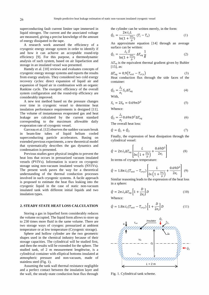
studied tank, of 2 m measurement lengthwise, is a
cylindrical container with elliptical bottoms insulated at
atmospheric pressure and non-vacuum, made of
stainless steel (Fig. 1).
Assuming the tank wall thermal resistance negligible
and a perfect contact between the insulation layer and
the wall, the steady-state conduction heat flux through
the cylinder can be written merely, in the form:
�̇�1 =2𝜋𝑖𝐿
ln(1 +2𝑋𝑖
𝐷)(𝑇𝑖 − 𝑇𝑜)(1)
An approximate equation [14] through an average
surface can be written:
�̇�1 =𝑖 𝑆̅
ln(1 +2𝑋𝑖
𝐷)∆𝑇𝑒𝑞
1
�̅�(2)
Teq is the equivalent thermal gradient given by Buhler
[15], as:
∆𝑇𝑒𝑞 = 0,9(𝑇𝑒𝑥𝑡 − 𝑇𝑐𝑟𝑦)(3)
Heat conduction flux through the side faces of the
container:
𝑄2̇ =𝑖
𝑒𝑖𝑆𝐿∆𝑇𝑒𝑞 (4)
With,
𝑆𝐿 = 2𝑆𝑏 = 0.69𝜋𝐷2(5)
Whence:
𝑄2̇ =𝑖
𝑒𝑖0.69𝜋𝐷2∆𝑇𝑒𝑞 (6)
The overall heat loss:
�̇� = �̇�1 + �̇�2(7)
Finally, the expression of heat dissipation through the
cylindrical vessel:
�̇� = 2𝜋𝑖∆𝑇𝑒𝑞 [𝐿
𝑙𝑛 (1 +2𝑒𝑖
𝐷)+0.69𝐷2
2𝑒𝑖] (8)
In terms of cryogen temperature:
�̇� = 1.8𝜋𝑖(𝑇𝑒𝑥𝑡 − 𝑇𝑐𝑟𝑦) [𝐿
𝑙𝑛 (1 +2𝑒𝑖
𝐷)+0.69𝐷2
2𝑒𝑖] (9)
Similar reasoning leads to the expression of the heat loss
in a sphere:
�̇� = 2𝜋𝑖∆𝑇𝑒𝑞 [1 +𝐷
2𝑒𝑖] 𝐷(10)
Whence:
�̇� = 1.8𝜋𝑖(𝑇𝑒𝑥𝑡 − 𝑇𝑐𝑟𝑦) [1 +𝐷
2𝑒𝑖] 𝐷(11)
Fig. 1. Cylindrical tank scheme.
L = 2 m
D
ei
Insulator
Vtk
Sin
Stk
Tcry
�̇�1
�̇�2
Text
26
Hocine Mzad
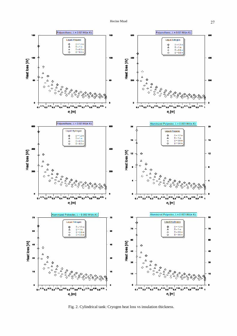
Fig. 2. Cylindrical tank: Cryogen heat loss vs insulation thickness.
27

Simple predictive heat leakage estimation of static non-vacuum insulated cryogenic vessel
Fig. 3. Spherical tank: Cryogen heat loss vs insulation thickness.
28

Hocine Mzad
TABLE 1
THERMAL PROPERTIES OF INSULATION MATERIALS
Material
Thermal
conductivity
W/(m.K)
Specific heat
J/(kg.K)
Density
kg/m3
Thermal
diffusivity
m2/s
Polyurethane foam 0.02 1674 40 0.3 10–6
Aluminized polyester
0.003 1171 1390 0.2 10–8
Selection of insulation material should be based on
initial cost, effectiveness, durability, the adaptation of its
shape and the installation methods available in each
particular area [13].
The main advantage of polyurethane foam in
comparison with other thermal insulation materials is
possibility to cover this material on the complicated
shape metal surfaces by spraying method, which leads
to significant cost savings.
From an economic point of view, it may be better to
choose an insulating material with a lower thermal
conductivity rather than increase the thickness of the
insulation. With highly reflective surface of polished
aluminium, aluminized polyester offers the glossy
metallic appearance of an aluminium foil at a reduced
weight and cost.
Using polyurethane and aluminised polyester (Tab. 1)
as insulation materials, heat leak calculations are
represented graphically while storing at cryogenic
temperatures (Figs 2 and 3). The thermal insulation
performance of these two materials is tested at the
environmental temperature of 293.15 K in a particular
range of temperature. Three storage types are considered:
liquid propane (Tcry = 230.95 K), liquid nitrogen (Tcry =
77.36 K), and liquid hydrogen (Tcry = 20.28 K).
3. RESULTS DISCUSSION AND SUGGESTIONS
Below, the thermal efficiency of two types of
insulation will be discussed, namely a foam
(Polyurethane) and a superinsulator (Aluminized
polyester). Insulation is applied to both cylindrical and
spherical tank.
From the analysis of figure 2, it can clearly be
deduced that insulation with polyurethane is not
recommended for the storage of cryogenic fluids such as
nitrogen (LN2) and hydrogen (LH2). Indeed, heat
leakage of 50 to 150 W occurs for an insulation layer
varying from 0.55 to 1 m thick in a cylindrical tank with
a length of 2 m. Nonetheless, it would possible to
consider LNG product storage such as liquid propane in
the studied cylindrical tank respecting an insulation
thickness limit of 0.55 m. In this case, the smallest
diameter (0.6 m) must be chosen with instantaneous
monitoring of the liquid temperature.
On the other hand, an aluminized polyester insulation
offers better thermal performance. Such kind of
insulator provides an acceptable insulation efficiency of
the considered cylindrical tank containing a cryogenic
liquid below 100 K. Lower heat leaks are observed, less
than 30 W with the condition that ei ≥ 0.33 m. For LNG
products such as liquid propane, the heat loss recorded
in this case is in the range [2-7] W corresponding to
superinsulation thickness ei ≥ 0.33 m. Although the
cylindrical shapes allow better integration in a crowded
environment, they can be used for intermediate storage
in production units.
Regarding the sphere storage (Fig. 3) insulated in
polyurethane, the losses exist despite a smaller volume
compared to the above cylindrical shape. However, if
there is a useful margin between the normal operating
pressure of storage and its maximum allowable pressure,
such tanks can be used for temporary cryogen storage at
a temperature around 80 K. In fact, heat transfer from
tank surrounding will cause a slow increase in its
temperature and pressure.
On the other hand, using aluminized polyester
insulation, some cryogenic fluids can be stored in a
spherical tank of small diameter, D ≤ 0.8 m. In this case
heat loss is less than 5 W for ei ≥ 0.45 m. Heat leakage
due to storage of liquid propane are negligible regardless
of insulation thickness, ie less than 1 W for a container
diameter of 0.6 m and [2-4] W for a diameter of 1.2 m.
Identification of the different heat loads on the system
would tell us the maximum range of insulation layer
thickness, which is of great practical significance.
Comparison of the tanks with insulation of various types
should be carried out for the same holding capacity of
the tanks to avoid the effect of the scale factors;
optimum thickness must be determined for each type of
insulation. Based on an energy cost balance, a recent
published work [13] allowed the optimization of
insulation thickness of cryogenic shells. The optimum
thickness is estimated according to the equation:
𝑒𝑜𝑝𝑡 = 𝐷 {(3.19Ψ
0.19Ψ + 8.76𝐷Ψ′ + 3.25𝐷2)−0.4259
+ 0.3008}
−1.1737
(12)
The parameter represents the ratio of energy cost
per 1 m of insulation on the insulation cost of 1 m3.
is the ratio of shell cost per 1 m2 on the insulation cost
of 1 m3.
The optimal thickness must satisfy a compromise
between tank diameter and layer thickness, i.e. 𝑒𝑜𝑝𝑡 ≤
1
3𝐷 . In the present case study, independently of the
volume of cryogenic storage, from low capacity
container (0.6 m) to the biggest tank (1.2 m),
polyurethane is the suitable insulator when storing at
low temperatures, around 230 K, like liquid propane.
Indeed, the maximum insulation thickness would be
𝑒𝑚𝑎𝑥 =1
4𝐷. Concerning storage at very low temperature in
the vicinity of 90 K like liquid nitrogen, a multilayer
insulation (MLI) made of aluminized polyester is
recommended. In this case the necessary maximum
insulation thickness is 𝑒𝑚𝑎𝑥 =1
2𝐷. Concerning storage
at extreme temperatures near 20 K, like hydrogen liquid,
the present investigated reservoirs needs a maximum
insulation thickness of 𝑒𝑚𝑎𝑥 =4
3𝐷.
29

Simple predictive heat leakage estimation of static non-vacuum insulated cryogenic vessel
For optimal stabilization, a thermal insulation with a
thickness adapted to the operating conditions has to be
used. It specifies operational requirements for static
non-vacuum insulated cryogenic vessels, designed for a
maximum allowable pressure greater than 0.5 bar.
4. CONCLUSIONS AND PERSPECTIVE
Through heat leakage estimation of static non-
vacuum cryogenic vessel by simple predictive method,
two major conclusions come out:
- Polyurethane foam, also known as cellular plastic or
expanded plastic, offer both a high strength-to-weight
ratio and low thermal conductivity. Opaque to
thermal radiation, this category of unevacuated
insulation is reasonably competitive in thermal
effectiveness at low temperatures. Omitting the
degradation of insulating properties with time, the
principal disadvantage highlighted in this paper is
low maximum temperature limits. Indeed,
polyurethane is not recommended for cryogenic
storage at very low temperatures, particularly below
200 K. However, its use is strongly advised in large
liquefied natural gas (LNG) storage tanks and LNG
ship tankers.
- Proper isolation clearly improves the efficiency of
cryogenic devices and minimizes cryogenic losses as
a result of evaporation. The use of the superinsulation
made of aluminized polyester allows the cryogenic
system to increase efficiency while reducing the size
and weight. In such case, the appropriate
temperatures are around 80 K like liquid nitrogen
(LN2). For extreme temperatures near absolute zero
(0 K), such as liquid hydrogen and helium, an
oversized insulation thickness will be required.
Therefore, we need to use Multi-layer insulation
(MLI) which is composed of multiple layers of thin
sheets.
Results presented in this article can be easily extended
to obtain a huge graph database (GDB) regrouping all
the cryogenic fluids as well as the LNG products stored
at low temperature. Abacuses can be created, useful for
engineers working in process industries where
insulation is a key parameter.
REFERENCES
[1] B.W. Birmingham, E.H. Brown, C.R. Class and A.F. Schmidt,
“Vessels for the storage and transport of liquid hydrogen”, J. of
Research of the National Bureau of Standards, vol. 58, no. 5, pp.
243-253, 1957. [2] R.B. Scott, “Thermal design of large storage vessels for liquid
hydrogen and helium”, J. of Research of the National Bureau of
Standards, vol. 58, no. 6, pp. 317-325, 1957. [3] Z. Li, L. Xu, H. Sun, Y. Xiao and J. Zhang, “Investigation on
performances of non-loss storage for cryogenic liquefied gas”,
Cryogenics, vol. 44, no. 5, pp. 357-362, 2004. [4] Y. Tanaka, T. Furusawa, M. Nakauchi and K. Nagashima, “Heat
transfer characteristics under cryogenic, low pressure
environments”, Physica C: Superconductivity and its Applications, vol. 469, no. 15-20, pp. 1862-1865, 2009.
[5] X. Li, G. Xie and R. Wang, “Experimental and numerical
investigations of fluid flow and heat transfer in a cryogenic tank at loss of vacuum”, Heat Mass Transfer, vol. 46, pp. 395-404,
2010.
[6] G.F. Xie, X.D. Li and R.S. Wang, “Experimental study of heat
transfer in a HVMLI cryogenic tank after SCLIV”, Heat Mass
Transfer, vol. 46, pp. 457-462, 2010.
[7] Y. Li, R. Wang and C. Wang, “Study on effect of liquid level on the heat leak into vertical cryogenic vessels”, Cryogenics, vol. 50,
no. 6-7, pp. 367-372, 2010.
[8] T. Rubeli, D. Colangelo, B. Dutoit and M. Vojenciak, “Heat transfer monitoring between quenched high-temperature
superconducting coated conductors and liquid nitrogen”, Progress
in Superconductivity and Cryogenics, vol. 17, no. 1, pp. 10-13, 2015.
[9] G.L. Guizzi, M. Manno, L.M. Tolomei and R.M. Vitali,
“Thermodynamic analysis of a liquid air energy storage system”, Energy, vol. 93, no. 2, pp. 1639-1647, 2015.
[10] S. Hamdy, T. Morosuk and G. Tsatsaronis, “Cryogenics-based energy storage: Evaluation of cold exergy recovery cycles”,
Energy, vol. 138, pp. 1069-1080, 2017.
[11] Z.Q. Li, X.J. Li, and M. Liu, “A new method fast measure cryogenic vessel heat leakage”, Progress in Superconductivity and
Cryogenics, vol. 22, no. 1, pp. 24-28, 2020.
[12] S. Bao, N. Garceau and W. Guo, “Heat and mass transfer during
a sudden loss of vacuum in a liquid helium cooled tube – Part II:
Theoretical modeling”, Int. J. Heat Mass Transfer, vol. 146,
118883, 2020. [13] H. Mzad and A. Haouam, “Optimization approach of insulation
thickness of non-vacuum cryogenic storage tank”, Progress in
Superconductivity and Cryogenics, vol. 22, no. 1, pp. 17-23, 2020. [14] R.R. Conte, “Elements of cryogenics”, Edition Masson & Cie, p.
332, Paris, France, 1970.
[15] S. Buhler, “Cryogenic technology”, Institute of Nuclear Physics, Orsay, France, 1998.
30
Copyright © 2022 FDOKUMEN