SI ERRATA PAGES (Errata highlighted) SEC 14 - Webflow
65
SI ERRATA PAGES (Errata highlighted) SEC 14 — Pages 3 through 8 SEC 16 — Pages 1 and 2 SEC 19 — Pages 9 through 12 SEC 20 — Pages 17 and 18 Pages 27 and 28 Pages 47 and 48 SEC 21 — Pages 13 through 16 SEC 22 — Pages 29 and 30 SEC 23— Pages 3 and 4 Pages 11 and 12 Pages 27 and 28 SEC 26 — Pages 1 through 34 Errata Page - July 2013
-
Upload
khangminh22 -
Category
Documents
-
view
3 -
download
0
Transcript of SI ERRATA PAGES (Errata highlighted) SEC 14 - Webflow

SI ERRATA PAGES (Errata highlighted)
SEC 14 — Pages 3 through 8
SEC 16 — Pages 1 and 2
SEC 19 — Pages 9 through 12
SEC 20 — Pages 17 and 18 Pages 27 and 28 Pages 47 and 48
SEC 21 — Pages 13 through 16
SEC 22 — Pages 29 and 30
SEC 23— Pages 3 and 4 Pages 11 and 12 Pages 27 and 28
SEC 26 — Pages 1 through 34
Errata Page - July 2013

14-3
nation of desuperheating and constant temperature condens-ing. This fact must be considered for proper design of the con-denser.
System pressure drop — Some typical values for pressure drops that must be considered are:
Condenser pressure drop 20 to 50 kPaLine hydraulic losses
Evaporator to Compressor* 0.7 to 10 kPa Compressor to Condenser 0.7 to 14 kPa Condenser to Receiver 3.5 to 7 kPa* This is an important consideration in refrigeration services
with low suction pressure to compressor.Refrigeration Stages
Refrigeration systems utilizing one, two, three, or four stag-es of compression have been successfully operated in various services. The number of levels of refrigeration generally de-pends upon the number of compression stages required, inter-stage heat loads, economics, and the type of compression.
One-stage system — A typical one-stage refrigeration sys-tem is shown in Fig. 14-3 where the data are for pure propane refrigerant. Fig. 14-4 illustrates a process application of a sin-gle level chiller and the associated cooling curve.
Two-stage system — Savings in the 20% range can often be achieved with a two-stage refrigeration system and inter-stage flash economizer. Additional savings can be realized by removing process heat at the interstage level rather than at the low stage level. A typical two-stage system with an intermedi-ate load is shown in Fig. 14-5 with data for pure propane.
Three-stage system — Additional power savings can be achieved by using a three-stage compression system. As with a two-stage system, flash economization and/or an intermediate heat load can be used. The savings, while not as dramatic as the two stage versus one-stage, can still be significant enough to justify the additional equipment. A typical three stage propane system is shown in Fig. 14-6.
System configuration — Energy consumption is fre-quently reduced as the number of stages is increased. For a propane refrigeration system, Fig. 14-7 illustrates the effect of
FIG. 14-3One-Stage Refrigeration System
FIG. 14-4
Single-Stage Cooling, Chilling and Heating Curves
FIG. 14-2
Process Flow Diagram and Pressure-Enthalpy Diagram
Errata Page - July 2013

14-4
720
7327 2931
380 580
765
FIG. 14-5
Two-Stage Refrigeration System
FIG. 14-6
Three-Stage Refrigeration System
Errata Page - July 2013

14-5
interstages without using refrigeration at intermediate levels. However, the installation cost of such refrigeration systems in-creases as the number of stages increases. The optimum overall cost will be a function of the specific system and has to be deter-mined for a set of economic criteria.
The compression power for refrigeration can be reduced fur-ther by shifting refrigerant load from cooler levels to warmer levels. Fig. 14-8 shows a refrigeration system using two levels of chilling. The gas is initially chilled to –1 °C with –4 °C pro-pane and then to –37 °C with –40 °C propane. The selection of the –4 °C level results from equal compression ratios for each stage. The interstage pressure and corresponding refrigerant temperature may be fixed by either equipment or process condi-tions. Equal compression ratios per stage are chosen whenever possible to minimize power.Example 14-1 — Calculate the power and condenser duty required for the process shown in Fig. 14-8 using propane refrigeration. De-sign condensing temperature is 49 °C. The pressure drop from the chillers to the compressor suction is 10 kPa. The pressure drop from compressor discharge to the receiver is 70 kPa.
Solution Steps:In order to determine the interstage refrigeration level for a
two-stage system, determine the ratio per stage:
r = Pd 1⁄n
Ps Eq 14-9
From the propane vapor pressure curve:Pd = 1670 kPa (abs) + 70 kPa = 1740 kPa (abs)Ps = 108 kPa – 10 kPa = 98 kPa (abs)
r = 1740 1⁄2
= 4.21 98
Thus the second stage suction pressure is:Ps2 = (98) (4.21) = 412 kPa
The first stage discharge pressure is:Pdl = 412 + 8 = 420 kPaFrom the vapor pressure curve for propane, the refrigera-
tion temperature at 420 kPa (abs) is –4 °C. Converting kW du-ties to kJ/h and substituting enthalpy values from Section 24, into Equation 14-5, we find the refrigerant flowrate through each chiller:
m1 = (26.4) (106) = 77 647 kg/h (720 – 380)
m2 = (10.6) (106) = 45 106 kg/h (765 – 530)where m1 is the flowrate through the first stage chiller, and m2 is the flowrate through the second stage chiller.
Liquid flow to the first-stage chiller (77 647 kg/h) is provided by flashing the liquid refrigerant from the refrigerant receiver at 49 °C and bypassing the second-stage chiller.
In order to determine the flow of liquid refrigerant from the receiver, consider the heat and material balances shown in Fig. 14-9. Here, let mb (kg/h) denote the refrigerant bypassing the second-stage chiller. The chiller produces 45 106 kg/h of re-frigerant vapor at –4 °C. These vapors flow through the second stage suction drum, and leave overhead. The liquid required from the second stage flash drum for the first stage chiller comes from the quantity mb.
By material balance, we find the vapors leaving the second stage suction drum as mb + 45 106 – 77 647 or mb – 32 541 kg/h. By heat balance around the suction drum, we can determine the amount of refrigerant, mb:
(mb – 32 541) (765) + (77 647) (380) = mb (530) + (45 106) (765)mb = 127 209 kg/h
FIG. 14-7
Effect of Staging on a Propane Refrigeration System
Stages, n1 2 3
Refrigeration Duty, kW 293 293 293Refrigeration Temperature, °C –40 –40 –40Refrigerant Condensing Temperature, °C 38 38 38Compression Requirements, kW 218 176 167Reduction in BP, % Base 19.2 23.3Condenser Duty, kW 511 469 462Change in condenser duty, % Base –8.2 –9.6
FIG. 14-8
Two-Level Chilling, Two-Stage Cooling System
Errata Page - July 2013

14-6
In order to calculate isentropic work for the first stage, it is necessary to determine the isentropic enthalpy at 412 kPa (abs). Fig. 24-20, the first stage inlet entropy equals 3.85 kJ/kg • K, and the corresponding isentropic enthalpy at 412 kPa (abs) is 782 kJ/kg.
The ideal change in enthalpy = 782 – 720 = 62 kJ/kgFor propane refrigerant k = 1.13, compression ratio, r, of 4.21
and the isentropic efficiency, ηi of 0.75, the required compression power for the first stage is obtained from Equation 14-7b:
BP1 = (62) (77 647) = 1783 kW (0.75) (3 600) Using Equation 14-7a we determine the first stage dis-
charge enthalpy is:
hvld = 62 + 820 = 803 kJ/kg 0.75 A material balance around the second compression stage
yields the total refrigerant flow:mT = m1 + (mb – 32 541) = 77 647 + (127 209 – 32 541) = 172 315 kg/hA heat balance at the second compression stage entrance
yields the second stage inlet enthalpy:
hv2s = (803) (77 647) + (765) (127 209 – 32 541) (172 315) = 782 kJ/kgFrom Fig. 24-27, the inlet entropy at 412 kPa (abs) and 782
kJ/kg is 3.85 kJ/(kg • K), and the isentropic enthalpy at 1740 kPa (abs) is 860 kJ/kg.
Substituting into Equation 14-6, the ideal enthalpy change across the second stage as:
∆h = 860 – 782 = 78 kJ/kgThe required compression power for the second stage is de-
termined from Equation 14-7b:
BP2 = (78) (172 315) (0.75) (3600) = 4978 kW
Hence, the compression required for the two-stage propane refrigeration system becomes:
BPT = 1783 + 4978 = 6761 kWUsing Equation 14-7a, the second stage discharge enthalpy is:
HV2d = 78 0.75 + 782 = 886 kJ/kg
Substituting into Equation 14-8 yields the condenser duty for the two-stage propane refrigeration system:
Qcd = (886 – 530) (172 315) = (6.134) (107) kJ/h = 17 039 kW
From Fig. 24-27 the second stage discharge temperature at 1740 kPa and enthalpy of 886 kJ/kg is 80 °C.
Condensing TemperatureCondensing temperature has a significant effect on the com-
pression power and condensing duty requirements. Mehra3 il-lustrated the effect of the condensing temperature on refrigera-tion requirements for one, two, and three stage systems. Results for a one-stage propylene refrigeration system are summarized in Fig. 14-10.
Fig. 14-10 illustrates that the colder the condensing tem-perature, the lower the power requirements for a given refrig-eration duty. Traditionally, the heat sinks for most refrig- era-tion systems have been either cooling water or ambient air. If cooling water or evaporative condensing is utilized, a 27 to 38 °C temperature can be achieved. Section 11 provides wet and dry bulb temperature data. Fig. 14-10 also indicates, to a certain extent, the effect on operations between summer and winter conditions as well as between day and night operations.
Refrigerant SubcoolingSubcooling liquid refrigerants is common in refrigeration
systems. Subcooling the refrigerant reduces the energy require-ments. It is carried out when an auxiliary source of cooling is readily available, and the source stream needs to be heated. Subcooling can be accomplished by simply installing a heat ex-changer on the appropriate refrigerant and process streams.
FIG. 14-9
Data for Heat and Material Balances
32 541
45 106
77 647
530
765
380
FIG. 14-10
Effect of Condensing Temperature
Condensing Temperature, °C
16
27
38
49
60
Refrigeration Duty, kW
293
293
293
293
293
Refrigeration Temperature, °C
–46
–46
–46
–46
–46
Compression Requirement, kW
157
199
248
320
413
Change in BP, % –36.6 –19.8 Base 28.8 66.4Condenser Duty, kW
451
492
539
613
709
Change in Condenser Duty, %
–16.3
–8.7
Base
13.6
31.5
Errata Page - July 2013

14-7
Example 14-2 — Consider installing an 880 kW subcooler on the liquid propane refrigerant from the receiver at 49 °C in Ex-ample 14-1 for the two-stage propane refrigeration system. The second stage of this system is shown in Fig. 14-11.
Solution Steps:By performing the heat balance around the subcooler and
the second stage suction drum, the liquid refrigerant flowrate to the subcooler is determined to be 158 624 kg/h. When com-paring this to the earlier flowrate of 172 315 kg/h, the refriger-ant flow is reduced by 13 691 kg/h.
By heat balance around the subcooler, we determine the en-thalpy of liquid propane refrigerant leaving the subcooler is 510 kJ/kg which corresponds to a temperature of 43 °C.
The flowrate of refrigerant through the second stage chiller becomes
m2 = (10.6) (106) (765 – 510) = 41 569 kg/h
As a result of subcooling, the flow of refrigerant through the second stage chiller has been reduced from 45 106 kg/h to 41 569 kg/h. The lower flowrates result in reduced compression power, condenser duty, and reduced size of piping and equip-ment. These benefits must be balanced against the installed cost of the subcooler exchanger.
Refrigerant For ReboilingRefrigerants have been successfully used for reboiling ser-
vices wherever applicable conditions exist. Reboiling is similar in concept to subcooling — heat is taken out of the refrigeration cycle.
In reboiling service, the heat removed from the refrigerant condenses the refrigerant vapor at essentially constant tem-perature and pressure. The liquid refrigerant produced in a re-boiler service is flashed to the next lower pressure stage to pro-duce useful refrigeration. The refrigerant condensing pressure is a function of the reboiling temperature.
Refrigerant CascadingIn the cascading of refrigerants, warmer refrigerants con-
dense cooler ones. Based on the low temperature requirements of a process, a refrigerant that is capable of providing the desired cold temperature is selected. For example, the lowest attainable temperature from ethane refrigerant is –85 °C (for a positive compressor suction pressure), whereas the lowest temperature level for propane is –40 °C (for a similar positive pressure).
In a refrigeration cycle, energy is transferred from lower to higher temperature levels economically by using water or ambi-ent air as the ultimate heat sink. If ethane is used as a refriger-ant, the warmest temperature level to condense ethane is its critical temperature of about 32 °C. This temperature requires unusually high compression ratios — making an ethane com-pressor for such service complicated and uneconomical. Also in order to condense ethane at 32 °C, a heat sink at 29 °C or lower is necessary. This condensing temperature is a difficult cooling water requirement in many locations. Thus a refrigerant such as propane is cascaded with ethane to transfer the energy from the ethane system to cooling water or air.
An example of a cascaded system is shown in Fig. 14-14, where an ethane system cascades into a propane system. The condenser duty for the ethane system is 9000 kW. This duty becomes a refrigeration load for the propane system along with
its 6740 kW refrigeration at –40 °C. Therefore, the propane re-frigeration system has to be designed to provide a total of 15 740 kW at –40 °C in addition to 2930 kW at –20 °C and 2050 kW at 7 °C.
Freon (CFC) Refrigerant Phase OutClorinated fluorocarbons (commonly called Freon) have
been used for many years as effective refrigerants in many ap-plications. However, the stability of these compounds, coupled with their chlorine content, has linked them to the depletion of the earth’s protective ozone layer. As a result, these compounds have been phased out of production and usage globally. Hydro-fluorocarbons (HFC) have been developed as an alternative.
Refrigerant HFC-410a has been developed to replace chloro-difluoromethane (R-22). This compound is reasonably close to R-22 in performance. Fig. 14-12 shows a comparison of HFC-410a and R-22. The refrigerant power requirement is quite similar but the operating pressures are higher for HFC-410a.
HFC-134a has been developed to replace dichlorodifluor-omethane (R-12). This compound is reasonably close to R-12 in performance but differences in equipment design and operation must be taken into account in the replacement. Fig. 14-13 shows a comparison of HFC-134a and R-12 for an example applica-tion. One of the important differences is the higher compression ratio necessary for this refrigerant.
Refrigerant PropertiesPhysical properties of pure component refrigerants in com-
mon use are given in Fig. 14-15. The vapor pressure curves for ethane, ethylene, propane, prpylene, and Refrigerant 22 (R-22) are available in Sections 23 and 24 or references 2, 5, 9, and 10. Figs. 14-35 through 14-37 contain properties for HFC-410a. Properties for HFC-134a are given in Figs. 14-38 through 14-40. References 12 and 13 contain additional data for these refriger-ants.
Enthalpy data are necessary in designing any refrigeration system. Pressure-enthalpy diagrams for pure ethane, ethylene, propane, propylene, and R-22 are available in Section 24 of this data book or references 2, 5, 9, and 10. References 12 and 13 contain additional information for these refrigerants.
FIG. 14-11
Refrigerant Subcooling
Errata Page - July 2013

14-8
Power and Condenser Duty EstimationSince many gas processing plants require mechanical refrig-
eration, generalized charts5 were developed to aid in a modular approach for designing refrigeration systems.
Because of the complexity of generalizing refrigeration sys-tems, the charts have been developed for four of the most com-mon refrigerants: ethylene, propylene, propane, and Refriger-ant 22.
In order to apply these curves to most of the commercially available compressors, a polytropic efficiency of 0.77 was as-sumed. The polytropic efficiency was converted into an isentro-pic efficiency1 to include the effects of compression ratio and specific heat ratio (k = Cp/Cv) for a given refrigerant. For well balanced and efficient operation of the compressor, an equal compression ratio between stages was employed.
The refrigeration level is defined as the temperature of the dew point vapor leaving the evaporator. The pressures at the com-pressor suction and side load inlet nozzles were adjusted by 10 kPa to allow for pressure drop. These charts also include a 35 kPa pressure drop across the refrigerant condenser for ethylene, and a 70 kPa drop for propane, propylene, and Refrigerant 22.
Before developing any system, one must define refrigerant temperature and condensing temperature of the refrigerant based on the medium used for condensing.
To achieve maximum energy conservation and minimum energy cost, it is necessary to match the process conditions and refrigeration compressor design to obtain the best efficiency.
After defining the lowest refrigerant level and the condens-ing temperature, the pressure at the evaporator and condenser can be established from the vapor-pressure curve for a specific refrigerant. All examples and data in this section are based upon pure component properties. In practice, pure hydrocarbon refrigerants are not always available. Impurities may cause sig-nificant deviations in design and performance.
One-stage systems — Figs. 14-16 through 14-20 provide data for estimating gas power and condenser duty requirements for one-stage refrigeration systems using ethylene, propane, propylene, R-22, and HFC 410a refrigerants.
Two-stage systems — The data for estimating gas power and refrigerant condenser duty requirements for two-stage re-frigeration systems utilizing ethylene, propane, propylene, R-22, and HFC 410a are shown in Figs. 14-22 through 14-26.
Three-stage systems — The data for estimating gas pow-er and condenser duty requirements for three-stage refrigera-tion systems utilizing ethylene, propane, propylene, and R-22 are presented in Figs. 14-27 through 14-31.Example 14-3 — Estimate the power and condenser duty re-quirements for a single stage propylene refrigeration system that will provide 26.4 (106) kJ/h of process chilling at a refriger-ant level of –29 °C.
Solution StepsThe unit BP for this example from Fig. 14-19 is 565 kW per
MW of refrigeration duty at an evaporator temperature of –29 °C and a condenser temperature of 38 °C. And, from Fig. 14-19, the condenser duty factor equals 1.565 MW per MW of refrigeration duty for the same evaporator and condenser temperatures. Hence, the total power and condenser duty are:
BP = (565) (7.325) = 4 139 kWQcd = (7325) (1.565) = 11 464 kW
Heat exchanger economizing — An alternative to flash economizing of the refrigeration cycle is to use a heat exchanger to accomplish an economizing step. Fig. 14-21 shows an exam-ple economizer using a heat exchanger. The heat exchanger is a chiller which uses some of the condensed refrigerant to subcool the balance of the condensed refrigerant stream. The refriger-ant used for the chilling is then fed to the interstage (or second stage) of the refrigeration compressor. The subcooled refriger-ant is then used for process chillers. The subcooled refrigerant produces less unusable vapor when flashed to suction drum conditions than a refrigerant stream that is not subcooled. Thus the use of the heat exchanger effectively shifts vapor from the low stage of compression to the high stage, thus saving pow-er. The resultant process impact is very similar to the flash economization previously discussed.
Design and Operating ConsiderationsThe following are some of the important parameters that
should be considered while designing any refrigeration system to provide a safe, reliable, and economical operation.
Oil removal — Oil removal requirements from evaporators are related to the type of the refrigerant, lubricant, evaporator, and compressor used in the refrigeration cycle. Fig. 14-32 illus-trates the application of an oil reclaimer in a propane refriger-ant cycle. In order to remove oil from the refrigerant, a slip
Fig. 14-12
Comparison Example of R-22 and HFC-410*
R-22 HFC-410a
Psuction, kPa (abs) 214.4 353
Pdisch 1965 3068
Compr. Ratio 9.19 8.7
kW/MW 78.6 78.9
Condenser Load kJ/kJ 1.52 1.51
*–23 °C Chiller, 49 °C Condensing, 69 kPa (ga) Condenser DP
FIG. 14-13
Theoretical Cycle Comparison of R-12 and HFC-134a*
R-12 HFC-134aCapacity (as % of R-12) 100 99.7Compressor Exit temperature °C Exit pressure, kPa (abs)
86.81348.6
83.11473.4
Compression ratio 4.1 4.7
*Conditions: Condenser, 54.4 °C; Evaporator, 1.7 °C; Comp. Suction, 26.7 °C; Expansion Device, 51.7 °C
Errata Page - July 2013
16-1
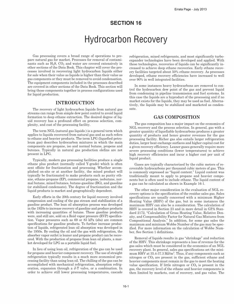
Gas processing covers a broad range of operations to pre-pare natural gas for market. Processes for removal of contami-nants such as H2S, CO2 and water are covered extensively in other sections of the Data Book. This chapter will cover the pro-cesses involved in recovering light hydrocarbon liquids either for sale when their value as liquids is higher than their value as gas components or they must be removed to avoid condensation. The equipment components included in the processes described are covered in other sections of the Data Book. This section will bring those components together in process configurations used for liquid production.
INTRODUCTIONThe recovery of light hydrocarbon liquids from natural gas
streams can range from simple dew point control to avoid liquid formation to deep ethane extraction. The desired degree of liq-uid recovery has a profound effect on process selection, com-plexity, and cost of the processing facility.
The term NGL (natural gas liquids ) is a general term which applies to liquids recovered from natural gas and as such refers to ethane and heavier products. The term LPG (liquefied petro-leum gas) describes hydrocarbon mixtures in which the main components are propane, iso and normal butane, propene and butenes. Typically in natural gas production olefins are not present in LPG.
Typically, modern gas processing facilities produce a single ethane plus product (normally called Y-grade) which is often sent offsite for fractionation and processing. Whether accom-plished on-site or at another facility, the mixed product will typically be fractionated to make products such as purity eth-ane, ethane-propane (EP), commercial propane, isobutane, nor-mal butane, mixed butanes, butane-gasoline (BG), and gasoline (or stabilized condensate). The degree of fractionation and the liquid products is market and geographically dependent.
Early efforts in the 20th century for liquid recovery involved compression and cooling of the gas stream and stabilization of a gasoline product. The lean oil absorption process was developed in the 1920s to increase recovery of gasoline and produce products with increasing quantities of butane. These gasoline products were, and still are, sold on a Reid vapor pressure (RVP) specifica-tion. Vapor pressures such as 69 or 83 kPa (abs) are common specifications for gasoline products. To further increase produc-tion of liquids, refrigerated lean oil absorption was developed in the 1950s. By cooling the oil and the gas with refrigeration, the absorber vapor outlet is leaner and propane product can be recov-ered. With the production of propane from lean oil plants, a mar-ket developed for LPG as a portable liquid fuel.
In lieu of using lean oil, refrigeration of the gas can be used for propane and heavier component recovery. The use of straight refrigeration typically results in a much more economical pro-cessing facility than using lean oil. The chilling of the gas can be accomplished with mechanical refrigeration, absorption refrig-eration, expansion through a J-T valve, or a combination. In order to achieve still lower processing temperatures, cascade
refrigeration, mixed refrigerants, and most significantly turbo-expander technologies have been developed and applied. With these technologies, recoveries of liquids can be significantly in-creased to achieve deep ethane recoveries. Early ethane recov-ery facilities targeted about 50% ethane recovery. As processes developed, ethane recovery efficiencies have increased to well over 90% in well integrated facilities.
In some instances heavy hydrocarbons are removed to con-trol the hydrocarbon dew point of the gas and prevent liquid from condensing in pipeline transmission and fuel systems. In this case the liquids are a byproduct of the processing and if no market exists for the liquids, they may be used as fuel. Alterna-tively, the liquids may be stabilized and marketed as conden-sate.
GAS COMPOSITIONThe gas composition has a major impact on the economics of
NGL recovery and the process selection. In general, gas with a greater quantity of liquefiable hydrocarbons produces a greater quantity of products and hence greater revenues for the gas processing facility. Richer gas also entails larger refrigeration duties, larger heat exchange surfaces and higher capital cost for a given recovery efficiency. Leaner gases generally require more severe processing conditions (lower temperatures) to achieve high recovery efficiencies and incur a higher cost per unit of liquid product.
Gases are typically characterized by the cubic meters of re-coverable hydrocarbons per thousand cubic meters of gas. This is commonly expressed as “liquid content.” Liquid content was traditionally meant to apply to propane and heavier compo-nents but is often used to include ethane. The liquid content of a gas can be calculated as shown in Example 16-1.
The other major consideration in the evaluation of NGL re-covery options is the specification of the residue sales gas. Sales specifications are usually concerned with a minimum Higher Heating Value (HHV) of the gas, but in some instances the maximum HHV can also be a consideration. The calculation of HHV is covered in Section 23 and in more detail in GPA Stan-dard 2172, “Calculation of Gross Heating Value, Relative Den-sity, and Compressibility Factor for Natural Gas Mixtures from Compositional Analysis.” In addition, for some gas sales the maximum and mininum Wobbe Number of the gas may be spec-ified. For more information on the calculation of Wobbe Num-ber, See Section 1 definitions.
Removal of liquids results in gas “shrinkage” and reduction of the HHV. This shrinkage represents a loss of revenue for the gas sales which must be considered in the economics of an NGL recovery plant. In general, sales gas specifications set the mini-mum HHV at 35.4-37.3 MJ/m3. Thus, if any components such as nitrogen or CO2 are present in the gas, sufficient ethane and heavier components must remain in the gas to meet the heating value specification. If little nitrogen or CO2 is present in the gas, the recovery level of the ethane and heavier components is then limited by markets, cost of recovery, and gas value. The
SECTION 16
Hydrocarbon Recovery
Errata Page - July 2013
16-2
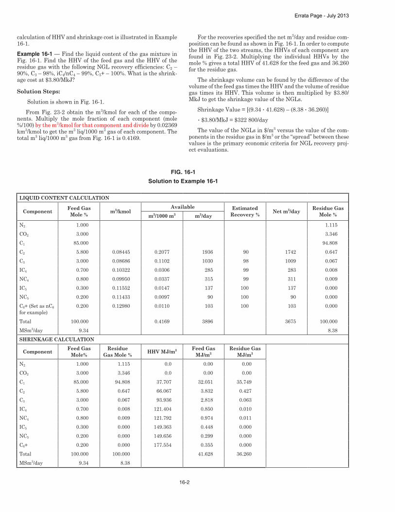
calculation of HHV and shrinkage cost is illustrated in Example 16-1.Example 16-1 — Find the liquid content of the gas mixture in Fig. 16-1. Find the HHV of the feed gas and the HHV of the residue gas with the following NGL recovery efficiencies: C2 – 90%, C3 – 98%, iC4/nC4 – 99%, C5+ – 100%. What is the shrink-age cost at $3.80/MkJ?
Solution Steps: Solution is shown in Fig. 16-1. From Fig. 23-2 obtain the m3/kmol for each of the compo-
nents. Multiply the mole fraction of each component (mole %/100) by the m3/kmol for that component and divide by 0.02369 km3/kmol to get the m3 liq/1000 m3 gas of each component. The total m3 liq/1000 m3 gas from Fig. 16-1 is 0.4169.
For the recoveries specified the net m3/day and residue com-position can be found as shown in Fig. 16-1. In order to compute the HHV of the two streams, the HHVs of each component are found in Fig. 23-2. Multiplying the individual HHVs by the mole % gives a total HHV of 41.628 for the feed gas and 36.260 for the residue gas.
The shrinkage volume can be found by the difference of the volume of the feed gas times the HHV and the volume of residue gas times its HHV. This volume is then multiplied by $3.80/MkJ to get the shrinkage value of the NGLs.
Shrinkage Value = [(9.34 • 41.628) – (8.38 • 36.260)] • $3.80/MkJ = $322 800/dayThe value of the NGLs in $/m3 versus the value of the com-
ponents in the residue gas in $/m3 or the “spread” between these values is the primary economic criteria for NGL recovery proj-ect evaluations.
LIQUID CONTENT CALCULATION
Component Feed Gas Mole % m3/kmol
Available Estimated Recovery % Net m3/day Residue Gas
Mole %m3/1000 m3 m3/dayN2 1.000 1.115CO2 3.000 3.346C1 85.000 94.808C2 5.800 0.08445 0.2077 1936 90 1742 0.647C3 3.000 0.08686 0.1102 1030 98 1009 0.067IC4 0.700 0.10322 0.0306 285 99 283 0.008NC4 0.800 0.09950 0.0337 315 99 311 0.009IC5 0.300 0.11552 0.0147 137 100 137 0.000NC5 0.200 0.11433 0.0097 90 100 90 0.000C6+ (Set as nC6 for example)
0.200 0.12980 0.0110 103 100 103 0.000
Total 100.000 0.4169 3896 3675 100.000MSm3/day 9.34 8.38SHRINKAGE CALCULATION
Component Feed Gas Mole%
Residue Gas Mole % HHV MJ/m3 Feed Gas
MJ/m3Residue Gas
MJ/m3
N2 1.000 1.115 0.0 0.00 0.00CO2 3.000 3.346 0.0 0.00 0.00C1 85.000 94.808 37.707 32.051 35.749C2 5.800 0.647 66.067 3.832 0.427C3 3.000 0.067 93.936 2.818 0.063IC4 0.700 0.008 121.404 0.850 0.010NC4 0.800 0.009 121.792 0.974 0.011IC5 0.300 0.000 149.363 0.448 0.000NC5 0.200 0.000 149.656 0.299 0.000C6+ 0.200 0.000 177.554 0.355 0.000Total 100.000 100.000 41.628 36.260MSm3/day 9.34 8.38
FIG. 16-1
Solution to Example 16-1
Errata Page - July 2013

19-9
rates, poor vapor-liquid contact can result. High liquid rates can cause flooding and dumping as the liquid capacity of the downcomers is exceeded.
In order to handle higher liquid rates, more downcomer area is required. This is often achieved by using multiple pass trays. Multipass trays increase liquid handling capacity for a given diameter due to increased weir length and reductions in the weir crest. Fig. 19-12 shows various configurations beyond a one pass tray where the liquid phase is split into two to four flow paths to increase liquid handling capacity.
Sizing“C” factor method — Many design methods for sizing
trayed fractionators have been used. Generally these methods are oriented toward liquid entrainment limitations or correla-tions for flooding limits. A simple method called the Souders and Brown equation8 involves using a Stokes’ Law type formula:
vmax = C ρL – ρv √ ρv Eq 19-11Note that ρL and ρv are at flowing temperature and pressure.
The value of C can be found from Fig. 19-13 based on tray spac-ing and liquid surface tension. The column diameter is:
DT = Vmax √ vmax (0.7854) Eq 19-12
This method was originally developed for bubble cap trays and gives a conservative diameter, especially for other types of trays.
Nomograph method — Manufacturers of valve trays have developed design methods for their trays. Design procedures are made available9, 10, 11 for preliminary studies. One such pro-cedure starts with the nomograph in Fig. 19-14.10 This is a simple relationship of liquid rate (GPM) and a quantity Vload defined as:
Vload = CFS ρv √(ρL – ρv) Eq 19-13
FIG. 19-9
Flow Through Vapor Passages28
(a) Vapor flow through bubble cap (b) Vapor flow through perforations
(c) Vapor flow through valves
FIG. 19-10
Valve Types28 FIG. 19-11
Limits of Satisfactory Tray Operation for a Specific Set of Tray Fluid Properties8
operating characteristics for a representative system. The va-por and liquid rates can vary independently over a broad range and the column will operate satisfactorily. At low vapor rates unsatisfactory tray dynamics may be characterized by vapor pulsation, dumping of liquid, or uneven distribution. At high vapor rates, the tower will eventually flood as liquid is entrained to the tray above or backed-up in the downcomers. At low liquid
Errata Page - July 2013

19-10
Simplified hand method — Tray vendors today provide computer programs to users to size both trayed and packed col-umns. These vendors should be contacted for copies of their pro-grams for their products. The method included here is a hand method that can be used for preliminary sizing of trayed col-umns and to understand the key parameters that affect column sizing.
Fig. 19-14 is an approximation only and does not take into account foaming which is a major consideration in many sys-tems. In order to compensate for foaming, a System Factor is used to adjust the vapor and liquid capacities (Fig. 19-15).
The downcomer velocity VD*dsg is found from Fig. 19-16.
VD*dsg is corrected by the System Factor:VDdsg = VD*
dsg (System Factor) Eq 19-14The other factor required for this design method is the vapor
capacity factor CAF.CAF = CAFo (System Factor) Eq 19-15
CAFo is read from Fig. 19-17. In order to compute the column cross sectional area, three quantities are needed.
FIG. 19-12
Alternative Liquid Flow Paths
FIG. 19-13
Souders-Brown Correlation for Approximate Tower Sizing8
Tray spacing, mm
Errata Page - July 2013

19-11
FIG. 19-14
Valve Tray Diameter10
Errata Page - July 2013
19-12
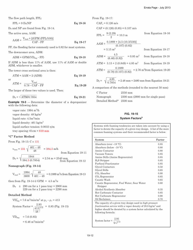
The flow path length, FPL:FPL = 9 DT/NP Eq 19-16
DT and NP are found from Fig. 19-14.The active area, AAM:
AAM = Vload + [(GPM (FPL/530)] CAF • FF Eq 19-17FF, the flooding factor commonly used is 0.82 for most systems.The downcomer area, ADM:
ADM = GPM/(VDdsg • FF) Eq 19-18If ADM is less than 11% of AAM, use 11% of AAM or double ADM, whichever is smaller.The tower cross sectional area is then:
ATM = AAM + 2 (ADM) Eq 19-19or
ATM = Vload 0.78 • CAF • FF Eq 19-20The larger of these two values is used. Then:
DT = √ ATM/0.7854 Eq 19-21Example 19-3 — Determine the diameter of a depropanizer with the following data:
vapor rate: 1994 m3/hvapor density: 48 kg/m3
liquid rate: 4.5m3/minliquid density: 461 kg/m3
liquid surface tension: 0.0033 η/mtray spacing: 61cm = 610 mm
“C” Factor MethodFrom Fig. 19-13: C ≅ 131
vmax = 131 461 – 48 = 384.3 m/h √ 48 from Equation 19-11 DT = 1944 = 2.54 m = 2540 mm √ 384.3 (0.7854) from Equation 19-12
Nomograph (Fig. 19-14) Vload =
1994 48 = 0.1889 m3/s from Equation 19-13 3600 √ 461 – 48then from Fig. 19-14 @ GPM = 4.5 m3/s
DT ≅ 290 cm for a 1 pass tray = 2900 mm 229 cm for a 2 pass tray = 2290 mm
Detailed MethodVD*
dsg = 7.6 m3/min/m2 at ρL – ρv = 413
System Factor = 2.93 413 0.32 = 0.85 (Fig. 19-15) 48 VDdsg = 7.6 (0.85) = 6.46 m3/min/m2
From Fig. 19-17:CAFo = 0.126 m/sCAF = (0.126) (0.85) = 0.107 m/s
FPL = 9 (2.29) = 10.3 m from Equation 19-16 2
AAM = 0.1889 + [4.5 (10.3/530)] (0.107) (0.82) = 3.15 m2 from Equation 19-17
ADM = 4.5 (6.46) (0.82) = 0.85 m2 from Equation 19-18
ATM = 3.15 + 2 (0.849) = 4.85 m2 from Equation 19-19
ATM = 0.1889 = 2.76 m2 from Equation 19-20 (0.78) (0.107) (0.82)
DT
= 4.85 = 2.48 mm = 2480 mm from Equation 19-21 √ 0.7854 A comparison of the methods (rounded to the nearest 50 mm)
C Factor 2550 mmNomograph 2300 mm (2900 mm for single pass)Detailed Method* 2500 mm
FIG. 19-15
System Factors9
Systems with foaming tendencies are taken into account by using a factor to derate the capacity of a given tray design. A list of the more common foaming systems and their recommended factor is below.
System FactorAbsorbers (over –18 °C) 0.85Absorbers (below –18 °C) 0.80Amine Contactor 0.80Vacuum Towers 0.85Amine Stills (Amine Regenerator) 0.85H2S Stripper 0.85Furfural Fractionator 0.85Glycol Contactors 0.50Glycol Stills 0.65CO2 Absorber 0.80CO2 Regenerator 0.85Caustic Wash 0.65Caustic Regenerator, Foul Water, Sour Water Stripper
0.60
Alcohol Synthesis Absorber 0.35Hot Carbonate Contactor 0.85Hot Carbonate Regenerator 0.90Oil Reclaimer, 0.70The capacity of a given tray design used in high pressure fractionation service with a vapor density of 28.8 kg/m3 and higher should be derated by a system factor calculated by the following formula:
System factor = 2.93
(ρv)0.32
Errata Page - July 2013

20-17
Solution Steps:1. Enter left side of Fig. 20-25 at 4200 kPa (abs) and proceed
to the H2S concentration line (4.18 mol%)2. Proceed vertically to the relative density of the gas (γ =
0.682)3. Follow the diagonal guide line to the temperature at the
bottom of the graph (T = 17.5 °C)4. Apply the C3 correction using the insert at the upper left.
Enter the left hand side at the H2S concentration and proceed to the C3 concentration line (0.67%). Proceed down vertically to the system pressure and read the cor-rection on the left hand scale (–1.5 °C)
Note: The C3 temperature correction is negative when on the left hand side of the graph and positive on the right hand side.
TH = 17.5 – 1.5 = 16 °CFig. 20-25 was developed based on calculated hydrate con-
ditions using the Peng-Robinson EOS. It has proven quite ac-curate when compared to the limited amount of experimental data available. It should only be extrapolated beyond the ex-perimental data base with caution.
Fig. 20-2634 presents experimental hydrate formation data for three mixtures of methane, propane and hydrogen sulfide. Results of selected hydrate prediction methods are also shown.
The addition of CO2 to pure methane will slightly increase the hydrate temperature at a fixed pressure.35 However, the ad-dition of CO2 to a “typical” sweet natural gas mixture will often lower the hydrate formation temperature at a fixed pressure. Fig. 20-27 is provided to portray these compositional effects. The hydrate curves for four gas compositions are shown. These were generated using a commercial hydrate program employ-ing the Peng-Robinson EOS. The four gas compositions are: Sweet Gas (0.6 rel. den. gas from Fig. 20-16) Sweet Gas containing 10% CO2 Sour Gas containing 10% H2S Sour Gas containing 10% CO2 and 10% H2S
Note that H2S significantly increases the hydrate tempera-
ture of a sweet natural gas. In this example, at 6900 kPa (abs), the addition of H2S (10 mol%) to a sweet gas mixture increases the hydrate temperature by 8 °C. On the other hand, CO2 has a minor effect on the hydrate formation temperature and slightly decreases the hydrate temperature for both the “sweet” and “sour” gases in this case.
EOS-based computer programs are probably the most con-sistent method of predicting hydrate formation temperatures today. Accuracy when compared to experimental data is usually ± 1 °C. This is generally adequate for design.
Hydrate InhibitionThe formation of hydrates can be prevented by:1. Maintaining the system temperature above the hydrate
formation temperature by the use of a heater and/or in-sulation
2. Dehydrating the hydrocarbon fluid (gas and/or liquid) to eliminate the condensation of liquid or solid water
3. Injection of a chemical inhibitor to prevent or mitigate hydrate formation
In some cases, heating or dehydration may not be practical or economically feasible.
In these cases, chemical inhibition can be an effective meth-od of preventing hydrate formation. Chemical inhibition utilizes injection of thermodynamic inhibitors (sometimes called equi-librium inhibitors) or low dosage hydrate inhibitors (LDHIs). Thermodynamic inhibitors are the traditional inhibitors (i.e., one of the glycols or methanol), which lower the temperature of hydrate formation. LDHIs are either kinetic hydrate inhibitors (KHIs) or antiagglomerants (AAs). They do not lower the tem-perature of hydrate formation, but do diminish its effect. KHIs lower the rate of hydrate formation, which inhibits its develop-ment for a defined duration. AAs allow the formation of hydrate crystals but restrict them to sub-millimeter size.
Thermodynamic inhibitors — Inhibition utilizes injec-tion of one of the glycols or methanol into a process stream where it can combine with the condensed aqueous phase to low-er the hydrate formation temperature at a given pressure. Both
FIG. 20-26
Experimental vs. Predicted Hydrate Conditions for Gases Containing C1, C3, and H2S
Composition, mol % Experimental Data17 Predicted Temperature, °C
C1 C3 H2S γ Temperature, °C
Pressure, kPa (abs) Fig. 20-13 Equation
20-3 Fig. 20-25
88.654 7.172 4.174 0.649 4.6 706 NA 2.6 5.488.654 7.172 4.174 0.649 11 1419 5.0 8.4 11.388.654 7.172 4.174 0.649 14.2 2024 7.2 11.2 14.188.654 7.172 4.174 0.649 18 3367 11.7 14.9 18.481.009 7.016 11.975 0.696 10.4 817 1.1 5.1 10.881.009 7.016 11.975 0.696 19.5 2813 11.7 14.9 21.560.888 7.402 31.71 0.823 13.1 686 2.8 7.1 13.260.888 7.402 31.71 0.823 19.1 1445 8.3 15.3 20.360.888 7.402 31.71 0.823 24.3 2558 12.8 19.7 24.860.888 7.402 31.71 0.823 27.8 4275 16.7 24.1 28.7
Errata Page - July 2013

20-18
glycol and methanol can be recovered with the aqueous phase, regenerated and reinjected. For continuous injection in services down to –40 °C, one of the glycols usually offers an economic ad-vantage versus methanol recovered by distillation. At cryogenic conditions (below –40 °C) methanol usually is preferred because glycol’s viscosity makes effective separation difficult.
Ethylene glycol (EG), diethylene glycol (DEG), and trieth-ylene glycol (TEG) have been used for hydrate inhibition. The most popular has been ethylene glycol because of its lower cost, lower viscosity, and lower solubility in liquid hydrocarbons.
Physical properties of methanol and methanol-water mix-tures are given in Fig. 20-28 through Fig. 20-31. Physical prop-erties of the most common glycols and glycol-water mixtures are given in Fig. 20-32 through Fig. 20-49. Tabular information for the pure glycols and methanol is provided in Fig. 20-50.
Equilibrium inhibitors are used in both pipeline/flowline ap-plications as well as in low temperature gas processing facili-ties. To be effective, the inhibitor must be present at the very point where the wet gas is cooled to its hydrate temperature.
Fig. 20-51 shows a flow diagram for a typical EG injection system in a refrigeration plant. In these facilities, the glycol inhibitor is sprayed into the gas upstream of the exchanger. The exchanger type can be shell and tube, plate or printed cir-cuit. As water condenses, the inhibitor is present to mix with the water and prevent hydrates. Injection must be in a manner to allow good distribution in the gas flow path. It is common practice to inject 2 to 3 times the glycol rate calculated from the correlations that follow.
The viscosity of ethylene glycol and its aqueous solutions increases significantly as temperature decreases. This effect must be considered in the design and rating of exchangers in low temperature gas processing facilities.
The inhibitor and condensed water mixture is separated from the gas stream along with a separate liquid hydrocarbon stream. At this point, the water dew point of the gas stream is essentially equal to or slightly lower than the separation tem-perature. Glycol-water solutions and liquid hydrocarbons can emulsify when agitated or when expanded from a high pressure to a lower pressure, e.g., JT expansion valve. Careful separator design normally allows nearly complete recovery of the diluted glycol for regeneration and reinjection.
The regenerator in a glycol injection system should be op-erated to produce a regenerated glycol solution that will have a freezing point below the minimum temperature encountered in the system. This is typically 75–80 wt%. Fig. 20-52 shows the freezing point of various concentrations of glycol water so-lutions.
The minimum inhibitor concentration in the free water phase may be approximated by Hammerschmidt’s equation.36
d = KH XI
MI (1 – XI) Eq 20-4
XI =
dMI KH + dMI
Eq 20-5
Where K H for ethylene glycol and methanol = 1297.Earlier editions of the Engineering Data Book suggested a
range of KH values (1297–2222) for glycols. Higher values of KH result in lower concentrations of rich (diluted) glycol (XI in Equation 20-5) which, in turn, suggests a lower inhibitor injec-tion rate. Experimental data suggests KH = 1297 is the correct constant as illustrated in Fig. 20-53. In some field operations,
FIG. 20-27
Hydrate Formation Conditions for Sweet Gas Showing Effects of CO2 and H2S
Errata Page - July 2013

20-27
Solution Steps:
Methanol1. Calculate the amount of water condensed per day from
Fig. 20-4, Win = 850 kg/106 Sm3
Wout = 150 kg/106 Sm3 ΔW =700kg/106 Sm3
Watercondensed=(700)(2.83)=1980kg/d2. Calculate required methanol inhibitor concentration
from Equation 20-5 and 20-6
d = 14 °C, M = 32 Solving for XI, From Equation 20-5, XI = 0.255, FromEquation20-6,molfr.=0.175(usethisvaluein
subsequentcalculations)From Fig. 20-54, Mass%=27.53. Calculate mass rate of inhibitor in water phase from
Equation20-9(assume100%methanolisinjected)
mI = XR • mH2O (0.275)(1980)
XL – XR = (1–0.275)
= 750kg/d
4. Estimate vaporization losses from Fig. 20-55. @4°Cand6200kPa(ga),losses=(30kg/106 Sm3)/ mol% MeOH in water phase dailylosses=(30)(2.83)(17.5)=1490kg/d5. Estimate losses to hydrocarbon liquid phase from Fig.
20-56. @ 4 °C and paraffinic fluid, Dist. Ratio = 110 mol%MeOHinhyd.liquid=17.5/110=0.16mol% 1 m3ofcondensatehasamassof780kg =(780/140)=5.6kmol/m3 of condensate =(5.6)(0.0016)=0.009kmolMeOH =(32)(0.009)=0.29kg/m3
Total MeOH losses to the hydrocarbon liquid phase =(0.29)(2.83)(56)=46kgMeOH/d Totalmethanolinjectionrate=750+1490+46 = 2286 kg/d
0%
10%
20%
30%
40%
50%
60%
70%
80%
90%
100%
0% 10% 20% 30% 40% 50% 60% 70% 80% 90% 100%
Mas
s %
mol %
Methanol
EG
FIG. 20-54
Mass % vs. Mol% for Methanol and EG Solutions
10
100
10 100
Pressure, bar
19.4 °C
15.3 °C
10.4 °C
5.0 °C
0.5 °C
-4.3 °C
19.4 oC
15.3 oC
10.4 oC
0.5 oC
-4.3 oC
5.0 oC
400
200
Distributionof methanol between aqueous and vapor phase, from various sources including VLE and LLE data.
Met
hano
l in
Vap
or P
hase
kg
met
hano
l per
mill
ion
Std
m3
( Mol
e pe
rcen
t met
hano
l in
aque
ous
liqui
d )
FIG. 20-55
Ratio of Methanol Vapor Concentration to Methanol Liquid Concentration
Errata Page - July 2013

20-28
Methanol left in the gas phase can be recovered by conden-sation with the remaining water in a downstream chilling pro-cess. Likewise, the methanol in the condensate phase can be recovered by downstream water washing.
80 wt% EG1. Calculate required inhibitor concentration from Equa-
tion 20-5d = 14 °C, M = 62, KH=1297Solving for XI, XI = 0.402. Calculate mass rate of inhibitor solution in water phase
fromEquation20-9 mI = (0.40)(1980) (0.80−0.40) =1980kg/dVaporization and liquid hydrocarbon losses are negligible.Hydrate inhibition with methanol or EG is widely used in
pipelines as well as in gas processing plants. The choice of in-hibitor is influenced by several factors. A few of these are listed below:
Methanol Advantages• Generally less expensive than EG• Requires lower concentrations in the aqueous phase • Can inhibit to very low temperatures• Has a lower viscosity than EG
• During regeneration, contaminants in the water phase (suchasdissolvedsolids) leavewiththewater,not themethanol
• Can be transported in the vapor phase (significant meth-anolvaporizationat injectionpoint)which isuseful forremoving hydrates that have formed downstream of the injectionpointinthesystem
Methanol Disadvantages• Higher inhibitor losses to the hydrocarbon vapor and liq-
uid phases• More difficult to recover methanol from the aqueous
phase• More toxic than EG• MoreflammablethanEG(lowerflashpoint)Methanol losses to the hydrocarbon vapor and liquid phases
has become a more significant issue due to increasingly strin-gent contaminant specifications for condensate, NGLs and natural gas.
EG Advantages• Very low solubility losses to the hydrocarbon phases and
generally not regarded as a contaminant• Much easier to recover from the water phase (regenera-
tion)• Less toxic and less flammable than methanol• Can also provide corrosion inhibition for “top of the line
corrosion” in pipelines
1
10
100
1000
-50 -30 -10 10 30 50
Temperature (oC)
No Toluene
28-33mol% Toluene
50-70 mol% Toluene
70-80 mol% Toluene
Distribution of methanol between aqueous and hydrocarbon phases, data from various sources. Hydrocarbon phases includes various alkane and cycloalkane compounds. Data shows the variation of distribution with changes in the amount of toluene in thehydrocarbon phase.
Dis
trib
utio
n R
atio
Mol
e fr
actio
n M
eOH
in A
queo
us P
hase
( Mol
e fr
actio
n M
eOH
in O
rgan
ic P
hase
)
FIG. 20-56
Liquid-Liquid Methanol Distribution Ratios
Errata Page - July 2013
20-47
Qw = kJ
4200 kg
(kg of water on bed) Eq 20-22
Qsi = (kg of sieve) 1.0 kJ
kg • K
(Trg – Ti) Eq 20-23
Qst = (kg of steel) 0.5 kJ
kg • K
(Trg – Ti) Eq 20-24
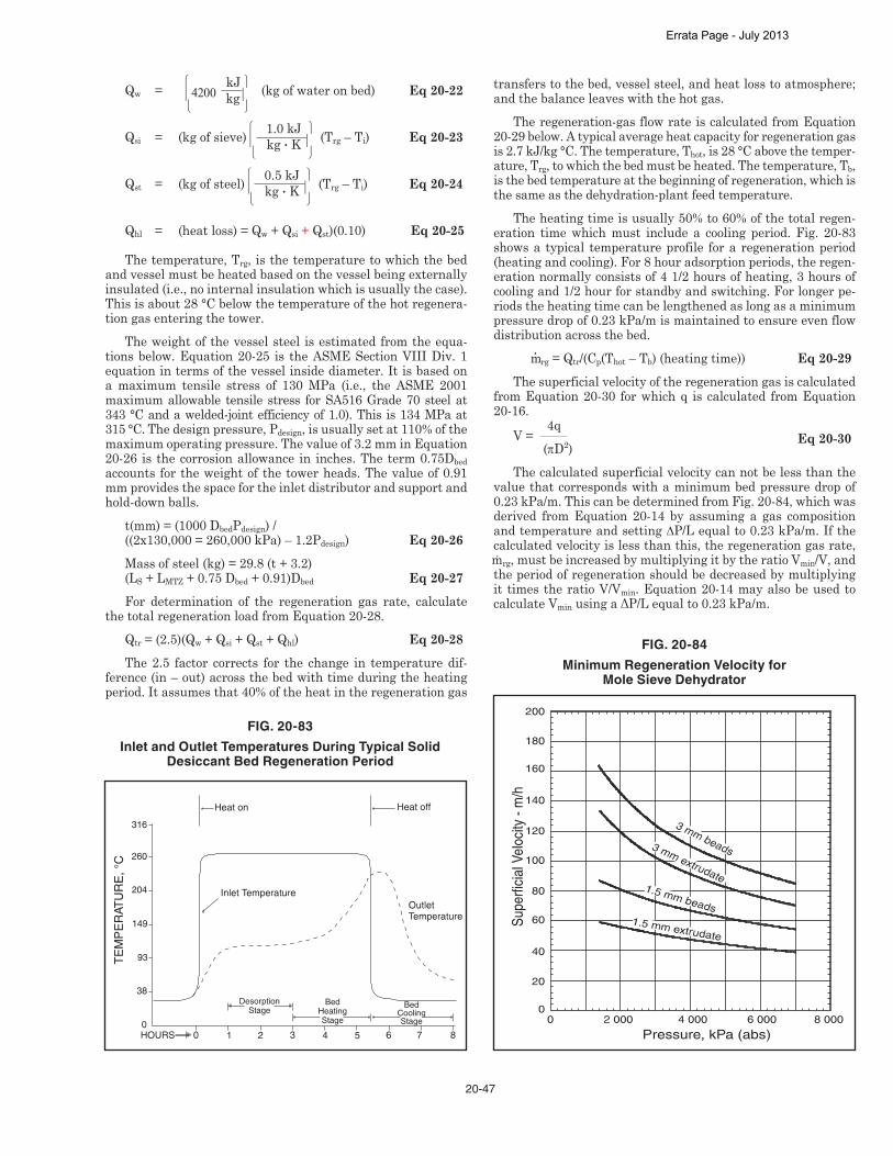
Qhl = (heat loss) = Qw + Qsi + Qst)(0.10) Eq 20-25
The temperature, Trg, is the temperature to which the bed and vessel must be heated based on the vessel being externally insulated (i.e., no internal insulation which is usually the case). This is about 28 °C below the temperature of the hot regenera-tion gas entering the tower.
The weight of the vessel steel is estimated from the equa-tions below. Equation 20-25 is the ASME Section VIII Div. 1 equation in terms of the vessel inside diameter. It is based on a maximum tensile stress of 130 MPa (i.e., the ASME 2001 maximum allowable tensile stress for SA516 Grade 70 steel at 343 °C and a welded-joint efficiency of 1.0). This is 134 MPa at 315 °C. The design pressure, Pdesign, is usually set at 110% of the maximum operating pressure. The value of 3.2 mm in Equation 20-26 is the corrosion allowance in inches. The term 0.75Dbed accounts for the weight of the tower heads. The value of 0.91 mm provides the space for the inlet distributor and support and hold-down balls.
t(mm) = (1000 DbedPdesign) / ((2x130,000 = 260,000 kPa) – 1.2Pdesign) Eq 20-26 Mass of steel (kg) = 29.8 (t + 3.2) (LS + LMTZ + 0.75 Dbed + 0.91)Dbed Eq 20-27For determination of the regeneration gas rate, calculate
the total regeneration load from Equation 20-28. Qtr = (2.5)(Qw + Qsi + Qst + Qhl) Eq 20-28The 2.5 factor corrects for the change in temperature dif-
ference (in – out) across the bed with time during the heating period. It assumes that 40% of the heat in the regeneration gas
transfers to the bed, vessel steel, and heat loss to atmosphere; and the balance leaves with the hot gas.
The regeneration-gas flow rate is calculated from Equation 20-29 below. A typical average heat capacity for regeneration gas is 2.7 kJ/kg °C. The temperature, Thot, is 28 °C above the temper-ature, Trg, to which the bed must be heated. The temperature, Tb, is the bed temperature at the beginning of regeneration, which is the same as the dehydration-plant feed temperature.
The heating time is usually 50% to 60% of the total regen-eration time which must include a cooling period. Fig. 20-83 shows a typical temperature profile for a regeneration period (heating and cooling). For 8 hour adsorption periods, the regen-eration normally consists of 4 1/2 hours of heating, 3 hours of cooling and 1/2 hour for standby and switching. For longer pe-riods the heating time can be lengthened as long as a minimum pressure drop of 0.23 kPa/m is maintained to ensure even flow distribution across the bed.
•mrg = Qtr/(Cp(Thot – Tb) (heating time)) Eq 20-29The superficial velocity of the regeneration gas is calculated
from Equation 20-30 for which q is calculated from Equation 20-16.
V = 4q
(πD2) Eq 20-30
The calculated superficial velocity can not be less than the value that corresponds with a minimum bed pressure drop of 0.23 kPa/m. This can be determined from Fig. 20-84, which was derived from Equation 20-14 by assuming a gas composition andtemperatureandsetting∆P/Lequalto0.23kPa/m.Ifthecalculated velocity is less than this, the regeneration gas rate, ·mrg, must be increased by multiplying it by the ratio Vmin/V, and the period of regeneration should be decreased by multiplying it times the ratio V/Vmin. Equation 20-14 may also be used to calculate VminusingaΔP/Lequalto0.23kPa/m.
FIG. 20-83
Inlet and Outlet Temperatures During Typical Solid Desiccant Bed Regeneration Period
FIG. 20-84
Minimum Regeneration Velocity for Mole Sieve Dehydrator
Errata Page - July 2013

20-48
General CommentsThe regeneration cycle frequently includes depressuring/
repressuring to match the regeneration gas pressure and/or to maximize the regeneration gas volume to meet the velocity criterion. In these applications, the rate of depressuring or re-pressuring should not exceed 350 kPa per/minute. Some appli-cations, termed pressure swing adsorption, regenerate the bed only with depressurization and sweeping the bed with gas just above atmospheric pressure, but this is not used in gas dehy-dration applications.
Moisture analyzers for very low water contents require care to prevent damage to the probes. When inserted into the beds, sample probes and temperature probes must be installed to reach the center of the gas phase.
Solid desiccant towers are insulated externally or possibly internally. Internal refractory requires careful installation and curing, usually before the desiccant is installed. It saves en-ergy but the greatest benefit is it can dramatically reduce the required heating and cooling times. This is often an important benefit for systems where regeneration times are limited. The primary disadvantage is the potential for wet gas bypassing the desiccant through cracks and defects in the insulation during the adsorption cycle.Example 20-14: 2.85 × 10⁶ Sm3/day of natural gas with a mo-lecular weight of 18 is to be processed for ethane recovery in a turbo-expander plant. It is water saturated at 4140 kPa (abs) and 38 °C and must be dried to –101 °C dew point. Determine the water content of the gas, and the amount of water that must be removed; and do a preliminary design of a molecular-sieve dehydration system consisting of two towers with down-flow adsorption in one tower and up-flow regeneration in the other. Use 4A molecular sieve of 3.2 mm beads (i.e., 4x8 mesh). The regeneration gas is part of the plant’s residue gas, which is at 4140 kPa (abs) and 38 °C and has a molecular weight of 17. The bed must be heated to 260 °C for regeneration.
Solution Steps1. Determinethebeddiameterandthecorresponding∆P/L
and V. First determine the maximum superficial velocity fromEquation20-14.Letthemaximum∆P/Lbe7.5kPa/m.
z = 0.93 from Fig. 23-8 for 17.4 mole weight which is con-servative
ρ = (18 mole weight) (4140 kPa (abs))/((8.3145) (311.15 °K) (0.93)) = 31 kg/m3 (Equation 23-2)
μ = 0.015 mPa•s (Fig. 23-27) Vmax = [(7.5 kPa/m)/(3.75•10–7)/(31 kg/m3)]1/2
– [(0.0693/3.75•10–7) (0.015 mPa s)/ (31 kg/m3)/2] = 758 m/h (Equation 20-14), rewritten in terms of V
m=[(2.85•106 Sm3/day)/((24 h/day)(23.646 Sm3kmole))] (18 kg/kmole) = 90 400 kg/h
q = (90 400 kg/h)/(31 kg/m3) = 2916 m3/h (Equation 20-16)
Dminimum = [(4(2916 m3/h))/ (π•758 m/h)]1/2 = 2.21 m (Equation 20-15)Roundoffupwardto2.25mdiameter,forwhichVand∆P/L
are adjusted as follows:
Vadjusted = (758 m/h)(2.21/2.25)2 = 731 m/h (Equation 20-17)
(∆P/L)adjusted = 7.5(731/758)2 = 7.0 kPa/m (Equation 20-21)
2. Estimate the amount of water to be removed from the feed per cycle for each bed. Base this on a 24-hour cycle consisting of 12 hours adsorbing and 12 hours regener-ating (heating, cooling, standby, and valve switching). From Fig. 20-4, the water content at 4140 kPa (abs) and 38 °C is 1410 mg/Sm3 (1410 kg/106 Sm3). The water con-tent at a dew point of –101 °C is essentially zero, so the water removed is the following:
w=(1410kg/106 Sm3)(2.85 106 Sm3/day)/(24 h/day)/ = 167 kg/h of water removed
Wr = (167 kg/h) (12 h) = 2004 kg water removed per 12-hour drying period or 24-hour cycle per bed.
3. Determine the amount of sieve required and the bed height based on a sieve bulk density of 720 kg/m3. Since the feed gas is water saturated, the relative humidity is 100%, so CSS is 1.0 from Fig. 20-81. From Fig. 20-82, CT is 0.93 at 38 °C. Applying the equations:
SS = (2004)/((0.13)(1.0)(0.93)) = 16 576 kg of sieve for each bed (Equation 20-18)
LS = (16 576)(4)/(3.1416 (2.3)2 (720)) = 5.54 m bed height (Equation 20-19)
LMTZ = (731/640)0.3 (0.52) = 0.54 m for mass-transfer zone (Equation 20-20)
LS + LMTZ = 5.54 + 0.54 = 6.08 m of sieve for each bed The total sieve = (6.08/5.54)(16 576)
= 18 192 kg for each bed4. Checkthebeddesignandpressuredropwhichisthe∆P/L
calculated in Step 1 times the total bed height calculated in Step 3: (7.0 kPa/m)(6.08 m) = 42.6 kPa which meets the criteron of not exceeding 35–55 kPa
5. Calculate the total heat required to desorb the water based on heating the bed and vessel to 260 °C. First cal-culate the weight of steel from Equation 20-26 and 20-27. Let the design pressure, Pdesign, be 110% of the operating pressure:
Pdesign = (4140)(1.1) = 4554 kPa (ga)
t = (1000) (2.25) (4554)
= 40.3 mm (Equation 20-26)
260 000 – 1.2 (4554) Mass of steel = (29.8) (40.3 + 3.2) (5.54 + 0.54 + (0.75) (2.25) + 0.91) (2.25) = 25 310 kg (Equation 20-27) Qst = (25 310 kg) (0.5 kJ/kg °C)
(260 °C – 38 °C) = 2 809 000 kJ (Equation 20-24) Qw = (4200 kJ/kg) (2004 kg water)
= 8 417 000 kJ (Equation 20-22) Qsi = (18 192 kg) (1 kJ/kg °C)
(260 °C – 38 °C) = 4 039 000 kJ (Equation 20-23) Qhl = (2 809 000 + 8 417 000 + 4 039 000)
(0.10) = 1 527 000 kJ (Equation 20-25) Qtr = (2.5) (2 809 000 + 8 417 000 + 4 039 000
+ 1 527 000) = 41 980 000 kJ (Equation 20-28)
Errata Page - July 2013

21-13
15–20% for MEA (more moles of amine per volume of solution).
• The required treating circulation rate is lower. This is a direct function of higher amine concentration.
• Reduced reboiler steam consumption.Typical concentrations of DGA® range from 50% to 60%
DGA® by weight while in some cases as high as 70 wt% has been used. DGA® has an advantage for plants operating in cold climates where freezing of the solution could occur. The freez-ing point for 50% DGA® solution is –34 °C. Because of the high amine degradation rate DGA® systems require reclaiming to remove the degradation product. DGA® reacts with both CO2 and COS to form N, N’, bis (hydroxyethoxyethyl) urea, gener-ally referred to as BHEEU.16 DGA® is recovered by reversing the BHEEU reaction in the reclaimer.
Methyldiethanolamine—Methyldiethanolamine (MDEA) is a tertiary amine which can be used to selectively remove H2S to pipeline specifications at moderate to high pressure. If in-creased concentration of CO2 in the residue gas does cause a problem with contract specifications or downstream processng, further treatment will be required. The H2S/CO2 ratio in the acid gas can be 10–15 times as great as the H2S/CO2 ratio in the sour gas. Some of the benefits of selective removal of H2S include:
• Reduced solution flow rates resulting from a reduction in the amount of acid gas removed
• Smaller amine regeneration unit• Higher H2S concentrations in the acid gas resulting in
reduced problems in sulfur recoveryCO2 hydrolyzes much slower than H2S. This makes possible
significant selectivity of tertiary amines for H2S. This fact is used by several companies who provide process designs using MDEA for selective removal of H2S from gases containing both H2S and CO2.
A feature of MDEA is that it can be partially regenerated in a simple flash. As a consequence the removal of bulk H2S and CO2 may be achieved with a modest heat input for regeneraion. However as MDEA solutions react only slowly with CO2 (see chemistry) activators must be added to the MDEA soluion to enhance CO2 absorption. If this is done, then the solvent is re-ferred to as promoted or activated MDEA.
Triethanolamine — Triethanolamine (TEA) is a tertiary amine and has exhibited selectivity for H2S over CO2 at low pressures. TEA was the first amine commercially used for gas sweetening. It was replaced by MEA and DEA because of its in-ability to remove H2S and CO2 to low outlet specifications. TEA has potential for the bulk removal of CO2 from gas streams. It has been used in many ammonia plants for CO2 removal.
Diisopropanolamine — Diisopropanolamine (DIPA) is a secondary amine which exhibits, though not as great as tertiary amines, selectivity for H2S. This selectivity is attributed to the steric hindrance of the chemical. (See later discussion on this topic.)
Formulated solvents and mixed amines — Formulated Solvents is the name given to a new family of amine-based sol-vents. Their popularity is primarily due to equipment size re-duction, reduced corrosion and energy savings over most of the other amines.
All the advantages of MDEA are valid for the Formulated Solvents, usually to a greater degree. Some formulations are capable at high pressure of slipping larger portions of inlet CO2 than generic MDEA to the outlet gas and at the same time re-moving H2S to less than 4 ppmv. Under conditions of low ab-sorber pressure and high CO2 /H2S ratios, such as Claus tail gas clean-up units, certain solvent formulations can slip up to 90% of the incoming CO2 to the incinerator.
At the other extreme, certain formulations remove CO2 to a level not possible with MDEA, so that the sweet gas is suit-able for cryogenic plant feed. Formulations are also available for CO2 removal in ammonia plants. Finally, there are solvent formulations, which remove H2S to 4 ppmv pipeline specifica-tions, while reducing high inlet CO2 concentrations to 2% for delivery to a pipeline. Typical treating applications for the gas processing industry, and the common treatment strategies em-ployed using formulated amines, are summarized in Fig. 21-12. Several general approaches are commonly used in the solvent formulations.
To achieve very low CO2 concentrations in the treated gas, the formulation may contain activators, such as piperazine or primary/secondary amines to promote CO2 removal.
In order to enhance H2S removal, and thereby allow great-er CO2 slip, stripping agents, such as inorganic acids may be used.
This need for a wide performance spectrum has led Formu-lated Solvent suppliers to develop a large stable of different MDEA-based solvent formulations or MDEA-based solvents. In summary, benefits claimed by suppliers are:
For New Plants• reduced corrosion• reduced circulation rate• lower energy requirements• smaller equipment due to reduced circulation rates For Existing Plants
• increase in capacity, i.e., gas through-put or higher inlet acid gas composition
• reduced corrosion• lower energy requirements and reduced circulation ratesFormulated solvents are proprietary to the specific supplier
offering the product. Companies offering these products and/or processes include INEOS, Huntsman Corporation, Dow Chemi-cal Company, UOP, BASF, Shell Global Solutions and Total via Prosernat.
Errata Page - July 2013

21-14
FIG. 21-12
Common Formulated Amines Applications
Treating Strategy Gas Treating Specification/Application
Deep H2S and CO2 removal
Outlet H2S (4 PPM) & CO2 ( down to <50 ppmv)/Treating high pressure sour gas w/ H2S for downstream cryogenic processing
Deep CO2 removal w/some CO2 slip
Outlet H2S (4 ppmv) & CO2 (0.5 to 2 mol%)/ Treating high pressure sour gas w/H2S to pipeline specifications
Deep CO2 RemovalOutlet CO2 down to <50 ppmv/Treating high pressure gas w/CO2 upstream of cryogenic processing
CO2 removal with slip
Outlet CO2 (2 mol%)/Treating highpressure gas w/CO2 to pipelinespecifications
Deep CO2 removal with bypass
Outlet CO2 (100–1000 ppmv)/Treating high pressure gas to produce pipeline quality gas (2 mol% CO2) using feed gas bypass
Deep H2S removal with high CO2 slip
Outlet H2S (10 ppmv to 250 ppmv) w/high CO2 slip/Sulfur plant tail gas treating ap-plications
Deep H2S removal with high CO2 slip
Outlet H2S (50 ppmv to 250 ppmv) w/high CO2 slip/Acid gas enrichment for Claus sulfur plant feed
Sterically hindered amines — Other amines have been used to treat sour gas.17 One specialty amine uses steric hin-drance (see nomenclature) to slow the rate of CO2 absorption. This type of amine and the associated technology is different than Formulated Solvents, which create the desired formula-tions by blending different components with a standard amine such as MDEA. These sterically hindered amines are very selective for the removal of H2S in the presence of CO2. For low pressure applications such as AGE and TGCU, the CO2 slip can be as high as 95%. An example of this technology is FLEXSORB®SE/SE Plus solvents, marketed by ExxonMobil Research and Engineering Company.18,19
Acid Gas EnrichmentNormally, Acid Gas Removal units (AGRs) remove essen-
tially all of the H2S and CO2 from the produced natural gas. As discussed previously, AGRs can utilize a variety of solvents, including generic and formulated MDEA. In some cases, con-trolled CO2 removal can be used using a selective solvent such as FLEXSORB®SE or an MDEA based solvent to leave some of the CO2 in the sales gas. However, for gas fields with high CO2 to H2S ratios, the acid gas stream from the AGR regenerator will have an unfavorably high CO2 to H2S ratio resulting in a poor quality feed to a Claus plant.
In the last few decades, Acid Gas Enrichment (AGE) has been used much more frequently to increase the H2S content in high CO2 containing acid gas streams. As the name implies, acid gas enrichment concentrates the H2S from the AGR system by further gas treatment in a second amine unit utilizing a se-lective amine solvent. Except for the use of the selective amine solvent, an AGE unit is similar to other traditional amine treat-ing units. Fig. 21-13 shows a simplified flow diagram of an acid gas enrichment unit. The AGR acid gas is fed to the base of an absorber column equipped with either trays or packing where
the H2S is absorbed via counter-current contacting with the de-scending amine solvent. The AGE absorber typically operates at low pressure [~0.5 barg, 48 kPa (ga)], compatible with the operating pressure of the upstream AGR regenerator overhead system, but generally somewhat higher to provide the required inlet pressure to the SRU, so that the main AGR doesn’t need to provide the extra pressure drop. The selective amine in the AGE preferentially absorbs the H2S and allows the CO2 to remain in the treated gas (also known as “CO2 slip”). The rich amine from the bottom of the absorber is then pumped through a rich-lean heat exchanger and on to a regenerator tower. The regenerator produces an enriched acid gas product overhead and the lean amine bottoms product to be recycled to the absorber.
To achieve the twin goals of low H2S in the treated gas and low CO2 in the enriched acid gas, the AGE amine solvent must maximize the selectivity for absorbing H2S. Unfortunately, the CO2 and H2S partial pressure driving forces in the AGE ab-sorber work against achieving these goals simultaneously.20 As the gas moves up the absorber tower, the H2S partial pres-sure is decreasing reducing the mass transfer driving force. At the same time, the CO2 partial pressure is increasing, making CO2 pick-up more difficult to avoid, so the concentration factor achieved in each acid gas enrichment step is limited.
Simplified design calculations — A simplified procedure for making rough estimates of the principal parameters for con-ventional MEA, DEA, DGA®, and MDEA amine treating facili-ties when both H2S and CO2 are present in the gas is given below. It is based on excerpts from Jones and Pearce,21 modified and ex-tended by the Section 21 Subcommittee22 in 2002. The procedure involves estimating the amine circulation rate and using it as the principal variable in estimating other parameters. For estimat-ing amine circulation rate, the following equations are suggested:For MEA:
m3/hr = 327 • (Qy/x) Eq 21-60.33 mol acid gas pick-up per mole MEA assumed) For DEA (conventional):m3/hr = 361 • (Qy/x) Eq 21-7 (0.5 mol acid gas pick-up per mole DEA assumed) For DEA (high loading):m3/hr = 256 • (Qy/x) Eq 21-8 (0.7 mol acid gas pick-up per mole DEA assumed) For DGA®
m3/hr = 448 • (Qy/x) Eq 21-9(0.39 mol acid gas pick-up per mole DGA assumed) For activated MDEA (assuming 9:1 ratio of MDEA to DEA)m3/hr = 415 • (Qy/x) Eq 21-9a(0.50 mol acid gas pick-up per mole mixture assumed)
Where:Q = Millions of cubic meters of sour gas to be
processed, MSm3/dayy = Acid gas concentration in sour gas, mole%x = Amine concentration in liquid solution, wt% (Use Fig. 21-4 to ensure amine concentration does not exceed maximum recommended concentration)
After the amine circulation has been estimated, heat and heat exchange requirements can be estimated from the infor-
Errata Page - July 2013

21-15
SU
MP
DR
UM
AG
E A
BS
OR
BE
R
TR
EA
TE
D G
AS
RIC
HA
MIN
EP
UM
P
RIC
H/L
EA
NE
XC
HA
NG
ER
RE
GE
NE
RA
TO
R
RE
FLU
X D
RU
M
RE
FLU
XP
UM
P
RE
BO
ILE
R
LEA
NS
OLU
TIO
NF
ILT
ER
LEA
N S
UR
GE
VE
SS
EL
LEA
NA
MIN
EP
UM
P
CA
RB
ON
TR
EA
TE
RF
INE
SF
ILT
ER
AG
RA
CID
GA
S
WA
TE
RW
AS
HP
UM
P
MA
KE
-UP
WA
TE
R
SU
MP
PU
MP
SU
MP
FIL
TE
R
EN
RIC
HE
DA
CID
GA
S
PU
RG
E
ST
EA
M
CO
ND
EN
SA
TE
1
LEA
NC
OO
LER
OV
ER
HE
AD
CO
ND
EN
SE
R
16810
FIG. 21-13
Standalone AGE Flow Diagram
Errata Page - July 2013

21-16
mation in Fig. 21-14. Pump power requirements can be esti-mated from Fig. 21-15.
Equations 21-6 to 21-9 normally provide conservative (high) estimates of required circulation rate. They should not be used if the combined H2S plus CO2 concentration in the gas is above 5 mole%. They also are limited to a maximum amine concentration of about 30% by mass.
The diameter of an amine plant contactor, can be estimated using the following equation:Contactor diameter
Dc = 10 800 • √Q / √P Eq 21-10
Where:Q = MSm3/day gas to contactorP = Contactor pressure in kPa (abs) Dc = Contactor diameter in mm before rounding up to near-est 150 mm.
Similarly, the diameter of the regenerator below the feed point can be estimated using the following equation:
Dr = 160 • √m3/hr Eq 21-11
Where:
m3/h = Amine circulation rate in m3 per hour
Dr = Regenerator bottom diameter in mmThe diameter of the section of the still above the feed point
can be estimated at 0.67 times the bottom diameter.Example 21-2 — 1.0 MSm3/day of gas available at 5860 kPa (ga) and containing 0.6% H2S and 2.8% CO2 is to be sweetened using 20%, by mass, DEA solution. If a conventional DEA system is to be used, what amine circulation rate is required, and what will be the principal parameters for the DEA treating system?
Solution:Using Equation 21-7, the required solution circulation is:
Flow (m3/h)=361•(Qy/x)=361•(1.0•3.4/20) = 61.4 m3/h of 20% DEA solution per minute.
Heat exchange requirements (from Fig. 21-14)Reboiler H = 93•61.4 = 5710 kW A = 4.63•61.4 = 284 m2
Rich-Lean amine exchanger H = 58•61.4 = 3560 kW A = 4.6•61.4 = 282 m2
Amine cooler H = 19.3•61.4 = 1185 kW A = 4.18•61.4 = 257 m2
Reflux condenser H = 38.6•61.4 = 2370 kW A = 2.13•61.4 = 131 m2
Power requirements (Fig. 21-15)Main amine pumps Power (kW) = 61.4•5860•0.00031 = 112Amine booster pumps Power (kW) = 61.4•0.2 = 12.3Reflux pumps Power (kW) = 61.4•0.2 = 12.3Aerial cooler Power (kW) = 61.4•1.2 = 74Contactor diameter Dc = 10 800•√
rounded up 1.0/√
5860 = 1230 mm or 1350 mm
Regenerator diameter below feed point:
Dr=160•√
61.4 = 1254 mm or 1350 mm (bottom) rounded up
Regenerator diameter above feed point: Dra = 0.67 • 1254 = 840 mm or 900 mm (top)
rounded up
EQUILIBRIUM DATA FOR AMINE-SOUR GAS SYSTEMS
One of the peculiarities of amine treating systems is the in-teractive effects of one acid gas constituent with amine upon the equilibrium partial pressure of the other constituent. The most commonly encountered sour gas constituents are H2S and CO2. The capacity of a given amine for either one of the acid gas constituents alone is much greater than when the two occur together.
Jones et al.23 have presented data to confirm the interactive effect of H2S and CO2 in MEA solutions. Lee et al.12,24 have pre-sented similar data for DEA solutions. Dingman et al.25 have FIG. 21-14
Estimated Heat Exchange Requirements
Duty, kW Area, m2
Reboiler (Direct fired) 93•m3/h 4.63•m3/hRich-Lean Amine HEX 58•m3/h 4.60•m3/hAmine cooler (air cooled) 19.3•m3/h 4.18•m3/hReflux condenser 38.6•m3/h 2.13•m3/h
FIG. 21-15
Estimated Power Requirements
Main Amine Solution Pumps m3/h•kPa(ga)•0.00031 = kWAmine Booster Pumps m3/h•0.20 = kWReflux Pumps m3/h•0.20 = kWAerial Cooler m3/h•1.20 = kW
Errata Page - July 2013

22-29
Heat in, kJ/h:Feed Gas = 328 623Combustion Air = 840 534H2S Combustion (42.02 kmols/h) (517 900) = 22 797 958HC Combustion (2.14 kmols/h) (802 800) = 1 717 982Claus Reaction (61.36/2 kmols/h) (–47 060) = –1 443 623 24 241 485
The flame temperature is approximately 1164 °C. Step 2 Waste Heat Boiler Duty
Assume that 1723 kPa (ga) steam is generated in the waste heat boiler and therefore that the temperature of the cooled combustion products is 371 °C. From Fig. 22-21 (ignoring S7), the distribution of sulfur vapor species at 371 °C is approxi-mately 0.5 mol % S2, 45 mol % S6, and 54.5 mol % S8. The cooled combustion product composition and waste heat boiler heat balance are therefore as follows:
Reaction Products H @ 1164 °C kmols/h kJ/kmol kJ/h H2S 26.69 50 740 1 354 116CO2 72.19 58 838 4 247 494H2O 133.09 45 998 6 122 007SO2 13.35 60 401 805 981N2 264.36 36 910 9 759 624S2 46.01 42 471 1 954 264S6 — — —S8 — — — 555.69 24 241 485 Cooled Reaction Products H @ 371 °C kmols/h kJ/kmol kJ/h H2S 26.69 13 410 357 879CO2 72.19 15 983 1 153 836H2O 133.09 13 160 1 751 465SO2 13.34 17 009 226 961N2 264.36 10 989 2 905 100S2 0.07 12 801 833S6 5.86 45 359 265 695S8 7.09 62 889 446 143 522.69 7 107 912∆H: 24 241 485 – 7 107 912 = 17 133 573 kJ/h
From Fig. 22-29 S2 (vapor) ’ S6 (vapor) (5.86) (284 900) = 1 668 817 kJ/hFrom Fig. 22-29 S2 (vapor) ’ S8 (vapor) (7.09) (413 800) = 2 935 558 kJ/h
Total heat duty 17 133 573 + 1 668 817 + 2 935 558 = 20 706 133 kJ/hNote: Partial pressure of sulfur vapor
= S2 + S6 + S8 (Total Pressure) Total Mols
= 0.07 + 5.86 + 7.09 (131.7) = 3.28 kPa 522.69 From Fig. 22-22, the vapor pressure of sulfur at 371 °C is ap-proximately 30.4 kPa, so no sulfur is condensed. Step 3 1st Sulfur Condenser
Assume a pressure drop through the condenser of 3.44 kPa, with the process stream further cooled to 177 °C. From Fig. 22-22, the vapor pressure of sulfur at 177 °C is 0.111 kPa so the stream is below the sulfur dewpoint. From Fig. 22-21, the distri-bution of sulfur species is 14.5 mol % S6 and 85.5 mol % S8. If no condensation took place, there would be 1.74 kmols/h of S6 and 10.26 kmols/h of S8. [Note: (6)(1.73) + (8)(10.20) = (2)(46.01)]
Uncondensed sulfur
= 0.111 [522.69 – (1.73 + 10.20)] 128.15 – 0.111
= 0.443 kmols/hS6: 0.145 (0.443) = 0.0642 kmols/h uncondensed
1.73 – 0.0642 = 1.67 kmols/h condensed S8: 0.853 (0.443) = 0.3779 kmols/h uncondensed 10.20 – 0.3779 = 9.82 kmols/h condensed Condenser Outlet Conditions H @ 177°
kmols/h kJ/kmol kJ/h H2S 26.69 6076 162 150CO2 72.19 7107 513 035H2O 133.09 6176 821 943SO2 13.34 7628 101 790N2 264.36 5189 1 371 719S2 (vapor) — — —S6 (vapor) 1.73 20 902 36 160S8 (vapor) 10.20 28 867 294 442 521.60 3 301 239
∆H: 7 107 912 – 3 301 239 = 3 806 673 kJ/hFig. 22-30 ∆H:
S6 (vapor) ’ Sliq (1.67) (418.2 • 6 • 32.04) = 134 227 kJ/hFig. 22-30 ∆H:
S8 (vapor) ’ Sliq (9.82) (287.2 • 8 • 32.04) = 722 900 kJ/hFig. 22-29 ∆H:
S2 (vapor) ’ S6 (vapor) (0.00227) (284 900) = 650 kJ/h
Errata Page - July 2013
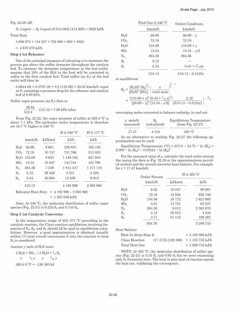
22-30
Fig. 22-29 ∆H:S2 (vapor) ’ S8 (vapor) (0.014 065) (413 800) = 5820 kJ/h
Total Duty3 806 673 + 134 227 + 722 900 + 650 + 5820= 4 670 270 kJ/h
Step 4 1st ReheaterOne of the principal purposes of reheating is to maintain the
process gas above the sulfur dewpoint throughout the catalyst bed. To estimate the dewpoint temperature at the bed outlet, assume that 20% of the H2S in the feed will be converted to sulfur in the first catalyst bed. Total sulfur (as S1) at the bed outlet will then be
0.0644 (6) + 0.3787 (8) + 0.2 (132.06) = 29.83 kmols/h vapor as S1 assuming a pressure drop for the reheater and catalyst bed of 6.89 kPa,
Sulfur vapor pressure (as S1) then is: 29.84 (121.3) = 7.06 kPa (abs) 512.4From Fig. 22-22, the vapor pressure of sulfur at 229.4 °C is
about 7.1 kPa. The preheater outlet temperature is therefore set 16.7 °C higher or 246 °C.
H @ 246 °C H @ 177 °C kmols/h kJ/kmol kJ/h kJ/h H2S 26.69 8 601 229 837 162 150CO2 72.19 10 137 731 796 513 035H2O 133.09 8 635 1 149 194 821 943SO2 13.34 10 847 144 744 101 790N2 264.36 7 238 1 913 357 1 371 719S6 0.12 29 426 3 531 2 508S8 0.34 40 694 13 836 9 815 510.13 4 185 996 2 982 960Reheater Heat Duty = 4 185 996 – 2 982 960 = 1 203 036 kJ/hNote: At 246 °C, the molecular distribution of sulfur vapor
species (Fig. 22-21) is 0.255 S6 and 0.745 S8.
Step 5 1st Catalytic ConverterIn the temperature range of 204–371 °C prevailing in the
catalytic reactors, the Claus reaction equilibrium involving for-mation of S2, S6, and S8 should all be used in equilibrium calcu-lations. However, a good approximation is obtained (usually within 1% total overall conversion) if only the reaction to form S8 is considered. Assume y mols of H2S react.
2 H2S + SO2 ’ 2 H2O + 3⁄8 S8
y 1⁄2 y y 3⁄16 y∆H @ 0 °C = –126 360 kJ
Feed Gas @ 246 °C Outlet Conditions kmols/h kmols/h H2S 26.69 26.69 – yCO2 72.19 72.19H2O, 133.09 133.09 + ySO2 13.34 13.34 – y/2N2 264.36 264.36S6 0.12 —S8 0.34 0.43 + (3⁄16)y 510.13 510.13 – 0.3125y
at equilibrium 3 – 1 8 Kp =
[H2O]2 [S8]3⁄8 π [H2S]2 [SO2] total mols
= [133.09 + y]2 [0.43 + 3⁄16 y]3⁄8 [1.2] – 5⁄8 [26.69 – y]2 [13.34 – y/2] [510.13 – 0.3125y]
converging moles converted to balance enthalpy in and out:
y, mols/h Kp Equilibrium Temperature (assumed) (calculated) (from Fig. 22-27) 17.47 4 134 305 °CAs an alternative to reading Fig. 22-27 the following ap-
proximation can be used:Equilibrium Temperatuire (°C) = 637.0 – 54.75 • ln (Kp) +
2.069 • ln (Kp)2 – 0.03324 • ln (Kp)3
For the assumed value of y, calculate the total outlet stream the (using the data in Fig. 22-28 or the approximations provid-ed earlier) and the overall converter heat balance. For example, for y = 17.47 kmols/h
Outlet Stream H @ 305 °C kmols/h kJ/kmol kJ/h H2S 9.22 10 847 99 987CO2 72.19 12 856 928 100H2O 150.56 10 772 1 621 905SO2 4.61 13 721 63 237N2 264.36 9 013 2 382 676S6 0.12 36 915 4 430S8 3.71 51 112 189 397 504.76 5 289 733
Heat BalanceHeat In (from Step 4) = 4 185 996 kJ/hClaus Reaction (17.47/2) (126 360) = 1 103 732 kJ/hTotal Heat Out = 5 289 733 kJ/hNOTE: At 305 °C, the molecular distribution of sulfur spe-
cies (Fig. 22-21) is 0.35 S6 and 0.65 S8 but we were examining only S8 formation here. The heat in plus heat of reaction equals the heat out, validating the convergence.
Errata Page - July 2013

23-3
FIG. 23-2 (Cont’d)
Physical Constants
Errata Page - July 2013

23-4
FIG. 23-2 (Cont’d)
Physical Constants
Errata Page - July 2013

23-11
Example 23-1 — Pure component properties Using Fig. 24-20, the P-H diagram for propane, calculate the
density of propane vapor at 110 °C and 2000 kPa (abs).
Solution On the P-H diagram at the intersection of the T = 110 °C, P
= 2000 kPa (abs) lines read v = 0.03 m3/kg. Then: ρ= 1/0.03 = 33.33 kg/m3
Using the EZ*THERMO90 version of the SRK91 equation of state, ρ is calculated to be 32.83 kg/m3, from which v = (1/32.83) = 0.03 m3/kg.
For propane at 110 °C and 2000 kPa (abs) using data from Fig. 24-27:
Z = MW • P = (44.10) (2000)
= 0.831 R • T • ρ (8.3145) (273 + 110) (33.33)
The SRK calculation gives ρ = 32.93 kg/m3, and Z = 0.842.
Gas Mixtures GPA Standard 2172, “Calculation of Gross Heating Value,
Relative Density and Compressibility Factor for Natural Gas Mixtures from Compositional Analysis” contains additional in-formation regarding the calculation of Z-factors for mixtures at pressures below 1000 kPa (abs).
Minor amounts of non-hydrocarbons — Fig 23-41 shows Z-factors for typical sweet natural gases. Using Z-factors from Fig. 23-4 should yield mixture volumes (densities) within 2% to 3% of the true values for reduced temperatures from slightly greater than 1.0 to the limits of the chart for both temperature and pressure. The chart has been prepared from data for binary mixtures of methane with ethane, propane and butane and data for natural gas mixtures. All mixtures have average molecular masses less than 40, and all gases contain less than 10% nitro-gen and less than 2% combined hydrogen sulfide and carbon dioxide. Fig. 23-4 applies for temperatures –7 °C or more above saturation up to pressures of 70 000 kPa (abs).
Appreciable amount of non-hydrocarbons — Fig. 23-4 does not apply for gases or vapors with more than 2% H2S and/or CO2 or more than 20% nitrogen. Use other methods for va-pors that have compositions atypical of natural gases mixtures or for mixtures containing significant amounts of water and/or acid gases, and for all mixtures as saturated fluids, other meth-ods should be employed.
Fig. 23-4 provides reasonably accurate gas Z-factors for natural gases with high nitrogen content, up to 50% (or even higher) when using the molar average pseudo-criticals from Equations 23-3a and 23-4a. The same approach applies to gas condensate fluids containing appreciable amounts of heptanes and heavier components. Critical temperatures and pressures for heptane and heavier fractions can be estimated from molec-ular weight and relative density, or average boiling point and relative density, using correlations presented in this section.
Figs. 23-5, 23-6 and 23-7 provide Z-factors for low molecular mass natural gases. These figures cover a wide range of molecu-lar masses (15.95 to 26.10), temperatures –70 to 500 °C) and pressures [up to 35 000 kPa (abs)]. For gases with molecular weights between those shown in Figs. 23-5 through 23-7, linear interpolation between adjacent charts is sufficient to compute the Z-factors.
In general, Z-factors for gases with less than 5% noncon-densable non-hydrocarbons, such as nitrogen, carbon dioxide, and hydrogen sulfide, result with less than 5% error. When the molecular weight is above 20 and the Z-factor is below 0.6, er-rors as large as 10% may occur.
Effect of acid gas content — Natural gases containing H2S and/or CO2 exhibit different Z-factor behavior than do sweet gases. Wichert and Aziz3 present a calculation procedure to account for these differences. Their method uses the standard gas Z-factor chart (Fig. 23-4) and provides accurate sour gas Z-factors that contain as much as 85% total acid gas. Wichert and Aziz define a “critical temperature adjustment factor,” ε, that is a function of the concentrations of CO2 and H2S in the sour gas. This correction factor adjusts the pseudo-critical temperature and pressure of the sour gas according to the equations:
Component
Mole Fraction,
yi
Component Critical
Temperature, Tci, K
Component Critical Pres-sure, Pci, kPa
Component Molecular
Mass, MWi
Pseudocritical Temperature
yi • Tci, K
Pseudocritical pressure
yi • pci, Kpa
Mixture Mo-lecular Mass
yi • MWi
Methane 0.8319 190.6 4599 16.043 158.560 3825.908 13.346Ethane 0.0848 305.4 4880 30.070 25.898 413.824 2.550Propane 0.0437 369.8 4240 44.097 16.160 185.288 1.927i-Butane 0.0076 407.8 3640 58.123 3.099 27.664 0.442n-Butane 0.0168 425.1 3784 58.123 7.142 63.571 0.976i-Pentane 0.0057 460.4 3381 72.150 2.624 19.272 0.411n-Pentane 0.0032 469.6 3365 72.150 1.503 10.768 0.231n-Hexane 0.0063 507.5 3012 86.177 3.197 19.976 0.543
1.0000 218.184 = Tc 4565.271 = Pc 20.426 = MWW
G = 20.246/28.9625 = 0.705
FIG. 23-3
Calculation of Pseudo-critical Temperature and Pressure for a Natural Gas Mixture
Errata Page - July 2013
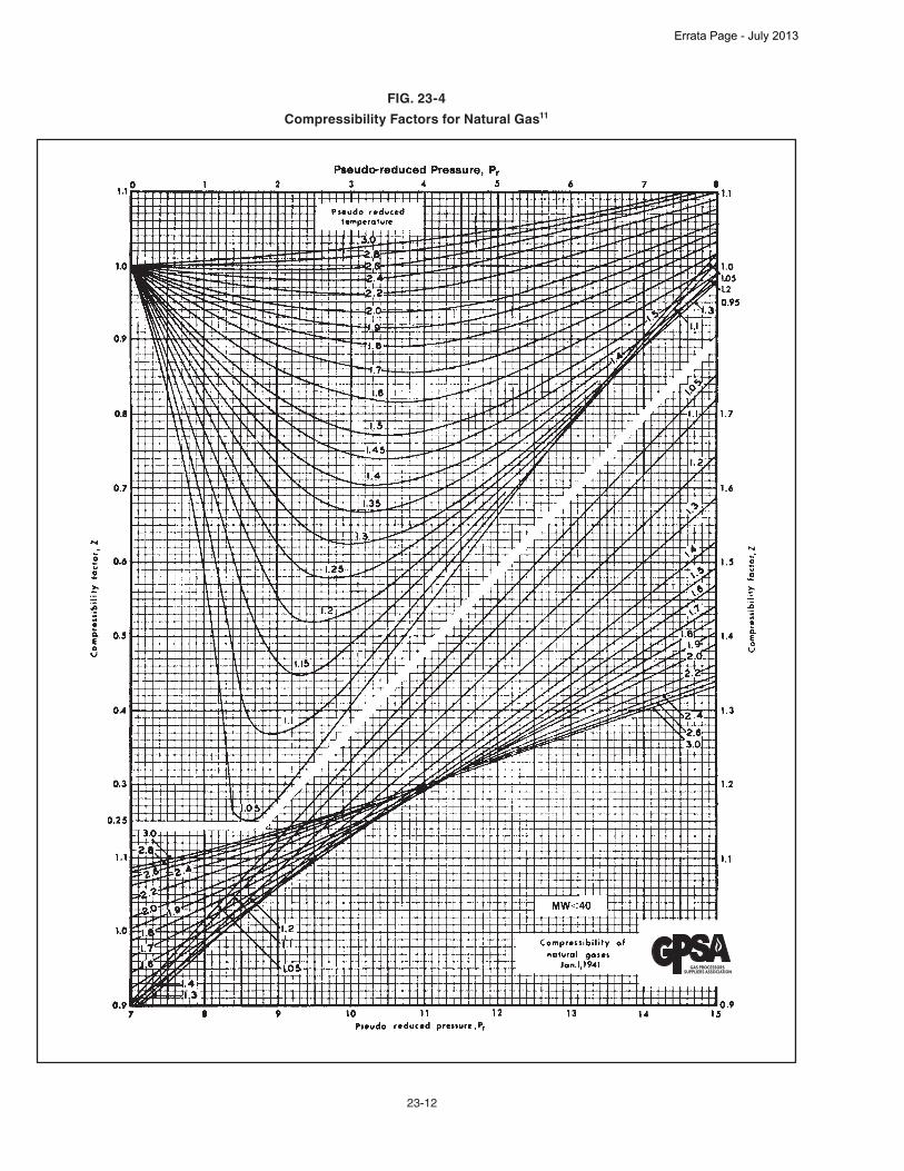
23-12
FIG. 23-4
Compressibility Factors for Natural Gas11
Errata Page - July 2013

23-27
References 99 through 105 contain most of the experimental data used by the authors of reference 45 and by NIST in their EOS development in REFPROP. The data comprises some 1200 points covering CO2/H2S mixtures ranging from 6% to 94% CO2, over a very wide range of pressures and temperatures. NIST were able to match most of these data points to better than 2%, with a small number of deviations over 10% and a few worst matches in the critical region. Current work is expected to be published later in 2011 by Kunz and Wagner.
A current GPA Research Project, Project No. 042, will in-clude density measurements for acid gas mixtures; its scope is described under “Viscosity”.
BOILING POINTS, CRITICAL PROPERTIES, ACENTRIC FACTOR,
VAPOR PRESSURE
Boiling Points Fig. 23-18 shows the interconversion between ASTM D-86
distillation 10% to 90% slope and the different boiling points used to characterize fractions of crude oil to determine the prop-erties; VABP, WABP, CABP, MeABP, and MABP. On the basis of ASTM D-86 distillation data, the volumetric average boiling (VABP) point is:
VABP = (t10 + t30 + t50 + t70 + t90)/5 Eq 23-12 where the subscripts 10, 30, 50, 70, and 90 refer to the volume percent recovered during the distillation. The 10% to 90% slope used as the abscissa in Fig. 23-18 is:
slope = (t90 – t10)/(90 – 10) Eq 23-13
To use the graph, locate the curve for the distillation VABP in the appropriate set for the type of boiling point desired. For the known 10–90% slope, read a correction for the VABP from the selected VABP curve. Example 23-4 — Determine the mean average boiling point (MeABP) and the molecular weight for a 56.8° API petroleum fraction with the following ASTM distillation data. % Over Temperature, °C
IBP 37.8 5 54.4 10 67.2 20 88.3 30 102.8 40 117.8 50 137.8 60 159.4 70 195.6 80 240.0 90 311.1 EP 337.8
IBP = initial boiling point EP = end pointSlope = (311.1 – 67.2)/80 = 3.05VABP = (67.2 + 102.8 + 137.8 + 195.6 + 311.1)/5 = 162.9 °CRefer to Fig. 23-18. Read down from a slope of 3.05 to the
interpolated curve to 162.9 °C in the set drawn with dashed lines (MeABP). Read a correction value of –29.5 on the ordinate. Then
MeABP = 162.9 – 29.5 = 133.4 °C
FIG. 23-18
Characterizing Boiling Points of Petroleum Fractions
Errata Page - July 2013

23-28
The significance of the various average boiling points, in-terconversion of D-86 and D-1160 ASTM distillations, and the calculation of true-boiling point and atmospheric flash curves from ASTM distillation data are in Chapters 3 and 4 of the API Technical Data Book.36
Molecular mass can be calculated from Equation 23-14 us-ing MeABP in K and S (relative density at 15 °C):
MW = 204.38 [(1.8 • T)0.118](S1.88) (e(0.00392T – 3.075 S)) Eq 23-14 This relationship has been evaluated in the molecular mass
range of 70 to 720; the MeABP of 36 to 560 °C; and the API range of 14° to 93°. Its average error was about 7%. Equation 23-14 is best used for molecular masses above 115, since it tends to over-predict below this value.Example 23-5 — Calculation of molecular mass. From Example 23-4:
S = 0.7515 for 56.8° APIMeABP = 133.4 + 273 = 406.4 K
Using Equation 23-14,MW = 204.38 [(1.8 • 406.4)0.118] [(0.7515)1.88]
[e(0.00392 • 406.4) – (3.075 • 0.7515)] = 127.0
Critical Properties Critical properties are of interest because they are used
to find reduced conditions of temperature and pressure as re-quired for corresponding states correlations. Pseudo-critical properties are used in many corresponding states correlations for mixtures.
The following equations taken from the API Technical Data Book36a, b can be used to estimate pseudo critical temperature and pressure for petroleum fractions (pseudo, or undefined components):
Ppc = [5.5303 (199)T–2.3125] • S2.3201 Eq 23-15Tpc = 19.0623 • T0.58848 • S0.3596 Eq 23-16These equations are in terms of T = MeABP (K) and relative
density (S) at 15 °C. Both of these correlations have been evalu-ated over the range of 80 to 690 molecular mass; 20 to 150 °C normal boiling point; and 6.6° to 95° API.Example 23-6 — Pseudocritical temperature and pressure.
Take the previous mixture (from Example 23-4) with: VABP = 166.4 °C MeABP = 118.4 °C API = 56.8° Molecular Weight = 127 (Ex. 23-5) ASTM D-86, 10% to 90% Slope = 3.05Find its pseudocritical temperature.
Solution StepsFrom Fig. 23-18 with ASTM D-86 slope = 3.05 find a VABP
correction of about – 65 °C (extrapolated from the left-hand group).
MABP = 166.4 – 65 = 101.4 °CUse Equation 23-16 to calculate the pseudocritical tempera-
ture as: Tpc = 19.0623 (118.4 + 273)0.58848 (0.7515)0.3596
= 577.1 K = 304.1 °C
For this 56.8° API fluid, estimate the pseudocritical pres-sure, using Eq. 23-15 and MeABP = 118.4 °C:
Ppc = [5.5303 (109)] (118.4 + 273)–2.3125 (0.7515)2.3021
= 2865 kPa (abs)
Acentric Factor The acentric factor, ω, is often a third parameter in corre-
sponding states correlations. Fig. 23-2 tabulates it for pure hy-drocarbons. The acentric factor is a function of Pvp, Pc, and Tc. It is arbitrarily defined as
ω = – log(Pvp/Pc)Tr = 0.7 –1.0 Eq 23-17 This definition requires knowledge of the critical (pseudo-
critical) temperature, vapor pressure, and critical (pseudo-criti-cal) pressure.
For a hydrocarbon mixture of known composition that con-tains similar components, a reasonably good estimate for the acentric factor is the molar average of the individual pure com-ponent acentric factors:
ω = ∑ yiωi Eq 23-18 If the vapor pressure is not known, ω can be estimated38 for
pure hydrocarbons or for fractions with boiling point ranges of 10 °C or less using:
ω = 3
log Pc – log 14.7
– 1.0
7 (Tc/Tb) – 1 Eq 23-19
Example 23-7 — Acentric factor. A narrow-boiling petroleum fraction has a VABP of 214.4 °C,
an ASTM slope of 0.75 and an API gravity of 41°. Estimate its acentric factor. In order to use Eq 23-19 we need the average boiling point (MeABP); the pseudocritical temperature (a func-tion of MABP); and the pseudocritical pressure (a function of MeABP).
From Fig. 23-18, the correction to VABP for mean average is –1.7 °C; and the correction for MABP is –2.8 °C. Note that for narrow-boiling fractions, all boiling points approach the volu-metric average. Then, MeABP = 212.7 °C and MABP is 211.6 °C.
From Eq. 23-14, the pseudocritical pressure is: T = 212.7 + 273.15 = 485.85 K S for 41° API = 141.5/(131.5 + 41) = 0.8203 Ppc = [5.5303 (109) (485.85)–2.3125] • (0.8203)2.3201
Ppc = 2141 kPa (abs)From Eq. 23-15, the pseudocritical temperature is:
Tpc = 19.0623 • (485.85)0.58848 • (0.8203)0.3596
Tpc = 676.4 K
ω = 3
log (2141) – log (101.325) – 1.0 = 0.444
7 (676.4/485.5) – 1
Vapor Pressure The vapor pressures of light hydrocarbons and some com-
mon inorganics in the temperature range below 38 °C appear in Fig. 23-19. Vapor pressures at higher temperatures, up to 315 °C, are in Fig. 23-20 for the same compounds. Note that, except for ethylene and propylene, the hydrocarbons are all nor-mal paraffins.
Errata Page - July 2013

26-1
SECTION 26
MembersGas Processors Suppliers Association
6526 East 60th StreetTulsa, Oklahoma 74145Phone: 918-493-3872
Fax: 918-493-3875Email: [email protected]://gpsa.GPAglobal.org
The following is a listing of the members of GPSA. Please contact them directly for further information. Behind this listing of members, the GPSA companies are classified by the type of services and supplies
that they provide to the industry. Services begin on page 26-15; Supplies begin on page 26-26.
Company& Address Phone FaxA+ Corporation 41041 Black Bayou Road Gonzales, LA 70737 http://www.geniefilters.com
225-644-5255 225-644-3975
Accurate Gas L.L.C. 116 Board Road Lafayette, LA 70508 http://www. accurategasllc.com
337-269-1217 337-269-1978
Accurate Lab Audits, LLC P.O. Box 248 Ville Platte, LA 70506
337-280-1003
Adsorption Technical Service, LLC 15138 Windsdowne Lane Cypress, TX 77429
281-256-0868 281-256-1996
Aeon PEC 505 Aero Drive Sheveport, LA 71107 http://www.aeonPEC.com
318-221-0122 318-425-2943
Aeros Environmental, Inc. 18828 Highway 65 Bakersfield, CA 93308
661-391-0112 661-391-0153
Afton Pumps, Inc. 7335 Ave. No. Houston, TX 77011 http://www.aftonpumps.com
713-923-9731 713-923-3902
Air Products and Chemicals 7201 Hamilton Blvd Allentown, PA 18195 http://www.airproducts.com
610-481-4544
Airgas, Inc. 110 W. 7th St., Ste. 1400 Tulsa, OK 74119 http://www.airgas.comAlfa Laval Inc. 5400 International Trade Drive Richmond, VA 23231 http://www.alfalaval.com
804-222-5300
Company& Address Phone FaxAllied Equipment 8000 N. Golder Odessa, TX 79764
432-367-6000
Alpine Site Services 5990 Kipling Parkway, #001 Arvada, CO 80004 http://www.alpinesites.com
303-420-0048 303-431-4843
AMCS Corporation 135 US Highway 202-206 Bedminister, NJ 07921 http://www.amcscorp.com
908-719-6560
AMEC Oil & Gas Americas 10777 Clay Rd. Houston, TX 77041 http://www.amec.com
713-570-8510
American Cleaning Systems, Inc. 5261 W. 42nd St. Odessa, TX 79764 http://www.amcleaning.net
432-381-3740
American Steel Pipe 1501 31st Ave. N. Birmingham, AL 35201 http://www.american-usa.com
205-307-2967 205-325-8194
Ametek Process Instruments 150 Freeport Road Pittsburgh, PA 15238
905-634-4401
Amspec LLC 11725 Port Road Seabrook, TN 77586 http://www.amspecllc.com
713-330-1000 713-330-4000
Analytical Instruments Corporation 9215 Solon Road, Ste. A4 Houston, TX 77064
713-460-5757 713-460-1987
Analytical Systems International 9215 Solon Road, Ste. A4 Houston, TX 77064 http://www.asikeco.com
281-516-3950 281-351-8925
Errata Page - July 2013
26-2
Company& Address Phone FaxAnguil Environmental 8855 N. 55th St. Milwaukee, WI 53223 http://www.anguil.com
414-365-6400 414-365-6410
Angus Measurement Services 4310 SW 33rd St. Oklahoma City, OK 73119
405-375-4970
Applied Consultants, Inc. 1221 Abrams Rd., Ste. 225 Richardson, TX 75081 http://www.appliedconsultants.com
972-235-1958 972-235-9010
ARC Energy Equipment 252 Judice Road Sunset, LA 70587 http://www.arcenergyequipment.com
337-852-1105 337-662-3153
Ardent Services LLC 170 New Camellia Blvd., Ste. 200 Covington, LA 70433
281-703-4649
Ariel Corporation 35 Blackjack Road Mt. Vernon, OH 43050 http://www.arielcorp.com
740-397-0311 740-397-3856
ASK Industries 24 Smith Road, Ste. 220 Midland, TX 79705 http://www.askindustries.com
866-366-5622 432-686-9415
Atlas Copco Gas and Process 3037 Industrial Parkway Santa Maria, CA 93455 http://www.atlascopco-gap.com
805-928-5757 805-925-3861
Audubon 10205 Westheimer Road, Ste. 600 Houston, TX 77042 http://www.aechou.com
713-728-7516 281-669-0591
AXH Air-Coolers 9717 East 42nd St., Suite 136 Tulsa, OK 74146 http://www.axh.com
918-663-0811 918-663-1972
AYERS, Michael, P.E. 3130 Walnut Bend #320 Houston, TX 77042-4779
713-575-8164
Azota Ltd. 9894 Bissonnet, Ste 580 Houston, TX 77036 http://www.azotaltd.com
281-768-4314 281-768-4370
B. enviroSAFE, Inc. 601 Lonesome Prairie Trail Haslet, TX 76052 http://www.benvirosafe.com/
817-439-4767 817-439-4149
Baker & O’Brien, Inc. 12221 Merit Dr., Ste. 1150 Dallas, TX 75251 http://www.bakerobrien.com
214-368-7626
Barry D. Payne & Associates, Inc. 10707 Corporate Dr. #222 Stafford, TX 77477 http://www.bdpayne.com
281-240-4488 281-240-3913
Bartlett Equipment Co. 4951 S Mingo Rd Tulsa, OK 74146 http://www.bartlettequipment.com
918-627-7040 918-691-7405
Company& Address Phone FaxBASF Corporation 1111 Bagby Street, Ste. 2600 Houston, TX 77002 http://www.basf.com
713-759-3024 713-759-3001
BCCK Engineering, Inc. 2500 No. Big Spring Midland, TX 79705 http://www.bcck.com
432-685-6095 432-685-7021
Bechtel 3000 Post Oak Boulevard Houston, TX 77056-6503 http://www.bechtel.com
713-235-2000 713-235-4820
BEI Engineers 3741 Red Bluff Road, Ste. 200 Pasadena, TX 77503 http://www.bei-us.com
713-475-2424
BENTEK Energy LLC 32045 Castle Court Evergreen, CO 80439 http://www.bentekenergy.com
303-988-1320 303-988-6409
Best PumpWorks 8885 Monroe Houston, TX 77061 http://www.bestpumpworks.com
713-956-2002 713-956-2141
Bexar Energy Holdings Inc. 111 Soledade, Ste. 830 San Antonio, TX 78205 http://www.bexarenergy.com
210-342-7106 210-223-0018
BFX Fabrication LLC 13465 Midway Road, Ste. 300 Dallas, TX 75244
469-374-5368
Black & Veatch Corp. Energy Division - Oil & Gas Houston, TX 77056 http://www.bv.com
713-416-9641
Blue Star Pipe 5700 Granite Parkway, Ste. 430 Plano, TX 75024
214-329-1233
Bowden Construction Co. P.O. Box 12308 Odessa, TX 79768 http://www.bowdenconstruction.com
432-366-8877 432-366-0936
Brahma Group Inc. 1132 South 500 West Salt Lake City, UT 84101 http://www.brahmagroupinc.com
801-521-5200 x 142
Brenntag Pacific Inc. P.O. Box 12430 Ogden, UT 84412 http://www.brenntag.com
801-627-4540 802-334-5141
Brice Equipment Co. P.O. Box 7945 Midland, TX 79708
432-697-3111
Bruker Daltonics 6 Glenway Drive The Hills, TX 78738
512-422-7157
Bryan Research & Engineering, Inc. P.O. Box 4747 Bryan, TX 77805 http://www.bre.com/
979-776-5220 979-776-4818
Errata Page - July 2013

26-3
Company& Address Phone FaxBuffalo Gap Instrumentation & Electrical 325 N. West Street Buffalo Gap, TX 79508 http://www.bgie.net
325-572-3389 325-572-3197
Burckhardt Compression U.S. 7240 Brittmoore Rd., Ste. 100 Houston, TX 77041 http://www.burckhardtcompression.com
281-582-1059
BWFS Industries 5637 Etheline Houston, TX 77039 http://www.bwfsindustries.com
281-590-9391 281-449-8563
C.R.C. Consulting P.O. Box 736 Perryton, TX 79070 http://www.crc-consulting.com
806-435-3418
C3 Resources LLC 2050 No. Loop W., Ste. 227 Houston, TX 77018 http://www.c3resources.com
713-476-9958 713-476-9975
Calgon Carbon Corporation 500 Calgon Carbon Dr. Pittsburgh, PA 15205 http://www.calgoncarbon.com
800-422-7266
Cameron Process & Compression Systems 11210 Equity Drive, Ste. 100 Houston, TX 77041 http://www.c-a-m.com/cs
713-895-3460
Cameron Process Systems 16250 Port Northwest Drive Houston, TX 77041 http://www.c-a-m.com/cs
866-754-3562 713-354-1923
Cameron Valves and Measurement 7200 Interstate 30 Little Rock, AR 72209 http://www.c-a-m.com
501-568-6000 501-570-5785
Catalytic Combustion Corporation 709 21st Avenue Bloomer, WI 54724 http://www.catalyticcombustion.com
715-568-2882 715-568-2884
Catalytic Products International, Inc. 980 Ensell Road Lake Zurich, IL 60047 http://www.cpilink.com
847-483-0334 847-438-0944
Catamount Constructors 1250 Bergen Parkway B200 Evergreen, CO 80439 http://www.catamountconstructors.com
303-710-3593
Caterpillar Inc. 13105 NW Freeway, Ste. 1010 Houston, TX 77040 http://www.cat.com
713-329-2207 713-329-2211
CB&I Two Riverway, Suite 1300 Houston, TX 77056 http://www.cbi.com
713-375-8000 713-375-8005
CECA Molecular Sieves 2000 Market Street Philidelphia, PA 19103 http://www.siliporite.com
281-251-4812 281-251-4812, ext. 2
Company& Address Phone FaxCEI Engineering Associates 3030 LBJ Freeway, Ste. 100 Dallas, TX 75234 http://www.ceieng.com
972-488-3737
CES Package Systems 21 Waterway Avenue The Woodlands, TX 77380 http://www.cespackagesystems.com
281-932-3675
CH2M Hill 14701 St. Mary’s Lane, Ste. 300 Houston, TX 77079 http://www.ch2m.com
281-721-8400 281-721-8401
Chapman Corporation 331 South Main Street Washington, PA 15301
724-250-2245
Chart Energy & Chemicals, Inc. 8665 New Trails Dr., #100 The Woodlands, TX 77381 http://www.chart-ec.com
612-227-4949
Chemical Products Industries, Inc. 7649 SW 34th St. Oklahoma City, OK 73179 http://www.chemicalproductsokc.com
405-745-2070 405-745-2276
Chemstations, Inc 11490 Westheimer Suite 900 Houston, TX 77077 http://www.chemstations.com
713-978-7700 713-978-7727
Chiyoda Corp. 2-12-1 Tsurumicho, Tsurumi-ku Yokohama, Kanagawa, JAPAN 230-8601 http://www.chiyoda-corp.com/en/
81-45-506-4630
Chromatic Industries 15B S. Trade Center Pkwy. Conroe, TX 77385 http://www.hemiwedge.com
936-539-5770
Cimation 10205 Westheimer Rd., Ste. 100 Houston, TX 77042 http://www.cimation.com
713-452-3350
City Pipe & Supply Corp. 2108 W. 2nd Odessa, TX 79763 http://www.citypipe.com
800-688-7473 432-333-2300
Clary E&I Services, LLC 110 W. Henderson Overton, TX 75684 http://www.claryei.com
903-834-0115 903-834-0116
Clear Creek Construction 945 E. Britton Rd Oklahoma City, OK 73114 http://www.clearcreekusa.com
405-478-3430
Coastal Chemical Co. LLC 5300 Memorial Drive, Suite 250 Houston, TX 77007 http://www.coastalchem.com
713-865-8787 713-865-8788
Coastal Flow Measurement, Inc. 2222 Bay Area Blvd., Suite 200 Houston, TX 77058 http://www.coastalflow.com
281-282-0622 281-282-0791
Errata Page - July 2013

26-4
Company& Address Phone FaxCompressor Engineering Corp. (CECO) 5440 Alder Houston, TX 77081
713-664-7333
Compressor Systems, Inc. P.O. Box 60760 Midland, TX 79711
432-495-3228
CompressorTech Two 12777 Jones Road, Ste. 225 Houston, TX 77070 http://www.compressortech2.com
832-205-3047
Condit Co. 7255 E 46th ST Tulsa, Ok 74145 http://www.conditcompany.com
918-663-5310 918-610-3451
Conestoga-Rovers & Associates 2270 Springlake Road, Suite 800 Dallas, TX 75234 http://www.craworld.com
972-331-8500 972-331-8501
Connelly-GPM, Inc. 3154 So. California Ave. Chicago, IL 60608
312-247-7237
Consulting and Field Services 1600 North Waverly Street Ponca City, OK 74601 http://www.cfsinspection.com
580-762-4510 580-762-1635
Contek Solutions LLC 6221 Chapel Hill Blvd., Ste. 300 Plano, TX 75093 http://www.contekllc.com
469-467-8296
Cook Compression 2203 Timberlock, Ste. 229 The Woodlands, TX 77380
281-636-8431
Corpac Steel Products Corp. 20803 Biscayne Blvd., Suite 502 Miami, FL 33021 http://www.corpacsteel.com
305-918-0540 305-931-2251
Corrosion Resistant Alloys 1310 W. Sam Houston Parkway North Houston, TX 77043
281-734-6280
Credence Gas Services LLC P.O. Box 2388 Alvin, TX 77512 http://www.credencegasservices.com
281-331-2219 281-331-2235
Criterion Catalyst and Technologies LP 16825 Northchase Drive, Ste. 1000 Houston, TX 77060
281-875-7899
Croft Automation LLC 712 Austin Ave Waco, TX 76701 http://www.croftautomation.com
903-388-6472 254-714-1710
Croft Production Systems, Inc. 19230 FM 442 Needville, TX 77461 http://www.croftsystems.net
979-793-2100
Cummings Electrical, Inc. 14900 Grand River Road, Ste. 124 Fort Worth, TX 76155 http://www.cummingselec.com
817-355-5300
Company& Address Phone FaxCummins Inc. 19739 Lake Stone Court Tomball, TX 77377 http://www.cumminsoilandgas.com
713-416-6235
Custom Compression Systems 1110 Unifab Road, Suite A New Iberia, LA 70560 http://www.customcompressionsystems.com
337-560-7700
D.F.Bergman, Inc. 17714 Mossy Ridge Lane Houston, TX 77095
281-859-9633
Daniel Measurement and Control 9720 Old Katy Rd. Houston, TX 77055
713-827-3874 713-827-3886
DBR Technology Center, Div. Schlumberger 9450 - 17 Avenue Edmonton, Al T6N 1M9 http://www.slb.com
780-463-8638 780-450-1668
DCG Partnership 1, Ltd. 4170A S. Main Pearland, TX 77581Detechtion Technologies 24 Greenway Plaza, #802 Houston, TX 77046 http://www.detechtion.com
800-780-9798 713-559-3059
Detector Electronics Corp. 6901 W 110th Street Minneapolis, MN 55438 http://www.Detronics.com
952 941 5665
Dew Point Control LLC P.O. Box 18887 Sugar Land, TX 77479-8887 http://www.dewpointcontrol.com
281-265-0101 281-265-0107
Dexter Field Services 2826 Morning Star New Braunfels, TX 78132
512-432-4754
Diablo Analytical Inc. 5141 Lone Tree Way Antioch, CA 94531 http://www.diabloanalytical.com
925-755-1005 925-755-1007
Dickson Process Systems Ltd. P.O. BOX 60478 Midland, TX 79711 http://www.dicksonprocess.com
432-561-8594 432-561-8990
Dresser-Rand Company 4121 Cross Bend Drive Arlington, TX 76016
214-597-7663
Eaton Metal Products Company 4800 York Street Denver, CO 80216
303-296-5729
EDG Inc. 10777 Westheimer Rd., #700 Houston, TX 77042
713-977-2347 713-977-2387
Edge Engineering & Science 16360 Park Ten Place, Ste. 300 Houston, TX 77084 http://www.edge-es.com
832-772-3003
Elkhorn Holdings Inc 71 Allegiance Cir Evanston, WY 82930 http://www.elkhornconstruction.com
307-789-1595 307-789-7145
Errata Page - July 2013

26-5
Company& Address Phone FaxElliott Group 10940 West Sam Houston Parkway N. Houston, TX 77064 http://www.elliott-turbo.com
281-517-7130 281-955-5072
EMD, Inc. 1411 Twin Oaks Wichita Falls, TX 76302 http://www.emdinc.com
940-322-2206 940-322-1719
Empact Analytical Systems Inc. 362 So. Main Brighton, CO 80601
303-637-0150
EnDyn Ltd. 301 West First St. Alice, TX 78332
800-723-6396 361-668-3906
Enerflex 10815 Telge Road Houston, TX 77095
281-345-5022
Energy Management & Services Co. 9990 Richmond Ave., Ste. 202 South Houston, TX 77042
713-456-7880 713-456-7881
Energy Recovery Inc. 1717 Doolittle Drive San Leandro, CA 94577 http://www.energyrecovery.com
281 633 6662
Energy Training Solutions 1310 Kingwood Drive Kingwood, TX 77339 http://www.energytrainingsolutions.com
281-783-5265 281-360-3874
EnerSys Corporation 12875 Capricorn Street Stafford, TX 77477 http://www.EnerSysCorp.com
281-598-7100 281-598-7199
Enerven Compression Services, LLC 8150 N. Central Expressway, Ste. 1100 Dallas, TX 75206 http://www.enerven.com
214-365-3200 214-265-0455
ENGlobal Corporation 12303 Airport Way, Ste. 145 Broomfield, CO 80021 http://www.ENGlobal.com
303-439-4325
EnRUD Resources, Inc. 1006 Vista Road Pasadena, TX 77504 http://www.enrud.com
713-943-1600
Enserca Engineering 165 S. Union Blvd., Ste. 1000 Lakewood, CO 80228
303-468-2720
Entero Corporation 1040 - 7 Ave SW Suite 500 Calgary, AB T2P 3G9 http://www.entero.com
403-261-1820 403-261-2816
EPC Inc. 14128 State Highway 110 South Whitehouse, TX 75791 http://www.epc0392.com
903-939-1555 903-939-1566
EPCON International Inc. 1250 Wood Branch Park Drive, Ste. 600 Houston, TX 77079
281-398-9400 281-398-9488
ESD Simulation Training, Inc. One Riverway, Ste. 1700 Houston, TX 77056 http://www.esd-simulation.com
713-300-3757
Company& Address Phone FaxeSimulation Inc. 1322 Space Park Drive, Suite A190 Houston, TX 77058 http://www.esimulation.com
713-962-3107 281-893-3319
Evonik Corporation 10200 Grogans Mill Road, Ste. 500 The Woodlands, TX 77380 http://www.evonik.com/northamerica
281-298-0290
Exeltech 7317 Jack Newell Blvd. N. Fort Worth, TX 76118
817-595-4969 817-595-1290
EXTERRAN 20602 E. 81st St. Broken Arrow, OK 74014 http://www.exterran.com
918-251-8571 918-259-2856
F.W. Murphy P.O. Box 470248 Tulsa, OK 74147 http://www.fwmurphy.com
918-317-4100 918-317-4266
Fabreeka International 13207 Tall Forest Cypress, TX 77429 http://www.fabreeka.com
2818945997 2818970064
Fabwell Corporation 8410 S. Regency Drive Tulsa, OK 74131-3621 http://www.fabwell.com
918-224-9060
Factory Direct Safety & Environmental 4153 Bluebonnet Drive Stafford, TX 77477 http://www.factorydirectsafety.com
832-532-9992
Fagen Inc. 1312 Catiline Place Baton Rouge, LA 70816
651-728-2312
FairFax Operations, LLC 123B N 14th Collinsville, OK 74021 http://www.fairfaxops.com
918-371-5139 918-371-5931
Fairwinds International 128 Northpark Blvd. Covington, LA 70433
985-809-3808
Federal Services LLC 120 E. Main Street Oklahoma City, OK 73104 http://www.federalcorp.com
405-239-7301 405-232-5438
FESCO, Ltd. 1100 FESCO Avenue Alice, TX 78332 http://www.fescoinc.com
361-661-7015 361-661-7019
FES-Southwest, Inc. 19221 IH-45 South Ste. 340 Conroe, TX 77385 http://www.fessw.com
281-296-7920 281-296-7177
Fisher Controls 205 S Center Street Marshalltown, IA 50158 http://www.fisher.com
641-754-3011 641-754-3026
Fluenta Inc. 1155 Dairy Ashford, Suite 211 Houston, Tx 77079 http://www.fluenta.com
281-972-2004 281-497-8687
Errata Page - July 2013

26-6
Company& Address Phone FaxFluor Enterprises, Inc. 3 Polaris Way Aliso Viejo, CA 92698
949-349-2231
FMC Technologies Direct Drive Systems 621 Burning Tree Road Fullerton, CA 92833
720-560-6177
Foster Wheeler USA Corporation 2020 Dairy Ashford Houston, TX 77077
281-597-3000 281-597-3028
Freese and Nichols, Inc. 4055 International Plaza, Ste. 200 Fort Worth, TX 76109 http://www.freese.com
817-735-7300
Future Pipe Industries 11811 Proctor Street Houston, TX 77038 http://www.futurepipe.com
281-847-2987
G2 Partners, LLC 10260 Westheimer Rd., St. 400 Houston, TX 77042 http://www.g2partnersllc.com
713-260-4000 713-260-4099
Garzo, Inc. 4430 Steffani Lane Houston, TX 77041
713-466-8679 713-466-8686
Gas Analytical Solutions, Inc. 19330 Highway 155 South Flint, TX 75762
903-825-2136 903-825-2184
Gas and Supply 111 Buras Drive Belle Chasse, LA 70037 http://www.gasandsupply.com
504-234-7700
Gas Corporation of America P.O. Box 5183 Wichita Falls, TX 76307 http://www.gas-corp.com
940-723-6015
Gas Equipment Company, Inc. 11616 Harry Hines Blvd Dallas, TX 75229 http://www.gasequipment.com
972-280-8430 972-620-4142
Gas Packaging Engineering Co. 3000, 150-6th Avenue S.W. Calgary, AB T2P 3Y7 http://www.gaspackages.com
403-538-2164
Gas Technology Corporation 1425 Greenway Drive, Suite 450 Irving, TX 75038 http://www.gastech.net
972-255-7800 972-550-0071
Gas Treatment Services B.V. Timmerbabriekstraat 12, Bergambacht GV, 2861 http://www.gtsbv.com
31 182 621890 31 182 621891
GE Oil & Gas, Inc. 4424 West Sam Houston Parkway North, Ste. 700 Houston, TX 77041GE Power & Water 1101 W. Saint Paul Ave. Waukesha, WI 53188 http://www.dresserwaukesha.com
262-547-3311 262-650-5650
Company& Address Phone FaxGEA Refrigeration North America Inc. 3475 Board Road York, PA 17406 http://www.geafes.com
717-309-3333
Genesis Systems 1501 10th Street #100 Plano, TX 75074 http://www.callgenesis.com
972-877-5016
Geolex, Inc. 500 Marquette Ave. NW #1350 Albuquerque, NM 87102 http://www.geolex.com
505-842-8000
G-Force and Associates, Inc. 5200 W. Highway 377 Tolar, TX 76476 http://www.gforcetx.com
817-573-3960
Global Compressor, LP 13415 Emmett Road Houston, TX 77084 http://www.globalcompressorparts.com
713-983-8773 713-983-7118
Global Process Systems SDN BHD Level 8 Menara See Hoy Chan, No. 373 Jalan Tun Razak Kuala Lumpur, WP 50400 http://www.globalprocesssystems.com
603 914 53000 603 216 13234
Gly-Tech Services 2054 Paxton St. Harvey, LA 70058 http://www.glytech.com
504-348-8566 504-348-8261
Goar Sulfur Services & Assistance 1522 Hubbard Dr. Tyler, TX 75703
903-561-3008
GRACE Davison 845 Redwing Street Bridge City, TX 77611Graves Analytical Services LLC P.O. Box 253 Hugoton, KS 67951
620-428-6053 620-428-6069
Gregory Gas Services, LLC 343592 E. 990 Rd. Chandler, OK 74834 http://www.gregorygasservices.com
918-866-2318 918-866-2263
Groundwater & Environmental Services, Inc. 440 Creamery Way, Ste. 500 Exton, PA 19341 http://www.gesonline.com
800-426=9871 x3022
GTS Energy 4050 36th Ave. NE Norman, OK 73026 http://www.gtsenergy.com
979-820-0556
Guild Associates, Inc. 5750 Shier-Rings Road Dublin, OH 43016 http://www.moleculargate.com
908-752-6420 614-798-1972
Gulf Coast Chemical, LLC 220 Jacqulyn Street Abbeville, LA 70510 http://www.gulfcoastchemical.com
337-898-0213 337-893-9927
Gulf Coast Dismantling, Inc. P.O. Box 5249 Pasadena, TX 77508
281-487-0595 281-487-0597
Errata Page - July 2013

26-7
Company& Address Phone FaxGulf Coast Measurement, Inc. P.O. Box 854 Cypress, TX 77410
281-357-0992 281-357-0994
Gulf Interstate Engineering 16010 Barkers Point Lane, Ste. 600 Houston, TX 77079
713-850-3585
Gulf Publishing Company 2 Greenway Plaza, Ste. 1020 Houston, TX 77046 http://www.hydrocarbonprocessing.com
713-523-4443
Gulsby Engineering Inc. 1250 Indiana St Humble, TX 77396
281-446-4230 281-446-5445
GWD 621 17th Street, Ste. 1200 Denver, CO 80293 http://www.gwddesign.com
303-951-9327
H&S Valve Inc. 6704 No. County Rd. West Odessa, TX 79702
432-362-0486 432-368-5052
H.J. Baker, PE 1511 Rock Ridge Dr. Cleveland, OK 74020
918-358-5286 425-928-2637
Halker Consulting, LLC 9400 Station Street, Ste. 300 Lone Tree, CO 80124 http://www.halkerconsulting.com
303-515-2700
Hammco Inc. 6901 N 115th E Ave Owasso, OK 74055 http://www.hammco-aircoolers.com
918-272-9575 918-272-9585
Harris Group Inc 1999 Broadway Suite 1500 Denver, CO 80202 http://www.harrisgroup.com
303-291-0355 303-291-0136
Heath Consultants Inc. 9030 Monroe Road Houston, TX 77061 http://www.heathus.com
713-844-1300 713-844-1309
HETSCO, Inc. 505 Pushville Rd. Greenwood, IN 46143 http://www.hetsco.com
317-535-4315 317-535-4684
HJ Baker, PE 1511 Rock Ridge Drive Cleveland, OK 74020
918-358-5286
Holloman Corp. 333 N. Sam Houston Pkwy, Level 6 Houston, TX 77060
281-260-1060
Houston Vessel Manufacturing LLC 16250 Tomball Parkway Houston, TX 77086 http://www.houstonvessel.com
713-550-1376
Howard Measurement Co., Inc. 1637 Enterprise St. Athens, TX 75751 http://www.howardmeasurement.com
903-677-0700
HPF Consultants, Inc. 601 N. Marienfeld, Suite 200 Midland, TX 79701-4365 http://www.hpfconsultants.com
432-685-4143 432-685-4145
Company& Address Phone FaxHSB Solomon Associates, LLC One Lincoln Centre, 5400 LBJ Freeway, Ste. 1400 Dallas, TX 75240 http://www.solomononline.com
972-739-1719 972-233-8332
Hunt, Guillot & Associates 603 Reynolds Drive Ruston, LA 71270 http://www.hga-llc.,com
318-255-6825
Huntsman Corp. 3040 Post Oak Blvd. Houston, TX 77056
713-235-6000 713-235-6977
HyBon Engineering 2404 Commerce Drive Midland, TX 79704
432-697-2292 432-697-2310
Hydrocarbon Technology Engineering 802 Merritt St., SE Grand Rapids, MI 49507
616-452-3279 616-452-3290
I&S Technical Resources, Inc. 248 Twin Lakes Blvd. West Columbia, TX 77486
832-476-5473
Ignition Systems & Controls, LP P. O. Box 60372 Midland, TX 79711-0372
915-697-6472
Industrial Distributors, Inc. 4920 Nome St., Unit A Denver,, CO 80239 http://www.idiprocess.com
303-375-9070 303-375-0911
Industrial Engineering Management, Inc. 4444 American Way, #200 Baton Rouge, LA 70816
225-214-4444
Industrial Gas Technology, Inc. 150 Vanderbilt Ct. Bowling Green, KY 42103 http://www.industrialgastechnology.com
270-783-0538
INEOS Oxide 2901 Wilcrest Suite 205 Houston, TX 77042 http://www.ineos.com
713-243-6200 713-243-6220
International Oil & Gas Consultants Pte, Ltd. 360 Orchard Road, #12-02 International Bldg. Singapore, 238869 http://www.iog-consultants.com
+65 6235 9030 +65 6235 6180
Intertek 801 Travis, Ste. 1500 Houston, TX 77002 http://www.intertek.com
713-430-8601
Invensys-Foxboro 8610 S. 66th E. Ave. Tulsa, OK 74133 http://www.iom.invensys.com
918-492-6301 918-492-6302
IPD 23231 Normandie Ave. Torrance, CA 90501 http://www.ipdparts.com
310-602-5317 310-530-2708
ISGAS 5807 Northdale Street Houston, TX 77087
713-645-5886 713-645-0661
Errata Page - July 2013

26-8
Company& Address Phone FaxJ MAR & Associates 15455 Dallas Parkway Suite 220 Addison, TX 75001 http://www.jmarassociates.com
972-732-8301
J. H. Foglietta Consulting LLC 5827 Fairdale Lane Houston, TX 77057
713-962-0470
J.W. Williams Inc.,a Flint Energy Services Co. 19814 G.H. Circle Waller, TX 77084
936-931-2424 936-931-2225
JEM Resources & Engineering, Inc. 10 Desta Drive, Ste. 175 Midland, TX 79705 http://www.jemengineering.com/
432-352-0802
JFE Engineering Corp. 2-1 Suehiro-cho, Tsurumi-Ku, Yokohama, 230-8611
81 45 505 07772
81 45 505 08941
JGC Corp. 2-3-1 Minato mirai, Nishi-ku Yokohama, Ka 220-6001 http://www.jgc.co.jp
045-682-8468 045-682-8835
John M. Campbell & Company 1215 Crossroads Blvd Norman, OK 73072 http://www.jmcampbell.com
405-321-1383 405-321-4533
Johnson Filtration Products, Inc. P.O. Box 30010 Amarillo, TX 79120
806-371-8033 806-372-5257
Johnson Matthey Catalysts 4106 New West Road Pasadena, TX 77507 http://www.jmcatalysts.com
713-598-4115 281-291-0721
Johnson Screens 16430 Park Ten Place Houston, TX 77084 http://www.johnsonscreens.com
832-590-4177 832-590-2050
Jonell, Inc P.O. Box 1092, 900 Industrial Pkwy Breckenridge, Tx 76424 http://www.jonellinc.com
254-559-7591 254-559-9863
Jord International 11200 Richmond Ave., #301 Houston, TX 77082 http://www.jord.com.au
832-300-7100 832-300-7104
Joule Processing LLC. 3200 Southwest Freeway, Ste. 2390 Houston, TX 77027 http://www.jouleprocessing.com
713-481-1864 713-481-1887
JV Industrial Companies 4040 Red Bluff Pasadena, TX 77503
281-842-9353
J-W Power Company 7074 S. Revere Parkway Centennial, CO 80112 http://www.jwoperating.com
720-385-3030 866-741-2025
Kahuna Ventures 10355 Westmoor, Ste. 250, Westminster, CO 80021
303-451-7374
Kams, Inc. 1831 NW 4th Dr. Oklahoma City, OK 73106
405-232-2636 405-232-3107
Company& Address Phone FaxKane Environmental Engineering 5307 Oakdale Creek Court Spring, TX 77379
281-370-6580 281-379-3735
KASKA, LLC 330 South Mill Pryor, OK 74361
918-825-3763
KBC Advanced Technologies 15021 Katy Freeway, Ste. 600 Houston, TX 77094 http://www.kbcat.com
281-293-8200
KBR, Inc. 601 Jefferson Street Houston, TX 77007 http://www.kbr.com
713-753-2000 713-753-2000
Kenny Electric 901 SW Frontage Rd. Fort Collins, CO 80254 http://www.kenny-electric.com
970-212-4334 970-490-2878
Kimray Inc. 52 NW 42nd Street Oklahoma City, OK 73118
405-525-6601 405-525-5630
Kleinfelder 7805 Mesquite Bend, Suite 100 Irving, Tx 75063 http://www.kleinfelder.com
972-868-5934 972-409-0008
Knighten Industries Inc. 3323 NC Rd. West Odessa, TX 79764
432-362-0468 432-362-9813
Koch-Glitsch, LP 4111 East 37th Street North Wichita, KS 67220 http://www.koch-glitsch.com
316-828-7208 316-828-7985
Kodiak Gas Processing LLC P.O. Box 418 Wilmette, IL 60091
214-601-6655
KW International 1223 Brittmoore Rd. Houston, TX 77043 http://www.kwintl.com
713-468-9581` 713-468-2770
L.A. Turbine 29151 Avenue Penn Valencia, CA 91355 http://www.laturbine.com
661-294-8290 661-294-8249
Laboratory Services 2609 W. Marland Hobbs, NM 88240
575-397-3713
Lauren Engineers & Constructors 22503 Katy Freeway Katy, TX 77450 http://www.laurenec.com
281-994-4232
LCM Industries, Inc. 1605 S. Marlin Dr. Odessa, TX 79763 http://www.lcmindustries.com
432-332-5516 432-332-5519
L-Con, Inc. Engineers/Constructors 12301 Kurland Dr., Ste. 200 Houston, TX 77034 http://www.L-Con.com
281-484-5266
LIG Midstream Co. LLC 615 N. Upper Broadway, Ste. 1200 Corpus Christi, TX 78401
361-654-6510
Errata Page - July 2013

26-9
Company& Address Phone FaxLinde Process Plants, Inc. 6100 S. Yale, Ste. 1200 Tulsa, OK 74136 http://www.lppusa.com
918-477-1200 918-477-1100
LKS Midstream Consulting LLC 5960 West Parker Road #278 - 233 Plano, TX 75093 http://lksmidstream.com
469-443-0637
Lockwood International 2209 N. Padre Island Dr. St. Y Corpus Christi, TX 78468 http://lockwoodint.com
361-815-8275 361-289-8839
Louisiana Valve Source, Inc. 101 Metals Dr. Youngsville, LA 70592 http://www.lavalve.com
337-856-9100 337-857-2969
M & J Valve 4150 South 100 East Ave., Suite 200W Tulsa, OK 74146
918-663-9595
M Chemical Co. 850 Colorado Blvd Los Angeles, CA 90041 http://www.mchemical.com
323-254-3600 323-257-6968
M&H Enterprises, Inc. 19450 Hwy 240, #600 Houston, TX 77070 http://www.mhes.com/
713-974-3627
Martin Energy Consultants P.O. Box 8064 The Woodlands, TX 77387
281-367-9401
Master Corp. 1330 East 8th St., Suite 105 Odessa, TX 79761-4713 http://www.mastercorporation.com
432-580-0600 432-335-0600
Masters Process Equipment 26118 North IH-45 Spring, TX 77386 http://www.mastersprocess.com
281-367-5699 281-367-5685
McAfee & Taft 1717 S. Boulder Ave, Ste. 900 Tulsa, OK 74119 http://www.mcafeetaft.com
918-587-0000
McJunkin Red Man Corporation P.O. Box 4395 Odessa, TX 79760
972-602-4075
Mechnical Equipment, Inc. P.O. Box 1800 Midland, TX 79702
432-687-0601
MEGTEC Systems Inc. 830 Prosper Road De Pere, WI 54115
920-339-2787
MEI LLC 138 Canal Street, Suite 501 Pooler, GA 31322 http://www.mei-consult.com
912-355-8001 912-355-0065
MHBT, Inc. 8144 Walnut Hill Lane, 16th Floor Dallas, TX 75231
972-770-1655
Michell Instruments Inc. 14915 Terra Point Cypress, TX 77429 http://www.michell.com/us
281-728-3982
Company& Address Phone FaxMidCon Compression LLC P.O. Box 18881 Oklahoma City, OK 73154 http://www.midconcompression.com
405-935-4159 405-849-0003
Mid-States Supply 1716 Guinotte Ave. Kansas City, MO 64120 http://www.midcoonline.com
800-825-1410 816-842-3630
Midstream Energy Group, Inc. 10707 Corporate Drive, Ste 158 Stafford, TX 77477 http://www.midstreamenergygroup.com
281-277-5560
Midway Laboratory Inc. 315 Main Street Taft, CA 93268 http://www.midwaylaboratory.com
661-765-2364 661-765-6920
MIRATECH Corp. 420 So. 145th East Ave. Tulsa, OK 74108
918-622-7077 918-622-3928
Mobile Analytical Labs Inc. P. O. Box 69210 Odessa, TX 79769
432-337-4744
MODEC International Inc. 14741 Yorktown Plaza Houston, TX 77040 http://www.modec.com
281-529-8100 281-529-8102
Modern Project Services TJ Carmody Cedar Rapids, IA 52406 http://www.modernprojectservices.com
319-730-8030 319-364-8368
Monico Monitoring, Inc. 5527 Louetta Road, Ste. D Spring, TX 77380 http://www.monicoinc.com
281-350-8751
Moore Control Systems Inc. 1435 Katy-Flewellen Katy, TX 77494 http://www.moore-control.com
281-392-7747 281-392-7727
Morrow Renewables LLC P.O. Box 61447 Midland, TX 79711 http://www.morrowrenewables.com
918-432-570-4200
Movilab, S.A. de C.V. Paseo de Francia 163 piso 1 Naucalpan, Mexico 53120
525553442121 X102
MSES Corrosion Products Division 609 West Main St. Clarksburg, WV 26302 http://www.msesproducts.com
304-624-9700 304-622-0981
Mueller Environmental Designs 7607 Wright Rd Houston, TX 77041 http://www.muellerenvironmental.com
832-300-1122 713-465-0997
Mustang Cat 12800 NW Freeway Houston, TX 77040
713-460-7238
Nalco Chemical Co. 4500 S Lakeshore Drive Tempe, AZ 85282 http://www.nalco.com
630-305-1000 480-774-0185
Errata Page - July 2013

26-10
Company& Address Phone FaxNetwork International 3555 Timmons Lane, Ste. 1200 Houston, TX 77027 http://www.networkintl.com
713-659-7500 713-850-0808
Neuman & Esser USA, Inc. 1502 East Summitry Circle Katy, TX 77449 http://www.neuman-esser.com
281-497-5113 281-497-5047
New Tech Global Ventures 202 Madison Square Colleyville, TX 76034
817-821-8107
Nextteq LLC 8406 Benjamin Road, Ste. J Tampa, FL 33634 http://www.nextteg.com
877-312-2333 877-312-2444
Niagara Blower Heat Transfer Solutions 673 Ontario St Buffalo, NY 14207 http://www.niagarablower.com
716-875-2000 716-875-1077
Nicholas Consulting Group Inc. 600 N. Marienfeld, Suite 390 Midland, TX 79701 http://www.thencg.com
432-570-8093 432-683-1993
Norriseal 11122 West Little York St. Houston, TX 77041 http://www.norriseal.com
713-466-3552 713-896-7386
Norwood S&S, LLC 6415 Calle Lozano Dr. Houston, TX 77041-2559 http://www.NorwoodSS.com
281-558-2946 281-558-8405
Nova Molecular Technologies 1 Parker Place, Ste. 725 Janesville,, WI 53545
608-754-6682
Oil & Gas Awards 60 A George Row London, SE164WA http://www.oilandgasawards.com
00121059 18471
Omni Flow Computers, Inc. 12620 W. Airport Blvd., Ste. 100 Sugar Land, TX 77479 http://www.omniflow.com
281-240-6161 281-240-6162
Onsite Power Inc. 6525 S. Riviera Way Aurora, CO 80016
303-690-8486
Optimized Gas Treating, Inc. P.O. Box 125 Clarita, OK 74535 http://www.ogtrt.com
580-428-3535 580-428-3535
Optimized Pipeline Solutions 59 Joshua Court Lake Jackson, TX 77566
979-583-8839
Optimized Process Designs 25610 Clay Road Katy, TX 77493 http://www.opd-inc.com
281-371-7500 281-371-0132
Optimized Process Furnaces 3995 S Santa Fe Chanute, KS 66720 http://www.firedheater.com
620-431-1260 620-431-6631
Company& Address Phone FaxOrtloff Engineers, Ltd. 415 W. Wall, Ste. 2000 Midland, TX 79701 http://www.ortloff.com
432-685-0277
Pantechs Laboratories, Inc. 5915 50th Street Lubbock, TX 79424 http://www.pantechs.com
806-797-4325 806-797-4474
Paragon Field Services 500 Main St La Marque, TX 77568 http://www.paragontexas.com
409-935-6602 409-935-9361
Parker Hannifin Corp. P. O. Box 599 Oxford, MI 48371
248-628-6400
PCL Industrial Construction Co. 15915 Katy Freeway, Ste. 300 Houston, TX 77094 http://www.pcl.com
281-249-8022
PECOFacet 118 Washington Avenue Mineral Wells, TX 76068 http://www.pecofacet.com
940-325-2575 940-325-4622
Peerless Mfg. Co. 2930 West Sam Houston Parkway, Ste. 225 Houston, TX 77043 http://www.peerlessmfg.com
281-655-7800
Pennwell Corp. 1455 West Loop S Houston, TX 77027 http://www.pennwell.com
713-963-6276 713-963-6285
Pentair Porous Media Corp. 4301 West Davis Conroe, TX 77304 http://www.pentair.com
936-788-1000 936-788-1220
Perry Gas Processors L.P. P.O. Box 13270 Odessa, TX 79768
432-332-0100
Petral Consulting Company P.O. Box 42586 Houston, TX 77242 http://www.petral.com/Petrin Corporation 1405 Commercial Drive Port Allen, TX 70767 http://www.petrincorp.com
800-256-7876 225-343-0475
Petro-Canada America Lubricants Inc. 4120 S. Juniper Ave. Broken Arrow, OK 74011 http://www.lubricants.petro-canada.ca
918-451-5655
Petronas TBG 83 KG Kuantan Klang, Selangor 41300 http://www.petronas.com.my
60323315348
Plant Eng. Construction Pte. Ltd. 21 Shipyard Rd. Singapore, 628144
65-6268-9788
Praxair Inc. 175 East Park Drive Tonawanda, NY 14151
716-879-2128
Errata Page - July 2013

26-11
Company& Address Phone FaxPrecision Flow Inc. P.O. Box 7137 Odessa, TX 79760
432-381-5131
Prime Controls, LP 815 Office Park Circle Lewisville, TX 75057 http://www.prime-controls.com
972-221-4849
Puffer Sweiven 4230 Greenbriar Drive Stafford, TX 77477 http://www.puffersweiven.com
281-240-2000 281-274-6438
Q.B. Johnson Manufacturing, Inc. 9000 S. Sunnylane Rd. Oklahoma City, OK 73189 http://www.qbjohnson.com
405-677-6676 405-670-3270
Q2 Technologies, LLC 14720 Highway 105 West, #200 Montgomery, TX 77356 http://www.q2technologies.com
936-588-2242 936-588-2298
QuantityWare GmbH Zeiloch 1b Bruchsal, 76646 http://www.quantityware.com
49 7251 982 3003
49 7251 982 3116
Questar Energy Services P. O. Box 1129 Rock Springs, WY 82902-1129
307-352-7292
Quorum Business Solutions, Inc. 811 Main Street, Ste. 2000 Houston, TX 77002 http://www.qbsol.com
713-430-8601 713-430-8697
R&R Engineering Co., Inc. 12585 E. 61st St. Broken Arrow, OK 74012
918-252-2571
Randall Gas Technologies 2 Riverway, Ste. 1300 Houston, TX 77056
713-375-8266
Ranger Plant Constructional Company, Inc. 5851 E. Interstate 20 Abilene, TX 79601 http://www.rpccinc.com
325-677-2888
Ref-Chem, L.P. 1128 S. Grandview Ave. Odessa, TX 79761 http://www.ref-chem.com
432-332-8531 432-332-3325
Regard Resources Co., Inc 555 Aero Dr. Shreveport, LA 71107 http://www.regardresources.com
318-425-2533 318-425-1014
REM Technology, Inc. 4306 Phil Street Bellaire, TX 77401 http://www.remtechnology.com
832-314-8255
RES Energy Solutions 2010 McAllister Rd. Houston, TX 77092 http://www.res-co.com
832-310-1801
Rexel Inc. 8042 Katy Freeway, Ste. 100 Houston, TX 77024 http://www.rexelusa.com
713-316-1700 713-686-8906
Company& Address Phone FaxRhine Ruhr Pty Ltd Unit 1, 10-30 West Circuit, Sunshine West Melbourne, Vi 3020 http://www.rhineruhr.com.au
61 3 9300 5000 61 3 9300 5001
Rino - K&K Compression, Ltd. 3302 Lilac Street Pasadena, TX 77505 http://www.rino-kk.com
281-487-3890 281-487-7472
River City Engineering 4830 Bob Billings Parkway, Suite 100B Lawrence, KS 66049 http://www.rivercityeng.com
785-842-4783 785-842-1450
RK Turbine Consultants 330 W. Government St. Pensacola, FL 32502
850-221-6029
Robert R. Reis, Attorney- Mediator, P.C. P. O. Box 520954 Tulsa, OK 74114
918-742-2028 918-742-2028
Rotor-Tech Inc. 10613 Stebbins Circle Houston, TX 77379 http://www.rotor-tech.com
713-984-8900 713-984-9425
Royal Filter Mfg. Co., Inc. 4327 S. 4th Chickasha, OK 73018 http://www.royalfilter.com
405-224-0229
S&B Engineers and Constructors, Ltd. 7825 Park Place Blvd. Houston, TX 77087
713-845-7850
S&B Infrastructure, Ltd. 100 E. 15th St., #650 Fort Worth, TX 76102 http://www.sbinfra.com
817-820-0036
Sagebrush Pipeline Equipment 8100 New Sapulpa Rd Tulsa, OK 74131 http://www.sagepipe.com
918-551-5600 918-224-8452
SAIC Energy, Environment, and Infrastructure One West Third, Ste. 200 Tulsa, OK 74103 http://www.saic.com/EEandI
918-599-4361
Salof Refrigeration Co., Inc. 1150 Schwab Road New Braunfels, TX 78132 http://www.salofcompanies.com
830-625-1613 830-625-0778
Samuel Engineering Inc. 8450 E. Crescent Pkwy., Ste. 2300 Greenwood Village, CO 80111 http://www.samuelengineering.com
303-714-4840
Saulsbury Industries Inc. 2951 E. Interstate 20 Odessa, TX 79766
432-366-3686 432-368-0061
Saxon Construction, Inc. 790 Brogdon Road Suwanee, GA 30024
770-271-2174 770-271-2176
SCFM Compression Systems, Inc. 3701 S. Maybelle Ave. Tulsa, OK 74107 http://www.scfm.com
918-663-1309 918-663-6140
Errata Page - July 2013

26-12
Company& Address Phone FaxSchwob Energy Services 2349 Glenda Lane Dallas, TX 75229 http://www.schwob.com
972-243-7674
S-Con, Inc. 8326 Hwy 21 West Bryan, TX 77807
979-822-4445
Scott Measurement Service Inc. P.O. Box 5247 Granbury, TX 76049 http://www.scottmeasurement.com
817-573-0036 817-573-0364
SEC Energy Products & Services L.P. 9523 Fairbanks N Houston Houston, TX 77064 http://www.sec-ep.com
281-890-9977 281-955-6346
Select Engineering, Inc. 1717 S. Boulder, Suite 600 Tulsa, OK 74119 http://www.select-engineering.com
918-592-1133 918-592-1134
Sep-Pro Systems, Inc. 11050 W. Little York, Bldg. K Houston, TX 77041 http://www.sepprosystems.com
832-243-7360
Sepra-Chem Corporation 10975 Spur 248 Tyler, TX 75707 http://www.sepra-chem.com
903-566-1015 903-566-1094
SERO Pump Systems, Inc. 3727 Greenbriar Drive, Ste. 105 Stafford, TX 77477 http://www.seropumps.com/
281-242-8080
Setec Astronomy, Inc. P.O. Box 6557 Tyler, TX 75711
903-312-9435
Shamrock Gas Analysis 1100 South Madden St. Shamrock, TX 79097 http://www.sgalab.com
806-256-3249 806-256-3159
Sherry Laboratories 2120 W. Willow St. Scott, LA 70583Simms Machinery International 2357 A Street Santa Maria, CA 93455 http://simmsmachineryinternational.com
805-349-2540 805-349-9959
SME Associates LLC 6715 Theall Rd. Houston, TX 77066
281-440-7350
SME Products, LP 6715 Theall Rd. Houston, TX 77066
281-440-7353
Smith & Burgess 5700 Northwest Central Drive, #301 Houston, TX 77092 http://www.smithburgess.com
713-082-2647
Smithco Engineering, Inc. 6312 S 39th West Avenue Tulsa, OK 74132 http://www.smithco-eng.com
918-446-4406 918-445-2857
SNC-Lavalin E&C 9009 West Loop South, Suite 800 Houston, TX 77096-1719 http://www.snclavalin.com
713-667-9162 713-667-9241
Company& Address Phone FaxSolutia - Therminol Heat Transfer Fluids 7710-T Cherry Park Dr #126 Houston, TX 77095 http://www.therminol.com
281-750-2661 207-213-3473
Southern Flow Companies, Inc. 5291 Hanselman Victoria, TX 77905 http://www.southernflow.com
361-575-4528 361-575-9512
Southern Heat Exchanger Services 12210 A US 90 East Houston, TX 77049
281-506-0934
Spartan Engineering Inc. 10820 E. 45th Street, Ste. 100 Tulsa, OK 74146 http://www.spartan-eng.com
918-895-7666
Specialty Process Equipment Corporation 6400 Hawes Road Humble, TX 77396 http://www.spec-pro.com
281-812-7732 281-852-7732
SpectraSensors Inc. 4333 W. Sam Houston Houston, TX 77043 http://www.spectrasensors.com
713-300-2719 713-856-6623
Spectrum-Prime Solutions, L.P. 24 E. Greenway Plaza, Ste. 1180 Houston, TX 77046 http://www.spectrumprime.com
713-589-6852
SPL Inc. 8880 Interchange Drive Houston, TX 77054 http://www.spl-inc.com
713-660-0901 713-660-6035
Strategic Automation Services LLC 16203 Park Row Road, Ste. 140 Houston, TX 77084
281-945-8900
Strategy Engineering & Consulting, LLC 15995 N. Barkers Landing, Ste. 200 Houston, TX 77079 http://www.strategyeng.com
281-657-7012
Subsurface Technology, Inc. 6925 Portwest Dr., Suite 110 Houston, TX 77024 http://www.subsurfacegroup.com
713-880-4640 713-880-3248
SulfaTreat, A Division of M-I LLC 17998 Chesterfield Airport Road, Suite 215 Chesterfield, MO 63005
800-726-7687
Sulfur Operation Support P.O. Box 1770 Ocean Springs, MS 39566Sulzer Chemtech 8505 E. North Belt Drive Humble, TX 77396
281-216-8562
Sundyne LLC 14845 West 64th Ave. Arvada, CO 80007 http://www.sundyne.com
303-425-0800 303-940-2911
Sunland Construction Inc. 315 Country Drive Delcambre, LA 70528 http://www.sunlandconstruction.com
337-685-2167 337-685-2168
Errata Page - July 2013
26-13
Company& Address Phone FaxSuperheat FGH Services, Inc. 680 Industrial Park Drive Evans, GA 30809 http://www.superheatfgh.com
706-790-5353 706-790-3383
Superior Specialty Gas Services, Inc. 1102 W. 36th St. N. Tulsa, OK 74127 http://www.supspecgas.com
918-592-0081 918-592-0095
Swagelok Oklahoma 9421 E. 54th St. Tulsa, OK 74145 http://www.swagelok.com/tulsa
918-258-8661 918-258-1262
T.F. Hudgins Inc. P.O. Box 920946 Houston, TX 77292-0946
713-682-3651
Taylor Forge Engineered Systems 308 N. Iron Street Paola, KS 66071
913-294-5331
TEA 7580 East 151st Street Bixby, OK 74008 http://www.teaeng.com
918-394-9444
Teague Nail and Perkins, Inc. 1100 Macon Street Fort Worth, TX 76102
817-665-7169
Tetra Technologies Inc. 24955 I 45 North The Woodlands, TX 77380 http://www.tetratec.com
281-364-4339
Texas Turbine, Inc. 624 Profit St Azle, TX 76020 http://www.txturbine.com
817-444-5528 817-444-3925
Texas Welders Supply 10210 I-45 North Houston, TX 77037
281-880-4392
The Arrington Corporation P.O. Box 3128 Flint, TX 75762 http://www.arringtoncompanies.com
903-894-6157 903-894-7428
The PROS Company 601 Texas Avenue Lubbock, TX 79401 http://www.thePROSco.com
806-749-7761 806-749-7762
Thomas Petroleum Ltd. P.O. Box 1876 Victoria, TX 77902
361-573-7662x123
Thomas Russell Co. 7050 S Yale, Ste 210 Tulsa, OK 74136 http://www.thomasrussellco.com
918-481-5682 918-481-7427
Thurmond-McGlothlin, Inc. 1428 N. Banks Pampa, TX 79066 http://www.tm-ems.com
806-665-5700 806-665-2632
Tiger Tower Services 3012 Farrell Road Houston, TX 77073 http://www.tigertowerservices.com
281-951-2500 281-951-2520
Tomcej Engineering Inc. P.O. Box 1274 Station Main Edmonton, Al T5J 2M8 http://www.tomcej.com
780-483-0248 780-483-0248
Company& Address Phone FaxTorrent Energy Services 5950 Berkshire Lane Dallas, TX 75225 http://www.torrentenergyservices.com
281-450-4000
Total Energy Corp. 100 W. Airport Road Stillwater, OK 74075 http://www.totalenergy.com
405-253-4728 405-743-2900
Toyo Engineering Corp. 2-8-1, Akanehama Narashino-shi, Chiba, 275-0024 http://www.toyo-eng.co.jp/
81 47 451 1111 81 47 454 1800
TRC Companies, Inc. 7761 Shaffer Parkway, Ste. 100 Littleton, CO 80127 http://www.trcsolutions.com
303-395-4021
Trimeric Corp. P.O. Box 826 Buda, TX 78610
512-295-8118
Trinity Consultants 12770 Merit Drive, Ste. 900 Dallas, TX 75251 http://www.trinityconsultants.com
972-661-8100
Trinity Containers, LLC 2525 Stemmons Freeway Suite 520 Dallas, TX 75207-2401 http://www.trinitycontainers.com
888-558-8529 214-589-8553
Trinity Contractors 803 Old Justin Road Argyle, TX 76226
940-240-5800
TriStar Global Energy Solutions 12600 N. Featherwood, Ste. 330 Houston, TX 77034 http://www.tristarges.com
713-463-9200 713-463-9216
TriTex Technologies Inc. 5339 Alpha Rd, Suite 215 Dallas, TX 75240 http://www.tritextech.com
972-233-2536 972-233-5160
Troy Construction Co. 8521 McHard Road Houston, TX 77053
281-437-6214
United Shutdown Safety 629 Howard Ave., Bldg. A Deer Park, TX 77536
281-241-1740
United Steel Structures, Inc. 1330 Enclave Parkway - Suite 400 Houston, TX 77077 http://www.ussi.com
281-496-1300
United/Wells Inc. P. O. Box 4575 Odessa, TX 79760
915-362-2361
Univar USA Inc. 11235 FM 529 RD. Houston, TX 77546 http://www.univarusa.com/oil.htm
214-632-4430 713-286-6965
Upstream Development and Engineering, Inc. 11767 Katy FWY, Suite 215 Houston, TX 77079 http://www.upstreamdne.com
281-752-7754 281-752-4559
Errata Page - July 2013

26-14
Company& Address Phone FaxURS 7800 E. Union Ave. Denver, CO 80237 http://www.urs.com
303-843-2000 303-843-2208
USA Environment, L.P. 10234 Lucore Street Houston, TX 77017 http://www.usaenviro.com
832-488-4088
Valerus 919 Milam, Ste. 1000 Houston, TX 77002 http://www.VALERUS-co.com
713-744-6100 713-744-6101
Van Gas Technologies 2950 Mechanics Street Lake City, PA 16423 http://www.vangastech.com
814-774-2631 814-774-0778
Vanco Equipment Co. 7033 E. 40th Street Tulsa, OK 74145
918-627-1920 918-627-6742
Vanderpool Pipeline Engineers Inc. P.O. Box 590 Littleton, CO 80160 http://www.vpeinc.com
303-798-0275 303-484-3880
Vanson Engineering Co. 1240 N. Van Buren St., Ste. 212 Anaheim, CA 92807
714-630-3344 714-630-0384
Vapor Point, LLC P.O. Box 1239 La Porte, TX 77572 http://www.vaporpoint.net
281-867-8186 281-867-8191
Vinson Process Controls 2747 Highpoint Oaks Drive Lewisville, TX 75067 http://www.vinsonprocess.com
972-459-8200 972-459-8316
Vintrol Inc. 5325 SW 36th St. Oklahoma City, OK 73179 http://www.vintrol.com
405-261-0770
Virtual Materials Group P.O. Box 786 Fulshear, TX 77441 http://www.virtualmaterials.com
281-346-1200 281-346-0288
Wagner Power Systems 4000 Osuna Road NE Albuquerque, NM 87109 http://www.wagnerpower.com
505-345-8411 505-344-0397
Waid Environmental 10800 Pecan Park Blvd., Ste. 300 Austin, TX 78750
512-255-9999
Welker, Inc. 13839 West Bellfort Sugar Land, TX 77498 http://www.welkereng.com
281-491-2331 281-491-8344
Company& Address Phone FaxWellsite Compressor & Equipment Co. 3600 Bent Cedar Trail Edmond, OK 73034 http://www.wellsitecompressor.com
405-282-8590 405-282-8591
Western Filter Co., Inc. 10702 E. 11th Street Tulsa, OK 74128 http://www.westernfilterco.com
918-949-4455 918-949-4459
Whitlow Professional Services 22164 MCH Rd., Ste. A Mandeville, LA 70471 http://www.whitlowps.com
985-893-1100
Willbros Group 4400 Post Oak Parkway, Ste. 1000 Houston, TX 77036 http://www.willbros.com
713-403-8000
Wilson Midstream Services, LLC 2807 Allen Street, #343 Dallas, TX 75204
214-774-9000
Wilson-Mohr 12610 W Airport Blvd #100 Sugar Land, TX 77478 http://www.wilsonmohr.com
281-295-8850 281-295-8870
WinSim Inc. 8653 FM 2759 Rd. Richmond, TX 77469 http://www.winsim.com
281-565-6700 281-565-7593
Wood Group Mustang, Inc. 16001 Park Ten Place Houston, TX 77077 http://www.mustangeng.com
713-215-8000 281-206-1678
Wood Group PSN 17000 Katy Frwy., Ste. 150 Houston, TX 77094
281-647-8413 281-398-1734
Worley Parsons Resources & Energy 125 West Huntington Dr. Arcadia, CA 91007
626-294-3558
York Process Systems 5692 E. Houston St. San Antonio, TX 78220 http://www.johnsoncontrols.com
210-661-9191 210-662-6591
ZAP Engineering & Construction Services 333 S. Allison Pkwy., Ste 100 Lakewood, CO 80226 http://www.zapecs.com
303-565-5533
Zeeco 22151 East 91st Street Broken Arrow, OK 74014
281-345-4110
Zeochem 1600 West Hill St. Louisville, KY 40210 http://www.zeochem.com
502-634-7600 502-634-8133
Errata Page - July 2013

26-15
COmplIaNCE - audITINgCH2M HillContek Solutions LLCEnerSsys CorporationGeolex, Inc.Gulf Interstate EngineeringHJ Baker, PEJoule Processing LLC.M&H Enterprises, Inc.McAfee & TaftMEI LLCNalco Chemical Co.QuantityWare GmbHSelect Engineering, Inc.Southern Flow Companies, Inc.SPL Inc.TRC Companies, Inc.Trinity Consultants
COmplIaNCE - CrITICal INCIdENT/EmErgENCy rESpONSE
Air Products and ChemicalsConestoga-Rovers & AssociatesHeath Consultants Inc.QuantityWare GmbHSelect Engineering, Inc.USA Environment, L.P.
COmplIaNCE - EmISSIONS TESTINgAeros Environmental, Inc.Anguil EnvironmentalCatalytic Products International, Inc.Conestoga-Rovers & AssociatesCroft Production Systems, Inc.
Federal Services LLCFESCO, LtdGly-Tech ServicesHeath Consultants Inc.SPL Inc.TRC Companies, Inc.
COmplIaNCE - ENvIrONmENTal SErvICESAir Products and ChemicalsAnguil EnvironmentalCatalytic Combustion CorporationCatalytic Products International, Inc.CEI Engineering AssociatesCH2M HillConestoga-Rovers & AssociatesContek Solutions LLCEdge Engineering & ScienceFreese and Nichols, Inc.G2 Partners, LLCGeolex, Inc.Gly-Tech ServicesM&H Enterprises, Inc.McAfee & TaftMIRATECH Corp.MSES Corrosion Products DivisionNalco Chemical Co.Pantechs Laboratories, Inc.SAIC Energy, Environment, and InfrastructureSPL Inc.TRC Companies, Inc.Trinity ConsultantsUnited Steel Structures, Inc.USA Environment, L.P.Vapor Point, LLCWillbros GroupWood Group Mustang, Inc.
Classification of Members
ServicesGas Processors Suppliers Association
6526 East 60th StreetTulsa, Oklahoma 74145Phone: 918-493-3872
Fax: 918-493-3875Email: [email protected]://gpsa.GPAglobal.org
The following is a listing of GPSA member companies classified by the type of services that they provide to the industry.
Errata Page - July 2013

26-16
COmplIaNCE - lEak dETECTION SErvICESAir Products and ChemicalsConestoga-Rovers & AssociatesContek Solutions LLCEnerSsys CorporationGeolex, Inc.Heath Consultants Inc.SPL Inc.Thurmond-McGlothlin, Inc.Trinity ConsultantsWillbros Group
COmplIaNCE - lEgal SErvICESENGlobal CorporationMcAfee & TaftRobert R. Reis, Attorney-Mediator, P.C.SPL Inc.
COmplIaNCE - SafETy CONSulTaNTAir Products and ChemicalsConestoga-Rovers & AssociatesContek Solutions LLCElkhorn Holdings IncFederal Services LLCG2 Partners, LLCGly-Tech ServicesGWDHJ Baker, PEM&H Enterprises, Inc.MEI LLCMSES Corrosion Products DivisionNalco Chemical Co.Select Engineering, Inc.Toyo Engineering Corp.TRC Companies, Inc.Willbros GroupWood Group Mustang, Inc.
COmplIaNCE - SECurITyCimationGWDMcAfee & TaftTRC Companies, Inc.
CONSulTINg - COmpuTEr SySTEmSAnalytical Instruments CorporationBarry D. Payne & Associates, Inc.CimationConestoga-Rovers & AssociatesEntero CorporationeSimulation Inc.Federal Services LLC
GWDM&H Enterprises, Inc.Modern Project ServicesMoore Control Systems Inc.Puffer SweivenQuantityWare GmbHQuorum Business Solutions, Inc.Select Engineering, Inc.Toyo Engineering Corp.Wilson-MohrWood Group Mustang, Inc.
CONSulTINg - ExpErT WITNESSApplied Consultants, Inc.Baker & O’Brien, Inc.Coastal Flow Measurement, Inc.Conestoga-Rovers & AssociatesGeolex, Inc.Gulsby Engineering Inc.HPF Consultants, Inc.J. H. Foglietta Consulting LLCJohn M. Campbell & CompanyOptimized Gas Treating, Inc.Robert R. Reis, Attorney-Mediator, P.C.Samuel Engineering Inc.Select Engineering, Inc.SPL Inc.The Arrington CorporationThurmond-McGlothlin, Inc.TRC Companies, Inc.Trinity ConsultantsTriTex Technologies Inc.Vanson Engineering Co.
CONSulTINg - fOrENSIC ENgINEErINgApplied Consultants, Inc.Baker & O’Brien, Inc.Conestoga-Rovers & AssociatesGeolex, Inc.John M. Campbell & CompanyModern Project ServicesThe PROS Company
CONSulTINg - COrrOSIONApplied Consultants, Inc.Conestoga-Rovers & AssociatesConsulting and Field ServicesFederal Services LLCGly-Tech ServicesGulf Coast Chemical, LLCGulf Interstate EngineeringGWDInternational Oil & Gas Consultants Pte, Ltd.John M. Campbell & CompanyModern Project ServicesMSES Corrosion Products Division
Errata Page - July 2013

26-17
Nalco Chemical Co.Toyo Engineering Corp.Troy Construction Co.Willbros Group
CONSulTINg - STraTEgy plaNNINgBaker & O’Brien, Inc.BENTEK Energy LLCConestoga-Rovers & AssociatesContek Solutions LLCeSimulation Inc.G2 Partners, LLCGeolex, Inc.Gulf Interstate EngineeringGulsby Engineering Inc.GWDHPF Consultants, Inc.J MAR & AssociatesJ. H. Foglietta Consulting LLCJohn M. Campbell & CompanyLKS Midstream Consulting LLCM&H Enterprises, Inc.MIRATECH Corp.Modern Project ServicesNalco Chemical Co.QuantityWare GmbHThe Arrington CorporationTRC Companies, Inc.TriTex Technologies Inc.Willbros Group
dISmaNTlE, SurpluS EquIpmENTARC Energy EquipmentElkhorn Holdings IncGas Technology CorporationGly-Tech ServicesGregory Gas Services, LLCGWDHETSCO, Inc.M&H Enterprises, Inc.Modern Project ServicesNicholas Consulting Group Inc.Q.B. Johnson Manufacturing, Inc.Ref-Chem, L.P.Saxon Construction, Inc.SCFM Compression Systems, Inc.
ENgINEErINg - prOCurEmENT aNd CONSTruCTION
Air Products and ChemicalsAllied EquipmentAMCS CorporationApplied Consultants, Inc.Barry D. Payne & Associates, Inc.Bowden Construction Co.
Brahma Group Inc.Catamount ConstructorsCB&ICH2M HillCimationConestoga-Rovers & AssociatesCroft Automation LLCCummings Electrical, Inc.Elkhorn Holdings IncEMD, Inc.ENGlobal CorporationEPC Inc.EXTERRANFagen Inc.FairFax Operations, LLCFreese and Nichols, Inc.Gas Corporation of AmericaGlobal Process Systems SDN BHDGulf Interstate EngineeringGulsby Engineering Inc.Halker Consulting, LLCHunt, Guillot & AssociatesJ.W. Williams Inc.,a Flint Energy Services Co.JGC Corp.Joule Processing LLC.KBR, Inc.L-Con, Inc. Engineers/ConstructorsLinde Process Plants, Inc.M&H Enterprises, Inc.Master Corp.MEI LLCMIRATECH Corp.MODEC International Inc.Modern Project ServicesMoore Control Systems Inc.Nicholas Consulting Group Inc.Optimized Process DesignsParagon Field ServicesPCL Industrial Construction Co.Petrin CorporationRef-Chem, L.P.Regard Resources Co., IncSAIC Energy, Environment, and InfrastructureSalof Refrigeration Co., Inc.Samuel Engineering Inc.Saulsbury Industries Inc.Saxon Construction, Inc.SCFM Compression Systems, Inc.SEC Energy Products & Services L.P.Select Engineering, Inc.SNC-Lavalin E&CSunland Construction Inc.Thomas Russell Co.Toyo Engineering Corp.TRC Companies, Inc.Troy Construction Co.Upstream Development and Engineering, Inc.URSValerus
Errata Page - July 2013

26-18
Vanson Engineering Co.Whitlow Professional ServicesWillbros GroupWilson-MohrWood Group Mustang, Inc.Wood Group PSN
ENgINEErINg - drafTINgAir Products and ChemicalsAllied EquipmentApplied Consultants, Inc.CB&ICEI Engineering AssociatesCH2M HillConestoga-Rovers & AssociatesCroft Automation LLCEMD, Inc.ENGlobal CorporationEPC Inc.EXTERRANFairFax Operations, LLCFreese and Nichols, Inc.G2 Partners, LLCGas Technology CorporationGulf Interstate EngineeringGulsby Engineering Inc.GWDHalker Consulting, LLCHarris Group IncHPF Consultants, Inc.Hunt, Guillot & AssociatesJGC Corp.Joule Processing LLC.L-Con, Inc. Engineers/ConstructorsLinde Process Plants, Inc.M&H Enterprises, Inc.Master Corp.MEI LLCModern Project ServicesMoore Control Systems Inc.MSES Corrosion Products DivisionNicholas Consulting Group Inc.Optimized Process DesignsQ.B. Johnson Manufacturing, Inc.Ref-Chem, L.P.Sagebrush Pipeline EquipmentSAIC Energy, Environment, and InfrastructureSalof Refrigeration Co., Inc.Samuel Engineering Inc.Saulsbury Industries Inc.SCFM Compression Systems, Inc.SEC Energy Products & Services L.P.Select Engineering, Inc.Simms Machinery InternationalSNC-Lavalin E&CThomas Russell Co.Toyo Engineering Corp.TRC Companies, Inc.TriTex Technologies Inc.
Upstream Development and Engineering, Inc.URSVanson Engineering Co.Welker, Inc.Whitlow Professional ServicesWillbros GroupWood Group Mustang, Inc.ZAP Engineering & Construction Services
ENgINEErINg - pIpElINEAir Products and ChemicalsApplied Consultants, Inc.BechtelCB&ICEI Engineering AssociatesCH2M HillConestoga-Rovers & AssociatesCroft Automation LLCElkhorn Holdings IncEMD, Inc.EXTERRANFabreeka InternationalFreese and Nichols, Inc.G2 Partners, LLCGlobal Process Systems SDN BHDGulf Interstate EngineeringGWDHalker Consulting, LLCHPF Consultants, Inc.Hunt, Guillot & AssociatesJGC Corp.Joule Processing LLC.KBR, Inc.M&H Enterprises, Inc.Master Corp.MEI LLCModern Project ServicesMSES Corrosion Products DivisionNalco Chemical Co.Nicholas Consulting Group Inc.Sagebrush Pipeline EquipmentSamuel Engineering Inc.Select Engineering, Inc.SNC-Lavalin E&CToyo Engineering Corp.TRC Companies, Inc.TriTex Technologies Inc.URSVanson Engineering Co.Whitlow Professional ServicesWillbros GroupWood Group Mustang, Inc.ZAP Engineering & Construction Services
ENgINEErINg - prOCESSAir Products and ChemicalsAllied Equipment
Errata Page - July 2013

26-19
AMCS CorporationAnalytical Instruments CorporationApplied Consultants, Inc.Atlas Copco Gas and ProcessBechtelCB&ICEI Engineering AssociatesCH2M HillConestoga-Rovers & AssociatesCredence Gas Services LLCCroft Automation LLCDetechtion TechnologiesDickson Process Systems Ltd.EMD, Inc.EnerSsys CorporationENGlobal CorporationEPC Inc.EXTERRANFagen Inc.FairFax Operations, LLCFreese and Nichols, Inc.G2 Partners, LLCGas Technology CorporationGEA Refrigeration North America Inc.Geolex, Inc.Global Process Systems SDN BHDGly-Tech ServicesGulf Interstate EngineeringGulsby Engineering Inc.GWDHalker Consulting, LLCHarris Group IncHPF Consultants, Inc.Hunt, Guillot & AssociatesInternational Oil & Gas Consultants Pte, Ltd.J. H. Foglietta Consulting LLCJGC Corp.Johnson Matthey CatalystsJonell, IncJoule Processing LLC.KBR, Inc.KW InternationalL-Con, Inc. Engineers/ConstructorsLinde Process Plants, Inc.LKS Midstream Consulting LLCM Chemical Co.M&H Enterprises, Inc.Master Corp.MEI LLCModern Project ServicesMSES Corrosion Products DivisionMueller Environmental DesignsNalco Chemical Co.Nicholas Consulting Group Inc.Optimized Process DesignsOrtloff Engineers, Ltd.Prime Controls, LPQ.B. Johnson Manufacturing, Inc.Ref-Chem, L.P.
Regard Resources Co., IncRhine Ruhr Pty LtdRiver City EngineeringSAIC Energy, Environment, and InfrastructureSamuel Engineering Inc.Saulsbury Industries Inc.SCFM Compression Systems, Inc.Select Engineering, Inc.SNC-Lavalin E&CSpecialty Process Equipment CorporationThe Arrington CorporationThomas Russell Co.Tomcej Engineering Inc.Toyo Engineering Corp.TriTex Technologies Inc.Upstream Development and Engineering, Inc.URSVanson Engineering Co.Welker, Inc.Whitlow Professional ServicesWillbros GroupWinSim Inc.Wood Group Mustang, Inc.Wood Group PSNZAP Engineering & Construction ServicesZeochem
faCIlITIES, EquIpmENTAeon PECAir Products and ChemicalsAllied EquipmentAMCS CorporationARC Energy EquipmentBrahma Group Inc.Cameron Valves and MeasurementCH2M HillCredence Gas Services LLCDew Point Control LLCDickson Process Systems Ltd.Elkhorn Holdings IncEMD, Inc.EXTERRANFabreeka InternationalGas Corporation of AmericaGas Equipment Company, Inc.Gas Technology CorporationGEA Refrigeration North America Inc.Global Compressor, LPGlobal Process Systems SDN BHDGregory Gas Services, LLCGulsby Engineering Inc.GWDHalker Consulting, LLCHammco Inc.Harris Group IncHPF Consultants, Inc.
Errata Page - July 2013
26-20
J.W. Williams Inc.,a Flint Energy Services Co.JGC Corp.Joule Processing LLC.KW InternationalLinde Process Plants, Inc.Masters Process EquipmentModern Project ServicesMueller Environmental DesignsNiagara Blower Heat Transfer SolutionsNicholas Consulting Group Inc.Optimized Process FurnacesPeerless Mfg. Co.Q.B. Johnson Manufacturing, Inc.Ref-Chem, L.P.Regard Resources Co., IncRiver City EngineeringRotor-Tech Inc.SAIC Energy, Environment, and InfrastructureSalof Refrigeration Co., Inc.Samuel Engineering Inc.SCFM Compression Systems, Inc.SEC Energy Products & Services L.P.Select Engineering, Inc.Sepra-Chem CorporationSmithco Engineering, Inc.SNC-Lavalin E&CSpecialty Process Equipment CorporationSPL Inc.Texas Turbine, Inc.Thomas Russell Co.Thurmond-McGlothlin, Inc.Toyo Engineering Corp.Upstream Development and Engineering, Inc.URSValerusVanson Engineering Co.Wagner Power SystemsWelker, Inc.Willbros Group
gaS COmprESSION - lEaSINgEXTERRANGas Technology CorporationJ-W Power CompanyMidCon Compression LLCMODEC International Inc.SEC Energy Products & Services L.P.Valerus
gaS COmprESSION - rEpaIrAir Products and ChemicalsBrahma Group Inc.Cameron Compression SystemsCameron Valves and MeasurementElkhorn Holdings Inc
Elliott GroupGas Technology CorporationGEA Refrigeration North America Inc.Global Compressor, LPJ-W Power CompanyL.A. TurbineNeuman & Esser USA, Inc.SEC Energy Products & Services L.P.Simms Machinery InternationalThe PROS CompanyValerusWagner Power SystemsWellsite Compressor & Equipment Co.Willbros Group
gaS COmprESSION - SalESA G Equipment CompanyAir Products and ChemicalsCameron Compression SystemsCameron Valves and MeasurementElliott GroupEXTERRANFES-Southwest, Inc.Gas Technology CorporationGEA Refrigeration North America Inc.Global Compressor, LPGlobal Process Systems SDN BHDGuild Associates, Inc.International Oil & Gas Consultants Pte, Ltd.J-W Power CompanyL.A. TurbineMidCon Compression LLCNeuman & Esser USA, Inc.Rino - K&K Compression, Ltd.SCFM Compression Systems, Inc.SEC Energy Products & Services L.P.Specialty Process Equipment CorporationValerusVanco Equipment Co.Wellsite Compressor & Equipment Co.York Process Systems
INSpECTIONS, TESTINg, aNalySIS - gaS CONTamINaTION TESTINg
Aeros Environmental, Inc.Analytical Instruments CorporationApplied Consultants, Inc.Conestoga-Rovers & AssociatesConsulting and Field ServicesGas Analytical Solutions, Inc.IntertekModern Project ServicesPantechs Laboratories, Inc.PECOFacetScott Measurement Service Inc
Errata Page - July 2013
26-21
SPL Inc.Willbros Group
INSpECTIONS, TESTINg, aNalySIS - gENEralAeros Environmental, Inc.Air Products and ChemicalsAnalytical Instruments CorporationApplied Consultants, Inc.Conestoga-Rovers & AssociatesConsulting and Field ServicesDBR Technology Center, Div. SchlumbergerElkhorn Holdings IncGEA Refrigeration North America Inc.Geolex, Inc.Gulf Interstate EngineeringHeath Consultants Inc.HPF Consultants, Inc.Hunt, Guillot & AssociatesIntertekModern Project ServicesMSES Corrosion Products DivisionNalco Chemical Co.Pantechs Laboratories, Inc.SCFM Compression Systems, Inc.Scott Measurement Service IncSimms Machinery InternationalSNC-Lavalin E&CSouthern Flow Companies, Inc.SPL Inc.Texas Turbine, Inc.Thurmond-McGlothlin, Inc.URSWillbros GroupZeochem
INSpECTIONS, TESTINg, aNalySIS - pIpElINEAeros Environmental, Inc.Air Products and ChemicalsAnalytical Instruments CorporationApplied Consultants, Inc.CEI Engineering AssociatesConestoga-Rovers & AssociatesElkhorn Holdings IncFESCO, LtdG2 Partners, LLCGulf Interstate EngineeringGWDHPF Consultants, Inc.Hunt, Guillot & AssociatesM&H Enterprises, Inc.Modern Project ServicesMSES Corrosion Products DivisionNalco Chemical Co.Southern Flow Companies, Inc.SPL Inc.Troy Construction Co.Willbros Group
OpEraTION, maINTENaNCE, rElIabIlITy - aNalyTICal labOraTOrIES
Analytical Instruments CorporationDiablo Analytical Inc.EXTERRANFESCO, LtdJohn M. Campbell & CompanyMidway Laboratory Inc.MSES Corrosion Products DivisionNalco Chemical Co.Pantechs Laboratories, Inc.Scott Measurement Service IncShamrock Gas AnalysisSouthern Flow Companies, Inc.SPL Inc.Thurmond-McGlothlin, Inc.Willbros Group
OpEraTION, maINTENaNCE, rElIabIlITy - faIlurE aNalySIS
Applied Consultants, Inc.Conestoga-Rovers & AssociatesGas Technology CorporationJohn M. Campbell & CompanyM&H Enterprises, Inc.MSES Corrosion Products DivisionNalco Chemical Co.Neuman & Esser USA, Inc.Samuel Engineering Inc.SCFM Compression Systems, Inc.Simms Machinery InternationalSNC-Lavalin E&CTexas Turbine, Inc.The PROS CompanyTroy Construction Co.Whitlow Professional Services
OpEraTION, maINTENaNCE, rElIabIlITy - INSpECTIONS
Aeon PECApplied Consultants, Inc.Conestoga-Rovers & AssociatesConsulting and Field ServicesEaton Metal Products CompanyGWDHETSCO, Inc.Hunt, Guillot & AssociatesJohn M. Campbell & CompanyKW InternationalL.A. TurbineM&H Enterprises, Inc.Modern Project ServicesNalco Chemical Co.Neuman & Esser USA, Inc.Paragon Field Services
Errata Page - July 2013

26-22
Ref-Chem, L.P.Samuel Engineering Inc.SCFM Compression Systems, Inc.SNC-Lavalin E&CTroy Construction Co.Whitlow Professional ServicesWillbros Group
OpEraTION, maINTENaNCE, rElIabIlITy - INSulaTION, paINTINg
Elkhorn Holdings IncGas Technology CorporationModern Project ServicesPetrin CorporationSunland Construction Inc.
OpEraTION, maINTENaNCE, rElIabIlITy - maChININg aNd rEpaIr
Air Products and ChemicalsAtlas Copco Gas and ProcessBest PumpWorksElkhorn Holdings IncElliott GroupGas Technology CorporationHETSCO, Inc.KW InternationalLouisiana Valve Source, Inc.Modern Project ServicesNeuman & Esser USA, Inc.SCFM Compression Systems, Inc.Simms Machinery InternationalSPL Inc.Wagner Power Systems
OpEraTION, maINTENaNCE, rElIabIlITy - mEaSurEmENT
Analytical Systems InternationalCameron Valves and MeasurementCoastal Flow Measurement, Inc.Detechtion TechnologiesDiablo Analytical Inc.Elkhorn Holdings IncFluenta Inc.GWDHeath Consultants Inc.Invensys-FoxboroLouisiana Valve Source, Inc.Modern Project ServicesNeuman & Esser USA, Inc.Omni Flow Computers, Inc.Sagebrush Pipeline EquipmentSamuel Engineering Inc.SPL Inc.Thurmond-McGlothlin, Inc.Welker, Inc.
OpEraTION, maINTENaNCE, rElIabIlITy - pErfOrmaNCE aNalySIS
Air Products and ChemicalsAMCS CorporationAnalytical Instruments CorporationApplied Consultants, Inc.Baker & O’Brien, Inc.CECA Molecular SievesDetechtion TechnologiesEMD, Inc.eSimulation Inc.FairFax Operations, LLCGas Technology CorporationGly-Tech ServicesGWDJohn M. Campbell & CompanyL.A. TurbineM&H Enterprises, Inc.Modern Project ServicesNeuman & Esser USA, Inc.Ortloff Engineers, Ltd.Pantechs Laboratories, Inc.River City EngineeringSamuel Engineering Inc.SCFM Compression Systems, Inc.Simms Machinery InternationalSNC-Lavalin E&CTexas Turbine, Inc.Toyo Engineering Corp.Welker, Inc.Whitlow Professional ServicesWood Group Mustang, Inc.
OpEraTION, maINTENaNCE, rElIabIlITy - SErvICES
Aeon PECAir Products and ChemicalsAllied EquipmentAtlas Copco Gas and ProcessBaker & O’Brien, Inc.BechtelBrahma Group Inc.Cameron Compression SystemsCameron Valves and MeasurementCatalytic Products International, Inc.CH2M HillClary E&I Services, LLCElkhorn Holdings IncElliott GroupEMD, Inc.eSimulation Inc.FairFax Operations, LLCFederal Services LLCGas Technology CorporationGly-Tech ServicesGregory Gas Services, LLCGWD
Errata Page - July 2013

26-23
HETSCO, Inc.John M. Campbell & CompanyM&H Enterprises, Inc.Mid-States SupplyModern Project ServicesMueller Environmental DesignsNalco Chemical Co.Neuman & Esser USA, Inc.Paragon Field ServicesSCFM Compression Systems, Inc.Shamrock Gas AnalysisSNC-Lavalin E&CSunland Construction Inc.URSUSA Environment, L.P.ValerusWelker, Inc.Willbros GroupWood Group PSN
prOCESS CONTrOlS - INSTrumENT aNd ElECTrICal CONSTruCTION
Allied EquipmentAnalytical Instruments CorporationAnalytical Systems InternationalBarry D. Payne & Associates, Inc.BechtelBrahma Group Inc.Buffalo Gap Instrumentation & ElectricalCB&IClary E&I Services, LLCCoastal Flow Measurement, Inc.Conestoga-Rovers & AssociatesCroft Automation LLCCummings Electrical, Inc.Detector Electronics Corp.Elkhorn Holdings IncEMD, Inc.EnerSsys CorporationENGlobal CorporationF.W. MurphyFagen Inc.Fisher ControlsGas Technology CorporationGEA Refrigeration North America Inc.Genesis SystemsGlobal Process Systems SDN BHDGWDHalker Consulting, LLCInvensys-FoxboroJGC Corp.Kenny ElectricLCM Industries, Inc.Linde Process Plants, Inc.Master Corp.MEI LLCModern Project ServicesMoore Control Systems Inc.MSES Corrosion Products Division
Nicholas Consulting Group Inc.NorrisealOptimized Process DesignsPCL Industrial Construction Co.Prime Controls, LPSalof Refrigeration Co., Inc.Samuel Engineering Inc.SCFM Compression Systems, Inc.Select Engineering, Inc.SPL Inc.Sunland Construction Inc.Thomas Russell Co.TriTex Technologies Inc.Vinson Process ControlsWillbros GroupWilson-MohrWood Group Mustang, Inc.
prOCESS CONTrOlS - lICENSEd prOCESSESAir Products and ChemicalsAllied EquipmentBarry D. Payne & Associates, Inc.BechtelCB&IConestoga-Rovers & AssociatesEMD, Inc.EXTERRANGEA Refrigeration North America Inc.Prime Controls, LPSalof Refrigeration Co., Inc.Vinson Process Controls
TEChNOlOgy - lNg prOCESSESAir Products and ChemicalsAMCS CorporationAtlas Copco Gas and ProcessBechtelCameron Valves and MeasurementCB&IChart Energy & Chemicals, Inc.Elliott GroupEXTERRANGas Corporation of AmericaGlobal Process Systems SDN BHDGuild Associates, Inc.International Oil & Gas Consultants Pte, Ltd.J. H. Foglietta Consulting LLCJGC Corp.John M. Campbell & CompanyKBR, Inc.Linde Process Plants, Inc.M&H Enterprises, Inc.MEI LLCNalco Chemical Co.Ortloff Engineers, Ltd.Pennwell Corp.Q.B. Johnson Manufacturing, Inc.
Errata Page - July 2013

26-24
Salof Refrigeration Co., Inc.Simms Machinery InternationalToyo Engineering Corp.URSZeochem
TEChNOlOgy - NITrOgEN rEjECTIONAir Products and ChemicalsAMCS CorporationBechtelCB&IChart Energy & Chemicals, Inc.Elliott GroupGas Corporation of AmericaGuild Associates, Inc.Gulsby Engineering Inc.GWDInternational Oil & Gas Consultants Pte, Ltd.J. H. Foglietta Consulting LLCLinde Process Plants, Inc.Ortloff Engineers, Ltd.Pennwell Corp.Salof Refrigeration Co., Inc.Thomas Russell Co.Toyo Engineering Corp.URSVanson Engineering Co.Zeochem
TEChNOlOgy - OffgaS rECOvEryAir Products and ChemicalsAMCS CorporationAnalytical Instruments CorporationAnguil EnvironmentalCatalytic Products International, Inc.CB&IDickson Process Systems Ltd.Elliott GroupGas Technology CorporationGEA Refrigeration North America Inc.Global Process Systems SDN BHDGly-Tech ServicesGuild Associates, Inc.Gulsby Engineering Inc.GWDInternational Oil & Gas Consultants Pte, Ltd.J. H. Foglietta Consulting LLCJGC Corp.Linde Process Plants, Inc.Ortloff Engineers, Ltd.Pennwell Corp.Salof Refrigeration Co., Inc.SCFM Compression Systems, Inc.Simms Machinery InternationalSpecialty Process Equipment CorporationToyo Engineering Corp.
URSValerusZeochem
TraININg, publICaTIONS - pIpElINE mapS & daTa
BENTEK Energy LLCG2 Partners, LLCJohn M. Campbell & CompanyPennwell Corp.Willbros Group
TraININg, publICaTIONS - prOCESSAir Products and ChemicalsCB&ICEI Engineering AssociatesDetechtion TechnologiesDickson Process Systems Ltd.ESD Simulation Training, Inc.eSimulation Inc.FairFax Operations, LLCFederal Services LLCGly-Tech ServicesGulf Publishing CompanyJ. H. Foglietta Consulting LLCJohn M. Campbell & CompanyOptimized Gas Treating, Inc.Pennwell Corp.QuantityWare GmbHRiver City Engineering
TrEaTINg - gaSAir Products and ChemicalsAllied EquipmentAnguil EnvironmentalBartlett Equipment Co.Calgon Carbon CorporationCatalytic Products International, Inc.CB&ICredence Gas Services LLCCroft Production Systems, Inc.DBR Technology Center, Div. SchlumbergerDickson Process Systems Ltd.Evonik CorporationEXTERRANGas Corporation of AmericaGas Technology CorporationGEA Refrigeration North America Inc.Geolex, Inc.Global Process Systems SDN BHDGregory Gas Services, LLCGuild Associates, Inc.Gulf Coast Chemical, LLCGulsby Engineering Inc.
Errata Page - July 2013

GWDIndustrial Distributors, Inc.INEOS OxideInternational Oil & Gas Consultants Pte, Ltd.John M. Campbell & CompanyJohnson Matthey CatalystsJoule Processing LLC.Linde Process Plants, Inc.M Chemical Co.MEI LLCNalco Chemical Co.Optimized Process DesignsQ.B. Johnson Manufacturing, Inc.Q2 Technologies, LLCSAIC Energy, Environment, and InfrastructureSalof Refrigeration Co., Inc.Samuel Engineering Inc.SCFM Compression Systems, Inc.Select Engineering, Inc.Sepra-Chem CorporationSNC-Lavalin E&CSpecialty Process Equipment CorporationThomas Russell Co.Tomcej Engineering Inc.Troy Construction Co.Univar USA Inc.URSValerusVanson Engineering Co.Vapor Point, LLCWelker, Inc.Zeochem
TrEaTINg - lIquIdAir Products and ChemicalsAllied EquipmentAnguil Environmental
Calgon Carbon CorporationCatalytic Products International, Inc.CB&IEvonik CorporationEXTERRANGas Corporation of AmericaGas Technology CorporationGEA Refrigeration North America Inc.Global Process Systems SDN BHDGly-Tech ServicesGregory Gas Services, LLCGulf Coast Chemical, LLCGulsby Engineering Inc.GWDIndustrial Distributors, Inc.INEOS OxideJohn M. Campbell & CompanyJohnson Matthey CatalystsJoule Processing LLC.Linde Process Plants, Inc.M Chemical Co.Nalco Chemical Co.Optimized Process DesignsPentair Porous Media Corp.Q2 Technologies, LLCSAIC Energy, Environment, and InfrastructureSamuel Engineering Inc.Select Engineering, Inc.Sepra-Chem CorporationSNC-Lavalin E&CSpecialty Process Equipment CorporationThomas Russell Co.Tomcej Engineering Inc.Troy Construction Co.Univar USA Inc.URSValerusVanson Engineering Co.Welker, Inc.Zeochem
26-25
Errata Page - July 2013

26-26
adSOrbENTS, CaTalySTS, mOlESIEvESAnalytical Instruments CorporationAnguil EnvironmentalCalgon Carbon CorporationCatalytic Combustion CorporationCatalytic Products International, Inc.CB&ICECA Molecular SievesChemical Products Industries, Inc.Croft Production Systems, Inc.Evonik CorporationEXTERRANGly-Tech ServicesGRACE DavisonGregory Gas Services, LLCGuild Associates, Inc.Gulf Coast Chemical, LLCIndustrial Distributors, Inc.Johnson Matthey CatalystsM Chemical Co.MIRATECH Corp.Mueller Environmental DesignsOnsite Power Inc.Q.B. Johnson Manufacturing, Inc.Salof Refrigeration Co., Inc.SCFM Compression Systems, Inc.Van Gas TechnologiesWestern Filter Co., Inc.Zeochem
aNalyzErS, SamplINg SySTEmSAnalytical Instruments CorporationAnalytical Systems InternationalBechtelCameron Valves and Measurement
Croft Automation LLCENGlobal CorporationFESCO, LtdGly-Tech ServicesHeath Consultants Inc.IntertekMichell Instruments Inc.MIRATECH Corp.Nalco Chemical Co.Nextteq LLCSagebrush Pipeline EquipmentSpectraSensors Inc.SPL Inc.Thurmond-McGlothlin, Inc.Welker, Inc.
auTOmaTION, INSTrumENTS, prOCESS CONTrOlS
Aeon PECAnalytical Instruments CorporationAnalytical Systems InternationalBarry D. Payne & Associates, Inc.Bartlett Equipment Co.BechtelBuffalo Gap Instrumentation & ElectricalCatalytic Combustion CorporationCatalytic Products International, Inc.CimationClary E&I Services, LLCCoastal Flow Measurement, Inc.Croft Automation LLCDetector Electronics Corp.Diablo Analytical Inc.Elliott GroupEMD, Inc.F.W. MurphyFederal Services LLCGenesis Systems
Classification of Members
Supplies Gas Processors Suppliers Association
6526 East 60th StreetTulsa, Oklahoma 74145Phone: 918-493-3872
Fax: 918-493-3875Email: [email protected]://gpsa.GPAglobal.org
The following is a listing of GPSA member companies classified by the type of services that they provide to the industry.
Errata Page - July 2013
26-27
Global Process Systems SDN BHDGregory Gas Services, LLCHPF Consultants, Inc.Invensys-FoxboroKW InternationalLCM Industries, Inc.Lockwood InternationalMichell Instruments Inc.Mid-States SupplyMIRATECH Corp.Moore Control Systems Inc.Nalco Chemical Co.Nicholas Consulting Group Inc.NorrisealPrime Controls, LPPuffer SweivenRexel Inc.Salof Refrigeration Co., Inc.SEC Energy Products & Services L.P.Select Engineering, Inc.SPL Inc.Texas Turbine, Inc.Thurmond-McGlothlin, Inc.Vinson Process ControlsWilson-Mohr
buIldINgSBechtelBrahma Group Inc.Croft Automation LLCElkhorn Holdings IncENGlobal CorporationModern Project ServicesSunland Construction Inc.Thurmond-McGlothlin, Inc.United Steel Structures, Inc.
ChEmICalSAir Products and ChemicalsAirgas, Inc.BechtelChemical Products Industries, Inc.Coastal Chemical Co. LLCEvonik CorporationGly-Tech ServicesGregory Gas Services, LLCGulf Coast Chemical, LLCINEOS OxideM Chemical Co.Nalco Chemical Co.Q2 Technologies, LLCSolutia - Therminol Heat Transfer FluidsUnivar USA Inc.Van Gas Technologies
COmplIaNCE (CONTINgENCy plaNS, EmISSION CONTrOlS, SafETy EquIpmENT)
Anguil EnvironmentalApplied Consultants, Inc.Calgon Carbon CorporationCatalytic Combustion CorporationCatalytic Products International, Inc.Croft Production Systems, Inc.F.W. MurphyGly-Tech ServicesHeath Consultants Inc.HJ Baker, PEMIRATECH Corp.Nextteq LLCOnsite Power Inc.Peerless Mfg. Co.Robert R. Reis, Attorney-Mediator, P.C.Vapor Point, LLCWestern Filter Co., Inc.
COmprESSOrS (aNd parTS)A G Equipment CompanyAriel CorporationAtlas Copco Gas and ProcessBechtelCameron Compression SystemsCameron Valves and MeasurementElliott GroupFabreeka InternationalFES-Southwest, Inc.Gas Equipment Company, Inc.GEA Refrigeration North America Inc.Global Compressor, LPGlobal Process Systems SDN BHDGuild Associates, Inc.International Oil & Gas Consultants Pte, Ltd.J-W Power CompanyL.A. TurbineMidCon Compression LLCNetwork InternationalNeuman & Esser USA, Inc.Nicholas Consulting Group Inc.Rino - K&K Compression, Ltd.Salof Refrigeration Co., Inc.SCFM Compression Systems, Inc.SEC Energy Products & Services L.P.Simms Machinery InternationalSpecialty Process Equipment CorporationSundyne LLCTexas Turbine, Inc.The PROS CompanyValerusVanco Equipment Co.Wellsite Compressor & Equipment Co.Western Filter Co., Inc.York Process Systems
Errata Page - July 2013

26-28
Electric Motors (and Supplies)BechtelBuffalo Gap Instrumentation & ElectricalClary E&I Services, LLCEMD, Inc.Gas Equipment Company, Inc.Mueller Environmental DesignsNetwork InternationalRexel Inc.Rino - K&K Compression, Ltd.Rotor-Tech Inc.Salof Refrigeration Co., Inc.SEC Energy Products & Services L.P.Wellsite Compressor & Equipment Co.
ENgINES (aNd parTS)Air Products and ChemicalsCameron Compression SystemsCroft Automation LLCCummins Inc.Global Compressor, LPIPDJ-W Power CompanyMueller Environmental DesignsNetwork InternationalRino - K&K Compression, Ltd.ValerusWagner Power SystemsWellsite Compressor & Equipment Co.Western Filter Co., Inc.
fIlTErSAeon PECBartlett Equipment Co.BechtelCalgon Carbon CorporationCoastal Chemical Co. LLCCroft Automation LLCFabwell CorporationGas Technology CorporationGEA Refrigeration North America Inc.Global Compressor, LPGly-Tech ServicesGregory Gas Services, LLCIndustrial Distributors, Inc.Johnson ScreensJonell, IncJ-W Power CompanyKW InternationalMIRATECH Corp.Modern Project ServicesMueller Environmental DesignsPECOFacetPentair Porous Media Corp.Q.B. Johnson Manufacturing, Inc.Rotor-Tech Inc.Royal Filter Mfg. Co., Inc.
SCFM Compression Systems, Inc.SEC Energy Products & Services L.P.Sepra-Chem CorporationVan Gas TechnologiesWelker, Inc.Western Filter Co., Inc.
fIrEd EquIp (bOIlErS, flarES, hEaTErS)Aeon PECBartlett Equipment Co.BechtelCatalytic Combustion CorporationCatalytic Products International, Inc.Croft Automation LLCCroft Production Systems, Inc.Gas Technology CorporationGly-Tech ServicesGregory Gas Services, LLCInternational Oil & Gas Consultants Pte, Ltd.KW InternationalModern Project ServicesMoore Control Systems Inc.Optimized Process FurnacesQ.B. Johnson Manufacturing, Inc.TriTex Technologies Inc.
INduSTrIal aNd SpECIalTy gaSESAccurate Gas Products L.L.C.Air Products and ChemicalsAirgas, Inc.Analytical Instruments CorporationGas and SupplySuperior Specialty Gas Services, Inc.
mEmbraNESAir Products and ChemicalsEvonik CorporationGuild Associates, Inc.Industrial Distributors, Inc.
OdOrIzaTION, OdOr CONTrOlAnguil EnvironmentalCalgon Carbon CorporationCatalytic Combustion CorporationCatalytic Products International, Inc.Heath Consultants Inc.M Chemical Co.Mueller Environmental DesignsNalco Chemical Co.Peerless Mfg. Co.Sagebrush Pipeline EquipmentVapor Point, LLCWelker, Inc.
Errata Page - July 2013

26-29
paCkagEd SySTEmSA G Equipment CompanyAeon PECAir Products and ChemicalsAllied EquipmentAnalytical Instruments CorporationBechtelCatalytic Combustion CorporationCatalytic Products International, Inc.Credence Gas Services LLCCroft Production Systems, Inc.Detector Electronics Corp.Dickson Process Systems Ltd.EPC Inc.EXTERRANFederal Services LLCFES-Southwest, Inc.Gas Technology CorporationGEA Refrigeration North America Inc.Global Process Systems SDN BHDGly-Tech ServicesGuild Associates, Inc.Hunt, Guillot & AssociatesJoule Processing LLC.J-W Power CompanyKoch-Glitsch, LPKW InternationalLinde Process Plants, Inc.Louisiana Valve Source, Inc.MODEC International Inc.Network InternationalNicholas Consulting Group Inc.Peerless Mfg. Co.Pentair Porous Media Corp.Q.B. Johnson Manufacturing, Inc.Regard Resources Co., IncSagebrush Pipeline EquipmentSalof Refrigeration Co., Inc.SCFM Compression Systems, Inc.Specialty Process Equipment CorporationSPL Inc.Texas Turbine, Inc.Thurmond-McGlothlin, Inc.ValerusWagner Power SystemsWelker, Inc.Wellsite Compressor & Equipment Co.Whitlow Professional ServicesWilson-MohrYork Process Systems
pIpE, valvES, fITTINgS, rEgulaTOrSAccurate Gas Products L.L.C.Aeon PECAirgas, Inc.American Steel PipeAnalytical Instruments Corporation
ARC Energy EquipmentBartlett Equipment Co.BechtelCameron Valves and MeasurementChromatic IndustriesCorpac Steel Products Corp.Croft Automation LLCF.W. MurphyFederal Services LLCFESCO, LtdFisher ControlsFuture Pipe IndustriesGas Equipment Company, Inc.Gas Technology CorporationGenesis SystemsGly-Tech ServicesGregory Gas Services, LLCJoule Processing LLC.J-W Power CompanyKimray Inc.KW InternationalLCM Industries, Inc.Lockwood InternationalLouisiana Valve Source, Inc.Mid-States SupplyModern Project ServicesNetwork InternationalNorrisealSagebrush Pipeline EquipmentSalof Refrigeration Co., Inc.Scott Measurement Service IncSPL Inc.Superior Specialty Gas Services, Inc.Thurmond-McGlothlin, Inc.Vinson Process ControlsWelker, Inc.
pIpElINE EquIpmENT (INSTallaTION, pIggINg, rEpaIr)
Air Products and ChemicalsBechtelBrahma Group Inc.Coastal Chemical Co. LLCCroft Automation LLCFabreeka InternationalFuture Pipe IndustriesSagebrush Pipeline EquipmentSelect Engineering, Inc.Specialty Process Equipment CorporationSunland Construction Inc.Thurmond-McGlothlin, Inc.Wagner Power SystemsWestern Filter Co., Inc.
prOCESS EquIpmENT - aIr COOlErSAeon PECBartlett Equipment Co.
Errata Page - July 2013

26-30
BechtelChart Energy & Chemicals, Inc.Credence Gas Services LLCCroft Production Systems, Inc.EXTERRANGas Technology CorporationGEA Refrigeration North America Inc.Gly-Tech ServicesGregory Gas Services, LLCHammco Inc.Jord InternationalJoule Processing LLC.J-W Power CompanyKimray Inc.Network InternationalNiagara Blower Heat Transfer SolutionsOnsite Power Inc.Ref-Chem, L.P.Salof Refrigeration Co., Inc.Smithco Engineering, Inc.Toyo Engineering Corp.
prOCESS EquIpmENT - dEhydraTIONAeon PECAir Products and ChemicalsAllied EquipmentARC Energy EquipmentBechtelCroft Automation LLCCroft Production Systems, Inc.Dickson Process Systems Ltd.EXTERRANFabwell CorporationGas Corporation of AmericaGas Technology CorporationGEA Refrigeration North America Inc.Genesis SystemsGlobal Process Systems SDN BHDGly-Tech ServicesGregory Gas Services, LLCGuild Associates, Inc.Gulsby Engineering Inc.International Oil & Gas Consultants Pte, Ltd.J.W. Williams Inc.,a Flint Energy Services Co.Johnson ScreensJoule Processing LLC.J-W Power CompanyKimray Inc.Koch-Glitsch, LPKW InternationalLinde Process Plants, Inc.Louisiana Valve Source, Inc.Michell Instruments Inc.Network InternationalNicholas Consulting Group Inc.Norwood S&S, LLCQ.B. Johnson Manufacturing, Inc.Ref-Chem, L.P.
Regard Resources Co., IncRhine Ruhr Pty LtdRotor-Tech Inc.Salof Refrigeration Co., Inc.SCFM Compression Systems, Inc.SEC Energy Products & Services L.P.Select Engineering, Inc.Specialty Process Equipment CorporationThomas Russell Co.Toyo Engineering Corp.ValerusVan Gas TechnologiesWelker, Inc.
prOCESS EquIpmENT - mEaSurEmENTAnalytical Instruments CorporationBechtelCameron Valves and MeasurementChromatic IndustriesCroft Automation LLCEMD, Inc.Federal Services LLCFESCO, LtdFluenta Inc.GEA Refrigeration North America Inc.Gly-Tech ServicesHeath Consultants Inc.J.W. Williams Inc.,a Flint Energy Services Co.J-W Power CompanyKimray Inc.L.A. TurbineLouisiana Valve Source, Inc.Nextteq LLCOmni Flow Computers, Inc.Sagebrush Pipeline EquipmentSelect Engineering, Inc.Southern Flow Companies, Inc.Specialty Process Equipment CorporationSPL Inc.Superior Specialty Gas Services, Inc.Thurmond-McGlothlin, Inc.Toyo Engineering Corp.Welker, Inc.Wilson-Mohr
prOCESS EquIpmENT - TurbOExpaNdErSAir Products and ChemicalsAtlas Copco Gas and ProcessBartlett Equipment Co.BechtelGenesis SystemsInternational Oil & Gas Consultants Pte, Ltd.Joule Processing LLC.L.A. TurbineSalof Refrigeration Co., Inc.Simms Machinery InternationalSpecialty Process Equipment Corporation
Errata Page - July 2013
26-31
Texas Turbine, Inc.Thomas Russell Co.Toyo Engineering Corp.
prOCESS EquIpmENT - vapOr rECOvEry uNITSAir Products and ChemicalsAnalytical Instruments CorporationBechtelCatalytic Combustion CorporationDew Point Control LLCEPC Inc.EXTERRANFabwell CorporationGas Technology CorporationGEA Refrigeration North America Inc.Genesis SystemsGlobal Process Systems SDN BHDGly-Tech ServicesGregory Gas Services, LLCGuild Associates, Inc.J.W. Williams Inc.,a Flint Energy Services Co.Joule Processing LLC.J-W Power CompanyKimray Inc.KW InternationalLouisiana Valve Source, Inc.Network InternationalNorwood S&S, LLCRef-Chem, L.P.Salof Refrigeration Co., Inc.Select Engineering, Inc.Texas Turbine, Inc.Toyo Engineering Corp.ValerusVapor Point, LLCWelker, Inc.Wellsite Compressor & Equipment Co.
prOCESS EquIpmENT - vESSElS, TaNkSAeon PECARC Energy EquipmentBechtelCredence Gas Services LLCCroft Production Systems, Inc.Dew Point Control LLCDickson Process Systems Ltd.Eaton Metal Products CompanyFabwell CorporationFagen Inc.Gas Technology CorporationGEA Refrigeration North America Inc.Genesis SystemsGlobal Process Systems SDN BHDGly-Tech ServicesGregory Gas Services, LLCHETSCO, Inc.Industrial Distributors, Inc.
International Oil & Gas Consultants Pte, Ltd.J.W. Williams Inc.,a Flint Energy Services Co.Johnson ScreensJord InternationalJoule Processing LLC.Kimray Inc.Koch-Glitsch, LPKW InternationalLouisiana Valve Source, Inc.Mueller Environmental DesignsNetwork InternationalNicholas Consulting Group Inc.Norwood S&S, LLCParagon Field ServicesPECOFacetPeerless Mfg. Co.Pentair Porous Media Corp.Q.B. Johnson Manufacturing, Inc.Regard Resources Co., IncRhine Ruhr Pty LtdRino - K&K Compression, Ltd.Salof Refrigeration Co., Inc.SCFM Compression Systems, Inc.SEC Energy Products & Services L.P.Select Engineering, Inc.Specialty Process Equipment CorporationToyo Engineering Corp.Trinity Containers, LLCValerusWelker, Inc.Western Filter Co., Inc.
prOCESS EquIpmENT - WaSTE hEaT rECOvEryAeon PECAnguil EnvironmentalAtlas Copco Gas and ProcessBartlett Equipment Co.BechtelCatalytic Products International, Inc.EXTERRANGas Technology CorporationGEA Refrigeration North America Inc.Genesis SystemsGly-Tech ServicesInternational Oil & Gas Consultants Pte, Ltd.Joule Processing LLC.Nalco Chemical Co.Network InternationalNicholas Consulting Group Inc.Optimized Process FurnacesSalof Refrigeration Co., Inc.Texas Turbine, Inc.Toyo Engineering Corp.
Process Equipment - CryogenicAir Products and ChemicalsAllied EquipmentARC Energy EquipmentAtlas Copco Gas and Process
Errata Page - July 2013
26-32
BechtelChart Energy & Chemicals, Inc.Credence Gas Services LLCEPC Inc.EXTERRANFabwell CorporationGas Corporation of AmericaGEA Refrigeration North America Inc.Genesis SystemsGlobal Process Systems SDN BHDHETSCO, Inc.International Oil & Gas Consultants Pte, Ltd.Joule Processing LLC.Koch-Glitsch, LPL.A. TurbineLinde Process Plants, Inc.Norwood S&S, LLCQ.B. Johnson Manufacturing, Inc.Salof Refrigeration Co., Inc.SCFM Compression Systems, Inc.Select Engineering, Inc.Simms Machinery InternationalTexas Turbine, Inc.Thomas Russell Co.Valerus
prOCESS EquIpmENT - ExChaNgErSAeon PECAir Products and ChemicalsARC Energy EquipmentAtlas Copco Gas and ProcessAXH Air-CoolersBartlett Equipment Co.BechtelCatalytic Products International, Inc.Chart Energy & Chemicals, Inc.Credence Gas Services LLCDew Point Control LLCEXTERRANFederal Services LLCFES-Southwest, Inc.Gas Technology CorporationGEA Refrigeration North America Inc.Genesis SystemsGly-Tech ServicesGregory Gas Services, LLCHETSCO, Inc.International Oil & Gas Consultants Pte, Ltd.J.W. Williams Inc.,a Flint Energy Services Co.Joule Processing LLC.L.A. TurbineMasters Process EquipmentNetwork InternationalNicholas Consulting Group Inc.Peerless Mfg. Co.Q.B. Johnson Manufacturing, Inc.Ref-Chem, L.P.Regard Resources Co., Inc
Salof Refrigeration Co., Inc.Specialty Process Equipment CorporationToyo Engineering Corp.York Process Systems
prOCESS EquIpmENT - lNgAir Products and ChemicalsARC Energy EquipmentAtlas Copco Gas and ProcessBechtelCredence Gas Services LLCElliott GroupEXTERRANFabwell CorporationGas Corporation of AmericaGEA Refrigeration North America Inc.Genesis SystemsGlobal Process Systems SDN BHDGuild Associates, Inc.International Oil & Gas Consultants Pte, Ltd.Johnson ScreensKoch-Glitsch, LPKW InternationalL.A. TurbineLinde Process Plants, Inc.MEI LLCNorwood S&S, LLCQ.B. Johnson Manufacturing, Inc.Ref-Chem, L.P.Salof Refrigeration Co., Inc.Simms Machinery InternationalSpecialty Process Equipment CorporationTexas Turbine, Inc.Toyo Engineering Corp.
pumpSAtlas Copco Gas and ProcessBartlett Equipment Co.BechtelBest PumpWorksFederal Services LLCGas Equipment Company, Inc.Gas Technology CorporationGly-Tech ServicesGregory Gas Services, LLCInternational Oil & Gas Consultants Pte, Ltd.Joule Processing LLC.Kimray Inc.Network InternationalPuffer SweivenRotor-Tech Inc.Select Engineering, Inc.SERO Pump Systems, Inc.Sundyne LLCValerusVanco Equipment Co.
Errata Page - July 2013

Wagner Power SystemsWelker, Inc.Western Filter Co., Inc.
rECONdITIONEd, SurpluS EquIpmENTAeon PECAir Products and ChemicalsAnalytical Instruments CorporationARC Energy EquipmentBest PumpWorksCameron Valves and MeasurementCroft Automation LLCCroft Production Systems, Inc.Gas Corporation of AmericaGas Technology CorporationGlobal Process Systems SDN BHDGly-Tech ServicesGregory Gas Services, LLCHPF Consultants, Inc.Joule Processing LLC.KW International
Louisiana Valve Source, Inc.Network InternationalRegard Resources Co., IncRino - K&K Compression, Ltd.SEC Energy Products & Services L.P.Simms Machinery InternationalThurmond-McGlothlin, Inc.Vinson Process ControlsWellsite Compressor & Equipment Co.
SOfTWarEAtlas Copco Gas and ProcessChemstations, IncCimationDetechtion TechnologiesEMD, Inc.ENGlobal CorporationJoule Processing LLC.Quorum Business Solutions, Inc.Spectrum-Prime Solutions, L.P.
26-33
Errata Page - July 2013

NOTES:
Errata Page - July 2013