Sharpen&Bend: Recovering Curved Sharp Edges in Triangle Meshes Produced by Feature-Insensitive...
13
GVU TECH. REPORT GIT-GVU-03-34. REVISED MAY 2004. 1 1 Sharpen&Bend: Recovering curved sharp edges in triangle meshes produced by feature-insensitive sampling M. Attene, B. Falcidieno, J. Rossignac and M. Spagnuolo Abstract - Various acquisition, analysis, visualization and compression approaches sample surfaces of 3D shapes in a uniform fashion, without any attempt to align the samples with sharp edges or to adapt the sampling density to the surface curvature. Consequently, triangle meshes that interpolate these samples usually chamfer sharp features and exhibit a relatively large error in their vicinity. We present two new filters that improve the quality of these re-sampled models. EdgeSharpener restores the sharp edges by splitting the chamfer edges and forcing the new vertices to lie on intersections of planes extending the smooth surfaces incident upon these chamfers. Bender refines the resulting triangle mesh using an interpolating subdivision scheme that preserves the sharpness of the recovered sharp edges while bending their polyline approximations into smooth curves. A combined Sharpen&Bend post-processing significantly reduces the error produced by feature-insensitive sampling processes. For example, we have observed that the mean-squared distortion introduced by the SwingWrapper remeshing-based compressor can often be reduced by 80% executing EdgeSharpener alone after decompression. For models with curved regions, this error may be further reduced by an additional 60% if we follow the EdgeSharpening phase by Bender. Index Terms: I.3.5 [Computer Graphics]: Computational Geometry and Object Modeling – Boundary representations, Geometric algorithms, languages and systems 1 INTRODUCTION The surfaces of 3D models are often represented by approximating triangle meshes. Their triangles are the simplest form of interpolant between surface samples, which may have been acquired with a laser scanner [2][3][18], computed from a 3D scalar field resolved on a regular grid [8][31], or identified on slices of medical data [10][12]. Most acquisition techniques restrict each sample to lie on a specific line or curve whose position is completely defined by a pre-established pattern. For example, a laser- scanner measures distances along a family of parallel or concentric rays that form a regular pattern or grid. One may also argue that an iso-surface extraction uses three such patterns, aligned with the three principal directions. Because the pattern of these rays or stabbing curves is not adjusted to hit the sharp edges and corners of the model, almost none of the samples lie on such sharp features. Therefore, the sharp edges and corners of the original shape are removed by the sampling process and replaced by irregularly triangulated chamfers. The error between the original shape and the approximating triangle mesh may be decreased by using a finer sampling step. But, over- sampling will increase significantly the number of vertices, and thus the associated transmission and processing cost. Furthermore, as observed by Kobbelt et al. [28], the associated aliasing problem will not be solved by over- sampling, since the surface normals in the reconstructed model will not converge to the normal field of the original object. Similar aliasing artifacts can be observed on models produced by surface remeshing, which is the basis of three of the most effective compression techniques published recently [5][20][39]. All three methods create a new mesh that approximates the original one. Vertices of the new mesh are placed on the original surface or at quantized locations near the surface, so that their position can be predicted more accurately and encoded with fewer bits. To reduce the encoding of each vertex to a single parameter, the vertices of the resampled mesh are restricted to each lie on a specific curve, which is completely defined by previously processed neighboring vertices. Unfortunately, almost none of the new vertices fall on sharp edges or corners. As a consequence, the sharp features are not captured in the new mesh and a significant error between the original surface and its approximating triangle mesh occurs near these sharp features. To reduce this error, one may choose to use a feature-sensitive remeshing process [29], which attempts to place the samples on the sharp edges and corners of the original model. Unfortunately, this solution requires a more verbose representation of the samples, which are no longer restricted to each lie on a specific curve and hence must be encoded using 3 coordinates each. ———————————————— • M. Attene, B. Falcidieno and M. Spagnuolo - Istituto di Matematica Applicata e Tecnologie Informatiche, sez. di Genova, Consiglio Nazionale delle Ricerche. E-mail: {attene, falcidieno, spagnuolo}@ge.imati.cnr.it. • J. Rossignac – College of Computing, Georgia Institute of Technology. E- mail: [email protected]
-
Upload
independent -
Category
Documents
-
view
3 -
download
0
Transcript of Sharpen&Bend: Recovering Curved Sharp Edges in Triangle Meshes Produced by Feature-Insensitive...

GVU TECH. REPORT GIT-GVU-03-34. REVISED MAY 2004.1
1
Sharpen&Bend: Recovering curvedsharp edges in triangle meshes produced
by feature-insensitive samplingM. Attene, B. Falcidieno, J. Rossignac and M. Spagnuolo
Abstract - Various acquisition, analysis, visualization and compression approaches sample surfaces of 3D shapes in a uniformfashion, without any attempt to align the samples with sharp edges or to adapt the sampling density to the surface curvature.Consequently, triangle meshes that interpolate these samples usually chamfer sharp features and exhibit a relatively large error intheir vicinity. We present two new filters that improve the quality of these re-sampled models. EdgeSharpener restores the sharpedges by splitting the chamfer edges and forcing the new vertices to lie on intersections of planes extending the smooth surfacesincident upon these chamfers. Bender refines the resulting triangle mesh using an interpolating subdivision scheme that preservesthe sharpness of the recovered sharp edges while bending their polyline approximations into smooth curves. A combinedSharpen&Bend post-processing significantly reduces the error produced by feature-insensitive sampling processes. For example,we have observed that the mean-squared distortion introduced by the SwingWrapper remeshing-based compressor can often bereduced by 80% executing EdgeSharpener alone after decompression. For models with curved regions, this error may be furtherreduced by an additional 60% if we follow the EdgeSharpening phase by Bender.
Index Terms: I.3.5 [Computer Graphics]: Computational Geometry and Object Modeling – Boundary representations, Geometricalgorithms, languages and systems
1 INTRODUCTIONThe surfaces of 3D models are often represented byapproximating triangle meshes. Their triangles are thesimplest form of interpolant between surface samples,which may have been acquired with a laser scanner[2][3][18], computed from a 3D scalar field resolved on aregular grid [8][31], or identified on slices of medical data[10][12]. Most acquisition techniques restrict each sample tolie on a specific line or curve whose position is completelydefined by a pre-established pattern. For example, a laser-scanner measures distances along a family of parallel orconcentric rays that form a regular pattern or grid. Onemay also argue that an iso-surface extraction uses threesuch patterns, aligned with the three principal directions.Because the pattern of these rays or stabbing curves is notadjusted to hit the sharp edges and corners of the model,almost none of the samples lie on such sharp features.Therefore, the sharp edges and corners of the original shapeare removed by the sampling process and replaced byirregularly triangulated chamfers. The error between theoriginal shape and the approximating triangle mesh may bedecreased by using a finer sampling step. But, over-sampling will increase significantly the number of vertices,and thus the associated transmission and processing cost.
Furthermore, as observed by Kobbelt et al. [28], theassociated aliasing problem will not be solved by over-sampling, since the surface normals in the reconstructedmodel will not converge to the normal field of the originalobject.
Similar aliasing artifacts can be observed on modelsproduced by surface remeshing, which is the basis of threeof the most effective compression techniques publishedrecently [5][20][39]. All three methods create a new meshthat approximates the original one. Vertices of the newmesh are placed on the original surface or at quantizedlocations near the surface, so that their position can bepredicted more accurately and encoded with fewer bits. Toreduce the encoding of each vertex to a single parameter,the vertices of the resampled mesh are restricted to each lieon a specific curve, which is completely defined bypreviously processed neighboring vertices. Unfortunately,almost none of the new vertices fall on sharp edges orcorners. As a consequence, the sharp features are notcaptured in the new mesh and a significant error betweenthe original surface and its approximating triangle meshoccurs near these sharp features. To reduce this error, onemay choose to use a feature-sensitive remeshing process[29], which attempts to place the samples on the sharpedges and corners of the original model. Unfortunately, thissolution requires a more verbose representation of thesamples, which are no longer restricted to each lie on aspecific curve and hence must be encoded using 3coordinates each.
————————————————
• M. Attene, B. Falcidieno and M. Spagnuolo - Istituto di MatematicaApplicata e Tecnologie Informatiche, sez. di Genova, Consiglio Nazionaledelle Ricerche. E-mail: {attene, falcidieno, spagnuolo}@ge.imati.cnr.it.
• J. Rossignac – College of Computing, Georgia Institute of Technology. E-mail: [email protected]

2
In order to retain the full benefit of the compactness of afeature-insensitive reti l ing while reducing theapproximation error, we have developed theEdgeSharpener approach. It automatically identifies thechamfers and replaces them with refined portions of themesh that more accurately approximate the original shape,restoring a piecewise linear approximation of the sharpedges.
After the sharp edges have been restored byEdgeSharpener, the error between the triangle mesh andthe original model is distributed more uniformly andaccounts for the difference between the original curvedsurface and its piecewise-linear approximation. When theoriginal surface is smooth everywhere, the error may befurther reduced by subdividing the approximating trianglemesh. An interpolating subdivision process [14][44] may beused to refine the triangle mesh globally, bending thetriangles to smoothen the surface at the edges and vertices.Unfortunately, when the original model contains sharpedges, such a bending process would round or blend thesharp edges restored by EdgeSharpener, and hence wouldincrease the error, annihilating the benefits achieved byEdgeSharpener. Considering sharp edges as if they wereboundaries, as suggested in [44], is not sufficient forretaining corners and sharp edges with dead-ends. Thus,we introduce here a new approach, called Bender, whichpreserves the sharpness of the features restored byEdgeSharpener, while bending them so that they formsmooth curves between sharp corners. For edges that arenot sharp and not adjacent to a sharp edge, Benderperforms a modified Butterfly subdivision [43][44]. Forother edges, we introduce new subdivision rules, whichmake it possible to properly refine sharp corners, sharpedges, and also smooth edges that connect to sharpfeatures. The benefits of combining Edge-Sharpener andBender (into a filter that we call Sharpen&Bend) areillustrated in Fig. 1.
A significant number of publications have been focusedon identifying sharp features in a 3D model [24][25], evenin the presence of noise. More recently, solutions wereproposed for maintaining sharp features during remeshing[28][41]. In both cases, the features to be extracted or
preserved are present in the model. In contrast to this bodyof previous work, our solution recovers sharp features in analiased model, from which they have been removed byfeature-insensitive retiling. Our edge-sharpening processworks well for meshes generated through a variety ofuniform sampling schemes and does not introduceundesirable side effects away from sharp features.
The above considerations reveal the importance ofSharpen&Bend for post-processing laser-digitized models.Most surface reconstruction approaches, in fact, are not ableto correctly reconstruct sharp features. Moreover, whilesufficient sampling conditions have been studied forsmooth 3D objects [2], a guaranteed-quality reconstructionof surfaces with sharp features has remained a challenge,even in the 2D case [13].
2 RELATED WORKExtracting sharp features from 3D data is important [40].Here, we successively discuss approaches that deal withunstructured data (scattered points), partially structured data(contours or profiles), and structured d a t a (polygonalmeshes). Then, we discuss feature-sensitive polygonization,re-tiling, smoothing, and subdivision approaches thatpreserve sharp features.
2.1 Identifying sharp features in unstructured pointclouds
When a scattered point sampling of a surface is sufficientlydense, sharp features may be inferred by analyzing theneighborhood of each point. This analysis may beperformed after a triangle mesh has been reconstructed [1]or directly from a point cloud [19], by first organizing itthrough a neighbor graph, then evaluating the flatness ofthe neighbors of each point, and finally extracting anoptimized sub-graph spanning non-flat vertices. Even afterpruning, the edges of that subgraph often form zigzagpatterns, because they connect input samples on oppositesides of sharp features.Gumhold et al. propose to smoothen the zigzags by fittinglow degree splines [19]. The resulting curves are likely to lieon chamfers, rather than on the intersections of extrapolatedsurfaces. For instance, if the original solid had a convex
Fig. 1: An original model (a) was re-meshed through a feature-insensitive algorithm (b). The sharp edges and corners were restored byEdgeSharpener (c). Then, Bender faired the smooth regions without rounding off the sharp features reconstructed by EdgeSharpener (d).For each model, the maximum distance from the original surface (Emax) and the mean-squared distortion (L2) are reported. All the values arepercent of the bounding-box diagonal.
b c d
Original Emax = 0.92% L2 = 0.12%
Emax = 0.21% L2 = 0.03%
Emax = 0.15% L2 = 0.01%
a
3
sharp edge, the chamfer produced by a feature-insensitivesampling would cut through the solid. The splineapproximation would lie on the chamfer and hence insidethe solid, rather than close to the original sharp edge.Perceptual grouping rules, based on surface normals, havebeen used to infer smooth surface patches [21]. Sharpfeatures are recovered as intersections of adjacent patches.When surface normals are not provided, the methodestimates them at each sample from the locations ofneighboring samples. Hence, normals at samples nearsharp features are polluted by neighbors on other patches.Polluted normals lead to errors in the estimation of sharpfeatures.
The two approaches described above work well fordense point clouds. The Edge-Sharpening approachproposed in this paper extends sharp feature recovery tocases where the vertices of the input triangle mesh aresparse. Moreover, the sharp edges recovered by our methodlie precisely on the intersections of the estimated incidentsmooth patches.
2.2 Recovering sharp features in scanned data setsIn most 3D data acquisition processes, the cloud of pointscaptured by a scanner is organized as uniformly spacedsamples along a series of nearly parallel rows. The spacingof the rows and of the points along a row is uniform in thescanner’s parameter space (an angle that controls theorientation of the laser beam), but not in terms of Euclideandistance. Sharp features are typically extracted by detectingcurvature extrema along each row and by matching thembetween successive rows [6]. Similarly, if the points areknown to be captured along straight profiles, as in typicalbathymetries, it is possible to join close vertices of adjacentprofiles into feature lines by analyzing, and possiblymatching, the shape of their neighborhood along the profile[35].
Clearly, one could adapt the above approaches totriangle meshes by computing regular cross-sections anddoing the 1-D analysis to find matching points. However,the cross-sections will typically not go through the samplepoints of the mesh being swept and hence would addsampling noise and reduce the reliability of the approach.
2.3 Recovering sharp edges in Triangle MeshesIn most situations, surface samples are sparse and thesurface that interpolates them is defined by atriangle/vertex incidence graph. In these cases, theadditional information given by the connectivity graph leadto significantly better sharp-edge recovery results whencompared to methods dealing with sparse clouds ofunstructured points. In [24], for example, a method isdescribed for extracting a multi-resolution organization ofsharp edges from a triangle mesh. The method is based onthe assignment of a weight to each edge, so that the weightis proportional to the dihedral angle, or to some measure ofthe dihedral angle which uses a bigger support. Then, the
heaviest edges are used to form patches of the surfacewhich are thinned through a skeletonization process. Sincethis process may become slow for dense meshes with manysharp features, the input triangulation is first turned into aprogressive mesh [22], and the feature extraction operateson the coarsest mesh. Higher resolution features areobtained by inverting the edge-contractions through vertex-splits, as described in [22], while keeping track of thefeatures.
This approach, however, may result in the identificationof a set of lines corresponding to small radius blends in theinput model, and it may prove difficult to tune theparameters in order to get only the features which areactually sharp.
The same difficulty prevented us to use the methoddescribed in [42], in which the identification of perceptuallysalient curvature extrema was used to detect curvaturefeatures. A curvature feature is a portion of the modelwhich has an extreme value of curvature in some direction,and is computed by grouping triangles with similarlycurved neighborhoods. A thinning algorithm can be used toturn the curvature features into feature lines approximatingsmall radius blends in the model.
2.4 Feature sensitive (re)meshingFeature sensitive sampling techniques have been mainlydeveloped for iso-surfaces and for polygonal meshes. Whenthe model being sampled is an iso-surface and the resultingmodel interpolates the samples through a polygonal mesh,the process is called feature sensitive meshing, tiling, orpolygonization. In the particular case where the input modelis already a triangle mesh, the process is called featuresensitive re-meshing or re-tiling.
The loss of sharp features during the polygonization ofiso-surfaces has been addressed in [33][34], where thestandard marching-cubes algorithm is improved byoptimizing the location of sample points so as to snap someof them onto sharp features. In [33], the initial meshproduced by marching-cubes is optimized by forcing itstriangles to become tangent to the iso-surface. Such aconstraint automatically eliminates the chamfers by movingeach of their triangles to either one or the other side of thesharp edge. Similarly, in [34] each vertex is iterativelymoved so that the normals at the triangles incident to thevertex converge to the normals of the underlying iso-surface. In a similar fashion, when remeshing an originaltriangulation, the aliasing problem may be avoided bysnapping some of the evenly distributed vertices to sharpfeature lines, as proposed in [41].
During the triangulation of an iso-surface, an extendedmarching cubes (EMC) algorithm [28] derives vertexnormals from the original scalar field and uses them todecide whether a voxel contains a sharp feature. If so,additional vertices are created in the voxel and placed onintersections between planes defined by the vertices andtheir normals.

4
This EMC approach was subsequently improved in [27],enabling it to accurately polygonize models with sharpfeatures using an adaptive subdivision of the space (i.e. anoctree), with the result of obtaining polygonal models withless faces.
These feature-sensitive surface triangulation approachesexploit information about the original surface. In contrast,the EdgeSharpener solution proposed here operates on atriangle mesh produced by a feature-insensitive samplingand yet is able to restore most of the sharp featuresautomatically, without additional information. One mayargue that an application of the EMC to a polygonal meshmay be used to infer and hence reconstruct the sharpfeatures. In [28], such an application (i.e. a remeshing) isdiscussed and, in fact, it is useful to improve the quality ofmeshes having degenerate elements or other badcharacteristics. In some cases, the information at the edge-intersections makes it possible to reconstruct sharp featuresin an Edge-Sharpener like manner. For example, if a cellcontains an aliased part that does not intersect the cell’sedges, the normal information at the intersections is used toextrapolate planes and additional points are created on theinferred sharp feature. If, on the other hand, the cell’s edgesdo intersect the aliased part, the normal informationbecomes noisy, and nothing can be predicted about anypossible feature reconstruction. In contrast, our approachfor the construction of the extrapolated planes makesEdgeSharpener less sensitive to such problems. Moreover,remeshing the whole model through the EMC approach canintroduce an additional error on the regions without sharpfeatures. Conversely, the local modification we proposeonly affects the aliased zones by subdividing only thetriangles that cut through the original solid (or through itscomplement) near sharp edges.
2.5 Feature preserving subdivision and smoothingThe problem of preserving sharp features during thesubdivision of polygonal surfaces has been tackled in [23],where the authors use a modification of the Loop’ssubdivision scheme [30] to improve the quality of theresults of their surface reconstruction algorithm. In theirapproach, after a coarse reconstruction which interpolatesthe input point cloud with a triangle mesh, edges of themesh are tagged as sharp if their dihedral angle exceeds athreshold or if they lie on the boundary. Then, the mesh isused as the input to a subdivision process that generates apiecewise smooth subdivision surface fitted to the datathrough an iterative optimization process. The optimizationcomputes an approximation of some limit points of thesurface and transforms the base domain so that these pointsbest fit the input data with respect to an energy function.All the modifications applied to the base domain preservethe tagged edges. For example, if a tagged edge is split,then the resulting two edges connecting the old end-pointswith the newly inserted vertex are tagged as well. Theresult of this process is a tagged base domain which can be
subdivided through a modification of the Loop’ssubdivision scheme which preserves the tagged features.Since the subdivision scheme is not interpolating, a trade-off between conciseness and fit to the data is necessary.
In a different approach, when the sharp features areselected on a quad-mesh by the user, modified subdivisionrules may be used to subdivide the mesh in order to obtainsharp features in the limit surface [7]. This is particularlyuseful for multiresolution editing purposes where, in orderto put a curved sharp edge on the limit surface, the user cansimply draw a piecewise linear curve on the base domain.Then, this curve will be subdivided through the modifiedrules that guarantee its eventual sharpness.
The B e n d e r algorithm introduced in this papersubdivides triangle meshes and is inspired by theapproximant scheme developed in [23]. When the model tobe improved does not contain noise, as in the case of mostresults of remeshing processes, an approximant schemesuch as Hoppe's [23] would introduce an unnecessary erroron vertices. Furthermore, such a scheme may require aconsiderable number of iterations to reach an acceptable fitto the data. In contrast, since our feature preservingsubdivision scheme is interpolatory, we preserve the inputdata while bending the surface patches interpolatingsample points.
When the input triangle mesh interpolates noisysamples, subdivision may have no benefit. Instead, asmoothing process may be needed after the Edge-Sharpening. Recent feature-preserving techniques for meshsmoothing [16][26] propose a penalty function that is basedon the distance between a sample P and a tangent planethrough sample Q to diminish the influence of P on Q whenthe two are separated by a sharp edge.
3 THE EDGE-SHARPENER ALGORITHMIn this section, we present the details of our Edge-Sharpening approach. A preliminary description was firstintroduced in a conference publication [4].
The errors produced by feature-insensitive samplingapproaches are concentrated in what we call chamfertriangles, which cut through the solid near sharp convexedges or through the solid’s complement near sharpconcave edges. Our objective is to identify these trianglesand to replace them with a finer triangle mesh portion thatbetter approximates the sharp features of the solid.
In order to preserve the integrity of the triangle mesh,we subdivide the chamfer triangles by inserting newvertices on edges between two chamfer triangles and alsoinside the corner triangles where several sharp featuresmeet. Our approach, which does not split the edges thatseparate chamfer and non-chamfer triangles, involves threeparts:• Identify the chamfer edges and corner triangles• Subdivide them by inserting new vertices,
5
• For each newly inserted vertex, estimate the sharp edge orcorner that we are trying to restore and snap the vertex ontothat sharp edge or corner.
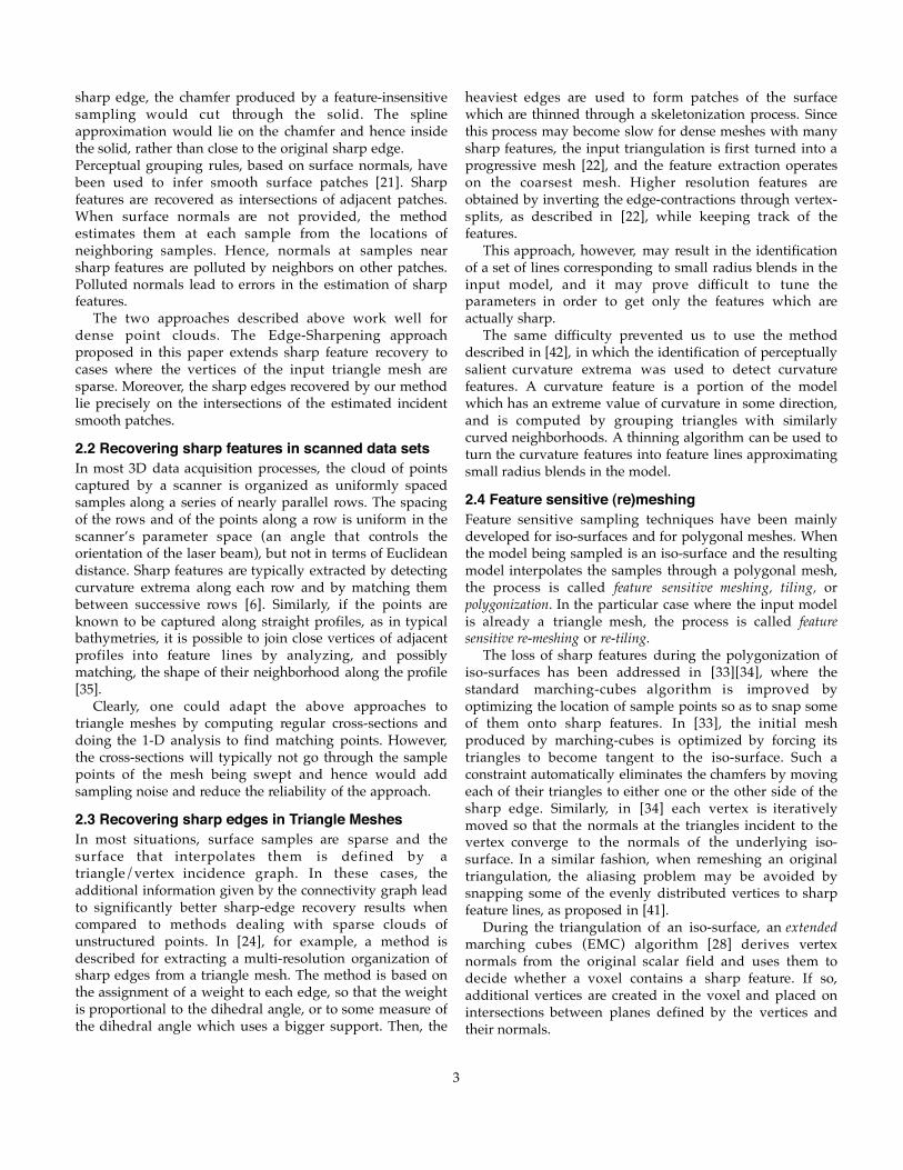
3.1 Identification of the chamfer trianglesOur approach identifies what we call chamfer edges, whichare shown in blue in Fig. 2. It is based on the identificationof smooth edges, which tessellate smooth portions of theoriginal model and are identified using the followingsimple heuristic.
In the remainder of the paper, an edge is said to besmooth if the angle between the normals to its two incidenttriangles is less than a given threshold, which we havechosen to be twice the average of such angles for the entiremesh. This choice of the threshold angle is motivated by thefollowing consideration: when an original piecewisesmooth model is sampled with a nearly infinite density, thedihedral angle at edges not belonging to chamfer trianglesis nearly π. Furthermore, the number of non-smooth edgesis negligible with respect to the total number of edges, thusthe average dihedral angle remains close to π or,equivalently, the average angle, ε, between the normals oftwo adjacent triangles remains close to 0. The influence ofnon-smooth edges on ε is small but not null, thus the actualangle for smooth edges is slightly smaller than ε. In practicewe do not have infinite samplings, so taking ε as thresholdmakes the algorithm too sensitive to small amounts ofnoise. We have experienced that doubling ε is a goodcompromise between theoretical correctness in the idealcase and robustness in all of the practical casesencountered.
Initial Input Smooth Edges
1 2 3
4 5 6
Fig. 2: An original model (top-left) was re-meshed through a featureinsensitive algorithm (top-right). The smooth edges in the aliased inputmodel were detected and the six filters (1-6) have selected the chamferedges and the corner triangles to be subdivided.
Our approach to identify chamfer triangles is based onthe initial identification of the smooth edges and on asuccession of six simple filters. Each filter colors the edges,
vertices, or triangles, based on the colors of their adjacent orincident elements. (To simplify the presentation, we usecolors instead of tags.)
The first step is to paint brown all of the smooth edges(we assume that all vertices, edges, and triangles areinitially gray), then we apply the following sequence of sixfilters:• Paint red each vertex whose incident edges are all brown. It is
surrounded by a smooth portion of the surface.• Paint red each triangle that has at least one red vertex. They
form the cores of a smooth regions.• Extend the cores by recursively painting red the triangles
adjacent to a red triangle through a brown edge.• Paint red the edges and vertices of red triangles.• Paint blue each non-red edge joining two red vertices. These
are the chamfer edges.• Paint green each triangle bounded by three blue edges. These
are the corner triangles where chamfers meet.
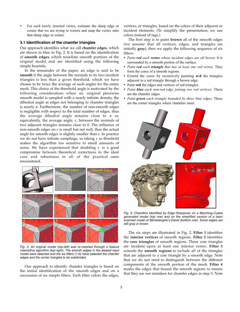
Fig. 3: Chamfers identified by Edge-Sharpener on a Marching-Cubesgenerated model (top row) and on the simplified version of a laserscanned model of Michelangelo’s David (bottom row). Some edges arestill gray or brown.
The six steps are illustrated in Fig. 2. Filter 1 identifiesthe interior vertices of smooth regions. Filter 2 identifiesthe core triangles of smooth regions. These core trianglesare incident upon at least one interior vertex. Filter 3extends the smooth regions to include all of the trianglesthat are adjacent to a core triangle by a smooth edge. Notethat we do not need to distinguish between the differentcomponents of the smooth portion of the mesh. Filter 4marks the edges that bound the smooth regions to ensurethat they are not mistaken for chamfer edges in step 5. Note

6
that these edges are not smooth. Filter 4 also identifies thevertices that bound the smooth regions. Filter 5 identifiesthe chamfer edges as those that connect vertices on theboundary of smooth regions but do not bound a smoothregion. Note that chamfer edges may, but need not, besmooth. Also note that some edges may still be gray andthat some brown edges may neither be part of a smoothregion nor be chamfer edges (Fig. 3). Finally, Filter 6identifies the corner triangles that are bounded by threechamfer edges and have all of their vertices on theboundary of smooth regions. Thus, they are at the junctionof at least three portions of smooth regions.
3.2 Subdivision of the chamfer trianglesTo subdivide the chamfer triangles, including the cornerones, we insert a new vertex in the middle of each chamferedge and in the middle of each corner triangle. Then, we re-triangulate the resulting polygons. We may have three cases(see Fig. 4):• A triangle with a single chamfer edge is split in two.• A triangle with two chamfer edges is split in three.• A corner triangle, which has three chamfer edges and an
interior vertex is split into six triangles forming a fan aroundthe interior vertex.
a b c
Fig. 4: Subdivision of a chamfer triangle with one (a) two (b) or three(c) chamfer edges.
3.3 Snapping new vertices onto sharp featuresFinally, we must find the proper position for each newvertex introduced in the middle of a chamfer edge or of acorner triangle. We use an extrapolation of the smoothsurfaces that are adjacent to these elements, as shown inFig. 5 and Fig. 6 and explained below.
B L
A
Fig. 5: Re-location of a new vertex splitting a chamfer edge.
To find the position of a new vertex V inserted in achamfer edge E, we consider the two original vertices, Aand B, of E. We compute the weighted sum N of thenormals to all of the red triangles incident upon A,normalize it, and define a plane P that is orthogonal to N
and passes through A. As weights, we use the anglebetween the two edges of the incident triangle that meet atA [32]. Similarly, we compute the weighted sum M of thenormals to all of the red triangles incident upon B,normalize it, and define a plane Q that is orthogonal to Mand passes through B. Finally, we move V to the closestpoint on the line L of intersection between planes P and Q.
Specifically, the final position of V is (A+B)/2+(h/k)H,where h=AB•N, where k=2(M•N)(AB•N)–2(AB•M), andwhere H=AB×(M×N)=(AB•N)M+(BA•M)N. The process isshown in Fig. 5.
To find the position of a new corner vertex, W, insertedin a corner triangle with vertices A, B, and C, we proceed asfollows. We first compute the weighted sum, N, of thenormals to all of the red triangles incident upon A,normalize it, and define a plane P that is orthogonal to Nand passes through A. Similarly, we define the plane Qthrough B with normal M and the plane R through C withnormal S. Then, we move W to the intersection of planes P,Q, and R, which is the solution of the system of three linearequalities: W•N=A•N, W•M=B•M, W•S=C•S (see Fig. 6). N
M S
Fig. 6: Re-location of a new vertex splitting a corner triangle.
3.4 Dealing with degenerate situationsFor simplicity, we have omitted in the previous sections
the discussion of degenerate cases. We identify them hereand explain how they are handled.
Nearly parallel planes: Such cases include situationswhere the pairs of planes are parallel or when the triplets ofplanes do not intersect at a single point, because theirnormals are coplanar. Moreover, since the algorithm istailored for nearly uniform triangulations, we have chosento avoid the creation of edges which are longer than thelongest edge of the input mesh (see Fig. 7). Thus, if theextrapolated position would require the creation of such along edge, or if the position itself is not defined because of alinear dependency between the planes, we simply leave thenewly inserted vertex in the middle of the chamfer edge orof the corner triangle.
Step features: In some cases, a portion of a triangle stripthat forms a chamfer is bordered by a concave edge on oneside and by a convex edge on the other. We detect thesesituations easily by analyzing the configuration of thetriangles incident on the end-points of the chamfer edge ortriangle. We treat these cases as the ones discussed above,and simply do not move the newly inserted vertices.
7
a b c
d
Fig. 7: In an input model (a) the chamfer edges joining nearly parallelsurfaces (b) were subdivided without moving the new vertices (c). Awrong model (d) would be obtained without our edge-length check.
Multi-corners: The original model may have more thanthree sharp edges meeting at a corner. In these cases, acorresponding re-sampled model has a strip of chamferedges for each original sharp edge, and these four stripsmeet at a region made of two or more corner triangles. Thenew points that split these adjacent corners (and thechamfer edges in between) are moved to the same position,resulting in the creation of degenerate (zero-area) triangles.Therefore, when the sharpening is complete, it may benecessary to eliminate some degenerate faces [9]. We havetuned our implementation by considering as degenerate atriangle having at least one angle smaller than 1 degree; inthis case we simply collapse the edge which is opposite tosuch an acute corner and update the connectivity graphconsistently.
4 BENDINGThe bending phase described in this section is particularlybeneficial when restoring c u r v e d models from atriangulation generated by a feature insensitive sampling.
The error between a curved smooth surface and itstriangle mesh approximation can often be reduced throughsubdivision. Because standard subdivision approacheswould round off the sharp features, we have developed anew subdivision scheme that preserves the sharpness ofsharp edges, while bending their piecewise linearapproximations into smooth curves.
4.1 Tagging the sharp edgesAs suggested previously [23] [29], we could attempt torecover the sharp edges from the mesh produced with EdgeSharpener, using a crude threshold on the dihedral angle.Unfortunately, when the sampling is curvature-insensitive,such an approach could mistakenly tag, as sharp, some ofthe edges lying on smooth surfaces with high curvature.
To reduce the frequency of these false positives, we wantto use the results of EdgeSharpener. However, the originalversion of EdgeSharpener only tags as sharp the new edgescreated by subdividing chamfer triangles. It does notexplicitly tag as sharp the original edges where smoothpatches meet. Hence, we have extended EdgeSharpener to
also tag as sharp the non-smooth edges that bound twosmooth faces. These pre-existing sharp edges are the non-smooth edges that bound two red triangles. To identifythem during EdgeSharpener, we perform the first threeEdgeSharpener filters as explained in the initial versionabove. After Filter 3, we execute a new filter, say Filter 3bis,which finds the non-brown edges with two adjacent redtriangles and tags their ending vertices. Filter 3bis also tagsall of the vertices having a non-manifold red neighborhood.Then, we execute the remaining filters and, at the end, wetag all of the vertices inserted by EdgeSharpener tosubdivide the chamfer triangles. Finally, we tag as sharp allof the edges which link two tagged vertices. This process isshown in Fig. 9.
c d
a b
Fig. 9: An original surface with a sharp edge is approximated by thetriangulation of a feature-insensitive sampling [a]. Filter 3bis hasdetected a non-brown edge having two incident red triangles and hastagged its vertices. Filter 3bis has also tagged a vertex having a nonmanifold red neighborhood (tagged vertices are shown in green in [b]).After the subdivision of the chamfer triangles, all of the newly insertedvertices have been tagged (yellow vertices in [c]). Finally, all of theedges joining two tagged vertices have been tagged as sharp (yellowedges in [d]). Note that the vertices of the tagged edges may havebeen tagged either in [b] or in [c].
4.2 The Bender algorithmThe Bender algorithm, introduced here, assumes that all ofthe sharp edges have been identified and tagged. Note thatit also can be executed on tagged meshes that are notnecessarily produced by EdgeSharpener.
We wish to smoothen the triangle mesh to bring it closerto the original curved surface. Because we assume that thesamples (i.e vertices) lie on the original surface, we use aninterpolatory subdivision scheme. We have selected to use amodification of the Butterfly subdivision [14], which splitseach triangle into four by inserting a new vertex in themiddle of each edge, as shown in Fig. 10.
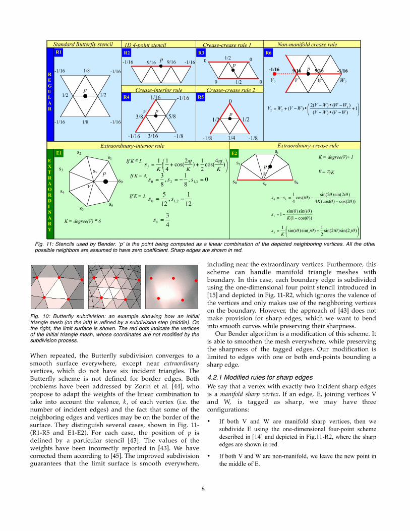
Each newly inserted vertex p is then moved to a positionthat is a linear combination of the edge’s end-points and sixneighboring vertices. The configuration of the neighborsand their weights, which define the stencil of thesubdivision rule, are reported in Fig. 11-R1, where thevertex p is marked by a black dot.
8
Fig. 10: Butterfly subdivision: an example showing how an initialtriangle mesh (on the left) is refined by a subdivision step (middle). Onthe right, the limit surface is shown. The red dots indicate the verticesof the initial triangle mesh, whose coordinates are not modified by thesubdivision process.
When repeated, the Butterfly subdivision converges to asmooth surface everywhere, except near extraordinaryvertices, which do not have six incident triangles. TheButterfly scheme is not defined for border edges. Bothproblems have been addressed by Zorin et al. [44], whopropose to adapt the weights of the linear combination totake into account the valence, k , of each vertex (i.e. thenumber of incident edges) and the fact that some of theneighboring edges and vertices may be on the border of thesurface. They distinguish several cases, shown in Fig. 11-(R1-R5 and E1-E2). For each case, the position of p isdefined by a particular stencil [43]. The values of theweights have been incorrectly reported in [43]. We havecorrected them according to [45]. The improved subdivisionguarantees that the limit surface is smooth everywhere,
including near the extraordinary vertices. Furthermore, thisscheme can handle manifold triangle meshes withboundary. In this case, each boundary edge is subdividedusing the one-dimensional four point stencil introduced in[15] and depicted in Fig. 11-R2, which ignores the valence ofthe vertices and only makes use of the neighboring verticeson the boundary. However, the approach of [43] does notmake provision for sharp edges, which we want to bendinto smooth curves while preserving their sharpness.
Our Bender algorithm is a modification of this scheme. Itis able to smoothen the mesh everywhere, while preservingthe sharpness of the tagged edges. Our modification islimited to edges with one or both end-points bounding asharp edge.
4.2.1 Modified rules for sharp edgesWe say that a vertex with exactly two incident sharp edgesis a manifold sharp vertex. If an edge, E, joining vertices Vand W, is tagged as sharp, we may have threeconfigurations:
• If both V and W are manifold sharp vertices, then wesubdivide E using the one-dimensional four-point schemedescribed in [14] and depicted in Fig.11-R2, where the sharpedges are shown in red.
• If both V and W are non-manifold, we leave the new point inthe middle of E.
Fig. 11: Stencils used by Bender. ‘p’ is the point being computed as a linear combination of the depicted neighboring vertices. All the otherpossible neighbors are assumed to have zero coefficient. Sharp edges are shown in red.
1/2
1/2
1/8
1/8
-1/16
-1/16
-1/16
-1/16
p
p 9/16 -1/16
9/16
-1/16
3/8 5/8
1/16
3/16
-1/16
-1/8 -1/16
p
V
p
W W2
Standard Butterfly stencil
Extraordinary-interior rule
1D 4-point stencil
Crease-interior rule
1/2 1/2
0
1/4 -1/8 -1/8
p
Crease-crease rule 2
Crease-crease rule 1
Extraordinary-crease rule
Non-manifold crease rule
V s0
p
s1 s2
s3
s4
s5 s6
++= )4
cos(2
1)
2cos(
4
11
K
j
K
j
Ks j
ππ
0,8
1,
8
33,120 =−== sss
12
1,
12
52,10 −= ss
K = degree(V) ≠ 6
p 1/2 0
0
1/2 0
0
V2
9/16 -1/16
9/16
-1/16
If K ≥ 5,
If K = 4,
If K = 3,
+
−•−
−•−•−+= 1
)()(
)()(2)( 2
22 WVWV
WWWVWVWV
sv
4
3=vs
K = degree(V)+1
p
s0
s1
sk sv
V
si
θ = π/K
+= )2sin()2sin(2
1)sin()sin(
1θθθθ jiji
Ks j
))2cos()(cos(4
)2sin()2sin()cos(
4
10 θθ
θθθ
−−=−=
K
iiss k
))cos(1(
)sin()sin(1
θθθ
−−=
K
isv
REGULAR
EXTRAORDINARY
R1
R5
R3
R4
R2 R6
E1 E2
V
9
• Now consider the case where only V is non-manifold. Let Fbe the sharp edge incident at W and different from E. Wereflect F on the other side of E. To do so, we consider theplane P containing both E and F. On P, we compute themirror F’ of F with respect to the bisector axis of E. Then weconsider F’ as being the only other sharp edge incident at Vand apply the four-point scheme (see Fig.11-R6).
4.2.2 Other modified subdivision rulesWhen subdividing an edge with only one end-point, say V0,on a sharp edge, we perform a topological cut along all thesharp edges incident upon V0. Specifically, if V0 has n>1incident sharp edges, we create n–1 copies of V0, sayV1…Vn, and duplicate all of the sharp edges meeting at V0.This process only involves topological operations and isillustrated in Fig. 12.
When V0 is the dead-end of a chain of sharp edges (n=1),we do not duplicate any vertex or edge, and simplyconsider V0 as if it were not on a sharp edge. In all the othercases, after the cut, the vertex V0 becomes a boundaryvertex. According to [43] and Fig. 11, we apply the suitableboundary rule and close the mesh back to its originalconfiguration.
Finally, if a non-sharp edge has both end points on atagged edge, we perform the cut for both vertices, apply theproper boundary rule, and close the mesh back.
V0 V0 V2
V1
Fig. 12: Example of topological cut along sharp edges (red on the left).In the image, V0, V1 and V2 have been displaced to show thetopological hole.
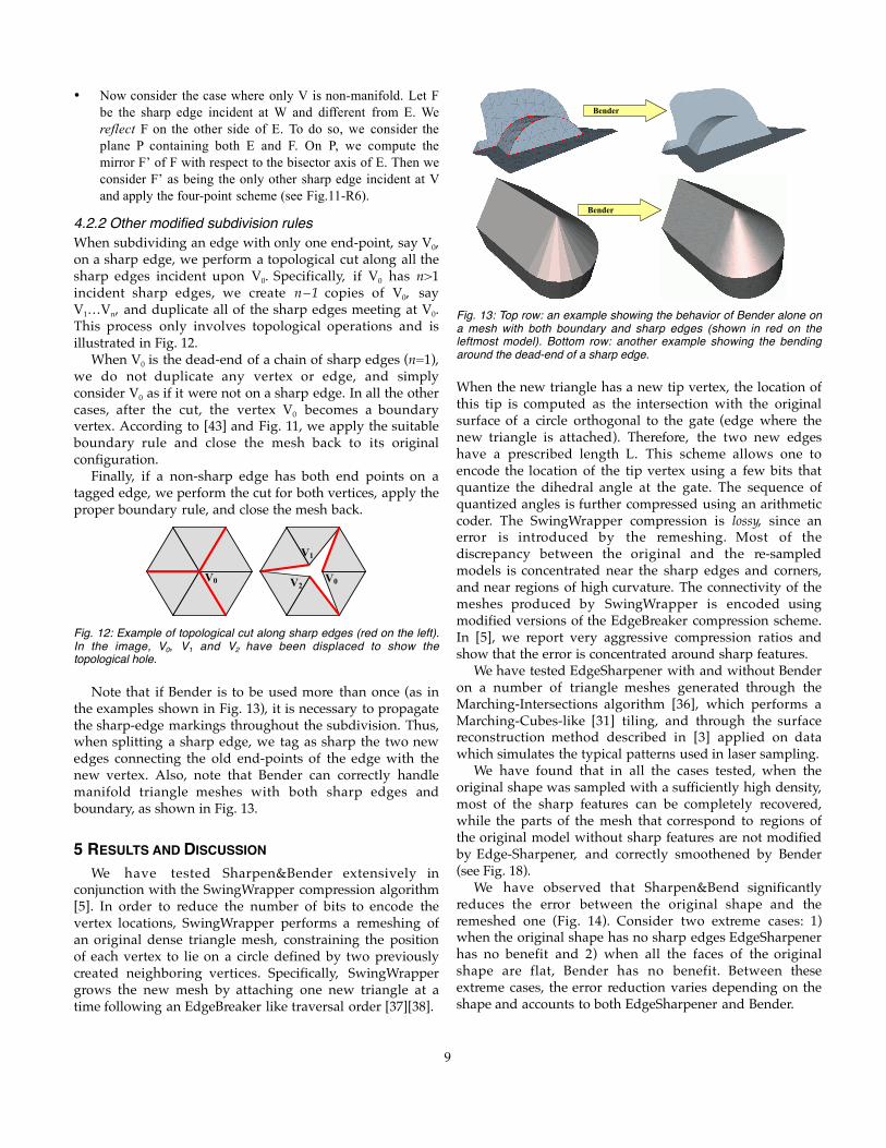
Note that if Bender is to be used more than once (as inthe examples shown in Fig. 13), it is necessary to propagatethe sharp-edge markings throughout the subdivision. Thus,when splitting a sharp edge, we tag as sharp the two newedges connecting the old end-points of the edge with thenew vertex. Also, note that Bender can correctly handlemanifold triangle meshes with both sharp edges andboundary, as shown in Fig. 13.
5 RESULTS AND DISCUSSIONWe have tested Sharpen&Bender extensively in
conjunction with the SwingWrapper compression algorithm[5]. In order to reduce the number of bits to encode thevertex locations, SwingWrapper performs a remeshing ofan original dense triangle mesh, constraining the positionof each vertex to lie on a circle defined by two previouslycreated neighboring vertices. Specifically, SwingWrappergrows the new mesh by attaching one new triangle at atime following an EdgeBreaker like traversal order [37][38].
Bender
Bender
Fig. 13: Top row: an example showing the behavior of Bender alone ona mesh with both boundary and sharp edges (shown in red on theleftmost model). Bottom row: another example showing the bendingaround the dead-end of a sharp edge.
When the new triangle has a new tip vertex, the location ofthis tip is computed as the intersection with the originalsurface of a circle orthogonal to the gate (edge where thenew triangle is attached). Therefore, the two new edgeshave a prescribed length L. This scheme allows one toencode the location of the tip vertex using a few bits thatquantize the dihedral angle at the gate. The sequence ofquantized angles is further compressed using an arithmeticcoder. The SwingWrapper compression is lossy, since anerror is introduced by the remeshing. Most of thediscrepancy between the original and the re-sampledmodels is concentrated near the sharp edges and corners,and near regions of high curvature. The connectivity of themeshes produced by SwingWrapper is encoded usingmodified versions of the EdgeBreaker compression scheme.In [5], we report very aggressive compression ratios andshow that the error is concentrated around sharp features.
We have tested EdgeSharpener with and without Benderon a number of triangle meshes generated through theMarching-Intersections algorithm [36], which performs aMarching-Cubes-like [31] tiling, and through the surfacereconstruction method described in [3] applied on datawhich simulates the typical patterns used in laser sampling.
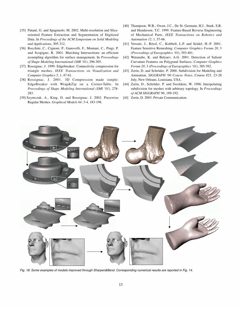
We have found that in all the cases tested, when theoriginal shape was sampled with a sufficiently high density,most of the sharp features can be completely recovered,while the parts of the mesh that correspond to regions ofthe original model without sharp features are not modifiedby Edge-Sharpener, and correctly smoothened by Bender(see Fig. 18).
We have observed that Sharpen&Bend significantlyreduces the error between the original shape and theremeshed one (Fig. 14). Consider two extreme cases: 1)when the original shape has no sharp edges EdgeSharpenerhas no benefit and 2) when all the faces of the originalshape are flat, Bender has no benefit. Between theseextreme cases, the error reduction varies depending on theshape and accounts to both EdgeSharpener and Bender.

10
Original Shape
Remeshed through
L∞ and L2
Distortions After
EdgeSharpen After
Sharp.&Bend Proc. Time
SwingWrapper
31554 faces
0.41% 0.054%
0.18% 0.031%
0.16% 0.021%
1.94
Reconstruction
11256 faces
0.67% 0.073%
0.26% 0.053%
0.19% 0.019%
0.61
March. Inters.
778 faces
0.35% 0.049%
0.19% 0.017%
0.14% 0.008%
0.04
March. Inters.
20121 faces
0.89% 0.090%
0.37% 0.014%
0.39% 0.006%
1.01
SwingWrapper
9668 faces
0.94% 0.11%
0.23% 0.08%
0.12% 0.013%
2.34
Reconstruction
7548 faces
0.81% 0.10%
0.35% 0.041%
0.31% 0.023%
0.49
Original mesh
13915 faces
- -
- -
- -
0.70
Fig. 14: Experimental results showing the reduction of the L∞ and L2
distortions due to both EdgeSharpener and Bender. The number in thesecond column counts the faces of the remeshed models. All theerrors are expressed as a percentage of the model's bounding boxdiagonal; errors are missing for the 'face' model because we did nothave an original surface to compare with. In the last column the totalrunning time is reported (in seconds). In all of the tests Bender was runonce, except for the 'hand' for which two iterations were performed.
If the input model interpolates a dense enoughsampling, EdgeSharpener is expected to have a strongimpact on the L∞ distortion, while Bender will mainlyreduce the L2 error. EdgeSharpener, however, will also havean impact on the L2 distortion, whose reduction maybecome significant if the original shape has only flat facesseparated by sharp edges. Furthermore, if the input modelwas obtained from too coarse a sampling, EdgeSharpenermay miss some sharp edges. In such a case, Bender willround these edges and may introduce a slight increase inthe L∞ distortion. Fig. 14 shows the results of ourexperiments which clearly agree with the aboveconsiderations. Errors have been computed through thepublicly available Metro tool [11], except for the model ofthe face for which we did not have an original surface tocompare with. The remeshed versions of the test models,along with their Sharpen&Bend improved versions, areshown in Fig. 18.
A further experiment concerned the evaluation of theerror reduction on a given shape sampled with differentdensities. In particular, we have monitored theimprovement of the rate-distortion curves of theSwingWrapper compressor; for all the models with sharpfeatures that we have remeshed, we have observed asignificant decrease of the L2 distortion for all the bit-ratesdue to both EdgeSharpener and Bender. Fig. 15 shows ourresults in four cases.
0 1 2 3 4 8 5 0
2
4
6
8
bits/v
L2 Initial Model
Sharpen&Bender
EdgeSharpener
0 1 2 3 4 8 5 0
2
4
6
8
bits/v
L2 Initial Model
Sharpen&Bender
EdgeSharpener
0 1 2 3 4 8 5 0
2
4
6
8
bits/v
L2 Initial Model
Sharpen&Bender
EdgeSharpener
0 1 2 3 4 8 5 0
2
4
6
8
bits/v
L2 Initial Model
Sharpen&Bender
EdgeSharpener
Fig. 15: Impact of EdgeSharpener and Bender on the rate-distortioncurves of the SwingWrapper compressor. Bit-per-vertex rates arerelative to the # of vertices of the original model. Errors are expressedin units of 10-4 of the bounding-box diagonal.
We conclude that the effectiveness of the proposedmethod is not restricted to uniformly sampled meshes. Forexample, EdgeSharpener correctly restores the sharpfeatures of typical meshes generated through interpolationof laser-captured point sets or through iso-surfacepolygonization procedures which exhibit a fair amount ofvariation in edge-length.
Finally, we have found that small quantities of noise donot prevent EdgeSharpener to correctly restore sharp edges.Modern, well-calibrated laser scanners produce absolutelyacceptable data. Clearly, if the amount of noise becomescomparable with the inter-sampling spacing, its influenceon the dihedral angles prevents the algorithm to identifysome chamfer elements, and some sharp edges may bemissed. Furthermore, for such heavily perturbed data aninterpolating subdivision is not appropriate, and it ispreferable to follow the EdgeSharpening by a feature-preserving smoothing [16][26] or by an approximantsubdivision of the tagged mesh [23].
5.1 LimitationsEdge-Sharpener can miss sharp features that are smallerthan the inter-sample spacing and may produce sharpedges where the original model has a feature that has beensmoothed with a small-radius blend (Fig. 17). There issimply not enough information in the sampling to recoversuch small features or blends.
Original
Fig. 16: Reconstruction of a sharp feature which blends smoothly ontoa flat surface. The “ripple” of the strip of chamfer triangles preventedthe red region to expand on the chamfer.

11
Also, in extremely rare cases, the alias corresponding toa feature that blends smoothly into a flat area may bepainted red, preventing the detection of some “desired”chamfer triangles. This situation, however, may happenonly if the strip of such triangles is not aliased, which isvery improbable in practical cases. Fig. 16, for example,shows the correct reconstruction of such a blended featurefrom a retiled model having the typically “rippled” strips ofchamfer triangles. On the other hand, if the same modelwas sampled through a grid exactly aligned with its sharpedges, the blended feature would not have been recoveredbecause its corresponding strip of chamfer triangles wouldhave been smoothly blended onto the flat face, and the redregion would have expanded along the strip throughbrown edges.
Finally, if an original model has a smooth face that isthinner than 3 times the inter-sample spacing, Edge-Sharpener may not be able to identify a sufficient numberof smooth vertices for it and hence may not be able torecover the sharp features which bound that face. As for theunwanted sharpening of small radius blends, this problemis a consequence of an insufficient sampling density, andmay be solved by using a denser sampling.
5.2 PerformanceOur experiments on a variety of meshes indicate that Edge-Sharpener is extremely fast and robust. For example, thesharpening of the models presented in this paper took lessthan 0.4 seconds each on a standard PC equipped with a1.7Ghz CPU. The performance of Bender is comparablewith the one of a typical subdivision scheme. Ourimplementation, which is not particularly optimized,subdivides an average of about 22000 triangles per second.Precise timings for the combined Sharpen&Bend algorithmare shown in Fig. 14, where each model was subdividedonce, except for the hand which was subdivided twice.
6 CONCLUSIONSWe have presented a simple, automatic, and efficient edge-sharpening procedure designed to recover the sharpfeatures that are lost by reverse engineering or byremeshing processes that use a non-adaptive sampling ofthe original surface. Also, we have introduced (1) a newautomatic tagging approach which marks the sharp edgesand (2) a Bender modified subdivision scheme thatsmoothens the surface and preserves the sharpness oftagged edges while bending chains of them into smoothcurves.
We have run numerous tests on models coming fromuniform remeshing, marching-cubes iso-surface generation,and surface reconstruction from nearly uniform clouds ofpoints. In all of the cases, in addition to the correctreconstruction of sharp features, we have observed that thedistortion between the mesh and the original model wassignificantly reduced by our sharpening process, while theparts of the mesh not corresponding to sharp features in theoriginal model were not modified. Moreover, when theoriginal model has curved areas, the application of Benderfurther decreases the distortion.
ACKNOWLEDGMENTSThis work is part of the bilateral research agreement“Surface Analysis” – GVU/GATECH and IMATI-GE/CNR.IMATI-GE was partially supported for this work by thenational FIRB project MACROGeo and by the EU ProjectAIM@SHAPE (Contract # 506766). Rossignac's work on thisproject was partly supported by a DARPA/NSF CARGOgrant #0138420. The authors thank all the members of theShape Modeling Group of the IMATI-GE/CNR and thereviewers for their helpful advice. Thanks are due to DenisZorin for providing the corrected coefficients of theextraordinary-crease rule.
Fig. 17: Unwanted creases may be produced if an original surface has blends whose radius is smaller than the inter-sample spacing (top row).If the sampling step is small compared to the blend radius, the blends are not modified by Edge-Sharpener (bottom row), while they aresmoothened as expected by Bender.
Fine Mesh
Chamfer Detection Chamfer Split
Original Model
Coarse Mesh
Bending

12
REFERENCES[1] Adamy, U., Giesen, J. and John, M. 2000. New techniques for
topologically correct surface reconstruction. In Proceedings ofIEEE Visualization '00, 373–380.
[2] Amenta, N., Choi, S. and Kolluri, R. 2001. The power crust. InProceedings of the 6th ACM Symposium on Solid Modeling andApplications, 249-260.
[3] Attene, M. and Spagnuolo, M. 2000. Automatic surfacereconstruction from point sets in space. Computer GraphicsForum 19, 3 (Proceedings of Eurographics '00), 457-465.
[4] Attene, M., Falcidieno, B., Rossignac, J. and Spagnuolo, M.2003. Edge-Sharpener: Recovering sharp features intriangulations of non-adaptively re-meshed surfaces. InProceedings of the 1st Eurographics Symposium on GeometryProcessing, 63-72.
[5] Attene, M., Falcidieno, B., Spagnuolo, M. and Rossignac, J.2003. SwingWrapper: Retiling triangle meshes for betterEdgeBreaker compression. ACM Transactions on Graphics 22,4, 982-996.
[6] Biasotti, S., Mortara, M. and Spagnuolo, M. 2000. SurfaceCompression and Reconstruction Using Reeb Graphs and ShapeAnalysis. In Proceedings of the Spring Conference on ComputerGraphics (SCCG '00), 174-185.
[7] Biermann, H., Martin, I.M., Zorin, D. and Bernardini, F. 2001.Sharp Features on Multiresolution Subdivision Surfaces. InProceedings of Pacific Graphics ’01, 140-149.
[8] Bloomenthal, J. 1988. Polygonization of implicit surfaces.Computer Aided Geometric Design 5, 341-355.
[9] Botsch, M. and Kobbelt, L. P. 2001. A Robust Procedure toEliminate Degenerate Faces from Triangle Meshes. InProceedings of Vision, Modeling and Visualization (VMV ‘01).
[10] Cheng, S. W. and Dey, T. K. 1999. Improved construction ofDelaunay based contour surfaces. In Proceedings of the ACMSymposium on Solid Modeling and Applications, 322-323.
[11] Cignoni, P., Rocchini, C. and Scopigno, R. 1998. Metro:measuring error on simplified surfaces. Computer GraphicsForum 17, 2 (Proceedings of Eurographics ’98), 167-174.
[12] Cong, G. and Parving, B. 2001. Robust and Efficient SurfaceReconstruction from Contours. The Visual Computer 17, 199-208.
[13] Dey, T. K. and Wenger, R. 2001. Reconstructing curves withsharp corners. Computational Geometry Theory Applications19, 89-99.
[14] Dyn, N., Gregory, J. and Levin, D. 1990. A butterflysubdivision scheme for surface interpolation with tensioncontrol. ACM Transactions on Graphics 9, 2, 160-169.
[15] Dyn, N., Gregory, J. and Levin, D. 1987. A four-pointinterpolatory subdivision scheme for curve design. ComputerAided Geometric Design 4, 257-268.
[16] Fleishman, S., Drori, I. and Cohen-Or, D. 2003. Bilateral MeshDenoising. In Proceedings of ACM SIGGRAPH '03, 950-953.
[17] Garland, M. and Heckbert, P.S. 1997. Surface Simplificationusing Quadric Error Metrics. In P roceedings of ACMSIGGRAPH '97, 209-216.
[18] Giesen, J. and John, M. 2002. Surface reconstruction based on a
dynamical system. Computer Graphics Forum 21, 3(Proceedings of Eurographics ‘02), 363-371.
[19] Gumhold, S., Wang, X. and Macleod, R. 2001. FeatureExtraction from Point Clouds. In Proceedings of the 10th
International Meshing Roundtable, 293-305.[20] Guskov, I., Vidimce, K., Sweldens, W. and Schröder, P. 2000.
Normal Meshes. In Proceedings of ACM SIGGRAPH '00, 95-102.
[21] G u y, G. and Medioni, G. 1997. Inference of Surfaces, 3DCurves and Junctions from sparse, noisy, 3D data. I E E ETransactions on Pattern Analysis and Machine Intelligence 19,11, 1265-1277.
[22] Hoppe, H. 1996. Progressive Meshes. In Proceedings of ACMSIGGRAPH '96, 99-108.
[23] Hoppe, H., Derose, T., Duchamp, T., Halstead, M., Jin, H.,Mcdonald, J., Schweitzer, J. and Stuetzle, W. 1994. Piecewisesmooth surface reconstruction. In P roceedings of ACMSIGGRAPH '94, 295-302.
[24] Hubeli, A. and Gross, M. H. 2001. Multiresolution featureextraction from unstructured meshes. In Proceedings of IEEEVisualization '01, 16–25.
[25] Hubeli, A., Meyer, K. and Gross, M. H. 2000. Mesh EdgeDetection. In Proceedings of the Workshop Lake Tahoe (LakeTahoe City, California, USA).
[26] Jones, T., Durand, F. and Desbrun, M. 2003. Non-Iterarive,Feature-Preserving Mesh Smoothing. In Proceedings of ACMSIGGRAPH '03, 943-949.
[27] Ju, T., Losasso, F., Schaefer, S. and Warren, J. 2002. DualContouring of Hermite Data. In P roceedings of ACMSIGGRAPH ’02, 339-346.
[28] Kobbelt, L. P., Botsch, M., Schwanecke, U. and Seidel, H-P.2001. Feature Sensitive Surface Extraction from Volume Data.In Proceedings of ACM SIGGRAPH '01, 57-66.
[29] Lee, A., Sweldens, W., Schröder, P., Cowsar, L. and Dobkin, D.1998. MAPS: Multiresolution Adaptive Parameterization ofSurfaces. In Proceedings of ACM SIGGRAPH ’98, 95-104.
[30] Loop, A. 1987. Smooth Subdivision Surfaces based onTriangles. Master’s thesis, University of Utah, Department ofMathematics.
[31] Lorensen, W. and Cline, H. 1987. Marching Cubes: a highresolution 3D surface construction algorithm. In Proceedings ofACM SIGGRAPH '87, 163-169.
[32] Mokhatarian, F., Khalili, N. and Yuen, P. 1998. Multi-Scale 3-DFree-Form Surface Smoothing. In Proceedings of the BritishMachine Vision Conference, 730-739.
[33] Ohtake, Y. and Belyaev, A.G. 2002. Dual/Primal MeshOptimization for Polygonized Implicit Surfaces. In Proceedingsof the ACM Symposium on Solid Modeling and Applications,171-178.
[34] Ohtake, Y., Belyaev, A.G. and Pasko, A. 2001. DynamicMeshes for Accurate Polygonization of Implicit Surfaces withSharp Features. In Proceedings of Shape ModelingInternational (SMI '01), 74-81.
13
[35] Patané, G. and Spagnuolo, M. 2002. Multi-resolution and Slice-oriented Feature Extraction and Segmentation of DigitizedData. In Proceedings of the ACM Symposium on Solid Modelingand Applications, 305-312.
[36] Rocchini, C., Cignoni, P., Ganovelli, F., Montani, C., Pingi, P.and Scopigno, R. 2001. Marching Intersections: an efficientresampling algorithm for surface management. In Proceedingsof Shape Modeling International (SMI ’01), 296-305.
[37] Rossignac, J. 1999. Edgebreaker: Connectivity compression fortriangle meshes. IEEE Transactions on Visualization andComputer Graphics 5, 1, 47-61.
[38] Rossignac, J. 2001. 3D Compression made simple:EdgeBreaker with Wrap&Zip on a Corner-Table. InProceedings of Shape Modeling International (SMI ’01), 278-283.
[39] Szymczak, A., King, D. and Rossignac, J. 2002. PiecewiseRegular Meshes. Graphical Models 64, 3-4, 183-198.
[40] Thompson, W.B., Owen, J.C., De St. Germain, H.J., Stark, S.R.and Henderson, T.C. 1999. Feature-Based Reverse Engineeringof Mechanical Parts. IEEE Transactions on Robotics andAutomation 12, 1, 57-66.
[41] Vorsatz, J., Rössl, C., Kobbelt, L.P. and Seidel, H.-P. 2001.Feature Sensitive Remeshing. Computer Graphics Forum 20, 3(Proceedings of Eurographics ‘01), 393-401.
[42] Watanabe, K. and Belyaev, A.G. 2001. Detection of SalientCurvature Features on Polygonal Surfaces. Computer GraphicsForum 20, 3 (Proceedings of Eurographics ‘01), 385-392.
[43] Zorin, D. and Schröder, P. 2000. Subdivision for Modeling andAnimation. SIGGRAPH '00 Course Notes, Course #23, 23-28July, New Orleans, Louisiana, USA.
[44] Zorin, D., Schröder, P. and Sweldens, W. 1996. Interpolatingsubdivision for meshes with arbitrary topology. In Proceedingsof ACM SIGGRAPH '96, 189-192.
[45] Zorin, D. 2003. Private Communication.
Fig. 18: Some examples of models improved through Sharpen&Bend. Corresponding numerical results are reported in Fig. 14.