SERVICE MANUAL - Toshiba
371
FILE NO. A03-009 PRINTED IN JAPAN, May.,2004 ToMo Indoor Unit <4-way Air Discharge Cassette Type> MMU-AP0091H, AP0121H, AP0151H, MMU-AP0181H, AP0241H, AP0271H, MMU-AP0301H, AP0361H, AP0481H MMU-AP0561H <2-way Air Discharge Cassette Type> MMU-AP0071WH, AP0091WH, AP0121WH, MMU-AP0151WH, AP0181WH, AP0241WH, MMU-AP0271WH, AP0301WH MMU-AP0481WH (CHINA market only) <1-way Air Discharge Cassette Type> MMU-AP0071YH, AP0091YH, AP0121YH, MMU-AP0151SH, AP0181SH, AP0241SH <Concealed Duct Standard Type> MMD-AP0071BH, AP0091BH, AP0121BH, MMD-AP0151BH, AP0181BH, AP0241BH, MMD-AP0271BH, AP0301BH, AP0361BH, MMD-AP0481BH, AP0561BH <Concealed Duct High Static Pressure Type> MMD-AP0181H, AP0241H, AP0271H, MMD-AP0361H, AP0481H, AP0721H, MMD-AP0961H <Under Ceiling Type> MMC-AP0151H, AP0181H, AP0241H, MMC-AP0271H, AP0361H, AP0481H <High Wall Type> MMK-AP0071H, AP0091H, AP0121H, MMK-AP0151H, AP0181H, AP0241H <Floor Standing Cabinet Type> MML-AP0071H, AP0091H, AP0121H, MML-AP0151H, AP0181H, AP0241H <Floor Standing Concealed Type> MML-AP0071BH, AP0091BH, AP0121BH, MML-AP0151BH, AP0181BH, AP0241BH <Floor Standing Type> MMF-AP0151H, AP0181H, AP0241H MMF-AP0271H, AP0361H, AP0481H MMF-AP0561H Outdoor Unit Cooling Only Model <Inverter Unit> MMY-MAP0501T8, MAP0601T8 MMY-MAP0801T8, MAP1001T8 MMY-MAP1201T8 Heat Pump Model <Inverter Unit> MMY-MAP0501HT8, MAP0601HT8 MMY-MAP0801HT8, MAP1001HT8 MMY-MAP1201HT8 Heat Pump Model <Inverter Unit> MMY-MAP0501HT7, MAP0601HT7 MMY-MAP0801HT7, MAP1001HT7 MMY-MAP1201HT7 SERVICE MANUAL TENTATIVE
-
Upload
khangminh22 -
Category
Documents
-
view
7 -
download
0
Transcript of SERVICE MANUAL - Toshiba
PRINTED IN JAPAN, May.,2004 ToMo
Indoor Unit<4-way Air Discharge Cassette Type>MMU-AP0091H, AP0121H, AP0151H,MMU-AP0181H, AP0241H, AP0271H,MMU-AP0301H, AP0361H, AP0481HMMU-AP0561H<2-way Air Discharge Cassette Type>MMU-AP0071WH, AP0091WH, AP0121WH,MMU-AP0151WH, AP0181WH, AP0241WH,MMU-AP0271WH, AP0301WHMMU-AP0481WH (CHINA market only)
<1-way Air Discharge Cassette Type>MMU-AP0071YH, AP0091YH, AP0121YH,MMU-AP0151SH, AP0181SH, AP0241SH<Concealed Duct Standard Type>MMD-AP0071BH, AP0091BH, AP0121BH,MMD-AP0151BH, AP0181BH, AP0241BH,MMD-AP0271BH, AP0301BH, AP0361BH,MMD-AP0481BH, AP0561BH<Concealed Duct High Static Pressure Type>MMD-AP0181H, AP0241H, AP0271H,MMD-AP0361H, AP0481H, AP0721H,MMD-AP0961H<Under Ceiling Type>MMC-AP0151H, AP0181H, AP0241H,MMC-AP0271H, AP0361H, AP0481H<High Wall Type>MMK-AP0071H, AP0091H, AP0121H,MMK-AP0151H, AP0181H, AP0241H<Floor Standing Cabinet Type>MML-AP0071H, AP0091H, AP0121H,MML-AP0151H, AP0181H, AP0241H<Floor Standing Concealed Type>MML-AP0071BH, AP0091BH, AP0121BH,MML-AP0151BH, AP0181BH, AP0241BH<Floor Standing Type>MMF-AP0151H, AP0181H, AP0241HMMF-AP0271H, AP0361H, AP0481HMMF-AP0561H
Outdoor Unit
Cooling Only Model<Inverter Unit>MMY-MAP0501T8, MAP0601T8MMY-MAP0801T8, MAP1001T8MMY-MAP1201T8
Heat Pump Model<Inverter Unit>MMY-MAP0501HT8, MAP0601HT8MMY-MAP0801HT8, MAP1001HT8MMY-MAP1201HT8
Heat Pump Model<Inverter Unit>MMY-MAP0501HT7, MAP0601HT7MMY-MAP0801HT7, MAP1001HT7MMY-MAP1201HT7
SERVICE MANUAL
TENTATIVE
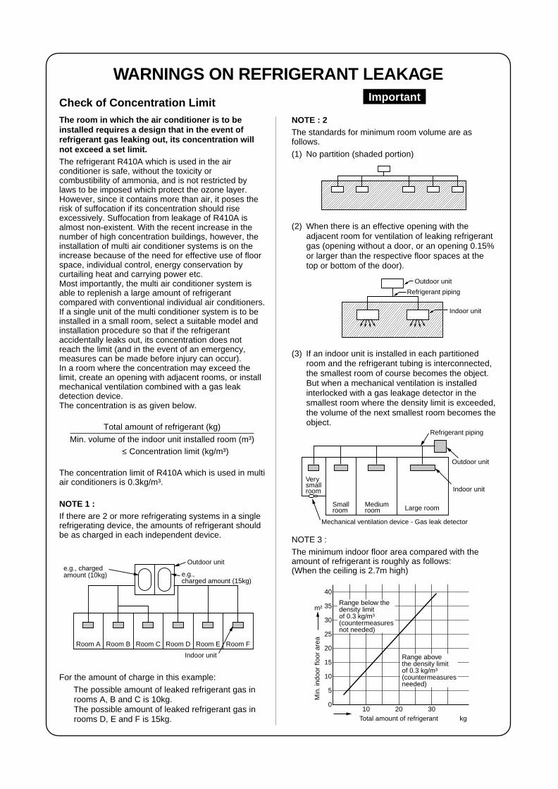
WARNINGS ON REFRIGERANT LEAKAGE
Outdoor unit
e.g.,charged amount (15kg)
e.g., chargedamount (10kg)
Indoor unit
Room A Room B Room C Room D Room E Room F
For the amount of charge in this example:
The possible amount of leaked refrigerant gas inrooms A, B and C is 10kg.The possible amount of leaked refrigerant gas inrooms D, E and F is 15kg.
NOTE : 2The standards for minimum room volume are asfollows.
(1) No partition (shaded portion)
Outdoor unit
Refrigerant piping
Indoor unit
(2) When there is an effective opening with theadjacent room for ventilation of leaking refrigerantgas (opening without a door, or an opening 0.15%or larger than the respective floor spaces at thetop or bottom of the door).
(3) If an indoor unit is installed in each partitionedroom and the refrigerant tubing is interconnected,the smallest room of course becomes the object.But when a mechanical ventilation is installedinterlocked with a gas leakage detector in thesmallest room where the density limit is exceeded,the volume of the next smallest room becomes theobject.
Outdoor unit
Refrigerant piping
Indoor unit
Verysmallroom
Smallroom
Mediumroom Large room
Mechanical ventilation device - Gas leak detector
NOTE 3 :
The minimum indoor floor area compared with theamount of refrigerant is roughly as follows:(When the ceiling is 2.7m high)
0
5
10
10 20 30
15
20
25
30
35
40
Range below the density limitof 0.3 kg/m³(countermeasuresnot needed)
Range above the density limitof 0.3 kg/m³(countermeasuresneeded)
Total amount of refrigerant kg
Min
. ind
oor
floor
are
a
m²
Check of Concentration LimitThe room in which the air conditioner is to beinstalled requires a design that in the event ofrefrigerant gas leaking out, its concentration willnot exceed a set limit.The refrigerant R410A which is used in the airconditioner is safe, without the toxicity orcombustibility of ammonia, and is not restricted bylaws to be imposed which protect the ozone layer.However, since it contains more than air, it poses therisk of suffocation if its concentration should riseexcessively. Suffocation from leakage of R410A isalmost non-existent. With the recent increase in thenumber of high concentration buildings, however, theinstallation of multi air conditioner systems is on theincrease because of the need for effective use of floorspace, individual control, energy conservation bycurtailing heat and carrying power etc.Most importantly, the multi air conditioner system isable to replenish a large amount of refrigerantcompared with conventional individual air conditioners.If a single unit of the multi conditioner system is to beinstalled in a small room, select a suitable model andinstallation procedure so that if the refrigerantaccidentally leaks out, its concentration does notreach the limit (and in the event of an emergency,measures can be made before injury can occur).In a room where the concentration may exceed thelimit, create an opening with adjacent rooms, or installmechanical ventilation combined with a gas leakdetection device.The concentration is as given below.
Total amount of refrigerant (kg)
Min. volume of the indoor unit installed room (m³)≤ Concentration limit (kg/m³)
The concentration limit of R410A which is used in multiair conditioners is 0.3kg/m³.
NOTE 1 :If there are 2 or more refrigerating systems in a singlerefrigerating device, the amounts of refrigerant shouldbe as charged in each independent device.
Important
NOTE
A direct current motor is adopted for indoor fan motor in the Concealed Duct Standard Type air conditioner.Caused from its characteristics, a current limit works on the direct current motor. When replacing the high-performance filter or when opening the service board, be sure to stop the fan. If an above action is executedduring the fan operation, the protective control works to stop the unit operation, and the check code “P12”may be issued. However it is not a trouble. When the desired operation has finished, be sure to reset thesystem to clear “P12” error code using the leak breaker of the indoor unit. Then push the operation stopbutton of the remote controller to return to the usual operation.
CONTENTSSAFETY CAUTION ............................................................................................ 4
1. OUTLINE .................................................................................................. 10
2. WIRING DIAGRAM................................................................................... 13
3. PARTS RATING........................................................................................ 26
4. REFRIGERANT PIPING SYSTEMATIC DRAWING ................................. 56
5. COMBINED REFRIGERANT PIPES SYSTEMATIC DRAWING .............. 59
6. CONTROL OUTLINE................................................................................ 64
7. APPLIED CONTROL ................................................................................ 74
8. TEST OPERATION ................................................................................... 88
9. TROUBLESHOOTING ............................................................................ 128
10. CONFIGURATION OF CONTROL CIRCUIT .......................................... 214
11. BACKUP OPERATIONS (EMERGENCY OPERATION) ........................ 228
12. OIL LEVEL JUDGMENT DISPLAY ........................................................ 233
13. REFRIGERANT RECOVERYWHEN REPLACING THE COMPRESSOR ............................................ 234
14. LEAKAGE/CLOGGING OF OIL-EQUALIZATION CIRCUIT .................. 240
15. REPLACING COMPRESSOR ................................................................ 242
16. REOLACING METHOD OF PARTS ....................................................... 249
17. P.C. BOARD EXCHANGE PROCEDURES ............................................ 259
4
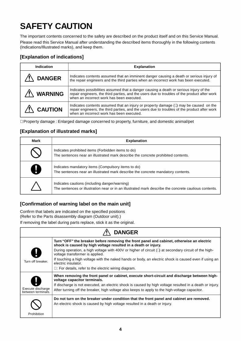
SAFETY CAUTIONThe important contents concerned to the safety are described on the product itself and on this Service Manual.
Please read this Service Manual after understanding the described items thoroughly in the following contents(Indications/Illustrated marks), and keep them.
[Explanation of indications]
Indication
DANGER
WARNING
CAUTION
Explanation
Indicates contents assumed that an imminent danger causing a death or serious injury ofthe repair engineers and the third parties when an incorrect work has been executed.
Indicates possibilities assumed that a danger causing a death or serious injury of therepair engineers, the third parties, and the users due to troubles of the product after workwhen an incorrect work has been executed.
Indicates contents assumed that an injury or property damage (∗ ) may be caused on therepair engineers, the third parties, and the users due to troubles of the product after workwhen an incorrect work has been executed.
∗ Property damage : Enlarged damage concerned to property, furniture, and domestic animal/pet
[Explanation of illustrated marks]
Mark Explanation
Indicates prohibited items (Forbidden items to do)The sentences near an illustrated mark describe the concrete prohibited contents.
Indicates mandatory items (Compulsory items to do)The sentences near an illustrated mark describe the concrete mandatory contents.
Indicates cautions (including danger/warning)The sentences or illustration near or in an illustrated mark describe the concrete cautious contents.
[Confirmation of warning label on the main unit]
Confirm that labels are indicated on the specified positions(Refer to the Parts disassembly diagram (Outdoor unit).)
If removing the label during parts replace, stick it as the original.
Turn “OFF” the breaker before removing the front panel and cabinet, otherwise an electricshock is caused by high voltage resulted in a death or injury.During operation, a high voltage with 400V or higher of circuit (∗ ) at secondary circuit of the high-voltage transformer is applied.If touching a high voltage with the naked hands or body, an electric shock is caused even if using anelectric insulator.∗ : For details, refer to the electric wiring diagram.
When removing the front panel or cabinet, execute short-circuit and discharge between high-voltage capacitor terminals.If discharge is not executed, an electric shock is caused by high voltage resulted in a death or injury.After turning off the breaker, high voltage also keeps to apply to the high-voltage capacitor.
Do not turn on the breaker under condition that the front panel and cabinet are removed.An electric shock is caused by high voltage resulted in a death or injury.
DANGER
Turn off breaker.
Execute dischargebetween terminals.
Prohibition
5
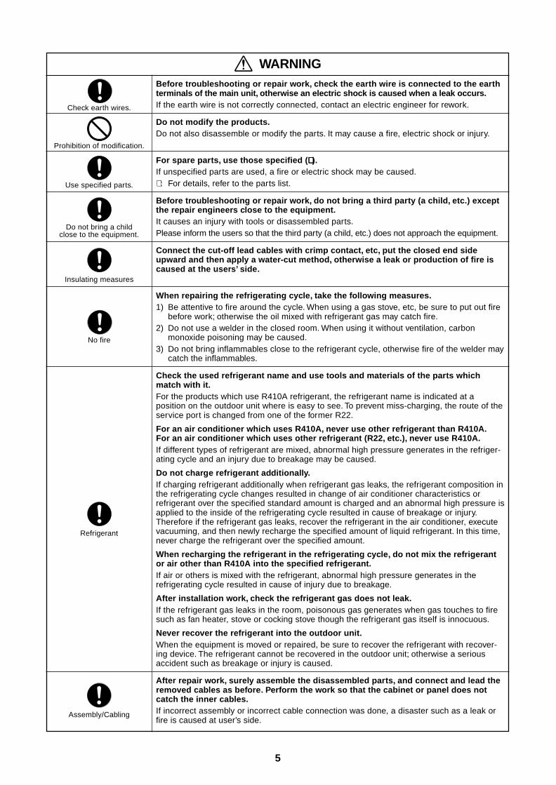
Before troubleshooting or repair work, check the earth wire is connected to the earthterminals of the main unit, otherwise an electric shock is caused when a leak occurs.If the earth wire is not correctly connected, contact an electric engineer for rework.
Do not modify the products.Do not also disassemble or modify the parts. It may cause a fire, electric shock or injury.
For spare parts, use those specified (∗∗∗∗∗ ).If unspecified parts are used, a fire or electric shock may be caused.∗ : For details, refer to the parts list.
Before troubleshooting or repair work, do not bring a third party (a child, etc.) exceptthe repair engineers close to the equipment.It causes an injury with tools or disassembled parts.Please inform the users so that the third party (a child, etc.) does not approach the equipment.
Connect the cut-off lead cables with crimp contact, etc, put the closed end sideupward and then apply a water-cut method, otherwise a leak or production of fire iscaused at the users’ side.
When repairing the refrigerating cycle, take the following measures.1) Be attentive to fire around the cycle. When using a gas stove, etc, be sure to put out fire
before work; otherwise the oil mixed with refrigerant gas may catch fire.2) Do not use a welder in the closed room. When using it without ventilation, carbon
monoxide poisoning may be caused.3) Do not bring inflammables close to the refrigerant cycle, otherwise fire of the welder may
catch the inflammables.
Check the used refrigerant name and use tools and materials of the parts whichmatch with it.For the products which use R410A refrigerant, the refrigerant name is indicated at aposition on the outdoor unit where is easy to see. To prevent miss-charging, the route of theservice port is changed from one of the former R22.
For an air conditioner which uses R410A, never use other refrigerant than R410A.For an air conditioner which uses other refrigerant (R22, etc.), never use R410A.If different types of refrigerant are mixed, abnormal high pressure generates in the refriger-ating cycle and an injury due to breakage may be caused.
Do not charge refrigerant additionally.If charging refrigerant additionally when refrigerant gas leaks, the refrigerant composition inthe refrigerating cycle changes resulted in change of air conditioner characteristics orrefrigerant over the specified standard amount is charged and an abnormal high pressure isapplied to the inside of the refrigerating cycle resulted in cause of breakage or injury.Therefore if the refrigerant gas leaks, recover the refrigerant in the air conditioner, executevacuuming, and then newly recharge the specified amount of liquid refrigerant. In this time,never charge the refrigerant over the specified amount.
When recharging the refrigerant in the refrigerating cycle, do not mix the refrigerantor air other than R410A into the specified refrigerant.If air or others is mixed with the refrigerant, abnormal high pressure generates in therefrigerating cycle resulted in cause of injury due to breakage.
After installation work, check the refrigerant gas does not leak.If the refrigerant gas leaks in the room, poisonous gas generates when gas touches to firesuch as fan heater, stove or cocking stove though the refrigerant gas itself is innocuous.
Never recover the refrigerant into the outdoor unit.When the equipment is moved or repaired, be sure to recover the refrigerant with recover-ing device. The refrigerant cannot be recovered in the outdoor unit; otherwise a seriousaccident such as breakage or injury is caused.
After repair work, surely assemble the disassembled parts, and connect and lead theremoved cables as before. Perform the work so that the cabinet or panel does notcatch the inner cables.If incorrect assembly or incorrect cable connection was done, a disaster such as a leak orfire is caused at user’s side.
WARNING
Check earth wires.
Prohibition of modification.
Use specified parts.
Do not bring a childclose to the equipment.
Insulating measures
No fire
Refrigerant
Assembly/Cabling
6
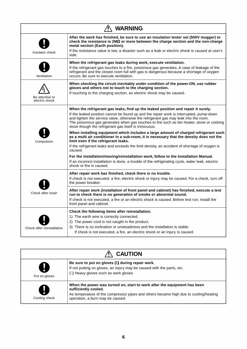
After the work has finished, be sure to use an insulation tester set (500V mugger) tocheck the resistance is 2MΩΩΩΩΩ or more between the charge section and the non-chargemetal section (Earth position).If the resistance value is low, a disaster such as a leak or electric shock is caused at user’sside.
When the refrigerant gas leaks during work, execute ventilation.If the refrigerant gas touches to a fire, poisonous gas generates. A case of leakage of therefrigerant and the closed room full with gas is dangerous because a shortage of oxygenoccurs. Be sure to execute ventilation.
When checking the circuit inevitably under condition of the power-ON, use rubbergloves and others not to touch to the charging section.If touching to the charging section, an electric shock may be caused.
When the refrigerant gas leaks, find up the leaked position and repair it surely.If the leaked position cannot be found up and the repair work is interrupted, pump-downand tighten the service valve, otherwise the refrigerant gas may leak into the room.The poisonous gas generates when gas touches to fire such as fan heater, stove or cockingstove though the refrigerant gas itself is innocuous.
When installing equipment which includes a large amount of charged refrigerant suchas a multi air conditioner in a sub-room, it is necessary that the density does not thelimit even if the refrigerant leaks.If the refrigerant leaks and exceeds the limit density, an accident of shortage of oxygen iscaused.
For the installation/moving/reinstallation work, follow to the Installation Manual.If an incorrect installation is done, a trouble of the refrigerating cycle, water leak, electricshock or fire is caused.
After repair work has finished, check there is no trouble.If check is not executed, a fire, electric shock or injury may be caused. For a check, turn offthe power breaker.
After repair work (installation of front panel and cabinet) has finished, execute a testrun to check there is no generation of smoke or abnormal sound.If check is not executed, a fire or an electric shock is caused. Before test run, install thefront panel and cabinet.
Check the following items after reinstallation.1) The earth wire is correctly connected.2) The power cord is not caught in the product.3) There is no inclination or unsteadiness and the installation is stable.
If check is not executed, a fire, an electric shock or an injury is caused.
Be sure to put on gloves (∗∗∗∗∗ ) during repair work.If not putting on gloves, an injury may be caused with the parts, etc.(∗ ) Heavy gloves such as work gloves
When the power was turned on, start to work after the equipment has beensufficiently cooled.As temperature of the compressor pipes and others became high due to cooling/heatingoperation, a burn may be caused.
Insulator check
Ventilation
Be attentive toelectric shock
Compulsion
Check after rerair
Check after reinstallation
Put on gloves
Cooling check
WARNING
CAUTION
7
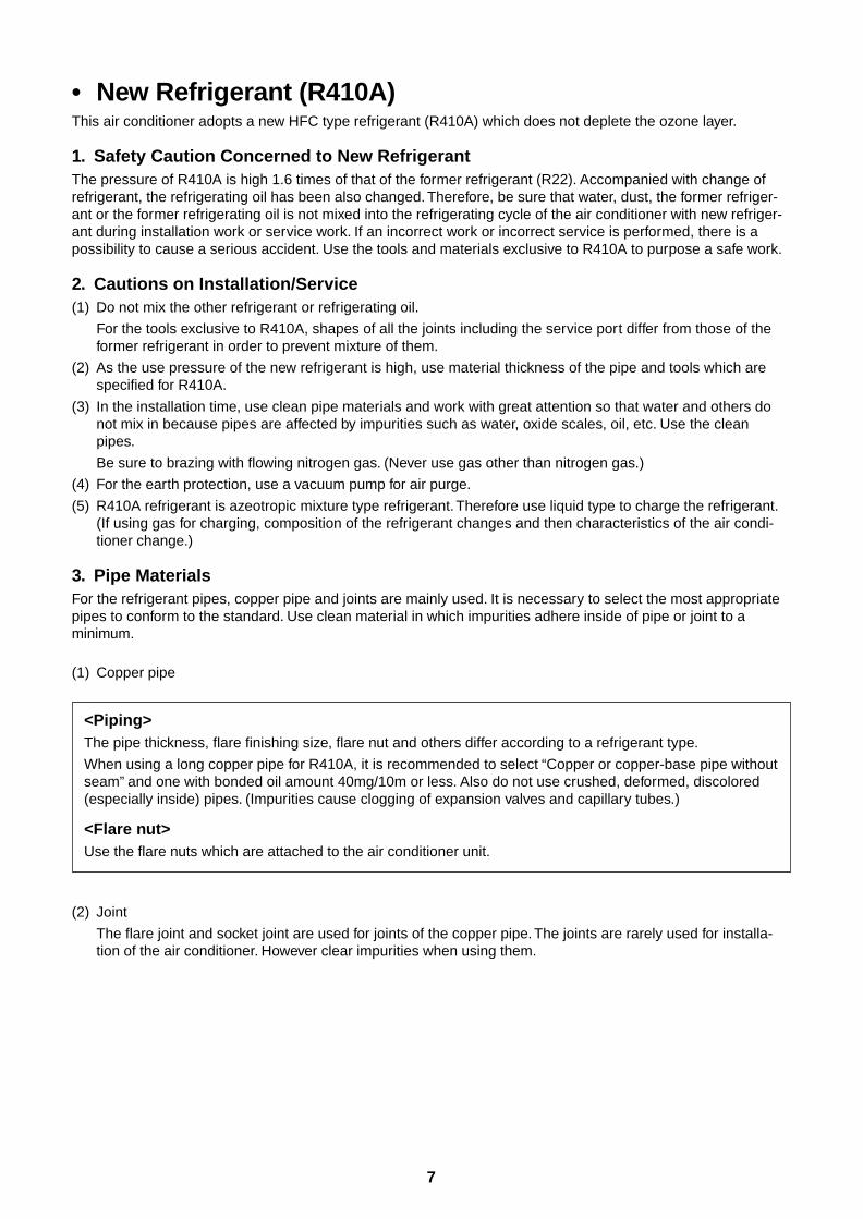
• New Refrigerant (R410A)This air conditioner adopts a new HFC type refrigerant (R410A) which does not deplete the ozone layer.
1. Safety Caution Concerned to New RefrigerantThe pressure of R410A is high 1.6 times of that of the former refrigerant (R22). Accompanied with change ofrefrigerant, the refrigerating oil has been also changed. Therefore, be sure that water, dust, the former refriger-ant or the former refrigerating oil is not mixed into the refrigerating cycle of the air conditioner with new refriger-ant during installation work or service work. If an incorrect work or incorrect service is performed, there is apossibility to cause a serious accident. Use the tools and materials exclusive to R410A to purpose a safe work.
2. Cautions on Installation/Service(1) Do not mix the other refrigerant or refrigerating oil.
For the tools exclusive to R410A, shapes of all the joints including the service port differ from those of theformer refrigerant in order to prevent mixture of them.
(2) As the use pressure of the new refrigerant is high, use material thickness of the pipe and tools which arespecified for R410A.
(3) In the installation time, use clean pipe materials and work with great attention so that water and others donot mix in because pipes are affected by impurities such as water, oxide scales, oil, etc. Use the cleanpipes.
Be sure to brazing with flowing nitrogen gas. (Never use gas other than nitrogen gas.)
(4) For the earth protection, use a vacuum pump for air purge.
(5) R410A refrigerant is azeotropic mixture type refrigerant. Therefore use liquid type to charge the refrigerant.(If using gas for charging, composition of the refrigerant changes and then characteristics of the air condi-tioner change.)
3. Pipe MaterialsFor the refrigerant pipes, copper pipe and joints are mainly used. It is necessary to select the most appropriatepipes to conform to the standard. Use clean material in which impurities adhere inside of pipe or joint to aminimum.
(1) Copper pipe
<Piping>The pipe thickness, flare finishing size, flare nut and others differ according to a refrigerant type.
When using a long copper pipe for R410A, it is recommended to select “Copper or copper-base pipe withoutseam” and one with bonded oil amount 40mg/10m or less. Also do not use crushed, deformed, discolored(especially inside) pipes. (Impurities cause clogging of expansion valves and capillary tubes.)
<Flare nut>Use the flare nuts which are attached to the air conditioner unit.
(2) Joint
The flare joint and socket joint are used for joints of the copper pipe. The joints are rarely used for installa-tion of the air conditioner. However clear impurities when using them.

8
4. Tools(1) Required Tools for R410A
Mixing of different types of oil may cause a trouble such as generation of sludge, clogging of capillary, etc.Accordingly, the tools to be used are classified into the following three types.
1) Tools exclusive for R410A (Those which cannot be used for conventional refrigerant (R22))
2) Tools exclusive for R410A, but can be also used for conventional refrigerant (R22)
3) Tools commonly used for R410A and for conventional refrigerant (R22)
The table below shows the tools exclusive for R410A and their interchangeability.
Tools exclusive for R410A (The following tools for R410A are required.)
Tools whose specifications are changed for R410A and their interchangeability
No.
Used tool
Flare tool
Copper pipe gauge foradjusting projectionmargin
Torque wrench
Gauge manifold
Charge hose
Vacuum pump adapter
Electronic balance forrefrigerant charging
Refrigerant cylinder
Leakage detector
Charging cylinder
Usage
Pipe flaring
Flaring by conventionalflare tool
Connection of flare nut
Evacuating, refrigerantcharge, run check, etc.
Vacuum evacuating
Refrigerant charge
Refrigerant charge
Gas leakage check
Refrigerant charge
Conventional airconditioner installation
Whether new equipmentcan be used withconventional refrigerant
Yes
*(Note 1)
No
No
Yes
Yes
No
Yes
No
Whether conven-tional equipment canbe used
*(Note 1)
*(Note 1)
No
No
No
Yes
No
No
No
(1) Vacuum pumpUse vacuum pump byattaching vacuum pump adapter.
(2) Torque wrench
(3) Pipe cutter
(4) Reamer
(5) Pipe bender
(6) Level vial
(7) Screwdriver (+, –)
(8) Spanner or Monkey wrench
(9) Hole core drill
(10) Hexagon wrench (Opposite side 4mm)
(11) Tape measure
(12) Metal saw
Also prepare the following equipments for other installation method and run check.
(1) Clamp meter
(2) Thermometer
(3) IInsulation resistance tester
(4) Electroscope
Existence ofnew equipmentfor R410A
Yes
Yes
Yes
Yes
Yes
Yes
Yes
Yes
(Note 2)
R410Aair conditioner installation
(Note 1) When flaring is carried out for R410A using the conventional flare tools, adjustment of projectionmargin is necessary. For this adjustment, a copper pipe gauge, etc. are necessary.
(Note 2) Charging cylinder for R410A is being currently developed.
General tools (Conventional tools can be used.)
In addition to the above exclusive tools, the following equipments which serve also for R22 are necessaryas the general tools.
9
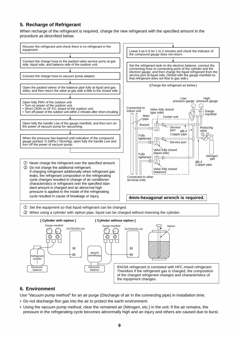
5. Recharge of RefrigerantWhen recharge of the refrigerant is required, charge the new refrigerant with the specified amount in theprocedure as described below.
Never charge the refrigerant over the specified amount. Do not charge the additional refrigerant.
If charging refrigerant additionally when refrigerant gasleaks, the refrigerant composition in the refrigeratingcycle changes resulted in change of air conditionercharacteristics or refrigerant over the specified stan-dard amount is charged and an abnormal highpressure is applied to the inside of the refrigeratingcycle resulted in cause of breakage or injury.
Set the equipment so that liquid refrigerant can be charged.
When using a cylinder with siphon pipe, liquid can be charged without inversing the cylinder.
Gauge manifold
[ Cylinder with siphon ] [ Cylinder without siphon ]
OUTDOOR unitGauge manifold
OUTDOOR unit
Electronic balance
Refrigerantcylinder
Electronic balance
Siphon
Refrigerantcylinder
6. EnvironmentUse “Vacuum pump method” for an air purge (Discharge of air in the connecting pipe) in installation time.
• Do not discharge flon gas into the air to protect the earth environment.
• Using the vacuum pump method, clear the remained air (Nitrogen, etc.) in the unit. If the air remains, thepressure in the refrigerating cycle becomes abnormally high and an injury and others are caused due to burst.
VL VH
Connected to indoor unit
Main pipe
Valve fully closed(gas side)
Center unit
Low-pressure gauge
High-pressure gauge
Gauge manifold
BrazedService port
Service port
Ø6.4Copper pipe
Ø6.4Copper pipe
Fully tightened
Fully tightened
Reducing valve
Nitrogen gas
Valve fully closed(liquid side)
Valve fully closed(balance)
Connected to other terminal units
(Charge the refrigerant as below.)
Recover the refrigerant and check there is no refrigerant in the equipment. Leave it as it is for 1 to 2 minutes and check the indicator of
the compound gauge does not return.
Set the refrigerant tank on the electron balance, connect the connecting hose to connecting ports of the cylinder and the electron gauge, and then charge the liquid refrigerant from the service port at liquid side. (Shield with the gauge manifold so that refrigerant does not flow to gas side.)
Connect the charge hose to the packed valve service ports at gas side, liquid side, and balance side of the outdoor unit.
Open the packed valves of the balance pipe fully at liquid and gas sides, and then return the valve at gas side a little to the closed side.
Open fully PMV of the outdoor unit.• Turn on power of the outdoor unit.• Short CN30 on I/F P.C. board of the outdoor unit.• Turn off power of the outdoor unit within 2 minutes after short-circuiting.
Open fully the handle Low of the gauge manifold, and then turn on the power of vacuum pump for vacuuming.
When the pressure has lowered until indication of the compound gauge pointed -0.1MPa (-76cmHg), open fully the handle Low and turn off the power of vacuum pump.
Connect the charge hose to vacuum pump adaptor.
R410A refrigerant is consisted with HFC mixed refrigerant.Therefore if the refrigerant gas is charged, the compositionof the charged refrigerant changes and characteristics ofthe equipment changes.
4mm-hexagonal wrench is required.
10
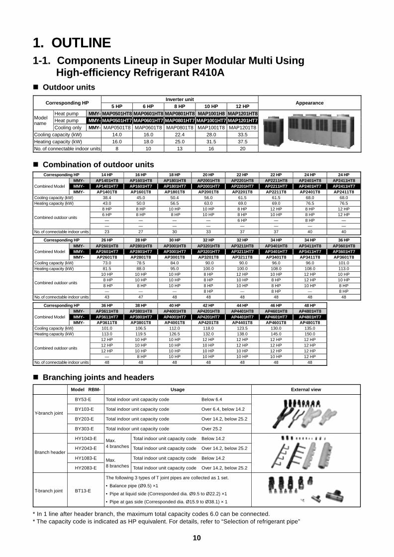
1. OUTLINE1-1. Components Lineup in Super Modular Multi Using
High-efficiency Refrigerant R410A Outdoor units
Inverter unitCorresponding HP
5 HP 6 HP 8 HP 10 HP 12 HPAppearance
Heat pump MMY- MAP0501HT8 MAP0601HT8 MAP0801HT8 MAP1001H8 MAP1201HT8Heat pump MMY- MAP0501HT7 MAP0601HT7 MAP0801HT7 MAP1001HT7 MAP1201HT7Model
nameCooling only MMY- MAP0501T8 MAP0601T8 MAP0801T8 MAP1001T8 MAP1201T8
Cooling capacity (kW) 14.0 16.0 22.4 28.0 33.5Heating capacity (kW) 16.0 18.0 25.0 31.5 37.5No. of connectable indoor units 8 10 13 16 20
Corresponding HP 14 HP 16 HP 18 HP 20 HP 22 HP 22 HP 24 HP 24 HPMMY- AP1401HT8 AP1601HT8 AP1801HT8 AP2001HT8 AP2201HT8 AP2211HT8 AP2401HT8 AP2411HT8MMY- AP1401HT7 AP1601HT7 AP1801HT7 AP2001HT7 AP2201HT7 AP2211HT7 AP2401HT7 AP2411HT7Combined ModelMMY- AP1401T8 AP1601T8 AP1801T8 AP2001T8 AP2201T8 AP2211T8 AP2401T8 AP2411T8
Cooling capacity (kW) 38.4 45.0 50.4 56.0 61.5 61.5 68.0 68.0Heating capacity (kW) 43.0 50.0 56.5 63.0 69.0 69.0 76.5 76.5
8 HP 8 HP 10 HP 10 HP 8 HP 12 HP 8 HP 12 HP6 HP 8 HP 8 HP 10 HP 8 HP 10 HP 8 HP 12 HP
— — — — 6 HP — 8 HP —Combined outdoor units
— — — — — — — —No. of connectable indoor units 23 27 30 33 37 37 40 40
Corresponding HP 26 HP 28 HP 30 HP 32 HP 32 HP 34 HP 34 HP 36 HPMMY- AP2601HT8 AP2801HT8 AP3001HT8 AP3201HT8 AP3211HT8 AP3401HT8 AP3411HT8 AP3601HT8MMY- AP2601HT7 AP2801HT7 AP3001HT7 AP3201HT7 AP3211HT7 AP3401HT7 AP3411HT7 AP3601HT7Combined ModelMMY- AP2601T8 AP2801T8 AP3001T8 AP3201T8 AP3211T8 AP3401T8 AP3411T8 AP3601T8
Cooling capacity (kW) 73.0 78.5 84.0 90.0 90.0 96.0 96.0 101.0Heating capacity (kW) 81.5 88.0 95.0 100.0 100.0 108.0 108.0 113.0
10 HP 10 HP 10 HP 8 HP 12 HP 10 HP 12 HP 10 HP 8 HP 10 HP 10 HP 8 HP 10 HP 8 HP 12 HP 10 HP 8 HP 8 HP 10 HP 8 HP 10 HP 8 HP 10 HP 8 HP
Combined outdoor units
— — — 8 HP — 8 HP — 8 HPNo. of connectable indoor units 43 47 48 48 48 48 48 48
Corresponding HP 36 HP 38 HP 40 HP 42 HP 44 HP 46 HP 48 HPMMY- AP3611HT8 AP3801HT8 AP4001HT8 AP4201HT8 AP4401HT8 AP4601HT8 AP4801HT8MMY- AP3611HT7 AP3801HT7 AP4001HT7 AP4201HT7 AP4401HT7 AP4601HT7 AP4801HT7Combined ModelMMY- AP3611T8 AP3801T8 AP4001T8 AP4201T8 AP4401T8 AP4601T8 AP4801T8
Cooling capacity (kW) 101.0 106.5 112.0 118.0 123.5 130.0 135.0Heating capacity (kW) 113.0 119.5 126.5 132.0 138.0 145.0 150.0
12 HP 10 HP 10 HP 12 HP 12 HP 12 HP 12 HP12 HP 10 HP 10 HP 10 HP 12 HP 12 HP 12 HP12 HP 10 HP 10 HP 10 HP 10 HP 12 HP 12 HP
Combined outdoor units
— 8 HP 10 HP 10 HP 10 HP 10 HP 12 HPNo. of connectable indoor units 48 48 48 48 48 48 48
Combination of outdoor units
Branching joints and headers
* In 1 line after header branch, the maximum total capacity codes 6.0 can be connected.* The capacity code is indicated as HP equivalent. For details, refer to “Selection of refrigerant pipe”
Y-branch joint
Branch header
T-branch joint
Model RBM-
BY53-E
BY103-E
BY203-E
BY303-E
HY1043-E
HY2043-E
HY1083-E
HY2083-E
BT13-E
Usage
Total indoor unit capacity code Below 6.4
Total indoor unit capacity code Over 6.4, below 14.2
Total indoor unit capacity code Over 14.2, below 25.2
Total indoor unit capacity code Over 25.2
Max. Total indoor unit capacity code Below 14.2
4 branches Total indoor unit capacity code Over 14.2, below 25.2
Max. Total indoor unit capacity code Below 14.2
8 branches Total indoor unit capacity code Over 14.2, below 25.2
The following 3 types of T joint pipes are collected as 1 set.
• Balance pipe (Ø9.5) ×1
• Pipe at liquid side (Corresponded dia. Ø9.5 to Ø22.2) ×1
• Pipe at gas side (Corresponded dia. Ø15.9 to Ø38.1) × 1
External view
11
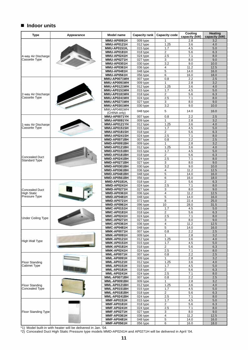
Indoor units
Type Appearance Model name Capacity rank Capacity code Coolingcapacity (kW)
Heatingcapacity (kW)
MMU-AP0091H 009 type 1 2.8 3.2MMU-AP0121H 012 type 1.25 3.6 4.0MMU-AP0151H, 015 type 1.7 4.5 5.0MMU-AP0181H 018 type 2 5.6 6.3MMU-AP0241H 024 type 2.5 7.1 8.0MMU-AP0271H 027 type 3 8.0 9.0MMU-AP0301H 030 type 3.2 9.0 10.0MMU-AP0361H 036 type 4 11.2 12.5MMU-AP0481H 048 type 5 14.0 16.0
4-way Air DischargeCassette Type
MMU-AP0561H 056 type 6 16.0 18.0MMU-AP0071WH 007 type 0.8 2.2 2.5MMU-AP0091WH 009 type 1 2.8 3.2MMU-AP0121WH 012 type 1.25 3.6 4.0MMU-AP0151WH 015 type 1.7 4.5 5.0MMU-AP0181WH 018 type 2 5.6 6.3MMU-AP0241WH 024 type 2.5 7.1 8.0MMU-AP0271WH 027 type 3 8.0 9.0MMU-AP0301WH 030 type 3.2 9.0 10.0
2-way Air DischargeCassette Type
MMU-AP0481WH(CHINA only) 048 type 5 14.0 16.0
MMU-AP0071YH 007 type 0.8 2.2 2.5MMU-AP0091YH 009 type 1 2.8 3.2MMU-AP0121YH 012 type 1.25 3.6 4.0MMU-AP0151SH 015 type 1.7 4.5 5.0MMU-AP0181SH 018 type 2 5.6 6.3
1-way Air DischargeCassette Type
MMU-AP0241SH 024 type 2.5 7.1 8.0MMD-AP0071BH 007 type 0.8 2.2 2.5MMD-AP0091BH 009 type 1 2.8 3.2MMD-AP0121BH 012 type 1.25 3.6 4.0MMD-AP0151BH 015 type 1.7 4.5 5.0MMD-AP0181BH 018 type 2 5.6 6.3MMD-AP0241BH 024 type 2.5 7.1 8.0MMD-AP0271BH 027 type 3 8.0 9.0MMD-AP0301BH 030 type 3.2 9.0 10.0MMD-AP0361BH 036 type 4 11.2 12.5MMD-AP0481BH 048 type 5 14.0 16.0
Concealed DuctStandard Type
MMD-AP0561BH 056 type 6 16.0 18.0MMD-AP0181H, 018 type 2 5.6 6.3MMD-AP0241H 024 type 2.5 7.1 8.0MMD-AP0271H 027 type 3 8.0 9.0MMD-AP0361H 036 type 4 11.2 12.5MMD-AP0481H 048 type 5 14.0 16.0MMD-AP0721H 072 type 8 22.4 25.0
Concealed DuctHigh StaticPressure Type
MMD-AP0961H 096 type 10 28.0 31.5MMC-AP0151H 015 type 1.7 4.5 5.0MMC-AP0181H 018 type 2 5.6 6.3MMC-AP0241H 024 type 2.5 7.1 8.0MMC-AP0271H 027 type 3 8.0 9.0MMC-AP0361H 036 type 4 11.2 12.5
Under Ceiling Type
MMC-AP0481H 048 type 5 14.0 16.0MMK-AP0071H 007 type 0.8 2.2 2.5MMK-AP0091H 009 type 1 2.8 3.2MMK-AP0121H 012 type 1.25 3.6 4.0MMK-AP0151H 015 type 1.7 4.5 5.0MMK-AP0181H 018 type 2 5.6 6.3
High Wall Type
MMK-AP0241H 024 type 2.5 7.1 8.0MML-AP0071H 007 type 0.8 2.2 2.5MML-AP0091H 009 type 1 2.8 3.2MML-AP0121H 012 type 1.25 3.6 4.0MML-AP0151H 015 type 1.7 4.5 5.0MML-AP0181H 018 type 2 5.6 6.3
Floor StandingCabinet Type
MML-AP0241H 024 type 2.5 7.1 8.0MML-AP0071BH 007 type 0.8 2.2 2.5MML-AP0091BH 009 type 1 2.8 3.2MML-AP0121BH 012 type 1.25 3.6 4.0MML-AP0151BH 015 type 1.7 4.5 5.0MML-AP0181BH 018 type 2 5.6 6.3
Floor StandingConcealed Type
MML-AP0241BH 024 type 2.5 7.1 8.0MMF-AP0151H 015 type 1.7 4.5 5.0MMF-AP0181H 018 type 2 5.6 6.3MMF-AP0241H 024 type 2.5 7.1 8.0MMF-AP0271H 027 type 3 8.0 9.0MMF-AP0361H 036 type 4 11.2 12.5MMF-AP0481H 048 type 5 14.0 16.0
Floor Standing Type
MMF-AP0561H 056 type 6 16.0 18.0
*1) Model built-in with heater will be delivered in Jan. ’04.*2) Concealed Duct High Static Pressure type models MMD-AP0241H and AP0271H will be delivered in April ’04.
12
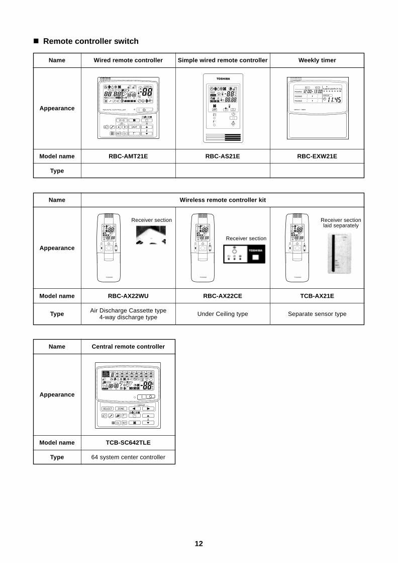
Remote controller switch
Name
Appearance
Model name
Type
Wired remote controller
RBC-AMT21E
Simple wired remote controller
RBC-AS21E
Weekly timer
RBC-EXW21E
Wireless remote controller kitName
Appearance
Model name
Type
RBC-AX22WU
Air Discharge Cassette type4-way discharge type
RBC-AX22CE
Under Ceiling type
TCB-AX21E
Separate sensor type
Receiver section
UNIT
SET CL
SETTING
UNIT No.
CODE No.
TEST
SET DATA
R.C. No.
˚CF
TESTSETTING
WEEKLY TIMER
ERROR
SuMoTuWeTh Fr SaPROGRAM1
PROGRAM2
PROGRAM3
ADR ADR ADRReceiver section
Receiver sectionlaid separately
Name
Appearance
Model name
Type
Central remote controller
TCB-SC642TLE
64 system center controller
SELECT ZONE
CL SET
GROUP
CODE No.
UNIT No.
No.R.C.
TEST
ZONEALLZONE
GROUP
SETTING
1234
SET DATA
13
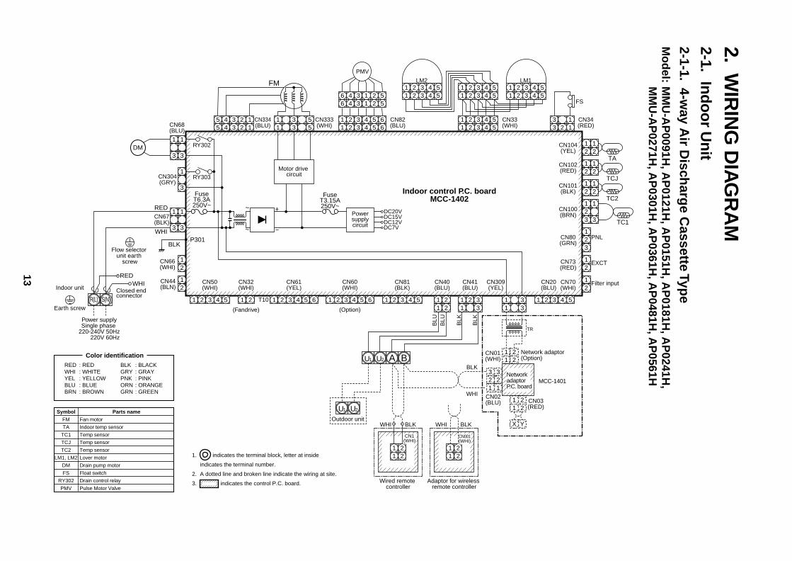
2.W
IRIN
G D
IAG
RA
M2-1.
Ind
oo
r Un
it2-1-1.
4-way A
ir Disch
arge C
assette Type
Mo
del:
MM
U-A
P0091H
, AP
0121H, A
P0151H
, AP
0181H, A
P0241H
,M
MU
-AP
0271H, A
P0301H
, AP
0361H, A
P0481H
, AP
0561HCN104(YEL)
CN102(RED)
CN101(BLK)
1 2 3 4 51 2 3 4 5
1 2 3 4 51 2 3 4 5
1 2 3 4 51 2 3 4 5
1 2 3 4 5 61 2 3 4 5
1 2 3 4 51 2 3 4 5 6
6 4 3 1 2 56 4 3 1 2 5
3 13 2 1
CN34(RED)
FS
CN33(WHI)
CN82(BLU)
5 4 3 2 15 4 3 2 1
CN334(BLU)
DC20V
CN333(WHI)CN68
(BLU)
CN304(GRY)
CN66(WHI)
CN44(BLN)
CN67(BLK)
LM1
PMV
Indoor control P.C. boardMCC-1402
12
12
TA12
12
TCJ12
12
TC2
CN100(BRN)
12
12
33
CN80(GRN)
PNL
EXCT
12
CN73(RED)
12
Filter input
(Option)(Fandrive)
CN70(WHI)
CN20(BLU)
12
3
TC1
1 2 3 4 51 2 3 4 5
LM2
1 2 3 4 5
CN81(BLK)
CN60(WHI)
CN32(WHI)
CN61(YEL)
CN50(WHI)
CN40(BLU)
T10 1 2 3 4 51 21 2 3 4 5 61 2 3 4 51 2 3
CN309(YEL)
1 2 31 2 3
1 21 2
CN41(BLU)
1 2 31 2 3
4 5 6
RY302
RY303
123
123
123
123
12
12
12
3
~ +
~ –
FuseT6.3A250V~
FuseT3.15A250V~
DC15VDC12VDC7V
P301BLK
RED
WHI
WHIRED
S(N)R(L)
Power supplySingle phase
220-240V 50Hz 220V 60Hz
Indoor unit
Earth screw
DM
FM
Powersupplycircuit
Motor drive circuit
Parts nameFan motor
Indoor temp sensor
Temp sensor
Temp sensor
Temp sensor
Lover motor
Drain pump motor
Float switch
Drain control relay
Pulse Motor Valve
Color identification
1. indicates the terminal block, letter at inside
indicates the terminal number.
2. A dotted line and broken line indicate the wiring at site.
3. indicates the control P.C. board.
RED : REDWHI : WHITEYEL : YELLOWBLU : BLUEBRN : BROWN
BLK : BLACKGRY : GRAYPNK : PINKORN : ORANGEGRN : GREEN
Closed end connector
CN01(WHI)
CN02(BLU)
Adaptor for wireless remote controller
CN03(RED)
Network adaptor (Option)
1 21 2
1 21 2
1 21 2
X Y
3 32 21 1
Wired remote controller
1 2
BAU2
1 2
CN1(WHI)
CN001(WHI)
WHIOutdoor unit
BLK WHI BLK
BLK
BLU
BLU
BLK
BLK
TR
WHI
U1
U2U1
Network adaptor P.C. board
MCC-1401
SymbolFM
TA
TC1
TCJ
TC2
LM1, LM2
DM
FS
RY302
PMV
Flow selector unit earth
screw
14
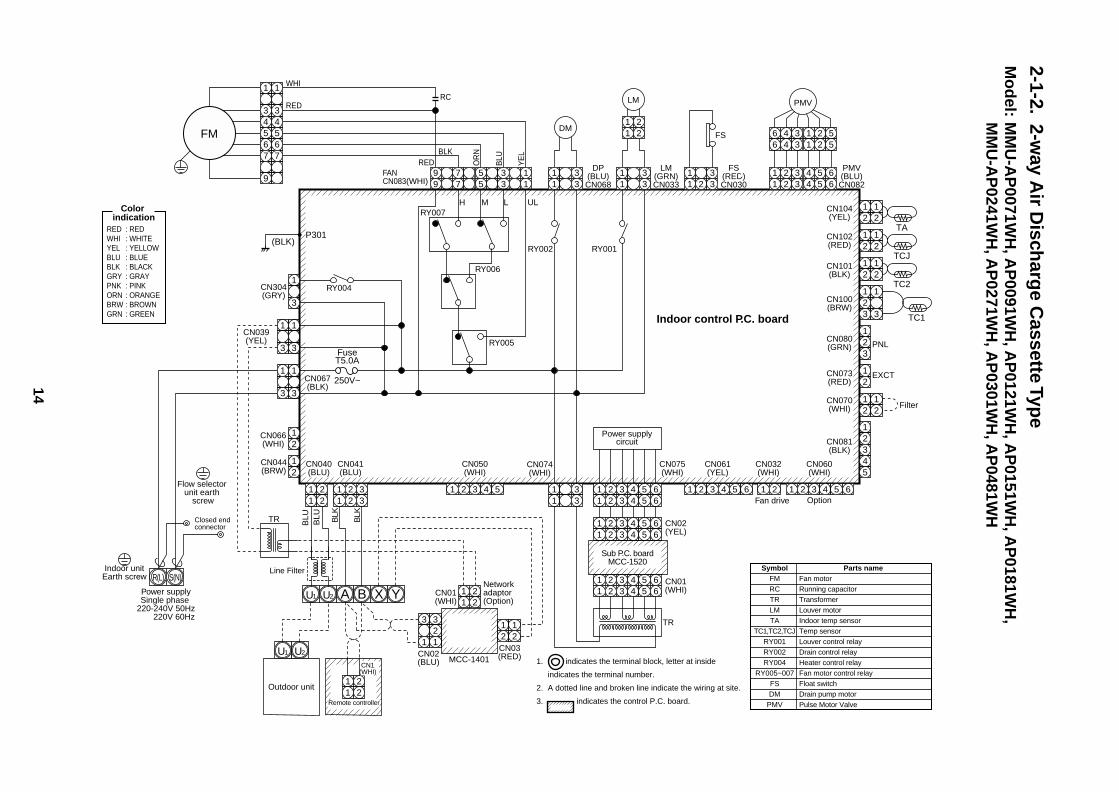
2-1-2.2-w
ay Air D
ischarg
e Cassette Typ
eM
od
el:M
MU
-AP
0071WH
, AP
0091WH
, AP
0121WH
, AP
0151WH
, AP
0181WH
,M
MU
-AP
0241WH
, AP
0271WH
, AP
0301WH
, AP
0481WH
CN104(YEL)
CN102(RED)
CN101(BLK)
5 4 3 2 15 4 3 2 1
9 8 7 69 8 7 6
FANCN083(WHI)
WHI
RED
DP(BLU)CN068
DM
CN304(GRY)
CN066(WHI)
CN067(BLK)
CN044(BRW)
Indoor control P.C. board
12
12
TA12
12
TCJ12
12
TC2
CN100(BRW)
12
12
33
CN080(GRN) PNL
EXCT
12
CN073(RED)
12
FilterCN070(WHI)
CN081(BLK)
CN060(WHI)
Option
CN032(WHI)
CN075(WHI)
CN074(WHI)
TR
12
12345
12
3
TC1
1 2 3 4 5 6
CN061(YEL)
Fan drive1 2 3 4 5 61 2 3 4 5 6
1 2 31 2 31 2 3
1 21 2
1 2 31 2 3
1 2 31 2 3
4 5 6
1 2 3 4 5 61 2 3 4 5 6
1 2 3 4 5 61 2 3 4 5 6
CN050(WHI)
CN041(BLU)
CN040(BLU)
CN01(WHI)
CN02(BLU)
Network adaptor (Option)
1 21 2 3 4 5
1 21 2
3 32
1 1CN03(RED)MCC-1401
2 21 1
RY004123
12
12
RY002
RY006
RY007
RY005
1 2
BA YXS(N)R(L)
U2
1 2Remote controller
CN1(WHI)
Power supplySingle phase
220-240V 50Hz 220V 60Hz
Indoor unitEarth screw
Outdoor unit
BLU
BLU BLK
BLK
U1
U2U1
Flow selector unit earth
screw
Power supplycircuit
CN01(WHI)
CN02(YEL)
Sub P.C. boardMCC-1520
SymbolFMRCTRLMTA
TC1,TC2,TCJRY001RY002RY004
RY005~007FSDM
PMV
Parts nameFan motorRunning capacitorTransformerLouver motorIndoor temp sensorTemp sensorLouver control relayDrain control relayHeater control relayFan motor control relayFloat switchDrain pump motorPulse Motor Valve
LM(GRN)CN033
LM
1 2 31 2 3
FS(RED)CN030
PMV(BLU)CN082
FS
1 2 31 2 3
1 2 31 2 3
4 5 64 5 6
6 4 36 4 3
1 2 51 2 5
RY001
TR
FuseT5.0A
250V~123
123
CN039(YEL)
123
123
1 21 2
PMV
12
12
34
34
56
56
77
9
FM
YE
L
BLU
OR
NBLK
H M L UL
RC
RED
1. indicates the terminal block, letter at inside
indicates the terminal number.
2. A dotted line and broken line indicate the wiring at site.
3. indicates the control P.C. board.
Closed end connector
Color indication
RED : REDWHI : WHITEYEL : YELLOWBLU : BLUEBLK : BLACKGRY : GRAYPNK : PINKORN : ORANGEBRW : BROWNGRN : GREEN
Line Filter
P301(BLK)
15
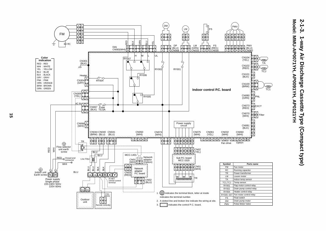
2-1-3.1-w
ay Air D
ischarg
e Cassette Typ
e (Co
mp
act type)
Mo
del: M
MU
-AP
0071YH
, AP
0091YH
, AP
0121YH
CN104(YEL)
CN102(RED)
CN101(BLK)
5 4 3 2 15 4 3 2 1
9 8 7 69 8 7 6
FANCN083(WHI)
DP(BLU)CN068
DM
CN304(GRY)
Heater
CN301(BLK)
CN066(WHI)
WHI
RED
BLU
BLUBLU
CN067(BLK)
Indoor control P.C. board
12
12
TA
TCJ
12
12
12
CN100(BRW)
12
12
33
CN080(GRN) PNL
EXCT
12
CN073(RED)
12
FilterCN070(WHI)
CN081(BLK)
CN060(WHI)
Option
CN032(WHI)
CN075(WHI)
CN074(WHI)
TR
12
12345
12
3
TC1
1 2 3 4 5 6
CN061(YEL)
Fan drive
1 2 3 4 5 61 2 3 4 5 61 2 3
1 2 31 3
1 21 2
1 2 31 2 3
1 2 31 2 3
1 2 31 2 3
4 5 6
CN050(WHI)
CN041(BLU)
CN040(BLU)
1 21 2
CN044(BRW)
CN01(WHI)
CN02(BLU)
Network adaptor (Option)
1 21 2 3 4 5
1 21 2
1 12 2
2 12
33 1
CN03(RED)
MCC-1401
RY004123
12
RY002
RY006
RY007
RY005
1 2
BA YXS(N)R(L) U2
1 2Remote controller
CN1(WHI)
Power supplySingle phase
220-240V 50Hz 220V 60Hz
Indoor unitEarth screw
Outdoorunit
BLU
BLU
RE
D
WH
I
BLK
BLK
U1
U2U1
Power supplycircuit
Network adaptor P.C. board
SymbolFM
RC
TR
LM
TA
TC1,TCJ
RY001
RY002
RY004
RY005~007
FS
DM
PMV
Parts nameFan motorRunning capacitorPower transformerLouver motorIndoor temp sensorTemp sensorFlap motor control relayDrain pump control relayHeater control relayFan motor control relayFloat switchDrain pump motorPulse Motor Valve
LM(GRN)CN033
LM
1 2 31 2 3
FS(RED)CN030
PMV(BLU)CN082
FS
1 2 31 2 3
1 2 31 2 3
4 5 64 5 6
6 4 36 4 3
1 2 51 2 5
RY001
AI-NET central control terminal
TR
FuseT5.0A
123
123
CN309(YEL)
AC IN
123
123
2 12 1
2 12 1
PMV12
12
34
34
56
56
FM
YE
L
BLU
OR
N
BLK
RE
D
H M L UL
RC
1. indicates the terminal block, letter at inside
indicates the terminal number.
2. A dotted line and broken line indicate the wiring at site.
3. indicates the control P.C. board.
Closed end connector
1 2 3 4 5 61 2 3 4 5 6
1 2 3 4 5 61 2 3 4 5 6
CN01(WHI)
CN02(YEL)
Sub P.C. boardMCC-1520
Color indication
RED : REDWHI : WHITEYEL : YELLOWBLU : BLUEBLK : BLACKGRY : GRAYPNK : PINKORN : ORANGEBRW : BROWNGRN : GREEN
Line Filter
Flow selector unit earth
screw
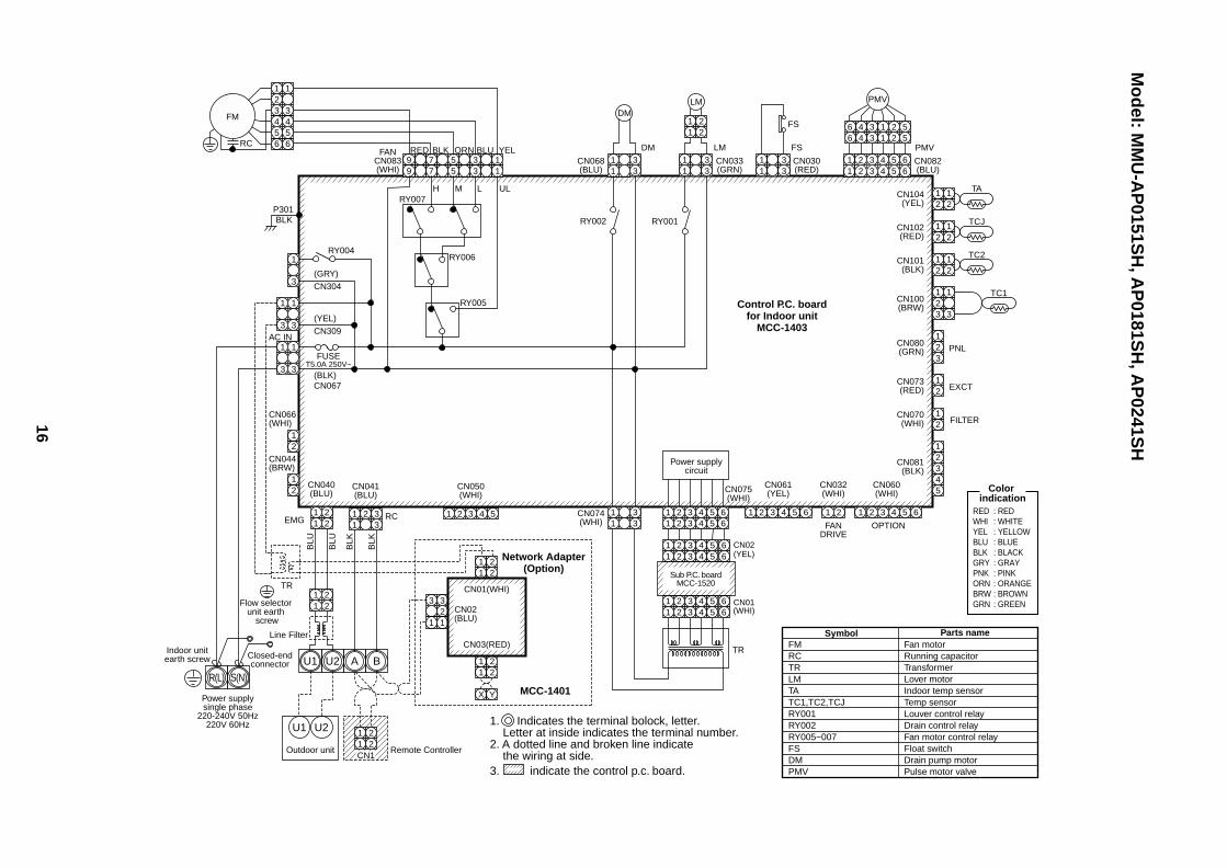
16
Mo
del: M
MU
-AP
0151SH
, AP
0181SH
, AP
0241SH
FMRCTRLMTATC1,TC2,TCJRY001RY002RY005~007FSDMPMV
Fan motorRunning capacitorTransformerLover motorIndoor temp sensorTemp sensorLouver control relayDrain control relayFan motor control relayFloat switchDrain pump motorPulse motor valve
Symbol Parts name
Color indication
RED : REDWHI : WHITEYEL : YELLOWBLU : BLUEBLK : BLACKGRY : GRAYPNK : PINKORN : ORANGEBRW : BROWNGRN : GREEN
1. Indicates the terminal bolock, letter. Letter at inside indicates the terminal number.2. A dotted line and broken line indicate the wiring at side.3. indicate the control p.c. board.
5 3 177
99 5 3 1
RY007P301
RY004
(GRY)CN304
(YEL)CN309
(BLK)
BLK
CN067
FUSET5.0A 250V~
RY006
RY005
H
RED BLK ORN BLU YEL
M L UL
3
1
3
1
3
1
3
1
3
1
RC
FM
123
1
3
CN104(YEL)
TA
21
21
CN102(RED)
TCJ
21
21
CN101(BLK)
CN100(BRW)
1
3
CN080(GRN)
TC2
PNL
EXCT
21
CN073(RED) 2
2
1
FILTERCN070(WHI)
CN081(BLK)
21
21
21
11
22
11
22
11
22
11
2
X Y
2
32
1 1
3
11 2
33 1 2 3 4 5 1 2 3 4 5 6 1 2 1 23 4 5 6 1 2 3 4 5 6
1 2 3 4 5 6
21
43
5
21
TC1
CN066(WHI)
AC IN
CN044(BRW)
CN040(BLU)
Outdoor unit Remote Controller
Power supplysingle phase
220-240V 50Hz220V 60Hz
Indoor unitearth screw Closed-end
connector
Line Filter
CN01(WHI)
CN03(RED)
CN02(BLU)
CN041(BLU)
CN050(WHI)
CN061(YEL)
CN032(WHI)
FANDRIVE
OPTION
CN060(WHI)
EMG
BLU
BLU
BLK
BLK
RC
TR
U1
U1 U2
U2 A B
Network Adapter(Option)
Control P.C. boardfor Indoor unit
MCC-1403
MCC-1401
11
22
CN1
11
33CN074
(WHI)
CN075(WHI)
Power supplycircuit
TR
11
33CN068
(BLU)
FANCN083(WHI)
RY002
DM
DM
11
33 CN033
(GRN)
RY001
LM
CN082(BLU)
PMV
LM
11
33 CN030
(RED)
FS
FS11
22
1 2 3 4 5 61 2 3 4 5 6
1 234 561 234 56
PMV3
1
321
654
654
R(L) S(N)
1 2 3 4 5 61 2 3 4 5 6
1 2 3 4 5 61 2 3 4 5 6
CN01(WHI)
CN02(YEL)
Sub P.C. boardMCC-1520
Flow selector unit earth
screw
17
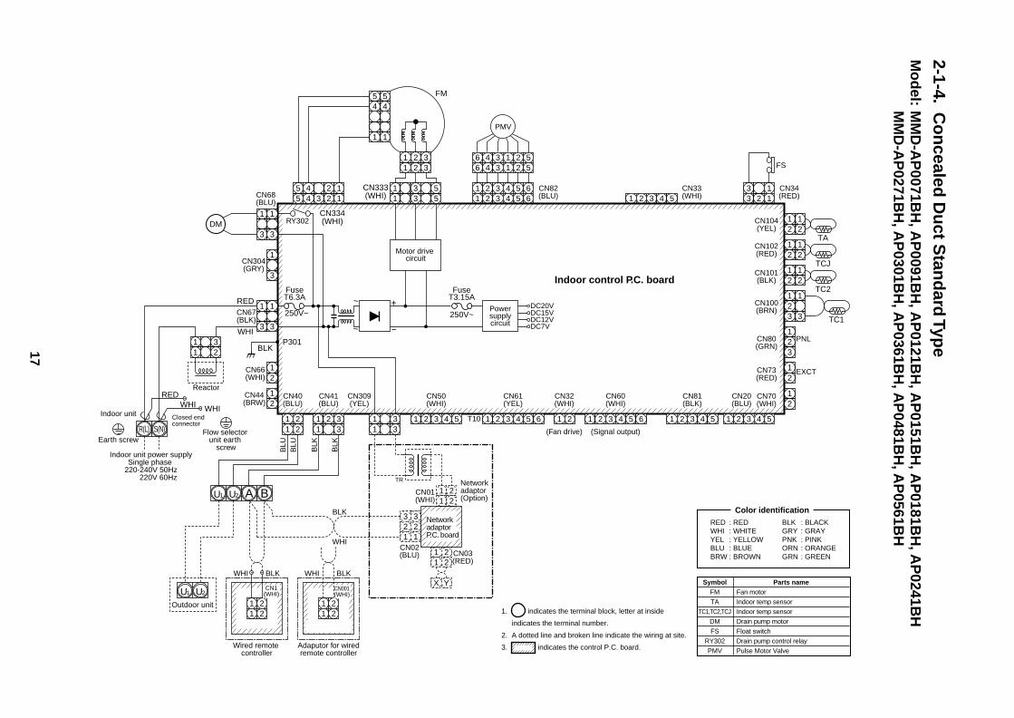
2-1-4.C
on
cealed D
uct S
tand
ard Typ
eM
od
el:M
MD
-AP
0071BH
, AP
0091BH
, AP
0121BH
, AP
0151BH
, AP
0181BH
, AP
0241BH
MM
D-A
P0271B
H, A
P0301B
H, A
P0361B
H, A
P0481B
H, A
P0561B
H
CN104(YEL)
CN102(RED)
CN101(BLK)
1 2 3 4 51 2 3 4 5 61 2 3 4 5 6
6 4 3 1 2 56 4 3 1 2 5
3 13 2 1
CN34(RED)
FS
CN33(WHI)
CN82(BLU)
DC20V
CN68(BLU)
CN304(GRY)
CN66(WHI)
CN44(BRW)
CN67(BLK)
Reactor
PMV
Indoor control P.C. board
12
12
TA12
12
TCJ12
12
TC2
CN100(BRN)
12
12
33
CN80(GRN)
PNL
EXCT
12
CN73(RED)
12
(Signal output)(Fan drive)
CN70(WHI)
CN20(BLU)
12
3
TC1
1 2 3 4 5
CN81(BLK)
CN60(WHI)
CN32(WHI)
CN61(YEL)
CN50(WHI)
Adaputor for wiredremote controller
CN309(YEL)
CN41(BLU)
CN40(BLU)
T10 1 2 3 4 51 21 2 3 4 5 61 2 3 4 51 2 31 2 31 2 3
1 2 31 2
1 21 2 3
1 31 2 2
4 5 6
1 21 2
RY302123
123
123
123
12
12
12
3
~ +
~ –
FuseT6.3A
250V~
FuseT3.15A
250V~ DC15VDC12VDC7V
P301BLK
RED
WHI
WHIWHIRED
Wired remote controller
1 2
BA
S(N)R(L)
U2
1 2
CN1(WHI)
CN001(WHI)
Indoor unit power supplySingle phase
220-240V 50Hz 220V 60Hz
Indoor unit
Earth screw
WHI
Outdoor unit
BLK WHI BLK
BLK
BLU
BLU
BLK
BLK
TR
WHI
U1
U2U1
DM
Powersupplycircuit
Motor drive circuit
CN01(WHI)
CN02(BLU) CN03
(RED)
Network adaptor (Option)
1 21 2
1 21 2
X Y
3 32 21 1
Network adaptor P.C. board
SymbolFM
TA
TC1,TC2,TCJ
DM
FS
RY302
PMV
Parts nameFan motor
Indoor temp sensor
Indoor temp sensor
Drain pump motor
Float switch
Drain pump control relay
Pulse Motor Valve
Color identification
1. indicates the terminal block, letter at inside
indicates the terminal number.
2. A dotted line and broken line indicate the wiring at site.
3. indicates the control P.C. board.
RED : REDWHI : WHITEYEL : YELLOWBLU : BLUEBRW : BROWN
BLK : BLACKGRY : GRAYPNK : PINKORN : ORANGEGRN : GREEN
Closed end connector
CN333(WHI)
CN334(WHI)
11
22
344
55
1 3 51 3
1 2 31 2 3
5
11
54
54
FM
Flow selector unit earth
screw
18
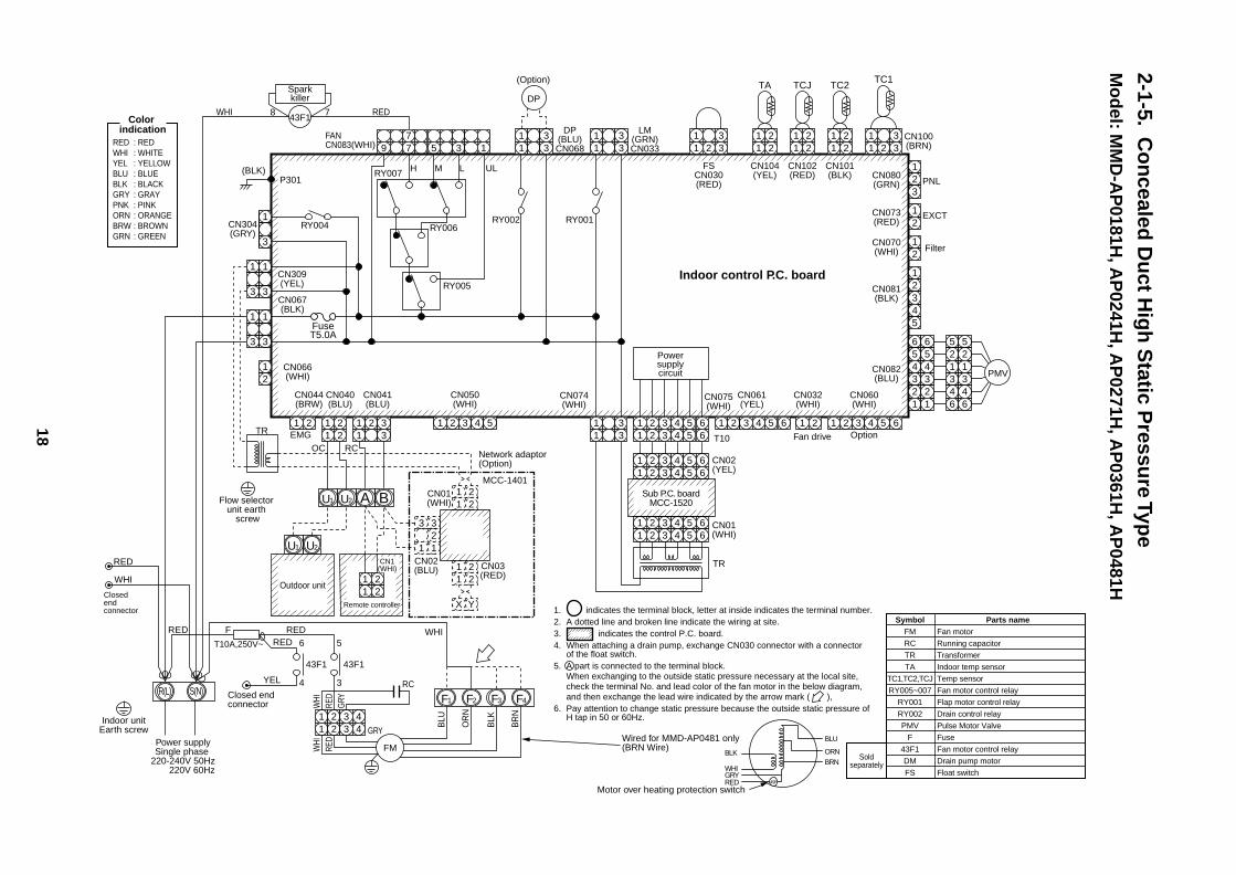
2-1-5.C
on
cealed D
uct H
igh
Static P
ressure Typ
eM
od
el: MM
D-A
P0181H
, AP
0241H, A
P0271H
, AP
0361H, A
P0481H
TC1TC2
CN080(GRN)
CN101(BLK)
CN073(RED)
CN070(WHI)
4 25 4 3 2 1
9 8 7 69 8 7 6
FANCN083(WHI)
DP(BLU)CN068
DP
CN304(GRY)
CN066(WHI)
CN067(BLK)
(BLK)PNL
EXCT
12
12
Filter
CN082(BLU)
CN060(WHI)
Option
CN032(WHI)
CN075(WHI)
CN074(WHI)
TR
T10
12
654321
654321
521346
521346
CN081(BLK)
12345
3
1 2 3 4 5 6
CN061(YEL)
Fan drive
1 2 3 4 5 61 2 3 4 5 61 2 3
1 2 31 3
1 21 21 2
1 2 31 2 3
1 2 31 2 3
4 5 6
CN050(WHI)
CN041(BLU)
CN040(BLU)
CN044(BRW)
1 21 2 3 4 5
RY004
P301
123
12
RY002RY006
RY007
RY005
1 2
BA
S(N)R(L)
U2
1 2Remote controller
CN1(WHI)
Power supplySingle phase
220-240V 50Hz 220V 60Hz
Indoor unitEarth screw
Outdoor unit
U1
U2U1
Powersupplycircuit
SymbolFM
RC
TR
TA
TC1,TC2,TCJ
RY005~007
RY001
RY002
PMV
F
43F1
DM
FS
Parts nameFan motor
Running capacitor
Transformer
Indoor temp sensor
Temp sensor
Fan motor control relay
Flap motor control relay
Drain control relay
Pulse Motor Valve
Fuse
Fan motor control relay
Drain pump motor
Float switch
Soldseparately
LM(GRN)CN033
1 2 31 2 3
CN100(BRN)
1 2 31 2 3
1 2 31 2 3
1 21 2
TCJ
CN102(RED)
1 21 2
TA
CN104(YEL)
FSCN030(RED)
1 21 2
RY001
TR
OCEMG
RC
FuseT5.0A
T10A,250V~
123
123
CN309(YEL)
123
123
REDWHI
H M L UL
1. indicates the terminal block, letter at inside indicates the terminal number.2. A dotted line and broken line indicate the wiring at site.3. indicates the control P.C. board.4. When attaching a drain pump, exchange CN030 connector with a connector
of the float switch.5. A part is connected to the terminal block.
When exchanging to the outside static pressure necessary at the local site, check the terminal No. and lead color of the fan motor in the below diagram, and then exchange the lead wire indicated by the arrow mark ( ),
6. Pay attention to change static pressure because the outside static pressure of H tap in 50 or 60Hz.
PMV
(Option)
CN01(WHI)
CN02(BLU)
WHI
WHI
RED
GRY
WHI
RED
BLU
OR
N
BLK
BR
N
GRY
YEL
REDREDRED F
RED
WHI
43F1
6
4
CN03(RED)
MCC-1401
Network adaptor (Option)
1 21 2
1 21 2
X Y
3 32
1 1
43F1
Sparkkiller
8 7
43F1
5
3
1 2 3 41 2 3 4
F1 F2 F3 F4
RC
FM
WHI
BLK
BLU
ORNBRN
GRYRED 49F
Indoor control P.C. board
Closed end connector
Closed end connector
Wired for MMD-AP0481 only(BRN Wire)
Motor over heating protection switch
Color indication
RED : REDWHI : WHITEYEL : YELLOWBLU : BLUEBLK : BLACKGRY : GRAYPNK : PINKORN : ORANGEBRW : BROWNGRN : GREEN
1 2 3 4 5 61 2 3 4 5 6
1 2 3 4 5 61 2 3 4 5 6
CN01(WHI)
CN02(YEL)
Sub P.C. boardMCC-1520Flow selector
unit earth screw
19
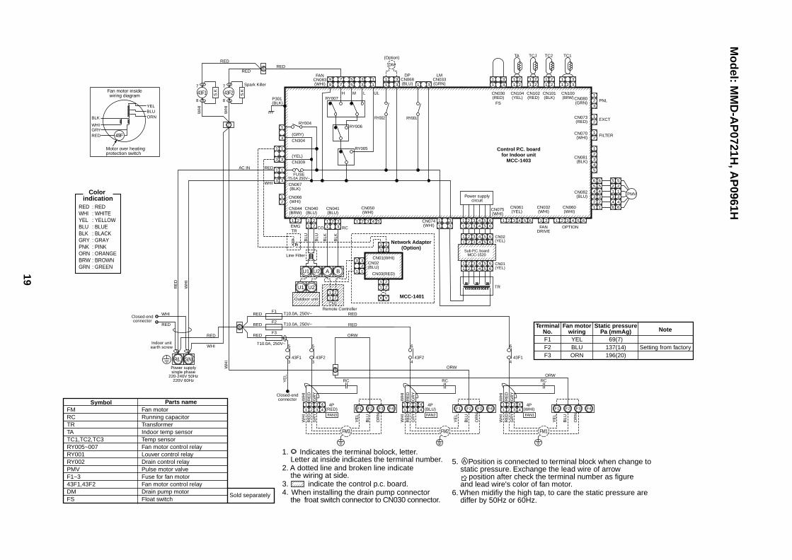
Mo
del: M
MD
-AP
0721H, A
P0961H
FMRCTRTATC1,TC2,TC3RY005~007RY001RY002PMVF1~343F1,43F2DMFS
Fan motorRunning capacitorTransformerIndoor temp sensorTemp sensorFan motor control relayLouver control relayDrain control relayPulse motor valveFuse for fan motorFan motor control relayDrain pump motorFloat switch
Sold separately
Symbol Parts name
1. Indicates the terminal bolock, letter. Letter at inside indicates the terminal number.2. A dotted line and broken line indicate the wiring at side.3. indicate the control p.c. board.4. When installing the drain pump connector the froat switch connector to CN030 connector.
5. Position is connected to terminal block when change to static pressure. Exchange the lead wire of arrow position after check the terminal number as figure and lead wire's color of fan motor.6. When midifiy the high tap, to care the static pressure are differ by 50Hz or 60Hz.
CN080(GRN) PNL
EXCT
23
1
2
2
3
3
4
4
5
56
1
12
2 2
3 3 34
4 4
55 56
6 61
1 1
CN073(RED) 2
1
FILTERCN070(WHI)
CN081(BLK)
CN082(BLU)
21
11
2 33
CN100(BRW)
11
22
CN101(BLK)
CN030(RED)
TC1TC2
11
22
CN102(RED)
TCJ
11
22
CN104(YEL)
TA
PMV
11
33
FS
5 3 177
99 5 3 1
RY007P301(BLK)
REDRED
Spark Killer
WH
I
WH
I
RED
YEL
BLK
WHIGRYRED
BLUORN
RY004
(GRY)CN304
(YEL)CN309
FUSET5.0A 250V~
RY006
RY005
H M L UL
3
1
3
1
3
1
3
1
3
1
6
8
7
21
11
221 2
11
22
11
2
X Y
2
32
1 1
3
11 2
33 1 2 3 4 5 1 2 3 4 5 6 1 2 1 23 4 5 6 1 2 3 4 5 6
1 2 3 4 5 6
CN066(WHI)
CN067(BLK)
AC IN RED
WHI
CN044(BRW)
EMG
Remote Controller
Power supplysingle phase
220-240V 50Hz220V 60Hz
Indoor unitearth screw
Closed-endconnector
Closed-endconnector
Line Filter
WHI
RED
RED
WHI
RE
D
WH
I
WH
I
CN01(WHI)
CN03(RED)
CN02(BLU)
CN040(BLU)
CN041(BLU)
CN050(WHI)
CN061(YEL)
CN032(WHI)
FANDRIVE
OPTION
CN060(WHI)
BLU
BLU
BLK
BLK
RCCOTR
U1 U2 A B
Network Adapter(Option)
Control P.C. boardfor Indoor unit
MCC-1403
MCC-140111
22
CN1
11
33CN074
(WHI)
CN075(WHI)
Power supplycircuit
TR
DPCN068(BLU)
LMCN033(GRN)
FANCN083(WHI)
RY002
1 3
RY001
R(L) S(N)
11
33
DM
(Option)
43F243F1
49F
F1 T10.0A, 250V~
T10.0A, 250V~
T10.0A, 250V~
RED
F2RED
F3RED
7
8
5
343F1
7
8
5
343F2
FAN3
4P(RED)
RC
ORW
RED
RED
ORW
ORW
YE
L
YE
L
WH
IR
ED
GR
Y
WH
IR
ED
GR
Y
BLU
OR
N
1 2 3 41 2 3 4
FM3
F1 F2 F3 F4
6
443F2
FAN2
4P(BLU)
RC
YE
L
WH
IR
ED
GR
Y
WH
IR
ED
GR
Y
BLU
OR
N
1 2 3 41 2 3 4
FM2
F1 F2 F3 F4
6
443F1
FAN1
4P(WHI)
RC
YE
L
WH
IR
ED
GR
Y
WH
IR
ED
GR
Y
BLU
OR
N
1 2 3 41 2 3 4
FM1
F1 F2 F3 F4
5
Motor over heatingprotection switch
Fan motor insidewiring diagram
Color indication
RED : REDWHI : WHITEYEL : YELLOWBLU : BLUEBLK : BLACKGRY : GRAYPNK : PINKORN : ORANGEBRW : BROWNGRN : GREEN
A
U1 U2
Outdoor unit
F1F2F3
TerminalNo.
YELBLUORN
Fan motorwiring
69(7)137(14)196(20)
Static pressurePa (mmAg)
Setting from factory
Note
1 2 3 4 5 61 2 3 4 5 6
1 2 3 4 5 61 2 3 4 5 6
CN01(YEL)
CN02(YEL)
Sub P.C. boardMCC-1520
S.K
S.K
20
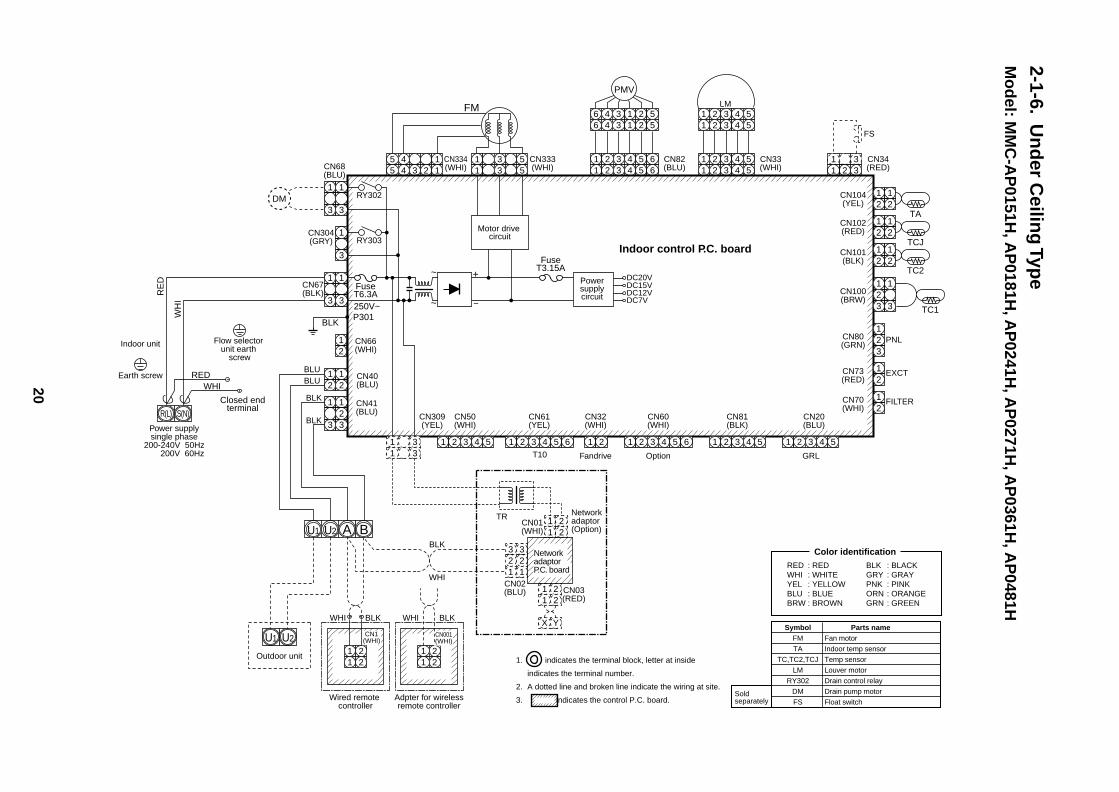
2-1-6.U
nd
er Ceilin
g Typ
eM
od
el: MM
C-A
P0151H
, AP
0181H, A
P0241H
, AP
0271H, A
P0361H
, AP
0481H
CN104(YEL)
CN102(RED)
CN101(BLK)
1 2 3 4 51 2 3 4 5
1 2 3 4 51
11
2
22
3
33
4
44
5
55
66
66
1 2 3 4 51 2 3 4 5
1 31 2 3
CN34(RED)
FS
CN33(WHI)
CN82(BLU)
5 4 15 4 3 2 1
CN334(WHI)
DC20V
CN333(WHI)CN68
(BLU)
CN304(GRY)
CN66(WHI)
CN67(BLK)
Indoor control P.C. board
12
12
TA12
12
TCJ12
12
TC2
CN80(GRN)
PNL
EXCT
12
CN73(RED)
12
FILTER
Option GRLFandrive
CN70(WHI)
CN20(BLU)
12
3
1 2 3 4 51 2 3 4 5
LM
1 2 3 4 5
CN60(WHI)
CN32(WHI)
CN61(YEL)
CN50(WHI)
Adpter for wirelessremote controller
CN309(YEL)
CN41(BLU)
T10
1 21 2 3 4 5 6
CN81(BLK)
1 2 3 4 51 2 3 4 51 2 31 2 31 2 3
CN40(BLU)
4 5 6
1 21 2
RY302123
123
123
123
12
12
12
12
1
33
12
3
RY303
~ +
~ –
FuseT6.3A250V~
FuseT3.15A
DC15VDC12VDC7V
P301BLK
REDWHI
Closed endterminal
RE
D
WH
I
Wired remote controller
Outdoor unit 1 2
BAU2U1
U2U1
1 2
CN1(WHI)
CN001(WHI)
Indoor unit
Earth screw
WHI BLK BLKWHI
BLK
TR
BLU
WHI
BLU
BLK
BLK
DM
FM
Powersupplycircuit
Motor drive circuit
CN01(WHI)
CN02(BLU) CN03
(RED)
Network adaptor (Option)
1 21 2
1 21 2
X Y
3 32 21 1
Network adaptor P.C. board
Color identification
1. indicates the terminal block, letter at inside
indicates the terminal number.
2. A dotted line and broken line indicate the wiring at site.
3. indicates the control P.C. board.
RED : REDWHI : WHITEYEL : YELLOWBLU : BLUEBRW : BROWN
BLK : BLACKGRY : GRAYPNK : PINKORN : ORANGEGRN : GREEN
S(N)R(L)
Power supplysingle phase
200-240V 50Hz 200V 60Hz
SymbolFM
TA
TC,TC2,TCJ
LM
RY302
DM
FS
Parts nameFan motor
Indoor temp sensor
Temp sensor
Louver motor
Drain control relay
Drain pump motor
Float switchSold separately
PMV
Flow selector unit earth
screw
CN100(BRW)
12
12
33 TC1
21
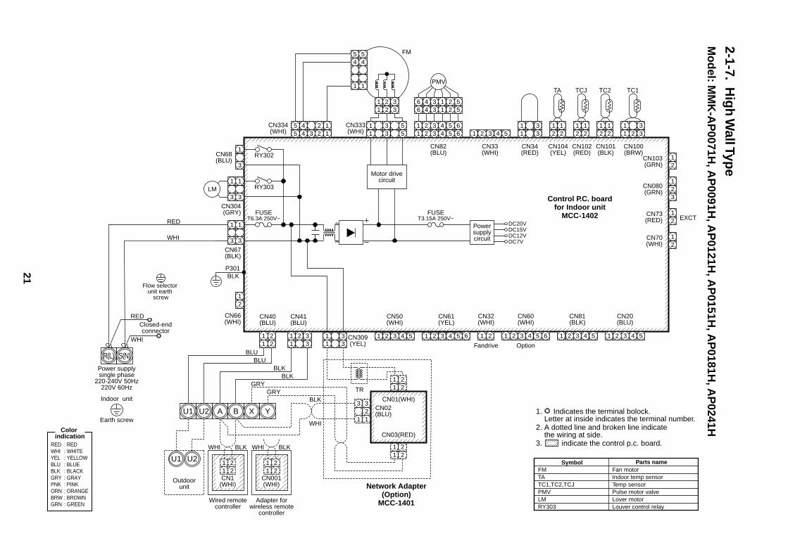
2-1-7.H
igh
Wall Typ
eM
od
el: MM
K-A
P0071H
, AP
0091H, A
P0121H
, AP
0151H, A
P0181H
, AP
0241H
FMTATC1,TC2,TCJPMVLMRY303
Fan motorIndoor temp sensorTemp sensorPulse motor valveLover motorLouver control relay
Symbol Parts name
Color indication
RED : REDWHI : WHITEYEL : YELLOWBLU : BLUEBLK : BLACKGRY : GRAYPNK : PINKORN : ORANGEBRW : BROWNGRN : GREEN
1. Indicates the terminal bolock. Letter at inside indicates the terminal number.2. A dotted line and broken line indicate the wiring at side.3. indicate the control p.c. board.
CN080(GRN)
EXCT
23
1
CN68(BLU)
3
1
CN304(GRY)
3
1
3
1
CN67(BLK)
CN66(WHI)
3
1
21
3
1
CN103(GRN) 2
1
CN73(RED) 2
1
CN70(WHI) 2
1
11
2 31 2 3 4 53
CN100(BRW)
CN101(BLK)
CN34(RED)
CN33(WHI)
1 2 3 4 5
CN20(BLU)
1 2 3 4 5
CN81(BLK)
1 2 3 4 5 6
CN60(WHI)
1 2 3 4 5 6
CN61(YEL)
1 2 31 31 3
1 21 21 2
31 3
4 5
CN50(WHI)
CN41(BLU)
CN40(BLU)
GRY
BLUBLU
BLKBLK
BLK
WHI
GRY
CN309(YEL) Option
1 2
CN32(WHI)
Fandrive
CN82(BLU)
Motor drivecircuit
CN333(WHI)
CN334(WHI)
TC1TC2
CN102(RED)
TCJ
21
21
21
21
21
21
CN104(YEL)
TA
11
33
1 2 3 4 5 61
11 2 3 4 5 6
1 234 561 234 56
22
344
55
1 3 51 3
1 2 31 2 3
5
PMV11
54
54
LM
P301BLK
RY302
FUSET6.3A 250V~
RY303
11
22
11
22
32
1 1
3CN01(WHI)
CN03(RED)
CN02(BLU)
TR
11
22
Network Adapter(Option)
MCC-1401
U1 U2
U1 U2
A B X Y
CN1(WHI)
WHI BLK
Wired remotecontroller
Outdoorunit
11
22
CN001(WHI)
WHI BLK
Adapter forwireless remote
controller
Power supplysingle phase
220-240V 50Hz220V 60Hz
Indoor unit
Earth screw
Closed-endconnector
RED
WHI
R(L) S(N)
FM
FUSET3.15A 250V~
Powersupplycircuit
DC20VDC15VDC12VDC7V
Control P.C. boardfor Indoor unit
MCC-1402
Flow selector unit earth
screw
RED
WHI
22
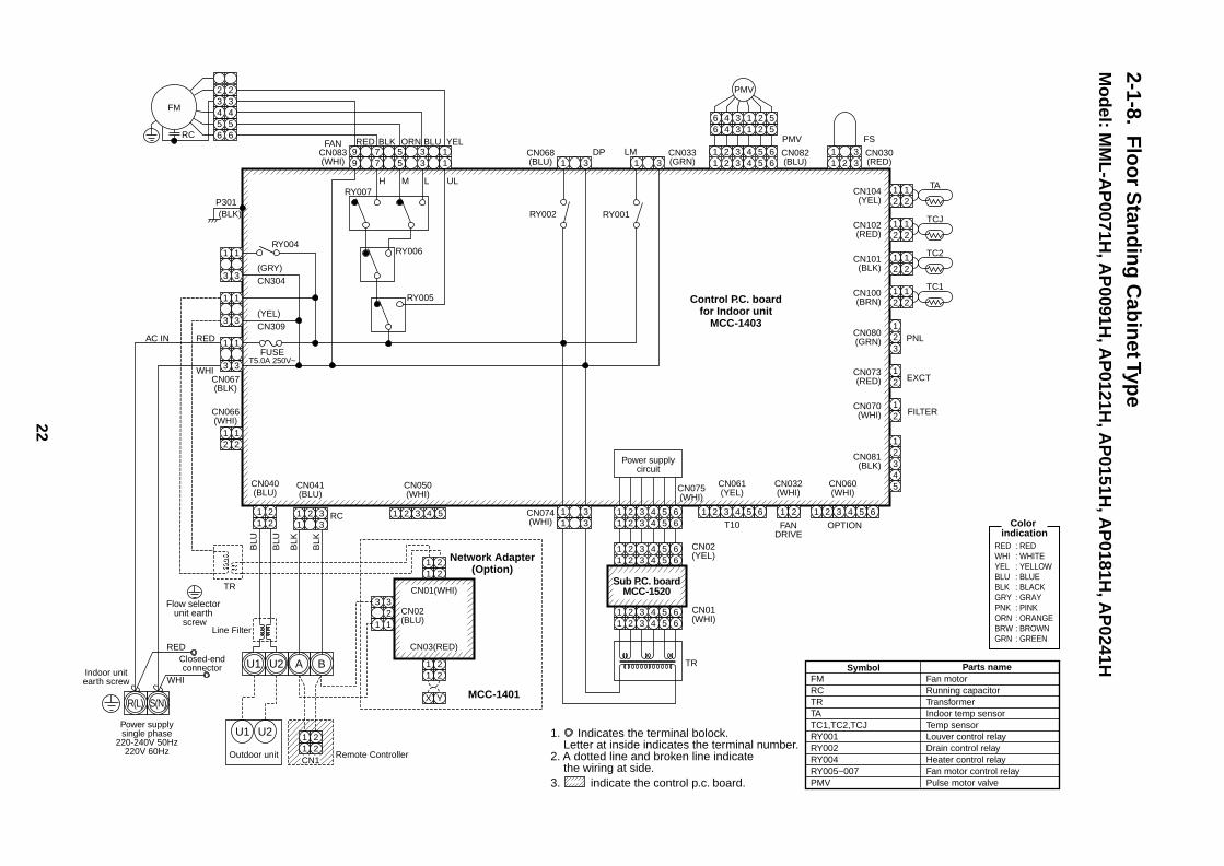
2-1-8.F
loo
r Stan
din
g C
abin
et Type
Mo
del: M
ML
-AP
0071H, A
P0091H
, AP
0121H, A
P0151H
, AP
0181H, A
P0241H
FMRCTRTATC1,TC2,TCJRY001RY002RY004RY005~007PMV
Fan motorRunning capacitorTransformerIndoor temp sensorTemp sensorLouver control relayDrain control relayHeater control relayFan motor control relayPulse motor valve
Symbol Parts name
Color indication
RED : REDWHI : WHITEYEL : YELLOWBLU : BLUEBLK : BLACKGRY : GRAYPNK : PINKORN : ORANGEBRW : BROWNGRN : GREEN
1. Indicates the terminal bolock. Letter at inside indicates the terminal number.2. A dotted line and broken line indicate the wiring at side.3. indicate the control p.c. board.
5 3 177
99 5 3 1
RY007P301(BLK)
RY004
(GRY)CN304
(YEL)CN309
FUSET5.0A 250V~
RY006
RY005
H
RED BLK ORN BLU YEL
M L UL
3
1
3
1
3
1
3
1
3
1
3
1
RC
FM
CN104(YEL)
TA
21
21
CN102(RED)
TCJ
21
21
CN101(BLK)
CN100(BRN)
1
3
CN080(GRN)
TC2
PNL
EXCT
21
CN073(RED) 2
2
1
32
45
1
FILTERCN070(WHI)
CN081(BLK)
21
21
21
11
22
11
22
11
2
X Y
2
32
1 1
3
11 2
33 1 2 3 4 5 1 2 3 4 5 6 1 2 1 23 4 5 6 1 2 3 4 5 6
1 2 3 4 5 6
1 2 3 4 5 61 2 3 4 5 6
1 2 3 4 5 61 2 3 4 5 6
21
TC1
21
21
CN066(WHI)
CN067(BLK)
AC IN RED
WHI
CN040(BLU)
Outdoor unit Remote Controller
Power supplysingle phase
220-240V 50Hz220V 60Hz
Indoor unitearth screw
Closed-endconnector
Line Filter
RED
WHI
CN01(WHI)
CN03(RED)
CN02(BLU)
CN041(BLU)
CN050(WHI)
CN061(YEL)
T10
CN032(WHI)
FANDRIVE
OPTION
CN060(WHI)
BLU
BLU
BLK
BLK
RC
TR
U1
U1 U2
U2 A B
Network Adapter(Option)
Control P.C. boardfor Indoor unit
MCC-1403
MCC-1401
11
22
CN1
11
33CN074
(WHI)
CN075(WHI)
Power supplycircuit
TR
1 3CN068(BLU)
FANCN083(WHI)
RY002
DP1 3
CN033(GRN)
RY001
LM CN082(BLU)
PMV
11
2 33 CN030
(RED)
FS
1 2 3 4 5 61 2 3 4 5 6
1 234 561 234 56
PMV32
32
654
654
R(L) S(N)
CN01(WHI)
CN02(YEL)
Sub P.C. boardMCC-1520
Flow selector unit earth
screw
23
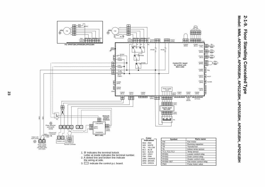
2-1-9.F
loo
r Stan
din
g C
on
cealed Typ
eM
od
el: MM
L-A
P0071B
H, A
P0091B
H, A
P0121B
H, A
P0151B
H, A
P0181B
H, A
P0241B
HGRN
1. Indicates the terminal bolock. Letter at inside indicates the terminal number.2. A dotted line and broken line indicate the wiring at side.3. indicate the control p.c. board.
5 3 177
99 5 3 1
RY007R301(BLK)
RY004
(GRY)CN304
(YEL)CN309
(BLK)CN067
FUSET5.0A 250V~
RY006
RY005
H
RED BLK ORN BLU YEL
M L UL
3
1
3
1
3
1
3
1
3
1
RCWH
I
1
3
1
3
CN104(YEL)
TA
21
21
CN102(RED)
TCJ
21
21
CN101(BLK)
CN100(BRW)
1
3
CN080(GRN)
TC2
PNL
EXCT
21
CN073(RED) 2
2
1
FILTERCN070(WHI)
CN081(BLK)
21
21
11
22
11
22
11
22
2 23
21 1
1 13
11 2
33 1 2 3 4 5 1 2 3 4 5 6 1 2 1 23 4 5 6 1 2 3 4 5 6
1 2 3 4 5 6
1 2 3 4 5 61 2 3 4 5 6
1 2 3 4 5 61 2 3 4 5 6
21
43
5
2
2
1
TC1
AC IN
CN044(BRW)
21 CN066
(WHI)
CN040(BLU)
Outdoor unit
Remote ControllerPower supplysingle phase
220-240V 50Hz220V 60Hz
Indoor unitearth screw
Closed-endconnector
CN01(WHI)
CN03(RED)
CN02(BLU)
CN03(RED)
CN041(BLU)
CN050(WHI)
CN061(YEL)
CN032(WHI)
FANDRIVE
OPTION
CN060(WHI)
EMG
TR
RED
RE
D
WH
I
WHI
U1 U2
U1 U2
A B X Y
Network adapter(Option)
Control P.C. boardfor undoor unit
MCC-1403
MCC-1401
For AP0071BH,AP0091BH,AP0121BH
11
22
CN1
11
33CN074
(WHI)
CN075(WHI)
Power supplycircuit
TR
11
33CN068
(BLU)
FANCN083(WHI)
RY002
11
33
11
2 33CN033
(GRN)
RY001
CN082(BLU)
CN030(RED)
PMV1 2 3 4 5 61 2 3 4 5 6
1 234 561 234 56
PMV
RED
42
42
365
365
R(L) S(N)
FMGRN
5 3 177
99 5 3 1
RED BLK ORN BLU YELFANCN083(WHI)
REDWHI
231
231
654
654
RC
FM
FMRCTRTATC1,TC2,TCJRY001RY002RY004RY005~007PMV
Fan motorRunning capacitorTransformerIndoor temp sensorTemp sensorLouver control relayDrain control relayHeater control releyFan motor control relayPulse motor valve
Symbol Parts nameColor indication
RED : REDWHI : WHITEYEL : YELLOWBLU : BLUEBLK : BLACKGRY : GRAYPNK : PINKORN : ORANGEBRW : BROWNGRN : GREEN
CN01(WHI)
CN02(YEL)
Sub P.C. boardMCC-1520
Flow selector unit earth
screw
24
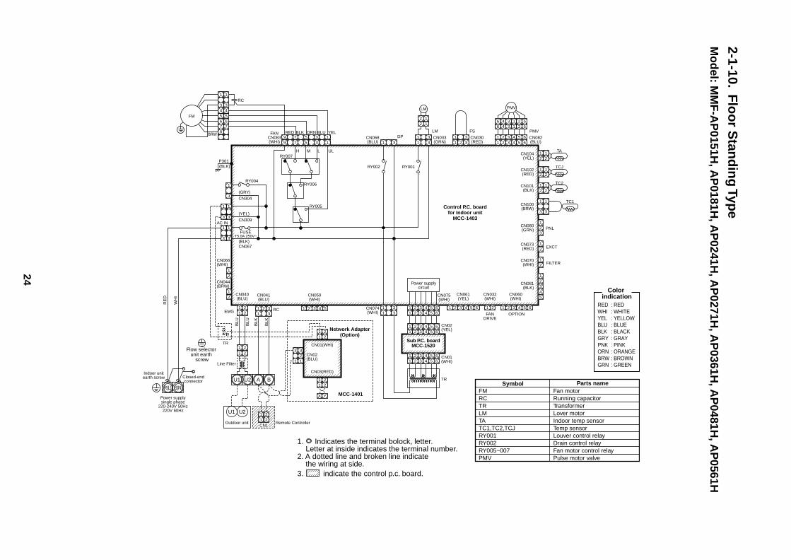
2-1-10.F
loo
r Stan
din
g Typ
eM
od
el: MM
F-A
P0151H
, AP
0181H, A
P0241H
, AP
0271H, A
P0361H
, AP
0481H, A
P0561H
FMRCTRLMTATC1,TC2,TCJRY001RY002RY005~007PMV
Fan motorRunning capacitorTransformerLover motorIndoor temp sensorTemp sensorLouver control relayDrain control relayFan motor control relayPulse motor valve
Symbol Parts name
Color indication
RED : REDWHI : WHITEYEL : YELLOWBLU : BLUEBLK : BLACKGRY : GRAYPNK : PINKORN : ORANGEBRW : BROWNGRN : GREEN
1. Indicates the terminal bolock, letter. Letter at inside indicates the terminal number.2. A dotted line and broken line indicate the wiring at side.3. indicate the control p.c. board.
5 3 177
99 5 3 1
RY007P301(BLK)
RY004
(GRY)CN304
(YEL)CN309
(BLK)CN067
FUSET5.0A 250V~
RY006
RY005
H
RED BLK ORN BLU YEL
M L UL
3
1
3
1
3
1
3
1
3
1
RC
BRW
FM
1
3
1
3
CN104(YEL)
TA
21
21
CN102(RED)
TCJ
21
21
CN101(BLK)
CN100(BRW)
1
3
CN080(GRN)
TC2
PNL
EXCT
21
CN073(RED) 2
2
1
FILTERCN070(WHI)
CN081(BLK)
21
21
21
11
22
11
22
11
22
11
2
X Y
2
32
1 1
3
11 2
33 1 2 3 4 5 1 2 3 4 5 6 1 2 1 23 4 5 6 1 2 3 4 5 6
1 2 3 4 5 6
21
43
5
21
TC1
CN066(WHI)
AC IN
CN044(BRW)
CN040(BLU)
Outdoor unit Remote Controller
Power supplysingle phase
220-240V 50Hz220V 60Hz
Indoor unitearth screw Closed-end
connector
Line Filter
CN01(WHI)
CN03(RED)
CN02(BLU)
CN041(BLU)
CN050(WHI)
CN061(YEL)
CN032(WHI)
FANDRIVE
OPTION
CN060(WHI)
EMG
BLU
BLU
RE
D
WH
I
BLK
BLK
RC
TR
U1
U1 U2
U2 A B
Network Adapter(Option)
Control P.C. boardfor Indoor unit
MCC-1403
MCC-1401
11
22
CN1
11
33CN074
(WHI)
CN075(WHI)
Power supplycircuit
TR
1 3CN068(BLU)
FANCN083(WHI)
RY002
DP11
33 CN033
(GRN)
RY001
LM
CN082(BLU)
PMV
LM
11
2 33 CN030
(RED)
FS
22
11
1 2 3 4 5 61 2 3 4 5 6
1 234 561 234 56
PMV
R(L) S(N)
3
1
3
1
654
654
787
1 2 3 4 5 61 2 3 4 5 6
1 2 3 4 5 61 2 3 4 5 6
CN01(WHI)
CN02(YEL)
Sub P.C. boardMCC-1520
Flow selector unit earth
screw
25
11
22
11
22
33
CN311(BLU)
CN03(WHI)
CN300(WHI)
CN301(WHI)
Except 5HP, 6HP
CN500(WHI)
CN01(BLU)
BLU
BLU
WH
IW
HI
7
5
3
1
7
5
3
1SV41
BLU
BLU
CN312(WHI)3
1
3
1SV2
BLU
BLU
CN324(RED)3
1
3
1SV3A
BLU
BLU
CN313(YEL)3
1
3
1SV3B
BLU
BLU
CN314(BLK)3
1
3
1SV3C
BLU
BLU
BRW
BRW
CN316(WHI)
Heater 1
1
3
1
3
CN315(BLU)
T Heater 2
1
3
1
3
CN310(WHI) 4321
21
SV51 BLUBLU
SV42
BLU
BLURY503CR503
RY502CR502
RY506CR506
RY507CR507
RY508CR508
RY509CR509
RY516CR516
RY517
L3
L1
CR517
RY504CR504
U1 U2 U3 U4 U5 U6
U1 U2 U5 U6
11
22
6 5 4 3 2 16 5 4 3 2 1
RED
BRN
BLU
OR
NYE
LW
HI
PMV1
4 3 24 3 2 1
RED
BLK
WH
I
6 5 4 3 2 16 5 4 3 2 1
RED
BRN
BLU
OR
NYE
LW
HI
PMV2PressureSensor
PS
CN501(RED)
4 3 14 3 2 1
RED
BLK
WH
I
PressureSensor
PD
CN508(RED)
4 3 2 14 3 2 1
OptionBoard
CN509(BLK)
4 3 2 14 3 2 1
OptionBoard
CN510(WHI)
4 3 2 14 3 2 1
OptionBoard
CN512(BLU)
CN306(WHI)
63H1
4 3 2 14 3 2 1
1 31 3
OptionBoard
CN513(BLU)
4 3 2 14
55 3 2 1
OptionBoard
CN308(BLU)
63H2
1 31 3
BLU(BLK)
BLU(BLK)CN502(WHI)
3
1
3
1
TD1(YEL)
TD2(RED)
TS1(GRY)
BLU(BLK)
BLU(BLK)
BLKBLK
3
1
3
1
CN504(WHI)
CN503(PNK)
TK1(BLK)
BLU(BLK)
BLU(BLK)
3
1
3
1
CN514(BLK)
TK2(BLU)
BLU(BLK)
BLU(BLK)
3
1
3
1
CN515(GRN)
TK3(BLU)
BLU(BLK)
BLU(BLK)
3
1
3
1
CN516(RED)
TK4(GRN)
BLU(BLK)
BLU(BLK)
3
1
3
1
CN523(YEL)
BLU
BLU3
1
3
1
CN100(BLK)
3
1
34 4
1
CN511(GRN)
21
21
TE1(BLK)
BLKBLK
CN505(GRN)
21
21
TO(BLK)
BLKBLK
CN507(YEL)
21
21
TL(WHI)
BLKBLK
CN521(WHI)
21
2
2 2
1
Optionboard
3
1
34 4
1
CN600(WHI)
T6.3AFUSE
CN325(YEL)
CN400(WHI)
CN305(RED)
ORN
BLK BLK
ORN
CN307(WHI)
RY521RY511
CN401WHI
RED
PN
KR
ED
BLU
WH
IB
LK
CN402
2 2
5 5
5 3 1 3 2 177 5
443
33
221
3 13 1
4 3 2 12 1
11
T6.3AFUSE
T6.3AFUSE
RED
WH
IBL
KG
RY
CN317(BLU)
CN323(WHI)
44
33
22
11
PNK
PNK
PNK
PNK
L1 L2 L3 N
OR
N
RED
BLUO
RN
BLK(
PNK)
BLK(
PNK)
Comp1
Comp2
1 21 2
4WV1SV3E
SV3D
RY518
CN321(RED)
BR
N
1 21 2
Accumulatorheater
RY510
CR521CR511CR510
CR518
ON
SW30
SW01
SW06
431ON 2
SW14
431ON 2
SW13
1ON
SW08
431ON 2
SW12
431ON 2
SW11
431ON 2
SW07
431ON 2
SW06
431ON 2
SW10
431ON 2
SW09
SW05SW04SW32
SW02 SW03
D603D602D601D600 D604
SW31
SW30
CN800
CN802Flash
654321
654
987
321
(Srvice)
3 13 1
3 13 1
3 2 13 2
5 45 4 1
3 2 13 2
5 45 4 1
3
1 CN18(RED)
CN17(BLK)
CN06(WHI)
CN26(BLU)
CN11CN10CN09
CN25(WHI)
WVU
BLK
PN
KR
ED
BLU
WH
IB
LK
PN
KR
ED
BLU
WH
IB
LK
BLUYEL
WHIREDYELBLU
CN22CN23
CM2 CN03CN02CN01
CN15 CN13
CN07WHI
CN08WHI
TSR
BLKWHIRED
Reactor
3 13 1
3 13 1
3 4 53 4
1 21 2 5
3 4 53 4
1 21 2
33
11
53 41 2 5
3 2 13 2
5 45 4 1
2 23 3
1 1 CN18(RED)
CN17(BLK)
CN06(WHI)CN26
(BLU)
CN500(WHI)
CN503(WHI)
CN504 CN505(RED)
CN506(BLK)CN502(BLU)
GRY
BLU
YEL
RED
CN501(RED)
CN11CN10CN09
CN25(WHI)
YEL
BLU
WVU
CN21
CN01
CN02
CN03
RED
WHI
BLK
GRY CN04CN23(BLU)CN22(WHI)
CN17
CN18
CN19
CN20
BLKWHIREDYELBLU
CN22CN23
CM1 CN03CN02CN01
CN15
BLK
BLU
YE
LY
EL
BLK
BLU
BLK
CN13
CN20WHI
CN21WHI
TSR
BLKWHIRED
Reactor
+ – + –
1 31 3
1 31 3
1
3
5
2
4
6
2
4
6
A1 A2
Mg-SW OCR
REDRED
REDREDREDWHIBLK
BLK
BLKGRYGRYGRY
PTC Themistor
54321
54321
3
1
3
1
5
3
1
5
3
1
3
1
3
1
54321
54321
CN01(WHI)
RE
D
WH
I
BLK
W V U
FM
–
+
+ –
YE
L
PN
K
PN
K
RE
D
RE
D
BLU
BLU
WH
IBLK W
HI
BLK
BLU
Indoorunit
Outdoorunit
Central remotecontroller
Transformer
RED
WHI
BLK
GRY
L1
L2
L3
N
Power Supply 3phase
380-415V 50Hz380 60Hz
RED : REDWHI : WHITEYEL : YELLOWBLU : BLUEBLK : BLACKGRY : GRAYPNK : PINKORN : ORANGEBRN : BRWNVLT : VIOLET
1. The two-dot chain line indicates wiring at the local site, and the dashed line indicates accessories sold separately and service cables, respectively.
2. , , and indicate the terminal blocks and the numerals indicate the terminal numbers.3. indicates P.C. board.
* Be sure to fix the electric parts cover surely with two screws.(Otherwise water enters into the box resulting in a trouble.)
CM1, CM2PMV1, PMV2SV2, SV41, SV42, SV51, SV3A, SV3B, SV3C, SV3D, SV3E4WV1COMP1, COMP2TS1TD1, TD2TE1TOTK1, TK2, TK3, TK4TLHEATER1, HEATER2, ACCU MEATERFMPSPD63H1, 63H2MG-SWOCR
CompressorPulse motor valve2-way valve coil4-way valve coilCompressor case thermo.Pipe temp. sensor (Inlet)Pipe temp. sensor (Outlet)Heat exchange temp. sensorAir temp. sensorOil temp. sensorLiquid temp. sensorCase heater, 230V, 26WFan motor (DC)Low pressure sensorHigh pressure sensorHigh pressure switchMagnet switchOvercurrent relay
Noise filterP.C. boardMCC-1366
Fan IPDUMCC-896 Interface
controlP.C. board
(I/F)MCC-1429
Power supplyterminal
Comp. IPDUNo.1
MCC-1502
MG-SW
OCR
Comp. IPDUNo.2
MCC-1502
Power supplyfor fan
MCC-1439
U1 U2 U3 U4 U5 U6
L1 L2 L3 N
Connecting terminal
Interface Control P.C. BoardMCC-1429
IPDU Board (2)MCC-1502
Noise filter P.C. boardMCC-1366
IPDU P.C. Board (1)MCC-1502
FAN IPDUP.C. Board
MCC-896, 897
Power supplyP.C. board for FAN
MCC-1439
Color indication
Symbol Parts name
Parts layoutEarth screw
U3 U4U1 U2
BLKWHIBLU
BLU
REDPNK
YEL
2-2.O
utd
oo
r Un
itM
od
el: MM
Y-M
AP
1401H, M
AP
1601H, M
AP
2241H, M
AP
2801H, M
AP
3351H
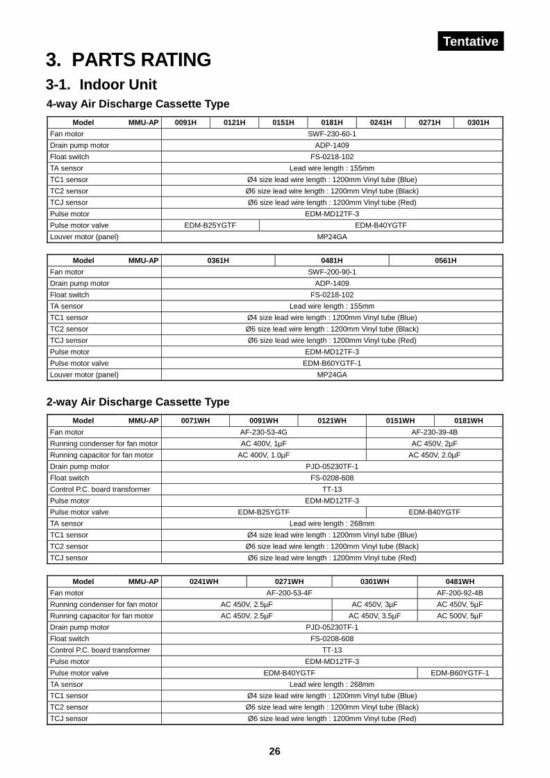
26
3. PARTS RATING3-1. Indoor Unit4-way Air Discharge Cassette Type
Model MMU-AP 0091H 0121H 0151H 0181H 0241H 0271H 0301H
Fan motor SWF-230-60-1
Drain pump motor ADP-1409
Float switch FS-0218-102
TA sensor Lead wire length : 155mm
TC1 sensor Ø4 size lead wire length : 1200mm Vinyl tube (Blue)
TC2 sensor Ø6 size lead wire length : 1200mm Vinyl tube (Black)
TCJ sensor Ø6 size lead wire length : 1200mm Vinyl tube (Red)
Pulse motor EDM-MD12TF-3
Pulse motor valve EDM-B25YGTF EDM-B40YGTF
Louver motor (panel) MP24GA
Model MMU-AP 0361H 0481H 0561H
Fan motor SWF-200-90-1
Drain pump motor ADP-1409
Float switch FS-0218-102
TA sensor Lead wire length : 155mm
TC1 sensor Ø4 size lead wire length : 1200mm Vinyl tube (Blue)
TC2 sensor Ø6 size lead wire length : 1200mm Vinyl tube (Black)
TCJ sensor Ø6 size lead wire length : 1200mm Vinyl tube (Red)
Pulse motor EDM-MD12TF-3
Pulse motor valve EDM-B60YGTF-1
Louver motor (panel) MP24GA
2-way Air Discharge Cassette Type
Model MMU-AP 0071WH 0091WH 0121WH 0151WH 0181WH
Fan motor AF-230-53-4G AF-230-39-4B
Running condenser for fan motor AC 400V, 1µF AC 450V, 2µF
Running capacitor for fan motor AC 400V, 1.0µF AC 450V, 2.0µF
Drain pump motor PJD-05230TF-1
Float switch FS-0208-608
Control P.C. board transformer TT-13
Pulse motor EDM-MD12TF-3
Pulse motor valve EDM-B25YGTF EDM-B40YGTF
TA sensor Lead wire length : 268mm
TC1 sensor Ø4 size lead wire length : 1200mm Vinyl tube (Blue)
TC2 sensor Ø6 size lead wire length : 1200mm Vinyl tube (Black)
TCJ sensor Ø6 size lead wire length : 1200mm Vinyl tube (Red)
Model MMU-AP 0241WH 0271WH 0301WH 0481WH
Fan motor AF-200-53-4F AF-200-92-4B
Running condenser for fan motor AC 450V, 2.5µF AC 450V, 3µF AC 450V, 5µF
Running capacitor for fan motor AC 450V, 2.5µF AC 450V, 3.5µF AC 500V, 5µF
Drain pump motor PJD-05230TF-1
Float switch FS-0208-608
Control P.C. board transformer TT-13
Pulse motor EDM-MD12TF-3
Pulse motor valve EDM-B40YGTF EDM-B60YGTF-1
TA sensor Lead wire length : 268mm
TC1 sensor Ø4 size lead wire length : 1200mm Vinyl tube (Blue)
TC2 sensor Ø6 size lead wire length : 1200mm Vinyl tube (Black)
TCJ sensor Ø6 size lead wire length : 1200mm Vinyl tube (Red)
Tentative
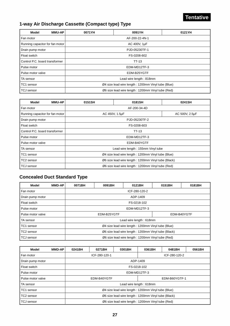
27
1-way Air Discharge Cassette (Compact type) Type
Model MMU-AP 0071YH 0091YH 0121YH
Fan motor AF-200-22-4N-1
Running capacitor for fan motor AC 400V, 1µF
Drain pump motor PJD-05230TF-1
Float switch FS-0208-602
Control P.C. board transformer TT-13
Pulse motor EDM-MD12TF-3
Pulse motor valve EDM-B25YGTF
TA sensor Lead wire length : 818mm
TC1 sensor Ø4 size lead wire length : 1200mm Vinyl tube (Blue)
TCJ sensor Ø6 size lead wire length : 1200mm Vinyl tube (Red)
Model MMU-AP 0151SH 0181SH 0241SH
Fan motor AF-200-34-4D
Running capacitor for fan motor AC 450V, 1.5µF AC 500V, 2.5µF
Drain pump motor PJD-05230TF-2
Float switch FS-0208-603
Control P.C. board transformer TT-13
Pulse motor EDM-MD12TF-3
Pulse motor valve EDM-B40YGTF
TA sensor Lead wire length : 155mm Vinyl tube
TC1 sensor Ø4 size lead wire length : 1200mm Vinyl tube (Blue)
TC2 sensor Ø6 size lead wire length : 1200mm Vinyl tube (Black)
TCJ sensor Ø6 size lead wire length : 1200mm Vinyl tube (Red)
Concealed Duct Standard Type
Model MMD-AP 0071BH 0091BH 0121BH 0151BH 0181BH
Fan motor ICF-280-120-2
Drain pump motor ADP-1409
Float switch FS-0218-102
Pulse motor EDM-MD12TF-3
Pulse motor valve EDM-B25YGTF EDM-B40YGTF
TA sensor Lead wire length : 618mm
TC1 sensor Ø4 size lead wire length : 1200mm Vinyl tube (Blue)
TC2 sensor Ø6 size lead wire length : 1200mm Vinyl tube (Black)
TCJ sensor Ø6 size lead wire length : 1200mm Vinyl tube (Red)
Model MMD-AP 0241BH 0271BH 0301BH 0361BH 0481BH 0561BH
Fan motor ICF-280-120-1 ICF-280-120-2
Drain pump motor ADP-1409
Float switch FS-0218-102
Pulse motor EDM-MD12TF-3
Pulse motor valve EDM-B40YGTF EDM-B60YGTF-1
TA sensor Lead wire length : 618mm
TC1 sensor Ø4 size lead wire length : 1200mm Vinyl tube (Blue)
TC2 sensor Ø6 size lead wire length : 1200mm Vinyl tube (Black)
TCJ sensor Ø6 size lead wire length : 1200mm Vinyl tube (Red)
Tentative
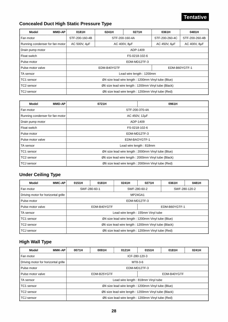
28
TentativeConcealed Duct High Static Pressure Type
Model MMD-AP 0181H 0241H 0271H 0361H 0481H
Fan motor STF-200-160-4B STF-200-160-4A STF-200-260-4C STF-200-260-4B
Running condenser for fan motor AC 500V, 4µF AC 400V, 8µF AC 450V, 6µF AC 400V, 8µF
Drain pump motor ADP-1409
Float switch FS-0218-102-6
Pulse motor EDM-MD12TF-3
Pulse motor valve EDM-B40YGTF EDM-B60YGTF-1
TA sensor Lead wire length : 1200mm
TC1 sensor Ø4 size lead wire length : 1200mm Vinyl tube (Blue)
TC2 sensor Ø6 size lead wire length : 1200mm Vinyl tube (Black)
TCJ sensor Ø6 size lead wire length : 1200mm Vinyl tube (Red)
Model MMD-AP 0721H 0961H
Fan motor STF-200-370-4A
Running condenser for fan motor AC 450V, 12µF
Drain pump motor ADP-1409
Float switch FS-0218-102-6
Pulse motor EDM-MD12TF-3
Pulse motor valve EDM-BAOYGTF-1
TA sensor Lead wire length : 818mm
TC1 sensor Ø4 size lead wire length : 2000mm Vinyl tube (Blue)
TC2 sensor Ø6 size lead wire length : 2000mm Vinyl tube (Black)
TCJ sensor Ø6 size lead wire length : 2000mm Vinyl tube (Red)
Under Ceiling Type
Model MMC-AP 0151H 0181H 0241H 0271H 0361H 0481H
Fan motor SWF-280-60-1 SWF-280-60-2 SWF-280-120-2
Driving motor for horizontal grille MP24GA1
Pulse motor EDM-MD12TF-3
Pulse motor valve EDM-B40YGTF EDM-B60YGTF-1
TA sensor Lead wire length : 155mm Vinyl tube
TC1 sensor Ø4 size lead wire length : 1200mm Vinyl tube (Blue)
TC2 sensor Ø6 size lead wire length : 1200mm Vinyl tube (Black)
TCJ sensor Ø6 size lead wire length : 1200mm Vinyl tube (Red)
High Wall Type
Model MMK-AP 0071H 0091H 0121H 0151H 0181H 0241H
Fan motor ICF-280-120-3
Driving motor for horizontal grille MT8-3-6
Pulse motor EDM-MD12TF-3
Pulse motor valve EDM-B25YGTF EDM-B40YGTF
TA sensor Lead wire length : 818mm Vinyl tube
TC1 sensor Ø4 size lead wire length : 1200mm Vinyl tube (Blue)
TC2 sensor Ø6 size lead wire length : 1200mm Vinyl tube (Black)
TCJ sensor Ø6 size lead wire length : 1200mm Vinyl tube (Red)
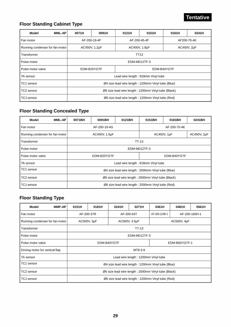
29
TentativeFloor Standing Cabinet Type
Model MML-AP 0071H 0091H 0121H 0151H 0181H 0241H
Fan motor AF-200-19-4F AF-200-45-4F AF200-70-4K
Running condenser for fan motor AC450V, 1.2µF AC400V, 1.8µF AC450V, 2µF
Transformer TT13
Pulse motor EDM-MD12TF-3
Pulse motor valve EDM-B25YGTF EDM-B40YGTF
TA sensor Lead wire length : 818mm Vinyl tube
TC1 sensor Ø4 size lead wire length : 1200mm Vinyl tube (Blue)
TC2 sensor Ø6 size lead wire length : 1200mm Vinyl tube (Black)
TCJ sensor Ø6 size lead wire length : 1200mm Vinyl tube (Red)
Floor Standing Concealed Type
Model MML-AP 0071BH 0091BH 0121BH 0151BH 0181BH 0241BH
Fan motor AF-200-19-4G AF-200-70-4K
Running condenser for fan motor AC450V, 1.5µF AC450V, 1µF AC450V, 2µF
Transformer TT-13
Pulse motor EDM-MD12TF-3
Pulse motor valve EDM-B25YGTF EDM-B40YGTF
TA sensor Lead wire length : 818mm Vinyl tube
TC1 sensor Ø4 size lead wire length : 2000mm Vinyl tube (Blue)
TC2 sensor Ø6 size lead wire length : 2000mm Vinyl tube (Black)
TCJ sensor Ø6 size lead wire length : 2000mm Vinyl tube (Red)
Floor Standing Type
Model MMF-AP 0151H 0181H 0241H 0271H 0361H 0481H 0561H
Fan motor AF-200-37R AF-200-63T AF-200-110M-1 AF-200-160H-1
Running condenser for fan motor AC500V, 3µF AC500V, 3.5µF AC500V, 4µF
Transformer TT-13
Pulse motor EDM-MD12TF-3
Pulse motor valve EDM-B40YGTF EDM-B60YGTF-1
Driving motor for vertical flap MT8-3-9
TA sensor Lead wire length : 1200mm Vinyl tube
TC1 sensor Ø4 size lead wire length : 1200mm Vinyl tube (Blue)
TC2 sensor Ø6 size lead wire length : 2000mm Vinyl tube (Black)
TCJ sensor Ø6 size lead wire length : 1200mm Vinyl tube (Red)
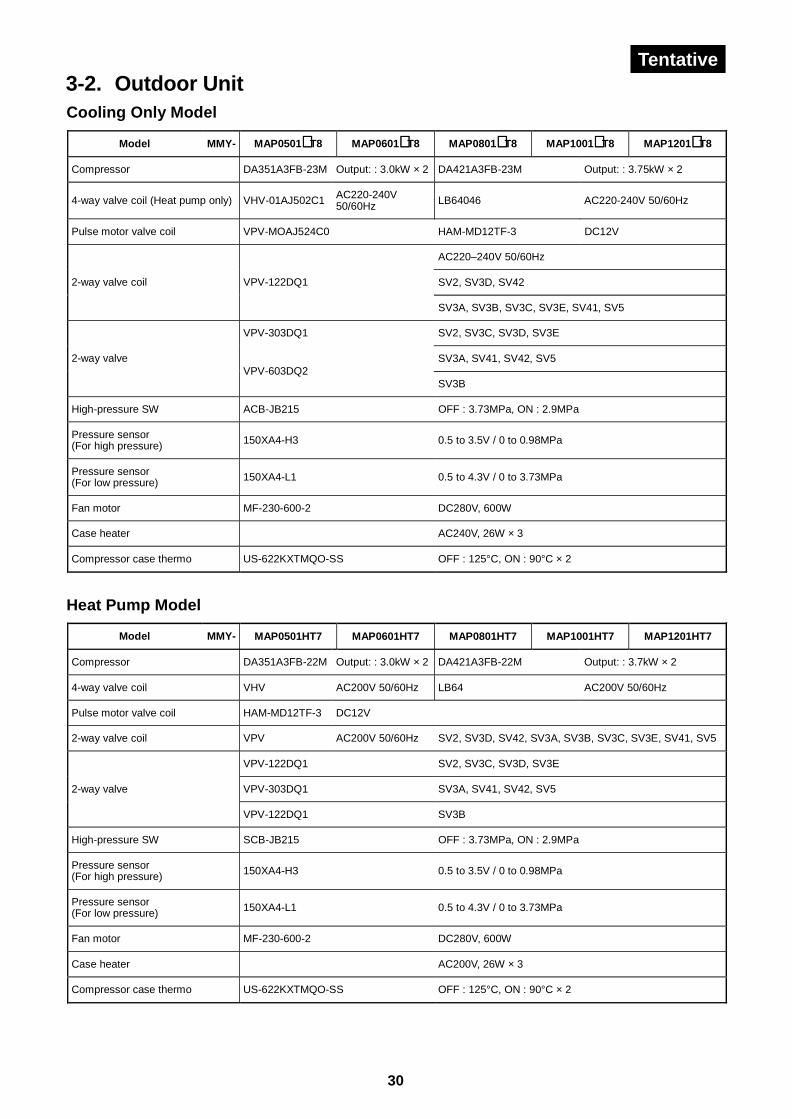
30
Tentative3-2. Outdoor UnitCooling Only Model
Model MMY- MAP0501∗ T8 MAP0601∗ T8 MAP0801∗ T8 MAP1001∗ T8 MAP1201∗ T8
Compressor DA351A3FB-23M Output: : 3.0kW × 2 DA421A3FB-23M Output: : 3.75kW × 2
4-way valve coil (Heat pump only) VHV-01AJ502C1 AC220-240V50/60Hz LB64046 AC220-240V 50/60Hz
Pulse motor valve coil VPV-MOAJ524C0 HAM-MD12TF-3 DC12V
AC220–240V 50/60Hz
SV2, SV3D, SV422-way valve coil VPV-122DQ1
SV3A, SV3B, SV3C, SV3E, SV41, SV5
VPV-303DQ1 SV2, SV3C, SV3D, SV3E
SV3A, SV41, SV42, SV52-way valveVPV-603DQ2
SV3B
High-pressure SW ACB-JB215 OFF : 3.73MPa, ON : 2.9MPa
Pressure sensor(For high pressure) 150XA4-H3 0.5 to 3.5V / 0 to 0.98MPa
Pressure sensor(For low pressure) 150XA4-L1 0.5 to 4.3V / 0 to 3.73MPa
Fan motor MF-230-600-2 DC280V, 600W
Case heater AC240V, 26W × 3
Compressor case thermo US-622KXTMQO-SS OFF : 125°C, ON : 90°C × 2
Heat Pump Model
Model MMY- MAP0501HT7 MAP0601HT7 MAP0801HT7 MAP1001HT7 MAP1201HT7
Compressor DA351A3FB-22M Output: : 3.0kW × 2 DA421A3FB-22M Output: : 3.7kW × 2
4-way valve coil VHV AC200V 50/60Hz LB64 AC200V 50/60Hz
Pulse motor valve coil HAM-MD12TF-3 DC12V
2-way valve coil VPV AC200V 50/60Hz SV2, SV3D, SV42, SV3A, SV3B, SV3C, SV3E, SV41, SV5
VPV-122DQ1 SV2, SV3C, SV3D, SV3E
VPV-303DQ1 SV3A, SV41, SV42, SV52-way valve
VPV-122DQ1 SV3B
High-pressure SW SCB-JB215 OFF : 3.73MPa, ON : 2.9MPa
Pressure sensor(For high pressure) 150XA4-H3 0.5 to 3.5V / 0 to 0.98MPa
Pressure sensor(For low pressure) 150XA4-L1 0.5 to 4.3V / 0 to 3.73MPa
Fan motor MF-230-600-2 DC280V, 600W
Case heater AC200V, 26W × 3
Compressor case thermo US-622KXTMQO-SS OFF : 125°C, ON : 90°C × 2
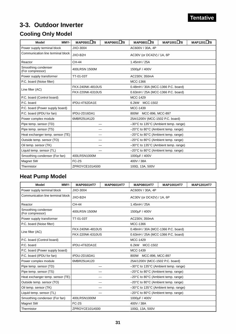
31
Tentative3-3. Outdoor InverterCooling Only Model
Model MMY- MAP0501∗ T8 MAP0601∗ T8 MAP0801∗ T8 MAP1001∗ T8 MAP1201∗ T8
Power supply terminal block JXO-3004 AC600V / 30A, 4P
Communication line terminal block JXO-B2H AC30V (or DC42V) / 1A, 6P
Reactor CH-44 1.45mH / 25A
Smoothing condenser(For compressor) 400LRSN 1500M 1500µF / 400V
Power supply transformer TT-01-03T AC230V, 350mA
P.C. board (Noise filter) MCC-1366
FKX-240NK-4810US 0.48mH / 30A (MCC-1366 P.C. board)Line filter (AC)
FKX-220NK-6310US 0.63mH / 25A (MCC-1366 P.C. board)
P.C. board (Control board) MCC-1429
P.C. board IPDU-4T62DA1E 6.2kW MCC-1502
P.C. board (Power supply board) MCC-1439
P.C. board (IPDU for fan) IPDU-2D16DA1 800W MCC-896, MCC-897
Power complex module 6MBR25UA120 25A/1200V (MCC-1502 P.C. board)
Pipe temp. sensor (TD) — –30°C to 135°C (Ambient temp. range)
Pipe temp. sensor (TS) — –20°C to 80°C (Ambient temp. range)
Heat exchanger temp. sensor (TE) — –20°C to 80°C (Ambient temp. range)
Outside temp. sensor (TO) — –20°C to 80°C (Ambient temp. range)
Oil temp. sensor (TK) — –30°C to 135°C (Ambient temp. range)
Liquid temp. sensor (TL) — –20°C to 80°C (Ambient temp. range)
Smoothing condenser (For fan) 400LRSN1000M 1000µF / 400V
Magnet SW FC-2S 400V / 38A
Thermistor ZPROYCE101A500 100Ω, 13A, 500V
Heat Pump ModelModel MMY- MAP0501HT7 MAP0601HT7 MAP0801HT7 MAP1001HT7 MAP1201HT7
Power supply terminal block JXO-3004 AC600V / 30A, 4P
Communication line terminal block JXO-B2H AC30V (or DC42V) / 1A, 6P
Reactor CH-44 1.45mH / 25A
Smoothing condenser(For compressor) 400LRSN 1500M 1500µF / 400V
Power supply transformer TT-01-03T AC230V, 350mA
P.C. board (Noise filter) MCC-1366
FKX-240NK-4810US 0.48mH / 30A (MCC-1366 P.C. board)Line filter (AC)
FKX-220NK-6310US 0.63mH / 25A (MCC-1366 P.C. board)
P.C. board (Control board) MCC-1429
P.C. board IPDU-4T62DA1E 6.2kW MCC-1502
P.C. board (Power supply board) MCC-1439
P.C. board (IPDU for fan) IPDU-2D16DA1 800W MCC-896, MCC-897
Power complex module 6MBR25UA120 25A/1200V (MCC-1502 P.C. board)
Pipe temp. sensor (TD) — –30°C to 135°C (Ambient temp. range)
Pipe temp. sensor (TS) — –20°C to 80°C (Ambient temp. range)
Heat exchanger temp. sensor (TE) — –20°C to 80°C (Ambient temp. range)
Outside temp. sensor (TO) — –20°C to 80°C (Ambient temp. range)
Oil temp. sensor (TK) — –30°C to 135°C (Ambient temp. range)
Liquid temp. sensor (TL) — –20°C to 80°C (Ambient temp. range)
Smoothing condenser (For fan) 400LRSN1000M 1000µF / 400V
Magnet SW FC-2S 400V / 38A
Thermistor ZPROYCE101A500 100Ω, 13A, 500V
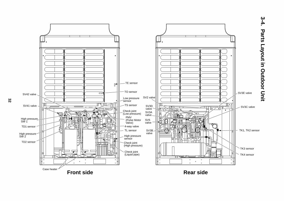
32
3-4.P
arts Layo
ut in
Ou
tdo
or U
nit
SV42 valve
SV41 valve
High pressureSW 1
High pressureSW 2
TD1 sensor
TD2 sensor
Case heater
TE sensor
PMV(Pulse MotorValve)
TS sensor
TO sensor
Check joint(Low pressure)
SV2 valve
SV3C valve
SV3E valve
SV3DvalveSV3Avalve
SV3Bvalve
SV5valve
Low pressuresensor
4-way valve
High pressuresensor
Check joint(High pressure)
TL sensor
Check joint(Liquid pipe)
Front side Rear side
TK1, TK2 sensor
TK3 sensor
TK4 sensor
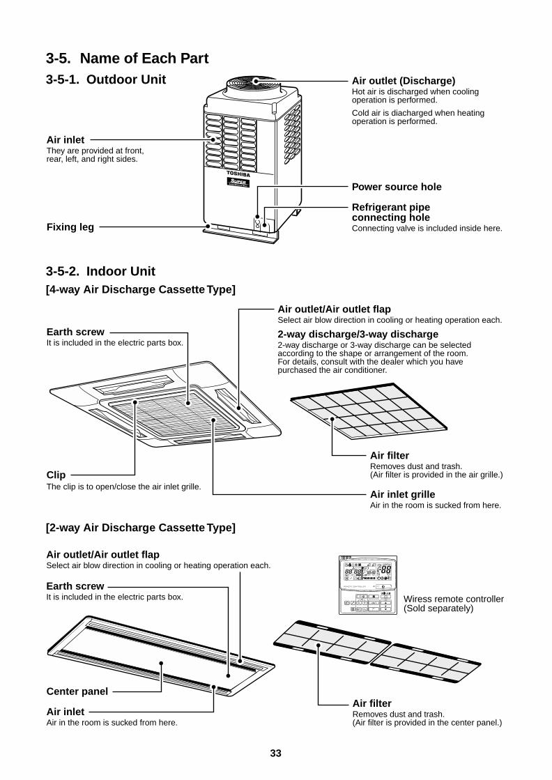
33
3-5. Name of Each Part3-5-1. Outdoor Unit
3-5-2. Indoor Unit[4-way Air Discharge Cassette Type]
[2-way Air Discharge Cassette Type]
Air inletThey are provided at front, rear, left, and right sides.
Fixing leg
Air outlet (Discharge)Hot air is discharged when cooling operation is performed.
Cold air is diacharged when heating operation is performed.
Power source hole
Refrigerant pipe connecting holeConnecting valve is included inside here.
Air outlet/Air outlet flapSelect air blow direction in cooling or heating operation each.
2-way discharge/3-way discharge2-way discharge or 3-way discharge can be selected according to the shape or arrangement of the room. For details, consult with the dealer which you have purchased the air conditioner.
Air filterRemoves dust and trash.(Air filter is provided in the air grille.)
Air inlet grilleAir in the room is sucked from here.
Earth screwIt is included in the electric parts box.
ClipThe clip is to open/close the air inlet grille.
Center panel
Air inletAir in the room is sucked from here.
Air filterRemoves dust and trash.(Air filter is provided in the center panel.)
Earth screwIt is included in the electric parts box.
Air outlet/Air outlet flapSelect air blow direction in cooling or heating operation each.
Wiress remote controller(Sold separately)
UNIT
SET CL
SETTING
UNIT No.
CODE No.
TEST
SET DATA
R.C. No.
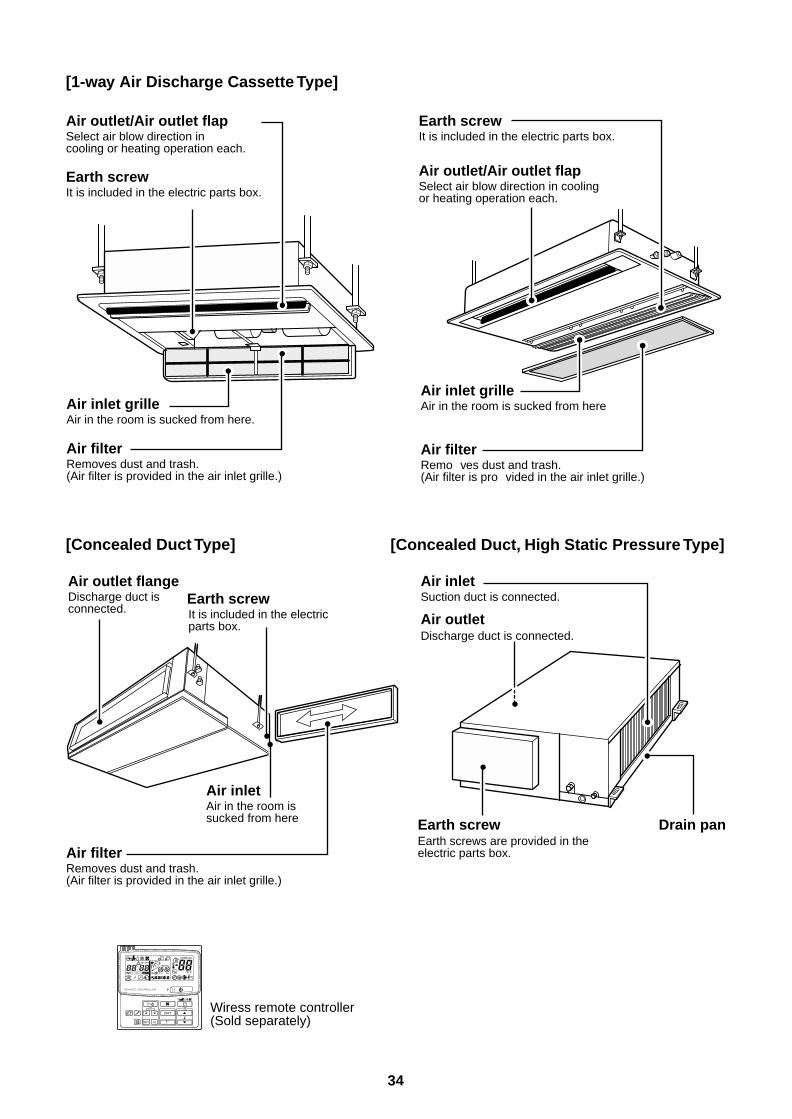
34
[1-way Air Discharge Cassette Type]
Air outlet/Air outlet flapSelect air blow direction incooling or heating operation each.
Earth screwIt is included in the electric parts box.
Air inlet grilleAir in the room is sucked from here.
Air filterRemoves dust and trash.(Air filter is provided in the air inlet grille.)
Air inletSuction duct is connected.
Air outletDischarge duct is connected.
Earth screw Drain panEarth screws are provided in theelectric parts box.
Earth screwIt is included in the electric parts box.
Air outlet/Air outlet flapSelect air blow direction in coolingor heating operation each.
Air inlet grilleAir in the room is sucked from here
Air filterRemo ves dust and trash.(Air filter is pro vided in the air inlet grille.)
Air outlet flangeDischarge duct is connected.
Earth screwIt is included in the electric parts box.
Air filterRemoves dust and trash.(Air filter is provided in the air inlet grille.)
Air inletAir in the room is sucked from here
Wiress remote controller(Sold separately)
UNIT
SET CL
SETTING
UNIT No.
CODE No.
TEST
SET DATA
R.C. No.
[Concealed Duct Type] [Concealed Duct, High Static Pressure Type]
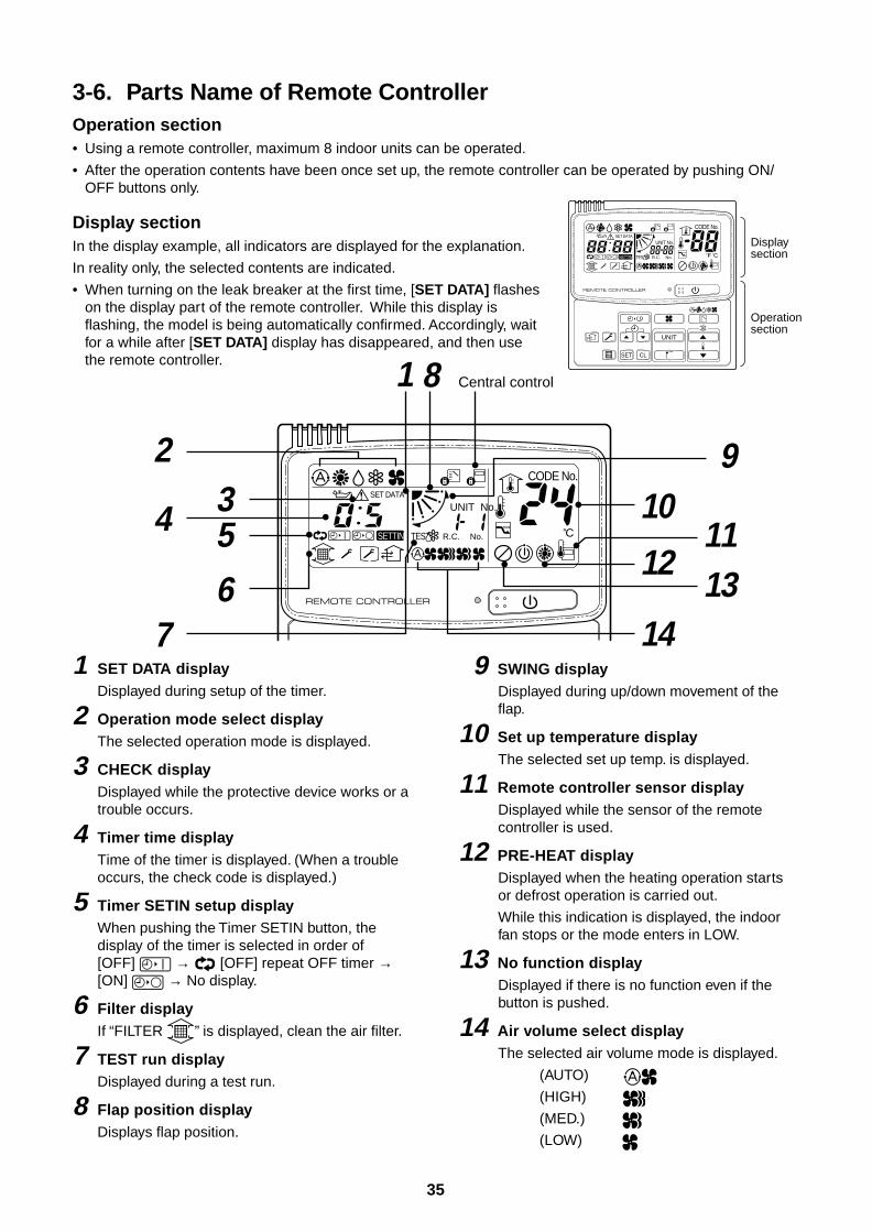
35
3-6. Parts Name of Remote ControllerOperation section• Using a remote controller, maximum 8 indoor units can be operated.
• After the operation contents have been once set up, the remote controller can be operated by pushing ON/OFF buttons only.
1 SET DATA displayDisplayed during setup of the timer.
2 Operation mode select displayThe selected operation mode is displayed.
3 CHECK displayDisplayed while the protective device works or atrouble occurs.
4 Timer time displayTime of the timer is displayed. (When a troubleoccurs, the check code is displayed.)
5 Timer SETIN setup displayWhen pushing the Timer SETIN button, thedisplay of the timer is selected in order of[OFF] → [OFF] repeat OFF timer →[ON] → No display.
6 Filter displayIf “FILTER ” is displayed, clean the air filter.
7 TEST run displayDisplayed during a test run.
8 Flap position displayDisplays flap position.
9 SWING displayDisplayed during up/down movement of theflap.
10 Set up temperature displayThe selected set up temp. is displayed.
11 Remote controller sensor displayDisplayed while the sensor of the remotecontroller is used.
12 PRE-HEAT displayDisplayed when the heating operation startsor defrost operation is carried out.
While this indication is displayed, the indoorfan stops or the mode enters in LOW.
13 No function displayDisplayed if there is no function even if thebutton is pushed.
14 Air volume select displayThe selected air volume mode is displayed.
(AUTO)
(HIGH)
(MED.)
(LOW)
Display section
Operation section
UNIT
SET CL
SETTING
UNIT No.
CODE No.
TEST
SET DATA
R.C. No.
SETTING
UNIT No.
CODE No.
TEST
SET DATA
R.C. No.
1
2
8 Central control
9 10
11 12
13 14
5
67
34
Display sectionIn the display example, all indicators are displayed for the explanation.
In reality only, the selected contents are indicated.
• When turning on the leak breaker at the first time, [SET DATA] flasheson the display part of the remote controller. While this display isflashing, the model is being automatically confirmed. Accordingly, waitfor a while after [SET DATA] display has disappeared, and then usethe remote controller.
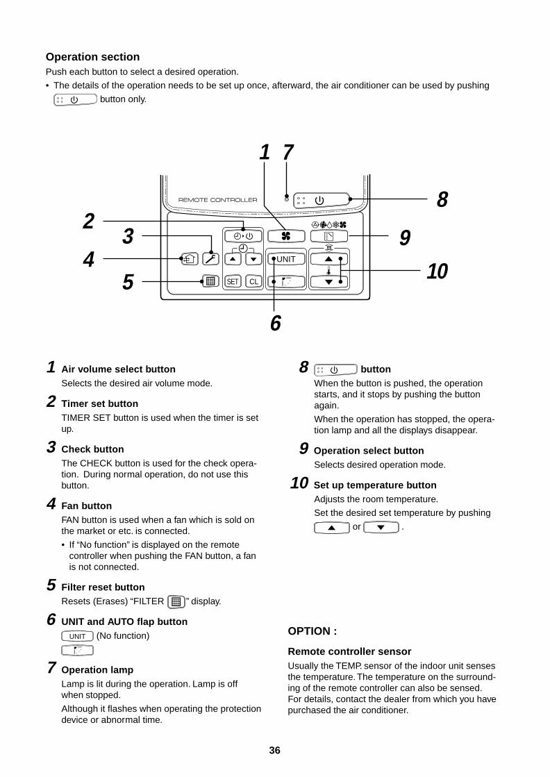
36
Operation sectionPush each button to select a desired operation.
• The details of the operation needs to be set up once, afterward, the air conditioner can be used by pushing
button only.
1 Air volume select buttonSelects the desired air volume mode.
2 Timer set buttonTIMER SET button is used when the timer is setup.
3 Check buttonThe CHECK button is used for the check opera-tion. During normal operation, do not use thisbutton.
4 Fan buttonFAN button is used when a fan which is sold onthe market or etc. is connected.
• If “No function” is displayed on the remotecontroller when pushing the FAN button, a fanis not connected.
5 Filter reset buttonResets (Erases) “FILTER ” display.
6 UNIT and AUTO flap buttonUNIT (No function)
7 Operation lampLamp is lit during the operation. Lamp is offwhen stopped.
Although it flashes when operating the protectiondevice or abnormal time.
8 buttonWhen the button is pushed, the operationstarts, and it stops by pushing the buttonagain.
When the operation has stopped, the opera-tion lamp and all the displays disappear.
9 Operation select buttonSelects desired operation mode.
10 Set up temperature buttonAdjusts the room temperature.
Set the desired set temperature by pushing
or .
OPTION :
Remote controller sensorUsually the TEMP. sensor of the indoor unit sensesthe temperature. The temperature on the surround-ing of the remote controller can also be sensed.For details, contact the dealer from which you havepurchased the air conditioner.
UNIT
SET CL
1
2
10 9
7
8
34
5
6
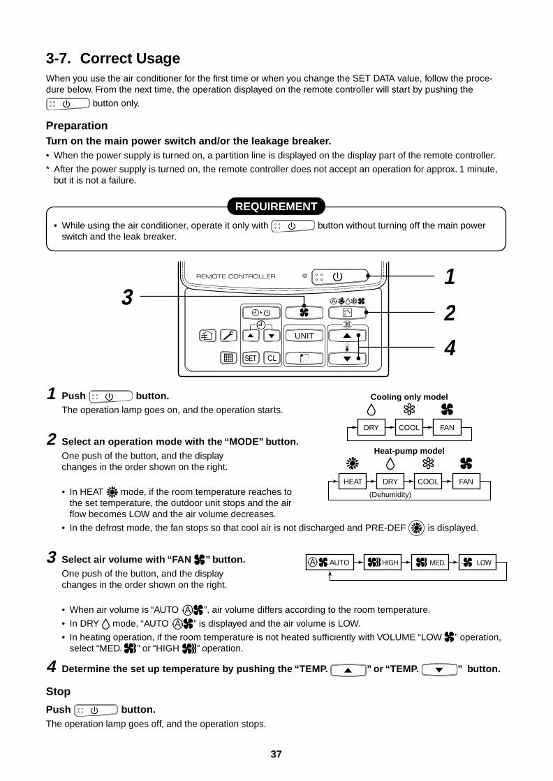
37
3-7. Correct UsageWhen you use the air conditioner for the first time or when you change the SET DATA value, follow the proce-dure below. From the next time, the operation displayed on the remote controller will start by pushing the
button only.
PreparationTurn on the main power switch and/or the leakage breaker.• When the power supply is turned on, a partition line is displayed on the display part of the remote controller.
* After the power supply is turned on, the remote controller does not accept an operation for approx. 1 minute,but it is not a failure.
REQUIREMENT
• While using the air conditioner, operate it only with button without turning off the main powerswitch and the leak breaker.
1 Push button.The operation lamp goes on, and the operation starts.
2 Select an operation mode with the “MODE” button.One push of the button, and the displaychanges in the order shown on the right.
• In HEAT mode, if the room temperature reaches tothe set temperature, the outdoor unit stops and the airflow becomes LOW and the air volume decreases.
• In the defrost mode, the fan stops so that cool air is not discharged and PRE-DEF is displayed.
3 Select air volume with “FAN ” button.One push of the button, and the displaychanges in the order shown on the right.
• When air volume is “AUTO ”, air volume differs according to the room temperature.
• In DRY mode, “AUTO ” is displayed and the air volume is LOW.
• In heating operation, if the room temperature is not heated sufficiently with VOLUME “LOW ” operation,select “MED. ” or “HIGH ” operation.
4 Determine the set up temperature by pushing the “TEMP. ” or “TEMP. ” button.
Stop
Push button.The operation lamp goes off, and the operation stops.
UNIT
1
2
4
3
SET CL
HEAT DRY COOL FAN
Heat-pump model
DRY COOL FAN
Cooling only model
(Dehumidity)
LOW MED. HIGH AUTO
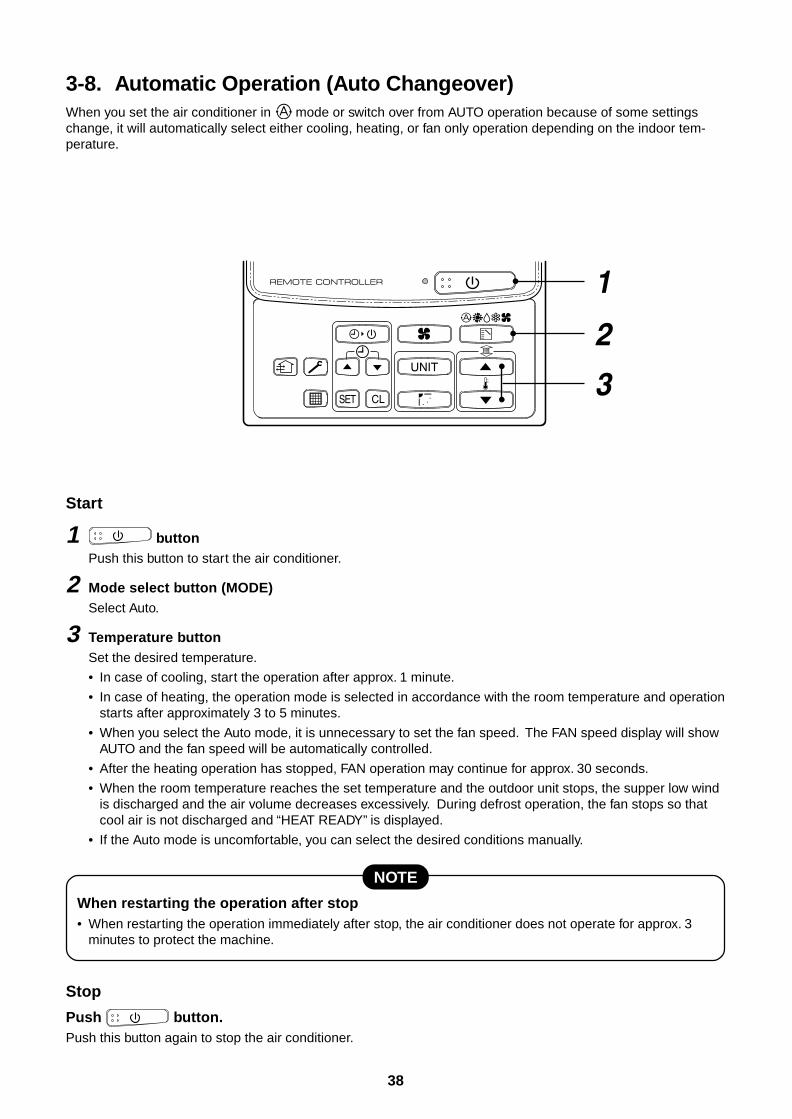
38
3-8. Automatic Operation (Auto Changeover)When you set the air conditioner in mode or switch over from AUTO operation because of some settingschange, it will automatically select either cooling, heating, or fan only operation depending on the indoor tem-perature.
Start
1 buttonPush this button to start the air conditioner.
2 Mode select button (MODE)Select Auto.
3 Temperature buttonSet the desired temperature.
• In case of cooling, start the operation after approx. 1 minute.
• In case of heating, the operation mode is selected in accordance with the room temperature and operationstarts after approximately 3 to 5 minutes.
• When you select the Auto mode, it is unnecessary to set the fan speed. The FAN speed display will showAUTO and the fan speed will be automatically controlled.
• After the heating operation has stopped, FAN operation may continue for approx. 30 seconds.
• When the room temperature reaches the set temperature and the outdoor unit stops, the supper low windis discharged and the air volume decreases excessively. During defrost operation, the fan stops so thatcool air is not discharged and “HEAT READY” is displayed.
• If the Auto mode is uncomfortable, you can select the desired conditions manually.
NOTE
When restarting the operation after stop• When restarting the operation immediately after stop, the air conditioner does not operate for approx. 3
minutes to protect the machine.
Stop
Push button.Push this button again to stop the air conditioner.
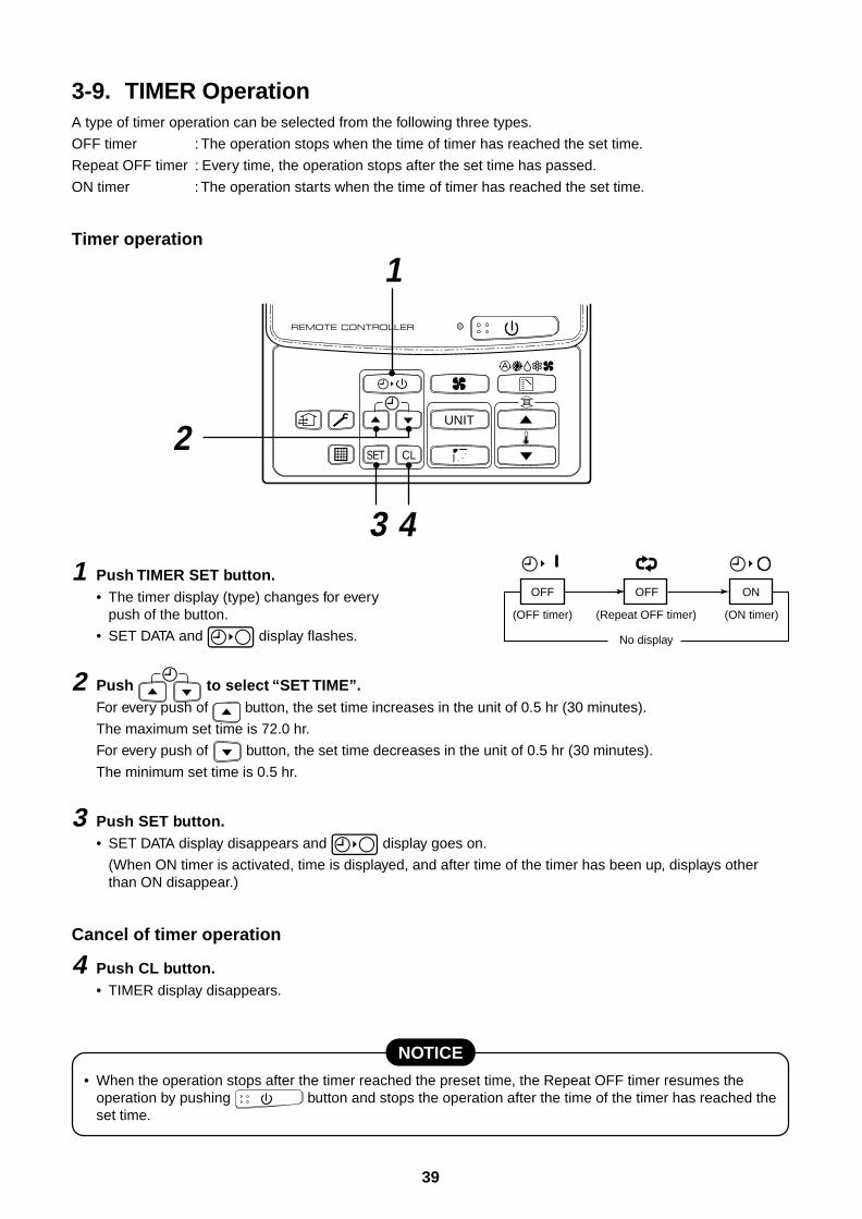
39
3-9. TIMER OperationA type of timer operation can be selected from the following three types.
OFF timer : The operation stops when the time of timer has reached the set time.
Repeat OFF timer : Every time, the operation stops after the set time has passed.
ON timer : The operation starts when the time of timer has reached the set time.
Timer operation
1 Push TIMER SET button.• The timer display (type) changes for every
push of the button.
• SET DATA and display flashes.
2 Push to select “SET TIME”.For every push of button, the set time increases in the unit of 0.5 hr (30 minutes).
The maximum set time is 72.0 hr.
For every push of button, the set time decreases in the unit of 0.5 hr (30 minutes).
The minimum set time is 0.5 hr.
3 Push SET button.• SET DATA display disappears and display goes on.
(When ON timer is activated, time is displayed, and after time of the timer has been up, displays otherthan ON disappear.)
Cancel of timer operation
4 Push CL button.• TIMER display disappears.
NOTICE
• When the operation stops after the timer reached the preset time, the Repeat OFF timer resumes theoperation by pushing button and stops the operation after the time of the timer has reached theset time.
UNIT
4
1
SET CL
3
2
OFF
(OFF timer) (Repeat OFF timer)
No display
(ON timer)
OFF ON
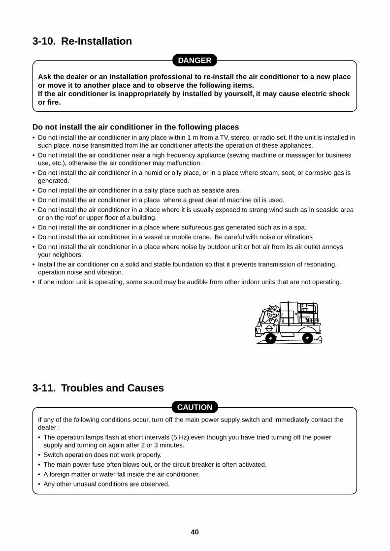
40
3-10. Re-Installation
DANGER
Ask the dealer or an installation professional to re-install the air conditioner to a new placeor move it to another place and to observe the following items.If the air conditioner is inappropriately by installed by yourself, it may cause electric shockor fire.
Do not install the air conditioner in the following places• Do not install the air conditioner in any place within 1 m from a TV, stereo, or radio set. If the unit is installed in
such place, noise transmitted from the air conditioner affects the operation of these appliances.
• Do not install the air conditioner near a high frequency appliance (sewing machine or massager for businessuse, etc.), otherwise the air conditioner may malfunction.
• Do not install the air conditioner in a humid or oily place, or in a place where steam, soot, or corrosive gas isgenerated.
• Do not install the air conditioner in a salty place such as seaside area.
• Do not install the air conditioner in a place where a great deal of machine oil is used.
• Do not install the air conditioner in a place where it is usually exposed to strong wind such as in seaside areaor on the roof or upper floor of a building.
• Do not install the air conditioner in a place where sulfureous gas generated such as in a spa.
• Do not install the air conditioner in a vessel or mobile crane. Be careful with noise or vibrations
• Do not install the air conditioner in a place where noise by outdoor unit or hot air from its air outlet annoysyour neighbors.
• Install the air conditioner on a solid and stable foundation so that it prevents transmission of resonating,operation noise and vibration.
• If one indoor unit is operating, some sound may be audible from other indoor units that are not operating.
3-11. Troubles and Causes
CAUTION
If any of the following conditions occur, turn off the main power supply switch and immediately contact thedealer :
• The operation lamps flash at short intervals (5 Hz) even though you have tried turning off the powersupply and turning on again after 2 or 3 minutes.
• Switch operation does not work properly.
• The main power fuse often blows out, or the circuit breaker is often activated.
• A foreign matter or water fall inside the air conditioner.
• Any other unusual conditions are observed.
41
3-12. Information
Confirmation before operation
• Turn on the power switch 12 hours before startingthe operation.
• Check whether earth wire is cut off or discon-nected.
• Check the air filter is connected to the indoor unit.
Heating capacity
• A heat pump system which absorbs heat fromoutside of the room and then discharges heat intothe room is adopted for heating. If the outsidetemperature falls, the heating capacity decreases.
• When the outside temperature is too low, it isrecommended to use this air conditioner togetherwith other heating equipment.
Defrost during heating operation
• In heating operation, if there is frost on the outdoorunit, the operation changes automatically to thedefrost operation (Approx. 2 to 10 minutes) toincrease the heating efficiency.
• During defrost operation, the fan of the indoor unitstops.
3-minutes protection
• When restarting the operation just after theoperation has been stopped or the main powerswitch has turned on, the outdoor unit does notwork for approx. 3 minutes in order to protect theair conditioner.
Power failure
• If a power failure occurred during operation, alloperations stop.
• When the power is returned after a power failure,the operation lamp notifies the power-ON byflashing operation lamp on the remote controller.
• When restarting the operation, push button again.
Fan rotation in stopped unit
• In heating operation even in the stopped indoorunit, the fan rotates once for several minutes perapprox. an hour when the other indoor unit isoperating to protect the air conditioner.
Protective device(High pressure switch)
This device stops automatically an operation whenexcessive force is applied on the air conditioner.
If the protective device works, the operation stopsand the operation lamp flashes.
When the protective device works, the indication
and the check code are displayed on the
display section of the remote controller. In thefollowing cases, the protective device may work.
In cooling operation• The suction port or discharge port of the outdoor
unit is closed.
• A strong wind continuously blows to the dischargeport of the outdoor unit.
In heating operation• Dust or waste adheres excessively to air filter of
the indoor unit.
• The discharge port of the indoor unit is closed.
If the protective device works, turn off the mainpower switch, solve the cause, and then start theoperation again.
Cooling/Heating operation of SuperModular Multi system air conditioner
• Although each indoor unit can be individuallycontrolled in the Super Modular Multi system airconditioner, the cooling operation and the heatingoperation cannot be simultaneously performed inthe multiple indoor units which are connected toan outdoor unit.
• If the cooling operation and the heating operationare simultaneously performed, the indoor unitwhich executes cooling operation stops, and onthe operation section lights up. On the other hand,the indoor unit which executes heating operationcontinues running. In a case that the manager ofthe air conditioner has fixed the operation tocooling or heating, an operation other than that setup is unavailable. If an operation other than thatset up is executed, on the operation sectionlights up and the operation stops.
Characteristics of heating operation
• The wind is not out just after starting an operation.The hot wind starts to blow 3 to 5 minutes after(Time differs according to indoor/outdoor tempera-ture.) the indoor heat exchanger has warmed up.
• During operation, the outdoor unit may stop if theoutside temperature rises.
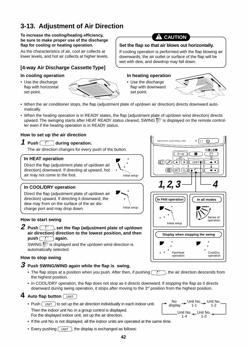
42
3-13. Adjustment of Air Direction
In cooling operation• Use the discharge
flap with horizontalset point.
In heating operation• Use the discharge
flap with downwardset point.
• When the air conditioner stops, the flap (adjustment plate of up/down air direction) directs downward auto-matically.
• When the heating operation is in READY states, the flap (adjustment plate of up/down wind direction) directsupward. The swinging starts after HEAT READY status cleared, SWING is displayed on the remote control-ler even if the heating operation is in READY status.
UNIT
SET CL
In FAN operation In all modes
Display when stopping the swing
Initial setup
Series of operation
Fan/Heat operation
Cool/Dry operation
1, 2, 3 4
How to set up the air direction
1 Push during operation.The air direction changes for every push of the button.
In HEAT operationDirect the flap (adjustment plate of up/down airdirection) downward. If directing at upward, hotair may not come to the foot.
In COOL/DRY operationDirect the flap (adjustment plate of up/down airdirection) upward. If directing it downward, thedew may from on the surface of the air dis-charge port and may drop down.
How to start swing
2 Push , set the flap (adjustment plate of up/downair direction) direction to the lowest position, and thenpush again.SWING is displayed and the up/down wind direction isautomatically selected.
How to stop swing
3 Push SWING/WIND again while the flap is swing.• The flap stops at a position when you push. After then, if pushing , the air direction descends from
the highest position.
• In COOL/DRY operation, the flap does not stop as it directs downward. If stopping the flap as it directsdownward during swing operation, it stops after moving to the 3rd position from the highest position.
4 Auto flap button UNIT
• Push UNIT to set up the air direction individually in each indoor unit.
Then the indoor unit No. in a group control is displayed.For the displayed indoor unit, set up the air direction.
• If the unit No. is not displayed, all the indoor units are operated at the same time.
• Every pushing UNIT , the display is exchanged as follows:
To increase the cooling/heating efficiency,be sure to make proper use of the dischargeflap for cooling or heating operation.
As the characteristics of air, cool air collects atlower levels, and hot air collects at higher levels.
CAUTION
Set the flap so that air blows out horizontally.If cooling operation is performed with the flap blowing airdownwards, the air outlet or surface of the flap will bewet with dew, and dewdrop may fall down.
[4-way Air Discharge Cassette Type]
No display
Unit No.1-1
Unit No.1-2
Unit No.1-3
Unit No.1-4
Initial setup
Initial setup
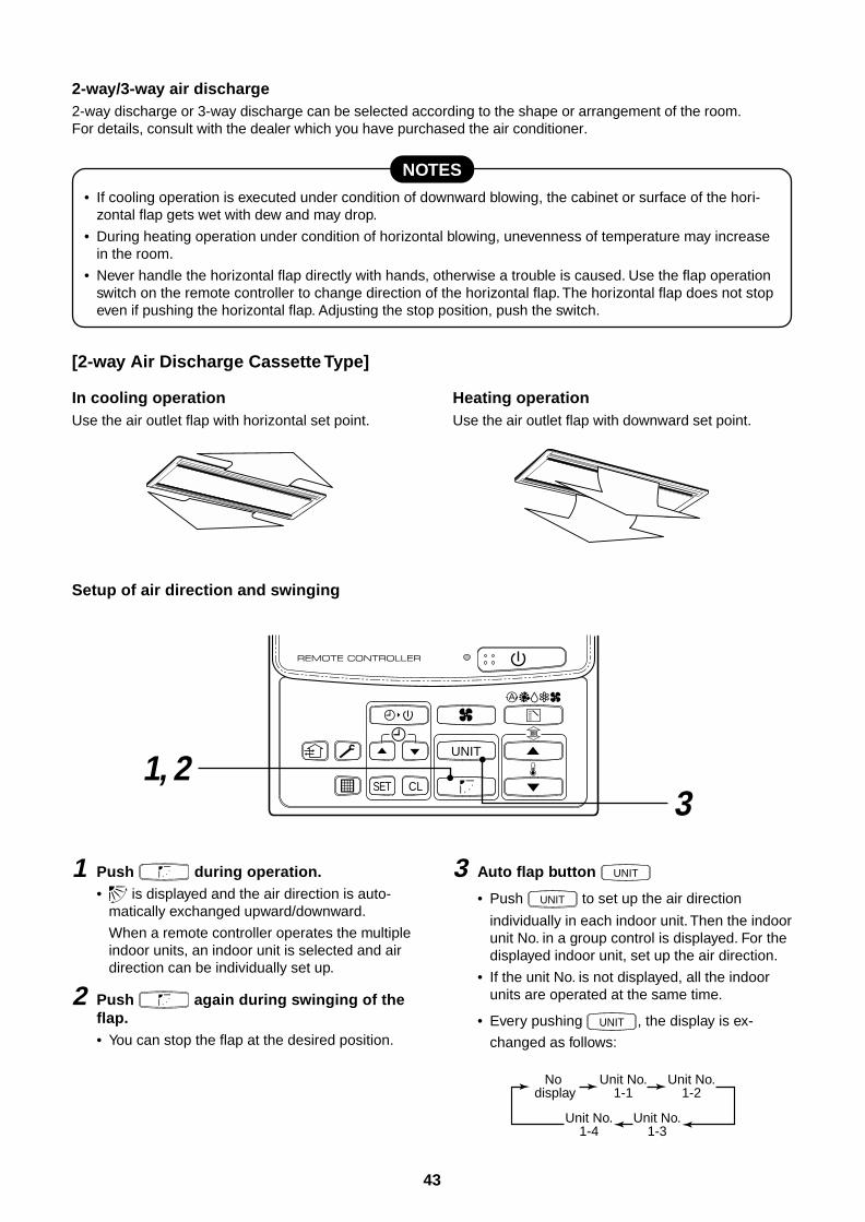
43
2-way/3-way air discharge2-way discharge or 3-way discharge can be selected according to the shape or arrangement of the room.For details, consult with the dealer which you have purchased the air conditioner.
NOTES
• If cooling operation is executed under condition of downward blowing, the cabinet or surface of the hori-zontal flap gets wet with dew and may drop.
• During heating operation under condition of horizontal blowing, unevenness of temperature may increasein the room.
• Never handle the horizontal flap directly with hands, otherwise a trouble is caused. Use the flap operationswitch on the remote controller to change direction of the horizontal flap. The horizontal flap does not stopeven if pushing the horizontal flap. Adjusting the stop position, push the switch.
[2-way Air Discharge Cassette Type]
In cooling operationUse the air outlet flap with horizontal set point.
1 Push during operation.• is displayed and the air direction is auto-
matically exchanged upward/downward.
When a remote controller operates the multipleindoor units, an indoor unit is selected and airdirection can be individually set up.
2 Push again during swinging of theflap.• You can stop the flap at the desired position.
3 Auto flap button UNIT
• Push UNIT to set up the air direction
individually in each indoor unit. Then the indoorunit No. in a group control is displayed. For thedisplayed indoor unit, set up the air direction.
• If the unit No. is not displayed, all the indoorunits are operated at the same time.
• Every pushing UNIT , the display is ex-
changed as follows:
UNIT
31, 2
SET CL
No display
Unit No.1-1
Unit No.1-2
Unit No.1-3
Unit No.1-4
Heating operationUse the air outlet flap with downward set point.
Setup of air direction and swinging
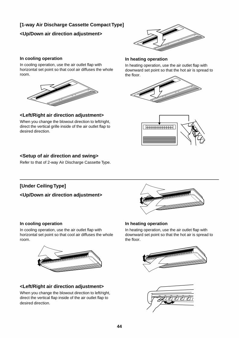
44
[1-way Air Discharge Cassette Compact Type]
<Up/Down air direction adjustment>
In cooling operationIn cooling operation, use the air outlet flap withhorizontal set point so that cool air diffuses the wholeroom.
In heating operationIn heating operation, use the air outlet flap withdownward set point so that the hot air is spread tothe floor.
<Left/Right air direction adjustment>When you change the blowout direction to left/right,direct the vertical grille inside of the air outlet flap todesired direction.
<Setup of air direction and swing>Refer to that of 2-way Air Discharge Cassette Type.
In cooling operationIn cooling operation, use the air outlet flap withhorizontal set point so that cool air diffuses the wholeroom.
In heating operationIn heating operation, use the air outlet flap withdownward set point so that the hot air is spread tothe floor.
<Left/Right air direction adjustment>When you change the blowout direction to left/right,direct the vertical flap inside of the air outlet flap todesired direction.
[Under Ceiling Type]
<Up/Down air direction adjustment>
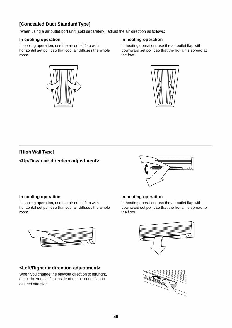
45
[Concealed Duct Standard Type]
When using a air outlet port unit (sold separately), adjust the air direction as follows:
In cooling operationIn cooling operation, use the air outlet flap withhorizontal set point so that cool air diffuses the wholeroom.
In heating operationIn heating operation, use the air outlet flap withdownward set point so that the hot air is spread atthe foot.
[High Wall Type]
<Up/Down air direction adjustment>
In cooling operationIn cooling operation, use the air outlet flap withhorizontal set point so that cool air diffuses the wholeroom.
In heating operationIn heating operation, use the air outlet flap withdownward set point so that the hot air is spread tothe floor.
<Left/Right air direction adjustment>When you change the blowout direction to left/right,direct the vertical flap inside of the air outlet flap todesired direction.
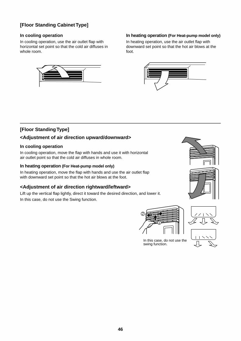
46
In cooling operationIn cooling operation, use the air outlet flap withhorizontal set point so that the cold air diffuses inwhole room.
In heating operation (For Heat-pump model only)
In heating operation, use the air outlet flap withdownward set point so that the hot air blows at thefoot.
[Floor Standing Cabinet Type]
[Floor Standing Type]
<Adjustment of air direction upward/downward>
In cooling operationIn cooling operation, move the flap with hands and use it with horizontalair outlet point so that the cold air diffuses in whole room.
In heating operation (For Heat-pump model only)
In heating operation, move the flap with hands and use the air outlet flapwith downward set point so that the hot air blows at the foot.
<Adjustment of air direction rightward/leftward>Lift up the vertical flap lightly, direct it toward the desired direction, and lower it.
In this case, do not use the Swing function.
1
2
In this case, do not use the swing function.
47
3-14. Air Conditioner Operations and Performance3 minutes protection function3-minutes protection function prevents the air conditioner from starting for initial 3 minutes after the main powerswitch/circuit breaker is turned on for re-starting the air conditioner.
Power failurePower failure during operation will stop the unit completely.
• To restart the operation, push the START/STOP button on the remote controller.
• Lightning or a wireless car telephone operating nearby may cause the unit to malfunction. Turn off the mainpower switch or circuit breaker and then turn them on again. Push the START/STOP button on the remotecontroller to restart.
Heating characteristicsPreheating operationThe air conditioner will not deliver warm air immediately after it is turned on. Warm air will start to flow out afterapproximately 5 minutes when the indoor heat exchanger warmed up.
Warm air control (In heating operation)When the room temperature reaches the set temperature, the fan speed is automatically reduced to prevent toblow cold draft. At this time, the outdoor unit will stop.
Defrosting operationIf the outdoor unit is frosted during the heating operation, defrosting starts automatically (for approximately2 to 10 minutes) to maintain the heating capacity.
• The fans in both indoor and outdoor units will stop during the defrosting operation.
• During the defrosting operation, the defrosted water will be drained from the bottom plate of the outdoor unit.
Heating capacityIn the heating operation, the heat is absorbed from the outside and brought into the room. This way of heatingis called heat pump system. When the outside temperature is too low, it is recommended to use another heatingapparatus in combination with the air conditioner.
Attention to snowfall and freeze on the outdoor unit• In snowy areas, the air inlet and air outlet of the outdoor unit are often covered with snow or frozen up.
If snow or freeze on the outdoor unit is left as it is, it may cause machine failure or poor warming.
• In cold areas, pay attention to the drain hose so that it perfectly drains water without water remaining inside forfreeze prevention. If water freezes in the drain hose or inside the outdoor unit, it may cause machine failure orpoor warming.
Air conditioner operating conditionsFor proper performance, operate the air conditioner under the following temperature conditions:
If air conditioner is used outside of the above conditions, safety protection may work.
Cooling operation
Dry operation
Heating operation
Outdoor temperature : –5°C to 43°C
Room temperature : 21°C to 32°C (Dry valve temp.), 15°C to 24°C (Wet valve temp.)
CAUTION Room relative humidity – less than 80 %. If the air conditioner operatesin excess of this figure, the surface of the air conditioner may cause dewing.
Outdoor temperature : 15°C to 43°C (Maximum suction air temp. 46°C)
Room temperature : 17°C to 32°C
Outdoor temperature : –15°C to 15°C (Wet valve temp.)
Room temperature : 15°C to 28°C (Dry valve temp.)
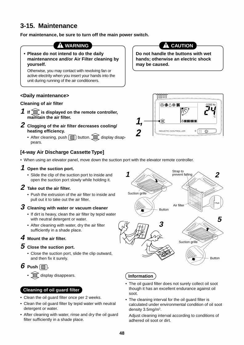
48
3-15. MaintenanceFor maintenance, be sure to turn off the main power switch.
WARNING
• Please do not intend to do the dailymaintenannce and/or Air Filter cleaning byyourself.Otherwise, you may contact with revolving fan oractive electrity when you insert your hands into theunit during running of the air conditioners.
CAUTION
Do not handle the buttons with wethands; otherwise an electric shockmay be caused.
<Daily maintenance>
Cleaning of air filter
1 If is displayed on the remote controller,maintain the air filter.
2 Clogging of the air filter decreases cooling/heating efficiency.• After cleaning, push button. display disap-
pears.
CODE No.
1, 2
[4-way Air Discharge Cassette Type]
• When using an elevator panel, move down the suction port with the elevator remote controller.
1 Open the suction port.• Slide the clip of the suction port to inside and
open the suction port slowly while holding it.
2 Take out the air filter.• Push the extrusion of the air filter to inside and
pull out it to take out the air filter.
3 Cleaning with water or vacuum cleaner• If dirt is heavy, clean the air filter by tepid water
with neutral detergent or water.
• After cleaning with water, dry the air filtersufficiently in a shade place.
4 Mount the air filter.
5 Close the suction port.• Close the suction port, slide the clip outward,
and then fix it surely.
6 Push .
• display disappears.
Cleaning of oil guard filter
• Clean the oil guard filter once per 2 weeks.
• Clean the oil guard filter by tepid water with neutraldetergent or water.
• After cleaning with water, rinse and dry the oil guardfilter sufficiently in a shade place.
Information
• The oil guard filter does not surely collect oil sootthough it has an excellent endurance against oilsoot.
• The cleaning interval for the oil guard filter iscalculated under environmental condition of oil sootdensity 3.5mg/m3.
Adjust cleaning interval according to conditions ofadhered oil soot or dirt.
Suction grille
Button
Strap to prevent falling
Air filterPush
Suction grille
Button
1 2
53
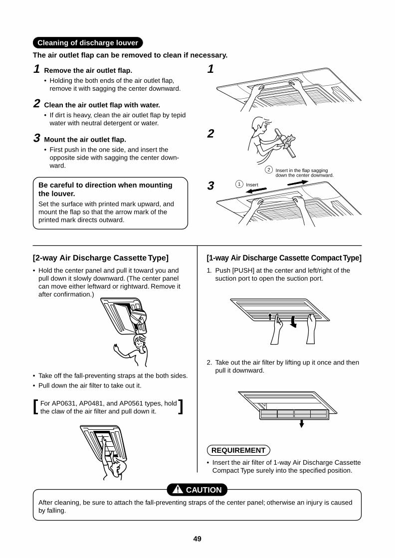
49
[ ]
Cleaning of discharge louver
The air outlet flap can be removed to clean if necessary.
1 Remove the air outlet flap.• Holding the both ends of the air outlet flap,
remove it with sagging the center downward.
2 Clean the air outlet flap with water.• If dirt is heavy, clean the air outlet flap by tepid
water with neutral detergent or water.
3 Mount the air outlet flap.• First push in the one side, and insert the
opposite side with sagging the center down-ward.
Be careful to direction when mountingthe louver.Set the surface with printed mark upward, andmount the flap so that the arrow mark of theprinted mark directs outward.
1 Insert
2 Insert in the flap sagging down the center downward.
1
2
3
[2-way Air Discharge Cassette Type]
• Hold the center panel and pull it toward you andpull down it slowly downward. (The center panelcan move either leftward or rightward. Remove itafter confirmation.)
[1-way Air Discharge Cassette Compact Type]
1. Push [PUSH] at the center and left/right of thesuction port to open the suction port.
• Take off the fall-preventing straps at the both sides.
• Pull down the air filter to take out it.
For AP0631, AP0481, and AP0561 types, holdthe claw of the air filter and pull down it.
CAUTION
After cleaning, be sure to attach the fall-preventing straps of the center panel; otherwise an injury is causedby falling.
2. Take out the air filter by lifting up it once and thenpull it downward.
REQUIREMENT
• Insert the air filter of 1-way Air Discharge CassetteCompact Type surely into the specified position.
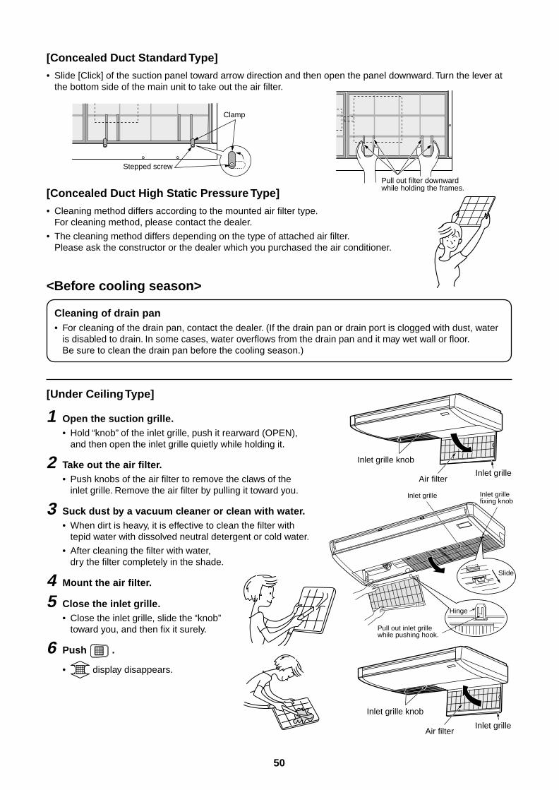
50
[Concealed Duct Standard Type]
• Slide [Click] of the suction panel toward arrow direction and then open the panel downward. Turn the lever atthe bottom side of the main unit to take out the air filter.
Clamp
Stepped screw
Pull out filter downward while holding the frames.[Concealed Duct High Static Pressure Type]
• Cleaning method differs according to the mounted air filter type.For cleaning method, please contact the dealer.
• The cleaning method differs depending on the type of attached air filter.Please ask the constructor or the dealer which you purchased the air conditioner.
<Before cooling season>
Cleaning of drain pan• For cleaning of the drain pan, contact the dealer. (If the drain pan or drain port is clogged with dust, water
is disabled to drain. In some cases, water overflows from the drain pan and it may wet wall or floor.Be sure to clean the drain pan before the cooling season.)
[Under Ceiling Type]
1 Open the suction grille.• Hold “knob” of the inlet grille, push it rearward (OPEN),
and then open the inlet grille quietly while holding it.
2 Take out the air filter.• Push knobs of the air filter to remove the claws of the
inlet grille. Remove the air filter by pulling it toward you.
3 Suck dust by a vacuum cleaner or clean with water.• When dirt is heavy, it is effective to clean the filter with
tepid water with dissolved neutral detergent or cold water.
• After cleaning the filter with water,dry the filter completely in the shade.
4 Mount the air filter.
5 Close the inlet grille.• Close the inlet grille, slide the “knob”
toward you, and then fix it surely.
6 Push .
• display disappears.
Inlet grille knob
Air filterInlet grille
Pull out inlet grille while pushing hook.
Inlet grille Inlet grille fixing knob
Hinge
Slide
Inlet grille knob
Air filterInlet grille
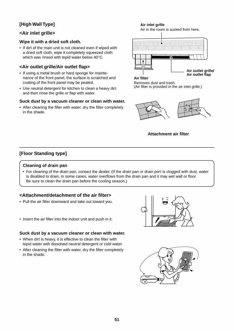
51
[High Wall Type]
<Air inlet grille>
Wipe it with a dried soft cloth.• If dirt of the main unit is not cleaned even if wiped with
a dried soft cloth, wipe it completely squeezed clothwhich was rinsed with tepid water below 40°C.
<Air outlet grille/Air outlet flap>• If using a metal brush or hard sponge for mainte-
nance of the front panel, the surface is scratched andcoating of the front panel may be pealed.
• Use neutral detergent for kitchen to clean a heavy dirtand then rinse the grille or flap with water.
Air inlet grilleAir in the room is sucked from here.
Air filterRemoves dust and trash.(Air filter is provided in the air inlet grille.)
Air outlet grille/Air outlet flap
Suck dust by a vacuum cleaner or clean with water.• After cleaning the filter with water, dry the filter completely
in the shade.
Attachment air filter
[Floor Standing type]
Cleaning of drain pan• For cleaning of the drain pan, contact the dealer. (If the drain pan or drain port is clogged with dust, water
is disabled to drain. In some cases, water overflows from the drain pan and it may wet wall or floor.Be sure to clean the drain pan before the cooling season.)
<Attachment/detachment of the air filter>• Pull the air filter downward and take out toward you.
• Insert the air filter into the indoor unit and push in it.
Suck dust by a vacuum cleaner or clean with water.• When dirt is heavy, it is effective to clean the filter with
tepid water with dissolved neutral detergent or cold water.
• After cleaning the filter with water, dry the filter completelyin the shade.
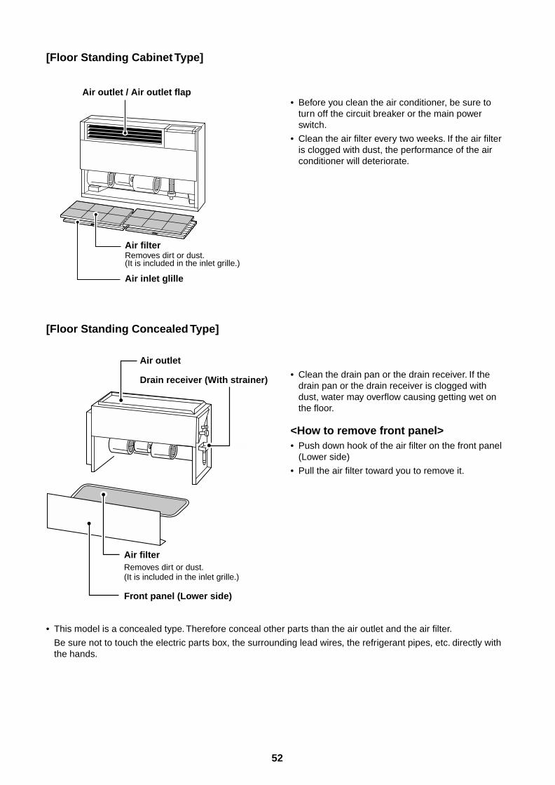
52
[Floor Standing Cabinet Type]
Air outlet
Drain receiver (With strainer)
Air filterRemoves dirt or dust.(It is included in the inlet grille.)
Front panel (Lower side)
Air outlet / Air outlet flap
Air filterRemoves dirt or dust.(It is included in the inlet grille.)
Air inlet glille
• Before you clean the air conditioner, be sure toturn off the circuit breaker or the main powerswitch.
• Clean the air filter every two weeks. If the air filteris clogged with dust, the performance of the airconditioner will deteriorate.
[Floor Standing Concealed Type]
• Clean the drain pan or the drain receiver. If thedrain pan or the drain receiver is clogged withdust, water may overflow causing getting wet onthe floor.
<How to remove front panel>• Push down hook of the air filter on the front panel
(Lower side)
• Pull the air filter toward you to remove it.
• This model is a concealed type. Therefore conceal other parts than the air outlet and the air filter.
Be sure not to touch the electric parts box, the surrounding lead wires, the refrigerant pipes, etc. directly withthe hands.
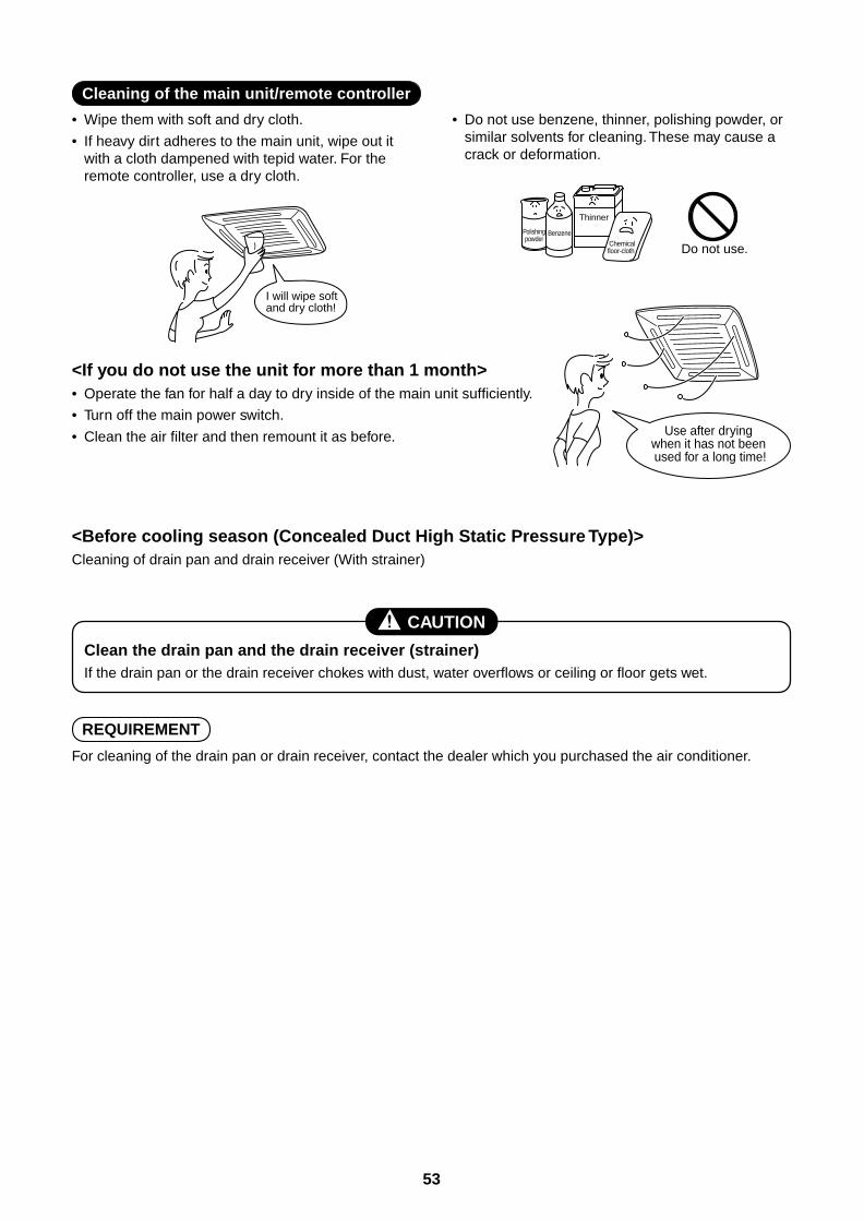
53
• Wipe them with soft and dry cloth.
• If heavy dirt adheres to the main unit, wipe out itwith a cloth dampened with tepid water. For theremote controller, use a dry cloth.
<If you do not use the unit for more than 1 month>• Operate the fan for half a day to dry inside of the main unit sufficiently.
• Turn off the main power switch.
• Clean the air filter and then remount it as before.
<Before cooling season (Concealed Duct High Static Pressure Type)>Cleaning of drain pan and drain receiver (With strainer)
CAUTION
Clean the drain pan and the drain receiver (strainer)If the drain pan or the drain receiver chokes with dust, water overflows or ceiling or floor gets wet.
REQUIREMENT
For cleaning of the drain pan or drain receiver, contact the dealer which you purchased the air conditioner.
• Do not use benzene, thinner, polishing powder, orsimilar solvents for cleaning. These may cause acrack or deformation.
Cleaning of the main unit/remote controller
I will wipe soft and dry cloth!
Do not use.
Polishingpowder
Benzene
Thinner
Chemical floor-cloth
Use after drying when it has not been used for a long time!
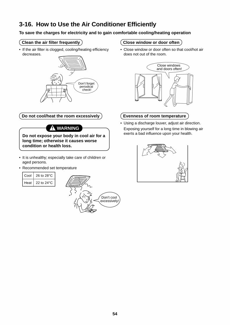
54
3-16. How to Use the Air Conditioner EfficientlyTo save the charges for electricity and to gain comfortable cooling/heating operation
Clean the air filter frequently
• If the air filter is clogged, cooling/heating efficiencydecreases.
Close window or door often
• Close window or door often so that cool/hot airdoes not out of the room.
Do not cool/heat the room excessively
WARNING
Do not expose your body in cool air for along time; otherwise it causes worsecondition or health loss.
• It is unhealthy; especially take care of children oraged persons.
• Recommended set temperature
Evenness of room temperature
• Using a discharge louver, adjust air direction.
Exposing yourself for a long time in blowing airexerts a bad influence upon your health.
Don’t forget periodical
check!
Close windows and doors often!
Don’t cool excessively!
Cool
Heat
26 to 28°C
22 to 24°C
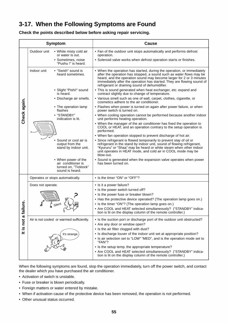
55
3-17. When the Following Symptoms are FoundCheck the points described below before asking repair servicing.
Symptom
Outdoor unit • White misty cold airor water is out.
• Sometimes, noise“Pushu !” is heard.
Indoor unit • “Swish” sound isheard sometimes.
• Slight “Pishi!” soundis heard.
• Discharge air smells.
• The operation lampflashes
• “STANDBY”indication is lit.
• Sound or cool air isoutput from thestand by indoor unit.
• When power of theair conditioner isturned on, “Ticktock”sound is heard.
Operates or stops automatically.
Does not operate.
Air is not cooled or warmed sufficiently.
Cause
• Fan of the outdoor unit stops automatically and performs defrostoperation.
• Solenoid valve works when defrost operation starts or finishes.
• When the operation has started, during the operation, or immediatelyafter the operation has stopped, a sound such as water flows may beheard, and the operation sound may become larger for 2 or 3 minutesimmediately after the operation has started. They are flowing sound ofrefrigerant or draining sound of dehumidifier.
• This is sound generated when heat exchanger, etc. expand andcontract slightly due to change of temperature.
• Various smell such as one of wall, carpet, clothes, cigarette, orcosmetics adhere to the air conditioner.
• Flashes when power is turned on again after power failure, or whenpower switch is turned on.
• When cooling operation cannot be performed because another indoorunit performs heating operation.
• When the manager of the air conditioner has fixed the operation toCOOL or HEAT, and an operation contrary to the setup operation isperformed.
• When fan operation stopped to prevent discharge of hot air.• Since refrigerant is flowed temporarily to prevent stay of oil or
refrigerant in the stand by indoor unit, sound of flowing refrigerant,“Kyururu” or “Shaa” may be heard or white steam when other indoorunit operates in HEAT mode, and cold air in COOL mode may beblow-out.
• Sound is generated when the expansion valve operates when powerhas been turned on.
• Is the timer “ON” or “OFF”?
• Is it a power failure?• Is the power switch turned off?• Is the power fuse or breaker blown?• Has the protective device operated? (The operation lamp goes on.)• Is the timer “ON”? (The operation lamp goes on.)• Are COOL and HEAT selected simultaneously? (“STANDBY” indica-
tion is lit on the display column of the remote controller.)
• Is the suction port or discharge port of the outdoor unit obstructed?• Are any door or window open?• Is the air filter clogged with dust?• Is discharge louver of the indoor unit set at appropriate position?• Is air selection set to “LOW” “MED”, and is the operation mode set to
“FAN”?• Is the setup temp. the appropriate temperature?• Are COOL and HEAT selected simultaneously? (“STANDBY” indica-
tion is lit on the display column of the remote controller.)
It is
no
t a
failu
re.
Ch
eck
agai
n.
When the following symptoms are found, stop the operation immediately, turn off the power switch, and contactthe dealer which you have purchased the air conditioner.
• Activation of switch is unstable.
• Fuse or breaker is blown periodically.
• Foreign matters or water entered by mistake.
• When if activation cause of the protective device has been removed, the operation is not performed.
• Other unusual status occurred.
Silent
It’s strange.
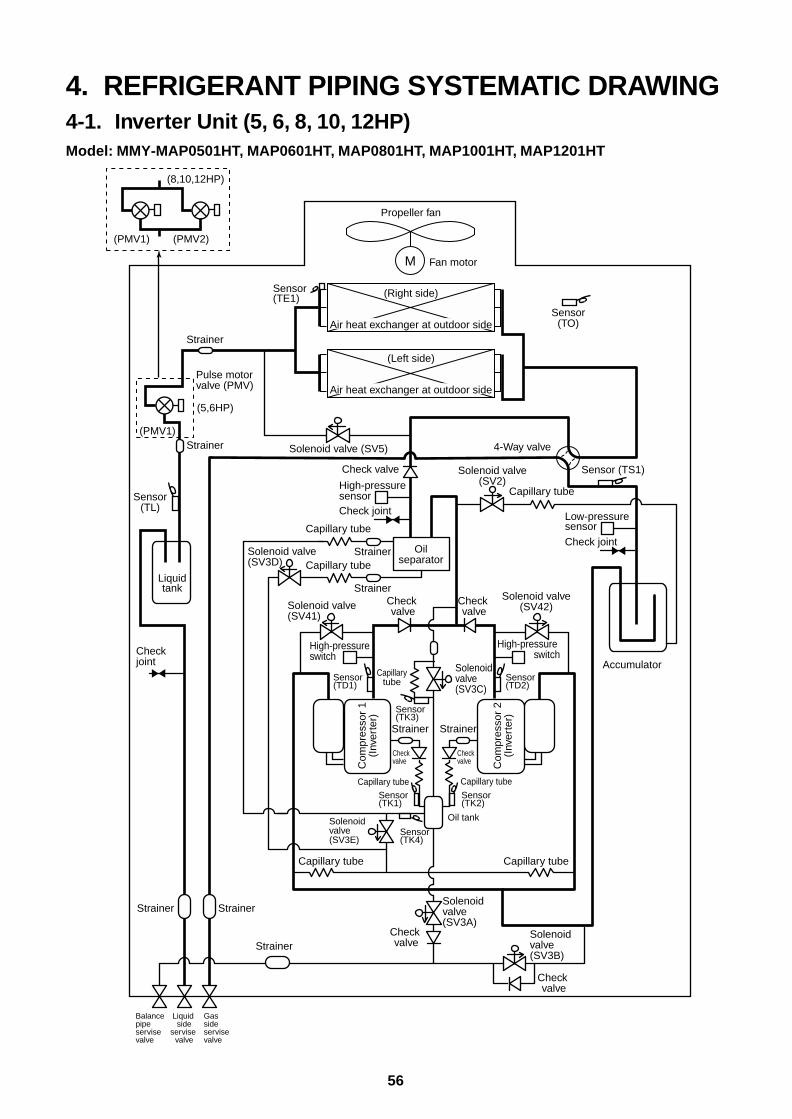
56
4. REFRIGERANT PIPING SYSTEMATIC DRAWING4-1. Inverter Unit (5, 6, 8, 10, 12HP)Model: MMY-MAP0501HT, MAP0601HT, MAP0801HT, MAP1001HT, MAP1201HT
Capillary tube
Capillarytube
Capillary tube
M
Propeller fan
Fan motor
Sensor(TO)
Sensor (TS1)
Sensor(TL)
Sensor(TE1) (Right side)
Air heat exchanger at outdoor side
(Left side)
Air heat exchanger at outdoor side
Solenoid valve(SV2)
Solenoid valve (SV5)
Solenoid valve(SV41)
Solenoid valve(SV3A)
Solenoid valve(SV3E)
Solenoid valve(SV3B)
Solenoid valve(SV3D)
Solenoid valve(SV3C)
4-Way valve
Check joint
Low-pressuresensor
Accumulator
Check joint
Check joint
High-pressure sensor
High-pressure switch
Oilseparator
Check valve
Check valve
Check valve
Check valve
Check valveC
ompr
esso
r 1
(Inv
erte
r)
Strainer
Strainer
Sensor(TK1)
Sensor(TK4)
Sensor(TK3)
Capillary tube
Capillary tube
Capillary tubeStrainer
Strainer
Strainer(PMV1)
Strainer
StrainerStrainer
Capillary tube
Capillary tube
Solenoid valve(SV42)
High-pressure switch
Check valve
Check valve C
ompr
esso
r 2
(Inv
erte
r)
Strainer
Sensor(TK2)
Sensor(TD2)
Sensor(TD1)
Liquidtank
Oil tank
Balance pipeservise valve
Liquid side
servise valve
Gas sideservise valve
Pulse motor valve (PMV)
(PMV1)
(8,10,12HP)
(5,6HP)
(PMV2)
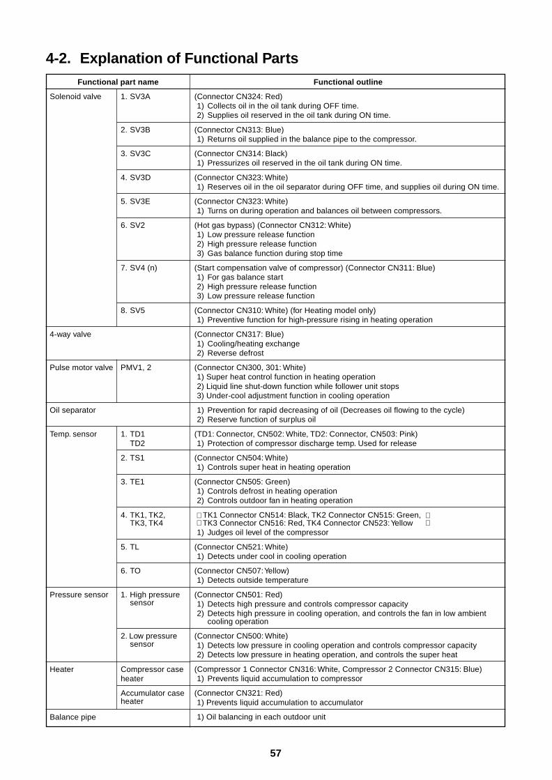
57
4-2. Explanation of Functional PartsFunctional part name
Solenoid valve 1. SV3A
2. SV3B
3. SV3C
4. SV3D
5. SV3E
6. SV2
7. SV4 (n)
8. SV5
4-way valve
Pulse motor valve PMV1, 2
Oil separator
Temp. sensor 1. TD1TD2
2. TS1
3. TE1
4. TK1, TK2,TK3, TK4
5. TL
6. TO
Pressure sensor 1. High pressuresensor
2. Low pressuresensor
Heater Compressor caseheater
Accumulator caseheater
Balance pipe
Functional outline
(Connector CN324: Red)1) Collects oil in the oil tank during OFF time.2) Supplies oil reserved in the oil tank during ON time.
(Connector CN313: Blue)1) Returns oil supplied in the balance pipe to the compressor.
(Connector CN314: Black)1) Pressurizes oil reserved in the oil tank during ON time.
(Connector CN323: White)1) Reserves oil in the oil separator during OFF time, and supplies oil during ON time.
(Connector CN323: White)1) Turns on during operation and balances oil between compressors.
(Hot gas bypass) (Connector CN312: White)1) Low pressure release function2) High pressure release function3) Gas balance function during stop time
(Start compensation valve of compressor) (Connector CN311: Blue)1) For gas balance start2) High pressure release function3) Low pressure release function
(Connector CN310: White) (for Heating model only)1) Preventive function for high-pressure rising in heating operation
(Connector CN317: Blue)1) Cooling/heating exchange2) Reverse defrost
(Connector CN300, 301: White)1) Super heat control function in heating operation2) Liquid line shut-down function while follower unit stops3) Under-cool adjustment function in cooling operation
1) Prevention for rapid decreasing of oil (Decreases oil flowing to the cycle)2) Reserve function of surplus oil
(TD1: Connector, CN502: White, TD2: Connector, CN503: Pink)1) Protection of compressor discharge temp. Used for release
(Connector CN504: White)1) Controls super heat in heating operation
(Connector CN505: Green)1) Controls defrost in heating operation2) Controls outdoor fan in heating operation
TK1 Connector CN514: Black, TK2 Connector CN515: Green, TK3 Connector CN516: Red, TK4 Connector CN523: Yellow1) Judges oil level of the compressor
(Connector CN521: White)1) Detects under cool in cooling operation
(Connector CN507: Yellow)1) Detects outside temperature
(Connector CN501: Red)1) Detects high pressure and controls compressor capacity2) Detects high pressure in cooling operation, and controls the fan in low ambient
cooling operation
(Connector CN500: White)1) Detects low pressure in cooling operation and controls compressor capacity2) Detects low pressure in heating operation, and controls the super heat
(Compressor 1 Connector CN316: White, Compressor 2 Connector CN315: Blue)1) Prevents liquid accumulation to compressor
(Connector CN321: Red)1) Prevents liquid accumulation to accumulator
1) Oil balancing in each outdoor unit
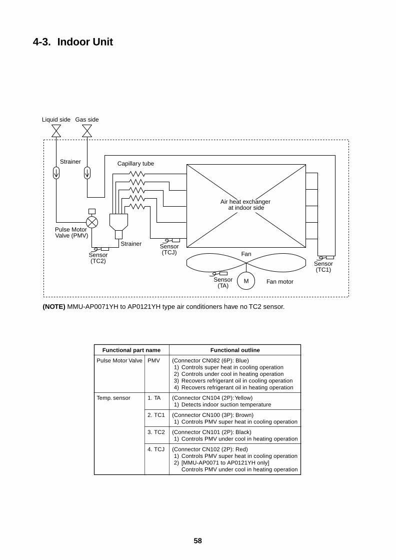
58
4-3. Indoor Unit
Functional part name
Pulse Motor Valve PMV
Temp. sensor 1. TA
2. TC1
3. TC2
4. TCJ
Functional outline
(Connector CN082 (6P): Blue)1) Controls super heat in cooling operation2) Controls under cool in heating operation3) Recovers refrigerant oil in cooling operation4) Recovers refrigerant oil in heating operation
(Connector CN104 (2P): Yellow)1) Detects indoor suction temperature
(Connector CN100 (3P): Brown)1) Controls PMV super heat in cooling operation
(Connector CN101 (2P): Black)1) Controls PMV under cool in heating operation
(Connector CN102 (2P): Red)1) Controls PMV super heat in cooling operation2) [MMU-AP0071 to AP0121YH only]
Controls PMV under cool in heating operation
Air heat exchanger at indoor side
Fan
M Fan motorSensor(TA)
Sensor(TC1)
Gas sideLiquid side
Strainer Capillary tube
Pulse Motor Valve (PMV)
Strainer Sensor(TCJ)Sensor
(TC2)
(NOTE) MMU-AP0071YH to AP0121YH type air conditioners have no TC2 sensor.
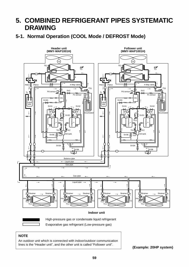
59
5. COMBINED REFRIGERANT PIPES SYSTEMATICDRAWING
5-1. Normal Operation (COOL Mode / DEFROST Mode)
NOTEAn outdoor unit which is connected with indoor/outdoor communicationlines is the “Header unit”, and the other unit is called “Follower unit”.
(Example: 20HP system)
FM
TO
TS1
Liquidtank
4-Way valve
Accumulator
TK2
TK4
TK1
SV3E
SV41 SV42
SV3D
SV3A
TK3
SV3C
Oil tank
OS
Header unit(MMY-MAP1001H)
Follower unit(MMY-MAP1001H)
TE1
SV5
SV3B
Ps sensor
SV2TL
PMV1 PMV2
Com
pres
sor
1
Com
pres
sor
2
TD1
HP HP
TD2
Pd sensor
FM
TO
TS1
Liquidtank
4-Way valve
Accumulator
TK2
TK4
TK1
SV3E
SV41 SV42
SV3D
SV3A
TK3
SV3C
Oil tank
OS
TE1
SV5
SV3B
Ps sensor
SV2TL
PMV1 PMV2
Com
pres
sor
1
Com
pres
sor
2
TD1
HP HP
TD2
Pd sensor
Strainer
TCJTC2 TC1
PMV
Strainer Strainer
TCJTC2 TC1
PMV
Strainer Strainer
TCJTC2 TC1
PMV
Strainer Strainer
TCJTC2 TC1
PMV
Strainer
Gas pipe
Gas pipe
Liquid pipe
Liquid pipe
Balance pipe
Indoor unit
High-pressure gas or condensate liquid refrigerant
Evaporative gas refrigerant (Low-pressure gas)
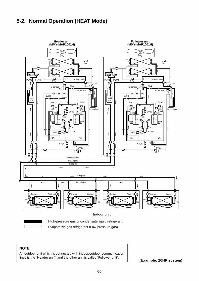
60
5-2. Normal Operation (HEAT Mode)
NOTEAn outdoor unit which is connected with indoor/outdoor communicationlines is the “Header unit”, and the other unit is called “Follower unit”.
(Example: 20HP system)
FM
TO
TS1
Liquidtank
4-Way valve
Accumulator
TK2
TK4
TK1
SV3E
SV41 SV42
SV3D
SV3A
TK3
SV3C
Oil tank
OS
Header unit(MMY-MAP1001H)
Follower unit(MMY-MAP1001H)
TE1
SV5
SV3B
Ps sensor
SV2TL
PMV1 PMV2
Com
pres
sor
1
Com
pres
sor
2
TD1
HP HP
TD2
Pd sensor
Strainer
TCJTC2 TC1
PMV
Strainer Strainer
TCJTC2 TC1
PMV
Strainer Strainer
TCJTC2 TC1
PMV
Strainer Strainer
TCJTC2 TC1
PMV
Strainer
Gas pipe
Gas pipe
Liquid pipe
Liquid pipe
Balance pipe
FM
TO
TS1
Liquidtank
4-Way valve
Accumulator
TK2
TK4
TK1
SV3E
SV41 SV42
SV3D
SV3A
TK3
SV3C
Oil tank
OS
TE1
SV5
SV3B
Ps sensor
SV2TL
PMV1 PMV2
Com
pres
sor
1
Com
pres
sor
2
TD1
HP HP
TD2
Pd sensor
Indoor unit
High-pressure gas or condensate liquid refrigerant
Evaporative gas refrigerant (Low-pressure gas)
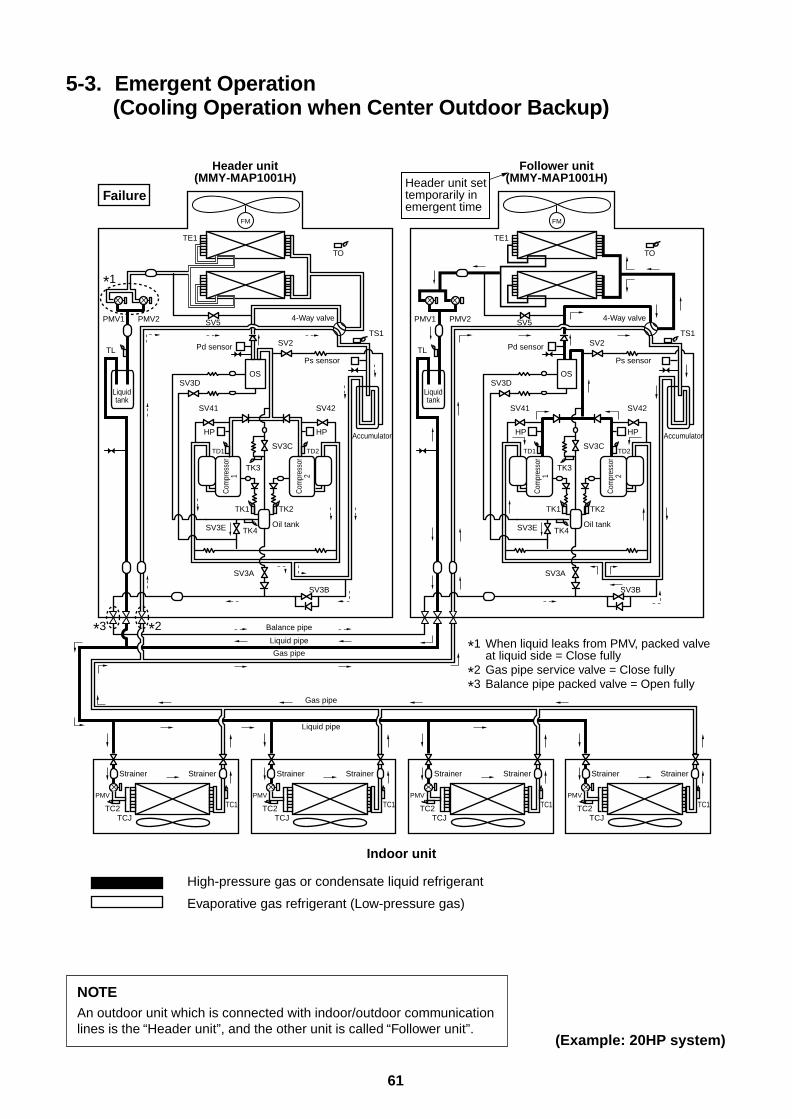
61
5-3. Emergent Operation(Cooling Operation when Center Outdoor Backup)
NOTEAn outdoor unit which is connected with indoor/outdoor communicationlines is the “Header unit”, and the other unit is called “Follower unit”.
(Example: 20HP system)
FM
TO
TS1
Liquidtank
4-Way valve
Accumulator
TK2
TK4
TK1
SV3E
SV41 SV42
SV3D
SV3A
TK3
SV3C
Oil tank
OS
Header unit(MMY-MAP1001H)
Follower unit(MMY-MAP1001H)
TE1
SV5
SV3B
Ps sensor
SV2TL
PMV1 PMV2
Com
pres
sor
1
Com
pres
sor
2
TD1
HP HP
TD2
Pd sensor
Strainer
TCJTC2 TC1
PMV
Strainer Strainer
TCJTC2 TC1
PMV
Strainer Strainer
TCJTC2 TC1
PMV
Strainer Strainer
TCJTC2 TC1
PMV
Strainer
Gas pipe
Gas pipe
Liquid pipe
Liquid pipe
Balance pipe
FM
TO
TS1
Liquidtank
4-Way valve
Accumulator
TK2
TK4
TK1
SV3E
SV41 SV42
SV3D
SV3A
TK3
SV3C
Oil tank
OS
TE1
SV5
SV3B
Ps sensor
SV2TL
PMV1 PMV2
Com
pres
sor
1
Com
pres
sor
2
TD1
HP HP
TD2
Pd sensor
Indoor unit
High-pressure gas or condensate liquid refrigerant
Evaporative gas refrigerant (Low-pressure gas)
Failure
*1
*1
When liquid leaks from PMV, packed valve at liquid side = Close fully
*2 Gas pipe service valve = Close fully
*3
*3 *2
Balance pipe packed valve = Open fully
Header unit set temporarily in emergent time

62
NOTEAn outdoor unit which is connected with indoor/outdoor communicationlines is the “Header unit”, and the other unit is called “Follower unit”.
(Example: 20HP system)
5-4. Emergent Operation(Heating Operation when Center Outdoor Backup)
FM
TO
TS1
Liquidtank
4-Way valve
Accumulator
TK2
TK4
TK1
SV3E
SV41 SV42
SV3D
SV3A
TK3
SV3C
Oil tank
OS
Header unit(MMY-MAP1001H)
Follower unit(MMY-MAP1001H)
TE1
SV5
SV3B
Ps sensor
SV2TL
PMV1 PMV2
Com
pres
sor
1
Com
pres
sor
2
TD1
HP HP
TD2
Pd sensor
Strainer
TCJTC2 TC1
PMV
Strainer Strainer
TCJTC2 TC1
PMV
Strainer Strainer
TCJTC2 TC1
PMV
Strainer Strainer
TCJTC2 TC1
PMV
Strainer
Gas pipe
Gas pipe
Liquid pipe
Liquid pipe
Balance pipe
FM
TO
TS1
Liquidtank
4-Way valve
Accumulator
TK2
TK4
TK1
SV3E
SV41 SV42
SV3D
SV3A
TK3
SV3C
Oil tank
OS
TE1
SV5
SV3B
Ps sensor
SV2TL
PMV1 PMV2
Com
pres
sor
1
Com
pres
sor
2
TD1
HP HP
TD2
Pd sensor
Indoor unit
High-pressure gas or condensate liquid refrigerant
Evaporative gas refrigerant (Low-pressure gas)
Failure
*1
*1
When liquid leaks from PMV, packed valve at liquid side = Close fully
*2 Gas pipe service valve = Close fully
*3
*3 *2
Balance pipe packed valve = Open fully
Header unit set temporarily in emergent time
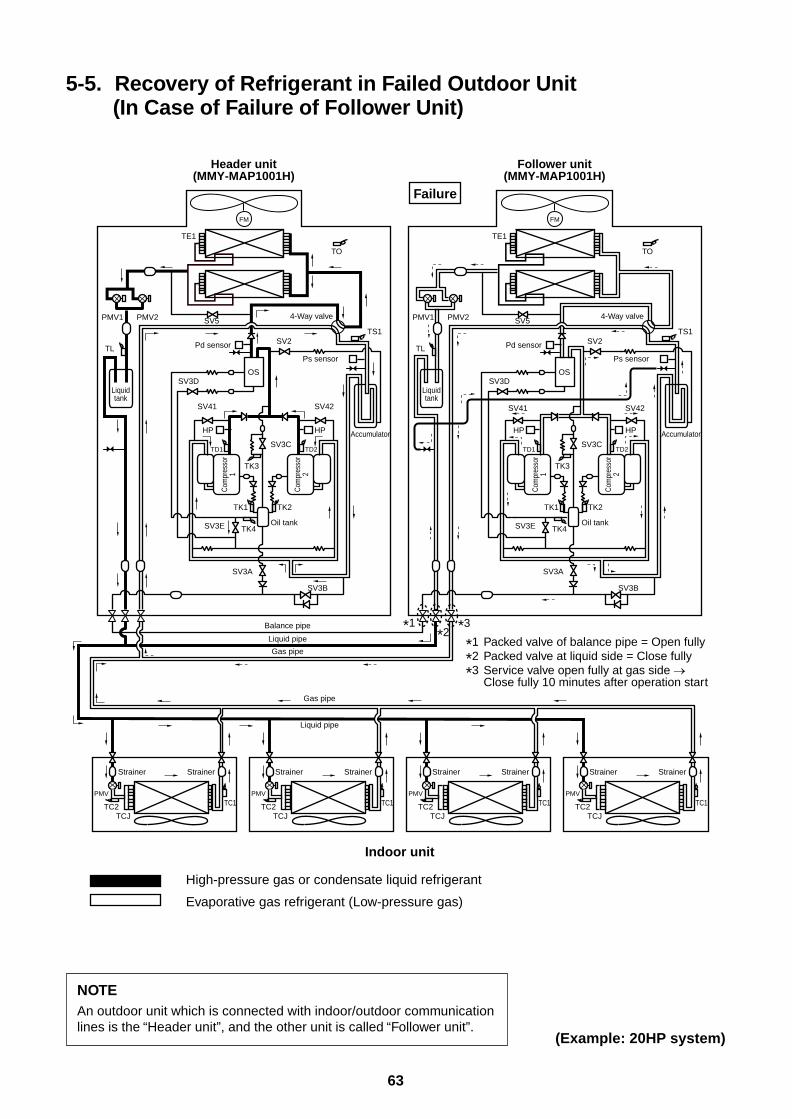
63
NOTEAn outdoor unit which is connected with indoor/outdoor communicationlines is the “Header unit”, and the other unit is called “Follower unit”.
(Example: 20HP system)
5-5. Recovery of Refrigerant in Failed Outdoor Unit(In Case of Failure of Follower Unit)
FM
TO
TS1
Liquidtank
4-Way valve
Accumulator
TK2
TK4
TK1
SV3E
SV41 SV42
SV3D
SV3A
TK3
SV3C
Oil tank
OS
Header unit(MMY-MAP1001H)
Follower unit(MMY-MAP1001H)
TE1
SV5
SV3B
Ps sensor
SV2TL
PMV1 PMV2
Com
pres
sor
1
Com
pres
sor
2
TD1
HP HP
TD2
Pd sensor
Strainer
TCJTC2 TC1
PMV
Strainer Strainer
TCJTC2 TC1
PMV
Strainer Strainer
TCJTC2 TC1
PMV
Strainer Strainer
TCJTC2 TC1
PMV
Strainer
Gas pipe
Gas pipe
Liquid pipe
Liquid pipe
Balance pipe
FM
TO
TS1
Liquidtank
4-Way valve
Accumulator
TK2
TK4
TK1
SV3E
SV41 SV42
SV3D
SV3A
TK3
SV3C
Oil tank
OS
TE1
SV5
SV3B
Ps sensor
SV2TL
PMV1 PMV2
Com
pres
sor
1
Com
pres
sor
2
TD1
HP HP
TD2
Pd sensor
Indoor unit
High-pressure gas or condensate liquid refrigerant
Evaporative gas refrigerant (Low-pressure gas)
Failure
*1 Packed valve of balance pipe = Open fully
*2 Packed valve at liquid side = Close fully
*3
*3*1*2
Service valve open fully at gas side Close fully 10 minutes after operation start
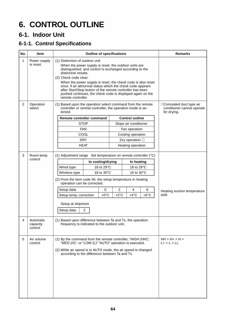
64
6. CONTROL OUTLINE6-1. Indoor Unit6-1-1. Control Specifications
No.
1
Outline of specifications
(1) Distinction of outdoor unitWhen the power supply is reset, the outdoor units aredistinguished, and control is exchanged according to thedistinctive results.
(2) Check code clearWhen the power supply is reset, the check code is also resetonce. If an abnormal status which the check code appearsafter Start/Stop button of the remote controller has beenpushed continues, the check code is displayed again on theremote controller.
RemarksItem
Power supplyis reset.
Remote controller command
STOP
FAN
COOL
DRY
HEAT
Control outline
Stops air conditioner.
Fan operation
Cooling operation
Dry operation ∗Heating operation
(1) Based upon the operation select command from the remotecontroller or central controller, the operation mode is se-lected.
2 Operationselect
∗ Concealed duct type airconditioner cannot operatefor drying.
3 Room temp.control
(1) Adjustment range Set temperature on remote controller (°C)
Wired type
Wireless type
In cooling/drying
18 to 29°C
18 to 30°C
In heating
18 to 29°C
16 to 30°C
(2) From the item code 06, the setup temperature in heatingoperation can be corrected.
Setup data
Setup temp. correction
0 2 4 6
+0°C +2°C +4°C +6°C
Setup at shipment
Setup data 2
Heating suction temperatureshift
4 Automaticcapacitycontrol
(1) Based upon difference between Ta and Ts, the operationfrequency is indicated to the outdoor unit.
Air volumecontrol
5 HH > H+ > H >L+ > L > LL
(1) By the command from the remote controller, “HIGH (HH)”,“MED (H)”, or “LOW (L)” “AUTO” operation is executed.
(2) While air speed is in AUTO mode, the air speed is changedaccording to the difference between Ta and Ts.
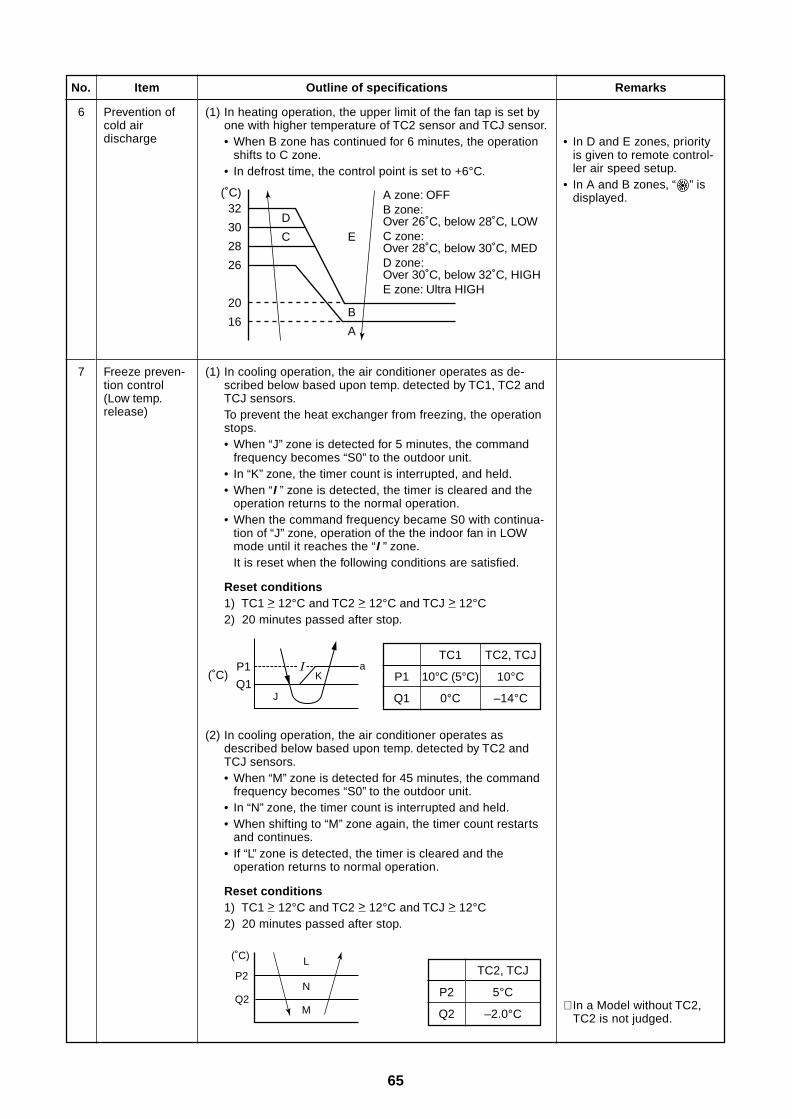
65
No.
6
Outline of specifications
(1) In heating operation, the upper limit of the fan tap is set byone with higher temperature of TC2 sensor and TCJ sensor.• When B zone has continued for 6 minutes, the operation
shifts to C zone.• In defrost time, the control point is set to +6°C.
Remarks
• In D and E zones, priorityis given to remote control-ler air speed setup.
• In A and B zones, “ ” isdisplayed.
Item
Prevention ofcold airdischarge
7 Freeze preven-tion control(Low temp.release)
(1) In cooling operation, the air conditioner operates as de-scribed below based upon temp. detected by TC1, TC2 andTCJ sensors.To prevent the heat exchanger from freezing, the operationstops.• When “J” zone is detected for 5 minutes, the command
frequency becomes “S0” to the outdoor unit.• In “K” zone, the timer count is interrupted, and held.• When “I ” zone is detected, the timer is cleared and the
operation returns to the normal operation.• When the command frequency became S0 with continua-
tion of “J” zone, operation of the the indoor fan in LOWmode until it reaches the “I ” zone.It is reset when the following conditions are satisfied.
Reset conditions1) TC1 > 12°C and TC2 > 12°C and TCJ > 12°C2) 20 minutes passed after stop.
P1
Q1
TC1 TC2, TCJ
10°C (5°C) 10°C
0°C –14°C
(2) In cooling operation, the air conditioner operates asdescribed below based upon temp. detected by TC2 andTCJ sensors.• When “M” zone is detected for 45 minutes, the command
frequency becomes “S0” to the outdoor unit.• In “N” zone, the timer count is interrupted and held.• When shifting to “M” zone again, the timer count restarts
and continues.• If “L” zone is detected, the timer is cleared and the
operation returns to normal operation.
Reset conditions1) TC1 > 12°C and TC2 > 12°C and TCJ > 12°C2) 20 minutes passed after stop.
∗ In a Model without TC2,TC2 is not judged.
P1
Q1(˚C)
aK
J
P2
Q2
(˚C) L
N
M
P2
Q2
TC2, TCJ
5°C
–2.0°C
E
B
A
A zone: OFFB zone: Over 26˚C, below 28˚C, LOWC zone: Over 28˚C, below 30˚C, MEDD zone: Over 30˚C, below 32˚C, HIGHE zone: Ultra HIGH
D
C
32
30
28
26
20
16
(˚C)
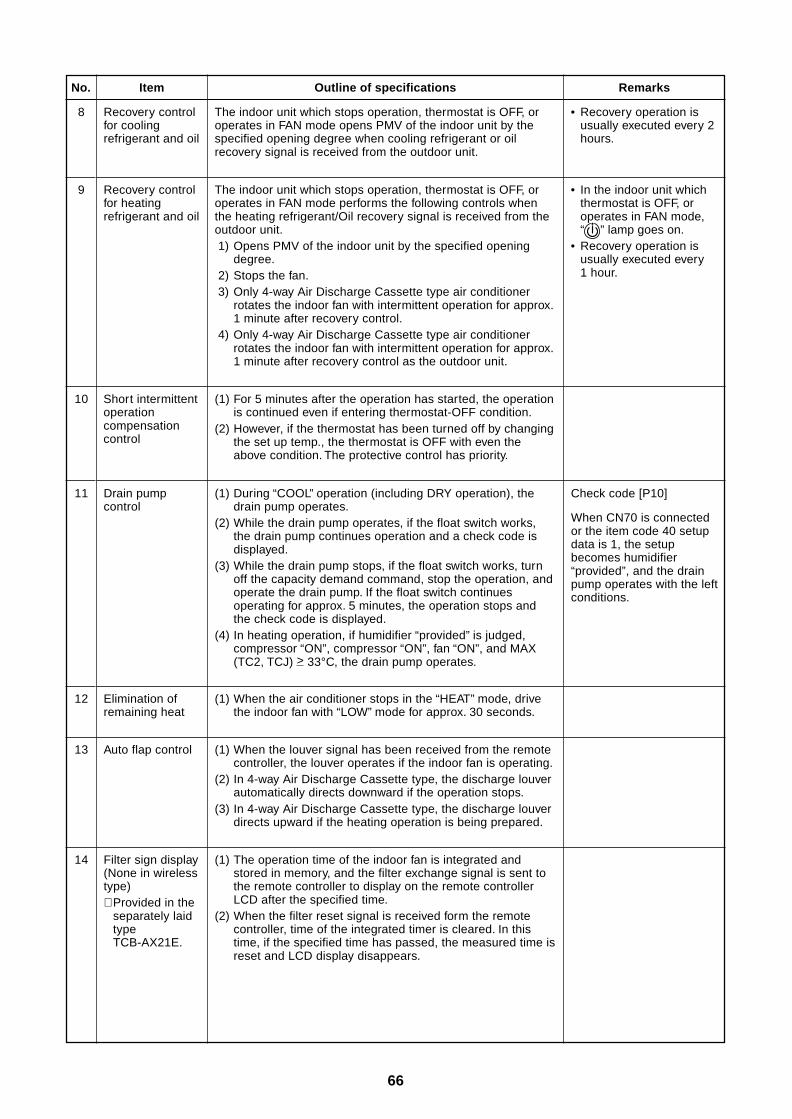
66
No.
8
Outline of specifications
The indoor unit which stops operation, thermostat is OFF, oroperates in FAN mode opens PMV of the indoor unit by thespecified opening degree when cooling refrigerant or oilrecovery signal is received from the outdoor unit.
Remarks
• Recovery operation isusually executed every 2hours.
Item
Recovery controlfor coolingrefrigerant and oil
9
10
11
Recovery controlfor heatingrefrigerant and oil
Short intermittentoperationcompensationcontrol
Drain pumpcontrol
The indoor unit which stops operation, thermostat is OFF, oroperates in FAN mode performs the following controls whenthe heating refrigerant/Oil recovery signal is received from theoutdoor unit. 1) Opens PMV of the indoor unit by the specified opening
degree. 2) Stops the fan. 3) Only 4-way Air Discharge Cassette type air conditioner
rotates the indoor fan with intermittent operation for approx.1 minute after recovery control.
4) Only 4-way Air Discharge Cassette type air conditionerrotates the indoor fan with intermittent operation for approx.1 minute after recovery control as the outdoor unit.
• In the indoor unit whichthermostat is OFF, oroperates in FAN mode,“ ” lamp goes on.
• Recovery operation isusually executed every1 hour.
(1) For 5 minutes after the operation has started, the operationis continued even if entering thermostat-OFF condition.
(2) However, if the thermostat has been turned off by changingthe set up temp., the thermostat is OFF with even theabove condition. The protective control has priority.
(1) During “COOL” operation (including DRY operation), thedrain pump operates.
(2) While the drain pump operates, if the float switch works,the drain pump continues operation and a check code isdisplayed.
(3) While the drain pump stops, if the float switch works, turnoff the capacity demand command, stop the operation, andoperate the drain pump. If the float switch continuesoperating for approx. 5 minutes, the operation stops andthe check code is displayed.
(4) In heating operation, if humidifier “provided” is judged,compressor “ON”, compressor “ON”, fan “ON”, and MAX(TC2, TCJ) > 33°C, the drain pump operates.
Check code [P10]
When CN70 is connectedor the item code 40 setupdata is 1, the setupbecomes humidifier“provided”, and the drainpump operates with the leftconditions.
12 Elimination ofremaining heat
(1) When the air conditioner stops in the “HEAT” mode, drivethe indoor fan with “LOW” mode for approx. 30 seconds.
13 Auto flap control (1) When the louver signal has been received from the remotecontroller, the louver operates if the indoor fan is operating.
(2) In 4-way Air Discharge Cassette type, the discharge louverautomatically directs downward if the operation stops.
(3) In 4-way Air Discharge Cassette type, the discharge louverdirects upward if the heating operation is being prepared.
14 Filter sign display(None in wirelesstype)∗ Provided in the
separately laidtypeTCB-AX21E.
(1) The operation time of the indoor fan is integrated andstored in memory, and the filter exchange signal is sent tothe remote controller to display on the remote controllerLCD after the specified time.
(2) When the filter reset signal is received form the remotecontroller, time of the integrated timer is cleared. In thistime, if the specified time has passed, the measured time isreset and LCD display disappears.
67
No.
15
Outline of specifications
<Operation standby> .......... Display on remote controller(1) • “P05” is one of displays of power wire missing.
• “P05” of power cable is detected.• “COOL/DRY” operation cannot be performed because the
other indoor unit is under “HEAT” operation.• “HEAT” operation cannot be performed because COOL
priority is set (Outdoor I/F P.C. board SW11 1-bit is ON)and the other indoor unit is under “COOL/DRY” operation.
• “FAN” operation cannot be performed because the systemperforms “Heat oil/Refrigerant recovery” operation.
• There is a unit in which indoor overflow “P10” is detected.• There is a unit in which interlock alarm “P23” is detected.
(2) The above indoor units unavailable to operate waits undercondition of thermostat OFF.
<HEAT standby> .................. Display on remote controller(1) • HEAT thermostat is OFF.
• During HEAT operation, the fan rotates with lower air speedthan one specified in order to prevent discharge of colddraft or stops. (including case that defrost operation isbeing performed)
• “HEAT” operation cannot be performed because COOLpriority is set (Outdoor I/F P.C. board SW11 bit 1 is ON) andthe other indoor unit is under “COOL/DRY” operation.
(2) “HEAT standby” is displayed until the above conditions arereleased.
Remarks
• “ ” goes on.
Item
“ ” and “ ”display(Operation andheating stand-by)
• “ ” goes on.
16 Selection ofcentral controlmode
(1) The contents which can be changed on the remote controllerat indoor unit side can be selected by setup at the centralcontroller side.
(2) In case of operation from TCC-LINK central controller(TCB-SC642TLE, etc.)[Central control mode 1] : Cannot operate[Central control mode 2] :Cannot operate, stop, select mode, set up temp.[Central control mode 3] :Cannot select mode, set up temp.[Central control mode 4] : Cannot select mode
(3) RBC-AMT21E (Wired remote controller)
While mode is the central control mode, “ CENTRAL”lights on the display part of the remote controller.
If operation is performedfrom the remote control“CENTRAL CONTROL”mode, the status isnotified with receivingsound.
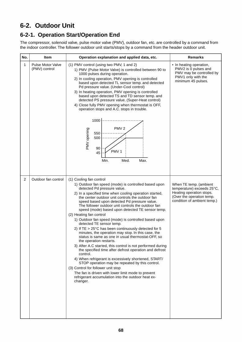
68
6-2. Outdoor Unit6-2-1. Operation Start/Operation EndThe compressor, solenoid valve, pulse motor valve (PMV), outdoor fan, etc. are controlled by a command fromthe indoor controller. The follower outdoor unit starts/stops by a command from the header outdoor unit.
No.
1
Operation explanation and applied data, etc.
(1) PMV control (using two PMV, 1 and 2)1) PMV (Pulse Motor Valve) is controlled between 90 to
1000 pulses during operation.2) In cooling operation, PMV opening is controlled
based upon detected TL sensor temp. and detectedPd pressure value. (Under-Cool control)
3) In heating operation, PMV opening is controlledbased upon detected TS and TD sensor temp. anddetected PS pressure value. (Super-Heat control)
4) Close fully PMV opening when thermostat is OFF,operation stops and A.C. stops in trouble.
Remarks
• In heating operation,PMV2 is 0 pulses andPMV may be controlled byPMV1 only with theminimum 45 pulses.
Item
Pulse Motor Valve(PMV) control
2 Outdoor fan control (1) Cooling fan control1) Outdoor fan speed (mode) is controlled based upon
detected Pd pressure value.2) In a specified time when cooling operation started,
the center outdoor unit controls the outdoor fanspeed based upon detected Pd pressure value.The follower outdoor unit controls the outdoor fanspeed (mode) based upon detected TE sensor temp.
(2) Heating fan control1) Outdoor fan speed (mode) is controlled based upon
detected TE sensor temp.2) If TE > 25°C has been continuously detected for 5
minutes, the operation may stop. In this case, thestatus is same as one in usual thermostat-OFF, sothe operation restarts.
3) After A.C started, this control is not performed duringthe specified time after defrost operation and defrostcontrol.
4) When refrigerant is excessively shortened, START/STOP operation may be repeated by this control.
(3) Control for follower unit stopThe fan is driven with lower limit mode to preventrefrigerant accumulation into the outdoor heat ex-changer.
PM
V o
peni
ng
4590
500550
1000
Min. Med. Max.
PMV 1
PMV 2
When TE temp. (ambienttemperature) exceeds 25°C,Heating operation stops.(Over the operation temp.condition of ambient temp.)
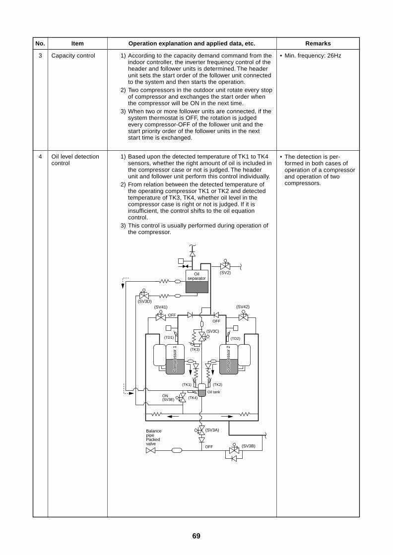
69
No.
3
Operation explanation and applied data, etc.
1) According to the capacity demand command from theindoor controller, the inverter frequency control of theheader and follower units is determined. The headerunit sets the start order of the follower unit connectedto the system and then starts the operation.
2) Two compressors in the outdoor unit rotate every stopof compressor and exchanges the start order whenthe compressor will be ON in the next time.
3) When two or more follower units are connected, if thesystem thermostat is OFF, the rotation is judgedevery compressor-OFF of the follower unit and thestart priority order of the follower units in the nextstart time is exchanged.
Remarks
• Min. frequency: 26Hz
Item
Capacity control
4 Oil level detectioncontrol
1) Based upon the detected temperature of TK1 to TK4sensors, whether the right amount of oil is included inthe compressor case or not is judged. The headerunit and follower unit perform this control individually.
2) From relation between the detected temperature ofthe operating compressor TK1 or TK2 and detectedtemperature of TK3, TK4, whether oil level in thecompressor case is right or not is judged. If it isinsufficient, the control shifts to the oil equationcontrol.
3) This control is usually performed during operation ofthe compressor.
(SV2)
(SV41)
(SV3A)
ON(SV3E)
OFF
OFF
OFF (SV3B)
(SV3D)
(SV3C)
Com
pres
sor
1C
ompr
esso
r 1
Com
pres
sor
2C
ompr
esso
r 2
Com
pres
sor
1
Com
pres
sor
2
(TK1)
(TK4)
(TK3)
(SV42)
(TK2)
(TD2)(TD1)
Oil tank
Balance pipePacked valve
Oilseparator
• The detection is per-formed in both cases ofoperation of a compressorand operation of twocompressors.
70
No.
5
Operation explanation and applied data, etc.
This control is provided to prevent the oil short in the compressorof each outdoor unit. This control is basically performed by ON/OFFoperation of the solenoid valves SV3A, SV3B, SV3C, SV3D.(For the schematic diagram of oil equation control.)(1) Oil equation control
This control supplies oil accumulated in the oil tank of eachoutdoor unit to the outdoor unit in which oil level moved down.This control is performed during compressor-ON of the headerunit when oil level judgment result of the header unit shows“Short” or the oil equation demand is issued from the system ofeven a header unit. In a case of system with a header unit (Nofollower unit is connected.), this control is not executed.
(2) Oil-short protective controlIf an oil equation control is executed, the protection stops whenthe status of oil short continues for 30 minutes, and it restartsafter 2 minutes and 30 seconds after. After then, if the protec-tion stop is repeated 3 times, an error is determined.(Restart is not performed.) The error code is “H07”.
RemarksItem
Oil equationcontrol
6 Refrigerant/Oilrecovery control
(1) In cooling operation, this control is executed to regularlyrecover the refrigerating oil stagnated in gas inter-unit pipe orindoor unit to the outdoor unit when the compressor drivingcommand is weak, and to prevent refrigerant accumulation inthe outdoor heat exchanger while low ambient cooling opera-tion is performed.This control is managed by the header outdoor unit.1) Control conditions
• Cooling oil recovery control is executed every 2 hoursapproximately.
2) Contents of control• Recovery time continues for approx. 2 or 3 minutes though
it differs according to the system capacity.(2) Refrigerant recovery control in heating room
During heating operation, this is executed to recover liquidrefrigerant stagnated in the stopped indoor unit. It is also used torecover oil in the outdoor heat exchanger in heating overloadoperation except with defrost condition.This control is managed by the header outdoor unit.1) Heating refrigerant recovery control is executed every an
hour approximately.2) Recovery time continues for approx. 2 to 10 minutes though
it differs according to the load condition.
(1) Defrost start conditionIn heating operation, the operating time is integrated when thedetected TE sensor temp was lower than -2°C, and when 25minutes have passed in the initial time after the compressorstarted and 55 minutes in the second time and after.
(2) Contents of control• If the outdoor units are combined, the defrost operation
forcedly continues for 2 minutes if the defrost operation hasbeen once started.
(3) Stop conditions of defrost operation• If the outdoor units are combined, the fan drive and compres-
sor inverter frequency may be controlled by Pd pressureduring defrost operation.
7 Defrost control(Reversedefrost method)
• During defrostingoperation, all thesolenoid valves of4-way are OFF and allcompressors aredriven.
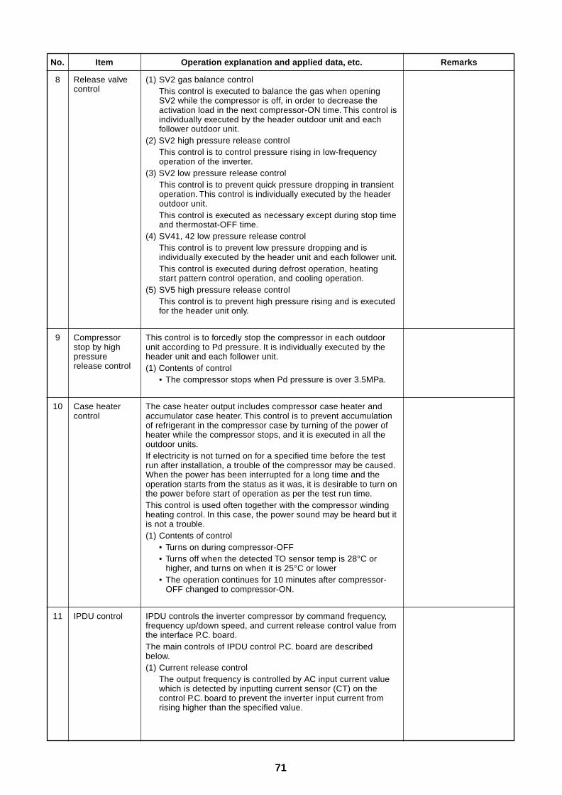
71
No.
8
Operation explanation and applied data, etc.
(1) SV2 gas balance controlThis control is executed to balance the gas when openingSV2 while the compressor is off, in order to decrease theactivation load in the next compressor-ON time. This control isindividually executed by the header outdoor unit and eachfollower outdoor unit.
(2) SV2 high pressure release controlThis control is to control pressure rising in low-frequencyoperation of the inverter.
(3) SV2 low pressure release controlThis control is to prevent quick pressure dropping in transientoperation. This control is individually executed by the headeroutdoor unit.This control is executed as necessary except during stop timeand thermostat-OFF time.
(4) SV41, 42 low pressure release controlThis control is to prevent low pressure dropping and isindividually executed by the header unit and each follower unit.This control is executed during defrost operation, heatingstart pattern control operation, and cooling operation.
(5) SV5 high pressure release controlThis control is to prevent high pressure rising and is executedfor the header unit only.
Item
Release valvecontrol
9 Compressorstop by highpressurerelease control
This control is to forcedly stop the compressor in each outdoorunit according to Pd pressure. It is individually executed by theheader unit and each follower unit.(1) Contents of control
• The compressor stops when Pd pressure is over 3.5MPa.
Remarks
10 Case heatercontrol
The case heater output includes compressor case heater andaccumulator case heater. This control is to prevent accumulationof refrigerant in the compressor case by turning of the power ofheater while the compressor stops, and it is executed in all theoutdoor units.If electricity is not turned on for a specified time before the testrun after installation, a trouble of the compressor may be caused.When the power has been interrupted for a long time and theoperation starts from the status as it was, it is desirable to turn onthe power before start of operation as per the test run time.This control is used often together with the compressor windingheating control. In this case, the power sound may be heard but itis not a trouble.(1) Contents of control
• Turns on during compressor-OFF• Turns off when the detected TO sensor temp is 28°C or
higher, and turns on when it is 25°C or lower• The operation continues for 10 minutes after compressor-
OFF changed to compressor-ON.
11 IPDU control IPDU controls the inverter compressor by command frequency,frequency up/down speed, and current release control value fromthe interface P.C. board.The main controls of IPDU control P.C. board are describedbelow.(1) Current release control
The output frequency is controlled by AC input current valuewhich is detected by inputting current sensor (CT) on thecontrol P.C. board to prevent the inverter input current fromrising higher than the specified value.
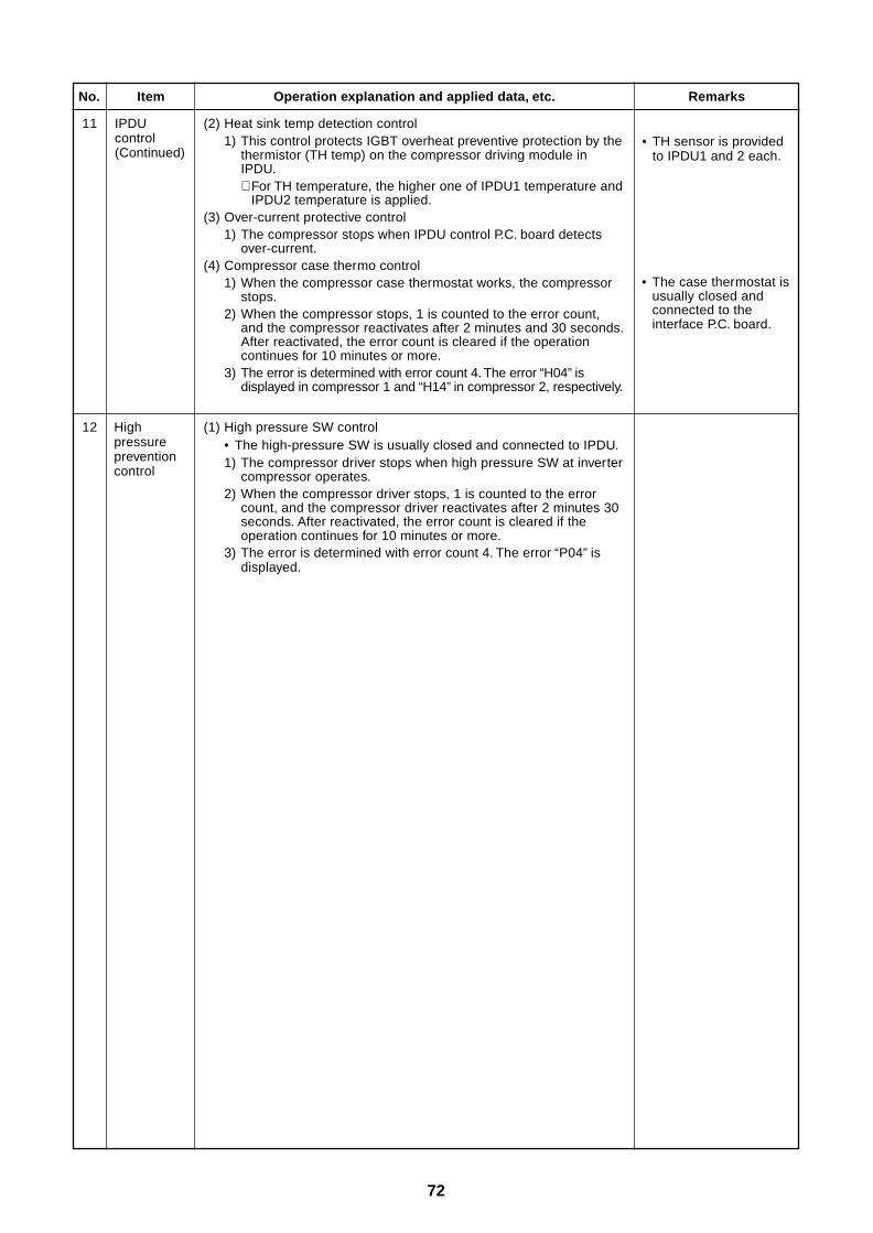
72
No.
11
Operation explanation and applied data, etc.
(2) Heat sink temp detection control1) This control protects IGBT overheat preventive protection by the
thermistor (TH temp) on the compressor driving module inIPDU.∗ For TH temperature, the higher one of IPDU1 temperature and
IPDU2 temperature is applied.(3) Over-current protective control
1) The compressor stops when IPDU control P.C. board detectsover-current.
(4) Compressor case thermo control1) When the compressor case thermostat works, the compressor
stops.2) When the compressor stops, 1 is counted to the error count,
and the compressor reactivates after 2 minutes and 30 seconds.After reactivated, the error count is cleared if the operationcontinues for 10 minutes or more.
3) The error is determined with error count 4. The error “H04” isdisplayed in compressor 1 and “H14” in compressor 2, respectively.
Item
IPDUcontrol(Continued)
Remarks
• TH sensor is providedto IPDU1 and 2 each.
12 Highpressurepreventioncontrol
(1) High pressure SW control• The high-pressure SW is usually closed and connected to IPDU.1) The compressor driver stops when high pressure SW at inverter
compressor operates.2) When the compressor driver stops, 1 is counted to the error
count, and the compressor driver reactivates after 2 minutes 30seconds. After reactivated, the error count is cleared if theoperation continues for 10 minutes or more.
3) The error is determined with error count 4. The error “P04” isdisplayed.
• The case thermostat isusually closed andconnected to theinterface P.C. board.
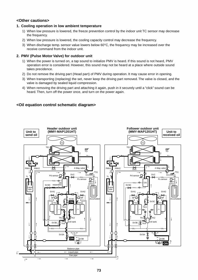
73
<Other cautions>1. Cooling operation in low ambient temperature
1) When low pressure is lowered, the freeze prevention control by the indoor unit TC sensor may decreasethe frequency.
2) When low pressure is lowered, the cooling capacity control may decrease the frequency.
3) When discharge temp. sensor value lowers below 60°C, the frequency may be increased over thereceive command from the indoor unit.
2. PMV (Pulse Motor Valve) for outdoor unit1) When the power is turned on, a tap sound to initialize PMV is heard. If this sound is not heard, PMV
operation error is considered. However, this sound may not be heard at a place where outside soundtakes precidence.
2) Do not remove the driving part (Head part) of PMV during operation. It may cause error in opening.
3) When transporting (replacing) the set, never keep the driving part removed. The valve is closed, and thevalve is damaged by sealed liquid compression.
4) When removing the driving part and attaching it again, push in it securely until a “click” sound can beheard. Then, turn off the power once, and turn on the power again.
<Oil equation control schematic diagram>
FM
TO
TS1
Liquidtank
4-Way valve
Accumulator
TK2
TK4
TK1
SV3E
SV41 SV42
SV3D
SV3A
TK3
SV3C
Oil tank
Header outdoor unit(MMY-MAP1201HT)
Follower outdoor unit(MMY-MAP1201HT)
TE1
SV5
SV3B
Ps sensor
SV2TL
PMV1 PMV2
Com
pres
sor
1
Com
pres
sor
2
TD1
HP HP
TD2
Pd sensor
FM
TO
TS1
Liquidtank
4-Way valve
Accumulator
TK2
TK4
TK1
SV3E
SV41 SV42
SV3DOil
separator
SV3A
TK3
SV3C
Oil tank
OS
TE1
SV5
SV3B
Ps sensor
SV2TL
PMV1 PMV2
Com
pres
sor
1
Com
pres
sor
2
TD1
HP HP
TD2
Pd sensor
Gas pipe
Liquid pipe
Balance pipe
Unit to send oil
Unit toreceived oil
ON
ON
ON
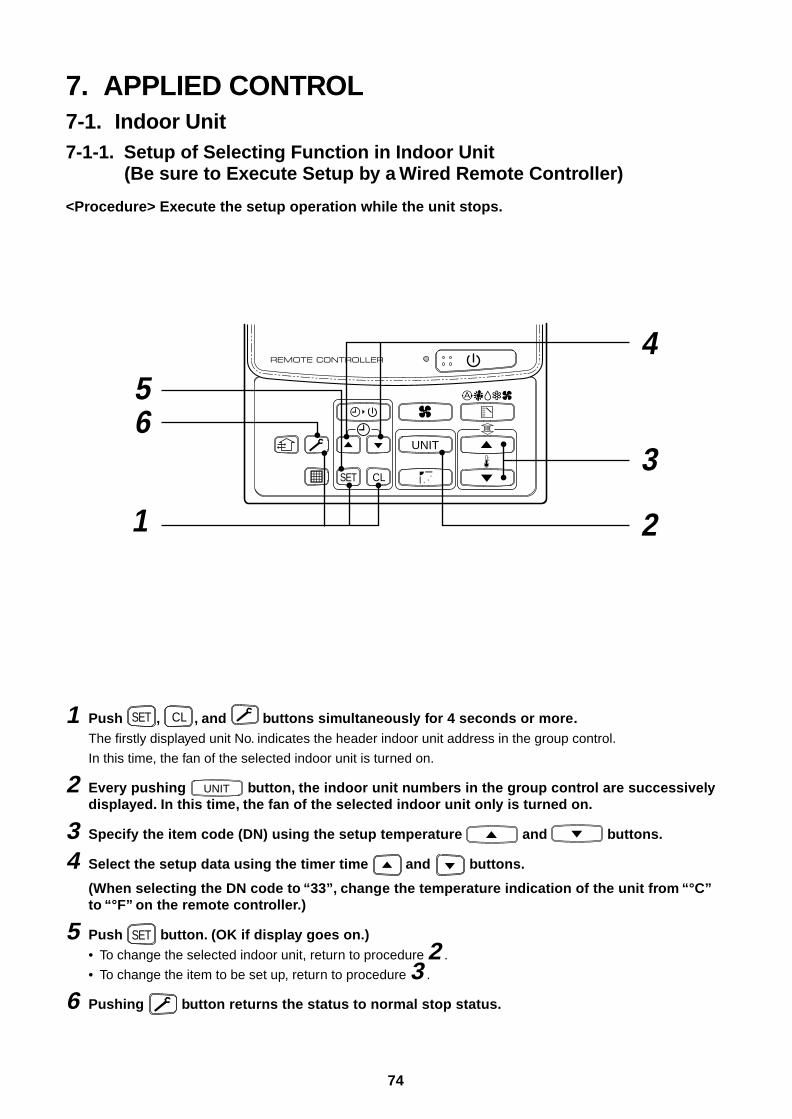
74
7. APPLIED CONTROL7-1. Indoor Unit7-1-1. Setup of Selecting Function in Indoor Unit
(Be sure to Execute Setup by a Wired Remote Controller)
<Procedure> Execute the setup operation while the unit stops.
1 Push SET , CL , and buttons simultaneously for 4 seconds or more.The firstly displayed unit No. indicates the header indoor unit address in the group control.
In this time, the fan of the selected indoor unit is turned on.
2 Every pushing UNIT button, the indoor unit numbers in the group control are successivelydisplayed. In this time, the fan of the selected indoor unit only is turned on.
3 Specify the item code (DN) using the setup temperature and buttons.
4 Select the setup data using the timer time and buttons.
(When selecting the DN code to “33”, change the temperature indication of the unit from “°C”to “°F” on the remote controller.)
5 Push SET button. (OK if display goes on.)• To change the selected indoor unit, return to procedure 2 .
• To change the item to be set up, return to procedure 3 .
6 Pushing button returns the status to normal stop status.
UNIT
SET CL
1
4
2
3 65
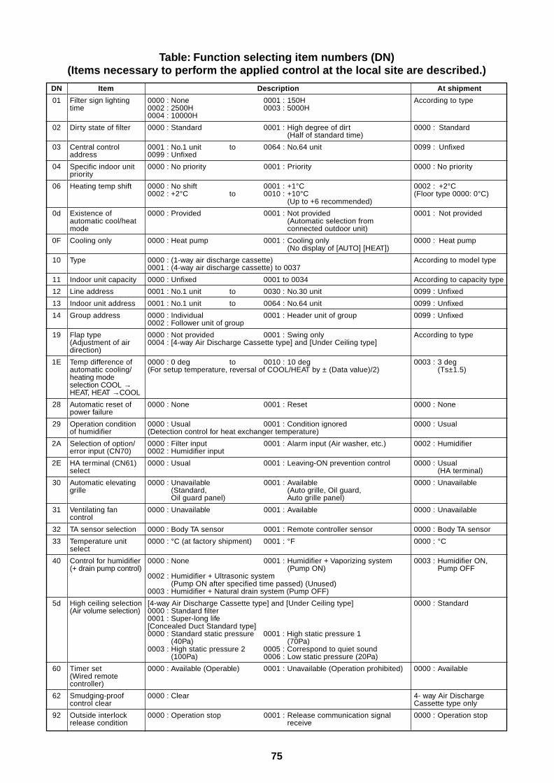
75
Table: Function selecting item numbers (DN)(Items necessary to perform the applied control at the local site are described.)
DN
01
02
03
04
06
0d
0F
10
11
12
13
14
19
1E
28
29
2A
2E
30
31
32
33
40
5d
60
62
92
Item
Filter sign lightingtime
Dirty state of filter
Central controladdress
Specific indoor unitpriority
Heating temp shift
Existence ofautomatic cool/heatmode
Cooling only
Type
Indoor unit capacity
Line address
Indoor unit address
Group address
Flap type(Adjustment of airdirection)
Temp difference ofautomatic cooling/heating modeselection COOL →HEAT, HEAT →COOL
Automatic reset ofpower failure
Operation conditionof humidifier
Selection of option/error input (CN70)
HA terminal (CN61)select
Automatic elevatinggrille
Ventilating fancontrol
TA sensor selection
Temperature unitselect
Control for humidifier(+ drain pump control)
High ceiling selection(Air volume selection)
Timer set(Wired remotecontroller)
Smudging-proofcontrol clear
Outside interlockrelease condition
Description
0000 : None 0001 : 150H0002 : 2500H 0003 : 5000H0004 : 10000H
0000 : Standard 0001 : High degree of dirt(Half of standard time)
0001 : No.1 unit to 0064 : No.64 unit0099 : Unfixed
0000 : No priority 0001 : Priority
0000 : No shift 0001 : +1°C0002 : +2°C to 0010 : +10°C
(Up to +6 recommended)
0000 : Provided 0001 : Not provided(Automatic selection fromconnected outdoor unit)
0000 : Heat pump 0001 : Cooling only(No display of [AUTO] [HEAT])
0000 : (1-way air discharge cassette)0001 : (4-way air discharge cassette) to 0037
0000 : Unfixed 0001 to 0034
0001 : No.1 unit to 0030 : No.30 unit
0001 : No.1 unit to 0064 : No.64 unit
0000 : Individual 0001 : Header unit of group0002 : Follower unit of group
0000 : Not provided 0001 : Swing only0004 : [4-way Air Discharge Cassette type] and [Under Ceiling type]
0000 : 0 deg to 0010 : 10 deg(For setup temperature, reversal of COOL/HEAT by ± (Data value)/2)
0000 : None 0001 : Reset
0000 : Usual 0001 : Condition ignored(Detection control for heat exchanger temperature)
0000 : Filter input 0001 : Alarm input (Air washer, etc.)0002 : Humidifier input
0000 : Usual 0001 : Leaving-ON prevention control
0000 : Unavailable 0001 : Available(Standard, (Auto grille, Oil guard,Oil guard panel) Auto grille panel)
0000 : Unavailable 0001 : Available
0000 : Body TA sensor 0001 : Remote controller sensor
0000 : °C (at factory shipment) 0001 : °F
0000 : None 0001 : Humidifier + Vaporizing system(Pump ON)
0002 : Humidifier + Ultrasonic system(Pump ON after specified time passed) (Unused)
0003 : Humidifier + Natural drain system (Pump OFF)
[4-way Air Discharge Cassette type] and [Under Ceiling type]0000 : Standard filter0001 : Super-long life[Concealed Duct Standard type]0000 : Standard static pressure 0001 : High static pressure 1
(40Pa) (70Pa)0003 : High static pressure 2 0005 : Correspond to quiet sound
(100Pa) 0006 : Low static pressure (20Pa)
0000 : Available (Operable) 0001 : Unavailable (Operation prohibited)
0000 : Clear
0000 : Operation stop 0001 : Release communication signalreceive
At shipment
According to type
0000 : Standard
0099 : Unfixed
0000 : No priority
0002 : +2°C(Floor type 0000: 0°C)
0001 : Not provided
0000 : Heat pump
According to model type
According to capacity type
0099 : Unfixed
0099 : Unfixed
0099 : Unfixed
According to type
0003 : 3 deg(Ts±1.5)
0000 : None
0000 : Usual
0002 : Humidifier
0000 : Usual(HA terminal)
0000 : Unavailable
0000 : Unavailable
0000 : Body TA sensor
0000 : °C
0003 : Humidifier ON,Pump OFF
0000 : Standard
0000 : Available
4- way Air DischargeCassette type only
0000 : Operation stop
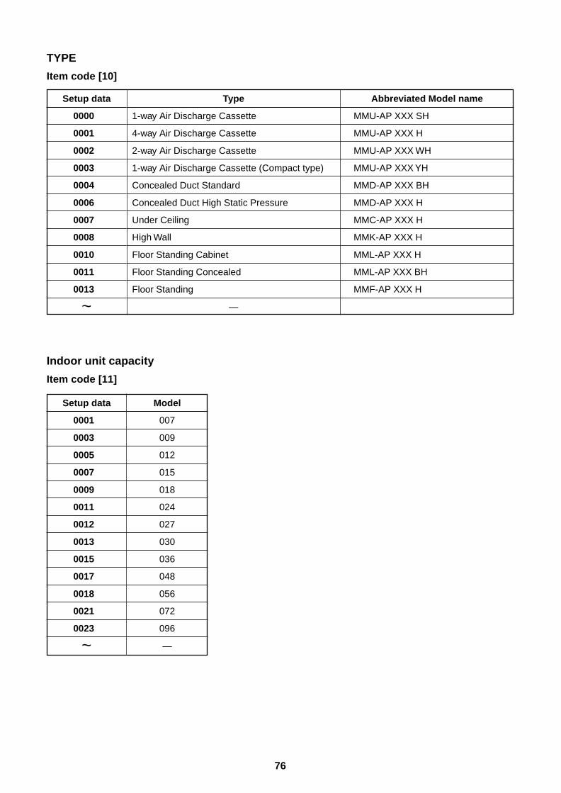
76
TYPE
Item code [10]
Type
1-way Air Discharge Cassette
4-way Air Discharge Cassette
2-way Air Discharge Cassette
1-way Air Discharge Cassette (Compact type)
Concealed Duct Standard
Concealed Duct High Static Pressure
Under Ceiling
High Wall
Floor Standing Cabinet
Floor Standing Concealed
Floor Standing
—
Abbreviated Model name
MMU-AP XXX SH
MMU-AP XXX H
MMU-AP XXX WH
MMU-AP XXX YH
MMD-AP XXX BH
MMD-AP XXX H
MMC-AP XXX H
MMK-AP XXX H
MML-AP XXX H
MML-AP XXX BH
MMF-AP XXX H
Setup data
0001
0003
0005
0007
0009
0011
0012
0013
0015
0017
0018
0021
0023
~
Model
007
009
012
015
018
024
027
030
036
048
056
072
096
—
Setup data
0000
0001
0002
0003
0004
0006
0007
0008
0010
0011
0013
~
Indoor unit capacity
Item code [11]
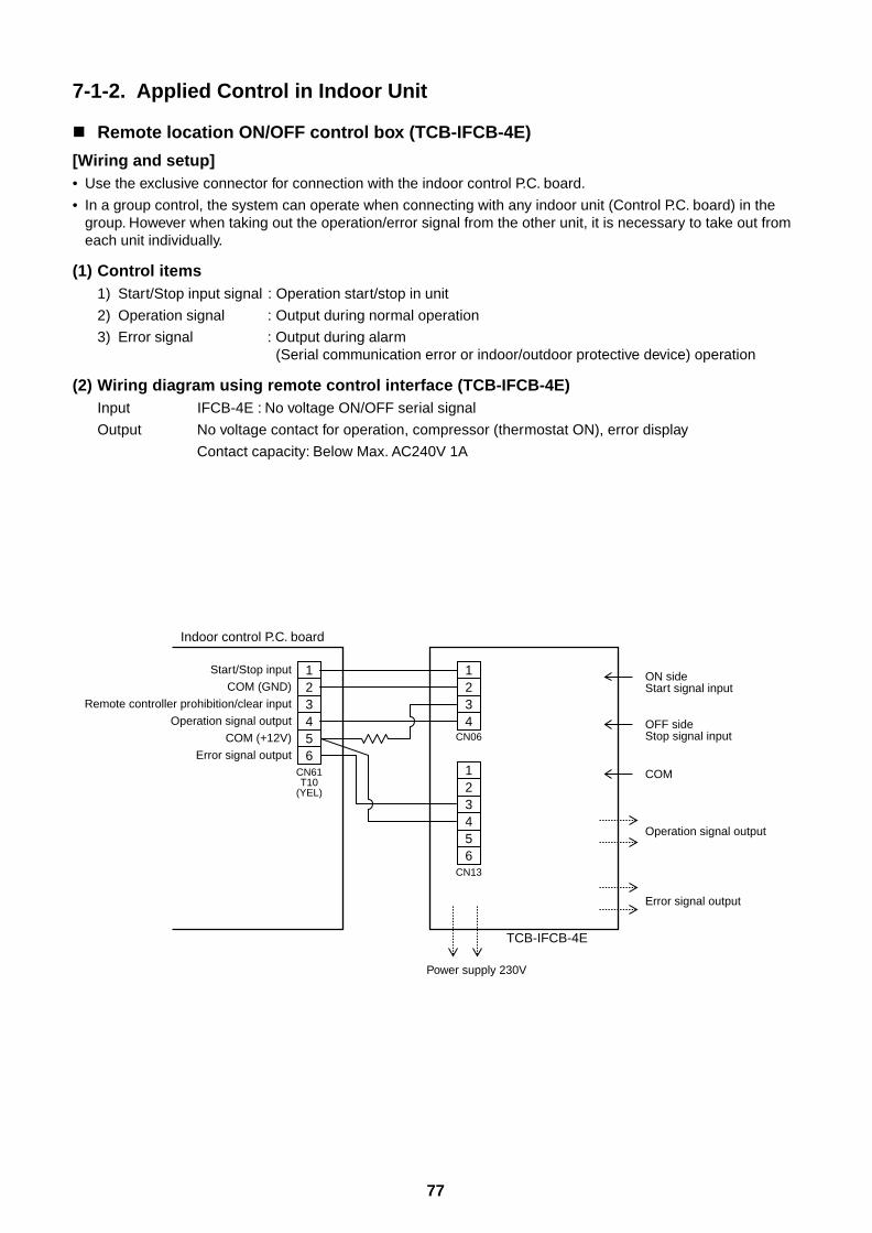
77
7-1-2. Applied Control in Indoor Unit
Remote location ON/OFF control box (TCB-IFCB-4E)
[Wiring and setup]• Use the exclusive connector for connection with the indoor control P.C. board.
• In a group control, the system can operate when connecting with any indoor unit (Control P.C. board) in thegroup. However when taking out the operation/error signal from the other unit, it is necessary to take out fromeach unit individually.
(1) Control items1) Start/Stop input signal : Operation start/stop in unit
2) Operation signal : Output during normal operation
3) Error signal : Output during alarm(Serial communication error or indoor/outdoor protective device) operation
(2) Wiring diagram using remote control interface (TCB-IFCB-4E)Input IFCB-4E : No voltage ON/OFF serial signal
Output No voltage contact for operation, compressor (thermostat ON), error display
Contact capacity: Below Max. AC240V 1A
123456
CN61T10
(YEL)
1234
1234
56
CN13
CN06
Start/Stop inputON sideStart signal input
Indoor control P.C. board
COM (GND)
Remote controller prohibition/clear input
Operation signal output
COM (+12V)
Error signal output
OFF sideStop signal input
COM
Operation signal output
Error signal output
Power supply 230V
TCB-IFCB-4E
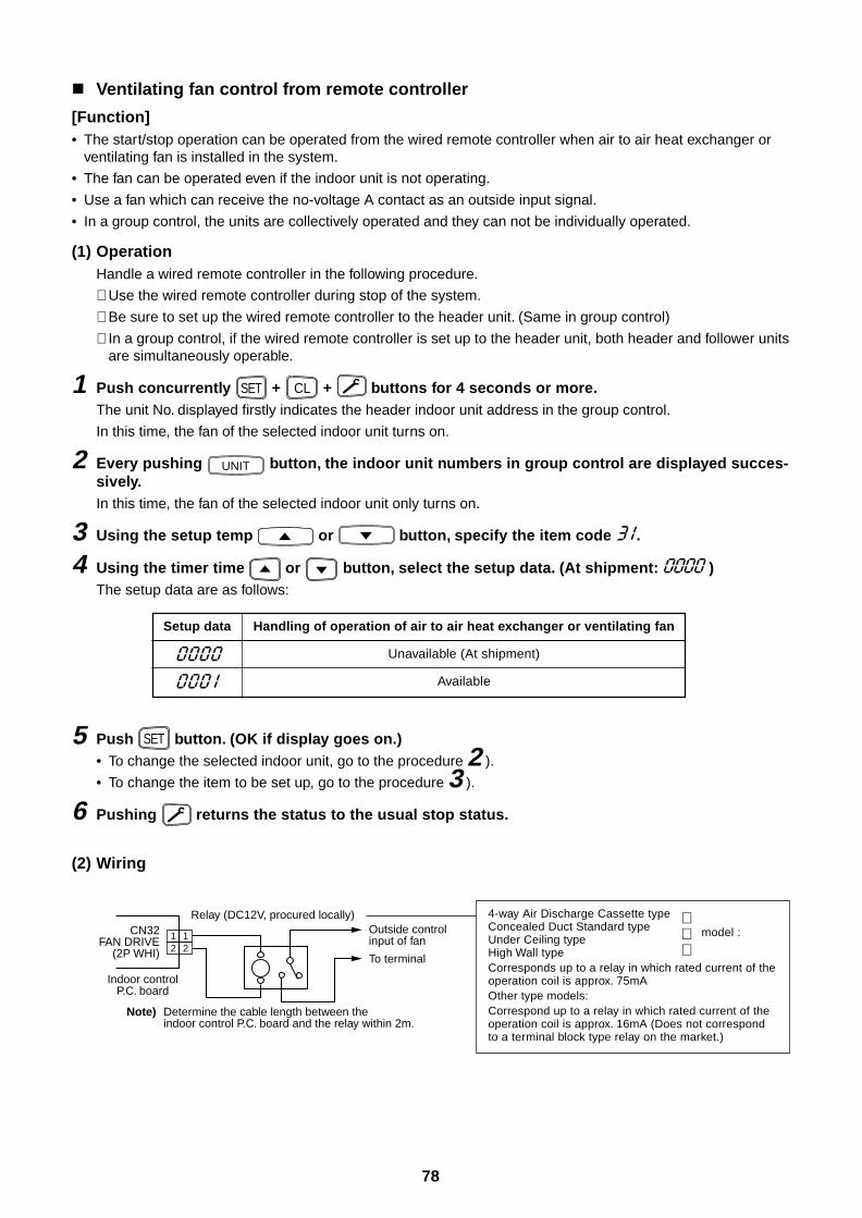
78
Ventilating fan control from remote controller
[Function]• The start/stop operation can be operated from the wired remote controller when air to air heat exchanger or
ventilating fan is installed in the system.
• The fan can be operated even if the indoor unit is not operating.
• Use a fan which can receive the no-voltage A contact as an outside input signal.
• In a group control, the units are collectively operated and they can not be individually operated.
(1) OperationHandle a wired remote controller in the following procedure.
∗ Use the wired remote controller during stop of the system.
∗ Be sure to set up the wired remote controller to the header unit. (Same in group control)
∗ In a group control, if the wired remote controller is set up to the header unit, both header and follower unitsare simultaneously operable.
1 Push concurrently SET + CL + buttons for 4 seconds or more.The unit No. displayed firstly indicates the header indoor unit address in the group control.
In this time, the fan of the selected indoor unit turns on.
2 Every pushing UNIT button, the indoor unit numbers in group control are displayed succes-sively.In this time, the fan of the selected indoor unit only turns on.
3 Using the setup temp or button, specify the item code .
4 Using the timer time or button, select the setup data. (At shipment: )The setup data are as follows:
Setup data
Handling of operation of air to air heat exchanger or ventilating fan
Unavailable (At shipment)
Available
12
12
CN32FAN DRIVE
(2P WHI)
Relay (DC12V, procured locally)Outside control input of fan
To terminal
Indoor controlP.C. board
Note) Determine the cable length between the indoor control P.C. board and the relay within 2m.
5 Push SET button. (OK if display goes on.)• To change the selected indoor unit, go to the procedure 2 ).
• To change the item to be set up, go to the procedure 3 ).
6 Pushing returns the status to the usual stop status.
(2) Wiring
4-way Air Discharge Cassette typeConcealed Duct Standard type model :Under Ceiling typeHigh Wall typeCorresponds up to a relay in which rated current of theoperation coil is approx. 75mAOther type models:Correspond up to a relay in which rated current of theoperation coil is approx. 16mA (Does not correspondto a terminal block type relay on the market.)
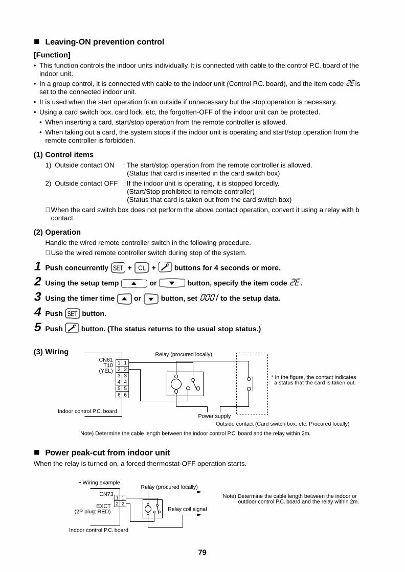
79
Leaving-ON prevention control
[Function]• This function controls the indoor units individually. It is connected with cable to the control P.C. board of the
indoor unit.
• In a group control, it is connected with cable to the indoor unit (Control P.C. board), and the item code isset to the connected indoor unit.
• It is used when the start operation from outside if unnecessary but the stop operation is necessary.
• Using a card switch box, card lock, etc, the forgotten-OFF of the indoor unit can be protected.
• When inserting a card, start/stop operation from the remote controller is allowed.
• When taking out a card, the system stops if the indoor unit is operating and start/stop operation from theremote controller is forbidden.
(1) Control items1) Outside contact ON : The start/stop operation from the remote controller is allowed.
(Status that card is inserted in the card switch box)
2) Outside contact OFF : If the indoor unit is operating, it is stopped forcedly.(Start/Stop prohibited to remote controller)(Status that card is taken out from the card switch box)
∗ When the card switch box does not perform the above contact operation, convert it using a relay with bcontact.
(2) OperationHandle the wired remote controller switch in the following procedure.
∗ Use the wired remote controller switch during stop of the system.
1 Push concurrently SET + CL + buttons for 4 seconds or more.
2 Using the setup temp or button, specify the item code .
3 Using the timer time or button, set to the setup data.
4 Push SET button.
5 Push button. (The status returns to the usual stop status.)
(3) Wiring
Power peak-cut from indoor unitWhen the relay is turned on, a forced thermostat-OFF operation starts.
12
12
34
34
56
56
CN61T10
(YEL)
Relay (procured locally)
Indoor control P.C. board
Note) Determine the cable length between the indoor control P.C. board and the relay within 2m.
* In the figure, the contact indicates a status that the card is taken out.
Power supplyOutside contact (Card switch box, etc: Procured locally)
12
12EXCT
(2P plug: RED)
CN73Relay (procured locally)
Note) Determine the cable length between the indoor or outdoor control P.C. board and the relay within 2m.
Relay coil signal
Indoor control P.C. board
• Wiring example
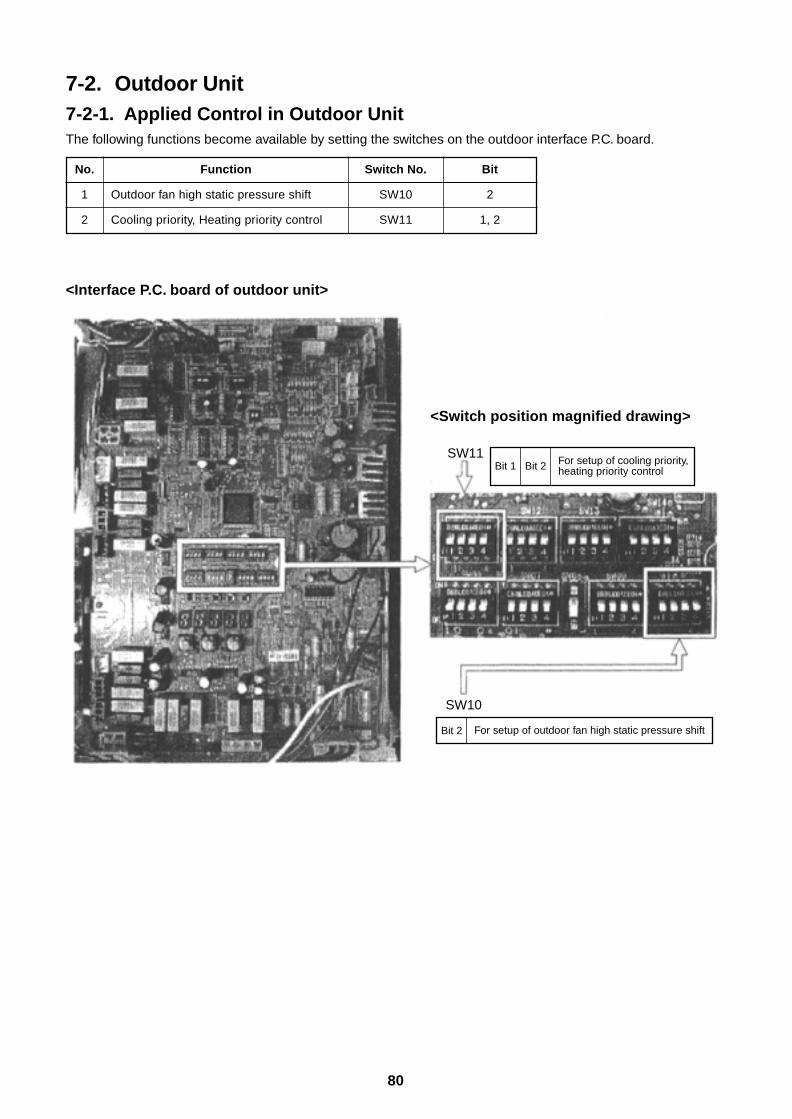
80
7-2. Outdoor Unit7-2-1. Applied Control in Outdoor UnitThe following functions become available by setting the switches on the outdoor interface P.C. board.
No.
1
2
Function
Outdoor fan high static pressure shift
Cooling priority, Heating priority control
Switch No.
SW10
SW11
Bit
2
1, 2
<Interface P.C. board of outdoor unit>
SW10
SW11Bit 1 Bit 2
Bit 2
For setup of cooling priority, heating priority control
For setup of outdoor fan high static pressure shift
<Switch position magnified drawing>
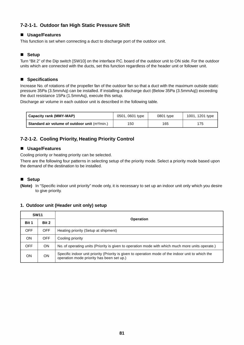
81
7-2-1-1. Outdoor fan High Static Pressure Shift
Usage/FeaturesThis function is set when connecting a duct to discharge port of the outdoor unit.
SetupTurn “Bit 2” of the Dip switch [SW10] on the interface P.C. board of the outdoor unit to ON side. For the outdoorunits which are connected with the ducts, set this function regardless of the header unit or follower unit.
SpecificationsIncrease No. of rotations of the propeller fan of the outdoor fan so that a duct with the maximum outside staticpressure 35Pa (3.5mmAq) can be installed. If installing a discharge duct (Below 35Pa (3.5mmAq)) exceedingthe duct resistance 15Pa (1.5mmAq), execute this setup.
Discharge air volume in each outdoor unit is described in the following table.
Capacity rank (MMY-MAP)
Standard air volume of outdoor unit (m³/min.)
0501, 0601 type 0801 type 1001, 1201 type
150 165 175
7-2-1-2. Cooling Priority, Heating Priority Control
Usage/FeaturesCooling priority or heating priority can be selected.
There are the following four patterns in selecting setup of the priority mode. Select a priority mode based uponthe demand of the destination to be installed.
Setup(Note) In “Specific indoor unit priority” mode only, it is necessary to set up an indoor unit only which you desire
to give priority.
1. Outdoor unit (Header unit only) setup
SW11
Bit 1 Bit 2
OFF OFF
ON OFF
OFF ON
ON ON
Operation
Heating priority (Setup at shipment)
Cooling priority
No. of operating units (Priority is given to operation mode with which much more units operate.)
Specific indoor unit priority (Priority is given to operation mode of the indoor unit to which theoperation mode priority has been set up.)
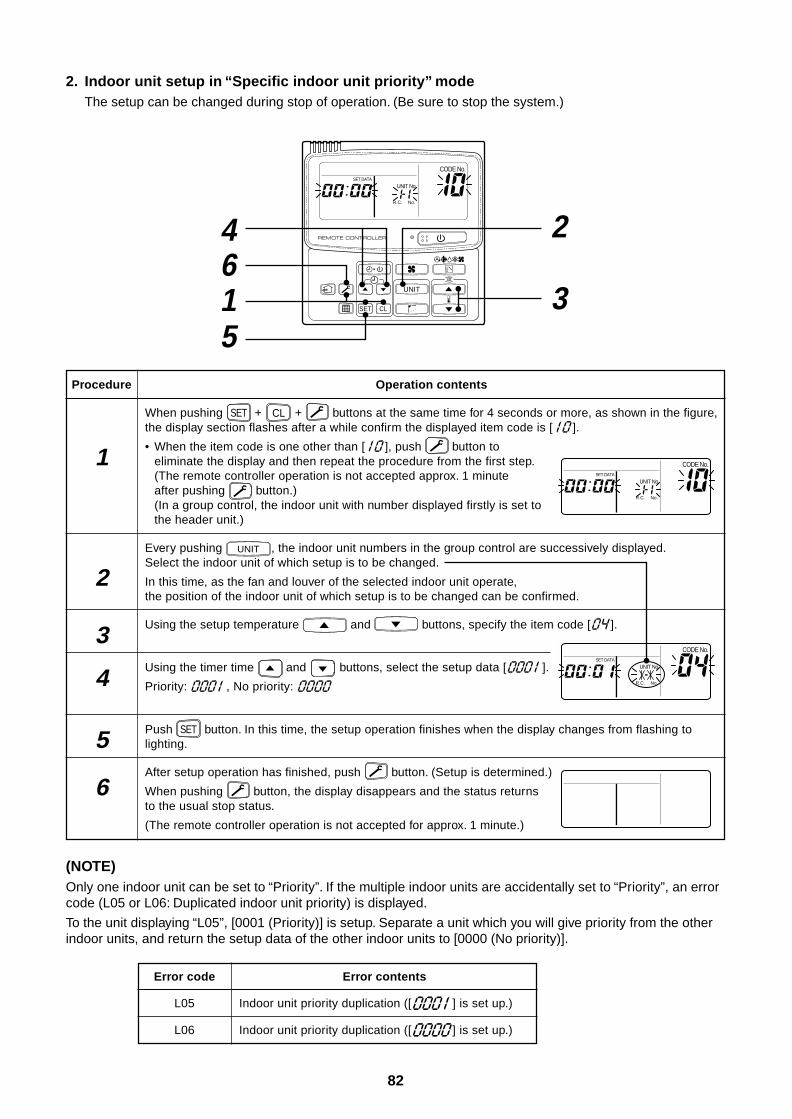
82
2. Indoor unit setup in “Specific indoor unit priority” modeThe setup can be changed during stop of operation. (Be sure to stop the system.)
Operation contents
When pushing SET + CL + buttons at the same time for 4 seconds or more, as shown in the figure,the display section flashes after a while confirm the displayed item code is [ ].
• When the item code is one other than [ ], push button toeliminate the display and then repeat the procedure from the first step.(The remote controller operation is not accepted approx. 1 minuteafter pushing button.)(In a group control, the indoor unit with number displayed firstly is set tothe header unit.)
Every pushing UNIT , the indoor unit numbers in the group control are successively displayed.Select the indoor unit of which setup is to be changed.
In this time, as the fan and louver of the selected indoor unit operate,the position of the indoor unit of which setup is to be changed can be confirmed.
Using the setup temperature and buttons, specify the item code [ ].
Using the timer time and buttons, select the setup data [ ].
Priority: , No priority:
Push SET button. In this time, the setup operation finishes when the display changes from flashing tolighting.
After setup operation has finished, push button. (Setup is determined.)
When pushing button, the display disappears and the status returnsto the usual stop status.
(The remote controller operation is not accepted for approx. 1 minute.)
(NOTE)Only one indoor unit can be set to “Priority”. If the multiple indoor units are accidentally set to “Priority”, an errorcode (L05 or L06: Duplicated indoor unit priority) is displayed.
To the unit displaying “L05”, [0001 (Priority)] is setup. Separate a unit which you will give priority from the otherindoor units, and return the setup data of the other indoor units to [0000 (No priority)].
Procedure
1
2
3
4
5
6
Error code
L05
L06
Error contents
Indoor unit priority duplication ([ ] is set up.)
Indoor unit priority duplication ([ ] is set up.)
15
46
2
3 UNIT
SET CL
UNIT No.
CODE No.SET DATA
R.C. No.
UNIT No.
CODE No.SET DATA
R.C. No.
UNIT No.
CODE No.SET DATA
R.C. No.
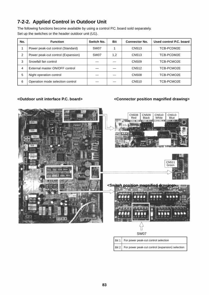
83
7-2-2. Applied Control in Outdoor UnitThe following functions become available by using a control P.C. board sold separately.
Set up the switches or the header outdoor unit (U1).
No.
1
2
3
4
5
6
Function
Power peak-cut control (Standard)
Power peak-cut control (Expansion)
Snowfall fan control
External master ON/OFF control
Night operation control
Operation mode selection control
Switch No.
SW07
SW07
—
—
—
—
Bit
1
1,2
—
—
—
—
Connector No.
CN513
CN513
CN509
CN512
CN508
CN510
Used control P.C. board
TCB-PCDM2E
TCB-PCDM2E
TCB-PCMO2E
TCB-PCMO2E
TCB-PCMO2E
TCB-PCMO2E
<Outdoor unit interface P.C. board>
SW07
Bit 1
Bit 2
For power peak-cut control selection
For power peak-cut control (expansion) selection
CN508Red
CN509Black
CN510White
CN513Blue
CN511Green
<Connector position magnified drawing>
<Switch position magnified drawing>
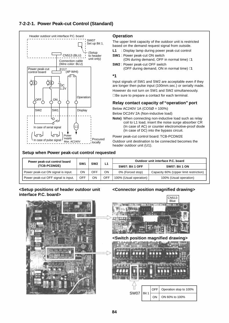
84
7-2-2-1. Power Peak-cut Control (Standard)
Setup when Power peak-cut control requested
Power peak-cut control board(TCB-PCDM2E)
Power peak-cut ON signal is input.
Power peak-cut OFF signal is input.
SW1 SW2 L1
ON OFF ON
OFF ON OFF
Outdoor unit interface P.C. board
SW07: Bit 1 OFF SW07: Bit 1 ON
0% (Forced stop) Capacity 60% (Upper limit restriction)
100% (Usual operation) 100% (Usual operation)
CN513 (BLU)
Header outdoor unit interface P.C. board
(Setup to headerunit only)
SW07Set up Bit 1.
Connection cable (Wire color: BLU)
Power peak-cut control board
PJ17(4P WHI)
L1
SW2
In case of serial signal
In case of pulse signal
SW1
OFF ON
Display
Operation
Power supplyMax. AC240V
Procured locally
DC1.2V
SW07 Bit 1Operation stop to 100%
ON 60% to 100%
OFF
ON
CN513Blue
<Setup positions of header outdoor unitinterface P.C. board>
<Connector position magnified drawing>
<Switch position magnified drawing>
OperationThe upper limit capacity of the outdoor unit is restrictedbased on the demand request signal from outside.L1 : Display lamp during power peak-cut controlSW1 : Power peak-cut ON switch
(ON during demand, OFF in normal time) ∗ 1SW2 : Power peak-cut OFF switch
(OFF during demand, ON in normal time) ∗ 1
*1Input signals of SW1 and SW2 are acceptable even if theyare longer then pulse input (100mm.sec.) or serially made.However do not turn on SW1 and SW2 simultaneously.∗ Be sure to prepare a contact for each terminal.
Relay contact capacity of “operation” portBelow AC240V 1A (COSØ = 100%)Below DC24V 2A (Non-inductive load)Note) When connecting non-inductive load such as relay
coil to L1 load, insert the noise surge absorber CR(In case of AC) or counter electromotive-proof diode(In case of DC) into the bypass circuit.
Power peak-cut control board: TCB-PCDM2EOutdoor unit destination to be connected becomes theheader outdoor unit (U1).
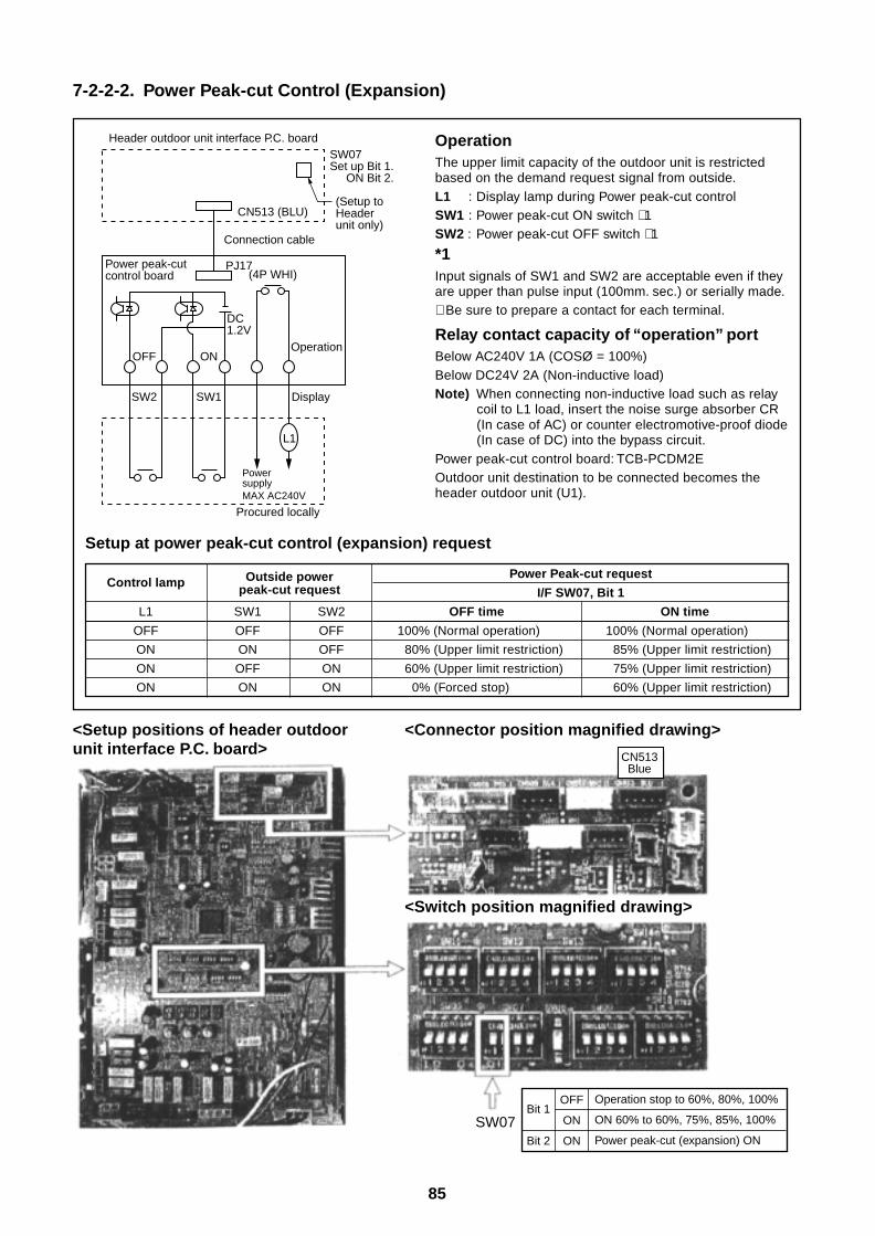
85
SW07Bit 1
Bit 2
Operation stop to 60%, 80%, 100%
ON 60% to 60%, 75%, 85%, 100%
Power peak-cut (expansion) ON
OFF
ON
ON
CN513Blue
7-2-2-2. Power Peak-cut Control (Expansion)
Setup at power peak-cut control (expansion) request
CN513 (BLU)
Header outdoor unit interface P.C. board
(Setup to Header unit only)
SW07Set up Bit 1. ON Bit 2.
Connection cable
Power peak-cut control board
PJ17(4P WHI)
L1
SW2 SW1
OFF ON
Display
Operation
Power supplyMAX AC240V
Procured locally
DC1.2V
<Setup positions of header outdoorunit interface P.C. board>
<Connector position magnified drawing>
<Switch position magnified drawing>
Control lamp
L1
OFF
ON
ON
ON
Outside powerpeak-cut request
SW1 SW2
OFF OFF
ON OFF
OFF ON
ON ON
Power Peak-cut request
I/F SW07, Bit 1
OFF time ON time
100% (Normal operation) 100% (Normal operation)
80% (Upper limit restriction) 85% (Upper limit restriction)
60% (Upper limit restriction) 75% (Upper limit restriction)
0% (Forced stop) 60% (Upper limit restriction)
OperationThe upper limit capacity of the outdoor unit is restrictedbased on the demand request signal from outside.L1 : Display lamp during Power peak-cut controlSW1 : Power peak-cut ON switch ∗ 1SW2 : Power peak-cut OFF switch ∗ 1
*1Input signals of SW1 and SW2 are acceptable even if theyare upper than pulse input (100mm. sec.) or serially made.∗ Be sure to prepare a contact for each terminal.
Relay contact capacity of “operation” portBelow AC240V 1A (COSØ = 100%)Below DC24V 2A (Non-inductive load)Note) When connecting non-inductive load such as relay
coil to L1 load, insert the noise surge absorber CR(In case of AC) or counter electromotive-proof diode(In case of DC) into the bypass circuit.
Power peak-cut control board: TCB-PCDM2EOutdoor unit destination to be connected becomes theheader outdoor unit (U1).
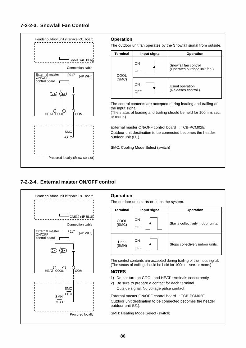
86
7-2-2-3. Snowfall Fan Control
7-2-2-4. External master ON/OFF control
OperationThe outdoor unit fan operates by the Snowfall signal from outside.
The control contents are accepted during leading and trailing ofthe input signal.(The status of leading and trailing should be held for 100mm. sec.or more.)
External master ON/OFF control board : TCB-PCM02EOutdoor unit destination to be connected becomes the headeroutdoor unit (U1).
SMC: Cooling Mode Select (switch)
OperationThe outdoor unit starts or stops the system.
The control contents are accepted during trailing of the input signal.(The status of trailing should be held for 100mm. sec. or more.)
NOTES1) Do not turn on COOL and HEAT terminals concurrently.2) Be sure to prepare a contact for each terminal.
Outside signal: No voltage pulse contact
External master ON/OFF control board : TCB-PCM02EOutdoor unit destination to be connected becomes the headeroutdoor unit (U1).
SMH: Heating Mode Select (switch)
Terminal
COOL(SMC)
Heat(SMH)
Input signal
ON
OFF
ON
OFF
Operation
Starts collectively indoor units.
Stops collectively indoor units.
Terminal
COOL(SMC)
Input signal
ON
OFF
ON
OFF
Operation
Snowfall fan control(Operates outdoor unit fan.)
Usual operation(Releases control.)
CN509 (4P BLK)
Header outdoor unit interface P.C. board
Connection cable
External master ON/OFF control board
PJ17 (4P WHI)
SMC
HEAT COOL COM
Procured locally (Snow sensor)
CN512 (4P BLU)
Header outdoor unit interface P.C. board
Connection cable
External master ON/OFF control board
PJ17 (4P WHI)
SMC
HEAT COOL COM
Procured locally
SMH
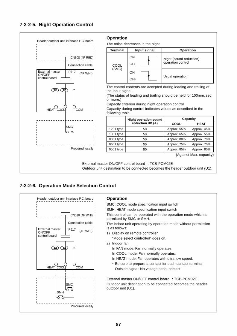
87
7-2-2-5. Night Operation Control
OperationThe noise decreases in the night.
Terminal
COOL(SMC)
Input signal
ON
OFF
ON
OFF
Operation
Night (sound reduction)operation control
Usual operation
The control contents are accepted during leading and trailing ofthe input signal.(The status of leading and trailing should be held for 100mm. sec.or more.)Capacity criterion during night operation controlCapacity during control indicates values as described in thefollowing table.
1201 type
1001 type
0801 type
0601 type
0501 type
(Against Max. capacity)
External master ON/OFF control board : TCB-PCM02EOutdoor unit destination to be connected becomes the header outdoor unit (U1).
Night operation soundreduction dB (A)
50
50
50
50
50
Capacity
COOL HEAT
Approx. 55% Approx. 45%
Approx. 65% Approx. 55%
Approx. 80% Approx. 70%
Approx. 75% Approx. 70%
Approx. 85% Approx. 80%
7-2-2-6. Operation Mode Selection Control
OperationSMC: COOL mode specification input switchSMH: HEAT mode specification input switchThis control can be operated with the operation mode which ispermitted by SMC or SMH.The indoor unit operating by operation mode without permissionis as follows:1) Display on remote controller
“Mode select controlled” goes on.2) Indoor fan
In FAN mode: Fan normally operates.In COOL mode: Fan normally operates.In HEAT mode: Fan operates with ultra low speed.* Be sure to prepare a contact for each contact terminal.
Outside signal: No voltage serial contact
External master ON/OFF control board : TCB-PCM02EOutdoor unit destination to be connected becomes the headeroutdoor unit (U1).
CN508 (4P RED)
Header outdoor unit interface P.C. board
Connection cable
External master ON/OFF control board
PJ17 (4P WHI)
SMC
HEAT COOL COM
Procured locally
CN510 (4P WHI)
Header outdoor unit interface P.C. board
Connection cable
External master ON/OFF control board
PJ17 (4P WHI)
SMC
HEAT COOL COM
Procured locally
SMH
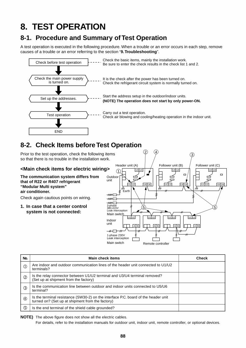
88
8. TEST OPERATION8-1. Procedure and Summary of Test OperationA test operation is executed in the following procedure. When a trouble or an error occurs in each step, removecauses of a trouble or an error referring to the section “9. Troubleshooting”.
Check the basic items, mainly the installation work.Be sure to enter the check results in the check list 1 and 2.
It is the check after the power has been turned on. Check the refrigerant circuit system is normally turned on.
Start the address setup in the outdoor/indoor units.(NOTE) The operation does not start by only power-ON.
Carry out a test operation. Check air blowing and cooling/heating operation in the indoor unit.
Check before test operation
Set up the addresses.
Test operation
END
Check the main power supplyis turned on.
8-2. Check Items before Test OperationPrior to the test operation, check the following itemsso that there is no trouble in the installation work.
<Main check items for electric wiring>
The communication system differs fromthat of R22 or R407 refrigerant“Modular Multi system”air conditioner.
Check again cautious points on wiring.
1. In case that a center controlsystem is not connected:
NOTE) The above figure does not show all the electric cables.
For details, refer to the installation manuals for outdoor unit, indoor unit, remote controller, or optional devices.
No.
Main check items
Are indoor and outdoor communication lines of the header unit connected to U1/U2terminals?
Is the relay connector between U1/U2 terminal and U3/U4 terminal removed?(Set up at shipment from the factory)
Is the communication line between outdoor and indoor units connected to U5/U6terminal?
Is the terminal resistance (SW30-2) on the interface P.C. board of the header unitturned on? (Set up at shipment from the factory)
Is the end terminal of the shield cable grounded?
Check
U1
U3
U2
U1
A
U2
U5 U6
U4
Header unit (A)
U1
U3
U2 U5 U6
U4
Follower unit (B)
U1
U3
U2 U5 U6
U4
Follower unit (C)
Outdoor unit
Indoor unit
Earth
3-phase 380-415VLeak interceptionMain switch
1-phase 230VLeak interception
Main switch
B
U1
A
U2
B
Remote controller
U1
A
U2
B
U1
A
U2
B
1
2 43
5 5
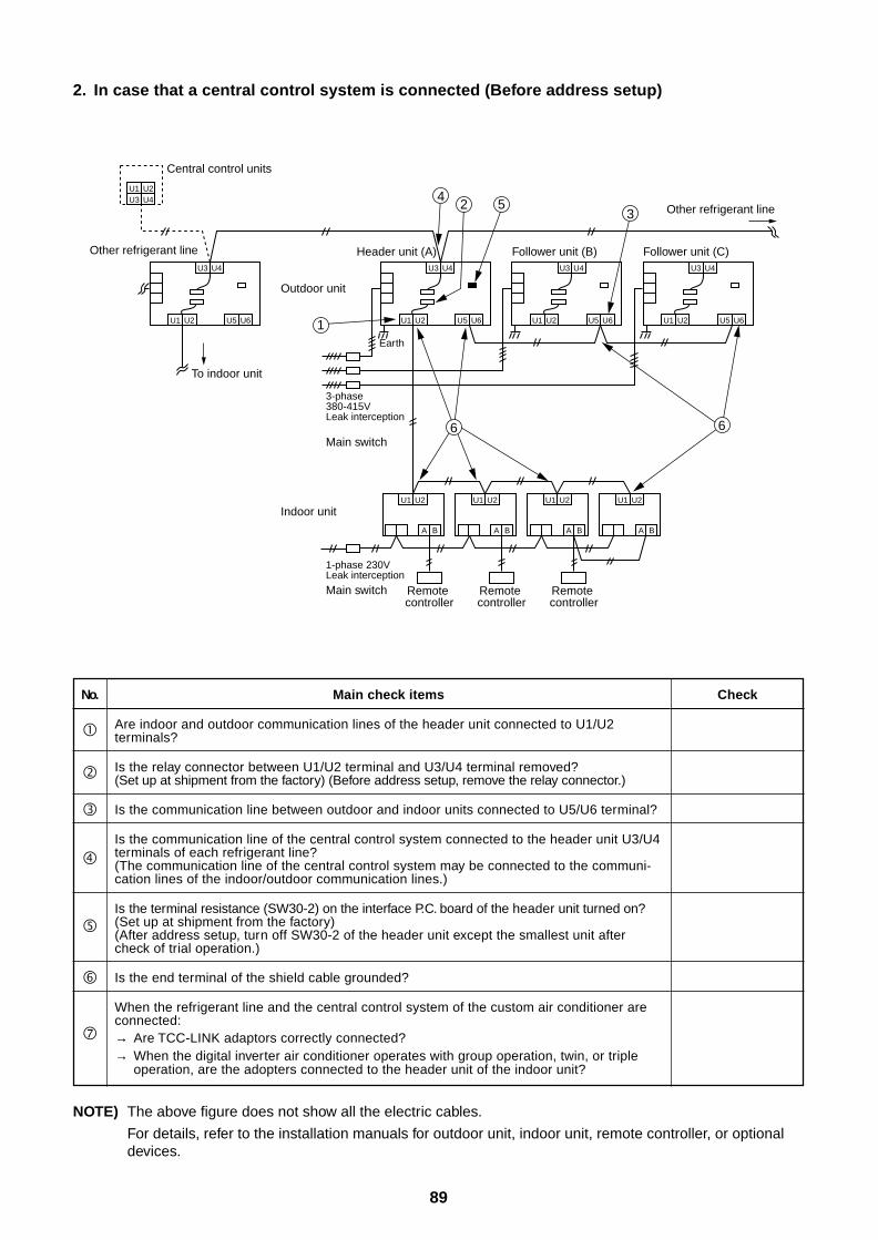
89
2. In case that a central control system is connected (Before address setup)
NOTE) The above figure does not show all the electric cables.
For details, refer to the installation manuals for outdoor unit, indoor unit, remote controller, or optionaldevices.
No.
Main check items
Are indoor and outdoor communication lines of the header unit connected to U1/U2terminals?
Is the relay connector between U1/U2 terminal and U3/U4 terminal removed?(Set up at shipment from the factory) (Before address setup, remove the relay connector.)
Is the communication line between outdoor and indoor units connected to U5/U6 terminal?
Is the communication line of the central control system connected to the header unit U3/U4terminals of each refrigerant line?(The communication line of the central control system may be connected to the communi-cation lines of the indoor/outdoor communication lines.)
Is the terminal resistance (SW30-2) on the interface P.C. board of the header unit turned on?(Set up at shipment from the factory)(After address setup, turn off SW30-2 of the header unit except the smallest unit aftercheck of trial operation.)
Is the end terminal of the shield cable grounded?
When the refrigerant line and the central control system of the custom air conditioner areconnected:→ Are TCC-LINK adaptors correctly connected?→ When the digital inverter air conditioner operates with group operation, twin, or triple
operation, are the adopters connected to the header unit of the indoor unit?
Check
U1U3
U2U4
U1
U3
U2 U5 U6
U4
U1
U3
U2
U1
A
U2
U5 U6
U4
Header unit (A)
U1
U3
U2 U5 U6
U4
Follower unit (B)
U1
U3
U2 U5 U6
U4
Follower unit (C)
Outdoor unit
Indoor unit
To indoor unit
Central control units
Other refrigerant line
Other refrigerant line
Earth
3-phase380-415VLeak interception
Main switch
1-phase 230VLeak interception
Main switch
B
Remote controller
U1
A
U2
B
Remote controller
U1
A
U2
B
Remote controller
U1
A
U2
B
1
2 53
6 6
4
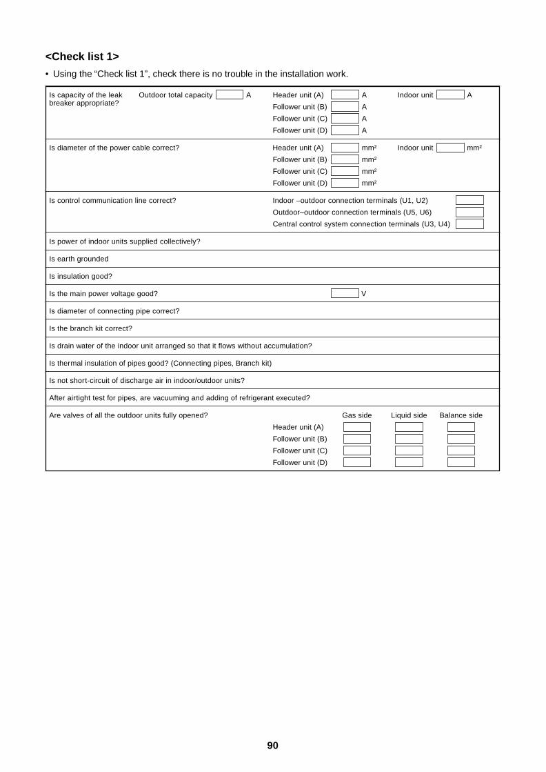
90
<Check list 1>
• Using the “Check list 1”, check there is no trouble in the installation work.
Is capacity of the leak Outdoor total capacity XXXX A Header unit (A) XXXX A Indoor unit XXXX Abreaker appropriate? Follower unit (B) XXXX A
Follower unit (C) XXXX A
Follower unit (D) XXXX A
Is diameter of the power cable correct? Header unit (A) XXXX mm² Indoor unit XXXX mm²
Follower unit (B) XXXX mm²
Follower unit (C) XXXX mm²
Follower unit (D) XXXX mm²
Is control communication line correct? Indoor –outdoor connection terminals (U1, U2) XXXX
Outdoor–outdoor connection terminals (U5, U6) XXXX
Central control system connection terminals (U3, U4) XXXX
Is power of indoor units supplied collectively?
Is earth grounded
Is insulation good?
Is the main power voltage good? XXXX V
Is diameter of connecting pipe correct?
Is the branch kit correct?
Is drain water of the indoor unit arranged so that it flows without accumulation?
Is thermal insulation of pipes good? (Connecting pipes, Branch kit)
Is not short-circuit of discharge air in indoor/outdoor units?
After airtight test for pipes, are vacuuming and adding of refrigerant executed?
Are valves of all the outdoor units fully opened? Gas side Liquid side Balance side
Header unit (A) XXXX XXXX XXXX
Follower unit (B) XXXX XXXX XXXX
Follower unit (C) XXXX XXXX XXXX
Follower unit (D) XXXX XXXX XXXX
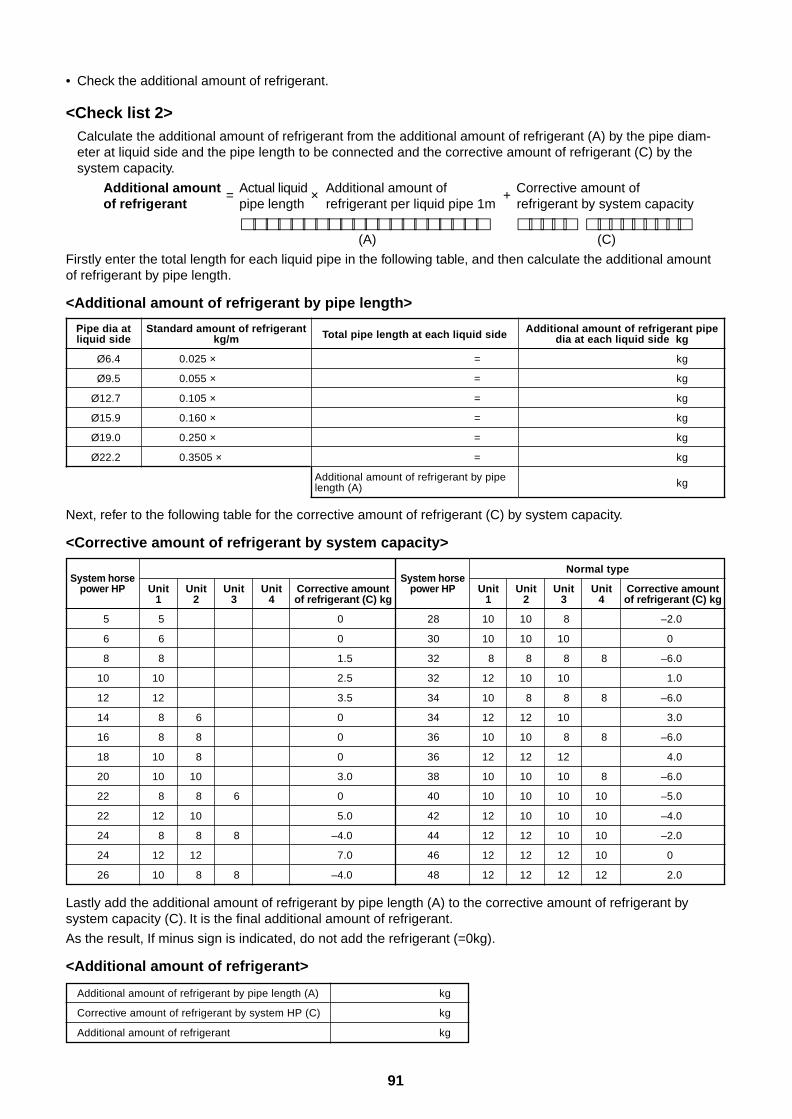
91
Pipe dia atliquid side
Ø6.4
Ø9.5
Ø12.7
Ø15.9
Ø19.0
Ø22.2
Standard amount of refrigerantkg/m
0.025 ×
0.055 ×
0.105 ×
0.160 ×
0.250 ×
0.3505 ×
Total pipe length at each liquid side
=
=
=
=
=
=
Additional amount of refrigerant by pipelength (A)
Additional amount of refrigerant pipedia at each liquid side kg
kg
kg
kg
kg
kg
kg
kg
System horsepower HP
5
6
8
10
12
14
16
18
20
22
22
24
24
26
Unit Unit Unit Unit1 2 3 4
5
6
8
10
12
8 6
8 8
10 8
10 10
8 8 6
12 10
8 8 8
12 12
10 8 8
Corrective amountof refrigerant (C) kg
0
0
1.5
2.5
3.5
0
0
0
3.0
0
5.0
–4.0
7.0
–4.0
System horsepower HP
28
30
32
32
34
34
36
36
38
40
42
44
46
48
Normal type
Unit Unit Unit Unit1 2 3 4
10 10 8
10 10 10
8 8 8 8
12 10 10
10 8 8 8
12 12 10
10 10 8 8
12 12 12
10 10 10 8
10 10 10 10
12 10 10 10
12 12 10 10
12 12 12 10
12 12 12 12
Corrective amountof refrigerant (C) kg
–2.0
0
–6.0
1.0
–6.0
3.0
–6.0
4.0
–6.0
–5.0
–4.0
–2.0
0
2.0
Lastly add the additional amount of refrigerant by pipe length (A) to the corrective amount of refrigerant bysystem capacity (C). It is the final additional amount of refrigerant.
As the result, If minus sign is indicated, do not add the refrigerant (=0kg).
<Additional amount of refrigerant>
Additional amount of refrigerant by pipe length (A)
Corrective amount of refrigerant by system HP (C)
Additional amount of refrigerant
kg
kg
kg
Next, refer to the following table for the corrective amount of refrigerant (C) by system capacity.
<Corrective amount of refrigerant by system capacity>
Normal type
• Check the additional amount of refrigerant.
<Check list 2>Calculate the additional amount of refrigerant from the additional amount of refrigerant (A) by the pipe diam-eter at liquid side and the pipe length to be connected and the corrective amount of refrigerant (C) by thesystem capacity.
Additional amount = Actual liquid × Additional amount of + Corrective amount ofof refrigerant pipe length refrigerant per liquid pipe 1m refrigerant by system capacity
(A) (C)
Firstly enter the total length for each liquid pipe in the following table, and then calculate the additional amountof refrigerant by pipe length.
<Additional amount of refrigerant by pipe length>
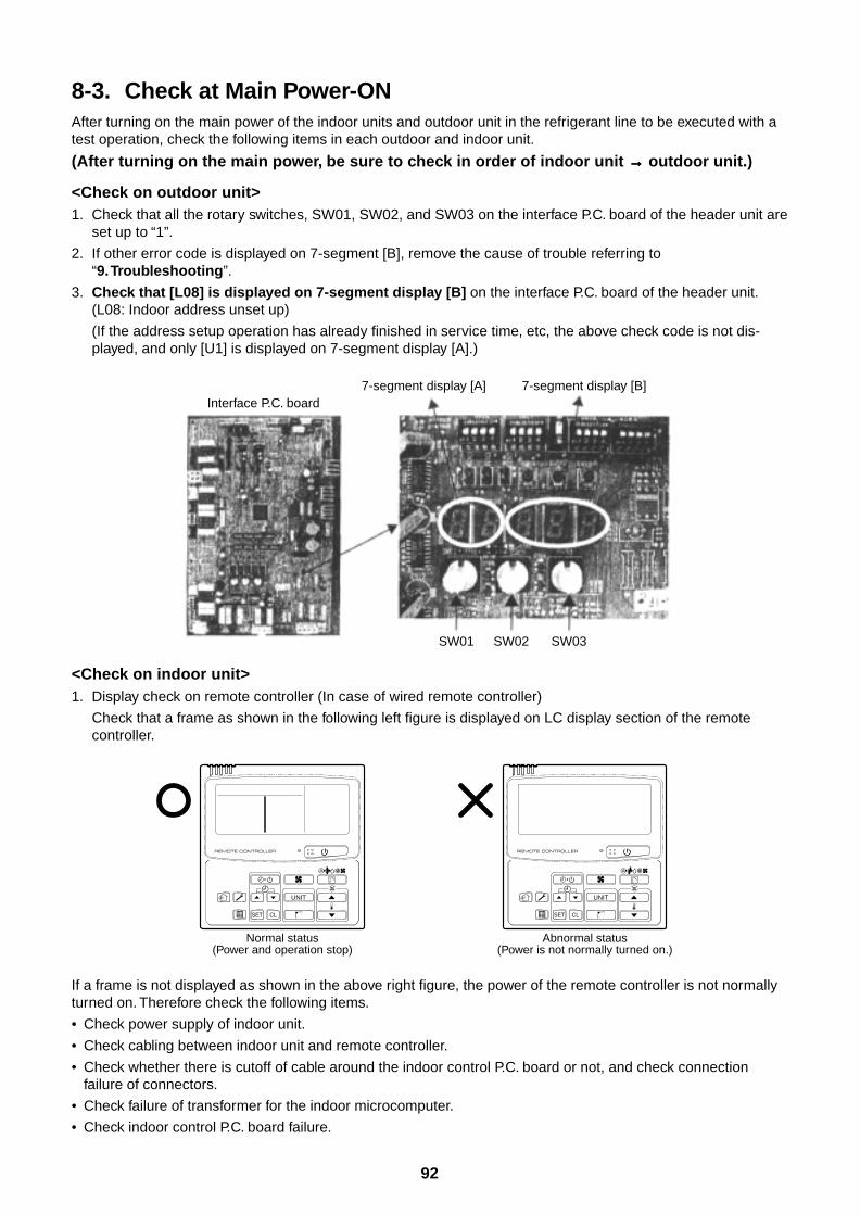
92
8-3. Check at Main Power-ONAfter turning on the main power of the indoor units and outdoor unit in the refrigerant line to be executed with atest operation, check the following items in each outdoor and indoor unit.
(After turning on the main power, be sure to check in order of indoor unit →→→→→ outdoor unit.)
<Check on outdoor unit>1. Check that all the rotary switches, SW01, SW02, and SW03 on the interface P.C. board of the header unit are
set up to “1”.
2. If other error code is displayed on 7-segment [B], remove the cause of trouble referring to“9. Troubleshooting”.
3. Check that [L08] is displayed on 7-segment display [B] on the interface P.C. board of the header unit.(L08: Indoor address unset up)
(If the address setup operation has already finished in service time, etc, the above check code is not dis-played, and only [U1] is displayed on 7-segment display [A].)
<Check on indoor unit>1. Display check on remote controller (In case of wired remote controller)
Check that a frame as shown in the following left figure is displayed on LC display section of the remotecontroller.
If a frame is not displayed as shown in the above right figure, the power of the remote controller is not normallyturned on. Therefore check the following items.
• Check power supply of indoor unit.
• Check cabling between indoor unit and remote controller.
• Check whether there is cutoff of cable around the indoor control P.C. board or not, and check connectionfailure of connectors.
• Check failure of transformer for the indoor microcomputer.
• Check indoor control P.C. board failure.
UNIT
SET CL
UNIT
SET CL
Normal status(Power and operation stop)
Abnormal status(Power is not normally turned on.)
Interface P.C. board7-segment display [A]
SW01 SW02 SW03
7-segment display [B]
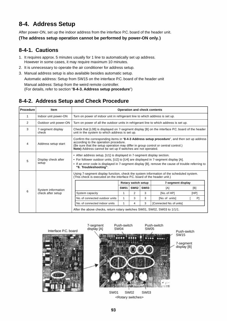
93
8-4. Address SetupAfter power-ON, set up the indoor address from the interface P.C. board of the header unit.
(The address setup operation cannot be performed by power-ON only. )
8-4-1. Cautions1. It requires approx. 5 minutes usually for 1 line to automatically set up address.
However in some cases, it may require maximum 10 minutes.
2. It is unnecessary to operate the air conditioner for address setup.
3. Manual address setup is also available besides automatic setup.
Automatic address: Setup from SW15 on the interface P.C. board of the header unit
Manual address: Setup from the weird remote controller.(For details, refer to section “8-4-3. Address setup procedure”)
8-4-2. Address Setup and Check Procedure
Procedure
1
2
3
4
5
6
Item
Indoor unit power-ON
Outdoor unit power-ON
7-segment displaycheck
Address setup start
Display check aftersetup
System informationcheck after setup
Operation and check contents
Turn on power of indoor unit in refrigerant line to which address is set up.
Turn on power of all the outdoor units in refrigerant line to which address is set up.
Check that [L08] is displayed on 7-segment display [B] on the interface P.C. board of the headerunit in the system to which address is set up.
Confirm the corresponding items in “8-4-3 Address setup procedure”, and then set up addressaccording to the operation procedure.(Be sure that the setup operation may differ in group control or central control.)Note) Address cannot be set up if switches are not operated.
• After address setup, [U1] is displayed in 7-segment display section.• For follower outdoor units, [U2] to [U4] are displayed in 7-segment display [A].• If an error code is displayed in 7-segment display [B], remove the cause of trouble referring to
“9. Troubleshooting”.
Using 7-segment display function, check the system information of the scheduled system.(This check is executed on the interface P.C. board of the header unit.)
System capacity
No. of connected outdoor units
No. of connected indoor units
Rotary switch setup
SW01 SW02 SW03
1 2 3
1 3 3
1 4 3
7-segment display
[A] [B]
[No. of HP] [HP]
[No. of units] [ P]
[Connected No. of units]
After the above checks, return rotary switches SW01, SW02, SW03 to 1/1/1.
Interface P.C. board
SW01 SW02<Rotary switches>
SW03
7-segmentdisplay [A]
Push-switch SW04
Push-switch SW05
Push-switch SW15
7-segmentdisplay [B]
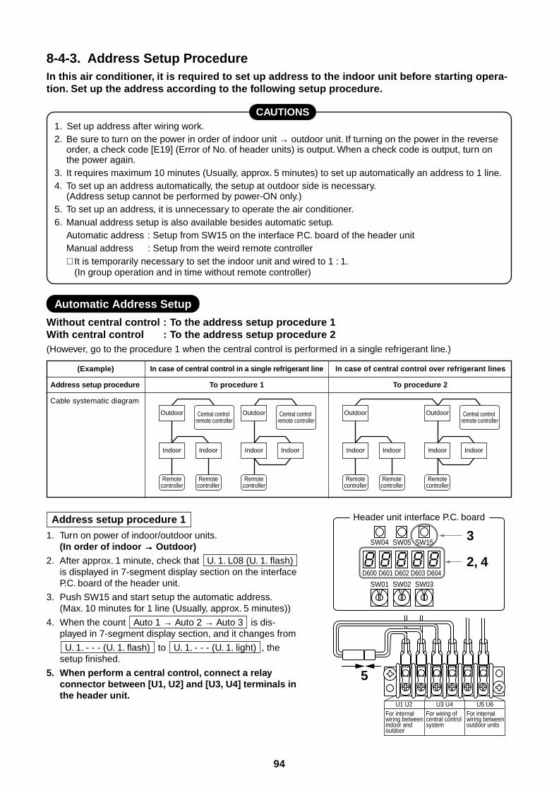
94
8-4-3. Address Setup ProcedureIn this air conditioner, it is required to set up address to the indoor unit before starting opera-tion. Set up the address according to the following setup procedure.
CAUTIONS1. Set up address after wiring work.2. Be sure to turn on the power in order of indoor unit → outdoor unit. If turning on the power in the reverse
order, a check code [E19] (Error of No. of header units) is output. When a check code is output, turn onthe power again.
3. It requires maximum 10 minutes (Usually, approx. 5 minutes) to set up automatically an address to 1 line.4. To set up an address automatically, the setup at outdoor side is necessary.
(Address setup cannot be performed by power-ON only.)5. To set up an address, it is unnecessary to operate the air conditioner.6. Manual address setup is also available besides automatic setup.
Automatic address : Setup from SW15 on the interface P.C. board of the header unitManual address : Setup from the weird remote controller∗ It is temporarily necessary to set the indoor unit and wired to 1 : 1.
(In group operation and in time without remote controller)
Automatic Address Setup
Without central control : To the address setup procedure 1With central control : To the address setup procedure 2(However, go to the procedure 1 when the central control is performed in a single refrigerant line.)
(Example)
Address setup procedure
Cable systematic diagram
In case of central control in a single refrigerant line
To procedure 1
In case of central control over refrigerant lines
To procedure 2
Address setup procedure 1
1. Turn on power of indoor/outdoor units.(In order of indoor →→→→→ Outdoor)
2. After approx. 1 minute, check that U. 1. L08 (U. 1. flash)is displayed in 7-segment display section on the interfaceP.C. board of the header unit.
3. Push SW15 and start setup the automatic address.(Max. 10 minutes for 1 line (Usually, approx. 5 minutes))
4. When the count Auto 1 → Auto 2 → Auto 3 is dis-played in 7-segment display section, and it changes from
U. 1. - - - (U. 1. flash) to U. 1. - - - (U. 1. light) , thesetup finished.
5. When perform a central control, connect a relayconnector between [U1, U2] and [U3, U4] terminals inthe header unit.
SW04
SW011 1 1
SW05 SW15
D600 D601 D602 D603 D604
SW02 SW03
3
5
2, 4
Header unit interface P.C. board
U1 U2For internal wiring between indoor and outdoor
U3 U4For wiring of central control system
U5 U6For internal wiring betweenoutdoor units
Outdoor
Indoor Indoor
Remotecontroller
Remotecontroller
Central control remote controller
Outdoor
Indoor Indoor
Remotecontroller
Central control remote controller
Outdoor
Indoor Indoor
Remotecontroller
Remotecontroller
Outdoor
Indoor Indoor
Remotecontroller
Central control remote controller
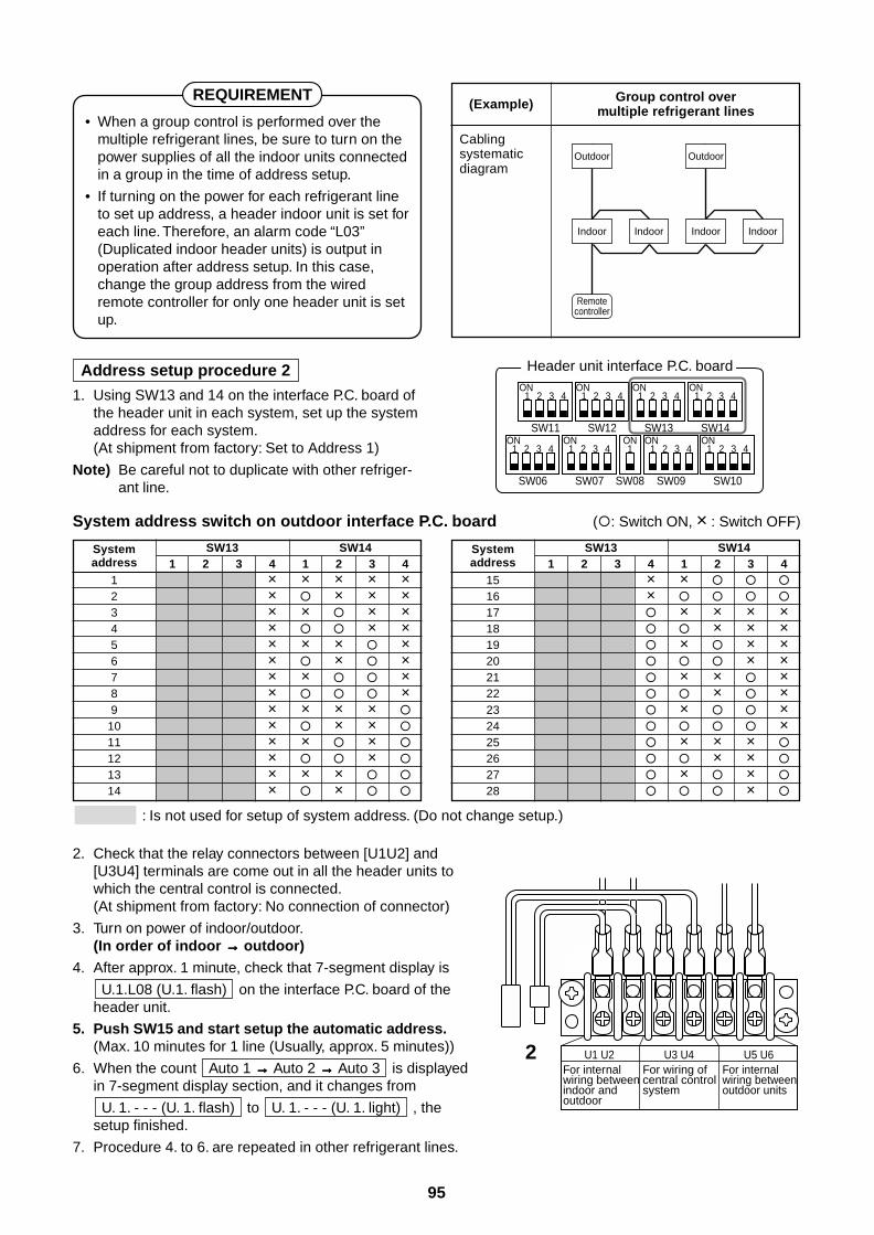
95
REQUIREMENT
• When a group control is performed over themultiple refrigerant lines, be sure to turn on thepower supplies of all the indoor units connectedin a group in the time of address setup.
• If turning on the power for each refrigerant lineto set up address, a header indoor unit is set foreach line. Therefore, an alarm code “L03”(Duplicated indoor header units) is output inoperation after address setup. In this case,change the group address from the wiredremote controller for only one header unit is setup.
(Example)
Cablingsystematicdiagram
Group control overmultiple refrigerant lines
Address setup procedure 2
1. Using SW13 and 14 on the interface P.C. board ofthe header unit in each system, set up the systemaddress for each system.(At shipment from factory: Set to Address 1)
Note) Be careful not to duplicate with other refriger-ant line.
System address switch on outdoor interface P.C. board (: Switch ON, × : Switch OFF)
2. Check that the relay connectors between [U1U2] and[U3U4] terminals are come out in all the header units towhich the central control is connected.(At shipment from factory: No connection of connector)
3. Turn on power of indoor/outdoor.(In order of indoor →→→→→ outdoor)
4. After approx. 1 minute, check that 7-segment display is
U.1.L08 (U.1. flash) on the interface P.C. board of theheader unit.
5. Push SW15 and start setup the automatic address.(Max. 10 minutes for 1 line (Usually, approx. 5 minutes))
6. When the count Auto 1 →→→→→ Auto 2 →→→→→ Auto 3 is displayedin 7-segment display section, and it changes from
U. 1. - - - (U. 1. flash) to U. 1. - - - (U. 1. light) , thesetup finished.
7. Procedure 4. to 6. are repeated in other refrigerant lines.
: Is not used for setup of system address. (Do not change setup.)
Systemaddress
123456789
1011121314
SW13 SW141 2 3 4 1 2 3 4
× × × × ×× × × ×× × × ×× × ×× × × ×× × ×× × ×× ×× × × ×
× × ×
× × ×
× ×
× × ×
× ×
Systemaddress
1516171819202122232425262728
SW13 SW141 2 3 4 1 2 3 4
× ×
×
× × × × × × × × × × × × × × × × × × × × × × ×
× ×
× ×
×
Outdoor
Indoor Indoor
Remotecontroller
Outdoor
Indoor Indoor
SW11
1ON
Header unit interface P.C. board
2 3 4
SW12
1ON
2 3 4
SW06
1ON
2 3 4
SW07
1ON ONON ON
2 3 4
SW09SW08
11 2 3 4
SW10
1 2 3 4
SW13
1ON
2 3 4
SW14
1ON
2 3 4
U1 U2For internal wiring between indoor and outdoor
U3 U4For wiring of central control system
U5 U6For internal wiring betweenoutdoor units
2
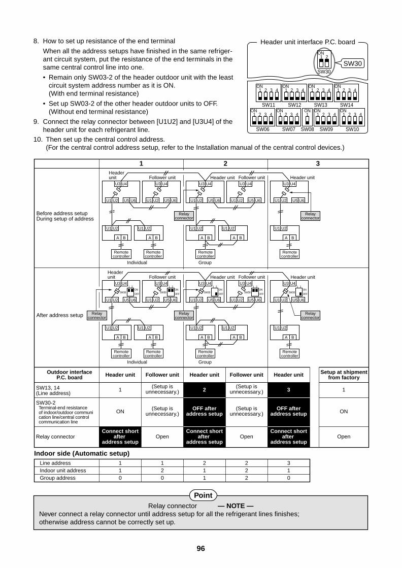
96
8. How to set up resistance of the end terminal
When all the address setups have finished in the same refriger-ant circuit system, put the resistance of the end terminals in thesame central control line into one.
• Remain only SW03-2 of the header outdoor unit with the leastcircuit system address number as it is ON.(With end terminal resistance)
• Set up SW03-2 of the other header outdoor units to OFF.(Without end terminal resistance)
9. Connect the relay connector between [U1U2] and [U3U4] of theheader unit for each refrigerant line.
PointRelay connector — NOTE —
Never connect a relay connector until address setup for all the refrigerant lines finishes;otherwise address cannot be correctly set up.
Header unit interface P.C. board
SW11
1ON
2 3 4
SW12
1ON
2 3 4
SW06
1ON
2 3 4
SW07
1ON ONON ON
2 3 4
SW09SW08
11 2 3 4
SW10
1 2 3 4
SW13
1ON
2 3 4
SW14
1ON
2 3 4
SW30SW30
1ON
2
Before address setupDuring setup of address
After address setup
SW13, 14(Line address)
SW30-2Terminal-end resistance of indoor/outdoor communi cation line/central control communication line
Relay connector
Indoor side (Automatic setup)Line addressIndoor unit addressGroup address
110
120
211
222
310
Connect shortafter
address setup
Connect shortafter
address setup
Connect shortafter
address setup
Setup at shipmentfrom factory
U3 U4
U1 U2 U5 U6
U1 U2
A B
Header unit
Individual Group
Remotecontroller
U3 U4
U1 U2 U5 U6
U1 U2
A B
Follower unit
Remotecontroller
Relayconnector
U3 U4
U1 U2 U5 U6
U1 U2
A B
Remotecontroller
U3 U4
U1 U2 U5 U6
U1 U2
A B
Follower unitU3 U4
U1 U2 U5 U6
U1 U2
A B
Header unit
Remotecontroller
Relayconnector
U3 U4
U1 U2 U5 U6
U1 U2
A B
Header unit
Header unit
Header unit Header unit
Individual Group
Remotecontroller
U3 U421
SW30ON
OFF
U1 U2 U5 U6
U1 U2
A B
Follower unit
Remotecontroller
Relayconnector
U3 U4
U1 U2 U5 U6
U1 U2
A B
Remotecontroller
U3 U4
U1 U2 U5 U6
U1 U2
A B
Follower unitU3 U4
U1 U2 U5 U6
U1 U2
A B
Remotecontroller
Relayconnector
Relayconnector
Open
ON
1 2
1 2 3
3 1
Header unit Follower unit Follower unitHeader unit Header unit
ON
Open Open
(Setup isunnecessary.)
(Setup isunnecessary.)
OFF afteraddress setup
OFF afteraddress setup
(Setup isunnecessary.)
(Setup isunnecessary.)
Outdoor interfaceP.C. board
21
SW30ON
OFF
21
SW30 SW30ON
OFF
21
SW30ON
OFF
21ON
OFF
10. Then set up the central control address.(For the central control address setup, refer to the Installation manual of the central control devices.)
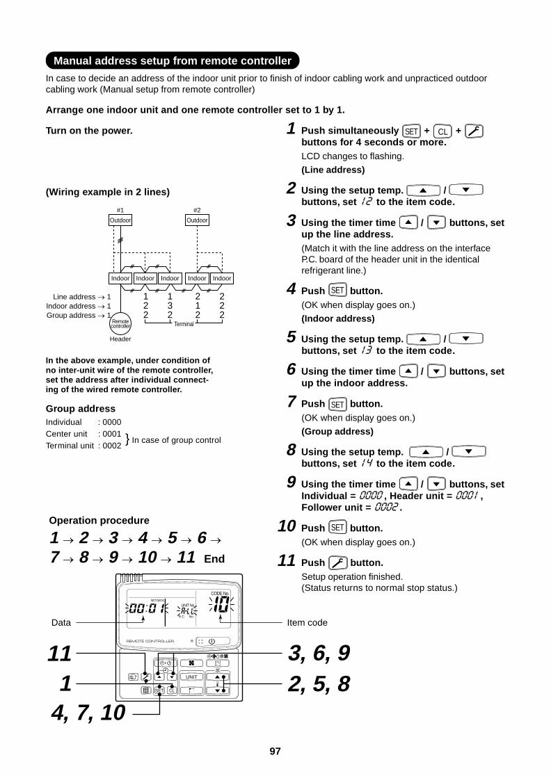
97
Manual address setup from remote controller
In case to decide an address of the indoor unit prior to finish of indoor cabling work and unpracticed outdoorcabling work (Manual setup from remote controller)
Arrange one indoor unit and one remote controller set to 1 by 1.
Turn on the power. 1 Push simultaneously SET + CL + buttons for 4 seconds or more.LCD changes to flashing.
(Line address)
2 Using the setup temp. / buttons, set to the item code.
3 Using the timer time / buttons, setup the line address.(Match it with the line address on the interfaceP.C. board of the header unit in the identicalrefrigerant line.)
4 Push SET button.(OK when display goes on.)
(Indoor address)
5 Using the setup temp. / buttons, set to the item code.
6 Using the timer time / buttons, setup the indoor address.
7 Push SET button.(OK when display goes on.)
(Group address)
8 Using the setup temp. / buttons, set to the item code.
9 Using the timer time / buttons, setIndividual = , Header unit = ,Follower unit = .
10 Push SET button.(OK when display goes on.)
11 Push button.Setup operation finished.(Status returns to normal stop status.)
UNIT
SET CL
UNIT No.
CODE No.SET DATA
R.C. No.
Operation procedure
1 2 3 4 5 6 7 8 9 10 11 End
2, 5, 8 3, 6, 9
14, 7, 10
11
Data Item code
Outdoor
Header
#1
Indoor Indoor Indoor
Line address 1Indoor address 1Group address 1
Outdoor
#2
Indoor Indoor
Terminal
122
132
212
222
Remotecontroller
(Wiring example in 2 lines)
In the above example, under condition ofno inter-unit wire of the remote controller,set the address after individual connect-ing of the wired remote controller.
Group addressIndividual : 0000Center unit : 0001Terminal unit : 0002
In case of group control
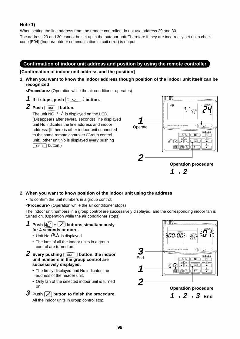
98
Note 1)When setting the line address from the remote controller, do not use address 29 and 30.
The address 29 and 30 cannot be set up in the outdoor unit. Therefore if they are incorrectly set up, a checkcode [E04] (Indoor/outdoor communication circuit error) is output.
Confirmation of indoor unit address and position by using the remote controller
[Confirmation of indoor unit address and the position]
1. When you want to know the indoor address though position of the indoor unit itself can berecognized;<Procedure> (Operation while the air conditioner operates)
1 If it stops, push button.
2 Push UNIT button.The unit NO is displayed on the LCD.(Disappears after several seconds) The displayedunit No indicates the line address and indooraddress. (If there is other indoor unit connectedto the same remote controller (Group controlunit), other unit No is displayed every pushing
UNIT button.)
2. When you want to know position of the indoor unit using the address• To confirm the unit numbers in a group control;
<Procedure> (Operation while the air conditioner stops)
The indoor unit numbers in a group control are successively displayed, and the corresponding indoor fan isturned on. (Operation while the air conditioner stops)
1 Push + buttons simultaneouslyfor 4 seconds or more.• Unit No is displayed.
• The fans of all the indoor units in a groupcontrol are turned on.
2 Every pushing UNIT button, the indoorunit numbers in the group control aresuccessively displayed.• The firstly displayed unit No indicates the
address of the header unit.
• Only fan of the selected indoor unit is turnedon.
3 Push button to finish the procedure.All the indoor units in group control stop.
Operation procedure
1 2
Operation procedure
1 2 3 End
Operate
End
UNIT
SET CL
UNIT No.
CODE No.
UNIT
SET CL
UNIT No.
CODE No.SET DATA
R.C. No.
2
3
1
1
2
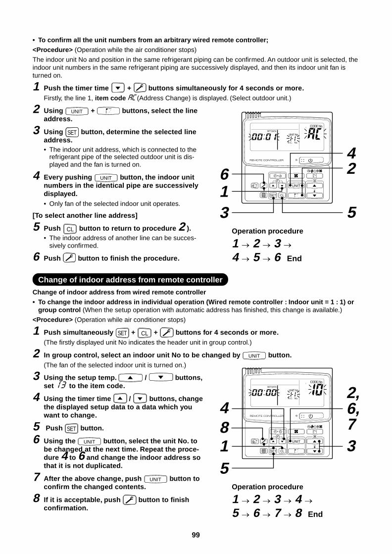
99
• To confirm all the unit numbers from an arbitrary wired remote controller;
<Procedure> (Operation while the air conditioner stops)
The indoor unit No and position in the same refrigerant piping can be confirmed. An outdoor unit is selected, theindoor unit numbers in the same refrigerant piping are successively displayed, and then its indoor unit fan isturned on.
1 Push the timer time + buttons simultaneously for 4 seconds or more.Firstly, the line 1, item code (Address Change) is displayed. (Select outdoor unit.)
2 Using UNIT + buttons, select the lineaddress.
3 Using SET button, determine the selected lineaddress.• The indoor unit address, which is connected to the
refrigerant pipe of the selected outdoor unit is dis-played and the fan is turned on.
4 Every pushing UNIT button, the indoor unitnumbers in the identical pipe are successivelydisplayed.• Only fan of the selected indoor unit operates.
[To select another line address]
5 Push CL button to return to procedure 2 ).• The indoor address of another line can be succes-
sively confirmed.
6 Push button to finish the procedure.
Change of indoor address from remote controller
Change of indoor address from wired remote controller
• To change the indoor address in individual operation (Wired remote controller : Indoor unit = 1 : 1) orgroup control (When the setup operation with automatic address has finished, this change is available.)
<Procedure> (Operation while air conditioner stops)
1 Push simultaneously SET + CL + buttons for 4 seconds or more.(The firstly displayed unit No indicates the header unit in group control.)
2 In group control, select an indoor unit No to be changed by UNIT button.(The fan of the selected indoor unit is turned on.)
3 Using the setup temp. / buttons,set to the item code.
4 Using the timer time / buttons, changethe displayed setup data to a data which youwant to change.
5 Push SET button.
6 Using the UNIT button, select the unit No. tobe changed at the next time. Repeat the proce-dure 4 to 6 and change the indoor address sothat it is not duplicated.
7 After the above change, push UNIT button toconfirm the changed contents.
8 If it is acceptable, push button to finishconfirmation.
Operation procedure
1 2 3 4 5 6 7 8 End
Operation procedure
1 2 3 4 5 6 End
16
5
4
3
2
48
UNIT
SET CL
UNIT No.
CODE No.SET DATA
R.C. No.
UNIT
SET CL
UNIT No.
CODE No.SET DATA
R.C. No.
15
2,6,73
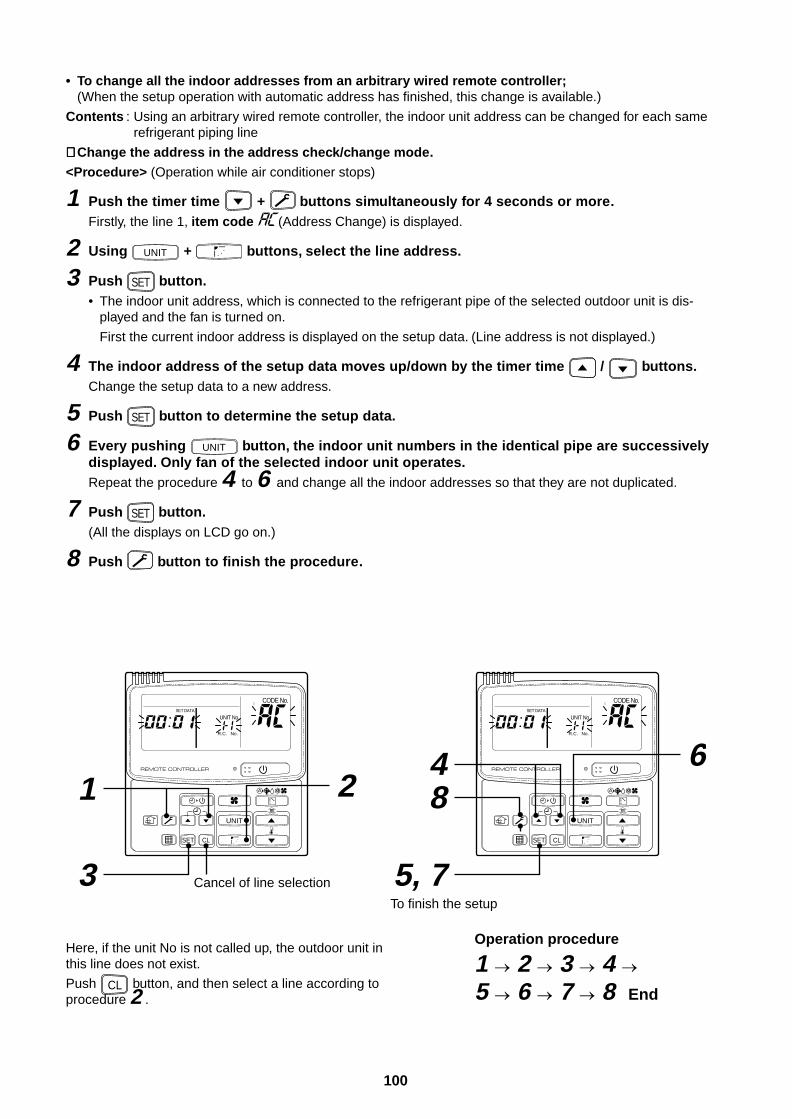
100
• To change all the indoor addresses from an arbitrary wired remote controller;(When the setup operation with automatic address has finished, this change is available.)
Contents : Using an arbitrary wired remote controller, the indoor unit address can be changed for each samerefrigerant piping line
∗∗∗∗∗ Change the address in the address check/change mode.
<Procedure> (Operation while air conditioner stops)
1 Push the timer time + buttons simultaneously for 4 seconds or more.Firstly, the line 1, item code (Address Change) is displayed.
2 Using UNIT + buttons, select the line address.
3 Push SET button.• The indoor unit address, which is connected to the refrigerant pipe of the selected outdoor unit is dis-
played and the fan is turned on.
First the current indoor address is displayed on the setup data. (Line address is not displayed.)
4 The indoor address of the setup data moves up/down by the timer time / buttons.Change the setup data to a new address.
5 Push SET button to determine the setup data.
6 Every pushing UNIT button, the indoor unit numbers in the identical pipe are successivelydisplayed. Only fan of the selected indoor unit operates.Repeat the procedure 4 to 6 and change all the indoor addresses so that they are not duplicated.
7 Push SET button.(All the displays on LCD go on.)
8 Push button to finish the procedure.
Here, if the unit No is not called up, the outdoor unit inthis line does not exist.
Push CL button, and then select a line according toprocedure 2 .
Operation procedure
1 2 3 4 5 6 7 8 End
84 6
5, 7
UNIT
SET CL
UNIT No.
CODE No.SET DATA
R.C. No.
1
3
2UNIT
SET CL
UNIT No.
CODE No.SET DATA
R.C. No.
To finish the setup
Cancel of line selection
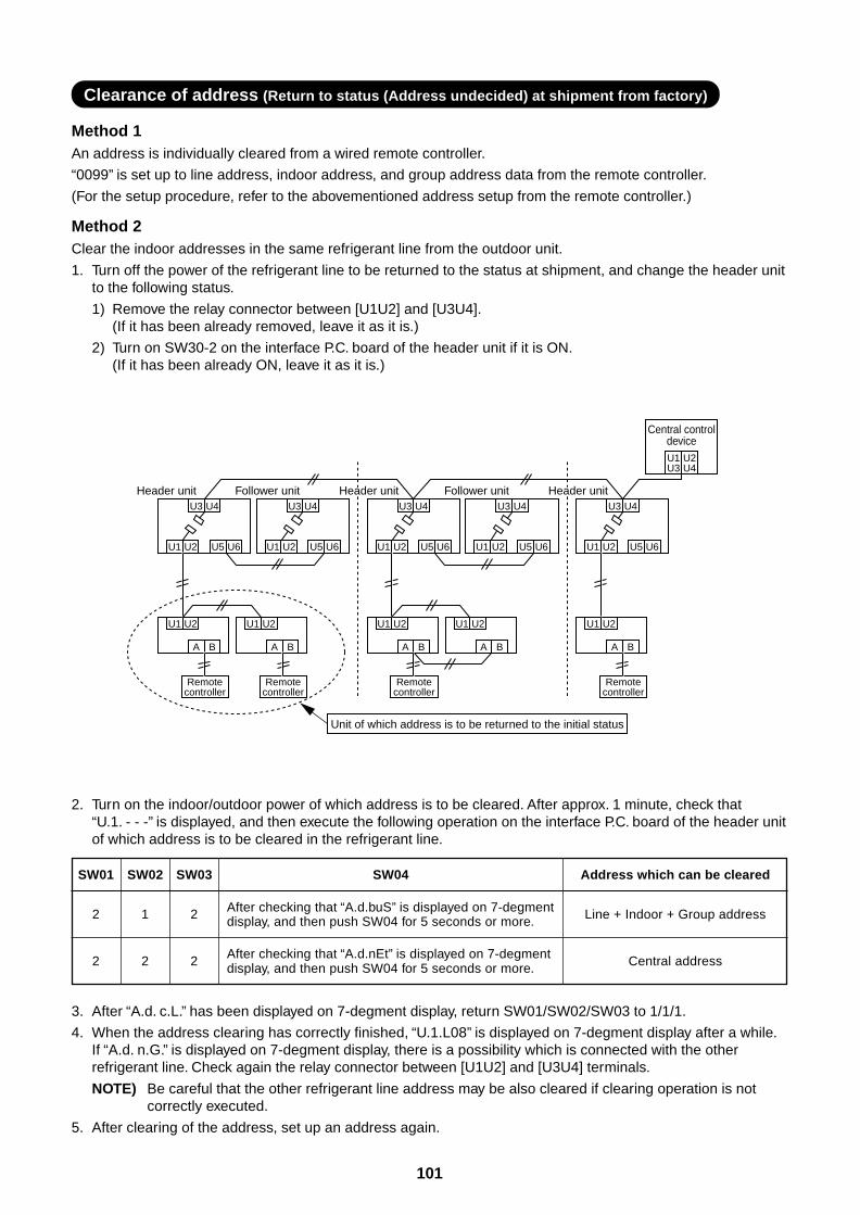
101
Clearance of address (Return to status (Address undecided) at shipment from factory)
Method 1An address is individually cleared from a wired remote controller.
“0099” is set up to line address, indoor address, and group address data from the remote controller.
(For the setup procedure, refer to the abovementioned address setup from the remote controller.)
Method 2Clear the indoor addresses in the same refrigerant line from the outdoor unit.
1. Turn off the power of the refrigerant line to be returned to the status at shipment, and change the header unitto the following status.
1) Remove the relay connector between [U1U2] and [U3U4].(If it has been already removed, leave it as it is.)
2) Turn on SW30-2 on the interface P.C. board of the header unit if it is ON.(If it has been already ON, leave it as it is.)
3. After “A.d. c.L.” has been displayed on 7-degment display, return SW01/SW02/SW03 to 1/1/1.
4. When the address clearing has correctly finished, “U.1.L08” is displayed on 7-degment display after a while.If “A.d. n.G.” is displayed on 7-degment display, there is a possibility which is connected with the otherrefrigerant line. Check again the relay connector between [U1U2] and [U3U4] terminals.
NOTE) Be careful that the other refrigerant line address may be also cleared if clearing operation is notcorrectly executed.
5. After clearing of the address, set up an address again.
SW01 SW02 SW03
2 1 2
2 2 2
SW04
After checking that “A.d.buS” is displayed on 7-degmentdisplay, and then push SW04 for 5 seconds or more.
After checking that “A.d.nEt” is displayed on 7-degmentdisplay, and then push SW04 for 5 seconds or more.
Address which can be cleared
Line + Indoor + Group address
Central address
2. Turn on the indoor/outdoor power of which address is to be cleared. After approx. 1 minute, check that“U.1. - - -” is displayed, and then execute the following operation on the interface P.C. board of the header unitof which address is to be cleared in the refrigerant line.
U3 U4
U1 U2 U5 U6
U1 U2
A B
Header unit
Remotecontroller
U3 U4
U1 U2 U5 U6
U1 U2
A B
Follower unit
Remotecontroller
U3 U4
U1 U2 U5 U6
U1 U2
A B
Remotecontroller
U3 U4
U1 U2 U5 U6
U1 U2
A B
Follower unitU3 U4
U1 U2
U1U3
U2U4
U5 U6
U1 U2
A B
Remotecontroller
Center unitCenter unit Center unitCenter unitHeader unit Header unit
Central controldevice
Unit of which address is to be returned to the initial status
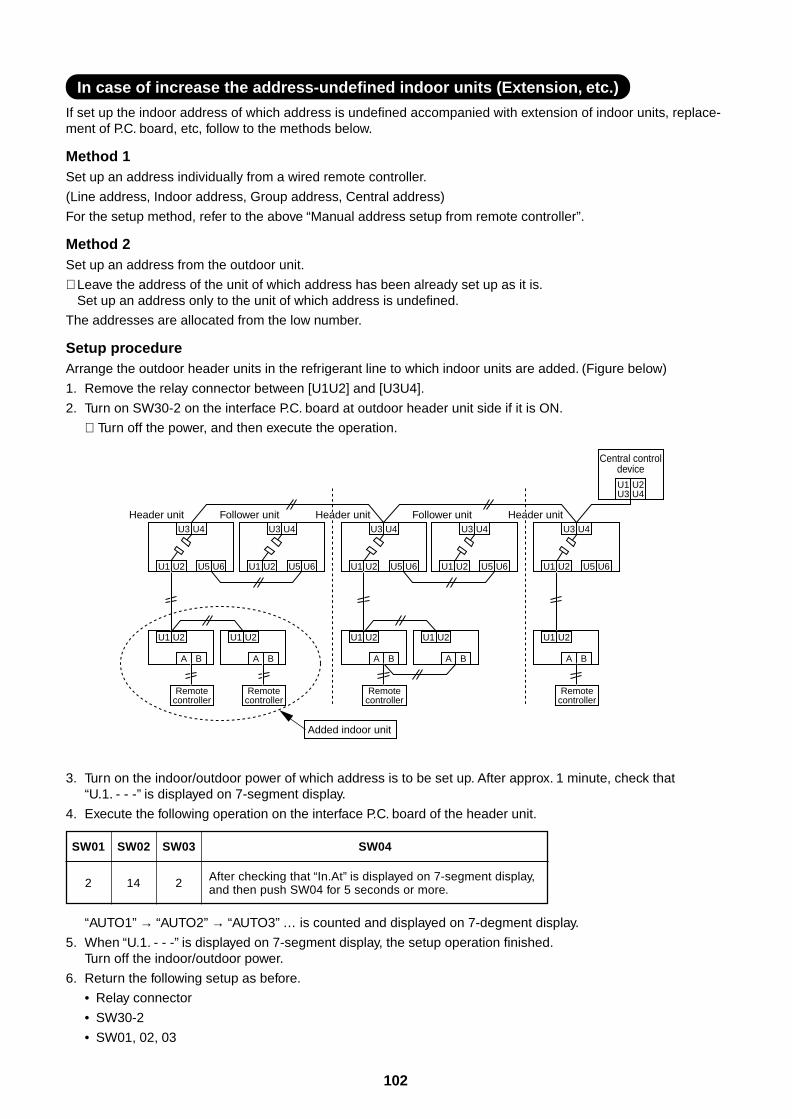
102
In case of increase the address-undefined indoor units (Extension, etc.)
If set up the indoor address of which address is undefined accompanied with extension of indoor units, replace-ment of P.C. board, etc, follow to the methods below.
Method 1Set up an address individually from a wired remote controller.
(Line address, Indoor address, Group address, Central address)
For the setup method, refer to the above “Manual address setup from remote controller”.
Method 2Set up an address from the outdoor unit.
∗ Leave the address of the unit of which address has been already set up as it is.Set up an address only to the unit of which address is undefined.
The addresses are allocated from the low number.
Setup procedureArrange the outdoor header units in the refrigerant line to which indoor units are added. (Figure below)
1. Remove the relay connector between [U1U2] and [U3U4].
2. Turn on SW30-2 on the interface P.C. board at outdoor header unit side if it is ON.
∗ Turn off the power, and then execute the operation.
“AUTO1” → “AUTO2” → “AUTO3” … is counted and displayed on 7-degment display.
5. When “U.1. - - -” is displayed on 7-segment display, the setup operation finished.Turn off the indoor/outdoor power.
6. Return the following setup as before.
• Relay connector
• SW30-2
• SW01, 02, 03
3. Turn on the indoor/outdoor power of which address is to be set up. After approx. 1 minute, check that“U.1. - - -” is displayed on 7-segment display.
4. Execute the following operation on the interface P.C. board of the header unit.
SW01 SW02 SW03
2 14 2
SW04
After checking that “In.At” is displayed on 7-segment display,and then push SW04 for 5 seconds or more.
U3 U4
U1 U2 U5 U6
U1 U2
A B
Header unit
Remotecontroller
U3 U4
U1 U2 U5 U6
U1 U2
A B
Follower unit
Remotecontroller
U3 U4
U1 U2 U5 U6
U1 U2
A B
Remotecontroller
U3 U4
U1 U2 U5 U6
U1 U2
A B
Follower unitU3 U4
U1 U2
U1U3
U2U4
U5 U6
U1 U2
A B
Remotecontroller
Center unit Center unitHeader unit Header unit
Central controldevice
Added indoor unit
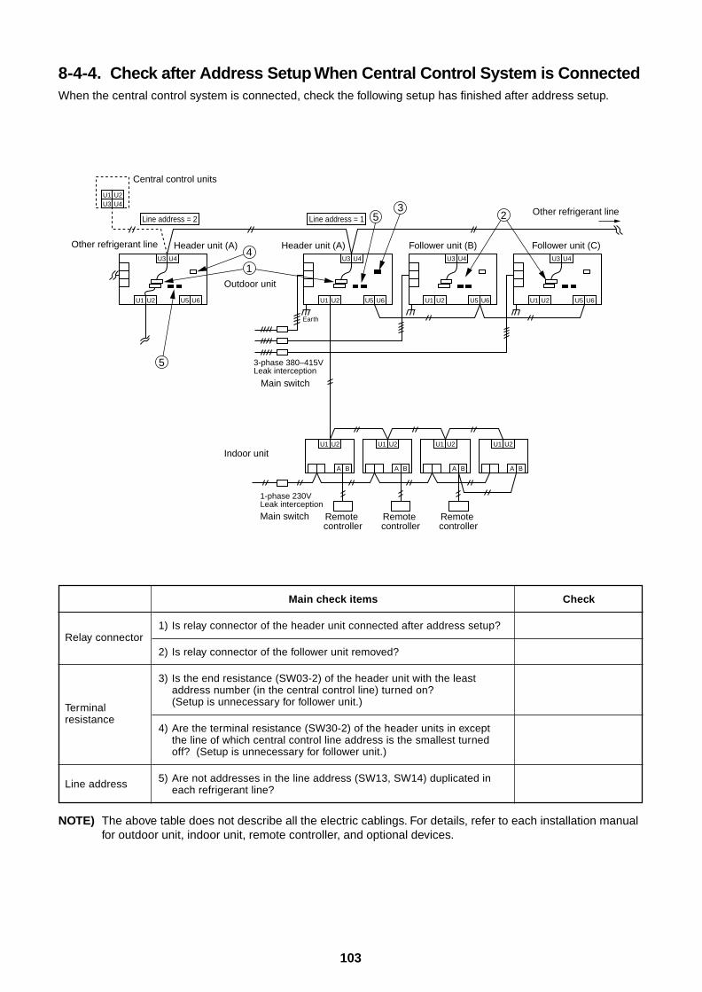
103
8-4-4. Check after Address Setup When Central Control System is ConnectedWhen the central control system is connected, check the following setup has finished after address setup.
NOTE) The above table does not describe all the electric cablings. For details, refer to each installation manualfor outdoor unit, indoor unit, remote controller, and optional devices.
Relay connector
Terminalresistance
Line address
Main check items
1) Is relay connector of the header unit connected after address setup?
2) Is relay connector of the follower unit removed?
3) Is the end resistance (SW03-2) of the header unit with the leastaddress number (in the central control line) turned on?(Setup is unnecessary for follower unit.)
4) Are the terminal resistance (SW30-2) of the header units in exceptthe line of which central control line address is the smallest turnedoff? (Setup is unnecessary for follower unit.)
5) Are not addresses in the line address (SW13, SW14) duplicated ineach refrigerant line?
Check
U1U3
U2U4
U1
U3
U2 U5 U6
U4
U1
U3
U2
U1
A
U2
U5 U6
U4
Header unit (A)
U1
U3
U2 U5 U6
U4
Follower unit (B)
U1
U3
U2 U5 U6
U4
Follower unit (C)
Outdoor unit
Indoor unit
Central control units
Line address = 2
Other refrigerant line
Other refrigerant line
Earth
3-phase 380–415VLeak interception
Main switch
1-phase 230VLeak interception
Main switch
B
Remote controller
U1
A
U2
B
Remote controller
U1
A
U2
B
Remote controller
U1
A
U2
B
53
2
5
Center unit (A)Header unit (A)
Line address = 1
1
4
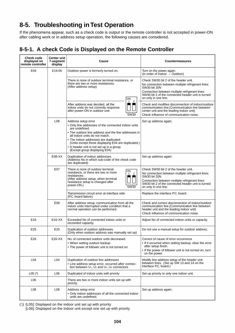
104
8-5. Troubleshooting in Test OperationIf the phenomena appear, such as a check code is output or the remote controller is not accepted in power-ONafter cabling work or in address setup operation, the following causes are considered.
8-5-1. A check Code is Displayed on the Remote ControllerCheck codedisplayed on
remote controller
E04
E16
E25
E26
L04
L05 (*)
L06
L08
Center unit7-segment
display
E19-00
L08
E08-XX
E07
E06
E16-XX
E25
E26-XX
L04
L06
L08
Cause
Outdoor power is formerly turned on.
There is none of outdoor terminal resistance, orthere are two or more resistances.(After address setup)
After address was decided, all theindoor units do not correctly responseafter power-ON in outdoor unit.
Address setup error• Only line addresses of the connected indoor units
are undefined.• The outdoor line address and the line addresses in
all indoor units do not match.• The indoor addresses are duplicated.
(Units except those displaying E04 are duplicated.)• A header unit is not set up in a group.
(Except group displaying E04)
Duplication of indoor addresses.(Address No in which sub-code of the check codeare duplicated)
There is none of outdoor terminalresistance, or there are two or moreresistances.(After address setup, when terminalresistance setup is changed afterpower-ON.)
Transmission circuit error at interface side(P.C. board failure)
After address setup, communication from all theindoor units interrupted under condition that anormal operation can be performed.
Exceeded No of connected indoor units orexceeded capacity.
Duplication of outdoor addresses.(Only when outdoor address was manually set up)
No. of connected outdoor units decreased.• When setting outdoor backup• The power of follower unit is not turned on.
Duplication of outdoor line addresses• Line address setup error, occurred after connec-
tion between U1, U2 and U3, U4 connectors
Duplicated of indoor units with priority
There are two or more indoor units set up withpriority.
Address setup error• Only indoor addresses of all the connected indoor
units are undefined.
(∗ ) [L05]: Displayed on the indoor unit set up with priority[L06]: Displayed on the indoor unit except one set up with priority
Countermeasures
Turn on the power again.(In order of Indoor → Outdoor)
Check SW30 bit 2 of the header unit.No connection between multiple refrigerant lines:SW30 bit 20NConnection between multiple refrigerant lines:SW30 bit 2 of the connected header unit is turnedon only in one line.
Check and modifies disconnection of indoor/outdoorcommunication line.(Communication line betweencenter unit and the leading indoor unit)Check influence of communication noise.
Set up address again.
Set up address again.
Check SW30 bit 2 of the header unit.No connection between multiple refrigerant lines:SW30 bit 20NConnection between multiple refrigerant lines:SW30 bit 2 of the connected header unit is turnedon only in one line.
Replace the interface P.C. board.
Check and correct disconnection of indoor/outdoorcommunication line.(Communication line betweenheader unit and the leading indoor unit)Check influence of communication noise.
Adjust No of connected indoor units or capacity.
Do not use a manual setup for outdoor address.
Correct of cause of error occurrence• If it occurred when setting backup, clear the error
after setup finish.• If the power of follower unit is not turned on, turn
on the power.
Modify line address setup of the header unitbetween lines. (Set up SW 13 and 14 on theinterface P.C. board.)
Set up priority to only one indoor unit.
Set up address again.
ON1
SW30
2
ON1
SW30
2
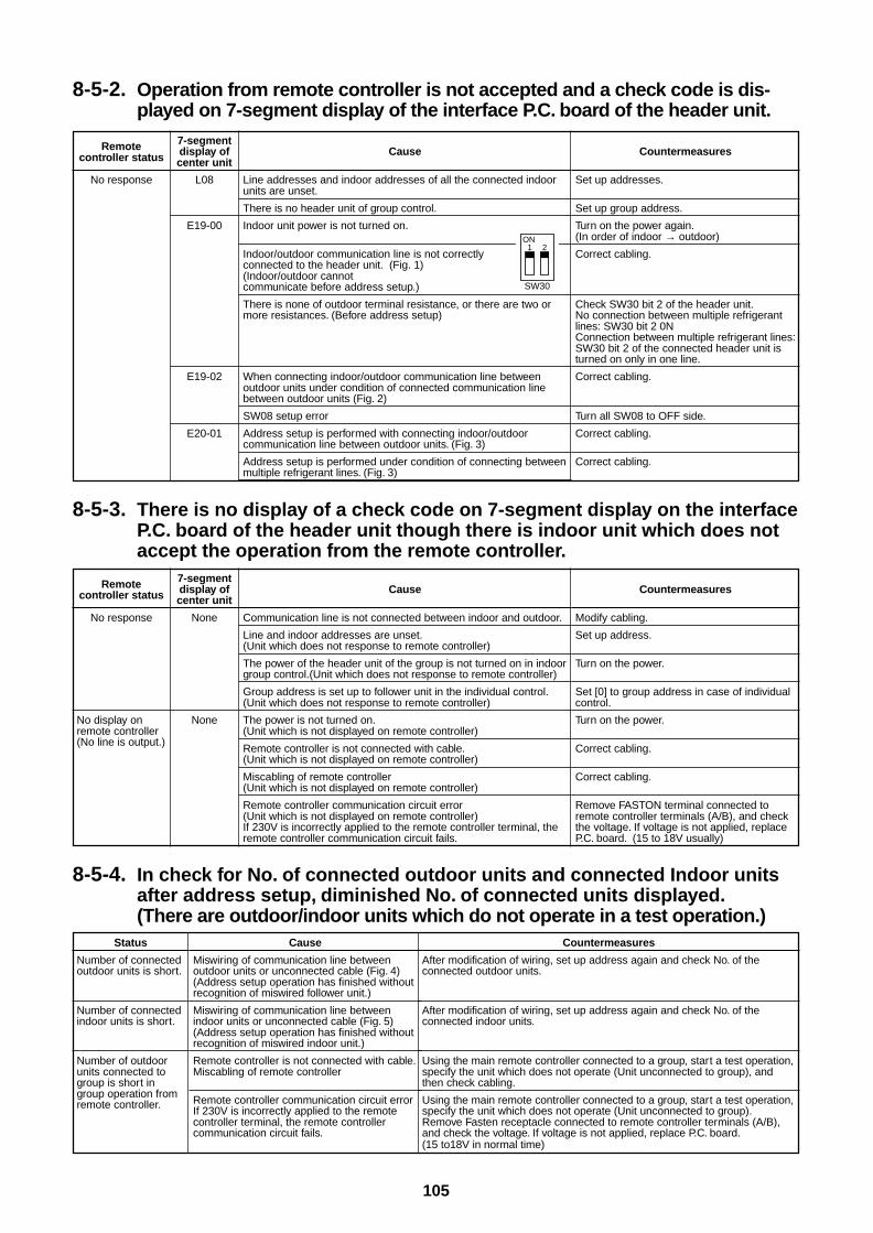
105
8-5-4. In check for No. of connected outdoor units and connected Indoor unitsafter address setup, diminished No. of connected units displayed.(There are outdoor/indoor units which do not operate in a test operation.)
8-5-2. Operation from remote controller is not accepted and a check code is dis-played on 7-segment display of the interface P.C. board of the header unit.
8-5-3. There is no display of a check code on 7-segment display on the interfaceP.C. board of the header unit though there is indoor unit which does notaccept the operation from the remote controller.
Remotecontroller status
No response
No display onremote controller(No line is output.)
7-segmentdisplay ofcenter unit
None
None
Cause
Communication line is not connected between indoor and outdoor.
Line and indoor addresses are unset.(Unit which does not response to remote controller)
The power of the header unit of the group is not turned on in indoorgroup control.(Unit which does not response to remote controller)
Group address is set up to follower unit in the individual control.(Unit which does not response to remote controller)
The power is not turned on.(Unit which is not displayed on remote controller)
Remote controller is not connected with cable.(Unit which is not displayed on remote controller)
Miscabling of remote controller(Unit which is not displayed on remote controller)
Remote controller communication circuit error(Unit which is not displayed on remote controller)If 230V is incorrectly applied to the remote controller terminal, theremote controller communication circuit fails.
Countermeasures
Modify cabling.
Set up address.
Turn on the power.
Set [0] to group address in case of individualcontrol.
Turn on the power.
Correct cabling.
Correct cabling.
Remove FASTON terminal connected toremote controller terminals (A/B), and checkthe voltage. If voltage is not applied, replaceP.C. board. (15 to 18V usually)
Remotecontroller status
No response
7-segmentdisplay ofcenter unit
L08
E19-00
E19-02
E20-01
Cause
Line addresses and indoor addresses of all the connected indoorunits are unset.
There is no header unit of group control.
Indoor unit power is not turned on.
Indoor/outdoor communication line is not correctlyconnected to the header unit. (Fig. 1)(Indoor/outdoor cannotcommunicate before address setup.)
There is none of outdoor terminal resistance, or there are two ormore resistances. (Before address setup)
When connecting indoor/outdoor communication line betweenoutdoor units under condition of connected communication linebetween outdoor units (Fig. 2)
SW08 setup error
Address setup is performed with connecting indoor/outdoorcommunication line between outdoor units. (Fig. 3)
Address setup is performed under condition of connecting betweenmultiple refrigerant lines. (Fig. 3)
Countermeasures
Set up addresses.
Set up group address.
Turn on the power again.(In order of indoor → outdoor)
Correct cabling.
Check SW30 bit 2 of the header unit.No connection between multiple refrigerantlines: SW30 bit 2 0NConnection between multiple refrigerant lines:SW30 bit 2 of the connected header unit isturned on only in one line.
Correct cabling.
Turn all SW08 to OFF side.
Correct cabling.
Correct cabling.
Status
Number of connectedoutdoor units is short.
Number of connectedindoor units is short.
Number of outdoorunits connected togroup is short ingroup operation fromremote controller.
Cause
Miswiring of communication line betweenoutdoor units or unconnected cable (Fig. 4)(Address setup operation has finished withoutrecognition of miswired follower unit.)
Miswiring of communication line betweenindoor units or unconnected cable (Fig. 5)(Address setup operation has finished withoutrecognition of miswired indoor unit.)
Remote controller is not connected with cable.Miscabling of remote controller
Remote controller communication circuit errorIf 230V is incorrectly applied to the remotecontroller terminal, the remote controllercommunication circuit fails.
Countermeasures
After modification of wiring, set up address again and check No. of theconnected outdoor units.
After modification of wiring, set up address again and check No. of theconnected indoor units.
Using the main remote controller connected to a group, start a test operation,specify the unit which does not operate (Unit unconnected to group), andthen check cabling.
Using the main remote controller connected to a group, start a test operation,specify the unit which does not operate (Unit unconnected to group).Remove Fasten receptacle connected to remote controller terminals (A/B),and check the voltage. If voltage is not applied, replace P.C. board.(15 to18V in normal time)
ON1
SW30
2
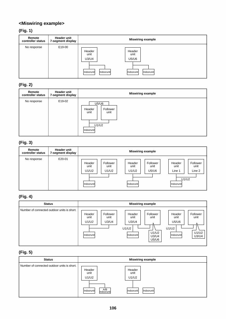
106
<Miswiring example>
(Fig. 1)
(Fig. 2)
Remotecontroller status
No response
Header unit7-segment display
E19-00
Miswiring example
Remotecontroller status
No response
Header unit7-segment display
E19-02
Miswiring example
(Fig. 3)
(Fig. 4)
(Fig. 5)
Remotecontroller status
No response
Header unit7-segment display
E20-01
Miswiring example
Status
Number of connected outdoor units is short.
Miswiring example
Status
Number of connected outdoor units is short.
Miswiring example
Headerunit
U3/U4
Indoorunit Indoorunit
Headerunit
U1/U2
Indoorunit A/BIndoorunit
Headerunit
U1/U2
Indoorunit Indoorunit
Headerunit
U1/U2
Followerunit
U1/U2
Indoorunit
Headerunit
U1/U2
Followerunit
U3/U4
Indoorunit
Headerunit
U3/U4
U1/U2
Followerunit
Indoorunit
Headerunit
U1/U2
Followerunit
U5/U6
Indoorunit
Headerunit
Line 1
U1/U2
Followerunit
Line 2
Indoorunit
Headerunit
Followerunit
U1/U2
U5/U6
Indoorunit
Headerunit
U5/U6
Indoorunit Indoorunit
U1/U2U3/U4U5/U6
Headerunit
U5/U6
U1/U2
Followerunit
IndoorunitU1/U2U3/U4

107
8-6. Test Operation Check8-6-1. Fan Check
When an error code has been displayed on the remote controller, remove the error cause referring to “Check code and check position displayed on remote controller and outdoor unit”.
Check indoor fan, fan motor, and fan circuit.
Check positions around the fan.
START
Push [START/STOP] button.
Select the operation mode [FAN].
Is air discharged from thedischarge port of the indoor unit?
Is there no abnormal sound?
Normal
Check all indoor unit in turn.
YES
YES
NO
NO
8-6-2. Cooling/Heating Test Operation CheckThe cooling/heating test operation check can be performed on both remote controller and outdoor interface P.C.board.
1. Test operation start/stop operation<Test operation from remote controller>Wired remote controller : Refer to the lower items in “Test operation” of wired remote controller.Wireless remote controller : Refer to the lower items in “Test operation” of wireless remote controller.
Wired remote controller
1 When pushing button for 4 seconds or more,[TEST] is displayed in the display section and themode enters in test operation mode.
2 Push button.
3 Using button, select an operation mode [COOL] or [HEAT].• Do not use operation mode other than [COOL] or [HEAT].
• Temperature adjustment is unavailable during test operation.
• Error is detected as usual.
4 When the test operation has finished, push button to stop the operation.(The same display as that in procedure 1) appears in the display section.)
5 Push button to clear the test operation mode.([TEST] display in the display section disappears and the statusreturns to the normal stop status.)
1,5
2,4
3UNIT
SET CLTEST
TEST
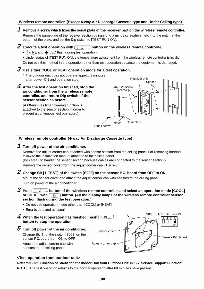
108
Wireless remote controller (Except 4-way Air Discharge Cassette type and Under Ceiling type)
1 Remove a screw which fixes the serial plate of the receiver part on the wireless remote controller.Remove the nameplate of the receiver section by inserting a minus screwdriver, etc into the notch at thebottom of the plate, and set the Dip switch to [TEST RUN ON].
2 Execute a test operation with button on the wireless remote controller.• , , and LED flash during test operation.
• Under status of [TEST RUN ON], the temperature adjustment from the wireless remote controller is invalid.
Do not use this method in the operation other than test operation because the equipment is damaged.
3 Use either COOL or HEAT operation mode for a test operation.* The outdoor unit does not operate approx. 3 minutes
after power-ON and operation stop.
4 After the test operation finished, stop theair conditioner from the wireless remotecontroller, and return Dip switch of thesensor section as before.(A 60-minutes timer clearing function isattached to the sensor section in order toprevent a continuous test operation.)
Wireless remote controller (4-way Air Discharge Cassette type)
1 Turn off power of the air conditioner.Remove the adjust corner cap attached with sensor section from the ceiling panel. For removing method,follow to the installation manual attached to the ceiling panel.(Be careful to handle the sensor section because cables are connected to the sensor section.)
Remove the sensor cover from the adjust corner cap. (1 screw)
2 Change Bit [1: TEST] of the switch [S003] on the sensor P.C. board from OFF to ON.Mount the sensor cover and attach the adjust corner cap with sensors to the ceiling panel.
Turn on power of the air conditioner.
3 Push button of the wireless remote controller, and select an operation mode [COOL]or [HEAT] with button. (All the display lamps of the wireless remote controller sensorsection flash during the test operation.)• Do not use operation mode other than [COOL] or [HEAT].
• Error is detected as usual.
4 When the test operation has finished, push button to stop the operation.
5 Turn off power of the air conditioner.Change Bit [1] of the switch [S003] on thesensor P.C. board from ON to OFF.
Attach the adjust corner cap withsensors to the ceiling panel.
<Test operation from outdoor unit>Refer to “8-7-2. Function of Start/Stop the Indoor Unit from Outdoor Unit” in “8-7. Service Support Function”.
NOTE) The test operation returns to the normal operation after 60 minutes have passed.
Sensor cover
Adjust corner cap
4 3 2 1
ON
Sensor P.C. board
S003 Bit 1 : OFF ON
Receiver unit
M4 × 25 screw(2 pieces)
Small screw
Spacer
Notch Nameplate
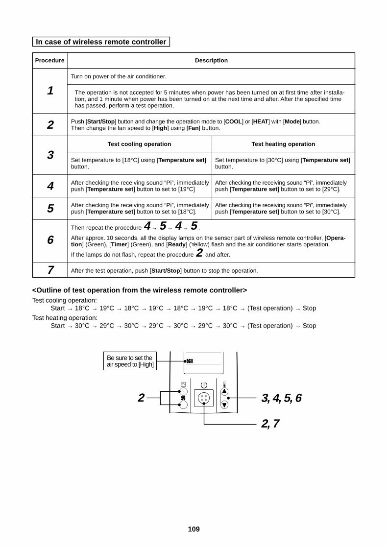
109
In case of wireless remote controller
Procedure
1
2
3
4
5
6
7
Description
Turn on power of the air conditioner.
The operation is not accepted for 5 minutes when power has been turned on at first time after installa-tion, and 1 minute when power has been turned on at the next time and after. After the specified timehas passed, perform a test operation.
Push [Start/Stop] button and change the operation mode to [COOL] or [HEAT] with [Mode] button.Then change the fan speed to [High] using [Fan] button.
Test cooling operation Test heating operation
Set temperature to [18°C] using [Temperature set] Set temperature to [30°C] using [Temperature set]button. button.
After checking the receiving sound “Pi”, immediately After checking the receiving sound “Pi”, immediatelypush [Temperature set] button to set to [19°C] push [Temperature set] button to set to [29°C].
After checking the receiving sound “Pi”, immediately After checking the receiving sound “Pi”, immediatelypush [Temperature set] button to set to [18°C]. push [Temperature set] button to set to [30°C].
Then repeat the procedure 4 → 5 → 4 → 5 .
After approx. 10 seconds, all the display lamps on the sensor part of wireless remote controller, [Opera-tion] (Green), [Timer] (Green), and [Ready] (Yellow) flash and the air conditioner starts operation.
If the lamps do not flash, repeat the procedure 2 and after.
After the test operation, push [Start/Stop] button to stop the operation.
2 3, 4, 5, 6
2, 7
Be sure to set the air speed to [High]
<Outline of test operation from the wireless remote controller>Test cooling operation:
Start → 18°C → 19°C → 18°C → 19°C → 18°C → 19°C → 18°C → (Test operation) → Stop
Test heating operation:Start → 30°C → 29°C → 30°C → 29°C → 30°C → 29°C → 30°C → (Test operation) → Stop
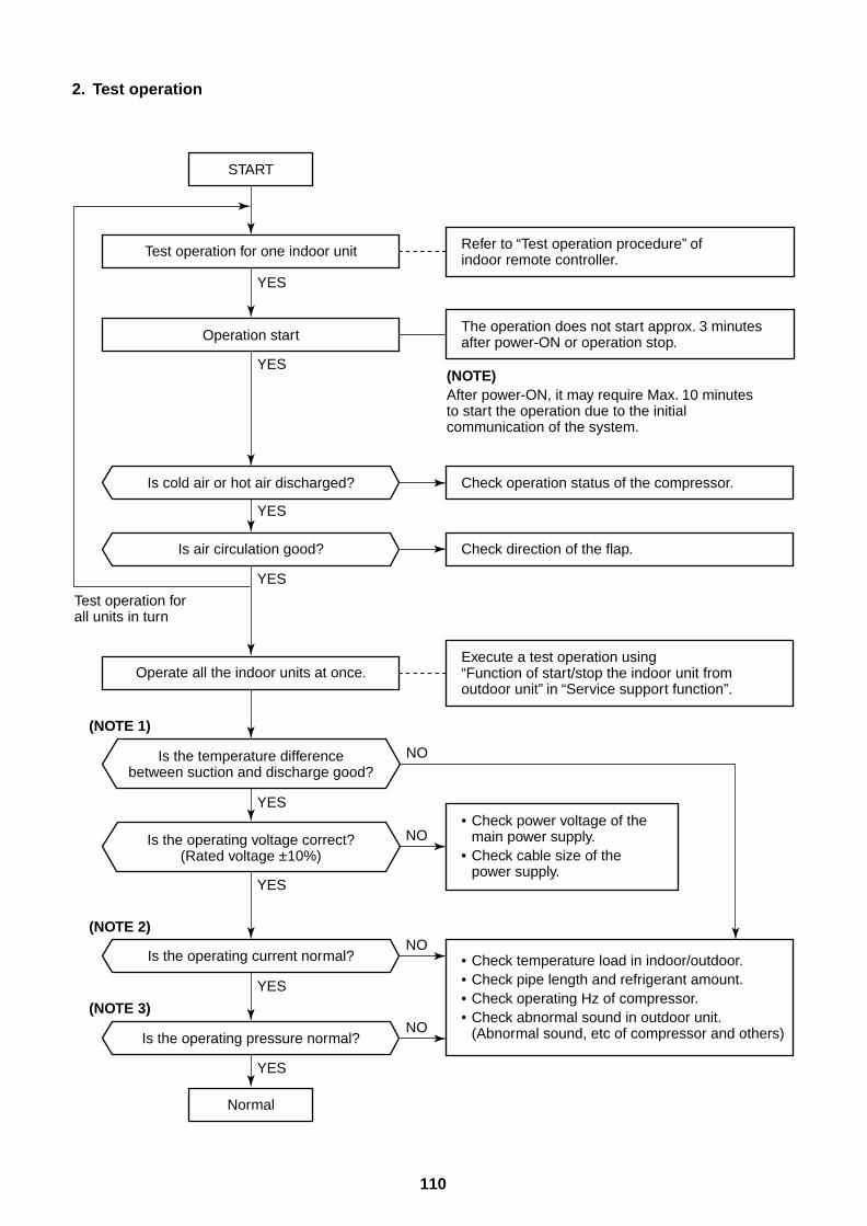
110
2. Test operation
Normal
START
Test operation for all units in turn
Test operation for one indoor unit
Operate all the indoor units at once.
Operation start
Is cold air or hot air discharged?
(NOTE 1)
(NOTE 2)
(NOTE 3)
Is the temperature differencebetween suction and discharge good?
Is the operating voltage correct?(Rated voltage ±10%)
Refer to “Test operation procedure” of indoor remote controller.
(NOTE)After power-ON, it may require Max. 10 minutes to start the operation due to the initial communication of the system.
Check operation status of the compressor.
Is air circulation good?
Is the operating current normal?
Is the operating pressure normal?
Check direction of the flap.
Execute a test operation using “Function of start/stop the indoor unit from outdoor unit” in “Service support function”.
• Check power voltage of the main power supply.
• Check cable size of the power supply.
• Check temperature load in indoor/outdoor.• Check pipe length and refrigerant amount.• Check operating Hz of compressor.• Check abnormal sound in outdoor unit.
(Abnormal sound, etc of compressor and others)
The operation does not start approx. 3 minutes after power-ON or operation stop.
YES
YES
YES
YES
YES
YES
YES
YES
NO
NO
NO
NO
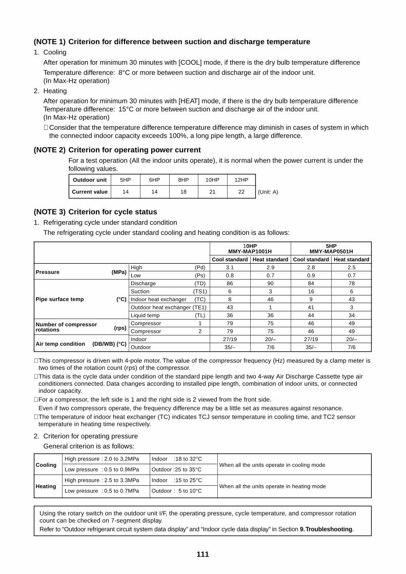
111
(NOTE 1) Criterion for difference between suction and discharge temperature1. Cooling
After operation for minimum 30 minutes with [COOL] mode, if there is the dry bulb temperature difference
Temperature difference: 8°C or more between suction and discharge air of the indoor unit.(In Max-Hz operation)
2. Heating
After operation for minimum 30 minutes with [HEAT] mode, if there is the dry bulb temperature differenceTemperature difference: 15°C or more between suction and discharge air of the indoor unit.(In Max-Hz operation)
∗ Consider that the temperature difference temperature difference may diminish in cases of system in whichthe connected indoor capacity exceeds 100%, a long pipe length, a large difference.
(NOTE 2) Criterion for operating power currentFor a test operation (All the indoor units operate), it is normal when the power current is under thefollowing values.
Outdoor unit
Current value
5HP 6HP 8HP 10HP 12HP
14 14 18 21 22 (Unit: A)
(NOTE 3) Criterion for cycle status1. Refrigerating cycle under standard condition
The refrigerating cycle under standard cooling and heating condition is as follows:
∗ This compressor is driven with 4-pole motor. The value of the compressor frequency (Hz) measured by a clamp meter istwo times of the rotation count (rps) of the compressor.
∗ This data is the cycle data under condition of the standard pipe length and two 4-way Air Discharge Cassette type airconditioners connected. Data changes according to installed pipe length, combination of indoor units, or connectedindoor capacity.
∗ For a compressor, the left side is 1 and the right side is 2 viewed from the front side.Even if two compressors operate, the frequency difference may be a little set as measures against resonance.
∗ The temperature of indoor heat exchanger (TC) indicates TCJ sensor temperature in cooling time, and TC2 sensortemperature in heating time respectively.
2. Criterion for operating pressure
General criterion is as follows:
Using the rotary switch on the outdoor unit I/F, the operating pressure, cycle temperature, and compressor rotationcount can be checked on 7-segment display.Refer to “Outdoor refrigerant circuit system data display” and “Indoor cycle data display” in Section 9. Troubleshooting.
Cooling
Heating
High pressure : 2.0 to 3.2MPa
Low pressure : 0.5 to 0.9MPa
High pressure : 2.5 to 3.3MPa
Low pressure : 0.5 to 0.7MPa
Indoor :18 to 32°C
Outdoor :25 to 35°C
Indoor :15 to 25°C
Outdoor : 5 to 10°C
When all the units operate in cooling mode
When all the units operate in heating mode
Pressure (MPa)
Pipe surface temp (°C)
Number of compressor(rps)rotations
Air temp condition (DB/WB) (°C)
High (Pd)
Low (Ps)
Discharge (TD)
Suction (TS1)
Indoor heat exchanger (TC)
Outdoor heat exchanger (TE1)
Liquid temp (TL)
Compressor 1
Compressor 2
Indoor
Outdoor
10HP 5HPMMY-MAP1001H MMY-MAP0501H
Cool standard Heat standard Cool standard Heat standard3.1 2.9 2.8 2.5
0.8 0.7 0.9 0.7
86 90 84 78
6 3 16 6
8 46 9 43
43 1 41 3
36 36 44 34
79 75 46 49
79 75 46 49
27/19 20/– 27/19 20/–
35/– 7/6 35/– 7/6
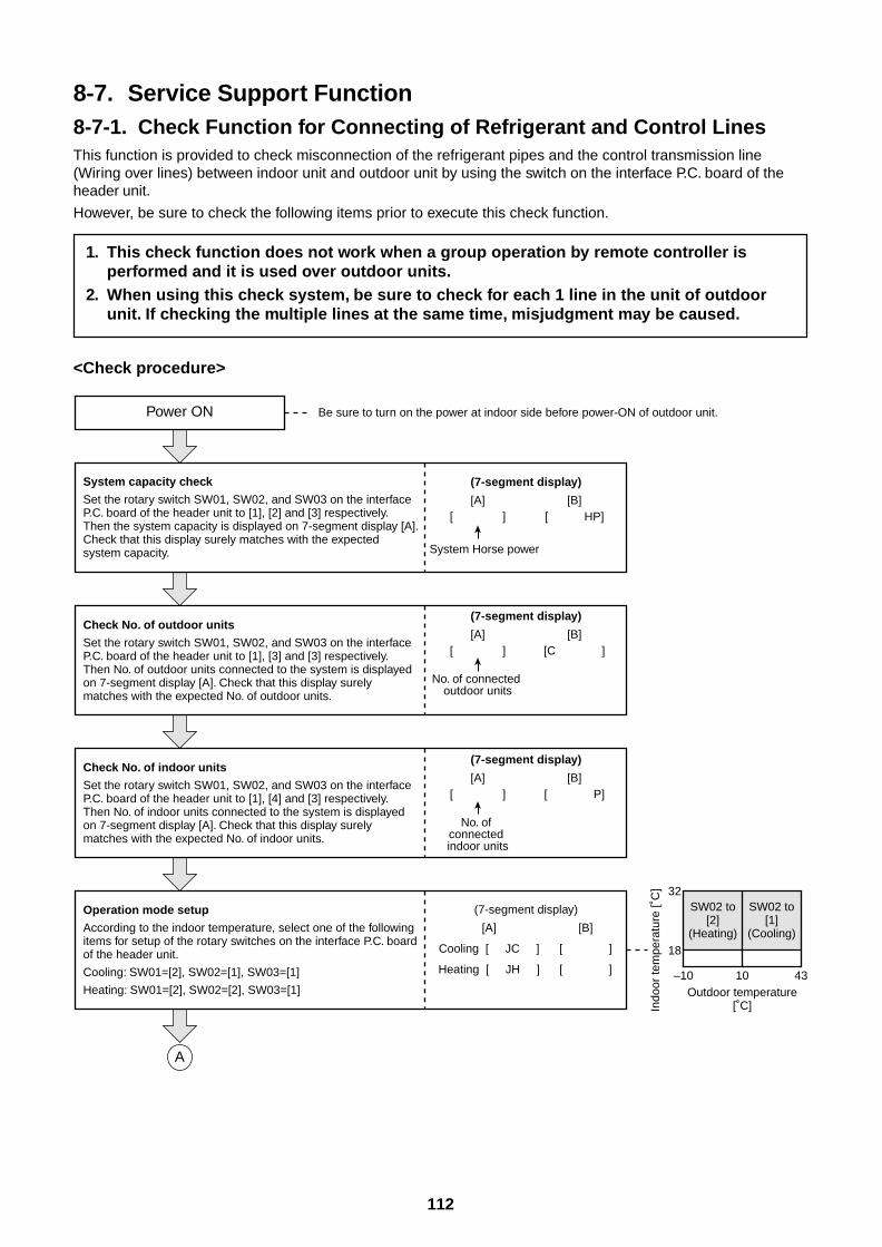
112
8-7. Service Support Function8-7-1. Check Function for Connecting of Refrigerant and Control LinesThis function is provided to check misconnection of the refrigerant pipes and the control transmission line(Wiring over lines) between indoor unit and outdoor unit by using the switch on the interface P.C. board of theheader unit.
However, be sure to check the following items prior to execute this check function.
1. This check function does not work when a group operation by remote controller isperformed and it is used over outdoor units.
2. When using this check system, be sure to check for each 1 line in the unit of outdoorunit. If checking the multiple lines at the same time, misjudgment may be caused.
<Check procedure>
Power ON Be sure to turn on the power at indoor side before power-ON of outdoor unit.
System capacity check
Set the rotary switch SW01, SW02, and SW03 on the interface P.C. board of the header unit to [1], [2] and [3] respectively. Then the system capacity is displayed on 7-segment display [A]. Check that this display surely matches with the expected system capacity.
(7-segment display)
[B][ HP]
(7-segment display)
[A][ ]
No. of connected outdoor units
[B][C ]
(7-segment display)
[A][ ]
No. of connected indoor units
[B][ P]
(7-segment display)
[A]
Cooling [ JC ]
Heating [ JH ]
[B]
[ ]
[ ]
Check No. of outdoor units
Set the rotary switch SW01, SW02, and SW03 on the interface P.C. board of the header unit to [1], [3] and [3] respectively. Then No. of outdoor units connected to the system is displayed on 7-segment display [A]. Check that this display surely matches with the expected No. of outdoor units.
Check No. of indoor units
Set the rotary switch SW01, SW02, and SW03 on the interface P.C. board of the header unit to [1], [4] and [3] respectively. Then No. of indoor units connected to the system is displayed on 7-segment display [A]. Check that this display surely matches with the expected No. of indoor units.
Operation mode setup
According to the indoor temperature, select one of the following items for setup of the rotary switches on the interface P.C. board of the header unit.
Cooling: SW01=[2], SW02=[1], SW03=[1]
Heating: SW01=[2], SW02=[2], SW03=[1]
Indo
or te
mpe
ratu
re [˚
C]
SW02 to[2]
(Heating)
32
18
–10 10 43
SW02 to[1]
(Cooling)
Outdoor temperature[˚C]
A
[A][ ]
System Horse power
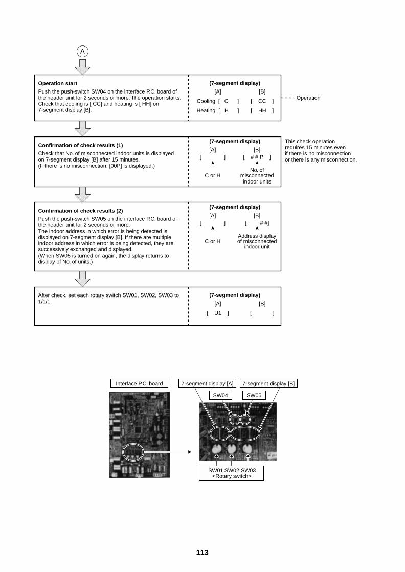
113
Operation start
Push the push-switch SW04 on the interface P.C. board of the header unit for 2 seconds or more. The operation starts. Check that cooling is [ CC] and heating is [ HH] on 7-segment display [B].
(7-segment display)
[A][ ]
C or H
[B][ # # P ]
No. ofmisconnectedindoor units
(7-segment display)
[A][ ]
C or H
[B][ # #]
Address displayof misconnected
indoor unit
(7-segment display)
[A]
[ U1 ]
[B]
[ ]
Confirmation of check results (1)
Check that No. of misconnected indoor units is displayed on 7-segment display [B] after 15 minutes.(If there is no misconnection, [00P] is displayed.)
Confirmation of check results (2)
Push the push-switch SW05 on the interface P.C. board of the header unit for 2 seconds or more. The indoor address in which error is being detected is displayed on 7-segment display [B]. If there are multiple indoor address in which error is being detected, they are successively exchanged and displayed. (When SW05 is turned on again, the display returns to display of No. of units.)
After check, set each rotary switch SW01, SW02, SW03 to 1/1/1.
(7-segment display)
[A]
Cooling [ C ]
Heating [ H ]
[B]
[ CC ]
[ HH ]
A
Operation
This check operation requires 15 minutes even if there is no misconnection or there is any misconnection.
Interface P.C. board 7-segment display [A] 7-segment display [B]
SW04 SW05
SW01 SW02 SW03<Rotary switch>
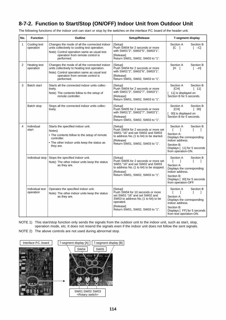
114
8-7-2. Function to Start/Stop (ON/OFF) Indoor Unit from Outdoor UnitThe following functions of the indoor unit can start or stop by the switches on the interface P.C. board of the header unit.
NOTE 1) This start/stop function only sends the signals from the outdoor unit to the indoor unit, such as start, stop,operation mode, etc. It does not resend the signals even if the indoor unit does not follow the sent signals.
NOTE 2) The above controls are not used during abnormal stop.
No.
1
2
3
4
Function
Cooling testoperation
Heating testoperation
Batch start
Batch stop
Individualstart
Individual stop
Individual testoperation
Outline
Changes the mode of all the connected indoorunits collectively to cooling test operation.Note) Control operation same as usual test
operation from remote control isperformed.
Changes the mode of all the connected indoorunits collectively to heating test operation.Note) Control operation same as usual test
operation from remote control isperformed.
Starts all the connected indoor units collec-tively.Note) The contents follow to the setup of
remote controller.
Stops all the connected indoor units collec-tively.
Starts the specified indoor unit.Notes)• The contents follow to the setup of remote
controller.• The other indoor units keep the status as
they are.
Stops the specified indoor unit.Note) The other indoor units keep the status
as they are.
Operates the specified indoor unit.Note) The other indoor units keep the status
as they are.
Setup/Release
[Setup]Push SW04 for 2 seconds or morewith SW01”2”, SW02”5”, SW03”1”.[Release]Return SW01, SW02, SW03 to “1”.
[Setup]Push SW04 for 2 seconds or morewith SW01”2”, SW02”6”, SW03”1”.[Release]Return SW01, SW02, SW03 to “1”.
[Setup]Push SW04 for 2 seconds or morewith SW01”2”, SW02”7”, SW03”1”.[Release]Return SW01, SW02, SW03 to “1”.
[Setup]Push SW05 for 2 seconds or morewith SW01”2”, SW02”7”, SW03”1”.[Release]Return SW01, SW02, SW03 to “1”.
[Setup]Push SW04 for 2 seconds or more setSW01 “16” and set SW02 and SW03to address No. (1 to 64) to be started.[Release]Return SW01, SW02, SW03 to “1”.
[Setup]Push SW05 for 2 seconds or more setSW01 “16” and set SW02 and SW03to address No. (1 to 64) to be stopped.[Release]Return SW01, SW02, SW03 to “1”.
[Setup]Push SW04 for 10 seconds or moreset SW01 “16” and set SW02 andSW03 to address No. (1 to 64) to beoperated.[Release]Return SW01, SW02, SW03 to “1”.
7-segment display
Section A Section B[C ] [ –C]
Section A Section B[H ] [ –H]
Section A Section B[CH] [ 11]
[ 11] is displayed onSection B for 5 seconds.
Section A Section B[CH] [ 00]
[ 00] is displayed onSection B for 5 seconds.
Section A Section B[ ] [ ]
Section A:Displays the correspondingindoor address.Section B:Displays [ 11] for 5 secondsfrom operation-ON.
Section A Section B[ ] [ ]
Section A:Displays the correspondingindoor address.Section B:Displays [ 00] for 5 secondsfrom operation-OFF.
Section A Section B[ ] [ ]
Section A:Displays the correspondingindoor address.Section B:Displays [ FF] for 5 secondsfrom test operation-ON.
Interface P.C. board 7-segment display [A] 7-segment display [B]
SW04 SW05
SW01 SW02 SW03<Rotary switch>
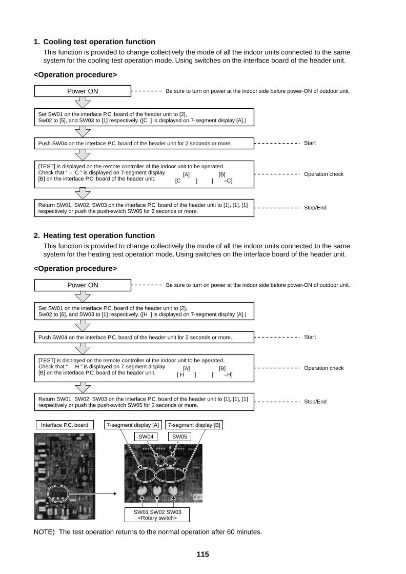
115
1. Cooling test operation functionThis function is provided to change collectively the mode of all the indoor units connected to the samesystem for the cooling test operation mode. Using switches on the interface board of the header unit.
<Operation procedure>
[A][C ]
[B][ –C]
Power ON Be sure to turn on power at the indoor side before power-ON of outdoor unit.
Set SW01 on the interface P.C. board of the header unit to [2], Sw02 to [5], and SW03 to [1] respectively. ([C ] is displayed on 7-segment display [A].)
Push SW04 on the interface P.C. board of the header unit for 2 seconds or more.
[TEST] is displayed on the remote controller of the indoor unit to be operated. Check that “ – C ” is displayed on 7-segment display [B] on the interface P.C. board of the header unit.
Return SW01, SW02, SW03 on the interface P.C. board of the header unit to [1], [1], [1] respectively or push the push-switch SW05 for 2 seconds or more.
Start
Operation check
Stop/End
Interface P.C. board 7-segment display [A] 7-segment display [B]
SW04 SW05
SW01 SW02 SW03<Rotary switch>
2. Heating test operation functionThis function is provided to change collectively the mode of all the indoor units connected to the samesystem for the heating test operation mode. Using switches on the interface board of the header unit.
<Operation procedure>
NOTE) The test operation returns to the normal operation after 60 minutes.
Power ON Be sure to turn on power at the indoor side before power-ON of outdoor unit.
Set SW01 on the interface P.C. board of the header unit to [2], Sw02 to [6], and SW03 to [1] respectively. ([H ] is displayed on 7-segment display [A].)
[A][ H ]
[B][ –H]
Push SW04 on the interface P.C. board of the header unit for 2 seconds or more.
[TEST] is displayed on the remote controller of the indoor unit to be operated. Check that “ – H ” is displayed on 7-segment display [B] on the interface P.C. board of the header unit.
Return SW01, SW02, SW03 on the interface P.C. board of the header unit to [1], [1], [1] respectively or push the push-switch SW05 for 2 seconds or more.
Start
Operation check
Stop/End
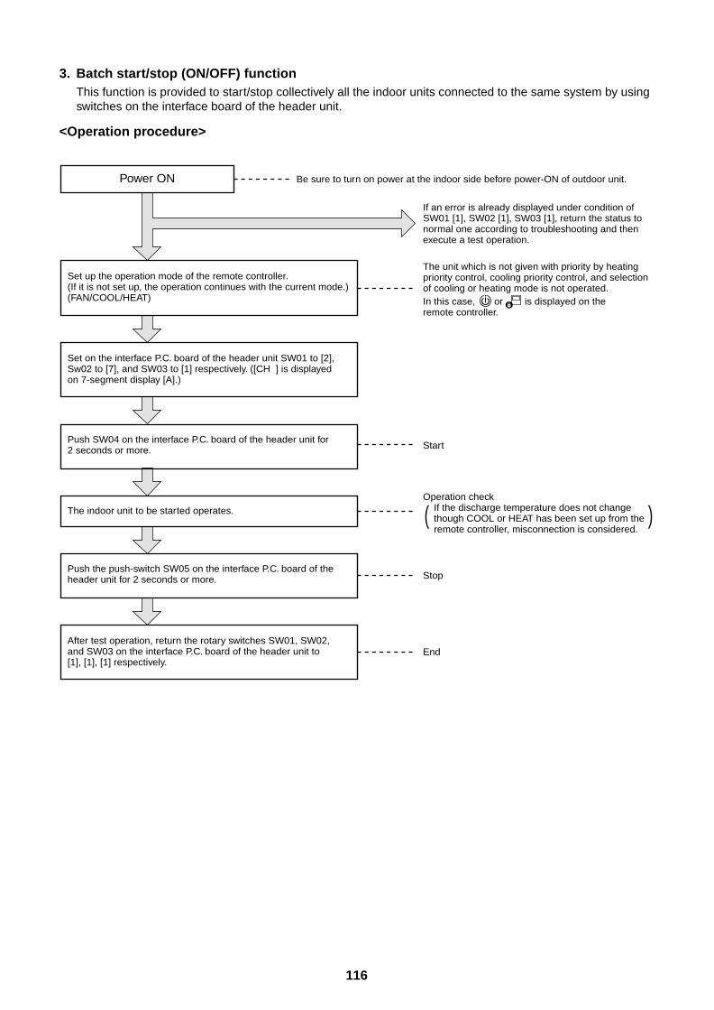
116
3. Batch start/stop (ON/OFF) functionThis function is provided to start/stop collectively all the indoor units connected to the same system by usingswitches on the interface board of the header unit.
<Operation procedure>
Power ON Be sure to turn on power at the indoor side before power-ON of outdoor unit.
The unit which is not given with priority by heating priority control, cooling priority control, and selection of cooling or heating mode is not operated. In this case, or is displayed on the remote controller.
If an error is already displayed under condition of SW01 [1], SW02 [1], SW03 [1], return the status to normal one according to troubleshooting and then execute a test operation.
Start
Stop
End
Operation check If the discharge temperature does not change though COOL or HEAT has been set up from the remote controller, misconnection is considered.
Set up the operation mode of the remote controller.(If it is not set up, the operation continues with the current mode.) (FAN/COOL/HEAT)
Set on the interface P.C. board of the header unit SW01 to [2], Sw02 to [7], and SW03 to [1] respectively. ([CH ] is displayed on 7-segment display [A].)
Push SW04 on the interface P.C. board of the header unit for 2 seconds or more.
The indoor unit to be started operates.
After test operation, return the rotary switches SW01, SW02, and SW03 on the interface P.C. board of the header unit to [1], [1], [1] respectively.
Push the push-switch SW05 on the interface P.C. board of the header unit for 2 seconds or more.
( )
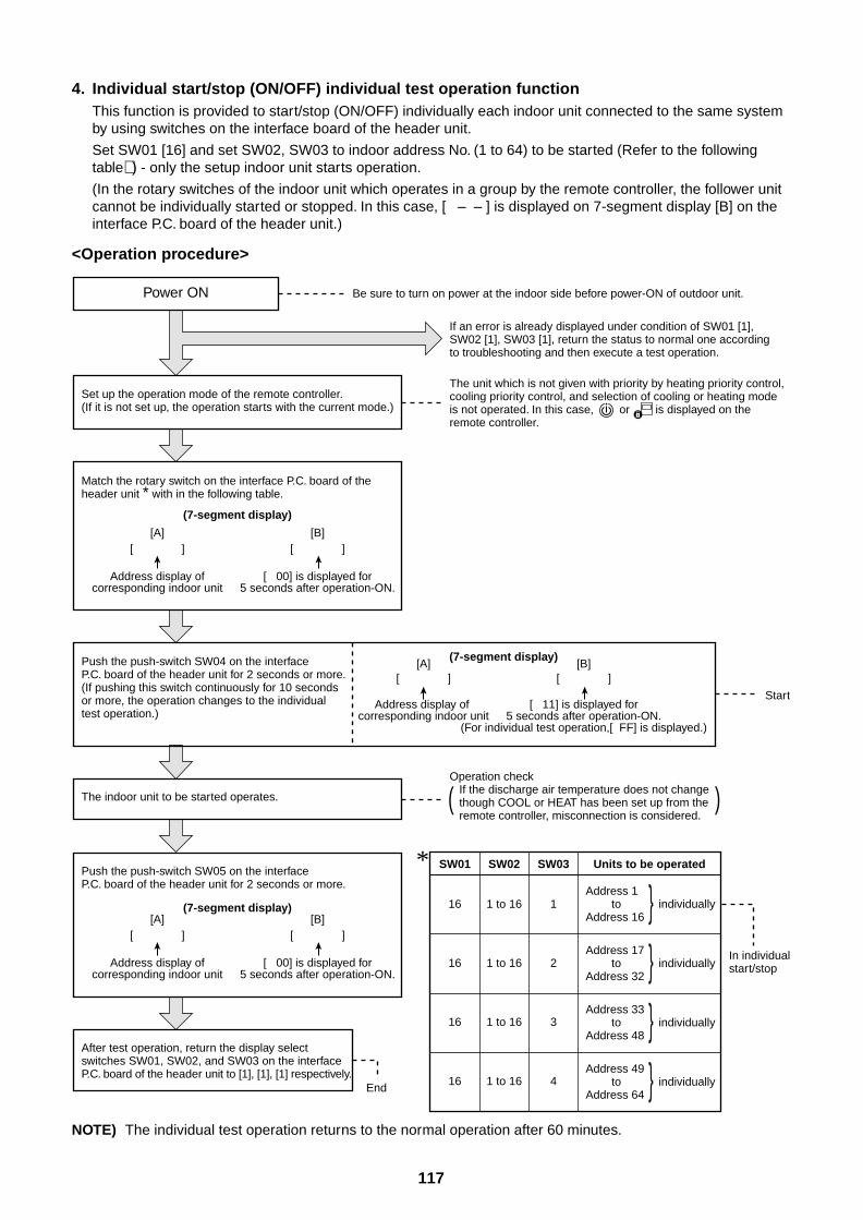
117
4. Individual start/stop (ON/OFF) individual test operation functionThis function is provided to start/stop (ON/OFF) individually each indoor unit connected to the same systemby using switches on the interface board of the header unit.
Set SW01 [16] and set SW02, SW03 to indoor address No. (1 to 64) to be started (Refer to the followingtable∗ ) - only the setup indoor unit starts operation.
(In the rotary switches of the indoor unit which operates in a group by the remote controller, the follower unitcannot be individually started or stopped. In this case, [ – – ] is displayed on 7-segment display [B] on theinterface P.C. board of the header unit.)
<Operation procedure>
NOTE) The individual test operation returns to the normal operation after 60 minutes.
Operation check If the discharge air temperature does not change though COOL or HEAT has been set up from the remote controller, misconnection is considered.( )
Power ON Be sure to turn on power at the indoor side before power-ON of outdoor unit.
Set up the operation mode of the remote controller.(If it is not set up, the operation starts with the current mode.)
(7-segment display)
[A][ ]
Address display ofcorresponding indoor unit
[B][ ]
[ 00] is displayed for5 seconds after operation-ON.
Match the rotary switch on the interface P.C. board of the header unit * with in the following table.
Push the push-switch SW04 on the interface P.C. board of the header unit for 2 seconds or more. (If pushing this switch continuously for 10 seconds or more, the operation changes to the individual test operation.)
The indoor unit to be started operates.
Push the push-switch SW05 on the interface P.C. board of the header unit for 2 seconds or more.
(7-segment display)[A]
[ ]
Address display ofcorresponding indoor unit
[B][ ]
[ 00] is displayed for5 seconds after operation-ON.
(7-segment display)[A]
[ ]
Address display of corresponding indoor unit
[B][ ]
[ 11] is displayed for5 seconds after operation-ON.
(For individual test operation,[ FF] is displayed.)
If an error is already displayed under condition of SW01 [1], SW02 [1], SW03 [1], return the status to normal one according to troubleshooting and then execute a test operation.
The unit which is not given with priority by heating priority control, cooling priority control, and selection of cooling or heating mode is not operated. In this case, or is displayed on the remote controller.
After test operation, return the display select switches SW01, SW02, and SW03 on the interface P.C. board of the header unit to [1], [1], [1] respectively.
Start
End
Address 1 to individuallyAddress 16
In individual start/stop
16 1 to 16 1
16 1 to 16 2
16 1 to 16 3
16 1 to 16 4
SW01 SW02 SW03 Units to be operated
Address 17 to individuallyAddress 32 Address 33 to individuallyAddress 48 Address 49 to individuallyAddress 64
*
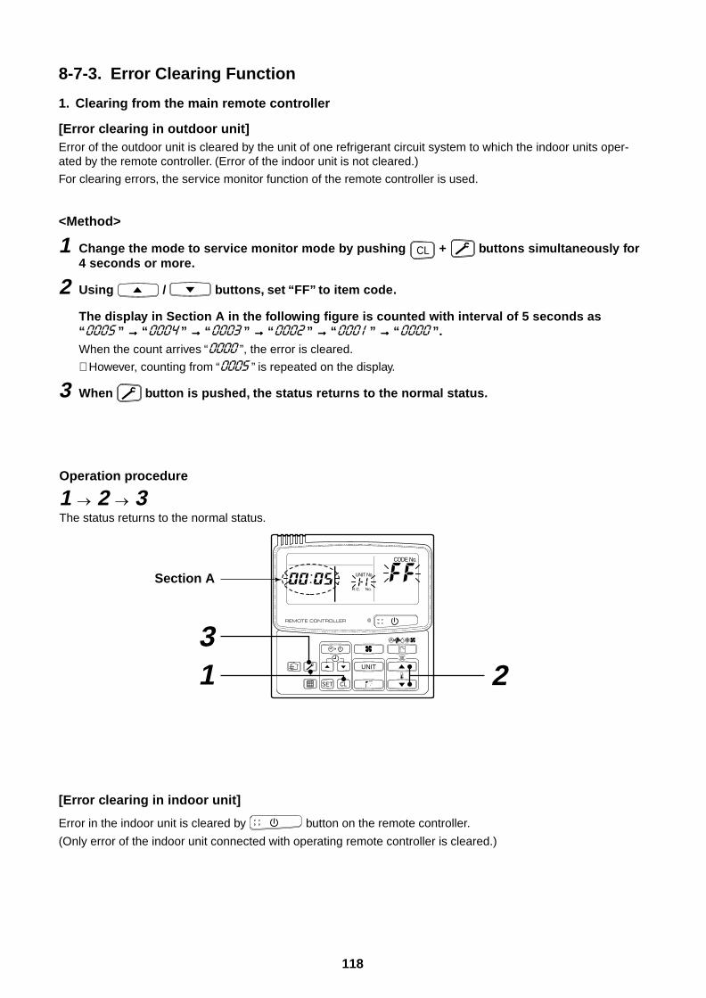
118
8-7-3. Error Clearing Function
1. Clearing from the main remote controller
[Error clearing in outdoor unit]Error of the outdoor unit is cleared by the unit of one refrigerant circuit system to which the indoor units oper-ated by the remote controller. (Error of the indoor unit is not cleared.)
For clearing errors, the service monitor function of the remote controller is used.
<Method>
1 Change the mode to service monitor mode by pushing CL + buttons simultaneously for4 seconds or more.
2 Using / buttons, set “FF” to item code.
The display in Section A in the following figure is counted with interval of 5 seconds as“ ” →→→→→ “ ” →→→→→ “ ” →→→→→ “ ” →→→→→ “ ” →→→→→ “ ”.When the count arrives “ ”, the error is cleared.
∗ However, counting from “ ” is repeated on the display.
3 When button is pushed, the status returns to the normal status.
[Error clearing in indoor unit]
Error in the indoor unit is cleared by button on the remote controller.
(Only error of the indoor unit connected with operating remote controller is cleared.)
UNIT
SET CL
UNIT No.
CODE No.
R.C. No.
Operation procedure
1 2 3The status returns to the normal status.
2 13
Section A
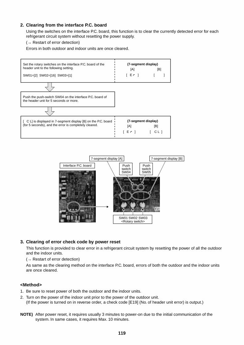
119
2. Clearing from the interface P.C. boardUsing the switches on the interface P.C. board, this function is to clear the currently detected error for eachrefrigerant circuit system without resetting the power supply.
(→ Restart of error detection)
Errors in both outdoor and indoor units are once cleared.
3. Clearing of error check code by power resetThis function is provided to clear error in a refrigerant circuit system by resetting the power of all the outdoorand the indoor units.
(→ Restart of error detection)
As same as the clearing method on the interface P.C. board, errors of both the outdoor and the indoor unitsare once cleared.
<Method>1. Be sure to reset power of both the outdoor and the indoor units.
2. Turn on the power of the indoor unit prior to the power of the outdoor unit.(If the power is turned on in reverse order, a check code [E19] (No. of header unit error) is output.)
NOTE) After power reset, it requires usually 3 minutes to power-on due to the initial communication of thesystem. In same cases, it requires Max. 10 minutes.
Set the rotary switches on the interface P.C. board of the header unit to the following setting.
SW01=[2] SW02=[16] SW03=[1]
(7-segment display)
[A]
[ E ]
[B]
[ C L ]
Push the push-switch SW04 on the interface P.C. board of the header unit for 5 seconds or more.
[ C L] is displayed in 7-segment display [B] on the P.C. board (for 5 seconds), and the error is completely cleared.
(7-segment display)
[A]
[ E ]
[B]
[ ]
Interface P.C. board
7-segment display [A] 7-segment display [B]
PushswitchSW04
PushswitchSW05
SW01 SW02 SW03<Rotary switch>
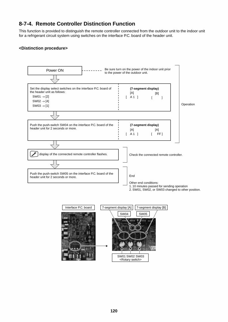
120
8-7-4. Remote Controller Distinction FunctionThis function is provided to distinguish the remote controller connected from the outdoor unit to the indoor unitfor a refrigerant circuit system using switches on the interface P.C. board of the header unit.
<Distinction procedure>
Power ON Be sure turn on the power of the indoor unit prior to the power of the outdoor unit.
Set the display select switches on the interface P.C. board of the header unit as follows:
SW01 [2]
SW02 [4]
SW03 [1]
(7-segment display)[A]
[ A 1 ][B]
[ ]
(7-segment display)
[A][ A 1 ]
[A][ FF ]
Push the push-switch SW04 on the interface P.C. board of the header unit for 2 seconds or more.
display of the connected remote controller flashes.
Push the push-switch SW05 on the interface P.C. board of the header unit for 2 seconds or more.
Operation
Check the connected remote controller.
End
Other end conditions:1. 10 minutes passed for sending operation 2. SW01, SW02, or SW03 changed to other position.
Interface P.C. board 7-segment display [A] 7-segment display [B]
SW04 SW05
SW01 SW02 SW03<Rotary switch>
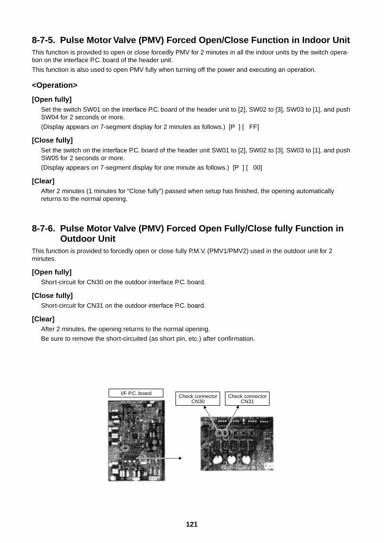
121
8-7-5. Pulse Motor Valve (PMV) Forced Open/Close Function in Indoor UnitThis function is provided to open or close forcedly PMV for 2 minutes in all the indoor units by the switch opera-tion on the interface P.C. board of the header unit.
This function is also used to open PMV fully when turning off the power and executing an operation.
<Operation>
[Open fully]Set the switch SW01 on the interface P.C. board of the header unit to [2], SW02 to [3], SW03 to [1], and pushSW04 for 2 seconds or more.
(Display appears on 7-segment display for 2 minutes as follows.) [P ] [ FF]
[Close fully]Set the switch on the interface P.C. board of the header unit SW01 to [2], SW02 to [3], SW03 to [1], and pushSW05 for 2 seconds or more.
(Display appears on 7-segment display for one minute as follows.) [P ] [ 00]
[Clear]After 2 minutes (1 minutes for “Close fully”) passed when setup has finished, the opening automaticallyreturns to the normal opening.
8-7-6. Pulse Motor Valve (PMV) Forced Open Fully/Close fully Function inOutdoor Unit
This function is provided to forcedly open or close fully P.M.V. (PMV1/PMV2) used in the outdoor unit for 2minutes.
[Open fully]Short-circuit for CN30 on the outdoor interface P.C. board.
[Close fully]Short-circuit for CN31 on the outdoor interface P.C. board.
[Clear]After 2 minutes, the opening returns to the normal opening.
Be sure to remove the short-circuited (as short pin, etc.) after confirmation.
I/F P.C. board Check connectorCN30
Check connectorCN31
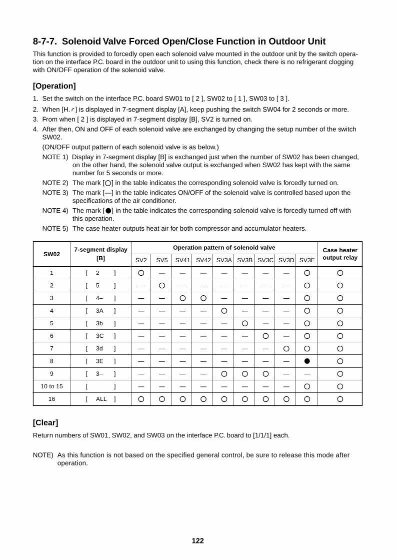
122
8-7-7. Solenoid Valve Forced Open/Close Function in Outdoor UnitThis function is provided to forcedly open each solenoid valve mounted in the outdoor unit by the switch opera-tion on the interface P.C. board in the outdoor unit to using this function, check there is no refrigerant cloggingwith ON/OFF operation of the solenoid valve.
[Operation]
1. Set the switch on the interface P.C. board SW01 to [ 2 ], SW02 to [ 1 ], SW03 to [ 3 ].
2. When [H. ] is displayed in 7-segment display [A], keep pushing the switch SW04 for 2 seconds or more.
3. From when [ 2 ] is displayed in 7-segment display [B], SV2 is turned on.
4. After then, ON and OFF of each solenoid valve are exchanged by changing the setup number of the switchSW02.
(ON/OFF output pattern of each solenoid valve is as below.)
NOTE 1) Display in 7-segment display [B] is exchanged just when the number of SW02 has been changed,on the other hand, the solenoid valve output is exchanged when SW02 has kept with the samenumber for 5 seconds or more.
NOTE 2) The mark [] in the table indicates the corresponding solenoid valve is forcedly turned on.
NOTE 3) The mark [—] in the table indicates ON/OFF of the solenoid valve is controlled based upon thespecifications of the air conditioner.
NOTE 4) The mark [] in the table indicates the corresponding solenoid valve is forcedly turned off withthis operation.
NOTE 5) The case heater outputs heat air for both compressor and accumulator heaters.
SW02
1
2
3
4
5
6
7
8
9
10 to 15
16
[Clear]
Return numbers of SW01, SW02, and SW03 on the interface P.C. board to [1/1/1] each.
NOTE) As this function is not based on the specified general control, be sure to release this mode afteroperation.
7-segment display[B]
[ 2 ]
[ 5 ]
[ 4– ]
[ 3A ]
[ 3b ]
[ 3C ]
[ 3d ]
[ 3E ]
[ 3– ]
[ ]
[ ALL ]
Operation pattern of solenoid valve
SV2 SV5 SV41 SV42 SV3A SV3B SV3C SV3D SV3E
— — — — — — —
— — — — — — —
— — — — — —
— — — — — — —
— — — — — — —
— — — — — — —
— — — — — — —
— — — — — — — —
— — — — — —
— — — — — — — —
Case heateroutput relay
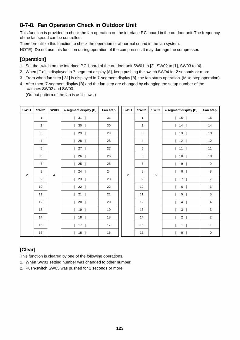
123
8-7-8. Fan Operation Check in Outdoor UnitThis function is provided to check the fan operation on the interface P.C. board in the outdoor unit. The frequencyof the fan speed can be controlled.
Therefore utilize this function to check the operation or abnormal sound in the fan system.
NOTE) Do not use this function during operation of the compressor. It may damage the compressor.
[Operation]1. Set the switch on the interface P.C. board of the outdoor unit SW01 to [2], SW02 to [1], SW03 to [4].
2. When [F. d] is displayed in 7-segment display [A], keep pushing the switch SW04 for 2 seconds or more.
3. From when fan step [ 31] is displayed in 7-segment display [B], the fan starts operation. (Max. step operation)
4. After then, 7-segment display [B] and the fan step are changed by changing the setup number of theswitches SW02 and SW03.
(Output pattern of the fan is as follows.)
[Clear]This function is cleared by one of the following operations.
1. When SW01 setting number was changed to other number.
2. Push-switch SW05 was pushed for 2 seconds or more.
SW01
2
SW02
1
2
3
4
5
6
7
8
9
10
11
12
13
14
15
16
SW03
4
Fan step
31
30
29
28
27
26
25
24
23
22
21
20
19
18
17
16
SW01
2
SW02
1
2
3
4
5
6
7
8
9
10
11
12
13
14
15
16
7-segment display [B]
[ 15 ]
[ 14 ]
[ 13 ]
[ 12 ]
[ 11 ]
[ 10 ]
[ 9 ]
[ 8 ]
[ 7 ]
[ 6 ]
[ 5 ]
[ 4 ]
[ 3 ]
[ 2 ]
[ 1 ]
[ 0 ]
Fan step
15
14
13
12
11
10
9
8
7
6
5
4
3
2
1
0
7-segment display [B]
[ 31 ]
[ 30 ]
[ 29 ]
[ 28 ]
[ 27 ]
[ 26 ]
[ 25 ]
[ 24 ]
[ 23 ]
[ 22 ]
[ 21 ]
[ 20 ]
[ 19 ]
[ 18 ]
[ 17 ]
[ 16 ]
SW03
5
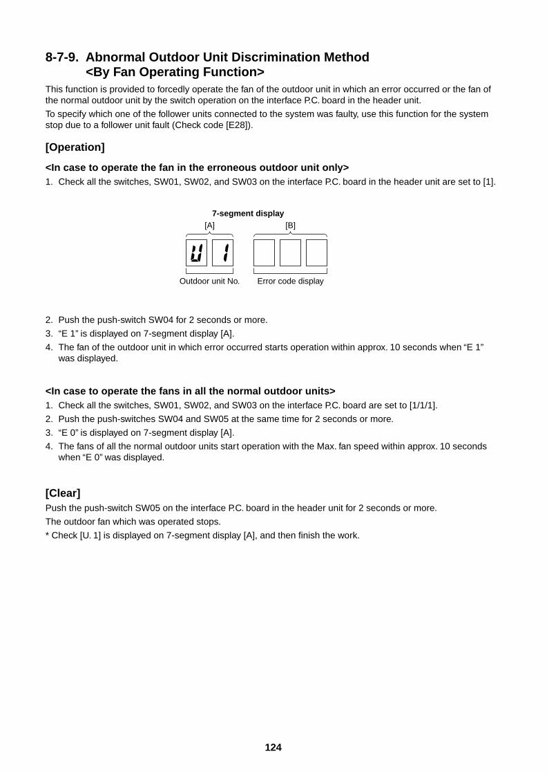
124
8-7-9. Abnormal Outdoor Unit Discrimination Method<By Fan Operating Function>
This function is provided to forcedly operate the fan of the outdoor unit in which an error occurred or the fan ofthe normal outdoor unit by the switch operation on the interface P.C. board in the header unit.
To specify which one of the follower units connected to the system was faulty, use this function for the systemstop due to a follower unit fault (Check code [E28]).
[Operation]
<In case to operate the fan in the erroneous outdoor unit only>1. Check all the switches, SW01, SW02, and SW03 on the interface P.C. board in the header unit are set to [1].
2. Push the push-switch SW04 for 2 seconds or more.
3. “E 1” is displayed on 7-segment display [A].
4. The fan of the outdoor unit in which error occurred starts operation within approx. 10 seconds when “E 1”was displayed.
<In case to operate the fans in all the normal outdoor units>1. Check all the switches, SW01, SW02, and SW03 on the interface P.C. board are set to [1/1/1].
2. Push the push-switches SW04 and SW05 at the same time for 2 seconds or more.
3. “E 0” is displayed on 7-segment display [A].
4. The fans of all the normal outdoor units start operation with the Max. fan speed within approx. 10 secondswhen “E 0” was displayed.
[Clear]Push the push-switch SW05 on the interface P.C. board in the header unit for 2 seconds or more.
The outdoor fan which was operated stops.
* Check [U. 1] is displayed on 7-segment display [A], and then finish the work.
7-segment display[A] [B]
Outdoor unit No. Error code display
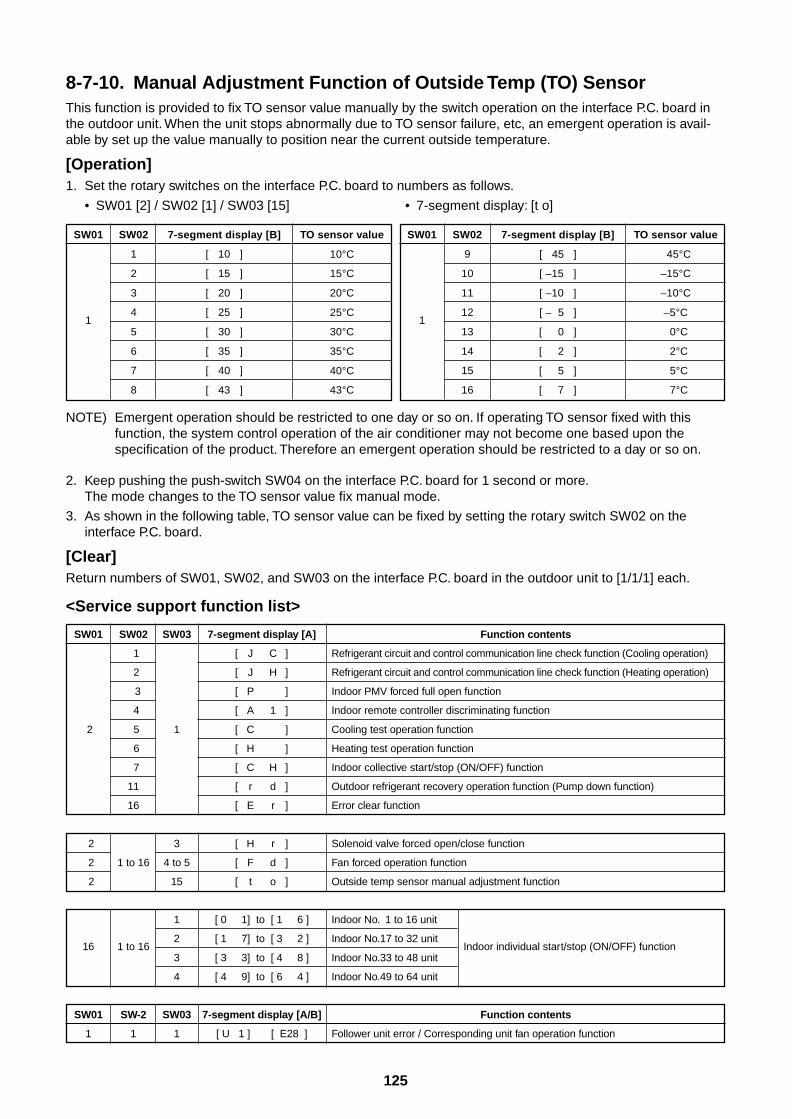
125
NOTE) Emergent operation should be restricted to one day or so on. If operating TO sensor fixed with thisfunction, the system control operation of the air conditioner may not become one based upon thespecification of the product. Therefore an emergent operation should be restricted to a day or so on.
2. Keep pushing the push-switch SW04 on the interface P.C. board for 1 second or more.The mode changes to the TO sensor value fix manual mode.
3. As shown in the following table, TO sensor value can be fixed by setting the rotary switch SW02 on theinterface P.C. board.
[Clear]Return numbers of SW01, SW02, and SW03 on the interface P.C. board in the outdoor unit to [1/1/1] each.
<Service support function list>
SW01
2
2
2
2
16
SW01
1
SW02
1
2
3
4
5
6
7
11
16
1 to 16
1 to 16
SW-2
1
SW03
1
3
4 to 5
15
1
2
3
4
SW03
1
7-segment display [A]
[ J C ]
[ J H ]
[ P ]
[ A 1 ]
[ C ]
[ H ]
[ C H ]
[ r d ]
[ E r ]
[ H r ]
[ F d ]
[ t o ]
[ 0 1] to [ 1 6 ]
[ 1 7] to [ 3 2 ]
[ 3 3] to [ 4 8 ]
[ 4 9] to [ 6 4 ]
7-segment display [A/B]
[ U 1 ] [ E28 ]
Function contents
Refrigerant circuit and control communication line check function (Cooling operation)
Refrigerant circuit and control communication line check function (Heating operation)
Indoor PMV forced full open function
Indoor remote controller discriminating function
Cooling test operation function
Heating test operation function
Indoor collective start/stop (ON/OFF) function
Outdoor refrigerant recovery operation function (Pump down function)
Error clear function
Solenoid valve forced open/close function
Fan forced operation function
Outside temp sensor manual adjustment function
Indoor No. 1 to 16 unit
Indoor No.17 to 32 unitIndoor individual start/stop (ON/OFF) function
Indoor No.33 to 48 unit
Indoor No.49 to 64 unit
Function contents
Follower unit error / Corresponding unit fan operation function
SW01
1
7-segment display [B]
[ 10 ]
[ 15 ]
[ 20 ]
[ 25 ]
[ 30 ]
[ 35 ]
[ 40 ]
[ 43 ]
TO sensor value
10°C
15°C
20°C
25°C
30°C
35°C
40°C
43°C
SW01
1
7-segment display [B]
[ 45 ]
[ –15 ]
[ –10 ]
[ – 5 ]
[ 0 ]
[ 2 ]
[ 5 ]
[ 7 ]
TO sensor value
45°C
–15°C
–10°C
–5°C
0°C
2°C
5°C
7°C
SW02
1
2
3
4
5
6
7
8
SW02
9
10
11
12
13
14
15
16
8-7-10. Manual Adjustment Function of Outside Temp (TO) SensorThis function is provided to fix TO sensor value manually by the switch operation on the interface P.C. board inthe outdoor unit. When the unit stops abnormally due to TO sensor failure, etc, an emergent operation is avail-able by set up the value manually to position near the current outside temperature.
[Operation]1. Set the rotary switches on the interface P.C. board to numbers as follows.
• SW01 [2] / SW02 [1] / SW03 [15] • 7-segment display: [t o]
126
8-7-11. Indoor Fan Operation Check FunctionThis function is provided to check operation of single indoor unit without using communication with the remotecontroller or outdoor unit. This function can be used regardless operating or stopping of the system.
However, if this function is used for a long time, a trouble of the air conditioner may be caused. Therefore usingof this function should be restricted to several minutes.
[Operation]1. Short-circuit CHK pin (CN71 on the indoor P.C. board).
If short-circuiting DISP pin (CN72 on the indoor P.C. board) while short-circuiting CHK pin (CN71 on theindoor P.C. board), the indoor PMV only becomes the minimum opening (30 pulse). When opening DISP pin,it becomes the maximum opening again.
[Clear]Open CHK pin. If the system is operating, it stops once but automatically restart after several minutes.
∗ For the details of CHK pin (CN71 on indoor P.C. board) and DISP pin (CN72 on indoor P.C. board), refer to11. Control circuit configuration, Indoor unit 2, Indoor P.C. board MCC-1402 and MCC-1403.
8-7-12. Indoor Fan Only Operating ModeWhen operating an air conditioner with indoor units and remote controller only in fan operation etc., this functioncan be used. A group operation is also available.
[Operation]1) Short circuit DISP pin (CN72 on the indoor P.C. board). However, if CHK pin (CN71 on the indoor P.C. board)has been previously short circuited, this function is unavailable.
2) In a group operation, set up a group as usual.
3) While DISP pin is short circuited, all the sensor error judgment operation and communication with the outdoorunit are not performed. PMV is fixed to the Max. opening.
[Clear]Open DISP pin.
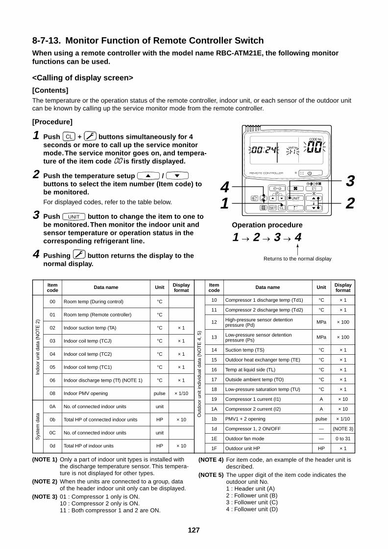
127
8-7-13. Monitor Function of Remote Controller SwitchWhen using a remote controller with the model name RBC-ATM21E, the following monitorfunctions can be used.
<Calling of display screen>
[Contents]The temperature or the operation status of the remote controller, indoor unit, or each sensor of the outdoor unitcan be known by calling up the service monitor mode from the remote controller.
[Procedure]
1 Push CL + buttons simultaneously for 4seconds or more to call up the service monitormode. The service monitor goes on, and tempera-ture of the item code is firstly displayed.
2 Push the temperature setup / buttons to select the item number (Item code) tobe monitored.For displayed codes, refer to the table below.
3 Push UNIT button to change the item to one tobe monitored. Then monitor the indoor unit andsensor temperature or operation status in thecorresponding refrigerant line.
4 Pushing button returns the display to thenormal display.
(NOTE 1) Only a part of indoor unit types is installed withthe discharge temperature sensor. This tempera-ture is not displayed for other types.
(NOTE 2) When the units are connected to a group, dataof the header indoor unit only can be displayed.
(NOTE 3) 01 : Compressor 1 only is ON.10 : Compressor 2 only is ON.11 : Both compressor 1 and 2 are ON.
Indo
or u
nit d
ata
(NO
TE
2)
Sys
tem
dat
a
Itemcode
00
01
02
03
04
05
06
08
0A
0b
0C
0d
Data name
Room temp (During control)
Room temp (Remote controller)
Indoor suction temp (TA)
Indoor coil temp (TCJ)
Indoor coil temp (TC2)
Indoor coil temp (TC1)
Indoor discharge temp (Tf) (NOTE 1)
Indoor PMV opening
No. of connected indoor units
Total HP of connected indoor units
No. of connected indoor units
Total HP of indoor units
Unit
°C
°C
°C
°C
°C
°C
°C
pulse
unit
HP
unit
HP
Displayformat
× 1
× 1
× 1
× 1
× 1
× 1/10
× 10
× 10
Out
door
uni
t ind
ivid
ual d
ata
(NO
TE
4, 5
)
Itemcode
10
11
12
13
14
15
16
17
18
19
1A
1b
1d
1E
1F
Data name
Compressor 1 discharge temp (Td1)
Compressor 2 discharge temp (Td2)
High-pressure sensor detentionpressure (Pd)
Low-pressure sensor detentionpressure (Ps)
Suction temp (TS)
Outdoor heat exchanger temp (TE)
Temp at liquid side (TL)
Outside ambient temp (TO)
Low-pressure saturation temp (TU)
Compressor 1 current (I1)
Compressor 2 current (I2)
PMV1 + 2 opening
Compressor 1, 2 ON/OFF
Outdoor fan mode
Outdoor unit HP
Unit
°C
°C
MPa
MPa
°C
°C
°C
°C
°C
A
A
pulse
—
—
HP
Displayformat
× 1
× 1
× 100
× 100
× 1
× 1
× 1
× 1
× 1
× 10
× 10
× 1/10
(NOTE 3)
0 to 31
× 1
(NOTE 4) For item code, an example of the header unit isdescribed.
(NOTE 5) The upper digit of the item code indicates theoutdoor unit No.1 : Header unit (A)2 : Follower unit (B)3 : Follower unit (C)4 : Follower unit (D)
UNIT
SET CL
UNIT No.
CODE No.
Operation procedure
1 2 3 4
14 3
2
Returns to the normal display
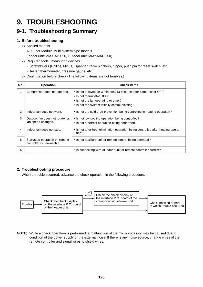
128
9. TROUBLESHOOTING9-1. Troubleshooting Summary
1. Before troubleshooting1) Applied models
All Super Module Multi-system type models
(Indoor unit: MMX-APXXX, Outdoor unit: MMY-MAPXXX)
2) Required tools / measuring devices
• Screwdrivers (Philips, Minus), spanner, radio pinchers, nipper, push pin for reset switch, etc.
• Tester, thermometer, pressure gauge, etc.
3) Confirmation before check (The following items are not troubles.)
2. Troubleshooting procedureWhen a trouble occurred, advance the check operation in the following procedure.
No.
1
2
3
4
5
6
Operation
Compressor does not operate.
Indoor fan does not work.
Outdoor fan does not rotate, orfan speed changes.
Indoor fan does not stop.
Start/stop operation on remotecontroller is unavailable.
——
Check items
• Is not delayed for 3 minutes? (3 minutes after compressor-OFF)• Is not thermostat OFF?• Is not the fan operating or timer?• Is not the system initially communicating?
• Is not the cold draft prevention being controlled in heating operation?
• Is not low cooling operation being controlled?• Is not a defrost operation being performed?
• Is not after-heat elimination operation being controlled after heating opera-tion?
• Is not auxiliary unit or remote control being operated?
• Is connecting wire of indoor unit or remote controller correct?
NOTE) While a check operation is performed, a malfunction of the microprocessor may be caused due tocondition of the power supply or the external noise. If there is any noise source, change wires of theremote controller and signal wires to shield wires.
TroubleCheck the check display on the interface P.C. board of the header unit.
Check the check display on the interface P.C. board of the corresponding follower unit. Check position or part
in which trouble occurred.
[E28]error
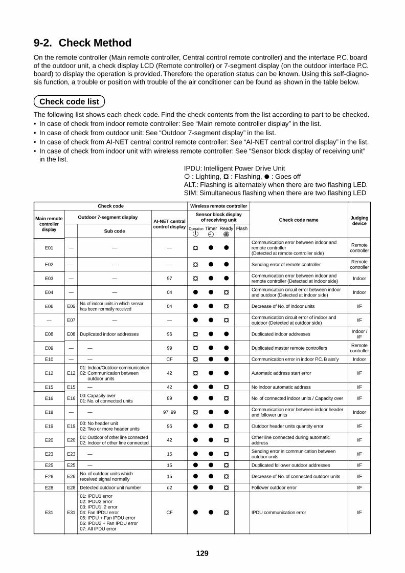
129
9-2. Check MethodOn the remote controller (Main remote controller, Central control remote controller) and the interface P.C. boardof the outdoor unit, a check display LCD (Remote controller) or 7-segment display (on the outdoor interface P.C.board) to display the operation is provided. Therefore the operation status can be known. Using this self-diagno-sis function, a trouble or position with trouble of the air conditioner can be found as shown in the table below.
Check code list
The following list shows each check code. Find the check contents from the list according to part to be checked.• In case of check from indoor remote controller: See “Main remote controller display” in the list.• In case of check from outdoor unit: See “Outdoor 7-segment display” in the list.• In case of check from AI-NET central control remote controller: See “AI-NET central control display” in the list.• In case of check from indoor unit with wireless remote controller: See “Sensor block display of receiving unit”
in the list.IPDU: Intelligent Power Drive Unit : Lighting, ¤ : Flashing, : Goes offALT.: Flashing is alternately when there are two flashing LED.SIM: Simultaneous flashing when there are two flashing LED
Check code
Main remotecontroller
display
E01
E02
E03
E04
E06
—
E08
E09
E10
E12
E15
E16
E18
E19
E20
E23
E25
E26
E28
E31
Outdoor 7-segment display
Sub code
— —
— —
— —
— —
E06No. of indoor units in which sensorhas been normally received
E07 —
E08 Duplicated indoor addresses
— —
— —
01: Indoor/Outdoor communicationE12 02: Communication between
outdoor units
E15 —
E16 00: Capacity over01: No. of connected units
— —
E1900: No header unit02: Two or more header units
E20 01: Outdoor of other line connected02: Indoor of other line connected
E23 —
E25 —
E26No. of outdoor units whichreceived signal normally
E28 Detected outdoor unit number
01: IPDU1 error02: IPDU2 error03: IPDU1, 2 error
E31 04: Fan IPDU error05: IPDU + Fan IPDU error06: IPDU2 + Fan IPDU error07: All IPDU error
AI-NET centralcontrol display
—
—
97
04
04
—
96
99
CF
42
42
89
97, 99
96
42
15
15
15
d2
CF
Wireless remote controller
Sensor block displayof receiving unit
Operation Timer Ready Flash
¤
¤
¤
¤ ¤ ¤¤
¤
¤
¤
¤ ¤¤
¤ ¤ ¤ ¤ ¤ ¤
¤
Check code name
Communication error between indoor andremote controller(Detected at remote controller side)
Sending error of remote controller
Communication error between indoor andremote controller (Detected at indoor side)
Communication circuit error between indoorand outdoor (Detected at indoor side)
Decrease of No. of indoor units
Communication circuit error of indoor andoutdoor (Detected at outdoor side)
Duplicated indoor addresses
Duplicated master remote controllers
Communication error in indoor P.C. B ass’y
Automatic address start error
No indoor automatic address
No. of connected indoor units / Capacity over
Communication error between indoor headerand follower units
Outdoor header units quantity error
Other line connected during automaticaddress
Sending error in communication betweenoutdoor units
Duplicated follower outdoor addresses
Decrease of No. of connected outdoor units
Follower outdoor error
IPDU communication error
Judgingdevice
Remotecontroller
Remotecontroller
Indoor
Indoor
I/F
I/F
Indoor /I/F
Remotecontroller
Indoor
I/F
I/F
I/F
Indoor
I/F
I/F
I/F
I/F
I/F
I/F
I/F
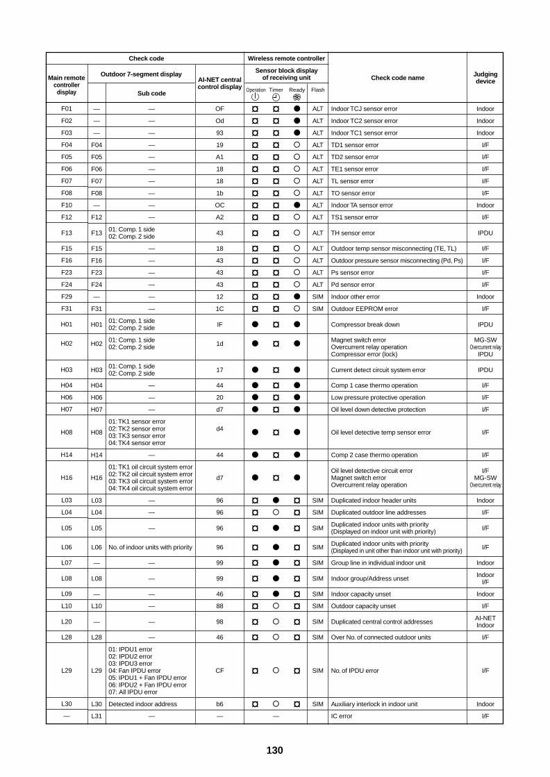
130
Check code name
Indoor TCJ sensor error
Indoor TC2 sensor error
Indoor TC1 sensor error
TD1 sensor error
TD2 sensor error
TE1 sensor error
TL sensor error
TO sensor error
Indoor TA sensor error
TS1 sensor error
TH sensor error
Outdoor temp sensor misconnecting (TE, TL)
Outdoor pressure sensor misconnecting (Pd, Ps)
Ps sensor error
Pd sensor error
Indoor other error
Outdoor EEPROM error
Compressor break down
Magnet switch errorOvercurrent relay operationCompressor error (lock)
Current detect circuit system error
Comp 1 case thermo operation
Low pressure protective operation
Oil level down detective protection
Oil level detective temp sensor error
Comp 2 case thermo operation
Oil level detective circuit errorMagnet switch errorOvercurrent relay operation
Duplicated indoor header units
Duplicated outdoor line addresses
Duplicated indoor units with priority(Displayed on indoor unit with priority)
Duplicated indoor units with priority(Displayed in unit other than indoor unit with priority)
Group line in individual indoor unit
Indoor group/Address unset
Indoor capacity unset
Outdoor capacity unset
Duplicated central control addresses
Over No. of connected outdoor units
No. of IPDU error
Auxiliary interlock in indoor unit
IC error
Check code
Main remotecontroller
display
F01
F02
F03
F04
F05
F06
F07
F08
F10
F12
F13
F15
F16
F23
F24
F29
F31
H01
H02
H03
H04
H06
H07
H08
H14
H16
L03
L04
L05
L06
L07
L08
L09
L10
L20
L28
L29
L30
—
Outdoor 7-segment display
Sub code
— —
— —
— —
F04 —
F05 —
F06 —
F07 —
F08 —
— —
F12 —
F13 01: Comp. 1 side02: Comp. 2 side
F15 —
F16 —
F23 —
F24 —
— —
F31 —
H0101: Comp. 1 side02: Comp. 2 side
H0201: Comp. 1 side02: Comp. 2 side
H0301: Comp. 1 side02: Comp. 2 side
H04 —
H06 —
H07 —
01: TK1 sensor error
H08 02: TK2 sensor error03: TK3 sensor error04: TK4 sensor error
H14 —
01: TK1 oil circuit system error
H16 02: TK2 oil circuit system error03: TK3 oil circuit system error04: TK4 oil circuit system error
L03 —
L04 —
L05 —
L06 No. of indoor units with priority
— —
L08 —
— —
L10 —
— —
L28 —
01: IPDU1 error02: IPDU2 error03: IPDU3 error
L29 04: Fan IPDU error05: IPDU1 + Fan IPDU error06: IPDU2 + Fan IPDU error07: All IPDU error
L30 Detected indoor address
L31 —
AI-NET centralcontrol display
OF
Od
93
19
A1
18
18
1b
OC
A2
43
18
43
43
43
12
1C
IF
1d
17
44
20
d7
d4
44
d7
96
96
96
96
99
99
46
88
98
46
CF
b6
—
Wireless remote controller
Sensor block displayof receiving unit
Operation Timer Ready Flash
¤ ¤ ALT
¤ ¤ ALT
¤ ¤ ALT
¤ ¤ ALT
¤ ¤ ALT
¤ ¤ ALT
¤ ¤ ALT
¤ ¤ ALT
¤ ¤ ALT
¤ ¤ ALT
¤ ¤ ALT
¤ ¤ ALT
¤ ¤ ALT
¤ ¤ ALT
¤ ¤ ALT
¤ ¤ SIM
¤ ¤ SIM
¤
¤
¤
¤
¤
¤
¤
¤
¤
¤ ¤ SIM
¤ ¤ SIM
¤ ¤ SIM
¤ ¤ SIM
¤ ¤ SIM
¤ ¤ SIM
¤ ¤ SIM
¤ ¤ SIM
¤ ¤ SIM
¤ ¤ SIM
¤ ¤ SIM
¤ ¤ SIM
—
Judgingdevice
Indoor
Indoor
Indoor
I/F
I/F
I/F
I/F
I/F
Indoor
I/F
IPDU
I/F
I/F
I/F
I/F
Indoor
I/F
IPDU
MG-SWOvercurrent relay
IPDU
IPDU
I/F
I/F
I/F
I/F
I/F
I/FMG-SW
Overcurrent relay
Indoor
I/F
I/F
I/F
Indoor
IndoorI/F
Indoor
I/F
AI-NETIndoor
I/F
I/F
Indoor
I/F
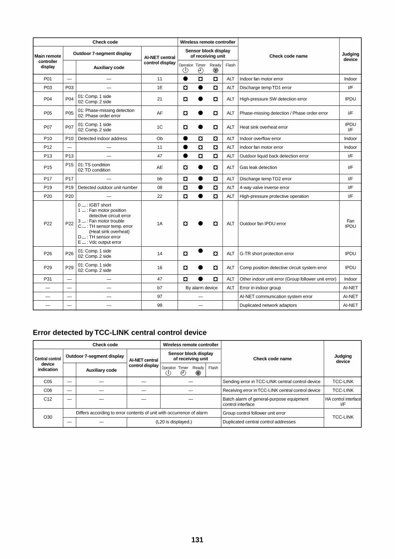
131
Check code
Main remotecontroller
display
P01
P03
P04
P05
P07
P10
P12
P13
P15
P17
P19
P20
P22
P26
P29
P31
—
—
—
Outdoor 7-segment display
Auxiliary code
— —
P03 —
P04 01: Comp. 1 side02: Comp. 2 side
P0501: Phase-missing detection02: Phase order error
P07 01: Comp. 1 side02: Comp. 2 side
P10 Detected indoor address
— —
P13 —
P15 01: TS condition02: TD condition
P17 —
P19 Detected outdoor unit number
P20 —
0 : IGBT short1 : Fan motor position
detective circuit error
P22 3 : Fan motor troubleC : TH sensor temp. error
(Heat sink overheat)D : TH sensor errorE : Vdc output error
P26 01: Comp. 1 side02: Comp. 2 side
P29 01: Comp. 1 side02: Comp. 2 side
— —
— —
— —
— —
AI-NET centralcontrol display
11
1E
21
AF
1C
Ob
11
47
AE
bb
08
22
1A
14
16
47
b7
97
99
Wireless remote controller
Sensor block displayof receiving unit
Operation Timer Ready Flash
¤ ¤ ALT
¤ ¤ ALT
¤ ¤ ALT
¤ ¤ ALT
¤ ¤ ALT
¤ ¤ ALT
¤ ¤ ALT
¤ ¤ ALT
¤ ¤ ALT
¤ ¤ ALT
¤ ¤ ALT
¤ ¤ ALT
¤ ¤ ALT
¤ ¤ ALT
¤ ¤ ALT
¤ ¤ ALT
By alarm device ALT
—
—
Check code name
Indoor fan motor error
Discharge temp TD1 error
High-pressure SW detection error
Phase-missing detection / Phase order error
Heat sink overheat error
Indoor overflow error
Indoor fan motor error
Outdoor liquid back detection error
Gas leak detection
Discharge temp TD2 error
4-way valve inverse error
High-pressure protective operation
Outdoor fan IPDU error
G-TR short protection error
Comp position detective circuit system error
Other indoor unit error (Group follower unit error)
Error in indoor group
AI-NET communication system error
Duplicated network adaptors
Judgingdevice
Indoor
I/F
IPDU
I/F
IPDUI/F
Indoor
Indoor
I/F
I/F
I/F
I/F
I/F
FanIPDU
IPDU
IPDU
Indoor
AI-NET
AI-NET
AI-NET
Error detected by TCC-LINK central control device
Check code
Central controldevice
indication
C05
C06
C12
O30
Outdoor 7-segment display
Auxiliary code
— —
— —
— —
— —
AI-NET centralcontrol display
—
—
—
Wireless remote controller
Sensor block displayof receiving unit
Operation Timer Ready Flash
—
—
—
Check code name
Sending error in TCC-LINK central control device
Receiving error in TCC-LINK central control device
Batch alarm of general-purpose equipmentcontrol interface
Group control follower unit error
Duplicated central control addresses
Judgingdevice
TCC-LINK
TCC-LINK
HA control interfaceI/F
TCC-LINKDiffers according to error contents of unit with occurrence of alarm
(L20 is displayed.)
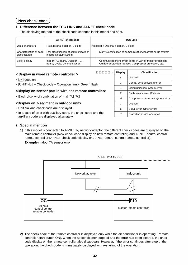
132
New check code
1. Difference between the TCC LINK and AI-NET check codeThe displaying method of the check code changes in this model and after.
Used characters
Characteristics of codeclassification
Block display
AI-NET check code
Hexadecimal notation, 2 digits
Few classification of communication/incorrect setup system
Indoor P.C. board, Outdoor P.C.board, Cycle, Communication
TCC Link
Alphabet + Decimal notation, 2 digits
Many classification of communication/incorrect setup system
Communication/Incorrect setup (4 ways), Indoor protection,Outdoor protection, Sensor, Compressor protection, etc.
< Display in wired remote controller >
• [ ] goes on.
• [UNIT No.] + Check code + Operation lamp (Green) flash
<Display on sensor part in wireless remote controller>
• Block display of combination of [ ] [ ] [ ]
<Display on 7-segment in outdoor unit>• Unit No. and check code are displayed.
• In a case of error with auxiliary code, the check code and theauxiliary code are displayed alternately.
Display
A
C
E
F
H
J
L
P
Classification
Unused
Central control system error
Communication system error
Each sensor error (Failure)
Compressor protective system error
Unused
Setup error, Other errors
Protective device operation
|||||||||→
2. Special mention1) If this model is connected to AI-NET by network adaptor, the different check codes are displayed on the
main remote controller (New check code display on new remote controller) and AI-NET central controlremote controller (AI-NET check code display on AI-NET central control remote controller).
Example) Indoor TA sensor error
2) The check code of the remote controller is displayed only while the air conditioner is operating (Remotecontroller start button ON). When the air conditioner stopped and the error has been cleared, the checkcode display on the remote controller also disappears. However, if the error continues after stop of theoperation, the check code is immediately displayed with restarting of the operation.
OCAI-NET
central control remote controller
AI-NETWORK BUS
F10
Master remote controller
IndoorunitNetwork adaptor
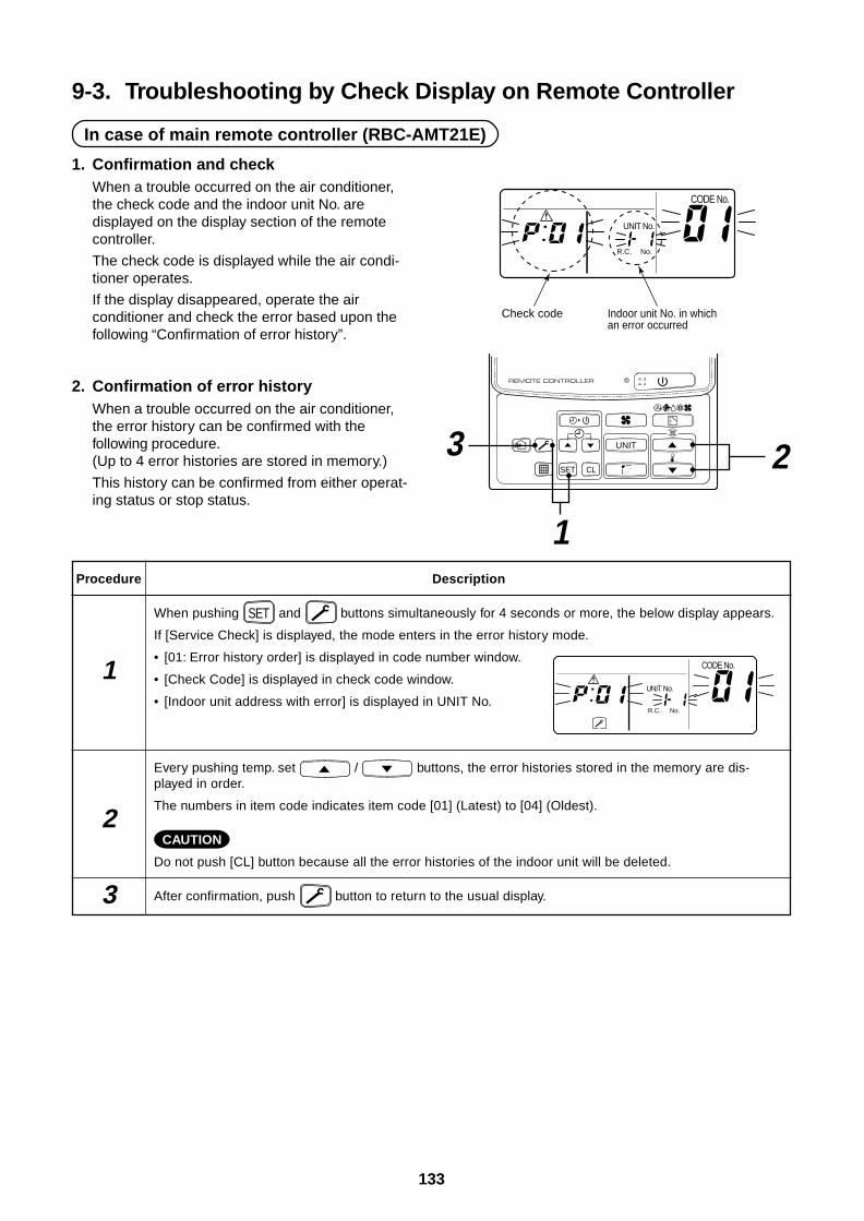
133
9-3. Troubleshooting by Check Display on Remote Controller
In case of main remote controller (RBC-AMT21E)
UNIT No.
CODE No.
R.C. No.
Check code Indoor unit No. in which an error occurred
UNIT
SET CL
3 2
1Procedure
1
2
3
Description
When pushing SET and buttons simultaneously for 4 seconds or more, the below display appears.
If [Service Check] is displayed, the mode enters in the error history mode.
• [01: Error history order] is displayed in code number window.
• [Check Code] is displayed in check code window.
• [Indoor unit address with error] is displayed in UNIT No.
Every pushing temp. set / buttons, the error histories stored in the memory are dis-played in order.
The numbers in item code indicates item code [01] (Latest) to [04] (Oldest).
CAUTION
Do not push [CL] button because all the error histories of the indoor unit will be deleted.
After confirmation, push button to return to the usual display.
UNIT No.
CODE No.
R.C. No.
1. Confirmation and checkWhen a trouble occurred on the air conditioner,the check code and the indoor unit No. aredisplayed on the display section of the remotecontroller.
The check code is displayed while the air condi-tioner operates.
If the display disappeared, operate the airconditioner and check the error based upon thefollowing “Confirmation of error history”.
2. Confirmation of error historyWhen a trouble occurred on the air conditioner,the error history can be confirmed with thefollowing procedure.(Up to 4 error histories are stored in memory.)
This history can be confirmed from either operat-ing status or stop status.
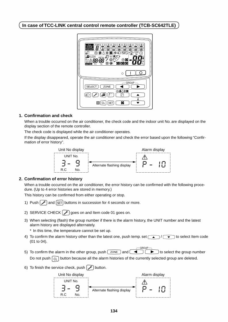
134
In case of TCC-LINK central control remote controller (TCB-SC642TLE)
1. Confirmation and checkWhen a trouble occurred on the air conditioner, the check code and the indoor unit No. are displayed on thedisplay section of the remote controller.
The check code is displayed while the air conditioner operates.
If the display disappeared, operate the air conditioner and check the error based upon the following “Confir-mation of error history”.
UNIT No.
Alternate flashing displayR.C No.
Unit No display Alarm display
SELECT ZONE
CL SET
GROUP
CODE No.
UNIT No.
No.R.C.
TEST
ZONEALLZONE
GROUP
SETTING
1234
SET DATA
2. Confirmation of error historyWhen a trouble occurred on the air conditioner, the error history can be confirmed with the following proce-dure. (Up to 4 error histories are stored in memory.)
This history can be confirmed from either operating or stop.
1) Push and SET buttons in succession for 4 seconds or more.
2) SERVICE CHECK goes on and Item code 01 goes on.
3) When selecting (flash) the group number if there is the alarm history, the UNIT number and the latestalarm history are displayed alternately.
* In this time, the temperature cannot be set up.
4) To confirm the alarm history other than the latest one, push temp. set / to select Item code(01 to 04).
5) To confirm the alarm in the other group, push ZONE and GROUP
to select the group number
Do not push CL button because all the alarm histories of the currently selected group are deleted.
6) To finish the service check, push button.
UNIT No.
Alternate flashing displayR.C No.
Unit No display Alarm display
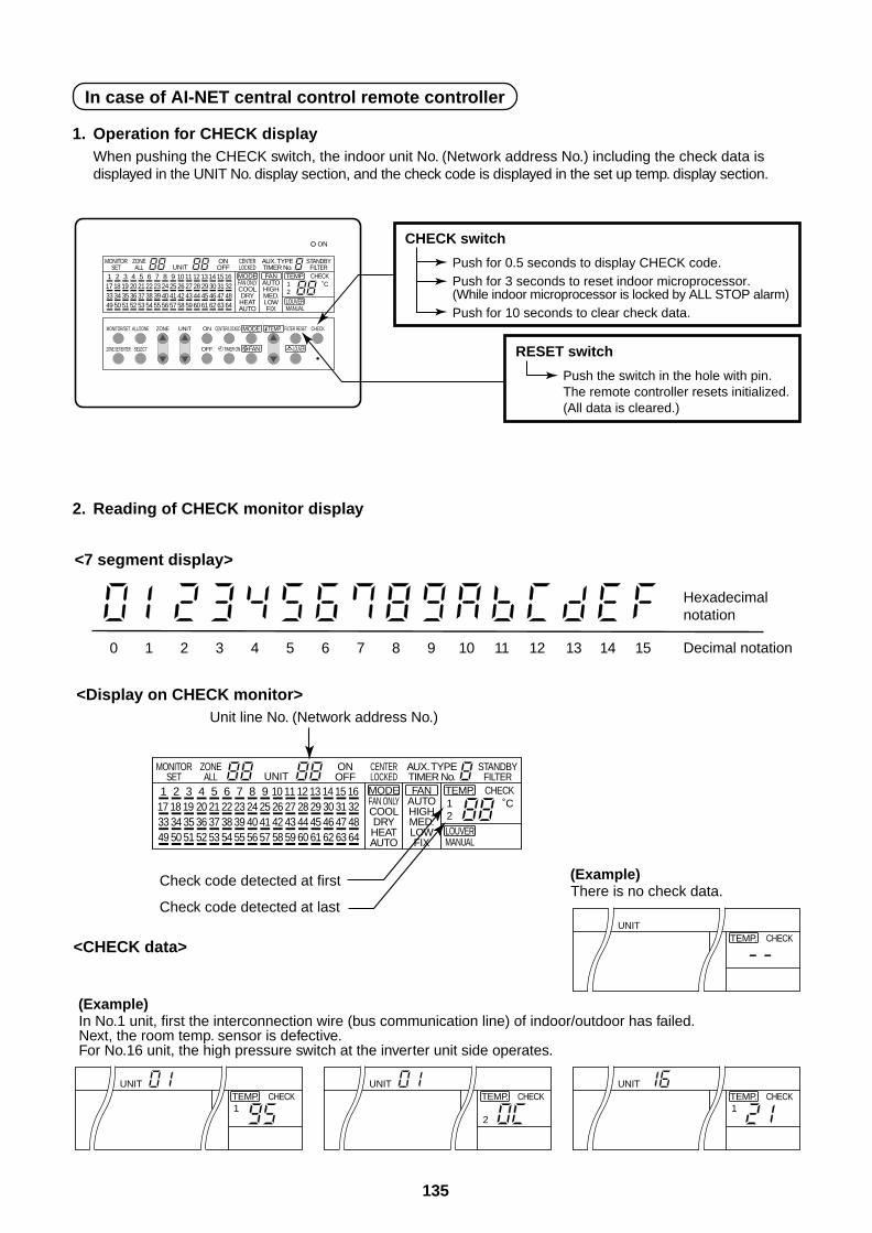
135
In case of AI-NET central control remote controller
1. Operation for CHECK displayWhen pushing the CHECK switch, the indoor unit No. (Network address No.) including the check data isdisplayed in the UNIT No. display section, and the check code is displayed in the set up temp. display section.
CHECK switch
Push for 0.5 seconds to display CHECK code.Push for 3 seconds to reset indoor microprocessor. (While indoor microprocessor is locked by ALL STOP alarm)Push for 10 seconds to clear check data.
RESET switch
Push the switch in the hole with pin.The remote controller resets initialized.(All data is cleared.)
0 1 2 3 4 5 6 7 8 9 10 11 12 13 14 15
(Example)
Hexadecimalnotation
Decimal notation
<7 segment display>
<Display on CHECK monitor>
<CHECK data>
In No.1 unit, first the interconnection wire (bus communication line) of indoor/outdoor has failed. Next, the room temp. sensor is defective. For No.16 unit, the high pressure switch at the inverter unit side operates.
(Example)There is no check data.
Unit line No. (Network address No.)
Check code detected at first
Check code detected at last
FILTER RESET
49 50 51 52 53 54 55 56 57 58 59 60 61 62 63 6433 34 35 36 37 38 39 40 41 42 43 44 45 46 47 4817 18 19 20 21 22 23 24 25 26 27 28 29 30 31 321
MONITORSET
ZONEALL
CENTERLOCKED
AUX. TYPETIMER No.
STANDBYFILTER
ONOFF
MODEFAN ONLYCOOLDRYHEATAUTO
ON
UNIT2 3 4 5 6 7 8 9 10 11 12 13 14 15 16 FAN
AUTOHIGHMED.LOWFIX
TEMP. CHECK12
˚C
LOUVERMANUAL
LOUVERFAN
TEMP.MODEMONITOR/SET ALL/ZONE ZONE UNIT ON CENTER/LOCKED CHECK
ZONE SET/ENTER SELECT OFF TIMER ON
49 50 51 52 53 54 55 56 57 58 59 60 61 62 63 6433 34 35 36 37 38 39 40 41 42 43 44 45 46 47 4817 18 19 20 21 22 23 24 25 26 27 28 29 30 31 321
MONITORSET
ZONEALL
CENTERLOCKED
AUX. TYPETIMER No.
STANDBYFILTER
ONOFF
MODEFAN ONLYCOOLDRYHEATAUTO
UNIT2 3 4 5 6 7 8 9 10 11 12 13 14 15 16 FAN
AUTOHIGHMED.LOWFIX
TEMP. CHECK12
˚C
LOUVERMANUAL
UNITTEMP. CHECK
2
UNITTEMP. CHECK1
UNITTEMP. CHECK1
UNITTEMP. CHECK
2. Reading of CHECK monitor display
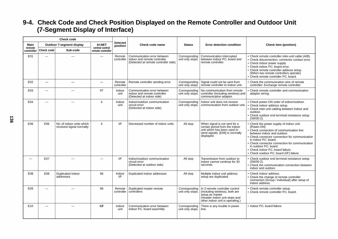
136
9-4. Check Code and Check Position Displayed on the Remote Controller and Outdoor Unit(7-Segment Display of Interface)
Check code
Mainremote
controller
E01
E02
E03
E04
E06
—
E08
E09
E10
Outdoor 7-segment display
Check code Sub-code
— —
— —
— —
— —
E06 No. of indoor units whichreceived signal normally
E07 —
E08 Duplicated indooraddresses
— —
— —
AI-NETcentral control
remote controller
—
—
97
4
4
—
96
99
CF
Detectedposition
Remotecontroller
Remotecontroller
Indoorunit
Indoorunit
I/F
I/F
IndoorI/F
Remotecontroller
Indoorunit
Check code name
Communication error betweenindoor and remote controller(Detected at remote controller side)
Remote controller sending error
Communication error betweenindoor and remote controller(Detected at indoor side)
Indoor/outdoor communicationcircuit error(Detected at indoor side)
Decreased number of indoor units
Indoor/outdoor communicationcircuit error(Detected at outdoor side)
Duplicated indoor addresses
Duplicated master remotecontrollers
Communication error betweenindoor P.C. board assembly
Status
Correspondingunit only stops.
Correspondingunit only stops.
Correspondingunit only stops.
Correspondingunit only stops.
All stop
All stop
All stop
Correspondingunit only stops.
Correspondingunit only stops.
Error detection condition
Communication interruptedbetween indoor P.C. board andremote controller.
Signal could not be sent fromremote controller to indoor unit.
No communication from remotecontroller (including wireless) andcommunication adaptor.
Indoor unit does not receivecommunication from outdoor unit.
When signal is not sent for acertain period from the indoorunit which has been used tosend signals, [E06] is normallydisplayed.
Transmission from outdoor toindoor cannot continue for 30seconds.
Multiple indoor unit addresssetup are duplicated.
In 2-remote controller control(including wireless), both aresetup as master(Header indoor unit stops andother indoor unit is operating.)
There is any trouble in powerline.
Check item (position)
• Check remote controller inter-unit cable (A/B).• Check disconnection, connector contact error.• Check indoor power supply.• Check indoor P.C. board error.• Check remote controller address setup.
(When two remote controllers operate)• Check remote controller P.C. board.
• Check the communication wire of remotecontroller: Exchange remote controller.
• Check remote controller and communicationadaptor wiring.
• Check power-ON order of indoor/outdoor.• Check indoor address setup.• Check inter-unit cabling between indoor and
outdoor.• Check outdoor end terminal resistance setup
(SW30-2).
• Check the power supply of indoor unit.(Power-ON)
• Check connection of communication linebetween indoor and outdoor.
• Check connector connection for communicationin indoor P.C. board.
• Check connector connection for communicationin outdoor P.C. board.
• Check indoor P.C. board failure.• Check outdoor P.C. board (I/F) failure.
• Check outdoor end terminal resistance setup(SW30-2).
• Check the communication connection betweenindoor and outdoor.
• Check indoor address.• Check the change of remote controller
connection (Group / individual) after setup ofindoor address.
• Check remote controller setup.• Check remote controller P.C. board.
• Indoor P.C. board failure
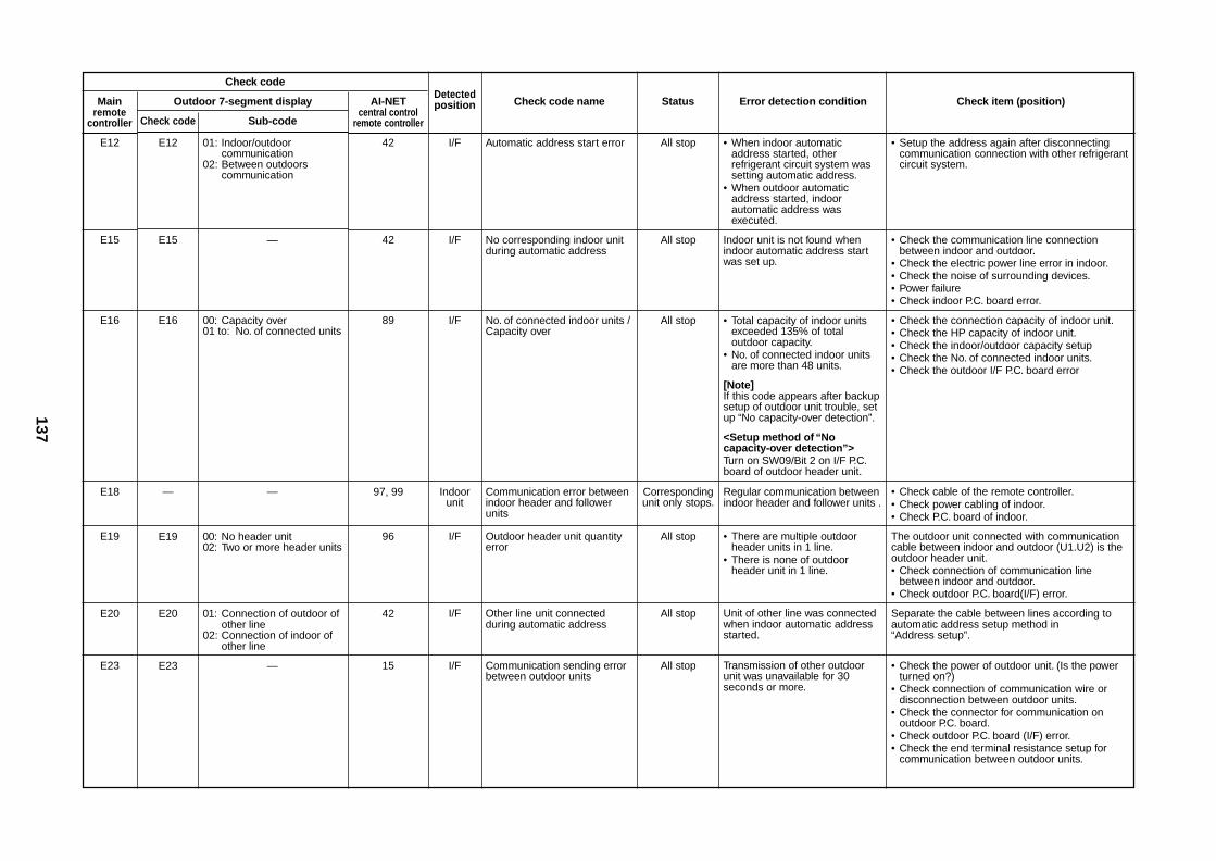
137
Check code
Mainremote
controller
E12
E15
E16
E18
E19
E20
E23
Outdoor 7-segment display
Check code Sub-code
E12 01: Indoor/outdoorcommunication
02: Between outdoorscommunication
E15 —
E16 00: Capacity over01 to: No. of connected units
— —
E19 00: No header unit02: Two or more header units
E20 01: Connection of outdoor ofother line
02: Connection of indoor ofother line
E23 —
AI-NETcentral control
remote controller
42
42
89
97, 99
96
42
15
Detectedposition
I/F
I/F
I/F
Indoorunit
I/F
I/F
I/F
Check code name
Automatic address start error
No corresponding indoor unitduring automatic address
No. of connected indoor units /Capacity over
Communication error betweenindoor header and followerunits
Outdoor header unit quantityerror
Other line unit connectedduring automatic address
Communication sending errorbetween outdoor units
Status
All stop
All stop
All stop
Correspondingunit only stops.
All stop
All stop
All stop
Error detection condition
• When indoor automaticaddress started, otherrefrigerant circuit system wassetting automatic address.
• When outdoor automaticaddress started, indoorautomatic address wasexecuted.
Indoor unit is not found whenindoor automatic address startwas set up.
• Total capacity of indoor unitsexceeded 135% of totaloutdoor capacity.
• No. of connected indoor unitsare more than 48 units.
[Note]If this code appears after backupsetup of outdoor unit trouble, setup “No capacity-over detection”.
<Setup method of “Nocapacity-over detection”>Turn on SW09/Bit 2 on I/F P.C.board of outdoor header unit.
Regular communication betweenindoor header and follower units .
• There are multiple outdoorheader units in 1 line.
• There is none of outdoorheader unit in 1 line.
Unit of other line was connectedwhen indoor automatic addressstarted.
Transmission of other outdoorunit was unavailable for 30seconds or more.
Check item (position)
• Setup the address again after disconnectingcommunication connection with other refrigerantcircuit system.
• Check the communication line connectionbetween indoor and outdoor.
• Check the electric power line error in indoor.• Check the noise of surrounding devices.• Power failure• Check indoor P.C. board error.
• Check the connection capacity of indoor unit.• Check the HP capacity of indoor unit.• Check the indoor/outdoor capacity setup• Check the No. of connected indoor units.• Check the outdoor I/F P.C. board error
• Check cable of the remote controller.• Check power cabling of indoor.• Check P.C. board of indoor.
The outdoor unit connected with communicationcable between indoor and outdoor (U1.U2) is theoutdoor header unit.• Check connection of communication line
between indoor and outdoor.• Check outdoor P.C. board(I/F) error.
Separate the cable between lines according toautomatic address setup method in“Address setup”.
• Check the power of outdoor unit. (Is the powerturned on?)
• Check connection of communication wire ordisconnection between outdoor units.
• Check the connector for communication onoutdoor P.C. board.
• Check outdoor P.C. board (I/F) error.• Check the end terminal resistance setup for
communication between outdoor units.
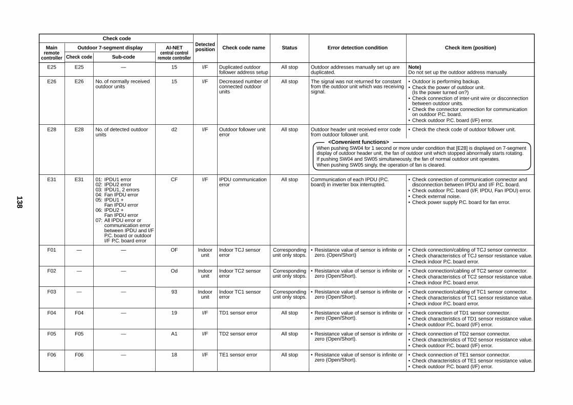
138
Check code
Mainremote
controller
E25
E26
E28
E31
F01
F02
F03
F04
F05
F06
Outdoor 7-segment display
Check code Sub-code
E25 —
E26 No. of normally receivedoutdoor units
E28 No. of detected outdoorunits
E31 01: IPDU1 error02: IPDU2 error03: IPDU1, 2 errors04: Fan IPDU error05: IPDU1 +
Fan IPDU error06: IPDU2 +
Fan IPDU error07: All IPDU error or
communication errorbetween IPDU and I/FP.C. board or outdoorI/F P.C. board error
— —
— —
— —
F04 —
F05 —
F06 —
AI-NETcentral control
remote controller
15
15
d2
CF
OF
Od
93
19
A1
18
Detectedposition
I/F
I/F
I/F
I/F
Indoorunit
Indoorunit
Indoorunit
I/F
I/F
I/F
Check code name
Duplicated outdoorfollower address setup
Decreased number ofconnected outdoorunits
Outdoor follower uniterror
IPDU communicationerror
Indoor TCJ sensorerror
Indoor TC2 sensorerror
Indoor TC1 sensorerror
TD1 sensor error
TD2 sensor error
TE1 sensor error
Status
All stop
All stop
All stop
All stop
Correspondingunit only stops.
Correspondingunit only stops.
Correspondingunit only stops.
All stop
All stop
All stop
Error detection condition
Outdoor addresses manually set up areduplicated.
The signal was not returned for constantfrom the outdoor unit which was receivingsignal.
Outdoor header unit received error codefrom outdoor follower unit.
Communication of each IPDU (P.C.board) in inverter box interrupted.
• Resistance value of sensor is infinite orzero. (Open/Short)
• Resistance value of sensor is infinite orzero (Open/Short).
• Resistance value of sensor is infinite orzero (Open/Short).
• Resistance value of sensor is infinite orzero (Open/Short).
• Resistance value of sensor is infinite orzero (Open/Short).
• Resistance value of sensor is infinite orzero (Open/Short).
Check item (position)
Note)Do not set up the outdoor address manually.
• Outdoor is performing backup.• Check the power of outdoor unit.
(Is the power turned on?)• Check connection of inter-unit wire or disconnection
between outdoor units.• Check the connector connection for communication
on outdoor P.C. board.• Check outdoor P.C. board (I/F) error.
• Check the check code of outdoor follower unit.
• Check connection of communication connector anddisconnection between IPDU and I/F P.C. board.
• Check outdoor P.C. board (I/F, IPDU, Fan IPDU) error.• Check external noise.• Check power supply P.C. board for fan error.
• Check connection/cabling of TCJ sensor connector.• Check characteristics of TCJ sensor resistance value.• Check indoor P.C. board error.
• Check connection/cabling of TC2 sensor connector.• Check characteristics of TC2 sensor resistance value.• Check indoor P.C. board error.
• Check connection/cabling of TC1 sensor connector.• Check characteristics of TC1 sensor resistance value.• Check indoor P.C. board error.
• Check connection of TD1 sensor connector.• Check characteristics of TD1 sensor resistance value.• Check outdoor P.C. board (I/F) error.
• Check connection of TD2 sensor connector.• Check characteristics of TD2 sensor resistance value.• Check outdoor P.C. board (I/F) error.
• Check connection of TE1 sensor connector.• Check characteristics of TE1 sensor resistance value.• Check outdoor P.C. board (I/F) error.
<Convenient functions>When pushing SW04 for 1 second or more under condition that [E28] is displayed on 7-segmentdisplay of outdoor header unit, the fan of outdoor unit which stopped abnormally starts rotating.If pushing SW04 and SW05 simultaneously, the fan of normal outdoor unit operates.When pushing SW05 singly, the operation of fan is cleared.
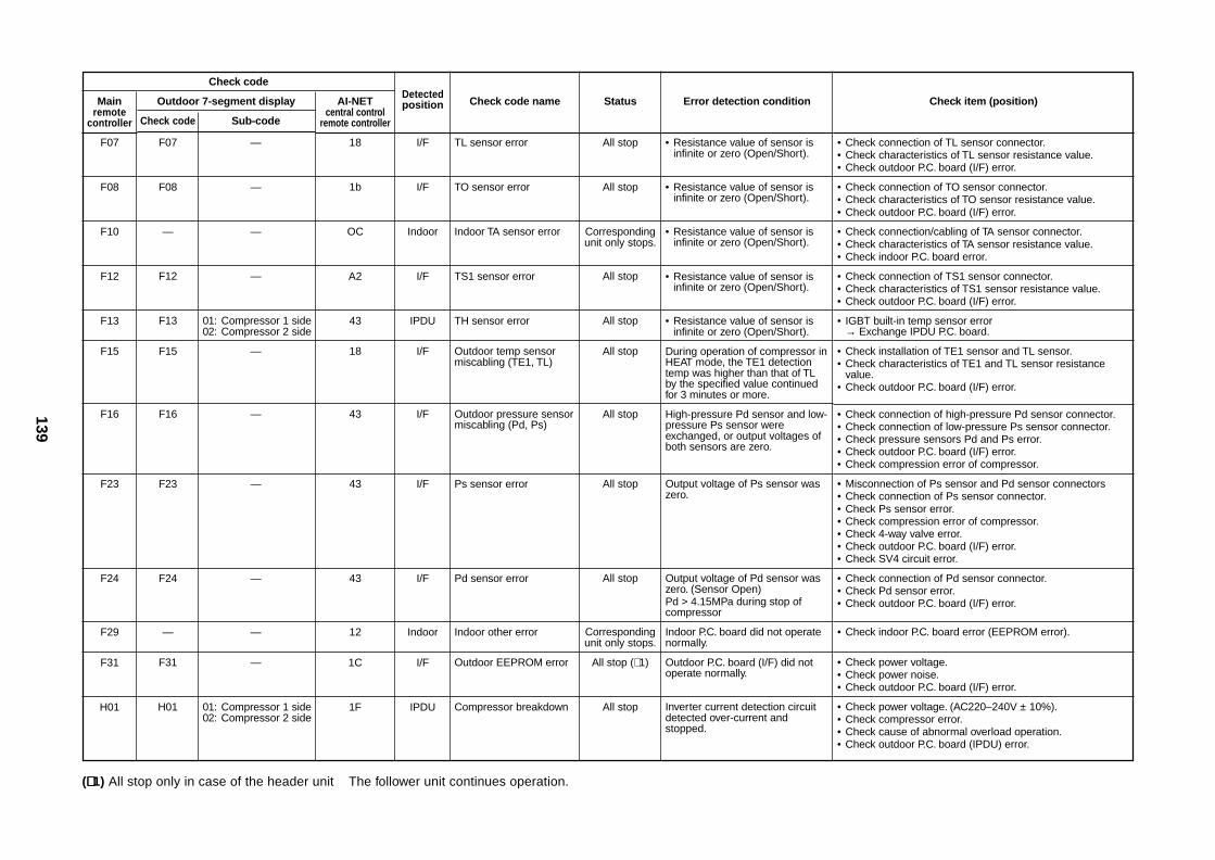
139
Check code
Mainremote
controller
F07
F08
F10
F12
F13
F15
F16
F23
F24
F29
F31
H01
Outdoor 7-segment display
Check code Sub-code
F07 —
F08 —
— —
F12 —
F13 01: Compressor 1 side02: Compressor 2 side
F15 —
F16 —
F23 —
F24 —
— —
F31 —
H01 01: Compressor 1 side02: Compressor 2 side
AI-NETcentral control
remote controller
18
1b
OC
A2
43
18
43
43
43
12
1C
1F
Detectedposition
I/F
I/F
Indoor
I/F
IPDU
I/F
I/F
I/F
I/F
Indoor
I/F
IPDU
Check code name
TL sensor error
TO sensor error
Indoor TA sensor error
TS1 sensor error
TH sensor error
Outdoor temp sensormiscabling (TE1, TL)
Outdoor pressure sensormiscabling (Pd, Ps)
Ps sensor error
Pd sensor error
Indoor other error
Outdoor EEPROM error
Compressor breakdown
Status
All stop
All stop
Correspondingunit only stops.
All stop
All stop
All stop
All stop
All stop
All stop
Correspondingunit only stops.
All stop (∗ 1)
All stop
Error detection condition
• Resistance value of sensor isinfinite or zero (Open/Short).
• Resistance value of sensor isinfinite or zero (Open/Short).
• Resistance value of sensor isinfinite or zero (Open/Short).
• Resistance value of sensor isinfinite or zero (Open/Short).
• Resistance value of sensor isinfinite or zero (Open/Short).
During operation of compressor inHEAT mode, the TE1 detectiontemp was higher than that of TLby the specified value continuedfor 3 minutes or more.
High-pressure Pd sensor and low-pressure Ps sensor wereexchanged, or output voltages ofboth sensors are zero.
Output voltage of Ps sensor waszero.
Output voltage of Pd sensor waszero. (Sensor Open)Pd > 4.15MPa during stop ofcompressor
Indoor P.C. board did not operatenormally.
Outdoor P.C. board (I/F) did notoperate normally.
Inverter current detection circuitdetected over-current andstopped.
Check item (position)
• Check connection of TL sensor connector.• Check characteristics of TL sensor resistance value.• Check outdoor P.C. board (I/F) error.
• Check connection of TO sensor connector.• Check characteristics of TO sensor resistance value.• Check outdoor P.C. board (I/F) error.
• Check connection/cabling of TA sensor connector.• Check characteristics of TA sensor resistance value.• Check indoor P.C. board error.
• Check connection of TS1 sensor connector.• Check characteristics of TS1 sensor resistance value.• Check outdoor P.C. board (I/F) error.
• IGBT built-in temp sensor error→ Exchange IPDU P.C. board.
• Check installation of TE1 sensor and TL sensor.• Check characteristics of TE1 and TL sensor resistance
value.• Check outdoor P.C. board (I/F) error.
• Check connection of high-pressure Pd sensor connector.• Check connection of low-pressure Ps sensor connector.• Check pressure sensors Pd and Ps error.• Check outdoor P.C. board (I/F) error.• Check compression error of compressor.
• Misconnection of Ps sensor and Pd sensor connectors• Check connection of Ps sensor connector.• Check Ps sensor error.• Check compression error of compressor.• Check 4-way valve error.• Check outdoor P.C. board (I/F) error.• Check SV4 circuit error.
• Check connection of Pd sensor connector.• Check Pd sensor error.• Check outdoor P.C. board (I/F) error.
• Check indoor P.C. board error (EEPROM error).
• Check power voltage.• Check power noise.• Check outdoor P.C. board (I/F) error.
• Check power voltage. (AC220–240V ± 10%).• Check compressor error.• Check cause of abnormal overload operation.• Check outdoor P.C. board (IPDU) error.
(∗∗∗∗∗ 1) All stop only in case of the header unit The follower unit continues operation.
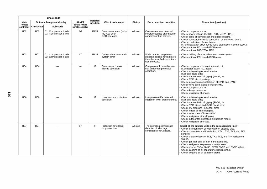
140
Check code
Mainremote
controller
H02
H03
H04
H06
H07
Outdoor 7-segment display
Check code Sub-code
H02 01: Compressor 1 side02: Compressor 2 side
H03 01: Compressor 1 side02: Compressor 2 side
H04 —
H06 —
H07 —
AI-NETcentral control
remote controller
1d
17
44
20
d7
Detectedposition
IPDU
IPDU
I/F
I/F
I/F
Check code name
Compressor error (lock)MG-SW errorOCR operation
Current detection circuitsystem error
Compressor 1 casethermo operation
Low-pressure protectiveoperation
Protection for oil leveldrop detection
Status
All stop
All stop
All stop
All stop
All stop
Error detection condition
Over-current was detectedseveral seconds after headercompressor had started.
While header compressorstopped, current flowed morethan the specified current andwas detected.
Compressor 1 case thermo-stat performed protectiveoperation.
Low-pressure Ps detectedoperation lower than 0.02MPa.
The operating compressordetected oil shortagecontinuously for 2 hours.
Check item (position)
• Check compressor error.• Check power voltage. (AC380 –10%, 415V +10%).• Check cable of compressor and phase-missing.• Check connector/terminal connection on IPDU P.C. board.• Check conduction of case heater.
(Check activation error due to liquid stagnation in compressor.)• Check outdoor P.C. board (IPDU) error.• Check outdoor MG-SW or OCR.
• Check cabling of current detection circuit system.• Check outdoor P.C. board (IPDU) error.
• Check compressor 1 case thermo circuit.(Connector, cable, P.C. board)
• Check full opening of service valve.(Gas and liquid side)
• Check outdoor PMV clogging. (PMV1, 2)• Check SV41 circuit leakage.• Check miscabling/misinstallation of SV41 and SV42.• Check valve open status of indoor PMV.• Check compressor error.• Check 4-way valve error.• Check refrigerant shortage.
• Check full opening of service valve.(Gas and liquid side)
• Check outdoor PMV clogging. (PMV1, 2)• Check SV41 circuit and SV42 circuit error.• Check low-pressure Ps sensor error.• Check indoor air filter clogging.• Check valve open of indoor PMV.• Check refrigerant pipe clogging.• Check outdoor fan operation. (In heating mode)• Check refrigerant shortage.
<Check all the outdoor units in the corresponding line.>• Check full opening of service valve of balance pipe.• Check connection and installation of TK1, TK2, TK3, and TK4
sensors.• Check characteristics of TK1, TK2, TK3, and TK4 resistance
values.• Check gas leak and oil leak in the same line.• Check refrigerant stagnation in compressor.• Check error of SV3A, SV3B, SV3C, SV3D, and SV3E valves.• Check clogging of oil separator oil return circuit.• Check clogging of oil-equation circuit.
MG-SW : Magnet Switch
OCR : Over-current Relay
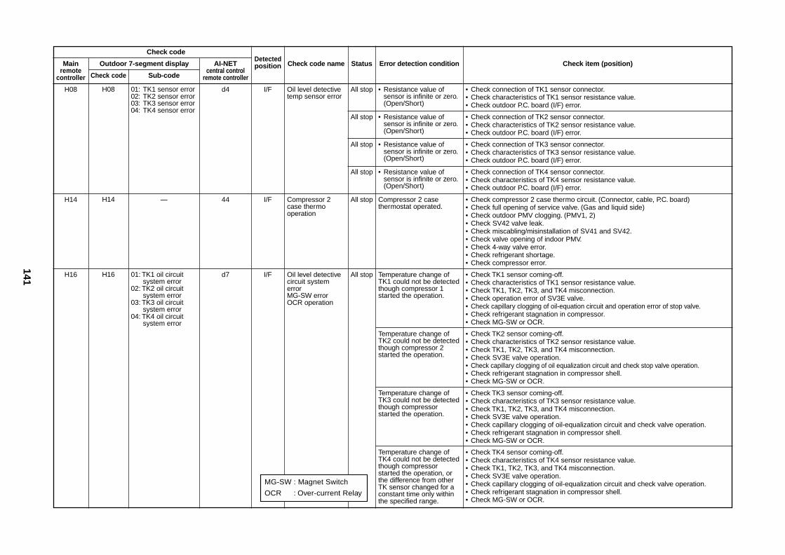
141
Check code
Mainremote
controller
H08
H14
H16
Outdoor 7-segment display
Check code Sub-code
H08 01: TK1 sensor error02: TK2 sensor error03: TK3 sensor error04: TK4 sensor error
H14 —
H16 01: TK1 oil circuitsystem error
02: TK2 oil circuitsystem error
03: TK3 oil circuitsystem error
04: TK4 oil circuitsystem error
AI-NETcentral control
remote controller
d4
44
d7
Detectedposition
I/F
I/F
I/F
Check code name
Oil level detectivetemp sensor error
Compressor 2case thermooperation
Oil level detectivecircuit systemerrorMG-SW errorOCR operation
Status
All stop
All stop
All stop
All stop
All stop
All stop
Error detection condition
• Resistance value ofsensor is infinite or zero.(Open/Short)
• Resistance value ofsensor is infinite or zero.(Open/Short)
• Resistance value ofsensor is infinite or zero.(Open/Short)
• Resistance value ofsensor is infinite or zero.(Open/Short)
Compressor 2 casethermostat operated.
Temperature change ofTK1 could not be detectedthough compressor 1started the operation.
Temperature change ofTK2 could not be detectedthough compressor 2started the operation.
Temperature change ofTK3 could not be detectedthough compressorstarted the operation.
Temperature change ofTK4 could not be detectedthough compressorstarted the operation, orthe difference from otherTK sensor changed for aconstant time only withinthe specified range.
Check item (position)
• Check connection of TK1 sensor connector.• Check characteristics of TK1 sensor resistance value.• Check outdoor P.C. board (I/F) error.
• Check connection of TK2 sensor connector.• Check characteristics of TK2 sensor resistance value.• Check outdoor P.C. board (I/F) error.
• Check connection of TK3 sensor connector.• Check characteristics of TK3 sensor resistance value.• Check outdoor P.C. board (I/F) error.
• Check connection of TK4 sensor connector.• Check characteristics of TK4 sensor resistance value.• Check outdoor P.C. board (I/F) error.
• Check compressor 2 case thermo circuit. (Connector, cable, P.C. board)• Check full opening of service valve. (Gas and liquid side)• Check outdoor PMV clogging. (PMV1, 2)• Check SV42 valve leak.• Check miscabling/misinstallation of SV41 and SV42.• Check valve opening of indoor PMV.• Check 4-way valve error.• Check refrigerant shortage.• Check compressor error.
• Check TK1 sensor coming-off.• Check characteristics of TK1 sensor resistance value.• Check TK1, TK2, TK3, and TK4 misconnection.• Check operation error of SV3E valve.• Check capillary clogging of oil-equation circuit and operation error of stop valve.• Check refrigerant stagnation in compressor.• Check MG-SW or OCR.
• Check TK2 sensor coming-off.• Check characteristics of TK2 sensor resistance value.• Check TK1, TK2, TK3, and TK4 misconnection.• Check SV3E valve operation.• Check capillary clogging of oil equalization circuit and check stop valve operation.• Check refrigerant stagnation in compressor shell.• Check MG-SW or OCR.
• Check TK3 sensor coming-off.• Check characteristics of TK3 sensor resistance value.• Check TK1, TK2, TK3, and TK4 misconnection.• Check SV3E valve operation.• Check capillary clogging of oil-equalization circuit and check valve operation.• Check refrigerant stagnation in compressor shell.• Check MG-SW or OCR.
• Check TK4 sensor coming-off.• Check characteristics of TK4 sensor resistance value.• Check TK1, TK2, TK3, and TK4 misconnection.• Check SV3E valve operation.• Check capillary clogging of oil-equalization circuit and check valve operation.• Check refrigerant stagnation in compressor shell.• Check MG-SW or OCR.
MG-SW : Magnet Switch
OCR : Over-current Relay
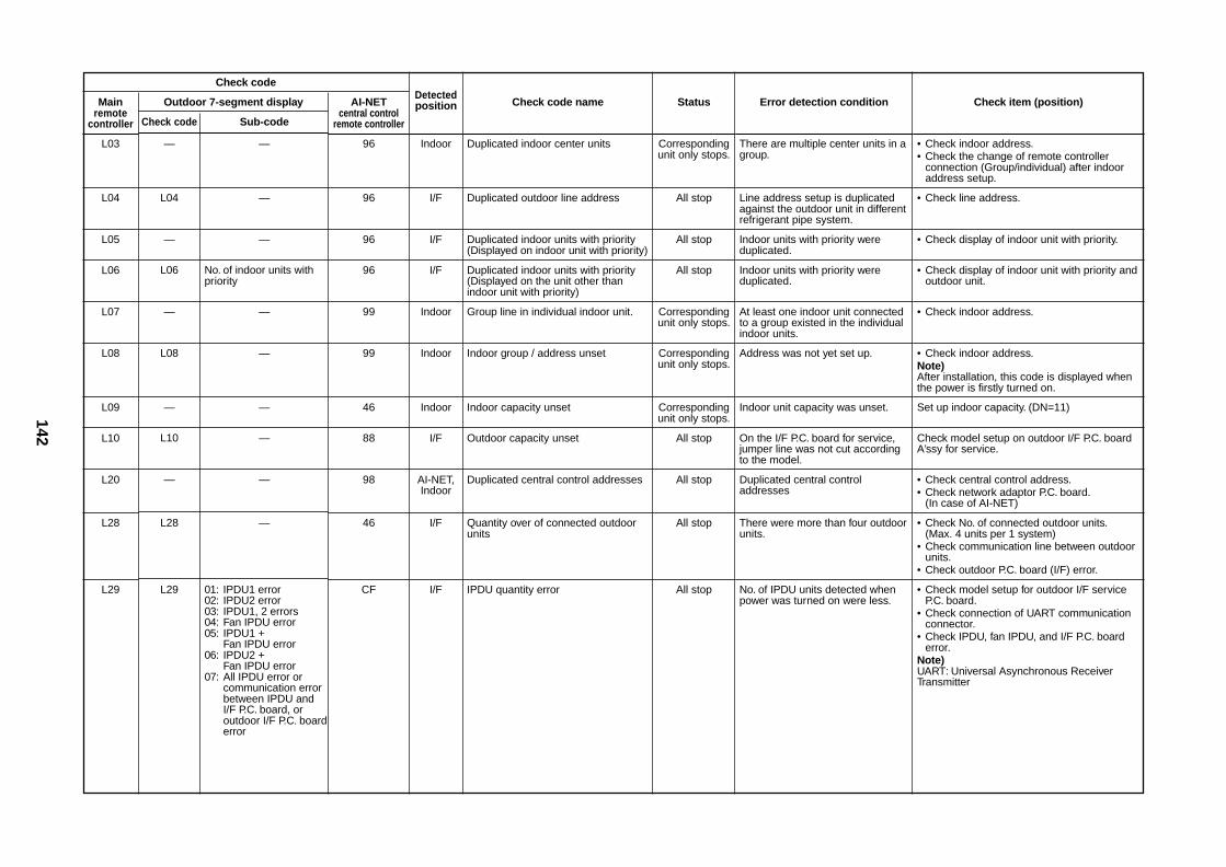
142
Check code
Mainremote
controller
L03
L04
L05
L06
L07
L08
L09
L10
L20
L28
L29
Outdoor 7-segment display
Check code Sub-code
— —
L04 —
— —
L06 No. of indoor units withpriority
— —
L08 —
— —
L10 —
— —
L28 —
L29 01: IPDU1 error02: IPDU2 error03: IPDU1, 2 errors04: Fan IPDU error05: IPDU1 +
Fan IPDU error06: IPDU2 +
Fan IPDU error07: All IPDU error or
communication errorbetween IPDU andI/F P.C. board, oroutdoor I/F P.C. boarderror
AI-NETcentral control
remote controller
96
96
96
96
99
99
46
88
98
46
CF
Detectedposition
Indoor
I/F
I/F
I/F
Indoor
Indoor
Indoor
I/F
AI-NET,Indoor
I/F
I/F
Check code name
Duplicated indoor center units
Duplicated outdoor line address
Duplicated indoor units with priority(Displayed on indoor unit with priority)
Duplicated indoor units with priority(Displayed on the unit other thanindoor unit with priority)
Group line in individual indoor unit.
Indoor group / address unset
Indoor capacity unset
Outdoor capacity unset
Duplicated central control addresses
Quantity over of connected outdoorunits
IPDU quantity error
Status
Correspondingunit only stops.
All stop
All stop
All stop
Correspondingunit only stops.
Correspondingunit only stops.
Correspondingunit only stops.
All stop
All stop
All stop
All stop
Error detection condition
There are multiple center units in agroup.
Line address setup is duplicatedagainst the outdoor unit in differentrefrigerant pipe system.
Indoor units with priority wereduplicated.
Indoor units with priority wereduplicated.
At least one indoor unit connectedto a group existed in the individualindoor units.
Address was not yet set up.
Indoor unit capacity was unset.
On the I/F P.C. board for service,jumper line was not cut accordingto the model.
Duplicated central controladdresses
There were more than four outdoorunits.
No. of IPDU units detected whenpower was turned on were less.
Check item (position)
• Check indoor address.• Check the change of remote controller
connection (Group/individual) after indooraddress setup.
• Check line address.
• Check display of indoor unit with priority.
• Check display of indoor unit with priority andoutdoor unit.
• Check indoor address.
• Check indoor address.Note)After installation, this code is displayed whenthe power is firstly turned on.
Set up indoor capacity. (DN=11)
Check model setup on outdoor I/F P.C. boardA’ssy for service.
• Check central control address.• Check network adaptor P.C. board.
(In case of AI-NET)
• Check No. of connected outdoor units.(Max. 4 units per 1 system)
• Check communication line between outdoorunits.
• Check outdoor P.C. board (I/F) error.
• Check model setup for outdoor I/F serviceP.C. board.
• Check connection of UART communicationconnector.
• Check IPDU, fan IPDU, and I/F P.C. boarderror.
Note)UART: Universal Asynchronous ReceiverTransmitter
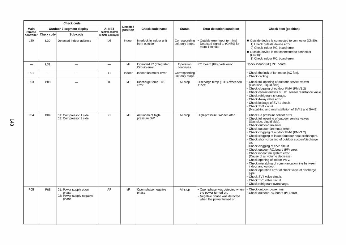
143
Check code
Mainremote
controller
L30
—
P01
P03
P04
P05
Outdoor 7-segment display
Check code Sub-code
L30 Detected indoor address
L31 —
— —
P03 —
P04 01: Compressor 1 side02: Compressor 2 side
P05 01: Power supply openphase
02: Power supply negativephase
AI-NETcentral control
remote controller
b6
—
11
1E
21
AF
Detectedposition
Indoor
I/F
Indoor
I/F
I/F
I/F
Check code name
Interlock in indoor unitfrom outside
Extended IC (IntegratedCircuit) error
Indoor fan motor error
Discharge temp TD1error
Actuation of high-pressure SW
Open phase negativephase
Status
Correspondingunit only stops.
Operationcontinues.
Correspondingunit only stops.
All stop
All stop
All stop
Error detection condition
• Outside error input terminalDetected signal to (CN80) formore 1 minute
P.C. board (I/F) parts error
Discharge temp (TD1) exceeded115°C.
High-pressure SW actuated.
• Open phase was detected whenthe power turned on.
• Negative phase was detectedwhen the power turned on.
Check item (position)
Outside device is connected to connector (CN80):1) Check outside device error.2) Check indoor P.C. board error.
Outside device is not connected to connector(CN80):1) Check indoor P.C. board error.
Check indoor (I/F) P.C. board.
• Check the lock of fan motor (AC fan).• Check cabling.
• Check full opening of outdoor service valves(Gas side, Liquid side).
• Check clogging of outdoor PMV. (PMV1,2)• Check characteristics of TD1 sensor resistance value.• Check refrigerant shortage.• Check 4-way valve error.• Check leakage of SV41 circuit.• Check SV4 circuit.
(Miscabling and misinstallation of SV41 and SV42)
• Check Pd pressure sensor error.• Check full opening of outdoor service valves
(Gas side, Liquid side).• Check outdoor fan error.• Check outdoor fan motor error.• Check clogging of outdoor PMV. (PMV1,2)• Check clogging of indoor/outdoor heat exchangers.• Check short-circuiting of outdoor suction/discharge
air.• Check clogging of SV2 circuit.• Check outdoor P.C. board (I/F) error.• Check indoor fan system error.
(Cause of air volume decrease)• Check opening of indoor PMV.• Check miscabling of communication line between
indoor and outdoor.• Check operation error of check valve of discharge
pipe.• Check SV4 valve circuit.• Check SV5 valve circuit.• Check refrigerant overcharge.
• Check outdoor power line.• Check outdoor P.C. board (I/F) error.
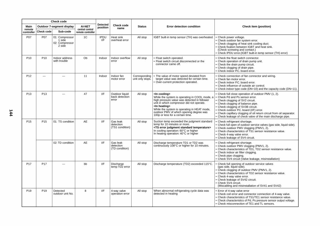
144
Check code
Mainremote
controller
P07
P10
P12
P13
P15
P17
P19
Outdoor 7-segment display
Check code Sub-code
P07 01: Compressor1 side
02: Compressor2 side
P10 Indoor addresswith trouble
— —
P13 —
P15 01: TS condition
02: TD condition
P17 —
P19 Detectedoutdoor unit No.
AI-NETcentral control
remote controller
1C
Ob
11
47
AE
AE
bb
8
Detectedposition
IPDUI/F
Indoor
Indoor
I/F
I/F
I/F
I/F
I/F
Check codename
Heat sinkoverheat error
Indoor overflowerror
Indoor fanmotor error
Outdoor liquidback detectionerror
Gas leakdetection(TS1 condition)
Gas leakdetection(TD condition)
Dischargetemp TD2 error
4-way valveoperation error
Status
All stop
All stop
Correspondingunit only stops.
All stop
All stop
All stop
All stop
All stop
Error detection condition
IGBT built-in temp sensor (TH) was overheated.
• Float switch operated.• Float switch circuit disconnected or the
connector came off.
• The value of motor speed deviated fromtarget value was detected for certain time.
• Over-current protection operated.
<In cooling>While the system is operating in COOL mode, ahigh pressure value was detected in followerunit in which compressor did not operate.<In heating>While the system is operating in HEAT mode,outdoor PMV of which opening degree was100p or less for a certain time.
Suction temp exceeded the judgment standardtemp for 10 minutes or more.<TS error judgment standard temperature>In cooling operation: 60°C or higherIn heating operation: 40°C or higher
Discharge temperature TD1 or TD2 wascontinuously 108°C or higher for 10 minutes.
Discharge temperature (TD2) exceeded 115°C.
When abnormal refrigerating cycle data wasdetected in heating
Check item (position)
• Check power voltage.• Check outdoor fan system error.• Check clogging of heat sink cooling duct.• Check fixation between IGBT and heat sink.
(Check screwing and contact.)• Check IPDU error.(IGBT built-in temp sensor (TH) error)
• Check the float switch connector.• Check operation of drain pump unit.• Check the drain pump circuit.• Check clogging of drain pipe.• Check indoor P.C. board error.
• Check connection of fan connector and wiring.• Check fan motor error.• Check indoor P.C. board error.• Check influence of outside air control.• Check indoor type code (DN=10) and the capacity code (DN=11).
• Check full close operation of outdoor PMV (1, 2).• Check Pd and Ps sensor error.• Check clogging of SV2 circuit.• Check clogging of balance pipe.• Check clogging of SV3B circuit.• Check outdoor P.C. board (I/F) error.• Check capillary clogging of oil return circuit from oil separator.• Check leakage of check valve of the main discharge pipe.
• Check refrigerant shortage.• Check full open of outdoor service valves (gas side, liquid side).• Check outdoor PMV clogging (PMV1, 2).• Check characteristics of TS1 sensor resistance value.• Check 4-way valve error.• Check leakage of SV4 circuit.
• Check refrigerant shortage.• Check outdoor PMV clogging (PMV1, 2).• Check characteristics of TD1, TD2 sensor resistance value.• Check indoor air filter clogging.• Check pipe clogging.• Check SV4 circuit (Valve leakage, misinstallation)
• Check full opening of outdoor service valves(gas side, liquid side).
• Check clogging of outdoor PMV (PMV1, 2).• Check characteristics of TD2 sensor resistance value.• Check 4-way valve error.• Check leakage of SV42 circuit.• Check SV4 circuit.
(Miscabling and misinstallation of SV41 and SV42)
• Error of 4-way valve error• Check coil error and connector connection of 4-way valve.• Check characteristics of TS1/TE1 sensor resistance value.• Check characteristics of Pd, Ps pressure sensor output voltage.• Check misconnection of TE1 and TL sensors.
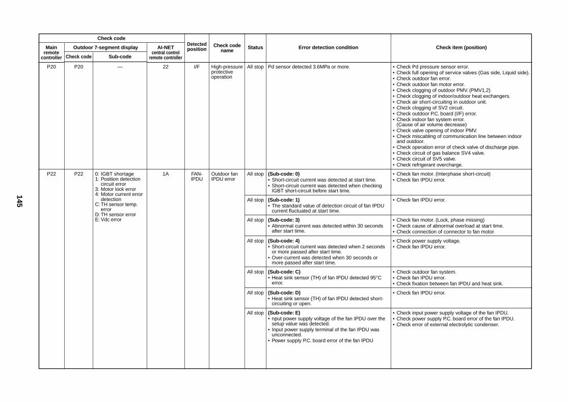
145
Check code
Mainremote
controller
P20
P22
Outdoor 7-segment display
Check code Sub-code
P20 —
P22 0: IGBT shortage1: Position detection
circuit error3: Motor lock error4: Motor current error
detectionC: TH sensor temp.
errorD: TH sensor errorE: Vdc error
AI-NETcentral control
remote controller
22
1A
Detectedposition
I/F
FAN-IPDU
Check codename
High-pressureprotectiveoperation
Outdoor fanIPDU error
Status
All stop
All stop
All stop
All stop
All stop
All stop
All stop
All stop
Error detection condition
Pd sensor detected 3.6MPa or more.
(Sub-code: 0)• Short-circuit current was detected at start time.• Short-circuit current was detected when checking
IGBT short-circuit before start time.
(Sub-code: 1)• The standard value of detection circuit of fan IPDU
current fluctuated at start time.
(Sub-code: 3)• Abnormal current was detected within 30 seconds
after start time.
(Sub-code: 4)• Short-circuit current was detected when 2 seconds
or more passed after start time.• Over-current was detected when 30 seconds or
more passed after start time.
(Sub-code: C)• Heat sink sensor (TH) of fan IPDU detected 95°C
error.
(Sub-code: D)• Heat sink sensor (TH) of fan IPDU detected short-
circuiting or open.
(Sub-code: E)• nput power supply voltage of the fan IPDU over the
setup value was detected.• Input power supply terminal of the fan IPDU was
unconnected.• Power supply P.C. board error of the fan IPDU
Check item (position)
• Check Pd pressure sensor error.• Check full opening of service valves (Gas side, Liquid side).• Check outdoor fan error.• Check outdoor fan motor error.• Check clogging of outdoor PMV. (PMV1,2)• Check clogging of indoor/outdoor heat exchangers.• Check air short-circuiting in outdoor unit.• Check clogging of SV2 circuit.• Check outdoor P.C. board (I/F) error.• Check indoor fan system error.
(Cause of air volume decrease)• Check valve opening of indoor PMV.• Check miscabling of communication line between indoor
and outdoor.• Check operation error of check valve of discharge pipe.• Check circuit of gas balance SV4 valve.• Check circuit of SV5 valve.• Check refrigerant overcharge.
• Check fan motor. (Interphase short-circuit)• Check fan IPDU error.
• Check fan IPDU error.
• Check fan motor. (Lock, phase missing)• Check cause of abnormal overload at start time.• Check connection of connector to fan motor.
• Check power supply voltage.• Check fan IPDU error.
• Check outdoor fan system.• Check fan IPDU error.• Check fixation between fan IPDU and heat sink.
• Check fan IPDU error.
• Check input power supply voltage of the fan IPDU.• Check power supply P.C. board error of the fan IPDU.• Check error of external electrolytic condenser.
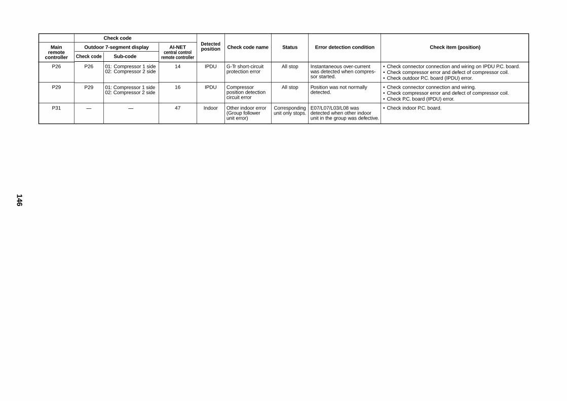
146
Check code
Mainremote
controller
P26
P29
P31
Outdoor 7-segment display
Check code Sub-code
P26 01: Compressor 1 side02: Compressor 2 side
P29 01: Compressor 1 side02: Compressor 2 side
— —
AI-NETcentral control
remote controller
14
16
47
Detectedposition
IPDU
IPDU
Indoor
Check code name
G-Tr short-circuitprotection error
Compressorposition detectioncircuit error
Other indoor error(Group followerunit error)
Status
All stop
All stop
Correspondingunit only stops.
Error detection condition
Instantaneous over-currentwas detected when compres-sor started.
Position was not normallydetected.
E07/L07/L03/L08 wasdetected when other indoorunit in the group was defective.
Check item (position)
• Check connector connection and wiring on IPDU P.C. board.• Check compressor error and defect of compressor coil.• Check outdoor P.C. board (IPDU) error.
• Check connector connection and wiring.• Check compressor error and defect of compressor coil.• Check P.C. board (IPDU) error.
• Check indoor P.C. board.
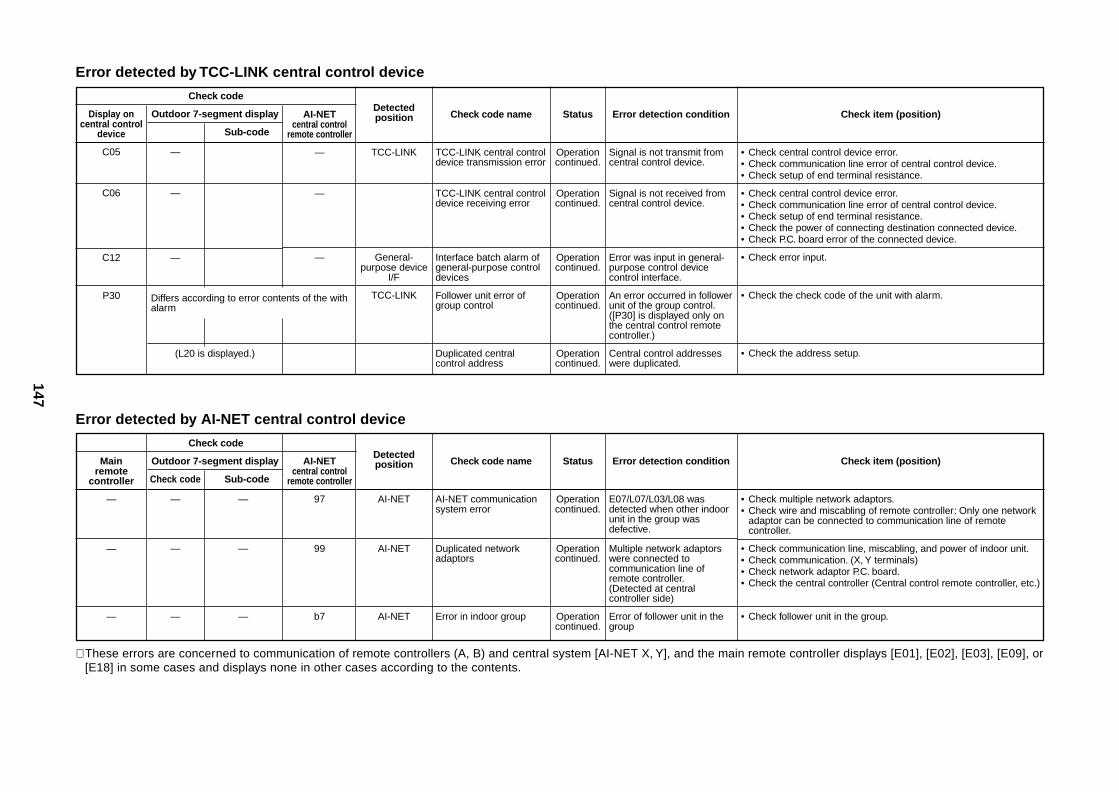
147
Error detected by TCC-LINK central control device
Check code
Display oncentral control
device
C05
C06
C12
P30
Outdoor 7-segment display
Sub-code
—
—
—
(L20 is displayed.)
AI-NETcentral control
remote controller
—
—
—
Detectedposition
TCC-LINK
General-purpose device
I/F
TCC-LINK
Check code name
TCC-LINK central controldevice transmission error
TCC-LINK central controldevice receiving error
Interface batch alarm ofgeneral-purpose controldevices
Follower unit error ofgroup control
Duplicated centralcontrol address
Status
Operationcontinued.
Operationcontinued.
Operationcontinued.
Operationcontinued.
Operationcontinued.
Error detection condition
Signal is not transmit fromcentral control device.
Signal is not received fromcentral control device.
Error was input in general-purpose control devicecontrol interface.
An error occurred in followerunit of the group control.([P30] is displayed only onthe central control remotecontroller.)
Central control addresseswere duplicated.
Check item (position)
• Check central control device error.• Check communication line error of central control device.• Check setup of end terminal resistance.
• Check central control device error.• Check communication line error of central control device.• Check setup of end terminal resistance.• Check the power of connecting destination connected device.• Check P.C. board error of the connected device.
• Check error input.
• Check the check code of the unit with alarm.
• Check the address setup.
Differs according to error contents of the withalarm
Error detected by AI-NET central control device
Check code
Mainremote
controller
—
—
—
Outdoor 7-segment display
Check code Sub-code
— —
— —
— —
AI-NETcentral control
remote controller
97
99
b7
Detectedposition
AI-NET
AI-NET
AI-NET
Check code name
AI-NET communicationsystem error
Duplicated networkadaptors
Error in indoor group
Status
Operationcontinued.
Operationcontinued.
Operationcontinued.
Error detection condition
E07/L07/L03/L08 wasdetected when other indoorunit in the group wasdefective.
Multiple network adaptorswere connected tocommunication line ofremote controller.(Detected at centralcontroller side)
Error of follower unit in thegroup
Check item (position)
• Check multiple network adaptors.• Check wire and miscabling of remote controller: Only one network
adaptor can be connected to communication line of remotecontroller.
• Check communication line, miscabling, and power of indoor unit.• Check communication. (X, Y terminals)• Check network adaptor P.C. board.• Check the central controller (Central control remote controller, etc.)
• Check follower unit in the group.
∗ These errors are concerned to communication of remote controllers (A, B) and central system [AI-NET X, Y], and the main remote controller displays [E01], [E02], [E03], [E09], or[E18] in some cases and displays none in other cases according to the contents.
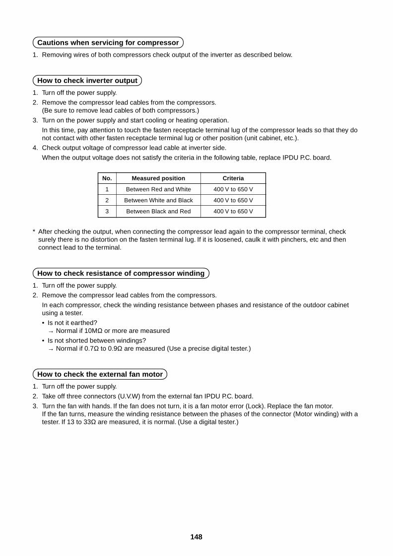
148
Cautions when servicing for compressor
1. Removing wires of both compressors check output of the inverter as described below.
How to check inverter output
1. Turn off the power supply.
2. Remove the compressor lead cables from the compressors.(Be sure to remove lead cables of both compressors.)
3. Turn on the power supply and start cooling or heating operation.
In this time, pay attention to touch the fasten receptacle terminal lug of the compressor leads so that they donot contact with other fasten receptacle terminal lug or other position (unit cabinet, etc.).
4. Check output voltage of compressor lead cable at inverter side.
When the output voltage does not satisfy the criteria in the following table, replace IPDU P.C. board.
No.
1
2
3
Measured position
Between Red and White
Between White and Black
Between Black and Red
Criteria
400 V to 650 V
400 V to 650 V
400 V to 650 V
* After checking the output, when connecting the compressor lead again to the compressor terminal, checksurely there is no distortion on the fasten terminal lug. If it is loosened, caulk it with pinchers, etc and thenconnect lead to the terminal.
How to check resistance of compressor winding
1. Turn off the power supply.
2. Remove the compressor lead cables from the compressors.
In each compressor, check the winding resistance between phases and resistance of the outdoor cabinetusing a tester.
• Is not it earthed?→ Normal if 10MΩ or more are measured
• Is not shorted between windings?→ Normal if 0.7Ω to 0.9Ω are measured (Use a precise digital tester.)
How to check the external fan motor
1. Turn off the power supply.
2. Take off three connectors (U.V.W) from the external fan IPDU P.C. board.
3. Turn the fan with hands. If the fan does not turn, it is a fan motor error (Lock). Replace the fan motor.If the fan turns, measure the winding resistance between the phases of the connector (Motor winding) with atester. If 13 to 33Ω are measured, it is normal. (Use a digital tester.)
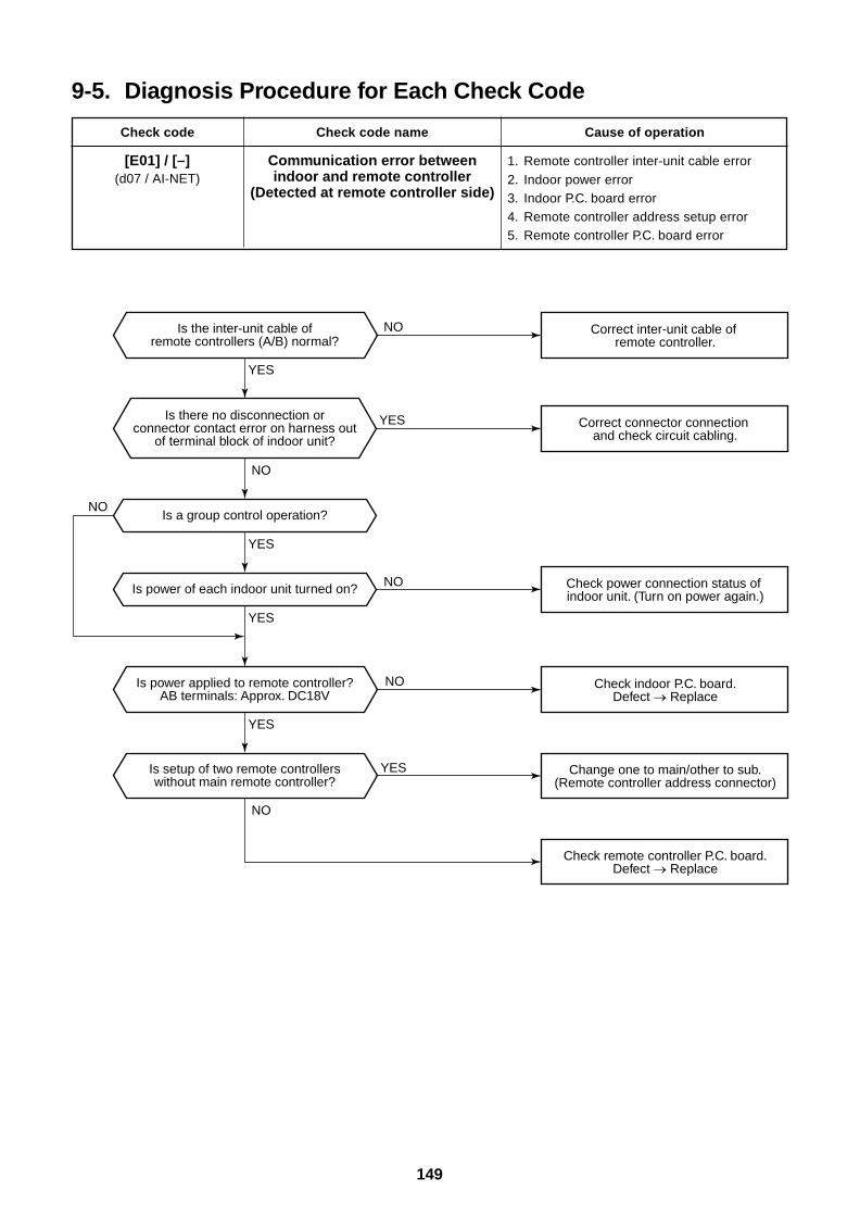
149
9-5. Diagnosis Procedure for Each Check Code
Check code
[E01] / [–](d07 / AI-NET)
Check code name
Communication error betweenindoor and remote controller
(Detected at remote controller side)
Cause of operation
1. Remote controller inter-unit cable error2. Indoor power error3. Indoor P.C. board error4. Remote controller address setup error5. Remote controller P.C. board error
Is a group control operation?
Is power of each indoor unit turned on?
YES
YES
YES
YES
YES
YES
NO
NO
NO
NO
NO
NO
Is there no disconnection orconnector contact error on harness out
of terminal block of indoor unit?
Is the inter-unit cable ofremote controllers (A/B) normal?
Is power applied to remote controller?AB terminals: Approx. DC18V
Is setup of two remote controllerswithout main remote controller?
Correct inter-unit cable of remote controller.
Correct connector connection and check circuit cabling.
Check power connection status of indoor unit. (Turn on power again.)
Check indoor P.C. board.Defect Replace
Change one to main/other to sub.(Remote controller address connector)
Check remote controller P.C. board.Defect Replace
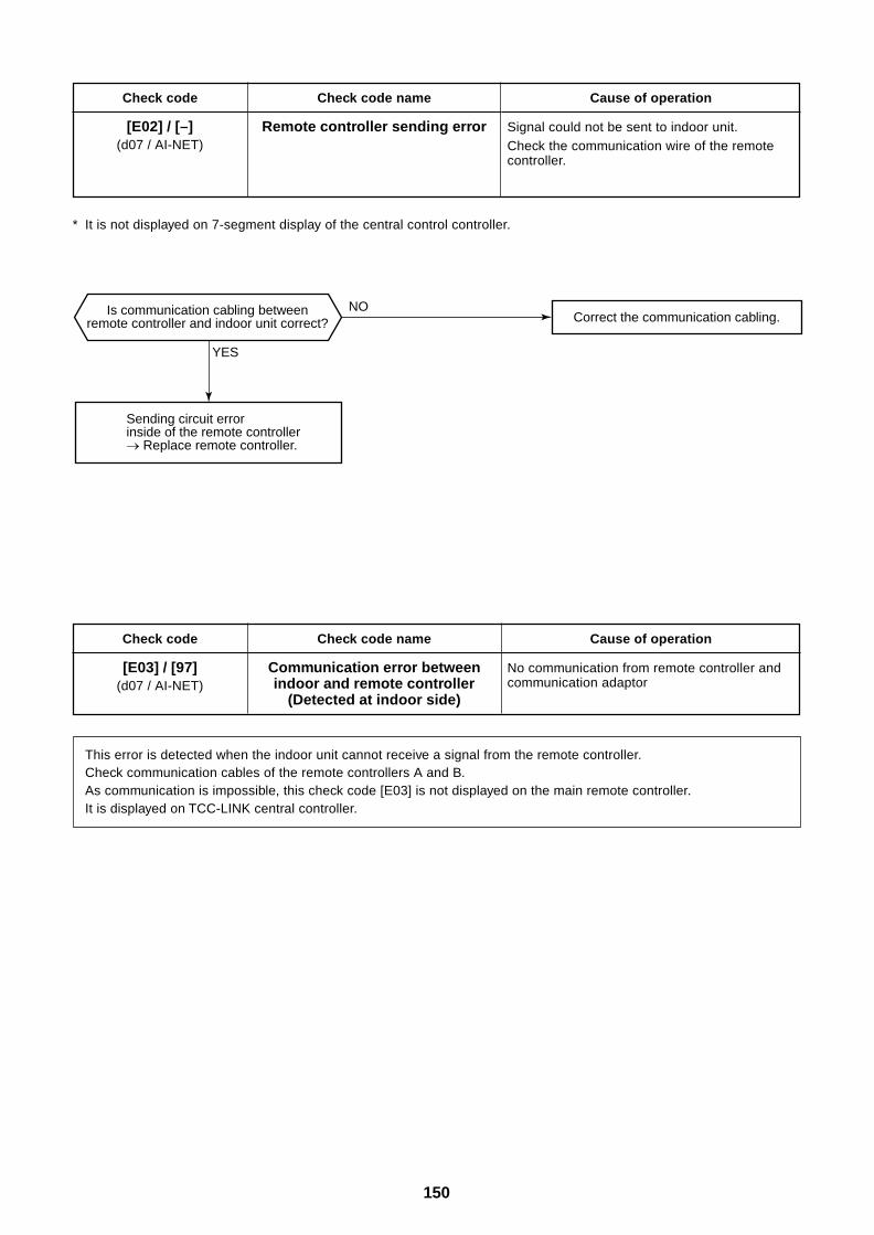
150
Check code name
Remote controller sending error
Cause of operation
Signal could not be sent to indoor unit.Check the communication wire of the remotecontroller.
* It is not displayed on 7-segment display of the central control controller.
Check code
[E03] / [97](d07 / AI-NET)
Check code name
Communication error betweenindoor and remote controller
(Detected at indoor side)
Cause of operation
No communication from remote controller andcommunication adaptor
This error is detected when the indoor unit cannot receive a signal from the remote controller.Check communication cables of the remote controllers A and B.As communication is impossible, this check code [E03] is not displayed on the main remote controller.It is displayed on TCC-LINK central controller.
Check code
[E02] / [–](d07 / AI-NET)
YES
NOIs communication cabling betweenremote controller and indoor unit correct?
Sending circuit error inside of the remote controller
Replace remote controller.
Correct the communication cabling.
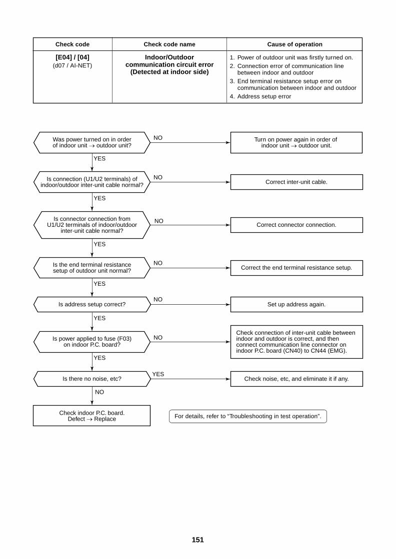
151
Check code
[E04] / [04](d07 / AI-NET)
Check code name
Indoor/Outdoorcommunication circuit error
(Detected at indoor side)
Cause of operation
1. Power of outdoor unit was firstly turned on.2. Connection error of communication line
between indoor and outdoor3. End terminal resistance setup error on
communication between indoor and outdoor4. Address setup error
For details, refer to “Troubleshooting in test operation”.
Is address setup correct?
Is there no noise, etc?
YES
YES
YES
YES
YES
YES
YES
NO
NO
NO
NO
NO
NO
NO
Is connector connection fromU1/U2 terminals of indoor/outdoor
inter-unit cable normal?
Was power turned on in orderof indoor unit outdoor unit?
Is the end terminal resistancesetup of outdoor unit normal?
Is power applied to fuse (F03)on indoor P.C. board?
Is connection (U1/U2 terminals) ofindoor/outdoor inter-unit cable normal?
Check indoor P.C. board.Defect Replace
Check connection of inter-unit cable between indoor and outdoor is correct, and then connect communication line connector on indoor P.C. board (CN40) to CN44 (EMG).
Correct inter-unit cable.
Turn on power again in order of indoor unit outdoor unit.
Correct connector connection.
Correct the end terminal resistance setup.
Set up address again.
Check noise, etc, and eliminate it if any.
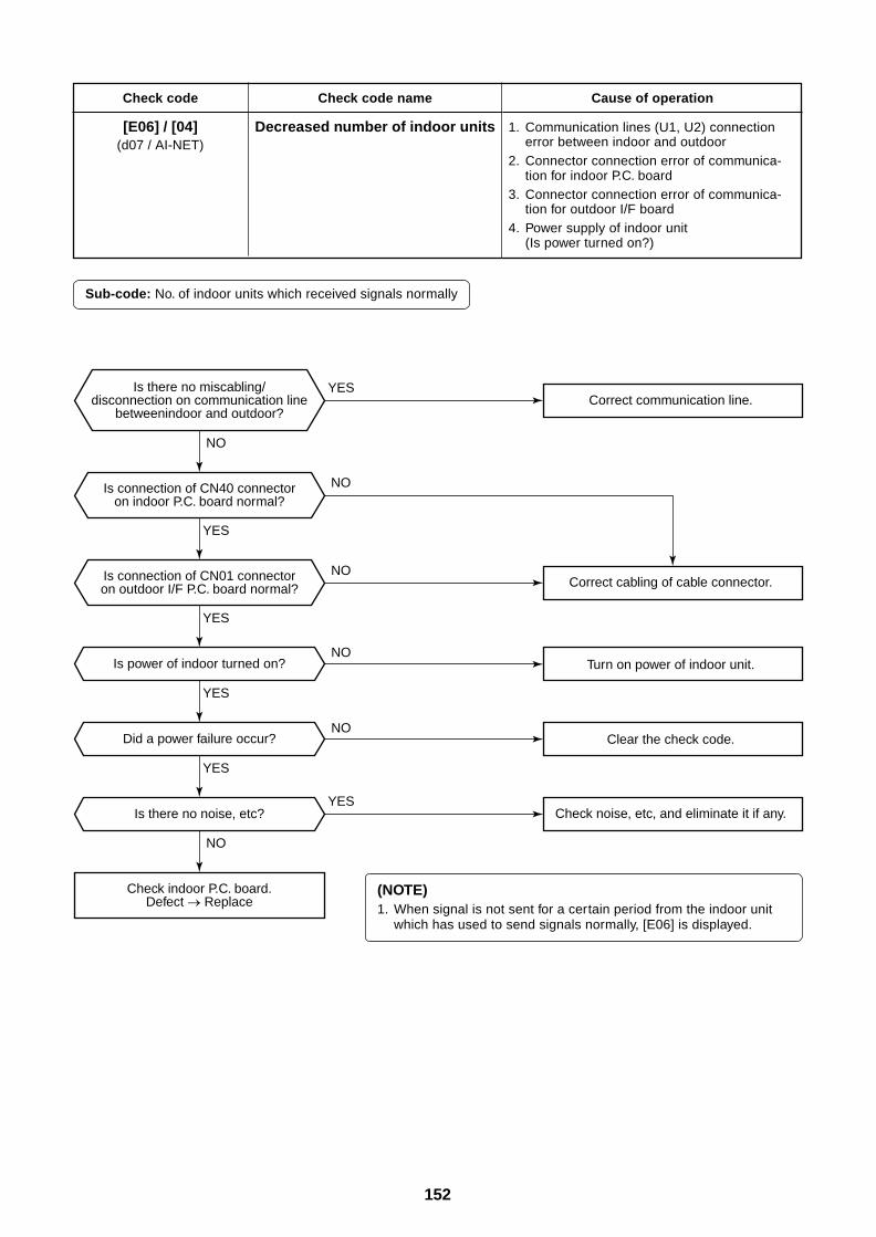
152
Check code
[E06] / [04](d07 / AI-NET)
Check code name
Decreased number of indoor units
Cause of operation
1. Communication lines (U1, U2) connectionerror between indoor and outdoor
2. Connector connection error of communica-tion for indoor P.C. board
3. Connector connection error of communica-tion for outdoor I/F board
4. Power supply of indoor unit(Is power turned on?)
Sub-code: No. of indoor units which received signals normally
(NOTE)1. When signal is not sent for a certain period from the indoor unit
which has used to send signals normally, [E06] is displayed.
Is power of indoor turned on?
Did a power failure occur?
Is there no noise, etc?
YES
YES
YES
YES
YES
YES
NO
NO
NO
NO
NO
NO
Is there no miscabling/disconnection on communication line
betweenindoor and outdoor?
Is connection of CN40 connectoron indoor P.C. board normal?
Is connection of CN01 connectoron outdoor I/F P.C. board normal?
Check indoor P.C. board.Defect Replace
Check noise, etc, and eliminate it if any.
Clear the check code.
Turn on power of indoor unit.
Correct cabling of cable connector.
Correct communication line.
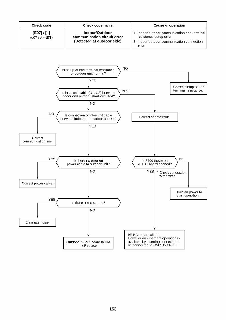
153
Check code
[E07] / [–](d07 / AI-NET)
Check code name
Indoor/Outdoorcommunication circuit error(Detected at outdoor side)
Cause of operation
1. Indoor/outdoor communication end terminalresistance setup error
2. Indoor/outdoor communication connectionerror
Is there noise source?
YES
YES
YES
YES
YES
YES
NO
NO
NO
NO
NO
NOIs setup of end terminal resistanceof outdoor unit normal?
Is inter-unit cable (U1, U2) betweenindoor and outdoor short-circuited?
Is connection of inter-unit cablebetween indoor and outdoor correct?
Is there no error onpower cable to outdoor unit?
Is F400 (fuse) onI/F P.C. board opened?
Outdoor I/F P.C. board failure Replace
Eliminate noise.
Correct power cable.
Correctcommunication line.
I/F P.C. board failureHowever an emergent operation is available by inserting connector to be connected to CN01 to CN33.
Correct short-circuit.
* Check conduction with tester.
Turn on power tostart operation.
Correct setup of endterminal resistance.
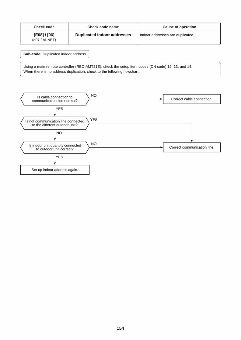
154
Check code
[E08] / [96](d07 / AI-NET)
Check code name
Duplicated indoor addresses
Cause of operation
Indoor addresses are duplicated.
Sub-code: Duplicated indoor address
Using a main remote controller (RBC-AMT21E), check the setup item codes (DN code) 12, 13, and 14.When there is no address duplication, check to the following flowchart.
YES
YES
YES
NO
NO
NOIs cable connection tocommunication line normal?
Is not communication line connectedto the different outdoor unit?
Is indoor unit quantity connectedto outdoor unit correct?
Set up indoor address again.
Correct communication line.
Correct cable connection.
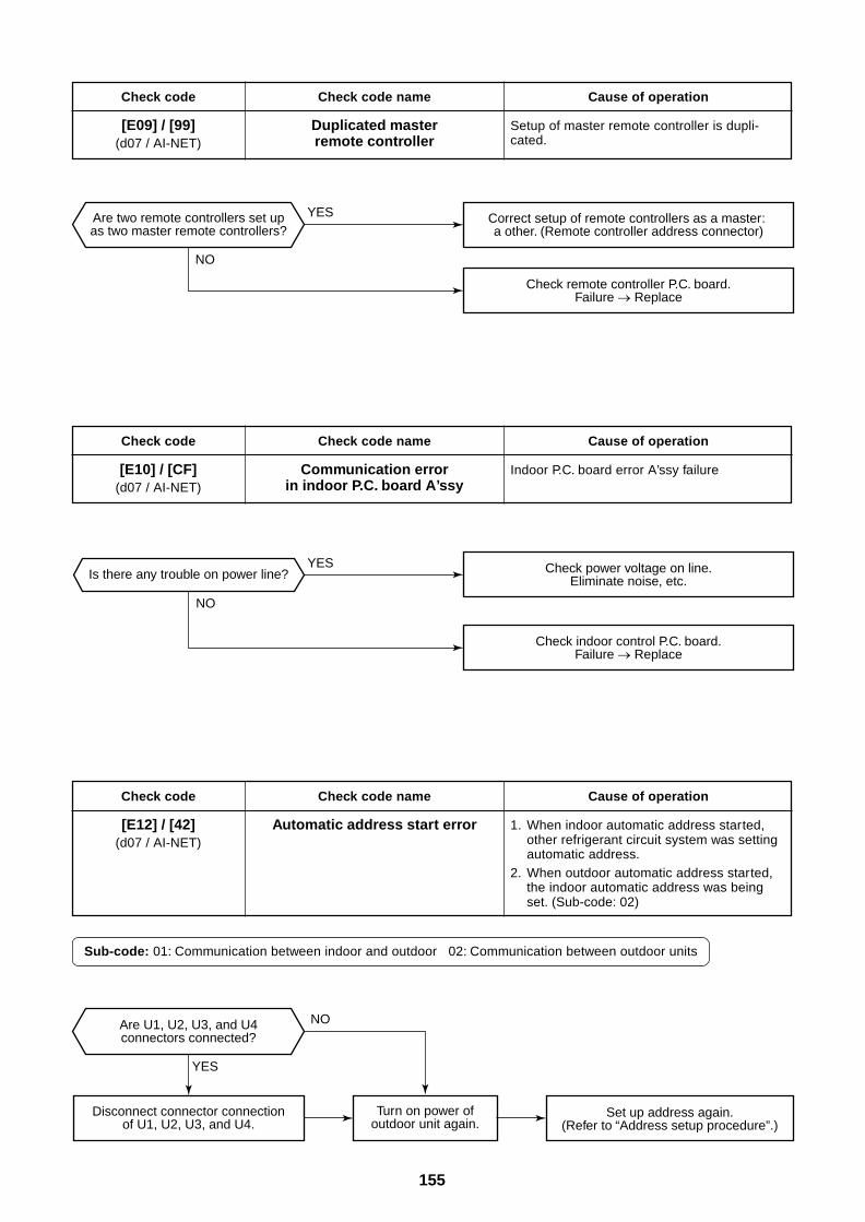
155
Is there any trouble on power line?
YES
YES
YES
NO
NO
NO
Are two remote controllers set upas two master remote controllers?
Are U1, U2, U3, and U4connectors connected?
Disconnect connector connectionof U1, U2, U3, and U4.
Set up address again.(Refer to “Address setup procedure”.)
Correct setup of remote controllers as a master: a other. (Remote controller address connector)
Turn on power ofoutdoor unit again.
Check indoor control P.C. board.Failure Replace
Check power voltage on line.Eliminate noise, etc.
Check remote controller P.C. board.Failure Replace
Check code
[E09] / [99](d07 / AI-NET)
Check code name
Duplicated masterremote controller
Cause of operation
Setup of master remote controller is dupli-cated.
Check code
[E10] / [CF](d07 / AI-NET)
Check code name
Communication errorin indoor P.C. board A’ssy
Cause of operation
Indoor P.C. board error A’ssy failure
Check code
[E12] / [42](d07 / AI-NET)
Check code name
Automatic address start error
Cause of operation
1. When indoor automatic address started,other refrigerant circuit system was settingautomatic address.
2. When outdoor automatic address started,the indoor automatic address was beingset. (Sub-code: 02)
Sub-code: 01: Communication between indoor and outdoor 02: Communication between outdoor units
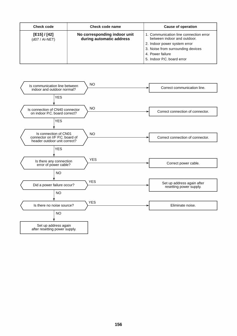
156
Check code
[E15] / [42](d07 / AI-NET)
Check code name
No corresponding indoor unitduring automatic address
Cause of operation
1. Communication line connection errorbetween indoor and outdoor.
2. Indoor power system error3. Noise from surrounding devices4. Power failure5. Indoor P.C. board error
YES
YES
YES
YES
YES
YES
NO
NO
NO
NO
NO
NO
Did a power failure occur?
Is there no noise source?
Is connection of CN01connector on I/F P.C. board ofheader outdoor unit correct?
Is communication line betweenindoor and outdoor normal?
Is connection of CN40 connectoron indoor P.C. board correct?
Is there any connectionerror of power cable?
Set up address againafter resetting power supply.
Set up address again afterresetting power supply.
Correct communication line.
Correct connection of connector.
Correct connection of connector.
Correct power cable.
Eliminate noise.
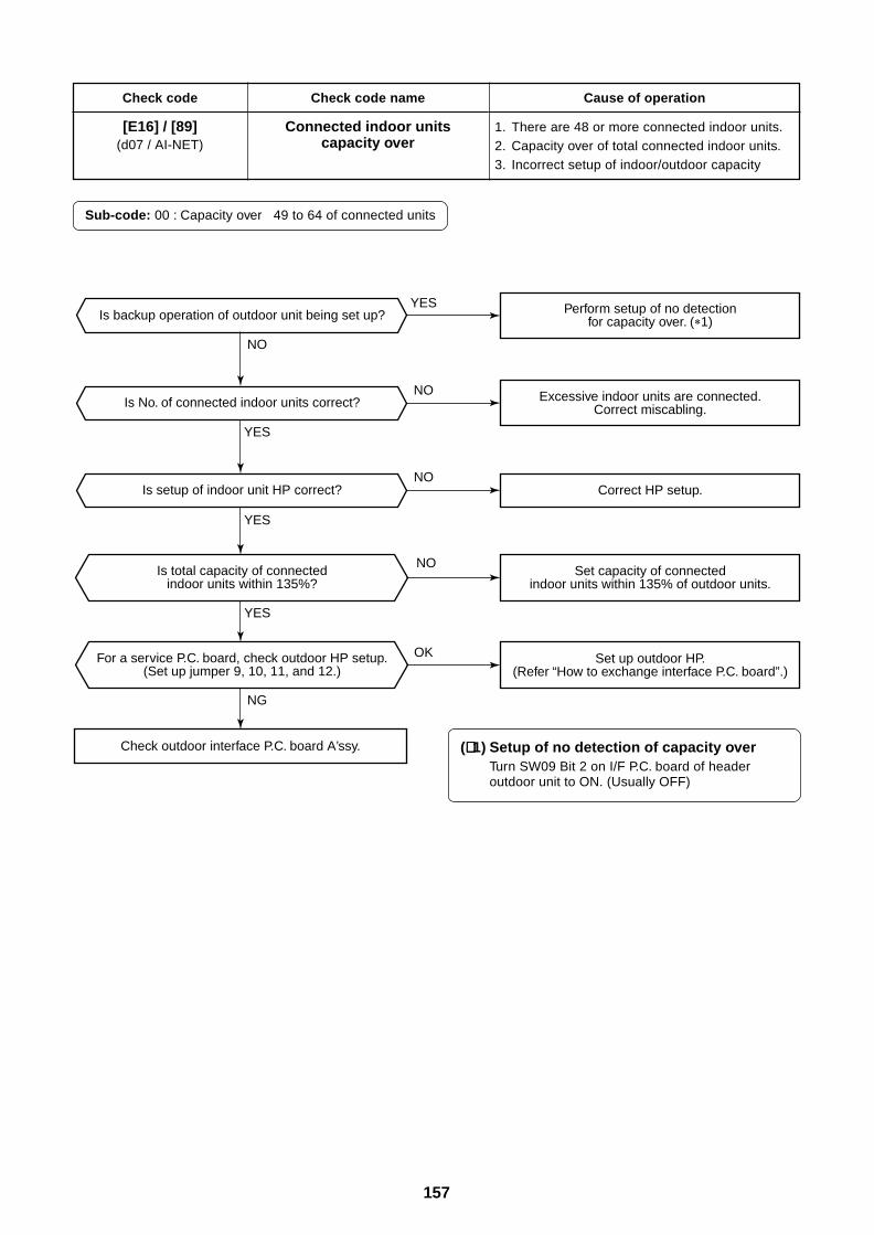
157
YES
YES
YES
YES
NO
NO
NO
NO
OK
NG
Is backup operation of outdoor unit being set up?
Is No. of connected indoor units correct?
Is setup of indoor unit HP correct?
Is total capacity of connectedindoor units within 135%?
For a service P.C. board, check outdoor HP setup.(Set up jumper 9, 10, 11, and 12.)
Set up outdoor HP.(Refer “How to exchange interface P.C. board”.)
Set capacity of connectedindoor units within 135% of outdoor units.
Correct HP setup.
Excessive indoor units are connected.Correct miscabling.
Perform setup of no detectionfor capacity over. ( 1)
Check outdoor interface P.C. board A’ssy.
Check code
[E16] / [89](d07 / AI-NET)
Check code name
Connected indoor unitscapacity over
Cause of operation
1. There are 48 or more connected indoor units.2. Capacity over of total connected indoor units.3. Incorrect setup of indoor/outdoor capacity
Sub-code: 00 : Capacity over 49 to 64 of connected units
(∗∗∗∗∗ 1) Setup of no detection of capacity overTurn SW09 Bit 2 on I/F P.C. board of headeroutdoor unit to ON. (Usually OFF)
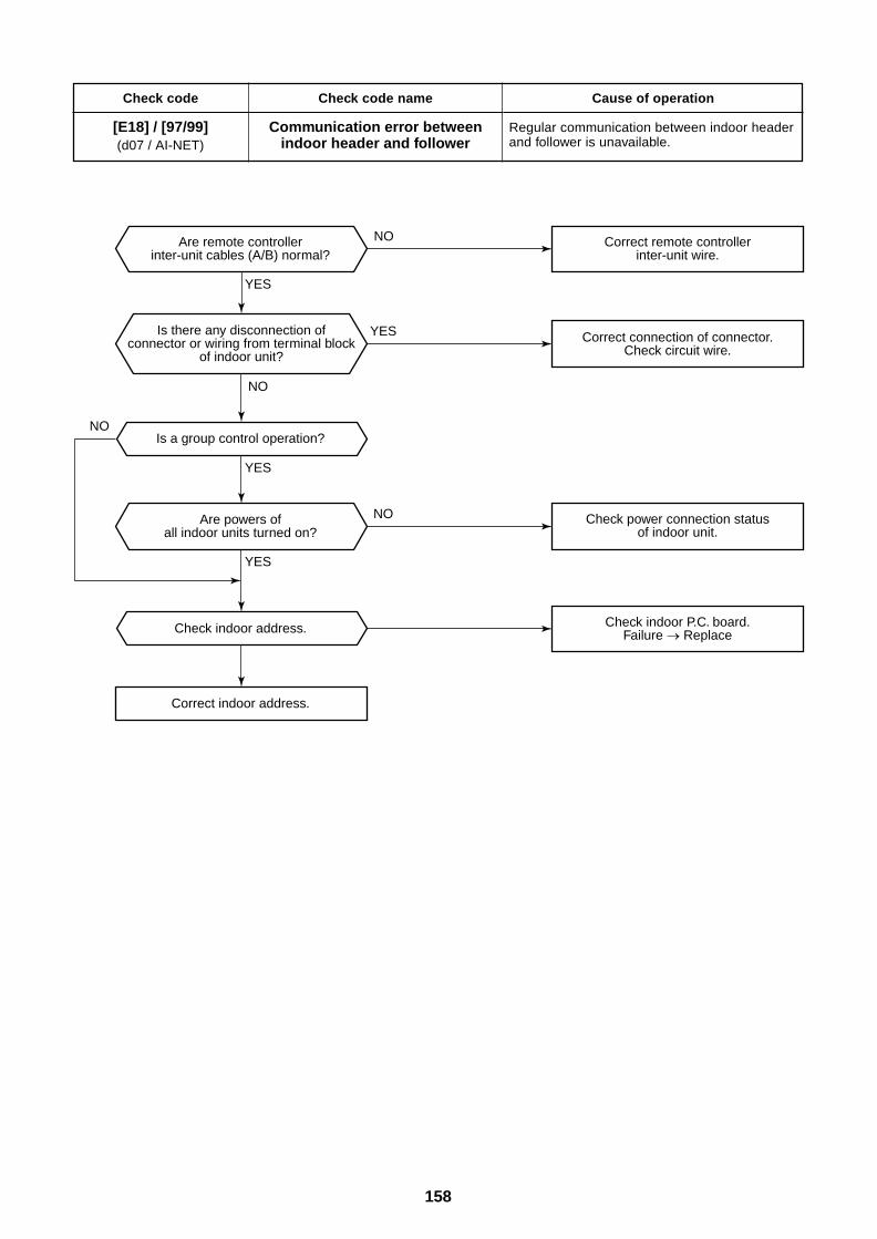
158
Check code
[E18] / [97/99](d07 / AI-NET)
Check code name
Communication error betweenindoor header and follower
Cause of operation
Regular communication between indoor headerand follower is unavailable.
YES
YES
YES
YES
NO
NO
NO
NO
Is a group control operation?
Check indoor address.
Correct indoor address.
Is there any disconnection ofconnector or wiring from terminal block
of indoor unit?
Are remote controllerinter-unit cables (A/B) normal?
Are powers ofall indoor units turned on?
Check indoor P.C. board.Failure Replace
Check power connection statusof indoor unit.
Correct connection of connector.Check circuit wire.
Correct remote controllerinter-unit wire.
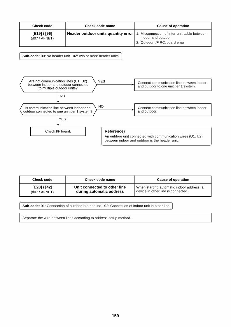
159
YES
YES
NO
NO
Are not communication lines (U1, U2)between indoor and outdoor connected
to multiple outdoor units?
Is communication line between indoor andoutdoor connected to one unit per 1 system?
Check I/F board.
Connect communication line between indoor and outdoor.
Connect communication line between indoor and outdoor to one unit per 1 system.
Check code
[E19] / [96](d07 / AI-NET)
Check code name
Header outdoor units quantity error
Cause of operation
1. Misconnection of inter-unit cable betweenindoor and outdoor
2. Outdoor I/F P.C. board error
Sub-code: 00: No header unit 02: Two or more header units
Check code
[E20] / [42](d07 / AI-NET)
Check code name
Unit connected to other lineduring automatic address
Cause of operation
When starting automatic indoor address, adevice in other line is connected.
Sub-code: 01: Connection of outdoor in other line 02: Connection of indoor unit in other line
Separate the wire between lines according to address setup method.
Reference)An outdoor unit connected with communication wires (U1, U2)between indoor and outdoor is the header unit.
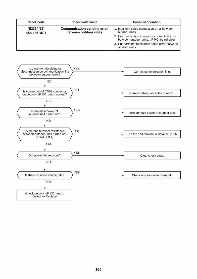
160
Check code
[E23] / [15](d07 / AI-NET)
Check code name
Communication sending errorbetween outdoor units
Cause of operation
1. Inter-unit cable connection error betweenoutdoor units
2. Communication connector connection errorbetween outdoor units, I/F P.C. board error
3. End terminal resistance setup error betweenoutdoor units
YES
YES
YES
YES
YES
YES
NO
NO
NO
NO
NO
NO
Did power failure occur?
Is there no noise source, etc?
Is there no miscabling ordisconnection on communication line
between outdoor units?
Is the end terminal resistancebetween outdoor units turned on?
(SW30 Bit 1)
Is connection of CN03 connectoron outdoor I/F P.C. board normal?
Check outdoor I/F P.C. board.Defect Replace
Is not main power ofoutdoor unit turned off?
Check and eliminate noise, etc
Clear check code.
Turn the end terminal resistance to ON.
Turn on main power of outdoor unit.
Correct cabling of cable connector.
Correct communication line.
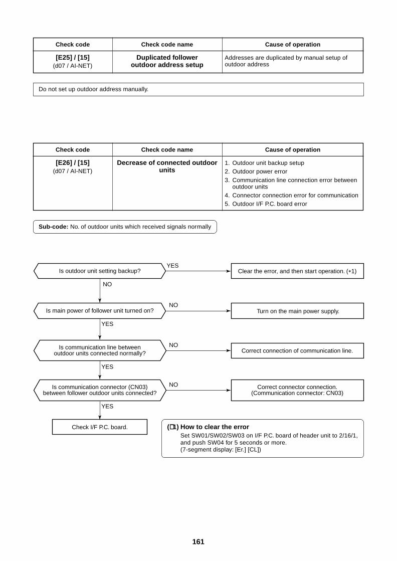
161
YES
YES
YES
YES
NO
NO
NO
NO
Is outdoor unit setting backup?
Is main power of follower unit turned on?
Is communication line betweenoutdoor units connected normally?
Is communication connector (CN03)between follower outdoor units connected?
Correct connector connection.(Communication connector: CN03)
Check I/F P.C. board.
Clear the error, and then start operation. ( 1)
Turn on the main power supply.
Correct connection of communication line.
Check code
[E25] / [15](d07 / AI-NET)
Check code name
Duplicated followeroutdoor address setup
Cause of operation
Addresses are duplicated by manual setup ofoutdoor address
Do not set up outdoor address manually.
Check code
[E26] / [15](d07 / AI-NET)
Check code name
Decrease of connected outdoorunits
Cause of operation
1. Outdoor unit backup setup2. Outdoor power error3. Communication line connection error between
outdoor units4. Connector connection error for communication5. Outdoor I/F P.C. board error
Sub-code: No. of outdoor units which received signals normally
(∗∗∗∗∗ 1) How to clear the errorSet SW01/SW02/SW03 on I/F P.C. board of header unit to 2/16/1,and push SW04 for 5 seconds or more.(7-segment display: [Er.] [CL])
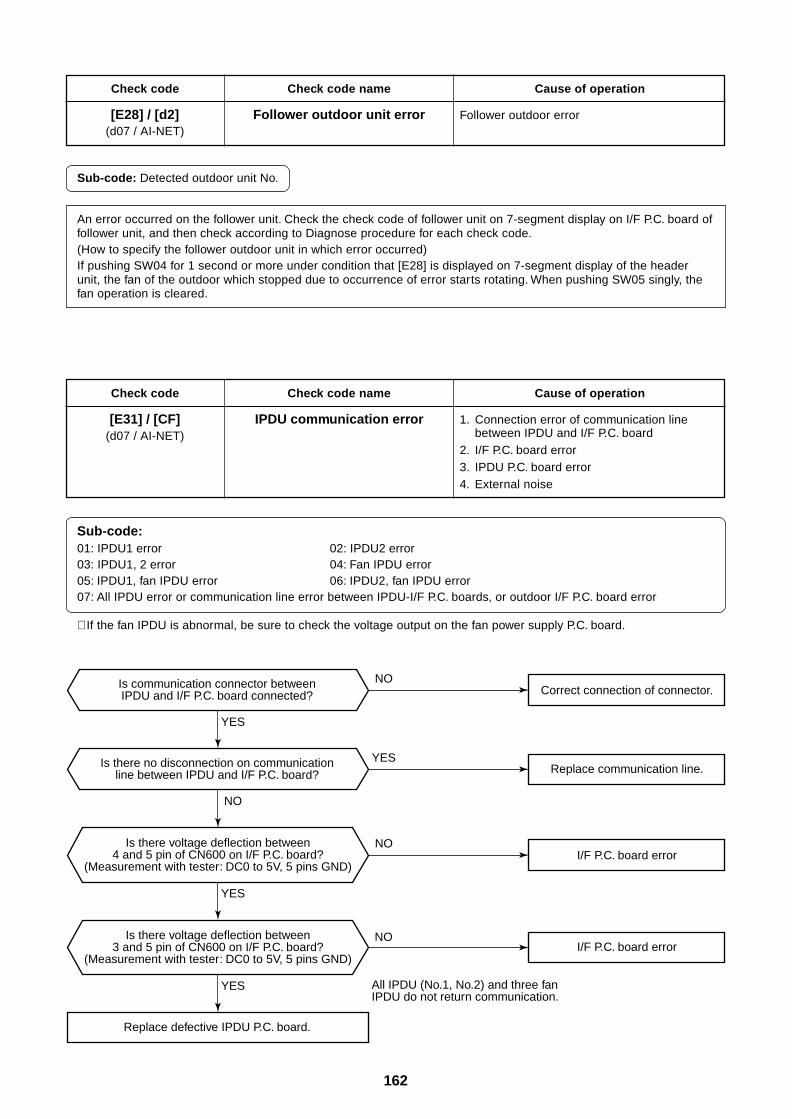
162
Check code
[E28] / [d2](d07 / AI-NET)
Check code name
Follower outdoor unit error
Cause of operation
Follower outdoor error
Sub-code: Detected outdoor unit No.
An error occurred on the follower unit. Check the check code of follower unit on 7-segment display on I/F P.C. board offollower unit, and then check according to Diagnose procedure for each check code.(How to specify the follower outdoor unit in which error occurred)If pushing SW04 for 1 second or more under condition that [E28] is displayed on 7-segment display of the headerunit, the fan of the outdoor which stopped due to occurrence of error starts rotating. When pushing SW05 singly, thefan operation is cleared.
Check code
[E31] / [CF](d07 / AI-NET)
Check code name
IPDU communication error
Cause of operation
1. Connection error of communication linebetween IPDU and I/F P.C. board
2. I/F P.C. board error3. IPDU P.C. board error4. External noise
Sub-code:01: IPDU1 error 02: IPDU2 error03: IPDU1, 2 error 04: Fan IPDU error05: IPDU1, fan IPDU error 06: IPDU2, fan IPDU error07: All IPDU error or communication line error between IPDU-I/F P.C. boards, or outdoor I/F P.C. board error
YES
YES
YES
YES
NO
NO
NO
NO
Replace defective IPDU P.C. board.
Correct connection of connector.
Replace communication line.
I/F P.C. board error
I/F P.C. board error
Is there voltage deflection between4 and 5 pin of CN600 on I/F P.C. board?
(Measurement with tester: DC0 to 5V, 5 pins GND)
Is there voltage deflection between3 and 5 pin of CN600 on I/F P.C. board?
(Measurement with tester: DC0 to 5V, 5 pins GND)
Is communication connector betweenIPDU and I/F P.C. board connected?
Is there no disconnection on communicationline between IPDU and I/F P.C. board?
All IPDU (No.1, No.2) and three fanIPDU do not return communication.
∗ If the fan IPDU is abnormal, be sure to check the voltage output on the fan power supply P.C. board.
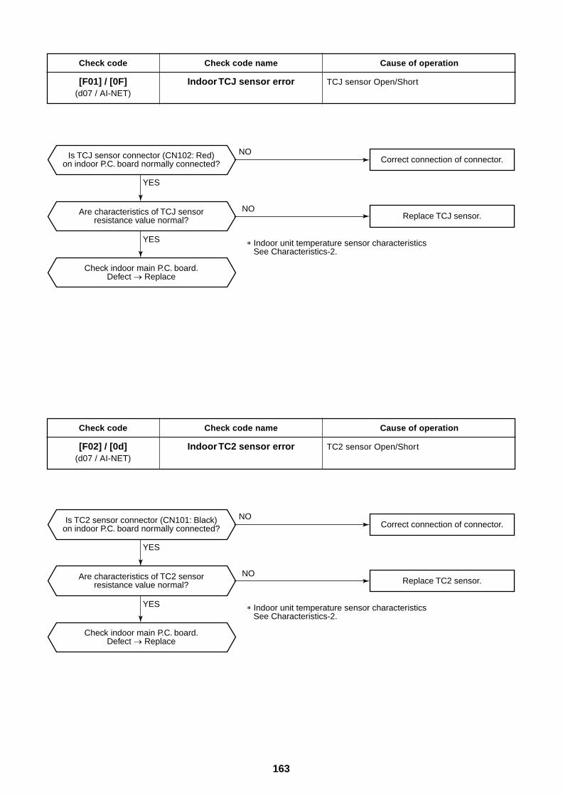
163
Check code
[F01] / [0F](d07 / AI-NET)
Check code name
Indoor TCJ sensor error
Cause of operation
TCJ sensor Open/Short
Check code
[F02] / [0d](d07 / AI-NET)
Check code name
Indoor TC2 sensor error
Cause of operation
TC2 sensor Open/Short
YES
YES
NO
NO
Correct connection of connector.
Replace TCJ sensor.
Correct connection of connector.
Replace TC2 sensor.
Is TCJ sensor connector (CN102: Red)on indoor P.C. board normally connected?
Are characteristics of TCJ sensorresistance value normal?
Check indoor main P.C. board.Defect Replace
Is TC2 sensor connector (CN101: Black)on indoor P.C. board normally connected?
Are characteristics of TC2 sensorresistance value normal?
Check indoor main P.C. board.Defect Replace
YES
YES
NO
NO
Indoor unit temperature sensor characteristics See Characteristics-2.
Indoor unit temperature sensor characteristics See Characteristics-2.
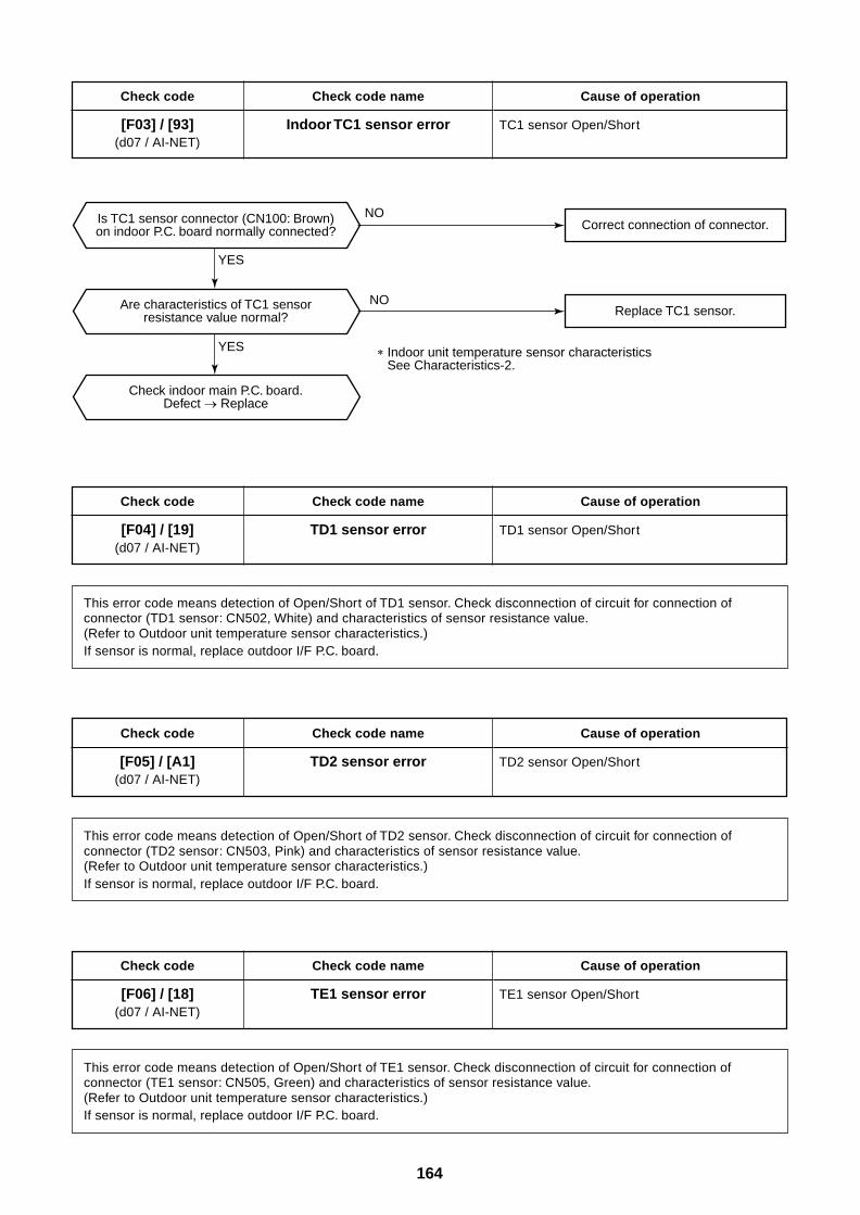
164
Check code
[F03] / [93](d07 / AI-NET)
Check code name
Indoor TC1 sensor error
Cause of operation
TC1 sensor Open/Short
Check code
[F04] / [19](d07 / AI-NET)
Check code name
TD1 sensor error
Cause of operation
TD1 sensor Open/Short
This error code means detection of Open/Short of TD1 sensor. Check disconnection of circuit for connection ofconnector (TD1 sensor: CN502, White) and characteristics of sensor resistance value.(Refer to Outdoor unit temperature sensor characteristics.)If sensor is normal, replace outdoor I/F P.C. board.
Check code
[F05] / [A1](d07 / AI-NET)
Check code name
TD2 sensor error
Cause of operation
TD2 sensor Open/Short
This error code means detection of Open/Short of TD2 sensor. Check disconnection of circuit for connection ofconnector (TD2 sensor: CN503, Pink) and characteristics of sensor resistance value.(Refer to Outdoor unit temperature sensor characteristics.)If sensor is normal, replace outdoor I/F P.C. board.
Check code
[F06] / [18](d07 / AI-NET)
Check code name
TE1 sensor error
Cause of operation
TE1 sensor Open/Short
This error code means detection of Open/Short of TE1 sensor. Check disconnection of circuit for connection ofconnector (TE1 sensor: CN505, Green) and characteristics of sensor resistance value.(Refer to Outdoor unit temperature sensor characteristics.)If sensor is normal, replace outdoor I/F P.C. board.
YES
YES
NO
NO
Correct connection of connector.
Replace TC1 sensor.
Is TC1 sensor connector (CN100: Brown)on indoor P.C. board normally connected?
Are characteristics of TC1 sensorresistance value normal?
Check indoor main P.C. board.Defect Replace
Indoor unit temperature sensor characteristics See Characteristics-2.
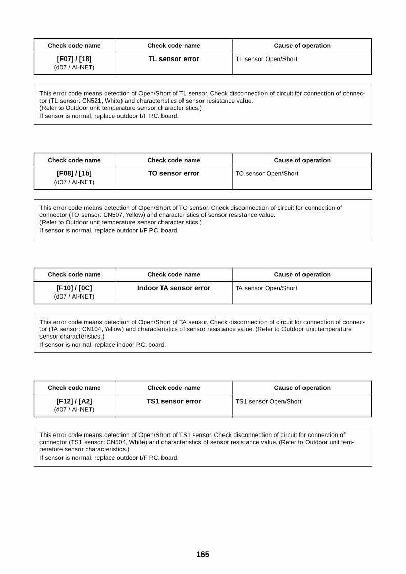
165
Check code name
[F07] / [18](d07 / AI-NET)
Check code name
TL sensor error
Cause of operation
TL sensor Open/Short
This error code means detection of Open/Short of TL sensor. Check disconnection of circuit for connection of connec-tor (TL sensor: CN521, White) and characteristics of sensor resistance value.(Refer to Outdoor unit temperature sensor characteristics.)If sensor is normal, replace outdoor I/F P.C. board.
Check code name
[F08] / [1b](d07 / AI-NET)
Check code name
TO sensor error
Cause of operation
TO sensor Open/Short
This error code means detection of Open/Short of TO sensor. Check disconnection of circuit for connection ofconnector (TO sensor: CN507, Yellow) and characteristics of sensor resistance value.(Refer to Outdoor unit temperature sensor characteristics.)If sensor is normal, replace outdoor I/F P.C. board.
Check code name
[F10] / [0C](d07 / AI-NET)
Check code name
Indoor TA sensor error
Cause of operation
TA sensor Open/Short
This error code means detection of Open/Short of TA sensor. Check disconnection of circuit for connection of connec-tor (TA sensor: CN104, Yellow) and characteristics of sensor resistance value. (Refer to Outdoor unit temperaturesensor characteristics.)If sensor is normal, replace indoor P.C. board.
Check code name
[F12] / [A2](d07 / AI-NET)
Check code name
TS1 sensor error
Cause of operation
TS1 sensor Open/Short
This error code means detection of Open/Short of TS1 sensor. Check disconnection of circuit for connection ofconnector (TS1 sensor: CN504, White) and characteristics of sensor resistance value. (Refer to Outdoor unit tem-perature sensor characteristics.)If sensor is normal, replace outdoor I/F P.C. board.
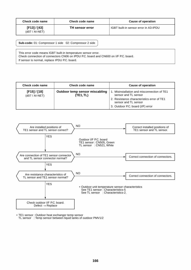
166
Check code name
[F13] / [43](d07 / AI-NET)
Check code name
TH sensor error
Cause of operation
IGBT built-in sensor error in A3-IPDU
Sub-code: 01: Compressor 1 side 02: Compressor 2 side
This error code means IGBT built-in temperature sensor error.Check connection of connectors CN06 on IPDU P.C. board and CN600 on I/F P.C. board.If sensor is normal, replace IPDU P.C. board.
Check code name
[F15] / [18](d07 / AI-NET)
Check code name
Outdoor temp sensor miscabling(TE1, TL)
Cause of operation
1. Misinstallation and misconnection of TE1sensor and TL sensor
2. Resistance characteristics error of TE1sensor and TL sensor
3. Outdoor P.C. board (I/F) error
YES
YES
YES
NO
NO
NO
Are installed positions ofTE1 sensor and TL sensor correct?
Are connection of TE1 sensor connectorand TL sensor connector normal?
Are resistance characteristics ofTL sensor and TE1 sensor normal?
Check outdoor I/F P.C. board.Defect Replace
Correct connection of connectors.
Correct connection of connectors.
Correct installed positions ofTE1 sensor and TL sensor.
Outdoor unit temperature sensor characteristicsSee TE1 sensor : Characteristics-5See TL sensor : Characteristics-2.
TE1 sensor : Outdoor heat exchanger temp sensorTL sensor : Temp sensor between liquid tanks of outdoor PMV1/2
Outdoor I/F P.C. boardTE1 sensor : CN505, GreenTL sensor : CN521, White
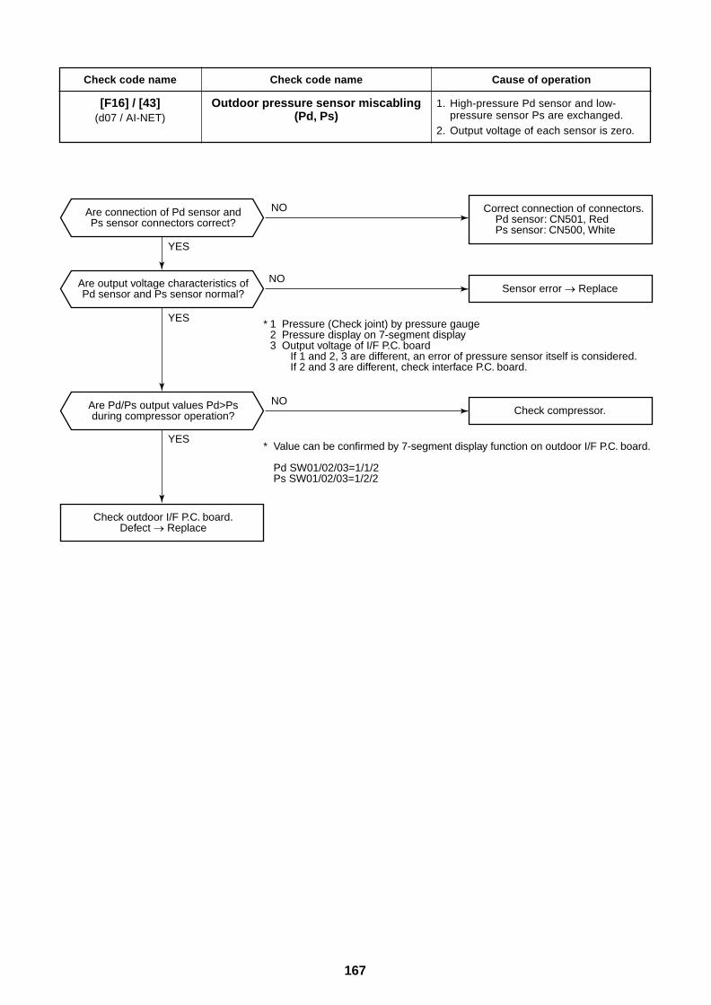
167
Check code name
[F16] / [43](d07 / AI-NET)
Check code name
Outdoor pressure sensor miscabling(Pd, Ps)
Cause of operation
1. High-pressure Pd sensor and low-pressure sensor Ps are exchanged.
2. Output voltage of each sensor is zero.
YES
YES
YES
NO
NO
NO
Sensor error Replace
Correct connection of connectors. Pd sensor: CN501, Red Ps sensor: CN500, White
Are connection of Pd sensor andPs sensor connectors correct?
Are output voltage characteristics ofPd sensor and Ps sensor normal?
Are Pd/Ps output values Pd>Psduring compressor operation?
Check outdoor I/F P.C. board.Defect Replace
* Value can be confirmed by 7-segment display function on outdoor I/F P.C. board.
Pd SW01/02/03=1/1/2Ps SW01/02/03=1/2/2
* 1 Pressure (Check joint) by pressure gauge2 Pressure display on 7-segment display3 Output voltage of I/F P.C. board
If 1 and 2, 3 are different, an error of pressure sensor itself is considered.If 2 and 3 are different, check interface P.C. board.
Check compressor.
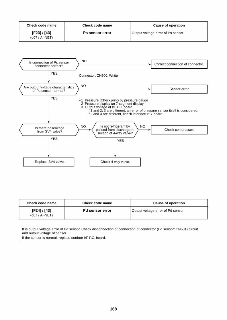
168
Check code name
[F23] / [43](d07 / AI-NET)
Check code name
Ps sensor error
Cause of operation
Output voltage error of Ps sensor
YES
YES
YES
NO
NO
Is not refrigerant bypassed from discharge tosuction of 4-way valve?
Sensor error
Is connection of Ps sensorconnector correct?
Are output voltage characteristicsof Ps sensor normal?
Is there no leakagefrom SV4 valve?
Replace SV4 valve.
YES
NO NO
1 Pressure (Check joint) by pressure gauge2 Pressure display on 7-segment display3 Output voltage of I/F P.C. board
If 1 and 2, 3 are different, an error of pressure sensor itself is considered.If 2 and 3 are different, check interface P.C. board.
Connector: CN500, White
Correct connection of connector.
Check 4-way valve.
Check compressor.
Check code name
[F24] / [43](d07 / AI-NET)
Check code name
Pd sensor error
Cause of operation
Output voltage error of Pd sensor
It is output voltage error of Pd sensor. Check disconnection of connection of connector (Pd sensor: CN501) circuitand output voltage of sensor.If the sensor is normal, replace outdoor I/F P.C. board.
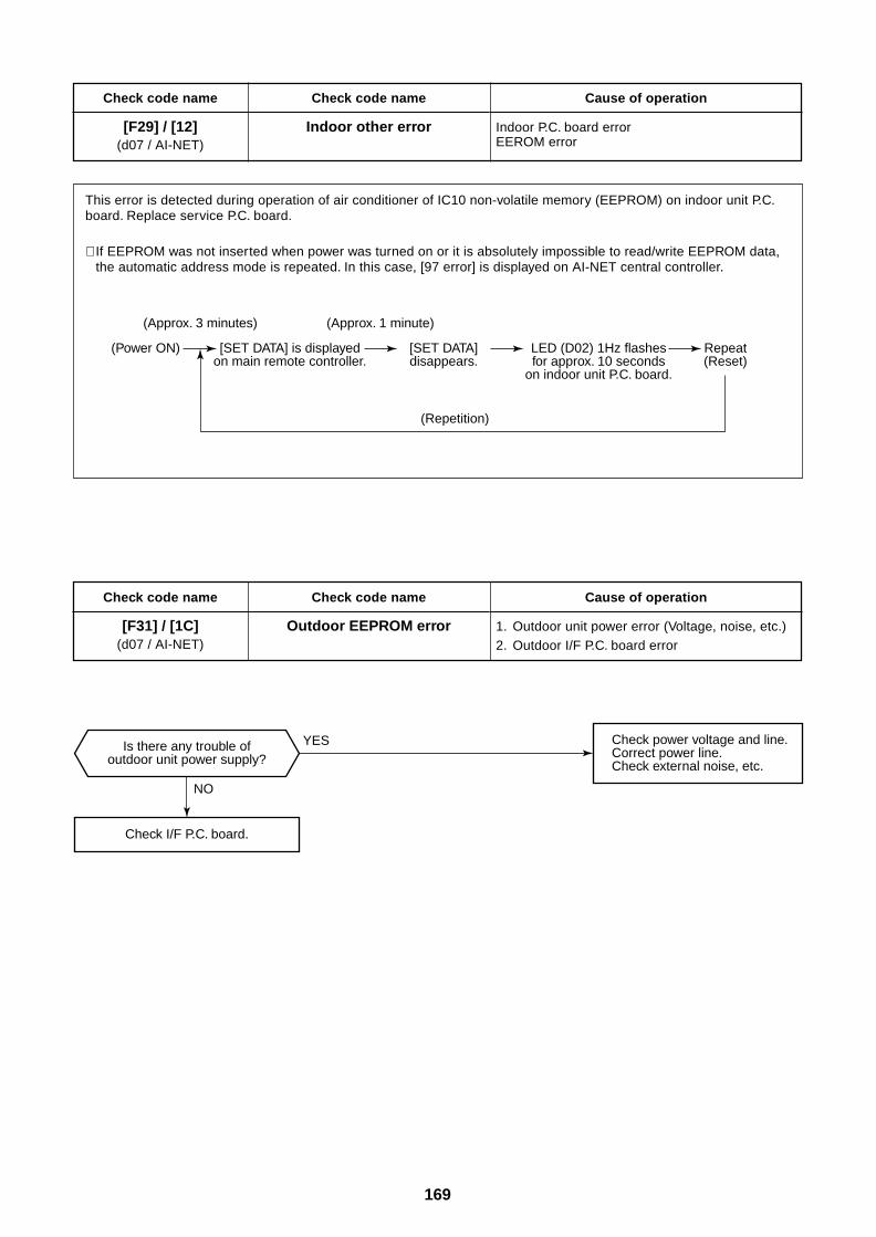
169
Check code name
[F29] / [12](d07 / AI-NET)
Check code name
Indoor other error
Cause of operation
Indoor P.C. board errorEEROM error
This error is detected during operation of air conditioner of IC10 non-volatile memory (EEPROM) on indoor unit P.C.board. Replace service P.C. board.
∗ If EEPROM was not inserted when power was turned on or it is absolutely impossible to read/write EEPROM data,the automatic address mode is repeated. In this case, [97 error] is displayed on AI-NET central controller.
Check code name
[F31] / [1C](d07 / AI-NET)
Check code name
Outdoor EEPROM error
Cause of operation
1. Outdoor unit power error (Voltage, noise, etc.)2. Outdoor I/F P.C. board error
(Approx. 3 minutes) (Approx. 1 minute)
(Power ON) [SET DATA] is displayedon main remote controller.
[SET DATA]disappears.
LED (D02) 1Hz flashesfor approx. 10 seconds
on indoor unit P.C. board.
Repeat(Reset)
(Repetition)
Check I/F P.C. board.
NO
YES Check power voltage and line.Correct power line.Check external noise, etc.
Is there any trouble ofoutdoor unit power supply?
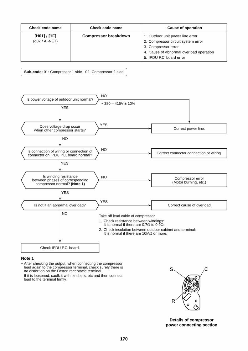
170
Check code name
[H01] / [1F](d07 / AI-NET)
Check code name
Compressor breakdown
Cause of operation
1. Outdoor unit power line error2. Compressor circuit system error3. Compressor error4. Cause of abnormal overload operation5. IPDU P.C. board error
Sub-code: 01: Compressor 1 side 02: Compressor 2 side
Details of compressorpower connecting section
YES
YES
YES
YES
YES
NO
NO
NO
NO
NO
Is power voltage of outdoor unit normal?
Is not it an abnormal overload?
Check IPDU P.C. board.
Is winding resistancebetween phases of corresponding
compressor normal? (Note 1)
Does voltage drop occurwhen other compressor starts?
Is connection of wiring or connection ofconnector on IPDU P.C. board normal?
Correct power line.
Correct connector connection or wiring.
Correct cause of overload.
Compressor error(Motor burning, etc.)
Note 1After checking the output, when connecting the compressor lead again to the compressor terminal, check surely there is no distortion on the Fasten receptacle terminal. If it is loosened, caulk it with pinchers, etc and then connect lead to the terminal firmly.
380 – 415V ± 10%
Take off lead cable of compressor.1. Check resistance between windings:
It is normal if there are 0.7 to 0.9 .2. Check insulation between outdoor cabinet and terminal:
It is normal if there are 10M or more.
S C
R
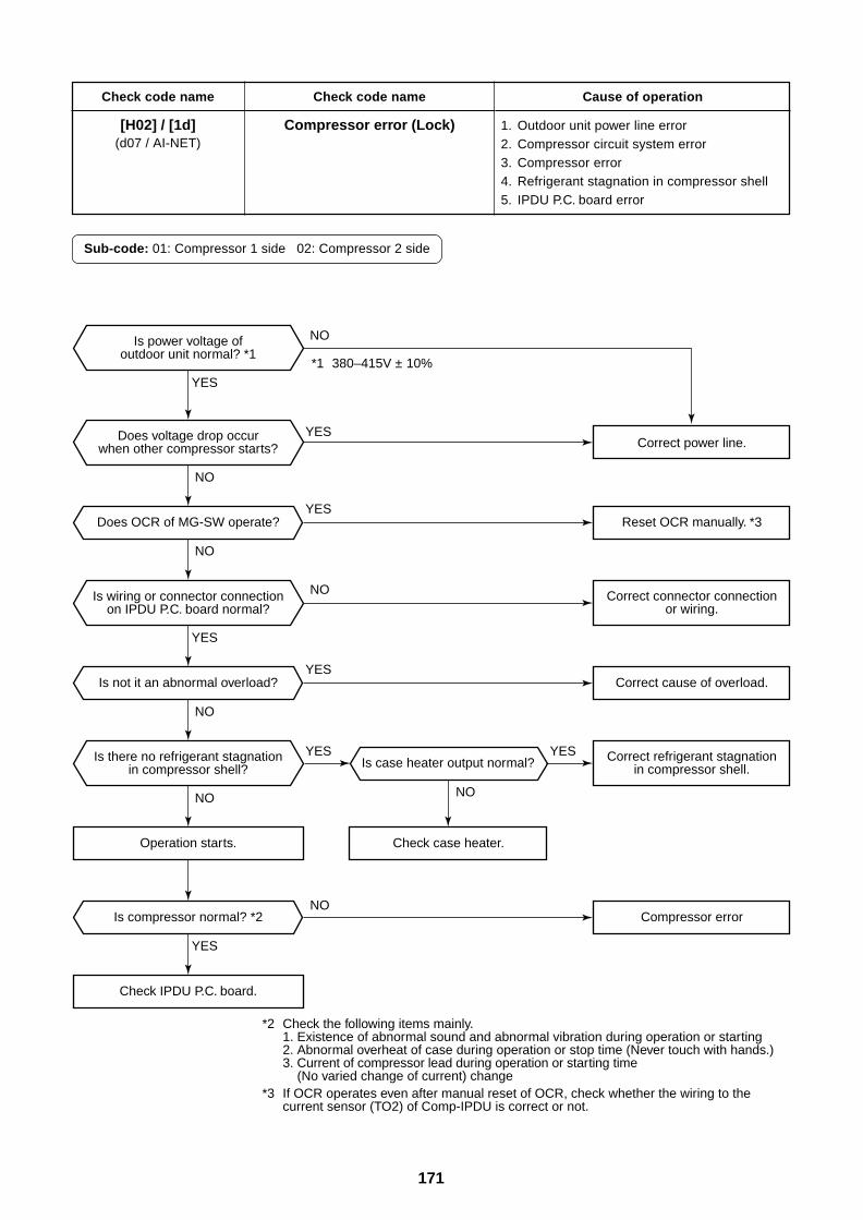
171
Check code name
[H02] / [1d](d07 / AI-NET)
Check code name
Compressor error (Lock)
Cause of operation
1. Outdoor unit power line error2. Compressor circuit system error3. Compressor error4. Refrigerant stagnation in compressor shell5. IPDU P.C. board error
Sub-code: 01: Compressor 1 side 02: Compressor 2 side
YES
YES
YES
YES
YES
YES YES
NO
NO NO
NO
NO
NO
NO
Operation starts.
Is compressor normal? *2
Check IPDU P.C. board.
Is not it an abnormal overload?
Is case heater output normal?
Is power voltage ofoutdoor unit normal? *1
Does voltage drop occurwhen other compressor starts?
Is wiring or connector connectionon IPDU P.C. board normal?
Is there no refrigerant stagnationin compressor shell?
Correct power line.
Correct cause of overload.
Compressor error
Correct connector connectionor wiring.
Correct refrigerant stagnationin compressor shell.
*1 380–415V ± 10%
*2 Check the following items mainly.1. Existence of abnormal sound and abnormal vibration during operation or starting2. Abnormal overheat of case during operation or stop time (Never touch with hands.)3. Current of compressor lead during operation or starting time
(No varied change of current) change*3 If OCR operates even after manual reset of OCR, check whether the wiring to the
current sensor (TO2) of Comp-IPDU is correct or not.
Check case heater.
YES
NO
Does OCR of MG-SW operate? Reset OCR manually. *3
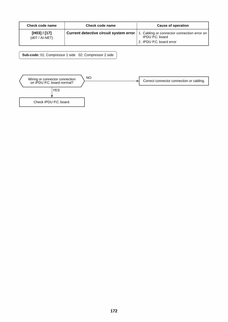
172
Check code name
[H03] / [17](d07 / AI-NET)
Check code name
Current detective circuit system error
Cause of operation
1. Cabling or connector connection error onIPDU P.C. board
2. IPDU P.C. board error
Sub-code: 01: Compressor 1 side 02: Compressor 2 side
YES
NO
Check IPDU P.C. board.
Correct connector connection or cabling.Wiring or connector connectionon IPDU P.C. board normal?
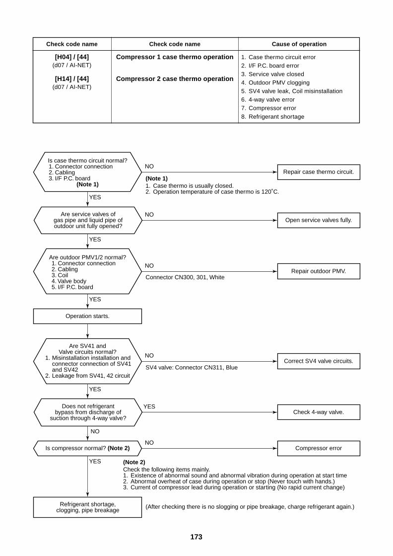
173
Check code name
[H04] / [44](d07 / AI-NET)
[H14] / [44](d07 / AI-NET)
Check code name
Compressor 1 case thermo operation
Compressor 2 case thermo operation
Cause of operation
1. Case thermo circuit error2. I/F P.C. board error3. Service valve closed4. Outdoor PMV clogging5. SV4 valve leak, Coil misinstallation6. 4-way valve error7. Compressor error8. Refrigerant shortage
(Note 1)1. Case thermo is usually closed.2. Operation temperature of case thermo is 120˚C.
(After checking there is no slogging or pipe breakage, charge refrigerant again.)
(Note 2)Check the following items mainly.1. Existence of abnormal sound and abnormal vibration during operation at start time2. Abnormal overheat of case during operation or stop (Never touch with hands.)3. Current of compressor lead during operation or starting (No rapid current change)
SV4 valve: Connector CN311, Blue
Connector CN300, 301, White
Is compressor normal? (Note 2)
Repair case thermo circuit.
Are service valves ofgas pipe and liquid pipe ofoutdoor unit fully opened?
Does not refrigerantbypass from discharge of
suction through 4-way valve?
Refrigerant shortage,clogging, pipe breakage
Is case thermo circuit normal?1. Connector connection2. Cabling3. I/F P.C. board
(Note 1)
Open service valves fully.
Repair outdoor PMV.
Correct SV4 valve circuits.
Check 4-way valve.
Compressor error
Operation starts.
Are outdoor PMV1/2 normal?1. Connector connection2. Cabling3. Coil4. Valve body5. I/F P.C. board
Are SV41 andValve circuits normal?
1. Misinstallation installation and connector connection of SV41 and SV42
2. Leakage from SV41, 42 circuit
YES
YES
YES
YES
YES
YES
NO
NO
NO
NO
NO
NO
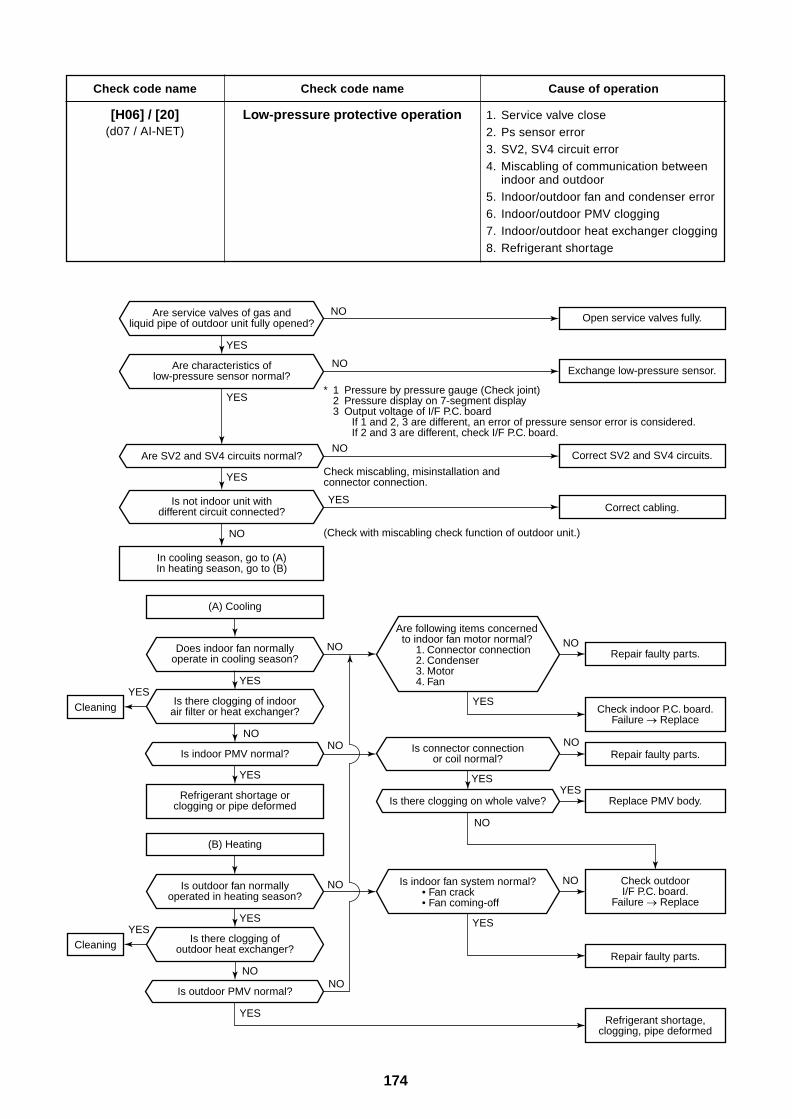
174
Check code name
[H06] / [20](d07 / AI-NET)
Check code name
Low-pressure protective operation
Cause of operation
1. Service valve close2. Ps sensor error3. SV2, SV4 circuit error4. Miscabling of communication between
indoor and outdoor5. Indoor/outdoor fan and condenser error6. Indoor/outdoor PMV clogging7. Indoor/outdoor heat exchanger clogging8. Refrigerant shortage
Is there clogging on whole valve?
Is outdoor fan normallyoperated in heating season?
* 1 Pressure by pressure gauge (Check joint)2 Pressure display on 7-segment display3 Output voltage of I/F P.C. board
If 1 and 2, 3 are different, an error of pressure sensor error is considered.If 2 and 3 are different, check I/F P.C. board.
Check miscabling, misinstallation and connector connection.
(Check with miscabling check function of outdoor unit.)
YESYES
YES
YES
YES YES
NO
YESYES
YES
YES
YES
YES
YES
NONO
NO
NO NO
NO
YES
NO
NO NO
NO
NO
NO
NO
Open service valves fully.
Exchange low-pressure sensor.
Correct SV2 and SV4 circuits.
Correct cabling.
Are SV2 and SV4 circuits normal?
Are service valves of gas andliquid pipe of outdoor unit fully opened?
Is not indoor unit withdifferent circuit connected?
In cooling season, go to (A)In heating season, go to (B)
Does indoor fan normallyoperate in cooling season?
Are characteristics oflow-pressure sensor normal?
Is outdoor PMV normal?
Is indoor PMV normal?
(A) Cooling
Is there clogging of indoorair filter or heat exchanger?
Is there clogging ofoutdoor heat exchanger?
Is connector connectionor coil normal?
Check indoor P.C. board.Failure Replace
Repair faulty parts.
Repair faulty parts.
Replace PMV body.
Repair faulty parts.
Are following items concerned to indoor fan motor normal?
1. Connector connection2. Condenser3. Motor4. Fan
Cleaning
Check outdoorI/F P.C. board.
Failure Replace
Refrigerant shortage,clogging, pipe deformed
Refrigerant shortage orclogging or pipe deformed
(B) Heating
Cleaning
Is indoor fan system normal?• Fan crack• Fan coming-off
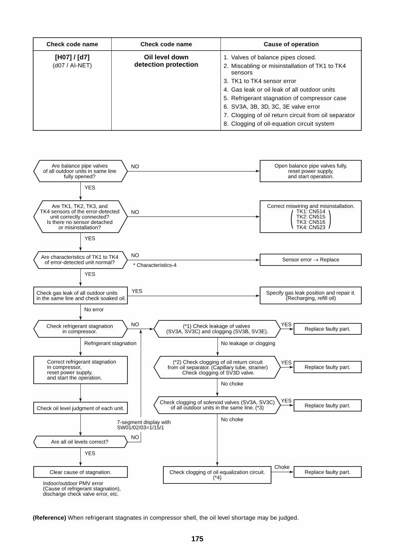
175
Check code name
[H07] / [d7](d07 / AI-NET)
Check code name
Oil level downdetection protection
Cause of operation
1. Valves of balance pipes closed.2. Miscabling or misinstallation of TK1 to TK4
sensors3. TK1 to TK4 sensor error4. Gas leak or oil leak of all outdoor units5. Refrigerant stagnation of compressor case6. SV3A, 3B, 3D, 3C, 3E valve error7. Clogging of oil return circuit from oil separator8. Clogging of oil-equation circuit system
(*2) Check clogging of oil return circuitfrom oil separator. (Capillary tube, strainer)
Check clogging of SV3D valve.
Indoor/outdoor PMV error (Cause of refrigerant stagnation), discharge check valve error, etc.
No leakage or clogging
Choke
No choke
No choke
Replace faulty part.
Are all oil levels correct?
(*1) Check leakage of valves (SV3A, SV3C) and clogging (SV3B, SV3E).
Check clogging of solenoid valves (SV3A, SV3C)of all outdoor units in the same line. (*3)
Check refrigerant stagnationin compressor.
Are characteristics of TK1 to TK4of error-detected unit normal?
Are balance pipe valvesof all outdoor units in same line
fully opened?
Open balance pipe valves fully,reset power supply,and start operation.
Are TK1, TK2, TK3, andTK4 sensors of the error-detected
unit correctly connected?Is there no sensor detached
or misinstallation?
Correct miswiring and misinstallation.TK1: CN514TK2: CN515TK3: CN516TK4: CN523
Replace faulty part.
Replace faulty part.
Replace faulty part.
Sensor error Replace
Specify gas leak position and repair it.(Recharging, refill oil)
( )
* Characteristics-4
YES
7-segment display with SW01/02/03=1/15/1
Check gas leak of all outdoor unitsin the same line and check soaked oil.
No error
Refrigerant stagnation
Correct refrigerant stagnation in compressor, reset power supply, and start the operation.
Check oil level judgment of each unit.
Clear cause of stagnation. Check clogging of oil equalization circuit.(*4)
YES
YES
YES
YES
YES
YES
YES
NO
NO
NO
NO
NO
(Reference) When refrigerant stagnates in compressor shell, the oil level shortage may be judged.
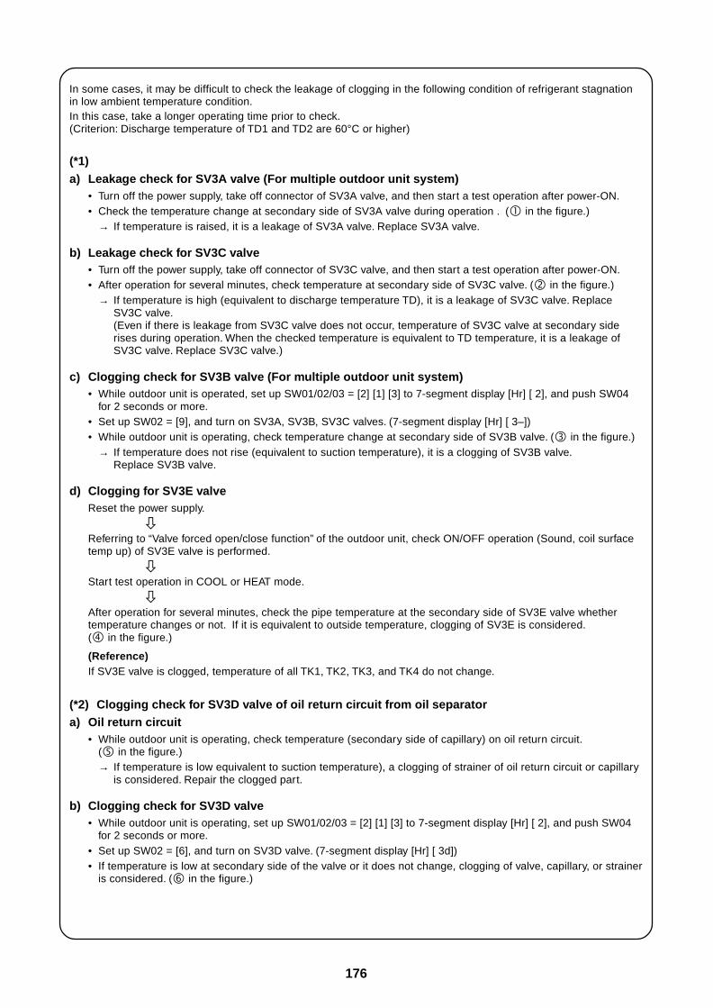
176
In some cases, it may be difficult to check the leakage of clogging in the following condition of refrigerant stagnationin low ambient temperature condition.In this case, take a longer operating time prior to check.(Criterion: Discharge temperature of TD1 and TD2 are 60°C or higher)
(*1)
a) Leakage check for SV3A valve (For multiple outdoor unit system)• Turn off the power supply, take off connector of SV3A valve, and then start a test operation after power-ON.• Check the temperature change at secondary side of SV3A valve during operation . ( in the figure.)
→ If temperature is raised, it is a leakage of SV3A valve. Replace SV3A valve.
b) Leakage check for SV3C valve• Turn off the power supply, take off connector of SV3C valve, and then start a test operation after power-ON.• After operation for several minutes, check temperature at secondary side of SV3C valve. ( in the figure.)
→ If temperature is high (equivalent to discharge temperature TD), it is a leakage of SV3C valve. ReplaceSV3C valve.(Even if there is leakage from SV3C valve does not occur, temperature of SV3C valve at secondary siderises during operation. When the checked temperature is equivalent to TD temperature, it is a leakage ofSV3C valve. Replace SV3C valve.)
c) Clogging check for SV3B valve (For multiple outdoor unit system)• While outdoor unit is operated, set up SW01/02/03 = [2] [1] [3] to 7-segment display [Hr] [ 2], and push SW04
for 2 seconds or more.• Set up SW02 = [9], and turn on SV3A, SV3B, SV3C valves. (7-segment display [Hr] [ 3–])• While outdoor unit is operating, check temperature change at secondary side of SV3B valve. ( in the figure.)
→ If temperature does not rise (equivalent to suction temperature), it is a clogging of SV3B valve.Replace SV3B valve.
d) Clogging for SV3E valveReset the power supply.
Referring to “Valve forced open/close function” of the outdoor unit, check ON/OFF operation (Sound, coil surfacetemp up) of SV3E valve is performed.
Start test operation in COOL or HEAT mode.
After operation for several minutes, check the pipe temperature at the secondary side of SV3E valve whethertemperature changes or not. If it is equivalent to outside temperature, clogging of SV3E is considered.( in the figure.)
(Reference)If SV3E valve is clogged, temperature of all TK1, TK2, TK3, and TK4 do not change.
(*2) Clogging check for SV3D valve of oil return circuit from oil separatora) Oil return circuit
• While outdoor unit is operating, check temperature (secondary side of capillary) on oil return circuit.( in the figure.)→ If temperature is low equivalent to suction temperature), a clogging of strainer of oil return circuit or capillary
is considered. Repair the clogged part.
b) Clogging check for SV3D valve• While outdoor unit is operating, set up SW01/02/03 = [2] [1] [3] to 7-segment display [Hr] [ 2], and push SW04
for 2 seconds or more.• Set up SW02 = [6], and turn on SV3D valve. (7-segment display [Hr] [ 3d])• If temperature is low at secondary side of the valve or it does not change, clogging of valve, capillary, or strainer
is considered. ( in the figure.)
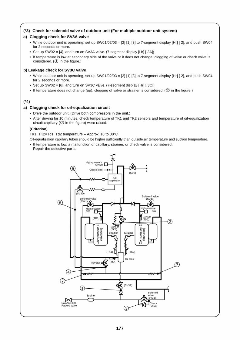
177
(*3) Check for solenoid valve of outdoor unit (For multiple outdoor unit system)
a) Clogging check for SV3A valve• While outdoor unit is operating, set up SW01/02/03 = [2] [1] [3] to 7-segment display [Hr] [ 2], and push SW04
for 2 seconds or more.• Set up SW02 = [4], and turn on SV3A valve. (7-segment display [Hr] [ 3A])• If temperature is low at secondary side of the valve or it does not change, clogging of valve or check valve is
considered. ( in the figure.)
b) Leakage check for SV3C valve• While outdoor unit is operating, set up SW01/02/03 = [2] [1] [3] to 7-segment display [Hr] [ 2], and push SW04
for 2 seconds or more.• Set up SW02 = [6], and turn on SV3C valve. (7-segment display [Hr] [ 3C])• If temperature does not change (up), clogging of valve or strainer is considered. ( in the figure.)
(*4)
a) Clogging check for oil-equalization circuit• Drive the outdoor unit. (Drive both compressors in the unit.)• After driving for 10 minutes, check temperature of TK1 and TK2 sensors and temperature of oil-equalization
circuit capillary ( in the figure) were raised.
(Criterion)TK1, TK2=Td1, Td2 temperature – Approx. 10 to 30°COil-equalization capillary tubes should be higher sufficiently than outside air temperature and suction temperature.• If temperature is low, a malfunction of capillary, strainer, or check valve is considered.
Repair the defective parts.
(SV2)
Solenoid valve(SV41)
(SV3D)
Check joint
High-pressure sensor
High-pressure SW
Oilseparator
Com
pres
sor
1(I
nver
ter)
Strainer Strainer
Sensor(TK3)
(TK1)
(SV3E) (TK4)
(TK2)
Solenoid valve(SV42)
High-pressure SW
Com
pres
sor
2(I
nver
ter)
Sensor(TD2)(TD1)
Oil tank
(SV3A)
Solenoid valve(SV3B)
Check valve
Strainer
5
6
4
7
3
1
7
2
Balance pipePacked valve
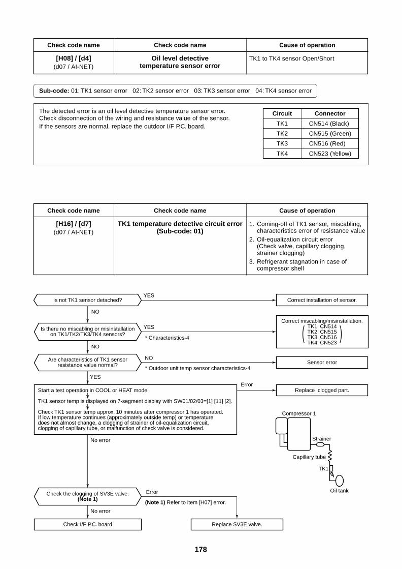
178
Check code name
[H08] / [d4](d07 / AI-NET)
Check code name
Oil level detectivetemperature sensor error
Cause of operation
TK1 to TK4 sensor Open/Short
Sub-code: 01: TK1 sensor error 02: TK2 sensor error 03: TK3 sensor error 04: TK4 sensor error
Circuit
TK1
TK2
TK3
TK4
Connector
CN514 (Black)
CN515 (Green)
CN516 (Red)
CN523 (Yellow)
The detected error is an oil level detective temperature sensor error.Check disconnection of the wiring and resistance value of the sensor.If the sensors are normal, replace the outdoor I/F P.C. board.
Check code name
[H16] / [d7](d07 / AI-NET)
Check code name
TK1 temperature detective circuit error(Sub-code: 01)
Cause of operation
1. Coming-off of TK1 sensor, miscabling,characteristics error of resistance value
2. Oil-equalization circuit error(Check valve, capillary clogging,strainer clogging)
3. Refrigerant stagnation in case ofcompressor shell
Is not TK1 sensor detached?
Is there no miscabling or misinstallationon TK1/TK2/TK3/TK4 sensors?
Start a test operation in COOL or HEAT mode.
TK1 sensor temp is displayed on 7-segment display with SW01/02/03=[1] [11] [2].
Check TK1 sensor temp approx. 10 minutes after compressor 1 has operated. If low temperature continues (approximately outside temp) or temperature does not almost change, a clogging of strainer of oil-equalization circuit, clogging of capillary tube, or malfunction of check valve is considered.
(Note 1) Refer to item [H07] error.
* Outdoor unit temp sensor characteristics-4
* Characteristics-4
Correct miscabling/misinstallation.TK1: CN514TK2: CN515TK3: CN516TK4: CN523
( )
YES
YES
YES
NO
NO
NO
Check I/F P.C. board
Correct installation of sensor.
Are characteristics of TK1 sensorresistance value normal?
Check the clogging of SV3E valve.(Note 1)
No error
Error
Error
No error
Sensor error
Replace clogged part.
Replace SV3E valve.
Strainer
Compressor 1
Oil tank
Capillary tube
TK1
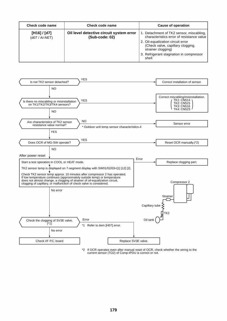
179
Check code name
[H16] / [d7](d07 / AI-NET)
Check code name
Oil level detective circuit system error(Sub-code: 02)
Cause of operation
1. Detachment of TK2 sensor, miscabling,characteristics error of resistance value
2. Oil-equalization circuit error(Check valve, capillary clogging,strainer clogging)
3. Refrigerant stagnation in compressorshell
Is not TK2 sensor detached?
Is there no miscabling or misinstallationon TK1/TK2/TK3/TK4 sensors?
Start a test operation in COOL or HEAT mode.
TK2 sensor temp is displayed on 7-segment display with SW01/02/03=[1] [12] [2].
Check TK2 sensor temp approx. 10 minutes after compressor 2 has operated. If low temperature continues (approximately outside temp) or temperature does not almost change, a clogging of strainer of oil-equalization circuit, clogging of capillary, or malfunction of check valve is considered.
*1 Refer to item [H07] error.
*2 If OCR operates even after manual reset of OCR, check whether the wiring to the current sensor (TO2) of Comp-IPDU is correct or not.
* Outdoor unit temp sensor characteristics-4
Correct miscabling/misinstallation.TK1: CN514TK2: CN515TK3: CN516TK4: CN523
( )
YES
YES
YES
NO
NO
NO
Check I/F P.C. board
Correct installation of sensor.
Check the clogging of SV3E valve.(*1)
Are characteristics of TK2 sensorresistance value normal?
No error
Error
Error
No error
Does OCR of MG-SW operate?YES
NO
Reset OCR manually.(*2)
Sensor error
Replace clogging part.
Replace SV3E valve.
Strainer
Compressor 2
Oil tank
Capillary tube
TK2
After power reset
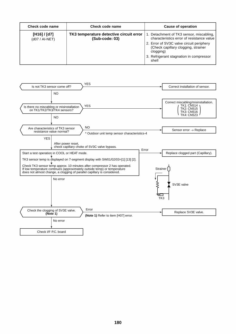
180
Check code name
[H16] / [d7](d07 / AI-NET)
Check code name
TK3 temperature detective circuit error(Sub-code: 03)
Cause of operation
1. Detachment of TK3 sensor, miscabling,characteristics error of resistance value
2. Error of SV3C valve circuit periphery(Check capillary clogging, strainerclogging)
3. Refrigerant stagnation in compressorshell
Is not TK3 sensor come off?
Is there no miscabling or misinstallationon TK1/TK2/TK3/TK4 sensors?
Start a test operation in COOL or HEAT mode.
TK3 sensor temp is displayed on 7-segment display with SW01/02/03=[1] [13] [2].
Check TK3 sensor temp approx. 10 minutes after compressor 2 has operated. If low temperature continues (approximately outside temp) or temperature does not almost change, a clogging of parallel capillary is considered.
(Note 1) Refer to item [H07] error.
* Outdoor unit temp sensor characteristics-4
Correct miscabling/misinstallation.TK1: CN514TK2: CN515TK3: CN516TK4: CN523
( )
YES
YES
YES
NO
NO
NO
Check I/F P.C. board
Correct installation of sensor.
Are characteristics of TK3 sensorresistance value normal?
Check the clogging of SV3E valve.(Note 1)
No error
Error
Error
No error
Sensor error Replace
Replace clogged part (Capillary).
Replace SV3E valve.
SV3E valve
Strainer
TK3
After power reset, check capillary choke of SV3C valve bypass.
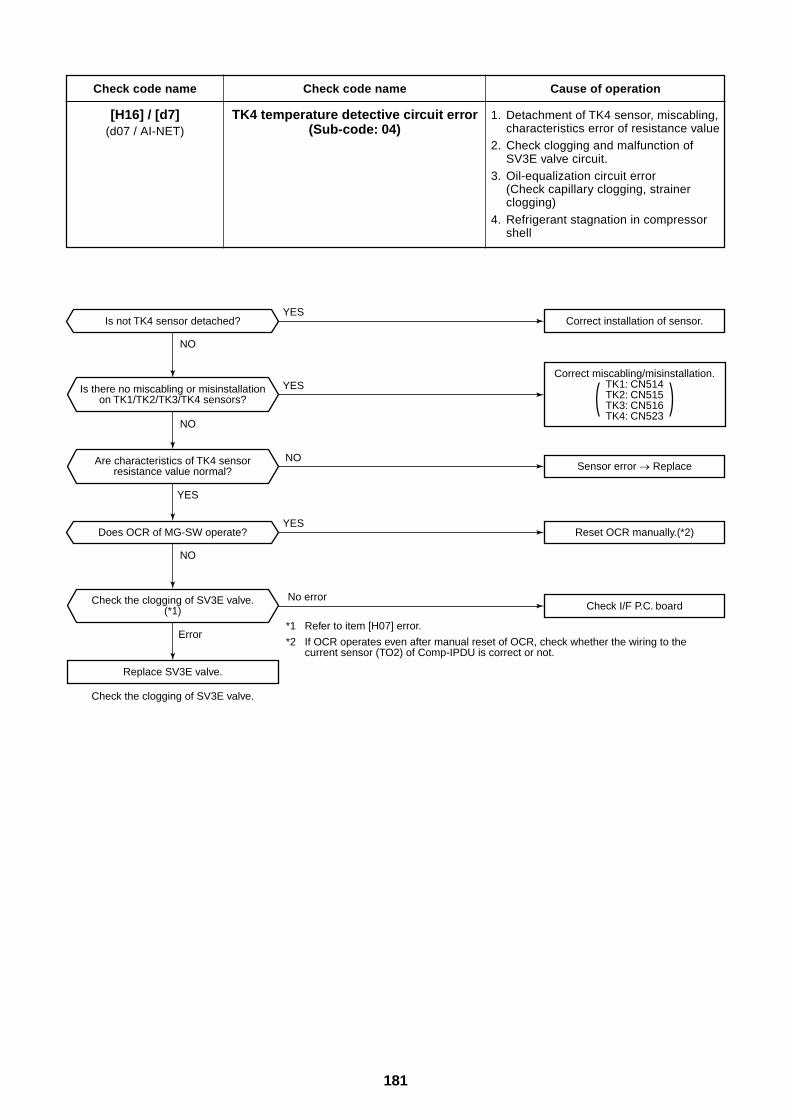
181
Check code name
[H16] / [d7](d07 / AI-NET)
Check code name
TK4 temperature detective circuit error(Sub-code: 04)
Cause of operation
1. Detachment of TK4 sensor, miscabling,characteristics error of resistance value
2. Check clogging and malfunction ofSV3E valve circuit.
3. Oil-equalization circuit error(Check capillary clogging, strainerclogging)
4. Refrigerant stagnation in compressorshell
Is not TK4 sensor detached?
Is there no miscabling or misinstallationon TK1/TK2/TK3/TK4 sensors?
Check the clogging of SV3E valve.
*1 Refer to item [H07] error.
*2 If OCR operates even after manual reset of OCR, check whether the wiring to the current sensor (TO2) of Comp-IPDU is correct or not.
Correct miscabling/misinstallation.TK1: CN514TK2: CN515TK3: CN516TK4: CN523
( )
YES
YES
YES
NO
NO
NO
Replace SV3E valve.
Correct installation of sensor.
Are characteristics of TK4 sensorresistance value normal?
Check the clogging of SV3E valve.(*1)
Error
No error
Does OCR of MG-SW operate?YES
NO
Reset OCR manually.(*2)
Sensor error Replace
Check I/F P.C. board
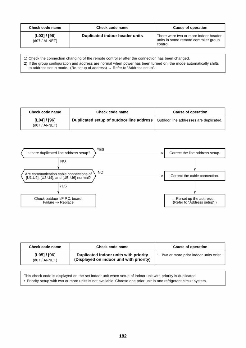
182
Check code name
[L03] / [96](d07 / AI-NET)
Check code name
Duplicated indoor header units
Cause of operation
There were two or more indoor headerunits in some remote controller groupcontrol.
1) Check the connection changing of the remote controller after the connection has been changed.2) If the group configuration and address are normal when power has been turned on, the mode automatically shifts
to address setup mode. (Re-setup of address) → Refer to “Address setup”.
Check code name
[L04] / [96](d07 / AI-NET)
Check code name
Duplicated setup of outdoor line address
Cause of operation
Outdoor line addresses are duplicated.
Check code name
[L05] / [96](d07 / AI-NET)
Check code name
Duplicated indoor units with priority(Displayed on indoor unit with priority)
Cause of operation
1. Two or more prior indoor units exist.
This check code is displayed on the set indoor unit when setup of indoor unit with priority is duplicated.• Priority setup with two or more units is not available. Choose one prior unit in one refrigerant circuit system.
YES
YES
NO
NO
Correct the line address setup.
Correct the cable connection.
Is there duplicated line address setup?
Are communication cable connections of[U1.U2], [U3.U4], and [U5, U6] normal?
Check outdoor I/F P.C. board.Failure Replace
Re-set up the address.(Refer to “Address setup”.)
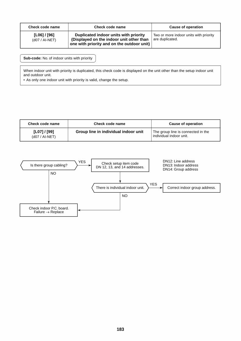
183
Check code name
[L06] / [96](d07 / AI-NET)
Check code name
Duplicated indoor units with priority(Displayed on the indoor unit other than
one with priority and on the outdoor unit)
Cause of operation
Two or more indoor units with priorityare duplicated.
Sub-code: No. of indoor units with priority
When indoor unit with priority is duplicated, this check code is displayed on the unit other than the setup indoor unitand outdoor unit.• As only one indoor unit with priority is valid, change the setup.
Check code name
[L07] / [99](d07 / AI-NET)
Check code name
Group line in individual indoor unit
Cause of operation
The group line is connected in theindividual indoor unit.
Is there group cabling?
Check indoor P.C. board.Failure Replace
There is individual indoor unit. Correct indoor group address.
Check setup item codeDN 12, 13, and 14 addresses.
DN12: Line addressDN13: Indoor addressDN14: Group address
YES
YES
NO
NO
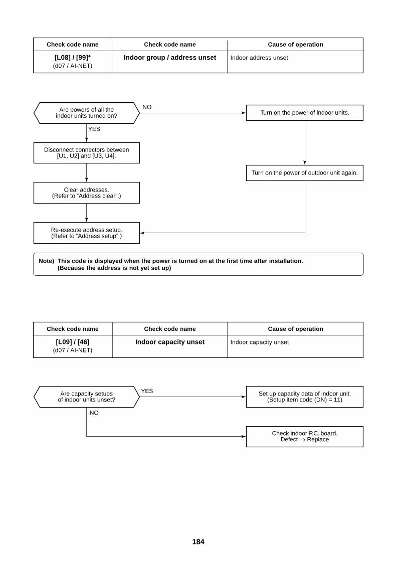
184
Check code name
[L08] / [99]*(d07 / AI-NET)
Check code name
Indoor group / address unset
Cause of operation
Indoor address unset
Check code name
[L09] / [46](d07 / AI-NET)
Check code name
Indoor capacity unset
Cause of operation
Indoor capacity unset
Note) This code is displayed when the power is turned on at the first time after installation.(Because the address is not yet set up)
Turn on the power of indoor units.
Turn on the power of outdoor unit again.
Are powers of all theindoor units turned on?
Disconnect connectors between[U1, U2] and [U3, U4].
Clear addresses.(Refer to “Address clear”.)
Re-execute address setup.(Refer to “Address setup”.)
YES
NO
Set up capacity data of indoor unit.(Setup item code (DN) = 11)
Check indoor P.C. board.Defect Replace
Are capacity setupsof indoor units unset?
YES
NO
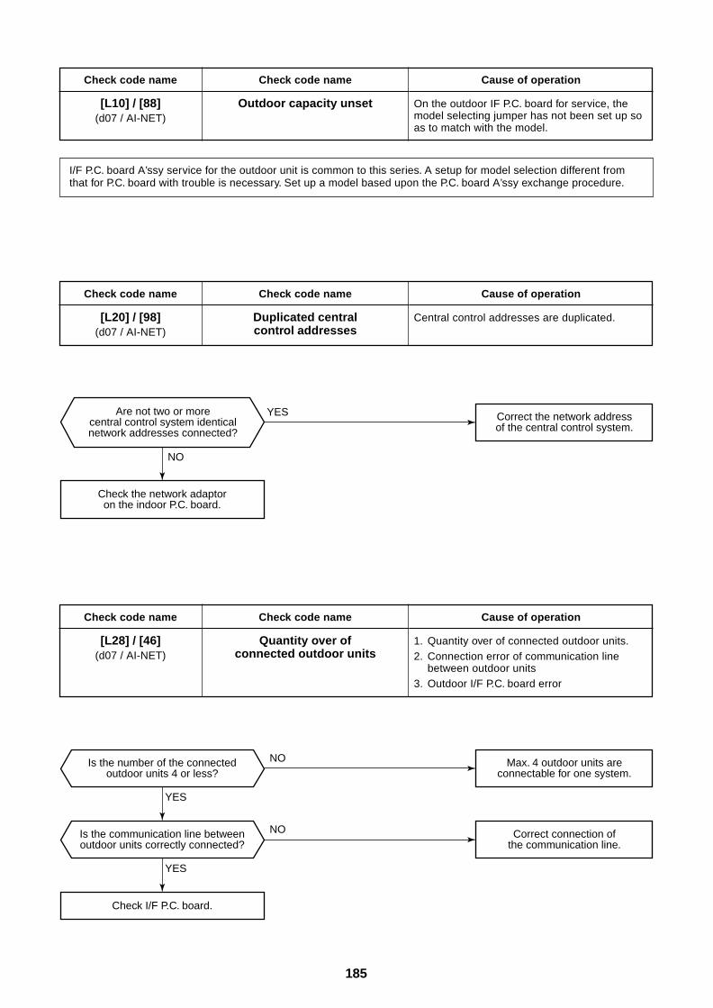
185
Check code name
[L10] / [88](d07 / AI-NET)
Check code name
Outdoor capacity unset
Cause of operation
On the outdoor IF P.C. board for service, themodel selecting jumper has not been set up soas to match with the model.
I/F P.C. board A’ssy service for the outdoor unit is common to this series. A setup for model selection different fromthat for P.C. board with trouble is necessary. Set up a model based upon the P.C. board A’ssy exchange procedure.
Check code name
[L20] / [98](d07 / AI-NET)
Check code name
Duplicated centralcontrol addresses
Cause of operation
Central control addresses are duplicated.
Check code name
[L28] / [46](d07 / AI-NET)
Check code name
Quantity over ofconnected outdoor units
Cause of operation
1. Quantity over of connected outdoor units.2. Connection error of communication line
between outdoor units3. Outdoor I/F P.C. board error
Are not two or morecentral control system identicalnetwork addresses connected?
Check the network adaptoron the indoor P.C. board.
Correct the network addressof the central control system.
YES
NO
Check I/F P.C. board.
Is the number of the connectedoutdoor units 4 or less?
Is the communication line betweenoutdoor units correctly connected?
Max. 4 outdoor units areconnectable for one system.
Correct connection ofthe communication line.
YES
YES
NO
NO
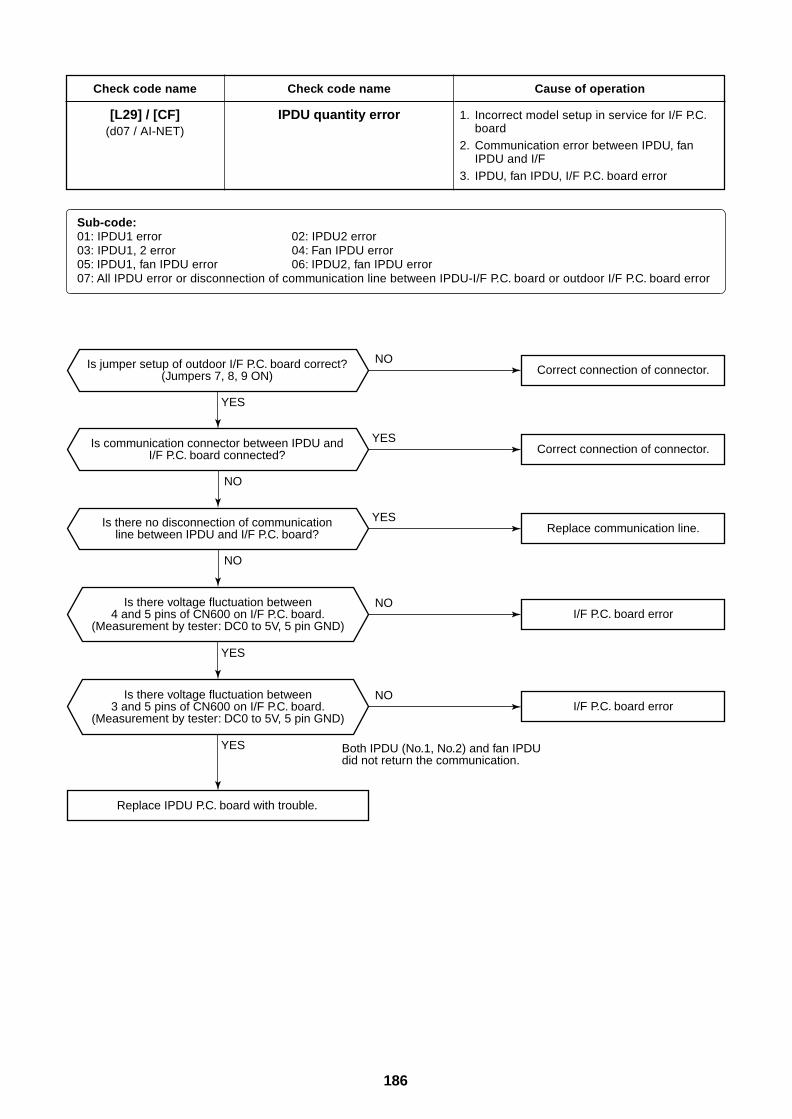
186
Check code name
[L29] / [CF](d07 / AI-NET)
Check code name
IPDU quantity error
Cause of operation
1. Incorrect model setup in service for I/F P.C.board
2. Communication error between IPDU, fanIPDU and I/F
3. IPDU, fan IPDU, I/F P.C. board error
Sub-code:01: IPDU1 error 02: IPDU2 error03: IPDU1, 2 error 04: Fan IPDU error05: IPDU1, fan IPDU error 06: IPDU2, fan IPDU error07: All IPDU error or disconnection of communication line between IPDU-I/F P.C. board or outdoor I/F P.C. board error
Replace IPDU P.C. board with trouble.
Correct connection of connector.
Replace communication line.
I/F P.C. board error
I/F P.C. board error
Correct connection of connector.
Is there voltage fluctuation between4 and 5 pins of CN600 on I/F P.C. board.
(Measurement by tester: DC0 to 5V, 5 pin GND)
Is there voltage fluctuation between3 and 5 pins of CN600 on I/F P.C. board.
(Measurement by tester: DC0 to 5V, 5 pin GND)
Is jumper setup of outdoor I/F P.C. board correct?(Jumpers 7, 8, 9 ON)
Is communication connector between IPDU andI/F P.C. board connected?
Is there no disconnection of communicationline between IPDU and I/F P.C. board?
Both IPDU (No.1, No.2) and fan IPDU did not return the communication.
YES
YES
YES
YES
YES
NO
NO
NO
NO
NO
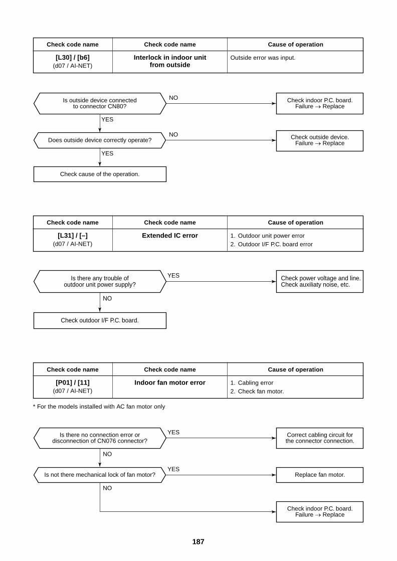
187
Check code name
[L30] / [b6](d07 / AI-NET)
Check code name
Interlock in indoor unitfrom outside
Cause of operation
Outside error was input.
Check code name
[L31] / [–](d07 / AI-NET)
Check code name
Extended IC error
Cause of operation
1. Outdoor unit power error2. Outdoor I/F P.C. board error
Check code name
[P01] / [11](d07 / AI-NET)
Check code name
Indoor fan motor error
Cause of operation
1. Cabling error2. Check fan motor.
* For the models installed with AC fan motor only
Does outside device correctly operate?
Check cause of the operation.
Is outside device connectedto connector CN80?
Check indoor P.C. board.Failure Replace
Check outside device.Failure Replace
YES
YES
NO
NO
Check outdoor I/F P.C. board.
Is there any trouble ofoutdoor unit power supply?
Check power voltage and line.Check auxiliaty noise, etc.
NO
YES
Is not there mechanical lock of fan motor?
Is there no connection error ordisconnection of CN076 connector?
Correct cabling circuit forthe connector connection.
Check indoor P.C. board.Failure Replace
Replace fan motor.YES
YES
NO
NO
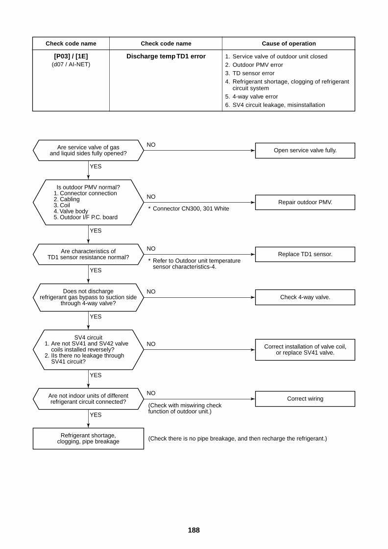
188
Check code name
[P03] / [1E](d07 / AI-NET)
Check code name
Discharge temp TD1 error
Cause of operation
1. Service valve of outdoor unit closed2. Outdoor PMV error3. TD sensor error4. Refrigerant shortage, clogging of refrigerant
circuit system5. 4-way valve error6. SV4 circuit leakage, misinstallation
Does not dischargerefrigerant gas bypass to suction side
through 4-way valve?
Open service valve fully.
Repair outdoor PMV.
Replace TD1 sensor.
Check 4-way valve.
Correct wiring
Correct installation of valve coil,or replace SV41 valve.
Are characteristics ofTD1 sensor resistance normal?
Are service valve of gasand liquid sides fully opened?
Are not indoor units of differentrefrigerant circuit connected?
Refrigerant shortage,clogging, pipe breakage
* Connector CN300, 301 White
* Refer to Outdoor unit temperature sensor characteristics-4.
(Check there is no pipe breakage, and then recharge the refrigerant.)
(Check with miswiring check function of outdoor unit.)
Is outdoor PMV normal?1. Connector connection2. Cabling3. Coil4. Valve body5. Outdoor I/F P.C. board
SV4 circuit1. Are not SV41 and SV42 valve
coils installed reversely?2. IIs there no leakage through
SV41 circuit?
YES
YES
YES
YES
YES
YES
NO
NO
NO
NO
NO
NO
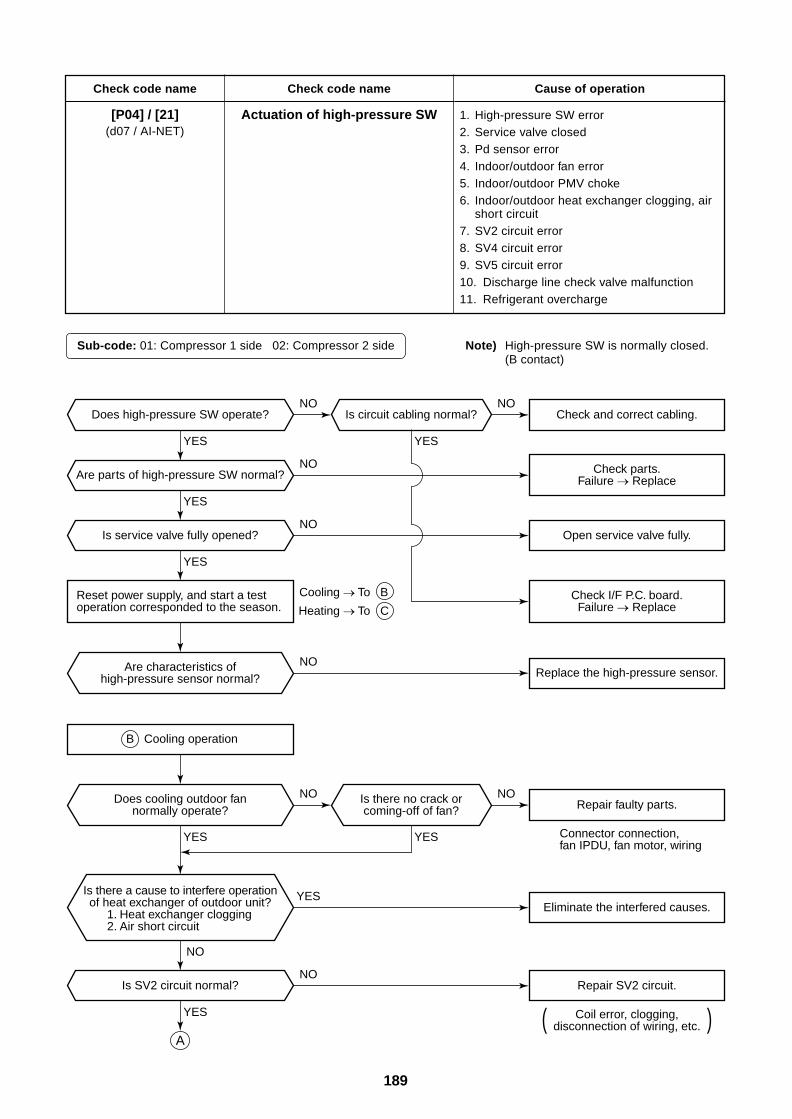
189
Check code name
[P04] / [21](d07 / AI-NET)
Check code name
Actuation of high-pressure SW
Cause of operation
1. High-pressure SW error2. Service valve closed3. Pd sensor error4. Indoor/outdoor fan error5. Indoor/outdoor PMV choke6. Indoor/outdoor heat exchanger clogging, air
short circuit7. SV2 circuit error8. SV4 circuit error9. SV5 circuit error10. Discharge line check valve malfunction11. Refrigerant overcharge
Sub-code: 01: Compressor 1 side 02: Compressor 2 side Note) High-pressure SW is normally closed.(B contact)
( )Coil error, clogging,disconnection of wiring, etc.
Cooling To B
Heating To C
Does high-pressure SW operate?
Are parts of high-pressure SW normal?
Is service valve fully opened?
B Cooling operation
Is SV2 circuit normal?
Open service valve fully.
Replace the high-pressure sensor.
Repair faulty parts.
Eliminate the interfered causes.
Repair SV2 circuit.
Is circuit cabling normal? Check and correct cabling.
Does cooling outdoor fannormally operate?
Is there no crack orcoming-off of fan?
Are characteristics ofhigh-pressure sensor normal?
Reset power supply, and start a testoperation corresponded to the season.
Check parts.Failure Replace
Check I/F P.C. board.Failure Replace
Connector connection, fan IPDU, fan motor, wiring
Is there a cause to interfere operationof heat exchanger of outdoor unit?
1. Heat exchanger clogging2. Air short circuit
A
YES
YES
YES
YES
YES YES
YES
YES
NO NO
NO
NO
NO
NO NO
NO
NO
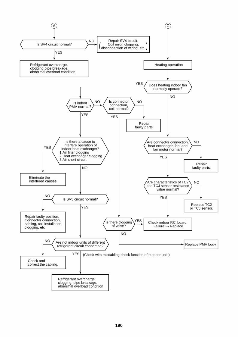
190
( )
Refrigerant overcharge,clogging, pipe breakage, abnormal overload condition
Heating operation
Check indoor P.C. board.Failure Replace
Repairfaulty parts.
Replace TC2or TCJ sensor.
Replace PMV body.
Is SV4 circuit normal?
Is SV5 circuit normal?
Are connector connection,heat exchanger, fan, and
fan motor normal?
Are characteristics of TC2and TCJ sensor resistance
value normal?
Is connectorconnection,coil normal?
Repair SV4 circuit.Coil error, clogging,
disconnection of wiring, etc.
Are not indoor units of differentrefrigerant circuit connected?
Is there cloggingof valve?
Is indoorPMV normal?
Does heating indoor fannormally operate?
Repairfaulty parts.
A C
Repair faulty position.Connector connection, cabling, coil installation, clogging, etc
Refrigerant overcharge, clogging,pipe breakage, abnormal overload condition
Check andcorrect the cabling.
(Check with miscabling check function of outdoor unit.)
Eliminate theinterfered causes.
Is there a cause tointerfere operation of
indoor heat exchanger?1 Air filter clogging2 Heat exchanger clogging3 Air short circuit
YES
YES
YES
YES
YES
YES
YESYES
YES
YES
NO
NO
NO
NO
NO
NO
NONONO
NO
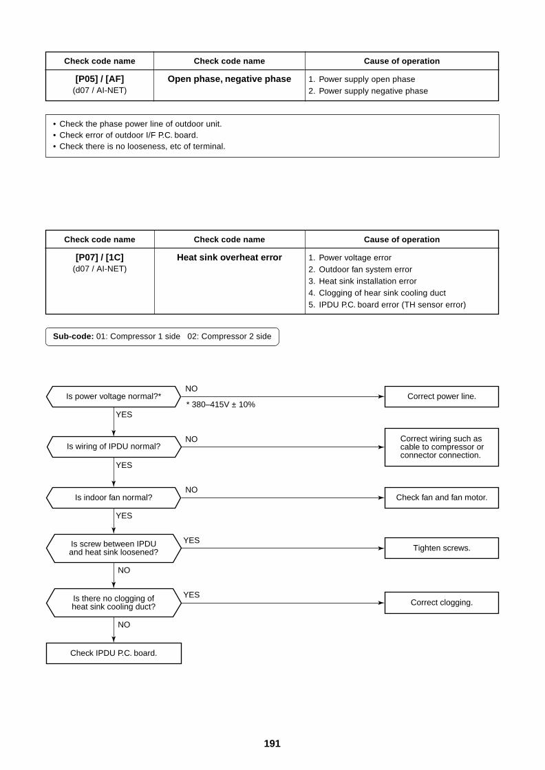
191
Check code name
[P05] / [AF](d07 / AI-NET)
Check code name
Open phase, negative phase
Cause of operation
1. Power supply open phase2. Power supply negative phase
• Check the phase power line of outdoor unit.• Check error of outdoor I/F P.C. board.• Check there is no looseness, etc of terminal.
Check code name
[P07] / [1C](d07 / AI-NET)
Check code name
Heat sink overheat error
Cause of operation
1. Power voltage error2. Outdoor fan system error3. Heat sink installation error4. Clogging of hear sink cooling duct5. IPDU P.C. board error (TH sensor error)
Sub-code: 01: Compressor 1 side 02: Compressor 2 side
Correct wiring such as cable to compressor or connector connection.
Is power voltage normal?*
Is indoor fan normal?
Check IPDU P.C. board.
Is wiring of IPDU normal?
Is screw between IPDUand heat sink loosened?
Is there no clogging ofheat sink cooling duct?
Correct power line.
Check fan and fan motor.
Tighten screws.
Correct clogging.
* 380–415V ± 10%
YES
YES
YES
YES
YES
NO
NO
NO
NO
NO
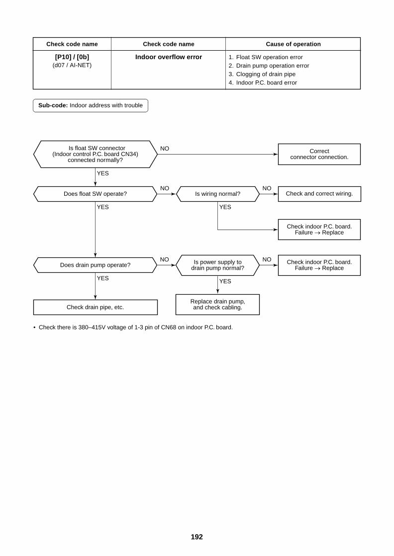
192
Check code name
[P10] / [0b](d07 / AI-NET)
Check code name
Indoor overflow error
Cause of operation
1. Float SW operation error2. Drain pump operation error3. Clogging of drain pipe4. Indoor P.C. board error
Sub-code: Indoor address with trouble
• Check there is 380–415V voltage of 1-3 pin of CN68 on indoor P.C. board.
Check drain pipe, etc.
Does drain pump operate?
Does float SW operate? Is wiring normal?
Is power supply todrain pump normal?
Replace drain pump,and check cabling.
Check indoor P.C. board.Failure Replace
Check indoor P.C. board.Failure Replace
Check and correct wiring.
Correctconnector connection.
YESYES
YESYES
YES
NONO
NONO
NOIs float SW connector(Indoor control P.C. board CN34)
connected normally?
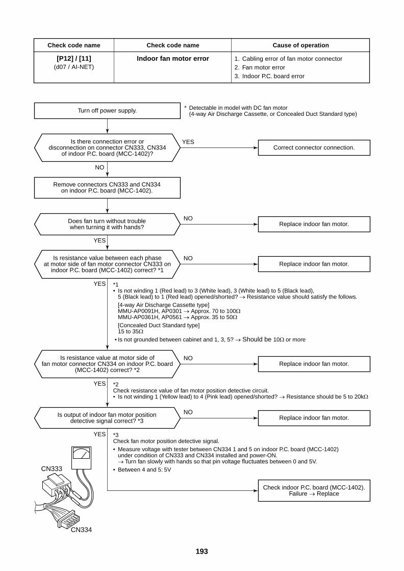
193
Check code name
[P12] / [11](d07 / AI-NET)
Check code name
Indoor fan motor error
Cause of operation
1. Cabling error of fan motor connector2. Fan motor error3. Indoor P.C. board error
Turn off power supply.
Correct connector connection.
Check indoor P.C. board (MCC-1402).Failure Replace
Is resistance value at motor side offan motor connector CN334 on indoor P.C. board
(MCC-1402) correct? *2
Is resistance value between each phaseat motor side of fan motor connector CN333 on
indoor P.C. board (MCC-1402) correct? *1
Is there connection error ordisconnection on connector CN333, CN334
of indoor P.C. board (MCC-1402)?
Is output of indoor fan motor positiondetective signal correct? *3
Does fan turn without troublewhen turning it with hands?
Remove connectors CN333 and CN334on indoor P.C. board (MCC-1402).
*2Check resistance value of fan motor position detective circuit.• Is not winding 1 (Yellow lead) to 4 (Pink lead) opened/shorted? Resistance should be 5 to 20k
*3Check fan motor position detective signal.• Measure voltage with tester between CN334 1 and 5 on indoor P.C. board (MCC-1402)
under condition of CN333 and CN334 installed and power-ON. Turn fan slowly with hands so that pin voltage fluctuates between 0 and 5V.
• Between 4 and 5: 5V
*1• Is not winding 1 (Red lead) to 3 (White lead), 3 (White lead) to 5 (Black lead),
5 (Black lead) to 1 (Red lead) opened/shorted? Resistance value should satisfy the follows.[4-way Air Discharge Cassette type]MMU-AP0091H, AP0301 Approx. 70 to 100MMU-AP0361H, AP0561 Approx. 35 to 50[Concealed Duct Standard type]15 to 35
• Is not grounded between cabinet and 1, 3, 5? Should be 10 or more
* Detectable in model with DC fan motor (4-way Air Discharge Cassette, or Concealed Duct Standard type)
Replace indoor fan motor.
Replace indoor fan motor.
Replace indoor fan motor.
Replace indoor fan motor.
CN333
CN334
YES
YES
YES
YES
YES
NO
NO
NO
NO
NO
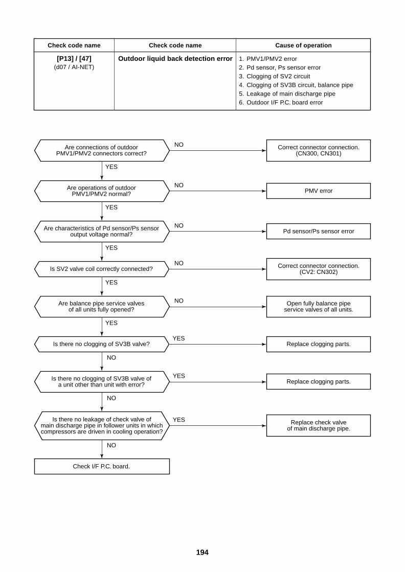
194
Check code name
[P13] / [47](d07 / AI-NET)
Check code name
Outdoor liquid back detection error
Cause of operation
1. PMV1/PMV2 error2. Pd sensor, Ps sensor error3. Clogging of SV2 circuit4. Clogging of SV3B circuit, balance pipe5. Leakage of main discharge pipe6. Outdoor I/F P.C. board error
Check I/F P.C. board.
Is there no clogging of SV3B valve?
Is SV2 valve coil correctly connected?
Is there no leakage of check valve ofmain discharge pipe in follower units in whichcompressors are driven in cooling operation?
Is there no clogging of SV3B valve ofa unit other than unit with error?
Are balance pipe service valvesof all units fully opened?
Are connections of outdoorPMV1/PMV2 connectors correct?
Are operations of outdoorPMV1/PMV2 normal?
Are characteristics of Pd sensor/Ps sensoroutput voltage normal?
Replace clogging parts.
Replace clogging parts.
PMV error
Pd sensor/Ps sensor error
Open fully balance pipeservice valves of all units.
Replace check valveof main discharge pipe.
Correct connector connection.(CV2: CN302)
Correct connector connection.(CN300, CN301)
YES
YES
YES
YES
YES
YES
YES
YES
NO
NO
NO
NO
NO
NO
NO
NO
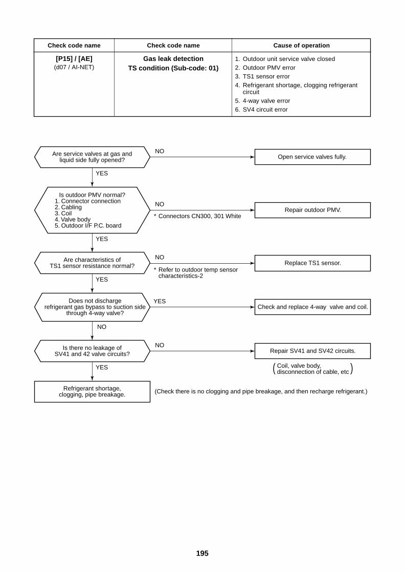
195
Check code name
[P15] / [AE](d07 / AI-NET)
Check code name
Gas leak detectionTS condition (Sub-code: 01)
Cause of operation
1. Outdoor unit service valve closed2. Outdoor PMV error3. TS1 sensor error4. Refrigerant shortage, clogging refrigerant
circuit5. 4-way valve error6. SV4 circuit error
( )
Open service valves fully.
Repair outdoor PMV.
Replace TS1 sensor.
Check and replace 4-way valve and coil.
Repair SV41 and SV42 circuits.
Are service valves at gas andliquid side fully opened?
Are characteristics ofTS1 sensor resistance normal?
Is there no leakage ofSV41 and 42 valve circuits?
Refrigerant shortage,clogging, pipe breakage.
* Connectors CN300, 301 White
* Refer to outdoor temp sensor characteristics-2
(Check there is no clogging and pipe breakage, and then recharge refrigerant.)
Coil, valve body, disconnection of cable, etc
Is outdoor PMV normal?1. Connector connection2. Cabling3. Coil4. Valve body5. Outdoor I/F P.C. board
YES
YES
YES
YES
YES
NO
NO
NO
NO
NO
Does not dischargerefrigerant gas bypass to suction side
through 4-way valve?
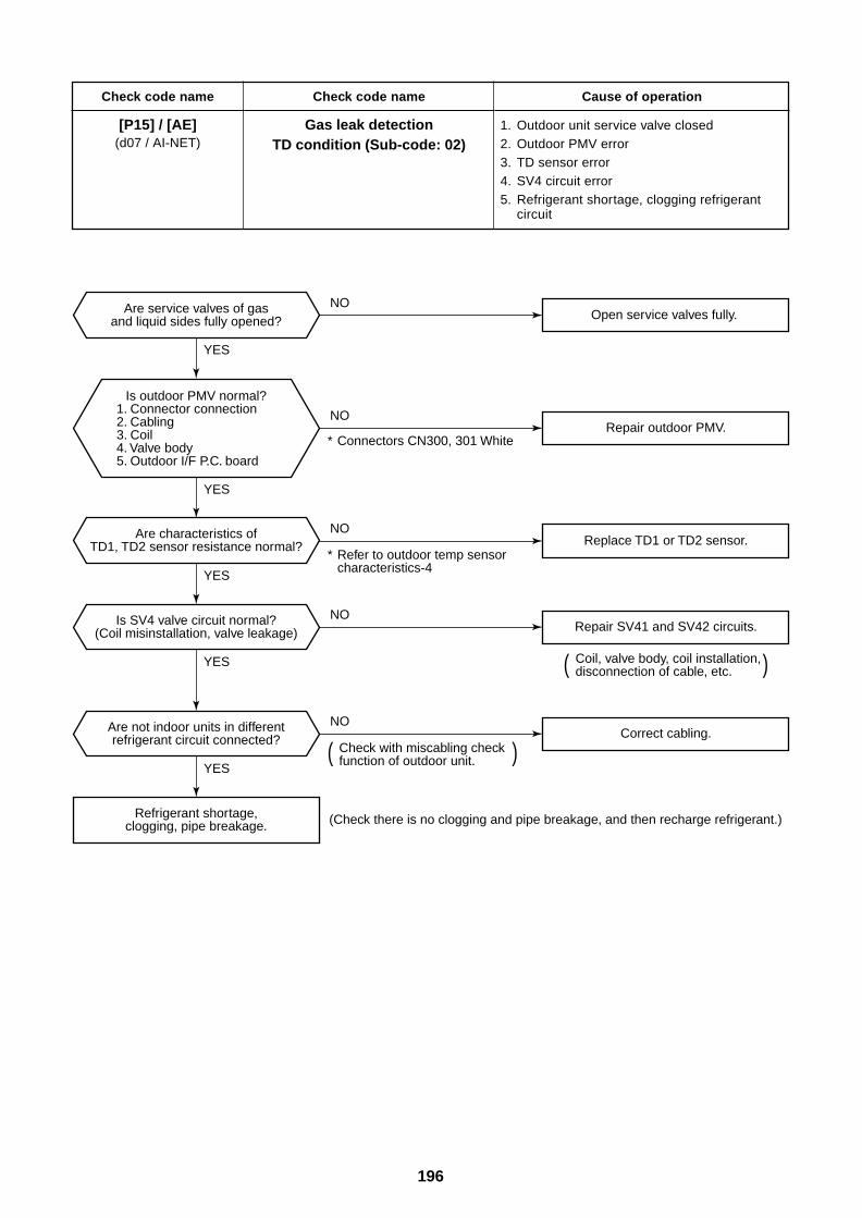
196
Check code name
[P15] / [AE](d07 / AI-NET)
Check code name
Gas leak detectionTD condition (Sub-code: 02)
Cause of operation
1. Outdoor unit service valve closed2. Outdoor PMV error3. TD sensor error4. SV4 circuit error5. Refrigerant shortage, clogging refrigerant
circuit
Coil, valve body, coil installation, disconnection of cable, etc.
Open service valves fully.
Repair outdoor PMV.
Replace TD1 or TD2 sensor.
Repair SV41 and SV42 circuits.
Correct cabling.
Are service valves of gasand liquid sides fully opened?
Are characteristics ofTD1, TD2 sensor resistance normal?
Is SV4 valve circuit normal?(Coil misinstallation, valve leakage)
Are not indoor units in differentrefrigerant circuit connected?
Refrigerant shortage,clogging, pipe breakage.
* Connectors CN300, 301 White
* Refer to outdoor temp sensor characteristics-4
Check with miscabling check function of outdoor unit.
(Check there is no clogging and pipe breakage, and then recharge refrigerant.)
Is outdoor PMV normal?1. Connector connection2. Cabling3. Coil4. Valve body5. Outdoor I/F P.C. board
( )
( )
YES
NO
YES
YES
YES
YES
NO
NO
NO
NO
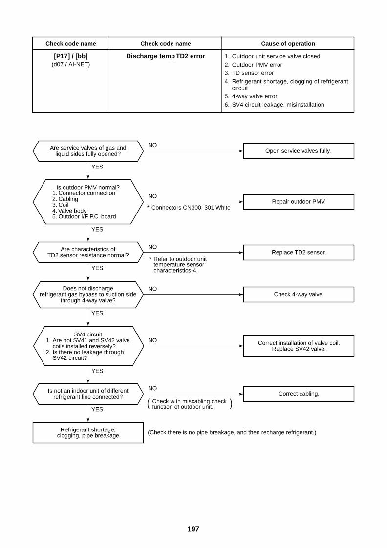
197
Check code name
[P17] / [bb](d07 / AI-NET)
Check code name
Discharge temp TD2 error
Cause of operation
1. Outdoor unit service valve closed2. Outdoor PMV error3. TD sensor error4. Refrigerant shortage, clogging of refrigerant
circuit5. 4-way valve error6. SV4 circuit leakage, misinstallation
Open service valves fully.
Repair outdoor PMV.
Replace TD2 sensor.
Check 4-way valve.
Correct cabling.
Are service valves of gas andliquid sides fully opened?
Are characteristics ofTD2 sensor resistance normal?
Refrigerant shortage,clogging, pipe breakage.
* Connectors CN300, 301 White
* Refer to outdoor unit temperature sensor characteristics-4.
(Check there is no pipe breakage, and then recharge refrigerant.)
Is outdoor PMV normal?1. Connector connection2. Cabling3. Coil4. Valve body5. Outdoor I/F P.C. board
SV4 circuit1. Are not SV41 and SV42 valve
coils installed reversely?2. Is there no leakage through
SV42 circuit?
YES
NO
NO
YES
YES
YES
YES
NO
NO
NO
Is not an indoor unit of differentrefrigerant line connected?
YES
NO
Correct installation of valve coil.Replace SV42 valve.
Check with miscabling check function of outdoor unit.( )
Does not dischargerefrigerant gas bypass to suction side
through 4-way valve?
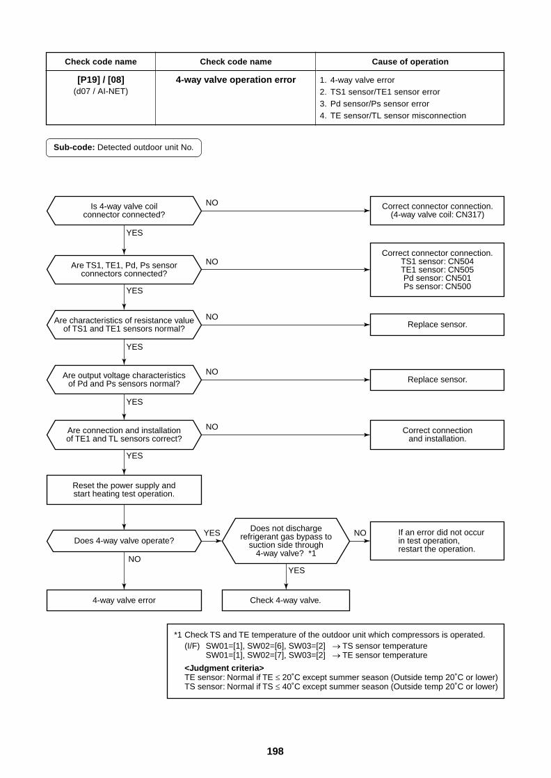
198
Check code name
[P19] / [08](d07 / AI-NET)
Check code name
4-way valve operation error
Cause of operation
1. 4-way valve error2. TS1 sensor/TE1 sensor error3. Pd sensor/Ps sensor error4. TE sensor/TL sensor misconnection
Sub-code: Detected outdoor unit No.
Replace sensor.
Replace sensor.
Does not dischargerefrigerant gas bypass to
suction side through4-way valve? *1
Check 4-way valve.
If an error did not occur in test operation,restart the operation.
Does 4-way valve operate?
4-way valve error
Is 4-way valve coilconnector connected?
Are TS1, TE1, Pd, Ps sensorconnectors connected?
Are characteristics of resistance valueof TS1 and TE1 sensors normal?
Are output voltage characteristicsof Pd and Ps sensors normal?
Are connection and installationof TE1 and TL sensors correct?
Reset the power supply andstart heating test operation.
Correct connector connection.(4-way valve coil: CN317)
Correct connectionand installation.
*1 Check TS and TE temperature of the outdoor unit which compressors is operated.(I/F) SW01=[1], SW02=[6], SW03=[2] TS sensor temperature
SW01=[1], SW02=[7], SW03=[2] TE sensor temperature
<Judgment criteria>TE sensor: Normal if TE 20˚C except summer season (Outside temp 20˚C or lower)TS sensor: Normal if TS 40˚C except summer season (Outside temp 20˚C or lower)
Correct connector connection.TS1 sensor: CN504TE1 sensor: CN505Pd sensor: CN501Ps sensor: CN500
YES
YES
YES
YES
YES
YES
YES NO
NO
NO
NO
NO
NO
NO
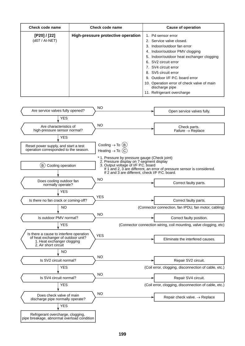
199
Check code name
[P20] / [22](d07 / AI-NET)
Check code name
High-pressure protective operation
Cause of operation
1. Pd sensor error2. Service valve closed.3. Indoor/outdoor fan error4. Indoor/outdoor PMV clogging5. Indoor/outdoor heat exchanger clogging6. SV2 circuit error7. SV4 circuit error8. SV5 circuit error9. Outdoor I/F P.C. board error
10. Operation error of check valve of maindischarge pipe
11. Refrigerant overcharge
Is there no fan crack or coming-off?
Is outdoor PMV normal?
Is SV2 circuit normal?
Is SV4 circuit normal?
Are service valves fully opened?
Reset power supply, and start a test operation corresponded to the season.
Does cooling outdoor fannormally operate?
Does check valve of maindischarge pipe normally operate?
Refrigerant overcharge, clogging, pipe breakage, abnormal overload condition
Are characteristics ofhigh-pressure sensor normal?
Open service valves fully.
Check parts. Failure Replace
* 1. Pressure by pressure gauge (Check joint)2. Pressure display on 7-segment display3. Output voltage of I/F P.C. board
If 1 and 2, 3 are different, an error of pressure sensor is considered.If 2 and 3 are different, check I/F P.C. board.
Is there a cause to interfere operationof heat exchanger of outdoor unit?
1. Heat exchanger clogging2. Air short circuit
Cooling To B
Heating To C
B Cooling operation
Correct faulty parts.
Correct faulty parts.
Correct faulty position.
Eliminate the interfered causes.
Repair SV2 circuit.
Repair check valve. Replace
Repair SV4 circuit.
(Connector connection, fan IPDU, fan motor, cabling)
(Connector connection wiring, coil mounting, valve clogging, etc)
(Coil error, clogging, disconnection of cable, etc.)
(Coil error, clogging, disconnection of cable, etc.)
YES
YES
YES
YES
YES
YES
YES
YES
YES
NO
NO
NO
NO
NO
NO
NO
NO
NO
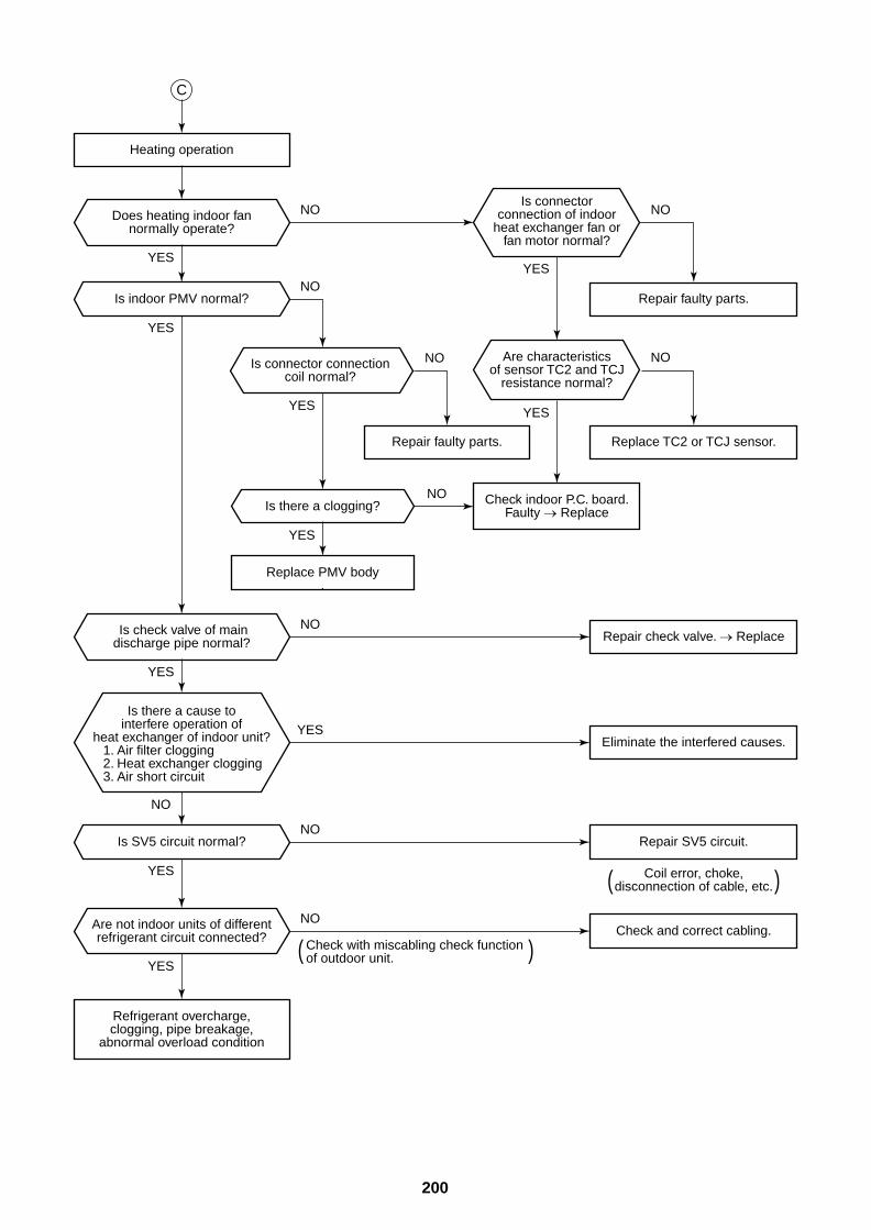
200
Heating operation
Is indoor PMV normal?
Is SV5 circuit normal?
Is there a clogging?
Check and correct cabling.
Repair SV5 circuit.
Replace PMV body.
Repair faulty parts.
Replace TC2 or TCJ sensor.Repair faulty parts.
Eliminate the interfered causes.
Refrigerant overcharge,clogging, pipe breakage,
abnormal overload condition
Is connectorconnection of indoor
heat exchanger fan orfan motor normal?
Are characteristicsof sensor TC2 and TCJ
resistance normal?
Is connector connectioncoil normal?
Does heating indoor fannormally operate?
Is check valve of maindischarge pipe normal?
Are not indoor units of differentrefrigerant circuit connected?
Check indoor P.C. board.Faulty Replace
C
Is there a cause tointerfere operation of
heat exchanger of indoor unit?1. Air filter clogging2. Heat exchanger clogging3. Air short circuit
Coil error, choke,disconnection of cable, etc.( )
( )Check with miscabling check function of outdoor unit.
Repair check valve. Replace
YES
YES
YES
YES
NO
NO
NO
NO
YES
YES
YES
YESYES
NO
NO NO
YES
NO
NO
NO
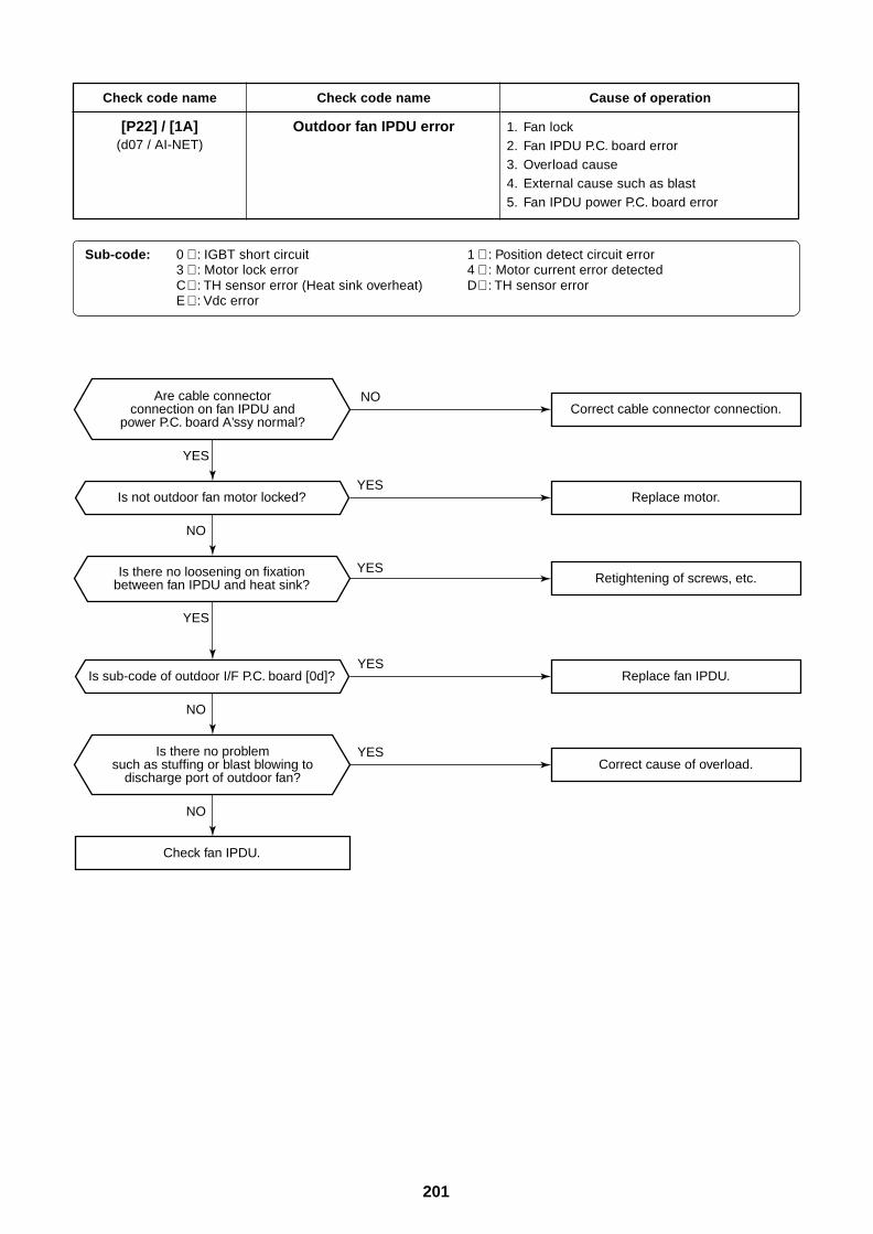
201
Check code name
[P22] / [1A](d07 / AI-NET)
Check code name
Outdoor fan IPDU error
Cause of operation
1. Fan lock2. Fan IPDU P.C. board error3. Overload cause4. External cause such as blast5. Fan IPDU power P.C. board error
Sub-code: 0 ∗ : IGBT short circuit 1 ∗ : Position detect circuit error3 ∗ : Motor lock error 4 ∗ : Motor current error detectedC ∗ : TH sensor error (Heat sink overheat) D∗ : TH sensor errorE ∗ : Vdc error
Is not outdoor fan motor locked?
Is sub-code of outdoor I/F P.C. board [0d]?
Check fan IPDU.
Correct cable connector connection.
Correct cause of overload.
Retightening of screws, etc.
Replace fan IPDU.
Is there no problemsuch as stuffing or blast blowing to
discharge port of outdoor fan?
Are cable connectorconnection on fan IPDU and
power P.C. board A’ssy normal?
Is there no loosening on fixationbetween fan IPDU and heat sink?
Replace motor.
YES
YES
YES
YES
YES
YES
NO
NO
NO
NO
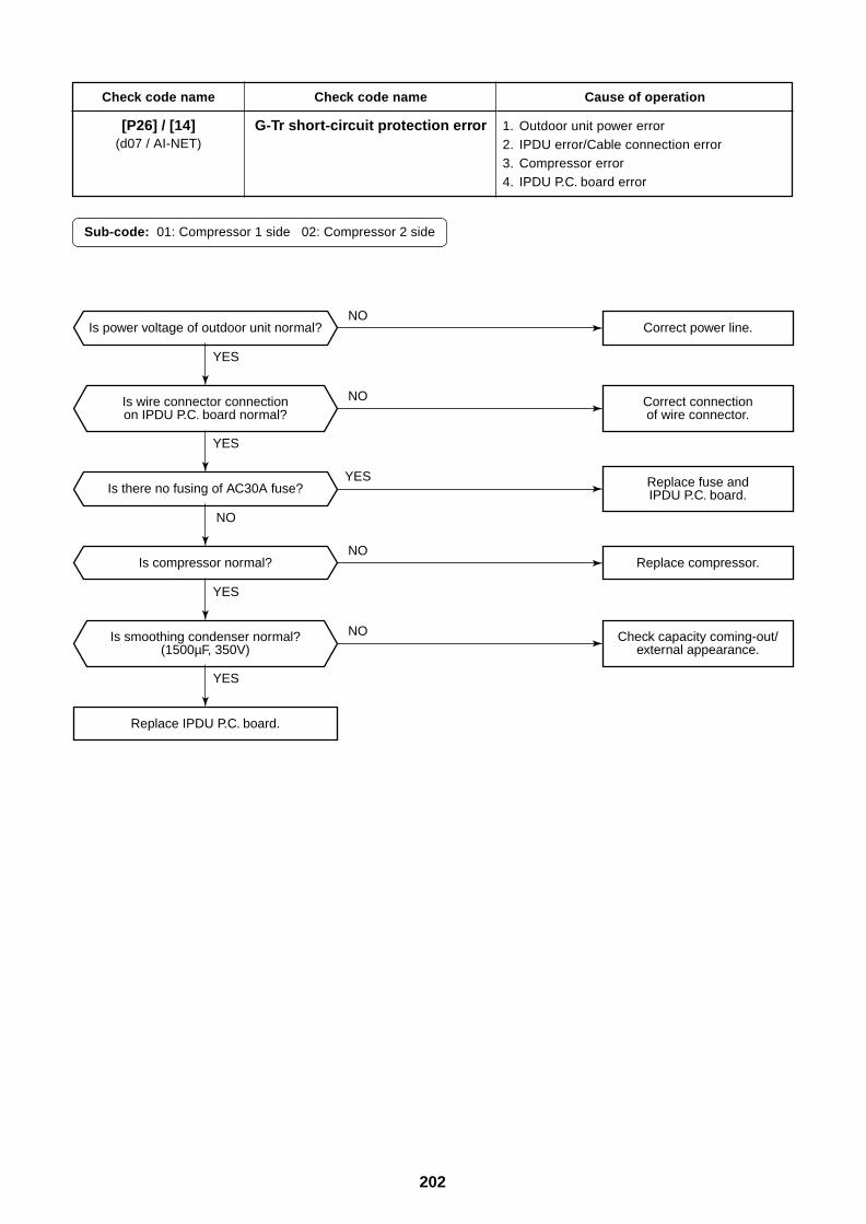
202
Check code name
[P26] / [14](d07 / AI-NET)
Check code name
G-Tr short-circuit protection error
Cause of operation
1. Outdoor unit power error2. IPDU error/Cable connection error3. Compressor error4. IPDU P.C. board error
Sub-code: 01: Compressor 1 side 02: Compressor 2 side
Is power voltage of outdoor unit normal?
Is there no fusing of AC30A fuse?
Replace IPDU P.C. board.
Is compressor normal?
Is wire connector connectionon IPDU P.C. board normal?
Is smoothing condenser normal?(1500µF, 350V)
Correct power line.
Replace compressor.
Correct connectionof wire connector.
Check capacity coming-out/external appearance.
Replace fuse andIPDU P.C. board.
YES
YES
NO
YES
YES
NO
NO
YES
NO
NO
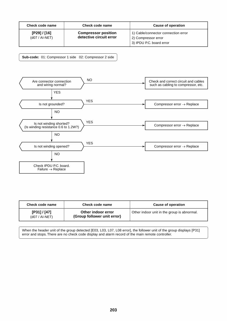
203
Check code name
[P29] / [16](d07 / AI-NET)
Check code name
Compressor positiondetective circuit error
Cause of operation
1) Cable/connector connection error2) Compressor error3) IPDU P.C. board error
Sub-code: 01: Compressor 1 side 02: Compressor 2 side
Check code name
[P31] / [47](d07 / AI-NET)
Check code name
Other indoor error(Group follower unit error)
Cause of operation
Other indoor unit in the group is abnormal.
When the header unit of the group detected [E03, L03, L07, L08 error], the follower unit of the group displays [P31]error and stops. There are no check code display and alarm record of the main remote controller.
Is not grounded?
Is not winding opened?
Are connector connectionand wiring normal?
Is not winding shorted?(Is winding resistance 0.6 to 1.2W?)
Check IPDU P.C. board.Failure Replace
Compressor error Replace
Compressor error Replace
Compressor error Replace
Check and correct circuit and cablessuch as cabling to compressor, etc.
YES
YES
YES
YES
NO
NO
NO
NO
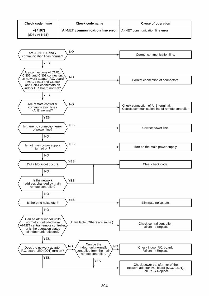
204
Check code name
[–] / [97](d07 / AI-NET)
Check code name
AI-NET communication line error
Cause of operation
AI-NET communication line error
Can be other indoor unitsnormally controlled from
AI-NET central remote controller,or is the operation statusof indoor unit reflected?
Can be theindoor unit normally
controlled from the mainremote controller?
Is the networkaddress changed by main
remote controller?
Are remote controllercommunication lines
(A, B) normal?
Correct communication line.
Correct connection of connectors.
Correct power line.
Turn on the main power supply.
Clear check code.
Eliminate noise, etc.
Check power transformer of thenetwork adaptor P.C. board (MCC-1401).
Failure Replace
Check central controller.Failure Replace
Check indoor P.C. board.Failure Replace
Did a block-out occur?
Is there no noise etc.?
Does the network adaptorP.C. board LED (D01) turn on?
Is there no connection errorof power line?
Is not main power supplyturned on?
Are AI-NET X and Ycommunication lines normal?
Are connections of CN01,CN02, and CN03 connectors
on network adaptor P.C. board(MCC-1401) and CN309and CN41 connectors onindoor P.C. board normal?
Check connection of A, B terminal.Correct communication line of remote controller.
Unavailable (Others are same.)
YES
YES
YES
YES
YES
YES
YES
YES
YES
YES
YES
NO NO
NO
NO
NO
NO
NO
NO
NO
NO
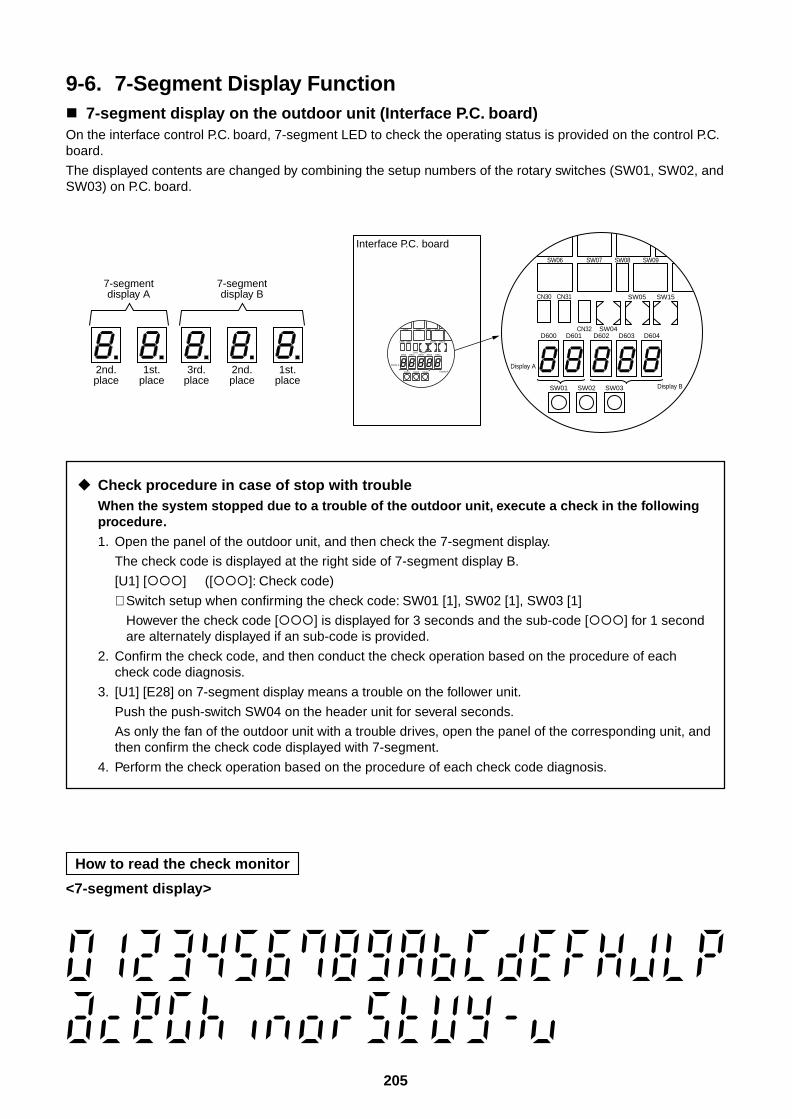
205
9-6. 7-Segment Display Function 7-segment display on the outdoor unit (Interface P.C. board)On the interface control P.C. board, 7-segment LED to check the operating status is provided on the control P.C.board.
The displayed contents are changed by combining the setup numbers of the rotary switches (SW01, SW02, andSW03) on P.C. board.
Check procedure in case of stop with troubleWhen the system stopped due to a trouble of the outdoor unit, execute a check in the followingprocedure.
1. Open the panel of the outdoor unit, and then check the 7-segment display.
The check code is displayed at the right side of 7-segment display B.
[U1] [] ([]: Check code)
∗ Switch setup when confirming the check code: SW01 [1], SW02 [1], SW03 [1]
However the check code [] is displayed for 3 seconds and the sub-code [] for 1 secondare alternately displayed if an sub-code is provided.
2. Confirm the check code, and then conduct the check operation based on the procedure of eachcheck code diagnosis.
3. [U1] [E28] on 7-segment display means a trouble on the follower unit.
Push the push-switch SW04 on the header unit for several seconds.
As only the fan of the outdoor unit with a trouble drives, open the panel of the corresponding unit, andthen confirm the check code displayed with 7-segment.
4. Perform the check operation based on the procedure of each check code diagnosis.
2nd.place
1st.place
7-segmentdisplay A
7-segmentdisplay B
3rd.place
2nd.place
1st.place
D602 D603 D604D600
CN30
SW08SW06
CN31
CN32 SW04D601
SW01
Display A
Display BSW02 SW03
SW05 SW15
SW07 SW09
D602 D603 D604D600
CN30
SW08SW06
CN31
CN32 SW04D601
SW01
Display A
Display BSW02 SW03
SW05 SW15
SW07 SW09
Interface P.C. board
How to read the check monitor
<7-segment display>
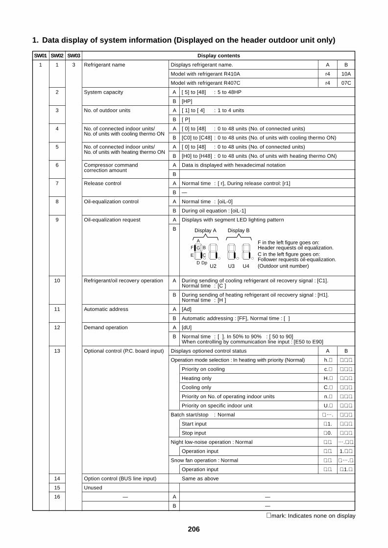
206
1. Data display of system information (Displayed on the header outdoor unit only)
SW01
1
SW02
1
2
3
4
5
6
7
8
9
SW03
3
Display contents
Refrigerant name Displays refrigerant name. A B
Model with refrigerant R410A r4 10A
Model with refrigerant R407C r4 07C
System capacity A [ 5] to [48] : 5 to 48HP
B [HP]
No. of outdoor units A [ 1] to [ 4] : 1 to 4 units
B [ P]
No. of connected indoor units/ A [ 0] to [48] : 0 to 48 units (No. of connected units)No. of units with cooling thermo ON
B [C0] to [C48] : 0 to 48 units (No. of units with cooling thermo ON)
No. of connected indoor units/ A [ 0] to [48] : 0 to 48 units (No. of connected units)No. of units with heating thermo ON
B [H0] to [H48] : 0 to 48 units (No. of units with heating thermo ON)
Compressor command A Data is displayed with hexadecimal notationcorrection amount
B
Release control A Normal time : [ r], During release control: [r1]
B —
Oil-equalization control A Normal time : [oiL-0]
B During oil equation : [oiL-1]
Oil-equalization request A Displays with segment LED lighting pattern
B
10
11
12
13
14
15
16
Refrigerant/oil recovery operation A During sending of cooling refrigerant oil recovery signal : [C1].Normal time : [C ]
B During sending of heating refrigerant oil recovery signal : [H1].Normal time : [H ]
Automatic address A [Ad]
B Automatic addressing : [FF], Normal time : [ ]
Demand operation A [dU]
B Normal time : [ ]. In 50% to 90% : [ 50 to 90]When controlling by communication line input : [E50 to E90]
Optional control (P.C. board input) Displays optioned control status A B
Operation mode selection : In heating with priority (Normal) h.∗ ∗ .∗ .∗ .
Priority on cooling c.∗ ∗ .∗ .∗ .
Heating only H.∗ ∗ .∗ .∗ .
Cooling only C.∗ ∗ .∗ .∗ .
Priority on No. of operating indoor units n.∗ ∗ .∗ .∗ .
Priority on specific indoor unit U.∗ ∗ .∗ .∗ .
Batch start/stop : Normal ∗ .…. ∗ .∗ .∗ .
Start input ∗ .1. ∗ .∗ .∗ .
Stop input ∗ .0. ∗ .∗ .∗ .
Night low-noise operation : Normal ∗ .∗ . ….∗ .∗ .
Operation input ∗ .∗ . 1.∗ .∗ .
Snow fan operation : Normal ∗ .∗ . ∗ .….∗ .
Operation input ∗ .∗ . ∗ .1.∗ .
Option control (BUS line input) Same as above
Unused
— A —
B —
G
A
D
F B
E C
Dp
Display A Display B
F in the left figure goes on: Header requests oil equalization.C in the left figure goes on: Follower requests oil-equalization.(Outdoor unit number)U2 U3 U4
∗ mark: Indicates none on display
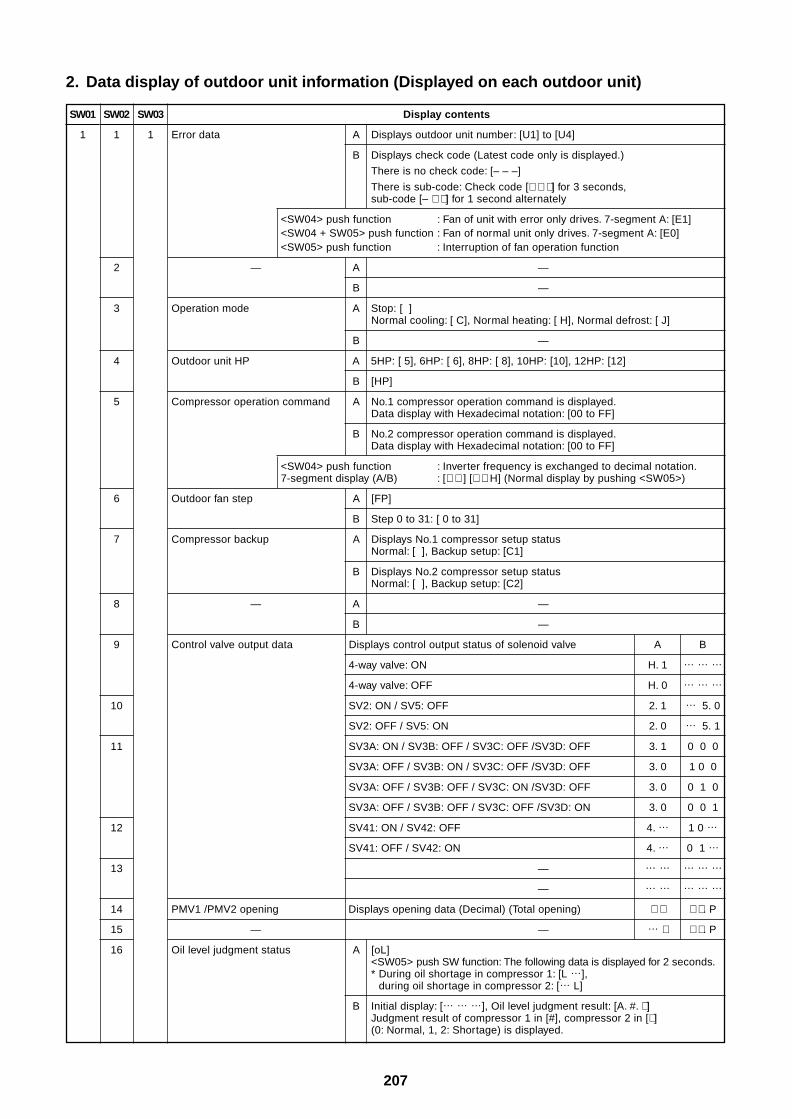
207
2. Data display of outdoor unit information (Displayed on each outdoor unit)
SW01
1
SW02
1
2
3
4
5
6
7
8
9
10
11
12
13
14
15
16
SW03
1
Display contents
Error data A Displays outdoor unit number: [U1] to [U4]
B Displays check code (Latest code only is displayed.)
There is no check code: [– – –]
There is sub-code: Check code [∗ ∗ ∗ ] for 3 seconds,sub-code [– ∗ ∗ ] for 1 second alternately
<SW04> push function : Fan of unit with error only drives. 7-segment A: [E1]<SW04 + SW05> push function : Fan of normal unit only drives. 7-segment A: [E0]<SW05> push function : Interruption of fan operation function
— A —
B —
Operation mode A Stop: [ ]Normal cooling: [ C], Normal heating: [ H], Normal defrost: [ J]
B —
Outdoor unit HP A 5HP: [ 5], 6HP: [ 6], 8HP: [ 8], 10HP: [10], 12HP: [12]
B [HP]
Compressor operation command A No.1 compressor operation command is displayed.Data display with Hexadecimal notation: [00 to FF]
B No.2 compressor operation command is displayed.Data display with Hexadecimal notation: [00 to FF]
<SW04> push function : Inverter frequency is exchanged to decimal notation.7-segment display (A/B) : [∗ ∗ ] [∗ ∗ H] (Normal display by pushing <SW05>)
Outdoor fan step A [FP]
B Step 0 to 31: [ 0 to 31]
Compressor backup A Displays No.1 compressor setup statusNormal: [ ], Backup setup: [C1]
B Displays No.2 compressor setup statusNormal: [ ], Backup setup: [C2]
— A —
B —
Control valve output data Displays control output status of solenoid valve A B
4-way valve: ON H. 1 … … …
4-way valve: OFF H. 0 … … …
SV2: ON / SV5: OFF 2. 1 … 5. 0
SV2: OFF / SV5: ON 2. 0 … 5. 1
SV3A: ON / SV3B: OFF / SV3C: OFF /SV3D: OFF 3. 1 0 0 0
SV3A: OFF / SV3B: ON / SV3C: OFF /SV3D: OFF 3. 0 1 0 0
SV3A: OFF / SV3B: OFF / SV3C: ON /SV3D: OFF 3. 0 0 1 0
SV3A: OFF / SV3B: OFF / SV3C: OFF /SV3D: ON 3. 0 0 0 1
SV41: ON / SV42: OFF 4. … 1 0 …
SV41: OFF / SV42: ON 4. … 0 1 …
— … … … … …
— … … … … …
PMV1 /PMV2 opening Displays opening data (Decimal) (Total opening) ∗ ∗ ∗ ∗ . P
— — … ∗ ∗ ∗ . P
Oil level judgment status A [oL]<SW05> push SW function: The following data is displayed for 2 seconds.* During oil shortage in compressor 1: [L …],
during oil shortage in compressor 2: [… L]
B Initial display: [… … …], Oil level judgment result: [A. #. ∗ ]Judgment result of compressor 1 in [#], compressor 2 in [∗ ](0: Normal, 1, 2: Shortage) is displayed.
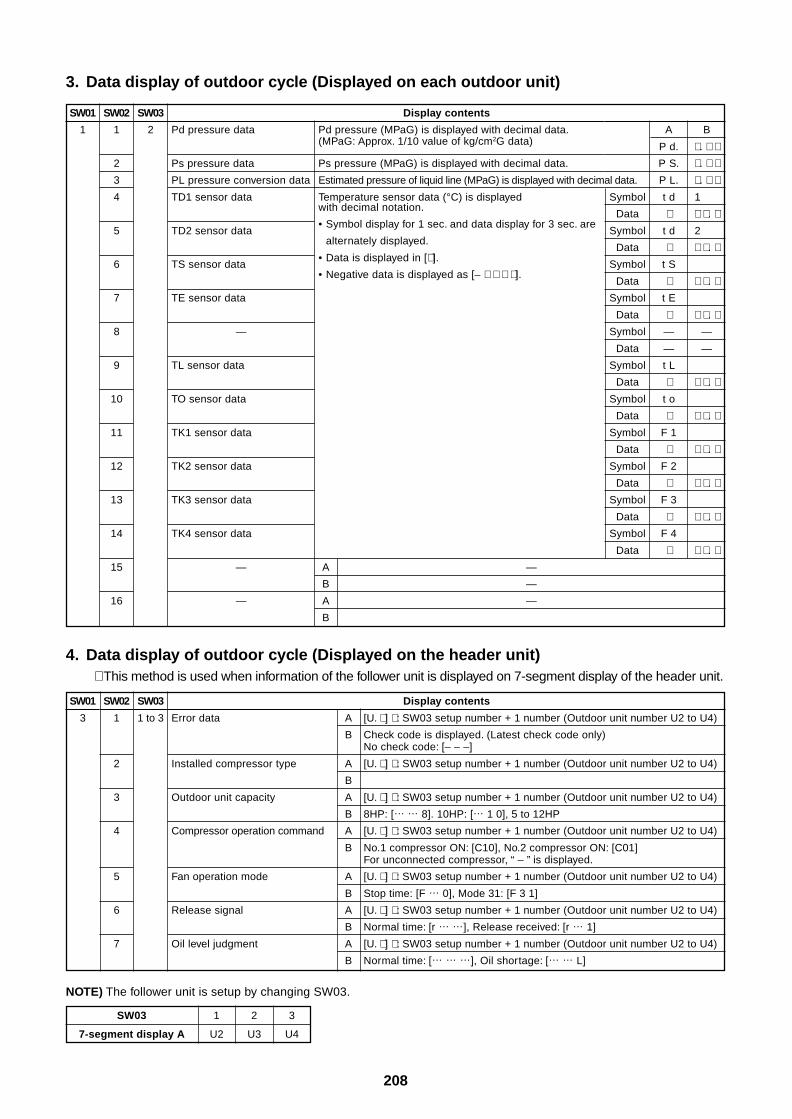
208
3. Data display of outdoor cycle (Displayed on each outdoor unit)
4. Data display of outdoor cycle (Displayed on the header unit)∗ This method is used when information of the follower unit is displayed on 7-segment display of the header unit.
SW01
1
SW02
1
2
3
4
5
6
7
8
9
10
11
12
13
14
15
16
SW03
2
Display contents
Pd pressure data Pd pressure (MPaG) is displayed with decimal data.(MPaG: Approx. 1/10 value of kg/cm2G data)
Ps pressure data Ps pressure (MPaG) is displayed with decimal data.
PL pressure conversion data Estimated pressure of liquid line (MPaG) is displayed with decimal data.
TD1 sensor data Temperature sensor data (°C) is displayedwith decimal notation.
TD2 sensor data• Symbol display for 1 sec. and data display for 3 sec. are
alternately displayed.
TS sensor data• Data is displayed in [∗ ].
• Negative data is displayed as [– ∗ ∗ ∗ ∗ ].
TE sensor data
—
TL sensor data
TO sensor data
TK1 sensor data
TK2 sensor data
TK3 sensor data
TK4 sensor data
— A —
B —
— A —
B
A B
P d. ∗ . ∗ ∗P S. ∗ . ∗ ∗P L. ∗ . ∗ ∗
Symbol t d 1 1 1
Data ∗ ∗ ∗ . ∗Symbol t d 2 1 1
Data ∗ ∗ ∗ . ∗Symbol t S
Data ∗ ∗ ∗ . ∗Symbol t E
Data ∗ ∗ ∗ . ∗Symbol — —
Data — —
Symbol t L
Data ∗ ∗ ∗ . ∗Symbol t o
Data ∗ ∗ ∗ . ∗Symbol F 1
Data ∗ ∗ ∗ . ∗Symbol F 2
Data ∗ ∗ ∗ . ∗Symbol F 3
Data ∗ ∗ ∗ . ∗Symbol F 4
Data ∗ ∗ ∗ . ∗
SW01
3
SW02
1
2
3
4
5
6
7
SW03
1 to 3
Display contents
Error data A [U. ∗ ] ∗ : SW03 setup number + 1 number (Outdoor unit number U2 to U4)
B Check code is displayed. (Latest check code only)No check code: [– – –]
Installed compressor type A [U. ∗ ] ∗ : SW03 setup number + 1 number (Outdoor unit number U2 to U4)
B
Outdoor unit capacity A [U. ∗ ] ∗ : SW03 setup number + 1 number (Outdoor unit number U2 to U4)
B 8HP: [… … 8]. 10HP: [… 1 0], 5 to 12HP
Compressor operation command A [U. ∗ ] ∗ : SW03 setup number + 1 number (Outdoor unit number U2 to U4)
B No.1 compressor ON: [C10], No.2 compressor ON: [C01]For unconnected compressor, “ – ” is displayed.
Fan operation mode A [U. ∗ ] ∗ : SW03 setup number + 1 number (Outdoor unit number U2 to U4)
B Stop time: [F … 0], Mode 31: [F 3 1]
Release signal A [U. ∗ ] ∗ : SW03 setup number + 1 number (Outdoor unit number U2 to U4)
B Normal time: [r … …], Release received: [r … 1]
Oil level judgment A [U. ∗ ] ∗ : SW03 setup number + 1 number (Outdoor unit number U2 to U4)
B Normal time: [… … …], Oil shortage: [… … L]
NOTE) The follower unit is setup by changing SW03.
SW03
7-segment display A
1 2 3
U2 U3 U4
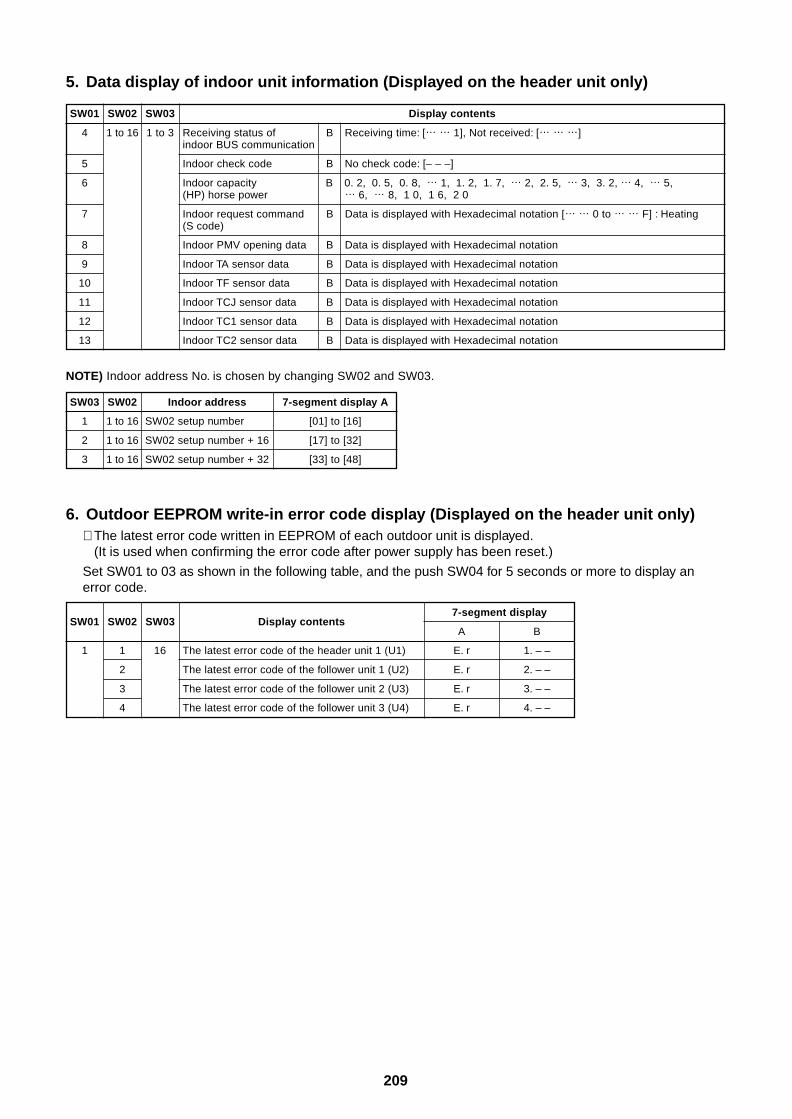
209
5. Data display of indoor unit information (Displayed on the header unit only)
SW01
4
5
6
7
8
9
10
11
12
13
SW02
1 to 16
SW03
1 to 3
Display contents
Receiving status of B Receiving time: [… … 1], Not received: [… … …]indoor BUS communication
Indoor check code B No check code: [– – –]
Indoor capacity B 0. 2, 0. 5, 0. 8, … 1, 1. 2, 1. 7, … 2, 2. 5, … 3, 3. 2, … 4, … 5,(HP) horse power … 6, … 8, 1 0, 1 6, 2 0
Indoor request command B Data is displayed with Hexadecimal notation [… … 0 to … … F] : Heating(S code)
Indoor PMV opening data B Data is displayed with Hexadecimal notation
Indoor TA sensor data B Data is displayed with Hexadecimal notation
Indoor TF sensor data B Data is displayed with Hexadecimal notation
Indoor TCJ sensor data B Data is displayed with Hexadecimal notation
Indoor TC1 sensor data B Data is displayed with Hexadecimal notation
Indoor TC2 sensor data B Data is displayed with Hexadecimal notation
NOTE) Indoor address No. is chosen by changing SW02 and SW03.
SW03
1
2
3
SW02
1 to 16
1 to 16
1 to 16
Indoor address
SW02 setup number
SW02 setup number + 16
SW02 setup number + 32
7-segment display A
[01] to [16]
[17] to [32]
[33] to [48]
6. Outdoor EEPROM write-in error code display (Displayed on the header unit only)∗ The latest error code written in EEPROM of each outdoor unit is displayed.
(It is used when confirming the error code after power supply has been reset.)
Set SW01 to 03 as shown in the following table, and the push SW04 for 5 seconds or more to display anerror code.
SW01
1
SW02
1
2
3
4
SW03
16
Display contents
The latest error code of the header unit 1 (U1)
The latest error code of the follower unit 1 (U2)
The latest error code of the follower unit 2 (U3)
The latest error code of the follower unit 3 (U4)
7-segment display
A B
E. r 1. – –
E. r 2. – –
E. r 3. – –
E. r 4. – –
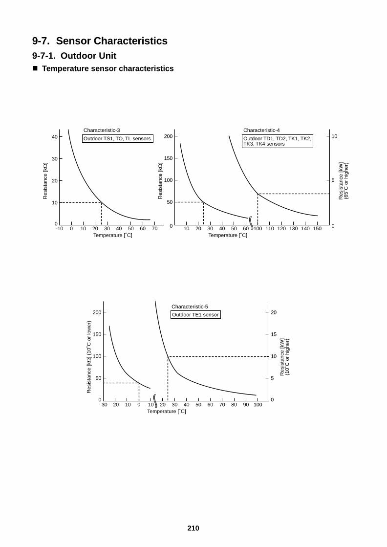
210
9-7. Sensor Characteristics9-7-1. Outdoor Unit Temperature sensor characteristics
-10
10
0
20
30
40
0 10 20 30 40 50 60 70
Characteristic-3
Temperature [˚C]
Outdoor TS1, TO, TL sensors
Res
ista
nce
[k]
50
0
100
150
200
0
5
10
10 20 30 40 50 60 100 110 120 130 140 150
Characteristic-4
Temperature [˚C]
Outdoor TD1, TD2, TK1, TK2, TK3, TK4 sensors
Res
ista
nce
[k]
Res
ista
nce
[kW
](6
5˚C
or
high
er)
50
0
100
150
200
5
0
10
15
20
-20-30 -10 0 10 20 30 40 50 60 70 80 90 100
Characteristic-5
Temperature [˚C]
Outdoor TE1 sensor
Res
ista
nce
[k] (
10˚C
or
low
er)
Res
ista
nce
[kW
](1
0˚C
or
high
er)
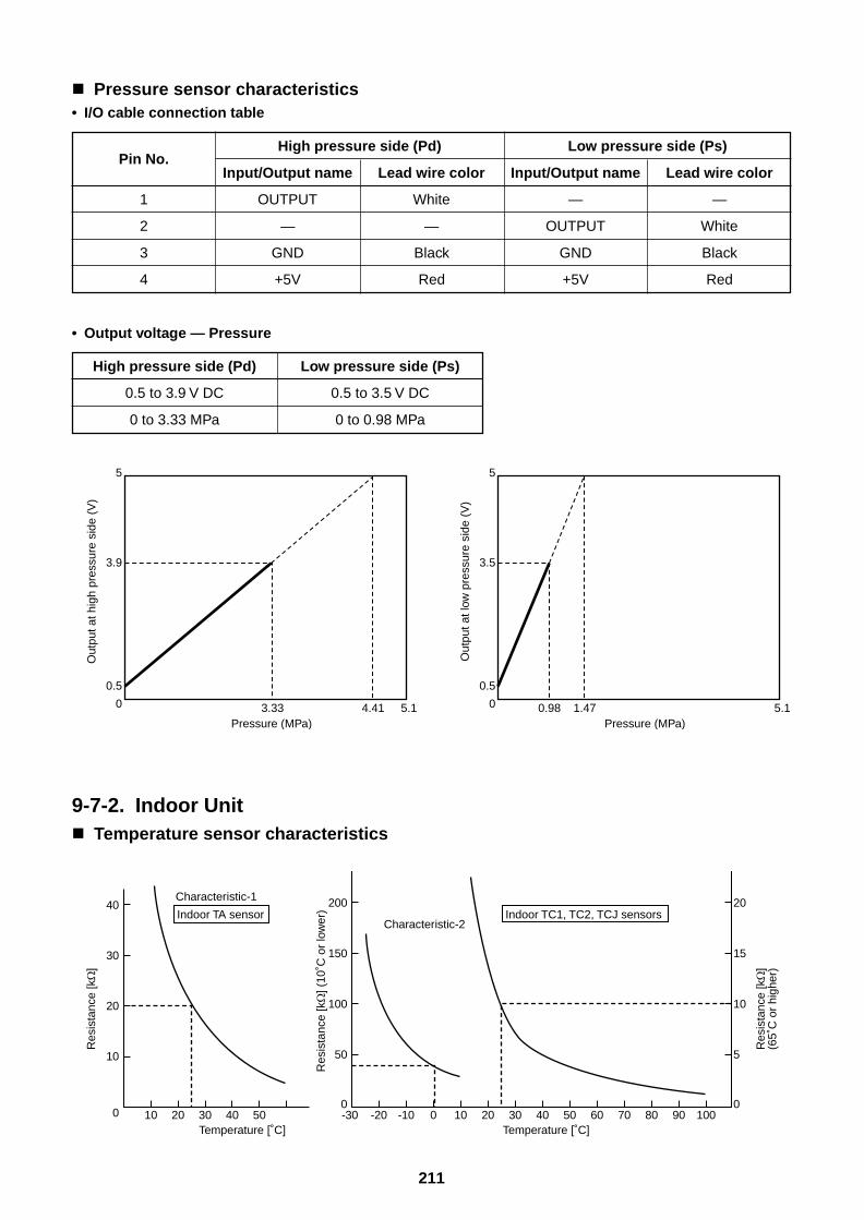
211
Pressure sensor characteristics• I/O cable connection table
Pin No.
1
2
3
4
High pressure side (Pd) Low pressure side (Ps)
Input/Output name Lead wire color Input/Output name Lead wire color
OUTPUT White — —
— — OUTPUT White
GND Black GND Black
+5V Red +5V Red
• Output voltage — Pressure
High pressure side (Pd) Low pressure side (Ps)
0.5 to 3.9 V DC 0.5 to 3.5 V DC
0 to 3.33 MPa 0 to 0.98 MPa
9-7-2. Indoor Unit Temperature sensor characteristics
Out
put a
t hig
h pr
essu
re s
ide
(V)
Pressure (MPa)
0.5
0
3.9
5
3.33 4.41 5.1
Out
put a
t low
pre
ssur
e si
de (
V)
Pressure (MPa)
0.5
0
3.5
5
0.98 1.47 5.1
10
0
20
30
40
10 20 30 40 50
Characteristic-1
Temperature [˚C]
Indoor TA sensor
Res
ista
nce
[k]
50
0
100
150
200
5
0
10
15
20
-20-30 -10 0 10 20 30 40 50 60 70 80 90 100
Characteristic-2
Temperature [˚C]
Indoor TC1, TC2, TCJ sensors
Res
ista
nce
[k] (
10˚C
or
low
er)
Res
ista
nce
[k]
(65˚
C o
r hi
gher
)
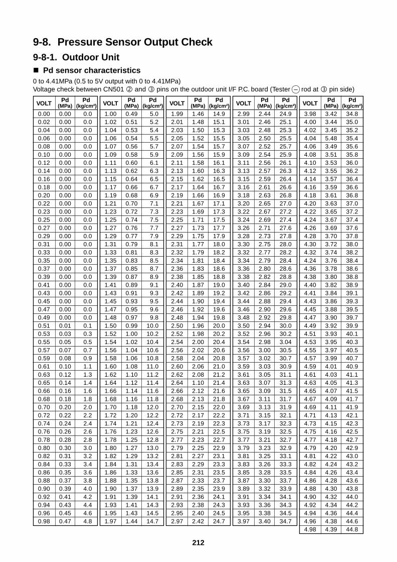
212
9-8. Pressure Sensor Output Check9-8-1. Outdoor Unit Pd sensor characteristics0 to 4.41MPa (0.5 to 5V output with 0 to 4.41MPa)Voltage check between CN501 and pins on the outdoor unit I/F P.C. board (Tester – rod at pin side)
VOLT
0.000.020.040.060.080.100.120.140.160.180.200.220.230.250.270.290.310.330.350.370.390.410.430.450.470.490.510.530.550.570.590.610.630.650.660.680.700.720.740.760.780.800.820.840.860.880.900.920.940.960.98
Pd(MPa)
0.000.000.000.000.000.000.000.000.000.000.000.000.000.000.000.000.000.000.000.000.000.000.000.000.000.000.010.030.050.070.080.100.120.140.160.180.200.220.240.260.280.300.310.330.350.370.390.410.430.450.47
Pd(kg/cm²)
0.00.00.00.00.00.00.00.00.00.00.00.00.00.00.00.00.00.00.00.00.00.00.00.00.00.00.10.30.50.70.91.11.31.41.61.82.02.22.42.62.83.03.23.43.63.84.04.24.44.64.8
VOLT
1.001.021.041.061.071.091.111.131.151.171.191.211.231.251.271.291.311.331.351.371.391.411.431.451.471.481.501.521.541.561.581.601.621.641.661.681.701.721.741.761.781.801.821.841.861.881.901.911.931.951.97
Pd(MPa)
0.490.510.530.540.560.580.600.620.640.660.680.700.720.740.760.770.790.810.830.850.870.890.910.930.950.970.991.001.021.041.061.081.101.121.141.161.181.201.211.231.251.271.291.311.331.351.371.391.411.431.44
Pd(kg/cm²)
5.05.25.45.55.75.96.16.36.56.76.97.17.37.57.77.98.18.38.58.78.99.19.39.59.69.8
10.010.210.410.610.811.011.211.411.611.812.012.212.412.612.813.013.213.413.613.813.914.114.314.514.7
VOLT
1.992.012.032.052.072.092.112.132.152.172.192.212.232.252.272.292.312.322.342.362.382.402.422.442.462.482.502.522.542.562.582.602.622.642.662.682.702.722.732.752.772.792.812.832.852.872.892.912.932.952.97
VOLT
2.993.013.033.053.073.093.113.133.153.163.183.203.223.243.263.283.303.323.343.363.383.403.423.443.463.483.503.523.543.563.573.593.613.633.653.673.693.713.733.753.773.793.813.833.853.873.893.913.933.953.97
VOLT
3.984.004.024.044.064.084.104.124.144.164.184.204.224.244.264.284.304.324.244.364.384.404.414.434.454.474.494.514.534.554.574.594.614.634.654.674.694.714.734.754.774.794.814.824.844.864.884.904.924.944.964.98
Pd(MPa)
1.461.481.501.521.541.561.581.601.621.641.661.671.691.711.731.751.771.791.811.831.851.871.891.901.921.941.961.982.002.022.042.062.081.102.122.132.152.172.192.212.232.252.272.292.312.332.352.362.382.402.42
Pd(MPa)
2.442.462.482.502.522.542.562.572.592.612.632.652.672.692.712.732.752.772.792.802.822.842.862.882.902.922.942.962.983.003.023.033.053.073.093.113.133.153.173.193.213.233.253.263.283.303.323.343.363.383.40
Pd(MPa)
3.423.443.455.483.493.513.533.553.573.593.613.633.653.673.693.703.723.743.763.783.803.823.843.863.883.903.923.933.953.973.994.014.034.054.074.094.114.134.154.164.184.204.224.244.264.284.304.324.344.364.384.39
Pd(kg/cm²)
14.915.115.315.515.715.916.116.316.516.716.917.117.317.517.717.918.018.218.418.618.819.019.219.419.619.820.020.220.420.620.821.021.221.421.621.822.022.222.322.522.722.923.123.323.523.723.924.124.324.524.7
Pd(kg/cm²)
24.925.125.325.525.725.926.126.326.426.626.827.027.227.427.627.828.028.228.428.628.829.029.229.429.629.830.030.23.0430.530.730.931.131.331.531.731.932.132.332.532.732.933.133.333.533.733.934.134.334.534.7
Pd(kg/cm²)
34.835.035.235.435.635.836.036.236.436.636.837.037.237.437.637.838.038.238.438.638.838.939.139.339.539.739.940.140.340.540.740.941.141.341.541.741.942.142.342.542.742.943.043.243.443.643.844.044.244.444.644.8
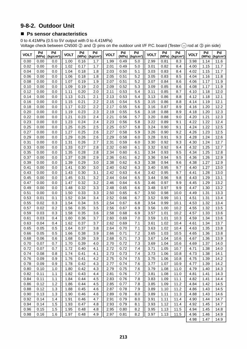
213
9-8-2. Outdoor Unit Ps sensor characteristics0 to 4.41MPa (0.5 to 5V output with 0 to 4.41MPa)Voltage check between CN500 and pins on the outdoor unit I/F P.C. board (Tester – rod at pin side)
VOLT
0.000.020.040.060.080.100.120.140.160.180.200.220.230.250.270.290.310.330.350.370.390.410.430.450.470.490.510.530.550.570.590.610.630.650.660.680.700.720.740.760.780.800.820.840.860.880.900.920.940.960.98
Pd(MPa)
0.000.000.000.000.000.000.000.000.000.000.000.000.000.000.000.000.000.000.000.000.000.000.000.000.000.000.000.010.020.020.030.030.040.050.050.060.070.070.080.090.090.100.110.110.120.120.130.140.140.150.16
Pd(kg/cm²)
0.00.00.00.00.00.00.00.00.00.00.00.00.00.00.00.00.00.00.00.00.00.00.00.00.00.00.00.10.30.20.30.40.40.50.50.60.70.70.80.90.91.01.11.11.21.31.31.41.51.51.6
VOLT
1.001.021.041.061.071.091.111.131.151.171.191.211.231.251.271.291.311.331.351.371.391.411.431.451.471.481.501.521.541.561.581.601.621.641.661.681.701.721.741.761.781.801.821.841.861.881.901.911.931.951.97
Pd(MPa)
0.160.170.180.180.190.190.200.210.210.220.230.230.240.250.250.260.260.270.280.280.290.300.300.310.320.320.330.340.340.350.350.360.370.370.380.390.390.400.410.410.420.420.430.440.440.450.460.460.470.480.48
Pd(kg/cm²)
1.71.71.81.81.92.02.02.12.22.22.32.42.42.52.62.62.72.82.82.93.03.03.13.23.23.33.33.43.53.53.63.73.73.83.93.94.04.14.14.24.34.34.44.54.54.64.64.74.84.84.9
VOLT
1.992.012.032.052.072.092.112.132.152.172.192.212.232.252.272.292.312.322.342.362.382.402.422.442.462.482.502.522.542.562.582.602.622.642.662.682.702.722.732.752.772.792.812.832.852.872.892.912.932.952.97
VOLT
2.993.013.033.053.073.093.113.133.153.163.183.203.223.243.263.283.303.323.343.363.383.403.423.443.463.483.503.523.543.563.573.593.613.633.653.673.693.713.733.753.773.793.813.833.853.893.893.913.933.953.97
VOLT
3.984.004.024.044.064.084.104.124.144.164.184.204.224.244.264.284.304.324.344.364.384.404.414.434.454.474.494.514.534.554.574.594.614.634.654.674.694.714.734.754.774.794.814.824.844.864.884.904.924.944.964.98
Pd(MPa)
0.490.490.500.510.510.520.530.530.540.550.550.560.560.570.580.580.590.600.600.610.620.620.630.640.640.650.650.660.670.670.680.690.690.700.710.710.720.720.730.740.740.750.760.760.770.780.780.790.790.800.81
Pd(MPa)
0.810.820.830.830.840.850.850.860.860.870.880.880.890.900.900.910.920.920.930.940.940.950.950.960.970.970.980.990.991.001.011.011.021.021.031.041.041.051.061.061.071.081.081.091.091.101.111.111.121.131.13
Pd(MPa)
1.141.151.151.161.171.171.181.181.191.201.201.211.221.221.231.241.241.251.251.261.271.271.281.291.291.301.311.311.321.321.331.341.341.351.361.361.371.381.381.391.391.401.411.411.421.431.431.441.451.451.461.47
Pd(kg/cm²)
5.05.05.15.25.25.35.45.45.55.65.65.75.85.85.96.06.06.16.16.26.36.36.46.56.56.66.76.76.86.96.97.07.17.17.27.37.37.47.47.57.67.67.77.87.87.98.08.08.18.28.2
Pd(kg/cm²)
8.38.48.48.58.68.68.78.88.88.98.99.09.19.19.29.39.39.49.59.59.69.79.79.89.99.9
10.010.110.110.210.210.310.410.410.510.610.610.710.810.810.911.011.011.111.211.211.311.411.411.511.5
Pd(kg/cm²)
11.611.711.711.811.911.912.012.112.112.212.312.312.412.512.512.612.712.712.812.912.913.013.013.113.213.213.313.413.413.513.613.613.713.813.813.914.014.014.114.214.214.314.314.414.514.514.614.714.714.814.914.9
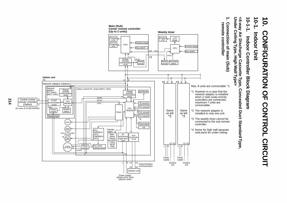
214
10.C
ON
FIGU
RA
TION
OF C
ON
TRO
L CIR
CU
IT10-1. In
do
or U
nit
10-1-1.In
do
or C
on
troller B
lock D
iagram
<4-way A
ir Disch
arge C
assette Type, C
on
cealed D
uct S
tand
ard Typ
e,U
nd
er Ceilin
g Typ
e, Hig
h W
all Type>
1.C
on
nectio
n o
f main
(Su
b)
remo
te con
troller
DisplayLCD
Function setupDisplay
LEDCPU
Remotecontroller
communicationcircuit
Remotecontroller
communicationcircuit
CPUH8/3039
Driver
Remotecontroller
communicationcircuit
Key switch
Powercircuit
Powercircuit
Transformer
Switchsetup
DC5V
DisplayLCD
LCDdriver
Function setupCPU
Key switch
Powercircuit
Secondarybattery
DC5V
*3
Sameas left
*2
CN2 CN1
#2 A B
LU1 U2
N
L
A B
N U1 U2
U1 U2
Powersupply
Outdoorunit
Sameas left
*2
#3 A B
LU1 U2
N
Powersupply
Outdoorunit
Network adaptor (Option)
Indoor unit#1
*4
Central controlremote controller
(Option)
X
Y(In case of AI-NETWORK)
NetworkadaptorP.C. board(MCC-1401)
Indoor control P.C. board (MCC-1402)
DC5V
DC20V
DC12V
DC5V
DC280V
AI-NETcommunication
circuit
CPUH8/3687
PMV
Louvermotor
Drainpump
Indoorfan motor
None for ConcealedDuct type
EEPROM
TA sensor
TCI sensor
TC2 sensor
TCJ sensor
Float input
HA
BUScommunication
circuit
Outdoor unit
Power supply1Ø200-240V, 50Hz
1Ø220V, 60Hz
ACsynchronoussignal input
circuit
CPUTMP88CH47FG(TMP88PH47FG)
Fan motorcontrol circuit
Start Alarm Ready
Thermostat ON COOL HEAT FAN
Indoor/Outdoorcommunication
Outsideoutput
Powercircuit
Max. 8 units are connectable. *1
*1 However in a case that the network adaptor is installed when 2 main (sub) remote controllers are connected, maximum 7 units are connectable.
*2 The network adaptor is installed to only one unit.
*3 The weekly timer cannot be connected to the sub remote controller.
*4 Nome for high wall spearatesold parts for under ceiling.
Main (Sub) Center remote controller(Up to 2 units) Weekly timer
*4
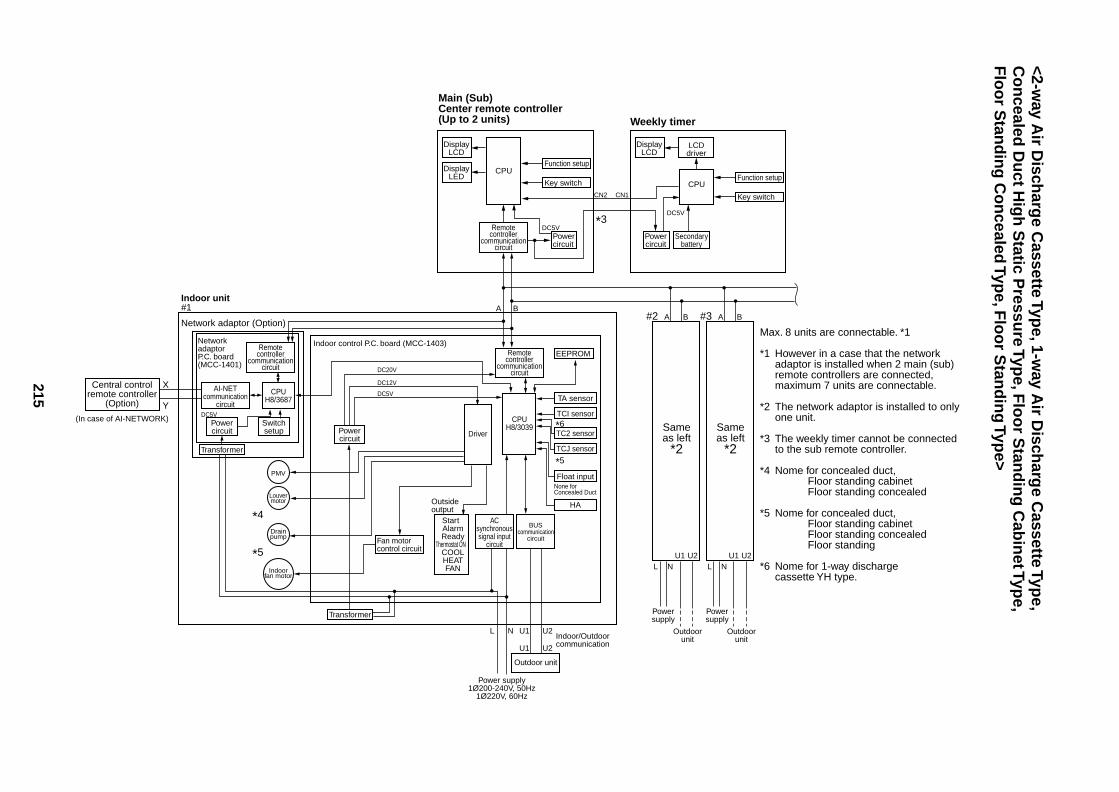
215
<2-way A
ir Disch
arge C
assette Type, 1-w
ay Air D
ischarg
e Cassette Typ
e,C
on
cealed D
uct H
igh
Static P
ressure Typ
e, Flo
or S
tand
ing
Cab
inet Typ
e,F
loo
r Stan
din
g C
on
cealed Typ
e, Flo
or S
tand
ing
Type>
DisplayLCD
Function setupDisplay
LEDCPU
Remotecontroller
communicationcircuit
Remotecontroller
communicationcircuit
CPUH8/3039
Driver
Remotecontroller
communicationcircuit
Key switch
Powercircuit
Powercircuit
Transformer
Transformer
Switchsetup
DC5V
DisplayLCD
LCDdriver
Function setupCPU
Key switch
Powercircuit
Secondarybattery
DC5V
*3
Sameas left
*2
CN2 CN1
#2 A B
LU1 U2
N
L
A B
N U1 U2
U1 U2
Powersupply
Outdoorunit
Sameas left
*2
#3 A B
LU1 U2
N
Powersupply
Outdoorunit
Network adaptor (Option)
Indoor unit#1
Central controlremote controller
(Option)
X
Y(In case of AI-NETWORK)
NetworkadaptorP.C. board(MCC-1401)
Indoor control P.C. board (MCC-1403)
DC5V
DC20V
DC12V
DC5VAI-NET
communicationcircuit
CPUH8/3687
PMV
Louvermotor
Drainpump
Indoorfan motor
EEPROM
TA sensor
TCI sensor
TC2 sensor
TCJ sensor
Float input
HA
BUScommunication
circuit
Outdoor unit
Power supply1Ø200-240V, 50Hz
1Ø220V, 60Hz
ACsynchronoussignal input
circuitFan motorcontrol circuit
Start Alarm Ready
Thermostat ON COOL HEAT FAN
Indoor/Outdoorcommunication
Outsideoutput
Powercircuit
Max. 8 units are connectable. *1
*1 However in a case that the network adaptor is installed when 2 main (sub) remote controllers are connected, maximum 7 units are connectable.
*2 The network adaptor is installed to only one unit.
*3 The weekly timer cannot be connected to the sub remote controller.
*4 Nome for concealed duct,Floor standing cabinetFloor standing concealed
*5 Nome for concealed duct,Floor standing cabinetFloor standing concealedFloor standing
*6 Nome for 1-way discharge cassette YH type.
Main (Sub) Center remote controller(Up to 2 units) Weekly timer
None for Concealed Duct
*4
*5
*6
*5
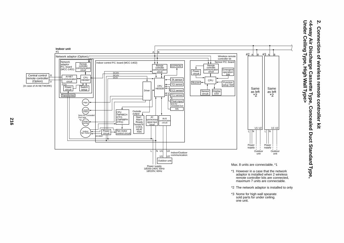
216
2.C
on
nectio
n o
f wireless rem
ote co
ntro
ller kit
<4-way A
ir Disch
arge C
assette Type, C
on
cealed D
uct S
tand
ard Typ
e,U
nd
er Ceilin
g Typ
e, Hig
h W
all Type>
Remotecontroller
communicationcircuit
Remotecontroller
communicationcircuit
Emergentoperation
SW
Functionsetup SW
CPU
CPUH8/3039
Driver
Remotecontroller
communicationcircuit
Powercircuit
Transformer
Switchsetup Same
as left*2
#2 A B
LU1 U2
N
L
A B
N U1 U2
U1 U2
Powersupply
Outdoorunit
Sameas left
*2
#3 A B
LU1 U2
N
Powersupply
Outdoorunit
Network adaptor (Option)
Indoor unit#1
Central controlremote controller
(Option)
X
Y(In case of AI-NETWORK)
NetworkadaptorP.C. board(MCC-1401)
Indoor control P.C. board (MCC-1402)
DC5V
DC20VDC12VDC5V
DC280V
AI-NETcommunication
circuit
CPUH8/3687
PMV
Louvermotor
Drainpump
Indoorfan motor
None for ConcealedDuct type
EEPROM
TA sensor
TCI sensor
TC2 sensor
TCJ sensor
Float input
HA
BUScommunication
circuit
Outdoor unit
Power supply1Ø200-240V, 50Hz
1Ø220V, 60Hz
ACsynchronoussignal input
circuit
CPUTMP88CH47FG(TMP88PH47FG)
Fan motorcontrol circuit
Start Alarm Ready
Thermostat ON COOL HEAT FAN
Indoor/Outdoorcommunication
Outsideoutput
Powercircuit
Max. 8 units are connectable. *1
*1 However in a case that the network adaptor is installed when 2 wireless remote controller kits are connected, maximum 7 units are connectable.
*2 The network adaptor is installed to only
*3 Nome for high wall spearatesold parts for under ceiling. one unit.
Powercircuit
Buzzer
Sensorcircuit
Wireless remotecontroller kit
DisplayLED
Sensor P.C. board
None for Concealed Duct
*3
*3
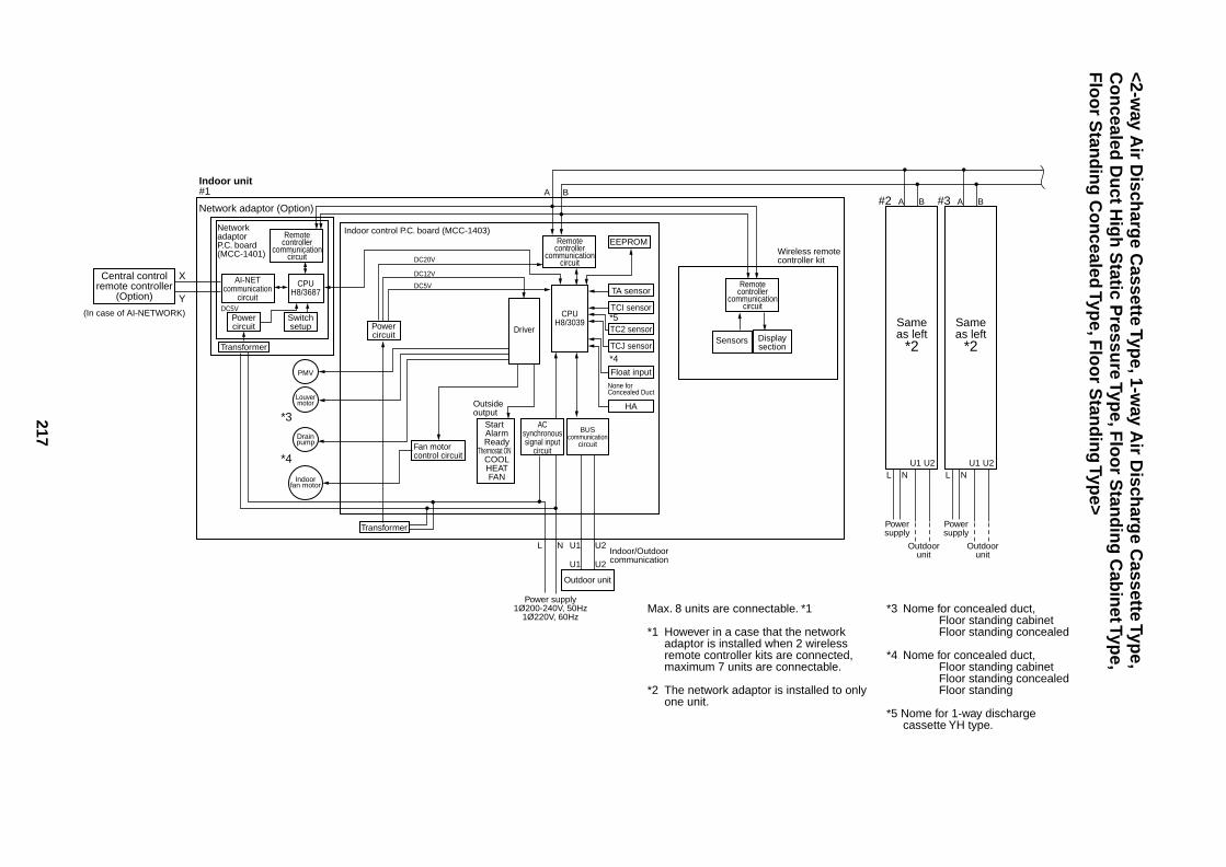
217
<2-way A
ir Disch
arge C
assette Type, 1-w
ay Air D
ischarg
e Cassette Typ
e,C
on
cealed D
uct H
igh
Static P
ressure Typ
e, Flo
or S
tand
ing
Cab
inet Typ
e,F
loo
r Stan
din
g C
on
cealed Typ
e, Flo
or S
tand
ing
Type>
Remotecontroller
communicationcircuit
CPUH8/3039
Driver
Remotecontroller
communicationcircuit
Powercircuit
Transformer
Transformer
Switchsetup Same
as left*2
#2 A B
LU1 U2
N
L
A B
N U1 U2
U1 U2
Powersupply
Outdoorunit
Sameas left
*2
#3 A B
LU1 U2
N
Powersupply
Outdoorunit
Network adaptor (Option)
Indoor unit#1
Central controlremote controller
(Option)
X
Y(In case of AI-NETWORK)
NetworkadaptorP.C. board(MCC-1401)
Indoor control P.C. board (MCC-1403)
DC5V
DC20V
DC12V
DC5VAI-NET
communicationcircuit
CPUH8/3687
PMV
Louvermotor
Drainpump
Indoorfan motor
EEPROM
TA sensor
TCI sensor
TC2 sensor
TCJ sensor
Float input
HA
BUScommunication
circuit
Outdoor unit
Power supply1Ø200-240V, 50Hz
1Ø220V, 60Hz
ACsynchronoussignal input
circuitFan motorcontrol circuit
Start Alarm Ready
Thermostat ON COOL HEAT FAN
Indoor/Outdoorcommunication
Outsideoutput
Powercircuit
Remotecontroller
communicationcircuit
*3 Nome for concealed duct,Floor standing cabinetFloor standing concealed
*4 Nome for concealed duct,Floor standing cabinetFloor standing concealedFloor standing
*5 Nome for 1-way discharge cassette YH type.
Max. 8 units are connectable. *1
*1 However in a case that the network adaptor is installed when 2 wireless remote controller kits are connected, maximum 7 units are connectable.
*2 The network adaptor is installed to only one unit.
Sensors
Wireless remotecontroller kit
Displaysection
None for Concealed Duct
*3
*4
*5
*4
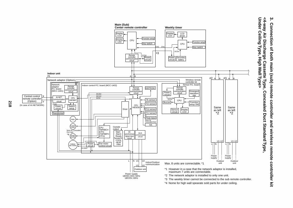
218
3.C
on
nectio
n o
f bo
th m
ain (su
b) rem
ote co
ntro
ller and
wireless rem
ote co
ntro
ller kit
<4-way A
ir Disch
arge C
assette Type, C
on
cealed D
uct S
tand
ard Typ
e,U
nd
er Ceilin
g Typ
e, Hig
h W
all Type>
Remotecontroller
communicationcircuit
Remotecontroller
communicationcircuit
Emergentoperation
SW
Functionsetup SW
CPU
CPUH8/3039
Driver
Remotecontroller
communicationcircuit
Powercircuit
Transformer
Switchsetup Same
as left*2
#2 A B
LU1 U2
N
L
A B
N U1 U2
U1 U2
Powersupply
Outdoorunit
Sameas left
*2
#3 A B
LU1 U2
N
Powersupply
Outdoorunit
Network adaptor (Option)
Indoor unit#1
Central controlremote controller
(Option)
X
Y(In case of AI-NETWORK)
NetworkadaptorP.C. board(MCC-1401)
Indoor control P.C. board (MCC-1402)
DC5V
DC20VDC12VDC5V
DC280V
AI-NETcommunication
circuit
CPUH8/3687
PMV
Louvermotor
Drainpump
Indoorfan motor
None for ConcealedDuct type
EEPROM
TA sensor
TCI sensor
TC2 sensor
TCJ sensor
Float input
HA
BUScommunication
circuit
Outdoor unit
Power supply1Ø200-240V, 50Hz
1Ø220V, 60Hz
ACsynchronoussignal input
circuit
CPUTMP88CH47FG(TMP88PH47FG)
Fan motorcontrol circuit
Start Alarm Ready
Thermostat ON COOL HEAT FAN
Indoor/Outdoorcommunication
Outsideoutput
Powercircuit
Max. 8 units are connectable. *1
*1 However in a case that the network adaptor is installed, maximum 7 units are connectable.
*2 The network adaptor is installed to only one unit.*3 The weekly timer cannot be connected to the sub remote controller.*4 Nome for high wall spearate sold parts for under ceiling.
Powercircuit
Buzzer
Sensorcircuit
Wireless remotecontroller kit
DisplayLED
Sensor P.C. board
DisplayLCD
Function setupDisplay
LEDCPU
Remotecontroller
communicationcircuit
Key switch
Powercircuit
DC5V
DisplayLCD
LCDdriver
Function setupCPU
Key switch
Powercircuit
Secondarybattery
DC5V
*3
CN2 CN1
Main (Sub) Center remote controller Weekly timer
DC5V
None for Concealed Duct
*4
*4
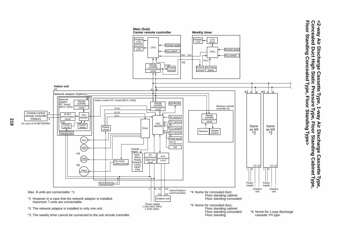
219
<2-way A
ir Disch
arge C
assette Type, 1-w
ay Air D
ischarg
e Cassette Typ
e,C
on
cealed D
uct H
igh
Static P
ressure Typ
e, Flo
or S
tand
ing
Cab
inet Typ
e,F
loo
r Stan
din
g C
on
cealed Typ
e, Flo
or S
tand
ing
Type>
*4 Nome for concealed duct,Floor standing cabinetFloor standing concealed
*5 Nome for concealed duct,Floor standing cabinetFloor standing concealedFloor standing
*6 Nome for 1-way discharge cassette YH type.
Max. 8 units are connectable. *1
*1 However in a case that the network adaptor is installed, maximum 7 units are connectable.
*2 The network adaptor is installed to only one unit.
*3 The weekly timer cannot be connected to the sub remote controller.
DisplayLCD
Function setupDisplay
LEDCPU
Remotecontroller
communicationcircuit
Key switch
Powercircuit
DC5V
DisplayLCD
LCDdriver
Function setupCPU
Key switch
Powercircuit
Secondarybattery
DC5V
*3
CN2 CN1
Main (Sub) Center remote controller Weekly timer
Remotecontroller
communicationcircuit
CPUH8/3039
Driver
Remotecontroller
communicationcircuit
Powercircuit
Transformer
Transformer
Switchsetup Same
as left*2
#2 A B
LU1 U2
N
L
A B
N U1 U2
U1 U2
Powersupply
Outdoorunit
Sameas left
*2
#3 A B
LU1 U2
N
Powersupply
Outdoorunit
Network adaptor (Option)
Indoor unit#1
Central controlremote controller
(Option)
X
Y(In case of AI-NETWORK)
NetworkadaptorP.C. board(MCC-1401)
Indoor control P.C. board (MCC-1403)
DC5V
DC20V
DC12V
DC5VAI-NET
communicationcircuit
CPUH8/3687
PMV
Louvermotor
Drainpump
Indoorfan motor
EEPROM
TA sensor
TCI sensor
TC2 sensor
TCJ sensor
Float input
HA
BUScommunication
circuit
Outdoor unit
Power supply1 200-240V, 50Hz
1 220V, 60Hz
ACsynchronoussignal input
circuitFan motorcontrol circuit
Start Alarm Ready
Thermostat ON COOL HEAT FAN
Indoor/Outdoorcommunication
Outsideoutput
Powercircuit
Remotecontroller
communicationcircuit
Sensors
Wireless remotecontroller kit
Displaysection
None for Concealed Duct
*4
*5
*6
*5
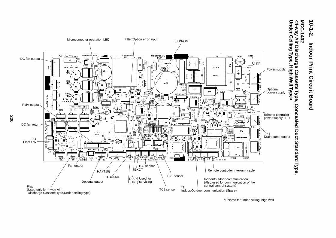
220
10-1-2.In
do
or P
rint C
ircuit B
oard
MC
C-1402
<4-way A
ir Disch
arge C
assette Type, C
on
cealed D
uct S
tand
ard Typ
e,U
nd
er Ceilin
g Typ
e, Hig
h W
all Type>
DC fan output
PMV output
DC fan return
*1Float SW
Flap(Used only for 4-way Air Discharge Cassette Type,Under ceiling type)
Fan output
Optional output
HA (T10)
CHKDISPTA sensor
EXCT
Used for servicing
TC2 sensor
TC1 sensor
TCJ sensorRemote controller inter-unit cable
Indoor/Outdoor communication(Also used for communication of the central control system)*1
Indoor/Outdoor communication (Spare)
*1 Nome for under ceiling, high wall
*1Drain pump output
Remote controller power supply LED
Optional power supply
Power supply
EEPROMFilter/Option error inputMicrocomputer operation LED
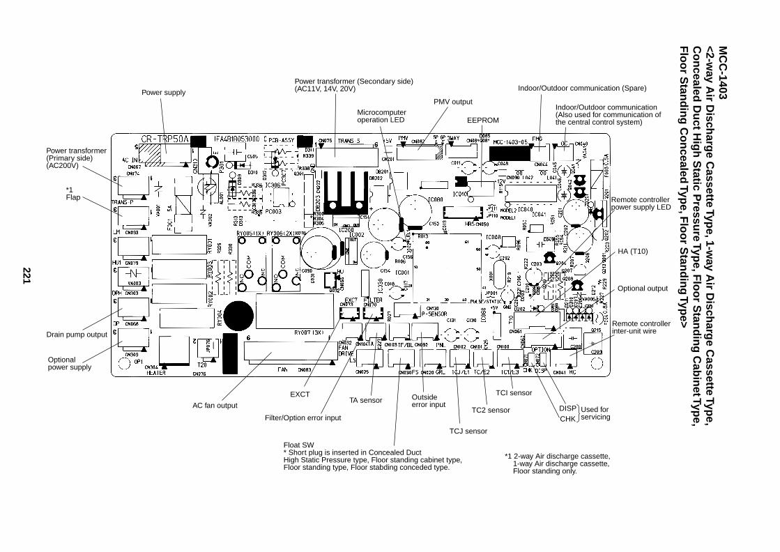
221
MC
C-1403
<2-way A
ir Disch
arge C
assette Type, 1-w
ay Air D
ischarg
e Cassette Typ
e,C
on
cealed D
uct H
igh
Static P
ressure Typ
e, Flo
or S
tand
ing
Cab
inet Typ
e,F
loo
r Stan
din
g C
on
cealed Typ
e, Flo
or S
tand
ing
Type>
Power transformer(Primary side)(AC200V)
*1Flap
Drain pump output
Optional power supply
AC fan output
EXCT
Filter/Option error input
TA sensor
Float SW* Short plug is inserted in Concealed Duct High Static Pressure type, Floor standing cabinet type,Floor standing type, Floor stabding conceded type.
*1 2-way Air discharge cassette, 1-way Air discharge cassette, Floor standing only.
Outside error input
TCJ sensor
TC2 sensor
TCI sensor
CHKDISP Used for
servicing
Remote controller inter-unit wire
Optional output
HA (T10)
Remote controller power supply LED
Indoor/Outdoor communication(Also used for communication of the central control system)
Indoor/Outdoor communication (Spare)
EEPROM
PMV outputMicrocomputer operation LED
Power transformer (Secondary side)(AC11V, 14V, 20V)Power supply
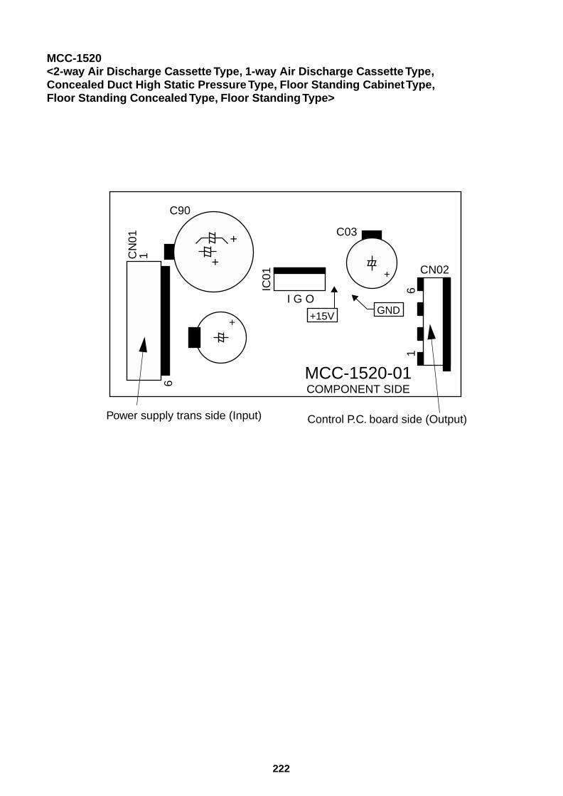
222
MCC-1520<2-way Air Discharge Cassette Type, 1-way Air Discharge Cassette Type,Concealed Duct High Static Pressure Type, Floor Standing Cabinet Type,Floor Standing Concealed Type, Floor Standing Type>
MCC-1520-01COMPONENT SIDE
IC01
16
CN
011
6
+
+
+
+ C03
CN02
C90
I G O
+15V GND
Control P.C. board side (Output)Power supply trans side (Input)
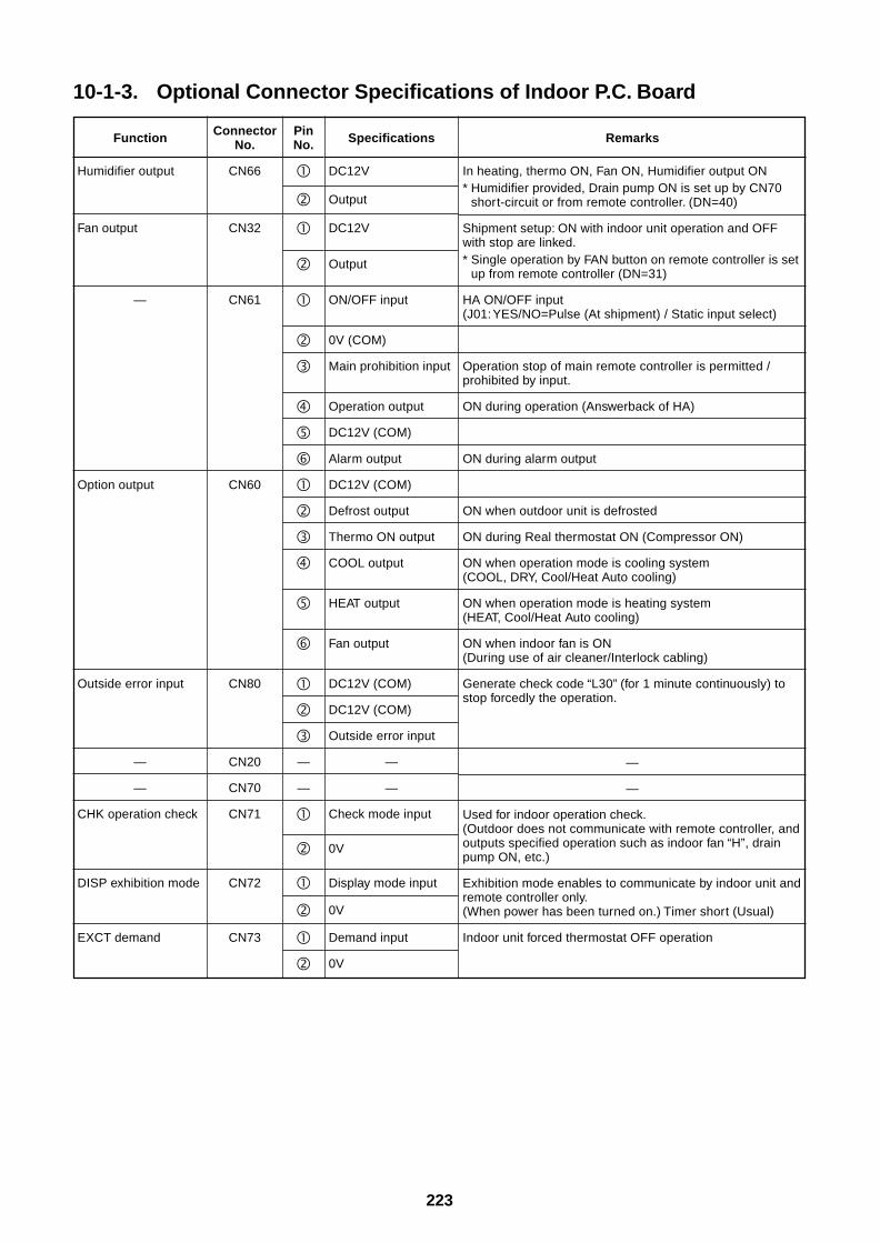
223
10-1-3. Optional Connector Specifications of Indoor P.C. Board
Function
Humidifier output
Fan output
—
Option output
Outside error input
—
—
CHK operation check
DISP exhibition mode
EXCT demand
ConnectorNo.
CN66
CN32
CN61
CN60
CN80
CN20
CN70
CN71
CN72
CN73
PinNo.
—
—
Specifications
DC12V
Output
DC12V
Output
ON/OFF input
0V (COM)
Main prohibition input
Operation output
DC12V (COM)
Alarm output
DC12V (COM)
Defrost output
Thermo ON output
COOL output
HEAT output
Fan output
DC12V (COM)
DC12V (COM)
Outside error input
—
—
Check mode input
0V
Display mode input
0V
Demand input
0V
Remarks
In heating, thermo ON, Fan ON, Humidifier output ON* Humidifier provided, Drain pump ON is set up by CN70
short-circuit or from remote controller. (DN=40)
Shipment setup: ON with indoor unit operation and OFFwith stop are linked.* Single operation by FAN button on remote controller is set
up from remote controller (DN=31)
HA ON/OFF input(J01: YES/NO=Pulse (At shipment) / Static input select)
Operation stop of main remote controller is permitted /prohibited by input.
ON during operation (Answerback of HA)
ON during alarm output
ON when outdoor unit is defrosted
ON during Real thermostat ON (Compressor ON)
ON when operation mode is cooling system(COOL, DRY, Cool/Heat Auto cooling)
ON when operation mode is heating system(HEAT, Cool/Heat Auto cooling)
ON when indoor fan is ON(During use of air cleaner/Interlock cabling)
Generate check code “L30” (for 1 minute continuously) tostop forcedly the operation.
—
—
Used for indoor operation check.(Outdoor does not communicate with remote controller, andoutputs specified operation such as indoor fan “H”, drainpump ON, etc.)
Exhibition mode enables to communicate by indoor unit andremote controller only.(When power has been turned on.) Timer short (Usual)
Indoor unit forced thermostat OFF operation
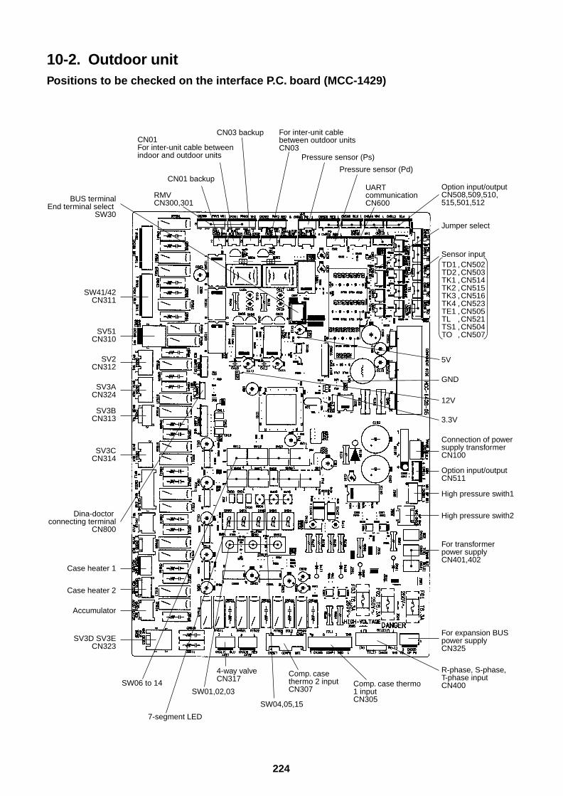
224
10-2. Outdoor unitPositions to be checked on the interface P.C. board (MCC-1429)
RMVCN300,301
CN01 backup
TD1 ,CN502TD2 ,CN503TK1 ,CN514TK2 ,CN515TK3 ,CN516TK4 ,CN523TE1 ,CN505TL ,CN521TS1 ,CN504TO ,CN507
5V
Sensor input
Jumper select
Option input/outputCN508,509,510,515,501,512
UART communication CN600
GND
12V
3.3V
R-phase, S-phase, T-phase inputCN400
For expansion BUS power supplyCN325
For transformer power supplyCN401,402
Option input/outputCN511
High pressure swith1
High pressure swith2
Connection of power supply transformerCN100
SW06 to 14
SV3D SV3ECN323
Dina-doctor connecting terminal
CN800
Case heater 1
Case heater 2
Accumulator
SV3CCN314
SV3BCN313
SV3ACN324
SV2CN312
SV51CN310
SW41/42CN311
BUS terminalEnd terminal select
SW30
SW01,02,03
SW04,05,15
Comp. case thermo 2 inputCN307
7-segment LED
CN03 backupCN01 For inter-unit cable between indoor and outdoor units
4-way valveCN317
Comp. case thermo 1 inputCN305
Pressure sensor (Pd)
Pressure sensor (Ps)
For inter-unit cable between outdoor units CN03
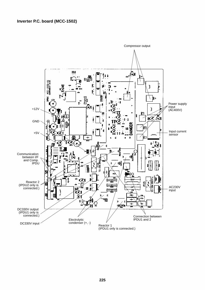
225
Inverter P.C. board (MCC-1502)
Communication between I/F and Comp.
IPDU
Reactor 2 (IPDU2 only is
connected.)
DC330V output (IPDU1 only is
connected.)
DC330V inputElectrolytic condenser (+, -)
Reactor 1(IPDU1 only is connected.)
Connection between IPDU1 and 2
AC230V input
Input current sensor
Power supplyinput (AC400V)
Compressor output
+5V
GND
+12V
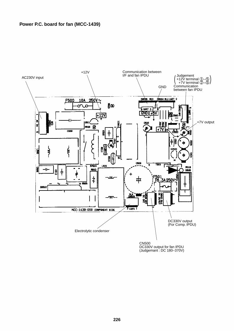
226
Power P.C. board for fan (MCC-1439)
AC230V input
+12V
GND
Electrolytic condenser
CN500DC330V output for fan IPDU(Judgemant : DC 180–370V)
DC330V output(For Comp. IPDU)
+7V output
Judgement +12V terminal 1 – 5 +7V terminal 2 – 5Communication between fan IPDU
Communication betweenI/F and fan IPDU
( )
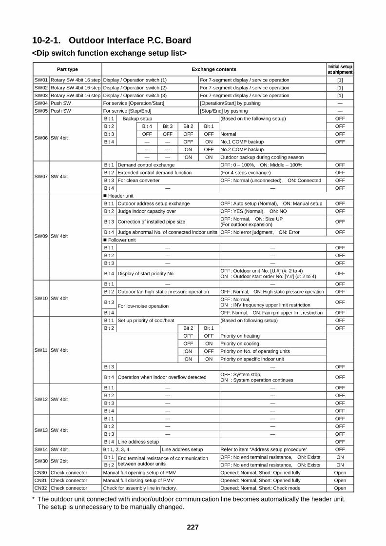
227
10-2-1. Outdoor Interface P.C. Board<Dip switch function exchange setup list>
* The outdoor unit connected with indoor/outdoor communication line becomes automatically the header unit.The setup is unnecessary to be manually changed.
Part type Exchange contents Initial setupat shipment
SW01 Rotary SW 4bit 16 step Display / Operation switch (1) For 7-segment display / service operation [1]
SW02 Rotary SW 4bit 16 step Display / Operation switch (2) For 7-segment display / service operation [1]
SW03 Rotary SW 4bit 16 step Display / Operation switch (3) For 7-segment display / service operation [1]
SW04 Push SW For service [Operation/Start] [Operation/Start] by pushing —
SW05 Push SW For service [Stop/End] [Stop/End] by pushing —
Bit 1 Backup setup OFF
Bit 2 Bit 4 Bit 3 Bit 2 Bit 1
(Based on the following setup)
OFF
Bit 3 OFF OFF OFF OFF Normal OFF
Bit 4 — — OFF ON No.1 COMP backup OFF
— — ON OFF No.2 COMP backup
SW06 SW 4bit
— — ON ON Outdoor backup during cooling season
Bit 1 Demand control exchange OFF: 0 – 100%, ON: Middle – 100% OFF
Bit 2 Extended control demand function (For 4-steps exchange) OFF
Bit 3 For clean converter OFF: Normal (unconnected), ON: Connected OFFSW07 SW 4bit
Bit 4 — — OFF
Header unit
Bit 1 Outdoor address setup exchange OFF: Auto setup (Normal), ON: Manual setup OFF
Bit 2 Judge indoor capacity over OFF: YES (Normal), ON: NO OFF
Bit 3 Correction of installed pipe size OFF: Normal, ON: Size UP(For outdoor expansion) OFF
Bit 4 Judge abnormal No. of connected indoor units OFF: No error judgment, ON: Error OFF
Follower unit
Bit 1 — — OFF
Bit 2 — — OFF
Bit 3 — — OFF
SW09 SW 4bit
Bit 4 Display of start priority No. OFF: Outdoor unit No. [U.#] (#: 2 to 4)ON : Outdoor start order No. [Y.#] (#: 2 to 4) OFF
Bit 1 — — OFF
Bit 2 Outdoor fan high-static pressure operation OFF : Normal, ON: High-static pressure operation OFF
Bit 3 OFF: Normal,ON : INV frequency upper limit restriction OFF
SW10 SW 4bit
Bit 4For low-noise operation
OFF: Normal, ON: Fan rpm upper limit restriction OFF
Bit 1 Set up priority of cool/heat (Based on following setup) OFF
Bit 2 Bit 2 Bit 1 OFF
OFF OFF Priority on heating
OFF ON Priority on cooling
ON OFF Priority on No. of operating units
ON ON Priority on specific indoor unit
Bit 3 — OFF
SW11 SW 4bit
Bit 4 Operation when indoor overflow detected OFF: System stop,ON : System operation continues OFF
Bit 1 — — OFF
Bit 2 — — OFF
Bit 3 — — OFFSW12 SW 4bit
Bit 4 — — OFF
Bit 1 — — OFF
Bit 2 — — OFF
Bit 3 — — OFFSW13 SW 4bit
Bit 4 Line address setup OFF
SW14 SW 4bit Bit 1, 2, 3, 4 Line address setup Refer to item “Address setup procedure” OFF
Bit 1 OFF: No end terminal resistance, ON: Exists ONSW30 SW 2bit
Bit 2End terminal resistance of communicationbetween outdoor units OFF: No end terminal resistance, ON: Exists ON
CN30 Check connector Manual full opening setup of PMV Opened: Normal, Short: Opened fully Open
CN31 Check connector Manual full closing setup of PMV Opened: Normal, Short: Opened fully Open
CN32 Check connector Check for assembly line in factory. Opened: Normal, Short: Check mode Open
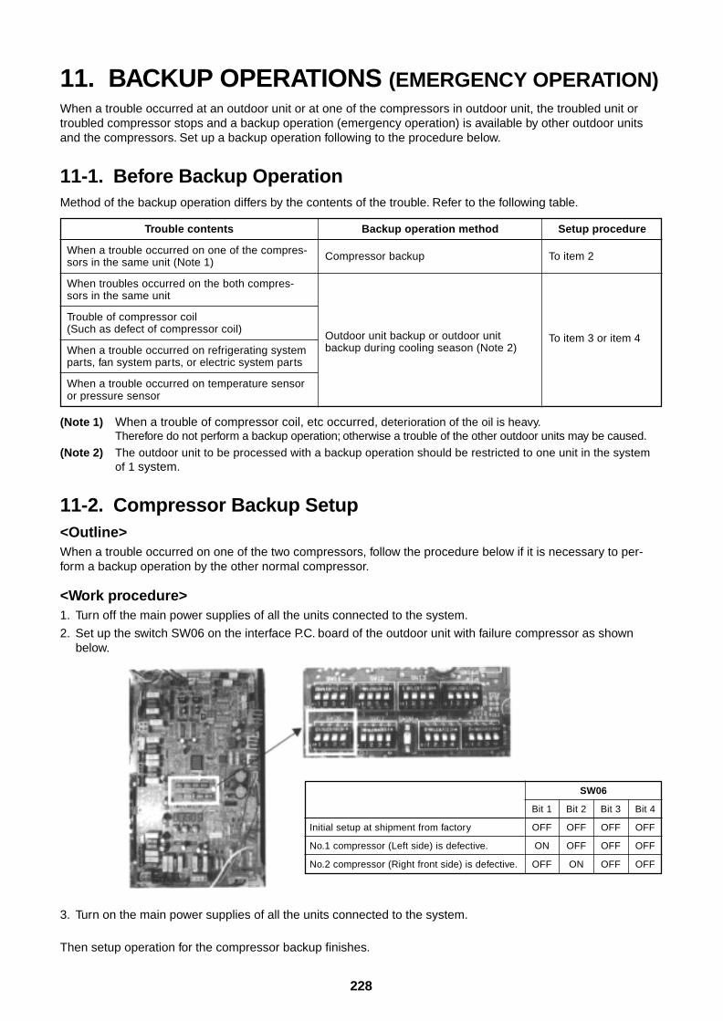
228
11. BACKUP OPERATIONS (EMERGENCY OPERATION)When a trouble occurred at an outdoor unit or at one of the compressors in outdoor unit, the troubled unit ortroubled compressor stops and a backup operation (emergency operation) is available by other outdoor unitsand the compressors. Set up a backup operation following to the procedure below.
11-1. Before Backup OperationMethod of the backup operation differs by the contents of the trouble. Refer to the following table.
Trouble contents
When a trouble occurred on one of the compres-sors in the same unit (Note 1)
When troubles occurred on the both compres-sors in the same unit
Trouble of compressor coil(Such as defect of compressor coil)
When a trouble occurred on refrigerating systemparts, fan system parts, or electric system parts
When a trouble occurred on temperature sensoror pressure sensor
Backup operation method
Compressor backup
Outdoor unit backup or outdoor unitbackup during cooling season (Note 2)
Setup procedure
To item 2
To item 3 or item 4
(Note 1) When a trouble of compressor coil, etc occurred, deterioration of the oil is heavy.Therefore do not perform a backup operation; otherwise a trouble of the other outdoor units may be caused.
(Note 2) The outdoor unit to be processed with a backup operation should be restricted to one unit in the systemof 1 system.
11-2. Compressor Backup Setup<Outline>When a trouble occurred on one of the two compressors, follow the procedure below if it is necessary to per-form a backup operation by the other normal compressor.
<Work procedure>1. Turn off the main power supplies of all the units connected to the system.
2. Set up the switch SW06 on the interface P.C. board of the outdoor unit with failure compressor as shownbelow.
3. Turn on the main power supplies of all the units connected to the system.
Then setup operation for the compressor backup finishes.
Initial setup at shipment from factory
No.1 compressor (Left side) is defective.
No.2 compressor (Right front side) is defective.
SW06
Bit 1 Bit 2 Bit 3 Bit 4
OFF OFF OFF OFF
ON OFF OFF OFF
OFF ON OFF OFF
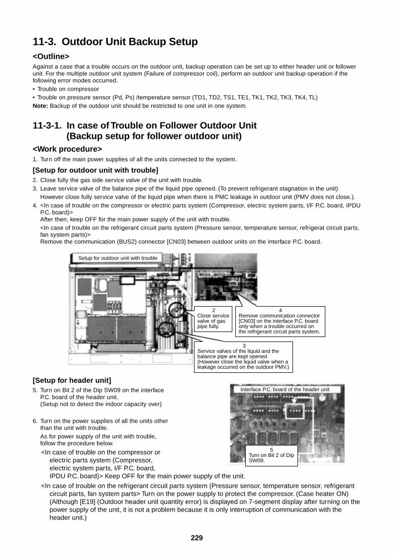
229
Setup for outdoor unit with trouble
3Service valves of the liquid and the balance pipe are kept opened. (However close the liquid valve when a leakage occurred on the outdoor PMV.)
4Remove communication connector [CN03] on the interface P.C. board only when a trouble occurred on the refrigerant circuit parts system.
2Close service valve of gas pipe fully.
11-3. Outdoor Unit Backup Setup<Outline>Against a case that a trouble occurs on the outdoor unit, backup operation can be set up to either header unit or followerunit. For the multiple outdoor unit system (Failure of compressor coil), perform an outdoor unit backup operation if thefollowing error modes occurred.• Trouble on compressor• Trouble on pressure sensor (Pd, Ps) /temperature sensor (TD1, TD2, TS1, TE1, TK1, TK2, TK3, TK4, TL)Note: Backup of the outdoor unit should be restricted to one unit in one system.
11-3-1. In case of Trouble on Follower Outdoor Unit(Backup setup for follower outdoor unit)
<Work procedure>1. Turn off the main power supplies of all the units connected to the system.
[Setup for outdoor unit with trouble]2. Close fully the gas side service valve of the unit with trouble.3. Leave service valve of the balance pipe of the liquid pipe opened. (To prevent refrigerant stagnation in the unit)
However close fully service valve of the liquid pipe when there is PMC leakage in outdoor unit (PMV does not close.).4. <In case of trouble on the compressor or electric parts system (Compressor, electric system parts, I/F P.C. board, IPDU
P.C. board)>After then, keep OFF for the main power supply of the unit with trouble.<In case of trouble on the refrigerant circuit parts system (Pressure sensor, temperature sensor, refrigerat circuit parts,fan system parts)>Remove the communication (BUS2) connector [CN03] between outdoor units on the interface P.C. board.
[Setup for header unit]5. Turn on Bit 2 of the Dip SW09 on the interface
P.C. board of the header unit.(Setup not to detect the indoor capacity over)
6. Turn on the power supplies of all the units otherthan the unit with trouble.As for power supply of the unit with trouble,follow the procedure below.
<In case of trouble on the compressor orelectric parts system (Compressor,electric system parts, I/F P.C. board,IPDU P.C. board)> Keep OFF for the main power supply of the unit.
<In case of trouble on the refrigerant circuit parts system (Pressure sensor, temperature sensor, refrigerantcircuit parts, fan system parts> Turn on the power supply to protect the compressor. (Case heater ON)(Although [E19] (Outdoor header unit quantity error) is displayed on 7-segment display after turning on thepower supply of the unit, it is not a problem because it is only interruption of communication with theheader unit.)
Interface P.C. board of the header unit
5Turn on Bit 2 of Dip SW09.
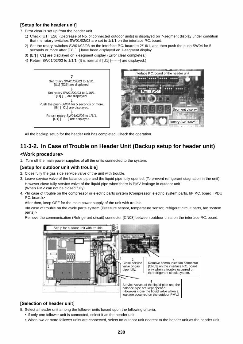
230
7Set rotary SW01/02/03 to 1/1/1.
[U1] [E26] are displayed.
Set rotary SW01/02/03 to 2/16/1.[Er] [ ] are displayed.
Push the push-SW04 for 5 seconds or more.[Er] [ CL] are displayed.
Return rotary SW01/02/03 to 1/1/1.[U1] [– – –] are displayed.
Interface P.C. board of the header unit
Push-SW04
Segment display
Rotary SW01/02/03
Setup for outdoor unit with trouble
3Service valves of the liquid pipe and the balance pipe are kept opened. (However close the liquid valve when a leakage occurred on the outdoor PMV.)
4Remove communication connector [CN03] on the interface P.C. board only when a trouble occurred on the refrigerant circuit system.
2Close service valve of gas pipe fully.
[Setup for the header unit]7. Error clear is set up from the header unit.
1) Check [U1] [E26] (Decrease of No. of connected outdoor units) is displayed on 7-segment display under conditionthat the rotary switches SW01/02/03 are set to 1/1/1 on the interface P.C. board.
2) Set the rotary switches SW01/02/03 on the interface P.C. board to 2/16/1, and then push the push SW04 for 5seconds or more after [Er] [ ] have been displayed on 7-segment display.
3) [Er] [ CL] are displayed on 7-segment display. (Error clear completes.)4) Return SW01/02/03 to 1/1/1. (It is normal if [U1] [– – –] are displayed.)
All the backup setup for the header unit has completed. Check the operation.
11-3-2. In Case of Trouble on Header Unit (Backup setup for header unit)<Work procedure>1. Turn off the main power supplies of all the units connected to the system.
[Setup for outdoor unit with trouble]2. Close fully the gas side service valve of the unit with trouble.3. Leave service valve of the balance pipe and the liquid pipe fully opened. (To prevent refrigerant stagnation in the unit)
However close fully service valve of the liquid pipe when there is PMV leakage in outdoor unit(When PMV can not be closed fully)
4. <In case of trouble on the compressor or electric parts system (Compressor, electric system parts, I/F P.C. board, IPDUP.C. board)>After then, keep OFF for the main power supply of the unit with trouble.<In case of trouble on the cycle parts system (Pressure sensor, temperature sensor, refrigerat circuit parts, fan systemparts)>Remove the communication (Refrigerant circuit) connector [CN03] between outdoor units on the interface P.C. board.
[Selection of header unit]5. Select a header unit among the follower units based upon the following criteria.
• If only one follower unit is connected, select it as the header unit.• When two or more follower units are connected, select an outdoor unit nearest to the header unit as the header unit.
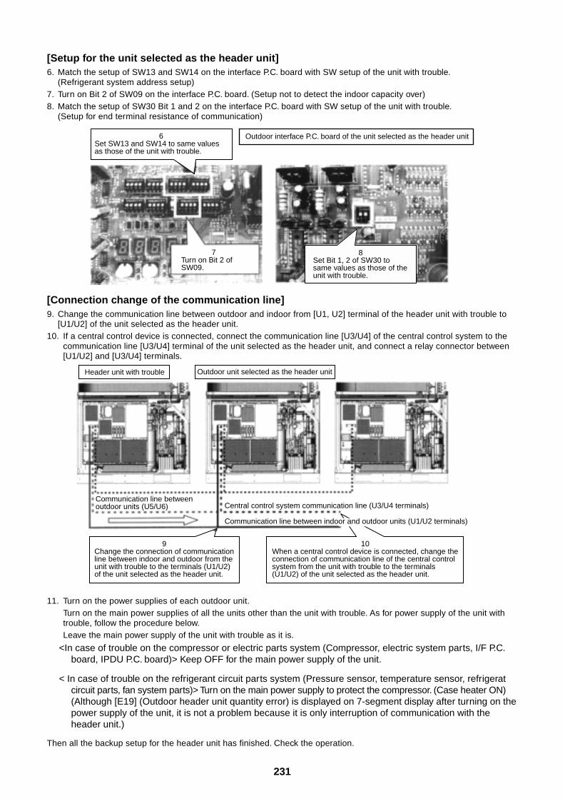
231
6Set SW13 and SW14 to same values as those of the unit with trouble.
Outdoor interface P.C. board of the unit selected as the header unit
7Turn on Bit 2 of SW09.
8Set Bit 1, 2 of SW30 to same values as those of the unit with trouble.
Header unit with trouble Outdoor unit selected as the header unit
Communication line between outdoor units (U5/U6) Central control system communication line (U3/U4 terminals)
9Change the connection of communication line between indoor and outdoor from the unit with trouble to the terminals (U1/U2) of the unit selected as the header unit.
10When a central control device is connected, change the connection of communication line of the central control system from the unit with trouble to the terminals (U1/U2) of the unit selected as the header unit.
Communication line between indoor and outdoor units (U1/U2 terminals)
[Setup for the unit selected as the header unit]6. Match the setup of SW13 and SW14 on the interface P.C. board with SW setup of the unit with trouble.
(Refrigerant system address setup)7. Turn on Bit 2 of SW09 on the interface P.C. board. (Setup not to detect the indoor capacity over)8. Match the setup of SW30 Bit 1 and 2 on the interface P.C. board with SW setup of the unit with trouble.
(Setup for end terminal resistance of communication)
[Connection change of the communication line]9. Change the communication line between outdoor and indoor from [U1, U2] terminal of the header unit with trouble to
[U1/U2] of the unit selected as the header unit.10. If a central control device is connected, connect the communication line [U3/U4] of the central control system to the
communication line [U3/U4] terminal of the unit selected as the header unit, and connect a relay connector between[U1/U2] and [U3/U4] terminals.
11. Turn on the power supplies of each outdoor unit.Turn on the main power supplies of all the units other than the unit with trouble. As for power supply of the unit withtrouble, follow the procedure below.Leave the main power supply of the unit with trouble as it is.
<In case of trouble on the compressor or electric parts system (Compressor, electric system parts, I/F P.C.board, IPDU P.C. board)> Keep OFF for the main power supply of the unit.
< In case of trouble on the refrigerant circuit parts system (Pressure sensor, temperature sensor, refrigeratcircuit parts, fan system parts)> Turn on the main power supply to protect the compressor. (Case heater ON)(Although [E19] (Outdoor header unit quantity error) is displayed on 7-segment display after turning on thepower supply of the unit, it is not a problem because it is only interruption of communication with theheader unit.)
Then all the backup setup for the header unit has finished. Check the operation.
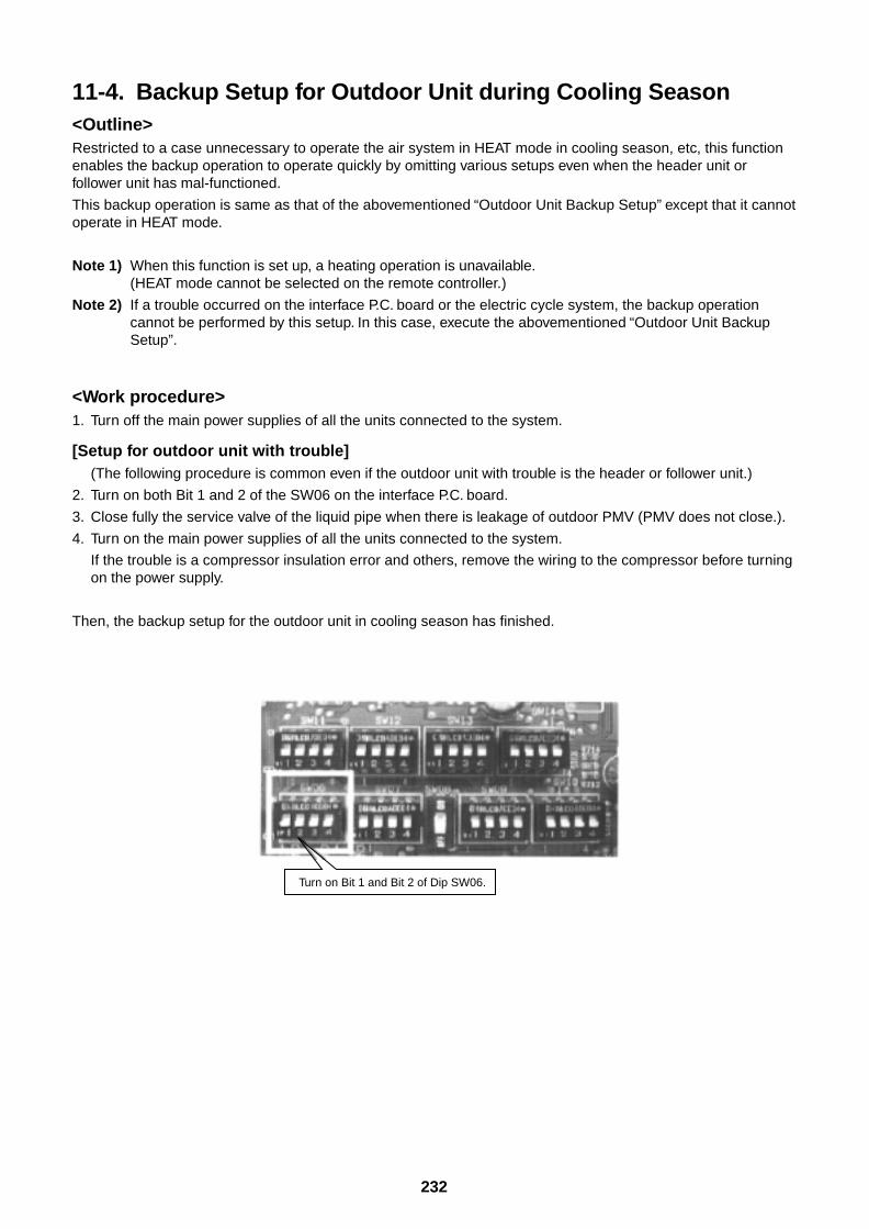
232
11-4. Backup Setup for Outdoor Unit during Cooling Season<Outline>Restricted to a case unnecessary to operate the air system in HEAT mode in cooling season, etc, this functionenables the backup operation to operate quickly by omitting various setups even when the header unit orfollower unit has mal-functioned.
This backup operation is same as that of the abovementioned “Outdoor Unit Backup Setup” except that it cannotoperate in HEAT mode.
Note 1) When this function is set up, a heating operation is unavailable.(HEAT mode cannot be selected on the remote controller.)
Note 2) If a trouble occurred on the interface P.C. board or the electric cycle system, the backup operationcannot be performed by this setup. In this case, execute the abovementioned “Outdoor Unit BackupSetup”.
<Work procedure>1. Turn off the main power supplies of all the units connected to the system.
[Setup for outdoor unit with trouble](The following procedure is common even if the outdoor unit with trouble is the header or follower unit.)
2. Turn on both Bit 1 and 2 of the SW06 on the interface P.C. board.
3. Close fully the service valve of the liquid pipe when there is leakage of outdoor PMV (PMV does not close.).
4. Turn on the main power supplies of all the units connected to the system.
If the trouble is a compressor insulation error and others, remove the wiring to the compressor before turningon the power supply.
Then, the backup setup for the outdoor unit in cooling season has finished.
Turn on Bit 1 and Bit 2 of Dip SW06.
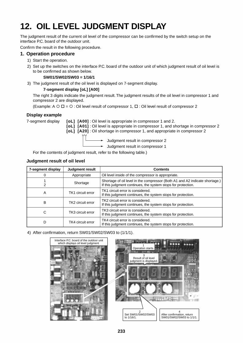
233
Interface P.C. board of the outdoor unitwhich displays oil level judgment
1Operation starts.
3Result of oil level
judgment is displayed.
2Set SW01/SW02/SW03 to 1/16/1.
4After confirmation, return SW01/SW02/SW03 to 1/1/1.
12. OIL LEVEL JUDGMENT DISPLAYThe judgment result of the current oil level of the compressor can be confirmed by the switch setup on theinterface P.C. board of the outdoor unit.
Confirm the result in the following procedure.
1. Operation procedure1) Start the operation.
2) Set up the switches on the interface P.C. board of the outdoor unit of which judgment result of oil level isto be confirmed as shown below.
SW01/SW02/SW03 = 1/16/1
3) The judgment result of the oil level is displayed on 7-segment display.
7-segment display [oL] [A00]
The right 3 digits indicate the judgment result. The judgment results of the oil level in compressor 1 andcompressor 2 are displayed.
(Example: A = : Oil level result of compressor 1, : Oil level result of compressor 2
Display example7-segment display [oL] [A00] : Oil level is appropriate in compressor 1 and 2.
[oL] [A01] : Oil level is appropriate in compressor 1, and shortage in compressor 2[oL] [A20] : Oil shortage in compressor 1, and appropriate in compressor 2
Judgment result in compressor 2Judgment result in compressor 1
For the contents of judgment result, refer to the following table.)
Judgment result of oil level
7-segment display
0
12
A
B
C
D
Judgment result
Appropriate
Shortage
TK1 circuit error
TK2 circuit error
TK3 circuit error
TK4 circuit error
Contents
Oil level inside of the compressor is appropriate.
Shortage of oil level in the compressor (Both A1 and A2 indicate shortage.)If this judgment continues, the system stops for protection.
TK1 circuit error is considered.If this judgment continues, the system stops for protection.
TK2 circuit error is considered.If this judgment continues, the system stops for protection.
TK3 circuit error is considered.If this judgment continues, the system stops for protection.
TK4 circuit error is considered.If this judgment continues, the system stops for protection.
4) After confirmation, return SW01/SW02/SW03 to (1/1/1).
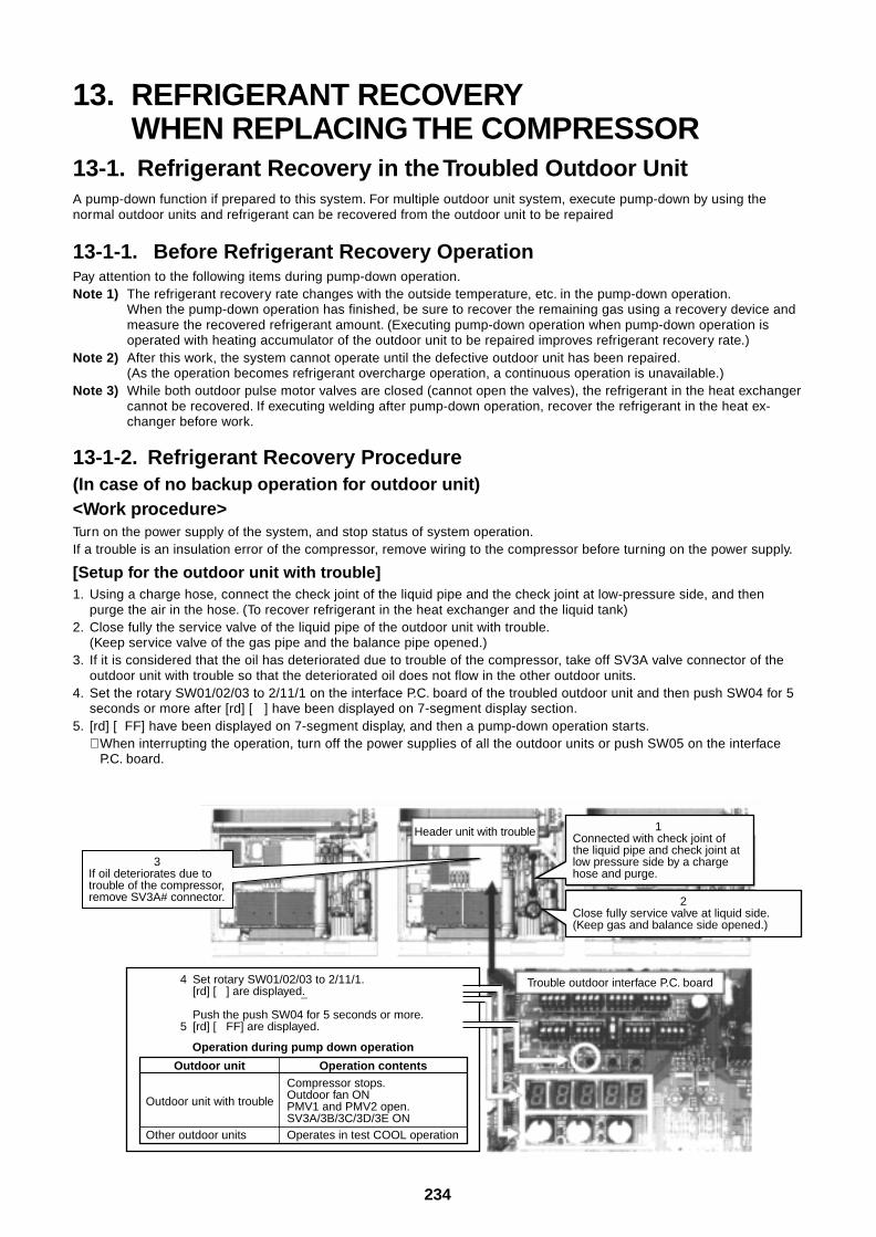
234
4 Set rotary SW01/02/03 to 2/11/1.[rd] [ ] are displayed.
¯Push the push SW04 for 5 seconds or more.
5 [rd] [ FF] are displayed.
Trouble outdoor interface P.C. board
Header unit with trouble
Operation during pump down operation
Outdoor unit Operation contents
Outdoor unit with trouble
Compressor stops.Outdoor fan ONPMV1 and PMV2 open.SV3A/3B/3C/3D/3E ON
Other outdoor units Operates in test COOL operation
3If oil deteriorates due to trouble of the compressor, remove SV3A# connector.
1Connected with check joint of the liquid pipe and check joint at low pressure side by a charge hose and purge.
2Close fully service valve at liquid side. (Keep gas and balance side opened.)
13. REFRIGERANT RECOVERYWHEN REPLACING THE COMPRESSOR
13-1. Refrigerant Recovery in the Troubled Outdoor UnitA pump-down function if prepared to this system. For multiple outdoor unit system, execute pump-down by using thenormal outdoor units and refrigerant can be recovered from the outdoor unit to be repaired
13-1-1. Before Refrigerant Recovery OperationPay attention to the following items during pump-down operation.Note 1) The refrigerant recovery rate changes with the outside temperature, etc. in the pump-down operation.
When the pump-down operation has finished, be sure to recover the remaining gas using a recovery device andmeasure the recovered refrigerant amount. (Executing pump-down operation when pump-down operation isoperated with heating accumulator of the outdoor unit to be repaired improves refrigerant recovery rate.)
Note 2) After this work, the system cannot operate until the defective outdoor unit has been repaired.(As the operation becomes refrigerant overcharge operation, a continuous operation is unavailable.)
Note 3) While both outdoor pulse motor valves are closed (cannot open the valves), the refrigerant in the heat exchangercannot be recovered. If executing welding after pump-down operation, recover the refrigerant in the heat ex-changer before work.
13-1-2. Refrigerant Recovery Procedure(In case of no backup operation for outdoor unit)<Work procedure>Turn on the power supply of the system, and stop status of system operation.If a trouble is an insulation error of the compressor, remove wiring to the compressor before turning on the power supply.
[Setup for the outdoor unit with trouble]1. Using a charge hose, connect the check joint of the liquid pipe and the check joint at low-pressure side, and then
purge the air in the hose. (To recover refrigerant in the heat exchanger and the liquid tank)2. Close fully the service valve of the liquid pipe of the outdoor unit with trouble.
(Keep service valve of the gas pipe and the balance pipe opened.)3. If it is considered that the oil has deteriorated due to trouble of the compressor, take off SV3A valve connector of the
outdoor unit with trouble so that the deteriorated oil does not flow in the other outdoor units.4. Set the rotary SW01/02/03 to 2/11/1 on the interface P.C. board of the troubled outdoor unit and then push SW04 for 5
seconds or more after [rd] [ ] have been displayed on 7-segment display section.5. [rd] [ FF] have been displayed on 7-segment display, and then a pump-down operation starts.
∗ When interrupting the operation, turn off the power supplies of all the outdoor units or push SW05 on the interfaceP.C. board.
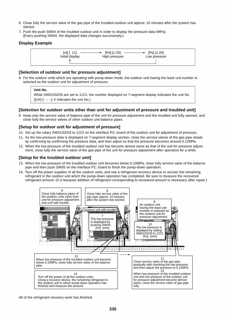
235
9Close fully balance pipes of the outdoor units other than unit for pressure adjustment and unit with trouble.
6Close fully service valve of the gas pipe approx. 10 minutes after the system has started.
11Close service valve of the gas pipe gradually with checking the low pressure, and then adjust the pressure to 0.12MPa.
12When low pressure of the troubled outdoor unit and low pressure of the outdoor unit for pressure adjustment become almost same, close the service valve of gas pipe fully.
13When low pressure of the troubled outdoor unit become below 0.10MPa, close fully service valve of the balance pipe.
14Turn off the power of all the outdoor units. Using a recovery device, the remaining refrigerant in the outdoor unit in which pump down operation has finished and measure the amount.
7The low pressure is displayed by pushing SW04.
[Ps] [###]
8An outdoor unit having the least unit number is selected as the outdoor unit for pressure adjustment.
10The low pressure is displayed by setting SW01/02/03 to 1/2/2.
[Ps] [###]
Outdoor unit with trouble
6. Close fully the service valve of the gas pipe of the troubled outdoor unit approx. 10 minutes after the system hasstarted.
7. Push the push SW04 of the troubled outdoor unit in order to display the pressure data (MPa).(Every pushing SW04, the displayed data changes successively.)
Display Example
[Selection of outdoor unit for pressure adjustment]8. For the outdoor units which are operating with pump-down mode, the outdoor unit having the least unit number is
selected as the outdoor unit for adjustment of pressure.
Unit No.While SW01/02/03 are set to 1/1/1, the number displayed on 7-segment display indicates the unit No.([U#] [– – –]: # indicates the unit No.)
[Selection for outdoor units other than unit for adjustment of pressure and troubled unit]9. Keep only the service valve of balance pipe of the unit for pressure adjustment and the troubled unit fully opened, and
close fully the service valves of other outdoor unit balance pipes.
[Setup for outdoor unit for adjustment of pressure]10. Set up the rotary SW01/02/03 to 1/2/2 on the interface P.C. board of the outdoor unit for adjustment of pressure.11. As the low-pressure data is displayed on 7-segment display section, close the service valves of the gas pipe slowly
by confirming by confirming the pressure data, and then adjust so that the pressure becomes around 0.12MPa.12. When the low-pressure of the troubled outdoor unit has become almost same as that of the unit for pressure adjust-
ment, close fully the service valve of the gas pipe of the unit for pressure adjustment after operation for a while.
[Setup for the troubled outdoor unit]13. When the low-pressure of the troubled outdoor unit becomes below 0.10MPa, close fully service valve of the balance
pipe and then push SW05 on the interface P.C. board to finish the pump-down operation.14. Turn off the power supplies of all the outdoor units, and use a refrigerant recovery device to recover the remaining
refrigerant in the outdoor unit which the pump-down operation has completed. Be sure to measure the recoveredrefrigerant amount. (It is because addition of refrigerant corresponding to recovered amount is necessary after repair.)
[rd] [ 11]Initial display
[Pd] [1.20]High pressure
[Ps] [1.20]Low pressure
All of the refrigerant recovery work has finished.
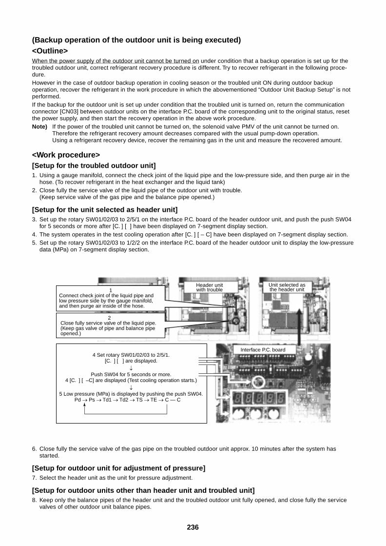
236
4 Set rotary SW01/02/03 to 2/5/1.[C. ] [ ] are displayed.
Push SW04 for 5 seconds or more.4 [C. ] [ –C] are displayed (Test cooling operation starts.)
5 Low pressure (MPa) is displayed by pushing the push SW04.Pd Ps Td1 Td2 TS TE C — C
Header unitwith trouble
Unit selected asthe header unit
Interface P.C. board
1Connect check joint of the liquid pipe and low pressure side by the gauge manifold, and then purge air inside of the hose.
2Close fully service valve of the liquid pipe.(Keep gas valve of pipe and balance pipe opened.)
(Backup operation of the outdoor unit is being executed)<Outline>When the power supply of the outdoor unit cannot be turned on under condition that a backup operation is set up for thetroubled outdoor unit, correct refrigerant recovery procedure is different. Try to recover refrigerant in the following proce-dure.However in the case of outdoor backup operation in cooling season or the troubled unit ON during outdoor backupoperation, recover the refrigerant in the work procedure in which the abovementioned “Outdoor Unit Backup Setup” is notperformed.If the backup for the outdoor unit is set up under condition that the troubled unit is turned on, return the communicationconnector [CN03] between outdoor units on the interface P.C. board of the corresponding unit to the original status, resetthe power supply, and then start the recovery operation in the above work procedure.Note) If the power of the troubled unit cannot be turned on, the solenoid valve PMV of the unit cannot be turned on.
Therefore the refrigerant recovery amount decreases compared with the usual pump-down operation.Using a refrigerant recovery device, recover the remaining gas in the unit and measure the recovered amount.
<Work procedure>[Setup for the troubled outdoor unit]1. Using a gauge manifold, connect the check joint of the liquid pipe and the low-pressure side, and then purge air in the
hose. (To recover refrigerant in the heat exchanger and the liquid tank)2. Close fully the service valve of the liquid pipe of the outdoor unit with trouble.
(Keep service valve of the gas pipe and the balance pipe opened.)
[Setup for the unit selected as header unit]3. Set up the rotary SW01/02/03 to 2/5/1 on the interface P.C. board of the header outdoor unit, and push the push SW04
for 5 seconds or more after [C. ] [ ] have been displayed on 7-segment display section.4. The system operates in the test cooling operation after [C. ] [ – C] have been displayed on 7-segment display section.5. Set up the rotary SW01/02/03 to 1/2/2 on the interface P.C. board of the header outdoor unit to display the low-pressure
data (MPa) on 7-segment display section.
6. Close fully the service valve of the gas pipe on the troubled outdoor unit approx. 10 minutes after the system hasstarted.
[Setup for outdoor unit for adjustment of pressure]7. Select the header unit as the unit for pressure adjustment.
[Setup for outdoor units other than header unit and troubled unit]8. Keep only the balance pipes of the header unit and the troubled outdoor unit fully opened, and close fully the service
valves of other outdoor unit balance pipes.
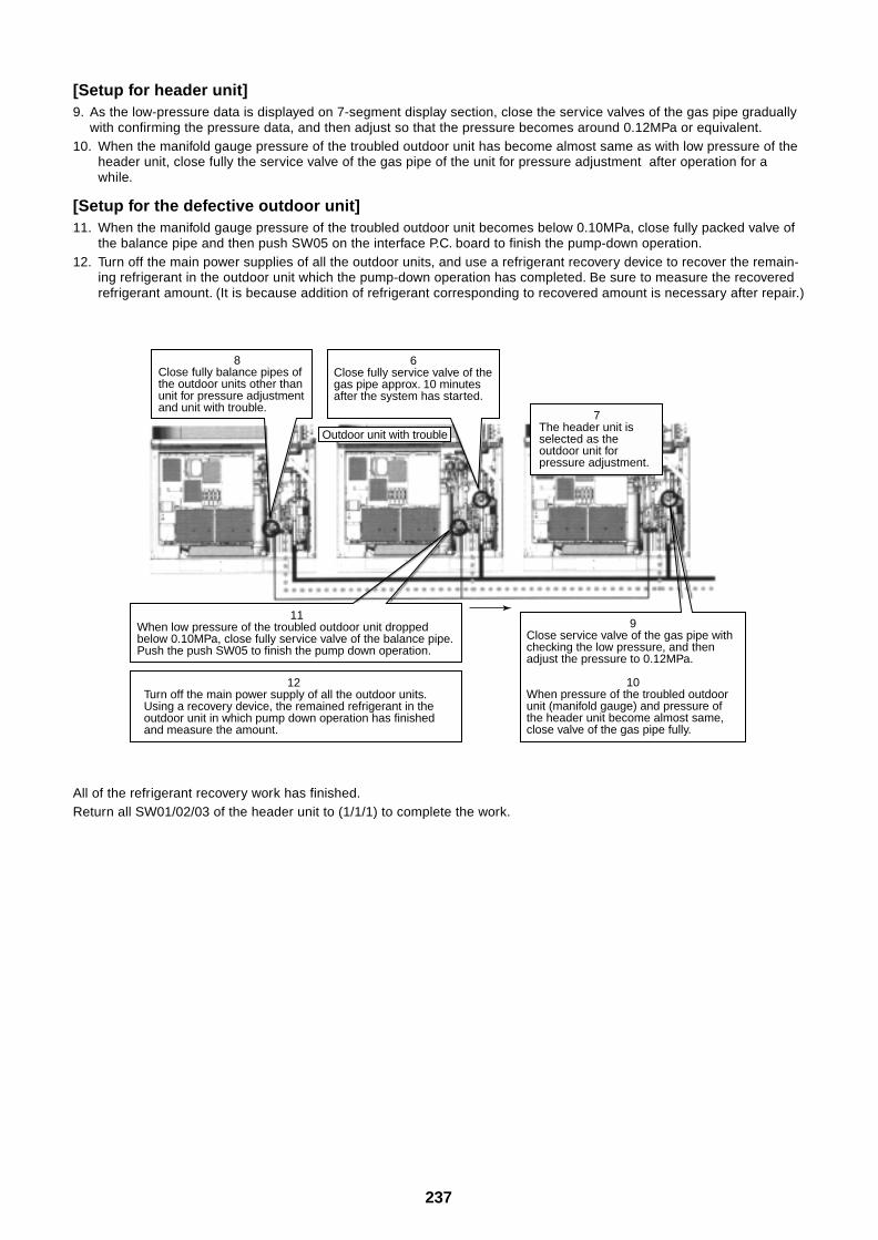
237
8Close fully balance pipes of the outdoor units other than unit for pressure adjustment and unit with trouble.
6Close fully service valve of the gas pipe approx. 10 minutes after the system has started.
9Close service valve of the gas pipe with checking the low pressure, and then adjust the pressure to 0.12MPa.
10When pressure of the troubled outdoor unit (manifold gauge) and pressure of the header unit become almost same, close valve of the gas pipe fully.
11When low pressure of the troubled outdoor unit dropped below 0.10MPa, close fully service valve of the balance pipe.Push the push SW05 to finish the pump down operation.
12Turn off the main power supply of all the outdoor units. Using a recovery device, the remained refrigerant in the outdoor unit in which pump down operation has finished and measure the amount.
7The header unit is selected as the outdoor unit for pressure adjustment.
Outdoor unit with trouble
[Setup for header unit]9. As the low-pressure data is displayed on 7-segment display section, close the service valves of the gas pipe gradually
with confirming the pressure data, and then adjust so that the pressure becomes around 0.12MPa or equivalent.10. When the manifold gauge pressure of the troubled outdoor unit has become almost same as with low pressure of the
header unit, close fully the service valve of the gas pipe of the unit for pressure adjustment after operation for awhile.
[Setup for the defective outdoor unit]11. When the manifold gauge pressure of the troubled outdoor unit becomes below 0.10MPa, close fully packed valve of
the balance pipe and then push SW05 on the interface P.C. board to finish the pump-down operation.12. Turn off the main power supplies of all the outdoor units, and use a refrigerant recovery device to recover the remain-
ing refrigerant in the outdoor unit which the pump-down operation has completed. Be sure to measure the recoveredrefrigerant amount. (It is because addition of refrigerant corresponding to recovered amount is necessary after repair.)
All of the refrigerant recovery work has finished.Return all SW01/02/03 of the header unit to (1/1/1) to complete the work.
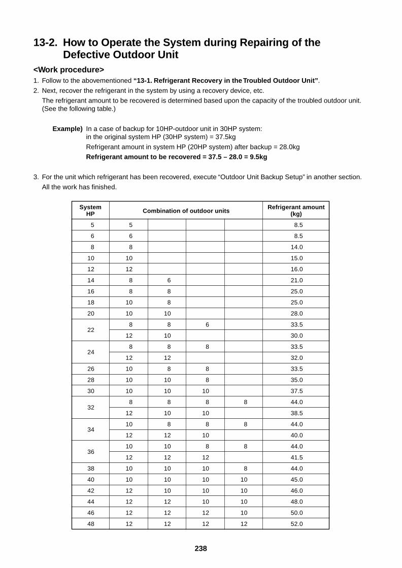
238
13-2. How to Operate the System during Repairing of theDefective Outdoor Unit
<Work procedure>1. Follow to the abovementioned “13-1. Refrigerant Recovery in the Troubled Outdoor Unit”.
2. Next, recover the refrigerant in the system by using a recovery device, etc.
The refrigerant amount to be recovered is determined based upon the capacity of the troubled outdoor unit.(See the following table.)
Example) In a case of backup for 10HP-outdoor unit in 30HP system:in the original system HP (30HP system) = 37.5kg
Refrigerant amount in system HP (20HP system) after backup = 28.0kg
Refrigerant amount to be recovered = 37.5 – 28.0 = 9.5kg
3. For the unit which refrigerant has been recovered, execute “Outdoor Unit Backup Setup” in another section.
All the work has finished.
SystemHP
5
6
8
10
12
14
16
18
20
22
24
26
28
30
32
34
36
38
40
42
44
46
48
Combination of outdoor units
5
6
8
10
12
8 6
8 8
10 8
10 10
8 8 6
12 10
8 8 8
12 12
10 8 8
10 10 8
10 10 10
8 8 8 8
12 10 10
10 8 8 8
12 12 10
10 10 8 8
12 12 12
10 10 10 8
10 10 10 10
12 10 10 10
12 12 10 10
12 12 12 10
12 12 12 12
Refrigerant amount(kg)
8.5
8.5
14.0
15.0
16.0
21.0
25.0
25.0
28.0
33.5
30.0
33.5
32.0
33.5
35.0
37.5
44.0
38.5
44.0
40.0
44.0
41.5
44.0
45.0
46.0
48.0
50.0
52.0
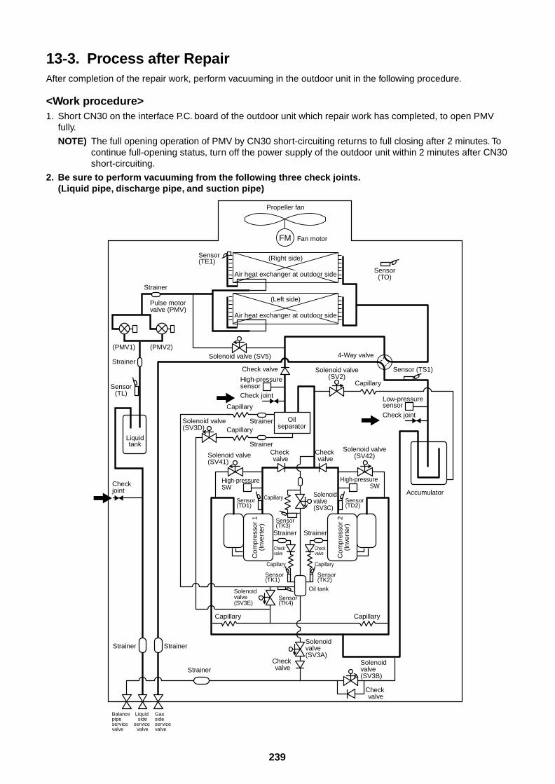
239
13-3. Process after RepairAfter completion of the repair work, perform vacuuming in the outdoor unit in the following procedure.
<Work procedure>1. Short CN30 on the interface P.C. board of the outdoor unit which repair work has completed, to open PMV
fully.
NOTE) The full opening operation of PMV by CN30 short-circuiting returns to full closing after 2 minutes. Tocontinue full-opening status, turn off the power supply of the outdoor unit within 2 minutes after CN30short-circuiting.
2. Be sure to perform vacuuming from the following three check joints.(Liquid pipe, discharge pipe, and suction pipe)
Capillary
Capillary
Capillary
FM
Propeller fan
Fan motor
Sensor(TO)
Sensor (TS1)
Sensor(TL)
Sensor(TE1) (Right side)
Air heat exchanger at outdoor side
(Left side)
Air heat exchanger at outdoor side
Solenoid valve(SV2)
Solenoid valve (SV5)
Solenoid valve(SV41)
Solenoid valve(SV3A)
Solenoid valve(SV3E)
Solenoid valve(SV3B)
Solenoid valve(SV3D)
Solenoid valve(SV3C)
4-Way valve
Check joint
Low-pressuresensor
Accumulator
Check joint
Check joint
High-pressure sensor
High-pressure SW
Oilseparator
Check valve
Check valve
Check valve
Check valve
Check valveC
ompr
esso
r 1
(Inv
erte
r)
Strainer
Strainer
Sensor(TK1)
Sensor(TK4)
Sensor(TK3)
Capillary
Capillary
CapillaryStrainer
Strainer
Strainer
Strainer
StrainerStrainer
Capillary
Capillary
Solenoid valve(SV42)
High-pressure SW
Check valve
Check valve C
ompr
esso
r 2
(Inv
erte
r)
Strainer
Sensor(TK2)
Sensor(TD2)
Sensor(TD1)
Liquidtank
Oil tank
Balance pipeservice valve
Liquid side
service valve
Gas sideservice valve
Pulse motor valve (PMV)
(PMV1) (PMV2)
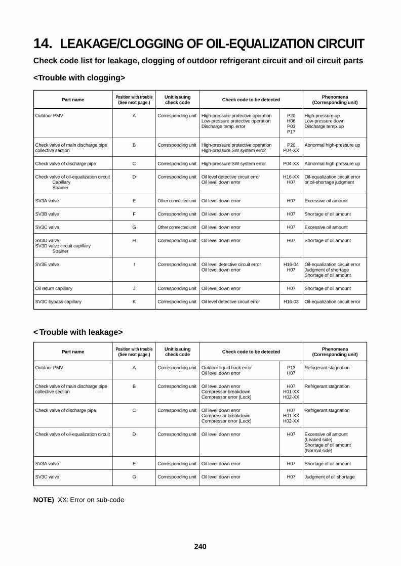
240
14. LEAKAGE/CLOGGING OF OIL-EQUALIZATION CIRCUITCheck code list for leakage, clogging of outdoor refrigerant circuit and oil circuit parts
<Trouble with clogging>
Part name
Outdoor PMV
Check valve of main discharge pipecollective section
Check valve of discharge pipe
Check valve of oil-equalization circuitCapillaryStrainer
SV3A valve
SV3B valve
SV3C valve
SV3D valveSV3D valve circuit capillary
Strainer
SV3E valve
Oil return capillary
SV3C bypass capillary
Position with trouble(See next page.)
A
B
C
D
E
F
G
H
I
J
K
Unit issuingcheck code
Corresponding unit
Corresponding unit
Corresponding unit
Corresponding unit
Other connected unit
Corresponding unit
Other connected unit
Corresponding unit
Corresponding unit
Corresponding unit
Corresponding unit
Check code to be detected
High-pressure protective operation P20Low-pressure protective operation H06Discharge temp. error P03
P17
High-pressure protective operation P20High-pressure SW system error P04-XX
High-pressure SW system error P04-XX
Oil level detective circuit error H16-XXOil level down error H07
Oil level down error H07
Oil level down error H07
Oil level down error H07
Oil level down error H07
Oil level detective circuit error H16-04Oil level down error H07
Oil level down error H07
Oil level detective circuit error H16-03
Phenomena(Corresponding unit)
High-pressure upLow-pressure downDischarge temp. up
Abnormal high-pressure up
Abnormal high-pressure up
Oil-equalization circuit erroror oil-shortage judgment
Excessive oil amount
Shortage of oil amount
Excessive oil amount
Shortage of oil amount
Oil-equalization circuit errorJudgment of shortageShortage of oil amount
Shortage of oil amount
Oil-equalization circuit error
< Trouble with leakage>
NOTE) XX: Error on sub-code
Part name
Outdoor PMV
Check valve of main discharge pipecollective section
Check valve of discharge pipe
Check valve of oil-equalization circuit
SV3A valve
SV3C valve
Position with trouble(See next page.)
A
B
C
D
E
G
Unit issuingcheck code
Corresponding unit
Corresponding unit
Corresponding unit
Corresponding unit
Corresponding unit
Corresponding unit
Check code to be detected
Outdoor liquid back error P13Oil level down error H07
Oil level down error H07Compressor breakdown H01-XXCompressor error (Lock) H02-XX
Oil level down error H07Compressor breakdown H01-XXCompressor error (Lock) H02-XX
Oil level down error H07
Oil level down error H07
Oil level down error H07
Phenomena(Corresponding unit)
Refrigerant stagnation
Refrigerant stagnation
Refrigerant stagnation
Excessive oil amount(Leaked side)Shortage of oil amount(Normal side)
Shortage of oil amount
Judgment of oil shortage
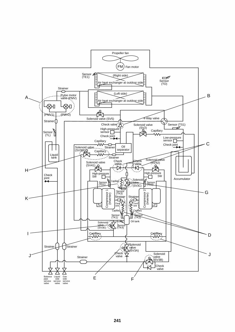
241
Capillary
Capillary
Capillary
FM
Propeller fan
Fan motor
Sensor(TO)
Sensor (TS1)
Sensor(TL)
Sensor(TE1) (Right side)
Air heat exchanger at outdoor side
(Left side)
Air heat exchanger at outdoor side
Solenoid valve(SV2)
Solenoid valve (SV5)
Solenoid valve(SV41)
Solenoid valve(SV3A)
Solenoid valve(SV3E)
Solenoid valve(SV3B)
Solenoid valve(SV3D)
Solenoid valve(SV3C)
4-Way valve
Check joint
Low-pressuresensor
Accumulator
Check joint
Check joint
High-pressure sensor
High-pressure SW
Oilseparator
Check valve
Check valve
Check valve
Check valve
Check valveC
ompr
esso
r 1
(Inv
erte
r)
Strainer
Strainer
Sensor(TK1)
Sensor(TK4)
Sensor(TK3)
Capillary
Capillary
CapillaryStrainer
Strainer
Strainer
Strainer
StrainerStrainer
Capillary
Capillary
Solenoid valve(SV42)
High-pressure SW
Check valve
Check valve C
ompr
esso
r 2
(Inv
erte
r)
Strainer
Sensor(TK2)
Sensor(TD2)
Sensor(TD1)
Liquidtank
Oil tank
Balance pipeservice valve
Liquid side
service valve
Gas sideservice valve
Pulse motor valve (PMV)
(PMV1) (PMV2)
B
C
G
D
J
FE
J
I
K
H
A
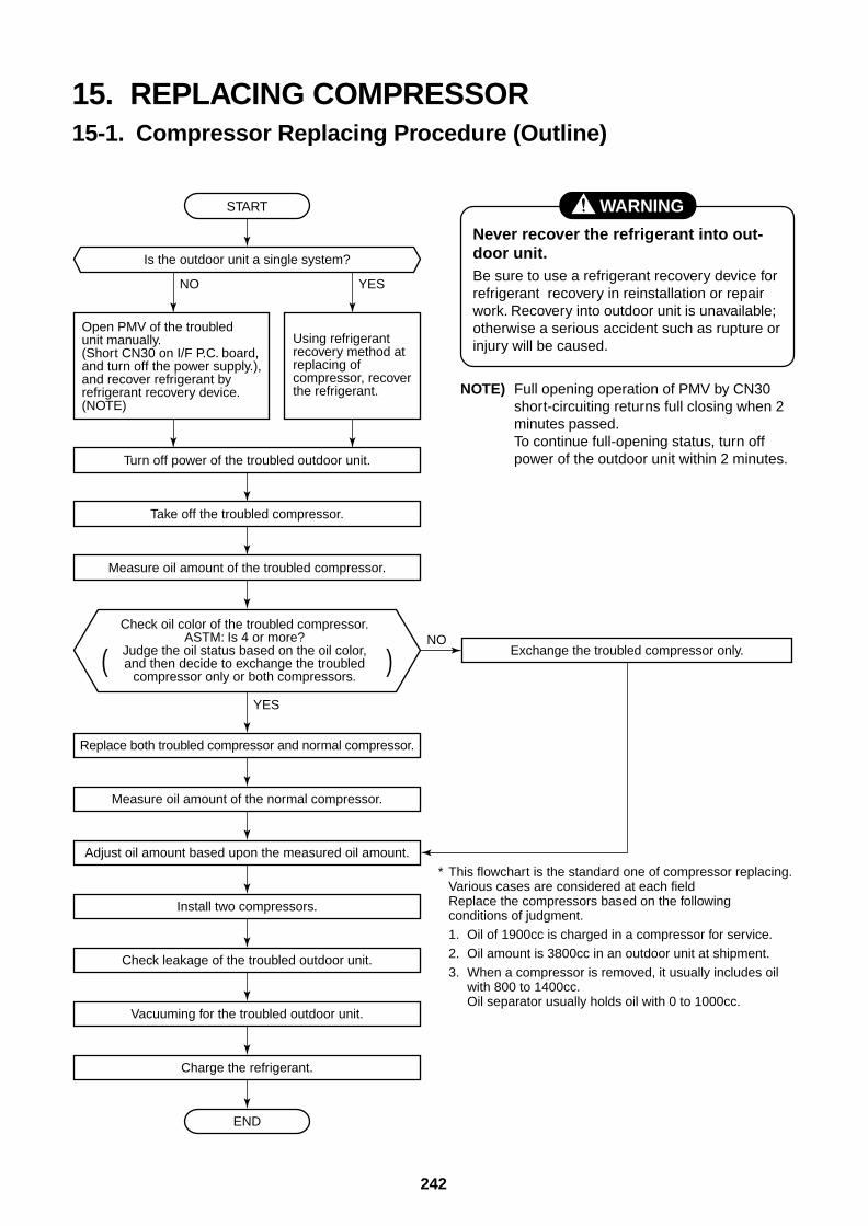
242
15. REPLACING COMPRESSOR15-1. Compressor Replacing Procedure (Outline)
( )
START
Is the outdoor unit a single system?
YES
YES
NO
NO
Open PMV of the troubled unit manually.(Short CN30 on I/F P.C. board, and turn off the power supply.), and recover refrigerant by refrigerant recovery device. (NOTE)
Using refrigerant recovery method at replacing of compressor, recover the refrigerant.
* This flowchart is the standard one of compressor replacing. Various cases are considered at each field Replace the compressors based on the following conditions of judgment.1. Oil of 1900cc is charged in a compressor for service.2. Oil amount is 3800cc in an outdoor unit at shipment.3. When a compressor is removed, it usually includes oil
with 800 to 1400cc. Oil separator usually holds oil with 0 to 1000cc.
Check oil color of the troubled compressor.ASTM: Is 4 or more?
Judge the oil status based on the oil color,and then decide to exchange the troubled
compressor only or both compressors.
Turn off power of the troubled outdoor unit.
Take off the troubled compressor.
Exchange the troubled compressor only.
Measure oil amount of the troubled compressor.
Replace both troubled compressor and normal compressor.
Measure oil amount of the normal compressor.
Adjust oil amount based upon the measured oil amount.
Install two compressors.
Check leakage of the troubled outdoor unit.
Vacuuming for the troubled outdoor unit.
Charge the refrigerant.
END
WARNING
Never recover the refrigerant into out-door unit.Be sure to use a refrigerant recovery device forrefrigerant recovery in reinstallation or repairwork. Recovery into outdoor unit is unavailable;otherwise a serious accident such as rupture orinjury will be caused.
NOTE) Full opening operation of PMV by CN30short-circuiting returns full closing when 2minutes passed.To continue full-opening status, turn offpower of the outdoor unit within 2 minutes.
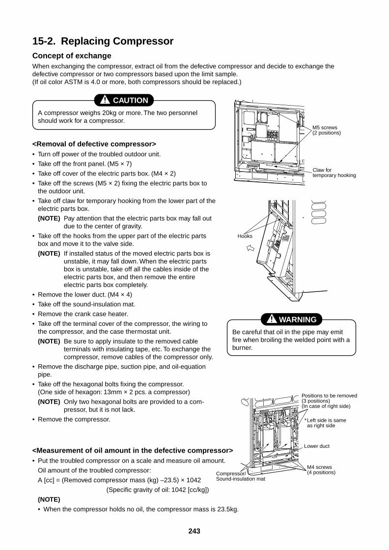
243
15-2. Replacing CompressorConcept of exchangeWhen exchanging the compressor, extract oil from the defective compressor and decide to exchange thedefective compressor or two compressors based upon the limit sample.(If oil color ASTM is 4.0 or more, both compressors should be replaced.)
CAUTION
A compressor weighs 20kg or more. The two personnelshould work for a compressor.
<Removal of defective compressor>• Turn off power of the troubled outdoor unit.
• Take off the front panel. (M5 × 7)
• Take off cover of the electric parts box. (M4 × 2)
• Take off the screws (M5 × 2) fixing the electric parts box tothe outdoor unit.
• Take off claw for temporary hooking from the lower part of theelectric parts box.
(NOTE) Pay attention that the electric parts box may fall outdue to the center of gravity.
• Take off the hooks from the upper part of the electric partsbox and move it to the valve side.
(NOTE) If installed status of the moved electric parts box isunstable, it may fall down. When the electric partsbox is unstable, take off all the cables inside of theelectric parts box, and then remove the entireelectric parts box completely.
• Remove the lower duct. (M4 × 4)
• Take off the sound-insulation mat.
• Remove the crank case heater.
• Take off the terminal cover of the compressor, the wiring tothe compressor, and the case thermostat unit.
(NOTE) Be sure to apply insulate to the removed cableterminals with insulating tape, etc. To exchange thecompressor, remove cables of the compressor only.
• Remove the discharge pipe, suction pipe, and oil-equationpipe.
• Take off the hexagonal bolts fixing the compressor.(One side of hexagon: 13mm × 2 pcs. a compressor)
(NOTE) Only two hexagonal bolts are provided to a com-pressor, but it is not lack.
• Remove the compressor.
<Measurement of oil amount in the defective compressor>• Put the troubled compressor on a scale and measure oil amount.
Oil amount of the troubled compressor:
A [cc] = (Removed compressor mass (kg) –23.5) × 1042
(Specific gravity of oil: 1042 [cc/kg])
(NOTE)
• When the compressor holds no oil, the compressor mass is 23.5kg.
WARNING
Be careful that oil in the pipe may emitfire when broiling the welded point with aburner.
Claw for temporary hooking
M5 screws(2 positions)
Hooks
Positions to be removed (3 positions)(In case of right side)
*Left side is same as right side
Lower duct
M4 screws (4 positions)Compressor/
Sound-insulation mat
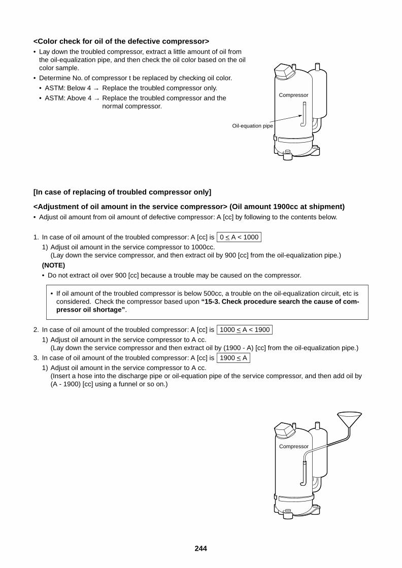
244
<Color check for oil of the defective compressor>• Lay down the troubled compressor, extract a little amount of oil from
the oil-equalization pipe, and then check the oil color based on the oilcolor sample.
• Determine No. of compressor t be replaced by checking oil color.
• ASTM: Below 4 → Replace the troubled compressor only.
• ASTM: Above 4 → Replace the troubled compressor and thenormal compressor.
[In case of replacing of troubled compressor only]
<Adjustment of oil amount in the service compressor> (Oil amount 1900cc at shipment)• Adjust oil amount from oil amount of defective compressor: A [cc] by following to the contents below.
1. In case of oil amount of the troubled compressor: A [cc] is 0 < A < 1000
1) Adjust oil amount in the service compressor to 1000cc.(Lay down the service compressor, and then extract oil by 900 [cc] from the oil-equalization pipe.)
(NOTE)
• Do not extract oil over 900 [cc] because a trouble may be caused on the compressor.
• If oil amount of the troubled compressor is below 500cc, a trouble on the oil-equalization circuit, etc isconsidered. Check the compressor based upon “15-3. Check procedure search the cause of com-pressor oil shortage”.
2. In case of oil amount of the troubled compressor: A [cc] is 1000 < A < 1900
1) Adjust oil amount in the service compressor to A cc.(Lay down the service compressor and then extract oil by (1900 - A) [cc] from the oil-equalization pipe.)
3. In case of oil amount of the troubled compressor: A [cc] is 1900 < A
1) Adjust oil amount in the service compressor to A cc.(Insert a hose into the discharge pipe or oil-equation pipe of the service compressor, and then add oil by(A - 1900) [cc] using a funnel or so on.)
Compressor
Oil-equation pipe
Compressor
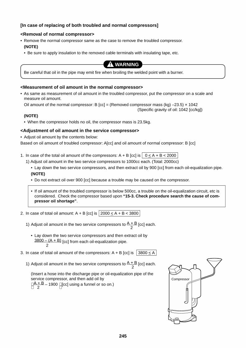
245
[In case of replacing of both troubled and normal compressors]
<Removal of normal compressor>• Remove the normal compressor same as the case to remove the troubled compressor.
(NOTE)
• Be sure to apply insulation to the removed cable terminals with insulating tape, etc.
WARNING
Be careful that oil in the pipe may emit fire when broiling the welded point with a burner.
<Measurement of oil amount in the normal compressor>• As same as measurement of oil amount in the troubled compressor, put the compressor on a scale and
measure oil amount.
Oil amount of the normal compressor: B [cc] = (Removed compressor mass (kg) –23.5) × 1042(Specific gravity of oil: 1042 [cc/kg])
(NOTE)
• When the compressor holds no oil, the compressor mass is 23.5kg.
<Adjustment of oil amount in the service compressor>• Adjust oil amount by the contents below:
Based on oil amount of troubled compressor: A[cc] and oil amount of normal compressor: B [cc]
1. In case of the total oil amount of the compressors: A + B [cc] is 0 < A + B < 2000
1) Adjust oil amount in the two service compressors to 1000cc each. (Total: 2000cc)
• Lay down the two service compressors, and then extract oil by 900 [cc] from each oil-equalization pipe.
(NOTE)
• Do not extract oil over 900 [cc] because a trouble may be caused on the compressor.
• If oil amount of the troubled compressor is below 500cc, a trouble on the oil-equalization circuit, etc isconsidered. Check the compressor based upon “15-3. Check procedure search the cause of com-pressor oil shortage”.
2. In case of total oil amount: A + B [cc] is 2000 < A + B < 3800
1) Adjust oil amount in the two service compressors to A + B [cc] each. 2
• Lay down the two service compressors and then extract oil by3800 – (A + B) [cc] from each oil-equalization pipe. 2
3. In case of total oil amount of the compressors: A + B [cc] is 3800 < A
1) Adjust oil amount in the two service compressors to A + B [cc] each. 2
(Insert a hose into the discharge pipe or oil-equalization pipe of theservice compressor, and then add oil by A + B – 1900 [cc] using a funnel or so on.) 2
Compressor
246
<Installation of compressor>• Install the compressor in the reverse procedure of removal.
• When removing the compressor, Fasten receptacle terminals of the compressor may be loosened.Prior to the installation, caulk a little to them with radio pinchers, reinsert them into the compressor,and then check there is no looseness.
(NOTES)
• Only two hexagonal bolts are provided to a compressor, but it is not lacking.
• The tightening torque of the hexagonal bolt to fix the compressor is 200kg/cm.
• If oil has been extracted from the accumulator, braze the cutoff pipe after pinching.
<Vacuuming>
(In case of single outdoor system>• Connect vacuum pump to the valve charge ports of the liquid and gas pipes and the check joint at high-
pressure side, and then drive the vacuum pump.
• Vacuum until the vacuum low-pressure gauge indicates 1 (mmHg).
(NOTE)
• Before vacuuming, open PMV fully. Vacuuming may not be executed for the heat exchanger of the outdoorunit under condition of PMV closed.
(In case of multiple outdoor units system)• In case of conducting the refrigerant recovery at replacing the compressor, perform vacuuming as
13-3. Process after repair.
<Full opening of PMV>• Turn on power of the outdoor unit.
• Short CN30 on I/F P.C. board of the outdoor unit.
• Turn off power of the outdoor unit within 2 minutes after short-circuiting.
<Refrigerant charging>• Add the same amount of refrigerant as the remaining refrigerant refrigerant from the charge port of the
service valve at liquid side.
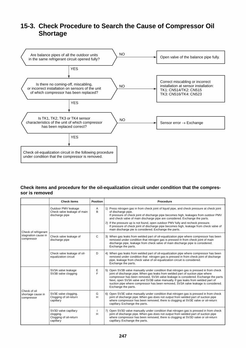
247
15-3. Check Procedure to Search the Cause of Compressor OilShortage
Check items and procedure for the oil-equalization circuit under condition that the compres-sor is removed
Check of refrigerantstagnation cause incompressor
Check of oilshortage cause incompressor
Check items
Outdoor PMV leakageCheck valve leakage of maindischarge pipe
Check valve leakage ofdischarge pipe
Check valve leakage of oil-equalization circuit
SV3A valve leakageSV3B valve clogging
SV3E valve clogging.Clogging of oil-returncapillary
SV3D valve capillaryclogging.Clogging of oil-returncapillary
Position
AB
C
D
EF
GH
IH
Procedure
1) Press nitrogen gas in from check joint of liquid pipe, and check pressure at check jointof discharge pipe.If pressure of check joint of discharge pipe becomes high, leakages from outdoor PMVand check valve of main discharge pipe are considered. Exchange the parts.
2) If the pressure up is not found, open outdoor PMV fully and recheck pressure.If pressure of check joint of discharge pipe becomes high, leakage from check valve ofmain discharge pie is considered. Exchange the parts.
3) When gas leaks from welded part of oil-equalization pipe where compressor has beenremoved under condition that nitrogen gas is pressed in from check joint of maindischarge pipe, leakage from check valve of main discharge pipe is considered.Exchange the parts.
4) When gas leaks from welded part of oil-equalization pipe where compressor has beenremoved under condition that nitrogen gas is pressed in from check joint of dischargepipe, leakage from check valve of oil-equalization circuit is considered.Exchange the parts.
5) Open SV3B valve manually under condition that nitrogen gas is pressed in from checkjoint of discharge pipe. When gas leaks from welded part of suction pipe wherecompressor has been removed, SV3A valve leakage is considered. Exchange the parts.Next, open SV3A valve and SV3B valve manually. If gas leaks from welded part ofsuction pipe where compressor has been removed, SV3A valve leakage is considered.Exchange the parts.
6) Open SV3E valve manually under condition that nitrogen gas is pressed in from checkjoint of discharge pipe. When gas does not output from welded part of suction pipewhere compressor has been removed, there is clogging at SV3E valve or oil-returncapillary. Exchange the parts.
7) Open SV3D valve manually under condition that nitrogen gas is pressed in from checkjoint of discharge pipe. When gas does not output from welded part of suction pipewhere compressor has been removed, there is clogging at SV3D valve or oil-returncapillary. Exchange the parts.
YES
YES
YES
NO
NO
NO
Are balance pipes of all the outdoor unitsin the same refrigerant circuit opened fully?
Check oil-equalization circuit in the following procedure under condition that the compressor is removed.
Open valve of the balance pipe fully.
Correct miscabling or incorrect installation at sensor installation:TK1: CN514/TK2: CN515TK3: CN516/TK4: CN523
Sensor error Exchange
Is there no coming-off, miscabling,or incorrect installation on sensors of the unit
of which compressor has been replaced?
Is TK1, TK2, TK3 or TK4 sensorcharacteristics of the unit of which compressor
has been replaced correct?
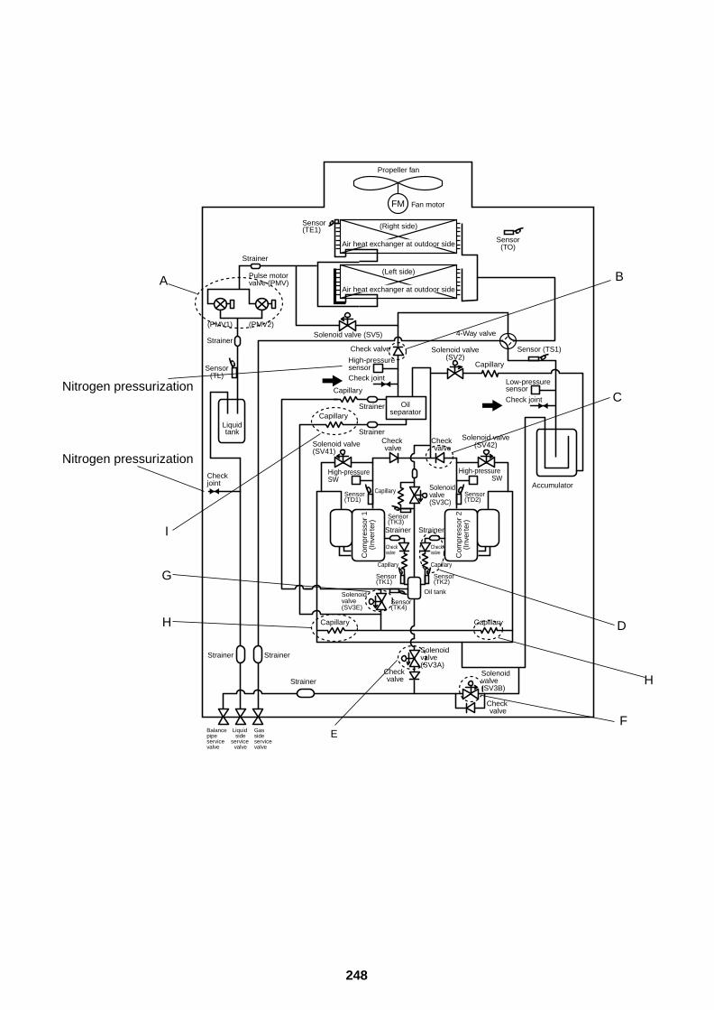
248
Capillary
Capillary
Capillary
FM
Propeller fan
Fan motor
Sensor(TO)
Sensor (TS1)
Sensor(TL)
Sensor(TE1) (Right side)
Air heat exchanger at outdoor side
(Left side)
Air heat exchanger at outdoor side
Solenoid valve(SV2)
Solenoid valve (SV5)
Solenoid valve(SV41)
Solenoid valve(SV3A)
Solenoid valve(SV3E)
Solenoid valve(SV3B)
Solenoid valve(SV3C)
4-Way valve
Check joint
Low-pressuresensor
Accumulator
Check joint
Check joint
High-pressure sensor
High-pressure SW
Oilseparator
Check valve
Check valve
Check valve
Check valve
Check valveC
ompr
esso
r 1
(Inv
erte
r)
Strainer
Strainer
Sensor(TK1)
Sensor(TK4)
Sensor(TK3)
Capillary
Capillary
CapillaryStrainer
Strainer
Strainer
Strainer
StrainerStrainer
Capillary
Capillary
Solenoid valve(SV42)
High-pressure SW
Check valve
Check valve C
ompr
esso
r 2
(Inv
erte
r)
Strainer
Sensor(TK2)
Sensor(TD2)
Sensor(TD1)
Liquidtank
Oil tank
Balance pipeservice valve
Liquid side
service valve
Gas sideservice valve
Pulse motor valve (PMV)
(PMV1) (PMV2)
B
C
D
FE
H
H
G
I
Nitrogen pressurization
Nitrogen pressurization
A
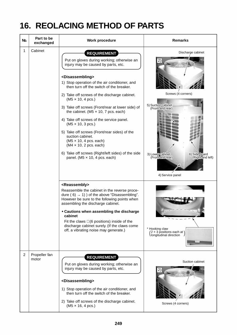
249
Discharge cabinet
Screws (4 corners)
5 Suction cabinet (Front and rear)
3 Lower cabinet (Front and rear)
6) Side board (Right and left)
5) Suction cabinet (Front and rear)
3) Lower cabinet (Front and rear)
6) Side board (Right and left)
4) Service panel
Suction cabinet
* Hooking claw 2 × 3 positions each at longitudinal direction
Screws (4 corners)
2)
2)
( )
16. REOLACING METHOD OF PARTS
No.
1
Part to beexchanged
Cabinet
Work procedure
REQUIREMENT
Put on gloves during working; otherwise aninjury may be caused by parts, etc.
<Disassembling>1) Stop operation of the air conditioner, and
then turn off the switch of the breaker.
2) Take off screws of the discharge cabinet.(M5 × 10, 4 pcs.)
3) Take off screws (Front/rear at lower side) ofthe cabinet. (M5 × 10, 7 pcs. each)
4) Take off screws of the service panel.(M5 × 10, 3 pcs.)
5) Take off screws (Front/rear sides) of thesuction cabinet.(M5 × 10, 4 pcs. each)(M4 × 10, 2 pcs. each)
6) Take off screws (Right/left sides) of the sidepanel. (M5 × 10, 4 pcs. each)
Remarks
2 Propeller fanmotor REQUIREMENT
Put on gloves during working; otherwise aninjury may be caused by parts, etc.
<Disassembling>
1) Stop operation of the air conditioner, andthen turn off the switch of the breaker.
2) Take off screws of the discharge cabinet.(M5 × 16, 4 pcs.)
<Reassembly>Reassemble the cabinet in the reverse proce-dure ( 6) → 1) ) of the above “Disassembling”.However be sure to the following points whenassembling the discharge cabinet.
Cautions when assembling the dischargecabinetFit the claws ∗ (6 positions) inside of thedischarge cabinet surely. (If the claws comeoff, a vibrating noise may generate.)
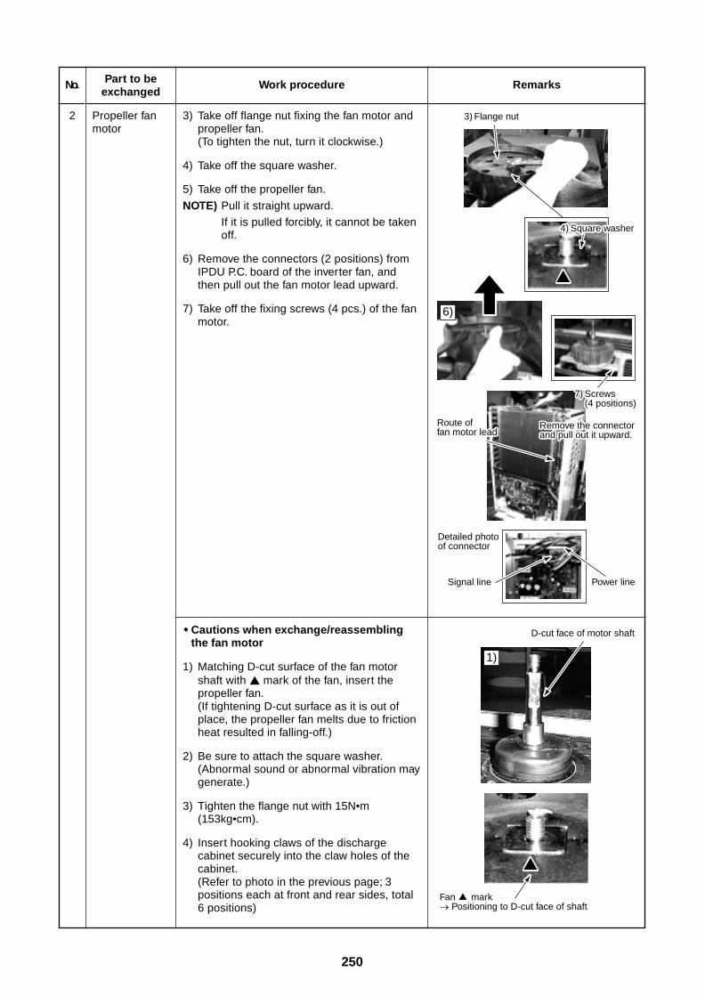
250
No.
2
Part to beexchanged
Propeller fanmotor
Work procedure
3) Take off flange nut fixing the fan motor andpropeller fan.(To tighten the nut, turn it clockwise.)
4) Take off the square washer.
5) Take off the propeller fan.
NOTE) Pull it straight upward.
If it is pulled forcibly, it cannot be takenoff.
6) Remove the connectors (2 positions) fromIPDU P.C. board of the inverter fan, andthen pull out the fan motor lead upward.
7) Take off the fixing screws (4 pcs.) of the fanmotor.
Remarks
Cautions when exchange/reassemblingthe fan motor
1) Matching D-cut surface of the fan motorshaft with mark of the fan, insert thepropeller fan.(If tightening D-cut surface as it is out ofplace, the propeller fan melts due to frictionheat resulted in falling-off.)
2) Be sure to attach the square washer.(Abnormal sound or abnormal vibration maygenerate.)
3) Tighten the flange nut with 15N•m(153kg•cm).
4) Insert hooking claws of the dischargecabinet securely into the claw holes of thecabinet.(Refer to photo in the previous page; 3positions each at front and rear sides, total6 positions)
Signal line Power line
Fan mark Positioning to D-cut face of shaft
D-cut face of motor shaft
3) Flange nut
7) Screws (4 positions)
Route of fan motor lead
Remove the connector and pull out it upward.
Route of fan motor lead
Remove the connector and pull out it upward.
Detailed photo of connector
6)
1)
4) Square washer
7) Screws (4 positions)
4) Square washer
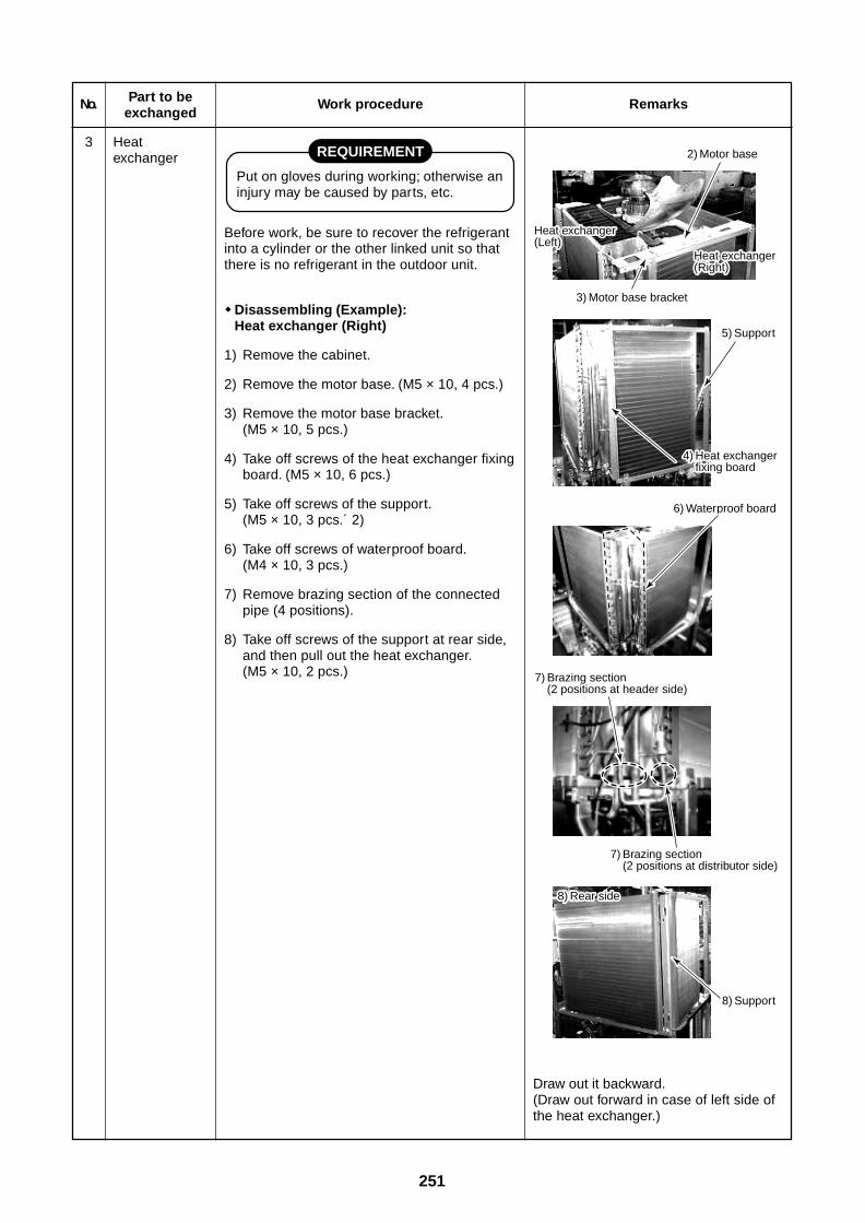
251
No.
3
Part to beexchanged
Heatexchanger
Work procedure
REQUIREMENT
Put on gloves during working; otherwise aninjury may be caused by parts, etc.
Before work, be sure to recover the refrigerantinto a cylinder or the other linked unit so thatthere is no refrigerant in the outdoor unit.
Disassembling (Example):Heat exchanger (Right)
1) Remove the cabinet.
2) Remove the motor base. (M5 × 10, 4 pcs.)
3) Remove the motor base bracket.(M5 × 10, 5 pcs.)
4) Take off screws of the heat exchanger fixingboard. (M5 × 10, 6 pcs.)
5) Take off screws of the support.(M5 × 10, 3 pcs.´ 2)
6) Take off screws of waterproof board.(M4 × 10, 3 pcs.)
7) Remove brazing section of the connectedpipe (4 positions).
8) Take off screws of the support at rear side,and then pull out the heat exchanger.(M5 × 10, 2 pcs.)
2) Motor base
Heat exchanger (Left)
Heat exchanger (Right)
Heat exchanger (Left)
Heat exchanger (Right)
5) Support
4) Heat exchanger fixing board
4) Heat exchanger fixing board
6) Waterproof board
7) Brazing section (2 positions at header side)
3) Motor base bracket
7) Brazing section (2 positions at distributor side)
8) Rear side8) Rear side
8) Support
Remarks
Draw out it backward.(Draw out forward in case of left side ofthe heat exchanger.)
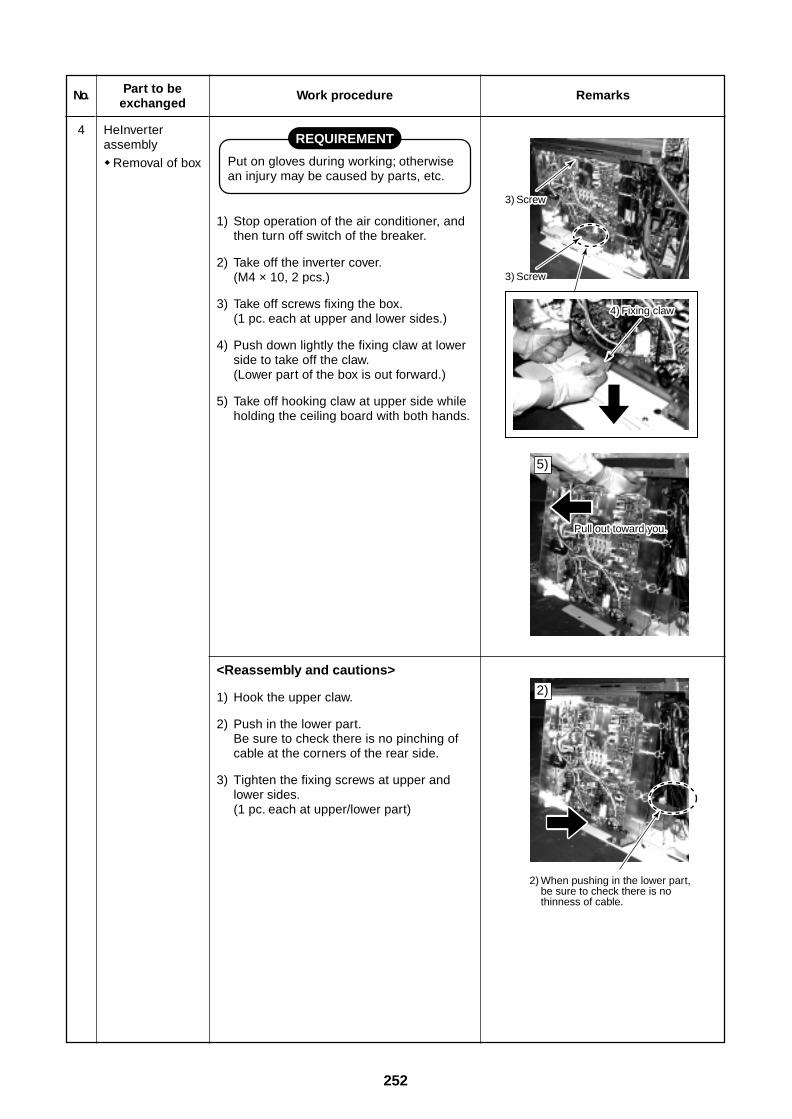
252
2) When pushing in the lower part, be sure to check there is no thinness of cable.
5)
2)
3 Screw
3 Screw
4) Fixing claw
Pull out toward you.
3) Screw
3) Screw
Pull out toward you.
4) Fixing claw
No.
4
Part to beexchanged
HeInverterassembly
Removal of box
Work procedure
REQUIREMENT
Put on gloves during working; otherwisean injury may be caused by parts, etc.
1) Stop operation of the air conditioner, andthen turn off switch of the breaker.
2) Take off the inverter cover.(M4 × 10, 2 pcs.)
3) Take off screws fixing the box.(1 pc. each at upper and lower sides.)
4) Push down lightly the fixing claw at lowerside to take off the claw.(Lower part of the box is out forward.)
5) Take off hooking claw at upper side whileholding the ceiling board with both hands.
Remarks
<Reassembly and cautions>
1) Hook the upper claw.
2) Push in the lower part.Be sure to check there is no pinching ofcable at the corners of the rear side.
3) Tighten the fixing screws at upper andlower sides.(1 pc. each at upper/lower part)
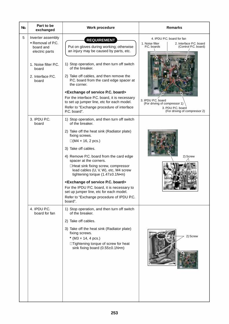
253
4. IPDU P.C. board for fan
1. Noise filter P.C. boards
2. Interface P.C. board (Control P.C. board)
3. IPDU P.C. board (For driving of compressor 1)
3. PDU P.C. board (For driving of compressor 2)
2) Screw
2) Screw
No.
5
Part to beexchanged
Inverter assembly
Removal of P.C.board andelectric parts
1. Noise filter P.C.board
2. Interface P.C.board
Work procedure
REQUIREMENT
Put on gloves during working; otherwisean injury may be caused by parts, etc.
1) Stop operation, and then turn off switchof the breaker.
2) Take off cables, and then remove theP.C. board from the card edge spacer atthe corner.
<Exchange of service P.C. board>For the interface P.C. board, it is necessaryto set up jumper line, etc for each model.
Refer to “Exchange procedure of interfaceP.C. board”.
Remarks
3. IPDU P.C.board
4. IPDU P.C.board for fan
1) Stop operation, and then turn off switchof the breaker.
2) Take off the heat sink (Radiator plate)fixing screws.
∗ (M4 × 16, 2 pcs.)
3) Take off cables.
4) Remove P.C. board from the card edgespacer at the corners.
∗ Heat sink fixing screw, compressorlead cables (U, V, W), etc, M4 screwtightening torque (1.47±0.1N•m)
<Exchange of service P.C. board>For the IPDU P.C. board, it is necessary toset up jumper line, etc for each model.
Refer to “Exchange procedure of IPDU P.C.board”.
1) Stop operation, and then turn off switchof the breaker.
2) Take off cables.
3) Take off the heat sink (Radiator plate)fixing screws.
(M3 × 14, 4 pcs.)
∗ Tightening torque of screw for heatsink fixing board (0.55±0.1N•m)
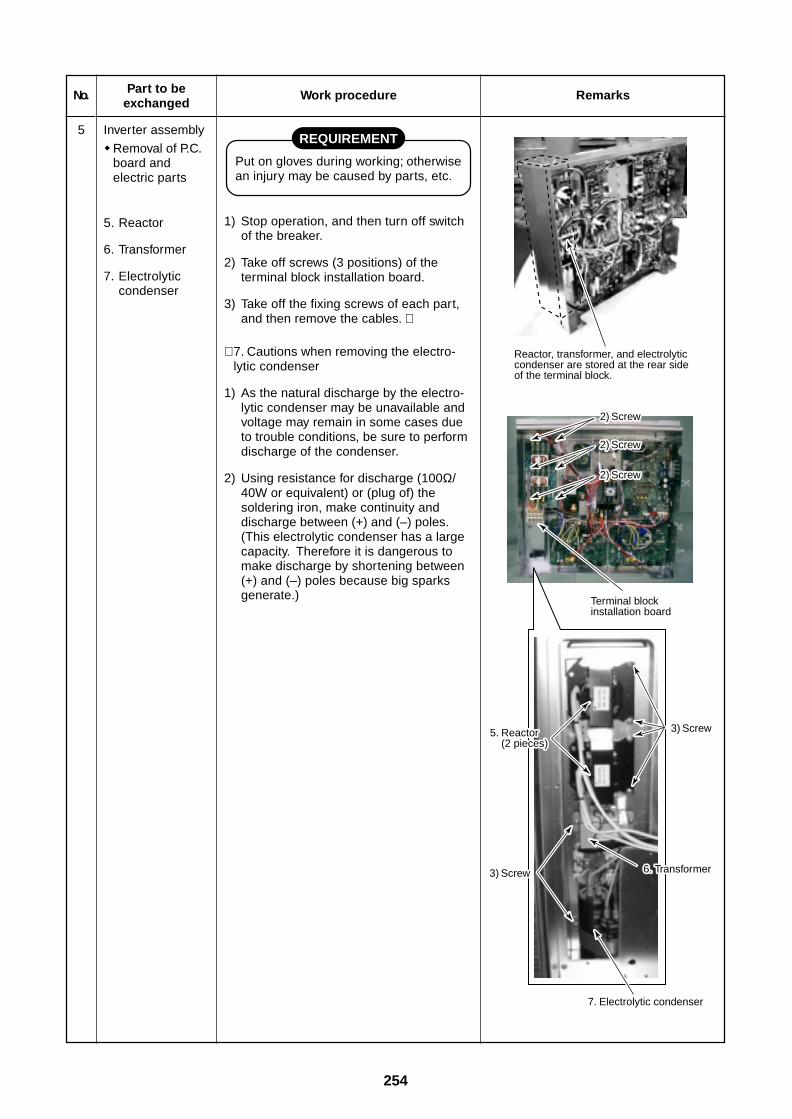
254
No.
5
Part to beexchanged
Inverter assembly
Removal of P.C.board andelectric parts
5. Reactor
6. Transformer
7. Electrolyticcondenser
Work procedure
REQUIREMENT
Put on gloves during working; otherwisean injury may be caused by parts, etc.
1) Stop operation, and then turn off switchof the breaker.
2) Take off screws (3 positions) of theterminal block installation board.
3) Take off the fixing screws of each part,and then remove the cables. ∗
∗ 7. Cautions when removing the electro-lytic condenser
1) As the natural discharge by the electro-lytic condenser may be unavailable andvoltage may remain in some cases dueto trouble conditions, be sure to performdischarge of the condenser.
2) Using resistance for discharge (100Ω/40W or equivalent) or (plug of) thesoldering iron, make continuity anddischarge between (+) and (–) poles.(This electrolytic condenser has a largecapacity. Therefore it is dangerous tomake discharge by shortening between(+) and (–) poles because big sparksgenerate.)
Remarks
Reactor, transformer, and electrolytic condenser are stored at the rear side of the terminal block.
Terminal block installation board
2) Screw2) Screw
7. Electrolytic condenser
2) Screw2) Screw
2) Screw2) Screw
5. Reactor (2 pieces)
5. Reactor (2 pieces)
3) Screw3) Screw
3) Screw3) Screw 6. Transformer6. Transformer
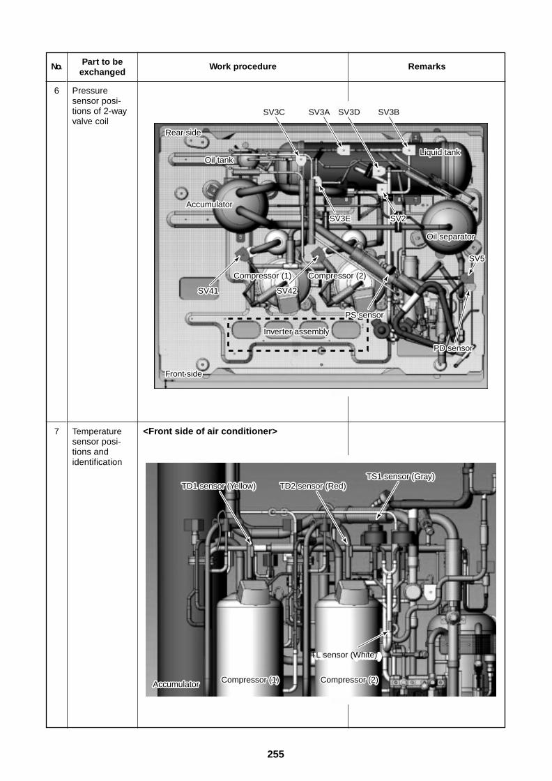
255
No.
6
Part to beexchanged
Pressuresensor posi-tions of 2-wayvalve coil
Work procedure Remarks
Compressor (1)Compressor (1)
Rear side
Front side
Oil tankLiquid tank
SV3C SV3A SV3D SV3B
SV3E SV2
PS sensor
PD sensor
SV5
SV41 SV42
Accumulator
Oil separator
Compressor (2)
Inverter assembly
Rear side
Front side
Oil tankLiquid tank
SV3C SV3A SV3D SV3B
SV3E SV2
PS sensor
PD sensor
SV5
SV41 SV42
Accumulator
Oil separator
Compressor (2)
Inverter assembly
TD1 sensor (Yellow) TD2 sensor (Red)TS1 sensor (Gray)
Accumulator
TL sensor (White)TL sensor (White)
Compressor (1) Compressor (2)
TD1 sensor (Yellow) TD2 sensor (Red)TS1 sensor (Gray)
Accumulator
TL sensor (White)
Compressor (1) Compressor (2)
7 Temperaturesensor posi-tions andidentification
<Front side of air conditioner>
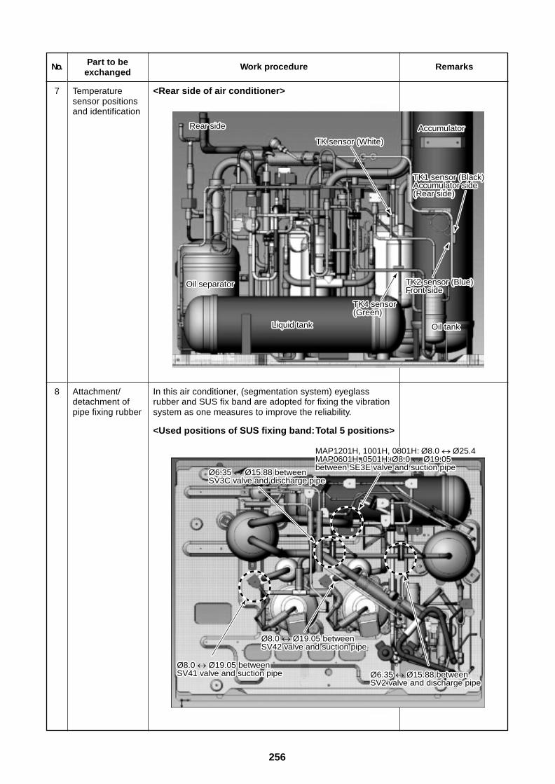
256
No.
7
Part to beexchanged
Temperaturesensor positionsand identification
Work procedure
<Rear side of air conditioner>
Remarks
Rear side
TK sensor (White)
Accumulator
TK1 sensor (Black)Accumulator side (Rear side)
Oil separator
Liquid tank
TK4 sensor (Green)
TK2 sensor (Blue)Front side
Oil tank
Rear side
TK sensor (White)
Accumulator
TK1 sensor (Black)Accumulator side (Rear side)
Oil separator
Liquid tank
TK4 sensor (Green)
TK2 sensor (Blue)Front side
Oil tank
Ø6.35 Ø15.88 between SV3C valve and discharge pipe
MAP1201H, 1001H, 0801H: Ø8.0 Ø25.4MAP0601H, 0501H: Ø8.0 Ø19.05between SE3E valve and suction pipe
Ø8.0 Ø19.05 between SV41 valve and suction pipe
Ø8.0 Ø19.05 between SV42 valve and suction pipe
Ø6.35 Ø15.88 between SV2 valve and discharge pipe
Ø6.35 Ø15.88 between SV3C valve and discharge pipe
MAP1201H, 1001H, 0801H: Ø8.0 Ø25.4MAP0601H, 0501H: Ø8.0 Ø19.05between SE3E valve and suction pipe
Ø8.0 Ø19.05 between SV41 valve and suction pipe
Ø8.0 Ø19.05 between SV42 valve and suction pipe
Ø6.35 Ø15.88 between SV2 valve and discharge pipe
8 Attachment/detachment ofpipe fixing rubber
In this air conditioner, (segmentation system) eyeglassrubber and SUS fix band are adopted for fixing the vibrationsystem as one measures to improve the reliability.
<Used positions of SUS fixing band: Total 5 positions>
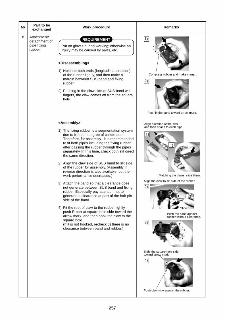
257
Push claw side against the rubber.
Compress rubber and make margin.
Push in the band toward arrow mark.
Align direction of the slits, and then attach to each pipe.
Matching the claws, slide them.
Align the claw to slit side of the rubber.
Push the band against rubber without clearance.
Slide the square hole side toward arrow mark.
Slide it.
1)
2)
1)
2)
3)
4)
1)
No.
8
Part to beexchanged
Attachment/detachment ofpipe fixingrubber
Work procedure
REQUIREMENT
Put on gloves during working; otherwise aninjury may be caused by parts, etc.
<Disassembling>
1) Hold the both ends (longitudinal direction)of the rubber lightly, and then make amargin between SUS band and fixingrubber.
2) Pushing in the claw side of SUS band withfingers, the claw comes off from the squarehole.
Remarks
<Assembly>
1) The fixing rubber is a segmentation systemdue to freedom degree of combination.Therefore, for assembly, it is recommendedto fit both pipes including the fixing rubberafter passing the rubber through the pipesseparately. In this time, check both slit directthe same direction.
2) Align the claw side of SUS band to slit sideof the rubber for assembly. (Assembly inreverse direction is also available, but thework performance decreases.)
3) Attach the band so that a clearance doesnot generate between SUS band and fixingrubber. Especially pay attention not togenerate a clearance at part of the hair pinside of the band.
4) Fit the root of claw to the rubber lightly,push R part at square hole side toward thearrow mark, and then hook the claw to thesquare hole.(If it is not hooked, recheck 3) there is noclearance between band and rubber.)
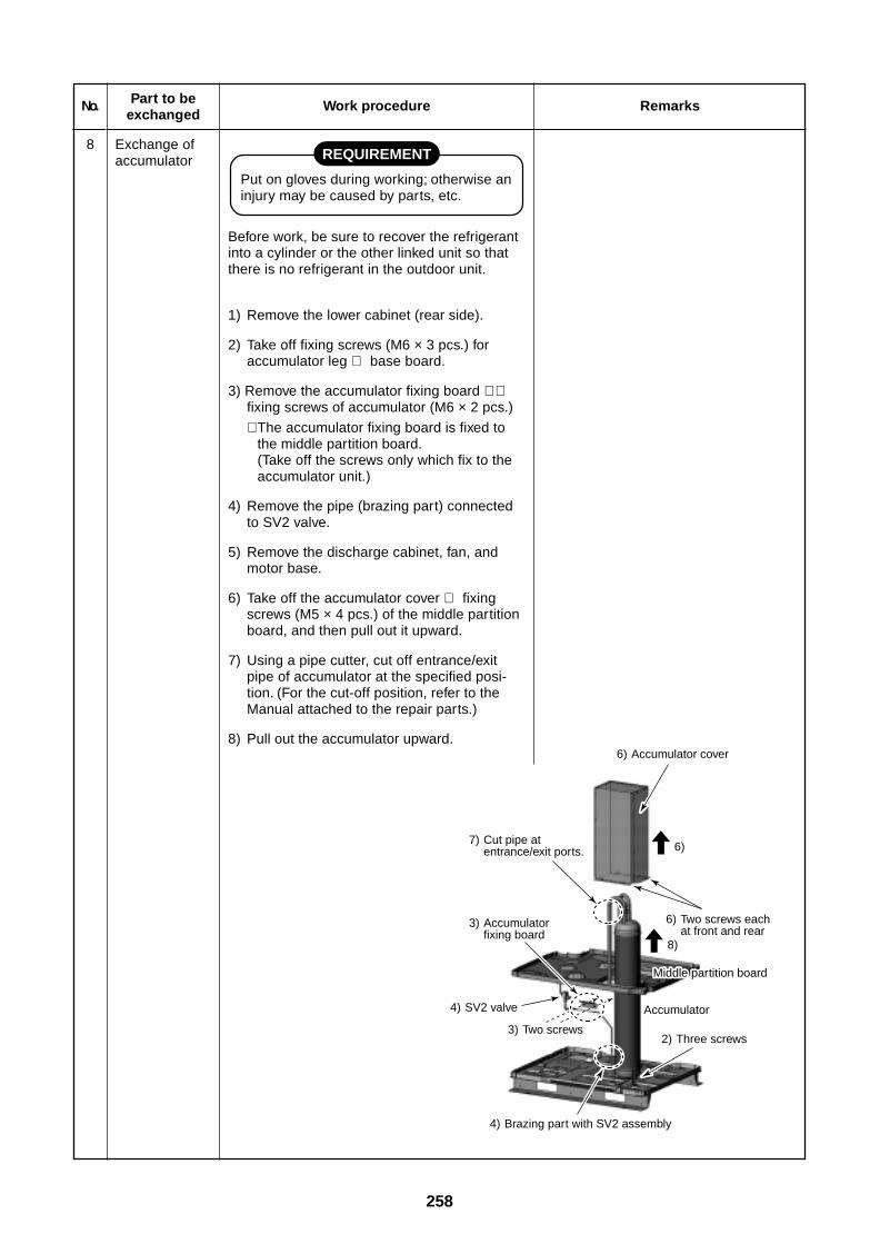
258
4) Brazing part with SV2 assembly
6) Accumulator cover
6) Two screws each at front and rear
8)
6)7) Cut pipe at
entrance/exit ports.
3) Accumulator fixing board
Middle parMiddle partition boardMiddle partition board
4) SV2 valve
3) Two screws
Accumulator
2) Three screws
No.
8
Part to beexchanged
Exchange ofaccumulator
Work procedure
REQUIREMENT
Put on gloves during working; otherwise aninjury may be caused by parts, etc.
Before work, be sure to recover the refrigerantinto a cylinder or the other linked unit so thatthere is no refrigerant in the outdoor unit.
1) Remove the lower cabinet (rear side).
2) Take off fixing screws (M6 × 3 pcs.) foraccumulator leg ⇔ base board.
3) Remove the accumulator fixing board ∗ ⇔fixing screws of accumulator (M6 × 2 pcs.)
∗ The accumulator fixing board is fixed tothe middle partition board.(Take off the screws only which fix to theaccumulator unit.)
4) Remove the pipe (brazing part) connectedto SV2 valve.
5) Remove the discharge cabinet, fan, andmotor base.
6) Take off the accumulator cover ⇔ fixingscrews (M5 × 4 pcs.) of the middle partitionboard, and then pull out it upward.
7) Using a pipe cutter, cut off entrance/exitpipe of accumulator at the specified posi-tion. (For the cut-off position, refer to theManual attached to the repair parts.)
8) Pull out the accumulator upward.
Remarks
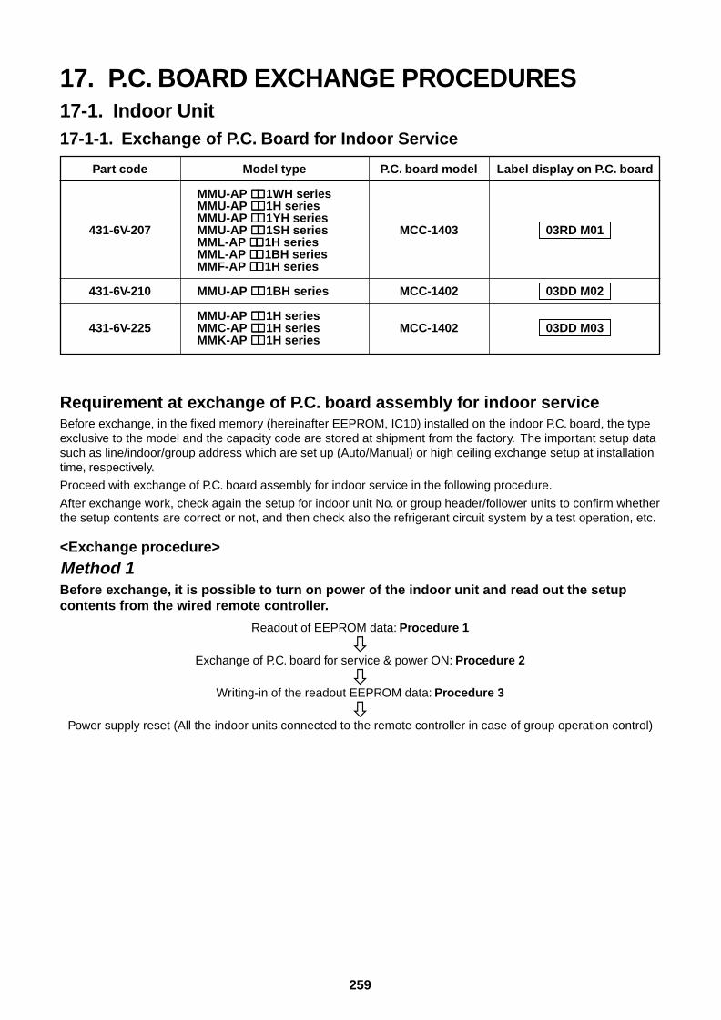
259
17. P.C. BOARD EXCHANGE PROCEDURES17-1. Indoor Unit17-1-1. Exchange of P.C. Board for Indoor Service
Part code
431-6V-207
431-6V-210
431-6V-225
Model type
MMU-AP ∗∗∗∗∗∗∗∗∗∗ 1WH seriesMMU-AP ∗∗∗∗∗∗∗∗∗∗ 1H seriesMMU-AP ∗∗∗∗∗∗∗∗∗∗ 1YH seriesMMU-AP ∗∗∗∗∗∗∗∗∗∗ 1SH seriesMML-AP ∗∗∗∗∗∗∗∗∗∗ 1H seriesMML-AP ∗∗∗∗∗∗∗∗∗∗ 1BH seriesMMF-AP ∗∗∗∗∗∗∗∗∗∗ 1H series
MMU-AP ∗∗∗∗∗∗∗∗∗∗ 1BH series
MMU-AP ∗∗∗∗∗∗∗∗∗∗ 1H seriesMMC-AP ∗∗∗∗∗∗∗∗∗∗ 1H seriesMMK-AP ∗∗∗∗∗∗∗∗∗∗ 1H series
P.C. board model
MCC-1403
MCC-1402
MCC-1402
Label display on P.C. board
03RD M01
03DD M02
03DD M03
Requirement at exchange of P.C. board assembly for indoor serviceBefore exchange, in the fixed memory (hereinafter EEPROM, IC10) installed on the indoor P.C. board, the typeexclusive to the model and the capacity code are stored at shipment from the factory. The important setup datasuch as line/indoor/group address which are set up (Auto/Manual) or high ceiling exchange setup at installationtime, respectively.
Proceed with exchange of P.C. board assembly for indoor service in the following procedure.
After exchange work, check again the setup for indoor unit No. or group header/follower units to confirm whetherthe setup contents are correct or not, and then check also the refrigerant circuit system by a test operation, etc.
<Exchange procedure>
Method 1Before exchange, it is possible to turn on power of the indoor unit and read out the setupcontents from the wired remote controller.
Readout of EEPROM data: Procedure 1
Exchange of P.C. board for service & power ON: Procedure 2
Writing-in of the readout EEPROM data: Procedure 3
Power supply reset (All the indoor units connected to the remote controller in case of group operation control)
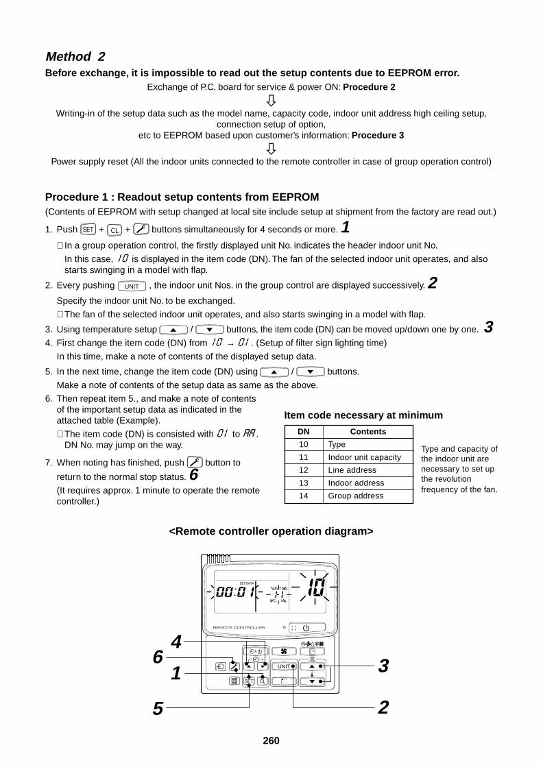
260
Method 2Before exchange, it is impossible to read out the setup contents due to EEPROM error.
Exchange of P.C. board for service & power ON: Procedure 2
Writing-in of the setup data such as the model name, capacity code, indoor unit address high ceiling setup,
connection setup of option,etc to EEPROM based upon customer’s information: Procedure 3
Power supply reset (All the indoor units connected to the remote controller in case of group operation control)
Procedure 1 : Readout setup contents from EEPROM(Contents of EEPROM with setup changed at local site include setup at shipment from the factory are read out.)
1. Push SET + CL + buttons simultaneously for 4 seconds or more. 1∗ In a group operation control, the firstly displayed unit No. indicates the header indoor unit No.
In this case, is displayed in the item code (DN). The fan of the selected indoor unit operates, and alsostarts swinging in a model with flap.
2. Every pushing UNIT , the indoor unit Nos. in the group control are displayed successively. 2Specify the indoor unit No. to be exchanged.
∗ The fan of the selected indoor unit operates, and also starts swinging in a model with flap.
3. Using temperature setup / buttons, the item code (DN) can be moved up/down one by one. 34. First change the item code (DN) from → . (Setup of filter sign lighting time)
In this time, make a note of contents of the displayed setup data.
5. In the next time, change the item code (DN) using / buttons.
Make a note of contents of the setup data as same as the above.
6. Then repeat item 5., and make a note of contentsof the important setup data as indicated in theattached table (Example).
∗ The item code (DN) is consisted with to .DN No. may jump on the way.
7. When noting has finished, push button to
return to the normal stop status. 6(It requires approx. 1 minute to operate the remotecontroller.)
DN
10
11
12
13
14
Contents
Type
Indoor unit capacity
Line address
Indoor address
Group address
Type and capacity ofthe indoor unit arenecessary to set upthe revolutionfrequency of the fan.
Item code necessary at minimum
<Remote controller operation diagram>
UNIT
SET CL
UNIT No.SET DATA
R.C. No.
46
5
1 3
2
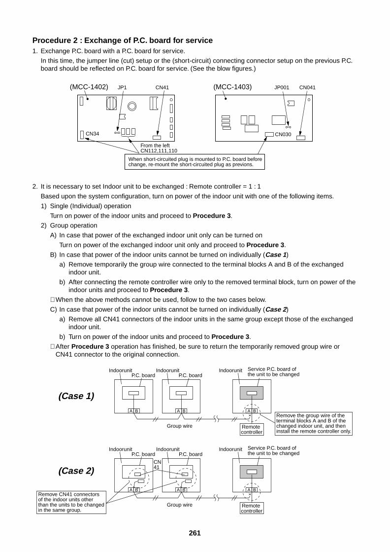
261
Procedure 2 : Exchange of P.C. board for service1. Exchange P.C. board with a P.C. board for service.
In this time, the jumper line (cut) setup or the (short-circuit) connecting connector setup on the previous P.C.board should be reflected on P.C. board for service. (See the blow figures.)
2. It is necessary to set Indoor unit to be exchanged : Remote controller = 1 : 1
Based upon the system configuration, turn on power of the indoor unit with one of the following items.
1) Single (Individual) operation
Turn on power of the indoor units and proceed to Procedure 3.
2) Group operation
A) In case that power of the exchanged indoor unit only can be turned on
Turn on power of the exchanged indoor unit only and proceed to Procedure 3.
B) In case that power of the indoor units cannot be turned on individually (Case 1)
a) Remove temporarily the group wire connected to the terminal blocks A and B of the exchangedindoor unit.
b) After connecting the remote controller wire only to the removed terminal block, turn on power of theindoor units and proceed to Procedure 3.
∗ When the above methods cannot be used, follow to the two cases below.
C) In case that power of the indoor units cannot be turned on individually (Case 2)
a) Remove all CN41 connectors of the indoor units in the same group except those of the exchangedindoor unit.
b) Turn on power of the indoor units and proceed to Procedure 3.
∗ After Procedure 3 operation has finished, be sure to return the temporarily removed group wire orCN41 connector to the original connection.
(MCC-1402) (MCC-1403)CN41JP1
From the leftCN112,111,110
CN34
CN041JP001
CN030
When short-circuited plug is mounted to P.C. board before change, re-mount the short-circuited plug as previons.
A B A B A B
IndoorunitP.C. board
IndoorunitP.C. board
Indoorunit Service P.C. board of the unit to be changed
Remote controller
Group wire
A B A B
IndoorunitP.C. board
A B
IndoorunitP.C. board
Indoorunit Service P.C. board of the unit to be changed
Remote controller
Group wire
(Case 1)
(Case 2)
Remove the group wire of the terminal blocks A and B of the changed indoor unit, and then install the remote controller only.
Remove CN41 connectors of the indoor units other than the units to be changedin the same group.
CN41
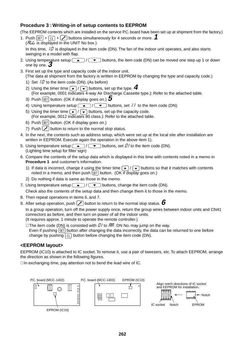
262
Procedure 3 : Writing-in of setup contents to EEPROM(The EEPROM contents which are installed on the service P.C. board have been set up at shipment from the factory.)
1. Push SET + CL + buttons simultaneously for 4 seconds or more. 1( is displayed in the UNIT No box.)
In this time, is displayed in the item code (DN). The fan of the indoor unit operates, and also startsswinging in a model with flap.
2. Using temperature setup / buttons, the item code (DN) can be moved one step up 1 or downone by one. 3
3. First set up the type and capacity code of the indoor unit.(The data at shipment from the factory is written in EEPROM by changing the type and capacity code.)
1) Set to the item code (DN). (As before)
2) Using the timer time / buttons, set up the type. 4(For example, 0001 indicates 4-way Air Discharge Cassette type.): Refer to the attached table.
3) Push SET button. (OK if display goes on.) 54) Using temperature setup / buttons, set to the item code (DN).
5) Using the timer time / buttons, set up the capacity code.(For example, 0012 indicates 80 class.): Refer to the attached table.
6) Push SET button. (OK if display goes on.)
7) Push button to return to the normal stop status.
4. In the next, the contents such as address setup, which were set up at the local site after installation arewritten in EEPROM. Execute again the operation in the above item 1).
5. Using temperature setup / buttons, set to the item code (DN).(Lighting time setup for filter sign)
6. Compare the contents of the setup data which is displayed in this time with contents noted in a memo inProcedure 1 and customer’s information.
1) If data is incorrect, change it using the timer time / buttons so that it matches with contentsnoted in a memo, and then push SET button. (OK if display goes on.)
2) Do nothing if data is same as those in the memo.
7. Using temperature setup / buttons, change the item code (DN).
Check also the contents of the setup data and then change them it to those in the memo.
8. Then repeat operations in items 6. and 7.
9. After setup operation, push button to return to the normal stop status. 6In a group operation, turn off the power supply once, return the group wires between indoor units and CN41connectors as before, and then turn on power of all the indoor units.(It requires approx. 1 minute to operate the remote controller.)
∗ The item code (DN) is consisted with to . DN No. may jump on the way.Even if pushing SET button after changing the data incorrectly, the data can be returned to one beforechange by pushing CL button before changing the item code (DN).
<EEPROM layout>EEPROM (IC10) is attached to IC socket. To remove it, use a pair of tweezers, etc. To attach EEPROM, arrangethe direction as shown in the following figures.
∗ In exchanging time, pay attention not to bend the lead wire of IC.
P.C. board (MCC-1402) P.C. board (MCC-1403) EPROM (IC10)
EPROMNotch
Notch
IC socket
EPROM (IC10)
Align notch directions of IC socket and EEPROM for installation.
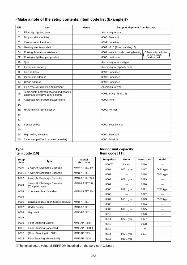
263
<Make a note of the setup contents. (Item code list (Example))>
DN
01
02
03
06
0d
0F
10
11
12
13
14
19
1E
28
2A
2E
30
31
32
40
5d
60
Item
Filter sign lighting time
Dirty condition of filter
Central control address
Heating inlet temp. shift
Cooling Auto mode existence
Cooling only/Heat pump select
Type
Indoor unit capacity
Line address
Indoor unit address
Group address
Flap type (Air direction adjustment)
Temp. width between cooling and heatingautomatic selective control points
Automatic restart from power failure
HA terminal (T10) selection
Sensor select
High ceiling selection
Timer setup (Wired remote controller)
Memo Setup at shipment from factory
According to type
0000: Standard
0099: Undefined
0002: +2°C (Floor standing: 0)
0001: No auto mode cooling/heating
0000: Heat pump
According to model type
According to capacity code
0099: Undefined
0099: Undefined
0099: Undefined
According to type
0003: 3 deg (Ts ± 1.5)
0000: None
0000: Normal
0000: Body sensor
0000: Standard
0000: Possible
TypeItem code [10]
∗ The initial setup value of EEPROM installed on the service P.C. board
* Automatic selectionby connectedoutdoor unit
( )
Indoor unit capacityItem code [11]
Setup data
0000∗
0001
0002
0003
0004
0005
0006
0007
0008
0009
0010
0011
0012
0013
0014
0015
Model
Invalid
0071 type
—
0091 type
—
0121 type
—
0151 type
—
0181 type
—
0241 type
—
—
0271 type
0301 type
Setup data
0016
0017
0018
0019
0020
0021
0022
0023
0024
0025
0026
0027
0028
~0034
Model
—
0481 type
0561 type
—
—
0721 type
—
0961 type
—
—
—
—
—
—
—
Setupdata
0000
0001∗
0002
0003
0004
0005
0006
0007
0008
0009
0010
0011
0012
0013
Type
1-way Air Discharge Cassette
4-way Air Discharge Cassette
2-way Air Discharge Cassette
1-way Air Discharge Cassette(Compact type)
Concealed Duct Standard
—
Concealed Duct High Static Pressure
Under Ceiling
High Wall
Floor Standing Cabinet
Floor Standing Concealed
(Floor Standing 8, 10HP)
Floor Standing (Below 6HP)
Modelabb. name
MMU-AP ∗∗∗ SH
MMU-AP ∗∗∗ H
MMU-AP ∗∗∗ WH
MMU-AP ∗∗∗ YH
MMD-AP ∗∗∗ BH
—
MMD-AP ∗∗∗ H
MMC-AP ∗∗∗ H
MMK-AP ∗∗∗ H
MML-AP ∗∗∗ H
MML-AP ∗∗∗ BH
MMF-AP ∗∗∗ H
MMF-AP ∗∗∗ H
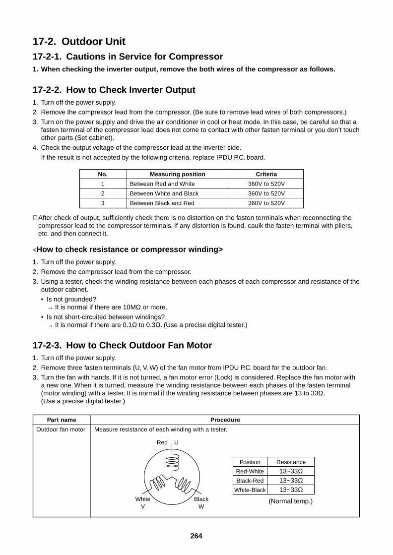
264
17-2. Outdoor Unit17-2-1. Cautions in Service for Compressor1. When checking the inverter output, remove the both wires of the compressor as follows.
17-2-2. How to Check Inverter Output1. Turn off the power supply.
2. Remove the compressor lead from the compressor. (Be sure to remove lead wires of both compressors.)
3. Turn on the power supply and drive the air conditioner in cool or heat mode. In this case, be careful so that afasten terminal of the compressor lead does not come to contact with other fasten terminal or you don’t touchother parts (Set cabinet).
4. Check the output voltage of the compressor lead at the inverter side.
If the result is not accepted by the following criteria, replace IPDU P.C. board.
No.
1
2
3
Measuring position
Between Red and White
Between White and Black
Between Black and Red
Criteria
360V to 520V
360V to 520V
360V to 520V
Part name
Outdoor fan motor
Procedure
Measure resistance of each winding with a tester.
∗ After check of output, sufficiently check there is no distortion on the fasten terminals when reconnecting thecompressor lead to the compressor terminals. If any distortion is found, caulk the fasten terminal with pliers,etc. and then connect it.
<How to check resistance or compressor winding>
1. Turn off the power supply.
2. Remove the compressor lead from the compressor.
3. Using a tester, check the winding resistance between each phases of each compressor and resistance of theoutdoor cabinet.
• Is not grounded?→ It is normal if there are 10MΩ or more.
• Is not short-circuited between windings?→ It is normal if there are 0.1Ω to 0.3Ω. (Use a precise digital tester.)
17-2-3. How to Check Outdoor Fan Motor1. Turn off the power supply.
2. Remove three fasten terminals (U, V, W) of the fan motor from IPDU P.C. board for the outdoor fan.
3. Turn the fan with hands. If it is not turned, a fan motor error (Lock) is considered. Replace the fan motor witha new one. When it is turned, measure the winding resistance between each phases of the fasten terminal(motor winding) with a tester. It is normal if the winding resistance between phases are 13 to 33Ω.(Use a precise digital tester.)
Red
WhiteV
BlackW
U
Position
Red-White
Black-Red
White-Black
Resistance
13~33Ω13~33Ω13~33Ω
(Normal temp.)
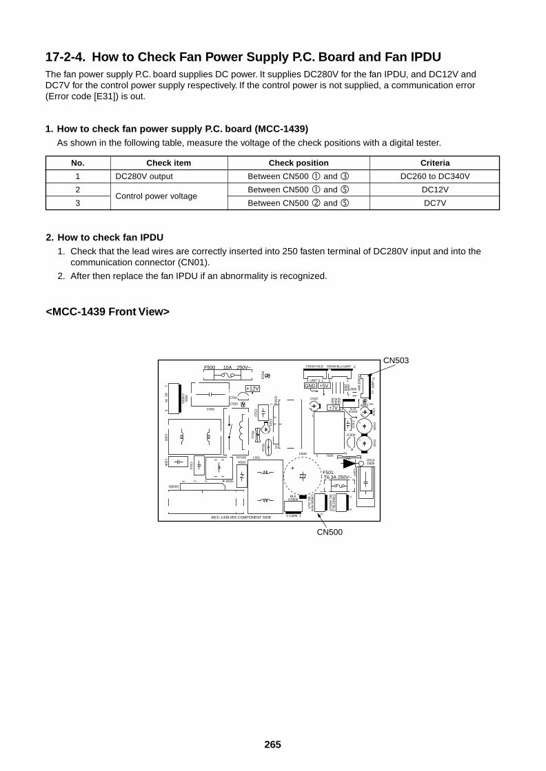
265
17-2-4. How to Check Fan Power Supply P.C. Board and Fan IPDUThe fan power supply P.C. board supplies DC power. It supplies DC280V for the fan IPDU, and DC12V andDC7V for the control power supply respectively. If the control power is not supplied, a communication error(Error code [E31]) is out.
1. How to check fan power supply P.C. board (MCC-1439)As shown in the following table, measure the voltage of the check positions with a digital tester.
No.
1
2
3
Check item
DC280V output
Control power voltage
Check position
Between CN500 and
Between CN500 and
Between CN500 and
Criteria
DC260 to DC340V
DC12V
DC7V
2. How to check fan IPDU1. Check that the lead wires are correctly inserted into 250 fasten terminal of DC280V input and into the
communication connector (CN01).
2. After then replace the fan IPDU if an abnormality is recognized.
<MCC-1439 Front View>
15
AC R
ED
CN
510
R523
C522
C521
R511
R518
IC5011
36
10
INL500
L506
C513
3 CAPA
BLKCN506
1
3
CN
502 BLU
DC
IN/O
UT
1
31
CN
500 WH
ID
C O
UT
R519D505
C509
C501
+12V
C520
F500 10A 250V~
+5V
+7V
GND
R505
DB500
+– ~~
R503
RY500 L501
F501 T6.3A 250V~
11
C523
C526
C524
RJ505J503
CN
503 WH
I
611
UA
RT
J502J504J501
C507
T500C508
56
IC500
J500
G OIC503
R513
CN505 RED
5 5 13 1
1
2
UNIT
C520
CN504 BLU UART
+
+
C531
+
+
+
+
CN503
CN500
MCC-1439-05S COMPONENT SIDE
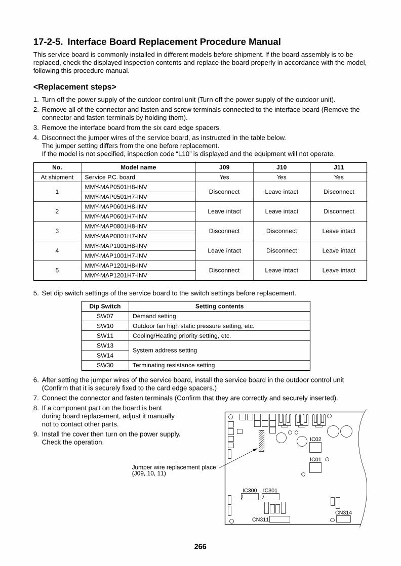
266
17-2-5. Interface Board Replacement Procedure ManualThis service board is commonly installed in different models before shipment. If the board assembly is to bereplaced, check the displayed inspection contents and replace the board properly in accordance with the model,following this procedure manual.
<Replacement steps>
1. Turn off the power supply of the outdoor control unit (Turn off the power supply of the outdoor unit).
2. Remove all of the connector and fasten and screw terminals connected to the interface board (Remove theconnector and fasten terminals by holding them).
3. Remove the interface board from the six card edge spacers.
4. Disconnect the jumper wires of the service board, as instructed in the table below.The jumper setting differs from the one before replacement.If the model is not specified, inspection code “L10” is displayed and the equipment will not operate.
No.
At shipment
1
2
3
4
5
Model name
Service P.C. board
MMY-MAP0501H8-INV
MMY-MAP0501H7-INV
MMY-MAP0601H8-INV
MMY-MAP0601H7-INV
MMY-MAP0801H8-INV
MMY-MAP0801H7-INV
MMY-MAP1001H8-INV
MMY-MAP1001H7-INV
MMY-MAP1201H8-INV
MMY-MAP1201H7-INV
J09 J10 J11
Yes Yes Yes
Disconnect Leave intact Disconnect
Leave intact Leave intact Disconnect
Disconnect Disconnect Leave intact
Leave intact Disconnect Leave intact
Disconnect Leave intact Leave intact
Dip Switch
SW07
SW10
SW11
SW13
SW14
SW30
Setting contents
Demand setting
Outdoor fan high static pressure setting, etc.
Cooling/Heating priority setting, etc.
System address setting
Terminating resistance setting
6. After setting the jumper wires of the service board, install the service board in the outdoor control unit(Confirm that it is securely fixed to the card edge spacers.)
7. Connect the connector and fasten terminals (Confirm that they are correctly and securely inserted).
8. If a component part on the board is bentduring board replacement, adjust it manuallynot to contact other parts.
9. Install the cover then turn on the power supply.Check the operation.
Jumper wire replacement place (J09, 10, 11)
IC02
IC01
CN314
IC300 IC301
CN311
5. Set dip switch settings of the service board to the switch settings before replacement.
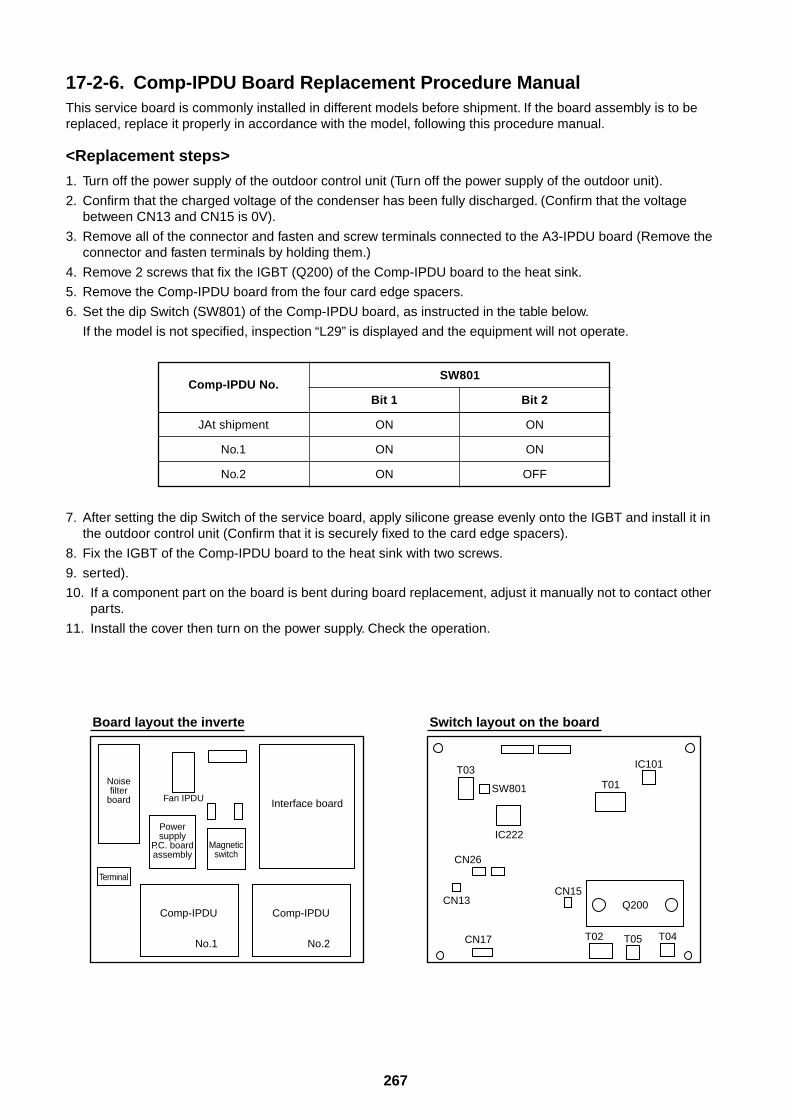
267
17-2-6. Comp-IPDU Board Replacement Procedure ManualThis service board is commonly installed in different models before shipment. If the board assembly is to bereplaced, replace it properly in accordance with the model, following this procedure manual.
<Replacement steps>
1. Turn off the power supply of the outdoor control unit (Turn off the power supply of the outdoor unit).
2. Confirm that the charged voltage of the condenser has been fully discharged. (Confirm that the voltagebetween CN13 and CN15 is 0V).
3. Remove all of the connector and fasten and screw terminals connected to the A3-IPDU board (Remove theconnector and fasten terminals by holding them.)
4. Remove 2 screws that fix the IGBT (Q200) of the Comp-IPDU board to the heat sink.
5. Remove the Comp-IPDU board from the four card edge spacers.
6. Set the dip Switch (SW801) of the Comp-IPDU board, as instructed in the table below.
If the model is not specified, inspection “L29” is displayed and the equipment will not operate.
7. After setting the dip Switch of the service board, apply silicone grease evenly onto the IGBT and install it inthe outdoor control unit (Confirm that it is securely fixed to the card edge spacers).
8. Fix the IGBT of the Comp-IPDU board to the heat sink with two screws.
9. serted).
10. If a component part on the board is bent during board replacement, adjust it manually not to contact otherparts.
11. Install the cover then turn on the power supply. Check the operation.
Comp-IPDU No.
JAt shipment
No.1
No.2
SW801
Bit 1 Bit 2
ON ON
ON ON
ON OFF
Noisefilter
board
Terminal
Powersupply
P.C. boardassembly
Interface board
Board layout the inverte
Comp-IPDU
No.1
Comp-IPDU
No.2
Magneticswitch
Fan IPDU
Switch layout on the board
Q200
IC101
IC222
SW801 T01T03
CN26
T05
CN15CN13
CN17 T04T02
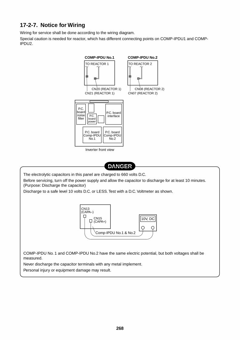
268
17-2-7. Notice for WiringWiring for service shall be done according to the wiring diagram.
Special caution is needed for reactor, which has different connecting points on COMP-IPDU1 and COMP-IPDU2.
DANGERThe electrolytic capacitors in this panel are charged to 660 volts D.C.
Before servicing, turn off the power supply and allow the capacitor to discharge for at least 10 minutes.(Purpose: Discharge the capacitor)
Discharge to a safe level 10 volts D.C. or LESS. Test with a D.C. Voltmeter as shown.
COMP-IPDU No. 1 and COMP-IPDU No.2 have the same electric potential, but both voltages shall bemeasured.
Never discharge the capacitor terminals with any metal implement.
Personal injury or equipment damage may result.
TO REACTOR 1
COMP-IPDU No.1
CN20 (REACTOR 1)CN21 (REACTOR 1)
TO REACTOR 2
COMP-IPDU No.2
CN08 (REACTOR 2)CN07 (REACTOR 2)
P.C.boardnoisefilter
P.C.boardpower
P.C. boardinterface
P.C. boardComp-IPDU
No.2
P.C. boardComp-IPDU
No.1
Inverter front view
10V, DC
CN13 (CAPA–)
CN15 (CAPA+)
Comp-IPDU No.1 & No.2
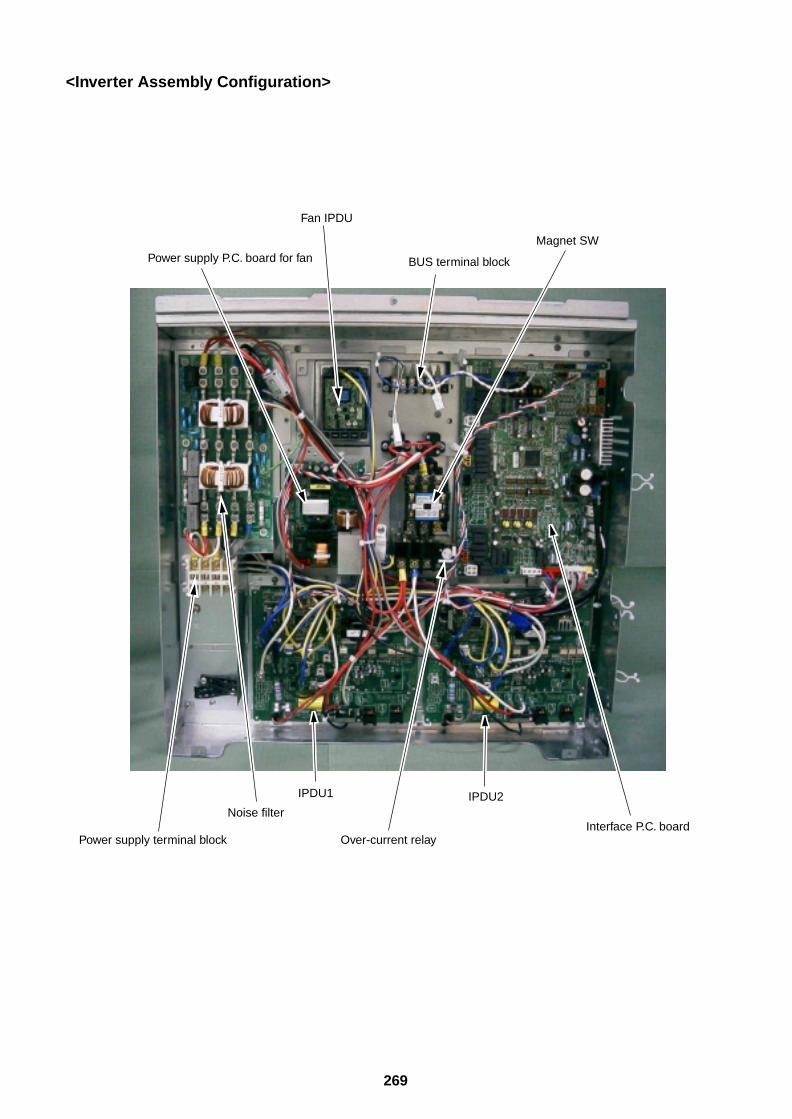
269
<Inverter Assembly Configuration>
Fan IPDU
Power supply P.C. board for fan
Noise filter
Power supply terminal block Over-current relay
BUS terminal block
Magnet SW
IPDU1 IPDU2
Interface P.C. board

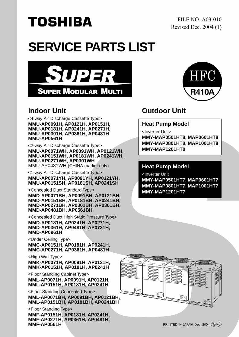
Indoor Unit<4-way Air Discharge Cassette Type>MMU-AP0091H, AP0121H, AP0151H,MMU-AP0181H, AP0241H, AP0271H,MMU-AP0301H, AP0361H, AP0481HMMU-AP0561H<2-way Air Discharge Cassette Type>MMU-AP0071WH, AP0091WH, AP0121WH,MMU-AP0151WH, AP0181WH, AP0241WH,MMU-AP0271WH, AP0301WHMMU-AP0481WH (CHINA market only)
<1-way Air Discharge Cassette Type>MMU-AP0071YH, AP0091YH, AP0121YH,MMU-AP0151SH, AP0181SH, AP0241SH<Concealed Duct Standard Type>MMD-AP0071BH, AP0091BH, AP0121BH,MMD-AP0151BH, AP0181BH, AP0241BH,MMD-AP0271BH, AP0301BH, AP0361BH,MMD-AP0481BH, AP0561BH<Concealed Duct High Static Pressure Type>MMD-AP0181H, AP0241H, AP0271H,MMD-AP0361H, AP0481H, AP0721H,MMD-AP0961H<Under Ceiling Type>MMC-AP0151H, AP0181H, AP0241H,MMC-AP0271H, AP0361H, AP0481H<High Wall Type>MMK-AP0071H, AP0091H, AP0121H,MMK-AP0151H, AP0181H, AP0241H<Floor Standing Cabinet Type>MML-AP0071H, AP0091H, AP0121H,MML-AP0151H, AP0181H, AP0241H<Floor Standing Concealed Type>MML-AP0071BH, AP0091BH, AP0121BH,MML-AP0151BH, AP0181BH, AP0241BH<Floor Standing Type>MMF-AP0151H, AP0181H, AP0241H,MMF-AP0271H, AP0361H, AP0481H,MMF-AP0561H
Outdoor Unit
Heat Pump Model<Inverter Unit>MMY-MAP0501HT8, MAP0601HT8MMY-MAP0801HT8, MAP1001HT8MMY-MAP1201HT8
Heat Pump Model<Inverter UnitMMY-MAP0501HT7, MAP0601HT7MMY-MAP0801HT7, MAP1001HT7MMY-MAP1201HT7
SERVICE PARTS LIST
PRINTED IN JAPAN, Dec.,2004 ToMo

92
CONTENTS
EXPLODED VIEWS AND PARTS LIST ............................................................. 4
1. 4-way Air Discharge Cassette Type ......................................................... 4
2. 2-way Air Discharge Cassette Type ....................................................... 10
3. 1-way Air Discharge Cassette Type ....................................................... 18
4. Concealed Duct Standard Type .............................................................. 24
5. Concealed Duct High Static Pressure Type .......................................... 33
6. Under Ceiling Type .................................................................................. 38
7. High Wall Type ......................................................................................... 44
8. Floor Standing Cabinet Type .................................................................. 52
9. Floor Standing Concealed Type ............................................................. 60
10. Floor Standing Type ................................................................................ 66
11. Panel Assembly ....................................................................................... 724-way Air Discharge Cassette Type ........................................................................... 72
2-way Air Discharge Cassette Type ........................................................................... 73
1-way Air Discharge Cassette Type ........................................................................... 74
12. Outdoor Unit ............................................................................................ 76
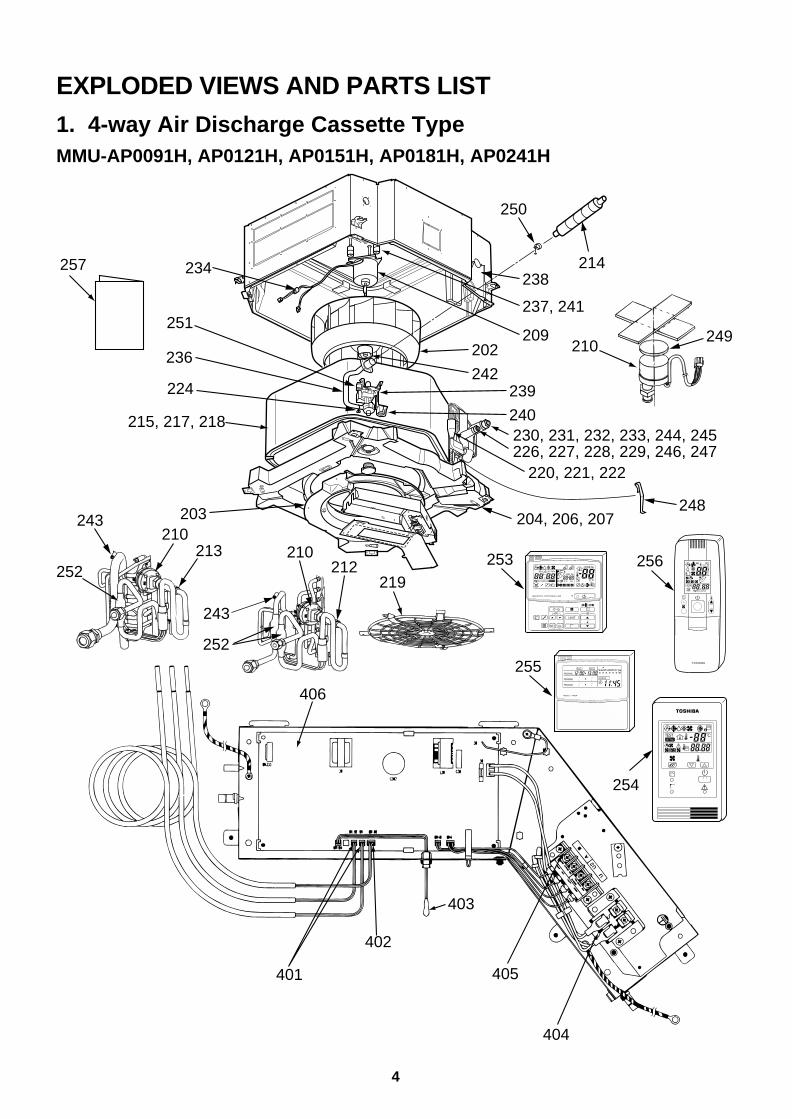
4
EXPLODED VIEWS AND PARTS LIST
1. 4-way Air Discharge Cassette TypeMMU-AP0091H, AP0121H, AP0151H, AP0181H, AP0241H
234
251
238
237, 241
209
239
240230, 231, 232, 233, 244, 245226, 227, 228, 229, 246, 247
220, 221, 222
202
242236
224
215, 217, 218
203
212
249210
219
257
252
243
250
210213
248
243
210
214
204, 206, 207
252
406
401
402
405
404
403
UNIT
SET CL
SETTING
UNIT No.
CODE No.
TEST
SET DATA
R.C. No.
ADR
˚CTESTSETTING
WEEKLY TIMER
ERROR
SuMoTuWeTh Fr SaPROGRAM1
PROGRAM2
PROGRAM3
254
253
255
256
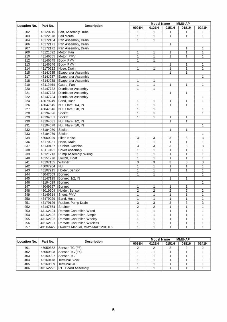
5
Model Name MMU-APLocation No. Part No. Description
0091H 0121H 0151H 0181H 0241H202 43120215 Fan, Assembly, Tube 1 1 1 1 1203 43122078 Bell Mouth 1 1 1 1 1204 43172164 Pan Assembly, Drain 1 1206 43172171 Pan Assembly, Drain 1207 43172172 Pan Assembly, Drain 1 1209 43121692 Motor, Fan 1 1 1 1 1210 43146555 Motor, PMV 1 1 1 1 1212 43146645 Body, PMV 1 1213 43146646 Body, PMV 1 1 1214 43170232 Hose, Drain 1 1 1 1 1215 4314J235 Evaporator Assembly 1 1217 4314J237 Evaporator Assembly 1218 4314J238 Evaporator Assembly 1 1219 43119464 Guard, Fan 1 1 1 1 1220 43147732 Distributor Assembly 1 1221 43147733 Distributor Assembly 1 1222 43147734 Distributor Assembly 1224 43079249 Band, Hose 1 1 1 1 1226 43047545 Nut, Flare, 1/4, IN 1 1 1 1227 43047546 Nut, Flare, 3/8, IN 1 1 1228 43194026 Socket 1 1 1229 43194051 Socket 1 1 1 1230 43194081 Nut, Flare, 1/2, IN 1 1231 43194078 Nut, Flare, 5/8, IN 1232 43194080 Socket 1 1233 43194079 Socket 1234 43060029 Filter, Noise 3 3 3 3 3236 43170231 Hose, Drain 1 1 1 1 1237 43139137 Rubber, Cushion 3 3 3 3 3238 43119451 Cover Assembly 1 1 1 1 1239 43121713 Pump Assembly, Wiring 1 1 1 1 1240 43151278 Switch, Float 1 1 1 1 1241 43197155 Washer 3 3 3 3 3242 43097204 Nut 1 1 1 1 1243 43107215 Holder, Sensor 1 1 1 1 1244 43047609 Bonnet 1 1 1245 43147195 Bonnet, 1/2, IN 1 1246 43194029 Bonnet 1247 43049697 Bonnet 1 1 1 1248 43019904 Holder, Sensor 2 2 2 2 2249 43149314 Sheet, PMV 1 1 1 1 1250 43479029 Band, Hose 1 1 1 1 1251 43179126 Rubber, Pump Drain 3 3 3 3 3252 43147664 Strainer 2 2 1 1 1253 4316V194 Remote Controller, Wired 1 1 1 1 1254 4316V195 Remote Controller, Simple 1 1 1 1 1255 4316V196 Remote Controller, Weekly 1 1 1 1 1256 4316V197 Remote Controller, Wireless 1 1 1 1 1257 4311M422 Owner’s Manual, MMY-MAP1201HT8 1 1 1 1 1
Model Name MMU-APLocation No. Part No. Description
0091H 0121H 0151H 0181H 0241H401 43050382 Sensor, TC (F6) 2 2 2 2 2402 43050398 Sensor, TG (F4) 1 1 1 1 1403 43150297 Sensor, TC 1 1 1 1 1404 43160478 Terminal Block 1 1 1 1 1405 43160509 Terminal, 4P 1 1 1 1 1406 4316V225 P.C. Board Assembly 1 1 1 1 1
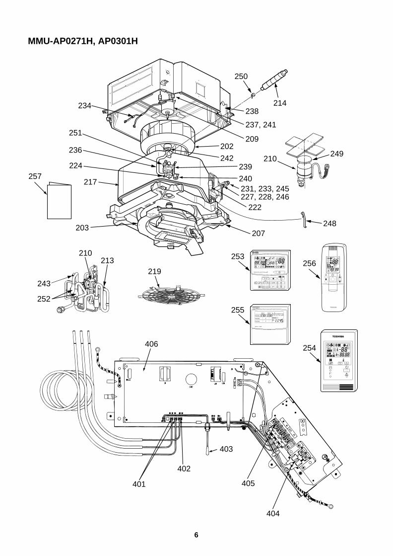
6
MMU-AP0271H, AP0301H
234
251
238
237, 241
209
239
240231, 233, 245227, 228, 246
222
202
242236
224
217
203
213
249210
219
257
250
248
243
210
214
207
252
406
401
402
405
404
403
UNIT
SET CL
SETTING
UNIT No.
CODE No.
TEST
SET DATA
R.C. No.
ADR
˚CTESTSETTING
WEEKLY TIMER
ERROR
SuMoTuWeTh Fr SaPROGRAM1
PROGRAM2
PROGRAM3
253
255
256
254
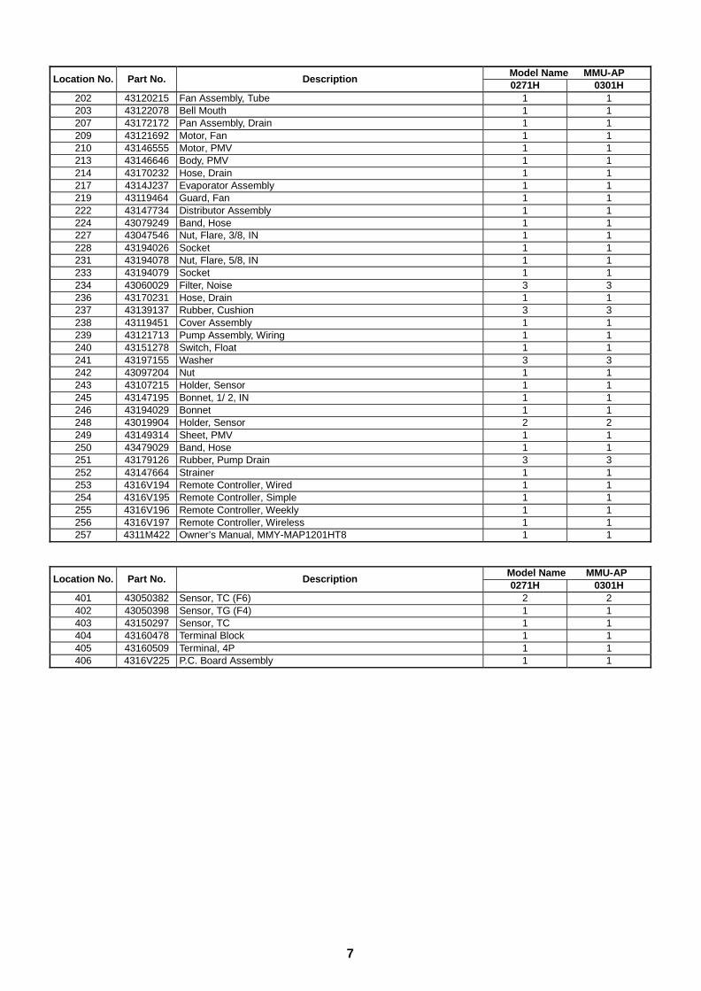
7
Model Name MMU-APLocation No. Part No. Description
0271H 0301H202 43120215 Fan Assembly, Tube 1 1203 43122078 Bell Mouth 1 1207 43172172 Pan Assembly, Drain 1 1209 43121692 Motor, Fan 1 1210 43146555 Motor, PMV 1 1213 43146646 Body, PMV 1 1214 43170232 Hose, Drain 1 1217 4314J237 Evaporator Assembly 1 1219 43119464 Guard, Fan 1 1222 43147734 Distributor Assembly 1 1224 43079249 Band, Hose 1 1227 43047546 Nut, Flare, 3/8, IN 1 1228 43194026 Socket 1 1231 43194078 Nut, Flare, 5/8, IN 1 1233 43194079 Socket 1 1234 43060029 Filter, Noise 3 3236 43170231 Hose, Drain 1 1237 43139137 Rubber, Cushion 3 3238 43119451 Cover Assembly 1 1239 43121713 Pump Assembly, Wiring 1 1240 43151278 Switch, Float 1 1241 43197155 Washer 3 3242 43097204 Nut 1 1243 43107215 Holder, Sensor 1 1245 43147195 Bonnet, 1/ 2, IN 1 1246 43194029 Bonnet 1 1248 43019904 Holder, Sensor 2 2249 43149314 Sheet, PMV 1 1250 43479029 Band, Hose 1 1251 43179126 Rubber, Pump Drain 3 3252 43147664 Strainer 1 1253 4316V194 Remote Controller, Wired 1 1254 4316V195 Remote Controller, Simple 1 1255 4316V196 Remote Controller, Weekly 1 1256 4316V197 Remote Controller, Wireless 1 1257 4311M422 Owner’s Manual, MMY-MAP1201HT8 1 1
Model Name MMU-APLocation No. Part No. Description
0271H 0301H401 43050382 Sensor, TC (F6) 2 2402 43050398 Sensor, TG (F4) 1 1403 43150297 Sensor, TC 1 1404 43160478 Terminal Block 1 1405 43160509 Terminal, 4P 1 1406 4316V225 P.C. Board Assembly 1 1
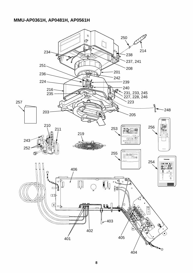
8
MMU-AP0361H, AP0481H, AP0561H
234
251
238
237, 241
208
239
240231, 233, 245227, 228, 246
223
201
242236
224
216235
203
211219
257
250
248
243
210
214
205
252
406
401
402
405
404
403
ADR
˚CTESTSETTING
UNIT
SET CL
SETTING
UNIT No.
CODE No.
TEST
SET DATA
R.C. No.
WEEKLY TIMER
ERROR
SuMoTuWeTh Fr SaPROGRAM1
PROGRAM2
PROGRAM3
256
254
253
255
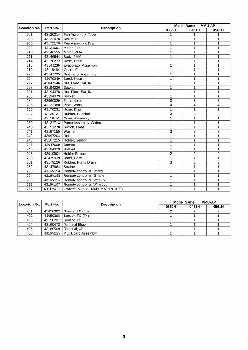
9
Model Name MMU-APLocation No. Part No. Description
0361H 0481H 0561H201 43120214 Fan Assembly, Tube 1 1 1203 43122078 Bell Mouth 1 1 1205 43172170 Pan Assembly, Drain 1 1 1208 43121691 Motor, Fan 1 1 1210 43146555 Motor, PMV 1 1 1211 43146644 Body, PMV 1 1 1214 43170232 Hose, Drain 1 1 1216 4314J236 Evaporator Assembly 1 1 1219 43119464 Guard, Fan 1 1 1223 43147735 Distributor Assembly 1 1 1224 43079249 Band, Hose 1 1 1227 43047546 Nut, Flare, 3/8, IN 1 1 1228 43194026 Socket 1 1 1231 43194078 Nut, Flare, 5/8, IN 1 1 1233 43194079 Socket 1 1 1234 43060029 Filter, Noise 3 3 3235 43122080 Plate, Wind 4 4 4236 43170231 Hose, Drain 1 1 1237 43139137 Rubber, Cushion 3 3 3238 43119451 Cover Assembly 1 1 1239 43121713 Pump Assembly, Wiring 1 1 1240 43151278 Switch, Float 1 1 1241 43197155 Washer 3 3 3242 43097204 Nut 1 1 1243 43107215 Holder, Sensor 1 1 1245 43047609 Bonnet 1 1 1246 43194029 Bonnet 1 1 1248 43019904 Holder Sensor 2 2 2250 43479029 Band, Hose 1 1 1251 43179126 Rubber, Pump Drain 3 3 3252 43147664 Strainer 1 1 1253 4316V194 Remote controller, Wired 1 1 1254 4316V195 Remote controller, Simple 1 1 1255 4316V196 Remote controller, Weekly 1 1 1256 4316V197 Remote controller, Wireless 1 1 1257 4311M422 Owner’s Manual, MMY-MAP1201HT8 1 1 1
Model Name MMU-APLocation No. Part No. Description
0361H 0481H 0561H401 43050382 Sensor, TC (F6) 2 2 2402 43050398 Sensor, TG (F4) 1 1 1403 43150297 Sensor, TC 1 1 1404 43160478 Terminal Block 1 1 1405 43160509 Terminal, 4P 1 1 1406 4316V225 P.C. Board Assembly 1 1 1
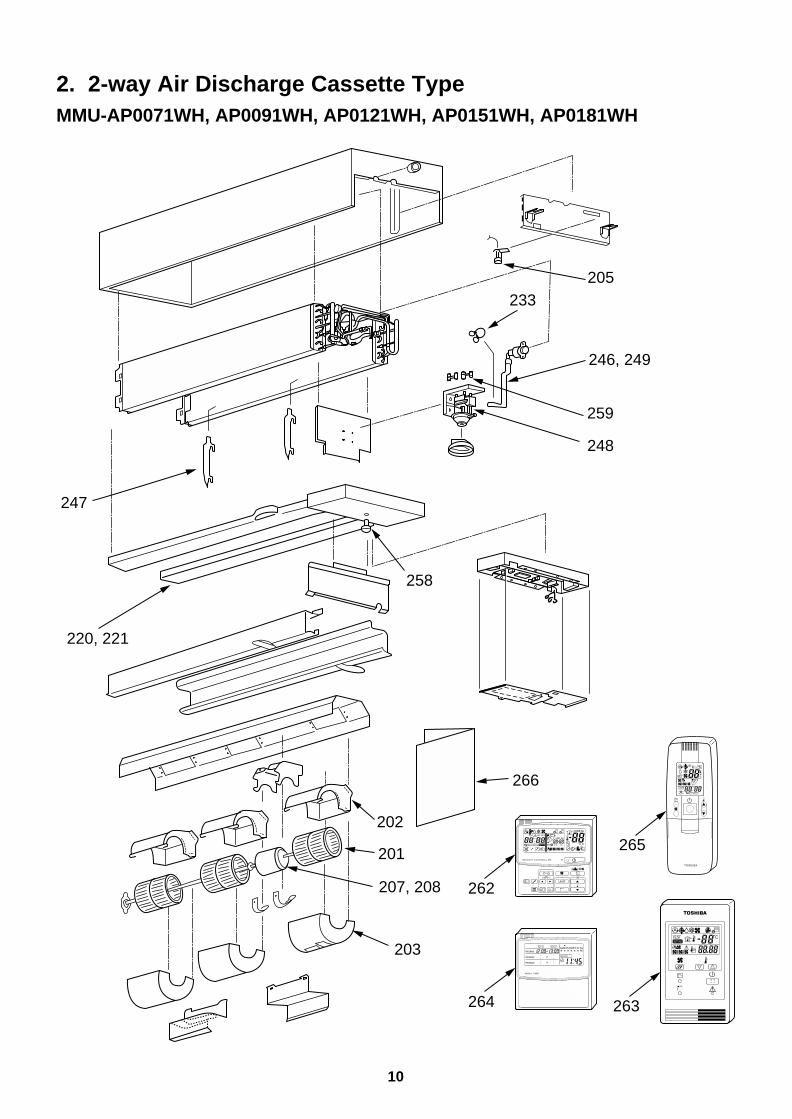
10
2. 2-way Air Discharge Cassette TypeMMU-AP0071WH, AP0091WH, AP0121WH, AP0151WH, AP0181WH
220, 221
258
203
207, 208
202
201
248
233
247
246, 249
259
205
266
262
264
265
263
UNIT
SET CL
SETTING
UNIT No.
CODE No.
TEST
SET DATA
R.C. No.
ADR
˚CTESTSETTING
WEEKLY TIMER
ERROR
SuMoTuWeTh Fr SaPROGRAM1
PROGRAM2
PROGRAM3
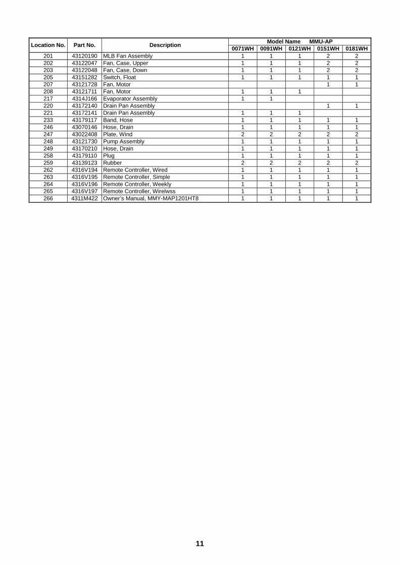
11
Model Name MMU-APLocation No. Part No. Description
0071WH 0091WH 0121WH 0151WH 0181WH201 43120190 MLB Fan Assembly 1 1 1 2 2202 43122047 Fan, Case, Upper 1 1 1 2 2203 43122048 Fan, Case, Down 1 1 1 2 2205 43151282 Switch, Float 1 1 1 1 1207 43121728 Fan, Motor 1 1208 43121711 Fan, Motor 1 1 1217 4314J166 Evaporator Assembly 1 1220 43172140 Drain Pan Assembly 1 1221 43172141 Drain Pan Assembly 1 1 1233 43179117 Band, Hose 1 1 1 1 1246 43070146 Hose, Drain 1 1 1 1 1247 43022408 Plate, Wind 2 2 2 2 2248 43121730 Pump Assembly 1 1 1 1 1249 43170210 Hose, Drain 1 1 1 1 1258 43179110 Plug 1 1 1 1 1259 43139123 Rubber 2 2 2 2 2262 4316V194 Remote Controller, Wired 1 1 1 1 1263 4316V195 Remote Controller, Simple 1 1 1 1 1264 4316V196 Remote Controller, Weekly 1 1 1 1 1265 4316V197 Remote Controller, Wirelwss 1 1 1 1 1266 4311M422 Owner’s Manual, MMY-MAP1201HT8 1 1 1 1 1
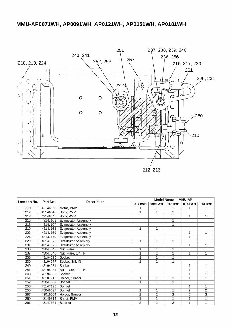
12
MMU-AP0071WH, AP0091WH, AP0121WH, AP0151WH, AP0181WH
212, 213
251
229, 231
257252, 253218, 219, 224
210
243, 241
261
236, 256216, 217, 223
237, 238, 239, 240
260
Model Name MMU-APLocation No. Part No. Description
0071WH 0091WH 0121WH 0151WH 0181WH210 43146555 Motor, PMV 1 1 1 1 1212 43146645 Body, PMV 1 1 1213 43146646 Body, PMV 1 1216 4314J165 Evaporator Assembly 1218 4314J167 Evaporator Assembly 1219 4314J168 Evaporator Assembly 1 1223 4314J169 Evaporator Assembly 1 1224 4314J170 Evaporator Assembly 1 1229 43147676 Distributor Assembly 1 1 1231 43147678 Distributor Assembly 1 1236 43047546 Nut, Flare 1 1 1237 43047545 Nut, Flare, 1/4, IN 1 1 1 1 1238 43194026 Socket 1 1 1239 43194077 Socket, 1/8, IN 1 1 1240 43194051 Socket 1 1241 43194081 Nut, Flare, 1/2, IN 1 1243 73194080 Socket 1 1251 43107215 Holder, Sensor 1 1 1 1 1252 43047609 Bonnet 1 1 1253 43147195 Bonnet 1 1256 43049697 Bonnet 1 1 1 2 2257 43019904 Holder, Sensor 2 2 2 2 2260 43149314 Sheet, PMV 1 1 1 1 1261 43147664 Strainer 2 2 2 1 1
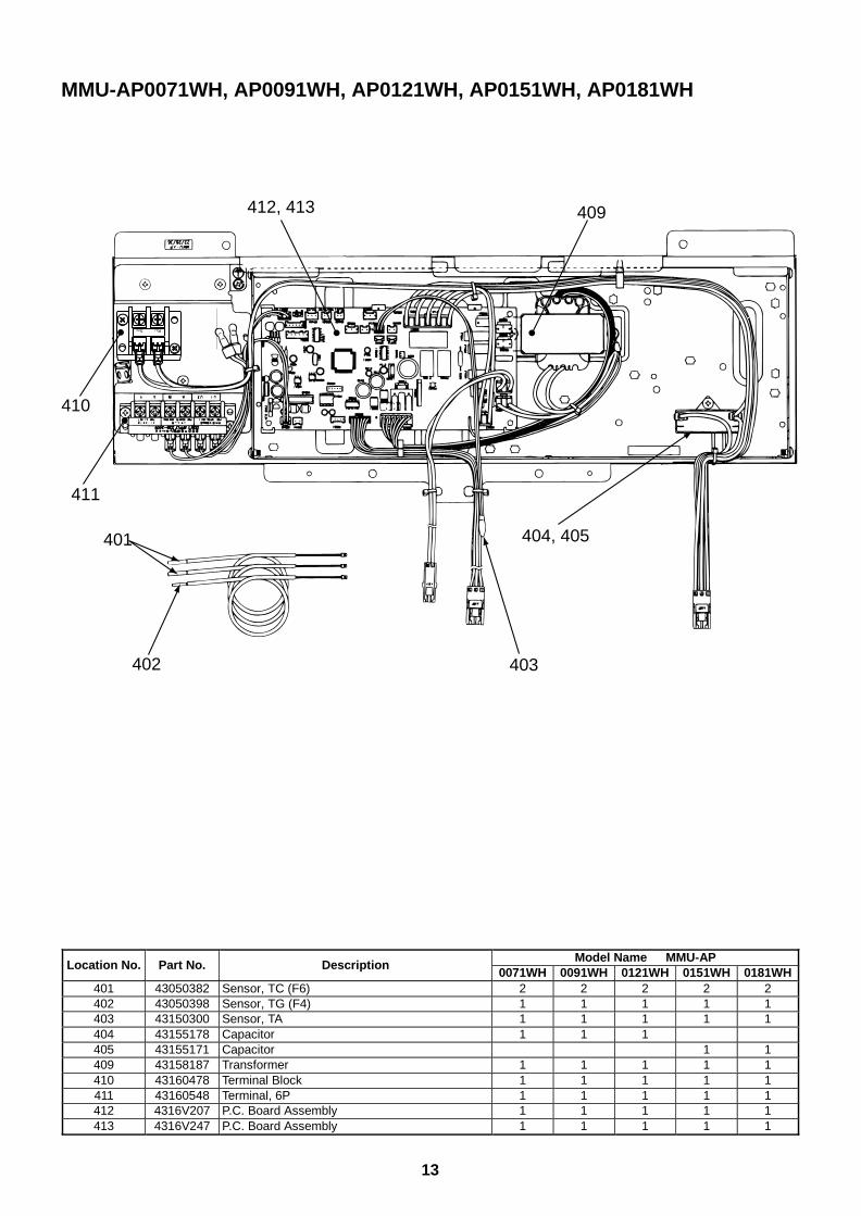
13
MMU-AP0071WH, AP0091WH, AP0121WH, AP0151WH, AP0181WH
403
404, 405401
402
411
410
412, 413 409
R(L)S(N)
Model Name MMU-APLocation No. Part No. Description
0071WH 0091WH 0121WH 0151WH 0181WH401 43050382 Sensor, TC (F6) 2 2 2 2 2402 43050398 Sensor, TG (F4) 1 1 1 1 1403 43150300 Sensor, TA 1 1 1 1 1404 43155178 Capacitor 1 1 1405 43155171 Capacitor 1 1409 43158187 Transformer 1 1 1 1 1410 43160478 Terminal Block 1 1 1 1 1411 43160548 Terminal, 6P 1 1 1 1 1412 4316V207 P.C. Board Assembly 1 1 1 1 1413 4316V247 P.C. Board Assembly 1 1 1 1 1
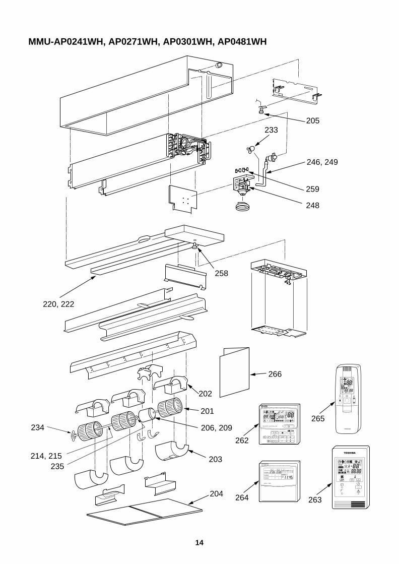
14
MMU-AP0241WH, AP0271WH, AP0301WH, AP0481WH
220, 222
258
203
234
214, 215235
206, 209
202
201
248
233
246, 249
259
205
266
204
262
264
265
263
UNIT
SET CL
SETTING
UNIT No.
CODE No.
TEST
SET DATA
R.C. No.
ADR
˚CTESTSETTING
WEEKLY TIMER
ERROR
SuMoTuWeTh Fr SaPROGRAM1
PROGRAM2
PROGRAM3
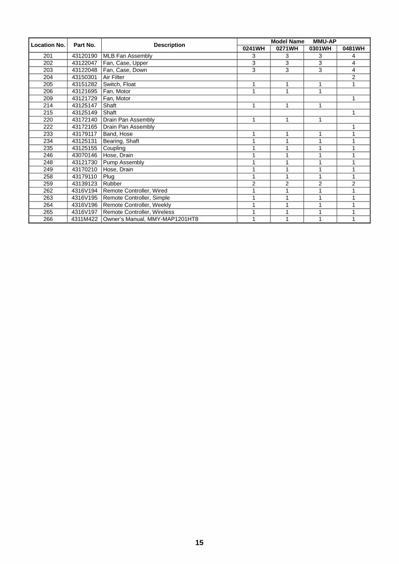
15
Model Name MMU-APLocation No. Part No. Description
0241WH 0271WH 0301WH 0481WH201 43120190 MLB Fan Assembly 3 3 3 4202 43122047 Fan, Case, Upper 3 3 3 4203 43122048 Fan, Case, Down 3 3 3 4204 43150301 Air Filter 2205 43151282 Switch, Float 1 1 1 1206 43121695 Fan, Motor 1 1 1209 43121729 Fan, Motor 1214 43125147 Shaft 1 1 1215 43125149 Shaft 1220 43172140 Drain Pan Assembly 1 1 1222 43172165 Drain Pan Assembly 1233 43179117 Band, Hose 1 1 1 1234 43125131 Bearing, Shaft 1 1 1 1235 43125155 Coupling 1 1 1 1246 43070146 Hose, Drain 1 1 1 1248 43121730 Pump Assembly 1 1 1 1249 43170210 Hose, Drain 1 1 1 1258 43179110 Plug 1 1 1 1259 43139123 Rubber 2 2 2 2262 4316V194 Remote Controller, Wired 1 1 1 1263 4316V195 Remote Controller, Simple 1 1 1 1264 4316V196 Remote Controller, Weekly 1 1 1 1265 4316V197 Remote Controller, Wireless 1 1 1 1266 4311M422 Owner’s Manual, MMY-MAP1201HT8 1 1 1 1
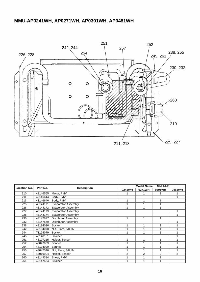
16
MMU-AP0241WH, AP0271WH, AP0301WH, AP0481WH
211, 213
251
230, 232
257254226, 228
225, 227
210
260
242, 244238, 255
245, 261
252
Model Name MMU-APLocation No. Part No. Description
0241WH 0271WH 0301WH 0481WH210 43146555 Motor, PMV 1 1 1 1211 43146644 Body, PMV 1213 43146646 Body, PMV 1 1 1225 4314J171 Evaporator Assembly 1 1 1226 4314J172 Evaporator Assembly 1 1 1227 4314J173 Evaporator Assembly 1228 4314J174 Evaporator Assembly 1230 43147677 Distributor Assembly 1 1 1232 43147679 Distributor Assembly 1238 43194026 Socket 1 1 1 1242 43194078 Nut, Flare, 5/8, IN 1 1 1 1244 73194079 Socket 1 1 1 1245 43148151 Strainer 1251 43107215 Holder, Sensor 1 1 1 1252 43047609 Bonnet 1 1 1 1254 43194029 Bonnet 1 1 1 1255 43047546 Nut, Flare, 3/8, IN 1 1 1 1257 43019904 Holder, Sensor 2 2 2 2260 43149314 Sheet, PMV 1 1 1261 43147664 Strainer 1 1 1
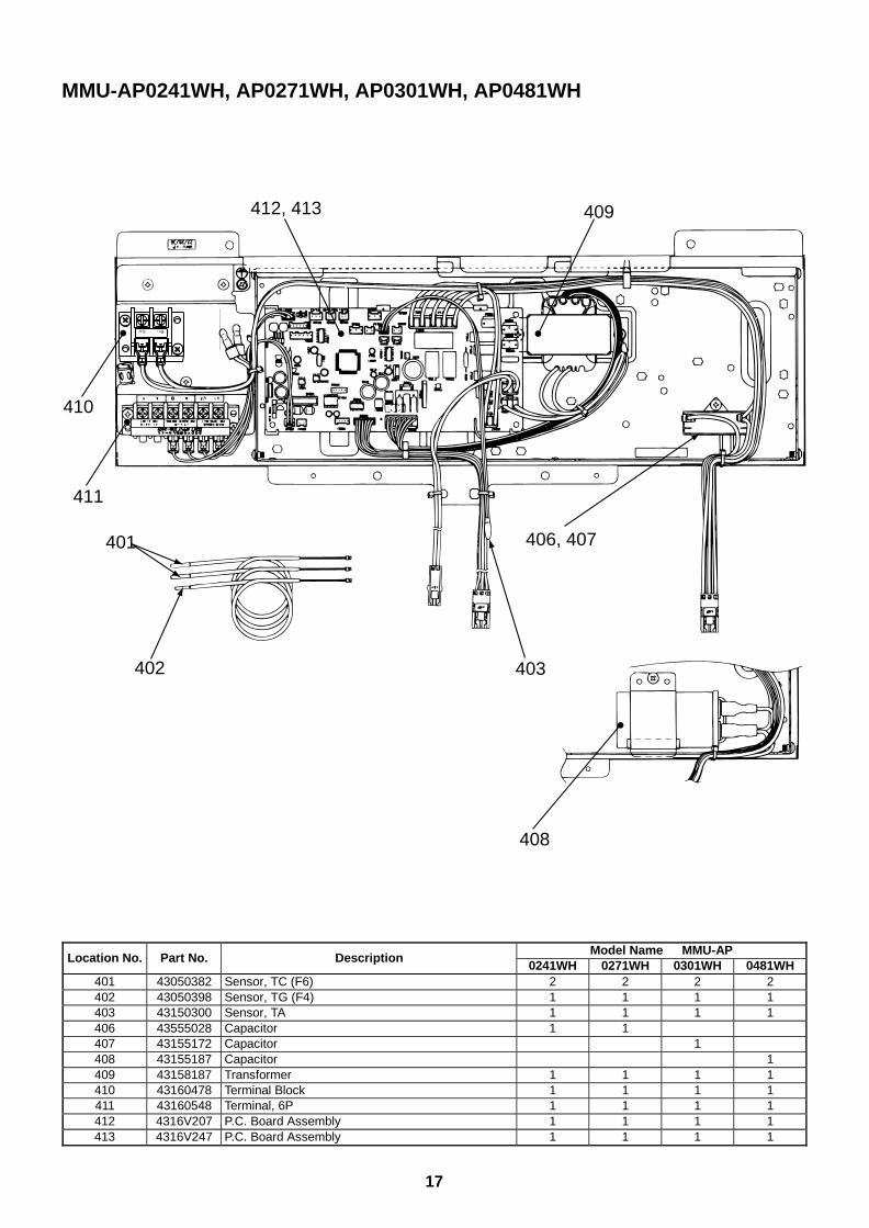
17
MMU-AP0241WH, AP0271WH, AP0301WH, AP0481WH
408
403
406, 407401
402
411
410
412, 413 409
R(L)S(N)
Model Name MMU-APLocation No. Part No. Description
0241WH 0271WH 0301WH 0481WH401 43050382 Sensor, TC (F6) 2 2 2 2402 43050398 Sensor, TG (F4) 1 1 1 1403 43150300 Sensor, TA 1 1 1 1406 43555028 Capacitor 1 1407 43155172 Capacitor 1408 43155187 Capacitor 1409 43158187 Transformer 1 1 1 1410 43160478 Terminal Block 1 1 1 1411 43160548 Terminal, 6P 1 1 1 1412 4316V207 P.C. Board Assembly 1 1 1 1413 4316V247 P.C. Board Assembly 1 1 1 1
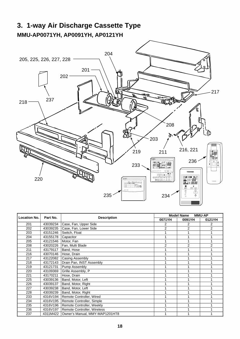
18
3. 1-way Air Discharge Cassette TypeMMU-AP0071YH, AP0091YH, AP0121YH
220
237
204205, 225, 226, 227, 228
202201
218
211219
203
208
217
216, 221
UNIT
SET CL
SETTING
UNIT No.
CODE No.
TEST
SET DATA
R.C. No.
ADR
˚CTESTSETTING
WEEKLY TIMER
ERROR
SuMoTuWeTh Fr SaPROGRAM1
PROGRAM2
PROGRAM3
235 234
233236
Model Name MMU-APLocation No. Part No. Description
0071YH 0091YH 0121YH201 43039234 Case, Fan, Upper Side 2 2 2202 43039235 Case, Fan, Lower Side 2 2 2203 43151246 Switch, Float 1 1 1204 43155178 Capacitor 1 1 1205 43121546 Motor, Fan 1 1 1208 43020226 Fan, Multi Blade 2 2 2211 43179117 Band, Hose 1 1 1216 43070146 Hose, Drain 1 1 1217 43122082 Casing Assembly 1 1 1218 43172143 Drain Pan, INST Assembly 1 1 1219 43121731 Pump Assembly 1 1 1220 43109369 Grille Assembly, P 1 1 1221 43170211 Hose, Drain 1 1 1225 43039136 Band, Motor, Left 1 1 1226 43039137 Band, Motor, Right 1 1 1227 43039238 Band, Motor, Left 1 1 1228 43039239 Band, Motor, Right 1 1 1233 4316V194 Remote Controller, Wired 1 1 1234 4316V195 Remote Controller, Simple 1 1 1235 4316V196 Remote Controller, Weekly 1 1 1236 4316V197 Remote Controller, Wireless 1 1 1237 4311M422 Owner’s Manual, MMY-MAP1201HT8 1 1 1
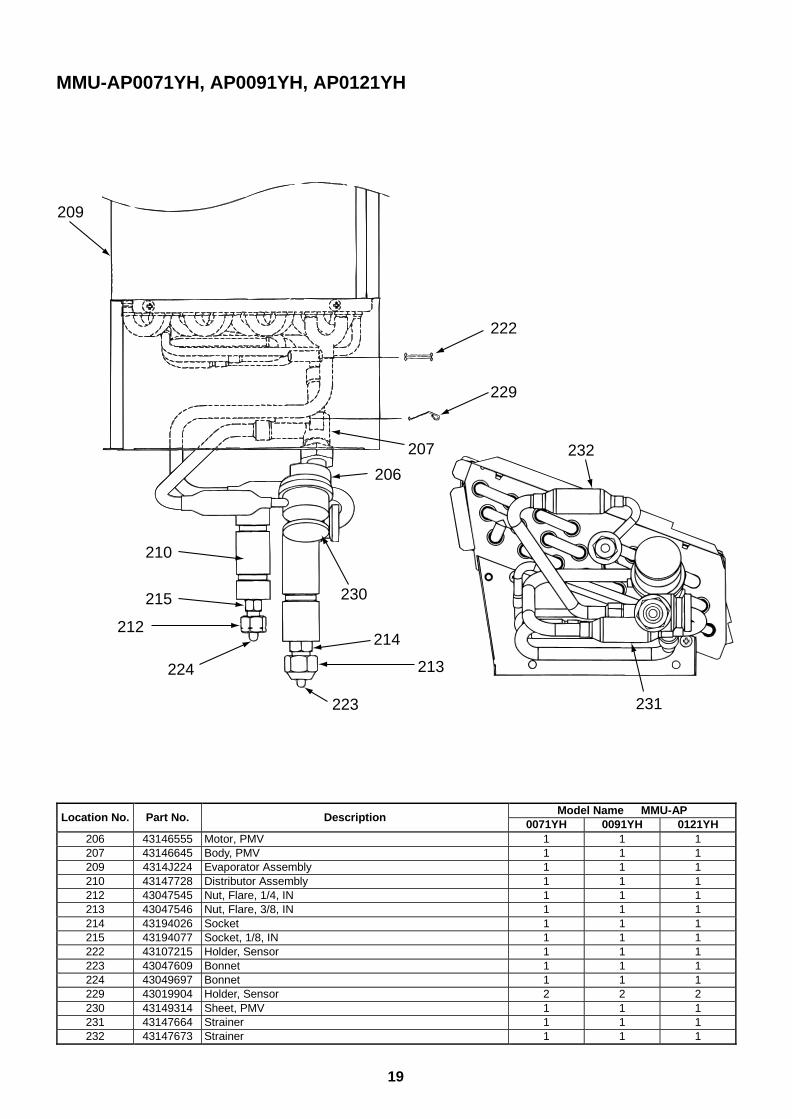
19
MMU-AP0071YH, AP0091YH, AP0121YH
222
229
206
209
232
214
213
231
212
215
210
223
224
207
230
Model Name MMU-APLocation No. Part No. Description
0071YH 0091YH 0121YH206 43146555 Motor, PMV 1 1 1207 43146645 Body, PMV 1 1 1209 4314J224 Evaporator Assembly 1 1 1210 43147728 Distributor Assembly 1 1 1212 43047545 Nut, Flare, 1/4, IN 1 1 1213 43047546 Nut, Flare, 3/8, IN 1 1 1214 43194026 Socket 1 1 1215 43194077 Socket, 1/8, IN 1 1 1222 43107215 Holder, Sensor 1 1 1223 43047609 Bonnet 1 1 1224 43049697 Bonnet 1 1 1229 43019904 Holder, Sensor 2 2 2230 43149314 Sheet, PMV 1 1 1231 43147664 Strainer 1 1 1232 43147673 Strainer 1 1 1
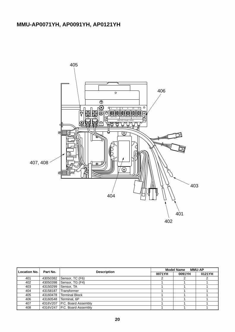
20
Model Name MMU-APLocation No. Part No. Description
0071YH 0091YH 0121YH401 43050382 Sensor, TC (F6) 2 2 2402 43050398 Sensor, TG (F4) 1 1 1403 43150299 Sensor, TA 1 1 1404 43158187 Transformer 1 1 1405 43160478 Terminal Block 1 1 1406 43160548 Terminal, 6P 1 1 1407 4316V207 P.C. Board Assembly 1 1 1408 4316V247 P.C. Board Assembly 1 1 1
MMU-AP0071YH, AP0091YH, AP0121YH
DON’T APPLY 220-240V
FOR INTER-UNITFOR AI-NET FOR REMOTE CONTROL
U1U2ABXY
R(L)S(N)
407, 408
404
402
401
403
406
405
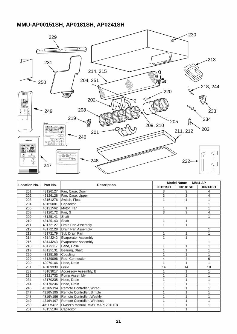
21
MMU-AP00151SH, AP0181SH, AP0241SH
231
229
218, 244
213
233
234
232
203
214, 215
202
208
219
201
230
205209, 210
211, 212
220
204, 251
UNIT
SET CL
SETTING
UNIT No.
CODE No.
TEST
SET DATA
R.C. No.
ADR
˚CTESTSETTING
WEEKLY TIMER
ERROR
SuMoTuWeTh Fr SaPROGRAM1
PROGRAM2
PROGRAM3
249
250
246
248247
Model Name MMU-APLocation No. Part No. Description
00151SH 00181SH 00241SH201 43126127 Fan, Case, Down 3 3 4202 43126128 Fan, Case, Upper 3 3 4203 43151276 Switch, Float 1 1 1204 43155081 Capacitor 1205 43121562 Motor, Fan 1 1 1208 43120172 Fan, S 3 3 4209 43125141 Shaft 1210 43125143 Shaft 1 1211 43172127 Drain Pan Assembly 1 1212 43172128 Drain Pan Assembly 1213 43172179 Sub Drain Pan 1 1 1214 4314J242 Evaporator Assembly 1 1215 4314J243 Evaporator Assembly 1218 43179117 Band, Hose 1 1 1219 43125131 Bearing, Shaft 1 1 1220 43125155 Coupling 1 1 1229 43139098 Rod, Connection 4 4 6230 43070146 Hose, Drain 1 1 1231 43109339 Grille 14 14 18232 43183017 Accessory Assembly, B 1 1 1233 43121732 Pump Assembly 1 1 1234 43170235 Hose, Drain 1 1 1244 43170236 Hose, Drain 1 1 1246 4316V194 Remote Controller, Wired 1 1 1247 4316V195 Remote Controller, Simple 1 1 1248 4316V196 Remote Controller, Weekly 1 1 1249 4316V197 Remote Controller, Wireless 1 1 1250 4311M422 Owner’s Manual, MMY-MAP1201HT8 1 1 1251 43155104 Capacitor 1 1
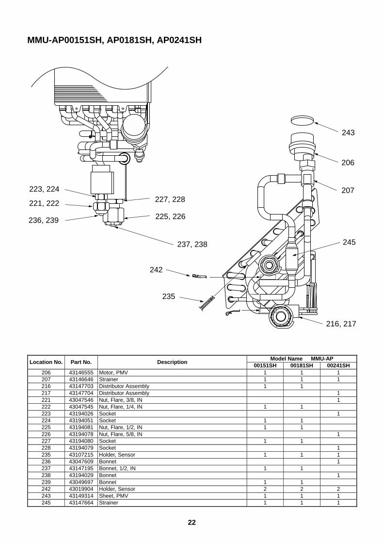
22
MMU-AP00151SH, AP0181SH, AP0241SH
221, 222
223, 224
236, 239
237, 238
227, 228
225, 226
243
206
207
245
216, 217
242
235
Model Name MMU-APLocation No. Part No. Description
00151SH 00181SH 00241SH206 43146555 Motor, PMV 1 1 1207 43146646 Strainer 1 1 1216 43147703 Distributor Assembly 1 1217 43147704 Distributor Assembly 1221 43047546 Nut, Flare, 3/8, IN 1222 43047545 Nut, Flare, 1/4, IN 1 1223 43194026 Socket 1224 43194051 Socket 1 1225 43194081 Nut, Flare, 1/2, IN 1 1226 43194078 Nut, Flare, 5/8, IN 1227 43194080 Socket 1 1228 43194079 Socket 1235 43107215 Holder, Sensor 1 1 1236 43047609 Bonnet 1237 43147195 Bonnet, 1/2, IN 1 1238 43194029 Bonnet 1239 43049697 Bonnet 1 1242 43019904 Holder, Sensor 2 2 2243 43149314 Sheet, PMV 1 1 1245 43147664 Strainer 1 1 1
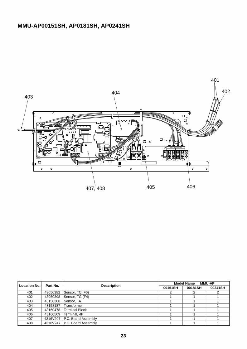
23
MMU-AP00151SH, AP0181SH, AP0241SH
R(L) S(N)
U1 U2 A B
DON’T APPLY 220-240V
FOR INTER-UNIT FOR REMOTE CONTROL
401
402
406405
404403
407, 408
Model Name MMU-APLocation No. Part No. Description
00151SH 00181SH 00241SH401 43050382 Sensor, TC (F6) 2 2 2402 43050398 Sensor, TG (F4) 1 1 1403 43150300 Sensor, TA 1 1 1404 43158187 Transformer 1 1 1405 43160478 Terminal Block 1 1 1406 43160509 Terminal, 4P 1 1 1407 4316V207 P.C. Board Assembly 1 1 1408 4316V247 P.C. Board Assembly 1 1 1
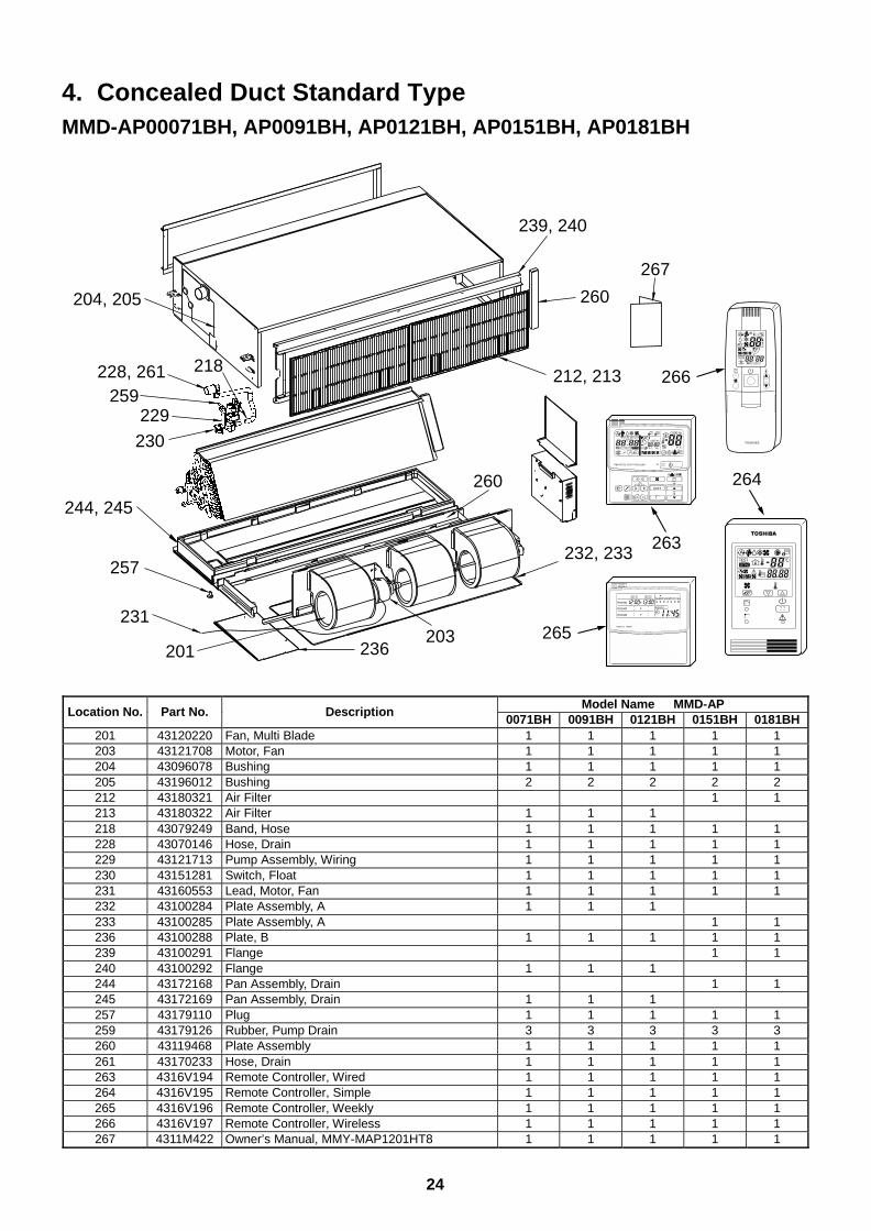
24
4. Concealed Duct Standard TypeMMD-AP00071BH, AP0091BH, AP0121BH, AP0151BH, AP0181BH
244, 245
236
232, 233
203
239, 240
212, 213
201
231
257
230
229259
228, 261 218
204, 205
267
260
260
265
263
264
266
UNIT
SET CL
SETTING
UNIT No.
CODE No.
TEST
SET DATA
R.C. No.
ADR
˚CTESTSETTING
WEEKLY TIMER
ERROR
SuMoTuWeTh Fr SaPROGRAM1
PROGRAM2
PROGRAM3
Model Name MMD-APLocation No. Part No. Description
0071BH 0091BH 0121BH 0151BH 0181BH201 43120220 Fan, Multi Blade 1 1 1 1 1203 43121708 Motor, Fan 1 1 1 1 1204 43096078 Bushing 1 1 1 1 1205 43196012 Bushing 2 2 2 2 2212 43180321 Air Filter 1 1213 43180322 Air Filter 1 1 1218 43079249 Band, Hose 1 1 1 1 1228 43070146 Hose, Drain 1 1 1 1 1229 43121713 Pump Assembly, Wiring 1 1 1 1 1230 43151281 Switch, Float 1 1 1 1 1231 43160553 Lead, Motor, Fan 1 1 1 1 1232 43100284 Plate Assembly, A 1 1 1233 43100285 Plate Assembly, A 1 1236 43100288 Plate, B 1 1 1 1 1239 43100291 Flange 1 1240 43100292 Flange 1 1 1244 43172168 Pan Assembly, Drain 1 1245 43172169 Pan Assembly, Drain 1 1 1257 43179110 Plug 1 1 1 1 1259 43179126 Rubber, Pump Drain 3 3 3 3 3260 43119468 Plate Assembly 1 1 1 1 1261 43170233 Hose, Drain 1 1 1 1 1263 4316V194 Remote Controller, Wired 1 1 1 1 1264 4316V195 Remote Controller, Simple 1 1 1 1 1265 4316V196 Remote Controller, Weekly 1 1 1 1 1266 4316V197 Remote Controller, Wireless 1 1 1 1 1267 4311M422 Owner’s Manual, MMY-MAP1201HT8 1 1 1 1 1
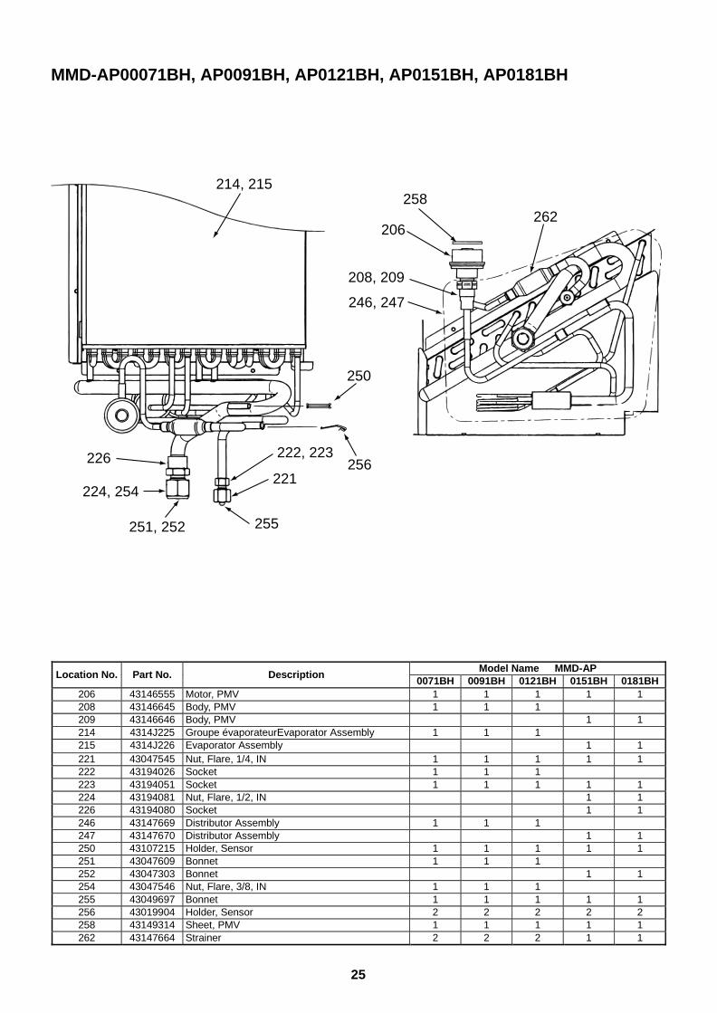
25
MMD-AP00071BH, AP0091BH, AP0121BH, AP0151BH, AP0181BH
221
250
258
226
206
208, 209
255
262
222, 223256
224, 254
246, 247
214, 215
251, 252
Model Name MMD-APLocation No. Part No. Description
0071BH 0091BH 0121BH 0151BH 0181BH206 43146555 Motor, PMV 1 1 1 1 1208 43146645 Body, PMV 1 1 1209 43146646 Body, PMV 1 1214 4314J225 Groupe évaporateurEvaporator Assembly 1 1 1215 4314J226 Evaporator Assembly 1 1221 43047545 Nut, Flare, 1/4, IN 1 1 1 1 1222 43194026 Socket 1 1 1223 43194051 Socket 1 1 1 1 1224 43194081 Nut, Flare, 1/2, IN 1 1226 43194080 Socket 1 1246 43147669 Distributor Assembly 1 1 1247 43147670 Distributor Assembly 1 1250 43107215 Holder, Sensor 1 1 1 1 1251 43047609 Bonnet 1 1 1252 43047303 Bonnet 1 1254 43047546 Nut, Flare, 3/8, IN 1 1 1255 43049697 Bonnet 1 1 1 1 1256 43019904 Holder, Sensor 2 2 2 2 2258 43149314 Sheet, PMV 1 1 1 1 1262 43147664 Strainer 2 2 2 1 1
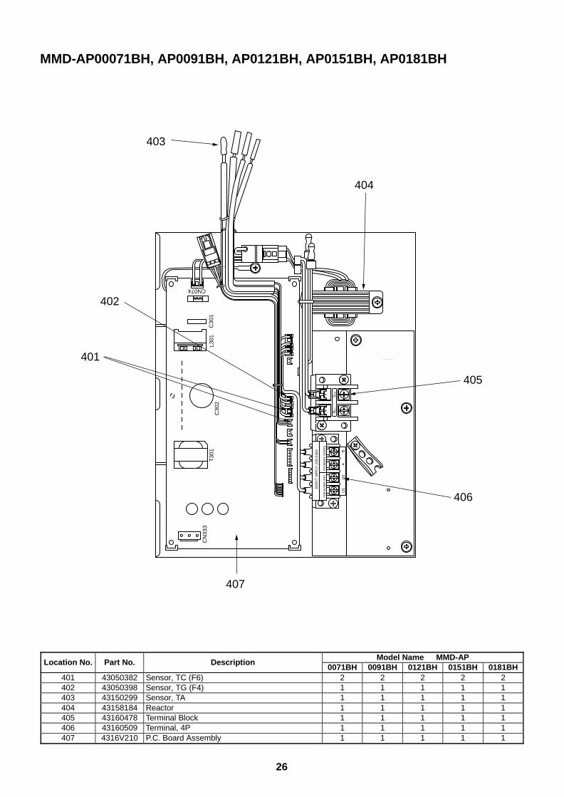
26
Model Name MMD-APLocation No. Part No. Description
0071BH 0091BH 0121BH 0151BH 0181BH401 43050382 Sensor, TC (F6) 2 2 2 2 2402 43050398 Sensor, TG (F4) 1 1 1 1 1403 43150299 Sensor, TA 1 1 1 1 1404 43158184 Reactor 1 1 1 1 1405 43160478 Terminal Block 1 1 1 1 1406 43160509 Terminal, 4P 1 1 1 1 1407 4316V210 P.C. Board Assembly 1 1 1 1 1
MMD-AP00071BH, AP0091BH, AP0121BH, AP0151BH, AP0181BH
U1
U2
AB
DO
N’T
AP
PLY
220
-240
V
FO
R IN
TE
R-U
NIT
FOR
REM
OTE
CONT
ROL
T30
1C
N33
3
C30
2C
301
L301
CN074
R(L
)S
(N)
405
404
403
402
401
407
406
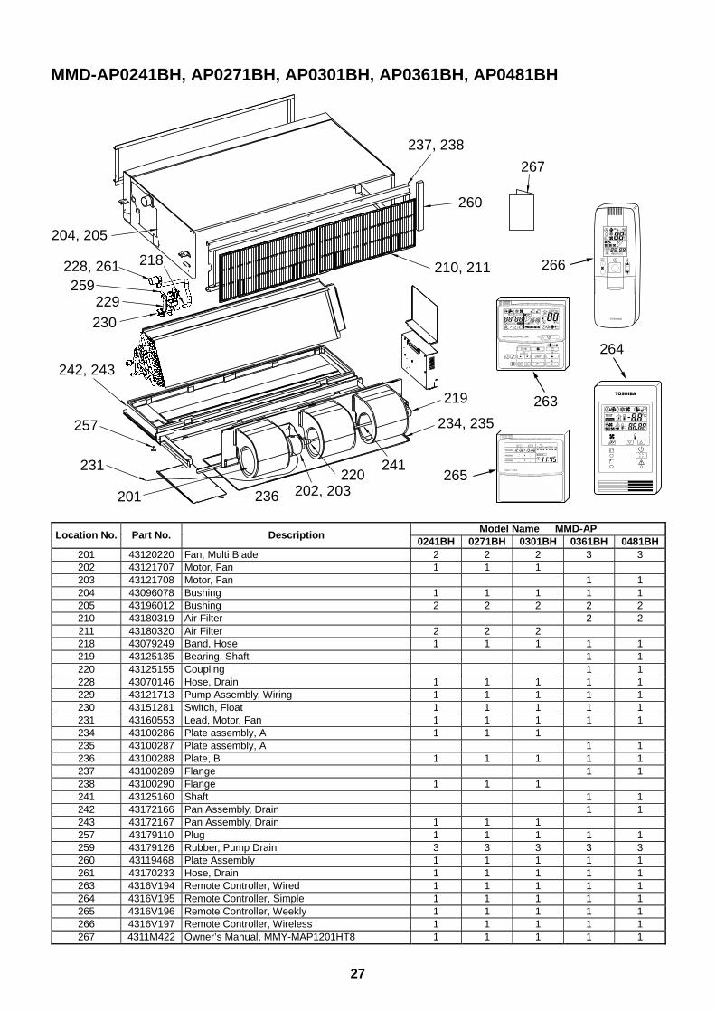
27
MMD-AP0241BH, AP0271BH, AP0301BH, AP0361BH, AP0481BH
242, 243
236 202, 203220
241
237, 238
210, 211
201
231
257
230
229259
228, 261 218
204, 205
267
219
234, 235
260
265
263
264
266
UNIT
SET CL
SETTING
UNIT No.
CODE No.
TEST
SET DATA
R.C. No.
ADR
˚CTESTSETTING
WEEKLY TIMER
ERROR
SuMoTuWeTh Fr SaPROGRAM1
PROGRAM2
PROGRAM3
Model Name MMD-APLocation No. Part No. Description
0241BH 0271BH 0301BH 0361BH 0481BH201 43120220 Fan, Multi Blade 2 2 2 3 3202 43121707 Motor, Fan 1 1 1203 43121708 Motor, Fan 1 1204 43096078 Bushing 1 1 1 1 1205 43196012 Bushing 2 2 2 2 2210 43180319 Air Filter 2 2211 43180320 Air Filter 2 2 2218 43079249 Band, Hose 1 1 1 1 1219 43125135 Bearing, Shaft 1 1220 43125155 Coupling 1 1228 43070146 Hose, Drain 1 1 1 1 1229 43121713 Pump Assembly, Wiring 1 1 1 1 1230 43151281 Switch, Float 1 1 1 1 1231 43160553 Lead, Motor, Fan 1 1 1 1 1234 43100286 Plate assembly, A 1 1 1235 43100287 Plate assembly, A 1 1236 43100288 Plate, B 1 1 1 1 1237 43100289 Flange 1 1238 43100290 Flange 1 1 1241 43125160 Shaft 1 1242 43172166 Pan Assembly, Drain 1 1243 43172167 Pan Assembly, Drain 1 1 1257 43179110 Plug 1 1 1 1 1259 43179126 Rubber, Pump Drain 3 3 3 3 3260 43119468 Plate Assembly 1 1 1 1 1261 43170233 Hose, Drain 1 1 1 1 1263 4316V194 Remote Controller, Wired 1 1 1 1 1264 4316V195 Remote Controller, Simple 1 1 1 1 1265 4316V196 Remote Controller, Weekly 1 1 1 1 1266 4316V197 Remote Controller, Wireless 1 1 1 1 1267 4311M422 Owner’s Manual, MMY-MAP1201HT8 1 1 1 1 1
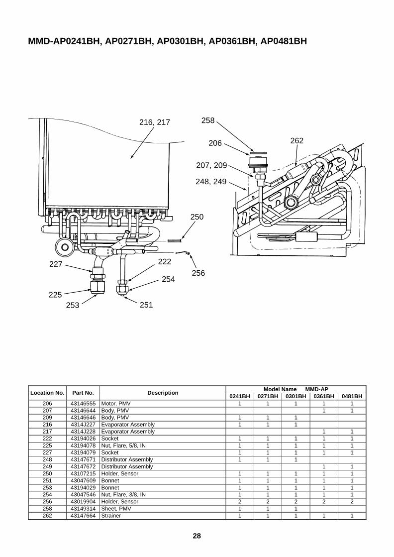
28
MMD-AP0241BH, AP0271BH, AP0301BH, AP0361BH, AP0481BH
253
262
225
227
207, 209
206
248, 249
251
254
222
256
250
216, 217 258
Model Name MMD-APLocation No. Part No. Description
0241BH 0271BH 0301BH 0361BH 0481BH206 43146555 Motor, PMV 1 1 1 1 1207 43146644 Body, PMV 1 1209 43146646 Body, PMV 1 1 1216 4314J227 Evaporator Assembly 1 1 1217 4314J228 Evaporator Assembly 1 1222 43194026 Socket 1 1 1 1 1225 43194078 Nut, Flare, 5/8, IN 1 1 1 1 1227 43194079 Socket 1 1 1 1 1248 43147671 Distributor Assembly 1 1 1249 43147672 Distributor Assembly 1 1250 43107215 Holder, Sensor 1 1 1 1 1251 43047609 Bonnet 1 1 1 1 1253 43194029 Bonnet 1 1 1 1 1254 43047546 Nut, Flare, 3/8, IN 1 1 1 1 1256 43019904 Holder, Sensor 2 2 2 2 2258 43149314 Sheet, PMV 1 1 1262 43147664 Strainer 1 1 1 1 1
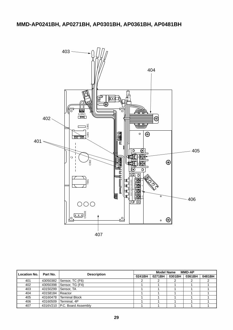
29
MMD-AP0241BH, AP0271BH, AP0301BH, AP0361BH, AP0481BH
U1
U2
AB
DO
N’T
AP
PLY
220
-240
V
FO
R IN
TE
R-U
NIT
FOR
REM
OTE
CONT
ROL
T30
1C
N33
3
C30
2C
301
L301
CN074
R(L
)S
(N)
405
404
403
402
401
407
406
Model Name MMD-APLocation No. Part No. Description
0241BH 0271BH 0301BH 0361BH 0481BH401 43050382 Sensor, TC (F6) 2 2 2 2 2402 43050398 Sensor, TG (F4) 1 1 1 1 1403 43150299 Sensor, TA 1 1 1 1 1404 43158184 Reactor 1 1 1 1 1405 43160478 Terminal Block 1 1 1 1 1406 43160509 Terminal, 4P 1 1 1 1 1407 4316V210 P.C. Board Assembly 1 1 1 1 1
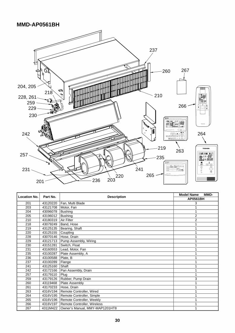
30
MMD-AP0561BH
242
236220
241
203
237
210
201
231
257
230
229259
228, 261218
204, 205
267
219
235
260
265
263
264
266
UNIT
SET CL
SETTING
UNIT No.
CODE No.
TEST
SET DATA
R.C. No.
ADR
˚CTESTSETTING
WEEKLY TIMER
ERROR
SuMoTuWeTh Fr SaPROGRAM1
PROGRAM2
PROGRAM3
Model Name MMD-Location No. Part No. Description
AP0561BH201 43120220 Fan, Multi Blade 3203 43121708 Motor, Fan 1204 43096078 Bushing 1205 43196012 Bushing 2210 43180319 Air Filter 2218 43079249 Band, Hose 1219 43125135 Bearing, Shaft 1220 43125155 Coupling 1228 43070146 Hose, Drain 1229 43121713 Pump Assembly, Wiring 1230 43151281 Switch, Float 1231 43160553 Lead, Motor, Fan 1235 43100287 Plate Assembly, A 1236 43100588 Plate, B 1237 43100289 Flange 1241 43125160 Shaft 1242 43172166 Pan Assembly, Drain 1257 43179110 Plug 1259 43179126 Rubber, Pump Drain 3260 43119468 Plate Assembly 1261 43170233 Hose, Drain 1263 4316V194 Remote Controller, Wired 1264 4316V195 Remote Controller, Simple 1265 4316V196 Remote Controller, Weekly 1266 4316V197 Remote Controller, Wireless 1267 4311M422 Owner’s Manual, MMY-MAP1201HT8 1
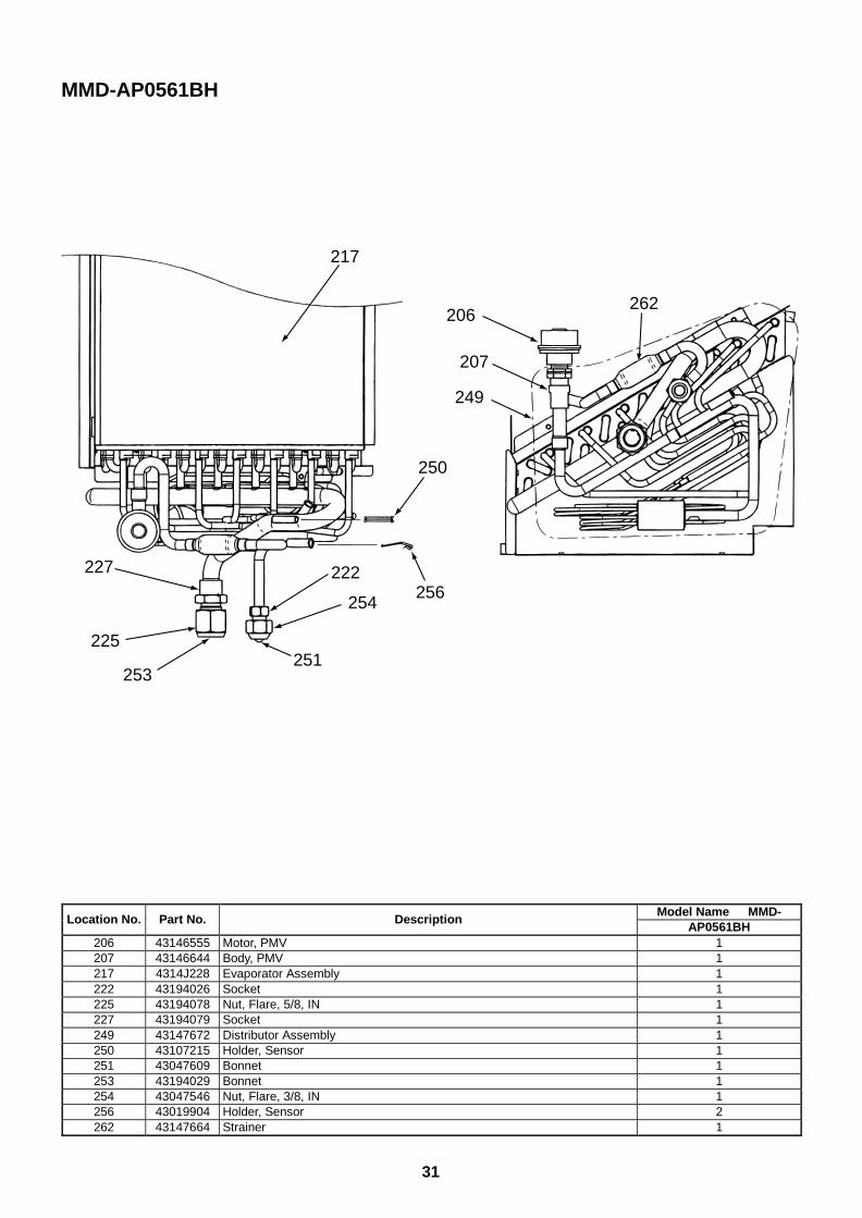
31
MMD-AP0561BH
253
262
225
227
207
206
249
251
254
222256
250
217
Model Name MMD-Location No. Part No. Description
AP0561BH206 43146555 Motor, PMV 1207 43146644 Body, PMV 1217 4314J228 Evaporator Assembly 1222 43194026 Socket 1225 43194078 Nut, Flare, 5/8, IN 1227 43194079 Socket 1249 43147672 Distributor Assembly 1250 43107215 Holder, Sensor 1251 43047609 Bonnet 1253 43194029 Bonnet 1254 43047546 Nut, Flare, 3/8, IN 1256 43019904 Holder, Sensor 2262 43147664 Strainer 1
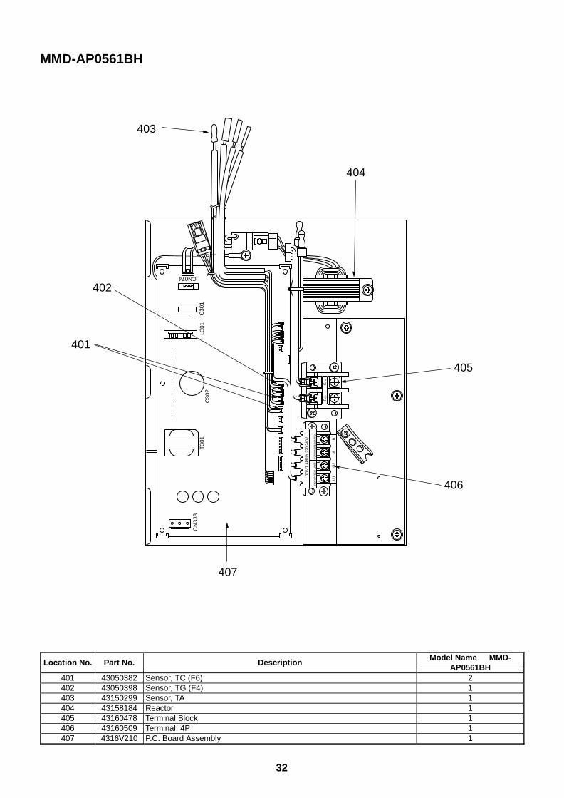
32
Model Name MMD-Location No. Part No. Description
AP0561BH401 43050382 Sensor, TC (F6) 2402 43050398 Sensor, TG (F4) 1403 43150299 Sensor, TA 1404 43158184 Reactor 1405 43160478 Terminal Block 1406 43160509 Terminal, 4P 1407 4316V210 P.C. Board Assembly 1
MMD-AP0561BH
U1
U2
AB
DO
N’T
AP
PLY
220
-240
V
FO
R IN
TE
R-U
NIT
FOR
REM
OTE
CONT
ROL
T30
1C
N33
3
C30
2C
301
L301
CN074
R(L
)S
(N)
405
404
403
402
401
407
406
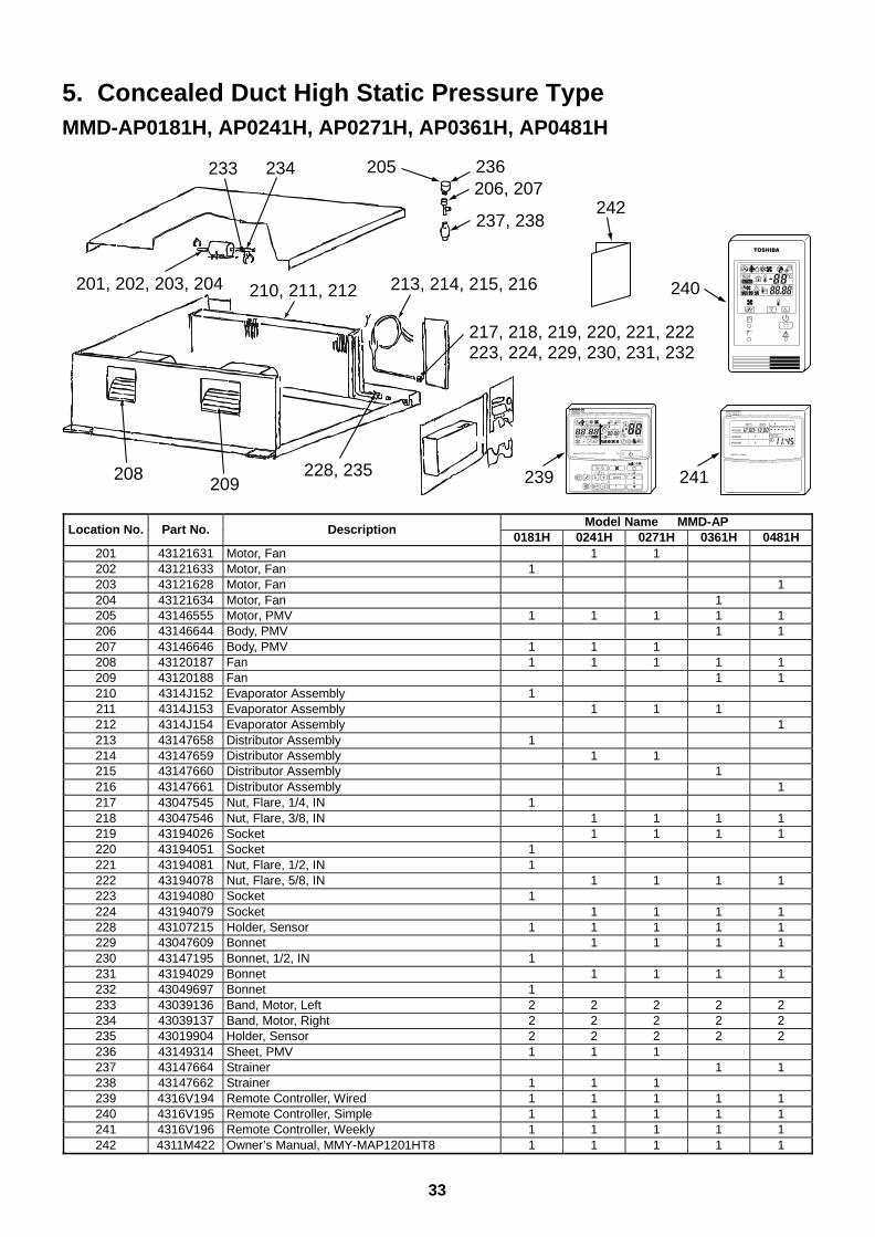
33
5. Concealed Duct High Static Pressure TypeMMD-AP0181H, AP0241H, AP0271H, AP0361H, AP0481H
213, 214, 215, 216
228, 235
201, 202, 203, 204
208209
210, 211, 212
217, 218, 219, 220, 221, 222223, 224, 229, 230, 231, 232
242
205
237, 238
239
236206, 207
233 234
241
240
UNIT
SET CL
SETTING
UNIT No.
CODE No.
TEST
SET DATA
R.C. No.
˚CTESTSETTING
WEEKLY TIMER
ERROR
SuMoTuWeTh Fr SaPROGRAM1
PROGRAM2
PROGRAM3
Model Name MMD-APLocation No. Part No. Description
0181H 0241H 0271H 0361H 0481H201 43121631 Motor, Fan 1 1202 43121633 Motor, Fan 1203 43121628 Motor, Fan 1204 43121634 Motor, Fan 1205 43146555 Motor, PMV 1 1 1 1 1206 43146644 Body, PMV 1 1207 43146646 Body, PMV 1 1 1208 43120187 Fan 1 1 1 1 1209 43120188 Fan 1 1210 4314J152 Evaporator Assembly 1211 4314J153 Evaporator Assembly 1 1 1212 4314J154 Evaporator Assembly 1213 43147658 Distributor Assembly 1214 43147659 Distributor Assembly 1 1215 43147660 Distributor Assembly 1216 43147661 Distributor Assembly 1217 43047545 Nut, Flare, 1/4, IN 1218 43047546 Nut, Flare, 3/8, IN 1 1 1 1219 43194026 Socket 1 1 1 1220 43194051 Socket 1221 43194081 Nut, Flare, 1/2, IN 1222 43194078 Nut, Flare, 5/8, IN 1 1 1 1223 43194080 Socket 1224 43194079 Socket 1 1 1 1228 43107215 Holder, Sensor 1 1 1 1 1229 43047609 Bonnet 1 1 1 1230 43147195 Bonnet, 1/2, IN 1231 43194029 Bonnet 1 1 1 1232 43049697 Bonnet 1233 43039136 Band, Motor, Left 2 2 2 2 2234 43039137 Band, Motor, Right 2 2 2 2 2235 43019904 Holder, Sensor 2 2 2 2 2236 43149314 Sheet, PMV 1 1 1237 43147664 Strainer 1 1238 43147662 Strainer 1 1 1239 4316V194 Remote Controller, Wired 1 1 1 1 1240 4316V195 Remote Controller, Simple 1 1 1 1 1241 4316V196 Remote Controller, Weekly 1 1 1 1 1242 4311M422 Owner’s Manual, MMY-MAP1201HT8 1 1 1 1 1
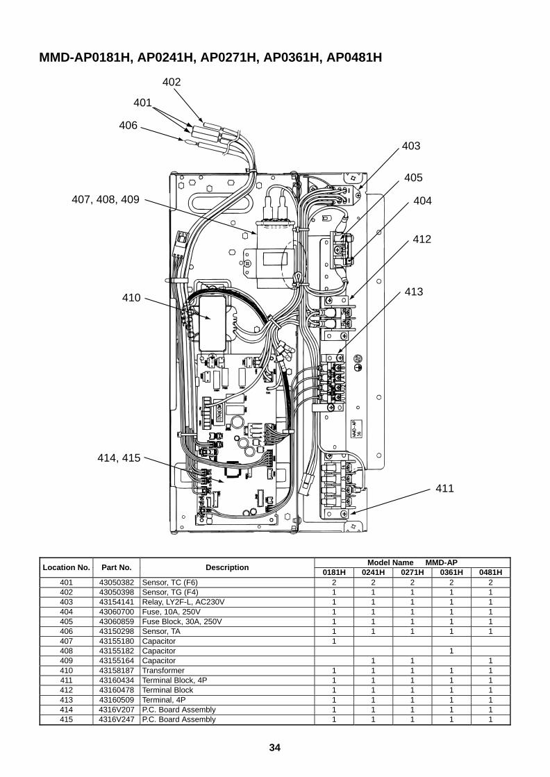
34
Model Name MMD-APLocation No. Part No. Description
0181H 0241H 0271H 0361H 0481H401 43050382 Sensor, TC (F6) 2 2 2 2 2402 43050398 Sensor, TG (F4) 1 1 1 1 1403 43154141 Relay, LY2F-L, AC230V 1 1 1 1 1404 43060700 Fuse, 10A, 250V 1 1 1 1 1405 43060859 Fuse Block, 30A, 250V 1 1 1 1 1406 43150298 Sensor, TA 1 1 1 1 1407 43155180 Capacitor 1408 43155182 Capacitor 1409 43155164 Capacitor 1 1 1410 43158187 Transformer 1 1 1 1 1411 43160434 Terminal Block, 4P 1 1 1 1 1412 43160478 Terminal Block 1 1 1 1 1413 43160509 Terminal, 4P 1 1 1 1 1414 4316V207 P.C. Board Assembly 1 1 1 1 1415 4316V247 P.C. Board Assembly 1 1 1 1 1
MMD-AP0181H, AP0241H, AP0271H, AP0361H, AP0481H
410
414, 415
407, 408, 409
411
413
412
404
405
403
402
406
401
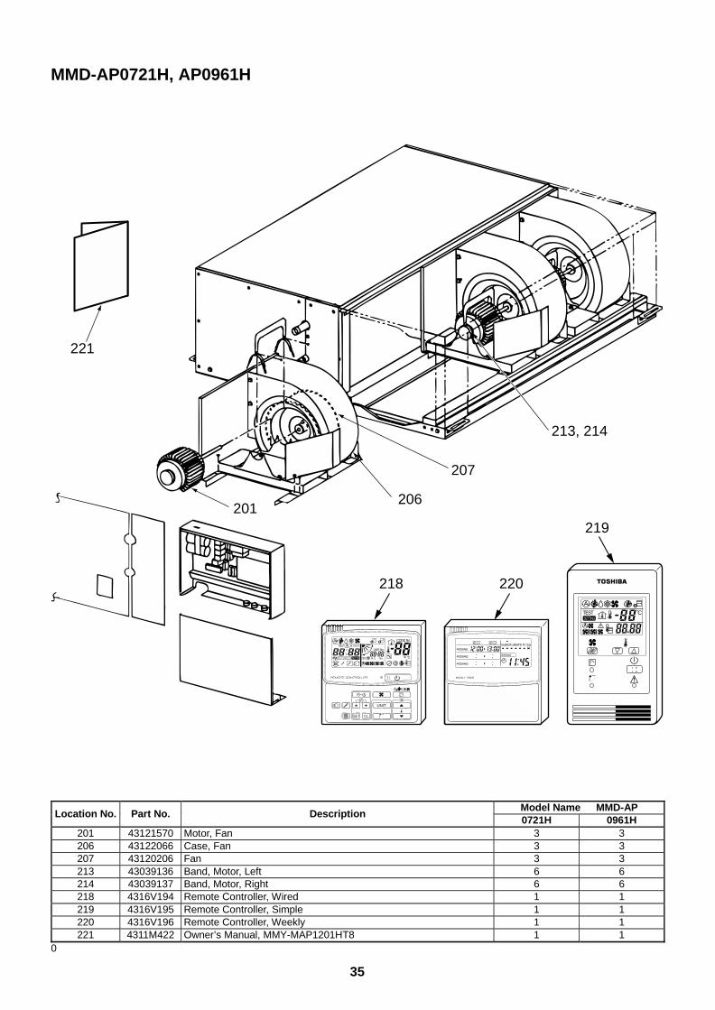
35
MMD-AP0721H, AP0961H
221
207
213, 214
206201
218 220
219
UNIT
SET CL
SETTING
UNIT No.
CODE No.
TEST
SET DATA
R.C. No.
˚CTESTSETTING
WEEKLY TIMER
ERROR
SuMoTuWeTh Fr SaPROGRAM1
PROGRAM2
PROGRAM3
Model Name MMD-APLocation No. Part No. Description
0721H 0961H201 43121570 Motor, Fan 3 3206 43122066 Case, Fan 3 3207 43120206 Fan 3 3213 43039136 Band, Motor, Left 6 6214 43039137 Band, Motor, Right 6 6218 4316V194 Remote Controller, Wired 1 1219 4316V195 Remote Controller, Simple 1 1220 4316V196 Remote Controller, Weekly 1 1221 4311M422 Owner’s Manual, MMY-MAP1201HT8 1 1
0
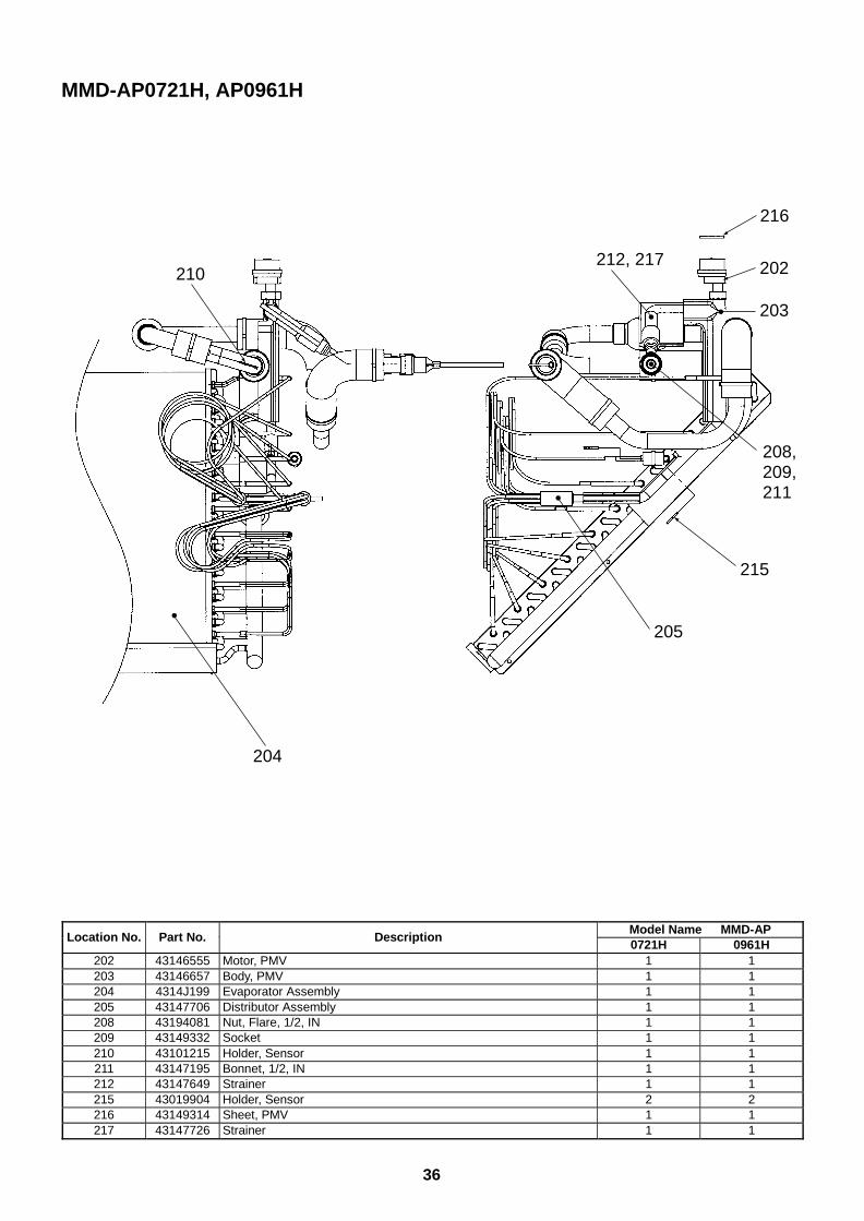
36
MMD-AP0721H, AP0961H
216
202
203
210
215
208, 209, 211
212, 217
205
204
Model Name MMD-APLocation No. Part No. Description
0721H 0961H202 43146555 Motor, PMV 1 1203 43146657 Body, PMV 1 1204 4314J199 Evaporator Assembly 1 1205 43147706 Distributor Assembly 1 1208 43194081 Nut, Flare, 1/2, IN 1 1209 43149332 Socket 1 1210 43101215 Holder, Sensor 1 1211 43147195 Bonnet, 1/2, IN 1 1212 43147649 Strainer 1 1215 43019904 Holder, Sensor 2 2216 43149314 Sheet, PMV 1 1217 43147726 Strainer 1 1
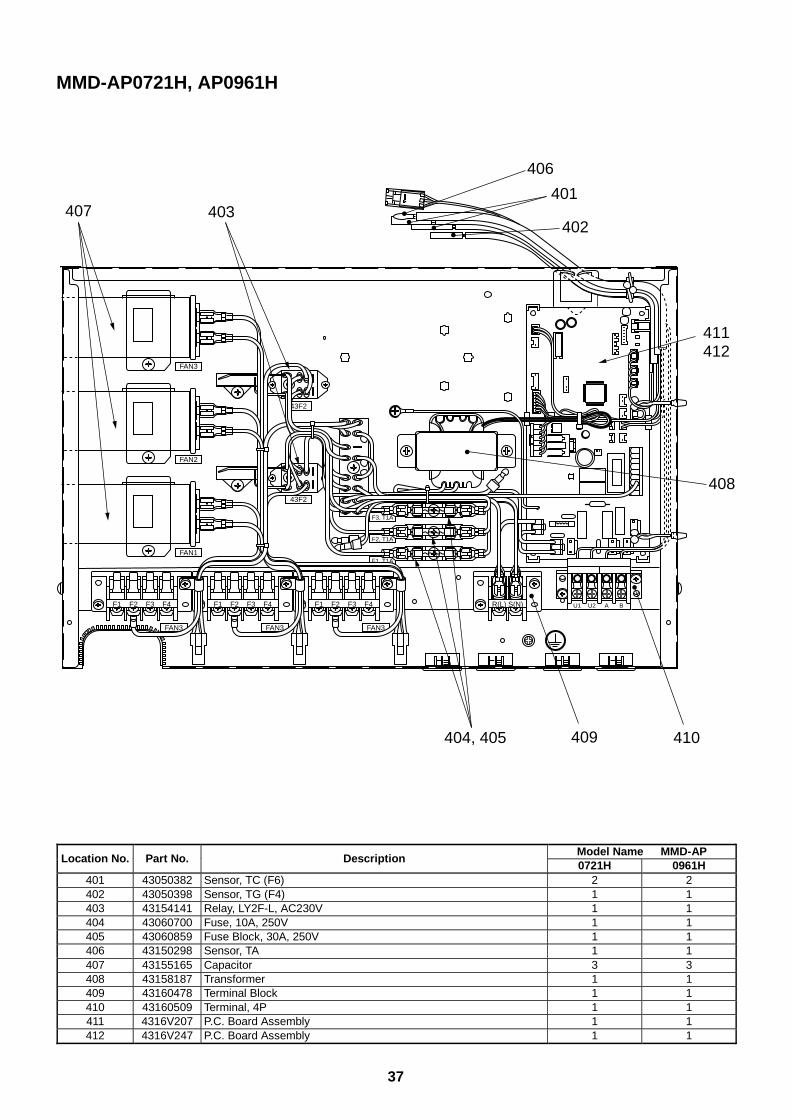
37
MMD-AP0721H, AP0961H
43F2
S(N) BAU2U1R(L)
FAN3
F1, T1A
F4F3F2F1
FAN3
F4F3F2F1
FAN3
FAN2
43F2
FAN1
FAN3
F4F3F2F1
F2, T1A
F3, T1A
410409
403407
404, 405
411412
408
401
406
402
Model Name MMD-APLocation No. Part No. Description
0721H 0961H401 43050382 Sensor, TC (F6) 2 2402 43050398 Sensor, TG (F4) 1 1403 43154141 Relay, LY2F-L, AC230V 1 1404 43060700 Fuse, 10A, 250V 1 1405 43060859 Fuse Block, 30A, 250V 1 1406 43150298 Sensor, TA 1 1407 43155165 Capacitor 3 3408 43158187 Transformer 1 1409 43160478 Terminal Block 1 1410 43160509 Terminal, 4P 1 1411 4316V207 P.C. Board Assembly 1 1412 4316V247 P.C. Board Assembly 1 1
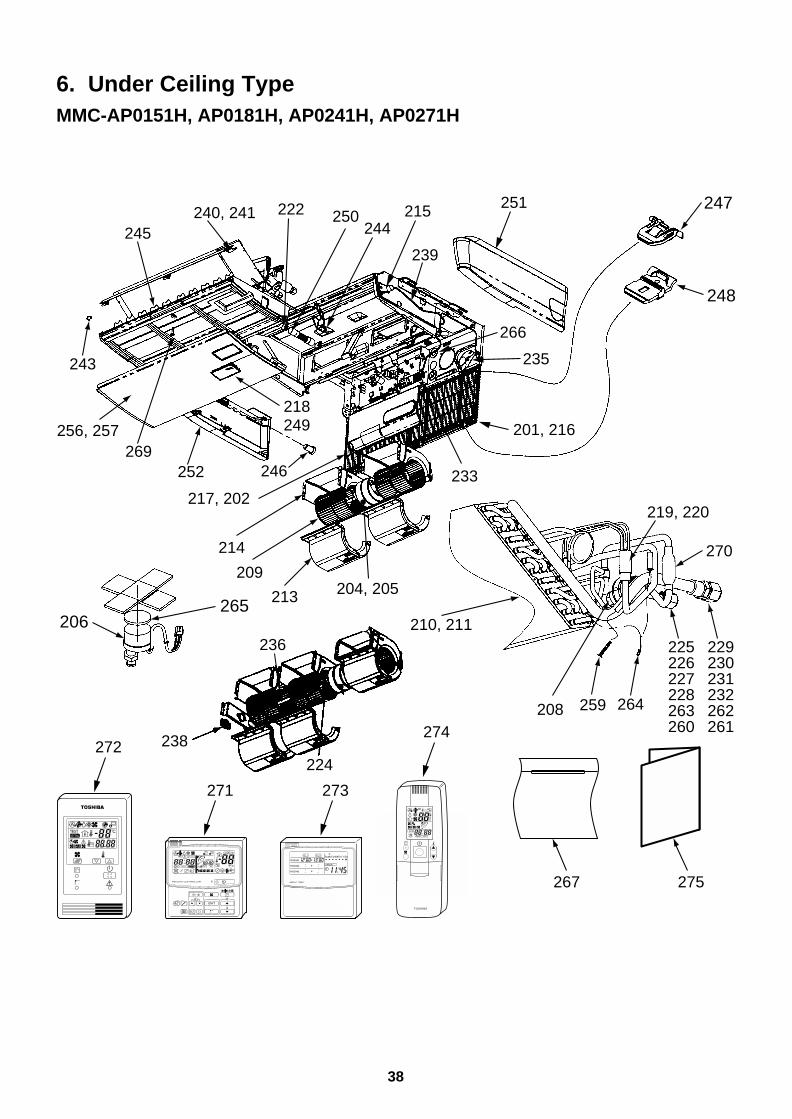
38
6. Under Ceiling TypeMMC-AP0151H, AP0181H, AP0241H, AP0271H
267 275
247
248
238
224
236
213
209
214
246
217, 202
252
256, 257
218249
269
243
245240, 241 250
201, 216
235
266
233
222244
215
239
251
204, 205265
206
270
219, 220
208
210, 211
264259
229230231232262261
225226227228263260
271 273
272274
UNIT
SET CL
SETTING
UNIT No.
CODE No.
TEST
SET DATA
R.C. No.
ADR˚CTESTSETTING
WEEKLY TIMER
ERROR
SuMoTuWeTh Fr SaPROGRAM1
PROGRAM2
PROGRAM3
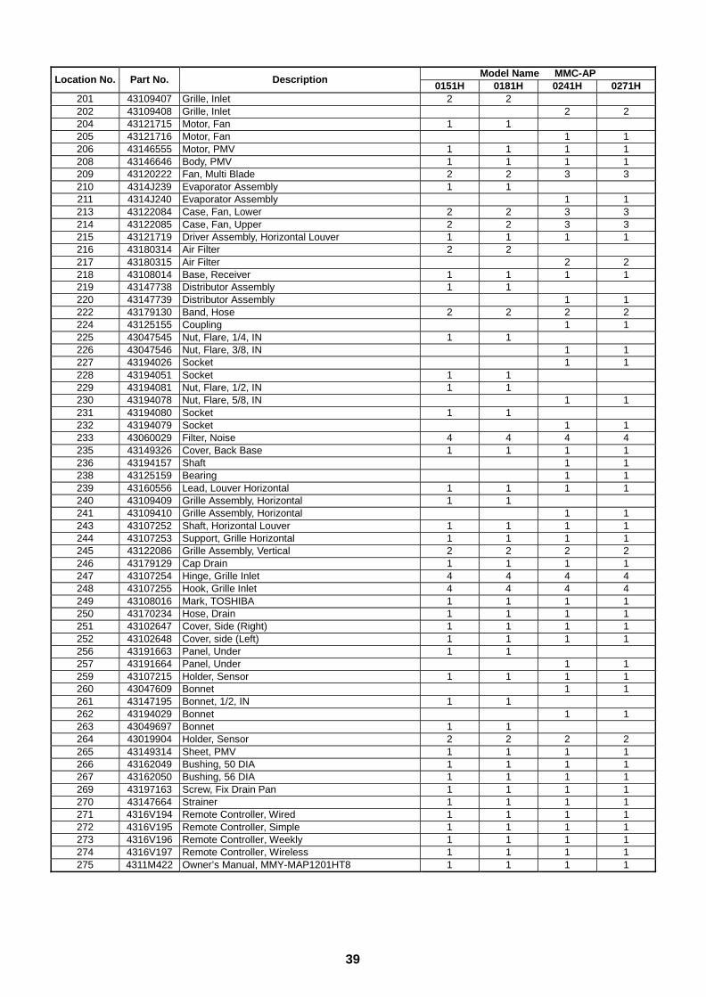
39
Model Name MMC-APLocation No. Part No. Description
0151H 0181H 0241H 0271H201 43109407 Grille, Inlet 2 2202 43109408 Grille, Inlet 2 2204 43121715 Motor, Fan 1 1205 43121716 Motor, Fan 1 1206 43146555 Motor, PMV 1 1 1 1208 43146646 Body, PMV 1 1 1 1209 43120222 Fan, Multi Blade 2 2 3 3210 4314J239 Evaporator Assembly 1 1211 4314J240 Evaporator Assembly 1 1213 43122084 Case, Fan, Lower 2 2 3 3214 43122085 Case, Fan, Upper 2 2 3 3215 43121719 Driver Assembly, Horizontal Louver 1 1 1 1216 43180314 Air Filter 2 2217 43180315 Air Filter 2 2218 43108014 Base, Receiver 1 1 1 1219 43147738 Distributor Assembly 1 1220 43147739 Distributor Assembly 1 1222 43179130 Band, Hose 2 2 2 2224 43125155 Coupling 1 1225 43047545 Nut, Flare, 1/4, IN 1 1226 43047546 Nut, Flare, 3/8, IN 1 1227 43194026 Socket 1 1228 43194051 Socket 1 1229 43194081 Nut, Flare, 1/2, IN 1 1230 43194078 Nut, Flare, 5/8, IN 1 1231 43194080 Socket 1 1232 43194079 Socket 1 1233 43060029 Filter, Noise 4 4 4 4235 43149326 Cover, Back Base 1 1 1 1236 43194157 Shaft 1 1238 43125159 Bearing 1 1239 43160556 Lead, Louver Horizontal 1 1 1 1240 43109409 Grille Assembly, Horizontal 1 1241 43109410 Grille Assembly, Horizontal 1 1243 43107252 Shaft, Horizontal Louver 1 1 1 1244 43107253 Support, Grille Horizontal 1 1 1 1245 43122086 Grille Assembly, Vertical 2 2 2 2246 43179129 Cap Drain 1 1 1 1247 43107254 Hinge, Grille Inlet 4 4 4 4248 43107255 Hook, Grille Inlet 4 4 4 4249 43108016 Mark, TOSHIBA 1 1 1 1250 43170234 Hose, Drain 1 1 1 1251 43102647 Cover, Side (Right) 1 1 1 1252 43102648 Cover, side (Left) 1 1 1 1256 43191663 Panel, Under 1 1257 43191664 Panel, Under 1 1259 43107215 Holder, Sensor 1 1 1 1260 43047609 Bonnet 1 1261 43147195 Bonnet, 1/2, IN 1 1262 43194029 Bonnet 1 1263 43049697 Bonnet 1 1264 43019904 Holder, Sensor 2 2 2 2265 43149314 Sheet, PMV 1 1 1 1266 43162049 Bushing, 50 DIA 1 1 1 1267 43162050 Bushing, 56 DIA 1 1 1 1269 43197163 Screw, Fix Drain Pan 1 1 1 1270 43147664 Strainer 1 1 1 1271 4316V194 Remote Controller, Wired 1 1 1 1272 4316V195 Remote Controller, Simple 1 1 1 1273 4316V196 Remote Controller, Weekly 1 1 1 1274 4316V197 Remote Controller, Wireless 1 1 1 1275 4311M422 Owner’s Manual, MMY-MAP1201HT8 1 1 1 1
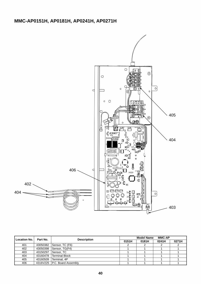
40
Model Name MMC-APLocation No. Part No. Description
0151H 0181H 0241H 0271H401 43050382 Sensor, TC (F6) 2 2 2 2402 43050398 Sensor, TG(F4) 1 1 1 1403 43150297 Sensor, TC 1 1 1 1404 43160478 Terminal Block 1 1 1 1405 43160509 Terminal, 4P 1 1 1 1406 4316V225 P.C. Board Assembly 1 1 1 1
MMC-AP0151H, AP0181H, AP0241H, AP0271H
405
404
403
406
402
404
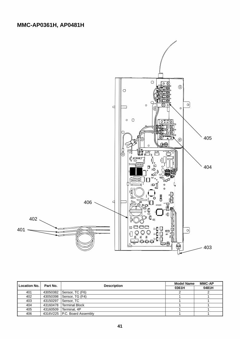
41
405
404
403
406
402
401
MMC-AP0361H, AP0481H
Model Name MMC-APLocation No. Part No. Description
0361H 0481H401 43050382 Sensor, TC (F6) 2 2402 43050398 Sensor, TG (F4) 1 1403 43150297 Sensor, TC 1 1404 43160478 Terminal Block 1 1405 43160509 Terminal, 4P 1 1406 4316V225 P.C. Board Assembly 1 1
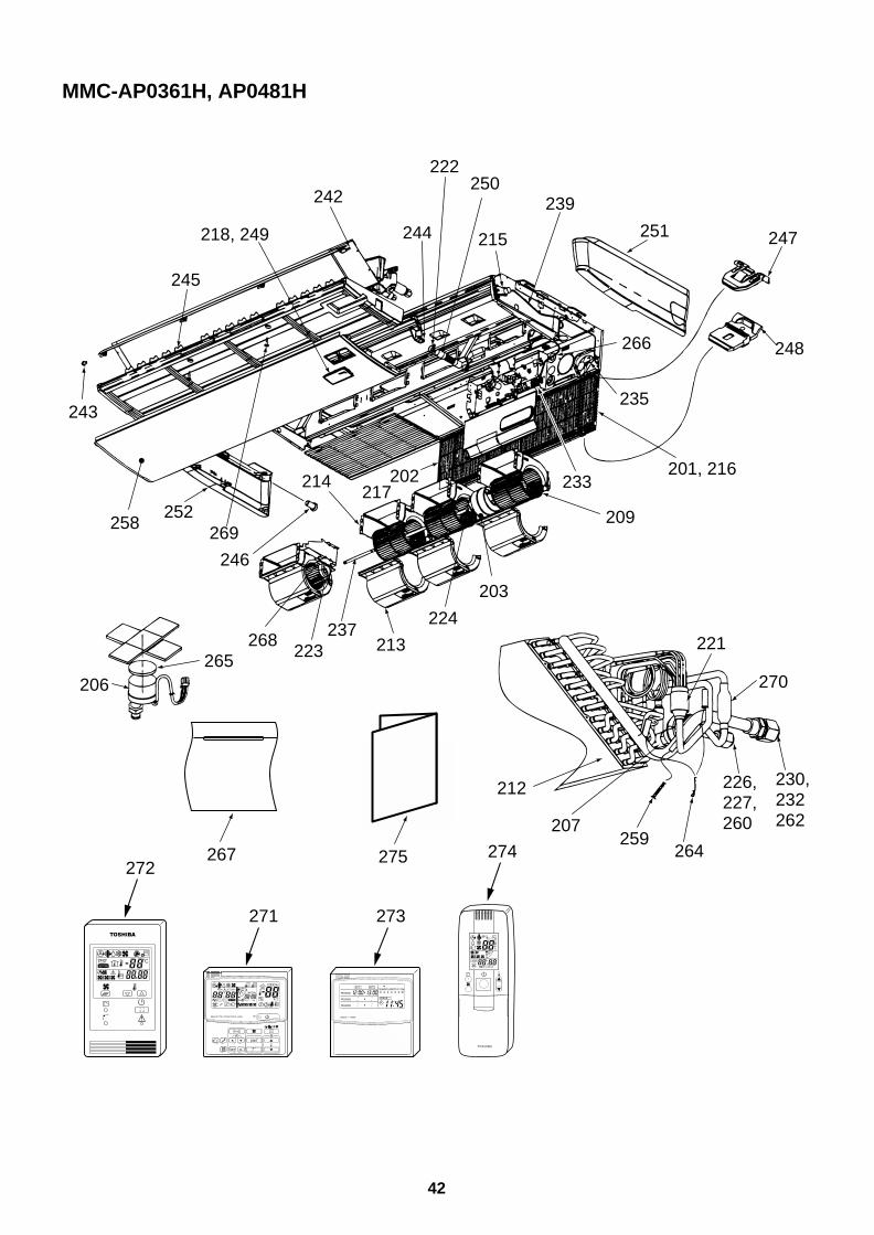
42
MMC-AP0361H, AP0481H
239
267 275
230,232262
226,227,260
270
221
264259
207
212
201, 216
209
233
235
266
217202
224
203
258
213237
223268
214
246
269252
243
245
218, 249 215
250222
244
242
251 247
248
206265
271 273
272274
UNIT
SET CL
SETTING
UNIT No.
CODE No.
TEST
SET DATA
R.C. No.
ADR˚CTESTSETTING
WEEKLY TIMER
ERROR
SuMoTuWeTh Fr SaPROGRAM1
PROGRAM2
PROGRAM3
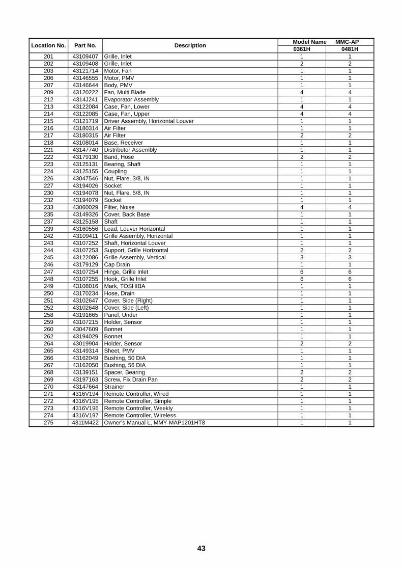
43
Model Name MMC-APLocation No. Part No. Description
0361H 0481H201 43109407 Grille, Inlet 1 1202 43109408 Grille, Inlet 2 2203 43121714 Motor, Fan 1 1206 43146555 Motor, PMV 1 1207 43146644 Body, PMV 1 1209 43120222 Fan, Multi Blade 4 4212 4314J241 Evaporator Assembly 1 1213 43122084 Case, Fan, Lower 4 4214 43122085 Case, Fan, Upper 4 4215 43121719 Driver Assembly, Horizontal Louver 1 1216 43180314 Air Filter 1 1217 43180315 Air Filter 2 2218 43108014 Base, Receiver 1 1221 43147740 Distributor Assembly 1 1222 43179130 Band, Hose 2 2223 43125131 Bearing, Shaft 1 1224 43125155 Coupling 1 1226 43047546 Nut, Flare, 3/8, IN 1 1227 43194026 Socket 1 1230 43194078 Nut, Flare, 5/8, IN 1 1232 43194079 Socket 1 1233 43060029 Filter, Noise 4 4235 43149326 Cover, Back Base 1 1237 43125158 Shaft 1 1239 43160556 Lead, Louver Horizontal 1 1242 43109411 Grille Assembly, Horizontal 1 1243 43107252 Shaft, Horizontal Louver 1 1244 43107253 Support, Grille Horizontal 2 2245 43122086 Grille Assembly, Vertical 3 3246 43179129 Cap Drain 1 1247 43107254 Hinge, Grille Inlet 6 6248 43107255 Hook, Grille Inlet 6 6249 43108016 Mark, TOSHIBA 1 1250 43170234 Hose, Drain 1 1251 43102647 Cover, Side (Right) 1 1252 43102648 Cover, Side (Left) 1 1258 43191665 Panel, Under 1 1259 43107215 Holder, Sensor 1 1260 43047609 Bonnet 1 1262 43194029 Bonnet 1 1264 43019904 Holder, Sensor 2 2265 43149314 Sheet, PMV 1 1266 43162049 Bushing, 50 DIA 1 1267 43162050 Bushing, 56 DIA 1 1268 43139151 Spacer, Bearing 2 2269 43197163 Screw, Fix Drain Pan 2 2270 43147664 Strainer 1 1271 4316V194 Remote Controller, Wired 1 1272 4316V195 Remote Controller, Simple 1 1273 4316V196 Remote Controller, Weekly 1 1274 4316V197 Remote Controller, Wireless 1 1275 4311M422 Owner’s Manual L, MMY-MAP1201HT8 1 1
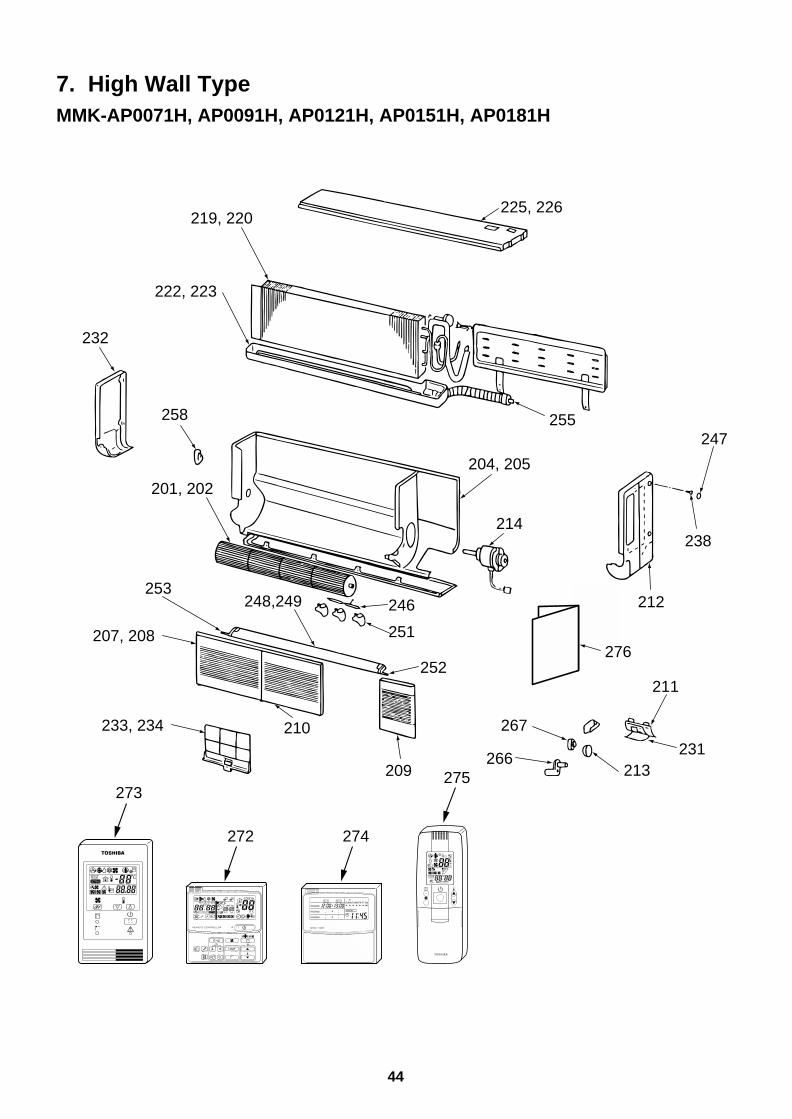
44
7. High Wall TypeMMK-AP0071H, AP0091H, AP0121H, AP0151H, AP0181H
225, 226219, 220
222, 223
201, 202
248,249
204, 205
214
232
258
246
251
253
207, 208
233, 234 210
209
255247
238
212
276
211
231213
267
266
252
272 274
273275
UNIT
SET CL
SETTING
UNIT No.
CODE No.
TEST
SET DATA
R.C. No.
ADR˚CTESTSETTING
WEEKLY TIMER
ERROR
SuMoTuWeTh Fr SaPROGRAM1
PROGRAM2
PROGRAM3
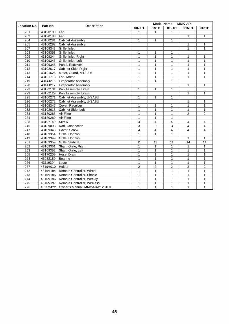
45
Model Name MMK-APLocation No. Part No. Description
0071H 0091H 0121H 0151H 0181H201 43120180 Fan 1 1 1202 43120183 Fan 1 1204 43100281 Cabinet Assembly 1 1 1205 43100282 Cabinet Assembly 1 1207 43109343 Grille, Inlet 1 1208 43109353 Grille, Inlet 1 1 1209 43109344 Grille, Inlet, Right 1 1 1 1 1210 43109345 Grille, Inlet, Left 1 1 1 1 1211 43109346 Panel, Receiver 1 1 1 1 1212 43102617 Cabinet Side, Right 1 1 1 1 1213 43121625 Motor, Guard, MT8-3-6 1 1 1 1 1214 43121718 Fan, Motor 1 1 1 1 1219 4314J216 Evaporator Assembly 1 1 1220 4314J217 Evaporator Assembly 1 1222 43172131 Pan Assembly, Drain 1 1 1223 43172129 Pan Assembly, Drain 1 1225 43100271 Cabinet Assembly, U-SABU 1 1 1226 43100272 Cabinet Assembly, U-SABU 1 1231 43109347 Cover, Receiver 1 1 1 1 1232 43102618 Cabinet Side, Left 1 1 1 1 1233 43180288 Air Filter 1 1 1 2 2234 43180289 Air Filter 1 1 1238 43197149 Screw 4 4 4 4 4246 43139098 Rod, Connection 3 3 3 4 4247 43109348 Cover, Screw 4 4 4 4 4248 43109354 Grille, Horizon 1 1 1249 43109349 Grille, Horizon 1 1251 43109359 Grille, Vertical 11 11 11 14 14252 43109351 Shaft, Grille, Right 1 1 1 1 1253 43109352 Shaft, Grille, Left 1 1 1 1 1255 43170209 Hose, Drain 1 1 1 1 1258 43022189 Bearing 1 1 1 1 1266 43119394 Lever 1 1 1 1 1267 4319V010 Holder 2 2 2 2 2272 4316V194 Remote Controller, Wired 1 1 1 1 1273 4316V195 Remote Controller, Simple 1 1 1 1 1274 4316V196 Remote Controller, Weekly 1 1 1 1 1275 4316V197 Remote Controller, Wireless 1 1 1 1 1276 4311M422 Owner’s Manual, MMY-MAP1201HT8 1 1 1 1 1
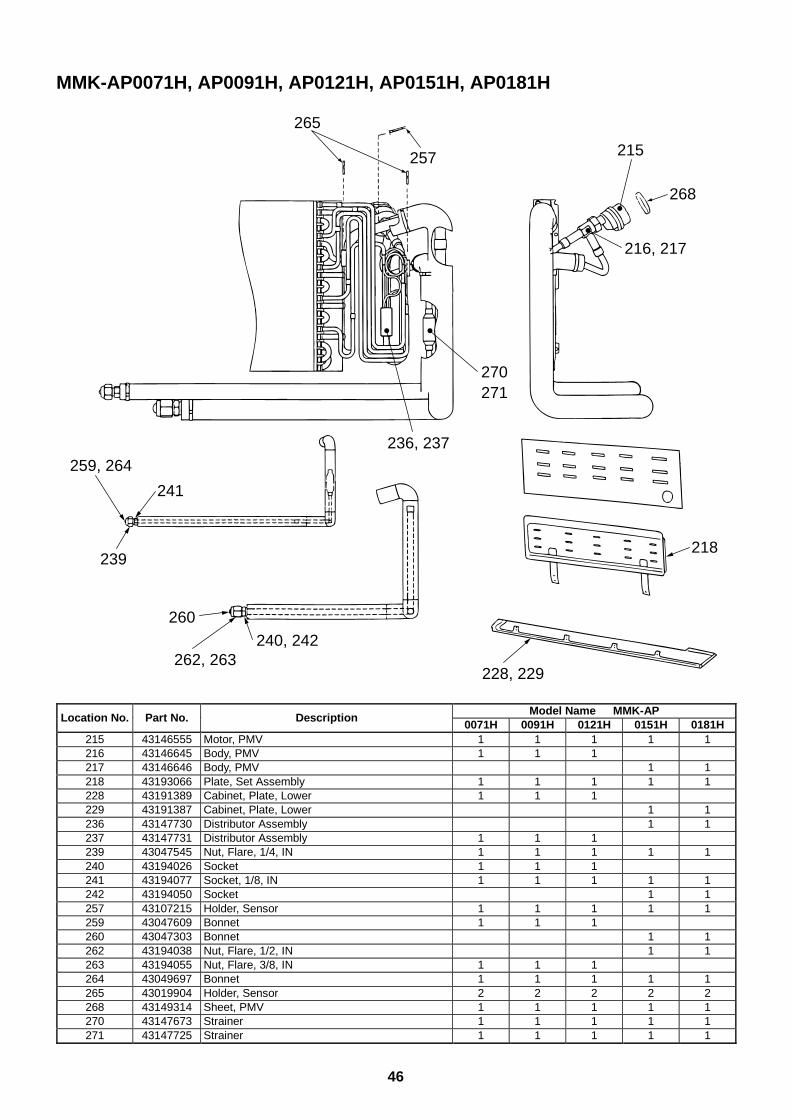
46
MMK-AP0071H, AP0091H, AP0121H, AP0151H, AP0181H
265
257
270271
268
215
216, 217
241
259, 264
239
260
262, 263240, 242
228, 229
218
236, 237
Model Name MMK-APLocation No. Part No. Description
0071H 0091H 0121H 0151H 0181H215 43146555 Motor, PMV 1 1 1 1 1216 43146645 Body, PMV 1 1 1217 43146646 Body, PMV 1 1218 43193066 Plate, Set Assembly 1 1 1 1 1228 43191389 Cabinet, Plate, Lower 1 1 1229 43191387 Cabinet, Plate, Lower 1 1236 43147730 Distributor Assembly 1 1237 43147731 Distributor Assembly 1 1 1239 43047545 Nut, Flare, 1/4, IN 1 1 1 1 1240 43194026 Socket 1 1 1241 43194077 Socket, 1/8, IN 1 1 1 1 1242 43194050 Socket 1 1257 43107215 Holder, Sensor 1 1 1 1 1259 43047609 Bonnet 1 1 1260 43047303 Bonnet 1 1262 43194038 Nut, Flare, 1/2, IN 1 1263 43194055 Nut, Flare, 3/8, IN 1 1 1264 43049697 Bonnet 1 1 1 1 1265 43019904 Holder, Sensor 2 2 2 2 2268 43149314 Sheet, PMV 1 1 1 1 1270 43147673 Strainer 1 1 1 1 1271 43147725 Strainer 1 1 1 1 1
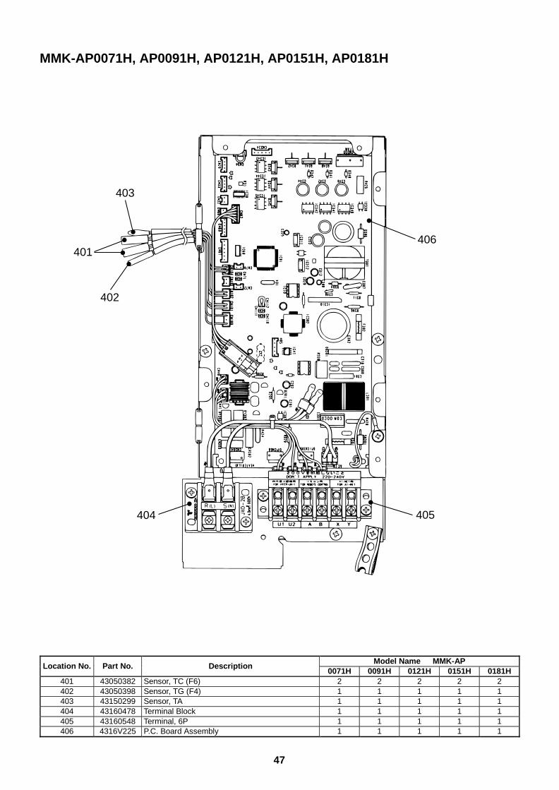
47
MMK-AP0071H, AP0091H, AP0121H, AP0151H, AP0181H
406401
403
405404
402
Model Name MMK-APLocation No. Part No. Description
0071H 0091H 0121H 0151H 0181H401 43050382 Sensor, TC (F6) 2 2 2 2 2402 43050398 Sensor, TG (F4) 1 1 1 1 1403 43150299 Sensor, TA 1 1 1 1 1404 43160478 Terminal Block 1 1 1 1 1405 43160548 Terminal, 6P 1 1 1 1 1406 4316V225 P.C. Board Assembly 1 1 1 1 1
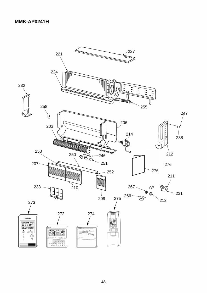
48
MMK-AP0241H
227
255
221
224
203
250
206
214
232
258
246
251
253
207
233 210
209
247
238
212
276
211
231
213
267
266
252 276
272 274
273275
UNIT
SET CL
SETTING
UNIT No.
CODE No.
TEST
SET DATA
R.C. No.
ADR˚CTESTSETTING
WEEKLY TIMER
ERROR
SuMoTuWeTh Fr SaPROGRAM1
PROGRAM2
PROGRAM3
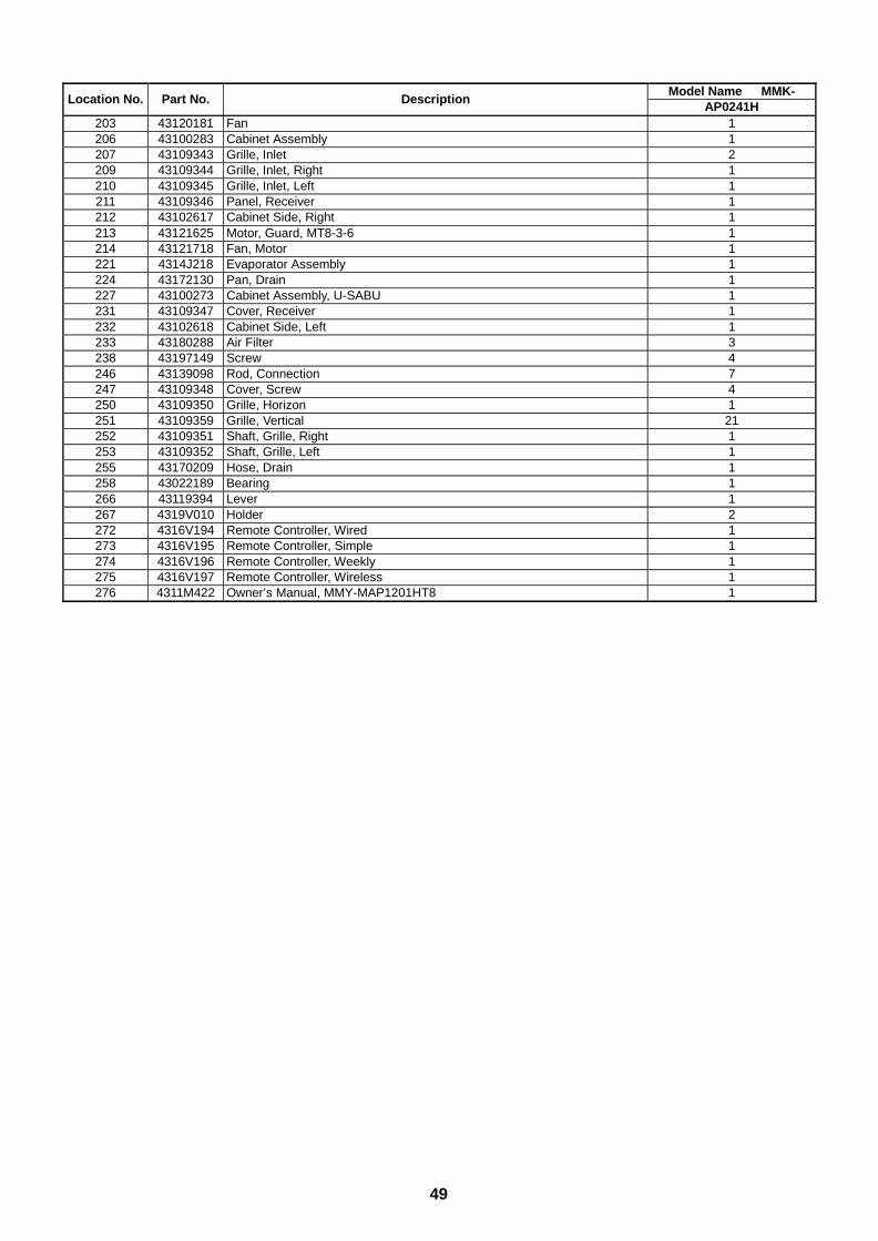
49
Model Name MMK-Location No. Part No. Description
AP0241H203 43120181 Fan 1206 43100283 Cabinet Assembly 1207 43109343 Grille, Inlet 2209 43109344 Grille, Inlet, Right 1210 43109345 Grille, Inlet, Left 1211 43109346 Panel, Receiver 1212 43102617 Cabinet Side, Right 1213 43121625 Motor, Guard, MT8-3-6 1214 43121718 Fan, Motor 1221 4314J218 Evaporator Assembly 1224 43172130 Pan, Drain 1227 43100273 Cabinet Assembly, U-SABU 1231 43109347 Cover, Receiver 1232 43102618 Cabinet Side, Left 1233 43180288 Air Filter 3238 43197149 Screw 4246 43139098 Rod, Connection 7247 43109348 Cover, Screw 4250 43109350 Grille, Horizon 1251 43109359 Grille, Vertical 21252 43109351 Shaft, Grille, Right 1253 43109352 Shaft, Grille, Left 1255 43170209 Hose, Drain 1258 43022189 Bearing 1266 43119394 Lever 1267 4319V010 Holder 2272 4316V194 Remote Controller, Wired 1273 4316V195 Remote Controller, Simple 1274 4316V196 Remote Controller, Weekly 1275 4316V197 Remote Controller, Wireless 1276 4311M422 Owner’s Manual, MMY-MAP1201HT8 1
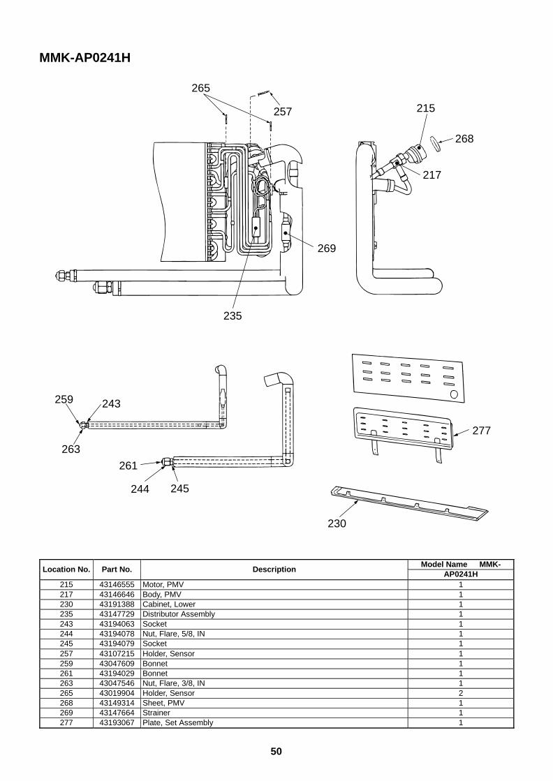
50
MMK-AP0241H
265
257
269
235
268
215
217
243259
263
261
244 245
277
230
Model Name MMK-Location No. Part No. Description
AP0241H215 43146555 Motor, PMV 1217 43146646 Body, PMV 1230 43191388 Cabinet, Lower 1235 43147729 Distributor Assembly 1243 43194063 Socket 1244 43194078 Nut, Flare, 5/8, IN 1245 43194079 Socket 1257 43107215 Holder, Sensor 1259 43047609 Bonnet 1261 43194029 Bonnet 1263 43047546 Nut, Flare, 3/8, IN 1265 43019904 Holder, Sensor 2268 43149314 Sheet, PMV 1269 43147664 Strainer 1277 43193067 Plate, Set Assembly 1
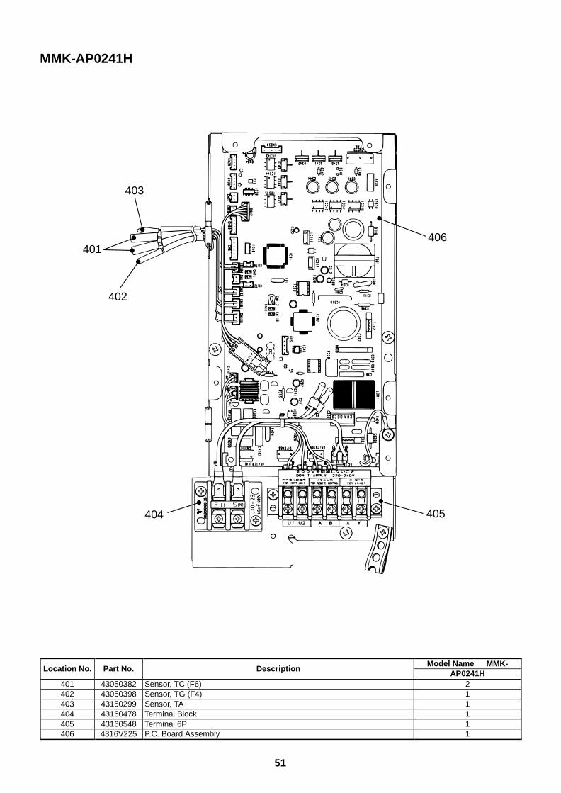
51
MMK-AP0241H
406401
403
405404
402
Model Name MMK-Location No. Part No. Description
AP0241H401 43050382 Sensor, TC (F6) 2402 43050398 Sensor, TG (F4) 1403 43150299 Sensor, TA 1404 43160478 Terminal Block 1405 43160548 Terminal,6P 1406 4316V225 P.C. Board Assembly 1
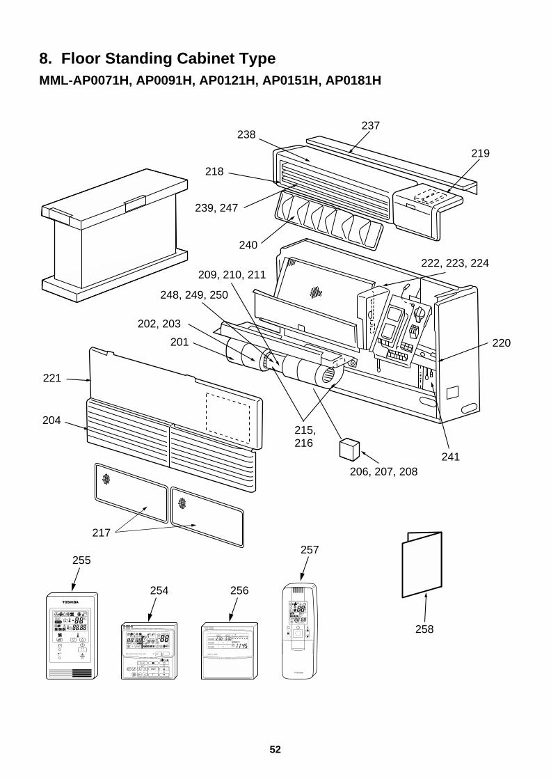
52
8. Floor Standing Cabinet TypeMML-AP0071H, AP0091H, AP0121H, AP0151H, AP0181H
215,216
241
220
219
237
222, 223, 224
202, 203
201
238
218
239, 247
240
209, 210, 211
248, 249, 250
206, 207, 208
258
221
204
217
254 256
255257
UNIT
SET CL
SETTING
UNIT No.
CODE No.
TEST
SET DATA
R.C. No.
ADR˚CTESTSETTING
WEEKLY TIMER
ERROR
SuMoTuWeTh Fr SaPROGRAM1
PROGRAM2
PROGRAM3
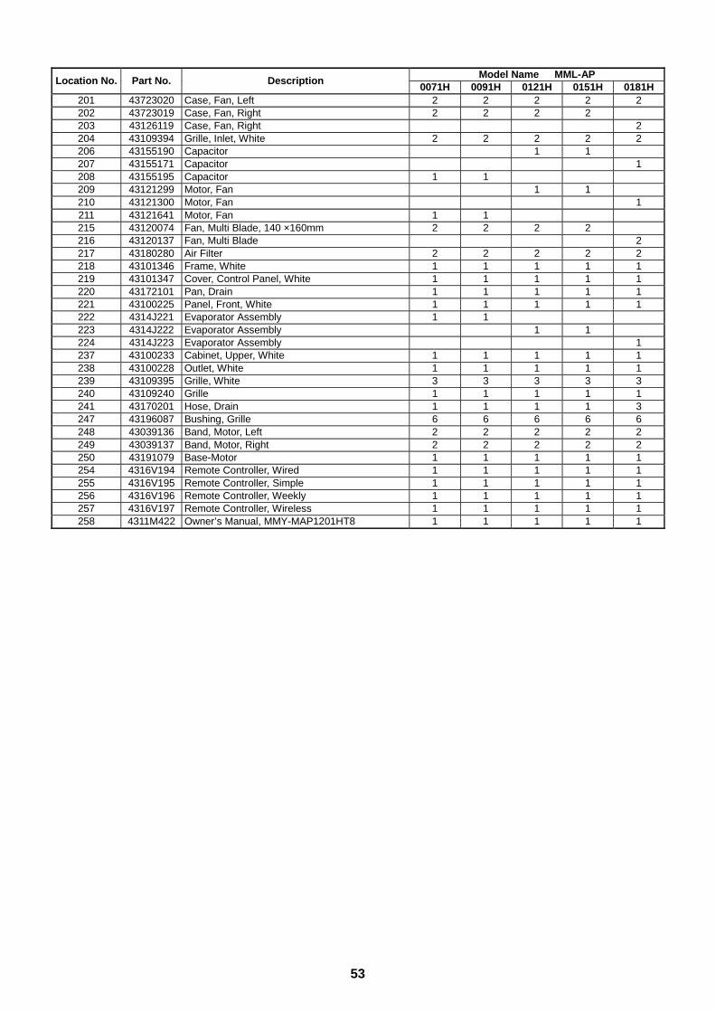
53
Model Name MML-APLocation No. Part No. Description
0071H 0091H 0121H 0151H 0181H201 43723020 Case, Fan, Left 2 2 2 2 2202 43723019 Case, Fan, Right 2 2 2 2203 43126119 Case, Fan, Right 2204 43109394 Grille, Inlet, White 2 2 2 2 2206 43155190 Capacitor 1 1207 43155171 Capacitor 1208 43155195 Capacitor 1 1209 43121299 Motor, Fan 1 1210 43121300 Motor, Fan 1211 43121641 Motor, Fan 1 1215 43120074 Fan, Multi Blade, 140 ×160mm 2 2 2 2216 43120137 Fan, Multi Blade 2217 43180280 Air Filter 2 2 2 2 2218 43101346 Frame, White 1 1 1 1 1219 43101347 Cover, Control Panel, White 1 1 1 1 1220 43172101 Pan, Drain 1 1 1 1 1221 43100225 Panel, Front, White 1 1 1 1 1222 4314J221 Evaporator Assembly 1 1223 4314J222 Evaporator Assembly 1 1224 4314J223 Evaporator Assembly 1237 43100233 Cabinet, Upper, White 1 1 1 1 1238 43100228 Outlet, White 1 1 1 1 1239 43109395 Grille, White 3 3 3 3 3240 43109240 Grille 1 1 1 1 1241 43170201 Hose, Drain 1 1 1 1 3247 43196087 Bushing, Grille 6 6 6 6 6248 43039136 Band, Motor, Left 2 2 2 2 2249 43039137 Band, Motor, Right 2 2 2 2 2250 43191079 Base-Motor 1 1 1 1 1254 4316V194 Remote Controller, Wired 1 1 1 1 1255 4316V195 Remote Controller, Simple 1 1 1 1 1256 4316V196 Remote Controller, Weekly 1 1 1 1 1257 4316V197 Remote Controller, Wireless 1 1 1 1 1258 4311M422 Owner’s Manual, MMY-MAP1201HT8 1 1 1 1 1
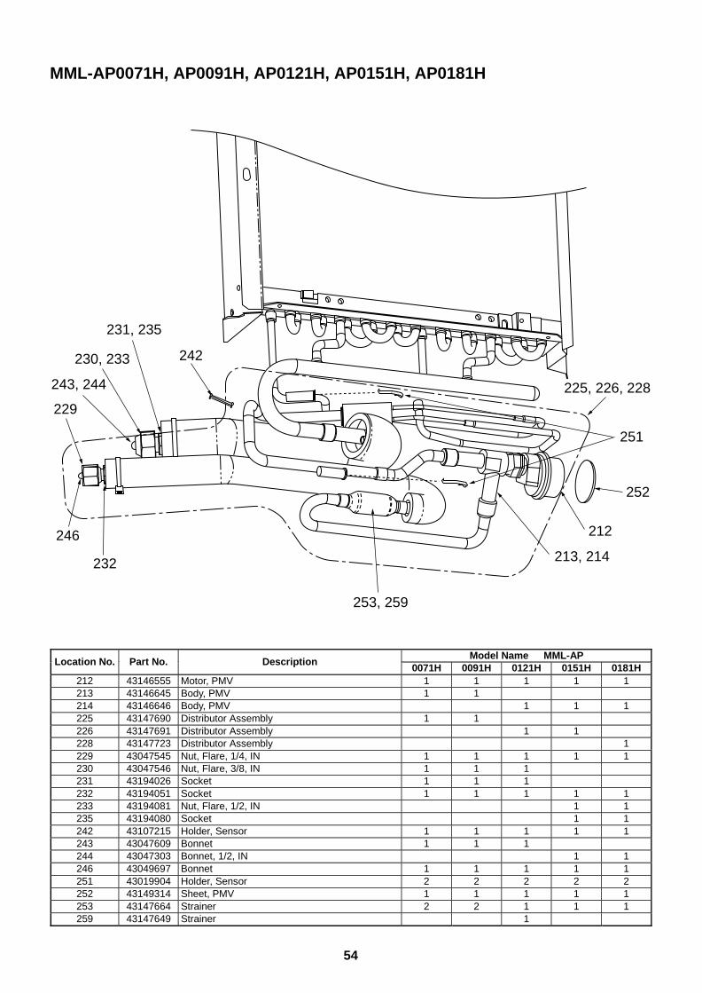
54
MML-AP0071H, AP0091H, AP0121H, AP0151H, AP0181H
242
231, 235
230, 233
229
243, 244
246
232
253, 259
213, 214
212
252
251
225, 226, 228
Model Name MML-APLocation No. Part No. Description
0071H 0091H 0121H 0151H 0181H212 43146555 Motor, PMV 1 1 1 1 1213 43146645 Body, PMV 1 1214 43146646 Body, PMV 1 1 1225 43147690 Distributor Assembly 1 1226 43147691 Distributor Assembly 1 1228 43147723 Distributor Assembly 1229 43047545 Nut, Flare, 1/4, IN 1 1 1 1 1230 43047546 Nut, Flare, 3/8, IN 1 1 1231 43194026 Socket 1 1 1232 43194051 Socket 1 1 1 1 1233 43194081 Nut, Flare, 1/2, IN 1 1235 43194080 Socket 1 1242 43107215 Holder, Sensor 1 1 1 1 1243 43047609 Bonnet 1 1 1244 43047303 Bonnet, 1/2, IN 1 1246 43049697 Bonnet 1 1 1 1 1251 43019904 Holder, Sensor 2 2 2 2 2252 43149314 Sheet, PMV 1 1 1 1 1253 43147664 Strainer 2 2 1 1 1259 43147649 Strainer 1
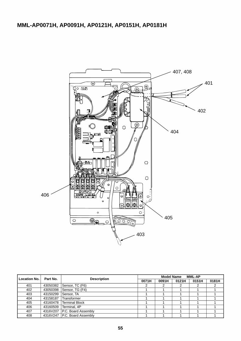
55
MML-AP0071H, AP0091H, AP0121H, AP0151H, AP0181H
403
405
406
401
402
404
407, 408
Model Name MML-APLocation No. Part No. Description
0071H 0091H 0121H 0151H 0181H401 43050382 Sensor, TC (F6) 2 2 2 2 2402 43050398 Sensor, TG (F4) 1 1 1 1 1403 43150299 Sensor, TA 1 1 1 1 1404 43158187 Transformer 1 1 1 1 1405 43160478 Terminal Block 1 1 1 1 1406 43160509 Terminal, 4P 1 1 1 1 1407 4316V207 P.C. Board Assembly 1 1 1 1 1408 4316V247 P.C. Board Assembly 1 1 1 1 1
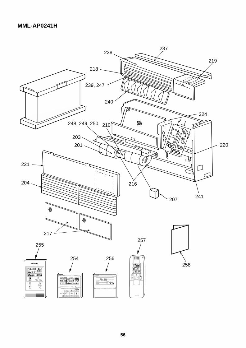
56
MML-AP0241H
216
241
258
220
219
237
224
203
201
238
218
239, 247
240
210248, 249, 250
207
221
204
217
254 256
255257
UNIT
SET CL
SETTING
UNIT No.
CODE No.
TEST
SET DATA
R.C. No.
ADR˚CTESTSETTING
WEEKLY TIMER
ERROR
SuMoTuWeTh Fr SaPROGRAM1
PROGRAM2
PROGRAM3
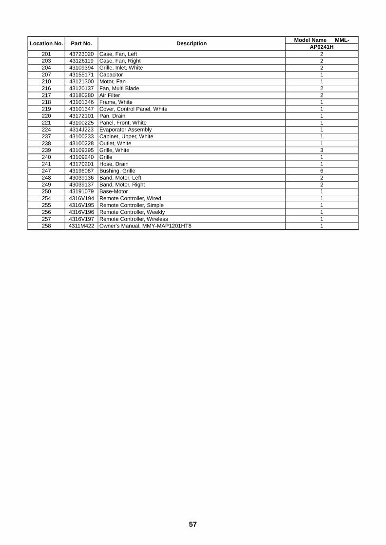
57
Model Name MML-Location No. Part No. Description
AP0241H201 43723020 Case, Fan, Left 2203 43126119 Case, Fan, Right 2204 43109394 Grille, Inlet, White 2207 43155171 Capacitor 1210 43121300 Motor, Fan 1216 43120137 Fan, Multi Blade 2217 43180280 Air Filter 2218 43101346 Frame, White 1219 43101347 Cover, Control Panel, White 1220 43172101 Pan, Drain 1221 43100225 Panel, Front, White 1224 4314J223 Evaporator Assembly 1237 43100233 Cabinet, Upper, White 1238 43100228 Outlet, White 1239 43109395 Grille, White 3240 43109240 Grille 1241 43170201 Hose, Drain 1247 43196087 Bushing, Grille 6248 43039136 Band, Motor, Left 2249 43039137 Band, Motor, Right 2250 43191079 Base-Motor 1254 4316V194 Remote Controller, Wired 1255 4316V195 Remote Controller, Simple 1256 4316V196 Remote Controller, Weekly 1257 4316V197 Remote Controller, Wireless 1258 4311M422 Owner’s Manual, MMY-MAP1201HT8 1
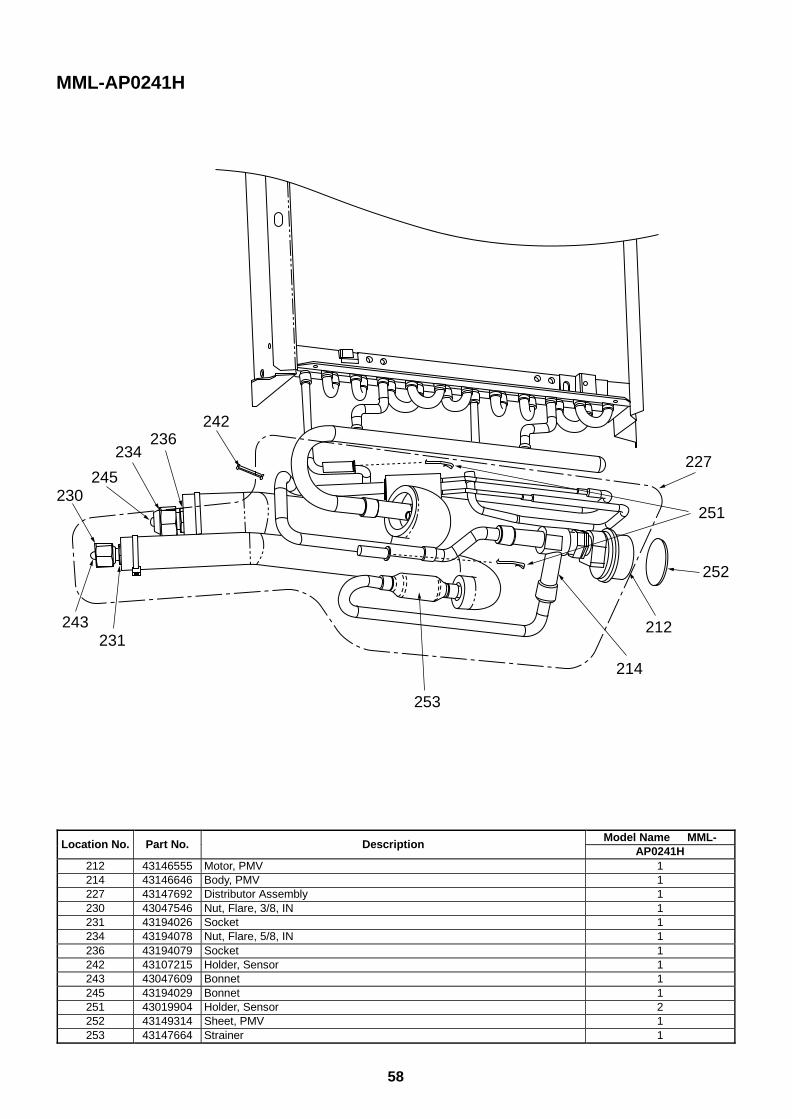
58
MML-AP0241H
242236
234
230245
243231
253
214
212
252
251
227
Model Name MML-Location No. Part No. Description
AP0241H212 43146555 Motor, PMV 1214 43146646 Body, PMV 1227 43147692 Distributor Assembly 1230 43047546 Nut, Flare, 3/8, IN 1231 43194026 Socket 1234 43194078 Nut, Flare, 5/8, IN 1236 43194079 Socket 1242 43107215 Holder, Sensor 1243 43047609 Bonnet 1245 43194029 Bonnet 1251 43019904 Holder, Sensor 2252 43149314 Sheet, PMV 1253 43147664 Strainer 1
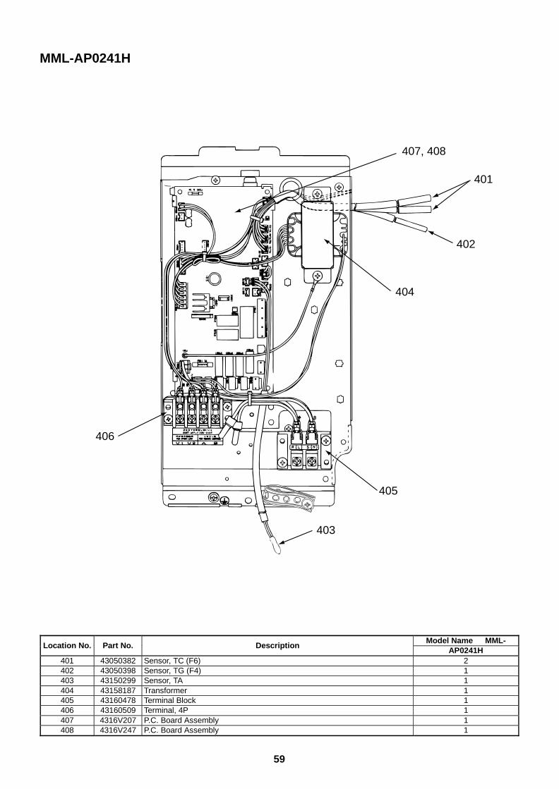
59
MML-AP0241H
403
405
406
401
402
404
407, 408
Model Name MML-Location No. Part No. Description
AP0241H401 43050382 Sensor, TC (F6) 2402 43050398 Sensor, TG (F4) 1403 43150299 Sensor, TA 1404 43158187 Transformer 1405 43160478 Terminal Block 1406 43160509 Terminal, 4P 1407 4316V207 P.C. Board Assembly 1408 4316V247 P.C. Board Assembly 1
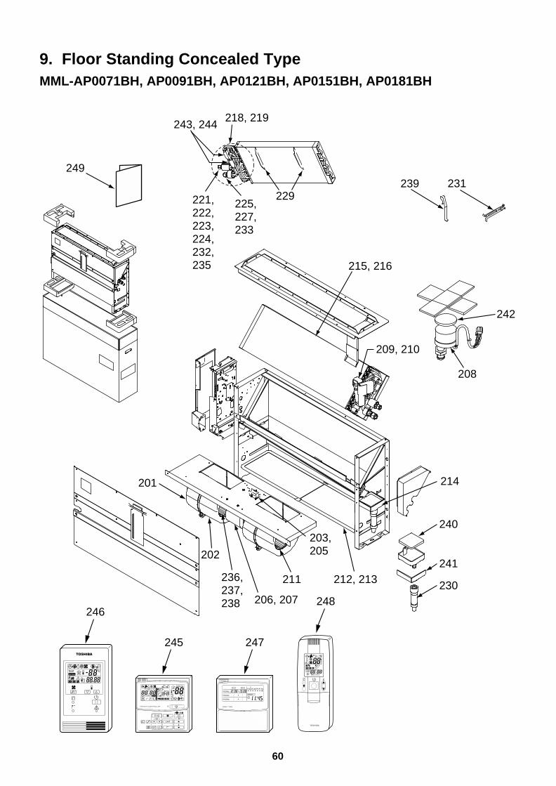
60
9. Floor Standing Concealed TypeMML-AP0071BH, AP0091BH, AP0121BH, AP0151BH, AP0181BH
249
201
202
236,237,238 206, 207
211
203,205
212, 213
240
241
230
214
208
242
209, 210
231239
215, 216
218, 219
229225,227,233
221,222,223,224,232,235
243, 244
245 247
246248
UNIT
SET CL
SETTING
UNIT No.
CODE No.
TEST
SET DATA
R.C. No.
ADR˚CTESTSETTING
WEEKLY TIMER
ERROR
SuMoTuWeTh Fr SaPROGRAM1
PROGRAM2
PROGRAM3
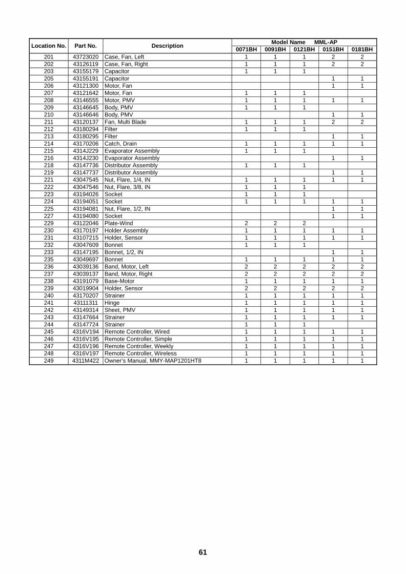
61
Model Name MML-APLocation No. Part No. Description
0071BH 0091BH 0121BH 0151BH 0181BH201 43723020 Case, Fan, Left 1 1 1 2 2202 43126119 Case, Fan, Right 1 1 1 2 2203 43155179 Capacitor 1 1 1205 43155191 Capacitor 1 1206 43121300 Motor, Fan 1 1207 43121642 Motor, Fan 1 1 1208 43146555 Motor, PMV 1 1 1 1 1209 43146645 Body, PMV 1 1 1210 43146646 Body, PMV 1 1211 43120137 Fan, Multi Blade 1 1 1 2 2212 43180294 Filter 1 1 1213 43180295 Filter 1 1214 43170206 Catch, Drain 1 1 1 1 1215 4314J229 Evaporator Assembly 1 1 1216 4314J230 Evaporator Assembly 1 1218 43147736 Distributor Assembly 1 1 1219 43147737 Distributor Assembly 1 1221 43047545 Nut, Flare, 1/4, IN 1 1 1 1 1222 43047546 Nut, Flare, 3/8, IN 1 1 1223 43194026 Socket 1 1 1224 43194051 Socket 1 1 1 1 1225 43194081 Nut, Flare, 1/2, IN 1 1227 43194080 Socket 1 1229 43122046 Plate-Wind 2 2 2230 43170197 Holder Assembly 1 1 1 1 1231 43107215 Holder, Sensor 1 1 1 1 1232 43047609 Bonnet 1 1 1233 43147195 Bonnet, 1/2, IN 1 1235 43049697 Bonnet 1 1 1 1 1236 43039136 Band, Motor, Left 2 2 2 2 2237 43039137 Band, Motor, Right 2 2 2 2 2238 43191079 Base-Motor 1 1 1 1 1239 43019904 Holder, Sensor 2 2 2 2 2240 43170207 Strainer 1 1 1 1 1241 43111311 Hinge 1 1 1 1 1242 43149314 Sheet, PMV 1 1 1 1 1243 43147664 Strainer 1 1 1 1 1244 43147724 Strainer 1 1 1245 4316V194 Remote Controller, Wired 1 1 1 1 1246 4316V195 Remote Controller, Simple 1 1 1 1 1247 4316V196 Remote Controller, Weekly 1 1 1 1 1248 4316V197 Remote Controller, Wireless 1 1 1 1 1249 4311M422 Owner’s Manual, MMY-MAP1201HT8 1 1 1 1 1
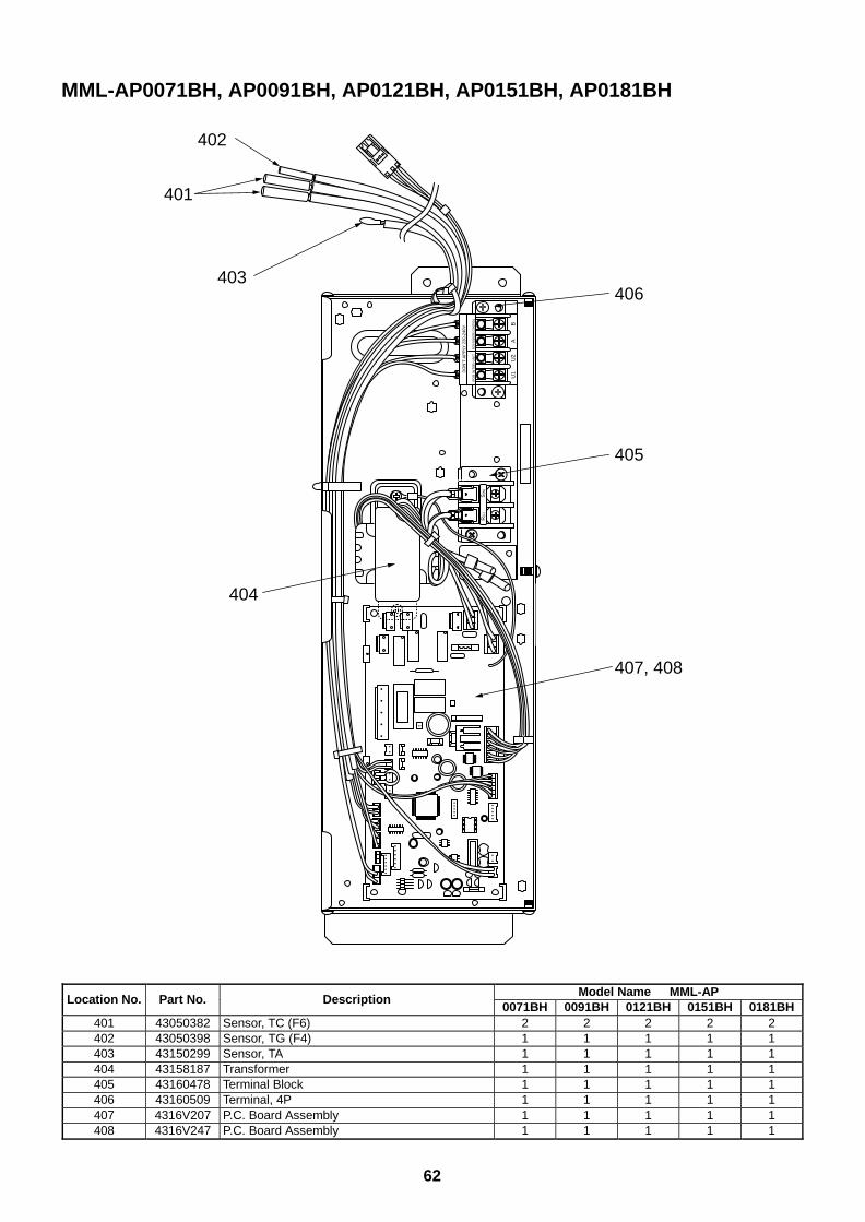
62
MML-AP0071BH, AP0091BH, AP0121BH, AP0151BH, AP0181BH
R(L
)S
(N)
U1
U2
AB
DO
N’T
AP
PLY
220
-240
V
FO
R IN
TE
R-U
NIT
FOR
REM
OTE
CONT
ROL
401
402
403406
405
407, 408
404
Model Name MML-APLocation No. Part No. Description
0071BH 0091BH 0121BH 0151BH 0181BH401 43050382 Sensor, TC (F6) 2 2 2 2 2402 43050398 Sensor, TG (F4) 1 1 1 1 1403 43150299 Sensor, TA 1 1 1 1 1404 43158187 Transformer 1 1 1 1 1405 43160478 Terminal Block 1 1 1 1 1406 43160509 Terminal, 4P 1 1 1 1 1407 4316V207 P.C. Board Assembly 1 1 1 1 1408 4316V247 P.C. Board Assembly 1 1 1 1 1
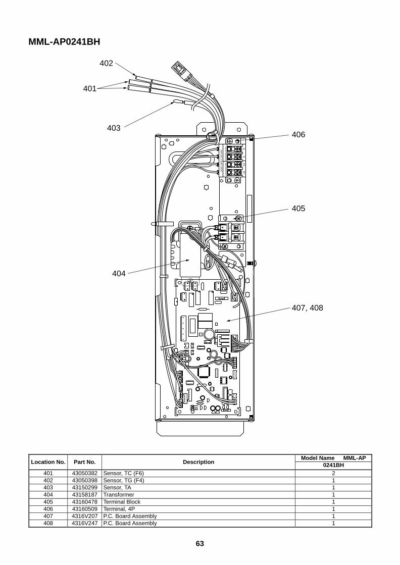
63
R(L
)S
(N)
U1
U2
AB
DO
N’T
AP
PLY
220
-240
V
FO
R IN
TE
R-U
NIT
FOR
REM
OTE
CONT
ROL
401
402
403406
405
407, 408
404
MML-AP0241BH
Model Name MML-APLocation No. Part No. Description 0241BH
401 43050382 Sensor, TC (F6) 2402 43050398 Sensor, TG (F4) 1403 43150299 Sensor, TA 1404 43158187 Transformer 1405 43160478 Terminal Block 1406 43160509 Terminal, 4P 1407 4316V207 P.C. Board Assembly 1408 4316V247 P.C. Board Assembly 1
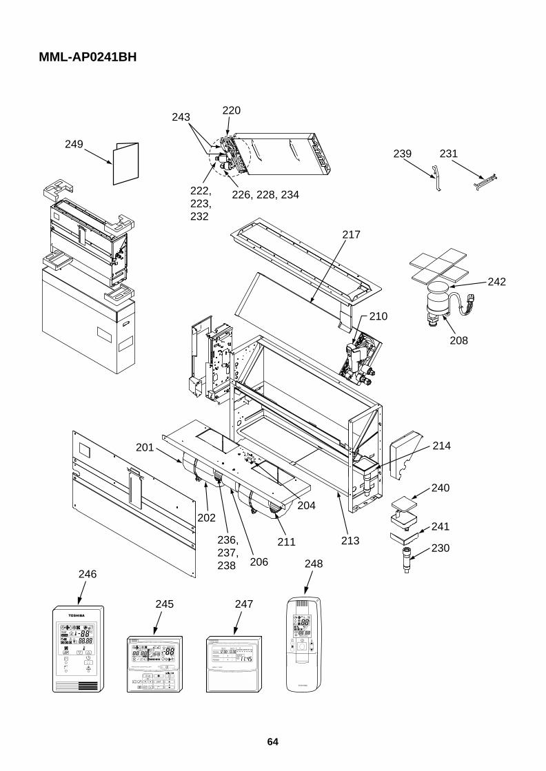
64
MML-AP0241BH
249
201
202
236,237,238 206
211
204
213
240
241
230
214
208
242
210
231239
217
220
226, 228, 234222,223,232
243
245 247
246248
UNIT
SET CL
SETTING
UNIT No.
CODE No.
TEST
SET DATA
R.C. No.
ADR˚CTESTSETTING
WEEKLY TIMER
ERROR
SuMoTuWeTh Fr SaPROGRAM1
PROGRAM2
PROGRAM3
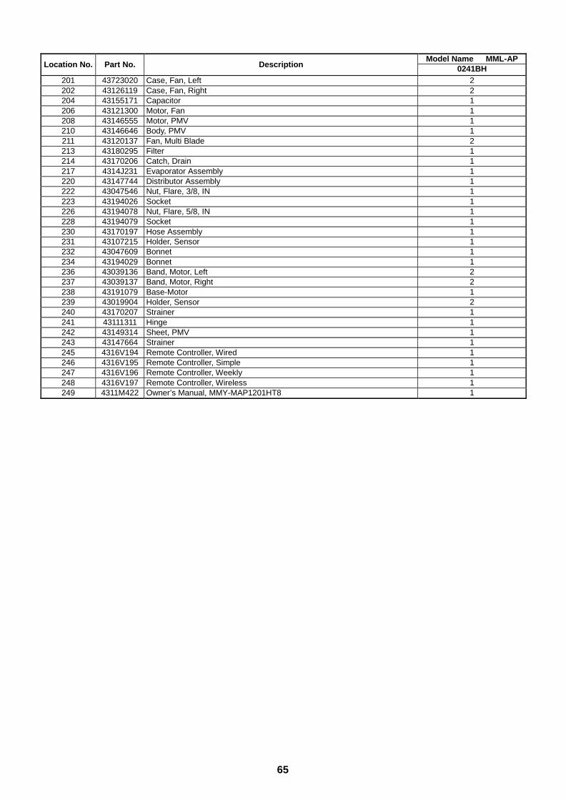
65
Model Name MML-APLocation No. Part No. Description 0241BH
201 43723020 Case, Fan, Left 2202 43126119 Case, Fan, Right 2204 43155171 Capacitor 1206 43121300 Motor, Fan 1208 43146555 Motor, PMV 1210 43146646 Body, PMV 1211 43120137 Fan, Multi Blade 2213 43180295 Filter 1214 43170206 Catch, Drain 1217 4314J231 Evaporator Assembly 1220 43147744 Distributor Assembly 1222 43047546 Nut, Flare, 3/8, IN 1223 43194026 Socket 1226 43194078 Nut, Flare, 5/8, IN 1228 43194079 Socket 1230 43170197 Hose Assembly 1231 43107215 Holder, Sensor 1232 43047609 Bonnet 1234 43194029 Bonnet 1236 43039136 Band, Motor, Left 2237 43039137 Band, Motor, Right 2238 43191079 Base-Motor 1239 43019904 Holder, Sensor 2240 43170207 Strainer 1241 43111311 Hinge 1242 43149314 Sheet, PMV 1243 43147664 Strainer 1245 4316V194 Remote Controller, Wired 1246 4316V195 Remote Controller, Simple 1247 4316V196 Remote Controller, Weekly 1248 4316V197 Remote Controller, Wireless 1249 4311M422 Owner’s Manual, MMY-MAP1201HT8 1
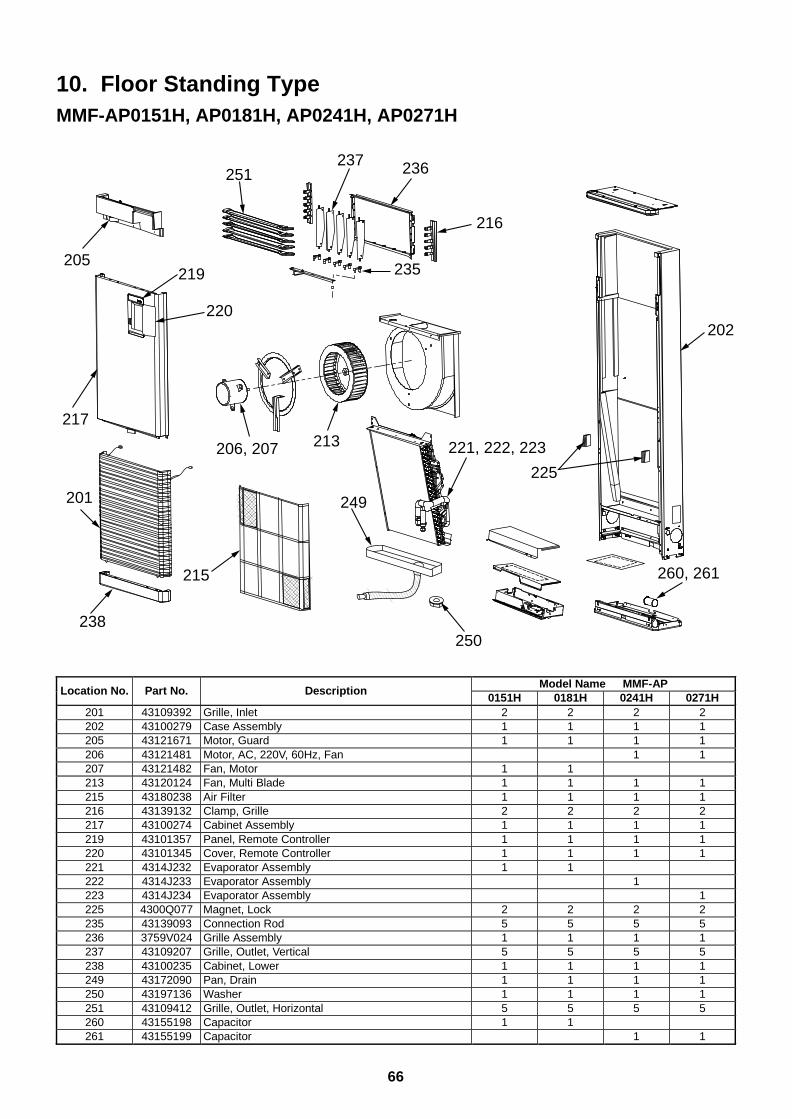
66
10. Floor Standing TypeMMF-AP0151H, AP0181H, AP0241H, AP0271H
202
260, 261
221, 222, 223206, 207
225
250
213
249
215
201
238
251
205219
220
217
216
236237
235
Model Name MMF-APLocation No. Part No. Description
0151H 0181H 0241H 0271H201 43109392 Grille, Inlet 2 2 2 2202 43100279 Case Assembly 1 1 1 1205 43121671 Motor, Guard 1 1 1 1206 43121481 Motor, AC, 220V, 60Hz, Fan 1 1207 43121482 Fan, Motor 1 1213 43120124 Fan, Multi Blade 1 1 1 1215 43180238 Air Filter 1 1 1 1216 43139132 Clamp, Grille 2 2 2 2217 43100274 Cabinet Assembly 1 1 1 1219 43101357 Panel, Remote Controller 1 1 1 1220 43101345 Cover, Remote Controller 1 1 1 1221 4314J232 Evaporator Assembly 1 1222 4314J233 Evaporator Assembly 1223 4314J234 Evaporator Assembly 1225 4300Q077 Magnet, Lock 2 2 2 2235 43139093 Connection Rod 5 5 5 5236 3759V024 Grille Assembly 1 1 1 1237 43109207 Grille, Outlet, Vertical 5 5 5 5238 43100235 Cabinet, Lower 1 1 1 1249 43172090 Pan, Drain 1 1 1 1250 43197136 Washer 1 1 1 1251 43109412 Grille, Outlet, Horizontal 5 5 5 5260 43155198 Capacitor 1 1261 43155199 Capacitor 1 1
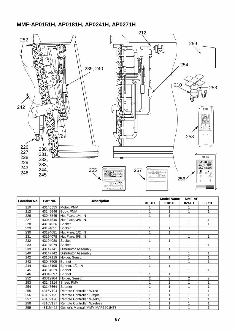
67
MMF-AP0151H, AP0181H, AP0241H, AP0271H
242
226,227,228,229,243,246
230,231,232,233,244,245
252
210 253
254
212
239, 240
259
255 257
256
258
UNIT
SET CL
SETTING
UNIT No.
CODE No.
TEST
SET DATA
R.C. No.
ADR
˚CTESTSETTING
WEEKLY TIMER
ERROR
SuMoTuWeTh Fr SaPROGRAM1
PROGRAM2
PROGRAM3
Model Name MMF-APLocation No. Part No. Description
0151H 0181H 0241H 0271H210 43146555 Motor, PMV 1 1 1 1212 43146646 Body, PMV 1 1 1 1226 43047545 Nut Flare, 1/4, IN 1 1227 43047546 Nut Flare, 3/8, IN 1 1228 43194026 Socket 1 1229 43194051 Socket 1 1230 43194081 Nut Flare, 1/2, IN 1 1231 43194078 Nut Flare, 5/8, IN 1 1232 43194080 Socket 1 1233 43194079 Socket 1 1239 43147741 Distributor Assembly 1 1240 43147742 Distributor Assembly 1 1242 43107215 Holder, Sensor 1 1 1 1243 43047609 Bonnet 1 1244 43147195 Bonnet, 1/2, IN 1 1245 43194029 Bonnet 1 1246 43049697 Bonnet 1 1252 43019904 Holder, Sensor 2 2 2 2253 43149314 Sheet, PMV 1 1 1 1254 43147664 Strainer 1 1 1 1255 4316V194 Remote Controller, Wired 1 1 1 1256 4316V195 Remote Controller, Simple 1 1 1 1257 4316V196 Remote Controller, Weekly 1 1 1 1258 4316V197 Remote Controller, Wireless 1 1 1 1259 4311M422 Owner’s Manual, MMY-MAP1201HT8 1 1 1 1
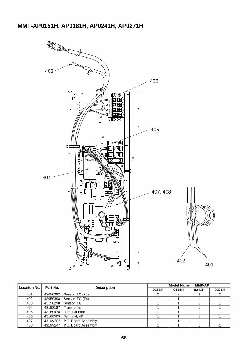
68
Model Name MMF-APLocation No. Part No. Description
0151H 0181H 0241H 0271H401 43050382 Sensor, TC (F6) 2 2 2 2402 43050398 Sensor, TG (F4) 1 1 1 1403 43150298 Sensor, TA 1 1 1 1404 43158187 Transformer 1 1 1 1405 43160478 Terminal Block 1 1 1 1406 43160509 Terminal, 4P 1 1 1 1407 4316V207 P.C. Board Assembly 1 1 1 1408 4316V247 P.C. Board Assembly 1 1 1 1
MMF-AP0151H, AP0181H, AP0241H, AP0271H
R(L
)S
(N)
U1
U2
AB
DO
N’T
AP
PLY
220
-240
V
FO
R IN
TE
R-U
NIT
FOR
REM
OTE
CONT
ROL
406
403
405
404
407, 408
402401
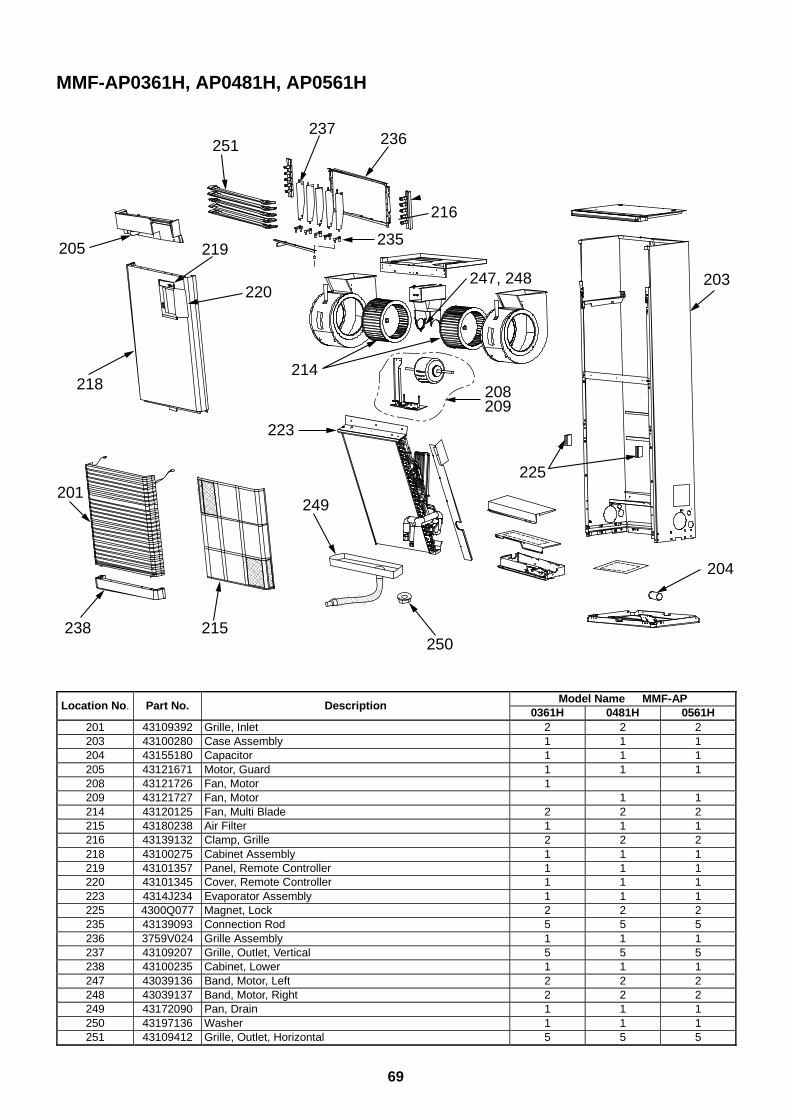
69
MMF-AP0361H, AP0481H, AP0561H
225
204
203
208209
215250
249
218
201
238
205 219
220
237236
216
247, 248
235
251
214
223
Model Name MMF-APLocation No. Part No. Description
0361H 0481H 0561H201 43109392 Grille, Inlet 2 2 2203 43100280 Case Assembly 1 1 1204 43155180 Capacitor 1 1 1205 43121671 Motor, Guard 1 1 1208 43121726 Fan, Motor 1209 43121727 Fan, Motor 1 1214 43120125 Fan, Multi Blade 2 2 2215 43180238 Air Filter 1 1 1216 43139132 Clamp, Grille 2 2 2218 43100275 Cabinet Assembly 1 1 1219 43101357 Panel, Remote Controller 1 1 1220 43101345 Cover, Remote Controller 1 1 1223 4314J234 Evaporator Assembly 1 1 1225 4300Q077 Magnet, Lock 2 2 2235 43139093 Connection Rod 5 5 5236 3759V024 Grille Assembly 1 1 1237 43109207 Grille, Outlet, Vertical 5 5 5238 43100235 Cabinet, Lower 1 1 1247 43039136 Band, Motor, Left 2 2 2248 43039137 Band, Motor, Right 2 2 2249 43172090 Pan, Drain 1 1 1250 43197136 Washer 1 1 1251 43109412 Grille, Outlet, Horizontal 5 5 5
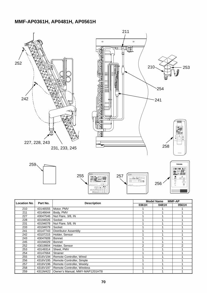
70
MMF-AP0361H, AP0481H, AP0561H
210 253
254
241
211
242
227, 228, 243231, 233, 245
252
259
255 257
256
258
UNIT
SET CL
SETTING
UNIT No.
CODE No.
TEST
SET DATA
R.C. No.
ADR
˚CTESTSETTING
WEEKLY TIMER
ERROR
SuMoTuWeTh Fr SaPROGRAM1
PROGRAM2
PROGRAM3
Model Name MMF-APLocation No. Part No. Description
0361H 0481H 0561H210 43146555 Motor, PMV 1 1 1211 43146644 Body, PMV 1 1 1227 43047546 Nut Flare, 3/8, IN 1 1 1228 43194026 Socket 1 1 1231 43194078 Nut Flare, 5/8, IN 1 1 1233 43194079 Socket 1 1 1241 43147743 Distributor Assembly 1 1 1242 43107215 Holder, Sensor 1 1 1243 43047609 Bonnet 1 1 1245 43194029 Bonnet 1 1 1252 43019904 Holder, Sensor 2 2 2253 43149314 Sheet, PMV 1 1 1254 43147664 Strainer 1 1 1255 4316V194 Remote Controller, Wired 1 1 1256 4316V195 Remote Controller, Simple 1 1 1257 4316V196 Remote Controller, Weekly 1 1 1258 4316V197 Remote Controller, Wireless 1 1 1259 4311M422 Owner’s Manual, MMY-MAP1201HT8 1 1 1
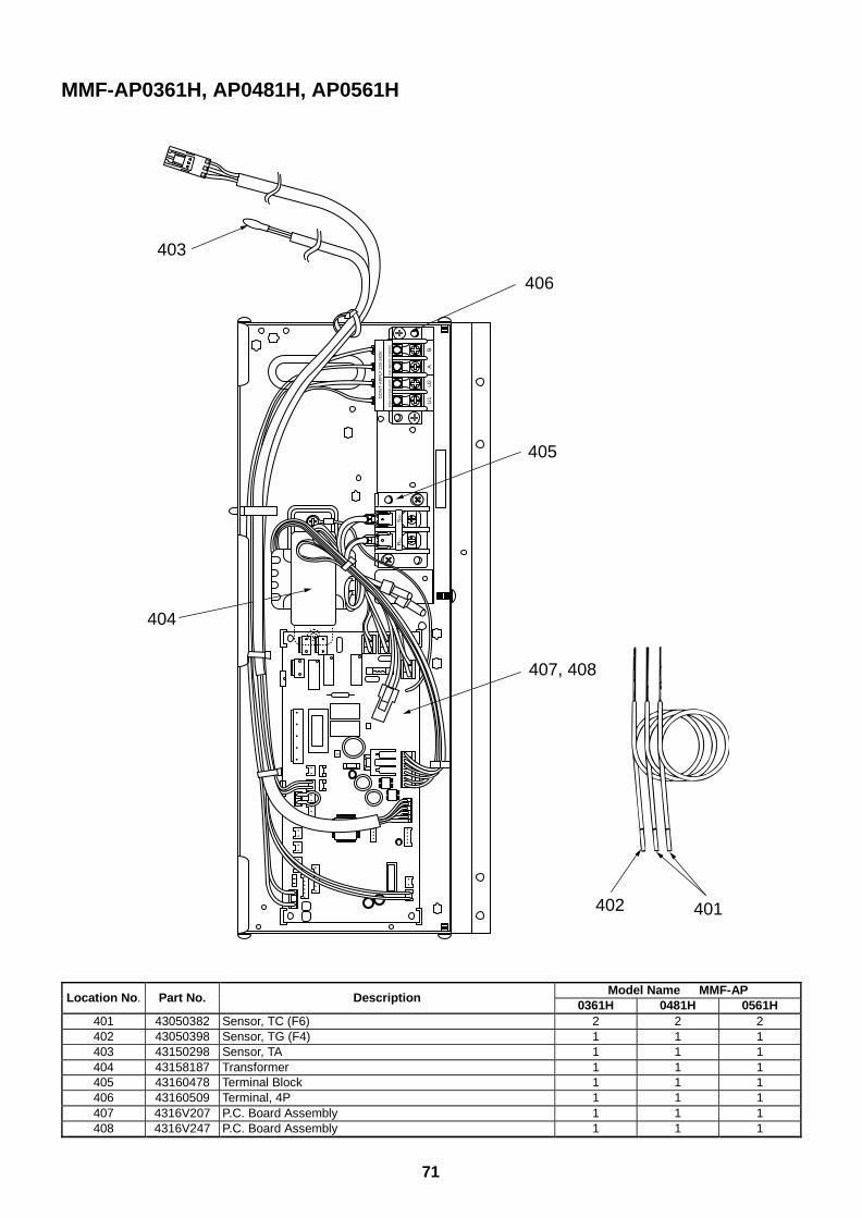
71
MMF-AP0361H, AP0481H, AP0561H
R(L
)S
(N)
U1
U2
AB
DO
N’T
AP
PLY
220
-240
V
FO
R IN
TE
R-U
NIT
FOR
REM
OTE
CONT
ROL
406
403
405
404
407, 408
402 401
Model Name MMF-APLocation No. Part No. Description
0361H 0481H 0561H401 43050382 Sensor, TC (F6) 2 2 2402 43050398 Sensor, TG (F4) 1 1 1403 43150298 Sensor, TA 1 1 1404 43158187 Transformer 1 1 1405 43160478 Terminal Block 1 1 1406 43160509 Terminal, 4P 1 1 1407 4316V207 P.C. Board Assembly 1 1 1408 4316V247 P.C. Board Assembly 1 1 1
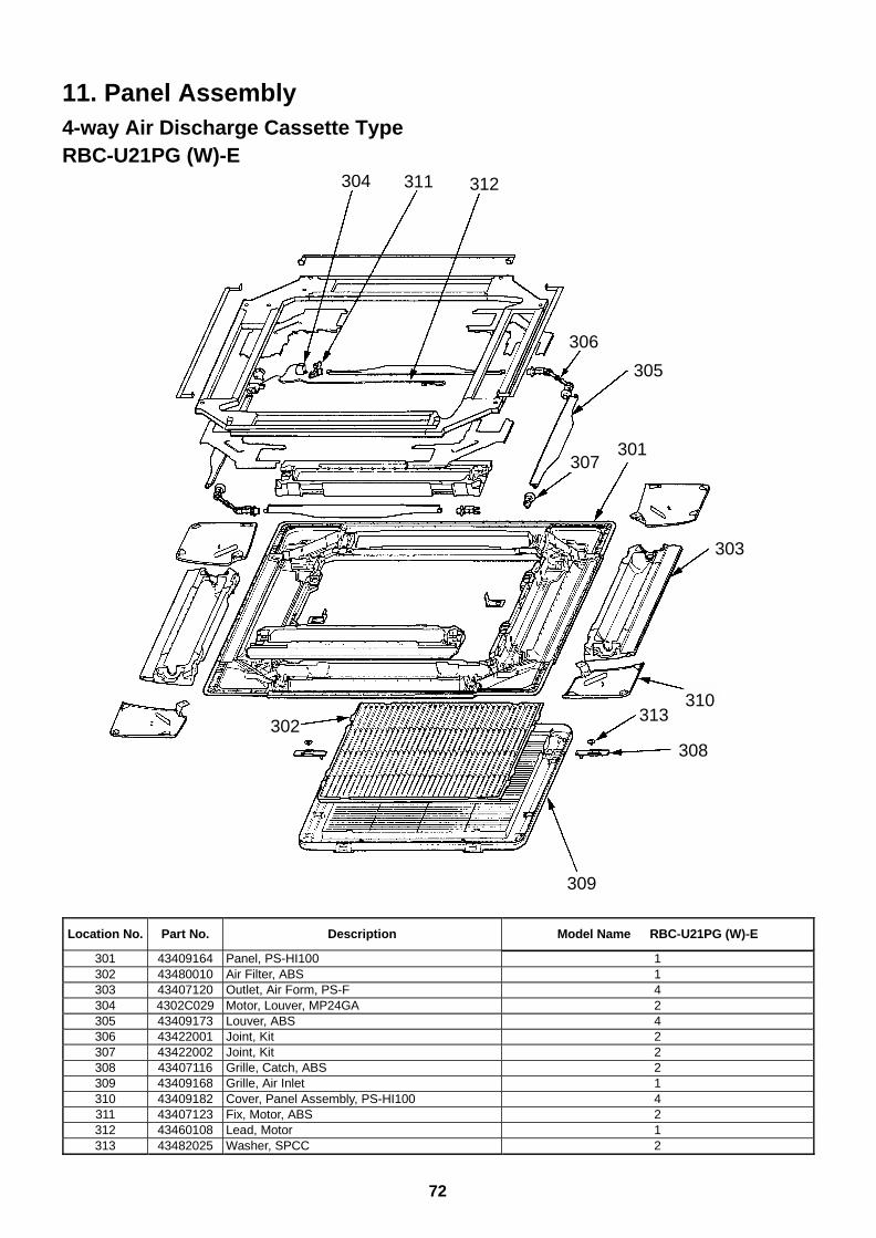
72
304 311
306
312
305
307
303
301
313
309
302308
310
11. Panel Assembly4-way Air Discharge Cassette TypeRBC-U21PG (W)-E
Location No. Part No. Description Model Name RBC-U21PG (W)-E
301 43409164 Panel, PS-HI100 1302 43480010 Air Filter, ABS 1303 43407120 Outlet, Air Form, PS-F 4304 4302C029 Motor, Louver, MP24GA 2305 43409173 Louver, ABS 4306 43422001 Joint, Kit 2307 43422002 Joint, Kit 2308 43407116 Grille, Catch, ABS 2309 43409168 Grille, Air Inlet 1310 43409182 Cover, Panel Assembly, PS-HI100 4311 43407123 Fix, Motor, ABS 2312 43460108 Lead, Motor 1313 43482025 Washer, SPCC 2
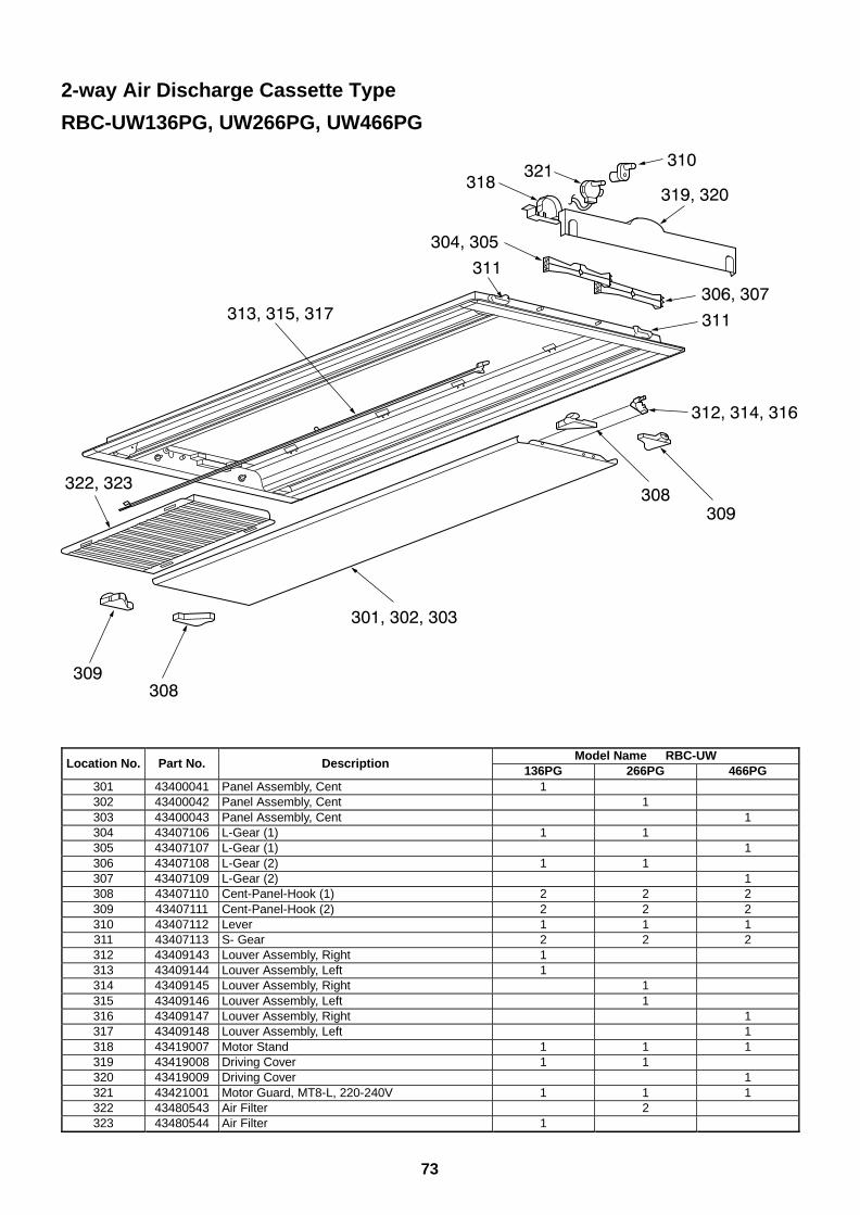
73
2-way Air Discharge Cassette Type
RBC-UW136PG, UW266PG, UW466PG
Model Name RBC-UWLocation No. Part No. Description
136PG 266PG 466PG301 43400041 Panel Assembly, Cent 1302 43400042 Panel Assembly, Cent 1303 43400043 Panel Assembly, Cent 1304 43407106 L-Gear (1) 1 1305 43407107 L-Gear (1) 1306 43407108 L-Gear (2) 1 1307 43407109 L-Gear (2) 1308 43407110 Cent-Panel-Hook (1) 2 2 2309 43407111 Cent-Panel-Hook (2) 2 2 2310 43407112 Lever 1 1 1311 43407113 S- Gear 2 2 2312 43409143 Louver Assembly, Right 1313 43409144 Louver Assembly, Left 1314 43409145 Louver Assembly, Right 1315 43409146 Louver Assembly, Left 1316 43409147 Louver Assembly, Right 1317 43409148 Louver Assembly, Left 1318 43419007 Motor Stand 1 1 1319 43419008 Driving Cover 1 1320 43419009 Driving Cover 1321 43421001 Motor Guard, MT8-L, 220-240V 1 1 1322 43480543 Air Filter 2323 43480544 Air Filter 1
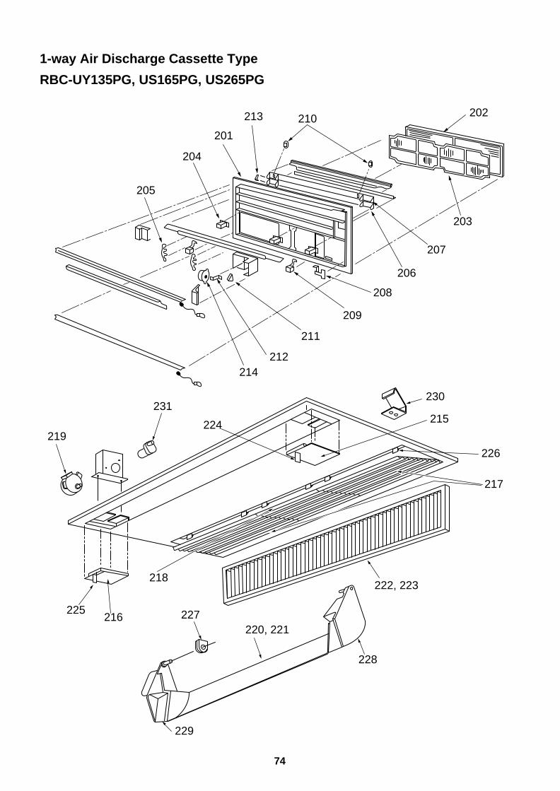
74
1-way Air Discharge Cassette Type
RBC-UY135PG, US165PG, US265PG
202210213
205
204
201
212214
211
209
208
206
207
203
222, 223218
216225
219
231
224 215
230
228
229
227220, 221
226
217
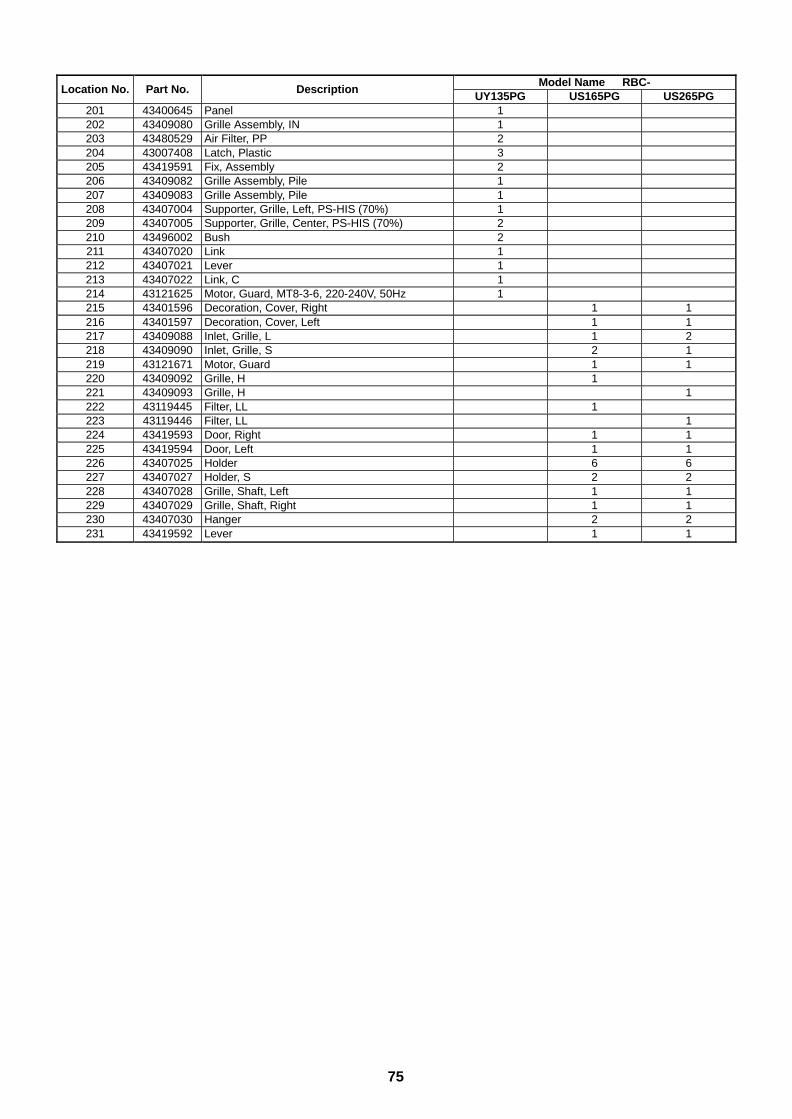
75
Model Name RBC-Location No. Part No. Description
UY135PG US165PG US265PG201 43400645 Panel 1202 43409080 Grille Assembly, IN 1203 43480529 Air Filter, PP 2204 43007408 Latch, Plastic 3205 43419591 Fix, Assembly 2206 43409082 Grille Assembly, Pile 1207 43409083 Grille Assembly, Pile 1208 43407004 Supporter, Grille, Left, PS-HIS (70%) 1209 43407005 Supporter, Grille, Center, PS-HIS (70%) 2210 43496002 Bush 2211 43407020 Link 1212 43407021 Lever 1213 43407022 Link, C 1214 43121625 Motor, Guard, MT8-3-6, 220-240V, 50Hz 1215 43401596 Decoration, Cover, Right 1 1216 43401597 Decoration, Cover, Left 1 1217 43409088 Inlet, Grille, L 1 2218 43409090 Inlet, Grille, S 2 1219 43121671 Motor, Guard 1 1220 43409092 Grille, H 1221 43409093 Grille, H 1222 43119445 Filter, LL 1223 43119446 Filter, LL 1224 43419593 Door, Right 1 1225 43419594 Door, Left 1 1226 43407025 Holder 6 6227 43407027 Holder, S 2 2228 43407028 Grille, Shaft, Left 1 1229 43407029 Grille, Shaft, Right 1 1230 43407030 Hanger 2 2231 43419592 Lever 1 1
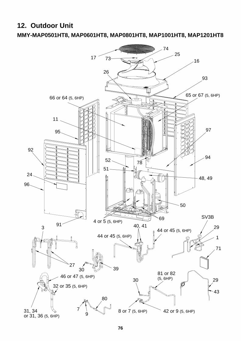
76
12. Outdoor UnitMMY-MAP0501HT8, MAP0601HT8, MAP0801HT8, MAP1001HT8, MAP1201HT8
913
4 or 5 (5, 6HP) SV3B
29
1
71
30
43
46 or 47 (5, 6HP)
80
44 or 45 (5, 6HP)
30
29
40, 41
81 or 82 (5, 6HP)
44 or 45 (5, 6HP)
3927
32 or 35 (5, 6HP)
8 or 7 (5, 6HP) 42 or 9 (5, 6HP)79
31, 34or 31, 36 (5, 6HP)
69
66 or 64 (5, 6HP)
74
51
52 78
48, 49
50
17 73
65 or 67 (5, 6HP)
97
94
93
96
92
24
95
11
26
1625
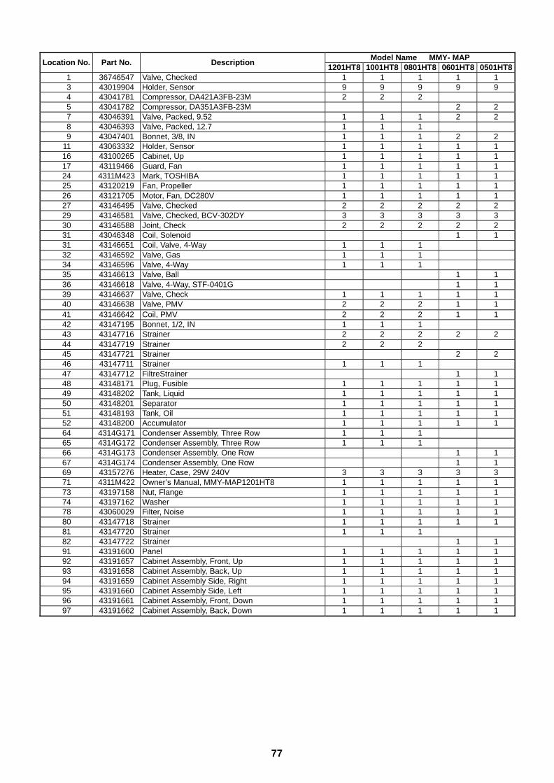
77
Model Name MMY- MAPLocation No. Part No. Description
1201HT8 1001HT8 0801HT8 0601HT8 0501HT81 36746547 Valve, Checked 1 1 1 1 13 43019904 Holder, Sensor 9 9 9 9 94 43041781 Compressor, DA421A3FB-23M 2 2 25 43041782 Compressor, DA351A3FB-23M 2 27 43046391 Valve, Packed, 9.52 1 1 1 2 28 43046393 Valve, Packed, 12.7 1 1 19 43047401 Bonnet, 3/8, IN 1 1 1 2 2
11 43063332 Holder, Sensor 1 1 1 1 116 43100265 Cabinet, Up 1 1 1 1 117 43119466 Guard, Fan 1 1 1 1 124 4311M423 Mark, TOSHIBA 1 1 1 1 125 43120219 Fan, Propeller 1 1 1 1 126 43121705 Motor, Fan, DC280V 1 1 1 1 127 43146495 Valve, Checked 2 2 2 2 229 43146581 Valve, Checked, BCV-302DY 3 3 3 3 330 43146588 Joint, Check 2 2 2 2 231 43046348 Coil, Solenoid 1 131 43146651 Coil, Valve, 4-Way 1 1 132 43146592 Valve, Gas 1 1 134 43146596 Valve, 4-Way 1 1 135 43146613 Valve, Ball 1 136 43146618 Valve, 4-Way, STF-0401G 1 139 43146637 Valve, Check 1 1 1 1 140 43146638 Valve, PMV 2 2 2 1 141 43146642 Coil, PMV 2 2 2 1 142 43147195 Bonnet, 1/2, IN 1 1 143 43147716 Strainer 2 2 2 2 244 43147719 Strainer 2 2 245 43147721 Strainer 2 246 43147711 Strainer 1 1 147 43147712 FiltreStrainer 1 148 43148171 Plug, Fusible 1 1 1 1 149 43148202 Tank, Liquid 1 1 1 1 150 43148201 Separator 1 1 1 1 151 43148193 Tank, Oil 1 1 1 1 152 43148200 Accumulator 1 1 1 1 164 4314G171 Condenser Assembly, Three Row 1 1 165 4314G172 Condenser Assembly, Three Row 1 1 166 4314G173 Condenser Assembly, One Row 1 167 4314G174 Condenser Assembly, One Row 1 169 43157276 Heater, Case, 29W 240V 3 3 3 3 371 4311M422 Owner’s Manual, MMY-MAP1201HT8 1 1 1 1 173 43197158 Nut, Flange 1 1 1 1 174 43197162 Washer 1 1 1 1 178 43060029 Filter, Noise 1 1 1 1 180 43147718 Strainer 1 1 1 1 181 43147720 Strainer 1 1 182 43147722 Strainer 1 191 43191600 Panel 1 1 1 1 192 43191657 Cabinet Assembly, Front, Up 1 1 1 1 193 43191658 Cabinet Assembly, Back, Up 1 1 1 1 194 43191659 Cabinet Assembly Side, Right 1 1 1 1 195 43191660 Cabinet Assembly Side, Left 1 1 1 1 196 43191661 Cabinet Assembly, Front, Down 1 1 1 1 197 43191662 Cabinet Assembly, Back, Down 1 1 1 1 1
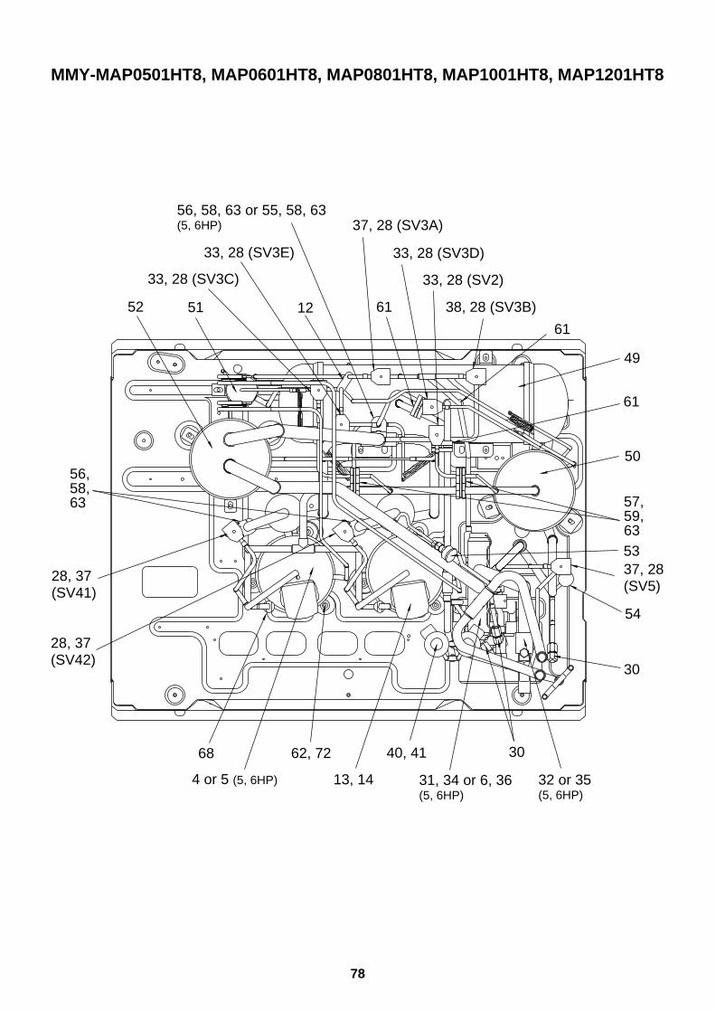
78
MMY-MAP0501HT8, MAP0601HT8, MAP0801HT8, MAP1001HT8, MAP1201HT8
56, 58, 63 or 55, 58, 63(5, 6HP)
12
61
61
33, 28 (SV3E)
33, 28 (SV3C)
38, 28 (SV3B)
33, 28 (SV2)
33, 28 (SV3D)
37, 28 (SV3A)
5152
30
53
54
57, 59,63
61
37, 28(SV5)
49
50
4 or 5 (5, 6HP) 31, 34 or 6, 36 (5, 6HP)
32 or 35 (5, 6HP)
3068 62, 72 40, 41
13, 14
56,58,63
28, 37(SV42)
28, 37(SV41)
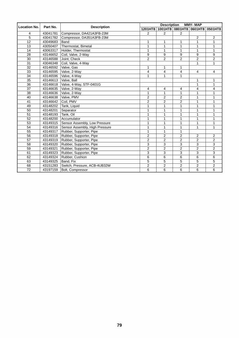
79
Description MMY- MAPLocation No. Part No. Description
1201HT8 1001HT8 0801HT8 0601HT8 0501HT84 43041781 Compressor, DA421A3FB-23M 2 2 25 43041782 Compressor, DA351A3FB-23M 2 2
12 43049683 Band 1 1 1 1 113 43050407 Thermostat, Bimetal 1 1 1 1 114 43063317 Holder, Thermostat 1 1 1 1 128 43146652 Coil, Valve, 2-Way 9 9 9 9 930 43146588 Joint, Check 2 2 2 2 231 43046348 Coil, Valve, 4-Way 1 132 43146592 Valve, Gas 1 1 133 43146595 Valve, 2-Way 4 4 4 4 434 43146596 Valve, 4-Way 1 1 135 43146613 Valve, Ball 1 136 43146618 Valve, 4-Way, STF-0401G 1 137 43146635 Valve, 2-Way 4 4 4 4 438 43146636 Valve, 2-Way 1 1 1 1 140 43146638 Valve, PMV 2 2 2 1 141 43146642 Coil, PMV 2 2 2 1 149 43148202 Tank, Liquid 1 1 1 1 150 43148201 Separator 1 1 1 1 151 43148193 Tank, Oil 1 1 1 1 152 43148200 Accumulator 1 1 1 1 153 43149315 Sensor Assembly, Low Pressure 1 1 1 1 154 43149316 Sensor Assembly, High Pressure 1 1 1 1 155 43149317 Rubber, Supporter, Pipe 1 1 156 43149318 Rubber, Supporter, Pipe 2 2 2 2 257 43149319 Rubber, Supporter, Pipe 2 2 2 2 258 43149320 Rubber, Supporter, Pipe 3 3 3 3 359 43149321 Rubber, Supporter, Pipe 2 2 2 2 261 43149323 Rubber, Supporter, Pipe 3 3 3 3 362 43149324 Rubber, Cushion 6 6 6 6 663 43149325 Band, Fix 5 5 5 5 568 43151283 Switch, Pressure, ACB-4UB32W 2 2 2 2 272 43197159 Bolt, Compressor 6 6 6 6 6
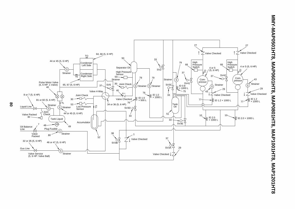
80
MM
Y-M
AP
0501HT
8, MA
P0601H
T8, M
AP
0801HT
8, MA
P1001H
T8, M
AP
1201HT
8
44 or 45 (5, 6 HP)
Strainer
Valve Packed 30
Joint Check
TLStrainer
Strainer
Plug Fusible
Strainer
Low Pressure Sensor
Joint Check
Strainer
81 or 82 (5, 6 HP)
8 or 7 (5, 6 HP)
Tank Liquid
Gus Line
Valve Packed
Oil Balance Line
CondenserLeft Side
CondenserRight Side
Liquid Line
Valve Service(5, 6 HP: Valve Ball)
Pulse Motor Valve(5, 6 HP: 1 Valve) 40
TE
Accumulator
Valve 4-Way
65, 67 (5, 6 HP)
64, 66 (5, 6 HP)
48 FP
37
52
53
30
32 or 35 (5, 6 HP)
80
7
44 or 45 (5, 6 HP)
49
TO
TS
46 or 47 (5, 6 HP)
StrainerStrainer
Valve Checked
Valve Checked
Valve Checked
Strainer Strainer
ID 1.0 × 500 L
ID 1.0 × 1000 L
TankOil
SV3A
SV3B
SV3E
SV2
SV5 Joint Check
High Pressure Sensor
Separator Oil
SV3D
SV3C ID 0.8× 1000 L
SV41
75
38
29
37
33
51
33
33
79
76
33
76
79
30
40
54
50
34 or 36 (5, 6 HP)
1
Strainer
79
2727
Valve CheckedValve Checked
TD
ID 2.0× 1000 L
ID 2.0 × 1000 L
ID 1.2× 1000 LID 1.2 × 1000 L
Valve Checked
High Pressure Switch
Com-pressor
Com-pressor
37
77
29
43
4 or 5 (5, 6 HP)
1010
77
2943
4 or 5 (5, 6 HP)
68
37SV42
Strainer
Valve Checked
TD
High Pressure Switch
68

81
Model Name MMY- MAPLocation No. Part No. Description
1201HT8 1001HT8 0801HT8 0601HT8 0501HT81 36746547 Valve, Checked 1 1 1 1 14 43041781 Compressor, DA421A3FB-23M 2 2 25 43041782 Compressor, DA351A3FB-23M 2 27 43046391 Valve, Packed, 9.52 1 1 1 2 28 43046393 Valve, Packed, 12.7 1 1 1
10 43047527 Tube, Capillary, ID 2.0 × 200L 1 1 1 1 127 43146495 Valve, Checked 2 2 2 2 229 43146581 Valve, Checked, BCV-302DY 3 3 3 3 330 43146588 Joint, Check 2 2 2 2 232 43146592 Valve, Gas 1 1 133 43146595 Valve, 2-Way 4 4 4 4 434 43146596 Valve, 4-Way 1 1 135 43146613 Valve, Ball 1 136 43146618 Valve, 4-Way, STF-0401G 1 137 43146635 Valve, 2-Way 4 4 4 4 438 43146636 Valve, 2-Way 1 1 1 1 140 43146638 Valve, PMV 2 2 2 1 143 43147716 Strainer 2 2 2 2 244 43147719 Strainer 2 2 245 43147721 Strainer 2 246 43147711 Strainer 1 1 147 43147712 Strainer 1 148 43148171 Plug, Fusible 1 1 1 1 149 43148202 Tank, Liquid 1 1 1 1 150 43148201 Separator 1 1 1 1 151 43148193 Tank, Oil 1 1 1 1 152 43148200 Accumulator 1 1 1 1 153 43149315 Sensor Assembly, Low Pressure 1 1 1 1 154 43149316 Sensor Assembly, High Pressure 1 1 1 1 164 4314G171 Condenser Assembly, Three Row 1 1 165 4314G172 Condenser Assembly, Three Row 1 1 168 43151283 Switch, Pressure, ACB-4UB32W 2 2 2 2 275 43146235 Tube, Capillary, Bypass 1 1 1 1 176 43146236 Tube, Capillary, Bypass, 1.0 × 2.0 × 110L 1 1 1 1 177 43146239 Tube, Capillary, ID 1.2 1 1 1 1 179 43147727 Strainer 3 3 3 3 380 43147718 Strainer 1 1 1 1 181 43147720 Strainer 1 1 182 43147722 Strainer 1 1
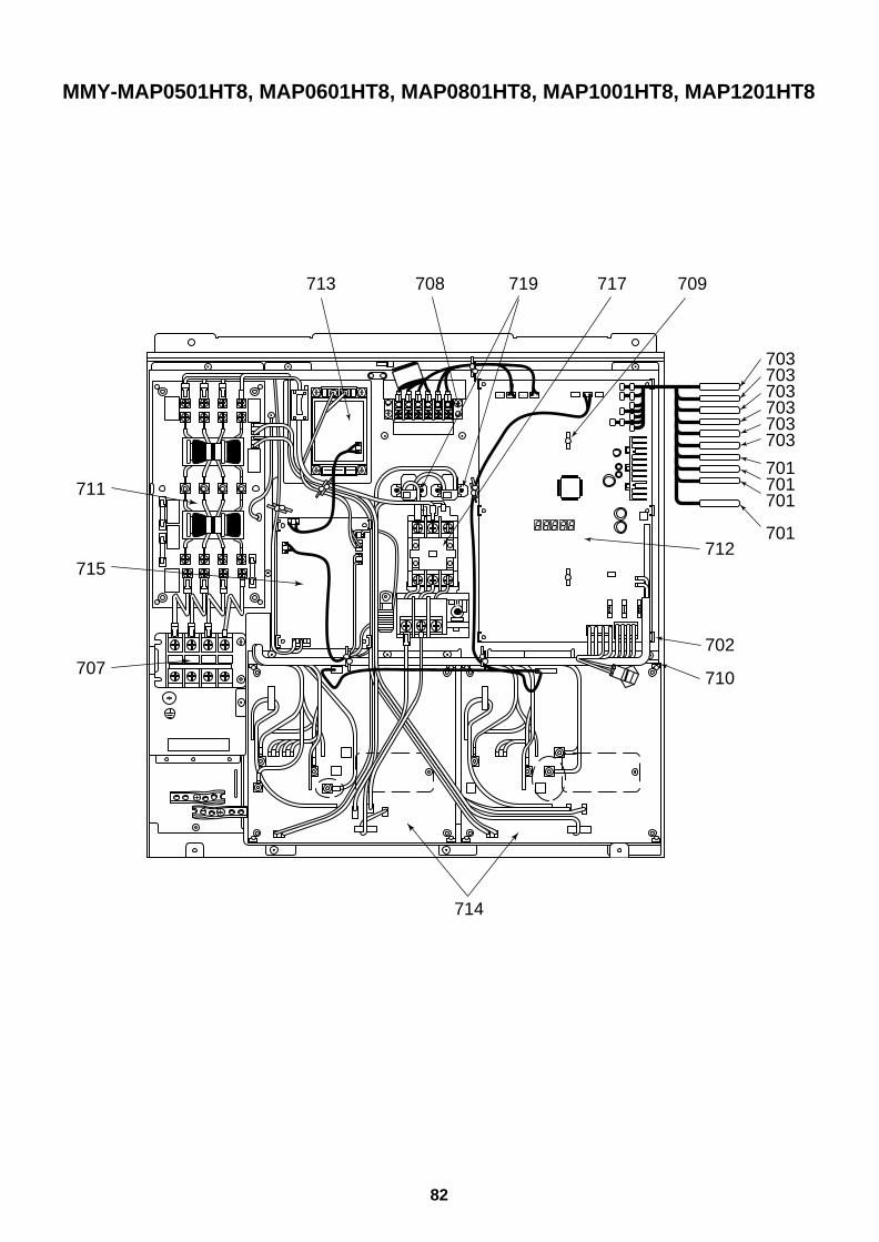
82
MMY-MAP0501HT8, MAP0601HT8, MAP0801HT8, MAP1001HT8, MAP1201HT8
703703703703703703
701701701
701712
708 719 717 709
702
710
714
707
715
711
713
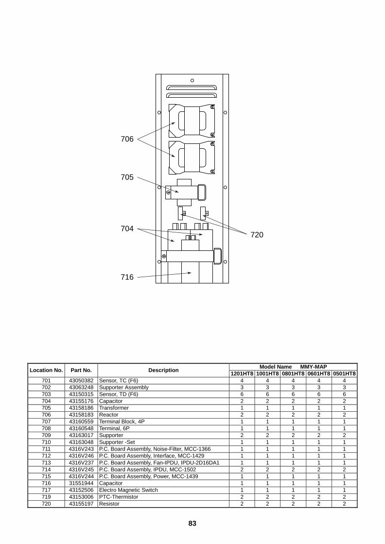
83
Model Name MMY-MAPLocation No. Part No. Description
1201HT8 1001HT8 0801HT8 0601HT8 0501HT8701 43050382 Sensor, TC (F6) 4 4 4 4 4702 43063248 Supporter Assembly 3 3 3 3 3703 43150315 Sensor, TD (F6) 6 6 6 6 6704 43155176 Capacitor 2 2 2 2 2705 43158186 Transformer 1 1 1 1 1706 43158183 Reactor 2 2 2 2 2707 43160559 Terminal Block, 4P 1 1 1 1 1708 43160548 Terminal, 6P 1 1 1 1 1709 43163017 Supporter 2 2 2 2 2710 43163048 Supporter -Set 1 1 1 1 1711 4316V243 P.C. Board Assembly, Noise-Filter, MCC-1366 1 1 1 1 1712 4316V246 P.C. Board Assembly, Interface, MCC-1429 1 1 1 1 1713 4316V237 P.C. Board Assembly, Fan-IPDU, IPDU-2D16DA1 1 1 1 1 1714 4316V245 P.C. Board Assembly, IPDU, MCC-1502 2 2 2 2 2715 4316V244 P.C. Board Assembly, Power, MCC-1439 1 1 1 1 1716 31551944 Capacitor 1 1 1 1 1717 43152506 Electro Magnetic Switch 1 1 1 1 1719 43153006 PTC-Thermistor 2 2 2 2 2720 43155197 Resistor 2 2 2 2 2
706
705
720704
716
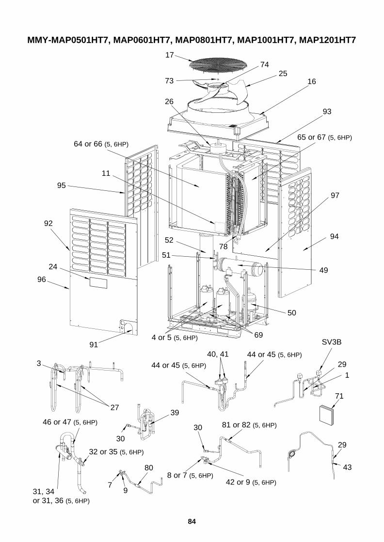
84
MMY-MAP0501HT7, MAP0601HT7, MAP0801HT7, MAP1001HT7, MAP1201HT7
914 or 5 (5, 6HP)
SV3B
29
1
30
43
46 or 47 (5, 6HP)
80
44 or 45 (5, 6HP)
3029
71
40, 41
81 or 82 (5, 6HP)
44 or 45 (5, 6HP)
3927
32 or 35 (5, 6HP)
8 or 7 (5, 6HP)42 or 9 (5, 6HP)7
931, 34or 31, 36 (5, 6HP)
69
64 or 66 (5, 6HP)
74
51
5278
24 49
50
17
73
65 or 67 (5, 6HP)
97
94
93
96
3
92
95
11
26
1625
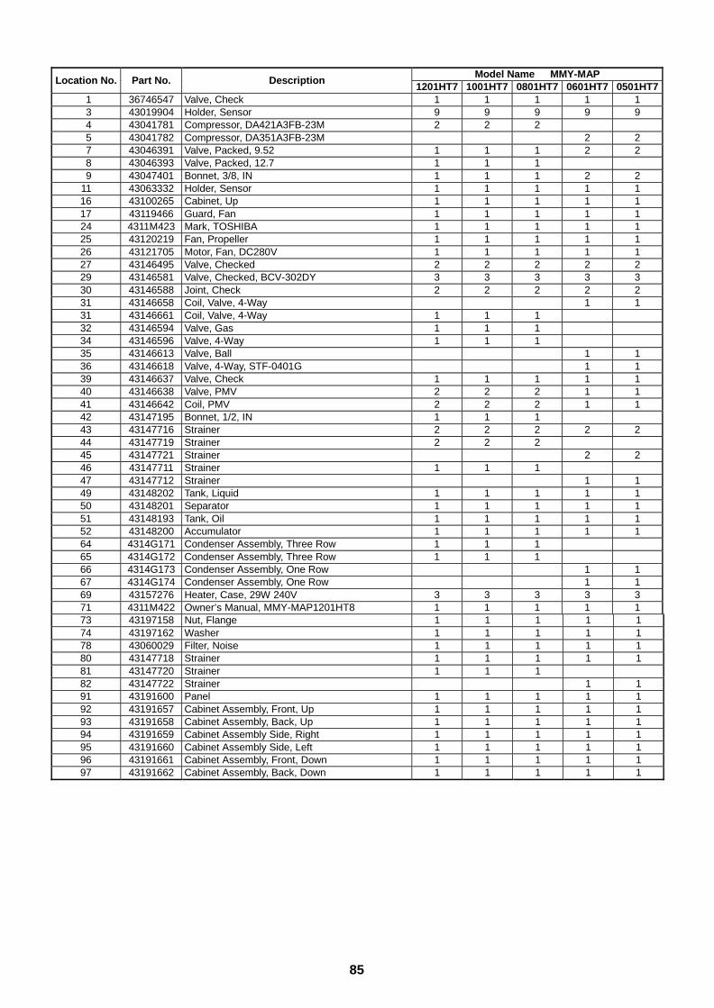
85
Model Name MMY-MAPLocation No. Part No. Description
1201HT7 1001HT7 0801HT7 0601HT7 0501HT71 36746547 Valve, Check 1 1 1 1 13 43019904 Holder, Sensor 9 9 9 9 94 43041781 Compressor, DA421A3FB-23M 2 2 25 43041782 Compressor, DA351A3FB-23M 2 27 43046391 Valve, Packed, 9.52 1 1 1 2 28 43046393 Valve, Packed, 12.7 1 1 19 43047401 Bonnet, 3/8, IN 1 1 1 2 2
11 43063332 Holder, Sensor 1 1 1 1 116 43100265 Cabinet, Up 1 1 1 1 117 43119466 Guard, Fan 1 1 1 1 124 4311M423 Mark, TOSHIBA 1 1 1 1 125 43120219 Fan, Propeller 1 1 1 1 126 43121705 Motor, Fan, DC280V 1 1 1 1 127 43146495 Valve, Checked 2 2 2 2 229 43146581 Valve, Checked, BCV-302DY 3 3 3 3 330 43146588 Joint, Check 2 2 2 2 231 43146658 Coil, Valve, 4-Way 1 131 43146661 Coil, Valve, 4-Way 1 1 132 43146594 Valve, Gas 1 1 134 43146596 Valve, 4-Way 1 1 135 43146613 Valve, Ball 1 136 43146618 Valve, 4-Way, STF-0401G 1 139 43146637 Valve, Check 1 1 1 1 140 43146638 Valve, PMV 2 2 2 1 141 43146642 Coil, PMV 2 2 2 1 142 43147195 Bonnet, 1/2, IN 1 1 143 43147716 Strainer 2 2 2 2 244 43147719 Strainer 2 2 245 43147721 Strainer 2 246 43147711 Strainer 1 1 147 43147712 Strainer 1 149 43148202 Tank, Liquid 1 1 1 1 150 43148201 Separator 1 1 1 1 151 43148193 Tank, Oil 1 1 1 1 152 43148200 Accumulator 1 1 1 1 164 4314G171 Condenser Assembly, Three Row 1 1 165 4314G172 Condenser Assembly, Three Row 1 1 166 4314G173 Condenser Assembly, One Row 1 167 4314G174 Condenser Assembly, One Row 1 169 43157276 Heater, Case, 29W 240V 3 3 3 3 371 4311M422 Owner’s Manual, MMY-MAP1201HT8 1 1 1 1 173 43197158 Nut, Flange 1 1 1 1 174 43197162 Washer 1 1 1 1 178 43060029 Filter, Noise 1 1 1 1 180 43147718 Strainer 1 1 1 1 181 43147720 Strainer 1 1 182 43147722 Strainer 1 191 43191600 Panel 1 1 1 1 192 43191657 Cabinet Assembly, Front, Up 1 1 1 1 193 43191658 Cabinet Assembly, Back, Up 1 1 1 1 194 43191659 Cabinet Assembly Side, Right 1 1 1 1 195 43191660 Cabinet Assembly Side, Left 1 1 1 1 196 43191661 Cabinet Assembly, Front, Down 1 1 1 1 197 43191662 Cabinet Assembly, Back, Down 1 1 1 1 1
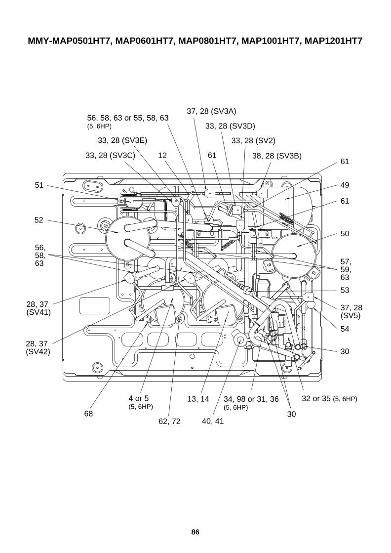
86
MMY-MAP0501HT7, MAP0601HT7, MAP0801HT7, MAP1001HT7, MAP1201HT7
56, 58, 63 or 55, 58, 63(5, 6HP)
1261
61
33, 28 (SV3E)
33, 28 (SV3C) 38, 28 (SV3B)
33, 28 (SV2)
33, 28 (SV3D)
37, 28 (SV3A)
51
52
30
53
54
57, 59, 63
61
37, 28(SV5)
49
50
4 or 5(5, 6HP)
34, 98 or 31, 36(5, 6HP)
32 or 35 (5, 6HP)
306862, 72 40, 41
13, 14
56, 58, 63
28, 37(SV42)
28, 37(SV41)
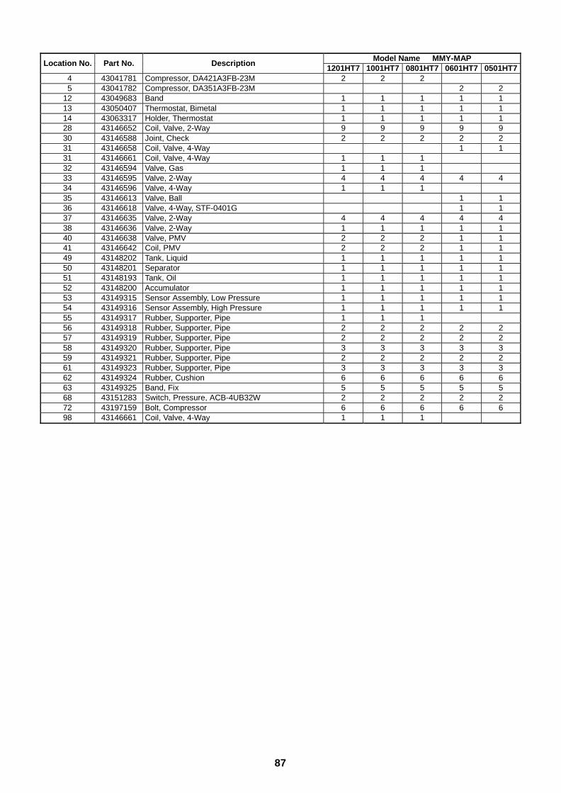
87
Model Name MMY-MAPLocation No. Part No. Description
1201HT7 1001HT7 0801HT7 0601HT7 0501HT74 43041781 Compressor, DA421A3FB-23M 2 2 25 43041782 Compressor, DA351A3FB-23M 2 2
12 43049683 Band 1 1 1 1 113 43050407 Thermostat, Bimetal 1 1 1 1 114 43063317 Holder, Thermostat 1 1 1 1 128 43146652 Coil, Valve, 2-Way 9 9 9 9 930 43146588 Joint, Check 2 2 2 2 231 43146658 Coil, Valve, 4-Way 1 131 43146661 Coil, Valve, 4-Way 1 1 132 43146594 Valve, Gas 1 1 133 43146595 Valve, 2-Way 4 4 4 4 434 43146596 Valve, 4-Way 1 1 135 43146613 Valve, Ball 1 136 43146618 Valve, 4-Way, STF-0401G 1 137 43146635 Valve, 2-Way 4 4 4 4 438 43146636 Valve, 2-Way 1 1 1 1 140 43146638 Valve, PMV 2 2 2 1 141 43146642 Coil, PMV 2 2 2 1 149 43148202 Tank, Liquid 1 1 1 1 150 43148201 Separator 1 1 1 1 151 43148193 Tank, Oil 1 1 1 1 152 43148200 Accumulator 1 1 1 1 153 43149315 Sensor Assembly, Low Pressure 1 1 1 1 154 43149316 Sensor Assembly, High Pressure 1 1 1 1 155 43149317 Rubber, Supporter, Pipe 1 1 156 43149318 Rubber, Supporter, Pipe 2 2 2 2 257 43149319 Rubber, Supporter, Pipe 2 2 2 2 258 43149320 Rubber, Supporter, Pipe 3 3 3 3 359 43149321 Rubber, Supporter, Pipe 2 2 2 2 261 43149323 Rubber, Supporter, Pipe 3 3 3 3 362 43149324 Rubber, Cushion 6 6 6 6 663 43149325 Band, Fix 5 5 5 5 568 43151283 Switch, Pressure, ACB-4UB32W 2 2 2 2 272 43197159 Bolt, Compressor 6 6 6 6 698 43146661 Coil, Valve, 4-Way 1 1 1

88
MM
Y-M
AP
0501HT
7, MA
P0601H
T7, M
AP
0801HT
7, MA
P1001H
T7, M
AP
1201HT
7
44 or 45 (5, 6 HP)
Strainer
Valve Packed 30
Joint Check
TLStrainer
Strainer
Plug Fusible
Strainer
Low Pressure Sensor
Joint Check
Strainer
81 or 82 (5, 6 HP)
8 or 7 (5, 6 HP)
Tank Liquid
Gus Line
Valve Packed
Oil Balance Line
CondenserLeft Side
CondenserRight Side
Liquid Line
Valve Service(5, 6 HP: Valve Ball)
Pulse Motor Valve(5, 6 HP: 1 Valve) 40
TE
Accumulator
Valve 4-Way
65, 67 (5, 6 HP)
64, 66 (5, 6 HP)
48 FP
37
52
53
30
32 or 35 (5, 6 HP)
80
7
44 or 45 (5, 6 HP)
49
TO
TS
46 or 47 (5, 6 HP)
StrainerStrainer
Valve Checked
Valve Checked
Valve Checked
Strainer Strainer
ID 1.0 × 500 L
ID 1.0 × 1000 L
TankOil
SV3A
SV3B
SV3E
SV2
SV5 Joint Check
High Pressure Sensor
Separator Oil
SV3D
SV3C ID 0.8× 1000 L
SV41
75
38
29
37
33
51
33
33
79
76
33
76
79
30
40
54
50
34 or 36 (5, 6 HP)
1
Strainer
79
2727
Valve CheckedValve Checked
TD
ID 2.0× 1000 L
ID 2.0 × 1000 L
ID 1.2× 1000 LID 1.2 × 1000 L
Valve Checked
High Pressure Switch
Com-pressor
Com-pressor
37
77
29
43
4 or 5 (5, 6 HP)
1010
77
2943
4 or 5 (5, 6 HP)
68
37SV42
Strainer
Valve Checked
TD
High Pressure Switch
68
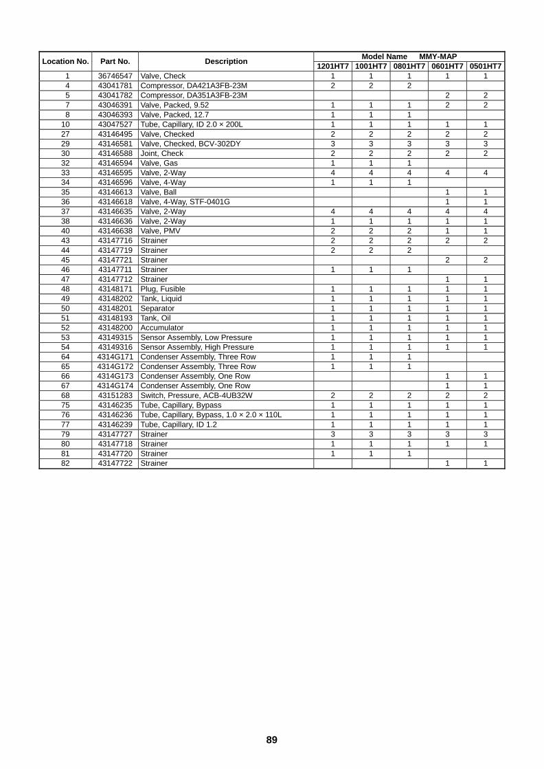
89
Model Name MMY-MAPLocation No. Part No. Description
1201HT7 1001HT7 0801HT7 0601HT7 0501HT71 36746547 Valve, Check 1 1 1 1 14 43041781 Compressor, DA421A3FB-23M 2 2 25 43041782 Compressor, DA351A3FB-23M 2 27 43046391 Valve, Packed, 9.52 1 1 1 2 28 43046393 Valve, Packed, 12.7 1 1 1
10 43047527 Tube, Capillary, ID 2.0 × 200L 1 1 1 1 127 43146495 Valve, Checked 2 2 2 2 229 43146581 Valve, Checked, BCV-302DY 3 3 3 3 330 43146588 Joint, Check 2 2 2 2 232 43146594 Valve, Gas 1 1 133 43146595 Valve, 2-Way 4 4 4 4 434 43146596 Valve, 4-Way 1 1 135 43146613 Valve, Ball 1 136 43146618 Valve, 4-Way, STF-0401G 1 137 43146635 Valve, 2-Way 4 4 4 4 438 43146636 Valve, 2-Way 1 1 1 1 140 43146638 Valve, PMV 2 2 2 1 143 43147716 Strainer 2 2 2 2 244 43147719 Strainer 2 2 245 43147721 Strainer 2 246 43147711 Strainer 1 1 147 43147712 Strainer 1 148 43148171 Plug, Fusible 1 1 1 1 149 43148202 Tank, Liquid 1 1 1 1 150 43148201 Separator 1 1 1 1 151 43148193 Tank, Oil 1 1 1 1 152 43148200 Accumulator 1 1 1 1 153 43149315 Sensor Assembly, Low Pressure 1 1 1 1 154 43149316 Sensor Assembly, High Pressure 1 1 1 1 164 4314G171 Condenser Assembly, Three Row 1 1 165 4314G172 Condenser Assembly, Three Row 1 1 166 4314G173 Condenser Assembly, One Row 1 167 4314G174 Condenser Assembly, One Row 1 168 43151283 Switch, Pressure, ACB-4UB32W 2 2 2 2 275 43146235 Tube, Capillary, Bypass 1 1 1 1 176 43146236 Tube, Capillary, Bypass, 1.0 × 2.0 × 110L 1 1 1 1 177 43146239 Tube, Capillary, ID 1.2 1 1 1 1 179 43147727 Strainer 3 3 3 3 380 43147718 Strainer 1 1 1 1 181 43147720 Strainer 1 1 182 43147722 Strainer 1 1
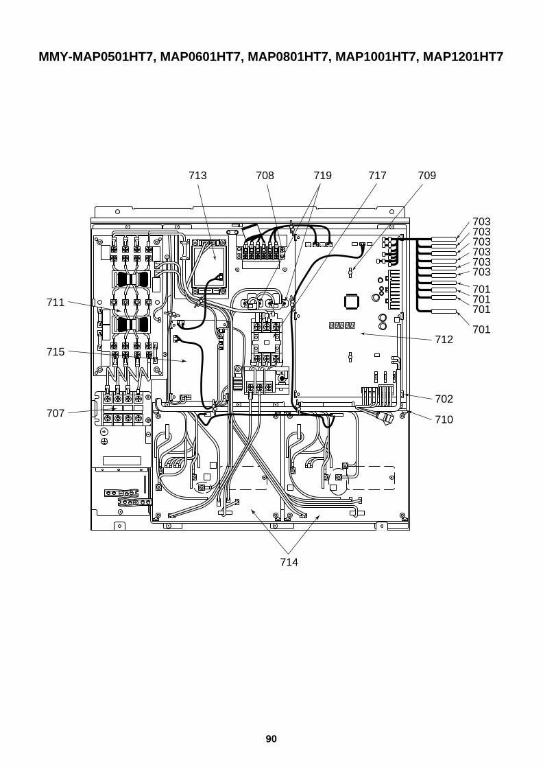
90
MMY-MAP0501HT7, MAP0601HT7, MAP0801HT7, MAP1001HT7, MAP1201HT7
712
708 719 717 709
702
710
714
707
715
711
713
703703703703703703
701701701
701

91
706
705
720704
716
Model Name MMY-MAPLocation No. Part No. Description
1201HT7 1001HT7 0801HT7 0601HT7 0501HT7701 43050382 Sensor, TC (F6) 4 4 4 4 4702 43063248 Supporter Assembly 3 3 3 3 3703 43150315 Sensor, TD (F6) 6 6 6 6 6704 43155176 Capacitor 2 2 2 2 2705 43158186 Transformer 1 1 1 1 1706 43158183 Reactor 2 2 2 2 2707 43160559 Terminal, Block, 4P 1 1 1 1 1708 43160548 Terminal, 6P 1 1 1 1 1709 43163017 Supporter 2 2 2 2 2710 43163048 Supporter-Set 1 1 1 1 1711 4316V243 P.C. Board Assembly, Noise-Filter, MCC-1366 1 1 1 1 1712 4316V246 P.C. Board Assembly, Interface, MCC-1429 1 1 1 1 1713 4316V237 P.C. Board Assembly, Fan-IPDU, IPDU-2D16DA1 1 1 1 1 1714 4316V245 P.C. Board Assembly, IPDU, MCC-1502 2 2 2 2 2715 4316V244 P.C. Board Assembly, Power, MCC-1439 1 1 1 1 1716 43155194 Capacitor 1 1 1 1 1717 43152506 Electro Magnetic Switch 1 1 1 1 1719 43153006 PTC-Thermistor 2 2 2 2 2720 43155197 Resistor 2 2 2 2 2

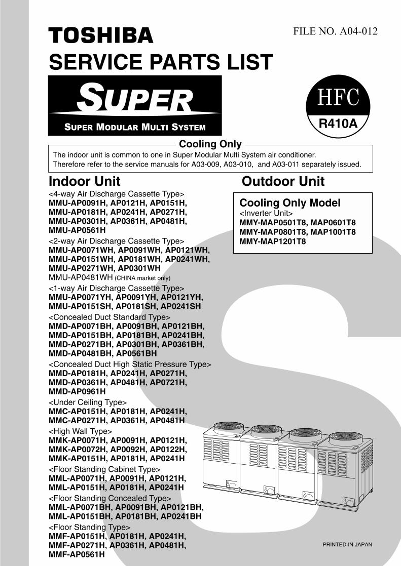
SERVICE PARTS LIST
FILE NO. A04-012
Indoor Unit<4-way Air Discharge Cassette Type>MMU-AP0091H, AP0121H, AP0151H, MMU-AP0181H, AP0241H, AP0271H,MMU-AP0301H, AP0361H, AP0481H,MMU-AP0561H<2-way Air Discharge Cassette Type>MMU-AP0071WH, AP0091WH, AP0121WH, MMU-AP0151WH, AP0181WH, AP0241WH, MMU-AP0271WH, AP0301WHMMU-AP0481WH (CHINA market only)
<1-way Air Discharge Cassette Type>MMU-AP0071YH, AP0091YH, AP0121YH, MMU-AP0151SH, AP0181SH, AP0241SH<Concealed Duct Standard Type>MMD-AP0071BH, AP0091BH, AP0121BH, MMD-AP0151BH, AP0181BH, AP0241BH, MMD-AP0271BH, AP0301BH, AP0361BH,MMD-AP0481BH, AP0561BH<Concealed Duct High Static Pressure Type>MMD-AP0181H, AP0241H, AP0271H, MMD-AP0361H, AP0481H, AP0721H,MMD-AP0961H<Under Ceiling Type>MMC-AP0151H, AP0181H, AP0241H, MMC-AP0271H, AP0361H, AP0481H<High Wall Type>MMK-AP0071H, AP0091H, AP0121H, MMK-AP0072H, AP0092H, AP0122H,MMK-AP0151H, AP0181H, AP0241H<Floor Standing Cabinet Type>MML-AP0071H, AP0091H, AP0121H, MML-AP0151H, AP0181H, AP0241H<Floor Standing Concealed Type>MML-AP0071BH, AP0091BH, AP0121BH, MML-AP0151BH, AP0181BH, AP0241BH<Floor Standing Type>MMF-AP0151H, AP0181H, AP0241H,MMF-AP0271H, AP0361H, AP0481H,MMF-AP0561H
R410A
PRINTED IN JAPAN
Outdoor Unit
Cooling Only Model<Inverter Unit>MMY-MAP0501T8, MAP0601T8MMY-MAP0801T8, MAP1001T8MMY-MAP1201T8
The indoor unit is common to one in Super Modular Multi System air conditioner.Therefore refer to the service manuals for A03-009, A03-010, and A03-011 separately issued.
Cooling Only

CONTENTS
1. Outdoor Unit • • • • • • • • • • • • • • • • • • • • • • • • • • • • • • • • • • • • • • • • • • • • • • • • • • • • • • • • • • • • • • • • • • • • • • • • • • • • • • • • • • • • • • • • • • • • • • • • • • • • • • • • • • • • • • 1
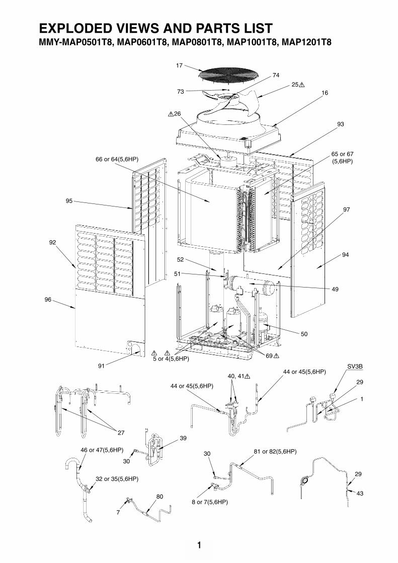
1
915 or 4(5,6HP)
SV3B
29
1
30
43
46 or 47(5,6HP)
80
44 or 45(5,6HP)
30
29
40, 41
81 or 82(5,6HP)
44 or 45(5,6HP)
3927
32 or 35(5,6HP)
8 or 7(5,6HP)
7
69
66 or 64(5,6HP)
74
51
52
49
50
17
73
65 or 67(5,6HP)
97
94
93
96
92
95
26
1625
MMY-MAP0501T8, MAP0601T8, MAP0801T8, MAP1001T8, MAP1201T8EXPLODED VIEWS AND PARTS LIST
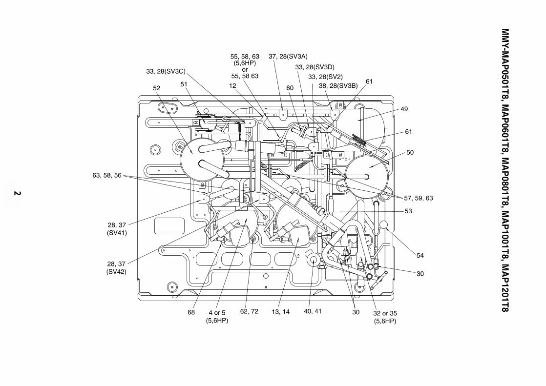
2
55, 58, 63(5,6HP)
or55, 58 63
1261
60
33, 28(SV3C)
38, 28(SV3B)33, 28(SV2)
33, 28(SV3D)
37, 28(SV3A)
5152
30
53
54
57, 59, 63
61
49
50
4 or 5(5,6HP)
32 or 35(5,6HP)
3068 62, 72 40, 4113, 14
63, 58, 56
28, 37(SV42)
28, 37(SV41)
MM
Y-MA
P0501T8, M
AP
0601T8, MA
P0801T8, M
AP
1001T8, MA
P1201T8
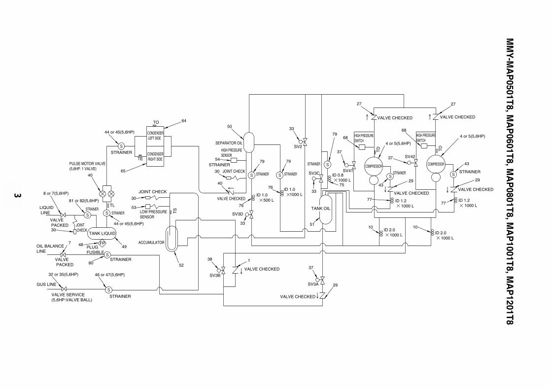
3
44 or 45(5,6HP)
STRAINER
VALVE PACKED JOINT
CHECK
TLSTRAINER
STRAINER
PLUGFUSIBLE
STRAINER
LOW PRESSURESENSOR
JOINT CHECK
STRAINER CONDENSER RIGHT SIDE
81 or 82(5,6HP)
8 or 7(5,6HP)
TANK LIQUID
GUS LINE
VALVE PACKED
OIL BALANCELINE
LIQUID LINE
VALVE SERVICE (5,6HP:VALVE BALL)
PULSE MOTOR VALVE(5,6HP: 1 VALVE)
TE
CONDENSER LEFT SIDE
ACCUMULATOR
65
64
48 FP
52
53
30
32 or 35(5,6HP)
80
7
44 or 45(5,6HP)
40
49
30
TO
TS
46 or 47(5,6HP)
STRAINERSTRAINER
VALVE CHECKED
VALVE CHECKED
VALVE CHECKED
STRAINER
ID 1.0 500 L
ID 1.0 1000 L
STRAINER
TANK OIL
SV3A
SV3B
SV2
JOINT CHECK
HIGH PRESSURESENSOR
SEPARATOR OIL
SV3D
SV3C ID 0.8 1000 L
SV41
75
38
29
37
51
33
33
79
76
33
76
79
30
40
54
50
1
STRAINER
79
2727
VALVE CHECKEDVALVE CHECKED
TD
ID 2.0 1000 L ID 2.0
1000 L
ID 1.2 1000 L
ID 1.2 1000 L
VALVE CHECKED
HIGH PRESSURESWITCH
COMPRESSOR
37
77
29
43
4 or 5(5,6HP)68
1010
77
2943
4 or 5(5,6HP)68
37SV42
HIGH PRESSURESWITCH
STRAINER
COMPRESSOR
VALVE CHECKED
TD
MM
Y-MA
P0501T8, M
AP
0601T8, MA
P0801T8, M
AP
1001T8, MA
P1201T8
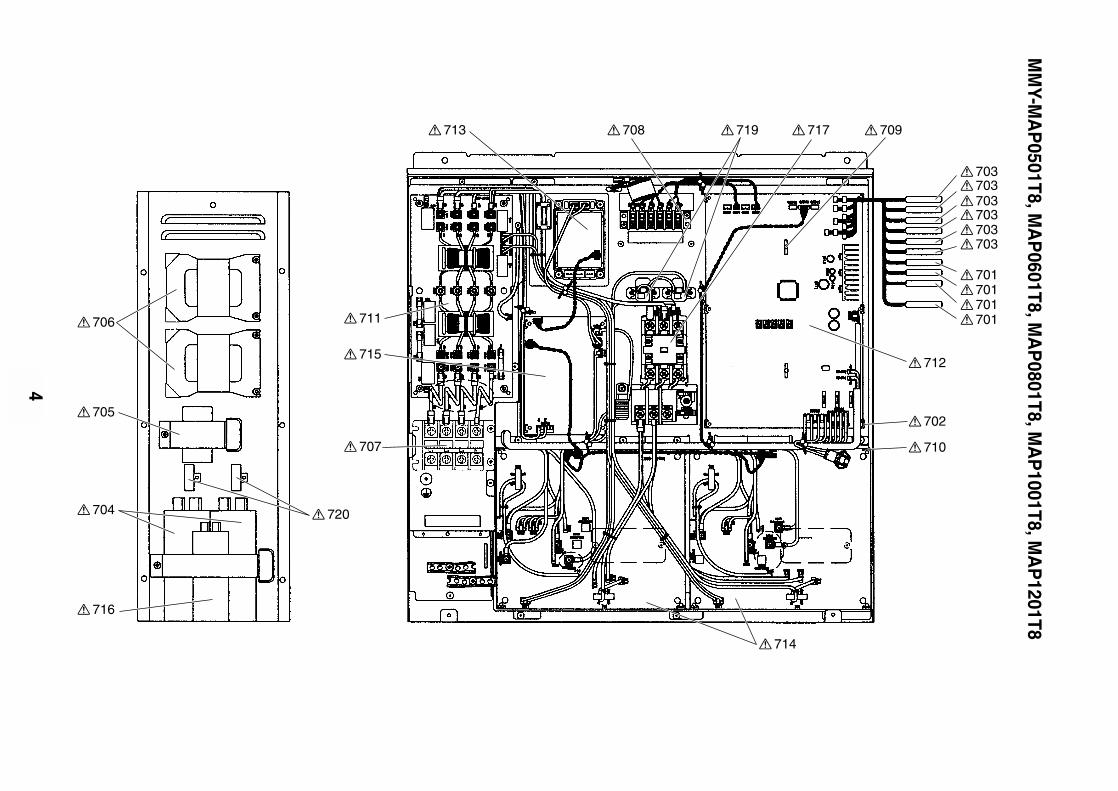
4
703703703703703703
701701701701
712
713 708 719 717 709
702
710
714
707
706
705
720704
716
715
711
MM
Y-MA
P0501T8, M
AP
0601T8, MA
P0801T8, M
AP
1001T8, MA
P1201T8
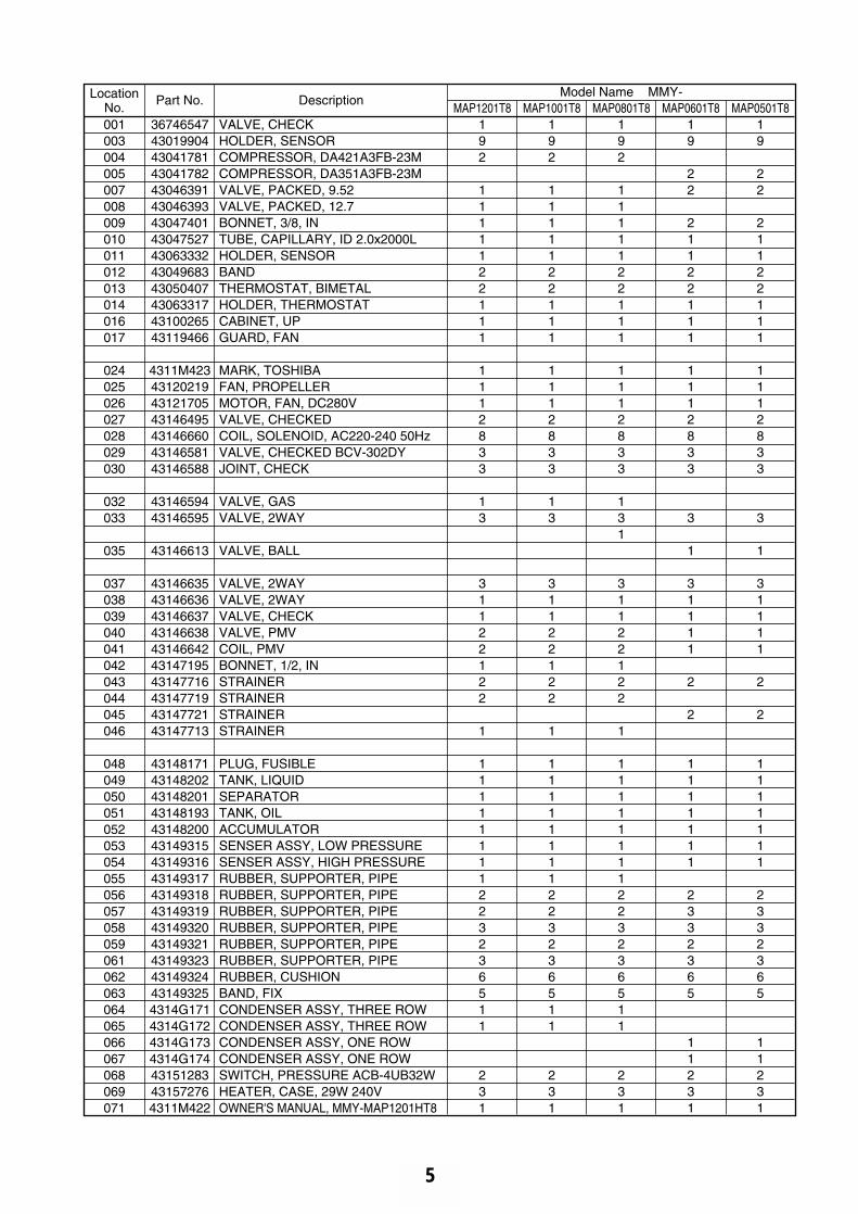
5
LocationNo.
Part No. Description
001003004005007008009010011012013014016017
024025026027028029030
032033
035
037038039040041042043044045046
048049050051052053054055056057058059061062063064065066067068069071
3674654743019904430417814304178243046391430463934304740143047527430633324304968343050407430633174310026543119466
4311M423431202194312170543146495431466604314658143146588
4314659443146595
43146613
43146635431466364314663743146638431466424314719543147716431477194314772143147713
4314817143148202431482014314819343148200431493154314931643149317431493184314931943149320431493214314932343149324431493254314G1714314G1724314G1734314G17443151283431572764311M422
192
1111122111
1112833
13
31122122
1
11111111223236511
231
192
1111122111
1112833
13
31122122
1
11111111223236511
231
192
1111122111
1112833
131
31122122
1
11111111223236511
231
19
22
21122111
1112833
3
1
31111
2
2
1111111
2332365
11231
19
22
21122111
1112833
3
1
31111
2
2
1111111
2332365
11231
VALVE, CHECKHOLDER, SENSORCOMPRESSOR, DA421A3FB-23MCOMPRESSOR, DA351A3FB-23MVALVE, PACKED, 9.52VALVE, PACKED, 12.7BONNET, 3/8, INTUBE, CAPILLARY, ID 2.0x2000LHOLDER, SENSORBANDTHERMOSTAT, BIMETALHOLDER, THERMOSTATCABINET, UPGUARD, FAN
MARK, TOSHIBAFAN, PROPELLERMOTOR, FAN, DC280VVALVE, CHECKEDCOIL, SOLENOID, AC220-240 50HzVALVE, CHECKED BCV-302DYJOINT, CHECK
VALVE, GASVALVE, 2WAY
VALVE, BALL
VALVE, 2WAYVALVE, 2WAYVALVE, CHECKVALVE, PMVCOIL, PMVBONNET, 1/2, INSTRAINERSTRAINERSTRAINERSTRAINER
PLUG, FUSIBLETANK, LIQUIDSEPARATORTANK, OILACCUMULATORSENSER ASSY, LOW PRESSURESENSER ASSY, HIGH PRESSURERUBBER, SUPPORTER, PIPERUBBER, SUPPORTER, PIPERUBBER, SUPPORTER, PIPERUBBER, SUPPORTER, PIPERUBBER, SUPPORTER, PIPERUBBER, SUPPORTER, PIPERUBBER, CUSHIONBAND, FIXCONDENSER ASSY, THREE ROWCONDENSER ASSY, THREE ROWCONDENSER ASSY, ONE ROWCONDENSER ASSY, ONE ROWSWITCH, PRESSURE ACB-4UB32WHEATER, CASE, 29W 240VOWNER'S MANUAL, MMY-MAP1201HT8
MAP1201T8Model Name MMY-
MAP1001T8 MAP0801T8 MAP0601T8 MAP0501T8
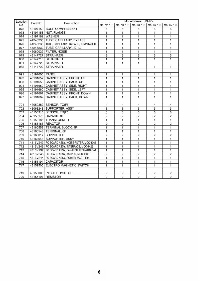
6
LocationNo.
Part No. DescriptionMAP1201T8
Model Name MMY-MAP1001T8 MAP0801T8 MAP0601T8 MAP0501T8
072073074075076077078079080081082
091092093094095096097
701702703704705706707708709710711712713714715716717
719720
4319715943197158431971624424623544246236442462394306002943147727431477184314772043147722
43191600431916574319165843191659431916604319166143191662
430503824306324843150315431551764315818643158183431605594316054843163017431630484316V2434316V2464316V2374316V2454316V2444315519443152506
4315300643155197
BOLT, COMPRESSORNUT, FLANGEWASHERTUBE, CAPILLARY, BYPASSTUBE, CAPILLARY, BYPASS, 1.0x2.0x2000LTUBE, CAPILLARY, ID 1.2FILTER, NOISESTRAINAERSTRAINAERSTRAINAERSTRAINAER
PANELCABINET ASSY, FRONT, UPCABINET ASSY, BACK, UPCABINET ASSY, SIDE, RIGHTCABINET ASSY, SIDE, LEFTCABINET ASSY, FRONT, DOWNCABINET ASSY, BACK, DOWN
SENSOR, TC(F6)SUPPORTER, ASSYSENSOR, TD(F6)CAPACITORTRANSFORMERREACTORTERMINAL BLOCK, 4PTERMINAL, 6PSUPPORTERSUPPORTER, ASSYPC BOARD ASSY, NOISE-FILTER, MCC-1366PC BOARD ASSY, INTERFACE, MCC-1429PC BOARD ASSY, FAN-IPDU, IPDU-2D16DA1PC BOARD ASSY, A3-IPDU, MCC-1502PC BOARD ASSY, POWER, MCC-1439CAPACITORELECTRO MAGNETIC SWITCH
PTC-THERMISTORRESISTOR
6111111311
1111111
43621211211112111
22
6111111311
1111111
43621211211112111
22
6111111311
1111111
43621211211112111
22
611111131
1
1111111
43621211211112111
22
611111131
1
1111111
43621211211112111
22