Service Booklet for the Engineer for Gas Condensing Boilers
52
Service Booklet for the Engineer for Gas Condensing Boilers 6 720 610 333-00.1R ZSBR 7-28 ICS1 GC-Number: 41 108 04 ZWBR 8-30 ICC2 GC-Number: 41 108 09 ZBR 8-35 ICS1 GC-Number: 41 108 05 ZWBR 11-37 ICC1 GC-Number: 41 108 10 ZWBR 7-28 HE plus GC-Number: 47 311 56 ZWBR 11-35 HE plus GC-Number: 47 311 57 7 181 465 347 (01.07) OSW
-
Upload
khangminh22 -
Category
Documents
-
view
1 -
download
0
Transcript of Service Booklet for the Engineer for Gas Condensing Boilers

Service Booklet for the Engineerfor Gas Condensing Boilers
ZSBR 7-28 ICS1 GC-Number: 41 108 04ZWBR 8-30 ICC2 GC-Number: 41 108 09ZBR 8-35 ICS1 GC-Number: 41 108 05ZWBR 11-37 ICC1 GC-Number: 41 108 10
ZWBR 7-28 HE plus GC-Number: 47 311 56ZWBR 11-35 HE plus GC-Number: 47 311 57
7 18
1 46
5 34
7 (0
1.07
) OS
W

7 181 465 347 (01.07)2
Contents
Contents
Safety precautions 3
Symbols 3
1 Layout of Appliance (ZSBR/ZWBR) 4
2 Operation 52.1 Standard display 52.2 Displaying service functions 52.3 Setting service functions 52.4 Resetting service functions to factory settings 52.4.1 Resetting service functions 0.0 to 4.9 to their
factory settings (Reset 1): 52.4.2 Resetting service functions 0.0 to 9.9 to the
factory setting (Reset 2): 5
3 Boiler service functions 63.1 Summary 63.2 Explanation of service functions 9
4 Rectifying faults 144.1 Boiler failure codes indication 144.1.1 ... on the boiler 144.1.2 ... on the programmer (optional accessory) 144.2 Summary 144.2.1 Appliance faults 144.2.2 Faults that are not indicated on any display 144.3 How to use the fault tables 164.4 Faults indicated on display 174.5 Faults that are not displayed 364.5.1 Appliance faults 364.5.2 Programmer faults 41
5 Appendix 455.1 NTC values 455.1.1 Outside temperature sensor 455.1.2 CH flow NTC sensor, heat store NTC
sensor, constant hot water NTC sensor and hot water NTC sensor 45
5.2 Electronic schemes 465.3 List of most important replacement parts 475.4 Approved corrosion inhibitors and
anti-freeze fluids for central heating water 485.5 Detecting corrosion by CFCs 49

7 181 465 347 (01.07)
Safety precautions
3
Safety precautions
RepairsB Repairs may only be carried out by an approved
installer!
B Before carrying out any work on the appliance, switch it off at the master switch!
B Even when the appliance is switched off at the mas-ter switch, some components on the PCB control board inside the control box are still live. Therefore:
B Before carrying out any work on the electrical parts of the appliance fully disconnect it from the power supply (e. g. by means of fuse or circuit breaker)!
B Flue ducting must not be modified in any way.
B Use only original spare parts!
Instructions to the customerB Advise the customer that he/she must not make any
modifications to the appliance or carry out any repairs on it.
B Draw attention to the need for an annual service (or maintenance contract if applicable).
Symbols
Signal words indicate the seriousness of the hazard in terms of the consequences of not following the safety instructions.
• Caution indicates that minor damage to property could result.
• Warning indicates that minor personal injury or seri-ous damage to property could result.
• Danger indicates that serious personal injury could result. In particularly serious cases, lives could be at risk.
Notes contain important information in cases where there is no risk of personal injury or damage to property.
Safety instructions in this document are identified by a warning-triangle sym-bol and are printed on a grey back-ground.
iNotes are identified by the symbol shown on the left. They are bordered by horizon-tal lines above and below the text

7 181 465 347 (01.07)4
Layout of Appliance (ZSBR/ZWBR)
1 Layout of Appliance (ZSBR/ZWBR)
Fan fixing screws
Burner fixing screws
Electrode assembly:Flame sensing electrodeIgnition electro-des
CH flow NTC sensor
CH flow safety temperature limiter
Variable-charac-teristic pump
Automatic vent
Gas flow restrictor: adju-sting screw for CO2 max.
Gas valve:adjusting screw for CO2 min.
Plate-type heat exchanger (ZWBR)
Hot water NTC sensor (ZWBR)
CH flow
Silencer
Fan
Fan connector
Mixer unit
Condensation trap
Gas supply pipe
Flue gas safety temperature limiter
Testing points:flue gasair
Inspection opening
Water switch(ZSBR)
Change-over valve motor
Change-over valve
Heatronic
Transformer

7 181 465 347 (01.07)
Operation
5
2 Operation
Instructions on the use of the text display module are given in the operating and installation instructions for the boiler.
Fig. 1 Controlsa Displayb “Up” or “More” buttonc “Down”, or “Less” buttond “Back” buttone “Nest” buttonf “Delete” button
2.1 Standard display
The text display shows the time, the CH flow tempera-ture and the measured outside temperature in plain English.
In addition, the 2-digit display also shows the current CH flow temperature in Heating mode and Hot Water mode (display range 00 °C to 99 °C).
2.2 Displaying service functions
B Press any button to activate the main menu.
B Press or button until the arrow cursor is pointing to Settings.
B Press the button.
B Press or button until the arrow cursor is pointing to Service .
B Press the button.
B Press button to select Display service parameters.Service function 0.0, Last fault is displayed.
B Press or button to cycle through the current settings.
B Press button to exit the menu.
2.3 Setting service functions
B Press any button to activate the main menu.
B Taste or button until the arrow cursor is pointing to Settings.
B Press the button.
B Press or button until the arrow cursor is pointing to Service.
B Press the button.The cursor is pointing to Display service parameters.
B Press and hold the button (for about 5 sec-onds) until the display shows shows Adjust service parameters and the first service function to be set, e.g. 2.0, Operating mode. If a fault has occurred, the display will show 0.0 and the last fault.
B Press or button until the desired service function is displayed.
B Press the button.The first line of the display shows Change value.
B Use the and buttons to enter the required setting.
B Press the button.The text display shows ATTENTION Store set-tings?.
B Press or to select yes or no.
B Press to confirm your selection.The text display shows Please wait ..., and the serv-ice function is then displayed with the new setting.
B Press the or button until the next func-tion you wish to change is displayed.
-or-B Press the button to exit the menu.
2.4 Resetting service functions to fac-tory settings
2.4.1 Resetting service functions 0.0 to 4.9 to their factory settings (Reset 1):
B Power OFF the appliance.
B Press the button and keep it pressed.
B Switch on the appliance, press and hold the but-ton until thedisplay shows r1 followed by [ ] .
2.4.2 Resetting service functions 0.0 to 9.9 to the factory setting (Reset 2):
B Power OFF the appliance.
B Simultaneously press and hold buttons and .
B Switch on appliance, press and hold the and buttons until the display shows r2 followed by [ ] .
iTo reset all parameters (except service settings) set on the text display module):
B Press and hold the button until the settings are deleted.

7 181 465 347 (01.07)6
Boiler service functions
3 Boiler service functions
3.1 Summary
Text display message DisplayRange adjustable from - to
Reset Value
0.0 Last fault 00 - FF Clear only 0
0.1 Flow temp. sensor 0 - 99 °C - -
0.2 Hot water temp. sensor 0 - 99 °C - -
0.3 Stor. tank temp. sensor1 0 - 99 °C - -
0.4 Stor. tank temp. sensor2 0 - 99 °C - -
1.2 Code plug 8714411 XXX 0 - 255 - -
1.5 Required flow temp. 0 - 99 °C - -
1.9 Module detection no module detectedbus module
- -
2.0 Operating mode - normalMinMax
normal
2.2 Pump switch mode - 1 - 3 2
2.3 Stor. tank charge output - 0 - 100% 100 %
2.4 Anti-cycle mode - 0 - 15 min 3 min
2.5 Max. flow temperature - 35 - 88 °C 88 °C
2.6 Switch.diff.flow temperature - 0 - 30 °C 0 °C
2.7 Autom. anti-cycle mode - onoff
on
2.9 Actual output 0 - 100 % - -
3.0 Fan speed 0 - 255 U/s - -
3.3 Ionisations current nolowmiddlehigh
- -
3.4 Pump mode - 0 - 3 01)
3.5 Pump blocking time - 0 - 240 sin 15-s increments
0 s
3.6 Software version BF 11.XX - -
Table 1

7 181 465 347 (01.07)
Boiler service functions
7
3.9 Link 8 - 9 openclosed
- -
Link Ls-Lr openclosed
- -
4.0 Stor. tank. therm.. (7-9) blockedheat demand
- -
4.1 Room therm. LSM blockedheat demand
- -
LSM release blockedheat demand
- -
4.2 Timer ch. 1 (heating) blockedheat demand
- -
Timer ch. 2 (hot wat.) blockedheat demand
- -
4.4 Heat demand (heating). yesno
- -
Heat demand (stor. tank). yesno
- -
4.5 Heat demand (hot water). yesno
- -
Keep hot period yesno
- -
4.6 Internal regulator blockedheat demand
- -
5.0 Max. output (heating) - 27 - 100% 100 %
5.1 Permanent ignition - noyes
no
5.2 GFA status / error 00h - FFh - -
5.5 Min. output - 27 - 100 % 27 %
5.8 Cyclic boiler starts - onoff
on
5.9 Fan speed (start) - lowhigh
low
6.7 Pump off (hot water). - offon
off
Text display message DisplayRange adjustable from - to
Reset Value
Table 1

7 181 465 347 (01.07)8
Boiler service functions
6.8 Cycle time (hot water) - 0 - 60 min 0 min
6.9 Duration (hot water) - 0 - 30 min 1 min
7.0 Pump map (heating) - 0 Pump step adjustable1 Const. pressure high2 Const. pressure middle3 Const. pressure low4 Prop.pressure high5 Prop.pressure low
4 Prop. pres-sure high
7.1 Map pump step (heat.). - 2 - 7 7
7.2 Antiblock. map pump. - offon
on
7.3 Air purge mode - offon autom. deaktivat.permanent on
on autom. deaktivat./ off
7.4 Actual map pump step 1 - 8 - -
7.5 Map pump load index 0 ... 255 - -
7.6 Map pump type 0 .. 99 - -
7.7 Output reduction - off only in heating modeonly in hot water modein heat./hot water mode.
only in heating mode
8.5 Siphonfillprogram - on, boiler min.output,on, adjust. min output,off
on, boiler min.output
9.2 Hot water on demand - offon
on
9.3 GFA-Asic-error 00h - FFh - -
1) The reset value depends on the code plug.
Text display message DisplayRange adjustable from - to
Reset Value
Table 1

7 181 465 347 (01.07)
Boiler service functions
9
3.2 Explanation of service functions
0.0 Last fault
The last fault can also be recalled for servicing pur-poses when the appliance is functioning correctly.
To delete the stored fault:
B Delete fault (no fault displayed).
B Press the button.
B Use the or button to select yes.
B Press the button.
If a list of the last 10 indicated faults is required for serv-icing purposes, look under Settings -> Service -> Fur-ther options -> Fault history.
0.1 Flow NTC
The temperature measured by the NTC sensor on the CH flow pipe is indicated.
0.2 Hot water NTC
The temperature measured by the NTC sensor on the plate-type heat exchanger outflow is indicated.
0.3 Storage tank NTC 1
Indirectly heated heat store (SO..., SK..., ST...):The temperature measured by NTC sensor 1 in the heat store is indicated.
Stratified-charge tank (ST...S):The temperature measured by NTC sensor 2 at the bot-tom of the heat store is indicated.
0.4 Storage tank NTC 2
Stratified-charge tank (ST...S):The temperature measured by NTC sensor 2 at the top of the heat store is indicated.
1.2 Code plug
The 10-digit part number of the code plug is indicated.
The code plug determines the appliance functions. If the appliance is converted from natural gas to LPG or vice versa (using conversion kit) the code plug also has to be changed.
1.5 Desired flow temp.
The CH flow temperature demanded by the text display module or a programmer connected to the bus module is displayed.
1.9 Module detection
The text display module shows the modules detected by the appliance.
2.0 Operating mode
There are 3 operating modes to choose from.
• Normal mode: the appliance operates according to the commands received from the programmer.
• Min mode: the appliance runs constantly at minimum output.The text display shows MIn mode. The 2-digit dis-play alternates between the CH flow temperature and – – .
• Max mode: the appliance runs constantly at maxi-mum output.The text display shows Max mode. The 2-digit dis-play alternates between the CH flow temperature and – –.
2.3 Stor. tank charge outp
The heat store charging output can be set to any level between the minimum and maximum rated heat output for hot water according to the heat transfer capacity of the heat store.
B Enter the heat store charging output setting on the commissioning record enclosed with the appliance.
2.4 Anti-cycle mode
This function is only active if service function 2.7 Auto-matic anti-cycle mode is disabled.
The anti-cycle time is factory set to 3 minutes.
The shortest possible period is 1 minute (recom-mended for single-pipe and hot-air heating systems).
The setting 0 means that the anti-cycle time is disabled.
B Enter the anti-cycle time on the commissioning record enclosed with the appliance.
2.5 Max. flow temperature
The maximum CH flow temperature can be set to between 35 °C and 88 °C (factory setting).
2.6 Switch diff. flow NTC
The switching difference is the permissible deviation from the specified CH flow temperature. It can be set in increments of 1 K. The adjustment range is from 0 to 30 K (factory setting: 0 K). The minimum CH flow tem-perature is 30 °C.
B Disable anti-cycle time (setting 0).
B The switching difference setting should be entered on the commissioning record supplied with the appli-ance.
iIf an outside-temperature controlled heat-ing programmer is used, no setting is re-quired.The anti-cycle time is optimised by the programmer.
iIf an outside-temperature controlled heat-ing programmer is used, no setting is re-quired on the appliance.

7 181 465 347 (01.07)10
Boiler service functions
2.7 Autom. anti-cycle mode
If an outside-temperature controlled programmer is con-nected to the appliance, the anti-cycle time is adjusted automatically.
Automatic adjustment of the anti-cycle time can be dis-abled. This may be necessary in the case of unfavoura-bly dimensioned heating systems.
If automatic adjustment of the anti-cycle time is disa-bled, the length of the anti-cycle time must be set under service function 2.4.
B If automatic adjustment of the anti-cycle time has been disabled, this should be entered on the com-missioning record enclosed with the appliance.
2.9 Actual output
The actual output of the appliance at the time viewed is displayed.
3.0 Fan speed
The current fan speed is displayed.
3.3 Ionisation current
The burner flame is monitored by measuring the ionisa-tion current generated during combustion. If no ionisa-tion current is detected, the gas valve shuts off. This ensures that unburned gas does not escape.
3.4 Pump mode (ZBR.. models only)
The possible settings are:
• Pump mode 1: if a heating pump and a 3-way valve for charging the heat store are connected.The 3-way valve is de-energised when the heat store circuit is open.
• Pump mode 2 (factory setting): if a circulation pump and a heat store charging pump are con-nected. In ECO mode, if the circulation pump and the heat store charging pump call for heat simultane-ously, the system alternates between 12 minutes heating and 12 minutes hot water.
• Pump mode 3: if a circulation pump and a heat store charging pump are connected. In ECO mode, if the circulation pump and the heat store charging pump call for heat at the same time, both pumps run simul-taneously. The heat store charging temperature has priority (up to 85 °C). The hydraulic configuration must be matched to this pump mode (use of a mixer unit and hydraulic balancing).
B The pump mode setting should be entered on the commissioning record enclosed with the appliance.
3.5 Pump blocking time (ZBR.. models only)
If the system incorporates a 3-way valve external to the appliance, the heating pump is disabled while the 3-way valve is being actuated. therefore, the blocking time of the heating pump should be ≥ the actuation time of the 3-way valve.The blocking time has an adjustment range of 0 to 16, with each increment equivalent to 15 seconds. The adjustment range therefore equates to 0 to 240 sec-onds.
Factory setting is 30 seconds.
B Enter the pump blocking time on the commissioning record enclosed with the appliance.
3.6 Software version
The version number of the software is displayed.
3.9 Jumper 8 - 9 / 3.9 Jumper Ls - Lr
When supplied, the appliance has a jumper fitted across terminals 8-9 (= Heat demand). If that connec-tion is opened (e.g. by a limiter for an underfloor heating system), heating mode is disabled.
When supplied, the appliance has a jumper fitted across terminals Ls-Lr (= Heat demand). If that connec-tion is opened (e.g. by an external 2-point programmer), heating mode is disabled.
4.0 Stor. tank therm. (7 - 9)
When supplied, the appliance has no jumper across ter-minals 7- 9 (= Disabled). If that connection is closed (e.g. by a heat store thermostat) heat store charging is enabled.
4.1 Room therm. LSM/ 4.1 LSM release
When supplied, a jumper is fitted across terminals LZ - L1 on the LSM (= Heat demand). If that connection is opened (e.g. by a connected room thermostat), heating mode is disabled.
LSM release shows the total number of all possible ena-ble signals connected via the LSM. As soon as a mod-ule connected to it (e.g. mechanical limiter for underfloor heating, limit switch on flue flap, combustion air flap, etc.) shuts off, heating and hot water modes are disabled.
4.2 Timer ch. 1 (heating)/ 4.2 Timer ch. 2(hot water)
Shows the status of channel 1 of the timer integrated in the text display module or the separate programmer.If that channel’s status is “Heat demand”, heating mode will be activated according to the programmer com-mands.
iOnly applies if service function 3.4, Pump mode, is set to Pump mode 1 (external 3-way valve for heat store charging is con-nected). Otherwise has no function.

7 181 465 347 (01.07)
Boiler service functions
11
Shows the status of channel 2 of the timer integrated in the text display module or the separate programmer.If that channel’s status is “Heat demand”, hot water mode will be activated according to the programmer commands.
4.4 Heat demand (heating)/Heat demand (stor. tank) (ZSBR.. only)
Heat demand (heating) shows the heat demand status for the central heating system.
If this channel’s status is “Heat demand”, heating mode will be activated according to the programmer com-mands.
Heat demand (stor. tank) shows the heat demand sta-tus for charging the heat store.
If this channel’s status is “Heat demand”, the heat store will be charged according to the commands from the heat store thermostat or NTC sensor.
4.5 Heat demand (hot water)/ Keep hot period (ZWBR... models only)
Heat demand (hot water) shows the heat demand sta-tus for the hot water function.If this channel’s status is “Heat demand”, the hot water function operates according to the commands from the hot water NTC sensor.
Keep hot period shows the constant hot water circuit status of the heat exchanger (ECO or Comfort mode). If this channel’s status is “Heat demand”, Comfort mode is active. If the status is “Disabled”, ECO mode with demand detection is active.
4.6 Internal regulator
The boiler has an internal anti-cycle function which pre-vents the burner overheating if the heat output can not be dissipated even in Min mode. The appliance will then switch off even when the system is calling for heat.
It will subsequently switch on again
• after 5 seconds in hot water mode
• after 30 seconds in heat store charging mode
• after 0 to 15 minutes in heating mode (depending on the setting for service function 2.4 Anti-cycle mode).
The anti-cycle function is cancelled by
• switching the appliance off and on again at the mas-ter switch,
• another demand for heat,
• activating Min or Max mode
• or briefly switching to summer mode on the tempera-ture control for CH flow.
5.0 Max. output (heating)
Some gas suppliers demand an output-dependent basic charge.
The heating output can be limited to any level between the min. rated heat output and the max. rated heat out-put to suit the specific heat requirements.
The factory setting is maximum rated output – display shows “100 %”.
5.1 Permanent ignition
This function allows permanent ignition without gas supply to be activated for the purposes of checking the ignition mechanism.
5.2 GFA status/error
The status of the automatic ignition module integrated in the PCB control board is indicated.
5.5 Min. output
The min. heat input is factory set, see technical data.The modulation range can be extended at the top end to suit the chimney conditions.
B Refer to settings table for heating and heat store charging output for details of the min. heat output in kW and the corresponding percentage (see installa-tion instructions for boiler).
B Enter percentage on text display module and confirm.
B Measure gas flow rate and compare with the figures quoted for the percentage shown. If different, correct the percentage figure!
B Enter min. rated heat output on the commissioning record enclosed with the appliance.
5.8 Cyclic boiler starts (ZSBR 3/5-16 A... only)
When supplied, this function is activated on the above appliances and prevents start-up problems caused by poor ignition characteristics.
A truncated start cycle is activated if the burner has not been in operation for more than 3 hours.
During a truncated start cycle, the fan runs and the gas valve is opened long enough to completely fill the gas pipe with gas (approx. 1 - 2 seconds) but the burner is not ignited.
This function is not required, and can not be activated, on any other models.
6.7 Pump off (hot water)
The appliance is supplied with this function activated, i.e. there is a delay before the pump switches on in hot water mode. This means that cold water comes out of the pipe to begin with, followed by hot water once the pump switches on.
If the pump is set to switch on immediately (Pump off function deactivated), the hot water temperature rises gradually until the set temperature is reached.
iEven if the heating output is limited, the full rated heat output remains available for hot water or heat store charging.

7 181 465 347 (01.07)12
Boiler service functions
If a stratified-charge tank is connected, it is useful to have the function activated.
The delayed cut-in of the pump then prevents cold water being pumped through the tank and cooling it down.
6.8 Cycle time (hot water) (ZWBR... only)
The appliance is supplied with the hot water cycle time set to 3 minutes.
The hot water cycle time specifies how long after hot water is drawn the pump continues to pump water through the internal hot water system.
6.9 Duration (hot water) (ZWBR... only)
The appliance is supplied with the hot water duration set to 3 minutes.
The hot water duration specifies how long after hot water is drawn heating mode remains disabled.
7.0 Pump map (heating) (not ZBR...)
The appliance is supplied with this function set to “4 Prop. pressure high”(see pump characteristic in boiler installation instructions).
The pump map indicates how the pump is controlled in heating mode. The pump switches between the various pump speeds so as to reproduce the characteristic curve selected. (The current setting can be viewed by means of service function 7.4.)
Changing the pump characteristic can be helpful if a lower pressure difference will guarantee the necessary circulation on the basis of the system dimensions and pump characteristic (see installation instructions).
If this parameter is set to “0 Pump step adjustable”, then the pump speed set under function 7.1 is active.
7.1 Map pump step (heat.) (not ZBR...)
The appliance is supplied with this function set to 1 (see pump characteristic in boiler installation instructions). However, the setting is only active if function 7.0, Pump map (heating), is set to “0 Pump step adjustable”.
This service function corresponds to the pump speed switch used on conventional heating pumps.
7.2 Antiblock. map pump (not ZBR...)
The appliance is supplied with this function activated.
If the pump threatens to jam, an oscillating pump action is activated. Afterwards, the required operating mode is continued.
7.3 Aeration mode (not ZBR...)
The first time the appliance is switched on, a once-only venting function is activated. The heating pump then switches on and off at intervals. This sequence lasts about 8 minutes and the text display shows “Aeration mode”. The 2-digit display shows “o
o” in alternation with the CH flow temperature. The automatic vent must be opened and then closed again once the venting sequence is complete.
• If the venting function is set to “On, autom. deacti-vat.”, once the sequence has been completed.
7.4 Actual map pump step (not ZBR...)
The currently active pump speed is displayed (see func-tion 7.0).
7.5 Map pump load index (not ZBR...)
The load index is displayed.
7.6 Map pump type (not ZBR...)
The pump type code of the pump fitted is displayed.
7.7 Output reduction
The appliance is supplied with this function activated. It prevents overload of the heat exchanger with high CH flow temperatures.
The output of the burner is reduced according to the CH flow temperature, i.e. up to 80 °C flow temperature, full burner output is permitted. Above 80 °C, the burner output is reduced as flow temperature increases up to 90 °C at which only minimum output is available (even with maximum heat demand).
This function can be deactivated for hot water and/or central heating mode.
iIn order to save as much energy as possi-ble and to minimise the possibility of water circulation noise, a low characteristic should be chosen.
iThe venting function can be activated manually after servicing.

7 181 465 347 (01.07)
Boiler service functions
13
8.5 Siphon fill program
The trap filling programme ensures that the condensa-tion trap is filled when the appliance is first installed or after it has been shut down for a long period: The con-densation trap prevents flue gas escaping from the appliance into the room in which it is installed.
The trap filling programme is activated:
• the appliance is switched on at the master switch
• the burner has not been in operation for at least 48 hours
• the appliance is switched from summer to winter mode.
The next time the heating or hot water system calls for heat, the appliance is held at minimum output for 15 minutes. The trap filling programme remains active until the appliance has completed 15 minutes of operation at minimum output.The text display shows “Siphon fill program” and the 2-digit display alternates between „-II-“ and the CH flow temperature.
The factory setting is „1“ (activated).
9.2 Hot water on demand
The appliance is supplied with this function activated.
This function relates to mode, the button lights up.
The demand detection function enables maximum gas and water economy. Briefly turning a hot water tap on and then off again sig-nals demand to the appliance which then heats up the water to the set temperature.Hot water is then available at short notice.
9.3 GFA-Asic error (automatic ignition module, extended messages)
The status of, or an error message from the automatic ignition module integrated in the PCB control board is displayed.
Warning: if the condensation trap is not filled, flue gas can escape!
B Only deactivate the trap filling program-me in order to carry out servicing work.
B Always re-activate trap filling program-me once servicing is complete.

7 181 465 347 (01.07)14
Rectifying faults
4 Rectifying faults
4.1 Boiler failure codes indication
4.1.1 ... on the boiler
In order to identify the specific boiler failure a two digit alphanumeric code is used. This allows a quick fault identification and solution.
The text display shows the message Fault EA. Please call service, for example. At the same time, the fault code appears on the 2-digit display, in this example: EA.
You can view an explanatory description of the fault indi-cated by going to Settings -> Service -> Service parameters, in this example: EA: During operation: Flame not detected.
The failures can be divided into four basic typologies, as described:
• The appliance continues to work at a minimum func-tion level (e. g. with error codes A5, A7, A8, AC, Ad, CC, FC).
• The appliance is locked until the failure is repaired (e. g. with error codes (b1, C1, d1, d3, E2, F0)).
• The appliance is locked, until the ON/OFF switch is turned (A1).
• The boiler has shut down and locked out ( flashes) and remains so until the cause of the fault has been eliminated and the lock-out cancelled (e.g. E9, EA, F0, F7, FA,Fd).
4.1.2 ... on the programmer (optional accessory)
A TW 2 remote control unit can also be connected to the text display module.
If other/more functions are required, another program-mer must be connected. Those programmers are then controlled via the bus module BM1.
For more detailed information, refer to the installation instructions for the boiler and the installed programmer.
Faults on this programmer are indicated by text mes-sages on the programmer display.
Once the fault has been put right, the programmer reverts to its normal display.
4.2 Summary
4.2.1 Appliance faults
4.2.2 Faults that are not indicated on any dis-play
iTo unblock the appliance:
B Press the unblock button until the digit – – appears on the display.Once the appliance starts up success-fully, the fault disappears from the text display.
Appliance faults ZB
R ..
. A
ZS
BR
... A
ZW
BR
...A
Pag
e
A1 X X 17
A5 X 18
A7 X X X 19
A8 X X X 20
Ad X X X 21
b1 X X X 22
C1 X X X 23
d3 X X X 24
E2 X X X 25
E9 X X X 26
EA X X X 28
F0 X X X 32
F7 X X X 33
FA X X X 34
FC X X X 35
Fd X X X 35
Table 2
Appliance faults ZBR
... A
ZSB
R ..
. A
ZWB
R ..
.A
Pag
e
Excessive burner noise, rum-bling noises
X X X 36
Flue gas levels incorrect, CO level too high
X X X 37
Ignition too harsh, ignition poor
X X X 38
Boiler indicates P1, P2, P3 at start-up and then restarts with P1, ...
X X X 36
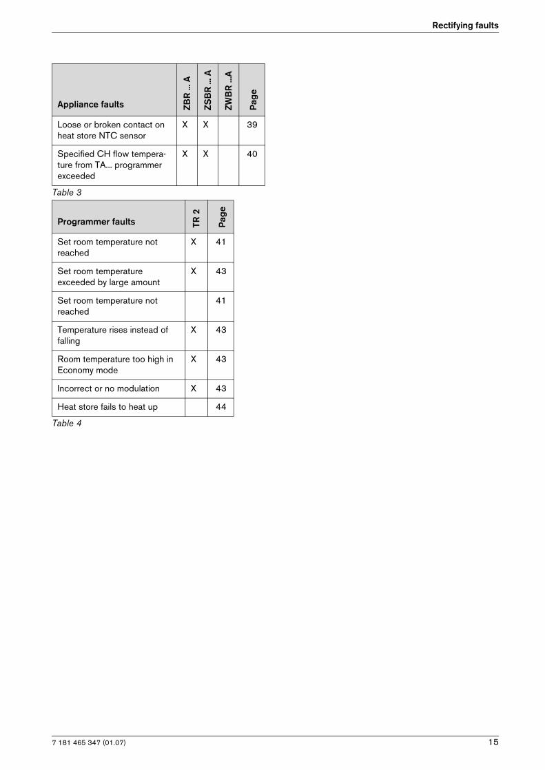
Table 3
7 181 465 347 (01.07)
Rectifying faults
15
Loose or broken contact on heat store NTC sensor
X X 39
Specified CH flow tempera-ture from TA... programmer exceeded
X X 40
Programmer faults TR 2
Pag
e
Set room temperature not reached
X 41
Set room temperature exceeded by large amount
X 43
Set room temperature not reached
41
Temperature rises instead of falling
X 43
Room temperature too high in Economy mode
X 43
Incorrect or no modulation X 43
Heat store fails to heat up 44
Table 4
Appliance faults ZBR
... A
ZSB
R ..
. A
ZWB
R ..
.A
Pag
e
Table 3

7 181 465 347 (01.07)16
Rectifying faults
4.3 How to use the fault tables
The procedure is explained using the fault code EA as an example:
The table heading shows the fault code and a general description of the fault.
In the example shown, you are instructed to note the current settings before going any further. If you can see the flame (answer to question is “yes”) you move on to Step 5. (↓ 5.). The question asked in Step 5 is “Is there a problem with the flue”. The flue must then be checked.
If the answer to the first question (“Is burner flame visi-ble?”) was“no””, then you go to and answer Question 2, “Is the gas cock turned on?”. If the gas cock is turned off, it must be turned on and the appliance reset. To do so, you press the button. Restart the appliance and run through a complete heat-demand cycle until the appliance switches off.
If the fault is now cured, the appliance will revert to nor-mal operation and the fault-finding process is complete. Now simply re-check the setting of the two temperature controls.
If the fault EA recurs during the heat-demand cycle, it will be shown on the display again. In that case continue the fault finding procedure from Step 3 (thermal cut-out in gas cock) as described above.
If a different fault code is displayed after the heat-demand cycle, find the appropriate section of the fault finding table and work through the procedure described step by step.
EA and flashing.
Flame not detected
Check Action
1. Is burner flame visible? yes: ↓5.
no: ↓2.
2. Is the gas cock turned on? yes: ↓3.
no: B Turn on the gas cock.
B Press , does appliance restart???
EA? ↓3.
3. Did the thermal security of the gascock lock out?
yes: B ...
no: ↓ ...
4. ...
5. Is there a problem with the flue?
B Check CO2 level in combustion air.> 0,2 % CO2?
yes: B Check the flue.
no: ↓ ....
... ...

7 181 465 347 (01.07)
Rectifying faults
17
4.4 Faults indicated on display
A1 flashing.
Controlled-characteristic pump has run dry
Check Action
1. System pressure below 1.2 bar? yes: B Power OFF the appliance.
B Check appliance and system for water leaks and repair as necessary.
B Top up system.
B Turn ON the appliance.
A1? ↓2.
no: ↓2.
2. Activate venting sequence. B Activate menu option Show service parameters.
B Select 7.3 Aeration mode select setting On, autom. deactivat. and confirm.
B Vent appliance1).
B Vent radiators.
↓3.
1) See installation instructions
3. Audible bearing damage on pump? yes: B Power OFF the appliance.
B Drain appliance.
B Replace pump.
B Top up system.
B Turn ON the appliance.

7 181 465 347 (01.07)18
Rectifying faults
A5 flashing.
Heat store NTC sensor 2 defective
Check Action
1. B Activate menu option Show service parameters.
B Select .4 Stor.tank temp.sensor2 .Is a temperature between 0. and 5. displayed?
yes: B Is the connector for heat store NTC sensor 2 cor-roded1), damaged or dirty? Replace affected components.
↓2.
1) For notes, refer to Appendix.
no: ↓3.
2. B Disconnect connector for heat store NTC sensor 2.
B Short-circuit the 2-pin connector on the end of the 20-pin connector lead assembly.After max. 60 sec:Display changes to temperature between 100. and 95.?
yes: B Power OFF the appliance.
B Change heat store NTC sensor 2.
B Plug the connection wire.
B Turn ON the appliance.
A7? ↓3.
no: B Change the 20-pin connector lead assembly.
↓3.
3. Temperature between 95. and 100. is displayed.
B Unplug the connector.After max. 60 sec.:Does the displayed code change to a value between 0. and 5.?
yes: B Power OFF the appliance.
B Change heat store NTC sensor 2.
B Plug the connection wire.
B Turn ON the appliance.
A7? ↓4.
no: ↓4.
4. B Unplug the 20-pin connector lead assembly from the Heatronic.After max. 60 sec.:Does the displayed code change to a value between 0. and 5.?
yes: B Change the 20-pin connector lead assembly.
no: B Power OFF the appliance.
B Disconnect the boiler electrical connection.
B Change PCB control board.
B Reconnect the boiler electrical connection.
B Turn ON the appliance.

7 181 465 347 (01.07)
Rectifying faults
19
A7 flashing.
Hot water NTC sensor defective
Check Action
1. B Activate menu option Show service parameters.
B Select.2 Hot water temp.sensor .Is a temperature between 0. and 5. displayed?
yes: B Is the connector for hot water NTC sensor corro-ded1), damaged or dirty? Replace affected com-ponents.
↓2.
1) For notes, refer to Appendix.
no: ↓3.
2. B Disconnect connector for hot water NTC sensor.
B Short-circuit the 2-pin connector on the end of the 20-pin connector lead assembly.Display changes to temperature between 100. and 95.?
yes: B Power OFF the appliance.
B Change hot water NTC sensor.
B Plug the connection wire.
B Turn ON the appliance.
A7? ↓3.
no: B Change the 20-pin connector lead assembly.
↓3.
3. Temperature between 95. and 100. is displayed.
B Unplug the connector.After max. 60 sec.:Does the displayed code change to a value between 0. and 5.?
yes: B Power OFF the appliance.
B Change hot water NTC sensor.
B Plug the connection wire.
B Turn ON the appliance.
A7? ↓4.
no: ↓4.
4. B Unplug the 20-pin connector lead assembly from the Heatronic.After max. 60 sec.:Does the displayed code change to a value between 0. and 5.?
yes: B Change the 20-pin connector lead assembly.
no: B Power OFF the appliance.
B Disconnect the boiler electrical connection.
B Change PCB control board.
B Reconnect the boiler electrical connection.
B Turn ON the appliance.

7 181 465 347 (01.07)20
Rectifying faults
A8 flashing.
No correct electrical connection
Check Action
1. Mode selector switch is between two settings
B Turn switch until it clicks into position.
A8? ↓2.
2. B Power OFF the appliance.
Wiring between TR 2 and text-display OK?
• Terminal 3 on TR 2 connected to Terminal 3 on textdisplay ?
• Terminal 4 ... Terminal 4 ....
etc.
yes: B Turn ON the appliance.
↓3.
no: B Rewire correctly as specified in the installation instructions.
B Turn ON the appliance.
after 90 sek.:A8? ↓3.
3. Lead(s) defective. B Check leads for continuity and replace as necessary.
A8? ↓4.
4. TR 2 defective. B Power OFF the appliance.
B Change TR 2 .
B Turn ON the appliance.

7 181 465 347 (01.07)
Rectifying faults
21
Ad flashing.
Heat store NTC sensor 1 not detected
Check Action
1. Is lead for heat store NTC sensor correctly routed, i.e. not through cable clamp?
yes: ↓2.
no: B Route connecting lead for heat store tempera-ture sensor as specified in installation instruc-tions.
2. B Activate menu option Show service parameters.
B Select.3 Stor.tank temp.sensor1 .Is a temperature between 0. and 5. displayed?
yes: Connector on end of NTC sensor lead:
B Flue gas connector corroded1), damaged or dirty? Change relative parts.
B Press button .
Ad? ↓3.
1)
no: ↓4.
3. Heat store -NTC 1:
B Unplug connector from PCB con-trol board.
B Short circuit the connector using wire jumper.After max. 60 sec:Display changes to temperature between 100. and 95.
yes: B Replace heat store NTC sensor 1.
no: B Power OFF the appliance.
B Disconnect the boiler electrical connection.
B Change PCB control board.
B Reconnect the boiler electrical connection.
B Turn ON the appliance.
4. Temperature between 95. and 100. is displayed.
B Unplug the connector.After max. 60 sec.:Does the displayed code change to a value between 0. and 5.?
yes: B Replace heat store NTC sensor 1.
no: B Power OFF the appliance.
B Disconnect the boiler electrical connection.
B Change PCB control board.
B Reconnect the boiler electrical connection.
B Turn ON the appliance.
7 181 465 347 (01.07)22
Rectifying faults
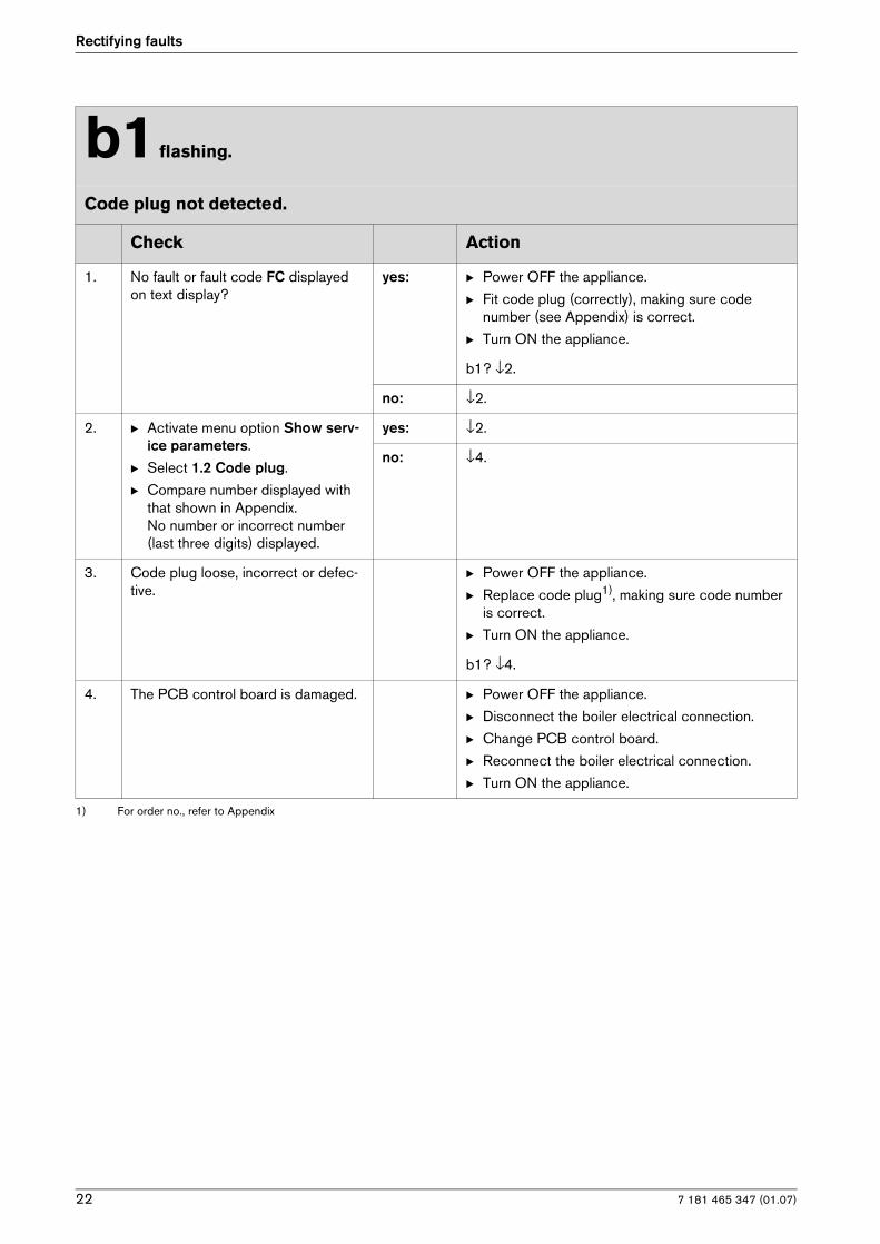
b1 flashing.
Code plug not detected.
Check Action
1. No fault or fault code FC displayed on text display?
yes: B Power OFF the appliance.
B Fit code plug (correctly), making sure code number (see Appendix) is correct.
B Turn ON the appliance.
b1? ↓2.
no: ↓2.
2. B Activate menu option Show serv-ice parameters.
B Select 1.2 Code plug.
B Compare number displayed with that shown in Appendix.No number or incorrect number (last three digits) displayed.
yes: ↓2.
no: ↓4.
3. Code plug loose, incorrect or defec-tive.
B Power OFF the appliance.
B Replace code plug1), making sure code number is correct.
B Turn ON the appliance.
b1? ↓4.
1) For order no., refer to Appendix
4. The PCB control board is damaged. B Power OFF the appliance.
B Disconnect the boiler electrical connection.
B Change PCB control board.
B Reconnect the boiler electrical connection.
B Turn ON the appliance.

7 181 465 347 (01.07)
Rectifying faults
23
C1 flashing.
Fan speed too low
Check Action
1. Fan lead connector properly con-nected?
yes: ↓2.
no: B Power OFF the appliance.
B Plug in connector.
B Turn ON the appliance.
C6? ↓2.
2. Fan lead defective? yes: B Power OFF the appliance.
B Replace fan lead.
B Turn ON the appliance.
C6? ↓3.
no: ↓3.
3. Fan defective? yes: B Power OFF the appliance.
B Plug the connection wire.
B Replace fan.
B Plug the connection wire.
B Turn ON the appliance.
C6? ↓4.
no: ↓4.
4. The PCB control board is damaged. B Power OFF the appliance.
B Disconnect the boiler electrical connection.
B Change PCB control board.
B Reconnect the boiler electrical connection.
B Turn ON the appliance.

7 181 465 347 (01.07)24
Rectifying faults
d3 flashing.
Wrong signal from pin 8-9.
Check Action
1. Jumper 8 - 9 fitted correctly? yes: ↓2.
no: B Power OFF the appliance.
B Fit jumper 8 - 9 correctly, tighten screw.
B Turn ON the appliance.
d3? ↓2.
2. B Turn ON the appliance.
B Measure voltage between Termi-nal 4 and Terminal 8.
24 V DC?
yes: ↓3.
no: ↓5.
3. Heat store NTC sensor connected to terminals 7, 8 and 9?
yes: B Power OFF the appliance.
B Plug heat store NTC sensor connector into PCB control board (303, page 46, Pos. 303). If lead has no connector: replace heat store NTC sen-sor.
B Turn ON the appliance.
d3? ↓4.
no: ↓4.
4. Existing heat store thermostat con-nected to Terminals 7, 8 and 9?
yes: B Power OFF the appliance.
B Fix the additional bridge 8-9 in the right position and close the screws.
B Turn ON the appliance.
d3? ↓5.
no: ↓5.
5. The PCB control board is damaged. B Power OFF the appliance.
B Disconnect the boiler electrical connection.
B Change PCB control board.
B Reconnect the boiler electrical connection.
B Turn ON the appliance.

7 181 465 347 (01.07)
Rectifying faults
25
E2 flashing.
The heating outlet NTC sensor is damaged.
Check Action
1. B Activate menu option Show service parameters.
B Select .1 Flow temp.sensor.Is a temperature between 0. and 5. displayed?
yes: The heating outlet NTC sensor is in short circuit:
B Power OFF the appliance.
B Replace CH flow NTC sensor; observe fitting instructions for NTC sensor when doing so.
B Turn ON the appliance.
E2? ↓2.
no: ↓ 2.
2. Heating outlet NTC sensor:Temperature between 95. and 100. is displayed.
yes: The CH flow NTC sensor is interrupted:
B Power OFF the appliance.
B Replace CH flow NTC sensor; observe fitting instructions for NTC sensor when doing so.
B Turn ON the appliance.
E2? ↓3.
no: ↓3.
3. Check if the 20-pin connector lead assembly is damaged.
B Power OFF the appliance.
B Change the 20-pin connector lead assembly.
B Turn ON the appliance.
E2? ↓4.
4. The PCB control board is damaged. B Power OFF the appliance.
B Disconnect the boiler electrical connection.
B Change PCB control board.
B Reconnect the boiler electrical connection.
B Turn ON the appliance.

7 181 465 347 (01.07)26
Rectifying faults
E9 and flashing.
Safety temperature limiter has tripped.
Check Action
1. Is the heating pressure between 1 and 2 bar?
yes: B Top up system.
B Vent appliance.
B Press , does appliance restart???
E9?↓2.
no: ↓2.
2. Is the pump blocked? yes: B Unblock the pump.
If pump won’t start:
B Power OFF the appliance.
B Disconnect the boiler electrical connection.
B Change the pump.
B Reconnect the boiler electrical connection.
B Turn ON the appliance.
B Press , does appliance restart???
E9? ↓3.
no: ↓3.
3. Is lead disconnected from one/both safety temperature limiters?
yes: B Power OFF the appliance.
B Connect lead.
B Turn ON the appliance.
B Press , does appliance restart???
E9? ↓4.
no: ↓4.
4. B Power OFF the appliance.
B Unplug the connector from the cut-off device.
B Measure the NTC electrical resist- ance.
R = ∞?
yes: B Change the over heating cut-off device.
B Connect flue gas safety temperature limiter lead.
B Turn ON the appliance.
B Press , does appliance restart???
E9? ↓5.
no: B Connect flue gas safety temperature limiter lead.
B Turn ON the appliance.
E9? ↓5.

7 181 465 347 (01.07)
Rectifying faults
27
5. B Power OFF the appliance.
B Remove fuse SI 3 from appliance PCB control board and test for continuity.
R = ∞?
yes: B Change the fuse.
B Turn ON the appliance.
B Press , does appliance restart???
E9? ↓6.
no: B Remount the fuse.
B Turn ON the appliance.
6. The PCB control board is damaged. B Power OFF the appliance.
B Disconnect the boiler electrical connection.
B Change PCB control board.
B Reconnect the boiler electrical connection.
B Turn ON the appliance.
E9 and flashing.
Safety temperature limiter has tripped.
Check Action

7 181 465 347 (01.07)28
Rectifying faults
EA and flashing.
During operation: flame not detected
Check Action
1. Is the flame present? yes: ↓6.
no: ↓2.
2. Is the gas cock open? yes: ↓3.
no: B Open the gas cock
B Press , does appliance restart???
EA? ↓3.
3. Is there air in the supply pipe? yes: B Vent supply pipe.
B Press , does appliance restart???
EA? ↓4.
no: ↓4.
4. Did the thermical security of the gascock lock out?
yes: B Reset security.
B Press , does appliance restart???
EA? ↓5.
no: ↓5.
5. Natural gas models:does the building have a supply pres-sure regulator?
yes: B Check that it is fitted correctly and functioning properly and correct if necessary.
B Check supply pressure, inform gas company if outside correct range.
B Press , does appliance restart???
EA? ↓6.
no: ↓6.
LPG models:is the flow rate of the gas supply to the appliance correct?
yes: ↓6.
no: B Is there enough gas in the supply cylinder?
B Is there air in the supply pipe?
B Is the solenoid valve in the “meter cabinet” open-ing?
B Is the supply pressure OK? (if the supply pres-sure is too high, check the pressure regulator in the “meter cabinet” and on the LPG supply cylin-der).
B Press , does appliance restart???
EA? ↓6.

7 181 465 347 (01.07)
Rectifying faults
29
6. Is the ground connection correct? yes: ↓7.
no: B Rewire correctly as specified in the installation instructions.
B Press , does appliance restart???
EA? ↓7.
7. Two phase net:Is there a resistor fitted between Pe and N?
yes: ↓8.
no: B Power OFF the appliance.
B Disconnect the boiler electrical connection.
B Insert resistance (Order no. 8 900 431 516) between the ground and the N connection.
B Reconnect the boiler electrical connection.
B Turn ON the appliance.
B Press , does appliance restart???
EA? ↓10.
8. Is condensation trap in condensing boiler blocked?
yes: B Unscrew condensation trap and clean.
B Press , does appliance restart???
EA? ↓12.
no: ↓9.
9. Check the gas valve?
B Power OFF the appliance.
B Unplug the connectors from the gas valve.
B Measure the gas valve coils I and II electrical resistance.R =164 ± 40 Ω?
yes: B Reconnect the gas valve.
B Turn ON the appliance.
B Press , does appliance restart???
EA? ↓10.
no: B Change the gas valve.
B Reconnect the gas valve.
B Turn ON the appliance.
B Press , does appliance restart???
EA? ↓10.
10. Is flue blocked?
B Check CO2 level in combustion air.> 0,2 % CO2?
yes: B Check the flue.
B Press , does appliance restart???
EA? ↓11.
no: ↓11.
EA and flashing.
During operation: flame not detected
Check Action

7 181 465 347 (01.07)30
Rectifying faults
11. Is flue gas CO2 level incorrect1) ? yes: B Adjust to correct level.
B Press , does appliance restart???
EA? ↓12.
no: ↓12.
12. B Activate menu option Show serv-ice parameters.
B Select 5.1 Permanent ignition.Continuous ignition OK?
yes: ↓13.
no: ↓16.
13. Ignition lead connected to ignition electrodes?
yes: ↓14.
no: B Connect cable to ignition electrode.
B Press , does appliance restart???
EA? ↓14.
14. Ignition cable connector engaged in switchbox?
yes: ↓15.
no: B Power OFF the appliance.
B Engage ignition cable connector in switchbox.
B Turn ON the appliance.
B Press , does appliance restart???
EA? ↓15.
15. Ignition cable defective? yes: B Power OFF the appliance.
B Replace ignition cable.
B Turn ON the appliance.
B Press , does appliance restart???
EA? ↓16.
no: ↓16.
16. B Select 3.3 Ionisation current.
Measured ionisation current medium or high?
yes: ↓18.
no: ↓17.
EA and flashing.
During operation: flame not detected
Check Action

7 181 465 347 (01.07)
Rectifying faults
31
17. Electrode assembly defective?
B Power OFF the appliance.
B Remove electrode assembly.Electrodes worn out?
yes: B Replace electrode assembly.
B Turn ON the appliance.
B Press , does appliance restart???
EA? ↓18.
no: B Refit electrode assembly.
B Turn ON the appliance.
B Press , does appliance restart???
EA? ↓18.
18. Check if the 20-pin connector lead assembly is damaged.
B Power OFF the appliance.
B Change the 20-pin connector lead assembly.
B Turn ON the appliance.
B Press , does appliance restart???
EA? ↓19.
19. The PCB control board is damaged. B Power OFF the appliance.
B Disconnect the boiler electrical connection.
B Change PCB control board.
B Reconnect the boiler electrical connection.
B Turn ON the appliance.
1) See installation instructions
EA and flashing.
During operation: flame not detected
Check Action

7 181 465 347 (01.07)32
Rectifying faults
F0 (and possibly ) flashing.
Internal failure
Check Action
1. B Activate menu option Show service parameters.
B Select 9.3 GFA-Asic-error.A message is displayed.
B Record figure displayed in service report.
↓2.
2. B Select 5.2 GFA status / error.A message is displayed.
B Record figure displayed in service report.
3. B Select Settings -> Service -> Further options -> Fault history.
Other faults apart from F0 dis-played?
yes: B Deal with fault(s) displayed as instructed in rele-vant fault table(s) .
no: ↓3.
4. flashing? yes: B Press button .
B Initiate demand for heat by pressing the . but-ton and then cancel after 30 seconds by pressing the button again.
B Initiate demand for heat twice more as described above.
F0? ↓4.
no: ↓4.
5. The PCB control board is damaged. B Power OFF the appliance.
B Disconnect the boiler electrical connection.
B Change PCB control board.
B Reconnect the boiler electrical connection.
B Turn ON the appliance.

7 181 465 347 (01.07)
Rectifying faults
33
F7 and flashing.
Although appliance switches off, flame still detected
Check Action
1. Electrode(s) dirty or defective. B Power OFF the appliance.
B Replace electrode assembly.
B Turn ON the appliance.
B Press , does appliance restart???
F7? ↓2.
2. B Power OFF the appliance.
B Disconnect the boiler electrical connection.
B Remove PCB control board.
PCB control board damp?
yes: B Dry PCB control board (e.g. with hair dryer).
B Refit PCB control board.
B Reconnect the boiler electrical connection.
B Press , does appliance restart???
F7? ↓3.
no: ↓3.
3. Is there a problem with the flue?
B Check CO2 level in combustion air.> 0,2 % CO2?
yes: B Check flue and repair or replace if necessary.
no: ↓4.
4. The PCB control board is damaged. B Power OFF the appliance.
B Disconnect the boiler electrical connection.
B Change PCB control board.
B Reconnect the boiler electrical connection.
B Turn ON the appliance.

7 181 465 347 (01.07)34
Rectifying faults
FA and flashing.
After appliance switches off flame is detected
Check Action
1. Is condensation trap in condensing boiler blocked?
yes: B Clean condensation trap discharge pipe.
B Press , does appliance restart???
FA? ↓2.
no: ↓2.
2. Electrodes faulty. B Replace electrode assembly.
B Turn ON the appliance.
B Press , does appliance restart???
FA?
B Power OFF the appliance.
↓3.
3. Problem with flue?
B Check CO2 level in combustion air.> 0,2 % CO2?
yes: B Check flue and repair or replace if necessary.
B Press , does appliance restart???
FA?
B Power OFF the appliance.
↓4.
no: ↓4.
4. The gas valve is damaged. B Change the gas valve.
B Turn ON the appliance.
B Press , does appliance restart???
FA?
B Power OFF the appliance.
↓5.
5. Check if the 20-pin connector lead assembly is damaged.
B Change the 20-pin connector lead assembly.
B Turn ON the appliance.
B Press , does appliance restart???
FA?
B Power OFF the appliance.
↓6.
6. The PCB control board is damaged. B Disconnect the boiler electrical connection.
B Change PCB control board.
B Reconnect the boiler electrical connection.
B Turn ON the appliance.

7 181 465 347 (01.07)
Rectifying faults
35
FC flashing.
Text display module not detected
Check Action
1. No fault or fault code FC displayed on text display?
B Power OFF the appliance.
B Fit code plug (correctly), making sure code number is correct (see Appendix).
B Turn ON the appliance.
FC? ↓2.
2. B Unplug text display module con-nector.
B Connecting lead between text dis-play module and Heatronic OK.?
yes: B Plug in connector.
FC? ↓3.
no: B Replace text display module.
FC? ↓3.
3. Text display module defective. B Replace text display module.
Fd and flashing.
Reset button pressed inadvertently
Check Action
1. B Press button again.
2. The PCB control board is damaged. B Disconnect the boiler electrical connection.
B Change PCB control board.
B Reconnect the boiler electrical connection.
B Turn ON the appliance.

7 181 465 347 (01.07)36
Rectifying faults
4.5 Faults that are not displayed
4.5.1 Appliance faults
Boiler indicates P1, P2, P3 at start-up and then restarts with P1..
Check Action
1. Fuse T 1.6 A (312) defective. yes: B Turn ON the appliance.
B Change the fuse.
B Power OFF the appliance.
Start sequence not completed? ↓2.
no: ↓2.
2. The PCB control board is damaged. B Change PCB control board.
Excessive burner noise, rumbling noises
Check Action
1. Does the gas supply type match the specifications on the appliance iden-tification plate?
yes: ↓2.
no: B Convert appliance to correct gas type1).
2. B Test gas supply pressure - OK?1)? yes: ↓3.
no: B Decommission appliance.
B Notify gas company.
3. Problem with flue?
B Check CO2 level in combustion air.> 0,2 % CO2?
yes: B Check flue and repair or replace if necessary.
no: ↓4.
4. B Remove silencer, flue pipe and mixer unit.Is internal flue pipe/silencer dirty or clogged or are seals defective or incorrectly fitted?
yes: B Repair or replace components.
B Grease seal before fitting,
B Make sure it is fitted in correct position.
no: ↓5.
5. Flue gas CO2 levels measured at min. and max. load do not match specified levels1).
B Measure CO2 levels.
yes: B Adjust CO2 levels.
no: B Power OFF the appliance.
B Change the gas valve.
B Turn ON the appliance.
1) See installation instructions

7 181 465 347 (01.07)
Rectifying faults
37
Flue gas levels incorrect, CO level too high
Check Action
1. Does the gas supply type match the specifications on the appliance iden-tification plate?
yes: ↓2.
no: B Convert appliance to correct gas type1).
2. B Test gas supply pressure1), - OK? yes: ↓3.
no: B Decommission appliance.
B Notify gas company.
3. Problem with flue?
B Check CO2 level in combustion air.> 0,2 % CO2?
yes: B Check flue and repair or replace if necessary.
no: ↓4.
4. Flue gas CO2 levels measured at min. and max. load do not match specified levels?1).
B Measure CO2 levels.
yes: B Adjust CO2 levels.
no: ↓5.
5. Gas volumetric flow too high when CO2 level correctly set1).
yes: B Reduce gas volumetric flow rate by means of adjusting screw on gas valve and/or gas flow restrictor.
B Check CO2 adjustment.
no: ↓6.
6. B Change the gas valve.
1) See installation instructions

7 181 465 347 (01.07)38
Rectifying faults
Ignition too harsh, ignition poor
Check Action
1. B Activate menu option Show service parameters.
B Select 5.1 Permanent ignition.Continuous ignition OK?
yes: ↓6.
no: ↓2.
2. Ignition lead connected to ignition electrodes?
yes: ↓3.
no: B Connect cable to ignition electrode.
B Press button .
Ignition poor? ↓3.
3. Ignition cable connector engaged in switchbox?
yes: ↓4.
no: B Power OFF the appliance.
B Engage ignition cable connector in switchbox.
B Turn ON the appliance.
B Press button .
B Power OFF the appliance.
Ignition poor? ↓4.
4. Ignition cable defective? yes: B Power OFF the appliance.
B Replace ignition cable.
B Turn ON the appliance.
B Press button .
B Power OFF the appliance.
Ignition poor? ↓5.
no: ↓5.
5. Electrode assembly defective?
B Power OFF the appliance.
B Remove electrode assembly.Electrodes worn out?
yes: B Replace electrode assembly.
B Turn ON the appliance.
B Press , does appliance restart???
Ignition poor? ↓6.
no: B Refit electrode assembly.
B Turn ON the appliance.
B Press , does appliance restart???
Ignition poor? ↓6.
6. Does the gas supply type match the specifications on the appliance iden-tification plate?
yes: ↓7.
no: B Carry out gas type conversion as described in installation instructions.
Ignition poor? ↓7.

7 181 465 347 (01.07)
Rectifying faults
39
7. B Test gas supply pressure 1)- OK?. yes: ↓8.
no: B Decommission appliance.
B Notify gas company.
8. Problem with flue?
B Check CO2 level in combustion air.> 0,2 % CO2?
yes: B Check flue and repair or replace if necessary.
Ignition poor? ↓8.
no: ↓9.
9. Flue gas CO2 levels measured at min. and max. load do not match specified levels.
B Measure CO2 levels.
yes: B Adjust CO2 levels.
no: ↓9.
10. Burner not correctly fitted or defec-tive?
B Remove burner.
Cover fixings not tight
or seal defective or not correctly fitted
orburner defective.
B Replace burner and seal if necessary
B Ensure seal is fitted in correct position.
1) See installation instructions
Ignition too harsh, ignition poor
Check Action
Loose or broken contact on heat store NTC sensor
Check Action
Heat store NTC sensor lead is not fit-ted as described in the installation instructions (i.e. the cable does not pass through the cable grip in the switchbox).
B Record condition of appliance as found in custo-mer service record.
B Route cable as specified in installation instruc-tions.
Text display fails to respond, no display or display incorrect
Check Action
Ignition lead is not fitted as specified in installation instructions (i.e. the lead should be routed through the clip on the underside of the air box).
B Route cable as specified in installation instruc-tions.

7 181 465 347 (01.07)40
Rectifying faults
Specified CH flow temperature from TA... programmer exceeded
Check Action
If outside-temperature controlled programmer (TA...) is connected to boiler:
• The anti-cycle time is adjusted by the programmer to the suit the system.
• The factory setting for the anti-cycle time (3 min.) and the heating mode hysteresis setting, if applicable, are deactivated.
• In cyclic mode, the switching of the boiler on or off is subject to a time delay in order to prevent diver-gence between the average CH flow temperature and the specified CH flow temperature.As a result (depending on the heat draw), the specified CH flow temperature is briefly exceeded.In extreme cases, it can happen that the burner does not switch off until the maximum CH flow tempe-rature is reached even though a lower CH flow temperature has been specified.
1. B Activate menu option Show service parameters.
B Select 2.7 Autom. anti-cycle mode.Read off status of automatic anti-cycle time (0 = Disabled, 1 = Enabled)
B Disable automatic anti-cycle time, i.e. change setting to 0.
2. B Select 2.4 Anti-cycle mode.
Read off anti-cycle time setting ( 0 ... 15 min)
B Set anti-cycle time as required, e.g. factory set-ting 3 min.

7 181 465 347 (01.07)
Rectifying faults
41
4.5.2 Programmer faults
Set room temperature not reached (TR 2)
Check Action
1. Thermostatic valve(s) set too low? yes: B Turn up thermostatic valve(s).
↓2.
no: ↓2.
2. CH flow temperature control on boiler set too low?
yes: B Turn up CH flow temperature control.
no: ↓3.
3. Air in the heating system. B Power OFF the appliance.
B Check appliance and system for water leaks and repair as necessary.
B Top up system.
B Activate menu option Show service parame-ters.
B Select 7.3 Aeration mode , select setting On, autom. deactivat. and confirm.
B Vent appliance1).
B Vent radiators.
B Turn ON the appliance.
1) See installation instructions

7 181 465 347 (01.07)42
Rectifying faults
Set room temperature not reached
Check Action
1. Thermostatic valve(s) set too low? yes: B Turn up thermostatic valve(s).
↓2.
no: ↓2.
2. Heating characteristic set too low? yes: B Correct heating characteristic.
↓3.
no: ↓3.
3. CH flow temperature control on boiler set too low?
yes: B Turn up CH flow temperature control.
↓4.
no: ↓4.
4. Heat store connected via HSM? yes: ↓5.
no: ↓6.
5. Is heat store temperature unreacha-ble (CH flow temperature control set too low)?
yes: B Turn up CH flow temperature control.
↓6.
no: ↓6.
6. Air in the heating system. B Power OFF the appliance.
B Check appliance and system for water leaks and repair as necessary.
B Top up system.
B Activate menu option Show service parame-ters.
B Select 7.3 Aeration mode , select setting On, autom. deactivat. and confirm.
B Vent appliance1).
B Vent radiators.
B Turn ON the appliance.
1) See installation instructions

7 181 465 347 (01.07)
Rectifying faults
43
Set room temperature exceeded by large amount
Check Action
1. Do radiators get too hot? yes: TR 2:
B Decrease setting of “Heating” control
↓2.
no: ↓2.
2. Bad choice of location for program-mer, e.g. outside wall, near window, in draught, on hollow wall, etc.
yes: B Select better installation location1).
↓3.
no: ↓3.
3. B Turn down thermostatic valve(s).n
1) See installation instructions
Temperature rises instead of falling
Check Action
Timer clock (DT 2) incorrectly set B Check setting and correct as necessary.
Room temperature too high in Economy mode
Check Action
Building retains heat well yes: B Set economy temperature lower.
-or-B Set earlier start time for Economy mode.
Incorrect or no modulation
Check Action
Programmer incorrectly wired B Check wiring against wiring diagram and correct as necessary.

7 181 465 347 (01.07)44
Rectifying faults
Heat store fails to heat up
Check Action
1. with TR 2:CH flow temperature control on boiler set too low.
B Increase CH flow temperature control setting.
2. Hot water temperature control on boiler set too low
B Increase hot water temperature control setting.

7 181 465 347 (01.07)
Appendix
45
5 Appendix
5.1 NTC values
5.1.1 Outside temperature sensor
5.1.2 CH flow NTC sensor, heat store NTC sen-sor, constant hot water NTC sensor and hot water NTC sensor
Outside temperature ( °C)
Measurement tolerance ± 10%
Resistance ( Ω)
-20 2 392
-16 2 088
-12 1 811
-8 1 562
-4 1 342
0 1 149
4 984
8 842
10 781
15 642
20 528
25 436
Table 5
Temperature ( °C) Measurement
tolerance ± 10%Resistance
( Ω)
20 14 772
25 11 981
30 9 786
35 8 047
40 6 653
45 5 523
50 4 608
55 3 856
60 3 243
65 2 744
70 2 332
75 1 990
80 1 704
85 1 464
90 1 262
95 1 093
100 950
Table 6

7 181 465 347 (01.07)46
Appendix
5.2 Electronic schemes
Fig. 24.1 Ignition transformer6 Temperature limiter, heat exchanger9 Flue gas temperature limiter18 Pump32 Flame sensing electrode33 Ignition electrode36 Temperature sensor in CH flow52 Solenoid valve 152.1 Solenoid valve 256 Gas valve CE 42761 Reset button84 Motor, 3-way valve (ZSBR)135 Master switch136 Temperature control for CH flow151 Fuse, slow 2.5 A, AC 230 V153 Transformer161 Link
226 Fan300 Code plug302 Earth connection310 Temperature control for hot water312 Fuse, slow T 1,6 A313 Fuse, slow T 0,5 A317 Digital display328 Terminal block for AC 230 V Mains supply 328.1 Link 363 Indicator lamp for burner364 Indicator lamp for power supply365 “Chimney sweep” button366 Service button367 ECO button400 Textdisplay 422 Connecting TR2
69
32
33
36
52.152
56
61
230 V
135
25 V
230V/AC
153 136
1511 2 4 7 8 9
161
M 226
300L N LsNs
328LR
302
310
312
313
317 363364 365 366ECO
367
4.1
328.1
18
84
M
400
43 F
M
6 720 610 603 - 03.1O
mains supply
422
rr
blblblbl bl
o
o
pp
p
o - orange bl - black r - red p - purple

7 181 465 347 (01.07)
Appendix
47
5.3 List of most important replacement parts
Component Order no. Remarks
Switchbox
PCB control board
8 748 300 385
Transformer 8 747 201 358
Ignition lead 8 714 401 878
20-pin connector lead assembly
8 714 401 912
Fuse 1 904 522 730 T 0,5 A
Fuse 1 904 522 740 T 1,6 A
Fuse 1 904 521 342 T 2,5 A
Code plug included in
Conversion kitG20 -> 31
7 710 149 050 ZWBR 8-30
Conversion kitG31 -> G20
7 710 239 086 ZWBR 11- 30
Conversion kit G20 -> G31
7 710 149 051 ZWBR 11 - 37
Conversion kitG31 -> G20
7 710 239 087 ZWBR 14 - 37
Conversion kitG20 -> G31
7 710 149 052 ZSBR 7-28
Conversion kitG31 -> G20
7 710 239 088 ZSBR 11-28
Conversion kitG20 -> G31
7 710 149 053 ZBR 8-35
Conversion kitG31 -> G20
7 710 239 089 ZBR 11-35
Conversion kitG20 -> G31
7 710 149 046 ZWBR 7-28
Conversion kitG31 -> G20
7 710 239 082 ZWBR 11-35
Conversion kitG20 -> G31
7 710 149 047 ZWBR 11-35
Conversion kitG31 -> G20
7 710 239 083 ZWBR 14-35
Table 7
Heat exchanger
Temperature lim-iter STB
8 729 000 144 110 °C
Flue gas temper-ature limiter
8 729 000 144
Temperature sensor, CH flow
8 714 500 054 NTC
Burner
Electrode assembly
8 718 107 064
Gas valve
Gas valve 8 747 003 516
Gas valve 8 747 003 515 ZBR 11/14..42A
Other components
Fan 8 717 204 325
Gas supply pipe 8 714 401 885
Textdisplay 8 747 208 081
Plate-type heat exchanger
8 715 406 659 ZWBR 7/11-28 A.
Component Order no. Remarks
Table 7

7 181 465 347 (01.07)48
Appendix
5.4 Approved corrosion inhibitors and anti-freeze fluids for central heating water
Manufacturer Description Remarks
Mixing concentra–tion % by weight
With all anti-freeze fluids and corrosion inhibitors, it is extremely important to observe the manufacturer’s recom-mended concentration levels and to check the concentration regularly.In the case of anti-freeze fluids, it should be noted that the efficiency of fluid-to-fluid heat transfer diminishes as the anti-freeze concentration increases.
Anti-freeze fluid
Hüls Ilexan E Anti-freeze fluid, equivalent to Antifrogen N.
Tyforop Chemie GmbH, Hamburg
Tyfocor L Anti-freeze fluid based on propylene glycol. 25-80
Schilling Chemie Varidos FSK Anti-freeze fluid based on ethylene glycol with good corrosion-inhibiting properties. Also suitable for aluminium.
22-55
Hoechst Antifrogen N Anti-freeze fluid based on ethylene glycol with good corrosion-inhibiting properties.
20-40
Fernox Alphi-11 Anti-freeze fluid with corrosion inhibitor, also suit-able for aluminium.
BASF Glythermin NF Anti-freeze fluid based on ethylene glycol with good corrosion-inhibiting properties, also suitable for aluminium.
20-62
Corrosion inhibitor
Schilling Chemie Varidos KK Corrosion inhibitor 0,5
Schilling Chemie Varidos 1+1 Corrosion inhibitor 1-2
Schilling Chemie Varidos AP Corrosion inhibitor, also suitable for aluminium. 1-2
BenckiserWassertechnik
Randophos HSUniversal
Corrosion inhibitor
Geminox,Frankreich
Inibal Corrosion inhibitor, suitable for aluminium. 1-2
Betz Dearborn,Belgien
Sentinel X 100 Corrosion inhibitor for hot water heating systems, also suitable for aluminium.
1,1
Fernox Copal Corrosion inhibitor, also suitable for aluminium. 1
Cillit Wassertechnik Cillit-HS Combi Corrosion inhibitor 0,5
Other additives
Fernox Restorer Superfloc Universal Cleanser
Cleaning agent (for sludge removal), also suitable for aluminium.
1-2
Fernox Superconcentrate Central heating Protector
Reduces limescale precipitation, also suitable for aluminium.
Table 8

7 181 465 347 (01.07)
Appendix
49
5.5 Detecting corrosion by CFCs
Halogenated hydrocarbons in the combustion air cause surface corrosion of the affected metal components. The combustion chamber and the boiler heating sur-faces (including stainless steel) are particularly suscep-tible to this type of attack as are the metal components in the flue socket, flue joints and the chimney.
The presence of halogenated hydrocarbons in the com-bustion air results in the production of highly caustic hydrochloric acid and - depending on the composition of the combustion air - hydrofluoric acid which build up inside the boiler and remain active over long periods of time.
In order to limit the damage, the source of the contami-nation must be located and sealed off. If this is not pos-sible, the combustion air must be brought to the appliance from an unaffected area.
Halogens can occur in the following areas:
Industrial sources
Dry cleaners Trichloroethylene, tetrachlo-roethylene, fluorinated hydro-carbons
Degreasing baths Perchloroethylene, trichlo-roethylene, methyl chloroform
Printers Trichloroethylene
Hairdressers Aerosol propellants, hydrocar-bons containing chlorine and fluorine (Freon)
Sources in the home
Cleaning and degreasing agents
Perchloroethylene, methyl chloroform, trichloroethylene, methylene chloride, carbon tetrachloride, hydrochloric acid
Hobby workshops
Solvents and thin-ners
Various chlorinated hydrocarb
Aerosol sprays Chlor-fluorinated hydrocar-bons (Freons)
Table 9

7 181 465 347 (01.07)50
Appendix
7 181 465 347 (01.07)
Appendix
51

Appendix