Series GFT2 Flow Totalizer - Dwyer Instruments
28
Series GFT2 Flow Totalizer Specifications - Installation and Operating Instructions Bulletin F-GFT2 DWYER INSTRUMENTS, INC. Phone: 219/879-8000 www.dwyer-inst.com P.O. BOX 373 • MICHIGAN CITY, INDIANA 46360, U.S.A. Fax: 219/872-9057 e-mail: [email protected] SPECIFICATIONS Input Analog Range: 0 to 5 VDC, 0 to 10 VDC, or 4 to 20 mA. Accuracy: ±0.1% FS. Operating Temperature: 14 to 158°F (-10 to 70°C). Power Supply: 12 to 26 VDC. Weight: 0.3 lbs (125 g).. The Series GFT2 Flow Totalizer is a microcontroller driven device designed to linearize the flow meter and controller flow curve plus display the instantaneous flow rate, total, and accumulated total. The totalizer is intended to be used with analog flow meters and controllers with analog 0 to 5 VDC, 0 to 10 VDC, or 4 to 20 mA interface. RS-232 or RS-485 digital interface is available. FEATURES • Up to 47 different volumetric and mass flow engineering units (including user- defined) • User adjustable LCD back light and contrast level • Compact design for unit mount, panel mount, wall mount, or field mount applications • Low and high flow alarms with programmable action delay. • Free configuration and mounting utility software • 0.51˝ (13 mm) LCD digits Unpacking the Totalizer The Totalizer was packed in a sturdy cardboard carton. Inspect the package for possible external damage from shipping. Open the carton carefully and inspect for any sign of concealed shipping damage. When unpacking make sure that all hardware is included. The hardware should include: (1) GFT2 (1) CD with Utility Software and operating manual (1) Mounting Bracket with 4 screws Safety Instructions The GFT2 is not intended for use in life support applications or where malfunctioning of a device may cause personal injury. When adjusting or servicing the GFT2, take special precaution to prevent inadvertent damage to the integral solid state circuitry. Electrical Connection 9-PIN FEMALE I/O PORT 47/64 [18.8] 3 [76.2] 3-13/32 [86.36] GFT2 FLOW TOTALIZER INPUT/OUTPUT STATUS Pin 1 2 3 v4 5 6 7 8 9 Function Power Supply, Common Power Supply, Positive RS-232 RX, Optional RS-485 (+) Analog Input (+), PV Input Analog Output (+), PV set point RS-232 Signal GND (RS-485 GND Optional) RS-232 TX, Optional RS-485 (-) Analog Input/Output reference (common for pins 4 and 5) +5 VDC reference input (for 5 to 10 VDC interface only) Note Power Input Power Input 12 to 26 VDC Communication (RS-232 is input, RS_485 input/output) Input Output Communication Reference Communication (RS-232 is output, RS-485 input/output) Table 1 “D” Connector
-
Upload
khangminh22 -
Category
Documents
-
view
3 -
download
0
Transcript of Series GFT2 Flow Totalizer - Dwyer Instruments

Series GFT2 Flow Totalizer
Specifications - Installation and Operating Instructions
Bulletin F-GFT2
DWYER INSTRUMENTS, INC. Phone: 219/879-8000 www.dwyer-inst.comP.O. BOX 373 • MICHIGAN CITY, INDIANA 46360, U.S.A. Fax: 219/872-9057 e-mail: [email protected]
SPECIFICATIONSInput Analog Range: 0 to 5 VDC, 0 to 10 VDC, or 4 to 20 mA.Accuracy: ±0.1% FS.Operating Temperature: 14 to 158°F (-10 to 70°C).Power Supply: 12 to 26 VDC. Weight: 0.3 lbs (125 g)..
The Series GFT2 Flow Totalizer is a microcontroller driven device designed tolinearize the flow meter and controller flow curve plus display the instantaneousflow rate, total, and accumulated total. The totalizer is intended to be used withanalog flow meters and controllers with analog 0 to 5 VDC, 0 to 10 VDC, or 4 to20 mA interface. RS-232 or RS-485 digital interface is available.
FEATURES• Up to 47 different volumetric and mass flow engineering units (including user-defined)• User adjustable LCD back light and contrast level• Compact design for unit mount, panel mount, wall mount, or field mountapplications• Low and high flow alarms with programmable action delay.• Free configuration and mounting utility software• 0.51˝ (13 mm) LCD digits
Unpacking the TotalizerThe Totalizer was packed in a sturdy cardboard carton. Inspect the package forpossible external damage from shipping. Open the carton carefully and inspect forany sign of concealed shipping damage. When unpacking make sure that allhardware is included. The hardware should include:
(1) GFT2(1) CD with Utility Software and operating manual(1) Mounting Bracket with 4 screws
Safety InstructionsThe GFT2 is not intended for use in life support applications or wheremalfunctioning of a device may cause personal injury. When adjusting or servicingthe GFT2, take special precaution to prevent inadvertent damage to the integralsolid state circuitry.
Electrical Connection
9-PIN FEMALEI/O PORT
47/64[18.8]
3[76.2]
3-13/32[86.36]
GFT2FLOW TOTALIZERINPUT/OUTPUT STATUS
Pin123
v4567
8
9
FunctionPower Supply, CommonPower Supply, PositiveRS-232 RX, Optional RS-485 (+)
Analog Input (+), PV InputAnalog Output (+), PV set pointRS-232 Signal GND (RS-485 GND Optional)RS-232 TX, Optional RS-485 (-)
Analog Input/Output reference (common for pins 4 and 5)+5 VDC reference input (for 5 to 10 VDC interface only)
NotePower InputPower Input 12 to 26 VDCCommunication(RS-232 is input, RS_485 input/output)InputOutputCommunication ReferenceCommunication(RS-232 is output, RS-485 input/output)
Table 1
“D” Connector

The power supply (PS), process variable (PV) input, set point (SP) control output, andserial communication interface signals are connected to the GFT2 via miniature 9 pinfemale “D” connector.
Power Supply ConnectionsThe power supply requirements for the GFT2 are: 12 to 26 VDC, (unipolar powersupply).DC Power (+) --------------- Pin 4 of the 9 pin “D” connector
DC Power (-) --------------- Pin 8 of the 9 pin “D” connector
Power Variable (PV) Input Signal ConnectionsDepending on jumper J2 configuration, input signal can be set to 0 to 5, 0 to 10VDC,
or 4 to 20 mA.
Set Point (SP) Output Signal ConnectionsSet Point (SP) output signal connection is only required if the GFT2 is mated to theflow controller and will be used as a source for Set Point control signal. Depending onthe jumper J2 configuration, the SP output signal can be set to 0 to 5, 0 to 10 VDC or
4 to 20 mA.
RS-232 Serial Communication Interface ConnectionsThe digital interface operates via RS-232 and provides access to all applicableinternal configuration parameters and data.The settings for the RS-232 communication interface are:Baud rate: default 9600 baudStop bit: 1Data bits: 8Parity: NoneFlow control: None
The RS-232 Communication Interface Connection must establish a crossoverconnection form the PC host connector to the “D” connector.RS-232 RX: Pin 2 on the host PC DB9 connector - Pin 7 of the 9 pin “D” connector(TX-)RS-232 TX: Pin 3 on the host PC DB9 connector - Pin 3 of the 9 pin “D” connector(RX-)RS-232 Signal GND: Pin 5 on the host PC DB9 connector - Pin 6 of the 9 pin “D”connector
RS-485 Communication Interface Connection:The RS-485 converter/adaptor must be configured for: multidrop, 2-wire, half duplexmode (see Figure 6). The transmitter circuit must be enabled by TD or RTS(depending on which is available on the converter/adapter). Settings for the receivercircuit should follow the selection made for the transmitter circuit in order to eliminateecho.
RS-485 T(-) or R(+) pin 7 of the 9 pin “D” connector (TX-)RS-485 T(+) or R(-) pin 3 of the 9 pin “D” connector (RX+)
RS-485 GND (if available) pin 6 of the 9 pin “D” connectorLCD Key-Pad Operation: Data Entry and ConfigurationDisplay Indications: Initially, after the power is first turned on, the banner screen is shown for 2 seconds,then the device firmware and EEPROM data base table revisions on the first line,communication interface type on the second line, baud rate and RS-485 hexadecimaladdress value on the third and fourth lines are shown for another 2 seconds.
Subsequently, the actual process information (PI) is displayed.Based on configuration (device function as flow meter or flow controller), differentparameters may be displayed in the Process Information (PI) screen by pressing theUP or DN pushbuttons.
Process Information screens can be configured to be static or dynamic. Using theScreen mask settings, the user can enable (unmask) or disable (mask) up to 4different process information combinations (see Figure 6). In static mode the UPbutton pages through the PI screens in the forward direction, the DN button pagesthrough the PI screens in the reverse direction. When the last PI screen is reached,the firmware “wraps around” and scrolls to the initial PI once again.
In the Dynamic display mode, firmware initiates automatic screen sequencing withuser-adjustable screen Cycle Time. When the last PI screen is reached, the firmware“wraps around” and scrolls to the initial PI screen once again.
NOTE: Actual content of the LCD screen may vary depending on the model and
-Do not apply power voltage above 28 VDC. Doing so willcause device damage or faulty operation.
-Make sure power is OFF when connecting or disconnecting any cables or wires inthe system.
CAUTION
When connecting the external signals to the input terminals,always check actual jumper J2 configuration. Do not exceed the
rated values shown in the specifications in Table 2. Failure to do so might causedamage to this device. Be sure to check if the wiring and the polarity of the powersupply and PV signals are correct before turning the power ON. Wiring error maycause damage or faulty operation.
CAUTION
The 4 to 20 mA current loop output is self-powered (non-isolated). Do NOT connect an external voltage source to the
output signals.
WARNING
When connecting the load to the output terminals always checkactual jumper J2 configuration. Do not exceed the rated values
shown in Table 3. Failure to do so might cause damage to this device. Be sure tocheck if the wiring and the polarity of the power supply and SP signals are correctbefore turning the power ON. Wiring error may cause damage or faulty operation.Do not connect external voltage source to the SP output terminals.
CAUTION
GFT2#1 GFT2#2 GFT2#3 GFT2#4 GFT2#N
HOST PCWITH RS-232 INTERFACE
RS-232 SIGNAL GNDRS-232 RX
RS-232 GNDT(+)T(-)RS-485
NOTE: RS-232 TO RS-485 CONVERTERHAS TO BE CONFIGURED FOR 2 WIREHALF DUPLEX SYSTEM
RS-232 TO RS-485 CONVERTER
NOTE: RS-485 GND SIGNAL IS OPTIONAL.UP LO 64 DEVICES ON ONE RS-485 SEGMENT
UP TO 2000 FEET
ADDRESS: 11 ADDRESS: 12 ADDRESS: 13 ADDRESS: 14 ADDRESS: FF
DB9FDB9FDB9FDB9F
RS-232 TX
Figure 1 RS-485 Multidrop Half Duplex Two Wire System
Figure 2
Maximum Rated Values for PV Input SignalsPV Input
Type0 to 5 VDC
0 to 10 VDC4 to 20 mA
J2 Jumper ConfigurationJ2D
10 to 1111 to 1210 to 11
J2E14 to 1514 to 1513 to 14
J2F17 to 1817 to 1816 to 17
MaximumSignal Level
≤6 VDC≤11 VDC≤25 mA
Note
249 Ω Passive, NotIsolated Current Input
Table 2DC Power (+) --------------- Pin 4 of the 9 pin “D” connectorDC Power (-) --------------- Pin 8 of the 9 pin “D” connector
Maximum Rated Load Impedence for SP Output SignalsSP Output
Type0 to 5 VDC
0 to 10 VDC4 to 20 mA
J2 Jumper ConfigurationJ2A
2 to 32 to 31 to 2
J2B5 to 65 to 64 to 5
J2C8 to 98 to 97 to 8
MaximumLoad Impedence
≤1000 Ω≤5000 Ω≤900 Ω
Note
Self powered(non-isolated)
Table 3DC Power (+) --------------- Pin 5 of the 9 pin “D” connectorDC Power (-) --------------- Pin 8 of the 9 pin “D” connector

device configuration.When GFT2 device is set as the last device on the RS-485 bus segment, and 220Ohm bus termination is required, set jumper J2G to position 19-20. This will resultin connection 220 Ohm resistor between RS-485 (+) and (-) terminals.
Digital and Pulse Optically-Isolated Outputs and ConnectionsGFT2 is equipped with two programmable digital optically-isolated outputs. Eachoutput can be assigned to any one of many different system events or configuredas pulse output.
Digital optically-isolated outputs use dedicated 4 position 3.5 mm male terminalblock header J1 located on the top side of the GFT2 enclosure . (Mated interfaceconnector: Tyco Electronics P/N 284510-4)
Optocoupler #1 - Terminal J1 (pins 1 and 2):
Plus (+) (passive) Terminal J1 pin 1Minus (-) (passive) Terminal J1 pin 2
Optocoupler #2 – Terminal J1 (pins 3 and 4):
Plus (+) (passive) Terminal J1 pin 3
Minus (-) (passive) Terminal J1 pin 4
Set Point Control (only for devices set as controller)When the GFT2 is configured as controller it can be used to control the set pointvalue for mated flow controller using the analog output interface. The set pointvalue can be adjusted locally using the LCD/ keypad, remotely via RS-232/RS-485digital interface, or can be programmed in advance using user preset programs ofup to sixteen steps (Program Set Point Mode).
NOTE: Before applying power and process signals, make sure the input/outputjumpers are installed in the correct position (see Figure 6).
Adjusting the Set Point using local LCD/Keypad: Current Set Point value isdisplayed on the second line of the main PI screen, next to the ‘S’ character. SeeFigure 7.
Pressing the ENT button while in the PI screen will activate Set Point adjustmentmode. The first character of the Set Point value will start to flash. Use the UP or DNbutton to increase/decrease digit value from 0 to 9. Use RIGHT or LEFT buttons tomove the cursor to another digit position. When desired Set Point value is entered,use the ENT button to accept the new Set Point value. If in the end of the Set Pointvalue entry the ESC button is pressed instead of ENT, the original Set Point valuewill be restored and Set Point adjustment mode will be deactivated. To exit form theSet Point adjustment mode before Set Point value is accepted, press ESC button.
NOTE: Since the Set Point value entered via local LCD/keypad is stored in the nonvolatile memory (EEPROM), it will be executed on the next device power up event.
NOTE: If Program Set Point mode is enabled and the program is running, the SetPoint value can be changed at any moment by the execution of the next active step.
Controlling Set Point value using Program Set Point Mode:In order to activate the Programmed Set Point: 1. Program Set Point mode has to be enabled.2. Program Loop parameter has to be set to desired value (On/Off).
3. Program Run parameter has to be set to “On”.Figure 5
Figure 3 - Initial PI Screen (Flow Meter)
Figure 4 - Initial PI Screen (Flow Controller)
Optically-isolated outputs require application of external DCvoltage across terminals. Do not exceed maximum allowed
limits for voltage and current: 2V < UCE < 40 V, 0.2 mA < ICE < 150 mA.
WARNING
Figure 6

As shown in the above picture, the program run parameter can be toggled “On” and“Off” by pressing RIGHT and LEFT keypad buttons while PI screen 4 is active. Ifthe Program Run status parameter set to “Off”, the program execution will pauseand current SP value will freeze until the Program Run status parameter is set to“On”.
NOTE: While Program Set Point mode is running, the current Set Point value alsocan be changed from local LCD/keypad and digital RS-232 communicationinterface. In this case, new Set Point value will be kept only until the nextsuccessive program step will be executed.
Menu Structure The diagram on the Figure 10 gives a general overview of the standard top-leveldisplay menu structure when running firmware version A001. The ESC pushbuttonis used to toggle between the Process Mode (PI screens) and the Setup menus.
UP and DN buttons must be used to move through the menu items. When the lastitem in the menu is reached, the menu “wraps around” and scrolls back to thebeginning of the menu items list. Similarly when the first menu item is highlightedand UP button is pressed, the menu “wraps around” and scrolls down to the end ofthe menu items list.
All process configuration parameters settings are password protected. In order toaccess or change them, Program Protection should be disabled. Each time thedevice is powered up, the Program Protection is enabled automatically. By default,device is shipped from the factory with Program Protection (PP) password set toZero (PP Disabled). If PP password is set to Zero (Disabled), entering PP passwordis not required and a following screen will appear when Program Protection menu
item will be selected. (See Figure 8).
Pressing the UP or DN button to select the Disabled option and then the ENTbutton to save settings will disable program protection.
If PP password is set to any value more than Zero, the firmware will prompt with“Enter PP Password” (see Figure 9). User must enter up to 3 digits programprotection code in order to be able to access password protected menus. Once thecorrect password is entered, Program Protection is turned off until the unit is
powered up again.Parameter EntryThere are two methods of data entry:1. Direct numerical number entry.2. Tabular Input from a table menu.
If the menu with direct numerical entry is selected, use the UP or DN button toincrease/decrease digit value from 0 to 9. Use the RIGHT or LEFT button to movethe cursor to another digit position. When the desired value is entered, use ENTbutton to accept (save in the EEPROM) the new value.
NOTE: During data entry, the input values are checked for acceptability. If data isnot acceptable, it is rejected and a message indicates that the new data has notbeen accepted.
If the menu with tabular entry is selected, the available menu options can be setwith the UP or DN buttons and are accepted by pressing the ENT button.
Submenu “Change PP Password”In order to get access to “Change PP Password” menu, program protection mustbe disabled. If PP password is set to Zero (Disabled), entering PP Password is notrequired and PP can be disabled from “Program Protection” menu (see Figure 3).If PP Password is set to any value more than Zero, the firmware will prompt with“Enter PP Password” (see Figure 9). User must enter program protection code(up to 3 digits). If PP password is lost or forgotten, contact Dwyer Instruments.
Figure 8
Figure 9
Figure 7

Once “Change PP Password” menu is selected, the following screen will appear:In order to protect device configuration parameters when changing the PPpassword, the old PP password must be entered.
NOTE: By default, the device shipped from the factory with Program Protection(PP) password set to Zero (PP Disabled).
Once old and new passwords are entered, the firmware will prompt with a
confirmation message (see Figure 12) that the new password has been saved.
Submenu “Device Information”This submenu contains information about the device’s main configurationparameters. These items are informational only, not password-protected, and can
not be changed (read only).Submenu “Measuring Units”Use the “Engineering Units and K-Factor Menu” to navigate to “Measuring Units”menu option. This option allows configuration of the flow meter/controller with thedesired units of measurement. These are global settings and determine whatappears on all process information screens and data log records. Units should beselected to meet each particular metering need. A total of 47 different volumetricand mass based engineering units are supported (See Table 4).
NOTE: Program the Measuring Units first because subsequent menus may bebased on the units selected. Once Flow Unit of Measure is changed, the Totalizer’sVolume based Unit of Measure will be changed automatically.
Program Protaction (PP)
Change PP Password
Device Information
EngUnits & K-Factor
Totalizer Settings
Opt Output Settings
General Settings
Device Diagnostic
Alarm Settings
***** Main Menu *****
Up/Dn
Event Register MenuAnalog Input countsAnalog Output ValueLCD Back Light Set.Pulse Output QueueCPU Temperature
Device Diagnostic
Opt Output #1 Set Opt Output #2 Set
Totalizer #1 Totalizer #2 Pulse Output
Flow Alarm Mode Low Flow Alarm High Flow Alarm Flow Alarm Delay Flow Alarm Latch
Measuring Units UserDefined Units K-Factor Settings
Device ID & FS FlowAnalog/Com InterfaceFirmware/EE VersionAlarm SettingsTotalizer#1 SettingsTotalizer#2 SettingsPulse & Dig. OutputsMated Device InfoGeneral Settings
Display Mode Screen Cycle Time
Screen Mask Display Back Light Display Contrast
Flow Meter Flow Controller
Baud Rate Settings RS-485 Bus Address
Full Scale Range Low Flow Cut-off Flow PowerUp Delay Fluid Std. Density Analog Output Cal. Analog Input Cal. Pilot Cal. Timer
Signal Condit. Mode NRF Num. of Samples NRF Time Interval Aver.Filter Damping FlowLinearizer Mode
Program SP Mode PSP Loop Mode PSP Steps Mask PSP Steps Settings
Totalizer #1 Mode Tot#1 Flow Start Tot#1 Action Vol. Tot#1 PowerOn Delay Tot#1 Auto Reset Tot#1 AutoRes Delay Reset Totalizer #1
Totalizer #2 ModeTot#2 Configuration
Tot#2 Flow Start Tot#2 Action Vol. Tot#2 PowerOn Delay Tot#2 Auto Reload Tot#2 AutoRel Delay Reset Totalizer #2
PulseOutput Mode Pulse Flow Start [Unit]/Pulse Pulse Active Time
Disabled Low F. Alarm High F. Alarm F. Range H-L Total#1 Event Total#2 Event Pulse Output Diagnostic Manual On
UD Unit K-Factor UD Unit Time Base UD Unit Use Density
K-Factor Mode Int. K-Factor Index User Def'd K-Factor
%FS
ml/sec ml/min ml/hr ml/day litr/sec litr/min litr/hr litr/day m^3/sec m^3/min m^3/hr m^3/day f^3/sec f^3/min f^3/hr f^3/day gal/sec gal/min gal/hr gal/day gram/sec gram/min gram/hr gram/day
kg/sec kg/min kg/hr kg/day lb/sec lb/min lb/hr lb/day Mton/min Mton/hr Igal/sec Igal/min Igal/hr Igal/day MilL/min MilL/hr MilL/day bbl/sec bbl/min bbl/hr bbl/day User
Ent
Event Reg. Status Event Latch Mask Event Reg. Mask Reset Event Reg.
Display Settings Device Function Communication Sett. Device Calibration Signal Conditioner Program Set Point
Ent
Ent
Ent
Ent
Ent
Ent
Ent
Figure 10
Figure 11
Figure 12
Figure 13
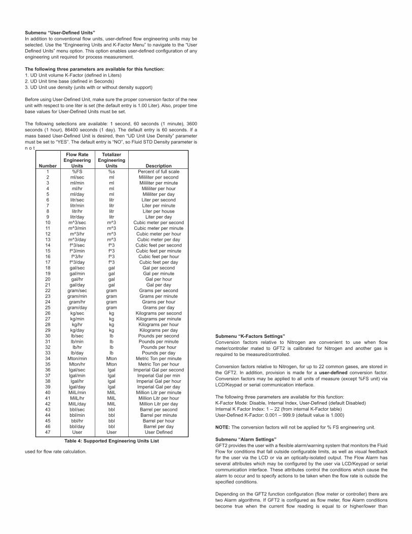
Submenu “User-Defined Units”In addition to conventional flow units, user-defined flow engineering units may beselected. Use the “Engineering Units and K-Factor Menu” to navigate to the “UserDefined Units” menu option. This option enables user-defined configuration of anyengineering unit required for process measurement.
The following three parameters are available for this function:1. UD Unit volume K-Factor (defined in Liters)2. UD Unit time base (defined in Seconds)3. UD Unit use density (units with or without density support)
Before using User-Defined Unit, make sure the proper conversion factor of the newunit with respect to one liter is set (the default entry is 1.00 Liter). Also, proper timebase values for User-Defined Units must be set.
The following selections are available: 1 second, 60 seconds (1 minute), 3600seconds (1 hour), 86400 seconds (1 day). The default entry is 60 seconds. If amass based User-Defined Unit is desired, then “UD Unit Use Density” parametermust be set to “YES”. The default entry is “NO”, so Fluid STD Density parameter isn o t
used for flow rate calculation.
Submenu “K-Factors Settings”Conversion factors relative to Nitrogen are convenient to use when flowmeter/controller mated to GFT2 is calibrated for Nitrogen and another gas isrequired to be measured/controlled.
Conversion factors relative to Nitrogen, for up to 22 common gases, are stored inthe GFT2. In addition, provision is made for a user-defined conversion factor.Conversion factors may be applied to all units of measure (except %FS unit) viaLCD/Keypad or serial communication interface.
The following three parameters are available for this function:K-Factor Mode: Disable, Internal Index, User-Defined (default Disabled)Internal K Factor Index: 1 – 22 (from internal K-Factor table)User-Defined K-Factor: 0.001 – 999.9 (default value is 1.000)
NOTE: The conversion factors will not be applied for % FS engineering unit.
Submenu “Alarm Settings”GFT2 provides the user with a flexible alarm/warning system that monitors the FluidFlow for conditions that fall outside configurable limits, as well as visual feedbackfor the user via the LCD or via an optically-isolated output. The Flow Alarm hasseveral attributes which may be configured by the user via LCD/Keypad or serialcommunication interface. These attributes control the conditions which cause thealarm to occur and to specify actions to be taken when the flow rate is outside thespecified conditions.
Depending on the GFT2 function configuration (flow meter or controller) there aretwo Alarm algorithms. If GFT2 is configured as flow meter, flow Alarm conditionsbecome true when the current flow reading is equal to or higher/lower than
Number123456789
1011121314151617181920212223242526272829303132333435363738394041424344454647
Table 4: Supported Engineering Units List
Flow RateEngineering
Units%FS
ml/secml/minml/hr
ml/daylitr/seclitr/minlitr/hr
litr/daym^3/secm^3/minm^3/hr
m^3/dayf^3/secf^3/minf^3/hr
f^3/daygal/secgal/mingal/hr
gal/daygram/secgram/mingram/hr
gram/daykg/seckg/minkg/hr
kg/daylb/seclb/minlb/hr
lb/dayMton/minMton/hrlgal/seclgal/minlgal/hr
lgal/dayMilL/minMilL/hr
MilL/daybbl/secbbl/minbbl/hr
bbl/dayUser
TotalizerEngineering
Units%smlmlmlmllitrlitrlitrlitr
m^3m^3m^3m^3f^3f^3f^3f^3galgalgalgal
gramgramgramgram
kgkgkgkglblblblb
MtonMtonlgallgallgallgalMilLMilLMilLbblbblbblbbl
User
DescriptionPercent of full scaleMililiter per secondMililiter per minuteMililiter per hourMililiter per dayLiter per secondLiter per minuteLiter per house
Liter per dayCubic meter per secondCubic meter per minuteCubic meter per hourCubic meter per day
Cubic feet per secondCubic feet per minuteCubic feet per hourCubic feet per day
Gal per secondGal per minuteGal per hourGal per day
Grams per secondGrams per minuteGrams per hourGrams per day
Kilograms per secondKilograms per minuteKilograms per hourKilograms per day
Pounds per secondPounds per minutePounds per hourPounds per day
Metric Ton per minuteMetric Ton per hour
Imperial Gal per secondImperial Gal per minImperial Gal per hourImperial Gal per dayMillion Litr per minuteMillion Litr per hourMillion Litr per dayBarrel per secondBarrel per minuteBarrel per hourBarrel per dayUser Defined

corresponding values of high and low flow Alarm levels. If GFT2 is configured asflow controller, flow Alarm conditions become true when difference between SetPoint value and current flow reading is equal or higher/lower than correspondingvalues of High and Low Flow Alarm levels.
Alarm actions can be assigned with preset Delay Interval (0-3600 seconds) toactivate the optically-isolated output (separate for High and Low alarm). LatchMode control feature allows each optical output to be latched on or follow thecorresponding alarm status.
The following settings are available for Flow Alarm (see Figure 10):
a) Flow Alarm Mode (Tabular entry) This function determines whether Flow Alarm is Enabled or Disabled. The followingsections are available: Enabled or Disabled. The default entry is Disabled. AlarmMode selections can be set with the UP and DN buttons and are accepted bypressing ENT button.
b) Low Flow Alarm (Numerical entry)The limit of required Low Flow Alarm value can be entered in increments of 0.1%from 0 – 100% FS. If a Low Alarm occurs and one of the two optional outputs is assigned to the LowFlow Alarm Event, the optically-isolated output will be activated: 1) For Flow Meter Function: when the flow is less than the Low Flow Alarm value.2) For flow controller function: when the absolute difference between Set Pointvalue and actual flow reading is equal or more than the Low Flow Alarm value andActual Flow value is less than Set Point value.
The Low Flow Alarm condition is also indicated on the corresponding ProcessInformation Screen displaying L character.
NOTE: For Flow Meter function, the value of the Low Flow Alarm must be less thanthe value of the High Flow Alarm
c) High Flow Alarm (Numerical entry)The limit of required High Flow Alarm value can be entered in increments of 0.1%from 0 – 100% FS. If a High Alarm occurs and one of the two optical outputs isassigned to the High Flow Alarm Event, the optically-isolated output will beactivated for:a) Flow Meter function: when the flow is more than the High Flow Alarm value.b) Flow Controller function: when absolute difference between Set Point value andActual Flow reading is equal or more than the High Flow Alarm value and actualflow value is more than Set Point value.
The High Flow Alarm condition is also indicated on the corresponding ProcessInformation Screen by displaying H character.
NOTE: For Flow Meter function, the value of the High Flow Alarm must be morethan the value of the Low Flow Alarm.
d) Flow Alarm Action Delay (Numerical entry)The Flow Alarm Action Delay is a time in seconds that the Flow Rate value remain
sabove the high limit or below the low limit before an alarm condition is validated.Valid settings are in the range of 0 to 3600 seconds (default value is 0, no delay).
e) Flow Alarm Action Latch (Tabular entry)The Flow Alarm Action Latch settings controls the Latch feature. If optically-isolatedoutput is assigned to the Flow Alarm Event, in some cases, the Flow Alarm Latchfeature may be desirable.
The following settings are available: Disable or Enable. By default, Flow Alarm isnon-latching. That means the alarm is indicated only while the monitored FlowValue exceeds the specified set conditions.
Submenu “Totalizer #1”GFT2 provides the user with two independent Programmable Flow Totalizers. Thetotal volume of the flowing fluid is calculated by integrating the actual instantaneousfluid flow rate with respect to time. Totalizer #1 (main totalizer) value is stored in theEEPROM and saved every (1) second. In case of power interruption, the last savedTotalizer value will be loaded on the next power on cycle, so main totalizer readingwill not be lost. Use the “Totalizer Menu” to navigate to the “Totalizer #1” menuoption. The following settings are available for Totalizer #1 (see Figure 10).
a) Totalizer #1 Mode (Tabular entry)This option determines whether Totalizer #1 is Enabled or Disabled. The followingselections are available: Enabled or Disabled. The default entry is Disabled.Totalizer #1 Mode selections can be set with the UP and DN buttons and areaccepted by pressing ENT button.
NOTE: Before enabling the Totalizer, ensure that all totalizer settings areconfigured properly. Totalizer Start values have to be entered in the currently activeVolumetric or Mass flow engineering unit. The Totalizer will not totalize until theProcess Flow Rate becomes equal to or more than the Totalizer Start value.Totalizer Event values must be entered in currently active volume or mass basedengineering units. If the Totalizer Event at preset total volume feature is notrequired, set Totalizer Event value to zero (default settings).
b) Totalizer #1 Flow Start (Numerical entry)This option allows the totalizer to start at a present flow rate. The Totalizer #1 willnot totalize until the process flow rate becomes equal to or more than the Totalizer#1 Flow Start value. The limit of required Totalizer #1 Flow Start value can beentered in increments of 0.1% from 0 to 100% FS.
c) Totalizer #1 Action Volume (Numerical entry)This option allows the user to activate preset required action when the totalizerreaches a preset volume. Totalizer #1 Action Volume value must be entered incurrently active volume/mass based engineering units. Totalizer #1 action eventbecomes true when Totalizer #1 reading is more or equal to preset "Totalizer #1Action Volume”. If the Totalizer #1 Action at preset total volume feature is notrequired, set “Totalizer #1 Action Volume” value to zero (default settings).
d) Totalizer #1 Power On Delay (Numerical entry)Sometimes it is convenient to start the Totalizer only after specified power up delayinterval. Most of the mass flow meters and controllers require some warm up timefrom the power up event in order to stabilize process variable output and getaccurate reading. “Totalizer #1 Power On Delay” option allows set specified timeinterval which must elapse from the device power up event before Totalizer will beactivated. Valid settings are in the range of 0 to 3600 seconds (default value is 0,no delay).
Figure 14
Figure 15

e) Totalizer #1 Auto Reset (Tabular entry)This option allows to automatically reset Totalizer #1 when it reaches preset ActionVolume value. This feature may be convenient for batch processing, whenpredefined volume of the fluid must be repeatedly dispensed into the process. Thefollowing selections are available: Enabled or Disabled.
The default entry is Disabled. Totalizer #1 Auto Reset selections can be set with theUP or DN buttons and are accepted by pressing ENT button.
f) Totalizer #1 Auto Reset Delay (Numerical entry)This option may be desirable when “Totalizer #1 Auto Reset” feature is enabled.Valid settings are in the range of 0 to 3600 seconds (default value is 0, no delay).
g) Reset Totalizer #1 (Numerical entry)The Totalizers #1 reading can be reset by selecting “Reset Totalizer #1” menu
option. A typical display with Totalizer #1 Reset screen is shown in Figure 14.
Once the “YES” option is selected, Totalizer #1 will be reset and the followingconfirmation screen will appear:Submenu “Totalizer #2”The Totalizer #2 (pilot totalizer) value is stored in the flow meter volatile memory(SRAM) and saved every 100 milliseconds (0.1 second). In case of powerinterruption, the Totalizer #2 volume will be lost (reset to zero). It is preferable touse Totalizer #2 for short term process flow calculation (for example: batchprocessing). Use the “Totalizer Menu” to navigate to “Totalizer #2” menu option. Thefollowing settings are available for Totalizer #2 (see Figure 10):
a) Totalizer #2 Mode (Tabular entry)This option determines whether Totalizer #2 is Enabled or Disabled. The followingselections are available: Enabled or Disabled. The default entry is Disabled.Totalizer #2 Mode selections can be set with the UP and DN buttons and areaccepted by pressing ENT button.
NOTE: Before enabling the Totalizer, ensure that all Totalizer settings areconfigured properly. Totalizer Start values must be entered in currently activeVolumetric or Mass flow engineering unit. The Totalizer will not totalize until theprocess flow rate becomes equal to or more than the Totalizer Start value. TotalizerEvent values must be entered in currently active volume or mass basedengineering units. If the Totalizer Event at preset total volume feature is notrequired, then set Totalizer Event value to zero (default settings).
b) Totalizer #2 Configuration (Tabular entry)Totalizer #2 can be configured to count up or down. When configured to countdown, be sure “Totalizer #2 Action Volume” parameter is set to the desired value ofmore than zero. In this case Totalizer #2 Action Event will be activated when thetotalizer counts down to zero. The following selections are available: Count UP orCount DN. The default entry is Count UP. Totalizer #2 configuration selections canbe set with the UP and DN buttons and are accepted by pressing ENT button.
c) Totalizer #2 Flow Start (Numerical entry)This option allows the start of the totalizer at a preset flow rate. The Totalizer #2 willnot totalize until the process flow rate becomes equal to or more than the Totalizer#2 Flow Start value. The limit of required Totalizer #2 Flow Start value can beentered in increments of 0.1% from 0 -100%FS.
d) Totalizer #2 Action Volume (Numerical entry)This option allows the user to activate preset required action when totalizer reachesa preset volume when totalizer configured to count up, or zero value when totalizerconfigured to count down. Totalizer #2 Action Volume value must be entered incurrently active volume/mass based engineering units. When set to count up,Totalizer #2 Action Event becomeS true when the totalizer #2 reading is more orequal to preset “Totalizer #2 Action Volume”. If the Totalizer#2 Action at preset totalvolume feature is not required, set “Totalizer #2 Action Volume” value to zero(default settings).
NOTE: When Totalizer #2 is configured to count down, be sure “Totalizer #2 ActionVolume” value is set to any value more than zero.
e) Totalizer #2 Power On Delay (Numerical entry)Sometimes it is convenient to start Totalizer only after specified power up delay
interval. Most of the mass flow meters and controllers require some warm up timefrom the power up event in order to stabilize process variable output and getaccurate reading. “Totalizer #2 Power On Delay” option allows set a specified timeinterval which must elapse from the device power-up event before Totalizer will beactivated. Valid settings are in the range of 0 to 3600 seconds (default value is 0,no delay).
Figure 16
Figure 17
Figure 18

f) Totalizer #2 Auto Reload (Tabular entry)This option allows to automatically reset/reload Totalizer #2 when it reaches presetAction Volume value (when configured to count UP) or zero value (when configuredto count Down). This feature may be convenient for batch processing whenpredefined volume of the fluid must be repeatedly dispensed into the process. Thefollowing selections are available: Enabled or Disabled. The default entry isDisabled. Totalizer #2 Auto Reload selections can be set with the UP and DNbuttons and are accepted by pressing the ENT button.
g) Totalizer #2 Auto Reset Delay (Numerical entry)This option may be desirable when “Totalizer #2 Auto Reload” feature is enabled.Valid settings are in the range of 0 to 3600 seconds (default value is 0, no delay).
h) Reset Totalizer #2 (Numerical entry)Totalizers #2 reading can be reset by selecting “Reset Totalizer #2” menu option. Atypical display with Totalizer #2 Reset screen is shown below.Once “YES” option is selected, the Totalizer #2 will be reset and the followingconfirmation screen will appear.Submenu “Pulse Output”The flow Pulse Output is operating independently from totalizers and, based onconfiguration settings (see Figure 10), can provide pulse frequency proportional toinstantaneous fluid flow rate.
The LCD/keypad and serial communication interface commands are provided to:• Enable/Disable Pulse Output• Start Pulse Output at preset flow rate (0.0 – 100.0%FS.• Configure the Unit/Pulse value (in current engineering units)• Configure Pulse Active On Time (10 – 6553 milliseconds)
NOTE: The Pulse Output minimum Active On time is 10 milliseconds (.01 second).The Optical Pulse Output cannot operate faster than one pulse every 100millisecond (.1 second). A good rule to follow is to set the Unit/Pulse value equal tothe maximum flow in the same units per second. This will limit the pulse rate to nofaster than one pulse every second.
For example: Maximum flow rate = 1200 kg/min(1200 kg/min = 20 kg/sec)If unit per pulse is set to 1200 kg/pulse, the Optical Pulse Output will pulse once every minute.
If unit per pulse is set to 20 kg per pulse, the Optical Pulse Output will pulse onceevery second.
The Optically-Isolated Pulse Output incorporate Pulse Output queue, whichaccumulate pulses if the Pulse Output is accumulating process flow faster than thePulse Output hardware can function. The queue will allow the pulses to “catch up”later if the flow rate decreases. A better practice is to slow down the Pulse Outputby increasing the value in the Unit/Pulse setting in the Pulse Output menu (seeFigure 10).
NOTE: If Pulse Output feature is required, one of the Digital Optically- solatedoutputs must be assigned to “Pulse Output” function. Pulse output signal will beaccessible via corresponding Digital Optically-Isolated output on the screwterminal header J1 (see Wiring Diagrams).
Submenu “Opt. Outputs Settings”Two sets of optically-isolated digital outputs are provided to actuate user-suppliedequipment. These are programmable via digital interface or LCD/Keypad such thatthe outputs can be made to switch when a specified event occurs (e.g. when a Lowor High Flow Alarm limit is exceeded or when the Totalizer reaches a specifiedvalue) or it may be directly controlled by user.
The user can configure each optical output action from 9 different options:• Disabled: No Action (output is not assigned to any events and is not energized)• Low Flow Alarm• High Flow Alarm• Range between High and Low Flow Alarm settings• Totalizer #1 reading exceed set limit• Totalizer #2 reading exceed set limit• Pulse Output function• Diagnostic: Output will be energized when any of the Diagnostic or System eventsare active• Manual On Control: Output will be energized until Disabled option will be selected.
By default, both optically-isolated outputs are disabled.
NOTE: Optically-isolated outputs are accessible via screw terminal header J1 andrequire application of external DC voltage across terminals. See Wiring Diagrams.
Submenu “Display Settings”
Process Information screens can be configured to be static (manual control) ordynamic (automatic sequencing). In the static mode pressing the UP button allowsthe user to page through the PI screens in the forward direction, pressing DN buttonpages through the PI screens in the reverse direction. When the last PI screen isreached, the firmware “wraps around” and scrolls to the initial PI screen once again.
NOTE: PI screens which are masked in the Screen Mask Register (see below) willbe skipped.
Use the “General Settings” menu to navigate to “Display Settings” menu option(see Figure 10).
The following settings are available for LCD Display:a) Display Mode (Tabular entry)This option determines whether Display screens are in static (manual control) ordynamic (automatic sequencing) mode. The following selections are available:Static or Dynamic. The default entry is: Static (manual control). Display screensmode parameter can be set with the UP and DN buttons and are accepted bypressing ENT button.
b) Screen Cycle Time (Numerical entry)This menu selection defines time interval in seconds for each PI screen to bedisplayed in the dynamic mode (automatic sequencing). Screen Cycle Time can beset to any value in the range between 1 to 3600 seconds (1 hour, numerical entry).
c) Screen Mask (Tabular entry)Using Screen Mask settings the user can enable (unmask) or disable (mask) up to4 different process variable combinations (see Figure 1). By default the unit isshipped from the factory with all PI screens enabled. A typical display with ScreenMask selection is shown below.In the example shown above, all PI screens are enabled. Each PI screen assignedto a corresponding bit in the PI Screen Register. In order to change PI Screen masksettings, the user should select the desired screen using UP and DN buttons andthen press RIGHT button. The asterisk will appear/disappear on the right side of thecorresponding screen. The asterisk represents that the screen is enabled. In orderto disable the screen, the corresponding asterisk must be removed. Use the ENTbutton to accept and save new PI Screen Mask settings in the device’s nonvolatilememory.
NOTE: PI Screen #1 cannot be disabled (unmasked).
d) Display Back Light (Numerical entry)Using Display Back Light settings the user can adjust the desired level of the LCDback light. The backlight has 19 different levels. Use UP and DN buttons to adjustback light level and press ENT button to accept and save back light level settingsin the device’s nonvolatile memory.

e) Display Contrast (Numerical entry)Using Display Contrast settings, the user can adjust the desired level of the LCDcontrast. The contrast has 16 different levels. Use UP and DN buttons to adjustcontrast level, and press ENT button to accept and save contrast level settings inthe device’s nonvolatile memory.
NOTE: By default, the contrast level is set to 6, which is the optimal level for roomtemperature (20°C or 70°F).
Submenu “Device Function”This menu selection allows the selection of GFT2 function according to the mateddevice type. If GFT2 is connected to the flow meter, then the “Meter” function mustbe selected. If GFT2 is connected to the flow controller, then “Controller” functionmust be selected.
NOTE: Based on “Device Function” (device function as flow meter or flowcontroller) settings, different parameters may be displayed in the ProcessInformation (PI) screen (see Figure 1) and different features of the GFT2 devicemay be enabled or disabled (set point control only enabled when GFT2 isconfigured as flow controller). Also, some features (e.g. Flow Alarm) may havedifferent behavior. Make sure the “Device Function” parameter is set according tothe actual device being used.
Submenu “Communication Settings”This menu selection allows the configuration of a serial communication interfacespeed (Baud rate) and device RS-485 bus address (only applicable for optional RS-485 interface). The following settings are available for “Communication Settings”(see Figure 10).
a) Baud Rate Settings (Tabular entry)
The Baud Rate Settings (Tabular entry) option determines device serialcommunication interface speed (Baud rate) and can be set to one of the following:1200, 2400, 4800, 9600, 19200, 38400, 57600, or 115200.
By default, the device shipped from the factory with Baud rate set to 9600.
NOTE: The Baud rate set on the GFT2 device should always follow the Baud rateof the host PC or PLC it is connected to.
b) RS-485 Bus Address (Numerical entry)The standard GFT2 comes with an RS-232 interface. The optional RS-485interface has two hexadecimal characters of the address, which must be assigned.
By default, each flow meter is shipped with RS-485 address set to 11 hexadecimal.When more than one device is present on RS-485 bus, each device should have aunique address. The two characters of the address in the hexadecimalrepresentation can be changed from 01 to FF.
NOTE: Address 00 is reserved for global addressing. Do not assign the globaladdress for any device. When command with global address is sent, all devices onthe RS-485 bus execute the command, but do not reply with an acknowledgemessage.
NOTE: Do not assign the same RS-485 address for two or more devices on thesame RS-485 address for two or more devices on the same RS-485 bus. If two ormore devices with the same address are connected to the one RS-485 network, acommunication collision will take place on the bus, and communication errors willoccur.
Submenu “Device Calibration”
The Calibration Menu contains the parameters, which have to be set according toflow meter/controller being used and according to required process conditions.These values should be changed only by properly trained personnel. DeviceAnalog Output and Input calibration was performed on the factory and should notbe initiated unless recommended by factory personnel. Following settings areavailable for “Device Calibration” menu selection:
a) Full-Scale Range (Numerical Entry)The Full-Scale Range value in liter per minute (L/min) should be set equal to thefull-scale range (converted to L/min) of the device mated to GFT2. The analog inputand output will be scaled automatically to this value. For example, if Full-ScaleRange value set to 10.0 L/min and device is configured for 0-5 VDC analog input,when 5.0 VDC is applied to GFT2 analog input the PI flow rate will indicate 100.0%FS. (if %FS units of measure is selected).
NOTE: Failure to set Full-Scale Range parameter in L/min equal to the full-scale
range (converted to L/min) of the device mated to GFT2 may cause erroneousreadings and unexpected device behavior.
b) Low Flow Cut-Off (Numerical entry)The low flow cut-off can be selected between 0.0 and 10.0 % of the full-scale range.Flows less than the cut-off value are internally driven to zero and not totalized.Default value of the “Low flow Cut-Off” parameter is zero (disabled).
c) Flow Power Up Delay (Numerical entry)Sometimes it is convenient to start the process of the input signals after thespecified power up delay interval. Most mass flow meters and controllers requiresome warm up time from the power up event in order to stabilize process variable
Figure 19
Figure 20
EventNumber
123456789
1011121314
Table 5
Diagnostic and Alarm Events DescriptionCPU Temperature Too High
High Flow AlarmLow Flow Alarm
Range Between High and LowTotalizer #1 Exceed Set Event Volume LimitTotalizer #2 Exceed Set Event Volume Limit
Optical Pulse Output Queue OverflowFlow Rate Above Limit
Vcc Power Voltage Out of RangeSerial Communication Error
EEPROM ErrorPower On Event (Power On Delay Time > 0)
Password EventFatal Error
LCD BIT Code0123456789ABCD
Figure 21
Figure 22
Figure 23
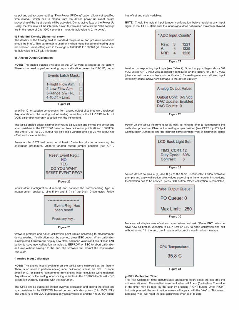
output and get accurate reading. “Flow Power UP Delay” option allows set specifiedtime interval, which has to elapse from the device power up event beforeprocessing of the input signals will be activated. During active faze of the Power UpDelay, the flow rate will be internally driven to zero and not totalized. Valid settingsare in the range of 0 to 3600 seconds (1 hour, default value is 0, no delay).
d) Fluid Std. Density (Numerical entry)The density of the flowing fluid at standard temperature and pressure conditionsshould be in g/L. This parameter is used only when mass-based engineering unitsare selected. Valid settings are in the range of 0.000001 to 10000.0 g/L. Factory setdefault value is 1.25 g/L (Nitrogen).
e) Analog Output Calibration
NOTE: The analog outputs available on the GFT2 were calibrated at the factory.There is no need to perform analog output calibration unless the DAC IC, output
amplifier IC, or passive components from analog output circuitries were replaced.Any alteration of the analog output scaling variables in the EEPROM table willVOID calibration warranty supplied with the instrument.
The GFT2 analog output calibration involves calculation and storing the off set andspan variables in the EEPROM based on two calibration points (0 and 100%FS).The 0 to 5 (0 to 10) VDC output has only scale variable and 4 to 20 mA output hasoffset and scale variables.
Power up the GFT2 instrument for at least 15 minutes prior to commencing thecalibration procedure. Observe analog output jumper position (see GFT2
Input/Output Configuration Jumpers) and connect the corresponding type ofmeasurement device to pins 5 (+) and 8 (-) of the 9-pin D-connector. Follow
firmware prompts and adjust calibration point values according to measurementdevice reading. If calibration must be aborted, press ESC button. When calibrationis completed, firmware will display new offset and span values and ask, “Press ENTbutton to save new calibration variables to EEPROM or ESC to abort calibrationand exit without saving.” In the end, the firmware will prompt the confirmationmessage.
f) Analog Input Calibration
NOTE: The analog inputs available on the GFT2 were calibrated at the factory.There is no need to perform analog input calibration unless the CPU IC, inputamplifier IC, or passive components from analog input circuitries were replaced.Any alteration of the analog input scaling variables in the EEPROM table will VOIDcalibration warranty supplied with the instrument.
The GFT2 analog output calibration involves calculation and storing the offset andspan variables in the EEPROM based on two calibration points (0 to 100% FS.).The 0 to 5 (0 to 10) VDC output has only scale variables and the 4 to 20 mA output
has offset and scale variables.
NOTE: Check the actual input jumper configuration before applying any inputsignal to the GFT2. Make sure the input signal does not exceed maximum allowed
level for corresponding input type (see Table 2). Do not apply voltages above 5.0VDC unless GFT2 input was specifically configured on the factory for 0 to 10 VDC(check actual model number and specification). Exceeding maximum allowed inputlevel may cause inadvertent damage to the device circuitry.
Power up the GFT2 instrument for at least 15 minutes prior to commencing thecalibration procedure. Observe the analog jumper position (see GFT2 Input/OutputConfiguration Jumpers) and the connect corresponding type of calibration signal
source device to pins 4 (+) and 8 (-) of the 9-pin D-connector. Follow firmwareprompts and apply calibration point values according to the on-screen instructions.If calibration has to be aborted, press ESC button. When calibration is completed,
firmware will display new offset and span values and ask, “Press ENT button tosave new calibration variables to EEPROM or ESC to abort calibration and exitwithout saving.” In the end, the firmware will prompt a confirmation message.
g) Pilot Calibration TimerThe Pilot Calibration timer accumulates operational hours since the last time theunit was calibrated. The smallest increment value is 0.1 hour (6 minutes). The valueof the timer may be reset by the user by pressing RIGHT button. Once RIGHTbutton is pressed, the confirmation screen will appear with the “Yes” or “No” menu.Selecting “Yes” will reset the pilot calibration timer back to zero.
Figure 24
Figure 25
Figure 26
Figure 27
Figure 28
Figure 29
Figure 30
Figure 31

Submenu “Signal Conditioner”A noise reduction filter algorithm (Running Average or Noise Reduction Filter) isnow available in the flow meter when pulsating flow or especially noisy signals areencountered. The Flow Linearizer algorithm is also available when flow linearitymust be improved.
The following settings are available for “Program Set Point” (see Figure 10):
a) Program Set Point Mode (Tabular entry)This function determines whether the Program Set Point is Enabled or Disabled.The following selections are available: Enabled or Disabled. The default entry isDisabled. Program Set Point Mode selections can be set with the UP and DNbuttons and are accepted by pressing ENT button.
b) Program Set Point Loop Mode (Tabular entry)This function determines whether Program Set Point Loop is Enabled or Disabled.If Loop is enabled, when program reaches the last step it wraps around and againstarts execution from the first enabled step. The following selections are available:Enabled or Disabled. The default entry is Disabled. Program Set Point Loop Modeselections can be set with the UP and DN buttons and are accepted by pressingENT button.
c) PSP Steps Mask (Tabular entry)Using PSP Steps Mask settings, the user can enable (unmask) or disable (mask)any step in the program. If the step is masked, the program will skip it and move tothe next enabled step. By default the unit is shipped from the factory with allprogram steps enabled (unmasked). A typical display with PSP Steps Maskselection is shown below.In the example shown above, all PSP Steps are enabled. Each PSP Step assigned
to a corresponding bit in the PSP Steps Register. In order to change PSP Step
mask settings, the user should select desired stop using UP and DN buttons andthen press RIGHT button. The asterisk will appear/ disappear on the right side ofthe corresponding step. The asterisk represents that step is enabled. In order todisable step, the corresponding asterisk has to be removed. Use ENT button toaccept and save new PSP Steps mask settings in device non volatile memory.
d) PSP Steps Settings (Numerical entry)Using PSP Steps Settings menu selection, the user can assign required set pointand time values for each step in the program. A typical display with PSP StepsSettings selection is shown below.In the example shown above, Step 01 is selected. For each step there are twoparameters: set point value in % FS and time interval in seconds. In order tochange PSP Step settings user should select desired step using UP and DNbuttons and then press ENT button. The cursor in the selected (highlighted)parameter will start flashing. Use UP, DN, LEFT, RIGHT buttons to adjust desiredvalue and then press ENT button to accept and save new PSP Step Settings in thedevice’s nonvolatile memory.
Submenu “Event Register Menu”GFT2 is equipped with a self-diagnostic Alarm Event Register which is available viadigital interface and on screen LCD indication. Use the “Diagnostic Menu” tonavigate to “Event Register Menu” menu option.
The following diagnostic events are supported:NOTE: Any Alarm or Diagnostic events that may have occurred (Event 0 to EventD) are stored in the internal status register. All detected events (if corresponding bitin the latch register is not masked) remain stored until the register is manually reset
(by keypad or by means of the serial communication interface). If event
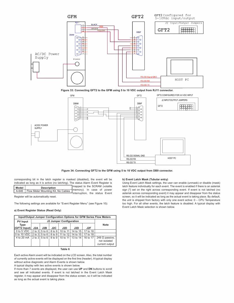
Figure 32: Connecting GFT2 to the GFM using 4-20mA output from DB9 connector.
corresponding bit in the latch register is masked (disabled), the event will beindicated as long as it is active (no latching). The status Alarm Event Register is
mapped to the SCRAM (volatilememory). In case of powerinterruption, the status Event
Register will be automatically reset.
The following settings are available for “Event Register Menu” (see Figure 10):
a) Event Register Status (Read Only)
Each active Alarm event will be indicated on the LCD screen. Also, the total numberof currently active events will be displayed on the first line (header). A typical displaywithout active diagnostic and Alarm Events is shown below.A typical display with two active events is shown below.If more than 7 events are displayed, the user can use UP and DN buttons to scrolland see all indicated events. If event is not latched in the Event Latch Maskregister, it may appear and disappear from the status screen, so it will be indicatedas long as the actual event is taking place.
b) Event Latch Mask (Tubular entry)Using Event Latch Mask settings, the user can enable (unmask) or disable (mask)latch feature individually for each event. The event is enabled if there is an asterisksign [*] set on the right across corresponding event. If event is not latched (noasterisk across corresponding event) it may appear and disappear from the statusscreen, so it will be indicated as long as the actual event is taking place. By default,the unit is shipped from factory with only one event active: 0 – CPU Temperaturetoo high. For all other events, the latch feature is disabled. A typical display withEvent Latch Mask selection is shown below.
Figure 33: Connecting GFT2 to the GFM using 5 to 10 VDC output from RJ11 connector.
ModelA-646
DescriptionFlow Meter Mounting Kit, No Cables
Input/Output Jumper Configuration Options for GFM Series Flow MetersPV Input
Type(GFT2 Input)0 to 5 VDC
0 to 10 VDC4 to 20 mA
J2 Jumper Configuration
J2A2 to 32 to 32 to 3
J2B5 to 65 to 65 to 6
J2C8 to 98 to 98 to 9
Note
249 Ω passive,not isolated
current output
J2D10 to 1111 to 1210 to 11
J2D14 to 1514 to 1513 to 14
J2F17 to 1817 to 1816 to 17
Table 6
AC/DC POWERSUPPLY
GFM
DB9M
RS-232 SIGNAL GNDRS-232 RXRS-232 TX
HOST PC
GFT2
DB9F
GFT2 CONFIGURED FOR 0-5 VDC INPUT
J2 INPUT/OUTPUT JUMPERS
GFT2
Figure 34: Connecting GFT2 to the GFM using 5 to 10 VDC output from DB9 connector.

In Figure 23, latch features for all events are disabled except event #0. In order tochange Event Latch Mask Settings the user should select desired event using UPand DN buttons and then press RIGHT button. The asterisk will appear/disappearon the right side of the corresponding event. The asterisk represents that the latch
feature is enabled. In order to disable latch feature, the corresponding asterisk hasto be removed. Use the ENT button to accept and save new Event Latch masksettings in the device’s non volatile memory.
c) Event Register Mask (Tabular entry)
Using Event Register Mask Settings user can individually enable (unmask) ordisable (mask) each event. The event is enabled if an asterisk sign [*] is set on the
right across from corresponding event. If the event is disabled, it will not beprocessed or indicated in the Events Status Register, even if actual conditions forevent have occurred. By default the unit is shipped from the factory with only oneevent active: “0 – CPU Temperature too high”. All other events are disabled. A
typical display with Event Register Mask selection is shown below.In the example shown above, all events are disabled except event #0. In order tochange Event Register Mask Settings, the user should select the desired eventusing UP and DN buttons and then press the RIGHT button. The asterisk willappear/disappear on the right side of the corresponding event. The asterisk
represents that the event is enabled. In order to disable the event, thecorresponding asterisk has to be removed. Use the ENT button to accept and save
Figure 35: Connecting GFT2 to the GFC Using 0 to 5 VDC Input/Output from DB15 Connector.
Figure 36: Connecting GFT2 to the GFC Using 4 to 20 mA Input/Output from DB15 Connector.

the new Event Register Mask Settings in the device’s nonvolatile memory.
d) Reset Event Register (Tabular entry)
The Event Register can be reset by selecting “Reset Event Register” menu option.A typical display with the Reset Event Register screen is shown below.Once the “YES” option is selected, the Event Register will be reset and thefollowing confirmation screen will appear.Submenu “Diagnostic Menu”The Diagnostics Menu can be used for troubleshooting purposes and providesinformation about the device’s internal variables. These items (except the Events
Register submenu described above) are informational only and may not bechanged (read only).
a) ADC Input Counts (Read Only)This menu selection provides raw, average, and filtered values of the ADC countsfor analog input circuitry (read only). A typical display with the ADC Input Countsscreen is shown below. b) Analog Output Values (Read Only)This menu selection provides information about currently selected analog outputconfiguration and DAC counts for analog output circuitry (read only). A typicaldisplay with DAC Output Values screen is shown below.
c) LCD Back Light Settings (Read Only)
This menu selection provides information about the LCD back light level, PWM dutycycle, and contrast (read only). A typical display with the LCD Back Light Settingsscreen is shown below.d) Pulse Output Queue (Read Only)This menu selection provides information about the Pulse Output Queue. A typicaldisplay with the Pulse Output Queue screen is shown below.e) CPU Temperature (Read Only)This menu selection provides the current value of the PCB and CPU temperaturein °C (read only). A typical display with the CPU Temperature reading is shownbelow.
Installation
General Directions• Mounting, electrical installations, parameters configuration, startup, andmaintenance of this instrument may only be performed by trained personnel.Personnel must read and understand this operating manual before performing any
installation or configuration steps.• The GFT2 device should only be operated by trained personnel. Allinstructions in this manual are to be observed.• Ensure that power and all input/output signals are correctly wiredup according to the wiring diagram provided in this manual. Thehousing of the device should only be opened by trained personnel.
Hardware Installation
NOTE: Electrostatic discharge may cause permanent damage tothe electronic circuitry. Before installing or connecting any wires, theinstaller must discharge himself by touching the building’s protective
Earth ground.
The GFT2 Totalizer Input/Output Flow Monitor/Controller can be attached(mounted) to the Dwyer GFM series flow meters, GFC series controllers, or usedstand alone (panel mounted or table-top installation).
Connecting GFT2 to GFM Series Flow Metera) MountingUse the GFM mounting kit (See Table 4) to attach GFT2 to the GFM flow meter.
b) Electrical ConnectionGFM flow meters have three different output interfaces (0 to 5, 5 to 10 VDC, 4 to20 mA), which can be used to provide flow input signal to the GFT2.
Optional GFC Power Supply/Cables and Mounting Kit AssembliesKit PartNumber
GFT2-20C
A-645
DescriptionShielded cable with
plug 110 VAC to12 VDC power supply,communication branch
GFC flow controllermounting kit, no cables,
no power supply
GFT2 Input/Output
0 to 5 VDC
N/A
Communication Interface Cable
Yes
N/A
GFC PowerSupply Option
12 VDC Only
N/A
Table 7
Input/Output Jumper Configuration Options for GFC Series Flow Controllers
Output0 to 5 VDC
4 to 20 mA
0 to 10 VDC
J2 Jumper ConfigurationJ2A
2 to 3
1 to 2
2 to 3
J2B5 to 6
4 to 5
5 to 6
J2C8 to 9
7 to 8
8 to 9
GFC Cable KitGFT2-20C or
A-645Not supported byGFC cable kitsNot supported
by GFC
J2D10 to 11
10 to 11
11 to 12
J2D14 to 15
13 to 14
14 to 15
J2F17 to 18
16 to 17
17 to 18
GFT2 PV TypeInput
0 to 5 VDC
4 to 20 mA
0 to 10 VDC
Table 8
Figure 37
An optional cables kit assembly is available for order:
c) Input/Output Jumper Configuration
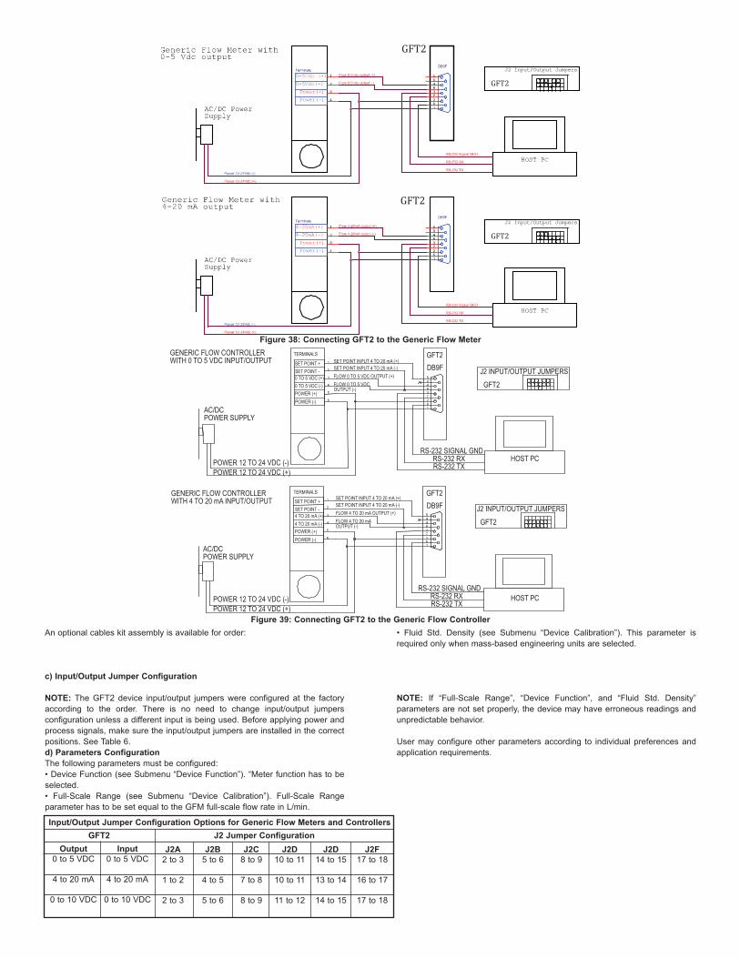
NOTE: The GFT2 device input/output jumpers were configured at the factoryaccording to the order. There is no need to change input/output jumpersconfiguration unless a different input is being used. Before applying power andprocess signals, make sure the input/output jumpers are installed in the correctpositions. See Table 6.d) Parameters ConfigurationThe following parameters must be configured:• Device Function (see Submenu “Device Function”). “Meter function has to beselected.• Full-Scale Range (see Submenu “Device Calibration”). Full-Scale Rangeparameter has to be set equal to the GFM full-scale flow rate in L/min.
• Fluid Std. Density (see Submenu “Device Calibration”). This parameter isrequired only when mass-based engineering units are selected.
NOTE: If “Full-Scale Range”, “Device Function”, and “Fluid Std. Density”parameters are not set properly, the device may have erroneous readings andunpredictable behavior.
User may configure other parameters according to individual preferences andapplication requirements.
GFT2
GFT2GFT2
GFT2
Figure 38: Connecting GFT2 to the Generic Flow MeterGENERIC FLOW CONTROLLERWITH 0 TO 5 VDC INPUT/OUTPUT
AC/DC POWER SUPPLY
AC/DC POWER SUPPLY
GENERIC FLOW CONTROLLERWITH 4 TO 20 mA INPUT/OUTPUT
GFT2
GFT2
RS-232 SIGNAL GNDRS-232 RXRS-232 TX
HOST PC
HOST PC
J2 INPUT/OUTPUT JUMPERSDB9F
GFT2DB9F
POWER 12 TO 24 VDC (-)POWER 12 TO 24 VDC (+)
POWER 12 TO 24 VDC (-)POWER 12 TO 24 VDC (+)
RS-232 SIGNAL GNDRS-232 RXRS-232 TX
GFT2J2 INPUT/OUTPUT JUMPERS
Figure 39: Connecting GFT2 to the Generic Flow Controller
Input/Output Jumper Configuration Options for Generic Flow Meters and Controllers
Output0 to 5 VDC
4 to 20 mA
0 to 10 VDC
J2 Jumper ConfigurationJ2A
2 to 3
1 to 2
2 to 3
J2B5 to 6
4 to 5
5 to 6
J2C8 to 9
7 to 8
8 to 9
J2D10 to 11
10 to 11
11 to 12
J2D14 to 15
13 to 14
14 to 15
J2F17 to 18
16 to 17
17 to 18
GFT2Input
0 to 5 VDC
4 to 20 mA
0 to 10 VDC
Connecting GFT2 to GFC Series Flow Controllera) MountingUse GFC mounting kit (see Table 7) to attach GFT2 to the GFC flow controller (seeFigure 35).
b) Electrical ConnectionGFC flow controllers have two output interfaces: 0 to 5 VDC and 4 to 20 mA whichcan be used to provide flow input signal to GFT2. They also support two analoginput signals: 0 to 5 VDC and 4 to 20 mA (jumper selectable on the GFC PC board).
Based on interface being used and power supply option, optional cable kitassemblies are available for order. See Table 7 for optional GFC cable kitassemblies.c) Input/Output Jumper Configuration
NOTE: The GFT2 device input/output jumpers were configured at the factoryaccording to the order. There is no need to change the input/output jumperconfiguration unless a different input is being used. Before applying power andprocess signals, make sure the input/output jumpers are installed in the correct
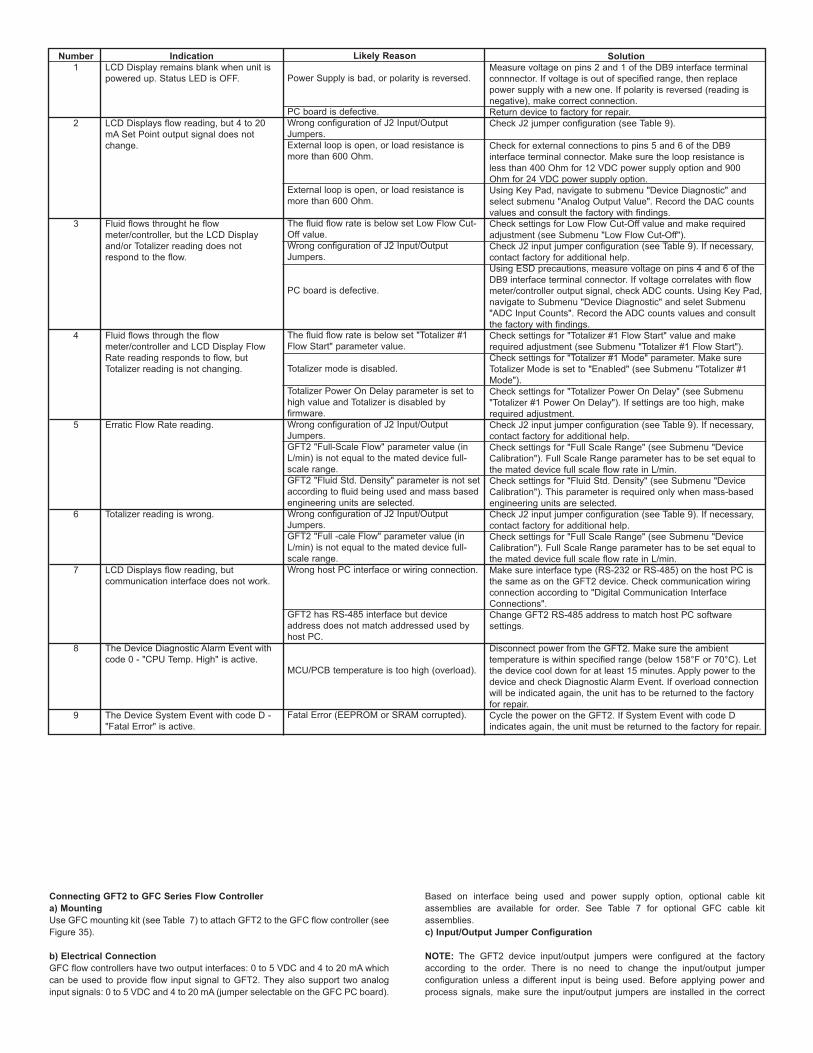
Number1
2
3
4
5
6
7
8
9
IndicationLCD Display remains blank when unit ispowered up. Status LED is OFF.
LCD Displays flow reading, but 4 to 20mA Set Point output signal does notchange.
Fluid flows throught he flowmeter/controller, but the LCD Displayand/or Totalizer reading does notrespond to the flow.
Fluid flows through the flowmeter/controller and LCD Display FlowRate reading responds to flow, butTotalizer reading is not changing.
Erratic Flow Rate reading.
Totalizer reading is wrong.
LCD Displays flow reading, butcommunication interface does not work.
The Device Diagnostic Alarm Event withcode 0 - "CPU Temp. High" is active.
The Device System Event with code D -"Fatal Error" is active.
Likely Reason
Power Supply is bad, or polarity is reversed.
PC board is defective.Wrong configuration of J2 Input/OutputJumpers.External loop is open, or load resistance ismore than 600 Ohm.
External loop is open, or load resistance ismore than 600 Ohm.
The fluid flow rate is below set Low Flow Cut-Off value.Wrong configuration of J2 Input/OutputJumpers.
PC board is defective.
The fluid flow rate is below set "Totalizer #1Flow Start" parameter value.
Totalizer mode is disabled.
Totalizer Power On Delay parameter is set tohigh value and Totalizer is disabled byfirmware.Wrong configuration of J2 Input/OutputJumpers.GFT2 "Full-Scale Flow" parameter value (inL/min) is not equal to the mated device full-scale range.GFT2 "Fluid Std. Density" parameter is not setaccording to fluid being used and mass basedengineering units are selected.Wrong configuration of J2 Input/OutputJumpers.GFT2 "Full -cale Flow" parameter value (inL/min) is not equal to the mated device full-scale range.Wrong host PC interface or wiring connection.
GFT2 has RS-485 interface but deviceaddress does not match addressed used byhost PC.
MCU/PCB temperature is too high (overload).
Fatal Error (EEPROM or SRAM corrupted).
SolutionMeasure voltage on pins 2 and 1 of the DB9 interface terminalconnnector. If voltage is out of specified range, then replacepower supply with a new one. If polarity is reversed (reading isnegative), make correct connection.Return device to factory for repair.Check J2 jumper configuration (see Table 9).
Check for external connections to pins 5 and 6 of the DB9interface terminal connector. Make sure the loop resistance isless than 400 Ohm for 12 VDC power supply option and 900Ohm for 24 VDC power supply option.Using Key Pad, navigate to submenu "Device Diagnostic" andselect submenu "Analog Output Value". Record the DAC countsvalues and consult the factory with findings.Check settings for Low Flow Cut-Off value and make requiredadjustment (see Submenu "Low Flow Cut-Off").Check J2 input jumper configuration (see Table 9). If necessary,contact factory for additional help.Using ESD precautions, measure voltage on pins 4 and 6 of theDB9 interface terminal connector. If voltage correlates with flowmeter/controller output signal, check ADC counts. Using Key Pad,navigate to Submenu "Device Diagnostic" and selet Submenu"ADC Input Counts". Record the ADC counts values and consultthe factory with findings.Check settings for "Totalizer #1 Flow Start" value and makerequired adjustment (see Submenu "Totalizer #1 Flow Start").Check settings for "Totalizer #1 Mode" parameter. Make sureTotalizer Mode is set to "Enabled" (see Submenu "Totalizer #1Mode").Check settings for "Totalizer Power On Delay" (see Submenu"Totalizer #1 Power On Delay"). If settings are too high, makerequired adjustment.Check J2 input jumper configuration (see Table 9). If necessary,contact factory for additional help.Check settings for "Full Scale Range" (see Submenu "DeviceCalibration"). Full Scale Range parameter has to be set equal tothe mated device full scale flow rate in L/min.Check settings for "Fluid Std. Density" (see Submenu "DeviceCalibration"). This parameter is required only when mass-basedengineering units are selected.Check J2 input jumper configuration (see Table 9). If necessary,contact factory for additional help.Check settings for "Full Scale Range" (see Submenu "DeviceCalibration"). Full Scale Range parameter has to be set equal tothe mated device full scale flow rate in L/min.Make sure interface type (RS-232 or RS-485) on the host PC isthe same as on the GFT2 device. Check communication wiringconnection according to "Digital Communication InterfaceConnections".Change GFT2 RS-485 address to match host PC softwaresettings.
Disconnect power from the GFT2. Make sure the ambienttemperature is within specified range (below 158°F or 70°C). Letthe device cool down for at least 15 minutes. Apply power to thedevice and check Diagnostic Alarm Event. If overload connectionwill be indicated again, the unit has to be returned to the factoryfor repair.Cycle the power on the GFT2. If System Event with code Dindicates again, the unit must be returned to the factory for repair.
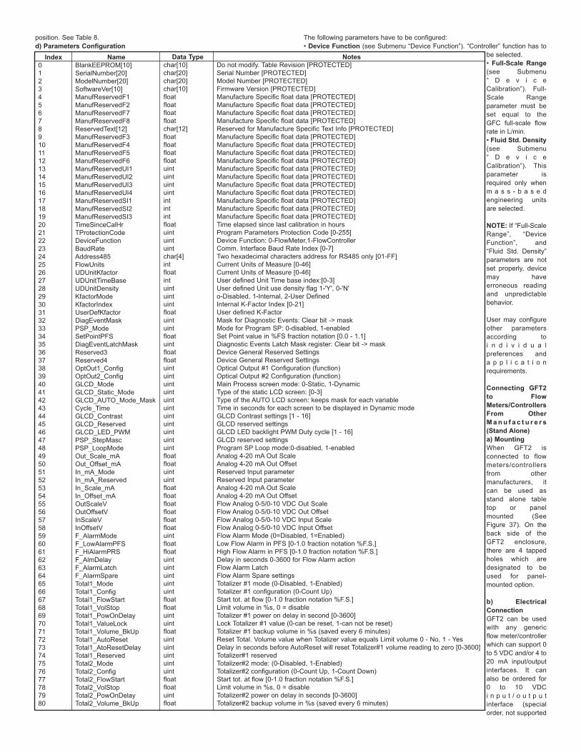
position. See Table 8. d) Parameters Configuration
The following parameters have to be configured:• Device Function (see Submenu “Device Function”). “Controller” function has to
be selected.• Full-Scale Range(see Submenu“ D e v i c eCalibration”). Full-Scale Rangeparameter must beset equal to theGFC full-scale flowrate in L/min.• Fluid Std. Density(see Submenu“ D e v i c eCalibration”). Thisparameter isrequired only whenm a s s - b a s e dengineering unitsare selected.
NOTE: If “Full-ScaleRange”, “DeviceFunction”, and“Fluid Std. Density”parameters are notset properly, devicemay haveerroneous readingand unpredictablebehavior.
User may configureother parametersaccording toi n d i v i d u a lpreferences anda p p l i c a t i o nrequirements.
Connecting GFT2to FlowMeters/ControllersFrom OtherM a n u f a c t u r e r s(Stand Alone)a) MountingWhen GFT2 isconnected to flowmeters/controllersfrom othermanufacturers, itcan be used asstand alone tabletop or panelmounted (SeeFigure 37). On theback side of theGFT2 enclosure,there are 4 tappedholes which aredesignated to beused for panel-mounted option.
b) ElectricalConnectionGFT2 can be usedwith any genericflow meter/controllerwhich can support 0to 5 VDC and/or 4 to20 mA input/outputinterfaces. It canalso be ordered for0 to 10 VDCi n p u t / o u t p u tinterface (specialorder, not supported
Index01234567891011121314151617181920212223242526272829303132333435363738394041424344454647484950515253545556575859606162636465666768697071727374757677787980
NameBlankEEPROM[10]SerialNumber[20]ModelNumber[20]SoftwareVer[10]ManufReservedF1ManufReservedF2ManufReservedF7ManufReservedF8ReservedText[12]ManufReservedF3ManufReservedF4ManufReservedF5ManufReservedF6ManufReservedUI1ManufReservedUI2ManufReservedUI3ManufReservedUI4ManufReservedSI1ManufReservedSI2ManufReservedSI3TimeSinceCalHrTProtectionCodeDeviceFunctionBaudRateAddress485FlowUnitsUDUnitKfactorUDUnitTimeBaseUDUnitDensityKfactorModeKfactorIndexUserDefKfactorDiagEventMaskPSP_ModeSetPointPFSDiagEventLatchMaskReserved3Reserved4OptOut1_ConfigOptOut2_ConfigGLCD_ModeGLCD_Static_ModeGLCD_AUTO_Mode_MaskCycle_TimeGLCD_ContrastGLCD_ReservedGLCD_LED_PWMPSP_StepMasc PSP_LoopModeOut_Scale_mAOut_Offset_mAIn_mA_ModeIn_mA_ReservedIn_Scale_mAIn_Offset_mAOutScaleVOutOffsetVInScaleVInOffsetVF_AlarmModeF_LowAlarmPFSF_HiAlarmPRSF_AlmDelayF_AlarmLatchF_AlarmSpareTotal1_ModeTotal1_ConfigTotal1_FlowStartTotal1_VolStopTotal1_PowOnDelayTotal1_ValueLockTotal1_Volume_BkUpTotal1_AutoResetTotal1_AtoResetDelayTotal1_ReservedTotal2_ModeTotal2_ConfigTotal2_FlowStartTotal2_VolStopTotal2_PowOnDelayTotal2_Volume_BkUp
Data Typechar[10]char[20]char[20]char[10]floatfloatfloatfloatchar[12]floatfloatfloatfloatuintuintuintuintintintintfloatuintuintuintchar[4]intfloatintuintuintuintfloatuintuintfloatuintfloatfloatuintuintuintuintuintuintuintuintuintuintuintfloatfloatuintuintfloatfloatfloatfloatfloatfloatuintfloatfloatuintuintuintuintuintfloatfloatuintuintfloatuintuintuintuintuintfloatfloatuintfloat
NotesDo not modify. Table Revision [PROTECTED]Serial Number [PROTECTED]Model Number [PROTECTED]Firmware Version [PROTECTED]Manufacture Specific float data [PROTECTED]Manufacture Specific float data [PROTECTED]Manufacture Specific float data [PROTECTED]Manufacture Specific float data [PROTECTED]Reserved for Manufacture Specific Text Info [PROTECTED]Manufacture Specific float data [PROTECTED]Manufacture Specific float data [PROTECTED]Manufacture Specific float data [PROTECTED]Manufacture Specific float data [PROTECTED]Manufacture Specific float data [PROTECTED]Manufacture Specific float data [PROTECTED]Manufacture Specific float data [PROTECTED]Manufacture Specific float data [PROTECTED]Manufacture Specific float data [PROTECTED]Manufacture Specific float data [PROTECTED]Manufacture Specific float data [PROTECTED]Time elapsed since last calibration in hoursProgram Parameters Protection Code [0-255]Device Function: 0-FlowMeter,1-FlowControllerComm. Interface Baud Rate Index [0-7]Two hexadecimal characters address for RS485 only [01-FF]Current Units of Measure [0-46]Current Units of Measure [0-46]User defined Unit Time base index:[0-3]User defined Unit use density flag 1-'Y', 0-'N'o-Disabled, 1-Internal, 2-User DefinedInternal K-Factor Index [0-21]User defined K-FactorMask for Diagnostic Events: Clear bit -> maskMode for Program SP: 0-disabled, 1-enabledSet Point value in %FS fraction notation [0.0 - 1.1]Diagnostic Events Latch Mask register: Clear bit -> maskDevice General Reserved SettingsDevice General Reserved SettingsOptical Output #1 Configuration (function)Optical Output #2 Configuration (function)Main Process screen mode: 0-Static, 1-DynamicType of the static LCD screen: [0-3]Type of the AUTO LCD screen: keeps mask for each variableTime in seconds for each screen to be displayed in Dynamic modeGLCD Contrast settings [1 - 16]GLCD reserved settingsGLCD LED backlight PWM Duty cycle [1 - 16]GLCD reserved settingsProgram SP Loop mode:0-disabled, 1-enabledAnalog 4-20 mA Out ScaleAnalog 4-20 mA Out OffsetReserved Input parameterReserved Input parameterAnalog 4-20 mA Out ScaleAnalog 4-20 mA Out OffsetFlow Analog 0-5/0-10 VDC Out ScaleFlow Analog 0-5/0-10 VDC Out OffsetFlow Analog 0-5/0-10 VDC Input ScaleFlow Analog 0-5/0-10 VDC Input OffsetFlow Alarm Mode (0=Disabled, 1=Enabled)Low Flow Alarm in PFS [0-1.0 fraction notation %F.S.]High Flow Alarm in PFS [0-1.0 fraction notation %F.S.]Delay in seconds 0-3600 for Flow Alarm actionFlow Alarm LatchFlow Alarm Spare settingsTotalizer #1 mode (0-Disabled, 1-Enabled)Totalizer #1 configuration (0-Count Up)Start tot. at flow [0-1.0 fraction notation %F.S.]Limit volume in %s, 0 = disableTotalizer #1 power on delay in second [0-3600]Lock Totalizer #1 value (0-can be reset, 1-can not be reset)Totalizer #1 backup volume in %s (saved every 6 minutes)Reset Total. Volume value when Totalizer value equals Limit volume 0 - No, 1 - YesDelay in seconds before AutoReset will reset Totalizer#1 volume reading to zero [0-3600]Totalizer#1 reservedTotalizer#2 mode: (0-Disabled, 1-Enabled)Totalizer#2 configuration (0-Count Up, 1-Count Down)Start tot. at flow [0-1.0 fraction notation %F.S.]Limit volume in %s, 0 = disableTotalizer#2 power on delay in seconds [0-3600]Totalizer#2 backup volume in %s (saved every 6 minutes)

by generic models).
N O T E :Do notc o n n e c tG F T 2
input/output circuitry to voltages above 5.5 VDC unless GFT2 was specifically
Index81828384858687888990919293949596979899100101102103104105106107108109110111112113114115116117118119120121122123124125126127128129130131132133134135136137138139140141142143144145146147148149150151152153154155156157158159160161162163
NameTotal2_ReloadVolStopTotal2_ReloadDelayTotal2_10SecBackUpTotal2_ReservedFlow_Pulse_ModePulseFlowStartUnits_Per_PulseActive_Low_TimeFlow_Pulse_ReservedFlowCondModeFlow_NRF_NSampleFlow_NRF_ErrLimitFlow_NRF_TimeLimitFlow_DampingFlow_WindowFlowLinearizerFlow_SC_ReservedFlowTbl[0]. FlowPFSInFlowTbl[0]. FlowPFSOutFlowTbl[1]. FlowPFSInFlowTbl[1]. FlowPFSOutFlowTbl[2]. Flow PFSInFlowTbl[2]. Flow PFSOutFlowTbl[3]. Flow PFSInFlowTbl[3]. Flow PFSOutFlowTbl[4]. FlowPFSInFlowTbl[4]. FlowPFSOutFlowTbl[5]. FlowPFSInFlowTbl[5]. FlowPFSOutFlowTbl[6]. FlowPFSInFlowTbl[6]. FlowPFSOutFlowTbl[7]. FlowPFSInFlowTbl[7]. FlowPFSOutFlowTbl[8]. FlowPFSInFlowTbl[8]. FlowPFSOutFlowTbl[9]. FlowPFSInFlowTbl[9]. FlowPFSOutFlowTbl[10]. FlowPFSInFlowTbl[10]. FlowPFSOutMDSerialNumberMeterFSRangeLowFlowCutOffFlowPowerUpDelayDensityFluidName[20]CalibratedBy[20]CalibratedAt[20]DateCalibrated[12]DateCalibratedDue[12]UserTagNamePSPTbl[0].PFSPSPTbl[0].TimePSPTbl[1].PFSPSPTbl[1].TimePSPTbl[2].PFSPSPTbl[2].TimePSPTbl[3].PFSPSPTbl[3].TimePSPTbl[4].PFSPSPTbl[4].TimePSPTbl[5].PFSPSPTbl[5].TimePSPTbl[6].PFSPSPTbl[0].TimePSPTbl[7].PFSPSPTbl[7].TimePSPTbl[8].PFSPSPTbl[8].TimePSPTbl[9].PFSPSPTbl[9].TimePSPTbl[10].PFSPSPTbl[10].TimePSPTbl[11].PFSPSPTbl[11].TimePSPTbl[12].PFSPSPTbl[12].TimePSPTbl[13].PFSPSPTbl[13].TimePSPTbl[14].PFSPSPTbl[14].TimePSPTbl[15].PFSPSPTbl[15].TimeEEMagicNumber
Data Typeuintuintuintuintuintfloatfloatuintuintuintuintfloatuintuintuintuintuinfloatfloatfloatfloatfloatfloatfloatfloatfloatfloatfloatfloatfloat floatfloatfloatfloatfloatfloatfloatfloatfloatfloatfloatfloatfloatfloatfloatfloatfloatfloatfloatfloatfloatfloatfloatfloatfloatfloatfloat floatfloatfloatfloatfloatfloatfloatfloatfloatfloatfloat floatfloatfloatfloatfloatfloatfloatfloatfloatfloatfloatfloatfloatfloatuint
NotesReload VolStop value when Totalizer reading counts down to zero 0 - No, 1 - YesDelay in seconds before Reload VolStop value when Totalizer reading counts down to zero [0-3600]Enable or Disable every 10 seconds EEPROM backup (reserved for future version release)Totalizer #2 reservedFlow Pulse Output Mode (0=Disabled, 1=Enabled)Start pulse output at flow [0-1.0 fraction notation %F.S.]Units per pulse scalingNumber of ms output will be activated when pulse is developedPulse Output Reserved0 - No conditioning, 1 - NRF, 2 - Running AverageFlow NRF Number of Samples [1 - 32]Flow NRF Error Value [0.05 10.0] %F.S. (FN)Flow NRF Time Interval [0-199], 0-disabledReading Damping 0-500 msFlow running average window [0-32] 0 - disableFlow Linearizer: On (1), off (0)Flow Signal Conditioner reservedFlow Linearizer Index 0 PFS In (must be 0.0)Flow Linearizer Index 0 PFS Out (must be 0.0)Flow Linearizer Index 1 PFS In [0.0 - 1.0]Flow Linearizer Index 1 PFS Out [0.0 - 1.0]Flow Linearizer Index 2 PFS In [0.0 - 1.0]Flow Linearizer Index 2 PFS Out [0.0 - 1.0]Flow Linearizer Index 3 PFS In [0.0 - 1.0]Flow Linearizer Index 3 PFS Out [0.0 - 1.0]Flow Linearizer Indes 4 PFS In [0.0 - 1.0]Flow Linearizer Indes 4 PFS Out [0.0 - 1.0]Flow Linearizer Indes 5 PFS In [0.0 - 1.0]Flow Linearizer Indes 5 PFS Out [0.0 - 1.0]Flow Linearizer Indes 6 PFS In [0.0 - 1.0]Flow Linearizer Indes 6 PFS Out [0.0 - 1.0]Flow Linearizer Indes 7 PFS In [0.0 - 1.0]Flow Linearizer Indes 7 PFS Out [0.0 - 1.0]Flow Linearizer Indes 8 PFS In [0.0 - 1.0]Flow Linearizer Indes 8 PFS Out [0.0 - 1.0]Flow Linearizer Indes 9 PFS In [0.0 - 1.0]Flow Linearizer Indes 9 PFS Out [0.0 - 1.0]Flow Linearizer Indes 10 PFS In [0.0 - 1.0]Flow Linearizer Indes 10 PFS Out [0.0 - 1.0]Serial Number for Mated DeviceDevice FS range in Std. L/minMust be between [0 and 0.1] fraction %F.S. notation [0-1.0]Flow Power Up delay [0-1200] sec.Fluid Density g/LName of the Fluid used for CalibrationName of person meter was calibrated byName of the Calibration LabCalibration dateDate Calibration dueUser Defined Device Tag Name or NumberPSP Table Index 0 Set Point PFS (0.0-1.0)PSP Table Index 0 Time (sec)PSP Table Index 1 Set Point PFS (0.0-1.0)PSP Table Index 1 Time (sec)PSP Table Index 2 Set Point PFS (0.0-1.0)PSP Table Index 2 Time (sec)PSP Table Index 3 Set Point PFS (0.0-1.0)PSP Table Index 3 Time (sec)PSP Table Index 4 Set Point PFS (0.0-1.0)PSP Table Index 4 Time (sec)PSP Table Index 5 Set Point PFS (0.0-1.0)PSP Table Index 5 Time (sec)PSP Table Index 6 Set Point PFS (0.0-1.0)PSP Table Index 6 Time (sec)PSP Table Index 7 Set Point PFS (0.0-1.0)PSP Table Index 7 Time (sec)PSP Table Index 8 Set Point PFS (0.0-1.0)PSP Table Index 8 Time (sec)PSP Table Index 9 Set Point PFS (0.0-1.0)PSP Table Index 9 Time (sec)PSP Table Index 10 Set Point PFS (0.0-1.0)PSP Table Index 10 Time (sec)PSP Table Index 11 Set Point PFS (0.0-1.0)PSP Table Index 11 Time (sec)PSP Table Index 12 Set Point PFS (0.0-1.0)PSP Table Index 12 Time (sec)PSP Table Index 13 Set Point PFS (0.0-1.0)PSP Table Index 13 Time (sec)PSP Table Index 14 Set Point PFS (0.0-1.0)PSP Table Index 14 Time (sec)PSP Table Index 15 Set Point PFS (0.0-1.0)PSP Table Index 15 Time (sec)Number used to verify EEPROM integrity
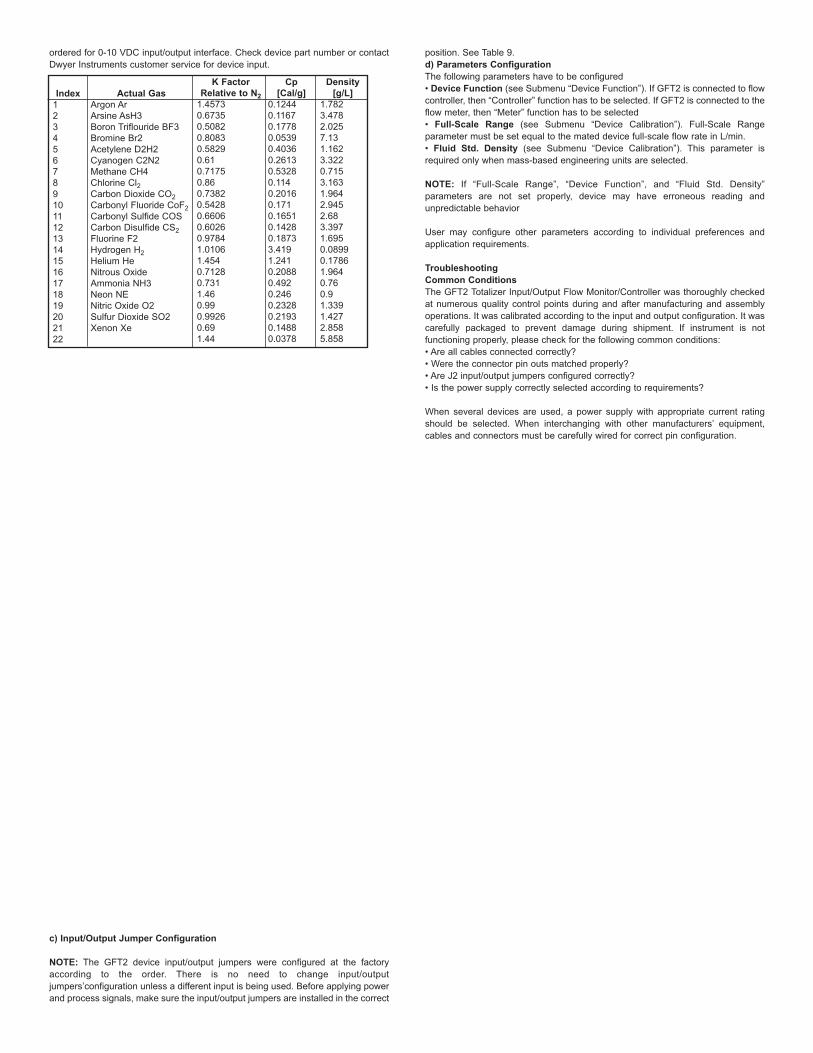
ordered for 0-10 VDC input/output interface. Check device part number or contactDwyer Instruments customer service for device input.
c) Input/Output Jumper Configuration
NOTE: The GFT2 device input/output jumpers were configured at the factoryaccording to the order. There is no need to change input/outputjumpers’configuration unless a different input is being used. Before applying powerand process signals, make sure the input/output jumpers are installed in the correct
position. See Table 9.d) Parameters ConfigurationThe following parameters have to be configured• Device Function (see Submenu “Device Function”). If GFT2 is connected to flowcontroller, then “Controller” function has to be selected. If GFT2 is connected to theflow meter, then “Meter” function has to be selected• Full-Scale Range (see Submenu “Device Calibration”). Full-Scale Rangeparameter must be set equal to the mated device full-scale flow rate in L/min.• Fluid Std. Density (see Submenu “Device Calibration”). This parameter isrequired only when mass-based engineering units are selected.
NOTE: If “Full-Scale Range”, “Device Function”, and “Fluid Std. Density”parameters are not set properly, device may have erroneous reading andunpredictable behavior
User may configure other parameters according to individual preferences andapplication requirements.
TroubleshootingCommon ConditionsThe GFT2 Totalizer Input/Output Flow Monitor/Controller was thoroughly checkedat numerous quality control points during and after manufacturing and assemblyoperations. It was calibrated according to the input and output configuration. It wascarefully packaged to prevent damage during shipment. If instrument is notfunctioning properly, please check for the following common conditions:• Are all cables connected correctly?• Were the connector pin outs matched properly?• Are J2 input/output jumpers configured correctly?• Is the power supply correctly selected according to requirements?
When several devices are used, a power supply with appropriate current ratingshould be selected. When interchanging with other manufacturers’ equipment,cables and connectors must be carefully wired for correct pin configuration.
Index12345678910111213141516171819202122
Actual GasArgon ArArsine AsH3Boron Triflouride BF3Bromine Br2Acetylene D2H2Cyanogen C2N2Methane CH4Chlorine Cl2Carbon Dioxide CO2Carbonyl Fluoride CoF2Carbonyl Sulfide COSCarbon Disulfide CS2Fluorine F2Hydrogen H2Helium HeNitrous OxideAmmonia NH3Neon NENitric Oxide O2Sulfur Dioxide SO2Xenon Xe
K FactorRelative to N2
1.45730.67350.50820.80830.58290.610.71750.860.73820.54280.66060.60260.97841.01061.4540.71280.7311.460.990.99260.691.44
Cp[Cal/g]
0.12440.11670.17780.05390.40360.26130.53280.1140.20160.1710.16510.14280.18733.4191.2410.20880.4920.2460.23280.21930.14880.0378
Density[g/L]
1.7823.4782.0257.131.1623.3220.7153.1631.9642.9452.683.3971.6950.08990.17861.9640.760.91.3391.4272.8585.858
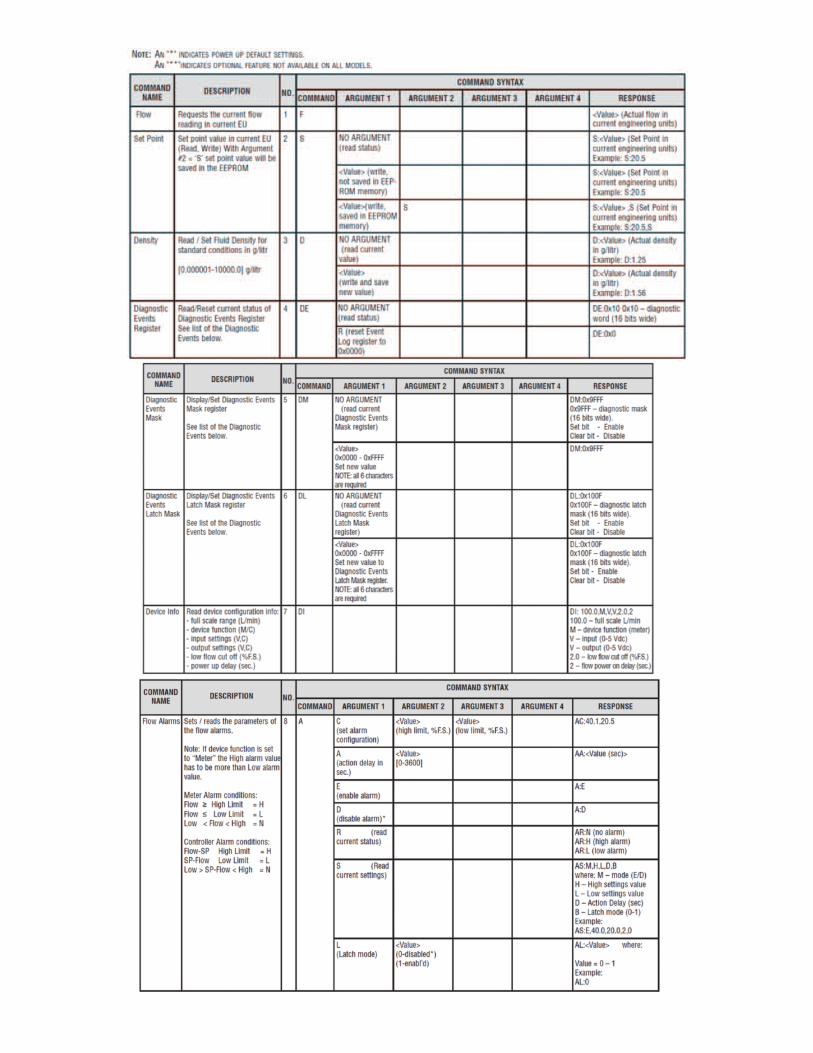


APPENDIX AGFT2 Totalizer Input/Output FlowMonitor/Controller EEPROM Variables 1
23456789
Not supported command or back door is not enabledWrong number of argumentsAddress is out of range (MR or MW commands)Wrong number of the characters in the argumentAttempt to alter Write Protected area in the EEPROMProper command or argument not foundWrong value of the argumentReservedManufacture specific into EE KEY (wrong key or key is disabled)
UART Error Codes
Index123456789
10111213141516171819202122
GasAr
AsH3BF3Br2
C2H2C2N2CH4Cl2CO2
COF2COSCS2F2H2He
N20NH3NENOO2
SO2Xe
Internal K-Factor Table ListK-Factor1.45730.67350.50820.80830.58290.61000.71750.86000.73820.54280.66060.60260.97841.01061.45400.71280.73101.46000.99000.99260.69001.4400
Code0123456789ABCD
Event DescriptionCPU Temp. HighHigh Flow AlarmLow Flow Alarm
Range betwen H-LTot#1 > LimitTot#2 > Limit
OptPulse QueueFlow OverLimit
Vcc OutOfRangeSerComm. ERROREEPROM ERROR
Power on EventPassword Event
Fatal Error
Diagnostic and System Events Codes and Bit PositionBit Position
0x00010x00020x00040x00080x00100x00200x00400x00800x01000x02000x04000x08000x10000x2000

APPENDIX BInternal K-Factors Table
APPENDIX CGFT2 ASCII Commands Set
RS-232/RS-485
The standard GFT2 comes with an RS-232 interface. The protocol described belowallows communication with the unit using either a custom software program or a“dumb” terminal. All values are set as printable ASCII characters. For RS-232interface, the start character and two characters of address have to be omitted. Forthe RS-485 interface, the start character is always ‘!’, and two characters ofaddress follow. The command string is terminated with a carriage return (line feedsare automatically stripped out by the GFT2):
RS-485 !<Addr>,<Cmd>,Arg1,Arg2,Arg3,Arg4<CR> Example: !12,F<CR>
©Copyright 2019 Dwyer Instruments, Inc. Printed in U.S.A. 3/19 FR# RA-444038-00 Rev. 2
DWYER INSTRUMENTS, INC. Phone: 219/879-8000 www.dwyer-inst.comP.O. BOX 373 • MICHIGAN CITY, INDIANA 46360, U.S.A. Fax: 219/872-9057 e-mail: [email protected]
This product is not intended to be used in life supportapplications!
CAUTION
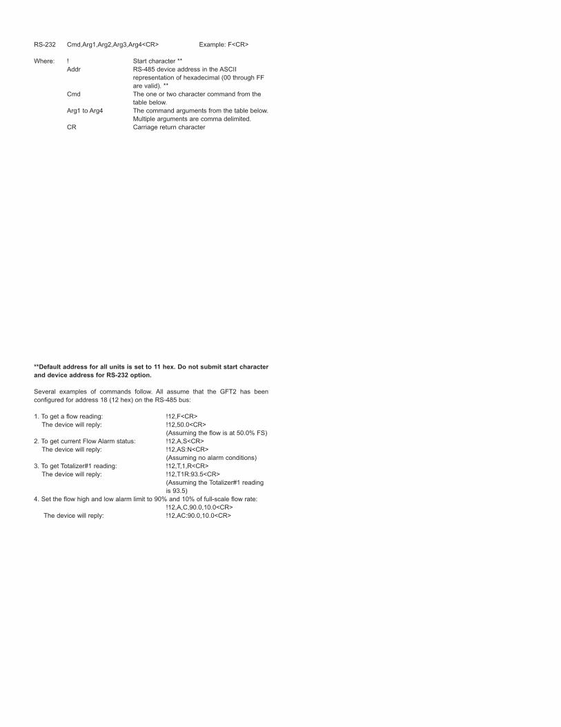
RS-232 Cmd,Arg1,Arg2,Arg3,Arg4<CR> Example: F<CR>
Where: ! Start character **Addr RS-485 device address in the ASCII
representation of hexadecimal (00 through FF are valid). **
Cmd The one or two character command from the table below.
Arg1 to Arg4 The command arguments from the table below.Multiple arguments are comma delimited.
CR Carriage return character
**Default address for all units is set to 11 hex. Do not submit start characterand device address for RS-232 option.
Several examples of commands follow. All assume that the GFT2 has beenconfigured for address 18 (12 hex) on the RS-485 bus:
1. To get a flow reading: !12,F<CR>The device will reply: !12,50.0<CR>
(Assuming the flow is at 50.0% FS)2. To get current Flow Alarm status: !12,A,S<CR>
The device will reply: !12,AS:N<CR>(Assuming no alarm conditions)
3. To get Totalizer#1 reading: !12,T,1,R<CR> The device will reply: !12,T1R:93.5<CR>
(Assuming the Totalizer#1 reading is 93.5)
4. Set the flow high and low alarm limit to 90% and 10% of full-scale flow rate:!12,A,C,90.0,10.0<CR>
The device will reply: !12,AC:90.0,10.0<CR>

APPENDIX DMechanical Drawings
APPENDIX ECircuit Layout DiagramsCircuit Layout Top
Circuit Layout BottomMirror
APPENDIX FWarranty
GFT2 Totalizer Input/Output Flow Monitor/Controller is warranted against parts andworkmanship for a period of one year from the date of purchase. It is assumed thatequipment selected by the customer is constructed of materials compatible with theenvironment in which the GFT2 is being used. Proper selection is the responsibilityof the customer. It is understood that power supply voltage and external signalsshould not exceed allowable limits provided in this manual, and it is deemed theresponsibility of the customer that only operators with basic knowledge of theequipment and its limitations are permitted to control and operate the equipmentcovered by this warranty. Anything to the contrary will automatically void Dwyer’sliability and the provisions of this warranty. Defective products will be repaired orreplaced at no charge solely at the discretion of Dwyer. Shipping charges are borneby the customer. This warranty is void if the equipment is damaged by accident ormisuse, or has been repaired or modified by anyone other than Dwyer or factoryauthorized service facility. This warranty defines the obligation of Dwyer and noother warranties expressed or implied are recognized.
MAINTENANCE/REPAIRUpon final installation of the Series GFT2 no routine maintenance is required. TheSeries GFT2 is not field serviceable and should be returned if repair is needed.Field repair should not be attempted and may void warranty.
WARRANTY/RETURNRefer to “Terms and Conditions of Sales” in our catalog and on our website. Contactcustomer service to receive a Return Goods Authorization number before shippingthe product back for repair. Be sure to include a brief description of the problemplus any additional application notes.