Sensor Learning Course - Store
44
July 2005 PG08301004E For more information visit: www.EatonElectrical.com 11-1 11 SENSOR LEARNING COURSE Contact Eaton University Training: www.EatonElectrical.com [email protected] (414) 449-7373 fax (414) 449-7378. Sensor Learning Course PG.05.07.T.E Table of Contents Eaton University Training . . . . . . . . . . . . . . . . . . . . . . . . . . . . . . . . . . . . . . . . . . . . . . . 11-2 Learning Module 23 . . . . . . . . . . . . . . . . . . . . . . . . . . . . . . . . . . . . . . . . . . . . . . . . . . . 11-4 Welcome . . . . . . . . . . . . . . . . . . . . . . . . . . . . . . . . . . . . . . . . . . . . . . . . . . . . . . . . . . 11-4 Sensor Basics . . . . . . . . . . . . . . . . . . . . . . . . . . . . . . . . . . . . . . . . . . . . . . . . . . . . . . 11-4 Review 1. . . . . . . . . . . . . . . . . . . . . . . . . . . . . . . . . . . . . . . . . . . . . . . . . . . . . . . . . . . 11-6 Limit Switches . . . . . . . . . . . . . . . . . . . . . . . . . . . . . . . . . . . . . . . . . . . . . . . . . . . . . 11-6 Actuators and Operating Heads . . . . . . . . . . . . . . . . . . . . . . . . . . . . . . . . . . . . . . 11-8 Limit Switch Types . . . . . . . . . . . . . . . . . . . . . . . . . . . . . . . . . . . . . . . . . . . . . . . . . 11-10 Review 2. . . . . . . . . . . . . . . . . . . . . . . . . . . . . . . . . . . . . . . . . . . . . . . . . . . . . . . . . . 11-12 Inductive Proximity Sensors. . . . . . . . . . . . . . . . . . . . . . . . . . . . . . . . . . . . . . . . . 11-12 How an Inductive Proximity Sensor Works . . . . . . . . . . . . . . . . . . . . . . . . . . . . 11-13 Review 3. . . . . . . . . . . . . . . . . . . . . . . . . . . . . . . . . . . . . . . . . . . . . . . . . . . . . . . . . . 11-14 Inductive Proximity Sensor Influences . . . . . . . . . . . . . . . . . . . . . . . . . . . . . . . . 11-15 Review 4. . . . . . . . . . . . . . . . . . . . . . . . . . . . . . . . . . . . . . . . . . . . . . . . . . . . . . . . . . 11-17 Capacitive Proximity Sensors . . . . . . . . . . . . . . . . . . . . . . . . . . . . . . . . . . . . . . . 11-18 Operation of the Capacitive Proximity Sensor . . . . . . . . . . . . . . . . . . . . . . . . . 11-18 Capacitive Proximity Sensor Influences . . . . . . . . . . . . . . . . . . . . . . . . . . . . . . . 11-19 Review 5. . . . . . . . . . . . . . . . . . . . . . . . . . . . . . . . . . . . . . . . . . . . . . . . . . . . . . . . . . 11-20 Photoelectric Sensors . . . . . . . . . . . . . . . . . . . . . . . . . . . . . . . . . . . . . . . . . . . . . . 11-20 Basic Operation of Photoelectric Sensors . . . . . . . . . . . . . . . . . . . . . . . . . . . . . 11-21 Photoelectric Sensor Styles and Uses . . . . . . . . . . . . . . . . . . . . . . . . . . . . . . . . 11-21 Modes of Detection . . . . . . . . . . . . . . . . . . . . . . . . . . . . . . . . . . . . . . . . . . . . . . . . 11-22 Review 6. . . . . . . . . . . . . . . . . . . . . . . . . . . . . . . . . . . . . . . . . . . . . . . . . . . . . . . . . . 11-24 Excess Gain . . . . . . . . . . . . . . . . . . . . . . . . . . . . . . . . . . . . . . . . . . . . . . . . . . . . . . . 11-25 Contrast . . . . . . . . . . . . . . . . . . . . . . . . . . . . . . . . . . . . . . . . . . . . . . . . . . . . . . . . . . 11-27 Environment . . . . . . . . . . . . . . . . . . . . . . . . . . . . . . . . . . . . . . . . . . . . . . . . . . . . . . 11-28 Review 7. . . . . . . . . . . . . . . . . . . . . . . . . . . . . . . . . . . . . . . . . . . . . . . . . . . . . . . . . . 11-28 Sensor Output Circuits . . . . . . . . . . . . . . . . . . . . . . . . . . . . . . . . . . . . . . . . . . . . . 11-29 Switching Logic . . . . . . . . . . . . . . . . . . . . . . . . . . . . . . . . . . . . . . . . . . . . . . . . . . . 11-31 Output Timing Modes . . . . . . . . . . . . . . . . . . . . . . . . . . . . . . . . . . . . . . . . . . . . . . 11-32 Review 8. . . . . . . . . . . . . . . . . . . . . . . . . . . . . . . . . . . . . . . . . . . . . . . . . . . . . . . . . . 11-34 Enclosure Ratings. . . . . . . . . . . . . . . . . . . . . . . . . . . . . . . . . . . . . . . . . . . . . . . . . . 11-34 IEC Ratings . . . . . . . . . . . . . . . . . . . . . . . . . . . . . . . . . . . . . . . . . . . . . . . . . . . . . . . 11-35 Review Answers . . . . . . . . . . . . . . . . . . . . . . . . . . . . . . . . . . . . . . . . . . . . . . . . . . . 11-36
-
Upload
khangminh22 -
Category
Documents
-
view
2 -
download
0
Transcript of Sensor Learning Course - Store

July 2005
PG08301004E For m
-1
11Sensor Learning CoursePG.05.07.T.E
11SE
NSO
RLE
ARN
ING
CO
URS
E
Table of ContentsEaton University Training. . . . . . . . . . . . . . . . . . . . . . . . . . . . . . . . . . . . . . . . . . . . . . . 11-2Learning Module 23 . . . . . . . . . . . . . . . . . . . . . . . . . . . . . . . . . . . . . . . . . . . . . . . . . . . 11-4
Welcome . . . . . . . . . . . . . . . . . . . . . . . . . . . . . . . . . . . . . . . . . . . . . . . . . . . . . . . . . . 11-4Sensor Basics . . . . . . . . . . . . . . . . . . . . . . . . . . . . . . . . . . . . . . . . . . . . . . . . . . . . . . 11-4Review 1. . . . . . . . . . . . . . . . . . . . . . . . . . . . . . . . . . . . . . . . . . . . . . . . . . . . . . . . . . . 11-6Limit Switches . . . . . . . . . . . . . . . . . . . . . . . . . . . . . . . . . . . . . . . . . . . . . . . . . . . . . 11-6Actuators and Operating Heads . . . . . . . . . . . . . . . . . . . . . . . . . . . . . . . . . . . . . . 11-8Limit Switch Types. . . . . . . . . . . . . . . . . . . . . . . . . . . . . . . . . . . . . . . . . . . . . . . . . 11-10Review 2. . . . . . . . . . . . . . . . . . . . . . . . . . . . . . . . . . . . . . . . . . . . . . . . . . . . . . . . . . 11-12Inductive Proximity Sensors. . . . . . . . . . . . . . . . . . . . . . . . . . . . . . . . . . . . . . . . . 11-12How an Inductive Proximity Sensor Works . . . . . . . . . . . . . . . . . . . . . . . . . . . . 11-13Review 3. . . . . . . . . . . . . . . . . . . . . . . . . . . . . . . . . . . . . . . . . . . . . . . . . . . . . . . . . . 11-14Inductive Proximity Sensor Influences. . . . . . . . . . . . . . . . . . . . . . . . . . . . . . . . 11-15Review 4. . . . . . . . . . . . . . . . . . . . . . . . . . . . . . . . . . . . . . . . . . . . . . . . . . . . . . . . . . 11-17Capacitive Proximity Sensors . . . . . . . . . . . . . . . . . . . . . . . . . . . . . . . . . . . . . . . 11-18Operation of the Capacitive Proximity Sensor . . . . . . . . . . . . . . . . . . . . . . . . . 11-18Capacitive Proximity Sensor Influences. . . . . . . . . . . . . . . . . . . . . . . . . . . . . . . 11-19Review 5. . . . . . . . . . . . . . . . . . . . . . . . . . . . . . . . . . . . . . . . . . . . . . . . . . . . . . . . . . 11-20Photoelectric Sensors . . . . . . . . . . . . . . . . . . . . . . . . . . . . . . . . . . . . . . . . . . . . . . 11-20Basic Operation of Photoelectric Sensors . . . . . . . . . . . . . . . . . . . . . . . . . . . . . 11-21Photoelectric Sensor Styles and Uses . . . . . . . . . . . . . . . . . . . . . . . . . . . . . . . . 11-21Modes of Detection . . . . . . . . . . . . . . . . . . . . . . . . . . . . . . . . . . . . . . . . . . . . . . . . 11-22Review 6. . . . . . . . . . . . . . . . . . . . . . . . . . . . . . . . . . . . . . . . . . . . . . . . . . . . . . . . . . 11-24Excess Gain. . . . . . . . . . . . . . . . . . . . . . . . . . . . . . . . . . . . . . . . . . . . . . . . . . . . . . . 11-25Contrast . . . . . . . . . . . . . . . . . . . . . . . . . . . . . . . . . . . . . . . . . . . . . . . . . . . . . . . . . . 11-27Environment . . . . . . . . . . . . . . . . . . . . . . . . . . . . . . . . . . . . . . . . . . . . . . . . . . . . . . 11-28Review 7. . . . . . . . . . . . . . . . . . . . . . . . . . . . . . . . . . . . . . . . . . . . . . . . . . . . . . . . . . 11-28Sensor Output Circuits . . . . . . . . . . . . . . . . . . . . . . . . . . . . . . . . . . . . . . . . . . . . . 11-29Switching Logic . . . . . . . . . . . . . . . . . . . . . . . . . . . . . . . . . . . . . . . . . . . . . . . . . . . 11-31Output Timing Modes . . . . . . . . . . . . . . . . . . . . . . . . . . . . . . . . . . . . . . . . . . . . . . 11-32Review 8. . . . . . . . . . . . . . . . . . . . . . . . . . . . . . . . . . . . . . . . . . . . . . . . . . . . . . . . . . 11-34Enclosure Ratings. . . . . . . . . . . . . . . . . . . . . . . . . . . . . . . . . . . . . . . . . . . . . . . . . . 11-34IEC Ratings . . . . . . . . . . . . . . . . . . . . . . . . . . . . . . . . . . . . . . . . . . . . . . . . . . . . . . . 11-35Review Answers. . . . . . . . . . . . . . . . . . . . . . . . . . . . . . . . . . . . . . . . . . . . . . . . . . . 11-36
ore information visit: www.EatonElectrical.com
Contact Eaton University Training:www.EatonElectrical.com
[email protected](414) 449-7373 fax (414) 449-7378.

July 2005
11-2
11SEN
SOR
LEARN
ING
COU
RSE
Sensor Learning CourseEaton University Training
Sensors: Limit Switches, Proximity & PhotoelectricCutler-Hammer Training at Eaton Corporation
Sensor Learning CourseThe following pages contain a com-plete learning course that will take you through the basic operation and application of limit switches, induc-tive and capacitive proximity sen-sors, and photoelectric sensors. Whether you’re a novice looking to get up to speed fast, or are already experienced in this area and just want to sharpen your skills, this course will be time well spent.
This course is part of the 101 Basics Series from Eaton University Training, a comprehensive series of learning modules covering a wide variety of power and control subjects.
About Eaton University TrainingEaton University Training exists to keep you, our partners, at the cutting edge of technical and professional development. We provide education solutions, promote a learning culture and foster talent development for our employees, channel partners, industry and academia.
We share our knowledge resources in a number of ways: from traditional classroom to paper-based distance learning programs to a complete web-based virtual learning environment at our electronic campus.
Eaton University Training educational programs put you directly on the path to career success. We partner with you to determine your knowledge needs and help you apply what you learned. And we’re committed to ensuring that you gain maximum return from your time and investment.
Classroom InteractionsEaton University Training classroom activities encourage interaction, collabo-ration and participation. You play an integral role in what happens. Experi-enced instructors facilitate a learning environment where you can feel comfortable making mistakes and asking questions. The result is a seamless classroom to on-the-job transition that allows you to directly apply your newfound knowledge. Making you and your company more productive and competitive.
■ Discover product features, benefits and applications in a product technology solutions seminar.
■ Gain hands-on experience maintaining electrical equipment or solving simulated power quality problems in one of our state-of-the-art laboratories.
■ Become qualified in Cutler-Hammer Information Technology solutions by Eaton, such as Bid Manager or Vista, in a computer training class.
■ Collaborate with your peers in one of our talent development workshops. And it doesn’t end there. Eaton University Training offers a full spectrum of per-sonal and professional development options. As new learning needs are identi-fied, our course offerings change to help you meet new challenges.
To browse the latest course offerings and register on-line, visit us on the World Wide Web.
For more information visit: www.EatonElectrical.com
Contact Eaton University Training:www.EatonElectrical.com
[email protected](414) 449-7373 fax (414) 449-7378.
Knowledge Powers Success. It takes knowledge to succeed. But, knowledge doesn’t just happen. It’s a continuous pro-cess of learning. Only lifelong learning allows you to keep in step with a world that is con-stantly changing.
So, you need to get smarter about learning and explore new ways of thinking. You need to take advantage of new experiences and employ cutting edge technologies.
Assess and develop your tal-ents. Empower yourself to find the answers and solutions of tomorrow.
Learn. Succeed.
PG08301004E

PG08301004E For m
-3July 2005
11Sensor Learning CourseEaton University Training
Sensors: Limit Switches, Proximity & Photoelectric11SE
NSO
RLE
ARN
ING
CO
URS
E
Virtual Campus Our virtual campus offers knowledge resources accessible from anywhere in the world, 24-hours-a-day, and 7-days-a-week. It’s where you go to register for classroom opportunities, participate in on-line learning courses, or search our library for learning tools including educational videos and technical documen-tation. You control the content, timing and pace of your learning program.
As technology evolves, Eaton University Training commits to giving you access to the most effective learning tools — right from your desktop.
Visit our virtual campus at www.EatonElectrical.com by clicking on the Eaton University Training icon. Employees can access us on the Eaton University Intranet.
Customized Learning Can’t find what you’re looking for? Please contact us. Eaton University Training has course consultants that work with you to customize a class or make recommendations based on your personal needs. For example:
■ Bring a class to your location, saving you time away from the plant or office.
■ Customize an existing class, placing emphasis on the subjects your group needs most.
■ Receive Eaton University product training outside of the regularly scheduled courses.
■ Connect with technical experts who will answer your specific questions. Start planning your customized learning. E-mail us at [email protected].
We look forward to helping power your success.
Eaton University Training at Eaton Corporation —Knowledge Powers Success
ore information visit: www.EatonElectrical.com
Contact Eaton University Training:www.EatonElectrical.com
[email protected](414) 449-7373 fax (414) 449-7378.
11-4
11SEN
SOR
LEARN
ING
COU
RSE
July 2005
Sensor Learning CourseLearning Module 23
Sensors: Limit Switches, Proximity & PhotoelectricWelcomeWelcome to Module 23, which is about sensors. As the name implies, sensors are devices that sense the presence or absence of objects. Sen-sors perform a number of functions in auto-mated manufacturing and material handling systems. For example, sensors can determine if an object is present, if tooling is broken, or if product is running down a conveyor line.
This module will take you through the basic operation and application of three major sensor categories: Limit Switches, Proximity Sensors and Photoelectric Sensors.
Like the other modules in this series, this one presents small, manageable sections of new material followed by a series of questions about that material. Study the mate-rial carefully then answer the questions without referring back to what you’ve just read. You are the best judge of how well you grasp the material. Review the material as often as you think necessary. The most important thing is establishing a solid foundation to build on as you move from topic to topic and module to module.
A Note on Font StylesKey points are in bold.
Glossary items are italicized and underlined the first time they appear. Clicking on them in the CD version will link to their definitions.
Viewing the GlossaryPrinted and CD versions have the glossary in Section 13.
Sensor BasicsA manual switch enables an operator to interact with a machine. If, for example, an operator sees a problem on a manufacturing line, he could move a switch to stop the line. Or, think of a light switch in your home. If you (the operator) want the light turned on, you have to move the switch.
A sensor can be thought of as an automatic switch. In a factory, a sensor can be used to detect a problem on the line and stop the line automatically. Or, in your home, a sensor could be used as a security device to detect an open window or door.
Sensors have contributed significantly to recent advances in manufacturing technology. Using a sensor makes a process or system more automated and removes the need for human operators to monitor and control the situation.
The three main categories of sensors are limit switches, proximity sensors and photoelectric sensors. Let’s take a moment to look at each type of sensor.
Limit SwitchA limit switch is an electrome-chanical device. A part of the limit switch, called an Actuator, is placed in the path of an oncoming object, such as a box on a conveyor. When the object contacts the actuator, the con-tacts in the limit switch are opened (or closed, depending on the limit switch’s design) to stop (or start) the flow of current in the electrical circuit.
Proximity SensorThis type of sensor uses an electromagnetic field to detect when an object is near. There is no physical con-tact between the object and the sensor. Inductive proxim-ity sensors detect only metal objects. Capacitive proximity sensors can sense both metallic and non-metallic objects.
Think of a manufacturing process where the alignment of a part is critical. A proximity sensor can be used to make sure the part is aligned within a certain tolerance. If the part is not properly aligned, the proximity sensor will be triggered.
This type of sensor is generally used to sense at dis-tances less than one inch.
Typical Sensors
Limit Switch with
Standard Roller Lever
Proximity Sensor Types
For more information visit: www.EatonElectrical.com PG08301004E

July 2005
PG08301004E For m
-5
11Sensor Learning CourseLearning Module 23 Sensors: Limit Switches, Proximity & Photoelectric11SE
NSO
RLE
ARN
ING
CO
URS
E
Photoelectric SensorThis type of sensor uses light to detect the presence or absence of an object. A Thru-Beam photoelectric sensor uses two devices (a light source and a detector) facing each other. Detection occurs when an object blocks or breaks the beam of light passing between them (Figure 1). A Diffuse Reflective sensor emits a light beam that must be reflected back to it by the target object itself for detection to occur (Figure 2). A Retroflective Sensing sen-sor emits a light beam that is reflected back to the sensor from a retroreflector. When an object blocks the beam between the sensor and the retroreflector, detection occurs (Figure 3). We’ll cover more on these types of pho-toelectric sensors later in this module.
Most electric garage door openers include a photoelectric sensor for safety reasons. If the photoelectric sensor’s beam is broken (by a child for example) as the door is going down, the sensor signals the door opener to reverse the direction of the door.
Although environmental factors can affect photoelectric sensors, these devices have a long sensing range. The objects they detect can be of any material.
Figure 1. Thru-Beam
Figure 2. Diffuse Reflective
Figure 3. Retro-Reflective
Sensor ComparisonEach of the three sensor categories has its strengths and weaknesses. Table 1 provides you with a comparison.
Table 1. Sensor Category Comparison
In the Workplace
As a conveyor moves the stacked boxes onto a turntable, a sensor detects the boxes in position and tells the machine to start the turntable and index the wrapping material. Another sensor monitors the play out of wrapping material to detect an empty spool and alert set-up personnel. Once the operation ends, the wrapped boxes move on to their shipping destination.
The Sensor “Sees” the Box and Tells the Wrapping Machine to Begin Operating
Thanks to sensors, the repetitive and tedious work done in this factory is handled precisely and reliably by machinery and systems working together.
Beam Complete Object Detected
Source Detector Source Detector
Beam Not Complete Object Detected
Source
Detector
Source
Detector
Source
Detector
Source
Detector
Beam Complete Object Detected
Limit Switches Proximity Sensors Photoelectric Sensors
Method of Detection
Physical contact Electromagnetic field
Light beam
Sensing Range Physical contact Close: within 1”(25.44 mm)
Far: can be 800’(243.8m)
Target Material Target must be able to withstand physical range
Inductive: metallic onlyCapacitive: metallic and non-metallic
Can be affected by target surface, for example, if the target is shiny or transparent
Object Markings Not able to detect Not able to detect Able to detectCost Low Low Low to high
depending upon sensing method
Sensor Size Tend to be large Small to large Very small (fiber optic) to large
Environmental Sensitivity
Affected by debris Inductive: electrical interferenceCapacitive: humidity
Light interference
Response Time Milliseconds Milliseconds Microseconds
ore information visit: www.EatonElectrical.com

11-6
11SEN
SOR
LEARN
ING
COU
RSE
July 2005
Sensor Learning CourseLearning Module 23
Sensors: Limit Switches, Proximity & PhotoelectricReview 1Answer the following questions without referring to the material just presented. Begin the next section when you are confident that you understand what you’ve already read.
1. Sensors can detect the ___________ or __________ of objects.
2. The three main sensor categories are:________________________________________________________________________
3. A limit switch is an _____________________ device that relies on physical contact with the target.
4. The sensor type that can only detect metallic objects is the __________ __________ sensor.
5. The sensor type that uses a broken beam of light to detect objects is commonly referred to as a ____________________ sensor.
Answers to Review 1 are on Page 11-36.
Limit SwitchesLet’s now take an in-depth look at the limit switch. It is a commonly used device. If you look around your kitchen, you can find a number of limit switches. For example, limit switches stop your microwave oven from operating unless the door is closed, and they ensure the light in your refrigerator is only on when the door is opened.
Remember, a limit switch is a mechanical device that requires the physical contact of an object with the switch’s actuator to make the contacts change state. The term limit switch is derived from this operation of the switch. As the object (or target) makes contact with the operator of the switch, it eventually moves the actuator to the “limit” where the contacts change state.
This mechanical action either opens (in a Normally Closed (N.C.) circuit) or closes (in a Normally Open (N.O.) circuit) the electrical contacts. The contacts then start or stop the flow of current in the electrical circuit.
The switching function can be used to control loads from simple relays to high-current solenoids, from logic devices to PLCs.
Strengths and WeaknessesAs with all devices, the limit switch has its strengths and weaknesses:
Table 2. Limit Switch Attributes
ApplicationsLimit switches are used in a variety of applications. Con-sider these:
Limit switches can be used to turn off a washing machine if the load becomes unbalanced. In automobiles, they turn on lights when the door is opened.
In industry, limit switches are used to limit the travel of machine parts, sequence operations or to detect moving items on a conveyor system.
Limit Switch ComponentsA limit switch consists of three main components.
The actuator is the part of the limit switch that physically comes in contact with the target. In some limit switches, the actuator is attached to an operating head. The operat-ing head translates a rotary, linear or perpendicular “trig-gering” motion into the motion type needed to open or close the electrical contacts of the switch.
The switch body is the component that contains the elec-trical contact mechanism.
The terminal screw or screw/clamp assembly necessary for wiring is referred to as the receptacle.
Limit Switch with Rod Lever
Strengths Weaknesses
• Can be used in almost any industrial environment because of its rugged design
• Can switch high inductance loads up to 10 amps
• Very precise in terms of accuracy and repeatability
• Low cost
• Moving mechanical parts wear out• Must touch target to sense• Relatively slow (5 times/sec.)
compared to electronic devices
Limit Switch Components
Actuator/Operating Head
Receptacle/Terminals
Receptacle/Terminals
Switch Body
For more information visit: www.EatonElectrical.com PG08301004E
July 2005
PG08301004E For m
-7
11Sensor Learning CourseLearning Module 23 Sensors: Limit Switches, Proximity & Photoelectric11SE
NSO
RLE
ARN
ING
CO
URS
E
In the Workplace
At the Marathon T-Shirt Company, boxes of apparel approach the end of the packaging line, ready to be stacked onto pallets. A palletizer with suction-cup grippers picks up a box and swings around to a waiting pallet.
How does the unit know it has reached its sixth layer of boxes? When the pivot arm reaches the top of its vertical travel rod, the arm hits a limit switch. The switch signals the system to send the full pallet down line and sets up an empty pallet to restart the process.
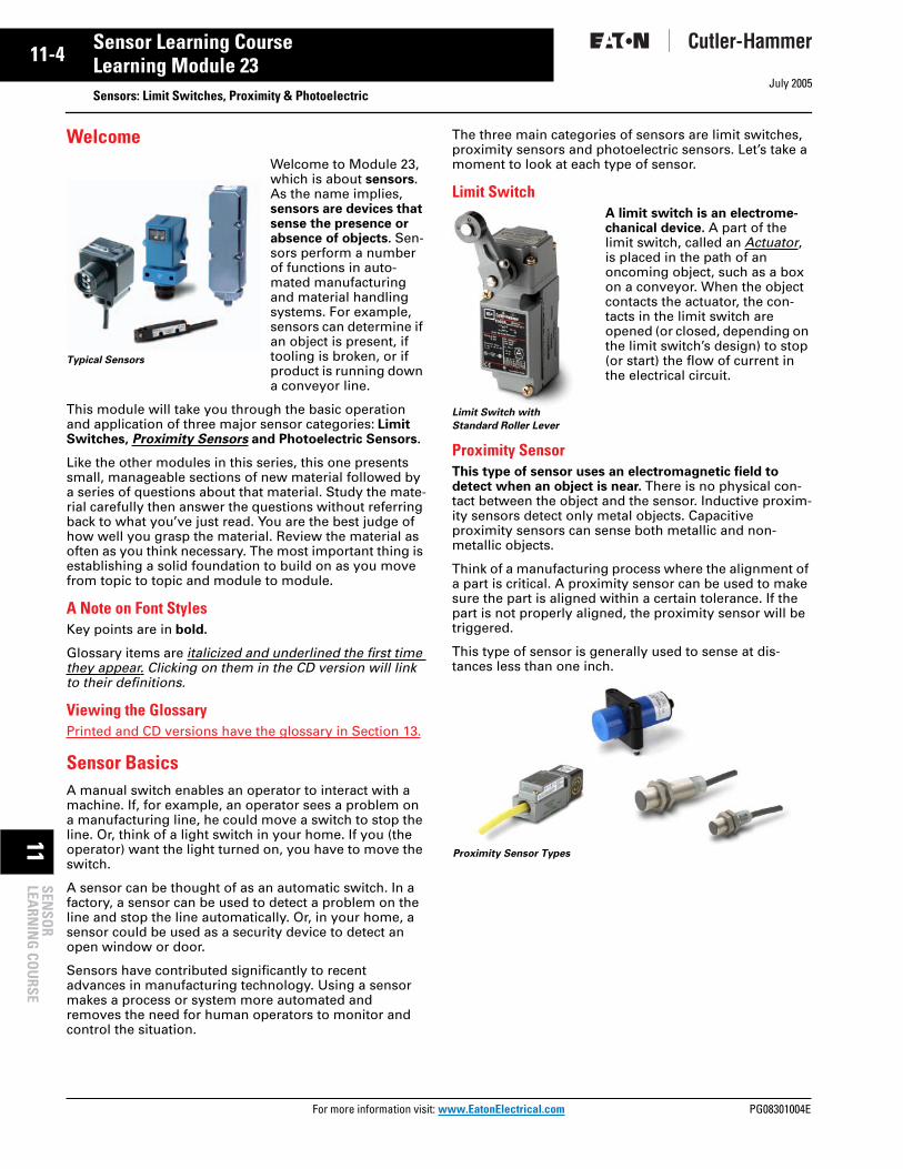
Limit Switch MovementLet’s take a closer look at what actually happens as a limit switch is activated. Imagine a target object moving toward a limit switch actuator.
Figure 4. Limit Switch Movement
1. The actuator is at its initial position. The limit switch contacts are in their normal “untriggered” position.
2. Contact is made with the target object and the actua-tor moves its Pre-travel distance. Contacts are still in their normal “untriggered” position.
3. The actuator reaches its operating point where the contacts change from their normal “untriggered” position to their “triggered” position.
In the case of a lever actuator, there is some Over-travel allowing the lever to move beyond the operat-ing point.
On plunger actuators, the overtravel distance is a safety margin for the sensor to avoid breakage.
The actuator begins the return to its initial position. The contacts return to their normal “untriggered” position as the actuator reaches its release point and resets the contacts.
4. The differential is the difference between the operat-ing and release point. Differential is engineered into the switch to guard against the effects of vibration and rapid on/off oscillations of the switch right at the operating point.
Limit Switch Movement DefinitionsHere are a few other terms that are used in describing the movement of the limit switch actuator:
The Operating Force is the force required to move the actuating element.
The minimum Return Force is the minimum force required to return the actuator to its initial position.
The total travel is the maximum allowable distance the actuating element can travel.
The ability of a switch to repeat its characteristics pre-cisely from one operation to the next is called the switch’s repeat accuracy.
In the Workplace
Inside this sawmill, a high-speed saw quickly reduces logs to construction beams.
In the process, chips and dust hang in the air. Breathing is impossible in the area without a mask. Even with goggles, it would be impossible to inspect the cutting.
The production department devised a system of limit switches to do the inspecting automatically. A remote operator can configure a set of limit switches to allow the log to be cut to the desired dimensions.
A Limit Switch in Action
DIFFERENTIAL
RESET POINT
INITIAL POSITION
OPERATINGPOINT
PRETRAVEL
OVERTRAVEL
Limit Switches Working Where People Cannot
ore information visit: www.EatonElectrical.com

11-8
11SEN
SOR
LEARN
ING
COU
RSE
July 2005
Sensor Learning CourseLearning Module 23
Sensors: Limit Switches, Proximity & PhotoelectricActuators and Operating HeadsChoosing the proper actuator (also called an operating head) for a limit switch depends on a number of applica-tion-specific factors. To select an actuator, you need to know shape, speed, direction and total travel specifications.
Operating heads fall into two broad types: Maintained Contact and Momentary Contact. Momentary contacts return to their normal state as soon as the actuator passes its release point. This type of operating head is also called “spring-return.”
With a maintained contact operating head, the contacts remain in the “triggered” position even after the actuator has been released. They are reset only by further mechanical action of the operating head. For example, on rotary operating heads, the contacts are reset by rotation in the opposite direction.
Actuators can take the form of rotary levers or plungers. We will look at specific actuator types on the next few pages.
Rotary Lever ActuatorsA typical lever actuator functions something like this: a Cam or plate hits the end of the lever arm, which rotates a shaft and operates the contacts in the switch.
The rotation may be momentary (spring-returned) or maintained. A lever arm can be a rod or a roller of a fixed or adjustable size. It may be made from any number of materials.
A rotary lever actuator is usually the best choice for the majority of applications. It can be used in any application where the cam moves perpendicular to the lever’s rota-tional shaft. This type of actuator also offers the benefit of a long life.
Let’s take a look at the different rotary lever actuator types available.
Table 3. Rotary Lever ActuatorsLever Type Illustration Application
Standard Roller
Used for most rotary lever applications. Available in various lengths. Roller typically made of nylatron for smooth operation and long wear.
Ball Bearing Roller
Used where abrasive dust would cause undue wear of standard nylatron rollers. Also used with high-speed cams.
Adjustable Length
Used where the length of arm required is not known when devices are ordered or where the target size or location may change from day to day. An operator can adjust the arm length before beginning production.
Forked Used with maintained contact style switches. When rollers are on opposite sides, one cam will trip the switch and the second will reset the switch. When rollers are on same side, one cam trips and resets the switch. Applied where the target approaches from two sides, such as a grinder that works back and forth.
Offset Used to obtain different cam track dimensions.
For more information visit: www.EatonElectrical.com PG08301004E

July 2005
PG08301004E For m
-9
11Sensor Learning CourseLearning Module 23 Sensors: Limit Switches, Proximity & Photoelectric11SE
NSO
RLE
ARN
ING
CO
URS
E
Table 3. Rotary Lever Actuators (Continued)
Plunger ActuatorsA typical plunger actuator functions something like this: a cam or plate hits the end of the plunger, which is pressed in and operates the contacts in the switch.
A plunger actuator is the best choice to monitor short, con-trolled machine movements, or where space or mounting restrictions will not permit the use of a lever actuator.
Lets take a look at the different plunger actuator types available.
Table 4. Plunger Actuators
Table 4. Plunger Actuators (Continued)Lever Type Illustration Application
One Way Roller
Used with reversible cams where operation in one direction only is required.
Rod or Loop
Used where unusual shape is required. Rod is typically made of steel or nylon. The loop is made of nylatron.
SpringRod
Used on conveyors where jam-ups may occur. Flexible rod moves in any direction and eliminates damage to arm or switch.
Lever Type Illustration Application
Top Push Rod
Actuation must be done in line with plunger axis. Care should be taken to avoid exceeding the overtravel stated by the manufacturer. A mechanical stop should be used where the possibility of overtravel exists.
Lever Type Illustration Application
Side Push Rod
Should be used where the mounting permits operating from the side only and not the top. As with the top push rod, avoid exceeding recommended overtravel. Available in both momentary and maintained styles.
Top and Side Push Roller
The function is similar to push rod styles, except there is a roller attached to the end of the rod. Typically used where a lever arm will not fit for lateral actuation. Roller can be positioned either vertically or horizontally.
Pin Most often used where extremely small differentials and operating forces are required.
Straight Used where the actuating element travels in same axis as plunger. Available in standard and extended lengths.
Lever Used in applications where the cam actuates in line with the plunger but may require a larger Differential or where an appreciable side thrust is present.
Roller Level Used in applications where the cam will pass by the switch laterally.
Roller Plunger
Used in applications where the cam may present some degree of side thrust. Roller helps deflect this.
Cat Whisker and Wobble Stick
Typically used in conveyor applications to count objects as they pass by. Can be actuated in any direction.
ore information visit: www.EatonElectrical.com

11-10
11SEN
SOR
LEARN
ING
COU
RSE
July 2005
Sensor Learning CourseLearning Module 23
Sensors: Limit Switches, Proximity & PhotoelectricMounting ConsiderationsWhen applying mechanical limit switches, consideration of the type of actuation needed, the mounting locale of the device and the speed of actuation are very important.
Cam Design
The cam angle should equal the lever arm angle for applications where the cam will not overtravel the actua-tor. Where relatively fast motions are involved, the cam should be of a shape that does not allow the actuator to receive a severe impact, or that releases the actuator sud-denly allowing it to snap back freely.
Figure 5. Cam Design
When using side-push or top-push plunger actuators, be sure the cam operates in line with the push rod axis. Do not use the limit switch body to act as a mechanical stop for the cam in overtravel applications. Some other type of barrier must be provided as the stop.
Mounting Location
Limit switches should never be mounted in locations that could allow false operations by normal movements of operator or machine components. They should be mounted rigidly, be maintenance accessible and have the cover plate facing that access point.
If liquid intrusion is a possibility, the switch should be mounted face down to allow gravity to prevent seepage through the seals on the operating head. All conduit con-nections should be tightly sealed.
In applications where machining chips or other debris accumulates, the limit switch should be mounted in a location, or at such an angle, that minimizes buildup on the operating head.
In the Workplace
At this leading frozen food processor, an automatic pallet stacking system is used. This system uses a wobble stick limit switch to detect when the pallets have been loaded to their desired level.
The switch then signals the con-veyor to send the load through an automatic vertical rise door into the freezer for quick freezing.
Limit Switch TypesThere are three basic classifications of limit switches available.
■ Standard Industrial■ Hazardous Location■ Precision
Let’s spend some time looking at each.
Standard Industrial SwitchOften the first choice for industrial applications, this switch functions in a variety of rugged industrial environments. This type of switch can be subjected to oil, grease, dirt, high-pressure wash-down, shock, vibration, etc. Typi-cally, these devices meet NEMA enclosure ratings of 1, 3, 3S, 4, 6, 12 and 13. An explanation of these ratings can be found in “Enclosure Ratings” on Page 11-34.
48º
48º48º
Cam
Into the Freezer
Standard Industrial Switch
Switch Body
Actuator/Operating Head
Receptacle/Terminals
For more information visit: www.EatonElectrical.com PG08301004E

July 2005
PG08301004E For m
11
11-Sensor Learning CourseLearning Module 23 Sensors: Limit Switches, Proximity & Photoelectric11SE
NSO
RLE
ARN
ING
CO
URS
E
Most limit switches on the market today are a plug-in type design, which means that the operating head, switch body and receptacle are separate components. If the switch becomes damaged or fails, it can be replaced in the field in less than a minute, without rewiring the switch. Simply remove the switch body, and the wiring remains intact in the receptacle. The majority of new industrial applications use the plug-in type due to its flex-ibility and ruggedness.
Non plug-in types are a popular design for DIN rail mounted limit switches. These switches are built to meet dimensional and operational standards set in Europe. They have typically the same electrical contact and enclosure ratings as the regular heavy-duty switches, but often their electrical and mechanical life is not as long. They are an economical alternative for applications where the switch is not subjected to physical abuse.
Hazardous Location SwitchThe hazardous location switch is ideal for use in harsh or dangerous environments. This switch is tough enough to contain an explosion within itself.
The one-piece switch body/receptacle is much heavier and thicker in construction than standard oil-tight switches. Like standard oil-tight switches, hazardous location switches have removable actuating heads attached to the switch body with four screws.
This switch type generally meets NEMA 1 requirements, and the hazardous location requirements of NEMA 7, Class I, Groups B, C and D; and NEMA 9, Class II, Groups E, F and G. Some manufacturers offer models rated NEMA 4X and 13 as well (see “Enclosure Ratings” on Page 11-34 for more information).
Precision Limit SwitchesThe precision limit switch is widely used in both commer-cial and industrial applications, ranging from appliances to farm equipment. It is often chosen for its precise oper-ating characteristics, small size and low cost.
Precision switches are typically available in two types: basic precision and enclosed precision. The basic preci-sion switch is of one-piece construction. The enclosed precision switch is simply a basic switch inside a die cast housing. Basic precision switches are generally not given a NEMA enclosure rating, while some enclosed precision switches can be rated NEMA 4 or 13.
Special Purpose Limit SwitchesSome applications require a limit switch to perform a special detection function. Such functions include direc-tion of an object’s movement, object’s height, width, length, etc. Let’s take a look at some of the special pur-pose limit switches
Table 5. Special Purpose Limit Switches
Hazardous Location Switches
Switch Type Illustration Application
Safety Guard
This type of switch is used to ensure safety for the operator of a dangerous machine. A standard limit switch could be false tripped or false actuated, posing a danger to the person operating the machine.Actuation of this switch occurs only when a keyed interlock is inserted into the key slot. The key is usually mounted on a safety door or machine guard so that when it is closed, the key slides into the slot, actuating the switch.
Precision Limit Switches
ore information visit: www.EatonElectrical.com

11-12
11SEN
SOR
LEARN
ING
COU
RSE
July 2005
Sensor Learning CourseLearning Module 23
Sensors: Limit Switches, Proximity & PhotoelectricTable 5. Special Purpose Limit Switches (Continued)
In the Workplace
In some manufacturing plants, rooms need to be closed off quickly because of contamination or fire. To help facilitate this process, high-speed doors have been developed. These doors may move as quickly as six feet per second.
At such speeds, the door would destroy itself quickly, if not for the use of limit switches. The limits switches are used to slow the door just before it is fully opened or fully closed.
Review 2Answer the following questions without referring to the material just presented. Begin the next section when you are confident that you understand what you’ve already read.
1. The three main components of a limit switch are:________________________________________________________________________
Match the terminology to the proper description:
8. The ability of a switch to repeat its characteristics from one operation to the next is called the switch’s repeat accuracy. TRUE FALSE
Answers to Review 2 are on Page 11-36.
Inductive Proximity SensorsThe inductive proximity sensor can be used to detect metal objects. It does this by creating an electromag-netic field.
With the ability to detect at close range, inductive prox-imity sensors are very useful for precision measurement and inspection applications.
Strengths and Weaknesses
Table 6. Inductive Proximity Sensor Attributes
Switch Type Illustration Application
Gravity Return
Unlike other rotary limit switches, this switch has no spring return mechanism. The weight of the operating lever must provide the force to return to its free position. This switch is usually mounted with the operating head facing down.It is often used in applications where very low operating forces from the target are required.
Neutral Position
With this limit switch, the direction of operation can be detected.One set of contacts is actuated when the lever is moved in one direction, and a second set of contacts is actuated when the lever is moved in the other direction.
Two Step
This switch operates to perform two functions with one switch. One set of contacts is activated after the lever is rotated 10°, and another set is activated at a 20° rotation (in the same direction).This switch can monitor an object’s height, orientation, position, completeness of assembly, etc.
Object moveslever
Weight of Lever (gravity)returns it to free position
CCW
CW
CWCCW10º 10º
20º20º
Limit Switches Help Operate This High-Speed Door
2. Initial position _____ A. Distance the actuator can travel safely beyond the operating point
3. Pre-travel distance
_____ B. Maximum allowable distance the actuator can travel
4. Operating point _____ C. Actuator and contacts are in the normal, or untriggered position
5. Overtravel _____ D. Actuator’s position at which the contacts change state
6. Release point _____ E. Actuator position where the contacts are reset to their normal “untriggered” state
7. Total travel _____ F. Actuator travel from contact with the target until the operating point
Strengths Weaknesses
• Immune to adverse environmental conditions
• High switching rate for rapid response applications
• Can detect metallic targets through non-metallic barriers
• Long operational life with virtually unlimited operating cycles
• Solid-state to provide a “bounce free” input signal to PLCs and other solid-state logic devices
• Limited Sensing Range(4" or 100 mm maximum)
• Detects only metal objects• May be affected by metal chips
accumulating on sensor face
For more information visit: www.EatonElectrical.com PG08301004E

July 2005
PG08301004E For m
13
11-Sensor Learning CourseLearning Module 23 Sensors: Limit Switches, Proximity & Photoelectric11SE
NSO
RLE
ARN
ING
CO
URS
E
ApplicationsProximity sensors are used in a variety of applications. Consider these:
Proximity sensors can be used to detect the end of travel on a positioning table, to determine speed by counting a gear’s teeth, or be used to check if a valve is fully opened or closed.
Proximity sensors can be used to detect the presence or absence of a metallic workpiece or metallic pallets on conveyor lines.
When a robot arm swings around for a pick and place operation, a proximity sensor makes sure the arm actu-ally has a part in its grippers.
In metal machining, proximity sensors can make sure the workpiece is mounted in the fixture, and that the drill bit has not broken off.
How an Inductive Proximity Sensor WorksInductive proximity sensors produce an oscillating and invisible radio frequency (RF) field at the sensor face. When metal objects are brought into this field, this oscil-lating field is affected. Each type and size of sensor has a specific sensing range switch point so that metal target detection is very accurate and repeatable.
The presence of a metallic target interrupts the field and alters (by Damping) the current in the sensor coil (Eddy Cur-rent kill) causing the detector circuit to sense the change. The sensor then triggers an output to a connected device.
ComponentsLet’s look at the components and the process step-by-step:
A metal object, or target, enters the sensing field.
The sensor coil is a coil of wire typically wound around a ferrite core. If you could see the electromagnetic field cre-ated by it, it would be cone shape. The target will pass through this field. The ferrite core shapes the field and the size of the coil determines the sensing range.
The oscillator circuit causes the field to cycle at a specific set radio frequency (100 KHz to 1 MHz). The presence of metal causes a change in the oscilla-tion, and an eddy current forms on the target. The metallic object induces a change in the magnetic field. This change creates a damping effect on the amount of signal that cycles back to the sensor coil.
The detector circuit senses the change and switches ON at a particular set point (amplitude). This ON signal gen-erates a signal to the solid-state output.
The output circuit remains active until the target leaves the sensing field. The oscillator responds with an increase in
amplitude, and when it reaches the set point, the detector circuit switches OFF. The output returns to its normal state.
HysteresisHysteresis is an engineered-in difference between the ON and OFF points.
If they were exactly the same point, there would be a chattering — a very rapid on-off-on-off cycle. That would cause a lot of needless stress on components activated by the circuit.
Figure 7. Hysteresis
With hysteresis, the Operate Point and the Release Point are slightly different distances from the sensor face.
Proximity Sensor TypesProximity sensors come in a wide variety of designs to meet the requirements of almost any industrial applica-tion. Let’s take a brief look at the types that are available.
Table 7. Proximity Sensors
Figure 6. Components
Type Illustration Application
Modular Limit Switch Type
The modular design can be tailored for many application types. Components can be easily switched out for short-run manufacturing changes.
Unitized Limit Switch Type
The sealed body protects the components in corrosive environments.
Tubular This is the design of choice for a growing number of applications. The small size allows for easy mounting in a fixture or for use in tight spaces found on many assembly lines.
MotionHysterisis
Operate Point
Release Point
ore information visit: www.EatonElectrical.com

11-14
11SEN
SOR
LEARN
ING
COU
RSE
July 2005
Sensor Learning CourseLearning Module 23
Sensors: Limit Switches, Proximity & PhotoelectricTable 7. Proximity Sensors (Continued)
In the Workplace
Without proximity sensors, the tips of the digits on the grippers of a robotic arm would be numb.
Coupled with the robot’s software control program and the responsive sensing ability of proximity sensors, a robot can grasp an object and not crush what it grips.
Review 3Answer the following questions without referring to the material just presented. Begin the next section when you are confident that you understand what you’ve already read.
1. Match the sensor component name to the correct picture.
a. Oscillator ____
b. Output _____
c. Detector _____
d. Sensor coil _____
Match the proximity sensor component with its function.
6. Hysteresis is the gap between the operate point and the release point to smooth the operation of the sensor. TRUE FALSE
Answers to Review 3 are on Page 11-36.
Type Illustration Application
Right Angle Tubular
This style enables mounting in tight locations.
High Current Tubular
Enables the smaller tubular design to carry extremely large inrush and continuous currents. Excellent for heavy equipment such as lift trucks.
Ferrous and Non-ferrous
Can detect either ferrous metals (steel/iron) or non-ferrous (brass/aluminum) metals. These units are suited to providing detection for assembly operations, such as aircraft or compact car engines.
Composite Housing
This corrosion-resistant unit performs well in high wash-down areas such as food processing, or places where caustic chemicals abound.
Pancake The extra wide coil on this unit achieves the widest and farthest range available: 3.94 inches. Ideal for oil rig applications and assembly of large parts.
Weld Field Immune
The magnetic field is not susceptible to the conflicting field created by arc welding. Useful for automated assembly lines where proximity sensors need to work in conjunction with welding equipment.
Proximity Sensors Allow a Robotic Arm to Safely Handle Fragile Components
2. Sensor coil _____ A. Sets up an electromagnetic field to create a wave pattern.
3. Oscillator _____ B. Alerts the electrical circuit an object has been detected.
4. Detector _____ C. Shapes the electromagnetic field.
5. Output _____ D. Looks for a change in frequency.
1
2
3
4
For more information visit: www.EatonElectrical.com PG08301004E

July 2005
PG08301004E For m
15
11-Sensor Learning CourseLearning Module 23 Sensors: Limit Switches, Proximity & Photoelectric11SE
NSO
RLE
ARN
ING
CO
URS
E
Inductive Proximity Sensor InfluencesWhen applying inductive proximity sensors, it is impor-tant to understand the sensing range and the factors that influence that range. The sensing range refers to the dis-tance between the sensor face and the target. It also includes the shape of the sensing field generated through the coil/core.
There are four main concerns when selecting and apply-ing proximity sensors:
■ Target Considerations (Material, Size, Shape and Approach)
■ Coil Size and Shielding■ Sensor Mounting Requirements■ Environment
Target MaterialYou need to know the target’s material. This information will help you determine the maximum sensing distance. Exceed this distance, and the damping effect necessary to trip the sensor’s output will not be created — and the sensor will fail to sense the target.
Proximity sensors work best with ferrous metals. Though these sensors detect other metals, the range will not be as great. Generally, the less iron in the target, the closer the target has to be to the sensor to be detected.
Manufacturers generally provide charts showing the nec-essary correction factors for various types of metals when applying their sensors. Each sensor style will have a correction factor to enable calculation for a particular target material.
Target SizeThe size of the target also matters. If you run a target smaller than the sensor’s “standard size,” sensing range will decrease. This is because a smaller target creates a weaker eddy current. However, a bigger target does not mean a longer sensing range.
The thickness of the target does not impact sensing range much. However, a very thin non-ferrous target can actually achieve a greater sensing range because it gen-erates an eddy current on both sides (known as the foil effect).
So, how big should the target be? The rule of thumb is: the size of the sensor’s diameter, or three times the sen-sor’s sensing range, whichever is greater.
Target ShapeThe shape of the target can have an impact on the sens-ing range. A round object, or an object with a rough surface can affect the damping effect of the sensor, and may require a closer sensing distance. Using a larger sensor size or an extended range sensor will also minimize this effect.
Target ApproachHow the target approaches the sensor matters as well. When an object comes at the sensor straight on, that’s an Axial Approach With this type of approach, you will need to protect the sensor physically. Allow for 25% overtravel.
Hysteresis tends to be greater for an axial approach than a lateral approach.
On a slide-by, or Lateral Approach, the target approaches the center axis of the sensing field from the side.
The target should not pass closer than the basic tolerance built into the machine design. Targets bumping into your sensor are a sure guarantee of eventual poor sensor performance.
For both approach types, make sure the target passes not more than 75% of the sensing distance from the sensor face. It is in this “Tip” area that variations in the sensing range occur.
In the Workplace
Motor oil is packaged on this automatic filling system.
As a one-quart bottle moves down the conveyor, the container passes an inductive proximity sensor located at the fill position.The label on the bottle has a distinctive design, printed with metallic inks. The label tells the proximity sensor the bottle is in position and ready to be filled.
2 Sn
SnCore
Figure 8. Axial Approach
D
0.75 x D
RecommendedSensing Area
Target
Sensing Distance of Target Used (Will Be Sn
for Standard Target)
Figure 9. Lateral Approach
An Inductive Proximity Sensor Being Used for Positive Placement
ore information visit: www.EatonElectrical.com

11-16
11SEN
SOR
LEARN
ING
COU
RSE
July 2005
Sensor Learning CourseLearning Module 23
Sensors: Limit Switches, Proximity & PhotoelectricCoil/Core SizeAn important factor in the range of the sensor is the con-struction of the coil/core. An open coil with no core will produce a field that could be actuated by a target from any direction. That wouldn’t be very practical for indus-trial applications.
For an inductive proximity sensor, the sensor coil that generates the field fits inside of a ferrite core. This cup-shaped piece of ferrite material is called a cup core. This core directs the field and shapes it.
Figure 10. Coil/Core Construction
A protective cap prevents dust or other environmental hazards from entering the sensor.
ShieldingTo focus the intensity of the field, the coil can be Shielded. In a standard range sensor, the ferrite cup core shapes the field to emanate straight from the sensing face of the sensor. In a sense, shielding it.
An extended range coil/core assembly does not use the standard cup core, just a core of ferrite. This Unshielded device allows the extension of the sensing range. There is less ferrite to absorb the electromagnetic field, so its range is wider and a little longer.
The decision to use a non-shielded sensor will impact the mounting of the sensor, as we will discuss that next.
Mounting ConsiderationsThe design of a sensor can affect how it is mounted.
A shielded sensor can be fully Embedded in a metal mounting block without affecting the range. They are sometimes referred to as flush mount sensors.
A non-shielded sensor needs clearance around it (called the metal-free zone) which is determined by its sensing range. Otherwise, the sensor will sense the metal mount-ing and be continuously operating.
Mounting two sensors closely together can also be a problem. If you position two proximity sensors too close together — either side by side or facing each other head to head — the two fields will clash with one another. Each sensor needs to be mounted at least three times its own sensing
range away from the other. The use of an alternative fre-quency head on one of the sensors will prevent adjacent sensors’ sensing fields from interacting.
In the Workplace
At an auto manufacturing plant, a drilling operation is performed on the valve blocks to allow for mounting the cover plates. The operation is totally unmanned.
The drill bit must form holes in an extremely hard material. Breaking drill bits is a fairly common occurrence. For this reason, a proximity sensor is in place. If a break occurs, the sensor signals the system to stop the operation so the drill bit may be replaced.
EnvironmentThe sensor’s environment can affect its performance dra-matically. Let’s take a look at some of these environmen-tal factors.
Debris can accumulate on the sensing cap, changing the range of the sensing field. In an application where metal chips are created, the sensor should be mounted to pre-vent those chips from building up on the sensor face. If this is not possible, then coolant fluid should be used to wash the chips off the face. An individual chip generally doesn’t have enough surface area to cause the sensor to turn on, but several of them could extend the sensing range and interfere with the accuracy of the sensor.
Cap Coil CupCore
SensorHead
Non-shieldedShielded
Figure 11. Shielding
Figure 12. Clear Zone
An Inductive Proximity Sensor Monitors Drilling Operation
For more information visit: www.EatonElectrical.com PG08301004E

July 2005
PG08301004E For m
17
11-Sensor Learning CourseLearning Module 23 Sensors: Limit Switches, Proximity & Photoelectric11SE
NSO
RLE
ARN
ING
CO
URS
E
Magnetic fields caused by electrical wiring located in the vicinity may affect sensor operation. If the field around the wires reaches an intensity that would saturate the fer-rite or the coil, the sensor will not operate. Sensors used in areas with high frequency welders can also be affected. To compensate for a welder, weld field immune sensors can be installed. Or, if the sensor is used with a PLC, a time delay can be programmed to ignore the sig-nal from the sensor for the time period that the welder is operating.
Radio transceivers (such as a walkie-talkie) can produce a signal with the same frequency as the oscillator circuit of the sensor. This is called radio frequency interference (RFI). Most manufacturers have taken steps to provide the maximum protection against RFI and false operation of the sensor.
Electrical interference from nearby motors, solenoids, relays and the like could have an affect on sensor opera-tion as well. An induced line or current spike (called a showering arc or EFT) can cause a false operation of the sensor. This spike can be produced by the electrical arc created when an electrical/mechanical switch or a contac-tor closes. If the lines connecting the sensor and these devices are adjacent and parallel to one another, the spike will affect the sensor. Most codes and specifications call for a separation of control and power leads so this is not often a problem.
The ambient temperature can affect sensing range. The effect is referred to as temperature drift. The sensing range can change by as much as ±10%.
Because sensing ranges can vary due to component, cir-cuit and temperature variations, along with the effects of normal machine wear, sensors should be selected based on sensing the target at 75%, and releasing at 125% of the rated sensing distance.
Figure 13. Sensing Distance Tolerances
In the Workplace
On the automated processing line at Harris House Paints, a can would occasionally come through the packaging process without a lid. Lids entered the line through a gravity feed and occasionally a lid would get momentarily hung up.
By mounting an inductive prox-imity sensor over the passing cans, the line could reject a can with a missing lid.
Review 4Answer the following questions without referring to the material just presented. Begin the next section when you are confident that you understand what you’ve already read.
1. Inductive proximity sensors work best with _____________ metals.
2. The target size rule of thumb is: the size of the sen-sor’s diameter, or three times the sensor’s sensing range, whichever is greater. TRUE FALSE
3. A target with a rough surface has no impact on the sensing range. TRUE FALSE
4. A slide-by approach to the sensor is called a lateral approach. TRUE FALSE
5. A straight on approach is called an axial approach.TRUE FALSE
6. When two sensors are to be mounted side-by-side, the use of an alternate frequency head on one of the sensors will not prevent the sensors’ sensing fields from interacting. TRUE FALSE
Answers to Review 4 are on Page 11-36.
125% 75%A
C B
A = Rated Sensing RangeB = Maximum Usable Sensing RangeC = Maximum Reset / Release Range
Target Sensor
An Inductive Proximity Sensor Keeps a Lid on Things
ore information visit: www.EatonElectrical.com

11-18
11SEN
SOR
LEARN
ING
COU
RSE
July 2005
Sensor Learning CourseLearning Module 23
Sensors: Limit Switches, Proximity & PhotoelectricCapacitive Proximity SensorsLet us now turn our attention to another proximity sen-sor, the capacitive proximity sensor. This sensor operates much like an inductive proximity sensor, but its means of sensing is much different.
Capacitive proximity sensors are designed to detect both metallic and nonmetallic targets. They are ideally suited for liquid level control and for sensing powdered or granulated material.
Strengths and WeaknessesConsider these strengths and weaknesses of the capaci-tive proximity sensor:
Table 8. Capacitive Proximity Sensor Attributes
ApplicationsHere are some examples showing how the detection power of capacitive proximity sensors is used:
■ Liquid level detection applications, such as preventing overfilling or underfilling, are common in the packag-ing industry.
■ Material level control applications, such as assuring that a sleeve of labels on a labeling line is not empty.
■ Counting applications, such as tracking units passing a point on a conveyor.
■ Induction molding process, detection of level of plastic pellets in feed hopper.
Operation of the Capacitive Proximity SensorA capacitor consists of two metal plates separated by a insulator (called a Dielectric). The operation of this type of sensor is based on dielectric Capacitance, which is the ability of a dielectric to store an electrical charge.
The distance between the plates determines the ability of the capacitor to store a charge.
Measuring the change in capacitance as an object enters the electrical field can be used as an ON/OFF switching function.
Figure 14. Capacator Operation
When this principle is applied to the capacitive proximity sensor, one capacitive plate is part of the switch, the enclosure (the sensor face) is the insulator. The target is the other “plate.” Ground is the common path.
Capacitive proximity sensors can detect any target that has a dielectric constant greater than air. Liquids have high dielectric constants. Metal also makes a good target.
Figure 15. Capacitive Proximity Sensor Operation
The capacitive proximity sensor has four basic elements: a sensor (which is a dielectric), an oscillator circuit, a detector circuit and an output circuit.
As an object approaches the sensor, the dielectric constant of the capacitor changes. The oscillator circuit’s oscillation begins when feedback capacitance is detected. This is just the opposite in the inductive proximity sensor, where the oscillation is damped when the target is present.
Figure 16. Oscillator Damping
The detector circuit monitors the oscillator’s output. When it detects sufficient change in the field, it switches on the output circuit.
The output circuit remains active until the target leaves the sensing field. The oscillator responds with a decrease in amplitude, and when it is no longer receiving sufficient capacitance feedback, the detector circuit switches OFF.
Strengths Weaknesses
• Can detect both metallic and nonmetallic objects at greater ranges than inductive sensors
• High switching rate for rapid response applications (counting)
• Can detect liquid targets through non-metallic barriers (glass, plastic)
• Long operation life, solid-state output for “bounce free” signals
• Affected by varying temperature, humidity and moisture conditions
• Not as accurate as inductive proximity sensors
Capacitive Proximity Sensors
Plates
Dielectric
Switch
100%
0 mmDistance
Cu
rren
t
Inductive Capacitive
100%
0 mmDistance
Cu
rren
t
For more information visit: www.EatonElectrical.com PG08301004E

July 2005
PG08301004E For m
19
11-Sensor Learning CourseLearning Module 23 Sensors: Limit Switches, Proximity & Photoelectric11SE
NSO
RLE
ARN
ING
CO
URS
E
There is a built-in difference between the operate and release amplitudes to provide hysteresis.
In the Workplace
As oil pours into this storage tank, a capacitive proximity sensor near the top signals the fill valve to close once the tank reaches capacity.
Another sensor near the bot-tom alerts the filling system if the level of the tank becomes too low.
Capacitive Proximity Sensor InfluencesMany of the same factors that influence the sensing range of inductive proximity sensors, also influence the sensing range of capacitive proximity sensors.
Typically, capacitive sensors have a greater sensing range than inductive sensors.
Table 9. Proximity Sensing Ranges
Sensing distance for capacitive proximity sensors is dependent on plate diameter. With inductive proximity sensors, the size of the coil is the determining factor.
Sensitivity AdjustmentMost capacitive proximity sensors are equipped with sensitivity adjustment potentiometers. Because the sen-sor measures a dielectric gap, it is important to be able to compensate for target and application conditions and adjust the sensing range.
Target Material and SizeA capacitive sensor should not be hand-held during set up. Because your hand has a dielectric constant greater than air, the sensor may detect your hand rather than the intended target.
Capacitive sensors can detect both ferrous and non-ferrous materials equally well. There is no derating factor to be applied when sensing metal targets. But, other materials do affect the sensing range. Because they can be used to detect liquid through a nonmetallic material such as glass or plastic, you need to ensure that the sen-sor detects just the liquid, not the container. The trans-parency of the container has no effect on the sensing.
For all practical purposes, the target size can be deter-mined in the same manner as was discussed in “Target Size” on Page 11-15 for inductive proximity sensors.
EnvironmentMany of the same factors that affect inductive proximity sensors, also affect capacitive sensors, only more so.
■ Embeddable mounting – capacitive sensors are gener-ally treated as non-shielded devices, and therefore, are not embeddable.
■ Flying chips – They are more sensitive to both metallic and nonmetallic chips and residue.
■ Adjacent sensors – more space between devices is required due to the greater, non-shielded sensing range.
■ Target background – because of both the greater sensing range, and its ability to sense metallic and nonmetallic materials, greater care in applying these sensors is needed when background conditions are present.
■ Ambient atmosphere – the amount of humidity in the air may cause a capacitive sensor to operate even when no target is present.
■ Welding magnetic fields – capacitive sensors are gen-erally not applied in a welding environment.
■ Radio Frequency Interference (RFI) – In the same way that inductive proximity sensors are affected, RFI inter-feres with capacitive sensor circuitry.
■ Showering arc (EFT) – induced electrical noise affects these sensors in the same way it does for an inductive sensor.
In the Workplace
On the fill line at Bud Springs Natural Water, five gallon plastic bottles pass along beneath a fill nozzle.
As water fills each bottle, a capacitive proximity sensor detects when the water reaches the specified level. As the sensor is more sensi-tive to water than it is to plastic, the sensor can “see through” the bottle wall.
Sensor with a Tubular Diameter of:
Inductive Extended Range Sensor
Capacitive Extended Range Sensor
18 mm 8 mm 10 mm30 mm 15 mm 20 mm34 mm — 40 mm
Capacitive Proximity Sensors in a Liquid Level Detection Application
A Capacitive Proximity Sensor “Sees Through” a Wall to Find the Target
ore information visit: www.EatonElectrical.com

11-20
11SEN
SOR
LEARN
ING
COU
RSE
July 2005
Sensor Learning CourseLearning Module 23
Sensors: Limit Switches, Proximity & PhotoelectricReview 5Answer the following questions without referring to the material just presented. Begin the next section when you are confident that you understand what you’ve already read.
1. The operation of a capacitive proximity sensor is based on dielectric capacitance.TRUE FALSE
2. The four main parts of a capacitive proximity sensor are:________________________________________________________________________________________________________________________
3. By measuring the change in capacitance as an object enters the field generated by the oscillator, it can be used for an on/off switching function. TRUE FALSE
4. When feedback capacitance is detected, the oscilla-tion ends. TRUE FALSE
5. When sensing metal targets, a derating factor must be applied. TRUE FALSE
6. The transparency of the container has no effect on the sensing. TRUE FALSE
Answers to Review 5 are on Page 11-36.
Photoelectric SensorsThe photoelectric sensor is a device with tremendous versatility and relatively low cost. Photoelectric sensors can detect objects more quickly and at further distances than many competitive technologies. For these reasons, photoelectric sensors are quickly becoming one of the most popular forms of automatic sensing used in manufacturing.
ApplicationsPhotoelectric sensors can provide solutions to a number of sensing situations. Some of the common uses for pho-toelectric sensors include:
Material Handling. A sensor can ensure that products move along a conveyor line in an orderly manner. The sensor will stop the operation if a jam occurs. And items can be counted as they move down the line.
Packaging. Sensors can verify that containers are filled properly, labeled properly and have tamper-proof seals in place.
Machine Operation. Sensors can watch to verify that a machine is operating properly, materials are present and tooling is not broken.
Paper Industry. Sensors can detect web flaws, web splice, clear web and paper presence, while maintaining high web speeds.
Design FlexibilityPhotoelectric sensors offer design flexibility to handle many types of situations. There are a variety of ways the transmitter and receiver can be arranged to meet the needs of the application.
Modes of OperationWe will briefly introduce you to these modes, and fully explain them later.
Table 10. Photoelectric Sensor Operation Modes
In the Workplace
At the tollbooth, the gate raises only when you have tossed in your coins. But how does the gate know when to drop back into place?
The gate is controlled by a photoelectric sensor that detects your car as it passes through the beam.
Photoelectric Sensors
Mode Description
Thru-Beam A source unit in one location sends a light beam to a detector unit in another location. An object is detected when it passes between the source unit and the detector unit, interrupting the light beam.
Reflex (Retro-Reflective)
The source and detector are housed in one package and placed on the same side of the target object’s path. When the object passes by, the source signal is reflected back to the detector by a retroreflector.
Diffuse Reflective The source and detector are housed in one package and placed on the same side of the target object’s path. When the object passes by, the source signal is reflected back to the detector off the target object itself.
Background Rejection (Perfect Prox)
This is a special type of diffuse reflective sensor that includes two detectors. This arrangement allows the sensor to detect targets reliably within a defined range, and to ignore objects just outside of this range. Unlike a standard diffuse reflective sensor, color or reflectivity has minimal effect on the sensing range of a Perfect Prox sensor.
A Photoelectric Sensor Prevents Commuters from Following You Through the Toll Booth for Free
For more information visit: www.EatonElectrical.com PG08301004E
July 2005
PG08301004E For m
21
11-Sensor Learning CourseLearning Module 23 Sensors: Limit Switches, Proximity & Photoelectric11SE
NSO
RLE
ARN
ING
CO
URS
E
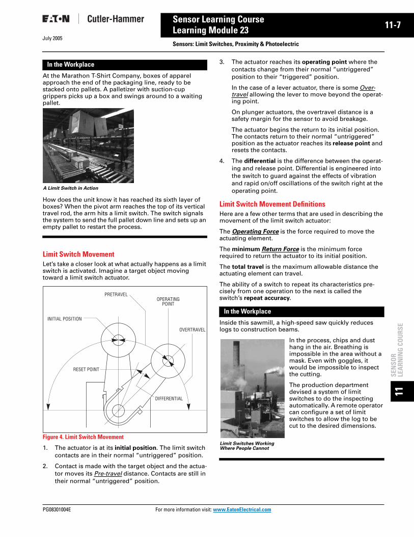
Basic Operation of Photoelectric SensorsThe operation of the photoelectric sensor is quite simple. A source LED sends a beam of light, which is picked up by a photodetector. When an object moves into the path of the light beam, the object is detected.
Let’s look at how a photoelectric sensor works.
Figure 17. Photoelectric Sensor Operation
The Light SourceThe light generated today by a photoelectric sensor comes from light emitting diodes, called LED. Using LEDs offers many significant advantages:
■ can be rapidly switched and instantly turned on and off■ extremely small■ consume very little power■ generate a negligible amount of heat■ life exceeds 100,000 hours (11 years) continuous use■ easily modulated to block false sensor triggering from
ambient light
Photoelectric Sensor Styles and Uses
General Purpose
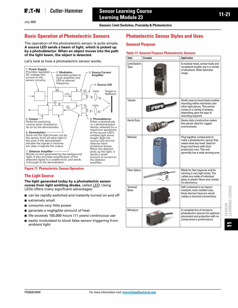
Table 11. General Purpose Photoelectric Sensors
1. Power SupplyProvides regulated DC voltage and current to the sensor circuitry.
2. Modulatorgenerates pulses to cycle amplifier and LED at desired frequency.
3. Source Current Amplifier
4. Source LED
Target or Reflector
5. OutputPerforms switchingroutine when directed to do so by the demodulator.
6. DemodulatorSorts out the light thrown out by the sensor from all other light in the area. If the demodulator decides the signals it receivesare okay, it signals the output.
7. Detector AmplifierBlocks current generated by the background light. It also provides amplification of the detected signal to a usable level, and sends it through to the demodulator.
8. PhotodetectorEither a photodiode or a phototransistor device, selected for a maximum sensitivity at the source LED’s emitted light wave-length. Both the source LED and the detector have protective lenses. When the detector picks up the light, it sends a small amount of current to the detector amplifier.
Lens
Lens
Style Example Application
Limit Switch Type
A modular head, sensor body and receptacle enable use in a variety of situations. Wide detection range.
Tubular Small, easy to mount body enables mounting within machinery and other tight places. This sensor comes in a variety of shapes, depending upon the type of mounting required.
Harsh Duty Heavy-duty construction makes this sensor ideal for rugged environments.
Modular Plug together components to make a photoelectric sensor that meets most any need. Ideal for large machinery with short production runs. This unit generally has a wide sensing area.
Fiber Optics Made for fast response and for sensing in very tight areas. The cables are made of individual glass or plastic fibers and contain no electronics.
Terminal Base
Self-contained in an impact-resistant, resin-molded case, these devices have pre-wired cables or terminal connections.
Miniature A complete line of miniature photoelectric sensors for optimum placement and protection with no compromise in performance.
ore information visit: www.EatonElectrical.com

11-22
11SEN
SOR
LEARN
ING
COU
RSE
July 2005
Sensor Learning CourseLearning Module 23
Sensors: Limit Switches, Proximity & PhotoelectricSpecialized Sensors
Table 12. Specialized Photoelectric Sensors
Fiber OpticsApplying Fiber Optic technology to photoelectric sensors means applications with space restrictions are not a problem. A fiber optic cable can detect objects in loca-tions too jammed for a standard sensor. Fiber optic cable is available in sizes as small as 0.002 inches in diameter.
Figure 18. A Glass Fiber Optic Cable
A glass fiber optic cable is made up of a large number of individual glass fibers, sheathed for protection against damage and excess flexing. Plastic fiber optic cables include a single plastic fiber in a protective coating. Nei-ther type of cable contains electronics.
Because light — rather than current — travels down these cables, the signal is unaffected by electromagnetic inter-ference (EMI) and vibration. The design also has built-in immunity to electrical noise and the inaccurate readings regular sensors can get.
Fiber optics can withstand high temperatures; plastic up to 158°F, standard glass up to 480°F, and specialized high temperature versions up to 900°F. Glass fibers can stand up to the harsh wash-down chemicals used in many food, beverage and pharmaceutical applications.
However, fiber optics have their disadvantages. They have a limited sensing distance, so they can be used only in tight areas. The maximum distance for the thru-beam design is just 15 inches. Also, these sensors have a small sensing area. A small drop of water or piece of dirt can easily fool fiber optics.
In the Workplace
In this cookie kitchen, fiber optic photoelectric sensors are placed in a hot oven. As long as the sensors detect motion as the trays of cookies move by, the oven stays on.
If the conveyor stops, the sensors will detect light or dark for too long, and the output device will shut down the oven.
Modes of DetectionIn most applications, photoelectric sensors generate an output any time an object is detected.
Light Operate vs. Dark OperateIf this occurs when the photodetector sees light, the sen-sor is said to be working in the light operate mode.
Figure 19. Light Operate and Dark Operate
If the control generates an output when the photodetec-tor does not see light, the control is said to be working in the dark operate mode.
Style Example Application
UV This sensor detects visible and invisible fluorescent substances.
Glass FibersEmbedded in
Epoxy
StainlessSteel
FerruleA Photoelectric Sensor Prevents Cookies from Being Burned
Source
Photo Sensor Sees Light:Load Is Operated
Light Operate Mode
Detector
Source
Detector
Photo Sensor Sees Dark:Load Is Not Operated
Source
Photo Sensor Sees Light:Load Is Not Operated
Dark Operate Mode
Detector
Source
Detector
Photo Sensor Sees Dark:Load Is Operated
For more information visit: www.EatonElectrical.com PG08301004E

July 2005
PG08301004E For m
23
11-Sensor Learning CourseLearning Module 23 Sensors: Limit Switches, Proximity & Photoelectric11SE
NSO
RLE
ARN
ING
CO
URS
E
Earlier, we briefly described the four basic operating modes that photoelectric sensors offer. These are:
■ Thru-Beam■ Reflex (Retro-Reflective)■ Diffuse Reflective■ Background Rejection (Perfect Prox)
Let’s now take some time to understand how each method works.
Thru-BeamSeparate light source and detector units face one another across an area. The column of light traveling in a straight line between the two lenses is the effective sensing beam. An object crossing the path has to com-pletely block the beam to be detected.
Figure 20. Thru-Beam Operation
Table 13. Thru-Beam Attributes
Reflex or Retro-ReflectiveThe source and detector are positioned parallel to each other on the same side of the object to be detected. Another element, called a retroreflector, is placed across from the source and detector. The retroreflector is similar to a reflector on the back of a bicycle. The retroreflector bounces the light from the source back to the detector.
When a target object passes between the source/detec-tor unit and the retroreflector, the beam is no longer reflected, and the target is sensed. The target has to block the entire beam.
Figure 21. Reflex Operation
In some cases, a reflex sensor can be falsely triggered by reflections from a shiny target’s surface. To avoid this, a Polarized Reflex Sensor can be used. The polarizing filter on the sensor ensures that only the light reflected by a retroreflector is recognized by the sensor.
Table 14. Reflex Attributes
Diffuse ReflectionThe source and detector are positioned on the same side of the target. The two components are aligned so that their fields of view cross. When the target moves into the area, light from the source is reflected off the target sur-face back to the detector.
Figure 22. Diffuse Reflection Operation
Table 15. Diffuse Reflective Attributes
Strengths Weaknesses
• Long sensing distance (up to 800 ft.)• Highly reliable• Can see through opaque objects
• Two components to mount and wire• Alignment could be difficult with a
longer distance detection zone
Source
Detector
Source
Object BlocksBeam
Detector
Field ofView
Normal State
Effective
Beam
Field ofView
Target Detected
Source/Detector
Retro-Reflector
Normal State
TargetObject
Target Detected
Retro-Reflector
Source/Detector
Object Does NotReflect Beam
TargetObject IsDetected
Strengths Weaknesses
• Medium range sensing distance• Low cost• Ease of installation• Alignment does not need to be exact • Polarizing filter ignores unwanted light
• Reflector must be mounted• Problems detecting clear objects• Dirt on retroreflector can hamper
operation• Not suitable for detecting small
objects• Detection distance and plane of
detection limited with a polarizing filter
Strengths Weaknesses
• Application flexibility• Low cost• Easy installation• Easy alignment• Many varieties available for many
application types
• Short sensing distance (under 6')• Sensing distance depends on target
size, surface and shape
Source/Detector
Normal State
Source/Detector
TargetObject
Object ReflectsBeam
TargetObject IsDetected
Target Detected
ore information visit: www.EatonElectrical.com

11-24
11SEN
SOR
LEARN
ING
COU
RSE
July 2005
Sensor Learning CourseLearning Module 23
Sensors: Limit Switches, Proximity & PhotoelectricBackground Rejection (Perfect Prox)This detection scheme is really a special type of diffuse reflective sensor. It combines extremely high sensing power with a sharp optical cut-off. This allows the sensor to reliably detect targets regardless of color, reflectance, contrast or surface shape, while ignoring objects just out-side of the target range.
This method uses two different photo-detectors. For the Perfect Prox unit with a six-inch range, the near detector has a range of 0 to 24 inches. Its far detector has a range of 6 to 24 inches.
Figure 23. Perfect Prox Sensor
Objects closer than six inches are detected only by the near detector. Objects between 6 and 24 inches are detected by both detectors.
If the near signal is stronger than the far signal, the sensor output is ON. If the far signal is stronger or equal to the near signal, the output is OFF. The result is a sensor with high Excess Gain for six inches, followed by a sharp cut-off.
In the Workplace
Hobbes Gear wanted to reduce the number of gears rejected on their line. One critical process is the automatic drilling of the gear’s mounting hole. To increase the reliability of the inspection process, Hobbes installed a Perfect Prox sensor.
The sensor is set to check for the presence of the machined hole in the gear. If the hole is present, the sensor’s light shines through it, to the conveyor belt. The belt is just beyond the sensor’s sensing distance. If a missing hole is detected, the sen-sor signals an air-operated cylinder plunger to reject the gear.
Review 6Answer the following questions without referring to the material just presented. Begin the next section when you are confident that you understand what you’ve already read.
1. The four modes of detection are:____________________________________________________________________________________________________________________
2. If the photoelectric sensor control generates an out-put when the photodetector does not see light, the control is working in the dark operate mode.TRUE FALSE
Match the mode of detection with its definition.
Answers to Review 6 are on Page 11-36.
Far DetectorField
Near Detector Field
Cut-OffDistance
Sensor
Cutoff Distance
Detection Distance
Gear Cut-away
Perfect Prox
Sensor
Detection Zone
A Perfect Prox is “Inspector #12”
3. Mode of detection that can pick up shiny objects.
____ A. Reflex
4. Sensing mode that has the longest range.
____ B. Perfect Prox
5. Sensing mode that combines extremely high sensing power with a sharp optical cut-off.
____ C. Thru-Beam
6. A polarizing filter used with this sensing mode ensures that only the light reflected by a retroreflector is recognized by the sensor.
____ D. Diffuse Reflective
For more information visit: www.EatonElectrical.com PG08301004E

July 2005
PG08301004E For m
25
11-Sensor Learning CourseLearning Module 23 Sensors: Limit Switches, Proximity & Photoelectric11SE
NSO
RLE
ARN
ING
CO
URS
E
Excess Gain
DefinitionExcess gain is a measurement of how much sensing power a photoelectric sensor has available beyond the power required to detect an object.
An excess gain of 1.00 at a given range means there is exactly enough power to detect an object under perfect conditions at that range. In other words, the range at which the excess gain equals 1.00 is the maximum range of the sensor.
Every model of sensor comes with an excess gain chart to help you determine the excess gain for an application’s sensing distance.
However, we have to take into consideration the follow-ing real-world variables:
■ Target size■ Target color■ Target surface texture■ Ability to block the beam■ Background■ Application environment
In the real world, there is contamination — dust, humidity and debris — that can settle on the lenses and reduce light transmission. Furthermore, each individual target may vary slightly from the next in color, reflectivity or dis-tance from the sensor.
If you use a sensor with an excess gain of exactly 1.00, you stand an excellent chance of not sensing the target reliably. To cover yourself, you need a sensor with the highest excess gain possible at the intended range. This ensures the sensor will continue to operate reliably when you need it. As the level of contamination gets worse, more excess gain will be needed to get past the poor visibility.
Applying Excess GainHow do you use excess gain in choosing a sensor for an application?
Consider an application for detecting boxes in an indus-trial environment. This area happens to have a consider-able amount of dust flying around. The boxes pass about two to five inches from the sensor as they move along the conveyor at the sensing location.
Figure 24. Typical Photoelectric Sensing Application
You are to select one of two diffuse reflective photoelec-tric sensors whose excess gain curves appear in the simplified graphs in Figure 25.
Figure 25. Choosing Sensors
Both sensors have acceptable curves. However, as con-taminants settle on each sensor’s lens, the sensor on the left will fail first. The sensor on the right would work bet-ter here because it delivers more excess gain.
You don’t want to rely solely on maximum range specifi-cations — always look for the maximum excess gain at the range where detection takes place.
The way excess gain is determined is different for each sensing mode. Let’s take some time to look at how each mode’s excess gain is determined.
TargetObject
Required RangeLimit
BackgroundObject
1000 1000
10
110.1 10 100
100
Gain Curve #1(Inches)
Gain Curve #2(Inches)
Area of Detection
100
10
10.01 0.1 1.0 10
ore information visit: www.EatonElectrical.com

11-26
11SEN
SOR
LEARN
ING
COU
RSE
July 2005
Sensor Learning CourseLearning Module 23
Sensors: Limit Switches, Proximity & PhotoelectricThru-BeamThis type of sensor’s excess gain is the simplest to mea-sure. Excess gain is almost exclusively a function of the separation between the source unit and the detector unit.
When implementing the excess gain for an application, start with the 1000 excess gain chart for the thru-beam sensor. Then consider:
■ Misalignment of the two units■ Dirt in the environment reduces gain
Figure 26. Typical Gain Curve for a Thru-Beam
Diffuse ReflectionNearly every diffuse reflective sensor has a unique com-bination of lenses and beam angles. As a result, nearly every sensor has a unique excess gain curve.
Figure 27. Diffuse Reflection Ranges
A short-range sensor delivers high excess gain over a short sensing distance and drops off quickly. The source’s beam and the detector’s field of view converge a short distance from the lenses. The energy present in that area is very high, allowing the detection of small targets. The sensor also ignores objects in the near background.
A long-range sensor’s source beam and detector’s field of view are positioned close together on the same axis. The ability to sense extends quite a distance. Excess gain peaks out several inches from the sen-sor, then drops off slowly over distance.
To sense into holes or cavities, or to pick up very small objects, use a focused diffuse reflective sensor. Or, a sensor with a very
small light spot size. The source and detector are posi-tioned behind the lens in order to focus the energy to a point. The excess gain is extremely high at this point and then drops off on either side of the sensing zone.
ReflexCalculating the excess gain for a reflex (retro-reflective) sensor is similar to the method used for diffuse reflective sensors.
With this type of sensor, excess gain and range are related to the light bouncing back from the reflector. Maximum operating range also depends upon lens geometry and detector amplifier gain.
The effective beam is defined as the actual size of the reflector surface. The target must be larger than the reflector before the sensor will recognize the target and switch its output.
Figure 29. Effective Reflex Sensor Beam
1000
10
110.1 10 100
100
Range (Feet)
1000
Short Range(Inches)
Long Range(Inches)
Focused Diffuse Reflective(Inches)
100
10
1
4000
1000
100
10
1
1000
100
10
1
0.010.1 10 20 30 40 50 60 70 100 1.0
1.0
10
1 10 100
Long Range Proximity
Short Range Proximity
Figure 28. Short-Range and Long-Range
Source Radiation
Retroreflector
Detector Field of View
Effective Beam
For more information visit: www.EatonElectrical.com PG08301004E

July 2005
PG08301004E For m
27
11-Sensor Learning CourseLearning Module 23 Sensors: Limit Switches, Proximity & Photoelectric11SE
NSO
RLE
ARN
ING
CO
URS
E
Light CurtainA Light Curtain is a specialized reflex sensor head. It has four transmitters and four detectors side by side behind a cylindrical lens. The light curtain emits a fan-shaped beam, which provides a wide viewing area.
Figure 30. Effective Light Curtain Sensor Beam
The distance from the lens to the reflector strip, together with the length of the reflector, serve to define the effec-tive detection area.
Figure 31. Effective Detection Area Graph
Corner Cube Retroreflector and ReflexIn the case of the corner cube reflector, range and excess gain depend upon on reflector quality.
Corner cube reflectors provide the highest signal return to the sensor. Cube style reflectors have 2000-3000 times the reflectivity of white paper.
Corner cube reflectors consist of three adjoining sides arranged at right angles to one another.
When a ray of light strikes one of the three adjoining sides, the ray is reflected to the second side, then to the third, and then back to its source in a direction parallel to its original course. Thousands of these cube shapes are molded into a rug-ged plastic reflector or vinyl material.
Glass bead retroreflectors are available in tape form for use in dispensers for package coding on convey-ors. They are also avail-able in sheet form that can be cut to size. The bead surface is typically rated at 200 to 900 times the reflec-tivity of white paper.
Only corner cube reflectors can be used with polarized reflex sensors. The light returned from the cube’s
surface is depolarized with respect to the light it received. Glass bead reflectors cannot be used with polarized retro-reflective sensors.
ContrastContrast measures the ability of a photoelectric sensor to detect an object. The contrast of a sensor is a ratio of the excess gain under light conditions to the excess gain under dark conditions. A ratio of 10:1 is desired. Contrast is important when a sensor has to detect semi-transparent objects or extremely small objects.
Each mode handles contrast differently.
Thru-Beam and ReflexThese modes are affected by:
■ Light transmissivity of an object or surface■ Size of an object in relation to the beam size
DiffuseThis mode is affected by:
■ Distance of the object or surface from the sensor■ Color or material of the object or surface■ Size of the object or surface
The ideal application provides infinite contrast ratio of the detection event. This is the case when 100% of the beam is blocked in reflex or thru-beam modes. For diffuse sensing, this occurs when nothing is present. Understanding the contrast ratio is critical when this situation does not exist, such as when detecting semitransparent objects. In some cases, it might be necessary to use a special low-contrast sensor designed for these applications.
+3+2+1--1-2-3
2 ft 4 ft 6 ft 8 ft 10 ftCurtain of Light Beam Profile
Deviation from Beam Center
in Feet
Light Ray
Figure 32. A Corner Cube Reflector
Light Ray
OpaqueMaterial
Figure 33. Glass Bead
ore information visit: www.EatonElectrical.com

11-28
11SEN
SOR
LEARN
ING
COU
RSE
July 2005
Sensor Learning CourseLearning Module 23
Sensors: Limit Switches, Proximity & PhotoelectricIn the Workplace
A thru-beam pair is positioned ten inches apart to detect a semi-transparent plastic bottle moving through the sensing zone. But the sensor is not picking up the bottle.
Given that the excess gain at that range is 100, and the bottle blocks only 5% of the light energy, the con-trast ratio is close to 1 (100/95). This does not meet the advised 10:1 ratio. The thru-beam pair is just too powerful.
Using a focused sensor positioned three to four inches from the bottle changes things. In this detection zone, the excess gain is between 20 and 100. (See Figure 31. Effective Detec-tion Area Graph on Page 11-27.)
EnvironmentThe list below ranks the level of contamination in a range of typical application environments.
Table 16. Level of Contamination Ranking
As you work your way down the list, the excess gain needed to overcome what’s hanging in the air gets higher.
To further complicate matters, with the reflex and thru-beam modes, the source and reflector can be in different locations with different levels of contamination.
For outdoor use, the environment can range from lightly dirty to extremely dirty.
Review 7Answer the following questions without referring to the material just presented. Begin the next section when you are confident that you understand what you’ve already read.
1. Excess gain is a measurement of how much sensing power a photoelectric sensor has available beyond the _____________ _____________.
2. Name the three factors that can affect excess gain.__________________________________________________________________________________________
3. Based on the excess gain charts below, which sensor would be best for an application, in a dirty environ-ment, for a target that is 10 inches away? ____
Figure 34. Typical Gain Curves
4. Nearly every diffuse reflective sensor has a unique excess gain curve because nearly every sensor has a unique combination of lenses and beam angles.TRUE FALSE
5. Only corner cube style reflectors should be used with polarized reflex sensors. TRUE FALSE
6. Contrast is not important when sensing semi-trans-parent targets. TRUE FALSE
Answers to Review 7 are on Page 11-36.
Ranking Description Minimum Excess Gain Required
Relatively clean No dirt buildup on lenses or reflectors 1.5 XSlightly dirty Slight buildup of dust, dirt, oil, moisture,
etc. on lenses or reflectors. Lenses should be cleaned on a regular schedule.
5 X
Moderately dirty Obvious contamination of lenses or reflectors. Lenses are cleared occasionally or when necessary.
10 X
Very dirty Heavy contamination of lenses. Heavy fog, mist, dust, smoke or oil film. Minimal cleaning of lenses takes place.
50 X
The Right Sensor Type Makes the Difference BetweenReliable Sensing and No Sensing at All
1000
BRange in Inches
100
10
10.01 1.0 10
1000
10
110.1 10 100
100
ARange in Feet
1000
10
110.1 10 100
100
CRange in Inches
For more information visit: www.EatonElectrical.com PG08301004E

July 2005
PG08301004E For m
29
11-Sensor Learning CourseLearning Module 23 Sensors: Limit Switches, Proximity & Photoelectric11SE
NSO
RLE
ARN
ING
CO
URS
E
Sensor Output CircuitsAs we learned earlier, sensors interface to other control circuits through the output circuit. The control voltage type is a determining factor when considering output type. Control voltage types, whether AC, DC or AC/DC, can be categorized as either Load-Powered Sensor or Line-Powered Sensor.
Load-PoweredLoad-powered devices are similar to limit switches. They are connected in series with the controlled load. These devices have two connection points to the circuit and are often referred to as 2-wire switches. The operating cur-rent is drawn through the load.
When the switch is not operated, it must draw a minimum operating cur-rent referred to as off-state leakage current. Off-state leakage current is also sometimes referred to as residual current. This cur-rent is used to keep the sensor electronics active while it “looks” for a tar-
get. Residual current is not a problem for loads such as relays, motor starters, etc. (with low impedance). How-ever, loads such as programmable logic controllers (with high impedance) require a leakage current of lower than 2 mA. Otherwise, the PLC might see the voltage as being an ON signal. Most sensors are 1.7 mA. If a particular PLC requires less than 1.7 mA, a loading resistor is added in parallel to the input to the PLC load. The resistor lowers the current seen by the PLC so it doesn’t false trigger.
The current required to maintain the sensor when the target is present, is called the Minimum Holding Current. This current may range from 3 mA to as much as 20 mA depending on the sensor specification. If the current drawn by the load is not high enough, then the sensor cannot operate. Sensors with a 4 mA or less minimum holding current can be used with PLCs without concern.
Line-PoweredLine-powered switches derive their power from the line and not through the load. They have three connection points to the circuit, and are often referred to as 3-wire switches.
The operating current the switch pulls from the line, is called the burden current. This is typically 20 mA. Because the operat-ing current doesn’t pass through the load, it is not a major concern for circuit design.
Two-Wire SensorsMost sensors are 3-wire devices, but some manufacturers
offer 2-wire devices. They are designed to be easy replacements for limit switches without the need to change wiring and logic.
Because 2-wire switches “steal” their operating power from the load circuit, there is a voltage drop across the switch when it is on (about 7 – 9 volts in AC powered devices).
If more than one 2-wire switch is wired in series with the load, there is a cumulative voltage drop across the switch. When more than one 2-wire switch is connected in parallel with a load, there is a cumulative effect on the leakage current. This increased off-state leakage current could cause a PLC to receive a false ON signal.
Output TypesThere are three output types available — Relay, Triac and Transistor.
A relay is a mechanical device that can handle load cur-rents at higher voltages. This allows the sensor to directly interface with motors, solenoids and other inductive loads. They can switch either AC or DC loads.
Relays are subject to contact wear and resistance build up, but contact life depends on the load current and the frequency of operations. Due to contact bounce, they can produce erratic results with counters, programmable logic controllers and other such devices, unless the input to those devices are filtered. Because relays are mechani-cal, they can add 10 to 25 milliseconds to a sensor’s Response Time.
For the majority of applications, these limitations cause no problems, or can easily be minimized. Relay outputs are very commonly used with sensors.
A triac is a solid-state device designed to control AC cur-rent. A triac switch turns on in less than a microsecond when its gate (control leg) is energized, and shuts off at the Zero Crossing of the AC power cycle.
Sensor Load
Figure 35. Load Powered/2-Wire Circuit
Load
Figure 36. Line-Powered/3-Wire Circuit
ore information visit: www.EatonElectrical.com

11-30
11SEN
SOR
LEARN
ING
COU
RSE
July 2005
Sensor Learning CourseLearning Module 23
Sensors: Limit Switches, Proximity & PhotoelectricFigure 37. Triac Output Circuit
Because a triac is a solid-state device, it is not subject to the mechanical limitations of a relay. Switching response time is limited only to the time it takes the 60 Hz AC power to go through one-half cycle.
Figure 38. AC Power Cycle
As long as a triac is used within its rated maximum current and voltage specification, life expectancy is virtually infi-nite. Triac devices used with sensors are generally rated at 2A loads or less, and can be directly interfaced with PLCs and other electronic devices. Triacs do have some limita-tions in that an inductive load directly connected can false trigger it. A Snubber Circuit can be used to minimize the problem. Shorting the load will destroy a triac, so the device should be short circuit protected to avoid this.
A transistor is a solid-state device designed to control DC current. They are most commonly used in low voltage DC powered sensors as the output switch. There are two types used, depending on the switching function. One is called NPN (Current Sink) Open Collector. The output transistor is connected to the negative DC. Current flows from the positive terminal through the load, to the sen-sor, to the negative terminal. The sensor “sinks” the cur-rent from the load.
Figure 39. Transistor Output Circuit (Sinking)
The second type used is called PNP (Current Source). The sensor is connected to the positive DC. Current flows from the positive terminal through the sensor, to the load, to the negative terminal. The sensor “sources” the current to the load.
Figure 40. Transistor Output Circuit (Sourcing)
Bilateral FET DevicePhotosensors have another output type called a bilateral FET output. This output has many advantages over the other types of outputs:
■ Switching of either AC or DC voltages■ Low “OFF-state” leakage■ Extremely fast response time■ Interface direct to TTL and CMOS circuits (for PLCs and
industrial computers)■ Does not self-generate line noise
FET is for Field Effect Transistor, and may become the most popular output in the future because of its near ideal operating characteristics.
The voltage applied to the gate (G) controls the conduc-tion resistance between the source (S) and drain (D). Because an FET is a resistive device, it doesn’t develop the fixed voltage drop across its terminals like other solid-state switches. It also does not require any residual or leakage current to keep the electronics powered in the OFF-state.
Figure 41. Bilateral FET Device (AC/DC Switch)
FET switches are independent of voltage or current phase and can be configured in circuits that will control either AC or DC voltages. For circuits using PLCs, computers or other sensitive devices, FETs are good because they do not generate any switch induced line noise like relay and triac switches.
Like the other solid-state outputs, they cannot tolerate line spikes or large inrush currents. In the illustration above, a transorb is used to protect the FET from voltage spikes and dissipate the energy as heat.
Inductiveor Capacitive Control Circuit
Opto-CouplerTriac Driver
SnubberTriac
GTo ACLoadCircuit
0Contact VAC
Time
1 Cycle = 16.66 mS1/2 Cycle = 8.33 mS
60 Hz1 Cycle
Circuit BC
E 36V
+V
Output
Common
36V+V
Output
Common
Circuit
CB
E
To Photoelectric
Control Circuit
Opto-Coupler Photo Voltaic Diode Stack
TransorbBilateral FET
ToAC/DCLoad
Circuit
DG
S
D
GS
+
For more information visit: www.EatonElectrical.com PG08301004E
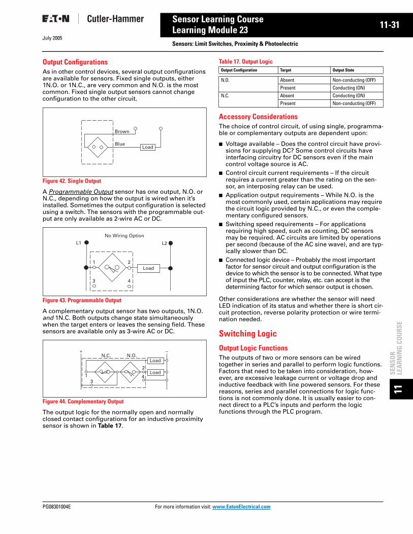
July 2005
PG08301004E For m
31
11-Sensor Learning CourseLearning Module 23 Sensors: Limit Switches, Proximity & Photoelectric11SE
NSO
RLE
ARN
ING
CO
URS
E
Output ConfigurationsAs in other control devices, several output configurations are available for sensors. Fixed single outputs, either 1N.O. or 1N.C., are very common and N.O. is the most common. Fixed single output sensors cannot change configuration to the other circuit.
Figure 42. Single Output
A Programmable Output sensor has one output, N.O. or N.C., depending on how the output is wired when it’s installed. Sometimes the output configuration is selected using a switch. The sensors with the programmable out-put are only available as 2-wire AC or DC.
Figure 43. Programmable Output
A complementary output sensor has two outputs, 1N.O. and 1N.C. Both outputs change state simultaneously when the target enters or leaves the sensing field. These sensors are available only as 3-wire AC or DC.
Figure 44. Complementary Output
The output logic for the normally open and normally closed contact configurations for an inductive proximity sensor is shown in Table 17.
Table 17. Output Logic
Accessory ConsiderationsThe choice of control circuit, of using single, programma-ble or complementary outputs are dependent upon:
■ Voltage available – Does the control circuit have provi-sions for supplying DC? Some control circuits have interfacing circuitry for DC sensors even if the main control voltage source is AC.
■ Control circuit current requirements – If the circuit requires a current greater than the rating on the sen-sor, an interposing relay can be used.
■ Application output requirements – While N.O. is the most commonly used, certain applications may require the circuit logic provided by N.C., or even the comple-mentary configured sensors.
■ Switching speed requirements – For applications requiring high speed, such as counting, DC sensors may be required. AC circuits are limited by operations per second (because of the AC sine wave), and are typ-ically slower than DC.
■ Connected logic device – Probably the most important factor for sensor circuit and output configuration is the device to which the sensor is to be connected. What type of input the PLC, counter, relay, etc. can accept is the determining factor for which sensor output is chosen.
Other considerations are whether the sensor will need LED indication of its status and whether there is short cir-cuit protection, reverse polarity protection or wire termi-nation needed.
Switching Logic
Output Logic FunctionsThe outputs of two or more sensors can be wired together in series and parallel to perform logic functions. Factors that need to be taken into consideration, how-ever, are excessive leakage current or voltage drop and inductive feedback with line powered sensors. For these reasons, series and parallel connections for logic func-tions is not commonly done. It is usually easier to con-nect direct to a PLC’s inputs and perform the logic functions through the PLC program.
Load
Brown
Blue
L1 L2
Load
No Wiring Option
1 2
3 4
Load1
34
+ –
2
LoadN.C. N.O.
Output Configuration Target Output State
N.O. Absent Non-conducting (OFF)Present Conducting (ON)
N.C. Absent Conducting (ON)Present Non-conducting (OFF)
ore information visit: www.EatonElectrical.com

11-32
11SEN
SOR
LEARN
ING
COU
RSE
July 2005
Sensor Learning CourseLearning Module 23
Sensors: Limit Switches, Proximity & PhotoelectricOutput Response Time and Speed of OperationPhotoelectric, inductive and capacitive sensors can oper-ate considerably faster than a limit switch, making them better choices for high-speed operations such as count-ing or sorting. The time it takes to respond, its speed of operation, is based on several factors. Let’s take a moment to consider them.
When a system is first powered up, the sensor cannot operate until the electronics are “powered up.” This is referred to as time before availability.
For AC sensors, this delay is typically from 35 millisec-onds up to as high as 100 milliseconds. For a DC sensor, the delay is typically 30 milliseconds.
Figure 45. Time Delay Before Availability
Once the target enters the sensing range and the detector causes the output to change state, a certain amount of time elapses. This is called response time. For an AC sen-sor this is usually less than 10 milliseconds. DC devices respond in microseconds.
Figure 46. Response Time and Release Time for an Inductive Proximity Sensor
Similarly, when the target leaves the sensing field there is a slight delay before the switch is restored to the OFF state. This is referred to as the Release Time. An AC sen-sor typically releases in one cycle (16.66 milliseconds) and DC devices usually in 3 milliseconds, or less.
In order to properly achieve high-speed operations, there are some basic principles that need to be applied. In addi-tion to the sensor’s response and release times, there is a similar delay for the load to operate. This is called the load response time. The total times combined are referred to as system response time. Similarly, there are load release time and system release time for when the target exits the sensing field. In order to ensure reliability and repeatability, the target must stay in the sensing field long enough to allow the load to respond. This is referred to as dwell time.
Output Timing ModesWhen a sensor is operated without a logic module, the output is generated for the length of time the object is detected. Some sensors are available with a logic module to allow setting timing functions.
Let’s look at each logic function, as illustrated in Table 18.
Table 18. Logic Functions
Load
Sensor
Target
ON
ON
OFF
ON
OFFTime Delay
Before AvailabilitySelectorSwitch
Sensor
ReleaseTime
ONSensor
OFF
INTargetOUT
ResponseTime
OperatePoint
ReleasePoint
ReleaseOperate
Timing Mode
Description Illustration
ON Delay Logic
This allows the output signal to turn on only after the target has been detected for a predetermined period of time. The output turns off as soon as the target passes out of range.ON delay is useful in bin fill or jam detection because the sensor will not false trigger on the normal flow of objects going past.
OFF Delay Logic
For applications where there is a problem with signal loss in the system, this function turns the output on when the object is detected, and then holds the ON signal for a set period of time after the object is no longer detected.
ON/OFF Delay Logic
This logic function combines both of the above — the output is only generated after the target has been detected for a set period of time, and will remain on after the target is no longer detected for a set period of time.The mode smooths the output of the sensor for applications such as jam detection, fill level detection and edge guide.
Input Signal
Output Signal
ON Delay
ON Delay
Input Signal
Output Signal
OFF Delay
OFF Delay
OFF Delay
Input Signal
Output Signal
ON Delay
OFFDelay
For more information visit: www.EatonElectrical.com PG08301004E

July 2005
PG08301004E For m
33
11-Sensor Learning CourseLearning Module 23 Sensors: Limit Switches, Proximity & Photoelectric11SE
NSO
RLE
ARN
ING
CO
URS
E
Table 18. Logic Functions (Continued) Table 18. Logic Functions (Continued)
In the Workplace
Paper breaks in a web printing press can result in time-consuming manual re-threading of the paper if the break is not immediately detected. A photoelectric sensor can detect this condition instantly, and do it in this tight space.
High excess gain and sharp optical cut-off ensure that background machinery is ignored. Meanwhile, paper is detected, regardless of texture, color or printing on it.
Timing Mode
Description Illustration
One-Shot Logic
This type of logic generates an output of a set length no matter how long an object is detected. A one-shot can be programmed to trigger on the leading or trailing edge of a target. A one-shot ON signal must time out before it can detect another input.This logic is useful in applications that require an output of specified length.
Retrig-gerable One-Shot Logic
This mode generates an output of predetermined length whenever an object is detected. The sequence restarts each time an object is detected, and will remain triggered as long as a stream of objects are detected before the one-shot times out. A retriggerable one-shot is useful in detecting underspeed conditions on conveyor lines.
Delayed One-Shot Logic
Combines on delay and one-shot logic. The one-shot feature is delayed for a predetermined period of time after an object is detected. A delayed one-shot is useful where the photoelectric control cannot be mounted exactly where the action is taking place. This includes applications like paint booths, high temperature ovens or drying bins.
Input Signal
Output Signal
One-Shot Pulse
One-Shot Pulse
Input Signal
One-Shot Pulse
One-Shot Pulse
Output Signal
One-Shot Pulse
Input Signal
Output Signal
Delay
One-Shot Pulse
Delay
Under-speed Detection Logic
Operates identically to a retriggerable one-shot. It detects speeds that fall below a certain predetermined level.In addition, the underspeed detector has a built-in latch feature that shuts the system down completely when the speed slows to a preset level. This prevents the one-shot from retriggering once it times out, eliminating erratic switching while the motor is winding down.
Under-speed/ Over-speed Detection Logic
Detects both overspeed and underspeed conditions. The detector is set to count a certain number of objects in a specified amount of time. If the system operates either at a higher or lower rate, an output is generated.
Input Signal
Underspeed
Output Signal
OverspeedUnderspeed
Input Signal
Output Signal
A Photoelectric Sensor Minimizes Downtime for this Printing Press
ore information visit: www.EatonElectrical.com

11-34
11SEN
SOR
LEARN
ING
COU
RSE
July 2005
Sensor Learning CourseLearning Module 23
Sensors: Limit Switches, Proximity & PhotoelectricReview 8Answer the following questions without referring to the material just presented.
Match the output circuit reference to its definition.
5. The initials designating a transistor output that sinks current from the load are ______________
6. The initials designating a transistor output that sources current to the load are ______________
In questions 7 through 13, match the term used to describe the following:
Answers to Review 8 are on Page 11-36.
Enclosure Ratings
NEMA Non-Hazardous Locations
Table 19. NEMA Non-Hazardous Locations
NEMA Hazardous Locations
Table 20. NEMA Hazardous Locations
1. The current required to maintain the sensor when a target is present _____
A. Residual Current (Leakage)
2. Having three connections (3-wire) to the circuit _____
B. Burden Current
3. The operating current the switch pulls from the line _____
C. Load-Powered
4. Having two connections (2-wire) to the circuit _____
D. Line-Powered
7. The delay of a sensor when the system is first powered up _____
A. Release time
8. The period during target sensing and the detector causing output to change to ON state _____
B. Dwell time
9. The period during target exiting the sensing range and the out-put changing to OFF state _____
C. ON delay logic
10. The period during which the target must stay in range to allow the load to respond _____
D. One shot logic
11. Logic module that allows output signal only after target detection for a set period of time _____
E. Time before availability
12. Logic module that allows output signal to be held ON for a set period of time _____
F. OFF delay logic
13. Logic module that allows output signal to be a specific length regardless of target physical size or detection timing _____
G. Response time
Type Description
1 For indoor use, primarily to provide a degree of protection against contact with the enclosed equipment.
3 Intended for outdoor use, primarily for a degree of protection against windblown dust, rain, sleet and external ice formation.
3R For outdoor use, primarily to provide a degree of protection against falling rain, sleet and external ice formation.
4 For indoor and outdoor use, primarily to provide a degree of protection against wind blown dust and rain, splashing water and hose directed water.
4X Intended for indoor or outdoor use, primarily to provide a degree of protection against corrosion, windblown dust and rain, splashing water and hose directed water.
6 Intended for indoor or outdoor use, primarily to provide a degree of protection against the entry of water during occasional temporary submersion at a limited depth.
6P Intended for indoor or outdoor use, primarily to provide a degree of protection against the entry of water during prolonged submersion at a limited depth.
12 Intended for indoor use, primarily to provide a degree of protection against dust, falling dirt and dripping non-corrosive liquids.
13 Intended for indoor use, primarily to provide a degree of protection against dust, spraying of water, oil and non-corrosive coolant.
Type Description
Type 7 For indoor use, within conditions of Class I and Groups shown, to withstand and contain an internal explosion of specified gases, or to contain an explosion sufficiently so as not to ignite an explosive gas-air mixture in the surrounding atmosphere.
Class I
Group A AcetyleneGroup B Hydrogen, butadiene, ethylene oxide, propylene oxideGroup C Carbon monoxide, ether, ethylene, hydrogen sulfide, morpholine,
cyclopropaneGroup D Gasoline, benzene, butane, propane, alcohol, acetone, ammonia, vinyl
chlorideType 9 For indoor use, within Class II and Groups shown below conditions, to
withstand and contain an internal explosion of specified dusts, or to contain an explosion sufficiently so as not to ignite an explosive dust-air mixture in the surrounding atmosphere.
Class II
Group E Metal dustsGroup F Carbon black, coke dust, coalGroup G Grain dust, flour, starch, sugar, plastics
For more information visit: www.EatonElectrical.com PG08301004E

July 2005
PG08301004E For m
35
11-Sensor Learning CourseLearning Module 23
Sensors: Limit Switches, Proximity & Photoelectric11SE
NSO
RLE
ARN
ING
CO
URS
E
IEC Ratings
IEC Environmental Closure Ratings — Examples of Designations
Figure 47. Examples of Designations
Index of Enclosure Ratings – IEC
Table 21. 1st Characteristic Numeral
Table 22. 2nd Characteristic Numeral
Protection against contact and penetration of solid bodies.
0 Not protected1 Protection against solid objects greater than 50 mm.2 Protection against solid objects greater than 12 mm.3 Protection against solid objects greater than 2.5 mm.4 Protection against solid objects greater than 1.0 mm.5 Dust protected6 Dust-tight
0 Not protected1 Protection against dripping water2 Protection against dripping water when tilted up 15 degrees3 Protection against rain4 Protection against splashing water5 Protection against water jets6 Protection against heavy seas7 Protection against the effects of immersion8 Protection against immersion
IP
Characteristic Letters1st Characteristic Numeral(See Table 21 Below)
2nd CharacteristicNumeral(See Table 22 Below)
An enclosure with this designation is protected againstthe penetration of solid objectsgreater than 1.0 mm and againstsplashing water.
Characteristic Letters1st Characteristic Numeral(See Table 21 Below)
An enclosure with thisdesignation is protected againstthe penetration of solid objectsgreater than 1.2 mm and againstrain.
4 4 IP 2 3
2nd CharacteristicNumeral(See Table 22 Below)
ore information visit: www.EatonElectrical.com

11-36
11SEN
SOR
LEARN
ING
COU
RSE
July 2005
Sensor Learning CourseLearning Module 23
Sensors: Limit Switches, Proximity & PhotoelectricReview Answers
Review 1 Answers1. Presence, absence
2. Limit Switch, Proximity Sensor, Photoelectric Sensor
3. Electromechanical
4. Inductive proximity
5. Photoelectric
Review 2 Answers1. Operating Head, Switch Body, Receptacle
2. C
3. F
4. D
5. A
6. E
7. B
8. True
Review 3 Answers1. a. 2
b. 4c. 3d. 1
2. C
3. A
4. D
5. B
6. True
Review 4 Answers1. Ferrous
2. True
3. False
4. True
5. True
6. False
Review 5 Answers1. True
2. Sensor (or Dielectric), Oscillator Circuit, Detector Circuit, Output Circuit
3. True
4. False
5. False
6. True
Review 6 Answers1. Thru-Beam. Reflex (or Retro-Reflective), Diffuse
Reflective, Background Rejection (or Perfect Prox®)
2. D
3. C
4. B
5. A
Review 7 Answers1. Power required
2. Target size, color, texture; Contamination (dust, humidity, debris); Application (distance, background, reflectivity)
3. C
4. True
5. True
6. False
Review 8 Answers1. A
2. D
3. B
4. C
5. NPN
6. PNP
7. E
8. G
9. A
10. B
11. C
12. F
13. D
For more information visit: www.EatonElectrical.com PG08301004E

July 2005
PG08301004E For m
-1
12Sensor ApplicationsPG.05.08.T.E
or Customer Service in the U.S. call 1-800-356-1243,in Canada call 1-800-268-3578.
For Application Assistance in the U.S. and Canadacall 1-800-426-9184.
12SE
NSO
RA
PPLI
CATI
ON
S
F
Table of ContentsOverview . . . . . . . . . . . . . . . . . . . . . . . . . . . . . . . . . . . . . . . . . . . . . . . . . . . . . . . . . . . . 12-1Sensor Applications . . . . . . . . . . . . . . . . . . . . . . . . . . . . . . . . . . . . . . . . . . . . . . . . . . 12-2
The sensor applications on the following pages range from basic problems to complex problems that can be solved only with specific Cutler-Hammer® sensors from Eaton’s electrical business.
The solution is summarized along with the Catalog Numbers of suggested models to be used. Note that many sensors are interchangeable; slight differences in the application may dictate the choice of one sensor over another. When full Catalog Numbers are listed, that specific model is suggested. Where no Suffix is given (e.g. 1451B) or only one family is listed, the choice of a specific model within the suggested type would be determined by operating voltage, sensing range, choice of cable or connector base, etc.
ore information visit: www.EatonElectrical.com

12-2July 2005
12SEN
SOR
APPLICATIO
NS
Sensor Applications
1. Broken Tool Detection
An E58 Harsh Duty Perfect Prox sen-sor is used to sense for the presence of the bit on a mill. The high sensing power and background rejection of the Perfect Prox allows reliable detection through high levels of cut-ting fluids, while ignoring objects just beyond the bit. The rugged harsh duty sensor survives constant exposure to lubricants, cutting fluids and flying metal chips.
2. Broken Bit Detection
A tubular E57 proximity sensor is used to detect the presence of a drill bit — should the drill bit be broken the sensor would signal a controller. For very small tools, a fine spot Comet Perfect Prox will reject the background while detecting a bro-ken drill bit.
3. Machining Processes
A ferrous only sensor is used in a process where aluminum is being machined. The ferrous only sensor ignores the aluminum (non-ferrous) chips from the machining process and only detects the ferrous target.
4. Tool Position
A tubular E57 proximity sensor is used to detect the position of a tool chuck.
5. Bottle Filling Detection
A clear object sensor is used to sense the presence of bottles at a fill-ing operation. The sensor offers high reliability in sensing clear bottles of different colors and thicknesses.
6. Process Control
A capacitive proximity sensor used to verify fill level of bottled water on a filling process line.
7. Jam Detection
A reflex control with a time delay module set for “delay dark” ignores momentary beam breaks. If the beam is blocked longer than the delay period, the output energizes to sound an alarm or stop the conveyor.
Description Catalog Number
E58 Perfect Prox Sensor E58-30DP or E58-18DP Sensor
Description Catalog Number
Tubular Inductive Proximity Sensor
E57 Product Family or iProx
Fine Spot Comet Perfect Prox 13105
Description Catalog Number
Tubular Inductive Proximity Sensor
E57 Product Family or iProx
Description Catalog Number
Tubular Inductive Proximity Sensor
E57 Product Family or iProx
Description Catalog Number
E65 Clear Object Sensor E66CBL1C or E65VBL1C
Description Catalog Number
Tubular Capacitive Proximity Sensor
E53 Product Family
Description Catalog Number
50 Series Reflex Sensor 1450B
Time Delay Logic Module 8251B
Plug-In Relay Output Device 8532B
3" Diameter Retroreflector 6200A-6501
For assistance with these or other applications,contact us at 1-800-426-9184.
For more information visit: www.EatonElectrical.com PG08301004E
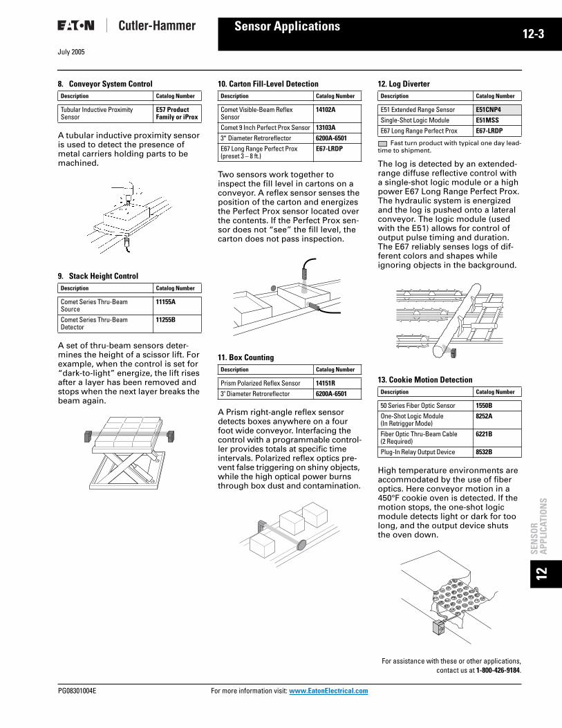
July 2005
PG08301004E For m
-3
12Sensor Applications12SE
NSO
RA
PPLI
CATI
ON
S
8. Conveyor System Control
A tubular inductive proximity sensor is used to detect the presence of metal carriers holding parts to be machined.
9. Stack Height Control
A set of thru-beam sensors deter-mines the height of a scissor lift. For example, when the control is set for “dark-to-light” energize, the lift rises after a layer has been removed and stops when the next layer breaks the beam again.
10. Carton Fill-Level Detection
Two sensors work together to inspect the fill level in cartons on a conveyor. A reflex sensor senses the position of the carton and energizes the Perfect Prox sensor located over the contents. If the Perfect Prox sen-sor does not “see” the fill level, the carton does not pass inspection.
11. Box Counting
A Prism right-angle reflex sensor detects boxes anywhere on a four foot wide conveyor. Interfacing the control with a programmable control-ler provides totals at specific time intervals. Polarized reflex optics pre-vent false triggering on shiny objects, while the high optical power burns through box dust and contamination.
12. Log Diverter
Fast turn product with typical one day lead-time to shipment.
The log is detected by an extended-range diffuse reflective control with a single-shot logic module or a high power E67 Long Range Perfect Prox. The hydraulic system is energized and the log is pushed onto a lateral conveyor. The logic module (used with the E51) allows for control of output pulse timing and duration. The E67 reliably senses logs of dif-ferent colors and shapes while ignoring objects in the background.
13. Cookie Motion Detection
High temperature environments are accommodated by the use of fiber optics. Here conveyor motion in a 450°F cookie oven is detected. If the motion stops, the one-shot logic module detects light or dark for too long, and the output device shuts the oven down.
Description Catalog Number
Tubular Inductive Proximity Sensor
E57 Product Family or iProx
Description Catalog Number
Comet Series Thru-Beam Source
11155A
Comet Series Thru-Beam Detector
11255B
Description Catalog Number
Comet Visible-Beam Reflex Sensor
14102A
Comet 9 Inch Perfect Prox Sensor 13103A
3" Diameter Retroreflector 6200A-6501
E67 Long Range Perfect Prox(preset 3 – 8 ft.)
E67-LRDP
Description Catalog Number
Prism Polarized Reflex Sensor 14151R
3" Diameter Retroreflector 6200A-6501
Description Catalog Number
E51 Extended Range Sensor E51CNP4
Single-Shot Logic Module E51MSS
E67 Long Range Perfect Prox E67-LRDP
Description Catalog Number
50 Series Fiber Optic Sensor 1550B
One-Shot Logic Module (In Retrigger Mode)
8252A
Fiber Optic Thru-Beam Cable (2 Required)
6221B
Plug-In Relay Output Device 8532B
For assistance with these or other applications,contact us at 1-800-426-9184.
ore information visit: www.EatonElectrical.com

12-4July 2005
12SEN
SOR
APPLICATIO
NS
Sensor Applications
14. Lid Detection
A pair of tubular proximity sensors used to, a) detect the presence of a can on a conveying line, and b) check for presence of a lid.
15. Tollbooth Control
Fast turn product with typical one day lead-time to shipment.
Thru-beam source/detector or the long range polarized reflex controls are used to time the toll gate. To elimi-nate toll cheating, the gate lowers the instant the rear of the paid car passes the control. The E67 Long Range Per-fect Prox allows you to mount the sen-sor on one side, instead of both. Plus with Perfect Prox, the E67 will detect cars with different colors and finishes while ignoring all other background objects. The rugged control handles harsh weather, abuse and 24-hour operation.
16. Garage Door Control
Fast turn product with typical one day lead-time to shipment.
A safe and secure garage is achieved through the use of thru-beam con-trols interfaced to the door control-ler. The door shuts automatically after a car leaves, and if the beam is broken while the door is lowering, the motor reverses direction and raises the door again.
17. Cut-Off Saw Control
Fast turn product with typical one day lead-time to shipment.
NOTE: All products listed are required for each two-foot increment.An array of thru-beam controls detect the length of the log in stan-dard two-foot increments. The cor-rect saw is then activated to cut the log at its longest standard length. High optical performance is a must in this dusty and dirty environment.
18. Liquid Level Detection
A pair of E53 capacitive proximity sensors are used to sense high and low liquid levels in a tank through a sight glass. This arrangement starts a pump to fill the tank when the lower sensor is energized and shuts the pump off when the top sensor is energized.
19. Bulk Material Detection
A capacitive proximity is used to control fill level of solids such as plastic pellets in a hopper or bin.
Description Catalog Number
Tubular Inductive Proximity Sensor
E57 Product Family or iProx
Description Catalog Number
20 Series Thru-Beam Source 1141D-6501
20 Series Thru-Beam Detector 1241D-6501
DPDT Relay Output Device 8526A-6501
E67 Long Range Perfect Prox E67-LRDP
Description Catalog Number
80 Series High Current Control Unit (2 Required)
8880C-6501
Description Catalog Number
E51 Thru-Beam Source E51ELA
E51 Thru-Beam Detector E51CLC1
Description Catalog Number
Tubular Capacitive Proximity Sensor
E53 Product Family
Description Catalog Number
Tubular Capacitive Proximity Sensor
E57 Product Family
For assistance with these or other applications,contact us at 1-800-426-9184.
For more information visit: www.EatonElectrical.com PG08301004E

July 2005
PG08301004E For m
-5
12Sensor Applications12SE
NSO
RA
PPLI
CATI
ON
S
20. Hopper Fill Level Control
The fill level on this machine hopper is controlled by a diffuse reflective control with a time delay module. The control must detect the level for a certain time interval before it ener-gizes the shut-off mechanism. This eliminates false “full” indications caused by extraneous material momentarily passing by the control.
21. Web Loop Control
A sensor that generates a “curtain-of-light” detects the length of a loop on a web drive system by measuring the amount of light returned from an array of retroreflectors. With this information, the analog control unit instructs a motor controller to speed up or slow down the web drive.
22. Parts Presence
A limit switch style proximity sensor, a Comet Perfect Prox or the iProx Sensor may be used to detect the presence of a part in a pick-and-place application for inspection. The Comet will detect any target mate-rial, color or finish while rejecting the background. The iProx can be programmed to sense a specific metal target while rejecting all other metal.
23. Small Parts Detection
Small objects moving through a “curtain-of-light” are counted by detecting a change in reflected light. A low contrast logic module inside the control unit responds to slight but abrupt signal variations while ignoring slow changes such as dust build-up.
24. Parts Detection
A four inch Perfect Prox sensor detects parts of various heights from 0.5 to 3 inches passing through a channel, while ignoring the channel bottom. For longer range sensing up to 8 ft., use the E67 Long Range Per-fect Prox. Installation is simple with no cutting or drilling of the channel required.
25. Filter Paper Length Control
A focused diffuse reflective sensor interfaces with a programmable con-troller to measure a specific length of corrugated automotive filter paper. The control detects the pres-ence or absence of a corrugation. When a predetermined number of corrugations has been detected, the programmable controller directs a shear to cut the paper.
Description Catalog Number
80 Series High Current Control Unit
8880C-6501
80 Series 18 Inch Diffuse Reflective Sensor
1381B
Time Delay Logic Module 8280A
Description Catalog Number
70 Series Analog Control Unit 8172A
70 Series Reflex Curtain-of-Light Sensor
1471A
Analog Isolation Module 8272A
Strip Retroreflector 6210A
Description Catalog Number
Limit Switch Inductive Proximity Sensor
E57 Product Family
Comet Perfect Prox 1310
iProx Inductive Proximity Sensor E59F
Description Catalog Number
70 Series High Power Control Unit 8171B
Low Contrast Logic Module 8215A
70 Series Reflex Curtain-of-Light Sensor
1471A
Strip Retroreflector 6210A
Triac Output Relay or Other Selection
8572A
Description Catalog Number
Comet Series 4 Inch Perfect Prox Sensor
13101A
E67 Long Range Perfect Prox E67-LDRP
Description Catalog Number
Comet Focused Diffuse Reflective Sensor
13102A
For assistance with these or other applications,contact us at 1-800-426-9184.
ore information visit: www.EatonElectrical.com

12-6July 2005
12SEN
SOR
APPLICATIO
NS
Sensor Applications
26. Broken Thread Detection
Fast turn product with typical one day lead-time to shipment.
A pair of remote thru-beam sensors scan over and under multiple strands of thread. If a thread breaks and passes through one of the beams, the low-contrast logic module detects the sudden change in signal strength and energizes the output. Because this logic module does not react to slow changes in signal strength, it can operate in a dusty environment with little maintenance.
27. Hypodermic Needle Quality Control
Fast turn product with typical one day lead-time to shipment.
A remote source and detector pair inspects for passage of light through a hypodermic needle. Their small design and waterproof stainless steel housing are appropriate for crowded machinery spaces and fre-quent washdowns. High signal strength allows quality inspection with hole sizes down to 0.007 inch.
28. Automotive Body Assembly
Automotive body assembly lines use welders which can cause standard inductive proximity sensors to perform erratically. Cutler-Hammer Weld-Field Immune Sensors from Eaton’s electrical business are designed to provide reliable operation in these environments.
29. Multi-Hole Casting Inspection
Fast turn product with typical one day lead-time to shipment.
Remote sensors inspect for the pres-ence of holes in a metal casting. Because each hole has its own inspection system, accurate defect information is recorded. Rugged sensor housing and extremely high signal strength handle dirt and grease with minimum maintenance. Using the modular control unit allows for dense packaging in small enclosures.
30. Web Flaw Detection
A web passes over an array of ret-roreflectors. When light is returned to the sensor head, the output is energized and the web shuts down. Because of the superior response time of the control unit, high web speeds can be maintained.
Description Catalog Number
70 Series High Power Control Unit 8171B
Low Contrast Logic Module 8215A
70 Series 375 Foot Thru-Beam Source (2 Required)
1173A-100
70 Series 375 Foot Thru-Beam Detector (2 Required)
1273A-100
DPDT Relay 8530A
Mounting Brackets 6142A
Description Catalog Number
70 Series High Power Control Unit 8171B
70 Series 300 Foot Thru-Beam Source
1173A-300
70 Series 300 Foot Thru-Beam Detector
1273A-300
Triac Output Relay 8573A
Description Catalog Number
Weld Field Immune Inductive Proximity Sensor
E57 Product Family
Description Catalog Number
70 Series Modular Control Unit (4 Required)
8771A
70 Series 35 Foot Thru-Beam Source (4 Required)
1173A-300
70 Series 35 Foot Thru-Beam Detector (4 Required)
1273A-300
Panel Mount Socket for Control Unit (4 Required)
8905A
Description Catalog Number
70 Series High Power Control Unit 8171B
Low Contrast Logic Module 8215A
DPDT Relay 8530A
70 Series Reflex Curtain-of-Light Sensor
1471A
Strip Retroreflector 6210A
For assistance with these or other applications,contact us at 1-800-426-9184.
For more information visit: www.EatonElectrical.com PG08301004E
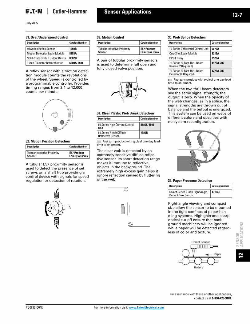
July 2005
PG08301004E For m
-7
12Sensor Applications12SE
NSO
RA
PPLI
CATI
ON
S
31. Over/Underspeed Control
A reflex sensor with a motion detec-tion module counts the revolutions of the wheel. Speed is controlled by a programmable controller. Provides timing ranges from 2.4 to 12,000 counts per minute.
32. Motion Position Detection
A tubular E57 proximity sensor is used to detect the presence of set screws on a shaft hub providing a control device with signals for speed regulation or detection of rotation.
33. Motion Control
A pair of tubular proximity sensors is used to determine full open and fully closed valve position.
34. Clear Plastic Web Break Detection
Fast turn product with typical one day lead-time to shipment.
The clear web is detected by an extremely sensitive diffuse reflec-tive sensor. Its short detection range makes it immune to reflective objects in the background. The extremely high excess gain helps it ignore reflection caused by fluttering of the web.
35. Web Splice Detection
Fast turn product with typical one day lead-time to shipment.
When the two thru-beam detectors see the same signal strength, the output is zero. When the opacity of the web changes, as in a splice, the signal strengths are thrown out of balance and the output is energized. This system can be used on webs of different colors and opacities with no system reconfiguration.
36. Paper Presence Detection
Right angle viewing and compact size allow the sensor to be mounted in the tight confines of paper han-dling systems. High gain and sharp optical cut-off ensure that back-ground machinery will be ignored while paper will be detected regard-less of color and texture.
Description Catalog Number
50 Series Reflex Sensor 1450B
Motion Detection Logic Module 8253A
Solid-State Switch Output Device 8562B
3 inch Diameter Retroreflector 6200A-6501
Description Catalog Number
Tubular Inductive Proximity Sensor
E57 Product Family or iProx
Description Catalog Number
Tubular Inductive Proximity Sensor
E57 Product Family or iProx
Description Catalog Number
80 Series High Current Control Unit
8880C-6501
80 Series 7 Inch Diffuse Reflective Sensor
1380B
Description Catalog Number
70 Series Differential Control Unit 9072A
One-Shot Logic Module 8213A
DPDT Relay 8526A
70 Series 30 Foot Thru-Beam Source (2 Required)
1173A-300
70 Series 30 Foot Thru-Beam Detector (2 Required)
1273A-300
Description Catalog Number
Comet Series 2 Inch Right Angle Perfect Prox Sensor
13104R
For assistance with these or other applications,contact us at 1-800-426-9184.
Comet Sensor
Paper
Rollers
ore information visit: www.EatonElectrical.com

12-8July 2005
12SEN
SOR
APPLICATIO
NS
Sensor Applications
37. Web Guiding
The 1372A-6501 slot sensor head is mounted so that the edge of the web extends into the slot and blocks half of the source beam. As the web moves into or out of position, a pro-portional signal is provided by the analog control unit to alert your con-trol system.
38. Damage Warning
Source and detector are mounted at opposite ends of a long warehouse storage shelf with the beam situated a safe distance below overhead obstacles (lighting, conduit, gas lines, ducts, pipes, etc.). If a forklift operator interrupts the beam while moving a load, a siren or flashing light will warn him to stop before any damage occurs.
39. Zero Pressure Accumulation Conveyor
E68 Series or 200 Series sensors detect and control the movement of boxes on the conveyor, to maximize throughput and eliminate line pres-sure between boxes.The sensor con-tains all required logic with no need for a PLC.
Description Catalog Number
70 Series Slot Sensor 1372A-6501
70 Series Analog Control Unit 8172A
Description Catalog Number
Comet Series 100 Foot Thru-Beam Source
11102A
Comet Series 100 Foot Thru-Beam Detector
12102A
Description Catalog Number
E68 Integral Sensor Valve E68-SVS
200 Series Zero Pressure Accumulation
14286/14266
For assistance with these or other applications,contact us at 1-800-426-9184.
For more information visit: www.EatonElectrical.com PG08301004E