Selective Sulfur Dioxide Absorption from Simulated Flue Gas ...
15
International Journal of Environmental Research and Public Health Article Selective Sulfur Dioxide Absorption from Simulated Flue Gas Using Various Aqueous Alkali Solutions in a Polypropylene Hollow Fiber Membrane Contactor: Removal Efficiency and Use of Sulfur Dioxide Hyun Sic Park 1,† , Dongwoan Kang 1,2,† , Jo Hong Kang 1 , Kwanghwi Kim 1 , Jaehyuk Kim 2 and Hojun Song 1, * Citation: Park, H.S.; Kang, D.; Kang, J.H.; Kim, K.; Kim, J.; Song, H. Selective Sulfur Dioxide Absorption from Simulated Flue Gas Using Various Aqueous Alkali Solutions in a Polypropylene Hollow Fiber Membrane Contactor: Removal Efficiency and Use of Sulfur Dioxide. Int. J. Environ. Res. Public Health 2021, 18, 597. https://doi.org/10.3390/ ijerph18020597 Received: 5 December 2020 Accepted: 6 January 2021 Published: 12 January 2021 Publisher’s Note: MDPI stays neu- tral with regard to jurisdictional clai- ms in published maps and institutio- nal affiliations. Copyright: © 2021 by the authors. Li- censee MDPI, Basel, Switzerland. This article is an open access article distributed under the terms and con- ditions of the Creative Commons At- tribution (CC BY) license (https:// creativecommons.org/licenses/by/ 4.0/). 1 Green Materials & Processes R&D Group, Korea Institute of Industrial Technology, 55 Jongga-ro, Jung-gu, Ulsan 44413, Korea; [email protected] (H.S.P.); [email protected] (D.K.); [email protected] (J.H.K.); [email protected] (K.K.) 2 Department of Civil and Environmental Engineering, Pusan National University, 2 Busandaehak-ro, 63beon-gil, Geumjeong-gu, Pusan 46241, Korea; [email protected] * Correspondence: [email protected]; Tel.: +82-52-980-6670 † These authors contributed equally to this work. Abstract: Hollow fiber membrane contactors (HFMCs) provide a large specific surface area. Thus, their significantly reduced volume provides an advantage compared to the conventional gas–liquid contactor. In this study, the selective removal efficiency of flue gas, in which sulfur oxide (SO 2 ) and carbon dioxide (CO 2 ) coexist, was measured using a polypropylene (PP) HFMC with such advantages. To increase the selective removal efficiency of SO 2 , experiments were conducted using various alkaline absorbents. As a result, with 0.05 M ammonia solution, the removal efficiency of 95% or more was exhibited with continuous operation for 100 h or more. We confirmed that the absorbent saturated by the once-through mode was aqueous ammonium sulfate ((NH 4 ) 2 SO 4 ) solution and could be used as a fertilizer without additional processing. Keywords: desulfurization; hollow fiber membrane contactor (HFMC); polypropylene (PP); sulfur oxide (SO 2 ); ammonium sulfate ((NH 4 ) 2 SO 4 ); once-through mode 1. Introduction Despite the continuous development of new and renewable energies, fossil fuel consumption is not expected to decrease significantly worldwide. According to a report by the International Energy Agency (IEA), fossil fuels’ share in primary energy will drop below 50% in 2040 compared to 67% in 2017 [1,2]. Due to the COVID-19 worldwide pandemic, carbon dioxide emissions are temporarily reduced (coal and oil use decreased by 7% and 8%, respectively), but greenhouse gas emissions are still maintained at high levels [3]. Carbon dioxide (CO 2 ), which is a cause of global warming from fossil fuel combustion, and sulfur oxides (SO X ), generated by sulfur contained in fuels, cause acid rain and fine dust, so they are materials that must be treated [4]. Sulfur oxides are typically emitted from coal-fired power plants and ships due to the use of heavy fuel oil, which has a sulfur content of 3.5% [5]. The emitted sulfur oxides undergo photochemical reactions in the atmosphere to form fine particles several micrometers in diameter. Therefore, most countries regulate the concentration of sulfur oxides emitted from coal-fired power plants to less than 60 ppm [6–8]. For ships, the fuel’s sulfur content should be less than 0.5% according to 2020 International Maritime Organization (IMO) sulfur oxide emission regulations, which is a strengthened regulation compared to the existing 3.5% [9]. Methods of reducing sulfur oxides emitted from fossil fuel combustion are generally classified as either desulfurization during or after combustion [8]. During combustion, desulfurization is a method of collecting sulfur oxides generated in the combustion process Int. J. Environ. Res. Public Health 2021, 18, 597. https://doi.org/10.3390/ijerph18020597 https://www.mdpi.com/journal/ijerph
-
Upload
khangminh22 -
Category
Documents
-
view
1 -
download
0
Transcript of Selective Sulfur Dioxide Absorption from Simulated Flue Gas ...
International Journal of
Environmental Research
and Public Health
Article
Selective Sulfur Dioxide Absorption from Simulated Flue GasUsing Various Aqueous Alkali Solutions in a PolypropyleneHollow Fiber Membrane Contactor: Removal Efficiency andUse of Sulfur Dioxide
Hyun Sic Park 1,†, Dongwoan Kang 1,2,†, Jo Hong Kang 1, Kwanghwi Kim 1, Jaehyuk Kim 2 and Hojun Song 1,*
�����������������
Citation: Park, H.S.; Kang, D.; Kang,
J.H.; Kim, K.; Kim, J.; Song, H.
Selective Sulfur Dioxide Absorption
from Simulated Flue Gas Using
Various Aqueous Alkali Solutions
in a Polypropylene Hollow Fiber
Membrane Contactor: Removal
Efficiency and Use of Sulfur Dioxide.
Int. J. Environ. Res. Public Health 2021,
18, 597. https://doi.org/10.3390/
ijerph18020597
Received: 5 December 2020
Accepted: 6 January 2021
Published: 12 January 2021
Publisher’s Note: MDPI stays neu-
tral with regard to jurisdictional clai-
ms in published maps and institutio-
nal affiliations.
Copyright: © 2021 by the authors. Li-
censee MDPI, Basel, Switzerland.
This article is an open access article
distributed under the terms and con-
ditions of the Creative Commons At-
tribution (CC BY) license (https://
creativecommons.org/licenses/by/
4.0/).
1 Green Materials & Processes R&D Group, Korea Institute of Industrial Technology, 55 Jongga-ro,Jung-gu, Ulsan 44413, Korea; [email protected] (H.S.P.); [email protected] (D.K.);[email protected] (J.H.K.); [email protected] (K.K.)
2 Department of Civil and Environmental Engineering, Pusan National University, 2 Busandaehak-ro,63beon-gil, Geumjeong-gu, Pusan 46241, Korea; [email protected]
* Correspondence: [email protected]; Tel.: +82-52-980-6670† These authors contributed equally to this work.
Abstract: Hollow fiber membrane contactors (HFMCs) provide a large specific surface area. Thus,their significantly reduced volume provides an advantage compared to the conventional gas–liquidcontactor. In this study, the selective removal efficiency of flue gas, in which sulfur oxide (SO2)and carbon dioxide (CO2) coexist, was measured using a polypropylene (PP) HFMC with suchadvantages. To increase the selective removal efficiency of SO2, experiments were conducted usingvarious alkaline absorbents. As a result, with 0.05 M ammonia solution, the removal efficiency of 95%or more was exhibited with continuous operation for 100 h or more. We confirmed that the absorbentsaturated by the once-through mode was aqueous ammonium sulfate ((NH4)2SO4) solution andcould be used as a fertilizer without additional processing.
Keywords: desulfurization; hollow fiber membrane contactor (HFMC); polypropylene (PP); sulfuroxide (SO2); ammonium sulfate ((NH4)2SO4); once-through mode
1. Introduction
Despite the continuous development of new and renewable energies, fossil fuelconsumption is not expected to decrease significantly worldwide. According to a reportby the International Energy Agency (IEA), fossil fuels’ share in primary energy will dropbelow 50% in 2040 compared to 67% in 2017 [1,2]. Due to the COVID-19 worldwidepandemic, carbon dioxide emissions are temporarily reduced (coal and oil use decreasedby 7% and 8%, respectively), but greenhouse gas emissions are still maintained at highlevels [3]. Carbon dioxide (CO2), which is a cause of global warming from fossil fuelcombustion, and sulfur oxides (SOX), generated by sulfur contained in fuels, cause acidrain and fine dust, so they are materials that must be treated [4]. Sulfur oxides are typicallyemitted from coal-fired power plants and ships due to the use of heavy fuel oil, which hasa sulfur content of 3.5% [5]. The emitted sulfur oxides undergo photochemical reactionsin the atmosphere to form fine particles several micrometers in diameter. Therefore,most countries regulate the concentration of sulfur oxides emitted from coal-fired powerplants to less than 60 ppm [6–8]. For ships, the fuel’s sulfur content should be less than0.5% according to 2020 International Maritime Organization (IMO) sulfur oxide emissionregulations, which is a strengthened regulation compared to the existing 3.5% [9].
Methods of reducing sulfur oxides emitted from fossil fuel combustion are generallyclassified as either desulfurization during or after combustion [8]. During combustion,desulfurization is a method of collecting sulfur oxides generated in the combustion process
Int. J. Environ. Res. Public Health 2021, 18, 597. https://doi.org/10.3390/ijerph18020597 https://www.mdpi.com/journal/ijerph

Int. J. Environ. Res. Public Health 2021, 18, 597 2 of 15
in the form of CaS by introducing CaO [10]. Limestone is mainly used for desulfurizationafter combustion, and the method of collecting sulfur oxides with gypsum in a scrubberis widely used worldwide. Alternatively, an alkaline solution, such as Mg solution orseawater, is injected into a spray tower, packed column, or bubble column to selectivelyabsorb and remove only SOX. However, in the process of producing by-product gypsum, alarge amount of carbon dioxide is generated. Besides, energy consumption occurs duringthe drying process of gypsum dehydration, and, eventually, carbon dioxide is generated.There is an issue of depleting high-quality limestone in several countries, including Korea,such as CaO and CaCO3, required to produce by-product gypsum. Other scrubbers arefaced with the challenge of increasing the efficiency of SOX removal and reducing thevolume of equipment by tightening environmental regulations [10–13]. Also, in the caseof the secondary flue gas desulfurization (FGD) scrubber install to meet the SO2 emissionstandards, there are disadvantages such as channeling and flooding [14].
Membrane contactors are known to be efficient gas–liquid contact reactors that cansignificantly reduce the volume compared to conventional reactors because they canprovide a large specific surface area (m2/m3) [15]. Besides, the investment cost andoperation cost are lower than that of FGD scrubbers, so it is energy-efficient, it is easyto increase capacity by adjusting the number of modules, and it has the advantage ofhaving excellent mass transfer properties [16]. According to a U.S. GTI Company report,when replacing the conventional FGD system with a membrane contactor, the total costis reduced to 35%, the operating cost is reduced to 40%, and the footprint requirement isreduced to 40% [17]. Membrane contactors have been used to remove CO2 from exhaust gasfrom the viewpoint of mitigating global warming. The membrane contactor has excellentperformance compared to other gas–liquid contactors because it flows into the hollow fibermembrane composed of polypropylene or the like. The solution can flow toward the outershell and maintain a consistent interface between the solution and the gas through themembranes pores. Membrane contactors have disadvantages, such as pore wetting, whichmay occur because the solution continuously contacts the membrane [18–21]. However,these disadvantages can be solved by increasing the surface tension of the absorbentor increasing the hydrophobicity of the membranes surface; studies have been activelyconducted to solve the problems.
Some papers have been published on selecting suitable absorbent for removing sulfuroxides using a membrane contactor [22–29]. In the literature, aqueous solutions, such assodium hydroxide (NaOH) and sodium sulfite (Na2SO3), showed desirable absorptionperformance as SO2 absorbents [30,31]. However, these absorbents are uneconomical dueto their high costs. In comparison, seawater, which has high SO2 removal efficiency, iseconomical. It has been reported as an alternative absorbent to conventional alkalinematerials such as magnesium hydroxide and limestone. Still, various problems withusing seawater have been reported, especially when seawater is discharged into the seaagain after the SO2 removal process [26]. Hence, it is essential to select a suitable SO2absorbent that efficiently removes SO2 removal and is economical and eco-friendly inmembrane contactors.
In this study, various alkaline solutions were applied to a laboratory-scale membranecontactor composed of polypropylene (PP), a representative hollow fiber membrane ma-terial, to examine the selective removal efficiency of SO2 in the simulated flue gas of amassive oil boiler. We investigated the removal characteristics of SO2 according to theconcentration and flow rate of each alkaline absorbent under constant SO2 compositionand temperature conditions. The height of the transfer unit (HTU) was calculated usingthe results obtained from the SO2 removal experiment, and the performance was com-pared with the conventional separation process. The liquid by-products of experimentsusing ammonia solution were analyzed to determine the SO2 removal efficiency and therecyclability of recovered SO2, and the possibility of use as a liquid fertilizer is presented.
Int. J. Environ. Res. Public Health 2021, 18, 597 3 of 15
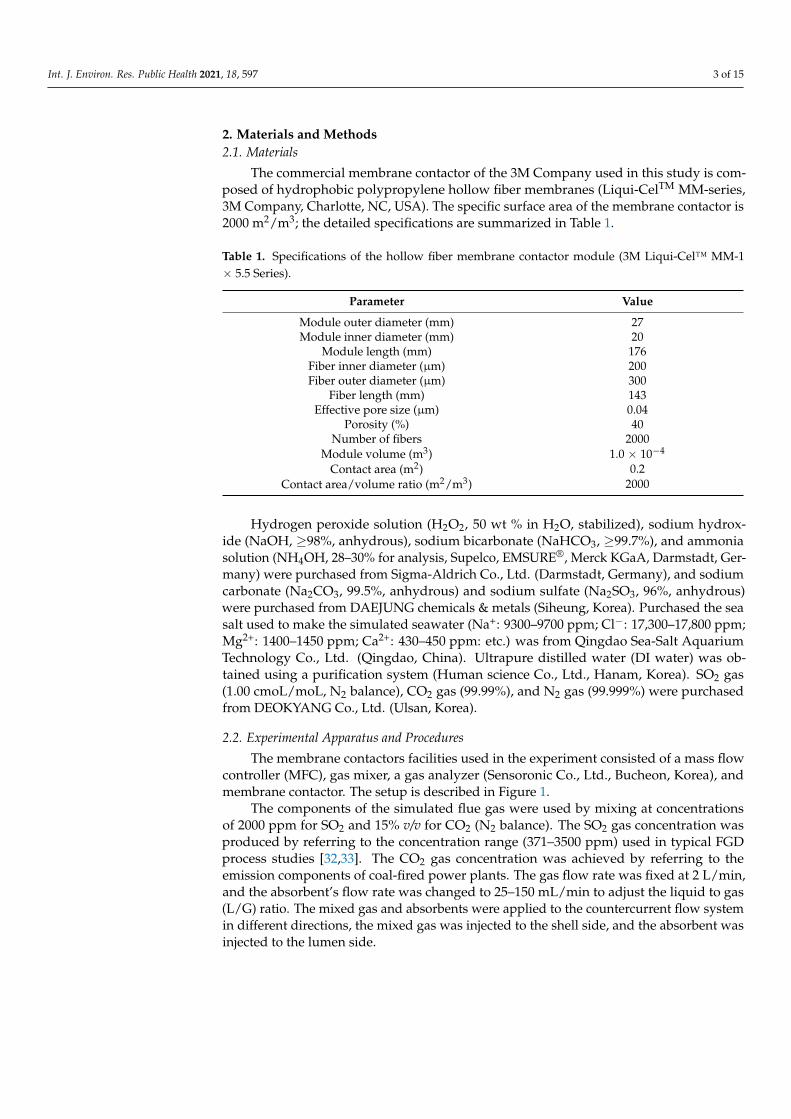
2. Materials and Methods2.1. Materials
The commercial membrane contactor of the 3M Company used in this study is com-posed of hydrophobic polypropylene hollow fiber membranes (Liqui-CelTM MM-series,3M Company, Charlotte, NC, USA). The specific surface area of the membrane contactor is2000 m2/m3; the detailed specifications are summarized in Table 1.
Table 1. Specifications of the hollow fiber membrane contactor module (3M Liqui-Cel™ MM-1× 5.5 Series).
Parameter Value
Module outer diameter (mm) 27Module inner diameter (mm) 20
Module length (mm) 176Fiber inner diameter (µm) 200Fiber outer diameter (µm) 300
Fiber length (mm) 143Effective pore size (µm) 0.04
Porosity (%) 40Number of fibers 2000
Module volume (m3) 1.0 × 10⁻⁴
Contact area (m2) 0.2Contact area/volume ratio (m2/m3) 2000
Hydrogen peroxide solution (H2O2, 50 wt % in H2O, stabilized), sodium hydrox-ide (NaOH, ≥98%, anhydrous), sodium bicarbonate (NaHCO3, ≥99.7%), and ammoniasolution (NH4OH, 28–30% for analysis, Supelco, EMSURE®, Merck KGaA, Darmstadt, Ger-many) were purchased from Sigma-Aldrich Co., Ltd. (Darmstadt, Germany), and sodiumcarbonate (Na2CO3, 99.5%, anhydrous) and sodium sulfate (Na2SO3, 96%, anhydrous)were purchased from DAEJUNG chemicals & metals (Siheung, Korea). Purchased the seasalt used to make the simulated seawater (Na+: 9300–9700 ppm; Cl−: 17,300–17,800 ppm;Mg2+: 1400–1450 ppm; Ca2+: 430–450 ppm: etc.) was from Qingdao Sea-Salt AquariumTechnology Co., Ltd. (Qingdao, China). Ultrapure distilled water (DI water) was ob-tained using a purification system (Human science Co., Ltd., Hanam, Korea). SO2 gas(1.00 cmoL/moL, N2 balance), CO2 gas (99.99%), and N2 gas (99.999%) were purchasedfrom DEOKYANG Co., Ltd. (Ulsan, Korea).
2.2. Experimental Apparatus and Procedures
The membrane contactors facilities used in the experiment consisted of a mass flowcontroller (MFC), gas mixer, a gas analyzer (Sensoronic Co., Ltd., Bucheon, Korea), andmembrane contactor. The setup is described in Figure 1.
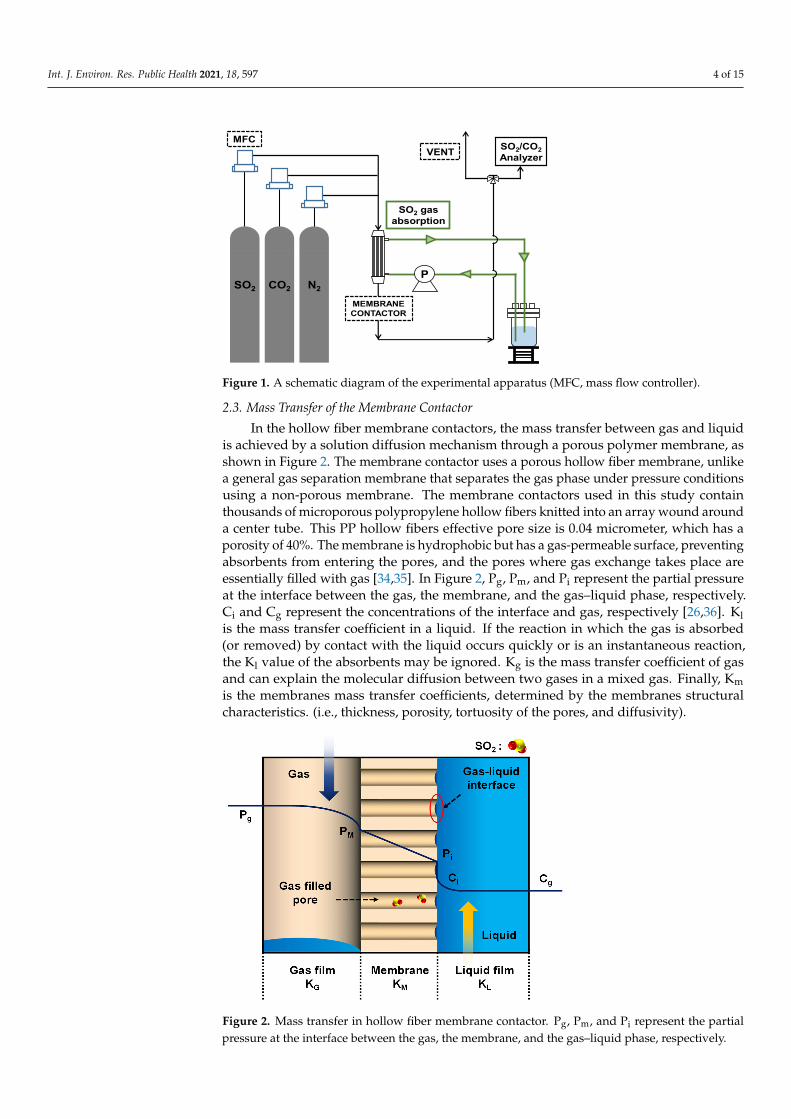
The components of the simulated flue gas were used by mixing at concentrationsof 2000 ppm for SO2 and 15% v/v for CO2 (N2 balance). The SO2 gas concentration wasproduced by referring to the concentration range (371–3500 ppm) used in typical FGDprocess studies [32,33]. The CO2 gas concentration was achieved by referring to theemission components of coal-fired power plants. The gas flow rate was fixed at 2 L/min,and the absorbent’s flow rate was changed to 25–150 mL/min to adjust the liquid to gas(L/G) ratio. The mixed gas and absorbents were applied to the countercurrent flow systemin different directions, the mixed gas was injected to the shell side, and the absorbent wasinjected to the lumen side.
Int. J. Environ. Res. Public Health 2021, 18, 597 4 of 15
Int. J. Environ. Res. Public Health 2021, 18, x 4 of 16
Figure 1. A schematic diagram of the experimental apparatus (MFC, mass flow controller).
The components of the simulated flue gas were used by mixing at concentrations of 2000 ppm for SO2 and 15% v/v for CO2 (N2 balance). The SO2 gas concentration was pro-duced by referring to the concentration range (371–3500 ppm) used in typical FGD process studies [32,33]. The CO2 gas concentration was achieved by referring to the emission com-ponents of coal-fired power plants. The gas flow rate was fixed at 2 L/min, and the absor-bent’s flow rate was changed to 25–150 mL/min to adjust the liquid to gas (L/G) ratio. The mixed gas and absorbents were applied to the countercurrent flow system in different directions, the mixed gas was injected to the shell side, and the absorbent was injected to the lumen side.
2.3. Mass Transfer of the Membrane Contactor In the hollow fiber membrane contactors, the mass transfer between gas and liquid
is achieved by a solution diffusion mechanism through a porous polymer membrane, as shown in Figure 2. The membrane contactor uses a porous hollow fiber membrane, unlike a general gas separation membrane that separates the gas phase under pressure condi-tions using a non-porous membrane. The membrane contactors used in this study contain thousands of microporous polypropylene hollow fibers knitted into an array wound around a center tube. This PP hollow fibers effective pore size is 0.04 micrometer, which has a porosity of 40%. The membrane is hydrophobic but has a gas-permeable surface, preventing absorbents from entering the pores, and the pores where gas exchange takes place are essentially filled with gas [34,35]. In Figure 2, Pg, Pm, and Pi represent the partial pressure at the interface between the gas, the membrane, and the gas–liquid phase, re-spectively. Ci and Cg represent the concentrations of the interface and gas, respectively [26,36]. Kl is the mass transfer coefficient in a liquid. If the reaction in which the gas is absorbed (or removed) by contact with the liquid occurs quickly or is an instantaneous reaction, the Kl value of the absorbents may be ignored. Kg is the mass transfer coefficient of gas and can explain the molecular diffusion between two gases in a mixed gas. Finally, Km is the membranes mass transfer coefficients, determined by the membranes structural characteristics. (i.e., thickness, porosity, tortuosity of the pores, and diffusivity).
MFC
SO2 gasabsorption
SO2 CO2 N2
SO2/CO2Analyzer
P
MEMBRANECONTACTOR
VENT
Figure 1. A schematic diagram of the experimental apparatus (MFC, mass flow controller).
2.3. Mass Transfer of the Membrane Contactor
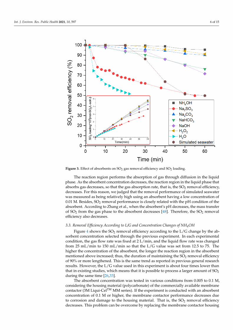
In the hollow fiber membrane contactors, the mass transfer between gas and liquidis achieved by a solution diffusion mechanism through a porous polymer membrane, asshown in Figure 2. The membrane contactor uses a porous hollow fiber membrane, unlikea general gas separation membrane that separates the gas phase under pressure conditionsusing a non-porous membrane. The membrane contactors used in this study containthousands of microporous polypropylene hollow fibers knitted into an array wound arounda center tube. This PP hollow fibers effective pore size is 0.04 micrometer, which has aporosity of 40%. The membrane is hydrophobic but has a gas-permeable surface, preventingabsorbents from entering the pores, and the pores where gas exchange takes place areessentially filled with gas [34,35]. In Figure 2, Pg, Pm, and Pi represent the partial pressureat the interface between the gas, the membrane, and the gas–liquid phase, respectively.Ci and Cg represent the concentrations of the interface and gas, respectively [26,36]. Klis the mass transfer coefficient in a liquid. If the reaction in which the gas is absorbed(or removed) by contact with the liquid occurs quickly or is an instantaneous reaction,the Kl value of the absorbents may be ignored. Kg is the mass transfer coefficient of gasand can explain the molecular diffusion between two gases in a mixed gas. Finally, Kmis the membranes mass transfer coefficients, determined by the membranes structuralcharacteristics. (i.e., thickness, porosity, tortuosity of the pores, and diffusivity).
Int. J. Environ. Res. Public Health 2021, 18, x 5 of 16
Figure 2. Mass transfer in hollow fiber membrane contactor. Pg, Pm, and Pi represent the partial pressure at the interface between the gas, the membrane, and the gas–liquid phase, respectively.
3. Results and Discussion 3.1. Characteristics of Hollow Fiber Membrane Contactor
Polymers, ceramics, and metals are used as materials for the membrane contactor. In metallic materials, the durability is the best, the swelling and wetting are low, and the chemical resistance is excellent. However, they are the costliest, and the processing and finely forming a thin film are difficult. Ceramic materials are also excellent in durability, chemical resistance, and thermal properties, but are fragile. For polymer materials, the membrane material is inexpensive compared to the previous two. It is possible to easily control the desired shape using a variety of polymers. However, there are disadvantages: swelling, wetting, and chemical resistance are weak [16,37]. For this reason, many studies considering polymer materials have used hydrophobic materials or increased hydropho-bicity through a surface modification to minimize the wetting phenomenon [38,39].
In general, high hydrophobic polymers include polypropylene(PP), polyvinylidene fluoride(PVDF), and polytetrafluoroethylene(PTFE) [36,40]. PTFE (11.50 USD/m) and PVDF (0.36 USD/m), which have fluorine groups in the main chain, have high hydropho-bicity and excellent physical and chemical properties. However, they are 36 and 1150 times more expensive than PP(0.01 USD/m), respectively [41]. Polymer membrane contac-tors are consumables and require regular replacement, so considering the replacement cost, using the relatively inexpensive PP, is desirable.
3.2. SO2 Removal Efficiencies of Various Absorbents The absorption of SO2 gas was performed through a once-through mode. The re-
moval rate was measured for one hour or until the SO2 removal rate was less than 50% using various absorbents (simulated seawater, H2O, H2O2, NaOH, NaHCO3, Na2CO3, Na2SO3, and NH4OH). The chemical equation for the SO2 removal reaction for the various absorbents used can be summarized as follows [26,33,42–45]:
SO2 (g) ↔ SO2 (aq), (1)
H2O (aq) + SO2 (aq) ↔ H2SO3 (aq), (2)
Figure 2. Mass transfer in hollow fiber membrane contactor. Pg, Pm, and Pi represent the partialpressure at the interface between the gas, the membrane, and the gas–liquid phase, respectively.

Int. J. Environ. Res. Public Health 2021, 18, 597 5 of 15
3. Results and Discussion3.1. Characteristics of Hollow Fiber Membrane Contactor
Polymers, ceramics, and metals are used as materials for the membrane contactor. Inmetallic materials, the durability is the best, the swelling and wetting are low, and the chem-ical resistance is excellent. However, they are the costliest, and the processing and finelyforming a thin film are difficult. Ceramic materials are also excellent in durability, chemicalresistance, and thermal properties, but are fragile. For polymer materials, the membranematerial is inexpensive compared to the previous two. It is possible to easily control thedesired shape using a variety of polymers. However, there are disadvantages: swelling,wetting, and chemical resistance are weak [16,37]. For this reason, many studies consid-ering polymer materials have used hydrophobic materials or increased hydrophobicitythrough a surface modification to minimize the wetting phenomenon [38,39].
In general, high hydrophobic polymers include polypropylene(PP), polyvinylidenefluoride(PVDF), and polytetrafluoroethylene(PTFE) [36,40]. PTFE (11.50 USD/m) andPVDF (0.36 USD/m), which have fluorine groups in the main chain, have high hydropho-bicity and excellent physical and chemical properties. However, they are 36 and 1150 timesmore expensive than PP(0.01 USD/m), respectively [41]. Polymer membrane contactorsare consumables and require regular replacement, so considering the replacement cost,using the relatively inexpensive PP, is desirable.
3.2. SO2 Removal Efficiencies of Various Absorbents
The absorption of SO2 gas was performed through a once-through mode. The removalrate was measured for one hour or until the SO2 removal rate was less than 50% using vari-ous absorbents (simulated seawater, H2O, H2O2, NaOH, NaHCO3, Na2CO3, Na2SO3, andNH4OH). The chemical equation for the SO2 removal reaction for the various absorbentsused can be summarized as follows [26,33,42–45]:
SO2 (g)↔ SO2 (aq), (1)
H2O (aq) + SO2 (aq)↔ H2SO3 (aq), (2)
H2O2 (aq) + SO2 (aq)↔ H2SO4 (aq), (3)
2NaOH (aq) + SO2 (g)→ Na2SO3 (aq) + H2O (aq), (4)
2NaHCO3 (aq) + SO2 (aq)→ Na2SO3 (aq) + 2CO2 (g) +H2O (aq), (5)
Na2CO3 (s) + SO2 (aq)→ Na2SO3 (aq) + CO2 (g), (6)
Na2SO3 (s) + SO2 (aq) + H2O (aq)→ 2NaHSO3 (aq), (7)
2NH4OH (aq) + SO2 (aq) + H2O (aq)↔ (NH4)2SO3 (aq) + 2H2O (aq), (8)
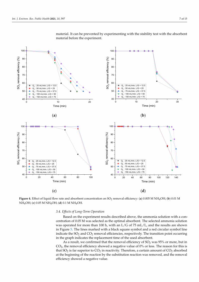
All absorbents except for simulated seawater and water were tested at a concentrationof 0.01 M, which was relatively low compared to that used in previous studies. Theperformance of the absorbent was high, in the descending order of: NH4OH > H2O2 >Na2CO3 > NaHCO3 > NaOH > simulated seawater > Na2SO3 > DI water, as depicted inFigure 3. The same trend can be confirmed by looking at the SO2 loading of the absorbentover time in Figure 3.
When DI water was used as an absorbent, as reported in the results for general SO2removal experiments, the removal rate rapidly decreased from the beginning of the experi-ment, and then showed a removal rate of 50% or less in less than 30 min [16,32,33,46,47].The tendency for various types of absorbents in this study is not much different from thosein the previous studies. However, the simulated seawater showed somewhat high SO2removal efficiency for 30 min after the experiment.
In the hollow fiber membrane contactor, the mass transfer between gas and liquid isachieved by diffusion through the hollow fiber membrane pores.
Int. J. Environ. Res. Public Health 2021, 18, 597 6 of 15
Int. J. Environ. Res. Public Health 2021, 18, x 6 of 16
H2O2 (aq) + SO2 (aq) ↔ H2SO4 (aq), (3)
2NaOH (aq) + SO2 (g) → Na2SO3 (aq) + H2O (aq), (4)
2NaHCO3 (aq) + SO2 (aq) → Na2SO3 (aq) + 2CO2 (g) +H2O (aq), (5)
Na2CO3 (s) + SO2 (aq) → Na2SO3 (aq) + CO2 (g), (6)
Na2SO3 (s) + SO2 (aq) + H2O (aq) → 2NaHSO3 (aq), (7)
2NH4OH (aq) + SO2 (aq) + H2O (aq) ↔ (NH4)2SO3 (aq) + 2H2O (aq), (8)
All absorbents except for simulated seawater and water were tested at a concentra-tion of 0.01 M, which was relatively low compared to that used in previous studies. The performance of the absorbent was high, in the descending order of: NH4OH > H2O2 > Na2CO3 > NaHCO3 > NaOH > simulated seawater > Na2SO3 > DI water, as depicted in Figure 3. The same trend can be confirmed by looking at the SO2 loading of the absorbent over time in Figure 3.
Figure 3. Effect of absorbents on SO2 gas removal efficiency and SO2 loading.
When DI water was used as an absorbent, as reported in the results for general SO2 removal experiments, the removal rate rapidly decreased from the beginning of the ex-periment, and then showed a removal rate of 50% or less in less than 30 min [16,32,33,46,47]. The tendency for various types of absorbents in this study is not much different from those in the previous studies. However, the simulated seawater showed somewhat high SO2 removal efficiency for 30 min after the experiment.
In the hollow fiber membrane contactor, the mass transfer between gas and liquid is achieved by diffusion through the hollow fiber membrane pores.
Figure 3. Effect of absorbents on SO2 gas removal efficiency and SO2 loading.
The reaction region performs the absorption of gas through diffusion in the liquidphase. As the absorbent concentration decreases, the reaction region in the liquid phase thatabsorbs gas decreases, so that the gas absorption rate, that is, the SO2 removal efficiency,decreases. For this reason, we judged that the removal performance of simulated seawaterwas measured as being relatively high using an absorbent having a low concentration of0.01 M. Besides, SO2 removal performance is closely related with the pH condition of theabsorbent. According to Zhang et al., when the absorbent’s pH decreases, the mass transferof SO2 from the gas phase to the absorbent decreases [48]. Therefore, the SO2 removalefficiency also decreases.
3.3. Removal Efficiency According to L/G and Concentration Changes of NH4OH
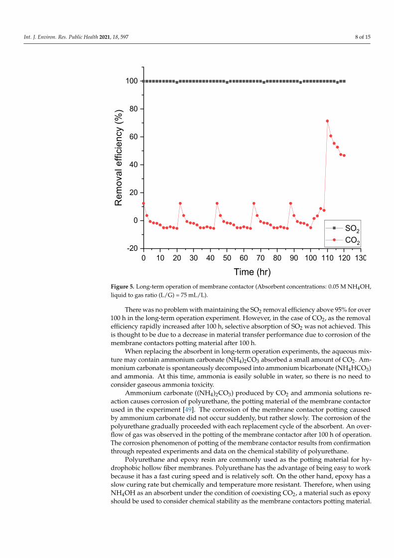
Figure 4 shows the SO2 removal efficiency according to the L/G change by the ab-sorbent concentration selected through the previous experiment. In each experimentalcondition, the gas flow rate was fixed at 2 L/min, and the liquid flow rate was changedfrom 25 mL/min to 150 mL/min so that the L/G value was set from 12.5 to 75. Thehigher the concentration of the absorbent, the longer the reaction region in the absorbentmentioned above increased; thus, the duration of maintaining the SO2 removal efficiencyof 90% or more lengthened. This is the same trend as reported in previous general researchresults. However, the L/G value used in this experiment is about four times lower thanthat in existing studies, which means that it is possible to process a larger amount of SO2during the same time [26,33].
The absorbent concentration was tested in various conditions from 0.005 to 0.1 M,considering the housing material (polycarbonate) of the commercially available membranecontactor (3M Liqui-CelTM MM series). If the experiment is conducted with an absorbentconcentration of 0.1 M or higher, the membrane contactor performance decreases dueto corrosion and damage to the housing material. That is, the SO2 removal efficiencydecreases. This problem can be overcome by replacing the membrane contactor housing
Int. J. Environ. Res. Public Health 2021, 18, 597 7 of 15
material. It can be prevented by experimenting with the stability test with the absorbentmaterial before the experiment.
Int. J. Environ. Res. Public Health 2021, 18, x 7 of 16
The reaction region performs the absorption of gas through diffusion in the liquid phase. As the absorbent concentration decreases, the reaction region in the liquid phase that absorbs gas decreases, so that the gas absorption rate, that is, the SO2 removal effi-ciency, decreases. For this reason, we judged that the removal performance of simulated seawater was measured as being relatively high using an absorbent having a low concen-tration of 0.01 M. Besides, SO2 removal performance is closely related with the pH condi-tion of the absorbent. According to Zhang et al., when the absorbent’s pH decreases, the mass transfer of SO2 from the gas phase to the absorbent decreases [48]. Therefore, the SO2 removal efficiency also decreases.
3.3. Removal Efficiency According to L/G and Concentration Changes of NH4OH Figure 4 shows the SO2 removal efficiency according to the L/G change by the absor-
bent concentration selected through the previous experiment. In each experimental con-dition, the gas flow rate was fixed at 2 L/min, and the liquid flow rate was changed from 25 mL/min to 150 mL/min so that the L/G value was set from 12.5 to 75. The higher the concentration of the absorbent, the longer the reaction region in the absorbent mentioned above increased; thus, the duration of maintaining the SO2 removal efficiency of 90% or more lengthened. This is the same trend as reported in previous general research results. However, the L/G value used in this experiment is about four times lower than that in existing studies, which means that it is possible to process a larger amount of SO2 during the same time [26,33].
(a)
(b)
(c)
(d)
Figure 4. Effect of liquid flow rate and absorbent concentration on SO2 removal efficiency: (a) 0.005 M NH4OH; (b) 0.01 M NH4OH; (c) 0.05 M NH4OH; (d) 0.1 M NH4OH.
0 10 2040
50
60
70
80
90
100
SO2 r
emov
al e
ffici
ency
(%)
Time (min)
QL : 25 mL/min, L/G = 12.5 QL : 50 mL/min, L/G = 25 QL : 75 mL/min, L/G = 37.5 QL : 100 mL/min, L/G = 50 QL : 150 mL/min, L/G = 75
0 10 20 3040
50
60
70
80
90
100
SO2 r
emov
al e
ffici
ency
(%)
Time (min)
QL : 25 mL/min, L/G = 12.5 QL : 50 mL/min, L/G = 25 QL : 75 mL/min, L/G = 37.5 QL : 100 mL/min, L/G = 50 QL : 150 mL/min, L/G = 75
0 20 40 60 80 10040
50
60
70
80
90
100
SO2 r
emov
al e
ffici
ency
(%)
Time (min)
QL : 25 mL/min, L/G = 12.5 QL : 50 mL/min, L/G = 25 QL : 75 mL/min, L/G = 37.5 QL : 100 mL/min, L/G = 50 QL : 150 mL/min, L/G = 75
0 20 40 60 80 100 120 14040
50
60
70
80
90
100
SO2 r
emov
al e
ffici
ency
(%)
Time (min)
QL : 25 mL/min, L/G = 12.5 QL : 50 mL/min, L/G = 25 QL : 75 mL/min, L/G = 37.5 QL : 100 mL/min, L/G = 50 QL : 150 mL/min, L/G = 75
Figure 4. Effect of liquid flow rate and absorbent concentration on SO2 removal efficiency: (a) 0.005 M NH4OH; (b) 0.01 MNH4OH; (c) 0.05 M NH4OH; (d) 0.1 M NH4OH.
3.4. Effects of Long-Term Operation
Based on the experiment results described above, the ammonia solution with a con-centration of 0.05 M was selected as the optimal absorbent. The selected ammonia solutionwas operated for more than 100 h, with an L/G of 75 mL/L, and the results are shownin Figure 5. The lines marked with a black square symbol and a red circular symbol lineindicate the SO2 and CO2 removal efficiencies, respectively. The transition point occurringin the graph indicates the replacement time of the used absorbent.
As a result, we confirmed that the removal efficiency of SO2 was 95% or more, but inCO2, the removal efficiency showed a negative value of 0% or less. The reason for this isthat SO2 is far superior to CO2 in reactivity. Therefore, a certain amount of CO2 absorbedat the beginning of the reaction by the substitution reaction was removed, and the removalefficiency showed a negative value.
Int. J. Environ. Res. Public Health 2021, 18, 597 8 of 15
Int. J. Environ. Res. Public Health 2021, 18, x 8 of 16
The absorbent concentration was tested in various conditions from 0.005 to 0.1 M, considering the housing material (polycarbonate) of the commercially available mem-brane contactor (3M Liqui-CelTM MM series). If the experiment is conducted with an ab-sorbent concentration of 0.1 M or higher, the membrane contactor performance decreases due to corrosion and damage to the housing material. That is, the SO2 removal efficiency decreases. This problem can be overcome by replacing the membrane contactor housing material. It can be prevented by experimenting with the stability test with the absorbent material before the experiment.
3.4. Effects of Long-Term Operation Based on the experiment results described above, the ammonia solution with a con-
centration of 0.05 M was selected as the optimal absorbent. The selected ammonia solution was operated for more than 100 h, with an L/G of 75 mL/L, and the results are shown in Figure 5. The lines marked with a black square symbol and a red circular symbol line indicate the SO2 and CO2 removal efficiencies, respectively. The transition point occurring in the graph indicates the replacement time of the used absorbent.
Figure 5. Long-term operation of membrane contactor (Absorbent concentrations: 0.05 M NH4OH, liquid to gas ratio (L/G) = 75 mL/L).
As a result, we confirmed that the removal efficiency of SO2 was 95% or more, but in CO2, the removal efficiency showed a negative value of 0% or less. The reason for this is that SO2 is far superior to CO2 in reactivity. Therefore, a certain amount of CO2 absorbed at the beginning of the reaction by the substitution reaction was removed, and the removal efficiency showed a negative value.
0 10 20 30 40 50 60 70 80 90 100 110 120 130-20
0
20
40
60
80
100
Rem
oval
effi
cien
cy (%
)
Time (hr)
SO2
CO2
Figure 5. Long-term operation of membrane contactor (Absorbent concentrations: 0.05 M NH4OH,liquid to gas ratio (L/G) = 75 mL/L).
There was no problem with maintaining the SO2 removal efficiency above 95% for over100 h in the long-term operation experiment. However, in the case of CO2, as the removalefficiency rapidly increased after 100 h, selective absorption of SO2 was not achieved. Thisis thought to be due to a decrease in material transfer performance due to corrosion of themembrane contactors potting material after 100 h.
When replacing the absorbent in long-term operation experiments, the aqueous mix-ture may contain ammonium carbonate (NH4)2CO3 absorbed a small amount of CO2. Am-monium carbonate is spontaneously decomposed into ammonium bicarbonate (NH4HCO3)and ammonia. At this time, ammonia is easily soluble in water, so there is no need toconsider gaseous ammonia toxicity.
Ammonium carbonate ((NH4)2CO3) produced by CO2 and ammonia solutions re-action causes corrosion of polyurethane, the potting material of the membrane contactorused in the experiment [49]. The corrosion of the membrane contactor potting causedby ammonium carbonate did not occur suddenly, but rather slowly. The corrosion of thepolyurethane gradually proceeded with each replacement cycle of the absorbent. An over-flow of gas was observed in the potting of the membrane contactor after 100 h of operation.The corrosion phenomenon of potting of the membrane contactor results from confirmationthrough repeated experiments and data on the chemical stability of polyurethane.
Polyurethane and epoxy resin are commonly used as the potting material for hy-drophobic hollow fiber membranes. Polyurethane has the advantage of being easy to workbecause it has a fast curing speed and is relatively soft. On the other hand, epoxy has aslow curing rate but chemically and temperature more resistant. Therefore, when usingNH4OH as an absorbent under the condition of coexisting CO2, a material such as epoxyshould be used to consider chemical stability as the membrane contactors potting material.

Int. J. Environ. Res. Public Health 2021, 18, 597 9 of 15
3.5. Overall Mass Transfer Coefficient for Various Absorbents
The overall mass transfer coefficient was calculated by inserting the SO2 removalefficiency results, the membrane contactors specification, and the gas flow rate intoEquation (9). The calculated coefficient value indicates the performance of the absorbentfor membrane contactors. The calculation equation is as follows [26]:
KGa = (Qg/ZP) × log[(CSO2,IN)/(CSO2,OUT)], (9)
where KGa is the overall mass transfer capacity coefficient (kmol/m3·hr·kPa), Qg is thegas flow rate, Z is the effective hollow fiber membrane length (m), and P is the operatingpressure (kPa). In this study, the membrane contactors do not depend on the pressureduring operation. The force applied to the membrane contactor is 1 atm, and the pressuredifference is close to zero. It was confirmed that there is no difference when comparing thepressure applied to the membrane contactor through an experiment [33,50].
Figure 6 shows the overall mass transfer coefficients for SO2 of various absorbentsover time. As the flow rate of the absorbent increases, the SO2 removal efficiency in thesimulated flue gas increases, and the overall mass transfer coefficient increases continuously.These results indicated that the prepared absorbent has excellent SO2 material transfercapability. The calculated overall mass transfer coefficient was maintained almost constantwhen the absorbent flow rate was over 75 mL/min (L/G = 37.5), and the flow rate at thispoint was found to be the optimum condition.
Int. J. Environ. Res. Public Health 2021, 18, x 10 of 16
Figure 6. Effect of absorbents on SO2 overall mass transfer coefficient.
The advantage of using KGa as the basis for comparison is that the effective contact area per unit volume describes the effective surface area in both the absorption tower and membrane contactor systems. The absorption towers and membrane contactor systems are beneficial because they have different packing densities, porosities, and total surface areas for mass transfer. However, it can approximate the membrane surface area with reasonable accuracy in the membrane contactor system, but the packed absorption towers wetting area is challenging to determine.
The separation process is based on the packing height (Z) value when calculating the theoretical process size [50]. The mass transfer height (HTU) used when calculating the Z-value is determined by the overall mass transfer coefficient and gas flow rate. Since the mass transfer height is used as a measure of general process efficiency, it can be confirmed by calculating the HTU value when calculating the ideal size and efficiency in the separa-tion process. The formula is as follows:
HTU = Qg/(KGa×SMC), (10)
where HTU is the mass transfer height, Qg is the gas flow rate, SMC is the cross-sectional area of the membrane contactor, and MC is membrane contactor.
Table 2 compares the HTU values of the conventional absorption tower and the set up to which the membrane contactor used in this study was applied. The HTU value cal-culated by applying the size of the membrane contactor module and the experimental value is 5 × 10⁻²; the volume is 1/36th when the membrane contactor is applied compared to the conventional packed column [26].
25 50 75 100 125 150
0.2
0.4
0.6
0.8
1.0
1.2
Liquid flow rate (mL/min)
K G (×
103 m
/s)
0.05
0.10
0.15
0.20
0.25
0.30
HTU
(m)
Figure 6. Effect of absorbents on SO2 overall mass transfer coefficient.
The advantage of using KGa as the basis for comparison is that the effective contactarea per unit volume describes the effective surface area in both the absorption tower andmembrane contactor systems. The absorption towers and membrane contactor systems arebeneficial because they have different packing densities, porosities, and total surface areasfor mass transfer. However, it can approximate the membrane surface area with reasonableaccuracy in the membrane contactor system, but the packed absorption towers wettingarea is challenging to determine.
The separation process is based on the packing height (Z) value when calculating thetheoretical process size [50]. The mass transfer height (HTU) used when calculating theZ-value is determined by the overall mass transfer coefficient and gas flow rate. Since the

Int. J. Environ. Res. Public Health 2021, 18, 597 10 of 15
mass transfer height is used as a measure of general process efficiency, it can be confirmedby calculating the HTU value when calculating the ideal size and efficiency in the separationprocess. The formula is as follows:
HTU = Qg/(KGa × SMC), (10)
where HTU is the mass transfer height, Qg is the gas flow rate, SMC is the cross-sectionalarea of the membrane contactor, and MC is membrane contactor.
Table 2 compares the HTU values of the conventional absorption tower and the setup to which the membrane contactor used in this study was applied. The HTU valuecalculated by applying the size of the membrane contactor module and the experimentalvalue is 5 × 10⁻²; the volume is 1/36th when the membrane contactor is applied comparedto the conventional packed column [26].
Table 2. Comparison of mass transfer height (HTU) values with absorption towers of conventional desulfurization facilities.
Packed Column [46] Spray Tower [51] Membrane Contactor [33] Membrane Contactor(This Work)
Effective lengthof module (m) 1.07–3.21 1.75–4.13 0.21–2.32 0.15
Flow rate of gas (L/min) 2 L/min(3 × 10−5 m3/s) - - -
SO2 removal efficiency (%) >99 - - -HTU (m) 0.6–1.8 0.98–2.32 0.12–1.3 0.05
Reactor volume 1 0.0061–0.0184 0.05–0.15 0.07–0.20
Packed columns, which are widely used, have high technology maturity. However,reported as the energy consumption of the conventional packed column is 0.58 kWh/Nm3-CO2, which can be reduced by about 33% when replaced by a membrane contactor system.Furthermore, the volume of absorption towers can be reduced by 63% with the applica-tion of the membrane contactor hybrid system compared to conventional gas absorptionsystems [52].
3.6. Reuse of By-Products
After the end of the experiment, we checked whether the absorbent reacts withSO2 by checking the absorbent pH value change. However, for more accurate structuralanalysis, Attenuated total reflectance-Fourier transform infrared spectroscopy (ATR-FTIR)spectrum analysis of the generated by-products was performed. Figure 7 compares theFTIR spectrum of 0.05 M aqueous ammonia solution used as an SO2 absorbent. (a) isan aqueous ammonia solution prepared at a concentration of 0.05 M; (b) is an absorbentwhen the SO2 removal efficiency was 99%; (c) is the IR spectrum result of the absorbentwhen the SO2 removal efficiency was reduced to 50% or less. The IR spectrum (d) of theammonium sulfate solution was prepared at a concentration of 0.05 M and was used toconfirm whether the prepared absorbent produced ammonium sulfate. As a result of IRanalysis, we found that as the absorption of SO2 proceeds, the characteristic peak observedin the aqueous ammonium sulfate solution increased (1050–1150 cm−1, asymmetric stretchbend of SO4 ion; 1400–1450 cm−1, deformation or umbrella bend of NH4 ion), confirmingthat ammonium sulfate was formed [53].
In the ammonium sulfate solution produced by the once-through mode, 3 L of NH4OH(0.05 M) can theoretically produce about 7.43 g of ammonium sulfate. Ammonia nitrogenused as fertilizer means nitrogen in the form of NH4 or NH3 ions, and ammonia dissolvedin water also exists as ammonia nitrogen used as fertilizer, so there is no need to remove it.However, it should be used following the appropriate concentration for each crop, and itis not suitable for acidic soils, so it should be used only in neutral or alkaline soils. Also,when mixed with basic fertilizer, ammonia volatilizes, so it should not be mixed.

Int. J. Environ. Res. Public Health 2021, 18, 597 11 of 15Int. J. Environ. Res. Public Health 2021, 18, x 12 of 16
Figure 7. FTIR spectra of fresh and SO2 absorbed aqueous NH4OH.
In the ammonium sulfate solution produced by the once-through mode, 3 L of NH4OH (0.05 M) can theoretically produce about 7.43 g of ammonium sulfate. Ammonia nitrogen used as fertilizer means nitrogen in the form of NH4 or NH3 ions, and ammonia dissolved in water also exists as ammonia nitrogen used as fertilizer, so there is no need to remove it. However, it should be used following the appropriate concentration for each crop, and it is not suitable for acidic soils, so it should be used only in neutral or alkaline soils. Also, when mixed with basic fertilizer, ammonia volatilizes, so it should not be mixed.
The world demand and the global market of ammonium sulfate used as fertilizer is expected to reach 29.81 million tons and 3.44 billion dollars, respectively, by 2022 [54]. Ammonium sulfate fertilizer is generally suitable for crops such as common wheat, corn, rice, cotton, sweet potato, sesame seeds, fruit trees, and vegetables. The appropriate amount of fertilizer used depends on the crop. In the case of wheat, 62 kg of ammonium sulfate fertilizer per 0.1 ha is used. It is considered that a sufficient supply of ammonium sulfate aqueous solution is possible by increasing the absorbent concentration used in this study or by scale-up the reaction facility [55]. Conventional ammonium sulfate fertilizers are used in powder form at once, resulting in adverse effects such as pest damage and cold resistance reduction due to nitrogen excess. Since ammonium sulfate fertilizer is fast-acting, it is common to divide it several times. Additional water should be used to prevent denitrification after fertilization. However, ammonium sulfate produced through the ex-periment is a liquid form containing moisture, so it can be sprayed as is. It is expected to be suitable given the regulations and standards of use because it does not contain heavy metal. Also, the produced ammonium sulfate contains a large amount of water in the form of an aqueous solution. Therefore, if applied in practice, an aqueous ammonium sulfate solution should be transported to the tank lorry for use, or additional facilities (e.g., dryer, crystalizer) should be used in the production process to supply it in powder form [56,57]. Besides, ammonium sulfate fertilizer does not cause acidification, and the rice yield in-creases by about 3% in reclaimed lands, alpine regions, and limestone regions compared with urea fertilizers [58,59].
Figure 7. FTIR spectra of fresh and SO2 absorbed aqueous NH4OH.
The world demand and the global market of ammonium sulfate used as fertilizeris expected to reach 29.81 million tons and 3.44 billion dollars, respectively, by 2022 [54].Ammonium sulfate fertilizer is generally suitable for crops such as common wheat, corn,rice, cotton, sweet potato, sesame seeds, fruit trees, and vegetables. The appropriateamount of fertilizer used depends on the crop. In the case of wheat, 62 kg of ammoniumsulfate fertilizer per 0.1 ha is used. It is considered that a sufficient supply of ammoniumsulfate aqueous solution is possible by increasing the absorbent concentration used in thisstudy or by scale-up the reaction facility [55]. Conventional ammonium sulfate fertilizersare used in powder form at once, resulting in adverse effects such as pest damage andcold resistance reduction due to nitrogen excess. Since ammonium sulfate fertilizer isfast-acting, it is common to divide it several times. Additional water should be used toprevent denitrification after fertilization. However, ammonium sulfate produced throughthe experiment is a liquid form containing moisture, so it can be sprayed as is. It is expectedto be suitable given the regulations and standards of use because it does not contain heavymetal. Also, the produced ammonium sulfate contains a large amount of water in theform of an aqueous solution. Therefore, if applied in practice, an aqueous ammoniumsulfate solution should be transported to the tank lorry for use, or additional facilities(e.g., dryer, crystalizer) should be used in the production process to supply it in powderform [56,57]. Besides, ammonium sulfate fertilizer does not cause acidification, and therice yield increases by about 3% in reclaimed lands, alpine regions, and limestone regionscompared with urea fertilizers [58,59].
However, when real flue gas is used, it is necessary to install a pretreatment facilitythat removes trace amounts of pollutants that may absorb some harmful substances bythe absorbent or reduce the membrane contactors performance. Pretreatment facilitiesare classified according to the type of pollutant. For example, cyclones, bag filters, andelectrostatic separators (ESPs) are often used to remove contaminants from particulatepollutants. Among these, bag filters are widely used as technologies to minimize dioxin,VOCs, and heavy metals by combining activated carbon at the facility front-end [60]. Also,the flue gas temperature is 90–140 ◦C, and the operating temperature of the membranecontactors used is below 80 ◦C or less. When real flue gas is used, to replace it with
Int. J. Environ. Res. Public Health 2021, 18, 597 12 of 15
membrane contactors applied to high temperatures, or operating temperatures will beadjusted through heat exchangers.
4. Conclusions
As a result of experimenting with the absorption of SO2 from the model of flue gasusing various absorbents, we found excellent performances for the following in descendingorder: NH4OH, Na2CO3, NaOH, and H2O2. When the ammonia solution was used asan absorbent, it showed a high selective removal efficiency of SO2 gas. As the L/G ratioincreased, mass transfer accelerated, and the removal efficiency was maintained for along time. We concluded that an absorbent with a concentration of 0.05 M is suitable formaintaining the SO2 removal efficiency and understanding the replacement cycle duringlong-term operation.
When replacing the conventional packed column with a membrane contactor com-posed of PP, gas separation and the removal performance are maintained, and the volumeof equipment is significantly reduced. The performance of conventional scrubbers andhollow fiber membrane contactors was compared in terms of increased contact surface arearather than the increased mass transfer coefficient. In the absorption process, the larger theinterface area between the gas and the liquid, the higher its overall velocity affecting theabsorption/removal performance. The membrane contactor has thousands of micro-sizedhollow fiber membranes modulated by housing materials, providing a large contact areadespite the small volume.
As a result of the experiment conducted with CO2 and SO2 coexisting, the SO2 removalperformance decreased due to corrosion of the membrane contactors’ potting material. Asa result, we confirmed that the wetting of the membrane contactor and the corrosion ofthe potting material decreased the separation and removal performance, thereby adverselyaffecting all processes of applying the membrane contactor. However, this problem can beovercome by replacing the potting material with a material with high chemical stability.Using a chemically stable potting material enables the application of a high-concentrationabsorbent to the membrane contactor.
Through this study, the possibility of the selective absorption of SO2 in flue gas andits reuse as a saturated absorbent fertilizer was confirmed using a once-through mode. If itcan be applied at a higher concentration than the currently used absorbent, it is expectedthat long-term operation of the desulfurization facility will be possible, and the amountof ammonium sulfate, a by-product, will increase. Although many issues remain to beresolved, such as the concentration of SO2 emitted or the concentration of absorbents used,we hope that this technology will allow by-products of the absorption process to be reusedas resources, not as waste.
Author Contributions: Methodology, D.K. and H.S.P.; Investigation, D.K.; Formal analysis, D.K.,H.S.P., J.H.K., and K.K.; Writing, H.S.P.; Conceptualization, D.K., J.H.K., and H.S.; Review & editing,H.S.P. and H.S.; visualization, H.S.P. and K.K.; Supervision, J.K. and H.S. All authors have read andagreed to the published version of the manuscript.
Funding: This study was funded by the Korea Institute of Energy Technology Evaluation andPlanning(KETEP) and the Ministry of Trade, Industry & Energy(MOTIE) of the Republic of Korea,grant number 20173030091890; and was conducted with the support by the Korea Evaluation Instituteof Industrial Technology (KEIT) grant funded by the Korea government (MOTIE), grant number20005884 and the APC was funded by the Ulsan Metropolitan City and Korea Institute of IndustrialTechnology, grant number U201900107, IZ-20-0073.
Institutional Review Board Statement: Not applicable.
Informed Consent Statement: Not applicable.
Data Availability Statement: The data presented in this study are openly available.
Conflicts of Interest: The authors declare no conflict of interest.
Int. J. Environ. Res. Public Health 2021, 18, 597 13 of 15
References1. International Energy Agency (IEA). World Energy Outlook 2018: Executive Summary; IEA: Paris, France, 2018.2. International Energy Agency. IEA Medium-Term Market Report 2016 Market Analysis and Forecasts to 2021; IEA: Paris, France,
2016; Volume 278.3. International Energy Agency. World Energy Outlook 2020; IEA: Paris, France, 2020.4. Jafarinejad, S. Control and treatment of sulfur compounds specially sulfur oxides (SOX) emissions from the petroleum industry:
A review. Chem. Int. 2016, 2, 242–253.5. Smith, C.E. Study evaluates refiners’ options to meet 2020 bunker fuel sulfur rules. Oil Gas J. 2018, 116, 60–67.6. Nugraha, F. Effective Implementation of Emission Control Area towards Cleaner Shipping Operations: Focusing on Sulphur Oxides (SOX)
Emission Reduction; World Maritime University Dissertations: Malmö, Sweden, 2009.7. Mao, X. Marine Engine Emission Standards for China’s Domestic Vessels; International Council on Clean Transportation:
Beijing, China, 2018.8. Lim, J.; Choi, Y.; Kim, G.; Song, H.; Kim, J. Modeling of Wet Flue Gas Desulfurization Process for Utilization of Low-Grade
Limestone. Korean Chem. Eng. Res. 2019, 57, 743–748.9. Chu Van, T.; Ramirez, J.; Rainey, T.; Ristovski, Z.; Brown, R.J. Global impacts of recent IMO regulations on marine fuel oil refining
processes and ship emissions. Transp. Res. Part D Transp. Environ. 2019, 70, 123–134. [CrossRef]10. Li, S.; Xu, T.; Sun, P.; Zhou, Q.; Tan, H.; Hui, S. NOX and SOX emissions of a high sulfur self-retention coal during air-staged
combustion. Fuel 2008, 87, 723–731. [CrossRef]11. Kikkawa, H.; Nakamoto, T.; Morishita, M.; Yamada, K. New wet FGD process using granular limestone. Ind. Eng. Chem. Res.
2002, 41, 3028–3036. [CrossRef]12. Mochida, I.; Korai, Y.; Shirahama, M.; Kawano, S.; Hada, T.; Seo, Y.; Yoshikawa, M.; Yasutake, A. Removal of SOX and NOX over
activated carbon fibers. Carbon 2000, 38, 227–239. [CrossRef]13. Tran, T.A. Research of the Scrubber Systems to Clean Marine Diesel Engine Exhaust Gases on Ships. J. Mar. Sci. Res. Dev. 2017,
7, 243. [CrossRef]14. Joo, S.H.; Bhatti, U.H.; Jin Park, H.; Jeong, D.H.; Baek, I.H.; Chan Nam, S.; Lee, K.B. Selective removal of SO2 from coal-fired flue
gas by alkaline solvents using a membrane contactor. Chem. Eng. Process. Process Intensif. 2020, 147, 107772. [CrossRef]15. Pabby, A.K.; Rizvi, S.S.; Requena, A.M. (Eds.) Handbook of Membrane Separations: Chemical, Pharmaceutical, Food, and Biotechnological
Applications Second Edition; CRC Press: Boca Raton, FL, USA, 2015. [CrossRef]16. Chan, Z.P.; Li, L.; Kang, G.; Ab Manan, N.; Cao, Y.; Wang, T. Deep CO2 removal using high pressure membrane contactors with
low liquid-to-gas ratio. Chem. Eng. Res. Des. 2020, 153, 528–536. [CrossRef]17. Li, S.; Zhou, S.J.; Pyrzynski, T.; Makkuni, A.; Meyer, H. Hybrid Membrane/Absorption Process for Post-Combustion CO2 Capture;
Institute of Gas Technology: Des Plaines, IL, USA, 2013. [CrossRef]18. Gabelman, A.; Hwang, S.T. Hollow fiber membrane contactors. J. Membr. Sci. 1999, 159, 61–106. [CrossRef]19. Enrico Drioli, E.; Curcio, A.C. Membrane Contactors: Fundamentals, Applications and Potentialities. Membr. Sci. Technol. 2005,
11, 186–253.20. Iversen, S.B.; Bhatia, V.K.; Dam-Johansen, K.; Jonsson, G. Characterization of microporous membranes for use in membrane
contactors. J. Membr. Sci. 1997, 130, 205–217. [CrossRef]21. Nagy, E. Membrane Contactors. Basic Equations of Mass Transport Through a Membrane Layer Second Edition; Elsevier: Amsterdam,
The Nederlands, 2019; pp. 337–345.22. Fasihi, M.; Shirazian, S.; Marjani, A.; Rezakazemi, M. Computational fluid dynamics simulation of transport phenomena in
ceramic membranes for SO2 separation. Math. Comput. Model. 2012, 56, 278–286. [CrossRef]23. Yang, J.; Yu, X.; Yan, J.; Tu, S.T.; Dahlquist, E. Effects of SO2 on CO2 capture using a hollow fiber membrane contactor. Appl. Energy
2013, 112, 755–764. [CrossRef]24. Luis, P.; Garea, A.; Irabien, A. Modelling of a hollow fibre ceramic contactor for SO2 absorption. Sep. Purif. Technol. 2010,
72, 174–179. [CrossRef]25. Gao, X.; Qiu, M.; Fu, K.; Xu, P.; Kong, X.; Chen, X.; Fan, Y. Feasibility analysis of SO2 absorption using a hydrophilic ceramic
membrane contactor. Chin. J. Chem. Eng. 2018, 26, 2139–2147. [CrossRef]26. Sun, X.; Meng, F.; Yang, F. Application of seawater to enhance SO2 removal from simulated flue gas through hollow fiber
membrane contactor. J. Membr. Sci. 2008, 312, 6–14. [CrossRef]27. Lv, Y.; Yu, X.; Tu, S.T.; Yan, J.; Dahlquist, E. Experimental studies on simultaneous removal of CO2 and SO2 in a polypropylene
hollow fiber membrane contactor. Appl. Energy 2012, 97, 283–288. [CrossRef]28. Shirazian, S.; Rezakazemi, M.; Marjani, A.; Rafivahid, M.S. Development of a mass transfer model for simulation of sulfur dioxide
removal in ceramic membrane contactors. Asia Pac. J. Chem. Eng. 2012, 7, 828–834. [CrossRef]29. Jeon, H.; Ahn, H.; Song, I.; Jeong, H.-K.; Lee, Y.; Lee, H.-K. Absorption of sulfur dioxide by porous hydrophobic membrane
contactor. Desalination 2008, 234, 252–260. [CrossRef]30. Luis, P.; Garea, A.; Irabien, A. Zero solvent emission process for sulfur dioxide recovery using a membrane contactor and ionic
liquids. J. Membr. Sci. 2009, 330, 80–89. [CrossRef]31. Luis, P.; Garea, A.; Irabien, A. Sulfur dioxide non-dispersive absorption in N,N-dimethylaniline using a ceramic membrane
contactor. J. Chem. Technol. Biotechnol. 2008, 83, 1570–1577. [CrossRef]

Int. J. Environ. Res. Public Health 2021, 18, 597 14 of 15
32. Newman, W.G.; Biggs, E. Sulphur Dioxide Removal from Stack Gases a Review of Available Methods; Ontario Ministry of theEnvironment: Toronto, ON, Canada, 1975.
33. Park, H.J.; Bhatti, U.H.; Joo, S.H.; Nam, S.C.; Park, S.Y.; Lee, K.B.; Baek, I.H. Experimental Study on the Selective Removal of SO2from a Ship Exhaust Gas Stream Using a Membrane Contactor. Ind. Eng. Chem. Res. 2019, 58, 14897–14905. [CrossRef]
34. Minier-Matar, J.; Janson, A.; Hussain, A.; Adham, S. Application of membrane contactors to remove hydrogen sulfide from sourwater. J. Membr. Sci. 2017, 541, 378–385. [CrossRef]
35. Dardor, D.; Janson, A.; AlShamari, E.; Adham, S.; Minier-Matar, J. The effect of Hydrogen sulfide oxidation with ultraviolet lightand aeration on sour water treatment via membrane contactors. Sep. Purif. Technol. 2020, 236, 116262. [CrossRef]
36. Chabanon, E.; Bounaceur, R.; Castel, C.; Rode, S.; Roizard, D.; Favre, E. Pushing the limits of intensified CO2 post-combustioncapture by gas-liquid absorption through a membrane contactor. Chem. Eng. Process. Process Intensif. 2015, 91, 7–22. [CrossRef]
37. Yan, S.P.; Fang, M.X.; Zhang, W.F.; Wang, S.Y.; Xu, Z.K.; Luo, Z.Y.; Cen, K.F. Experimental study on the separation of CO2 fromflue gas using hollow fiber membrane contactors without wetting. Fuel Process. Technol. 2007, 88, 501–511. [CrossRef]
38. Goh, P.S.; Naim, R.; Rahbari-Sisakht, M.; Ismail, A.F. Modification of membrane hydrophobicity in membrane contactors forenvironmental remediation. Sep. Purif. Technol. 2019, 227, 115721. [CrossRef]
39. Lv, Y.; Yu, X.; Jia, J.; Tu, S.T.; Yan, J.; Dahlquist, E. Fabrication and characterization of superhydrophobic polypropylene hollowfiber membranes for carbon dioxide absorption. Appl. Energy 2012, 90, 167–174. [CrossRef]
40. Atchariyawut, S.; Jiraratananon, R.; Wang, R. Separation of CO2 from CH4 by using gas-liquid membrane contacting process.J. Membr. Sci. 2007, 304, 163–172. [CrossRef]
41. Khaisri, S.; de Montigny, D.; Tontiwachwuthikul, P.; Jiraratananon, R. Comparing membrane resistance and absorption perfor-mance of three different membranes in a gas absorption membrane contactor. Sep. Purif. Technol. 2009, 65, 290–297. [CrossRef]
42. Liu, Y.; Wang, Q.; Yin, Y.; Pan, J.; Zhang, J. Advanced oxidation removal of NO and SO2 from flue gas by usingultraviolet/H2O2/NaOH process. Chem. Eng. Res. Des. 2014, 92, 1907–1914. [CrossRef]
43. Chu, G.W.; Luo, Y.; Shan, C.Y.; Zou, H.K.; Xiang, Y.; Shao, L.; Chen, J.F. Absorption of SO2 with ammonia-based solution in acocurrent rotating packed bed. Ind. Eng. Chem. Res. 2014, 53, 15731–15737. [CrossRef]
44. Tunali, Y.I.; Ertunç, S. Use of natural soda ash production process waste for SO2 removal. Environ. Prot. Eng. 2017,44, 69–80. [CrossRef]
45. Ryashentsev, M.S.; Timashkov, K.V.; Volodin, A.M.; Epikhin, A.N. Investigation of the Oxidation Process of the AbsorptionSolution in Ammonia Flue Gas Desulfurization Technology. Power Technol. Eng. 2018, 51, 691–695. [CrossRef]
46. Park, H.H.; Deshwal, B.R.; Kim, I.W.; Lee, H.K. Absorption of SO2 from flue gas using PVDF hollow fiber membranes in agas-liquid contactor. J. Membr. Sci. 2008, 319, 29–37. [CrossRef]
47. Kong, X.; Gong, D.; Ke, W.; Qiu, M.; Fu, K.; Xu, P.; Chen, X.; Fan, Y. Investigation of Mass Transfer Characteristics of SO2Absorption into NaOH in a Multichannel Ceramic Membrane Contactor. Ind. Eng. Chem. Res. 2020, 59, 11054–11062. [CrossRef]
48. Zhang, L.; Wu, S.; Gao, Y.; Sun, B.; Luo, Y.; Zou, H.; Chu, G.; Chen, J. Absorption of SO2 with calcium-based solution in a rotatingpacked bed. Sep. Purif. Technol. 2019, 214, 148–155. [CrossRef]
49. Ismail, A.F.; Kumari, S.N. Potential effect of potting resin on the performance of hollow fibre membrane modules in a CO2/CH4gas separation system. J. Membr. Sci. 2004, 236, 183–191. [CrossRef]
50. Demontigny, D.; Tontiwachwuthikul, P.; Chakma, A. Comparing the absorption performance of packed columns and membranecontactors. Ind. Eng. Chem. Res. 2005, 44, 5726–5732. [CrossRef]
51. Chung, T.W.; Wu, H. Comparison between spray towers with and without fin coils for air dehumidification using triethyleneglycol solutions and development of the mass-transfer correlations. Ind. Eng. Chem. Res. 2000, 39, 2076–2084. [CrossRef]
52. Yeon, S.H.; Lee, K.S.; Sea, B.; Park, Y.I.; Lee, K.H. Application of pilot-scale membrane contactor hybrid system for removal ofcarbon dioxide from flue gas. J. Membr. Sci. 2005, 257, 156–160. [CrossRef]
53. Boer, G.J.; Sokolik, I.N.; Martin, S.T. Infrared optical constants of aqueous sulfate-nitrate-ammonium multi-component tro-pospheric aerosols from attenuated total reflectance measurements-Part I: Results and analysis of spectral absorbing features.J. Quant. Spectrosc. Radiat. Transf. 2007, 108, 17–38. [CrossRef]
54. Ammonium Sulfate Market Worth $3.44 Billion By 2022: Grand View Research, Inc. Available online: https://www.prnewswire.com/news-releases/ammonium-sulfate-market-worth-344-billion-by-2022-grand-view-research-inc-565751001.html (accessedon 26 December 2020).
55. Properties of Ammonium Sulfate Fertilizer and Fertilization Method. CAPRO. Available online: http://www.hcccapro.co.kr/kr/customer_support/data/show.asp?id=7&page=1 (accessed on 4 January 2021).
56. Doko, M.B.; Bassani, V.; Casadebaig, J.; Cavailles, L.; Jacob, M. Preparation of proteolytic enzyme extracts from Ananas comosusL., Merr. fruit juice using semipermeable membrane, ammonium sulfate extraction, centrifugation and freeze-drying processes.Int. J. Pharm. 1991, 76, 199–206. [CrossRef]
57. Lakerveld, R.; Verzijden, N.G.; Kramer, H.; Jansens, P.; Grievink, J. Application of Ultrasound for Start-Up of Evaporative BatchCrystallization of Ammonium Sulfate in a 75-L Crystallizer. AIChE J. 2011, 57, 3367–3377. [CrossRef]
58. Chang, H.; Han, S.H.; Kim, S.; Park, M.J.; An, J.; Kang, H.; Yi, M.-J.; Akhmadi, K.; Son, Y. Effects of Nitrogen Fertilization onGrowth of Populus sibirica and Ulmus pumila Seedlings and Soil Properties in a Semi-Arid Area, Mongolia. J. Clim. Chang. Res.2015, 6, 249–256. [CrossRef]

Int. J. Environ. Res. Public Health 2021, 18, 597 15 of 15
59. Periasamy, A.; Muruganand, S.; Palaniswamy, M. Vibrational studies of Na2SO4, K2SO4, NaHSO4 and KHSO4 crystals.Rasayan J. Chem. 2009, 2, 981–989.
60. Cui, Y.Y.; Yang, G.H.; Xiao, G.H.; Zhou, J.H.; Ding, G.Z.; Pan, X.J. Adsorption of Dioxin by Bag Filter + Powdered ActivatedCarbon. Water Air Soil Pollut. 2017, 228, 160. [CrossRef]