Accelerating landscape change on the slopes and grazing country
Upload
independentCategory
view
4download
0
INTERNATIONAL JOURNAL FOR NUMERICAL AND ANALYTICAL METHODS IN GEOMECHANICSInt. J. Numer. Anal. Meth. Geomech., (in press)Published online in Wiley InterScience (www.interscience.wiley.com). DOI: 10.1002/nag.578
Seismic response of slopes subjected to incident SV waveby an improved boundary element approach
Behrouz Gatmiri1,2, Khoa-Van Nguyen1,3,*,y and Kaveh Dehghan1,4
1CERMES, Ecole Nationale des Ponts et Chaussees, 6-8 avenue Blaise Pascal, Cite Descartes, Champs-sur-Marne,77455 Marne-la-Vallee Cedex 2, France
2Department of Civil Engineering, University of Tehran, Tehran, Iran3SEFI-INTRAFOR, Society in Geotechnics, 9-11 rue Gustave Eiffel, Grigny 91350, France
4 Institut de Physique du Globe de Paris, 4 place Jussieu, 75252 Paris cedex 05, France
SUMMARY
In this paper, an improved boundary element approach for 2D elastodynamics in time-domain ispresented. This approach consists in the truncation of time integrations, based on the rapid decrease of thefundamental solutions with time. It is shown that an important reduction of the computation time as wellas the storage requirement can be achieved. Moreover, for half-plane problems, the size of boundaryelement (BE) meshes and the computation time can be significantly reduced. The proposed approach isused to study the seismic response of slopes subjected to incident SV waves. It is found that largeamplifications take place on the upper surface close to the slope, while attenuations are produced on thelower surface. The results also show that surface motions become very complex when the incidentwavelength is comparable with the size of the slope or when the slope is steep. Copyright # 2006 JohnWiley & Sons, Ltd.
Received 12 March 2006; Revised 11 October 2006; Accepted 14 October 2006
KEY WORDS: boundary element; elastodynamics; time-domain; topography; slope; earthquake
INTRODUCTION
It is well known that the effects of surface topographies on seismic motions exist and can besignificant. Macroseismic observations and instrumental studies of recent destructive earth-quakes (San Fernando}U.S.A. 1971, Friuli}Italy 1976, Chile 1985, Manjil}Iran 1990,Kozani}Greece 1995, etc.) provide the evidence and the importance of these effects. As aconsequence, a considerable amount of theoretical and numerical studies have been achieved asan attempt to model and quantify these effects.
*Correspondence to: Khoa-Van Nguyen, SEFI-INTRAFOR, 9-11 rue Gustave Eiffel, Grigny 91350, France.yE-mail: [email protected]
Copyright # 2006 John Wiley & Sons, Ltd.
As the subject is complex, analytical solutions can only be derived for a very limited numberof simple configurations [1, 2]; numerical methods are to be used in order to model these effectsin more realistic circumstances. Since the pioneering work of Aki and Larner [3], significantprogress on numerical methods has been achieved. Subsequent studies have been essentiallyconducted using finite difference methods [4, 5], finite element methods [6, 7], boundary methods[8, 9] and discrete wavenumber methods [10, 11]. Among these methods, the direct boundaryelement method (BEM) has, in recent years, gained increasing popularity in dealing withgeotechnical earthquake problems due to its efficient and convenient numerical scheme. In fact,the BEM can model outgoing waves correctly through infinite domains, and then it can avoidthe introduction of fictitious boundary conditions. Therefore, this method is well suited to dealwith wave propagation problems. In addition, this method reduces the problem dimension byone, which yields a great numerical advantage. Moreover, the BEM can be coupled with finitedifference methods [12], finite element methods [13] and discrete wavenumber methods [14].
A disadvantage of the BEM in solving dynamic problems in time-domain is the dramaticincrease of the computation time as well as the storage requirement with the number of time stepduring the BE time-matching procedure. In order to improve this drawback, an improved BEapproach, applied to 2D transient elastodynamics, has been proposed and validated in thiswork. Based on the truncation of time integrations, this approach can reduce significantly thecomputation time as well as the storage requirement while keeping a reasonable accuracy. Usingthe proposed approach, a parametric study on the seismic response of slopes within an elastichalf-plane due to incident SV waves has been done. The role of some key parameters, such asexciting dimensionless frequency and slope angle, has been studied and discussed. Results of thisparametric study may clarify the seismic response of sloping sites.
BASIC BOUNDARY ELEMENT FORMULATIONS
Consider a homogeneous isotropic elastic medium, occupying a volume O and bounded by asurface G; subjected to an incident plane wave. By neglecting the initial conditions and the bodyforce, the boundary integral equation of elastodynamics in time-domain for this medium can beexpressed as follows:
cijðxÞujðx; tÞ ¼ZG½Gijðx; xÞ � tjðxÞ �Hijðx; xÞ � ujðxÞ� dGþ ueqi ðx; tÞ ð1Þ
where x is the source point, x is the field point; ui and ti are the amplitudes of the ith componentof displacement and traction vectors, respectively, at the boundary; ueqi is the incoming-wavefield; symbol� indicates a Riemann convolution integral; cij is the discontinuity term dependingonly upon the local geometry of the boundary at x;Gij and Hij are the fundamental solutionsrepresenting the displacement and the traction at x in direction i due to a unit point forceapplied at x in the j-direction, these fundamental solutions for 2D transient elastodynamics canbe found in [15].
The numerical implementation of Equation (1) needs the discretization in both time andspace. For this purpose, the boundary G is subdivided into individual elements, and the timeaxis ð0; tNÞ is divided into N equal increments Dt: In this work, the quadratic spatial variation ofthe field variables (displacement and traction) is assumed over each element. Both constant andlinear temporal variations can be used for each field variable. For a more stable time-matching
B. GATMIRI, K.-V. NGUYEN AND K. DEHGHAN
Copyright # 2006 John Wiley & Sons, Ltd. Int. J. Numer. Anal. Meth. Geomech. (in press)
DOI: 10.1002/nag
scheme, especially for problems where the traction at the boundary may be discontinuous intime (e.g. the sudden application of the boundary external force or the wave reflection at a fixedboundary), Israil and Banerjee [16] and Nguyen [17] have pointed out that a mixed kind oftemporal variation should be used: the traction is assumed to remain constant during twocontinuous time steps while the displacement is taken to be linear during a time step. Theexplicit expressions of temporal functions involved in Gij and Hij kernels are given in [16]; theyare simple enough to carry out analytically time integrations. Spatial integrations arenumerically treated by classical Gaussian quadrature formulas. Strongly singular elementaryintegrals are evaluated using the well-known technique of rigid body motion [18]. In order toapply this technique to half-plane problems, the region of interest must be enclosed withfictitious boundary elements, known as ‘enclosing elements’ [19].
By using the collocation procedure, a system of algebraic equations containing thedisplacements and tractions at all collocation points at time step N is obtained and can beput into the following matrix form:
cUN ¼ ðG1TN �H1UNÞ þXN�1m¼1
ðGN�mþ1Tm �HN�mþ1UmÞ þUNeq ð2Þ
At time tN ¼ NDt; only half the boundary variables are unknown, the rest are known and sois the past history. After applying the specified boundary conditions, Equation (2) can berearranged as follows:
AXN ¼ BYN þXN�1m¼1
ðGN�mþ1Tm �HN�mþ1UmÞ þUNeq ð3Þ
where Um; Tm are, respectively, the global vectors of nodal tractions and displacements with thesuperscript referring to the time-step index; GN�mþ1; HN�mþ1 are the kernel matrices; XN ; YN
are, respectively, the unknown and known components of UN and TN ; and A, B are theassociated coefficients matrices.
Equation (3) can be solved for given boundary values using any standard matrix solver.Knowing the boundary values, the displacement at selected interior points can be determined byEquation (1) with cij as unit diagonal matrix.
IMPROVED BOUNDARY ELEMENT APPROACH
Formulations
During the time-matching procedure of Equation (3), the time integration process always startsfrom the initial time t0 after each time step, due to the convolution product. In fact, the responseof the considered domain O at any time t depends on the history of boundary values up to andincluding t: Therefore, the computation time increases dramatically, nearly in exponentialfunction, with the number of time steps. In addition, this integration process requires a largeamount of data (matrices GN�mþ1 and HN�mþ1; all full and asymmetric) to be stored andmanipulated until the end of the computation; this requirement grows up also with the numberof time steps. In order to improve this drawback, which may seriously compromise theapplicability of the BEM in transient elastodynamics, we propose to truncate time integrationswhile keeping the accuracy within a reasonable tolerance. This truncation is based on the fast
SEISMIC RESPONSE OF SLOPES
Copyright # 2006 John Wiley & Sons, Ltd. Int. J. Numer. Anal. Meth. Geomech. (in press)
DOI: 10.1002/nag
decrease of the fundamental solutions Gij and Hij with time; this decrease means a smallinfluence of early states (Um; TmÞ (m small) on the current state (UN ; TNÞ when N is high enough.In the present work, by the same method of Davey and Hinduja [20] for solving transient heatconduction problems, we have established an improved BE approach for transientelastodynamics as described below.
In order to avoid the convolution product, one can carry out time integrations from tN�1 totN ; not from initial time t0; by considering the previous state tN�1 as the initial condition of thecurrent state tN : According to this procedure, the boundary integral equation of elastodynamicsin time-domain can be written in other form as follows:
cijðxÞuNj ðxÞ ¼ZO
Z tN
tN�1
Gijðx; x; t� tÞFjðx; tÞ dt dOþ uNeqjðxÞ
þZG
Z tN
tN�1
½Gijðx;x; t� tÞtjðx; tÞ �Hijðx;x; t� tÞujðx; tÞ� dt dG ð4Þ
or in matrix form as
cUN ¼ZOFN�1ðxÞG1ðxÞ dOþ ðG1TN �H1UNÞ þUN
eq ð5Þ
where Fi is the body force.Equation (5) enables us to calculate the current state tN from the former state tN�1: If k
former states are known ðk > 1Þ; the current state can also be determined from these states, thenEquation (5) can be modified as:
cUN ¼ZOFN�kðxÞGkðxÞ dOþ
XNm¼N�kþ1
ðGN�mþ1Tm �HN�mþ1UmÞ þUNeq ð6Þ
Avoiding the subdivision of the domain of interest in volume elements, we evaluateapproximately the domain integral in Equation (6) by applying the theorem of average valuein the following way:Z
OFN�kðxÞGkðxÞ dO�
RO GkðxÞ dOR
O Gk�1ðxÞ dO|fflfflfflfflfflfflfflfflfflfflffl{zfflfflfflfflfflfflfflfflfflfflffl}ck
ZOFN�kðxÞGk�1ðxÞ dO ð7Þ
To evaluate the second term of the right member in formula (7), we apply successivelyEquation (6) with (N � 1, m) and (N � 1, m� 1) as follows:
cUN�1 ¼ZOFN�k�1ðxÞGkðxÞ dOþ
XN�1m¼N�k
ðGN�mþ1Tm �HN�mþ1UmÞ þUNeq ð8Þ
cUN�1 ¼ZOFN�kðxÞGk�1ðxÞ dOþ
XN�1m¼N�kþ1
ðGN�mþ1Tm �HN�mþ1UmÞ þUNeq ð9Þ
From Equations (8) and (9), one obtains:ZOFN�kðxÞGk�1ðxÞ dO ¼
ZOFN�k�1ðxÞGkðxÞ dOþ ðGkþ1TN�k �Hkþ1UN�kÞ ð10Þ
B. GATMIRI, K.-V. NGUYEN AND K. DEHGHAN
Copyright # 2006 John Wiley & Sons, Ltd. Int. J. Numer. Anal. Meth. Geomech. (in press)
DOI: 10.1002/nag
Equations (7) and (10) may be combined to yield the first approximation of Equation (6):
cUN �ck
ZOFN�k�1ðxÞGkðxÞ dOþ ckðG
kþ1TN�k �Hkþ1UN�kÞ
þXN
m¼N�kþ1
ðGN�mþ1Tm �HN�mþ1UmÞ þUNeq ð11Þ
By the similar way, the domain integral in Equation (11) can be approximately evaluated asfollows:Z
OFN�k�1ðxÞGkðxÞ dO�ck
ZOFN�k�1ðxÞGk�1ðxÞ dO
�ck
ZOFN�k�2ðxÞGkðxÞ dOþ ðGkþ2TN�k�1 �Hkþ2UN�k�1Þ
� �ð12Þ
Then, we get the second approximation of Equation (6):
cUN �ðckÞ2
ZOFN�k�2ðxÞGkðxÞ dOþ ðckÞ
2ðGkþ2TN�k�1 �Hkþ2UN�k�1Þ
þ ckðGkþ1TN�k �Hkþ1UN�kÞ þ
XNm¼N�kþ1
ðGN�mþ1Tm �HN�mþ1UmÞ þUNeq ð13Þ
Continuing the recurrence procedure described above, we get finally the last approximation ofEquation (6):
cUN �ðckÞN�k
ZOF0ðxÞGkðxÞ dOþ
XN�ki¼1
ðckÞiðGkþiTN�k�iþ1 �HkþiUN�k�iþ1Þ
þXN
m¼N�kþ1
ðGN�mþ1Tm �HN�mþ1UmÞ þUNeq ð14Þ
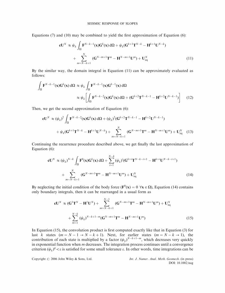
By neglecting the initial condition of the body force ðF0ðxÞ ¼ 0 8x 2 OÞ; Equation (14) containsonly boundary integrals, then it can be rearranged in a usual form as
cUN �ðG1TN �H1UNÞ þXN�1
m¼N�kþ1
ðGN�mþ1Tm �HN�mþ1UmÞ þUNeq
þXN�km¼1
ðckÞN�kþ1�mðGN�mþ1Tm �HN�mþ1UmÞ ð15Þ
In Equation (15), the convolution product is first computed exactly like that in Equation (3) forlast k states ðm ¼ N � 1! N � kþ 1Þ: Next, for earlier states ðm ¼ N � k! 1Þ; thecontribution of each state is multiplied by a factor ðckÞ
N�kþ1�m; which decreases very quicklyin exponential function when m decreases. The integration process continues until a convergencecriterion ðckÞ
q5e is satisfied for some small tolerance e: In other words, time integrations can be
SEISMIC RESPONSE OF SLOPES
Copyright # 2006 John Wiley & Sons, Ltd. Int. J. Numer. Anal. Meth. Geomech. (in press)
DOI: 10.1002/nag
truncated after kþ q steps ðkþ q5NÞ: The truncated equation can be written in the similarform of Equation (3) as
AXN �BYN þXN�1
m¼N�kþ1
ðGN�mþ1Tm �HN�mþ1UmÞ þUNeq
þXN�k
m¼N�k�q
ðckÞN�kþ1�mðGN�mþ1Tm �HN�mþ1UmÞ ð16Þ
The coefficient ck is computed by applying the theorem of divergence as follows:
ck ¼
RO GkðxÞ dOR
O Gk�1ðxÞ dO¼
RG I
kðxÞ dGRG I
k�1ðxÞ dGð17Þ
where IkðxÞ ¼ Iðx; tÞjkDtðk�1ÞDt and Iðx; tÞ ¼RO
R t0 Gðx; tÞ dt dO
IðxÞ ¼1
2pr
X2m¼1
Hðam � 1Þv3m
1
2dijI1m �
1
3I2m
� �
I1m ¼ rðam cosh�1ðamÞ � bmÞ � vm cosh�1ðvm=rÞ þffiffiffiffiffiffiffiffiffiffiffiffiffiffiffiv2m � r2
q
I2m ¼ rð1� r;ir;jÞðb3m � ðv
2m=r
2 � 1Þ3=2Þ
am ¼vmt
rand bm ¼
ffiffiffiffiffiffiffiffiffiffiffiffiffiffia2m � 1
qwhere r is the mass density; v1 and v2 are the velocities of the compression and shear waves,respectively; r is the distance between the source point and the field point; and HðxÞ representsthe Heaviside step function.
To determine the current state by Equation (16), we need to know only kþ q former states.So time integrations are to be performed only for kþ q steps instead of all N steps; thecomputation time reduction is thus significant. Moreover, only first kþ q pairs of matricesðGi;HiÞ need to be stored instead of all N pairs; the saving in temporary storage requirement isremarkable. Note that the proposed approach gives approximate solutions, whose accuracy iscontrolled by the tolerance e and the number k: The choice of these parameters depends on thetype of the considered problem. For half-plane problems analysed in the following examples,k ¼ 5 and e ¼ 0:1 are selected. Note that e is not a true error measure, it provides only a guidefor the time truncation.
Numerical examples
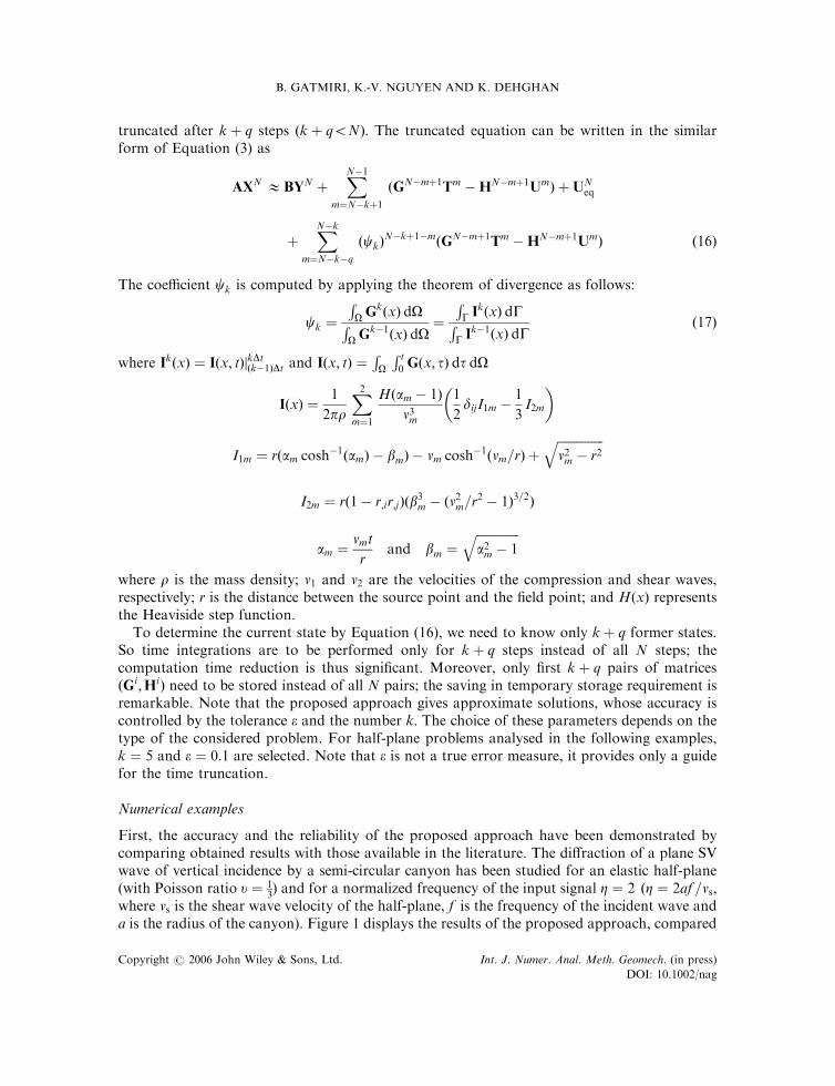
First, the accuracy and the reliability of the proposed approach have been demonstrated bycomparing obtained results with those available in the literature. The diffraction of a plane SVwave of vertical incidence by a semi-circular canyon has been studied for an elastic half-plane(with Poisson ratio u ¼ 1
3) and for a normalized frequency of the input signal Z ¼ 2 ðZ ¼ 2af =vs;
where vs is the shear wave velocity of the half-plane, f is the frequency of the incident wave anda is the radius of the canyon). Figure 1 displays the results of the proposed approach, compared
B. GATMIRI, K.-V. NGUYEN AND K. DEHGHAN
Copyright # 2006 John Wiley & Sons, Ltd. Int. J. Numer. Anal. Meth. Geomech. (in press)
DOI: 10.1002/nag
with those obtained by Kawase [14] and by Sanchez-Sesma and Campillo [9] for both horizontaland vertical displacement amplitudes. Good agreement between these solutions was found.
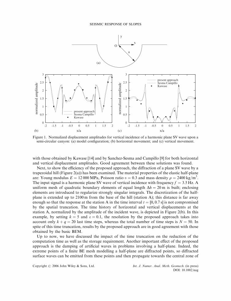
Next, to show the efficiency of the proposed approach, the diffraction of a plane SV wave by atrapezoidal hill (Figure 2(a)) has been examined. The material properties of the elastic half-planeare: Young modulus E ¼ 12 000MPa; Poisson ratio u ¼ 0:3 and mass density r ¼ 2400 kg=m3:The input signal is a harmonic plane SV wave of vertical incidence with frequency f ¼ 3:5 Hz: Auniform mesh of quadratic boundary elements of equal length Dh ¼ 20 m is built; enclosingelements are introduced to regularize strongly singular integrals. The discretization of the half-plane is extended up to 2100m from the base of the hill (station A); this distance is far awayenough so that the response at the station A in the time interval t ¼ ½0; 0:7 s� is not compromisedby the spatial truncation. The time history of horizontal and vertical displacements at thestation A, normalized by the amplitude of the incident wave, is depicted in Figure 2(b). In thisexample, by setting k ¼ 5 and e ¼ 0:1; the resolution by the proposed approach takes intoaccount only kþ q ¼ 20 last time steps, whereas the total number of time steps is N ¼ 50: Inspite of this time truncation, results by the proposed approach are in good agreement with thoseobtained by the basic BEM.
Up to now, we have discussed the impact of the time truncation on the reduction of thecomputation time as well as the storage requirement. Another important effect of the proposedapproach is the damping of artificial waves in problems involving a half-plane. Indeed, theextreme points of a finite BE mesh modelling a half-plane are diffracted points, so diffractedsurface waves can be emitted from these points and then propagate towards the central zone of
a
x
y
O
0
0.5
1
1.5
2
2.5
3
-2 -1.5 -1 -0.5 0 0.5 1 1.5 2
norm
aliz
ed a
mpl
itude
x/a
present approachSesma CampilloKawase
0
0.5
1
1.5
2
2.5
3
-2 -1.5 -1 -0.5 0 0.5 1 1.5 2
norm
aliz
ed a
mpl
itude
x/a
present approachSesma CampilloKawase
(a)
(b) (c)
Figure 1. Normalized displacement amplitudes for vertical incidence of a harmonic plane SV wave upon asemi-circular canyon: (a) model configuration; (b) horizontal movement; and (c) vertical movement.
SEISMIC RESPONSE OF SLOPES
Copyright # 2006 John Wiley & Sons, Ltd. Int. J. Numer. Anal. Meth. Geomech. (in press)
DOI: 10.1002/nag
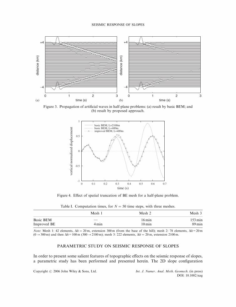
the model (Figure 3(a)). Errors due to these artificial waves may be significant, the BE mesh of ahalf-plane should be extended enough so that these waves cannot reach the central zone in theconsidered time interval. Therefore, the size of the BE mesh increases with the considered timeinterval, then the computation time may considerably increase. By using the proposedapproach, artificial waves emitted at early time are not taken into account in the calculationafter some time steps, owing to the time truncation, and they are progressively attenuated downto zero (Figure 3(b)). As a consequence, the BE mesh has only to be extended to a ‘modest’distance, so that artificial waves are completely attenuated before arriving at the central zone ofthe model.
In order to illustrate the above argument, the spatial truncation effect has been studied byexamining the previous example. Two BE meshes are considered: one extended up to 2100mfrom the base of the hill, which is far away enough for the considered time interval t ¼ ½0; 0:7 s�;and the other up to only 300m. The time history of the normalized vertical displacement at thestation A is shown in Figure 4. The difference of results obtained by the basic BEM from thetwo meshes means a significant error due to the mesh truncation. However, results from thesetwo meshes converge if the proposed approach is used for the small mesh. Table I shows thecomputation times (on PC 1.7GHz, 256Mb RAM) by the basic BEM and the proposedapproach, with three different meshes of the previous example. The result demonstrates clearlythe important reduction in computation time by the proposed approach, especially for half-plane problems. Note that the size of the BE mesh and the number kþ q steps necessary for thecomputation are nearly independent of the time interval. As a consequence, the more thenumber of time steps, the more the gain in the computation time as well as the storagerequirement.
L 1 =40m
H=40m
L o =100m
A
-3
-2
-1
0
1
2
3
0 0.1 0.2 0.3 0.4 0.5 0.6 0.7
norm
aliz
ed d
ispl
acem
ent
time (s)
basic BEMimproved BEM
-1
-0.5
0
0.5
1
0 0.1 0.2 0.3 0.4 0.5 0.6 0.7no
rmal
ized
dis
plac
emen
t
time (s)
basic BEMimproved BEM
(a)
(b) (c)
Figure 2. Normalized displacements at the base of a trapezoidal hill subjected to the incidence of aharmonic plane SV wave: (a) model configuration; (b) horizontal movement; and (c) vertical movement.
B. GATMIRI, K.-V. NGUYEN AND K. DEHGHAN
Copyright # 2006 John Wiley & Sons, Ltd. Int. J. Numer. Anal. Meth. Geomech. (in press)
DOI: 10.1002/nag
PARAMETRIC STUDY ON SEISMIC RESPONSE OF SLOPES
In order to present some salient features of topographic effects on the seismic response of slopes,a parametric study has been performed and presented herein. The 2D slope configuration
0 1 2 3time (s)
dist
ance
(km
)
+4
−4
0 1 2 3time (s)
dist
ance
(km
)
+4
−4
(a) (b)
Figure 3. Propagation of artificial waves in half-plane problems: (a) result by basic BEM; and(b) result by proposed approach.
-1
-0.5
0
0.5
1
0 0.1 0.2 0.3 0.4 0.5 0.6 0.7
vert
ical
nor
mal
ized
dis
plac
emen
t
time (s)
basic BEM, L=2100mbasic BEM, L=400mimproved BEM, L=400m
Figure 4. Effect of spatial truncation of BE mesh for a half-plane problem.
Table I. Computation times, for N ¼ 50 time steps, with three meshes.
Mesh 1 Mesh 2 Mesh 3
Basic BEM } 16min 153minImproved BE 4min 10min 89min
Note: Mesh 1: 42 elements, Dh ¼ 20m; extension 300m (from the base of the hill); mesh 2: 78 elements, Dh=20m(0! 300m) and then Dh=100m (300! 2100m); mesh 3: 222 elements, Dh ¼ 20m; extension 2100m.
SEISMIC RESPONSE OF SLOPES
Copyright # 2006 John Wiley & Sons, Ltd. Int. J. Numer. Anal. Meth. Geomech. (in press)
DOI: 10.1002/nag
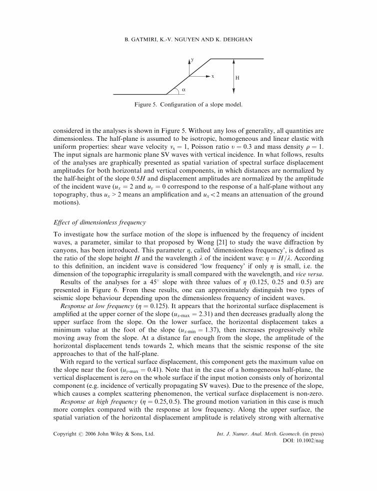
considered in the analyses is shown in Figure 5. Without any loss of generality, all quantities aredimensionless. The half-plane is assumed to be isotropic, homogeneous and linear elastic withuniform properties: shear wave velocity vs ¼ 1; Poisson ratio u ¼ 0:3 and mass density r ¼ 1:The input signals are harmonic plane SV waves with vertical incidence. In what follows, resultsof the analyses are graphically presented as spatial variation of spectral surface displacementamplitudes for both horizontal and vertical components, in which distances are normalized bythe half-height of the slope 0:5H and displacement amplitudes are normalized by the amplitudeof the incident wave (ux ¼ 2 and uy ¼ 0 correspond to the response of a half-plane without anytopography, thus ux > 2 means an amplification and ux52 means an attenuation of the groundmotions).
Effect of dimensionless frequency
To investigate how the surface motion of the slope is influenced by the frequency of incidentwaves, a parameter, similar to that proposed by Wong [21] to study the wave diffraction bycanyons, has been introduced. This parameter Z; called ‘dimensionless frequency’, is defined asthe ratio of the slope height H and the wavelength l of the incident wave: Z ¼ H=l: Accordingto this definition, an incident wave is considered ‘low frequency’ if only Z is small, i.e. thedimension of the topographic irregularity is small compared with the wavelength, and vice versa.
Results of the analyses for a 458 slope with three values of Z (0.125, 0.25 and 0.5) arepresented in Figure 6. From these results, one can approximately distinguish two types ofseismic slope behaviour depending upon the dimensionless frequency of incident waves.
Response at low frequency ðZ ¼ 0:125Þ: It appears that the horizontal surface displacement isamplified at the upper corner of the slope ðux-max ¼ 2:31Þ and then decreases gradually along theupper surface from the slope. On the lower surface, the horizontal displacement takes aminimum value at the foot of the slope ðux-min ¼ 1:37Þ; then increases progressively whilemoving away from the slope. At a distance far enough from the slope, the amplitude of thehorizontal displacement tends towards 2, which means that the seismic response of the siteapproaches to that of the half-plane.
With regard to the vertical surface displacement, this component gets the maximum value onthe slope near the foot ðuy-max ¼ 0:41Þ: Note that in the case of a homogeneous half-plane, thevertical displacement is zero on the whole surface if the input motion consists only of horizontalcomponent (e.g. incidence of vertically propagating SV waves). Due to the presence of the slope,which causes a complex scattering phenomenon, the vertical surface displacement is non-zero.
Response at high frequency ðZ ¼ 0:25; 0:5Þ: The ground motion variation in this case is muchmore complex compared with the response at low frequency. Along the upper surface, thespatial variation of the horizontal displacement amplitude is relatively strong with alternative
x
y
H
α
Figure 5. Configuration of a slope model.
B. GATMIRI, K.-V. NGUYEN AND K. DEHGHAN
Copyright # 2006 John Wiley & Sons, Ltd. Int. J. Numer. Anal. Meth. Geomech. (in press)
DOI: 10.1002/nag
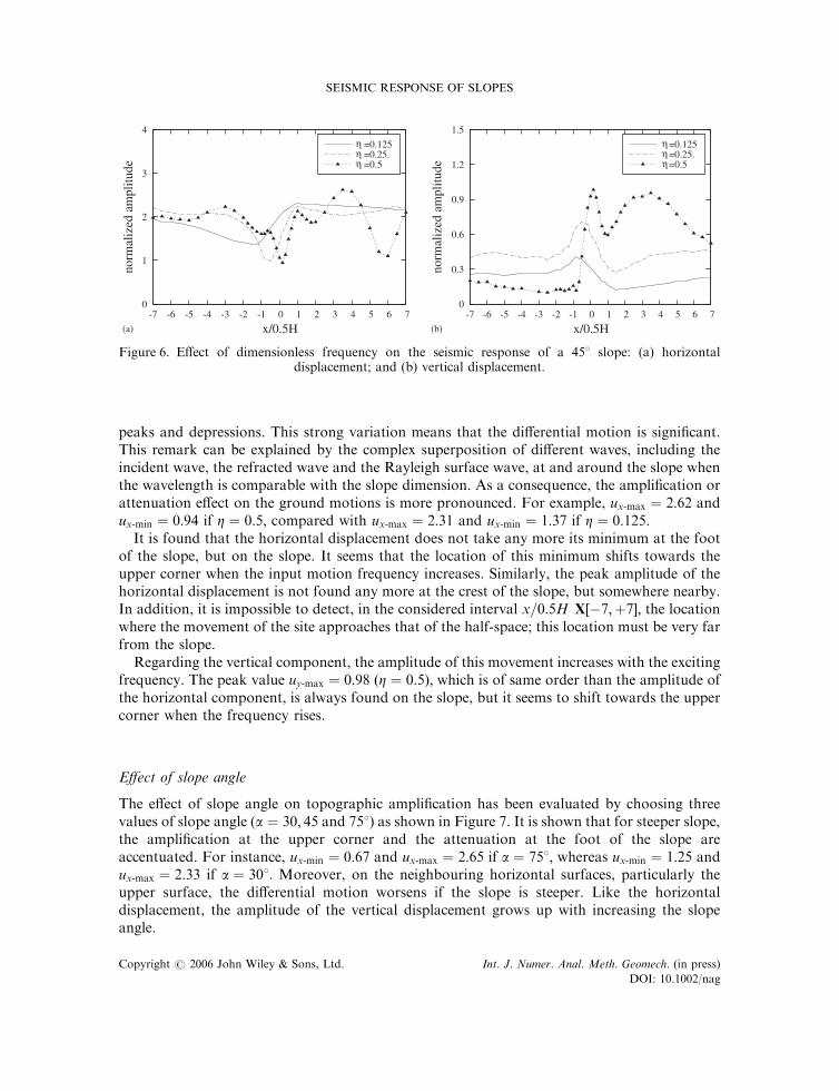
peaks and depressions. This strong variation means that the differential motion is significant.This remark can be explained by the complex superposition of different waves, including theincident wave, the refracted wave and the Rayleigh surface wave, at and around the slope whenthe wavelength is comparable with the slope dimension. As a consequence, the amplification orattenuation effect on the ground motions is more pronounced. For example, ux-max ¼ 2:62 andux-min ¼ 0:94 if Z ¼ 0:5; compared with ux-max ¼ 2:31 and ux-min ¼ 1:37 if Z ¼ 0:125:
It is found that the horizontal displacement does not take any more its minimum at the footof the slope, but on the slope. It seems that the location of this minimum shifts towards theupper corner when the input motion frequency increases. Similarly, the peak amplitude of thehorizontal displacement is not found any more at the crest of the slope, but somewhere nearby.In addition, it is impossible to detect, in the considered interval x=0:5H X½�7;þ7�; the locationwhere the movement of the site approaches that of the half-space; this location must be very farfrom the slope.
Regarding the vertical component, the amplitude of this movement increases with the excitingfrequency. The peak value uy-max ¼ 0:98 ðZ ¼ 0:5Þ; which is of same order than the amplitude ofthe horizontal component, is always found on the slope, but it seems to shift towards the uppercorner when the frequency rises.
Effect of slope angle
The effect of slope angle on topographic amplification has been evaluated by choosing threevalues of slope angle (a ¼ 30; 45 and 758) as shown in Figure 7. It is shown that for steeper slope,the amplification at the upper corner and the attenuation at the foot of the slope areaccentuated. For instance, ux-min ¼ 0:67 and ux-max ¼ 2:65 if a ¼ 758; whereas ux-min ¼ 1:25 andux-max ¼ 2:33 if a ¼ 308: Moreover, on the neighbouring horizontal surfaces, particularly theupper surface, the differential motion worsens if the slope is steeper. Like the horizontaldisplacement, the amplitude of the vertical displacement grows up with increasing the slopeangle.
0
1
2
3
4
-7 -6 -5 -4 -3 -2 -1 0 1 2 3 4 5 6 7
norm
aliz
ed a
mpl
itude
x/0.5H
η =0.125η =0.25.η =0.5
0
0.3
0.6
0.9
1.2
1.5
-7 -6 -5 -4 -3 -2 -1 0 1 2 3 4 5 6 7
norm
aliz
ed a
mpl
itude
x/0.5H
η=0.125η=0.25.η=0.5
(a) (b)
Figure 6. Effect of dimensionless frequency on the seismic response of a 458 slope: (a) horizontaldisplacement; and (b) vertical displacement.
SEISMIC RESPONSE OF SLOPES
Copyright # 2006 John Wiley & Sons, Ltd. Int. J. Numer. Anal. Meth. Geomech. (in press)
DOI: 10.1002/nag

CONCLUSIONS
An improved BE approach for solving 2D transient elastodynamic problems was presented andvalidated in this work. This approach, based on the time integration truncation, cansignificantly reduce the total computation time, the storage requirement and the size of BEmeshes modelling a half-plane, while the accuracy remains reasonable. Owing to theseadvantages, the use of this BE approach becomes very attractive for problems involving thewave propagation in semi-infinite media, such as geotechnical earthquake engineering problems.
In the present work, the topographic effects on the earthquake ground motions of slopingsites were investigated. It was demonstrated that surface motions at a given site can be stronglyamplified or attenuated by the local surface irregularities like slopes. Because of a complexdiffraction phenomenon, the seismic response of a sloping site is totally different from the inputmotions. It was found that large amplifications take place on the upper surface close to theslope, while attenuations are produced on the lower surface. The parametric study showed theimportant role of two parameters: the exciting dimensionless frequency Z and the slope angle a:In general, when the dimension of the topographic irregularity is small compared with thewavelength (Z small), the slope has a little effect on the seismic response of the given site. On thecontrary, at high values of Z; the wave diffraction phenomenon is more pronounced, so the effectof the slope on the earthquake ground motions becomes considerable. Indeed, when thedimensionless frequency Z increases, the differential motions are more significant, the verticalcomponent of the surface motions is more important and the influence zone of the slope iswider. The slope angle a plays also an important role: the steeper the slope, the more importantthe differential motions and the displacement amplification (for both horizontal and verticalcomponents).
REFERENCES
1. Wong H, Trifunac M. Scattering of plane SH waves by a semi-elliptical canyon. Earthquake Engineering andStructural Dynamics 1974; 3:157–169.
0
1
2
3
4
-7 -6 -5 -4 -3 -2 -1 0 1 2 3 4 5 6 7
norm
aliz
ed a
mpl
itude
x/0.5H
α=30°α=45°α=75°
0
0.4
0.8
1.2
1.6
-7 -6 -5 -4 -3 -2 -1 0 1 2 3 4 5 6 7
norm
aliz
ed a
mpl
itude
x/0.5H
α =30°α =45°α =75°
(a) (b)
Figure 7. Effect of slope angle on the seismic response of slopes ðZ ¼ 0:25Þ: (a) horizontal displacement;and (b) vertical displacement.
B. GATMIRI, K.-V. NGUYEN AND K. DEHGHAN
Copyright # 2006 John Wiley & Sons, Ltd. Int. J. Numer. Anal. Meth. Geomech. (in press)
DOI: 10.1002/nag

2. Sanchez-Sesma FJ. Diffraction of elastic SH waves by wedges. Bulletin of the Seismological Society of America 1985;75:1435–1446.
3. Aki K, Larner KL. Surface motion of a layered medium having an irregular interface due to incident plane SHwaves. Journal of Geophysical Research 1970; 70:933–954.
4. Boore DM. A note on the effect of simple topography on seismic SH waves. Bulletin of the Seismological Society ofAmerica 1972; 62:275–284.
5. Boore D, Harmsen S, Harding S. Wave scattering from a steep change in surface topography. Bulletin of theSeismological Society of America 1981; 71:117–125.
6. Smith WD. The application of finite element analysis to elastic body wave propagation problems. GeophysicalJournal of the Royal Astronomical Society 1975; 42:747–768.
7. Castellani A, Peano A, Sardella L. On analytical and numerical techniques for seismic analysis of topographicirregularities. Proceedings of the 7th European Conference on Earthquake Engineering, Athens, Greece, vol. 2, 1982;415–423.
8. Wong H, Jennings P. Effect of canyon topographies on strong ground motion. Bulletin of the Seismological Societyof America 1975; 65:1239–1257.
9. Sanchez-Sesma FJ, Campillo M. Diffraction of P, SV and Rayleigh waves by topographic features: a boundaryintegral formulation. Bulletin of the Seismological Society of America 1991; 81(6):2234–2253.
10. Bard P-Y. Diffracted waves and displacement field over two-dimensional elevated topographies. Geophysical Journalof the Royal Astronomical Society 1982; 71:731–760.
11. Bouchon M. A simple, complete numerical solution to the problem of diffraction of SH waves by an irregularsurface. Journal of the Acoustical Society of America 1985; 77:1–5.
12. Cole DM, Kosloff DD, Minster BJ. A numerical boundary integral equation for elastodynamics. Bulletin of theSeismological Society of America 1978; 68:1331–1357.
13. Gatmiri B, Kamalian M. Combination of boundary element and finite element methods for evaluation of dynamicresponse of saturated porous media. 5th European Conference on Numerical Methods in Geomechanical Engineering,Paris, France, 2002; 947–956.
14. Kawase H. Time-domain response of a semicircular canyon for incident SV, P and Rayleigh waves calculated bythe discrete wavenumber boundary element method. Bulletin of the Seismological Society of America 1988;78:1415–1437.
15. Israil ASM, Banerjee PK. Advanced time-domain formulation of BEM for two-dimensional transientelastodynamics. International Journal for Numerical Methods in Engineering 1990; 29:1421–1440.
16. Israil ASM, Banerjee PK. Two-dimensional transient wave propagation problems by time-domain BEM.International Journal of Solids and Structures 1990; 26(8):851–864.
17. Nguyen KV. Etude des effets de site dus aux conditions topographiques et geotechniques par une methode hybrideelements finis/elements frontieres. Ph.D. Dissertation, Ecole Nationale des Ponts et Chaussees, France, 2005.
18. Banerjee PK, Ahmad S, Manolis GD. Transient elastodynamic analysis of three-dimensional problems by boundaryelement method. Earthquake Engineering and Structural Dynamics 1986; 14:933–949.
19. Ahmad S, Banerjee PK. Multi-domain BEM for two-dimensional problems of elastodynamics. International Journalfor Numerical Methods in Engineering 1988; 26:891–911.
20. Davey K, Hinduja S. An improved procedure for solving transient heat conduction problems using the boundaryelement method. International Journal for Numerical Methods in Engineering 1989; 28:2293–2306.
21. Wong HL. Effect of surface topography on the diffraction of P, SV and Rayleigh waves. Bulletin of the SeismologicalSociety of America 1982; 72:1167–1183.
SEISMIC RESPONSE OF SLOPES
Copyright # 2006 John Wiley & Sons, Ltd. Int. J. Numer. Anal. Meth. Geomech. (in press)
DOI: 10.1002/nag
Copyright © 2022 FDOKUMEN