Training Report - Warehouse Operations Management SCMS Training
Upload
khangminh22Category
view
1download
0
Security EscortSE2000 Series
en Training Manual

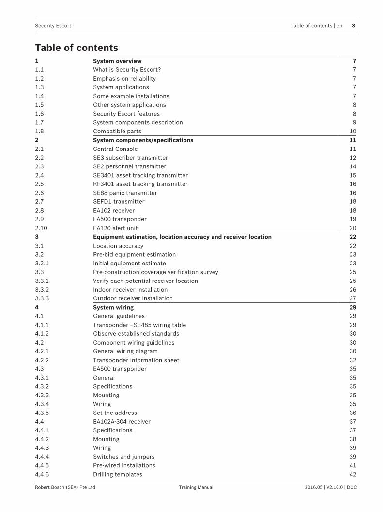
Security Escort Table of contents | en 3
Robert Bosch (SEA) Pte Ltd Training Manual 2016.05 | V2.16.0 | DOC
Table of contents1 System overview 71.1 What is Security Escort? 71.2 Emphasis on reliability 71.3 System applications 71.4 Some example installations 71.5 Other system applications 81.6 Security Escort features 81.7 System components description 91.8 Compatible parts 102 System components/specifications 112.1 Central Console 112.2 SE3 subscriber transmitter 122.3 SE2 personnel transmitter 142.4 SE3401 asset tracking transmitter 152.5 RF3401 asset tracking transmitter 162.6 SE88 panic transmitter 162.7 SEFD1 transmitter 182.8 EA102 receiver 182.9 EA500 transponder 192.10 EA120 alert unit 203 Equipment estimation, location accuracy and receiver location 223.1 Location accuracy 223.2 Pre-bid equipment estimation 233.2.1 Initial equipment estimate 233.3 Pre-construction coverage verification survey 253.3.1 Verify each potential receiver location 253.3.2 Indoor receiver installation 263.3.3 Outdoor receiver installation 274 System wiring 294.1 General guidelines 294.1.1 Transponder - SE485 wiring table 294.1.2 Observe established standards 304.2 Component wiring guidelines 304.2.1 General wiring diagram 304.2.2 Transponder information sheet 324.3 EA500 transponder 354.3.1 General 354.3.2 Specifications 354.3.3 Mounting 354.3.4 Wiring 354.3.5 Set the address 364.4 EA102A-304 receiver 374.4.1 Specifications 374.4.2 Mounting 384.4.3 Wiring 394.4.4 Switches and jumpers 394.4.5 Pre-wired installations 414.4.6 Drilling templates 42
4 en | Table of contents Security Escort
2016.05 | V2.16.0 | DOC Training Manual Robert Bosch (SEA) Pte Ltd
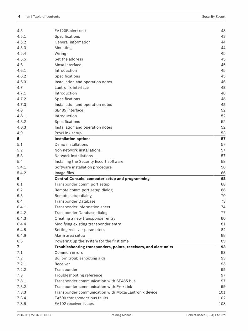
4.5 EA120B alert unit 434.5.1 Specifications 434.5.2 General information 444.5.3 Mounting 444.5.4 Wiring 454.5.5 Set the address 454.6 Moxa interface 454.6.1 Introduction 454.6.2 Specifications 454.6.3 Installation and operation notes 464.7 Lantronix interface 484.7.1 Introduction 484.7.2 Specifications 484.7.3 Installation and operation notes 484.8 SE485 interface 524.8.1 Introduction 524.8.2 Specifications 524.8.3 Installation and operation notes 524.9 ProxLink setup 535 Installation options 575.1 Demo installations 575.2 Non-network installations 575.3 Network installations 575.4 Installing the Security Escort software 585.4.1 Software installation procedure 585.4.2 Image files 666 Central Console, computer setup and programming 686.1 Transponder comm port setup 686.2 Remote comm port setup dialog 686.3 Remote setup dialog 706.4 Transponder Database 736.4.1 Transponder information sheet 746.4.2 Transponder Database dialog 776.4.3 Creating a new transponder entry 806.4.4 Modifying existing transponder entry 816.4.5 Setting receiver parameters 826.4.6 Alarm area setup 886.5 Powering up the system for the first time 897 Troubleshooting transponders, points, receivers, and alert units 937.1 Common errors 937.2 Built-in troubleshooting aids 937.2.1 Receiver 937.2.2 Transponder 957.3 Troubleshooting reference 977.3.1 Transponder communication with SE485 bus 977.3.2 Transponder communication with ProxLink 997.3.3 Transponder communication with Moxa/Lantronix device 1017.3.4 EA500 transponder bus faults 1027.3.5 EA102 receiver issues 103

Security Escort Table of contents | en 5
Robert Bosch (SEA) Pte Ltd Training Manual 2016.05 | V2.16.0 | DOC
7.4 Receiver configuration dialog 1067.5 Post construction setup 1097.5.1 Testing the location accuracy of an installation 1097.5.2 Improving the location accuracy of an installation 1117.6 System preferences dialog 1127.7 Security Preferences dialog 1187.8 System Defaults dialog 1227.9 System Labels dialog 1237.10 Subscriber Database 1247.10.1 Print Subscriber Database 1257.10.2 Edit Subscriber Database record 1267.10.3 Additional subscriber information 1307.10.4 Subscriber images 1317.10.5 Subscriber Database Advanced Features 1317.10.6 Subscriber (individual) Pager Setup 1367.10.7 Fixed Location Transmitters 1387.11 Schedules dialog 1387.11.1 Ignore Holidays for this schedule 1407.11.2 Edit Schedule Times dialog 1407.11.3 View Alarm Groups dialog 1417.11.4 Alarm Groups dialog 1427.11.5 Alarm Group State dialog 1437.11.6 Current Check-in Status dialog 1447.12 Exporting, importing and merging the Subscriber Database 1457.12.1 ".dat" file format 1467.12.2 Exporting the Subscriber Database 1517.12.3 Importing the Subscriber Database 1527.12.4 Merging the Subscriber Database 1537.13 Exporting and importing the Transponder Database 1557.13.1 ".dat" file format 1557.13.2 XML file format 1637.13.3 Exporting the Transponder Database 1687.13.4 Importing the Transponder Database 1697.14 Operator Database 1707.14.1 Edit Operator Database record 1717.14.2 Authority levels 1727.15 Reports Database 1737.15.1 Report statistics 1747.15.2 Map 1757.15.3 Edit data 1757.15.4 Delete 1767.15.5 Locate Key 1767.15.6 Key Select 1777.15.7 Incomplete 1777.16 System redundancy 1777.16.1 Automatic redundancy 1787.16.2 Manual redundancy 1788 System menus and dialogs 1798.1 File menu 179
6 en | Table of contents Security Escort
2016.05 | V2.16.0 | DOC Training Manual Robert Bosch (SEA) Pte Ltd
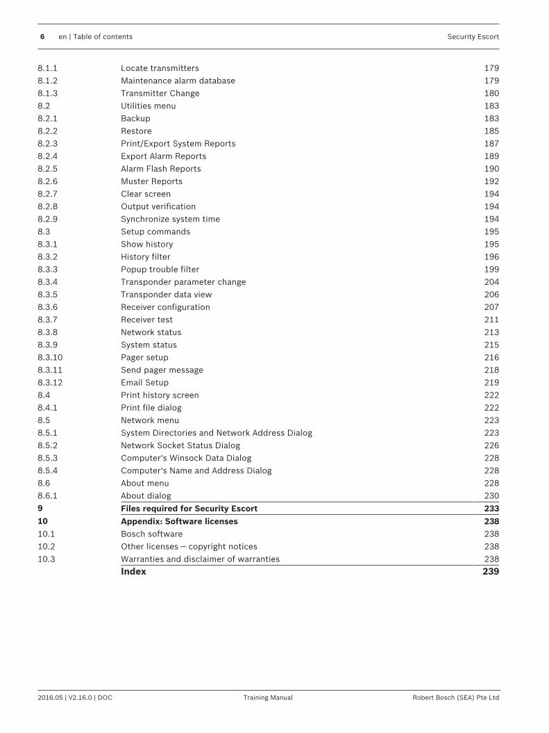
8.1.1 Locate transmitters 1798.1.2 Maintenance alarm database 1798.1.3 Transmitter Change 1808.2 Utilities menu 1838.2.1 Backup 1838.2.2 Restore 1858.2.3 Print/Export System Reports 1878.2.4 Export Alarm Reports 1898.2.5 Alarm Flash Reports 1908.2.6 Muster Reports 1928.2.7 Clear screen 1948.2.8 Output verification 1948.2.9 Synchronize system time 1948.3 Setup commands 1958.3.1 Show history 1958.3.2 History filter 1968.3.3 Popup trouble filter 1998.3.4 Transponder parameter change 2048.3.5 Transponder data view 2068.3.6 Receiver configuration 2078.3.7 Receiver test 2118.3.8 Network status 2138.3.9 System status 2158.3.10 Pager setup 2168.3.11 Send pager message 2188.3.12 Email Setup 2198.4 Print history screen 2228.4.1 Print file dialog 2228.5 Network menu 2238.5.1 System Directories and Network Address Dialog 2238.5.2 Network Socket Status Dialog 2268.5.3 Computer's Winsock Data Dialog 2288.5.4 Computer's Name and Address Dialog 2288.6 About menu 2288.6.1 About dialog 2309 Files required for Security Escort 23310 Appendix: Software licenses 23810.1 Bosch software 23810.2 Other licenses — copyright notices 23810.3 Warranties and disclaimer of warranties 238
Index 239

Security Escort System overview | en 7
Robert Bosch (SEA) Pte Ltd Training Manual 2016.05 | V2.16.0 | DOC
1 System overview1.1 What is Security Escort?
– Unique multiple user help call and asset tracking system– Identifies user information and location, by floor, above or below ground– Small, easy to carry transmitters– Indoor/outdoor protection for 60,000+ users and assets as well as multiple buildings– Man-down alarm, officer tracking & guard tour– Post-alarm tracking and alarm map recall– System capabilities perfect for campus and community environments
1.2 Emphasis on reliability– Supported by a multi million dollar company– Extensive field testing under maximum abuse conditions, from -20°F to +120°F– Supervised system communication– Low battery user and system operator notification– Archived retrieval of system activity– Patented technology– Post alarm transmitter tracking– System-wide backup power feature
1.3 System applications– Student Safety– Officer Tracking– Guard Tour– Employee/Faculty Security– VIP Protection– Executive Protection– Man-Down– Asset Tracking
1.4 Some example installationsEducational Facilities:– Florida Southern, FL– Oswego State, NY– Nazareth College, NY
Healthcare Facilities:– New Hanover Medical Center, NC– Provo Psychiatric Hospital, Utah– Fairport Retirement Home, NY
Correctional Facilities:– Westchester County D.O.C., Valhalla, NY– Immigration & Naturalization Facility, TX– US Naval Brig, SC
Other:– Diamond Mines, South Africa– Amusement Park, FL– International Art Museum, NY

8 en | System overview Security Escort
2016.05 | V2.16.0 | DOC Training Manual Robert Bosch (SEA) Pte Ltd
1.5 Other system applications– Hotels & Casinos– Amusement Parks– Commercial Complexes
– Buildings– Parking Lots/Garages
– Museums– Financial Institutions– Child Care Facilities
1.6 Security Escort featuresThe Security Escort System is engineered to provide reliability and user ease of operation. Ourpatented feature set allows for customization and integration in any installation. Thesefeatures ensure system integrity and the comfort that when assistance is needed, help is just aclick away.
User Self Test– Assures you that your transmitter is working– Battery condition sent with every transmission– Each test verifies system integrity– Logs each test performed for easy access and reporting– Can be performed indoors and outdoors– Ensures user acceptance and peace of mind
Asset Tracking– Location of assets– Protection against removal– Wireless sensing– No re-cabling for asset relocation– Auto tracking and location identification
Fixed Point Identification– Allows for identification of any fixed point– Simple system integration– Expands over all system capability and functionality

Security Escort System overview | en 9
Robert Bosch (SEA) Pte Ltd Training Manual 2016.05 | V2.16.0 | DOC
1.7 System components description
Figure 1.1: System Block Diagram
1 Subscriber transmitter 9 Serial to Ethernet interface
2 Point tracking transmitter 10 Slave workstation
3 Personnel transmitter 11 Master workstation
4 Up to 8 workstation 12 SE485 interface
5 LAN 13 Spread spectrum wireless links
6 Up to 8 receivers 14 Alert unit
7 Up to 8 bus 15 Strobe
8 Transponder
The transmitter is a miniature, hand-held radio transmitter used to transmit either a distressor a test signal. The receivers are located throughout the protected area and detect the radiotransmissions from transmitters. Alert units are siren/strobe units activated in the event of analarm. Transponders are devices that control groups of receivers and alert units, connected tothem by wire. Each transponder relays alarm and test signals from its receivers to the CentralConsole. In addition, the transponder tests for device and wiring faults, and transmits problemconditions to the Central Console. The Central Console consists of a computer (plus anoptional backup and up to 8 optional workstations) which receives alarm and trouble signalsfrom the transponders, analyzes the signals, activates strobes and sirens on the alert units,and produces a display for the Security dispatcher. Each of these system elements isdescribed more fully in the sections that follow.
10 en | System overview Security Escort
2016.05 | V2.16.0 | DOC Training Manual Robert Bosch (SEA) Pte Ltd
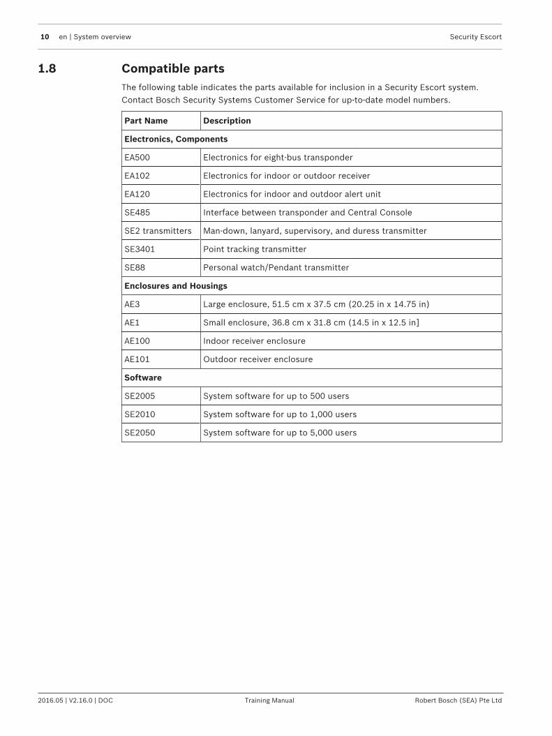
1.8 Compatible partsThe following table indicates the parts available for inclusion in a Security Escort system.Contact Bosch Security Systems Customer Service for up-to-date model numbers.
Part Name Description
Electronics, Components
EA500 Electronics for eight-bus transponder
EA102 Electronics for indoor or outdoor receiver
EA120 Electronics for indoor and outdoor alert unit
SE485 Interface between transponder and Central Console
SE2 transmitters Man-down, lanyard, supervisory, and duress transmitter
SE3401 Point tracking transmitter
SE88 Personal watch/Pendant transmitter
Enclosures and Housings
AE3 Large enclosure, 51.5 cm x 37.5 cm (20.25 in x 14.75 in)
AE1 Small enclosure, 36.8 cm x 31.8 cm (14.5 in x 12.5 in]
AE100 Indoor receiver enclosure
AE101 Outdoor receiver enclosure
Software
SE2005 System software for up to 500 users
SE2010 System software for up to 1,000 users
SE2050 System software for up to 5,000 users
Security Escort System components/specifications | en 11
Robert Bosch (SEA) Pte Ltd Training Manual 2016.05 | V2.16.0 | DOC
2 System components/specifications2.1 Central Console
DescriptionThe Central Console consists of one or two computers (and up to 8 additional workstations)running the Security Escort software within the Microsoft Windows environment. Onecomputer serves as the master controller for the entire Security Escort system and the secondslave computer serves as a back-up. The slave computer can be used for administrativefunctions such as adding subscribers or performing routine system tests without interferingwith the operation of the main computer. The workstations can perform all normal SecurityEscort functions with the exception of communicating with the transponders.
Software overviewThe Central Console contains all of the operating software and all of the databases requiredby the Security Escort system. The installation and maintenance portion of the Security Escortsoftware is designed to facilitate set-up and modification of the system and to provide rapiddiagnosis of system problems, usually with only one person being required. The systemsoftware also continually monitors the status of each transponder to ensure it is functioningcorrectly.
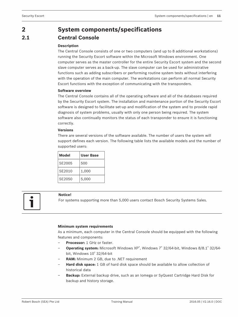
VersionsThere are several versions of the software available. The number of users the system willsupport defines each version. The following table lists the available models and the number ofsupported users:
Model User Base
SE2005 500
SE2010 1,000
SE2050 5,000
Notice!For systems supporting more than 5,000 users contact Bosch Security Systems Sales.
Minimum system requirementsAs a minimum, each computer in the Central Console should be equipped with the followingfeatures and components:– Processor: 1 GHz or faster.– Operating system: Microsoft Windows XP®, Windows 7® 32/64-bit, Windows 8/8.1® 32/64-
bit, Windows 10® 32/64-bit– RAM: Minimum 2 GB, due to .NET requirement– Hard disk space: 1 GB of hard disk space should be available to allow collection of
historical data– Backup: External backup drive, such as an Iomega or SyQuest Cartridge Hard Disk for
backup and history storage.

12 en | System components/specifications Security Escort
2016.05 | V2.16.0 | DOC Training Manual Robert Bosch (SEA) Pte Ltd
– Video: VGA (640 x 480) at 256 colors minimum, 800 x 600 High color (16 bits)recommended, 1024 x 768 High color supported. True color (24 bits) is also supported. Ifdisplaying subscriber images, High color (16 bits) or True color (24 bits) should be used.
– Modem: Optional V.32bis (14.4), V.34 (33.8), or V.90 (56.6) modem for remote accessand pager dial-out. If modem is external an additional serial port is required.
– Sound: Any Windows compatible sound system. One set of computer speakers percomputer.
– Printer: Parallel or network printers.– Additional serial ports (if needed): Any multi-port board fully supported by Windows. A
four-port ISA serial port card made by Digiboard, model AccelePort Xe, part number76000035. Required four-port cable for DB25, part number 76000008. Digiboard alsomakes eight- and sixteen-port solutions. They may be contacted at www.digiboard.com.
Databases– Alarm reports: Each alarm is saved as a record containing subscriber data, time and date
of alarm, acknowledgment and silence times, responding officer, problem description,and action taken. The alarm map can be reproduced and the location text is displayed.
– History: A complete chronological history of all system actions, tests, and alarms isrecorded.
– Operators: File of those authorized to use the Security Escort system.– Subscriber: Complete record of all subscriber data and current status, low battery, and
last test date and time.– Transponders: System configuration containing all installed equipment and system
interrelationships.
Other Specifications– Temperature range: 0 ºC to +40 ºC (+32 ºF to +105 ºF)– Primary power: 120 V AC 900 W (two computers, two monitors and one printer).– Backup power: 1200 V A UPS per computer will provide 45 minutes to one hour backup.
System should also be backed up by an emergency generator for extended blackouts (canbe shared with other emergency equipment).
– Pager: Pager support is included and selected troubles can be automatically sent to aservice pager.
2.2 SE3 subscriber transmitter
Features– Alerts Central Console of user’s name and location immediately on alarm.– Post-alarm tracking, alarm map recall, and more.– Allows user to test from anywhere within the protected area.– Internal antenna.– Four-year battery life, field replaceable.– Key-chain attachment.

Security Escort System components/specifications | en 13
Robert Bosch (SEA) Pte Ltd Training Manual 2016.05 | V2.16.0 | DOC
– Low battery indication at Central Console.– Optional silent alarm.
DescriptionThe SE3 subscriber transmitter contains a unique code which is associated with thesubscriber at the time the transmitter is assigned. When the subscriber generates an alarm,this code is sent to the Central Console. The Central Console graphically displays thesubscriber’s location on a map along with the subscriber’s picture, his or her name, andaddress.
Transmitting an alarmIn the event of an emergency, the user simply presses and holds the alarm buttons to producean alarm. Depending on the installed options, when an alarm is generated withinapproximately two seconds, the sounders in any nearby receivers will be activated as well asthe strobes and sirens connected to nearby alert units. The alarm signal is transmitted to thereceivers which in turn relay the alarm signal to the transponder and along to the CentralConsole. The Central Console then graphically displays the subscriber’s location along withthe subscriber’s name, vital information (such as a medical condition or disability) and apicture of the subscriber. Also, once an alarm is initiated, the transmitter commences its auto-tracking feature.
Auto-trackingDuring an alarm, the transmitter automatically resends the alarm signal every few seconds,constantly updating the Central Console of the subscriber’s location.
TestingThe test mode allows a subscriber to test their transmitter anywhere in the protected area.When the user is indoors in sight of an indoor receiver, or outdoors in sight of a strobe,pressing the buttons in sequence performs a test. If the test is successful, a small green lightwill flash on the indoor receiver, or the strobe will flash briefly. There will be no response atall if the test fails. If the test fails, the user should contact the Security office as soon aspossible.Every successful test is recorded in the Subscriber Database in the Central Console softwareand optionally printed on the hardcopy printer. The Subscriber Database contains all of theinformation relating to each subscriber, including the date and time of the most recent testtransmission. It is possible to search the Subscriber Database for individuals who have notperformed tests for a specified period of time.
Low battery reportingWhen the transmitter is tested, a special “low battery” message is included in thetransmission to the Central Console if the transmitter’s battery is in need of replacing. Also,the system will not give a visual or audible response during a test, indicating that thetransmitter requires service. Low battery alerts are logged at the Central Console.
Available modelsThere are two SE3 models available:– User transmitter: This is the standard transmitter used by all system subscribers.– Security transmitter: This is the same as the standard transmitter except the transmitter
does not emit an audible tone when activated. This transmitter is normally distributed toSecurity personnel.

14 en | System components/specifications Security Escort
2016.05 | V2.16.0 | DOC Training Manual Robert Bosch (SEA) Pte Ltd
2.3 SE2 personnel transmitter
Features– Personal duress alarm transmitter.– Man-down alarm.– Lanyard pull alarm (optional).– Allows user to test from anywhere within the protected area.– Notifies Central Console of user’s name and location immediately on alarm.– Post-alarm and supervision tracking, alarm map recall, and more.– Internal antenna.– User replaceable battery with four-year life.– Belt clip attachment.– Optional silent manual alarm.– Low battery indication.– Optional holster for common security belt sizes.
DescriptionThe SE2 personnel transmitter contains a unique code which is associated with the user at thetime the transmitter is assigned. When the user generates an alarm, this code is sent to theCentral Console. The Central Console graphically displays the user’s location on a map alongwith the user’s picture, and his or her name, and any other necessary information.
Transmitting an alarmThere are three ways in which an alarm may be generated, depending on the features enabledon the transmitter. The types of alarms are as follows:– Manual duress alarm: An alarm can be initiated by pressing the large button on the
transmitter.– Man-down alarm: The transmitter will transmit an alarm to the Central Console if it is
tipped 60° from upright.– Lanyard pull: A cord connected to the pin inserted in the base of the transmitter can be
looped around a utility belt and if the pin is removed from the transmitter (such as whenthe transmitter is pulled away from the belt), the transmitter will immediately go intoalarm.
Auto-tracking featureDuring an alarm, the transmitter automatically resends the alarm signal every few secondsconstantly updating the Central Console of the user’s location.
Supervision trackingWith supervision tracking enabled, the transmitter will send a tracking signal to the CentralConsole constantly updating the user’s location.
TestingThe test mode allows a user to test their transmitter anywhere in the protected area. Whenthe user is indoors, in sight of an indoor receiver, or outdoors, in sight of a strobe, pressingthe manual test button performs a test. If the test is successful, a small green light will flashon the indoor receiver, or the strobe will flash briefly. There will be no response at all if thetest fails. If the test fails, the user should contact the Security office as soon as possible.

Security Escort System components/specifications | en 15
Robert Bosch (SEA) Pte Ltd Training Manual 2016.05 | V2.16.0 | DOC
When the transmitter is tested, a special “low battery” message is included in thetransmission to Central Console if the transmitter’s battery is in need of replacing. Everysuccessful test is recorded in the Subscriber Database in the Central Console software andoptionally printed on the hardcopy printer. The Subscriber Database contains all of theinformation relating to each subscriber, including the date and time of the most recent testtransmission. It is possible to search the Subscriber Database for individuals who have notperformed tests for a specified period of time.
2.4 SE3401 asset tracking transmitter
Features– Alerts Central Console of Transmitter’s ID and location immediately on alarm.– Available post-alarm tracking, alarm map recall, and more.– Internal antenna.– Two-year battery life.– Can be mounted virtually anywhere on virtually anything.– Low battery indication at Central Console.– Includes mounting plate.
DescriptionThe SE3401 Point Tracking Transmitter contains a unique code which is associated with anasset at the time the Transmitter is assigned. When an alarm is generated, this code is sent tothe Central Console, which graphically displays the asset’s location on a map along with apicture of the asset and any other necessary information.
InstallationThe SE3401 can be configured to monitor magnetic or dry external contacts. When mountedwith an external magnet, the SE3401 is mounted on the asset and the magnet is mounted onan opposite surface (such as a wall). When mounted with external contacts, the SE3401 canbe mounted anywhere on the asset and connects to the contact by two wires connected tothe terminals inside the Transmitter and an end-of-line resistor.
Transmitting an AlarmDepending on the installed options, when an alarm is generated within approximately twoseconds, the sounders in any nearby Receivers could be activated as well as the Strobes andSirens connected to nearby Alert Units. The alarm signal is transmitted to the Receivers whichin turn relay the alarm signal to the Transponder and along to the Central Console. The CentralConsole graphically displays the Transmitter’s location along with the asset’s description anda picture of the asset. Also, once an alarm is initiated, the Transmitter commences its Auto-Tracking feature.
Auto Tracking FeatureOnce an alarm has been initiated (such as when the Transmitter has been moved away fromthe magnet) the Auto-Tracking feature will begin. The Transmitter will send a signal back tothe Central Console every few seconds updating its location for several minutes. To reset theTransmitter after an alarm has been initiated, all device conditions (e.g., tamper, loop,magnet) must be reset to normal.

16 en | System components/specifications Security Escort
2016.05 | V2.16.0 | DOC Training Manual Robert Bosch (SEA) Pte Ltd
Supervision FeatureThe SE3401 Point Tracking Transmitter can also be configured to transmit periodically whenthere is no other activity to report its status and location to the Central Console.
Low Battery ReportingWhen the Transmitter is tested, a special “low battery” message is included in thetransmission to the Central Console if the Transmitter’s battery is in need of replacing. Theselow battery alerts are logged at the Central Console.
2.5 RF3401 asset tracking transmitter
Features– Supervised Sensor Loop (monitors any dry contact device)– Internal Reed Switch (used with magnet)– Supervisory Signal Every 65 Minutes– Complete Status, including Battery and Tamper Sent with Every Transmission– Compatible with all DS RF-TechTM Receivers @304 MHz– Factory Programmed Transmitter ID for Quick and Simple Transmitter Enrollment– Installer (or user) Replaceable Lithium Battery– Quick Install Mounting Base Plate Included– Cover Tamper
DescriptionThe RF3401 Point Transmitter features a supervised sensor loop and a magnetic reed switch.Use the supervised sensor loop to monitor any device with a dry contact output. When usedwith an external magnet assembly the RF3401 reed switch allows for quick and easyinstallation on doors and windows.
2.6 SE88 panic transmitter
Security Escort System components/specifications | en 17
Robert Bosch (SEA) Pte Ltd Training Manual 2016.05 | V2.16.0 | DOC
Features– Can be worn like a watch, pendant or mounted to a permanent location– Once activated, sends immediate notification of wearer's identity and location– Water resistant
DescriptionThe SE88 Security Escort Watch/Pendant Panic Transmitter is designed to work with theSecurity Escort System. Once activated, the wearer's identity and location is sent to thesecurity office. The SE88 may be worn like a watch, around the neck like a pendant or evenmounted to a stationary location with a mounting bracket (optional accessories, please orderseparately). It is ideal for use in elder care or assisted living facilities where immediateemergency notification is required.
Transmitting an Alarm– In the event of an emergency, the user simply presses and holds the alarm buttons to
produce an alarm. Transmittal will vary with different options. Generally, within twoseconds of an alarm being generated, sounders in Receivers and Strobes or Sirensconnected to Alert Units will activate.
– The alarm signal transmits to the Receivers. The Receivers relay the alarm signal to theTransponder and to the Central Console.
– The Central Console displays the user’s location, picture, name, and vital information(such as a medical condition or disability).
Auto-Tracking Feature– During an alarm, the Transmitter automatically resends the alarm signal every few
seconds constantly updating the Central Console of the user’s location.
Testing– The Test Mode allows a user to test his or her Transmitter anywhere in the protected
area. When the user is indoors in sight of an Indoor Receiver, or outdoors in sight of aStrobe, pressing the buttons in sequence performs a test. If the test is successful, a smallgreen light will flash on the indoor Receiver, or the Strobe will flash briefly. There will beno response at all if the test fails. If the test fails, the user should contact the SecurityOffice as soon as possible.
– Every successful test is recorded in the Subscriber Database in the Central ConsoleSoftware and optionally printed on the hardcopy printer. The Subscriber Databasecontains all of the information relating to each subscriber, including the date and time ofthe most recent test transmission. It is possible to search the Subscriber Database forindividuals who have not performed tests for a specified period of time.
Low Battery Reporting– When the Transmitter is tested, a special “low battery” message is included in the
transmission to Central Console if the Transmitter’s battery is in need of replacing. Also,the system will not give a visual or audible response during a test, indicating that theTransmitter requires service. Low battery alerts are logged at the Central Console.

18 en | System components/specifications Security Escort
2016.05 | V2.16.0 | DOC Training Manual Robert Bosch (SEA) Pte Ltd
2.7 SEFD1 transmitter
Calls for Help Even When You CannotCalls for Help Even When You CannotThe SEFD1 Fall Detector and Personal Help Button provides assistance that no other personalHelp Button can offer. The device alerts your emergency monitoring service automatically whenit detects a fall, even if you are unable to push the Help Button on the device.The SEFD1 is designed to work in and immediately around your home or facility. The devicemust be close enough to a receiver for a help signal to be received. The coverage area of thedevice will vary from one location to another. It is important for you to know the effectiverange of your device.The SEFD1 is designed to detect falls that meet certain criteria. It may not detect every fall,especially slight falls that are generally not disabling. The SEFD1 Fall Detector device may alsogenerate a fall alarm when you have not fallen. For example, if the device drops on the floor, itmay alert the monitoring center that you have fallen.
OperationThe SEFD1 device transmits three conditions:– Push Button (Help Button)– Fall– Low Battery
2.8 EA102 receiver
Features– Receives Transmitter alarms and tests, and relays the information to the Transponder.– Built-in self testing through Buddy Check feature.– Indoor and outdoor security enclosures available.
Security Escort System components/specifications | en 19
Robert Bosch (SEA) Pte Ltd Training Manual 2016.05 | V2.16.0 | DOC
– Indoor enclosure provides confirmation of successful Transmitter test. (Outdoorenclosures use other type of signaling device, such as a Horn/Strobe.)
– Indoor Receivers provide local sounders in alarm events.
DescriptionThe Receivers are located throughout the protected area, including building interiors.Each Receiver contains a radio receiver to detect the transmissions from Transmitters, and amicrocomputer to decode and interpret the received test and alarm messages. In addition, themicrocomputer monitors tampering and other problems, and reports such conditions to theTransponder.Each Receiver contains an internal self-contained sounder. These sounders are optionallyactivated if the Receiver has detected an alarm transmission.Indoor Receivers are typically mounted on inside walls and are housed in small beige,rectangular units. Indoor Receivers have one red and one green light. The green light is usedto indicate a successful test of a Transmitter; the red light is only illuminated during certainsystem tests and during alarms.Outdoor Receivers are contained in small weatherproof enclosures typically mounted on thesides of buildings and on light posts. Outdoor Receivers do not have the visible red and greenLED’s. Outdoors, the strobe lights connected to the Alert Units flash to acknowledge asuccessful test.
Function During an AlarmIn the event of an alarm, the Receivers detect an alarm signal from a Transmitter and send thisinformation to the Transponder. The Transponder forwards this information the CentralConsole where, using the reported information from all the Receivers that detected the signal,the location of the transmission is graphically displayed on the Alarm Map.
Buddy CheckIn addition to its radio receiver, each Receiver also contains a transmitter functionally similarto the hand held Transmitters. This transmitter can be commanded by the Central Console totransmit a test message to other nearby Receivers. This Buddy Checking is performedperiodically to verify that the Receivers are functioning satisfactorily. Results of the BuddyCheck are compared with the results of earlier Buddy Checks, and any changes in a Receiver’ssensitivity are reported to the Central Console where this information is stored in a systemdatabase.
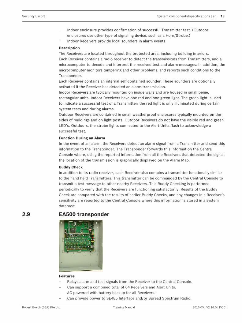
2.9 EA500 transponder
Features– Relays alarm and test signals from the Receiver to the Central Console.– Can support a combined total of 64 Receivers and Alert Units.– AC powered with battery backup for all Receivers.– Can provide power to SE485 Interface and/or Spread Spectrum Radio.

20 en | System components/specifications Security Escort
2016.05 | V2.16.0 | DOC Training Manual Robert Bosch (SEA) Pte Ltd
– Available in a large or small indoor enclosure.– Monitors Receivers and Alert Units 10 times per second for alarms, tests, tamper
notification, and power loss.
DescriptionThe Transponder is a device controller for up to 64 devices -- any combination of Receiversand Alert Units. Its primary function is to monitor the Receivers and Alert Units and reportconditions and events to the Central Console via either wire or ProxLink radios. It alsoprovides power output to certain devices.
InstallationThe Transponder can be mounted in one of two different sized enclosures. It is alwaysmounted indoors. The devices are connected to the Transponder by means of eight four-wireMultiplex Busses, two wires for power and two wires for data. Each bus is capable ofsupporting up to eight devices. A Security Escort System supports up to 255 Transponders.
ConfigurationEach Receiver and Alert Unit is identified to its Transponder by a Multiplex Address which isset during system installation using a multi-position switch on the Receiver or Alert Unit circuitboard. Transponders communicate on the data bus with individual Multiplex devices byissuing commands, which contain the Receiver or Alert Unit’s Multiplex Address.
Setup and TestingEach Transponder and the devices connected to it are set up and can be tested remotely fromthe Central Console. Also, each Transponder reports any problems, such as low battery,immediately upon detecting them.
Function During an AlarmWhen a Receiver or Alert Unit detects an alarm, it goes into an “Off Normal” state. To quicklylocate any devices which might be in the “Off Normal” state, the Transponder issues globalcommands (which are interpreted simultaneously by all of its devices) approximately 10 timesper second. These global commands are followed by commands to specific devices todetermine the nature of the “Off Normal” condition and, in the case of an alarm (or test), toobtain the Transmitter Identification Number, Transmitter battery condition, and receivedsignal strength. This information is then sent to the Central Console, by either wire or throughProxLink radios, where it is used to graphically display the identity of the subscribertransmitting the alarm and to determine the subscriber’s location.
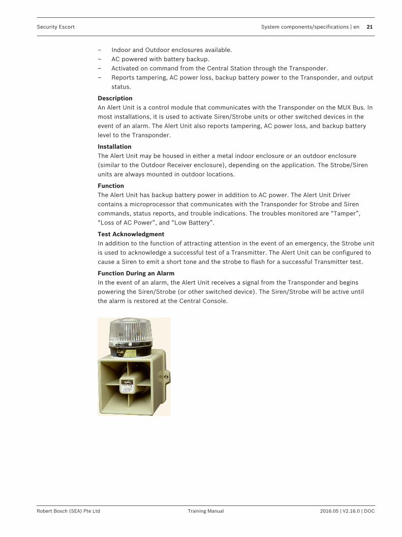
2.10 EA120 alert unit
Features– Provides output for alarm annunciation through the Siren/Strobe or other third party
switched device.– Provides output to Siren/Strobe to indicate a successful Transmitter test.
Security Escort System components/specifications | en 21
Robert Bosch (SEA) Pte Ltd Training Manual 2016.05 | V2.16.0 | DOC
– Indoor and Outdoor enclosures available.– AC powered with battery backup.– Activated on command from the Central Station through the Transponder.– Reports tampering, AC power loss, backup battery power to the Transponder, and output
status.
DescriptionAn Alert Unit is a control module that communicates with the Transponder on the MUX Bus. Inmost installations, it is used to activate Siren/Strobe units or other switched devices in theevent of an alarm. The Alert Unit also reports tampering, AC power loss, and backup batterylevel to the Transponder.
InstallationThe Alert Unit may be housed in either a metal indoor enclosure or an outdoor enclosure(similar to the Outdoor Receiver enclosure), depending on the application. The Strobe/Sirenunits are always mounted in outdoor locations.
FunctionThe Alert Unit has backup battery power in addition to AC power. The Alert Unit Drivercontains a microprocessor that communicates with the Transponder for Strobe and Sirencommands, status reports, and trouble indications. The troubles monitored are “Tamper”,“Loss of AC Power”, and “Low Battery”.
Test AcknowledgmentIn addition to the function of attracting attention in the event of an emergency, the Strobe unitis used to acknowledge a successful test of a Transmitter. The Alert Unit can be configured tocause a Siren to emit a short tone and the strobe to flash for a successful Transmitter test.
Function During an AlarmIn the event of an alarm, the Alert Unit receives a signal from the Transponder and beginspowering the Siren/Strobe (or other switched device). The Siren/Strobe will be active untilthe alarm is restored at the Central Console.

22 en | Equipment estimation, location accuracy and receiver location Security Escort
2016.05 | V2.16.0 | DOC Training Manual Robert Bosch (SEA) Pte Ltd
3 Equipment estimation, location accuracy and receiverlocationA Security Escort system installation consists of three major steps:1. the pre-bid equipment estimation,2. the pre-construction coverage verification survey, and3. the post construction setup.
The Security Escort receivers work effectively in a wide variety of installations and can beplaced with confidence provided these installation requirements are met. Therefore, at thepre-bid stage, it is acceptable to estimate the required equipment. To ensure proper coverageafter proposal acceptance, potential receiver locations can be verified using a standardreceiver in test mode or the portable test receiver before construction begins.
3.1 Location accuracyThe Security Escort system provides quick response to a duress call. Its intent is to dispatch aresponding individual to an area without additional delay to their response to that duress call.
Figure 3.2: System Block Diagram
The Security Escort system uses radio frequency (RF) for alarm transmissions. This issignificant because it prevents normal construction from blocking the signal and helps toeliminate dead spots where the alarm could not be heard. The fact that RF energy passesthrough normal construction prevents Security Escort from locating an alarm with 100%certainty to a specific side of a wall. Alarms originating at or near building walls will typicallybe indicated within 7.5 m (25 ft) of the actual location. However, there may be times when thecomputed location may appear to be on the other side of the wall.The Security Escort system was designed to provide a computed alarm location typicallywithin 7.5 m (25 ft) of the actual location when indoors, and a computed alarm locationtypically within 15 m (50 ft) of the actual location outdoors. Any deviation from the followinginstallation guidelines will degrade the computed location accuracy. Therefore, to achieveaccuracy, the following installation guidelines must be adhered to.

Security Escort Equipment estimation, location accuracy and receiver location | en 23
Robert Bosch (SEA) Pte Ltd Training Manual 2016.05 | V2.16.0 | DOC
3.2 Pre-bid equipment estimationThe pre-bid equipment estimation is performed prior to bidding the installation. At this point,it must be determined what type of coverage is desired, and where the coverage will berequired. For example, the amount of equipment required for a full-coverage (indoor andoutdoor) system in a multi-building application is greater than an installation that requiresoutdoor only coverage. The customer should be consulted, and the areas of most concernshould be given special consideration.
3.2.1 Initial equipment estimateNumber of indoor receiversTo estimate the number of indoor receivers, first read Indoor receiver installation. Assume thereceivers are placed on a grid with a maximum spacing of 25 m (80 ft) between receivers forstandard construction. In multi-floor applications the receivers on each floor must be placeddirectly above the receivers on the floor below (this is required for proper floor-to-floorlocation).For example, to determine the number of receivers required to protect a building of standardconstruction of 60 m x 30 m (200 ft x 100 ft) and four floors:
1. To determine the number of receivers in each direction, divide each dimension of thebuilding by 25 m (80 ft), drop the remainder, and add 1. For example:– 60 m/25 m = 2.4, becomes 2, add 1 = 3
(200 ft/80 ft = 2.5, becomes 2, add 1 = 3)– 30 m/25 m =1.2, becomes 1, add 1 = 2
(100 ft/80 ft =1.25, becomes 1, add 1 = 2)2. To determine the number of receivers required per floor, multiply the number of receivers
in one direction by the number of receivers in the other direction.(3 x 2 = 6) 6 receivers per floor.
3. To determine the total number of receivers, multiply the number of receivers per floor bythe number of floors.(6 x 4 = 24) 24 receivers for the building.
Figure 3.3: Determining the Number of Indoor Receivers Required
1 Receivers (6)

24 en | Equipment estimation, location accuracy and receiver location Security Escort
2016.05 | V2.16.0 | DOC Training Manual Robert Bosch (SEA) Pte Ltd
Each floor would require 6 receivers, resulting in a total of 24 receivers to protect thisbuilding.For the best location accuracy, consistent receiver spacing is important. Do not placereceivers significantly closer in one section of a building than another section.
Number of outdoor receivers
To estimate the number of receivers, first read Outdoor receiver installation. Assume amaximum receiver spacing of 90 m (300 ft) between receivers, in both directions, for receiversthat are not within 30 m (100 ft) of a building with inside coverage. Receivers within 30 m(100 ft) of a building should be spaced the same as receivers in the building (spacing theoutside receivers at a somewhat larger spacing is acceptable in most cases).An outside area directly between two buildings with inside protection will need no additionalreceivers if the buildings are 90 m (300 ft) or less apart. If the buildings are more than 90 m(300 ft) apart the outside receivers should be evenly spaced between the buildings. Make surethe standard 90 m (300 ft) spacing is not exceeded. For spacing outside adjacent to a coveredbuilding, start the 90 m (300 ft) spacing at the building wall.
Allowance for special coverage requirementsFor purposes of the bid, the number of receivers estimated above should be raised by 5% toallow for special coverage considerations and RF problem areas.
Number of transpondersAssume one transponder per building for indoor installations. If wiring can be run from otherbuildings or from outdoor receivers, they may be connected to one transponder. Never exceedthe total number of 64 devices (receivers and alert units) per transponder. All outside wiringmust be under ground, or in metal conduit.
Number of receivers and alert units per busFor transponders, each bus can handle 8 receivers and alert units. However, it is a good ideato leave some addresses available on each bus to allow for future expansion. For systems witha high number of supervised transmitters, see Transponder wiring notes.

Security Escort Equipment estimation, location accuracy and receiver location | en 25
Robert Bosch (SEA) Pte Ltd Training Manual 2016.05 | V2.16.0 | DOC
Bus wireThe multiplex bus for transponder should be wired with 4 conductor 18 gauge (1.2 mm) wire.The wire should not be paired or shielded. In the United States this is the same as fire systemwire, except it should not be red.
Number of alert unitsThe number of alert units will be determined by each system’s requirements. In general,enough alert units should be installed to be heard and seen from all outdoor locations ofprotection. Remember that even in a silent system, alert units can be used outside to providetest feedback. Horn/strobe units should be mounted in predictable locations to make themeasy to identify by subscribers. Alert units are not required indoors because the indoorreceiver provides alarm and test feedback. Each transponder will drive one siren and onestrobe if they are less than 15 m (50 ft) from the transponder.It is a good idea for each protected parking lot to have a siren/strobe near it.
3.3 Pre-construction coverage verification surveyThe pre-construction coverage verification survey is performed after the bid is accepted andbefore construction begins. It is done to determine the location of each receiver. Each receiverlocation should be checked using a standard receiver in the test mode.
3.3.1 Verify each potential receiver locationUsing a receiver in “receiver spacing” mode”Receiver spacing” mode is enabled with jumper P5 in place (jumper P4 removed) on areceiver (see the EA102 Receiver Installation Instructions).This mode is exactly the same as the “test” mode, except that only transmissions with anadequate receive margin are sounded. This indicates the maximum acceptable spacing ofreceivers. Use the following procedure to test the spacing of receivers:
1. Mount the first receiver.
2. Put jumpers P1, P2, P3, and P5 in place, and remove all other jumpers. Power thereceiver from a or 12 VDC source.
3. Take the second receiver and a transmitter a distance away from the first receiver.
4. Activate the transmitter.
5. If receiver 1 sounds the test beep, receiver 2 is within range. Repeat this test untilreceiver 1 no longer sounds the test beeps. Move back to the last location where receiver1 received the test beeps. This location marks the maximum spacing between receivers.The distance between receivers should not exceed 25 m (80 ft) indoors and 90 m (300 ft)outdoors. Mount receiver 2 at this location or closer to receiver 1.
Notice!Do not use the “test” mode (jumper P4) to determine receiver spacing.

26 en | Equipment estimation, location accuracy and receiver location Security Escort
2016.05 | V2.16.0 | DOC Training Manual Robert Bosch (SEA) Pte Ltd
Figure 3.4: Receiver Spacing
1 Receiver 1 stops sounding the testbeeps when receiver 2 is moved pastthis point
3 Receiver 2 at maximum range
2 Receiver 1 4 Receiver 2 beyond maximum range
Using a transponder, receivers, and laptop computer to determine receiver location
Notice!System software and an area map must be installed on a laptop computer to use this method.
A transponder with long multiplex wires connected to receivers can be used to see actualalarm location before the receivers are placed. Place the receivers in the proposed locationswired back to the transponder. Program the receivers with their locations in the TransponderDatabase. Using the maintenance transmitter and the maintenance alarm database, activatealarm transmissions within the area surrounded by the temporarily placed receivers. Verifythat the location accuracy is acceptable at all points of concern. If not acceptable move thereceivers, update the receiver location in the Transponder Database, and retest. Do not testoutside of the last receiver in any direction, as this gives incorrect locations. Repeat this testin all areas of different construction and concern at the site.
3.3.2 Indoor receiver installation– Indoor receivers must be mounted in a evenly spaced grid no more than 25 m (80 ft)
apart.– Indoor receivers must be mounted 1.5 to 1.8 m (5 ft to 6 ft) above the floor. This is true
even if this is a single story building. Do not mount receivers above the ceiling or in roofrafters.
– In multistory buildings, the receivers must be mounted directly above the receivers on thefloor below. The same number of receivers must be used on each floor level. If you meetall of the indoor installation guidelines, you can expect the computed location to indicatethe correct floor about 95% of the time.
– Receivers must not be mounted within 30 cm (1 ft) of any metal object, including wiremesh, metal foil, metal pipe and HVAC ducting in walls.

Security Escort Equipment estimation, location accuracy and receiver location | en 27
Robert Bosch (SEA) Pte Ltd Training Manual 2016.05 | V2.16.0 | DOC
– Take care that large metal objects do not shield a receiver from a protected area. Forexample metal staircases, metal food serving lines, metal walls, lead lined walls, metalroofs, wire mesh in walls, walk-in freezers and refrigerators.
For the best indoor and outdoor location or an indoor only system– Mount the indoor receivers on the recommended 25 m (80 ft) grid, with the last row of
indoor receivers on the outside wall of the building. Do this even if the building is lessthan 25 m (80 ft) wide or long.
– There should be a receiver at each outside corner of a building.
Handling two protected buildings sharing a common wall with floor levels that do not match– Ask the customer which building has areas of greater concern and favor the
recommended mounting heights in that building.– The recommended 25 m (80 ft) maximum indoor spacing grid should be maintained
throughout both buildings as if the wall in question was not there. Mounting heights onlyfor those receivers at or near (within 6 m [20 ft]) the wall in question should be affected.Mounting heights for all other receivers in the buildings must follow the indoorrecommendation. Mark the recommended mounting height for receivers on the higherfloor level and also mark the recommended mounting height for receivers on the lowerfloor level. Mount the receiver at its normal grid location midway between these twoheights, but not above the ceiling level of the lower floor.
3.3.3 Outdoor receiver installation– Outdoor receivers must be mounted in a evenly spaced grid no more than 90 m (300 ft)
apart.– Outdoor receivers must be mounted 3 m (10 ft) above the ground.– Receivers must not be mounted within 30 cm (1 ft) of any metal object, including fences,
metal walls and walls with wire mesh. If a receiver is mounted on a metal fence, thatfence should be grounded (not floating or insulated from ground) and the receiver shouldbe spaced 30 cm (1 ft) from the fence and 3 m (10 ft) above the ground.
– Take care that large metal objects do not shield a receiver from a protected area. Forexample; metal fences, metal staircases, metal buildings, power transformers and metalroofs.
– Receiver locations should be below building overhangs and eaves as these can shield theareas below them.
– Receivers should have a clear line of sight of the protected area. Therefore, take carewhere the ground is hilly or uneven, that there are no areas and low spots where severalreceivers can’t hear the signal.
Transition areas between indoor and outdoor areas– An outside area directly between two buildings with complete indoor protection will need
no additional receivers between the buildings, if they are 90 m (300 ft) or less apart.– When protecting an outside area directly between two buildings with complete indoor
protection, and they are more than 90 m (300 ft) apart, place a row of outside receiversevenly spaced between the buildings. Make sure the receiver row does not exceed thestandard 90 m (300 ft) spacing from the buildings. The spacing between receivers in thatrow should be about the same as the spacing for the receivers in the buildings.
28 en | Equipment estimation, location accuracy and receiver location Security Escort
2016.05 | V2.16.0 | DOC Training Manual Robert Bosch (SEA) Pte Ltd
– Indoor receivers should be no more than 25 m (80 ft) apart and outdoor receivers shouldbe no more that 90 m (300 ft) apart. Both of these recommendations work well in theirrespective areas. However, if a building is adjacent to an outdoor area, that building willhave a greater density of receivers and, therefore, has a tendency to pull the computedlocation towards it. To counteract the building tendency to pull the location, consider thefollowing special cases:– If the outdoor area adjacent to the building is wide open and the customer is not
concerned about reduced location accuracy in this area, then nothing special needsto be done. Follow the normal indoor and outdoor recommendations.
– The building is near the boundary of the protected area, with or without a fence atthe boundary. The receivers in the building should be placed at the recommended 25m (80 ft) spacing. The receivers at the boundary of the protected area near thebuilding should be spaced about the same as those in the building, approximatingthe same grid as used in the building.
– The building is adjacent to a large protected outdoor area that extends for more than90 m (300 ft) from the building. The receivers in the building should be placed at therecommended 25 m (80 ft) spacing. The receivers in the large protected outdoorarea should be placed on the normal 90 m (300 ft) grid except for the first row ofreceivers adjacent to the building. This first row of outdoor receivers in the transitionarea should “split the difference” between the indoor and outdoor spacing at about60 m (200 ft).
Boundary areas at the outer edge of the protected areaThe system cannot locate an alarm past the last receiver at the boundary of the protectedarea. Therefore, the last row of receivers must be at or past the end of the protected area.

Security Escort System wiring | en 29
Robert Bosch (SEA) Pte Ltd Training Manual 2016.05 | V2.16.0 | DOC
4 System wiring4.1 General guidelines
After the site survey (and special pre-construction verifications) has been completed, thewiring can be run between the proposed locations of the system components and the CentralConsole. See specific installation instructions accompanying each component for wiringdetails.The following table indicates the specifications for the wiring:
Application DiagramRef
Gauge Conductors MaximumDistance
Notes
From To
Transponder Transformer 1 1.5 mm(16AWG)
2 15 m (50 ft) Standardlamp cord
Alert Unit 2 1.2 mm(18AWG)
4 900 m (3000ft) per bus
Solid, nottwisted, notshielded
Receiver 2 1.2 mm(18AWG)
4 900 m (3000ft) per bus
Solid, nottwisted, notshielded
SE485 3 0.5 mm(24AWG)
4 wire, 2twisted pair
SeeTransponder– SE485Wiring table.
IMPORTANT!Must betwisted pair,not shielded.CAT5 cablepreferred.
Siren/Strobe 4 1.2 mm(18AWG)
4 15 m (50 ft) Solid, nottwisted, notshielded
Alert Unit Transformer 5 1.5 mm(16AWG)
2 15 m (50 ft) Standardlamp cord
Siren/Strobe 6 1.5 mm(18AWG)
4 15 m (50 ft) Solid, nottwisted, notshielded
Tab. 4.1: Wiring Guidelines
4.1.1 Transponder - SE485 wiring table
Number ofTransponders
Maximum WireLength
1 to 4 6100 m (20000 ft)
8 3050 m (10000 ft)
12 1525 m (5000 ft)

30 en | System wiring Security Escort
2016.05 | V2.16.0 | DOC Training Manual Robert Bosch (SEA) Pte Ltd
Number ofTransponders
Maximum WireLength
16 900 m (3000 ft)
Tab. 4.2: Transponder – SE485 Wiring Table
4.1.2 Observe established standardsInstall cable according to local code requirements. In the USA, refer to the National ElectricalCode Standards, located in Chapter 8 Article 800 of the National Electrical Code, and applicablelocal and regional codes.
4.2 Component wiring guidelines
4.2.1 General wiring diagram
Figure 4.5: General Wiring Diagram

Security Escort System wiring | en 31
Robert Bosch (SEA) Pte Ltd Training Manual 2016.05 | V2.16.0 | DOC

32 en | System wiring Security Escort
2016.05 | V2.16.0 | DOC Training Manual Robert Bosch (SEA) Pte Ltd
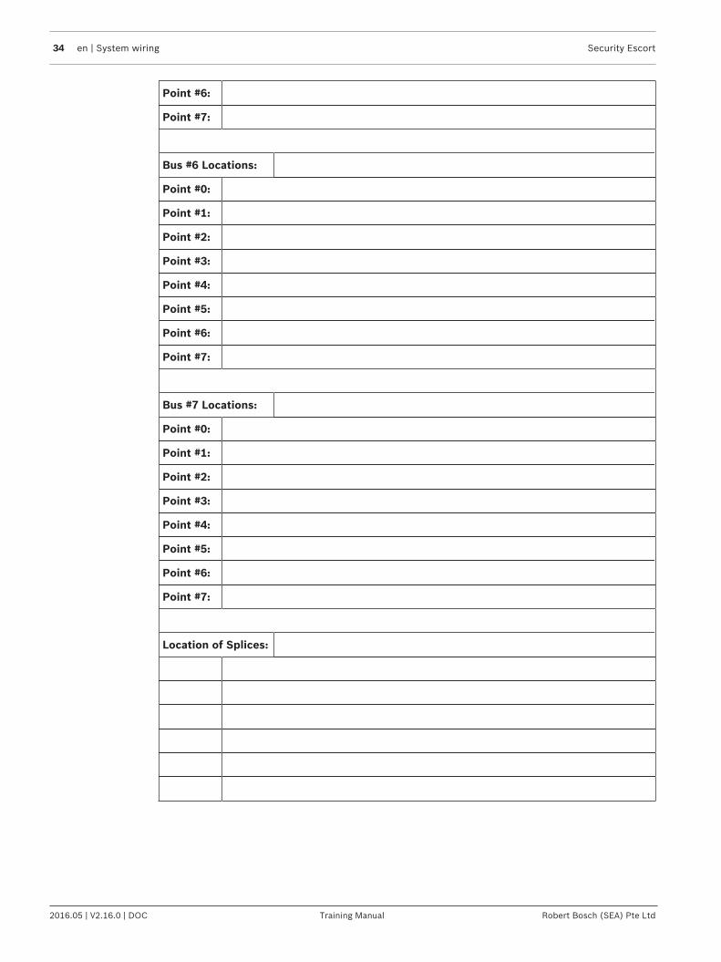
4.2.2 Transponder information sheet
TransponderNumber:
TransponderLocation:
Transformer for TransponderLocation:
Breaker PanelLocation:
BreakerNumber:
Siren/StrobeOutput To:
KeyswitchMonitoring To:
Bus #0 Locations:
Point #0:
Point #1:
Point #2:
Point #3:
Point #4:
Point #5:
Point #6:
Point #7:
Bus #1 Locations:
Point #0:
Point #1:
Point #2:
Point #3:
Point #4:
Point #5:
Point #6:
Point #7:
Bus #2 Locations:
Point #0:
Point #1:

Security Escort System wiring | en 33
Robert Bosch (SEA) Pte Ltd Training Manual 2016.05 | V2.16.0 | DOC
Point #2:
Point #3:
Point #4:
Point #5:
Point #6:
Point #7:
Bus #3 Locations:
Point #0:
Point #1:
Point #2:
Point #3:
Point #4:
Point #5:
Point #6:
Point #7:
Bus #4 Locations:
Point #0:
Point #1:
Point #2:
Point #3:
Point #4:
Point #5:
Point #6:
Point #7:
Bus #5 Locations:
Point #0:
Point #1:
Point #2:
Point #3:
Point #4:
Point #5:
34 en | System wiring Security Escort
2016.05 | V2.16.0 | DOC Training Manual Robert Bosch (SEA) Pte Ltd
Point #6:
Point #7:
Bus #6 Locations:
Point #0:
Point #1:
Point #2:
Point #3:
Point #4:
Point #5:
Point #6:
Point #7:
Bus #7 Locations:
Point #0:
Point #1:
Point #2:
Point #3:
Point #4:
Point #5:
Point #6:
Point #7:
Location of Splices:

Security Escort System wiring | en 35
Robert Bosch (SEA) Pte Ltd Training Manual 2016.05 | V2.16.0 | DOC
4.3 EA500 transponder
4.3.1 GeneralThe EA500 transponder is the Security Escort module that provides communications betweenthe Central Console and the many receivers and alert units throughout the protected area. Inaddition to its communications functions, it also supplies power to the receivers. Eachtransponder also includes drivers for a single strobe and siren.
4.3.2 Specifications
Enclosure (AE3): 15 in. W, 20.75 in. H, 4.25 in. D
Hardware Kit: H500
Temperature Range: -40° to +149°F (-40° to +65°C)
Power: 18.0 VAC, 50 VA maximum plug-in Transformer for 110 V, 60 HzSupplies battery backed 12.0 VDC power to Receivers
Power Output: 9V DC used for SE485 or for Proxim radio power
Driver Outputs: Strobe: 500 mA solid state sink, terminal switches to ground in an alarmcondition.Siren: 500 mA solid state sink, terminal switches to ground in an alarmcondition.
Battery Backup: 12 VDC Lead Acid Battery
Multiplex Buses: 8 multiplex drivers, each capable of driving 8 Receivers or Alert Unitsfor a combined total of 64 Receivers and Alert Units per transponder
Comm. Interface: Selectable SE485 or RS-232
Keyswitch Input: 47k EOL resistor, supervised loop
Compatibility: *ROM version 4.00 or greater (version shipped with this unit) iscompatible with “‑304” equipment (e.g., EA102A-304). Version 4.00 orgreater is NOT compatible with non “-304” equipment.*ROM versions earlier than 4.00 are compatible with non “-304”equipment.
4.3.3 MountingNormally, the enclosures are mounted first and all the wiring run, then the electronics aremounted, wired, and tested.The enclosures come with their own mounting hardware (H500 Hardware Kit) for mountingthe enclosure to a wall and mounting the circuit board to the enclosure.– Mount the enclosure to the mounting surface.– Mount the circuit board to the enclosure.
4.3.4 WiringWire the transponder. See wiring diagram on Set the address, page 36.Wiring to receivers and alert units can be home-run (individual), daisy-chain (from device todevice), or a combination of both. T-tapping is okay. The recommended cable is 4-conductor,18 AWG (1.2 mm) fire rated.
36 en | System wiring Security Escort
2016.05 | V2.16.0 | DOC Training Manual Robert Bosch (SEA) Pte Ltd
Wiring from SE485 to transponders can be home-run (individual), daisy-chain (from device todevice), or a combination of both. T-tapping is okay. The recommended cable is 4-conductor,22 AWG (0.8 mm).
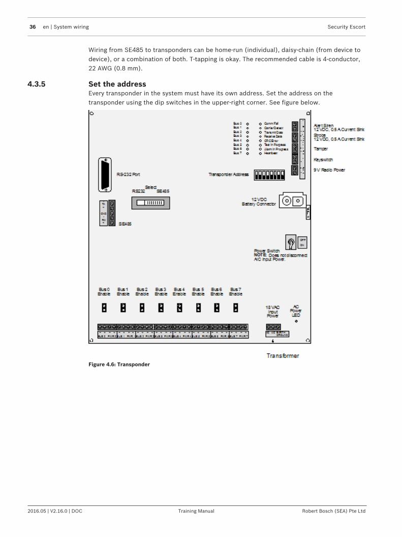
4.3.5 Set the addressEvery transponder in the system must have its own address. Set the address on thetransponder using the dip switches in the upper-right corner. See figure below.
Figure 4.6: Transponder
Security Escort System wiring | en 37
Robert Bosch (SEA) Pte Ltd Training Manual 2016.05 | V2.16.0 | DOC
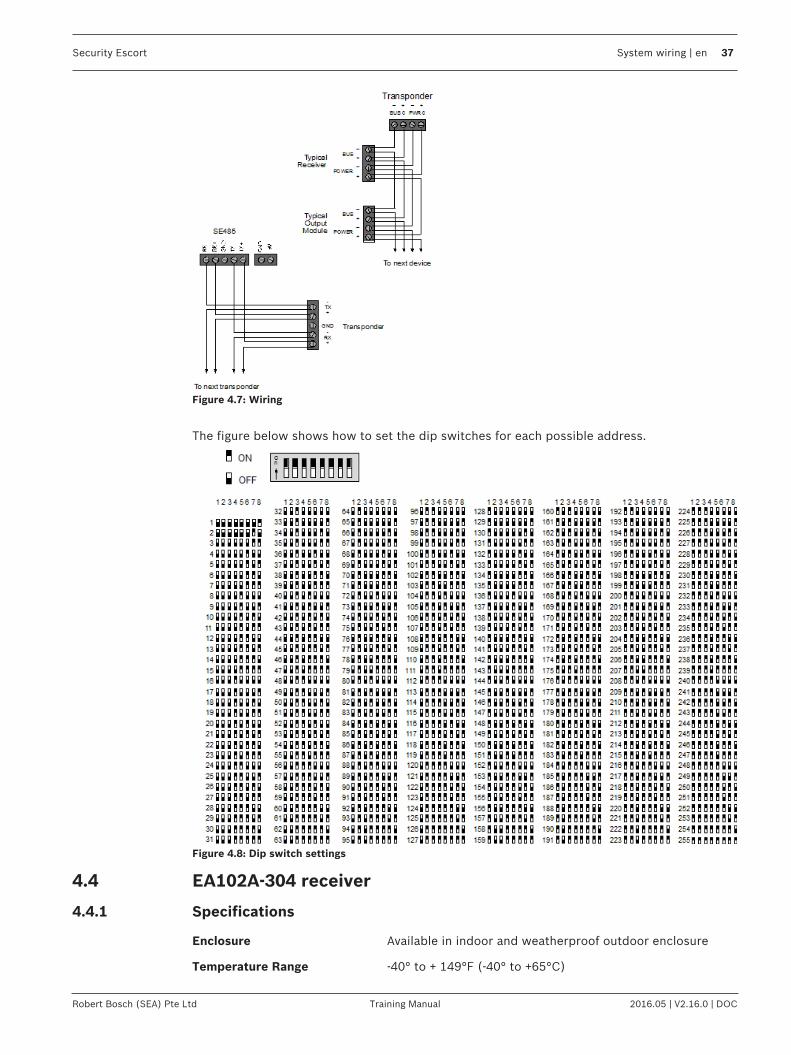
Figure 4.7: Wiring
The figure below shows how to set the dip switches for each possible address.
Figure 4.8: Dip switch settings
4.4 EA102A-304 receiver
4.4.1 Specifications
Enclosure Available in indoor and weatherproof outdoor enclosure
Temperature Range -40° to + 149°F (-40° to +65°C)

38 en | System wiring Security Escort
2016.05 | V2.16.0 | DOC Training Manual Robert Bosch (SEA) Pte Ltd
Power 12VDC, 25 mA typical, 55mA with horn sounding
RF Input Frequency 304.000 Mhz
Signal Strength Measured in 255 steps
Antenna Type Diversity antennas
Compatibility SE2x-304 Series and SE4x-304 Series Transmitters; EA500BTransponder with a ROM version 4.00 or greater.
Notice!The EA102A-304 is compatible only with other “-304” equipment (e.g., the SE2x-304 and theSE4x-304). Also, do NOT install this unit in conjunction with an EA500B transponder with aROM version earlier than 4.00.
4.4.2 MountingChoose a mounting location based upon the previous site survey. The receiver should bemounted as close as possible to the location found with the test receiver. The following is aguideline for receiver mounting and spacing:
Indoor receiver installationReceiver spacing: Receiver spacing should be no more than 24 m (80 ft) between receiversfor standard construction. Range will be dependent upon the construction of the building. Forexample: a building with hollow drywall walls may support 24 m (80 ft) spacing; a buildingwith steel reinforced concrete may require reduced spacing. It is very important to maintain aconsistent spacing as this will ensure optimum signal locating. The more receivers that candetect a transmitted signal, the more accurate the locating will be.Mounting height: Receivers should be mounted 1.5 to 1.8 m (5 to 6 ft) from the floor.Maintain a consistent mounting height to ensure optimum signal locating. Do not placereceivers close to the ceiling; this will cause them to be closer to the floor above, andtherefore, reduce the floor to floor location accuracy. It may also be helpful to place thereceivers somewhat higher only on the top floor to be covered and somewhat lower only onthe bottom floor to be covered.Multi-floor installations: Receivers must be mounted over one another in multi-floorinstallations. This helps maintain proper floor-to-floor reception.
Select a mounting location that:– provides a clear line-of-sight of the protected area, if possible,– is at least 30 m (1 ft) away from metal objects such as HVAC ducts,– is on an inside wall, if possible,– is 1.5 to 1.8 m (5 to 6 ft) from the floor,– is not at a barrier where it is important to resolve which side an alarm location is on, and– will not be damaged by tampering or opening doors.

Security Escort System wiring | en 39
Robert Bosch (SEA) Pte Ltd Training Manual 2016.05 | V2.16.0 | DOC
Outdoor receiver installationReceiver spacing: Receivers should be mounted every 91.5 m (300 ft). It is very important tomaintain as consistent spacing as possible, as this will ensure optimum signal locating. Themore receivers that can detect a transmitted signal, the more accurate the locating will be.Each receiver should have a clear line-of-sight of the intended protection area.Mounting height: Receivers should be mounted 3 m (10 ft) above grade. Maintain a mountingheight that is as consistent as possible to ensure optimum signal locating.Overhangs/eaves: Receiver locations should be below building overhangs and eaves. Mosttransmissions will occur a few feet (1 m) above grade; mounting above overhangs and eavescould result in inaccurate signal locating. Be especially careful around metal roofs as these canblock the signal.
Select a mounting location that:– provides a clear line-of-sight of the protected area,– is away from metallic objects such as chain-link fences and electrical transformers. If
coverage is required near such items, testing should be performed near these items todetermine the potential need for additional receivers,
– is 3 m (10 ft) above grade,– is not at a barrier where is it important to resolve which side an alarm location is on,– is easy to service, and– will not be damaged by tampering.
4.4.3 Wiring
Notice!Apply power only after all connections have been made and inspected.
Connect wiring as shown:
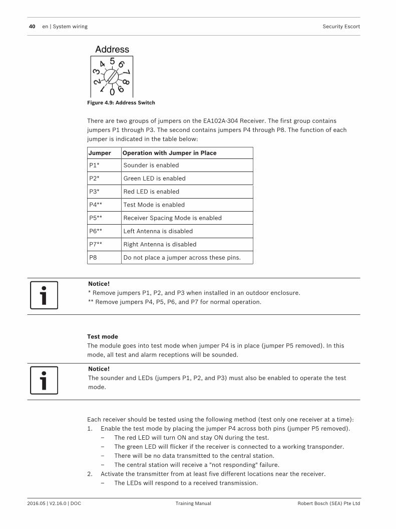
4.4.4 Switches and jumpersLoop addressThe rotary switch is used to select the loop address. This is the address that is reported to thetransponder which the receiver is connected to. Each device on a loop should have its ownaddress. Only addresses 0 through 7 are valid. Do not use addresses 8 and 9.
40 en | System wiring Security Escort
2016.05 | V2.16.0 | DOC Training Manual Robert Bosch (SEA) Pte Ltd
Figure 4.9: Address Switch
There are two groups of jumpers on the EA102A-304 Receiver. The first group containsjumpers P1 through P3. The second contains jumpers P4 through P8. The function of eachjumper is indicated in the table below:
Jumper Operation with Jumper in Place
P1* Sounder is enabled
P2* Green LED is enabled
P3* Red LED is enabled
P4** Test Mode is enabled
P5** Receiver Spacing Mode is enabled
P6** Left Antenna is disabled
P7** Right Antenna is disabled
P8 Do not place a jumper across these pins.
Notice!* Remove jumpers P1, P2, and P3 when installed in an outdoor enclosure.** Remove jumpers P4, P5, P6, and P7 for normal operation.
Test modeThe module goes into test mode when jumper P4 is in place (jumper P5 removed). In thismode, all test and alarm receptions will be sounded.
Notice!The sounder and LEDs (jumpers P1, P2, and P3) must also be enabled to operate the testmode.
Each receiver should be tested using the following method (test only one receiver at a time):1. Enable the test mode by placing the jumper P4 across both pins (jumper P5 removed).
– The red LED will turn ON and stay ON during the test.– The green LED will flicker if the receiver is connected to a working transponder.– There will be no data transmitted to the central station.– The central station will receive a "not responding" failure.
2. Activate the transmitter from at least five different locations near the receiver.– The LEDs will respond to a received transmission.

Security Escort System wiring | en 41
Robert Bosch (SEA) Pte Ltd Training Manual 2016.05 | V2.16.0 | DOC
– If the receiver detected all the packets from the transmission, the sounder will beepthree times.
– If the receiver detected the transmission, but some of the packets were missing, itwill beep once. This could indicate that the signal is not sufficient from this location.
Testing receiver spacingReceiver spacing mode is enabled with jumper P5 in place (jumper P4 removed). This mode isexactly the same as the test mode above, except that only transmissions with an adequatereceive margin are sounded. This indicates the maximum acceptable spacing of receivers. Usethe following procedure to test the spacing of receivers:1. Mount the first receiver.2. Take the second receiver and a transmitter a distance away from the first receiver.3. Activate the transmitter.4. If receiver 1 sounds the test beeps, receiver 2 is within range. Repeat this test until
receiver 1 no longer sounds the test beeps. Move back to the last location where receiver1 received the test beeps. This location marks the maximum spacing between receivers.Mount receiver 2 at this location or closer to receiver 1.
Notice!Do not use the test mode (jumper P4) to determine receiver spacing.
Figure 4.10: Receiver Spacing
1 Receiver 1 stops sounding the testbeeps when receiver 2 is moved pastthis point
3 Receiver 2 at maximum range
2 Receiver 1 4 Receiver 2 beyond maximum range
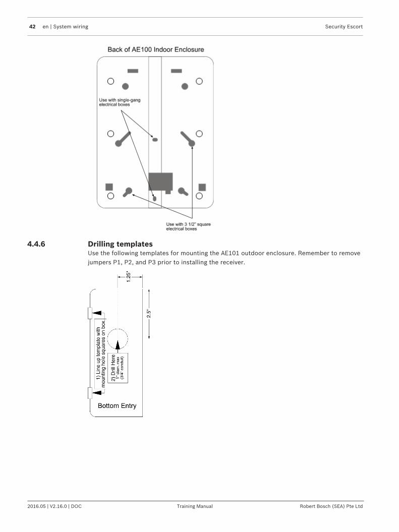
4.4.5 Pre-wired installationsWhen mounting the enclosure to a pre-wired electrical box, make sure that the electrical boxhas a six inch overhead clearance. The enclosure should be mounted as shown below:
42 en | System wiring Security Escort
2016.05 | V2.16.0 | DOC Training Manual Robert Bosch (SEA) Pte Ltd
4.4.6 Drilling templatesUse the following templates for mounting the AE101 outdoor enclosure. Remember to removejumpers P1, P2, and P3 prior to installing the receiver.

Security Escort System wiring | en 43
Robert Bosch (SEA) Pte Ltd Training Manual 2016.05 | V2.16.0 | DOC
Figure 4.11: Drilling Template for AE101 Outdoor Enclosure Bottom Entry
4.5 EA120B alert unit
4.5.1 Specifications
Electronics: EA120B
Enclosures: Indoor: AE1 (9"H x 7"W x 1.75"D)Outdoor: AE101 (14.75"H x 12.75"W x 3.5" D)

44 en | System wiring Security Escort
2016.05 | V2.16.0 | DOC Training Manual Robert Bosch (SEA) Pte Ltd
Hardware Kits: Indoor: H500Outdoor: H121Temperature RangePowerBattery Backup
-40 °F to + 149 °F (-40 °C to +65 °C)18 V AC, 50 VA12 V DC Lead Acid Battery
Accessory Equipment Horn/Strobe: E28000B• Strobe: 500 mA solid state sink, terminal switches to ground in analarm condition.• Siren: 500 mA solid state sink, terminal switches to ground in analarm condition.• Power: 12 V @ 1A, max.
Transformer:Batteries
Battery Cables:
(3 Amp Hour):(7 Amp Hour):
TR1850E28629BE19729BC316 (3 or 7 Amp)C315 (17 Amp)C311 (3 or 7 Amp expansion)
Compatibility EA500B ROM Version 4.00 or higher
4.5.2 General informationThe alert unit is a driver for output modules such as Security Escort's E28000B horn/strobe.The unit should be mounted indoors; however, an outdoor enclosure is available. The horn/strobe should always be mounted outdoors.The alert unit gets its main power (for horn/strobe activation) from the 18 V AC transformerand its backup power from a battery; however, the multiplex bus will continue to supply thetransponder information on status and troubles in the event "local" power is lost.
4.5.3 MountingNormally, the enclosures are mounted first and all the wiring run, then the electronics aremounted, wired, and tested.The enclosures come with their own mounting hardware. The hardware kits listed above arefor mounting the circuit board to the enclosures (the indoor hardware kit also includes atamper switch and a lock and key).Mount the circuit board to the enclosure as indicated in the figures below.

Security Escort System wiring | en 45
Robert Bosch (SEA) Pte Ltd Training Manual 2016.05 | V2.16.0 | DOC
4.5.4 WiringWire the alert unit using the figure below:
4.5.5 Set the addressEvery module on each multiplex bus of the transponder must have its own address. Set theaddress on the alert unit using the address switch.Use only address numbers 0 through 7. Do NOT use address numbers 8 and 9.
4.6 Moxa interface
4.6.1 IntroductionThe Moxa interface is used between the RS-232 signal bus of the Security Escort transponder,and the Ethernet connection of the Local Area Network (LAN) in order to communicate withthe Security Escort Central Console.
4.6.2 Specifications
RecommendedModel:
NPort 5150

46 en | System wiring Security Escort
2016.05 | V2.16.0 | DOC Training Manual Robert Bosch (SEA) Pte Ltd
Dimensions: 52 mm (2.05 in) x 80 mm (3.15 in) x 22 mm (0.89 in)
Power: Use the included 12 – 48 V DC on barrel connector
RecommendedCable:
Standard male DB9 to female DB9 serial cable (not included).
4.6.3 Installation and operation notes
– The Moxa device must be powered at all times. Use the included power adapter.– A standard male DB9 to female DB9 serial cable is used to connect the transponder to
the Moxa device.– Instructions on setting up the Moxa device is based on the recommended model NPort
5150 (firmware version: 3.4 Build 11080114).
The pinouts of male DB9 serial port of Moxa NPort 5150 are as follows:
Figure 4.12: Moxa NPort 5150 Male DB9
Pin Number RS-232 RS-422/RS-485(4W)
RS-485(2W)
1 DCD TXD-(A) --
2 RxD TXD+(B) --
3 TxD RXD+(B) Data+(B)
4 DTR RXD-(A) Data-(A)
5 GND GND GND
6 DSR -- --
7 RTS -- --
8 CTS -- --
9 -- -- --
Notice!Third party user interfaces are subject to change without notice at the sole discretion of therespective providers but configuration setting shall remains as specified.
Follow the instructions below to set up the NPort 5150 device and use the serial cable toconnect the transponder to the Ethernet network.1. Connect NPort 5150 to the Ethernet network.

Security Escort System wiring | en 47
Robert Bosch (SEA) Pte Ltd Training Manual 2016.05 | V2.16.0 | DOC
2. Set up and configure the IP address of the Moxa device. There are several methods toconfigure the IP address. Please refer to the Moxa User Manual on steps to configure theIP address.
3. From a computer on the Ethernet network, login to the Moxa device using the webbrowser interface.
4. Go to Serial Settings > Port 1. Remove any entry in the Port alias field (it must beempty). Set the Baud Rate field as “9600”, the Data Bits field as “8”, the Stop Bits fieldas “1”, the Parity field as “None”, the Flow Control field as “None”, the FIFO field as“Enable” and the Interface field as “RS-232”.
5. Click the [Submit] button to make the changes and restart the Moxa device.6. Go to Operating Settings > Port 1. It is recommended (depending on the setup
environment) to enter “1” in the TCP alive check time field, “0” in the Inactivity timefield, and “0” in the Force transmit field. Please refer to the Moxa User Manual for furtherdetails. Enter the port number of the transponder in the Local TCP Port field. This port

48 en | System wiring Security Escort
2016.05 | V2.16.0 | DOC Training Manual Robert Bosch (SEA) Pte Ltd
number must be the same number as the one that is set for the transponder in theTransponder Database of the Security Escort software.
7. Click the [Submit] button to make the changes and restart the Moxa device.8. The connecting cable is a male DB9 to female DB9 serial cable. Connect the male DB9
connector to the transponder and the female DB9 connector to the Moxa device.
4.7 Lantronix interface
4.7.1 IntroductionThe Lantronix interface is used between the RS-232 signal bus of the Security Escorttransponder, and the Ethernet connection of the Local Area Network (LAN) in order tocommunicate with the Security Escort Central Console.
4.7.2 Specifications
RecommendedModel:
UDS1100
Dimensions: 90 mm (3.5 in) x 64 mm (2.5 in) x 23 mm (0.9 in)
Power: Use the included 9 – 30 V DC on barrel connector
RecommendedCable:
Modified male DB25 to male DB9 serial cable (do not use the serial cableincluded)
4.7.3 Installation and operation notes
– The Lantronix device must be powered at all times. Use the included power adapter.

Security Escort System wiring | en 49
Robert Bosch (SEA) Pte Ltd Training Manual 2016.05 | V2.16.0 | DOC
– Do not use the female DB9-to-male DB25 serial cable included. A modified serial cablemust be used to connect the transponder to the Lantronix device.
– Instructions on setting up the Lantronix device is based on the recommended modelUDS1100.
The pinouts of female DB25 serial port of Lantronix are as follows:
Figure 4.13: Lantronix UDS1100 Female DB25
Pin Number RS-232 Signals
1 Chassis Ground
2 Transmit Data
3 Receive Data
4 Request to Send
5 Clear to Send
6 Data Set Ready
7 Signal Ground
8 Carrier Detect
9 ---
10 ---
11 Receive Clock Out
12 ---
13 ---
14 ---
15 Transmit Clock In
16 ---
17 Receive Clock In
18 Local Loopback
19 ---
20 Data Terminal Ready
21 Remote Loopback
22 ---

50 en | System wiring Security Escort
2016.05 | V2.16.0 | DOC Training Manual Robert Bosch (SEA) Pte Ltd
Pin Number RS-232 Signals
23 ---
24 Transmit Clock Out
25 Test Mode
Notice!Third party user interfaces are subject to change without notice at the sole discretion of therespective providers but configuration setting shall remains as specified.
Follow the instructions below to set up the UDS1100 device and modify the serial cable toconnect the transponder to the Ethernet network.1. Connect UDS1100 to the Ethernet network.2. Set up and configure the IP address of the Lantronix device. There are several methods to
configure the IP address. Refer to the Lantronix User Guides on steps to configure the IPaddress.Connect the Lantronix device to the Ethernet network.
3. From a computer on the Ethernet network, login to the Lantronix device using the webbrowser interface with the default user ID and password.
4. Go to Channel 1 > Serial Settings. Configure the Protocol field as “RS232”, the FlowControl field as “None”, the Baud Rate field as “9600”, the Data Bits field as “8”, theParity field as “None”, and the Stop Bits field as “1”.
5. Click the [OK] button to apply the settings,

Security Escort System wiring | en 51
Robert Bosch (SEA) Pte Ltd Training Manual 2016.05 | V2.16.0 | DOC
6. Go to Channel 1 > Connection. Select “TCP” from the drop down list of Protocol field.Enter the port number of the transponder in the Local Port field. This port number is thesame number as the one that is set for the transponder in the Transponder Database ofthe Security Escort software.
7. Click the [OK] button to apply the settings.8. The connecting cable is a modified male DB9 to male DB25 serial cable. Only 3 wires are
compulsory for the modification of DB9 to DB25 cable as illustrated in the table below.
RS232 Pin Assignment
DB9 Pin Male DB25 Pin Male
Pin Pin
2 2
3 3
5 7
Tab. 4.3: Wiring – Required pins
9. Connect the male DB9 connector to the transponder and the male DB25 connector to theLantronix device.

52 en | System wiring Security Escort
2016.05 | V2.16.0 | DOC Training Manual Robert Bosch (SEA) Pte Ltd
4.8 SE485 interface
4.8.1 IntroductionThe SE485 is designed as an interface between the RS-485 signal bus of the Security Escorttransponder, and the serial bus (RS-232) of the Security Escort Central Console.
4.8.2 Specifications
Dimensions: 135 mm (5.375 in) x 85 mm (3.031 in) x 30 mm (1.187 in)
Power: Use the included 120 V AC adaptor to 9 V DC, 300 mA or power from thetransponder
RecommendedCable:
2 twisted pair, 4 conductor, 22 AWG (0.8 mm)
Compatibility EA500B transponderEA501B transponder
4.8.3 Installation and operation notes– Remove the cover by removing the cover screws shown below.
– Connect the wiring as shown below.

Security Escort System wiring | en 53
Robert Bosch (SEA) Pte Ltd Training Manual 2016.05 | V2.16.0 | DOC
– After wiring the system, replace the cover and power up the unit.
Operation notes– Each transponder must have its own address.– For the Security Escort ® system to maintain operation, the SE485 must be powered at all
times. Use the 9 V adaptor provided plugged into an uninterrupted power supply (UPS).– The SE485 may also be powered from the transponder’s 9 V output connected to the 9 V
DC input wiring connectors.– Up to four SE485s can be included in an installation. If using multiple SE485s, use the
connector cable provided.
4.9 ProxLink setup
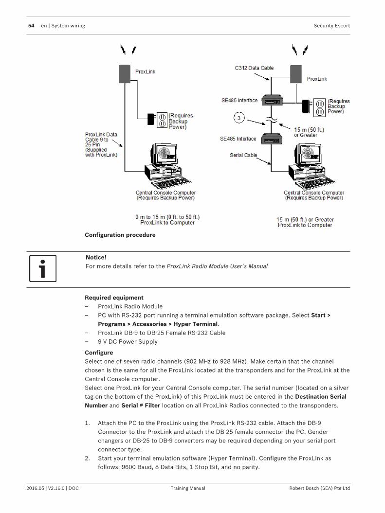
54 en | System wiring Security Escort
2016.05 | V2.16.0 | DOC Training Manual Robert Bosch (SEA) Pte Ltd
Configuration procedure
Notice!For more details refer to the ProxLink Radio Module User’s Manual
Required equipment– ProxLink Radio Module– PC with RS-232 port running a terminal emulation software package. Select Start >
Programs > Accessories > Hyper Terminal.– ProxLink DB-9 to DB-25 Female RS-232 Cable– 9 V DC Power Supply
ConfigureSelect one of seven radio channels (902 MHz to 928 MHz). Make certain that the channelchosen is the same for all the ProxLink located at the transponders and for the ProxLink at theCentral Console computer.Select one ProxLink for your Central Console computer. The serial number (located on a silvertag on the bottom of the ProxLink) of this ProxLink must be entered in the Destination SerialNumber and Serial # Filter location on all ProxLink Radios connected to the transponders.
1. Attach the PC to the ProxLink using the ProxLink RS-232 cable. Attach the DB-9Connector to the ProxLink and attach the DB-25 female connector the PC. Genderchangers or DB-25 to DB-9 converters may be required depending on your serial portconnector type.
2. Start your terminal emulation software (Hyper Terminal). Configure the ProxLink asfollows: 9600 Baud, 8 Data Bits, 1 Stop Bit, and no parity.
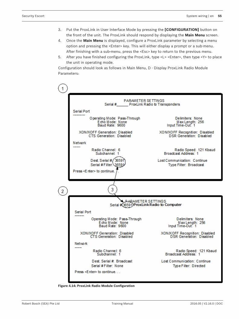
Security Escort System wiring | en 55
Robert Bosch (SEA) Pte Ltd Training Manual 2016.05 | V2.16.0 | DOC
3. Put the ProxLink in User Interface Mode by pressing the [CONFIGURATION] button onthe front of the unit. The ProxLink should respond by displaying the Main Menu screen.
4. Once the Main Menu is displayed, configure a ProxLink parameter by selecting a menuoption and pressing the <Enter> key. This will either display a prompt or a sub-menu.After finishing with a sub-menu, press the <Esc> key to return to the previous menu.
5. After you have finished configuring the ProxLink, type <L> <Enter>, then type <Y> to placethe unit in operating mode.
Configuration should look as follows in Main Menu, D - Display ProxLink Radio ModuleParameters:
Figure 4.14: ProxLink Radio Module Configuration

56 en | System wiring Security Escort
2016.05 | V2.16.0 | DOC Training Manual Robert Bosch (SEA) Pte Ltd
1 ProxLink radio module configurationfor the transponders
3 These numbers must match
2 ProxLink radio module configurationfor the central station

Security Escort Installation options | en 57
Robert Bosch (SEA) Pte Ltd Training Manual 2016.05 | V2.16.0 | DOC
5 Installation options5.1 Demo installations
When the software is used for demo purposes, it is limited to ten records in the SubscriberDatabase, one transponder in the Transponder Database and only receivers 0 through 3 onbus 0 can be defined for that transponder (no other points can be programmed for thattransponder). If these limitations are observed, the software will communicate with the singletransponder and the system can be used with full functionality for demo purposes. Refer tothe Installing the Security Escort software section of to install the software.After the software has been installed, do not run it. Double-click the HDD32.EXE file in theSecurity Escort directory (“C:\ESCORT”). This will install the driver for the software key. Thisis required even for demo installations that will not have the software key. If the HDD32.EXEinstaller is not run before the Security Escort software is run the first time, the Security Escortsoftware will stop with an error and HDD32.EXE will automatically run. The demo installationis complete at this point and you do not have to refer to the rest of this document.In demo mode, communications are allowed to one transponder even if the TransponderDatabase has more than one transponder in it for diagnostic purposes. The transponderselected in the Transponder current status or Transponder communications dialog will bethe transponder that can be communicated with. The transponder can be reselected at anytime to change the current transponder in communication. All tests, supervisions andmaintenance alarms will function normally; however only subscriber alarms that containreports from receivers 0 through 3 on bus 0 will function. If an alarm also includes otherreceivers reporting, that alarm will be ignored. Therefore, actual Security Escort operation canbe demonstrated using up to 4 receivers. Also a demo system can be used to directly connectto transponders using the actual Transponder Database from the system to perform allfunctions except subscriber alarms. This is desirable to allow a laptop to be plugged directlyinto a transponder to diagnose problems. In both of these modes the Subscriber Databasemust have five or less subscribers.
5.2 Non-network installationsIf this system is not using the network to connect master, slave and workstation computers,refer to the Security Escort software installation section of this document to install thesoftware. After the software has been installed, do not run it. Plug the software key into theUSB port on the computer and double-click the HDD32.EXE file in the Security Escortdirectory (“C:\ESCORT”). This will install the driver for the software key.If the HDD32.EXE installer is not run before the Security Escort software is run the first time,the Security Escort software will stop with an error and HDD32.EXE will automatically run. Anon-network installation is complete at this point and you do not have to refer to the rest ofthis document.
5.3 Network installationsThe Security Escort software supports a single master computer, a single slave computer(optional) and a maximum of eight workstations (limited to the number programmed in thesoftware key). The master computer normally processes the real time communications to thetransponders and controls the system. The slave computer can assume the master’s role byswitching the transponder communications to the slave computer. This system redundancyfeature is explained in further details in the System redundancy chapter of the TechnicalReference Manual. The workstation computers allow other computers to respond to alarms,perform maintenance and edit the databases.

58 en | Installation options Security Escort
2016.05 | V2.16.0 | DOC Training Manual Robert Bosch (SEA) Pte Ltd
5.4 Installing the Security Escort software
5.4.1 Software installation procedureTypically the Security Escort program is delivered on a CD-ROM.
Notice!Exit all other programs before inserting the CD-ROM.
An autorun feature should automatically start the installation program. If not, run SETUP.EXEusing one of the following methods:1. Double click the Computer icon on the desktop. Select the Compact Disc (X:), double-
click the INSTALLER directory. Double-click the SETUP.EXE icon. X is the letter of the CD-ROM drive.
2. Go to Start > Programs > Windows Explorer. In Windows Explorer, select the CompactDisc (X:) and double-click the INSTALLER directory. Double-click the SETUP.EXE icon.
3. Click Start > Run. Type “X:\INSTALLER\SETUP.EXE” in the Open textbox and click the[OK] button. X is the drive letter for the CD-ROM drive.
Once SETUP.EXE is running, the following Welcome dialog appears.
Figure 5.15: Security Escort Setup Welcome Dialog
You can click the [Cancel] button at any stage of installation to abort installation. The ExitSetup dialog will appear. Click the [Yes] button to abort installation.

Security Escort Installation options | en 59
Robert Bosch (SEA) Pte Ltd Training Manual 2016.05 | V2.16.0 | DOC
Figure 5.16: Exit Setup Dialog
Otherwise, click the [Next >] button. The License Agreement dialog appears.
Figure 5.17: License Agreement Dialog
Click the [Yes] button to accept the License Agreement. The Readme Information dialogappears.

60 en | Installation options Security Escort
2016.05 | V2.16.0 | DOC Training Manual Robert Bosch (SEA) Pte Ltd
Figure 5.18: Readme Information Dialog
Read the entire file before proceeding (use the scroll bar on the right side to see the portionnot currently displayed). Once done, click the [Next >] button. The Choose DestinationLocation dialog appears. Select the location on the hard disk drive to install the SecurityEscort program. Typically, the default location would be ideal (“C:\ESCORT”).

Security Escort Installation options | en 61
Robert Bosch (SEA) Pte Ltd Training Manual 2016.05 | V2.16.0 | DOC
Figure 5.19: Choose Destination Location Dialog
If you wishes to install the program in a different location, click the [Browse] button and theChoose Folder dialog to appears. Select the desired folder and click the [OK] button. You willreturn to the Choose Destination Folder dialog.
Figure 5.20: Choose Folder Dialog
Click the [Next >] button on the Choose Destination Folder dialog. The Setup Type dialogappears.

62 en | Installation options Security Escort
2016.05 | V2.16.0 | DOC Training Manual Robert Bosch (SEA) Pte Ltd
Figure 5.21: Setup Type Dialog
Select the type of installation you desire.– Typical – For new installations, this is the option you should choose. It guarantees that all
required components are installed and includes the installer for the software key. Usethis selection for demo installations. Do not use this selection on existing installations; itreplaces the databases and maps with the demo databases and maps.
– Compact – Only installs the application files. This selection can be used to update anexisting installation. It does not write over the databases and map files. This selectioncannot be used for new installations because it does not contain all requiredcomponents, the installer for the software key, databases, and maps.
– Custom – This selection contains all systems components, databases, and maps. You maychoose which to install.
Click the [Next >] button. The Select Program Folder dialog appears for you to place theSecurity Escort shortcuts in the selected program folder.

Security Escort Installation options | en 63
Robert Bosch (SEA) Pte Ltd Training Manual 2016.05 | V2.16.0 | DOC
Figure 5.22: Select Program Folder Dialog
We are set to install the program. Click the [Next >] button. The installation starts, displayingthe progress status.
Figure 5.23: Installation Progress Dialog
Once installation has completed, the Installation Complete dialog appears, Click the [Finish]button to finish the installation.

64 en | Installation options Security Escort
2016.05 | V2.16.0 | DOC Training Manual Robert Bosch (SEA) Pte Ltd
Figure 5.24: Installation Complete Dialog
To manually start the Security Escort program after installation, go to Start > Programs >Security Escort.In a live system, it is recommended that the Security Escort program be configured toautomatically start. To auto start the program, place a shortcut to ESC32.EXE (the SecurityEscort program, typically located in “C:\ESCORT”) in the following path:C:\ProgramData\Microsoft\Windows\Start Menu\Programs\Startup\Security Escort\
Turning on Microsoft .NET Framework featureAfter installing the Security Escort software, you need to turn on the .NET feature in order forthe software to work. Go to Start > Control Panel > Programs and Features.
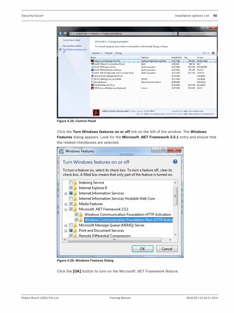
Security Escort Installation options | en 65
Robert Bosch (SEA) Pte Ltd Training Manual 2016.05 | V2.16.0 | DOC
Figure 5.25: Control Panel
Click the Turn Windows features on or off link on the left of the window. The WindowsFeatures dialog appears. Look for the Microsoft .NET Framework 3.5.1 entry and ensure thatthe related checkboxes are selected.
Figure 5.26: Windows Features Dialog
Click the [OK] button to turn on the Microsoft .NET Framework feature.

66 en | Installation options Security Escort
2016.05 | V2.16.0 | DOC Training Manual Robert Bosch (SEA) Pte Ltd
Figure 5.27: Change Progress Dialog
5.4.2 Image filesMap file generation and scalingThe Security Escort maps are standard Windows bitmap files (.BMP). MAP0.EDB is the defaultmap file, usually the ground floor in multiple map systems. The map must be saved in theSecurity Escort subdirectory (typically “C:\ESCORT”). These maps may be created fromscratch using any Windows paint program, however it is best to scan in an existing site map.Commercial copy centers usually have scanners that can handle larger drawing sizes.If an AutoCad file is available, have AutoCad export a bitmap for the best looking maps thatrequire the least work to make presentable. If the scale of the exported map is too large or toosmall, re-export the map at the corrected scale rather than scaling the map in a graphic editor.Scaling a bitmap file directly will produce a file that will require a significant amount of manualeffort to make presentable.Save the scanned image as a Windows bitmap file (.BMP) with 256 colors (8 bit color). HighColor (16 bit) or True Color (24 bit) can also be used, but the file sizes will be much largerand the maps will be slower to load and may require more system RAM. It should be scaled sothat the entire map file is at least 800 by 600 pixels (covering the entire Windows screen). TheSecurity Escort software auto scrolls the map; therefore it is not a problem if the map is largerthan the screen. The map should not be too large. There should be enough area of the map onthe screen when an alarm is shown, so there is no question where in the facility the alarm islocated from a quick review of the map. A good rule-of-thumb is 100 pixels would represent 15m (50 ft) or greater.
Multiple map filesFor a multi-story building, the maps for each floor must have the same resolution. Each mapmust be vertically aligned with all the floors above and below it. Therefore the maps will havethe same origin (0,0 = upper left corner). Typically, you would do the map for the ground floor,then make the maps for the other floors by editing copies of the ground floor map.Where transponders from multiple systems are reporting into the same computer, the map(s)for each system is separate and assigned unique map numbers, from the other maps on thatsame computer. The origin for the maps for each system is 0,0 = upper left corner. Therefore,the location of the receivers in the transponder database will only consider this system’s mapwithout respect to the maps for any other systems being handled by the same computer.The maps must be named MAP0.EDB, MAP1.EDB through MAP99.EDB. Where MAP0.EDB isthe default map file, usually the ground floor. The Security Escort software shows the defaultmap if there are no other events being processed at a given time.

Security Escort Installation options | en 67
Robert Bosch (SEA) Pte Ltd Training Manual 2016.05 | V2.16.0 | DOC
Assign the desired map number to an area or point in the Transponder Database. Assign themap for a fixed location transmitter in the Subscriber Database Advanced dialog.

68 en | Central Console, computer setup and programming Security Escort
2016.05 | V2.16.0 | DOC Training Manual Robert Bosch (SEA) Pte Ltd
6 Central Console, computer setup and programming6.1 Transponder comm port setup
Go to menu Setup > Transponder comm port setup… This dialog connects the communicationport indexes set for each transponder in the Transponder Database to the physicalcommunication ports on the computer.
Figure 6.28: Transponder Comm Port Setup dialog
COM The actual physical communication port over whichcommunications to the transponder will be carried.
Carrier Det If checked, verify that the communications port is not inuse before communicating. Only to be used on half duplexlinks where Carrier Detect indicates that the link is in use.This setting is normally unchecked and rarely used.
No CTS If checked, do not monitor the Clear to Send beforecommunicating. This setting is normally checked.
Mon Power If checked, monitor the Ring Indicator pin to indicate aremote power supply used on this communication link hasnot failed. This setting is normally unchecked.
6.2 Remote comm port setup dialogThis dialog connects the network, modem and system serial ports to the physicalcommunication ports on the computer and sets their baud rate.

Security Escort Central Console, computer setup and programming | en 69
Robert Bosch (SEA) Pte Ltd Training Manual 2016.05 | V2.16.0 | DOC
Figure 6.29: Remote Comm Port Setup Dialog
Network Port This port connects the master and slave computers of theSecurity Escort System. If this system has only a singlecomputer, this setting should be set to none.
Modem Port This port typically connects to the modem for remote accessand pager dial out. If set in the Remote Setup dialog, usethis port without a modem for direct connection to acomputer that is always on line.
System Serial 1/2 This is a general-purpose serial port. Its function is set up inthe Remote Setup dialog.
COM The actual physical communication port over which thesecommunications are carried.

70 en | Central Console, computer setup and programming Security Escort
2016.05 | V2.16.0 | DOC Training Manual Robert Bosch (SEA) Pte Ltd
Baud The speed at which characters are transmitted on this serialport. This setting must match the baud rate of the deviceconnected at the other end of this serial connection. Thissetting should always be at the highest speed that bothconnected devices have in common. Modem connections aretypically much more efficient, if the baud rate is setsignificantly faster than the modems rated speed (for a 28.8modem, set the baud rate to 57600 or 115200). The defaultsetting is 9600 baud.
CR/LF Appends carriage return and line feed characters at the endof each string transmitted (default). Only functions with thesystem serial ports (ignored on the network and modemports).
CR Only Appends a carriage return character at the end of eachstring transmitted. Only functions with the system serialports (ignored on the network and modem ports).
LF Only Appends a line feed character at the end of each stringtransmitted. Only functions with the system serial ports(ignored on the network and modem ports).
6.3 Remote setup dialogThis dialog sets up the remote access and system serial port parameters.
Figure 6.30: Slave and Remote Computer Access Parameters Dialog

Security Escort Central Console, computer setup and programming | en 71
Robert Bosch (SEA) Pte Ltd Training Manual 2016.05 | V2.16.0 | DOC
Default Master computer This computer is either the only computer in the system, oron startup, this computer defaults to the Master computer ina live Security Escort System.
Default Slave computer On startup, this computer defaults to the slave computer ina live Security Escort System.
Workstation computer This computer is used in a live Security Escort System for alloperator functions. It cannot control the system like theMaster and Slave computers.
Remote computer This computer is not in a live Security Escort System. It isused only for remote access. For this setting to be enabled,all transponder communication ports and the network portmust be set to “None”.
Emergency answer only Allows the Master computer to answer a remote access onlyafter 10 rings. If the Master does not answer, the Slaveanswers after 12 rings.
Master computer answers Allows the Master computer to answer a remote access afterthe programmed number of rings. If the Master does notanswer, the Slave will answer after the programmed numberof rings plus 2.
Slave computer answers Allows the Slave computer to answer a remote access afterthe programmed number of rings. If the Slave does notanswer, the Master answers after the programmed numberof rings plus 2. Generally, it is better to have the Mastercomputer answer remote access calls.
Direct connect port The modem port is not connected to a modem. This settingwill allow a direct connection to another computer. Thisadditional computer will not display alarms, but otherwisewill behave like a Slave computer.
Answering machine override If checked, an answering machine is connected to thisphone line. If the answering machine answers a remoteaccess call, hang up and redial. When another call isreceived within 1 min. of the last ring of a previous call, theSecurity Escort System will answer on the first ring,overriding the answering machine.
Pulse dial If checked, use pulse dial on all outgoing calls. Otherwise,tone dialing (default) is used.
Answer on ring Program the number of rings on which to answer. If there isan answering machine on this phone line, set the number ofrings to at least 2 greater than the number of rings theanswering machine answers. Also check the AnsweringMachine Override checkbox.
Dialing prefix On outgoing calls, enter the dialing prefix, if any.

72 en | Central Console, computer setup and programming Security Escort
2016.05 | V2.16.0 | DOC Training Manual Robert Bosch (SEA) Pte Ltd
Password This is the password that is used to gain remote access tothe Security Escort System. If the first 5 characters of thepassword match the remote systems password, read onlyaccess will be allowed. If the first 8 characters match, youwill be allowed to edit databases remotely (not currentlyimplemented). If all 12 characters match, you will also beallowed to change system parameters remotely.
Password verify For verification, reenter the same password as above.
Disabled If selected, this system serial port is disabled (default).
History filter output If selected, this system serial port sends out whatever itemsthat are selected in the History Filter dialog.
Video switcher control If selected, this system serial port sends out the stringsprogrammed in the Video Switcher field of the TransponderDatabase Edit dialog’s Area data. Also see Video switcherrestore field below.
Remote system control If selected, this system is controlled by another systemthrough a proprietary protocol. This setting can only be usedwhen two systems are specifically designed to worktogether.
Local Service Pages If selected, system will send service pages via the local port.
Local Security Pages If selected, system will send security pages via the localport.
All Local Pages If selected, system will send both service and security pagesvia the local port.
Video switcher restore This string is transmitted on any system serial portprogrammed for Video switcher control when all alarms arerestored. This string is transmitted to the video switcher toreset it to the default displays. Up to 20 characters can beentered. Control characters can be entered as [^][A] forcontrol A.
Modem init This is the initialization string transmitted to the modem toset it up for all communications except paging. Normally,this setting does not need to change. To allow changes tothis string, hold down the <Shift> + <Ctrl> keys when thisdialog is first opened. This string is specific to each modemmodel. The default string should work with most modems.
Modem reset This is the reset string transmitted to the modem. Normally,this setting does not need to change. To allow changes tothis string, hold down the <Shift>+ <Ctrl> keys when thisdialog is first opened. This string is specific to each modemmodel. The default string should work with most modems.
[Save] Save the changes and close the dialog window.
[Cancel] Cancel the changes and close the dialog window..

Security Escort Central Console, computer setup and programming | en 73
Robert Bosch (SEA) Pte Ltd Training Manual 2016.05 | V2.16.0 | DOC
6.4 Transponder DatabaseThe Transponder Database is established at system set-up and contains all necessaryconfiguration data for each transponder, receiver and alert unit. It describes the basicstructure of the installation, including all device names, locations, types, multiplex addresses,etc. This information is used by the Central Console to generate “Alarm” and “Test” displayson the Console and in determining which alert units are to be activated. Access to theTransponder Database is from the File menu on the main menu bar. The following paragraphsdescribe the elements of the Transponder Database dialog.

74 en | Central Console, computer setup and programming Security Escort
2016.05 | V2.16.0 | DOC Training Manual Robert Bosch (SEA) Pte Ltd
6.4.1 Transponder information sheet
TransponderNumber:
TransponderLocation:
Transformer for TransponderLocation:
Breaker PanelLocation:
BreakerNumber:
Siren/StrobeOutput To:
KeyswitchMonitoring To:
Bus #0 Locations:
Point #0:
Point #1:
Point #2:
Point #3:
Point #4:
Point #5:
Point #6:
Point #7:
Bus #1 Locations:
Point #0:
Point #1:
Point #2:
Point #3:
Point #4:
Point #5:
Point #6:
Point #7:
Bus #2 Locations:
Point #0:
Point #1:

Security Escort Central Console, computer setup and programming | en 75
Robert Bosch (SEA) Pte Ltd Training Manual 2016.05 | V2.16.0 | DOC
Point #2:
Point #3:
Point #4:
Point #5:
Point #6:
Point #7:
Bus #3 Locations:
Point #0:
Point #1:
Point #2:
Point #3:
Point #4:
Point #5:
Point #6:
Point #7:
Bus #4 Locations:
Point #0:
Point #1:
Point #2:
Point #3:
Point #4:
Point #5:
Point #6:
Point #7:
Bus #5 Locations:
Point #0:
Point #1:
Point #2:
Point #3:
Point #4:
Point #5:

76 en | Central Console, computer setup and programming Security Escort
2016.05 | V2.16.0 | DOC Training Manual Robert Bosch (SEA) Pte Ltd
Point #6:
Point #7:
Bus #6 Locations:
Point #0:
Point #1:
Point #2:
Point #3:
Point #4:
Point #5:
Point #6:
Point #7:
Bus #7 Locations:
Point #0:
Point #1:
Point #2:
Point #3:
Point #4:
Point #5:
Point #6:
Point #7:
Location of Splices:

Security Escort Central Console, computer setup and programming | en 77
Robert Bosch (SEA) Pte Ltd Training Manual 2016.05 | V2.16.0 | DOC
6.4.2 Transponder Database dialogThe Transponder Database is established at system set-up and contains all necessaryconfiguration data for each transponder, receiver and alert unit. It describes the basicstructure of the installation, including all device names, locations, types, multiplex addresses,etc. This information is used by the Central Console to generate alarm and test displays on theCentral Console and in determining which alert units are to be activated.
Figure 6.31: Find Transponder’s Database Dialog
Access the Transponder Database from the File menu on the main menu bar. The followingtable describes the elements of the Find Transponder’s Database Record dialog.
Type This field indicates the type of transponder record that you arecurrently viewing. Currently, there is only one type of transponderavailable.
Name This drop-down list contains the names of the transponders. Selectingthe name of the transponder in the drop-down list displays informationof the transponder record in the dialog window. The transpondernames are assigned during set-up and are used to indicate the physicallocation of the transponder, or the region of the protected areacovered by a particular transponder.

78 en | Central Console, computer setup and programming Security Escort
2016.05 | V2.16.0 | DOC Training Manual Robert Bosch (SEA) Pte Ltd
CreatedModifiedModify Oper
The system software automatically creates these 3 fields to the right ofthe Find Transponder’s Database Record dialog. They represent thedate the transponder was first entered into the Transponder Database,the date of the last change of any entry for this transponder, and theidentity of the operator making the last change (determined from thepassword entered to make the change).
ID This is a number assigned to the transponder at system set-up. It isused by the Central Console to identify the transponder during allcommunications between the Central Console and the transponder.The number must agree with the transponder address, which is setduring final installation using switches on the transponder circuitboard.Note: The number 0 is not allowed as a transponder address.
Radio ID This is the identification number for the radio interface unit, if thetransponder communicates to the Central Console by means of a radiolink. (This feature is currently not implemented)
Comm Mode This indicates which communication mode that the Central Console isusing to communicate with the transponder.
IP Address If the Comm Mode is “TCP IP”, this field will appear in the dialogwindow. This field indicates the IP address assigned to thetransponder.
Port No. If the Comm Mode is “TCP IP”, this field will appear in the dialogwindow. This field indicates which Central Console communicationsport will be used to communicate with this transponder.
Comm Port Index If the Comm Mode is “RS232”, this field will appear in the dialogwindow. This field indicates which Central Console communicationsport will be used to communicate with this transponder. TheTransponder Comm Port Setup dialog selects the specific physicalport that this index will refer to.
Isolate From All OtherTransponders ForLocation
When checked, this transponder is isolated from all other transpondersfor location considerations. This should be used when distanttransponders sometimes hear an alarm and throw off the alarmlocation calculation. If this checkbox is checked, it indicates that thistransponder is protecting an area that is independent of all othertransponders in the system. When an alarm is reported, and receiverson this transponder have the best reception, only the receivers on thistransponder will be considered for the location of this alarm. If anothertransponder has the best reception, then the receivers on thistransponder will be ignored for the location of this alarm.

Security Escort Central Console, computer setup and programming | en 79
Robert Bosch (SEA) Pte Ltd Training Manual 2016.05 | V2.16.0 | DOC
IgnoreCommunicationsFailure
This checkbox allows communications failures to be ignored for thistransponder. It is used during a new installation for transponders thatare not yet fully on line. During system maintenance, when atransponder is out of service for a while, it is used so that thecommunications failure messages will not flash on the screen anddistract the operator. Checking this checkbox causes the system toignore communication failure. Therefore, if communications fail withthis transponder, the area this transponder protects will not beprotected, and alarms from subscribers in that area will be missedwithout the operator’s knowledge. This checkbox should not bechecked in a live system.
[Insert New] Clicking this button displays a new Edit Transponder’s DatabaseRecord dialog window. This is used to enter a new transponder to thedatabase.
[Edit Data] Clicking this button allows the currently displayed transponder’sdatabase record to be modified.
[Kill Transponder] Clicking this button deletes the currently displayed transponder’sdatabase record. If the transponder is “killed”, its data is permanentlydeleted and cannot be recovered.
[Delete Point] Clicking this button deletes the currently displayed point from thecurrent transponder’s database record. If the point is deleted, its datais permanently deleted and cannot be recovered.
[Copy] Clicking this button copies the currently displayed transponder’sdatabase record into a new transponder record. This allows similarlyconfigured transponders to be programmed once then copied into anew record.Note: It is not possible to edit the Transponder ID itself. If thisshould be necessary, the [Copy] button can be used to produceanother Transponder Database entry duplicating the first, but withthe Transponder ID blank. The new Transponder ID can be entered,the new data saved by using the [Save] button, and the oldtransponder entry can be deleted using the [Kill Transponder]button.
[Print] Clicking this button prints the currently displayed transponder’sdatabase record.
[Beginning] Clicking this button changes the currently displayed transponder to thefirst transponder in the database.
[Previous] Clicking this button changes the currently displayed transponder to theprevious transponder in the database.
[Next] Clicking this button changes the currently displayed transponder to thenext transponder in the database.
[End of File] Clicking this button changes the currently displayed transponder to thelast transponder in the database.

80 en | Central Console, computer setup and programming Security Escort
2016.05 | V2.16.0 | DOC Training Manual Robert Bosch (SEA) Pte Ltd
MUX Point DataThe lower section of the Find Transponder’s Database Record dialog window providesinformation on the devices controlled by the selected transponder record.Two digits represent each receiver or alert unit address. The first is the number of themultiplex bus on which the device is mounted (0 to 7) and the second is the multiplex pointaddress assigned to the particular device. On each of the eight multiplex busses, up to 8devices may be installed, but each device must be assigned a unique multiplex point address(0 to 7). More than one device can have a particular multiplex point address, but only ondifferent busses. The multiplex point addresses are assigned by switch settings on the device(receiver or alert unit) circuit boards. These multiplex point address settings are also a part ofthe Transponder Database. The multiplex address shown in the Transponder Database andthe multiplex address set on the device circuit board must agree. The Transponder Setupdialog is used to verify multiplex address settings.
Notice!It is a good idea to create an entry in the Transponder Database for each transponder in thesystem before entering the data for each device, so that all transponders appear in the drop-down menus.
6.4.3 Creating a new transponder entryCreating and modifying the Transponder Database requires special authority levels usuallyassigned only to the installing company’s personnel. Clicking the [Insert New] button opens anew Transponder Database dialog window.The System Design Layout Sheets prepared in advance by the installation manager shouldcontain the necessary information for assigning the Transponder Name and ID, the CommPort or Radio ID, as well as the names and multiplex addresses for all receivers and alert unitsconnected to each transponder. The layout sheets will also contain the text to be used toindicate the receiver locations and will designate the alert units to be driven by each receiver.

Security Escort Central Console, computer setup and programming | en 81
Robert Bosch (SEA) Pte Ltd Training Manual 2016.05 | V2.16.0 | DOC
Figure 6.32: Blank Dialog Resulting from Selection of [Insert New] Button
The new elements of the Edit Transponder’s Database Record dialog.
Trouble Type Text This is the text that will be shown in the trouble dialog when theremote key input on the transponder goes active (shorted).
Trouble Tamper Text This is the text that will be shown in the trouble dialog when theremote key input on the transponder goes into trouble (open).
Trouble ResponseText
This is the text that will be shown in the trouble dialog as the responsetest. The actions the responding individual should take.
Show Points If selected, the lower section of the Transponder Database dialog willshow the point’s (receiver, virtual receiver or alert unit’s) databasevalues.
Show Areas If selected, the lower section of the Transponder Database dialog willshow the alarm area’s database values.
6.4.4 Modifying existing transponder entryIf the transponder is already defined in the Transponder Database, the [Edit Data] button isused to complete or modify the data. The data that can be modified is the same when creatinga new transponder entry (see Creating a new transponder entry, page 80).

82 en | Central Console, computer setup and programming Security Escort
2016.05 | V2.16.0 | DOC Training Manual Robert Bosch (SEA) Pte Ltd
6.4.5 Setting receiver parametersCreate or modify the receivers of the transponder using the features of the Point or AreaData. For configuring Area Data, refer to the Alarm area setup section. The sections belowexplain how to configure the receiver points for the transponder.
Entering point numberEach receiver and alert unit connected to the transponder has a unique Point Numberassigned during the system design process. This Point Number ranges from 0 to 63, andcorresponds to a specific bus number and point multiplex address number. The multiplexaddress, set by means of switches on the device (receiver or alert unit) itself, mustcorrespond with the Point Number assigned in the Transponder Database.There is a one-to-one relationship between the Point Number and the combination ofMultiplex Point Address / Bus Number pair. For example, a device programmed withMultiplex Point Address location 3 on Bus Number 5 would correspond to the Point Number29.Clicking the [?] button to the right of the Point Number text box opens a dialog windowdisplaying the Point Number in a table. Clicking on any Point Number in the tableautomatically closes this window and fills the number in the Point Number field on theTransponder Database dialog. The Bus number and Point address are also changed to reflectthe selection.
Figure 6.33: Select Point Dialog with "All Points" Selected
This table provides a quick way to select a particular device without having to translatebetween the two numbering (Bus Number/Point Address) systems. The three buttons at thebottom of this dialog allow the user to display:

Security Escort Central Console, computer setup and programming | en 83
Robert Bosch (SEA) Pte Ltd Training Manual 2016.05 | V2.16.0 | DOC
1. all possible device numbers ([All Points] button) regardless that the particulartransponder has a device assigned to the number,
2. only locations populated by receivers ([Receivers Only] button), or3. only locations populated by alert units ([Alerts Only] button).
Figure 6.34: Select Point Dialog with "Receivers Only" Selected
Alternatively, the [+], [-], [Bus +] and [Bus –] buttons, just below the Point Number and PointType, allow the user to quickly advance the device selection by one location, either one Pointlocation ([+] or [-]) or one Bus number ([Bus +] or [Bus -]). This is useful when a task requiresproceeding from device to device, as during system setup or check out. The [?] button is usedto display all devices to facilitate quick selection of a particular device. It is most useful whendiagnosing a problem with a particular device.
Selecting the Point TypeThe Point Type drop-down list indicates the type of device at the location currently selected inthe Point Number field. Once the Point Number text box contains the proper value, thedevice type can be selected from the Point Type drop-down list.
Figure 6.35: Drop-Down List for Selection of Point Type
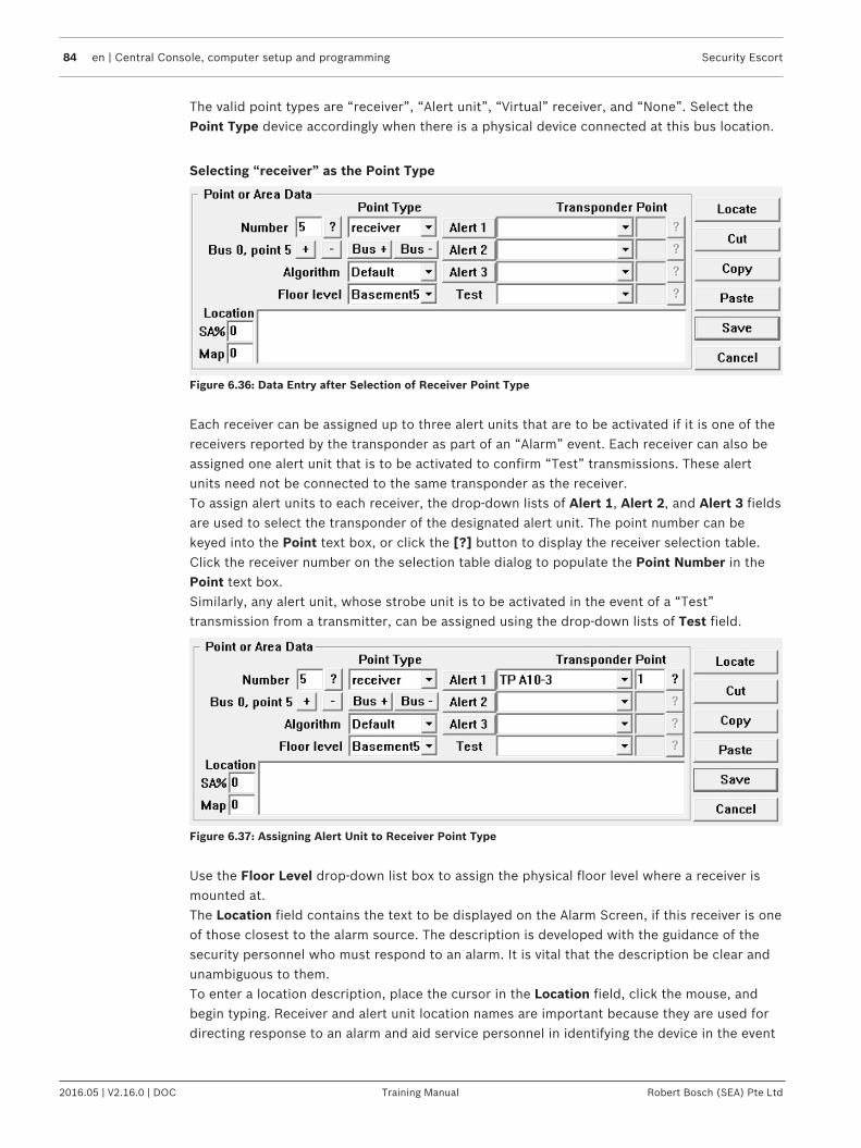
84 en | Central Console, computer setup and programming Security Escort
2016.05 | V2.16.0 | DOC Training Manual Robert Bosch (SEA) Pte Ltd
The valid point types are “receiver”, “Alert unit”, “Virtual” receiver, and “None”. Select thePoint Type device accordingly when there is a physical device connected at this bus location.
Selecting “receiver” as the Point Type
Figure 6.36: Data Entry after Selection of Receiver Point Type
Each receiver can be assigned up to three alert units that are to be activated if it is one of thereceivers reported by the transponder as part of an “Alarm” event. Each receiver can also beassigned one alert unit that is to be activated to confirm “Test” transmissions. These alertunits need not be connected to the same transponder as the receiver.To assign alert units to each receiver, the drop-down lists of Alert 1, Alert 2, and Alert 3 fieldsare used to select the transponder of the designated alert unit. The point number can bekeyed into the Point text box, or click the [?] button to display the receiver selection table.Click the receiver number on the selection table dialog to populate the Point Number in thePoint text box.Similarly, any alert unit, whose strobe unit is to be activated in the event of a “Test”transmission from a transmitter, can be assigned using the drop-down lists of Test field.
Figure 6.37: Assigning Alert Unit to Receiver Point Type
Use the Floor Level drop-down list box to assign the physical floor level where a receiver ismounted at.The Location field contains the text to be displayed on the Alarm Screen, if this receiver is oneof those closest to the alarm source. The description is developed with the guidance of thesecurity personnel who must respond to an alarm. It is vital that the description be clear andunambiguous to them.To enter a location description, place the cursor in the Location field, click the mouse, andbegin typing. Receiver and alert unit location names are important because they are used fordirecting response to an alarm and aid service personnel in identifying the device in the event

Security Escort Central Console, computer setup and programming | en 85
Robert Bosch (SEA) Pte Ltd Training Manual 2016.05 | V2.16.0 | DOC
of a problem. The Problem Reports displayed on the central console and printed by thehardcopy printer contain the device location descriptions that are entered in the Locationfield.The Map field defines which bitmap to display for this receiver or area when an alarm isclosest to it. The default map is 0, which corresponds to bitmap MAP0.EDB stored in theSecurity Escort sub-directory. Map 1 is MAP1.EDB. There can be 100 maps per Security EscortSystem (0 to 99).
Selecting “Virtual” receiver as the Point TypeUse the “Virtual” selection when there is no physical device connected at this bus location.Starting with version 2.03 of the Security Escort software, you can add “Virtual” receivers in the Transponder Database. A “Virtual” receiver is added at one of the 64points allowed per transponder. However, there is no physical hardware used.
Figure 6.38: Data Entry after Selection of Virtual Receiver Point Type
The “Virtual” receiver is intended to compensate in cases where there is a receiver imbalance.For example, if a building with a dense population of receivers is adjacent to a fence with fewreceivers and an alarm occurs between them; the alarm location may pull towards thebuilding. The “Virtual” receiver references two other physical receivers that must be on thesame transponder. Only if both of the referenced receivers receive an alarm transmission, thenthe “Virtual” receiver will be added to the alarm as if was a physical receiver that heard thealarm at the average receive level of the 2 referenced receivers.Both the referenced receivers are configured in the Receiver 1 and Receiver 2 fields. Theseare the two receivers, on the same transponder, that a “Virtual” receiver assumes the averageof. Both receivers must receive a signal before the “Virtual” receiver reports it also received asignal that is the average of the other two receivers signals. The location algorithm andsensitivity adjust work the same for a “Virtual” receiver as for a physical receiver. Enter thereceiver’s Point Number in the fields, or click the [?] button to select the receiver accordingly.The “Virtual” receiver’s location and sensitivity may be adjusted the same as a physicalreceiver. After a “Virtual” receiver is added, verify the surrounding areas to make sure theyhave not been adversely affected. In no event should a “Virtual” receiver be utilized as a costsavings measure to avoid the installation of an actual receiver.For explanations of Floor level, Location and Map fields, please refer to section Selecting“receiver” as the Point Type.
Selecting the algorithmStarting with version 2.03 of the Security Escort software, there are 5 different locationalgorithms that can be selected on an individual receiver basis in the Transponder Database.“Classic” (original Security Escort algorithm), “Linear”, “Low” pull, “Medium” pull and

86 en | Central Console, computer setup and programming Security Escort
2016.05 | V2.16.0 | DOC Training Manual Robert Bosch (SEA) Pte Ltd
“Strong” pull. By default when a receiver is set for outside or tunnel, it will use the “Linear”algorithm and all other receivers will use the “Low” pull algorithm. The receiver that hears thealarm transmission the strongest will determine the algorithm used for this alarm.
Figure 6.39: Location algorithm selection
Changing the algorithm setting for a receiver only affects the location when the alarm is closeto this receiver and it hears the alarm the strongest. The stronger the pull the more the alarmwill be pulled towards the receiver, with linear having no extra pull.The algorithm setting will only be available if the Enable algorithm tweaks checkbox ischecked in the System Preferences dialog. Also starting with version 2.03 of the SecurityEscort software, individual receiver sensitivity can be set in the Transponder Database.Receivers can be adjusted from 50% to 149% of their normal sensitivity using the SA%setting.
Adjusting the Sensitivity (SA%)Security Escort software version 2.03 and higher allow individual receiver sensitivity to be setin the Transponder Database. Receivers can be adjusted from 50% to 149% of their normalsensitivity. No physical receiver changes or upgrades are required. This setting should only bechanged if there are known location accuracy problems in the area of this receiver. Settings of50 to 99 desensitize the receiver to 50% to 99% of the actual received signal strength.Settings of 1 to 49 increase the sensitivity to 101% to 149% of the actual received signalstrength. Try changing the sensitivity of receivers one at a time while testing the alarmlocation response. For example, if alarms are being pulled towards a particular receiver, lowerits sensitivity in 10% increments and retest. If the area can be corrected using this method,verify the surrounding areas to make sure they have not been adversely affected. Generally, itis better if the correction is done in small steps while verifying the adjacent areas, rather thantrying to correct the entire error in one step.The SA% option is only available if the Enable algorithm tweaks checkbox is checked in theSystem Preferences dialog. Also in the Transponder Database, the Algorithm dropdown listallows selection of “Default”, “Classic”, “Linear”, “Low”, “Medium” or “Strong” pull locationalgorithms for each transmitter. The point reporting the best reception level determines theactual algorithm used for the location on any event. If programmed as “Default”, the algorithmused is “Linear” for points programmed as outdoor or tunnel. All other points use “Low”. If thepoint reporting the best reception level is not programmed for the “Default” algorithm, thelocation calculation uses the algorithm programmed.
Other miscellaneous command buttonsThe functions of the other miscellaneous command buttons are as of below:
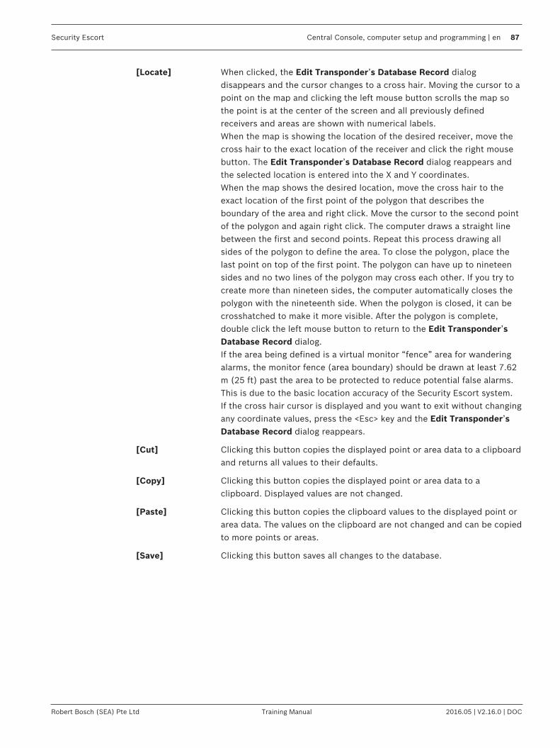
Security Escort Central Console, computer setup and programming | en 87
Robert Bosch (SEA) Pte Ltd Training Manual 2016.05 | V2.16.0 | DOC
[Locate] When clicked, the Edit Transponder’s Database Record dialogdisappears and the cursor changes to a cross hair. Moving the cursor to apoint on the map and clicking the left mouse button scrolls the map sothe point is at the center of the screen and all previously definedreceivers and areas are shown with numerical labels.When the map is showing the location of the desired receiver, move thecross hair to the exact location of the receiver and click the right mousebutton. The Edit Transponder’s Database Record dialog reappears andthe selected location is entered into the X and Y coordinates.When the map shows the desired location, move the cross hair to theexact location of the first point of the polygon that describes theboundary of the area and right click. Move the cursor to the second pointof the polygon and again right click. The computer draws a straight linebetween the first and second points. Repeat this process drawing allsides of the polygon to define the area. To close the polygon, place thelast point on top of the first point. The polygon can have up to nineteensides and no two lines of the polygon may cross each other. If you try tocreate more than nineteen sides, the computer automatically closes thepolygon with the nineteenth side. When the polygon is closed, it can becrosshatched to make it more visible. After the polygon is complete,double click the left mouse button to return to the Edit Transponder’sDatabase Record dialog.If the area being defined is a virtual monitor “fence” area for wanderingalarms, the monitor fence (area boundary) should be drawn at least 7.62m (25 ft) past the area to be protected to reduce potential false alarms.This is due to the basic location accuracy of the Security Escort system.If the cross hair cursor is displayed and you want to exit without changingany coordinate values, press the <Esc> key and the Edit Transponder’sDatabase Record dialog reappears.
[Cut] Clicking this button copies the displayed point or area data to a clipboardand returns all values to their defaults.
[Copy] Clicking this button copies the displayed point or area data to aclipboard. Displayed values are not changed.
[Paste] Clicking this button copies the clipboard values to the displayed point orarea data. The values on the clipboard are not changed and can be copiedto more points or areas.
[Save] Clicking this button saves all changes to the database.

88 en | Central Console, computer setup and programming Security Escort
2016.05 | V2.16.0 | DOC Training Manual Robert Bosch (SEA) Pte Ltd
[Cancel] Clicking this button closes the dialog. If changes were made, the dialogbelow gives you another chance to save the changes by clicking the [Yes]button.
6.4.6 Alarm area setupIn the Transponder Database under the File menu, select the transponder where the alarmarea is to be programmed in. Click the [Edit Data] button, followed by Show areas radiobutton and select the desired area.
Figure 6.40: Transponder Area Edit Dialog

Security Escort Central Console, computer setup and programming | en 89
Robert Bosch (SEA) Pte Ltd Training Manual 2016.05 | V2.16.0 | DOC
Number Each transponder can have up to 80 areas defined in them (prior to version2.04 of the software, only 40 areas could be defined). This area number rangefrom 0 to 79. Use the [Locate] button to define the area graphically on themap.
Video Switcher Selects a system serial port that is programmed in the Remote Setup dialog.The purpose is to display the area, where the alarm is most likely located, onthe CCTV monitors near the Central Console. The string would activate amacro in the video switcher that selects the appropriate camera, and controlsany required zoom and tilt actions. Up to 40 characters may be entered.Control characters may be entered as "^A" for control A.
Pager Group This Pager Group field may be programmed with a pager group that is pagedif the alarm location is determined to be in this area. This pager group will bethe first group paged to allow quick response by those individuals chargedwith responding to an alarm in this area. Each area may be assigned a pagergroup that can be the same or different from other alarm areas.The default alarm Pager group defined in the Pager Setup dialog will also bepaged after the pager group is assigned to an area. If a pager group is notassigned to an area or the alarm location is not within a defined area, thenonly the default pager group will be paged.
Floor Determines the floor number that this area is defined for. The areas on floorsabove and below this one may be defined differently. In order for an area tobe selected when an alarm is received, the location determined by theCentral Console must be located within the defined area, and it must belocated on the designated floor.
Virtual FenceArea
If this checkbox is checked, this area will not be used for normal alarm arealocation. This area will only be used to define a “Virtual” fence. Specifictransmitters in the Subscriber Database can reference this transponder andarea. When they reference this area, and the system locates the transmitterposition outside the area, a wandering (“Virtual” fence) alarm will begenerated. This alerts the operator and shows the position of the transmitter.
6.5 Powering up the system for the first timeAfter the system is configured, the system may be powered up. If the system uses multipletransponders, it is easier and more effective to power up the transponders one at a time. Bydoing this, troubleshooting time can be significantly reduced, especially for transponders todetermine if there is a wiring problem in the SE485 bus between transponders.
Notice!It is very important that twisted pair wiring is used for the SE485 bus. The Tx+ and Tx- wiresmust be twisted together and the Rx+ and Rx- wires must be twisted together.

90 en | Central Console, computer setup and programming Security Escort
2016.05 | V2.16.0 | DOC Training Manual Robert Bosch (SEA) Pte Ltd
1. Turn on the power switch on the first transponder. In the Security Escort Central Consolesoftware, select the menu Setup > Transponder current status. The following dialogwindow appears:
2. Select the desired transponder. Click the [Reset Transponder Troubles] button. If theselected transponder is communicating with the Central Console, the number “1” willappear in the Total Outgoing Messages and Successful Incoming Messages fields. Thetransponder is now communicating with the Central Console software. If the number “1”only appeared in the Total Outgoing Messages field, there is a wiring problem betweenthe Central Console and the transponder (refer to Troubleshooting reference, page 97 ofthis manual and locate the problem).
3. Check the Stress test checkbox. This tests the communications reliability by causing theCentral Console software to send a continuous stream of messages to the selectedtransponder. The values in the Successful Incoming Messages and Total OutgoingMessages fields should start counting up rapidly, with few if any errors. It is normal tohave slightly fewer Total Outgoing Messages than Successful Incoming Messages. If theerrors are greater than 1% of the number of messages, then there is a problem thatshould be corrected (refer to Troubleshooting transponders, points, receivers, and alertunits, page 93 of this manual and locate the problem).
4. After the stress test runs, any current troubles are displayed in the box in theTransponder current status window. Correct any troubles at this time.

Security Escort Central Console, computer setup and programming | en 91
Robert Bosch (SEA) Pte Ltd Training Manual 2016.05 | V2.16.0 | DOC
5. From the Setup menu, select Transponder communications. The following dialog windowappears:
6. Select the desired transponder. Then click the [Not Responding Map] button. A gridshould appear on the screen. The columns of the grid represent multiplex buses from 0 to7 (left to right). The rows of the grid are points on the multiplex buses from 0 to 7(bottom to top). At this point there will be a zero (0) on the grid location for eachreceiver connected to the selected transponder. A zero means that a receiver isprogrammed in the database and is communicating with the transponder. If the number 1appears at a point location, the receiver is programmed in the database but notcommunicating to the transponder (refer to Troubleshooting reference, page 97 of thismanual and locate the problem). If an X appears on the grid at a point location thereceiver is communicating to the transponder but is not programmed in the database.Reprogram this point in the database or rotate the receiver ID rotary switch on thereceiver’s circuit board to the proper point number. (Y = Alert unit is in the database butnot responding to the system; N = Alert unit is in the database and is responding to the

92 en | Central Console, computer setup and programming Security Escort
2016.05 | V2.16.0 | DOC Training Manual Robert Bosch (SEA) Pte Ltd
system.)
7. When the transponder is communicating with all the receivers and the ReceiversDatabase records are correct, back up the database files to the hard drive, if any changeswere made. Select the menu Utilities > Backup, and make sure it is pointed to the harddrive. Click the [Backup] button. It is also wise to back up each database to a USB flashdrive. Mark the USB flash drive label with the databases and backup date.
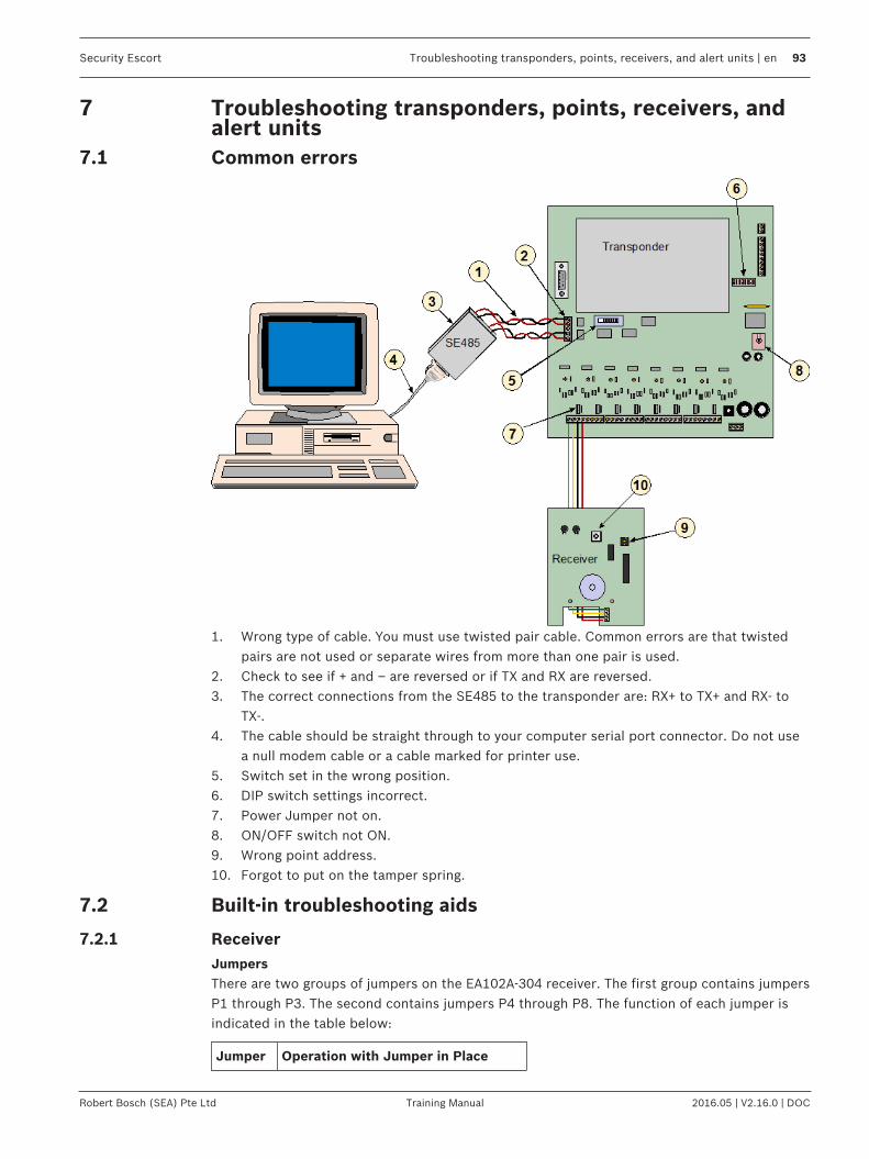
Security Escort Troubleshooting transponders, points, receivers, and alert units | en 93
Robert Bosch (SEA) Pte Ltd Training Manual 2016.05 | V2.16.0 | DOC
7 Troubleshooting transponders, points, receivers, andalert units
7.1 Common errors
1. Wrong type of cable. You must use twisted pair cable. Common errors are that twistedpairs are not used or separate wires from more than one pair is used.
2. Check to see if + and – are reversed or if TX and RX are reversed.3. The correct connections from the SE485 to the transponder are: RX+ to TX+ and RX- to
TX-.4. The cable should be straight through to your computer serial port connector. Do not use
a null modem cable or a cable marked for printer use.5. Switch set in the wrong position.6. DIP switch settings incorrect.7. Power Jumper not on.8. ON/OFF switch not ON.9. Wrong point address.10. Forgot to put on the tamper spring.
7.2 Built-in troubleshooting aids
7.2.1 ReceiverJumpersThere are two groups of jumpers on the EA102A-304 receiver. The first group contains jumpersP1 through P3. The second contains jumpers P4 through P8. The function of each jumper isindicated in the table below:
Jumper Operation with Jumper in Place

94 en | Troubleshooting transponders, points, receivers, and alert units Security Escort
2016.05 | V2.16.0 | DOC Training Manual Robert Bosch (SEA) Pte Ltd
P1* Sounder is enabled
P2* Green LED is enabled
P3* Red LED is enabled
P4** Test mode is enabled
P5** Receiver spacing mode is enabled
P6** Left antenna is disabled
P7** Right antenna is disabled
P8 Do not place a jumper across thesepins
Notice!* Remove jumpers P1, P2, and P3 when installed in an outdoor enclosure.** Remove jumpers P4, P5, P6, and P7 for normal operation.
Test modeEach EA102A receiver provides a test mode that may be used to check the unit’s functionality.The module goes into test mode when jumper P4 is in place (jumper P5 removed). In thismode, all test and alarm receptions will be sounded.
Notice!The sounder and LEDs (jumpers P1, P2, and P3) must also be enabled to operate the testmode.
Each receiver should be tested using the following method (test only one receiver at a time):1. Enable the test mode by placing the jumper P4 across both pins (jumper P5 removed).
– The red LED will turn ON and stay ON during the test. This indicates that power isproperly connected and the receiver is in test mode. If the red LED does not comeon check the POWER+ and POWER- wiring to this receiver. Also verify thecorresponding transponder bus enable jumper is in place and the transponder is onand powered.
– The green LED will flicker if the receiver is connected to a working transponder. Ifthe green LED is not flickering verify the BUS+ and BUS – wiring to this receiver(note, this is a rapid flickering).
– There will be no data transmitted to the Central Console. Therefore, the CentralConsole will report this receiver as “Not responding” while the receiver is in testmode.
2. Activate the transmitter from different locations near the receiver.– The red and green LEDs will respond to a received transmission.– If the receiver detected all the packets from the transmission, the sounder will beep
three times.– If the receiver detected the transmission, but some of the packets were missing, it
will beep once. This could indicate that the signal is not sufficient from this location.
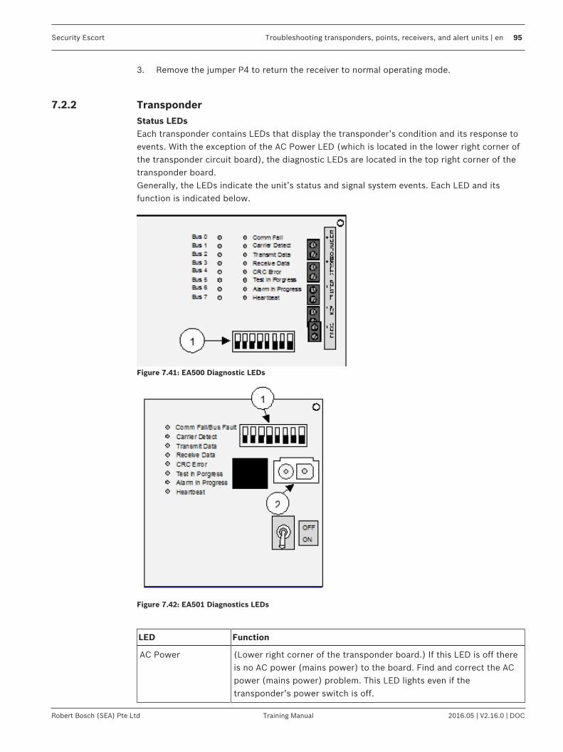
Security Escort Troubleshooting transponders, points, receivers, and alert units | en 95
Robert Bosch (SEA) Pte Ltd Training Manual 2016.05 | V2.16.0 | DOC
3. Remove the jumper P4 to return the receiver to normal operating mode.
7.2.2 TransponderStatus LEDsEach transponder contains LEDs that display the transponder’s condition and its response toevents. With the exception of the AC Power LED (which is located in the lower right corner ofthe transponder circuit board), the diagnostic LEDs are located in the top right corner of thetransponder board.Generally, the LEDs indicate the unit’s status and signal system events. Each LED and itsfunction is indicated below.
Figure 7.41: EA500 Diagnostic LEDs
Figure 7.42: EA501 Diagnostics LEDs
LED Function
AC Power (Lower right corner of the transponder board.) If this LED is off thereis no AC power (mains power) to the board. Find and correct the ACpower (mains power) problem. This LED lights even if thetransponder’s power switch is off.

96 en | Troubleshooting transponders, points, receivers, and alert units Security Escort
2016.05 | V2.16.0 | DOC Training Manual Robert Bosch (SEA) Pte Ltd
LED Function
Comm Fail This LED lights if the transponder is in a communications failurecondition with the Central Console. It automatically goes out whencommunications are restored.
Carrier Detect This LED is operational only for SE485 communications. It flashesevery time any transponder (including this transponder) on thisSE485 bus sends a message to the Central Console. It is used tomonitor overall communications from the transponders to the CentralConsole. If the Carrier Detect LED stays on, there is a problem withone of the transponders on this bus, or the wiring, that must becorrected before normal communications are restored.
Transmit Data This LED flashes every time this transponder sends a message to theCentral Console, whether or not the Central Console receives it. Ifthis transponder initiated the communications and the CentralConsole correctly receives the message, the Receive Data LED shouldflash soon after indicating the central station successfully returned anacknowledgement.
Receive Data This LED flashes every time this transponder successfully receives amessage addressed to it from the Central Console. If the CentralConsole initiated the communications, the Transmit Data LED shouldflash soon after indicating that this transponder is returning anacknowledgement.
CRC Error This LED comes on every time a message is received containingerrors, whether or not it was addressed to this transponder. The LEDremains on until the next message addressed to this transponder isreceived without error. The most common cause for this LED to turnon is wiring errors. Verify that the SE485 TX+ and TX- are on a twistedpair. Also verify that the SE485 RX+ and RX - are on a twisted pair.
Test in Progress This LED comes on whenever a transmitter is tested. It stays on forthe duration of the test display, typically 5-sec. to 10-sec., then it goesout. If a test is received while another test is in progress, the Test inProgress LED goes out momentarily then comes on for the duration ofthe second test.
Alarm in Progress This LED comes on whenever a transmitter is in alarm. It stays on forthe duration of the transponder’s involvement in the alarm, then itgoes out. If an alarm is received while another alarm is in progress,the Alarm in Progress LED goes out momentarily then stays on as longas any alarms are active in the transponder. An alarm that causes thereceiver sounders to stay on keeps the Alarm in Progress LED on.Silent alarms or alarms from unauthorized transmitters cause theAlarm in Progress LED to turn on and to go out when the CentralConsole acknowledges the alarm message. This also occurs for everyalarm follower message. A maintenance alarm message causes theAlarm in Progress LED to come on for 5-sec. to 10-sec. then toautomatically go off.

Security Escort Troubleshooting transponders, points, receivers, and alert units | en 97
Robert Bosch (SEA) Pte Ltd Training Manual 2016.05 | V2.16.0 | DOC
LED Function
Heartbeat Flashes at a fixed rate to indicate the microprocessor is operatingnormally. If this LED stops flashing, the transponder is notoperational. Turn it off for 5-sec. using the power switch. Then turn itback on. If the LED does not flash, the transponder should have theAC power and the back-up battery disconnected. Wait a few secondsand then reconnect. If the LED does not flash at this time, thetransponder should be replaced.
Bus 0 to 7 Normally these LEDs are on if the corresponding Bus Enable jumper isin place, and is off if the jumper is removed. If the bus is enabled, theLED flashes off and comes back on every time a receiver or alertmodule on that bus communicates with the transponder. A Bus LEDflashes at the rate of the heartbeat LED if there is any kind of busfault (data to ground, data to power, and bus power to ground) onthat bus. On the EA501, the communications failure LED flashes atthis rate since there is no Bus LED. A Bus LED flashes at half the rateof the Heartbeat LED if there are no points reporting on that bus(open connection). On the EA501 the communications failure LEDflashes at this rate. If a Bus LED is flashing for a bus that is notenabled, it can be reset in the Central Console’s Transponder DataView dialog by selecting this transponder and clicking the [Clear EE]button. There are two special displays on the Bus LEDs. All the BusLEDs go out, and for 2-sec. a single LED is on. Walking down thedisplay from bus 0 to bus 7 indicates that a battery test is in progress.Usually after the tamper switch is released, the bus LEDs countrapidly to indicate the EEPROM memory is being updated.
Verifying communicationsTo verify communications, press the test feature on any transmitter. The Test in Progress LEDcomes on. If it did not come on, the receivers are not communicating with the transponder.About a second after the Test in Progress LED comes on, the Transmit Data LED flashes(indicating the transponder is sending the test message to the Central Console). Less than asecond later the Receive Data LED flashes (indicating the Central Console returned anacknowledgement).Toggling the transponder’s tamper switch on/off causes the Transmit Data LED to flash(indicating that the transponder is sending the tamper message to the Central Console). Lessthan a second later the Receive Data LED flashes (indicating the Central Console returns anacknowledgement).
7.3 Troubleshooting reference
7.3.1 Transponder communication with SE485 bus

98 en | Troubleshooting transponders, points, receivers, and alert units Security Escort
2016.05 | V2.16.0 | DOC Training Manual Robert Bosch (SEA) Pte Ltd
Symptoms Probable Cause Possible Solutions
All transponders on one busin communications failure
Power to SE485. Check 9 V DC adapter forproper voltage. Red PowerLED should be ON (onSE485).
Wire between SE485 andtransponder incorrectlyinstalled.
Check to make sure transmitfrom transponder goes toreceive of SE485 and receivefrom transponder goes totransmit on SE485 (RX+ to TX+, RX- to TX-).
Open, short, or groundedcable from SE485 to firstsplice or transponder.
Use VOM to test cable forshort, open or ground. Repairor replace cable. Also checkfor + - pair reversed.
Wrong cable between SE485and computer.
Cable should be a straightthrough cable to yourcomputer serial portconnection. Do not use nullmodem cable or cablemarked for printer.
Bad SE485 Module. Replace SE485 Module.
Using third party RS-485interface.
Due to changes made fortransient protection,transformer isolation, and linkbusy detection, these signalsare not compatible with thirdparty RS-485 Interfaces.Replace with SE485
High communications errorcount.
Wire between SE485 andtransponder incorrectlyinstalled.
Check to make sure transmitfrom transponder goes toreceive of SE485 and receivefrom transponder goes totransmit on SE485 (RX+ to TX+, RX- to TX-).
Wrong wire type. Wire type must be twistedpair.

Security Escort Troubleshooting transponders, points, receivers, and alert units | en 99
Robert Bosch (SEA) Pte Ltd Training Manual 2016.05 | V2.16.0 | DOC
Symptoms Probable Cause Possible Solutions
Single transponder incommunication failure.
Transponder not on. Check power switch.
Wrong transponder address. Check DIP switch setting ontransponder to correspondwith your transponder database setting.
RS-232/SE485 switchposition.
Check slide switch ontransponder to make sure it isin the SE485 position.
SE485 wiring on transponder. Check to make sure transmitfrom transponder goes toreceive of SE485 and receivefrom transponder goes totransmit on SE485 (RX+ to TX+, RX- to TX-).
Close lightning hit. Power down transponder andrestart. If this does not workreplace transponder.
Bad transponder. Replace transponder.
Tab. 7.4: Transponder communications with SE485 bus
7.3.2 Transponder communication with ProxLink

100 en | Troubleshooting transponders, points, receivers, and alert units Security Escort
2016.05 | V2.16.0 | DOC Training Manual Robert Bosch (SEA) Pte Ltd
Symptoms Probable Cause Possible Solutions
Communication failures fromall transponders.
Loss of power. Check power to ProxLinkfrom Central Console. Also, ifusing SE485, check power toSE485 module.
Cable from ProxLink tocomputer.
Must use 25 to 9 pin cablesupplied from Proxim.
ProxLink Radio Module mightbe in Programming Mode.
Unplug power to ProxLinkand plug back in to re-startProxLink.
SE485 Module. Check wiring between SE485and computer, and SE485 atProxLink Radio Module.Transmit should be going toreceive and receive should begoing to transmit (RX+ to TX+,RX- to TX-).
Cable from SE485. Cable from SE485 tocomputer must be straightthrough 25 pin to 25 pin or 25pin to 9 pin depending onyour serial port on the backof the computer. Do not usecable labeled for printer ornull modem cable. Replacecable if bad. Check cablebetween SE485 and ProxLinkRadio Module. Replace if bad.
ProxLink Radio Module. Check programming forCentral Console ProxLinkRadio Module to be sure it iscorrect. If everything elsechecks OK, replace ProxLink..

Security Escort Troubleshooting transponders, points, receivers, and alert units | en 101
Robert Bosch (SEA) Pte Ltd Training Manual 2016.05 | V2.16.0 | DOC
Symptoms Probable Cause Possible Solutions
One transponder incommunication fail onProxLink Radio Module link.
Transponder. 1. Check slide switch ontransponder to makesure it is in the RS-232position.
2. Check DIP switchaddress for transponderto be sure it correspondswith TransponderDatabase.
Cable from ProxLink RadioModule to transponder.
Replace cable.
ProxLink Radio Module. 3. Check power toProxLink. Make sureradio power LED is lit.
4. Check antennaconnection to ProxLinkRadio Module.
5. Check programming forProxLink Radio Module.
6. Radio out of range or notin line of sight of centralconsole antenna.
7. Ice on antenna.8. If antenna is remote from
ProxLink, use RG8Ucable to prevent dB loss.
9. Replace ProxLink RadioModule.
SE485. 10. Check power to ProxLinkto SE485.
11. Make sure slide switchon transponder is set forSE485.
12. Check wiring fromtransponder to SE485(RX+ to TX+, RX- to TX-).Make sure transmit goesto receive and receivegoes to transmit.
13. Replace SE485 Module.
Tab. 7.5: Transponder communication with ProxLink
7.3.3 Transponder communication with Moxa/Lantronix device

102 en | Troubleshooting transponders, points, receivers, and alert units Security Escort
2016.05 | V2.16.0 | DOC Training Manual Robert Bosch (SEA) Pte Ltd
Symptoms Probable Cause Possible Solutions
Communication failures fromall transponders.
Loss of power. Check power to Moxa/Lantronix device.
Cable from Moxa device totransponder.
Must use standard 9 pinfemale to 9 pin male cable.
Cable from Lantronix deviceto transponder.
Must use modified 25 pinmale to 9 pin male cable.Refer to the Lantronix wiringnotes.
Moxa/Lantronix device mightnot be running.
Unplug power to Moxa/Lantronix device and plugback in to restart Moxa/Lantronix device.
Cable from Moxa/Lantronixdevice to Ethernet network.
Check Ethernet cablebetween Moxa/Lantronixdevice and Ethernet network.Replace if cable is bad.
Tab. 7.6: Transponder communication with Moxa/Lantronix device
7.3.4 EA500 transponder bus faults

Security Escort Troubleshooting transponders, points, receivers, and alert units | en 103
Robert Bosch (SEA) Pte Ltd Training Manual 2016.05 | V2.16.0 | DOC
Symptoms Probable Cause Possible Solutions
Bus failure. Bus power jumper not inplace.
Place jumper on forcorresponding bus (see thetransponder’s InstallationInstructions for location ofjumper).
Short or open on the buswires.
Put meter across bus wire.Should be reading between7.5 V DC to 10.5 V DC. Ifvoltage is not present orlower than 9 V, check wiring(BUS+ to BUS-) for possibleground, short, or open.
No power to receiver. Check power for 10.5 V DC to13.5 V DC. If lower than 10 VDC or no voltage present,check wiring (PWR+ to PWR-)on power side of receiver,repair, or replace cable.
Close lightning hit. Power down transponder (ACand battery) for 30-sec., thenturn power back on. If busfailure does not clear,probable cause would be badbus on transponder.
Bad bus on transponder. Remove cable from bus,meter terminals with VOM. Ifvoltage is lower then 9 V DCon BUS+ or lower then 12 VDC on PWR+, replacetransponder.
Tab. 7.7: EA500 transponder bus faults
7.3.5 EA102 receiver issues

104 en | Troubleshooting transponders, points, receivers, and alert units Security Escort
2016.05 | V2.16.0 | DOC Training Manual Robert Bosch (SEA) Pte Ltd
Symptoms Probable Cause Possible Solutions
Single receiver notresponding.
Address switch in wrongposition.
Rotate switch to correspondwith transponder databaselocation.
Open on the bus wires. Put meter across bus wire.Should be reading between7.5 V DC to 10.5 V DC. Ifvoltage is not present orlower than 9 V, check wiring(BUS+ to BUS-) for possibleground or open.
No power to receiver. Check power for 10.5 V DC to13.5 V DC. If lower than 10 Vor no voltage present, checkwiring (PWR+ to PWR-) onpower side of receiver repairor replace cable.
Defective receiver. If power is present on BUS+and PWR+ and rotary switchis set to correct address,replace receiver.
Single receiver intermittentlynot responding.
Receiver is located past the900 m (3000 ft) maximumcable run.
Re-engineer location orreroute cable to be under 900m (3000 ft).
Moisture on circuit board. Seal housing where moistureis entering enclosure. Replacereceiver until the old onedries out.
Cable going to groundoccasionally.
Replace or repair cable.
Insects nesting on circuitboard.
Seal any entry point andspray insect repellent insidehousing to stop any furtherinvasions into receiver.
Bad splice to receiver. Check all splices to makesure cables are tight and notloose causing high resistantopen.
Defective receiver. If power is present on BUS+and PWR+, between 7.5 V DCand 10.5 V DC on bus, and10.5 V DC and 13.5 V DC onpower, replace receiver.

Security Escort Troubleshooting transponders, points, receivers, and alert units | en 105
Robert Bosch (SEA) Pte Ltd Training Manual 2016.05 | V2.16.0 | DOC
Symptoms Probable Cause Possible Solutions
Single receiver reporting badcheck sum.
Two receivers on the bus withthe same address ID number.
Check rotary switches on allreceivers on that bus to besure there are no duplicate IDnumbers.
Moisture or water onreceiver.
Replace receiver with newone until the old receiverdries out. Seal any pointwhere moisture is enteringthe receiver housing.
Length of cable to receiver.Receiver is mounted over 900m (3000 ft.) fromtransponder.
Reconfigure the bus run tomake sure receiver is within900 m (3000 ft.) of thetransponder.
Bad splice to receiver. Check all splices to makesure cables are tight and notloose causing high resistanceopen.
Defective receiver. If power is present on BUS+and PWR+, between 7.5 VDCand 10.5 VDC on bus and10.5 VDC and 13.5 VDC onpower replace receiver.
Receiver jamming. Electrical equipment in areacausing jamming on receiver.
Go to the software dialogSetup receiver configuration.Increase jamming thresholdby one degree at a time untiljamming stops and receiverreturns to normal. If jammingpersists after increasing level,relocate receiver or attemptto identify and minimize thejamming source.

106 en | Troubleshooting transponders, points, receivers, and alert units Security Escort
2016.05 | V2.16.0 | DOC Training Manual Robert Bosch (SEA) Pte Ltd
Symptoms Probable Cause Possible Solutions
Receiver LEDs not working. LEDs not positioned behindviewing lens.
Remove cover, straightenLEDs, replace cover carefullyso LEDs are positionedbehind viewing lens. Usemaintenance transmitter ontest and alarm after installingcover to check visibility ofLED.
Jumpers in “OFF” position onreceiver.
Remove cover, check jumpersto right of sounder above redLED and make sure jumpersP2 and P3 are “ON”.
Bad receiver. After performing the stepsabove and LEDs still do notoperate on test or alarm,replace the receiver.
Receiver’s sounder notoperating.
Jumper in “OFF” position onreceiver.
Remove the cover, checkjumper to right of sounderabove red LED and make surejumper P1 is “ON”.
“Run Silent” is turned on inthe Central Console software.
At the Central Console, selectmenu Setup > TransponderParameter dialog and un-check the Run Silentcheckbox.
Bad receiver. If the sounder still does notoperate after performing thesteps above, replace thereceiver.
Tab. 7.8: EA102 receiver issues
7.4 Receiver configuration dialogOnce the receiver and alert unit data for a transponder has been entered into theTransponder Database, this dialog is used to verify that each receiver is working and isproperly addressed in the database. This setup tool identifies errors in the address switchsettings of receivers and alert units as well as data entry errors in the Transponder Database.
To Confirm the RF ReceptionTo confirm the RF reception, LED, sounder operation and location of each receiver, selectReceiver configuration from the Setup menu. The following dialog appears:

Security Escort Troubleshooting transponders, points, receivers, and alert units | en 107
Robert Bosch (SEA) Pte Ltd Training Manual 2016.05 | V2.16.0 | DOC
Figure 7.43: Receiver Configuration Dialog
Select the desired transponder. Click on the [?] button next to the point number. A bus andpoint grid will appear showing the programmed receivers. Click on the lowest point numberbutton. If the first receiver is point 0, click on the [0] button, or if the first receiver is point 1,click on the [1] button. The point number will be automatically entered. Click the [Put thisreceiver in setup mode] button. The red and green LEDs will light for the selected receiver onthe selected transponder.

108 en | Troubleshooting transponders, points, receivers, and alert units Security Escort
2016.05 | V2.16.0 | DOC Training Manual Robert Bosch (SEA) Pte Ltd
Figure 7.44: Receiver Configuration Dialog
Take the maintenance transmitter and go to the selected receiver. The red and green lightshould be lit up when you arrive at the first receiver location. Transmit an alarm from themaintenance transmitter. The receiver should activate by blinking the red lights and soundingthe sounder (if the sounder jumper is in place on the receiver).This will confirm that the RF portion of the receiver is working and you are at the rightlocation. The software will then turn off the LEDs on the tested receiver. The receiver with thenext higher point number will be automatically selected and its red and green LEDs will light.Proceed to that receiver and perform the same operation with an alarm on the maintenancetransmitter until the operation of all receivers has been confirmed and all receivers areworking and in their proper location on that transponder.If the LEDs fail to light, the LED jumpers may be missing on that receiver, the receiver may beset to the wrong address, or you may be at the wrong location. If the LEDs are lit but thereceiver fails to respond to the maintenance alarm, there may be a problem with the receiverboard or another receiver is receiving the signal stronger.Repeat the above sequence starting with step 1 for all transponders and receivers in thesystem.

Security Escort Troubleshooting transponders, points, receivers, and alert units | en 109
Robert Bosch (SEA) Pte Ltd Training Manual 2016.05 | V2.16.0 | DOC
Note: The illuminated LEDs indicate to the service person standing near the device that thereceiver is actually the one currently in the setup mode. If the LEDs of the designated receiverare not illuminated, there is probably an error in the switch settings of the receiver or an errorin the address in the Transponder Database. To help resolve such problems, the person at theCentral Console can command any device to illuminate its LED’s and/or sound its horn.
7.5 Post construction setup
7.5.1 Testing the location accuracy of an installation
Notice!Before doing any of the following testing, it is important to verify that every receiver in thesystem is functioning correctly using the procedure described in the Security Escort HardwareInstallation Manual. Additionally, every receiver must be programmed in the TransponderDatabase with its actual physical location and floor level. It is also important that receiversthat are physically stacked directly above one another on floors of a building are alsolocated at the same X and Y coordinates in the database.
There are three methods that can be used to verify the location accuracy of an installedsystem, using a standard subscriber transmitter or using a maintenance transmitter. Repeatthe chosen process throughout all protected areas. Ask the customer for the areas where theyhave special concerns and devote extra attention to those areas, since the customer is likelyto be more critical in those areas.Remember the intent of the Security Escort system is to dispatch a responding individual toan area that will not add additional delay to their response to that duress call. Therefore, thecomputed location should be considered to be in error only when it would add unacceptableadditional time to the alarm response.While testing, it is helpful to see which receivers are involved in the alarm response and therelative reception level they reported. To display the receivers, select menu Utilities >Security Preferences. Make sure the No receiver icons checkbox is not checked and click the[Save] button. Select menu Setup > System Preferences. If Show test levels and Showmaintenance levels checkboxes are checked, the relative reception level is shown in thereceiver icons; otherwise, the floor number will be shown.When testing with any of the following methods, the transmitter must be used exactly as itwould be used in normal operation. A transmitter designed to be belt mounted or used in aholster must be in its normal mounting attitude and be worn on the belt of the individualoriginating the test transmissions. Handheld transmitters must be held in the hand aboutwaist high, never held above the head.
Using a standard subscriber transmitter1. This method requires two people with radio contact between them. One person operates
the computer running the Security Escort software, and the other takes the subscribertransmitter to the area to be tested.
2. Press the alarm on the transmitter and remain at the spot where you transmitted.3. The computer operator acknowledges the alarm and accurately describes the computed
location over the radio. The individual with the transmitter should confirm the reportedlocation or describe over the radio the actual location. Either individual must record alldiscrepancies, including the actual and computed locations.

110 en | Troubleshooting transponders, points, receivers, and alert units Security Escort
2016.05 | V2.16.0 | DOC Training Manual Robert Bosch (SEA) Pte Ltd
We recommend using a map or floor plan and drawing an arrow from the actual alarmlocation to the reported location. It is also helpful if all successful alarm locations aremarked with a P (passed), then the alarm can be reset from the computer screen.
4. For areas where there are alarm location problems, try facing in different directions in thesame spot. Also generate additional alarms from different spots to fully understand theextent of the problem. You should generate alarms in areas adjacent to the area with theproblem to see if they are also affected.
Using a maintenance transmitter with only one person1. The Security Escort software retains the last 50 maintenance alarm locations. Make sure
you are the only one using a maintenance transmitter on site, buddy check is off, and thatyou limit yourself to a maximum of 50 maintenance alarms per sequence.
2. Synchronize the time on your watch to the computer. Carry a detailed map or floor planof the area to be tested that you can write on.
3. Take the maintenance transmitter to the area to be tested. Press the alarm on thetransmitter and accurately mark the spot on the map where you transmitted with a“1” (for the first transmission). Also record the time of the first transmission only.
4. Continue to the next location, transmit and mark that spot on the map with a “2.” Repeatthe process throughout the area to be tested, being sure not to exceed 50 alarmtransmissions and making sure that at least 10-sec. elapse between transmissions.
5. When finished, return to the computer and select menu File > Maintenance AlarmDatabase. Scroll through the alarm list to find the alarm that matches the time of yourfirst transmission. This is the maintenance alarm that you marked as “1” on your map.
6. Confirm that the actual location from the map matches the reported location.7. If the actual location differs from the reported location, draw an arrow on the map from
the actual location to the reported location. Press the up arrow once to go to the nextalarm. Compare the locations, drawing an arrow to the reported location if they differ.Repeat this procedure for all points on your map, making sure that the points on the mapstop when you run out of entries in the scrolling list on the computer screen. Otherwise,the points on the map and the screen are out of sync and the errors on your map areincorrect and misleading.
8. For areas where there were alarm location problems, you may want to repeat the processabove facing different directions from the same spot. This generates additional alarmsfrom different spots in the problem areas to fully understand the extent of the problem.
9. You should also generate alarms in areas adjacent to the area with the problem to see ifthey are also affected.
Using a maintenance transmitter with two people1. The two people must have radio contact between them. One person operates the
computer running the Security Escort software and the other takes the maintenancetransmitter to the area to be tested.
2. At the computer select menu File > Maintenance Alarm Database. Make sure the topitem in the scrolling list is selected.
3. Press the alarm on the transmitter and remain at the spot where you transmitted. At thecomputer, observe the alarm and accurately describe the computed location over theradio. The individual with the transmitter should confirm the reported location ordescribe the actual location over the radio. Either individual must record all

Security Escort Troubleshooting transponders, points, receivers, and alert units | en 111
Robert Bosch (SEA) Pte Ltd Training Manual 2016.05 | V2.16.0 | DOC
discrepancies, including the actual and computed locations. We recommend using a mapor floor plan and drawing an arrow from the actual alarm location to the reportedlocation. It is also helpful if all successful alarm locations are marked with a P (passed).
4. For areas where there are alarm location problems, try facing in different directions fromthe same spot.
5. Generate additional alarms from different spots to fully understand the extent of theproblem.
6. You should generate alarms in areas adjacent to the area with the problem to see if theyare also affected.
Reviewing potential problem areasReview the potential problem areas on the maps with the customer to see which areas causethem concerns, and which areas they consider acceptable. If the customer considers an areaacceptable, it is typically not worth spending additional time trying to improve the locationaccuracy in those areas.
7.5.2 Improving the location accuracy of an installationOnce we have identified those areas that must be improved, what are the options to improvethe computed location accuracy?
Notice!All changes using the following steps could potentially change the computed locations for allalarms at or around the changed area. Therefore, after any change is made, the entire vicinityaround the changed area must be verified.
– Typically the first thought is to add more receivers in the problem area. Generally this is abad approach. If the system was properly designed using the recommended grid layout,adding extra receivers in any area of the grid will distort the response in adjacent areasand floors. While it may seem to fix the problem area, typically it will create moreproblems in adjacent areas. The exception is when an area is shielded by something suchas wire mesh in the walls that prevent the RF transmitted signal from passing through.Therefore, additional receivers may have to be added in the shielded area to ensure thatall alarm transmissions will be heard.
– Verify that the location of the receivers in the Transponder Database is accurate to theirphysical location, and the receivers are indicated to be at the correct floor level. It is alsoimportant that receivers that were physically stacked directly above one another on floorsof a building are also located at the same X and Y coordinates in the database.
– Try changing the Transponder Database location of receivers (not the actual physicallocation) one at a time while testing the alarm location response, using one of the testingmethods above. For example, if alarms are getting pulled outside a building in one area,move the closest receiver (in the Transponder Database) to that area a little further intothe building and retest. If the area can be corrected using this method, verify thesurrounding areas to make sure they were not adversely affected. It is generally better ifthe correction is done in small steps while verifying the adjacent areas, rather than tryingto correct the entire error in one step.
– Starting with version 2.03 and higher, the Security Escort software allows individualreceiver sensitivity to be set in the Transponder Database. Receivers can be adjustedfrom 50% to 149% of their normal sensitivity. No physical receiver changes or upgradesare required. Try changing the Transponder Database sensitivity of receivers one at a

112 en | Troubleshooting transponders, points, receivers, and alert units Security Escort
2016.05 | V2.16.0 | DOC Training Manual Robert Bosch (SEA) Pte Ltd
time while testing the alarm location response, using one of the testing methods above.For example if alarms are being pulled towards a particular receiver, lower its sensitivityin 10% increments and retest. If the area can be corrected using this method, verify thesurrounding areas to make sure they have not been adversely affected. It is generallybetter if the correction is done in small steps while verifying the adjacent areas, ratherthan trying to correct the entire error in one step.
– Starting with version 2.03 and higher of the Security Escort software, there are fivedifferent location algorithms that can be selected on an individual receiver basis in theTransponder Database. “Classic” (original Security Escort algorithm), “Linear”, “Low“pull, “Medium” pull and “Strong” pull. By default, when a receiver is set for outside ortunnel, it will use the “Linear” algorithm and all other receivers will use the “Low” pullalgorithm. The receiver that hears the alarm transmission the strongest will determine thealgorithm used for this alarm. Changing the Transponder Database algorithm setting for areceiver only affects the location when the alarm is close to this receiver and it hears thealarm the strongest. Change the Transponder Database algorithm setting for a receiverand test in its area, using one of the testing methods above. The stronger the pull themore the alarm will be pulled towards the receiver, with “Linear” having no extra pull.Verify the surrounding areas to make sure they have not been adversely affected.
– Starting with version 2.03 and higher of the Security Escort software, the five differentlocation algorithms can individually limit how close other receivers must be to the level ofthe receiver hearing the alarm the best, before they will be included in the alarm.“Classic” (original Security Escort algorithm), “Linear”, “Low” pull, “Medium” pull and“Strong” pull each have a separate setting. By adjusting this setting you can control ifdistant receivers with low receive levels will be considered in the alarm calculation.
– Starting with version 2.03 and higher of the Security Escort software, you can add“Virtual” receivers in the Transponder Database. A “Virtual” receiver is added at one ofthe 64 points allowed per transponder. However, there is no physical hardware used. The“Virtual” receiver is intended to compensate in cases where there is a receiver imbalance.For example if a building with a dense population of receivers is adjacent to a fence withfew receivers and an alarm occurs between them; the alarm location may pull towards thebuilding. The “Virtual” receiver references to other physical receivers that must be on thesame transponder. Only if both of the referenced receivers receive an alarm transmission,then the “Virtual” receiver will be added to the alarm as if was a physical receiver thatheard the alarm at the average receive level of the two reference receivers.The “Virtual” receiver’s location and sensitivity may be adjusted the same as a physicalreceiver. After a “Virtual” receiver is added, verify the surrounding areas to make surethey have not been adversely affected. In no event should a “Virtual” receiver be utilizedas a cost savings measure to avoid the installation of an actual receiver.
7.6 System preferences dialogThe System preferences dialog under the Setup menu contains a number of settings thatgovern the behavior of the Security Escort System.

Security Escort Troubleshooting transponders, points, receivers, and alert units | en 113
Robert Bosch (SEA) Pte Ltd Training Manual 2016.05 | V2.16.0 | DOC
Figure 7.45: System Preferences Dialog
Force map backgrounderase
Use this checkbox to erase the map screen. It should only bechecked if there are problems with icons not being clearedproperly from the screen. Otherwise it will cause the screen toflicker.
Run buddy check This checkbox enables and disables the buddy check feature ofthe system. When checked, the Central Console periodicallyissues a command (via the transponders) to each receiver, toactivate its on-board transmitter. The Central Console thencompares the signals received from neighboring receivers to theresults of earlier buddy checks, thus identifying receivers, whichappear to have changed sensitivity.
Day month format Checking this checkbox causes all dates to be presented in daymonth year format rather than the month day year format used inNorth America.
Supervise unauthorizedt Supervise unauthorized transmitter.
High speed buddy check Checking this checkbox allows the buddy check to run as fast asit can. Normally, only one buddy check transmission is sent eachminute.

114 en | Troubleshooting transponders, points, receivers, and alert units Security Escort
2016.05 | V2.16.0 | DOC Training Manual Robert Bosch (SEA) Pte Ltd
Show maintenance levels Checking this checkbox causes the Central Console to displaythe signal strength measured by each receiver as a number (from1 to 15) inside the receiver icon when maintenance alarms aredisplayed. Otherwise, the floor number is displayed.
Show test levels Checking this checkbox causes signal strength levels to appearon the receiver icons when displaying tests on the main mapscreen. Otherwise the green test” icons are displayed.
Enable algorithm tweaks Checking this checkbox causes the Map Scale, Alarm Spot Size,and depth settings to be displayed in this dialog. It also controlsthe display of the SA% and Algorithm settings in the EditTransponder’s Database Record dialog
Pager communications Normally, this checkbox is not checked. If checked, thecommunications to the dial-up wide area paging system throughthe modem will be displayed on the history screen. This functionis only used to diagnose communications problems to the pagingsystem.
Monitor communications Normally, this checkbox is not checked. If checked, thecommunications to the modem will be displayed on the historyscreen. This function is only used to diagnose communicationsproblems with the modem.
Monitor supervisions Monitor supervision alarms.
Display maintenance alarm Normally, when a maintenance alarm is received from amaintenance transmitter, the red LED on all receivers hearing thetransmission will flash for 5 seconds. If this checkbox is checked,the receiver with the loudest reception level will turn on both thered and green LED for 5 seconds.
Sound maintenance alarm If this checkbox is checked, the receiver with the loudestreception level on a maintenance alarm will turn on its sounderfor 5 seconds. Normally this checkbox is not checked.
Disable idle processing Normally this software registers with Windows to return to theSecurity Escort System if there is any idle time. The SecurityEscort System can use it to speed up its response to serialcommunications and other background tasks. If checked, thesoftware will not register for the idle time. Normally, thischeckbox is not checked. Windows can show the amount of timeeach application (task) is taking. When this checkbox is notchecked, it may appear that Security Escort System is “hogging”the processor resources. This is not true, because the SecurityEscort System is only taking the time that Windows gives itthrough the idle process. To prove this, check this checkbox. Theamount of time that the Security Escort System needs will dropdramatically, and it will continue to operate normally (samecommunications responses will be slowed by several hundredmilliseconds).

Security Escort Troubleshooting transponders, points, receivers, and alert units | en 115
Robert Bosch (SEA) Pte Ltd Training Manual 2016.05 | V2.16.0 | DOC
No buddy check delay If checked, the software does not impose the hour betweenbuddy checks from the same receiver. Normally, this checkbox isnot checked and should not be checked for live systems.
No password to exit If checked, the software will exit without asking for a password.Normally, this checkbox is not checked.
No password on reentry If checked, the software will not ask for a password when theuser switches to another program and then switches back to thestill running Security Escort. Normally, this checkbox is notchecked.
No password timeout If checked, the software will not ask for a password after thescreen saver kicks in. Normally, this checkbox is not checked.
Bring to front on alarm If checked, the software will jump to the front when a new alarmoccurs. Normally, this checkbox is checked.
Bring to front on trouble If checked, the software will jump to the front when a troubledialog pops up. Normally, this checkbox is checked.
Control room output tosiren
If checked, whenever there is an unacknowledged alarm, thesiren output on the control room output indicated below willoperate.
Control room output tostrobe
If checked, whenever there is an unacknowledged alarm, thestrobe output on the control room output indicated below willoperate.
Control room output tospare
If checked, whenever there is an unacknowledged alarm, thespare output on the control room output indicated below willoperate.
Not always top window If the Security Escort System is intended to be the onlyapplication running on this computer, leave this checkboxunchecked. This will prevent other applications from taking overthe screen. The Security Escort System will always be present. Ifthe Security Escort System is to be run on a computer with otherapplications, check this checkbox and it will share thecomputer’s display like all other Windows applications. Afterchecking this checkbox, stop and restart the Security EscortSystem for this feature to take effect. This checkbox isunchecked by default.
Excel test history files Do not check this checkbox in a live Security Escort System. Itis for diagnostic Engineering testing only.

116 en | Troubleshooting transponders, points, receivers, and alert units Security Escort
2016.05 | V2.16.0 | DOC Training Manual Robert Bosch (SEA) Pte Ltd
ID Receiver / Point Assign a receiver for automated transmitter exchanges. TheSecurity Escort System contains a feature where the transmitteridentification number can be automatically entered into theSubscriber Database. This is used for entering transmitterswhen first issuing them to subscribers and for transmitterexchanges.This automatic capture of the transmitter identification numberis accomplished by performing certain procedural steps (see theSecurity Escort Operation Manual) and then using the transmitterto make a test transmission in close proximity to a designatedreceiver, usually located close to the Central Console. Bycapturing the transmitter identification number in this manner,keystroke errors are avoided during database entries andchanges. The receiver chosen for this purpose is designated asthe ID Capture Receiver. To assign the ID Capture Receiver, itstransponder name and its Point Number are selected using theboxes labeled ID Receiver and Point.
Control room / Point The Security Escort System Software can activate an output toattract attention when there is an alarm that has been receivedand no operator has responded to the system yet. To assign thecontrol room output, select the transponder it is connected to,and its Point Number.
Map scale % This value changes the scale that the maps are presented with. Itis not intended for normal operation, but is typically used fortesting to allow more of the map to be seen. The setting mayrange from 30% to 400%. The Enable Algorithm Tweakscheckbox must be checked for this to be displayed.
Alarm spot size This setting changes the size of the yellow dot that marks thecalculated location of the alarm. The settings range from 19 to76 (half to double the default alarm dot size). It is best to set thesize of the alarm spot so that represents a diameter of 15.24 m(50 ft.) on the displayed map, as this is the area where thetransmission of the alarm most likely took place. The EnableAlgorithm Tweaks checkbox must be checked for this to bedisplayed.
Linear depth This setting controls the involvement of receivers in the alarmlocation calculation only when the “Linear Algorithm” is beingused. The setting can range from 0 to 6 (default is 2). When setto 0, only the receivers closer to the actual location of the alarmwill be considered in the location calculation. As the setting israised, more distant receivers will be included in the alarmcalculation. Typically, lower settings are better than highersettings. This setting should be changed if there are knownproblems with the location using the “Linear Algorithm”. TheEnable Algorithm Tweaks checkbox must be checked for this tobe displayed.

Security Escort Troubleshooting transponders, points, receivers, and alert units | en 117
Robert Bosch (SEA) Pte Ltd Training Manual 2016.05 | V2.16.0 | DOC
Low depth This setting controls the involvement of receivers in the alarmlocation calculation only when the “Low Algorithm” is beingused. The setting can range from 0 to 6 (default is 2). When setto 0, only the receivers closer to the actual location of the alarmwill be considered in the location calculation. As the setting israised, more distant receivers will be included in the alarmcalculation. Typically, lower settings are better than highersettings. Change this setting if there are known problems withthe location using the “Low Algorithm”. The Enable AlgorithmTweaks checkbox must be checked for this to be displayed.
Medium depth This setting controls the involvement of receivers in the alarmlocation calculation only when the “Medium Algorithm” is beingused. The setting can range from 0 to 6 (default is 2). When setto 0, only the receivers closer to the actual location of the alarmwill be considered in the location calculation. As the setting israised, more distant receivers will be included in the alarmcalculation. Typically, lower settings are better than highersettings. Change this setting if there are known problems withthe location using the “Medium Algorithm”. The EnableAlgorithm Tweaks checckbox must be checked for this to bedisplayed.
Strong depth This setting controls the involvement of receivers in the alarmlocation calculation only when the “Strong Algorithm” is beingused. The setting can range from 0 to 6 (default is 2). When setto 0, only the receivers closer to the actual location of the alarmwill be considered in the location calculation. As the setting israised, more distant receivers will be included in the alarmcalculation. Typically, lower settings are better than highersettings. Change this setting if there are known problems withthe location using the “Strong Algorithm”. The Enable AlgorithmTweaks checkbox must be checked for this to be displayed.
Alarm zone Four alarm zones allow the selection of which alarms fromspecific transmitters are reported on this workstation. Thisworkstation displays the alarms only for the alarm zones that arechecked. Each transmitter can be assigned to one or more alarmzones and when that transmitter generates an alarm (if thisworkstation has one or more of the same alarm zones checked),that alarm is displayed. The system defaults to all alarmsdisplayed on all workstations.
[Save] Save the changes and close the dialog window.
[Cancel] Cancel the changes and close the dialog window.

118 en | Troubleshooting transponders, points, receivers, and alert units Security Escort
2016.05 | V2.16.0 | DOC Training Manual Robert Bosch (SEA) Pte Ltd
7.7 Security Preferences dialogThe Security Preferences dialog is used to make important settings that govern how theSecurity Escort System reacts in the event of alarm and test transmissions from thesubscribers’ transmitters. This dialog is available only to the Security Director or his/her keyoperator.
Figure 7.46: Security Preferences Dialog
Most of the options given are simple checkboxes. To activate or deactivate the option given,click on the checkbox adjacent to the text. A check mark appears in the checkbox adjacent toactivated option, empty checkboxes signify deactivated options. Some options in the SecurityPreferences dialog require numerical values. To change the current values, click the text boxcontaining the values, then type in a new value.Clicking the [Save] button saves the modifications and exits the Security Preferences dialog.Click the [Cancel] button to save the changes made so far, to discard the changes, or toremain in the Security Preferences dialog.
Turn on outside sounders This checkbox is used to activate or deactivate the sirens onalert units and transponders. Some security directors prefer thatall alarms be silent, others choose to employ sirens. Checkingthis option causes the sirens on the alert units, to sound in theevent of an alarm. Temporarily deactivating the sounders may benecessary during maintenance.
Turn on alarm strobes Checking this option causes the strobe lights on the alert unitsand transponders, to flash in the event of an alarm.

Security Escort Troubleshooting transponders, points, receivers, and alert units | en 119
Robert Bosch (SEA) Pte Ltd Training Manual 2016.05 | V2.16.0 | DOC
Display unauthorized alarmsThis checkbox determines if “unauthorized" alarms are to bedisplayed on the Central Console. Unauthorized alarms are thosetriggered by transmitters not currently registered in theSubscriber Database. These could be transmitters that havebeen removed from the database because they were lost orstolen, they could be transmitters not yet issued, or they couldbe transmitters issued to subscribers at another Security EscortSystem. Typically this checkbox should not be checked.
Sound unauthorized alarms This checkbox determines if "unauthorized” alarms are to besounded on the horns of the receivers and the sirens of the alertunits and transponders. The option is not available unless theDisplay unauthorized alarms option is selected. Typically thischeckbox should not be checked.
Filter virtual fence If the virtual fence option is be used, this box may be checked ifsome false alarms are generated to reduce the number of thefalse alarms. If it is checked then the actual alarms will bedelayed by the supervision period of the transmitter.
No point text if area text This checkbox affects the location text shown on the alarmscreen. If this checkbox is checked and the alarm is determinedto be within a predefined area then only the area text will bedisplayed (any receiver location text will be suppressed).Typically this checkbox should be checked.
Output includes subscriberID
If this checkbox is checked, then any time the system prints ordisplays text for an alarm or test the subscriber’s ID number willalso be displayed. Otherwise the subscriber’s ID will not beshown.
Output includes transmitterID
If this checkbox is checked, then any time the system prints ordisplays text for an alarm or test the transmitter ID number willalso be displayed. Otherwise the transmitter ID will not beshown. Typically this checkbox would not be checked.
Limit alarms to 1transponder
This checkbox should not be checked. It was used only in asystem where all transponders operate on areas that areseparate from each other. It would prevent all interactionsbetween receivers on different transponders. Typically thiswould be very undesirable and there is now a selection on anindividual transponder basis to accomplish this feature.
Limit alarms to one area This checkbox should not be checked. It is used only in a systemwhere all transponders operate on areas that are separate fromeach other.
Man down Alarm On Autotrack
If this checkbox is checked, then any time there is a man downalarm, the auto track functionality will be activated. Otherwisethere is no auto track functionality for the alarm.
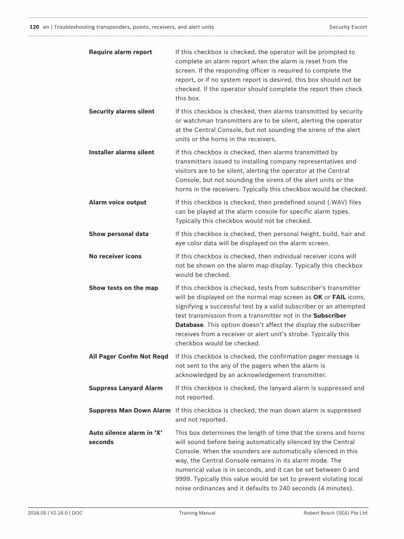
120 en | Troubleshooting transponders, points, receivers, and alert units Security Escort
2016.05 | V2.16.0 | DOC Training Manual Robert Bosch (SEA) Pte Ltd
Require alarm report If this checkbox is checked, the operator will be prompted tocomplete an alarm report when the alarm is reset from thescreen. If the responding officer is required to complete thereport, or if no system report is desired, this box should not bechecked. If the operator should complete the report then checkthis box.
Security alarms silent If this checkbox is checked, then alarms transmitted by securityor watchman transmitters are to be silent, alerting the operatorat the Central Console, but not sounding the sirens of the alertunits or the horns in the receivers.
Installer alarms silent If this checkbox is checked, then alarms transmitted bytransmitters issued to installing company representatives andvisitors are to be silent, alerting the operator at the CentralConsole, but not sounding the sirens of the alert units or thehorns in the receivers. Typically this checkbox would be checked.
Alarm voice output If this checkbox is checked, then predefined sound (.WAV) filescan be played at the alarm console for specific alarm types.Typically this checkbox would not be checked.
Show personal data If this checkbox is checked, then personal height, build, hair andeye color data will be displayed on the alarm screen.
No receiver icons If this checkbox is checked, then individual receiver icons willnot be shown on the alarm map display. Typically this checkboxwould be checked.
Show tests on the map If this checkbox is checked, tests from subscriber's transmitterwill be displayed on the normal map screen as OK or FAIL icons,signifying a successful test by a valid subscriber or an attemptedtest transmission from a transmitter not in the SubscriberDatabase. This option doesn’t affect the display the subscriberreceives from a receiver or alert unit’s strobe. Typically thischeckbox would be checked.
All Pager Confm Not Reqd If this checkbox is checked, the confirmation pager message isnot sent to the any of the pagers when the alarm isacknowledged by an acknowledgement transmitter.
Suppress Lanyard Alarm If this checkbox is checked, the lanyard alarm is suppressed andnot reported.
Suppress Man Down Alarm If this checkbox is checked, the man down alarm is suppressedand not reported.
Auto silence alarm in 'X'seconds
This box determines the length of time that the sirens and hornswill sound before being automatically silenced by the CentralConsole. When the sounders are automatically silenced in thisway, the Central Console remains in its alarm mode. Thenumerical value is in seconds, and it can be set between 0 and9999. Typically this value would be set to prevent violating localnoise ordinances and it defaults to 240 seconds (4 minutes).

Security Escort Troubleshooting transponders, points, receivers, and alert units | en 121
Robert Bosch (SEA) Pte Ltd Training Manual 2016.05 | V2.16.0 | DOC
Recall operator in 'X'seconds
This box determines the length of time before a recall alert isissued to the operator at the Central Console when an alarm isbeing displayed. If neither the mouse nor any key has beenactuated for the specified length of time, the Central Consolewill trigger the alarm sound once. This feature preventsinadvertently ignoring an active alarm event. The numerical valueis in seconds, and it can be set between 0 and 240. Typically thiswould be set to 60 seconds.
On outside tests, flashstrobe for 'X' seconds
The entry in this box controls the approximate length of time thestrobe on an alert unit will flash to signify a successfultransmitter test. The value is in seconds, and can be set between0 and 15. Typically it is set to 5 seconds.
Man down delay timer ‘X’seconds
This value controls the time that a transmitter must be in a mandown condition before a man down alarm is displayed. Typicallyit would be set to 10 seconds. Setting this value too short willcause inadvertent man down alarms to be generated.
Man down jitter timer ‘X’seconds
This value controls the time that a transmitter will not beconsidering any man down alarm if man down alarm is receivedimmediately after restore and before jitter time expire. Thissetting will not be used in normal system.
Auto Reset Comm Ports ‘X’hours
This value controls the time that all the comm ports in thesystem will be automatically reset after configured duration. Thissetting is used only if any communication failure is observed andshould not be used unnecessarily.
Trigger all the outputs onalarm ‘X’ seconds
This option turns on all outputs of the transponders, and alertunits for the duration configured (1-255 seconds) when alarm isgenerated. If someone acknowledges an alarm during thisduration, all these outputs will be turned off. Otherwise, afterthis duration has lapsed, all these outputs will be turned offautomatically. If this value is set to 0, the system will trigger theoutputs during alarms in the default normal behavior.
End of shift reminder A check in this checkbox causes a prompt to appear on theCentral Console screen every 5 minutes for 30 minutes prior tothe end of each shift if there are incident reports that have notyet been completed. It is intended for responding officers tocomplete alarm reports before the end of their shift.
First, Second, Third shiftreminder
The entries in these fields are the times (24-hour clock) at whichthe Central Console will prompt the operator that there is one ormore incident reports that have not yet been completed.Prompts will be given only if the End of Shift Reminder option isselected.

122 en | Troubleshooting transponders, points, receivers, and alert units Security Escort
2016.05 | V2.16.0 | DOC Training Manual Robert Bosch (SEA) Pte Ltd
Database find level This is the minimum receive level (1-255) that must be heardbefore the system will automatically enter the transmitter in theSubscriber Locate dialog. It determines the distance thesubscriber’s transmitter must be within the specified ID capturereceiver (set in the System Preferences dialog) before thesystem will recognize the test.
Locate test level This is the minimum receive level (1-255) that must be heardbefore the system will accept a test generated by a transmitterother than a guard, to be printed with a location. It determinesthe distance the transmitter must be within from a receiverbefore the system will recognize the test and print the location.If the transmitter is too far away from the receiver, thatreceiver’s green light will not be displayed, so the guard knowsthat they must move closer to the receiver for the test toregister.
Guard tour level This is the minimum receive level (1-255) that must be heardbefore the system will accept a test generated by the guard’stransmitter to be entered as a location in the guard tour report.It determines the distance the guard’s transmitter must bewithin from a receiver before the system will recognize the testand create the guard tour entry. If the guard is too far away fromthe receiver, that receiver’s green light will not be displayed, sothe guard knows that they must move closer to the receiver forthe test to register.
Guard tour minutes This setting controls the time spacing, in minutes, for entries ofthe guard’s current location in the automatically generated guardtour report. Therefore if set to 15 minutes, an entry will begenerated each 15 minutes that the guard’s transmitter is withinrange of the system.
Watchdog minutes This setting controls the time spacing, in minutes, for entries ofthe guard’s current location in the automatically generated guardtour report. Therefore if set to 15 minutes, an entry will begenerated each 15 minutes that the guard’s transmitter is withinrange of the system.
Popup trouble box contactinformation”
Each yellow, pop-up trouble box that is displayed on the CentralConsole advises of system problems, containing specificinstructions for the operator. Entries in this text box will bedisplayed in the pop-up trouble boxes whenever a systemproblem occurs that requires attention. This information usuallyincludes the name and telephone number of the designatedSecurity Escort maintenance technicians.
7.8 System Defaults dialogThis dialog allows the names for each class of subscribers to be changed to match the specificapplication of this Security Escort System.
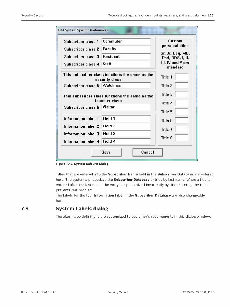
Security Escort Troubleshooting transponders, points, receivers, and alert units | en 123
Robert Bosch (SEA) Pte Ltd Training Manual 2016.05 | V2.16.0 | DOC
Figure 7.47: System Defaults Dialog
Titles that are entered into the Subscriber Name field in the Subscriber Database are enteredhere. The system alphabetizes the Subscriber Database entries by last name. When a title isentered after the last name, the entry is alphabetized incorrectly by title. Entering the titlesprevents this problem.The labels for the four Information label in the Subscriber Database are also changeablehere.
7.9 System Labels dialogThe alarm type definitions are customized to customer’s requirements in this dialog window.

124 en | Troubleshooting transponders, points, receivers, and alert units Security Escort
2016.05 | V2.16.0 | DOC Training Manual Robert Bosch (SEA) Pte Ltd
Figure 7.48: System Label Dialog
7.10 Subscriber DatabaseA subscriber is anyone who has been issued a Security Escort transmitter. This databaseincludes all transmitters assigned in the system, whether they are protecting people or things.The Subscriber Database is very similar to the Operator Database; the method by which thenames and other information are stored is virtually identical.

Security Escort Troubleshooting transponders, points, receivers, and alert units | en 125
Robert Bosch (SEA) Pte Ltd Training Manual 2016.05 | V2.16.0 | DOC
Figure 7.49: Find Subscriber's Database Record
The information stored in a subscriber’s file includes the person’s name, local address andphone number, permanent address and phone number, subscriber identification number(typically the individual’s Social Security number), the transmitter identification code (eachtransmitter has its own unique code which identifies the subscriber during tests and alarms),and the subscriber’s classification (commuter, resident, faculty, staff, and so on).
[Reset] Clicking the [Reset] button clears the number of Total Tests count.
[Clear] Clicking the [Clear] button removes the Low Battery indication. Thisshould only be done after the transmitter battery is replaced or a newtransmitter is issued.
[Print] Clicking the [Print] button displays the Subscriber Print dialog.
7.10.1 Print Subscriber DatabaseClicking the [Print] button displays the Subscriber Print dialog. Select one of the indicatedsort orders and the data fields that you desire in the report.

126 en | Troubleshooting transponders, points, receivers, and alert units Security Escort
2016.05 | V2.16.0 | DOC Training Manual Robert Bosch (SEA) Pte Ltd
Figure 7.50: Subscriber Print Dialog
[Write EXCEL import file] Clicking the [Write EXCEL import file] button causes all thefields of all the records to be sent to the “subscrib.txt” file in thefolder in which Security Escort was installed. This file may bedirectly imported into Microsoft Excel or any other applicationthat accepts tab delimited text..
[Print] Clicking the [Print] button causes the selected data fields toprint on the report printer in the indicated sort order.
[Cancel] Clicking the [Cancel] button aborts the print dialog and returnsto the previous screen.
7.10.2 Edit Subscriber Database recordWhen editing a subscriber’s file or creating a new file, the following information must beentered to complete the file: subscriber name, subscriber identification number, andtransmitter identification code. The computer does not allow the edit screen to be closed untilall of the mandatory fields are completed. The accuracy of information in the SubscriberDatabase is very important: in the event that a subscriber transmits an alarm, the informationdisplayed in the alarm screen is taken from this database. A faulty address could hindersecurity’s response to an alarm.

Security Escort Troubleshooting transponders, points, receivers, and alert units | en 127
Robert Bosch (SEA) Pte Ltd Training Manual 2016.05 | V2.16.0 | DOC
Figure 7.51: Edit Subscriber's Database Record (Transmitter)
Transmitter Type Click the drop-down list to select the type of transmitter thatis assigned to the subscriber. Currently, only the standardtransmitter is supported.

128 en | Troubleshooting transponders, points, receivers, and alert units Security Escort
2016.05 | V2.16.0 | DOC Training Manual Robert Bosch (SEA) Pte Ltd
Subscriber Type Click the drop-down list select the appropriate class for thissubscriber or asset. Selecting the subscriber type allows thealarm signal to be used to acknowledge alarms remotely. Itdoes not create an alarm. When this transmitter transmits analarm, the alarms present on the alarm screen areacknowledged in the order they were received. This is thesame order the alarms would be received on a pager for aapproving officer.The Subscriber Type available:Acknowledgement – subscriber with acknowledgementtransmittersCommuter – normal subscriber typeFaculty – normal subscriber typeInstaller – subscriber with maintenance transmittersOut of Service – out of service transmittersPoint type – point transmitter for monitoring assetsResident – normal subscriber typeSecurity – subscriber with security transmittersStaff – normal subscriber typeUnclassified (default)Visitor – normal subscriber typeWatchman – normal subscriber type
Disability If this individual is handicapped, select an item from this dropdown list. The condition is displayed on the alarm screen. If ahandicap is selected, the Notes field will not show on thealarm screen.
Disabled There is an option to disable an individual subscriber'stransmitter in such a way that it does not produce an alarmmessage on the Central Console. This can be used to halt asubscriber’s misuse of the system. Disabling or enabling asubscriber is accomplished by locating the subscriber in theSubscriber Database, clicking on the [Edit Data] button, andclicking the checkbox next to Disabled in the upper-left cornerof the dialog. If the box has a check mark, the subscriber'stransmitter is ignored by the system; if it does not, thetransmitter is recognized and alarms are displayed.
Silent If checked, a system that normally sounds alarms is silent forall alarms generated by this transmitter.
Supervision Duration Specific transmitter types periodically transmit supervisorymessages so the system can monitor their function andlocation. The supervisory feature must be enabled in thetransmitter. For transmitters with the supervisory featureenabled, select the interval for these Supervisory messagesfrom the drop-down list. The values for the drop-down list are“None”, “10 Seconds”, “30 Seconds”, “90 Seconds” and “1Hour”. The supervision period specific to the assignedtransmitter must be selected if this feature is used.

Security Escort Troubleshooting transponders, points, receivers, and alert units | en 129
Robert Bosch (SEA) Pte Ltd Training Manual 2016.05 | V2.16.0 | DOC
Name The individual or item assigned to this transmitter. This is arequired field.
Address Address of this individual or item within the protected area.The first address line on the left side, which is not the homeaddress, is shown on the alarm screen.
City City of this individual or item within the protected area.
State State of this individual or item within the protected area.
Zip Zip code of this individual or item within the protected area.
Phone The phone number to access this individual within theprotected area. The phone number on the left side, which isnot the home phone, is shown on the alarm screen.
Subscriber ID The Subscriber ID (typically the Social Security Number) mustbe typed into this field. This is a required field. It must be filledin with a unique ID.
Transmitter ID / New ID The transmitter identification code can be typed into this field,but a much faster and error free method is to delete anyexisting entry in the Transmitter ID field and then perform atest with the transmitter to be assigned to this subscriber. Thenew Transmitter ID displays in the New ID field. The newTransmitter ID must be manually entered into the TransmitterID field, or use the mouse to highlight the existing TransmitterID and press and hold the <Shift> key and press the <Insert>key. (This transfers the new Transmitter ID to the correctfield.) This is a required field; it must be filled in with a uniqueID. Complete the change to the Subscriber information byclicking the [Save] button.
Alarm Zone Specific alarm zones are assigned to the different computerworkstations of the Security Escort system. Each transmitterentered in the Subscriber Database can be assigned to one ormore of the alarm zones. You may control on which computerworkstations alarms from this transmitter appear.
Alarm Background Color Select the desired background color to display for alarm whenthis transmitter is activated.
Female/Male HeightBuildHair colorEye color
These characteristics are shown on the alarm screen.
Image / [Browse] Enter the filename for the image of this individual or item to beshown on the alarm screen. Click the [Browse] button to opena dialog box to select the filename from a list of available files.

130 en | Troubleshooting transponders, points, receivers, and alert units Security Escort
2016.05 | V2.16.0 | DOC Training Manual Robert Bosch (SEA) Pte Ltd
[Advanced] Used to set up special transmitters that monitor fixedlocations. These features are not used for personaltransmitters. This button is available only to the maintenanceand installation personnel (see the Security Escort TechnicalReference Manual).
[Information] The [Information] button is used to enter specific informationabout the holder of this transmitter.
[Save] Clicking the [Save] button saves all changes to the database.
[Cancel] Clicking the [Cancel] button allows you to abort and cancel allchanges to the database. A confirmation dialog box appearsasking for confirmation to save changes before closing. Clickthe [Yes] button to save the changes, [No] button to abort thechanges, or [Cancel] button to return to the Edit Subscriberdialog.
7.10.3 Additional subscriber informationThe [Information] button is used to enter specific information about the holder of thistransmitter. Car type, parking sticker number, license number, and medical information areexamples of the types of information typically entered. Each field typically holds differentinformation. The installer can change the field labels to labels that would define your intendedusage.
Figure 7.52: Information Entry Screen

Security Escort Troubleshooting transponders, points, receivers, and alert units | en 131
Robert Bosch (SEA) Pte Ltd Training Manual 2016.05 | V2.16.0 | DOC
[Done] Clicking the [Done] button closes the information entry dialogand returns to the Edit Subscriber’s Database Record dialog.Clicking the [Save] button saves all changes to the database.
7.10.4 Subscriber imagesThis software does not capture the images, it displays images that were previously capturedby some other means. The subscriber image can be captured using a digital camera, videocapture board etc. The source of the image is not critical. We have not identified, nor require aspecific manufacturer of the image capture equipment. The images must be saved individuallyin JPG format. The images should not be larger that 160 pixels wide and 160 pixels high. Ifthey are they will have to be scaled and therefore they may loose image quality. The path tothe images is set in Subscriber image file path field (default location of the images is "C:\ESCORT\IMAGES", but they can be located anywhere) found in the menu Network > Systemdirectories and network address dialog. The three-character file extension of the image filesis set in Extension field (default is “JPG”). Subscriber images may also be saved in Windowsbitmap (.BMP). However this format requires significantly more disk storage.Only when the display is set to 640 x 480 (not recommended), the images are displayed ontop of the map and the Scaling % field (10 to 200) controls the size of the image (try differentsettings to control the image size in the alarm screen). From the menu Files > SubscriberDatabase dialog, select the desired subscriber, then click the [Edit data] button. The Imagefield is the name of file of this subscriber's image. For example, if the subscriber's image isstored in a file with the name "Image1.jpg", enter "Image1" in this textbox.You should have a minimum of a 1 MB video card memory to display the subscriber’s images.To get the best color displayed on your LCD monitor, make sure to set it to “True Color (32-bit)”. Open Screen Resolution by clicking the Start button Picture of the Start button, clickingControl Panel, and then, under Appearance and Personalization, clicking Adjust screenresolution. Click Advanced settings, and then click the Monitor tab. Under Colors, select TrueColor (32 bit), and then click OK.(256 color likely will produce undesirable results). When in doubt set to High Color. In thesame dialog "Desktop area" can be set to 640x480, 800x600 or 1024x768 pixels. When thedisplay is set to 640x480 (not recommended) the images are displayed on top of the map andtherefore limit how much of the map displayed. The 1024x768 setting may require too muchmemory for most video cards and show more of the map, decreasing the size of the mapdetails. Most video cards can be set to 800x600 and when in doubt this setting should beselected. If you can't choose these settings you video card or monitor setting may beincorrect, refer to the system documentation to correct.
7.10.5 Subscriber Database Advanced FeaturesThe Subscriber Database contains the information on the transmitters that are assigned in thesystem. See the Security Escort Operation Manual for the basic operations of the SubscriberDatabase dialog. See the section on Exporting, importing and merging the Subscriber Database,page 145 for information on the data merge, import and export functions of the SubscriberDatabase.The following section explains the advanced features of the Subscriber Database dialog whenyou are inserting a new or editing an existing subscriber.
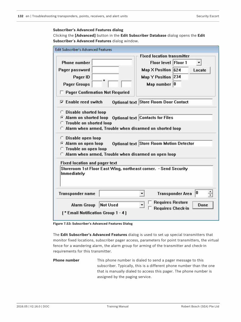
132 en | Troubleshooting transponders, points, receivers, and alert units Security Escort
2016.05 | V2.16.0 | DOC Training Manual Robert Bosch (SEA) Pte Ltd
Subscriber’s Advanced Features dialogClicking the [Advanced] button in the Edit Subscriber Database dialog opens the EditSubscriber’s Advanced Features dialog window.
Figure 7.53: Subscriber’s Advanced Features Dialog
The Edit Subscriber’s Advanced Features dialog is used to set up special transmitters thatmonitor fixed locations, subscriber pager access, parameters for point transmitters, the virtualfence for a wandering alarm, the alarm group for arming of the transmitter and check-inrequirements for this transmitter.
Phone number This phone number is dialed to send a pager message to thissubscriber. Typically, this is a different phone number than the onethat is manually dialed to access this pager. The phone number isassigned by the paging service.

Security Escort Troubleshooting transponders, points, receivers, and alert units | en 133
Robert Bosch (SEA) Pte Ltd Training Manual 2016.05 | V2.16.0 | DOC
Pager password This is the password to be sent to the paging service when a page issent to this subscriber. Leave blank if not required (typically thepager password is not required). The pager password is assigned bythe paging service.
Pager ID This is the ID that identifies the pager to receive the pager message(many times this value is the last 7 digits that would be manuallydialed to access this pager). The pager ID is assigned by the pagingservice.
Pager Groups The first pager group (*) can be used for email notification. You canenter the email notification group “01”, “02”, “03” or “04” toconfigure the notification of this specific subscriber alarm to be sentvia email to that email notification group. If the pager group (*) is leftempty, alarms for this subscriber will send an email to the defaultnotification group “00”.Any data entered from 5 to 99 in the first pager group (*) will betreated as a pager group. The subscriber can be a member of up to 3different pager groups. Enter the group numbers in the pager groupfields respectively.
Pager Confirmation NotRequired
If checked, the confirmation pager message is not sent to this pagerif alarm is acknowledged by an acknowledgement transmitter.
Fixed locationtransmitter
This section is to be used only when this transmitter is mounted in afixed location (it does not move). When this transmitter transmitsand alarm it will always be reported at the programmed location.
Floor level This is the floor level where this alarm is to be located for a fixedlocation transmitter.
Map X Position This is the X coordinate of the map position where this alarm is to belocated for a fixed location transmitter.
Map Y Position This is the Y coordinate of the map position where this alarm is to belocated for a fixed location transmitter.
Locate When clicked, the dialog will disappear and the cursor will change toa cross hair. Moving the cursor to a point on the map and clicking theleft mouse button will scroll the map so that point is at the center ofthe screen.When the map is showing the desired alarm location, move the crosshair to the exact location of the alarm to be reported and click theright mouse button. The dialog will reappear and the selectedlocation will be entered into the X and Y coordinates.If while the cross hair cursor is being displayed, you desire to exitwithout changing any coordinate values, press the <Esc> key and thetransponder edit dialog will reappear.
Map number Defines which bitmap is to be displayed for the fixed location of thistransmitter. The default map is 0, which corresponds to bitmapMAP0.EDB stored in the “Escort” sub-directory. Map 1 would beMAP1.EDB. There can be 100 maps per Security Escort system(0-99).

134 en | Troubleshooting transponders, points, receivers, and alert units Security Escort
2016.05 | V2.16.0 | DOC Training Manual Robert Bosch (SEA) Pte Ltd
Enable reed switch If checked the reed switch input of this transmitter enabled to causean alarm. Otherwise the reed switch input will be disabled. The alarmgroup this transmitter is assigned to must be armed, for this input tocause an alarm, which is displayed. If no alarm group is assigned, thetransmitter is always armed. For this option to be enabled, thetransmitter’s class must be set to “Point type”.
Optional text This is optional text that will be added to the location text when thisinput reports an alarm. For this option to be enabled, thetransmitter’s class must be set to “Point type”.
Disable on shorted loop If selected, a shorted loop on this transmitter will not cause an alarmor trouble report to be displayed. For this option to be enabled, thetransmitter’s class must be set to “Point type”.
Alarm on shorted loop If selected and the alarm group, where this transmitter is assignedto, is armed, then a shorted loop on this transmitter will cause analarm report to be displayed. The alarm group this transmitter isassigned to must be armed, for this input to cause an alarm, which isdisplayed. If no alarm group is assigned, the transmitter is alwaysarmed. For this option to be enabled, the transmitter’s class must beset to “Point type”.
Trouble on shorted loop If selected, a shorted loop on this transmitter will cause a troublereport to be displayed. For this option to be enabled, thetransmitter’s class must be set to “Point type”.
Alarm when armed,Trouble when disarmedon shorted loop
If selected and the alarm group, where this transmitter is assignedto, is armed; then a shorted loop on this transmitter will cause analarm report to be displayed. If selected and the alarm group, wherethis transmitter is assigned to, is disarmed, then a shorted loop onthis transmitter will cause a trouble report to be displayed. If noalarm group is assigned, the transmitter is always armed. For thisoption to be enabled, the transmitter’s class must be set to “Pointtype”.
Disable open loop If selected, an open loop on this transmitter will not cause an alarmor trouble report to be displayed. For this option to be enabled, thetransmitter’s class must be set to “Point type”.
Alarm on open loop If selected and the alarm group, where this transmitter is assignedto, is armed, then an open loop on this transmitter will cause analarm report to be displayed. The alarm group, where this transmitteris assigned to, must be armed for this input to cause an alarm, whichis displayed. If no alarm group is assigned, the transmitter is alwaysarmed. For this option to be enabled, the transmitter’s class must beset to “Point type”.
Trouble on open loop If selected, an open loop on this transmitter will cause a troublereport to be displayed. For this option to be enabled, thetransmitter’s class must be set to “Point type”.

Security Escort Troubleshooting transponders, points, receivers, and alert units | en 135
Robert Bosch (SEA) Pte Ltd Training Manual 2016.05 | V2.16.0 | DOC
Alarm when armed,Trouble when disarmedon open loop
If selected and the alarm group, where this transmitter is assignedto, is armed; then an open loop on this transmitter will cause analarm report to be displayed. If selected and the alarm group, wherethis transmitter is assigned to, is disarmed, then an open loop on thistransmitter will cause a trouble report to be displayed. If no alarmgroup is assigned, the transmitter is always armed. For this option tobe enabled, the transmitter’s class must be set to “Point type”.
Fixed location andpager text
This is the text that will be displayed as the location of the alarm forfixed location transmitters and on pagers reporting this alarm.
Transponder name Select the transponder with the area that is defined for a wandering(virtual fence) alarm. See Transponder Area below for the operationand setup of the wandering alarm (virtual fence alarm).
Transponder Area Wandering alarm - Create a protected area by placing a virtualmonitor “fence” around an area of the main map. These areas aredefined in the Transponder Database. If this transmitter isconstrained to remain within one of these defined areas, first selectthe defining transponder in Transponder name above. Then selectthe desired area from this drop-down list of the transponder’s areanames.For the wandering alarm to work, the supervision period must alsobe programmed for this transmitter.Then specific transmitters are marked in the subscriber database, tobe constrained within a specific fenced area defined by this option. Ifthe transmitters leave their defined area, the system will report thisas a Wandering alarm and continue to monitor and track the locationof the transmitter until the alarm is canceled from the screen in thenormal way. However, these tracking updates can only occur everysupervision transmission period (not on an accelerated rate like atracking alarm).The Security Escort system computes the location of the transmitterswhen they broadcast automatic supervision transmissionsperiodically.Because of the basic location accuracy and the floor-to-floor accuracyof the system, there is a potential for some false alarms. If falsealarms are a problem, check the Filter Virtual Fence checkbox in theSecurity Preferences dialog. If you do this, two successive locationcalculations will have to indicate the transmitter has moved outsidethe protected area before an alarm is generated. The downside ofthis is a delay in the reporting of a wandering alarm of one extratransmitter supervision period.
Alarm Group This is the alarm group that controls the arm/disarm status of thistransmitter. Select the desired alarm group from the dropdown list ofthe alarm group names. This alarm group must be armed, for thistransmitter to cause an alarm, which is displayed. If no alarm groupis assigned, the transmitter is always armed.
Requires Restore When this checkbox is checked, transmitter will have to be restored.
136 en | Troubleshooting transponders, points, receivers, and alert units Security Escort
2016.05 | V2.16.0 | DOC Training Manual Robert Bosch (SEA) Pte Ltd
Requires Check-in When this checkbox is checked, this transmitter will have to beactivated once each day during the Check-in Schedule time. At theend of the check-in period, if the subscriber fails to check-in, a Failedto Check-in Report will be generated and presented to the operatorof the software. This report contains all of the people who failed tocheck-in with their first address line and phone number. Allsubscribers in the report must be checked on to make sure they arenot in need of assistance, as this may be a life-treating situation. Aprinted report may also be generated.If the transmitter is not a point type, then the transmitter cangenerate alarms and therefore a test transmission will be used forthe check-in.If the transmitter is a point type, then any non-trouble transmissionwill serve as a check-in.One of the 10 schedules must be selected as the check-in scheduleto define the check-in period.
Done Click this button when all changes to this dialog are completed andreturn the main Subscriber Database edit dialog.
7.10.6 Subscriber (individual) Pager SetupIn the Subscriber Database select the record for the desired individual. Click the [Edit Data]button, followed by the [Advanced] button. The dialog below will be displayed.

Security Escort Troubleshooting transponders, points, receivers, and alert units | en 137
Robert Bosch (SEA) Pte Ltd Training Manual 2016.05 | V2.16.0 | DOC
Figure 7.54: Subscriber Database Advanced Dialog
The pager ID is required for all individual pagers dial-up and local. If the phone number andpassword are assigned, the page will be sent over the modem connection. If the phonenumber and password fields are blank, the page will be routed to the local paging system. Ifyou do not desire this individual to have pager support leave the phone number, password andpager ID fields all blank.If the pager information is entered above, this individual may be assigned to 2 paging groups.Each group will accept 8 members maximum. Remember it takes time to communicate with apaging service, therefore only add members to a group if they need to be there, otherwise youmay slow the paging report to people that must respond.A pager group may contain members accessed by the local paging system and membersthat require dial-up access. Dial-up access typically takes much longer and it may slowpages to the local paging system.

138 en | Troubleshooting transponders, points, receivers, and alert units Security Escort
2016.05 | V2.16.0 | DOC Training Manual Robert Bosch (SEA) Pte Ltd
7.10.7 Fixed Location Transmitters
Figure 7.55: Fixed Location Dialog
The paging feature may use different paging companies and they may require different baudrates. Set the baud rate to the highest baud rate common to all of the paging companies to beaccessed.The character limit (characters per page), pages per call affect all pages of the indicated type(local and dial-up). These fields must be set to the lowest setting for any of the routes thatmay be used. Remember that dial-up pages may be routed to different paging companies andthey may have different restrictions.
7.11 Schedules dialogThis selection informs management of the ten-time of day/day of week schedules andholidays. The top portion of the display shows the ten-time-of-day/day-of-week schedules thatSecurity Escort supports. For each schedule, there is an indication the schedule is currentlyactive or armed (ACT); otherwise, the schedule is disarmed (OFF).

Security Escort Troubleshooting transponders, points, receivers, and alert units | en 139
Robert Bosch (SEA) Pte Ltd Training Manual 2016.05 | V2.16.0 | DOC
Figure 7.56: Schedule Screen
For each day-of-the-week, the arm time (time the schedule becomes active) and disarm time(time the schedule becomes inactive) are displayed. To edit the arm and disarm times, clickthe [Edit Schedule Times] button. Double clicking the number of the schedule allows you toname the schedules.
This schedule defines the check-in times
One of the ten schedules can be used to define the check-intimes for those subscribers that must check-in. Click on theschedule for the check-in schedule, highlighting it. Thencheck this checkbox, to set the selected schedule as thecheck-in schedule. Both the arm time and disarm time mustbe programmed for every day the check-ins must take place.The arm time is the start of the check-in schedule and itmust occur before the disarm time that marks the end of thecheck-in schedule for that day.
[Edit Schedule Times] Clicking this button displays the Edit Schedule Times dialogso the day of week arm and disarm schedule times can beedited.
[View Alarm Groups] Clicking this button displays the View Alarm Groups dialog.This screen shows the alarm groups assigned to the selectedschedule and their current arming state.
Ignore Holidays for thisSchedule
Each schedule can use the holiday dates as exceptions.

140 en | Troubleshooting transponders, points, receivers, and alert units Security Escort
2016.05 | V2.16.0 | DOC Training Manual Robert Bosch (SEA) Pte Ltd
7.11.1 Ignore Holidays for this scheduleEach schedule can use the holiday dates as exceptions. Schedules are activated (armed)following the normal schedules if the holiday dates are configured to be ignored. Otherwise,the schedules are activated the entire day for the holiday dates.
Figure 7.57: Holiday Selection in the Schedule Dialog
Ignore Holidays for this Schedule If the Ignore Holidays checkbox is checked for theindicated holiday dates, the schedules are activated(armed) that entire day. If the Ignore Holidays checkboxis not checked, the normal action of the schedules takesplace on the holiday dates.
Date […] Clicking this button displays a calendar where you cangraphically select a date.
[Remove >>] Clicking this button removes the selected date from theHoliday dates list box.
[<< Add] Clicking this button adds the date shown to the Holidaydates list box.
7.11.2 Edit Schedule Times dialogThis dialog allows the arming and disarming times to be programmed for each of the days ofthe week. All times are expressed in 24-hour time (00:00 to 23:59). Each schedule has oneArm Time and one Disarm Time for each of the 7 days of the week.If both the Arm Time and Disarm Time are programmed to 00:00, the schedule will be active(armed) for the entire day.If the Arm Time is 00:00 and the Disarm Time is programmed, the schedule will be active(armed) from midnight to the programmed Disarm Time. The schedule will be off (disarmed)from the Disarm Time to the end of the day.If the Disarm Time is 00:00 and the Arm Time is programmed, the schedule will be off(disarmed) from midnight to the programmed Arm Time. The schedule will be active (armed)from the Arm Time to the end of the day.

Security Escort Troubleshooting transponders, points, receivers, and alert units | en 141
Robert Bosch (SEA) Pte Ltd Training Manual 2016.05 | V2.16.0 | DOC
Figure 7.58: Edit Schedule Time dialog
If both the Disarm Time and the Arm Time are programmed, and the Disarm Time occursbefore the Arm Time (normal 8 to 5 style day), the schedule will be active (armed) frommidnight to the programmed Disarm Time. The schedule will be off (disarmed) from theDisarm Time to the Arm Time. The schedule will be active (armed) from the Arm Time to theend of the day.If both the Disarm Time and the Arm Time are programmed, and the Arm Time occurs beforethe Disarm Time, the schedule is off (disarmed) from midnight to the programmed Arm Time.The schedule is active (armed) from the Arm Time to the Disarm Time. The schedule is off(disarmed) from the Disarm Time to the end of the day.
Arm Time This is the time that the schedule becomes active (on or armed) forthe selected day of the week. Times are expressed in 24-hour time(00:00 to 23:59).
Disarm Time This is the time that the schedule goes off (disarmed) for theselected day of the week. Times are expressed in 24-hour time(00:00 to 23:59).
Day of the Week Select the day you desire to change the time for. The Arm Time andDisarm Time are programmed separately for each day of the week.You must individually select each day of the week, and set thedesired times.
7.11.3 View Alarm Groups dialogThis dialog shows the alarm groups that are assigned to the selected schedule and theircurrent arming state. The “ON” and “OFF” states indicate that the alarm group is undermanual control. “AUTO” is under control of the selected schedule. The alarm group will bearmed if the schedule is active.

142 en | Troubleshooting transponders, points, receivers, and alert units Security Escort
2016.05 | V2.16.0 | DOC Training Manual Robert Bosch (SEA) Pte Ltd
Figure 7.59: View Alarm Groups Dialog
7.11.4 Alarm Groups dialogThis dialog allows setup and arm/disarm control of the 99 alarm groups. Any number of pointtype transmitters can be assigned to an alarm group in the Subscriber Database’s Advanceddialog. However, each transmitter can only be assigned to one alarm group.An alarm group can be manually armed and disarmed, or assigned to a schedule toautomatically arm and disarm the alarm group.
Figure 7.60: Alarm Groups Dialog
Alarm group name Enter a descriptive name to identify the function of the points inthis alarm group.

Security Escort Troubleshooting transponders, points, receivers, and alert units | en 143
Robert Bosch (SEA) Pte Ltd Training Manual 2016.05 | V2.16.0 | DOC
Alarm group # This is the number of the alarm group (1-99).
Arming state of this alarmgroup
The Off (disarmed), On (armed) and Automatic by Scheduleselection control the arming state of this alarm group.
Off (disarmed) Selecting this option disarms the alarm group. The alarm groupwill remain off (disarmed) until manually changed in this dialogto On (armed) or Automatic by Schedule.
On (armed) Selecting this option arms the alarm group. The alarm group willremain on (armed) until manually changed in this dialog to Off(disarmed) or Automatic by Schedule.
Automatic by schedule Selecting this option assigns the alarm group’s arming state tobe controlled by the indicated schedule. When the schedule isactive (on or armed) the alarm group will be armed. When theschedule is off (disarmed) the alarm group will be disarmed. Anynumber of alarm groups may be assigned to the same schedule.
[First] Clicking this button takes you to alarm group 1.
[Previous] Clicking this button takes you to the next lower alarm group fromthe one currently displayed. It will not wrap around. Therefore, itwill be disabled at alarm group 1.
[Next] Clicking this button takes you to the next higher alarm groupfrom the one currently displayed. It will not wrap around.Therefore, it will be disabled at alarm group 99.
[Last] Clicking this button takes you to alarm group 99.
7.11.5 Alarm Group State dialogThis dialog will display a list of the alarm groups that are currently armed, and have one ormore transmitters (points) faulted. The points are presented because they were not restoredwhen their automatic schedule armed, or there was an alarm while the alarm group was on.

144 en | Troubleshooting transponders, points, receivers, and alert units Security Escort
2016.05 | V2.16.0 | DOC Training Manual Robert Bosch (SEA) Pte Ltd
Figure 7.61: Alarm Group State Dialog
[Print Report] Clicking this button prints the displayed data to the report printer.
[Acknowledge] Clicking this button closes the dialog if it was selected from the menu.However, if the dialog was presented automatically at the arm time of analarm group’s automatic schedule because they were not restored, or therewas an alarm while the alarm group was on, then you are required to enteryour password to acknowledge the dialog, and remove it from thiscomputer’s (and all other computer workstations) screens.
7.11.6 Current Check-in Status dialogThis dialog displays a list of subscribers that are required to check-in and failed to do soduring the last check-in period. Also shown are their addresses, phone numbers, and the lasttime they checked-in.
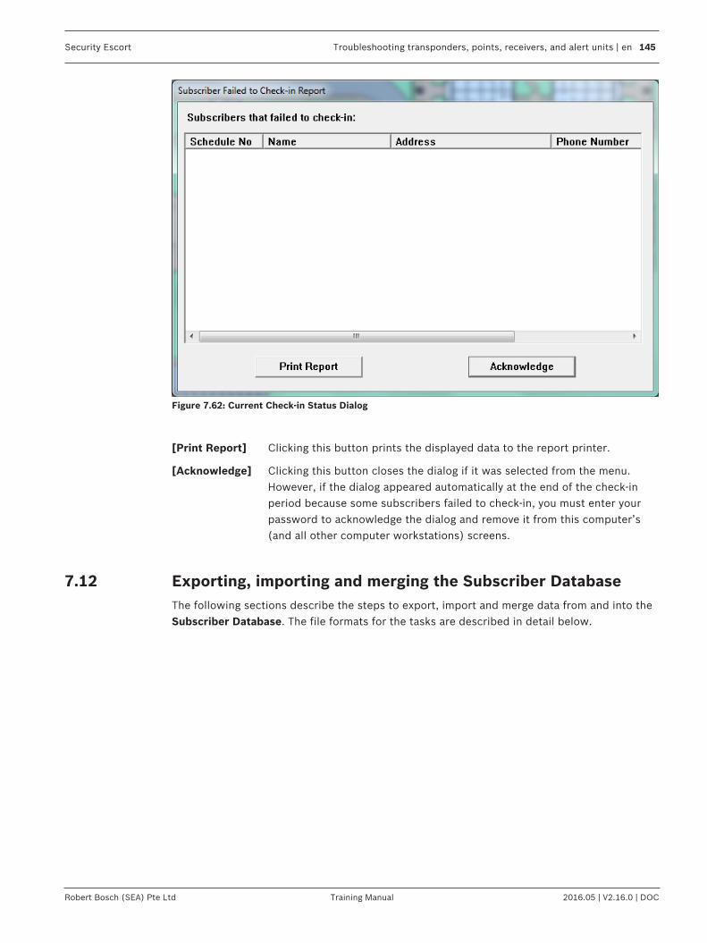
Security Escort Troubleshooting transponders, points, receivers, and alert units | en 145
Robert Bosch (SEA) Pte Ltd Training Manual 2016.05 | V2.16.0 | DOC
Figure 7.62: Current Check-in Status Dialog
[Print Report] Clicking this button prints the displayed data to the report printer.
[Acknowledge] Clicking this button closes the dialog if it was selected from the menu.However, if the dialog appeared automatically at the end of the check-inperiod because some subscribers failed to check-in, you must enter yourpassword to acknowledge the dialog and remove it from this computer’s(and all other computer workstations) screens.
7.12 Exporting, importing and merging the Subscriber DatabaseThe following sections describe the steps to export, import and merge data from and into theSubscriber Database. The file formats for the tasks are described in detail below.
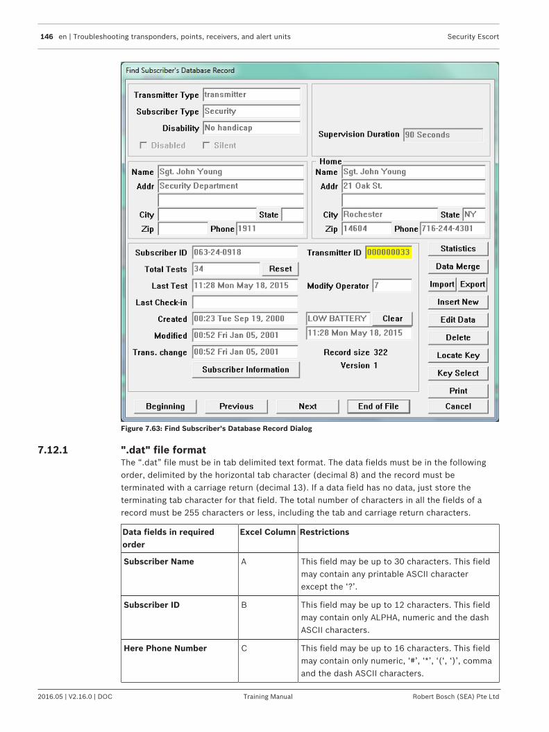
146 en | Troubleshooting transponders, points, receivers, and alert units Security Escort
2016.05 | V2.16.0 | DOC Training Manual Robert Bosch (SEA) Pte Ltd
Figure 7.63: Find Subscriber's Database Record Dialog
7.12.1 ".dat" file formatThe “.dat” file must be in tab delimited text format. The data fields must be in the followingorder, delimited by the horizontal tab character (decimal 8) and the record must beterminated with a carriage return (decimal 13). If a data field has no data, just store theterminating tab character for that field. The total number of characters in all the fields of arecord must be 255 characters or less, including the tab and carriage return characters.
Data fields in requiredorder
Excel Column Restrictions
Subscriber Name A This field may be up to 30 characters. This fieldmay contain any printable ASCII characterexcept the ‘?’.
Subscriber ID B This field may be up to 12 characters. This fieldmay contain only ALPHA, numeric and the dashASCII characters.
Here Phone Number C This field may be up to 16 characters. This fieldmay contain only numeric, ‘#’, ‘*’, ‘(‘, ‘)’, commaand the dash ASCII characters.
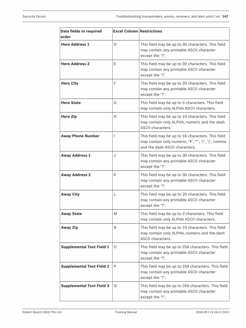
Security Escort Troubleshooting transponders, points, receivers, and alert units | en 147
Robert Bosch (SEA) Pte Ltd Training Manual 2016.05 | V2.16.0 | DOC
Data fields in requiredorder
Excel Column Restrictions
Here Address 1 D This field may be up to 30 characters. This fieldmay contain any printable ASCII characterexcept the ‘?’.
Here Address 2 E This field may be up to 30 characters. This fieldmay contain any printable ASCII characterexcept the ‘?’.
Here City F This field may be up to 20 characters. This fieldmay contain any printable ASCII characterexcept the ‘?’.
Here State G This field may be up to 3 characters. This fieldmay contain only ALPHA ASCII characters.
Here Zip H This field may be up to 10 characters. This fieldmay contain only ALPHA, numeric and the dashASCII characters.
Away Phone Number I This field may be up to 16 characters. This fieldmay contain only numeric, ‘#’, ‘*’, ‘(‘, ‘)’, commaand the dash ASCII characters.
Away Address 1 J This field may be up to 30 characters. This fieldmay contain any printable ASCII characterexcept the ‘?’.
Away Address 2 K This field may be up to 30 characters. This fieldmay contain any printable ASCII characterexcept the ‘?’.
Away City L This field may be up to 20 characters. This fieldmay contain any printable ASCII characterexcept the ‘?’.
Away State M This field may be up to 3 characters. This fieldmay contain only ALPHA ASCII characters.
Away Zip N This field may be up to 10 characters. This fieldmay contain only ALPHA, numeric and the dashASCII characters.
Supplemental Text Field 1 O This field may be up to 254 characters. This fieldmay contain any printable ASCII characterexcept the ‘?’.
Supplemental Text Field 2 P This field may be up to 254 characters. This fieldmay contain any printable ASCII characterexcept the ‘?’.
Supplemental Text Field 3 Q This field may be up to 254 characters. This fieldmay contain any printable ASCII characterexcept the ‘?’.
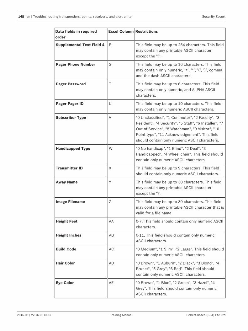
148 en | Troubleshooting transponders, points, receivers, and alert units Security Escort
2016.05 | V2.16.0 | DOC Training Manual Robert Bosch (SEA) Pte Ltd
Data fields in requiredorder
Excel Column Restrictions
Supplemental Text Field 4 R This field may be up to 254 characters. This fieldmay contain any printable ASCII characterexcept the ‘?’.
Pager Phone Number S This field may be up to 16 characters. This fieldmay contain only numeric, ‘#’, ‘*’, ‘(‘, ‘)’, commaand the dash ASCII characters.
Pager Password T This field may be up to 6 characters. This fieldmay contain only numeric, and ALPHA ASCIIcharacters.
Pager Pager ID U This field may be up to 10 characters. This fieldmay contain only numeric ASCII characters.
Subscriber Type V "0 Unclassified", "1 Commuter", "2 Faculty", "3Resident", "4 Security", "5 Staff", "6 Installer", "7Out of Service", "8 Watchman", "9 Visitor", "10Point type", "11 Acknowledgement". This fieldshould contain only numeric ASCII characters.
Handicapped Type W "0 No handicap", "1 Blind", "2 Deaf", "3Handicapped", "4 Wheel chair". This field shouldcontain only numeric ASCII characters.
Transmitter ID X This field may be up to 9 characters. This fieldshould contain only numeric ASCII characters.
Away Name Y This field may be up to 30 characters. This fieldmay contain any printable ASCII characterexcept the ‘?’.
Image Filename Z This field may be up to 30 characters. This fieldmay contain any printable ASCII character that isvalid for a file name.
Height Feet AA 0-7, This field should contain only numeric ASCIIcharacters.
Height Inches AB 0-11, This field should contain only numericASCII characters.
Build Code AC "0 Medium", "1 Slim", "2 Large". This field shouldcontain only numeric ASCII characters.
Hair Color AD "0 Brown", "1 Auburn", "2 Black", "3 Blond", "4Brunet", "5 Grey", "6 Red". This field shouldcontain only numeric ASCII characters.
Eye Color AE "0 Brown", "1 Blue", "2 Green", "3 Hazel", "4Grey". This field should contain only numericASCII characters.
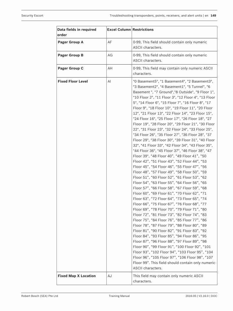
Security Escort Troubleshooting transponders, points, receivers, and alert units | en 149
Robert Bosch (SEA) Pte Ltd Training Manual 2016.05 | V2.16.0 | DOC
Data fields in requiredorder
Excel Column Restrictions
Pager Group A AF 0-99, This field should contain only numericASCII characters.
Pager Group B AG 0-99, This field should contain only numericASCII characters.
Pager Group C AH 0-99, This field may contain only numeric ASCIIcharacters.
Fixed Floor Level AI "0 Basement5", "1 Basement4", "2 Basement3","3 Basement2", "4 Basement1", "5 Tunnel", "6Basement ", "7 Ground","8 Outside", "9 Floor 1","10 Floor 2", "11 Floor 3", "12 Floor 4", "13 Floor5", "14 Floor 6", "15 Floor 7", "16 Floor 8", "17Floor 9", "18 Floor 10", "19 Floor 11", "20 Floor12", "21 Floor 13", "22 Floor 14", "23 Floor 15","24 Floor 16", "25 Floor 17", "26 Floor 18", "27Floor 19", "28 Floor 20", "29 Floor 21", "30 Floor22", "31 Floor 23", "32 Floor 24", "33 Floor 25","34 Floor 26", "35 Floor 27", "36 Floor 28", "37Floor 29", "38 Floor 30", "39 Floor 31", "40 Floor32", "41 Floor 33", "42 Floor 34", "43 Floor 35","44 Floor 36", "45 Floor 37", "46 Floor 38", "47Floor 39", “48 Floor 40”, “49 Floor 41”, “50Floor 42”, “51 Floor 43”, “52 Floor 44”, “53Floor 45”, “54 Floor 46”, “55 Floor 47”, “56Floor 48”, “57 Floor 49”, “58 Floor 50”, “59Floor 51”, “60 Floor 52”, “61 Floor 53”, “62Floor 54”, “63 Floor 55”, “64 Floor 56”, “65Floor 57”, “66 Floor 58”, “67 Floor 59”, “68Floor 60”, “69 Floor 61”, “70 Floor 62”, “71Floor 63”, “72 Floor 64”, “73 Floor 65”, “74Floor 66”, “75 Floor 67”, “76 Floor 68”, “77Floor 69”, “78 Floor 70”, “79 Floor 71”, “80Floor 72”, “81 Floor 73”, “82 Floor 74”, “83Floor 75”, “84 Floor 76”, “85 Floor 77”, “86Floor 78”, “87 Floor 79”, “88 Floor 80”, “89Floor 81”, “90 Floor 82”, “91 Floor 83”, “92Floor 84”, “93 Floor 85”, “94 Floor 86”, “95Floor 87”, “96 Floor 88”, “97 Floor 89”, “98Floor 90”, “99 Floor 91”, “100 Floor 92”, “101Floor 93”, “102 Floor 94”, “103 Floor 95”, “104Floor 96”, “105 Floor 97”, “106 Floor 98”, “107Floor 99”. This field should contain only numericASCII characters.
Fixed Map X Location AJ This field may contain only numeric ASCIIcharacters.
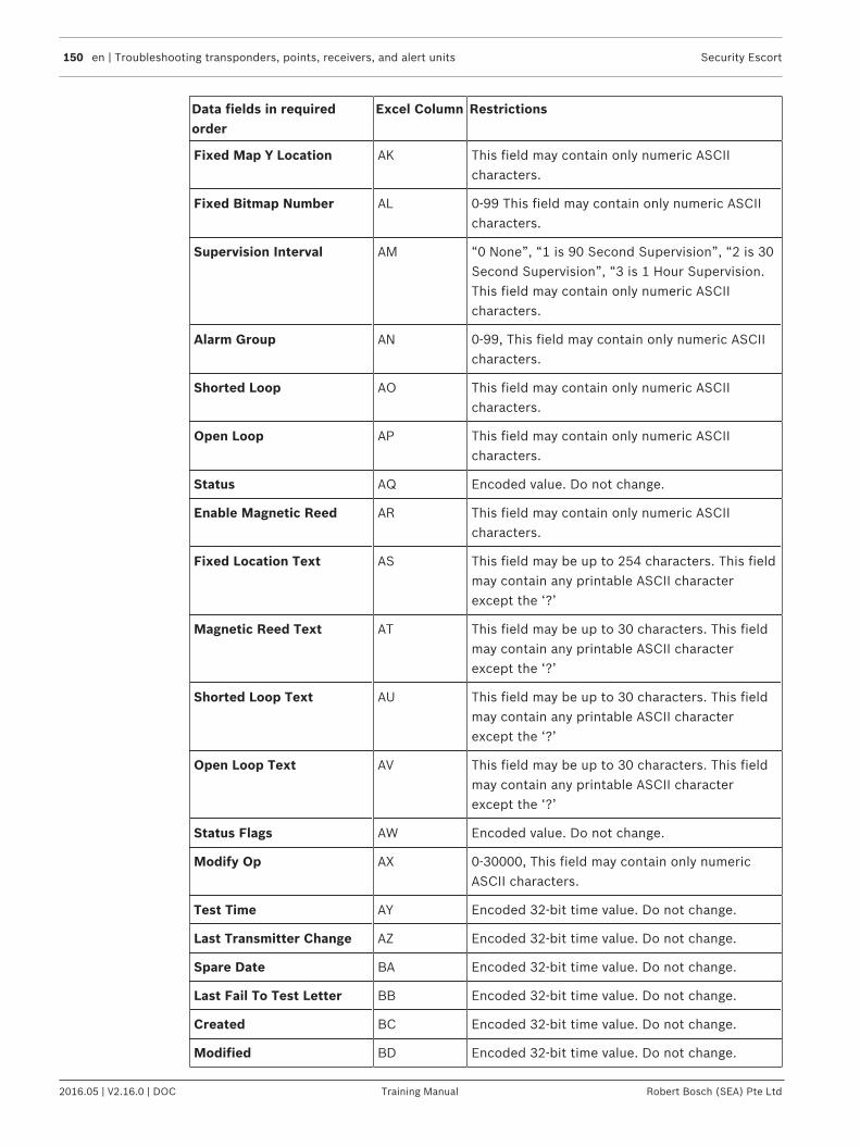
150 en | Troubleshooting transponders, points, receivers, and alert units Security Escort
2016.05 | V2.16.0 | DOC Training Manual Robert Bosch (SEA) Pte Ltd
Data fields in requiredorder
Excel Column Restrictions
Fixed Map Y Location AK This field may contain only numeric ASCIIcharacters.
Fixed Bitmap Number AL 0-99 This field may contain only numeric ASCIIcharacters.
Supervision Interval AM “0 None”, “1 is 90 Second Supervision”, “2 is 30Second Supervision”, “3 is 1 Hour Supervision.This field may contain only numeric ASCIIcharacters.
Alarm Group AN 0-99, This field may contain only numeric ASCIIcharacters.
Shorted Loop AO This field may contain only numeric ASCIIcharacters.
Open Loop AP This field may contain only numeric ASCIIcharacters.
Status AQ Encoded value. Do not change.
Enable Magnetic Reed AR This field may contain only numeric ASCIIcharacters.
Fixed Location Text AS This field may be up to 254 characters. This fieldmay contain any printable ASCII characterexcept the ‘?’
Magnetic Reed Text AT This field may be up to 30 characters. This fieldmay contain any printable ASCII characterexcept the ‘?’
Shorted Loop Text AU This field may be up to 30 characters. This fieldmay contain any printable ASCII characterexcept the ‘?’
Open Loop Text AV This field may be up to 30 characters. This fieldmay contain any printable ASCII characterexcept the ‘?’
Status Flags AW Encoded value. Do not change.
Modify Op AX 0-30000, This field may contain only numericASCII characters.
Test Time AY Encoded 32-bit time value. Do not change.
Last Transmitter Change AZ Encoded 32-bit time value. Do not change.
Spare Date BA Encoded 32-bit time value. Do not change.
Last Fail To Test Letter BB Encoded 32-bit time value. Do not change.
Created BC Encoded 32-bit time value. Do not change.
Modified BD Encoded 32-bit time value. Do not change.
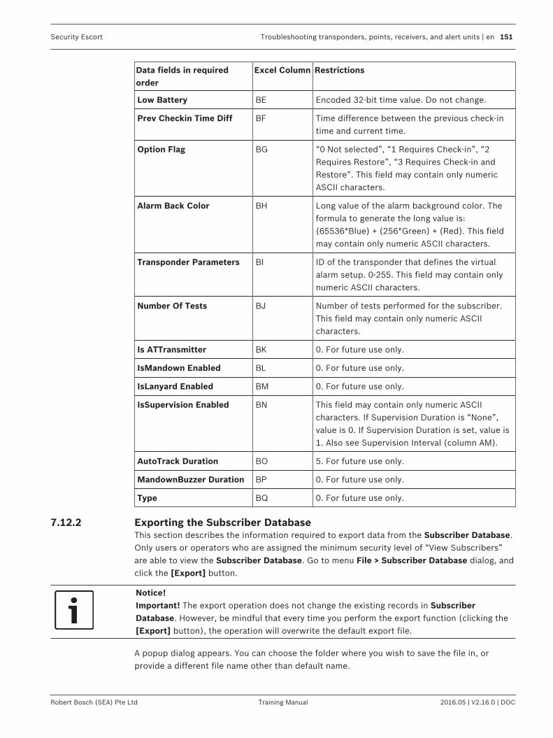
Security Escort Troubleshooting transponders, points, receivers, and alert units | en 151
Robert Bosch (SEA) Pte Ltd Training Manual 2016.05 | V2.16.0 | DOC
Data fields in requiredorder
Excel Column Restrictions
Low Battery BE Encoded 32-bit time value. Do not change.
Prev Checkin Time Diff BF Time difference between the previous check-intime and current time.
Option Flag BG “0 Not selected”, “1 Requires Check-in”, “2Requires Restore”, “3 Requires Check-in andRestore”. This field may contain only numericASCII characters.
Alarm Back Color BH Long value of the alarm background color. Theformula to generate the long value is:(65536*Blue) + (256*Green) + (Red). This fieldmay contain only numeric ASCII characters.
Transponder Parameters BI ID of the transponder that defines the virtualalarm setup. 0-255. This field may contain onlynumeric ASCII characters.
Number Of Tests BJ Number of tests performed for the subscriber.This field may contain only numeric ASCIIcharacters.
Is ATTransmitter BK 0. For future use only.
IsMandown Enabled BL 0. For future use only.
IsLanyard Enabled BM 0. For future use only.
IsSupervision Enabled BN This field may contain only numeric ASCIIcharacters. If Supervision Duration is “None”,value is 0. If Supervision Duration is set, value is1. Also see Supervision Interval (column AM).
AutoTrack Duration BO 5. For future use only.
MandownBuzzer Duration BP 0. For future use only.
Type BQ 0. For future use only.
7.12.2 Exporting the Subscriber DatabaseThis section describes the information required to export data from the Subscriber Database.Only users or operators who are assigned the minimum security level of “View Subscribers”are able to view the Subscriber Database. Go to menu File > Subscriber Database dialog, andclick the [Export] button.
Notice!Important! The export operation does not change the existing records in SubscriberDatabase. However, be mindful that every time you perform the export function (clicking the[Export] button), the operation will overwrite the default export file.
A popup dialog appears. You can choose the folder where you wish to save the file in, orprovide a different file name other than default name.

152 en | Troubleshooting transponders, points, receivers, and alert units Security Escort
2016.05 | V2.16.0 | DOC Training Manual Robert Bosch (SEA) Pte Ltd
Figure 7.64: Export Confirmation Dialog
Be patient, as it may take a while, and watch for the disk activity to stop. If the export issuccessful, a confirmation dialog appears. You will find the file in the specified folder.
7.12.3 Importing the Subscriber DatabaseThis section describes the information required to import data into the Subscriber Database.
Notice!There is no way to undo the operations. Therefore, it is recommended to perform a databasebackup prior to starting the task. Upon completion of the task, verify the updated data beforethe new database is placed in service. If there are problems, restore the Subscriber Databasefrom the backup.
Notice!Important!Proceeding with the import operation will delete all existing records in Subscriber Database.The record entries in import file are then imported to the Subscriber Database, validated andsorted by the Subscriber ID.The number of record entries that is imported is subject to the number of subscribersallowed for the purchased license. You can find this limit in the menu About > About… If thislimit is reached during the import, a pop-up message appears to inform the user.
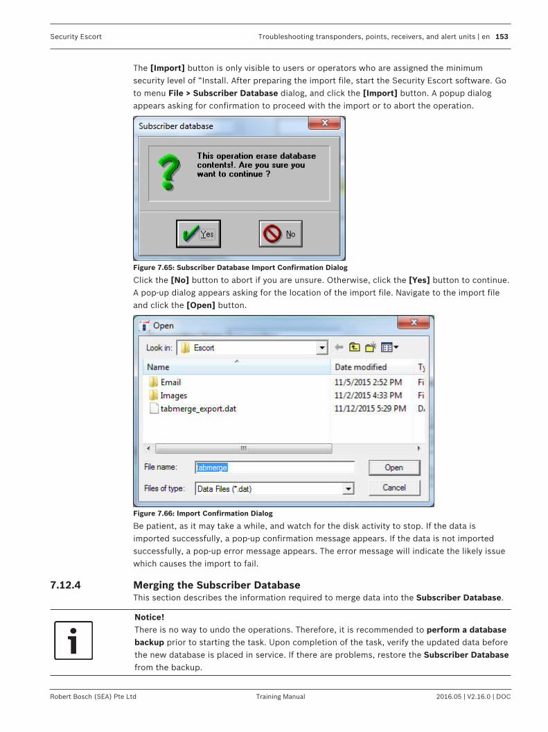
Security Escort Troubleshooting transponders, points, receivers, and alert units | en 153
Robert Bosch (SEA) Pte Ltd Training Manual 2016.05 | V2.16.0 | DOC
The [Import] button is only visible to users or operators who are assigned the minimumsecurity level of “Install. After preparing the import file, start the Security Escort software. Goto menu File > Subscriber Database dialog, and click the [Import] button. A popup dialogappears asking for confirmation to proceed with the import or to abort the operation.
Figure 7.65: Subscriber Database Import Confirmation Dialog
Click the [No] button to abort if you are unsure. Otherwise, click the [Yes] button to continue.A pop-up dialog appears asking for the location of the import file. Navigate to the import fileand click the [Open] button.
Figure 7.66: Import Confirmation Dialog
Be patient, as it may take a while, and watch for the disk activity to stop. If the data isimported successfully, a pop-up confirmation message appears. If the data is not importedsuccessfully, a pop-up error message appears. The error message will indicate the likely issuewhich causes the import to fail.
7.12.4 Merging the Subscriber DatabaseThis section describes the information required to merge data into the Subscriber Database.
Notice!There is no way to undo the operations. Therefore, it is recommended to perform a databasebackup prior to starting the task. Upon completion of the task, verify the updated data beforethe new database is placed in service. If there are problems, restore the Subscriber Databasefrom the backup.

154 en | Troubleshooting transponders, points, receivers, and alert units Security Escort
2016.05 | V2.16.0 | DOC Training Manual Robert Bosch (SEA) Pte Ltd
Notice!Important!The record entries in the “.dat” file are merged with existing records in the SubscriberDatabase. If the Subscriber ID field in the file matches a record in the Subscriber Database,the existing record will be merged with the corresponding record entry in the file. Unmatchedrecords will be inserted into the Subscriber Database as new records.The total number of records is subject to the number of subscribers allowed for thepurchased license. You can find this limit in the menu About > About… If this limit is reachedduring the merge, a pop-up message appears to inform the user.
The [Data Merge] button is only visible to users or operators who are assigned the minimumsecurity level of “Install”. After preparing the merge file, start the Security Escort software. Goto menu File > Subscriber Database dialog, and click the [Data Merge] button. A pop-updialog appears asking for the location of the merge file. Navigate to the merge file and clickthe [Open] button.
Figure 7.67: Merge Confirmation Dialog
Be patient, as it may take a while, and watch for the disk activity to stop. If the data is mergedsuccessfully, a pop-up confirmation message appears. If the data is not merged successfully, apop-up error message appears. The error message will indicate the likely issue which causesthe merge to fail.

Security Escort Troubleshooting transponders, points, receivers, and alert units | en 155
Robert Bosch (SEA) Pte Ltd Training Manual 2016.05 | V2.16.0 | DOC
7.13 Exporting and importing the Transponder DatabaseThe following sections describe the steps to export and import data from and into theTransponder Database. The operation supports XML and “.dat” with tab delimited fileformats. The export and import tasks are described in detail as follows.
Notice!If extensions for known file types are enabled, this could affect the export and importoperations of the database. These extensions should be hidden from view.For Windows 7, open Windows Explorer. From the menu bar, click Tools > Folder options…menu item. The Folder Options window appears. Click the View tab. Under the Advancedsettings tree, look for the Hide extensions for known file types option. Ensure that thecheckbox is selected.For Windows 10, open File Explorer (This PC). From the menu bar, click View menu item toview the ribbon menu. Ensure that the checkbox of the File name extensions option is notselected.
Figure 7.68: Find Transponder's Database Record Dialog
7.13.1 ".dat" file formatThe “.dat” file must be in tab delimited text format. The data fields must be in the followingorder, delimited by the horizontal tab character (decimal 8) and the record must beterminated with a carriage return (decimal 13). If a data field has no data, just store theterminating tab character for that field. The total number of characters in all the fields of arecord must be 255 characters or less, including the tab and carriage return characters.
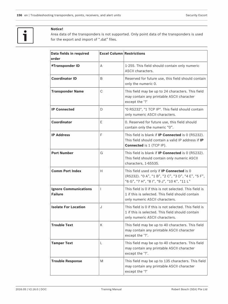
156 en | Troubleshooting transponders, points, receivers, and alert units Security Escort
2016.05 | V2.16.0 | DOC Training Manual Robert Bosch (SEA) Pte Ltd
Notice!Area data of the transponders is not supported. Only point data of the transponders is usedfor the export and import of “.dat” files.
Data fields in requiredorder
Excel Column Restrictions
#Transponder ID A 1-255. This field should contain only numericASCII characters.
Coordinator ID B Reserved for future use, this field should containonly the numeric 0.
Transponder Name C This field may be up to 24 characters. This fieldmay contain any printable ASCII characterexcept the ‘?’
IP Connected D "0 RS232", "1 TCP IP". This field should containonly numeric ASCII characters.
Coordinator E 0. Reserved for future use, this field shouldcontain only the numeric “0”.
IP Address F This field is blank if IP Connected is 0 (RS232).This field should contain a valid IP address if IPConnected is 1 (TCP IP).
Port Number G This field is blank if IP Connected is 0 (RS232).This field should contain only numeric ASCIIcharacters, 1-65535.
Comm Port Index H This field used only if IP Connected is 0(RS232). “0 A”, “1 B”, “2 C”, “3 D”, “4 E”, “5 F”,“6 G”, “7 H”, “8 I”, “9 J”, “10 K”, “11 L”
Ignore CommunicationsFailure
I This field is 0 if this is not selected. This field is1 if this is selected. This field should containonly numeric ASCII characters.
Isolate For Location J This field is 0 if this is not selected. This field is1 if this is selected. This field should containonly numeric ASCII characters.
Trouble Text K This field may be up to 40 characters. This fieldmay contain any printable ASCII characterexcept the ‘?’.
Tamper Text L This field may be up to 40 characters. This fieldmay contain any printable ASCII characterexcept the ‘?’.
Trouble Response M This field may be up to 135 characters. This fieldmay contain any printable ASCII characterexcept the ‘?’

Security Escort Troubleshooting transponders, points, receivers, and alert units | en 157
Robert Bosch (SEA) Pte Ltd Training Manual 2016.05 | V2.16.0 | DOC
Data fields in requiredorder
Excel Column Restrictions
Point Number 0 N This field must be 0 (the point number). Thisfield should contain only numeric ASCIIcharacters.
Point Type O “0 receiver”, “1 Alert unit”, “2 Virtual”, “7 None”.This field should contain only numeric ASCIIcharacters.
Algorithm Number P “0 Default”, “1 Classic”. “2 Linear”, “3 Low”, “4Medium”, “5 Strong”. This field should containonly numeric ASCII characters.
Floor Q "0 Basement5", "1 Basement4", "2 Basement3","3 Basement2", "4 Basement1", "5 Tunnel", "6Basement ", "7 Ground","8 Outside", "9 Floor 1","10 Floor 2", "11 Floor 3", "12 Floor 4", "13 Floor5", "14 Floor 6", "15 Floor 7", "16 Floor 8", "17Floor 9", "18 Floor 10", "19 Floor 11", "20 Floor12", "21 Floor 13", "22 Floor 14", "23 Floor 15","24 Floor 16", "25 Floor 17", "26 Floor 18", "27Floor 19", "28 Floor 20", "29 Floor 21", "30 Floor22", "31 Floor 23", "32 Floor 24", "33 Floor 25","34 Floor 26", "35 Floor 27", "36 Floor 28", "37Floor 29", "38 Floor 30", "39 Floor 31", "40 Floor32", "41 Floor 33", "42 Floor 34", "43 Floor 35","44 Floor 36", "45 Floor 37", "46 Floor 38", "47Floor 39", “48 Floor 40”, “49 Floor 41”, “50Floor 42”, “51 Floor 43”, “52 Floor 44”, “53Floor 45”, “54 Floor 46”, “55 Floor 47”, “56Floor 48”, “57 Floor 49”, “58 Floor 50”, “59Floor 51”, “60 Floor 52”, “61 Floor 53”, “62Floor 54”, “63 Floor 55”, “64 Floor 56”, “65Floor 57”, “66 Floor 58”, “67 Floor 59”, “68Floor 60”, “69 Floor 61”, “70 Floor 62”, “71Floor 63”, “72 Floor 64”, “73 Floor 65”, “74Floor 66”, “75 Floor 67”, “76 Floor 68”, “77Floor 69”, “78 Floor 70”, “79 Floor 71”, “80Floor 72”, “81 Floor 73”, “82 Floor 74”, “83Floor 75”, “84 Floor 76”, “85 Floor 77”, “86Floor 78”, “87 Floor 79”, “88 Floor 80”, “89Floor 81”, “90 Floor 82”, “91 Floor 83”, “92Floor 84”, “93 Floor 85”, “94 Floor 86”, “95Floor 87”, “96 Floor 88”, “97 Floor 89”, “98Floor 90”, “99 Floor 91”, “100 Floor 92”, “101Floor 93”, “102 Floor 94”, “103 Floor 95”, “104Floor 96”, “105 Floor 97”, “106 Floor 98”, “107Floor 99”. This field should contain only numericASCII characters.

158 en | Troubleshooting transponders, points, receivers, and alert units Security Escort
2016.05 | V2.16.0 | DOC Training Manual Robert Bosch (SEA) Pte Ltd
Data fields in requiredorder
Excel Column Restrictions
Alert Unit 1 R This field contains the Transponder ID of thealert unit. If this is not configured, this field is 0.This field should contain only numeric ASCIIcharacters.
Alert Unit 1 Point S This field contains the alert unit point number. Ifthis is not configured, this field is -1. This fieldshould contain only numeric ASCII characters.
Alert Unit 2 T This field contains the Transponder ID of thealert unit. If this is not configured, this field is 0.This field should contain only numeric ASCIIcharacters.
Alert Unit 2 Point U This field contains the alert unit point number. Ifthis is not configured, this field is -1. This fieldshould contain only numeric ASCII characters.
Alert Unit 3 V This field contains the Transponder ID of thealert unit. If this is not configured, this field is 0.This field should contain only numeric ASCIIcharacters.
Alert Unit 3 Point W This field contains the alert unit point number. Ifthis is not configured, this field is -1. This fieldshould contain only numeric ASCII characters.
Alert Unit Test X This field contains the Transponder ID of thealert unit. If this is not configured, this field is 0.This field should contain only numeric ASCIIcharacters.
Alert Unit Test Point Y This field contains the alert unit point number. Ifthis is not configured, this field is -1. This fieldshould contain only numeric ASCII characters.
Point Location Text Z This field may be up to 100 characters. This fieldmay contain any printable ASCII characterexcept the ‘?’.
Map X Position AA X position of the point on the map. Default is 0.This field should contain only numeric ASCIIcharacters.
Map Y Position AB Y position of the point on the map. Default is 0.This field should contain only numeric ASCIIcharacters.
Sensitivity Adjust AC 0-99. This field should contain only numericASCII characters.
Bitmap Number AD 0-99. This field should contain only numericASCII characters.

Security Escort Troubleshooting transponders, points, receivers, and alert units | en 159
Robert Bosch (SEA) Pte Ltd Training Manual 2016.05 | V2.16.0 | DOC
Data fields in requiredorder
Excel Column Restrictions
Point Number 1 AE This field must be 1 (the point number). Thisfield should contain only numeric ASCIIcharacters.
Point Type AF “0 receiver”, “1 Alert unit”, “2 Virtual”, “7 None”.This field should contain only numeric ASCIIcharacters.
Algorithm Number AG “0 Default”, “1 Classic”. “2 Linear”, “3 Low”, “4Medium”, “5 Strong”. This field should containonly numeric ASCII characters.
Floor AH "0 Basement5", "1 Basement4", "2 Basement3","3 Basement2", "4 Basement1", "5 Tunnel", "6Basement ", "7 Ground","8 Outside", "9 Floor 1","10 Floor 2", "11 Floor 3", "12 Floor 4", "13 Floor5", "14 Floor 6", "15 Floor 7", "16 Floor 8", "17Floor 9", "18 Floor 10", "19 Floor 11", "20 Floor12", "21 Floor 13", "22 Floor 14", "23 Floor 15","24 Floor 16", "25 Floor 17", "26 Floor 18", "27Floor 19", "28 Floor 20", "29 Floor 21", "30 Floor22", "31 Floor 23", "32 Floor 24", "33 Floor 25","34 Floor 26", "35 Floor 27", "36 Floor 28", "37Floor 29", "38 Floor 30", "39 Floor 31", "40 Floor32", "41 Floor 33", "42 Floor 34", "43 Floor 35","44 Floor 36", "45 Floor 37", "46 Floor 38", "47Floor 39", “48 Floor 40”, “49 Floor 41”, “50Floor 42”, “51 Floor 43”, “52 Floor 44”, “53Floor 45”, “54 Floor 46”, “55 Floor 47”, “56Floor 48”, “57 Floor 49”, “58 Floor 50”, “59Floor 51”, “60 Floor 52”, “61 Floor 53”, “62Floor 54”, “63 Floor 55”, “64 Floor 56”, “65Floor 57”, “66 Floor 58”, “67 Floor 59”, “68Floor 60”, “69 Floor 61”, “70 Floor 62”, “71Floor 63”, “72 Floor 64”, “73 Floor 65”, “74Floor 66”, “75 Floor 67”, “76 Floor 68”, “77Floor 69”, “78 Floor 70”, “79 Floor 71”, “80Floor 72”, “81 Floor 73”, “82 Floor 74”, “83Floor 75”, “84 Floor 76”, “85 Floor 77”, “86Floor 78”, “87 Floor 79”, “88 Floor 80”, “89Floor 81”, “90 Floor 82”, “91 Floor 83”, “92Floor 84”, “93 Floor 85”, “94 Floor 86”, “95Floor 87”, “96 Floor 88”, “97 Floor 89”, “98Floor 90”, “99 Floor 91”, “100 Floor 92”, “101Floor 93”, “102 Floor 94”, “103 Floor 95”, “104Floor 96”, “105 Floor 97”, “106 Floor 98”, “107Floor 99”. This field should contain only numericASCII characters.
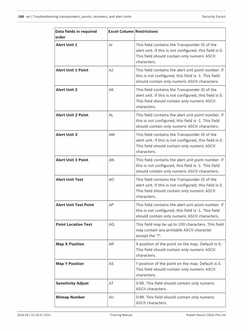
160 en | Troubleshooting transponders, points, receivers, and alert units Security Escort
2016.05 | V2.16.0 | DOC Training Manual Robert Bosch (SEA) Pte Ltd
Data fields in requiredorder
Excel Column Restrictions
Alert Unit 1 AI This field contains the Transponder ID of thealert unit. If this is not configured, this field is 0.This field should contain only numeric ASCIIcharacters.
Alert Unit 1 Point AJ This field contains the alert unit point number. Ifthis is not configured, this field is -1. This fieldshould contain only numeric ASCII characters.
Alert Unit 2 AK This field contains the Transponder ID of thealert unit. If this is not configured, this field is 0.This field should contain only numeric ASCIIcharacters.
Alert Unit 2 Point AL This field contains the alert unit point number. Ifthis is not configured, this field is -1. This fieldshould contain only numeric ASCII characters.
Alert Unit 3 AM This field contains the Transponder ID of thealert unit. If this is not configured, this field is 0.This field should contain only numeric ASCIIcharacters.
Alert Unit 3 Point AN This field contains the alert unit point number. Ifthis is not configured, this field is -1. This fieldshould contain only numeric ASCII characters.
Alert Unit Test AO This field contains the Transponder ID of thealert unit. If this is not configured, this field is 0.This field should contain only numeric ASCIIcharacters.
Alert Unit Test Point AP This field contains the alert unit point number. Ifthis is not configured, this field is -1. This fieldshould contain only numeric ASCII characters.
Point Location Text AQ This field may be up to 100 characters. This fieldmay contain any printable ASCII characterexcept the ‘?’.
Map X Position AR X position of the point on the map. Default is 0.This field should contain only numeric ASCIIcharacters.
Map Y Position AS Y position of the point on the map. Default is 0.This field should contain only numeric ASCIIcharacters.
Sensitivity Adjust AT 0-99. This field should contain only numericASCII characters.
Bitmap Number AU 0-99. This field should contain only numericASCII characters.
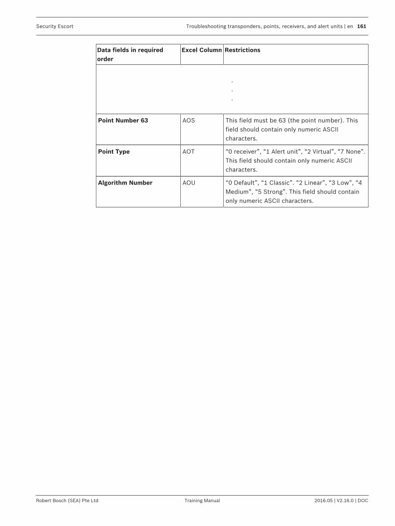
Security Escort Troubleshooting transponders, points, receivers, and alert units | en 161
Robert Bosch (SEA) Pte Ltd Training Manual 2016.05 | V2.16.0 | DOC
Data fields in requiredorder
Excel Column Restrictions
.
.
.
Point Number 63 AOS This field must be 63 (the point number). Thisfield should contain only numeric ASCIIcharacters.
Point Type AOT “0 receiver”, “1 Alert unit”, “2 Virtual”, “7 None”.This field should contain only numeric ASCIIcharacters.
Algorithm Number AOU “0 Default”, “1 Classic”. “2 Linear”, “3 Low”, “4Medium”, “5 Strong”. This field should containonly numeric ASCII characters.
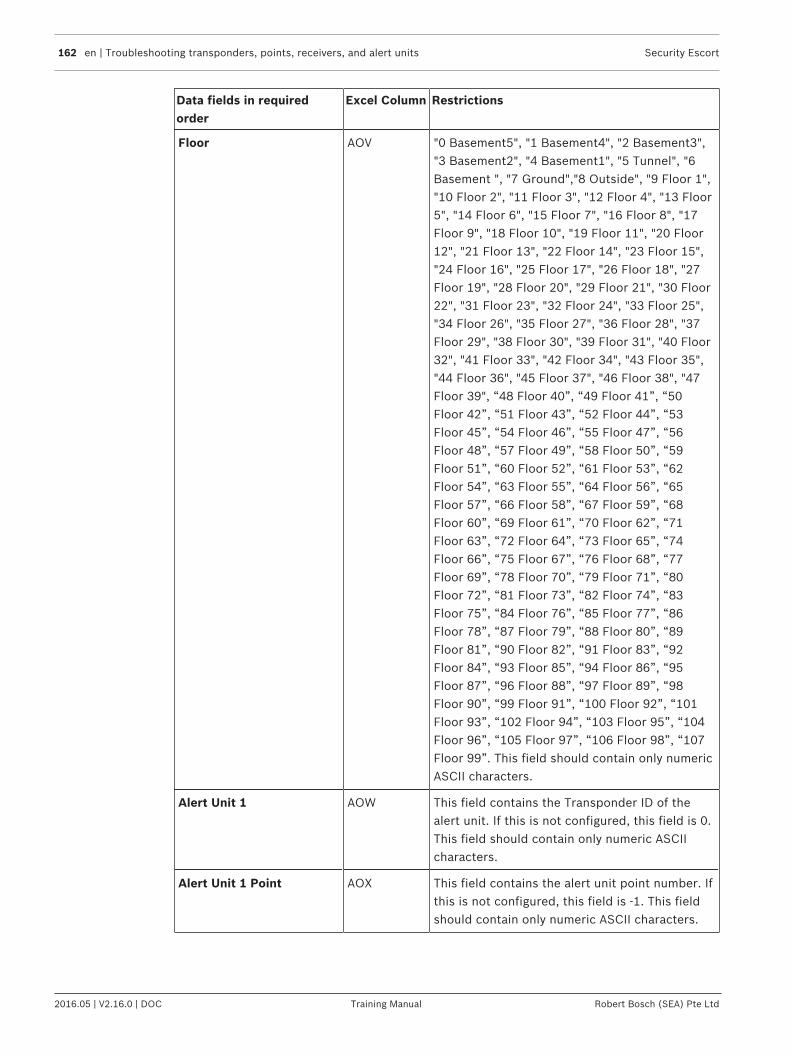
162 en | Troubleshooting transponders, points, receivers, and alert units Security Escort
2016.05 | V2.16.0 | DOC Training Manual Robert Bosch (SEA) Pte Ltd
Data fields in requiredorder
Excel Column Restrictions
Floor AOV "0 Basement5", "1 Basement4", "2 Basement3","3 Basement2", "4 Basement1", "5 Tunnel", "6Basement ", "7 Ground","8 Outside", "9 Floor 1","10 Floor 2", "11 Floor 3", "12 Floor 4", "13 Floor5", "14 Floor 6", "15 Floor 7", "16 Floor 8", "17Floor 9", "18 Floor 10", "19 Floor 11", "20 Floor12", "21 Floor 13", "22 Floor 14", "23 Floor 15","24 Floor 16", "25 Floor 17", "26 Floor 18", "27Floor 19", "28 Floor 20", "29 Floor 21", "30 Floor22", "31 Floor 23", "32 Floor 24", "33 Floor 25","34 Floor 26", "35 Floor 27", "36 Floor 28", "37Floor 29", "38 Floor 30", "39 Floor 31", "40 Floor32", "41 Floor 33", "42 Floor 34", "43 Floor 35","44 Floor 36", "45 Floor 37", "46 Floor 38", "47Floor 39", “48 Floor 40”, “49 Floor 41”, “50Floor 42”, “51 Floor 43”, “52 Floor 44”, “53Floor 45”, “54 Floor 46”, “55 Floor 47”, “56Floor 48”, “57 Floor 49”, “58 Floor 50”, “59Floor 51”, “60 Floor 52”, “61 Floor 53”, “62Floor 54”, “63 Floor 55”, “64 Floor 56”, “65Floor 57”, “66 Floor 58”, “67 Floor 59”, “68Floor 60”, “69 Floor 61”, “70 Floor 62”, “71Floor 63”, “72 Floor 64”, “73 Floor 65”, “74Floor 66”, “75 Floor 67”, “76 Floor 68”, “77Floor 69”, “78 Floor 70”, “79 Floor 71”, “80Floor 72”, “81 Floor 73”, “82 Floor 74”, “83Floor 75”, “84 Floor 76”, “85 Floor 77”, “86Floor 78”, “87 Floor 79”, “88 Floor 80”, “89Floor 81”, “90 Floor 82”, “91 Floor 83”, “92Floor 84”, “93 Floor 85”, “94 Floor 86”, “95Floor 87”, “96 Floor 88”, “97 Floor 89”, “98Floor 90”, “99 Floor 91”, “100 Floor 92”, “101Floor 93”, “102 Floor 94”, “103 Floor 95”, “104Floor 96”, “105 Floor 97”, “106 Floor 98”, “107Floor 99”. This field should contain only numericASCII characters.
Alert Unit 1 AOW This field contains the Transponder ID of thealert unit. If this is not configured, this field is 0.This field should contain only numeric ASCIIcharacters.
Alert Unit 1 Point AOX This field contains the alert unit point number. Ifthis is not configured, this field is -1. This fieldshould contain only numeric ASCII characters.
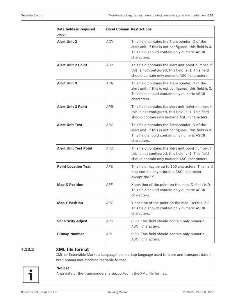
Security Escort Troubleshooting transponders, points, receivers, and alert units | en 163
Robert Bosch (SEA) Pte Ltd Training Manual 2016.05 | V2.16.0 | DOC
Data fields in requiredorder
Excel Column Restrictions
Alert Unit 2 AOY This field contains the Transponder ID of thealert unit. If this is not configured, this field is 0.This field should contain only numeric ASCIIcharacters.
Alert Unit 2 Point AOZ This field contains the alert unit point number. Ifthis is not configured, this field is -1. This fieldshould contain only numeric ASCII characters.
Alert Unit 3 APA This field contains the Transponder ID of thealert unit. If this is not configured, this field is 0.This field should contain only numeric ASCIIcharacters.
Alert Unit 3 Point APB This field contains the alert unit point number. Ifthis is not configured, this field is -1. This fieldshould contain only numeric ASCII characters.
Alert Unit Test APC This field contains the Transponder ID of thealert unit. If this is not configured, this field is 0.This field should contain only numeric ASCIIcharacters.
Alert Unit Test Point APD This field contains the alert unit point number. Ifthis is not configured, this field is -1. This fieldshould contain only numeric ASCII characters.
Point Location Text APE This field may be up to 100 characters. This fieldmay contain any printable ASCII characterexcept the ‘?’.
Map X Position APF X position of the point on the map. Default is 0.This field should contain only numeric ASCIIcharacters.
Map Y Position APG Y position of the point on the map. Default is 0.This field should contain only numeric ASCIIcharacters.
Sensitivity Adjust APH 0-99. This field should contain only numericASCII characters.
Bitmap Number API 0-99. This field should contain only numericASCII characters.
7.13.2 XML file formatXML or Extensible Markup Language is a markup language used to store and transport data inboth human-and machine-readable format.
Notice!Area data of the transponders is supported in the XML file format.

164 en | Troubleshooting transponders, points, receivers, and alert units Security Escort
2016.05 | V2.16.0 | DOC Training Manual Robert Bosch (SEA) Pte Ltd
The XML tree consists of 3 main elements, namely the <Transponder>, <Receivers> and
<Areas> elements. The <Transponder> element is the parent element, with child elements
<Receivers> and <Areas>. The <Receivers> element has a sub element <Receiver>. The
<Areas> element has a sub element <Area> which contains another level of sub element
<ProtectedAreaPoints>.
Below is an example of a typical tree with an empty structure:<Transponder>
<Receivers>
<Receiver />
</Receivers>
<Areas>
<Area>
<ProtectedAreaPoints />
</Area>
</Areas>
</Transponder>
Below is an example of the XML tree with some elements and attributes:
<Transponder TransponderID="255" Name="North Point Hospital"
IsIPConnected="0" IPAddress="" PortNumber="0" CommPortIndex="0">
<Receivers>
<Receiver Address="0" PointType="0" AlgoNumber="0" AlarmIcon="9"
TS_TrpID="255" TS_MUXAddress="255" Rx_LocationText="1st Floor by South Exit
Door" MapXPosition="430" MapYPosition="479" SensitivityAdjust="0"
BitmapNumber="0" />
<Receiver Address="1" PointType="0" AlgoNumber="0" AlarmIcon="9"
TS_TrpID="255" TS_MUXAddress="255" Rx_LocationText="1st Floor Center of
Main Lobby" MapXPosition="429" MapYPosition="215" SensitivityAdjust="0"
BitmapNumber="0" />
</Receivers>
<Areas>
<Area AreaID="0" FloorIcon="9" PagerGroupA="0" BitmapNumber="0"
LocationText="1st Floor Main Lobby Area" MatrixSwitchText="">
<ProtectedAreaPoints ProtectedXArea1="386"
ProtectedYArea1="292" ProtectedXArea2="386" ProtectedYArea2="292"
ProtectedXArea3="385" ProtectedYArea3="209" ProtectedXArea4="470"
ProtectedYArea4="209" ProtectedXArea5="468" ProtectedYArea5="297"
ProtectedXArea6="387" ProtectedYArea6="294" />
</Area>
<Area AreaID="1" FloorIcon="9" PagerGroupA="0" BitmapNumber="0"
LocationText="1st Floor Main Entrance & Accounting Area"
MatrixSwitchText="">
<ProtectedAreaPoints ProtectedXArea1="385"
ProtectedYArea1="293" ProtectedXArea2="385" ProtectedYArea2="293"
ProtectedXArea3="468" ProtectedYArea3="297" ProtectedXArea4="470"
ProtectedYArea4="351" ProtectedXArea5="384" ProtectedYArea5="348"
ProtectedXArea6="386" ProtectedYArea6="294" />

Security Escort Troubleshooting transponders, points, receivers, and alert units | en 165
Robert Bosch (SEA) Pte Ltd Training Manual 2016.05 | V2.16.0 | DOC
</Area>
</Areas>
</Transponder>
<Transponder TransponderID="1" Name="South Point Hospital"
IsIPConnected="0" IPAddress="" PortNumber="0" CommPortIndex="0">
<Receivers>
<Receiver Address="6" PointType="0" AlgoNumber="0" AlarmIcon="9"
Rx_LocationText="1st Floor by South Exit Door" MapXPosition="430"
MapYPosition="479" SensitivityAdjust="0" BitmapNumber="0" />
<Receiver Address="7" PointType="0" AlgoNumber="0" AlarmIcon="9"
Rx_LocationText="1st Floor Center of Main Lobby" MapXPosition="429"
MapYPosition="215" SensitivityAdjust="0" BitmapNumber="0" />
</Receivers>
</Transponder>
The following attributes are applicable to the respective elements.
<Transponder> element
Attribute Value
TransponderID ID of the transponder. 1-255. This field should contain onlynumeric ASCII characters.
Name Name of the transponder. This field may be up to 24 characters.This field may contain any printable ASCII character except the ‘?’
IsIPConnected 0 if transponder is connected via RS232, 1 if transponder isconnected via TCP IP. This field should contain only numericASCII characters.
IPAddress The value is blank if IsIPConnected is 0 (RS232). The value shouldcontain a valid IP address if IsIPConnected is 1 (TCP IP).
PortNumber The value is 0 if IsIPConnected is 0 (RS232). The value is 1-65535if IsIPConnected is 1 (TCP IP).
CommPortIndex The value is always 0 if IsIPConnected is 1 (TCP IP). IfIsIPConnected is 0 (RS232), the following values are valid: 0 (A),1 (B), 2 (C), 3 (D), 4 (E), 5 (F), 6 (G), 7 (H), 8 (I), 9 (J), 10 (K), 11(L)
<Receiver> element
Attribute Value
Address Address of the receiver. 0-63. This field should contain onlynumeric ASCII characters.
PointType Type of point. This field should contain only numeric ASCIIcharacters. Valid values are: 0 (receiver), 1 (Alert unit), 2 (Virtual)and 7 (None).

166 en | Troubleshooting transponders, points, receivers, and alert units Security Escort
2016.05 | V2.16.0 | DOC Training Manual Robert Bosch (SEA) Pte Ltd
Attribute Value
AlgoNumber This field should contain only numeric ASCII characters. Validvalues are: 0 (Default), 1 (Classic). 2 (Linear), 3 (Low), 4(Medium) and 5 (Strong).
AlarmIcon Floor level of the point. This field should contain only numericASCII characters. Valid values are: 0 (Basement5), 1 (Basement4),2 (Basement3), 3 (Basement2), 4 (Basement1), 5 (Tunnel), 6(Basement), 7 (Ground), 8 (Outside), 9 (Floor 1), 10 (Floor 2), 11(Floor 3), 12 (Floor 4), 13 (Floor 5), 14 (Floor 6), 15 (Floor 7), 16(Floor 8), 17 (Floor 9), 18 (Floor 10), 19 (Floor 11), 20 (Floor 12),21 (Floor 13), 22 (Floor 14), 23 (Floor 15), 24 (Floor 16), 25(Floor 17), 26 (Floor 18), 27 (Floor 19), 28 (Floor 20), 29 (Floor21), 30 (Floor 22), 31 (Floor 23), 32 (Floor 24), 33 (Floor 25), 34(Floor 26), 35 (Floor 27), 36 (Floor 28), 37 (Floor 29), 38 (Floor30), 39 (Floor 31), 40 (Floor 32), 41 (Floor 33), 42 (Floor 34), 43(Floor 35), 44 (Floor 36), 45 (Floor 37), 46 (Floor 38), 47 (Floor39), 48 (Floor 40), 49 (Floor 41), 50 (Floor 42), 51 (Floor 43), 52(Floor 44), 53 (Floor 45), 54 (Floor 46), 55 (Floor 47), 56 (Floor48), 57 (Floor 49), 58 (Floor 50), 59 (Floor 51), 60 (Floor 52), 61(Floor 53), 62 (Floor 54), 63 (Floor 55), 64 (Floor 56), 65 (Floor57), 66 (Floor 58), 67 (Floor 59), 68 (Floor 60), 69 (Floor 61), 70(Floor 62), 71 (Floor 63), 72 (Floor 64), 73 (Floor 65), 74 (Floor66), 75 (Floor 67), 76 (Floor 68), 77 (Floor 69), 78 (Floor 70), 79(Floor 71), 80 (Floor 72), 81 (Floor 73), 82 (Floor 74), 83 (Floor75), 84 (Floor 76), 85 (Floor 77), 86 (Floor 78), 87 (Floor 79), 88(Floor 80), 89 (Floor 81), 90 (Floor 82), 91 (Floor 83), 92 (Floor84), 93 (Floor 85), 94 (Floor 86), 95 (Floor 87), 96 (Floor 88), 97(Floor 89), 98 (Floor 90), 99 (Floor 91), 100 (Floor 92), 101(Floor 93), 102 (Floor 94), 103 (Floor 95), 104 (Floor 96), 105(Floor 97), 106 (Floor 98), 107 (Floor 99).
TS_TrpID This field contains the Transponder ID of the alert unit. If this isnot configured, the value is 0. This field should contain onlynumeric ASCII characters.
TS_MUXAddress This field contains the alert unit point number. If this is notconfigured, the value is -1. This field should contain only numericASCII characters.
Rx_LocationText Location of the point. This field may be up to 100 characters. Thisfield may contain any printable ASCII character except the ‘?’.
MapXPosition X position of the point on the map. Default value is 0. This fieldshould contain only numeric ASCII characters.
MapYPosition Y position of the point on the map. Default value is 0. This fieldshould contain only numeric ASCII characters.
SensitivityAdjust 0-99. This field should contain only numeric ASCII characters.
BitmapNumber 0-99. This field should contain only numeric ASCII characters.

Security Escort Troubleshooting transponders, points, receivers, and alert units | en 167
Robert Bosch (SEA) Pte Ltd Training Manual 2016.05 | V2.16.0 | DOC
<Area> element
Attributes Value
AreaID ID of the area. 0-79. This field should contain only numeric ASCIIcharacters.
FloorIcon Floor of the area. This field should contain only numeric ASCIIcharacters. Valid values are: 0 (Basement5), 1 (Basement4), 2(Basement3), 3 (Basement2), 4 (Basement1), 5 (Tunnel), 6(Basement), 7 (Ground), 8 (Outside), 9 (Floor 1), 10 (Floor 2), 11(Floor 3), 12 (Floor 4), 13 (Floor 5), 14 (Floor 6), 15 (Floor 7), 16(Floor 8), 17 (Floor 9), 18 (Floor 10), 19 (Floor 11), 20 (Floor 12),21 (Floor 13), 22 (Floor 14), 23 (Floor 15), 24 (Floor 16), 25(Floor 17), 26 (Floor 18), 27 (Floor 19), 28 (Floor 20), 29 (Floor21), 30 (Floor 22), 31 (Floor 23), 32 (Floor 24), 33 (Floor 25), 34(Floor 26), 35 (Floor 27), 36 (Floor 28), 37 (Floor 29), 38 (Floor30), 39 (Floor 31), 40 (Floor 32), 41 (Floor 33), 42 (Floor 34), 43(Floor 35), 44 (Floor 36), 45 (Floor 37), 46 (Floor 38), 47 (Floor39), 48 (Floor 40), 49 (Floor 41), 50 (Floor 42), 51 (Floor 43), 52(Floor 44), 53 (Floor 45), 54 (Floor 46), 55 (Floor 47), 56 (Floor48), 57 (Floor 49), 58 (Floor 50), 59 (Floor 51), 60 (Floor 52), 61(Floor 53), 62 (Floor 54), 63 (Floor 55), 64 (Floor 56), 65 (Floor57), 66 (Floor 58), 67 (Floor 59), 68 (Floor 60), 69 (Floor 61), 70(Floor 62), 71 (Floor 63), 72 (Floor 64), 73 (Floor 65), 74 (Floor66), 75 (Floor 67), 76 (Floor 68), 77 (Floor 69), 78 (Floor 70), 79(Floor 71), 80 (Floor 72), 81 (Floor 73), 82 (Floor 74), 83 (Floor75), 84 (Floor 76), 85 (Floor 77), 86 (Floor 78), 87 (Floor 79), 88(Floor 80), 89 (Floor 81), 90 (Floor 82), 91 (Floor 83), 92 (Floor84), 93 (Floor 85), 94 (Floor 86), 95 (Floor 87), 96 (Floor 88), 97(Floor 89), 98 (Floor 90), 99 (Floor 91), 100 (Floor 92), 101(Floor 93), 102 (Floor 94), 103 (Floor 95), 104 (Floor 96), 105(Floor 97), 106 (Floor 98), 107 (Floor 99).
PagerGroupA Pager group. Default value is 0.
BitmapNumber Graphic map of the area. 0-99. This field should contain onlynumeric ASCII characters.
LocationText Location of the point. This field may be up to 100 characters. Thisfield may contain any printable ASCII character except the ‘?’.
MatrixSwitchText ASCII value to control video matrix switch.
<ProtectedAreaPoints> element
Attributes Value
ProtectedXArea1 1st coordinate point X of the area. This field should contain onlynumeric ASCII characters.
ProtectedYArea1 1st coordinate point Y of the area. This field should contain onlynumeric ASCII characters.

168 en | Troubleshooting transponders, points, receivers, and alert units Security Escort
2016.05 | V2.16.0 | DOC Training Manual Robert Bosch (SEA) Pte Ltd
Attributes Value
ProtectedXArea2 2nd coordinate point X of the area. This field should contain onlynumeric ASCII characters.
ProtectedYArea2 2nd coordinate point Y of the area. This field should contain onlynumeric ASCII characters.
ProtectedXArea3 3rdcoordinate point X of the area. This field should contain onlynumeric ASCII characters.
ProtectedYArea3 3rd coordinate point Y of the area. This field should contain onlynumeric ASCII characters.
.
.
.
ProtectedXArea19 19th coordinate point X of the area. This field should contain onlynumeric ASCII characters.
ProtectedYArea19 19th coordinate point Y of the area. This field should contain onlynumeric ASCII characters.
7.13.3 Exporting the Transponder DatabaseThis section describes the information required to export data from the TransponderDatabase.Only users or operators who are assigned the minimum security level of “Install” is able toview the Transponder Database. Go to menu File > Transponder Database dialog, and clickthe [Export] button.
Notice!Important! The export operation does not change the existing records in TransponderDatabase. However, be mindful that every time you perform the export function (clicking the[Export] button), the operation will overwrite the default “TRANSMERGE_EXPORT.DAT” or“TRANSMERGE_EXPORT.XML” file.
A dialog box appears. You can choose the folder where you wish to save the file in, or provideyour own name for the file. Click the drop-down list of Save as type field to choose the formatof the file you wish to export to (“.dat” or “.xml” formats).

Security Escort Troubleshooting transponders, points, receivers, and alert units | en 169
Robert Bosch (SEA) Pte Ltd Training Manual 2016.05 | V2.16.0 | DOC
Figure 7.69: Export Confirmation Dialog
Be patient, as it may take a while, and watch for the disk activity to stop. If the export issuccessful, a confirmation dialog appears. You will find the file in the specified folder.
7.13.4 Importing the Transponder DatabaseThis section describes the information required to import data into the TransponderDatabase.
Notice!There is no way to undo the operations. Therefore, it is recommended to perform a databasebackup prior to starting the task. Upon completion of the task, verify the updated data beforethe new database is placed in service. If there are problems, restore the TransponderDatabase from the backup.
Notice!Important!Proceeding with the import operation will delete all existing records in TransponderDatabase. The record entries in import file are then imported to the Transponder Database,validated by the Transponder ID.The number of record entries that is imported is subject to the number of transpondersallowed for the purchased license. You can find this limit in the menu About > About… If thislimit is reached during the import, a pop-up message appears to inform the user.

170 en | Troubleshooting transponders, points, receivers, and alert units Security Escort
2016.05 | V2.16.0 | DOC Training Manual Robert Bosch (SEA) Pte Ltd
Only users or operators who are assigned the minimum security level of “Install” is able toview the Transponder Database. After preparing the file in “.dat” or “.xml” format, start theSecurity Escort software. Go to menu File > Transponder Database dialog, and click the[Import] button. A popup dialog appears asking for confirmation to proceed with the importor to abort the operation.
Figure 7.70: Transponder Database Import Dialog
Click the [No] button to abort if you are still unsure. Otherwise, click the [Yes] button tocontinue. A popup dialog appears asking for the file to be used for the import process.Navigate the folders, select the file and click the [Open] button accordingly.
Figure 7.71: Import Confirmation Dialog
Be patient, as it may take a while, and watch for the disk activity to stop. If the data isimported successfully, a pop-up confirmation message appears. If the data is not importedsuccessful, a pop-up error message appears. The error message will indicate the likely issuecausing the import to fail.
7.14 Operator DatabaseThe figure below is a typical screen from the Operator Database. The term operator is used torefer to a person with the authority to use the various features of the Security Escort systemsoftware. The term includes the Security department's dispatchers who initiate responses to

Security Escort Troubleshooting transponders, points, receivers, and alert units | en 171
Robert Bosch (SEA) Pte Ltd Training Manual 2016.05 | V2.16.0 | DOC
alarms, Security Officers who may be required to produce incident reports, and otheremployees of the Security department who may be responsible for maintaining the Subscriberand Operator Databases.
Figure 7.72: Find Operator’s Database Record
The information in an Operator Database record includes the individual’s password, full name,a unique operator identification number, an authority level, local address and phone number,and notes. All fields except the Password field are displayed. Even when a specific operator’sfile is edited (via the [Edit Data] button); the password is represented by a number ofasterisks for security reasons.
7.14.1 Edit Operator Database recordWhen adding a new operator or editing the data for an existing operator, the Edit OperatorRecord dialog appears. Certain information fields must be completed to produce a validrecord. The password, the authority level, and the name must be entered. All the otherinformation in the operator’s file is optional, including the local address, local phone number,and notes.
Notice!There are two boxes for passwords in the Edit Operator Record dialog, Password, andPassword Verify. Since the operator cannot see what is being entered while typing in thepassword field, it must be entered twice to safeguard against errors; password modificationsare not accepted if the entries in the Password and Password Verify text boxes are notidentical.
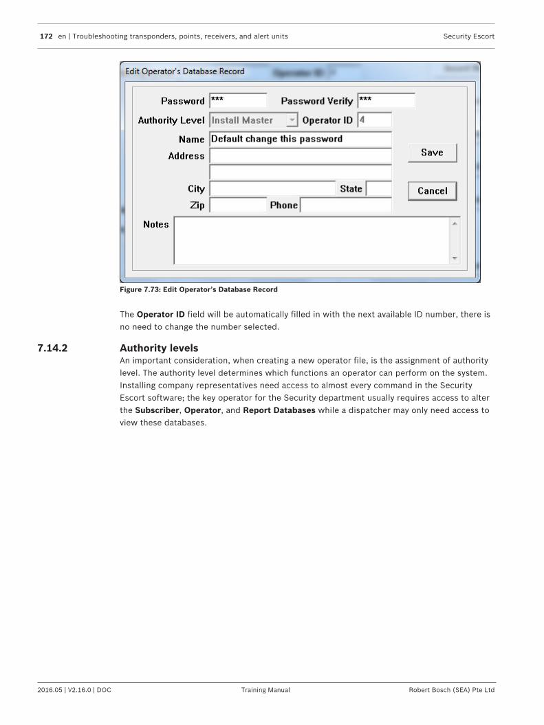
172 en | Troubleshooting transponders, points, receivers, and alert units Security Escort
2016.05 | V2.16.0 | DOC Training Manual Robert Bosch (SEA) Pte Ltd
Figure 7.73: Edit Operator’s Database Record
The Operator ID field will be automatically filled in with the next available ID number, there isno need to change the number selected.
7.14.2 Authority levelsAn important consideration, when creating a new operator file, is the assignment of authoritylevel. The authority level determines which functions an operator can perform on the system.Installing company representatives need access to almost every command in the SecurityEscort software; the key operator for the Security department usually requires access to alterthe Subscriber, Operator, and Report Databases while a dispatcher may only need access toview these databases.
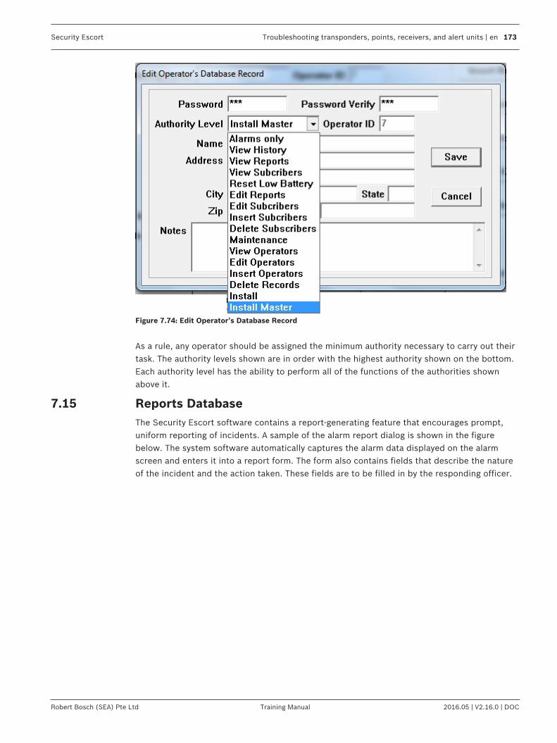
Security Escort Troubleshooting transponders, points, receivers, and alert units | en 173
Robert Bosch (SEA) Pte Ltd Training Manual 2016.05 | V2.16.0 | DOC
Figure 7.74: Edit Operator’s Database Record
As a rule, any operator should be assigned the minimum authority necessary to carry out theirtask. The authority levels shown are in order with the highest authority shown on the bottom.Each authority level has the ability to perform all of the functions of the authorities shownabove it.
7.15 Reports DatabaseThe Security Escort software contains a report-generating feature that encourages prompt,uniform reporting of incidents. A sample of the alarm report dialog is shown in the figurebelow. The system software automatically captures the alarm data displayed on the alarmscreen and enters it into a report form. The form also contains fields that describe the natureof the incident and the action taken. These fields are to be filled in by the responding officer.

174 en | Troubleshooting transponders, points, receivers, and alert units Security Escort
2016.05 | V2.16.0 | DOC Training Manual Robert Bosch (SEA) Pte Ltd
Figure 7.75: Find Alarm Report Database Record
The system software can be configured to require that a report be completed prior to the endof the shift in which the incident occurred. If the Require Alarm Report option is chosen inthe Edit Security Preferences dialog, the report can be filled out immediately after the alarmis reset. However, if the report is not completed a reminder prompt appears on the screenevery 5 min. for 30 min. before the end of the shift. The time at which the prompt is to displayis also set in the Edit Security Preferences dialog.All of the common database commands are available in the Reports Database, with thefollowing additional commands.
7.15.1 Report statisticsClicking the [Statistics] button summarizes all the alarm reports that are captured in thedatabase. The alarm reports statistics window lists the number of alarms reports according totheir problem types.

Security Escort Troubleshooting transponders, points, receivers, and alert units | en 175
Robert Bosch (SEA) Pte Ltd Training Manual 2016.05 | V2.16.0 | DOC
Figure 7.76: Alarm Report Statistics
7.15.2 MapThe act of resetting an alarm causes a report to be saved into the Reports Database. A part ofthe alarm report record is a copy of the alarm screen that is displayed at the time of theincident. Clicking the [Map] button reconstructs the screen as it appeared to the dispatcher.
Figure 7.77: Active Alarm Map
7.15.3 Edit dataSelect the appropriate problem type, and then enter the name of the officer who responded tothe alarm. Finish with a description of the problem and the action taken. Save the updatedrecord by clicking the [Save] button.

176 en | Troubleshooting transponders, points, receivers, and alert units Security Escort
2016.05 | V2.16.0 | DOC Training Manual Robert Bosch (SEA) Pte Ltd
Figure 7.78: Edit Alarm Report Information
7.15.4 DeleteThis button deletes the alarm report from the database. If the report is deleted, the data cannot be recovered.
7.15.5 Locate KeyThis button works similarly to the [Locate Key] button in the Operator and SubscriberDatabase. Entering the Subscriber Name, Transmitter ID, Subscriber ID, Subscriber Class,problem type, or a specific time and date can locate a specific report.
Figure 7.79: Locate Alarm Database Record
As in the Operator and Subscriber Database, the subscriber records are temporarily orderedaccording to the field entered in the Locate Key dialog.

Security Escort Troubleshooting transponders, points, receivers, and alert units | en 177
Robert Bosch (SEA) Pte Ltd Training Manual 2016.05 | V2.16.0 | DOC
7.15.6 Key SelectThis button also works similarly to its counterparts in the Operator and Subscriber Database.Using it, the reports can be ordered by Subscriber Name, Transmitter ID, Subscriber ID,Alarm Time, Problem Type, or Subscriber Type.
Figure 7.80: Select Database Key
7.15.7 IncompleteWhen this button is clicked, the most recent incident report file that has not been completedwill be displayed. The reports are not reordered when this command is used.
7.16 System redundancyThe Security Escort system redundancy is operational as long as master and slave controllersare configured in a network setup. By default, master computer is the one controlling thedevices. If the master computer is unavailable for some reasons, slave computer could takeover the operation (automatically or manually). Once the master computer is back online,slave computer will hand over the control to the master computer. If both the master andslave computers are not available, the system is not operational. Devices will take control bythemselves.
Notice!In the event where the master computer is unavailable and the slave computer takes controlof the devices, alarms will be reported on the slave computer. If the master computerbecomes available again, it will try to take control of the devices.However, if there are still unacknowledged alarms on the slave computer, the mastercomputer will not succeed in taking control, as the alarms need to be acknowledged on theslave computer first. The master computer will try to take control of the devices continuouslyuntil the unacknowledged alarms on the slave computer are acknowledged accordingly.During the acknowledgement process, the receiver’s sounders and red LEDs may not beturned off properly. You may need to turn these off manually from menu Setup > Receiverconfiguration.
There are 2 types of redundancy:
178 en | Troubleshooting transponders, points, receivers, and alert units Security Escort
2016.05 | V2.16.0 | DOC Training Manual Robert Bosch (SEA) Pte Ltd
1. Automatic redundancy – system will automatically determine which computer will be themain controller based on the online availability of the master and slave computers (notapplicable for RS232 connections).
2. Manual redundancy – manually determine which computer (master or slave) will be themain controller.
7.16.1 Automatic redundancyAutomatic redundancy kicks in during the following circumstances:1. Master computer information is not configured in slave computer – If the master
computer’s related information is not configured in the slave computer, the slavecomputer will consider the master computer as unavailable. As such, the control ofdevices will switch to the slave computer automatically.
2. Master computer not reachable from slave computer – If the master computer’s relatedinformation is configured in the slave computer, but the slave computer is unable toconnect to the master computer, the slave computer will keep attempting to connect for10 consecutive times. If the slave computer is still unable to connect to the mastercomputer, the control of devices will switch to the slave computer automatically.
3. Master computer not responding – The slave computer will send “heart beat” messagesto the master computer every second. The master computer will acknowledge each “heartbeat” messages to the slave computer. If the slave computer did not receive 6 continuous“heart beat” acknowledgements from the master computer, the slave computer willconsider the master computer as unreachable. As such, the control of devices will switchto the slave computer automatically.
4. Master computer acknowledges “heart beat” message – The slave computer will send the“heart beat messages” continuously. Once the slave computer receives the “heart beat”acknowledgement from the master computer, the slave computer will consider themaster computer as being back in operation. As such, the slave computer disconnects allthe devices and requests the master computer to take control of the devices.
7.16.2 Manual redundancyManual redundancy is only applicable to the following circumstances:1. RS232 connected to either master or slave computer – Switch the RS232 connection
manually to the other computer.
2. Newly RS232 connected computer takes control – The newly RS232 connected computerwill inform the other computer to lose their control. The other computer will disconnectall the devices. The newly connected RS232 system will connect and take control of thedevices.

Security Escort System menus and dialogs | en 179
Robert Bosch (SEA) Pte Ltd Training Manual 2016.05 | V2.16.0 | DOC
8 System menus and dialogs8.1 File menu
Figure 8.81: File Menu
8.1.1 Locate transmittersThis selection allows the operator to display the last reported location of the transmitterassigned to the indicated individual or asset. When the individual or asset is selected from thelist, the time of the last supervision report is shown (or “None” is displayed if no supervisionreport was received from that transmitter). On the map, the last report location is shown.
Figure 8.82: Locate Transmitters
8.1.2 Maintenance alarm databaseMaintenance transmitters, when activated in the “Test” or “Alarm” mode, generate a series ofmultiple data packets like subscriber transmitters. However, a special code in each packetidentifies the transmitter as a “Maintenance Transmitter”.The receiver responds to a maintenance “Alarm” or “Test” transmission in the same way itresponds to a subscriber “Alarm” or “Test”, unless the receiver has been put in the “Setup”mode. The transponder then reports the maintenance transmitter identification number andall signal levels to the Central Console, which then creates the location estimate andprocesses the data as it would for a normal alarm.
Notice!All maintenance transmitters are assumed to be valid so there is no need for the CentralConsole to check for the identification number in the Subscriber Database.

180 en | System menus and dialogs Security Escort
2016.05 | V2.16.0 | DOC Training Manual Robert Bosch (SEA) Pte Ltd
Figure 8.83: Maintenance "Alarm” With Signal Levels Shown in Icons
"The Central Console will not generate an audible alert for the operator, nor will it create an“alarm” display on the main Central Console screen. Because they can be set to graphicallydisplay received signal levels, maintenance “alarms” are very useful to verify that the systemcoverage exists at any location in the protected area, and that receiver redundancy isadequate.
8.1.3 Transmitter ChangeThe Transmitter Change command on the File menu is used when it is necessary to change asubscriber’s transmitter.Selecting Transmitter Change opens the Locate Subscriber’s Database Record dialog. Thesubscriber’s record in the Subscriber Database can be quickly found by entering theSubscriber Name, Subscriber ID, current Transmitter ID, Address Items, Phone Number,Pager Items or Pager Group. This method of locating a particular subscriber’s record isidentical to using the [Locate Key] button in the Subscriber Database: the first record, whichis identical to the entered data, is shown. It may be necessary to scroll using the [Previous]and [Next] buttons to find the appropriate record.

Security Escort System menus and dialogs | en 181
Robert Bosch (SEA) Pte Ltd Training Manual 2016.05 | V2.16.0 | DOC
Figure 8.84: Locate Subscriber’s Database Record
Perform a test using the old transmitter if possible. This should fill in the Transmitter ID field.Then click the [Find] button.
Notice!Be absolutely certain that the correct record is displayed before entering the newTransmitter ID (Identification Code). Changing the wrong subscriber’s record makes tworecords ineffective: the correct subscriber will be misidentified and the subscriber whoserecord was incorrectly altered will be disabled. If possible, perform a test with thesubscriber’s old transmitter after the change has been made: the test should fail.

182 en | System menus and dialogs Security Escort
2016.05 | V2.16.0 | DOC Training Manual Robert Bosch (SEA) Pte Ltd
Figure 8.85: Find Subscriber’s Database Record
When the correct subscriber’s record is displayed, click on the [Change] button and perform atest using the new transmitter. The new transmitter identification code will be automaticallypopulated into the New transmitter ID field.
Figure 8.86: Save Subscriber’s Database Record after Change of Transmitter ID
Manually enter the New transmitter ID into the Transmitter ID field or use the mouse tohighlight the old Transmitter ID value, press and hold the <Shift> key and tap the <Insert> key.Then click the [Save] button. A prompt appears, asking for a second test to confirm thechange.

Security Escort System menus and dialogs | en 183
Robert Bosch (SEA) Pte Ltd Training Manual 2016.05 | V2.16.0 | DOC
Test the new transmitter again. You should see a green light on a nearby receiver, and thisdialog should automatically disappear from the screen, confirming the change was successful.
8.2 Utilities menu
Figure 8.87: Utilities Menu
8.2.1 BackupThis feature provides a convenient process for saving the information in the databases tobackup files.
!
Warning!To prevent the accidental loss, the databases should be backed up at least once a week tomultiple backups. At least one of these backup copies should be kept in a different locationfrom the central console’s location.
Weekly backups are recommended to permit data recovery if the computer memory shouldbecome corrupted. If this unlikely event occurs, an operator can quickly restore the databasesin question with the Restore command. Backups should be made any time significant changesare made to any database.
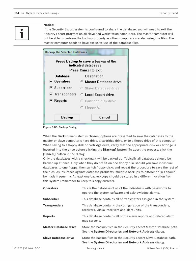
184 en | System menus and dialogs Security Escort
2016.05 | V2.16.0 | DOC Training Manual Robert Bosch (SEA) Pte Ltd
Notice!If the Security Escort system is configured to share the database, you will need to exit theSecurity Escort program on all slave and workstation computers. The master computer willnot be able to perform the backup properly as other computers are also using the files. Themaster computer needs to have exclusive use of the database files.
Figure 8.88: Backup Dialog
When the Backup menu item is chosen, options are presented to save the databases to themaster or slave computer’s hard drive, a cartridge drive, or to a floppy drive of this computer.When saving to a floppy disk or cartridge drive, verify that the appropriate disk or cartridge isinserted into the drive before clicking the [Backup] button. To abort the process, click the[Cancel] button in the dialog.Only the databases with a checkmark will be backed up. Typically all databases should bebacked up at once. Only when they do not fit on one floppy disk should you save individualdatabases to one floppy, then switch floppy disks and repeat the procedure to save the rest ofthe files. As insurance against database problems, multiple backups to different disks shouldbe made frequently. At least one backup copy should be stored in a different location fromthis system (remember to keep this copy current).
Operators This is the database of all of the individuals with passwords tooperate the system software and acknowledge alarms.
Subscriber This database contains all of transmitters assigned in the system.
Transponders This database contains the configuration of the transponders,receivers, virtual receivers and alert units.
Reports This database contains all of the alarm reports and related alarmmap screens.
Master Database drive Store the backup files in the Security Escort Master Database path.See the System Directories and Network Address dialog.
Slave Database drive Store the backup files in the Security Escort Slave Database path.See the System Directories and Network Address dialog.

Security Escort System menus and dialogs | en 185
Robert Bosch (SEA) Pte Ltd Training Manual 2016.05 | V2.16.0 | DOC
Local Escort drive Store the backup files in the save sub-directory as the SecurityEscort System components are stored on this computer (typicallyC:\ESCORT).
Cartridge disk drive Store the backup files in the Backup / restore to disk cartridgepath assigned in the System Preferences dialog. This path maypoint to a cartridge disk drive, to a local hard disk or to a networkdisk drive.
Floppy A: Store the backup files on the floppy disk in floppy disk drive A.
[Backup] When the [Backup] button is clicked, all databases selected with acheckmark will be saved to the destination selected on the right.
8.2.2 RestoreShould one or more database files become corrupted or erased due to a hard drive failure,power surges or other unpredictable events, it is necessary to restore the databases frombackup files. The Restore function allows loading of selected databases from backup files. It isnot necessary to perform the Restore function on all databases in order to restore any one. Allchanges that occurred since the last backup are lost when a database is restored. Therefore,restore only those databases with a problem. Backups should be made whenever significantchanges are made to any database.
Notice!If the Security Escort system is configured to share the database, you will need to exit theSecurity Escort program on all slave and workstation computers. The master computer willnot be able to perform the restore properly as other computers are also using the files. Themaster computer needs to have exclusive use of the database files.
Figure 8.89: Restore Dialog
186 en | System menus and dialogs Security Escort
2016.05 | V2.16.0 | DOC Training Manual Robert Bosch (SEA) Pte Ltd
Select the database to be restored on the left. On the right, this is where the database backupis currently located. Click the [Restore] button to replace the existing database file with thebackup. This process also rebuilds the database and its index tables to correct most databasestructure problems. To abort the restore process, click the [Cancel] button.
Operators This is the database of all of the individuals with passwords tooperate the system software and acknowledge alarms.
Subscriber This database contains all of transmitters assigned in thesystem.
Transponders This database contains the configuration of the transponders,receivers, virtual receivers and alert units.
Reports This database contains all of the alarm reports and relatedalarm map screens.
Master Database drive Store the backup files in the Security Escort MasterDatabasepath. See the System Directories and NetworkAddress dialog.
Slave Database drive Store the backup files in the Security Escort SlaveDatabasepath. See the System Directories and NetworkAddress dialog.
Local Escort drive Store the backup files in the save sub-directory as theSecurity Escort System components are stored on thiscomputer (typically “C:\ESCORT”).
Cartridge disk drive Store the backup files in the Backup / restore to diskcartridge path assigned in the System Preferences dialog.This path may point to a cartridge disk drive, to a local harddisk or to a network disk drive.
Floppy A Store the backup files on the floppy disk in floppy disk driveA.
Clear entire file If selected and the [Restore] button clicked, then that entiredatabase will be cleared of all records. This selection must beused with extreme caution! Hold down the <Shift>+<Ctr;>keys when opening the dialog to enable the Clear entire fileoption.

Security Escort System menus and dialogs | en 187
Robert Bosch (SEA) Pte Ltd Training Manual 2016.05 | V2.16.0 | DOC
[Restore] When the [Restore] button is clicked the database selectedwill be restored from the destination selected on the right.
This message box is a reminder that if changes to the systemdatabases have been made since the backup was made, thechanges will be lost. Therefore those changes must be redoneto the restored database.
This message box indicates the restore has been completed.The previous database file has been renamed with an .OLDextension and saved in the Escort sub-directory. Only themost recent database of each type is retained.
8.2.3 Print/Export System ReportsThis dialog allows the system reports to be printed on demand, scheduled for printing eachnight at midnight or weekly on Sunday at midnight. To print a report, select the left-checkboxfor each desired report and click the [Print] button (only visible when printer is enabled fromPrinter > Select report printer dialog box). Select the Midnight report or the Sunday onlycheckboxes to automatically schedule the selected report at those times.

188 en | System menus and dialogs Security Escort
2016.05 | V2.16.0 | DOC Training Manual Robert Bosch (SEA) Pte Ltd
Figure 8.90: Print/Export System Reports Dialog
Daily test report Report of testing by classes of subscriber for the last 24 hoursbroken down by hour.
Low battery report Report of all subscriber transmitters currently reporting lowbattery.
Not testing report Report of all subscriber transmitters that have not tested theirtransmitters within the last 28 days.
Receivers not heard fromreport
Report of all receivers that have not heard transmissionsrecently. This could indicate a problem with the receiver’s abilityto hear alarms and test transmissions.
Daily trouble report Report of all the troubles currently being reported bytransponders, receivers and alert units.
Guard tour report Report of the guard tours collected within the last day. Thisselection does not generate a printed report. However, theMidnight report and Sunday only checkboxes must be checkedto write a file of the guard tour information. Another applicationlike Microsoft Excel can sort and print the desired reports.
Guard tour exception reportThe guard tour exception reports collected within the last day.Not currently implemented.
New alarm reports Alarm reports for all of the new alarms that have been receivedby the system.

Security Escort System menus and dialogs | en 189
Robert Bosch (SEA) Pte Ltd Training Manual 2016.05 | V2.16.0 | DOC
Fail to test letters Notices to all of the subscribers that have not tested within thelast 28 days. Not currently implemented.
Weekly subscriber testreport
Report of subscriber testing for the last 7 days broken down byhour.
Weekly security test report Report of security personnel testing for the last 7 days brokendown by hour.
Weekly watchman testreport
Report of watchman personnel testing for the last 7 days brokendown by hour.
Weekly maintenance testreport
Report of maintenance testing for the last 7 days broken downby hour.
Subscriber Check-in report Report of all subscribers that failed to check-in during the lastscheduled check-in period.
Supervision Location report Report of all supervision enabled subscribers and their lastknown location.
[Print] The [Print] button is only enabled if the printer is enabled fromthe Printer > Select report printer dialog box. Clicking thisbutton prints all reports that are checked in the left-hand checkboxes.
[Export] The [Export] button is enabled if only the Not testing report isselected. Other reports must not be selected. Clicking thisbutton exports the Not testing report in a ".csv" file format.
[Save] Clicking this button saves the current configuration of selectedreports and closes the dialog box. The reports that are selectedpreviously are now marked as selected when you open the dialogbox again subsequently.
[Cancel] Clicking this button closes the dialog box without saving thecurrent configuration of selected reports.
Print report now Reports that are selected are printed when the Print button isclicked.
Midnight report Reports are automatically generated every midnight for allreports that are checked in the Midnight report checkboxes.
Sunday report Reports are automatically generated every Sunday at midnightfor all reports that are checked in the Sunday reportcheckboxes.
8.2.4 Export Alarm ReportsThis dialog allows the alarm reports to be exported to CSV file. To export an alarm report, youmay directly enter the alarm date range, or click the […] (ellipsis) button in From Date, ToDate fields and select From Time, To Time from the respective drop-down values. An alarmreport can also be generated based on the subscriber details. Select the Subscriber ID,Subscriber Name, Transmitter ID or Subscriber Type from the drop down list to generate analarm report only for the selected values.

190 en | System menus and dialogs Security Escort
2016.05 | V2.16.0 | DOC Training Manual Robert Bosch (SEA) Pte Ltd
Figure 8.91: Export Alarm Report
The alarm report can be sorted by Alarm Time, Transmitter ID, Subscriber Name, ProblemType, Subscriber Type, by using the Sort By drop-down list. You can change the report nameand file location by pressing the […] (ellipsis) button. Clicking the [Export] button saves thereport to the specified file. Clicking the [Cancel] button cancels the report generation andexits from the dialog window.
8.2.5 Alarm Flash ReportsThis dialog allows the operator to view the alarm history for the last 4, 8, 12 or 24 hours fromthe current time. The operator would be able to see details of the alarms from the report list.Alarms that were triggered within the time frame appear in the list box. The following aredetails of the Alarm Flash Report dialog.
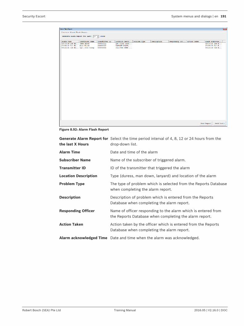
Security Escort System menus and dialogs | en 191
Robert Bosch (SEA) Pte Ltd Training Manual 2016.05 | V2.16.0 | DOC
Figure 8.92: Alarm Flash Report
Generate Alarm Report forthe last X Hours
Select the time period interval of 4, 8, 12 or 24 hours from thedrop-down list.
Alarm Time Date and time of the alarm
Subscriber Name Name of the subscriber of triggered alarm.
Transmitter ID ID of the transmitter that triggered the alarm
Location Description Type (duress, man down, lanyard) and location of the alarm
Problem Type The type of problem which is selected from the Reports Databasewhen completing the alarm report.
Description Description of problem which is entered from the ReportsDatabase when completing the alarm report.
Responding Officer Name of officer responding to the alarm which is entered fromthe Reports Database when completing the alarm report.
Action Taken Action taken by the officer which is entered from the ReportsDatabase when completing the alarm report.
Alarm acknowledged Time Date and time when the alarm was acknowledged.

192 en | System menus and dialogs Security Escort
2016.05 | V2.16.0 | DOC Training Manual Robert Bosch (SEA) Pte Ltd
[Save Report] Click the button to save the report in tab delimited format (“.dat”file). A dialog appears to confirm the name and location of the fileto be saved.
The default name of the file to be saved isAlarm_Flash_Report_DD_MM_YYYY_HH_MM_SS where DD is dayof the month, MM is the month, YYYY is the year, HH is the hour,MM is the minute and SS is the second.Click the [Save] button to save the file or [Cancel] button toabort the operation.If there are no records in the Alarm Flash Report, clicking the[Save] button will generate an error message dialog.
[Send Email] Click the button to send the report in tab delimited format (“.dat”file) attached in an email, with the filename as the subjectheader, to the default Email Notification Group “00”.The default Email Notification Group is configured in Setup >Email Setup… menu.If there are no records in the Alarm Flash Report, clicking the[Send Email] button will generate an error message dialog.
8.2.6 Muster ReportsThis dialog allows the operator to view the current locations of the transmitters that are insupervision mode. This would be helpful, for example, in the event of an emergencyevacuation where the location of the subscribers can be known quickly. The operator wouldbe able to see details of the transmitter from the list at one glance. The following are detailsof the Muster Report dialog.

Security Escort System menus and dialogs | en 193
Robert Bosch (SEA) Pte Ltd Training Manual 2016.05 | V2.16.0 | DOC
Figure 8.93: Muster Report
[Refresh] Click the button to refresh the Muster Report.
Supervision Time Time and date of the last supervision message from thetransmitter.
Subscriber Name Name of the subscriber.
Transmitter ID ID of the transmitter.
Floor Info Information of the floor where the transmitter is located.
Area/Nearby Receivers Area and/or receiver ID nearest to the transmitter location.

194 en | System menus and dialogs Security Escort
2016.05 | V2.16.0 | DOC Training Manual Robert Bosch (SEA) Pte Ltd
[Save Report] Click the button to save the report in tab delimited format (“.dat”file). A dialog appears to confirm the name and location of the fileto be saved.
The default name of the file to be saved isMuster_Report_DD_MM_YYYY_HH_MM_SS where DD is day ofthe month, MM is the month, YYYY is the year, HH is the hour, MMis the minute and SS is the second.Click the [Save] button to save the file or [Cancel] button toabort the operation.If there are no records in the Muster Report, clicking the [Save]button will generate an error message dialog.
[Send Email] Click the button to send the report in tab delimited format (“.dat”file) attached in an email, with the filename as the subjectheader, to the default Email Notification Group “00”.The default Email Notification Group is configured in Setup >Email Setup… menu.If there are no records in the Muster Report, clicking the [SendEmail] button will generate an error message dialog.
8.2.7 Clear screenTo clear the screen of any outdated or unwanted data, choose this feature from the Utilitiesmenu. The screen automatically resets to its normal operations mode.
8.2.8 Output verificationWhen selected, the system is scanned to verify that all alarm outputs are in the correct state.Any output found in the wrong state is corrected.
8.2.9 Synchronize system timeSelecting this option on the master computer causes the time on the slave and all of theworkstation computers to be updated to the master computer’s time.

Security Escort System menus and dialogs | en 195
Robert Bosch (SEA) Pte Ltd Training Manual 2016.05 | V2.16.0 | DOC
8.3 Setup commands
Figure 8.94: Setup Menu
8.3.1 Show historyWhen selected, the default map display is replaced by a scrolling text window showing themost recent events that occurred in the system. The window can list historical events andoperations of the Central Console software. Examples include list of any alarms and theactions taken, name of person who logged into the Central Console, changes to the database,communication results between the devices, and so on.The events displayed can be selected in the History Filter dialog under the Setup Menu. AfterShow History is selected, this menu item changes to Show Map.

196 en | System menus and dialogs Security Escort
2016.05 | V2.16.0 | DOC Training Manual Robert Bosch (SEA) Pte Ltd
Figure 8.95: Show History Log
8.3.2 History filterThis dialog selects the classes of events recorded for (sent to) specific output devices. Fromthe Select Destination group, select the History screen, Printer, History files or Systemserial ports option. Notice that when this selection is changed, the checked items alsochange. There is a different set of events output for each destination selected. For eachdestination, the events must be individually configured.

Security Escort System menus and dialogs | en 197
Robert Bosch (SEA) Pte Ltd Training Manual 2016.05 | V2.16.0 | DOC
Figure 8.96: History Filter Dialog
History screen This option selects the events to be displayed on the computerscreen when Show History is selected.
Printer This option selects the events to be sent to the printer.
History archive file A This option selects the events to be sent to the a_audit.txt filestored in the Security Escort sub-directory (typically C:\ESCORT\a_audit.txt). There is a minimum set of events that cannot bedisabled, so they are always recorded.
History archive file B This option selects the events to be sent to the b_audit.txt filestored in the Security Escort sub-directory (typically C:\ESCORT\b_audit.txt).
System serial port 1 This option selects the events to be sent to the system serialport 1. System serial port 1 is assigned a physical comm port inthe Remote Comm Port Setup dialog, and the History FilterOutput field must be set in the Remote Setup dialog.
System serial port 2 This option selects the events to be sent to the system serialport 2. System serial port 2 is assigned a physical comm port inthe Remote Comm Port Setup dialog, and the History FilterOutput field must be set in the Remote Setup dialog.
198 en | System menus and dialogs Security Escort
2016.05 | V2.16.0 | DOC Training Manual Robert Bosch (SEA) Pte Ltd
Transponder restriction This option selects a transponder for the following restrictions:No Restriction: This selection is typically left at this setting at alltimes. The output is not restricted by an individual transponder.Only From Transponder Selected: The selected events are onlyoutput if they were reported from the transponder selected inthe transponder above.All from Transponder Selected : All events are reported fromthe transponder selected above. The selected events arereported from all other transponders in the system.
Alarms Outputs the information about an alarm including location, butnot the transponder and receiver levels. This is the data typicallysent to a printer.
Points, reporting alarm Outputs the transponder and receiver levels for an alarm.Typically, this is the data too detailed to send to a printer and isused for diagnostics, not normal system operation.
Tests, single line Outputs the simple information about a test. Typically, this is thedata normally sent to a printer.
Tests including point Info Outputs the transponder and receiver levels for a test. This is thedata usually too detailed to send to a printer and is used fordiagnostics, not normal system operation. If this option isselected, Test, single line above, would not be selected for thesame output device.
Transmitter low battery Outputs low battery reports received from transmitters.
Operator activity log Outputs all other operator activity (audit trail) not covered byspecific event selections.
Preferences changes Outputs all changes made to system preference selections.
Database backup andrestore
Records all database backup and restore activity.
Operator database changes Records all changes to the operator database.
Subscriber databasechanges
Records all changes to the subscriber database.
Transponder data changes Records all changes to the transponder database.
Spare 2 This is a future option that has no function at this time (leaveunchecked).
Report database changes Records all changes to the Alarm Report Database.
Communications failure Records all communication failures and restorations.
Transponder communicationRecords all communications to transponders. This selection isonly used for engineering diagnostics. Leaving this item selectedgenerates a significant amount of history and fills up the harddisk drive quickly. Leave this item unchecked.
Supervision monitor Reports changes in the supervision status for all transmittersthat are being supervised.

Security Escort System menus and dialogs | en 199
Robert Bosch (SEA) Pte Ltd Training Manual 2016.05 | V2.16.0 | DOC
RF point troubles Output all reported radio frequency communication of receiverand alert unit troubles. Typically this item would be checked fordevices used to monitor problems.
Transponder maps Outputs all transponder status maps. This selection is only usedfor diagnostics. Leave this item unchecked.
Receive level maps Outputs all maintenance alarm receive level maps. This selectionis only used for diagnostics. Leave this item unchecked.
Database errors Outputs all reported database errors. This item is checked.
Transponder troubles Outputs all reported transponder troubles. This item is checkedfor devices used to monitor problems.
Point troubles Outputs all reported receiver and alert unit troubles. This item ischecked for devices used to monitor problems.
Login changes Reports all new system operator login and logout activity.
Network communications Records all communications between networked computers.This selection is only used for engineering diagnostics. Leavingthis item selected, generates a significant amount of history andfills up the hard disk drive very quickly and may bog down thesystem during high traffic times. Always leave this itemunchecked.
Modem communications Records all communications to the modem for remotecommunications and pager access. This selection is only used fordiagnosing pager communication problems. Leave this itemunchecked.
Analyze alarms This option outputs data allowing an engineer to evaluate howwell the location algorithm is performing. Leave this itemunchecked.
Master computer switch Records when the master and slave computers switch roles.
Transponder data view Allows the data created by the Transponder Data View screen tobe output. This selection is only used for engineeringdiagnostics. Leave this item unchecked.
Printer output Allows the data being sent to the printer to be sent to otheroutputs. This item is unchecked.
8.3.3 Popup trouble filterThe Security Escort System contains many built-in self testing features. Each transpondertests the condition of the receivers and alert units connected to it.When the transponder finds a device reporting a trouble condition, it communicates theproblem and the device identity to the Central Console. This generates a brief alert tone,displays a pop-up message for the operator, and sends an optional pager message. Themessage indicates the nature of the trouble and instructs the operator on the proper course ofaction. The event is recorded on the hard disks of both the main and backup computers andon the printout.The status of the device is recorded in the Transponder Current Status menu item under theSetup menu.

200 en | System menus and dialogs Security Escort
2016.05 | V2.16.0 | DOC Training Manual Robert Bosch (SEA) Pte Ltd
Figure 8.97: "Pop-Up" Alert Showing Tamper Trouble
This dialog allows the selection of which type of troubles that will appear in pop-up messageson the console screen, or be sent to the service pager. The troubles described below arealways recorded in the Transponder current status window, but may or may not produce apop-up display or pager message, depending on the selections for Popup or Pagercheckboxes.
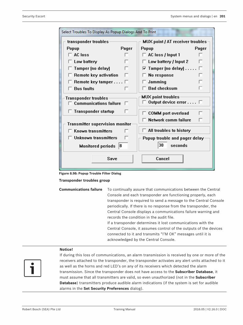
Security Escort System menus and dialogs | en 201
Robert Bosch (SEA) Pte Ltd Training Manual 2016.05 | V2.16.0 | DOC
Figure 8.98: Popup Trouble Filter Dialog
Transponder troubles group
Communications failure To continually assure that communications between the CentralConsole and each transponder are functioning properly, eachtransponder is required to send a message to the Central Consoleperiodically. If there is no response from the transponder, theCentral Console displays a communications failure warning andrecords the condition in the audit file.If a transponder determines it lost communications with theCentral Console, it assumes control of the outputs of the devicesconnected to it and transmits “I’M OK” messages until it isacknowledged by the Central Console.
Notice!If during this loss of communications, an alarm transmission is received by one or more of thereceivers attached to the transponder, the transponder activates any alert units attached to itas well as the horns and red LED’s on any of its receivers which detected the alarmtransmission. Since the transponder does not have access to the Subscriber Database, itmust assume that all transmitters are valid, so even unauthorized (not in the SubscriberDatabase) transmitters produce audible alarm indications (if the system is set for audiblealarms in the Set Security Preferences dialog).

202 en | System menus and dialogs Security Escort
2016.05 | V2.16.0 | DOC Training Manual Robert Bosch (SEA) Pte Ltd
The Central Console also attempts to reestablish communicationsby continually requesting transmissions from the transponder andlistening on the communications channel. When communicationsare restored with the Central Console, the transponder transmitsany alarm and trouble conditions that occurred during thecommunications loss. Control of the horns, LEDs, strobes, andsirens reverts to the Central Console.This approach to managing a communications loss assures thatalarm events cannot go undetected even if the Central Console isout of operation temporarily.
AC loss The transponder senses when it loses AC power and reports thecondition to the Central Console. After a few seconds delay, theCentral Console displays a pop-up alert and records the conditionin the audit file. See Transponder Current Status dialog.
Low battery Periodically during normal operation, the transponder tests itsbattery. If the test fails, it immediately reports the condition to theCentral Console. After a few seconds delay, the Central Consoledisplays a pop-up alert and the condition is recorded in the auditfile.
Tamper The transponder immediately senses and reports the actuation ofits tamper switch. The Central Console immediately displays a pop-up alert and records the condition in the audit file. Tamper reportsare not delayed by the pop-up trouble and pager delay.
Remote key activation The transponder immediately senses and reports the activation(shorting) of its remote key input when it is enabled in theTransponder Parameter dialog. The Central Console displays apop-up alert and records the condition in the audit file.
Remote key tamper The transponder immediately senses and reports the fault (open)of its remote key input when it is enabled in the TransponderParameter dialog. The Central Console immediately displays a pop-up alert and records the condition in the audit file.
Transponder startup The transponder reports to the Central Console when it first startsup. This can be caused by a technician turning the transponder onor by a watchdog failure of the on board microprocessor. TheCentral Console immediately displays a pop-up alert and recordsthe condition in the audit file.
Bus faults When the transponder is unable to communicate to any receiversor alert units on one or more of its multiplex busses, it immediatelyreports the condition to the Central Console. The Central Consolereports the condition by means of a pop-up alert if the conditionpersists more than a few seconds. The condition is also recordedin the audit file.
Security Escort System menus and dialogs | en 203
Robert Bosch (SEA) Pte Ltd Training Manual 2016.05 | V2.16.0 | DOC
MUX bus point troubles group
AC loss The microprocessor of the alert unit detected the absence of ACpower. Loss of AC power affects only the strobe and sirenfunctions of the alert unit. Batteries provide backup power for thestrobes and sirens. The logic and communications functions derivetheir power from the multiplex bus.
Low Battery The alert unit tested for a low battery condition and the test failed.
Tamper Whenever the cover is removed from a receiver or alert unit, theon-board microprocessor detects the tamper and it is reported tothe transponder. Tamper reports are not delayed by the pop-uptrouble and pager delay.
No response Whenever a receiver fails to respond to a command from thetransponder, a “No Response” message is sent by the transponderto the Central Console. This can occur if a multiplex bus wire is cutor a device is damaged.
Jamming Each receiver monitors the level of radio energy being received atall times. If the level exceeds a preset threshold, for a presetlength of time, the on-board microprocessor reports jamming.
Output device error The transponder generates this message when it commands areceiver or alert unit to activate or deactivate an output device(siren, strobe, horn, or LED) and the device fails to respondcorrectly.
Bad checksum This message is generated by the transponder and sent to theCentral Console whenever the transponder detects message errorsin the communications between receivers and alert units.
Transmitter supervision monitoring group
Known transmitters To continually monitor the status of all transmitters programmed inthe database that send periodic supervision transmissions. If anymonitored transmitters stop sending supervision transmissions, apop-up trouble is displayed.
Unknown transmitters To monitor for periodic supervision transmissions fromtransmitters not programmed in the database, a pop-up troubledisplays if transmissions from transmitters not programmed in thedatabase are received.
Monitored periods This is the number of supervision intervals that are consecutivelymissed before a pop-up screen reports a specific transmitterstopped reporting supervision transmissions.
Communications port monitor
Comm port overload A pop-up trouble screen displays if the communications traffic tothe transponders exceeds the system is capability.
Network comm failure A pop-up trouble screen displays if the communications betweenthe master and slave computers fails.

204 en | System menus and dialogs Security Escort
2016.05 | V2.16.0 | DOC Training Manual Robert Bosch (SEA) Pte Ltd
Delay to ignore troubles that auto reset
Pop-up trouble and pagerdelay
The delay in seconds before a trouble displays on the computerscreen. If a restore for a trouble is received before a trouble isdisplayed (this delay expires), the trouble and the restore areignored. Tamper troubles are not delayed.
8.3.4 Transponder parameter changeThis dialog allows parameters stored in the transponder’s EEPROM memory to be viewed andchanged.
Figure 8.99: Transponder Parameter Change Dialog
Run silent If checked, the receivers and alert units on this transponder do notsound an alarm. This includes alarms received during acommunications failure with the Central Console.
Optional parameter This option is currently disabled and reserved for future use.

Security Escort System menus and dialogs | en 205
Robert Bosch (SEA) Pte Ltd Training Manual 2016.05 | V2.16.0 | DOC
Loop communications Normally the transponders are connected in parallel (party line) sothey can all hear if any other transponders are in communications sothey don't collide when communicating. However if fiber opticcommunications is used between the transponders and PC they can'tbe connected this way. Therefore they are connected in a loop. Thetransmission from the PC goes to the receiver on the firsttransponder. The transmission from the first transponder goes to thereceiver on the second transponder and so on, until the transmissionfrom the last transponder goes to the receiver on the PC. This optiontells the transponders they are connected this way so it can react.You must make this change to the first transponder first, followedwith the second, continuing in order until all is done.
Enable remote key( If checked, the remote key supervised input on this transponder isenabled. Otherwise it will be ignored.
Uses Proxim radio Only check this item if a Proxim radio is used to communicate to theCentral Console.
Comm fail to siren out If this item is checked, the siren output on this transponder activateswhen a communications failure is detected at the Central Console.
Verbose point reports If checked, alarm and test reports include average levels and packetcount information. This extra information is for diagnostic proposesonly and is not required for system operation. Since the additionaldata increases the system traffic load leave this item unchecked.
Test min level This is the minimum receive level (1 to 255) a receiver must seebefore the green light displays acknowledging a successful test.Leave this item at default (128).
Test differential This is the minimum difference in receive level (1 to 255) a receivermust be less than the loudest receiver hearing a test before thegreen light displays acknowledging a successful test. Leave this itemat default (64).
Alarm min level This is the minimum receive level (1 to 255) a receiver must seebefore the sounder and red light is displayed for an alarm. Leave thisitem at default (1).
Alarm differential This is the minimum difference in receive level (1 to 255) a receivermust be less than the loudest receiver hearing an alarm before thesounder and red light are displayed for an alarm. Leave this item atdefault (255).
Byte These are future options, leave at default (0).
Spare These are future options, leave unchecked..
Test transmitter typeTest receiver 1, 2, 3, 4Transmit delayTransmit pointLoad delayTamper load
These parameters are used for engineering system load testing only.Do not use in a live system, as they can generate more traffic than asystem can handle; therefore, actual alarms may be missed. Leavethem at default.

206 en | System menus and dialogs Security Escort
2016.05 | V2.16.0 | DOC Training Manual Robert Bosch (SEA) Pte Ltd
Transponder Selects the transponder the data is presented for.
[Previous] Returns to the previous transponder in the system.
[Next] Advances to the next transponder in the system.
[Send change] Sends the changes made to the selected transponder. Changes arenot made to the transponder EEPROM memory unless this button isclicked.
[Reset to Default] Reset the selected transponder to the default settings.
[Cancel] Cancel the operation and close the dialog window.
8.3.5 Transponder data viewThis dialog is solely for engineering evaluation of the transponder only.
Figure 8.100: Transponder Data View Dialog
[RAM point info] Views the RAM image of point information.
[RAM point stat] Views the RAM image of point status.
[RAM point trouble] Views the RAM image of point trouble.
[RAM EE mstat batt] Views the RAM and EEPROM images of transponder status andbattery condition.
[RAM EE buss fault] Views the RAM and EEPROM images of transponder MUX busfault condition.
[RAM counters] Views the RAM image of the process registers.
Security Escort System menus and dialogs | en 207
Robert Bosch (SEA) Pte Ltd Training Manual 2016.05 | V2.16.0 | DOC
[EE point info] Views the EEPROM image of point information.
[EE point stat] Views the EEPROM image of point status.
[EE point trouble] Views the EEPROM image of point trouble.
[Bus micro revision] Views the bus micro revision for the connected points.
[Last MUX message] Views the last MUX bus message received.
[EE counters] Views the EEPROM image of the process registers.
[Save EE] Saves the current RAM image to the EEPROM memory on thetransponder.
[Clear EE] Clears the EEPROM memory on the transponder and resets thetransponder.
[Previous] Returns to the previous transponder in the system.
[Next] Advances to the next transponder in the system.
[Cancel] Cancels the operation and closes the dialog window.
8.3.6 Receiver configurationOnce the receiver and alert unit data for a transponder has been entered into theTransponder Database, this dialog is used to verify that each receiver is working and isproperly addressed in the database. This setup tool identifies errors in the address switchsettings of receivers and alert units as well as data entry errors in the Transponder Database.

208 en | System menus and dialogs Security Escort
2016.05 | V2.16.0 | DOC Training Manual Robert Bosch (SEA) Pte Ltd
Figure 8.101: Receiver Configuration Dialog
[Put this receiver in setupmode]
This button initiates the setup process by causing both thered and green LED of the selected receiver to light up. Thered and green LED will be flashing. On the Central Console,this button changes the [Abort setup for this MUX Point]button to be able to proceed to the next device in the eventthat one receiver is not set up properly.
Ambient value The Ambient value, shown above Auto Advance, shows thecurrent ambient level at the receiver. To get an updatedambient reading, select the point and click the [Transmit]button followed by the [Ambient] button.
Auto Advance If this checkbox is checked, the Central Consoleautomatically selects the receiver with the next higher pointaddress.
RF micro revision The receiver’s RF micro revision level is shown below AutoAdvance. To get an updated reading, click the [Revision]button.
Security Escort System menus and dialogs | en 209
Robert Bosch (SEA) Pte Ltd Training Manual 2016.05 | V2.16.0 | DOC
Horn - Siren If this checkbox is checked, the horn output of a receiver orthe siren output of an alert unit is turned on upon clickingthe [On] button, or turned off upon clicking the [Off]button. If this checkbox is not checked, the state of thisoutput does not change.
Red LED - Strobe If this checkbox is checked, the red LED output of a receiveror the strobe output of an alert unit is turned on uponclicking the [On] button, or turned off upon clicking the[Off] button. If this checkbox is not checked, the state ofthis output does not change.
Green Led If this checkbox is checked, the green LED output of areceiver or the spare output of an alert unit is turned onupon clicking the [On] button, or turned off upon clickingthe [Off] button. If this checkbox is not checked, the stateof this output does not change.
[Off] Upon clicking the button, any checked outputs (Horn-Siren,Green LED, Red LED - Strobe) is turned off for the selectedpoint on the selected transponder. If the output does notchange, click the [On] button followed by the [Off] buttonagain.
[On] Upon clicking the button, any checked outputs (Horn-Siren,Green LED, Red LED - Strobe) is turned on for the selectedpoint on the selected transponder. If the output does notchange, click the [Off] button followed by the [On] buttonagain.
[Antenna] Normally, a receiver automatically switches between itsdiversity antennas during normal operation (leave thedefault selection on a working system at this setting). Thereceiver can be forced to use only the left or right antenna,or always switch by selecting the appropriate setting andclicking the [Antenna] button.
[Ant map] Clicking the [Ant map] button causes the system tointerrogate the current antenna switching settings of allreceivers on this transponder.
[Reset point] Clicking the [Reset point] causes the microprocessors onthis point to reset as if they were just powered up. Areceiver should not be reset in a working system, as it cancause receptions to be lost.
[Transmit] Clicking the [Transmit] button causes this receiver to sendone test transmission.
[Ambient] Clicking the [Ambient] button causes the system tointerrogate the current ambient levels of all receivers on thistransponder.

210 en | System menus and dialogs Security Escort
2016.05 | V2.16.0 | DOC Training Manual Robert Bosch (SEA) Pte Ltd
[Revision] Clicking the [Revision] button causes the system tointerrogate the RF micro revision levels of all receivers onthis transponder.
[Jamming] A receiver monitors the ambient level during normaloperation. If the ambient level rises above the jammingsetting and jamming trouble, it is reported to the CentralConsole. The receiver’s jamming level can be adjusted byselecting the appropriate setting (shown in hexadecimallevels) and clicking the [Jamming] button.
[Jam map] Clicking the [Jam map] button causes the system tointerrogate the jamming setting levels of all receivers on thistransponder.
[Cancel] Clicking the [Cancel] button closes the dialog window.
Put this receiver in setup modeThis button initiates the setup process by causing both the red and green LED of the selectedreceiver to light up. The red and green LED will be flashing. On the Central Console, thisbutton changes the [Abort setup for this MUX point] button to be able to proceed to the nextdevice in the event that one receiver is not set up properly.The next step is using a maintenance transmitter to transmit an alarm while standing near thereceiver.
Notice!The illuminated LED indicate to the service person standing near the device that the receiveris actually the one currently in the setup mode. If the LED of the designated receiver are notilluminated, there is probably an error in the switch settings of the receiver or an error in theaddress in the Transponder Database. To help resolve such problems, the person at theCentral Console can command any device to illuminate its LED and/or sound its horn.
If the receiver in the setup mode detects the maintenance alarm and if the received signal isthe strongest of all receivers, the horn on the receiver sounds briefly and the LEDs go off. Thisindicates the receiver is functioning properly and the receiver’s address is set correctly in theTransponder Database and on the receiver’s switches.
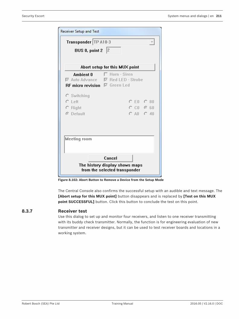
Security Escort System menus and dialogs | en 211
Robert Bosch (SEA) Pte Ltd Training Manual 2016.05 | V2.16.0 | DOC
Figure 8.102: Abort Button to Remove a Device from the Setup Mode
The Central Console also confirms the successful setup with an audible and text message. The[Abort setup for this MUX point] button disappears and is replaced by [Test on this MUXpoint SUCCESSFUL] button. Click this button to conclude the test on this point.
8.3.7 Receiver testUse this dialog to set up and monitor four receivers, and listen to one receiver transmittingwith its buddy check transmitter. Normally, the function is for engineering evaluation of newtransmitter and receiver designs, but it can be used to test receiver boards and locations in aworking system.

212 en | System menus and dialogs Security Escort
2016.05 | V2.16.0 | DOC Training Manual Robert Bosch (SEA) Pte Ltd
Figure 8.103: Receiver Test Dialog
Transponder Select the transponder for the transmitting point and eachreceiving point. They can be on the same or differenttransponders.
Transmitting Point Select the point (receiver) on the selected transponder togenerate the transmissions.
Total transmissions The total number of times the designated receivertransmitted the test message.
Missed all receivers The total number of times where the test transmission wasnot heard by any of the designated receivers.
Enable Rec This checkbox must be checked for this receiver to monitorthe test transmissions.
Point Select the point (receiver) on this transponder to monitorthe test transmissions.
Hits The number of times this receiver successfully heard the testtransmission.
Misses The number of times this receiver failed to hear the testtransmission.
Highest The left box displays the highest receive level at which thetest transmission was heard. The right box displays thegreatest number of packets heard from a single testtransmission.

Security Escort System menus and dialogs | en 213
Robert Bosch (SEA) Pte Ltd Training Manual 2016.05 | V2.16.0 | DOC
Average The left box displays the average receive level at which thetest transmission was heard. The right box displays theaverage number of packets heard from a single testtransmission.
Lowest The left box displays the lowest receive level at which thetest transmission was heard. The right box displays the leastnumber of packets heard from a single test transmission.
Run test The test only runs when this checkbox is checked. To stopthe test and retain the test values, uncheck this checkbox.
Spacing This slows the test by forcing this number of secondsbetween test transmissions. Normally, this setting is left atthe default of 0.
Stop test and reset counters Clicking this button stops the test and resets all values.
Close dialog, does not stop test Clicking this button closes this dialog but does not stop thetest from running. Reopening the dialog displays the currentprogress of the test. The test should not be left runningunless there is a specific need, as it generates both RF andsystem traffic.
8.3.8 Network statusThis dialog shows the status of communications on the network, modem, and system serialports.
Figure 8.104: Network Status Dialog
Successful Incoming Messages This value is the number of messages that the systemsuccessfully received on this communication port.

214 en | System menus and dialogs Security Escort
2016.05 | V2.16.0 | DOC Training Manual Robert Bosch (SEA) Pte Ltd
Incoming Communication Errors This value is the number of messages that the systemdetected errors in, on this communication port. If displayedin yellow, this value is more than 1.5% of the SuccessfulIncoming Messages.
Incoming Retried Messages This value is number of successful receptions that indicatedthat they retried by the sending application. If displayed inyellow, this value is more than 1.5% of the SuccessfulIncoming Messages.
Total Outgoing Messages This value is total number of outgoing messages sent on thisport.
Outgoing Retried Messages This value is number of outgoing messages that were retriedbecause the receiving application did not acknowledgethem. If displayed in yellow, this value is more than 1.5% ofthe Total Outgoing Messages.
Receiver Buffer Max This value is maximum number of bytes received on thisserial port, but not yet processed by the system. If displayedin yellow, more than 50% of the queue was in use.
Transmit Buffer Max This value is maximum number of bytes processed by thesystem, but not yet transmitted on this serial port. Ifdisplayed in yellow, more than 50% of the queue was in use.
Buffer Overflow This is the number of times a byte was lost by the softwarefor a serial port because the input buffer overflowed. Byteswere placed into the input buffer faster than the systemcould process them.
Hardware Overrun This is the number of times a byte was lost by the hardwarefor a serial port because it was not fast enough to processthe byte into the input buffer.
Total Remote AccessConnections
This value is the total number of times a remote accessconnection was successful.
Total Wrong Access CodeAttempts
This value is the number of times a remote accessconnection was attempted and rejected because a validremote access code was not received.
Last Remote Access Time This is the time and date of the last successful remoteaccess attempt.
Successful pager messages This value is the number of successful pager messages sent.
Failed pager attempts This value is the number of times a pager message dial-outwas unsuccessful.
[Reset Status] Clicking this button resets all values shown in this dialog.
[Refresh Data] Clicking this button refreshes all values shown in this dialog.The values are not automatically updated when the dialog isleft open.
[Cancel] Clicking this button closes the dialog window.

Security Escort System menus and dialogs | en 215
Robert Bosch (SEA) Pte Ltd Training Manual 2016.05 | V2.16.0 | DOC
8.3.9 System statusThis dialog shows the status of internal system queues and communications on the serialports assigned to transponders.
Figure 8.105: System Status Dialog
Maximum Retry Messages This value is maximum number of messages in queue to besent to all transponders in the system, and were not yetacknowledged. If displayed in yellow, more than 50% of thequeue was in use at this value.
Maximum Alarm Messages This value is the maximum number of alarms that the systemprocessed at its busiest time. If displayed in yellow, morethan 50% of the maximum was in use.
Maximum Trouble Messages This value is the maximum number of troubles in the queueyet to be displayed. If displayed in yellow, more than 50% ofthe queue was in use.
Max Low Battery Messages This value is the maximum number of transmitters with lowbatteries yet to be displayed. If displayed in yellow, morethan 50% of the queue was in use.
Max Test Strobe Messages This value is the maximum number of test strobes in use atone time. If displayed in yellow, more than 50% of the queuewas in use.
Max Man Down Messages This value is the maximum number of transmitters timingman down events, at one time. If displayed in yellow, morethan 50% of the queue was in use.
Supervision Monitors This value is the current number of transmitters beingmonitored for supervision transmissions.
Max Spooler Bytes This value is the maximum number of bytes spooled for theprinter at one time. If displayed in yellow, more than 50% ofthe queue was in use.
216 en | System menus and dialogs Security Escort
2016.05 | V2.16.0 | DOC Training Manual Robert Bosch (SEA) Pte Ltd
Max Report Spooler Bytes This value is the maximum number of bytes spooled for theprinter for Guard Tour Reports at one time. If displayed inyellow, more than 50% of the queue was in use.
Max Receiver Buffer This value is the maximum number of bytes received fromtransponders on this serial port, but not yet processed bythe system. If displayed in yellow, more than 50% of thequeue was in use.
Max Transmit Buffer This value is the maximum number of bytes processed bythe system, but not yet transmitted to the transponders onthis serial port. If displayed in yellow, more than 50% of thequeue was in use.
Hardware Overrun This is the number of times a byte was lost by the hardwarefor a serial port because it was not fast enough to processthe byte into the input buffer.
Buffer Overflow Count This is the number of times a byte was lost by the softwarefor a serial port because the input buffer overflowed. Byteswere placed into the input buffer faster than the systemcould process them.
Overload Level This is a measure of the amount of time peak traffic on thisserial port was greater than the system’s ability to handle it.The system automatically sheds non-essential tasks whenthis value rises.
Overload Count This is a measure of the number of times peak traffic on thisserial port was greater than the system’s ability to handle it.The system automatically sheds non-essential tasks whenthis value rises.
[Reset Status] Clicking this button resets all values in this shown in thisdialog.
[Refresh Data] Clicking this button refreshes all values shown in this dialog.The values are not automatically updated when the dialog isleft open.
[Cancel] Clicking this button closes the dialog window.
8.3.10 Pager setupThis dialog sets up remote pager access for troubles (service) and alarms (security).

Security Escort System menus and dialogs | en 217
Robert Bosch (SEA) Pte Ltd Training Manual 2016.05 | V2.16.0 | DOC
Figure 8.106: Pager Setup Dialog
Automatically sendselected troubles
If checked, send the troubles selected in the Popup trouble filterdialog to the service pager.
Phone number Phone number to be dialed to access the paging service. This phonenumber is usually different from the number you would manually dialto send a page. The paging company assigns this value.
Password This is the password that must be sent to the paging service to sendthe page. If not required, leave this field black. Usually a password isnot required. The paging company assigns this value.
Pager ID This is the ID that identifies the specific pager that this message is tobe sent to. Many times, it is the last 7 digits of the phone number thatyou would manually dial to access this pager. The paging companyassigns this value.
Character limit This is the maximum number of characters allowed per page.Typically, this is set to 80 characters. The Security Escort System willtruncate the pager message at this number of characters. The pagingcompany assigns this value.
Pages per call This is the maximum number of pager messages allowed per phonecall. Typically, this is set to 4 pages per call. When this number ofmessages have been sent, and there are more messages to bedelivered; the Security Escort System will hang up and redial thepaging service to deliver the remaining messages. The pagingcompany assigns this value.

218 en | System menus and dialogs Security Escort
2016.05 | V2.16.0 | DOC Training Manual Robert Bosch (SEA) Pte Ltd
Pager group This is the group of up to 8 pagers that this message is to be sent to.You may program the individual pager as well as a group of pagers.The pager group will be sent the page before the individual.
Baud rate This is the baud rate that will be used to communicate with the pagingcomputers. The paging company assigns this value.
System name This identifies the Security Escort System when multiple SecurityEscort Systems report to the same service pager. Keep this field asshort as reasonably possible since these characters, including spacecharacter, will be sent before each trouble message and they areincluded in the Character limit set above. If not desired, leave blank.
System phone This will present phone number to be called in response to the servicepage. Only use if required since these characters, plus a space, will besent before each trouble message. They are included with the Systemname in the Character limit set above. If not desired, leave blank.
Send installer demoalarms
If checked, demo alarms will be sent to the security pager.
Send all other alarms If checked, all actual alarms will be sent to the security pager.
Security Pager ConfmNot Reqd
If checked, the confirmation pager message is not sent to the securitypager when the alarm is acknowledged by an acknowledgementtransmitter.
Cancel page If alarmreset
If checked, the alarm page will be canceled if the alarm is reset beforeit can be communicated to the paging service.
Send page a secondtime, 2 minute delay
If checked an alarm page will be sent a second time to the securitypager. Do this in case the pager was in an area where pages could notbe heard when the first page was sent.
Do not resend alarmpage
If checked, a pager message is sent to the security person only oncetill the alarm is cancelled or acknowledged.
Modem init This is the initialization string sent to the modem to set it up for pagercommunications. Normally, this setting would not have to be changed.To allow changes to this string, hold down the <Shift> + <Ctrl> keyswhen this dialog is first opened. This string is specific to each modemmodel. The default setting should work with most modems.
[Save] Save the changes and close the dialog window.
[Cancel] Cancel the changes and close the dialog window.
8.3.11 Send pager messageAllows manually entered messages to be sent to the service or security pagers. Service andsecurity pagers are configured in the Pager setup dialog. Individuals and group pagerassignments are configured in the Subscriber Database.

Security Escort System menus and dialogs | en 219
Robert Bosch (SEA) Pte Ltd Training Manual 2016.05 | V2.16.0 | DOC
Figure 8.107: Send Pager Message Dialog
Insert the text to be sent here. Enter the text to be sent to the pagers in the large text boxat the top of the dialog.
[Send Service] Causes the entered message to be sent to the service pagerand service pager group.
[Send Security] Causes the entered message to be sent to the security pagerand security pager group.
[Stop all pages] Causes all pages currently queued (automatic or manual) tobe aborted and deleted. Use with caution.
Pager group To send a page to all members of a group, enter the pagergroup number here (1 to 99).
[Send to group] Click this button to send the text entered to the indicatedpager group.
[Send to Individual] Click this button to send the text entered to the individualthat is selected from the drop down list.
[Cancel] Cancel and close this dialog window..
8.3.12 Email SetupThis dialog allows you to configure the settings of the SMTP server and the emails for thenotification groups so that emails, for example alarms or reports, can be sent to the groups.

220 en | System menus and dialogs Security Escort
2016.05 | V2.16.0 | DOC Training Manual Robert Bosch (SEA) Pte Ltd
Figure 8.108: Email Setup
Notice!To setup the email notification, you need to configure your SMTP server settings. Check withyour SMTP server provider if you are unsure of the configuration.
SMTP Server Configuration
Enable Email Service Tick this checkbox to configure the SMTP server information. If thisis not checked, email will not be sent out.
SMTP Address SMTP server address, e.g. “smtp.gmail.com”. Maximum number ofcharacters is 74.
SMTP Port Port number that the SMTP server uses for communication.Generally, port 25, 465 or 587 is used, but some may use customizedport from 1 to 65535. Note: Ensure that the port is not blocked onyour network.
Enable Authentication Tick this checkbox if the SMTP server requires username andpassword authentication before the email can be sent out.
SMTP Username Enter the SMTP username for authentication by SMTP server.Maximum number of characters is 31.

Security Escort System menus and dialogs | en 221
Robert Bosch (SEA) Pte Ltd Training Manual 2016.05 | V2.16.0 | DOC
SMTP Password Enter the SMTP password of the user for authentication by SMTPserver. Maximum number of characters is 31.
Enable SSL/TLS Tick this checkbox if the SMTP server requires securecommunication for the authentication between the SMTP server andclient.
From Address Enter the email address that will authenticate with the SMTP server,e.g. “[email protected]”. Maximum number of characters is74.
[Delete] This button only appears after you have configured and saved theSMTP Server configuration. Click the button to delete theconfiguration.
[Save] Click the button to save the changes made to the SMTP ServerConfiguration section.
Email Configuration
Notification Group Select the Notification Group “00”, “01”, “02”, “03” or “04” from thedrop-down list.Notification Group “00” is the default group where emailnotifications for alarms are sent to the recipients. Note: Ifunauthorized alarms are set up to display on the screen (seeSecurity Preferences section), these alarms will also be sent viaemail to the default notification group.Notification Group “01”, “02”, “03” and “04” are used to customizeemails of alarms for specific subscribers. See the SubscriberDatabase Advanced Features section for details.
Email Address 1 Alarm email will be sent to email address of person 1. Maximumnumber of characters is 74.
Email Address 2 Alarm email will be sent to email address of person 2. Maximumnumber of characters is 74.
Email Address 3 Alarm email will be sent to email address of person 3. Maximumnumber of characters is 74.
Email Address 4 Alarm email will be sent to email address of person 4. Maximumnumber of characters is 74.
Email Address 5 Alarm email will be sent to email address of person 5. Maximumnumber of characters is 74.
[Delete] This button only appears after you have configured and saved theemail configuration. Click the button to delete the selectedNotification Group configuration.
[Save] Click the button to save the changes made to the EmailConfiguration section.

222 en | System menus and dialogs Security Escort
2016.05 | V2.16.0 | DOC Training Manual Robert Bosch (SEA) Pte Ltd
The alarm emails that were sent contain the alarm type, location area and date/time of thealarm as the subject header. Name of the subscriber and the subscriber ID, phone number andaddress are also included in the email content.
8.4 Print history screenThis selection will print the current data in the History Screen buffer to the report printer.
8.4.1 Print file dialogEnter the name of the file to be printed or click the [Browse…] button to open the CommonOpen File dialog. Then click the [Print] button to print the file to the report printer.
Figure 8.109: Print File Dialog
This is the standard Windows Common Open File dialog that is used for selecting the file tobe printed. It works the same as any other Window’s standard application.
Figure 8.110: Common Open File Dialog

Security Escort System menus and dialogs | en 223
Robert Bosch (SEA) Pte Ltd Training Manual 2016.05 | V2.16.0 | DOC
8.5 Network menuThis is the network menu used to set up and monitor the TCP/IP network and the computer’sfile paths.
Figure 8.111: Network Menu
8.5.1 System Directories and Network Address DialogUse this dialog to set up the network IP addresses, ports and related options. File paths canalso be configured.
Figure 8.112: System Directories and Network Address Dialog

224 en | System menus and dialogs Security Escort
2016.05 | V2.16.0 | DOC Training Manual Robert Bosch (SEA) Pte Ltd
Databases are not shared If this option is not checked, the master and all the slave andworkstation computers share the same database files. Thischeckbox must only be checked if each computer has its owncopy of the databases stored locally. In normal operation, thischeckbox is typically unchecked. If this checkbox is checked, thedatabases must be manually updated using Backup and Restoreevery time changes are made to the database.
Show connection pop-ups If this option is checked, it will display a pop-up message boxwhenever a network connection is initiated or released withanother computer. Unchecking this checkbox stops the messageboxes from displaying. In normal operation, this checkbox istypically unchecked.
Show all error pop-ups If this option is checked, it will display a pop-up message boxwhenever a network error is reported. Unchecking this checkboxstops the message boxes from displaying. In normal operation,this checkbox is typically unchecked.
Disable auto reconnect If this option is checked, the system will not automaticallyattempt to reconnect a lost connection each minute. Uncheckingthis checkbox allows the system to automatically reconnect alost connection. In normal operation, this checkbox should beunchecked.
Auto synchronize time If this option is checked, the master computer will automaticallysynchronize the time on the slave and workstation computersonce each night.
Comm. fail reset If this option is checked, the master computer will reset whencommunication failure occurs..
Master’s Network Address: The IP address of the master computer. The Security Escortsystem requires a fixed IP address for the master computer.
Master's Network ListenPort
A unique number that indicates the Security Escort software isattempting to set up a connection. Other software uses differentport numbers, allowing the network interface card to be sharedwith other network applications. Typically, this is set as “4561”.
Slave's Network Address The IP address of the slave computer. The Security Escortsystem requires a fixed IP address for the optional slavecomputer.
Slave's Network Listen Port A unique number that indicates the Security Escort software isattempting to set up a connection. Other software uses differentport numbers, allowing the network interface card to be sharedwith other network applications. Typically, this is set to “4561”.
Security Escort System menus and dialogs | en 225
Robert Bosch (SEA) Pte Ltd Training Manual 2016.05 | V2.16.0 | DOC
[Learn address] Clicking this button on the master computer automaticallypopulates the master’s IP address in the Master’s NetworkAddress textbox, and the master’s network port in the Master’sNetwork Listen Port textbox. Clicking this button on the slavecomputer automatically populates the master’s IP address in theSlave’s Network Address textbox, and the master’s networkport in the Slave’s Network Listen Port textbox. If the computerhas more than one network interface card (NIC), you must verifythat the correct IP address was selected by comparing thisaddress to the IP address that was programmed in the ControlPanel TCP/IP protocol. If the address is not correct, manuallyenter the correct IP address.
Remote Control ListeningPort
The Security Escort will be listening on this port to communicatewith the OPC server. A separate OPC server is created tocommunicate between the OPC client and the Security Escortsystem. The OPC server holds the alarm and trouble messages,and sends the same to the available client once it is connected.The OPC server will send the status of the Security Escort to theOPC client. The OPC sever also acknowledges and deletes alarmand trouble messages from OPC client. If the connectionbetween OPC server and Security Escort goes down, the OPCserver will try to reconnect with Security Escort. Once theconnection to the Security Escort becomes active, the SecurityEscort will send all the available alarms to the OPC server. TheOPC server in turn sends the alarm back to OPC client; hencethe OPC client may display some duplicate alarms.
Master Database path The path that this slave or workstation computer uses to accessthe shared database files on the master computer. This path mayhave a different drive letter on the different slave andworkstation computers. They are typically on the mastercomputer, but they may be on a file server or any other networkaccessible drive. Note: With version 2.04 and above of thesoftware, it is possible to use UNC path names instead ofmapping drive letters. Therefore, the path to the mastercomputer’s database would be “\\MASTER\ESCORT”.
Autobackup to the slavedatabase
If this option is checked, the slave computer will back up alldatabases in the Master Database path to the Slave Databasepath each night at 3:00 am.

226 en | System menus and dialogs Security Escort
2016.05 | V2.16.0 | DOC Training Manual Robert Bosch (SEA) Pte Ltd
Slave Database path The path that this master or workstation computer uses toaccess the hot backup database files on the slave computer. Thispath may have a different drive letter on the different master andworkstation computers. They are usually on the slave computer,but they may be on a file server or any other network accessibledrive. Typically, they would not be stored on the same computeras the Master Database path, so a single failure would notprevent access to both the master and slave database files.Note: With version 2.04 or above of the software, it is possibleto use UNC path names instead of mapping drive letters.Therefore, the path to the slave computer’s database would be“\\SLAVE\ESCORT”.
Local Escort path The path on this workstation where the Security Escort wasinstalled in. Typically it is “C:\ESCORT”.
Backup / restore to diskcartridge path
When backing up or restoring the databases to a disk cartridge,this is the path that is used.
Subscriber image file path The Security Escort System software can display an image foreach subscriber on the alarm screen. This parameter tells thesoftware the path where the image files are stored. The defaultis “C:\ESCORT\IMAGES”.
Extension The subscriber images can be in JPEG or Windows Bitmapformat. All images in a system must be in the same format. Forthe JPEG format, enter the Windows extension “JPG”. For theBitmap format, enter the Windows extension “BMP”.
Scaling % When the display is set to 640x480 pixels, and subscriber imagesare being displayed, this parameter controls the image size. Thisvalue can range from 10 to 100%, and should be adjusted whileviewing alarms to get the desired image size. When the display isset to 800x600 or larger (recommended), this parameter has noeffect.
[Save] Clicking this button saves the changes and closes the dialogwindow.
[Cancel] Clicking this button aborts the changes and closes the dialogwindow.
8.5.2 Network Socket Status DialogThis dialog shows diagnostic information for the selected TCP/IP socket.

Security Escort System menus and dialogs | en 227
Robert Bosch (SEA) Pte Ltd Training Manual 2016.05 | V2.16.0 | DOC
Figure 8.113: Current Network Socket Status Dialog
Successful IncomingMessages
Number of messages that the system has successfully received onthis socket.
Incoming CommunicationErrors
Number of messages that the system detected errors in, on thissocket. If displayed in yellow, this value is more than 1.5% of theSuccessful Incoming Messages.
Incoming RetriedMessages
Number of successful receptions which indicated that the retries bythe sending application. If displayed in yellow, this value is morethan 1.5% of the Successful Incoming Messages.
Total Outgoing Messages Total number of outgoing messages that were sent on this socket.
Outgoing RetriedMessages
Number of outgoing messages that were retried because thereceiving application did not acknowledge them. If displayed inyellow, this value is more than 1.5% of the Total OutgoingMessages.
Receive Buffer Max Maximum number of bytes that were received on this serial port,but not yet processed by the system. If displayed in yellow, morethan 50% of the queue was in use.
Transmit Buffer Max Maximum number of bytes that were processed by the system, butnot yet transmitted on this socket. If displayed in yellow, more than50% of the queue was in use.

228 en | System menus and dialogs Security Escort
2016.05 | V2.16.0 | DOC Training Manual Robert Bosch (SEA) Pte Ltd
[Reset Status] Clicking this button resets all values shown in this dialog.
[Refresh Data] Clicking this button refreshes all values shown in this dialog. Thevalues are not automatically updated when the dialog is left open.
8.5.3 Computer's Winsock Data DialogThis dialog shows information about the Windows Winsock support. This is only used fordiagnostic purposes.
Figure 8.114: Computer’s Winsock Data Dialog
8.5.4 Computer's Name and Address DialogThis dialog shows the computer’s network name and current IP address.
Figure 8.115: Computer's Name and IP Address Dialog
8.6 About menu

Security Escort System menus and dialogs | en 229
Robert Bosch (SEA) Pte Ltd Training Manual 2016.05 | V2.16.0 | DOC
Figure 8.116: About Menu
Demo manual alarm, subscriber 1For demonstration only, and can’t be used in a live system.It causes system to display an alarm from the subscriberwith transmitter ID number 1. In the System Preferencesdialog, select Enable Demo Selections checkbox to enablethese demo alarm and trouble selections. The transpondercommunication ports and network communication portsmust also be disabled, and the operator of the system mustlogin at “Installer” or “Installer Master” authority level.
Demo lanyard alarm, subscriber2
For demonstration only, and can’t be used in a live system.It causes system to display a lanyard alarm from thesubscriber with transmitter ID number 2.
Demo man down alarm,subscriber 3
For demonstration only, and can’t be used in a live system.It causes system to display a man down alarm from thesubscriber with transmitter ID number 3. The man downalarm is delayed by the programmed man down delay(usually 10 seconds).
Demo man down restoral,subscriber 3
For demonstration only, and can’t be used in a live system.It will restore a previous man down alarm from thesubscriber with transmitter ID number 2, if it has not timedout and is not being displayed.
Demo test subscriber 1 For demonstration only, and can’t be used in a live system.It simulates a test from the subscriber with transmitter IDnumber 1.
Demo test subscriber 2 For demonstration only, and can’t be used in a live system.It simulates a test from the subscriber with transmitter IDnumber 2.
230 en | System menus and dialogs Security Escort
2016.05 | V2.16.0 | DOC Training Manual Robert Bosch (SEA) Pte Ltd
Demo test subscriber 3 with lowbattery
For demonstration only, and can’t be used in a live system.It simulates a test from the subscriber with transmitter IDnumber 3. This test also reports low battery.
Demo troubles For demonstration only, and can’t be used in a live system.It simulates troubles from a transponder. Point troubles aresimulated for AC loss, tamper and no response.Transponder troubles are simulated for remote key andremote key tamper. The individual troubles can be enabledor disabled in the Popup Trouble Filter dialog. The troubledelay in the Popup Trouble Filter dialog will also affectthese troubles. Therefore, for demo purposes, it should beset to 0.
Demo trouble restoral For demonstration only, and can’t be used in a live system.It simulates trouble restorals for all the troubles sent inDemo Troubles.
Demo maintenance alarm For demonstration only, and can’t be used in a live system.It simulates an alarm from a maintenance transmitter.
Demo maintenance test For demonstration only, and can’t be used in a live system.It simulates a test from a maintenance transmitter.
8.6.1 About dialogThe About dialog presents the version information, copyright data and internal processingtimers.

Security Escort System menus and dialogs | en 231
Robert Bosch (SEA) Pte Ltd Training Manual 2016.05 | V2.16.0 | DOC
Figure 8.117: About Dialog
Version At the top of the dialog, the software versionand the date and time that it was compiled, isdisplayed.
Free Disk Space This shows the free disk space on the “C”drive of this computer.
Total Disk Space This shows the total disk space on the “C”drive of this computer.
Tick Time The amount of time spent in the time tickprocessor per pass.
Idle Time The amount of time spent In the idle timeprocessor per pass.
Alarm Time The amount of time spent to process eachalarm report from a transponder.

232 en | System menus and dialogs Security Escort
2016.05 | V2.16.0 | DOC Training Manual Robert Bosch (SEA) Pte Ltd
Test Time The amount of time spent to process each testreport from a transponder.
Other Time The amount of time spent to process eachtrouble and other message reports from atransponder.
Alarm Location The amount of time spent to compute an alarmlocation.
Tick Passes Hour The number of passes through the tick timeprocessor that occurred in an hour.
Idle Passes Hour The number of passes through the idle timeprocessor that occurred in an hour.
Serial number Displays the serial number of this SecurityEscort System installation as read from thesoftware key.
Maximum users Displays the maximum number of users thatthis Security Escort System installation allows.This number is programmed into the softwarekey.
Max transponders Displays the maximum number of transpondersthat this Security Escort System installationallows. This number is programmed into thesoftware key.
Max workstations Displays the maximum number of workstationsthat this Security Escort System installationallows. This number is programmed into thesoftware key.
[Reset Max] Resets all of the max timers.

Security Escort Files required for Security Escort | en 233
Robert Bosch (SEA) Pte Ltd Training Manual 2016.05 | V2.16.0 | DOC
9 Files required for Security EscortThe following files must be in the same directory as ESC32.EXE (default “C:\ESCORT”).
Files Description
Esc32.exe the main program
Bwcc32.dll support for the dialogappearance
Cdrvdl32.dll communications support
Cdrvhf32.dll communications support
Cdrvxf32.dll communications support
Commsc32.dll communications support
W32mkde.exe the database manager
W32mkrc.dll support for the databasemanager
Wbtrcall.dll support for the databasemanager
Wbtrv32.dll support for the databasemanager
Lfbmp70n.dll support for the screen images
Lfcmp70n.dll support for the screen images
Ltkrn70n.dll support for the screen images
Ltfil70n.dll support for the screen images
The following files are the preferences for this workstation and are stored in the samedirectory as ESC32.EXE.
Files Description
Wprefers.edb the workstation preferences settings
Prefersc.edb Old system preferences settings. This file is converted togprefers.edb and wprefers.edb, and then is automatically deleted.
The map of the facility is a standard Windows bitmap (BMP) file. It must be stored in the samedirectory as ESC32.EXE.
Files Description
MAP0.EDB Main map bitmap file.
MAP1.EDB Extra map bitmap file if used.
MAP2.EDB Extra map bitmap file if used.
The following files are the system databases that are stored at the Master Database path(duplicate copy in the Slave Database Path).

234 en | Files required for Security Escort Security Escort
2016.05 | V2.16.0 | DOC Training Manual Robert Bosch (SEA) Pte Ltd
Files Description
Operator.edb System Operators Database
Preferen.edb System Preferences settings
Reports.edb Alarm Reports database
Subscrib.edb Database of the Subscribers/ Transmitters
Transpon.edb Database of the System Configuration
Gprefers.edb Global system preferences settingss
The following sound files should be in the Windows media directory:
Files Description
SEtroubl.wav trouble sound
SEalarm.wav alarm sound
These are sample images for demo and test. The following files should be in the IMAGESdirectory, which is a sub-directory to the ESC32.EXE directory (default “C:\ESCORT\IMAGES”)
Files Description
Image1.jpg sample subscriber image
Image2.jpg sample subscriber image
Image3.jpg sample subscriber image

Security Escort Files required for Security Escort | en 235
Robert Bosch (SEA) Pte Ltd Training Manual 2016.05 | V2.16.0 | DOC
Notes

236 en | Files required for Security Escort Security Escort
2016.05 | V2.16.0 | DOC Training Manual Robert Bosch (SEA) Pte Ltd
Notes

Security Escort Files required for Security Escort | en 237
Robert Bosch (SEA) Pte Ltd Training Manual 2016.05 | V2.16.0 | DOC
Notes

238 en | Appendix: Software licenses Security Escort
2016.05 | V2.16.0 | DOC Training Manual Robert Bosch (SEA) Pte Ltd
10 Appendix: Software licensesThis product contains both software that is proprietary Bosch software licensed under theBosch standard license terms, and software licensed on the basis of other licenses.
10.1 Bosch softwareAll Bosch software © Bosch Security Systems. Bosch software is licensed under the terms ofthe End User License Agreement (EULA) of Bosch Security Systems B.V. or Bosch SecuritySystems Inc, as available together with the physical carrier (CD or DVD). Any use is subject toagreement and compliance with such EULA, as applicable.
10.2 Other licenses — copyright noticesBosch is committed to comply with the relevant terms of any open source license included inits products. The open source licenses for Security Escort are listed in theOpenSourceLicensing.doc file in the Open Source folder of the CD-ROM. The relevant opensource software or source code can also be obtained by downloading from the Bosch productcatalog website.
10.3 Warranties and disclaimer of warrantiesSoftware provided under other licenses has specific disclaimers of warranties. These arerepeated in the full license texts, and apply in full to the relevant software components. Allsoftware components provided under the other licenses are provided "as is" without anywarranty of any kind, including but not limited to any implied warranty of merchantability orfitness for a particular purpose, unless stated otherwise in writing. Please see the full text ofthe relevant software licenses for further details. The Bosch standard product warranty onlyapplies to the combination of hardware and software as delivered by Bosch. Without prejudiceto any licensee's right to apply the provisions of a relevant software license, any modificationof any software delivered with or as part of the product may render any warranty on the wholeproduct or any parts thereof null and void, and Bosch is entitled to charge fees for anyservices in relation thereto.

Security Escort Index | en 239
Robert Bosch (SEA) Pte Ltd Training Manual 2016.05 | V2.16.0 | DOC
IndexSymbols- 83+ 83
AAbort setup for this MUX point 211About dialog 230About menu 228AC loss 202, 203Acknowledge 144, 145Acknowledge subscriber type 128Action Taken 191Add 140Address 129Advanced 130Alarm 115
maintenance 179Alarm acknowledged Time 191Alarm area setup 88Alarm Background Color 129Alarm differential 205Alarm Flash Report dialog 190Alarm group 135Alarm group # 143Alarm group name 142Alarm Group State dialog 143Alarm Groups dialog 142Alarm Location 232Alarm map 175Alarm min level 205Alarm on open loop 134Alarm on shorted loop 134Alarm report
incomplete 177Alarm Reports Database 173Alarm spot size 116Alarm Time 191, 231Alarm type definitions 123Alarm voice output 120Alarm when armed, trouble when disarmed on open
loop 135Alarm when armed, Trouble when disarmed on
shorted loop 134Alarm Zone 117, 129Alarms 198Alert 84Alert unit
estimating number of 25Alert units to receivers 84
Algorithm 85All from Transponder Selected 198All Pager Confm Not Reqd 120Ambient 208, 209Analyze alarms 199Answer on ring 71answering machine 71Answering machine override 71Ant map 209Antenna 209Area definition with polygon 87Area number 89Area/Nearby Receivers 193Arm Time 141Arming state of this alarm group 143Authority levels 172Auto Advance 208Auto Reset Comm Ports ‘X’ hours 121Auto silence alarm in 'X' seconds 120Auto synchronize time 224Autobackup to the slave database 225Automatic by schedule 143Automatic redundancy 178Automatically send selected troubles 217Average 213
BBackup 185Backup / restore to disk cartridge path 226Backup and restore 185Backup databases 183Bad checksum 203Baud 70Baud rate 218Beginning 79bitmap 131BMP 131Bring to front on alarm 115Bring to front on trouble 115Browse 129Buddy check 113Buffer Overflow 214Buffer Overflow Count 216Build 129Bus - 83Bus + 83Bus fault 202Bus micro revision 207Byte 205

240 en | Index Security Escort
2016.05 | V2.16.0 | DOC Training Manual Robert Bosch (SEA) Pte Ltd
CCancel 88, 126, 130Cancel page if alarm reset 218Carrier Det 68Cartridge 226Cartridge disk drive 185Central Console
Function of 11minimum system requirements 11software overview 11versions 11wiring 46, 48
Character limit 217Check-in Schedule 136Choose Destination Location dialog 60City 129Classic algorithm 85Clear 125Clear EE 207Clear screen 194Close dialog, does not stop test 213COM 68, 69Comm fail to siren out 205Comm Mode 78Comm Port Index 78Comm port overload 203Comm. fail reset 224Communications
failure of 201Communications failure 198Communications failure messages
disabling 79Compatible parts 10Computer
Master 71remote 71Slave 71workstation 71
Contact information 122Control room 116Control room output to siren 115Control room output to spare 115Control room output to strobe 115Copy 79, 87CR Only 70CR/LF 70Created 78CTS Control 68Current Check-in Status dialog 144
Cut 87
DDaily test report 188Daily trouble report 188Database backup 183Database backup and restore 198Database errors 199Database find level 122Database restore 185Databases
operator:editing 170reports:map 175reports:sorting 176subscriber:editing 124
Databases are not shared 224Day month format 113Day of the Week 141Default Master computer 71Default Slave computer 71Delete 176Delete Point 79Demo alarms 218Demo lanyard alarm 229Demo low battery 230Demo maintenance alarm 230Demo maintenance test 230Demo man down alarm 229Demo man down restoral 229Demo manual alarm 229Demo Test 229Demo test subscriber 229Demo trouble restorals 230Demo troubles 230Descrtiption 191Dialing prefix 71Direct connect port 71Disability 128Disable auto reconnect 224Disable idle processing 114Disable on shorted loop 134Disable open loop 134Disabled 72, 128Disarm Time 141Display maintenance alarm 114Display unauthorized alarms 119Do not resend alarm page 218Done 131, 136
EEdit Data 79, 175
Security Escort Index | en 241
Robert Bosch (SEA) Pte Ltd Training Manual 2016.05 | V2.16.0 | DOC
Edit operator record 171Edit Schedule Times 139Edit Schedule Times dialog 140EE counters 207EE point info 207EE point stat 207EE point trouble 207Email Address 1 221Email Address 2 221Email Address 3 221Email Address 4 221Email Address 5 221Email Setup 219Emergency answer only 71Enable algorithm tweaks 114Enable Authentication 220Enable Email Service 220Enable Rec 212Enable reed switch 134Enable remote key 205Enable SSL/TLS 221End of File 79End of shift reminder 121Equipment estimation
general 23Excel test history files 115Export 189Exporting a Subscriber Database 145Exporting a Transponder Database 155Exporting the Subscriber Database 151Exporting the Transponder Database 168Eye Color 129
FFail to test letters 189Failed pager attempts 214Failed to Check-in Report 136Female 129File menu 179Files required 233Filter virtual fence 119, 135First 143Fixed location and pager text 135Fixed location transmitter 133Floor 89Floor Info 193Floor Level 84, 133Floppy A 185Force map background erase 113Free Disk Space 231
From Address 221
GGenerate Alarm Report for the last X Hours 191Green Led 209Guard tour exception report 188Guard tour level 122Guard tour minutes 122Guard tour report 188
HHair Color 129Hardware Overrun 214, 216Height 129High speed buddy check 113Highest 212History archive file A 197History archive file B 197History filter dialog 196History filter output 72History screen 197Hits 212Horn - Siren 209
IID Receiver 116Idle Passes Hour 232Idle processing
disable 114Idle Time 231Ignore Communications Failure 79Ignore Holidays for this Schedule 139, 140Image 131Image File 129Image file path 226Importing a Subscriber Database 145Importing a Transponder Database 155Importing the Subscriber Database 152Importing the Transponder Database 169Incoming Communication Errors 214, 227Incoming Retried Messages 214, 227Incomplete alarm report 177Indoor receiver installation 26Information 130Information field labels 123Insert New 79Insert new transponder 81Installation Complete dialog 63Installation procedure 58Installation starts
progress 63Installer alarms silent 120

242 en | Index Security Escort
2016.05 | V2.16.0 | DOC Training Manual Robert Bosch (SEA) Pte Ltd
IP Address 78Isolate From All Other Transponders For Location 78
JJam map 210Jamming 210Jamming of receiver 203JPG 131
KKey Select 177Kill Transponder 79Known transmitters 203
LLantronix interface
DB25 pinouts 49wiring 48
Last 143Last MUX message 207Last Remote Access Time 214Learn address button 225LF Only 70Limit alarms to 1 transponder 119Limit alarms to one area 119Linear algorithm 85Linear depth 116Load delay 205Local Escort drive 185Local Escort path 226Locate 87, 133Locate Key 176Locate test level 122Locate transmitters 179Location 84
estimate of 179Text to be displayed 84
Location accuracy 22, 25, 109, 111Location algorithm 85Location Description 191Login changes 199Loop communications 205Low battery
alert unit 203transponder 202
Low battery report 188Low depth 117Low pull algorithm 85Lowest 213
MMaintenance "alarm" 180
Maintenance alarm 114, 179Maintenance transmitter 210
use in setup mode 210Male 129Man down Alarm On Auto track 119Man down delay timer ‘X’ seconds 121Man down jitter timer ‘X’ seconds 121Manual redundancy 178Map 85
alarm 175Map file generation 66Map file scaling 66Map number 133Map scale % 116Map X position 133Map Y position 133Master computer 71Master computer answers 71Master computer switch 199Master Database drive 184Master Database path 225Master’s Network Address 224Master's Network Listen Port 224Max Low Battery Messages 215Max Man Down Messages 215Max Receiver Buffer 216Max Report Spooler Bytes 216Max Spooler Bytes 215Max Test Strobe Messages 215Max Transmit Buffer 216Max transponders 232Max workstations 232Maximum Alarm Messages 215Maximum Retry Messages 215Maximum Trouble Messages 215Maximum users 232Medium depth 117Medium pull algorithm 85Merging a Subscriber Database 145Merging the Subscriber Database 153Midnight report 189Minimum system requirements 11Missed all receivers 212Misses 212modem 114Modem communications 199Modem init 72, 218Modem Port 69Modem reset 72
Security Escort Index | en 243
Robert Bosch (SEA) Pte Ltd Training Manual 2016.05 | V2.16.0 | DOC
Modfying existing transponder 81Modified 78Modify Oper 78Moinitor supervisions 114Mon Power 68Monitor communications 114Monitored periods 203Moxa interface
DB9 pinouts 46wiring 46
Moxa/Lantronixtroubleshooting 101
Multiple map files 66Multiplex point
address, explanation of 80Multiplex receiver
for automatic ID# capture 116Multiplex receiver parameters 82Muster Report dialog 192
NName 129National Electrical Code 30Network comm failure 203Network communications 199Network Port 69Network status dialog 213New alarm reports 188New ID 129Next 79, 143, 206, 207No buddy check delay 115No CTS 68No password on reentry 115No password timeout 115No password to exit 115No point text if area text 119No receiver icons 120No response
from multiplex device 203No Restriction 198Not always top window 115Not testing report 188Notification Group 221
OOff 209Off (disarmed) 143On 209On (armed) 143On outside tests, flash strobe for 'X' seconds 121Only From Transponder Selected 198
Open loop alarm 134Open loop disable 134Open loop trouble 134Operator activity log 198Operator Database 170Operator database changes 198Optional parameter 204Optional text 134Other Time 232Outdoor receiver installation 27Outgoing Retried Messages 214, 227Output device error 203Output includes subscriber ID 119Output includes transmitter ID 119Output verification 194Overload Count 216Overload Level 216
PPage to individuals 219Pager
send message 218Pager communications 114Pager confirmation not required 133Pager Group 89, 218, 219Pager groups 133Pager ID 133, 217Pager password 133Pager setup 216Pager text Manual 219Pages per call 217paging service 217Password 72, 115, 171, 217Password verify 72Paste 87Personal Ttransmitter
automatic capture of ID# 116Pervious 143Phone 129Phone number 132, 217Point 116, 212Point troubles 199Point Type 83, 84, 85Points, reporting alarm 198Polygon to define area 87Pop-up trouble and pager delay 204Popup trouble filter dialog 200

244 en | Index Security Escort
2016.05 | V2.16.0 | DOC Training Manual Robert Bosch (SEA) Pte Ltd
Port No. 78Power loss
alert unit 203transponder 202
Pre-construction coverage verification survey 25Preferences changes 198Previous 79, 206, 207Print 79, 125, 126, 189Print file dialog 222Print Report 144, 145Print report now 189Print Subscriber Database 125Print System Reports dialog 189Print/Export System Reports dialog 187Printer 197Printer output 199Problem Type 191ProxLink
configuration 54setup 54troubleshooting 99
Pulse dial 71Put this receiver in setup mode 208, 210
RRadio ID 78RAM counters 206RAM EE buss fault 206RAM EE mstat batt 206RAM point info 206RAM point stat 206RAM point trouble 206Readme Information dialog 59Recall operator in 'X' seconds 121Receive Level Maps 199Received signal strength
checkbox for displaying 114measuring with maintenance transmitter 179
Receiverconfiguration 106, 207determining receiver location 25installation 26, 27system power up 91, 107testing receiver spacing 25troubleshooting 103
Receiver 1 85Receiver 2 85Receiver Buffer Max 214, 227Receiver configuration dialog 207Receiver parameters 82
Receiver sensitivity adjust 86Receiver test dialog 211Receivers
estimating number of 23Receivers not heard from report 188Red Led - Strobe 209Reed switch 134Refresh Data 214, 216, 228Remote comm port setup dialog 68Remote computer 71Remote Control Listening Port 225Remote key activation 202Remote key tamper 202Remote setup dialog 70Remote system control 72Remove >> 140Report
End of shift reminder for 121trouble, filtering 200
Report database changes 198Reports Database 173Require alarm report 120Requires check-in 136Requires restore 135Reset 125Reset Max 232Reset point 209Reset Status 214, 216, 228Reset to Default 206Responding Officer 191Restore database 185Restore to disk cartridge path 226Revision 210RF micro revision 208RF point troubles 199Run buddy check 113Run silent 204Run test 213
SSA% 86Save 87, 130Save EE 207Scaling 226Schedules dialog 138SE485 interface adapter
troubleshooting 97Security alarms silent 120Security pager 218Security Pager Confm Not Reqd 218

Security Escort Index | en 245
Robert Bosch (SEA) Pte Ltd Training Manual 2016.05 | V2.16.0 | DOC
Security preferences 118Security Preferences dialog 135Select Point dialog 82Send all other alarms 218Send change 206Send installer demo alarms 218Send page a second time, 2 minute delay 218Send pager message dialog 218Send Security 219Send Service 219Send to group 219Sensitivity adjust 86Serial number 232service pager 217Setup Type dialog 61Shift reminder 121Shorted loop alarm 134Shorted loop disable 134Shorted loop trouble 134Show all error pop-ups 224Show Areas 81Show connection pop-ups 224Show History 195Show maintenance levels 114Show Map 195Show personal data 120Show Points 81Show test levels 114Show tests on the map 120Silent 128Site survey 25
General 22Slave computer 71Slave computer answers 71Slave Database drive 184Slave Database path 226Slave's Network Address 224Slave's Network Listen Port 224SMTP Address 220SMTP Password 221SMTP Port 220SMTP Username 220Sound maintenance alarm 114Sound unauthorized alarms 119Spacing 213Spare 205Spare 2 198State 129Stop all pages 219
Stop test and reset counters 213Strong depth 117Strong pull algorithm 86Subscriber
advanced features dialog 131Subscriber Check-in report 189Subscriber class names 122Subscriber Database 124, 131, 145, 151, 152, 153Subscriber database changes 198Subscriber Database editing 126Subscriber ID 129Subscriber image Extension 226Subscriber image file path 226Subscriber image Scaling 226Subscriber images 131Subscriber Name 191, 193Subscriber Type 128Successful Incoming Messages 213, 227Successful pager messages 214Sunday report 189Supervise unauthorized 113Supervision Duration 128Supervision Location report 189Supervision monitor 198Supervision Monitors 215Supervision period 135Supervision Time 193Suppress Lanyard Alarm 120Suppress Man Down Alarm 120Synchronize system time 194System block diagram 9System Defaults dialog 122System Labels dialog 123System name 218System phone 218System power up 89System preferences
setting 112System preferences dialog 112System redundancy 177
automatic 178manual 178
System Serial 69System serial port 197System status dialog 215
TTamper 203
transponder 202Tamper load 205

246 en | Index Security Escort
2016.05 | V2.16.0 | DOC Training Manual Robert Bosch (SEA) Pte Ltd
test 84, 114Test differential 205Test min level 205Test on this MUX point SUCCESSFUL 211Test receiver 205Test Time 232Test transmitter type 205Tests including point Info 198Tests, single line 198This schedule defines the check-in times 139Tick Passes Hour 232Tick Time 231Titles for subscribers 123tone dialing 71Total Disk Space 231Total Outgoing Messages 214, 227Total Remote Access Connections 214Total transmissions 212Total Wrong Access Code Attempts 214Transmit 209Transmit Buffer Max 214, 227Transmit delay 205Transmit point 205Transmitter
exchanging 180location 179
Transmitter Change 180Transmitter ID 129, 191, 193Transmitter low battery 198Transmitter supervision duration 128Transmitter Type 127Transmitting Point 212Transponder 206, 212
database 77Database:creating new entry 80estimating number of 24removing from database 79system power up 90, 91, 107troubleshooting 97, 99, 101, 102
Transponder area 135Transponder comm port setup dialog 68Transponder communication 198Transponder data changes 198Transponder data view 199Transponder data view dialog 206Transponder Database 155, 168, 169Transponder Database dialog 77Transponder ID 78Transponder maps 199
Transponder Name 77, 135Transponder parameter change dialog 204Transponder point number 82Transponder restriction 198Transponder startup 202Transponder troubles 199Transponder Type 77Trigger all the outputs on alarm 'X' seconds 121Trouble 115
Emergency contact text box for 122Trouble on open loop 134Trouble on shorted loop 134Trouble Response Text 81Trouble Tamper Text 81Trouble Type Text 81Troubles 217Turn on alarm strobes 118Turn on outside sounders 118
UUnknown transmitters 203Uses Proxim radio 205Utilities menu 183
VVerbose point reports 205Version 231Video Switcher 89Video switcher control 72Video switcher restore 72View Alarm Groups 139View Alarm Groups dialog 141virtual fence 87, 119Virtual fence alarm 89, 135Virtual Fence Area 89Virtual receiver 85Virtual receiver Point Type 85
WWandering alarm 89Wandering alarms 87Watchdog minutes 122Weekly maintenance test report 189Weekly security test report 189Weekly subscriber test report 189Weekly watchman test report 189Wiring
general 29Lantronix 48Moxa 46SE485 29
Wondering alarm 135

Security Escort Index | en 247
Robert Bosch (SEA) Pte Ltd Training Manual 2016.05 | V2.16.0 | DOC
Workstation computer 71Write EXCEL import file 126
ZZip 129

248 en | Index Security Escort
2016.05 | V2.16.0 | DOC Training Manual Robert Bosch (SEA) Pte Ltd

Security Escort Index | en 249
Robert Bosch (SEA) Pte Ltd Training Manual 2016.05 | V2.16.0 | DOC

250 en | Index Security Escort
2016.05 | V2.16.0 | DOC Training Manual Robert Bosch (SEA) Pte Ltd


Robert Bosch (SEA) Pte Ltd11 Bishan Street 21573943 SingaporeSingaporewww.boschsecurity.com© Robert Bosch (SEA) Pte Ltd, 2016
Bosch Sicherheitssysteme GmbHRobert-Bosch-Ring 585630 GrasbrunnGermanywww.boschsecurity.com© Robert Sicherheitssysteme GmbH, 2016
Copyright © 2022 FDOKUMEN