Section D-2 Fire-Resistance Ratings - BC Publications
27
Fire-Performance Ratings Division B – Appendix D British Columbia Building Code 2018 Division B Section D-2 Fire-Resistance Ratings D-2.1. Masonry and Concrete Walls D-2.1.1. Minimum Equivalent Thickness for Fire-Resistance Rating The minimum thicknesses of unit masonry and monolithic concrete walls are shown in Table D-2.1.1. Hollow masonry units and hollow-core concrete panels shall be rated on the basis of equivalent thickness as described in Subsection D-1.6. D-2.1.2. Applicability of Ratings 1) Ratings obtained as described in Article D-2.1.1. apply to either loadbearing or non-loadbearing walls, except for walls described in Sentences (2) to (6). 2) Ratings for walls with a thickness less than the minimum thickness prescribed for loadbearing walls in this Code apply to non-loadbearing walls only. 3) Masonry cavity walls (consisting of 2 wythes of masonry with an air space between) that are loaded to a maximum allowable compressive stress of 380 kPa have a fire resistance at least as great as that of a solid wall of a thickness equal to the sum of the equivalent thicknesses of the 2 wythes. 4) Masonry cavity walls that are loaded to a compressive stress exceeding 380 kPa are not considered to be within the scope of this Appendix. 5) A masonry wall consisting of 2 types of masonry units, either bonded together or in the form of a cavity wall, shall be considered to have a fire-resistance rating equal to that which would apply if the whole of the wall were of the material that gives the lesser rating. 6) A non-loadbearing cavity wall made up of 2 precast concrete panels with an air space or insulation in the cavity between them shall be considered to have a fire-resistance rating as great as that of a solid wall of a thickness equal to the sum of the thicknesses of the 2 panels. Table D-2.1.1. Minimum Equivalent Thicknesses (1) of Unit Masonry and Monolithic Concrete Walls Loadbearing and Non-Loadbearing, mm Type of Wall Fire-Resistance Rating 30 min 45 min 1h 1.5 h 2h 3h 4h Solid brick units (80% solid and over), actual overall thickness 63 76 90 108 128 152 178 Cored brick units and hollow tile units (less than 80% solid), equivalent thickness 50 60 72 86 102 122 142 Solid and hollow concrete masonry units, equivalent thickness Type S or N concrete (2) 44 59 73 95 113 142 167 Type L 1 20S concrete 42 54 66 87 102 129 152 Type L 1 concrete 42 54 64 82 97 122 143 Type L 2 20S concrete 42 54 64 81 94 116 134 Type L 2 concrete 42 54 63 79 91 111 127 Monolithic concrete and concrete panels, equivalent thickness Type S concrete 60 77 90 112 130 158 180 Type N concrete 59 74 87 108 124 150 171 Type L40S or Type L concrete 49 62 72 89 103 124 140 Notes to Table D-2.1.1.: (1) See definition of equivalent thickness in Subsection D-1.6. (2) Hollow concrete masonry units made with Type S or N concrete shall have a minimum compressive strength of 15 MPa based on net area, as defined in CSA A165.1, “Concrete Block Masonry Units.” Effective December 10, 2018 to December 11, 2019
-
Upload
khangminh22 -
Category
Documents
-
view
2 -
download
0
Transcript of Section D-2 Fire-Resistance Ratings - BC Publications

Fire-Performance Ratings Division B – Appendix D
British Columbia Building Code 2018 Division B
Section D-2 Fire-Resistance Ratings
D-2.1. Masonry and Concrete WallsD-2.1.1. Minimum Equivalent Thickness for Fire-Resistance Rating
The minimum thicknesses of unit masonry and monolithic concrete walls are shown in Table D-2.1.1. Hollow masonry units and hollow-core concrete panels shall be rated on the basis of equivalent thickness as described in Subsection D-1.6.
D-2.1.2. Applicability of Ratings
1) Ratings obtained as described in Article D-2.1.1. apply to either loadbearing or non-loadbearing walls, except for walls described in Sentences (2) to (6).
2) Ratings for walls with a thickness less than the minimum thickness prescribed for loadbearing walls in this Code apply to non-loadbearing walls only.
3) Masonry cavity walls (consisting of 2 wythes of masonry with an air space between) that are loaded to a maximum allowable compressive stress of 380 kPa have a fire resistance at least as great as that of a solid wall of a thickness equal to the sum of the equivalent thicknesses of the 2 wythes.
4) Masonry cavity walls that are loaded to a compressive stress exceeding 380 kPa are not considered to be within the scope of this Appendix.
5) A masonry wall consisting of 2 types of masonry units, either bonded together or in the form of a cavity wall, shall be considered to have a fire-resistance rating equal to that which would apply if the whole of the wall were of the material that gives the lesser rating.
6) A non-loadbearing cavity wall made up of 2 precast concrete panels with an air space or insulation in the cavity between them shall be considered to have a fire-resistance rating as great as that of a solid wall of a thickness equal to the sum of the thicknesses of the 2 panels.
Table D-2.1.1.Minimum Equivalent Thicknesses(1) of Unit Masonry and Monolithic Concrete Walls
Loadbearing and Non-Loadbearing, mm
Type of Wall Fire-Resistance Rating
30 min 45 min 1 h 1.5 h 2 h 3 h 4 h
Solid brick units (80% solid and over), actual overall thickness 63 76 90 108 128 152 178
Cored brick units and hollow tile units (less than 80% solid), equivalent thickness
50 60 72 86 102 122 142
Solid and hollow concrete masonry units, equivalent thickness
Type S or N concrete(2) 44 59 73 95 113 142 167
Type L120S concrete 42 54 66 87 102 129 152
Type L1 concrete 42 54 64 82 97 122 143
Type L220S concrete 42 54 64 81 94 116 134
Type L2 concrete 42 54 63 79 91 111 127
Monolithic concrete and concrete panels, equivalent thickness
Type S concrete 60 77 90 112 130 158 180
Type N concrete 59 74 87 108 124 150 171
Type L40S or Type L concrete 49 62 72 89 103 124 140
Notes to Table D-2.1.1.:(1) See definition of equivalent thickness in Subsection D-1.6.(2) Hollow concrete masonry units made with Type S or N concrete shall have a minimum compressive strength of 15 MPa based on net area, as defined in CSA A165.1,
“Concrete Block Masonry Units.”
Effective December 10, 2018 to December 11, 2019
Division B – Appendix D Fire-Performance Ratings
Division B British Columbia Building Code 2018
D-2.1.3. Framed Beams and Joists
Beams and joists that are framed into a masonry or concrete fire separation shall not reduce the thickness of the fire separation to less than the equivalent thickness required for the fire separation.
D-2.1.4. Credit for Plaster Thickness
On monolithic walls and walls of unit masonry, the full plaster finish on one or both faces multiplied by the factor shown in Table D-1.7.1. shall be included in the wall thickness shown in Table D-2.1.1., under the conditions and using the methods described in Subsection D-1.7.
D-2.1.5. Walls Exposed to Fire on Both Sides
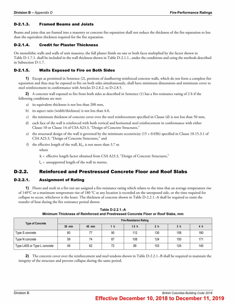
1) Except as permitted in Sentence (2), portions of loadbearing reinforced concrete walls, which do not form a complete fire separation and thus may be exposed to fire on both sides simultaneously, shall have minimum dimensions and minimum cover to steel reinforcement in conformance with Articles D-2.8.2. to D-2.8.5.
2) A concrete wall exposed to fire from both sides as described in Sentence (1) has a fire-resistance rating of 2 h if the following conditions are met:
a) its equivalent thickness is not less than 200 mm,
b) its aspect ratio (width/thickness) is not less than 4.0,
c) the minimum thickness of concrete cover over the steel reinforcement specified in Clause (d) is not less than 50 mm,
d) each face of the wall is reinforced with both vertical and horizontal steel reinforcement in conformance with either Clause 10 or Clause 14 of CSA A23.3, “Design of Concrete Structures,”
e) the structural design of the wall is governed by the minimum eccentricity (15 + 0.03h) specified in Clause 10.15.3.1 of CSA A23.3, “Design of Concrete Structures,” and
f) the effective length of the wall, klu, is not more than 3.7 mwhere
k = effective length factor obtained from CSA A23.3, “Design of Concrete Structures,”
lu = unsupported length of the wall in metres.
D-2.2. Reinforced and Prestressed Concrete Floor and Roof SlabsD-2.2.1. Assignment of Rating
1) Floors and roofs in a fire test are assigned a fire-resistance rating which relates to the time that an average temperature rise of 140°C or a maximum temperature rise of 180 °C at any location is recorded on the unexposed side, or the time required for collapse to occur, whichever is the lesser. The thickness of concrete shown in Table D-2.2.1.-A shall be required to resist the transfer of heat during the fire resistance period shown.
2) The concrete cover over the reinforcement and steel tendons shown in Table D-2.2.1.-B shall be required to maintain the integrity of the structure and prevent collapse during the same period.
Table D-2.2.1.-AMinimum Thickness of Reinforced and Prestressed Concrete Floor or Roof Slabs, mm
Type of Concrete Fire-Resistance Rating
30 min 45 min 1 h 1.5 h 2 h 3 h 4 h
Type S concrete 60 77 90 112 130 158 180
Type N concrete 59 74 87 108 124 150 171
Type L40S or Type L concrete 49 62 72 89 103 124 140
Effective December 10, 2018 to December 11, 2019

Fire-Performance Ratings Division B – Appendix D
British Columbia Building Code 2018 Division B
D-2.2.2. Floors with Hollow Units
The fire resistance of floors containing hollow units may be determined on the basis of equivalent thickness as described in Subsection D-1.6.
D-2.2.3. Composite Slabs
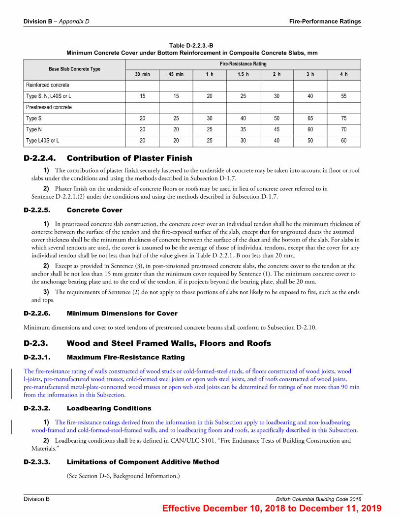
1) For composite concrete floor and roof slabs consisting of one layer of Type S or N concrete and another layer of Type L40S or L concrete in which the minimum thickness of both the top and bottom layers is not less than 25 mm, the combined fire-resistance rating may be determined using the following expressions:
a) when the base layer consists of Type S or N concrete,
b) when the base layer consists of Type L40S or L concrete,
where
R = fire resistance of slab, h,
t = total thickness of slab, mm, and
d = thickness of base layer, mm.
2) If the base course described in Sentence (1) is covered by a top layer of material other than Type S, N, L40S or L concrete, the top course thickness may be converted to an equivalent concrete thickness by multiplying the actual thickness by the appropriate factor listed in Table D-2.2.3.-A. This equivalent concrete thickness may be added to the thickness of the base course and the fire-resistance rating calculated using Table D-2.2.1.-A.
3) The minimum concrete cover under the main reinforcement for composite concrete floor and roof slabs with base slabs less than 100 mm thick shall conform to Table D-2.2.3.-B For base slabs 100 mm or more thick, the minimum cover thickness requirements of Table D-2.2.1.-B shall apply.
4) Where the top layer of a 2-layer slab is less than 25 mm thick, the fire-resistance rating for the slab shall be calculated as though the entire slab were made up of the type of concrete with the lesser fire resistance.
Table D-2.2.1.-BMinimum Concrete Cover over Reinforcement in Concrete Slabs, mm
Type of Concrete Fire-Resistance Rating
30 min 45 min 1 h 1.5 h 2 h 3 h 4 h
Type S, N, L40S or L concrete 20 20 20 20 25 32 39
Prestressed concrete slabs Type S, N, L40S or L concrete
20 25 25 32 39 50 64
Table D-2.2.3.-AMultiplying Factors for Equivalent Thickness
Top Course MaterialBase Slab Normal Density Concrete
(Type S or N)Base Slab Low Density Concrete
(Type L40S or L)
Gypsum board 3 2.25
Cellular concrete (mass density 400 – 560 kg/m3 ) 2 1.50
Vermiculite and perlite concrete (mass density 560 kg/m3 or less) 1.75 1.50
Portland cement with sand aggregate 1 0.75
Terrazzo 1 0.75
R � 0.00018t2 – 0.00009dt � 8.7t
R � 0.0001t2 � 0.0002dt – 0.0001d2 � 6.4t
Effective December 10, 2018 to December 11, 2019
Division B – Appendix D Fire-Performance Ratings
Division B British Columbia Building Code 2018
D-2.2.4. Contribution of Plaster Finish1) The contribution of plaster finish securely fastened to the underside of concrete may be taken into account in floor or roof
slabs under the conditions and using the methods described in Subsection D-1.7.
2) Plaster finish on the underside of concrete floors or roofs may be used in lieu of concrete cover referred to in Sentence D-2.2.1.(2) under the conditions and using the methods described in Subsection D-1.7.
D-2.2.5. Concrete Cover
1) In prestressed concrete slab construction, the concrete cover over an individual tendon shall be the minimum thickness of concrete between the surface of the tendon and the fire-exposed surface of the slab, except that for ungrouted ducts the assumed cover thickness shall be the minimum thickness of concrete between the surface of the duct and the bottom of the slab. For slabs in which several tendons are used, the cover is assumed to be the average of those of individual tendons, except that the cover for any individual tendon shall be not less than half of the value given in Table D-2.2.1.-B nor less than 20 mm.
2) Except as provided in Sentence (3), in post-tensioned prestressed concrete slabs, the concrete cover to the tendon at the anchor shall be not less than 15 mm greater than the minimum cover required by Sentence (1). The minimum concrete cover to the anchorage bearing plate and to the end of the tendon, if it projects beyond the bearing plate, shall be 20 mm.
3) The requirements of Sentence (2) do not apply to those portions of slabs not likely to be exposed to fire, such as the ends and tops.
D-2.2.6. Minimum Dimensions for Cover
Minimum dimensions and cover to steel tendons of prestressed concrete beams shall conform to Subsection D-2.10.
D-2.3. Wood and Steel Framed Walls, Floors and RoofsD-2.3.1. Maximum Fire-Resistance Rating
The fire-resistance rating of walls constructed of wood studs or cold-formed-steel studs, of floors constructed of wood joists, wood I-joists, pre-manufactured wood trusses, cold-formed steel joists or open web steel joists, and of roofs constructed of wood joists, pre-manufactured metal-plate-connected wood trusses or open web steel joists can be determined for ratings of not more than 90 min from the information in this Subsection.
D-2.3.2. Loadbearing Conditions
1) The fire-resistance ratings derived from the information in this Subsection apply to loadbearing and non-loadbearing wood-framed and cold-formed-steel-framed walls, and to loadbearing floors and roofs, as specifically described in this Subsection.
2) Loadbearing conditions shall be as defined in CAN/ULC-S101, “Fire Endurance Tests of Building Construction and Materials.”
D-2.3.3. Limitations of Component Additive Method
(See Section D-6, Background Information.)
Table D-2.2.3.-BMinimum Concrete Cover under Bottom Reinforcement in Composite Concrete Slabs, mm
Base Slab Concrete TypeFire-Resistance Rating
30 min 45 min 1 h 1.5 h 2 h 3 h 4 h
Reinforced concrete
Type S, N, L40S or L 15 15 20 25 30 40 55
Prestressed concrete
Type S 20 25 30 40 50 65 75
Type N 20 20 25 35 45 60 70
Type L40S or L 20 20 25 30 40 50 60
Effective December 10, 2018 to December 11, 2019

Fire-Performance Ratings Division B – Appendix D
British Columbia Building Code 2018 Division B
1) The fire-resistance rating of a framed assembly depends primarily on the time during which the membrane on the fire-exposed side remains in place.
2) The assigned times in Sentences D-2.3.4.(2), (3) and (4) are not intended to be construed as the fire-resistance ratings of the individual components of an assembly, nor are they intended to be construed as times that are applicable or acceptable for use beyond the method and systems described in this Subsection. These assigned times are the individual contributions of each component to the overall fire-resistance rating of an assembly, which is permitted to be derived using the component additive method described in this Subsection.
3) The fire-resistance rating calculated by the component additive method cannot be increased by installing membranes in multiple layers, other than as specified in Tables D-2.3.4.-A, D-2.3.4.-B, and D-2.3.4.-C.
D-2.3.4. Method of Calculation
1) In the component additive method, the fire-resistance rating of a framed assembly is calculated by adding the time assigned in Sentence (2) for the membrane on the fire-exposed side to the time assigned in Sentence (3) for the framing members and then adding any time assigned in Sentence (4) for additional protective measures, such as the inclusion of insulation or of reinforcement for a membrane. For loadbearing walls where resilient metal channels are installed with a single layer of gypsum board membrane in accordance with Table D-2.3.4.-A, the fire-resistance rating determined using this method of calculation must be reduced by 10 min.
2) The times to be used in the component additive method that have been assigned to membranes on the fire-exposed side of the assembly, which are partly based on their ability to remain in place during fire tests, are listed in Tables D-2.3.4.-A, D-2.3.4.-B, D-2.3.4.-C and D-2.3.4.-D. (This is not to be confused with the fire-resistance rating of the membrane, which also takes into account the rise in temperature on the unexposed side of the membrane. [See Sentence D-2.3.3.(2).])
Table D-2.3.4.-ATime Assigned to Protective Membranes on Fire-Exposed Side of Wood-Framed and Cold-Formed-Steel-Framed Walls
Description of FinishTime, min
Loadbearing Walls Non-Loadbearing Walls
11.0 mm Douglas Fir plywood phenolic bonded – 10(1)
14.0 mm Douglas Fir plywood phenolic bonded – 15(1)
12.7 mm Type X gypsum board 25(2) 25
15.9 mm Type X gypsum board 40(2) 40(3)
Double 12.7 mm Type X gypsum board(4) 50 80
Notes to Table D-2.3.4.-A:(1) Applies to stud cavities filled with mineral wool conforming to CAN/ULC-S702, “Mineral Fibre Thermal Insulation for Buildings,” and having a mass per unit area of not less
than 2 kg/m2, with no additional credit for insulation according to Table D-2.3.4.-G.(2) Applies only to wood-framed walls.(3) Applies only to steel-framed walls.(4) Resilient metal channels are permitted to be installed at a spacing of 400 mm o.c. with no effect on the rating of the wall assembly.
Table D-2.3.4.-BTime Assigned to Gypsum Board Membranes on Fire-Exposed Side of Floors
Description of Finish Resilient Metal Channels(1)Time, min
Floors with Wood or Steel Joists Floors with Open-Web Steel Joists
12.7 mm Type X gypsum boardSpaced ≤ 400 mm o.c.(2)
25(3) –
15.9 mm Type X gypsum board 40 –
12.7 mm Type X gypsum board–
25(4) 25
15.9 mm Type X gypsum board 40(4) 40
Double 12.7 mm Type X gypsum board Spaced ≤ 400 mm o.c.(5) 50(3) –
Double 12.7 mm Type X gypsum board Spaced at 600 mm o.c.(6) 45(3) –
Effective December 10, 2018 to December 11, 2019

Division B – Appendix D Fire-Performance Ratings
Division B British Columbia Building Code 2018
3) The times to be used in the component additive method that have been assigned to wall framing members and to floor and roof framing members are listed in Tables D-2.3.4.-E and D-2.3.4.-F respectively.
Double 15.9 mm Type X gypsum board Spaced ≤ 600 mm o.c.(6) 60(3) –
Notes to Table D-2.3.4.-B:(1) See Figures A-9.10.3.1.-A, A-9.10.3.1.-B and A-9.10.3.1.-D in Note A-9.10.3.1. for the attachment of single and double layers of gypsum board to resilient metal channels.(2) Resilient metal channels must be installed to achieve the stated rating.(3) Applies to wood joists, wood trusses, wood I-joists and cold-formed steel joists (C-shaped joists).(4) Applies to wood joists and pre-fabricated metal-plate-connected wood trusses.(5) Resilient metal channels must be installed or gypsum board must be applied directly to the structural members, which must be spaced not more than 400 mm o.c.(6) Resilient metal channels are permitted to be installed with no effect on the rating of the floor assembly. Gypsum board is also permitted to be directly applied to the
structural members.
Table D-2.3.4.-CTime Assigned to Gypsum Board Membranes on Fire-Exposed Side of Roofs
Description of Finish Time, min(1)
12.7 mm Type X gypsum board 25
15.9 mm Type X gypsum board 40
Notes to Table D-2.3.4.-C:(1) Applies to wood joists, pre-fabricated metal-plate-connected wood trusses, and open-web steel joists with ceiling supports spaced ≤ 400 mm o.c.
Table D-2.3.4.-DTime Assigned for Contribution of Lath and Plaster Protection on Fire-Exposed Side
Type of Lath Plaster Thickness, mm
Type of Plaster Finish
Portland Cement and Sand(1) or Lime and Sand
Gypsum and Sand or Gypsum Wood Fibre
Gypsum and Perlite or Gypsum and Vermiculite
Time, min(2)
9.5 mm gypsum 13 – 35 55
16 – 40 65
19 – 50 80(3)
Metal 19 20 50 80(3)
23 25 65 80(3)
26 30 80 80(3)
Notes to Table D-2.3.4.-D:(1) For mixture of Portland cement-sand plaster, see Sentence D-1.7.2.(2).(2) Applies to loadbearing and non-loadbearing wood studs or non-loadbearing cold-formed-steel studs, to floors constructed of wood joists or open-web steel joists, and to
roofs constructed of wood joists, pre-manufactured metal-plate-connected wood trusses, or open-web steel joists.(3) Values shown for these membranes have been limited to 80 min because the fire-resistance ratings of framed assemblies derived from these Tables must not exceed
1.5 h.
Table D-2.3.4.-B (continued)Time Assigned to Gypsum Board Membranes on Fire-Exposed Side of Floors
Description of Finish Resilient Metal Channels(1)Time, min
Floors with Wood or Steel Joists Floors with Open-Web Steel Joists
Effective December 10, 2018 to December 11, 2019

Fire-Performance Ratings Division B – Appendix D
British Columbia Building Code 2018 Division B
4) Preformed insulation of glass, rock or slag fibre and cellulose fibre insulation provide additional protection to wood studs by shielding the studs from exposure to the fire and thus delaying the time of collapse. The use of preformed glass fibre, preformed rock or slag fibre and dry-blown cellulose insulation material does not decrease the rating of wall assemblies with the membranes identified in Table D-2.3.4.-A. Similarly, the use of preformed glass fibre, preformed rock or slag fibre and cellulose insulation material does not decrease the rating of floor assemblies constructed with wood joists, wood trusses, wood I-joists and cold-formed-steel floor joists (C-shaped joists), provided the insulation is not in direct contact with the membranes identified in Table D-2.3.4.-B. The use of reinforcement in the membrane exposed to fire also adds to the fire resistance by extending the time to failure. Table D-2.3.4.-G shows the time increments that may be added to the fire resistance if these features are incorporated in the assembly.
Table D-2.3.4.-ETime Assigned for Contribution of Wood-Framed or Cold-Formed-Steel-Framed Walls
Description of FrameTime, min
Loadbearing Walls Non-Loadbearing Walls
Wood studs spaced ≤ 400 mm o.c. 20
15
10Wood studs spaced ≤ 600 mm o.c.
Cold-formed-steel studs spaced ≤ 400 mm o.c.
Cold-formed-steel studs spaced ≤ 600 mm o.c. 10 –
Table D-2.3.4.-FTime Assigned for Contribution of Wood or Steel Frame of Floors and Roofs
Description of FrameTime, min
Type of Assembly Structural Members
Floor(1)Wood joists, wood I-joists, wood trusses and cold-formed-steel joists spaced ≤ 600 mm o.c.
10(2)
Open-web steel joists with ceiling supports spaced ≤ 400 mm o.c.
Roof
Wood joists spaced ≤ 400 mm o.c. 10
Open-web steel joists with ceiling supports spaced ≤ 400 mm o.c. 10
Wood truss assemblies [metal-plate-connected] spaced ≤ 600 mm o.c. 5
Notes to Table D-2.3.4.-F:(1) Resilient metal channels are permitted to be installed with no effect on the rating of the floor assembly.(2) Applies only to floor structural members that are protected by a membrane.
Table D-2.3.4.-GTime Assigned for Additional Protection
Description of Additional Protection Time, min
Add to the fire-resistance rating of wood stud walls, sheathed with gypsum board or lath and plaster, if the spaces between the studs are filled with preformed insulation of rock or slag fibres conforming to CAN/ULC-S702, “Mineral Fibre Thermal Insulation for Buildings,” and with a mass per unit area of not less than 1.22 kg/m2 of wall surface
15(1)
Add to the fire-resistance rating of non-loadbearing wood stud walls, sheathed with gypsum board or lath and plaster, if the spaces between the studs are filled with preformed insulation of glass fibres conforming to CAN/ULC-S702, “Mineral Fibre Thermal Insulation for Buildings,” and having a mass per unit area of not less than 0.6 kg/m2 of wall surface
5(2)
Add to the fire-resistance rating of loadbearing wood stud walls sheathed with gypsum board if the spaces between the studs are filled with insulation of cellulose fibres conforming to CAN/ULC-S703, “Cellulose Fibre Insulation for Buildings,” and having a density of not less than 50 kg/m3
10
Add to the fire-resistance rating of plaster on gypsum lath ceilings if 0.76 mm diam wire mesh with 25 mm by 25 mm openings or 1.57 mm diam diagonal wire reinforcing at 250 mm o.c. is placed between lath and plaster
30
Add to the fire-resistance rating of plaster on gypsum lath ceilings if 76 mm wide metal lath strips are placed over joints between lath and plaster
10
Effective December 10, 2018 to December 11, 2019

Division B – Appendix D Fire-Performance Ratings
Division B British Columbia Building Code 2018
5) Cellulose fibre insulation conforming to CAN/ULC-S703, “Cellulose Fibre Insulation for Buildings,” applied in conformance with CAN/CGSB-92.2-M, “Trowel or Spray Applied Acoustical Material,” does not affect the fire-resistance rating of a non-loadbearing cold-formed-steel stud wall assembly, provided that it is sprayed to either face of the wall cavity.
D-2.3.5. Considerations for Various Types of Assemblies
1) Interior vertical fire separations are to be rated for exposure to fire on each side (see Sentence 3.1.7.3.(2)). The method described in this Subsection applies when a membrane is provided on both sides of the assembly. However, in the calculation of the fire-resistance rating of such an assembly using this method, no additional contribution to fire resistance is to be assigned for a membrane on the non-fire-exposed side, since its contribution is already accounted for in the values assigned to the other components of the assembly.
2) Exterior wall assemblies required to have a fire-resistance rating are required to be rated for exposure to fire from the interior side only (see Sentence 3.1.7.3.(3)). When deriving a fire-resistance rating for such wall assemblies using the method described in this Subsection, only wood studs with a single layer of gypsum board or non-loadbearing cold-formed-steel studs conforming to Table D-2.3.4.-E may be used. Such walls must have a membrane on the exterior side of the stud consisting of plywood, oriented strandboard or gypsum sheathing and exterior cladding. Additional materials are also permitted between the required sheathing and cladding. The spaces between the studs are to be filled with insulation conforming to CAN/ULC-S702, “Mineral Fibre Thermal Insulation for Buildings,” and having a mass per unit area of not less than 1.22 kg/m2 of wall surface. However, in the calculation of the fire-resistance rating of such an assembly, no additional contribution to fire resistance is to be assigned for a membrane on the non-fire-exposed side, since its contribution is already accounted for in the values assigned to the other components of the assembly.
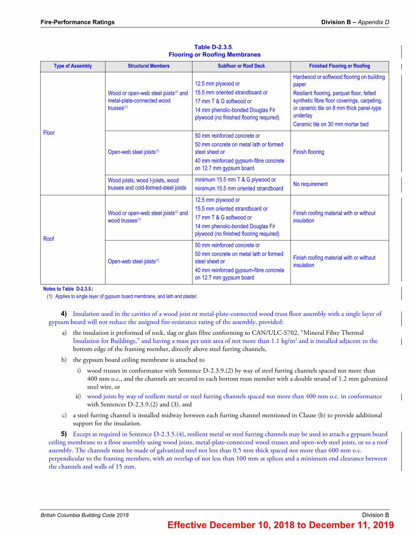
3) In the case of a floor or roof assembly, the Code only requires testing for fire exposure from below. Floors or roofs must have an upper flooring or roofing membrane in accordance with Table D-2.3.5.
Add to the fire-resistance rating of plaster on 9.5 mm thick gypsum lath ceilings (Table D-2.3.4.-D) if supports for lath are 300 mm o.c.
10
Add to the fire-resistance rating of floor assemblies if the spaces between the structural members are filled with preformed insulation of rock or slag fibres conforming to CAN/ULC-S702, “Mineral Fibre Thermal Insulation for Buildings,” and having a mass per unit area of not less than 1.22 kg/m2 of floor surface
5(2)
Add to the fire-resistance rating of floor assemblies if the spaces between the structural members are filled with wet-blown cellulose fibres conforming to CAN/ULC-S703, “Cellulose Fibre Insulation for Buildings,” and having a density of not less than 50 kg/m3
5(2)(3)
Add to the fire-resistance rating of floor assemblies where the floor topping on the unexposed side of the floor assemblies consists of concrete not less than 38 mm thick
5(2)
Notes to Table D-2.3.4.-G:(1) Applies to wood-framed walls only.(2) Applies to wood joists, wood trusses, wood I-joists and cold-formed-steel joists (C-shaped joists).(3) Applies to cellulose fibre:
(i) for wood joists, wood I-joist and wood trusses–that is spray-applied with a minimum density of 50 kg/m3, a minimum depth of 90 mm on the underside of the subfloor, and of 90 mm on the sides of the structural members;
(ii) for cold-formed-steel joists–that is spray-applied with a minimum density of 50 kg/m3 and a minimum thickness of 90 mm on the underside of the subfloor, of 90 mm on the sides of the structural members, and of 13 mm on the underside of the bottom flange other than at resilient metal channel locations.
Table D-2.3.4.-G (continued)Time Assigned for Additional Protection
Description of Additional Protection Time, min
Effective December 10, 2018 to December 11, 2019
Fire-Performance Ratings Division B – Appendix D
British Columbia Building Code 2018 Division B
4) Insulation used in the cavities of a wood joist or metal-plate-connected wood truss floor assembly with a single layer of gypsum board will not reduce the assigned fire-resistance rating of the assembly, provided:
a) the insulation is preformed of rock, slag or glass fibre conforming to CAN/ULC-S702, “Mineral Fibre Thermal Insulation for Buildings,” and having a mass per unit area of not more than 1.1 kg/m2 and is installed adjacent to the bottom edge of the framing member, directly above steel furring channels,
b) the gypsum board ceiling membrane is attached to
i) wood trusses in conformance with Sentence D-2.3.9.(2) by way of steel furring channels spaced not more than 400 mm o.c., and the channels are secured to each bottom truss member with a double strand of 1.2 mm galvanized steel wire, or
ii) wood joists by way of resilient metal or steel furring channels spaced not more than 400 mm o.c. in conformance with Sentences D-2.3.9.(2) and (3), and
c) a steel furring channel is installed midway between each furring channel mentioned in Clause (b) to provide additional support for the insulation.
5) Except as required in Sentence D-2.3.5.(4), resilient metal or steel furring channels may be used to attach a gypsum board ceiling membrane to a floor assembly using wood joists, metal-plate-connected wood trusses and open-web steel joists, or to a roof assembly. The channels must be made of galvanized steel not less than 0.5 mm thick spaced not more than 600 mm o.c. perpendicular to the framing members, with an overlap of not less than 100 mm at splices and a minimum end clearance between the channels and walls of 15 mm.
Table D-2.3.5.Flooring or Roofing Membranes
Type of Assembly Structural Members Subfloor or Roof Deck Finished Flooring or Roofing
Floor
Wood or open-web steel joists(1) and metal-plate-connected wood trusses(1)
12.5 mm plywood or
15.5 mm oriented strandboard or
17 mm T & G softwood or
14 mm phenolic-bonded Douglas Fir plywood (no finished flooring required)
Hardwood or softwood flooring on building paper
Resilient flooring, parquet floor, felted synthetic fibre floor coverings, carpeting, or ceramic tile on 8 mm thick panel-type underlay
Ceramic tile on 30 mm mortar bed
Open-web steel joists(1)
50 mm reinforced concrete or
50 mm concrete on metal lath or formed steel sheet or
40 mm reinforced gypsum-fibre concrete on 12.7 mm gypsum board
Finish flooring
Wood joists, wood I-joists, wood trusses and cold-formed-steel joists
minimum 15.5 mm T & G plywood or
minimum 15.5 mm oriented strandboardNo requirement
Roof
Wood or open-web steel joists(1) and wood trusses(1)
12.5 mm plywood or
15.5 mm oriented strandboard or
17 mm T & G softwood or
14 mm phenolic-bonded Douglas Fir plywood (no finished flooring required)
Finish roofing material with or without insulation
Open-web steel joists(1)
50 mm reinforced concrete or
50 mm concrete on metal lath or formed steel sheet or
40 mm reinforced gypsum-fibre concrete on 12.7 mm gypsum board
Finish roofing material with or without insulation
Notes to Table D-2.3.5.:(1) Applies to single layer of gypsum board membrane, and lath and plaster.
Effective December 10, 2018 to December 11, 2019

Division B – Appendix D Fire-Performance Ratings
Division B British Columbia Building Code 2018
D-2.3.6. Framing Members
1) The values shown in Tables D-2.3.4.-A, D-2.3.4.-B, D-2.3.4.-D and D-2.3.12. apply to membranes supported on framing members installed in their conventional orientation and spaced in conformance with Tables D-2.3.4.-E and D-2.3.4.-F.
2) Wood studs and wood roof framing members are to be not less than 38 mm by 89 mm. Wood floor joists are to be not less than 38 mm by 184 mm, except where they are used in an assembly from Table D-2.3.4.-D or from Table D-2.3.5. that uses a single layer of gypsum board as the lower (ceiling) membrane, in which case, wood floor joists are to be not less than 38 mm by 89 mm.
3) Wood roof trusses are to consist of wood chord and web framing members not less than 38 mm by 89 mm and metal connector plates fabricated from galvanized steel not less than 1 mm in nominal thickness with projecting teeth not less than 8 mm long.
4) Wood floor trusses are to consist of:
a) metal-plate-connected wood trusses that are not less than 305 mm deep with wood chord and web framing members not less than 38 mm by 64 mm and metal connector plates fabricated from galvanized steel not less than 1 mm in nominal thickness with projecting teeth not less than 8 mm long;
b) metal-web wood trusses that are not less than 286 mm deep with wood chords not less than 38 mm by 64 mm and V-shaped webs made from galvanized steel not less than 1 mm in nominal thickness with plate areas having teeth not less than 8 mm long; or
c) fingerjoined wood trusses that are not less than 330 mm deep with fingerjoined connections, chord members not less than 38 mm by 64 mm, and web members not less than 38 mm by 38 mm glued together with a R-14 phenol-resorcinol resin conforming to CSA O112.10, “Evaluation of Adhesives for Structural Wood Products (Limited Moisture Exposure).”
5) Wood I-joists are to be not less than 241 mm deep with flanges that are not less than 38 mm by 38 mm and an oriented strandboard or plywood web that is not less than 9.5 mm thick.
6) The dimensions for dressed lumber given in CSA O141, “Softwood Lumber,” are to be used for wood studs, joists, I-joists and trusses.
7) Cold-formed-steel studs for non-loadbearing walls are to consist of galvanized steel that is not less than 0.5 mm thick and not less than 63 mm wide, and have a flange that is not less than 31 mm wide.
8) Cold-formed-steel studs in non-loadbearing wall assemblies are to be installed with not less than a 12 mm clearance between the top of the stud and the top of the runner to allow for expansion in the event of a fire. Where the studs are required to be attached for alignment purposes during erection, they must be attached to the bottom runners only.
9) Cold-formed-steel studs for loadbearing walls are to consist of galvanized steel that is not less than 0.912 mm thick but not greater than 1.52 mm thick, with a C-shaped cross-section not less than 92 mm deep by 41 mm wide and 12.7 mm stiffening lips.
10) Cold-formed-steel studs in loadbearing wall assemblies are to be installed with diagonal cross-bracing.
11) Cold-formed-steel floor joists (C-shaped joists) are to be not less than 41 mm wide × 203 mm deep × 1.22 mm material thickness.
12) The allowable spans for wood joists listed in the Span Tables in Part 9 are provided for floors supporting specific occupancies.
D-2.3.7. Plaster Finish
The thickness of plaster finish shall be measured from the face of gypsum or metal lath.
D-2.3.8. Edge Support for Gypsum Board in Wall Assembly
Gypsum board installed over framing or furring in a wall assembly shall be installed so that all edges are supported, except that 15.9 mm Type X gypsum board may be installed horizontally with the horizontal joints unsupported when framing members are at 400 mm o.c. maximum.
Effective December 10, 2018 to December 11, 2019

Fire-Performance Ratings Division B – Appendix D
British Columbia Building Code 2018 Division B
D-2.3.9. Membrane Fastening
1) Except as provided in Sentences (2) to (5), Table D-2.3.4.-B and Sentence D-2.3.5.(5), the application of lath and plaster finish shall conform to CSA A82.30-M, “Interior Furring, Lathing and Gypsum Plastering,” and of gypsum board finish shall conform to ASTM C 840, “Application and Finishing of Gypsum Board.”
2) Where a membrane referred to in Table D-2.3.4.-A, D-2.3.4.-B, D-2.3.4.-C , D-2.3.4.-D or D-2.3.12. is applied to steel framing or furring, fasteners shall penetrate not less than 10 mm through the metal.
3) Except as provided in Sentence (4), where a membrane referred to in Table D-2.3.4.-A, D-2.3.4.-B, D-2.3.4.-C, D-2.3.4.-D or D-2.3.12. is applied to wood framing or furring, minimum fastener penetrations into wood members shall conform to Table D-2.3.9. for the time assigned to the membrane.
4) Where a membrane is applied in 2 layers, the fastener penetrations described in Table D-2.3.9. shall apply to the base layer. Fasteners for the face layer shall penetrate not less than 20 mm into wood supports.
5) In a double layer application of gypsum board on wood supports, fastener spacing shall conform to ASTM C 840, “Application and Finishing of Gypsum Board.”
D-2.3.10. Ceiling Membrane Openings – Combustible Construction
1) Except as permitted in Article D-2.3.12., where a floor or roof assembly of combustible construction is assigned a fire-resistance rating on the basis of this Subsection and incorporates a ceiling membrane described in Table D-2.3.4.-B, D-2.3.4.-C or D-2.3.4.-D, the ceiling membrane may be penetrated by openings leading to ducts within concealed spaces above the membrane provided:
a) the assembly is not required to have a fire-resistance rating in excess of 1 h,
b) the area of any openings does not exceed 930 cm2 (see Sentence (2)),
c) the aggregate area of openings does not exceed 1% of the ceiling area of the fire compartment,
d) the depth of the concealed space above the ceiling is not less than 230 mm,
e) no dimension of any opening exceeds 310 mm,
f) supports are provided for openings with any dimension exceeding 150 mm where framing members are spaced greater than 400 mm o.c.,
g) individual openings are spaced not less than 2 m apart,
h) the ducts above the membrane are sheet steel and are supported by steel strapping firmly attached to the framing members, and
i) the clearance between the top surface of the membrane and the bottom surface of the ducts is not less than 100 mm.
2) Where an individual opening permitted in Sentence (1) exceeds 130 cm2 in area, it shall be protected by
a) a fire stop flap conforming to CAN/ULC-S112.2, “Fire Test of Ceiling Firestop Flap Assemblies,” that activates at a temperature approximately 30°C above the normal maximum temperature that occurs in the ducts, whether the air duct system is operating or shut down, or
b) thermal protection above the duct consisting of the same materials as used for the ceiling membrane, mechanically fastened to the ductwork and extending 200 mm beyond the opening on all sides (see Article D-2.3.10.).
Table D-2.3.9.Membrane Fastening
Type of Membrane
Minimum Penetration of Fasteners for Membrane Protection on Wood Framing, mm
5-25 30-35 40 50 55-70 80
Time,(1) min
Single layer 20 29 32 – – –
Double layer 20 20 20 29 35 44
Gypsum lath 20 20 23 23 29 29
Notes to Table D-2.3.9.:(1) Assigned contributions of membranes to fire resistance are listed in Tables D-2.3.4.-A, D-2.3.4.-B, D-2.3.4.-C, D-2.3.4.-D and D-2.3.12.
Effective December 10, 2018 to December 11, 2019
Division B – Appendix D Fire-Performance Ratings
Division B British Columbia Building Code 2018
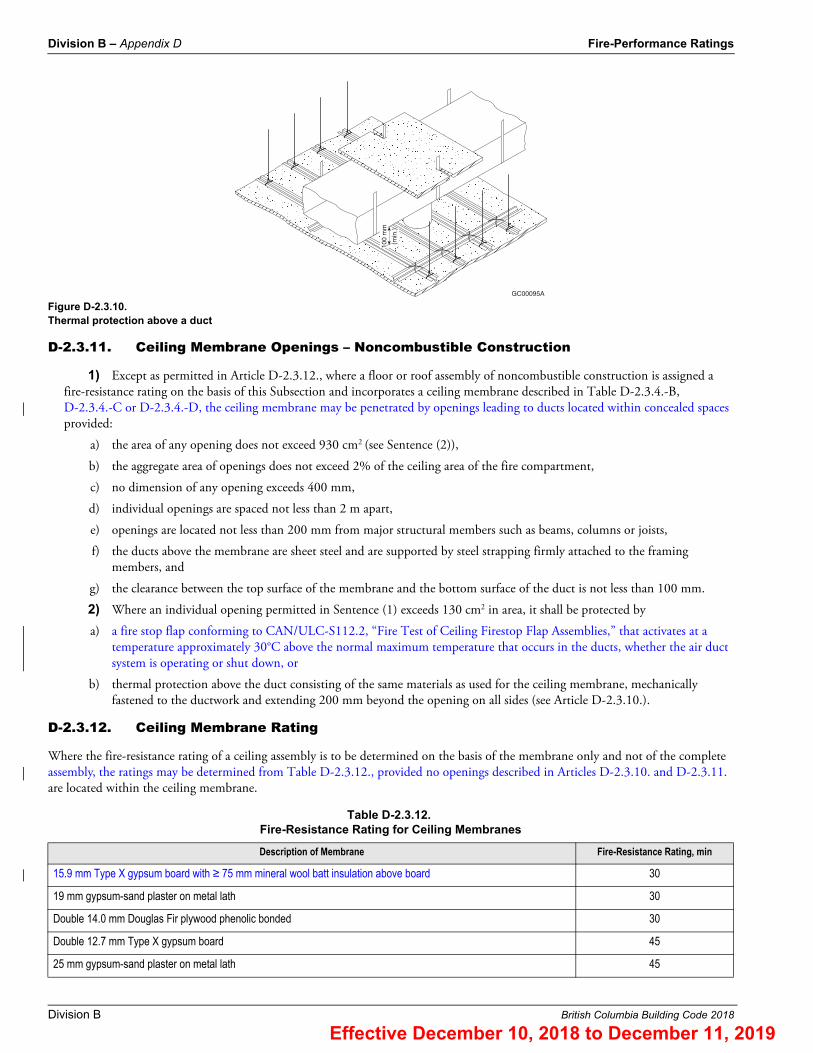
Figure D-2.3.10.Thermal protection above a duct
D-2.3.11. Ceiling Membrane Openings – Noncombustible Construction
1) Except as permitted in Article D-2.3.12., where a floor or roof assembly of noncombustible construction is assigned a fire-resistance rating on the basis of this Subsection and incorporates a ceiling membrane described in Table D-2.3.4.-B, D-2.3.4.-C or D-2.3.4.-D, the ceiling membrane may be penetrated by openings leading to ducts located within concealed spaces provided:
a) the area of any opening does not exceed 930 cm2 (see Sentence (2)),
b) the aggregate area of openings does not exceed 2% of the ceiling area of the fire compartment,
c) no dimension of any opening exceeds 400 mm,
d) individual openings are spaced not less than 2 m apart,
e) openings are located not less than 200 mm from major structural members such as beams, columns or joists,
f) the ducts above the membrane are sheet steel and are supported by steel strapping firmly attached to the framing members, and
g) the clearance between the top surface of the membrane and the bottom surface of the duct is not less than 100 mm.
2) Where an individual opening permitted in Sentence (1) exceeds 130 cm2 in area, it shall be protected by
a) a fire stop flap conforming to CAN/ULC-S112.2, “Fire Test of Ceiling Firestop Flap Assemblies,” that activates at a temperature approximately 30°C above the normal maximum temperature that occurs in the ducts, whether the air duct system is operating or shut down, or
b) thermal protection above the duct consisting of the same materials as used for the ceiling membrane, mechanically fastened to the ductwork and extending 200 mm beyond the opening on all sides (see Article D-2.3.10.).
D-2.3.12. Ceiling Membrane Rating
Where the fire-resistance rating of a ceiling assembly is to be determined on the basis of the membrane only and not of the complete assembly, the ratings may be determined from Table D-2.3.12., provided no openings described in Articles D-2.3.10. and D-2.3.11. are located within the ceiling membrane.
Table D-2.3.12.Fire-Resistance Rating for Ceiling Membranes
Description of Membrane Fire-Resistance Rating, min
15.9 mm Type X gypsum board with ≥ 75 mm mineral wool batt insulation above board 30
19 mm gypsum-sand plaster on metal lath 30
Double 14.0 mm Douglas Fir plywood phenolic bonded 30
Double 12.7 mm Type X gypsum board 45
25 mm gypsum-sand plaster on metal lath 45
100
mm
(min
.)
GC00095A
Effective December 10, 2018 to December 11, 2019
Fire-Performance Ratings Division B – Appendix D
British Columbia Building Code 2018 Division B
D-2.3.13. Membrane Penetrations in Combustible and Noncombustible Construction
1) Where a wall, floor or roof assembly is assigned a fire-resistance rating on the basis of this Subsection and includes a membrane or membranes described in Table D-2.3.4.-A, D-2.3.4.-B, D-2.3.4.-C, D-2.3.4.-D or D-2.3.12., penetrations of the membrane or membranes must be fire stopped in conformance with the applicable requirements in Article 3.1.9.1. or Sentence 9.10.9.6.(1).
D-2.3.14. Beams
1) Where a steel beam is included with an open-web steel joist and is protected by the same continuous ceiling, the beam is assumed to have a fire-resistance rating equal to that assigned to the rest of the assembly.
2) The ratings in this Subsection assume that the construction to which the beam is related is a normal one and does not carry unusual loads from the floor or slab above.
D-2.3.15. Wired Glass Assembly Support
1) Openings in a vertical fire separation having a fire-resistance rating of not more than 1 h are allowed to be protected by wired glass assemblies, provided the wired glass is
a) not less than 6 mm thick;
b) reinforced by a steel wire mesh in the form of diamonds, squares or hexagons having dimensions of
i) approximately 25 mm across the flats, using wire of not less than 0.45 mm diameter, orii) approximately 13 mm across the flats, using wire of not less than 0.40 mm diameter, the wire to be centrally
embedded during manufacture and welded or intertwined at each intersection;
c) set in fixed steel frames with metal not less than 1.35 mm thick and providing a glazing stop of not less than 20 mm on each side of the glass; and
d) limited in area so that
i) individual panes are not more than 0.84 m2, with neither height nor width more than 1.4 m, andii) the area not structurally supported by mullions is not more than 7.5 m2.
2) It is intended that the structural mullions referred to in Subclause (1)(d)(ii) will not distort or be displaced to the extent that there would be a failure of the wired glass closure during the period for which a closure in the fire separation would be expected to function. Hollow structural steel tubing not less than 100 mm square filled with a Portland cement-based grout will satisfy the intent of the Subclause.
D-2.4. Solid Wood Walls, Floors and RoofsD-2.4.1. Minimum Thickness
The minimum thickness of solid wood walls, floors and roofs for fire-resistance ratings from 30 min to 1.5 h is shown in Table D-2.4.1.
Double 15.9 mm Type X gypsum board 60
32 mm gypsum-sand plaster on metal lath 60
Table D-2.3.12. (continued)Fire-Resistance Rating for Ceiling Membranes
Description of Membrane Fire-Resistance Rating, min
Effective December 10, 2018 to December 11, 2019

Division B – Appendix D Fire-Performance Ratings
Division B British Columbia Building Code 2018
D-2.4.2. Increased Fire-Resistance Rating
1) The fire-resistance rating of the assemblies described in Table D-2.4.1. may be increased by 15 min if one of the following finishes is applied on the fire-exposed side:
a) 12.7 mm thick gypsum board,
b) 20 mm thick gypsum-sand plaster on metal lath, or
c) 13 mm thick gypsum-sand plaster on 9.5 mm gypsum lath.
2) Fastening of the plaster to the wood structure shall conform to Subsection D-2.3.
D-2.4.3. Supplementary Ratings
Supplementary ratings based on tests are included in Table D-2.4.3. The ratings given shall apply to constructions that conform in all details with the descriptions given.
D-2.5. Solid Plaster PartitionsD-2.5.1. Minimum Thickness
The minimum thickness of solid plaster partitions for fire-resistance ratings from 30 min to 4 h is shown in Table D-2.5.1.
Table D-2.4.1.Minimum Thickness of Solid Wood Walls, Roofs and Floors, mm(1)(2)
Type of ConstructionFire-Resistance Rating
30 min 45 min 1 h 1.5 h
Solid wood floor with building paper and finish flooring on top(3)
89 114 165 235
Solid wood, splined or tongued and grooved floor with building paper and finish flooring on top(4)
64 76 – –
Solid wood walls of loadbearing vertical plank(3) 89 114 140 184
Solid wood walls of non-loadbearing horizontal plank(3) 89 89 89 140
Notes to Table D-2.4.1.:(1) See CSA O141, “Softwood Lumber,” for sizes.(2) The fire-resistance ratings and minimum dimensions for floors also apply to solid wood roof decks of comparable thickness with finish roofing material.(3) The assembly shall consist of 38 mm thick members on edge fastened together with 101 mm common wire nails spaced not more than 400 mm o.c. and staggered in the
direction of the grain.(4) The floor shall consist of 64 mm by 184 mm wide planks either tongued and grooved or with 19 mm by 38 mm splines set in grooves and fastened together with 88 mm
common nails spaced not more than 400 mm o.c.
Table D-2.4.3.Fire-Resistance Rating of Non-Loadbearing Built-up Solid Wood Partitions(1)
Construction Details Actual Overall Thickness, mm Fire-Resistance Rating
Solid panels of wood boards 64 mm to 140 mm wide grooved and joined with wood splines, nailed together, boards placed vertically with staggered joints, 3 boards thick
58 30 min
Solid panels with 4 mm plywood facings(2) glued to 46 mm solid wood core of glued, tongued and grooved construction for both sides and ends of core pieces with tongued and grooved rails in the core about 760 mm apart
54 1 h
Notes to Table D-2.4.3.:(1) The ratings and notes are taken from “Fire Resistance Classifications of Building Constructions,” Building Materials and Structures Report BMS 92, National Bureau of
Standards, Washington, 1942.(2) Ratings for plywood faced panel are based on phenolic resin glue being used for gluing facings to wood frames. If other types of glue are used for this purpose, the ratings
apply if the facings are nailed to the frames in addition to being glued.
Effective December 10, 2018 to December 11, 2019

Fire-Performance Ratings Division B – Appendix D
British Columbia Building Code 2018 Division B
D-2.6. Protected Steel ColumnsD-2.6.1. Minimum Thickness of Protective Covering
The minimum thickness of protective covering to steel columns is shown in Tables D-2.6.1.-A to D-2.6.1.-F for fire-resistance ratings from 30 min to 4 h.
Table D-2.5.1.Minimum Thickness of Non-Loadbearing Solid Plaster Partitions, mm
Type of Plaster on Metal Lath(1)Fire-Resistance Rating
30 min 45 min 1 h 1.5 h 2 h 3 h 4 h
Portland cement-sand(2) or Portland cement-lime-sand 50(3) – – – – – –
Gypsum-sand 50(3) 50(3) 64 – – – –
Gypsum-vermiculite, gypsum-perlite, Portland cement-vermiculite or Portland cement-perlite
50(3) 50(3) 50(3) 58 64 83 102
Notes to Table D-2.5.1.:(1) Metal lath shall be expanded metal lath or welded woven wire fabric supported on 19 mm vertical light steel studs spaced not more than 600 mm o.c. Plaster shall be
applied to both sides of the lath.(2) For mixture of Portland cement-sand plaster, see Sentence D-1.7.2.(2).(3) CSA A82.30-M, “Interior Furring, Lathing and Gypsum Plastering,” does not permit solid plaster partitions less than 50 mm thick.
Table D-2.6.1.-AMinimum Thickness of Concrete or Masonry Protection to Steel Columns, mm
Description of CoverFire-Resistance Rating
30 min 45 min 1 h 1.5 h 2 h 3 h 4 h
Monolithic concrete
Type S concrete(1) (column spaces filled)(2) 25 25 25 25 39 64 89
Type N or L concrete(1) (column spaces filled)(2) 25 25 25 25 32 50 77
Concrete masonry units(3) or precast reinforced concrete units
Type S concrete (column spaces not filled) 50 50 50 50 64 89 115
Type N or L concrete (column spaces not filled) 50 50 50 50 50 77 102
Clay or shale brick(4) (column spaces filled)(2) 50 50 50 50 50 64 77
Clay or shale brick(4) (column spaces not filled) 50 50 50 50 50 77 102
Hollow clay tile(5) (column spaces filled)(2) 50(6) 50(6) 50(6) 50(6) (7) (7) (7)
Hollow clay tile(5) (column spaces not filled) 50(6) 50(6) 50(6) – – – –
Notes to Table D-2.6.1.-A:(1) Applies to cast-in-place concrete reinforced with 5.21 mm diam wire wrapped around column spirally 200 mm o.c., or 1.57 mm diam wire mesh with 100 mm by 100 mm
openings.(2) The space between the protective covering and the web or flange of the column shall be filled with concrete, cement mortar or a mixture of cement mortar and
broken bricks.(3) Concrete masonry shall be reinforced with 5.21 mm diam wire or wire mesh with 1.19 mm diam wire and 10 mm by 10 mm openings, laid in every second course.(4) Brick cover 77 mm thick or less shall be reinforced with 2.34 mm diam wire or 1.19 mm diam wire mesh with 10 mm by 10 mm openings, laid in every second course.(5) Hollow clay tiles and masonry mortar shall be reinforced with 1.19 mm diam wire mesh with 10 mm by 10 mm openings, laid in every horizontal joint and lapped
at corners.(6) Hollow clay tiles shall conform to CAN/CSA-A82, “Fired Masonry Brick Made from Clay or Shale.”(7) 50 mm nominal hollow clay tile, reinforced with 1.19 mm diam wire mesh with 10 mm by 10 mm openings laid in every horizontal joint and covered with 19 mm
gypsum-sand plaster and with limestone concrete fill in column spaces, has a 4 h fire-resistance rating.
Effective December 10, 2018 to December 11, 2019

Division B – Appendix D Fire-Performance Ratings
Division B British Columbia Building Code 2018
Table D-2.6.1.-BMinimum Thickness of Plaster Protection to Steel Columns, mm
Description Fire-Resistance Rating(1)(2)
30 min 45 min 1 h 1.5 h 2 h 3 h 4 h
Gypsum-sand plaster on 9.5 mm gypsum lath(3) 13 13 13 20 – – –
Gypsum-perlite or vermiculite plaster on 9.5 mm gypsum lath(3) 13 13 13 20 25 – –
Gypsum perlite or vermiculite plaster on 12.7 mm gypsum lath(3) 13 13 13 20 25 32 50
Gypsum perlite or vermiculite plaster on double 12.7 mm gypsum lath(3) 13 13 13 20 25 25 32
Portland cement-sand plaster on metal lath(4)(5) 25 25 25 – – – –
Notes to Table D-2.6.1.-B:(1) Fire-resistance ratings of 30 min and 45 min apply to columns whose M/D ratio is 30 or greater. Fire-resistance ratings greater than 45 min apply to columns whose M/D
ratio is greater than 60. Where the M/D ratio is between 30 and 60 and the required fire-resistance rating is greater than 45 min, the total thickness of protection specified in the Table shall be increased by 50%. (To determine M/D, refer to Article D-2.6.4.)
(2) Where the thickness of plaster over gypsum lath is 25 mm or more, wire mesh with 1.57 mm diam wire and openings not exceeding 50 mm by 50 mm shall be placed midway in the plaster.
(3) Lath held in place by 1.19 mm diam wire wrapped around lath 450 mm o.c.(4) Expanded metal lath 1.36 kg/m2 fastened to 9.5 mm by 19 mm steel channels held in vertical position around column by 1.19 mm diam wire ties.(5) For mixture of Portland cement-sand plaster, see Sentence D-1.7.2.(2).
Table D-2.6.1.-CMinimum Thickness of Gypsum-Sand Plaster on Metal Lath Protection to Steel Columns, mm
M/D(1)Fire-Resistance Rating
30 min 45 min 1 h 1.5 h 2 h 3 h
30 to 60 16 16 32 – – –
over 60 to 90 16 16 16 32 – –
over 90 to 120 16 16 16 25 39 –
over 120 to 180 16 16 16 16 25 –
over 180 16 16 16 16 25 39
Notes to Table D-2.6.1.-C:(1) To determine the M/D ratio, refer to Article D-2.6.4.
Table D-2.6.1.-DMinimum Thickness of Gypsum-Perlite or Gypsum-Vermiculite Plaster on Metal Lath Protection to Steel Columns, mm
M/D(1)Fire-Resistance Rating
30 min 45 min 1 h 1.5 h 2 h 3 h 4 h
30 to 60 16 16 20 32 35 – –
over 60 to 90 16 16 16 20 26 35 45
over 90 to 120 16 16 16 16 26 35 45
over 120 to 180 16 16 16 16 20 32 35
over 180 16 16 16 16 16 26 35
Notes to Table D-2.6.1.-D:(1) To determine the M/D ratio, refer to Article D-2.6.4.
Effective December 10, 2018 to December 11, 2019

Fire-Performance Ratings Division B – Appendix D
British Columbia Building Code 2018 Division B
Table D-2.6.1.-ESteel Columns with Sheet-Steel Membrane and Insulation as Shown in Figures D-2.6.1-A. and D-2.6.1-B.
Type of ProtectionSteel Thickness,(1)
mmFastening(2) Insulation
Fire-Resistance Rating
See Figure D-2.6.1.-A 0.51No. 8 sheet-metal screws 9.5 mm long, 200 mm o.c.
50 mm mineral wool batts(3) 45 min
See Figure D-2.6.1.-B 0.64Self-threading screws or No. 8 sheet-metal screws, 600 mm o.c.
2 layers 12.7 mm gypsum board 1.5 h
See Figure D-2.6.1.-A 0.64No. 8 sheet-metal screws, 9.5 mm long 200 mm o.c.
75 mm mineral wool batts,(3) 12.7 mm gypsum board
2 h
See Figure D-2.6.1.-B 0.76Crimped joint or No. 8 sheet-metal screws, 300 mm o.c.
2 layers 15.9 mm gypsum board 2 h
Notes to Table D-2.6.1.-E:(1) Minimum thickness, galvanized or wiped-zinc-coated sheet-steel.(2) Sheet-steel shall be securely fastened to the floor and superstructure, or where sheet-steel cover does not extend floor to floor, fire stopping shall be provided at the level
where sheet-steel protection ends. In the latter case, an alternate type of fire protection shall be applied between the fire stopping and the superstructure.(3) Conforming to CAN/ULC-S702, “Mineral Fibre Thermal Insulation for Buildings,” Type 1A, minimum density 30 kg/m3: column section and batts wrapped with 25 mm
mesh chicken wire.
Table D-2.6.1.-FMinimum M/D Ratio for Steel Columns Covered with Type X Gypsum Board Protection(1)
Minimum Thickness of Type X Gypsum Board Protection,(2) mm
Fire-Resistance Rating
1 h 1.5 h 2 h 3 h
12.7 75 – – –
15.9 55 – – –
25.4 35 60 – –
28.6 35 50 – –
31.8 35 40 75 –
38.1 35 35 55 –
41.3 35 35 45 –
44.5 35 35 35 –
47.6 35 35 35 –
50.8 35 35 35 75
63.5 35 35 35 45
Notes to Table D-2.6.1.-F:(1) To determine the M/D ratio, refer to Article D-2.6.4.(2) See Article D-2.6.5.
Effective December 10, 2018 to December 11, 2019

Division B – Appendix D Fire-Performance Ratings
Division B British Columbia Building Code 2018
Figure D-2.6.1.-AColumn protected by sheet-steel membrane and mineral-wool insulation
Figure D-2.6.1.-BColumn protected by sheet-steel membrane and gypsum board
steel column M/D not less than 60
gypsum board
sheet steel cover
mineral wool insulation wire mesh
sheet metal screws
EG01227B
screw or crimp joint
steel column M/D not less than 60
gypsumboard
sheet steel cover
EG01228B
Effective December 10, 2018 to December 11, 2019

Fire-Performance Ratings Division B – Appendix D
British Columbia Building Code 2018 Division B
D-2.6.2. Hollow Unit Masonry Columns
For hollow-unit masonry column protection, the thickness shown in Tables D-2.6.1.-A to D-2.6.1.-D is the equivalent thickness as described in Subsection D-1.6.
D-2.6.3. Effect of Plaster
The effect on fire-resistance ratings of the addition of plaster to masonry and monolithic concrete column protection is described in Subsection D-1.7.
D-2.6.4. Determination of M/D Ratio
1) The ratio M/D to which reference is made in Tables D-2.6.1.-B, D-2.6.1.-C, D-2.6.1.-D and D-2.6.1.-F shall be found by dividing “M,” the mass of the column in kilograms per metre by “D,” the heated perimeter of the steel column section in metres.
2) The heated perimeter “D” of steel columns, shown as the dashed line in Figure D-2.6.4.-A, shall be equal to 2 (B+H) in Examples (1) and (2), and 3.14B in Example (3). In Figure D-2.6.4.-B, the heated perimeter “D” shall be equal to 2 (B+H).
Figure D-2.6.4.-AExample (1), standard or wide-flange beam; Example (2), hollow structural section (rectangular or square); Example (3), hollow structural section (round)
H
B
example (1)
H
B
example (2)
B
example (3)
EG01229A
Effective December 10, 2018 to December 11, 2019
Division B – Appendix D Fire-Performance Ratings
Division B British Columbia Building Code 2018
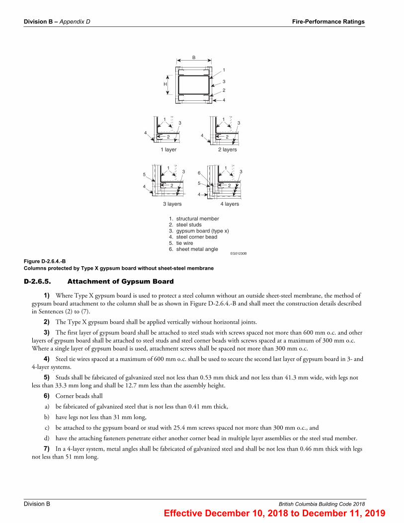
Figure D-2.6.4.-BColumns protected by Type X gypsum board without sheet-steel membrane
D-2.6.5. Attachment of Gypsum Board
1) Where Type X gypsum board is used to protect a steel column without an outside sheet-steel membrane, the method of gypsum board attachment to the column shall be as shown in Figure D-2.6.4.-B and shall meet the construction details described in Sentences (2) to (7).
2) The Type X gypsum board shall be applied vertically without horizontal joints.
3) The first layer of gypsum board shall be attached to steel studs with screws spaced not more than 600 mm o.c. and other layers of gypsum board shall be attached to steel studs and steel corner beads with screws spaced at a maximum of 300 mm o.c. Where a single layer of gypsum board is used, attachment screws shall be spaced not more than 300 mm o.c.
4) Steel tie wires spaced at a maximum of 600 mm o.c. shall be used to secure the second last layer of gypsum board in 3- and 4-layer systems.
5) Studs shall be fabricated of galvanized steel not less than 0.53 mm thick and not less than 41.3 mm wide, with legs not less than 33.3 mm long and shall be 12.7 mm less than the assembly height.
6) Corner beads shall
a) be fabricated of galvanized steel that is not less than 0.41 mm thick,
b) have legs not less than 31 mm long,
c) be attached to the gypsum board or stud with 25.4 mm screws spaced not more than 300 mm o.c., and
d) have the attaching fasteners penetrate either another corner bead in multiple layer assemblies or the steel stud member.
7) In a 4-layer system, metal angles shall be fabricated of galvanized steel and shall be not less than 0.46 mm thick with legs not less than 51 mm long.
H
B
1
3
2
4
1 layer
1
2
3
4
2 layers
1
2
3
4
3 layers
1
2
3
4
4 layers
1
2
3
4
5
65
1. structural member2. steel studs3. gypsum board (type x)4. steel corner bead5. tie wire6. sheet metal angle
EG01230B
Effective December 10, 2018 to December 11, 2019

Fire-Performance Ratings Division B – Appendix D
British Columbia Building Code 2018 Division B
D-2.6.6. Concrete Filled Hollow Steel Columns
1) A fire-resistance rating, R, is permitted to be assigned to concentrically loaded hollow steel columns that are filled with plain concrete, steel-fibre reinforced concrete or bar-reinforced concrete, that are fabricated and erected within the tolerances stipulated in CSA S16, “Design of Steel Structures,” and that comply with Sentences (2) and (3), provided:
where
C = axial compressive force due to dead and live loads without load factors, kN,
Cmax =
but shall not exceed
a) 1.0 C'r for plain concrete filling (PC),
b) 1.1 C'r for steel-fibre reinforced concrete filling (FC), and
c) 1.7 C'r for bar-reinforced concrete filling (RC),where
C'r =
where
a = constant obtained from Table D-2.6.6.-A,
f 'c = specified compressive strength of concrete in accordance with CSA A23.3, “Design of Concrete Structures,” MPa,
rc = radius of gyration of the concrete area,
Ac = area of concrete, mm2,
D = outside diameter of a round column or outside width of a square column, mm,
Ec = initial elastic modulus for concrete, considering the effects of long-term loading for normal-weight concrete =
, where f 'c is expressed in MPa, S is the short-term load, and T is the total load on the
column,
R = specified fire-resistance rating, min,
KL = effective length of column as defined in CSA S16, “Design of Steel Structures,” mm,
c = , and
c = 0.60
subject to the validity limits stated in Table D-2.6.6.-B.
Table D-2.6.6.-AValues of Constant “a”
Filling Type Concrete Type(1) Steel Reinforcement Circular Columns Square Columns
PC S n/a 0.070 0.060
FC S ≈ 2% 0.075 0.065
RC S 1.5%-3% 0.080 0.070
RC S 3%-5% 0.085 0.075
PC N n/a 0.080 0.070
FC N ≈ 2% 0.085 0.075
C � Cmax
�a (f�c � 20) D2.5�2
R(KL – 1000)
Effective December 10, 2018 to December 11, 2019

Division B – Appendix D Fire-Performance Ratings
Division B British Columbia Building Code 2018
2) A pair of steam vent holes shall be provided at each end of the hollow steel column and at each intermediate floor level, and the holes shall be
a) not less than 13 mm in diameter,
b) located on opposite faces, 150 mm above or below a base plate, cap plate or concrete slab,
c) orientated so that adjacent pairs are perpendicular, and
d) not obstructed by other building elements.
3) Load application and reaction shall be through end bearing in accordance with CSA S16, “Design of Steel Structures.”
D-2.7. Individually Protected Steel BeamsD-2.7.1. Minimum Thickness of Protective Covering
The minimum thickness of protective covering on steel beams exposed to fire on 3 sides for fire-resistance ratings from 30 min to 4 h is shown in Table D-2.7.1.
RC N 1.5%-3% 0.090 0.080
RC N 3%-5% 0.095 0.085
Notes to Table D-2.6.6.-A:(1) See Subsection D-1.4.
Table D-2.6.6.-BValidity Limits
ParameterType of Concrete Filling
PC FC RC
f'c (MPa) 20 to 40 20 to 55 20 to 55
D (round) (mm) 140 to 410 140 to 410 165 to 410
D (square) (mm) 140 to 305 102 to 305 175 to 305
Reinforcement (%) n/a ≈ 2% of the concrete mix by mass 1.5% to 5% of cross-sectional area(1)
Concrete Cover (mm) n/a n/a ≥ 25
R (min) ≤ 120 ≤ 180 ≤ 180
KL (mm) 2 000 to 4 000 2 000 to 4 500 2 000 to 4 500
Class(2) 1, 2 or 3 1, 2 or 3 1, 2 or 3
Notes to Table D-2.6.6.-B:(1) Limits on size, number and spacing of bars and ties in accordance with CSA A23.3, “Design of Concrete Structures.”(2) Classification of sections in accordance with CSA S16, “Design of Steel Structures.”
Table D-2.7.1.Minimum Thickness of Cover to Individual Protected Steel Beams, mm(1)
Description of CoverFire-Resistance Rating
30 min 45 min 1 h 1.5 h 2 h 3 h 4 h
Type S concrete(2) (beam spaces filled solid) 25 25 25 25 32 50 64
Type N or L concrete(2) (beam spaces filled solid) 25 25 25 25 25 39 50
Gypsum-sand plaster on 9.5 mm gypsum lath(3) 13 13 13 20 – – –
Gypsum-perlite or vermiculite plaster on 9.5 mm gypsum lath(3) 13 13 13 13 25 – –
Gypsum-perlite or gypsum-vermiculite on 12.7 mm gypsum lath(3) 13 13 13 20 25 39 50
Table D-2.6.6.-A (continued)Values of Constant “a”
Filling Type Concrete Type(1) Steel Reinforcement Circular Columns Square Columns
Effective December 10, 2018 to December 11, 2019

Fire-Performance Ratings Division B – Appendix D
British Columbia Building Code 2018 Division B
D-2.7.2. Types of Concrete
Concrete is referred to as Type S, N or L, depending on the nature of the aggregate used. This is described in Article D-1.4.1.
D-2.7.3. Effect of Plaster
The effect on fire-resistance ratings of the addition of plaster finish to concrete or masonry beam protection is described in Article D-1.7.1.
D-2.7.4. Exceptions
The fire resistance of protected steel beams depends on the means used to hold the protection in place. Because of the importance of this factor, no rating has been assigned in Table D-2.7.1. to masonry units used as protective cover to steel beams. These ratings, however, may be determined on the basis of comparison with column protection at the discretion of the authority having jurisdiction, if satisfactory means of fastening are provided.
D-2.7.5. Beam Protected by a Membrane
A steel beam or steel joist assembly that is entirely above a horizontal ceiling membrane will be protected from fire below the membrane and will resist structural collapse for a period equal to the fire-resistance rating determined in conformance with Subsection D-2.3. The support for this membrane shall be equivalent to that described in Subsection D-2.3. The rating on this basis shall not exceed 1.5 h.
D-2.8. Reinforced Concrete ColumnsD-2.8.1. Minimum Dimensions
Minimum dimensions for reinforced concrete columns and minimum concrete cover for vertical steel reinforcement are obtained from Articles D-2.8.2. to D-2.8.5., taking into account the type of concrete, the effective length of the column and the area of the vertical reinforcement.
D-2.8.2. Method
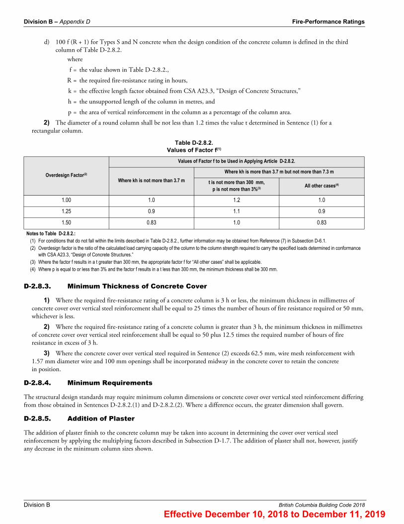
1) The minimum dimension, t, in millimetres, of a rectangular reinforced concrete column shall be equal to
a) 75 f (R + 1) for all Types L and L40S concrete,
b) 80 f (R + 1) for Type S concrete when the design condition of the concrete column is defined in the second and fourth columns of Table D-2.8.2.,
c) 80 f (R + 0.75) for Type N concrete when the design condition of the concrete column is defined in the second and fourth columns of Table D-2.8.2., and
Gypsum-perlite or vermiculite plaster on double 12.7 mm gypsum lath(3) 13 13 13 20 25 25 39
Portland cement-sand on metal lath(4) 23 23 23 – – – –
Gypsum-sand on metal lath(4) (plaster in contact with lower flange) 16 20 25 39 – – –
Gypsum-sand on metal lath with air gap between plaster and lower flange(4) 16 16 16 25 25 – –
Gypsum-perlite or gypsum-vermiculite on metal lath(4) 16 16 16 23 23 35 48(5)
Notes to Table D-2.7.1.:(1) Where the thickness of plaster finish applied over gypsum lath is 26 mm or more, the plaster shall be reinforced with wire mesh with 1.57 mm diam wire and 50 mm by
50 mm openings placed midway in the plaster.(2) Applies to cast-in-place concrete reinforced by 5.21 mm diam wire spaced 200 mm o.c. or 1.57 mm diam wire mesh with 100 mm by 100 mm openings.(3) Lath held in place by 1.18 mm diam wire wrapped around the gypsum lath 450 mm o.c.(4) Expanded metal lath 1.63 kg/m2 fastened to 9.5 mm by 19 mm steel channels held in position by 1.19 mm diam wire.(5) Plaster finish shall be reinforced with wire mesh with 1.57 mm diam wire and 50 mm by 50 mm openings placed midway in the plaster.
Table D-2.7.1. (continued)Minimum Thickness of Cover to Individual Protected Steel Beams, mm(1)
Description of CoverFire-Resistance Rating
30 min 45 min 1 h 1.5 h 2 h 3 h 4 h
Effective December 10, 2018 to December 11, 2019
Division B – Appendix D Fire-Performance Ratings
Division B British Columbia Building Code 2018
d) 100 f (R + 1) for Types S and N concrete when the design condition of the concrete column is defined in the third column of Table D-2.8.2.
where
f = the value shown in Table D-2.8.2.,
R = the required fire-resistance rating in hours,
k = the effective length factor obtained from CSA A23.3, “Design of Concrete Structures,”
h = the unsupported length of the column in metres, and
p = the area of vertical reinforcement in the column as a percentage of the column area.
2) The diameter of a round column shall be not less than 1.2 times the value t determined in Sentence (1) for a rectangular column.
D-2.8.3. Minimum Thickness of Concrete Cover
1) Where the required fire-resistance rating of a concrete column is 3 h or less, the minimum thickness in millimetres of concrete cover over vertical steel reinforcement shall be equal to 25 times the number of hours of fire resistance required or 50 mm, whichever is less.
2) Where the required fire-resistance rating of a concrete column is greater than 3 h, the minimum thickness in millimetres of concrete cover over vertical steel reinforcement shall be equal to 50 plus 12.5 times the required number of hours of fire resistance in excess of 3 h.
3) Where the concrete cover over vertical steel required in Sentence (2) exceeds 62.5 mm, wire mesh reinforcement with 1.57 mm diameter wire and 100 mm openings shall be incorporated midway in the concrete cover to retain the concrete in position.
D-2.8.4. Minimum Requirements
The structural design standards may require minimum column dimensions or concrete cover over vertical steel reinforcement differing from those obtained in Sentences D-2.8.2.(1) and D-2.8.2.(2). Where a difference occurs, the greater dimension shall govern.
D-2.8.5. Addition of Plaster
The addition of plaster finish to the concrete column may be taken into account in determining the cover over vertical steel reinforcement by applying the multiplying factors described in Subsection D-1.7. The addition of plaster shall not, however, justify any decrease in the minimum column sizes shown.
Table D-2.8.2.Values of Factor f(1)
Overdesign Factor(2)
Values of Factor f to be Used in Applying Article D-2.8.2.
Where kh is not more than 3.7 m
Where kh is more than 3.7 m but not more than 7.3 m
t is not more than 300 mm, p is not more than 3%(3) All other cases(4)
1.00 1.0 1.2 1.0
1.25 0.9 1.1 0.9
1.50 0.83 1.0 0.83
Notes to Table D-2.8.2.:(1) For conditions that do not fall within the limits described in Table D-2.8.2., further information may be obtained from Reference (7) in Subsection D-6.1.(2) Overdesign factor is the ratio of the calculated load carrying capacity of the column to the column strength required to carry the specified loads determined in conformance
with CSA A23.3, “Design of Concrete Structures.”(3) Where the factor f results in a t greater than 300 mm, the appropriate factor f for “All other cases” shall be applicable.(4) Where p is equal to or less than 3% and the factor f results in a t less than 300 mm, the minimum thickness shall be 300 mm.
Effective December 10, 2018 to December 11, 2019

Fire-Performance Ratings Division B – Appendix D
British Columbia Building Code 2018 Division B
D-2.8.6. Built-in Columns
The fire-resistance rating of a reinforced concrete column that is built into a masonry or concrete wall so that not more than one face may be exposed to the possibility of fire at one time may be determined on the basis of cover to vertical reinforcing steel alone. In order to meet this condition, the wall shall conform to Subsection D-2.1. for the fire-resistance rating required.
D-2.9. Reinforced Concrete BeamsD-2.9.1. Minimum Cover Thickness
The minimum thickness of cover over principal steel reinforcement in reinforced concrete beams is shown in Table D-2.9.1. for fire-resistance ratings from 30 min to 4 h where the width of the beam or joist is at least 100 mm.
D-2.9.2. Maximum Rating
No rating over 2 h may be assigned on the basis of Table D-2.9.1. to a beam or joist where the average width of the part that projects below the slab is less than 140 mm, and no rating over 3 h may be assigned where the average width of the part that projects below the slab is less than 165 mm.
D-2.9.3. Beam Integrated in Floor or Roof Slab
For the purposes of these ratings, a beam may be either independent of or integral with a floor or roof slab assembly.
D-2.9.4. Minimum Thickness
Where the upper extension or top flange of a joist or T-beam in a floor assembly contributes wholly or partly to the thickness of the slab above, the total thickness at any point shall be not less than the minimum thickness described in Table D-2.2.1.-A for the fire-resistance rating required.
D-2.9.5. Effect of Plaster
The addition of plaster finish to a reinforced concrete beam may be taken into account in determining the cover over principal reinforcing steel by applying the multiplying factors described in Subsection D-1.7.
D-2.10. Prestressed Concrete BeamsD-2.10.1. Minimum Cross-Sectional Area and Thickness of Cover
The minimum cross-sectional area and thickness of concrete cover over steel tendons in prestressed concrete beams for fire-resistance ratings from 30 min to 4 h are shown in Table D-2.10.1.
Table D-2.9.1.Minimum Cover to Principal Steel Reinforcement in Reinforced Concrete Beams, mm
Type of Concrete Fire-Resistance Rating
30 min 45 min 1 h 1.5 h 2 h 3 h 4 h
Type S, N or L 20 20 20 25 25 39 50
Table D-2.10.1.Minimum Thickness of Concrete Cover over Steel Tendons in Prestressed Concrete Beams, mm(1)
Type of Concrete
Area of Beam, cm2 Fire-Resistance Rating
30 min 45 min 1 h 1.5 h 2 h 3 h 4 h
Type S or N
260 to 970 25 39 50 64 – – –
Over 970 to 1 940 25 26 39 45 64 – –
Over 1 940 25 26 39 39 50 77 102
Effective December 10, 2018 to December 11, 2019

Division B – Appendix D Fire-Performance Ratings
Division B British Columbia Building Code 2018
D-2.10.2. Minimum Cover Thickness
The cover for an individual tendon shall be the minimum thickness of concrete between the surface of the tendon and the fire-exposed surface of the beam, except that for ungrouted ducts the assumed cover thickness shall be the minimum thickness of concrete between the surface of the duct and the surface of the beam. For beams in which several tendons are used, the cover is assumed to be the average of the minimum cover of the individual tendons. The cover for any individual tendon shall be not less than half the value given in Table D-2.10.1. nor less than 25 mm.
D-2.10.3. Applicability of Ratings
The ratings in Table D-2.10.1. apply to a beam that is either independent of or integral with a floor or roof slab assembly. Minimum thickness of slab and minimum cover to steel tendons in prestressed concrete slabs are contained in Subsection D-2.2.
D-2.10.4. Effect of Plaster
The addition of plaster finish to a prestressed concrete beam may be taken into account in determining the cover over steel tendons by applying the multiplying factors described in Subsection D-1.7.
D-2.10.5. Minimum Cover
1) Except as provided in Sentence (2), in unbonded post-tensioned prestressed concrete beams, the concrete cover to the tendon at the anchor shall be not less than 15 mm greater than the minimum required away from the anchor. The concrete cover to the anchorage bearing plate and to the end of the tendon, if it projects beyond the bearing plate, shall be not less than 25 mm.
2) The requirements in Sentence (1) do not apply to those portions of beams not likely to be exposed to fire (such as the ends and the tops of flanges of beams immediately below slabs).
D-2.11. Glued-Laminated Timber Beams and ColumnsD-2.11.1. Applicability of Information
The information in Subsection D-2.11. applies to glued-laminated timber beams and columns required to have fire-resistance ratings greater than those afforded under the provisions of Article 3.1.4.6.
D-2.11.2. Method of Calculation
1) The fire-resistance rating of glued-laminated timber beams and columns in minutes shall be equal to
a) 0.1 fB [4 − 2(B/D)] for beams that may be exposed to fire on 4 sides,
b) 0.1 fB [4 − (B/D)] for beams that may be exposed to fire on 3 sides,
c) 0.1 fB [3 − (B/D)] for columns that may be exposed to fire on 4 sides, and
d) 0.1 fB [3 − (B/2D)] for columns that may be exposed to fire on 3 sides, where
f = the load factor shown in Figure D-2.11.2.-A,
B = the full dimension of the smaller side of a beam or column in millimetres before exposure to fire [see Figure D-2.11.2.-B],
D = the full dimension of the larger side of a beam or column in millimetres before exposure to fire [see Figure D-2.11.2.-B],
Type L Over 970 25 25 25 39 50 77 102
Notes to Table D-2.10.1.:(1) Where the thickness of concrete cover over the tendons exceeds 64 mm, a wire mesh reinforcement with 1.57 mm diam wire and 100 mm by 100 mm openings shall be
incorporated in the beams to retain the concrete in position around the tendons. The mesh reinforcement shall be located midway in the cover.
Table D-2.10.1.Minimum Thickness of Concrete Cover over Steel Tendons in Prestressed Concrete Beams, mm(1)
Type of Concrete
Area of Beam, cm2 Fire-Resistance Rating
30 min 45 min 1 h 1.5 h 2 h 3 h 4 h
Effective December 10, 2018 to December 11, 2019

Fire-Performance Ratings Division B – Appendix D
British Columbia Building Code 2018 Division B
k = the effective length factor obtained from CSA O86, “Engineering Design in Wood,”
L = the unsupported length of a column in millimetres.
2) The factored resistance of a beam or column shall be determined by using the specified strengths in CSA O86, “Engineering Design in Wood.”
Figure D-2.11.2.-AFactors to compensate for partially loaded columns and beams
Note to Figure D-2.11.2.-A:
(1) See Sentence (2).
Figure D-2.11.2.-BFull dimensions of glued-laminated beams and columns
10075502501.0
1.1
1.2
1.3
1.4
1.5
1.6
Load
fact
or, f
Factored load* / factored resistance(1), %
*In the case of beams, use bending moment in place of load.
columns ≥ 12
and all beams
KLB
columns < 12KLB
EC01237A
B
D
column
B
D
column
wall
B
D
beam
B
D
beam
floor
EG01238A
Effective December 10, 2018 to December 11, 2019