PLUMBER - Open School BC
100
Plumber Cover goes here PLUMBER Activity Plans
-
Upload
khangminh22 -
Category
Documents
-
view
0 -
download
0
Transcript of PLUMBER - Open School BC

Plumber Cover goes here
PLUMBERActivity Plans

Youth Explore Trades Skills
PlumberTable of Contents
Acknowledgements . . . . . . . . . . . . . . . . . . . . . . . . . . . . . . . . . . 3
Cast Iron . . . . . . . . . . . . . . . . . . . . . . . . . . . . . . . . . . . . . . . 7
Crimping . . . . . . . . . . . . . . . . . . . . . . . . . . . . . . . . . . . . . . . 19
Drafting . . . . . . . . . . . . . . . . . . . . . . . . . . . . . . . . . . . . . . . . 33
Fixtures Installation . . . . . . . . . . . . . . . . . . . . . . . . . . . . . . . . . . 51
Soldering . . . . . . . . . . . . . . . . . . . . . . . . . . . . . . . . . . . . . . . 59
Solvent Welding . . . . . . . . . . . . . . . . . . . . . . . . . . . . . . . . . . . . 73
Thread Connections . . . . . . . . . . . . . . . . . . . . . . . . . . . . . . . . . 89

This work is licensed under a Creative Commons Attribution-NonCommercial-ShareAlike 4.0 International License unless otherwise indicated.
Youth Explore Trades Skills Plumber
3
Acknowledgments and Third Party Copyright
Youth Explore Trades Skills Learning Resources DevelopmentOpen School BC, the Custom Programs work unit of the BC Ministry of Education, and the BC Industry Trades Authority are grateful to the following individuals and organizations for their contributions to the Youth Explore Trades Skills Learning Resources Development Project.
2013 Curriculum Advisory CommitteeBrian Campbell, District Principal, Careers and International Education, SD 60 (Peace River North)
Larry Espe, Superintendent of Trades and Student Transitions, BC Ministry of Education
Colleen Hannah, Aboriginal Agreements Coordinator, BC Ministry of Education
Rodger Hargreaves, Career Programs, SD 62 (Sooke)
Mike Howard, President, BC Technology Education Association, SD 19 (Revelstoke)
Erin Johnston, Manager, Labour Supply Initiatives, BC Industry Training Authority
Eleanor Liddy, Director, Open School BC
Eric MacNeil, President, BC Culinary Arts Specialist Association
Jim Pelton, former Director, Training Delivery, BC Industry Training Authority
Glenn Rowan, Education Officer, Graduation, Dual Credit, Industry Training, BC Ministry of Education
Tim Winkelmans, Lead, Graduation Standards, Educational Technologies, Learning Alternatives, BC Ministry of Education
2013 Resource Development Planning Session (July 10, Victoria BC)Dick Brouwer, SD 63 (Saanich)
Jeff Dickson, SD 35 (Langley)
Brad Edmondson, SD 36 (Surrey)
Adrian Hill, Project Manager, Open School BC
Mike Howard, President, BC Technology Education Association, SD 19 (Revelstoke)
Tom Hoyme, SD 42 (Maple Ridge-Pitt Meadows)
Eleanor Liddy, Director, Open School BC
Erin Johnston, Manager, Labour Supply Initiatives, BC Industry Training Authority
Ken Jorgensen, SD 57 (Prince George)
Karen Larsen, Career Programs Coordinator, SD 39 (Vancouver)

Acknowledgments and Third Party Copyright Plumber
4 Youth Explore Trades Skills
Martin Lim, Vice-President, BC Technology Education Association, SD 36 (Surrey)
David Olsen, SD 69 (Qualicum)
Stu Rhodes, SD 63 (Saanich)
Glenn Rowan, Education Officer, Graduation, Dual Credit, Industry Training, BC Ministry of Education
Rhonda Stangeland, SD 38 (Richmond)
Chris Teskey, Project Manager, Open School BC
Cory Williams, Manager, Program Standards, BC Industry Training Authority
Open School BC Production TeamCopyright: Shannon Sangster
Editing: Keith Learmonth
Graphics: Max Licht (http://www.maxlicht.com)
Graphics Coordination: Christine Ramkeesoon
Photography: Dennis Evans
Project Managers: Adrian Hill, Tracey Peever, Chris Teskey
Project Supervision: Monique Brewer (Director), Jennifer Riddel (Manager, Instructional Services)
Production Technicians: Brian Glover, Beverly Hooks
Website Construction and Design: Christine Ramkeesoon
Third Party CopyrightEvery effort has been made to contact copyright holders for third party works included in the Youth Explore Trades Skills learning resources. If you have any questions or concerns, please contact [email protected]
PlumberDraftingFigure 22—Lamp constructed from piping and bottles: used by permission, courtesy of La Rosca Lights LLC. https://s-media-cache-ak0.pinimg.com/564x/e0/62/e9/e062e910e6a990b3b721d23729865ea5.jpg
Cast IronFigure 7—The Ridgid Press Snap soil cutter is a user-friendly method of cutting cast iron pipe. Used by permission, courtesy of Ridgid.
CrimpingFigure 4—Go/no go gauge. Used by permission, courtesy of Nibco.

Plumber Acknowledgments and Third Party Copyright
Youth Explore Trades Skills 5
Fixtures InstallationFigure 2—Closet bolts will be used to tighten the bowl to the floor flange. Used by permission, courtesy of Oatey SCS.
Figure 5—A union type p-trap has a threaded connection that allows quick removal for cleaning or inspection. It also allows the teacher to reuse this p-trap. Used by permission, courtesy of Nibco.
Figure 6 –A compression-style CR 19 will fit over copper pipe. The chrome nut is then tightened to compress a brass ring providing a watertight seal. Used by permission, courtesy of iBuild.
Figure 7—Closet flanges may have plastic plugs in the drain. A Slotted screwdriver and a hammer can quickly remove it. Used by permission, courtesy of Nibco.
Figure 9—Faucets are normally connected to the basin by means of a threaded nut. Braided water supply lines run from the brass connections to the CR 19 stops. Used by permission, courtesy of DIY Project-aholic.
Solvent WeldingFigure 2—Ridgid FC-200 capable of cutting ABC pipe up to 2” Used by permission, courtesy of Home Depot.
The following images are all used by permission, courtesy of Nibco:
Figure 3–ABS 45°, The hub by hub 45° (left), hub by spigot 45° (right)
Figure 4—ABS 90° elbow
Figure 5—ABS tee
Figure 6—ABS Wye
Figure 7—ABS double wye
Figure 8—ABS line cleanout
Figure 9—ABS p trap
Figure 11—ABS water closet floor flange.
Figure 12—ABS bushing

Acknowledgments and Third Party Copyright Plumber
6 Youth Explore Trades Skills

This work is licensed under a Creative Commons Attribution-NonCommercial-ShareAlike 4.0 International License unless otherwise indicated.
Youth Explore Trades Skills Plumber
7
Cast Iron
DescriptionStudents will assemble and disassemble cast iron pipe and fittings according to provided specifications.
Lesson OutcomesThe student will be able to:
• Assemble cast iron pipe and fittings using mechanical joint (M.J.) couplings• Accurately mark and cut cast iron pipe
AssumptionsThe teacher has a basic knowledge of cast iron piping.
TerminologySnap cutter: a common phrase to describe a cast iron soil pipe cutter. “Snap” refers to the sharp sound produced when the pipe is sheared.
Soil pipe: drainage piping that conducts waste relying on gravity for free flow of materials.
Sounding: lightly tapping on cast iron with a metal object. A sharp ring indicates no cracks are present. A dull thud indicates a crack that will cause a leak.
Estimated Time2–6 hours
Recommended Number of StudentsActivities could be done individually or in groups of up to four students, depending on the availability of hand tools and facilities.
FacilitiesSmall individual activities could be conducted in a typical technology education shop with bench tops and adequate floor space. Larger activities would require a vertical surface for securing pipe.

Cast Iron Plumber
8 Youth Explore Trades Skills
Tools• Soil pipe cutter (also known as a snap cutter). One per group of six students.• Cordless drill with adjustable clutch setting and 5⁄16" socket• Tape measure• Torpedo level• Confined space snap cutters (Figure 1)• 5⁄16" nut driver (one per pair of students)• 5⁄16" torque wrench. Ridgid Model 902 (https://www.ridgid.com/us/en/torque-wrenches) or
equivalent. One per pair of students. 5⁄16" socket and ratchet may be substituted but used with caution as clamps are easily stripped.
• Soapstone or construction crayon• Torpedo level (one per pair of students)
Figure 1—The snap cutter is the industry standard method for cutting cast iron soil pipe.
Materials• 3" M.J. clamps (Figure 2)• Construction crayons• 3" cast iron pipe. Available in 10' lengths. Length required will depend on the activity.• Cast iron fittings. 45°, 90° bends; wyes, tees, caps, reducers, depending upon activity

Plumber Cast Iron
Youth Explore Trades Skills 9
Figure 2—No-hub soil pipe coupling with 5⁄16" gear clamp
ResourcesAssembly of M.J. couplings
http://www.smillieltd.ca/pdfDocs/Duriron/Duriron-Bulletin-PF6y.pdf
Use of snap cutters
http://www.dailymotion.com/video/xibzuz_reed-manufacturing-soil-pipe-cutters_lifestyle#.UeBPDUGTibM
Reasons to choose cast iron pipe
https://www.askthebuilder.com/virtues-of-cast-iron-pipe/
DemonstrationWorking with cast iron is an excellent introduction to techniques used in plumbing. The process of planning, constructing, and testing models the procedure found on job sites. It is recommended that the teacher first demonstrate the assembly procedure, and then allow students to construct several projects. Most students enjoy working with cast iron as it does not require extensive procedural information or safety training before creating a tangible object.
Assembly Demonstration1. Loosen M.J. clamp using nut driver.
2. Slide stainless steel band over end of pipe or fitting.
3. Slide rubber gasket over end of pipe or fitting, then roll opposite side of gasket using palms of both hands (Figure 3).
4. Insert top pipe fully into pipe with gasket (Figure 4).
5. Align top pipe (Figure 5).
6. Slide stainless steel band over rubber gasket.
7. Align band so that it is centred over rubber gasket.
8. Tighten bands using the nut driver.

Cast Iron Plumber
10 Youth Explore Trades Skills
9. Look at pipe or fittings to ensure proper alignment.
10. Torque bands for maximum tightness. Torque wrenches should be pre-set to 60 inch-pounds of torque. Great care should be taken if a ratchet and socket are used, as it is easy to overtighten the clamps and strip the bands. A cordless drill with a 5⁄16" socket can also be used to tighten the clamps, but great care must be taken to not over-tighten and strip the clamps.
Figure 3—Rolling the rubber gasket allows a pipe or fitting to be easily inserted into the gasket.
Figure 4—The top pipe should be fully inserted, then aligned straight.

Plumber Cast Iron
Youth Explore Trades Skills 11
Figure 5—Pipes are aligned straight within the gasket, even if the pipe is not cut perfectly straight.
Following the assembly demonstration, students should be capable of assembling a series of fittings and pipes. After students have had some experience with this procedure, further instruction can fine-tune their skills. The strength of cast iron piping as a teaching tool is that it is easy to loosen clamps and reposition them to improve alignment.
Fine tuning would include:
• Align piping so that when seen from a distance, the assembly appears to be one piece. When cast iron pipe is cut, it is rarely perfectly square. It is acceptable for pipe to be fully inserted into clamps and then repositioned slightly for alignment purposes. A torpedo level can be used to assist in this process.
• Align clamps so the bands are centred over the rubber gasket. Maximum pressure is not evenly applied if the clamps are not centred.
• Align clamps so the nuts are pointed in the same direction. This attention to the aesthetic detail of a piping installation improves the professional look of a system (Figure 6).
• Once clamps have been in place for several minutes, clamps can be re-torqued as the pressure around the rubber gasket equalizes.

Cast Iron Plumber
12 Youth Explore Trades Skills
Figure 6—An example of a poorly installed clamp. The stainless steel band will not generate enough pressure to create a watertight seal.
Cutting DemonstrationOnce students have begun to find success in assembling fittings, it is suggested they begin to experience the challenge of accurately cutting cast iron. As this can be troublesome for beginners, it is suggested that students work in pairs. The industry standard at the time of this writing is the “snap” cutter. However, the Ridgid press snap soil pipe cutter is also becoming more widely used (Figure 7).
Figure 7—The Ridgid press snap soil cutter is a user-friendly method of cutting cast iron pipe.

Plumber Cast Iron
Youth Explore Trades Skills 13
1. Mark the location of the intended cut using a construction crayon, soapstone, or pencil. An X is commonly used to mark cast iron, as the chain of the cutter obscures the view of a single line.
2. Loosen the adjustment nut by turning counter-clockwise.
3. Place a wood block or scrap piece under the pipe to allow the chain to easily fit under the pipe.
4. Position the chain with cutting wheels over the cut location.
5. Insert the chain into the snap cutter jaws and tighten the adjustment nut until snug. Continue to turn the adjustment nut until the upper handle is at a 45° angle above the floor.
6. Score the pipe by applying slight pressure on the end of the handle.
7. Rotate the pipe a few degrees and apply quick firm pressure to cut the pipe.
8. A tap on the end of the pipe with a metal object such as a nut driver should produce a sharp bell sound. A dull thud indicates a cracked pipe, which should not be used. This technique is known as sounding.
Figure 8—Novices learning to use snap cutters tend to be more successful when working in pairs.

Cast Iron Plumber
14 Youth Explore Trades Skills
Activity 1: Cast Iron TowerHave students cut and assemble six pieces of cast iron piping cut 6" long. The teacher should check the accuracy of cuts, alignment of clamps, and alignment of pipe. As discussed above, the first step is to have students experience the apparent simplicity of assembling cast iron. As students begin to experience success, the teacher can introduce finer points of assembly.
Figure 9—Poor practices generate a tower that is unstable.
Figure 10—A well-constructed tower demonstrates attention to detail and a professional attitude.
Plumber Cast Iron
Youth Explore Trades Skills 15
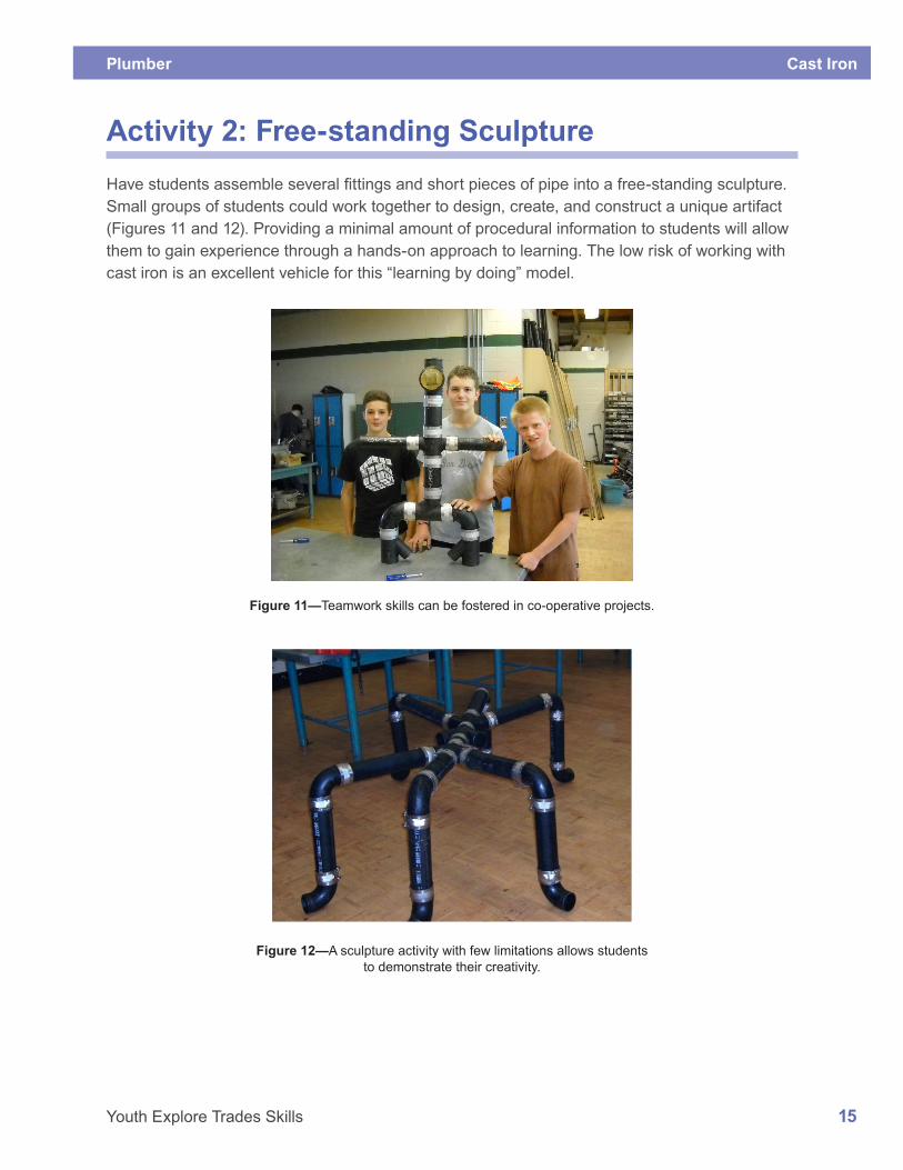
Activity 2: Free-standing SculptureHave students assemble several fittings and short pieces of pipe into a free-standing sculpture. Small groups of students could work together to design, create, and construct a unique artifact (Figures 11 and 12). Providing a minimal amount of procedural information to students will allow them to gain experience through a hands-on approach to learning. The low risk of working with cast iron is an excellent vehicle for this “learning by doing” model.
Figure 11—Teamwork skills can be fostered in co-operative projects.
Figure 12—A sculpture activity with few limitations allows students to demonstrate their creativity.
Cast Iron Plumber
16 Youth Explore Trades Skills
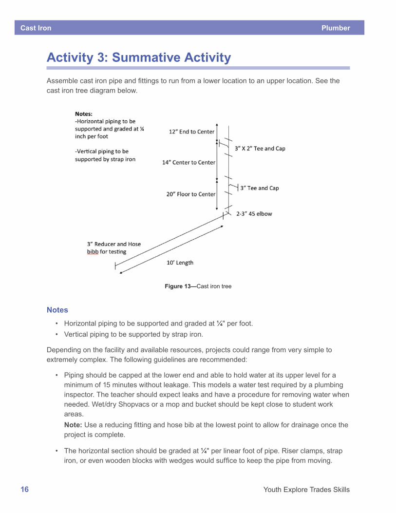
Activity 3: Summative ActivityAssemble cast iron pipe and fittings to run from a lower location to an upper location. See the cast iron tree diagram below.
Figure 13—Cast iron tree
Notes• Horizontal piping to be supported and graded at ¼" per foot.• Vertical piping to be supported by strap iron.
Depending on the facility and available resources, projects could range from very simple to extremely complex. The following guidelines are recommended:
• Piping should be capped at the lower end and able to hold water at its upper level for a minimum of 15 minutes without leakage. This models a water test required by a plumbing inspector. The teacher should expect leaks and have a procedure for removing water when needed. Wet/dry Shopvacs or a mop and bucket should be kept close to student work areas.Note: Use a reducing fitting and hose bib at the lowest point to allow for drainage once the project is complete.
• The horizontal section should be graded at ¼" per linear foot of pipe. Riser clamps, strap iron, or even wooden blocks with wedges would suffice to keep the pipe from moving.

Plumber Cast Iron
Youth Explore Trades Skills 17
Figure 14—Wooden wedges and strap iron grade this cast iron in a shop environment.
• The vertical section must be supported using strap iron or riser clamps. If piping extends above 5', great care must be taken with regard to safety. Working on ladders with the risk of heavy piping falling increases the possibility of an accident. The teacher should consider the age and ability of students before constructing a tall structure.
Figure 15—Strap iron is used in industry to support vertical piping.
Cast Iron Plumber
18 Youth Explore Trades Skills
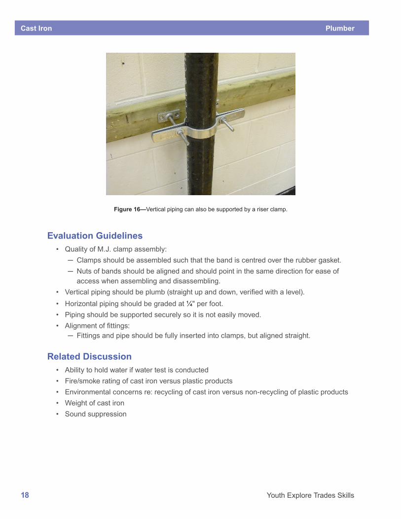
Figure 16—Vertical piping can also be supported by a riser clamp.
Evaluation Guidelines• Quality of M.J. clamp assembly:
─ Clamps should be assembled such that the band is centred over the rubber gasket. ─ Nuts of bands should be aligned and should point in the same direction for ease of access when assembling and disassembling.
• Vertical piping should be plumb (straight up and down, verified with a level).• Horizontal piping should be graded at ¼" per foot.• Piping should be supported securely so it is not easily moved.• Alignment of fittings:
─ Fittings and pipe should be fully inserted into clamps, but aligned straight.
Related Discussion• Ability to hold water if water test is conducted• Fire/smoke rating of cast iron versus plastic products• Environmental concerns re: recycling of cast iron versus non-recycling of plastic products• Weight of cast iron• Sound suppression

This work is licensed under a Creative Commons Attribution-NonCommercial-ShareAlike 4.0 International License unless otherwise indicated.
Youth Explore Trades Skills Plumber
19
Crimping
DescriptionStudents will learn to crimp and remove cross-linked polyethylene (PEX) pipe and fittings.
Lesson OutcomesThe student will be able to:
• Connect crimp fittings and pipe to create a watertight seal• Connect pipe and fittings to given dimensions• Disassemble crimp fittings
AssumptionsThe teacher is familiar with crimping procedures.
TerminologyFitting: an object used to connect one or more pieces of piping material.
Crimping: the pressing together of a flexible ring to secure a watertight seal between pipe and a fitting.
Rough in: installing a piping system before it is covered and inaccessible. Rough-in piping is inspected by a local plumbing inspector before further work is permitted. Correct sizing, support, and ability to withstand water pressure are inspected.
Estimated Time2–6 hours
Recommended Number of StudentsActivities could be done individually or in pairs, depending on the availability of hand tools.
FacilitiesSmall individual activities could be conducted in a typical technology education shop with bench tops. Larger activities would necessitate a flat vertical surface. Stud walls or plywood would provide a realistic surface upon which students could construct projects. See the “activity” sections for greater detail.
Crimping Plumber
20 Youth Explore Trades Skills
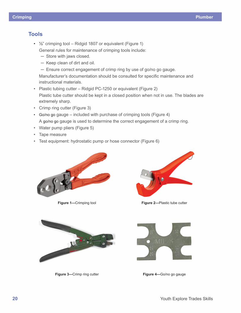
Tools• ½” crimping tool – Ridgid 1807 or equivalent (Figure 1)
General rules for maintenance of crimping tools include: ─ Store with jaws closed. ─ Keep clean of dirt and oil. ─ Ensure correct engagement of crimp ring by use of go/no go gauge.
Manufacturer’s documentation should be consulted for specific maintenance and instructional materials.
• Plastic tubing cutter – Ridgid PC-1250 or equivalent (Figure 2)Plastic tube cutter should be kept in a closed position when not in use. The blades are extremely sharp.
• Crimp ring cutter (Figure 3)• Go/no go gauge – included with purchase of crimping tools (Figure 4)
A go/no go gauge is used to determine the correct engagement of a crimp ring.• Water pump pliers (Figure 5)• Tape measure• Test equipment: hydrostatic pump or hose connector (Figure 6)
Figure 1—Crimping tool Figure 2—Plastic tube cutter
Figure 3—Crimp ring cutter Figure 4—Go/no go gauge

Plumber Crimping
Youth Explore Trades Skills 21
Figure 5—Water pump pliers Figure 6—Hydrostatic pump
Materials• ½" PEX pipe (available in straight lengths of 20' or coils of 50, 100, 500, or 1000')• ½" crimp rings (typically purchased by the hundred or in bags of 50)• ½" crimp fittings. Types depend on the activity.
ResourcesDetailed description of crimping
http://www.pexuniverse.com/content/how-install-pex-tubing-installation
PEX Information
http://www.pexinfo.com

Crimping Plumber
22 Youth Explore Trades Skills
Crimp FittingsCrimp fittings are used to connect at least two pieces of PEX pipe. The most common diameter of PEX piping used is ½”.
Figures 7–12 show several of the most common fittings.
Figure 7—½" crimp 90° elbow used to make a sharp change of direction
Figure 8—½" crimp tee used to connect three pieces of pipe
Figure 9—½" coupling used to connect two pieces of pipe
Figure 10—½" crimp adapter to solder fitting* used to connect a soldered copper pipe to PEX
Figure 11—½" PEX or crimp by external (male) thread. This adapter can be used to connect PEX piping systems to a threaded internal (female) fitting.
Figure 12—½" crimp plug used at outlets to cap piping
*Note: The solder joint must be made BEFORE crimping or the plastic will soften and leak when under pressure.
Plumber Crimping
Youth Explore Trades Skills 23
DemonstrationWorking with cross-linked polyethylene (generically known as PEX) is an excellent introduction to techniques used in plumbing. The process of planning, constructing, and testing models the procedure found on job sites. It is recommended that teachers demonstrate an assembly and disassembly procedure to students and then allow them to construct several projects.
PEX piping is now commonly used for water distribution lines in British Columbia. In the past, copper water lines were the standard. However, several factors have allowed PEX to become much more common:
• Crimping PEX lines is much faster than soldering copper lines.• The smooth interior of PEX piping offers low resistance to water flow.• The lifespan of PEX piping is excellent.• The cost of manufacturing PEX piping is relatively low in comparison to mining copper.
The trade-off for using PEX piping is that it is easily damaged in exposed locations and it is susceptible to melting in areas of high heat.
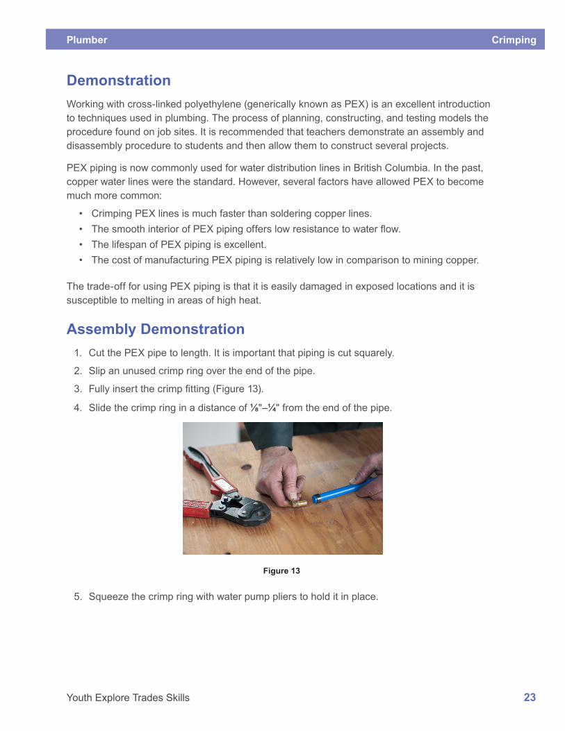
Assembly Demonstration1. Cut the PEX pipe to length. It is important that piping is cut squarely.
2. Slip an unused crimp ring over the end of the pipe.
3. Fully insert the crimp fitting (Figure 13).
4. Slide the crimp ring in a distance of ⅛"–¼" from the end of the pipe.
Figure 13
5. Squeeze the crimp ring with water pump pliers to hold it in place.

Crimping Plumber
24 Youth Explore Trades Skills
6. Use the crimping tool (Figure 14).
Figure 14—Using the crimping tool
Note: Demonstrate use of the go/no go tool to ensure correct engagement (Figure 15). This need only be done once during the construction phase, not after every crimp. See the “Resources” section for additional online resources outlining this procedure.
Figure 15—Using the go/no go gauge
Disassembly Demonstration1. Remove any pressure from within the pipe.
2. Cut the pipe approximately ¾" back from its end.
3. Use crimp ring cutter to cut the ring.
4. The cut ring should be recycled (copper is valuable).
5. The small piece of pipe goes into the garbage.
6. Longer pieces of pipe can be stored for future use.
7. Fittings should be returned to their correct storage location.

Plumber Crimping
Youth Explore Trades Skills 25
Testing DemonstrationAttach a hydrostatic pump or hose connector to the piping project.
Bring the pressure up to 200 psi (1400 kpa) if using the pump; otherwise use line pressure.
The piping system should be able to withstand pressure without leakage. Should a leak occur, the most common sources of error are:
• The crimp ring was not crimped.• The pipe was not cut squarely.• The end of the pipe was damaged.• The fitting was defective.
Depending on the source of the leak, students may have to re-crimp or remove a section of piping. The process of testing at the rough-in stage is important for students to understand. Occupancy of a building is not permitted unless a rough-in inspection was successful.
Crimping Plumber
26 Youth Explore Trades Skills
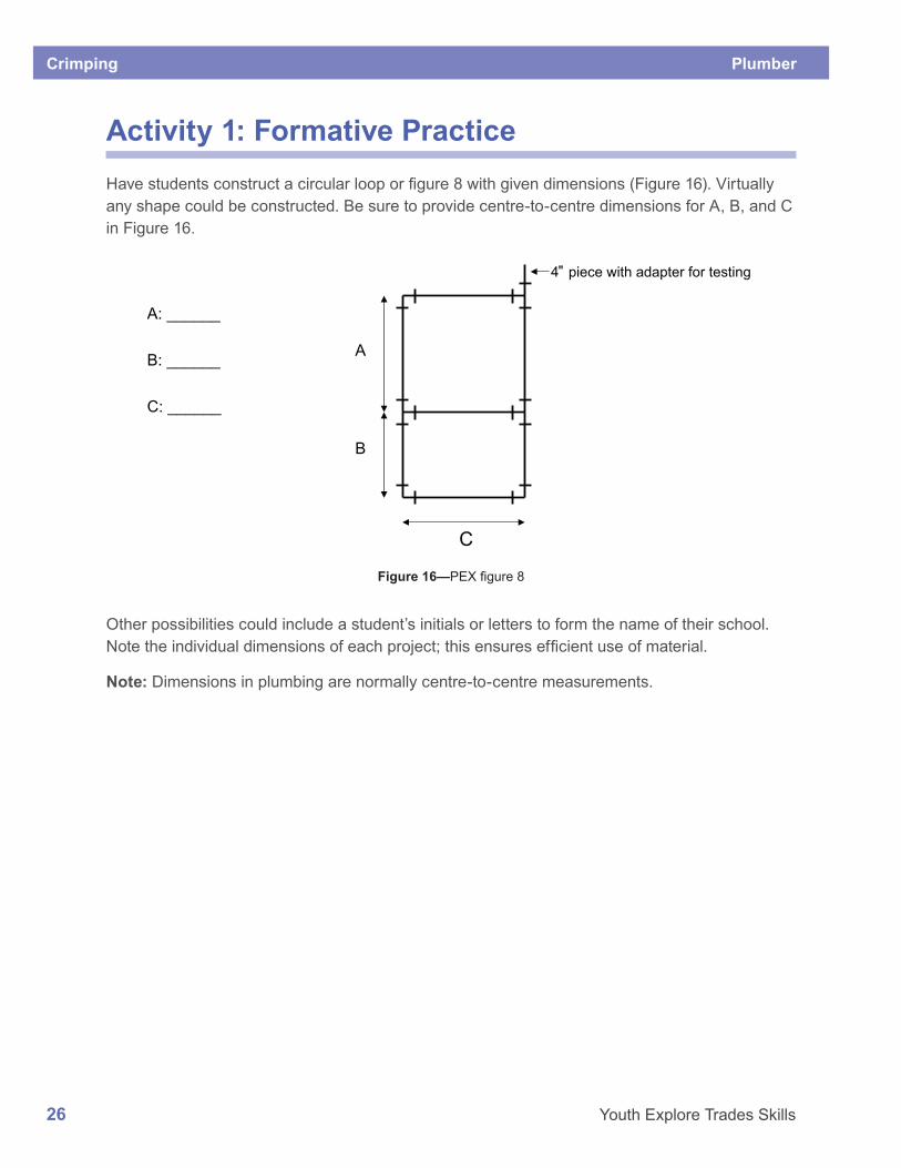
Activity 1: Formative PracticeHave students construct a circular loop or figure 8 with given dimensions (Figure 16). Virtually any shape could be constructed. Be sure to provide centre-to-centre dimensions for A, B, and C in Figure 16.
4 piece with adapter for testing
A: ______
B: ______
C: ______
B
A
C
"
Figure 16—PEX figure 8
Other possibilities could include a student’s initials or letters to form the name of their school. Note the individual dimensions of each project; this ensures efficient use of material.
Note: Dimensions in plumbing are normally centre-to-centre measurements.

Plumber Crimping
Youth Explore Trades Skills 27
Activity 2: Sprinkler ArrangementConstruct a free-standing arrangement of piping with a hose connector on one end and a sprinkler outlet on the other. Sprinkler outlets can be purchased at most hardware stores.
Have students construct the sprinkler assembly given in Figure 17. Be sure to provide centre-to-centre dimensions for A, B, and C.
A: ______ B: ______ C: ______
B
A
C
Connect sprinkler heads on top of 2 pieces
Connect hose adapter
"
Figure 17—PEX sprinkler system

Crimping Plumber
28 Youth Explore Trades Skills
Activity 3: Summative ActivityConstruct a rough-in for several fixtures (Figure 18).
PEX water supply
Plan view
Wal
l WC
LAV
16 30
Wall
"
" "
21⁄
Figure 18—Crimping rough-in:
plan view using ½" PEX water supply
Procedure:
1. Accurately lay out the location of all piping using chalk lines and pencil.
2. Have your teacher approve the layout.
3. Install the piping accurately, using correct crimping technique.
4. Test the piping.
5. Have your teacher inspect the installation.
6. Remove the pressure and disassemble the project.
Notes:
• WC (Water Closet) will be an American Standard Cadet toilet. See specification sheet for location of water supply.
• LAV (Lavatory) will be an American Standard Ellisse sink. See specification sheet for location of hot and cold water supply.
• Given dimensions are shown to centre of fixtures.

Plumber Crimping
Youth Explore Trades Skills 29
Note: hot and cold tiedtogether for testing purposes
• •
•
A
B
C
D
EF
G
Hot Cold
Figure 19—Crimping rough-in: front view
Provide students with dimensions for A, B, C, and D in Figure 19. See the manufacturer specification sheet for the dimensions E, F, and G.
It is recommended to conduct the rough-in on a section of plywood to allow chalk lines and layout to be checked before installation occurs. Removing the challenge of drilling studs allows students to focus on laying out piping on a two-dimensional plane.

Crimping Plumber
30 Youth Explore Trades Skills
Installation Notes• A painted plywood wall serves as an excellent surface for laying out and installing pipe.
Pencil, chalk lines, and levels can be used to transfer dimensions from the given drawing to the surface. The teacher should check student layouts before allowing them to install piping.
• Time and space permitting, the plywood could be removed and piping installed within studs (as it would be in an authentic construction setting). The plywood layout would serve as a full-sized template. Should students be required to drill through studs, a Milwaukee right angle drill (or equivalent) would be required (Figure 20).
Figure 20—Right angle drill
• Pipe should be fastened with appropriate clips. Talon clips may be used on a flat surface but are difficult to reuse. Plastic pipe clips are a better choice, as they can be screwed to a surface where necessary and easily reused.
• Piping can be tested using a hydrostatic pump or a hose connector connected to a wall hydrant.
• To present a more realistic example of rough-in specifications, actual rough-in dimensions may be used. See the referenced spec sheets for American Standard bathroom sink and toilet.
Plumber Crimping
Youth Explore Trades Skills 31
Source
Sink: http://www.americanstandard.ca/assets/documents/amstdca/spec/SpecSheet_260.pdf
Toilet: http://www.americanstandard.ca/assets/documents/amstdca/spec/SpecSheet_6648.pdf
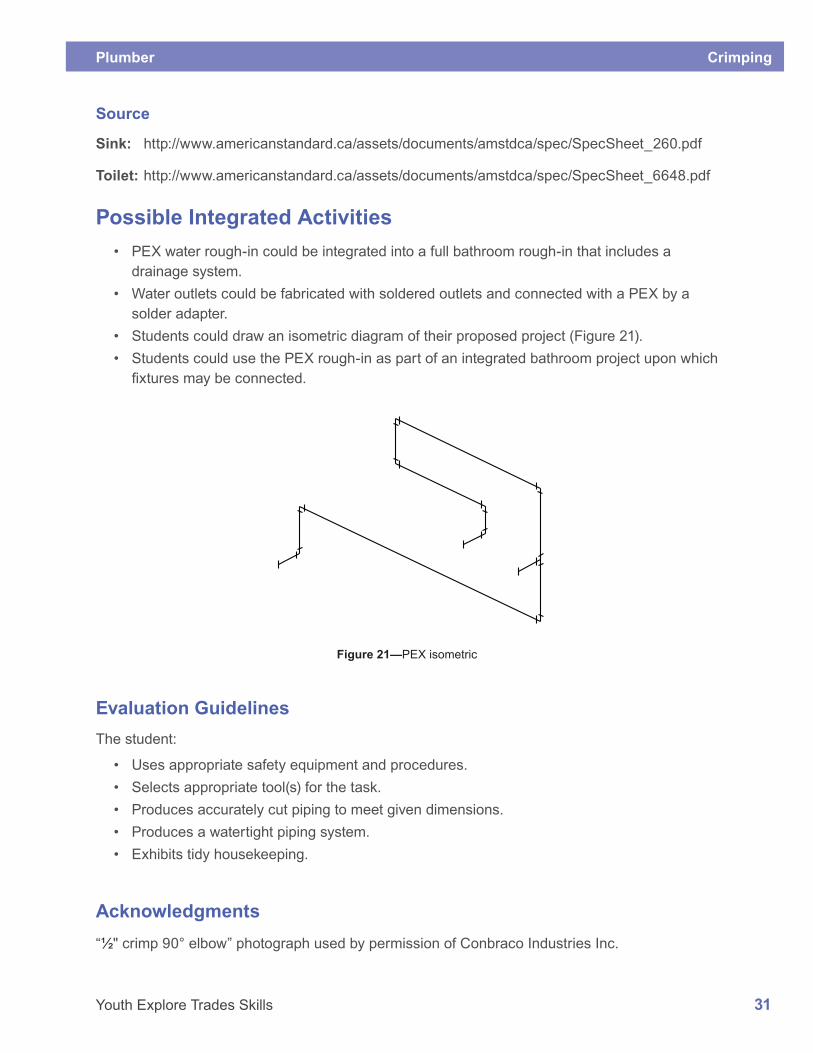
Possible Integrated Activities• PEX water rough-in could be integrated into a full bathroom rough-in that includes a
drainage system.• Water outlets could be fabricated with soldered outlets and connected with a PEX by a
solder adapter.• Students could draw an isometric diagram of their proposed project (Figure 21).• Students could use the PEX rough-in as part of an integrated bathroom project upon which
fixtures may be connected.
Figure 21—PEX isometric
Evaluation GuidelinesThe student:
• Uses appropriate safety equipment and procedures.• Selects appropriate tool(s) for the task.• Produces accurately cut piping to meet given dimensions.• Produces a watertight piping system.• Exhibits tidy housekeeping.
Acknowledgments“½" crimp 90° elbow” photograph used by permission of Conbraco Industries Inc.

Crimping Plumber
32 Youth Explore Trades Skills

This work is licensed under a Creative Commons Attribution-NonCommercial-ShareAlike 4.0 International License unless otherwise indicated.
Youth Explore Trades Skills Plumber
33
Drafting: Orthographic and Isometric Drawings
DescriptionStudents will learn to develop and interpret plumbing drawings typically found in construction. There are two parts to this lesson:
• Part 1: Orthographic drawings• Part 2: Isometric drawings
Lesson OutcomesThe student will be able to:
• Create orthographic drawings of objects, including a piping system• Create isometric drawings of objects, including a piping system
AssumptionsThe teacher has a basic understanding of drafting. This document seeks to teach the student about practices used in the plumbing trade. It is assumed the teacher has a basic understanding of the development of orthographic projections and isometric drawings.
TerminologyFitting: an object used to connect one or more pieces of piping material to another.
Isometric: a method of representing three-dimensional objects on a flat surface by means of a drawing that shows three planes of the object.
Orthographic: a method for representing a three-dimensional object by means of several views from various planes.
Estimated Time1–3 hours
Recommended Number of StudentsIndividual activity
FacilitiesClassroom activity

Drafting: Orthographic and Isometric Drawings Plumber
34 Youth Explore Trades Skills
Tools• Pencil, ruler, eraser• Tee square (Figure 1)• 30/60/90 triangle
Figure 1—A tee square is used to align drafting drawings to a square surface (such as a table).
Materials• Unlined paper• Isometric paper (Figure 2)
2 1
2 1
BB
A
NAME TITLE DATE PERIOD
A
Figure 2—Isometric paper is helpful for novice students to design isometric drawings.
Plumber Drafting: Orthographic and Isometric Drawings
Youth Explore Trades Skills 35
ResourcesBrief overview of freehand isometrics
http://www.youtube.com/watch?v=KN7281MUp_U
Fun video showing the development of an isometric drawing of a Rubik’s cube
http://www.youtube.com/watch?v=BPDpsaX-Usw
Activity BackgroundCommunication between architects, homeowners, tradespeople, and inspectors plays an important role in the development of any project. While this could take place through extended conversations, the most efficient way to ensure success is through the use of drawings and diagrams. A plumber should be competent in creating and interpreting drawings. Time and materials can be wasted if a project is not planned well.
Part 1: Orthographic DrawingsOrthographic drawings are projections from a single angle. Most objects can be fully represented showing a front view, side view, and top (or plan) view.
The biggest limitation of orthographic drawings is they represent a single perspective that may not show details hidden from view. For this reason, several views may have to be shown to indicate all details. Most commonly, front views and top views are shown.

Drafting: Orthographic and Isometric Drawings Plumber
36 Youth Explore Trades Skills
Activity 1: Create Orthographic ProjectionsHave students create an orthographic representation of an object. Large, box-like objects without a lot of detail tend to be good starting points.
Figure 3—Imagine an object floating inside a glass box.
Figure 4—Each side of the glass box shows only one plane of the object, and all lines are straight and parallel.

Plumber Drafting: Orthographic and Isometric Drawings
Youth Explore Trades Skills 37
Labeling views is a helpful method for students to make the connection between an object and its orthographic projection (Figures 5 and 6).
Figure 5—Views in an orthographic drawing
Figure 6—Drawing with the glass box flattened out

Drafting: Orthographic and Isometric Drawings Plumber
38 Youth Explore Trades Skills
Activity 2: Create Plumbing Orthographic ProjectionsThe teacher should create a piping system large enough so that it can be displayed at the front of the class and students can draw an orthographic of the object. As the plumbing orthographic samples below display, the object could be drawn from different perspectives.
Piping systems are regularly represented by orthographic projections. Blueprints of a large project are typically top (or plan) views. This activity is designed for students to draw orthographic projections of an actual piping system. The challenge of creating piping orthographics is that symbols must be used to represent 90° elbows or tees pointing toward or away from the viewer. Figure 7 identifies the possible orthographic projection views that could be used to represent an elbow fitting.
Top view Right side view
Front view
Left side view
Figure 7—Elbow fitting with possible orthographic projection views labelled

Plumber Drafting: Orthographic and Isometric Drawings
Youth Explore Trades Skills 39
For the fitting shown in Figure 7, the orthographic projection for the indicated views would be shown as in Figure 8.
Top (plan) view
Left side view Front view Right side view
Figure 8—Orthographic projections for the elbow fitting in Figure 7.
Top view Right side view
Front view
Figure 9—Tee fitting with possible orthographic projection views labelled

Drafting: Orthographic and Isometric Drawings Plumber
40 Youth Explore Trades Skills
For the fitting shown Figure 9, the orthographic projection for the indicated views would be shown as in Figure 10.
Top (plan) view
Front view Right side view
Figure 10—Orthographic projections for tee fitting in Figure 9
Figure 10 identifies the possible orthographic projection views that could be used to represent the tee fitting being referenced.
Notes• A fitting shown pointing “outward” from the page is shown with a dot. This represents the
inside of the fitting.
• A fitting shown pointing “inward” into the page is indicated with a solid line halfway through the fitting. This represents the back of a fitting.
• As the sample plumbing orthographic illustrates, the biggest drawback of orthographic projections is that fittings are often hidden from view. In other words, the fittings closest to the viewer are clearly indicated, but the details of piping “in behind” are not shown.
• The hashmarks indicate the connection to another pipe or fitting.
Figures 12–14 show samples of an orthographic projection that could be created after viewing the arrangement of piping in Figure 11. Students could be directed to draw each of the three views.

Plumber Drafting: Orthographic and Isometric Drawings
Youth Explore Trades Skills 41
Figure 11—Tube structure for orthographic drawing activity
Figure 12—Front view Figure 13—Plan view Figure 14—Right view

Drafting: Orthographic and Isometric Drawings Plumber
42 Youth Explore Trades Skills
Part 2: Isometric DrawingsIsometric drawings are most commonly used by tradespeople to communicate a large amount of information in a single drawing. Because isometric drawings show three sides of an object, they make it easy to visualize how a finished project may look or to better understand how the pieces will fit together. As demonstrated in the development of orthographic drawings, much more detail can be conveyed in a single isometric drawing than in a series of three orthographic drawings.
Figure 15—Isometrics show a three-dimensional object from three perspectives in a single drawing.
An isometric drawing can be identified by several factors:
• Vertical planes or edges are still drawn vertically.• Left and right planes are drawn at an angle of 30° above horizontal.• No horizontal lines are found on isometrics.
The strength of using isometrics in the plumbing trade is that all fittings can be shown on a single drawing, whereas an orthographic may have fittings hidden from view. This can create confusion and uncertainty in the mind of the tradesperson. It is common practice for a tradesperson to examine blueprint drawings (orthographic plan views) and create isometric sketches to clarify areas of uncertainty. This can be used to discuss issues with inspectors, supervisors, architects, or homeowners. The ability to visualize and plan a project before actually using materials is a valuable skill.

Plumber Drafting: Orthographic and Isometric Drawings
Youth Explore Trades Skills 43
Figure 16—Assembly drawings are typically drawn in isometric form, as they can convey how parts are to be connected.

Drafting: Orthographic and Isometric Drawings Plumber
44 Youth Explore Trades Skills
AAV(vent)
1stroof vent
1stroof vent
2ndroof vent
AW CO
CO
KS
WCWC
To public sewer
Bas
Sh
Bas - Basin (bath sink) Sh - ShowerWC - Water closet (toilet)AW - Auto washer KS - Kitchen sink CO - Clean out
4" CAST3" PVC2" PVC1½" PVC
Rear Addition - Plumbing Drains/Vents - V3
Figure 17—Isometric drawings allow a tradesperson to accurately determine how systems will be integrated and what supplies will be necessary for construction.

Plumber Drafting: Orthographic and Isometric Drawings
Youth Explore Trades Skills 45
Activity 3: Create Isometric DrawingsHave students sketch an object using correct isometric standards. Large rectangular objects such as a television or computer are typically best for beginners. Labelling the sides of the object with a sticky note may assist novices to differentiate between the different planes. Isometric paper (includes vertical axes as well as 30° axes already laid out) is an excellent way to begin. As students begin to understand the parallel manner of the various planes, a tee square and 30/60/90 triangle on unlined paper can be used.
Teacher Notes• Isometric paper can be used as a tool to support the novice. It serves as a physical
reminder of the 30° planes used to create depth on the flat drawing surface.
• Depending on the age and ability of the students, sketching isometrics freehand (without a straightedge) may be an objective toward which students should be working. Isometrics are commonly sketched on job sites to quickly communicate information. As students gain confidence and expertise, this skill should be developed.
• Teachers should encourage students to incorporate isometric sketching into other activities. The design of virtually any product begins with a sketch showing how the product will eventually look. The ability to communicate an idea to others without extensive conversations is an excellent means of brainstorming.
Figure 18—Basic shapes and simple ideas can be shown more realistically through the
development of isometric sketches.
Figure 19—More complex shapes can be created by creating wire frames or boxes to which
detail is added.

Drafting: Orthographic and Isometric Drawings Plumber
46 Youth Explore Trades Skills
Activity 4: Create Piping Isometric DrawingsHave students create an isometric drawing based on an existing system of pipe. See below for sample pictures and drawings that could be created. As students gain skill, more complex systems could be shown and drawn.
Teacher Notes• The shoulders of the fittings are drawn parallel to the opposing outlet.
• In terms of classroom management, it is likely easiest to show pictures of small systems on a projector rather than guiding students to draw isometrics in a lock-step format.
Below are sample piping arrangements and the isometrics that would represent them.
Figure 20—ABS piping installation Figure 21—Isometric drawing of ABS piping installation

Plumber Drafting: Orthographic and Isometric Drawings
Youth Explore Trades Skills 47
Figure 22—Lamp constructed from piping and bottles
Figure 23—Isometric drawing of piping and bottle lamp. An open-headed arrow is used to represent a
light bulb.

Drafting: Orthographic and Isometric Drawings Plumber
48 Youth Explore Trades Skills
Figure 24—Drainage and water lines
Figure 25—Isometric drawing of drainage and water lines

Plumber Drafting: Orthographic and Isometric Drawings
Youth Explore Trades Skills 49
Evaluation GuidelinesOverall neatness:
• Lines are concisely drawn.• Lettering is done to a high quality (all uppercase).• Guidelines are fully erased to avoid confusion.
Drawing conforms to orthographic standards:
• Accuracy of drawing to actual object• Alignment of views (top view above front view, for example)• Correct use of symbols (fittings pointed away from or toward viewer)
Drawing conforms to isometric standards:
• Correct use of symbols (i.e., shoulders on fittings)• Conformity to 30° planes• Accuracy of drawing to actual project

Drafting: Orthographic and Isometric Drawings Plumber
50 Youth Explore Trades Skills

This work is licensed under a Creative Commons Attribution-NonCommercial-ShareAlike 4.0 International License unless otherwise indicated.
Youth Explore Trades Skills Plumber
51
Fixtures Installation
DescriptionStudents will learn to install a toilet and lavatory basin.
Lesson OutcomesThe student will be able to:
• Install a toilet• Install a lavatory basin
Assumptions• The teacher is familiar with fixture installation.
• Fixtures will be installed after a rough-in has been completed.
• This activity will be part of an integrated project that includes water supply and drainage lines.
• Since the procedure for installing fixtures may vary, consult manufacturer’s resources for specific instructions. A number of videos and websites are listed in the “Resources” section.
TerminologyBasin: a hand sink found in a bathroom; also known as a lavatory.
Fixture: an object connected to plumbing lines to convey water or drainage.
Trim: devices connected to a fixture to facilitate drainage or a supply of water. For example, the trim for a lavatory would be the faucet, drain pipe, and water shut-off valves.
Water closet: the traditional term used to refer to a bathroom; in modern terms, it refers to a toilet.
Estimated Time2–6 hours
Recommended Number of StudentsActivities could be done individually or in pairs, depending on available fixtures and facilities.

Fixtures Installation Plumber
52 Youth Explore Trades Skills
FacilitiesTo create a realistic experience, it is suggested that fixture installation be part of an integrated project that includes water lines and a drainage system. This environment could be created by connecting existing water lines and a drainage system; however, a more mobile option is to drain the piping into a container with a submersible pump. The pump could then recycle the water and pressurize the water system. Another option is portable workstations, which could be constructed on pallets with wheels.
ToolsA variety of hand tools will be needed. Alternates could be provided based on the level of experience of the students. At the very least, the following tools are suggested:
• Adjustable wrenches (6", 8", and 12")• Water pump pliers• Hacksaw• Basin wrench (Figure 1)
Figure 1—A basin wrench is used to reach into areas too difficult for a wrench to fit.
MaterialsToilet installation
• Toilet bowl and tank• Closet T bolts (Figure 2)• Braided closet supply tube for toilet (12")• Toilet seat• Wax or foam toilet seal. Wax seals are most
commonly used in industry, but they cannot be reused.

Plumber Fixtures Installation
Youth Explore Trades Skills 53
Figure 2—Closet bolts will be used to tighten the bowl to the floor flange.
Basin installation• Basin • Faucet (some models include a drain assembly)• Tailpiece (drain) assembly (Figure 3)• 2 braided supply tubes for lavatory (hot and cold water
lines will need to be connected)• 2 CR 19 angle stops• 1 ABS 1¼ × 1½" slip joint adapter• 1 ABS 1½" union type p-trap (Figure 5)• 1 ABS 1½" coupling• ABS solvent cement• ABS pipe 1½"• 3½" chrome escutcheons• Screws and washers
Figure 3—Drain assemblies will include a system for plugging the drain. It may be a pop-out plug or a mechanically activated plug.

Fixtures Installation Plumber
54 Youth Explore Trades Skills
Figure 4—A mechanical pop-out (PO) plug allows the user to control the drain plug by means of a rod and
lever.
Figure 5—A union type p-trap has a threaded connection that allows quick removal for cleaning or
inspection. It also allows the teacher to reuse this p-trap.
ResourcesAs indicated above, the installation of a toilet and lavatory will vary by manufacturer, so provided documentation should be consulted. Below are a number of guides that may prove useful.
How to remove and install a new toilet
http://www.youtube.com/watch?v=Y_hVZ3rPzm4
How to install a new toilet
http://www.youtube.com/watch?v=ZRCp8OeL1YQ
http://www.homedepot.ca/know-how/videos/how-to-install-a-toilet
Toilet installation videos
http://buildipedia.com/at-home/bathroom/diy-how-to-install-a-toilet
http://www.kohler.com/video/162/Kohler-Canada/lvl1id?196/Installation/lvl2id?198/Cimarron-Toilet-(English)/playlistid?86130044001/Cimarron-Toilet-(english)/videoid?616339440001/Cimarron-(TM)-Toilet-Installation--Step-3/
Lavatory installation guides
http://www.rona.ca/en/projects/Installing-a-drop-in-sink-in-a-bathroom-countertop#allSteps
Lavatory installation video
http://buildipedia.com/at-home/bathroom/how-to-install-a-bathroom-lavatory

Plumber Fixtures Installation
Youth Explore Trades Skills 55
Activity 1: Installation of FixturesThe final step in a plumbing installation is the installation of the fixtures. It is the culminating event that provides the most tangible evidence of the correct installation of a plumbing system. This activity can serve as a guide to installing a toilet (also known as a water closet) and a basin (a small sink located in a bathroom, also known as a lavatory). As addressed in the “facilities” section, a source of water and a location for drainage would allow the fixtures to function.
Toilet InstallationThe following is a general installation procedure. Consult the manufacturer’s documentation or information found in the “Resources” section for greater detail.
1. Turn off the water supply. • Cut the water line at a distance of 1½" from the finished wall.• Place a small container under the pipe outlet to capture water draining out of the pipe.
2. Install CR 19 angle stops on the toilet supply and lavatory supplies.• If PEX piping has been used, crimp the CR 19. • If copper piping has been used, use a compression-style CR 19 (Figure 6).
3. If necessary, remove the plug from the toilet flange (Figure 7).
4. Remove the toilet bowl from its packaging.
Figure 6—A compression-style CR 19 will fit over copper pipe. The chrome nut is
then tightened to compress a brass ring, providing a watertight seal.
Figure 7—Closet flanges may have plastic plugs in the drain.
A slotted screwdriver and a hammer can quickly remove it.

Fixtures Installation Plumber
56 Youth Explore Trades Skills
5. Place the brass closet bolts in floor flange facing upward (Figure 8).
6. Place the wax seal or foam gasket on the closet flange.
7. Place the closet bolts in the closet flange.
• Foam gaskets are not normally used in industry, but they provide a cleaner, reusable method to seal the toilet.
8. Place the bowl over the seal and align the closet bolts through the holes.
9. Kneel or sit on the bowl to seat it onto the wax seal.
10. Place the plastic washers, brass washers, and brass nuts on the bolts.
11. Tighten the brass nuts onto the closet bolts. Great care must be taken to ensure the student does not overtighten the nuts and crack the fixture. If the bolts are too long they must be cut off using a hacksaw.
12. Snap the plastic caps onto the washers.
13. Remove the tank from the box.
14. Place the sponge gasket on the plastic horn on the bottom of the tank.
15. Attach the tank to the bowl with the supplied hardware.
16. Connect the tank following the manufacturer’s instructions.
17. Connect the braided water closet supply tube from the CR 19 to the tank.
18. Turn on the water.
19. Flush the toilet.
20. Install the seat.
Figure 8—Brass closet bolts are aligned with the floor flange to secure the bowl to the flange.

Plumber Fixtures Installation
Youth Explore Trades Skills 57
Basin InstallationThe following is a general installation procedure. Consult the manufacturer’s documentation or information found in the “Resources” section for greater detail.
1. Prepare countertop to receive the lavatory.
• Cut an opening in the countertop following the manufacturer’s directions.
2. Attach the faucet to the basin (Figure 9).
3. Attach the basin to the countertop.
4. Connect the braided water lines from the CR 19 to the faucet.
5. Connect the drain trim to the basin, following the manufacturer’s directions.
6. Connect the drain to the ABS outlet (Figure 10).
Figure 9—Faucets are normally connected to the basin by means of a threaded nut. Braided water supply lines run from the
brass connections to the CR 19 stops.

Fixtures Installation Plumber
58 Youth Explore Trades Skills
Braided water supply lines
CR 19 angle stops
Escutcheons can be used to give a more finished look
1½" coupling
Tail piece assemblywill connect fixtureto p-trap
1¼" × 1½" Slip joint adapter
1½" p-trap with cleanout
Figure 10—Connections to a basin
Evaluation GuidelinesThe student:
• Uses appropriate safety equipment and procedures.• Selects appropriate tool(s) for the task.• Produces accurately cut piping to meet given dimensions.• Assembles fixtures that function correctly.• Produces a watertight piping system.• Conducts tidy housekeeping.

This work is licensed under a Creative Commons Attribution-NonCommercial-ShareAlike 4.0 International License unless otherwise indicated.
Youth Explore Trades Skills Plumber
59
Soldering
DescriptionStudents will prepare copper pipe and fittings for soldering. Students will then solder and pressure test the system.
Lesson OutcomesThe student will be able to:
• Prepare copper pipe and fittings for assembly• Solder copper pipe and fittings• Test soldered joints• Disassemble copper fittings
Assumptions• The teacher should be aware of potential dangers involved in soldering, and safety should
be a primary concern. • Students should be familiar with tools and procedures.• Students should wear eye protection and be aware of the danger of getting burned.• Adequate ventilation or working outside will reduce exposure to fumes. • Fire extinguishers should be readily accessible.
TerminologyFitting: an object used to connect several pieces of piping material.
Flux: an acid paste material used to assist in the process of soldering copper pipe and fittings. It assists the solder to flow smoothly.
Hose bib: a globe valve that has been adapted for attaching a garden hose.
Rough in: the process of having plumbing systems installed, tested, and inspected before the building enters the finishing stage.
Sand cloth: an open-mesh sanding material used to clean copper pipe and fittings in preparation for soldering.
Solder: a metal alloy used to join metal objects without heating them to their melting point. The current industry standard is lead-free and tin-based.
Soldering: the process in which two or more metal pieces are joined together with a metal (alloy) having a lower melting temperate.
Striker: a friction device that uses a flint to light gas flame torches.
Soldering Plumber
60 Youth Explore Trades Skills
Estimated Time2–6 hours
Recommended Number of StudentsSoldering is an individual activity but preparation for soldering could be done with a partner.
Facilities• Shop setting with flat, stable working surface (student benches).
• Access to a water hose connection is required for testing. Alternatively, a hydrostatic pump could be used.
• A chain vise is highly recommended but not mandatory.
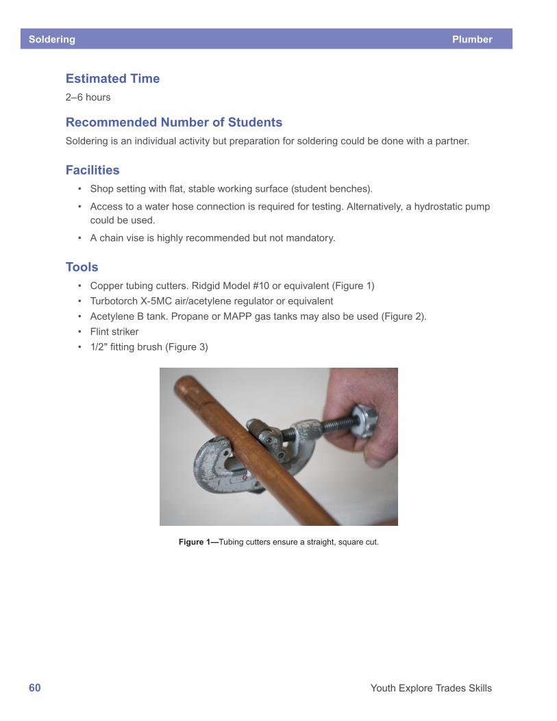
Tools• Copper tubing cutters. Ridgid Model #10 or equivalent (Figure 1)• Turbotorch X-5MC air/acetylene regulator or equivalent • Acetylene B tank. Propane or MAPP gas tanks may also be used (Figure 2).• Flint striker• 1/2" fitting brush (Figure 3)
Figure 1—Tubing cutters ensure a straight, square cut.

Plumber Soldering
Youth Explore Trades Skills 61
Figure 2—Acetylene B tank and regulator shown with a handle and accessory hook
Figure 3—A fitting brush is the best way to clean the inside of copper fittings.
Materials• Flux suitable for soldering copper• Lead-free solder• Open-mesh sand cloth• ½" copper fittings (an assortment of 90° elbows, tees, caps, and hose connectors,
depending on activity)• ½" type L copper pipe (available in 12' lengths) • Clean rags

Soldering Plumber
62 Youth Explore Trades Skills
ResourcesHow copper pipe and fittings are made
https://www.youtube.com/watch?v=uk8PLBAfmpM
How to cut various types of plumbing pipes
https://www.thisoldhouse.com/how-to/how-to-cut-plumbing-pipes-and-tubing
Tips and tricks for soldering
http://www.youtube.com/watch?v=83K7yfzWGFo
How to solder
http://www.youtube.com/watch?v=doqoEJJOdYA
DemonstationWorking with copper pipe and fittings is an exciting way for students to learn about the plumbing trade. The process of planning, constructing, and testing models the procedure found on job sites. In addition, the potential danger of working with torches can help students to understand the need for safety procedures.
Assembly Demonstration1. Cut the pipe to the given dimension using tubing cutters.
2. Ream both ends of the tube to allow maximum flow through the pipe.
3. Use the sand cloth to clean the outside of the copper pipe for a distance of approximately 2" (Figure 4).
4. Use a fitting brush to clean the inside shoulder of the fitting (Figure 5).
Figure 4—Polishing the outside of the pipe ensures good bonding between the pipe and solder.
Plumber Soldering
Youth Explore Trades Skills 63
Figure 5—Polishing the inside of a fitting with a fitting brush. An alternate solution is to use sand cloth and a pinky finger.
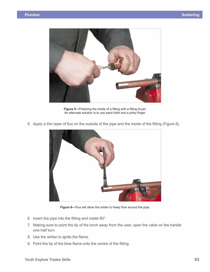
5. Apply a thin layer of flux on the outside of the pipe and the inside of the fitting (Figure 6).
Figure 6—Flux will allow the solder to freely flow around the pipe.
6. Insert the pipe into the fitting and rotate 90°.
7. Making sure to point the tip of the torch away from the user, open the valve on the handle one-half turn.
8. Use the striker to ignite the flame.
9. Point the tip of the blue flame onto the centre of the fitting.

Soldering Plumber
64 Youth Explore Trades Skills
10. When the flux begins to bubble, touch the tip of the solder to the joint area between the pipe and the fitting.
Figure 7—Heat should be applied at the centre of the fitting to draw the solder into the shoulder.
11. If the solder does not melt, continue to heat the shoulder of the fitting.
12. If the solder does melt, pull the torch tip away from the fitting and allow the solder to run into the fitting.
13. Continue to alternate application of heat and solder until a continuous bead of solder is visible around the circumference of the pipe.
14. Solder the other shoulders of the fitting using the method above.
15. Excess solder will gather at the bottom of the fitting and form a “grape.” The tip of the solder or a rag can be used to remove the grapes. Additional heat may need to be applied.
16. When all fittings are soldered, turn the torch handle valve fully off (clockwise).
17. Allow the fittings to cool, then remove the excess flux with a clean rag.
18. Excess flux must be completely removed from piping. Its acidic nature will colour the copper green, as corrosion occurs within hours of soldering.

Plumber Soldering
Youth Explore Trades Skills 65
Disassembly DemonstrationRemoving copper fittings from pipe is a technique that can be frustrating to novice students. Although the procedure for lighting the torch is the same as for assembling copper fittings, the technique for disassembly requires patience. Some tips for removing fittings are:
• All water must be drained from the piping system. Any water will cool the copper enough that the solder will not melt.
• At least one end of the system must be open to atmospheric pressure. An enclosed system will tend to create a situation in which the solder will not melt.
• When removing fittings, water pump pliers must be placed in the corner of the fitting (Figure 8). Students tend to grab the shoulder of the fitting, ovalling the fitting and crimping it into place.
• Adding flux or solder may assist the solder to become more free-flowing.
• Pulling a fitting off pipe is more a matter of technique than of brute strength. Short tugs in the lateral direction will prove more successful than strong rotational pulls.
• Students should be aware that the removed fittings will be hot. They should be placed carefully on a table or into a bucket of water.
Figure 8—Copper fittings should be grasped at the corner so they don’t bind on the pipe.

Soldering Plumber
66 Youth Explore Trades Skills
Activity 1: Solder an Enclosed Loop and Then Pressure Test
A
B
Figure 9—Copper loop. Adapter is soldered on for pressure test.
Have students construct the copper loop. Provide students with centre-to-centre dimensions for A and B.
Procedure 1. Cut the pipe using the tubing cutters.
2. Clean the pipe and fittings.
3. Flux the outside of the pipe and the inside of the fittings.
4. Solder the pipe following all safety procedures!
5. Clean excess flux.
6. Visually inspect all joints.
7. Pressure test the loop.

Plumber Soldering
Youth Explore Trades Skills 67
Teacher Notes• Teacher management of torches will ensure their safe usage. A good technique may be
to designate an assembly area with fittings and pipe, and a soldering area with several torches. Torches should be secured in an upright position or located where they cannot be tipped over. A bungee cord around a table leg and the tank is the simplest solution.
• The fumes generated from soldering can be problematic. If ventilation is not adequate, a fan could be set up to draw fumes away from students. Alternatively, tables or chain vises could be set up outside.
• The visual inspection of a soldered joint allows the student to reheat and re-solder a joint if necessary before pressure testing. Once water is introduced as part of testing, soldering cannot be conducted: i.e., all water must be completely drained before soldering.
• Water piping is most easily pressure-tested by soldering a hose bib to the student project, then connecting it to a hose.

Soldering Plumber
68 Youth Explore Trades Skills
Activity 2: Students Design and Create a Copper Sculpture
Figure 10—Copper sculpture
Using a maximum of 10 elbows and 6 tees, design a unique copper sculpture that will be soldered.
Procedure1. Draw an isometric of your sculpture in the given area.
2. Have your teacher approve the design.
3. Construct your sculpture!

Plumber Soldering
Youth Explore Trades Skills 69
Figure 11—Good soldering technique can be developed while allowing individual creativity.

Soldering Plumber
70 Youth Explore Trades Skills
Activity 3: Integrated ActivityA copper rough-in could be integrated into a full bathroom rough-in that includes a drainage system and fixtures. Due to the high cost of copper pipe and fittings, an alternative to completing an entire copper system is to create copper outlets that could be connected to PEX piping (Figure 12).
Figure 12—An adapter can be used to connect the copper outlet pipe to a PEX piping system.

Plumber Soldering
Youth Explore Trades Skills 71
Evaluation Guidelines• Solder must be bright and smooth. Dull grey colour or a coarse finish indicates the solder
was not completely melted.• Excess flux removed.• Ability to hold water.• Piping is prepared to meet given dimensions.• Tidy housekeeping.• Student follows safety procedures.
Related DiscussionPast practice of lead-based solder
Lead has been used to seal piping systems since the time of the Romans. Its use was greatly reduced (if not outright banned) in the 1980s when the detrimental effects of trace amounts of lead were studied.
Cost and ease of copper pipe systems versus PEX systems
PEX (or crimped) water lines can be installed without the use of flame torches. It is not uncommon to hear of a building damaged or destroyed by the careless use of a torch.
Production and environmental impact of piping production
Copper must be mined and has a significant environmental impact.

Soldering Plumber
72 Youth Explore Trades Skills

This work is licensed under a Creative Commons Attribution-NonCommercial-ShareAlike 4.0 International License unless otherwise indicated.
Youth Explore Trades Skills Plumber
73
Solvent Welding
DescriptionStudents will learn to correctly prepare, assemble, and solvent weld ABS piping.
Lesson OutcomesThe student will be able to:
• Accurately cut plastic piping• Prepare plastic piping for solvent welding• Safely solvent weld plastic piping
AssumptionsThe eacher is familiar with the tools, materials, and procedures related to solvent welding.
TerminologyABS: an acronym for acrylonitrile butadiene styrene; the most common plastic pipe used for drainage, waste, and venting (DWV) in British Columbia.
Dry fit: a technique commonly used to prepare for installation of piping. With dry fit installation, small sections of pipe and fittings are pushed together without solvent cement so they can be easily disassembled. When sections of pipe are confirmed to be correct, fittings are disassembled and bonded with solvent cement.
Materials Safety Data Sheet (MSDS): information specific to an individual product’s safe usage and handling.
Solvent weld: the process of using a liquid solvent to chemically bond plastic pipe and fittings.
WHMIS: commonly used acronym for “Workplace Hazardous Materials Information System,” Canada’s method for communicating information regarding the safe handling and usage of materials.
Estimated Time2–8 hours
Recommended Number of StudentsActivities could be done individually or in pairs.

Solvent Welding Plumber
74 Youth Explore Trades Skills
FacilitiesShop setting with flat, stable working surface (student benches). Access to water (hose) required for testing. Solvent welding gives off strong fumes. Good ventilation or an outdoor area is advisable.
The preferred method of holding pipe for beginners is a chain vise available in portable (Figure 1) or bench-top versions. Alternatively, a standard wood vise or a flat surface upon which the pipe could be held securely would suffice.
Figure 1—Portable chain vise for holding pipe
ToolsABS pipe can be cut in several ways. The most common method in industry is using a hacksaw with a 14–18 tooth blade. Alternatives include:
• Reciprocating saw• Hand saw with mitre box• Tubing cutter with plastic cutting wheel• Mitre saw• Plastic pipe cutter (Figure 2)

Plumber Solvent Welding
Youth Explore Trades Skills 75
Figure 2—Ridgid FC-200 capable of cutting ABS pipe up to 2"
Materials• An assortment of 1½", 2", and 3" diameter ABS pipe, depending on activity
• ABS solvent cement (yellow), generically referred to as glue. Technically, solvent cement is the correct term, as the solvent chemically softens the plastic surfaces before bonding occurs as the solvent evaporates.
• ABS fittings (type and quantity depending on activity): 45° bends, 90° bends, 22° bends; wyes, tees, caps, reducers, line cleanouts. See below for fittings commonly available at plumbing wholesalers or retail outlets.
Figure 3—ABS 45°. The hub by hub 45 shown on the left connects two pieces of piping. The hub by spigot 45 shown on the right fits directly into another fitting (typically a wye).

Solvent Welding Plumber
76 Youth Explore Trades Skills
Elbows are available as fittings, meaning one end can fit directly into another fitting without adding further pipe. The 45° elbow may also be referred to as a ⅛th bend, as 45° represents ⅛th of a full circle (360°).
Figure 4—ABS 90° elbow Figure 5—ABS tee
Also available as fitting 90s and may be referred to as ¼ bends.
Many combinations of outlet sizes are available. Note how the throat of the branch directs the flow of waste moving through the fitting.
Figure 6—ABS wye Figure 7—ABS double wye

Plumber Solvent Welding
Youth Explore Trades Skills 77
Figure 8—ABS line cleanout Figure 9—ABS p-trap. A solid p-trap is pictured (all solvent welded connections).
This fitting with its removable plug is a mandatory part of any drainage system. The plug must be located so it may be removed for inspection or cleaning if a blockage occurs within the system.
The trap provides a water seal that prevents sewer gas from coming into the living space. Traps are connected below basins, showers, and bathtubs. The trap for a toilet is located within the bowl, so a p-trap does not need to be connected.
Fixturetailpiece
Sewer gascan’t seepinto home
Clean-out plug
Water caught intrap creates seal
Figure 10—A cutaway view of a p-trap. Note that p-traps may have a cleanout plug to allow for cleaning or inspection of the piping. A solid p-trap is used if the trap is located in location
that is not easily accessible (for example, a crawlspace).
Figure 11—ABS water closet floor flange

Solvent Welding Plumber
78 Youth Explore Trades Skills
The flange must be securely attached to the floor using brass screws. The flange then provides a sturdy platform upon which a toilet (also known as a water closet) can be fastened. Brass screws, bolts, and washers are used below a toilet as they are highly resistant to corrosion.
Figure 12—ABS bushing
Bushings fit inside a fitting to facilitate a reduction in the size of piping.
ResourcesSolvent welding literature and link to online training system; general information with a specific focus on two-stage solvent welding for PVC pipe
http://www.ipexinc.com/Content/Training/TrainingDetails.aspx?Training=OnlineSolventCementTrainingCourse&LanguageCode=en-CA
ABS solvent welding video
http://www.youtube.com/watch?v=bLstgZCREPc
ABS solvent welding information sheet
http://www.arrowadhesives.com/HowTo.html
WHMIS information and resources
http://www2.worksafebc.com/Topics/WHMIS/Home.asp
MSDS for ABS solvent cement
http://www.sluyter.com/files/products/abs-55y-lv.pdf

Plumber Solvent Welding
Youth Explore Trades Skills 79
Activity 1: Cut Pipe Squarely and AccuratelyHave students cut 10 pieces of ABS 1" long. The students can lay out the pieces flat on a table to check for consistency and straightness. Industry tolerance is typically +/– ⅛" accuracy of length. As described in the “Tools” section, many methods of cutting ABS are available. The teacher could have students practise several methods. In addition, cutting with a hacksaw can be practised in several positions. Plumbers should be able to cut pipe accurately in whatever environment they are working. This includes trenches, crawlspaces, or even seated in front of a cabinet. Students could practise by supporting the pipe with a chain vise, ladder, or even with no support (seated on the floor) (Figure 13).
Burrs on the inside and outside edges of pipe should be removed by hand, rag, utility knife, or file. A de-burring tool could also be used. Outside burrs interfere with the insertion of the pipe into the fitting, while inside burrs may interfere with the free flow of materials through the pipe (Figure 14).
Figure 13—Cutting ABS with only a ladder support can be challenging at first.
Figure 14—Cutting ABS in a seated position
Figure 15—Ridgid de-burring tool to remove burrs on inside and outside edges of pipe
Solvent Welding Plumber
80 Youth Explore Trades Skills
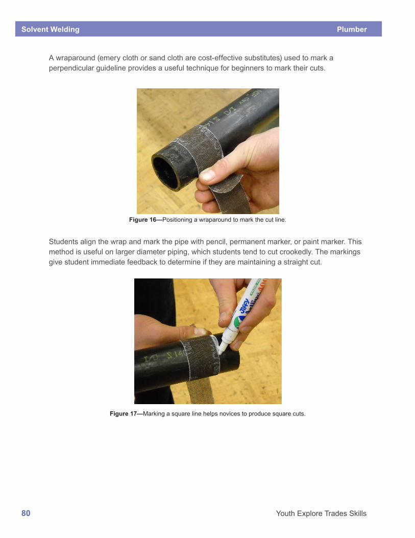
A wraparound (emery cloth or sand cloth are cost-effective substitutes) used to mark a perpendicular guideline provides a useful technique for beginners to mark their cuts.
Figure 16—Positioning a wraparound to mark the cut line.
Students align the wrap and mark the pipe with pencil, permanent marker, or paint marker. This method is useful on larger diameter piping, which students tend to cut crookedly. The markings give student immediate feedback to determine if they are maintaining a straight cut.
Figure 17—Marking a square line helps novices to produce square cuts.
Plumber Solvent Welding
Youth Explore Trades Skills 81
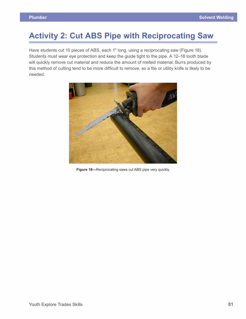
Activity 2: Cut ABS Pipe with Reciprocating SawHave students cut 10 pieces of ABS, each 1" long, using a reciprocating saw (Figure 18). Students must wear eye protection and keep the guide tight to the pipe. A 12–18 tooth blade will quickly remove cut material and reduce the amount of melted material. Burrs produced by this method of cutting tend to be more difficult to remove, so a file or utility knife is likely to be needed.
Figure 18—Reciprocating saws cut ABS pipe very quickly.

Solvent Welding Plumber
82 Youth Explore Trades Skills
Activity 3: Assemble PipingHave students assemble a small system of fittings and pipe to given dimensions using ABS solvent cement. See the ABS starter drawing (Figure 19) as an example. Pairs of students could build letters to spell their school’s name. There are also many games involving throwing beanbags or rings that could be built.
Note: Assembled fittings and pipe can only be disassembled within minutes of solvent welding. Within a period of 24 hours, maximum bonding strength occurs, and fittings become extremely difficult to remove from pipe.
Safety: Students should wear eye protection and gloves when working with ABS solvent cement. Appropriate safety measures and first aid information can be found in the MSDS.
• Have students work with a partner to create their assigned letter.
• All letters must be a maximum of 16" tall and 12" wide.
• Students must dry fit all pipe and fittings before they are permitted to solvent weld.
Figure 19—Sample ABS starter project

Plumber Solvent Welding
Youth Explore Trades Skills 83
Activity 4: SculptureHave students design and create an object from ABS pipe and fittings. See Figure 20 as an example.
• Students sketch an object they wish to construct, including dimensions. Alternatively, an open-ended design technique could be employed. For example, a list of fittings and a given length of pipe could be made available to each student.
• Students cut pipe and dry-fit fittings. For the purposes of disassembly and modelling correct solvent welding technique, a small brush with white grease can be used. The grease serves as a lubricant that will make the fittings much easier to disassemble or reuse. The grease must be removed with a rag before solvent welding occurs.
Figure 20—Sample ABS sculpture
Parts List• (4) 1½" 45° elbows• (4) 1½" tees• (4) 1½" cross• (6) 1½" 90° elbows
Procedure• Have students sketch a 3-D object that will be
built with ABS pipe and fittings.
• Students are permitted a maximum of 20 fittings and 6' of pipe.
• Students must have their designs approved by the teacher before constructing their sculptures.
Figure 21—A sculpture using ABS fittings and pipe

Solvent Welding Plumber
84 Youth Explore Trades Skills
Activity 5: Integrated ActivityStudents assemble drainage piping for use in draining a washroom. See Figure 22 as an example.
Wall
LAV
WCSH
44" 24"
80"
3" Sanitaryconnection
Plan view
30"
Wal
l
Wal
lFigure 22—ABS rough-in
• The teacher will explain to students that they will be assisted in designing a draining system to accommodate all fixtures.
• Have students draw the drainage system, including the pipe size (Figure 23).

Plumber Solvent Welding
Youth Explore Trades Skills 85
Wall
1½"
3"
2"
12"12"12"
15"
3"
3" Sanitaryconnection
Plan view
Wal
l
Wal
l
Figure 23—ABS rough-in (key)
Teacher Notes• See Figure 24 for further detail.• 2" to LAV is necessary for venting of other fixtures.• Indicated dimensions are available from manufacturer’s specifications online.
Notes/SpecificationsFixture schedule (see manufacturer’s documentation for location of drains)
• WC – American Standard Champion Model 5325010• LAV – American Standard Studio Above Counter Model 0621001• SH – Maax Cyrene Model 300001
Wall Schedule• 2 × 4" wall with ½" drywall (actual width of wall will be 3½" + drywall)

Solvent Welding Plumber
86 Youth Explore Trades Skills
3"3"
2"1½"
2-3" 45°3" 90° elbow
3" double wye3" × 2" bushing (to LAV)3" × 1½" bushingand 45° elbow (to shower)
2-2" 45° elbows2" line cleanout2" × 1½" × 1½" tee1½" 90° elbow1½" cap (p-trap to beadded after water test)
2-1½" 45° elbows1½" cap (p-trap to beadded after water test)
1½" for vent
Figure 24—Rough in isometric
Teacher Notes• Depending on time available, it may be easier to provide students with all dimensions and
a layout of piping.• Piping must be supported so it will not move when filled with water. A common method for
this is the use of ½" strap iron (Figure 25).
• Horizontal piping should be graded at ¼" per linear foot of pipe. An approximation of one-quarter bubble on a level would suffice (Figure 26).
• When piping is complete and open ends are capped, a water test can be performed. This involves filling the system with water and checking for leaks. The water test is conducted on all drainage systems for a local inspector.
• Once a wall finish (drywall or tile) is complete, fixtures including p-traps may be connected to the drainage system.

Plumber Solvent Welding
Youth Explore Trades Skills 87
Figure 25—Strapping is a cost-effective way to support piping. Use screws through the perforations to support horizontal or vertical piping.
Figure 26—A torpedo level can indicate horizontal level, vertical plumb, and 45° angle. Some models can also indicate grade (angle) of piping. A level showing approximately
one-quarter of the bubble above horizontal can be used as an approximation of ¼" per foot.
Evaluation GuidelinesThe student:
• Assembles pipe and fittings accurately to given dimensions. Suggested tolerance of ⅛".• Cuts pipe square.• Assembles joints correctly.• Removes excess solvent cement.• Follows all safety procedures.• Assembles pipe and fittings so they are able to hold water.

Solvent Welding Plumber
88 Youth Explore Trades Skills

This work is licensed under a Creative Commons Attribution-NonCommercial-ShareAlike 4.0 International License unless otherwise indicated.
Youth Explore Trades Skills Plumber
89
Threaded Connections
DescriptionStudents will learn to use pipe wrenches to work with threaded pipe. Students will measure accurately and determine fitting allowance.
Lesson OutcomesThe student will be able to:
• Use pipe wrenches to assemble and disassemble threaded piping systems• Accurately measure centre-to-centre dimensions• Calculate fitting allowances
AssumptionsThe teacher is familiar with:
• Use of pipe wrenches• Imperial measurement system (i.e., fractional parts of an inch)• Threaded fitting and pipe terminology
TerminologyFemale thread: internal threads on the inside of a fitting.
Fitting allowance: the dimension from the end of a pipe inserted into a fitting to the outlet of the fitting.
Male thread: external threads on the outside of a pipe.
Nipple: a piece of pipe threaded on both ends with a length of 12" or less.
Thread engagement: the length of pipe inserted into a fitting to the point where the threads are snug and a watertight seal can be achieved.
Estimated Time2–3 hours
Recommended Number of StudentsActivity could be done individually or in pairs.

Threaded Connections Plumber
90 Youth Explore Trades Skills
Facilities• Shop setting with flat, stable working surface (student benches).
• The preferred method of holding pipe is in a chain vise (available in portable or bench top versions).
Figure 1—Portable chain vise for holding pipe
Tools• 14" pipe wrenches. 2 per group (Figure 2)• A 14" pipe wrench is recommended for up to 1" pipe• Imperial tape measure
Figure 2—Pipe wrench

Plumber Threaded Connections
Youth Explore Trades Skills 91
Optional• Threading equipment• Reamer• Pipe cutter• Oiler• Ridgid thread cutting oil
In this activity, students are required to disassemble, measure, and assemble threaded pipe and fittings. Due to the high cost of threading equipment, it is suggested the teacher prepare the threaded connections for the students. Should resources be available, the industry standard for cutting threads is the Ridgid Model 300. The carriage includes a cutter, reamer, and die head. A more cost-effective method for teaching students is a hand threading set such as the Ridgid Model 00-R. However, because it is rarely used in industry it has limited usefulness.
Figure 3—Ridgid Model 300 power threader

Threaded Connections Plumber
92 Youth Explore Trades Skills
Materials• An assortment of ½" and ¾" malleable iron pipe fittings. Quantity and type dependent on
activity.
• Threaded pipes (known as nipples) are readily available in lengths up to 60". Quantity and type dependent on activity.
• If threading equipment is available, ½" and ¾" schedule 40 malleable iron pipe (typically available in 21' lengths). Schedule refers to the wall thickness of the pipe.
ResourcesSafety tips for using pipe wrenches
http://www.ccohs.ca/oshanswers/safety_haz/hand_tools/pipetools.html
Pipe fitter’s Handbook
http://pipe-valve-fitting.com/wp-content/uploads/2013/02/PipeFittersHB_Apr12.pdf

Plumber Threaded Connections
Youth Explore Trades Skills 93
Activity 1: Determining Fitting AllowanceA common dimension required for the assembly of threaded steel projects is the fitting allowance. The following can serve as a guide for introducing this concept in an activity format.
Students work in pairs and are given an assortment of malleable iron (commonly known as steel or black) nipples. See the “Fitting Allowances” table below as a sample worksheet for collecting data. Once all nipples have been measured and recorded, students are asked to tighten a single 90° elbow onto one end of the nipple using a chain vise and two pipe wrenches. An accurate dimension from the end of the nipple to the centre of the outlet is then measured. This is repeated for each of the nipples. The difference between the end-to-end measurement and the end-to-centre (of the 90) measurement is the fitting allowance.
End-to-centre
Fitting allowance
End-to-end
Figure 4—End-to-end, end-to-centre, and fitting allowance
Fitting allowance can be seen as the “extra” length that is added to a pipe that must be taken into account when assembling a piping system. If a centre-to-centre measurement is required, two fitting allowances need to be taken into account to determine the correct length of the pipe.
Centre-to-centre
Figure 5—In most cases, centre-to-centre dimensions are used in plumbing

Threaded Connections Plumber
94 Youth Explore Trades Skills
Taking an End-to-Centre MeasurementCorrect technique involves hooking the tape measure over the end of a pipe, aligning the tape to be parallel with the pipe, and measuring to the nearest ⅛".
Fitting allowance is an important concept for young people investigating trades to understand. Initially, it is important for students to be able to use this information to assemble piping projects. Because most dimensions in the plumbing trade are centre-to-centre, plumbers must be able to calculate end-to-end measurements. Further discussion can be tied to Social Studies curriculum and the Industrial Revolution. Because global standards for manufacturing tolerances have been established, fittings and pipe from around the world can be expected to fit together.
Figure 6—Correctly taking an end-to-centre measurement.
Figure 7—Care should be taken to keep the hook of the tape measure on the end of the pipe.

Plumber Threaded Connections
Youth Explore Trades Skills 95
Fitting Allowances
Organize your assigned pipe nipples and measure their length.
Tighten elbows onto one end of your pipes and record the end-to-centre measurement below.
Record the difference between the measurements in the column below.
End-to-end length End-to-centre length Fitting allowance
Demonstration of Proper Pipe Wrench TechniqueThreaded fittings should be assembled using one wrench to tighten a fitting, and another to hold the pipe against the direction of the tightening while a chain vise supports the work. This method ensures a controlled tightening using the strength of arms, shoulders, and chest.
Figure 8—Controlled movement of pipe wrenches is accomplished with two wrenches and good hand placement.

Threaded Connections Plumber
96 Youth Explore Trades Skills
Key points are:
• Stable stance to maintain balance
• Wrenches within shoulder width apart aligned to move in opposite directions
• Jaws of wrenches centred over pipe or fittings
• Controlled movement of wrenches so strength of entire upper body is used
Figure 9—The chain vise is only used to support the work. The tightening of the fitting is accomplished by moving
the two wrenches in opposite directions.
Once students have experimentally determined a consistent fitting allowance for the pipes they were working with, the teacher can share manufacturer’s documentation that indicates the theoretical fitting allowance. Many sources for this can be found within manufacturers’ documentation. The fitting allowances for common pipe sizes are listed below:
Pipe diameter Fitting allowance(to nearest 1⁄16")
Fitting allowance (to nearest ⅛")
½" 0.69" = 11⁄16" ¾"
¾" 0.81" = 13⁄16" 7⁄8"
1" 0.92" = 15⁄16" 1"

Plumber Threaded Connections
Youth Explore Trades Skills 97
Possible discrepancies between theoretical and practical measurements are:
• Student has over-tightened or under-tightened the fitting. Hand tight plus two full rotations is typical. The term snug is used in the trade to describe a fitting that is tightened to the point where a leak would not occur.
• Malleable iron fittings can be stretched if they are over-tightened. As the pipe is forced into the fitting, the shoulder is stretched permanently and will alter the thread engagement for future use. The fitting is still use able but will not give accurate fitting allowances.
• If students have threaded the pipe, the length of the thread must be done consistently and precisely to produce accurate thread engagement and fitting allowances.
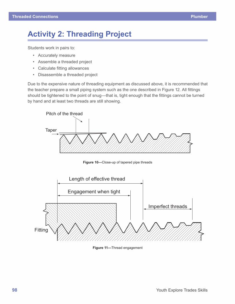
Threaded Connections Plumber
98 Youth Explore Trades Skills
Activity 2: Threading ProjectStudents work in pairs to:
• Accurately measure• Assemble a threaded project• Calculate fitting allowances• Disassemble a threaded project
Due to the expensive nature of threading equipment as discussed above, it is recommended that the teacher prepare a small piping system such as the one described in Figure 12. All fittings should be tightened to the point of snug—that is, tight enough that the fittings cannot be turned by hand and at least two threads are still showing.
Pitch of the thread
Taper
Figure 10—Close-up of tapered pipe threads
Engagement when tight
Imperfect threads
Length of effective thread
Fitting
Figure 11—Thread engagement

Plumber Threaded Connections
Youth Explore Trades Skills 99
Measure and Wrench
AB
C
D
E
G
F
Figure 12—Piping system for threading project
• Measure all indicated pipes and record in the table that follows. All measurements must be to the nearest ⅛".
• Disassemble your project and complete the table.
• Show your teacher all pieces.
• Reassemble and ensure correct dimensions.
All joints must be tight.
All pipes should be aligned using two pipe wrenches.

Threaded Connections Plumber
100 Youth Explore Trades Skills
Complete the following table (to the nearest ⅛").
Assembled project
Unassembled project Length of pipe only
Difference 2 fitting allowances
Difference divided by 2 1 fitting allowance
A:
B:
C:
D:
E:
F:
G:
A correctly engaged fitting should be turned three to four turns by hand and two to three turns with pipe wrenches, with two imperfect threads still showing. The taper (or angle) of the threads ensures a watertight seal when the pipe is wedged into the fitting.
Evaluation GuidelinesThe student:
• Demonstrates ability to use an imperial tape measure to take accurate measurements.
• Uses pipe wrenches correctly.
• Assembles pipe and fittings to specification within ⅛" on all measurements.