Second Spine: Upper Body Assistive Device for Human Load Carriage
11
Joon-Hyuk Park Robotics and Rehabilitation (ROAR) Lab, Department of Mechanical Engineering, Columbia University, New York, NY 10027 e-mail: [email protected] Xin Jin Robotics and Rehabilitation (ROAR) Lab, Department of Mechanical Engineering, Columbia University, New York, NY 10027 e-mail: [email protected] Sunil K. Agrawal 1 Professor Fellow ASME Director of ROAR Laboratory Robotics and Rehabilitation (ROAR) Lab, Department of Mechanical Engineering, Columbia University, New York, NY 10027 e-mail: [email protected] Second Spine: Upper Body Assistive Device for Human Load Carriage This study presents the development of second spine, an upper body assistive device for human load carriage. The motivation comes from reducing musculoskeletal injuries caused by carrying a heavy load on the upper body. Our aim was to design a wearable upper body device that can prevent musculoskeletal injuries during human load carriage by providing a secondary load pathway—second spine—to transfer the loads from shoulders to pelvis while also allowing a good range of torso motion to the wearer. Static analysis of the backpack and the second spine was first performed to investigate the feasi- bility of our concept design. The development of second spine had two considerations: load distribution between shoulders and pelvis, and preserving the range of torso motion. The design was realized using load bearing columns between the shoulder support and hip belt, comprising multiple segments interconnected by cone-shaped joints. The per- formance of second spine was evaluated through experimental study, and its biomechani- cal effects on human loaded walking were also assessed. Based on the findings from second spine evaluation, we proposed the design of a motorized second spine which aims to compensate the inertia force of a backpack induced by human walking through active load modulation. This was achieved by real-time sensing of human motion and actuating the motors in a way that the backpack motion is kept nearly inertially fixed. Simulation study was carried out to determine the proper actuation of motors in response to the human walking kinematics. The performance of motorized second spine was evaluated through an instrumented test-bed using Instron machine. Results showed a good agree- ment with simulation. It was shown that the backpack motion can be made nearly station- ary with respect to the ground which can further enhance the effectiveness of the device in assisting human load carriage. [DOI: 10.1115/1.4029293] 1 Introduction and Background Human ambulation while carrying a heavy backpack load can increase the risk of musculoskeletal injuries particularly on vul- nerable areas such as ankles, knees, shoulder joints, and the lum- bar spine. Among these injuries, the most common ones involve the lower limbs (foot blisters, metatarsalgia, stress fractures, and knee pain) and the lower back (low back pain, spasm, disk tear/ herniation, and spinal stenosis) [1]. Prevalence of low back pain is higher for subjects who carry large loads on a regular basis (e.g., material handlers and nurses [2], infantrymen [3], and young scholars [4]). Adolescents, for example, show significant effects of muscle fatigue after just 15 min of walking with a rucksack load of 15–20% body weight (BW) [5]. Often, the children suffer from back pain if they exceed this range [6]. School children typi- cally are at an increased risk for lower back pain if they carry loads over 20% of BW [7]. Higher activity required in particular muscles in the upper body to support the backpack load also causes increase in physical fatigue which further decreases the human performance. If loaded walking is performed regularly as a part of daily duties, back pain can become chronic and create a fi- nancial burden with medical costs. Rucksack palsy is one of the most common injuries that paralyzes the arms due to excessive pressure on the C5 and C7 nerve root in the upper brachial plexus from rucksack shoulder straps [3]. Many works have been published in the past which deal with biomechanical and physiological effects of transporting loads while walking. It has been reported that walking with a backpack increases the forward lean of the trunk to maintain the combined center of mass (COM) of the upper body and the carried load over the feet. This increased forward lean has been hypothesized to cause back injuries [8] and excessive foot strain [9]. By locating loads higher in the pack, this postural adaptation is reduced because less rotation of the trunk is required to bring the COM of the backpack over the feet [10]. However, since head, arms, and trunk can be roughly modeled as an inverted pendulum rotating about the hip joint, such load arrangements may actually result in higher upper body inertia and consequently higher muscle activa- tions at the pelvis to keep postural stability, especially while walk- ing on uneven terrain [10]. Thus, current backpack technology imposes a trade-off between forward lean reduction and postural stability. There are several studies that show the use of a framed back- pack with a hip belt to reduce the pressure on the shoulders and decrease lower back pain [11]. It has been shown that the stress on the shoulders can be reduced by partially transferring the load to the hip [12], even though the effectiveness depends on the specific backpack model [13]. Decreased pressures on the shoulders may not only reduce shoulder discomfort and nerve compression caus- ing rucksack palsy [12] but also reduce the stress on the spine since the rigid structure of the backpack acts as an alternative pathway to transfer loads to the lower body. However, there are situations where significant loads have to be carried outside the backpack (e.g., a military tactical vest with standard equipment and bullet-proof inserts). In these cases, a more wearable solution to transfer loads from shoulders to pelvis is desirable. Despite many detrimental effects arising from backpack load carrying, a good engineered design is still unavailable and the effectiveness in reducing the muscle fatigue and risk of injuries in human load carriage is yet to be proven. This provides the motivation for our 1 Corresponding author. Manuscript received September 26, 2014; final manuscript received December 1, 2014; published online December 31, 2014. Assoc. Editor: Venkat Krovi. Journal of Mechanisms and Robotics FEBRUARY 2015, Vol. 7 / 011012-1 Copyright V C 2015 by ASME Downloaded From: http://mechanismsrobotics.asmedigitalcollection.asme.org/ on 01/02/2015 Terms of Use: http://asme.org/terms
Transcript of Second Spine: Upper Body Assistive Device for Human Load Carriage

Joon-Hyuk ParkRobotics and Rehabilitation (ROAR) Lab,
Department of Mechanical Engineering,
Columbia University,
New York, NY 10027
e-mail: [email protected]
Xin JinRobotics and Rehabilitation (ROAR) Lab,
Department of Mechanical Engineering,
Columbia University,
New York, NY 10027
e-mail: [email protected]
Sunil K. Agrawal1Professor
Fellow ASME
Director of ROAR Laboratory
Robotics and Rehabilitation (ROAR) Lab,
Department of Mechanical Engineering,
Columbia University,
New York, NY 10027
e-mail: [email protected]
Second Spine: Upper BodyAssistive Device for HumanLoad CarriageThis study presents the development of second spine, an upper body assistive device forhuman load carriage. The motivation comes from reducing musculoskeletal injuriescaused by carrying a heavy load on the upper body. Our aim was to design a wearableupper body device that can prevent musculoskeletal injuries during human load carriageby providing a secondary load pathway—second spine—to transfer the loads fromshoulders to pelvis while also allowing a good range of torso motion to the wearer. Staticanalysis of the backpack and the second spine was first performed to investigate the feasi-bility of our concept design. The development of second spine had two considerations:load distribution between shoulders and pelvis, and preserving the range of torso motion.The design was realized using load bearing columns between the shoulder support andhip belt, comprising multiple segments interconnected by cone-shaped joints. The per-formance of second spine was evaluated through experimental study, and its biomechani-cal effects on human loaded walking were also assessed. Based on the findings fromsecond spine evaluation, we proposed the design of a motorized second spine which aimsto compensate the inertia force of a backpack induced by human walking through activeload modulation. This was achieved by real-time sensing of human motion and actuatingthe motors in a way that the backpack motion is kept nearly inertially fixed. Simulationstudy was carried out to determine the proper actuation of motors in response to thehuman walking kinematics. The performance of motorized second spine was evaluatedthrough an instrumented test-bed using Instron machine. Results showed a good agree-ment with simulation. It was shown that the backpack motion can be made nearly station-ary with respect to the ground which can further enhance the effectiveness of the devicein assisting human load carriage. [DOI: 10.1115/1.4029293]
1 Introduction and Background
Human ambulation while carrying a heavy backpack load canincrease the risk of musculoskeletal injuries particularly on vul-nerable areas such as ankles, knees, shoulder joints, and the lum-bar spine. Among these injuries, the most common ones involvethe lower limbs (foot blisters, metatarsalgia, stress fractures, andknee pain) and the lower back (low back pain, spasm, disk tear/herniation, and spinal stenosis) [1]. Prevalence of low back pain ishigher for subjects who carry large loads on a regular basis (e.g.,material handlers and nurses [2], infantrymen [3], and youngscholars [4]). Adolescents, for example, show significant effectsof muscle fatigue after just 15 min of walking with a rucksackload of 15–20% body weight (BW) [5]. Often, the children sufferfrom back pain if they exceed this range [6]. School children typi-cally are at an increased risk for lower back pain if they carryloads over 20% of BW [7]. Higher activity required in particularmuscles in the upper body to support the backpack load alsocauses increase in physical fatigue which further decreases thehuman performance. If loaded walking is performed regularly as apart of daily duties, back pain can become chronic and create a fi-nancial burden with medical costs. Rucksack palsy is one of themost common injuries that paralyzes the arms due to excessivepressure on the C5 and C7 nerve root in the upper brachial plexusfrom rucksack shoulder straps [3].
Many works have been published in the past which deal withbiomechanical and physiological effects of transporting loadswhile walking. It has been reported that walking with a backpack
increases the forward lean of the trunk to maintain the combinedcenter of mass (COM) of the upper body and the carried load overthe feet. This increased forward lean has been hypothesized tocause back injuries [8] and excessive foot strain [9]. By locatingloads higher in the pack, this postural adaptation is reducedbecause less rotation of the trunk is required to bring the COM ofthe backpack over the feet [10]. However, since head, arms, andtrunk can be roughly modeled as an inverted pendulum rotatingabout the hip joint, such load arrangements may actually result inhigher upper body inertia and consequently higher muscle activa-tions at the pelvis to keep postural stability, especially while walk-ing on uneven terrain [10]. Thus, current backpack technologyimposes a trade-off between forward lean reduction and posturalstability.
There are several studies that show the use of a framed back-pack with a hip belt to reduce the pressure on the shoulders anddecrease lower back pain [11]. It has been shown that the stress onthe shoulders can be reduced by partially transferring the load tothe hip [12], even though the effectiveness depends on the specificbackpack model [13]. Decreased pressures on the shoulders maynot only reduce shoulder discomfort and nerve compression caus-ing rucksack palsy [12] but also reduce the stress on the spinesince the rigid structure of the backpack acts as an alternativepathway to transfer loads to the lower body. However, there aresituations where significant loads have to be carried outside thebackpack (e.g., a military tactical vest with standard equipmentand bullet-proof inserts). In these cases, a more wearable solutionto transfer loads from shoulders to pelvis is desirable. Despitemany detrimental effects arising from backpack load carrying, agood engineered design is still unavailable and the effectivenessin reducing the muscle fatigue and risk of injuries in human loadcarriage is yet to be proven. This provides the motivation for our
1Corresponding author.Manuscript received September 26, 2014; final manuscript received December 1,
2014; published online December 31, 2014. Assoc. Editor: Venkat Krovi.
Journal of Mechanisms and Robotics FEBRUARY 2015, Vol. 7 / 011012-1Copyright VC 2015 by ASME
Downloaded From: http://mechanismsrobotics.asmedigitalcollection.asme.org/ on 01/02/2015 Terms of Use: http://asme.org/terms

study to design an upper body load assistive device that can essen-tially modulate the backpack load in a way different from a con-ventional backpack.
The design of the second spine was accomplished by a systemof structures, in the form of a vest, which are compliant but canalso transform into a rigid structure. Its unique feature is the capa-bility to change its load bearing characteristics from high stiffnessto high flexibility/compliance by means of a simple manualadjustment that can be operated by the user. In this paper, themodeling of a backpack and the second spine is first carried out.Then, the design of a system and experimental evaluation are pre-sented. The second part of the paper introduces the concept ofinertia compensation using a motorized second spine. Simulationstudies were performed followed by design and implementation ofactive components within the second spine. In the last part of thepaper, we discuss the potential impacts of these preliminary find-ings on human load carriage.
2 Modeling of Second Spine
2.1 Static Analysis. This section deals with the static analysisof a backpack on the human body as well as the intermediate loadbearing device imposed between the backpack and the body. Theanalysis was done using a simplified 2D model of each compo-nent. A load assistive device was modeled consisting of a shouldersupport, load bearing columns, and the hip belt, Fig. 1(c). It wasassumed that the device forms a single rigid structure with suffi-ciently high stiffness such that it does not undergo any structuraldeformation. It was also assumed that there are no contact forcesbetween the device and the body except at the hip belt. The maingoal of this study is to identify the static forces acting on thebackpack-device interface and the device-human interface suchthat the design requirements can be established to guide the propergeometry/sizing/material selections for the device.
Figure 1(a) shows the two force components exerted on thebody from a backpack. The majority of the backpack vertical loadis supported by the shoulder straps from which it is transmitted tothe body. There is also a moment about Z axis at the hip generatedfrom the backpack being offset to the body. It is partially transmit-ted to the back via contact between the backpack and the body. Abackpack with hip belt can be used to reduce the loads on shoulderand partially distribute it to pelvis, Fig. 1(b). However, theshoulder straps still need to be tightened to keep the backpack in
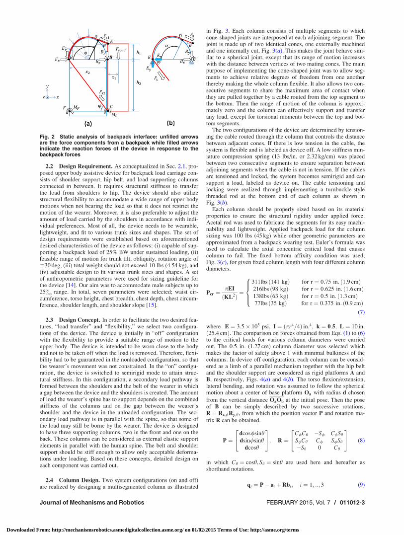
place and there is generally a certain threshold of load that thebelt can support. If the load assistive device is placed in betweenthe backpack and the body as shown in Fig. 1(c), the upper bodycan be fully relieved from stress as all the vertical force compo-nents from a backpack can be transferred to the hip. Severalassumptions were made to simplify the model: (i) backpack doesnot have a relative motion with respect to the device and is rigidlyfixed at point B, Fig. 2(a), (ii) shoulder support does not deform,(iii) planar model: backpack load is evenly distributed on bothshoulders via straps hence off-plane forces are negligible, and (iv)backpack is considered as a lumped mass at a vertical distancedh1 from the pelvis and horizontal distance x1 from the back. Theaim of proposed static modeling was to calculate three force com-ponents acting on the two load bearing elements that are analo-gous to the free-fix column undergoing both axial and lateralforces. Four points are of particular interest in this model. Thoseare B, C, E, and F, the four end points of two columns. The forceequilibrium about point B gives
Bx ¼Floadx1
coshh1 � sin/h2
ðcoshþ cos/Þ (1)
By ¼ Fload �Floadx1
coshh1 � sin/h2
ðsinhþ sin/Þ (2)
and the force equilibrium about point E gives
Ex ¼Floadx1
coshh1 � sin/h2
ðsin/þ coshÞ (3)
Ex ¼Floadx1
coshh1 � sin/h2
ðcos/þ sinhÞ (4)
also,
XMz;C : �Fload
x1ðcoshþ cos/Þh2
ðcoshh1 � cos/h2Þþ x1 ¼ 0 (5)
XMz;F : �Fload
x1ðsin/þ coshÞh2
ðcoshh1 � cos/h2Þþ x1 þ x2 ¼ 0 (6)
Above expressions of forces are functions of geometry andapplied load which will help in determining the appropriate sizingand material selection for the columns in design phase.
Fig. 1 Static modeling of backpack loading: unfilled arrows indicate the forces between thebackpack and human interface, filled arrows indicate the resultant force acting on the body,and c.m denotes the center of mass of human torso; (a) general backpack loading inducesvertical load and the moment about trunk, (b) backpack with a hip belt, and (c) backpackworn with load bearing device
011012-2 / Vol. 7, FEBRUARY 2015 Transactions of the ASME
Downloaded From: http://mechanismsrobotics.asmedigitalcollection.asme.org/ on 01/02/2015 Terms of Use: http://asme.org/terms
2.2 Design Requirement. As conceptualized in Sec. 2.1, pro-posed upper body assistive device for backpack load carriage con-sists of shoulder support, hip belt, and load supporting columnsconnected in between. It requires structural stiffness to transferthe load from shoulders to hip. The device should also utilizestructural flexibility to accommodate a wide range of upper bodymotions when not bearing the load so that it does not restrict themotion of the wearer. Moreover, it is also preferable to adjust theamount of load carried by the shoulders in accordance with indi-vidual preferences. Most of all, the device needs to be wearable,lightweight, and fit to various trunk sizes and shapes. The set ofdesign requirements were established based on aforementioneddesired characteristics of the device as follows: (i) capable of sup-porting a backpack load of 25% BW under sustained loading, (ii)feasible range of motion for trunk tilt, obliquity, rotation angle of630 deg, (iii) total weight should not exceed 10 lbs (4.54 kg), and(iv) adjustable design to fit various trunk sizes and shapes. A setof anthropometric parameters were used for sizing guideline forthe device [14]. Our aim was to accommodate male subjects up to25& range. In total, seven parameters were selected; waist cir-cumference, torso height, chest breadth, chest depth, chest circum-ference, shoulder length, and shoulder slope [15].
2.3 Design Concept. In order to facilitate the two desired fea-tures, “load transfer” and “flexibility,” we select two configura-tions of the device. The device is initially in “off” configurationwith the flexibility to provide a suitable range of motion to theupper body. The device is intended to be worn close to the bodyand not to be taken off when the load is removed. Therefore, flexi-bility had to be guaranteed in the nonloaded configuration, so thatthe wearer’s movement was not constrained. In the “on” configu-ration, the device is switched to semirigid mode to attain struc-tural stiffness. In this configuration, a secondary load pathway isformed between the shoulders and the belt of the wearer in whicha gap between the device and the shoulders is created. The amountof load the wearer’s spine has to support depends on the combinedstiffness of the columns and on the gap between the wearer’sshoulder and the device in the unloaded configuration. The sec-ondary load pathway is in parallel with the spine, so that some ofthe load may still be borne by the wearer. The device is designedto have three supporting columns, two in the front and one on theback. These columns can be considered as external elastic supportelements in parallel with the human spine. The belt and shouldersupport should be stiff enough to allow only acceptable deforma-tions under loading. Based on these concepts, detailed design oneach component was carried out.
2.4 Column Design. Two system configurations (on and off)are realized by designing a multisegmented column as illustrated
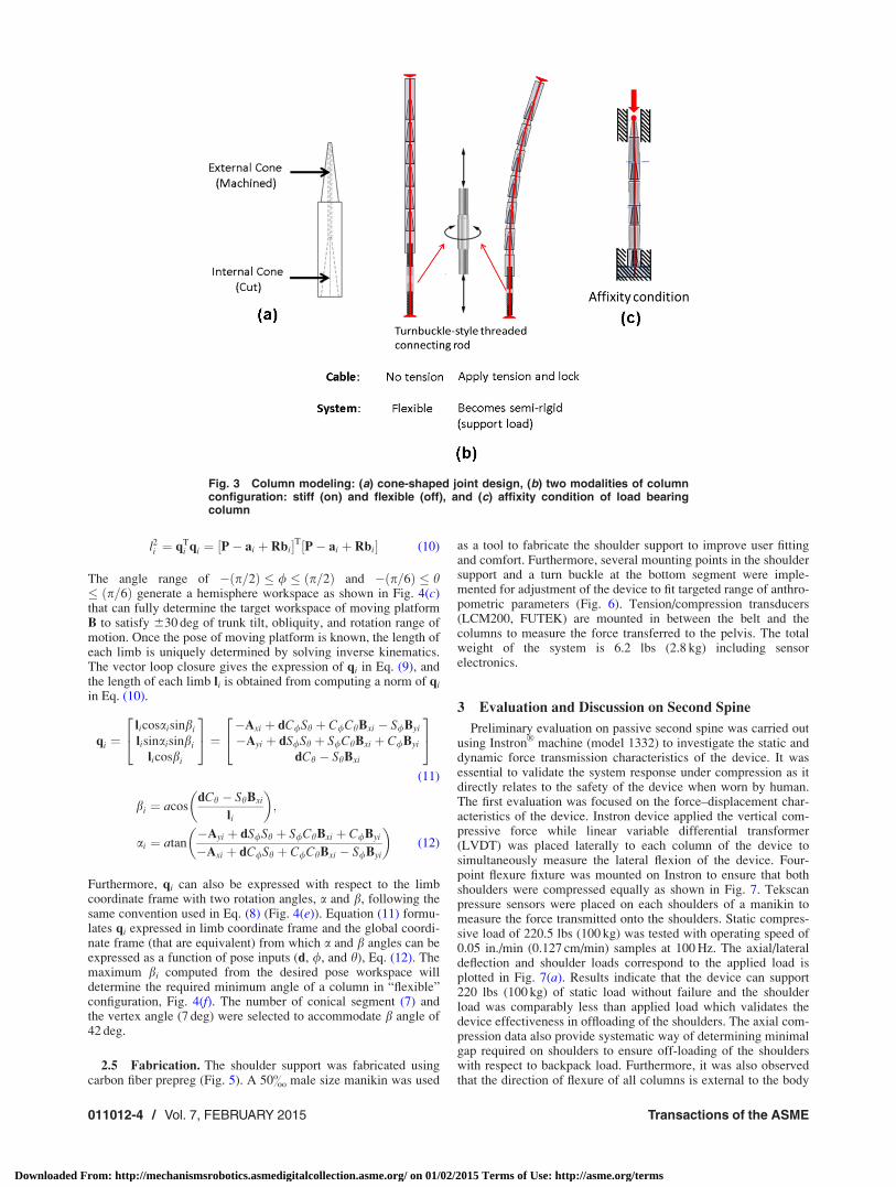
in Fig. 3. Each column consists of multiple segments to whichcone-shaped joints are interposed at each adjoining segment. Thejoint is made up of two identical cones, one externally machinedand one internally cut, Fig. 3(a). This makes the joint behave sim-ilar to a spherical joint, except that its range of motion increaseswith the distance between vertices of two mating cones. The mainpurpose of implementing the cone-shaped joint was to allow seg-ments to achieve relative degrees of freedom from one anotherthereby making the whole column flexible. It also allows two con-secutive segments to share the maximum area of contact whenthey are pulled together by a cable routed from the top segment tothe bottom. Then the range of motion of the column is approxi-mately zero and the column can effectively support and transferany load, except for torsional moments between the top and bot-tom segments.
The two configurations of the device are determined by tension-ing the cable routed through the column that controls the distancebetween adjacent cones. If there is low tension in the cable, thesystem is flexible and is labeled as device off. A low stiffness min-iature compression spring (13 lbs/in. or 2.32 kg/cm) was placedbetween two consecutive segments to ensure separation betweenadjoining segments when the cable is not in tension. If the cablesare tensioned and locked, the system becomes semirigid and cansupport a load, labeled as device on. The cable tensioning andlocking were realized through implementing a turnbuckle-stylethreaded rod at the bottom end of each column as shown inFig. 3(b).
Each column should be properly sized based on its materialproperties to ensure the structural rigidity under applied force.Acetal rod was used to fabricate the segments for its easy machi-nability and lightweight. Applied backpack load for the columnsizing was 100 lbs (45 kg) while other geometric parameters areapproximated from a backpack wearing test. Euler’s formula wasused to calculate the axial concentric critical load that causescolumn to fail. The fixed bottom affixity condition was used,Fig. 3(c), for given fixed column length with four different columndiameters.
Pcr ¼pEI
ðKL2Þ¼
311lbs ð141 kgÞ for r ¼ 0:75 in: ð1:9 cmÞ216lbs ð98 kgÞ for r ¼ 0:625 in: ð1:6 cmÞ138lbs ð63 kgÞ for r ¼ 0:5 in: ð1:3 cmÞ77lbs ð35 kgÞ for r ¼ 0:375 in: ð0:9 cmÞ
8>><>>:
(7)
where E ¼ 3:5� 105 psi; I ¼ pr4=4ð Þ in:4; k ¼ 0:5; L ¼ 10 in:ð25:4 cmÞ. The comparison on forces obtained from Eqs. (1) to (6)to the critical loads for various column diameters were carriedout. The 0.5 in. (1.27 cm) column diameter was selected whichmakes the factor of safety above 1 with minimal bulkiness of thecolumns. In device off configuration, each column can be consid-ered as a limb of a parallel mechanism together with the hip beltand the shoulder support are considered as rigid platforms A andB, respectively, Figs. 4(a) and 4(b). The torso flexion/extension,lateral bending, and rotation was assumed to follow the sphericalmotion about a center of base platform Oa with radius d chosen
from the vertical distance OaOb at the initial pose. Then the poseof B can be simply described by two successive rotations,R ¼ Rz;/Ry;h, from which the position vector P and rotation ma-
trix R can be obtained.
P ¼dcos/sinhdsin/sinh
dcosh
24
35; R ¼
C/Ch �S/ C/Sh
S/Ch C/ S/Sh
�Sh 0 Ch
24
35 (8)
in which Ch ¼ cosh; Sh ¼ sinh are used here and hereafter asshorthand notations.
qi ¼ P� ai þ Rbi; i ¼ 1; ::; 3 (9)
Fig. 2 Static analysis of backpack interface: unfilled arrowsare the force components from a backpack while filled arrowsindicate the reaction forces of the device in response to thebackpack forces
Journal of Mechanisms and Robotics FEBRUARY 2015, Vol. 7 / 011012-3
Downloaded From: http://mechanismsrobotics.asmedigitalcollection.asme.org/ on 01/02/2015 Terms of Use: http://asme.org/terms
l2i ¼ qTi qi ¼ ½P� ai þ Rbi�T½P� ai þ Rbi� (10)
The angle range of � p=2ð Þ � / � p=2ð Þ and � p=6ð Þ � h� p=6ð Þ generate a hemisphere workspace as shown in Fig. 4(c)that can fully determine the target workspace of moving platformB to satisfy 630 deg of trunk tilt, obliquity, and rotation range ofmotion. Once the pose of moving platform is known, the length ofeach limb is uniquely determined by solving inverse kinematics.The vector loop closure gives the expression of qi in Eq. (9), andthe length of each limb li is obtained from computing a norm of qi
in Eq. (10).
qi ¼licosaisinbi
lisinaisinbi
licosbi
24
35 ¼ �Axi þ dC/Sh þ C/ChBxi � S/Byi
�Ayi þ dS/Sh þ S/ChBxi þ C/Byi
dCh � ShBxi
24
35
(11)
bi ¼ acosdCh � ShBxi
li
� �;
ai ¼ atan�Ayi þ dS/Sh þ S/ChBxi þ C/Byi
�Axi þ dC/Sh þ C/ChBxi � S/Byi
� �(12)
Furthermore, qi can also be expressed with respect to the limbcoordinate frame with two rotation angles, a and b, following thesame convention used in Eq. (8) (Fig. 4(e)). Equation (11) formu-lates qi expressed in limb coordinate frame and the global coordi-nate frame (that are equivalent) from which a and b angles can beexpressed as a function of pose inputs (d, /, and h), Eq. (12). Themaximum bi computed from the desired pose workspace willdetermine the required minimum angle of a column in “flexible”configuration, Fig. 4(f). The number of conical segment (7) andthe vertex angle (7 deg) were selected to accommodate b angle of42 deg.
2.5 Fabrication. The shoulder support was fabricated usingcarbon fiber prepreg (Fig. 5). A 50& male size manikin was used
as a tool to fabricate the shoulder support to improve user fittingand comfort. Furthermore, several mounting points in the shouldersupport and a turn buckle at the bottom segment were imple-mented for adjustment of the device to fit targeted range of anthro-pometric parameters (Fig. 6). Tension/compression transducers(LCM200, FUTEK) are mounted in between the belt and thecolumns to measure the force transferred to the pelvis. The totalweight of the system is 6.2 lbs (2.8 kg) including sensorelectronics.
3 Evaluation and Discussion on Second Spine
Preliminary evaluation on passive second spine was carried outusing Instron
VR
machine (model 1332) to investigate the static anddynamic force transmission characteristics of the device. It wasessential to validate the system response under compression as itdirectly relates to the safety of the device when worn by human.The first evaluation was focused on the force–displacement char-acteristics of the device. Instron device applied the vertical com-pressive force while linear variable differential transformer(LVDT) was placed laterally to each column of the device tosimultaneously measure the lateral flexion of the device. Four-point flexure fixture was mounted on Instron to ensure that bothshoulders were compressed equally as shown in Fig. 7. Tekscanpressure sensors were placed on each shoulders of a manikin tomeasure the force transmitted onto the shoulders. Static compres-sive load of 220.5 lbs (100 kg) was tested with operating speed of0.05 in./min (0.127 cm/min) samples at 100 Hz. The axial/lateraldeflection and shoulder loads correspond to the applied load isplotted in Fig. 7(a). Results indicate that the device can support220 lbs (100 kg) of static load without failure and the shoulderload was comparably less than applied load which validates thedevice effectiveness in offloading of the shoulders. The axial com-pression data also provide systematic way of determining minimalgap required on shoulders to ensure off-loading of the shoulderswith respect to backpack load. Furthermore, it was also observedthat the direction of flexure of all columns is external to the body
Fig. 3 Column modeling: (a) cone-shaped joint design, (b) two modalities of columnconfiguration: stiff (on) and flexible (off), and (c) affixity condition of load bearingcolumn
011012-4 / Vol. 7, FEBRUARY 2015 Transactions of the ASME
Downloaded From: http://mechanismsrobotics.asmedigitalcollection.asme.org/ on 01/02/2015 Terms of Use: http://asme.org/terms

so that the device will not yield undesirable pressure exerted onhuman body during compression. Cyclic compressive load wasalso successfully tested on the device with 130 lbs (59 kg) com-pression applied at 1 Hz frequency.
The next evaluation was focused on system response duringdynamic loading condition by simulating the base excitation simi-lar to human walking through Instron machine. Two backpackloading conditions, 25 lbs (11.3 kg) and 50 lbs (22.7 kg), three
Fig. 4 Mobility analysis in off configuration: (a) imposing parallel mechanism concept, (b)base platform A (hip belt) and moving platform B (shoulder support) geometry wherein OA
and OB are the center of A and B, respectively, (c) desired workspace of B constructed fromplatform center (OB) range of motion, (d) conceptualizing 3D spherical motion about OA withradius d, (e) expressing vector qi in limb coordinate frame, and (f) cone-shaped segmentcharacterization based on column bending angle b
Fig. 5 Fabrication process of carbon fiber shoulder support
Journal of Mechanisms and Robotics FEBRUARY 2015, Vol. 7 / 011012-5
Downloaded From: http://mechanismsrobotics.asmedigitalcollection.asme.org/ on 01/02/2015 Terms of Use: http://asme.org/terms

base-excitation frequencies, 1, 2, and 3 Hz, and three base excita-tion amplitudes, 0.4 in. (1 cm), 0.6 in. (1.5 cm), and 0.78 in.(2 cm) were tested that closely replicating pelvic vertical motionduring human walking [16]. Three tension/compression load cellsmounted to each column measured the force transmission betweenthe shoulder support and hip belt. Load cell data were sampled ata frequency of 1 kHz, postprocessed with low-pass filter (fourthorder Butterworth, cut off frequency¼ 10 Hz), averaged overcycle, Fig. 7(b). From static test, the transferred load was approxi-mately 50% of applied load. Base excitation indeed induced theinertia force transmitted to the belt where the peak force wasincreased with increasing frequency and/or mass.
The range of motion study was also performed to evaluate theeffects of the device on the range of motion of the torso. It wasseen that approximately 70% of natural range of motion of torsowas still achieved in device off mode, reaching more than 30 deg
of trunk tilt, oblique and rotation degrees of freedom (Fig. 8).These experimental results suggest that both design goals of sec-ond spine, i.e., load transfer and motion capability, have been suc-cessfully accomplished through utilizing modular load bearingcolumns with two system modalities.
The human subject study on second spine was conducted [17],and only the key results will be discussed here as it is not the mainscope of this study. From human trials, the second spine wasshown to alleviate pressure on shoulders significantly and alsoreduce trunk inclination during loaded walking. These effects arebeneficial for load carriage and can potentially help in mitigatingshoulder discomfort, rucksack palsy [10], foot strain [1], andlower back injuries [18]. In addition, increased muscular activityof quadriceps and triceps surae was observed which indicates ahigher dynamic load transferred to the lower extremities [13].These results are in line with the previous works showing twomajor body adaptations in kinematics and muscle kinetics as aresult of walking while carrying backpack loads: larger flexionangle of the trunks and higher muscle activations on the lowerextremities [1,19]. We also observed increased hip extension andknee flexion during weight acceptance, showing adaptations in thebody in order to absorb higher impact forces and shock duringheel strike [12,20]. These results suggest that the second spineprovides a secondary pathway to rigidly transfer load fromshoulders to the pelvis, bypassing the spinal column. It helps off-load the upper body and relieve stress. However, dynamic forcesare no longer attenuated by natural damping of the vertebralcolumn thus higher impact forces are transferred to the lowerextremities. Therefore, it was a logical step for us to consider thenext version of the second spine which incorporates the activecomponents to modulate the backpack load exerted on human.Hence, we introduce motorized second spine in Sec. 4.1 and pro-pose the concept of Backpack inertia compensation during humanload carriage.
Fig. 6 Second spine with adjustable design to fit between 25and 75 male
Fig. 7 Evaluation on second spine: (a) load versus lateral/axial deflection and shoulderload, (b) sum of transmitted force from shoulders to pelvis through second spine averagedover cycle for two loading conditions with three excitation frequencies at 0.8 in. (2 cm)amplitude, and (c) experimental apparatus
011012-6 / Vol. 7, FEBRUARY 2015 Transactions of the ASME
Downloaded From: http://mechanismsrobotics.asmedigitalcollection.asme.org/ on 01/02/2015 Terms of Use: http://asme.org/terms

4 Motorized Second Spine
Human walking induces periodic vertical acceleration of theupper body. Over ground walking induces vertical accelerationson the head, thorax, and pelvis [16]. These accelerations can bemodeled as periodic functions with roughly twice the frequencyof human gait. If a mass is rigidly attached to the upper body dur-ing walking, it undergoes the same acceleration which adds inertiaforces to the body. Then the body essentially requires more energyto compensate for the static and the dynamic loads induced bymass. Moreover, higher muscle force is required during weight ac-ceptance and pushes off in order to compensate for the largerimpact forces. Furthermore, the vertical displacement of the pelviscan increase with higher maneuver such as running or jumping. Insuch cases, the larger displacement over the same time period willresult in increase in the peak accelerations, consequently generat-ing higher peak inertia forces induced from a backpack. Sections4.1 to 4.3 focus on how such inertia forces of a backpack duringhuman walking can be compensated by implementing an activeload modulation through a second spine.
4.1 Theoretical Study. A backpack worn by human duringwalking can be modeled as a mass undergoing harmonic excita-tion of the base. Let y(t) and x(t) denote, respectively, the verticaldisplacements of the pelvis and the backpack. Backpack sup-ported by a second spine can be modeled as a rigid connectionbetween the mass and the pelvis, as depicted in Fig. 9(a). In thiscase, backpack has no relative motion with respect to the pelvis,y(t)¼ x(t). Consider a simple harmonic motion of the base,y(t)¼Y sin xy(t). For the moving base of mass m, the force trans-mitted to the pelvis R is the sum of gravitational force and theinertia force.2
R ¼ mðgþ €xÞ (13)
If an active component is imposed between the base and the mass,it can generate a motion to the mass relative to the base denotedas z(t) which can be expressed as another sinusoidal function withcontrollable amplitude, frequency and phase as follows:
zðtÞ ¼ Z sin ðxztþ /Þ (14)
Then, x(t) can be rewritten as
xðtÞ ¼ yðtÞ þ zðtÞ ¼ Y sin ðxytÞ þ Z sin ðxztþ /Þ (15)
which is the sum of two harmonic waves. In general, this willresult in one of three interferences (i.e., constructive, destructive,or beat) based on the relative frequency, amplitude, and phase oftwo waves [21]. Two conditions should be satisfied in order tohave destructive interference while avoiding beat phenomena: (i)the difference between the frequency of two waves must be assmall as possible (i.e., xy�xz), ii) two waves must be antiphase(i.e., / ¼ p). By setting xy¼xz¼x and the use of trigonometricidentities, x(t) can be expressed in sinusoid form
xðtÞ ¼ X sin ðxtþ UÞ (16)
in which
X ¼ffiffiffiffiffiffiffiffiffiffiffiffiffiffiffiffiffiffiffiffiffiffiffiffiffiffiffiffiffiffiffiffiffiffiffiffiffiffiffiffiffiY2 þ Z2 þ 2YZ cos /
p(17)
U ¼ tan�1 Z sin /Y þ Z cos /
(18)
where the amplitude X and the phase U are explicitly determinedby the active component modulation. Thus transmitted force inEq. (13) becomes
R ¼ m½gþ x2Xsinðxtþ UÞ� (19)
or
RðtÞ ¼ m½gþ x2xðtÞ� (20)
Hence, the amplitude of transmitted force mx2X increases propor-tionally to X when the mass m and base excitation parameters Y,x are considered as constant inputs. Therefore, destructive inter-ference will be desired to reduce the amplitude of resulting wave’samplitude. From Eq. (17), X is found as a function of Y, Z, and U.Hence, minimizing X becomes the optimization problem wherethe maximum value of the force transmitted to the pelvis can bereduced by appropriate selection of Z and U.
minðXÞ ¼ minðffiffiffiffiffiffiffiffiffiffiffiffiffiffiffiffiffiffiffiffiffiffiffiffiffiffiffiffiffiffiffiffiffiffiffiffiffiffiffiffiffiY2 þ Z2 þ 2YZ cos /
pÞ (21)
Fig. 8 Trunk rotational range in sagittal, coronal, and trans-verse planes, represented as “tilt,” “obliquity,” and “rotation,”respectively, without backpack. Trunk angles are relative to theglobal frame.
Fig. 9 Schematics of mass undergoing base excitation: (a)mass rigidly connected to the moving base and (b) active com-ponent modulating relative motion of the mass with respect tothe base
2Peak pelvic vertical acceleration is approximately 62 m/s2 for normal walking[16].
Journal of Mechanisms and Robotics FEBRUARY 2015, Vol. 7 / 011012-7
Downloaded From: http://mechanismsrobotics.asmedigitalcollection.asme.org/ on 01/02/2015 Terms of Use: http://asme.org/terms

It should be noted that X� 0 from Eq. (17) as X has to be a realconstant. Equation (21) can be rewritten after dividing both sidesby Y as
X
Y¼
ffiffiffiffiffiffiffiffiffiffiffiffiffiffiffiffiffiffiffiffiffiffiffiffiffiffiffiffiffiffiffiffiffiffiffiffiffiffiffiffiffiffiffiffiffiffi1þ Z
Y
� �2
þ2Z
Y
� �cosU
s(22)
By defining displacement transmissibility Td¼X/Y and amplituderatio Ra¼ Z/Y, the cost function is expressed as
minðTdÞ where Td ¼ffiffiffiffiffiffiffiffiffiffiffiffiffiffiffiffiffiffiffiffiffiffiffiffiffiffiffiffiffiffiffiffiffiffiffiffiffiffi1þ R2
a þ 2RacosUq
(23)
Also note that Td and Ra are both non-negative real values. It isapparent that U that minimizes the last term on the right hand sideis p for 0�U� 2p. Hence, Td can be simplified as
Td ¼ffiffiffiffiffiffiffiffiffiffiffiffiffiffiffiffiffiffiffiffiffiffiffiffiffiffiffiffiffiffiffiffiffiffiffiffiffiffi1þ R2
a þ 2RacosUq
¼ Ra � 1 (24)
From Eqs. (23) to (24), Ra and U that minimize Td are 1 and p,respectively, giving Td¼ 0. From this result, Ra ¼ 1 gives Z¼ Ywhich indicates the amplitude of the relative motion has to beequivalent to that of base excitation with phase angle of p. Thiswould make Td¼ 0 indicating the motion of mass becomesstationary in response to the amplitude and frequency of the baseexcitation. The transmitted force can be rewritten as
R ¼ m gþ
ffiffiffiffiffiffiffiffiffiffiffiffiffiffiffiffiffiffiffiffiffiffiffiffiffiffiffiffiffiffiffiffiffiffiffiffiffiffiffiffiffiffiffiffiffiffi1þ Z
Y
� �2
þ2Z
Y
� �cosU
s0@
1Asinðxtþ UÞ
0@
1A (25)
Figure 10 shows variation of force transmissibility with varyingamplitude ratio. It clearly shows the force transmitted to the pelviscan be less than the rigid connection (i.e., FT < 1, below dashedline) by properly modulating amplitude and phase of active com-ponent. It also evidently shows that force transmission is minimafor [Z, U]¼ [Y, p] at which R becomes zero. The design criterionis determined from this simulation results to modulate the phaseand the amplitude ratio that lies in the region (A) for given m, Y,and x.
4.2 Implementation
4.2.1 Hardware Configuration. Once motorized second spinewas conceptualized through modeling, simulation and instru-mented testing, designing an actuator for the active component
Fig. 10 Simulation results of force transmissibility of motor-ized second spine with amplitude ratio for different phasevalues
Fig. 11 CAD drawings and physical models: (a) actuator units and (b) motorized secondspine
011012-8 / Vol. 7, FEBRUARY 2015 Transactions of the ASME
Downloaded From: http://mechanismsrobotics.asmedigitalcollection.asme.org/ on 01/02/2015 Terms of Use: http://asme.org/terms

was followed. Spindle drive (type of ball-screw) mounted to a DCmotor was selected for linear actuation mechanism from whichthe maximum torque and speed requirements of a motor can bedetermined given the system inputs: mass m (100 lbs, 45 kg), fre-quency x (6.28 rad, 2 Hz), and the amplitude Y (1.57 in., 4 cm).The length of spindle lead was selected to be 2 in. (5 cm) toaccommodate the total pelvic vertical displacement with respectto the ground [16]. First, the peak force required by each actuatorwas calculated by dividing the peak transmitted force (531 N)obtained from Eq. (13) by the number of actuators (3). Second,required torque of spindle Ms and that of motor Mm were calcu-lated using Eqs. (26) and (27), respectively.
Ms mNmð Þ ¼ Fs � p
2� p� fs
¼ 177� 0:5
2� p� 0:8¼ 17:62 mNm (26)
where Fs is the feed load (N), p is the thread lead (mm), and fs isthe efficiency of the spindle.
Mm mNmð Þ ¼ Fs � p
2� p� i� fm
¼ 17:62
3:8� 0:8¼ 5:80 mNm (27)
where i is the gearhead reduction ratio and fm is the efficiency ofthe complete spindle drive.
Based on these criteria, the motor (RE-max 24, Maxon) andspindle drive (GP 22, Maxon) were selected. Figure 11 shows thedescription of motor unit and the hardware. The motor togetherwith spindle drive runs the flange nut up and down to which theload-bearing column is connected. The cable tensioning/lockingmechanism on each load bearing column is on top of the flangenut so that the two column configurations (rigid/flexible) can stillbe achieved independently from the motor actuation. Tension/compression load cell was placed in between the flange nut andthe column, measuring the force transmitted from the shouldersupport to the hip belt.
The electronics of the system consists of three motor units,three load cells, one accelerometer, one inertia measurement unit(IMU), one controller board, and a power supply as illustrated inFig. 12. Each motor is connected to and powered by a servocon-troller that receives signals from encoders attached to the motor.Servocontroller is used for driving the motor and relaying signalsfrom encoders to the controller board. The load cell signal firstgoes through the amplifier and is received by the controller board.
A tri-axis accelerometer is mounted on the belt, measuring verti-cal acceleration. The controller board (National InstrumentsbRIO-9636) receives all the analog and digital signals from thesensors, applying control algorithms and outputs the commandaccordingly to the motor. Sensor data are stored on the controllerboard for postanalysis. Control algorithms are developed inLABVIEW
VR
and deployed on controller. An AC–DC power supply isused to power the controller board and servocontrollers while allother electronics are powered from the controller board.
4.2.2 Control Algorithm. The controller for the motorizedsecond spine incorporates sensor data from the accelerometerplaced on the pelvic belt and IMU placed at the chest. Figure 13shows the schematic of the controller. The controller has twofunctions: posture adaptation of the upper body and inertia com-pensation of a backpack during walking. The dynamic load com-pensation is achieved by actively changing the relativedisplacement of backpack with respect to pelvis in response tohuman motion. When the wearer performs dynamic motionlikewalking, the controller will move the backpack in the reversedirection of the human movement, thereby keeping the backpackstationary in the inertial frame and reduce the force caused by theacceleration and deceleration of the backpack. The accelerometerplaced at the belt measures the vertical acceleration when thewearer’s body is in motion. This measured acceleration is thenintegrated twice to obtain the vertical displacement. A Bessel highpass filter with a cut off frequency of 0.75 Hz is applied to discard
Fig. 12 Illustration of the system hardware configuration
Fig. 13 Illustration of control algorithm with two controlmodalities: inertia compensation and posture adaptation
Journal of Mechanisms and Robotics FEBRUARY 2015, Vol. 7 / 011012-9
Downloaded From: http://mechanismsrobotics.asmedigitalcollection.asme.org/ on 01/02/2015 Terms of Use: http://asme.org/terms

the low frequency vertical displacement. The purpose of this highpass filter is to make sure the motors move around the initial posi-tion and avoid saturation over time. The filtered signal is thennegated to be used as a motor desired output displacement forinertia compensation. The posture adaptation is implemented inaddition to inertia compensation scheme, realized by adjusting theorientation of the shoulder support according to the wearer’supper body motion. IMU (VectorNav-100) is placed on the chestto detect the trunk oblique and tilt angles. The controller then cal-culates the adjustment needed from three motors to make shouldersupport follow the similar posture as the trunk. The average heightof the columns is kept constant during this process.
The controller is designed to combine the desired motions ofeach motor computed from aforementioned two functions andtransfers it to proportional-integral-derivative (PID) controller.PID controller outputs the commands to the plant from where themotors are actuated to follow the desired motions. The PID gainsfor each motor were tuned empirically during the instrumentedtest-bed testing (described in Section 4.3) to best follow the peri-odic inputs of pelvic vertical motion that replicates humanwalking.
4.3 Evaluation. The experimental evaluation of the inertiacompensation of the motorized second spine was carried outthrough simulated test-bed using Instron. LVDT were mounted onInstron frame that simultaneously measure the vertical displace-ment of the base and the mass relative to inertial frame (Fig. 14).The device was directly mounted on the base without using amanikin. Also, 10 lbs (4.5 kg) mass was fixed on top of the
shoulder support instead of applying through a backpack. Theseparticular settings were to prevent any unmodeled disturbances,such as friction between the device and the manikin or load offsettoward the back from the use of a backpack. Experiment was per-formed with 2p frequency and 10 lbs (4.5 kg) mass for three dif-ferent conditions: motor off (z(t)¼ 0), motor on with antiphase(U¼p), motor on with in-phase (U¼ 0). Figure 14 also plots thevertical displacement of the base and the mass with respect to theinertial frame and force transmitted to the hip belt. Results in bothplots are in good agreement with those obtained from simulations.From this result, it can be shown that our concept of compensatingbackpack motion is valid, suggesting that the backpack motioncan be nearly inertially fixed by active modulation of motorizedsecond spine at which the dynamic force transferred to pelvis isminimized.
5 Conclusion
This work presented two versions of upper body assistive de-vice for human load carriage, second spine and motorized secondspine. The formal provides a secondary load pathway in parallelto the human spine and maintains a range of torso motion whilethe latter offers inertia compensation of backpack during loadedwalking. First, the second spine was designed to reduce the inci-dence of sores and injuries related to load carrying while allowingthe necessary upper body motion. The device utilizes two systemconfigurations, device off and on, to offer the following function-alities: transferring load from the shoulders to the pelvis and pro-viding flexibility to accommodate upper body motions. This was
Fig. 14 Evaluation on motorized second spine: (a) experiment setup, (b) verticaldisplacement of belt and shoulder support for three different conditions, and (c) left: forcetransmitted to the belt over time, and right: transmitted force averaged over cycle
011012-10 / Vol. 7, FEBRUARY 2015 Transactions of the ASME
Downloaded From: http://mechanismsrobotics.asmedigitalcollection.asme.org/ on 01/02/2015 Terms of Use: http://asme.org/terms

accomplished by designing multisegment load bearing columnswhich consist of links with cone-shaped ends that mate with eachother using springs. A cable is routed through these segments tomodulate columns’ structural compliance. Additional efforts onadjustable and conformal design of the device were made in orderto provide larger envelope to users with various physical parame-ters. The experimental validation of the device was carried outusing Instron machine to test the functionality and performance ofthe device.
Previous studies on biomechanical effects of second spine onloaded walking showed that it significantly alleviates the pressurefrom shoulders and reduces trunk tilt inclination to be able towalk in more upright posture. However, dynamic load exerted onthe lower limbs was increased which was also reflected fromhigher hip flexion and knee extension angle during weight accep-tance as well as higher muscle activations in the lower limbmuscles. These findings indicated that with the device the loadswere successfully transferred from shoulders to waist bypassingthe vertebral column. The device was also shown to exhibit versa-tility when it is in off configuration by providing more than 70%of wearer’s maximum range of upper body motion.
The next version of second spine was modeled based on thefindings from passive design. It demonstrated the inertia forcecompensation concept in human load carriage using a motorizedsecond spine. It senses the vertical acceleration of pelvis and con-trols the backpack motion such that it can be stationary withrespect to inertial frame thereby reduce inertia forces. It was real-ized by incorporating sensors, motors, and controllers to the sec-ond spine. Theoretical models of loaded walking with and withoutthe second spine were developed and simulation studies were per-formed to find the optimal motor actuation in response to thehuman walking. Based on motion and power requirements ofactuators in human loaded walking, mechanical and electricalhardware were selected and implemented to the device. The con-trol law for the two modalities of the device are introduced, oneusing IMU for posture adaptation and the other using accelerome-ter for inertia compensation. Finally, motorized second spine wasevaluated through instrumented test-bed using Instron. Resultsshowed that the motion of a backpack can be made nearly inertialfrom which, as a result, the inertia force induced during walkingcan be minimized.
Overall, the device can be used to mitigate potential risks ofmusculoskeletal injuries on the upper body caused by carrying aheavy backpack. Wearing the device can be advantageous interms of decreasing axial compression of the upper body, protect-ing shoulder joints by reducing localized pressure on the should-ers, reducing some of the muscle activation responsible forsupporting the load. Moreover, motorized second spine can offerinertia compensation during loaded walking which may bringmore benefits to the wearer. Another advantage of this deviceover traditional frame backpacks is that it can support loads thatare not carried in backpacks, such as protective or equipmentvests, in addition to backpack loads. In future studies, biomechan-ical and physiological effects of motorized second spine duringactual human load carriage will be investigated and implementa-tion of other control algorithms to study their impact on humanperformance and to further improve the robustness and perform-ance of the device.
Acknowledgment
We gratefully acknowledge our Warrior Web team in ROARlab at Columbia University and our collaborators in Center ofComposite Material (CCM) at University of Delaware. This workwas supported by Defense Advanced Research Projects Agency(DARPA) through Warrior Web Project (W911QX-12-C-0042).
References[1] Knapik, J., Harman, E., and Reynolds, K., 1996, “Load Carriage Using Packs:
A Review of Physiological, Biomechanical and Medical Aspects,” Appl.Ergon., 27(3), pp. 207–216.
[2] Reynolds, K., Kaszuba, J., Mello, R., and Patton, J., 1990, “Prolonged Tread-mill Load Carriage: Acute Injuries and Changes in Foot Anthropometry,” U.S.Army Research Institute of Environmental Medicine, Natick, MA, TechnicalReport No. T1-91.
[3] Quesada, P., Mengelkoch, L., Hale, R., and Simon, S., 2000, “Biomechanicaland Metabolic Effects of Varying Backpack Loading on Simulated Marching,”Ergonomics, 43(3), pp. 293–309.
[4] Hong, Y., Li, J., and Fong, D., 2008, “Effect of Prolonged Walking With Back-pack Loads on Trunk Muscle Activity and Fatigue in Children,” J. Electro-myogr. Kinesiol., 18(6), pp. 990–996.
[5] Abe, D., Muraki, S., and Yasukouch, A., 2008, “Ergonomic Effects of Load Car-riage on Energy Cost of Gradient Walking,” Appl. Ergon., 39(2), pp. 144–149.
[6] Attwells, R., Birrell, S., Hooper, R., and Mansfield, N., 2006, “Influence of Car-rying Heavy Loads on Soldier’s Posture, Movements and Gait,” Ergonomics,49(14), pp. 1527–1537.
[7] Trevelyan, F., and Legg, S., 2006, “Back Pain in School Children Where toFrom Here?,” Appl. Ergon., 37(1), pp. 45–54.
[8] Harman, E., Hoon, K., Frykman, P., and Pandorf, C., 2000, “The Effects of Back-pack Weight on the Biomechanics of Load Carriage,” U.S. Army Research Insti-tute of Environmental Medicine, Natick, MA, Technical Report No. T00-17.
[9] Al-Khabbaz, Y., Shimada, T., and Hasegawa, M., 2008, “The Effect ofBackpack Heaviness on Trunk-Lower Extremity Muscle Activities and TrunkPosture,” Gait Posture, 28(2), pp. 297–302.
[10] Han, K., Harman, E., Frykman, P., Johnson, M., Russell, F., and Rosenstein,M., 1992, “Load Carriage: The Effects of Walking Speed on Gait Timing,Kinetics, and Muscle Activity: 773,” Med. Sci. Sports Exercise, 24(5), p. S126.
[11] Devroey, C., Jonkers, I., de Becker, A., Lenaerts, G., and Spaepen, A., 2007,“Evaluation of the Effect of Backpack Load and Position During Standing andWalking Using Biomechanical, Physiological and Subjective Measures,” Ergo-nomics, 50(5), pp. 728–742.
[12] Ghori, G., and Luckwill, R., 1985, “Responses of the Lower Limb to Load Carryingin Walking Man,” Eur. J. Appl. Physiol. Occup. Physiol., 54(2), pp. 145–150.
[13] Holewijn, M., 1990, “Physiological Strain Due to Load Carrying,” Eur. J. Appl.Physiol. Occup. Physiol., 61(3), pp. 237–245.
[14] Gordon, C. C., Churchill, T., Clauser, C. E., Bradtmiller, B., McConville, J. T.,Tebbetts, I., and Walker, R. A., 1989, “1988 Anthropometric Survey of U.S.Army Personnel: Summary Statistics Interim Report,” U.S. Army Research,Development and Engineering Center, Natick, MA, Technical Report No.NATICK/TR-89/027.
[15] Park, J., Stegall, P., Zanotto, D., Vashista, V., Jin, X., and Agrawal, S., 2013,“Design of the Second Spine: A Secondary Pathway to Transfer Loads Fromthe Shoulders to the Pelvis,” ASME Paper No. DETC2013-12795, pp.1–9.
[16] Winter, D. A., 1991, The Biomechanics and Motor Control of Human Gait: Nor-mal, Elderly and Pathological, University of Waterloo Press, Waterloo, Canada.
[17] Park, J., Zanotto, D., Vashista, V., Xin, J., Stegall, P., and Agrawal, S., 2014,“Second Spine: A Device to Relieve Stresses on the Upper Body During LoadedWalking,” 5th IEEE, RAS & EMBS International Conference on BiomedicalRobotics and Biomechatronics, Sao Paulo, Brazil, Aug. 12–15, pp. 689–694.
[18] McGill, S., 1997, “The Biomechanics of Low Back Injury: Implications onCurrent Practice in Industry and the Clinic,” J. Biomech., 30(5), pp. 465–475.
[19] Knapik, J., Reynolds, K., and Harman, E., 2004, “Soldier Load Carriage:Historical, Physiological, Biomechanical, and Medical Aspects,” Mil. Med.,169(1), pp. 45–56.
[20] Birrell, S., Hooper, R., and Haslam, R., 2007, “The Effect of Military Load Car-riage on Ground Reaction Forces,” Gait Posture, 26(4), pp. 611–614.
[21] Rao, S., 2011, Mechanical Vibrations, 5th ed., Prentice Hall, Upper SaddleRiver, NJ.
Journal of Mechanisms and Robotics FEBRUARY 2015, Vol. 7 / 011012-11
Downloaded From: http://mechanismsrobotics.asmedigitalcollection.asme.org/ on 01/02/2015 Terms of Use: http://asme.org/terms