sear ii application cn028 (9v737-a01e) prepared for canadian ...
40
PRINTED IN U.S.A. CONFIGURATION SUMMARY SEAR II APPLICATION CN028 (9V737-A01E) PREPARED FOR CANADIAN NATIONAL RAILWAY COMPANY JANUARY 2008, REVISED APRIL 2014 DOCUMENT NO. SIG-00-04-14-001 VERSION E.1 Siemens Industry, Inc., Rail Automation 9568 Archibald Ave., Suite 100, Rancho Cucamonga, California 91730 1-800-793-SAFE Copyright © 2014 Siemens Industry, Inc., Rail Automation All rights reserved
-
Upload
khangminh22 -
Category
Documents
-
view
0 -
download
0
Transcript of sear ii application cn028 (9v737-a01e) prepared for canadian ...
PRINTED IN U.S.A.
CONFIGURATION SUMMARY
SEAR II APPLICATION CN028 (9V737-A01E) PREPARED FOR CANADIAN NATIONAL RAILWAY COMPANY JANUARY 2008, REVISED APRIL 2014
DOCUMENT NO. SIG-00-04-14-001 VERSION E.1
Siemens Industry, Inc., Rail Automation 9568 Archibald Ave., Suite 100, Rancho Cucamonga, California 91730
1-800-793-SAFE Copyright © 2014 Siemens Industry, Inc., Rail Automation All rights reserved
9V737-A01E CN028 CONFIGURATION
ii Document No.: SIG-00-04-14-001 Version: E.1
PROPRIETARY INFORMATION Siemens Industry, Inc., Rail Automation (Siemens) has a proprietary interest in the information contained herein and, in some instances, has patent rights in the systems and components described. It is requested that you distribute this information only to those responsible people within your organization who have an official interest. This document, or the information disclosed herein, shall not be reproduced or transferred to other documents or used or disclosed for manufacturing or for any other purpose except as specifically authorized in writing by Siemens.
TRANSLATIONS
The manuals and product information of Siemens are intended to be produced and read in English. Any translation of the manuals and product information are unofficial and can be imprecise and inaccurate in whole or in part. Siemens Industry, Inc., Rail Automation does not warrant the accuracy, reliability, or timeliness of any information contained in any translation of manual or product information from its original official released version in English and shall not be liable for any losses caused by such reliance on the accuracy, reliability, or timeliness of such information. Any person or entity who relies on translated information does so at his or her own risk.
WARRANTY INFORMATION
Siemens Industry, Inc., Rail Automation warranty policy is as stated in the current Terms and Conditions of Sale document. Warranty adjustments will not be allowed for products or components which have been subjected to abuse, alteration, improper handling or installation, or which have not been operated in accordance with Seller's instructions. Alteration or removal of any serial number or identification mark voids the warranty.
SALES AND SERVICE LOCATIONS
Technical assistance and sales information on Siemens Industry, Inc., Rail Automation products may be obtained at the following locations:
Siemens Industry, Inc., Rail Automation Siemens Industry, Inc., Rail Automation 2400 NELSON MILLER PARKWAY 939 S. MAIN STREET LOUISVILLE, KENTUCKY 40223 MARION, KENTUCKY 42064 TELEPHONE: (502) 618-8800 TELEPHONE: (270) 918-7800 FAX: (502) 618-8810 CUSTOMER SERVICE: (800) 626-2710 SALES & SERVICE: (800) 626-2710 TECHNICAL SUPPORT: (800) 793-7233 WEB SITE: http://www.rail-automation.com/ FAX: (270) 918-7830
FCC RULES COMPLIANCE
The equipment covered in this manual has been tested and found to comply with the limits for a Class A digital device, pursuant to part 15 of the FCC Rules. These limits are designed to provide reasonable protection against harmful interference when the equipment is operated in a commercial environment. This equipment generates, uses, and can radiate radio frequency energy and, if not installed and used in accordance with the instruction manual, may cause harmful interference to radio communications. Operation of this equipment in a residential area is likely to cause harmful interference in which case the user will be required to correct the interference at his/her own expense.

9V737-A01E CN028 CONFIGURATION
iii Document No.: SIG-00-04-14-001 Version: E.1
DOCUMENT HISTORY
Version Release Date
Sections Changed
Details of Change
E January 2008
1.0 • Updated Input 17 Label and Normal Logic State in table.
• Added Note 4. 14.4 • Modified paragraph for TESTSWK operation.
E.1 April 2014 all Rebrand for Siemens

9V737-A01E CN028 CONFIGURATION
iv Document No.: SIG-00-04-14-001 Version: E.1
This page intentionally left blank
9V737-A01E CN028 CONFIGURATION
v Document No.: SIG-00-04-14-001 Version: E.1
Table of Contents
Section Title Page PROPRIETARY INFORMATION .................................................................................. ii TRANSLATIONS ........................................................................................................... ii WARRANTY INFORMATION ....................................................................................... ii SALES AND SERVICE LOCATIONS ........................................................................... ii FCC RULES COMPLIANCE ......................................................................................... ii DOCUMENT HISTORY ............................................................................................... iii
1.0 DIGITAL INPUT CONFIGURATION ............................................................................. 1 2.0 INDICATOR LED ASSIGNMENTS ............................................................................... 2 3.0 BATTERY INPUT CONFIGURATION .......................................................................... 2 4.0 RELAY OUTPUT CONFIGURATION ........................................................................... 3 5.0 ECHELON CONFIGURATION ..................................................................................... 3 6.0 AUTO DETECTION ANALOG/DIGITAL INPUTS......................................................... 3 7.0 SITE SETUP MENU ITEMS ......................................................................................... 4 8.0 DTMF OPERATION ...................................................................................................... 5
8.1 Activation ....................................................................................................................... 5 8.2 De-Activation ................................................................................................................. 5 8.3 Other Notes ................................................................................................................... 6 8.4 Event Log Messages .................................................................................................... 6
9.0 ALARM CONDITIONS .................................................................................................. 7 9.1 AC Power Alarm (T1) .................................................................................................... 8
9.1.1 Alarm Text ..................................................................................................................... 8 9.1.2 T1 LED .......................................................................................................................... 8 9.1.3 Office Alarm Management System ............................................................................... 8
9.2 Battery (B12, XB12, B14) Alarm (T2) ........................................................................... 9
9.2.1 Alarm Text ..................................................................................................................... 9 9.2.2 T2 LED .......................................................................................................................... 9 9.2.3 Office Alarm Management System ............................................................................. 10
9.3 Flash Rate / Light(s) Out (T3) ..................................................................................... 10
9.3.1 Alarm Text ................................................................................................................... 10 9.3.2 T3 LED ........................................................................................................................ 10 9.3.3 Office Alarm Management System ............................................................................. 11
9.4 Warning Time (Track 1 or 2) Alarm (T4) ..................................................................... 11
9.4.1 Alarm Text ................................................................................................................... 11 9.4.2 T4 LED ........................................................................................................................ 12 9.4.3 Office Alarm Management System ............................................................................. 12

9V737-A01E CN028 CONFIGURATION
vi Document No.: SIG-00-04-14-001 Version: E.1
9.5 Crossing Active Too Long (T5) ................................................................................... 14
9.5.1 Alarm Text ................................................................................................................... 14 9.5.2 T5 LED ........................................................................................................................ 14 9.5.3 Office Alarm Management System ............................................................................. 14
9.6 Gate Remains Down Alarm (T6) ................................................................................. 14
9.6.1 Alarm Text ................................................................................................................... 14 9.6.2 T6 LED ........................................................................................................................ 15 9.6.3 Office Alarm Management System ............................................................................. 15
9.7 Gate Not Down Alarm (T7) ......................................................................................... 15
9.7.1 Alarm Text ................................................................................................................... 15 9.7.2 T7 LED ........................................................................................................................ 15 9.7.3 Office Alarm Management System ............................................................................. 16
9.8 Gate Not Recovered Alarm (T8) ................................................................................. 16
9.8.1 Alarm Text ................................................................................................................... 16 9.8.2 T8 LED ........................................................................................................................ 17 9.8.3 Office Alarm Management System ............................................................................. 17
10.0 TRAIN MOVE INFORMATIONAL MESSAGES ......................................................... 17 10.1 Pre-ring ........................................................................................................................ 17 10.2 Station Stop, or a Stop and Proceed, or Delayed Approach ...................................... 18 10.3 Tail Ring ...................................................................................................................... 18 10.4 False Detection ........................................................................................................... 18 10.5 Slow Train - GCP3000 equipped locations only ......................................................... 19 10.6 Switching moves (Multiple activations) ...................................................................... 19 10.7 Alarm Message Numbers ........................................................................................... 20 10.8 Informational Message Numbers ................................................................................ 23 10.9 Message Numbering Scheme..................................................................................... 23 10.10 Trouble Light Output – (Relay Output1 used to drive external lamp) ......................... 23 10.11 Alarms from GCP ........................................................................................................ 24
10.11.1 Alarm Text ................................................................................................................. 24 10.11.2 Office Alarm Management System ........................................................................... 24
11.0 GCP ONLINE/OFFLINE MESSAGES ........................................................................ 25 11.1 Alarm Text ................................................................................................................... 25 11.2 Office Alarm Management System ............................................................................. 25
12.0 SSCC III ...................................................................................................................... 26 13.0 iLODs .......................................................................................................................... 26 14.0 ADDITIONAL INFORMATION .................................................................................... 26
14.1 HXP Diagnostics ......................................................................................................... 26 14.2 SEAR II Health Messages .......................................................................................... 26
14.2.1 Office Alarm Management System ............................................................................. 27
9V737-A01E CN028 CONFIGURATION
vii Document No.: SIG-00-04-14-001 Version: E.1
14.2.2 Special E-mails ........................................................................................................... 27 14.3 User Test Mode ........................................................................................................... 27 14.4 Test Switch .................................................................................................................. 28 14.5 Local Test Message .................................................................................................... 28 14.6 Remote Test Message ................................................................................................ 28 14.7 Indicator LED Test ...................................................................................................... 29
15.0 DIALING INTO A SEAR II LOCATION ....................................................................... 29 15.1 To obtain SEAR II Standard Event Report: ................................................................ 29 15.2 To obtain train speed information for an HXP location: .............................................. 30

9V737-A01E CN028 CONFIGURATION
viii Document No.: SIG-00-04-14-001 Version: E.1
This page intentionally left blank
9V737-A01E CN028 CONFIGURATION
1 Document No.: SIG-00-04-14-001 Version: E.1
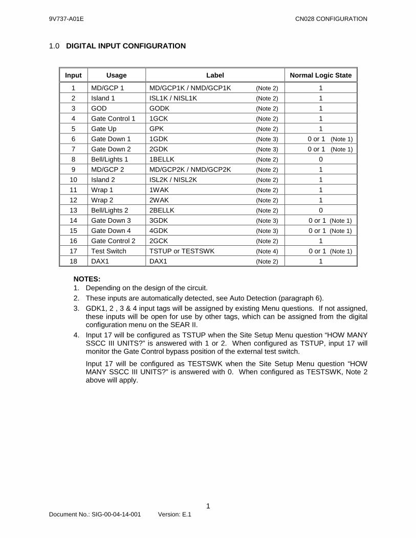
1.0 DIGITAL INPUT CONFIGURATION
Input Usage Label Normal Logic State
1 MD/GCP 1 MD/GCP1K / NMD/GCP1K (Note 2) 1 2 Island 1 ISL1K / NISL1K (Note 2) 1 3 GOD GODK (Note 2) 1 4 Gate Control 1 1GCK (Note 2) 1 5 Gate Up GPK (Note 2) 1 6 Gate Down 1 1GDK (Note 3) 0 or 1 (Note 1) 7 Gate Down 2 2GDK (Note 3) 0 or 1 (Note 1) 8 Bell/Lights 1 1BELLK (Note 2) 0 9 MD/GCP 2 MD/GCP2K / NMD/GCP2K (Note 2) 1 10 Island 2 ISL2K / NISL2K (Note 2) 1 11 Wrap 1 1WAK (Note 2) 1 12 Wrap 2 2WAK (Note 2) 1 13 Bell/Lights 2 2BELLK (Note 2) 0 14 Gate Down 3 3GDK (Note 3) 0 or 1 (Note 1) 15 Gate Down 4 4GDK (Note 3) 0 or 1 (Note 1) 16 Gate Control 2 2GCK (Note 2) 1 17 Test Switch TSTUP or TESTSWK (Note 4) 0 or 1 (Note 1) 18 DAX1 DAX1 (Note 2) 1
NOTES: 1. Depending on the design of the circuit. 2. These inputs are automatically detected, see Auto Detection (paragraph 6). 3. GDK1, 2 , 3 & 4 input tags will be assigned by existing Menu questions. If not assigned,
these inputs will be open for use by other tags, which can be assigned from the digital configuration menu on the SEAR II.
4. Input 17 will be configured as TSTUP when the Site Setup Menu question “HOW MANY SSCC III UNITS?” is answered with 1 or 2. When configured as TSTUP, input 17 will monitor the Gate Control bypass position of the external test switch.
Input 17 will be configured as TESTSWK when the Site Setup Menu question “HOW MANY SSCC III UNITS?” is answered with 0. When configured as TESTSWK, Note 2 above will apply.
9V737-A01E CN028 CONFIGURATION
2 Document No.: SIG-00-04-14-001 Version: E.1
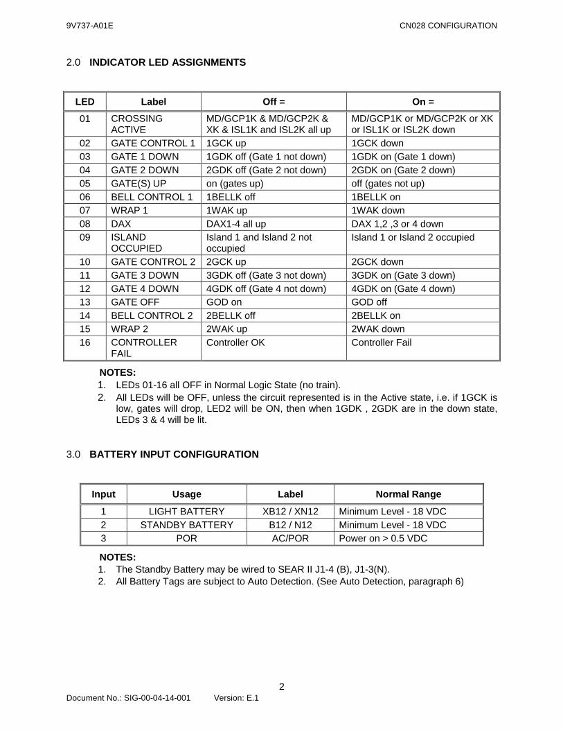
2.0 INDICATOR LED ASSIGNMENTS
LED Label Off = On = 01 CROSSING
ACTIVE MD/GCP1K & MD/GCP2K & XK & ISL1K and ISL2K all up
MD/GCP1K or MD/GCP2K or XK or ISL1K or ISL2K down
02 GATE CONTROL 1 1GCK up 1GCK down 03 GATE 1 DOWN 1GDK off (Gate 1 not down) 1GDK on (Gate 1 down) 04 GATE 2 DOWN 2GDK off (Gate 2 not down) 2GDK on (Gate 2 down) 05 GATE(S) UP on (gates up) off (gates not up) 06 BELL CONTROL 1 1BELLK off 1BELLK on 07 WRAP 1 1WAK up 1WAK down 08 DAX DAX1-4 all up DAX 1,2 ,3 or 4 down 09 ISLAND
OCCUPIED Island 1 and Island 2 not occupied
Island 1 or Island 2 occupied
10 GATE CONTROL 2 2GCK up 2GCK down 11 GATE 3 DOWN 3GDK off (Gate 3 not down) 3GDK on (Gate 3 down) 12 GATE 4 DOWN 4GDK off (Gate 4 not down) 4GDK on (Gate 4 down) 13 GATE OFF GOD on GOD off 14 BELL CONTROL 2 2BELLK off 2BELLK on 15 WRAP 2 2WAK up 2WAK down 16 CONTROLLER
FAIL Controller OK Controller Fail
NOTES: 1. LEDs 01-16 all OFF in Normal Logic State (no train). 2. All LEDs will be OFF, unless the circuit represented is in the Active state, i.e. if 1GCK is
low, gates will drop, LED2 will be ON, then when 1GDK , 2GDK are in the down state, LEDs 3 & 4 will be lit.
3.0 BATTERY INPUT CONFIGURATION
Input Usage Label Normal Range
1 LIGHT BATTERY XB12 / XN12 Minimum Level - 18 VDC 2 STANDBY BATTERY B12 / N12 Minimum Level - 18 VDC 3 POR AC/POR Power on > 0.5 VDC
NOTES: 1. The Standby Battery may be wired to SEAR II J1-4 (B), J1-3(N). 2. All Battery Tags are subject to Auto Detection. (See Auto Detection, paragraph 6)
9V737-A01E CN028 CONFIGURATION
3 Document No.: SIG-00-04-14-001 Version: E.1
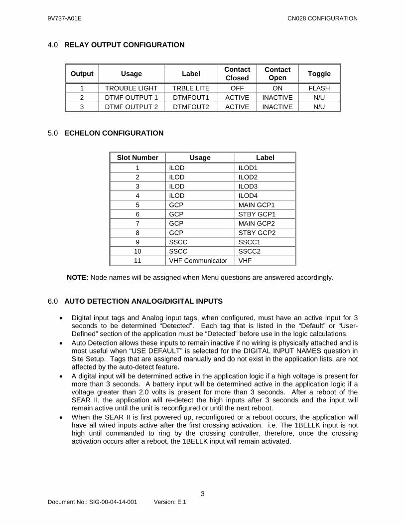
4.0 RELAY OUTPUT CONFIGURATION
Output Usage Label Contact Closed
Contact Open Toggle
1 TROUBLE LIGHT TRBLE LITE OFF ON FLASH 2 DTMF OUTPUT 1 DTMFOUT1 ACTIVE INACTIVE N/U 3 DTMF OUTPUT 2 DTMFOUT2 ACTIVE INACTIVE N/U
5.0 ECHELON CONFIGURATION
Slot Number Usage Label 1 ILOD ILOD1 2 ILOD ILOD2 3 ILOD ILOD3 4 ILOD ILOD4 5 GCP MAIN GCP1 6 GCP STBY GCP1 7 GCP MAIN GCP2 8 GCP STBY GCP2 9 SSCC SSCC1 10 SSCC SSCC2 11 VHF Communicator VHF
NOTE: Node names will be assigned when Menu questions are answered accordingly.
6.0 AUTO DETECTION ANALOG/DIGITAL INPUTS
• Digital input tags and Analog input tags, when configured, must have an active input for 3 seconds to be determined “Detected”. Each tag that is listed in the “Default” or “User-Defined” section of the application must be “Detected” before use in the logic calculations.
• Auto Detection allows these inputs to remain inactive if no wiring is physically attached and is most useful when “USE DEFAULT” is selected for the DIGITAL INPUT NAMES question in Site Setup. Tags that are assigned manually and do not exist in the application lists, are not affected by the auto-detect feature.
• A digital input will be determined active in the application logic if a high voltage is present for more than 3 seconds. A battery input will be determined active in the application logic if a voltage greater than 2.0 volts is present for more than 3 seconds. After a reboot of the SEAR II, the application will re-detect the high inputs after 3 seconds and the input will remain active until the unit is reconfigured or until the next reboot.
• When the SEAR II is first powered up, reconfigured or a reboot occurs, the application will have all wired inputs active after the first crossing activation. i.e. The 1BELLK input is not high until commanded to ring by the crossing controller, therefore, once the crossing activation occurs after a reboot, the 1BELLK input will remain activated.
9V737-A01E CN028 CONFIGURATION
4 Document No.: SIG-00-04-14-001 Version: E.1
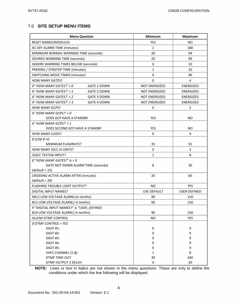
7.0 SITE SETUP MENU ITEMS
Menu Question Minimum Maximum
RESET NAMES/MODULES YES NO AC OFF ALARM TIME (minutes) 1 180 MINIMUM NORMAL WARNING TIME (seconds) 20 94 DESIRED WARNING TIME (seconds) 20 99 IGNORE WARNING TIMES BELOW (seconds) 0 10 PRERING / STNSTOP TIME (minutes) 1 10 SWITCHING MOVE TIMER (minutes) 0 90 HOW MANY GATES? 0 4 IF ‘HOW MANY GATES?’ > 0 GATE 1 DOWN NOT ENERGIZED ENERGIZED IF ‘HOW MANY GATES?’ > 1 GATE 2 DOWN NOT ENERGIZED ENERGIZED IF ‘HOW MANY GATES?’ > 2 GATE 3 DOWN NOT ENERGIZED ENERGIZED IF ‘HOW MANY GATES?’ > 3 GATE 4 DOWN NOT ENERGIZED ENERGIZED HOW MANY GCPS? 0 2 IF ‘HOW MANY GCPS?’ > 0 DOES GCP HAVE A STANDBY
YES
NO
IF ‘HOW MANY GCPS?’ > 1 DOES SECOND GCP HAVE A STANDBY
YES
NO
HOW MANY iLODS? 0 4 If ILOD # >0 MINIMUM FLASHRATE?
35
55
HOW MANY SSCC III UNITS? 0 2 1SSCC TESTSW INPUT? 1 8 If “HOW MANY GATES?” is > 0 GATE NOT DOWN ALARM TIME (seconds) (default = 15)
8
30
CROSSING ACTIVE ALARM AFTER (minutes) (default = 20)
20 60
FLASHING TROUBLE LIGHT OUTPUT? NO YES DIGITAL INPUT NAMES? USE DEFAULT USER-DEFINED XB12 LOW VOLTAGE ALARM,(in tenths): 90 150 B12 LOW VOLTAGE ALARM,( in tenths): 90 150 If “DIGITAL INPUT NAMES?” is “USER_DEFINED B14 LOW VOLTAGE ALARM,( in tenths):
90
150
ALLOW DTMF CONTROL NO YES If DTMF CONTROL = YES DIGIT #1: DIGIT #2: DIGIT #3: DIGIT #4: DIGIT #5: VHFC CHANNEL (1-8): DTMF TIME-OUT DTMF OUTPUT 2 DELAY:
0 0 0 0 0 1
30 0
9 9 9 9 9 8
240 20
NOTE: Lines or text in Italics are not shown in the menu questions. These are only to define the conditions under which the line following will be displayed.

9V737-A01E CN028 CONFIGURATION
5 Document No.: SIG-00-04-14-001 Version: E.1
8.0 DTMF OPERATION
Activate crossing (station stop track 1) xxxxx11# De-activate crossing (station stop track 1) xxxxx10# Activate crossing (station stop track 2) xxxxx21# De-activate crossing (station stop track 2) xxxxx20# Activate crossing (maintenance) xxxxx31# De-activate crossing (maintenance) xxxxx30#
NOTES: 1. xxxxx = Digits as entered during site setup. 2. When a valid code is received, a beep tone will be returned via radio. 3. When a digit is received, a 10 second timer will be started. The digit receive queue will be
cleared when the timer expires, or when a valid code is received. 4. DTMF1 Output will be assigned to Relay Output 2 onboard the SEAR II module. 5. DTMF2 Output can be assigned to a Relay Output on an external I/O module, connected via
Echelon to the SEAR II.
8.1 ACTIVATION
DTMF1 output contact will be open during the INACTIVE state. When any of the activation codes are detected, DTMF1 will be determined ACTIVE, contact closed. If DTMF2 exists, its output contact will be open during the INACTIVE state. The DTMF2 output will become ACTIVE, contact closed, after the DTMF OUTPUT 2 DELAY time programmed by the user configuration, 0 to 20 seconds. The timer will be started by DTMF1 becoming active.
8.2 DE-ACTIVATION
If the de-activate code is received while the corresponding activate code is true, both DTMF1 and DTMF2 outputs will be set to INACTIVE. Island 1 occupancy for more than 5 seconds will cause both DTMF1 and DTMF2 to be set to INACTIVE, only if the Station Stop Track 1 code was received to cause the activation. Island 2 occupancy for more than 5 seconds will cause both DTMF1 and DTMF2 to be set to INACTIVE, only if the Station Stop Track 2 code was received to cause the activation. The DTMF TIME-OUT timer, which is programmed by the user configuration (time 30 to 240 seconds) will start whenever any of the 3 activation codes are received. If the timer reaches the preset time, DTMF1 and DTMF2 will both be set to INACTIVE. If the maintenance activation code causes the activation, then de-activation will occur at the end of the DTMF TIME-OUT timer, or upon receipt of the maintenance de-activation code. An island occupancy will not de-activate a maintenance code activation.
9V737-A01E CN028 CONFIGURATION
6 Document No.: SIG-00-04-14-001 Version: E.1
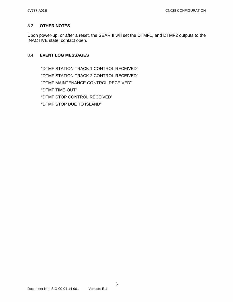
8.3 OTHER NOTES
Upon power-up, or after a reset, the SEAR II will set the DTMF1, and DTMF2 outputs to the INACTIVE state, contact open.
8.4 EVENT LOG MESSAGES
“DTMF STATION TRACK 1 CONTROL RECEIVED”
“DTMF STATION TRACK 2 CONTROL RECEIVED”
“DTMF MAINTENANCE CONTROL RECEIVED”
“DTMF TIME-OUT”
“DTMF STOP CONTROL RECEIVED”
“DTMF STOP DUE TO ISLAND”
9V737-A01E CN028 CONFIGURATION
7 Document No.: SIG-00-04-14-001 Version: E.1
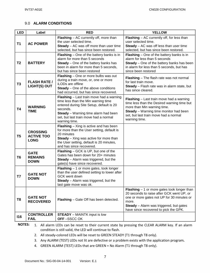
9.0 ALARM CONDITIONS
LED Label RED YELLOW
T1 AC POWER Flashing – AC currently off, more than the user selected time. Steady – AC was off more than user time selected, but has since been restored.
Flashing – AC currently off, for less than user selected time. Steady – AC was off less than user time selected, but has since been restored.
T2 BATTERY
Flashing – One of the battery banks is in alarm for more than 5 seconds Steady – One of the battery banks has been in alarm for more than 5 seconds, but has since been restored
Flashing – One of the battery banks is in alarm for less than 5 seconds Steady – One of the battery banks has been in alarm for less than 5 seconds, but has since been restored
T3 FLASH RATE / LIGHT(S) OUT
Flashing – One or more bulbs was out during a train move, or, one or more iLODs are offline Steady – One of the above conditions had occurred, but has since recovered.
Flashing – The flash rate was not normal for last train move. Steady – Flash rate was in alarm state, but has since cleared.
T4 WARNING TIME
Flashing – Last train move had a warning time less than the Min warning time entered during Site Setup, default is 20 seconds. Steady – Warning time alarm had been set, but last train move had a normal warning time.
Flashing – Last train move had a warning time less than the Desired warning time but more than Min warning time. Steady – Warning time monitor had been set, but last train move had a normal warning time.
T5 CROSSING ACTIVE TOO LONG
Flashing – Xing is active and has been for more than the User setting, default is 20 minutes Steady – Xing was active for more than the User setting, default is 20 minutes, and has since recovered.
T6 GATE REMAINS DOWN
Flashing – GCK is UP, but one of the Gates has been down for 20+ minutes Steady – Alarm was triggered, but the gate(s) have since recovered.
T7 GATE NOT DOWN
Flashing – 1 or more gates, took longer than the user defined setting to lower after GCK went down Steady – Alarm was triggered, but the last gate move was ok.
T8 GATE NOT RECOVERED Flashing – Gate Off has been detected.
Flashing – 1 or more gates took longer than 20 seconds to raise after GCK went UP, or one or more gates not UP for 30 minutes or more. Steady – Alarm was triggered, but gates have since recovered to pick the GPK.
I16 CONTROLLER FAIL
STEADY – MAINTK input is low OFF –SSCC OK
NOTES: 1. All alarm LEDs can be reset to their current state by pressing the CLEAR ALARM key. If an alarm condition is still valid, the LED will continue to flash.
2. All steady-colored LEDs will be reset to GREEN STEADY (T1 through T8 only). 3. Any ALARM (TEST) LEDs not lit are defective or a problem exists with the application program. 4. GREEN ALARM (TEST) LEDs that are GREEN = No Alarm (T1 through T8 only).

9V737-A01E CN028 CONFIGURATION
8 Document No.: SIG-00-04-14-001 Version: E.1
9.1 AC POWER ALARM (T1)
Alarm if POR input has been < 0.5 VDC for AC OFF ALARM TIME (1 to 180 minutes) or more, send in “AC OFF”. An alarm will be sent in each time a train passes the location with POR < 0.5 VDC for AC OFF ALARM TIME (1 to 180 minutes) or more: PWR OFF TRAIN. Alarm clears if POR input is normal for a minimum of 5 minutes. Only voltage changes of greater than 0.5 V will be logged in the Standard Event Report.
9.1.1 Alarm Text
(XNG)AC OFF (XNG)AC ON With AC OFF (POR input has been < 0.5 VDC for AC OFF ALARM TIME [1 to 180 minutes] or more), send in the following alarm each time a train passes the location: (XNG)PWR OFF TRAIN
9.1.2 T1 LED
GREEN upon start of the application program.
YELLOW FLASHING if AC power is lost for less than AC OFF ALARM TIME (1 to 180 minutes).
YELLOW STEADY if power lost for less than AC OFF ALARM TIME (1 to 180 minutes) and then restored.
RED FLASHING if AC power is lost for AC OFF ALARM TIME (1 to 180 minutes) or more.
RED STEADY if power is lost for AC OFF ALARM TIME (1 to 180 minutes) or more, and then restored for a minimum of 5 minutes.
NOTE: AC OFF ALARM TIME is set by user during Site Setup
9.1.3 Office Alarm Management System
Call maintainer after AC power has been off for a total of 180 minutes. The “pwr off train” messages received will only be used for statistic / investigation (not for calling out the supervisor / maintainer). *** For the initial phase-in period, contact supervisor instead of maintainer.
9V737-A01E CN028 CONFIGURATION
9 Document No.: SIG-00-04-14-001 Version: E.1
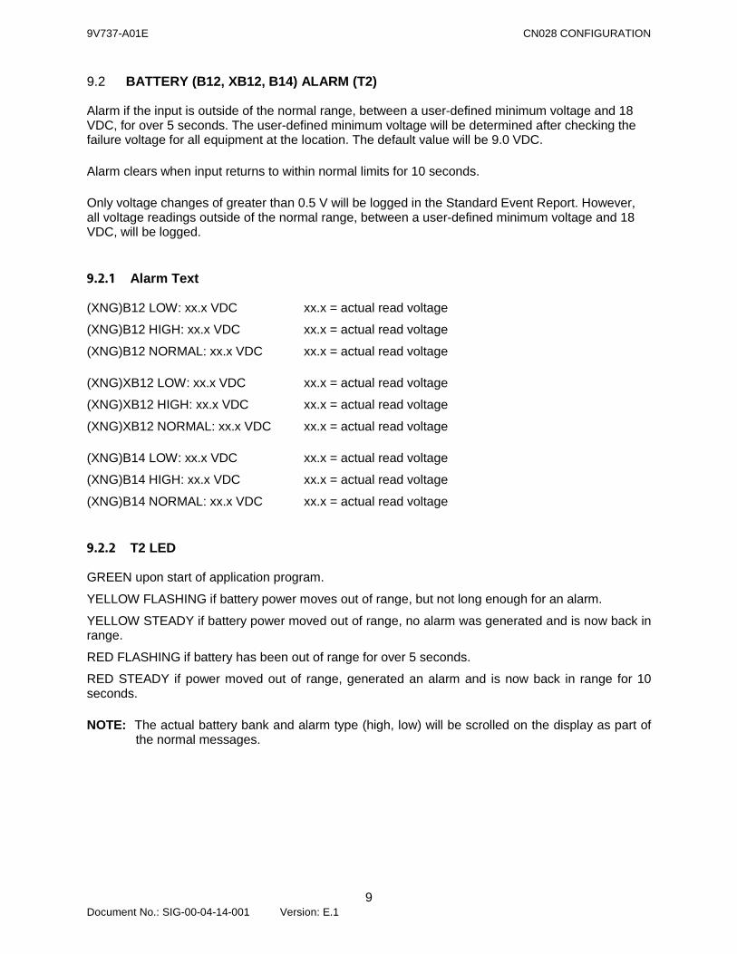
9.2 BATTERY (B12, XB12, B14) ALARM (T2)
Alarm if the input is outside of the normal range, between a user-defined minimum voltage and 18 VDC, for over 5 seconds. The user-defined minimum voltage will be determined after checking the failure voltage for all equipment at the location. The default value will be 9.0 VDC. Alarm clears when input returns to within normal limits for 10 seconds. Only voltage changes of greater than 0.5 V will be logged in the Standard Event Report. However, all voltage readings outside of the normal range, between a user-defined minimum voltage and 18 VDC, will be logged.
9.2.1 Alarm Text
(XNG)B12 LOW: xx.x VDC xx.x = actual read voltage
(XNG)B12 HIGH: xx.x VDC xx.x = actual read voltage
(XNG)B12 NORMAL: xx.x VDC xx.x = actual read voltage (XNG)XB12 LOW: xx.x VDC xx.x = actual read voltage
(XNG)XB12 HIGH: xx.x VDC xx.x = actual read voltage
(XNG)XB12 NORMAL: xx.x VDC xx.x = actual read voltage (XNG)B14 LOW: xx.x VDC xx.x = actual read voltage
(XNG)B14 HIGH: xx.x VDC xx.x = actual read voltage
(XNG)B14 NORMAL: xx.x VDC xx.x = actual read voltage
9.2.2 T2 LED
GREEN upon start of application program.
YELLOW FLASHING if battery power moves out of range, but not long enough for an alarm.
YELLOW STEADY if battery power moved out of range, no alarm was generated and is now back in range.
RED FLASHING if battery has been out of range for over 5 seconds.
RED STEADY if power moved out of range, generated an alarm and is now back in range for 10 seconds. NOTE: The actual battery bank and alarm type (high, low) will be scrolled on the display as part of
the normal messages.
9V737-A01E CN028 CONFIGURATION
10 Document No.: SIG-00-04-14-001 Version: E.1
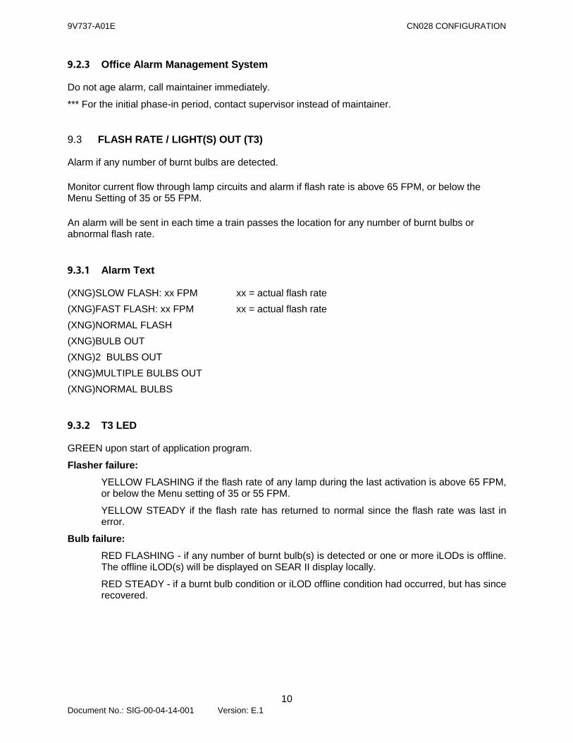
9.2.3 Office Alarm Management System
Do not age alarm, call maintainer immediately.
*** For the initial phase-in period, contact supervisor instead of maintainer.
9.3 FLASH RATE / LIGHT(S) OUT (T3)
Alarm if any number of burnt bulbs are detected. Monitor current flow through lamp circuits and alarm if flash rate is above 65 FPM, or below the Menu Setting of 35 or 55 FPM. An alarm will be sent in each time a train passes the location for any number of burnt bulbs or abnormal flash rate.
9.3.1 Alarm Text
(XNG)SLOW FLASH: xx FPM xx = actual flash rate (XNG)FAST FLASH: xx FPM xx = actual flash rate (XNG)NORMAL FLASH (XNG)BULB OUT (XNG)2 BULBS OUT (XNG)MULTIPLE BULBS OUT (XNG)NORMAL BULBS
9.3.2 T3 LED
GREEN upon start of application program.
Flasher failure: YELLOW FLASHING if the flash rate of any lamp during the last activation is above 65 FPM, or below the Menu setting of 35 or 55 FPM.
YELLOW STEADY if the flash rate has returned to normal since the flash rate was last in error.
Bulb failure: RED FLASHING - if any number of burnt bulb(s) is detected or one or more iLODs is offline. The offline iLOD(s) will be displayed on SEAR II display locally.
RED STEADY - if a burnt bulb condition or iLOD offline condition had occurred, but has since recovered.
9V737-A01E CN028 CONFIGURATION
11 Document No.: SIG-00-04-14-001 Version: E.1
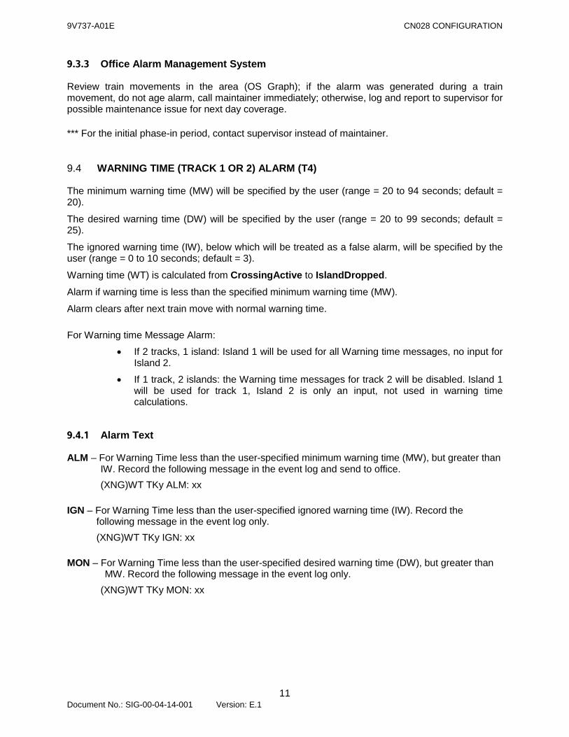
9.3.3 Office Alarm Management System
Review train movements in the area (OS Graph); if the alarm was generated during a train movement, do not age alarm, call maintainer immediately; otherwise, log and report to supervisor for possible maintenance issue for next day coverage. *** For the initial phase-in period, contact supervisor instead of maintainer.
9.4 WARNING TIME (TRACK 1 OR 2) ALARM (T4)
The minimum warning time (MW) will be specified by the user (range = 20 to 94 seconds; default = 20).
The desired warning time (DW) will be specified by the user (range = 20 to 99 seconds; default = 25).
The ignored warning time (IW), below which will be treated as a false alarm, will be specified by the user (range = 0 to 10 seconds; default = 3).
Warning time (WT) is calculated from CrossingActive to IslandDropped.
Alarm if warning time is less than the specified minimum warning time (MW).
Alarm clears after next train move with normal warning time. For Warning time Message Alarm:
• If 2 tracks, 1 island: Island 1 will be used for all Warning time messages, no input for Island 2.
• If 1 track, 2 islands: the Warning time messages for track 2 will be disabled. Island 1 will be used for track 1, Island 2 is only an input, not used in warning time calculations.
9.4.1 Alarm Text
ALM – For Warning Time less than the user-specified minimum warning time (MW), but greater than IW. Record the following message in the event log and send to office. (XNG)WT TKy ALM: xx
IGN – For Warning Time less than the user-specified ignored warning time (IW). Record the
following message in the event log only. (XNG)WT TKy IGN: xx
MON – For Warning Time less than the user-specified desired warning time (DW), but greater than
MW. Record the following message in the event log only. (XNG)WT TKy MON: xx
9V737-A01E CN028 CONFIGURATION
12 Document No.: SIG-00-04-14-001 Version: E.1
The above message will be sent to the office for the first good train move after one or more of the WT ALM messages, if the warning time is less than (DW), but greater than (MW). INFO – For each normal train move, record the following message in the event log if no other
train move message is required. (XNG)WT TKy INFO: xx
The above message will be sent to the office for the first good train move after one or more of the WT alarm messages, if warning time is greater than (DW). NOTE: where y = track number, xx is Warning time in seconds The user-specified minimum warning time, desired warning time and ignored warning time will be sent to the office when the application program is restarted.
9.4.2 T4 LED
GREEN upon start of application program.
YELLOW FLASHING if last train by crossing had a warning time less than DW but greater than MW.
YELLOW STEADY if prior train had a warning time less than DW and last train had normal warning time.
RED FLASHING if last train by crossing had a warning time alarm (less than MW).
RED STEADY if prior train had alarm and last train had no alarm.
CrossingActive is calculated by looking at the MD/GCP1K, MD/GCP2K and XK inputs to see if any have dropped. If any of these names are not assigned, they are ignored.
IslandDropped is calculated by either the ISL1K or ISL2K inputs dropping. The first to drop will be recognized. If CrossingActive is not TRUE when this flag becomes TRUE, then it is also set to TRUE. If either name is not assigned, it will be ignored.
9.4.3 Office Alarm Management System
Review train movements in the area (OS Graph); if the alarm was generated during a train movement, proceed with the following for the different types of alarms (ALM/IGN/MON); otherwise, log and report to supervisor and responsible engineer for information by email. ALM – For short warning time (less than the minimum required, MW, but greater than the
ignored warning time, IW): 1. Connect to / dial into the location (refer to section 10 on “Dialing into a SEAR II
location” for instructions) and obtain the SEAR II Standard Event Report. 2. Check the train speeds recorded associated with the ALM short warning time alarm.

9V737-A01E CN028 CONFIGURATION
13 Document No.: SIG-00-04-14-001 Version: E.1
If the alarm does not appear to have been caused by a slow moving train or an accelerating train (see below for explanation), treat as crossing failure critical alarm and restrict crossing. Slow moving trains: trains with speeds of less than 15MPH were likely switching or doing some work in the area. Log and report to supervisor and responsible engineer for information by email. An example for this type of alarm:
WT ALM TK1: 16 sec, WABASH, 199.50, 289190G, 06/11/03 16:43:22
Investigation revealed that this was caused by Train M3197104 northbound. It appears that Train 319 was switching or doing some work in the area. OS log indicates that it was at M.199.5 from 14:50 to 17:11. The following speeds were logged in the SEAR II Standard Event Report for Train 319 for the short warning time alarm:
Thu 11-06-2003 16:43:22.34 main gcp1: Track 1 Warn Time 16 Thu 11-06-2003 16:43:22.34 main gcp1: Track 1 Det Speed 5 Thu 11-06-2003 16:43:22.34 main gcp1: Track 1 Avg Speed 5 Thu 11-06-2003 16:43:22.34 main gcp1: Track 1 Isl Speed 7
Accelerating trains: the SEAR II crossing monitors have recorded a number of short warning time alarms caused by accelerating passenger trains. Log and report to supervisor and responsible engineer for information by email. An example for this type of alarm:
WT ALM TK1: 19 sec, WABASH, 199.50, 289190G, 07/11/03 05:21:02
Investigation revealed that this was caused by Train P0587106 northbound. This alarm was caused by an accelerating passenger train with the following speeds logged in the SEAR II Standard Event Report:
Fri 11-07-2003 5:21:02.29 main gcp1: Track 1 Warn Time 18 Fri 11-07-2003 5:21:02.29 main gcp1: Track 1 Det Speed 14 Fri 11-07-2003 5:21:02.29 main gcp1: Track 1 Avg Speed 16 Fri 11-07-2003 5:21:02.29 main gcp1: Track 1 Isl Speed 19
IGN – For nill warning time (below the time user entered for ignore warning times, IW) – log and investigate train move – determine whether this was caused by a slow-moving train using the OS Graph. Connect to / dial into location and download the Standard Event Report if necessary. Log and report to supervisor and responsible engineer for information by email.
MON – For warning time lower than desired (DW), but greater than the minimum required (MW) –
monitor crossing, wait for the next train (indefinitely) and check its warning time, escalate to an alarm (ALM) stage for second occurrence in 24 hours, call supervisor for next day coverage. Log and report to supervisor and responsible engineer for information by email.
9V737-A01E CN028 CONFIGURATION
14 Document No.: SIG-00-04-14-001 Version: E.1
9.5 CROSSING ACTIVE TOO LONG (T5)
Alarm if CrossingActive TRUE for a user-specified number of minutes (default = 20 minutes). CrossingActive means either the MD/GCP1K, MD/GCP2K, XR is down or the Island is down. NOTE: No new T5 alarm will be generated after an “XING ACTIVE xx MIN” alarm has been generated and sent to the office. Alarm clears when CrossingActive becomes FALSE.
9.5.1 Alarm Text
(XNG)XING ACTIVE: xxx MINUTES xxx= user-specified number of minutes.
9.5.2 T5 LED
GREEN upon start of application program. RED FLASHING if CrossingActive is TRUE for user-specified number of minutes. RED STEADY if alarm condition occurred and is currently not in alarm.
9.5.3 Office Alarm Management System
Review train movements in the area (OS Graph); if the alarm was generated during a train movement, determine whether the alarm was caused by a slow-moving or stopped train using the OS Graph, connect to / dial into location and download the Standard Event Report if necessary. For slow-moving or stopped trains, log and report to supervisor by email. Otherwise, call maintainer immediately. *** For the initial phase-in period, contact supervisor instead of maintainer.
9.6 GATE REMAINS DOWN ALARM (T6)
Alarm if GCK is up but 1GDK, 2GDK, 3GDK or 4GDK remains down for 20+ minutes. Alarm clears when all valid inputs are up. NOTE: The gate down inputs are mapped to internal flags which account for normally-energized or
non-energized inputs at the crossing.
9.6.1 Alarm Text
(XNG)GATE1 DWN 20+ MIN (XNG)GATE2 DWN 20+ MIN (XNG)GATE3 DWN 20+ MIN (XNG)GATE4 DWN 20+ MIN
9V737-A01E CN028 CONFIGURATION
15 Document No.: SIG-00-04-14-001 Version: E.1
9.6.2 T6 LED
GREEN upon start of application program. RED FLASHING if currently in alarm. RED STEADY if alarm occurred and is presently cleared.
9.6.3 Office Alarm Management System
Review train movements in the area (OS Graph); if the alarm was generated during a train movement, do not age alarm, call maintainer immediately. Otherwise, log and report to supervisor for information by email. *** For the initial phase-in period, contact supervisor instead of maintainer.
9.7 GATE NOT DOWN ALARM (T7)
Alarm “GATE NOT DOWN IN TIME” if any gate down input remains FALSE for more than a user-defined number of seconds (range: 8 to 30 seconds with 15 seconds as the default) after the gate control has de-energized. Alarm “ISL DWN, GATE NOT DOWN” if the gate never did come down for a train. This alarm will look for the gate down input = TRUE confirmation after the gate control de-energized and before Island 1 or Island 2 dropped. Alarm clears when gate down inputs are all TRUE in proper time.
9.7.1 Alarm Text
(XNG)GATE1 NOT DWN IN TIME (XNG)GATE2 NOT DWN IN TIME (XNG)GATE3 NOT DWN IN TIME (XNG)GATE4 NOT DWN IN TIME (XNG)ISL DWN, GATE NOT DOWN
9.7.2 T7 LED
GREEN upon start of application program. RED FLASHING if currently in alarm. RED STEADY if alarm occurred and is presently cleared after proper gate operation.
9V737-A01E CN028 CONFIGURATION
16 Document No.: SIG-00-04-14-001 Version: E.1
9.7.3 Office Alarm Management System
(XNG)GATEX NOT DOWN IN TIME: (NOTE: X following GATE = 1, 2, 3 or 4) Review train movements in the area (OS Graph); if the alarm was generated during a train movement, log as one occurrence. Count occurrences in 24 hours – if there are two occurrences within 24 hours, call maintainer immediately. Otherwise, log and report to supervisor for information by e-mail. (XNG)ISL DWN GATE NOT DOWN: Review train movements in the area (OS Graph); if the alarm was generated during a train movement, do not age alarm, call maintainer immediately. Otherwise, log and report to supervisor for information by email. *** For the initial phase-in period, contact supervisor instead of maintainer.
9.8 GATE NOT RECOVERED ALARM (T8)
Alarm if the gate up input remains low for more than 20 seconds after the gate control has energized. Alarm if gate up input is low for 30 minutes, with all GCK inputs UP. Alarm clear when gate up input picks. Alarm if gate off is detected (by the GOD input). If Gate Off is detected, the return of the GODK input for 10 seconds will cause a message to the office.
9.8.1 Alarm Text
(XNG)GATES NOT RECOVERED
(XNG)GATE OFF DETECTED
(XNG)GATE OFF CORRECTED
(XNG)GATE NOT UP
(XNG)GATE UP CLEAR
9V737-A01E CN028 CONFIGURATION
17 Document No.: SIG-00-04-14-001 Version: E.1
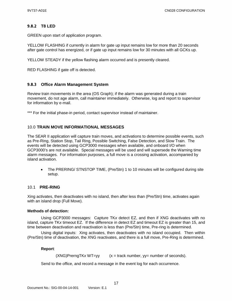
9.8.2 T8 LED
GREEN upon start of application program. YELLOW FLASHING if currently in alarm for gate up input remains low for more than 20 seconds after gate control has energized, or if gate up input remains low for 30 minutes with all GCKs up. YELLOW STEADY if the yellow flashing alarm occurred and is presently cleared. RED FLASHING if gate off is detected.
9.8.3 Office Alarm Management System
Review train movements in the area (OS Graph); if the alarm was generated during a train movement, do not age alarm, call maintainer immediately. Otherwise, log and report to supervisor for information by e-mail. *** For the initial phase-in period, contact supervisor instead of maintainer.
10.0 TRAIN MOVE INFORMATIONAL MESSAGES
The SEAR II application will capture train moves, and activations to determine possible events, such as Pre-Ring, Station Stop, Tail Ring, Possible Switching, False Detection, and Slow Train. The events will be detected using GCP3000 messages when available, and onboard I/O when GCP3000’s are not available. Special messages will be used and will supersede the Warning time alarm messages. For information purposes, a full move is a crossing activation, accompanied by island activation.
• The PRERING/ STNSTOP TIME, (Pre/Stn) 1 to 10 minutes will be configured during site setup.
10.1 PRE-RING
Xing activates, then deactivates with no island, then after less than (Pre/Stn) time, activates again with an island drop (Full Move). Methods of detection: Using GCP3000 messages: Capture TKx detect EZ, and then if XNG deactivates with no island, capture TKx timeout EZ. If the difference in detect EZ and timeout EZ is greater than 15, and time between deactivation and reactivation is less than (Pre/Stn) time, Pre-ring is determined. Using digital inputs: Xing activates, then deactivates with no island occupied. Then within (Pre/Stn) time of deactivation, the XNG reactivates, and there is a full move, Pre-Ring is determined.
Report: (XNG)PrerngTKx WT=yy (x = track number, yy= number of seconds).
Send to the office, and record a message in the event log for each occurrence.
9V737-A01E CN028 CONFIGURATION
18 Document No.: SIG-00-04-14-001 Version: E.1
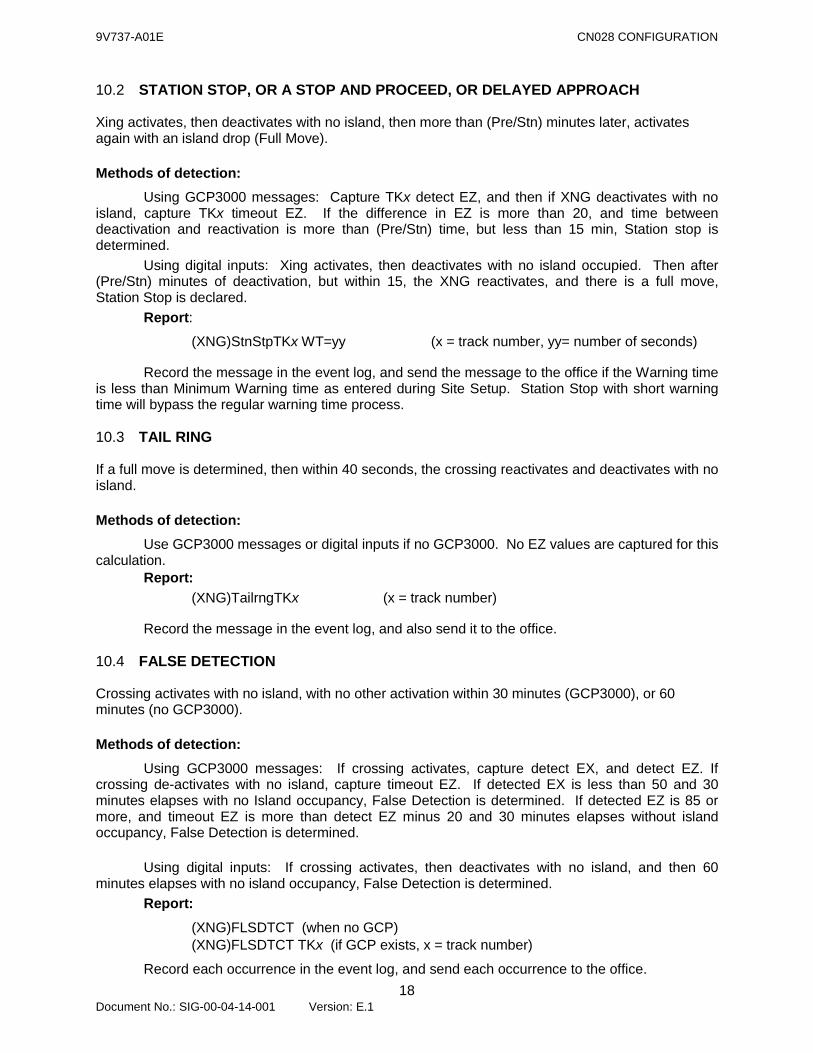
10.2 STATION STOP, OR A STOP AND PROCEED, OR DELAYED APPROACH
Xing activates, then deactivates with no island, then more than (Pre/Stn) minutes later, activates again with an island drop (Full Move). Methods of detection: Using GCP3000 messages: Capture TKx detect EZ, and then if XNG deactivates with no island, capture TKx timeout EZ. If the difference in EZ is more than 20, and time between deactivation and reactivation is more than (Pre/Stn) time, but less than 15 min, Station stop is determined. Using digital inputs: Xing activates, then deactivates with no island occupied. Then after (Pre/Stn) minutes of deactivation, but within 15, the XNG reactivates, and there is a full move, Station Stop is declared.
Report: (XNG)StnStpTKx WT=yy (x = track number, yy= number of seconds)
Record the message in the event log, and send the message to the office if the Warning time is less than Minimum Warning time as entered during Site Setup. Station Stop with short warning time will bypass the regular warning time process.
10.3 TAIL RING
If a full move is determined, then within 40 seconds, the crossing reactivates and deactivates with no island. Methods of detection: Use GCP3000 messages or digital inputs if no GCP3000. No EZ values are captured for this calculation.
Report: (XNG)TailrngTKx (x = track number)
Record the message in the event log, and also send it to the office.
10.4 FALSE DETECTION
Crossing activates with no island, with no other activation within 30 minutes (GCP3000), or 60 minutes (no GCP3000). Methods of detection:
Using GCP3000 messages: If crossing activates, capture detect EX, and detect EZ. If crossing de-activates with no island, capture timeout EZ. If detected EX is less than 50 and 30 minutes elapses with no Island occupancy, False Detection is determined. If detected EZ is 85 or more, and timeout EZ is more than detect EZ minus 20 and 30 minutes elapses without island occupancy, False Detection is determined.
Using digital inputs: If crossing activates, then deactivates with no island, and then 60
minutes elapses with no island occupancy, False Detection is determined. Report:
(XNG)FLSDTCT (when no GCP) (XNG)FLSDTCT TKx (if GCP exists, x = track number)
Record each occurrence in the event log, and send each occurrence to the office.
9V737-A01E CN028 CONFIGURATION
19 Document No.: SIG-00-04-14-001 Version: E.1
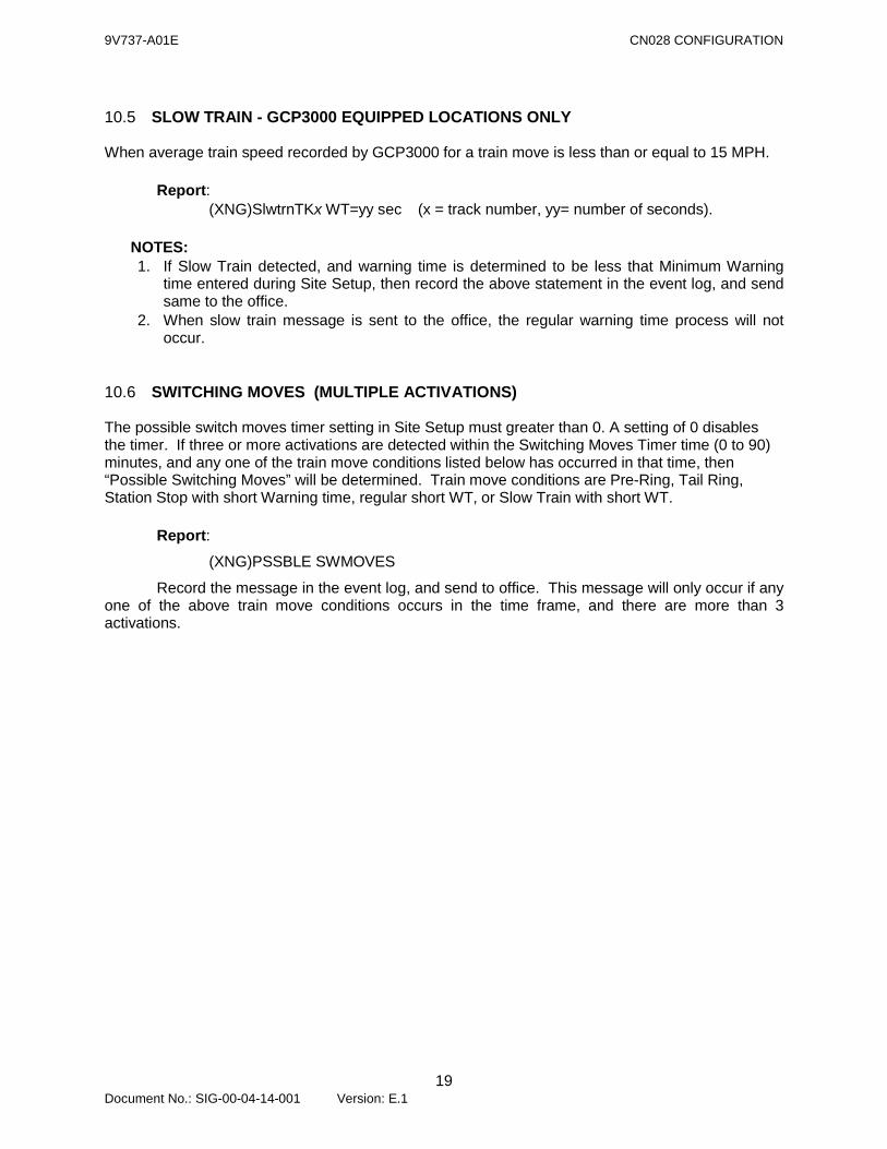
10.5 SLOW TRAIN - GCP3000 EQUIPPED LOCATIONS ONLY
When average train speed recorded by GCP3000 for a train move is less than or equal to 15 MPH.
Report: (XNG)SlwtrnTKx WT=yy sec (x = track number, yy= number of seconds).
NOTES: 1. If Slow Train detected, and warning time is determined to be less that Minimum Warning
time entered during Site Setup, then record the above statement in the event log, and send same to the office.
2. When slow train message is sent to the office, the regular warning time process will not occur.
10.6 SWITCHING MOVES (MULTIPLE ACTIVATIONS)
The possible switch moves timer setting in Site Setup must greater than 0. A setting of 0 disables the timer. If three or more activations are detected within the Switching Moves Timer time (0 to 90) minutes, and any one of the train move conditions listed below has occurred in that time, then “Possible Switching Moves” will be determined. Train move conditions are Pre-Ring, Tail Ring, Station Stop with short Warning time, regular short WT, or Slow Train with short WT. Report: (XNG)PSSBLE SWMOVES
Record the message in the event log, and send to office. This message will only occur if any one of the above train move conditions occurs in the time frame, and there are more than 3 activations.
9V737-A01E CN028 CONFIGURATION
20 Document No.: SIG-00-04-14-001 Version: E.1
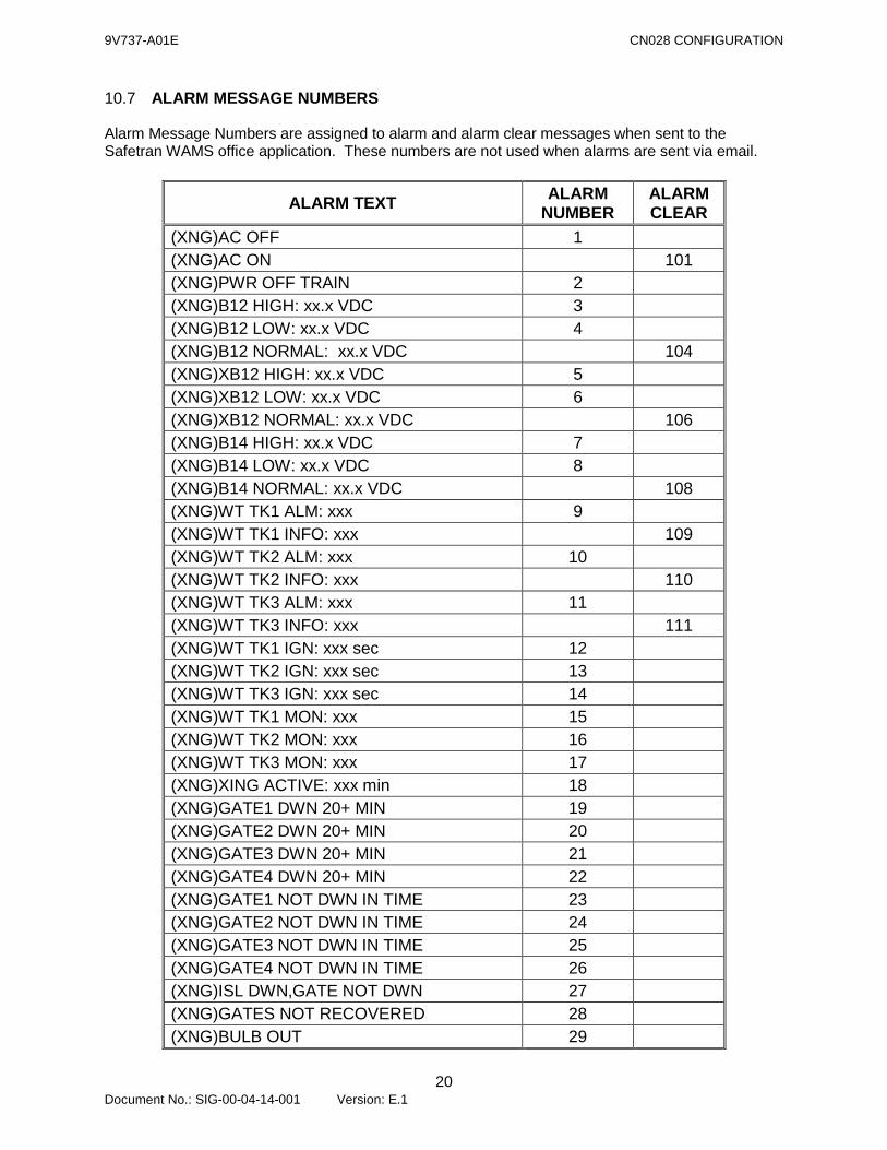
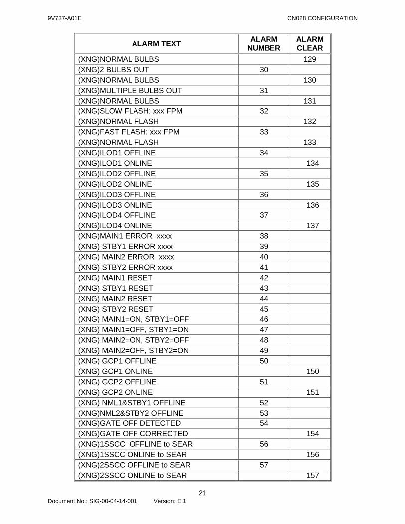
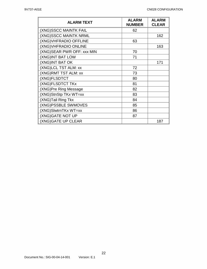
10.7 ALARM MESSAGE NUMBERS
Alarm Message Numbers are assigned to alarm and alarm clear messages when sent to the Safetran WAMS office application. These numbers are not used when alarms are sent via email.
ALARM TEXT ALARM NUMBER
ALARM CLEAR
(XNG)AC OFF 1 (XNG)AC ON 101 (XNG)PWR OFF TRAIN 2 (XNG)B12 HIGH: xx.x VDC 3 (XNG)B12 LOW: xx.x VDC 4 (XNG)B12 NORMAL: xx.x VDC 104 (XNG)XB12 HIGH: xx.x VDC 5 (XNG)XB12 LOW: xx.x VDC 6 (XNG)XB12 NORMAL: xx.x VDC 106 (XNG)B14 HIGH: xx.x VDC 7 (XNG)B14 LOW: xx.x VDC 8 (XNG)B14 NORMAL: xx.x VDC 108 (XNG)WT TK1 ALM: xxx 9 (XNG)WT TK1 INFO: xxx 109 (XNG)WT TK2 ALM: xxx 10 (XNG)WT TK2 INFO: xxx 110 (XNG)WT TK3 ALM: xxx 11 (XNG)WT TK3 INFO: xxx 111 (XNG)WT TK1 IGN: xxx sec 12 (XNG)WT TK2 IGN: xxx sec 13 (XNG)WT TK3 IGN: xxx sec 14 (XNG)WT TK1 MON: xxx 15 (XNG)WT TK2 MON: xxx 16 (XNG)WT TK3 MON: xxx 17 (XNG)XING ACTIVE: xxx min 18 (XNG)GATE1 DWN 20+ MIN 19 (XNG)GATE2 DWN 20+ MIN 20 (XNG)GATE3 DWN 20+ MIN 21 (XNG)GATE4 DWN 20+ MIN 22 (XNG)GATE1 NOT DWN IN TIME 23 (XNG)GATE2 NOT DWN IN TIME 24 (XNG)GATE3 NOT DWN IN TIME 25 (XNG)GATE4 NOT DWN IN TIME 26 (XNG)ISL DWN,GATE NOT DWN 27 (XNG)GATES NOT RECOVERED 28 (XNG)BULB OUT 29
9V737-A01E CN028 CONFIGURATION
21 Document No.: SIG-00-04-14-001 Version: E.1
ALARM TEXT ALARM NUMBER
ALARM CLEAR
(XNG)NORMAL BULBS 129 (XNG)2 BULBS OUT 30 (XNG)NORMAL BULBS 130 (XNG)MULTIPLE BULBS OUT 31 (XNG)NORMAL BULBS 131 (XNG)SLOW FLASH: xxx FPM 32 (XNG)NORMAL FLASH 132 (XNG)FAST FLASH: xxx FPM 33 (XNG)NORMAL FLASH 133 (XNG)ILOD1 OFFLINE 34 (XNG)ILOD1 ONLINE 134 (XNG)ILOD2 OFFLINE 35 (XNG)ILOD2 ONLINE 135 (XNG)ILOD3 OFFLINE 36 (XNG)ILOD3 ONLINE 136 (XNG)ILOD4 OFFLINE 37 (XNG)ILOD4 ONLINE 137 (XNG)MAIN1 ERROR xxxx 38 (XNG) STBY1 ERROR xxxx 39 (XNG) MAIN2 ERROR xxxx 40 (XNG) STBY2 ERROR xxxx 41 (XNG) MAIN1 RESET 42 (XNG) STBY1 RESET 43 (XNG) MAIN2 RESET 44 (XNG) STBY2 RESET 45 (XNG) MAIN1=ON, STBY1=OFF 46 (XNG) MAIN1=OFF, STBY1=ON 47 (XNG) MAIN2=ON, STBY2=OFF 48 (XNG) MAIN2=OFF, STBY2=ON 49 (XNG) GCP1 OFFLINE 50 (XNG) GCP1 ONLINE 150 (XNG) GCP2 OFFLINE 51 (XNG) GCP2 ONLINE 151 (XNG) NML1&STBY1 OFFLINE 52 (XNG)NML2&STBY2 OFFLINE 53 (XNG)GATE OFF DETECTED 54 (XNG)GATE OFF CORRECTED 154 (XNG)1SSCC OFFLINE to SEAR 56 (XNG)1SSCC ONLINE to SEAR 156 (XNG)2SSCC OFFLINE to SEAR 57 (XNG)2SSCC ONLINE to SEAR 157
9V737-A01E CN028 CONFIGURATION
22 Document No.: SIG-00-04-14-001 Version: E.1
ALARM TEXT ALARM NUMBER
ALARM CLEAR
(XNG)SSCC MAINTK FAIL 62 (XNG)SSCC MAINTK NRML 162 (XNG)VHFRADIO OFFLINE 63 (XNG)VHFRADIO ONLINE 163 (XNG)SEAR PWR OFF: xxx MIN 70 (XNG)INT BAT LOW 71 (XNG)INT BAT OK 171 (XNG)LCL TST ALM: xx 72 (XNG)RMT TST ALM: xx 73 (XNG)FLSDTCT 80 (XNG)FLSDTCT TKx 81 (XNG)Pre Ring Message 82 (XNG)StnStp TKx WT=xx 83 (XNG)Tail Ring Tkx 84 (XNG)PSSBLE SWMOVES 85 (XNG)SlwtrnTKx WT=xx 86 (XNG)GATE NOT UP 87 (XNG)GATE UP CLEAR 187
9V737-A01E CN028 CONFIGURATION
23 Document No.: SIG-00-04-14-001 Version: E.1
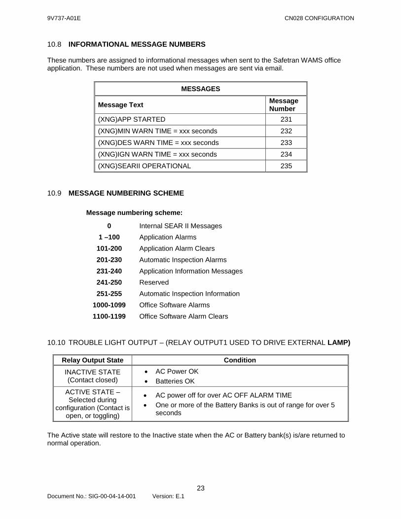
10.8 INFORMATIONAL MESSAGE NUMBERS
These numbers are assigned to informational messages when sent to the Safetran WAMS office application. These numbers are not used when messages are sent via email.
MESSAGES
Message Text Message Number
(XNG)APP STARTED 231
(XNG)MIN WARN TIME = xxx seconds 232
(XNG)DES WARN TIME = xxx seconds 233
(XNG)IGN WARN TIME = xxx seconds 234
(XNG)SEARII OPERATIONAL 235
10.9 MESSAGE NUMBERING SCHEME
Message numbering scheme:
0 Internal SEAR II Messages 1 –100 Application Alarms
101-200 Application Alarm Clears 201-230 Automatic Inspection Alarms 231-240 Application Information Messages 241-250 Reserved 251-255 Automatic Inspection Information
1000-1099 Office Software Alarms 1100-1199 Office Software Alarm Clears
10.10 TROUBLE LIGHT OUTPUT – (RELAY OUTPUT1 USED TO DRIVE EXTERNAL LAMP)
Relay Output State Condition INACTIVE STATE (Contact closed)
• AC Power OK • Batteries OK
ACTIVE STATE – Selected during
configuration (Contact is open, or toggling)
• AC power off for over AC OFF ALARM TIME • One or more of the Battery Banks is out of range for over 5
seconds
The Active state will restore to the Inactive state when the AC or Battery bank(s) is/are returned to normal operation.
9V737-A01E CN028 CONFIGURATION
24 Document No.: SIG-00-04-14-001 Version: E.1
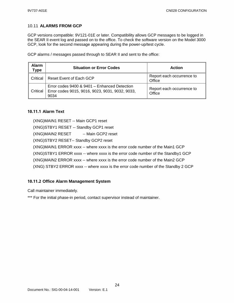
10.11 ALARMS FROM GCP
GCP versions compatible: 9V121-01E or later. Compatibility allows GCP messages to be logged in the SEAR II event log and passed on to the office. To check the software version on the Model 3000 GCP, look for the second message appearing during the power-up/test cycle. GCP alarms / messages passed through to SEAR II and sent to the office:
Alarm Type Situation or Error Codes Action
Critical Reset Event of Each GCP Report each occurrence to Office
Critical Error codes 9400 & 9401 – Enhanced Detection Error codes 9015, 9016, 9023, 9031, 9032, 9033, 9034
Report each occurrence to Office
10.11.1 Alarm Text
(XNG)MAIN1 RESET -- Main GCP1 reset (XNG)STBY1 RESET -- Standby GCP1 reset (XNG)MAIN2 RESET -- Main GCP2 reset (XNG)STBY2 RESET-- Standby GCP2 reset (XNG)MAIN1 ERROR xxxx -- where xxxx is the error code number of the Main1 GCP (XNG)STBY1 ERROR xxxx -- where xxxx is the error code number of the Standby1 GCP (XNG)MAIN2 ERROR xxxx -- where xxxx is the error code number of the Main2 GCP (XNG) STBY2 ERROR xxxx -- where xxxx is the error code number of the Standby 2 GCP
10.11.2 Office Alarm Management System
Call maintainer immediately.
*** For the initial phase-in period, contact supervisor instead of maintainer.
9V737-A01E CN028 CONFIGURATION
25 Document No.: SIG-00-04-14-001 Version: E.1
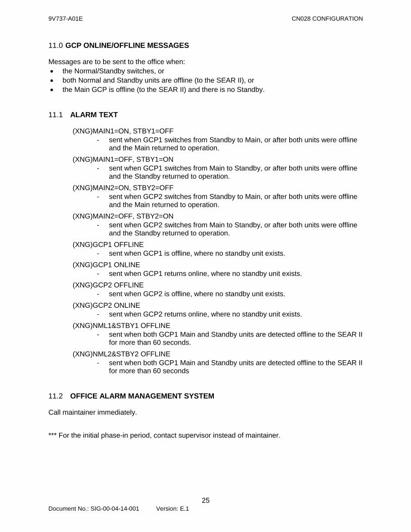
11.0 GCP ONLINE/OFFLINE MESSAGES
Messages are to be sent to the office when: • the Normal/Standby switches, or • both Normal and Standby units are offline (to the SEAR II), or • the Main GCP is offline (to the SEAR II) and there is no Standby.
11.1 ALARM TEXT
(XNG)MAIN1=ON, STBY1=OFF - sent when GCP1 switches from Standby to Main, or after both units were offline
and the Main returned to operation. (XNG)MAIN1=OFF, STBY1=ON
- sent when GCP1 switches from Main to Standby, or after both units were offline and the Standby returned to operation.
(XNG)MAIN2=ON, STBY2=OFF - sent when GCP2 switches from Standby to Main, or after both units were offline
and the Main returned to operation. (XNG)MAIN2=OFF, STBY2=ON
- sent when GCP2 switches from Main to Standby, or after both units were offline and the Standby returned to operation.
(XNG)GCP1 OFFLINE - sent when GCP1 is offline, where no standby unit exists.
(XNG)GCP1 ONLINE - sent when GCP1 returns online, where no standby unit exists.
(XNG)GCP2 OFFLINE - sent when GCP2 is offline, where no standby unit exists.
(XNG)GCP2 ONLINE - sent when GCP2 returns online, where no standby unit exists.
(XNG)NML1&STBY1 OFFLINE - sent when both GCP1 Main and Standby units are detected offline to the SEAR II
for more than 60 seconds. (XNG)NML2&STBY2 OFFLINE
- sent when both GCP1 Main and Standby units are detected offline to the SEAR II for more than 60 seconds
11.2 OFFICE ALARM MANAGEMENT SYSTEM
Call maintainer immediately. *** For the initial phase-in period, contact supervisor instead of maintainer.
9V737-A01E CN028 CONFIGURATION
26 Document No.: SIG-00-04-14-001 Version: E.1
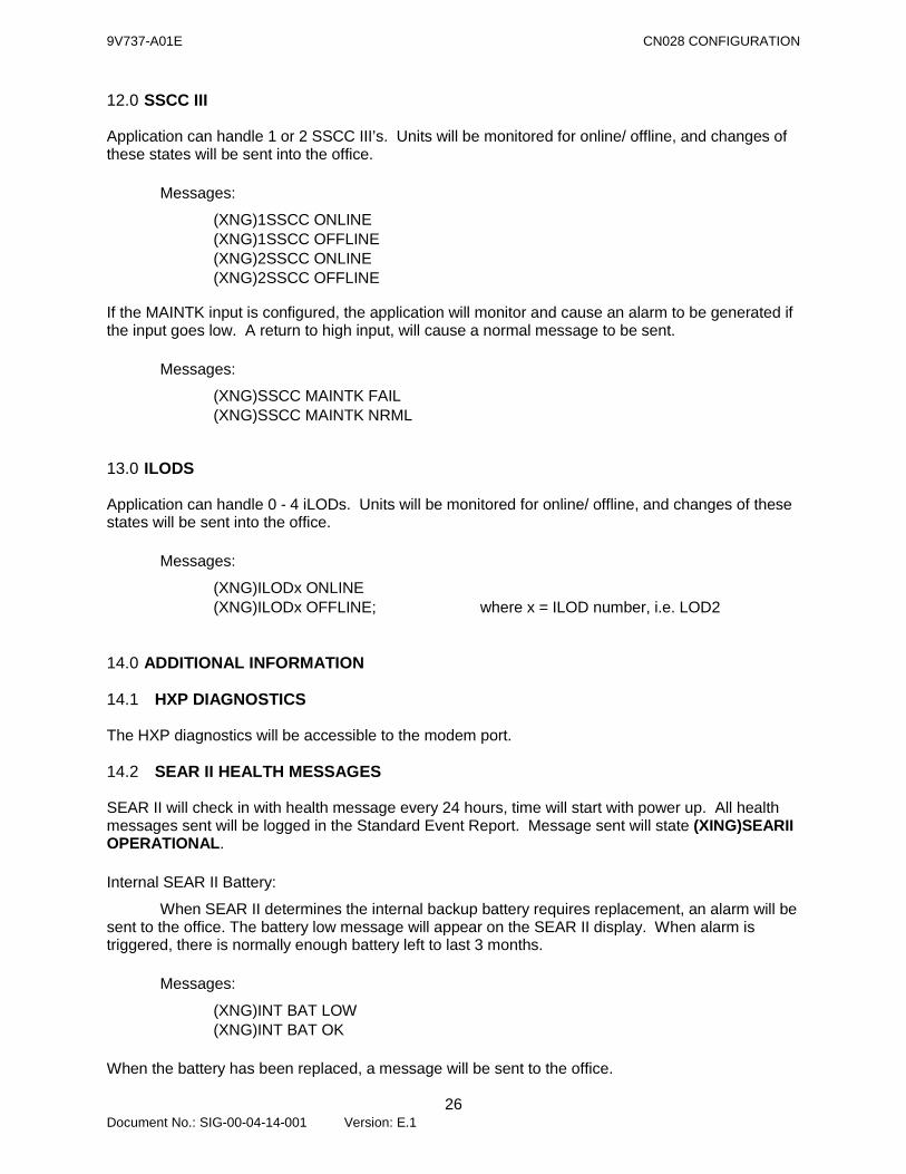
12.0 SSCC III
Application can handle 1 or 2 SSCC III’s. Units will be monitored for online/ offline, and changes of these states will be sent into the office. Messages:
(XNG)1SSCC ONLINE (XNG)1SSCC OFFLINE (XNG)2SSCC ONLINE (XNG)2SSCC OFFLINE
If the MAINTK input is configured, the application will monitor and cause an alarm to be generated if the input goes low. A return to high input, will cause a normal message to be sent. Messages:
(XNG)SSCC MAINTK FAIL (XNG)SSCC MAINTK NRML
13.0 ILODS
Application can handle 0 - 4 iLODs. Units will be monitored for online/ offline, and changes of these states will be sent into the office. Messages:
(XNG)ILODx ONLINE (XNG)ILODx OFFLINE; where x = ILOD number, i.e. LOD2
14.0 ADDITIONAL INFORMATION
14.1 HXP DIAGNOSTICS
The HXP diagnostics will be accessible to the modem port.
14.2 SEAR II HEALTH MESSAGES
SEAR II will check in with health message every 24 hours, time will start with power up. All health messages sent will be logged in the Standard Event Report. Message sent will state (XING)SEARII OPERATIONAL. Internal SEAR II Battery:
When SEAR II determines the internal backup battery requires replacement, an alarm will be sent to the office. The battery low message will appear on the SEAR II display. When alarm is triggered, there is normally enough battery left to last 3 months. Messages:
(XNG)INT BAT LOW (XNG)INT BAT OK
When the battery has been replaced, a message will be sent to the office.
9V737-A01E CN028 CONFIGURATION
27 Document No.: SIG-00-04-14-001 Version: E.1
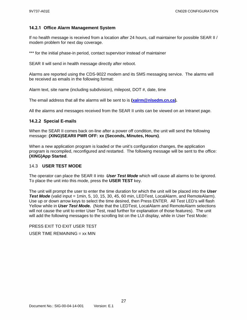
14.2.1 Office Alarm Management System
If no health message is received from a location after 24 hours, call maintainer for possible SEAR II / modem problem for next day coverage. *** for the initial phase-in period, contact supervisor instead of maintainer SEAR II will send in health message directly after reboot. Alarms are reported using the CDS-9022 modem and its SMS messaging service. The alarms will be received as emails in the following format: Alarm text, site name (including subdivision), milepost, DOT #, date, time The email address that all the alarms will be sent to is ([email protected]). All the alarms and messages received from the SEAR II units can be viewed on an Intranet page.
14.2.2 Special E-mails
When the SEAR II comes back on-line after a power off condition, the unit will send the following message: (XING)SEARII PWR OFF: xx (Seconds, Minutes, Hours). When a new application program is loaded or the unit’s configuration changes, the application program is recompiled, reconfigured and restarted. The following message will be sent to the office: (XING)App Started.
14.3 USER TEST MODE
The operator can place the SEAR II into User Test Mode which will cause all alarms to be ignored. To place the unit into this mode, press the USER TEST key. The unit will prompt the user to enter the time duration for which the unit will be placed into the User Test Mode (valid input = 1min, 5, 10, 15, 30, 45, 60 min, LEDTest, LocalAlarm, and RemoteAlarm). Use up or down arrow keys to select the time desired, then Press ENTER. All Test LED’s will flash Yellow while in User Test Mode. (Note that the LEDTest, LocalAlarm and RemoteAlarm selections will not cause the unit to enter User Test, read further for explanation of those features). The unit will add the following messages to the scrolling list on the LUI display, while in User Test Mode: PRESS EXIT TO EXIT USER TEST
USER TIME REMAINING = xx MIN
9V737-A01E CN028 CONFIGURATION
28 Document No.: SIG-00-04-14-001 Version: E.1
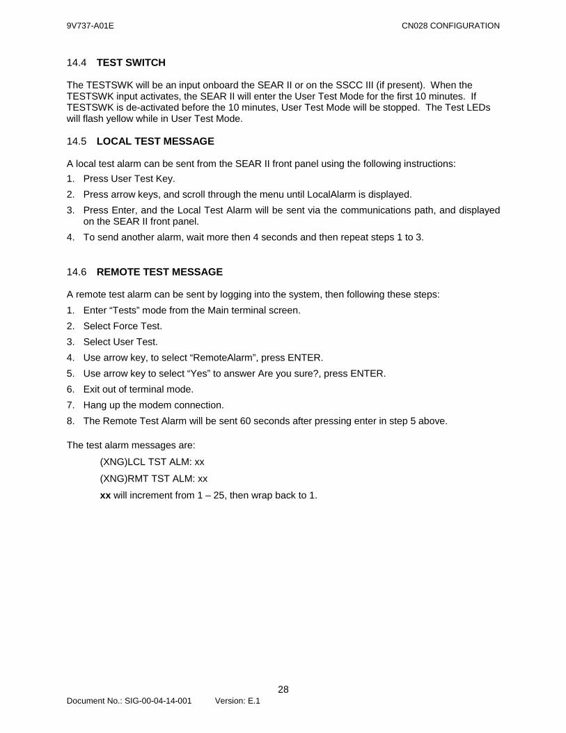
14.4 TEST SWITCH
The TESTSWK will be an input onboard the SEAR II or on the SSCC III (if present). When the TESTSWK input activates, the SEAR II will enter the User Test Mode for the first 10 minutes. If TESTSWK is de-activated before the 10 minutes, User Test Mode will be stopped. The Test LEDs will flash yellow while in User Test Mode.
14.5 LOCAL TEST MESSAGE
A local test alarm can be sent from the SEAR II front panel using the following instructions: 1. Press User Test Key. 2. Press arrow keys, and scroll through the menu until LocalAlarm is displayed. 3. Press Enter, and the Local Test Alarm will be sent via the communications path, and displayed
on the SEAR II front panel. 4. To send another alarm, wait more then 4 seconds and then repeat steps 1 to 3.
14.6 REMOTE TEST MESSAGE
A remote test alarm can be sent by logging into the system, then following these steps: 1. Enter “Tests” mode from the Main terminal screen. 2. Select Force Test. 3. Select User Test. 4. Use arrow key, to select “RemoteAlarm”, press ENTER. 5. Use arrow key to select “Yes” to answer Are you sure?, press ENTER. 6. Exit out of terminal mode. 7. Hang up the modem connection. 8. The Remote Test Alarm will be sent 60 seconds after pressing enter in step 5 above. The test alarm messages are:
(XNG)LCL TST ALM: xx
(XNG)RMT TST ALM: xx
xx will increment from 1 – 25, then wrap back to 1.
9V737-A01E CN028 CONFIGURATION
29 Document No.: SIG-00-04-14-001 Version: E.1
14.7 INDICATOR LED TEST
The operator can place the SEAR II into LED Test Mode which will cause the 16 Indicator LED’s to light steady for 10 seconds. To place the unit into this mode, press the USER TEST key. The unit will prompt the user with user test time selections, shown in the display. Press the Up or Down Arrow keys until “LEDTest” is displayed. Then press the ENTER key. The 16 Indicator LED’s will light steady for 10 seconds, then revert to the normal operating state, as defined in the application logic.
15.0 DIALING INTO A SEAR II LOCATION
(For a location with a cellular modem.)
15.1 TO OBTAIN SEAR II STANDARD EVENT REPORT:
Open a HyperTerminal session with 8-N-1 connection settings (8 Data bits, No Parity and 1 stop bit). Enter the phone number associated with the SEAR II location to connect to (e.g. 116302226145 for Wabash Avenue) and Dial (note that the phone number associated with each alarm can be found in the sender’s email address and is available on the server at \\EDM-RG-F05\TWR21HW2\CROSSING MONITOR\SEARII\Locations). Upon connecting, press Ctrl-L to display the password prompt, enter ssc as the password. The Main menu will now appear, use the down arrow to go to Option B) Reports and press ENTER. Press ENTER with ‘A) Standard Report’ highlighted on the screen. Specify the Start and End date/time for the report desired, press ENTER to accept date/time range. Use the down arrow to change the Format to Print/Capture, press ENTER. When prompted to “Enable text capturing then hit any key”, enable text capturing by going to Transfer – Capture Text and enter a file name. Press any key. The SEAR II Standard Event Report is now being printed on the screen and being captured in the file specified. When prompted to “Stop text capturing then hit any key to return”, stop text capturing by going to Transfer – Capture Text and select Stop. Press any key. Use the down arrow to go to Exit (to exit the Reports menu). Use the down arrow to go to Exit (to exit the Main Menu). Close Hyper Terminal session and review the SEAR II Standard Event Report obtained.
9V737-A01E CN028 CONFIGURATION
30 Document No.: SIG-00-04-14-001 Version: E.1
15.2 TO OBTAIN TRAIN SPEED INFORMATION FOR AN HXP LOCATION:
From the Main menu, use the down arrow to go to Option J) Passthrough.
Press any key to enter the pass-through mode.
Press ENTER to display the HXP Recorder Main Menu.
Enable text capturing by going to Transfer – Capture Text and enter a file name.
Select Option 1 to Print Train Record Log.
The HXP Train Record Log is now being printed on the screen and being captured in the file specified.
When the HXP Recorder Main Menu appears again, stop text capturing by going to Transfer – Capture Text and select Stop.
Press Ctrl-X to exit the pass-through mode.
Press any key to return to the SEAR II Main Menu.

9V737-A01E CN028 CONFIGURATION
31 Document No.: SIG-00-04-14-001 Version: E.1
NOTES

Siemens Industry, Inc., Rail Automation 2400 Nelson Miller Parkway Louisville, Kentucky 40223
(502) 618-8800
Siemens Industry, Inc., Rail Automation California R&D Division
9568 Archibald Ave., Suite 100 Rancho Cucamonga, California 91730
(909) 532-5300