
Circular Seamless Stainless Steel Hollow Products from Japan
Seamless Model-Based Design and Deploymentof Wireless Networked Systems
Tobias Schwalb, Tobias Gadeke, Johannes Schmid and Klaus D. Muller-GlaserKarlsruhe Institute of Technology, Institute for Information Processing Technologies
Engesserstr. 5, 76131 Karlsruhe, GermanyEmail: {tobias.schwalb, tobias.gaedeke, johannes.schmid, klaus.mueller-glaser}@kit.edu
Abstract—To allow for rapid abstract development of algo-rithms, model-based tools are often used nowadays. These toolssupport design using predefined blocks, adaptation using param-eters, simulation in a virtual environment and also generationof code for programming embedded devices. However, there isusually no direct connection between the embedded system andthe model for programming and runtime control and monitoring.
In this paper, we present a seamless tool chain for model-based algorithm development, simulation and integration on anembedded system as well as runtime control and monitoringfrom model level. Based on our concept, the development ofalgorithms can largely be separated from the execution platformand its control and monitoring possibilities. Yet, it is possibleto feedback monitored data to support the simulation. Theconcept is integrated and evaluated and its applicability for thedevelopment of an algorithm is demonstrated by means of anexample from the field of wireless senor networks localization.
We conclude that the outlined approach offers a simpleopportunity to reduce development overhead.
I. INTRODUCTION
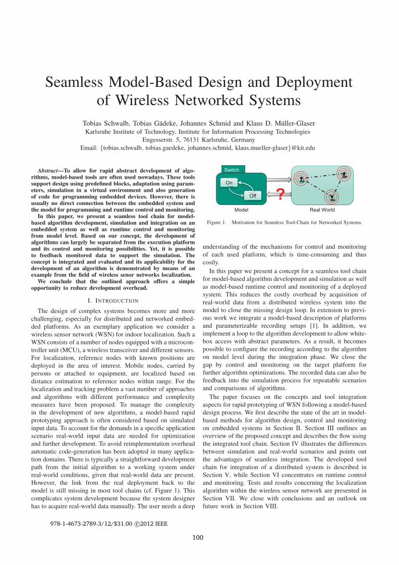
The design of complex systems becomes more and morechallenging, especially for distributed and networked embed-ded platforms. As an exemplary application we consider awireless sensor network (WSN) for indoor localization. Such aWSN consists of a number of nodes equipped with a microcon-troller unit (MCU), a wireless transceiver and different sensors.For localization, reference nodes with known positions aredeployed in the area of interest. Mobile nodes, carried bypersons or attached to equipment, are localized based ondistance estimation to reference nodes within range. For thelocalization and tracking problem a vast number of approachesand algorithms with different performance and complexitymeasures have been proposed. To manage the complexityin the development of new algorithms, a model-based rapidprototyping approach is often considered based on simulatedinput data. To account for the demands in a specific applicationscenario real-world input data are needed for optimizationand further development. To avoid reimplementation overheadautomatic code-generation has been adopted in many applica-tion domains. There is typically a straightforward developmentpath from the initial algorithm to a working system underreal-world conditions, given that real-world data are present.However, the link from the real deployment back to themodel is still missing in most tool chains (cf. Figure 1). Thiscomplicates system development because the system designerhas to acquire real-world data manually. The user needs a deep
? Real World
On
Off
Switch
Model
Figure 1. Motivation for Seamless Tool-Chain for Networked Systems.
understanding of the mechanisms for control and monitoringof each used platform, which is time-consuming and thuscostly.
In this paper we present a concept for a seamless tool chainfor model-based algorithm development and simulation as wellas model-based runtime control and monitoring of a deployedsystem. This reduces the costly overhead by acquisition ofreal-world data from a distributed wireless system into themodel to close the missing design loop. In extension to previ-ous work we integrate a model-based description of platformsand parameterizable recording setups [1]. In addition, weimplement a loop to the algorithm development to allow white-box access with abstract parameters. As a result, it becomespossible to configure the recording according to the algorithmon model level during the integration phase. We close thegap by control and monitoring on the target platform forfurther algorithm optimizations. The recorded data can also befeedback into the simulation process for repeatable scenariosand comparisons of algorithms.
The paper focuses on the concepts and tool integrationaspects for rapid prototyping of WSN following a model-baseddesign process. We first describe the state of the art in model-based methods for algorithm design, control and monitoringon embedded systems in Section II. Section III outlines anoverview of the proposed concept and describes the flow usingthe integrated tool chain. Section IV illustrates the differencesbetween simulation and real-world scenarios and points outthe advantages of seamless integration. The developed toolchain for integration of a distributed system is described inSection V, while Section VI concentrates on runtime controland monitoring. Tests and results concerning the localizationalgorithm within the wireless sensor network are presented inSection VII. We close with conclusions and an outlook onfuture work in Section VIII.
978-1-4673-2789-3/12/$31.00 c©2012 IEEE
100
II. RELATED WORK
In this section we discuss the state of the art for model-baseddesign methods of embedded systems and their connectionduring runtime, especially considering WSN.
A. Design of Embedded Systems and Platform Models
In general, development of embedded systems follows theV-Model in the different phases for design, integration andtest [2]. In many application domains, design of complexalgorithms and systems is mainly performed using model-based tools. Well-known tools in this area are for examplethe Matlab-Simlink package [3], Ascet [4] and Labview [5].These provide predefined building blocks with adaptable func-tionalities, which can be connected to form complex systems.Furthermore, these tools allow the simulation of algorithmsand their environments as well as support code generation (e.g.C-code) for integration on embedded platforms. In our conceptwe use Matlab/Simulink for the design and simulation of thealgorithm, as it is an established tool package used by manydevelopers. We connect it with our concept of component-based runtime control and monitoring.
Usually a model-integrated approach is used for the de-velopment of embedded systems. Thereby, domain specificlanguages (DSL), defined in metamodels, are integrated fordescribing different aspects and allow for example imple-mentation, analysis and verification. In addition to principlesand techniques of model-integrated embedded software devel-opment, Karsai et al. describe the capabilities of associatedtools [6]. A Unified Modeling Language (UML) profile forabstract specification, analysis and design of complex real-time embedded systems is the Modeling and Analysis ofReal-Time and Embedded systems profile (MARTE) [7]. Itis mainly used for design [8], but does not consider runtimeaspects. Another technique is to use abstract component-based representations of systems. A comparison of differentframeworks used for real-time embedded systems is given in[9]. We use a component-based representation in our concept,based on our previous work [1]. In this paper we extend thepresented component model by the description of platformsand debugging scenarios.
The development of embedded systems using platform-based descriptions and a rigorous methodology for embeddedsoftware development is discussed in [10]. Cordeiro et al.present an agile development methodology for embeddedsystems by using platform-based design to support systemconstraints and reduce costs [11]. Comparing to these, we con-centrate on describing the abilities of the platforms concerningcontrol, monitoring and on-chip recording.
B. Model-based Control and Monitoring
Model-based monitoring for embedded targets is supportedby Matlab / Simulink. Especially using the Stateflow toolbox,which describes Statechart diagrams [3]. However, real-timemonitoring is rarely considered and only special target systemsare supported. Other available tool chains include a runtime
management based on components, but consider specific do-mains. A component-based hierarchical software platform forautomotive electronics is shown in [12]. It shows a seriesof tools for model-driven development, visual configurationand automatic code generation. In [13], Gu et al. present anend-to-end tool-chain for model-based design and analysis ofcomponent-based embedded real-time software in the avionicsdomain. It includes the configuration of source code as wellas runtime instrumentation and statistics that are fed back intomodels. A framework for debugging at design- and runtime byvalidating interactions between components is shown in [14].The control of debugging structures on reconfigurable hard-ware from model level using functional models is discussedin [15]. In comparison, in our concept we use an architecturalmodel, which relates to the structure of the system.
C. Tool chains for Wireless Sensor Networks
While model-based design methods have been adoptedfor a range of application domains, applications for WSNare still typically hand-coded today. For actual deploymentsoperating systems which take strong limitations in resources(e.g., performance, bandwidth, energy) into account have beendeveloped during the last years [16]. Along with the operatingsystems, WSN simulators have been used. They allow for arapid deployment of code, tested in simulations [17]. However,still hand-coding is needed and thus needs a deep under-standing of the system. Also, the integration with real-worlddata is complex because of the missing feedback link fromreal-world to development. A model-based framework for thedevelopment of wireless sensor-networks has been presentedin [18]. The presented method, however, concentrates on thedesign phase of the network and does not address runtimeoperation of the network. In general, it can be concludedthat there is still a strong lack of seamless tool integrationespecially in the domain of WSN.
III. CONCEPT
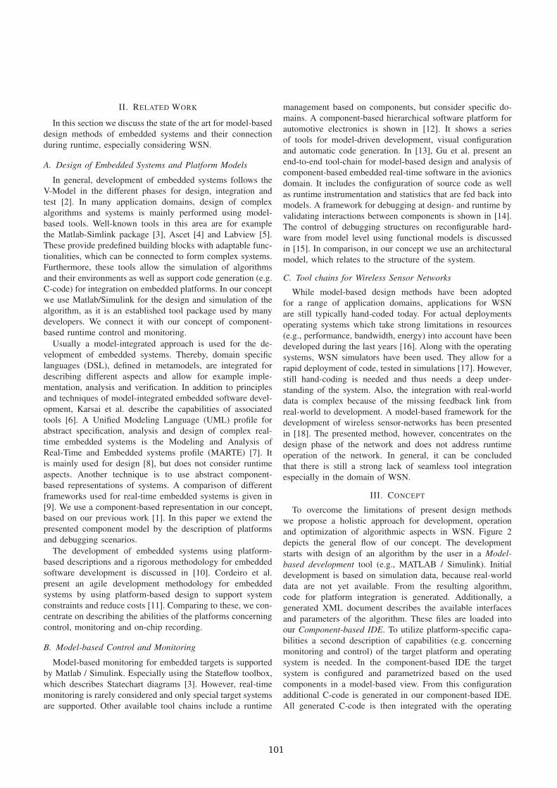
To overcome the limitations of present design methodswe propose a holistic approach for development, operationand optimization of algorithmic aspects in WSN. Figure 2depicts the general flow of our concept. The developmentstarts with design of an algorithm by the user in a Model-based development tool (e.g., MATLAB / Simulink). Initialdevelopment is based on simulation data, because real-worlddata are not yet available. From the resulting algorithm,code for platform integration is generated. Additionally, agenerated XML document describes the available interfacesand parameters of the algorithm. These files are loaded intoour Component-based IDE. To utilize platform-specific capa-bilities a second description of capabilities (e.g. concerningmonitoring and control) of the target platform and operatingsystem is needed. In the component-based IDE the targetsystem is configured and parametrized based on the usedcomponents in a model-based view. From this configurationadditional C-code is generated in our component-based IDE.All generated C-code is then integrated with the operating
101
Model-based development IDE
Simulation �� Real-World Data
C-Code
Platform specific IDE
Network Stack
Algorithm Module
Control & Monitoring
e
Interfaces & Parameters
C
Component (Sensor Node)
Network Connection
Algorithm
es &
Platform description
Component - based IDE
Model C-Code
Runtime Data
Platform Configuration
Runtime Connection
Programming
C C
NeCo
Code- generation
Control and Monitoring
ata Ru
Figure 2. Concept for Model-Based Design, Control and Monitoring of Embedded Systems.
system and network stack. In the next step, the whole system iscompiled and linked by a Platform specific IDE. The resultingbinary file is loaded into the nodes program-memory, either bya wired link or an over-the-air upgrade method.
After programming the network runs and can be controlledand monitored by the same Component-based IDE, which isused to setup the platform configuration during integration.Thereby, the network is shown in an abstract component-basedrepresentation on model level (see Figure 6). Parameters of theindividual components can be controlled and the status of thenodes monitored. One of the main advantages is the introducedfeedback loop. Data from a real-world deployment can beeither recorded in the Component-based IDE or according tothe setup of the platforms on the nodes in the network, whichare equipped with SD-cards. After the data are recorded, theycan be fed back into the model-based development tool foroptimization and improvement of the algorithms. We split themodel-based development and the platform configuration, con-trol and monitoring into different tools as we want to use onone hand established present tools for algorithm developmentand on the other hand applicable DSLs for our application.
IV. SIMULATION VS. REAL-WORLD TESTING
In general, simulation and real-world tests are used for theimprovement of algorithm performance and identification oferrors. The main advantage of simulations is that no realhardware system is needed, resulting in a test possibility atan early stage in the development process. Additionally, allsignals are accessible and can be monitored as well as directlyrelated to the designed model. Furthermore, the environmentcan be made predictable, in a way that tests or evaluations canbe reproduced with different scenarios.
However, the additional integration of the environment(including other interacting systems) is also the main dis-advantage of a simulation. There is always a trade-off inmodel building between a realistic and a simple model ofthe environment. For realistic models high costs need to be
considered as it is not part of the sold product and it is complexto represent realistic environments. Therefore, there are alwayslimitations in simulating reality. In real-world tests, in contrast,the environment is directly present, however many situationscannot be exactly reproduced. The main disadvantages of real-world tests are the need of real hardware, limited access tointernal signals and the usually missing connection to thedevelopment model of the algorithm. Tests in the design phaseare often performed using prototyping systems, with highcomputing power and additional interfaces, as the real systemis not available. However, these need customized software andtreatment for control and monitoring mostly.
In general both methods are necessary. In our wirelesssensor network example we use simulation for algorithm op-timization and real-world tests for environment tests. Also weintegrate data recorded on real-world tests in the simulationsto combine the advantages of reproducible tests and real data.
V. DESIGN AND INTEGRATION
In this section we discuss the integration phase and con-centrate on the simulation and programming process. Addi-tionally, we describe the developed metamodel for platformrepresentation and recording setups.
A. Simulation and Programming
Algorithm development is an important step in order todesign robust and reliable systems. In the following, wefocus on two different exemplary algorithms for localization.Both are based on distance estimations between nodes bymeasuring the received signal strength (RSS). Fixed anchornodes broadcast their positions periodically and mobile nodescalculate their own position based on the chosen algorithmand parameters. Due to the fluctuating behavior of RSS underdifferent environmental conditions, parameters have to be care-fully evaluated and filtering needs to be applied for reasonableresults. A very common stochastic filter used for informationfusion, especially in localization and navigation, is the Kalman
102
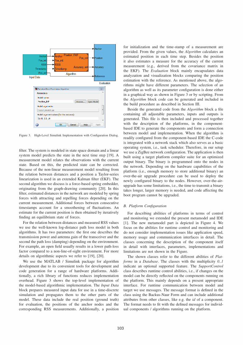
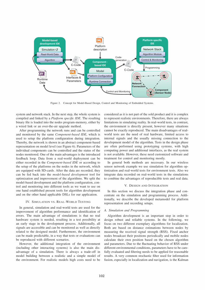
Figure 3. High-Level Simulink Implementation with Configuration Dialog.
filter. The system is modeled in state space domain and a linearsystem model predicts the state in the next time step [19]. Ameasurement model relates the observations with the currentstate. Based on this, the predicted state can be corrected.Because of the non-linear measurement model resulting fromthe relation between distances and a position a Taylor-serieslinearization is used in an extended Kalman filter (EKF). Thesecond algorithm we discuss is a force-based spring embedder,originating from the graph-drawing community [20]. In thisfilter, estimated distances in the network are modeled by springforces with attracting and repelling forces depending on thecurrent measurement. Additional forces between consecutivetimestamps account for a smoothening of fluctuations. Anestimate for the current position is then obtained by iterativelyfinding an equilibrium state of forces.
For the relation between distances and measured RSS valueswe use the well-known log-distance path loss model in bothalgorithms. It has two parameters: the first one describes thetransmission power and antenna gain of the transceiver and thesecond the path loss (damping) depending on the environment.For example, an open field usually results in a lower path-lossfactor compared to a non-line-of-sight environment. For moredetails on algorithmic aspects we refer to [19], [20].
We use the MATLAB / Simulink package for algorithmdevelopment due to its convenient tools for development andcode generation for a range of hardware platforms. Addi-tionally, a rich library of functions reduces implementationoverhead. Figure 3 shows the top-level implementation ofthe model-based algorithmic implementation. The Input Datablock prepares measured input data for use in a time-discretesimulation and propagates them to the other parts of themodel. These data include the real position (ground truth)for evaluation, the positions of the anchor nodes and thecorresponding RSS measurements. Additionally, a position
for initialization and the time-stamp of a measurement areprovided. From the given values, the Algorithm calculates anestimated position in each time step. Besides the positionit also estimates a measure for the accuracy of the currentmeasurement (e.g., derived from the covariance matrix inthe EKF). The Evaluation block mainly encapsulates dataanalyzation and visualization blocks comparing the positionestimation with the reference. As mentioned above, the algo-rithms might have different parameters. The selection of analgorithm as well as its parameter configuration is done eitherin a graphical way as shown in Figure 3 or by scripting. Fromthe Algorithm block code can be generated and included inthe build procedure as described in Section III.
Beside the generated code from the Algorithm block a filecontaining all adjustable parameters, inputs and outputs isgenerated. This file is then included and processed togetherwith the description of the platforms, in the component-based IDE to generate the components and form a connectionbetween model and implementation. When the algorithm isreadily configured from the component-based IDE the C-codeis integrated with a network stack which also serves as a basicoperating system, i.e., task scheduler. Therefore, in our setupwe use a ZigBee network configuration. The application is thenbuilt using a target platform compiler suite for an optimizedoutput binary. The binary is programmed onto the nodes inthe network. Depending on the hardware capabilities of theplatform (i.e., enough memory to store additional binary) anover-the-air upgrade procedure can be used to deploy thenewly configured binary to the nodes. However, over-the-air-upgrade has some limitations, i.e., the time to transmit a binarytakes longer, larger memory is needed, and code affecting theboot program cannot be upgraded.
B. Platform Configuration
For describing abilities of platforms in terms of controland monitoring we extended the present metamodel and IDE[1]. The new metamodel part is depicted in Figure 4. Wefocus on the abilities for runtime control and monitoring anddo not consider implementation issues like application speed,memory usage and communication interfaces in detail. Theclasses concerning the description of the component itselfin detail with interfaces, parameters, implementations andlimitations are not shown in the Figure.
The shown classes refer to the different abilities of Plat-forms in a Database. The classes with the multiplicity 0..1indicate an optional supported feature. The SupportControlclass describes runtime control abilities, i.e., if changes on themodel can be directly reflected on the components running onthe platform. This mainly depends on a present appropriateinterface. For runtime communication between model andtarget we use messages. The message format is defined in theclass using the Backus-Naur Form and can include additionalattributes from other classes, like e.g. the id of a component.The format needs to fit with the defined messages for individ-ual components / algorithms running on the platform.
103
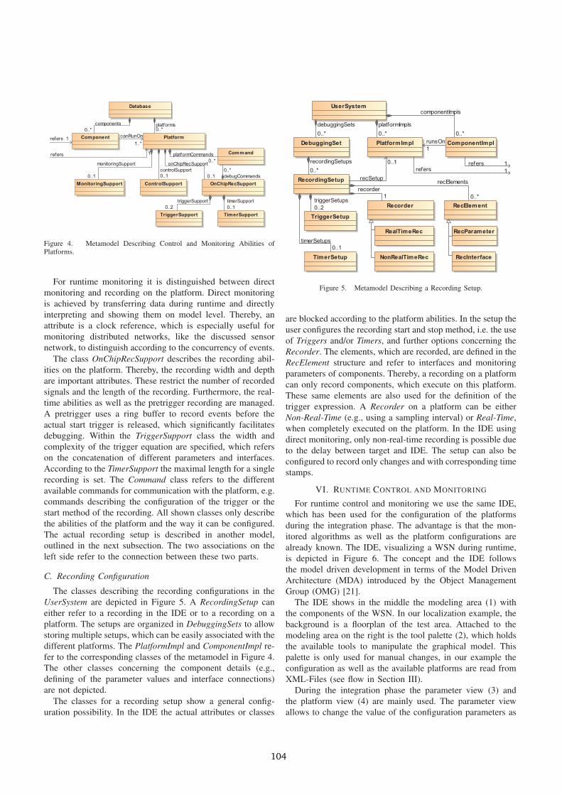
Figure 4. Metamodel Describing Control and Monitoring Abilities ofPlatforms.
For runtime monitoring it is distinguished between directmonitoring and recording on the platform. Direct monitoringis achieved by transferring data during runtime and directlyinterpreting and showing them on model level. Thereby, anattribute is a clock reference, which is especially useful formonitoring distributed networks, like the discussed sensornetwork, to distinguish according to the concurrency of events.
The class OnChipRecSupport describes the recording abil-ities on the platform. Thereby, the recording width and depthare important attributes. These restrict the number of recordedsignals and the length of the recording. Furthermore, the real-time abilities as well as the pretrigger recording are managed.A pretrigger uses a ring buffer to record events before theactual start trigger is released, which significantly facilitatesdebugging. Within the TriggerSupport class the width andcomplexity of the trigger equation are specified, which referson the concatenation of different parameters and interfaces.According to the TimerSupport the maximal length for a singlerecording is set. The Command class refers to the differentavailable commands for communication with the platform, e.g.commands describing the configuration of the trigger or thestart method of the recording. All shown classes only describethe abilities of the platform and the way it can be configured.The actual recording setup is described in another model,outlined in the next subsection. The two associations on theleft side refer to the connection between these two parts.
C. Recording Configuration
The classes describing the recording configurations in theUserSystem are depicted in Figure 5. A RecordingSetup caneither refer to a recording in the IDE or to a recording on aplatform. The setups are organized in DebuggingSets to allowstoring multiple setups, which can be easily associated with thedifferent platforms. The PlatformImpl and ComponentImpl re-fer to the corresponding classes of the metamodel in Figure 4.The other classes concerning the component details (e.g.,defining of the parameter values and interface connections)are not depicted.
The classes for a recording setup show a general config-uration possibility. In the IDE the actual attributes or classes
Figure 5. Metamodel Describing a Recording Setup.
are blocked according to the platform abilities. In the setup theuser configures the recording start and stop method, i.e. the useof Triggers and/or Timers, and further options concerning theRecorder. The elements, which are recorded, are defined in theRecElement structure and refer to interfaces and monitoringparameters of components. Thereby, a recording on a platformcan only record components, which execute on this platform.These same elements are also used for the definition of thetrigger expression. A Recorder on a platform can be eitherNon-Real-Time (e.g., using a sampling interval) or Real-Time,when completely executed on the platform. In the IDE usingdirect monitoring, only non-real-time recording is possible dueto the delay between target and IDE. The setup can also beconfigured to record only changes and with corresponding timestamps.
VI. RUNTIME CONTROL AND MONITORING
For runtime control and monitoring we use the same IDE,which has been used for the configuration of the platformsduring the integration phase. The advantage is that the mon-itored algorithms as well as the platform configurations arealready known. The IDE, visualizing a WSN during runtime,is depicted in Figure 6. The concept and the IDE followsthe model driven development in terms of the Model DrivenArchitecture (MDA) introduced by the Object ManagementGroup (OMG) [21].
The IDE shows in the middle the modeling area (1) withthe components of the WSN. In our localization example, thebackground is a floorplan of the test area. Attached to themodeling area on the right is the tool palette (2), which holdsthe available tools to manipulate the graphical model. Thispalette is only used for manual changes, in our example theconfiguration as well as the available platforms are read fromXML-Files (see flow in Section III).
During the integration phase the parameter view (3) andthe platform view (4) are mainly used. The parameter viewallows to change the value of the configuration parameters as
104
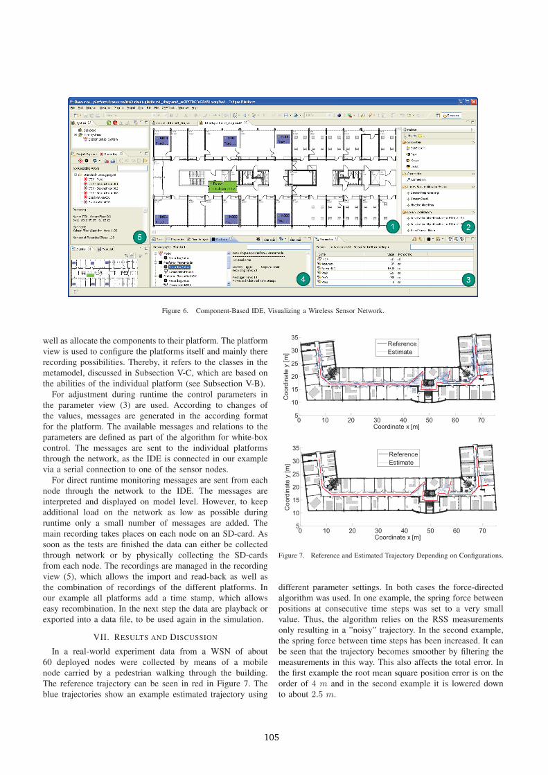
Figure 6. Component-Based IDE, Visualizing a Wireless Sensor Network.
well as allocate the components to their platform. The platformview is used to configure the platforms itself and mainly thererecording possibilities. Thereby, it refers to the classes in themetamodel, discussed in Subsection V-C, which are based onthe abilities of the individual platform (see Subsection V-B).
For adjustment during runtime the control parameters inthe parameter view (3) are used. According to changes ofthe values, messages are generated in the according formatfor the platform. The available messages and relations to theparameters are defined as part of the algorithm for white-boxcontrol. The messages are sent to the individual platformsthrough the network, as the IDE is connected in our examplevia a serial connection to one of the sensor nodes.
For direct runtime monitoring messages are sent from eachnode through the network to the IDE. The messages areinterpreted and displayed on model level. However, to keepadditional load on the network as low as possible duringruntime only a small number of messages are added. Themain recording takes places on each node on an SD-card. Assoon as the tests are finished the data can either be collectedthrough network or by physically collecting the SD-cardsfrom each node. The recordings are managed in the recordingview (5), which allows the import and read-back as well asthe combination of recordings of the different platforms. Inour example all platforms add a time stamp, which allowseasy recombination. In the next step the data are playback orexported into a data file, to be used again in the simulation.
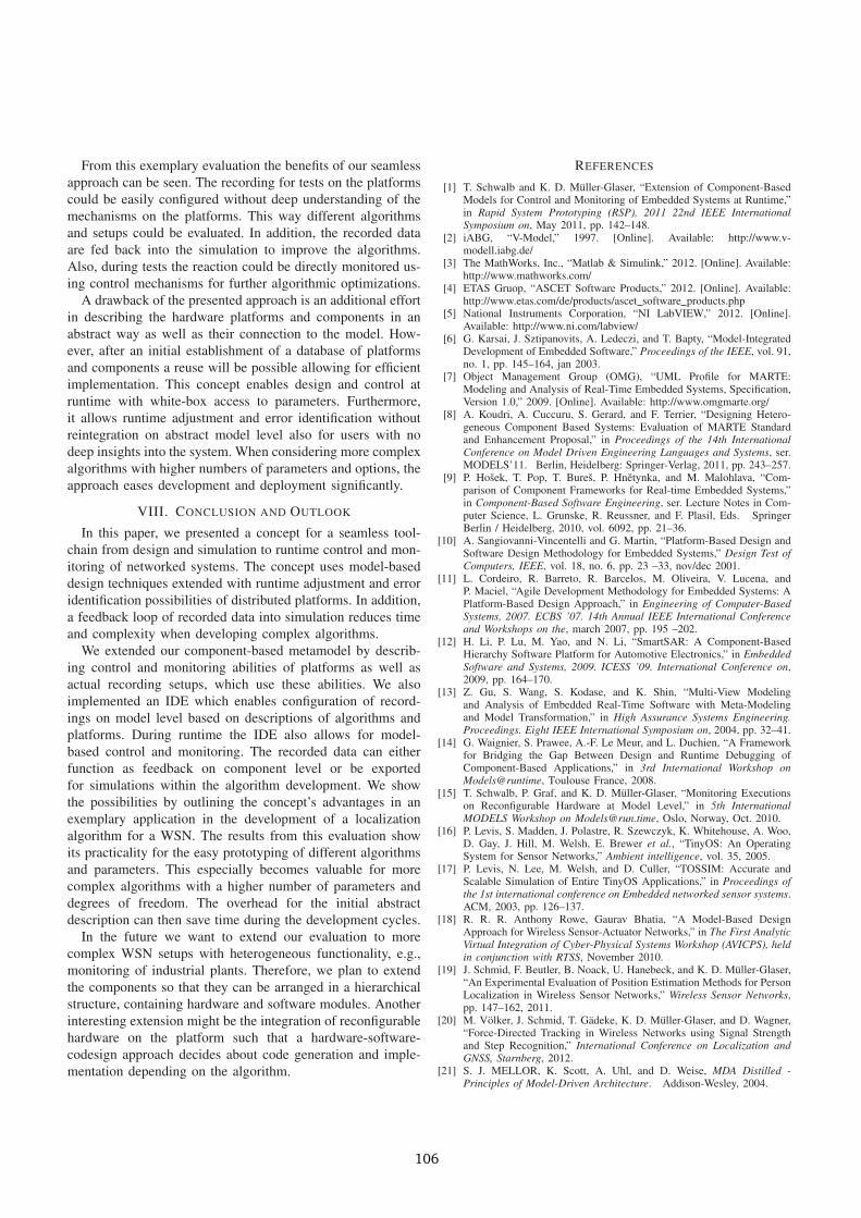
VII. RESULTS AND DISCUSSION
In a real-world experiment data from a WSN of about60 deployed nodes were collected by means of a mobilenode carried by a pedestrian walking through the building.The reference trajectory can be seen in red in Figure 7. Theblue trajectories show an example estimated trajectory using
0 10 20 30 40 50 60 705
10
15
20
25
30
35
Coordinate x [m]
Coo
rdin
ate
y [m
]
ReferenceEstimate
0 10 20 30 40 50 60 705
10
15
20
25
30
35
Coordinate x [m]
Coo
rdin
ate
y [m
]
ReferenceEstimate
Figure 7. Reference and Estimated Trajectory Depending on Configurations.
different parameter settings. In both cases the force-directedalgorithm was used. In one example, the spring force betweenpositions at consecutive time steps was set to a very smallvalue. Thus, the algorithm relies on the RSS measurementsonly resulting in a ”noisy” trajectory. In the second example,the spring force between time steps has been increased. It canbe seen that the trajectory becomes smoother by filtering themeasurements in this way. This also affects the total error. Inthe first example the root mean square position error is on theorder of 4 m and in the second example it is lowered downto about 2.5 m.
105
From this exemplary evaluation the benefits of our seamlessapproach can be seen. The recording for tests on the platformscould be easily configured without deep understanding of themechanisms on the platforms. This way different algorithmsand setups could be evaluated. In addition, the recorded dataare fed back into the simulation to improve the algorithms.Also, during tests the reaction could be directly monitored us-ing control mechanisms for further algorithmic optimizations.
A drawback of the presented approach is an additional effortin describing the hardware platforms and components in anabstract way as well as their connection to the model. How-ever, after an initial establishment of a database of platformsand components a reuse will be possible allowing for efficientimplementation. This concept enables design and control atruntime with white-box access to parameters. Furthermore,it allows runtime adjustment and error identification withoutreintegration on abstract model level also for users with nodeep insights into the system. When considering more complexalgorithms with higher numbers of parameters and options, theapproach eases development and deployment significantly.
VIII. CONCLUSION AND OUTLOOK
In this paper, we presented a concept for a seamless tool-chain from design and simulation to runtime control and mon-itoring of networked systems. The concept uses model-baseddesign techniques extended with runtime adjustment and erroridentification possibilities of distributed platforms. In addition,a feedback loop of recorded data into simulation reduces timeand complexity when developing complex algorithms.
We extended our component-based metamodel by describ-ing control and monitoring abilities of platforms as well asactual recording setups, which use these abilities. We alsoimplemented an IDE which enables configuration of record-ings on model level based on descriptions of algorithms andplatforms. During runtime the IDE also allows for model-based control and monitoring. The recorded data can eitherfunction as feedback on component level or be exportedfor simulations within the algorithm development. We showthe possibilities by outlining the concept’s advantages in anexemplary application in the development of a localizationalgorithm for a WSN. The results from this evaluation showits practicality for the easy prototyping of different algorithmsand parameters. This especially becomes valuable for morecomplex algorithms with a higher number of parameters anddegrees of freedom. The overhead for the initial abstractdescription can then save time during the development cycles.
In the future we want to extend our evaluation to morecomplex WSN setups with heterogeneous functionality, e.g.,monitoring of industrial plants. Therefore, we plan to extendthe components so that they can be arranged in a hierarchicalstructure, containing hardware and software modules. Anotherinteresting extension might be the integration of reconfigurablehardware on the platform such that a hardware-software-codesign approach decides about code generation and imple-mentation depending on the algorithm.
REFERENCES
[1] T. Schwalb and K. D. Muller-Glaser, “Extension of Component-BasedModels for Control and Monitoring of Embedded Systems at Runtime,”in Rapid System Prototyping (RSP), 2011 22nd IEEE InternationalSymposium on, May 2011, pp. 142–148.
[2] iABG, “V-Model,” 1997. [Online]. Available: http://www.v-modell.iabg.de/
[3] The MathWorks, Inc., “Matlab & Simulink,” 2012. [Online]. Available:http://www.mathworks.com/
[4] ETAS Gruop, “ASCET Software Products,” 2012. [Online]. Available:http://www.etas.com/de/products/ascet software products.php
[5] National Instruments Corporation, “NI LabVIEW,” 2012. [Online].Available: http://www.ni.com/labview/
[6] G. Karsai, J. Sztipanovits, A. Ledeczi, and T. Bapty, “Model-IntegratedDevelopment of Embedded Software,” Proceedings of the IEEE, vol. 91,no. 1, pp. 145–164, jan 2003.
[7] Object Management Group (OMG), “UML Profile for MARTE:Modeling and Analysis of Real-Time Embedded Systems, Specification,Version 1.0,” 2009. [Online]. Available: http://www.omgmarte.org/
[8] A. Koudri, A. Cuccuru, S. Gerard, and F. Terrier, “Designing Hetero-geneous Component Based Systems: Evaluation of MARTE Standardand Enhancement Proposal,” in Proceedings of the 14th InternationalConference on Model Driven Engineering Languages and Systems, ser.MODELS’11. Berlin, Heidelberg: Springer-Verlag, 2011, pp. 243–257.
[9] P. Hosek, T. Pop, T. Bures, P. Hnetynka, and M. Malohlava, “Com-parison of Component Frameworks for Real-time Embedded Systems,”in Component-Based Software Engineering, ser. Lecture Notes in Com-puter Science, L. Grunske, R. Reussner, and F. Plasil, Eds. SpringerBerlin / Heidelberg, 2010, vol. 6092, pp. 21–36.
[10] A. Sangiovanni-Vincentelli and G. Martin, “Platform-Based Design andSoftware Design Methodology for Embedded Systems,” Design Test ofComputers, IEEE, vol. 18, no. 6, pp. 23 –33, nov/dec 2001.
[11] L. Cordeiro, R. Barreto, R. Barcelos, M. Oliveira, V. Lucena, andP. Maciel, “Agile Development Methodology for Embedded Systems: APlatform-Based Design Approach,” in Engineering of Computer-BasedSystems, 2007. ECBS ’07. 14th Annual IEEE International Conferenceand Workshops on the, march 2007, pp. 195 –202.
[12] H. Li, P. Lu, M. Yao, and N. Li, “SmartSAR: A Component-BasedHierarchy Software Platform for Automotive Electronics,” in EmbeddedSoftware and Systems, 2009. ICESS ’09. International Conference on,2009, pp. 164–170.
[13] Z. Gu, S. Wang, S. Kodase, and K. Shin, “Multi-View Modelingand Analysis of Embedded Real-Time Software with Meta-Modelingand Model Transformation,” in High Assurance Systems Engineering.Proceedings. Eight IEEE International Symposium on, 2004, pp. 32–41.
[14] G. Waignier, S. Prawee, A.-F. Le Meur, and L. Duchien, “A Frameworkfor Bridging the Gap Between Design and Runtime Debugging ofComponent-Based Applications,” in 3rd International Workshop onModels@runtime, Toulouse France, 2008.
[15] T. Schwalb, P. Graf, and K. D. Muller-Glaser, “Monitoring Executionson Reconfigurable Hardware at Model Level,” in 5th InternationalMODELS Workshop on [email protected], Oslo, Norway, Oct. 2010.
[16] P. Levis, S. Madden, J. Polastre, R. Szewczyk, K. Whitehouse, A. Woo,D. Gay, J. Hill, M. Welsh, E. Brewer et al., “TinyOS: An OperatingSystem for Sensor Networks,” Ambient intelligence, vol. 35, 2005.
[17] P. Levis, N. Lee, M. Welsh, and D. Culler, “TOSSIM: Accurate andScalable Simulation of Entire TinyOS Applications,” in Proceedings ofthe 1st international conference on Embedded networked sensor systems.ACM, 2003, pp. 126–137.
[18] R. R. R. Anthony Rowe, Gaurav Bhatia, “A Model-Based DesignApproach for Wireless Sensor-Actuator Networks,” in The First AnalyticVirtual Integration of Cyber-Physical Systems Workshop (AVICPS), heldin conjunction with RTSS, November 2010.
[19] J. Schmid, F. Beutler, B. Noack, U. Hanebeck, and K. D. Muller-Glaser,“An Experimental Evaluation of Position Estimation Methods for PersonLocalization in Wireless Sensor Networks,” Wireless Sensor Networks,pp. 147–162, 2011.
[20] M. Volker, J. Schmid, T. Gadeke, K. D. Muller-Glaser, and D. Wagner,“Force-Directed Tracking in Wireless Networks using Signal Strengthand Step Recognition,” International Conference on Localization andGNSS, Starnberg, 2012.
[21] S. J. MELLOR, K. Scott, A. Uhl, and D. Weise, MDA Distilled -Principles of Model-Driven Architecture. Addison-Wesley, 2004.
106
Copyright © 2022 FDOKUMEN