SE5a UM Manual - Stevens AeroModel
39
SE5.a Britain's WWI Anti-Tyranny Aerial Platform Wing Span: 14.5 inches | Wing Area: 76 square inches | Average Flying Weight: 1.6 ounces Build Instructions - Version 1.0 (revised 05.13.2014) Build Instructions SE5.a UM Build Instructions. © 2013 Stevens AeroModel all rights reserved. Page 1
-
Upload
khangminh22 -
Category
Documents
-
view
1 -
download
0
Transcript of SE5a UM Manual - Stevens AeroModel

SE5.a
Britain's WWI Anti-Tyranny Aerial PlatformWing Span: 14.5 inches | Wing Area: 76 square inches | Average Flying Weight: 1.6 ounces
Build Instructions - Version 1.0 (revised 05.13.2014)
Build Instructions
SE5.a UM Build Instructions. © 2013 Stevens AeroModel all rights reserved.! Page 1

WARRANTY
Stevens AeroModel guarantees this kit to be free from defects in both material and workmanship at the date of purchase. This warranty does not cover any component parts damaged by use or modification. In no case shall Stevens AeroModel’s liability exceed the original cost of the purchased kit. Further, Stevens AeroModel reserves the right to change or modify this warranty without notice.
LIABILITY RELEASE
In that Stevens AeroModel has no control over the final assembly or material used for final assembly, no liability shall be assumed nor accepted for any damage resulting from use by the user. By the act of using the user-assembled product, the user accepts all resulting liability.
If the buyer is not prepared to accept the liability associated with the use of this product, the buyer is advised to return this kit immediately in new and unused condition to the place of purchase.
THIS PRODUCT IS NOT INTENDED FOR CHILDREN 12 YEARS OF AGE OR YOUNGER.
WARNING: This product may contain chemicals known to the state of California to cause cancer and/or birth defects or other reproductive harm.
PRODUCT SUPPORT
This product has been engineered to function properly and perform as advertised, with the suggested power system and supporting electronics as outlined within this product manual. Product support cannot be provided, nor can Stevens AeroModel assist in determining the suitability or use of electronics, hardware, or power systems not explicitly recommended by Stevens AeroModel.
For product assembly support, replacement parts, hardware, and electronics to complete this model, please contact Stevens AeroModel at www.stevensaero.com.
Stevens AeroModel26405 Judge Orr Rd., Colorado Springs, CO 80808 USA719-387-4187 www.stevensaero.com
Build Instructions
SE5.a UM Build Instructions. © 2013 Stevens AeroModel all rights reserved.! Page 2
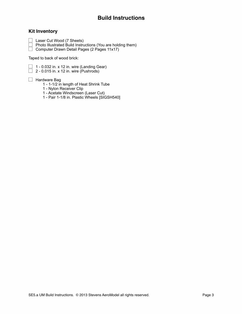
Kit Inventory
☐ Laser Cut Wood (7 Sheets)☐ Photo Illustrated Build Instructions (You are holding them)☐ Computer Drawn Detail Pages (2 Pages 11x17)
Taped to back of wood brick:
☐ 1 - 0.032 in. x 12 in. wire (Landing Gear)☐ 2 - 0.015 in. x 12 in. wire (Pushrods)
☐ Hardware Bag1 - 1-1/2 in length of Heat Shrink Tube1 - Nylon Receiver Clip1 - Acetate Windscreen (Laser Cut)1 - Pair 1-1/8 in. Plastic Wheels [SIGSH540]
Build Instructions
SE5.a UM Build Instructions. © 2013 Stevens AeroModel all rights reserved.! Page 3
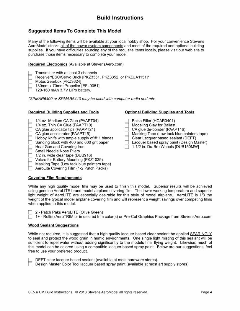
Suggested Items To Complete This Model
Many of the following items will be available at your local hobby shop. For your convenience Stevens AeroModel stocks all of the power system components and most of the required and optional building supplies. If you have difficulties sourcing any of the requisite items locally, please visit our web site to purchase those items necessary to complete your model.
Required Electronics (Available at StevensAero.com)
☐ Transmitter with at least 3 channels ☐ Receiver/ESC/Servo Brick [PKZ3351, PKZ3352, or PKZUA1151]*☐ Motor/Gearbox [PKZ3624]☐ 130mm x 70mm Propellor [EFL9051]☐ 120-160 mAh 3.7V LiPo battery.
*SPMAR6400 or SPMAR6410 may be used with computer radio and mix.
Covering Film Requirements
While any high quality model film may be used to finish this model. Superior results will be achieved using genuine AeroLITE brand model airplane covering film. The lower working temperature and superior light weight of AeroLITE are especially desirable for this style of model airplane. AeroLITE is 1/3 the weight of the typical model airplane covering film and will represent a weight savings over competing films when applied to this model.
☐ 2 - Patch Paks AeroLITE (Olive Green)☐ 1+ - Roll(s) AeroTRIM or in desired trim color(s) or Pre-Cut Graphics Package from StevensAero.com
Wood Sealant Suggestions
While not required, it is suggested that a high quality lacquer based clear sealant be applied SPARINGLY to seal and protect the wood grain in humid environments. One single light misting of this sealant will be sufficient to repel water without adding significantly to the models final flying weight. Likewise, much of this model can be colored using a compatible lacquer based spray paint. Below are our suggestions, feel free to use your preferred product.
☐ DEFT clear lacquer based sealant (available at most hardware stores).☐ Design Master Color Tool lacquer based spray paint (available at most art supply stores).
Required Building Supplies and Tools
☐ 1/4 oz. Medium CA Glue (PAAPT04)☐ 1/4 oz. Thin CA Glue (PAAPT10)☐ CA glue applicator tips (PAAPT21)☐ CA glue accelerator (PAAPT15)☐ Hobby Knife with ample supply of #11 blades☐ Sanding block with 400 and 600 grit paper☐ Heat Gun and Covering Iron☐ Small Needle Nose Pliers☐ 1/2 in. wide clear tape (DUB916)☐ Velcro for Battery Mounting (PKZ1039)☐ Masking Tape (Low tack blue painters tape)☐ AeroLite Covering Film (1-2 Patch Packs)
Optional Building Supplies and Tools
☐ Balsa Filler (HCAR3401)☐ Modeling Clay for Ballast☐ CA glue de-bonder (PAAPT16)☐ Masking Tape (Low tack blue painters tape)☐ Clear Lacquer based sealant (DEFT)☐ Lacquer based spray paint (Design Master)☐ 1-1/2 in. Du-Bro Wheels [DUB150MW]
Build Instructions
SE5.a UM Build Instructions. © 2013 Stevens AeroModel all rights reserved.! Page 4
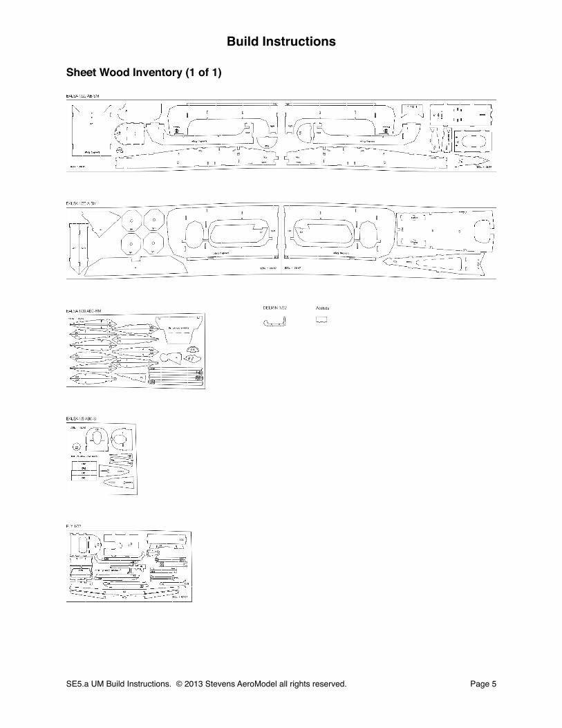
Sheet Wood Inventory (1 of 1)
Build Instructions
SE5.a UM Build Instructions. © 2013 Stevens AeroModel all rights reserved.! Page 5

Builders Notes
Build Instructions
SE5.a UM Build Instructions. © 2013 Stevens AeroModel all rights reserved.! Page 6
General Assembly Instructions
Thank you, for purchasing this Stevens SE5.a UM. This product has been developed and manufactured using state of the art CAD/CAM systems and features a unique interlocking construction process that, when compared to traditional methods found in other model aircraft kits, save countless hours of measuring, cutting, sanding, and fitting. We are certain that you’ll find our kit to offer a truly exceptional build experience. As this kit is recommended for the novice model builder and pilot; we invite beginners who have purchased this kit to seek the help of a seasoned builder and pilot. At any time should one run across a term or technique that is foreign please don’t hesitate to contact our staff with your questions.
READ THIS!
Please READ and RE-READ these instructions along with any other included documentation prior to starting your build and/or contacting our staff for builder support.
Pre-sanding
Do not skip this step. Prior to removing any parts from the laser cut sheet wood use a sanding block loaded with 250-400 grit paper and lightly sand the back side of each sheet of wood. This step removes any residue produced as a result of the laser cutting process and, as we have found that most stock wood sizes run several thousandths of an inch over sized, slightly reduces the thickness of each sheet.
Leave your pre-sanded parts in the sheet until required in the assembly process.
Protecting your worktable
Use the poly tube that this kit was shipped in as a non-stick barrier between your worktable and the product assembly. Promptly clean up any epoxy spills with rubbing alcohol and a disposable towel.
Bonding the assembly
As this product tabs, notches, and otherwise interlocks like a 3D puzzle we suggest that when fitting parts you dry fit (use no glue) the parts together first. It’s advised to work 1-2 steps ahead in the instructions using this dry-fit technique which allows ample opportunity to inspect the fit and location of assembled components and realizes a benefit as each successive part contributes to pulling the entire assembly square. Once you arrive at the end of a major assembly sequence square your work on top of a flat building table and revisit the dry fit joints with glue. Using the dry-fit process you’ll be able to recover from a minor build mistake and will ultimately end up with a more square and true assembly.
Unless otherwise noted in the instructions we find it easier to tack glue parts (temporarily bonding parts in assembly using a small dot of glue) using medium CA glue applied with a fine-tip CA glue applicator tip. Tight fitting joints should be bonded using thin CA glue applied, sparingly, with a CA glue applicator tip.
Never force the fit!
Remember this is a precision cut kit our machines cut to within 5 thousandths of an inch in accuracy. Yet the wood stock supplied by the mill may vary in thickness by up to 20 thousandths. This variance in the wood stock can cause some tabs/notches to fit very tight. With this in mind, consider lightly sanding, or lightly pinching, a tight fitting tab rather than crushing and forcing your parts together. You’ll break fewer parts in assembly and will end up with a more square and true airframe.
Manual Updates
Please check our web-site for updates to these instructions prior to commencing the build.
To obtain downloads and updates relative to this model aircraft kit, please visit the corresponding product page at StevensAero.com
Build Instructions
SE5.a UM Build Instructions. © 2013 Stevens AeroModel all rights reserved.! Page 7
Fuselage
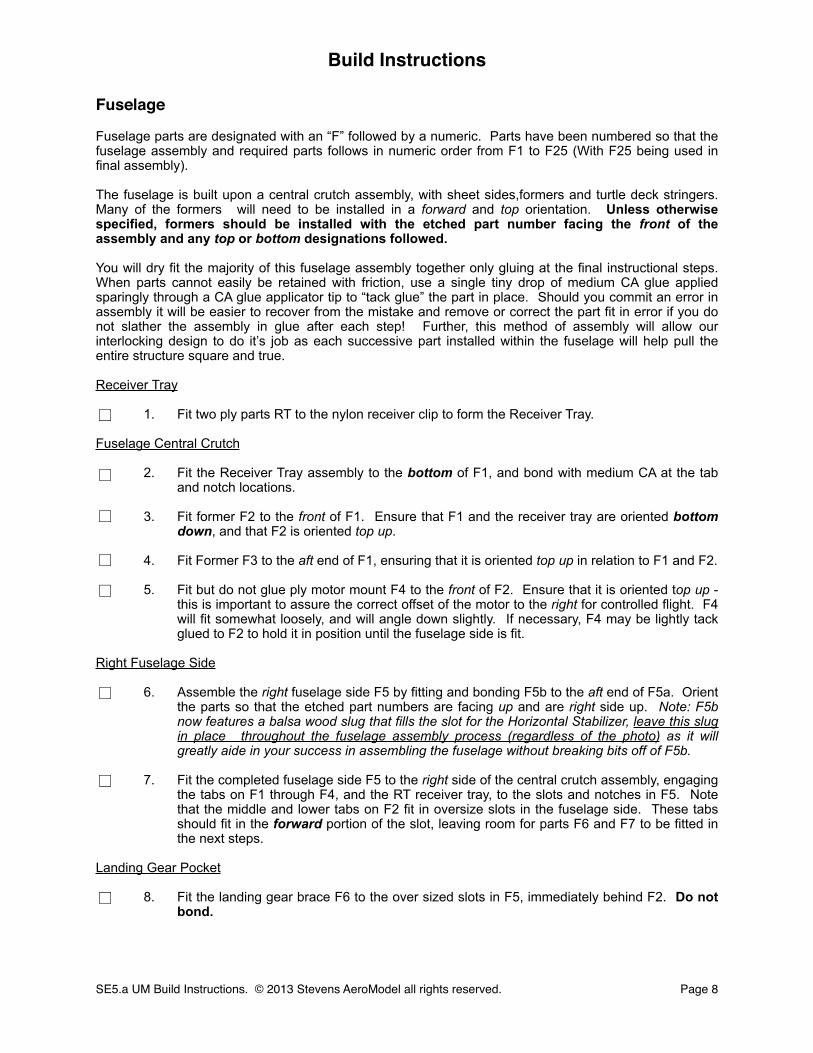
Fuselage parts are designated with an “F” followed by a numeric. Parts have been numbered so that the fuselage assembly and required parts follows in numeric order from F1 to F25 (With F25 being used in final assembly).
The fuselage is built upon a central crutch assembly, with sheet sides,formers and turtle deck stringers. Many of the formers will need to be installed in a forward and top orientation. Unless otherwise specified, formers should be installed with the etched part number facing the front of the assembly and any top or bottom designations followed.
You will dry fit the majority of this fuselage assembly together only gluing at the final instructional steps. When parts cannot easily be retained with friction, use a single tiny drop of medium CA glue applied sparingly through a CA glue applicator tip to “tack glue” the part in place. Should you commit an error in assembly it will be easier to recover from the mistake and remove or correct the part fit in error if you do not slather the assembly in glue after each step! Further, this method of assembly will allow our interlocking design to do it’s job as each successive part installed within the fuselage will help pull the entire structure square and true.
Receiver Tray
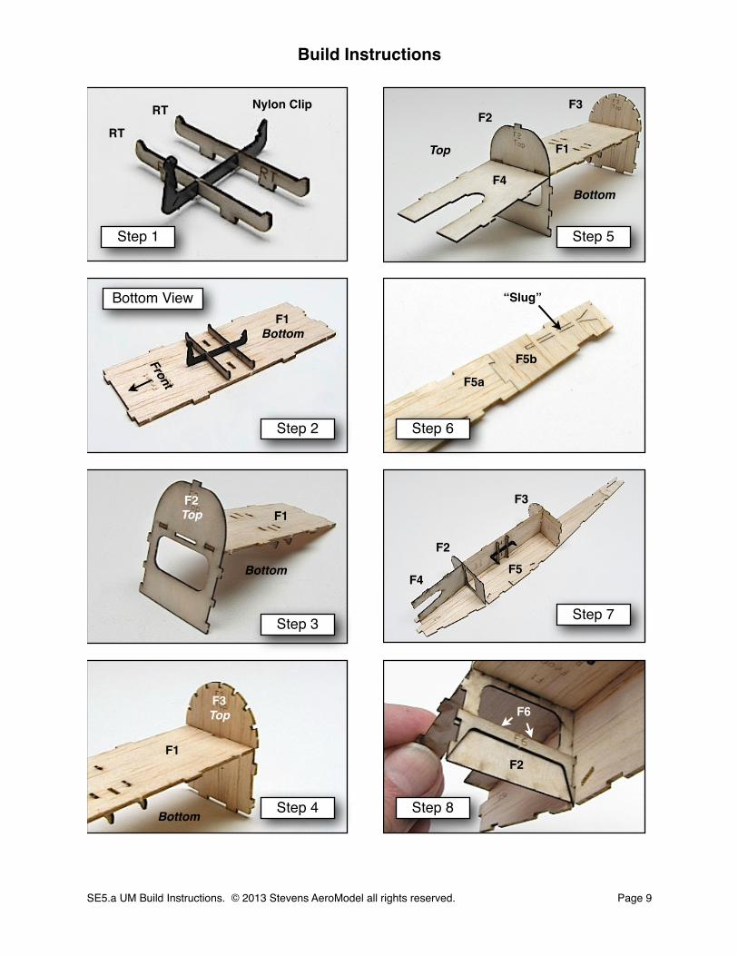
1. Fit two ply parts RT to the nylon receiver clip to form the Receiver Tray.
Fuselage Central Crutch
2. Fit the Receiver Tray assembly to the bottom of F1, and bond with medium CA at the tab and notch locations.
3. Fit former F2 to the front of F1. Ensure that F1 and the receiver tray are oriented bottom down, and that F2 is oriented top up.
4. Fit Former F3 to the aft end of F1, ensuring that it is oriented top up in relation to F1 and F2.
5. Fit but do not glue ply motor mount F4 to the front of F2. Ensure that it is oriented top up - this is important to assure the correct offset of the motor to the right for controlled flight. F4 will fit somewhat loosely, and will angle down slightly. If necessary, F4 may be lightly tack glued to F2 to hold it in position until the fuselage side is fit.
Right Fuselage Side
6. Assemble the right fuselage side F5 by fitting and bonding F5b to the aft end of F5a. Orient the parts so that the etched part numbers are facing up and are right side up. Note: F5b now features a balsa wood slug that fills the slot for the Horizontal Stabilizer, leave this slug in place throughout the fuselage assembly process (regardless of the photo) as it will greatly aide in your success in assembling the fuselage without breaking bits off of F5b.
7. Fit the completed fuselage side F5 to the right side of the central crutch assembly, engaging the tabs on F1 through F4, and the RT receiver tray, to the slots and notches in F5. Note that the middle and lower tabs on F2 fit in oversize slots in the fuselage side. These tabs should fit in the forward portion of the slot, leaving room for parts F6 and F7 to be fitted in the next steps.
Landing Gear Pocket
8. Fit the landing gear brace F6 to the over sized slots in F5, immediately behind F2. Do not bond.
Build Instructions
SE5.a UM Build Instructions. © 2013 Stevens AeroModel all rights reserved.! Page 8
□
□
□
□
□
□
□
□
Build Instructions
SE5.a UM Build Instructions. © 2013 Stevens AeroModel all rights reserved.! Page 9
Step 1
Step 2
Step 3
Step 4 Step 8
Step 7
Step 6
Step 5
RT
RT
F1Bottom
F1F2Top
F5a
F5
F2
Front
F3Top
F1
F6
Bottom View
Bottom
Bottom
F2F3
F1
F4Bottom
Top
F2
F3
F4
Nylon Clip
F5b
“Slug”
Fuselage Cont.
Landing Gear Pocket Cont.
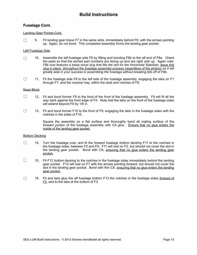
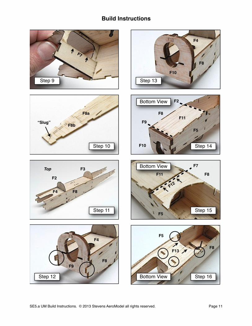
9. Fit landing gear brace F7 in the same slots, immediately behind F6, with the arrows pointing up. Again, do not bond. This completed assembly forms the landing gear pocket.
Left Fuselage Side
10. Assemble the left fuselage side F8 by fitting and bonding F8b to the aft end of F8a. Orient the parts so that the etched part numbers are facing up and are right side up. Again note: F8b now features a balsa wood slug that fills the slot for the Horizontal Stabilizer, leave this slug in place throughout the fuselage assembly process (regardless of the photos) as it will greatly aide in your success in assembling the fuselage without breaking bits off of F8b.
11. Fit the fuselage side F8 to the left side of the fuselage assembly, engaging the tabs on F1 through F7, and the receiver tray, within the slots and notches of F8.
Nose Block
12. Fit and bond former F9 to the front of the front of the fuselage assembly. F9 will fit all the way back against the front edge of F4. Note that the tabs on the front of the fuselage sides will extend beyond F9 by 1/8 in.
13. Fit and bond former F10 to the front of F9, engaging the tabs in the fuselage sides with the notches in the sides of F10.
Square the assembly on a flat surface and thoroughly bond all mating surface of the forward portion of the fuselage assembly with CA glue. Ensure that no glue enters the inside of the landing gear pocket.
Bottom Decking
14. Turn the fuselage over, and fit the forward fuselage bottom decking F11 to the notches in the fuselage sides, between F2 and F9. F11 will rest on F2, but should not cover the slot in the landing gear pocket. Bond with CA, ensuring that no glue enters the landing gear pocket.
15. Fit F12 bottom decking to the notches in the fuselage sides immediately behind the landing gear pocket. F12 will rest on F7 with the arrows pointing forward, but should not cover the slot in the landing gear pocket. Bond with thin CA, ensuring that no glue enters the landing gear pocket.
16. Fit and tack glue the aft fuselage bottom F13 the notches in the fuselage sides forward of F3, and to the tabs at the bottom of F3.
Build Instructions
SE5.a UM Build Instructions. © 2013 Stevens AeroModel all rights reserved.! Page 10
□
□
□
□
□
□
□
□
Build Instructions
SE5.a UM Build Instructions. © 2013 Stevens AeroModel all rights reserved.! Page 11
Step 9
Step 10
Step 11
Step 12 Step 16
Step 15
Step 14
Step 13
F7
F8a
F8b
F8
F9
F10
F11
F12
F13
Bottom View
Bottom View
Bottom View
F2
F3
F4
Top
F8
F4
F4
F5
F8
F10
F9
F5
F11 F8
F7
F2
F8
F5
F8
“Slug”
Fuselage Cont.
Bottom Decking Cont.
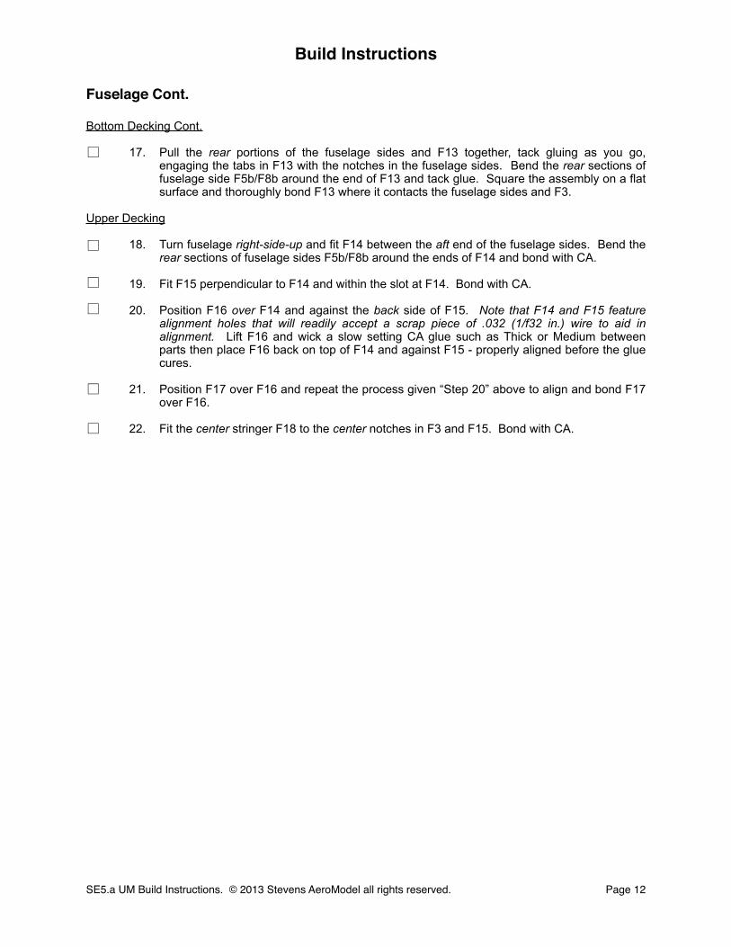
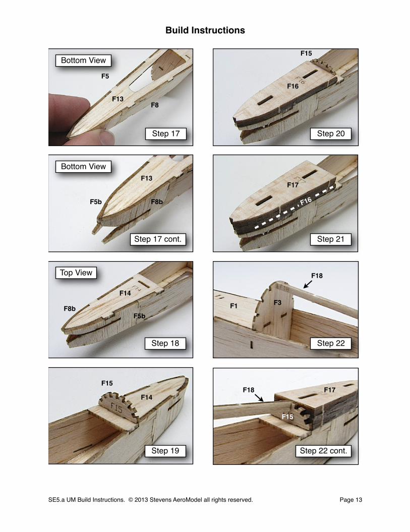
17. Pull the rear portions of the fuselage sides and F13 together, tack gluing as you go, engaging the tabs in F13 with the notches in the fuselage sides. Bend the rear sections of fuselage side F5b/F8b around the end of F13 and tack glue. Square the assembly on a flat surface and thoroughly bond F13 where it contacts the fuselage sides and F3.
Upper Decking
18. Turn fuselage right-side-up and fit F14 between the aft end of the fuselage sides. Bend the rear sections of fuselage sides F5b/F8b around the ends of F14 and bond with CA.
19. Fit F15 perpendicular to F14 and within the slot at F14. Bond with CA.
20. Position F16 over F14 and against the back side of F15. Note that F14 and F15 feature alignment holes that will readily accept a scrap piece of .032 (1/f32 in.) wire to aid in alignment. Lift F16 and wick a slow setting CA glue such as Thick or Medium between parts then place F16 back on top of F14 and against F15 - properly aligned before the glue cures.
21. Position F17 over F16 and repeat the process given “Step 20” above to align and bond F17 over F16.
22. Fit the center stringer F18 to the center notches in F3 and F15. Bond with CA.
Build Instructions
SE5.a UM Build Instructions. © 2013 Stevens AeroModel all rights reserved.! Page 12
□
□
□
□
□
□
Build Instructions
SE5.a UM Build Instructions. © 2013 Stevens AeroModel all rights reserved.! Page 13
Step 17
Step 17 cont.
Step 18
Step 19 Step 22 cont.
Step 22
Step 21
F13
F15
F14
F16
F17
F3
F18
F18
Bottom View
Step 20
Bottom View
Top View
F13
F5
F8
F5bF8b
F8bF5b
F14
F15
F16
F15
F1
F17

Fuselage Cont.
Upper Decking Cont.
23. Fit and bond two stringers F19 to the next set of notches on either side of F18.
24. Fit and bond two stringers F20 to the next set of notches out from stringers F19.
25. Fit and bond the outer stringers F21 to the last set of notches out from stringers F20, just above the fuselage sides.
26. Fit and bond former F22 to the notch in F1 immediately in front of and against former F3.
27. Fit and bond former F23 to the notch in F1 between formers F2 and F22.
28. Locate the fuselage sheeting F24 and moisten the etched side with glass cleaner, allowing it to soak in for a minute or two.
While you wait on F24 to soak, flip to “Step 75” and read the “Builder Tip” to determine if you’d like to pre-install your motor and gearbox now.
29. Fit F24 to the tabs in formers F19, F2, and F23, with the etched and moist side up.
30. Wrap F24 around the formers F9, F2, and F23 bringing the left and right edges of part F24 flush with the upper edges of the fuselage sides. The aft end of F24 will wrap around F22 with the split portion of F24 coming together at the top of F22. Now do not bond, instead, hold F24 in place with low tack masking tape until completely dry.
Build Instructions
SE5.a UM Build Instructions. © 2013 Stevens AeroModel all rights reserved.! Page 14
□
□
□
□
□
□
□
□

Build Instructions
SE5.a UM Build Instructions. © 2013 Stevens AeroModel all rights reserved.! Page 15
Step 23
Step 24
Step 25
Step 26
Step 28
Step 27
F19
F20
F21F20
F23
F24
F22
Moisten this side with glass cleaner
Tabs
F3
Step 29
Step 30
F18
F19
F19
F22
F1
F2
F9
F2
F23
F22
F24
Tape and allow to dry.
Fuselage Cont.
Upper Decking Cont.
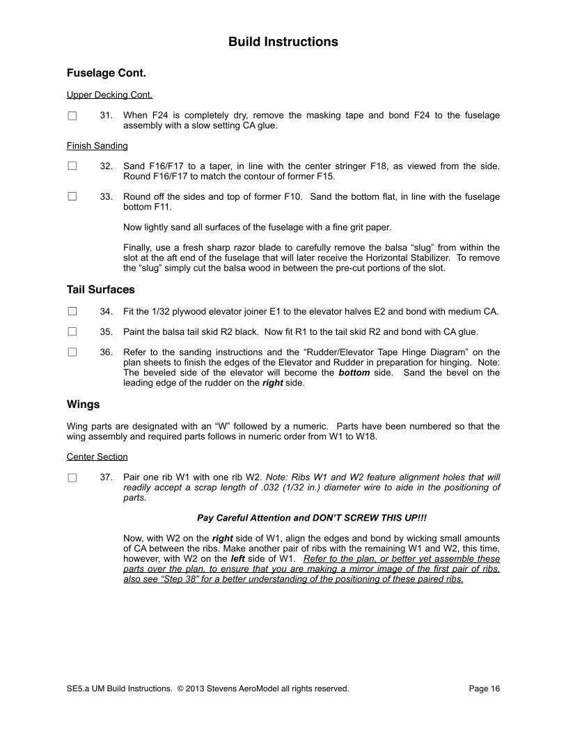
31. When F24 is completely dry, remove the masking tape and bond F24 to the fuselage assembly with a slow setting CA glue.
Finish Sanding
32. Sand F16/F17 to a taper, in line with the center stringer F18, as viewed from the side. Round F16/F17 to match the contour of former F15.
33. Round off the sides and top of former F10. Sand the bottom flat, in line with the fuselage bottom F11.
Now lightly sand all surfaces of the fuselage with a fine grit paper.
Finally, use a fresh sharp razor blade to carefully remove the balsa “slug” from within the slot at the aft end of the fuselage that will later receive the Horizontal Stabilizer. To remove the “slug” simply cut the balsa wood in between the pre-cut portions of the slot.
Tail Surfaces
34. Fit the 1/32 plywood elevator joiner E1 to the elevator halves E2 and bond with medium CA.
35. Paint the balsa tail skid R2 black. Now fit R1 to the tail skid R2 and bond with CA glue.
36. Refer to the sanding instructions and the “Rudder/Elevator Tape Hinge Diagram” on the plan sheets to finish the edges of the Elevator and Rudder in preparation for hinging. Note: The beveled side of the elevator will become the bottom side. Sand the bevel on the leading edge of the rudder on the right side.
Wings
Wing parts are designated with an “W” followed by a numeric. Parts have been numbered so that the wing assembly and required parts follows in numeric order from W1 to W18.
Center Section
37. Pair one rib W1 with one rib W2. Note: Ribs W1 and W2 feature alignment holes that will readily accept a scrap length of .032 (1/32 in.) diameter wire to aide in the positioning of parts.
Pay Careful Attention and DON’T SCREW THIS UP!!!
Now, with W2 on the right side of W1, align the edges and bond by wicking small amounts of CA between the ribs. Make another pair of ribs with the remaining W1 and W2, this time, however, with W2 on the left side of W1. Refer to the plan, or better yet assemble these parts over the plan, to ensure that you are making a mirror image of the first pair of ribs. also see “Step 38” for a better understanding of the positioning of these paired ribs.
Build Instructions
SE5.a UM Build Instructions. © 2013 Stevens AeroModel all rights reserved.! Page 16
□
□
□
□
□
□
□

Build Instructions
SE5.a UM Build Instructions. © 2013 Stevens AeroModel all rights reserved.! Page 17
Step 32
Step 32 cont.
Step 33 Step 37
Step 36
Step 35
Step 34E2
R1
W2
W1
E2
E1
Step 31
Sand in line with center stringer
Round
Round
In line with bottom of
fuselage F11
45 deg.
R2
F24
F18
F10

Wings Cont.
Center Section Cont.
38. Fit each set of paired W1/W2 ribs to the notches in ply spar W3, with ribs W oriented to the inside of the assembly.
39. Fit and tack glue the rear portion of the center section sheeting W4 to the tabs at the aft end of ribs W1.
40. Bend W4 over the W1 ribs, engaging the tabs in the forward portion of ribs W1 to the notches in the sides of W4. Tack glue with small drops of medium CA. Note that W4 sheeting will only cover the W1 ribs leaving W2 exposed to receive the Upper Panels.
41. Square the center section assembly on a flat surface and thoroughly bond the ribs to the center sheeting with CA. Turn assembly over and bond the spar W3 to the center sheeting.
Upper Panels
42. Assemble one W5 wing panel sheeting by fitting and bonding parts W5a to W5b with thin CA. Ensure the etched surface of W5a and W5b are both oriented to the same side of the wing panel.
43. Lay the panel on the table with the etched side facing up. Now, fit and bond the spar W6 to the notches within the cut-out in the wing panel.
44. Fit the rear portion of ribs W7, W8, and W9 to the notches in the rear of the wing panel, matching the positions indicated on the plan. Now, tack glue the trailing edge of all ribs on wing assembly with medium CA to retain the parts.
45. Turn the panel over, and bend the W5 wing panel sheeting over the ribs, engaging the tabs on the ribs with the notches in the wing panel. Hold wing panel down on a flat surface, and thoroughly bond all mating surfaces with CA glue.
Finally, repeat steps 42 through 45 to build the opposite upper wing panel. Be certain to build a right and left wing panel. If you followed our instruction to orient all W5a/b parts with etching up you cannot help but complete this successfully. If you have mixed the part orientation of W5 up you’ll want to pay careful attention and work directly over the plan to make a right and left panel.
Build Instructions
SE5.a UM Build Instructions. © 2013 Stevens AeroModel all rights reserved.! Page 18
□
□
□
□
□ □
□ □
□ □
□ □

Build Instructions
SE5.a UM Build Instructions. © 2013 Stevens AeroModel all rights reserved.! Page 19
Step 38
Step 39
Step 40
Step 41 Step 45
Step 44
Step 43
Step 42
W3
W1
W4
W5a
W6
W9
W2
W2
Leading Edge
W5b
W8W7
Paired Ribs
W4
W3
W4
W3
W5
W5
W5
W9 W8W7
W6
W6
W1
W1
Fuselage
Lower Panels
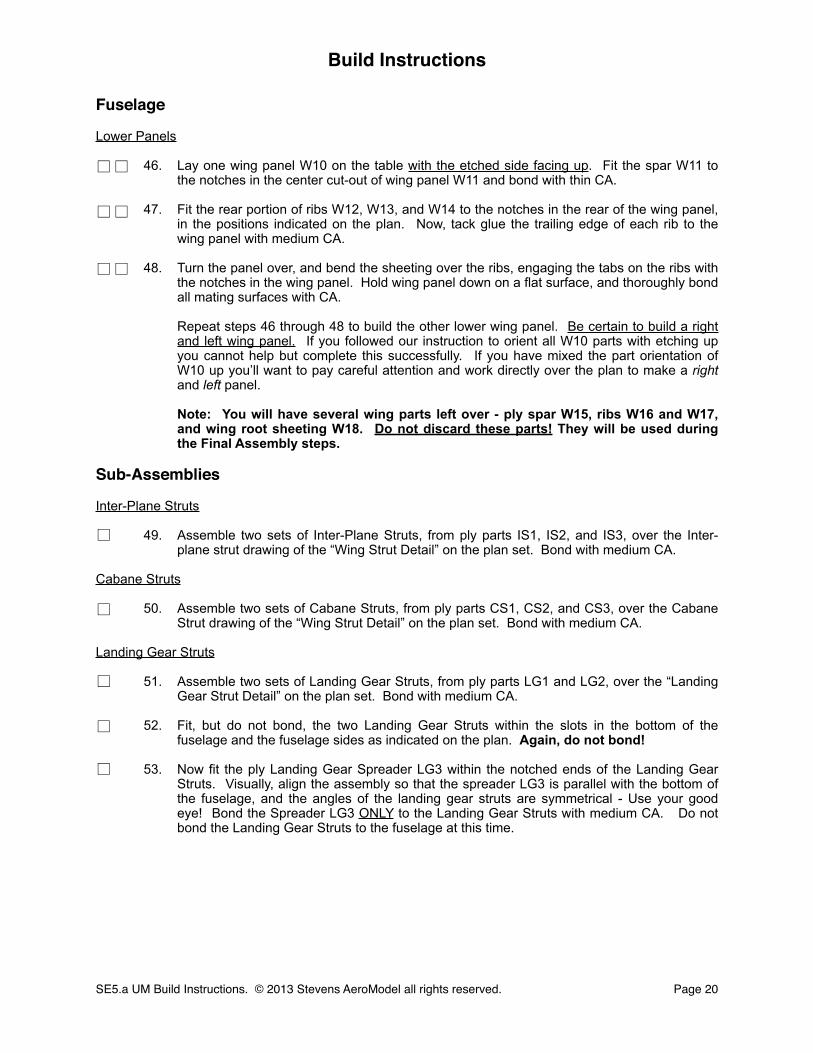
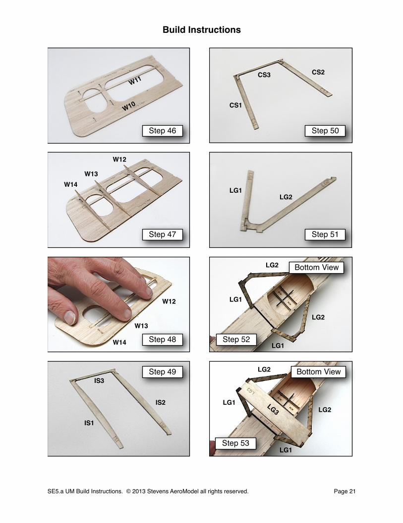
46. Lay one wing panel W10 on the table with the etched side facing up. Fit the spar W11 to the notches in the center cut-out of wing panel W11 and bond with thin CA.
47. Fit the rear portion of ribs W12, W13, and W14 to the notches in the rear of the wing panel, in the positions indicated on the plan. Now, tack glue the trailing edge of each rib to the wing panel with medium CA.
48. Turn the panel over, and bend the sheeting over the ribs, engaging the tabs on the ribs with the notches in the wing panel. Hold wing panel down on a flat surface, and thoroughly bond all mating surfaces with CA.
Repeat steps 46 through 48 to build the other lower wing panel. Be certain to build a right and left wing panel. If you followed our instruction to orient all W10 parts with etching up you cannot help but complete this successfully. If you have mixed the part orientation of W10 up you’ll want to pay careful attention and work directly over the plan to make a right and left panel.
Note: You will have several wing parts left over - ply spar W15, ribs W16 and W17, and wing root sheeting W18. Do not discard these parts! They will be used during the Final Assembly steps.
Sub-Assemblies
Inter-Plane Struts
49. Assemble two sets of Inter-Plane Struts, from ply parts IS1, IS2, and IS3, over the Inter-plane strut drawing of the “Wing Strut Detail” on the plan set. Bond with medium CA.
Cabane Struts
50. Assemble two sets of Cabane Struts, from ply parts CS1, CS2, and CS3, over the Cabane Strut drawing of the “Wing Strut Detail” on the plan set. Bond with medium CA.
Landing Gear Struts
51. Assemble two sets of Landing Gear Struts, from ply parts LG1 and LG2, over the “Landing Gear Strut Detail” on the plan set. Bond with medium CA.
52. Fit, but do not bond, the two Landing Gear Struts within the slots in the bottom of the fuselage and the fuselage sides as indicated on the plan. Again, do not bond!
53. Now fit the ply Landing Gear Spreader LG3 within the notched ends of the Landing Gear Struts. Visually, align the assembly so that the spreader LG3 is parallel with the bottom of the fuselage, and the angles of the landing gear struts are symmetrical - Use your good eye! Bond the Spreader LG3 ONLY to the Landing Gear Struts with medium CA. Do not bond the Landing Gear Struts to the fuselage at this time.
Build Instructions
SE5.a UM Build Instructions. © 2013 Stevens AeroModel all rights reserved.! Page 20
□ □
□ □
□
□ □
□
□
□
□
Build Instructions
SE5.a UM Build Instructions. © 2013 Stevens AeroModel all rights reserved.! Page 21
Step 46
Step 47
Step 48
Step 49
Step 53
Step 52
Step 51
Step 50
W10
W13
W12
IS1
IS3
CS1
LG1LG2
LG3
W11
W14
IS2
CS2CS3
Bottom View
Bottom View
LG1
LG2
LG2
LG1
LG1
LG1
LG2
LG2
W14
W13
W12
Sub-Assemblies Cont.
Landing Gear Struts Cont.
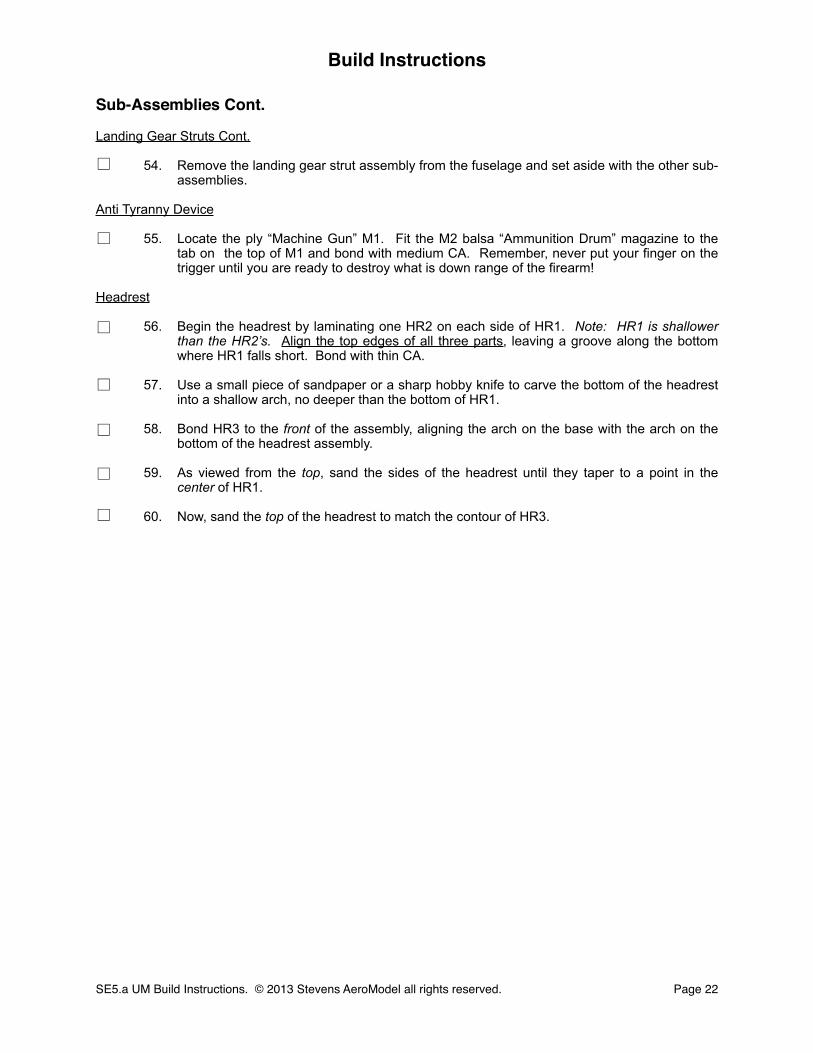
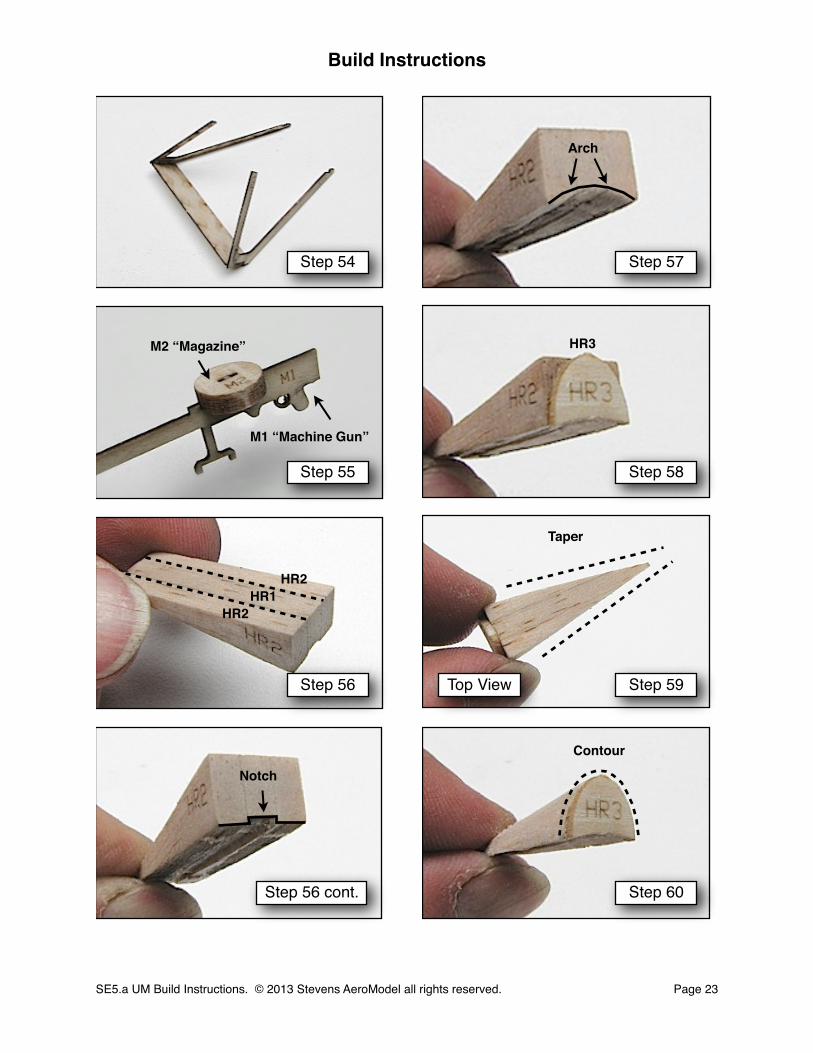
54. Remove the landing gear strut assembly from the fuselage and set aside with the other sub-assemblies.
Anti Tyranny Device
55. Locate the ply “Machine Gun” M1. Fit the M2 balsa “Ammunition Drum” magazine to the tab on the top of M1 and bond with medium CA. Remember, never put your finger on the trigger until you are ready to destroy what is down range of the firearm!
Headrest
56. Begin the headrest by laminating one HR2 on each side of HR1. Note: HR1 is shallower than the HR2’s. Align the top edges of all three parts, leaving a groove along the bottom where HR1 falls short. Bond with thin CA.
57. Use a small piece of sandpaper or a sharp hobby knife to carve the bottom of the headrest into a shallow arch, no deeper than the bottom of HR1.
58. Bond HR3 to the front of the assembly, aligning the arch on the base with the arch on the bottom of the headrest assembly.
59. As viewed from the top, sand the sides of the headrest until they taper to a point in the center of HR1.
60. Now, sand the top of the headrest to match the contour of HR3.
Build Instructions
SE5.a UM Build Instructions. © 2013 Stevens AeroModel all rights reserved.! Page 22
□
□
□
□
□
□
□
Build Instructions
SE5.a UM Build Instructions. © 2013 Stevens AeroModel all rights reserved.! Page 23
Step 54
Step 55
Step 56
Step 56 cont. Step 60
Step 59
Step 58
Step 57
M2 “Magazine”
M1 “Machine Gun”
HR1HR2
HR2
Notch
Arch
HR3
Taper
Contour
Top View
Sub-Assemblies Cont.
Headrest
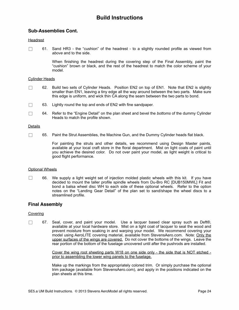
61. Sand HR3 - the “cushion” of the headrest - to a slightly rounded profile as viewed from above and to the side.
When finishing the headrest during the covering step of the Final Assembly, paint the “cushion” brown or black, and the rest of the headrest to match the color scheme of your model.
Cylinder Heads
62. Build two sets of Cylinder Heads. Position EN2 on top of EN1. Note that EN2 is slightly smaller than EN1, leaving a tiny edge all the way around between the two parts. Make sure this edge is uniform, and wick thin CA along the seam between the two parts to bond.
63. Lightly round the top and ends of EN2 with fine sandpaper.
64. Refer to the “Engine Detail” on the plan sheet and bevel the bottoms of the dummy Cylinder Heads to match the profile shown.
Details
65. Paint the Strut Assemblies, the Machine Gun, and the Dummy Cylinder heads flat black.
For painting the struts and other details, we recommend using Design Master paints, available at your local craft store in the floral department. Mist on light coats of paint until you achieve the desired color. Do not over paint your model, as light weight is critical to good flight performance.
Optional Wheels
66. We supply a light weight set of injection molded plastic wheels with this kit. If you have decided to mount the taller profile spindle wheels from Du-Bro RC [DUB150MWL] Fit and bond a balsa wheel disc WH to each side of these optional wheels. Refer to the option notes on the “Landing Gear Detail” of the plan set to sand/shape the wheel discs to a streamlined profile.
Final Assembly
Covering
67. Seal, cover, and paint your model. Use a lacquer based clear spray such as Deft®, available at your local hardware store. Mist on a light coat of lacquer to seal the wood and prevent moisture from soaking in and warping your model. We recommend covering your model using AeroLITE covering material, available from StevensAero.com. Note: Only the upper surfaces of the wings are covered. Do not cover the bottoms of the wings. Leave the rear portion of the bottom of the fuselage uncovered until after the pushrods are installed.
Cover the wing root sheeting parts W18 on one side only - the side that is NOT etched - prior to assembling the lower wing panels to the fuselage.
Make up the markings from the appropriately colored trim. Or simply purchase the optional trim package (available from StevensAero.com), and apply in the positions indicated on the plan sheets at this time.
Build Instructions
SE5.a UM Build Instructions. © 2013 Stevens AeroModel all rights reserved.! Page 24
□
□
□
□
□
□
□
Build Instructions
SE5.a UM Build Instructions. © 2013 Stevens AeroModel all rights reserved.! Page 25
Step 61
Step 62
Step 63
Step 64 Step 67 cont.
Step 67
Step 66
Step 65
EN1
EN2
WH
WH
Round
EN1
Round
Edge
Bevel
Leave bottom uncovered until after pushrod installation.
Bottom View
Optional Wheels and Covers

Final Assembly Cont.
Pushrod Installation
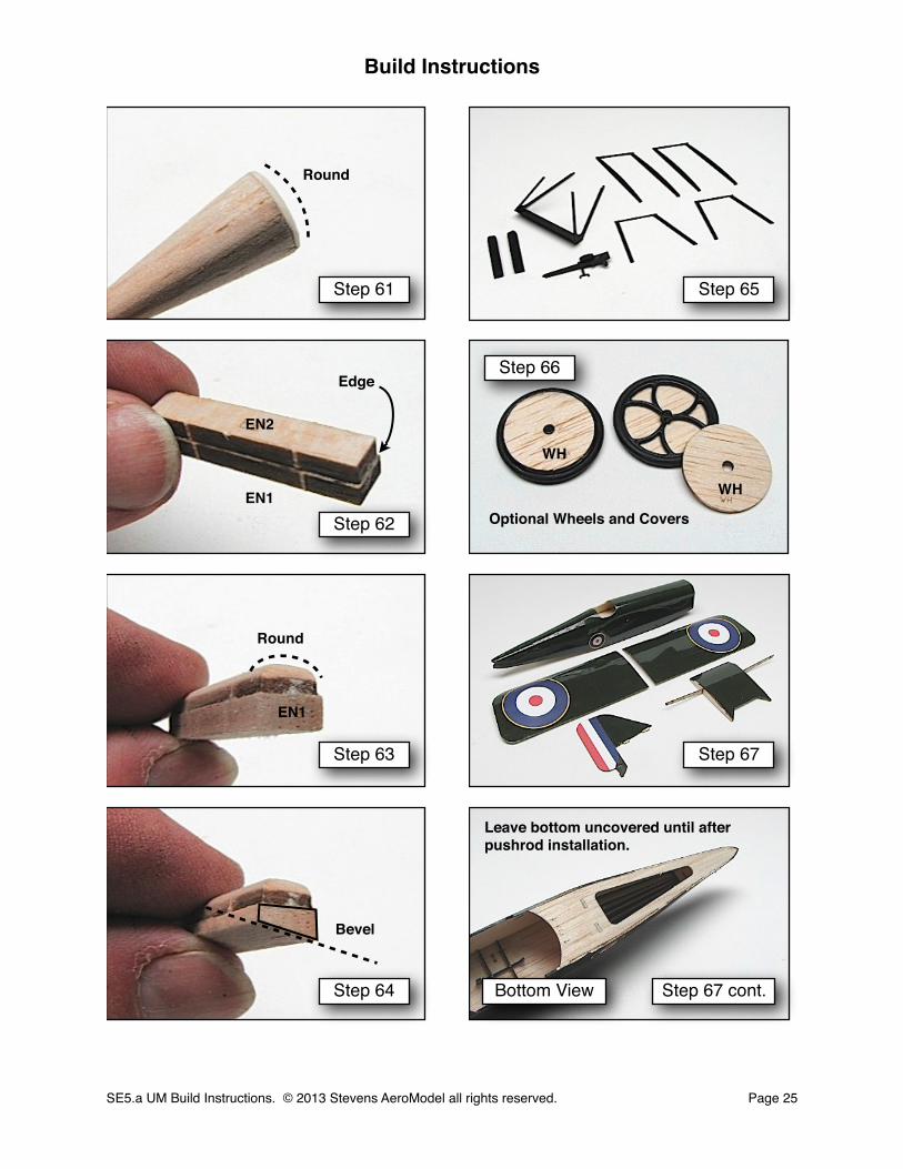
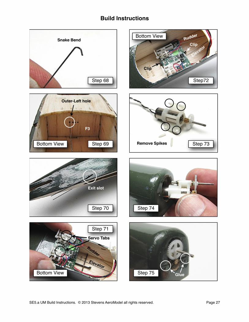
68. Rudder pushrod - Refer to the Pushrod Detail on the plan sheet and make a “snake” bend at one end of a 12 in. length of .015 in. wire.
69. Feed the straight end of the wire through the outer-left hole in former F3 and into the rear portion of the fuselage.
70. Slit the covering over the pushrod exit slots on each side of the fuselage. Access the pushrod through the opening in the bottom of the fuselage, and, using small needle-nose pliers, feed the pushrod through the exit slot in the RIGHT fuselage side.
Repeat steps 68 through 70 to make and install the Elevator pushrod, passing it through the inner-left hole in F3, and out of the exit slot in the LEFT fuselage side.
Electronics Installation
71. First test your receiver for proper function. Now orient the receiver [PKZ3352] so that the geared ends of the servos are pointing forward. Connect the rudder pushrod to the servo nearest the antenna, and the elevator pushrod to the servo nearest to the battery lead. Connect the pushrods to the middle, medium sized hole in the servo tabs.
72. Fit one edge of the receiver board into the slot in the short arm of the receiver clip. Press the other edge down until it snaps into the slot in the long arm of the receiver clip.
73. Test your motor for proper function. Now, remove the spikes from the mounting tabs of the motor [PKZ3624] and sand the tabs smooth.
74. Feed the motor lead into the nose, under the motor mount plate, and through the opening in former F2. Slide the tabs on the motor gearbox into the slots on either side of the opening in the nose.
75. Seat the motor all the way back in the opening, ensuring that it is lying flat on the F4 motor mount plate, and equally spaced between the mounting ears. Additionally, ensure that no part of the fuselage interferes with the free operation of the motor gears. If there is any binding between the gears and the nose structure, use a sharp hobby knife to carefully trim away the edges of the opening until the gears turn freely.
Secure the motor by wicking a small drop of medium CA onto the front of each mounting tab. Be careful not to get CA glue onto the gear set of the motor/gearbox.
Builder Tip: Do not neglect to test the motor for proper function prior to installation within the model. Gluing in a defective motor will, indeed, ruin your weekend! I also find it easier to handle this part when I, first, mount the prop to the gearbox shaft before bonding the motor in place; this gives a bit more of a handle to hang on to when holding this part in position. Finally, note that some builders prefer to simply pre-install the motor just prior to “Step 29”. Pre-installation of the motor is completely acceptable just follow steps 73, 74, and 75 as given above and be careful when sanding the model not to damage the gearbox shaft.
Build Instructions
SE5.a UM Build Instructions. © 2013 Stevens AeroModel all rights reserved.! Page 26
□ □
□
□ □
□ □
□
□
□
□
Build Instructions
SE5.a UM Build Instructions. © 2013 Stevens AeroModel all rights reserved.! Page 27
Step 68
Step 69
Step 70
Step 71
Step 75
Step 74
Step 73
Step72
Outer-Left hole
F3
Bottom View
Bottom View
Bottom View
Exit slot
Servo Tabs
Clip
Clip
Glue
Snake Bend
Remove Spikes
RudderElevator
Rudder
Elevator
Final Assembly Cont.
Electronics Installation Cont.
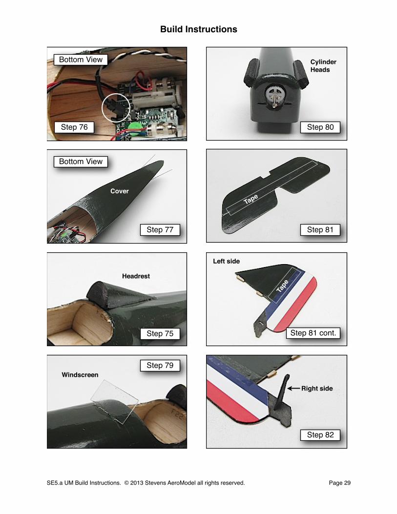
76. Connect the motor lead to the socket on the receiver board. Orient the lead so that the black wire is nearest the receiver clip in the center of the board.
The Little Details
77. If desired, cover the bottom of the fuselage to hide the push-rod access.
78. Position the Headrest on the Turtle Deck as shown on the plan, aligned with the center stringer. Bond to the turtle deck by wicking medium CA along the base of the headrest, using a fine glue tip.
79. Position the pre-cut acetate Windscreen as shown on the plan and mark where the two tabs at the bottom of the windscreen contact the fuselage deck. Use the point of a sharp hobby knife to slit the deck at these marks, angling the knife back to match the approximate angle of the windscreen. Press the tabs on the Windscreen into the slits until the base is flush with the deck. Wick a drop of medium CA along the base of the Windscreen and mounting tabs to secure.
80. Position the dummy Cylinder Heads on either side of the nose, where indicated on the plan and the “Engine Detail”. Bond by wicking medium CA under and along the base of each cylinder head.
Finish Control Surfaces
81. Refer to the Tape Hinge Diagram on the plan sheets, and connect the Elevator and rudder to their stabilizer surfaces with narrow strips of clear tape. Tape the Elevator on top, and the Rudder on the left side.
82. Fit and bond a control horn to the slot in the Tail Skid, extending from the right side of the Rudder.
Build Instructions
SE5.a UM Build Instructions. © 2013 Stevens AeroModel all rights reserved.! Page 28
□
□
□
□
□
□
□
Build Instructions
SE5.a UM Build Instructions. © 2013 Stevens AeroModel all rights reserved.! Page 29
Step 76
Step 77
Step 75
Step 79
Step 82
Step 81 cont.
Step 81
Step 80
Bottom View
Bottom View
CoverTape
Tape
Right side
Windscreen
Headrest
CylinderHeads
Left side
Final Assembly Cont.
Finish Control Surfaces Cont.
83. Slit the covering over the slot for the Elevator control horn on the lower-left side of the Elevator. Fit and bond the control horn with thin CA.
84. Slide the Horizontal Stabilizer into the slot in the rear of the fuselage (if this slot has not been opened up and freed of the balsa “slug”, you need to go back and complete “Step 48”. Now, ensure that the Horizontal Stabilizer is seated all the way forward, and that the Elevator moves freely. Make certain that the Elevator is free to move within the recess cut in the rear of the fuselage assembly; if not, remove the stabilizer and, using a sharp hobby knife, trim the open area and re-fit. Now, square the stabilizer perpendicular with the fuselage sides as viewed from above and from the front. Bond the stabilizer by wicking a small amount of medium CA at several points along the seam where it joins the fuselage.
85. Remove the covering over the slots in the aft end of the fuselage turtle deck above the Horizontal Stabilizer to receive the Vertical Stabilizer and Rudder assembly. Fit the tabs on the Vertical Stabilizer within these slots. Square the Vertical Stabilizer and Rudder assembly perpendicular to the fuselage and Horizontal Stabilizer and bond with medium CA to retain.
86. Refer to the “Pushrod Detail” on the plan sheet, and connect the pushrods to the control horns on the Elevator and Rudder. Tip: Pre-shrink the heat shrink tubing over two scrap lengths of .015 wire using a heat gun or soldering iron. Allow to cool, and remove the wire. Cut the tube into 1/2 in. lengths and connect the pushrods. Now you have a tight fitting sleeve without having to get a soldering iron near your model!
87. Remove the covering over the two slots in the bottom decking of the fuselage below the Horizontal Stabilizer. Now, fit and bond the sub-fin V2 with CA glue.
Complete Landing Gear
88. Refer to the Landing Gear Detail on the plan sheet, to mark and bend the landing gear from the length of .032 wire supplied in your kit, over the drawing. Proceed carefully! Accuracy is very important for a good fit.
89. Slit the covering over the landing gear pocket and insert the wire Landing Gear. Insert the ply landing gear retainer F25 into the slot; pressing it all the way into the slot. Friction should be enough to retain the Landing Gear, but you may wick thin CA around the slot and the points where the wire exits the fuselage to ensure it stays put.
90. Slit the covering over the slots in the fuselage bottom just forward of the landing gear wire. Fit the Landing Gear Strut assembly to the slots and the notches along the bottom of the fuselages sides. Bond the strut assembly to the fuselage with Medium CA. Do not bond the landing gear wires to the struts as they must be free to flex and absorb some of the shock of landing.
Build Instructions
SE5.a UM Build Instructions. © 2013 Stevens AeroModel all rights reserved.! Page 30
□
□
□
□
□
□
□
□

Build Instructions
SE5.a UM Build Instructions. © 2013 Stevens AeroModel all rights reserved.! Page 31
Step 83
Step 84
Step 85
Step 86 Step 90
Step 89
Step 88
Step 87
Lower left side
Bottom View
Bottom View
Bottom View
Bottom View
Sub-Fin V2
Push all the
way in
Bond
Bond
NoGlue
Final Assembly Cont.
Complete Landing Gear Cont.
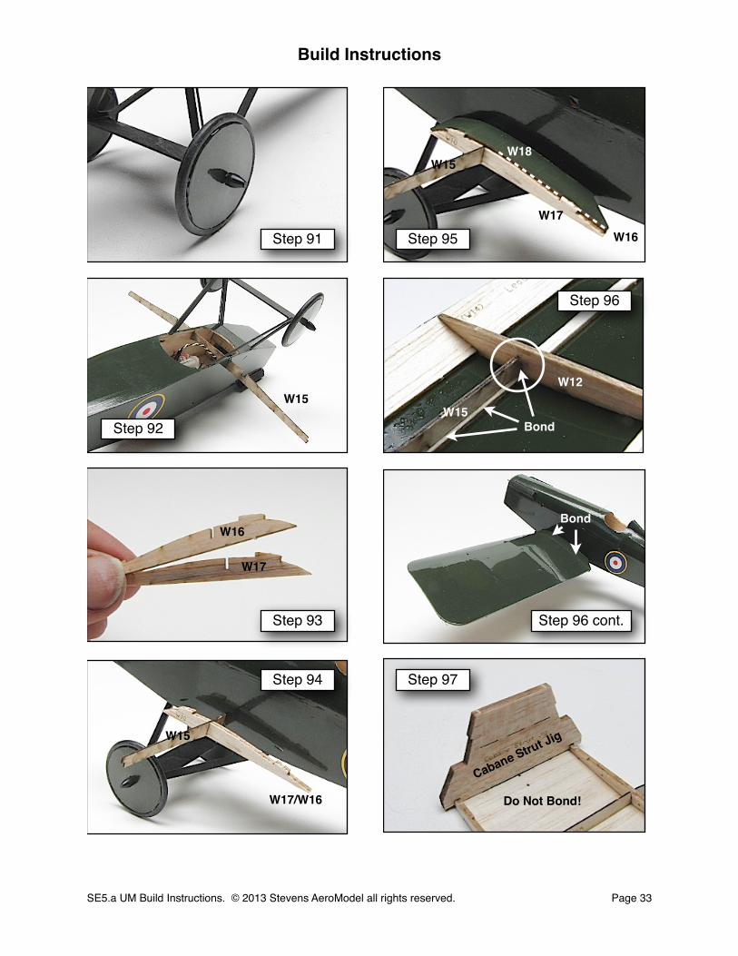
91. Fit provided plastic wheels or the optional finished wheel assemblies to the landing gear wire. You may either trim the wire to length and fit the wheel retainers that came with the optional wheel assemblies, or bend the wire up 90 degrees and trim off the excess to retain the provided wheels.
Finish the Lower Wing
92. Fit the lower wing spar W15 to the slots in the bottom of the fuselage sides just forward of the rear landing gear struts. Ensure that W15 is fully seated within the slots, and bond with CA glue. Note: We programed the laser to cut a small horizontal line directly above the spar engagement slot that references the proper depth at which W15 is entirely seated within the fuselage assembly. The top surface of spar W15 should not be seated past this laser cut line and trying to install the W15 beyond this line would likely result in the crushing of the balsa at the fuselage sides.
93. Laminate one W16 and one W17 rib together. While it doesn’t matter which rib is on which side as the ribs are identical, the plan shows W16 on the inside and W17 to the outside. Align the edges carefully, or use the alignment holes, and wick CA glue between the ribs to bond.
94. Fit the paired W16/W17 rib assembly to the notch in the left side of the spar. Do not bond.
95. Slit the covering over the two slots in the fuselage side to receive W18. Fit the wing root sheeting W18, previously covered, to the fuselage side and the ribs W16/W17. Only the inner rib, W16, will be covered by W18 as the outer W17 rib will receive the outer wing panel when it is installed.
96. Grab the lower-left wing panel, turn the model over, and insert the tab at the end of W15 into the slot in rib W12 just below the balsa spar. Fit the root of the wing panel to the exposed rib in the W16/W17 assembly. Bond the panel at rib W12, along the seam between the spars, and along the wing root at the paired W16/W17 rib.
Repeat steps 93 through 96, substituting references to the left and lower-left with right and lower-right to complete the installation of the right wing panel.
Finish the Upper Wing
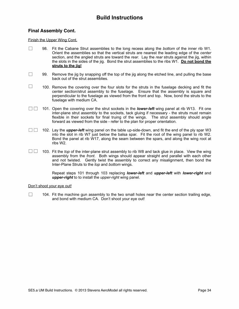
97. Lay the center section assembly on the table up-side-down. Fit the Cabane Strut Jig to the ribs as shown in the picture, aligning the front face of the jig with the trailing edge of the center section. Do not bond the jig to the wing assembly!
Build Instructions
SE5.a UM Build Instructions. © 2013 Stevens AeroModel all rights reserved.! Page 32
□
□ □
□ □
□
□ □
□ □
□
Build Instructions
SE5.a UM Build Instructions. © 2013 Stevens AeroModel all rights reserved.! Page 33
Step 91
Step 92
Step 93
Step 94 Step 97
Step 96 cont.
Step 96
Step 95
W16
W17
W18
Cabane Strut Jig
W15W12
Bond
Bond
Do Not Bond!
W17W16
W15
W15
W15
W17/W16
Final Assembly Cont.
Finish the Upper Wing Cont.
98. Fit the Cabane Strut assemblies to the long recess along the bottom of the inner rib W1. Orient the assemblies so that the vertical struts are nearest the leading edge of the center section, and the angled struts are toward the rear. Lay the rear struts against the jig, within the slots in the sides of the jig. Bond the strut assemblies to the ribs W1. Do not bond the struts to the jig!
99. Remove the jig by snapping off the top of the jig along the etched line, and pulling the base back out of the strut assemblies.
100. Remove the covering over the four slots for the struts in the fuselage decking and fit the center section/strut assembly to the fuselage. Ensure that the assembly is square and perpendicular to the fuselage as viewed from the front and top. Now, bond the struts to the fuselage with medium CA.
101. Open the covering over the strut sockets in the lower-left wing panel at rib W13. Fit one inter-plane strut assembly to the sockets, tack gluing if necessary - the struts must remain flexible in their sockets for final truing of the wings. The strut assembly should angle forward as viewed from the side - refer to the plan for proper orientation.
102. Lay the upper-left wing panel on the table up-side-down, and fit the end of the ply spar W3 into the slot in rib W7 just below the balsa spar. Fit the root of the wing panel to rib W2. Bond the panel at rib W17, along the seam between the spars, and along the wing root at ribs W2.
103. Fit the top of the inter-plane strut assembly to rib W8 and tack glue in place. View the wing assembly from the front. Both wings should appear straight and parallel with each other and not twisted. Gently twist the assembly to correct any misalignment, then bond the Inter-Plane Struts to the top and bottom wings.
Repeat steps 101 through 103 replacing lower-left and upper-left with lower-right and upper-right to to install the upper-right wing panel.
Don’t shoot your eye out!
104. Fit the machine gun assembly to the two small holes near the center section trailing edge, and bond with medium CA. Don’t shoot your eye out!
Build Instructions
SE5.a UM Build Instructions. © 2013 Stevens AeroModel all rights reserved.! Page 34
□
□
□
□ □
□
□ □
□ □
Build Instructions
SE5.a UM Build Instructions. © 2013 Stevens AeroModel all rights reserved.! Page 35
Step 97 cont.
Step 98
Step 99
Step 100 Step 104
Step 103
Step 102
Step 101
Even withtrailing edge
Bond
F4
W7
Break off
Remove
Bond
Tack glue
Bond
Do Not Bond!
Tack
No glue!
W3
Caution!
Final Assembly Cont.
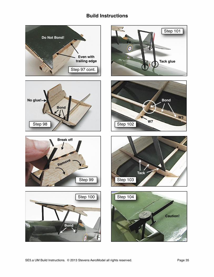
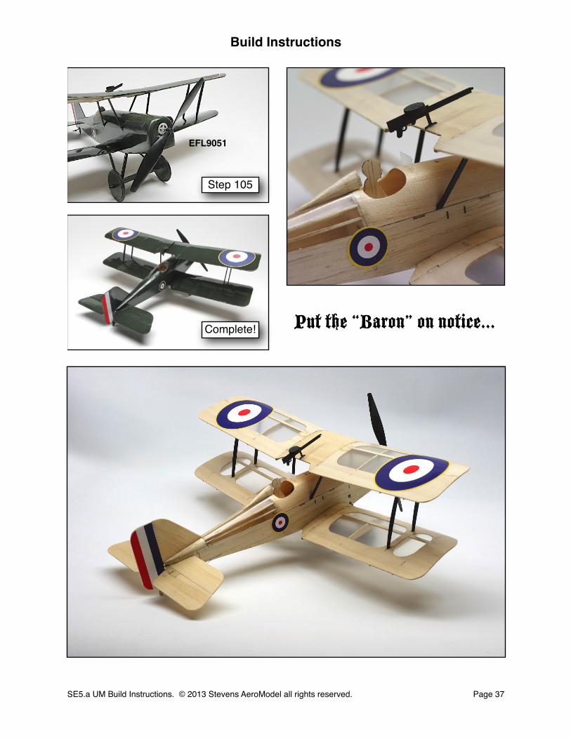
105. Install the propellor [EFL9051] to the motor shaft.
Congratulations! Your Stevens AeroModel SE5.a UM is complete! Run around the house making machine gun noises until your family dis-owns you, then proceed to the Set-up and Pre-Flight sections to prepare your model for those early morning dawn patrols over the western front in search of the ever illusive Hun!
“Steve’s” deep thought on the SE5.a UM:
I have some final thoughts on assembly of this model that I’d like to share with you.
It seems that our simple single surface flying model line has evolved from one-evening wonders, such as the Diddle Bug, to seemingly more and more detail rich and part intensive scale models. As exciting as this is, these models can seem intimidating to first time builders... especially when it comes to covering all those little parts.
This may come as a shocker to many of you but; I didn’t get into this business because I had time to build or even enjoyed investing weeks into building and covering models. In fact, the opposite is true. I was/am super busy with work and family and while I had little interest in pre-assembled products (ARFs) I was disillusioned by the skill and time commitment that most contemporary model aircraft kits required to achieve results that I was not ashamed to put my AMA number on! I was earnestly in search of a product that, in short order, even I could churn out respectable looking results with. When none was found I started Stevens AeroModel to provide such an experience to fellow busy builders.
Therefore I want to reach out to my fellow busy builders and point out that while this manual shows the construction and assembly of this model as completely covered in Olive Green AeroLITE it is entirely unnecessary to cover the whole model. In fact, superb, more true to scale, and a much quicker results can be achieved by simply covering the upper flying surfaces, and open turtle deck stringers, with clear AeroLITE film or even dope and tissue. I recommend sealing the model using a light coat of clear spray lacquer (DEFT). The sealing process raises the grain in the balsa slightly so you will need to knock it back down with some fine sand paper and shoot it once more (lightly) with clear spray lacquer. Now either leave the model in natural wood / clear covering to show off the intricate construction detail, or grab some compatible lacquer based paints from your hobby supply and lightly airbrush the model to a more realistic Olive Drab scheme, the results are astoundingly good and so much quicker than covering all those parts individually.
Remember, we just provided the canvas so you can take on personalizing your model as you see fit. What ever finishing method you choose I hope you have enjoyed building the SE5.a UM as much as I have and that you have found it to be an innovative and thoughtful kit product.
Thank you for purchasing our models I look forward to seeing your own implementation of the SE5.a UM!
-Bill Stevens
Build Instructions
SE5.a UM Build Instructions. © 2013 Stevens AeroModel all rights reserved.! Page 36
□
Build Instructions
SE5.a UM Build Instructions. © 2013 Stevens AeroModel all rights reserved.! Page 37
Step 105
Complete!
EFL9051
Put the “Baron” on notice...

Setup
☐ Inspect the wings for any warps that may have worked their way in when covering or while the model was in storage, and remove prior to flight. DO NOT ATTEMPT FLIGHT IF THE WINGS ARE WARPED.
☐ Center control surface then set direction, rate of travel, and dampening (expo).
Rudder Travel Rate +/- 15 degrees 30% expo
Elevator TravelRate +/- 15 degrees 30% expo
☐ Mount your battery (we suggest a 130-160 mAh 3.7V LiPo). The battery will lie loose within the fuselage, tucked in over the spar in the lower wing and through the opening in former W2. Alternatively, and if weight and balance will allow, one can open the balsa fuselage bottom decking forward of the lower wing. Use a battery lead extension and mount the battery to the inside wall of the fuselage forward of the wing. In any event it may be necessary to move the battery fore and aft to achieve the proper balance of the model as given in the Pre-Flight section.
Pre-Flight
Have an experienced pilot assist you with pre-flighting your new model. Just like having someone proof read something you’ve written, having a second fresh set of eyes to inspect your final product is often helpful at avoiding disaster.
While not an exhaustive pre-flight check these are some of the major items that you should consider using when developing your own pre-flight check list. Get in the habit of always pre-flighting your models before each and every flight.
☐ Weight and Balance - Check the SE5.a UM’s balance. The model should balance at the points etched under the wing tips of the upper wing, or 1-3/8 inches aft of the leading edge of the upper wing.
☐ Use your right and left hand index fingers and suspend the model from below, between the marked CG measurements. Site from profile of aircraft against horizon. If the fuselage side appears to hang level with horizon line, then the SE5.a UM is properly balanced to fly. Move equipment and or battery within fuselage to obtain proper balance.
☐ Check Weather - Your first flight with the SE5.a UM should be outdoors and in zero wind conditions. The SE5a UM is a delight to fly in winds up to 5-7 mph so long as the pilot is capable.
☐ Inspect airframe for warps and obvious signs of wear or damage. Do not fly a damaged or warped model.
☐ Inspect control surfaces for center, proper direction of travel, rate of throw, secure pushrod connections, hinges, and receiver/servo mounting hardware.
☐ Check wing attach points for damage and/or wear.
☐ Inspect battery for full charge. Never begin a flight with a partially charged battery.
☐ Clear prop! Before applying power to the model, clear and keep clear of the prop arc.
Build Instructions
SE5.a UM Build Instructions. © 2013 Stevens AeroModel all rights reserved.! Page 38

☐ Range check radio. Follow the radio makers guidelines for performing a proper range check.
☐ Check for traffic. Proceed to the flight line (With your mentor/instructor if you are a novice pilot) and observe other RC traffic. If the runway is clear, and no one is in the pattern to land, loudly announce your intentions to take off. Remember etiquette dictates that all aircraft on ground must yield the runway to those landing.
☐ Go flying. Point model into wind (if present) and steadily advance throttle to full. Use rudder to correct track while on ground roll. Within several feet the model should be airborne. Fly model to a comfortable 1-2 mistake high altitude, reduce throttle to stop climb, then trim model for straight and level f l ight at a comfortable cruise speed (Depending on speed control responsiveness, the SE5.a UM typically cruises at just over 1/2 throttle).
☐ Setup for landing. Clearly announce your intention to land. Make landings into the wind. With rudder/elevator control and no ailerons setting up landings in cross-winds should be avoided until you are comfortable with the model’s in-flight behavior.
Congratulations!
You’ve completed your first flight(s) on your Stevens Aero SE5.a UM.
By now you’ll have noticed that the SE5.a UM is a very stable airplane. When built straight, and trimmed for level flight, the model will always return to wings level from any attitude.
If your first flight was a bit more exciting than you’d have liked and are having problems with erratic flight performance; please inspect your equipment and airframe for damage, improper installation, and/or twists and warps. The most common mistake is to try and fly with a warped or twisted wing. Make certain that your wing is straight before you fly.
At Stevens AeroModel, we are committed to improving your building and flying experience. We are constantly refining our processes, designs, and manuals to reflect customer
feedback. You may correspond with the Stevens AeroModel staff at:
email: [email protected]: 719-387-4187
Build Instructions
SE5.a UM Build Instructions. © 2013 Stevens AeroModel all rights reserved.! Page 39