Schedules (Concession Agreement – Bus Terminal cum ... - PIDB
118
1 Schedules (Concession Agreement – Bus Terminal cum Commerical Complex at Patiala on PPP basis) Schedule-A Site of the Project Schedule-B Development of the Project Schedule-C Project Facilities Schedule-D Specifications & Standards Schedule-E Applicable Permits Schedule-F Performance Security Schedule-G Project Completion Schedule Schedule-H Drawings Schedule-I Tests Schedule-J Completion Certificate ( Provisional Completion Certificate ) Schedule-K Maintenance Requirements (Repair/ Rectification of Defect and Deficiencies) Schedule-L Intentionally Left Blank Schedule-M Monthly User Statement Schedule-N, O, P Deleted Schedule -Q Terms of Reference for Independent Engineer Schedule -R Adda Fee and Parking Fee Schedule -S Escrow Agreement Schedule -T Deleted Schedule -U Vesting Certificate Schedule -V Substitution Agreement
-
Upload
khangminh22 -
Category
Documents
-
view
2 -
download
0
Transcript of Schedules (Concession Agreement – Bus Terminal cum ... - PIDB

1
Schedules
(Concession Agreement – Bus Terminal cum Commerical Complex at Patiala on PPP basis)
Schedule-A Site of the Project
Schedule-B Development of the Project
Schedule-C Project Facilities
Schedule-D Specifications & Standards
Schedule-E Applicable Permits
Schedule-F Performance Security
Schedule-G Project Completion Schedule
Schedule-H Drawings
Schedule-I Tests
Schedule-J Completion Certificate ( Provisional Completion Certificate )
Schedule-K Maintenance Requirements
(Repair/ Rectification of Defect and Deficiencies)
Schedule-L Intentionally Left Blank
Schedule-M Monthly User Statement
Schedule-N, O, P Deleted
Schedule -Q Terms of Reference for Independent Engineer
Schedule -R Adda Fee and Parking Fee
Schedule -S Escrow Agreement
Schedule -T Deleted
Schedule -U Vesting Certificate
Schedule -V Substitution Agreement

2
SCHEDULE –A (See Clause 10.1)
SITE OF THE PROJECT
1. The Site
The total area of the site available with Concessioning Authority is about 8.51 Acre. The area of the Project Site for proposed Bus Terminal cum Commercial Complex Project is approximately 6.25 acre (as Appendix-1). Out of the total available area, the remaninng area has been kept reserved for Construction of PRTC Complex by PRTC, as per the following details.
Sr. No.
Area Details / Particulars Area (approx.)
1. Area of the proposed site available with PRTC 8.51
2. Area Reserved for Construction of PRTC Complex (Covering PRTC Offices Building, PRTC Workshop(s), PRTC Fuel Station and for other requirement of PRTC including dedicated Access Road from Patiala-Rajpura Road, as per PRTC plan & discretion).
2.26
Total of Project Site for Bus Terminal cum Commercial Complex
6.25
Note: The Site Topographical Survey drawing to be prepared by the Concessionaire and same shall be approved by the Concessioning Authority. The approved site map and area shall be the proposed ‘Project Site’ and form part of the Concession Agreement.

3
SCHEDULE - B (See Clause 2.1)
DEVELOPMENT OF THE PROJECT
The Concessionaire is required to plan, design, finance, construct, develop, equip, operate, maintain and manage the Project i.e. Bus Terminal and Commercial Complex. The main focus of the Concessionaire should be to develop a State-of-the-Art Bus Terminal with better facilities for passengers/ public and a Commercial Complex thereby creating a good public facility with iconic exteriors & facade. The Concessionaire would be given the option to plan and design the Bus Terminal and Commercial Complex Building conforming to the applicable Building Bye-Laws and regulations/ norms/ standards for respective project components including arranging approval from the competent authority. The Main Project Components to be developed at the Project Site are:
• Bus Terminal with Minimum Obligatroy Project Facilities as per Schedule C of the Concession Agreement • Commercial Complex, having minimum 43,000 (forty three thousand) sq. ft. of covered built-up area,
as per Applicable Laws and provisions of Concession Agreement. The nature of the activities and facilities that can be allowed for the Commercial Complex includes - Shops in Shopping Mall/Multiplex, Fun and Play Zones/Food Courts/Hotel, Restaurants, Beauty Salons/ Spas/Hypermarket /Retail Showrooms for Consumer goods / Garments / Electronics etc./Bank’s and Bank’s ATM.
The Concessionaire may use or allow the use of the Project for other activities, which are not indicated in the Concession Agreement, only after prior written approval of the Concessioning Authority. However, the decision of the Concessioning Authority shall be final in this regard.
The proposed Bus Terminal-cum-Commercial Complex shall be planned and designed with contemporary innovative design on the lines of post modernism and design elements. The exterior/ facade of the building could be in combination of glass/ metal/ tile/ fusion thereof. The building shall be planned and designed with efficient floor plates, wide column spans/ spacing and having high floor clearance and good circulation area.
The first step, which the Concessionaire would be required to adhere, is the submission of detailed plans, design and drawings of the Project Facility. This shall also include the floor wise plan and design of the Project facilities, cross sections, elevations and working drawings fit for the construction of the Project facility. With the objective to provide a “State-of-the-Art” facility, the Concessionaire shall construct the building works as per applicable development control regulations and building bylaws subject to clearance from Airport Authorities and fulfillment of other applicable norms/ laws/ rules such as setbacks, distance between buildings etc. However, adherence to the structural safety and fire safety requirements as per National Building Code shall be compulsory.
In addition to this, the Concessionaire shall plan, design and construct the Bus Terminal and the related passenger amenities as per Schedule –C of the Concession Agreement, on the ground floor or any other level/ floor of the Project Facility and shall be utilized accordingly. All the facilities which are required for creation of a complete State-of-the-Art Bus Terminal shall be developed by the Concessionaire. In relation to the Bus Terminal, the Concessionaire shall adhere to the “Technical Specifications and Standards” as laid down in this Concession Agreement.
The Concessioning Authority shall not unreasonably interfere with the internal layout of the Commercial Complex, proposed by the Concessionaire, except the Bus Terminal. However, it is to be noted that the Bus Terminal is a main component of the Project hence, should be pre-dominantly visible to the general public travelling on the raods outside the Project Site. Also, the entry and exit of the Bus Terminal and Commercial Complex shall be kept separate in a way so as to avoid any conflict between the Users of respective buildings/ areas.
It would also be the obligation of the Concessionaire to provide and install all internal and external services i.e. internal sanitary and plumbing; internal electrical services and installation along with Electric Sub-station; fire detection; fire alarm and firefighting services; air conditioning (as applicable) services in entire Commercial Complex including the Bus Terminal and the related passenger amenities would be developed and also, elevator/ escalator for the Commercial Complex; communication system and services.
In addition to this, the Concessionaire shall ensure that the Bus Terminal has a rigid pavement in Pavement Quality Concrete (PQC) for the Bus Movement and Parking areas and shall also plan overall traffic circulation within the campus and on roads outside the campus.
The Concessionaire shall plan and construct adequate public parking area for both Bus Terminal and Commercial Complex area including separate entry and exit for Buses, passengers and users of Commercial Complex. The Concessionaire would be required to follow the parking norms for Commercial Buildings. The norms adopted for

4
development regulations are subject to approval from competent authority and the development proposed should adhere to the development regulations in force by the competent authorities at the time of approval.
The Concessionaire shall plan and provide Estate Services i.e. water supply distribution, storm water collection and disposal, sewage collection, solid waste collection and disposal along-with Municipal Services; campus electrification including arranging service connection from the applicable authorities.(Rain Water Harvesting, Sewage Treatment Plant)
It is clarified that in addition to the above-stated “Scope of Work”, the Concessionaire shall be required to carry out any incidental works and services as required and to comply with all the provisions of the Concession Agreement, the Schedules to the Concession Agreement and the Technical Specifications & Standards of the Concession Agreement while construction of the project facility. Construction Works The Concessionaire shall ensure that construction of building structure of the Bus Terminal Facilities is undertaken in accordance with the design approved by the Independent Engineer in consultation with the Punjab Roadways/PRTC/PIDB or any other body of Punjab Governemnt. Entire construction shall be in conformity with the Technical Specifications and Standards set forth in this document. The development works shall include, but be not limited to, the following:
· Preparation of master plan for the entire site for development of Bus Terminal Facilities and Commercial Facilities.
· Detailed design & detailed engineering with Good for Construction drawings related to the execution of the Bus Terminal Facilities.
· Development of Bus Terminal Elements which shall include the bus bays (alighting, boarding and idle parking), bus circulation area, exit & entry for buses and other components described in subsequent paragraphs of this Schedule.
· Passenger Amenities shall include, but be not limited to, shops, kiosks, ticketing counters, tourist information centre, toilets, drinking water chambers, waiting halls, seating facilities, dustbins, parking areas for public, private and intermediate public transport, etc and other components described..
· Design and construct supporting infrastructure facilities related to internal roads, curb stones, foot paths, Solid Waste Management, Rain Water Harvesting, Water Supply and Sanitation, Electric Sub Station, solar lighting (if needed), Communication System, Facilities for the differentially-abled persons.
Bus Terminal Facilities The Bus Terminal Facilities shall comprise of the following: 1. Bus Terminal Elements
The development works under this head shall include the following sub-components: · Bus Bays for Boarding & Alighting and for Idle Parking · Bus Circulation Area & Approach Roads · Entry & Exit of buses to the Bus Terminal Facility · Entry & Exit of passengers to the Bus Terminal Facility · Interconnecting Subways & Pathways, Escalators, Ramps between various components · Providing & management of Information System including public address system · Security Guard Cabins at entry/ exit of bus terminal · Adda Fees collection system at the exit. · Hi-tech Security System for Bus Terminal Facilities
2. Passenger Amenities
The Passenger Amenities shall mainly comprise of the following: · Passenger Concourse Area for Boarding & Alighting · Passenger Platform for Alighting & Boarding · Ticketing Counters, Enquiry Counters, Reservation Office · Tourist Information Centers · Waiting Halls & Seating Arrangements · Cloak Rooms & Parcel Rooms · Public Utilities (Toilets, Drinking Water Chambers etc.)

5
· Commercial sub-components like kiosks, canteen, restaurants, mini food courts, newspaper stands, book stalls, ATMs and general merchandize shops & stores etc.
· Rest Room for the crew members and staff including wash rooms · Information Sign boards & display boards · Parking Area for private vehicles (two wheelers and cars) and for intermediate public transport like auto
rickshaws, taxis along with the approach, entry and exit, drop-in and drop-off areas, pick-up zones · Concessionaire's Office
3. Deleted 4. Common areas and Support Infrastructure
The supporting infrastructure requirements in the bus terminal shall comprise of the following: . Water Supply and Sanitation Structures · Storm Water Drainage · Rain Water Harvesting Structures · Solid Waste Management Systems · Communication Systems · Landscaped Area · Electric Sub-Station /Transformer · Compound Walls and other physical separators for the segregation of components · Service lanes for modal transfer from public and private modes of transport to and from bus terminal · Bus-Q-Shelters for city buses · Roads, curb stones and food paths
5. Any other structure and facilities
Notwithstanding anything contained hereinabove, any other structure and facilities as may be required under the Concession Agreement shall be provided by the Concessionaire.
Planning & Design Parameters For Bus Terminal Area The Concessionaire shall consider and comply with the following planning & design parameters. The most important design consideration for a terminal is the safety requirement, which can be met by segregating the traffic movements and convert the terminal into an ‘active urban street’ concept. Pedestrian circulation inside the bus terminal complex shall be designed in such a manner that no passenger may tread on to the bus movement areas. For efficient working of the bus terminal and to reduce the noise & air pollution the movement of vehicular traffic in the bus terminal should be totally unobstructed and the entry & exit of buses as well as the arrival and departure bays shall be designed in such a fashion that the bus traffic shall not be in conflict with any of the other activities of the terminal. The interior of the terminal should be duly reckoned for its usefulness, open areas and aesthetics. Bus terminal shall have high quality seating, flooring, ceiling, lighting etc. Marble wainscoting, aluminum/ S.S. finishes, granite floors, impressive lighting fixtures, granite and limestone should be incorporated into its art deco design including glow signage. The factors to be considered in the Bus Terminal design by appreciating activity and facility inter-relationship are: · Segregation of terminal and non-terminal traffic · Segregation of vehicular and passenger traffic · Segregation of traffic by type, function and direction · Co-ordination of different activities in terms of functional and spatial inter-relationships · Separate access for Bus Terminal Facilities and Commercial Facilities · Provision of efficient information system for Users · Provision of good necessary and identified facilities to meet requirement of all user groups · Achieving minimum passenger and vehicular processing time · Achieving overall functional and space efficiency · Achieving smooth flow for all types of traffic to and from the terminal The building should be Bureau of Energy Efficiency, Energy Conservation and Development Code compliant to the extent possible. This will help to save energy cost and also entitle to get carbon credits.

6
Note: Concessionaire shall mandatorily adhere to the guidelines of MORT&H applicable to National Highways and shall also observe building bye laws of Development Authority/local bodies/Town Planning/NBC/CPWD or any other norms while preparing the master plan and detailed design of Bus Terminal Facilities and Commercial Facilities
Bus Terminal Elements 1. Bus Entry/Exit to the Terminal
The bus circulation pattern in the bus terminal shall be such that there is no queuing of buses at the entry/exit of the bus terminal. The entry and exit shall be separate for the buses and other vehicles. Speed-breakers shall be provided near the entry and exit. The entry and exit shall be on the main external road(s) viz. (i) Patiala-Chandigarh Road and / or Sirhind Byepass Road as approved by the Concessioning Authority. Concessioniare has to plan the bus terminal keeping in view an additional access road from Sirhind Road, which may be avaible in future. Concessioning Authoroity is making efforts to arrange an additional access road to bus terminal site ( in addition to the present access road i.e. Patiala-Chandigarh Road) in order to improve the accessibility of proposed bus terminal. Therefore, plan of the bus terminal shall be finalised keeping in view this additional access road proposal of Concessioning Authority. In case more than one entry and exit is provided on the roadside, a buffer of minimum 7m shall be provided parallel to the same road.
2. Service Time at Bays for Buses
The internal circulation pattern of the buses in the terminal shall be planned such that alighting and boarding time is at least 4 and 10 minutes respectively.
3. Pavement for Bus Terminal
The Concessionaire shall construct the bus circulation and the parking area along with the approach roads to various components in the bus terminal with rigid pavement. The pavement shall be designed for at least 30 years as per the relevant IRC standard, and suitable drainage facilities are to be provided as per the standards of IRC.
4. Idle Parking for Buses
The idle parking bays are to be earmarked separately within the bus terminal. However there shall be enough circulation area to ensure safe movement, turning and maneuvering of the buses. The idle parking bay area shall be marked and designated with thermoplastic paint along with the provision of appropriate informatory sign boards.
5. Traffic Signs and Signages
The Concessionaire shall provide signages with customer focused approach. The Concessionaire should consider guidelines given below: Adequate number of traffic signs (informatory, cautionary and warning) and sign boards shall be provided in the bus terminal for convenience of crew and other users. Signs shall be located for maximum visibility at or before all important locations within the bus terminal. Signs shall be placed with such spacing that the infrequent or new user can readily find his or her way without assistance. All signages should comply with relevant standards and codes. Signage shall also include items relating to regulatory enforcement (e.g. no smoking, no parking here, etc.) Relate outbound passengers to the surrounding community with appropriate signage. Pavement markings shall be provided as per requirement in the bus terminal area for convenience to crew and users.

7
6. Functional and Geometric Design Dimension Parameters
The following table indicates the minimum dimensions related to functional and geometric design aspects of the bus terminal components.
Table 1 Minimum Functional and Geometric Dimensions
S. No. Parameter Minimum Dimension (No./Length/Width)
1 Bus Bay dimension 3.6m x 10.5 m clear space along with a stub arm of 1.2 m wide.
2 Turning radius for bus movement Not less than 14.0m 3 Driveway width for bus Not less than 16.0 m
4 Clear Distance between the boarding/alighting bay and idle bay for buses Not less than 15.0m
5 Width of the passenger platform, in case of bus bays on only one side of the passenger platform Not less than 9.0m
6 Width of the passenger platform, in case, the bus bays are provided on both sides of the passenger platform Not less than 15.0m
7 Clear height of passenger concourse in the boarding area including boarding platforms Not less than 6.0m
8 Clear height of passenger concourse in the alighting are including alighting platforms Not less than 3.5m
9 Driveway width at the bus entry/exit gates Not less than 9.00m 10 Minimum width of ramps for usage by passengers Not less than 3.75m
11 Minimum width of vehicular ramps leading to basement parking Not less than 4.50m
12 Minimum width of rams for buses Not less than 9.00m
13 Minimum width for interconnecting subways, incase they are provided Not less than 10.00m
14 Minimum width of Foot Over Bridge (FOB), if provided ≥ 5.0m Passenger Amenities Passenger Entry/Exit to the Bus Terminal
(a) The passenger entry to the bus terminal shall be separate from the vehicular entry and exit with minimum width
of 7.5 m and a foyer to mark distinction. (b) The passenger circulation in the bus terminal shall be such that there is no conflict with bus or other vehicular
traffic circulation. The Intermediate Public Transport (IPT) and private parking area shall have a direct connectivity with the passenger concourse area.
(c) The passenger concourse area for the alighting and the boarding areas in the bus terminal shall be interconnected for easy accessibility and better modal transfer. The passenger amenities like waiting hall, toilet blocks, drinking water chambers, enquiry counters, reservation counters, canteen, kiosks etc shall be conveniently located in the passenger concourse areas for effective utilisation by the users.
(d) The alighting and boarding platforms including the passenger concourse area for boarding and alighting shall be covered by suitable roofing of steel structure or RCC. The canopy shall extend over the bus bays beyond the edge of the platform by minimum 2m to protect against rain, sun and other weather adversaries. The Concessionaire shall be permitted to choose the technical specifications for projections so as to conserve the FAR as may be admissible under the applicable norms.
(e) Suitably illuminated signboards and display boards shall be placed indicating the various passenger amenities in the terminal. Any passenger movement in the bus circulation area shall be restrained for safety to passengers and vehicles. It shall have proper illumination and sign boards for safe movement of passengers.
(f) Any entry of IPT and private vehicles in the bus circulation and passenger circulation area shall be prohibited. (g) In case the basement parking is provided, it shall have a direct interconnectivity with the passenger concourse
areas by means of staircases/escalators and ramps/lifts. Suitable arrangements have to be made in the passenger concourse area interconnectivity with the basement parking area for the physically disabled. The interconnectivity arrangements between the bus terminal areas shall be free of any encumbrances at all times.
8
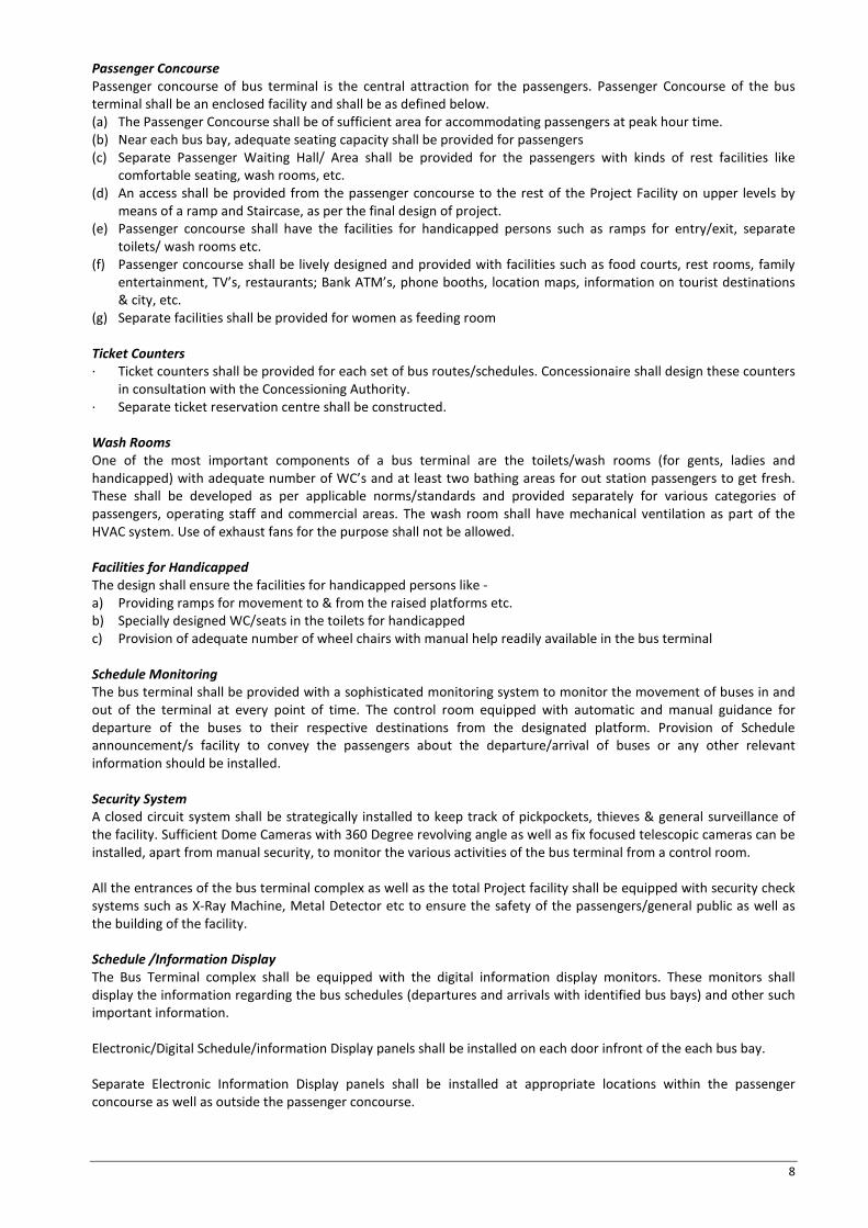
Passenger Concourse Passenger concourse of bus terminal is the central attraction for the passengers. Passenger Concourse of the bus terminal shall be an enclosed facility and shall be as defined below. (a) The Passenger Concourse shall be of sufficient area for accommodating passengers at peak hour time. (b) Near each bus bay, adequate seating capacity shall be provided for passengers (c) Separate Passenger Waiting Hall/ Area shall be provided for the passengers with kinds of rest facilities like
comfortable seating, wash rooms, etc. (d) An access shall be provided from the passenger concourse to the rest of the Project Facility on upper levels by
means of a ramp and Staircase, as per the final design of project. (e) Passenger concourse shall have the facilities for handicapped persons such as ramps for entry/exit, separate
toilets/ wash rooms etc. (f) Passenger concourse shall be lively designed and provided with facilities such as food courts, rest rooms, family
entertainment, TV’s, restaurants; Bank ATM’s, phone booths, location maps, information on tourist destinations & city, etc.
(g) Separate facilities shall be provided for women as feeding room
Ticket Counters · Ticket counters shall be provided for each set of bus routes/schedules. Concessionaire shall design these counters
in consultation with the Concessioning Authority. · Separate ticket reservation centre shall be constructed.
Wash Rooms One of the most important components of a bus terminal are the toilets/wash rooms (for gents, ladies and handicapped) with adequate number of WC’s and at least two bathing areas for out station passengers to get fresh. These shall be developed as per applicable norms/standards and provided separately for various categories of passengers, operating staff and commercial areas. The wash room shall have mechanical ventilation as part of the HVAC system. Use of exhaust fans for the purpose shall not be allowed.
Facilities for Handicapped The design shall ensure the facilities for handicapped persons like - a) Providing ramps for movement to & from the raised platforms etc. b) Specially designed WC/seats in the toilets for handicapped c) Provision of adequate number of wheel chairs with manual help readily available in the bus terminal Schedule Monitoring The bus terminal shall be provided with a sophisticated monitoring system to monitor the movement of buses in and out of the terminal at every point of time. The control room equipped with automatic and manual guidance for departure of the buses to their respective destinations from the designated platform. Provision of Schedule announcement/s facility to convey the passengers about the departure/arrival of buses or any other relevant information should be installed. Security System A closed circuit system shall be strategically installed to keep track of pickpockets, thieves & general surveillance of the facility. Sufficient Dome Cameras with 360 Degree revolving angle as well as fix focused telescopic cameras can be installed, apart from manual security, to monitor the various activities of the bus terminal from a control room. All the entrances of the bus terminal complex as well as the total Project facility shall be equipped with security check systems such as X-Ray Machine, Metal Detector etc to ensure the safety of the passengers/general public as well as the building of the facility. Schedule /Information Display The Bus Terminal complex shall be equipped with the digital information display monitors. These monitors shall display the information regarding the bus schedules (departures and arrivals with identified bus bays) and other such important information. Electronic/Digital Schedule/information Display panels shall be installed on each door infront of the each bus bay. Separate Electronic Information Display panels shall be installed at appropriate locations within the passenger concourse as well as outside the passenger concourse.

9
The directional sign for various facilities at the bus terminal should be displayed through a well sighted glow display boards/monitors. Minimum Walking distance The walking distance for the pedestrians/passengers should be kept minimum. This shall be achieved by providing drive-ways, parking & disembarkation facilities at appropriate locations etc. Baggage Trolleys Baggage trolleys shall be provided to facilitate the passengers to move their luggage from the parking lots etc. to their respective bus departure bays, between arrival and parkings, between short route bus bays and long route bus bays etc. Separate facilities shall be provided to senior citizens like wheelchairs to transfer baggage and passengers alike. Sanitation& Hygiene For keeping the proper hygiene of the bus terminal area/s, the sanitation facilities should be well equipped with preferably following: · Sweepers for cleaning the surface · Machine Water Spraying and mopers · Vacuum Cleaners · Scrubbing Machines · Dust Bins and Spittoons · Mechanical Ventilation of Toilet/ Washrooms including circulation of fresh air. The bus terminal shall be well equipped with the proper mechanized debris collection and disposal system. Drinking Water Shall be dispensed from Industrial Water Purifiers with adequate number and provision of disposable tumblers etc. Cloak rooms The cloakroom facility to keep baggage for passengers who wish to do so shall be provided at adequate locations. The x-ray machines etc. shall be installed for the searching the baggage for an unwanted/banned articles from a security consideration. Along with the above facility a room for missing baggage must be made. And all baggage must be claimed only after proper identity proof. Fire Fighting System & Power backup The Bus Terminal shall have automatic addressable fire-detection, fire alarm and fire fighting system. The campus shall have adequate number of fire hydrant as per the bye-laws of the region/city with easy access by fire tenders. Also the bus terminal shall be equipped with the 24 hour power back up in case of power failure etc. The basement ( as applicable) should have sprinkler fire fighting system. Cab/Taxi Facilities The cab /taxi facility shall be integrated along with the bus terminal. The information regarding the various routes of cabs with their charges should be displayed adequately inside the terminal as well as near the cab booth. Interiors of the Bus Terminal The Bus Terminal should be known for its usefulness, open areas and aesthetics. Bus terminal shall have high quality seating, flooring, ceiling, lighting etc. Bus Terminal Parking Area (a) The Intermediate Public Transport (IPT) modes like the auto rickshaws and taxis are the expected modal change for
the users apart from the intercity bus transport. The private modes of transport are two-wheelers, cars and cycles. There should be provision for arrival, departure and parking of these categories of private and public transport vehicles.
(b) The parking area shall be integrated with the bus terminal such that there is easy accessibility for the passengers. The parking area shall be suitably segregated into reservoirs for two-wheelers, cars, auto rickshaws and cycles.
(c) The parking area shall consist of drop-in and drop-off zones for the various private and IPT vehicles. Bus-Q-Shelters shall be constructed near the alighting zone to enable the passengers to board the city bus.
(d) All parking spaces shall be constructed with rigid pavement to withstand vehicle loads and forces due to frequent acceleration and deceleration of vehicles. Parking bays/areas shall have proper cross slope and drainage. They shall be marked with paint as per IRC35-1997 to demarcate parking and circulation space.
(e) The minimum dimensions in case of provision of multi-level parking is provided in the following table:
10
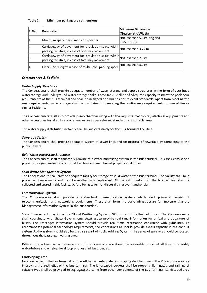
Table 2 Minimum parking area dimensions
S. No. Parameter Minimum Dimension (No./Length/Width)
1 Minimum space bay dimensions per car Not less than 5.2 m long and 3.25 m wide
2 Carriageway of pavement for circulation space within parking facilities, in case of one-way movement Not less than 3.75 m
3 Carriageway of pavement for circulation space within parking facilities, in case of two-way movement Not less than 7.5 m
4 Clear Floor Height in case of multi- level parking space Not less than 3.0 m
Common Area & Facilities
Water Supply Structures The Concessionaire shall provide adequate number of water storage and supply structures in the form of over head water storage and underground water storage tanks. These tanks shall be of adequate capacity to meet the peak hour requirements of the bus terminal and shall be designed and built as per relevant standards. Apart from meeting the user requirements, water storage shall be maintained for meeting the contingency requirements in case of fire or similar incidents. The Concessionaire shall also provide pump chamber along with the requisite mechanical, electrical equipments and other accessories installed in a proper enclosure as per relevant standards in a suitable area. The water supply distribution network shall be laid exclusively for the Bus Terminal Facilities. Sewerage System The Concessionaire shall provide adequate system of sewer lines and for disposal of sewerage by connecting to the public sewers. Rain Water Harvesting Structures The Concessionaire shall mandatorily provide rain water harvesting system in the bus terminal. This shall consist of a properly designed network which shall be clean and maintained properly at all times. Solid Waste Management System The Concessionaire shall provide adequate facility for storage of solid waste at the bus terminal. The facility shall be a proper enclosure and should not be aesthetically unpleasant. All the solid waste from the bus terminal shall be collected and stored in this facility, before being taken for disposal by relevant authorities. Communication System The Concessionaire shall provide a state-of-art communication system which shall primarily consist of telecommunication and networking equipments. These shall form the basic infrastructure for implementing the Management Information System in the bus terminal. State Government may introduce Global Positioning System (GPS) for all of its fleet of buses. The Concessionaire shall coordinate with State Government/ department to provide real time information for arrival and departure of buses. The Passenger information system should provide real time information consistent with guidelines. To accommodate potential technology requirements, the concessionaire should provide excess capacity in the conduit system. Audio system should also be used as a part of Public Address System. The series of speakers should be located throughout the passenger waiting area. Different departments/maintenance staff of the Concessionaire should be accessible on call at all times. Preferably walky-talkies and wireless local loop phones shall be provided. Landscaping Area No area/pocket in the bus terminal is to be left barren. Adequate Landscaping shall be done in the Project Site area for improving the aesthetics of the bus terminal. The landscaped pockets shall be properly illuminated and railings of suitable type shall be provided to segregate the same from other components of the Bus Terminal. Landscaped area

11
shall be provided properly and effort should be made to provide a suitable buffer zone /area /belt between the passenger concourse area and the commercial complex. Electricity Supply & Illumination Standards An electric sub-station/ Transformer may be provided in the bus terminal for electric supply to the Bus Terminal Facility. Apart from the electric supply, in case of emergencies, there shall be provision for Standby Diesel Generator Sets of suitable capacity which shall be provided in the bus terminal in a non-polluting manner for power backup to the terminal during power breakdowns and power cuts. The bus terminal shall be adequately lit as per the minimum approximate illumination standards prescribed. During night time common areas and facilities should be sufficiently illuminated to ensure visibility and safety to users. High mast lighting shall be provided to lit up the bus terminal area. Table 3 Minimum Illumination Standards
S. No. Project Component Minimum Approximate Illumination (Lux)
1 Passager Circulation Area 150 2 Administrative Office 150 3 Corridors 70 4 Restaurant 70 5 Cloakroom 100 6 Toilets 100 7 Waiting Halls 150 8 Parking Areas,
a) Surface Parking
b) Basement Parking
c) Ramp
50
70
70
9 Roofs 20 10 External Lighting 20 11 Bus Q Shelters for city buses 60 Compound Wall Compound wall for the Bus Terminal & Project Site area shall be constructed to protect the terminal complex from external threats, encroachments etc. Material Specifications In order to obtain minimum standards for the development of the bus terminal components, various materials are specified for selected items of works. The concessionaire shall use the material specified in the table below for the construction of the bus terminal and the ancillary facilities. Table 4 Material Specifications
S.No. Material Specification
1 Flooring / Skirting / Dado
Offices, Stores, Waiting Halls, Dormitories, Rest Rooms
Stores, Dormitories, Rest rooms: · Flooring: Vitrified tiles with minimum size of 60cm x 60cm · Skirting: 10.0 cm high of Vitrified tile Waiting rooms,
Offices: · Flooring: Vitrified tiles · Skirting: 10.0 cm high of Vitrified tile

12
B Passenger Circulation Area and Canteen/ Restaurant, Shops, Booths
Flooring: Vitrified tiles with minimum size of 60cm x 60cm Skirting: 10.0 cm high skirting of Vitrified Tiles Dado: 135 cm high dado of Vitrified Tiles
Passenger Platform Rough Kota Stone with minimum size of 60cm x 60cm (38 mm thick)
Staircase With unpolished granite (15 mm thick)
C Toilet Blocks Flooring: Granite (12 mm thick) Skirting: 10.0 cm high skirting of Granite Dado: 135 cm Granite/dado up to lintel height
D Bus Ticket Counter, Enquiry Counter, Reservation Counter, Information Centre Top, Wash Basin Slab Tops in and table tops of Kitchen/Pantry
Polished Granite (38 mm thick) in single piece as far as possible.
E Electric Sub Station/Generator Room
Ironite Flooring (50 mm thick)
F Kitchen/Pantry Flooring: Granite stone (38 mm thick) with stone size 60 cm x 60 cm Skirting: 10.0 cm high skirting of Granite stone (38 mm thick) Dado: 47.5 cm high dado of Granite stone (1.5’’ thick) above the counter top
G Ramp With rough Kota Stone/staggered granite (38 mm thick)
H In general Flooring : 50mm thick Cement Concrete— M35 grade Skirting : 30cm high skirting of Polished Kota Stone (38 mm thick)
I Basement Cement Concrete Flooring
2 Plastering/ Cladding / Painting
A Brick Walls, Concrete members connected with brick work
Walls shall be in cement mortar (1:4) plastered (12mm thick inside face and 20mm thick external face) and painted with oil bound distemper above skirting / dado after applying of putty, primer to give a perfect even surface
B Reinforced Cement Concrete
RCC slab ceilings shall be plastered with 12 mm thick in CM 1:4. Columns in the platform area shall have faulted vertical surfaces painted in sandtex matt cement paint of Dholpur stone colour shade. (Painting shall be done after the 12 mm thick cement plaster 1:4 mix)
C Internal Finishing of the Terminal Building
12 mm thick cement plaster 1:4 mix and shall be painted with oil bounded distemper
D External Finishing of the Terminal Building (i) Platform Wall
The surfaces shall be of Marble/Stone/aluminum composite panels cladding/Glass/HPL or any other material with good aesthetics. Remaining walls facing towards platform shall be plastered (20 mm single mala) above 135 cm high granite stone dado and painted with oil bound distemper
E Internal wooden and steel joinery
Painted with Synthetic Enamel 1st quality of approved shade
3 Joinery / Doors / Windows / Shutters / Ventilators

13
A Offices, Stores, Waiting Room, Dormitories, Rest Rooms
Joinery: All doors and windows chowkhats shall be 16 gauge pressed steel double or single rebate as per requirement, prefilled with 1:3:6 cement concrete, as per PWD Building Specifications. Doors: All door shutters shall be 40 mm thick teak wood with 12 mm thick panels of water proof as per PWD Building Specifications. Windows: Window shutters shall be 35 mm thick of teak wood having glass panes as per PWD Building Specifications. Wire gauge shutters shall be provided wherever required. Cupboard Frame/Shutters: Teak wood as per PWD Building Specifications. Glazing: Plain or Tinted glass of minimum thickness 5 mm. Shutters : Rolling Shutters
B Counters, Reservation Counters, Information Counters
Windows : Windows (size 2m x 1m) with plain glass panes covered with window grill on the external side made of MS sections as per PWD Building Specifications, having suitable openings for public interface
C Bus Ticket Counters Windows: Windows (size 2m x 1m) with window grill on the external side made of MS sections as per PWD Building Specifications, having suitable openings for public interface
D Toilets PVC flush doors
E Water Proofing Works Water proofing of basement as per PWD Building Specifications (Box type water proofing)
4 Furniture
A Waiting Halls Chairs: Stainless steel chairs with back rest, grouted/fixed to the floor of approved make of Godrej etc. Tables: Steel framework with 20 mm thick wooden/board top, finished with lamination of approved make with lock and key arrangement.
B Offices Chairs : Office Chairs of approved make Tables : Steel structure with 20 mm thick wooden/board top, finished with sunmica (lamination) of approved make Cupboards: Factory made steel cupboards of approved make
5 External Works
A Pavement-Bus Terminal Circulation Area
30 cm thick Cement Concrete Pavement. M35 grade in panels of size 3m X 3mm with steel reinforcement at corner 0.9m x 0.9m width 8mm dia. Steel @ 150mm c/c laid over 100mm thick lean concerete 1:3:6 including 6mm thick fine sand uniformaly spread with providing laying in portion separation membrane of impermeable polythene sheet 125 micron over lap width 300mm nailing to lower surface making 12mm expansion joint with 220 mm shaitax board as per CRRI specification The rigid pavement shall be designed as per IRC: 58-2015. Construction of rigid pavement shall conform to MORT&H Specifications.
B Pavement-Parking Area for vehicles
20 cm thick Cement Concrete Pavement. M30 grade in panels of size 3m X 3mm with steel reinforcement at corner 0.9m x 0.9m width 8mm dia. Steel @ 150mm c/c laid over 100mm thick lean concerete 1:3:6 including 6mm thick fine sand uniformaly spread with providing laying in portion separation

14
The Concessionaire shall adhere to the Technical Specifications of the Concession Agreement while construction of the facility and has the option to upgrade the Technical Specifications in consultation with the Concessioning Authority without any extra consideration. The Concessionaire shall follow Good Industry Practice for construction of the Project, wherever specifications are not stipulated in the Concession Agreement & its Schedules, Technical Specifications etc.
membrane of impermeable polythene sheet 125 micron over lap width 300mm nailing to lower surface making 12mm expansion joint with 220 mm shaitax board as per CRRI specification Parking area should be covered and paved. M25 grade interlocking pavers of 80 mm thickness should be provided over 30 mm sand layer.
Boundary Wall The boundary wall of the bus terminal shall be 1.75m high, plastered 20mm on both sides of the wall with oil bound distemper on both the sides.
C Kerbs and Precast Channel Stones
For all internal roads shall cement concrete as per PWD Specifications
D Bus Stoppers RCC and RS Joists
E Platform Nosing 7.5 cm x 7.5 cm MS angle
F Railing Stainless steel
G Footpaths/ Passenger entry- exit Rough Kota / Nimbaheda / Mandana Stone (38 mm thick)
H Ramps Cement concrete (M30 grade)
I Plinth Protection 60 cm to 90 cm plinth protection of 38 cm thick M20 cement concrete laid over 10cm thick lean concrete M10 and 10cm thick sand combined with toe wall wherever required
J Water Proofing Laying integral type (India type) cement based water proofing system using brickbats with the approved water proofing Compounds
K Pedestrian concourse area Nimbaheda / Mandana Stone (38 mm thick)
6 BUS-Q-SHELTERS FOR CITY BUSES
A Flooring Stable and anti skid type, concrete or pre polished concrete designer tiles 20 mm thick of approved colour, shape and pattern, in floor jointed with neat cement slurry/binding material, over a bed of 150 mm cement concrete mix of 1:4:8 and 50mm thick cement mortar of 1:6 mix. The tactile tiles to be laid as per provisions for physically challenged.
B Steel Work as Sub Structure Pre fab to the extent possible, either Mild Steel in built up tubular trusses or of any other material with the approval of Independent Engineer.
C Steel Work/ frames To be of pre-fab type, able to house the hanging/fastening of display panels, informative maps etc.
D Roof Sleek mild steel frame with polycarbonate sheet or better material to achieve slender appearance.
E Painting Work a primer coat and three coats of Plastic paint (duco paint is preferred) and on mild steel members, a primer coat with 2/3 coats of enamel paint. In case of Aluminum section, anodizing of 20 microns.

15
Schedule-C PROJECT FACILITIES
The project facilities or amenities at the Bus Terminal premises shall consist of, but not limited to, the following: Sr. No. Facilities Minimum Requirement
BUS TERMINAL REQUIREMENTS
1 Bus Circulation and Parking of Buses ( at Ground Floor)
Boarding Bays 50 Bays Ideal Bays/ Maintenance Bays 28 Bays 2 Bus Terminal Building
2.1 Passenger Amenities
Concourse/ Circulation area
Minimum width of alighting platform shall be 3.0m The minimum platform and passenger concourse area (alighting) to be provided in the bus terminal shall be 21009 Square Feet (Ground Floor) The passenger amenities like waiting hall generals (8403Sq.ft. in Ground Floor), toilet blocks, drinking water chambers, canteen, kiosks etc shall be conveniently located in the passenger concourse areas. The various operational requirements like the Enquiry offices, Reservation offices & Ticketing Office along with enclosure for waiting space, Tourist Information Centre shall be located in the passenger concourse area. Perch benches of steel framework, grouted/fixed to the platform base, (total equivalent to 600 chairs) to be provided in the bus terminal. The seating arrangement to be evenly distributed in the passenger concourse area and waiting areas in the bus terminal.
Digital Displays Boards/Display Boards, and Variable Message Sign Boards
Provide at least 150 digital display boards in a bus terminal area with illumination at appropriate locations for information on bus routes, bus time table, fare lists, location of various passenger amenities in the terminal etc. Provide Digital Displays and Variable Message Sign Boards in the bus terminal at appropriate locations like entry and exit, waiting halls, enquiry counters, passenger concourse area for providing updated information to the users.
Digital Display Clocks Provide Digital Display Clocks suspended from the ceiling by suitable holders in the passenger concourse area, with maximum spacing between the clocks to be 30 m.
Public Address/ Announcement System
An announcement booth shall be provided in the terminal in an dedicated / separate area of at least 10 sqm. Public Address/ Announcement System shall provided in the terminal
Waiting areas (Air conditioned waiting lounge)
One Air Conditioned Deluxe Waiting Hall of 300 pax. Seating capacity to be provided in the bus terminal The Waiting Lounge shall be a privileged facility with provision of television set, executive class furniture, lockers, and display boards for information etc. The Waiting Lounge shall have independently attached toilet blocks (consisting of WC’s, urinals, washbasins and bathrooms) separate for gents and ladies.
16
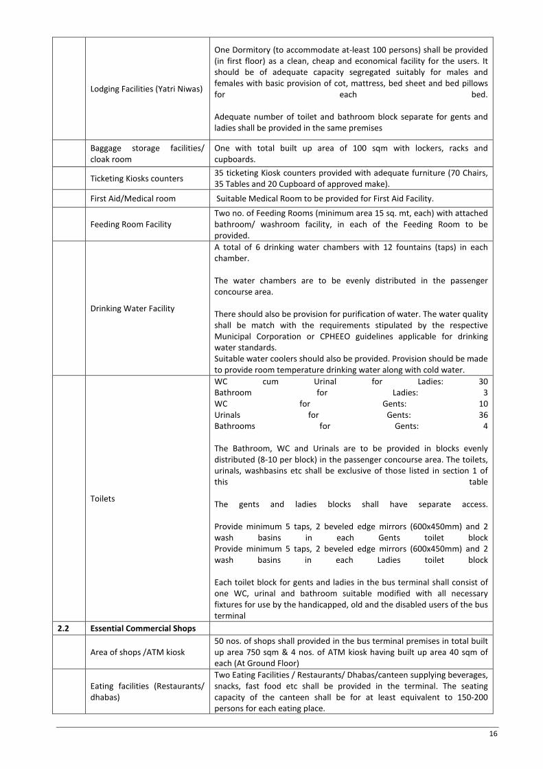
Lodging Facilities (Yatri Niwas)
One Dormitory (to accommodate at-least 100 persons) shall be provided (in first floor) as a clean, cheap and economical facility for the users. It should be of adequate capacity segregated suitably for males and females with basic provision of cot, mattress, bed sheet and bed pillows for each bed. Adequate number of toilet and bathroom block separate for gents and ladies shall be provided in the same premises
Baggage storage facilities/ cloak room
One with total built up area of 100 sqm with lockers, racks and cupboards.
Ticketing Kiosks counters 35 ticketing Kiosk counters provided with adequate furniture (70 Chairs, 35 Tables and 20 Cupboard of approved make).
First Aid/Medical room Suitable Medical Room to be provided for First Aid Facility.
Feeding Room Facility Two no. of Feeding Rooms (minimum area 15 sq. mt, each) with attached bathroom/ washroom facility, in each of the Feeding Room to be provided.
Drinking Water Facility
A total of 6 drinking water chambers with 12 fountains (taps) in each chamber. The water chambers are to be evenly distributed in the passenger concourse area. There should also be provision for purification of water. The water quality shall be match with the requirements stipulated by the respective Municipal Corporation or CPHEEO guidelines applicable for drinking water standards. Suitable water coolers should also be provided. Provision should be made to provide room temperature drinking water along with cold water.
Toilets
WC cum Urinal for Ladies: 30 Bathroom for Ladies: 3 WC for Gents: 10 Urinals for Gents: 36 Bathrooms for Gents: 4 The Bathroom, WC and Urinals are to be provided in blocks evenly distributed (8-10 per block) in the passenger concourse area. The toilets, urinals, washbasins etc shall be exclusive of those listed in section 1 of this table The gents and ladies blocks shall have separate access. Provide minimum 5 taps, 2 beveled edge mirrors (600x450mm) and 2 wash basins in each Gents toilet block Provide minimum 5 taps, 2 beveled edge mirrors (600x450mm) and 2 wash basins in each Ladies toilet block Each toilet block for gents and ladies in the bus terminal shall consist of one WC, urinal and bathroom suitable modified with all necessary fixtures for use by the handicapped, old and the disabled users of the bus terminal
2.2 Essential Commercial Shops
Area of shops /ATM kiosk 50 nos. of shops shall provided in the bus terminal premises in total built up area 750 sqm & 4 nos. of ATM kiosk having built up area 40 sqm of each (At Ground Floor)
Eating facilities (Restaurants/ dhabas)
Two Eating Facilities / Restaurants/ Dhabas/canteen supplying beverages, snacks, fast food etc shall be provided in the terminal. The seating capacity of the canteen shall be for at least equivalent to 150-200 persons for each eating place.

17
PCO kiosk/ booth 2 PCO kiosks or telephone Booth to be developed.
Vendor/Hawker Zone Vendor/Hawker Zone to be provided.
Courier/ Postal Services Two Parcel room shall be provided in the bus terminal premises in total built up area of 30 sqm each
2.3 Area for Terminal Staff amenities
Revenue /Admn. Office Office Space for General Manager, Terminal Manager, along with their respective support staff and other key personnel’s (Minimum area of 100 sqm. in First Floor)
Terminal Office/Bus Operation and Management Office for Concessionaire
To be provided as per the Concessionaire’s organization structure for the O&M of the bus terminal. (Minimum area of 100 sqm. in First Floor)
Security Guard Cabins Security Guard Cabin is to be provided near the bus terminal entry and exit gates.
Canteen
Canteen supplying beverages, snacks, fast food etc shall be provided in the terminal. The seating capacity of the canteen shall be for at least 60 persons.
Drinking water/ Wash Room/ Toilets
Drinking water/ Wash Room/ Toilets to be developed.
2.4 Area for Bus Staff amenities
Dormitory (for overnight operations) , Rest rooms, Drinking water, Toilets
The facility to be provided in a minimum total built up area of 3395 Square Feet (For Approximately 50 pax. at First floor) along with the adequate supporting utilities like toilets etc. The dormitory shall be furnished with essential furniture like cots, mattress, pillows and lockers and other furniture as deemed necessary
3 Vehicle Parking
Private Vehicle Parking
The parking area shall be suitable segregated into lots for various categories of private and IPT vehicles. 20 Three wheelers/Tempo/Travelers/ Cycles 500 Scooter/ M.Cycle 60 Cars For Basement parking suitable lift facility /escalators for vertical transportation of passengers to be provided.
Feeder Service Parking
The parking area (at Ground Floor) shall be suitable segregated into lots for various categories of vehicles. 50 Rickshaw, 40 Auto Rickshaw, 30 Cabs/Taxi
Note: There should be a provision for ramp for handicapped and elderly persons. The small facilities/space utilisation shall be decided at the stage of finalization of the design of the entire facility and shall be as per the approval of the Concessioning Authority and or Independent Engineer.
Scope of Activity that are allowable in shops / Passenger Amenities: The commercial activities/shops for the passenger amenities (in addition to toilets, cloakroom, etc) are indicated below. Any activity not covered under this list, shall require prior approval from the Concessioning Authority. Shops • Tea/Coffee stall

18
• Fruit/ Juice Shops • Sweet Shops /Ice-cream parlors • Fast Food outlets/Snack Shops (Nuts etc.) • Restaurants • Convenience • General Merchant Stores • Departmental Stores • Stationary/Book Shop/Newspaper stand • Chemists/Pharmacists • Textile retail outlets • Travel accessories • Shoe Retail/Repair Outlets • PCO • Barber/Hair Saloon Services/Offices • Banks/Finance Companies/ATMs • Yatri Niwas (Boarding & Lodging) • Professionals: Doctors/Dentist • Business Centre Internet Café (Telephone, fax, Internet, e-mail etc.) • Courier Agencies • Insurance Company Offices Any commercial establishment or vendor selling objectionable items, as notified by Concessioning Authority either presently or in future, should not be allotted any space or allowed to enter the premises of the Bus Terminal-cum-Commercial Complex. The Concessionaire would ensure, by either planned allocation of space or control that any activity generated by Kiosks, if any, should not hamper the bus terminal operations or people’s movement in the passenger concourse area
19
SCHEDULE – D SPECIFICATIONS AND STANDARDS
Technical Specifications & Standards
General Requirements The technical specifications, in accordance with which the construction works of the Bus Terminal Facilities as per the Master Plan to be executed by the Concessionaire, shall comprise of the following:
(a) General Technical Specifications (b) Supplementary Technical Specifications
General Technical Specifications All the items of work shall be executed as per PWD Specifications. Any item or part of the item not covered in PWD Specifications shall be executed as per relevant IS Codes or CPWD Specifications or as per the directions of Concessioning Authority /PRTC. The design of facilities for the handicapped and the disabled people, like the toilets, bathrooms, ramps shall be designed as per the respective IS Codes and guidelines issued by Govt. of India or Govt. of Punjab.
These codes and specifications shall deem to be bound in this document. The technical specifications for Civil, Mechanical and Electrical installations works are detailed in the subsequent sections.
Supplementary Technical Specifications This part shall comprise various amendments/modifications/additions to the relevant codes and standards.
When an Amended/Modified/Added clause supersedes a clause or part thereof in the said specifications, then any reference to the superseded clause shall be deemed to refer to the Amended/Modified clause or part thereof.
In so far as any Amended/Modified/Added clause may come in conflict or be inconsistent with any of the provisions of the said specifications under reference, the Amended/Modified/Added clause shall always prevail. While carrying out any work the Concessionaire shall ensure that any requirements specific to the site and similar factors are kept in view.
All measurements shall be made in the metric system. The measurements and computations unless/otherwise indicated shall be carried nearest to the following limits.
Length and breadth : 5 mm Height, Depth or thickness : 1 mm Area : 0.01 sq.m. Cubic Contents : 0.01 cu.m.
Technical Specifications - Civil/Building Works
Material Specification All items of works shall be executed as per PWD Specifications. Any item or part of the item not covered in PWD Specifications shall be executed on relevant BIS specification or CPWD Specification or as per directions of Authority. The brief specification of main materials involved and items to be executed are given below: 1. Bricks Bricks shall be sound, hard, well-burnt, uniform in size, shape and colour, homogeneous in texture, giving a metallic ringing sound, free from flaws, cracks, holes, lumps or grit and arises should be square, straight and sharply defined. They shall not break when struck against each other and dropped flat from a height of 1m to the ground. They shall conform to IS 1077 giving classes of common burnt clay bricks. Maximum absorption shall not be more than 20% of its dry weight on immersion in water for 24 hours. Minimum crushing strength shall be 75 kg/sq cm.
Bricks for masonry work in foundations as well as in superstructure shall be first class burnt clay bricks conforming to PWD Specifications.
2. Cement Ordinary Portland Cement (OPC) 43/53 grade Conforming to latest PWD Building Works Specifications, 2014 and IS 8112-2013/12269-2013 shall be allowed for concreting in both plain & R.C.C. works. In no case Portland Pozzolonic cement shall be allowed for such work. In case of non-availability of O.P.C. Cement Port Land Pozzolonic cement, conforming to relevant ISI specification of the same popular brands shall be permitted for masonry work in foundations and superstructure with the permission of the Independent Engineer. Cement shall be stored and stacked

20
at the site of work according to PWD norms.
In no case, the cement shall be procured for requirement beyond 3 months and the same shall also be consumed within three months’ time. All such cements, which shall be having storing age more than three months or otherwise appeared to be deteriorated, shall be got retested for compressive strength and initial and final setting time, before use. Decision for equivalent use or no use of such cements for works other than concreting shall be taken by the Independent Engineer and shall be final and binding.
3. Concreting In order to achieve accuracy in the proportion of batching, batching plant should be installed and maintained at the site for the concreting work or Ready mix concrete shall be procured on prior approval of Independent Engineer.
4. Steel Reinforcement High yield strength deformed bar TMT (HYSD TMT) having minimum strength of 415 N/ mm2 up to and including 25 mm diameter and 500 N/mm2 for bigger diameter confirming to IS: 1786 shall be used as reinforcement for RCC works. Binding wire shall be conforming to IS: 432. All steel shall be sound and free from cracks surface flaws laminations, rough and imperfect edges and all other defects.
The variation in weight per meter length of the bars shall be permitted only up to the following limits: · 6 mm & 8mm +7% · 10 mm & 12 mm +4% · 16 mm & above +3%
Spacer blocks shall be made conforming to M15 concrete tied with binding wires as specified or PVC spacer shall be used prior approval of Independent Engineer.
5. Structural steel General requirements relating a supply of structural steel shall conform to IS 8910. Requirements for mild steel (standard quality) plate, sections bars etc, designated as E250 (Fe 410-W) for use in structural work (as per IS:2062-2006, superseding IS 1977, 8500).
Structural steel such as angle section, T-sections, I-sections, Channels & steel plates shall be conforming to IS: 226. Structural steel used in the works other than steel in reinforced concrete, rails and fastenings shall be either of the following type:
a. Mild steel conforming to IS : 226 - "Structural Steel (Standard quality)" or IS : 2062 - "Structural Steel (fusion welding quality)
b. Whenever high tensile steel is specified it shall be conforming to IS: 961 - "Structural steel (High Tensile)".
c. All steel tubes shall be hot finished seamless steel tubes (HFS) of the specified strength and shall conform to IS: 1161. Tubes made by other processes and which have been subjected to cold working, shall be regarded as hot finished if they have been subsequently been heat treated and are supplied in the normalized condition
6. Water Water for all purposes of preparing, mortars, concrete and curing of masonry and concrete works in construction shall conform to PWD Specifications.
7. Earth Earth for embankment and backfills in masonry works etc. shall be free from slumps, roots, grass, clods and large pieces of stones, and shall be conforming to PWD Specifications.
8. Brick Ballast Bricks ballast for use in foundation and under floors shall conform PWD Specifications.
9. Fine Aggregate
The Fineness Modulus (FM) of sand shall be 2.0-3.50 as per latest IS-383. It shall be free from harmful impurities and deleterious substances. In case fine dust and silt is found more than 4% the same shall be washed thoroughly before use.
10. Sand for Plastering and Mortars
For plain and reinforced cement concrete (PCC and RCC) or prestressed concrete (PSC) works, fine aggregate shall consist of clean, hard, strong and durable pieces of crushed stone, crushed gravel, or a suitable combination of

21
natural sand, crushed stone or gravel. They shall not contain dust, lumps, soft or flaky, materials, mica or other deleterious materials in such quantities as to reduce the strength and durability of the concrete, or to attack the embedded steel. Motorised sand washing machines should be used to remove impurities from sand. Fine aggregate having positive alkali-silica reaction shall not be used. All fine aggregate shall conform to IS: 383 and test for conformity shall be carried out as per IS: 2386 (Part I to VIII). The Contractor shall submit to the Engineer the entire information indicated in Appendix A of IS: 383. The fineness modules of fine aggregate shall neither be less than 2.0 nor greater than 3.5.
11. Coarse Aggregate
Unless, otherwise specified or ordered, only ¾” (20 mm) nominal size crushed aggregate shall be used as coarse aggregate for concreting purpose in slabs, beams, columns, in superstructure and foundations as per IS: 383 – 19 70. The same size aggregate shall be used for conglomerate floors also. In lintels and slabs having thickness less than 12 cm, 12.5 mm nominal size crushed aggregate shall be used. Crushed aggregate shall not be having aggregate impact value more than 30 and water absorption more than 2%.
12. Glass Panes
Thickness of glass panes according to the size of opening and its quality shall conform to PWD Specifications. Only the first quality glass panes of popular brands shall be permitted for use. Glass panes shall be checked both for the required thickness as well as weight per unit area.
13. Bitumen for coating DPC
Suitable type of bitumen as per PWD Specifications or CPWD Specifications or relevant IS code shall only be permitted for bitumen coatings of roof top and D.P.C.
14. Timber/ Joinery
Timber for joinery purpose shall conform in general to PWD Specifications. 15. Plywood
The plywood in general shall be conforming to PWD Specifications for cupboard shutters the specified ply should be urea bonded whereas for flush doors shutters the specified ply to be used shall be phenol bonded only. The plywood should be termite proof and water proof.
16. Wire Gauge
Wire gauge for joinery purpose shall conform to PWD Specifications. 17. Other Materials
i. All other materials required for the construction shall conform to relevant PWD Specifications/or latest BIS specification or CPWD Specifications, or as per directions of Independent Engineer/ PRTC/PUNJAB ROADWAYS.
ii. White cement: Wherever is to be used, shall comply with India standard IS: 269 and its color shall be pure white.
iii. Paints and allied material: Only first quality paints duly BIS marked shall be used for the finishing item wherever required. Material shall be as per the following IS specification: wooden & metallic surface:-
a) Synthetic enamel finish (for exterior uses) as per IS: 520 b) Synthetic enamel with semi glass finish (for interior uses) as per IS: 133
I. Priming coat IS : 102 II. Zinc chromate primer on Iron Steel IS : 107
III. Aluminum paint IS : 165 IV. Turpentine oil IS : 83 V. Linseed oil IS : 77,75 & 78
VI. Varnish Exterior IS : 338 VII. Varnish Interior IS : 337
VIII. Filler for enamel paints IS : 110 IX. Wood filler IS : 345 X. Putty for wooden frame IS : 419
XI. Putty for metal frame IS : 420 XII. Brushes IS : 384
XIII. Paint remover IS : 430 XIV. Shellac IS : 16 XV. Denatured Spirit IS : 234

22
18. CI Pipe Fitting (Rain water pipe) The pipes shall be manufactured by closed grain CI and shall satisfy IS 1230 in all respects. The number of pipes and the diameter shall be worked out on the basis of 1” Sq. of CSA for every 60 specifications No. 3.54. The minimum weight v/s nominal diameter shall be as under:
Minimum Weight ad Nominal Diameter
Nominal (mm) Weight/m Length (m) Size of socket Thick (mm) 90 14 1.8 114.4 3.2 50 26 1.8 166.2 3.6
Specifications of Work
Internal Civil Works
1. Earth excavation embankments & cuttings
Making up of plinths shall be carried out as per PWD Specifications. Source of soil for filling purposes shall have to be got approved from the Independent Engineer of work.
2. Compaction of Earth work
Compaction of earthwork shall be carried out as per PWD Specifications. Earthwork excavation of foundations and filling of trenches and filling under floors as per PWD Specifications.
3. Demolition
Demolition, if any involves shall be carried out as per PWD Specifications. Disposed- nothing shall be paid for disposal of non-perishable material. Perishable material shall be handed over to Authority.
4. Centering and Shuttering
Centering and shuttering shall be carried out as per PWD Specifications.
5. Cement concrete for Ordinary structures Cement concrete for ordinary structures shall be executed as per PWD Specifications.
6. Reinforced concrete For all works in super structure/ foundation 1:1.5:3 nominal mix by volume shall be used for achieving strength of M20 concrete.
Only crushed coarse aggregates shall be used for concreting.
Steel shall be high yield strength deformed bars conforming to IS – 1786 or TMT steel.
7. DPC Item of D.P.C. shall be executed as per PWD Specifications.
8. Precast Lintels All lintels up to 7”0’ in length in masonry work over doors and windows shall not be laid Cast-in-Situ but shall be precasted as per instruction of the Independent Engineer and shall be hoisted and placed at appropriate level, during masonry work, lintels beyond 4’-6” length shall be laid in situ. Lintels will be casted over a pucca platform, and shall be cured for at least 10 days in a tank built at site and be dried completely before placing.
9. Brick Masonry Wherever the brick masonry shall involve in the execution of work, the same shall be carried out as per PWD Specifications. All the instructions regarding workmanship such as bond and laying, joints straightness, face work raking of joints and scaffolding etc. shall be followed as per the PWD Specifications. The masonry shall be carried out in the cement mortar. Corbelling, Coping and Cornices shall be executed as per specifications. 4 ½” and 3” thick masonry partition walls. Partition walls shall be constructed as per PWD Specifications.
10. Roofing and Water proofing treatments / drainage a) Rooftops shall be painted with bitumen, as per PWD Specifications. b) Laying brick bat coba water proofing of average 115 mm thick at terrace using cement mortar 1:3 arranging
brick bats according to the slope, adding suitable water proofing compound for water tightness and again

23
providing on top cement mortar 1:3 including addition of water proofing compound and finishing the top with neat cement @ 2.75 kg/m2 and preparing the rough surface as per directed.
c) Water Proofing for Basement floor and surface. Providing & laying Box type waterproofing treatment to floors and external surfaces of underground structures. The treatment comprises of waterproofing layer, average 100 mm. thick for floors, using two layers of polished kota stones placed diagonally with cut joints Bottom layer of 15 mm. thick 1:3 C.M. bedding with approved waterproofing chemical. 20 mm. to 25 mm. thick rough polished kota stone laid diagonally above the 1st layer with cut joints. Joints shall be sealed by 1:1 C.M. with approved waterproofing chemical. The above two layers shall be laid again, in the same manner as described above. The final layer of 30 mm. thick I.P.S. shall be laid with approved water proofing chemical having desired finish as directed including curing etc. complete on any surface, at all heights. The contractor to give testing for water tightness.
d) Rain water pipes shall be fixed as per PWD Specifications e) Execution of top and bottom khurras and spouts shall be done as per PWD Specifications. f) Unless, otherwise specified, the normal bitumen felt waterproofing treatment shall be executed as per
PWD Specifications. g) Wherever required the water proofing of roofs shall be as per manufactures specifications approved by the
Independent Engineer.
11. Floorings and Dados Various types of flooring and dados shall be executed as per PWD Specifications, as detailed below:- Flooring and Dados Specifications
A White glazed ceramic Tile flooring
As per PWD building Specifications, Chapter 12 Flooring Works
B Marble flooring
C Polished kota stone flooring
D Rough Polished kota stone flooring
E Vitrified Tile flooring
F Granite Stone flooring
G Ironite flooring/Cement Concrete Flooring with Metallic Hardener Topping
H Granite Tile flooring
I Trimix flooring
Polished kota stone flooring shall be carried out as PWD building Specifications, Chapter 12 Flooring Works. Polished kota stone shall not be used less than 22’’x 18” in size.
Dados: Polished kota stone or Vitrified tile dado shall be executed as per the relevant specification of PWD building Specifications.
Skirting (3/4’’ thick) of Polished kota stone shall be executed as per the relevant specification of PWD building Specifications.
Granite Stone shall be executed as per the relevant specification of PWD building Specifications. Vitrified tile shall be executed as per the PWD building Specifications.
Ironite flooring/ Cement Concrete Flooring with Metallic Hardener Topping shall be executed as per the relevant PWD building Specifications.
Granite tiles shall be executed as per PWD building Specifications.
Trimix flooring shall be executed as per PWD building Specificationsof pavement in material Specification.
12. Cupboard Shutters Cupboard shutters shall be wooden as per PWD building Specifications.

24
13. Door Shutters All door shutters shall be 40 mm thick wooden with 12 mm thick panels of waterproof as per PWD building Specifications.
14. Windows Shutters Window shutters shall be 35 mm thick of wooden having glass panes as per PWD building Specifications. Wire gauge shutters should be provided wherever required.
15. Wire gauge Shutters Wire gauge shutters shall be as per PWD building Specifications.
16. Doors, Windows and Shutters Other than Wooden Specifications for Doors, Windows and Shutters other than Wooden
a Aluminum windows and As per IS 1948-1961 & IS 1949-1961 And PWD building Specifications
b Collapsible gates As per IS 10521-1983 and PWD building Specifications
c Steel rolling shutters As per IS 6248-1979 and PWD building Specifications
d Steel door frames As per IS 4351-1976 and PWD building Specifications
e Steeldoors, ventilators
windows and As per IS 1038-1983 & PWD building Specifications
f Pressed steel chowkhats PWD building Specifications
Factory made pressed steel chowkhats shall be manufactured out of 16 gauge M.S. Sheet (1.25 mm thick) cutting bending straightening and finishing shall be mechanical and not manual. Chowkhats shall be framed with 6mm fillet seam welding.
The pressed steel chowkhats shall be provided with two coats of steel primer and the chowkhats cavity shall be filled with 1:2:4 concrete, prior to fixing at site.
17. Plastering, Pointing and Rendering Cement plaster will be executed in the specified mortars as per PWD building Specifications. For cement rendering and for cement pointing PWD building Specifications shall be followed.
18. Painting, White washing and Distempering These items shall be executed as per PWD building Specifications.
Painting and varnishing works shall be executed as per PWD building Specifications.
Painting on Plastered/ Concrete Surface: The plastered surface above dado as per relevant Specification of PWD building Specifications. Only first quality paint/ emulsion shall be used. The item shall be executed as per PWD building Specifications of painting.
Painting Wooden Surfaces shall be painted with first quality approved brand of paint and execution of item shall be carried out as per PWD building Specifications.
Painting Iron and Steel Work: Iron and Steel Works shall be painted as per PWD building Specifications. The first coat shall be applied of red oxide primer of first quality. The subsequent coats shall be of approved shade and approved brands of first quality paints.
White Washing shall be executed as PWD building Specifications and Colour washing shall be executed as per PWD building Specifications.
Oil Bound distempering for internal finishing shall be executed as per PWD building Specifications.
Cement based paints: Cement based paints of approved make and shade shall be executed as per relevant specifications.

25
19. Cement Concrete Road works Latest edition of MoRTH specifications shall be followed for road works.
20. Expansion Joints Expansion Joints shall be provided in the buildings wherever required. The conditions for providing expansion joints are as under:
1) Where the length of the building blocks exceed 50 meters. 2) All the components such as ramps stain links of corridors with the main building. 3) In case of provision for horizontal further expansion be provided. 4) In case of level difference exceeding 1.8 mts. Type of expansion joints: In case of larger blocks framed shutters, only double column, double beam expansion joints shall be provided:
a) In case of masonry blocks double beam expansion joints will be provided along with expansion joints on walls.
b) In case of connecting link corridors cantilever type of expansion joints will be provided. These joints shall be maintained in the flooring itself preferably or will be covered with 300 mm wide separate piece of flooring material specified.
Expansion Joints in the wall shall be covered from inside with 14 gauge aluminium sheet 150 mm wide fixed with appropriate fastener on one side of the wall. In no case bracket type expansion joints will be provided.
External Civil Works 1. Parking Area Covered area with interlocking pavers shall be as per PWD Specifications.
2. M.S. Gates M.S. Gates shall be as per PWD Specifications.
3. Boundary Wall Boundary wall around the BUS TERMINAL shall be 1.8m high, constructed in first class brick masonry.
4. Kerb & Channels Kerbs & channels wherever provided along the roadside shall conform to relevant PWD Specifications. 5. Jungle Clearance Clearing of weeds, shrubs, brushwood and congress grass under this item shall be removed by roots. Tree shall not be cut. The item shall be executed as per PWD Specifications.
6. Subgrade of Internal Roads The top 2’ portion of embankment in the complete formation width of the internal roads, which is sub grade of the road, shall consist of sandy soils. A1, A2 and A3 type soils as per PRA classification conforming to latest IRC specification shall be only allowed in sub grade. Silty & clayey soil, which make weak sub grade & have no self-drainage shall not be permitted for use.
7. Stone Metal 60-11.2 mm Crushed stone metal of approved quarries shall be only used for construction for roads. It should be angular and drawn from hard durable tough stones of uniform texture. It should not absorb water more than 1% and its aggregate impact value should not be more than 30. The grading should confirm to MoRTH specification as given in table below:
Grading of Crushed Stone Metal Sieve Designation Percent by weight passing 60 mm 100.00 53 mm 95-100 45 mm 65-90 22.4 mm 0-10 11.2 mm 0-5

26
8. Grit The crushed aggregates for mix seal surfacing shall be blended in the requirement ratio or achieving the proper gradation as per MoRTH specification. The individual size of the grit should also be conforming to MoRTH, specification.
Technical Specifications – Public Health and Fire Fighting Works General Technical Conditions
1. Scope of Work
a) Work under this section shall consist of furnishing all materials, equipment and applicable necessary and required to completely furnish all the plumbing and other specialized services as described herein.
b) Without restricting to the generality of the foregoing the sanitary fixtures shall include the following:
• Sanitary Fixtures
• Soil, waste, rainwater and vent pipes Water supply (internal and external) External sewerage system
• Storm water drainage system c) The Concessionaire must get acquainted with the proposed site for the works and study specifications
carefully. d) Works area shall be as per finalized and approved drawings from the Independent Engineer.
2. Specifications a) Work under this section shall be carried out strictly in accordance with specifications. b) Items not covered under these specifications due to any ambiguity or misprints, or additional works, the work
shall be carried out as per the PWD Specifications. c) Works not covered under 2.1 and 2.2 shall be carried out as per relevant Indian Standards specifications or
codes of practice or as per directions of Authority.
3. Execution of Work a) The work shall be carried out in conformity with Architectural, HVAC, Electrical, plumbing, Structural, and other
specialized services. b) The Concessionaire shall make provision for hangers, sleeves, structural openings and other requirements well
in advance to prevent hold up of progress of construction programme. c) On award of the concession, the Concessionaire shall submit a programme of construction in the form of a
PERT chart or bar chart for approval of the Independent Engineer. All the dates and time Chapter agreed upon shall be strictly adhered to, within the stipulated time of completion / commissioning along with the specified phasing, if any.
4. Drawings a) Plumbing drawings would be diagrammatic and shall be followed as closely as actual construction permits. Any
deviations made shall be in conformity with the Architectural drawings. b) Architectural drawings shall take precedence over plumbing or other services drawings as to all dimensions. c) Concessionaire’s shall verify all dimensions at site and bring to the notice of the Independent Engineer of
works all discrepancies or deviations noticed. The Independent Engineer decision shall be final. d) Large size details and manufacturers dimension for materials to be incorporated shall take precedence over
small-scale drawings.
5 Inspection and testing of materials a) The Concessionaire shall be required, if requested to produce the manufacturers’ test certificate for the
particular batch of materials supplied to him. The test carried out shall be as per the relevant Indian Standards. b) For examination and testing of materials and works at the site the Concessionaire shall provide all testing and
gauging equipments necessary but not limited to the following: • Theodolite • Dumpy level • Steel tapes • Weighing machine • Plumb bob, Spirit levels, Hammers • Micrometers • Thermometers, Stoves • Hydraulic test machine • Smoke test machine

27
c) All such equipment shall be tested for calibration at any approved laboratory, if required by the Independent Engineer.
d) All testing equipment shall be preferably located in special room meant for the purpose.
6. Metric conversion a) All dimensions and sizes of materials and equipment given in the specifications are commercial metric sizes. b) Any weights or sizes given in the specification having changed due to metric conversion, the nearest
equivalents sizes accepted by Indian Standards shall be acceptable without any additional cost.
7. Reference points a) The Concessionaire shall provide permanent benchmarks, flag tops and other reference points for the proper
execution of work and these shall be preserved till the end of the work.
b) All such reference points shall be in relation to the levels and locations given in the Architectural and plumbing drawings (to be detailed out by the Concessionaire).
8. Reference Drawings a) The Concessionaire shall maintain one set of all drawings issued to him as reference drawings. These shall not
be used on site. b) All corrections, deviations and changes made on the site shall be shown on these reference drawings for final
incorporation in the completion drawings. All changes to be made shall be initialled by the Independent Engineer. These will then form the “As-Built Drawings”
9. Shop Drawings a) The Concessionaire shall submit to the Independent Engineer four copies of the shop drawings. Shop drawings
shall be submitted under following conditions: • Showing any changes in layout in the plumbing drawings • Equipment layout and piping, wiring diagram • Manufacturer’s or Concessionaire’s fabrication drawings for any materials or equipment supplied by them.
b) The Concessionaire shall submit four copies of catalogues, manufacturer’s drawings. Equipment characteristic data or performances charts as required by the Independent Engineer.
10. Completion Drawings a) On completions of work the Concessionaire shall submit one complete sets of original tracings and two prints
of “as built” drawings to the employer. These drawings shall have the following information:
I. Run of all piping and diameters on all floors and vertical stacks.
II. Ground and invert levels of all drainage pipes together with location of all manholes and connections upto outfall
III. Run of all water supply lines with diameters, locations, of control valves, access panels
IV. Locations of all mechanical equipment with layout and piping connections.
b) The Concessionaire shall provide four sets of catalogues performances data and list of spare parts together with the name and address of the manufacturer for all electrical and mechanical equipment provided by him.
11. Testing a) Piping and drainage works shall be tested as specified under the relevant clauses of the specifications. b) Tests shall be performed in the presence of the Independent Engineer. c) All materials and equipments found defective shall be replaced and whole work tested to meet the
requirements of the specifications. d) The Concessionaire shall perform all such tests as may be necessary and required by the local authorities to
meet Municipal or other bye-laws in force. e) The Concessionaire shall provide all labour, equipment and materials for the performances of the tests.
12. Site Clearance and Clean up a) The Concessionaire shall, from time to time clear away all debris and excess materials accumulated at the site b) After the fixtures, equipments and appliances have been installed and commissioned, the Concessionaire shall

28
clean up the same and remove all plaster, paints, stains, stickers and other foreign matter of discoloration leaving the same in a ready to use condition
c) On completion of all works, the Concessionaire shall demolish all stores, remove all surplus materials and leave the site in a broom clean condition.
13. License and Permit a) The Concessionaire must hold a valid plumbing licenses issued by the Municipal Authority or other Competent
Authority under whose jurisdiction the work falls b) The Concessionaire must keep constant liaison with the competent authority and obtain approval of all
drainage and water supply works carried out by him. c) The Concessionaire shall obtain, from the competent authority certificates with respect to his work as required
for occupation of the building. d) All inspection fees or submission fees should be paid by the Concessionaire.
14. Cutting and Making good No structural member shall be chased or cut without the written permission of the Independent Engineer.
15. Materials a. All materials used in the works shall conform to the tender specification.
b. As far as possible materials bearing BIS certification marks shall be used with the approval of the Independent Engineer.
c. Unless otherwise specified and expressly approved in writing by the Independent Engineer, materials of makes and specifications mentioned with technical specification shall be used.
16. Mock up a. The Concessionaire shall install all pipes, fixtures, clamps and accessories and fixing devices in mock up shaft and
room so constructed as directed by the Independent Engineer without any cost. The materials used in the mock up may be reused in the works if found undamaged.
b. Any tiles or finished surfaces or floors damaged by the Concessionaire while doing his work shall be made good with new tiles or other finishing material.
Technical Specifications - Sanitary Fixtures
1. Scope of Work a. Work under this section shall consist of furnishing all material and labour as necessary and required to completely
install all sanitary fixtures, brass and chromium plated fittings and accessories, as specified hereinafter.
b. Without restricting to the generality of the foregoing the sanitary fixtures shall include all sanitary fixtures, C.P. fittings and accessories etc. necessary and required for the building.
c. Whether specifically mentioned or not all fixtures and appliances shall be provided with all fixing devices, nuts, bolts, and screws, hangers as required.
2. General Requirements a. All fixtures and fittings shall be provided with all such accessories as are required to complete the item in working
condition
b. All fixtures and accessories shall be fixed in accordance with a set pattern matching the tiles of interior finish. Whether necessary the fittings shall be centered to dimensions and pattern desired.
c. Fixing screws shall be half round head chromium plated brass with C.P. washers wherever required as per direction of the Independent Engineer.
d. All fittings and fixtures shall be fixed in a neat workmanlike manner true to levels and heights and in accordance with the manufacturer’s recommendations. Care shall be taken to fix all inlet and outlet pipes at correct positions. Faulty locations shall be made good and any damage to the finished floor, tiling or terrace shall be made good by the Concessionaire.
e. When directed the Concessionaire shall install fixtures and accessories in a mock-up room for the approval of the Independent Engineer. Sample room fixtures may be reused on the works if undamaged.
3. Indian W.C. a. Indian W.C. pan shall be Orissa pattern of size. Each WC shall be provided with a 100 mm diameter cast iron of

29
porcelain ‘P’ or ‘S’ traps with or without vent horn.
b. W.C. shall be flushed by means of a C.I. high level flushing cistern or low-level cistern of polyethylene body complete with accessories or with 32 mm diameter C.P. flush valve.
4. Anglo Indian W.C. a. Anglo Indian W.C. shall be wash down type ‘P’ or ‘S’ trap set.
b. Each Anglo Indian W.C. set shall be provided with a solid plastic seat, rubbers buffers and chromium-plated hinges.
c. Plastic seat shall be so fixed that it remains absolutely stationery in vertical position without falling down on the W.C.
d. Each Anglo Indian W.C. shall be flushed with porcelain flushing cistern or an exposed or concealed type flush valve. Flush pipe/bend shall be connected to the W.C. by means of a suitable rubber adapter. 25 % of total W.C are Indian W.C
5. European W.C. a. European W.C. shall be wash down single or double siphonic type floor or wall mounted and flushed by means of
porcelain low level flushing cistern or the exposed or concealed type flush valve. Flush pipe/bend shall be connected to the W.C. by means of suitable rubber adapter. Wall hung W.C. shall be supported by C.I. floor mounted chair. 50 % of total W.C are Indian W.C
b. Each W.C. seat shall be so fixed that it remains absolutely stationery in vertical position without falling down on the W.C.
6. Urinals a. Urinals shall be lipped type half stall white glazed vitreous China of approximate Size 630 x 420 x 380 mm size.
b. Half stall Urinals shall be provided with 15 mm diameter C.P. spreader, 32 mm diameter C.P. domical waste and C.P. brass bottle trap with pipe and wall flange and shall be fixed to wall by one C.I. bracket and two C.I. wall clips as recommended by manufacturers’ or as directed by the Independent Engineer.
c. Half stall urinals shall be fixed with C.P. brass screws and shall be provided with 32mm diameter domical waste leading to urinals trap.
d. Urinals shall be flushed by means of automatic porcelain flushing cistern or exposed or concealed type urinal flush valve, as specified in manual flushing system.
e. Flush valve for urinal shall be provided
f. Flush pipes of flushing cistern with sizes of main and branch flush pipe shall be as follows:
Table 6: Flush Pipes Sizes
No. of urinals In Range
Capacity of cistern litres
Size of main flush pipe
Size of branch flush pipe
Size of connection urinal
One 5 - - 15
Two 10 20 - 15
Three 10 25 - 15
g. Alternatively, Urinals may be flush with flush valves, exposed or concealed type.
h. Waste pipes for urinals shall be any one of the following:
(i) G.I. pipe
(ii) Rigid P.V.C
(iii) U. P.V.C. or PE pipes
i. Waste pipes may be exposed on wall or concealed in chase. Specifications for waste pipes shall be same as given in PWD Specifications
7. Lavatory Basin
30
a. Lavatory basins shall be white glazed vitreous china or poly marble of size, shape and type specified in the bill of quantities.
b. Each basin shall be provided with R.S. or C.I. bracket and clips and the basin securely fixed to wall. Placing of basins over the brackets without secure fixing shall not be accepted.
c. Each basin shall be provided with 32mm diameter C.P. brass bottle trap with C.P. pipe to wall and flame.
d. Each basin shall be provided with fittings or mixing fittings.
e. Basins shall be fixed at proper heights.
8. Sinks a. Sinks shall be of stainless steel.
b. Each sink shall be provided with R.S. or C.I. brackets and clips and securely fixed.
c. Counter top sinks shall be fixed with suitable angle iron clips or brackets as recommended by the manufacturer. Each sink shall be provided with 40mm diameter C.P. waste with chain and plug or P.V.C. waste. Fixing shall be done as directed by the Independent Engineer.
d. Fittings for supply to sinks shall be C.P. brass single hole mixing fitting with swinging spout for hot and cold water and C.P. brass swan neck tap swinging spout for cold water supply.
9. Mirrors
a. Mirrors shall be electro coated copper 5.5 mm thick of guaranteed reputed make.
b. The image shall be clear and without waviness at all angles of vision.
c. Mirrors shall be provided with backing of 12 mm thick 6mm thick cement asbestos sheet fixed with C.P. brass semi round-headed screws and cup washers or C.P. brass clamps as specified or instructed by the Independent Engineer.
10. Shower set a. Shower set shall comprise of one/two C.P. brass concealed stop cocks with two long body brass/C.P. brass bid
cock, or bath spout.
b. Each shower set shall also be provided with C.P. shower arm with wall flange and showerhead of approved quality.
c. Concealed stopcocks shall be so fixed as to keep the wall flange clear off the finished wall. Wall flanges embedded in the finishing of wall shall not be accepted.
11. Accessories a. The Concessionaire shall install all chromium plated and porcelain accessories or as directed by the Independent
Engineer.
b. All C.P. accessories shall be fixed with C.P. brass half round head screws and cup washers in wall with raw plugs or nylon sleeves and shall include cutting and making good as required or directed by the Independent Engineer.
c. Porcelain accessories shall be fixed in walls and set in cement mortar 1:2 (1 cement:2 coarse sand) and fixed in relation to the tiling work.
12. Urinal Partitions a. Urinal partitions shall be white glazed vitreous china or 25mm thick marble of size.
b. Porcelain partitions shall be fixed at proper height with C.P. brass bolts, anchor fasteners and M.S. clip as recommended by the manufacturer and directed by the Independent Engineer.
Technical Specifications – Soil, Waste & Vent Pipe
1. Scope of work
a. Work under this section shall consist of furnishing all labour, materials, equipment and appliances necessary and required to completely install all soil, waste, vent and rainwater pipes.
b. Without restriction to the generally of the foregoing, the soil, waste, vent and rainwater pipes system shall

31
include the followings:
(i) Vertical and Horizontal soil, waste and vent pipes, rainwater pipes & fittings, joint clamps and connections to the fixtures
(ii) Connections of pipes of gully traps and manholes etc.
(iii) Floor and urinal traps, cleanout plugs, inlet fittings and rainwater head as specified.
(iv) Waste pipes connections from all fixtures e.g. wash basins, sinks, urinals, and kitchen equipments.
(v) Testing of all pipes.
2. General Requirements
a. All materials shall be new of the best quality conforming to specifications and subject to the approval of the Independent Engineer.
b. Pipes and fittings shall be fixed truly vertical, horizontal or in slopes as required in a neat workman like manner.
c. Pipes shall be fixed in a manner as to provide easy accessibility for repair and maintenance and shall not cause obstruction in shafts, passages etc.
d. Pipes shall be securely fixed to walls and ceiling by suitable clamps at intervals specified.
e. Access doors for fitting and cleaning shall be so located that they are easily accessible for repair and maintenance.
f. All works shall be executed as directed by the Independent Engineer.
3. Cast iron pipes and fittings
a. Cast Iron Pipes
(i) Soil, waste, vent anti-symphonize and rainwater pipe shall be cast iron pipes/UPVC.
All pipes shall be straight and smooth and inside free from irregular bore, blow holes cracks and other manufacturing defects. Pipes shall be centrifugally spun iron soil pipes conforming to IS: 3989-1970, or sand cast IS: 1729-1967.
(ii) Standard weight, dimensions and pig lead required for joints shall be as follows: For pipes conforming to IS: 3989-1970 (centrifugally spun soil pipes).
Table 7: Pipe Joints Sizes and Weights
Nominal (inch)
Diameter (mm)
Thickness (mm)
Overall Weight 6’ length or 1.83m (kg)
Internal diameter of socket (mm)
Depth of
lead (mm)
2 50 3.5 8.5 73 25 3 75 3.5 12.7 99 25 4 100 4.0 19.2 126 25 6 150 5.0 35.5 178 38 For conforming to IS 1729-1967 (sand cast iron soil pipes and fittings) 2 50 5 11.41 76 25 3 75 5 16.52 101 25 4 100 5 21.67 129 25 6 150 5 31.91 181 38
(iii) Tolerance
Acceptable tolerance for pipes to I.S. 3989 and ISI 1729 shall be as follows: · Wall thickness -15%
· Length +20mm
· Weight -10%
b. Fittings
(i) Fittings shall conform to the same Indian Standard as for matching Concessionaire use pipes and fittings of

32
matching specifications.
(ii) Fittings shall be of the required degree of curvature with or without access doors.
(iii) Access door shall be made up with 3mm thick insertion rubber washer and white lead. The bolts shall be lubricated with grease or white lead for easy removal later. The fixing shall be air and water tight.
c. Fixing
(i) All vertical pipes shall be fixed by M.S. clamps truly vertical. Branch pipes shall be connected to the stack at the same angle as that of the fittings. No collars shall be used on vertical stacks. Each stack shall be terminated at top with a cowl. (Terminal Guard).
(ii) Horizontal pipes running along ceiling shall be fixed on structural adjustable clamps of special design shown on the drawings or as directed. Horizontal pipes shall be laid to uniform slope and the clamps adjusted to the proper levels so that the pipes fully rest on them.
(iii) The Concessionaire shall provide all sleeves, openings, hangers, and inserts during the construction. All damages shall be made good to restore the surface.
d. Cast iron pipes for drainage
(i) All drainage lines passing under building, floors and roads, in exposed position above ground or at basement ceiling level shall be C.I.L.A pipes position of such pipes shall be generally shown either on ground level drawing or ceiling of basement.
(ii) Cast iron pipes shall be centrifugally spun iron pipes conforming to I.S. 1536-1967.
Quality certificates shall be furnished. (iii) Fittings and Inspection Chambers:-
· Fittings used for C.I. drainage pipe shall conform to ISI 1538- 1967. Junction from branch pipes shall be made by ‘Y’, ‘T’.
· The Concessionaire shall provide cast iron inspection chamber at all junction. Inspection chamber shall be specially cast with inlet, outlet and branches or appropriate and required sizes.
· Cleanout plugs shall be provided on head of each drain. Cleanout plugs shall be of size matching the full bore of the pipe. Plugs shall be made out with G.I. coupling caulked into the socket of the pipe or fittings. The end shall be provided with a brass screwed plug with suitable key for opening.
e. Laying
(i) All cast iron pipes and fittings shall be joined with best quality soft pig lead, which shall be free from impurities. In wet trenches joints shall be made from lead wool. Nothing extra shall be paid for lead wool joints. Depth of the pig lead and weight for joints shall be as given in this section above.
· The spigot of pipe fittings shall be centered in the adjoining socket by caulking.
Sufficiently turns of tarred gaskin will be given to leave unfilled depth of socket for depth of 45mm when the gaskin has been caulked tightly barrel and against the face of the socket. Molten pig lead shall than be poured to fill the remainder of the socket. The lead shall then be solidly caulked with suitable tools and hammer weighting not.
· For lead wool joints the socket shall be caulked with tarred gaskin, as explained above. The lead wool shall be inserted into the sockets and tightly caulked home skein with suitable tools and hammer of not less than 2 kg weight until joint is filled.
Testing: All cast iron pipes for drainage shall be tested to a hydraulic test of 3- meter head. Test for straightness shall be same as for stoneware pipe. A test register shall be maintained which shall be signed and dated by the Concessionaire, and representative of the Independent Engineer.
4. Clamps
a. M.S. clamps shall be of standard design and fabricated from M.S. flat 40x3mm thick.
They shall be painted with two coats of black bitumen paint before fixing.

33
b. Where M.S. clamps are to be fixed on RCC columns or slotted angles, walls or beam they shall be fixed with 40x3mm flat iron “U” type clamps with anchor fasteners of approved design or 6mm nuts and bolts.
c. Structural clamps shall be fabricated from M.S. structural members e.g. rods, angles, channels flats. The Concessionaire shall provide all nuts bolts, welding material and paint the clamps with one coat of red oxide and two or more coats of block enamel paint. Wooden saddles, where required shall be provided free of cost.
d. Slotted angle/channel supports on walls shall be provided. Angles/channels shall be fixed to brick walls with bolts embedded in cement concrete blocks and to RCC walls with suitable anchor fasteners. The spacing of support bolts horizontally shall not exceed 1m.
e. Wherever M.S. clamps are required to be anchored directly to brick walls, concrete slabs, beams of columns, nothing extra shall be payable for clamping arrangement and making good with cement concrete 1:2:4 (1 cement: 2 coarse sand: 4 mm stone aggregate 20mm nominal size).
5. Traps
a. Nahni Traps or Floor Traps
Nahni Traps or floor traps shall be cast iron, deep seal with an effective seal of 50mm. The trap and waste pipes shall be set in cement concrete blocks firmly supported on the structural floor. The blocks shall be in 1:2:4 mix (1 cement:2 coarse sand:4 stone aggregate 20 mm nominal size) and extended to 40 mm below finished floor level. The Concessionaire shall provide all necessary shuttering and centering for the blocks. Size of the block shall be 30x30cms of the required depth.
b. Urinal Traps
Urinal Traps shall be cast iron P or S trap with or without vent and set in cement concrete blocks specified above without extra charge. Vitreous china channel with Openable cover shall be provided under the urinals.
c. Floor Trap inlet
Bathroom traps and connections shall ensure free and silent flow of discharging water. Where specified, the Concessionaire shall provide a special type cast iron inlet hopper without or with one, two or three inlet sockets to receive the waste pipes. Joint between waste and hopper inlet socket shall be lead caulked joint. Hopper shall be connected to a C.I. P. or S. trap with at least 50mm seal (Hopper and traps shall be paid for separately) floor trap inlet hoppers and the trap shall be set in cement concrete blocks as specified above without extra charge.
d. C.P. /Stainless Steel Gratings
Floor and urinal traps shall be provided with 100, 150 mm square or round C.P. / Stainless steel grating with frame of approval design and shape. Minimum thickness shall be 4-5 mm or as specified in the bill of quantities.
6. Jointing Soil waste vent and rainwater pipes shall be jointed with refined pig lead conforming to IS 27-1977. A sufficient skein or jute rope shall be caulked to leave a minimum space for the pig lead as given in PWD Specifications /CPWD Specifications to pour in. After pouring the lead shall be caulked in the joint with request caulking tool and hammer. All surplus lead shall be cut and joint left 460 with rim of the socket neatly.
7. Cleanout Plugs
The Concessionaire shall provide cast brass cleanout plugs as required cleanout plugs shall be threaded and provided with keyholes for opening. Cleanout plugs shall be fixed to the pipe by a G.I. socket and lead caulked joint.
8. Waste Pipe from Appliances
a. Waste pipe from appliances e.g. washbasins, sinks, urinals, bathtubs, water coolers shall be of galvanized steel, lead or PVC.
b. All pipes shall be fixed in gradient towards the outfalls of drains. Pipes inside a toilet room shall be in chase. Where required pipes may be run at ceiling level in suitable gradient and supported on structural clamps. Spacing for clamps for such pipes shall be as follows:
Table 8: Pipe wise Spacing for Clamps

34
Pipes Vertical Spacing (cm) Horizontal Spacing (cm) G.I. Pipes 300 240 P.V.C. Pipes 180 120 Lead pipes 120 120
c. Galvanized Pipes
Pipes shall be galvanized steel tubes, conforming to I.S.: 1239-1979 (medium class) and quality certificates shall be furnished. Pipes shall be provided with all required fittings e.g. Tees, couplings, bends, elbows, Unions, Reducers, Nipples, Plugs. All G.I. waste pipes shall be terminated at the point of connection with the appliance with an outlet of suitable diameter.
9. Lead Pipes
a. Where specified, lead pipes shall be used for waste and connections to anti- siphonage pipes and W.C. connections.
b. Lead pipes shall be seamless drawn pipes conforming to IS. 404 (part-I) 1977. Weight and wall thickness shall be as follows:
Table 9: Weight and Wall Thickness Details for Lead Pipes
Nominal I/D (mm) Wall Thickness Wt. Kg/m 32 2.6 3.28 40 2.6 3.95 50 2.7 5.07 75 2.7 7.48 100 2.7 9.88
c. Lead pipes shall be straightened by wooden mandrel and bent to required shape by filling sand Connection between appliance, stacks or traps shall be made with solder joints. Solder shall be 64% lead and 36% pure tin. All lead waste pipes in exposed positions shall be painted with one coat of red primer and two or more coats of synthetic enamel paint of approved quality and shade.
10. Polyethylene Pipes
d. Where specified, polythene pipes shall be high-density polythene pipe confirming to IS: 4984-78. The details of the nominal outer diameter, weight and working pressure at 20 degree C shall be as per the above standards or as per manufacturers specifications subject to approval of the Independent Engineer.
e. Polythene pipes may be cold bending to a radius of not less than eight times of their external diameter. Pipes bent for smaller radius may be made by not bending.
f. Fittings used for polythene pipes shall be compression moulded fittings matching to the above specifications or for higher diameter, fabricated as per required specifications.
g. Jointing
Jointing and fixing for polythene pipes shall be made as per manufacturer’s specifications but generally by means of butt welding or detachable nuts or flanged joints or screwed joints. The type of joint shall be used as per the site conditions. The ultimate finish of pipe shall be complete as directed by the Independent Engineer.
h. All pipes shall be tested after installation for a pressure equal to twice the maximum working pressure in the line.
11. Cement Concrete Cast iron soil and waste pipes under floor, in concrete slabs and in wall chases (When cut specially for the pipe) shall be incased in cement concrete 1:2:4 (1 cement: 2 coarse sand: 4 stone aggregate 20mm size) 75 mm in bed and all- round. When pipes are running well above the structural slab, the encased pipes shall be supported with suitable cement concrete pillars of required height and size of intervals as directed by the Independent Engineer.
12. Painting
a. H.C.I. soil waste vent and rainwater pipes in exposed location, in shafts and pipe spaces shall be painted with two or more coats of synthetic enamel paint to give an even shade.
b. Paint shall be of approved quality and shade where directed pipes shall be painted in accordance with approved

35
pipe colour code.
c. Waste pipes in chase shall be painted with two coats at bitumen paint, covered with polythene tape and a final coat of bitumen paint. Exposed pipes shall be painted with two or more coats or synthetic enamel paint.
d. C.I. soil and waste pipes below ground and covered in cement concrete or lead pipes shall not be painted.
13. Cutting and Making Goods Pipes shall be fixed and tested as building proceeds. The Concessionaire shall provide all necessary holes cut outs and chases in structural as building works proceeds. Wherever holes are cut or left originally, they shall be made good with cement concrete 1:2:4 (1 cement: 2 coarse sand: 4 stone aggregate 20 mm nominal size) or cement mortar 1:2 (1 cement: 2 coarse sand) and the surface restored as in original condition.
14. Testing
a. Before use at site all C.I. soil pipes shall be tested be filling up with water for at least 10 minutes. After filling, pipes shall be struck with a hammer and inspected for blowholes and cracks. All defective pipes shall be rejected and removed from the site within 48 hours. Pipes with minor sweating shall be accepted at the discretion of the Independent Engineer.
b. Pipes shall be tested after installation, by filling up the stack with water. All openings and connections shall be suitable plugged. The total head in the stack shall however not 3m exceed.
c. Alternatively, the Concessionaire may test all soil and waste stacks by a smoke testing machine. Smoke shall be pumped into the stack after plugging all inlet and connections. The top end shall however be left open. The stack shall then be observed for leakage and all defective pipes and fittings removed or repaired as directed by the Independent Engineer.
d. A test register shall be maintained and all entries shall be signed and dated by the Concessionaire and the Independent Engineer.
Technical Specifications – Excavation and Pipelines
1. Excavation The excavation for pipe works shall be open cutting unless the permission of the Independent Engineer for the ground to be tunnelled is obtained in writing. Where sewers have to be constructed along narrow passages, the Independent Engineer may order the excavation to be made partly in tunnel and in such cases the excavated soil shall be brought back later on for refilling the trenches or tunnel.
2. Opening out Trenches
In excavation the trenches, etc. the solid road metalling, pavements, curbing etc. and turf is to placed on one side and preserved for reinstatement when the trenches or other excavation shall be filled up. Before any road metal is replaced, it shall be carefully shifted. The surface of all trenches and holes shall be restored and maintained to the satisfaction of the Independent Engineer and of the owners of the roads or other property traversed and the Concessionaire shall not cut out or break down and live fence of trees in the line of the proposed works but shall tunnel under them, unless the Independent Engineer shall order to the contrary.
The Concessionaire shall grub up and clear the surface over the trenches and other excavations of all trees, stumps roots and all other encumbrances effecting execution of the work and shall remove them from the site to the approval of the Independent Engineer.
3. Obstruction of Roads
The excavation for pipe works shall be open cutting unless the permission of the Independent Engineer for the ground to be tunnelled is obtained in writing. Where sewers have to be constructed along narrow passages, the Independent Engineer may order the excavation to the made partly in tunnel and in cases the excavated soil shall be brought back later on for refilling the trenches or tunnel.
4. Removal of Filth
All night soil, filth or any other offensive matter met with during the execution of the works, immediately removed after it is taken out of any trench, sewer of cess pool, shall not be deposited on to the surface of any

36
street or where it is likely to be a nuisance or passed into any sewer or drain but shall be at once put into the Carts and removed to a suitable place to be provided by the Concessionaire.
5. Excavation to be taken to Proper Depths
The trenches shall be excavated to such a depth that the pipes shall rest on concrete or on firm bedding as described in the several clauses relating to these to so that the inverts may be at the levels given in the sections. In bad ground the Independent Engineer may order the concessionaire to excavate to a greater depth and to fill up the excavation to the level of the sewers with concrete, broken stone, gravel or other materials.
6. Refilling After the pipes or other work has been laid and proved to be water light, the trench or other excavations shall be refilled. Utmost care shall be taken in doing this, so that no damage shall be caused to sewer site and other permanent work. The filling in the hunches and upto 75 cm above the crown of the sewer shall consist of the finest selected materials placed carefully in 15 cm layers and flooded and consolidated. After this has been laid, the trench and other excavation shall be refilled carefully in 15 cm layers with materials taken from the excavation, each layer being watered to assist in the consolidation unless the Independent Engineer shall otherwise direct.
7. The Concessionaire to Restore Settlement and Damages The Concessionaire shall at his own costs and charges make good promptly during the whole period the works are in hand, any settlement that may occur in the surfaces of roads, berms, footpaths, gardens, open spaces etc. whether public or private caused by his trenches or by his other excavations and he shall be liable for any accidents caused thereby. He shall also at his own expenses and charges repair and make good and damage done to buildings and other property.
8. Disposal of Surplus Soil The Concessionaire shall at his own costs and charges provide places for disposal of all surplus materials not required to be used on the works. As each trench is refilled, the surplus soil shall be immediately removed, the surface properly restored and roadways and sides left clear.
9. Timbering of Sewer and Trenches
a) The Concessionaire shall at all times support efficiently and effectively the sides of the sewer trenches and other excavations by suitable timbering, piling and sheeting and they shall be close, timbered in loose or sandy strata and below the surface of the sub soil water level.
b) All timbering sheeting and plinth with their walls and supports shall be of adequate dimensions and strength and fully braced and strutted so that no risk of collapse or subsidence of the walls of the trench shall take place.
c) The Concessionaire shall be held responsible and will be accountable for the sufficiency of all timbering, branches, sheeting and piling used as also for all damage to persons and property resulting from improper quality, strength, placing, maintaining or removing of the same.
10. Shoring of Buildings The Concessionaire shall shore up all buildings, walls and other structures, the stability of which is liable to be endangered by the execution of the work and shall be fully responsible for all damages to persons or property resulting from any accident.
11. Removal of Water from Sewer, Trench etc. The Concessionaire shall at all times during the progress of the work keep the trenches and excavations free from water which shall be disposed of by him in a manner as will neither cause injury to the public health nor to the public or private property nor to the work completed or in progress nor to the surface of any roads or streets, nor cause any interference with the use of the same by the public.
12. Width and Depth of Trench The Independent Engineer shall have the power of giving an order in writing to the Concessionaire to increase the maximum width for excavation in trenches for various classes of sewer, manholes and other works in certain lengths, to be specifically laid down by him, where on account of bad ground or other unusual conditions, he considers that such increased widths are necessary in view of the site conditions.

37
Technical Specifications – Water Supply 1. Scope of Work
a) Work under this section consists of furnishing all labour, material, equipment and appliances necessary and required to completely install the water supply system as required by the drawings, specified hereafter.
b) Without restricting to the generality of the foregoing the water supply system shall include the following:
(i) All water lines to different parts of building and making connection from source etc.
(ii) Pipe protection and painting.
(iii) Providing hot water geysers/system and insulation of hot water pipe lines, wherever required.
(iv) Control valves, masonry chambers and other appurtenances.
(v) Connections to all plumbing fixtures, kitchen equipment, tanks and appliances.
(vi) Excavation and refilling of pipe trenches wherever necessary
2. General Requirements
a) All materials shall be new of the best quality conforming to specifications. All works executed shall be to the satisfaction of the Independent Engineer.
b) Pipes and fittings shall be fixed truly vertical, horizontal or in slopes as required in a neat workmanlike manner.
c) Short or long bends shall be used on all main pipelines as far as possible. Use of elbows shall be restricted for short connections.
d) As far as possible all bends shall be formed by means of a hydraulic pipe bending machine for pipes up to 65mm diameter.
e) Pipes shall be fixed in manner as to provide easy accessibility for repair and maintenance and shall not cause obstructions in shafts, passages etc.
f) Pipes shall be securely fixed to walls and ceiling by suitable clamps at intervals specified.
g) Valves and other appurtenances shall be so located as to provide easy accessibility for operations, maintenance and repairs.
3. G. I. Pipes, Fittings and Valves a) All pipes inside the buildings and where specified, outside the building shall be galvanized steel tubes conforming
to IS 1239-1979 of class specified. When class is not specified they shall be medium class.
b) Fittings shall be malleable iron galvanized fittings, approved make. All fittings shall have manufactures trade mark stamped on it. Fittings for G.I pipes shall include bends, tees, reducers, nipples, unions, bushes. Fittings shall of IS 1878 – (part I to X) 1975.
c) Pipes and fittings shall be jointed with screwed fittings care shall be taken to remove burr from the end of the pipe after cutting by a round file. Genuine red lead with grummet and a few strands of fine hemp shall be applied.. Care shall be taken to avoid air pockets G.I. pipes inside toilets shall be fixed in wall chases well above the floor. No pipes shall be inside a sunken floor as far as possible. Pipes may be run under the ceiling or floors.
4. Clamps G.I. pipes in shafts and other locations shall be supported by M.S. clamps of design approved by the Independent Engineer. Pipe in wall chases shall be anchored by iron hooks. Pipes at ceiling level shall be supported on structural clamps fabricated from M.S. structural as described in section II. Pipes in typical shafts shall be supported on slotted angles/ channels as specified elsewhere.
5. Unions The Concessionaire shall provide adequate number of unions on all pipes to enable dismantling later Unions shall be provided near each gunmetal valve, stop cocks, or check valves and on straight runs as necessary at appropriate locations.
6. Flanges Flanged connections shall also be provided on all equipments connections as necessary and required or as directed by the Independent Engineer. Flanges shall be of forged type and not casted. Connections shall be made by the correct number and size of the bolts and made with 3mm thick insertion rubber washer. Where hot water or steam connections are made insertion gasket shall be of 1.5 m thick compressed asbestos fibre gaskets approved by the Independent Engineer. Bolts hole diameter. For flange shall conform to match the

38
specifications for C.I. sluice valve to IS 780-1984.
7. Trenches All G.I. Pipes below ground level shall be laid in trenches shall have a minimum cover of 60 cm. Excavation for trenches shall be done as specified, but the width and depth of the trenches shall be as follows:
Table 10: Diameter wise Width & Depth of Trenches
Diameter of pipes Width of Trenches Depth of Trenches 15 mm to 50 mm 30 cm 75 cm 65 mm to 100mm 45 cm 100 cm
8. Where specified in the bill of quantities all G.I. pipes in trenches shall be protected with fine sand 15cm thick layer all-round before filling in the trenches.
9. Painting a) All pipes above ground shall be painted with one coat of red led and two coats
of synthetic enamel paint of approved shade and quality. Pipe shall be painted to standard colour code. b) All pipes in chases and below floor shall be painted two or more coats of anti- corrosive bitumen paint.
10. Pipe Protection Where specified in the Chapter of quantities all pipes in chase or below ground shall be protected against corrosion by applying two coats of bitumen paint, wrapping with polythene tape and finishing with one more coat of bitumen paint.
11. H.D.P.E. Threaded Pipes a) The H.D.P.E. pipe shall be a threaded type of GI standard i.e. having specifications equivalent of GI of IS 1239
medium class but confirming to IS 4984-78
b) The H.D.P.E. pipe shall confirm to pressure rating of 10 kg/sq cm and shall only be used for internal cold water in the building.
c) All other specification for laying and jointing shall conform to BIS so that GI pipe including for fitting etc., except no pipe protection is required in this case as specified in para 9.1, 9.2 and 10.
12. Gun Metal Valves Valves 65mm diameter and below shall be heavy gunmetal full may valves are globe bulbs confirming to IS: 778-1971, 10kg/sq cm or 20 kg/cm square as specified in bill of quantities. Valves shall be attested at manufacturer’s work and the same on it. All valves shall be approved by the Independent Engineer before they are allowed to be used on work. However the final responsibility of the quality of material lies with the Concessionaire.
13. Sluice valves A valves 80mm diameter and above shall be CI double flanged sluice walls and/ or as specified in bill of quantities. Sluice valves shall be cast iron double flanged, with rising spindle is sluice valve shall be provided with wheels for valves in exposed position and kept for underground valves. The Concessionaire shall provide suitable operating keys for sluice valves with cap tops.
Sluice valves shall be best quality confirming to IS: 780-1969 of class specified.
14. Butterfly valves Butterfly valves shall be C.I. as per IS 13095-1991 and having C.I. body, epoxy power coated disc, nitrile rubber sheet and all other detail as per requirement. The valves shall be jointed with flanged joints. The specification of the flanges shall be as per I.S.-6392-1971. Valve up to 150 mm diameter shall be either hand lever or cap operated and from 200mm diameter and above shall be gearbox operated.
15. Testing a) All pipes, fittings and valves shall be tested by hydrostatic pressure of 7.5 kg/sq cm.
Pressure shall be maintained for a period of at least 120 minutes without any drop in the pressure after fixing at site. A test register shall be maintained and all entries shall be signed and dated by the Concessionaires and the Independent Engineer.
b) In addition to the sectional testing carried out during the construction, the Concessionaire shall test the entire
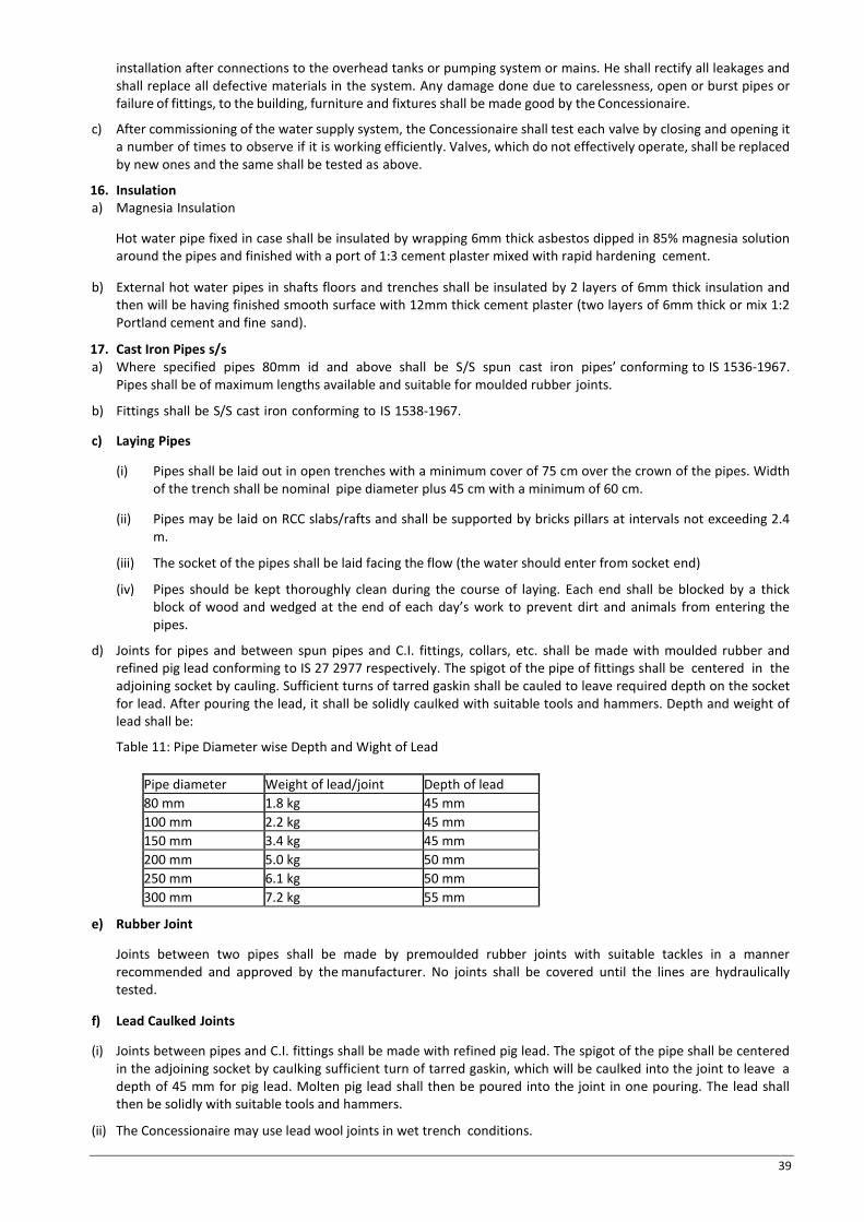
39
installation after connections to the overhead tanks or pumping system or mains. He shall rectify all leakages and shall replace all defective materials in the system. Any damage done due to carelessness, open or burst pipes or failure of fittings, to the building, furniture and fixtures shall be made good by the Concessionaire.
c) After commissioning of the water supply system, the Concessionaire shall test each valve by closing and opening it a number of times to observe if it is working efficiently. Valves, which do not effectively operate, shall be replaced by new ones and the same shall be tested as above.
16. Insulation a) Magnesia Insulation
Hot water pipe fixed in case shall be insulated by wrapping 6mm thick asbestos dipped in 85% magnesia solution around the pipes and finished with a port of 1:3 cement plaster mixed with rapid hardening cement.
b) External hot water pipes in shafts floors and trenches shall be insulated by 2 layers of 6mm thick insulation and then will be having finished smooth surface with 12mm thick cement plaster (two layers of 6mm thick or mix 1:2 Portland cement and fine sand).
17. Cast Iron Pipes s/s a) Where specified pipes 80mm id and above shall be S/S spun cast iron pipes’ conforming to IS 1536-1967.
Pipes shall be of maximum lengths available and suitable for moulded rubber joints.
b) Fittings shall be S/S cast iron conforming to IS 1538-1967.
c) Laying Pipes
(i) Pipes shall be laid out in open trenches with a minimum cover of 75 cm over the crown of the pipes. Width of the trench shall be nominal pipe diameter plus 45 cm with a minimum of 60 cm.
(ii) Pipes may be laid on RCC slabs/rafts and shall be supported by bricks pillars at intervals not exceeding 2.4 m.
(iii) The socket of the pipes shall be laid facing the flow (the water should enter from socket end)
(iv) Pipes should be kept thoroughly clean during the course of laying. Each end shall be blocked by a thick block of wood and wedged at the end of each day’s work to prevent dirt and animals from entering the pipes.
d) Joints for pipes and between spun pipes and C.I. fittings, collars, etc. shall be made with moulded rubber and refined pig lead conforming to IS 27 2977 respectively. The spigot of the pipe of fittings shall be centered in the adjoining socket by cauling. Sufficient turns of tarred gaskin shall be cauled to leave required depth on the socket for lead. After pouring the lead, it shall be solidly caulked with suitable tools and hammers. Depth and weight of lead shall be:
Table 11: Pipe Diameter wise Depth and Wight of Lead
Pipe diameter Weight of lead/joint Depth of lead 80 mm 1.8 kg 45 mm 100 mm 2.2 kg 45 mm 150 mm 3.4 kg 45 mm 200 mm 5.0 kg 50 mm 250 mm 6.1 kg 50 mm 300 mm 7.2 kg 55 mm
e) Rubber Joint
Joints between two pipes shall be made by premoulded rubber joints with suitable tackles in a manner recommended and approved by the manufacturer. No joints shall be covered until the lines are hydraulically tested.
f) Lead Caulked Joints
(i) Joints between pipes and C.I. fittings shall be made with refined pig lead. The spigot of the pipe shall be centered in the adjoining socket by caulking sufficient turn of tarred gaskin, which will be caulked into the joint to leave a depth of 45 mm for pig lead. Molten pig lead shall then be poured into the joint in one pouring. The lead shall then be solidly with suitable tools and hammers.
(ii) The Concessionaire may use lead wool joints in wet trench conditions.

40
g) Anchor Blocks
Suitable anchor blocks shall be provided at all bends and tees to encounter the excessive thrust development due to water hammer.
18. Valves
a) Air Valves
(i) Air valves shall be provided in all high points in the system to prevent air locks.
(ii) Air valves shall be of single acting heavy duty brass spring type.
b) Scour Valves
Scour valves shall be provided at all low points in the system. Valves shall be gunmetal full way valves for sizes 50 mm diameter. And below and butterfly valves 65 mm diameter and above.
c) Sluice Valve
(i) Sluice valve shall be socket type or double flanged type confirming to IS 780.
(ii) Joints for socket valves shall be lead caulked joints as specified above.
(iii) Joints for double flanged sluice valve shall be made with suitable tail/socket pieces on pipe line and flanges joints made with 3mm thick insertion rubber gasket with appropriate number of bolts, nuts, washers etc.
19. Fire Hydrants
a) Fire hydrant shall be cast iron stand post type with 63mm diameter instantaneous gunmetal outlets conforming to I.S. 908
b) Each fire hydrant shall be provided with an 80 mm cast iron sluice valve, duct foot bend and a suitable 63 mm diameter flanged cast iron pipe for correcting the installation height of the hydrant.
20. Valve chambers The Concessionaire shall provide suitable brick masonry chambers in cement mortar 1:5 (1 cement: 5 coarse sand) on cement concrete foundations 150 mm thick 1:4:8 mix (1 cement: 4 fine sand: 8 graded stone aggregate 40 mm nominal size) 15 mm thick cement plaster of 1:4 (1 cement: 4 coarse sand) inside and outside finished with a floating coat at neat cement inside with casts iron surface box approved by fire brigade including excavation, back filling complete.
Valve chamber shall be of following size: For depth 90 cms – 60 x 60 cms For depths upto 100 cms beyond–120x120 cms
21. Testing a) All pipes, fitting and valves shall be tested by hydrostatic pressure of 7.5 kg/sq.cm.
Pressure shall be maintained for a period of at least 120 minutes without any drop in the pressure after fixing at site. A test register shall be maintained and all entries shall be signed and dated by the Concessionaires and the Independent Engineer.
b) In addition to the sectional testing carried out during the construction, the Concessionaire shall test the entire installation after connections to the overhead tanks or pumping system or mains. He shall rectify all leakages and shall replace all defective materials in the system. Any damage done due to carelessness, open or burst pipes or failure of fittings to the building, furniture and fixtures shall be made good.
c) After commissioning of the water supply system, the Concessionaire shall test each valve by closing and opening it a number of times to observe if it is working effectively. New ones shall replace valves, which do not effectively operate, and the same shall be tested as above.
22. Intentionally left blank
23. Disinfective a) After completion of the work, the Concessionaire shall flush clean the entire system with the city’s filtered water
after connection has been made.
b) After the first flushing, add commercial bleaching powder or achieve a dosage of 2 to 3 mg/l of water in the system

41
added and flushed. This operation should be performed twice to ensure that the system is fully disinfected and usable.
24. Pre-commissioning a) Ensure that all pipes are free from debris and obstructions.
b) Check all valves and fire hydrant for effective opening and closing action. Defects should be rectified or valves replaced.
c) Ensure that all connections to branches have been made.
(i) Ensure that mains have been connected to the respective pumps, underground and overhead tanks.
(ii) Water supply should be available at main underground tank. (c) All main line valves should be closed.
25. Commissioning a) Fill tank with water. Add 1 kg fresh bleaching powder after making a solution to be added near inlet.
b) Start water supply pumps and allow water to fill main underground tank. Water will first fill the fire tank and then overflow to the domestic tanks.
c) After filling overhead reservoirs drain the same to its one forth capacity through tank scour valve (this is to ensure removal of all mud, debris etc. from the tank).
d) Fill overhead tank to full.
e) Release waste in the main lines by opening valves in each circuit. Drain out water in the system through system scour valve or fire hydrant in lower regions. Ensure clean water in now coming out of the system.
f) Open valves for individual cluster. Observe for leakages or mal function, check pressure and flow at end of line by opening hydrants etc. Remove and rectify defects notice.
g) Check all fire hydrants for proper operation by opening each valve and allowing water to flow for few minutes. Also check for effective closure of valve.
h) The entire water supply system should be disinfected with bleaching powder and system flush cleaned.
i) Send four samples of water drawn from four extreme locations for testing for bacteriological in sterilized bottles obtained from the concerned laboratory. (Laboratory personal may collect the samples themselves).
26. Responsibility Responsibility for various activities in pre commissioning and commissioning procedures will rest with the Concessionaire.
Technical Specifications – Sewerage/Drainage System 1. Scope of Work a) Work under the section shall consist of furnishing all labour materials equipment and appliances necessary and
required to completely finish sewerage / drainage system as required by the proposal approved and specified hereinafter.
b) Without restricting to the generality of the foregoing the sewerage / drainage system shall include (i) Internal / External sewer line. (ii) Excavation including refilling etc. (iii) Construction of collection chambers manholes and drop connections. (iv) Construction of grease trap etc. (v) Construction of external sewer line. (vi) Storm water drainage and disposal.
2. General Requirements a) All materials shall be new of the best quality conforming to specifications and subject to the approval of the
Independent Engineer.
b) Drainage lines shall be laid to the required gradients and profiles
c) All drainage work shall be done in accordance with the local municipal byelaws
d) Concessionaire shall obtain necessary approval and permission for the drainage system from the municipal or any other competent authority.
e) Location of all manholes, catch basins, etc. shall be confirmed by the Independent Engineer before the actual

42
execution of work at site.
f) All works shall be executed as directed by the Independent Engineer.
3. Alignments and grade The sewers and storm water lines shall be laid to alignment and gradient shown on the drawings but subject to such modifications as shall be ordered by the Independent Engineer from time to time to meet the requirements of the works. No deviations from the lines depths of cutting or gradients of sewer shown on the plans and sectors shall be permitted except to the direction in writing of the Independent Engineer.
4. Excavation a) The excavation for sewers and stone water drains shall be in open cutting unless the permission of the
Independent Engineer for the ground to be tunnelled is obtained in writing. Where sewers have to be constructed along narrow passages, the Independent Engineer may order the excavation to be made partly in tunnel and in such cases the excavated soil be brought back later on for refilling the trenches or tunnel.
b) Opening Out Trenches
In excavation the trenches, etc., the soiling roads, metalling, pavement, kerbing etc., and turf shall be placed on one side and preserved for reinforcement when the trenches or other excavation shall be filled up. Before any road metal is replaced, it shall be carefully shifted. The surface of all trenches and holes shall be restored and maintained to the satisfaction of Authority/Independent Engineer.
the Independent Engineer and of the owners of the roads or other property traversed and the Concessionaire shall not cut out or break down any live fence of trees in the line of the proposed works but shall tunnel under them, unless the Independent Engineer shall order to the contrary.
c) Obstruction of Roads
The Concessionaire shall not occupy or obstruct by his operation more than one half of the width of any road or street and if insufficient space shall then be left for public and private transit, he shall remove the materials excavated and bring them back again when the trench is required to be refilled. The Concessionaire shall obtain the consent of the Independent Engineer in writing before closing any road to vehicular traffic and the foot walks must be clear at all times.
d) Removal of Filth
All night soil, filth or any other offensive matter is met with during the execution of works, immediately after it is taken out of any trench, sewer or cess pool, shall not be deposited on the surface of any street or where it is likely to be a nuisance or passed into any sewer or drain but shall be at once put into the carts and removed to suitable place to be provided by the Concessionaire.
e) Excavation to be taken to Proper Depth
The trenches shall be excavated to such a depth that the sewer shall rest on concrete described by the several clauses relating thereto and so that the inverts may be at the levels given the sections. In bad ground, the Independent Engineer may order the Concessionaire to excavate to a greater depth than that shown on the drawings and to fill up the excavation to the level of the sewer with concrete, broken stone, gravel or other materials.
f) Refilling
After the sewer or other work has been laid and proved to be water tight, the trench or other excavations shall be refilled. Utmost care shall be taken in doing this, so that no damage shall be caused to the sewer and other permanent work. The filling in the haunches and upto 75 cm above the crown of the sewer shall consist of the finest selected materials place carefully in 15 cm. Layers and flooded and consolidated. After this has laid the trench and other excavation shall be refilled carefully in 15 cm layers with materials taken from the excavation, each layer being watered to assist in the consolidation unless the Independent Engineer shall otherwise direct.
g) The Concessionaire to restore settlement and damages
The Concessionaire shall at his own costs and charges, make good promptly during the whole period, the work are in hand, any settlement that may occur in the surfaces of roads, berms, footpaths, gardens, open spaces, etc., whether public or private caused by his trenches or by his other excavations and he shall be liable for any accidents caused thereby, he shall also, at his own expenses and charges repair and make good any damage done to

43
buildings and other property.
h) Disposal of Surplus Soil
The Concessionaire shall at his own costs and charges provide places for disposal of all surplus materials not required to be used on the works. As each trenches refilled the surplus soil shall be immediately removed, the surface properly restored and roadways and sides left clear.
i) Timbering of sewer and trenches
The Concessionaire shall at all times support efficiently and effectively the sides of the sewer trenches and other excavation by suitable timbering, pilling and sheeting and they shall be closed, timbered in loose or sandy strata and below the surface of the sub-soil water level.
All timbering sheeting and pilling with their walling supports shall be adequate dimensions and strength and fully braced and strutted so that no risk of collapse or subsidence of the walls of the trench shall take place.
The Concessionaire shall be held responsible and will be accountable for the sufficiency of all timbering, bracing, sheeting and pilling used as also for, all damage to persons and property resulting from improper quality, strength, placing maintaining or removing of the same.
j) Shoring of building
The Concessionaire shall shore up all buildings, walls and other structures, the stability of which is liable to be endangered by the execution of the work and shall be fully responsible for all damages to persons of property resulting from any accident.
k) Removal of water from sewer, trench etc.
(i) The Concessionaire shall at all times during the progress of the work keep the trenches and excavations free from water which shall be disposed of by him in a manner as will neither cause injury to the public health nor to the public or private property nor to the work completed or in progress nor to the surface of any roads or streets, nor cause any interference with the use of the same by the public.
(ii) If any excavation carried out at any point or points to a greater width than the specified cross section of the sewer with its envelope, the full width of the trench shall be filled with concrete by the Concessionaire.
l) Width of Trench
The Independent Engineer shall have power by giving an order in writing to the Concessionaire to increase the maximum width for excavation in trenches for various classes of sewer, man holes and other works in certain lengths to be specifically laid down by him, where on account of bad ground or other unusual conditions, he considers that such increased widths are necessary in view of the site conditions.
5. Salt Glazed Stoneware Pipes
a) Stoneware pipes shall be first class quality salt glazed and free from rough texture inside and outside and straight. All pipes shall have the manufacturer name marked on it and shall comply to IS 651-1971. Approved makes [PERFECT or BURN].
b) Laying and jointing of stone ware salt glazed pipes
(i) Pipes are liable to be damaged in transit and not withstanding tests that may have been made before dispatch each pipe shall be examined carefully on arrival at site. Each pipe shall be rung with a wooden hammer or mallet and those that do not ring true and clear shall be rejected. Sound pipes shall be carefully stacked to prevent damage. All defective pipes should be segregated, marked in a conspicuous manner and their use in the works prevented.
(ii) The pipes shall be laid with sockets leading up hill and should rest on solid and even foundations for the full length of the barrel. Socket holes shall be formed in the foundation sufficiently deep to allow the pipe jointer room to work right round the pipe and as short as practicable to admit the socket and allow the joint to be made.
(iii) Where pipes are not bedded on concrete the trench bottom shall be left slightly high and carefully bottomed up as pipe laying proceeds so that the pipe barrels rest on firm ground, if excavation has been carried too low it shall be made up with cement concrete (1:5:10) mix at the Concessionaire’s expenses and

44
charges.
(iv) If the bottom of the trench consists of rock or very hard ground that cannot be easily excavated to a smooth surface, the pipes shall be laid on cement concrete bed to ensure even bearing.
c) Jointing of pipes
Tarred gasket shall first be wrapped round the spigot of each pipe and the spigot shall then be placed in to the socket of the pipe previously laid, the pipe then shall be adjusted and fixed in its correct position and the gasket caulked tightly home so as to fill not more than one quarter of the total length to the socket.
The remainder of the socket shall be filled with a stiff mix of cement mortar (1 cement:
1 clear sharp washed sand). When the socket is filled, a fillet should be formed round the joint with a trowel forming and angle of 45 degrees with the barrel of the pipe. The mortar shall be mixed as needed for immediate use and no mortar shall be beaten up & used after it has begun to set.
After the joint has been made and extraneous materials shall be remove from inside the joint with a suitable scraper “badger”. The newly made joints shall be protected until set from the sun drying winds, rain or dust. Sacking or other materials, which can be kept damp, shall be used. The joint shall be exposed and spaces left all round the pipes for inspection by the Independent Engineer. The inside of the sewer must be left absolutely clear in bore and free round cement mortar or other obstructions throughout its entire length, and shall efficiently drain and discharge.
d) Testing
All lengths of the sewer and drain shall be fully tested for water tightness by means of water pressure maintained for not less than 30 minutes. Testing shall be carried out from manhole to manhole. All pipes shall be subjected to a test pressure of at least, 1.5 meter head of water at the highest point. Pressure shall, however, not exceed 1.5 meter head at any point. The pipes shall be plugged preferably with standard design plugs with rubber plugs on both ends. The upper end shall, however, be connected to a pipe for filing with water and getting the required head.
A test register shall be maintained which shall be signed and dated by Concessionaire and Independent Engineer.
6. Gully Traps
a) Gully traps shall be of the same quality as described for stoneware pipes in Clause 5 above.
b) Gully traps shall be fixed in cement concrete 1:4:8 mix and brick masonry. Chamber 30x 30cm C.I. sealed cover and frame weighing not less than 7.3 Kg to be constructed as per standard drawings. Where necessary, sealed cover shall be replaced with C.I. grating of the same size (1 Cement: 4 Coarse: 8 stone aggregate 40 mm nominal size).
7. Reinforced Cement Concrete Pipes
a) All underground storm water drainage pipes and sewer lines where specified (other than those specified cast iron) shall be centrifugally spun RCC pipes of specified class. Pipes shall be true and straight with uniform bore throughout. Cracked, wrapped pipes shall not be used on the work. All pipes shall be tested by the manufacturer and the Concessionaire shall produce, when directed, a certificate to the effect from the manufacturer.
b) Laying
R.C.C. spun pipes shall be laid on cement concrete bed or cradle as specified and shown on the detailed drawings. The cradle may be precast and sufficiently cured to prevent cracks and breakage in handling. The invert of the cradles shall be left 12mm below the invert level of the pipe and property placed on the solid to prevent any disturbance. The pipe shall then be placed on the bed concrete of cradles and set for the line gradient by means of sight rails and boning rods, etc. Cradles or concrete bed may be omitted, if directed by the Independent Engineer.
c) Jointing
After setting out the pipes the collar shall be centered over the joint and filled in with tarred gaskin, so that sufficient space is left on either side of the collar to receive the mortar. The space shall then be filled with cement mortar (1 cement: 2 fine sand) and caulked by means of proper tools. All joints shall be finished at an angle of 45 degrees to the longitudinal axis of the pipe on both sides of the collars neatly.

45
d) Testing
All pipes shall be tested to a hydraulic test of 1.5 m head for at least 30 minutes at the highest point in the section under test. Test shall also be carried out similar to those for stoneware pipes given in this chapter. The Concessionaire shall also carry out the smoke test. A test register shall be maintained which shall be signed and dated by Concessionaire/ Independent Engineer.
8. Cast Iron Pipes for Drainage
a) All drainage lines passing under building, floors and roads with heavy traffic, in exposed position above ground e.g. service floor and basement ceiling shall be cast iron pipes.
b) Cast iron pipes shall be centrifugally spun cast iron pipes conforming to IS 1536- 1967.
Quality certificate shall be furnished.
c) Fittings and Inspection Chambers
Fittings used for C.I. drainage pipes shall conform to IS 1538-1967. Wherever, possible junction from branch pipes shall be made by a Y tee. Cleanout plugs shall be provided on head of each drain and at locations indicated on plans or as directed by independent Engineer. Cleanout plugs shall be of size matching the full bore of the pipe. Plugs shall be made from G.I. coupling caulked into the socket of the pipe for fitting. The end of the provided with a brass screwed plugs with suitable key for opening.
d) Laying
(i) All cast iron pipes and fittings shall be joined with best quality soft pig lead (conforming to IS 279-1977) which shall be free from impurities.
(ii) The spigot of pipe of fittings shall be centered in the adjoining socket by caulking.
Sufficient turns of tarred gaskin will be given to leave unfilled the required depth of socket for depth 45 mm when the gaskin has been caulked tightly home jointing ring shall be placed round the barrel and against the face of the socket. Molten pig lead shall then be poured to fill the remainder of the socket. This shall be done in one pouring. The lead shall then be solidly caulked with suitable tools and hammers weighing not less than 2 kg. For lead wool joints the socket shall be caulked with tarred gaskin as explained above. The lead wool shall be inserted into the sockets and tightly caulked home by gaskin with suitable tools and hammers of not less than 2 kg.
(iii) For the lead wool joints the socket shall be caulked with tarred gaskin, as explained above. The lead wool shall be inserted into the sockets and tightly caulked home by gaskin with suitable tools and hammers of not less than 2kg weight until joint is filled.
e) Testing
All cast iron pipes for drainage shall be tested to a hydraulic test of 3-meter head. Test for straightness shall be same as for stoneware pipe given in point 5.4 of Clause 4.3.6 of Chapter 4. A test register shall be maintained which shall be signed and dated by Concessionaire and Independent Engineer.
9. Cement Concrete and Masonry Works (for manholes and chambers, etc.)
a) Water: Water used for all constructional purpose shall be clear and free from oil, acid, alkali, organic and other
harmful matters, which can deteriorate the strength and / or durability of structure. In general, the water suitable for drinking purpose shall be considered as good enough for constructional purposes.
b) Aggregate For Concrete:
The aggregate for concrete shall be in accordance with I.S. 383 and I.S. 515 in general; these shall be free from all impurities that may cause corrosion of the reinforcement. Before actual use these shall be washed in water, if required as per the direction of Independent Engineer. The size of the coarse aggregate shall be done as per IS 383.
c) Sand:
Sand for various constructional purposes shall comply in all respects with I.S. 650 and I.S. 2116. It shall be clean, coarse hard and strong, sharp, durable, uncoated, free from any mixture of clay, dust, vegetable
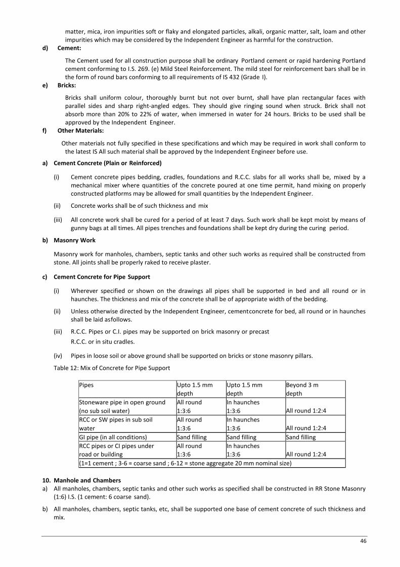
46
matter, mica, iron impurities soft or flaky and elongated particles, alkali, organic matter, salt, loam and other impurities which may be considered by the Independent Engineer as harmful for the construction.
d) Cement:
The Cement used for all construction purpose shall be ordinary Portland cement or rapid hardening Portland cement conforming to I.S. 269. (e) Mild Steel Reinforcement. The mild steel for reinforcement bars shall be in the form of round bars conforming to all requirements of IS 432 (Grade I).
e) Bricks:
Bricks shall uniform colour, thoroughly burnt but not over burnt, shall have plan rectangular faces with parallel sides and sharp right-angled edges. They should give ringing sound when struck. Brick shall not absorb more than 20% to 22% of water, when immersed in water for 24 hours. Bricks to be used shall be approved by the Independent Engineer.
f) Other Materials:
Other materials not fully specified in these specifications and which may be required in work shall conform to the latest IS All such material shall be approved by the Independent Engineer before use.
a) Cement Concrete (Plain or Reinforced)
(i) Cement concrete pipes bedding, cradles, foundations and R.C.C. slabs for all works shall be, mixed by a mechanical mixer where quantities of the concrete poured at one time permit, hand mixing on properly constructed platforms may be allowed for small quantities by the Independent Engineer.
(ii) Concrete works shall be of such thickness and mix
(iii) All concrete work shall be cured for a period of at least 7 days. Such work shall be kept moist by means of gunny bags at all times. All pipes trenches and foundations shall be kept dry during the curing period.
b) Masonry Work
Masonry work for manholes, chambers, septic tanks and other such works as required shall be constructed from stone. All joints shall be properly raked to receive plaster.
c) Cement Concrete for Pipe Support
(i) Wherever specified or shown on the drawings all pipes shall be supported in bed and all round or in haunches. The thickness and mix of the concrete shall be of appropriate width of the bedding.
(ii) Unless otherwise directed by the Independent Engineer, cement concrete for bed, all round or in haunches shall be laid as follows.
(iii) R.C.C. Pipes or C.I. pipes may be supported on brick masonry or precast R.C.C. or in situ cradles.
(iv) Pipes in loose soil or above ground shall be supported on bricks or stone masonry pillars.
Table 12: Mix of Concrete for Pipe Support
Pipes Upto 1.5 mm depth
Upto 1.5 mm depth
Beyond 3 m depth
Stoneware pipe in open ground (no sub soil water)
All round 1:3:6
In haunches 1:3:6
All round 1:2:4
RCC or SW pipes in sub soil water
All round 1:3:6
In haunches 1:3:6
All round 1:2:4
GI pipe (in all conditions) Sand filling Sand filling Sand filling RCC pipes or CI pipes under road or building
All round 1:3:6
In haunches 1:3:6
All round 1:2:4
(1=1 cement ; 3-6 = coarse sand ; 6-12 = stone aggregate 20 mm nominal size) 10. Manhole and Chambers a) All manholes, chambers, septic tanks and other such works as specified shall be constructed in RR Stone Masonry
(1:6) I.S. (1 cement: 6 coarse sand).
b) All manholes, chambers, septic tanks, etc, shall be supported one base of cement concrete of such thickness and mix.

47
c) All manholes shall be provided with cement concrete benching in 1:2:4 mix (1 cement 2 coarse sand 4 stone aggregate 20 mm nominal size) The benching shall have a slope of 10 cms towards the channels. The depth of the channel shall be full diameter of the pipe. Benching shall be finished with a floating coat of neat cement.
d) All manholes shall be plastered with 25 mm thick cement mortar 1:3 mix (1 cement 3 coarse sand) in finished with a floating coat of neat cement inside. Manholes shall be plastered outside as above but with rough plaster.
e) All manholes with depths greater than 1 m shall be provide with Ferro Cement Foot Steps.
f) All manholes shall be provided with cast iron covers and frames and embedded in reinforced cement concrete slab. Weight of cover and frame shall be approximately chosen.
g) Size of Manhole should not be less than 1500 x 900 mm in normal circumstances. Circular manhole shall be construction with minimum 1 meter internal dia.
h) Drop Connection
(i) Drop connections shall be provided between branch sewer and main sewer or in the main sewer itself in the steep ground when the difference in the invert level of the two exceeds 45 cm of the required size.
(ii) Drop connections from the gully trap to main sewer on rectangular manholes shall be made inside the manhole and shall have H.C.I. special type door on top and heel rest bend at bottom connected by a H.C.I. pipe. This pipe shall be supported by holder bat clamp at 180 cm intervals with one clamp for each drop connection. All joints shall be lead caulked joints 25 cm deep.
(iii) Drop connections from branch sewer to main sewer shall be made outside the manhole wall with glazed stone ware pipe tee connection, vertical pipe and bend at the bottom. The top of the tee shall be finished up to the surface level and provided with a C.I. hinged type frame and cover 30 cm x 30cm. The connection shall be embedded in the cement concrete 1:2:4 mix 15 cm all round the pipe and tee upto the surface chamber of the tee.
(iv) Drop connection made from vertical stack directly into the manhole shall not be considered as drop connection.
Technical Specifications – Fire Hy drant System 1. Scope of work
Work under this section shall consist of furnishing all labour, materials, equipment and appliances necessary and required to completely install wet. Riser fire system as required by the drawings and specified hereinafter or given in this Chapter of quantities. Without restricting to the generally of the foregoing, the fire hydrant system shall include the following:
a) Black steel mains including valves, hydrants and appurtenances.
b) Black steel pipe fire risers within the building
c) Landing valves, canvas hose pipes, hose reels, hose cabinets, fire brigade connections to pumps, appliances and pressure reducing devices.
d) Excavation, anchor blocks and valve chamber.
2. General Requirements
All materials shall be of the best quality conforming to the specifications and subject to the approval of the employer. Pipes and fittings shall be fixed truly vertical, horizontal or in slopes as required in a neat workmanlike manner.
Pipes shall be fixed in a manner as to provide easy accessibility for repair and maintenance and shall not cause obstruction in shafts passages, etc. Pipes shall be securely fixed to walls and ceilings by suitable clamps at intervals specified. Only approved type of anchor fasteners shall be used for R.C.C. ceilings and walls. Valves and other appurtenances shall be so located that they are easily accessible for operations, repairs and maintenance.
3 Pipes and fittings for Internal Work
a) All pipes within the building in exposed locations and shafts inclunding connections buried under floor shall be black steel tubes conferming to IS : 1239-1979 (Heavy class) with screwed or welded joints as specified by the Independent Engineer.
b) Fittings for M.S. pipes shall be approved type malleable iron (forged fittings) for tapered screwed joints. Fittings
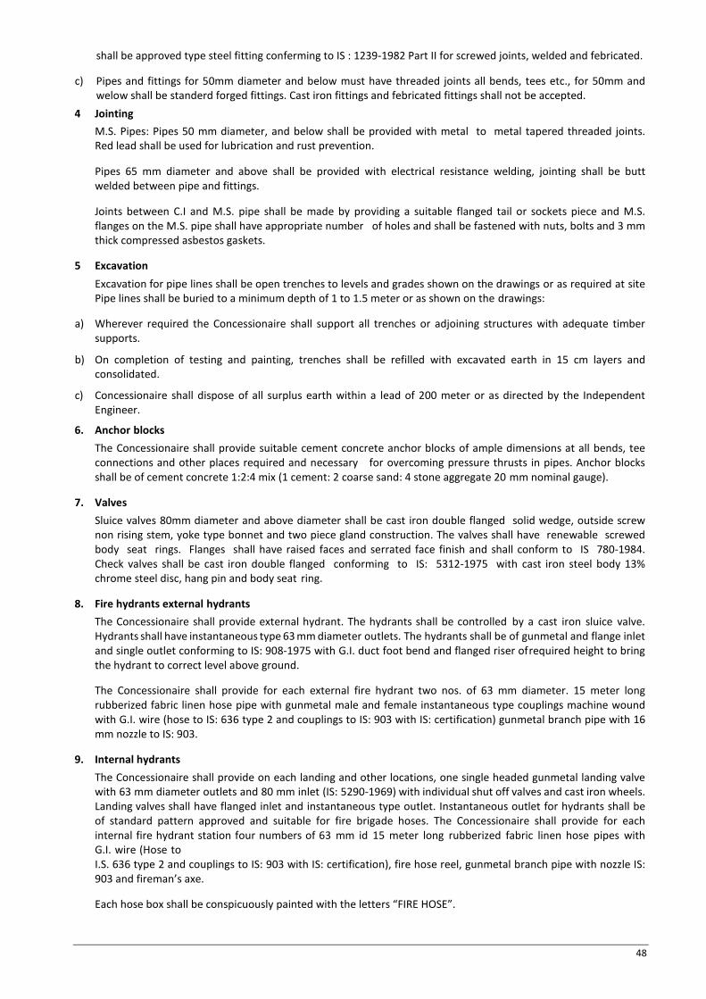
48
shall be approved type steel fitting conferming to IS : 1239-1982 Part II for screwed joints, welded and febricated.
c) Pipes and fittings for 50mm diameter and below must have threaded joints all bends, tees etc., for 50mm and welow shall be standerd forged fittings. Cast iron fittings and febricated fittings shall not be accepted.
4 Jointing M.S. Pipes: Pipes 50 mm diameter, and below shall be provided with metal to metal tapered threaded joints. Red lead shall be used for lubrication and rust prevention.
Pipes 65 mm diameter and above shall be provided with electrical resistance welding, jointing shall be butt welded between pipe and fittings.
Joints between C.I and M.S. pipe shall be made by providing a suitable flanged tail or sockets piece and M.S. flanges on the M.S. pipe shall have appropriate number of holes and shall be fastened with nuts, bolts and 3 mm thick compressed asbestos gaskets.
5 Excavation Excavation for pipe lines shall be open trenches to levels and grades shown on the drawings or as required at site Pipe lines shall be buried to a minimum depth of 1 to 1.5 meter or as shown on the drawings:
a) Wherever required the Concessionaire shall support all trenches or adjoining structures with adequate timber supports.
b) On completion of testing and painting, trenches shall be refilled with excavated earth in 15 cm layers and consolidated.
c) Concessionaire shall dispose of all surplus earth within a lead of 200 meter or as directed by the Independent Engineer.
6. Anchor blocks The Concessionaire shall provide suitable cement concrete anchor blocks of ample dimensions at all bends, tee connections and other places required and necessary for overcoming pressure thrusts in pipes. Anchor blocks shall be of cement concrete 1:2:4 mix (1 cement: 2 coarse sand: 4 stone aggregate 20 mm nominal gauge).
7. Valves Sluice valves 80mm diameter and above diameter shall be cast iron double flanged solid wedge, outside screw non rising stem, yoke type bonnet and two piece gland construction. The valves shall have renewable screwed body seat rings. Flanges shall have raised faces and serrated face finish and shall conform to IS 780-1984. Check valves shall be cast iron double flanged conforming to IS: 5312-1975 with cast iron steel body 13% chrome steel disc, hang pin and body seat ring.
8. Fire hydrants external hydrants The Concessionaire shall provide external hydrant. The hydrants shall be controlled by a cast iron sluice valve. Hydrants shall have instantaneous type 63 mm diameter outlets. The hydrants shall be of gunmetal and flange inlet and single outlet conforming to IS: 908-1975 with G.I. duct foot bend and flanged riser of required height to bring the hydrant to correct level above ground.
The Concessionaire shall provide for each external fire hydrant two nos. of 63 mm diameter. 15 meter long rubberized fabric linen hose pipe with gunmetal male and female instantaneous type couplings machine wound with G.I. wire (hose to IS: 636 type 2 and couplings to IS: 903 with IS: certification) gunmetal branch pipe with 16 mm nozzle to IS: 903.
9. Internal hydrants The Concessionaire shall provide on each landing and other locations, one single headed gunmetal landing valve with 63 mm diameter outlets and 80 mm inlet (IS: 5290-1969) with individual shut off valves and cast iron wheels. Landing valves shall have flanged inlet and instantaneous type outlet. Instantaneous outlet for hydrants shall be of standard pattern approved and suitable for fire brigade hoses. The Concessionaire shall provide for each internal fire hydrant station four numbers of 63 mm id 15 meter long rubberized fabric linen hose pipes with G.I. wire (Hose to I.S. 636 type 2 and couplings to IS: 903 with IS: certification), fire hose reel, gunmetal branch pipe with nozzle IS: 903 and fireman’s axe.
Each hose box shall be conspicuously painted with the letters “FIRE HOSE”.

49
10 Fire hose reels The Concessionaire shall provide standard fire hose reels with 20 mm diameter high pressure rubber hose of 36.5 meter length with gunmetal nozzle with 5mm bore, and control valve, shut of nozzle connected wall mounted on circular hose reel of heavy duty mild steel construction and cast iron brackets. Hose reel shall conform to IS: 884-1969. The hose reel shall be connected directly to the M.S pipe riser through an independent connection.
11 Orifice flanges Provide orifice flanges fabricated from 6 mm thick stainless steel plate to reduce pressure on individual hydrants to restrict the operating pressure to 3.5 kg/sqmt. The design of the orifice flanges shall be given by the Concessionaire as per the location and pressure conditions of each hydrant/hose reel.
12 Fire brigade connection Provide gunmetal two or four way collecting head with 63 mm diameter instantaneous type inlet with built in check valve and 100/150 mm diameter outlet connection to the fire main grid and for tank filling, collecting head shall conform to IS 904-1965.
13 Draw off connection
a) Air valves
Provide 25 mm i/d. screwed inlet single acting brass air valve on all high points in the system on top of air cushion tanks.
b) Drain valve
Provide 50 mm id. G.I. pipe to IS: 1239 (Medium class) with 50 mm gunmetal full way valve for draining any water in the system in low pockets as directed by the Independent Engineer.
c) Hydrant/Valve Chambers
The Concessionaire shall provide suitable brick masonry chambers in cement mortar 1:5 (1cement: 5 coarse sand) on cement concrete foundations 150 mm thick 1:4:8 mix (1 cement:4 fine sand:8 graded stone aggregate 40mm nominal size) 15 mm thick cement plaster inside and outside finished with a floating coat of neat cement, inside with cast iron surface box approved by fire brigade including excavation, back filling, complete Valve chamber shall be of the following size: For depths 100cm and beyond 120x120 cms Weight of C.I. frame and cover shall be 38 kg.
14 Pipe protection All pipes above ground and in exposed locations shall be painted with one coat of red- oxide primer and two or more coats of synthetic enamel paint of approved shade. All buried MS. Pipes shall be provided with protection against soil corrosion by applying two coats of coal tar hot enamel paint, two layers reinforced fiber glass tissue and finished with one coat of the above paint (as per IS: 10221)
15 Pipe support All pipes shall be adequately supported from ceiling or walls from existing inserts by structural clamps fabricated from M.S. Structural, e.g., rods, channels, angles and flats. All clamps shall be painted with one coat of red lead and two coats of black enamel paint.
Where inserts are not provided the Concessionaire shall provide anchor fasteners. Anchor fastener shall be fixed to walls and ceilings by drilling holes with electrical drill in an approved manner as recommended by the manufacturer of the fasteners.
16 Testing All pipes in the system shall be tested to a hydrostatic pressure of 14.5 kg/sq.cm. without drop in pressure for at least 2 hours.
17 Hose cabinets Provide hose cabinets for internal/ external hydrants fabricated from 16 gauge MS sheet with single or double glass front door and locking arrangement with breakable glass key access arrangement, duly painted red with stove enamelled paint fixed to wall or self supported on floor as per site conditions. The cabinet shall also have a separate chamber to keep the key with breakable glass as per approved design. Hose cabinets shall be fabricated from 16 gauge MS sheet of fully welded construction with hinged double front door partially glazed with locking

50
arrangement stove enamelled fire red paint with “FIRE HOSE” written on it prominently. Samples of hose cabinet for internal and external works are not approved from the Independent Engineer before installation at site.
Technical Specifications – Pumps and Ancillary Equipment 1. Scope of work
Work under this section shall consist of furnishing all labour, materials, Equipment and appliances necessary and required to completely install electrically operated pumps for fire hydrant and sprinkler installations as specified hereinafter. Without restricting to the generality of the foregoing, the pumps and the ancillary equipment shall include the following:- · Electrically operated pumps with motors, base plate and accessories · Alarm system with all accessories wiring and connections. · Pumps suction and delivery headers, valves, air vessel & connections. · Pressure gauges. · Electrical switchboard, wiring, cabling, cable tray and earthing.
2. General requirements Pumps shall be installed true level on suitable concrete foundations. Base Plate shall be firmly fixed by foundation bolts properly grouted in the concrete foundations.Pumps and motors shall be truly aligned by suitable instruments. All pumps connection shall be standard flanged type with appropriate number of bolts. Manufacturer’s instructions regarding installation connections and commissioning shall be followed with respect to all pumps, switchgear and accessories.
3. Fire and jockey pumps
a) Pumping Sets
Pumping sets shall be multistage horizontal centrifugal multi-stage outlet pumps with cast iron body and bronze dynamically balanced impeller connecting shaft shall be stainless steel. Pumps shall be connected to drive by means of a flexible coupling with sheet metal guard. Pumps shall be provided with approved type of mechanical seals and pressure gauge with isolation cock on the delivery side. Pumps shall be capable of furnishing not less than 150% of the rated capacity at a head of not less than 65 % of the rated head. The shut off head shall not exceed 120% of the rated head.
b) Wet Riser Hydrant and Sprinkler Systems
Wet riser hydrant and sprinkler shall be pressurized through a set of pumps driven by electric motors. Desired pressure shall be created and maintained in the systems by means of main and Jockey pump sets. The working of the pumps sets shall be as under:
· Main pump for Hydrant and Sprinkler systems. · Automatic start on reduction in the pressure in the system at pre- determined level.
Also manual start arrangement shall be made in case of failure of automatic start system. · Pump set shall stop by manual operation only. · Stand by main pump (Diesel Engine Driven)
In the event of failure in the operation of main pump sets for hydrants and sprinklers, the standby main pump shall come into operation when the pressure in the system is reduced to a pre-determined level. Also manual start arrangement shall be made in case of failure of automatic start arrangements. Pump set shall stop by manual operation only.
c) Jockey Pump
Starting and stopping of Jockey pump set shall be automatic at pre-determined levels.
However, arrangements for manual start and stop of the pump shall also be made. Jockey pump shall take care of small leakages in the piping system and pumps cushion tanks.
4. Electric Drive Electrically driven pumps shall be provided with totally enclosed induction motors suitable for fire pumps. The motors should be rated not to draw more than 4.5 times the starting current. Motors shall be at least equivalent to the horse power required to drive the pump at 150% of its rates discharge. The motors shall be wound for class E insulation and windings shall be vacuum impregnated with heat and moisture resisting varnish, glass fibre insulated.

51
5. Diesel Engine Diesel Engine shall be of suitable HP with individual heat assemblies. The engine shall be water-cooled and shall include heat exchanger and connecting piping strainer isolating and pressure reducing valves, bye-pass line complete in all respects. The Engine shall be of direct injection type with low noise and exhaust emission levels. The speed of engine shall match the pump speed for direct drive.
The engine shall be capable of being started without the use of the wicks, cartridge heater plugs or either at engine room temperature of 7 degree C. and shall take full load within 15 seconds from the receipt of the signal to start. The engine shall effectively operate at 38 degree C. ambient temperature at 150 meters above mean sea level. Noise level of the engine shall not exceed 105 db. (free field sound pressure) at 3 meters distance. The engine shall be self starting type up to 4 deg. C shall be provided with one 24 volts heavy duty D.C. battery, star term cutout, battery leads complete in all respects. One additional spare battery shall be provided. The battery shall have a capacity of 200 ampere hours and 640 amperes cold cranking amperage. Provide a battery charger of 10 to 15 amperes capacity with trickle and booster charging facility and regulators. Arrangement for starting shall be automatic on receiving the signal. But shut off shall be manual. The engine shall be provided with an oil bath or dry type air cleaner as per manufacturer’s design. Engine shall be suitable for running on high speed diesel oil. The system shall be provided with a control panel with push button starting. Arrangement also wired to operate the engine on a differential pressure gauge.
The entire system shall be mounted on a common structural base plate with anti - vibration mounting, Dunlop make, and flexible connections on the suction and delivery piping. Provide one fully mounted and supported day oil tank fabricated from 6 mm thick MS sheet electrically welded of 8 hours working load but not less than 200 liters. Provide level indicators-low level and fill level in the day oil tank on the control panel through float switches and an air breather. Provide on exhaust pipe with suitable muffler (resident type) to discharge the engine gases to outside in open air as per site conditions (Concessionaire to check the site).Provide all accessories, fittings, and fixtures necessary and required for a complete operating engine set. The exhaust pipe shall be taken outside the Building with a number of bends (approx length 20 meters.) and shall be duly heat insulated with rain cover. The Concessionaire shall indicate special requirement, if any, for the ventilation of the pump room.
6. Base Plate Pumps and motors shall be mounted on a common structural base plate with anti- vibration mounting.
7. Air Vessel Provide one air vessel fabricated from 12 mm M.S. plate with dished ends & suitable supporting legs. Each air vessel shall be provided with a 100 mm diameter flanged connection from pump, one 25 mm diameter. drain with valve, one gunmetal water level gauge and 25 mm sockets for pressure switches. The vessel shall be 450 mm diameter x 2000 mm high and tested to 28 kg / sqcm pressure.
The fire pumps shall operate on drop of 1 kg / sqcm pressure in the mains. The pump operating sequence shall be arranged in a manner to start the pumps automatically but should be stopped by starter push buttons only.
8. Vibration eliminators Provide on all suction and delivery lines double-flanged reinforced neoprene flexible pipe connectors. Connectors should be suitable for a working pressure of each pump and tested to the test pressure give in the relevant heat. Length of the test connector shall be as per manufacturer details.
9. Switchboard cubicle Provide and install one switch board cubicle of approved dust and vermin proof type fabricated from 16 gauge M.S. sheet and finished with synthetic enamel paint of approved shade and shall have plastic identification for different motors. The cubicle shall comprise of the following:- (a) Aluminum bus bar of rated capacity in a separate chamber with two additional share chambers. (b) Incoming main isolation switch fuse unit of required capacity HRC fuses. (c) Isolation switch fuse unit of required capacity HRC fuses, one for each motor. (d) Fully automatic auto transformer starters with push buttons one for each motor. (e) Fully automatic “STAR DELTA” starters with push buttons for jockey pumps. (f) Single phasing prevention for suitable rating for each motor. (g) Panel type ampere meters, one for each motor. (h) Panel type volt meter on incoming main with rotary selector switch to read voltage between phase to
neutral and phase to phase. (i) Three neon phase indicating lamps on incoming main.

52
(j) Two rotary switches for manual/ auto operations of fire and sprinkler pumps. (k) All interconnecting colour coded wiring from incoming main to switch gear, meters and accessories within
the switchboard panel. All switchgears and accessories shall be of approved make such as SIEMENS, ENGLISH ELECTRIC, LARSEN AND TOUBRO or equivalent as approved by the Independent Engineer. Switchboard cubicles shall be floor-mounted type.
10. Cables The Concessionaire shall provide all power and control cables from the motor control centre to various motors and control devices. Cables should conform to IS: 1554 and carry BIS certification mark. Wiring cables should conform to IS: 694. All power and wiring cables shall be aluminium conductors PVC insulated armoured and PVC sheathed of 1.1 KW grade. All control cables shall have stranded conductors. The cables shall be supplied in drums as far as possible and bear the manufacturer’s identification mark. All cable joints shall be made in an approved manner as per accepted practice.
11. Earthing There shall be two independent earthing stations at least 3 meters away from the pump room. The earthing shall consist of an earth tape connected to an independent plate made of C.I. having a conductivity of not less than 100% international standard. All electrical apparatus, cable boxes and sheath/ armour clamps shall be connected to the main bar by means of branch earth connections of appropriate size. All joints in the main bar and branch bar shall have the lapping surface properly tinned to prevent oxidation. The joints shall be revetted and sweathed.
Earth plates shall be buried in a pit 1.2 x 1.2 meter a minimum depth of 3 meter below the ground. The connections between the main bars shall be made by means of three 10 mm brass studs and fixed at 100 mm centres. The pit shall filled with coke breeze, rock salt and loose soil. A.G.I.Pipe of 20mm i/d. with perforation on the periphery shall be placed vertically over the plate to reach ground level for watering. A brick masonry manhole 30 x 30 x 30 cm. size shall be provided to surround the pipe for inspection. A bolted removable link connecting main bar outside the pit portion leading to the plate shall be accommodated in this manhole for testing.
12. Commissioning Commissioning of the systems shall commence only after: (a) All pipes, accessories, pumping set, fire alarms, etc., have been completely installed and tested. (b) The electrical connection has been made & direction of motors rotation checked. (c) Related works by
other agencies has been completed in all respects. (c) Water supply is available in adequate quantity in the underground tank. (e) Basement drainage pumps
are fully commissioned. (d) On completion of all related work given in para above, start pumping sets and develop desired pressures
in both the systems. (e) Open one hydrant and test if pump starts at desired drop in pressure and the alarm operates. If required
make adjustments and retest. 13. Maintenance manual
On completion of the entire work and successful commissioning, the Concessionaire shall hand over four copies of maintenance manuals of all equipment installed by him. Maintenance manuals shall include information relating to make, model No. year of manufacture for all electrical and mechanical equipments with names of local supplies or manufacturers’ agents.
Technical Specifications – Commissioning for Fire-fighting System
1. Scope of Work Work under this section shall consist of pre commissioning, commissioning, testing and providing guarantees for all equipments, appliances and accessories supplied and installed by the Concessionaire under this contract.
2. General Requirements The Concessionaire shall provide all tools, equipments, metering and testing devices required for the purpose.
On award of concession, the Concessionaire shall submit a detailed proposal giving methods of testing and gauging the performance of the equipment to be supplied and installed under this contract.
3. Pre-commissioning On completion the installation of all pumps, piping, valves, pipe connections, electrical wiring, motor control

53
panels and water level controlling devices the Concessionaire shall proceed as follows:
Testing of M.C.C.:
(a) Insulation resistance test with 500 volt megger, before and after high voltage test, on all power and control wiring.
(b) High voltage test at 2000 volts A.C. for one minute on all power and control wiring.
(c) Low voltage continuity test (t volts) on power wiring of each feeder, between bust bars and outgoing terminals with switches and conductors in closed position.
(d) Low voltage continuity test (6 volts) on all control wiring.
(e) Operation test for all feelers with only control supply made “ON” to ensure correctness of control wiring, operation of the various equipment used, such as push buttons, protective devices, indicating lamps and relays, etc. All conductors shall be checked for the presence of humming and chattering.
(f) Earth continuity test with voltage not exceeding 6 volts between various non- current carrying metallic of equipment, steel work, etc., and the earth bus provided in the M.C.C.
(g) Operation of all instruments and meters provided on the M.C.C.
4. Fire Protection System
(a) Check all hydrant valves and if any valve is open than close it. Check that all suction and delivery connections are properly made.
(b) Tests run and check rotation of each motor and correct the same required.
5. Pipe Work Check all clamps, support and hangers provided for the pipes. Fill up pipes with water and apply hydrostatic pressure to the systems as given in the specifications if any leakage is found. Rectify the same and retest the pipes.
6. Commissioning and Testing Fire Hydrant System
(a) Pressurize the fire hydrant system by running the main fire pump and after attaining the required pressure shut off the pump.
(b) Open by-pass valve and allow the pressure to drop in the system. Check that the jockeys pump cuts-in and cuts-out at the preset pressures. If necessary adjust the pressure switch for the jockey pump. Close by-pass valve.
(c) Open hydrant valve and allow the water to flow into the fire water tank in order to avoid wastage of water. The main fire pump should cut-in the present pressure and should not cut-out automatically on reaching the normal line pressure. The main fire pump should stop only by manual push button. However, the jockey pumps should cut out as soon as the main pump starts.
(d) Switch off the main fire pump and test check the diesel engine driven pump in the same manner as the electrically driven pump.
(e) When the fire pumps have been checked for satisfactory working on automatic, open fire hydrant valves simultaneously and allow the hosepipes to discharge water into the fire tank to avoid wastages. The electrically driven pump should run continuously for eight hours so that its performance can be checked.
(f) Diesel engine driven pump should also be checked in the same manner as given above by running for 8 hours.
(g) Check each landing valve, male and female coupling and branch pipes for compatibility with each other. The Concessionaire shall replace any fitting, which is found to be incompatible and does not fit into the other properly. Landing valves shall also be checked by opening and closing under pressure.
7. Handing Over The Concessionaire to the complete satisfaction of the Independent Engineer shall do all commissioning and testing. The Concessionaire shall also get the system approved from the local fire authorities and submit NOC received from the Fire Department /Authority.
8. Regulations, codes of practice, references and standards The aspects of the design which are related to HSE must respect applicable Regulations, Codes of Practice and

54
Standards. Those which are relevant to this project are listed below in order of priority. International codes and regulations shall be applied unless more stringent national rules exist. In case of conflict, priority shall be given according to the following list: · National Regulations,
· Manufacturers Standards,
· International Codes and Standards.
9. National regulations The Bus terminal project shall comply with the applicable International, National & State regulations.
10. Company standards The design of project facility shall comply with the latest revisions of the State Safety Standards, Fire Brigade & International Codes, Specifications and design criteria as provided in the contract.
Technical Specifications – Installation of Tube well a) Selection of site
The site where the employer wants to sink the tube well should be examined. Any previous data available with the Concessionaire, of the nearby areas should be made use to evolve suitable procedure for drilling, developing and testing etc
b) Drilling
The drilling shall be done in accordance with the specification contained in IS: 2800 Part_ I, 1979 and as described in Chapter of work
c) Drilling time log book
As the drilling progresses, and accurate drilling time logbook shall be maintained by the Concessionaire, indicating time taken to drill every two meters of depth where there is change of strata. This log will enable interpretation regarding the nature of formation (hard, soft, unconsolidated etc.), which has a bearing of water fielding capacity of the formation
d) Geological data
Samples of drill cuttings from different strata shall be collected at suitable intervals preferably at every two meters depth drilled or at closer intervals, if a change in strata is met with. After the drilling has reached sufficient depth all the samples of strata collected shall be got examined analyzed in a laboratory
e) Design and lowering of pipe assembly
The design and diameter of the housing pipe shall be as specified in the Chapter of work. The size and length of blind pipes and slotted shall be in accordance with the requirements to the strata met with, the expected discharge and the depth of tube well. The design of the pipe assembly for stainer pipe and column pipe shall be submitted by the Concessionaire and approved by the independent Engineer
f) Gravel packing
All gravel shall consist of hard well-rounded particles reasonably uniform in diameter meter and shall be of a size given in the Chapter of work
g) Developments of Tube well
The well shall be developed either by surging and agitating or by over pumping and back wash with an acceptable method may also be adopted with the consent of the independent engineer. The development process shall be continued until the stabilization of sand and gravel pack has taken place. The development of the tube well by over pumping should be done at 15% to 25% higher discharge than the expected discharge from the tube well
h) Grouting and sealing
Grouting and sealing of the tube may well be done, if required by the corporation depending upon the site conditions and quality of the discharge of the strata encountered. It should be applied in one continuous operation. Sealing of the tube well may be done by grouting angular space between bore and the housing

55
pipe, thickness of grouting depending upon the quality of water
i) Handing over of the Tube well
The tube-well should be handed over to the employer in complete shape and closed by a well cap for the period between the completions of tube well and the installation of the pump set. The following information should be furnished by the Concessionaire on completion of the tube well · Strata chart of the tube well indicating different types of soil met with at different depth. · Samples of strata collected, neatly packed and correctly marked in sample bags/wooden box. · Chart of actual pipes assemble lowered indicating size of pipes, depth range where slotted/ strainer pipes,
depth ranges, where slotted/ strainer pipes have been used, depth and diameter of housing pipe, reduced level of the top of the housing pipe and diameter and depth of the bore hole.
· Geo hydro testing result of the borewell
· Position of every joint in the well assembly.
· Hours of development done by compressed air, pump set or by other means.
· Pumping water level at developed discharge · Report of the samples of water got tested in the approved laboratories
j) Verticality and alignment
As per IS: 2800(part- II) 1980
List of IS Codes Relating to Plumbing Works Vitreous IS: 2556-1974
IS 2556-1981 (Part II) IS: 2556-1984
Cast Iron Cistern IS: 774-1984
Ball Valve IS: 1703-1977
Cistern Brackets Toilet Seat Cover
IS: 775-1970 IS: 2548-1983
Vitreous China Cistern IS: 2326-1987
Sand Cast Iron Pipes & Fittings IS: 1729-1979
Spun Cast Iron Pipes & Fittings IS: 3989-1984
GI Pipes IS: 1239-1979
Galvanizing for GI pipe IS: 4736-1986
Pipe Threads IS: 554-1985
Malleable Iron Fitting IS: 1879-1987
Cast Iron Sluice Valves IS: 780-1984
Full way valves IS: 778-1984
Brass Ferrule IS: 2692-1978
Stone Ware Gully Trap IS: 651-1980
R.C.C. Pipes IS: 458-1971
Cast Iron Class L.A. Pipes IS: 1536-1989
Cast (Spun) Iron Fittings Pig Lead
IS: 1538-1976 IS: 782-1966
Induction Motors IS: 4691
3.4 Electrical Installation Works 3.4.1 General
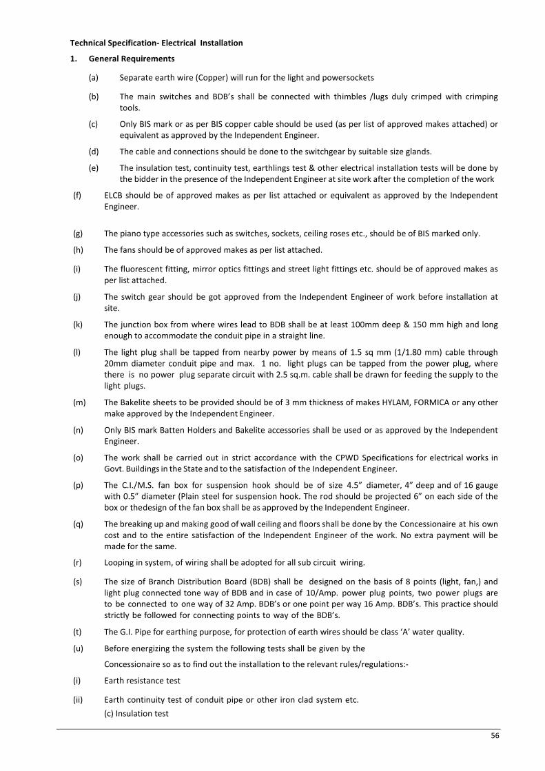
56
Technical Specification- Electrical Installation
1. General Requirements
(a) Separate earth wire (Copper) will run for the light and power sockets
(b) The main switches and BDB’s shall be connected with thimbles /lugs duly crimped with crimping tools.
(c) Only BIS mark or as per BIS copper cable should be used (as per list of approved makes attached) or equivalent as approved by the Independent Engineer.
(d) The cable and connections should be done to the switchgear by suitable size glands.
(e) The insulation test, continuity test, earthlings test & other electrical installation tests will be done by the bidder in the presence of the Independent Engineer at site work after the completion of the work
(f) ELCB should be of approved makes as per list attached or equivalent as approved by the Independent Engineer.
(g) The piano type accessories such as switches, sockets, ceiling roses etc., should be of BIS marked only.
(h) The fans should be of approved makes as per list attached.
(i) The fluorescent fitting, mirror optics fittings and street light fittings etc. should be of approved makes as per list attached.
(j) The switch gear should be got approved from the Independent Engineer of work before installation at site.
(k) The junction box from where wires lead to BDB shall be at least 100mm deep & 150 mm high and long enough to accommodate the conduit pipe in a straight line.
(l) The light plug shall be tapped from nearby power by means of 1.5 sq mm (1/1.80 mm) cable through 20mm diameter conduit pipe and max. 1 no. light plugs can be tapped from the power plug, where there is no power plug separate circuit with 2.5 sq.m. cable shall be drawn for feeding the supply to the light plugs.
(m) The Bakelite sheets to be provided should be of 3 mm thickness of makes HYLAM, FORMICA or any other make approved by the Independent Engineer.
(n) Only BIS mark Batten Holders and Bakelite accessories shall be used or as approved by the Independent Engineer.
(o) The work shall be carried out in strict accordance with the CPWD Specifications for electrical works in Govt. Buildings in the State and to the satisfaction of the Independent Engineer.
(p) The C.I./M.S. fan box for suspension hook should be of size 4.5” diameter, 4” deep and of 16 gauge with 0.5” diameter (Plain steel for suspension hook. The rod should be projected 6” on each side of the box or the design of the fan box shall be as approved by the Independent Engineer.
(q) The breaking up and making good of wall ceiling and floors shall be done by the Concessionaire at his own cost and to the entire satisfaction of the Independent Engineer of the work. No extra payment will be made for the same.
(r) Looping in system, of wiring shall be adopted for all sub circuit wiring.
(s) The size of Branch Distribution Board (BDB) shall be designed on the basis of 8 points (light, fan,) and light plug connected tone way of BDB and in case of 10/Amp. power plug points, two power plugs are to be connected to one way of 32 Amp. BDB’s or one point per way 16 Amp. BDB’s. This practice should strictly be followed for connecting points to way of the BDB’s.
(t) The G.I. Pipe for earthing purpose, for protection of earth wires should be class ‘A’ water quality.
(u) Before energizing the system the following tests shall be given by the
Concessionaire so as to find out the installation to the relevant rules/regulations:-
(i) Earth resistance test
(ii) Earth continuity test of conduit pipe or other iron clad system etc. (c) Insulation test

57
(iii) Polarity test
(v) The control switch should not be installed at height less than 120 cm from floor level or as directed by the Independent Engineer or as per site requirement.
(w) The bodies of branch distribution fuse board should be machine made with 1.60 mm thick solid steel sheet.
(x) Grip fuse units of sheet metal/iron clad, switch & branch distribution fuse boards should be of N.C. type so as to have the facility of interchange ability.
(y) Brass screws to fix brown Bakelite/white glazed or translucent back side Painted sheet cover 3 mm thick. This should be fixed by means of flat headed brass machines screws with brass ring washers underneath.
(z) All conduit used in work shall be adequately bushed with P.V.C. bushes to prevent abrasion of insulation of conductor and shall also be bonded earth.
(aa) The connection of earth wire with sheet metal/iron clad switch and branch distribution fuse boards or other metallic cases shall be according to the Indian Electricity Rules and made by means of suitable cable socket soldered at the end of earth wire.
(bb) Welded conduit pipe (Screw type) made from 1.60mm thick sheet coated with two coats of approved paint shall be used. The conduit pipe shall be joined by means of screwed sockets so that it shall be electrically continuous throughout. The threads shall be free from grease oil etc. and no material of nature should be allowed to come in contact with the conduit. Sharp edges or bare should not be allowed to remain due to which insulation of conduit pipe is likely to be damaged.
(cc) For the complete work of Electrical Installation, the Concessionaire shall provide circuit key diagram before the finalizing of bill for display at the important places in the Bus Terminal as per the instructions of the Independent Engineer.
(dd) The electrical installation work shall be carried out in accordance with Indian Standard Code of practice for Electrical wiring installation IS: 732- 1989 and IS: 2274-1963. It shall also be in conformity with the current Indian Electricity Rules & Regulations and Requirements of the local electricity supply authority and fire insurance regulation. Electrical work in general shall be carried out as per CPWD Specifications with upto date amendment.
2. Scope of Work
The scope of work shall cover internal and external electrical works for proposed bus stand. The items/activities covered under internal electrical works shall include the following:-
a) Main Distribution Boards, Sub Distribution Boards. Switch fuse unit/MCB isolators etc. complete in all respect.
b) Cables from Main Distribution Board to Sub Distribution Boards. Submain Wiring from Main/Sub Distribution Boards to various final Distribution Boards.
c) Point wiring of all lights points. Ceiling fan points, exhaust fan points, light Plug points, general power points, metal clad plug & socket outlet points etc., including supply and fixing of light and power accessories etc. complete in all respects.
d) Light fixtures, ceiling fans, exhaust fans.
e) Provision for telephone system consisting of conduit and cabling from telephone distribution board upto each outlet including main & sub tag blocks, telephone outlets incoming GI/SW pipe etc. complete in all respect.
f) SW/GI pipes for cables, manholes, cable tray and other items required to complete with electrical installation work in all respects.
g) Earthing of electrical installation complete in all respects.
h) Scope of work shall include supply installation, testing and commissioning of complete electrical installation as described above.
i) Providing standby Power by installation of D.G. set of suitable capacity.
j) Sub-station work covering 11 KV Board, 11KV Cable, Transformer, LT Cable and main LT panel and

58
Emergency panel etc.
k) External cabling from Substation to various blocks.
l) Obtain NOC from Electrical Inspector for the Electrical Substation
3. Standard and Regulations
All equipment, switchgear, cables and other items of work shall conform to Indian Standard specifications
The installation shall conform in all respects to Indian Standards Code of Practice for Electrical Wiring Installation IS: 732-1989. It shall also be in conformity with the current Indian Electricity Rules and the Regulations and Requirements of the Local Electric Supply Authority, Local laws/by laws in so far as these become applicable to the installation. Wherever these specifications call for a higher standard of materials and/or workmanship than those required by any of the above regulations, these specifications shall take precedence over the said regulations and standard. In general, the materials, equipment and workmanship shall conform to the following Indian Standards with up to date amendments/revisions if any unless otherwise called for.
Table 13: List of Approved Makes Description Specification Makes a) Specification for DG Set 415V 3 Phase 4 wire, 50Hz
IS 4722-1992 BS 5514
Mahindra, Kirloskar, Cumminus, Ashok Layland
b) 11 KV Vacuum Circuit Breaker
IS 3427-1991 IS 12729-1988
L & T, Siemens, Hager, ABB
c) Transformer 111 KV/0.433 KV
IS 2026-1977 Volttamp, BHEL, Kirloskar, Crompton Greeves
d) XLPE cable 11 KV
IS 7098 Part I & II 1988/1985
Polycab, Havels, Skytone, Paramount, CCI, Finolex
e) PVC insulated (heavy duty) electric cable Part I for voltage upto 1100 volts
IS 1554-1988
Polycab, Havels, Paramount, CCI, Finolex
f) Making arrangement for Switch gear Bus bars, main connection & auxiliary wiring
IS 375-1963
Havels, Indo Asian, L & T, Siemens, Hager, C & S
g) Specifications for normal duty air break switches & composite units for air break switches & fuses for voltage not exceeding 1000 volts
IS 13947-1993 (Part I to V)
Havels, Indo Asian, L & T, Siemens, Hager, C & S
Specification for low voltage switchgear & control gear assemblies.
IS 8623-1993 (Part I to III)
Havels, Indo Asian, L & T, Siemens, Hager, C & S
i) Specifications for enclosed distribution
IS 2675-1983 Havels, Indo Asian, L & T, Siemens, Hager, C & S
Installation & maintenance of Switchgear
IS 10118-1982 (Part I to IV)
avels, Indo Asian, L & T, Siemens, Hager, C & S
k) HRC Fuses IS 9224-1979 Havels, Indo Asian, L & T, Siemens, Hager, C & S
l) Specification for Rigid Steel conduits for electrical wiring
IS 9537-1981 (Part – II)
Nihir, Precision, Vraj, BEC, AKG

59
m) Specifications for accessories for rigid steel conduits for electrical wiring
IS 3837-1976
Nihir, Precision, Vraj, BEC, AKG
Description Specification Makes n) 3 pin plugs & socket outlets
IS 1293-1988
Anchor, Hager, Cab tree, C & S, Havells, HPL Sudhir, Diamond, L&T Panels, Capitor Panels
o) General & Safety requirements for electric light fittings.
IS 1913-1978
---
p) Electric ceiling fans & regulators
IS 374-1979 Havells, Crompton, Orient, Bajaj
q) Code of practice for earthing
IS 3043-1987 Electrode Earth
r) Current transformers
IS 2705 – 1992 (Part – I)
AE, Kappa, L&T
s) Shunt capacitors for power system
IS 2834 – 2986 GE, ABB,
t) Exhaust Chimney IS 6533 – 1989 (Part– II)
Usha, Havells, Crompton, Bajaj, Almonard
u) (u) HSD Storage Tanks IS 803/864 As per brand approved Inspection and approval of the work by local authority on completion of this work. The Concessionaire shall obtain and deliver to the Independent Engineer all the certificates of inspection and approval by the electrical inspectorate as required.
Panel, Main Distribution Boards / Sub distribution Boards 1. General
The scope covers supply, installation, testing and commissioning of power panels, incorporating circuit breakers, fuse units, bus bars, interconnections, earthing etc., meeting the requirements shown in equipment Chapter and the drawings. The Panel should be fabricated by CPRI approved panel builder only & should strictly follow all standards & code.
Main Distribution Board/ Sub Distribution Boards shall be metal clad totally enclosed, rigid, floor mounting, air insulated, cubicle type for use on 415 volts, 3 phase, 50 cycle system. System shall be suitable for a fault withstand capacity of 50 KA RMS, symmetrical equipment shall be designed for operation in high ambient temperature and high humidity tropical atmospheric conditions.
2. Standards
a) The equipment shall be designed to conform to the requirement of:
(i) IS–8623 – Factory Built Assemblies of switchgear and control gear
(ii) IS-4237 – General requirements for switchgear and control gear for Voltages and exceeding 1000 volts.
(iii) IS-2147 – Degree of Protection provided by enclosures for low voltage switchgear and control gear.
(iv) IS-375 – Marking and arrangement of bus bars
b) Individual equipment housed in the Main & Sub Distribution Board shall Conform to the following IS specifications with upto date amendments if any
(i) Moulded Case Circuit Breakers IS 2516 (Part I & II/ Sec I) – 1977
(ii) Fuse Switch & Switch Fuse Units IS 4064 – 1978
(iii) H.R.C. Fuse links IS 2208-1962 or IS 9224-1979

60
(iv) Current Transformers IS 2705
(v) Voltage Transformer IS 3156 (f) Relays IS 32.31
(vi) Indicating Instruments IS 1248
(vii) Integrating Instruments IS 722
(viii) Control Switches & Push Buttons IS 6875
(ix) Auxiliary Concessionaires IS 2959
c) Distribution Boards
It includes Supply, Installation, Testing and Commissioning of Distribution Boards standard company fabricated or to be fabricated by fabricator & should be double door type.
Distribution Board shall be double door type with extended loose wire box at the top & suitable for flush installation. All distribution boards shall be of three phase (415 Volts) type with incoming isolator or MCB &/or ELCB as in Chapter of quantities. Distribution boards shall contain plug in or bolted type miniature circuit breaker mounted on bus bars. Miniature circuit breakers shall be quick made & quick break type with trip free mechanism. MCB shall have thermal & magnetic short circuit protection. MCB shall conform to IS 8828-1978. Distribution boards shall comprise of 200A rating copper bus bar, earth terminal, MCB, DP, RCCB and neutral link mounted in three-tier phase wise. All distribution boxed shall be made by approved/licenses MCB/DP manufacturer. The bus bar shall be such that circuit could be isolated easily. Neutral bus bars shall be provided with the same number of terminals, as there are single ways on the board, in addition to the terminals for incoming mains. An earth bar of similar size at the neutral bar shall also be provided. Phase barrier shall be fitted and all live parts shall be screened from the front. Ample clearance shall be provided between all live metal and the earth case & adequate space for all incoming & outgoing cables. All distribution boards enclosures shall have an etched zinc base stove painted followed by synthetic stoved enamel, colour light gray. A circuit identification card in clear plastic cover shall be provided for each distribution board and made from 16-gauge sheet.
Earth leakage circuit breaker/residual current circuit breakers-Earth leakage circuit breaker shall be current operated type and of 100 ma sensitivity unless otherwise stated. For single-phase distribution, ELCB shall be housed within the DB box. For three-phase distribution board, the ELCB shall be housed in the same box.
d) Metallic Conduct-Wiring System
(i) Type and Size of Conduit
All conduit pipes shall be of approved gauge (not less than 16 SWG for conduits of sizes upto 32 mm diameter) solid drawn or reamed by welding finished with stove enameled surface). All conduit accessories shall be of threaded type and under no circumstances pin grip type accessories shall be used. The maximum number of PVC insulated 650/1100 volts grade copper conductor cable that can be drawn in conduit of various sizes shall be as per IS: code. No conduit less than 20 mm in diameter shall be used.
(ii) Conduit Joints
Conduit pipes shall be joined by means of threaded couplers, and threaded accessories only. In long distance straight run of conduits inspection type couplers at reasonable intervals shall be provided or running threads with couplers and jamnuts shall be provided. In the later case the bare threaded portion shall be treated with anti- corrosive preservative. Threads on conduit pipes in all cases shall be between 13mm to 19mm long sufficient to accommodate pipes to full threaded portion of couplers or accessories.
Cut end of conduit pipe shall have no sharp edges or any burrs left to avoid damage to the insulation of conductor while pulling them through such pipes.
(iii) Protection Against Condensation
The layout of conduit should be such that any condensation or sweating inside the conduit is drained out. Suitable precaution should also be taken to prevent entry of insects inside the conduit.

61
(iv) Protection of Conduit Against Rust
The outer surface of conduit including all bends, unions, tees, junction boxes etc. forming part of conduit system shall be adequately protected against rust when such system is exposed to weather by being painted with two coats of oxide paint applied before they are fixed. In all cases, no bar threaded portion of conduit pipe shall be allowed. Unless such bare thread portion of conduit is treated with anti-corrosive preservation or covered with approved plastic compound.
(v) Painting of Conduit and Accessories
After installation, all accessible surface of conduit pipes, fittings, switch and regulator boxes etc. shall be painted with two coats of approved enameled paint or aluminum paint as required to match the finish of surrounding wall, trusses etc.
(vi) Fixing of Conduits Recessed/ concealed conduit
The case in the wall shall be neatly made and of ample dimensions to permit the conduit to be fixed in the manner desired. In the case of building under construction, conduit shall be buried in the wall before plastering and shall be finished neatly after creation of conduit. In case of exposed brick/rubble masonry work, special care shall be taken to fix the conduit and accessories in the position along with the building work. Entire work of chasing the wall, fixing the conduit in chases, and burying the conduit in mortar before the plastering shall form part of point wiring work. The condition pipe shall be fixed by means of staples or by means of saddles not more than 60cm apart or by any other approved means of fixing.
Fixing of standard bends and elbows shall be avoided as far as practicable and all curves maintained by bending the conduit pipe itself will treated with some approved preservation compound to secure protection against rust. Suitable inspection boxes to the barest minimum requirement shall be provided to permit periodical inspection and to facilitate replacement of wires, if necessary. These shall be mounted flush with the wall. Suitable ventilating holes shall be provided in the inspection box covers. Wherever the length of conduit run is more than 10 meters, then circular junction box shall be provided.
(vii) Outlet Boxes & Covers
The switch box shall be made of metal on all sides except on the front. Boxes shall be hot tip galvanized mild steel. Upto 20 x 30 cm size M.S. box shall have wall thickness of 16 SWG. The metallic boxes shall be painted with anti-corrosive paint before erection. Clear depth of the box shall not be less than 60 mm. All fitting shall be fitted in the flush pattern. Phenolic laminated sheet of approved shade shall be used for switch box covers. These shall be of 3 mm thick synthetic phenolic resin bonded laminated sheet as base material and conform to grade P-1 of IS 2036-1994.
(viii) Erection and Earthing of Conduits
The conduit of each circuit or section shall be completed before conductors are drawn in. The entire system of conduit after erection shall be tested for mechanical and electrical continuity throughout and permanently connected to earth conforming to the requirement by means of special approved type of earthing clamp effectively fastened to conduit pipe in a workmen like manner for a perfect continuity between the earth and conduit. Gas, water pipe shall not be used as earth medium.
(ix) Switches
All 5 and 15 Amp switches shall be of piano type of 240 volts A.C. grade to be installed. All switches shall be fixed on 3 mm thick laminated sheet cover. All 5 Amp socket shall be 3 pin type. All 15 Amp socket shall be 6 pin type suitable for 15/5 Amp. All switches & sockets outlets controlling the lights or fans shall be connected to the phase wire of the circuit. Switches shall be located at 1200 mm above finished floor level unless otherwise indicated or as directed by the Independent Engineer.
(x) Flush Cover Plates
All switches, sockets, telephones and TV outlets etc. shall be fixed on 3 mm thick phenoliclaminated sheet cover unless otherwise specified. Flush cover plate shall be secured to the box with counter sunk brass screws & cup washers.
(xi) Wall Socket Plate
All 5 and 15 Amp socket outlet shall be 3 and 6 pin respectively. Each outlet shall have a switch located beside the socket preferable on the same flush cover plate or as per site requirement. The earth terminal
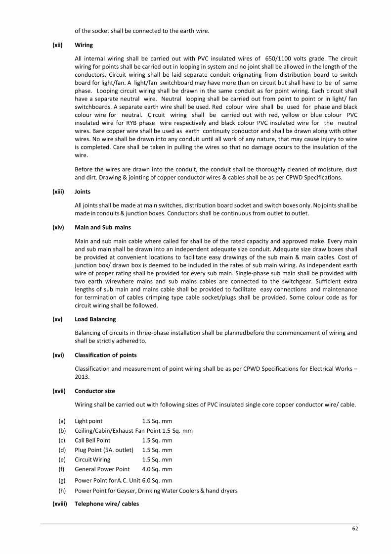
62
of the socket shall be connected to the earth wire.
(xii) Wiring
All internal wiring shall be carried out with PVC insulated wires of 650/1100 volts grade. The circuit wiring for points shall be carried out in looping in system and no joint shall be allowed in the length of the conductors. Circuit wiring shall be laid separate conduit originating from distribution board to switch board for light/fan. A light/fan switchboard may have more than on circuit but shall have to be of same phase. Looping circuit wiring shall be drawn in the same conduit as for point wiring. Each circuit shall have a separate neutral wire. Neutral looping shall be carried out from point to point or in light/ fan switchboards. A separate earth wire shall be used. Red colour wire shall be used for phase and black colour wire for neutral. Circuit wiring shall be carried out with red, yellow or blue colour PVC insulated wire for RYB phase wire respectively and black colour PVC insulated wire for the neutral wires. Bare copper wire shall be used as earth continuity conductor and shall be drawn along with other wires. No wire shall be drawn into any conduit until all work of any nature, that may cause injury to wire is completed. Care shall be taken in pulling the wires so that no damage occurs to the insulation of the wire.
Before the wires are drawn into the conduit, the conduit shall be thoroughly cleaned of moisture, dust and dirt. Drawing & jointing of copper conductor wires & cables shall be as per CPWD Specifications.
(xiii) Joints
All joints shall be made at main switches, distribution board socket and switch boxes only. No joints shall be made in conduits & junction boxes. Conductors shall be continuous from outlet to outlet.
(xiv) Main and Sub mains
Main and sub main cable where called for shall be of the rated capacity and approved make. Every main and sub main shall be drawn into an independent adequate size conduit. Adequate size draw boxes shall be provided at convenient locations to facilitate easy drawings of the sub main & main cables. Cost of junction box/ drawn box is deemed to be included in the rates of sub main wiring. As independent earth wire of proper rating shall be provided for every sub main. Single-phase sub main shall be provided with two earth wirewhere mains and sub mains cables are connected to the switchgear. Sufficient extra lengths of sub main and mains cable shall be provided to facilitate easy connections and maintenance for termination of cables crimping type cable socket/plugs shall be provided. Some colour code as for circuit wiring shall be followed.
(xv) Load Balancing
Balancing of circuits in three-phase installation shall be planned before the commencement of wiring and shall be strictly adhered to.
(xvi) Classification of points
Classification and measurement of point wiring shall be as per CPWD Specifications for Electrical Works – 2013.
(xvii) Conductor size
Wiring shall be carried out with following sizes of PVC insulated single core copper conductor wire/ cable.
(a) Light point 1.5 Sq. mm (b) Ceiling/Cabin/Exhaust Fan Point 1.5 Sq. mm (c) Call Bell Point 1.5 Sq. mm (d) Plug Point (5A. outlet) 1.5 Sq. mm (e) Circuit Wiring 1.5 Sq. mm (f) General Power Point 4.0 Sq. mm
(g) Power Point for A.C. Unit 6.0 Sq. mm (h) Power Point for Geyser, Drinking Water Coolers & hand dryers
(xviii) Telephone wire/ cables

63
Separate conduits shall be provided for internal telephone wiring of telephone wiring of telephone system commencing from tag block. Each telephone outlet shall be wired with 2 pair telephone cable from the tag block. All telephone wires shall be of .61 mm diameter annealed tinned high conductivity copper conductor PVC insulated & PVC sheathed gray conforming to ITD specifications SWS 113 B & C. Multipair PVC insulated cables and laid in conduit shall be provided for connecting various tag blocks. Telephone cables used for external connections shall be armoured. This cable shall be laid directly in ground or in pipe etc. as call for elsewhere.
Following number of 2 pair wire/ cables shall be drawn in various sizes of conduits as listed below:
· 20 mm conduit - upto 3 cables
· 25 mm conduit - more than 3 and upto 6 cables.
(xix) Maximum number of wires that can be taken in any conduit shall be as per the Table given below:
Table 14: Maximum Permissible Number of Wires in a Conduit Nominal Cross Sectional area of conductor in sq. mm
20 mm
25 mm
32 mm
38 mm
51 mm
64 mm
S B S B S B S B S B S B 1 2 3 4 5 6 7 8 9 10 11 12 13 1.5 5 4 10 8 18 12 - - - - - - 2.5 5 3 8 6 12 10 - - - - - - 4 3 2 6 5 10 8 - - - - - - 6 2 - 5 4 8 7 - - - - - - 10 2 - 4 3 6 5 8 6 - - - - 16 - - 2 2 3 3 6 5 10 7 12 8 25 - - - - 3 2 5 3 8 6 9 7 35 - - - - - - 3 2 6 5 8 6 50 - - - - - - - - 5 3 6 5 70 - - - - - - - - 4 3 5 4 Note:
(a) The above table shows the maximum capacity of conduits for a simultaneous drawing in of cables.
(b) The columns headed ”S” apply to runs of conduits which have distance not exceeding 4.25 m between draw in boxes and which do not defect from the straight by an angle of more than 15 degrees. The columns headed “B” apply to runs of conduit, which defect from the straight by an angle of more than 15 degree.
(c) Conduit sizes are the nominal external diameter.
Lighting Fixture and Fans, Air Cooling & AC 1. General
(a) The Concessionaire shall apply and install lighting fixtures including but not limited to lamps, ballasts, accessories fixing hardware necessary for installations, as required, and as herein specified.
(b) All fixtures shall be delivered to the building complete with suspension accessories, canopies, casing, sockets, holders, reflectors, ballasts, diffusing material, louvers, plaster frames, recessing boxes, etc. all wired and assembled as indicated.
(c) Fixtures, housing, frame or canopy, shall provide a suitable cover for fixture outlet box or fixture opening.
(d) Fixtures shall comply with all applicable requirements as herein outlined unless otherwise specified.
(e) Manufacturer’s name and catalogue number of lighting fixtures are given for general reference only. It shall be understood that the actual fixtures supplied shall meet all the requirements of the specification, and if necessary, the standard fixture indicated for reference, shall be modified accordingly.
(f) Fixtures shall bear manufacturer’s name and the factory inspection label.
(g) Fixtures shall be completely wired can constructed to comply with the IEE wiring regulations

64
requirements for lighting fixtures, unless otherwise specified.
(h) Re-clamping the fixture shall be possible without having to remove the fixture from its place.
(i) Lamps of the proper type, wattage and voltage rating shall be furnished and installed in each fixture.
2. Construction
(a) Fixture shall be constructed of 0.5mm thick steel minimum. If other metals are used they shall be of the required thickness to have at least the same mechanical strength. Cast portions of fixtures shall be not less than 1.5 mm thick.
(b) Metal parts of the fixture, shall be completely free from burrs & tool marks.
Solder shall not be used as a mechanical fastening device on any part of the fixture joints shall be welded and ground smooth.
(c) Fixtures with visible frames shall have concealed hinges and catches.
(d) Recessed fixtures shall be constructed so as to fit into ceiling without distorting either the fixture or the ceiling. Plaster rings shall be provided for plaster ceilings. The Concessionaire shall coordinate the dimensions with the false ceiling tile dimensions.
(e) Outdoor fixtures (under canopy or directly exposed to the weather) shall be constructed of an appropriate weather resistant material including gasketing- preventing entrance of water into wiring, and shall be marked by the manufacturer “ Suitable for outdoor use.”
(f) Fixture with hinged diffuser doors shall be provided with spring clips or other retaining devices to prevent the diffuser from moving.
(g) All plastic diffusers shall be of acrylic, unless otherwise noted.
(h) Incandescent fixtures shall be equipped with porcelain medium base with nickel- plated shells.
(i) Pendent fixtures and lamp holders shall be provided with ball type aligners.
(j) Fluorescent fixtures shall be provided with white lamp holders.
(k) Industrial type fluorescent fixtures shall have turret type lamp holders
3. Finish
(a) All hardware shall be bonderised, cadmium plated, given a corrosion- resistant phosphate treatment or other approved rust inhibiting prime coat, to provide a rust proof base before application of finish. Finish shall be baked enamel.
(b) Non-reflecting surfaces such as fixture frames and trims shall be finished with baked enamel paint, unless otherwise specified. The colour of the paint shall be as directed later by the Independent Engineer.
(c) Light reflecting surfaces shall be finished with baked white enamel paint having a reflection factor of not less than 85%.
(d) All parts of the reflector shall be completely covered by the finished and free from irregularities.
(e) Unpainted surfaces shall finished with a clear lacquer except for anodized or “Azac” surfaces.
(f) After finish has been applied and cured, it shall be capable of withstanding a 1 cm radius bend without showing signs of cracking, peeling or loosening from the base metal.
(g) Finish shall be capable of withstanding 72 hours exposure to an ultra – violet.
RS sun lamp placed 10 cm from the surface without discoloration, hardening, or warping and shall retain the same reflection characteristics after exposure.
4. Wiring
(a) Fluorescent fixtures shall be wired with not lesser than 1.5 sq mm asbestos- covered wire. No splice or tap shall be located within an arm, stem or chain. Wire shall be continuous from splice in outlet box of the building wiring system to lamp socket or to ballast terminals.
(b) Wiring within incandescent fixtures and for connection to the branch circuit wiring up to the outlet box of lighting point shall not be less than 1.5 sq mm silicone rubber insulated wire. (150 degree centigrade temperature)

65
5. Installation
(a) Fixtures shall be installed at mounting heights as instructed on site by the Engineer. Pendent fixtures within the same room or area shall be installed plump and at a uniform height from the finished floor. Adjustment of height shall be made during installation. Flush mounted recessed fixtures, shall be installed so as to completely eliminate leakage of light within the fixture and between the fixture and adjacent finish.
(b) Fixture mounted outlet boxes shall be rigidly secured to a fixture stud in the outlet box. Hickeys or extension pieces shall be installed where required to facilitate proper installation. Fixture located on the exterior of the building shall be installed with non-ferrous metal screws finished to match the fixtures.
6. Lamps-General
(a) Lamp shall be supplied and installed in all lighting fixtures listed in the Schedules of lighting fixtures on the drawings.
(b) Lamps used for temporary lighting service shall not be used in the final lamping of fixture units.
(c) Lamps shall be of wattage and type as shown in this Schedule.
(d) Lamps for permanent installation shall not be placed in the fixtures, until so directed by the Independent Engineer and this shall be accomplished directly before the building areas are ready for occupancy.
(e) LED lights & fittings shall be used.
7. Fixture Samples
Detailed catalogue for all fixtures or as required by the Independent Engineer, sample fixtures shall be submitted for prior approval of the Independent Engineer before orders for the fixtures are placed.
8. Testing
After all lighting fixtures are installed and are connected their respective switches, test all fixtures to ensure operation on their correct switch in the presence of the Engineer. All un-operating fixtures or ones connected to the wrong or inconvenient located switch shall be correctly connected as directed by the Independent Engineer.
9. Ceiling Fans
All ceiling fans shall be provided with suspension arrangement in the concrete/slab/roof member. Fan box with MS hook to be provided under by electrical Concessionaire covered under subhead point wiring item no. 1 ceiling fan shall be double ball bearing type, copper wound motor complete with canopy, down rod, blades etc. and shall conform to relevant IS standards. Ceiling fan shall be white in colour. Ceiling fan shall be provided with standard regulator. Regulator shall be suitable for 240 volts A.C. supply 50 Hz and shall be of continuous duty type.
10. Exhaust Fans
Exhaust fans shall be heavy-duty type with double ball bearing & conforming to IS 2312-1967. Exhaust fan shall be complete with copper wound motor, capacitor, louvers/shutter frame & mounting bracket. Exhaust fan shall be suitable for operation on 240 volts single phase A.C. supply.
11. Wiring
(a) All the wiring outside the panel interconnection between AMF and DG set shall be drawn into 14 gauge MS conduits or enclosed trunking.
(b) The minimum size of wire outside the AMF panel shall be as per the requirement of electric load and adequate size.
(c) The size of control cable inside the panel shall be 2.5 sq. mm copper control cable.
(d) All the wires and cables shall be suitable for 650/1100 volts.
(e) All the wiring shall be carried out as per IS: 700

66
Earthing
1. General
All the non-current metal parts of electrical installation shall be earthed properly. All metal conduits trunking, switchgear, distribution boards, switch boxes, outlet boxes and all other parts made of metal shall be bounded together and connected by means of specified earthing conductors to an efficient earthing system.
Earthing work shall be conforming to CPWD Specifications for Earthing work and IS 3043.
2. Earthing Conductor
Earth continuity conductor along with sub main wiring from Main/ Sub Distribution boards to various distribution boards shall be of copper. Earth continuity conductor connecting Main & Sub Distribution boards to earth electrode shall be with galvanized MS strip.
3. Plate Earth Electrode
Earthing shall be provided with either GI Plate electrode or copper plate electrode of following minimum dimensions: GI Plate Electrode 600m x 600mm x 6mm thick Copper Plate Electrode 600m x 600mm x 3 mm thick The electrode shall be made cylindrical buried in ground with its faces vertical and not less than 3 meters below ground level 20 mm diameter medium class GI Pipe shall be provided and attached to the electrode. A funnel with mesh shall be provided on the top of this pipe for watering and earth electrode. Earth electrode the watering funnel attachment shall be housed in masonry enclosure of not less than300x300x300 mm deep. A cast iron or MS frames with cover having locking arrangement shall be provided at top 3 meters from the building. Care shall be taken that the excavation for earth electrode may not affect the column footing or foundation of the building. In such cases electrode may be further away from the building.
If the earth resistance is too high and multiple electrode earthing does not give adequate low resistance to earth, then the soil resistivity immediately surrounding the electrode shall be reduced by addition of sodium chloride calcium chloride, sodium carbonates copper sulphate, salt and soft coke or charcoal in suitable proportions.
4. Resistance to Earth
The resistance of earthing system shall not exceed 2 ohm. Commissioning Check List of Electrical Works
1. Scope
Before commissioning of the electrical installations the Concessionaire shall check all the items mentioned and arrange for testing of all the equipments in the presence of the Independent Engineer.
a) Functional Checking
(i) Check all closing, tripping, supervision & interlock of control devices. (b) Check operation of all alarm circuits.
(ii) All 415 and 230 V power cables to be meggered.
b) Earthing (i) Measure resistance of each earth well/rod by isolating the same from station grid as well as from
other earth well/ rods and when resistance of two earths at a time measure by D.C. drops method. (ii) Check continuity of grid conductors and wires. (iii) Soil resistivity tests. (iv) In addition to the above any other specified by manufactures shall be carried out as per
manufacturer’s instructions. (v) Measurement voltage across bearing pedestal insulation & between rotor shaft & bearing. (vi) Test the fire detection system if provided. (vii) Check operation of protection relays by putting short circuit bat at different location. (viii) Check open circuit and short circuit characteristics of generators.

67
(ix) Check load characteristics of exciters.
c) Metals (i) Check nameplate details according to specification. (ii) Physical check for any damage. (iii) Check calibration by comparing it with a substandard meter. (iv) Megger all insulated portions. (v) Check C.T. and V.T. connections with particular reference to their polarities for power type meter.
d) Relays (i) Check nameplate details according to specifications. (ii) Check for any physical damage. (iii) Check internal wiring. (iv) Megger all terminals to body; Megger AC to DC Terminals. (v) Check operating characteristics by secondary injections (vi) Check minimum pick up voltage of D.C. coils. (vii) Check operation of electrical / mechanical targets. (viii) Relay settings. (ix) Check C.T. and V.T. connection with particular reference to their polarities for directional, distance type relays.
e) Current Transformer - Preliminary checks (i) Check nameplate details according to specification. (ii) Check for physical damage (iii) Check tightness of all bolts, clamps, connecting terminals (iv) Check for oil level and leakages (v) Check connections (vi) Check cleanliness of insulators and bushings
f) Commissioning Checks (i) Megger between winding & winding terminals to body (ii) Polarity test: (iii) Ratio identification checking of all ratios on all cores by primary injection of current. (iv) Magnetization characteristics, secondary winding resistance (v) Capacitance and tan – deltas test (vi) Dielectric test of oil (wherever applicable) (vii) Spare CT cores, if any to be shorted and earthed.
g) Control Panels - Preliminary Checks (i) Check name plate details of every associated equipment according to Specifications (ii) Check for physical damage (iii) Check tightness of all nuts, clamps, connecting terminals. (iv) Check cleanliness (v) Check earthing
h) Commissioning Checks (i) Switch developments (ii) Each wire shall traced by continuity tests & it should be made sure that the wiring is as per relevant drawings. All interconnections between panel/ equipment shall be similarly checked. (iii) All the wires should be meggered to earth (iv) Checks on relays (v) Checks on motors (vi) Settings of relays, other alarm, tripping devices interlocks as per schemes (vii) Phase angle checks measurements of magnitude and phase angle of current transformer secondary currents and potentials transformer secondary voltages. (viii) Functional checking of all control circuit e.g. closing tripping. Control, interlock, supervision and alarm circuit including proper functioning of the component equipments.
i) Diesel Generating Set
Factory Tests- Factor test shall incorporate the following:
I. Routine tests
II. High voltage tests

68
III. Short circuit tests
IV. Instantaneous short circuit. Withstanding test
V. Insulation resistance test.
The Concessionaire shall furnish type tests certificate for Independent Engineer. These tests shall be conducted as per the requirement of BS: 2613 or IS : 4722 and the original test certificate shall be furnished.
j) Site Tests
After erection is completed following test shall be conducted. (i) Insulation resistance of the generator.
(ii) Speed no load voltage and full load voltage regulation
(iii) Frequency on no load half load and full load
(iv) Full load test for 6 hrs at rated voltage, speed & frequency
The readings shall be observed with calibrated meter. Only meter shall be used for the test. The reading shall be properly tabulated submitted in triplicate to the Independent Engineer.
k) Testing Of Control
All the safety control and protection devices of the DG set shall be tested for correct calibration and operation. The result of the test shall be tabulated and submitted in triplicate to the Independent Engineer.
l) Trials - Preliminary Trials After completion of erection of DG set and before carrying out main trials. Preliminary trials shall be conducted in the presence of the Independent Engineer; such trials include the checking and adjustment of all instruments relays timers’ interlocks and meters. Crankshaft alignment shall be checked when the engine is cold insulation of stator, rotor & exciter windings reading recorded.
m) Main Trials
Main trial shall be of 12 hrs continuous run at full load and including one hour at 110% of full load.
n) AMF Panel and Engine Trial
AMF Panel and engine control panel shall be tested for automatic operation by injecting proper current one voltage by a separate source. The satisfactory working of automatic operation shall be tested & necessary adjustment shall be done for relays in the presence of the Independent Engineer and the result shall be recorded in the test sheet at 30 minutes interval. Alternator efficiency as determined in works test shall be used as the basis of calculation for fuel consumption rate. Test providing the satisfactory performance of all safety and operating controls shall be carried out. Starting time of sets shall be tested at least five times and the sufficient time interval to allow for cold start. A set of tools and tackles has to be supplied along with each set and shall be included in the cost of DG set.
o) Transformer - Preliminary Checks (i) Compare name plate details with the specifications (ii) Check for any physical damage, in particular of bushings (iii) Check tightness of all bolts, clamps, connecting terminals (iv) Check cleanliness of bushings (v) Check for oil leakage and oil level (vi) Breather condition, check whether breathing line is free, silica jet is reactivated oil in available at the bottom. (vii) Check for clearances, particularly in case of bus ducts (viii) Water tightness of terminal boxes and bus ducts. (ix) Ensure that all cooler and cooler header valves are opened (x) Releasing of air from bushings (Very important) Buchholz relay. (xi) Check the bushing horn gaps (xii) Check that the transformer is correctly installed with reference to its phasing

69
p) Commissioning Tests (i) Test the transformer oil for dielectric strength, tan-delta, and activity resistivity and dissolved gases. (ii) Test bushing oil for dielectric strength. (iii) Insulation test of winding (including tertiary winding if available). (iv) Capacitance and tan-delta test of condenser type bushings, before assembly.
q) Test the Transformer for the following (i) Voltage/turns ratio at all the taps (ii) Winding resistance at all the taps (iii) Short circuit impedance at full winding (iv) Magnetic balance at full winding (v) Core loss at service tap at low voltage (vi) Capacitance and tan-delta (vii) IR and PI (viii) Vector group test (ix) Phase sequence test
r) Current Transformer (i) Continuity test (ii) Polarity test (iii) Insulation resistance tests (iv) Magnetization characteristics (v) Rough ratio test (vi) Secondary winding resistance (vii) Line connection as per phasing diagram (viii) Winding resistance (ix) Insulation resistance of control wiring (x) Core load test (xi) Buchholz relay operation for alarm and trip (xii) OLTC control indicating and alarm circuits (xiii) Operation test of all protective devices and interlocks (xiv) Calibration of temperature indicator (oil & winding temperature relays)
s) Cooling System (i) Fan motor rating and fan mounting (wherever applicable) (ii) Oil pumping equipment (wherever applicable) (iii) Operation of valves (iv) Operation of flow switches (v) Operation test of cooling equipment (vi) Check fan motors for insulation, continuity, vibration and temperature rise and direction of rotation. (vii) Check the lighting arrester installation
Safety Equipment
a) Danger Notices
Danger notices shall be affixed permanently in a conscious position in Hindi or English and the local language of the district with sign of skull and bones at every overhead lines, transformer, electrical equipment motors, etc.
b) First aid box
Standard first aid box with all standard contents shall be supplied.
c) Fire buckets
The fire buckets unit shall consist of our galvanized iron baskets which shall be with round bottom and of 13 litres capacity. They shall be filled with dry sand. Arrangement shall be made to hang them on GI Pipe stand comprising of at least 2 vertical and one horizontal members of 500 mm GI Pipe. The stands have books and locking chain arrangement. The buckets and stand shall be painted with epoxy red paint.
d) Fire extinguisher
Fire extinguisher of 4.5 kg. capacity shall be of approved make. It shall be filled with Carbon tetrachloride. It shall have horns. Extinguishers shall be fixed on wall/ columns with necessary clamps made out 50 mm x 6 mm MS flat
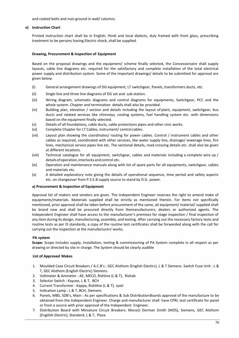
70
and coated bolts and nuts ground in wall/ columns.
e) Instruction Chart
Printed instruction chart shall be in English, Hindi and local dialects, duly framed with front glass, prescribing treatment to be persons having Electric shock, shall be supplied.
Drawing, Procurement & Inspection of Equipment
Based on the proposal drawings and the equipment/ scheme finally selected, the Concessionaire shall supply layouts, cable line diagrams etc. required for the satisfactory and complete installation of the total electrical power supply and distribution system. Some of the important drawings/ details to be submitted for approval are given below.
(i) General arrangement drawings of DG equipment, LT switchgear, Panels, transformers ducts, etc.
(ii) Single line and three line diagrams of DG set and sub-station. (iii) Wiring diagram, schematic diagrams and control diagrams for equipments, Switchgear, PCC and the
whole system. Chapter and termination details shall also be provided. (iv) Building plan, elevation / section and details including the layout of plant, equipment, switchgear, bus
ducts and related services like chimneys, cooling systems, fuel handling system etc. with dimensions based on the equipment finally selected.
(v) Details of all foundations, cable ducts, cable protections pipes and other civic works. (vi) Complete Chapter for LT Cables, instrument/ control cables. (vii) Layout plan showing the coordinates/ routing for power cables. Control / instrument cables and other
cables as required, coordinated with other services, like water supply line, drainage/ sewerage lines, fire lines, mechanical service pipes line etc. The sectional details, road-crossing details etc. shall also be given at different locations.
(viii) Technical catalogue for all equipment, switchgear, cables and materials including a complete wire up / details of operation, interlocks and control etc.
(ix) Operation and maintenance manuals along with list of spare parts for all equipments, switchgear, cables and materials etc.
(x) A detailed explanatory note giving the details of operational sequence, time period and safety aspects etc. on changeover from P.S.E.B supply source to stand by D.G. power.
a) Procurement & Inspection of Equipment
Approval list of makers and vendors are given. The Independent Engineer reserves the right to amend make of equipments/materials. Materials supplied shall be strictly as mentioned therein. For items not specifically mentioned, prior approval shall be taken before procurement of the same, all equipment/ material/ supplied shall be brand new and shall be procured directly from themanufacturers, dealers or authorized agents. The Independent Engineer shall have access to the manufacturer’s premises for stage inspection / final inspection of any item during its design, manufacturing, assembly, and testing. After carrying out the necessary factory tests and routine tests as per IS standards, a copy of the routine test certificates shall be forwarded along with the call for carrying out the inspection at the manufacturers’ works.
PA system Scope: Scope includes supply, Installation, testing & commissioning of PA System complete in all respect as per drawing or directed by site in charge. The System should be clearly audible
List of Approved Makes 1. Moulded Case Circuit Breakers / A.C.B’s : GEC Alsthom (English Electirc), L & T Siemens. Switch Fuse Unit : L &
T, GEC Alsthom (English Electric) Siemens. 2. Voltmeter & Ammeter : AE, MECO, Rishline (L & T), Rishab 3. Selector Switch : Kaycee, L & T, BCH 4. Current Transformer : Kappa, Rishlilne (L & T), Jyoti 5. Indication Lamp : L & T, BCH, Siemens 6. Panels, MBS, SDB’s, Main : As per specifications & Sub Distribution Boards approval of the manufacture to be
obtained from the Independent Engineer. Charge and manufacturer shall have CPRI, test certificate for panel or from a source with prior approval of the Independent Engineer.
7. Distribution Board with Miniature Circuit Breakers: Morarji Dorman Smith (MDS), Siemens, GEC Alsthom (Engilish Electric), Standard, L & T, Plaza.

71
8. XLPE Insulated PVC sheath Armoured cables of 1.1 KV grade as per IS : 1554 : ICL, Fort gloster, CCI(Cable Corporation of India), NICCO, Paramount.
9. FRLS Insulated copper conductor single core standard wires of 650/ 1100 volt grade: National, Finolex, RPG, and FordGloster, Paramount.
10. Switches & Sockets : Anchor, SSK, Havells, MK. 11. Telephone Wire : National, Plaza, Universal, NICCO, Paramount, finolex 12. M.S. Conduit (BIS marked) : BEC, NIC, Steelcraft, AKG 13. Flourescent Light Fixture: Philips, Wipro, Bajaj Incandescent Light fixture. Bajaj, Decon, Philips. 14. Ceiling fan & Cabin fan : Crompton, Bajaj, Usha 15. Earth Leakage Circuit Breajers/RCCB: MDS, GEC Alsthom (English Electric) Datar, L & T/ Hager, Siemans,
Plaza. 16. Diesel Generator Set;Kirloskar, Ashok Leyland, Greaves cotton, Ruston, Stampford. 17. Alternator : Kirlosker, Greaves, Stampford, Jyoti 18. 11 KV Switch gear with VCB/Load break switch: SIEMENS, L & T, B.H.E.L., GEC Alsthom . 19. 11 KV/0.433 KV Transformer: GEC Alsthom B.H.E.L., Bharat Bijle, Kirloskar, Volttas. 20. 11 KV cable: Cable Corporation of Indiameter, Fort Gloster, Industrial Cable Universal Cable, Torrent,
Paramount. 21. Capacitors: L & T, GEC, C & G, Asian 22. H.T. Termination: Xencon (CCI) Raychem, Dension Mahindra & Mahindra. 23. Street light fixture: Philips, Bajaj, Wipro, Crompton. 24. Amplifier: Boss, Ahuja. Bosch. 25. Speaker: Boss, Ahuja, Bosch. 26. LT Panels : Advance, Adlec, Tri Square, Diamond Electric, Sudir Gensets 27. 11 KV HT Panels: Advance, Adlec, Tri Square Note: The above list is indicative but not exhaustive.

72
SCHEDULE –E (See Clause 4.1.3)
APPLICABLE PERMITS
1 Applicable Permits 1.1 The Concessionaire shall obtain, as required under the Applicable Laws, the following Applicable
Permits on or before the Appointed Date, save and except to the extent of a waiver granted by the Confirming Party in accordance with Clause 4.1.3 of the Agreement:
S.No. An Indicative List Agency
( As applicable) 1 Water Connection Local Municipal Body/ Municipal
Corporation / Committee 2 Shifting of Services and Utilities Local Municipal Body/ Municipal
/Corporation / Committee 3 Traffic Management during operation Traffic Police
4 Application for PAN, sales tax and other tax registrations etc.
Concerned Departments of State Govt. and GoI
5 Electricity Connection State Electricity Board/ Corporation
6 Clearance for employing labour-Primary employer Labour Commissioner
7 Clearance for blasting and use of explosives Commissioner of Explosives and Police Department, GoP
8 Employment of migrant labour Labour Commissioner
9 Cutting of Trees MOEF&CC, GoI
10 Licence for hotel, other activities Concerned Departments of GoP and GoI
12 Installation of Lifts/Elevators/Escalators Concerned Departments of GoP
13 Fire safety equipment Police Department
14 Drains and sewers Water & Sanitations Department
15 Boiler and Diesel Generator Set Concerned Department of GoP
16 Labour Camps District Health Officer
17 Working in Night Shifts Police Department, Local Municipal Body/ Municipal Corporation / Committee
18 Re-routing of Buses and other vehicles Dept. Of Transport, GoP Traffic Police,
19 Installation of Bathing Plant PPCB, Inspector of Factories
20 Any other permits or clearance /No Objection Certificates required under Applicable Laws
Concerned Competent Authority

73
SCHEDULE – F (See Clause 9.1)
PERFORMANCE SECURITY PEPSU Road Transport Corporation (PRTC) Patiala,............................. WHEREAS: (A) …………….. (the “Concessionaire”) and PEPSU Road Transport Corporation (PRTC) (Concessioning Authority)
have entered into a Concession Agreement dated …………… (the “Agreement”) whereby the Concessioning Authority is entrusted with Development, Construction, Operation and Maintenance of Bus Terminal cum Commercial Complex atPatialain the State of Punjab on design, build, finance, operate and transfer (“DBFOT”) basis, subject to and in accordance with the provisions of the Agreement.
(B) The Agreement requires the Concessionaire to furnish a Performance Security to the Concessioning Authority in a sum of Rs. **** (Rupees ***** crore) (the “Guarantee Amount”) as security for due and faithful performance of its obligations, under and in accordance with the Agreement, for a period of 180 (one hundred eighty) days beyond the Concession Period as defined in the Agreement).
(C) We, …………………… through our Branch at …………………. (the “Bank”) have agreed to furnish this Bank Guarantee by way of Performance Security.
NOW, THEREFORE, the Bank hereby, unconditionally and irrevocably, guarantees and affirms as follows: 1. The Bank hereby unconditionally and irrevocably guarantees the due and faithful performance of the
Concessionaire’s obligations during the Concession Period and 180 (one hundred eighty) days beyond the Construction Period, under and in accordance with the Agreement, and agrees and undertakes to pay to Concessioning Authority, upon its mere first written demand, and without any demur, reservation, recourse, contest or protest, and without any reference to the Concessionaire, such sum or sums upto an aggregate sum of the Guarantee amount as the Concessioning Authority shall claim, without the Concessioning Authority being required to prove or to show grounds or reasons for its demand and/or for the sum specified therein.
2. A letter from the Concessioning Authority, under the hand of an Officer not below the rank of __________, that the Concessionaire has committed default in the due and faithful performance of all or any of its obligations under and in accordance with the Agreement shall be conclusive, final and binding on the Bank. The Bank further agrees that Concessioning Authority shall be the sole judge as to whether the Concessionaire is in default in due and faithful performance of its obligations during the Construction Period under the Agreement and its decision that the Concessionaire is in default shall be final, and binding on the Bank, notwithstanding any differences between the Concessioning Authority and the Concessionaire, or any dispute between them pending before any court, tribunal, arbitrators or any other authority or body, or by the discharge of the Concessionaire for any reason whatsoever.
3. In order to give effect to this Guarantee, Concessioning Authority shall be entitled to act as if the Bank were the principal debtor and any change in the constitution of the Concessionaire and/or the Bank, whether by their absorption with any other body or corporation or otherwise, shall not in any way or manner affect the liability or obligation of the Bank under this Guarantee.
4. It shall not be necessary, and the Bank hereby waives any necessity, for the Concessioning Authority to proceed against the Concessionaire before presenting to the Bank its demand under this Guarantee.
5. The Concessioning Authority shall have the liberty, without affecting in any manner the liability of the Bank under this Guarantee, to vary at any time, the terms and conditions of the Agreement or to extend the time or period for the compliance with, fulfilment and/or performance of all or any of the obligations of the Concessionaire contained in the Agreement or to postpone for any time, and from time to time, any of the rights and powers exercisable by the Concessioning Authority against the Concessionaire, and either to enforce or forbear from enforcing any of the terms and conditions contained in the Agreement and/or the securities available to the Concessioning Authority, and the Bank shall not be released from its liability and obligation under these presents by any exercise by the Concessioning Authority of the liberty with reference to the matters aforesaid or by reason of time being given to the Concessionaire or any other forbearance, indulgence, act or omission on the part of the Concessioning Authority or of any other matter or thing whatsoever
74
which under any law relating to sureties and guarantors would but for this provision have the effect of releasing the Bank from its liability and obligation under this Guarantee and the Bank hereby waives all of its rights under any such law.
6. This Guarantee is in addition to and not in substitution of any other guarantee or security now or which may hereafter be held by the Concessioning Authority in respect of or relating to the Agreement or for the fulfilment, compliance and/or performance of all or any of the obligations of the Concessionaire under the Agreement.
7. Notwithstanding anything contained hereinbefore, the liability of the Bank under this Guarantee is restricted to the Guarantee Amount and this Guarantee will remain in force until expiry of 180 (one hundred eighty) days beyond the Concession Period and unless a demand or claim in writing is made by Concessioning Authority on the Bank under this Guarantee, no later than 6 (six) months from the date of expiry of this Guarantee, all rights of the Concessioning Authority under this Guarantee shall be forfeited and the Bank shall be relieved from its liabilities hereunder.
8. Left Blank 9. The Bank undertakes not to revoke this Guarantee during its currency, except with the previous
express consent of the Concessioning Authority in writing, and declares and warrants that it has the power to issue this Guarantee and the undersigned has full powers to do so on behalf of the Bank.
10. Any notice by way of request, demand or otherwise hereunder may be sent by post addressed to the Bank at its above referred Branch, which shall be deemed to have been duly authorised to receive such notice and to effect payment thereof forthwith, and if sent by post it shall be deemed to have been given at the time when it ought to have been delivered in due course of post and in proving such notice, when given by post, it shall be sufficient to prove that the envelope containing the notice was posted and a certificate signed by an officer of the Concessioning Authority that the envelope was so posted shall be conclusive.
11. This Guarantee shall come into force with immediate effect and shall remain in force and effect for a period of _ _ _ _ _ _ _ _ _ _ _ _ or until it is released earlier by Concessioning Authority pursuant to the provisions of the Agreement Signed and sealed this …………. day of …... 20………. at ……….
SIGNED, SEALED AND DELIVERED For and on behalf of the BANK by:
(Signature)
(Name) (Designation) (Code Number)
(Address)
NOTES: (i) The bank guarantee should contain the name, designation and code number of the officer(s) signing the
guarantee. (ii) The address, telephone number and other details of the Head Office of the Bank as well as of issuing
Branch should be mentioned on the covering letter of issuing Branch.

75
SCHEDULE –G (See Clause 12.1)
PROJECT COMPLETION SCHEDULE
1 Project Completion Schedule – Bus Terminal During Construction Period, the Concessionaire shall comply with the requirements set forth in this Schedule-G
for each of the Project Milestones and the Schedule Completion Date (the “Project Completion Schedule”). Within 15 (fifteen) days of the date of each Project Milestone, the Concessionaire shall notify the Concessioning Authority of such compliance along with necessary particulars thereof. For the avoidance of doubt, it is agreed that the provisions of this schedule for Commercial Complex component shall be as per clause 8 (below) .
2. Project Milestone-I 2.1 Project Milestone –I shall occur on the date falling on the 120th (one hundred and twentieth) day from the
Appointed Date (the “Project Milestone-I”). 2.2 Prior to the occurrence of Project Milestone-I, the Concessionaire shall have commenced the construction of the
Project and expended not less than 15% (fifteen per cent) of the total capital cost set forth in the Financial Package towards bus terminal component of Project.
3. Project Milestone-II 3.1 Project Milestone-II shall occur on the date falling on the 270th (two hundred and seventieth) day from the
Appointed Date (the “Project Milestone-II”). 3.2 Prior to the occurrence of Project Milestone-II, the Concessionaire shall have expended not less than 45%
(fourty five per cent) of the total capital cost set forth in the Financial Package towards bus terminal component of Project..
4. Project Milestone – III 4.1 Project Milestone-III shall occur on the date falling on the 365th (three hundred and sixty fifth) day from the
Appointed Date (the “Project Milestone-III”). 4.2 Prior to the occurrence of Project Milestone-III, the Concessionaire shall have expended not less than 75%
(seventy-five per cent) of the total capital cost set forth in the Financial Package towards bus terminal component of Project.
5. Scheduled Project Completion Date 5.1 The Scheduled Project Completion Date shall occur on the 550th (five hundred and fiftieth) day from the
Appointed Date. 5.2 On or before the Scheduled Project Completion Date, the Concessionaire shall have completed Bus Terminal
component in accordance with this Agreement.
6 Extension of period
Upon extension of any or all of the aforesaid Project Milestones or the Scheduled Completion Date, as the case may be, under and in accordance with the provisions of this agreement, the Project Completion Schedule shall be deemed to have been amended accordingly.
7. Delay in Completing Bus Terminal
In the event that the Bus Terminal Component of project is not completed within 90 (ninety) days from its Scheduled Project Completion Date, unless delay is on account of reasons solely attributable to the Concessioning Authority or due to Force Majeure, the Concessioning Authority shall be entitled to terminate this Agreement.
8. Project Completion Schedule – Commercial Complex 8.1 Scheduled Project Completion Date - Commercial Complex shall occur on the 1100th (eleven hundred) day from
the Appointed Date.

76
8.2 On or before the Scheduled Project Completion Date - Commercial Complex, the Concessionaire shall have completed minimum covered buil-up area as stipulated in Schedule-B, in accordance with this Agreement.
8.3 In the event that the Concessionaire fails to achieve the Scheduled Project Completion Date - Commercial Complex, as per clause 8(a) above, unless such failure has occurred due to Force Majeure or for reasons solely attributable to the Concessioning Authority, it shall pay Damages to the Concessioning Authority in a sum calculated at the rate of 0.1% (zero point one per cent) of the amount of Performance Security for delay of each day until Scheduled Project Completion Date - Commercial Complex is achieved; provided that if the Scheduled Completion Date - Commercial Complex are extended in accordance with the provisions of this Agreement, the dates set forth in clause 8(a) above, shall be deemed to be modified accordingly.

77
SCHEDULE-H
DRAWINGS
1. Approved Layout Plan of the Project Site shall be enclosed with this Concession Agreement.
2. Architectural drawings and Structural drawings of the Project at the Project Site.
3. Any other pertinent drawings and detailing to facilitate operation and maintenance of systems and services at Project Site.
4. Operating and Maintenance Manuals for the equipment and services as provided and installed at the Project Site.

78
SCHEDULE-I (See Clause 14.1.2)
TESTS 1. Schedule for Tests 1.1 The Concessionaire shall, no later than 30 (thirty) days prior to the likely completion of Project (i.e. Bus
Terminal) at Project Site, notify the Independent Engineer and the Concessioning Authority of its intent to subject the Project to Tests, and no later than 7 (seven) days prior to the actual date of Tests, furnish to the Independent Engineer and the Concessioning Authority detailed inventory and particulars of all works and equipment forming part of Project.
1.2 The Concessionaire shall notify the Independent Engineer of its readiness to subject the Project to Tests at any time after 7 (seven) days from the date of such notice, and upon receipt of such notice, the Independent Engineer shall, in consultation with the Concessionaire, determine the date and time for each Test and notify the same to the Concessioning Authority who may designate its representative to witness the Tests. The Independent Engineer shall thereupon conduct the Tests itself or cause any of the Tests to be conducted in accordance with Article 14 and this Schedule-I.
2. Tests 2.1 Visual and physical Test: The Independent Engineer shall conduct a visual and physical check of all type of
equipment as installed at the Project Site to determine that all works and equipment forming part thereof conform to the provisions of this Agreement.
2.2 Test drive: The Independent Engineer shall undertake a test drive of the Project Site by a Car to determine that the quality of service conforms to the provisions of the Agreement.
2.3 Riding quality Test: Riding quality of each lane of the Bus Bay Areas and other parts of the Project, where the Buses, Cars, Taxi etc would be driven or halted shall be checked with the help of a calibrated bump integrator and the maximum permissible roughness for purposes of this Test shall be 2000 (two thousand) mm for each kilometer.
2.4 Pavement Composition Test: The thickness and composition of the pavement structure shall be checked on a sample basis by digging pits to determine conformity of such pavement structure with Specifications and Standards. The sample shall consist of one pit in each direction of travel to be chosen at random in each stretch of 3 (three) kilometres of the Project. The first pit for the sample shall be selected by the Independent Engineer through an open draw of lots and every third kilometer from such first pit shall form part of the sample for this pavement quality test.
2.5 Left Blank 2.6 Structural Test: All the structures constructed by the Concessionaire shall be subjected to the Rebound
Hammer and ultrasonic Pulse Velocity tests, to be conducted in accordance with the procedure described in consultation with the Independent Engineer.
2.7 Other Tests: The Independent Engineer may require the Concessionaire to carry out or cause to be carried additional Tests, in accordance with Good Industry Practice, for determining the compliance of the Project with Specifications and Standards.
2.8 Environmental audit: The Independent Engineer shall carry out a check to determine conformity of the Project with the environmental requirements set forth in Applicable Laws and Applicable Permits.
2.9 Safety review: Safety audit of the Project shall have been undertaken by the Independent Engineer as set forth in Schedule-L, and on the basis of such audit, the Independent Engineer shall determine conformity of the Project with the provisions of this Agreement.
2.10 It shall also include any other tests and audits including that as may be prescribed by the Concessioning Authority to assure that the Project is fully conforming to, meets with standards, Specifications, requirements and functional aspects as described in detail in Schedule-D to this Agreement. 2.11 The Concessioning Authority shall examine and check the adequacy and competency of the human resources as deployed to their satisfaction.
3. Agency for conducting Tests All tests set forth in this Schedule-I shall be conducted by the Independent Engineer in association with Concessioning Authority or such other agency or person as it may specify.
4. Completion / Provisional Certificate Upon successful completion of Tests, the Independent Engineer shall issue the Completion Certificate or the Provisional Certificate, as the case may be, in accordance with the provisions of Article 14.

79
SCHEDULE-J (See Clause 14.2 & 14.3)
COMPLETION CERTIFICATE 1 I, ……………………..(Name of the Independent Engineer), acting as Independent Engineer, under and in
accordance with the Concession Agreement dated …………….(the “Agreement”), for Development of Bus Terminal cum Commercial Complex atPatialain the State of Punjab (the “Project”) on design, build, finance, operate and transfer (DBFOT) basis, through …………………………….(Name of Concessionaire), hereby certify that the Tests specified in Article 14 and Schedule-I of the Agreement have been successfully undertaken to determine compliance of the Project with the provisions of the Agreement, and I am satisfied that the Project can be safely and reliably placed in commercial service of the Users thereof.
2 It is certified that, in terms of the aforesaid Agreement, all works and services forming part of development of Project have been completed, and the Project is hereby declared fit for entry into commercial operation on this the ……..day of ………..20…. .
SIGNED, SELAED AND DELIVERED
For and on behalf of INDEPENDENT ENGINEER by: (Signature) (Name) (Designation) (Address)
PROVISIONAL CERTIFICATE 1. I/We,____________________ (Name of the Independent Engineer), acting as Independent Engineer, under
and in accordance with the Concession Agreement dated…………..(the “Agreement”), for Development of Bus Terminal cum Commercial Complex atPatialain the State of Punjab (the “Project”) on design, build, finance, operate and transfer (DBFOT) basis through …………………… (Name of Concessionaire), hereby certify that the Tests specified in Article 14 and Schedule-I of the Agreement have been undertaken to determine compliance of the Project with the provisions of the Agreement.
2. The Construction and development Works that were found to be incomplete and/or deficient have been
specified in the Punch List appended hereto, and the Concessionaire has agreed and accepted that it shall complete and /or rectify all such works in the time and manner set forth in the agreement. [Some of the incomplete works have been delayed as a result of reasons attributable to the Concessioning Authority or due to Force Majeure and the Provisional Certificate cannot be withheld on this Account. Though the remaining incomplete works have been delayed as a result of reasons attributable to the Concessionaire,] I am satisfied that having regard to the nature and extent of such incomplete works, it would not be prudent to withhold commercial operation of the Project, pending completion thereof.
3. In view of the foregoing, I am satisfied that the Project can be safely and reliably placed in commercial service
of the Users thereof, and in terms of the Agreement, the Project is herby provisionally declared fit for entry into commercial operation on this the …….day of ……..20….
ACCEPTED, SIGNED, SEALED AND DELIVERED For and on Behalf of CONCESSIONAIRE by: (Signature) (Name and Designation) (Address)
SIGNED, SELAED AND DELIVERED For and on behalf INDEPENDENT INDEPENDENT ENGINEER by: (Signature) (Name and Designation) (Address)

80
SCHEDULE-K (See Clause 17.2)
MAINTENANCE REQUIREMENTS
1. Maintenance Requirements 1.1 The Concessionaire shall, at all times, operate and maintain the Project and Project Site in accordance with
the provisions of the Agreements, Applicable Laws and Applicable Permits. In particular, the Concessionaire shall, at all times during the Operation Period, conform to the maintenance requirements set forth in this Schedule-K (the “Maintenance Requirements”).
1.2 The Concessionaire shall repair or rectify any defect or deficiency set forth in Paragraph 2 of this Schedule-K
within the time limit specified therein and any failure in this behalf shall constitute a breach of the Agreement. Upon occurrence of any breach hereunder, the Concessioning Authority shall be entitled to recover Damages as set forth in Clause 17.8 of the Agreement, without prejudice to the rights of the Concessioning Authority under the Agreement, including Termination thereof.
2. Repair/rectification of defects and deficiencies The obligations of the Concessionaire in respect of Maintenance Requirements shall include repair and rectification of defects and deficiencies specified in Annex-I of the Schedule-K within the time limit set forth therein.
3 Other defects and deficiencies 3.1 In respect of any defect or deficiency not specified in Annex-I of this Schedule-K, the Concessionaire shall
undertake repair or rectification in accordance with Good Industry Practice. 3.2 In respect of any defect or deficiency not specified in Annex-I of this Schedule-K, the Independent Engineer
may, in conformity with Good Industry Practice, specify the permissible limit of deviation or deterioration with reference to the Specifications and Standards, and any deviation or deterioration beyond the permissible limit shall be repaired or rectified by the Concessionaire within the time limit specified by the Independent Engineer.
4. Extension of time limit Notwithstanding anything to the contrary specified in this Schedule-K, if the nature and extent of any defect or deficiency justifies more time for its repair or rectification than the time specified herein, the Concessionaire shall be entitled to additional time in conformity with Good Industry Practice. Such additional time shall be determined by the Independent Engineer and conveyed to the Concessionaire and the Concessioning Authority with reasons thereof.
5. Emergency repairs/ restoration Notwithstanding anything to the contrary contained in this Schedule-K, if any defect, deficiency or deterioration in the Project poses a hazard to safety or risk of damage to property, the Concessionaire shall promptly take all reasonable measures for eliminating or minimising such danger.
6. Daily Inspection by the Concessionaire The Concessionaire shall, through its Independent Engineer, undertake a daily visual inspection of the Project and maintain a record thereof in a register to be kept in such form and manner as the Independent Engineer may specify. Such record shall be kept in safe custody of the Concessionaire and shall be open to inspection by the Concessioning Authority and the Independent Engineer at any time during office hours.
7. Divestment Requirement All defects and deficiencies specified in this Schedule-K shall be repaired and rectified by the Concessionaire so that the Project conforms to the Maintenance requirements on the Transfer Date.

81
Annex-I (Schedule-K)
Repair / Rectification of Defects and Deficiencies The O & M of Bus Terminal-cum-Commercial Complex premises shall be carried out to maintain the performance standards, which shall comprise, but shall not be limited to that described below. The performance levels define the level at which the Project is to be operated & maintained. Performance standards are defined for both the operation and maintenance. The obligation of the Concessionaire with respect to Maintenance requirements shall include the rectification of the defects and deficiencies specified below within the time limit set forth against such deficiency or defect. Notwithstanding anything contrary to specified in this schedule, if the nature and extent of any defect justifies more time for its repair or rectification as compared to time specified herein, the Concessionaire shall be entitled to additional time in conformity with good industry practice. However, the Concessionaire shall get prior approval from the Concessioning Authority, for such additional requirement of time. Notwithstanding anything to the contrary contained in this schedule, if any defect, deficiency or deterioration in the Project poses danger to the life and property of the Users thereof, the Concessionaire shall promptly take all reasonable measures in consultation with Concessioning Authority for elimination or minimizing such danger.
1. Performance Standard for Operations
The operations management shall include the following operations:
1. Regular Operations 2. Emergency Operations
1.1 Regular Operations
Regular operations include the following: a. Permitting smooth and uninterrupted flow of traffic during normal operating conditions. b. Functioning of the Adda Fees collection system including charging and collecting the Fees from the bus
Concessionaires c. Functioning of the passenger amenities and the parking facilities. d. Functioning of the various building services and estate services. e. Traffic management within the Bus Terminal during routine and periodic maintenance.
Concessionaire shall adhere to the following Performance Indicators:
Component Operation Performance Indicator Bus Terminal
The bus traffic has to be managed very efficiently especially during the peak hours of the day along with the passenger traffic to ensure that the buses get the desired service time at the alighting and boarding bays. The arrival and departure of the buses shall be as per the bus timetable issued by the Concessioning Authority. The Concessionaire shall adhere to the issued bus timetable. The buses shall occupy the proper designated bay in the respective terminal as per the bus timetable. The bus bays shall be allocated for the various routes. It shall be ensured that the bus circulation is not in conflict with other vehicular or passenger/pedestrian movement while at entry and exit from the bus terminal.
To remain operational 24 hours a day throughout the year.
Adda Fees collection The Concessionaire shall ensure that the There shall be 24 hours staffing

82
system queue of buses at the Adda Fees counter at any point of time shall not be more than 4 numbers and the total waiting time for a bus at the collection counter shall not be more than 60 seconds. Any failure in the Adda Fees collection mechanism (computers, printers, related software’s etc.) shall be rectified/ replaced within 6 hours. The barrier gates shall be automatically operated. The barriers shall be opened after identification of ‘Smart Card’ through remote sensors or touch pads etc. There shall also be computerized cash registering systems for printing/issuing and accounting of tickets. The Adda Fees ticket shall bear the registration number, Concessionaire’s name and entry/exit time of the bus. Daily backup/record of the Adda Fees collection data shall be taken in a central server. The computers/cash register system shall have an uninterrupted power supply backup of at least 30 minutes. It should have connectivity to the standby generator at all times. There shall be at least one telephone/communication facility at each Adda Fees counter.
with supervisors for Adda Fees collection.
Number of buses in queue at each Adda Fees counter
Not more than 4 buses
Information System, Display Boards, Public Address System
The announcements and displays of the bus routes, arrivals and departures shall be clear, legible, audible and updated. Any change in the bus timetable, fares, routes etc. shall be immediately updated on the respective display, information boards.
The digital display items shall remain operational for passenger convenience 24 hours a day throughout the year.
Enquiry /Reservation Counter
The enquiry counter of the respective bus operators shall remain operational for 16 hours in a day with staff in two shifts throughout the year for the public.
Enquiry counter remains operational for 16 hours (5.00A.M-9.00P.M) a day throughout the year.
Waiting Halls, Toilet Blocks and Water Chambers
The passenger traffic has to be managed very efficiently especially during the peak hours of the day to ensure that the passengers get the desired level of service and comfort.
It shall remain operational 24 hours a day, throughout the year in the bus terminal for the public.
Parking Area
The Concessionaire has to ensure that the vehicles are parked at the designated parking areas for each category of vehicles and also ensure ease of entry/ exit of vehicles.
The parking area shall be open to the private and IPT vehicles for 24 hours throughout the year. There shall be 24 hours staffing for parking fee collection.
Security A closed circuit system shall be strategically installed to keep track of pickpockets, thieves & general surveillance of the project facility. Dome Cameras with 360 Degree revolving angle as well as fix focused telescopic cameras shall be installed, apart from manual security, to monitor various activities of the bus terminal from a control room. All the entrances of the bus terminal
The Project facility security staff shall be on duty and all equipments related to security/surveillance of the project facility shall be operational, for 24 hours throughout the year.

83
complex as well as the total Project facility shall be equipped with x-ray machines or other such security check systems to ensure the safety of the passengers/general public as well as the building of the facility. Concessionaire shall make the Employ security staff to ensure safe operations during day and night. They shall adequately guard the Project facilities and keep a strict vigil on the passenger movements.
Water Supply Water Supply shall be available for 24 hours at all the desired places like toilets, waiting halls, rest rooms, shops, other commercial facilities, fire fighting tank (if any), drinking water chambers, offices and canteen kitchen of the project facility.
Toilets Already covered above To remain operational 24 hours a day throughout the year.
Waiting Hall Already covered above To remain operational 24 hours a day throughout the year.
Electricity and Lighting
Electricity shall be available for 24 hours.
Standby Generator Sets
Standby generator sets to supply power to the project facility must be available at all times in case of disruption or breakdown in power supply.
Telecommunication and Networking Equipments
These shall remain functional throughout to ensure and maintain interconnectivity between the various components of the project facility.
Bus Terminal Operation and Maintenance Office
This shall remain open for 12 hours (8:00 AM – 8:00 PM) a day and throughout the year to ensure the supervisory functioning of the regular operations of the bus terminal.
Rest /Waiting rooms for running crew
These shall remain functional for 24 hours a day and throughout the year along with designated toilets
1.2 Emergency Operations
The Concessionaire shall be responsible for minimizing disruption to the traffic in the event of accidents/ breakdowns and/or incidents affecting the safety and use of the Project by providing adequate warnings, informatory signs etc. and by maintaining liaison procedures with emergency services. This is achieved by the provision of the following:
(a) Declare a state of emergency and inform the Concessioning Authority. (b) Remove passengers from the affected area. (c) Co-ordinate with the emergency services and informing them about the situation. (d) Reorganize the operations with proper information, sufficient number or warning, regulatory,
information signs, displays or temporary change in bus circulation or passenger circulation. (e) Attend to the affected area using manpower, machinery at Concessionaire’s disposal. (f) Clear the affected site and arrange for repairs.

84
(g) Make a report of the incident to the Independent Engineer and Concessioning Authority.
The Concessionaire shall evolve a comprehensive recovery plan for the restoration of the breakdown in the operations. The plan must be documented by record keeping procedures. The recovery plan shall include the following components:
(a) Identify and prioritize essential facility functions for recovery. (b) Procedures for repairs / rebuilding / modifications, if any (c) Contingencies for alternate data processing / protection of vital records. (d) Identify possible alternative traffic circulation / parking plans. (e) Documentation process for after action reports.
Liasoning with the nearby emergency services such as trauma centers, hospitals, police station, fire brigade office.
2.0 Performance Standards for Maintenance 2.1 Routine Maintenance Performance Standards
S. No.
Serviceability Indicator Required Maintenance Level
Permissible Time Limit for repairs/rectifications
Civil Works 1 Potholes in the pavement
(any cavity of diameter more than 150mm and depth 25 mm or more)
Maximum 3 numbers in the bus circulation, roads and bay area
Potholes shall be repaired within 7 days after their detection
2 Cracks more than 3 mm wide in the pavement
Maximum 5.0% in the vehicular circulation and bus bay area
Cracks must be sealed within 7 days after their detection by pressure grouting or guniting.
3 Rutting in the pavement (Any longitudinal depression measured using 2m straight edge shall not exceed 20 mm)
Maximum 1.0% in the vehicular circulation and bus bay area
Rutting shall be repaired within 15 days after their detection.
4. Cracks in building, roofs, terraces, walls and water tanks
Cracks shall be repaired within 7 days after their detection
5 Worn out areas, holes in floors, damaged edges and joints of concrete/ cement works
Shall be repaired within 15 days after their detection
6. Boundary Walls Any damage/ breach to the boundary wall of the project facility shall be rectified within three (3) days after their detection.
7 Walls shall be clean without any paint wearing.
No stains, splits, weathered paint to be left exposed
Any stains, splits, weathered paint on the walls of the project facility shall be cleaned within 2 days
8 Pavement Surface shall be clean, without debris
Nil Soil debris, trash and other objects on the surface shall be removed within 2 hours
9 Flooring, skirting, dado finishes should be intact
Maximum 5% per 1000 sqm area
Any damaged, missing, crack tiles in Flooring, Skirting, Dado finishes shall be repaired, replaced within seven days of detection
10. Joints in Cement Concrete Pavement
Maximum 60 cm length in any pavement panel.
To be prepared within 24 hours by special gum.
11. Distress Cement Concrete Pavement
Cracking/ settlement exceeding 5 mm
The distressed panel to be replaced within 30 days.

85
12. Public Concourse Enclosure No signs of distress To be replaced within 7 days in case of any damage
13. Staircases shall be clean and functional
Nil The staircases shall be cleaned at least twice a day. Damaged handrails, risers or treads shall be repaired within seven days after detection.
14. Cracks, spalling / scaling, blistering of plaster and damages to walls or façade
Maximum 5% per 1000 sqm area
Shall be rectified within 15 days.
15. Damages to painting and finishes
Maximum 5% per 1000 sqm area
Timely intervention as and when necessary to maintain façade beauty.
16. Traffic/directional signs, road/pavement markings shall be visible and legible
Nil Any damages/ wearing shall be repaired and rectified within three days. The damaged and missing signs shall be replaced within fifteen days.
Roof Inspection
1. Vegetation growing on the roof
Timely intervention. Cut any vegetation growing on the roof and fill concrete cement and mortar in that gap.
2. Vibration in roof sheeting due to windstorm.
Any noises due to vibration of roof sheeting shall be rectified within 3 days
3. Check for cans, bottles, leaves, rags, debris etc on the roof
Clear and sweep every month; before monsoons and during monsoons at closer interval.
Water Supply and Sanitation 1. All drinking water chambers
shall be cleaned and functional
A minimum of 95% drinking water chambers shall be functional
These shall be cleaned daily. Water supply shall be maintained for 24 hours. Drinking water quality in all the seasons shall be as per WHO standards. These chambers shall be cleaned after every six hours. Any damaged fixtures or tiles in the water chambers shall be replaced, repaired within seven days of detection.
2. Water supply pumps, pressure vessels and related components.
Maintained as per manuals furnished by manufacturers/ original installation contractors.
3. Water valves and conveyance network (pipes).
Do away with leakages within 3 days and blockages within 24 hours. Check the water pressure regularly.
4. Clean and disinfect underground and overhead tanks.
Ensure that there is no deposition of sediments, organic/ pathogenic growth.
Cleaning of water tanks should be done every month.
5. Sanitary fittings A minimum of 95% toilets and urinals shall be functional
All toilets shall be cleaned, using disinfectants, properly every 4 hours from 5.00 am to 9.00 pm. Ensure that all sanitary fittings are intact and in running condition. All leakages from the taps, flush cistern or pipes should be stopped within 24 hours. Ensure that washbasin and sanitary fittings should not get chocked at any point of time. Damaged toilets and urinal pots, washbasins, cisterns, mirrors, taps shall be replaced with the new one of the same specification within seven days of detection. Non-functional toilets, Urinals, bathrooms shall be demarked with suitable signboards.

86
6 External Drainage System shall be functional free from clogging
Nil Obstructions must be cleared within two days after detection. Damages must be repaired within seven days after detection by reconstructing to the adequate shape and size. De-silting operations should be done once in a six months time with minor repairs if needed. During Monsoon, any blocked vent ways shall be cleaned immediately. All filth or any other offensive matter met during the cleaning shall be disposed off properly but in no case allowed to collect/ accumulate in the campus. All gratings and covers should be in place at all times and during regular maintenance operation should be kept out of bound from users.
7. Water Logging in common areas (passenger concourse, commercial complex, toilets, bathrooms, tap points etc.)
Timely intervention. Nowhere in the common area any form of water (drinking/ washing and sewage) should be allowed to be collected at any time. Temporary restoration within four hours and permanent restoration within 24 hours.
8. Solid Waste A minimum of 95% Dustbins, spittoons shall be functional
To prevent any refuse or solid waste from being deposited on or in the premises (other than at the refuse collection points/bins (trash or garbage collector provided for such purpose) and to arrange for its disposal daily to secondary collection centres or designated disposal site. Closed plastic litter bins of about 30-40 litres capacity would be provided in the bus terminal as ‘community bins’ with handles on the top or on the sides, which would be used by the commuters, visitors and the tenants of the project facility. These bins would be located at regular intervals (about 50 meters). The dustbin shall be emptied after every six hours or earlier if it is full or if creates foul smell in the neighbourhoodneighbourhood
ELECTRICAL
1 Power Supply Any disruption in power supply shall be rectified in six hours. Standby power supply by DG sets shall be ready to be operated and should be available 24 hours. In no case power supply to common areas (passenger concourse, toilets, staircases etc.) shall be stopped for more than 2 minutes during night time and 5 minutes during daytime.
2 Electrical rooms, electrical equipments in public areas
Inspect daily to ensure that these areas are locked at all times and limited access is provided to authorized person only.
3. Cables and wires Inspect every week to see cable and wire connections are insulated, clean and

87
firm/intact. 4. Electric Meter Check all meters once in a month time to
ensure that they are functioning and are showing correct readings.
5. Light fittings, includes fluorescent, incandescent, high and or low-pressure sodium, mercury vapour and normal bulbs.
A minimum of 95% light fittings and fixtures shall be functional. Required level of illumination as per Norms and Specified standards shall be followed and maintained
Temporary measures within 4 hours. Permanent restoration within 3 days. Replacement of lamps and allied fixtures should be carried out promptly.
6. Switchgear, motor control centres and circuit breaker panels
Ensure that all switchgears, motor control centres and circuit breaker panels are in a good condition. Timely intervention with temporary measures within 4 hours, permanent restoration within 7 days, depending on nature and intensity of work required as decided by the Concessioning Authority and any faulty equipment should be replaced with the same specification equipment.
7. Other electrical equipments like switches, receptacles, wiring, conduit, junction boxes, lighting protection equipment etc
A minimum of 95% of fittings and fixtures shall be functional
Replace faulty electrical equipments, if required, with the same specification within 24 hours after detection.
8. All Information Signages and Display Boards shall be visible, legible and functional
Maximum 2% number of damaged signages and boards
These shall be cleaned once in a week. Damaged signages and boards shall be replaced, repaired within seven days of their detection
9. Public Address System Minimum of 95% of the public address system components should be functional.
Regular inspection and maintenance of public address system to ensure its functionality at all times. In case of any fault, temporary measures should be taken within 4 hours and permanent restoration within 7 days
10. Earthing System Proper Earthing System shall be installed as per standards specified and maintained
Regular maintenance of earthing system to ensure earth continuity at all points in the electrical system upto the main distribution board in each module.
11. Pumps The Concessionaire shall ensure that there shouldn’t be any leaking at mechanical seal. Also check the coupling for alignment and make sure that mounting bolts are secure. Check gauges for proper operation. Also check bearing temperature/s, whether any undue noise or vibration is observed and readings of pressure, voltage and current. Any defects in pumps should be given priority and temporary restoration should take place within six hours and permanent restoration within three days.
VENTILATION AND LIGHTING
1. Lighting shall be functional The ventilators, sky-lits etc. serving as source of natural ventilation and other

88
lighting shall be cleaned once in seven days
2 Natural and Mechanical Ventilation.
Any disruption to mechanical ventilation, if provided shall be rectified within 24 hours. Sky-lits, ventilators, shafts etc shall be cleaned after every 15 days. Minimize noise level of the ventilation system through regular greasing of parts and machinery and ensure that there is no excessive vibration.
CARPENTARY AND RELATED SERVICES 1. Seating arrangements shall
not be damaged Maximum 5% number of damaged seats
Any damaged seat shall be repaired, replaced within three days of detection. These shall be cleaned 6 times daily and checked that they are firmly fixed/grouted to the platform with the base.
2. Other wooden furniture like almirah, office tables, chairs, shelf etc.
Any damaged wooden furniture shall be repaired, replaced within seven days of detection.
3. Anti-termite treatment Take proactive action in order to save the wooden furniture and structure from termite attack. Antitermite treatment should take place at regular interval (once in a month time)
4. Maintenance of Doors and Windows
Any loose hinges of the doors and windows should be taken care off immediately after their detection. If window glass are making sound or vibrating in the windy atmosphere then make sure that there should be no gap between the beading and glass. Any broken glass should be replaced within 3 days.
5. Holes and depression in the wooden structure
Any holes and depression in the wooden structure should be immediately filled with epoxy putty after their detection.
6. Servicing of rolling shutter Regular maintenance of rolling shutter to ensure reduction in noise from opening and closing of the shutter. If rolling shutter is not functioning then replace the defective spring or/ gear mechanism within seven days.
MISCELLANEOUS
1. Telecommunication and Networking Systems shall be functional
Temporary measures within 8 hours, and permanent restoration within 3 days
2. Adda Fees Collection Booth shall be clean with proper services
Shall be cleaned daily. No disruption in building services like lighting, electricity, telecommunication. Display Boards shall be legible and clear.
3. Adda Fees Collection Systems shall be functional
Any failure in the Adda Fees collection mechanism (computers, printers, related softwares etc.) shall be rectified within 6 hours. There shall be computerized cash registering systems for printing/issuing and accounting of tickets. The Adda Fees ticket shall bear the registration number,

89
Concessionaire’s name and exit time of the bus. Daily backup/record of the Adda Fees collection data shall be taken.
4. Barriers shall be functional Any failure in the functioning of the barriers shall be rectified within 6 hours.
5. Defects in all other utilities like water supply/tap/tap connections/pipe/sewer and drainage pipes/tanks & overflow/glasses/window panes/all other building furniture
Timely intervention with temporary measures within 8 hours, permanent restoration within 7 days, depending on nature and intensity of work required.
6. Complaint Register shall be functional
Shall be available in the Bus Terminal Supervisor’s office at all the times. The Complaint register shall be produced before the Concessioning Authority as and when asked for.
7. Security Provide security system and adequate security staff, as per Concession Agreement, so as to ensure safety of project facility and masses, especially women and children.
8. Rodents/ Pest Control Routine disinfections, once in 15 days time, by usage of chemicals of all common areas to maintain hygiene and prevent any air or water borne diseases. Special care should be taken during rainy/monsoon or any other season when the incidence of epidemics are more.
9. Fire Detection, Fire Alarm and Fire Fighting System
Shall be functional at all times. Defective detectors shall be replaced within 24 hours. Designed water pressure shall be maintained in the fire fighting system at all times and any leakage shall be checked within 24 hours.
10. Air Conditioning (HVAC) System
The system shall be operational and functional at all times meeting the designed parameters. Failure of any components shall be restored within 3 hours. Mechanical Ventilation in Toilets shall be repaired within 3 hours.
Periodic/Preventive Maintenance
Apart from the routine maintenance works, the following periodic maintenance works shall be done in the Bus Terminal. All preventive maintenance work should be listed and the time of their execution should be planned beforehand at the beginning of year. For periodic maintenance, a register should be maintained and for each periodic maintenance work, some pages should be allotted. An index should be made in the beginning of the register where each preventive maintenance work is listed with the page numbers and its details.
Further periodic maintenance work should be so organized that there is little inconvenience to the commuters/ users, office occupants in areas, bus movement or disruption of any activity related to the bus terminal.
2.3 Preventive Maintenance Performance Standard

90
Periodic Maintenance Activities Time Limit for Maintenance/Renewal Repainting traffic markings (thermo plastic point.
Once in three years or early if worn out and not visible
Repainting of Bus Terminal building and all other structures.
Once in three years
Repainting/spirit polish of carpentry work like joinery, doors, windows, ventilators, wooden furniture etc in the offices, cabins, booths etc.
Once in three years
Painting external surface with water proofing cement paint
Once in three years
Cleaning and disinfecting of water storage/ distribution tanks, water mains
Once in a month
Cleaning of manholes/ gully chambers/ inspection chambers and flushing of building sewers
Once in a six months time
Polishing wooden doors/ windows with spirit polish/ polish/ synthetic acrylic polish
Once in three years
Cleaning electrical installations, fans etc Once in a year or as per manufacturer’s installation, operation and maintenance instruction manual.
Collection of water samples for physical, chemical and bacteriological analysis of water
Once every fifteen days
Painting of external steel structures Once in a three years Painting of all pipes above the ground level Once in a three years Painting of cooler window frames and grills, if any
Once in a year
Polishing of flooring Once in three years Mechanical Equipments Once in a year or as per manufacturer’s operation
and maintenance instruction manual Roof Inspection Once in a year and before monsoon to see and repair
whether roof drainage is functioning properly. Also check for presence of leaks and historical information for leaks during long continued rain, leaks occurring every rain etc. Check exposure of bituminous coating due to loose or missing gravel or slag and fix it on an annual basis. Also check all flashing for wind damage, loss of bituminous coating, loose seams and edges, damaged caulking and curling, and exposed edges.
Water proofing of roofs, terraces and tanks Once in three years Exterior coatings (water proofing) on walls Once in three years Transparent water proofing coating of tiles like mosaic, Dholpur, marble etc
Once in three years
Water proofing of interior walls and interior ceilings
Once in three years
Damp proofing of toilets Once in three years Pumps Annual maintenance, which includes:
1. Cleaning and examination of all bearings for flaws developed.
2. Examination of shaft sleeves for wear or scour
3. Impeller hubs and vane tips to be checked for any pitting or erosion
4. All instruments and flaw meters to be recalibrated
5. End play of all bearings to be checked. Analogous addressable fire detection, fire alarm and fire fighting system
Once in a year including conducting of mock drill
Air Conditioning (HVAC) system Once in a year with cleaning of filters at regular interval.

91
2.4 Major Maintenance Work The Concessionaire shall be responsible at his own cost, for all maintenance and repairs of the project facility and all its components including, building, roads, pavements, buildings, toll plaza, allied works etc.
The above and the other necessary standards shall conform to norms as laid out in Bihar Motor Vehicles Rules 1989 and other relevant BIS codes/IS codes/NBC codes for functional requirements of buildings etc. The performance standards shall match the service standard of comparable International practice for buildings.
2.5 Maintenance of Commercial Complex
The Concessionaire shall be responsible, at his cost, for all maintenance and repair works of the commercial complex including that of services as per provision of relevant BIS codes, National Building Code etc. to meet the functional requirement and to maintain aesthetics of the Complex, and campus as a whole. The equipment, appliances, facilities and services shall be operational at all times. The Concessioning Authority shall have the right to inspect the Complex at any time to deserve the standards extent of maintenance.
However before taking back the Complex, on termination of the Concession Agreement, the Complex shall be inspected by the representative of Concessioning Authority and or /Independent Engineer and representative of Concessioning Authority and or /Independent Engineer three months prior to the expiry date and furnish the Inspection Report detailing out the defects, deficiencies in the building, services and facilities for which necessary measures are to be taken by the Concessionaire and copy of the Report shall be submitted to Authority. The Concessionaire shall undertake the requisite measures 15 days prior to the date of termination of the Concession Agreement to the entire satisfaction of the Independent Engineers and Independent Engineer. It is to be understood that Buildings to be taken over by Authority shall be structurally sound, finishing as per acceptable standards, services are fully functional and operational, equipments, appliances and machinery is in working condition supported with requisite certificate in this regard from original manufactures. The Concessioning Authority shall have the right to undertake any necessary measures to bring the building, finishing, services and facilities to desired standards through other agencies and cost thereof shall be reimbursed by the Concessionaire or alternately Authority shall appropriate the ailments from Performance Security/ Renewed Performance Security.

92
SCHEDULE-L
INTENTIONALLY LEFT BLANK

93
SCHEDULE-M (See clause 19.5)
MONTHLY USER FEE STATEMENT Project: Month:
Type of Vehicle
For corresponding month of previous year
For preceding month
For the month reported upon
No. of Vehicles
Fee collected (in lakh Rs.)
No. of Vehicles
Fee collected (in lakh Rs.)
Fee per vehicle (in Rs.)
No. of Vehicles
Fee collected (in lakh Rs.)
(1) (2) (3) (4) (5) (6) (7) (8)
A.
B.
C.
D.
E.
F.
Grand Total
. Note 1: The above Monthly Fee Statements format can be amended in consultation with the Concessioning Authority. Remarks, if any:

94
SCHEDULE -N DELETED
SCHEDULE-O
DELETED
SCHEDULE-P DELETED

95
SCHEDULE – Q (See clause 23.2.1)
TERMS OF REFERENCE FOR INDEPENDENT ENGINEER 1. Role and functions of the Independent Engineer 1.1 The role and functions of the Engineer shall include the following: (i) review of the Drawings and Documents as set forth in Paragraph 2; (ii) review, inspection and monitoring of Construction Works as set forth in Paragraph 3; (iii) conducting Test on completion of construction and issuing completion/ Provisional certificate as set forth in
Paragraph 4; (iv) review, inspection and monitoring of O&M as set forth in Paragraph 5; (v) review, inspection and monitoring of Divestment Requirements as set forth in Paragraph 6; (vi) determining, as required under the Agreement, the costs of any works or services and/or their
reasonableness; (vii) determining, as required under the Agreement, the period or any extension thereof, for performing any duty
or obligation; (viii) assisting the Parties in resolution of disputes as set forth in Paragraph 7; and (ix) undertaking all other duties and functions in accordance with the Agreement. 1.2 The Independent Engineer shall discharge its duties in a fair, impartial and efficient manner, consistent with
the highest standards of professional integrity and Good Industry Practice. 3. Development Period
2.1 During the Development Period, the Independent Engineer shall undertake a detailed review of the Drawings
to be furnished by the Concessionaire along with supporting data, including the geo-technical and hydrological investigations, characteristics of materials from borrow areas and quarry sites, topographical surveys and traffic surveys. The Independent Engineer shall complete such review and send its comments/observations to the Concessioning Authority and the Concessionaire within 15 (fifteen) days of receipt of such drawings. In particular, such comments shall specify the conformity or otherwise of such Drawings with the Scope of the Project and Specifications and Standards.
2.2 The Independent Engineer shall review any modified Drawings or supporting documents sent to it by the Concessionaire and furnish its comments within 7 (seven) days of receiving such Drawings or Documents.
2.3 The Independent Engineer shall review the Drawings sent to it by the Safety Consultant in accordance with Schedule-L and furnish its comments thereon to the Concessioning Authority and the Concessionaire and the Concessionaire within 7 (seven) days of receiving such Drawings. The Independent Engineer shall also review the Safety Report and furnish its comments thereon to the Concessioning Authority within 15 (fifteen) days of receiving such report.
2.4 The Independent Engineer shall review the detailed design, construction methodology, quality assurance procedures and the procurement, engineering and construction time schedule sent to it by the Concessionaire and furnish its comments within 15 (fifteen) days of receipt thereof.
2.5 Upon reference by the Concessioning Authority, the Independent Engineer shall review and comment on the EPC Contract or any other contract for construction, operation and maintenance of the Project, and furnish its comments within 7 (seven) days from receipt of such reference from the Concessioning Authority.
3. Construction Period 3.1 In respect of the Drawings, Documents received by the Independent Engineer for its review and comments
during the Construction Period, the provisions of Paragraph 2 shall apply, mutatis mutandis. 3.2 The Independent Engineer shall review the monthly progress report furnished by the Concessionaire and
send its comments thereon to the Concessioning Authority and the Concessionaire within 7 (seven) days of receipt of such report.
3.3 The Independent Engineer shall inspect the Construction Works and the Project once every month, preferably after receipt of the monthly progress report from the Concessionaire, but before the 20th (twentieth) day of each month in any case, and make out a report of such inspection (the “Inspection Report”) setting forth an overview of the status, progress, quality and safety of construction, including the work methodology adopted, the materials used and their sources, and conformity of Construction Works with the Scope of the Project and the Specifications and Standards. In a separate section of the Inspection

96
Report, the Independent Engineer shall describe in reasonable detail the lapses, defects or deficiencies observed by it in the construction of the Project. The Independent Engineer shall send a copy of its Inspection Report to the Concessioning Authority and the Concessionaire within 7 (seven) days of the inspection.
3.4 The Independent Engineer may inspect the Project more than once in a month if any lapses, defects or deficiencies require such inspections.
3.5 For determining that the Construction Works conform to Specifications and Standards, the Independent Engineer shall require the Concessionaire to carry out, or cause to be carried out, tests on a sample basis, to be specified by the Independent Engineer in accordance with Good Industry Practice for quality assurance. The Independent Engineer shall issue necessary directions to the Concessionaire for ensuring that the tests are conducted in a fair and efficient manner, and shall monitor and review the results thereof.
3.6 The sample size of the tests, to be specified by the Independent Engineer under Paragraph 5.5, shall comprise 20% (twenty per cent) of the quantity or number of tests prescribed for each category or type of tests in Quality Control manuals; provided that the Independent Engineer may, for reasons to be recorded in writing, increase the aforesaid sample size by up to 10% (ten per cent) for certain categories or types of tests.
3.7 The timing of tests referred to in Paragraph 3.5, and the criteria for acceptance/ rejection of their results shall be determined by the Independent Engineer in accordance with the Quality Control Manuals. The tests shall be undertaken on a random sample basis and shall be in addition to, and independent of, the tests that may be carried out by the Concessionaire for its own quality assurance in accordance with Good Industry Practice.
3.8 In the event that the Concessionaire carries out any remedial works for removal or rectification of any defects or deficiencies, the Independent Engineer shall require the Concessionaire to carry out, or cause to be carried out, tests to determine that such remedial works have brought the Construction Works into conformity with the Specifications and Standards, and the provisions of this Paragraph 5 shall apply to such tests.
3.9 In the event that the Concessionaire fails to achieve any of the Project Milestones, the Independent Engineer shall undertake a review of the progress of construction and indentify potential delays, if any. If the Engineer shall determine that completion of the Project is not feasible within the time specified in the Agreement, it shall require the Concessionaire to indicate within 15 (fifteen) days the steps proposed to be taken to expedite progress, and the period within which the Project Completion Date shall be achieved. Upon receipt of a report from the Concessionaire forthwith, the Independent Engineer shall review the same and send its comments to the Concessioning Authority and the Concessionaire forthwith.
3.10 If at any time during the Construction Period, the Independent Engineer determines that the Concessionaire has not made adequate arrangements for the safety of workers and Users in the zone of construction or that any work is being carried out in a manner that threatens the safety of the workers and the Users, it shall make a recommendation to the Concessioning Authority forthwith, identifying the whole or part of the Construction Works that should be suspended for ensuring safety in respect thereof.
3.11 In the event that the Concessionaire carries out any remedial measures to secure the safety of suspended works and Users, it may by notice in writing, require the Independent Engineer to inspect such works, and within 3 (three) days of receiving such notice, the Independent Engineer shall inspect the suspended works and make a report to the Concessioning Authority forthwith, recommending whether or not such suspension may be revoked by the Concessioning Authority.
3.12 If suspension of Construction Works is for reasons not attributable to the Concessionaire, the Independent Engineer shall determine extension of dates set forth in the Project Completion Schedule, to which the Concessionaire is reasonably entitled, and shall notify the Concessioning Authority and the Concessionaire of the same.
3.13 The Independent Engineer shall carry out or cause to be carried out all the Tests specified in Schedule-I and issue a Completion Certificate or Provisional Certificate, as the case may be. For carrying out its functions under this Paragraph 3.13 and all matters incidental thereto, the Independent Engineer shall act under and in accordance with the provisions of Article 14 and Schedule-I.
3.14 Upon reference from the Concessioning Authority, the Independent Engineer shall make a fair and reasonable assessment of the costs of providing information, works and services as set forth in Article 16 and certify the reasonableness of such costs for payment by the Concessioning Authority to the Concessionaire.
3.15 The Independent Engineer shall aid and advise the Concessionaire in preparing the Maintenance Manual. 4 Operation Period 4.1 In respect of the Drawings, Documents and Reports received by the Independent Engineer for its review and
comments during the Operation Period, the provisions of Paragraph 2 shall apply, mutatis mutandis.

97
4.2 The Independent Engineer shall review the annual Maintenance Programme furnished by the Concessionaire and send its comments thereon to the Concessioning Authority and the Concessionaire within 15 (fifteen) days of receipt of the Maintenance Programme.
4.3 The Independent Engineer shall review the monthly status report furnished by the Concessionaire and send its comments thereon to the Concessioning Authority and the Concessionaire within 7 (seven) days of receipt of such report.
4.4 The Independent Engineer shall inspect the Project once every month, preferably after receipt of the monthly status report from the Concessionaire, but before the 20th (twentieth) day of each month in any case, and make out an O&M Inspection Report setting forth an overview of the status, quality and safety of O&M including its conformity with the Maintenance Requirements and Safety Requirements. In a separate section of the O&M Inspection Report, the Independent Engineer shall describe in reasonable detail the lapses, defects or deficiencies observed by it in O&M of the Project with particular reference to defects and deficiencies included in Annex-II to Schedule-K of the Project. The Independent Engineer shall send a copy of its O&M Inspection Report to the Concessioning Authority and the Concessionaire within 7 (seven) days of the inspection.
4.5 The Independent Engineer may inspect the Project more than once in a month, if any lapses, defects or deficiencies require such inspections.
4.6 The Independent Engineer shall in its O&M Inspection Report specify the tests, if any, that the Concessionaire shall carry out, or cause to be carried out, for the purpose of determining that the Project is in conformity with the Maintenance Requirements. It shall monitor and review the results of such tests and the remedial measures, if any, taken by the Concessionaire in this behalf.
4.7 In respect of any defect or deficiency referred to in Paragraph 3 of Schedule-K, the Independent Engineer shall, in conformity with Good Industry Practice, specify the permissible limit of deviation or deterioration with reference to the Specifications and Standards and shall also specify the time limit for repair or rectification of any deviation or deterioration beyond the permissible limit.
4.8 The Independent Engineer shall determine if any delay has occurred in completion of repair or remedial works in accordance with the Agreement, and shall also determine the Damages, if any, payable by the Concessionaire to the Concessioning Authority for such delay.
4.9 The Independent Engineer shall examine the request of the Concessionaire for closure of any part of the Project for undertaking maintenance/ repair thereof, keeping in view the need to minimise disruption in traffic and the time required for completing such maintenance/repair in accordance with Good Industry Practice. It shall grant permission with such modifications, as it may deem necessary, within 3 (three) days of receiving a request from the Concessionaire. Upon expiry of the permitted period of closure, the Independent Engineer shall monitor the re-opening of such part, and in case of delay, determine the Damages payable by the Concessionaire to the Concessioning Authority under Clause 17.7.
4.10 The Independent Engineer shall monitor and review the curing of defects and deficiencies by the Concessionaire as set forth in Clause 19.4.
4.11 In the event that the Concessionaire notifies the Independent Engineer of any modifications that it proposes to make to the Project, the Independent Engineer shall review the same and send its comments to the Concessioning Authority and the Concessionaire within 15 (fifteen) days of receiving the proposal.
4.12 The Independent Engineer shall undertake traffic sampling, as and when required by the Concessioning Authority, under and in accordance with Article 22 and Schedule-O.
5 Termination 5.1 At any time, not earlier than 90 (ninety) days prior to Termination but not later than 15 (fifteen) days prior to
such Termination, the Independent Engineer shall, in the presence of a representative of the Concessionaire, inspect the Project for determining compliance by the Concessionaire with the Divestment Requirements set forth in Clause 38.1 and, if required, cause tests to be carried out at the Concessionaire’s cost for determining such compliance. If the Independent Engineer determines that the status of the Project is such that its repair and rectification would require a larger amount than the sum set forth in Clause 39.2, it shall recommend appropriation of the same from the Performance Security.
5.2 The Independent Engineer shall inspect the Project once in every 15 (fifteen) days during a period of 90 (ninety) days after Termination for determining the liability of the Concessionaire under Article 39, in respect of the defects or deficiencies specified therein. If any such defect or deficiency is found by the Independent Engineer, it shall make a report in reasonable detail and send it forthwith to the Concessioning Authority and the Concessionaire.
6 Determination of costs and time

98
6.1 The Independent Engineer shall determine the costs, and/or their reasonableness, that are required to be determined by it under the Agreement.
6.2 The Independent Engineer shall determine the period, or any extension thereof, that is required to be determined by it under the Agreement.
7 Assistance in Dispute resolution 7.1 When called upon by either Party in the event of any Dispute, the Independent Engineer shall mediate and
assist the Parties in arriving at an amicable settlement. 7.2 In the event of any disagreement between the Parties regarding the meaning, scope
and nature of Good Industry Practice, as set forth in any provision of the Agreement, the Independent Engineer shall specify such meaning, scope and nature by issuing a reasoned written statement relying on good industry practice and authentic literature.
8 Other duties and functions
The Independent Engineer shall perform all other duties and functions specified in the Agreement. 9 Miscellaneous 9.1 The Independent Engineer shall notify its programme of inspection to the Concessioning Authority and to the
Concessionaire, who may, in their discretion, depute their respective representatives to be present during the inspection.
9.2 A copy of all communications, comments, instructions, Drawings or Documents sent by the Independent Engineer to the Concessionaire pursuant to this TOR, and a copy of all the test results with comments of the Engineer thereon shall be furnished by the Independent Engineer to the Concessioning Authority forthwith.
9.3 The Independent Engineer shall obtain, and the Concessionaire shall furnish in two copies thereof, all communications and reports required to be submitted, under this Agreement, by the Concessionaire to the Independent Engineer, whereupon the Independent Engineer shall send one of the copies to the Concessioning Authority along with its comments thereon.
9.4 The Independent Engineer shall retain at least one copy each of all Drawings and Documents received by it, including 'as-built' Drawings, and keep them in its safe custody.
9.5 Upon completion of its assignment hereunder, the Independent Engineer shall duly classify and list all Drawings, Documents, results of tests and other relevant records, and hand them over to the Concessioning Authority or such other person as the Concessioning Authority may specify, and obtain written receipt thereof. Two copies of the said document shall also be furnished in micro film form or in such other medium as may be acceptable to the Concessioning Authority.

99
SCHEDULE –R (See Clause 27.1.1)
Adda Fee and Parking Fee
Adda Fee (w.e.f. 1st April 2019)
Particulars Adda Fee (Rs) Escalation / Increase
Bus 110
Rs. 5 after every 2 years
Mini Bus 60 Bus Night Halting Charges 110 Mini Bus Night Halting Charges 60 Note : 1. Buses owned or being operated by PRTC under Km Scheme are exempted from Adda Fee. Night
hallting charges from buses owned by PRTC are exempted. However night halting charges from buses being operated by PRTC on km scxheme (i.e. the buses not owned by PRTC) shall be payble.
2. Adda Fee shall be notified by the District Collector, Patiala as per the provisions of Motor Vehicle Act/ Applicable Laws.
3. The above Ada Fee is excluding of Goods & Service Tax.
Parking Charges /Fee (including Goods & Service Tax) (W.e.f. 1st April 2019)
Sr. No. Particulars Parking Fee/ Charges
(Rs) Escalation / Increase
1. Cars/SUVs
Fee (0-1 Hrs.) 10 Rs. 5 after every 6
years
Fee (0-6 Hrs.) 15 Rs. 5 after every 3 years Fee (0-12 Hrs.) 30
Fee (0-24 Hrs.)/Day Pass 25 2. Two-wheelers
Fee (0-1 Hrs.) 5 Rs. 5 after every 8
years
Fee (0-6 Hrs.) 10
Rs. 5 after every 5 years
Fee (0-8 Hrs.) 15 Fee (0-24 Hrs.)/Day Pass 12 Helmet Fee 5
3. Three -wheelers /Others (Tampo/ traveler/ Tourist Mini bus/ Mini Van etc.)
Fee (0-8 Hrs.) 25 Rs. 5 after every 3 years
Fee (0-24 Hrs.) 40

100
SCHEDULE- S ESCROW AGREEMENT
THIS ESCROW AGREEMENT is entered into on this the ………….. day of …………….. 20…… AMONGST 1 …………………………… Limited, a company incorporated under the provisions of the Companies Act, 1956 and
having its registered office at ……………………. (hereinafter referred to as the “Concessionaire” which expression shall, unless repugnant to the context or meaning thereof, include its successors, permitted assigns and substitutes);
And
2 ……………………… (name and particulars of the Escrow Bank) and having its registered office at …………………………… (hereinafter referred to as the “Escrow Bank” which expression shall, unless repugnant to the context or meaning thereof, include its successors and substitutes);
And
3 PEPSU Road Transport Corporation (PRTC), represented by ______, and having its principal offices at _________ (hereinafter referred to as the “Concessioning Authority” which expression shall, unless repugnant to the context or meaning thereof, include its administrators, successors and assigns).
WHEREAS:
(A) The Concessioning Authority has entered into a Concession Agreement dated ………………….. with the Concessionaire (the “Concession Agreement”) for the Development of Bus Terminal cum Commercial Complex atPatialain the State on DBFOT basis, and a copy of which is annexed hereto and marked as Annex-A to form part of this Agreement.
(B) The Concession Agreement requires the Concessionaire to establish an Escrow Account, inter alia, on the terms and conditions stated therein.
NOW, THEREFORE, in consideration of the foregoing and the respective covenants and agreements set forth in this Agreement, the receipt and sufficiency of which is hereby acknowledged, and intending to be legally bound hereby, the Parties agree as follows:
1 DEFINITIONS AND INTERPRETATION
1.1 Definitions
In this Agreement, the following words and expressions shall, unless repugnant to the context or meaning thereof, have the meaning hereinafter respectively assigned to them:
“Agreement” means this Escrow Agreement and any amendment thereto made in accordance with the provisions contained herein;
“Concession Agreement” means the Concession Agreement referred to in Recital (A) above and annexed hereto as Annex-A, and shall include all of its Recitals and Schedules and any amendments made thereto in accordance with the provisions contained in this behalf therein;
“Cure Period” means the period specified in this Agreement for curing any breach or default of any provision of this Agreement by the Concessionaire, and shall commence from the date on which a notice is delivered by the Concessioning Authority to the Concessionaire asking the latter to cure the breach or default specified in such notice;
“Escrow Account” means an escrow account established in terms of and under this Agreement, and shall include the Sub-Accounts;
“Escrow Default” shall have the meaning ascribed thereto in Clause 6.1;

101
“Parties” means the parties to this Agreement collectively and “Party” shall mean any of the Parties to this Agreement individually;
“Payment Date” means, in relation to any payment specified in Clause 4.1, the date(s) specified for such payment; and
“Sub-Accounts” means the respective Sub-Accounts of the Escrow Account, into which the monies specified in Clause 4.1 would be credited every month and paid out if due, and if not due in a month then appropriated proportionately in such month and retained in the respective Sub Accounts and paid out therefrom on the Payment Date(s).
1.2 Interpretation
1.2.1 The words and expressions beginning with capital letters and defined in this Agreement shall have the meaning ascribed thereto herein, and the words and expressions used in this Agreement and not defined herein but defined in the Concession Agreement shall, unless repugnant to the context, have the meaning ascribed thereto in the Concession Agreement.
1.2.2 References to Clauses are, unless stated otherwise, references to Clauses of this Agreement.
1.2.3 The rules of interpretation stated in Clauses 1.2, 1.3 and 1.4 of the Concession Agreement shall apply, mutatis mutandis, to this Agreement.
2 ESCROW ACCOUNT
2.1 Escrow Bank to act as trustee
2.1.1 The Concessionaire hereby appoints the Escrow Bank to act as trustee for the Concessioning Authority and the Concessionaire in connection herewith and authorises the Escrow Bank to exercise such rights, powers, authorities and discretion as are specifically delegated to the Escrow Bank by the terms hereof together with all such rights, powers, authorities and discretion as are reasonably incidental hereto, and the Escrow Bank accepts such appointment pursuant to the terms hereof.
2.1.2 The Concessionaire hereby declares that all rights, title and interest in and to the Escrow Account shall be vested in the Escrow Bank and held in trust for the Concessioning Authority and the Concessionaire, and applied in accordance with the terms of this Agreement. No person other than the Concessioning Authority and the Concessionaire shall have any rights hereunder as the beneficiaries of, or as third party beneficiaries under this Agreement.
2.2 Acceptance of Escrow Bank
The Escrow Bank hereby agrees to act as such and to accept all payments and other amounts to be delivered to and held by the Escrow Bank pursuant to the provisions of this Agreement. The Escrow Bank shall hold and safeguard the Escrow Account during the term of this Agreement and shall treat the amount in the Escrow Account as monies deposited by the Concessionaire or the Concessioning Authority with the Escrow Bank. In performing its functions and duties under this Agreement, the Escrow Bank shall act in trust for the benefit of, and as agent for, the Concessioning Authority and the Concessionaire or their nominees, successors or assigns, in accordance with the provisions of this Agreement.
2.3 Establishment and operation of Escrow Account
2.3.1 Within 30 (thirty) days from the date of this Agreement, and in any case prior to the COD, the Concessionaire shall open and establish the Escrow Account with the ……………………………………….. (name of Branch) Branch of the Escrow Bank. The Escrow Account shall be denominated in Rupees.
2.3.2 The Escrow Bank shall maintain the Escrow Account in accordance with the terms of this Agreement and its usual practices and applicable regulations, and pay the maximum rate of interest payable to similar customers on the balance in the said account from time to time.

102
2.3.3 The Escrow Bank and the Concessionaire shall agree on the detailed mandates, terms and conditions, and operating procedures for the Escrow Account, but in the event of any conflict or inconsistency between this Agreement and such mandates, terms and conditions, or procedures, this Agreement shall prevail.
2.4 Escrow Bank’s fee
The Escrow Bank shall be entitled to receive its fee and expenses in an amount, and at such times, as may be agreed between the Escrow Bank and the Concessionaire. For the avoidance of doubt, such fee and expenses shall form part of the O&M Expenses and shall be appropriated from the Escrow Account in accordance with Clause 4.1.
2.5 Rights of the parties
The rights of the Concessioning Authority and the Concessionaire in the monies held in the Escrow Account are set forth in their entirety in this Agreement and the Concessioning Authority and the Concessionaire shall have no other rights against or to the monies in the Escrow Account.
3 DEPOSITS INTO ESCROW ACCOUNT
3.1 Deposits by the Concessionaire
3.1.1 The Concessionaire agrees and undertakes that it shall deposit into and/or credit the Escrow Account with:
(a) all monies received in relation to the Project from Banks, insurence and shareholders;
(b) all fee and other revenues from or in respect of the Project, including the proceeds of any rentals, deposits, capital receipts or insurence claims; and
(c) all payments by the Concessioning Authority, after deduction of any outstanding Concession Fee; and
(d) Termination Payments.
3.1.2 The Concessionaire may at any time make deposits of its other funds into the Escrow Account, provided that the provisions of this Agreement shall apply to such deposits.
3.2 Deposits by the Concessioning Authority
The Concessioning Authority agrees and undertakes that, as and when due and payable, it shall deposit into and/or credit the Escrow Account with:
(a) all Fee collected by the Concessioning Authority in exercise of its rights under the Concession Agreement; and
(b) Termination Payments:
Provided that, notwithstanding the provisions of Clause 4.1.1, the Concessioning Authority shall be entitled to appropriate from the aforesaid amounts, any Concession Fee due and payable to it by the Concessionaire, and the balance remaining shall be deposited into the Escrow Account.
3.3 Interest on deposits
The Escrow Bank agrees and undertakes that all interest accruing on the balances of the Escrow Account shall be credited to the Escrow Account; provided that the Escrow Bank shall be entitled to appropriate therefrom the fee and expenses due to it from the Concessionaire in relation to the Escrow Account and credit the balance remaining to the Escrow Account.
4 WITHDRAWALS FROM ESCROW ACCOUNT
4.1 Withdrawals during Concession Period

103
4.1.1 At the beginning of every month, or at such shorter intervals as the Concessionaire may by written instructions determine, the Escrow Bank shall withdraw amounts from the Escrow Account and appropriate them in the following order by depositing such amounts in the relevant Sub-Accounts for making due payments, and if such payments are not due in any month, then retain such monies in such Sub-Accounts and pay out therefrom on the Payment Date(s):
(a) all taxes due and payable by the Concessionaire for and in respect of the Project;
(b) Concession Fee due and payable to the Concessioning Authority;
(c) all payments relating to construction of the Project / Project Assets;
(d) O&M Expenses, subject to the ceiling set by the Independent Engineer in accordance with Good Industry Practice;
(e) O&M Expenses and other costs and expenses incurred by the Concessioning Authority in accordance with the provisions of this Agreement, and certified by the Concessioning Authority as due and payable to it; ,
(f) monthly proportionate provision of Debt Service due in an Accounting Year;
(g) all payments and Damages certified by the Concessioning Authority as due and payable to it by the Concessionaire; and
(h) balance, if any, in accordance with the instructions of the Concessionaire.
The amounts specified in Clause 3.3.1 (a) to (h) constitute the Permitted Payments. For each Year, Bank Performa would be separately provided by the Concessionaire to the Escrow Bank, with the permission of Lenders Representative, not later than 60 days prior to the first day of each Year.
4.1.2 No later than 60 (sixty) days prior to the commencement of each Accounting Year, the Concessionaire shall provide to the Escrow Bank, details of the amounts likely to be required for each of the payment obligations set forth in this Clause 4.1; provided that such amounts may be subsequently modified, with prior written approval of the Concessioning Authority, if fresh information received during the course of the year makes such modification necessary.
4.2 Withdrawals upon Termination
Upon Termination of the Concession Agreement, all amounts standing to the credit of the Escrow Account shall, notwithstanding anything in this Agreement, be appropriated and dealt with in the following order:
(a) all taxes due and payable by the Concessionaire for and in respect of the Project;
(b) outstanding Concession Fee;
(c) all payments and Damages certified by the Concessioning Authority as due and payable to it by the Concessionaire;
(d) cost of repair and restoration of damages to the Project on account of a Non Political Event:
(e) all outstanding debt and interest thereon;
(f) retention and payments arising out of, or in relation to, liability for defects and deficiencies set forth in Article 39 of Concession Agreement;
(g) incurred or accrued O&M Expenses;
(h) any other payments required to be made under the Agreement; and
(i) balance, if any, in accordance with the instructions of the Concessionaire:

104
Provided that the disbursements specified in Sub-clause (i) of this Clause 4.2 shall be undertaken only after the Vesting Certificate has been issued by the Concessioning Authority.
4.3 Application of insufficient funds
Funds in the Escrow Account shall be applied in the serial order of priority set forth in Clauses 4.1 and 4.2, as the case may be. If the funds available are not sufficient to meet all the requirements, the Escrow Bank shall apply such funds in the serial order of priority until exhaustion thereof.
4.4 Application of insurance proceeds
Notwithstanding anything in this Agreement, the proceeds from all insurance claims, except life and injury, shall be deposited into and/or credited to the Escrow Account and utilised for any necessary repair, reconstruction, reinstatement, replacement, improvement, delivery or installation of the Project, and the balance remaining, if any, shall be applied in accordance with the provisions contained of this Agreement.
4.5 Withdrawals during Suspension
Notwithstanding anything to the contrary contained in this Agreement, the Concessioning Authority may exercise all or any of the rights of the Concessionaire during the period of Suspension under Article 36 of the Concession Agreement. Any instructions given by the Concessioning Authority to the Escrow Bank during such period shall be complied with as if such instructions were given by the Concessionaire under this Agreement and all actions of the Concessioning Authority hereunder shall be deemed to have been taken for and on behalf of the Concessionaire.
5 OBLIGATIONS OF THE ESCROW BANK
5.1 Segregation of funds
Monies and other property received by the Escrow Bank under this Agreement shall, until used or applied in accordance with this Agreement, be held by the Escrow Bank in trust for the purposes for which they were received, and shall be segregated from other funds and property of the Escrow Bank.
5.2 Notification of balances
7 (seven) business days prior to each Payment Date (and for this purpose the Escrow Bank shall be entitled to rely on an affirmation by the Concessionaire to the relevant Payment Dates), the Escrow Bank shall notify the Concessioning Authority of the balances in the Escrow Account and Sub-Accounts as at the close of business on the immediately preceding business day.
5.3 Communications and notices
In discharge of its duties and obligations hereunder, the Escrow Bank:
(a) may, in the absence of bad faith or gross negligence on its part, rely as to any matters of fact which might reasonably be expected to be within the knowledge of the Concessionaire upon a certificate signed by or on behalf of the Concessionaire;
(b) may, in the absence of bad faith or gross negligence on its part, rely upon the authenticity of any communication or document believed by it to be authentic;
(c) shall, within 5 (five) business days after receipt, deliver a copy to the Concessioning Authority of any notice or document received by the Escrow Bank in its capacity as the Escrow Bank from the Concessionaire or any other person hereunder or in connection herewith; and
(d) shall, within 5 (five) business days after receipt, deliver a copy to the Concessionaire of any notice or document received by the Escrow Bank from the Concessioning Authority in connection herewith.

105
5.4 No set off
The Escrow Bank agrees not to claim or exercise any right of set off, banker’s lien or other right or remedy with respect to amounts standing to the credit of the Escrow Account. For the avoidance of doubt, it is hereby acknowledged and agreed by the Escrow Bank that the monies and properties held by the Escrow Bank in the Escrow Account shall not be considered as part of the assets of the Escrow Bank and being trust property, shall in the case of bankruptcy or liquidation of the Escrow Bank, be wholly excluded from the assets of the Escrow Bank in such bankruptcy or liquidation.
5.5 Regulatory approvals
The Escrow Bank shall use its best efforts to procure, and thereafter maintain and comply with, all regulatory approvals required for it to establish and operate the Escrow Account. The Escrow Bank represents and warrants that it is not aware of any reason why such regulatory approvals will not ordinarily be granted to the Escrow Bank.
6 ESCROW DEFAULT
6.1 Escrow Default
6.1.1 Following events shall constitute an event of default by the Concessionaire (an “Escrow Default”) unless such event of default has occurred as a result of Force Majeure or any act or omission of the Concessioning Authority:
(a) the Concessionaire commits breach of this Agreement by failing to deposit any receipts into the Escrow Account as provided herein and fails to cure such breach by depositing the same into the Escrow Account within a Cure Period of 5 (five) business days;
(b) the Concessionaire causes the Escrow Bank to transfer funds to any account of the Concessionaire in breach of the terms of this Agreement and fails to cure such breach by depositing the relevant funds into the Escrow Account or any Sub-Account in which such transfer should have been made, within a Cure Period of 5 (five) business days; or
(c) the Concessionaire commits or causes any other breach of the provisions of this Agreement and fails to cure the same within a Cure Period of 5 (five) business days.
6.1.2 Upon occurrence of an Escrow Default, the consequences thereof shall be dealt with under and in accordance with the provisions of the Concession Agreement.
7 TERMINATION OF ESCROW AGREEMENT
7.1 Duration of the Escrow Agreement
This Agreement shall remain in full force and effect so long as any of its obligations to the Concessioning Authority remain to be discharged, unless terminated earlier by consent of all the Parties or otherwise in accordance with the provisions of this Agreement.
7.2 Substitution of Escrow Bank
The Concessionaire may, by not less than 45 (forty five) days prior notice to the Escrow Bank and the Concessioning Authority, terminate this Agreement and appoint a new Escrow Bank, provided that arrangements are made satisfactory to the Concessioning Authority for transfer of amounts deposited in the Escrow Account to a new Escrow Account established with the successor Escrow Bank. The termination of this Agreement shall take effect only upon coming into force of an Escrow Agreement with the substitute Escrow Bank.
7.3 Closure of Escrow Account
The Escrow Bank shall, at the request of the Concessionaire made on or after the payment by the Concessionaire of all outstanding amounts under the Concession Agreement including the payments specified in Clause 4.2, and upon confirmation of receipt of such payments, close the Escrow Account and

106
Sub-Accounts and pay any amount standing to the credit thereof to the Concessionaire. Upon closure of the Escrow Account hereunder, the Escrow Agreement shall be deemed to be terminated.
8 SUPPLEMENTARY ESCROW AGREEMENT
8.1 Supplementary escrow agreement
Any lender providing financial assistance for the Project and the Concessionaire shall be entitled to enter into a supplementary escrow agreement with the Escrow Bank providing, inter alia, for detailed procedures and documentation matters not covered under this Agreement such as the rights and obligations of lenders, investment of surplus funds, restrictions on withdrawals by the Concessionaire in the event of breach of this Agreement or upon occurrence of an Escrow Default, procedures relating to operation of the Escrow Account and withdrawal therefrom, reporting requirements and any matters incidental thereto; provided that such supplementary escrow agreement shall not contain any provision which is inconsistent with this Agreement and in the event of any conflict or inconsistency between provisions of this Agreement and such supplementary escrow agreement, the provisions of this Agreement shall prevail.
9 INDEMNITY
9.1 General indemnity
9.1.1 The Concessionaire will indemnify, defend and hold the Concessioning Authority and Escrow Bank harmless against any and all proceedings, actions and third party claims for any loss, damage, cost and expense arising out of any breach by the Concessionaire of any of its obligations under this Agreement or on account of failure of the Concessionaire to comply with Applicable Laws and Applicable Permits.
9.1.2 The Concessioning Authority will indemnify, defend and hold the Concessionaire harmless against any and all proceedings, actions and third party claims for any loss, damage, cost and expense arising out of failure of the Concessioning Authority to fulfil any of its obligations under this Agreement materially and adversely affecting the performance of the Concessionaire’s obligations under the Concession Agreement or this Agreement other than any loss, damage, cost and expense arising out of acts done in discharge of their lawful functions by the Concessioning Authority, its officers, servants and agents.
9.1.3 The Escrow Bank will indemnify, defend and hold the Concessionaire harmless against any and all proceedings, actions and third party claims for any loss, damage, cost and expense arising out of failure of the Escrow Bank to fulfil its obligations under this Agreement materially and adversely affecting the performance of the Concessionaire’s obligations under the Concession Agreement other than any loss, damage, cost and expense, arising out of acts done in discharge of their lawful functions by the Escrow Bank, its officers, servants and agents.
9.2 Notice and contest of claims
In the event that any Party hereto receives a claim from a third party in respect of which it is entitled to the benefit of an indemnity under Clause 9.1 or in respect of which it is entitled to reimbursement (the “Indemnified Party”), it shall notify the other Party responsible for indemnifying such claim hereunder (the “Indemnifying Party”) within 15 (fifteen) days of receipt of the claim and shall not settle or pay the claim without the prior approval of the Indemnifying Party, which approval shall not be unreasonably withheld or delayed. In the event that the Indemnifying Party wishes to contest or dispute the claim, it may conduct the proceedings in the name of the Indemnified Party and shall bear all costs involved in contesting the same. The Indemnified Party shall provide all cooperation and assistance in contesting any claim and shall sign all such writings and documents as the Indemnifying Party may reasonably require.
10 DISPUTE RESOLUTION
10.1 Dispute resolution
10.1.1 Any dispute, difference or claim arising out of or in connection with this Agreement, which is not resolved amicably, shall be decided finally by reference to arbitration to a Board of Arbitrators comprising one nominee of each Party to the dispute, and where the number of such nominees is an even number, the nominees shall elect another person to such Board. Such arbitration shall be held in accordance with
107
provisions of Arbitration and Conciliation Act, 1996 or any other statute law thereunder or modification thereof for the time being in force shall apply to the arbitration proceedings under this Clause.
10.1.2 The Arbitrators shall issue a reasoned award and such award shall be final and binding on the Parties. The venue of arbitration shall be Chandigarh and the language of the arbitration shall be English.
11. MISCELLANEOUS PROVISIONS
11.1 Governing law and jurisdiction
This Agreement shall be construed and interpreted in accordance with and governed by the laws of India, and the Courts at Chandigarh shall have jurisdiction over all matters arising out of or relating to this Agreement.
11.2 Waiver of sovereign immunity
The Concessioning Authority unconditionally and irrevocably:
(a) agrees that the execution, delivery and performance by it of this Agreement constitute commercial acts done and performed for commercial purpose;
(b) agrees that, should any proceedings be brought against it or its assets, property or revenues in any jurisdiction in relation to this Agreement or any transaction contemplated by this Agreement, no immunity (whether by reason of sovereignty or otherwise) from such proceedings shall be claimed by or on behalf of the Concessioning Authority with respect to its assets;
(c) waives any right of immunity which it or its assets, property or revenues now has, may acquire in the future or which may be attributed to it in any jurisdiction; and
(d) consents generally in respect of the enforcement of any judgement or award against it in any such proceedings to the giving of any relief or the issue of any process in any jurisdiction in connection with such proceedings (including the making, enforcement or execution against it or in respect of any assets, property or revenues whatsoever irrespective of their use or intended use of any order or judgement that may be made or given in connection therewith).
11.3 Priority of agreements
In the event of any conflict between the Concession Agreement and this Agreement, the provisions contained in the Concession Agreement shall prevail over this Agreement.
11.4 Alteration of terms
All additions, amendments, modifications and variations to this Agreement shall be effectual and binding only if in writing and signed by the duly authorized representatives of the Parties.
11.5 Waiver
11.5.1 Waiver by any Party of a default by another Party in the observance and performance of any provision of or obligations under this Agreement:
(a) shall not operate or be construed as a waiver of any other or subsequent default hereof or of other provisions of or obligations under this Agreement;
(b) shall not be effective unless it is in writing and executed by a duly authorized representative of the Party; and
(c) shall not affect the validity or enforceability of this Agreement in any manner.
11.5.2 Neither the failure by any Party to insist on any occasion upon the performance of the terms, conditions and provisions of this Agreement or any obligation thereunder nor time or other indulgence granted by any Party to another Party shall be treated or deemed as waiver of such breach or acceptance of any variation or the relinquishment of any such right hereunder.

108
11.6 No third party beneficiaries
This Agreement is solely for the benefit of the Parties and no other person or entity shall have any rights hereunder.
11.7 Survival
11.7.1 Termination of this Agreement:
(a) shall not relieve the Parties of any obligations hereunder which expressly or by implication survive termination hereof; and
(b) except as otherwise provided in any provision of this Agreement expressly limiting the liability of either Party, shall not relieve either Party of any obligations or liabilities for loss or damage to the other Party arising out of, or caused by, acts or omissions of such Party prior to the effectiveness of such termination or arising out of such termination.
11.7.2 All obligations surviving the cancellation, expiration or termination of this Agreement shall only survive for a period of 3 (three) years following the date of such termination or expiry of this Agreement.
11.8 Severability
If for any reason whatever any provision of this Agreement is or becomes invalid, illegal or unenforceable or is declared by any court of competent jurisdiction or any other instrumentality to be invalid, illegal or unenforceable, the validity, legality or enforceability of the remaining provisions shall not be affected in any manner, and the Parties will negotiate in good faith with a view to agreeing to one or more provisions which may be substituted for such invalid, unenforceable or illegal provisions, as nearly as is practicable to such invalid, illegal or unenforceable provision. Failure to agree upon any such provisions shall not be subject to dispute resolution under Clause 10.1 of this Agreement or otherwise.
11.9 Successors and assigns
This Agreement shall be binding on and shall inure to the benefit of the Parties and their respective successors and permitted assigns.
11.10 Notices
All notices or other communications to be given or made under this Agreement shall be in writing and shall either be delivered personally or sent by courier or registered post with an additional copy to be sent by facsimile or e-mail. The address for service of each Party, its facsimile number and e-mail are set out under its name on the signing pages hereto. A notice shall be effective upon actual receipt thereof, save that where it is received after 5.30 (five thirty) p.m. on a business day, or on a day that is not a business day, the notice shall be deemed to be received on the first business day following the date of actual receipt. Without prejudice to the foregoing, a Party giving or making a notice or communication by facsimile or e-mail shall promptly deliver a copy thereof personally, or send it by courier or registered post to the addressee of such notice or communication. It is hereby agreed and acknowledged that any Party may by notice change the address to which such notices and communications to it are to be delivered or mailed. Such change shall be effective when all the Parties have notice of it.
11.11 Language
All notices, certificates, correspondence and proceedings under or in connection with this Agreement shall be in English.
11.12 Authorized representatives
Each of the Parties shall, by notice in writing, designate their respective authorized representatives through whom only all communications shall be made. A Party hereto shall be entitled to remove and/or substitute or make fresh appointment of such authorized representative by similar notice.
11.13 Original Document

109
This Agreement may be executed in three counterparts, each of which when executed and delivered shall constitute an original of this Agreement.
IN WITNESS WHEREOF THE PARTIES HAVE EXECUTED AND DELIVERED THIS AGREEMENT AS OF THE DATE FIRST ABOVE WRITTEN.
THE COMMON SEAL OF CONCESSIONAIRE has been affixed pursuant to the resolution passed by the Board of Directors of the Concessionaire at its meeting held on the ……… day of …… 20…… hereunto affixed in the presence of ………, Director, who has signed these presents in token thereof and ………, Company Secretary / Authorized Officer who has countersigned the same in token thereof in the presence of$: (Signature) (Name) (Address) (Fax No.)
SIGNED, SEALED AND SIGNED, SEALED AND
DELIVERED DELIVERED
For and on behalf of For and on behalf of
ESCROW BANK by: THE CONCESSIONING AUTHORITY by:
(Signature) (Signature) (Si )
(Name) (Name)
(Designation) (Designation)
(Address) (Address)
(Fax No.) (Fax No.)
(e-mail address) (e-mail address)
In the presence of:
1. 2.

110
SCHEDULE –T
DELETED

111
SCHEDULE -U (See Clause 38.3)
VESTING CERTIFICATE 1 PEPSU Road Transport Corporation (PRTC) (the Concessioning Authority) refers to the Concession
Agreement dated................ (the "Agreement") entered into with the ……...………………………(the "Concessionaire") for Development of Bus Terminal cum Commercial Complex at Patiala” (the "Project") on design, build, finance, operate and transfer ("DBFOT") basis
2 The Concessioning Authority hereby acknowledges compliance and fulfilment by the Concessionaire of the Divestment Requirements set forth in Clause 38.1 of the Agreement on the basis that upon issue of this Vesting Certificate, the Concessioning Authority shall be deemed to have acquired, and all title and interest of the Concessionaire in or about the Project shall be deemed to have vested unto the Concessioning Authority, free from any encumbrances, charges and liens whatsoever.
3 Notwithstanding anything to the contrary contained hereinabove, it shall be a condition of this Vesting Certificate that nothing contained herein shall be construed or interpreted as waiving the obligation of the Concessionaire to rectify and remedy any defect or deficiency in any of the Divestment Requirements and/or relieving the Concessionaire in any manner of the same.
Signed this _________day of ____________, 20__ at ……….. .
AGREED, ACCEPTED AND SIGNED SIGNED, SEALED AND DELIVERED For and on behalf of For and on behalf of CONCESSIONAIRE by: DIRECTORATE OF STATE TRANSPORT by:
(Signature) (Signature) (Name) (Name) (Designation) (Designation) (Address) (Address)
In the presence of: 1. 2.

112
SCHEDULE - V (See Clause 40.3.1)
SUBSTITUTION AGREEMENT THIS SUBSTITUTION AGREEMENT is entered into on this the……………… day of……… 20……. AMONGST
1 PEPSU Road Transport Corporation (PRTC), having its principal offices at _______ (hereinafter referred to as the "Concessioning Authority" which expression shall unless repugnant to the context or meaning thereof include its administrators, successors and assigns);
2 …………………………Limited a company incorporated under the provisions of the Companies Act, 1956 and
having its registered office at .............., (hereinafter referred to as the "Concessionaire" which expression shall unless repugnant to the context or meaning thereof include its successors and permitted assigns and substitutes);
4 ………………………………….. (name and particulars of Lenders' Representative) and having its registered office at ..................., acting for and on behalf of the Senior Lenders as their duly authorised agent with regard to matters arising out of or in relation to this Agreement (hereinafter referred to as the "Lenders' Representative", which expression shall unless repugnant to the context or meaning thereof include its successors and substitutes);
WHEREAS: (A) The Concessioning Authority has entered into a Concession Agreement dated........... with the
Concessionaire (the "Concession Agreement") for Development of Bus Terminal cum Commercial Complex at Patiala” (the “Project”) in the State of Punjab on design, build, finance, operate and transfer basis (“DBFOT”), and a copy of which is annexed hereto and marked as Annex-A to form part of this Agreement.
(B) Senior Lenders have agreed to finance the Project in accordance with the terms and conditions set forth
in the Financing Agreements.
(C) Senior Lenders have requested the Concessioning Authority to enter into this Substitution Agreement for securing their interests through assignment, transfer and substitution of the Concession to a Nominated Company in accordance with the provisions of this Agreement and the Concession Agreement.
(D) In order to enable implementation of the Project including its financing, construction, operation and
maintenance, the Concessioning Authority has agreed and undertaken to transfer and assign the Concession to a Nominated Company in accordance with the terms and conditions set forth in this Agreement and the Concession Agreement.
NOW, THEREFORE, in consideration of the foregoing and the respective covenants and agreements set forth in this Agreement, the receipt and sufficiency of which is hereby acknowledged, and intending to be legally bound hereby, the Parties agree as follows:
1 DEFINITIONS AND INTERPRETATION 1.1 Definitions
In this Substitution Agreement, the following words and expressions shall, unless repugnant to the context or meaning thereof, have the meaning hereinafter respectively assigned to them: "Agreement" means this Substitution Agreement and any amendment thereto made in accordance with the provisions contained in this Agreement; "Financial Default" means occurrence of a material breach of the terms and conditions of the Financing Agreements or a continuous default in Debt Service by the Concessionaire for a minimum period of 3 (three) months;

113
"Lenders' Representative" means the person referred to as the Lenders' Representative in the foregoing Recitals; "Nominated Company" means a company, incorporated under the provisions of the Companies Act, 1956/ 2013, selected by the Lenders' Representative, on behalf of Senior Lenders, and proposed to the Concessioning Authority for assignment/transfer of the Concession as provided in this Agreement; "Notice of Financial Default" shall have the meaning ascribed thereto in Clause 3.2.1; and "Parties" means the parties to this Agreement collectively and "Party" shall mean any of the Parties to this Agreement individually.
1.2 Interpretation
1.2.1 References to Lenders' Representative shall, unless repugnant to the context or meaning thereof, mean references to the Lenders' Representative, acting for and on behalf of Senior Lenders.
1.2.2 References to Clauses are, unless stated otherwise, references to Clauses of this Agreement.
1.2.3 The words and expressions beginning with capital letters and defined in this Agreement shall have the meaning ascribed thereto herein, and the words and expressions used in this Agreement and not defined herein but defined in the Concession Agreement shall, unless repugnant to the context, have the meaning ascribed thereto in the Concession Agreement.
1.2.4 The rules of interpretation stated in Clauses 1.2, 1.3 and 1.4 of the Concession Agreement shall apply, mutatis mutandis, to this Agreement.
2 ASSIGNMENT 2.1 Assignment of rights and title
The Concessionaire hereby agrees to assigns the rights, title and interest in the Concession to, and in favour of, the Lenders' Representative pursuant to and in accordance with the provisions of this Agreement and the Concession Agreement by way of security in respect of financing by the Senior Lenders under the Financing Agreements.
3 SUBSTITUTION OF THE CONCESSIONAIRE 3.1 Rights of substitution 3.1.1 Pursuant to the rights, title and interest assigned under Clause 2.1, the Lenders' Representative shall be
entitled to substitute the Concessionaire by a Nominated Company under and in accordance with the provisions of this Agreement and the Concession Agreement.
3.1.2 The Concessioning Authority hereby agrees to substitute the Concessionaire by endorsement on the
Concession Agreement in favour of the Nominated Company selected by the Lenders' Representative in accordance with this Agreement. (For the avoidance of doubt, the Senior Lenders or the Lenders' Representative shall not be entitled to operate and maintain the Project as Concessionaire either individually or collectively).
3.2 Substitution upon occurrence of Financial Default 3.2.1 Upon occurrence of a Financial Default, the Lenders' Representative may issue a notice to the
Concessionaire (the "Notice of Financial Default") along with particulars thereof, and send a copy to the Concessioning Authority for its information and record. A Notice of Financial Default under this Clause 3 shall be conclusive evidence of such Financial Default and it shall be final and binding upon the Concessionaire for the purposes of this Agreement.
3.2.2 Upon issue of a Notice of Financial Default hereunder, the Lenders' Representative may, without prejudice to any of its rights or remedies under this Agreement or the Financing Agreements, substitute the Concessionaire by a Nominated Company in accordance with the provisions of this Agreement.
3.2.3 At any time after the Lenders' Representative has issued a Notice of Financial Default, it may by notice
require the Concessioning Authority to suspend all the rights of the Concessionaire and undertake the

114
operation and maintenance of the Project in accordance with the provisions of Article 36 of the Concession Agreement, and upon receipt of such notice, the Concessioning Authority shall undertake Suspension under and in accordance with the provisions of the Concession Agreement. The aforesaid Suspension shall be revoked upon substitution of the Concessionaire by a Nominated Company, and in the event such substitution is not completed within 180 (one hundred and eighty) days from the date of such Suspension, the Concessioning Authority may terminate the Concession Agreement forthwith by issuing a Termination Notice in accordance with the provisions of the Concession Agreement; provided that upon written request from the Lenders' Representative and the Concessionaire, the Concessioning Authority may extend the aforesaid period of 180 (one hundred and eighty) days by a period not exceeding 90 (ninety) days. For the avoidance of doubt, the Concessioning Authority expressly agrees and undertakes to terminate the Concession Agreement forthwith, upon receipt of a written request from the Lender’s Representative at any time after 240 (two hundred and forty) days from the date of Suspension hereunder.
3.3 Substitution upon occurrence of Concessionaire Default 3.3.1 Upon occurrence of a Concessionaire Default, the Concessioning Authority shall by a notice inform the
Lenders' Representative of its intention to issue a Termination Notice and grant 15 (fifteen) days time to the Lenders' Representative to make a representation, stating the intention to substitute the Concessionaire by a Nominated Company.
3.3.2 In the event that the Lenders' Representative makes a representation to the Concessioning Authority within the period of 15 (fifteen) days specified in Clause 3.3.1, stating that it intends to substitute the Concessionaire by a Nominated Company, the Lenders' Representative shall be entitled to undertake and complete the substitution of the Concessionaire by a Nominated Company in accordance with the provisions of this Agreement within a period of 180 (one hundred and eighty) days from the date of such representation, and the Concessioning Authority shall either withhold Termination or undertake Suspension for the aforesaid period of 180 (one hundred and eighty) days; provided that upon written request from the Lenders' Representative and the Concessionaire, the Concessioning Authority shall extend the aforesaid period of 180 (one hundred and eighty) days by a period not exceeding 90 (ninety) days.
3.4 Procedure for substitution 3.4.1 The Concessioning Authority and the Concessionaire hereby agree that on or after the date of Notice of
Financial Default or the date of representation to the Concessioning Authority under Clause 3.3.2, as the case may be, the Lenders' Representative may, without prejudice to any of the other rights or remedies of the Senior Lenders, invite, negotiate and procure offers, either by private negotiations or public auction or tenders for the take over and transfer of the Project including the Concession to the Nominated Company upon such Nominated Company's assumption of the liabilities and obligations of the Concessionaire towards the Concessioning Authority under the Concession Agreement and towards the Senior Lenders under the Financing Agreements.
3.4.2 To be eligible for substitution in place of the Concessionaire, the Nominated Company shall be required to fulfill the eligibility criteria that were laid down by the Concessioning Authority for pre-qualify and shortlisting the bidders for award of the Concession; provided that the Lenders' Representative may represent to the Concessioning Authority that all or any of such criteria may be waived in the interest of the Project, and if the Concessioning Authority determines that such waiver shall not have any material adverse effect on the Project, it may waive all or any of such eligibility criteria.
3.4.3 Upon selection of a Nominated Company, the Lenders' Representative shall request the Concessioning Authority to: (a) accede to transfer to the Nominated Company the right to construct, operate and maintain the
Project in accordance with the provisions of the Concession Agreement; (b) endorse and transfer the Concession to the Nominated Company, on the same terms and conditions,
for the residual Concession Period; and (c) enter into a Substitution Agreement with the Lenders' Representative and the Nominated Company
on the same terms as are contained in this Agreement.
3.4.4 If the Concessioning Authority has any objection to the transfer of Concession in favour of the Nominated Company in accordance with this Agreement, it shall within 15 (fifteen) days from the date of proposal made by the Lenders' Representative, give a reasoned order after hearing the Lenders' Representative. If no such objection is raised by the Concessioning Authority, the Nominated Company shall be deemed to have been accepted. The Concessioning Authority thereupon shall transfer and endorse the Concession within 15 (fifteen) days of its acceptance/deemed acceptance of the Nominated Company; provided that in the event

115
of such objection by the Concessioning Authority, the Lenders' Representative may propose another Nominated Company whereupon the procedure set forth in this Clause 3.4 shall be followed for substitution of such Nominated Company in place of the Concessionaire.
3.5 Selection to be binding
The decision of the Lenders' Representative and the Concessioning Authority in selection of the Nominated Company shall be final and binding on the Concessionaire. The Concessionaire irrevocably agrees and waives any right to challenge the actions of the Lenders' Representative or the Senior Lenders or the Concessioning Authority taken pursuant to this Agreement including the transfer/assignment of the Concession in favour of the Nominated Company. The Concessionaire agrees and confirms that it shall not have any right to seek revaluation of assets of the Project or the Concessionaire's shares. It is hereby acknowledged by the Parties that the rights of the Lenders' Representative are irrevocable and shall not be contested in any proceedings before any court or Concessioning Authority and the Concessionaire shall have no right or remedy to prevent, obstruct or restrain Concessioning Authority or the Lenders' Representative from effecting or causing the transfer by substitution and endorsement of the Concession as requested by the Lenders' Representative.
4 PROJECT AGREEMENTS 4.1 Substitution of Nominated Company in Project Agreements
The Concessionaire shall ensure and procure that each Project Agreement contains provisions that entitle the Nominated Company to step into such Project Agreement, in its discretion, in place and substitution of the Concessionaire in the event of such Nominated Company's assumption of the liabilities and obligations of the Concessionaire under the Concession Agreement.
5 TERMINATION OF CONCESSION AGREEMENT 5.1 Termination upon occurrence of Financial Default
At any time after issue of a Notice of Financial Default, the Lenders' Representative may by a notice in writing require the Concessioning Authority to terminate the Concession Agreement forthwith, and upon receipt of such notice, the Concessioning Authority shall undertake Termination under and in accordance with the provisions of Article 37 of the Concession Agreement.
5.2 Termination when no Nominated Company is selected In the event that no Nominated Company acceptable to the Concessioning Authority is selected and recommended by the Lenders' Representative within the period of 180 (one hundred and eighty) days or any extension thereof as set forth in Clause 3.3.2, the Concessioning Authority may terminate the Concession Agreement forthwith in accordance with the provisions thereof.
5.3 Realisation of Debt Due The Concessioning Authority and the Concessionaire hereby acknowledge and agree that, without prejudice to their any other right or remedy, the Lenders' Representative is entitled to receive from the Concessionaire, without any further reference to or consent of the Concessionaire, the Debt Due upon Termination of the Concession Agreement. For realisation of the Debt Due, the Lenders' Representative shall be entitled to make its claim from the User Fee, due to the Concessionaire in accordance with the provisions of the Concession Agreement.
6 DURATION OF THE AGREEMENT 6.1 Duration of the Agreement
This Agreement shall come into force from the date hereof and shall expire at the earliest to occur of the following events: (a) Termination of the Agreement; or (b) no sum remains to be advanced, or is outstanding to the Senior Lenders, under the Financing
Agreements.
7 INDEMNITY 7.1 General indemnity 1 The Concessionaire will indemnify, defend and hold the Concessioning Authority and the Lenders'
Representative harmless against any and all proceedings, actions and third party claims for any loss, damage, cost and expense of whatever kind and nature arising out of any breach by the Concessionaire of any of its obligations under this Agreement or on account of failure of the Concessionaire to comply with Applicable Laws and Applicable Permits.
2 The Concessioning Authority will indemnify, defend and hold the Concessionaire harmless against any

116
and all proceedings, actions and third party claims for any loss, damage, cost and expense arising out of failure of the Concessioning Authority to fulfil any of its obligations under this Agreement, materially and adversely affecting the performance of the Concessionaire's obligations under the Concession Agreement or this Agreement, other than any loss, damage, cost and expense, arising out of acts done in discharge of their lawful functions by the Concessioning Authority, its officers, servants and agents.
3 The Lenders' Representative will indemnify, defend and hold the Concessionaire harmless against any and all proceedings, actions and third party claims for any loss, damage, cost and expense arising out of failure of the Lenders' Representative to fulfil its obligations under this Agreement, materially and adversely affecting the performance of the Concessionaire's obligations under the Concession Agreement, other than any loss, damage, cost and expense, arising out of acts done in discharge of their lawful functions by the Lenders' Representative, its officers, servants and agents.
7.2 Notice and contest of claims
In the event that any Party hereto receives a claim from a third party in respect of which it is entitled to the benefit of an indemnity under Clause 7.1 or in respect of which it is entitled to reimbursement (the "Indemnified Party"), it shall notify the other Party responsible for indemnifying such claim hereunder (the "Indemnifying Party") within 15 (fifteen) days of receipt of the claim and shall not settle or pay the claim without the prior approval of the Indemnifying Party, such approval not to be unreasonably withheld or delayed. In the event that the Indemnifying Party wishes to contest or dispute the claim, it may conduct the proceedings in the name of the Indemnified Party and shall bear all costs involved in contesting the same. The Indemnified Party shall provide all cooperation and assistance in contesting any claim and shall sign all such writings and documents as the Indemnifying Party may reasonably require.
8. DISPUTE RESOLUTION 8.1 Dispute Resolution 8.1.1 Any dispute difference or claim arising out of or in connection with this agreement, which is not resolved
amicably, shall be decided finally by reference to arbitration to a Board of Arbitrators comprising one nominee of each Party to the dispute, and where the number of such nominee is an even number, the nominees shall elect another person to such Board. Such arbitration shall be held in accordance with provisions of the Arbitration and Conciliation Act, 1996.
8.1.2 The Arbitrators shall issue a reasoned award and such award shall be final and binding on the Parties. The
venue of arbitration shall be Chandigarh and the language of arbitration shall be English.
9 MISCELLANEOUS PROVISIONS 9.1 Governing law and jurisdiction
This Agreement shall be construed and interpreted in accordance with and governed by the laws of India, and the Courts at Chandigarh shall have jurisdiction over all matters arising out of or relating to this Agreement.
9.2 Waiver of sovereign immunity The Concessioning Authority unconditionally and irrevocably: (a) agrees that the execution, delivery and performance by it of this Agreement constitute commercial
acts done and performed for commercial purpose; (b) agrees that, should any proceedings be brought against it or its assets, property or revenues
in any jurisdiction in relation to this Agreement or any transaction contemplated by this Agreement, no immunity (whether by reason of sovereignty or otherwise) from such proceedings shall be claimed by or on behalf of the Concessioning Authority with respect to its assets;
(c) waives any right of immunity which it or its assets, property or revenues now has, may acquire in the future or which may be attributed to it in any jurisdiction; and
(d) consents generally in respect of the enforcement of any judgement or award against it in any such proceedings to the giving of any relief or the issue of any process in any jurisdiction in connection with such proceedings (including the making, enforcement or execution against it or in respect of any assets, property or revenues whatsoever irrespective of their use or intended use of any order or judgement that may be made or given in connection therewith).
9.3 Priority of agreements In the event of any conflict between the Concession Agreement and this Agreement, the provisions contained in the Concession Agreement shall prevail over this Agreement.

117
9.4 Alteration of terms All additions, amendments, modifications and variations to this Agreement shall be effectual and binding only if in writing and signed by the duly authorised representatives of the Parties.
9.5 Waiver 9.5.1 Waiver by any Party of a default by another Party in the observance and performance of any provision of or
obligations under this Agreement: (a) shall not operate or be construed as a waiver of any other or subsequent default hereof or of other
provisions of or obligations under this Agreement; (b) shall not be effective unless it is in writing and executed by a duly authorised representative of the
Party; and (c) shall not affect the validity or enforceability of this Agreement in any manner.
9.5.2 Neither the failure by either Party to insist on any occasion upon the performance of the terms, conditions and
provisions of this Agreement or any obligation thereunder nor time or other indulgence granted by a Party to another Party shall be treated or deemed as waiver of such breach or acceptance of any variation or the relinquishment of any such right hereunder.
9.6 No third party beneficiaries
This Agreement is solely for the benefit of the Parties and no other person or entity shall have any rights hereunder.
9.7 Survival 9.7.1 Termination of this Agreement:
(a) shall not relieve the Parties of any obligations hereunder which expressly or by implication survive termination hereof; and
(b) except as otherwise provided in any provision of this Agreement expressly limiting the liability of either Party, shall not relieve either Party of any obligations or liabilities for loss or damage to the other Party arising out of or caused by acts or omissions of such Party prior to the effectiveness of such termination or arising out of such termination.
9.7.2 All obligations surviving the cancellation, expiration or termination of this Agreement shall only survive for a
period of 3 (three) years following the date of such termination or expiry of this Agreement. 9.8 Severability
If for any reason whatever any provision of this Agreement is or becomes invalid, illegal or unenforceable or is declared by any court of competent jurisdiction or any other instrumentality to be invalid, illegal or unenforceable, the validity, legality or enforceability of the remaining provisions shall not be affected in any manner, and the Parties will negotiate in good faith with a view to agreeing to one or more provisions which may be substituted for such invalid, unenforceable or illegal provisions, as nearly as is practicable to such invalid, illegal or unenforceable provision. Failure to agree upon any such provisions shall not be subject to dispute resolution under Clause 8 of this Agreement or otherwise.
9.9 Successors and assigns
This Agreement shall be binding on and shall inure to the benefit of the Parties and their respective successors and permitted assigns.
9.10 Notices
All notices or other communications to be given or made under this Agreement shall be in writing, shall either be delivered personally or sent by courier or registered post with an additional copy to be sent by facsimile or e-mail. The address for service of each Party, its facsimile number and e-mail address are set out under its name on the signing pages hereto. A notice shall be effective upon actual receipt thereof, save that where it is received after 5.30 (five thirty) p.m. on any day, or on a day that is a public holiday, the notice shall be deemed to be received on the first working day following the date of actual receipt. Without prejudice to the foregoing, a Party giving or making a notice or communication by facsimile or e-mail shall promptly deliver a copy thereof personally, or send it by courier or registered post to the addressee of such notice or communication. It is hereby agreed and acknowledged that any Party may by notice change the address to which such notices and communications to it are to be delivered or mailed. Such change shall be effective when all the Parties have notice of it.
118
9.11 Language
All notices, certificates, correspondence and proceedings under or in connection with this Agreement shall be in English.
9.12 Authorised representatives
Each of the Parties shall by notice in writing designate their respective authorised representatives through whom only all communications shall be made. A Party hereto shall be entitled to remove and/or substitute or make fresh appointment of such authorised representative by similar notice.
9.13 Original Document
This Agreement may be executed in four counterparts, each of which when executed and delivered shall constitute an original of this Agreement.
IN WITNESS WHEREOF THE PARTIES HAVE EXECUTED AND DELIVERED THIS AGREEMENT AS OF THE DATE FIRST ABOVE WRITTEN. THE COMMON SEAL OF CONCESSIONAIRE has been affixed pursuant to the resolution passed by the Board of Directors of the Concessionaire at its meeting held on the ………..day of ………, 20….. hereunto affixed in the presence of …………., Director, who has signed these presents in token thereof and …….., Company Secretary / Authorised Officer who has countersigned the same in token thereof in the presence of$:
SIGNED, SEALED AND DELIVERED For and on behalf of THE GOVERNMENT OF PUNJAB by: (Signature) (Name) (Designation (Address) (Fax No.) (e-mail address)
SIGNED, SEALED AND DELIVERED For and on behalf of _____________ by:
SIGNED, SEALED AND DELIVERED For and on behalf of (Signature) SENIOR LENDERS by the Lenders' Representative: (Name) (Designation) (Signature) (Address) (Name) (Fax No.) (Designation) (E-mail address) (Address) (Fax No.) (E-mail address) In the presence of: 1. 2.