Scattering from groove patterns in a perfectly conducting surface
11
Scattering from groove patterns in a perfectly conducting surface Guy A. Schiavone Thayer School of Engineering, Dartmouth College, Hanover, New Hampshire 03755 K. O’Neill Cold Regions Research and Engineering Laboratory, 72 Lyme Road, Hanover, New Hampshire 03755 K. D. Paulsen Thayer School of Engineering, Dartmouth College, Hanover, New Hampshire 03755 Received April 12, 1996; accepted February 3, 1997; revised manuscript received March 31, 1997 Electromagnetic scattering is investigated for assemblages of parallel open cavities recessed in a perfectly con- ducting ground plane. Cavities of a variety of shapes are treated, with cross-sectional dimensions of the order of one or two electromagnetic wavelengths. Under the assumption that the cavities form grooves of effectively infinite length, a two-dimensional analysis treats transverse incidence under both E- and H-polarized illumi- nation (E and H fields parallel to groove axis, respectively). For the most part, any coupling between cavity responses on the surface produces negligible effects on far-field diffraction patterns, even when cavities are extremely close together and when induced currents flow between adjacent cavities. Thus one may usually construct diffraction patterns for assemblages of grooves by simply superposing responses calculated for each cavity in isolation. Despite possibly substantial differences among the individual scattering patterns from contributing cavities, regularly spaced arrangements of two or more cavities produced grating-type diffraction patterns. This allows inference of the distance between grooves, based on separation between the pattern’s peaks and troughs. Combinations of dissimilar cavities may produce diffraction patterns with peaks that are shifted away from locations expected on the basis of the grating equation, but with a characteristic spacing between the peaks approximately preserved. Random perturbation of groove locations relative to uniform spacing produces a decay in ensemble-average diffraction pattern as scattering angles diverge from the specu- lar direction. A simple theory quantifies the exponential dependency of this grating pattern suppression and shows its effect on the angular range available for identification of scattering characteristics. Monte Carlo – type backscatter simulations including all intercavity coupling demonstrate the success of the theory and thereby explain the type of pattern suppression seen in measurements. © 1997 Optical Society of America [S0740-3232(97)02509-X] 1. INTRODUCTION As the basic building blocks of non-planar-surface geom- etries, protrusions and open cavities have an obvious im- portance in the study of scattering. This applies to the many forms of natural or random surfaces, with very var- ied or irregular cavity shapes, as well as to more uniform manufactured geometries. Because of dramatic improve- ments in grating manufacture in recent times, the value of applying microwave and millimeter-wave experimental studies to the understanding of resonance region scatter- ing phenomena involving single or multiple cavities has become well recognized. 1 With the emergence of optical disks and similar information technology, we see an in- creased interest in the analytical and physical modeling of scattering from pits in a surface (e.g., Ref. 2). Despite the importance of this area, surprisingly little work has been published that reveals any generalities about the scattering behavior of such structures in themselves. Lord Rayleigh (Refs. 3 and 4 and subsequent republica- tions) pursued the scattering consequences of perfectly periodic arrangements of dips or protrusions in a surface. His studies provided the seminal formulation for much subsequent work on grating behavior in periodic scatter- ing. The scattering pattern from an individual open cav- ity or period shapes the overall modal pattern produced by a periodic array of such cavities; this focuses attention on the scattering characteristics of individual cavities. While Lord Rayleigh was successful in producing an ana- lytical description of scattering from a single semicircular excresence in a perfectly conducting surface under certain conditions, 4 he lamented the lack of a comparable solu- tion for the isolated open cavity problem. Only very re- cently has some progress been made in this regard for re- stricted cases. 5 Many of the numerically oriented studies have built on the equivalent source/generalized network approach of Harrington and Mautz. 6 Subsequent work on scattering from open cavities (cavity-backed apertures) has focused primarily on formulation and numerical solu- tion methodology (e.g., Refs. 7 – 14). Recently, Depine and Skigin 15 have developed a modal theory for solving the problem of scattering from a finite number of rectan- gular grooves of arbitrary width and spacing in a metallic 2212 J. Opt. Soc. Am. A / Vol. 14, No. 9 / September 1997 Schiavone et al. 0740-3232/97/0902212-11$10.00 © 1997 Optical Society of America
-
Upload
independent -
Category
Documents
-
view
5 -
download
0
Transcript of Scattering from groove patterns in a perfectly conducting surface

2212 J. Opt. Soc. Am. A/Vol. 14, No. 9 /September 1997 Schiavone et al.
Scattering from groove patterns in a perfectlyconducting surface
Guy A. Schiavone
Thayer School of Engineering, Dartmouth College, Hanover, New Hampshire 03755
K. O’Neill
Cold Regions Research and Engineering Laboratory, 72 Lyme Road, Hanover, New Hampshire 03755
K. D. Paulsen
Thayer School of Engineering, Dartmouth College, Hanover, New Hampshire 03755
Received April 12, 1996; accepted February 3, 1997; revised manuscript received March 31, 1997
Electromagnetic scattering is investigated for assemblages of parallel open cavities recessed in a perfectly con-ducting ground plane. Cavities of a variety of shapes are treated, with cross-sectional dimensions of the orderof one or two electromagnetic wavelengths. Under the assumption that the cavities form grooves of effectivelyinfinite length, a two-dimensional analysis treats transverse incidence under both E- and H-polarized illumi-nation (E and H fields parallel to groove axis, respectively). For the most part, any coupling between cavityresponses on the surface produces negligible effects on far-field diffraction patterns, even when cavities areextremely close together and when induced currents flow between adjacent cavities. Thus one may usuallyconstruct diffraction patterns for assemblages of grooves by simply superposing responses calculated for eachcavity in isolation. Despite possibly substantial differences among the individual scattering patterns fromcontributing cavities, regularly spaced arrangements of two or more cavities produced grating-type diffractionpatterns. This allows inference of the distance between grooves, based on separation between the pattern’speaks and troughs. Combinations of dissimilar cavities may produce diffraction patterns with peaks that areshifted away from locations expected on the basis of the grating equation, but with a characteristic spacingbetween the peaks approximately preserved. Random perturbation of groove locations relative to uniformspacing produces a decay in ensemble-average diffraction pattern as scattering angles diverge from the specu-lar direction. A simple theory quantifies the exponential dependency of this grating pattern suppression andshows its effect on the angular range available for identification of scattering characteristics. Monte Carlo–type backscatter simulations including all intercavity coupling demonstrate the success of the theory andthereby explain the type of pattern suppression seen in measurements. © 1997 Optical Society of America[S0740-3232(97)02509-X]
1. INTRODUCTIONAs the basic building blocks of non-planar-surface geom-etries, protrusions and open cavities have an obvious im-portance in the study of scattering. This applies to themany forms of natural or random surfaces, with very var-ied or irregular cavity shapes, as well as to more uniformmanufactured geometries. Because of dramatic improve-ments in grating manufacture in recent times, the valueof applying microwave and millimeter-wave experimentalstudies to the understanding of resonance region scatter-ing phenomena involving single or multiple cavities hasbecome well recognized.1 With the emergence of opticaldisks and similar information technology, we see an in-creased interest in the analytical and physical modelingof scattering from pits in a surface (e.g., Ref. 2). Despitethe importance of this area, surprisingly little work hasbeen published that reveals any generalities about thescattering behavior of such structures in themselves.Lord Rayleigh (Refs. 3 and 4 and subsequent republica-tions) pursued the scattering consequences of perfectlyperiodic arrangements of dips or protrusions in a surface.
0740-3232/97/0902212-11$10.00 ©
His studies provided the seminal formulation for muchsubsequent work on grating behavior in periodic scatter-ing. The scattering pattern from an individual open cav-ity or period shapes the overall modal pattern producedby a periodic array of such cavities; this focuses attentionon the scattering characteristics of individual cavities.While Lord Rayleigh was successful in producing an ana-lytical description of scattering from a single semicircularexcresence in a perfectly conducting surface under certainconditions,4 he lamented the lack of a comparable solu-tion for the isolated open cavity problem. Only very re-cently has some progress been made in this regard for re-stricted cases.5 Many of the numerically oriented studieshave built on the equivalent source/generalized networkapproach of Harrington and Mautz.6 Subsequent workon scattering from open cavities (cavity-backed apertures)has focused primarily on formulation and numerical solu-tion methodology (e.g., Refs. 7–14). Recently, Depineand Skigin15 have developed a modal theory for solvingthe problem of scattering from a finite number of rectan-gular grooves of arbitrary width and spacing in a metallic
1997 Optical Society of America

Schiavone et al. Vol. 14, No. 9 /September 1997 /J. Opt. Soc. Am. A 2213
plane. Interest remains strong in analytical techniquesand particular diffraction properties, even for single rect-angular cavities, when distinctive surface properties areinvolved.16 Still, the literature lacks a systematic exami-nation of cavity scattering results themselves, especiallyfor more varied geometries; one finds comparatively fewgeneralizations concerning the scattering behavior andits implications.
Using a variety of experimental and analytical meth-ods, we have focused our investigations on the scatteringeffects of attributes such as cavity shape, size, and ar-rangement over a surface, particularly involving a finitenumber of cavities.17–19 Study has generally been re-stricted to two-dimensional scattering, that is, scatteringfrom one-dimensional surface patterns subjected to trans-verse incidence. Three-dimensional beam characteristicsare taken into account in comparisons with laboratorydata. Both E and H polarizations (E and H fields paral-lel to cavity axis, respectively) are considered under theassumption that the surface material is a perfect reflec-tor. Much of our attention has been devoted to use ofscattering patterns for estimation of separation betweencavities, as would be useful in a variety of remote sensingand quality control endeavors. In some cases informa-tion about individual contributing cavities can also beinferred.17,19
In most natural surfaces as well as some constructedsituations, we will not find perfect periodicity. For ex-ample, twisted cables exhibit approximately periodic sur-face structure. Scattering studies20 have shown distor-tions in the backscatter patterns from such cables, withthe equivalent of the higher propagating Floquet modessuppressed. The analysis of grating imperfections thatare due to periodic errors has been studied at least as farback as Rowland’s 1893 work on the theory of ghosts,21
continuing up to the recent work of Dusseaux et al.22
Yueh et al.23 formulated and solved for the scatteringfrom randomly perturbed periodic surfaces. They usedthe extended-boundary condition and the small-perturbation methods for the case of small-scale rough-ness on larger underlying periodic undulations. Knottsand O’Donnell24 investigated scattering from uniformlyspaced grooves with randomly varied depths, devoting at-tention particularly to multiple-scattering and backscat-ter enhancement effects. Johnson and Christodoulou25
use a Galerkin formulation with entire-domain basisfucntions to study the difference between finite periodicand aperiodic strip gratings for both TE and TM cases.They show that an underlying systematic variation ofgrating dimensions is capable of focusing energy in a waythat periodic gratings cannot. In natural circumstancesfeaturing approximately repeating structures, we expecteven more variability in both the surface profile and thescattered field than was present in these studies. It isimportant to investigate and quantify the effects that weshould expect, relative to the behavior of perfect gratings.
Overall, we report below on the formulation, the com-putation, and the measurements designed to illuminate(1) the discernibility of grating-type effects, for combina-tions of cavities that are up to a couple of electromagneticwavelengths in cross section, for various polarizationsand geometries; (2) the effects on far-field diffraction pat-
terns of coupling between cavity responses and its impli-cations for predicting such patterns and inferring infor-mation about the scattering surface; (3) the displacementin angular location of scattered field modes when geo-metrically dissimilar cavities are arranged in an array,with the approximate survival of characteristic angularspacing of those modes; and (4) the identification and thequantification of angle-dependent suppression of gratingpatterns as a result of randomization of cavity locationrelative to a perfect grid.
2. SCATTERING FROM NEIGHBORINGCAVITIESWe begin by considering each nth open cavity as a scat-terer that has the (complex) far-field E or H field patternPn(u i , us) when it is located at the origin and subject totransverse plane-wave illumination (see Fig. 1). If N1 1 such scatterers are located along the surface with av-erage center-to-center separation p, then the completefar-field scattering pattern P(u i , us) will be the sum ofthe individual Pn with phase shifts according to position:
P~u i , us! 5 (n50
N
Pn~u i , us!
3 exp@ik~sin u i 2 sin us!~np 1 dn!#, (1)
where the sign convention for incidence and scatteringangles u i and us is shown in the figure and k is the elec-tromagnetic wave number. In a perfectly periodic spac-ing, the nth scatterer is located at x 5 np; in more gen-eral arrangements, each scatterer is displaced by somepossibly random distance dn from that position. Here weregard the real or equivalent currents in the vicinity ofeach open cavity as the source of the scattered field. Ifthe source currents associated with any cavity are influ-enced by the responses of nearby cavities, then each con-tributing Pn may show the influence of coupling along thesurface.
In a perfectly periodic array of cavities that are wellseparated, each will have the same contributing Pn be-cause, to within a good approximation, all cavities scatterindependently. Alternatively, if domain end effects areneglected, the cavities may also have identical Pn if they
Fig. 1. Two open cavities, each of width w and separated by adistance p, in the surface of a perfect electric conductor.

2214 J. Opt. Soc. Am. A/Vol. 14, No. 9 /September 1997 Schiavone et al.
are so close together that their responses are significantlybut uniformly coupled. In the latter case, perfect period-icity produces identical contributing Pn functions, thoughthey will be different from what they would have been ifthe same cavities were well separated. When all scatter-ers produce an identical contribution Pn 5 P0 (except forpositional phase shift), then the total pattern in Eq. (1)may be written as P0(u i , us)QN(u i , us), where the sum-mation of exponentials is contained in the array factorQN . This is the principle of pattern multiplication, bywhich the pattern from an individual scatterer effectivelyprovides an envelope for QN . This focuses our intereston the individual cavity pattern, since, under the rightcircumstances, we can build up the total pattern knowingonly this profile and the cavity locations. It also high-lights the question of whether or not the cavities scatterindependently: If they do, then we need to determineonly the P0 associated with a single cavity in isolation.
For two scatterers contributing identical P0 with dn5 0, we find that
uPu2 5 uP0u2uQ2u2 5 uP0u22~1 1 cos c!, (2)
where
c 5 kp~sin u i 2 sin us!.
Q2 is periodic in sin ui when sin us 5 2sin ui , i.e., forbackscatter. For a given u i , it is periodic in sin us withuniform maxima when sin us 5 sin ui 1 nl /p and minimaof zero midway between. This is the classical gratingequation.3,4,26 Floquet modes exhibit the same periodic-ity in fields scattered by infinite periodic surfaces underplane-wave illumination. One sees from the above thatany number of repeated cavities will produce this period-icity in a scattered field when they are regularly spacedalong the surface. If we can detect this periodicity withinthe distorting envelope imposed by P0 , then we can inferthe cavity separation p. Our previous work has shownthat, at least in some cases, it is also possible to infer theaperture width of contributing cavities by distinguishingthe character of P0 within the total P through elementaryspectral analysis.19 At a minimum, we wish here to in-vestigate further the extent to which P0 does or does notmask the revealing structure of QN for different polariza-tions and more varied cavity shapes.
While the P0 pattern may cause difficulties in the esti-mation of cavity separation even under ideal circum-stances, any irregularities in the surface geometry willadd further complications. Under uniform cavity spacing(dn 5 0), pattern multiplication may be distorted or de-stroyed by variation of shape from cavity to cavity or bynonuniform coupling. Each of these factors can causevariation of Pn along the surface, so that no common P0can simply be factored out of the summation in Eq. (1).If, relative to a reference pattern P0 for some individualcavity, we express the pattern of a second cavity ash(u i , us)P0 , the combined pattern will be P0Qh , with
uQhu2 5 2@~1 1 h02!/2 1 h0 cos~c 1 ch!#, (3)
where h0 and ch are the angle-dependent amplitude andphase of h, respectively. For cavities of the order of oneor a few electromagnetic wavelengths across and withcenter-to-center separation p necessarily greater than
that, we investigate the question of whether the variationresulting from c will be distinguishable from that whichis due to ch . To the extent that this is the case, we willstill be able to infer p despite contrasting contributionsfrom the individual cavities. We note that this will re-quire us to distinguish the frequency of variation in pat-tern shape associated with cos c; in general, maxima andminima will be shifted from their grating equation loca-tions because of ch .
Displacement of cavity position from an ideal periodicarrangement will also cause variation of Q from its idealperiodic pattern. Consider scattering from an assem-blage of cavities, each with some nonzero dn but each stillcontributing the same P0 to the total pattern. Thus weassume either that all the contributing cavities are scat-tering independently under uniform illumination or thatin any case their responses are uniformly coupled alongthe surface with insignificant disturbance that is due todn . If we assume that dn varies randomly with zeromean and a variance s 2 according to the same Gaussianprobability density G(d) for each n, i.e.,
G~d! 51
sA2pexp~2d2/2s 2!, (4)
then the coherent expection of the combined scatteredfield is
^P& 5 P0~u i , us!(n50
N
exp~inc!^exp~ikdF!&
5 P0~u i , us!(n50
N
exp~inc!1
sA2p
3 E2`
`
exp~ikdF 2 d2/2s 2!dd, (5)
which is readily evaluated as
^P& 5 P0QN exp@2~ksF!2/2#, (6)
where F denotes sin ui 2 sin us . Taking the expectation^ • & produces an ensemble average, which, in Eqs. (5) and(6), corresponds to the coherent scattered field. We seethat pattern multiplication is preserved under variationof cavity location but is diminished by a decay factor thatincreases with variance of cavity location. From thepoint of view of inferring p or of seeing the shape of eitherP0 or QN , the question is how much of an effect that vari-ance has as F increases. For backscatter at normal inci-dence, for example, F is zero; horizontal variation of cav-ity position has no effect, and the decay factor is unity.However, as u i increases, the decay factor drops towardzero at a rate determined by s 2. This may restrict theangular range over which one might obtain sufficientlystrong signals for analysis. Thus we investigate the ef-fect of variation of cavity position on the bounds of therange in u i over which patterns in P0 or QN might still bediscerned. We note that, in principle, the same deriva-tions as those presented above may be performed when dhas any other physically suitable, possibly non-Gaussiandistribution. Any admissible and smooth density func-tion that declines monotonically from a zero mean islikely to produce qualitatively similar results.
Schiavone et al. Vol. 14, No. 9 /September 1997 /J. Opt. Soc. Am. A 2215
A relation similar to that in Eq. (6) but for field inten-sity can be obtained from the expression
^uPu2& 5 uP0u2(n50
N
(m50
N
exp@ik~n 2 m !pF#
3 ^exp@ik~dn 2 dm!F#&. (7)
Assuming the same independent Gaussian distribution ofd for each n or m value and denoting dn 2 dm as z, onemay readily determine the probability distribution for zby standard techniques27:
G1~z! 51
2sApexp~2z2/4s 2!. (8)
Applying this expression in Eq. (7) and using methodssimilar to those required above, we evaluate the integralsto obtain
^uPu2& 5 uP0u2QNN exp@2~ksF!2#, (9)
where
QNN [ (n50
N
(m50
N
exp@ik~n 2 m !pF#. (10)
We note the similarity between Eqs. (6) and (9): In eachcase pattern multiplication still applies, with the additionof an exponential decay factor that depends on F and s.The decay of the pattern is more rapid in terms of inten-sity. The intensity array factor QNN has its peaks andtroughs in the same locations as those of the array factorfor field magnitude; however, its peaks are narrower.
The analysis pursued here is most illuminating when itproceeds in terms of the disturbance or diffracted scat-tered field Pd . We define Pd to be the difference betweenthe total scattered field Pt and the ‘‘reflected’’ field Pr ,where the latter is the field that would be reflected from aperfectly flat ground plane of the same extent but withoutcavities. Pr is rarely of interest, while Pd shows the ef-fects of the cavities only and highlights the phenomena ofinterest here. With an appropriate selection of equiva-lent sources to express the entire set of fields, Pd may bedetermined from the tangential E-field values across theaperture alone.17–19 This is convenient in that it avoidsintegration over the entire ground-plane surface to yieldthe scattered field of interest, and it keeps the focus of at-tention on the cavity itself. The computational cost re-sides in having to obtain the field over the aperture whenthat might not have been necessary otherwise. Determi-nation of Pd in this manner is ultimately desirable be-cause it avoids distortions that can result from subtrac-tion of Pr from Pt , with domain end effects and thefrequently small magnitude of Pd relative to Pr and Pt .
All P quantities in the above equations may be consid-ered to be diffracted field quantities; for example, P0 inEq. (1) would be understood as Pd0 , etc. However, wenote that this implies a coherent sum relative to a com-mon phase reference for all contributing scatterers. Thismight be obtainable in practice if one were recording re-flections, say, from reliably transverse illumination of alength of two approximately parallel tracks, with very ac-curate range determination over the length of track; orfrom a single plate with many grooves all precisely ma-
chined in the same plane. However, maintaining a co-herent phase reference over ensemble averaging becomesdifficult in most realistic circumstances. In the case ofparallel tracks, coherent ensemble averaging would con-sist in combining returns simultaneously from a numberof track sections with possibly contrasting cavity separa-tions from section to section. The framework presentedabove would be meaningful if one maintained preciselytransverse incidence and maintained range from a consis-tent centerline of the tracks or introduced a phase correc-tion corresponding to variations of range. Under thesecircumstances the parameter d would correspond to a pre-sumably modest variation relative to an otherwise consis-tent location. However, any gross wandering of thecourse of the tracks that was not accounted for or anyobliquity of incidence would muddle the meaning of thecoherent ensemble average and the subtraction of Pr .Similarly, averaging together responses of differentgrooved plates with any variation of location or phasecalibration between plates would also present problems.Thus it will often make the most sense to proceed interms of the Pt by using scattering cross section withoutreference to phase. The participation of Pr can be seen ifone assumes that it is invariant over the ensemble, thatis, that it is deterministic and constant. The equivalentof Eq. (9) can then be developed by using the same meth-ods that produced the equations above, yielding
^uPtu2& 5 uPd0u2QNN exp@2~ksF!2# 1 2 Re~Pr* Pd0QN!
3 exp@2~ksF!2/2# 1 uPru2. (11)
While the decay factor in the second term on the right-hand side declines more slowly than that in the first term,we note that Pr will often be significant only in a narrowangular range about the specular direction. Thus, as-suming that the illuminated area is wide relative to thewavelength, one will obtain essentially the same back-scatter patterns in Pt as in Pd if one avoids normal inci-dence.
3. RESULTSA. Coupling and Cavity GeometryThe issue of the degree and the influence of coupling be-tween responses at points on a scattering surface has sub-stantial implications for both practical application andtheoretical calculation. For some time it has been widelyrecognized that, in randomly rough surfaces, the currentsat points separated by more than approximately one ortwo correlation lengths have negligible mutual influenceon the ensemble-average pattern from a number of suchsurfaces. Considering certain types of individual roughsurfaces, as opposed to ensembles, Maystre and Rossi28
note that surface currents show negligible influence thatis due to activity at points more than approximately oneor two electromagnetic wavelengths away. Whether con-sidering sets of two cavities or ensembles of cavities andcavity-filled surfaces, we specifically focus here on (1) theeffect of coupled responses on the (far-field) scatteringpattern, as opposed to surface currents per se, and (2) theeffects of inter-cavity coupling on the scattering pattern.We emphasize that the latter point does not treat the mu-
2216 J. Opt. Soc. Am. A/Vol. 14, No. 9 /September 1997 Schiavone et al.
tual influence of any two randomly selected points on thesurface as a simple function of separation. Surely evenwell-separated points within individual cavities respondjointly, given multiple reflections in the larger grooves.Rather, we focus on the mutual relation of responses be-tween cavities, more or less the equivalent of consideringthe mutual influence of points separated by the highestasperities in the surfaces of Maystre and Rossi.
In our previous work,19 coupling effects between rect-angular cross-sectional cavities were shown to be negli-gible even for extremely small cavity separation. Thisapplied to cavities of the order of one or a few wave-lengths in cross-sectional size under H-polarized illumi-nation. We begin here by examining results for similarcases under E polarization. Figure 2 shows far-fieldbackscatter from a set of two identical rectangular cavi-ties of specified depth (d) and width (w). The param-eters shown with the indicated center-to-center separa-tion p mean that there was approximately a 2.2l distancebetween aperture edges. Here, as in other figures in thispaper, the plots are scaled arbitrarily to show patternonly, relative to the same reference where appropriate.In the computed results, a point-matching boundary inte-gral equation method was employed, which fully solvedthe equivalent of the wave equation and therefore incor-porated all coupling between cavities. Results werechecked for energy consistency and for agreement withother analytical methods, with other published results,and with our own Ka-band laboratory measurements.Details are provided in Refs. 17–19. We note that a re-alistically nonplanar, nonuniform incident beam wastypically employed, primarily to simulate as closely aspossible the conditions under which our laboratory mea-surements were made. The effects of the spectral diver-sity of the incident beam are visible primarily in the re-sults involving many cavities, where some broadening ofpeaks occurs. Results are unaffected in most other re-spects. In a few cases, additionally tapered beams wereemployed to suppress computational domain end effectswhen the relatively small response of a centrally locatedcavity was to be isolated.
Clearly, pattern multiplication applies to the case inFig. 2, as the single cavity Pd0 provides an envelope forthe total pattern. An array of elements, each of whichproduced identical isotropic patterns, would result in acombined pattern with uniformly high peaks at the angu-lar positions indicated by the arrows, instead of peaksthat follow the magnitude of Pd0 , as shown. For our cav-ity scattering case, computations and laboratory mea-surements agree well, and peaks appear approximately atthe angular locations predicted by the grating equation(arrows). Thus p can be estimated from these results,and Pd0 does not distort the peak spacing unduly. Inother cases the distortions that are due to Pd0 may bemore severe, but generally it is possible to estimate p rea-sonably well for pairs of identical cavities of a variety ofshapes of this order of size.17–19
The limits of coupling with this cavity geometry arepursued in Fig. 3 where results of measurements at thecenter of the Ka band are shown. (Compare with Fig. 6in Ref. 19 for the H-polarized equivalent.) While d andw are the same as above, here the separation between ap-
erture edges is provided only by a thin metal partition ofapproximately 0.125l thickness. The power of the cou-pling field was calculated as the difference between Pdmeasured when both cavities were present and that ob-tained by superposition of the Pd0 measured from each in-dividual cavity. We note that the coupling power is gen-erally more than 15 dB below the total diffracted pattern.The coupling power is so small relative to Pt , Pd , andPr that it competes with the noise. And in these mea-sured data, its determination requires the subtraction ofPr , which includes target edge effects. These and theprevious H-polarization results suggest that one may con-
Fig. 2. Measured and computed E-polarized backscatter dif-fracted fields from two rectangular cross-sectional cavities. Theparameters are p 5 3.85l, w 5 1.65l, d 5 0.77l, and l5 0.909 cm.
Fig. 3. Measured strength of coupling relative to power of totaldiffracted field for backscatter from two rectangular cross-sectional cavities in close proximity under E-polarized illumina-tion.

Schiavone et al. Vol. 14, No. 9 /September 1997 /J. Opt. Soc. Am. A 2217
struct scattering patterns for periodic sets of rectangularcavities of this type by simply superposing the individualcavity patterns. If all cavities are the same, then patternmultiplication will apply, and more complicated solutionstrategies need not be pursued. Numerous simulationshave supported this contention.
Other geometries and polarizations may not be so ac-commodating when separations are minimal. Seekingworst cases, we considered a two-cycle lowered cosine cav-ity shape (inset in Fig. 4) under H polarization. There isno separation between apertures in the sense that onecycle of the sinusoid proceeds directly into the next.There is some distance between the bottoms of the twocavities; however, there is no geometrically sharp dividerbetween them. With the E field in the (x, z) plane, cur-rents will be generated that may flow freely from one cav-ity to the other. Calculation of this structure’s responseusing the integral equations does not distinguish separatecavities and allows all possible coupling to take place.Nevertheless, it seems clear from Fig. 4 that the single co-sine cavity Pd0 provides an envelope, scaling what wouldotherwise be equal peaks in the underlying QN pattern.Thus, at least in the far field, there is no obvious evidenceof interaction between the cavities along the surface.One obtains the same sequence of peaks to be expectedfrom simple superposition of the independent single-cavity diffraction patterns. Note that the low point inthe Pd0 pattern falls largely between the peaks in the to-tal diffraction pattern. Were this otherwise, it coulddamage the lobe structure that we seek in the latter.Cavities that are large relative to the wavelength will ingeneral feature Pd0 with more lobes and more low pointsat smaller off-normal angles than will smaller cavities.In principle, this threatens to mar the clear visibility ofthe Pd lobe structure. However, larger cavities are nec-essarily separated (center to center) by larger p relativeto l. This in turn means that there will be more lobes inthe complete Pd , so that enough of the desired shapeshould still survive.
The effects of cross-sectional geometry were investi-gated further for periodic sets of identical cavities of vari-
Fig. 4. H-polarization backscatter patterns for a single cosinegroove and for two contiguous cosine grooves (geometry in inset),in each of which w 5 2l and d 5 l.
ous shapes.18 As above, calculations were performedthat allowed all coupling, in order to determine when itwas significant. In the examples in the figures below,simple plane-wave incidence was assumed and only dis-turbance fields are shown, in order to retain focus on cav-ity effects only. With more than minimal separations atboth polarizations, simulations treated structures with2–20 grooves of rectangular, semicircular, triangular,(lowered) sinusoidal, and asymmetrical sawtooth crosssection. All cavities were the same size in the sense thateach had an aperture width of 1.76l and depth equal tohalf that value. Despite some distortions of the QN peaklocations on account of steep or low-amplitude portions ofthe overlying Pd0 patterns for some cases, the resultingdiffraction patterns almost invariably contained recogniz-able structure that implied p. E-polarization cases weremost consistently free of evidence of cavity coupling, ex-
Fig. 5. E-polarized diffracted field backscatter for eight semicir-cular grooves with diffracted single-groove pattern.
Fig. 6. Same as Fig. 5, but for H polarization.
2218 J. Opt. Soc. Am. A/Vol. 14, No. 9 /September 1997 Schiavone et al.
emplified by the patterns in Fig. 5, showing results for aset of eight semicircular cavities. Pattern multiplicationis clearly evident, with the envelope provided by uPd0u.The greatest coupling effects were observed in surfaceswith this same semicircular groove cross section but withH-polarized illumination. Figure 6 shows correspondingresults; clearly, the uPdu pattern does not follow the uPd0uenvelope. At the same time, we note that the location ofpeaks is such that one may still infer a reasonable esti-mate of p. Thus pattern multiplication applies approxi-mately, but the effective Pd0 differs from the independentscattering one. Additional simulations with semicirculargrooves under H-polarization show increasing evidence ofcoupling effects as the number of cavities increases, start-ing with 2, with the trend leveling off when there are ap-proximately eight cavities. At that point there areenough cavities away from the edges of the domain sothat most grooves experience relatively uniform couplingwith nearest neighbors.
B. Dissimilar CavitiesPattern multiplication can be disturbed either by varia-tion of contributing Pn , so there is no common P0 , or byvariation of cavity position, so that the phase relationsproducing QN are disturbed. Actually, in both cases it isthe phase relations of contributing Pn that are most cru-cial, assuming that the amplitudes of response are suffi-
cient over the angular range of interest. Cavities withapertures that are small relative to the wavelength willproduce smooth amplitude patterns over a large range ofscattering angles. Here we focus on cavities that are oneor more wavelengths across. Despite the lobed shapes ofuPd0u from these larger cavities, one generally obtainsenough amplitude over a broad angular range to see thedistinctive, higher number of lobes in the underlying QN ,regardless of cavity shape.
To shed light on the scattering characteristics of morerealistic configurations, we explored the effect of combina-tions of cavities with dissimilar shapes. All combina-tions of cavities with rectangular, semicircular, triangu-lar, and sinusoidal cross section were considered, underE-polarized illumination. All cavities had aperturewidths of 1.6l and depths equal to half that value. Be-cause, based on the above results for this polarization, in-tercavity coupling should be negligible, two-cavity diffrac-tion patterns were obtained by phase shift andsuperposition of the Pd0 was obtained assuming indepen-dent scattering. Results show that it is usually possibleto infer the patterns necessary to estimate p.17 Figure 7shows example results for the combination of a semicircu-lar and a triangular cavity. The upper plots illustrate,for two different separations, the diffracted field patternmagnitudes for each contributing cavity and for the com-bination. The lower plots show the magnitude of the
Fig. 7. Backscatter field patterns (top) and their amplitude spectra (bottom) for a combination of semicircular and triangular cavities.
Schiavone et al. Vol. 14, No. 9 /September 1997 /J. Opt. Soc. Am. A 2219
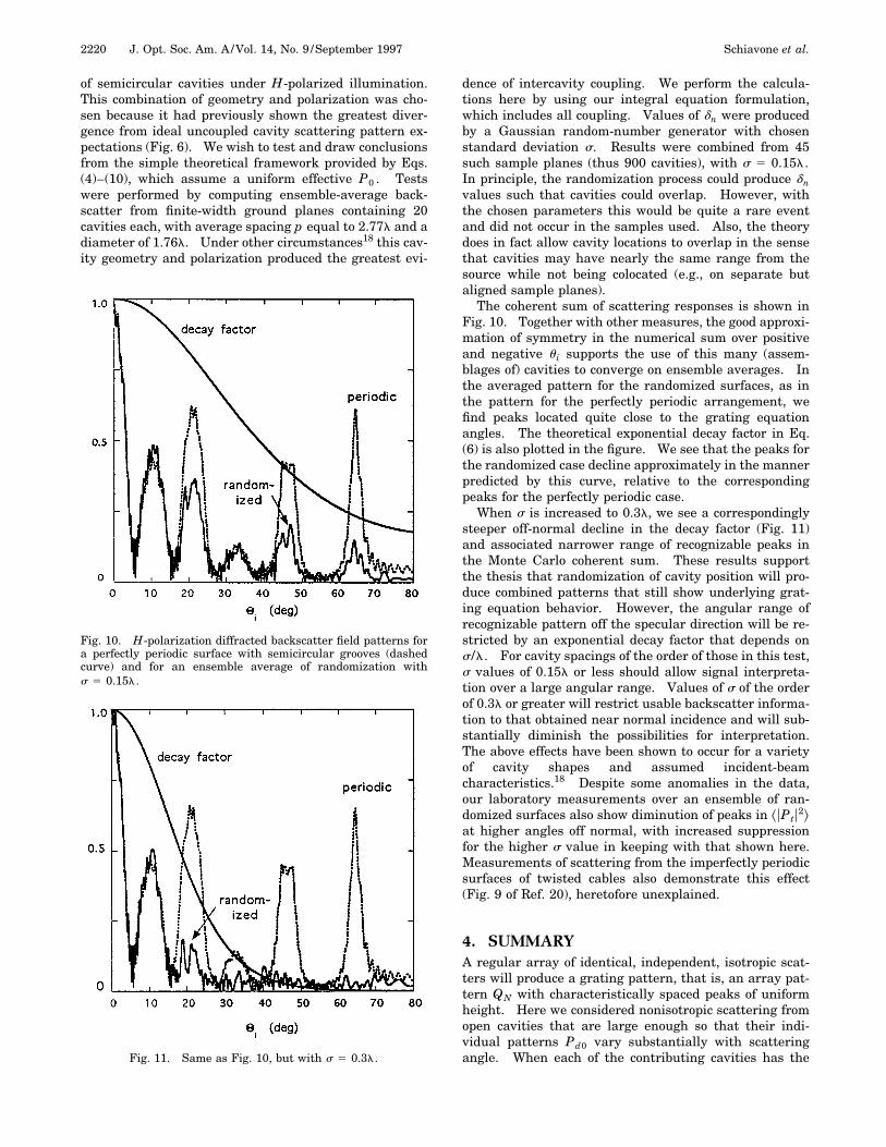
Fourier transform F(n) of the combination uPdu curves inthe upper plots, in terms of frequency n relative to sin ui.Evidence of the underlying separation p appears in thestrong frequency content at n values near 4 and 6 for thesmaller and larger separations, respectively. Interest-ingly, we also note the two peaks at lower n values, corre-sponding to the distinct contributing Pd0 of the individualcavities. The locations of these peaks do not change inthe lower plots when the cavity separation changes, andeach appears roughly at the n values that one would ex-pect, based on the shapes of the individual uPd0u shown.
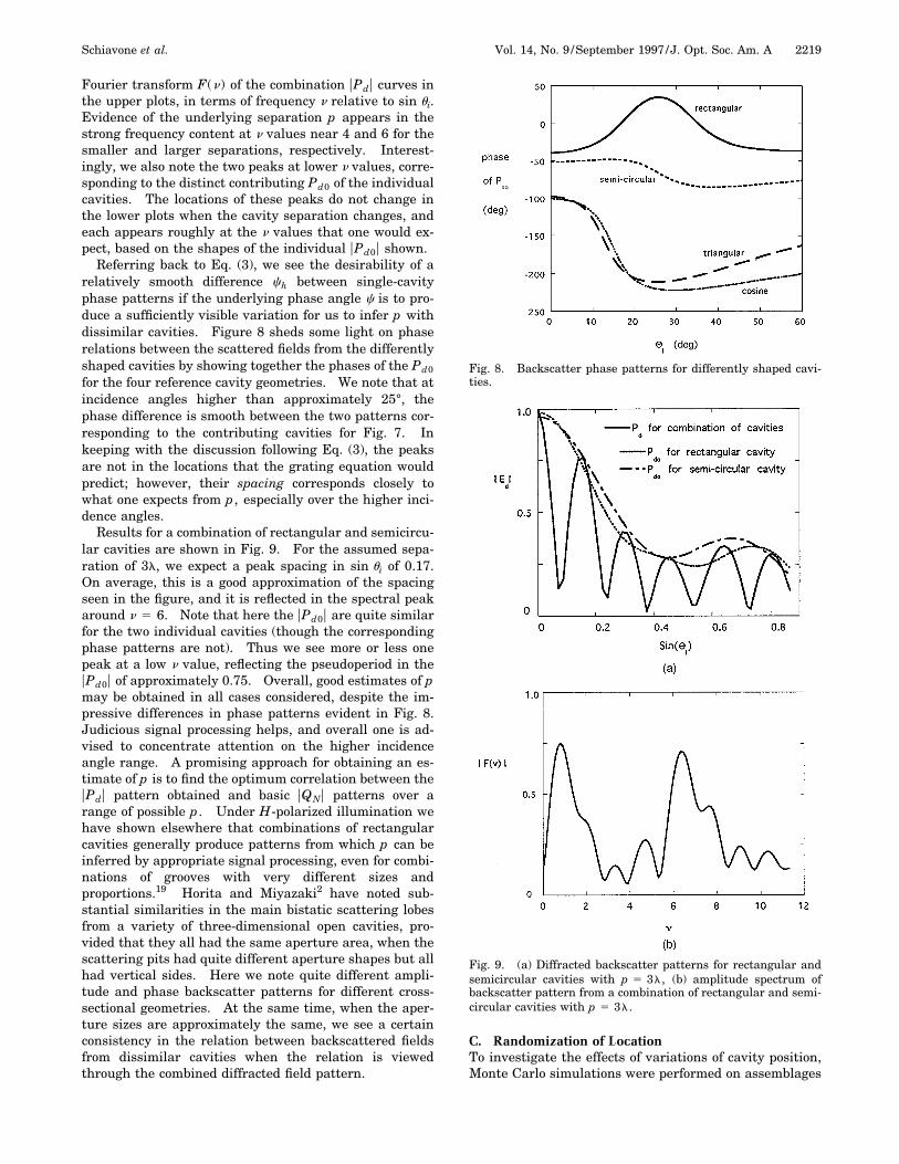
Referring back to Eq. (3), we see the desirability of arelatively smooth difference ch between single-cavityphase patterns if the underlying phase angle c is to pro-duce a sufficiently visible variation for us to infer p withdissimilar cavities. Figure 8 sheds some light on phaserelations between the scattered fields from the differentlyshaped cavities by showing together the phases of the Pd0
for the four reference cavity geometries. We note that atincidence angles higher than approximately 25°, thephase difference is smooth between the two patterns cor-responding to the contributing cavities for Fig. 7. Inkeeping with the discussion following Eq. (3), the peaksare not in the locations that the grating equation wouldpredict; however, their spacing corresponds closely towhat one expects from p, especially over the higher inci-dence angles.
Results for a combination of rectangular and semicircu-lar cavities are shown in Fig. 9. For the assumed sepa-ration of 3l, we expect a peak spacing in sin ui of 0.17.On average, this is a good approximation of the spacingseen in the figure, and it is reflected in the spectral peakaround n 5 6. Note that here the uPd0u are quite similarfor the two individual cavities (though the correspondingphase patterns are not). Thus we see more or less onepeak at a low n value, reflecting the pseudoperiod in theuPd0u of approximately 0.75. Overall, good estimates of pmay be obtained in all cases considered, despite the im-pressive differences in phase patterns evident in Fig. 8.Judicious signal processing helps, and overall one is ad-vised to concentrate attention on the higher incidenceangle range. A promising approach for obtaining an es-timate of p is to find the optimum correlation between theuPdu pattern obtained and basic uQNu patterns over arange of possible p. Under H-polarized illumination wehave shown elsewhere that combinations of rectangularcavities generally produce patterns from which p can beinferred by appropriate signal processing, even for combi-nations of grooves with very different sizes andproportions.19 Horita and Miyazaki2 have noted sub-stantial similarities in the main bistatic scattering lobesfrom a variety of three-dimensional open cavities, pro-vided that they all had the same aperture area, when thescattering pits had quite different aperture shapes but allhad vertical sides. Here we note quite different ampli-tude and phase backscatter patterns for different cross-sectional geometries. At the same time, when the aper-ture sizes are approximately the same, we see a certainconsistency in the relation between backscattered fieldsfrom dissimilar cavities when the relation is viewedthrough the combined diffracted field pattern.
C. Randomization of LocationTo investigate the effects of variations of cavity position,Monte Carlo simulations were performed on assemblages
Fig. 8. Backscatter phase patterns for differently shaped cavi-ties.
Fig. 9. (a) Diffracted backscatter patterns for rectangular andsemicircular cavities with p 5 3l, (b) amplitude spectrum ofbackscatter pattern from a combination of rectangular and semi-circular cavities with p 5 3l.
2220 J. Opt. Soc. Am. A/Vol. 14, No. 9 /September 1997 Schiavone et al.
of semicircular cavities under H-polarized illumination.This combination of geometry and polarization was cho-sen because it had previously shown the greatest diver-gence from ideal uncoupled cavity scattering pattern ex-pectations (Fig. 6). We wish to test and draw conclusionsfrom the simple theoretical framework provided by Eqs.(4)–(10), which assume a uniform effective P0 . Testswere performed by computing ensemble-average back-scatter from finite-width ground planes containing 20cavities each, with average spacing p equal to 2.77l and adiameter of 1.76l. Under other circumstances18 this cav-ity geometry and polarization produced the greatest evi-
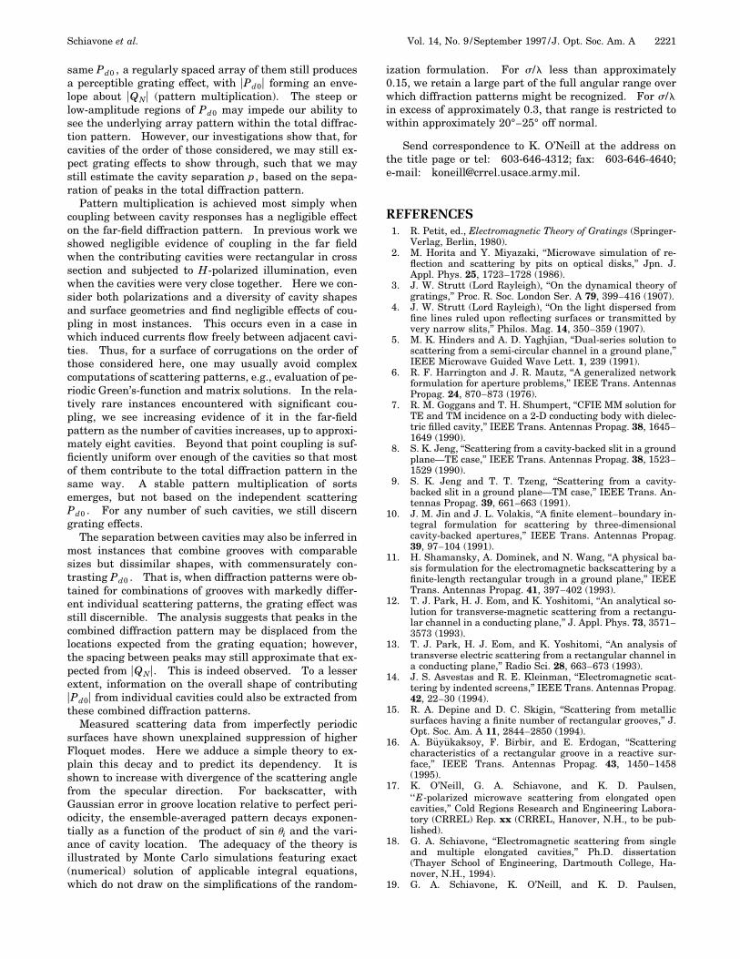
Fig. 10. H-polarization diffracted backscatter field patterns fora perfectly periodic surface with semicircular grooves (dashedcurve) and for an ensemble average of randomization withs 5 0.15l.
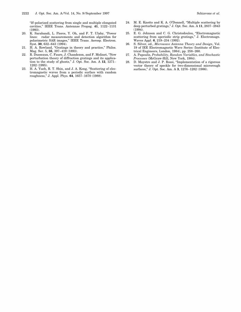
Fig. 11. Same as Fig. 10, but with s 5 0.3l.
dence of intercavity coupling. We perform the calcula-tions here by using our integral equation formulation,which includes all coupling. Values of dn were producedby a Gaussian random-number generator with chosenstandard deviation s. Results were combined from 45such sample planes (thus 900 cavities), with s 5 0.15l.In principle, the randomization process could produce dnvalues such that cavities could overlap. However, withthe chosen parameters this would be quite a rare eventand did not occur in the samples used. Also, the theorydoes in fact allow cavity locations to overlap in the sensethat cavities may have nearly the same range from thesource while not being colocated (e.g., on separate butaligned sample planes).
The coherent sum of scattering responses is shown inFig. 10. Together with other measures, the good approxi-mation of symmetry in the numerical sum over positiveand negative u i supports the use of this many (assem-blages of) cavities to converge on ensemble averages. Inthe averaged pattern for the randomized surfaces, as inthe pattern for the perfectly periodic arrangement, wefind peaks located quite close to the grating equationangles. The theoretical exponential decay factor in Eq.(6) is also plotted in the figure. We see that the peaks forthe randomized case decline approximately in the mannerpredicted by this curve, relative to the correspondingpeaks for the perfectly periodic case.
When s is increased to 0.3l, we see a correspondinglysteeper off-normal decline in the decay factor (Fig. 11)and associated narrower range of recognizable peaks inthe Monte Carlo coherent sum. These results supportthe thesis that randomization of cavity position will pro-duce combined patterns that still show underlying grat-ing equation behavior. However, the angular range ofrecognizable pattern off the specular direction will be re-stricted by an exponential decay factor that depends ons/l. For cavity spacings of the order of those in this test,s values of 0.15l or less should allow signal interpreta-tion over a large angular range. Values of s of the orderof 0.3l or greater will restrict usable backscatter informa-tion to that obtained near normal incidence and will sub-stantially diminish the possibilities for interpretation.The above effects have been shown to occur for a varietyof cavity shapes and assumed incident-beamcharacteristics.18 Despite some anomalies in the data,our laboratory measurements over an ensemble of ran-domized surfaces also show diminution of peaks in ^uPtu2&at higher angles off normal, with increased suppressionfor the higher s value in keeping with that shown here.Measurements of scattering from the imperfectly periodicsurfaces of twisted cables also demonstrate this effect(Fig. 9 of Ref. 20), heretofore unexplained.
4. SUMMARYA regular array of identical, independent, isotropic scat-ters will produce a grating pattern, that is, an array pat-tern QN with characteristically spaced peaks of uniformheight. Here we considered nonisotropic scattering fromopen cavities that are large enough so that their indi-vidual patterns Pd0 vary substantially with scatteringangle. When each of the contributing cavities has the
Schiavone et al. Vol. 14, No. 9 /September 1997 /J. Opt. Soc. Am. A 2221
same Pd0 , a regularly spaced array of them still producesa perceptible grating effect, with uPd0u forming an enve-lope about uQNu (pattern multiplication). The steep orlow-amplitude regions of Pd0 may impede our ability tosee the underlying array pattern within the total diffrac-tion pattern. However, our investigations show that, forcavities of the order of those considered, we may still ex-pect grating effects to show through, such that we maystill estimate the cavity separation p, based on the sepa-ration of peaks in the total diffraction pattern.
Pattern multiplication is achieved most simply whencoupling between cavity responses has a negligible effecton the far-field diffraction pattern. In previous work weshowed negligible evidence of coupling in the far fieldwhen the contributing cavities were rectangular in crosssection and subjected to H-polarized illumination, evenwhen the cavities were very close together. Here we con-sider both polarizations and a diversity of cavity shapesand surface geometries and find negligible effects of cou-pling in most instances. This occurs even in a case inwhich induced currents flow freely between adjacent cavi-ties. Thus, for a surface of corrugations on the order ofthose considered here, one may usually avoid complexcomputations of scattering patterns, e.g., evaluation of pe-riodic Green’s-function and matrix solutions. In the rela-tively rare instances encountered with significant cou-pling, we see increasing evidence of it in the far-fieldpattern as the number of cavities increases, up to approxi-mately eight cavities. Beyond that point coupling is suf-ficiently uniform over enough of the cavities so that mostof them contribute to the total diffraction pattern in thesame way. A stable pattern multiplication of sortsemerges, but not based on the independent scatteringPd0 . For any number of such cavities, we still discerngrating effects.
The separation between cavities may also be inferred inmost instances that combine grooves with comparablesizes but dissimilar shapes, with commensurately con-trasting Pd0 . That is, when diffraction patterns were ob-tained for combinations of grooves with markedly differ-ent individual scattering patterns, the grating effect wasstill discernible. The analysis suggests that peaks in thecombined diffraction pattern may be displaced from thelocations expected from the grating equation; however,the spacing between peaks may still approximate that ex-pected from uQNu. This is indeed observed. To a lesserextent, information on the overall shape of contributinguPd0u from individual cavities could also be extracted fromthese combined diffraction patterns.
Measured scattering data from imperfectly periodicsurfaces have shown unexplained suppression of higherFloquet modes. Here we adduce a simple theory to ex-plain this decay and to predict its dependency. It isshown to increase with divergence of the scattering anglefrom the specular direction. For backscatter, withGaussian error in groove location relative to perfect peri-odicity, the ensemble-averaged pattern decays exponen-tially as a function of the product of sin ui and the vari-ance of cavity location. The adequacy of the theory isillustrated by Monte Carlo simulations featuring exact(numerical) solution of applicable integral equations,which do not draw on the simplifications of the random-
ization formulation. For s/l less than approximately0.15, we retain a large part of the full angular range overwhich diffraction patterns might be recognized. For s/lin excess of approximately 0.3, that range is restricted towithin approximately 20°–25° off normal.
Send correspondence to K. O’Neill at the address onthe title page or tel: 603-646-4312; fax: 603-646-4640;e-mail: [email protected].
REFERENCES1. R. Petit, ed., Electromagnetic Theory of Gratings (Springer-
Verlag, Berlin, 1980).2. M. Horita and Y. Miyazaki, ‘‘Microwave simulation of re-
flection and scattering by pits on optical disks,’’ Jpn. J.Appl. Phys. 25, 1723–1728 (1986).
3. J. W. Strutt (Lord Rayleigh), ‘‘On the dynamical theory ofgratings,’’ Proc. R. Soc. London Ser. A 79, 399–416 (1907).
4. J. W. Strutt (Lord Rayleigh), ‘‘On the light dispersed fromfine lines ruled upon reflecting surfaces or transmitted byvery narrow slits,’’ Philos. Mag. 14, 350–359 (1907).
5. M. K. Hinders and A. D. Yaghjian, ‘‘Dual-series solution toscattering from a semi-circular channel in a ground plane,’’IEEE Microwave Guided Wave Lett. 1, 239 (1991).
6. R. F. Harrington and J. R. Mautz, ‘‘A generalized networkformulation for aperture problems,’’ IEEE Trans. AntennasPropag. 24, 870–873 (1976).
7. R. M. Goggans and T. H. Shumpert, ‘‘CFIE MM solution forTE and TM incidence on a 2-D conducting body with dielec-tric filled cavity,’’ IEEE Trans. Antennas Propag. 38, 1645–1649 (1990).
8. S. K. Jeng, ‘‘Scattering from a cavity-backed slit in a groundplane—TE case,’’ IEEE Trans. Antennas Propag. 38, 1523–1529 (1990).
9. S. K. Jeng and T. T. Tzeng, ‘‘Scattering from a cavity-backed slit in a ground plane—TM case,’’ IEEE Trans. An-tennas Propag. 39, 661–663 (1991).
10. J. M. Jin and J. L. Volakis, ‘‘A finite element–boundary in-tegral formulation for scattering by three-dimensionalcavity-backed apertures,’’ IEEE Trans. Antennas Propag.39, 97–104 (1991).
11. H. Shamansky, A. Dominek, and N. Wang, ‘‘A physical ba-sis formulation for the electromagnetic backscattering by afinite-length rectangular trough in a ground plane,’’ IEEETrans. Antennas Propag. 41, 397–402 (1993).
12. T. J. Park, H. J. Eom, and K. Yoshitomi, ‘‘An analytical so-lution for transverse-magnetic scattering from a rectangu-lar channel in a conducting plane,’’ J. Appl. Phys. 73, 3571–3573 (1993).
13. T. J. Park, H. J. Eom, and K. Yoshitomi, ‘‘An analysis oftransverse electric scattering from a rectangular channel ina conducting plane,’’ Radio Sci. 28, 663–673 (1993).
14. J. S. Asvestas and R. E. Kleinman, ‘‘Electromagnetic scat-tering by indented screens,’’ IEEE Trans. Antennas Propag.42, 22–30 (1994).
15. R. A. Depine and D. C. Skigin, ‘‘Scattering from metallicsurfaces having a finite number of rectangular grooves,’’ J.Opt. Soc. Am. A 11, 2844–2850 (1994).
16. A. Buyukaksoy, F. Birbir, and E. Erdogan, ‘‘Scatteringcharacteristics of a rectangular groove in a reactive sur-face,’’ IEEE Trans. Antennas Propag. 43, 1450–1458(1995).
17. K. O’Neill, G. A. Schiavone, and K. D. Paulsen,‘ ‘E-polarized microwave scattering from elongated opencavities,’’ Cold Regions Research and Engineering Labora-tory (CRREL) Rep. xx (CRREL, Hanover, N.H., to be pub-lished).
18. G. A. Schiavone, ‘‘Electromagnetic scattering from singleand multiple elongated cavities,’’ Ph.D. dissertation(Thayer School of Engineering, Dartmouth College, Ha-nover, N.H., 1994).
19. G. A. Schiavone, K. O’Neill, and K. D. Paulsen,
2222 J. Opt. Soc. Am. A/Vol. 14, No. 9 /September 1997 Schiavone et al.
‘‘H-polarized scattering from single and multiple elongatedcavities,’’ IEEE Trans. Antennas Propag. 41, 1122–1131(1993).
20. K. Sarabandi, L. Pierce, Y. Oh, and F. T. Ulaby, ‘‘Powerlines: radar measurements and detection algorithm forpolarimetric SAR images,’’ IEEE Trans. Aerosp. Electron.Syst. 30, 632–643 (1994).
21. H. A. Rowland, ‘‘Gratings in theory and practice,’’ Philos.Mag. Ser. 5, 35, 397–419 (1893).
22. R. Dusseaux, C. Faure, J. Chandezon, and F. Molinet, ‘‘Newperturbation theory of diffraction gratings and its applica-tion to the study of ghosts,’’ J. Opt. Soc. Am. A 12, 1271–1282 (1995).
23. H. A. Yueh, R. T. Shin, and J. A. Kong, ‘‘Scattering of elec-tromagnetic waves from a periodic surface with randomroughness,’’ J. Appl. Phys. 64, 1657–1670 (1988).
24. M. E. Knotts and K. A. O’Donnell, ‘‘Multiple scattering bydeep perturbed gratings,’’ J. Opt. Soc. Am. A 11, 2837–2843(1994).
25. E. G. Johnson and C. G. Christodoulou, ‘‘Electromagneticscattering from aperiodic strip gratings,’’ J. Electromagn.Waves Appl. 6, 219–234 (1992).
26. S. Silver, ed., Microwave Antenna Theory and Design, Vol.19 of IEE Electromagnetic Wave Series (Institute of Elec-trical Engineers, London, 1984), pp. 258–260.
27. A. Papoulis, Probability, Random Variables, and StochasticProcesses (McGraw-Hill, New York, 1984).
28. D. Maystre and J. P. Rossi, ‘‘Implementation of a rigorousvector theory of speckle for two-dimensional microroughsurfaces,’’ J. Opt. Soc. Am. A 3, 1276–1282 (1986).