Scalable Software Platform Architecture for the Power ...
74
Aki Hokkanen Scalable Software Platform Architecture for the Power Distribution Protection and Analysis Vaasa 2020 School of Technology and Innovation Software engineering, master’s thesis
-
Upload
khangminh22 -
Category
Documents
-
view
0 -
download
0
Transcript of Scalable Software Platform Architecture for the Power ...

Aki Hokkanen
Scalable Software Platform Architecture for the Power Distribution Protection and Analysis
Vaasa 2020
School of Technology and Innovation Software engineering, master’s thesis

2
Acknowledgement
This thesis was done for ABB Distribution Solutions. I want to thank everyone from
ABB who contributed to this thesis from the bottom of my heart especially my
instructor Ville Luoma. Naturally, I wish to extend the thank you to my supervisor
Teemu Mäenpää as well.
I want to take this opportunity to thank everyone I have met during my studies. All of
you have played a part along this road. We had a wonderful ride and I hope we can
continue this trip for years to come.
Lastly, I want to thank my family for their unwavering support from the first year of
kindergarten to this day. Mom, you finally achieved your toughest goal yet – your son is
a Master of Science.
Aki Hokkanen
10.3.2020

3
VAASAN YLIOPISTO Teknillinen tiedekunta Tekijä: Aki Hokkanen Tutkielman nimi: Skaalautuva ohjelmistoalusta-arkkitehtuuri sähköverkon jakelun turvaamiseksi ja analysoimiseksi Tutkinto: Diplomi-insinööri Oppiaine: Ohjelmistotekniikka Työn ohjaaja: DI Ville Luoma Työn valvoja: KTT Teemu Mäenpää Valmistumisvuosi: 2020 Sivumäärä: 74
TIIVISTELMÄ: Tämä opinnäytetyö tutkii mikropalveluarkkitehtuurin etuja verrattuna perinteiseen monoliitti-seen sovellusarkkitehtuuriin ja perinteisiin ympäristöihin. Mikropalveluarkkitehtuuri koostuu useista palveluista, jotka palvelevat kukin yhtä tarkoitusta ja sovelluksen kaikki erilliset toimin-not ovat omissa säilöissään, joita kutsutaan konteiksi. Kontit perustuvat Linux-ytimeen. Tämä opinnäytetyö tehtiin ABB (ASEA Brown Boveri) Distribution Solutions -yritykselle yhden nykyisen sovelluksen nykyaikaistamiseksi. Tämän tutkielmamme päätavoite on kuvata siirtyminen monoliittisesta sovellusarkkitehtuurista mikropalveluarkkitehtuuriin. Törmäsimme työn aikana kuitenkin ongelmiin, jotka estivät työn läpimenon. Näistä ongelmista merkittävin oli monoliittisen sovelluksen korkea riippuvuuden aste eri ohjelman osien välillä. Projektin lopputuloksen oli tarkoitus olla todiste konseptitason ohjelmistosta. Sitä emme pystyneet toteuttamaan. Käytimme toimintamallitutkimusta metodologiana ohjaamaan meitä päätöksenteossa. Valit-simme toimintamallitutkimuksen työmme metodologiaksi, koska huomasimme sen tukevan in-teraktiivista työskentelyä. Tämä sopi meidän tilanteeseemme erittäin hyvin, sillä olimme päivit-täin ABB:n toimistolla tekemässä tätä tutkimusta. Toimintamallitutkimus tähtää ensisijaisesti lopputulokseen, joka meidän tapauksessamme olisi ollut vanhan sovelluksen istutus uuteen ark-kitehtuuriin. Yksi tärkeimmistä tuloksistamme on, että onnistuimme määrittelemään kriittiset kysymykset, joihin on puututtava ennen siirtymistä monoliittisesta arkkitehtuurista mikropalveluarkkiteh-tuuriin. Näitä löydöksiä olivat vuosien aikana kertynyt teknologinen velka, epätäydellinen tieto vanhasta sovelluksesta sekä järjestelmän sisäiset riippuvuudet. Nämä riippuvuudet muodosta-vat merkittävän haasteen monoliitin uudelleen jäsentämisessä mikroarkkitehtuurin mukaiseksi. Neljäntenä löydöksenä huomasimme, että käytettävissä olevia resursseja, kuten aika, asiantun-tijat ja rahoitus, on oltava riittävästi tarkoituksenmukaisen tuloksen saavuttamiseksi. Teoreettisena kontribuutiona tuotimme oman versiomme Action Design Research -menetel-mään. Yhdistimme menetelmän kaksi ensimmäistä vaihetta siten, että samalla, kun asiakasor-ganisaatio määritteli ongelmaa, tutkimusryhmämme tarjosi ongelmiin ratkaisuja. Näistä ratkai-suista asiakasorganisaatio valitsi heille sopivimman. Tämä prosessi oli mahdollinen, koska kä-vimme avointa jatkuvaa keskustelua ABB:n kehitysyksikön kanssa.
AVAINSANAT: mikropalveluarkkitehtuuri, konttiteknologia, virtualisointi, skaalautuvuus, Ac-tion Design Research -metodologia
4
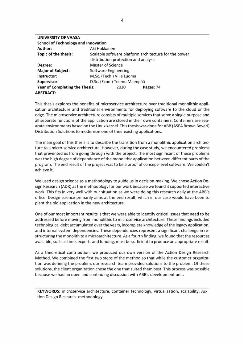
UNIVERSITY OF VAASA School of Technology and Innovation Author: Aki Hokkanen Topic of the thesis: Scalable software platform architecture for the power distribution protection and analysis Degree: Master of Science Major of Subject: Software Engineering Instructor: M.Sc. (Tech.) Ville Luoma Supervisor: D.Sc. (Econ.) Teemu Mäenpää Year of Completing the Thesis: 2020 Pages: 74
ABSTRACT: This thesis explores the benefits of microservice architecture over traditional monolithic appli-cation architecture and traditional environments for deploying software to the cloud or the edge. The microservice architecture consists of multiple services that serve a single purpose and all separate functions of the application are stored in their own containers. Containers are sep-arate environments based on the Linux kernel. This thesis was done for ABB (ASEA Brown Boveri) Distribution Solutions to modernize one of their existing applications. The main goal of this thesis is to describe the transition from a monolithic application architec-ture to a micro-service architecture. However, during the case study, we encountered problems that prevented us from going through with the project. The most significant of these problems was the high degree of dependence of the monolithic application between different parts of the program. The end result of the project was to be a proof of concept-level software. We couldn't achieve it. We used design science as a methodology to guide us in decision-making. We chose Action De-sign Research (ADR) as the methodology for our work because we found it supported interactive work. This fits in very well with our situation as we were doing this research daily at the ABB’s office. Design science primarily aims at the end result, which in our case would have been to plant the old application in the new architecture. One of our most important results is that we were able to identify critical issues that need to be addressed before moving from monolithic to microservice architecture. These findings included technological debt accumulated over the years, incomplete knowledge of the legacy application, and internal system dependencies. These dependencies represent a significant challenge in re-structuring the monolith to a microarchitecture. As a fourth finding, we found that the resources available, such as time, experts and funding, must be sufficient to produce an appropriate result. As a theoretical contribution, we produced our own version of the Action Design Research Method. We combined the first two steps of the method so that while the customer organiza-tion was defining the problem, our research team provided solutions to the problem. Of these solutions, the client organization chose the one that suited them best. This process was possible because we had an open and continuing discussion with ABB's development unit.
KEYWORDS: microservice architecture, container technology, virtualization, scalability, Ac-tion Design Research -methodology

5
Table of Contents
1 Introduction 9
2 Microservice architectures 13
2.1 What is a service? 15
2.2 Benefits gained with microservice architecture 16
2.3 Communication between different services 20
2.4 Architectural change in our case study 21
2.5 Common pitfalls in transit 23
3 Virtualization architectures 25
3.1 Container Technologies 28
3.1.1 Docker 30
3.1.2 RKT 32
3.2 Edge computing 32
3.3 Cloud Technologies 34
4 Methodology 36
5 Path toward microservice architecture 41
5.1 Selection of the technologies 41
5.2 Methodology in action 46
5.2.1 First iteration – User interface 51
5.2.2 Second iteration – Document delivery 53
5.2.3 Final iteration 57
6 Results 59
7 Conclusions 63
References 66

6
Figures
FIgure 1. Example of a monolithic application’s stack (Seedotech, 2018). ................. 14
Figure 2. Example of a microservice architecture (M&S Consulting, 2019). ............... 16
Figure 3. Generic microservice architecture topology (Kang, 2019). .......................... 20
Figure 4. Monolithic software architecture in our case study based on an internal ABB
architecture diagram. .............................................................................................. 22
Figure 5. Highly dependent microservice architecture (Richards, 2016). ................... 24
Figure 6. Virtual machine vs Linux container vs Non-Linux container (Erlandsson, 2019).
................................................................................................................................ 27
Figure 7. Docker container communication with Linux kernel (Yakimov, 2016). ........ 30
Figure 8. Generic IaaS -architecture (Kozlovszky et al., 2013). ................................... 35
Figure 9. Action Design Research (ADR) process (based on Baskerville et al., 2018). . 39
Figure 10. CPU performance of bare-metal, Docker and Rkt (Xie et al., 2017). .......... 44
Figure 11. CPU load and network performance (Xie et al., 2017). ............................. 45
Figure 12. Proposed architectural diagram of the proof of concept application. ....... 47
Figure 13. Pattern transitioning to microservice architecture (Balalaie et al., 2016). . 50
Figure 14. User interface for the platform. ............................................................... 53
Figure 15.Graphs of an COMTRADE files current. ..................................................... 57
Figure 16. Final architecture of our case study. ......................................................... 58
Tables
Table 1. Comparison between monolithic and microservice architecture (Kalske et al.,
2017). ...................................................................................................................... 19
Table 2. Differences between virtual machines and containers (Bauer, 2018). .......... 29
Table 3. Steps taken throughout the process. ........................................................... 40
Table 4. Docker versus Rkt comparison. ................................................................... 46
Table 5. Steps taken in practice to achieve to proof of concept. ................................ 56

7
Abbreviations ABB ASEA Brown Boveri
ADR Action Design Research
API Application Programmable Interface
APPC App Container
AUFS originally: AnotherUnionFileSystem, currently: advanced multi-layered unification filesystem
AWS Amazon Web Services
BTRFS B-Tree File System
COMTRADE Common format for Transient Data Exchange
CPU Central Processing Unit
CRUD Create, Read, Update and Delete
CTO Chief Technology Officer
FB Function Block
FLOC Fault Locator
HTTP Hypertext Transfer Protocol
IaaS Infrastructure as a Service
IEC International Electrotechnical Commission
IEEE Institution of Electrical and Electronics Engineers
IEDs Intelligent Electronic Devices
IOT Internet of Things
IPC InterProcess Communication
JAR Java Archive
LTE Long Term Evolution
LXC Linux Containers

8
NAT Network Address Translation
NoSQL Not only SQL
OS Operating System
PSRCS Power Systems Relaying & Controls Committee
PID Process Identification
POC Proof of Concept
RAM Random Access Memory
REST Representational State Transfer
RTDB Real-time Data Base
SaaS Software as a Service
SQL Structured Query Language
UFS Unix File System
UTS Unix Time Sharing
VFS Virtual File System
VM Virtual Machine
WAR Web Application Resource or Web Application Archive
Wi-Fi Wireless Fidelity

9
1 Introduction
Software industry is going through massive evolutions currently and most of the
practices from the twentieth century have started to become outdated, since the
computing power of modern hardware is capable of outstanding performance (see for
example Ross & Feeny, 1999; Hirschheim & Klein, 2012). In the modern world, software
engineering is less about building one giant application, but rather it is trending towards
building an application that has multiple services. These services work autonomously to
increase fault-tolerance and reduce the resources spent on maintenance as individual
services cannot be broken by modifications done to other parts of the code. Companies
such as Netflix (Mauro, 2015) and Uber (Uber, 2019) have already adopted the
architectural change towards a microservice architecture and have reaped its benefits.
The cost of transferring data is reducing and the speed at which data can be transferred
is increasing (Cisco, 2018; Cisco, 2019). This has enabled to redirect the processing of
any given data from on premise solutions to for instance the cloud or the edge. Data
gathering and processing volumes are increasing by huge margins currently and this
provides companies with valuable data that has not been available previously. This has
also impacted the companies working with electrical grids.
This thesis is done for ABB’s Distribution Solutions. Distribution Solutions manufactures
relays for high voltage / medium voltage substations in the electrical grid. These relays
can gather a huge variety of data ranging from voltage to current and temperature in
the relay. These measures provide critical information about the relays as a malfunction
can cause debilitating damage to the grid. For this reason, a fault detection algorithm
has been developed. It can identify faults in the grid and inform the operators where the
fault is located. This reduces the time to repair the fault and get the grid up and running
again. Currently, the software running in the substations is an application with a
monolithic application architecture and part of this thesis aims to transit that
architecture to a more modern architecture, specifically a microservice architecture.
(ABB, 2018)

10
The research need for this thesis was found in the fact that the software has been run
only in the substations. It has been run with industrial computers in the substations as
well as within a virtual machine. The most obvious benefit of running the application
outside of the substation would be the fact that software updates would be easier to
deploy as the technicians could install them remotely rather than going on site. Another
benefit of running in the cloud will be gained, with the transition from a monolithic
application architecture to a microservice architecture. Obviously, not all the
functionality can be moved away from the substations as some of the function blocks
are very time sensitive, such as the overcurrent detection (Jokela, 2014). However, the
fault locator algorithm is not as time sensitive. Thus, allowing us to create a proof of
concept level solution.
A modern way to create scalable architectures is by creating microservices. Each service
is responsible for a single function of the whole application. This provides meaningful
upside as an architecture compared to the old monolithic architecture that has been
created in the past. According to Namiot & Sneps-Sneppe (2014), a monolithic
application is a file that is deployed as a united solution like a Web Application Archive
(WAR) file for Java web applications. Internally it may have multiple services, but when
inspected it acts as one. An application with monolithic architecture is scaled by running
multiple identical copies of the application. The benefits for microservice architecture
include but are not limited to the following concepts: Isolation for the application, which
reduces the time to deploy new features; Creating a microservice architecture reduces
the size of the codebase; Each team can take ownership of their own services. Thus,
microservice architecture is providing autonomy to pick and choose the best
technological tools to use for their services, be it language, framework or whatever else
the team believes is necessary to get the job done in the most efficient way possible.
(Newman, 2015; Fetzer, 2016; Alshuqayran, Ali & Evans, 2016; Amaral, Polo, Carrera,
Mohomed, Unuvar & Steinder, 2015)
Containers are commonly leveraged to achieve a microservice architecture (Amaral et al.,
2015). Containers can be thought as being a way to package your software into
11
something resembling a shipping container. These containers are one of the tools that
enable developers to create and deploy code easier and faster than before. Additionally,
they work independently so dependency issues do not arise like in more traditional
development. “Works on my computer” -problem should not occur with containers as
they can be thought as sort of black boxes.
The purpose of this master’s thesis is two-folded. Firstly, the aim is to create a proof of
concept (POC) level artefact that has a microservice architecture and containerized
services. Secondly, the goal is to restructure the current monolithic application
architecture to a modern microservice architecture. The research questions pertaining
to this research are:
1) Can a monolithic software be transformed into a microservice architecture?
2) What are the pitfalls and misconceptions of transitioning to a microservice
architecture found during this thesis?
In addition to the two main questions above, a sub-question was also formed during the
research:
3) Is it sensible to transit this monolithic application architecture to a microservice
architecture?
In the following two chapters we will be discussing the theory behind the different
virtualization architectures and technologies. Firstly, we shall discuss the microservice
architecture, as it is the modern way of creating an architecture that is robust and highly
scalable by leveraging containers. We will delve into different container technologies
and aim to highlight the different advantages and disadvantages of each separately.
After that the focus will shift on to the different platforms available to host the solution.
More specifically, the aim will be to assess different service providers and their products
to find the most suitable environment to run our services.

12
A description of used methodology will be given after the theory is introduced in this
master’s thesis. Design science was selected as a good starting point for this thesis as
the problem was introduced to by a third party. In addition, the thesis will be a
qualitative case study research which provides further assurance that design science
could be used as a methodology within this field of research. We have chosen to use
Action Design Research (ADR) (Baskerville, Baiyere, Gregor, Hevner & Rossi, 2018) as the
method of conducting the research as we were in constant collaboration with ABB’s
team.
The fifth chapter will describe the different technologies used in our proof of concept
and describe how the proof of concept was created. The reader will gain a deeper
understanding of the different iterations done during the creation of the proof of
concept and realize the most common pitfalls we encountered during this process. Most
importantly, we will try to guide the reader to the right path if s/he wishes to attempt
to recreate our experiments.
After the empirical study is explained in detail, it is time to analyse the results gained.
We will take a closer look at what we accomplished during the empirical study and show
the benefits of this research. Lastly, conclusions will be made on whether our research
is a success and if there is something we would like to change in hindsight.

13
2 Microservice architectures
A common way of creating an application in the past times was to create an application
where all its parts were in the same stack. This meant that the whole application is a
single unit. Commonly all the codebase was packaged into a single file like a JAR or WAR
file. The benefit of this is that the application is easy to test and deploy, but there are
two main reason why this architecture is becoming outdated: modifications to code take
a long time and a monolith only scales one dimensionally. (Messina, Rizzo, Storniolo &
Urso, 2016)
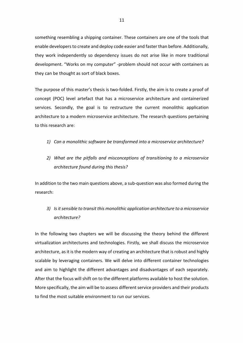
In general, a monolithic application stack is thought to consist of three different layers
(Premchand & Choudhry, 2018). These layers are application layer, business logic layer
and data access layer. The application layer in its simplest form is the user interface via
which the user of the application can interact with. Business logic layer provides the
functions that the user can do with the user interface like adding new users to the
application. Data access layer enables the user’s data to be modified, be saved into or
be deleted from a database. These three different layers work in cohesion and enable
the software to be used. They together also form a single instance to be replicated when
needed to improve the performance of the said application. Figure 1. describes a general
monolithic application stack.
14
FIgure 1. Example of a monolithic application’s stack (Seedotech, 2018).
Once the application goes through multiple versions and more functionality is
introduced during the lifecycle of the application, the likelihood of bugs creeping in to
the code increases. The codebase on the other hand keeps on growing thus making it
increasingly more difficult to find where the bug is located and therefore increasing the
time it takes to deploy new features to the code. Moreover, a certain functionality may
require more computing power than all the rest. However, since the codebase requires
all the code for the application to be executable, the entire codebase must be running
in multiple instances to scale up the application. This reduces efficiency of the system.
For example, let us inspect the stack of Figure 1. more in depth. We clearly have a block
that is meant for user management. However, once all the users are onboarded to the
system, the computing power required for the user management section of the code
decreases, while traffic to the movie management section of the stack. This either
creates a bottleneck of resources as not enough resources are available for the movie
management section or it creates waste as user management block is idle.

15
2.1 What is a service?
The above-mentioned scalability issue led to the creation of the concept of services.
James Lewis and Martin Fowler (2014) claim that microservice was invented in a
software architecture workshop in May of 2011. Services are individual parts of the
application that service a specific function of the application. For instance, one of the
services could be the user management service, which allows creation, reading,
updating and removing (CRUD) functions for accounts and the other service could be
the movie management service. These services operate autonomously and making
changes within one of them does not require modifications to other services. Each of
the services uses technologies deemed as lightweight, such as Hypertext Transfer
Protocol (HTTP) and Representational State Transfer (REST). Required business
capabilities are what define the services, each capability equates to a service.
Centralized management of services is left to the bare minimum. (Lewis & Fowler, 2014)
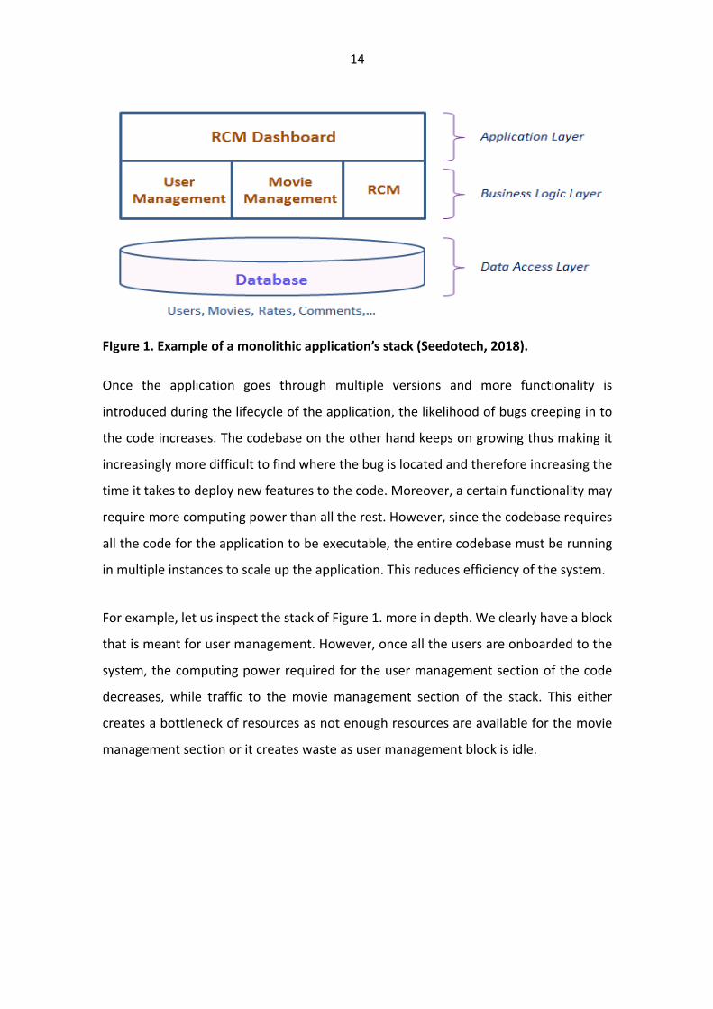
Figure 2. is an example of a microservice architecture and it describes the inner workings
of such an architecture. Each microservice is a single deployable entity and therefore
can be scaled up or down depending on the amount of usage of each service. All of the
services are packaged into their own separate containers. The user interface is one of
the containerized microservices. It allows the user to interact with the other containers.
The other microservices are core functions needed for the application to work. In our
case study we will have an architecture that consist of the user interface container, an
analytics container that does all of the analysis for the relays and a database to store the
files in. Our architecture would resemble the far-left side of the architecture described
in Figure 2.
16
Figure 2. Example of a microservice architecture (M&S Consulting, 2019).
2.2 Benefits gained with microservice architecture
There are few concrete improvements with microservice architecture compared to a
monolithic one according to Newman (2015), Fetzer (2016) and Alshuqayran et al.
(2016). These include (i) flexibility with different technologies to be used within each
service; (ii) service isolation, which leads to increase in service quality and security (iii)
service ownership enabling the service architecture structure to be moulded to fit the
team structure. Knoche & Hasselbring (2018) add to this list of benefits with the
reduction of the size of the codebase.
Flexibility gained by microservices is due to the separation of technologies used. As each
of the services is handled by a single team, they can choose amongst themselves, which
tool is the right one for the job. Within the same application multiple, multiple different
languages and frameworks can be utilized to achieve the greatest result through the
path of least resistance (Lewis & Fowler, 2014). Probably the easiest way of getting
perspective of this granted flexibility is to look at different data storage options. An easy

17
way to approach this subject is to compare Structured Query Language (SQL) and Not
only SQL (NoSQL). A modern application will ideally want to use both databases and
creating a microservice architecture will make it possible to do so. Relational databases
should be used when a fixed schema is required, such as the user database. NoSQL
databases are more suited towards databases where flexible schemas are preferred like
a shopping cart.
Service isolation is what enables the flexibility. It is generally granted using containers
that provide the bound context for each service. This provides both security as well as
quality. Security is enhanced as gaining access to a single service does not immediately
unlock the whole application for the malicious user. Service quality is improved as even
if one of the services crashes, it does not cripple the whole system. Additionally, the
containers provide a shorter restart time as the container images are smaller in size
compared to virtual machines (VM). We will delve deeper into containers in the next
section of this thesis. Furthermore, introducing new updates to the application does not
require the whole application to be built all over again, but rather only the service that
had the feature appended must be built again.
Service ownership is what enables this on the organizational side. This mandates the
creation of cross-functional teams (Lewis & Fowler, 2014) as each team must be able to
develop their service from the ground up all the way up to production. This leverages
Conway’s law that states the following (Conway, 1968, p. 1):
Any organization that designs a system (defined broadly) will produce a design whose structure is a copy of the organization's communication structure.
Thus, leading to teams that can self-sufficiently develop and deploy their own services
and communication is needed only within the team therefore greatly increasing the
speed of deployment. The ownership of the service should not end once the
development is finished, but rather example should be taken from Amazon’s “you build
it, you run it” principle (Gray, 2006). In this interview, Vogels Chief Technology Officer
(CTO), of Amazon in 2006, describes how operational responsibilities given to
developers has increased the quality of service for Amazon. Vogel attributes this to the

18
customer feedback loop gained from the daily contact with the customers. In addition,
we believe that it also holds the developers accountable for their own code as they will
receive direct feedback for their own code. Developers will strive to deliver better code
as they feel more responsible of the quality of the code and because they want to avoid
negative feedback coming from the customers.
The benefits of microservices come with some costs added to them. According to
Kazanavičius & Mažeika (2019), microservice architecture adds complexity to the system
as it becomes a distributed one. Performance is also affected since communication will
happen over a network rather than internal calls.
Microservices fit well in within the DevOps paradigm. Creating small and nimble services
that flow through continuous delivery, integration and monitoring pipelines is what
most concretely enables faster deployment and increases availability of applications
(Balalaie, Heydarnoori & Jamshidi, 2016). According to Balalaie et al. (2016),
development and operation teams have been separated traditionally. However, this
might not in fact produce the best results. This is since development teams and
operations teams work in very different frequency regarding the rate of changes.
Development teams generally push out multiple updates, while operation teams tend
to be more reserved to achieve a more stable release. Due to having two full sized teams
running to deploy new updates, the sheer number of people taking part in the
integration process is big thus resulting in a dire need of accurate communication. All
these issues described above, lead to a slower deployment of software updates.
DevOps enhanced with microservices can respond to many of the problematic situations
caused by the conventional way of developing applications. Reduction in
communication required between teams is the catalyst that drives faster deployment
times as each team is only responsible for their own product and operations team is only
responsible for delivering a pipeline for the deployment of new features on to the
application, preferably with even automated testing integrated into the pipeline.

19
However, we will not explore DevOps further than this, since it is out of scope for this
thesis.
To sum up the differences between a monolithic application architecture and a
microservice architecture, we believe that Kalske, Mäkitalo & Mikkonen (2017)
summarized it best in the following Table 1.:
Table 1. Comparison between monolithic and microservice architecture (Kalske et al., 2017).
Category Monolith Microservices
Time to market Fast in the beginning, slower later as codebase grows.
Slower in the beginning, because of the technical challenges that microservices have. Faster later.
Refactoring Hard to do, as changes can af-fect multiple places.
Easier and safe because changes are contained inside the micro-service.
Deployment The whole monolith has to be deployed always.
Can be deployed in small parts, only one service at a time.
Coding language Hard to change as codebase is large. Requires big rewriting.
Language and tools can be se-lected per service. Services are small so changing is easy.
Scaling Scaling means deploying the whole monolith.
Scaling can be done per service.
DevOps skills Does not require much as the number of technologies is limited.
Multiple different technologies, a lot of DevOps skills required.
Understandability Hard to understand as com-plexity is high. A lot of moving parts.
Easy to understand as codebase is strictly modular and services use SRP.
Performance No communicational over-head. Technology stack might not support performance.
Communication adds overhead. Possible performance gains be-cause of technology choices.

20
2.3 Communication between different services
As we have established that each service is its own isolated entity, we have yet to define
the way they communicate with each other. This way is called an application
programmable interface (API), which is a standard way of different services to send
standardized messages between each other thus allowing a smooth transfer of data
between each of the services. API’s enable the inner workings of each service to stay
obscure, which enhances the security aspect of the services as well. Say, that an
individual gets access to one of the services, as each of the services only communicate
between each other via an API the access is only partial and therefore not as damaging
as it would have been for an application with a monolithic software architecture. Figure
3. describes the way traffic is directed to each of the microservices from the client (Kang,
2019).
Figure 3. Generic microservice architecture topology (Kang, 2019).
The client first provides credentials via identity provider after which it can process
requests made by the user via the API gateway to the different services in the
application.

21
2.4 Architectural change in our case study
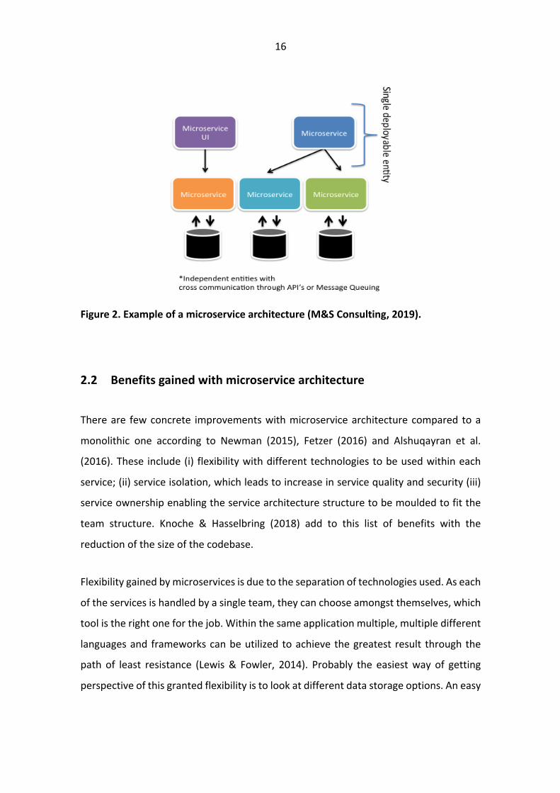
Currently, the software architecture for our case study in ABB is as described in Figure
4. As of writing this research, it is monolithic and all functionality within the same block.
The objective is to separate the function library and function library service from the
rest and create a microservice of that part of the software. The driving forces for this
change are the ones listed earlier in this chapter, the main reasons being: faster
development cycles, easier maintenance during production and easier scalability both
vertically and horizontally.
The most important of these is easier maintenance during production, since it reduces
resources spent on a process that does not add value to the current software. Faster
development cycles add on top of the reduced time needed for maintenance in
increasing the efficiency of the development department. Lastly, easier scalability,
especially horizontally, enables development of a single service at a time. Thus, limiting
the effect of new patches on the old software. Currently, when new patches are
introduced, it affects the whole stack. However, with microservice architecture this can
be minimized to only concern the service under development. Vertical scaling will
become more important it the future, once the application is deployed into production.
We do not expect the traffic to ramp up just yet in the proof of concept phase.
22
Figure 4. Monolithic software architecture in our case study based on an internal ABB
architecture diagram.
The functionality starts from the connectivity package, which is directly linked to the
configuration interface. The configuration interface allows the user to configure the re-
lays and save them to the storage. At runtime, the configuration interface delivers the
configuration files to the execution engine that is responsible for running the applica-
tions. Applications access the libraries, which in turn access services to run. For this the-
sis, we will be focusing on the part that is now described under application 2 in the func-
tion library called the Fault Locator (FLOC) Function Block (FB). This is the fault locator
function block. Its job is to pinpoint the distance of the fault from the relay located in
the electrical substation. For the function to run, it seems like it only needs to access the
streams library and function library. These two should form their own services. The
streams library is responsible for the data streams that are produced by the relays. Each
relay is capable of recording data with a sampling rate measured with at the very least

23
in microseconds. This data is then saved to the real time data base (RTDB), which can be
accessed via the RTDB user interface client.
2.5 Common pitfalls in transit
The transit to microservices is a two-phase process. The first of which is splitting the
functionality of the monolithic application into smaller pieces, each piece being its own
service. The second phase is to restructure the monolithic database to fit the newly
created services. (Richards, 2016)
As stated previously, each service can have its own database if deemed necessary. This
grants the developer the benefit of choosing whether they want a relational database
or a NoSQL database in addition to creating the database exactly required for the
service. Thus, leading to lesser overhead. As all the different services are isolated, a
communication route must be defined. The most common way to achieve this is by using
REST APIs. They work in a predefined set of stateless operations. However, they
communicate over the network and thus, introduce a new set of potential problems.
According to Malavalli & Sathappan (2015), these problems include the following:
network reliability, latency, bandwidth and network security.
Drawing from this, it is generally thought as best practice to share nothing between the
different services. However, in practice this might not be efficient to uphold, but rather
share as little as possible (Richards, 2016). Adding to this, Richards (2016) defines an
example where sharing is beneficial. Running a service for security and authentication
introduces overhead reducing the reliability and performance of the whole application.
Therefore, it is more beneficial to have all the authentication related code wrapped into
a Java Archive (JAR) file to avoid constant excess remote calls. For specific purposes such
as this a shared functionality can be useful, but in most cases, it should be avoided. If
too many dependencies are allowed in to the system, it will create a situation as
described in Figure 5.

24
Figure 5. Highly dependent microservice architecture (Richards, 2016).
Dependency as high as this disrupts the notion of bounded context within microservice
architecture. Thus, being counter-productive to the idea that alterations to code in
microservice architecture are quick to test and deploy as each service is autonomous.
(Taibi & Lenarduzzi, 2018)
25
3 Virtualization architectures
In this chapter we will first describe the origin of virtualization. After which we will
compare the current industry standards, virtual machines and containers, with each
other and give a short introduction of two viable container solutions. Lastly, we will
introduce the most common environments to store these virtualized solutions, namely
cloud and edge.
Virtualization began in the 1960s (Garber, 2012). At first it meant the division of
mainframes into logical components, but since then the term has been expanded.
Nowadays, virtualization can be either hardware virtualization, desktop virtualization or
containerization. In this thesis we will briefly touch upon hardware virtualization by
explaining what virtual machines are, but then concentrate on containerization, as it is
the more current technology and better suits our needs.
A more traditional virtualization architecture is a virtual machine. Virtual machine is a
machine that runs on normal hardware and it has been segmented into smaller parts,
with the underlying hardware decoupled from the running software (Rosenblum &
Garfinkel, 2005). Virtual machines run a full operating system (OS) and if there are
multiple virtual machines on a single server a hypervisor is responsible for managing the
resources of the server (Dahlstedt, 2012). A hypervisor can either be software, firmware
or hardware that manages the virtual machines on the server. This server is referred to
as a host machine. Host machine delivers resources such as random access memory
(RAM) and central processing unit (CPU) to virtual machines. These resources are shared
between all the different virtual machines on the server and may be divided equally or
different virtual machines may be allocated with more resources than others if a certain
virtual machine requires more computing power.
Virtual machines that run on a host machine are referred to as guest machines (Reuben,
2007). Guest machines include everything that it needs to run on its own and can be
thought of as an individual computer, which just happens to run on a server that hosts

26
multiple guest machines. The most common components included in guest machines
are system binaries and libraries. Guest machines also have a hardware stack of their
own, which contains virtualized network adapters, storage and CPU. In layman’s terms,
this translates to the guest machine having its own full-fledged operating system as
stated above. So, when looking inside of a virtual machine it is just a normal computer,
but looking at the situation on a server level, it is an application that uses resources of
the host machine.
There are two practical ways running a virtual machine – a hosted hypervisor and a bare-
metal hypervisor. A hosted hypervisor means that it operates on top of the operating
system of the host machine e.g. a computer can run any operating system (OS) and have
a virtual machine running on it (Burckart, Ivory, Kaplinger, Kenna & Shook, 2013). This
way the virtual machine can not directly access the hardware, but rather through the
host operating system.
Hosted hardware reduces the impact of underlying hardware, since the virtual machine
is not responsible for drivers. Therefore, it can be run on a wider range of machines as
the host operating system only needs to communicate with the hardware. However, the
drawback of this is that the resource overhead increases as a separate operating system
is run in the stack.
Bare metal hypervisor is the opposite of a hosted hypervisor as the mentioned benefits
and disadvantages are reversed. The bare metal hypervisor reduces the overhead
compared to running the virtual machine on top of the host machine’s operating system
as it interacts directly with the hardware. In practice, this means that the hypervisor will
be installed directly to host machine’s server as the operating system (Burckart et al.,
2013). In this case the hypervisor will have its own device drivers and will interact with
each component of the server directly, including operations such as I/O, processing and
OS-specific tasks. The advantage of this is that it increases performance, scalability and
stability. The downside is that it will restrict the compatibility as hypervisors can only

27
support a limited number of components as not all the drivers can be preinstalled into
the hypervisor.
Containers on the other hand are much lighter than virtual machines (Li & Xia, 2016).
They usually leverage much smaller versions of the base software, thus reducing the
amount of disk space consumed. Containers are also used for a specific purpose and
they only carry out a single function rather than running a fully-fledged operating system
constantly. This is also demonstrated in Figure 6. (Erlandsson, 2019). Both the virtual
machine and a non-Linux based container platform require the use of a hypervisor to
run the docker engine. This increases the load on the servers compared to just running
the plain docker engine on top of the host Linux. By looking more carefully the reader
might recognize the fact that in Figure 6. the Host Linux and Guest Linux in fact operate
identically. Therefore, running containers more specifically Docker on a non-Linux
system is not really that efficient.
Figure 6. Virtual machine vs Linux container vs Non-Linux container (Erlandsson, 2019).
Virtualization of the software architecture provides a modular system that can be easily
scaled up or down depending on the need at any time. This reduces the deployment
time and makes it easier to alter the configuration when needed.

28
Next, we will compare the three different options depicted in Figure 6. with respect to
our case study; namely Virtual machines, Docker (Linux) and Docker (Non-Linux). For the
virtual machine it would mean that we deploy a virtual machine on to a server running
either in the cloud or an on-premise server. This virtual machine would then have its
own kernel and all other functions that a fully-fledged operating system running on
hardware would require. However, leveraging the Docker containers on a machine
running Linux operating system allows us to deploy all of our containers directly onto a
server running Docker engine as it is able to use the resources of the server natively.
Thus, reducing the overhead of the system. Therefore, if we were to deploy Docker on
a non-Linux environment, we would have to run it in a virtual machine which has Linux
installed, which would decrease the efficiency of the system.
As of writing this thesis, the software we are modernizing has already been deployed
into a virtual machine as a monolithic application. However, there are multiple reasons
to move towards a microservice architecture. These are for example reduced impact of
patching the system and increasing the scalability of the system.
3.1 Container Technologies
The main idea of containers is akin to virtual machines. Container’s goal is to create a
unit that contains the application and its dependencies that can be run anywhere. In
addition to the isolation, containers and virtual machines both leverage virtualization
techniques to allow more efficient use of computing power, when considering cost
efficiency and energy consumption. The differences can be found in the architecture.
The main difference when considering virtual machines and containers is that virtual
machines provide hardware virtualizations, while containers virtualize the operating-
system. This is done by abstracting the “user space”.
29
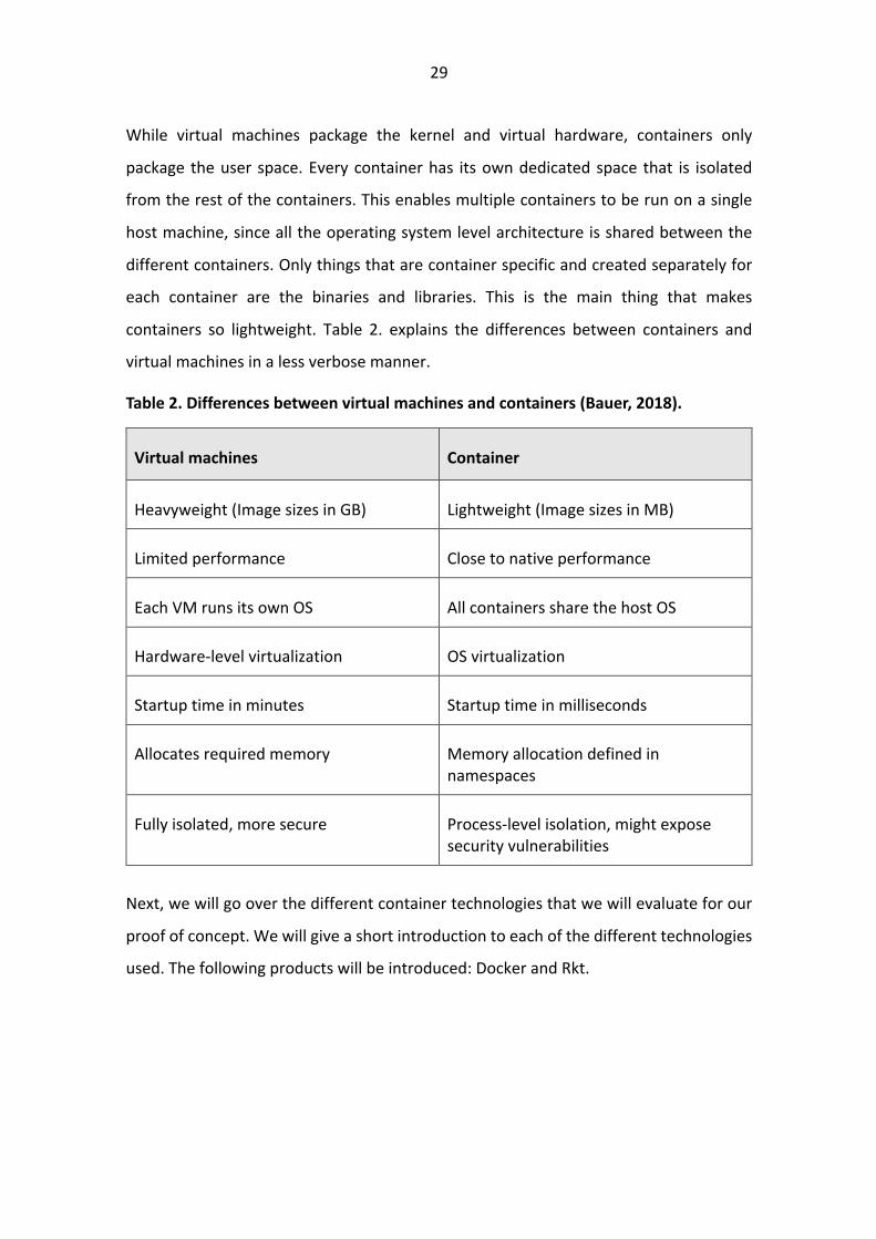
While virtual machines package the kernel and virtual hardware, containers only
package the user space. Every container has its own dedicated space that is isolated
from the rest of the containers. This enables multiple containers to be run on a single
host machine, since all the operating system level architecture is shared between the
different containers. Only things that are container specific and created separately for
each container are the binaries and libraries. This is the main thing that makes
containers so lightweight. Table 2. explains the differences between containers and
virtual machines in a less verbose manner.
Table 2. Differences between virtual machines and containers (Bauer, 2018).
Virtual machines Container
Heavyweight (Image sizes in GB) Lightweight (Image sizes in MB)
Limited performance Close to native performance
Each VM runs its own OS All containers share the host OS
Hardware-level virtualization OS virtualization
Startup time in minutes Startup time in milliseconds
Allocates required memory Memory allocation defined in namespaces
Fully isolated, more secure Process-level isolation, might expose security vulnerabilities
Next, we will go over the different container technologies that we will evaluate for our
proof of concept. We will give a short introduction to each of the different technologies
used. The following products will be introduced: Docker and Rkt.
30
3.1.1 Docker
Docker (Docker, 2019) was first released in 2011 but debuted to public in 2013. It is a
container service that allows developers to bundle software, libraries and configuration
files. It uses namespaces to isolate applications from the underlying operating system.
At first it leveraged Linux Containers (LXC), but later they released their own engine
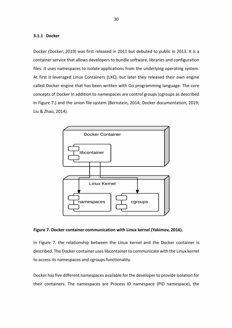
called Docker engine that has been written with Go programming language. The core
concepts of Docker in addition to namespaces are control groups (cgroups as described
in Figure 7.) and the union file system (Bernstein, 2014; Docker documentation, 2019;
Liu & Zhao, 2014).
Figure 7. Docker container communication with Linux kernel (Yakimov, 2016).
In Figure 7. the relationship between the Linux kernel and the Docker container is
described. The Docker container uses libcontainer to communicate with the Linux kernel
to access its namespaces and cgroups functionality.
Docker has five different namespaces available for the developer to provide isolation for
their containers. The namespaces are Process ID namespace (PID namespace), the

31
networking namespace (net namespace), InterProcess communication namespace (IPC
namespace), mount namespace (mnt namespace) and Unix timesharing system (uts
namespace). (Liu & Zhao, 2014).
The PID namespace allows each process to have its own process ID. Networking
namespace provides the process its own network artefacts like routing table, iptables
and loopback interface. IPC namespace provides isolation for mechanisms like
semaphore, message queues and shared memory segments. Mount namespace gives
each container its own mountpoint and finally Unix timesharing system namespace
allows the different containers to view and change their assigned hostnames (Dua, Raja
& Kakadia, 2014).
Linux control groups are a functionality similar as in the Linux kernel (Docker
documentation, 2019). They are meant for the system administration and control needs.
Control groups allow processes to be arranged into a hierarchy, which enables the user
to set limits for resource usage such as for the consumption of memory and processing
priority. This can be used to freeze running processes like batch processing and continue
a later time depending on the state of the hard drive i.e. where the free space is located
for the hard drive. Control groups are a hierarchal, treelike data structure. The child
process inherits certain attributes from its parent. The root of the tree is a process called
init.
Union file systems, or UnionFS, are file systems that operate by creating layers, making
them very lightweight and fast. Docker uses union file systems to provide the building
blocks for containers. Docker can make use of several union file system variants
including: AnotherUnionFileSystem (AUFS), B-Tree File System (BTRFS), Virtual File
System (VFS), and DeviceMapper (Liu & Zhao, 2014).
32
3.1.2 RKT
Rkt is a container engine that has been developed by CoreOS. Its basic idea is the same
as Dockers as they both are used to spin up containers. The main difference with Rkt
when compared to Docker is that Rkt’s interface is just a single executable file (Rkt
documentation, 2019).
Rkt can also be easily integrated with existing init systems such as Systemd and advanced
clustering environments. It is an open standard application container or otherwise
known as App Container (APPC). Rkt is also able to run Docker containers. The reason
Rkt can be easily integrated into the init system is that it does not have a centralized
daemon.
Security is also one of the advantages when comparing Rkt to Docker. This is because
Rkt contains a permission split function. It is designed to avoid unnecessary operations
to run with root privileges. In addition, default signature verification and other advanced
features for security considerations are provided (Xie, Wang & Wang, 2017).
3.2 Edge computing
As more and more items such as cars, beverage automates, toasters and for the
purposes of this thesis relays are connected to the internet, the amount of data
transferred grows and the bandwidth requirements increase linearly with the amount
of data transferred. As data transfer is limited to the speed of light, the need to reduce
the distance from device to cloud increases to reduce the amount of time it takes for a
request from the user to be completed. This is the reason why edge computing is gaining
traction in the field. Edge computing means that rather than sending all the data to be
processed in the cloud most of it is processed “locally” or to be more specific, on the
edge of the network. Therefore, it is called “edge computing” (Li & Wang, 2018).

33
Reducing the amount of data transferred to the cloud also has the benefit of reducing
the distance travelled, which directly reduces the amount of time spent waiting for the
data to arrive. The delay from the time sent to the time received is called latency and it
is measured in milliseconds. While milliseconds seem like a small fraction of time and
speed of light is extremely fast, the amount of time spent waiting compounds as the
amount of traffic is increasing constantly. According to Cisco Global Cloud Index, the
amount of Internet of Things (IoT) data sent this year alone is predicted to reach 507.5
zettabytes (Cisco Systems, 2018). For reference, one zettabyte is one trillion gigabytes.
Factoring in that the size of a single IoT request is usually no larger than a couple of
megabytes, one can quickly start to comprehend the number of requests done annually
and then multiplying it with the latency and the total time spent waiting is gargantuan.
For the scope of this thesis however, the more impactful benefit of the edge is the fact
that with pre-processing done on site, we do not have to send all the data to cloud. That
reduces the amount of data we must store to cloud and thus, reducing the costs.
Additionally, if we had to send everything we can gather from the relays of our
substations, the amount of bandwidth required would have been impractical.
The two most recognized issues with edge computing are large scale geographic
distribution of the computing infrastructure and the dynamic nature of edge devices.
Most of the cases where edge computing is incorporated is an IoT application, where
sensors read data such as voltage. (Giang, Lea, Blackstock & Leung, 2018). In the case
for this thesis, it is exactly that. However, these challenges do not in fact concern us yet.
For now, we are contempt with just inspecting a single substation as its own entity and
therefore the devices or sensors we encounter within any given entity do not spread
into a large geographic area. This means that all the devices reporting to the edge
computer are within a few meters of the actual device. The most apparent disadvantage
when devices are spread is that they communicate over a heterogeneous network
through different ways of communication (for example Wireless Fidelity (Wi-Fi), Long
Term Evolution (LTE), Wired, etc.) and there are both static and dynamic endpoints with

34
different reachability (for example direct Internet Protocol (IP) addresses vs behind a
Network Address Translation (NAT)). For us the communication protocol is fixed to
IEC61850 and the endpoints are static, and all share the same reachability as they are
within the same network (Giang et al., 2018).
The other problem currently with edge devices is that they are usually highly dynamic.
Load fluctuations and context changes like change in location are constantly happening.
This causes variation that can be hard to optimize since load balancing and dynamic
scaling is not that easy to create with edge resources due to them not being centralized
and readily available like cloud computing resources. (Giang et al., 2018). Then again, as
our load can be thought as Boolean in nature as we only perform a fixed number of tasks
in the edge, this concern is not of great importance pertaining to our situation. We do
not have to worry about load balancing since we can accurately guess the amount of
load we will ever see.
3.3 Cloud Technologies
Cloud computing has become an industry standard in the past ten years. Cloud
computing is just buying server space from a centralized location provided by a cloud
service provider. However, most companies order something to complement the server
space. This is usually done as a service. It can be anything ranging from Infrastructure-
as-a-Service (IaaS) to Software-as-a-Service (SaaS) (Liu, 2010).
IaaS is the closest to just buying up server space and placing it on your premises. The
crucial difference is that in IaaS the servers are in the cloud service providers data center
and the cloud service provider also takes care of the maintenance of the servers. Below
is a picture of a generic IaaS -architecture (Kozlovszky, Törőcsik, Schubert & Póserné,
2013).
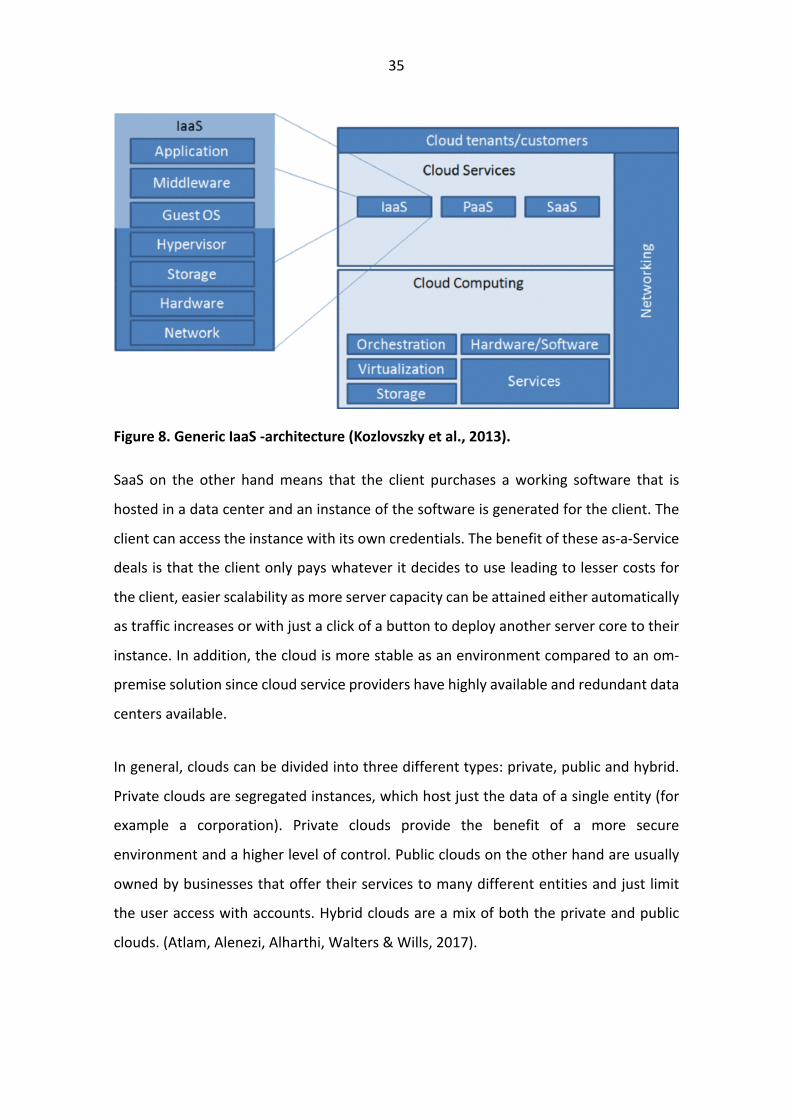
35
Figure 8. Generic IaaS -architecture (Kozlovszky et al., 2013).
SaaS on the other hand means that the client purchases a working software that is
hosted in a data center and an instance of the software is generated for the client. The
client can access the instance with its own credentials. The benefit of these as-a-Service
deals is that the client only pays whatever it decides to use leading to lesser costs for
the client, easier scalability as more server capacity can be attained either automatically
as traffic increases or with just a click of a button to deploy another server core to their
instance. In addition, the cloud is more stable as an environment compared to an om-
premise solution since cloud service providers have highly available and redundant data
centers available.
In general, clouds can be divided into three different types: private, public and hybrid.
Private clouds are segregated instances, which host just the data of a single entity (for
example a corporation). Private clouds provide the benefit of a more secure
environment and a higher level of control. Public clouds on the other hand are usually
owned by businesses that offer their services to many different entities and just limit
the user access with accounts. Hybrid clouds are a mix of both the private and public
clouds. (Atlam, Alenezi, Alharthi, Walters & Wills, 2017).
36
4 Methodology
Design science research (DSR) has increased its relevancy in information systems studies
in the last 20 years (Hevner, vom Brocke & Maedche, 2019). The main objective of design
science research is to enable new capabilities for humans and organizations by designing
novel artefacts represented by constructs, models, methods and instantiations (Hevner,
March, Park & Ram, 2004; Peffers, Tuunanen, Rothenberger & Chatterje, 2008; Gregor
& Hevner, 2013). In general, the aim of design science research is to provide a set of
rules to help one design a new process or an artefact.
According to Hevner et al. (2019), design science research is positioned ideally for
contributing to both research and practice within the field of digital innovation as it
focuses directly on the design and deployment of innovative artefacts. Currently, ABB
runs all the algorithms within the relays. Our objective is to create a novel approach for
ABB to run the algorithms in an edge or cloud environment. Therefore, we believe it is
accurate to talk of a digital innovation within the scope of ABB. Hevner et al. (2019) state
that design science research projects not only produce a novel digital innovation
artefact, but additionally they should produce the required processes and procedures
for the deployment and use of the artefact in the problem context.
The aim of the practical part is to create a proof of concept level architectural design of
algorithms running in an edge or cloud environment to increase the scalability of the
platform and reduce the maintenance costs when patching the system, which aligns
with the statement of March & Storey (2008) saying that novelty and utility of
constructed artefacts are the corner stones of contributions in design science research.
To accompany their sentiments Weber (2010, p. 2) claims the following:
“The focus of an IT artifact lies on the problem itself. It is finished when it satisfies the requirements of all stakeholders and solves the relevant problem. On the one
hand, it is necessary to understand why an IT artifact works or does not work while on the other hand it is necessary to understand how the IT artifact was
created. “

37
We will conclude that the work provided in the next chapters will be sufficient after all
relevant parties, such as representatives from ABB, agree to it with the proper
documentation to describe how our proposed artefact works.
There are numerous of different methods for conducting a design science research
project. The first one was created by Nunamaker Jr, Chen & Purdin in 1990 in which they
introduced systems development as a possible way to conduct information systems
research. This is considered as a good first step towards defining design science for
information systems research, but it demonstrated a clear lack of theoretical or scientific
outputs (Baskerville, Baiyere, Gregor, Hevner & Rossi, 2018).
Walls, Widmeyer & El Sawy in 1992 and March & Smith in 1995 continued to pursue
from the work of Nunamaker et al. (1990) by proposing kernel theories to amend the
deficiencies in the works of Nunamaker et al. (1990). In 2002, Markus, Majchrzak &
Gasser presented a concrete design and a theory that to this day are still valid design
methods. Following the work of Markus et al. (2002), Hevner et al. (2004) established
principles of canonical design research. Peffers et al. (2008) in turn created a process
outline for design science research. Finally, Kuechler and Vaishnavi in 2008 came up with
a high-level design process, that according to them most DSR methods follow
(Baskerville et al., 2018).
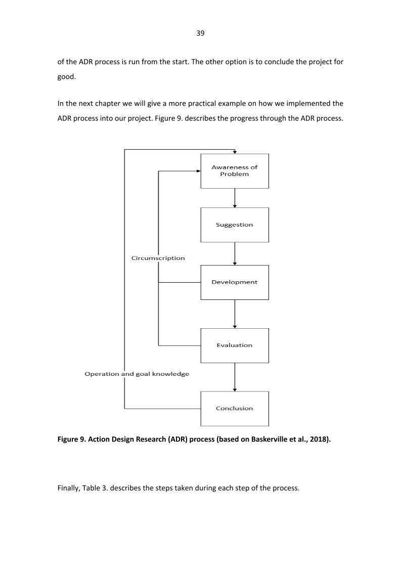
Baskerville et al. (2018) adapted the model created by Kuechler and Vaishnavi (2008)
and for our intents and purposes their model fit well. The adapted model of Baskerville
et al. (2018) is presented in Figure 9. It consists of five steps: Awareness of problem,
Suggestion, Development, Evaluation and Conclusion. Awareness of problem and
Suggestion outline the initial issue and propose a suggested mean of solving it. In
Development phase an artefact is created, and it will start producing data for analysis.
Once development is finished, evaluation of the created artefact is done with the data
produced by the artefact. During Development and Evaluation phases circling back
towards Awareness of problem can be done if needed to redefine problems that may
arise during development or evaluation. Finally, conclusions are drawn after evaluation
38
has been completed and passed. Next, we will give a more detailed explanation how
these steps work in the design and development of our artefact.
Each passing of the process is to be thought of as a sprint and it should provide a part of
the solution. It starts with the client (ABB in our case) defining a set of limitations and
goals according to their needs, id est Awareness of problem -phase. This is in our opinion
the most important phase of the process since it provides us the framework to complete
the project.
Suggestion phase is our chance of present our solution to the client based on the
limitations and goals set in the Awareness of the problem -phase. In theory these are
separate steps, but in our opinion having an open discussion during the Awareness of
the problem -phase and suggesting ideas based on the limitations and goals provided
for more interaction between the client and us and therefore a deeper understanding
of the problem at hand.
During the Development phase it is on us to create the solution based on the framework
decided in the first two steps of the process. If problems are to arise during development
the discourse is to be open and priority toward the client. It is hard to predict future
pitfalls during the Awareness of the problem and Suggestion phases and therefore
circumscription might have to be done during the Development phase rotating back to
the Awareness of the problem -phase. This is the reason open discourse between us,
and the client is essential even during the Development phase.
If, however no problems arise during development, the next phase is us presenting our
solution to the client for evaluation. Here it is vital that the client gives feedback on the
developed artefact. If the artefact is not up to the standards of the client, the next option
is to go back to defining the problem more specifically. However, if no problems are
detected it is time to conclude the process and deliver the lessons learned during the
process. If there are still sprints left to complete the entire artefact, then a new iteration
39
of the ADR process is run from the start. The other option is to conclude the project for
good.
In the next chapter we will give a more practical example on how we implemented the
ADR process into our project. Figure 9. describes the progress through the ADR process.
Figure 9. Action Design Research (ADR) process (based on Baskerville et al., 2018).
Finally, Table 3. describes the steps taken during each step of the process.

40
Table 3. Steps taken throughout the process.
ADR Step Actions in this study
Awareness of Problem Held meetings with ABB to discuss the limitations and goals
for the process. The goal is to set clear targets on the end
product after each sprint.
Suggestion Done in unison with Awareness of Problem -phase. Clear
suggestions given during the Awareness of Problem -phase
to meet the requirements for future phases. The final
suggestion was presented in the last of our meetings.
Development Development was done individually, while having constant
communication with the development team of ABB to
discuss problems leading to circumscription.
Evaluation Once we deemed development for iteration was ready to be
presented, we held a meeting with ABB to demonstrate what
we had achieved. When requirements were met, we moved
to conclude the sprint.
Conclusion Concluding the sprint and moving forward to the next sprint.
41
5 Path toward microservice architecture
In this chapter we will go through the selection process of the technologies. We selected
six different criteria to evaluate the two different container platforms. We also set a
maximum point limit for each criterion. As there were only two viable container
platforms to choose from, we decided that we would split the amount of points given
within the criterion based on performance.
After analysing the different technology options, we will present the steps we took
during the development of the artefact. To guide us through the process we relied
heavily on the ADR method presented in the previous chapter. However, we altered it
slightly to more reflect the workflow of ABB.
5.1 Selection of the technologies
Initially we were planning to evaluate different container technologies and cloud
technologies, but during the process of developing the container platform we realized
we could not get a fully functional platform. Thus, we decided it was not evaluate the
different cloud platform options.
We selected to review the container technologies with the following criteria: overall use,
ease of use, academic research, security, performance and licensing. The results of this
review can be found in Table 4. at the end of this section.
At first, we discussed how to grade the technologies according to the selected criteria.
It was important to assess the different options for technology to grant us the best
probability of completing the proof of concept. We decided to use a grading totaling to
maximum points of 100. After that we agreed the maximum grade for each of the
criteria. We agreed that the academic research is a strong and most important factor
while choosing the technology and therefore we emphasized that criterion most. Thus,
we gave it the maximum points of 30. Second most important criteria were overall use
42
and security, because these are important criteria for ABB as well. For these we gave the
maximum points of 20. Ease of use, performance and licensing were graded all with the
same scale of ten, because these were deemed to have the least impact on the proof of
concept.
Overall use is representing the actual usage of each technology. This criterion is based
on the Google search results by checking the number of sites returned by searching
“Docker” and “Rkt”. Gathered data clearly illustrates that Docker is currently the market
leader in container technologies. The actual parity between Docker and Rkt is much
greater than 3:1, but Rkt was given favour as it is still a less mature product and might
not have reached a critical mass yet to be fully adopted by the industry. A simple Google
search with the words “Docker” and “Container” returns 29,5 million results, while “Rkt”
and “Container” only returns 253 000 results as per today. However, the industry
perception does matter and therefore we chose to value it at a scale of 20 of which
Docker gained 15 and Rkt 5 points.
Ease of use encompasses quite a few factors. Firstly, the sharing of images was one
aspect. Docker Inc. provides a service to hold private docker images for a small monthly
fee, while CoreOS does not. Additionally, it is generally accepted that Docker has a lower
bar for entry when it comes to the two different platforms. Ease of use criterion is for
convenience rather than a showstopper, so it was set at a scale on 10 points. Docker
was graded at 7 points and Rkt at 3 points.
Academic research on this area was limited, but from the sources (Xie et al., 2017) we
found Docker was favoured. However, as we could not find enough of reliable sources
from academic studies, we only gave Docker a slight edge in this criterion. In addition to
academic research we found a corroborating research study conducted Forrester Inc.
The Forrester New Wave Enterprise Container Platform, Q4 2018 Report further
supported the claims of the academic research of Docker slightly topping Rkt. However,
we would like to remind, that Forrester Inc. is not an academic source and therefore the
results of their study should not be considered as a de facto truth. As this is an academic
43
research, it should also be reflected in the scale as well. A weight of 30 points was set
for this criterion. As Docker seemed to edge out in front by just a marginal advantage,
we graded it with 17 points and Rkt with 13 respectively.
In regards, to security Rkt was developed to address the severe security issues that once
were apparent in Docker. The most common objection against Docker was that it runs
containers with root privileges. This is not the case anymore as Docker has been
addressing these security issues. According to Xie et al. (2017) overall the Rkt platform
is more secure than Docker due to it running less of the operations as root due to
permission split function and on other advanced features for security. We think that
security is an important factor to consider, when comparing new technologies so we
gave it a scale of 20 and Rkt was granted 15 of those 20 points, which leaves Docker with
only 5.
The following criterion is performance. The scientific study measuring Rkt and Docker
against bare metal performance was conducted by Xie et al. in 2017. They measured
the CPU performance with a Y-cruncher. Y-cruncher is a commonly used program to
measure CPU performance.

44
Figure 10. CPU performance of bare-metal, Docker and Rkt (Xie et al., 2017).
From Figure 10. can be seen that Docker performs slightly better than Rkt. However, the
difference in CPU performance time is negligible. Regarding CPU performance Docker
and Rkt appear to be practically equal and thus, this should not be a major factor when
choosing a container platform. Therefore, we graded performance with the scale of ten.
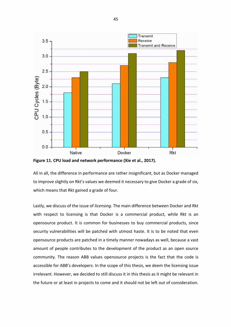
Figure 11. demonstrates the amount of CPU cycles needed to transmit and receive the
data as measured by Xie et al. (2017). For measurement they used a Linux command
“perf stat -a”. Both containers add significant overhead, but when compared against
each other the differences again are rather insignificant. However, it is to be noted that
Docker once again comes slightly ahead of Rkt.
45
Figure 11. CPU load and network performance (Xie et al., 2017).
All in all, the difference in performance are rather insignificant, but as Docker managed
to improve slightly on Rkt’s values we deemed it necessary to give Docker a grade of six,
which means that Rkt gained a grade of four.
Lastly, we discuss of the issue of licensing. The main difference between Docker and Rkt
with respect to licensing is that Docker is a commercial product, while Rkt is an
opensource product. It is common for businesses to buy commercial products, since
security vulnerabilities will be patched with utmost haste. It is to be noted that even
opensource products are patched in a timely manner nowadays as well, because a vast
amount of people contributes to the development of the product as an open source
community. The reason ABB values opensource projects is the fact that the code is
accessible for ABB’s developers. In the scope of this thesis, we deem the licensing issue
irrelevant. However, we decided to still discuss it in this thesis as it might be relevant in
the future or at least in projects to come and it should not be left out of consideration.

46
Due to the irrelevancy we will grade both with a grade of five. Thus, the scale for this
criterion is ten.
We have gathered a summary of all the set points in Table 4. The final evaluation stands
that Docker received 55 points while Rkt gathered 45 points. For this reason, Docker was
chosen as our desired platform.
Table 4. Docker versus Rkt comparison.
Criteria Max. points Docker points Rkt points
overall use 20 15 5
ease of use 10 7 3
research 30 17 13
security 20 5 15
performance 10 6 4
licensing 10 5 5
total 100 55 45
5.2 Methodology in action
As explained previously, we decided to use ADR as a method for conducting our
research. We thought it was a solid process to follow for our development as we were
in constant communication with ABB’s development team. As explained in the previous
chapter, ADR is an iterative process and each iteration consists of five phases that are
Awareness of the problem, Suggestion, Development, Evaluation and Conclusion.
The problem was defined as follows: ABB has a software that is written with a monolithic
application architecture that is used to monitor the electrical substations. There were
several motivational factors involved that drove ABB towards the change to
microservice architecture. Firstly, maintaining monolithic software is difficult. Secondly,

47
scaling an application with monolithic architecture is not efficient. Lastly, ABB’s
customers generally want to buy their products, because of the added value provided
by their intellectual property rather than just the hardware solutions.
The two first factors have been described in depth in previous chapters. The last factor
is an issue of product development. The objective was to create an application that could
communicate with hardware regardless of hardware vendor. Because IEC 61850 and
Common format for Transient Data Exchange (COMTRADE) are strictly defined data
exchange standards, they enable this objective.
Our task was to separate one of the functions from the monolithic legacy application,
more specifically, the fault locator algorithm. Then transform it to a containerized
microservice with a browser-based user interface. We saw three distinct iterations
required to complete the project. The three different phases are the web service,
document delivery and the fault locator applications itself. Figure 12. describes our
proposed microservice architecture.
Figure 12. Proposed architectural diagram of the proof of concept application.
We saw the need for three different containers as procedurally there are three different
phases to get the algorithm to run. First the user engages with the web user interface
48
by selecting the algorithm they wish to run. After that, the user is prompted to provide
the files needed to run the chosen algorithm. In the case of the fault locator algorithm,
the required files are the Common format for Transient Data Exchange for power
systems (COMTRADE) -file and the configuration file. Once the files have been stored
within the document delivery container, the algorithm can be run in the third container
returning the results back to the web user interface. To get a deeper understanding of
the inner workings of the fault locator algorithm and the files, we would like to refer the
reader to explore the IEC 61850 -documentation as the algorithm itself is out of scope
for this thesis and rather used as an example to prove that microservice architecture can
be achieved.
It could be argued that the document delivery container should be within the web user
interface container. However, we think that keeping the data separated from the web
facing interface is beneficial. In the future, we plan on using the same document delivery
container for multiple different algorithms, so the isolation here enables easier updates
on the application as well. Lastly, we want to set up a NoSQL document store as our
document database, because it enables us to store all our files in a single container
rather than setting up a relational database, defining a table and columns. On the other
hand, if we at some point need a relational database and we have set up the document
delivery inside the web user interface -container, it will be much harder for us to
implement the new database.
We agreed upon the three containers and decided that each of the containers was to be
built in a sprint that was two weeks long. Altogether, we decided that the development
would take six weeks to complete. We decided to proceed in the order of in which the
process would appear to the user. In other words, we would start with the user
interface, then move to the document delivery container and lastly, we would complete
the development by containerizing the fault locator -algorithm. Each of these sprints
should result in a completion of the ADR process for us to call the sprint a success. The
first step of the process however, was to setup an environment that supports the
development.

49
To start we decided to setup a constant delivery and integration pipeline. To achieve
that, we decided to use Travis CI (Travis CI, 2019). Travis CI is a constant integration
platform that will allow us to deploy code directly to Amazon Webservices (AWS)
(Amazon Web Services, 2019) or any other cloud provider. However, we decided to go
with Amazon webservices, because of the ease of use. The benefit of using Travis CI is
most definitely the fact that we can automate tests for the code to be run upon
deployment. Furthermore, if all the tests pass it will directly upload them to AWS and in
this case GitHub as well for version control.
GitHub (GitHub, 2019) is an opensource version control service that developers can use
to store code and use as a version control tool. GitHub is widely used in organisations.
The reason we selected GitHub, rather than GitLab, which is meant for enterprises, is
the fact that our work will not be a commercial product but is only for a proof of concept.
We also highly suggest that when our work is taken deployed as a major release then it
will be moved into ABB’s GitLab.
On AWS we used elastic beanstalk (Amazon Web Services Elastic Beanstalk, 2019), which
is perfect for our use case as it provides easy scalability for our service and we can
directly deploy code through Travis CI. The benefit of elastic beanstalk is that it supports
most of the common languages and servers. Additionally, it automatically handles
factors regarding deployment such as capacity provisioning, load balancing, auto-scaling
and application health monitoring. Thus, granting us a stable service. It could be argued,
that this step was taken too soon. However, we are strongly of the opinion that things
should be done right from the outset and not left until it is desperately needed. The
pattern seen in Figure 13. by Balalaie et al. (2016) for transitioning to microservice
architecture supports this claim.

50
Figure 13. Pattern transitioning to microservice architecture (Balalaie et al., 2016).
The first order of business for their pattern is to setup the continuous integration to
support the constant development. For this thesis, only the first two rows of the pattern
are relevant, since we do not have the resources to produce a fully developed
application. After continuous integration was setup, the development process was ready
to start.
The integrated development environments used for development were JetBrains’ tools
(Jetbrains, 2019) for the Python code. For the JavaScript code we used Microsoft’s Visual
Studio (Microsoft, 2019). These were just chosen based upon personal preference and
should not alter the results in any shape.

51
Above we have described all the setup we did before we started the development work
with iterations. In the next chapters, we will represent the actual process of transitioning
to the microservice architecture from the monolithic architecture.
5.2.1 First iteration – User interface
At first, we set forth to complete the web service as we deemed it was the easiest of the
three components to complete and required no knowledge of the legacy system. Thus,
we could complete the user interface and meanwhile keep our eyes and ears open for
any and all silent knowledge we could gather from the development team about the
fault locator algorithm.
Based on the discussions we had with ABB, regarding the awareness of the problem, the
web service had no specific requirements for technology or appearance. Therefore, we
were able to choose the technologies we deemed best fit for the issue at hand. We
consulted ABB about the technologies we are going to suggest using and they had no
objections.
We decided to create the user interface using Python’s Django framework. This decision
was partly made since we had prior knowledge of Django and realised it would provide
us with all the functionality we needed for the service. Django also has built-in databases
and admin panels that would make the administration of users easier during production.
This is a clear benefit, since the administrators would not have to get involved with the
source code, but they could rather accomplish all the tasks with a graphical user
interface provided for them. Additionally, in the far future, once the application starts
scaling horizontally, it would also highlight the benefit of being able to choose which
ever language or framework is best suited for the job. This is because we suspect that
future applications will be developed in JavaScript.

52
The development of the user interface went very smoothly, and we did not encounter
any major issues during the whole time as was expected. As this was just for a proof of
concept level application, we created a mock-up of the user interface with only the
necessary components and links between the pages. We did not use a lot of time to
refine the user interface to look as good as we possibly could, but rather made it
functional. However, one thing to note, the user interface is responsive, meaning that it
scales based on the size of monitor the user it is viewing it from. We made this possible
by using Bootstrap (Bootstrap, 2019). Bootstrap is a framework that has a plethora of
readymade functions that allow the developer to setup grids in which content can be
placed within the user interface. We settled for a grid with three columns and made one
of the columns link to the document delivery container.
Once we completed the first version of the user interface, we presented it to ABB, and
they deemed it would suffice for now. Figure 14. depicts the designed user interface.
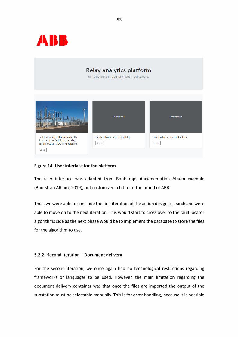
53
Figure 14. User interface for the platform.
The user interface was adapted from Bootstraps documentation Album example
(Bootstrap Album, 2019), but customized a bit to fit the brand of ABB.
Thus, we were able to conclude the first iteration of the action design research and were
able to move on to the next iteration. This would start to cross over to the fault locator
algorithms side as the next phase would be to implement the database to store the files
for the algorithm to use.
5.2.2 Second iteration – Document delivery
For the second iteration, we once again had no technological restrictions regarding
frameworks or languages to be used. However, the main limitation regarding the
document delivery container was that once the files are imported the output of the
substation must be selectable manually. This is for error handling, because it is possible

54
that the COMTRADE file has no outputs defined or they are defined incorrectly. No other
requirements were defined.
For the fault locator algorithm to run it requires two separate files from which it gathers
the data needed. These files are the configuration file that defines the configuration of
the relay and the COMTRADE file, which is the standardized file format defined by Power
Systems Relaying & Controls Committee (PSRCS), which is part of the Institution of
Electrical and Electronics Engineers (IEEE) Power & Energy Society. The COMTRADE -file
is produced by the Intelligent Electronic Devices (IEDs), which in our case is the
electronic protective relay, within the electrical substation. The IEDs monitor the
different characteristics of the electricity flowing through them such as current, voltage,
power and frequency. With digital signal processing the IEDs can detect fault on
conditions and on occurrence the IEDs produce a COMTRADE -file to report the fault
data. The COMTRADE -file can then be used by analytics tools to calculate information
about the occurred fault, such as the location of the fault with the fault locator
algorithm. With the configuration and COMTRADE -files we can accurately deduce in
which of the outputs and how far from the substation the fault is located.
To start this sprint, we held meetings with the developers from ABB and discussed
possible solutions for the problem. We came up with a solution that presumed that the
fault locator algorithm would be an independent component that could be run similarly
than you would run a program from the command line. Also, the files it needed could
be provided in a similar way as you would provide arguments for a function. This would
make it simple for us to build a document delivery container in which to store the
documents needed. Once the documents would be delivered, we could easily mount the
fault locator container with the document delivery container to enable the use of the
fault locator algorithm.
During the suggestion meetings it turned out that this in fact would not be possible due
to two reasons: the underlying system itself is not compatible with Linux containers and
the function itself is dependent on about 90% of the whole monolithic system. The

55
evaluation on the spot was that making the application Linux compatible would be at
least six months of work. However, the scope of the research and allocated resources
made it not feasible for us to pursue this option. This caused us to halt the process and
evaluate our options.
We came back to the table with the initial idea to run the whole application within a .net
container. This would solve our compatibility issues with Linux containers and a
Microsoft based application. However, we were faced with yet another issue. The legacy
application was not compatible with any of the version of the .net core available
container images.
The other setback we faced was the matter of the highly dependent monolithic
application architecture. The fault locator in fact did not operate as a single function to
be called, but rather it was a collection of small calculations that required nearly all the
legacy application to run. This, as referenced in chapter 2.5 of this thesis, made the
decomposition of the monolithic application unpractical. From Figure 13. it can be seen,
that according to Balalaie et al. (2016) this prevents us from moving onward with their
pattern.
Since we could not provide a meaningful suggestion to solve either of the reported
issues with our resources in a timely matter, we could not move forth to development.
Once more we convened to discuss the problem but both sides thought that the
obstacles in front could not be overcome. However, we still are of the opinion that the
value of microservice architecture leveraging containers is there. So, we decided that
we would provide a functional application that could be used to demonstrate the
functionality of containers.

56
Table 5. Steps taken in practice to achieve to proof of concept.
Problem Proposed solution Result
Web based user interface
to ease the use.
User interface to be
created with Python’s
Django framework.
Accepted and completed.
Document delivery
container to store files to
be used for the fault
locator.
Creation of the database
container to store the
files.
Accepted, but
development halted,
because severe issue
pinpointed.
Fault locator algorithm
could not be run as an
isolated function.
Containerize the whole
application.
Rejected as no further
value would be gained and
additionally compatibility
was a question.
Compatibility issues
detected during
suggestion meeting.
Modernize the
architecture to be
compatible.
Decided not to move
forward as the resources
needed were far greater
than was available.
Fault Locator algorithm
required too many
dependencies from the
legacy code. Thus, not
feasible to transform it to
a microservice.
Create a simplified version
of the original project
without the Fault Locator
algorithm.
Accepted and completed.
However, we still are of the opinion that the value of microservice architecture
leveraging containers is there so we decided that we would provide a functional
application that could be used to demonstrate the functionality of containers.

57
5.2.3 Final iteration
We decided together with ABB to make a simple application that demonstrates that
communication between containers can be achieved. We shared the understanding that
the requirements for this was to create an architecture with two containers. One to hold
the user interface and the other to analyse COMTRADE files and return the name of the
relay if it is defined.
For the analysis of the COMTRADE -files we decided to use David Parrini’s opensource
COMTRADE -file Python module (Parrini, 2019) and containerize it. It is able to parse the
.cfg and .dat files that are delivered when an error occurs. With matplotlib we were able
to draw graphs from these files that show the current (see Figure 15.).
Figure 15. Graphs of an COMTRADE files current.
Parrini’s module can plot different graphs from the COMTRADE files. In Figure 15., we
plotted two currents IA and IB just to show the functionality of the module.
Figure 16. describes the overall architecture of the application. All together it has two
different containers, specifically the user interface and COMTRADE containers. The user

58
interface container holds the web-based user interface shown in Figure 14. In addition
to holding the user interface, it also stores the files uploaded by the user. This allows us
to separate functionality and provide isolation. Additionally, when new functionality is
added in the future it enables the files to be used in the other containers as well. We
concluded that importing the files to a database would not provide any added value,
since the files could in fact just be saved into the container itself.
The COMTRADE container holds the COMTRADE python module (Parrini, 2019), which
allows us to parse the COMTRADE files. An example of the output returned by the
COMTRADE container is shown in Figure 15. This functionality was layered on top of the
initial requirement, but we can also get the container to return the name of the relay,
which was our initially intended functionality.
The Algorithms added in the future depicts how following algorithms can be
incorporated into the current architecture. This becomes relevant if the transit to
microservice architecture will be completed after this thesis. This architecture model
enables the scalability of the application to the fullest as explained in the previous
chapters.
Figure 16. Final architecture of our case study.

59
6 Results
We were not able to develop the initial idea of this thesis to the proof of concept level.
However, we think that even though the development could not be completed we have
still achieved to answer the questions we set out to answer. In this part of the thesis we
will go over the research questions, but in addition to that we will try to give more
context what went wrong and how to avoid these issues in the future.
The first research question was framed: “Can a monolithic software be transformed into
a microservice architecture?” In short, the answer is most definitely, but upon reflection
done in hindsight the smarter question might be: “When is transforming a monolithic
application architecture into a microservice architecture smart?” This is in fact the more
important question. Upon reviewing all the articles relating to microservices referred in
this thesis, the reader might get a sense of microservice architecture being the perfect
tool for every job. However, if anything our work proves that sometimes there is wisdom
found in ways past. We would like to propose a prerequisites list that must be in order
before thinking about transit to microservice architecture:
- Minimal technological debt acquired during the years
- Know the legacy application in depth
- Avoid systems that are highly dependent
- Do not rush it, it will take time and resources.
What we mean with the technological debt is that make sure the application is running
in the most recent of versions for everything used within. Otherwise, one will most likely
be facing compatibility issues especially soon, since containers are still fairly new
technology the versions predating them are most likely not supported. In the future, this
60
might be less of an issue if the older versions are still maintained. However, we would
still strongly recommend on trying to eliminate all the debt accrued.
There are multiple reasons why monolithic application came before microservice
architecture, for example computational and network speed limitations. However, one
key factor is also the fact that monolithic architectures are less complex. Distributing the
code into isolated environments that only communicate between each other through
API’s increases the complexity of the system. Therefore, implanting a new developer
into a research project meant to redesign an old architecture that they are completely
unfamiliar with increases the likelihood of errors. At the very least it increases the
difficulty of the already complex process even more.
If possible, avoid systems that are highly dependent. However, if the system requires a
microservice architecture either for scalability or other reasons, the first step to take is
to make sure that the two issues mentioned before are in order. Thus, allowing for
containerizing of the whole application. This per se is not much, but it is a good first step
into getting familiar with containerization and microservice architecture. However, in
our case we deemed it obsolete to go forth with containerizing the whole application in
a single container, since we could not find any additional value since the application had
been run in virtualized environments prior to this thesis.
The high dependency also led to the problem we faced was that the algorithm could not
run without most of the components of the system. Even if we were able to decompose
the monolith, we would have had to separate the auxiliary calculations into separate
containers. This would have increased the application’s overhead and led to an overall
reduction in system performance. Thus, we concluded that it would not provide any
further value.
Transitioning to a microservice architecture is a huge undertaking and should not be
thought of as anything less. Resources needed will probably be greater than initially
forecasted, since most likely unforeseen circumstances will result into obstacles that will
61
hinder the transition process. During the development process, we in fact found a study
that had undertaken a similar endeavour as ours. One thing to note however, the scale
of their application was even bigger than ours. This study was conducted by Knoche &
Hasselbring (2018) in which they present a successful transition to microservice
architecture from a monolithic application architecture. As of publishing their paper
their project had been running for nearly four years and by that point, they themselves
called it almost completed. This should provide an example of what sort of timeframe is
to be expected with a project of this scope.
The last paragraph relates directly to the second research question as well which was
“What are the pitfalls and misconceptions of transitioning to a microservice architecture
found during this thesis?” That being the resources required to successfully carry out the
project from start to finish. We drastically underestimated the time and other resources
required for this project as should be clear by the study done by Knoche & Hasselbring
(2018). Unfortunately, we only came across this case study in the latter part of our own
research. Had we found this study earlier in our own research we probably might have
pivoted in to a different angle of research.
Yet again we arrive in the issue of high dependency. As stated previously, one of the
most common misconceptions regarding the microservice architectures is the limitation
set by the dependencies within the system. In our case, it resulted in a total halt in
development as we could not provide meaningful results.
All together, we think that the list mentioned previously about the prerequisites for
transitioning to a microservice architecture sums up all the pitfalls we encountered
during our development.
In addition to the pitfalls we encountered, another pitfall that would most like have been
encountered further in the development than we reached is the susceptibility to partial
failures. This cannot occur in monolithic applications, since the whole application fails if

62
part of it fails. However, in distributed it is important to handle failures gracefully and
not let the whole system die if a service goes down.
Lastly, we would like to address our sub-question for this thesis. In retrospect, while we
do see the advantages microservice architecture has over the monolithic architecture,
especially since physically the devices themselves are distributed with great lengths
between each substation, we do not think at this time that it is sensible use of resources
to transit this application to a microservice architecture. The most significant reason for
this is the high dependency of the application. However, like stated previously we do
see the benefit in moving to a microservice architecture and if that is the desire, we
think that all together it might be smarter to build the application from the ground up.

63
7 Conclusions
Even though we did not manage to provide a working proof of concept level application
to ABB we believe that we managed to demonstrate the basic principles and highlight
the pitfalls one is likely to encounter when moving from a monolithic application
architecture to a microservice architecture.
In our opinion the two most relevant findings of this study were the adjustment of the
ADR process to combine the Awareness of problem and Suggestion phases together and
the list of prerequisites that have to be in order before attempting to transit to a
microservice architecture.
The prerequisites list is a good reference when thinking about going towards a
microservice architecture as these issues we highlighted are probably the first obstacles
future projects will encounter as well. Our results clearly indicate that this is by no means
a light undertaking and other research presented in this thesis support this claim.
Having an open communication during Awareness of problem and Suggestion phases
allowed us to do them simultaneously and in collaboration with the development team.
This also clearly reduced the time it took us to understand the underlying problems we
were facing with the development. Thus, we would propose future research done with
Action Design Research to try if combining the first two phases produces positive results
to them as well.
Furthermore, regarding the question of communication and knowledge transfer. ABB is
globally operating in 100 countries and ABB’s Distribution Solutions is operating in half
of them. Software development is decentralized resulting in fragmented development
teams all working towards the same goals, but in completely different practices. Thus,
leading to potential issues regarding communication and in-depth knowledge of the
created software. Therefore, it would be beneficial to develop processes that support
shared communication and understanding of the overall application. Moving forward
64
we would propose ABB looking into reassuring that knowledge transfer is constant and
the enterprise architecture is well defined. With enterprise architecture we mean a
topological description how all the components developed in decentralized teams
operate with each other.
As theoretical contributions, we believe that once all of the deficiencies have been dealt
with a solid base towards transit to microservice architecture can be done. This can be
also generalized and others willing to embark on this transit should also account for the
list of prerequisites. Additionally, we are strongly of the opinion that the combination of
the first two phases of the ADR method provided us with a clear way of moving forward
and we noticed a reduction in wasted time. However, this was possible only because of
the willingness for open communication from the client organization.
The main contribution of the community of practice, namely ABB, is the concrete
application we developed. It illustrates the benefits that microservices and containers
can bring to an organization. The code was delivered to ABB and if they choose it can be
used as a base to continue with the proof of concept, once the problems described in
the previous chapters have been eliminated.
At this moment we would not encourage ABB to pursue microservice architecture for
the selected software’s codebase. While we do recognize the benefits granted by it, the
effort and resources required exceed the benefits gained. We propose that if
microservice architecture is truly desired, building a new solution should be the most
straightforward approach. Obviously, reusing parts of the original software should be
considered wherever applicable.
The limitations for this thesis are at least the following. The list of prerequisites is most
likely incomplete. Other issues could have risen if any other application would have been
chosen or we would have been able to continue further into the research. Thus, this
leads to us into another limitation, which is the limited resources, mainly time, available
for this case study. Another limitation to this thesis is that we were limited with

65
resources to verify our results on the issue regarding selection of the technologies,
especially when it comes to Rkt.
To elaborate on the future research mentioned earlier in this chapter. A solid way to
verify the experiences we gained, future research could measure the difference in time
spent between the regular ADR process and when the Awareness of the Problem and
Suggestion phases were combined.
Another interesting line of future research would be to create two simultaneously
running projects for the same application. One of the projects would try to modernize
certain functionality of the application, while the other project would develop the same
functionality from scratch. Thus, providing valuable information whether modernizing a
legacy is efficient.
Still one interesting future study could be to recreate the experiment with Rkt and see
if the results are like ours. Additionally, the comparison presented in this thesis between
Docker and Rkt could be verified.

66
References
ABB. (2018). Managing Relion IEDs Protection and control IED manager PCM600
Retrieved 2.12.2019 from
https://search.abb.com/library/Download.aspx?DocumentID=1MRS756483&Lang
uageCode=en&DocumentPartId=LoRes&Action=Launch.
Alshuqayran, N.; Ali, N.; & Evans, R. (2016, November). A Systematic Mapping Study
in Microservice Architecture. In (2016 IEEE 9th International Conference on Service-
Oriented Computing and Applications (SOCA), 44-51.
Amaral, M.; Polo, J.; Carrera, D.; Mohomed, I.; Unuvar, M.; & Steinder, M. (2015,
September). Performance Evaluation of Microservices Architectures using
Containers. In 2015 IEEE 14th International Symposium on Network Computing and
Applications, 27-34.
Amazon Web Services. (2019). Retrieved November 27, 2019 from
aws.amazon.com
Amazon Web Services. (2019). AWS Elastic Beanstalk. Retrieved November 27, 2019
from https://aws.amazon.com/elasticbeanstalk/
Atlam, H. F.; Alenezi, A.; Alharthi, A.; Walters, R. J.; & Wills, G. B. (2017, June).
Integration of Cloud Computing with Internet of Things: Challenges and Open
Issues. In 2017 IEEE International Conference on Internet of Things (iThings) and
IEEE Green Computing and Communications (GreenCom) and IEEE Cyber, Physical
and Social Computing (CPSCom) and IEEE Smart Data (SmartData), 670-675.

67
Balalaie, A.; Heydarnoori, A.; & Jamshidi, P. (2016). Microservices Architecture
Enables DevOps: Migration to a Cloud-Native Architecture. IEEE Software, 33(3),
42-52.
Baskerville, R.; Baiyere, A.; Gregor, S.; Hevner, A.; & Rossi, M. (2018). Design Science
Research Contributions: Finding a Balance between Artifact and Theory. Journal of
the Association for Information Systems, 19(5), 3.
Bauer, R. (2018). What’s the Diff: VMs vs Containers. Retrieved 4.12.2019 from
https://www.backblaze.com/blog/vm-vs-containers/
Bernstein, D. (2014). Containers and Cloud: From LXC to Docker to Kubernetes. IEEE
Cloud Computing, 1(3), 81-84.
Bootstrap. (2019). Retrieved November 27, 2019 from https://getbootstrap.com/
Bootstrap. (2019). Album example. Retrieved 5.12.2019 from
https://getbootstrap.com/docs/4.3/examples/album/
Burckart, E. J.; Ivory, A. J.; Kaplinger, T. E.; Kenna, S. J.; & Shook, A. K. (2013). U.S.
Patent No. 8,601,129. Washington, DC: U.S. Patent and Trademark Office.
Cisco Systems. (2018). Global Cloud Index retrieved November 27, 2019 from
https://www.cisco.com/c/en/us/solutions/collateral/service-provider/global-
cloud-index-gci/white-paper-c11-738085.html.
Cisco Systems. (2019). Cisco Visual Networking Index retrieved December 2, 2019
from https://www.cisco.com/c/en/us/solutions/collateral/service-provider/visual-
networking-index-vni/white-paper-c11-741490.html.
Conway, M. E. (1968). How Do Committees Invent. Datamation, 14(4), 28-31.

68
Dahlstedt, J. (2012). U.S. Patent No. 8,156,492. Washington, DC: U.S. Patent and
Trademark Office.
Docker documentation. (2019). retrieved November 27, 2019 from
https://docs.docker.com/
Dua, R.; Raja, A. R.; & Kakadia, D. (2014, March). Virtualization vs Containerization
to Support PaaS. In 2014 IEEE International Conference on Cloud Engineering, 610-
614.
Erlandsson, Z. (2019). Suitability of OCR Engines in Information Extraction Systems:
a Comparative Evaluation. Degree project in computer science and engineering. KTH
Royal Institute of Technology, School of Electrical Engineering and Computer
Science. Stockholm, Sweden
Fetzer, C. (2016). Building Critical Applications using Microservices. IEEE Security &
Privacy, 14(6), 86-89.
Garber, L. (2012). The Challenges of Securing the Virtualized
Environment. Computer, 45(1), 17-20.
Giang, N. K.; Lea, R.; Blackstock, M.; & Leung, V. C. (2018, July). Fog at the Edge:
Experiences Building an Edge Computing Platform. In 2018 IEEE International
Conference on Edge Computing (EDGE), 9-16.
GitHub. (2019). Retrieved November 27, 2019 from github.com.
Gray, J. (2006). A conversation with Werner Vogels. ACM Queue, 4(4), 14-22.
Gregor, S.; & Hevner, A. R. (2013). Positioning and Presenting Design Science
Research for Maximum Impact. MIS Quarterly, 37(2), 337-355.

69
Hevner, A.; March, S. T.; Park, J.; & Ram, S. (2004). Design Science Research in
Information Systems. MIS Quarterly, 28(1), 75-105.
Hevner, A.; vom Brocke, J.; & Maedche, A. (2019). Roles of Digital Innovation in
Design Science Research. Retrieved November 4, 2019 from
https://link.springer.com/article/10.1007/s12599-018-0571-z..
Hirschheim, R.; & Klein, H. K. (2012). A Glorious and Not-So-Short History of the
Information Systems Field. Journal of the association for Information
Systems, 13(4), 188.
Jokela, V. (2014). Sähköasemadatan Laajamittainen Analysointi. Retrieved
December 2, 2019 from https://dspace.cc.tut.fi/dpub/handle/123456789/22621
Jetbrains. (2019). Retrieved November 27, 2019 from
https://www.jetbrains.com/pycharm/
Kalske, M.; Mäkitalo, N.; & Mikkonen, T. (2017, June). Challenges When Moving
from Monolith to Microservice Architecture. In International Conference on Web
Engineering, 32-47. Springer, Cham.
Kang, Brandon. (Jan 29, 2019). Generic Microservice Architecture Topology.
Medium. Retrieved November 27, 2019 from
https://medium.com/@sangjinn/how-to-manage-api-in-the-msa-microservices-
architecture-world-2c4ec90c677e, 11.11.2019
Kazanavičius, J.; & Mažeika, D. (2019, April). Migrating Legacy Software to
Microservices Architecture. In 2019 Open Conference of Electrical, Electronic and
Information Sciences (eStream), 1-5. IEEE.

70
Knoche, H.; & Hasselbring, W. (2018). Using Microservices for Legacy Software
Modernization. IEEE Software, 35(3), 44-49.
Kozlovszky, M.; Törőcsik, M.; Schubert, T.; & Póserné, V. (2013, May). IaaS type
Cloud infrastructure assessment and monitoring. In 2013 36th International
Convention on Information and Communication Technology, Electronics and
Microelectronics (MIPRO), 249-252. IEEE.
Kuechler, B.; & Vaishnavi, V. (2008). On Theory Development in Design Science
Research: Anatomy of a Research Project. European Journal of Information
Systems, 17(5), 489-504.
Lewis J.; & Fowler M. (Mar 2014). Microservices. Retrieved November 27, 2019
from martinfowler.com/articles/microservices.html.
Li, Y.; & Wang, S. (2018, July). An Energy-Aware Edge Server Placement Algorithm
in Mobile Edge Computing. In 2018 IEEE International Conference on Edge
Computing (EDGE), 66-73.
Li, Y.; & Xia, Y. (2016, December). Auto-scaling web applications in hybrid cloud
based on docker. In 2016 5th International Conference on Computer Science and
Network Technology (ICCSNT), 75-79. IEEE.
Liu, D.; & Zhao, L. (2014, December). The research and implementation of cloud
computing platform based on docker. In 2014 11th International Computer
Conference on Wavelet Active Media Technology and Information Processing
(ICCWAMTIP), 475-478. IEEE.
Liu, G. (2010, April). Research on independent SaaS platform. In 2010 2nd IEEE
International Conference on Information Management and Engineering, 110-113.
IEEE.

71
Malavalli, D.; & Sathappan, S. (2015, November). Scalable Microservice Based
Architecture For Enabling DMTF Profiles. In 2015 11th International Conference on
Network and Service Management (CNSM), 428-432. IEEE.
Mauro, T. (2015, February). Nginx — Adopting Microservices at Netflix: Lessons for
Architectural Design [Online] Retrieved 13.11.2019 from
https://www.nginx.com/blog/microservices-atnetflix-architectural-best-practices/
March, S. T.; & Smith, G. F. (1995). Design and natural science research on
information technology. Decision Support Systems, 15(4), 251-266.
March, S. T.; & Storey, V. C. (2008). Design Science in the Information Systems
Discipline: An Introduction to the Special Issue on Design Science Research. MIS
Quarterly, 32(4), 725-730.
Markus, M. L.; Majchrzak, A.; & Gasser, L. (2002). A Design Theory for Systems That
Support Emergent Knowledge Processes. MIS Quarterly, 26(3), 179-212.
Messina, A.; Rizzo, R.; Storniolo, P.; & Urso, A. (2016). A Simplified Database Pattern
for the Microservice Architecture. In The Eighth International Conference on
Advances in Databases, Knowledge, and Data Applications (DBKDA), 35-40.
Microsoft. (2019). Retrieved November 27, 2019 from
https://visualstudio.microsoft.com/
M&S Consulting. (2019). Oracle Cloud DevOps and Cloud Native Applications.
Retrieved November 27, 2019 from https://www.mandsconsulting.com/oracle-
cloud-devops-and-cloud-native-applications/ 11.11.2019
Namiot, D.; & Sneps-Sneppe, M. (2014). On Micro-services
Architecture. International Journal of Open Information Technologies, 2(9), 24-27.

72
Newman, S. (2015). Building Microservices: Designing Fine-Grained Systems.
O'Reilly Media, Inc.
Nunamaker Jr, J. F.; Chen, M.; & Purdin, T. D. (1990). Systems Development in
Information Systems Research. Journal of Management Information Systems, 7(3),
89-106.
Parrini, D. (2019). Python COMTRADE. Retrieved 25.12.2019 from
https://github.com/dparrini/python-comtrade/commits/master/README.md
Peffers, K.; Tuunanen, T.; Rothenberger, M.A.; & Chatterje, S. (2007). A Design
Science Research Methodology for Information Systems Research, Journal of
Management Information Systems, 24(3), 45-77. doi:10.2753/MIS0742-
1222240302
Premchand, A.; & Choudhry, A. (2018, February). Architecture Simplification at
Large Institutions using Micro Services. In 2018 International Conference on
Communication, Computing and Internet of Things (IC3IoT) (pp. 30-35). IEEE.
Reuben, J. S. (2007). A Survey on Virtual Machine Security. Helsinki University of
Technology, 2(36).
Richards, M. (2016). Microservices AntiPatterns and Pitfalls. O'Reilly Media.
Retrieved November 27, 2019 from
https://theswissbay.ch/pdf/_to_sort/O'Reilly/microservices-antipatterns-and-
pitfalls.pdf 12.11.2019
Rkt documentation. (2019). Retrieved November 27, 2019 from:
https://coreos.com/rkt/docs/latest/ 12.11.2019

73
Rosenblum, M.; & Garfinkel, T. (2005). Virtual machine monitors: Current
technology and future trends. Computer, 38(5), 39-47.
Ross, J. W.; & Feeny, D. F. (1999). The Evolving Role of the CIO. Retrieved November
27, 2019 from https://dspace.mit.edu/bitstream/handle/1721.1/2758/SWP-4089-
43797710-CISR-308.pdf
Seedotech, R. (2018). Monolithic vs Microservice Architecture. Retrieved November
27, 2019 from https://medium.com/@raycad.seedotech/monolithic-vs-
microservice-architecture-e74bd951fc14 11.11.2019
Taibi, D.; & Lenarduzzi, V. (2018). On the Definition of Microservice Bad Smells. IEEE
software, 35(3), 56-62.
Travis CI. (2019). Retrieved November 27, 2019 from https://travis-ci.org/
Uber documentation. (2019). Retrieved November 27, 2019 from
https://eng.uber.com/tag/microservice/ 13.11.2019
Walls, J. G.; Widmeyer, G. R.; & El Sawy, O. A. (1992). Building an Information
System Design Theory for Vigilant EIS. Information Systems Research, 3(1), 36-59.
Weber, S. (2010). Design Science Research: Paradigm or Approach? AMCIS 2010
Proceedings 214.
Xie, X. L.; Wang, P.; & Wang, Q. (2017, July). The performance analysis of Docker
and rkt based on Kubernetes. In 2017 13th International Conference on Natural
Computation, Fuzzy Systems and Knowledge Discovery (ICNC-FSKD), 2137-2141.
IEEE.

74
Yakimov, B. (2016). Containerization with Docker. Retrieved 25.12.2019 from
https://itgix.com/blog/post/containerization-with-docker/