SBC System catalogue 2022 | 2023 - Product Index
273
SBC System catalogue 2022 | 2023 Electronic instrumentation, control and automation technology for machines, facilities and real estate
-
Upload
khangminh22 -
Category
Documents
-
view
0 -
download
0
Transcript of SBC System catalogue 2022 | 2023 - Product Index

SBC System catalogue 2022 | 2023Electronic instrumentation, control and automation technology for machines, facilities and real estate


Contents
ProductsA1 Automation stations
A2 HMI Visualization and operating
A3 Room controllers
A4 Consumption data capture
A5 Accessories for automation technology
Basic systemsB1 SBC Software
B2 Communication & Interaction
B3 SBC S-Web: Visualisation, Trending, Alarming
B4 Room control
AppendixC1 Status: Product launch and availability
C2 Abbreviations
C3 Type listing
7
85
101
117
137
153
187
217
237
247
251
253

Saia PCD®
Technology
Saia ®PCD Technology
www.saia-pcd.com
This catalogue presents the current product range for the automation of technical infrastructure. It includes facilities for energy production and distribution, water supply, telecommunications, transport networks and HVAC facilities in buildings.
The catalogue provides an introduction on how to understand and be able to assess for yourself the qualities and properties of the ICA/automation technology you have integrated and/or planned. You can see which technical capabilities exist for operating infrastructure objects more cost-effectively and with less effort. You can recognize how you can avoid dependencies which are disadvantageous to your business. You can find products “Made for Lean Automation Technology” which are designed to give you more peace of mind.
You can find the technical basis for consulting, engineering and invitations to tenders. You can recognize how Saia PCD technology can help you to achieve maximum flexibility in project implementation and the following optimization phase. Maximum flexibility helps you to deal with the 2 basic constants of the project business better and more easily. These include: a) You are lacking important information and requirements in the planning phase. b) The actual construction design deviates from your plan. Despite this, everything should be finished on time and within
budget.
Here you can find the general technical principles for mounting and cabling SBC device technology. You can un-derstand how applications are created with SBC S-Engineering software tools and how they can be changed in the lifecycle. You can recognize which device, which software tools and application modules are suited to an invitation to tender or project description.
You invest, operate, manage…
You plan, advise, calculate…
You install, implement and provide service…
How can the SBC System Catalogue
help you?
Our catalogue does not feature products with a lifecycle likely to end in a few years’ time. We no longer recommend these “end of life” products when planning new projects. They will therefore no longer be listed in the manual. A list of all the available SBC products can only be found in the current price list. Here you will also find products which are specially designed for the automation of industrial production machines
SBC S-Monitoring Systems
This catalogue does not cover all the products supplied by Saia Burgess Controls. An aware choice based on relevance was made for as many of our customers as possible.
This resulted in the following focus topics: Instrumentation, control and automation (ICA) technology of
primary installations Increased efficiency when using natural resources Technical integration and automation of buildings
Electricity, water, gas, heating Electricity, water, gas, heating
Strategic focus on primary systems with SBC technology Long lifecycle, adaptable, expandable
Strategic focus on resource efficiency Record, display and control the consump-tion of electricity, water, gas, heating, etc. with SBC S-Monitoring Systems. Suitable
for use everywhere where technology has to be easily and reliably integrated into operations but is to remain flexible and
expandable – from residential homes to industrial facilities.
Our Saia PCD® technology
Your installation

KNX
Profibus
Technical cornerstonesIn order to achieve the shared objectives of operators and owners of automation systems, we need a suitable stable technical foundation. This foundation comprises 4 basic properties which are common to all Saia PCD controllers.
1 Modularity in hardware and function enables high flexibility and adaptability at any time during the lifecycle of 15…20 years.
2 Maximum portability: The project’s application software can be ported over all device classes and device generations throughout the lifecycle; even by the owner/operator alone.
3 Complete openness in communication. All device functions and data can be seen from the outside and used. Complete openness also in licensing the SBC software tools, because SBC software tools are available to anyone.
4 Standard technology only: The ICA functions of Saia PCD devices are implemented using standardized technology that is in common use and is recognized around the world (web + IT). We do not use proprietary technologies. Saia PCD S-Bus is the exception. We need this in order to get right into the core of the Saia PCD devices, e.g. debugging.
Shared objectives Being able to understand and assess products and their integration into systems is essential. Knowing what objectives they were created to achieve helps accomplish this. These objectives should largely be identical to those of operators, planners and integrators of ICA systems.
Shared objectives bring everyone together – just as the shared methods and values of the companies involved make collaboration easier and ensure success. The following two pages provide a short overview of this.
Bus technology usable with Saia PCD control devicesOther protocols can also be implemented later as a PLC program

1950
1978
2008
2002
1990
2010
2019
2018
2016
2006
www.saia-pcd.com
SBCGivisiez
IEC EN 61131-2This standard defines in 150 pages how electronic items should be developed and produced to satisfy PLC quality requirements. It ensures, among other things, that service is possible even without specialists. Look out for the exten-sion “-2”. Many suppliers work only to PLC standard 61131-3. But that standard only defines the programming method type, regardless of the hardware/design quality. In addition, standard 61131-3 does not specify the portability of application software from one device series to another, nor from one hardware version to the next.
Control systemsSaia-Burgess Controls AG, or SBC, is based in a bilingual (German and French) part of western Switzerland – the locality which is home to companies with a global reputa-tion and to leading schools and universi-ties in the field of technology. Saia Burgess Controls is a wholly-owned subsidiary of Honeywell International Inc. and operates according to the “bottom up” principle: the needs of the grassroots are defined and inte-grated into the development and manufac-turing process. The company has developed and marketed electronic components and
Development, production and sale of industrial-grade electronic components and systems for control/automation engineering.
measurement and control systems since 1950. The products are distinguished by an extremely long service life. They are used in heating, ventilation and climate control, energy management and water systems. A further important pillar of the company is OEM production. SBC products are always fit for pur-pose and are guarantors of technological progress.
Our mission
At the end of the seventies, Saia Burgess Controls became a pio-neer in the field of programmable logic controllers (PLCs), known and used long-term under the Saia® brand name. In parallel with the component business, Saia Burgess Controls grew to become a supplier of measurement and control technology systems.
In 2010, with the complete redesign of the Saia PCD1, the smallest device series joined the Saia PCD3 and Saia PCD2 in being fully modernised. The 3rd generation of Saia PCD control devices is now complete. This is char-acterised by the following equation:Saia PCD® = PLC + IT + WebSeamless integration of world renowned open technologies for web and IT on freely programmable, industrial electronics with the same quality and life cycle as the robust, industrial PLC.
In the early days, Saia Burgess Controls manufactured mainly electronic timers. The spec-trum of use extended from house installations to machine technology.
The year 2006 saw the start of the product line for fully integrated bus compatible electronic energy meters.
In the same year, Saia Burgess Controls launched the world’s first completely web- based touch- panel for automation.
Value and culture of a PLC companyWhen they use our products customers gain value added in the form of sustainable earnings. For this reason, we develop products with a long life cycle of problem-free, reliable opera-tion. Installed products can be adapted to changing needs at any time. Investments made by the customer are lasting and not constantly subject to incompatibilities or forced and unwanted innovations. This is why we develop PLC-based technology, with its sustained customer benefit and ease of upgrade. For more than 50 years, our company has remained true to these values.
Since application settings all too often fail to behave in accordance with the standards, we have made Saia PCD1, 2, 3 control technology more robust against interference than the CE standard requires. We set high standards for our-selves. This gives our customers greater security and peace of mind
Alongside the strict IEC 61131-2 PLC hardware standard, Saia PCD control technology also meets the stringent requirements of various testing authori-ties for marine engineering.
About us …Murten
Zurich
Geneva
Bern
Basel

saia-pcd.com
From bid phase to production and far beyond: All in-house
Control and measurement electronics should have the same life cycle as the installa-tion plant technology. During this cycle the technology must remain adaptable and expandable at all times; it should therefore be modular and in PLC quality.
The compatibility and free portability of system/machine software is safeguarded over an entire product generation of 18 to 25 years. This can only be achieved if we develop all the engineering soft-ware ourselves, and systematically use “interpreted program code”. This approach requires rather more hardware resources, but allows user software to be portable across several controller generations.
View of lifecycle for Saia PCD® control equipment
Product care phase>10 years
Service phase>5 years
18 years Saia PCD control device lifecycle < 25 years
Changeover phase
Program-compatible subsequent generation
Introduction phase3–5 years
Our customer baseThe spread of our customers is a distinctive feature of our company. More than 50% of our corporate turnover is achieved with “small” system integrators, who carry out infrastructure automation projects. At the other end of the scale, we also develop and manufacture products for well-known international companies in electrical automation. Midway between the two are the production machine builders. Many of these supply HeaVAC and “energy” machines for infrastructure. In process technology, Saia PCD controllers are found in machines for stoneworking, textiles, printing, assembly, etc. In the case of machine controllers, we have no specific industry focus but rather a customer focus. Target customers are manufacturers of production machines who value an economical and innovative controller technology that offers them ample room for their own added value and product differentia-tion. We provide our customers with individual adaptations to achieve maximum efficiency for their needs.
Our Saia PCD® technology
Your installation
Product Development
Software, firmware and hard-ware developed in-house
Guaranteed product life cycle and compatibility for over 15 years
Faster and more reliable pro-duction of custom orders
Production
Two modern SMD lines with 560 feeder positions
Effective mounting capacity of 80,000 components per hour
Selective soldering machine for processing densely populated, critical boards
ICT, AOI and boundary scan test methods
Assembly
Production and assembly based on the “lean” principle
Direct final assembly in work cells downstream of the SMD line, no intermediate storage
A machine-assembled board becomes a finished product ready for dispatch, including packaging and documentation.
Logistics
75,000 order items
12,000 packages
1,000 sales items kept in stock
Delivery reliability: >96%
Delivery time: 80% of items within 48 hours
Training and Support
The aim is to achieve a high level of autonomy and ef-ficiency for our customers.
Product support and training centres at every sales support location
Practical basic and advanced training facilities at the factory in Switzerland

saia-pcd.com
12,3
R&D Support Team - Werk Reperaturservice im Werk
Our value contribution on the way to an installed and optimized ICA solution.
SBC Support
Requirements profiles of operators/owners
Fully operational installations/systems
SBC Components & Systems
System integratorsEngineering & ServiceSBC
Support
Lean automation support The greatest benefits are achieved with mini-mum operating costs if the requirements profile of the user/operator is implemented as perfectly as possible in automation solutions. This profile only becomes clear in long-term operation and when there is good knowledge of the individual application. For this reason, people who imple-ment and maintain the operational automation/ICA solution should be as close to the application as possible. SBC support is thus fully focused on achieving maximum autonomy and independ-ence with high efficiency for system integrators, systems builders and operators.Saia Burgess Controls does not deal with the realization and maintenance of installed, fully operational automation/ICA solutions. A device manufacturer simply does not have the strategic starting position to be the best here.
Customer support
SBC support structureThe satisfaction and economic success of the oper-ator/user when using SBC technology is influenced by many groups of people. For this reason, SBC support specifically supports everyone involved in the planning, implementation and operation of fa-cility installations. Support engineers are available to the customer for advice and assistance. The field service support engineers are assigned to a sup-port center in the country/region. Their employees are available to all interested parties by phone, e-mail and NetMeeting. Where the scope and type of local resources is not sufficient, there is a further factory support level in the background. Large training facilities for HeaVAC technology are also provided here. Online help is available 24 hours a day, 7 days a week at www.sbc-support.com.
Support structure for SBC components and systems
Mission: The logistics support ensures that products from the factory can be delivered within a week to each (industrialized) place on earth.
We consider service to be an integral part of the sale price. As a result, our customers experience success and delight when using our products. For us, satisfaction is not an option or an “accessory”, but part of the basic product. As a system manufacturer, our support expertise goes far beyond one single device. Our products are components and systems.
www.sbc-support.comOnline help is available 24/7.
Quality and performance of SBC supportThe quality and performance of our support deter-mines our success. We regularly have independent institutes assess our customers’ satisfaction with the support service. The results of the survey are checked for credibility by authorities such as the German company TÜV Süd before publication.
Breakdown of sales
Saia Burgess Controls : For us, revenue from service
is of virtually no significance. We derive no profit from
operator/owner problems and costs over the life cycle.
SBC support is free of charge, because every device
delivered includes support when needed.
Soft
war
e <
3 %
Supp
ort
< 1%
Dev
ices
Har
dwar
e >
95
%
$
Field service
Technical customer support
in the region/country
Logistics/catalogsupport
in the region/country
HVAC application support & training
at the factory
Technical customer support
Backup team
Logistics/catalog support
at the factory
R&D support team at the factory Repair service at the factory
Support eng.application/
product
Support eng.technical andcommercial

A Products
A1 Automation stations
A1.1 System description
A1.2 PCD3 – modular cartridge construction
A1.3 Standby System
A1.4 PCD2 – modular, expandable, compact CPU
A1.5 PCD1 – modular, expandable, compact CPU
A1.6 PCD1 E-Line – compact design for electrical distributors
A2 HMI Visualization and operating
A3 HMI Visualization and operating
A4 Consumption data acquisition
A5 Cabinet components
7
8
19
37
45
59
69
85
101
117
137


7
12
34
5
A1
Aut
omat
ion
stat
ions
Ope
rati
on
and
mon
itor
ing
Roo
m c
ontr
olle
rsCo
nsum
er
data
acq
uisi
tion
Swit
ch c
abin
et
com
pone
nts
Automation stations Programmable for measuring, regulation and control devices. Modular series consisting of industrial quality CPU, I/O and communication modules with a service life that will last for decades. The application software can be simply and reliably adapted and expanded throughout its service life. It can be used for all device series (Saia PCD1, 2 and 3).
1.1 Basic system properties
1.4 PCD2 – modular technology with a compact design
1.5 PCD1 – modular, expandable, compact CPU
Presentation of the Saia PCD COSinus control operating system – hardware structure – program execution – memory system and service capability.
External dimensions independent of the type and number of the integrated hardware modules. Expandable system up to 1023 I/Os – up to 15 simultaneously operated communication interfaces.
18 basic I/Os which can be expanded to max. 50 I/Os with 2 optional I/O modules – up to 8 simultaneously operated communication interfaces.
1.6 PCD1 E-Line – compact design for electrical distributors
Programmable I/O modules I/O modules Communication modules and gateways
E-Line product line for specific applications in very confined spaces.
1.3 Standby System
PCD3.M6880 standby controller PCD3.T668 smart RIO for standby system
1.2 PCD3 – modular cartridge construction
Saia PCD3.Mxx6x as high power CPU Saia PCD3.M5xxx as standard control device Saia PCD3.T66x remote I/O stations
Saia PCD3.M3xxx as the most compact base unit Saia PCD3.M2 with dedicated I/O level
and function
Up to 1023 I/Os – up to 13 simultaneously operated communication interfaces.
Standby system for highly available automation solutions.
Page 8
19
37
45
59
69

8
bedienen/managen
messen regeln
PLC+ (Web+IT)
=
Saia PCDs combine PLC functionality with innovative web and IT technology in an industrial quality system. The basic equation Saia PCD® = PLC + (web + IT) means that the conventional automation pyramid is becoming an open, transparent structure.
The service life of Saia PCD®: Compatibility and portability guaranteed for all device types across generations.
The Saia PCD system with its open technology stands for total transparency, combinability and openness. This applies between all the levels of the automation pyramid, the automation world and the actual operating environment of the user. To achieve this, all Saia PCD control and regulation devices generally include comprehensive web + IT functions. These functions do not require additional hardware and form an integral part of every device. Machines and systems can therefore be very easily integrated into the existing IT infrastruc-ture.
We develop our products to provide customers with direct added value that enables them to generate sustainable revenue. This requires products with a long service life and flawless and reliable operation. Previously installed products must always be able to adapt to changing needs. Existing investments should not always be made obsolete by unwanted, forced innovations and incompatibilities. This is why we attach such great importance to PLC-based technology with its sustained customer benefit and ease of upgrade. Our company has remained true to these values for over 50 years. Moreover, we only use components that comply with industrial standards and which have a service life of at least 20 years.
1.1 Saia PCD® System description PLC + (Web + IT ) = Saia PCD®
Management level
Field level
Automation level
Automation pyramid by definition: strictly separate levels; insulated from the outside world.
Automation pyramid Saia PCD opens up through standard technology
Service life planning of Saia PCD® control devices. Enables maximum profitability of your investment in expertise and systems. Long service life without expensive reinvestment and no high service costs.
Product maintenance phase > 10 years
Service phase > 5 years
Introduction phase 3–5 years
Changeover phase
The next generation is compatible with the program
18 years < service life of Saia PCD® control device < 25 years
9
12
34
5
IIIIIIIIIIIIIIIIIIIIIII
IIIIIIIIIIIIIIIIIIIIIII
Aut
omat
ion
stat
ions
Ope
rati
on
and
mon
itor
ing
Roo
m c
ontr
olle
rsCo
nsum
er
data
acq
uisi
tion
Swit
ch c
abin
et
com
pone
nts
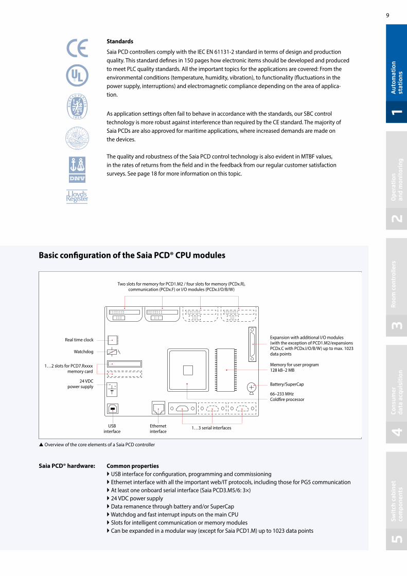
Basic configuration of the Saia PCD® CPU modules
Standards
Saia PCD controllers comply with the IEC EN 61131-2 standard in terms of design and production quality. This standard defines in 150 pages how electronic items should be developed and produced to meet PLC quality standards. All the important topics for the applications are covered: From the environmental conditions (temperature, humidity, vibration), to functionality (fluctuations in the power supply, interruptions) and electromagnetic compliance depending on the area of applica-tion.
As application settings often fail to behave in accordance with the standards, our SBC control technology is more robust against interference than required by the CE standard. The majority of Saia PCDs are also approved for maritime applications, where increased demands are made on the devices.
The quality and robustness of the Saia PCD control technology is also evident in MTBF values, in the rates of returns from the field and in the feedback from our regular customer satisfaction surveys. See page 18 for more information on this topic.
Common properties USB interface for configuration, programming and commissioning Ethernet interface with all the important web/IT protocols, including those for PG5 communication At least one onboard serial interface (Saia PCD3.M5/6: 3×) 24 VDC power supply Data remanence through battery and/or SuperCap Watchdog and fast interrupt inputs on the main CPU Slots for intelligent communication or memory modules Can be expanded in a modular way (except for Saia PCD1.M) up to 1023 data points
Saia PCD® hardware:
Overview of the core elements of a Saia PCD controller
Watchdog
1…2 slots for PCD7.Rxxxx memory card
24 VDC power supply
USB interface
Ethernet interface
1…3 serial interfaces
Expansion with additional I/O modules (with the exception of PCD1.M2/expansions PCDx.C with PCDx.I/O/B/W) up to max. 1023 data points
Memory for user program 128 kB–2 MB
66–233 MHz Coldfire processor
Battery/SuperCap
Two slots for memory for PCD1.M2 / four slots for memory (PCDx.R), communication (PCDx.F) or I/O modules (PCDx.I/O/B/W)
Real time clock

10
COSinus
COSinus COSinus
We developed the core of the Saia PCD operating systems between 2001 and 2003 as part of a European cooperation project with Philips and Nokia. We then expanded the core and focused on an operating system for advanced, industry-quality measuring, control and regulation devices. A dedicated operating system for ICA technology – a control operating system (COS). Developed in-house and with all aspects fully covered.
Saia PCD® COSinus – Control Operating System
Why COSinus?
The control operating system (COS) ensures that customers’ application software will always operate on all platforms, is portable across device generations and expandable over several decades. Hardware and the Windows® programming tools may change, but the customer will not have to modify the application code. The hardware, software tool and application software can be compared to the sides of a triangle. If hardware and/or software changes, the angles must adjust for the application software to remain unchanged. We expanded the abbreviation COS to the name COSinus due to the trigonometric relation-ships in triangles.
The COSinus operating system always provides the application with the same infrastructure, regardless of the underlying hardware and processor. The key to this is the Saia virtual machine. It ensures that an application program created with PG5 works on all PCDs across generations.
The main components of Saia PCD® COSinus
1 Multi-tasking kernel: Abstracts the hardware, incl. I/Os and communication interfaces, provides basic multi-tasking functionality on which the program processing of Saia PCD programming is also based.
2 Virtual Saia PCD machine: This is the logic machine that executes the PG5 programs. The virtual Saia PCD code is interpreted and guarantees that programs are always executed in a consistent manner on different PCD controllers. The three hubs of the PG5 application program are the following: Media: Memory of the virtual PCD machine such as registers, flags, meters, etc. Program execution: Program and organisation blocks, text, monitoring, error processing, memory management, etc. System functions: Access to the hardware, I/Os, interfaces and drivers
3 Automation Server: The Automation Server includes widely used web/IT technologies and ensures data exchange between users and automation solutions with no proprietary hardware or software required.
4 Communication protocols: Various field and automation protocols such as BACnet®, Lon, Profibus, Modbus, DALI, M-Bus, and many others.
Saia PCD COSinus connects user programs
and various hardwareHardware
Kernel
Virtual Saia PCD maschine
User application
Automation Server
Communication protocols
Hardware type A Hardware type B
Kernel Kernel
Virtual Saia PCD machine
Virtual Saia PCD machine
User application User application
Automation Server
Automation Server
Communication protocols
Communication protocols

11
12
34
5t1 t3t2
t1 t2 t3
t1 t2 t3 t4
XOB XOBXOB XOBXOB
BACnet®
BACnet® BACnet®
BACnet® BACnet®
BACnet®
Aut
omat
ion
stat
ions
Ope
rati
on
and
mon
itor
ing
Roo
m c
ontr
olle
rsCo
nsum
er
data
acq
uisi
tion
Swit
ch c
abin
et
com
pone
nts
The user program consists of one or more organisation blocks that are executed by the PCD Interpreter. Each user program has at least one cyclical organisation block, COB, the COB0. The PCDs are mono-processor systems. Saia PCD 1, 2, 3 control and regulation devices have a main processor that processes all the tasks. The user program has a special role here and is processed as a core task. In addition to the user program, any communication tasks and server functions (web, FTP) are processed. The CPU capacity is allocated accordingly. The cycle time for the user program not only depends on the length of the program itself, but also on the simultaneous additional load.
Execution of the user program
Cycle time with no additional communication
Cycle time with BACnet® communication and interrupt (XOB)
Cycle time with BACnet® communication
Examples:
The COSinus operating system ensures that all tasks are processed. An intelligent load balance must be maintained between the user program and communication. This actually occurs in planning practice. It is only problematic if the contractor uses a lower performing Saia PCD CPU than planned to save money or is “saving” on CPUs by concentrating tasks on one CPU.
Cold start Application ApplicationApplication Application
Application
Application Application Application
Application ApplicationCold start
Cold start
The more communication takes place, the longer the cycle time (tx), which may result in variations in the cycle time. If this variation in the cycle time is not required, for example because regulation must take place in a fixed time period and ideally without jitters, make sure that this part of the program is executed in an XOB. The priority of the XOBs is higher than that of the COBs and higher than many other operating system tasks. The above example shows that a periodic XOB interrupts the cyclic program and the execu-tion of the BACnet® task.

12
. . . SNTP, DHCP, DNS . . .
Data types and program blocks*
Register (32 bit) 16,384Flags (1 bit): 16,384
Timers (31 bit) and meters (31 bit): 1600 (Partitioning configurable)
Cyclical organisation blocks COB: 0…31“Exception” organisation blocks (XOB): 0…31
Program blocks (PB): 1000Function blocks (FB): 2000Text/data blocks DB: 8192Sequential blocks (SB): 96
The main XOBs and their priority levels
Priority 4 XOB 0: Network out
Priority 3 XOB 7: System overload – displayed if the interrupt XOB queue
is overflowing XOB 13: Error flag – displayed in the event of communication
or calculation errors or an invalid instruction
Priority 2 XOB 16: Cold start XOBs 14, 15: Periodic XOBs XOBs 20…25: Interrupts
Priority 1 XOB 2: Battery failure XOB 10: Nesting depth exceeded when PB/FBs are displayed XOB 12: Index register overflow
Saia PCD® Opcode
Saia PG5® generates a platform-independent opcode that is interpret-ed by the Saia PCD. As a result, the same program runs on different platforms. This also enables the user program to be updated with a flash card as the operating system of the Saia PCD performs the neces-sary actions to copy and execute the program from the flash card to the memory.Code that is generated (= compiled) and optimised for the specific platform will of course run faster. This compiler is not integrated into the PC tool (Saia PG5®). Saia PCD COSinus knows how this code should be implemented into the relevant hardware most effectively. The program is compiled when it is loaded into the Saia PCD.
Automation server
The Automation Server is part of the COSinus operating system. It includes widespread web/IT technologies and ensures data exchange between users and automation solutions with no pro-prietary hardware or software required. Specifically adjusted automation functions and objects form the relevant counterpart in the controller application. The web/IT functions can therefore be optimally and seamlessly integrated into the automation device and used efficiently.
Automation device
Electrician
Maintenance Supervisor
Operator Operations Manager
Programmer
Service technician
Saia PG5® Software tool
Saia PCD CPU
Editing
PCD opcode
Download
Compiler
Execution
Web server: The system and process are visualised in the form of web pages and can be requested from the web server via browsers such as Internet Explorer, Firefox, etc.
File system: Process data, records, etc. are stored in easy-to- access files. Standard formats make it easy to process them further, e.g. with Microsoft Excel
FTP server Load files into the automation device over the network using FTP, or export files from it.
Email: Critical system statuses, alarms and log data can be sent by email.
SNMP: Messages and alarms are transmitted in accordance with IT standards. Access to automation data using the IT management system.
Automation Server components
You can find a full list in the PG5 help section.
* This information is dependent on the hardware and the COSinus version.
Target group-oriented data output
You can find a full list in the PG5 help section.
* This information is dependent on the hardware and the COSinus version.

13
12
34
5
IIIIIIIIIIIIIIIIIIIIIII
IIIIIIIIIIIIIIIIIIIIIII
IIIIIIIIIIIIIIIIIIIIIII
IIIIIIIIIIIIIIIIIIIIIII
Aut
omat
ion
stat
ions
Ope
rati
on
and
mon
itor
ing
Roo
m c
ontr
olle
rsCo
nsum
er
data
acq
uisi
tion
Swit
ch c
abin
et
com
pone
nts
A user program may contain various data types. This includes data that is relevant for a fast regulation process and data records that must be collected over a long period or saved permanently. All these data types have different requirements in terms of hardware. For example, a regulation-relevant process requires a fast memory to calculate and provide current values. However, historical data records require sufficient remanent mass memory to cover a long period of time.
Memory management in the Saia PCD® systems
If a user program function is placed in PG5, various memory areas are required in the system. These areas can basically be divided into 3 groups. The parameter group controls the behaviour of the FBox that is processed in the user program. Defined statuses of the parameters result in responses in the FBox. Using the example of the HDLog function, the log data of the associated parameters is written to the file system in an Excel-compatible file format. Various templates are provided in the Web Editor to visualise this file in the web application. These can be easily connected to the FBox using a range of parameters. As the visualisa-
Saia PG5® FBox shown as an object in the Saia PG5® Fupla engineering environment. To the right you can see which functions belong to the object.
This is how the functions of a memory area belonging to the Saia PG5® FBox are mapped.
Memory areas of the Saia PCD® systems A distinction is made between two key memory areas.The user memory, which ensures fast access for reading and writing, contains time-criti-cal content such as media and the program code executed by the CPU. However, this memory is not a programmable read-only memory (PROM) and is buffered by a bat-tery. The flash memory, on the other hand, per-manently saves data and provides space for historical data records or data that will not change during the operation of the system. The backup of the user application can be stored in a file system, which means that the processing of teh program is guaranteed.
tion pages only change when the Saia PG5® project is created, these are stored in the file system.
Visualisation
Log data
CodeCode
Parameters
RAM Flash memory

14
PCD1.M2xxxPCD3.Mxx6xPCD7.D4xxVT5F
PCD2.M5xxx
Automation devices with integrated μSD cardThe automation devices Saia PCD3 Plus, Saia PCD1.M2 and the programmable panel are provided with an onboard μSD flash card. When loading a user application with Saia PG5®, all the necessary files in the internal flash memory are stored on the μSD card. If the operating voltage is connected to the automation device and there is no executable program in the user memory, COSinus attempts to load a valid program from the μSD card on startup.
Memory management of the Saia PCD® systems with COSinus operating system
Automation devices with no integrated onboard flashIn the case of automation devices with no integrated μSD card and which are equipped with the COSinus system, the user application is copied direct to the user memory from Saia PG5®. If no valid program is detected in the user program when the controller is started up, a search is executed for a backup program in the onboard flash or an optional memory module.
Saia PCD1.M2xxx
Saia PCD2.M554x
Saia PCD3.Mxx6x Saia PCD7.D4xxVT5F
Loading of the user program from Saia PG5® onto Saia PCD automation devices and allocation of different data between the storage media.
DRAM SRAM Media (R, T, F)
File systemConfiguration
SRAM data
User program
RIO application load as required
RAMMicroSD flash card
DRAM RAM TEXT/DB RAM TEXT/DB
SRAM SRAMUser programROM TEXT/DB
User programROM TEXT/DB
Media (R, T, F) Media (R, T, F)
Onboard flashRAM
Save if required
File system
Saia PCD1.M2220-C15

15
12
34
5
Activity
Busy
Write
Diag
User
Aut
omat
ion
stat
ions
Ope
rati
on
and
mon
itor
ing
Roo
m c
ontr
olle
rsCo
nsum
er
data
acq
uisi
tion
Swit
ch c
abin
et
com
pone
nts
Memory expansion and resources of the Saia PCD® systems
User memoryMemory allocation of PCD2.M5xx0
RAM User program and DB/text
1024 kbytes
Flash memory Backup memory 1024 kbytes
Flash memory expansions 4 expansion modules
Memory allocation of PCD1.M2xx0
RAM User program: 512 kByte … 1 MByte DB/text: 128 kByte … 1 MByte
Flash memory File system 8 … 128 Mbytes
(maximum of 900 … 2,500 files or 225 … 625 directories)
Flash memory expansions 1 expansion module
Memory allocation of PCD3.Mxx6x
RAM User program: 2 Mbyte DB/text: 1 Mbyte
Flash memory File system 128 Mbytes
(maximum of 2,500 files or 625 directories)
Flash memory expansions 4 expansion modules
User memory
User memory
μSD flash
μSD flash
8–128 MBFile system
Flash ROM expansions
Flash ROM expansions
Expansion device(max. 1)
1024 kB
Flash ROM expansions
2048 kB 1024 kB
8–128 MBFile system
1024 kB 1024 kB

16
Activity
Busy
Write
Diag
User
PCD3.R600 Module holder for SD flash memory cardswith 512 and 1024 MB
PCD7.R-SD512 / PCD7.R-SD1024SD flash memory cards with 512 MB / 1024 MB
PCD7.R610 with PCD7.R-MSD1024Basic module with Micro SD flash card with 1024 MB
PCD7.R562 BACnet®128 MB for file system and firmware expansion for BACnet® configu-ration files with BACnet® applications
Expansion options of the user file system
Saia PCD systems can be expanded by at least 1 to a maximum of 4 external memory modules that contain a user system. An external file system is ideal as a backup for the entire user application and enables users to save trend data, alarms and event lists, as well as log files defined by the user. An external file system may contain up to 900 files or 225 directories.
The application’s system backup contains all the vital information and data that must be available to process the application. This enables users to easily and securely reset the controller to a saved and known state.With the system backup function of the Saia PCD COSinus operating system, it is also possible to fully duplicate a system and copy it to an identical piece of hardware with no additional adjustments required (copy/paste).The system backup can be created in the office on a Saia PCD memory mod-ule using an automation device of identical construction. Any technician (without training, a manual or software tools) can then perform a system restore or a system update direct on site should any changes be applied – totally within the meaning of lean automation.
Creating a system backup A system backup can also be created by the licence-freeSaia PG5® software tool “Online Configurator”.The system can be backed up either on the internal flash memory module or on an optional memory module Saia PCD7.Rxxx.
Using a system backup No dedicated software tools are required to restore a system backup. This only requires an optional Saia PCD7.Rxxx memory module that contains a system backup for the target controller.Press and hold the run/stop button for 3 seconds to restore the application contained in the backup memory module. The COSinus operating system automatically looks for a system backup of the application in all the storage media connected to the automation device. If a valid system backup of the operating system is found, it is “automati-cally” loaded into the user memory. The automation device restarts.
The system backup – entire automation project
Memory media for external backups
Content of a system backup created on an exter-nal module with a file system
Creation of a system backup with the Online Configurator
User memory (RAM)
File system backup
ConfigurationUser program
DB/textRIO applicationsMedia (R, C, T, F)
User file system
128 MB
1024 MB
512 MB1024 MB

17
12
34
5
FAQ
Aut
omat
ion
stat
ions
Ope
rati
on
and
mon
itor
ing
Roo
m c
ontr
olle
rsCo
nsum
er
data
acq
uisi
tion
Swit
ch c
abin
et
com
pone
nts
Can third-party local I/Os be connected via S-Bus? In the manual we have excluded these for the Saia PCD controllers. SBC S-Bus is a proprietary protocol that is essentially designed for communication with engineer-ing and debugging tools, to connect the management level or process control systems and for PCD to PCD communication. It is not suitable or approved for the connection of local I/Os from different manufacturers. I/Os from third-party manufacturers should be inte-grated professionally and safely using one of the many manufacturer-independent field bus systems.
Can the Saia PCD controllers connect direct to the Internet?When Saia PCD controllers are connected direct to the Internet, they are also a potential target of cyber at-tacks. Appropriate protective measures must always be taken to guarantee secure operation. PCD controllers include simple, integrated protection features. However, secure operation on the Internet is only ensured if external routers are used with a firewall and encrypted VPN connections. For more information, please refer to our support site: http://sbc.do/Me4r-LqwE
How do I connect a third-party device to the PCD if the protocol is not supported in the PCD firm-ware and there is not a corresponding FBox library either? One of the greatest strengths of the Saia PCD is that, in addition to the numerous “off the shelf” communication protocols available, users themselves can implement any protocol required in the user program. This is pos-sible via a serial interface and also via Ethernet.You can find PG5 example programs on our support site on this topic.
FAQs for the design of automation systems
What is the difference between centralised and decentralised I/Os?When remote I/Os are accessed, a communications task always has to run. This task interrupts the process-ing of the actual ICA task, thus extending the cycle time (page 11). If cycle time is important and critical, it is more efficient to use central I/Os.
How many central I/Os per Saia PCD®?The I/O capacity of a Saia PCD automation station depends on the maximum number of pluggable I/O modules, i.e. 64 modules for the Saia PCD2 and Saia PCD3 series. Each module requires 16 bits. This gives a maximum of 1024 binary signals overall. Each Saia PCD CPU in this system catalogue can read all 1024 binary signals in under 10 msec and make them available to the user program logic. For calculation purposes, assume a value of 0.01 msec per binary I/O and 0.03 msec per analogue value.
In practice, the number of I/Os is limited by the cycle time required for the user program (see explanation page 11). If the Saia PG5® IL Editor is used to write a resource-efficient user program in text form, the 64 I/O slots of the Saia PCD automation station will be fully usable. The cycle time will certainly be well below 100 msec.
If the graphic software engineering tool Saia PG5® Fupla and prefabricated system templates (Saia PG5® DDC Suite) are used to create the application software, then only half the 64 possible I/O modules should be equipped for a cycle time of <100 msec. Additional communication and data processing tasks will further increase cycle time.
In the case of fully graphic software engineering for control-intensive applications combined with ad-ditional tasks (e.g., BACnet®, gateway, management functions), it is inadvisable to use more than 300 I/Os per automation station.

18
How does communication influence the application cycle time? If the PCD is set as the server (master station), it has lit-tle or no control over its partner stations. Should these partner stations send large amounts of data simultane-ously, the PCD MUST receive them. The receiving/pro-cessing of these data packages will take priority over the application cycle time. The cycle time may conse-quently be increased depending on the workload. The PCD processing time may be significantly increased if several partner stations send large volumes of data simultaneously. The impact will be minimal if the PCD is set as client (slave station). The figures below are based on a PCD3.M5340 with a program cycle time of 100 ms, excluding additional communication. Web server Displaying a page on a micro browser pan-el or PC does not have a major impact. Loading a large file such as a Java applet or an offline trend during the transfer can increase cycle time by 40…50%. The same applies when large files are transferred via FTP. S-Bus or Modbus communication via Ethernet: Each partner station running under full load increases the cycle time by approx. 8%. Serial S-Bus: Each slave-type communication at 38.4 kbit/s increases the cycle time by 5% (port #2). In the case of PCDx.F2xx modules, the increase is approx. 17%. At 115 Kbits the cycle time is approximately 20% higher. Modbus RTU: A client at 115 kbit/s increases the cycle time by about 11% (port #2). In the case of PCDx.F2xx modules, the increase is approx. 45%.
What exactly does MTBF mean? Where can I find the MTBF values for Saia PCD® controllers? MTBF stands for Mean Time Between Failures. The time referred to is the period of operation between two consecutive failures of a unit (module, device or sys-tem). The higher the MTBF value, the more “reliable” the device. On average, a device with a MTBF of 100 hours will fail more often than a similar device with a MTBF of 1,000 hours. The MTBF value can be calculated in purely mathematical terms or based on empirical values. Please bear in mind that the MTBF value of the overall installation depends on the values of the individual switch cabinet components.An overview of the MTBF values of the PCD controllers is included on our support site.The return rate is of greater relevance in practice. We analyse all the devices that return from the field. The return rates of the current PCD controllers during the warranty period (30 months) are as follows: PCD2.M5xxx: 0.94% PCD3.M5xxx: 0.99% PCD3.M3xxx: 1.14%
What part of the memory will be lost if the battery fails, and how does the PDC react?In theory, the user memory of the PCD, which contains the content of the media such as registers, counters, meters, flags, and the writeable part of the DB and text elements, will be lost in the event of a failure of the power supply with a battery that is also weak or defective. We now have to distinguish between two different types of PCDs. Controllers equipped with an internal micro SD card store the user program and associated initial values of the media in a system partition. Should the user memory be lost with no backup, the data will be reloaded into the user memory and the program will be processed again with the parameters that were defined at the time of the download in PG5. Controllers with no internal file system require a backup containing the user program and associated media. This backup can be created using PG5 when downloading the application. As a general rule, there should be a backup of the PCD of the last download of an application to an external file system of the PCD to restore the program and media content in the event of an empty memory.If a backup of the application of a PCD is available and the content of the user memory is not feasible, the applica-tion will be restored from the point at which the backup was created.

19
12
34
5
Activity
Busy
Write Prot
Diag
User
0 1
23
456
78
9
SAIA BURGESS CONTROLS
PCD7.R-SD1024
Aut
omat
ion
stat
ions
Ope
rati
on
and
mon
itor
ing
Roo
m c
ontr
olle
rsCo
nsum
er
data
acq
uisi
tion
Swit
ch c
abin
et
com
pone
nts
1.2 PCD3 – modular cartridge construction1.2.1 Overview of fully programmable controllers Saia PCD3 device series
Design of the Saia PCD3 series Page
Description of the basic structure and general features of the modular Saia PCD3 series
Saia PCD3.Mxxxx controllersBase units with 4 slots for I/O modules
PCD3.Mxx60 High Power CPU PCD3.M3x60 Minimum Basic CPU
Up to 5 integrated communication interfaces that can be expanded by up to 13 communication interfaces using plug-in modules. Integrated Automation Server in all CPUs.
Saia PCD3.Txxx remote I/O stations RIOsRemote peripheral nodes
PCD3.T66x Smart Ethernet RIO
Saia PCD3.Cxxx module holder for I/O expansion Module holder for I/O modules
PCD3.C100 4 I/O slots PCD3.C110 2 I/O slots PCD3.C200 4 I/O slots with 24 VDC power supply
Expandable up to 1023 I/Os
Saia PCD3 input/output modules in cassette designModules with various functions with plug-in terminals
PCD3.Axxx Digital output modules PCD3.Bxxx Combined digital input/output modules PCD3.Exxx Digital input modules PCD3.Wxxx Analogue input/output modules
Saia PCD3 interface modulesPlug-in modules to expand the communication interfaces (up to 4 modules or 8 interfaces)
PCD3.F1xx 1 serial interface RS-232, RS-422/485 PCD3.F2xx 2 serial interfaces RS-232, RS-422/RS-485 BACnet® MSTP, DALI,
M-Bus, Belimo MP-Bus
Saia PCD3 memory modulesPlug-in memory modules for data and program backup
PCD3.R5xx Flash memory module for slots 0…3 PCD3.R6xx Basic module for SD flash card for slots 0…3 PCD7.R-SD SD Flash cards for PCD3.R6xx PCD7.R5xx Flash memory module for slots M1 and M2 PCD7.R610 Basic module for micro SD flash card PCD7.R-MSD Micro SD flash cards for PCD7.R610
Consumables and accessories for Saia PCD3 controllersBatteries, terminals, system cables, labelling accessories…
20
22
34
21
26
30
31
33

20
180
28.5
63.8
125.8
139
67.3
100.
5
3532
.832
.7
130
Saia PCD3.M5560
With the left expansion, the Standard (PCD3.M5/M6xxx) and High Power (PCD3.Mxx60) CPU types have slots for a battery holder module with LED indicators, a run/stop switch, two slots for flash memory modules and two additional communication interfaces. The LED indicators on the battery module display the status of the CPU and battery and any errors in the application. The battery also protects the data in the event of an interruption to the power supply. It can be replaced during operation while under power. The configuration, programs and data can be transferred from one controller to another using the plug-in flash memory modules. No programming tool is required for this.
Design of Saia PCD3 controllers
PCD3.Mxxxxx base unit Base unit with CPU and 4 slots for I/O modules, communication or other specific modules (e.g. PCD3.Hxxx counter modules)
Dimensions
Standard and High Power CPU with slots for battery and memory modules, run/stop switch and additional interfaces
PCD3.M5xx0/M6xx0 PCD3.M3xx0 without left expansion
Minimum Basic CPU without battery module. PCD3.Rxxx memory modules are plugged into an I/O slot.
The CPU has been incorporated into the back panel of the device, unlike comparable systems. Its capacity can be increased individually with plug-in communication modules and/or intelligent I/O modules. These have a direct, very fast bus connection to the CPU.
180 × 100.5 × 139 mm (W × H × D) 130 × 100.5 × 139 mm (W × H × D)
Expansion connection for I/O module holder
24 VDC power supply, RS-485 interface (Port 2),Watchdog
relay, interrupt inputs
Earth connection
USB connection
Ethernetconnection
RUN/STOP-switch
4 slots for I/O modules, communication modules or other intelligent modules
Battery module
Memory modules
RUN/STOP LED indicator
RS-232 PGU (Port 0)
RS-422/485 (Port 3 or 10) The CPU is incorporated into the back
panel. An additional 4 I/O modules can therefore be inserted into the same area.
I/O bus for stan-dard modules
Fast serial bus (SPI) for running up to 4 intelligent modules
Ground connection for I/O modules
Device design

21
12
34
5
Saia PCD3.C100Saia PCD3.C200
ETH 2.1 ETH 2.2
Ethernet 2
USB
Saia PCD3.M6860 Saia PCD3.C100
A400
A400
A400
A400
A400
A400
A400
A400
E400
E400
E400
E400
E400
E400
E400
E400
66130
3
1
2
4
Saia PCD3.C200
Aut
omat
ion
stat
ions
Ope
rati
on
and
mon
itor
ing
Roo
m c
ontr
olle
rsCo
nsum
er
data
acq
uisi
tion
Swit
ch c
abin
et
com
pone
nts
Saia PCD3.Cxxx module holder
All standard I/O modules can be used in the expansion module holders. Com-munication modules or other intelligent modules can only be used in the slots of the Basic CPU.
Extension plug and cables
PCD3.K010 Extension plug PCD3.K106 Extension cable 0.7 m PCD3.K116 Extension cable 1.2 m
PCD3.C110with 2 I/O slots
PCD3.C100/200 with 4 I/O slots
Easy assembly of the CPUs and module holders on DIN rail (1 × 35 mm)
System expansion up to 1023 I/OSingle- and multiple-row mounting of the module holders
I/O expansion module holders are available in either a 2- or 4-slot version. This enables users to expand the PCD3 controllers to a max. 64 I/O modules or a max. 1023 I/Os.
PCD3.K1xxExtension cable for multiple-row mounting
PCD3.Mxxxx CPU incl. 4 I/O slots
PCD3.C100 I/O module holder 4 slots
PCD3.K010 Extension plug
PCD3.K106 or PCD3.K116Extension cable for multi-row mounting
Available types
PCD3.C100 Expansion module holder with 4 I/O slots PCD3.C110 Expansion module holder with 2 I/O slots PCD3.C200 Expansion module holder with 4 I/O slots and
terminal connectors for 24 VDC power supply for all connected I/O modules, plus any downstream PCD3.C1xx module holders
PCD3 in multiple-row mounting in the switch cabinet
4 slots for I/O modules
Expansion connection for I/O module holder
24 VDC power supply terminal
Ground connection
LED indicator for internal 5 V supply voltage
Terminal for CPU or I/O module
holder
I/O bus for stan-dard modules
Ground connection for I/O modules
Device design
PCD3.C100 I/O module holder 4 slots

22
WWW EMAILFTP SNMP
MP-Bus
DALIM-Bus
EnOceanKNX-EIB
Profibus
Modbus
Lon-IP
BACnet
CAN
Saia PCD3.Mxx60 controllers High-performance CPU for any requirement
The Saia PCD3 Power CPU has sufficient system re-sources to operate up to 13 communication interfaces in the same device. Even the most demanding tasks, such as simultaneous communication via BACnet® and Lon IP, are handled reliably.
Types
PCD3.M5360 CPU basic module with Ethernet TCP/IP, 2 MB of program memory
PCD3.M5560 CPU basic module with Ethernet TCP/IP, 2 MB of program memory, Profibus-DP-Slave
PCD3.M6860 CPU basic module with 2 Ethernet TCP/IP, 2 MB of program memory
The generous memory resources (4 GB) of the new PCD3 Power CPU enable users to record/monitor, archive and control the data and statuses of all plants in the Saia PCD, even with no computer equipment and control system software. Applications for the various plants (HVAC) can be created easily using the graphic PG5 engineering tool and application-specific software libraries.
The fast processor and increased system resources provide the High Power CPU with sufficient power reserves to process the most demanding control and communication tasks.
System properties Up to 1023 inputs/outputs
Can be expanded remotely with RIO PCD3.T66x
Up to 13 communication interfaces
Onboard USB and Ethernet interface
2 Ethernet interfaces (PCD3.M6860 only)
Fast program processing (0.1 μs for bit operations)
Large onboard memory for programs (2 MB) and data (128 MB file system)
Memory with SD flash cards can be expanded up to 4 GB
Automation Server for integration in Web/IT systems
AUTOMATION SERVER INTEGRATED IN THE BASE UNIT
Heating – ventilation – air conditioning – plumbing – electrical
Management level
Automation level
Field level
Tele
com
Inte
rnet
Ethe
rnet

23
12
34
5A
utom
atio
n st
atio
nsO
pera
tion
an
d m
onit
orin
gR
oom
con
trol
lers
Cons
umer
da
ta a
cqui
siti
onSw
itch
cab
inet
co
mpo
nent
s
I/O
File system
Program
CPU Speed Basic Power
1023
up to 4.2 GByte
2 MByte
0.1/0.3 µs bit/word
PCD3.M5360 PCD3.M5560 PCD3.M6860
Technical DataPower Power
DP SlavePower
2 × EthernetNumber of inputs/outputs 1023
or I/O module slots 64
I/O expansion connection for PCD3.Cxxx module holder Yes
Processing time [µs] bit operation word operation
0.1…0.8 µs 0.3 µs
Real-time clock (RTC) Yes
Onboard memory
Program memory, DB/text (flash) 2 MB
User memory, DB/text (RAM) 1 MB
Flash memory (S-RIO, configuration and backup) 128 MB
User flash file system (INTFLASH) 128 MB
Data backup 1…3 years with lithium battery
Onboard interfaces
USB 1.1 Yes
Ethernet 10/100 Mbits, full-duplex, auto-sensing/auto-crossing Yes 2 ×
RS-232 on D-Sub connector (PGU/Port 0) up to 115 kbits No
RS-485 on terminal block (Port 2) or RS-485 Profibus-DP Slave, Profi S-Net on terminal block (Port 2)
up to 115 kbits up to 187.5 kbits
up to 115 kbits No
RS-485 on D-Sub connector (Port 3)* or Profibus-DP Slave, Profi S-Net on D-Sub connector (Port 10)*
Up to 115 kbits 1) No
Up to 115 kbits 2) Up to 1.5 Mbits 2)
No No
* can be used as an alternative 1) electrically connected 2) electrically isolated
Saia PCD3.Mxx60 controllers High-performance CPU
Options
The data memory can be expanded to 4 GB with flash memory modules (with file system).
Optional data interfaces
I/O slot 0 PCD3.F1xx modules for RS-232, RS-422, RS-485 and Belimo MP-Bus
I/O slot 0…3 up to 4 modules or 8 interfaces: PCD3.F2xx modules for RS-232, RS-422, RS-485, BACnet® MS/TP, Belimo MP-Bus, DALI and M-Bus
General specifications
Supply voltage (in accordance with EN/IEC 61131-2)
24 VDC, –20/+25% max. incl. 5% ripple or 19 VAC ±15% two-way rectified (18 VDC)
Power consumption typically 15 W for 64 I/Os
Capacity 5 V/+V (24 V) internal max. 600 mA/100 mA

24
WWW EMAILFTP SNMP
PCD3.M3160 PCD3.M3360Technical Data Basic Power Basic Power
Number of inputs/outputs 64 1023
or I/O module slots 4 64
I/O expansion connection for PCD3.Cxxx module holder No Yes
Processing times [µs] bit operation word operation
0.1…0.8 µs0.3 µs
Real-time clock (RTC) Yes
Onboard memory
Main memory (RAM) for program and DB/text No
Program memory, DB/text (FLASH) 512 kByte
Working memory, DB/text (RAM) 128 kByte
Flash memory (S-RIO, configuration and backup) 128 MByte
User flash file system (INTFLASH) 128 MByte
Data backup 4 hours with SuperCap
Onboard interfaces
USB 1.1 Yes
Ethernet 10/100 Mbits, full-duplex, auto-sensing/auto-crossing Yes
RS-485 on terminal block (Port 2) or RS-485 Profibus-DP Slave, Profi-S-Net on terminal block (Port 2)
up to 115 kbitsup to 187.5 kbits
Saia PCD3.M3xx0 controllers The base CPU for simple applications
Options
The data memory can be expanded to 4 GB with flash memory modules (with file system).
Optional data interfaces
I/O slot 0 PCD3.F1xx modules for RS-232, RS-422, RS-485 and Belimo MP-Bus
I/O slot 0…3 - up to 4 modules or 8 interfaces: PCD3.F2xx modules for RS-232, RS-422, RS-485, BACnet® MS/TP, Belimo MP-Bus, DALI and M-Bus
General specifications
Supply voltage (in accordance with EN/IEC 61131-2) 24 VDC, –20/+25% max. incl. 5% ripple or 19 VAC ±15% two-way rectified (18 VDC)
Power consumption typically 15 W for 64 I/Os
Capacity 5 V/+V (24 V) internal max. 600 mA/100 mA
Types PCD3.M3160 CPU basic module with Ethernet TCP/IP,
64 I/Os, 512 kByte of program memory
PCD3.M3360 CPU basic module with Ethernet TCP/IP, 1023 I/Os, 512 kByte of program memory
AUTOMATION SERVER INTEGRATED IN THE BASE UNIT
I/O
File system
Program
CPU Speed CPU Speed Basic Power
1023
Up to 4 GB
512 kByte
0.3/0.9 µs 0.1/0.3 µs Bit/Word

25
12
34
5
A810
B160
E111
E165
W325
W800
E160
E161
A460
Aut
omat
ion
stat
ions
Ope
rati
on
and
mon
itor
ing
Roo
m c
ontr
olle
rsCo
nsum
er
data
acq
uisi
tion
Swit
ch c
abin
et
com
pone
nts
Saia PCD3 input and output modules in cassette design
The functions of the Saia PCD3 can be expanded as required using a wide range of plug-in I/O modules and can be adapted to specific requirements. This not only ensures that a project can be implemented quickly, but also provides the option of expanding or modifying the system at any time.
System properties
Numerous variants available
Slot direct in the Saia PCD3 basic CPU or in the module holder
Full integration in the Saia PCD3 housing
Stable cartridge construction
Connection to the I/O level via plug-in spring terminal blocks or ribbon cables and adapters
I/O terminal blocks are supplied as standard
No tools required for replacing modules
Insertion of I/O modules
Type A10-pin 2.5 mm2
Connecting plugs/terminals
Type D Connecting plug for ribbon cable (not supplied with the module)
Type K 10-pin 1.0 mm2
Type J 8-pin 1.5 mm2
Type F 12-pin 1.5 mm2
Type E 14-pin 1.5 mm2
Type C 24-pin 1.0 mm2
Clips
Additional safeguard
with screw
Guideway
PCD3 with 4 module positions
Label holder
Plug-in terminals
Nameplate with connection description
LED for status indication
Simple exchange of I/O modules
Spare terminals, ribbon connectors with system cables and separate terminals are ordered as accessories (see pages 33 and 150).
Types
PCD3.Axxx Digital output modules PCD3.Bxxx Combined digital input/output modules PCD3.Exxx Digital input modules PCD3.Fxxx Communication modules PCD3.Hxxx Fast counter modules PCD3.Rxxx Memory modules PCD3.Wxxx Analogue input/output modules
Over 50 modules available with different functionalities
Module type
Label holder
26
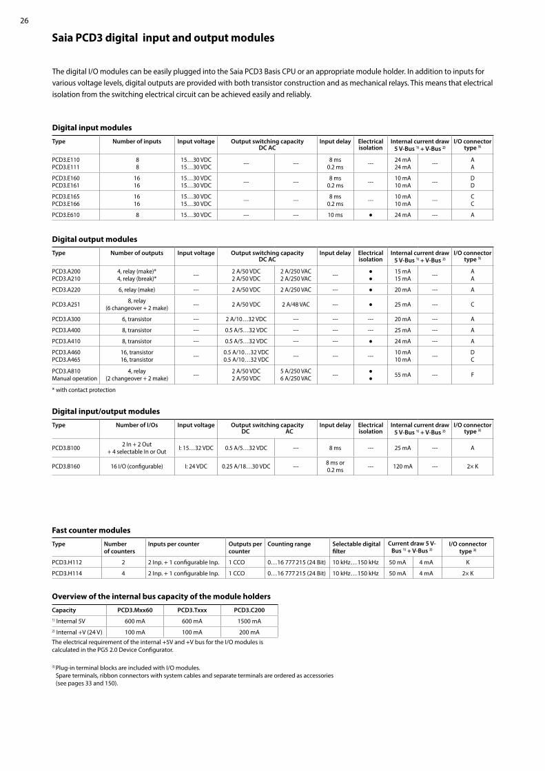
Saia PCD3 digital input and output modules
The digital I/O modules can be easily plugged into the Saia PCD3 Basis CPU or an appropriate module holder. In addition to inputs for various voltage levels, digital outputs are provided with both transistor construction and as mechanical relays. This means that electrical isolation from the switching electrical circuit can be achieved easily and reliably.
Digital input modules
Type Number of inputs Input voltage Output switching capacityDC AC
Input delay Electrical isolation
Internal current draw5 V-Bus 1) + V-Bus 2)
I/O connectortype 3)
PCD3.E110PCD3.E111
8 8
15…30 VDC15…30 VDC --- --- 8 ms
0.2 ms --- 24 mA24 mA --- A
A
PCD3.E160PCD3.E161
1616
15…30 VDC15…30 VDC --- --- 8 ms
0.2 ms --- 10 mA10 mA --- D
D
PCD3.E165PCD3.E166
1616
15…30 VDC15…30 VDC --- --- 8 ms
0.2 ms --- 10 mA10 mA --- C
C
PCD3.E610 8 15…30 VDC --- --- 10 ms 24 mA --- A
Digital output modules
Type Number of outputs Input voltage Output switching capacityDC AC
Input delay Electrical isolation
Internal current draw5 V-Bus 1) + V-Bus 2)
I/O connectortype 3)
PCD3.A200 PCD3.A210
4, relay (make)* 4, relay (break)* --- 2 A/50 VDC
2 A/50 VDC2 A/250 VAC 2 A/250 VAC ---
15 mA 15 mA --- A
A
PCD3.A220 6, relay (make) --- 2 A/50 VDC 2 A/250 VAC --- 20 mA --- A
PCD3.A251 8, relay (6 changeover + 2 make) --- 2 A/50 VDC 2 A/48 VAC --- 25 mA --- C
PCD3.A300 6, transistor --- 2 A/10…32 VDC --- --- --- 20 mA --- A
PCD3.A400 8, transistor --- 0.5 A/5…32 VDC --- --- --- 25 mA --- A
PCD3.A410 8, transistor --- 0.5 A/5…32 VDC --- --- 24 mA --- A
PCD3.A460PCD3.A465
16, transistor16, transistor --- 0.5 A/10…32 VDC
0.5 A/10…32 VDC --- --- --- 10 mA10 mA --- D
C
PCD3.A810Manual operation
4, relay (2 changeover + 2 make) --- 2 A/50 VDC
2 A/50 VDC5 A/250 VAC6 A/250 VAC ---
55 mA --- F
* with contact protection Digital input/output modules
Type Number of I/Os Input voltage Output switching capacityDC AC
Input delay Electrical isolation
Internal current draw5 V-Bus 1) + V-Bus 2)
I/O connectortype 3)
PCD3.B100 2 In + 2 Out + 4 selectable In or Out I: 15…32 VDC 0.5 A/5…32 VDC --- 8 ms --- 25 mA --- A
PCD3.B160 16 I/O (configurable) I: 24 VDC 0.25 A/18…30 VDC --- 8 ms or 0.2 ms --- 120 mA --- 2× K
3) Plug-in terminal blocks are included with I/O modules. Spare terminals, ribbon connectors with system cables and separate terminals are ordered as accessories (see pages 33 and 150).
Fast counter modules
Type Number of counters
Inputs per counter Outputs per counter
Counting range Selectable digital filter
Current draw 5 V-Bus 1) + V-Bus 2)
I/O connector type 3)
PCD3.H112 2 2 Inp. + 1 configurable Inp. 1 CCO 0…16 777 215 (24 Bit) 10 kHz … 150 kHz 50 mA 4 mA K
PCD3.H114 4 2 Inp. + 1 configurable Inp. 1 CCO 0…16 777 215 (24 Bit) 10 kHz … 150 kHz 50 mA 4 mA 2× K
Overview of the internal bus capacity of the module holders
Capacity PCD3.Mxx60 PCD3.Txxx PCD3.C2001) Internal 5V 600 mA 600 mA 1500 mA2) Internal +V (24 V) 100 mA 100 mA 200 mA
The electrical requirement of the internal +5V and +V bus for the I/O modules is calculated in the PG5 2.0 Device Configurator.

27
12
34
5A
utom
atio
n st
atio
nsO
pera
tion
an
d m
onit
orin
gR
oom
con
trol
lers
Cons
umer
da
ta a
cqui
siti
onSw
itch
cab
inet
co
mpo
nent
s
Saia PCD3 analogue input and output modules
The numerous analogue modules allow complex control tasks or measurements to be performed. The resolution is between 8 and 16 bits, depending on the speed of the AD converter. The digitised values can be further processed direct in the project in the Saia PCD3. The large number of different modules means that suitable modules are available for almost any requirement.
Manual control modules
Analogue input modules
Type Total Channels
Signal ranges/description Resolution Electrical isolation
Internal current draw5 V-Bus 1) + V-Bus 2)
I/O connec-tor type 3)
PCD3.W200PCD3.W210PCD3.W220
8 In 8 In 8 In
0…+10 V0…20 mA 4) Pt1000: –50 °C…400 °C/Ni1000: –50 °C…+200 °C
10 Bit10 Bit10 Bit
---8 mA8 mA8 mA
5 mA5 mA
16 mA
AAA
PCD3.W300PCD3.W310PCD3.W340
PCD3.W350PCD3.W360PCD3.W380
8 In8 In8 In
8 In8 In8 In
0…+10 V0…20 mA 4) 0…+10 V/0…20 mA 4) Pt1000: –50 °C…400 °C/Ni1000: –50 °C…+200 °CPt100: –50 °C…+600 °C/Ni100: –50 °C…+250 °CPt1000: –50 °C…+150 °C–10 V…+10 V, –20 mA…+20 mA, Pt/Ni1000, Ni1000 L&S, NTC10k/NTC20k (configuration using software)
12 Bit12 Bit12 Bit
12 Bit12 Bit13 Bit
---
8 mA8 mA8 mA
8 mA8 mA
25 mA
5 mA5 mA
20 mA
30 mA20 mA25 mA
AAA
AA
2× K
PCD3.W305PCD3.W315PCD3.W325
7 In7 In7 In
0…+10 V0…20 mA 4) –10 V…+10 V
12 Bit12 Bit12 Bit
60 mA60 mA60 mA
0 mA0 mA0 mA
EEE
PCD3.W745 4 In Temperature module for TC type J, K and 4-wire Pt/Ni
100/1000 16 Bit 200 mA 0 mA6)
Analogue output modules
Type Number of channels
Signal ranges/description Resolution Electrical isolation
Internal current draw5 V-Bus 1) + V-Bus 2)
I/O connec-tor type 3)
PCD3.W400PCD3.W410
4 Out4 Out
0…+10 V0…+10 V/0…20 mA/4…20 mA jumper-selectable
8 Bit8 Bit --- 1 mA
1 mA30 mA30 mA
AA
PCD3.W600PCD3.W610
4 Out4 Out
0…+10 V0…+10 V/–10 V…+10 V/0…20 mA/4…20 mA jumper-selectable
12 Bit12 Bit ---
4 mA110 mA
20 mA0 mA
AA
PCD3.W605PCD3.W615PCD3.W625
6 Out4 Out6 Out
0…+10 V0…20 mA/4…20 mA parameters can be set–10 V…+10 V
10 Bit10 Bit10 Bit
110 mA55 mA
110 mA
0 mA0 mA0 mA
EEE
PCD3.W800 4 Out, 3 of which are manually
operated
0…+10 V, short circuit-proofed 10 Bit --- 55 mA 35 mA 5) J
Analogue input/output modules
Type Number of channels
Signal ranges/description Resolution Electrical isolation
Internal current draw5 V-Bus 1) + V-Bus 2)
I/O connec-tor type 3)
PCD3.W525 4 In +
2 Out
In: 0…10 V, 0(4)…20 mA, Pt1000, Pt500 or Ni1000 (selectable via DIP switch)
Out: 0…10 V or 0(4)…20 mA (selectable via software)
In: 14 Bit
Out: 12 Bit
40 mA 0 mA I
PCD3.A810Relay outputs, 2 changeover and 2 make
PCD3.W800 4 analogue outputs (3 of these operable)
3) Plug-in I/O terminal blocks are included with I/O modules. Spare terminals, ribbon connectors with system cables and separate terminals are ordered as accessories (see pages 33 and 150).
4) 4 … 20 mA via user program5) At 100% output value and 3 kΩ load6) With soldered spring terminal block
Overview of the internal bus capacity of the module holders
Capacity PCD3.Mxx60 PCD3.T66x PCD3.C2001) Internal 5V 600 mA 600 mA 1500 mA2) Internal +V (24 V) 100 mA 100 mA 200 mA
The electrical requirement of the internal +5V and +V bus for the I/O modules is calculated in the PG5 Device Configurator.

28
Saia PCD3.C200 Saia PCD3.C100
A810
A810
A860
B160
A860
A860
A860
A200
Saia PCD3.C200 Saia PCD3.C100Saia PCD3.M5560
Saia
PCD
3Sa
ia P
CD3 F
210
F281
W340
E160
E160
E160
E160
E160
W610
W340
W340
Information for project planning with PCD3 module holders
The internal load current taken by the I/O modules from the +5V and +V (24V) supply must not exceed the maximum supply current specified for the CPUs, RIOs or PCD3.C200 module holders.
Example calculation for the current consumption of the internal +5V and +V (24V) bus of the I/O modules
The calculation example shows that internal capacity is maintained in the CPU basic mod-ule PCD3.M5560 and the holder module PCD3.C200. The CPU basic module has a sufficient reserve to receive an additional communication module in the empty slot 0. The holder module PCD3.C200 also has sufficient reserves to connect an additional PCD3.C100 or PCD3.C110 holder module. The power consumption of the internal +5V and +V (24 V) bus for the I/O modules is automatically calculated in the PG5 2.x Device Configurator.
The following aspects should be considered when planning PCD3 applications:
PCD3.M5560 CPU incl. 4 I/O slots
PCD3.C100 I/O module holder 4 slots
Extension plugPCD3.K010
PCD3.C100 I/O module holder 4 slots
PCD3.C100 I/O module holder 4 slots
PCD3.C200 I/O module holder 4 slots
Exte
nsio
n ca
ble
PCD
3.K1
06/K
116
Extension plug PCD3.K010
Consumption C200 + C100 Module Internal 5V Internal +V (24V)A200 15 mAA810 40 mAA810 40 mAA860 18 mATotal C200 113 mAA460 10 mAA460 10 mAA460 10 mAW380 25 mA 25 mATotal C100 55 mA 25 mATotal C200 168 mA 25 mA
Capacity PCD3.M5560 PCD3.C200Internal 5V 600 mA 1500 mAInternal +V (24V) 100 mA 200 mA
Consumption M5560 + C100 + C100 Module Internal 5V Internal +V (24V)Not used F210 110 mA F281 90 mA 15 mAW340 8 mA 20 mATotal M5560 208 mA 35 mAW340 8 mA 20 mAW340 8 mA 20 mAW610 110 mA 0 mAE160 10 mA Total C100 136 mA 40 mAE160 10 mA E160 10 mA E160 10 mA E160 10 mA Total C100 40 mA 0Total M5560 384 mA 75 mA
In keeping with lean automation, it is recommended to leave the first slot in the CPU basic module free for any subsequent expansions. Both single I/O modules and communication modules can be used in this slot.
The total length of the I/O bus is limited by technical factors; the shorter, the better.
The PCD3.C200 is used to extend the I/O bus or for the internal power supply (+5V and +V (24V)) to a module segment. Please note the following rules:
Do not use more than six PCD3.C200s in a single configuration, or the time delay will exceed the I/O access time. Use a maximum of five PCD3.K106/116 cables.
Insert a PCD3.C200 after each cable (at the start of a row). Exception: In a small configuration with no more than 3 PCD3.C1xxs, these can be supplied from the PCD3.Mxxx. A PCD3.C200 is not required.
If an application is mounted in a single row (max. 15 module holders), then after five PCD3.C100 a PCD3.C200 must be used to amplify the bus signal (unless the configuration ends with the fifth PCD3.C100).
If the application is mounted in multiple rows, the restricted length of cable means that only three module holders (1× PCD3.C200 and 2× PCD3.C100) may be mounted in one row.

29
12
34
5A
utom
atio
n st
atio
nsO
pera
tion
an
d m
onit
orin
gR
oom
con
trol
lers
Cons
umer
da
ta a
cqui
siti
onSw
itch
cab
inet
co
mpo
nent
s
+18 V
0 V
GND
+24 V =
0V
L N
L
N
±15%
±20%24 VDC
19 VAC
Grounding and connection plan
Grounding and connection concept analogue inputs that are not electrically isolated (PCD3.W2x0, PCD3.W3x0)
Saia PCD3 power supply and connection concept
It is generally recommended to use robust and interference-resistant SBC power supply units with 24 VDC output. See Chapter 5.1 for available types.
Connection concept for PCD3.W2x0 The reference potential of signal sources must be wired to a common GND distributor at the “–” terminal
External power supply
A two-way rectified supply can be used for most modules.The following modules must be connected to smoothed 24 VDC: PCD3.H1xx
Connection concept for PCD3.W3x0 The reference potential of voltage and current inputs must be wired to a common GND distributor at the “–” terminal. Tempera-ture sensors must be wired to a common GND distributor at the “COM” terminal. The module PCD3.W380 has a 2-wire connection for the inputs and requires no external GND distributor.
Signal sources (such as temperature sensors) should be connected direct to the input module wherever possible.
To obtain optimum measurement results, avoid connection to a ground bar. Additional external GND connections to the sensor signals may result in equalising currents which distort the measurement.
If shielded cables are used, the shielding should be continued to a ground bar.
The zero potential (GND) of the 24 V supply is connected to the GND and the controller’s grounding terminal. If possible, this should be connected to the ground bar with a short wire (<25 cm) with a cross section of 1.5 mm2. The same applies to the negative connection to the PCD3.F1xx or the interrupt terminal.
Any shielding of analogue signals or communication cables should also be brought to the same grounding potential, either via a negative terminal or via the ground bar.
All negative connections are linked internally. For flawless operation, these connections should be reinforced externally by short wires with a cross section of 1.5 mm2.
Transformer min. 50 VA
2.5 mm2 2.5 mm2
W...
A...
E...
0V +24VDC
Earthing bar
max
. 25
cmm
in. 2
.5 m
m2
0...10 V Pt/Ni 1000
Mea
surin
gre
sist
orM
easu
ring
resi
stor
Sign
also
urce
Sign
also
urce
Cablewith
Shield
Distributor„V“ and „C“
Distributor„Temp.“
Power PCD
Earthingbar
9 8 7 6 5 4 3 2 1 0
- E7 E6 E5 E4 E3 E2 E1 E0
-
PGND COM
0...10 V Pt/Ni 1000
max
. 25
cmm
in. 2
.5 m
m2
Mea
surin
gre
sist
orM
easu
ring
resi
stor
Sign
also
urce
Sign
also
urce
Cablewith
Shield
Distributor
Power PCD
Earthingbar
-PGND
9 8 7 6 5 4 3 2 1 0- E7 E6 E5 E4 E3 E2 E1 E0
Power Supply

30
5560
F121
F121F210
Read Int Indref:Modbus
Enable Error
NumberAdd R 500
FuncRemAdd
Communication interfaces of Saia PCD3.Mxxxx controllers
In addition to the interfaces that the Saia PCD3 has onboard, the interface functions can also be expanded using various slots. Numerous protocols are therefore supported by the PCD3. For the majority of protocols, the physical bus specifications are offered as a plug-in module. If this is not the case, the bus can be connected via an external converter.
Modem communication with the PCD S-Bus Modbus JCI N2-Bus KNX® S-Mode/EIB
(with external converter)
Fully programmable physical interfaces
Module Specifications Slot Electrical isolation
Internal current draw 5V +V (24 V)
I/O connec-tor type 1)
PCD3.F110 RS-422 with RTS/CTS or RS-485 2) I/O 0 --- 40 mA --- A
PCD3.F121 RS-232 with RTS/CTS, DTR/DSR, DCD I/O 0 --- 15 mA --- A
PCD3.F150 RS-485 2) I/O 0 130 mA --- A
PCD3.F210 RS-422/RS-485 2), plus PCD7.F1xxS as option I/O 0…3 --- 110 mA --- 2× K
PCD3.F221 RS-232 plus PCD7.F1xxS as option I/O 0…3 --- 90 mA --- 2× K
Physical interfaces for specific protocols
Module Specifications Slot Electrical isolation
Internal current draw 5V +V (24 V)
I/O connec-tor type 1)
PCD3.F180 Belimo MP-Bus, for connecting up to 8 drives on one line I/O 0 --- 15 mA 15 mA A
PCD3.F215 BACnet® MS/TP or freely programmable I/O 0…3 --- 110 mA --- 2× K
PCD3.F261 DALI I/O 0…3 --- 90 mA --- A
PCD3.F270 M-Bus 240 nodes I/O 0…3 --- 70 mA 8 mA A
PCD3.F271 M-Bus 20 nodes I/O 0…3 --- 70 mA 8 mA A
PCD3.F272 M-Bus 60 nodes I/O 0…3 --- 70 mA 8 mA A
PCD3.F281 Belimo MP-Bus with slot for PCD7.F1xxS modules I/O 0…3 --- 90 mA 15 mA 2× K
System properties required for PCD3.Fxxx modules:The PCD3 system has a processor that serves both the application and the serial ports. To determine the maximum communication capacity for each PCD3.M5xx0 system, consult the infor-mation and examples provided in the manual 26-789 for PCD3.M5xx0.
Interface modules for optional insertion in PCD3.F2xx modules
Module SpecificationsPCD7.F110S RS-422 with RTS/CTS or
RS-485 2) (electrically connected)PCD7.F121S RS-232 with RTS/CTS, DTR/DSR, DCD,
suitable for modem, EIB connectionPCD7.F150S RS-485 2) (electrically isolated)dPCD7.F180S Belimo® MP-Bus for connecting up to 8 drives on one line
DALI EnOcean
(with external converter) M-Bus BACnet® MS/TP HMI editor applications with
PCD7.Dxxx text terminals (RS-232 only)
Protocols supported by PCD3.Mxxxx via FBoxes PCD3.F1xx for slot 0Port 1 RS-232 or RS-422 or RS-485or MP-Bus
PCD3.F2xx for slot no. 0…3PCD3.F221 RS-232 PCD3.F210 RS-422/RS-485 PCD3.F281 MP-Bus PCD3.F215 BACnet®-MS/TPPCD3.F261 DALI PCD3.F27x M-Bus
1) Plug-in I/O terminal blocks are included with I/O modules. Spare terminals, ribbon connectors with system cables and separate terminals are ordered as accessories (see pages 33 and 150).
2) with termination resistors that can be activated.

31
12
34
5
Saia PCD3.M3360
Activity
Busy
Write
Diag
User
Saia PCD3.M5560
Activity
Busy
Write
Diag
User
PCD7.R562
PCD7.R610
PCD3.R56x
PCD3.R600
PCD3.R562 PCD3.R600 PCD3.R562 PCD3.R600
PCD7.R562 PCD7.R610
PCD3.M3xxxPCD3.M5xxx / PCD3.M6xxx
Aut
omat
ion
stat
ions
Ope
rati
on
and
mon
itor
ing
Roo
m c
ontr
olle
rsCo
nsum
er
data
acq
uisi
tion
Swit
ch c
abin
et
com
pone
nts
Memory modules of Saia PCD3.Mxxxx controllers
In addition to the onboard memory contained in the base units, PCD3 controllers can also be expanded in a modular way with various flash memory modules for programs and data. The various communication protocols where the firmware is installed on the flash cards can also be used by simply inserting the relevant card. More information on memory management and construction can be found in Chapter 1.1 Saia PCD System description.
System properties Configuration, programs and data can be transferred from one CPU to another Two slots (M1 and M2) for memory cards Additional memory cards can be inserted in the I/O slots using I/O adapters Memory can be expanded by up to 4 GB
Flash memory with file system, program and data backup, BACnet® for M1/M2 slot
Type Description Slot
PCD7.R562 Flash card with BACnet® and 128 MB file system M1 & M2PCD7.R610 Basic module for Micro SD flash cards M1 & M2PCD7.R-MSD1024 Micro SD flash card 1024 MB, PCD formatted PCD7.R610
Plug-in flash modules for I/O module slots for all PCD3.Mxxx0s
Type Description Slot
PCD3.R562 Flash card with BACnet® and 128 MB file system I/O 0…3
Saia PCD3 basic module for SD flash cards with file system
Type Description Slot
PCD3.R600 Basic module with slot for SD flash cards(Up to 4 modules in I/O slots 0 to 3 on a CPU)
I/O 0…3
PCD7.R-SD512 SD flash card, 512 MB with file system ---
PCD7.R-SD1024 SD flash card, 1024 MB with file system ---
Spare parts (battery and battery holder module) see consumables and accessories (see pages 34 and 169).
Slot
Battery holder module
M2M1

32
(4 310 8723 0)
Addressing and labelling of I/O modules and module holdersI/O module slots in the module holder are labelled with numbers:
The provided inscription labels can either be used for additional labelling of the I/O modules. They are blank and, depending on require-ments, may either be labelled by hand.
The circuit diagram printed on the side of each I/O module makes wiring easier and also helps during commissioning. Sufficient space is available on the other side of the cassette for the user to add customised labelling with the self-adhesive labels supplied.
Additional labelling on the front The PCD3 modules can also be labelled on the front panel. Neutral labels with a snap-on cover (clip) are available for this purpose.
Consumables and accessories for Saia PCD3 controllers
Fast labelling of I/O modules with the LabelEditorThe LabelEditor is included in the PG5 Controls Suite Device Configurator.This software tool is used to label PCD3 label clips efficiently.
Labelling accessories
Order type
Without clip With clip
The EPLAN® electric P8 macros are available on the support site. The macros and article data are also provided on the EPLAN® data portal.
EPLAN macros
EPLAN macros are available for project planning and engineering
Download: www.sbc-support.com

33
12
34
5
PCD2.K525
PCD2.K23x
Aut
omat
ion
stat
ions
Ope
rati
on
and
mon
itor
ing
Roo
m c
ontr
olle
rsCo
nsum
er
data
acq
uisi
tion
Swit
ch c
abin
et
com
pone
nts
Saia PCD3 battery and battery holder module
Type Description
PCD3.R010 Battery kit for PCD3.M3x60 Basic CPU (battery module for slot #3 incl. lithium battery CR2032)
463948980 Battery holder module (for PCD3.M5x60 and PCD3.M6xx0)
450748170 Lithium battery for PCD Base CPU
Saia PCD3 housing covers
Type Description
410474930 Cover for PCD3.M5x60 and PCD3.M6xx0
PCD3.E009 Empty module housing for unused PCD3 I/O slots
410475150 Slot cover for unused PCD3 I/O slots
Saia PCD3 plug-in screw terminal blocks for basic modules and module holders
Type Description440549950 8-pin spring terminal block for power supply to PCD3.Mxxx0
440549520 Screw terminal 2-pin for supply PCD3.C200
Saia PCD3 plug-in terminal blocks and labelling for I/O modules
Type Description440549540 Plug-in I/O spring terminal block 10 - pin for wires up to 2.5 mm2 type A
440549560 Plug-in I/O spring terminal block 24 - pin for wires up to 1.0 mm2 type C
440549980 Plug-in I/O spring terminal block 14 - pin for wires up to 1.5 mm2 type E
440549360 Plug-in I/O spring terminal block 12 - pin for PCD3.A810 for wires up to 1.5 mm2 type F
440549340 Plug-in I/O spring terminal block 8 - pin for PCD3.W800 for wires up to 1.5 mm2 type J
440550480 Plug-in I/O spring terminal block 10 - pin for wires up to 1.0 mm2 type K
431087230 Set of 10 units: Transparent snap-on label holder including neutral inscription labels (2× DIN A4)
System cables and “ribbon screw terminal” adapters (see Chapter 5.10 for details)
Type DescriptionSystem cables for digital modules with 16 I/Os PCD2.K221 Sheathed, round cable with 32 strands of 0.25 mm², 1.5 m long, PCD side 34-pin ribbon cable connector type D,
process side: strand ends free, colour coded
PCD2.K223 Sheathed, round cable with 32 strands of 0.25 mm², 3.0 m long, PCD side 34-pin ribbon cable connector type D, process side: strand ends free, colour coded
System cables for adapters PCD2.K520/..K521/..K525 PCD2.K231 Sheathed, half-round cable with 34 strands, each 0.09 mm², 1.0 m long, 34-pin ribbon connector at both ends type D
PCD2.K232 Sheathed, half-round cable with 34 strands, each 0.09 mm², 2.0 m long, 34-pin ribbon connector at both ends type D
System cables for 2 relay interfaces PCD2.K551/K552 PCD2.K241 Sheathed, half-round cable with 34 strands, each 0.09 mm2, 1.0 m long, PCD side 34-pin ribbon connector type D,
process side two 16-pin ribbon connector
PCD2.K242 Sheathed, half-round cable with 34 strands, each 0.09 mm2, 2.0 m long, PCD side 34-pin ribbon connector type D, process side two 16-pin ribbon connectors
“Ribbon/screw terminal” adapters
Type DescriptionPCD2.K520 for 16 inputs/outputs, with 20 screw terminals without LED
PCD2.K521 for 16 inputs/outputs, with 20 screw terminals and LED (for source operation only)
PCD2.K525 for 16 inputs/outputs, with 3 × 16 screw terminals and LED (for source operation only)
PCD2.K551 Relay interface for 8 PCD transistor outputs with 24 screw terminals and LED
PCD2.K552 Relay interface for 8 PCD transistor outputs with 24 screw terminals, LED and manual control mode (on-off auto switch) and 1 output as feedback for manual control
Consumables and accessories for Saia PCD3.Mxxx0 controllers
Type J
Type F
Type A
Type C
Type E
Type K
8-pin
2-pin
Type D

34
28.563.8
125.8
139
67.3
100.
535
32.8
32.7
660Saia PCD3.T 200
W340
C110
A400
A400
E110
Saia PCD3.CSaia PCD3.C
E110
E110
E110
W340
A465
130
Saia PCD3.MSaia PCD3.T660
1.2.2 Saia PCD3.T66x remote I/O stations
The Smart RIOs are more than just another Ethernet remote I/O system. They can be programmed like a PLC and are therefore the ideal solution for distributed automation in line with the lean philosophy. Smart RIOs can be equipped with PCD3 I/O modules and expanded with PCD3 I/O module holders up to 256 I/Os per RIO station.
Dimensions
Order details
Design of Saia PCD3.T66x: Smart RIO head station with 4 slots for I/O modules
System properties Can be used as a simple remote I/O station
or an intelligent programmable I/O station. Can be programmed with PG5. Important or
time-critical tasks can be processed direct in the RIO. The RIO user programs are managed centrally
in the Smart RIO Manager (PCD) and distrib-uted to the RIOs automatically.
Smart RIO
PCD3.T665 Smart-RIO, Ether S-IO data exchange, programmable, 32 kByte program memory
PCD3.T666 Smart RIO, Ether S-IO data exchange, programmable, 128 kByte program memory, serial interfaces
I/O module holder
PCD3.C100 Expansion module holder with 4 I/O slotsPCD3.C110 Expansion module holder with 2 I/O slotsPCD3.C200 Expansion module holder with 4 I/O slots and terminals for 24 VDC power supply
Data exchange with efficient Ether S-IO protocol. Simple configuration with the RIO network configurator. Cross-communication with other PCD
systems using Ether S-Bus (FBoxes). Intelligent communication modules
(M-Bus, DALI) are supported with PCD3.T666.
Other communication protocols (e.g. Modbus) via Ethernet TCP/IP and with PCD3.T666, also via the onboard RS-485 interface. Integrated Automation Server
The standard I/O modules of the PCD3 series can be used. For more information and types, see Chapter “„Saia PCD3 input and output modules in cassette design“” on page 25.
I/O modules I/O extensions up to 256 I/O per RIO station
Extension plug PCD3.K010
PCD3.T66xCPU incl.4 I/O slots
PCD3.C100I/O module holder4 slots
PCD3.C110I/O module holder2 slots
Expansion connection for I/O module holder
Supply 24 VDC RS-485 interface
Earth connectionUSBconnection
Ethernet
4 slots for I/O modules and communication modules
RUN/STOP LED indicator
Fast serial bus (SPI) for operating up to 4 intelligent modules (PCD3.T666 only)
I/O bus for standard modules
Ground connection for I/O modules

35
12
34
5
Smart Automation Manager
Smart RIOs PCD3.T66x
Ethernet
S1 S2 S3 S4
M
Aut
omat
ion
stat
ions
Ope
rati
on
and
mon
itor
ing
Roo
m c
ontr
olle
rsCo
nsum
er
data
acq
uisi
tion
Swit
ch c
abin
et
com
pone
ntsThe exchange of data can be easily configured in PG5 with the RIO network configurator. The configured exchange of data between RIO
and the Manager is processed automatically by the operating system. No user program is required for this. The Manager sends the data to the Smart RIOs on a cyclical basis with broadcast or unicast telegrams. The RIOs also send their data or statuses of their inputs to the RIO Manager on a cyclical basis.
2 different transfer cycle times can be set per RIO station:– Short cycle time for high-priority data– Normal cycle time for low-priority or slow data
The Smart RIOs can be used both as simple remote I/O stations and as intelligent programmable RIO stations.
The application programs are centrally managed by the Smart Automation Manager and distributed to the Smart RIOs. If hardware is replaced, the programs and the con-figuration are reloaded automatically. The Manager must have sufficient memory resources to save the RIO programs. The onboard program memory and the plug-in flash memory modules PCD7.Rxxx and PCD3.Rxxx can be used for this.
Data transfer with Ether S-IO protocol
Number of RIOs Minimum data transfer cycle time10 50 ms20 100 ms40 200 ms80 400 ms
128 800 ms
Data transfer cycle times
Simple configuration of the data transfer in the RIO network configurator
Distributed automation system design with Smart RIO
As Smart Automation Managers, PCD1.M21x0, PCD2.M5, PCD3.M3/5/6 CPUs and the programmable micro browser panel PCD7.D4xxxT5F can be used
Standard network components (e.g. Q.NET-5TX / 8TX) can be used to set up the Ethernet network
The maximum number of RIOs per Manager depends on the type of Manager used
Central program management in the Manager
Program & Configuration M & S1, S2, S3, S4
Smart Automation Stations

36
Property PCD3.T665 PCD3.T666
Number of inputs/outputs 64 in base unit, expandable to 256I/O module slots 4 in base unit, expandable to 16I/O modules supported PCD3.Exxx, PCD3.Axxx, PCD3.Bxxx, PCD3.Wxxxmax. number of RIO stations 128Protocol for data transfer Ether S-IOEthernet connection 10/100 Mbits, full-duplex, auto-sensing, auto-crossingDefault IP configuration IP address: 192.168.10.100
Subnet mask: 255.255.255.0 Default gateway: 0.0.0.0
USB interface for configuration and diagnostics YesProgram memory 32 kByte 128 kByteWeb server for configuration and diagnostics YesWeb server for user pages YesOnboard file system for web pages and data 512 kByteBACnet® No NoOnboard interrupt inputs 2Onboard RS-485 interface No YesSpecial modules for I/O slot 0 only --- PCD3.F1xx
for I/O slots 0…3 (up to 4 modules)
PCD3.H1xx counter------
PCD3.H1xx counter PCD3.F261 DALI
PCD3.F27x M-BusS-Web alarming/trending No NoWatchdog No Real-time clock No Software clock (not battery-powered) yes, synchronised by the Manager Battery No
Technical Data
In the case of lean automation, it is inefficient to exploit the specified limits or max. number of stations per Manager and max. number of I/Os per RIO. The following points should be considered:
The load on the RIO Manager increases with the rising number of RIO stations. This has an impact on the overall application in the RIO Manager.
If there is a large number of RIOs, a sufficiently large volume of PCD media must be reserved on the Manager for the data transfer.
With the increased number of RIO stations, the build and download process in PG5 is extended accordingly. Likewise, the start-up behaviour of the Manager or the entire RIO network is proportionately longer.
Recommendation: 20 Smart RIOs per Manager is an effective configuration for efficient and flawless operation and easy commissioning and support.The Smart RIOs do not have a battery. In the event of an interruption to the power supply, all the data in the RAM memory (registers, flags, DBs/text) will be lost. Data and parameters that are remanent must either be transferred by the Manager or stored in the RIO’s flash file system. If this is not possible, it is recommended to use a normal controller instead of a Smart RIO. The user programs are stored in the flash memory of the RIOs and are retained in the event of an interruption to the power supply.
System properties/limits and recommendations for lean automation
Smart Automation Manager (master station)
max. 32 RIO stations PCD1.M212x, PCD3.M3160, PCD3.M3360max. 64 RIO stations PCD1.M2160, PCD2.M4160,
PCD7.D410VT5F, PCD7.D412DT5Fmax. 128 RIO stations PCD2.M4560, PCD3.M5360, PCD3.M5560, PCD3.M6860
General data
Supply voltage 24 VDC ±20% smoothed or 19 VAC ±15% two-way rectified Capacity of 5 V bus / +V bus (24 V) max. 600 mA/100 mA Ambient temperature 0…+55 °C or 0…+40 °C (depending on mounting position) Storage temperature –20…+70 °C Relative humidity 30…95% RH with no condensation Mechanical strength in accordance with EN/IEC 61131-2

37
12
34
5A
utom
atio
n st
atio
nsO
pera
tion
an
d m
onit
orin
gR
oom
con
trol
lers
Cons
umer
da
ta a
cqui
siti
onSw
itch
cab
inet
co
mpo
nent
s
1.3.1 PCD3.M6880 Modular PCD3 standby controller with 2 Ethernet TCP/IP ports and a coprocessor for standby operation.
1.3 Standby SystemWith the PCD3.M6880 standby controllers, redundant automation solutions can be achieved. This helps to ensure uninterrupted operation of systems and processes.
1.3.2 PCD3.T668 Smart RIO for standby system, for connection to the PCD3.M6880 CPU1.
Page 41
43

38
SCADA 1 SCADA 2
Smart RIOs PCD3.T668
Standby System OverviewIntroduction
The PCD3.M6880 Standby Controllers are for creating redundant automation solutions, to ensure the uninterrupted operation of sys-tems and processes.
Standby (redundant automation) systems from SBC have the following characteristics:
Based on the modular and robust PCD3 family, using standard modules.
Simple system architecture to reduce costs.
Standby processors with shared Ethernet Remote I/Os avoids the duplication of the inputs/outputs and the sensors/actuators.
Programmable remote I/Os create intelligent decentralized nodes to provide additional reliability.
The network uses standard Ethernet components, and can run over a standard Ethernet TCP/IP network along with other services.
Easy engineering and commissioning, using the PG5 Project Manager to automatically generate the project.
Uninterrupted switching from Standby to Active device.
Standby controllers contain two processors. One processor runs the redundant program and monitors the active PCD. The second independent processor runs other non-redundant processes. This significantly increases the performance and flexibility of the system.
Comprehensive diagnostic features to aid commissioning and fault finding.
Terminology
The following definitions will provide a better understanding of the properties and operating principles:
Standby Controller The PCD3.M6880 controller which supports the standby feature.
Primary PCD The PCD which becomes the active device by default when the system is powered up, depending on the configuration.
Secondary PCD The PCD which becomes the standby device on power up, and only takes over active control in the event of a fault on the active device.
Active PCD The PCD whose CPU1 is in Active Mode, running the redundant program and controlling the inputs/outputs (PCD3.T668 RIOs).
Standby PCD The PCD whose CPU1 is in Standby mode. It does not run the redundant program and the outputs (PCD3.T668 RIOs) are not controlled by this device.
Main CPU CPU0 of the Primary or the Secondary PCD, which runs the non-redundant program. This program may be different on the Primary and Secondary devices.
Redundant CPU CPU1 of the Primary or Secondary PCD, which contains the Redundant program. This program must be the same on the primary and Secondary devices. This CPU is either in Active mode and running the Redundant program, or in Standby mode and monitoring the Active PCD.
Typical layout of a redundancy system with two PCD3.M6880 Standby devices and PCD3.T668 Ethernet Smart RIOs.
IP network with fibre optic ring
Standby Controller
PCD3.M6880
Primary SecondaryEthernet
Process I/O Process I/O
SCADA-System

39
12
34
5A
utom
atio
n st
atio
nsO
pera
tion
an
d m
onit
orin
gR
oom
con
trol
lers
Cons
umer
da
ta a
cqui
siti
onSw
itch
cab
inet
co
mpo
nent
s
Redundant control solutions are created using two PCD3.M6880 Standby Controllers. The input/outputs (process signals) are con-nected and controlled via PCD3.T668 Ethernet smart RIOs. The RIO stations are connected to both controllers via an Ethernet con-nection. This means there is no need to have duplicate inputs, outputs, sensors and actuators. The two PCDs (primary and second-ary) monitor each other. If the active PCD fails, the standby PCD takes over processing and control of the connected RIO stations. The process image (I/O) and the internal PCD media (F, R, T, C, DB) - the synchronization data - are continuously transferred from the active PCD to the standby PCD via the Ethernet connection. This ensures uninterrupted switching from the active to the standby PCD.
Ordering Information
The Redundant CPU1 has two independent Ethernet interfaces. The ETH 2.x interface is reserved exclusively for operating the PCD3.T668 RIO stations. The PCDs also synchronize their process data via the same interface. For security reasons, we recommend setting up this network as a ring structure with specific network components from third-party providers. We have had good experi-ences with the industrial Ethernet switches from Hirschmann.
Ethernet 2 (2 port switch)
Ethernet 1
Type Description Weight
PCD3.M6880 Modular PCD3 standby controller with 2 Ethernet TCP/IP ports and a coprocessor for standby operation. 820 g
PCD3.T668 Smart RIO for standby system, for connection to the PCD3.M6880 CPU1. 480 g
The ETH 1 interface on CPU0 is available for connecting and operating other systems and devices. For example, SCADA systems can be connected via this interface. SBC does not provide its own SCADA system for redundant automation solutions, but almost any system can be used. A single SCADA system, or an additional redundant SCADA system can be used if it supports redundant controllers. The PCD3.M6880 controllers provide detailed status and diagnostic information which can be evaluated by the SCADA systems.

40
SCADA 1 SCADA 2
Smart RIOs PCD3.T668
SCADA 1 SCADA 2
Smart RIOs PCD3.T668
SCADA 1 SCADA 2
Smart RIOs PCD3.T668
Standby CPU PCD3.M6880
Standby CPU PCD3.M6880
Designing the System
Redundant automation solutions can be achieved with various network topologies.
Physically separating the management network (SCADA systems) and the network for the remote I/Os is recommended. We also rec-ommend setting up the remote I/O network in a ring structure using fibre-optic network components. This significantly increases the performance, security and, above all, the network availability and thus the system reliability. Standard devices from third-party provid-ers can be used for the network components (switches). We have had good experiences with the switches (RS30) from Hirschmann. However, the networks can also be set up with standard components in a star structure. A shared physical network for the remote I/Os and management systems is also possible, but availability of the system will be reduced accordingly.
Shared physical network in a star topology with standard components
Recommended network topology with physically separate networks and a fibre-optic ring
Physically separate networks in a star topology with standard components
Network redundancy with fiber optical ring
Standby Controller
PCD3.M6880
Primary SecondaryEthernet
Process I/O Process I/O
SCADA-System
Standby Controller
PCD3.M6880
Primary SecondaryEthernet
Process I/O Process I/O
SCADA-System
Ethernet
Secondary
Process I/O Process I/O
SCADA-System
Primary Ethernet

41
12
34
5
PCD3.M6880
Eth 2.2 Eth 2.1 USB Eth 1
Aut
omat
ion
stat
ions
Ope
rati
on
and
mon
itor
ing
Roo
m c
ontr
olle
rsCo
nsum
er
data
acq
uisi
tion
Swit
ch c
abin
et
com
pone
nts
The PCD3.M6880 standby controller has two independent processors (CPU0 and CPU1). Both processors have their own independent PCD media (F, R, T, C, DB/TX).
The redundant CPU1 runs the redundant user program and controls the shared inputs/outputs of the PCD3.T668 remote I/Os. The redundant programs in the primary and secondary PCD3.M6880s are identical. During normal operation, only the active PCD runs the redundant program. CPU1‘s internal used PCD media (F, R, T, C, DB/TX) are transferred from the active to the standby PCD via the Ethernet interface 2 (ETH2.x). In the event of a fault, the standby PCD takes over operation without interruption, and runs the redundant program using the last process image from the active PCD.
Depending on requirements, the user programs of the main CPU0 can be different in the primary and secondary PCD3.M6880. CPU0 has the same capabilities as a standard PCD (e.g. PCD3.M5560). Local I/Os in the PCD‘s slots, and the I/O expansion modules, are controlled by CPU0. External systems and devices (SCADA systems, web browsers and other external devices) communicate only with CPU0. CPU0‘s internal PCD media (F, R, T, C, DB) are not synchronized between the active and standby PCD.
CPU1‘s program cannot directly access the local IOs or CPU0‘s media (and vice versa). Data is exchanged between CPU0 and CPU1 using a data exchange mechanism. The data to be exchanged (PCD media) are define in global symbol files. This data is automatically exchanged between CPU0 and CPU1 on each program cycle.
1 Data Media Transfer (Exchange Range or/and CSF/FBox)2 S-Bus GWY CPU0 to CPU1 (2 different S-Bus address)3 Redundant program on CPU1 runs only if active. Same program on both PCDs.4 Non-redundant program can be different in both PCDs.
Standby controller PCD3.M6880
Redundant CPU1
Main CPU0
1Media 2S-Bus
3Redundant Program
4Non redundant Program
IO Flash
BACnet LON Com
Ethernet RIO PCD3.T668
SCADA and/or other systems
1.3.1 PCD3.M6880 Standby Controller Architecture of the PCD3.M6880

42
Saia PCD3.M6880 controllersHigh Power Standby Controller
PCD3.M6880
Property/function Main CPU0 Redundant CPU1
Number of inputs/outputs 1023 ––
or I/O-module slots 64 ––
I/O expansion connection for PCD3.C module holder Yes ––
Processing time [µs] bit operation word operation
0.1…0.8 µs 0.3 µs
Real time clock (RTC) Yes
On-Board memory
Program memory, DB/TEXT (Flash) 2 MByte
User memory, DB/TEXT (RAM) 1 MByte 128 KByte
Flash memory (Program, S-RIO and configuration) 128 MByte
User flash file system (INTFLASH) 128 MByte ––
PCD media:RegisterFlagDB/TEXT
16384163848192
16384163848192
On-Board interfaces
USB 1.1 Yes No
Ethernet 10/100 Mbit/s, full-duplex, auto-sensing/auto-crossing ETH1 ETH2.x (2 port switch)
RS-485 on terminal block (Port 2) or RS-485 Profibus-DP Slave, Profi-S-Net on terminal block (Port 2)
up to 115 kbit/s up to 187.5 kbit/s ––
Optional communication interfaces
I/O slot 0:PCD3.F1xx modules for RS-232, RS-422, RS-485 and Belimo MP-Bus Yes No
I/O slot 0…3 up to 4 modules or 8 interfaces:PCD3.F2xx modules for RS-232, RS-422, RS-485, BACnet® MS/TP, Belimo MP-Bus, DALI and M-Bus
Yes No
Other features
Communication protocols/systems (BACnet, Modbus, DALI, M-Bus…) As PCD3.M6860 without 2nd Ethernet No
Automation server (web server, FTP server, e-mail, SNMP, flash file system…) Yes No
Connection and operation of PCD3.T668 remote I/O Number of supported RIO stations
No––
Yes64
Connection and operation of PCD3.T665/T666 remote I/ONumber of supported RIO stations
Yes64
No––
Access to the I/O slots in the basic housing as well as to the PCD3.Cxxx I/O terminal bases Yes No
I/O
File system
Program
CPU Speed Basic Power
1023
up to 4.2 GByte
2 MByte
0.1/0.3 µs bit/word
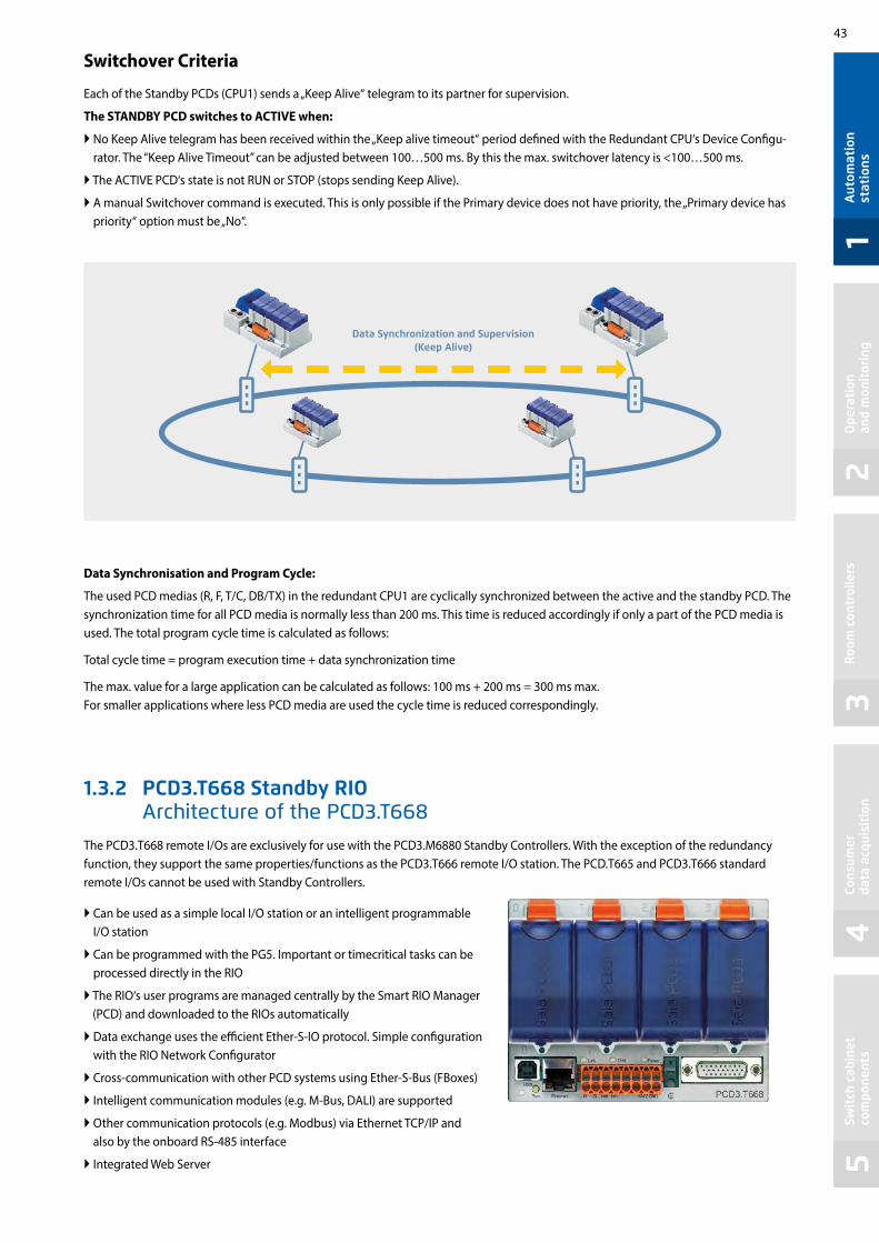
43
12
34
5A
utom
atio
n st
atio
nsO
pera
tion
an
d m
onit
orin
gR
oom
con
trol
lers
Cons
umer
da
ta a
cqui
siti
onSw
itch
cab
inet
co
mpo
nent
s
Switchover Criteria
Each of the Standby PCDs (CPU1) sends a „Keep Alive“ telegram to its partner for supervision.
The STANDBY PCD switches to ACTIVE when:
No Keep Alive telegram has been received within the „Keep alive timeout“ period defined with the Redundant CPU‘s Device Configu-rator. The “Keep Alive Timeout” can be adjusted between 100…500 ms. By this the max. switchover latency is <100…500 ms.
The ACTIVE PCD‘s state is not RUN or STOP (stops sending Keep Alive).
A manual Switchover command is executed. This is only possible if the Primary device does not have priority, the „Primary device has priority“ option must be „No“.
1.3.2 PCD3.T668 Standby RIO Architecture of the PCD3.T668
The PCD3.T668 remote I/Os are exclusively for use with the PCD3.M6880 Standby Controllers. With the exception of the redundancy function, they support the same properties/functions as the PCD3.T666 remote I/O station. The PCD.T665 and PCD3.T666 standard remote I/Os cannot be used with Standby Controllers.
Can be used as a simple local I/O station or an intelligent programmable I/O station
Can be programmed with the PG5. Important or timecritical tasks can be processed directly in the RIO
The RIO‘s user programs are managed centrally by the Smart RIO Manager (PCD) and downloaded to the RIOs automatically
Data exchange uses the efficient Ether-S-IO protocol. Simple configuration with the RIO Network Configurator
Cross-communication with other PCD systems using Ether-S-Bus (FBoxes)
Intelligent communication modules (e.g. M-Bus, DALI) are supported
Other communication protocols (e.g. Modbus) via Ethernet TCP/IP and also by the onboard RS-485 interface
Integrated Web Server
Data Synchronisation and Program Cycle:
The used PCD medias (R, F, T/C, DB/TX) in the redundant CPU1 are cyclically synchronized between the active and the standby PCD. The synchronization time for all PCD media is normally less than 200 ms. This time is reduced accordingly if only a part of the PCD media is used. The total program cycle time is calculated as follows:
Total cycle time = program execution time + data synchronization time
The max. value for a large application can be calculated as follows: 100 ms + 200 ms = 300 ms max.For smaller applications where less PCD media are used the cycle time is reduced correspondingly.
Data Synchronization and Supervision (Keep Alive)

44
Property PCD3.T668Number of inputs/outputs 64 in base unit, extensible to 256
I/O-module slots 4 in base unit, extensible to 16
I/O-modules supported PCD3.Exxx, PCD3.Axxx, PCD3.Bxxx, PCD3.Wxxx
Max. number of RIO stations 128
Protocol for data transfer Ether-S-IO
Ethernet connection 10/100 Mbit/s, full-duplex, auto-sensing, auto-crossing
Default IP configuration IP address: 192.168.10.100Subnet mask: 255.255.255.0
Default gateway: 0.0.0.0
USB port for configuration and diagnostics yes
Program memory 128 kByte
Web server for configuration and diagnostics yes
Web server for user pages yes
On-Board file system for web pages and data 512 kByte
BACnet® no
On-Board interrupt inputs 2
On-Board RS-485 interface yes
Special modules for I/O-slot 0 only PCD3.F1xx
for I/O-slots 0…3 (up to 4 modules)
PCD3.H1xx counterPCD3.F261 DALI
PCD3.F27x M-Bus
S-Web alarming/trending no
Watchdog no
Real-time clock no
Software clock (not battery-powered) yes, synchronized by the Manager
Battery no
General dataSupply voltage 24 VDC ±20 % smoothed or 19 VAC ±15 % full-wave rectified
Capacity of 5 V bus / 24 V bus max. 650 mA/100 mA
Ambient temperature 0…+55 °C or 0…+40 °C (depending on mounting position)
Storage temperature –20…+70 °C
Relative humidity 30…95 % RH with no condensation
Mechanical strength according to EN/IEC 61131-2
Technical data
With lean automation, it is not recommended to make full use of the specified limits with regard to the maximum number of stations per Manager and the maximum number of I/Os per RIO. The following points should be taken into account:
The load on the RIO Manager increases with the rising number of RIO stations. This has an impact on the overall application in the RIO Manager.
If there is a large number of RIOs, a sufficiently large amount of PCD media must be reserved on the Manager for the data transfer.
With a rising number of RIO stations, the build and download process in PG5 is lengthened accordingly. Likewise, the start-up behavior of the Manager or the entire RIO network is proportionately longer.
Recommendations: 20 Smart RIOs per Manager is a sensible configuration for efficient and problem-free operation, and simple commissioning and support.The Smart RIOs do not have a battery. In the event of an interruption to the power supply, all the data in the RAM memory (registers, flags, DBs/text) will be lost. Data and parameters that are to remain must either be transferred by the Manager or stored in the RIO’s flash file system. If this is not possible, the use of a normal controller in place of a Smart RIO is recommended. The user programs are stored in the flash memory of the RIOs and are retained in the event of an interruption to the power supply.
System properties/limits and recommendations for lean automation

45
12
34
5
PCD7.R562
SAIA BURGESS CONTROLS
PCD7.R-SD1024
Aut
omat
ion
stat
ions
Ope
rati
on
and
mon
itor
ing
Roo
m c
ontr
olle
rsCo
nsum
er
data
acq
uisi
tion
Swit
ch c
abin
et
com
pone
nts
1.4 PCD2 – modular, expandable, compact CPUOverview of fully programmable controllers Saia PCD2 device series
Saia PCD2 module holder for I/O expansionModule holder for I/O modules PCD2.C1000 4 I/O slots PCD2.C2000 8 I/O slots
Expandable up to 1023 I/Os
Saia PCD2 input/output modulesModules with various functions with plug-in terminals PCD2.Exxx Digital input modules PCD2.Axxx Digital output modules PCD2.Bxxx Digital input/output modules PCD2.Wxxx Analogue input/output modules PCD2.Gxxx Combined input/output modules
Saia PCD2 memory modules Plug-in memory modules for data and program backup PCD2.R6xx Basic module for SD flash cards for slots 0…3 PCD7.R-SD SD flash cards for PCD3.R6xx PCD7.R5xx Flash memory modules for slots M1 & M2 PCD7.R610 Flash memory modules for slot M1 & M2
Consumables and accessories for Saia PCD2 controllersHousing covers, plug-in screw terminal blocks, I/O bus connection, battery, system cables and adapters
Saia PCD2 interface modulesPlug-in modules to expand the communication interfaces (up to 4 modules or 8 interfaces) PCD7.F1xxS 1 serial interface RS-232, RS-422/485, Belimo MP-Bus PCD2.F2xxx 2 serial interfaces RS-232, RS-422/RS-485 PCD2.F2150 BACnet® MSTP PCD2.F2610 DALI PCD2.F27x0 M-Bus PCD2.F2180 Belimo MP-Bus
Saia PCD2 controllersPage
Base unit with 4 slots for I/O modules PCD2.M4160 Basic 64 I/Os PCD2.M4560 Extended 1023 I/Os
Base unit with 8 slots for I/O modules PCD2.M5540 Expanded with Ethernet switch
Up to 4 integrated communication interfaces. With plug-in modules expandable up to max.15 communica-tion interfaces. Integrated Automation Server in all CPUs.
50
51
55
57
54
46

46
125 mm
200
mm
Do not remove
Mem
ory
CPU
X2MPI
X1
X3Ext
X4
0 16
3248O
C
Error
Run
Halt
X8
X6
X5
X7
Slot A
X9
S1
Bat
t
M1
S2
PCD7FxxxS
Mem
ory
Mem
ory
Mem
ory
PCD
2.M
4560
PCD2.M4560
WWW EMAILFTP SNMP
Saia PCD2.M4xx controllers
The PCD2.M4x60 controller is based on a flat, space-saving housing design that has already been successfully used in the OEM and project business for many years. This modular, fully programmable CPU is suitable for both small and large applications, for example in machine controllers, building automation and infrastructure automation. The modular CPU is powerful, compact and can be expanded with up to 1,023 local data points Generous memory resources and sufficient CPU power for demanding communication tasks with up to 14 interfaces (BACnet, Profibus, M-Bus, Modbus, DALI, etc.).
System properties
Up to 14 communication interfaces 4 slots for PCD2 I/O modules in base unit Up to 64 inputs/outputs in base unit, can be expanded locally to up to 1,023 I/O Automation Server onboard Large onboard memory for programs (2 MB) and data (128 MB) Memory with SD flash cards can be expanded up to 4 GB Battery-free with FRAM technology – protects PCD media (R, F, DB/TEXT) from loss even in a de-energised state
Dimensions MountingDimensions Mounting
Compact mass: 142 × 213 × 49 mm
Screw diameter: less than Ø 4.9Screw head diameter: less than Ø 8.0
2 I/O module slots
Connector for I/O expansion housing
Connector for interface module PCD7.F1xxS
2-port Ethernet switch
Connector for 24 VDC voltage supply and RS-485 interface
LEDs
USB interface
Onboard RS-485 interface (electrically isolated)
Slot for optional battery module
Slot for memory module PCD7.Rxxx
Connector for interrupt inputs
Slot for PCD7.F1xxS interface modules
I/O 0 I/O 1
I/O 3 I/O 2
I/O bus for stand-ard modules
Fast serial bus (SPI)for running up to 4 intel-ligent modules
Ground connection for I/O modules
2 I/O module slots
AUTOMATION SERVER INTEGRATED IN THE BASE UNIT

47
12
34
5A
utom
atio
n st
atio
nsO
pera
tion
an
d m
onit
orin
gR
oom
con
trol
lers
Cons
umer
da
ta a
cqui
siti
onSw
itch
cab
inet
co
mpo
nent
s
Technical data and ordering information for PCD2.M4xxx controllers
Accessories, e.g. connectors, covers, etc. are described in the last page of this chapter.
Details can be found in the manual 27-645.
Technical overview
Technical data PCD2.M4160 PCD2.M4560
Number of digital inputs onboard 4 digital inputs (24 V, 4 × interrupt)
Number of digital inputs/outputs in the base unitresp. I/O module slots in the base unit
644
Number of digital inputs/outputs expandable with PCD2.C2000 and PCD2.C1000 module holders resp. I/O module slots 960
60
Processing time [µs] Bit operation Word operation
0.1…0.8 μs0.3 μs
Real-time clock (RTC) Yes
Supercap to support real-time clock < 10 days
Slot for optional battery holder module Order number 463948980
Yes, to support real-time clock for < 3 years
Onboard memory
Program memory, DB/text (flash) 512 kB 2 MB
User memory, DB/text (RAM) 128 kB 1 MB
Flash memory (S-RIO, configuration and backup) 128 MB 128 MB
User flash file system (INTFLASH) 8 MB 128 MB
Data backup with FRAM technology (the data is retained in a de-energised state) for R, F, DB, TEXT for R, F, DB, TEXT
Onboard interfaces
USB 1.1 ≤ 12 Mbit/s
Ethernet, 2-port switch ≤ 10/100 Mbit/s, full duplex, auto-sensing/auto-crossing
RS-485 on terminal block (port 0) ≤ 115.2 kbit/s
RS-485 free protocols on D-Sub connector (port 2) or RS-485 Profibus-DP Slave, Profi-S-Net on D-Sub connector (port 10)
No ≤ 115.2 kbit/s ≤ 1.5 Mbit/s (elec. isolated)
Additional interfaces
PCD2.F2xxx modules for RS-232, RS-422, RS-485, BACnet MS/TP, Belimo MP-Bus, DALI and M-Bus
I/O slot 0…1 2 modules
I/O slot 0…3 4 modules
Slot A for PCD7.F1xxS modules Yes
General data
Supply voltage (in accordance with EN/IEC 61131-2) 24 VDC, –20/+25% max. incl. 5% ripple
Power consumption typically 15 W for 64 I/Os
Load capacity 5 V/+ V internal max. 800 mA/250 mA
Ordering information
Type Description
PCD2.M4160 PCD2 processor unit with Ethernet TCP/IP, 512 kbytes program memory, 64 I/Os
PCD2.M4560 PCD2 processor unit with Ethernet TCP/IP, 2 MB program memory, 1,023 I/Os

48
X1 X2
X3
X4
24 VDC
Battery
WD
Run
Halt
Error
010
919
X5
X6
2030
2939
S1O
C
X8
X7
ETH2
ETH1
USB
S2
254 70
208
PGU X2
X8
X5
16 32 48
112 6496 80
O C
Error
Run
Halt
WD
24 VDC
Battery
X7
X6
X4
X3
Slot A #1
Slot A #2
PCD
2.M
5540
S1
X1 MPI
X9
0
RUN
HALT
X1 X2
M1
Slot A1
X3
X4
M2
X6
X5
Slot A2
Slot C
PCD2.M5xxx
Saia PCD2.M5xxx controllers
Due to its flat housing design, the Saia PCD2.M5xxx is ideal for space-saving applications. The powerful CPU enables the control and regulation functions of complex applications with up to 1023 central data points. This allows the PCD2 to be expanded for Lon IP® or BACnet®-compatible controller using plug-in memory modules. The PCD2 has communication interfaces such as USB, Ethernet, RS-485 and onboard Automation Server.
System properties
Up to 15 communication interfaces (RS-232, RS-485, etc.) 8 I/O slots that can be expanded using module holders
to max. 64 slots (1023 central data points) Remote I/O expansion with RIO PCD3.T66x (Ethernet) 1 MB of program memory Automation Server Onboard
Dimensions
Onboard interfaces of the Saia PCD2.M5xxx
Type Connection Port Transmission rate
RS-232 (serial) or RS-485 (serial)
X2 (D-Sub)X5 (terminal)
0 0
≤ 115.2 kbit/s ≤ 115.2 kbit/s
RS-485 (serial) for free protocols or Profi S-Net / Profibus DP Slave
X1 (D-Sub)X1 (D-Sub)
310
≤ 115.2 kbit/s≤ 1.5 Mbit/s
Ethernet (2-port switch) (PCD2.M5540 only) Ethernet 9 10/100 Mbit/s
USB 1.1 (PGU) USB --- ≤ 12 Mbit/s
Mounting
Data memory with flash memory modules that can be expanded to 4 GB 6 fast interrupt/counter inputs on the CPU Compatible with all PCD3 module holders
8 I/O-module slots 0…7
Connection for I/O expansion
Flash cardsUSB port2-port Ethernet switch (PCD2.M5540 only)
Interrupt inputs
Lithium battery
Onboard interface and power supply
Run/stop switch
LEDs
C slot for Profibus Master module
Slot for communication module with X3 connection
The same instructions apply as for the PCD3 in Chapter 1.2 and in the Manual 26-856 regarding the power supply and the grounding plan.
Slot for communication module with X4 connection
Module slot
Module slot
I/O bus for standard modules
Fast serial bus (SPI) for running up to 4 intelligent modules
Ground connection for I/O modules
I/O 5 I/O 4I/O 7 I/O 6
I/O 3I/O 2I/O 1I/O 0

49
12
34
5
WWW EMAILFTP SNMP
Aut
omat
ion
stat
ions
Ope
rati
on
and
mon
itor
ing
Roo
m c
ontr
olle
rsCo
nsum
er
data
acq
uisi
tion
Swit
ch c
abin
et
com
pone
nts
Technical data and ordering information for PCD2.M5xxx controllers
Technical overview
Technical data
Number of onboard digital inputs/outputs 6 digital inputs (24 V, 4 × interrupt) 2 digital outputs (2 × PWM, 24 V 100 mA)
Number of digital inputs/outputs in the base unitor I/O module slots in the base unit
1288
Number of digital inputs/outputs with 7 PCD2.C2000 module holdersor I/O module slots
89656
Processing times [µs] bit operation word operation
0.3…1.5 μs0.9 μs
Real-time clock (RTC) Yes
Onboard memory
Main memory (RAM) for program and DB/Text 1 MB
Flash memory (S-RIO, configuration and backup) 2 MB
User flash file system (INTFLASH) No
Data backup 1…3 years with lithium battery
Onboard communication interfaces
RS-232, RS-485 / PGU ≤ 115 kbit/s
RS-485 Profibus DP–Slave, Profi S-Net (S-IO, S-Bus) ≤ 1.5 Mbit/s
USB 1.1 (PGU) ≤ 12 Mbit/s
Ethernet, 2-port switch (PCD2.M5540 only) ≤ 10/100 Mbit/s (full duplex, auto-sensing/auto-crossing)
General specifications
Supply voltage (in accordance with EN/IEC 61131-2) 24 VDC, –20/+25% max. incl. 5% ripple
Load capacity 5 V / + V internal max. 1400 mA / 800 mA
Automation Server Flash memory, file system, FTP and web server, email, SNMP
Order details
Type Description
PCD2.M5540 Programmable controller, 1024 kByte of RAM, Ethernet interface
Additional accessories, e.g. connectors, covers, etc. are described on the last page of this Chapter.
AUTOMATION SERVER INTEGRATED IN THE BASE UNIT

50
254 70
208
208
142 70
PCD2.C2000 PCD2.C1000
Saia PCD2.Cxxxx module holder
Up to 8 Saia PCD2.C1000 or Saia PCD2.C2000 module holders can be connected to the Saia PCD2.M4x60 (7 with PCD2.M5xxx). This makes it possible to connect up to 64 I/O modules or 1023 digital I/Os. A module holder has space for 4/8 I/O modules. In addition to Saia PCD2.Cxxxx module holders, all Saia PCD3 module holders can also be connected.
System properties
Up to 1023 central data points Numerous module variants
can be plugged in Mounting is quick and easy Can be combined with Saia
PCD3.Cxxx module holders Connections for a power supply
on each module holder Can be connected below or next
to each other
Dimensions PCD2.C2000
Dimensions PCD2.C1000
No more than 5 extension cables may be used for this.
I/O bus extension cable PCD2.K106
I/O bus connectionsPCD2.K010 or extension cable PCD3.K106PCD3.K116
Saia PCD2 I/O module holder
Type Description
PCD2.C1000 Expansion module holder with 4 I/O slots
PCD2.C2000 Expansion module holder with 8 I/O slots
PCD2.K010 I/O bus connector
PCD2.K106 I/O bus extension cable length 0.9 m (connection between PCD2.M5xxx and PCD2.Cxxxx)
PCD3.K106 I/O bus extension cable length 0.7 m (connection between two module holders)
PCD3.K116 I/O bus extension cable length 1.2 m (connection between two module holders)
PCD2.M5x40 to PCD2.Cx000 PCD2.M4x60 to PCD2.Cx000 PCD2.Cx000 to PCD2.Cx000
PCD2.K106 PCD2.K010 PCD3.K106 PCD3.K116
PCD2.K010 PCD3.K106 PCD3.K116
8 I/O-module slots 0…7
Power supply
I/O bus
4 I/O-module slots 0…3
I/O 7 I/O 6 I/O 5 I/O 4
I/O 0 I/O 1 I/O 2 I/O 3 I/O 0 I/O 1
I/O 3 E/A 2
I/O bus for standard modules
Ground connection for I/O modules

51
12
34
5
0 1 2 3
7 6 5 4
Aut
omat
ion
stat
ions
Ope
rati
on
and
mon
itor
ing
Roo
m c
ontr
olle
rsCo
nsum
er
data
acq
uisi
tion
Swit
ch c
abin
et
com
pone
nts
Overview of Saia PCD2 plug-in I/O modules
The functions of the Saia PCD2 can be expanded as required using a wide range of plug-in I/O modules and adapted to specific needs. This not only ensures that a project can be implemented quickly, but also provides the option of expanding the system at any time during operation.
General type key
PCD2.Axxx Digital output modulesPCD2.Bxxx Combined digital input/output modulesPCD2.Exxx Digital input modulesPCD2.Fxxx Communication modulesPCD2.Hxxx Fast counter modulesPCD2.Rxxx Memory modulesPCD2.Wxxx Analogue input/output modules
System properties
Numerous variants available Slot direct in the Saia PCD2.M4x60, PCD2.M5540,
PCD1.M2xxx or on the module holder Full integration into the Saia PCD2 housing Compact design Up to 16 I/Os per module Modules with an input delay of 0.2 ms
Insertion into housing Slots for I/O modules
Differences between the terminals of the I/O modules
The screw terminal blocks and connectors can also be ordered individually as accessories.
Type K2 × 5-pin plug
Type L 10-pin terminalplug-in
Type M 14-pin plug-in terminal
Type N 20-pin terminal
Type O34-pin flat cable
Type P 14-pin terminalplug-in
Type R 17-pin terminal
More than 50 modules available with different functionalities
Detent latch
Bus con-nector

52
Saia PCD2 digital input and output modules
The digital I/O modules can be easily plugged into Saia PCD2 and Saia PCD1 base units or a suitable I/O module holder. In addition to inputs for various voltage levels, digital outputs are provided with both transistor construction and as mechanical relays. This means that electrical isolation from the switching electrical circuit can be achieved easily and reliably.
Digital input modulesType Number of inputs Input voltage Switching capacity
DC ACInput filter Electrical
isolationCurrent draw
5V-Bus 1) +V-Bus 2)I/O connec-tor type 3)
PCD2.E110PCD2.E111
8 8
15…30 VDC15…30 VDC
--- --- 8 ms0.2 ms
--- 24 mA24 mA
--- LL
PCD2.E160 PCD2.E161PCD2.E165PCD2.E166
16161616
15…30 VDC15…30 VDC15…30 VDC15…30 VDC
--- --- 8 ms0.2 ms8 ms
0.2 ms
--- 72 mA72 mA72 mA72 mA
--- OONN
PCD2.E610 8 15…30 VDC --- --- 10 ms 24 mA --- L
Digital output modulesType Number of outputs Input voltage Switching capacity
DC ACInput filter Electrical
isolationCurrent draw
5V-Bus 1) +V-Bus 2)I/O connec-tor type 3)
PCD2.A200 4, relay (make with contact protection)
--- 2 A/50 VDC 2 A/250 VAC --- 15 mA --- L
PCD2.A220 6, relay (make) --- 2 A/50 VDC 2 A/250 VAC --- 20 mA --- L
PCD2.A250 8, relay (make) --- 2 A/50 VDC 2 A/48 VAC --- 25 mA --- M
PCD2.A400 8, transistor --- 0.5 A/5…32 VDC --- --- --- 25 mA --- L
PCD2.A410 8, transistor --- 0.5 A/5…32 VDC --- --- 24 mA --- L
PCD2.A460
PCD2.A465
16, transistor (with short circuit protection)
16, transistor (with short circuit protection)
---
---
0.5 A/10…32 VDC
0.5 A/10…32 VDC
---
---
---
---
---
---
74 mA
74 mA
---
---
O
N
Digital input/output modulesType Number of I/Os Input voltage Switching capacity
DC ACInput filter Electrical
isolationCurrent draw
5V-Bus 1) +V-Bus 2)I/O connec-tor type 3)
PCD2.B100 2 In + 2 Out + 4 selectable In or Out 15…32 VDC 0.5 A/5…32 VDC --- 8 ms --- 25 mA --- L
PCD2.B160 16 I/O (in blocks of 4 configurable) 24 VDC 0.25 A/18…30 VDC --- 8 ms or
0.2 ms --- 120 mA --- 2× K
Fast counter modules
Type Number of counters
Inputs per counter Outputs per counter
Counting range Selectable digital filter
Current draw 5V-Bus 1) +V-Bus 2)
I/O connec-tor type 3)
PCD2.H112 2 2 In + 1 configurable In 1 CCO 0…16 777 215 (24 bit) 10 kHz … 150 kHz 50 mA 4 mA K
PCD2.H114 4 2 In + 1 configurable In 1 CCO 0…16 777 215 (24 bit) 10 kHz … 150 kHz 50 mA 4 mA 2 × K
The internal load current drawn by the I/O modules from the +5V and +V bus supply must not exceed the maximum supply current specified for the PCD2.M4x60, PCD2.M5540, PCD2.Cxxxx and PCD1.M2xxx.
3) Plug-in I/O terminal blocks are supplied with I/O modules. Spare terminals, ribbon connectors with system cables and separate terminals are ordered as accessories (see pages 57 and 150).
Overview of the internal bus capacity of the module holders
Capacity PCD1.M2xxx PCD2.M4x60 PCD2.M5540 PCD2.C1000 PCD2.C20001) Internal 5V bus 500 mA 800 mA 1400 mA 1400 mA 1400 mA
2) Internal +V (24 V) 200 mA 250 mA 800 mA 800 mA 800 mA
The electrical requirement of the internal +5V and +V bus for the I/O modules is calculated in the PG5 2.1 Device Configurator.

53
12
34
5A
utom
atio
n st
atio
nsO
pera
tion
an
d m
onit
orin
gR
oom
con
trol
lers
Cons
umer
da
ta a
cqui
siti
onSw
itch
cab
inet
co
mpo
nent
s
Saia PCD2 analogue input and output modules
The numerous analogue modules allow complex control tasks or measurements. Depending on the speed of the AD converter, the resolution is between 8 and 16 bits. The digitised values can be processed further direct in the project in the PCD2 and PCD1. The large number of different modules means that the most suitable module is available for almost any requirement.
Analogue input modules
Type / Order no.
Number of channels
Signal range Resolution Electrical isolation
Current draw 5V-Bus 1) +V-Bus 2)
I/O connec-tor type 3)
PCD2.W200PCD2.W210PCD2.W220
8 In8 In8 In
0…+10 V0…20 mA (4…20 mA via user program)Pt1000: –50 °C…400 °C/Ni1000: –50 °C…+200 °C
10 bits10 bits10 bits
--- 8 mA8 mA8 mA
5 mA5 mA
16 mA
LLL
PCD2.W300PCD2.W310PCD2.W340
PCD2.W350PCD2.W360PCD2.W380
8 In8 In8 In
8 In8 In8 In
0…+10 V0…20 mA (4…20 mA via user program)0…+10 V/0…20 mA (4…20 mA via user program)Pt1000: –50 °C…400 °C/Ni1000: –50 °C…+200 °CPt100: –50 °C…+600 °C/Ni100: –50 °C…+250 °CPt1000: –50 °C…+150 °C0–10 V…+10 V, –20 mA…+20 mA, Pt/Ni1000, Ni1000 L&S, NTC10k/NTC20k (configuration via software)
12 bits12 bits12 bits
12 bits12 bits13 bits
--- 8 mA8 mA8 mA
8 mA8 mA
25 mA
5 mA5 mA
20 mA
30 mA20 mA25 mA
LLL
LL
2× K
PCD2.W315 7 In 0…20 mA (4…20 mA via user program) 12 bits 60 mA 0 mA P
PCD2.W745 4 In Temperature module for TC type J, K and 4-wire Pt/Ni 100/1000 16 bits 200 mA 0 mA R
Analogue output modules
TypeOrder no.
Number of channels
Signal range Resolution Electrical isolation
Current draw 5V-Bus 1) +V-Bus 2)
I/O connec-tor type 3)
PCD2.W400PCD2.W410
4 Out4 Out
0…+10 V0…+10 V/0…20 mA/4…20 mA jumper-selectable
8 bits8 bits
--- 1 mA1 mA
30 mA30 mA
LL
PCD2.W600PCD2.W610
4 Out4 Out
0…+10 V0…+10 V/–10 V…+10 V/0…20 mA/4…20 mA selectable with jumper
12 bits12 bits
--- 4 mA110 mA
20 mA0 mA
LL
PCD2.W605 PCD2.W615
6 Out4 Out
0…+10 V0…20 mA/4…20 mA, configurable
10 bits10 bits
110 mA55 mA
0 mA0 mA
PP
Analogue input/output modules
Type / Order no.
Number of channels
Signal range Resolution Electrical isolation
Current draw 5V-Bus 1) +V-Bus 2)
I/O connec-tor type 3)
PCD2.W525 4 In +
2 Out
I: I:0…10 V, 0(4)…20 mA, Pt 1000, Pt 500 or Ni 1000 (selectable by DIP switch)
O: 0…10 V or 0(4)…20 mA (selectable by software)
In: 14 bits
Out: 12 bits
40 mA 0 mA P
Saia PCD2 mixed digital and analogue input and output modulesWith the multi-function I/O module PCD2.G200 a total of 24 digital and analogue inputs and outputs is achieved. Thus, the need for additional module holders can be avoided, and sophisticated small applications can be implemented cost-effectively.
Multifunctional input/output modules
Type / Order no.
Number of channels
Signal range Resolution Input filter Electrical isolation
Current draw 5V-Bus 1) +V-Bus 2)
I/O connec-tor type 3)
PCD2.G200 4 In Digital: 15…30 VDC 8 ms --- 12 mA 35 mA KB black
4 Out Digital: 0.5 A/10…32 VDC --- KB black
2 In 2 In 4 In
Analogue: 0…10 VAnalogue: Pt1000 or Ni1000Analogue: Universal, 0…10 V, 0…20 mA, Ni/Pt1000
(selectable via DIP switch)
12 bits 12 bits 12 bits
10 ms 20 ms 10 ms
Ni/Pt 20 ms
--- K orange
8 Out Analogue: 0…10 V 10 bits --- K orange
1) 2) 3) See page 57

54
Modbus Stationref:PSBChannel
En BsyConSConL
PAddStn
0210
0 1 2 3
A2
A1
C
0 1
PCD2.M5540PCD2.M4x60
3 2
PCD2.F2810
PCD2.F2150
PCD2.F2210
PCD7.F150S
In addition to the onboard interfaces of Saia PCD2, the interface functions can also be expanded in a modular way with various slots. The PCD2 series therefore supports numerous protocols. The physical bus specifications are available for most protocols as a plug-in module. If this is not the case, the bus can be connected via an external converter.
Protocols supported by the PCD2.M4x60, PCD2.M5540 via FBoxes
Modem communication with the PCD HMI editor applications with PCD7.Dxxx text terminals Serial S-Net (S-Bus) Modbus JCI N2-Bus KNX® S-Mode/EIB (with external converter) DALI EnOcean (with external converter) M-Bus BACnet®
Communication interfaces of the Saia PCD2 controllers
Physical interfaces that can be fully programmed
Module Specifications Electrical isolation
Current draw 5V-Bus +V-Bus Slot
I/O connector
type 1)
PCD7.F110S RS-422 with RTS/CTS or RS-485 2) --- 40 mA --- A1 / A2 PCD7.F121S RS-232 with RTC/CTS, DTR/DSR, DCD,
suitable for modem or EIB connection --- 15 mA --- A1 / A2
PCD7.F150S RS-485 2) 130 mA --- A1 / A2 PCD2.F2100 RS-422/RS-485 2), plus PCD7.F1xxS as an option --- 110 mA --- I/O 0-3 2× K
PCD2.F2210 RS-232 plus PCD7.F1xxS as option --- 90 mA --- I/O 0-3 2× K
Physical interfaces for specific protocols
Module Specifications Electrical isolation
Current draw 5V-Bus +V-Bus Slot
I/O connector
type 1)
PCD7.F180S Belimo MP-Bus, for connecting up to 8 drives on one line --- 15 mA 15 mA A1 / A2 PCD2.F2150 BACnet® MS/TP or fully programmable --- 110 mA --- I/O 0-3 2× K
PCD2.F2610 DALI --- 90 mA --- I/O 0-3 L
PCD2.F2700 M-Bus 240 nodes --- 70 mA 8 mA I/O 0-3 L
PCD2.F2710 M-Bus 20 nodes --- 70 mA 8 mA I/O 0-3 L
PCD2.F2720 M-Bus 60 nodes --- 70 mA 8 mA I/O 0-3 L
PCD2.F2810 Belimo MP-Bus with base for PCD7.F1xxS modules --- 90 mA 15 mA I/O 0-3 2× K1) Plug-in I/O terminal blocks are included with I/O modules. Spare terminals, ribbon connectors with system cables and separate terminals are ordered as
accessories (see pages 57 and 150). 2) with line termination resistors that can be activated.3) For 254 network variables, with base for PCD7.F1xxS modules.
System properties of PCD2.F2xxx modulesThe following points must be noted when using the PCD2.F2xxx interface modules: Up to 4 PCD2.F2xxx modules (8 interfaces) can be used in slots 0…3 for each PCD2 system. The PCD2 system has a processor to process both the application and the serial interfaces.
Processing of the interface modules requires the appropriate CPU capacity. Consult the information and examples provided in the Manual 26-856 for PCD2.M5
to determine the maximum communication capacity for each PCD2.M5 system.
Saia FBoxes for Modbus Slots for interface modules
PCD2.F2150 with PCD7.F150S
Slot no.
max. 4 PCD2.F2xxxmax. 2 PCD2.F2xxx
max. 2 PCD2.F2xxx additional at PCD2.M4560

55
12
34
5
PGU X2
X8
X5
16 32 48
112 6496 80O
C
Error
Run
Halt
WD
24 VDC
Battery
X7
X6
X4
X3
Slot A #1
Slot A #2
PCD
2.M
5540
S1
X1 MPI
X9
0
RUN
HALT
M2M1
PCD7.R562
PCD7.R610
PCD2.M5540PCD2.M4x60
M1
Aut
omat
ion
stat
ions
Ope
rati
on
and
mon
itor
ing
Roo
m c
ontr
olle
rsCo
nsum
er
data
acq
uisi
tion
Swit
ch c
abin
et
com
pone
nts
The functions of the Saia PCD2 can be expanded using flash memory. Memory cards with file systems and data backup are available for this task. The various protocols whose firmware is installed on the flash cards can also be used by simply inserting the relevant card. The controller therefore becomes BACnet® compatible. More information to memory management and structure is contained in Chap-ter 1.1 Saia PCD System Description.
System properties
Onboard user memory: 1024 kByte RAM for program + DB/text 2 MB flash memory (S-RIO, configuration and
backup)
Expansion options: Two slots (M1 and M2) for memory cards
integrated into the CPU
Memory modules of the Saia PCD2 controllers
Flash memory with file system, program and data backup, BACnet®
Type Description Slot
PCD7.R562 Flash card with BACnet® and 128 MB file system M1 & M2PCD7.R610 Holder module for micro SD card M1 & M2PCD7.R-MSD1024 MicroSD memory card 1 GB, PCD formatted PCD7.R610
Slots M1 and M2 PCD7.R562 PCD7.R610
Slot no.
Battery for data backup
Type Description
463948980 Battery holder module for PCD2. M4x60450748170 Lithium battery for PCD processor unit (RENATA button battery type CR 2032)
System properties of PCD7.R562 modules Only one BACnet® module can be operated per PCD2.M5540.
Slots for memory modules

56
Download: www.sbc-support.com
I0 I1 I2 I3 I4 I5 I6 I7 I16
I17
I18
I19
I20
I21
I22
I23
I32
I33
I34
I35
I36
I37
I38
I39
I48
I49
I50
I51
I52
I53
I54
I55
E110 Slot#0 E110 Slot#1 E110 Slot#2 E110 Slot#3
O64O65O66O67O68O69O70O71
O80O81O82O83O84O85O86O87
O96O97O98O99O100O101O102O103
O112O113O114O115O116O117O118O119
A400 Slot#7 A400 Slot#6 A400 Slot#5 A400 Slot#4
Consumables and accessories for Saia PCD2 controllers
Fast labelling of I/O modules with the Saia LabelEditor
The software tool efficiently labels the PCD2 labelling strip. The user can enter the unique data point text in the tool. This can then be printed out on A4 paper. The user selects appropriate distance formats for the various types of PCD2 modules. The text entered can be saved as templates and reused.
SBC Label Editor is delivered with the PG5 Controls Suite.
The EPLAN® electric P8 macros are available on the support site. The macros and article data are also available on the EPLAN® data portal.
EPLAN macros
EPLAN macros are available for project planning and engineering

57
12
34
5A
utom
atio
n st
atio
nsO
pera
tion
an
d m
onit
orin
gR
oom
con
trol
lers
Cons
umer
da
ta a
cqui
siti
onSw
itch
cab
inet
co
mpo
nent
s
Saia PCD2 housing coversSaia PCD2 housing covers
TypeType DescriptionDescription
410477190410477190 Cover for PCD2.M5x40 without logo (neutral housing cover)Cover for PCD2.M5x40 without logo (neutral housing cover)
Saia PCD2 plug-in screw terminal blocks for onboard I/OsSaia PCD2 plug-in screw terminal blocks for onboard I/Os
TypeType DescriptionDescription
440549160440549160 Plug-in screw terminal block, 10-pin, labelling 0… 9Plug-in screw terminal block, 10-pin, labelling 0… 9
440549170440549170 Plug-in screw terminal block, 10-pin, labelling 10…19Plug-in screw terminal block, 10-pin, labelling 10…19
440549180440549180 Plug-in screw terminal block, 10-pole, labelling 20…29Plug-in screw terminal block, 10-pole, labelling 20…29
440549190440549190 Plug-in screw terminal block, 10-pole, labelling 30…39Plug-in screw terminal block, 10-pole, labelling 30…39
Plug-in screw terminal blocks and connectors for Saia PCD2 I/O modulesPlug-in screw terminal blocks and connectors for Saia PCD2 I/O modules
TypeType DescriptionDescription
440548470440548470 Plug-in screw terminal block, 10-pin (type L) for wires up toPlug-in screw terminal block, 10-pin (type L) for wires up to 1.5 mm 1.5 mm22, labelling 0…9, labelling 0…9
440550480440550480 Plug-in spring terminal block 2 × 5-pin (type K) for wires up toPlug-in spring terminal block 2 × 5-pin (type K) for wires up to 1.0 mm 1.0 mm22, orange, orange
440550540440550540 Plug-in spring terminal block 2 × 5-pin (type KB) for wires up toPlug-in spring terminal block 2 × 5-pin (type KB) for wires up to 1.0 mm 1.0 mm22, black, black
I/O bus connectionI/O bus connection
TypeType DescriptionDescription
PCD2.K010PCD2.K010 I/O bus connectorI/O bus connector
PCD2.K106PCD2.K106 I/O bus extension cableI/O bus extension cable
BatteryBattery
TypeType DescriptionDescription
463948980463948980 Battery carrier module for PCD2. M4x60Battery carrier module for PCD2. M4x60
450748170450748170 Lithium battery for PCD2.M5540Lithium battery for PCD2.M5540
System cables for digital modules with 16 I/OsSystem cables for digital modules with 16 I/Os1)1)
PCD2.K221PCD2.K221 Sheathed, round cable with 32 strands, each 0.25 mm²Sheathed, round cable with 32 strands, each 0.25 mm², , 1.5 m long1.5 m long,, PCD side: PCD side: 34-pin 34-pin ribbon connector ribbon connector type Dtype D, process side: strand ends free, colour coded , process side: strand ends free, colour coded
PCD2.K223 PCD2.K223 Sheathed, round cable with 32 strands, each 0.25 mm²Sheathed, round cable with 32 strands, each 0.25 mm², , 3.0 m long3.0 m long, , PCD side: PCD side: 34-pin 34-pin ribbon connector ribbon connector type Dtype D, process side: strand ends free, colour coded, process side: strand ends free, colour coded
System cables for adapters PCD2.K520/…K521/…K525System cables for adapters PCD2.K520/…K521/…K5251)1)
PCD2.K231PCD2.K231 Sheathed, half-round cable with 34 strands, each 0.09 mm², 1.0 m long, Sheathed, half-round cable with 34 strands, each 0.09 mm², 1.0 m long, with 34-pin ribbon connector type D at both endswith 34-pin ribbon connector type D at both ends
PCD2.K232PCD2.K232 Sheathed, half-round cable with 34 strands, each 0.09 mm², 2.0 m long,Sheathed, half-round cable with 34 strands, each 0.09 mm², 2.0 m long,with 34-pin ribbon connector type D at both endswith 34-pin ribbon connector type D at both ends
System cables for 2 relay interfaces PCD2.K551/K552System cables for 2 relay interfaces PCD2.K551/K5521)1)
PCD2.K241PCD2.K241 Sheathed, half-round cable with 34 strands, each 0.09 mm², 1.0 m long, Sheathed, half-round cable with 34 strands, each 0.09 mm², 1.0 m long, PCD side 34-pin ribbon connector type D, process side: two 16-pin ribbon connectors PCD side 34-pin ribbon connector type D, process side: two 16-pin ribbon connectors
PCD2.K242PCD2.K242 Sheathed, half-round cable with 34 strands, each 0.09 mm², 2.0 m long, Sheathed, half-round cable with 34 strands, each 0.09 mm², 2.0 m long, PCD side 34-pin ribbon connector type D, process side: two 16-pin ribbon connectorsPCD side 34-pin ribbon connector type D, process side: two 16-pin ribbon connectors
“Ribbon connector “Ribbon connector screw terminal” adapters screw terminal” adapters
PCD2.K520PCD2.K520 for 16 inputs/outputs, with 20 screw terminals, without LEDfor 16 inputs/outputs, with 20 screw terminals, without LED
PCD2.K521PCD2.K521 for 16 inputs/outputs, with 20 screw terminals and LED (for source operation only)for 16 inputs/outputs, with 20 screw terminals and LED (for source operation only)
PCD2.K525PCD2.K525 for 16 inputs/outputs, with 3 × 16 screw terminals and LED (for source operation only)for 16 inputs/outputs, with 3 × 16 screw terminals and LED (for source operation only)
PCD2.K551PCD2.K551 Relay interface for 8 PCD transistor outputs with 24 screw terminals and LED Relay interface for 8 PCD transistor outputs with 24 screw terminals and LED
PCD2.K552PCD2.K552 Relay interface for 8 PCD transistor outputs with 24 screw terminals, LED and manual control mode Relay interface for 8 PCD transistor outputs with 24 screw terminals, LED and manual control mode (switch on-off-auto) and 1 output as feedback for the manual control mode(switch on-off-auto) and 1 output as feedback for the manual control mode
Consumables and accessories for Saia PCD2 controllers
1) For details, see Chapter 5.10

58

59
12
34
5A
utom
atio
n st
atio
nsO
pera
tion
an
d m
onit
orin
gR
oom
con
trol
lers
Cons
umer
da
ta a
cqui
siti
onSw
itch
cab
inet
co
mpo
nent
s
1.5 PCD1 – modular, expandable, compact CPU
The Saia PCD1 systems are the smallest programmable Saia PCD controllers in a flat design. Along
with the standard communication interfaces, integrated data memory and web/IT functionality,
all controllers also have at least 18 integrated I/Os. The PCD1 controllers are ideally suited to small-
scale automation tasks, whose challenges and tasks can be successfully processed by the power-
ful CPU.
The many communication options are another advantage: Ethernet TCP/IP, USB port, the onboard
RS-485 interface and the expansion options with BACnet®, for instance, are a small sample of the
performance capability of PCD1.
Saia PCD1.M2220-C15The E-Line control is ideally suited by the compact design for installation in an electrical sub-distribution. It can be used for example for the other E-Line modules as zoning / master station. Type: PCD1.M2220-C15 E-Line CPU with Ethernet, 512kB integriatede I/Os (4 DI, 2AI, 1 WD) two free I/O Slots a variety of communication options
Saia PCD E-Controller (PCD1.M0160E0)The E-controller in compact design includes in the default delivery condition S-Monitoring (energy)-functionalities, which can be customized with Saia PG5
Type: PCD1.M0160E0 with S-Monitoring function 18 integrated E/As no free I/O slots
1.5.1 Saia PCD1.M2 seriesPage
Saia PCD1.M2xxx are compact and may be expanded via modules.
Types PCD1.M2160 with Ethernet TCP/IP and expanded memory PCD1.M2120 with Ethernet TCP/IP
18 integrated I/Os2 free I/O slots
1.5.2 Saia PCD1.Room (PCD1.M2110R1) Saia PCD1.Room is for applications in the field of room automation and HeaVAC.
Type PCD1.M2110R1 with Ethernet TCP/IP
for room automation applications
24 integrated I/Os 1 free I/O slot
72
132
60
64

60
M1
Slot A
X2 X1 X0
X3
141 49
220
WWW EMAILFTP SNMP
1.5.1 Saia PCD1.M2xxx controller
The Saia PCD1.M2xxx series is a compact controller with onboard I/Os and in addition two free I/O slots for plug-in or communication interface modules. The Web/IT functionality, the onboard memory, the range of standard communication interfaces and the expansion options offer ideal solutions for small to medium systems.
Device design
Mounting Dimensions Power supply and connection concept
Additional information is provided in the Chapter Saia PCD3 power supply and connection concept, and in the Manual 26-875.
on a level surface on two DIN rails ( 2 × 35 mm in accordance with DIN EN 60715 TH35)
Compact mass: 140.8 × 220 × 49 mm mm
Types
PCD1.M2160 with Ethernet TCP/IP and expanded memory PCD1.M2120 with Ethernet TCP/IP
System properties Up to 50 inputs/outputs
May be expanded remotely with RIO PCD3.T66x
Up to 8 communication interfaces
USB and Ethernet interface onboard
Large onboard memory for programs (up to 1 MB) and data (up to 128 MB file system)
Automation Server for integration into Web/IT systems
Slot for memory modules
Terminals for integrated inputs and outputs
Terminals for optional connection (slot A)
2 free slots with SPI (high-speed serial Bus) for I/O or communication modules
Voltage supply 24 VDC Watchdog relay
RS-485 interface
Ethernet connection (2-port switch)
USB port
Operating LEDs
Slot for communication
interfaces
Battery
RUN/STOP button
Supply
Ground bar
1.5 mm2 / max. 25 cm
IO0 IO1
AUTOMATION SERVER INTEGRATED IN THE BASE UNIT

61
12
34
5A
utom
atio
n st
atio
nsO
pera
tion
an
d m
onit
orin
gR
oom
con
trol
lers
Cons
umer
da
ta a
cqui
siti
onSw
itch
cab
inet
co
mpo
nent
s
Memory and file system Types: PCD1.M2160 PCD1.M2120
Program memory, DB/Text (Flash) 1 MB 512 kByte
User memory, DB/Text (RAM) 1 MB 128 kByte
Onboard user flash file system 128 MB 8 MB
Integrated communicationEthernet connection (2-port switch) 10/100 Mbit/s, full-duplex, auto-sensing, auto-crossing Yes Yes
USB port USB 1.1 device 12 Mbit/s Yes Yes
RS-485 (terminal X3), up to 115 kbit/s Yes Yes
Overview Saia PCD1.M2xxx
Onboard inputs/outputs
Inputs:6 Digital inputs (4 + 2 interrupts) 15…30 VDC, 3 ms input filter (0.2 ms for the interrupts) Terminal X12 Analogue inputs, selectable via DIP switch –10…+10 VDC, 0…±20 mA, Pt1000, Ni1000, Ni1000 L&S, 0…2.5 kΩ,
12 bit resolution Terminal X1
Outputs:4 Digital outputs 24 VDC / 0.5 A Terminal X01 PWM output 24 VDC / 0.2 A Terminal X0
selectable/configurable via PG54 Digital inputs or outputs 24 VDC / data as digital inputs or outputs Outputs: Terminal X01 Watchdog relay or make contact 48 VAC or VDC, 1 A With DC switching voltage a free-wheeling diode should be
connected in parallel to the load Terminal X3
General specificationsOperating voltage 24 VDC, –20/+25 % max. inkl. 5% ripple (in accordance with EN/IEC 61131-2)Battery for data backup (replaceable) Lithium battery with a service life of 1 to 3 yearsOperating temperature: 0…55 °CDimensions (W × H × D) 142 × 226 × 49 mmMounting location 2× DIN rails in accordance with DIN EN60715 TH35 (2 × 35 mm) or on a flat surfaceProtection type IP 20Capacity 5 V/+V (24 V) internal max. 500 mA/200 mAPower consumption typically 12 W
Plug-in I/O modules for slots I/O 0 and I/O 1The modules listed in the PCD2.M5 series (Chapter 1.4) are also used for the Saia PCD1 series.
Detent latch Bus connector
I/O 0 I/O 1
Technical data
Analogue output module Saia PCD7.W600 This module has 4 analogue outputs 0 to +10 V with a 12-bit resolution and has been specifically developed for the new PCD1 CPUs (PCD1.M2xxx, PCD1.M0160E0, PCD1.M2110R1). It can be plugged into slot A of the PCD1 CPU like the PCD7.F1xxS communication module.

62
M1
Slot A
X2 X1 X0
X3
PCD7.R562
PCD7.R610
CommunicationElectrical isolation
Internal current con-sumption 5V +V (24 V) Slot
I/O con-nector type 1)
PCD7.F110S RS-485/RS-422 --- 40 mA – Slot A
PCD7.F121S RS-232 with RTC/CTS, DTR/DSR, DCD suitable for modem, EIB connection --- 15 mA – Slot A
PCD7.F150S RS-485 with termination resistors that can be activated 130 mA – Slot A
PCD7.F180S Belimo MP-Bus, for connecting up to 8 drives on one line --- 15 mA 15 mA Slot A
PCD2.F2100 RS-422/RS-485 plus PCD7.F1xxS as option --- 110 mA – IO 0/1 2× K
PCD2.F2150 BACnet® MS/TP RS-485 plus PCD7.F1xxS as an option --- 110 mA – IO 0/1 2× K
PCD2.F2210 RS-232 plus PCD7.F1xxS as an option --- 90 Ma – IO 0/1 2× K
PCD2.F2610 DALI Master for up to 64 DALI devices --- 90 Ma – IO 0/1 L
PCD2.F27x0 M-Bus master with 2 M-Bus interfaces --- 70 mA 8 mA IO 0/1 L
PCD2.F2810 Belimo MP-Bus plus PCD7.F1xxS as an option --- 90 Ma 15 mA IO 0/1 2× K
1) Plug-in I/O terminal blocks are included with I/O modules. Spare terminals, ribbon connectors with system cables and separate terminals are ordered as accessories.
In addition to the onboard interfaces, the interface functions can also be expanded in a modular way using the various slots. Numerous protocols are therefore supported by the Saia PCD1.M2 series. Detailed information and an overview is contained in the Chapter BA communication systems.
Saia PCD1.M2xxx interface options
System properties of PCD2.F2xxx modules
The following points must be noted when using the PCD2.F2xxx interface modules: Max. 2 modules PCD2.F2xxx (4 interfaces) can be used in slots I/O 0/1 per PCD1.M2 system. Consult the information and examples provided in the Manual 26-875 for PCD1.M2 to determine
the maximum communication capacity for each PCD1.M2 system.
Memory expansion and communication
PCD7.R562 Flash memory module for BACnet® firmware with 128 MB file system M1
PCD7.R610 Basic module for Micro SD flash card M1
PCD7.R-MSD1024 Micro SD flash card 1024 MB, PCD formatted PCD7.R610
The onboard memory of the Saia PCD1.M2xxx can be expanded using a Saia PCD7.Rxxx module in slot M1. In addition, the Saia PCD1.M21x0 can be expanded with BACnet® IP. Additional information about the memory management and structure is contained in the Chapter Saia PCD System Description.
Memory modules
IO0 IO 1

63
12
34
5A
utom
atio
n st
atio
nsO
pera
tion
an
d m
onit
orin
gR
oom
con
trol
lers
Cons
umer
da
ta a
cqui
siti
onSw
itch
cab
inet
co
mpo
nent
s
Accessories and consumables for Saia PCD1.M2xxx
For small and medium systems Modernisation and expansion of existing systems through, for example, the compact construction Versatile interface options, including to existing systems as a gateway, for example: optimisation of a cooling system
by setting all the free parameters
Battery for data backupType Description
450748170 Lithium battery for PCD processor unit (RENATA button battery type CR 2032)
Plug-in screw terminal block440550890 Plug-in screw terminal block, 11-pin, labelling 0…10 Terminal X0440550870 Plug-in screw terminal block, 9-pin, labelling 11…19 Terminal X1440550880 Plug-in screw terminal block, 10-pin, labelling 20…29 Terminal X2440549190 Plug-in screw terminal block, 10-pin, labelling 30…39 Terminal X3
Labelling
The self-adhesive labels can be printed direct with the SBC LabelEditor from the PG5 Device Configurator
Use as communication interface with M-Bus in a district heating network
Range of uses
Connection to an existing EIB/KNX installation providing conference rooms with a web connection
The EPLAN® electric P8 macros are available on the support site. The macros and article data are also provided on the EPLAN® data portal.
EPLAN macros
EPLAN macros are available for project planning and engineering.

64
141 49
220
1.5.2 Saia PCD1.Room (PCD1.M2110R1)
Saia PCD1.Room (PCD1.M2110R1) is a programmable room controller for complex solutions with many commu-nication options. In addition to the I/Os that are already integrated, the controller has a free I/O slot for individual expansion with inputs/outputs or communication options. Web/IT functions for mobile operation, for instance, are also already onboard. Furthermore, Saia PCD1.Room offers various possibilities for integrating other systems in the room using standard communication interfaces. (Energy) efficient and individual room automation can be easily implemented as a result. The controller also provides a good basis for achieving the energy efficiency classes in accordance with EN 15232:2012.
Lighting, sun protection and individual room regulation can be optimally coordinated with one another with this controller. This example showing possible assignments was compiled based on applications in accordance with the VDI 3813 list of room automation functions and the DIN EN 15232 list of building automation functions.
Device design with connection example
The Smart RIO Manager function is not supported!
Mounting Dimensions Power supply and connection concept
Further information is provided in the Chapter Saia PCD3 power supply and connection concept, and in the Manual 26-875.
on two DIN rails (2 × 35 mm in accordance with DIN EN 60715 TH35)
on a level surface
Supply
Ground bar
1.5 mm2 / max. 25 cm
Compact mass:140.8 × 220 × 49 mm
1× make contact 48 VAC e.g. switching contact
1×serial communication RS-485: e.g. connection external receiver EnOcean
Power supply 24 VDC
USB port
Ethernet connection (2-port switch) e.g. to the Internet (remote control via browser is possible as a result)
1×optional terminals for serial communication depending on the PCD7.F1xxS module e.g. – MP-Bus (with PCD7.
F180S) for Belimo actuating drives.
2× analogue inputs: – 10…+10 VDC, 0…+/–20
mA, Pt1000, Ni1000, Ni1000 L&S, 0…2.5 kΩ
e.g. – Brightness measurement– Air temperature measu-rement
6× digital inputs: 15…30 VDCe.g.– Presence detection– Window monitoring
4× Digital inputs/outputs (selectable)24 VDCe.g.– Dewpoint monitoring– Time switch program
5× digital outputs: 24 VDCe.g.– Signal presence– Switch/set binary output
2× analogue outputs: 0…10 VDC, 0(4)…20 mAe.g.– Volume flow control– Adjust temperature
setpoint
4× analogue inputs: 0…10 VDC, 0(4)…20 mA, Pt500, Pt1000, Ni1000e.g.– Air quality measurement– Precipitation detection
Expansion options I/O or com-munication module e.g. DALI (PCD2.F2610)

65
12
34
5
WWW EMAILFTP SNMP
Aut
omat
ion
stat
ions
Ope
rati
on
and
mon
itor
ing
Roo
m c
ontr
olle
rsCo
nsum
er
data
acq
uisi
tion
Swit
ch c
abin
et
com
pone
nts
Overview of Saia PCD1.Room (PCD1.M2110R1)
Onboard inputs/outputsInputs:6 Digital inputs (4 + 2 interrupts) 15…30 VDC, 3 ms / 0.2 ms input filter Terminal X12 Analogue inputs, selectable via DIP switch –10…+10 VDC, 0…±20 mA,
Pt1000, Ni1000, Ni1000 L&S, 0…2.5 kΩ, 12 bit resolution Terminal X1
4 Analogue inputs, selectable via DIP switch 0…10 VDC, 0(4)…20 mA, Pt1000, Pt 500, Ni1000, 14 bit resolution IO 1
Outputs:4 Digital outputs 24 VDC / 0.5 A Terminal X01 PWM output 24 VDC / 0.2 A Terminal X02 Analogue outputs, selectable via PG5 0…10 VDC or 0(4)…20 mA, 12 bit resolution IO 1
selectable/configurable via PG54 Digital inputs or outputs 24 VDC / data as digital inputs or digital outputs Terminal X01 Watchdog relay or as make contact 48 VAC or VDC, 1 A
With DC switching voltage a free-wheeling diode should be connected in parallel to the load
Terminal X3
General specificationsOperating voltage 24 VDC, –20/+25 % max. inkl. 5% ripple (in accordance with EN/IEC 61131-2)Battery for data backup (replaceable) Lithium battery with a service life of 1 to 3 yearsOperating temperature: 0…55 °CDimensions (W × H × D) 142 × 226 × 49 mmMounting location 2× DIN rails in accordance with DIN EN60715 TH35 (2 × 35 mm) or on a smooth surfaceProtection type IP 20Capacity 5 V/+V (24 V) internal max. 500 mA/200 mAPower consumption typically 12 WAutomation Server Flash memory, file system, FTP and web server, email, SNMP
Only a PCD2.W525 module that is already supplied with the controller in the default setup functions in slot I/O 1. If the module is removed, the controller will go to Stop!
Plug-in I/O modules for slot I/O 0
The modules listed in the PCD2.M5 series (Chapter 1.4) are also used for the Saia PCD1 series.
Memory and file system Type: PCD1.M2110R1Program memory, DB/text (Flash) 256 kByte
User memory, DB/text (RAM) 128 kByte
Onboard user flash file system 8 MB Integrated communicationEthernet connection (2-port switch) – 10/100 Mbit/s, full-duplex, auto-sensing, auto-crossing yesUSB port – USB 1.1 device 12 Mbit/s yesRS-485 – (terminal X3), up to 115 kbit/s yes
Technical data
Detent latch Bus connector
I/O 0 I/O 1
Analogue output module Saia PCD7.W600 This module has 4 analogue outputs 0 to +10 V with a 12-bit resolution and has been developed specifically for use with the new PCD1 CPUs (PCD1.M2xx0, PCD1.M0160E0, PCD1.M2110R1). It can be plugged into slot A of the PCD1 CPU like the PCD7.F1xxS communication module.
AUTOMATION SERVER INTEGRATED IN THE BASE UNIT

66
W Modul
M1
Slot A
X2 X1 X0
X3
PCD7.R562
PCD7.R610
In addition to the onboard interfaces, the interface functions can also be expanded in a modular way using the various slots. Numerous protocols are therefore supported by the Saia PCD1.M2110R1. A detailed list of all the protocols can be found in the Chapter BA communication systems.
Saia PCD1.Room (PCD1.M2110R1) interface options
System properties of PCD2.F2xxx modules
The following points must be noted when using the PCD2.F2xxx interface modules: Per PCD1.M2110R1 Room Edition a max. of 1 module PCD2.F2xxx (2 interfaces) can be used with slot I/O0. Consult the information and examples provided in the Manual 27-619 for PCD1.M2110R1 to determine the maximum
communication capacity for each PCD1.M2 system.
The onboard memory can be expanded using a PCD7.Rxxx module in slot M1. In addition, BACnet® IP can be activated. Additional information about the memory management and structure is contained in the Chapter Saia PCD System description.
Memory modules
IO 0
CommunicationElectrical isolation
Internal current con-sumption 5V +V (24 V) Slot
I/O con-nector type 1)
PCD7.F110S RS-422 avec RTS/CTS ou RS-485 2) --- 40 mA – Slot A
PCD7.F121S RS-232 with RTC/CTS, DTR/DSR, DCD, suitable for modem or EIB connection --- 15 mA – Slot A
PCD7.F150S RS-485 2) 130 mA – Slot A
PCD7.F180S Belimo MP-Bus, for connecting up to 8 drives on one line --- 15 mA 15 mA Slot A
PCD2.F2100 RS-422/RS-485 2), plus PCD7.F1xxS en option --- 110 mA – IO 0/1 2× K
PCD2.F2150 BACnet® MS/TP RS-485 plus PCD7.F1xxS as an option --- 110 mA – IO 0/1 2× K
PCD2.F2210 RS-232 plus PCD7.F1xxS as an option --- 90 Ma – IO 0/1 2× K
PCD2.F2610 DALI master for up to 64 DALI devices --- 90 Ma – IO 0/1 L
PCD2.F27x0 M-Bus master with 2 M-Bus interfaces --- 70 mA 8 mA IO 0/1 L
PCD2.F2810 Belimo MP-Bus plus PCD7.F1xxS as an option --- 90 Ma 15 mA IO 0/1 2× K
1) Plug-in I/O terminal blocks are supplied with I/O modules. Spare terminals, ribbon connectors with system cables and separate terminals are ordered as accessories.
2) with line termination resistors that can be activated.
Memory expansion and communication
PCD7.R562 Flash memory module for BACnet® firmware with 128 MB file system M1
PCD7.R610 Basic module for Micro SD flash card M1
PCD7.R-MSD1024 Micro SD flash card 1024 MB, PCD formatted PCD7.R610

67
12
34
5A
utom
atio
n st
atio
nsO
pera
tion
an
d m
onit
orin
gR
oom
con
trol
lers
Cons
umer
da
ta a
cqui
siti
onSw
itch
cab
inet
co
mpo
nent
s
Accessories and consumables for Saia PCD1.Room (PCD1.M2110R1)
Applications must take the exact number of I/Os into account. Coupling relays (e.g.: PCD7.L252) or El-Line-RIO (S-Bus) required. The S-Bus stations are limited to a maximum of 10 units per PCD1.Room. The same applies to Modbus stations (total of 10 units).
The EPLAN® electric P8 macros are available on the support site. The macros and article data are also provided on the EPLAN® data portal.
EPLAN macros
EPLAN macros are available for project planning and engineering
Battery for data backupType Description
450748170 Lithium battery for PCD processor unit (RENATA button battery type CR 2032)
Plug-in screw terminal block
440550890 Plug-in screw terminal block, 11-pin, labelling 0…10 Terminal X0
440550870 Plug-in screw terminal block, 9-pin, labelling 11…19 Terminal X1
440550880 Plug-in screw terminal block, 10-pin, labelling 20…29 Terminal X2
Range of uses:
Labelling
The self-adhesive labels can be printed direct with the SBC LabelEditor from the PG5 Device Configurator
Options for programmable applications: Radiators Fan coil applications Cooling ceiling VAV – variable air volume Air quality control Signal contacts (occupancy control,
presence detection, window monitoring) Lighting control Blind control etc.
Connection options via the following:
Analogue signals (onboard) S-Bus (onboard) Modbus (onboard) Internet access, web server (onboard) BACnet® with PCD7.R562 (slot M1) BACnet® MS/TP with PCD2.F2150 (slot I/O 0) KNX over IP (IP onboard) KNX TP with an external coupler EnOcean with external receiver.
Applications Room control units

68

69
12
34
5A
utom
atio
n st
atio
nsO
pera
tion
an
d m
onit
orin
gR
oom
con
trol
lers
Cons
umer
da
ta a
cqui
siti
onSw
itch
cab
inet
co
mpo
nent
s
1.6 PCD1 E-Line Compact design for electrical distributors
Overview of Saia PCD E-Line device series
1.6.1 PCD1 E-Line system overview
1.6.2 PCD1 controller for E-Line
1.6.3 PCD1 E-Line full programmable modules
1.6.4 PCD1 E-Line input and output modules
1.6.5 E-Line system components
Description of the basic structure and system of the PCD1 E-Line series
The E-Controller for installation in electrical distributors is the ideal controller as a master and Ethernet interface for the Saia PCD1 E-Line
PCD1.M2220-C15 additional Saia PCD controllers
Programmable modules for specific applications
PCD1.G1100-C15 Light and shade module PCD1.F2611-C15 DALI module and add. RS-485 PCD1.W5300-C15 Analogue module
I/O modules with override operating level
S-Series L-Series
Extension of the communication options
Power supplies
Page 70
72
75
80
83

70Et
hern
etRS
-485
1.6.1 PCD1 E-Line system overview
The Saia PCD1 E-Line series was specifically developed for installation in electrical sub-distributors. The compact design enables automation in confined spaces. The two-wire bus connection between individual modules enables both centralised and decentralised automation over a distance of up to 1000 m. The modules are designed and produced in accordance with IEC 61131-2 to industrial quality. The extensive programmability and integration of Web+IT technologies enables effective automation over the entire service life of plants and properties.
Control systemVisualisation and control of the connected components is an important aspect of automation. The web server can directly undertake the tasks of the control system for this purpose for small applications. For more complex projects, data is transferred to a control system via standard communication protocols such as BACnet. The Saia PCD® Supervisor control system is suitable for this.
ControllerThe Saia PCD controller functions as a master for the attached modules. Here it can undertake more complex controls and form the interface to the control level. The integrated automation server and the Web+IT functions can be directly used here to visualise the control via a web panel or browser. Saia PCD is the ideal interface for other plants thanks to the support of numerous protocols such as BACnet, Modbus, etc.
Programmable I/O modulesThe programmable I/O modules of the Saia PCD1 E-Line series with Saia PG5® enable the autonomous and safe operation of the modules even if communication to the master station is interrupted. The local function of a room, for example, is therefore guaranteed at any time. The modules are programmed with Saia PG5® via the master controller or directly via USB.
I/O modulesThe PCD1 E-Line I/O modules enable centralised automation in the control cabinet and the decentralised distribution of the components through the bus connection. They can be commissioned quickly using the implemented override operation.
System Accessories Power supplies are offered as a supplement for installation in the electrical distribution.

71
12
34
5
Arno
45
110
33
90
4
62
48
35 105
62
Aut
omat
ion
stat
ions
Ope
rati
on
and
mon
itor
ing
Roo
m c
ontr
olle
rsCo
nsum
er
data
acq
uisi
tion
Swit
ch c
abin
et
com
pone
nts
General properties of the Saia PCD1 E-Line modules
Mounting in the sub-distributorThe E-Line design enables the modules to be mounted in standard electrical sub-distributors. This signifi-cantly reduces the complexity of the mounting compared to automation control cabinets.
Bus topologyCommunication with the S-Bus protocol is optimised for speed and creates a reliable connection up to 1000 m. The modules can be used as local or remote modules.
Bus wiringDB- and /DA+ terminals must be used for exchang-ing data between the modules. The bus is through-wired to a terminal to ensure the exchange between modules to avoid an interruption in the bus con-nection.
Product number key (ASN key)Some main features of the E-Line mod-ules can be identified immediately using the product number key. For example, if a module is fully programmable (5 at the end) or suitable for RIO mode (a 0).
Flexible cables with a cross section of no more than 0.75 mm² are permissible for bus wiring. 1.5 mm² on maximum applies for the overall terminal.
Example: PCD1.Gxxxx-C15
0: not programmable 5: programmable
1: with LED for I/O 2: with LED and man.
override op.3: with LED and display
A: 24 VDC C: 24 VDC / VAC F: 230 VAC J: 110…230 VAC
Mounting
Dimensions
on DIN rails 35 mm(in accordance with DIN EN 60715) TH35
Compatible with electrical control cabinets (in accordance with DIN 43880, size 2 × 55 mm)
Housing width2 HP (35 mm)
2 module wide
Housing width6 HP (105 mm) 6 module wide
Up to 1000 m
Accessories and consumables*EPLAN macros
EPLAN macros are available for project planning and engineering
The EPLAN® electric P8 macros are available on the support site. The macros and article data are also provided on the EPLAN® data portal.
*In preparation
Housing width10 HP (175 mm) 10 module wide

72
45 110
33
90
4
62
48
WWW EMAILFTP SNMP
Device design
2 × RS-485 interface
Terminals for integrated inputs and outputs and the watchdog
relay
Bus termination
RS-485
Ethernet connection
(2 port switch)
USB connection
Operation LEDs
RUN / STOP button
Slot for memory modules
1.6.2 PCD1 E-Line controller
The Saia PCD1 E-Line CPU series was specifically developed for installation in electrical sub-distributors. The compact design enables automation in confined spaces. The E-Line CPU is designed and produced to industrial quality in accordance with IEC 61131-2. The extensive programmability and integration of web+IT technologies enables effective automation over the entire service life of plants and properties. The Saia PCD E-Line CPU is the ideal interface for other plants owing to the support of numerous protocols such as BACnet, Modbus, etc. It is also ideal to achieve (energy-) efficient and individual room automation. It also provides a good basis to achieve the energy efficiency classes in accordance with EN 15232:2012.
4 digital inputs 2 analogue inputs, individually configurable via software 1 Watchdog relay/changeover contact Electrical isolation between supply, bus and I/Os Pluggable terminal blocks protected by flaps Status LEDs on the front Ethernet switch, 2× RS-485 and USB interface Large onboard memory for data (up to 128 MByte file system)
Automation server for integration in web+IT systems Freely programmable with Saia PG5® FRAM technology
Features
on DIN rails 35 mm(in accordance with DIN EN 60715 TH35)
Housing width 10 HP (175 mm) Compatible with electrical control cabinets (in accordance with DIN 43880, size 2 × 55 mm)
Dimensions and installation
The device is supplied by a 24 VDC or AC voltage supply.
Connection concept
2 free slots with SPI (high-speed serial Bus) for I/O or communication modules
Voltage supply 24 VDC
Status LEDs
AUTOMATION SERVER INTEGRATED IN THE BASE UNIT

73
12
34
5A
utom
atio
n st
atio
nsO
pera
tion
an
d m
onit
orin
gR
oom
con
trol
lers
Cons
umer
da
ta a
cqui
siti
onSw
itch
cab
inet
co
mpo
nent
s
Technical data PCD1.M2220-C15
Memory and file system
Program memory, DB/Text (Flash) 512 kByte
User memory, DB/Text (RAM) 128 kByte
Onboard user flash file system 128 MB
Integrated communication
Ethernet connection (2-port switch) Yes
10/100 Mbit/s, full-duplex, auto-sensing, auto-crossing Yes
Service interface: Micro USB Yes
RS-485, up to 115 kbit/s Yes
General specificationsOperating voltage Nominal 24 VAC (50 Hz) or DC, 24 VDC, –20/+25 % incl. 5% ripple,
24 VAC, –15 %/+15% (in accordance with EN/IEC 61131-2)
Operating temperature: 0…55 °C
Dimensions (W × H × D) 175 × 110 × 62 mm
Mounting location 2 × DIN rails in accordance with DIN EN60715 TH35 (2 × 35 mm) or on a flat surface
Power consumption typically 6.5 W
Onboard inputs/outputsInputs Terminal
4 Digital inputs 24 VAC / VDC source operation (positive switching) or sink operation X14 + X18
2 Analogue inputs, selectable via “Device Configurator”
–10…+10 VDC, Pt1000, Ni1000, Ni1000 L&S, 0…2.5 kΩ, 0…7.5 kΩ, 0…300 kΩ (NTC10k and NTC20k), 12 bit resolution X10
Outputs
1 Watchdog relay or change-over contact
48 VAC or VDC, 1 A With DC switching voltage a free-wheeling diode should be connected in parallel to the load X18
Overview Saia PCD1.M2220-C15
Plug-in I/O modules for slots I/O 0 and I/O 1The modules listed in the PCD2.M4 and PCD2.M5 series (Chapter 1.4) are also used for the E-Line CPUs.
Detent latch Bus connector I/O 1 I/O 0

74
PCD7.R562
PCD7.R610
In addition to the onboard interfaces, the interface functions can also be expanded in a modular way using the various slots. Numerous protocols are therefore supported by the Saia PCD1.M2220-C15. Detailed information and an overview is contained in the Chapter BA communication systems.
PCD1.M2220-C15 interface options
System properties of PCD2.F2xxx modules
The following points must be noted when using the PCD2.F2xxx interface modules: Max. 2 modules PCD2.F2xxx (4 interfaces) can be used in slots I/O 0/1 per PCD1.M2220-C15.
Memory expansion and communication
PCD7.R562 Flash memory module for BACnet® firmware with 128 MB file system M1
PCD7.R610 Basic module for Micro SD flash card M1
PCD7.R-MSD1024 Micro SD flash card 1024 MB, PCD formatted PCD7.R610
The onboard memory of the E-Line CPU can be expanded using a Saia PCD7.Rxxx module in slot M1. In addition, the controller can be expanded with BACnet® IP. Additional information about the memory management and structure is contained in the chapter Saia PCD System Description.
Memory modules
The PCD1.M0/PCD1.M2 controllers and PCD2.M5, PCD3.M3/5/6 CPUs as well as the programmable Micro Browser panel PCD7.D4xxxT5F can be used as head-end stations.Here, the controller can process higher-level control processes and gather, process and visualise data and form the interface to the control level.
System design with PCD1 E-Line modules and Saia PCD® controllers
CommunicationElectrical isolation
Internal current con-sumption 5V +V (24 V) Slot
I/O con-nector type 1)
PCD7.F110S RS-422 with RTS/CTS or RS-485 2) --- 40 mA – Slot A 3)
PCD7.F121S RS-232 with RTC/CTS, DTR/DSR, DCD, suitable for modem or EIB connection --- 15 mA – Slot A 3)
PCD7.F150S RS-485 2) 130 mA – Slot A 3)
PCD7.F180S Belimo MP-Bus, for connecting up to 8 drives on one line --- 15 mA 15 mA Slot A 3)
PCD2.F2100 RS-422/RS-485 2), plus PCD7.F1xxS en option --- 110 mA – IO 0/1 2× K
PCD2.F2150 BACnet® MS/TP RS-485 plus PCD7.F1xxS as an option --- 110 mA – IO 0/1 2× K
PCD2.F2210 RS-232 plus PCD7.F1xxS as an option --- 90 Ma – IO 0/1 2× K
PCD2.F2610 DALI master for up to 64 DALI devices --- 90 Ma – IO 0/1 L
PCD2.F27x0 M-Bus master with 2 M-Bus interfaces --- 70 mA 8 mA IO 0/1 L
PCD2.F2810 Belimo MP-Bus plus PCD7.F1xxS as an option --- 90 Ma 15 mA IO 0/1 2× K
1) Plug-in I/O terminal blocks are supplied with I/O modules. Spare terminals, ribbon connectors with system cables and separate terminals are ordered as accessories.
2) with line termination resistors that can be activated.3) On slot A of the PCD2 communication cards PCD2.Fxxxx.

75
12
34
5
USB
E-Line App
RS-485
Back
bone
Aut
omat
ion
stat
ions
Ope
rati
on
and
mon
itor
ing
Roo
m c
ontr
olle
rsCo
nsum
er
data
acq
uisi
tion
Swit
ch c
abin
et
com
pone
nts
1.6.3 PCD1 E-Line fully programmable modules
The Saia PCD1 E-Line fully programmable modules are for specific applications. For example for room automation, zone control and decentralised automation. The modules are freely programmed using the Saia PG5® tool. The Saia PCD1 E-Line series enables autonomous and safe operation of the modules even if communication to the master station is interrupted. The local function of a room, for example, is therefore guaranteed at any time.
System properties Freely programmable modules for specific applications Galvanic isolation between supply, bus and I/Os Pluggable terminal blocks protected by covers Status LEDs on the front RS-485 and USB interface Industrial quality Each wire is a connection
Bus topology and applications
All the modules are freely programmable and can be operated as “standalone”. Data is exchanged between them via the RS-485 connection and a terminal, e.g. a level controller.
Thanks to the options with the autonomous functions, the modules are ideally suitable for: Room automation Zone control Decentralised automation
LEDThe currently active statuses are displayed on the respective LEDs for the inputs and outputs. The same applies to the voltage supply, communication and errors.
Configuration via USB interface
The installation programme can be downloaded from the SBC Support page: www.sbc-support E-Line RIO I/O modules.
Connection conceptThe modules are supplied with a 24 VDC or AC voltage supply. Supply to the modules is below.
E-Line Configuration App This app can be used to configure the communication protocol on the RS-485 of the E-Line RIO’s, the baud rate, parity and stop bits as well as the station number of the E-Line RIO. S-Bus or Modbus can be selected as the serial communication protocol. The modules are delivered from the factory with S-Bus. If the rotary switches are set to position 99, the station number can be defined by the device configuration in a range of 0 … 253. The E-Line app can be operated on PCs with Windows 7 and Windows 10 operating systems. A USB connection between the PC and the E-Line RIO is required.
Level controllers for all rooms on the same floor

76
USBPG5
PG5
RS-485
Out Blind- En Err- Sync Busy- Set Up-- Pos Down-- IUp LastCmd-- IDown- Cmd0
In PuhButton 1- En Cmd- In LastCmd-
In addition to these libraries, a new “E-Suite V2” library is available for specific applications that can be created with the Saia PCD1 E-Line modules. An example for the electrical plant: Shade control, light dimming…
Program blocks
COB COB 0
XOB XOB 10, 12, 13 and 16
PB / FB 100 with maximum hierarchy of 8
Data types
ROM Text / DB 50
Memory
Program memory 64 kBytes
More details on which FBoxes are supported is available on our support page www.sbc-support.com
ProgramNon-volatile memory (Flash memory)
The media Volatile memory (RAM) without battery backup
Not all functions are available compared to a PCDx.Mxxxx controller. These modules do not have an automation server for example.
ProgrammingThe modules are programmed with Saia PG5® via a master controller or directly via Micro-USB. This enables additional options for commissioning and during operation.
Programming direct via USBE-Line modules have a Micro-USB connection at the front of the module. For example, the user program for the related module or a firmware update for the module can be loaded via the direct connection of the PC to the module via USB.
Programming via a master controller (PCDx.Mxxxx)The master controller connected to the freely programmable E-Line modules uses the RS-485 bus (S-Bus), to load the user program or a firmware update on the corresponding modules. Here the master controller is used as a gateway.
Binary Blinker Block Control (no SB) Buffers Com.Text (not interpreted) Converter Counter DALI E-Line Driver (new) Data Block Data Buffer EIB Driver (partly) EnOcean (partly)
List of libraries that are supported:
The modules are programmed with Saia PG5® using FBoxes or IL. A range of FBoxes is therefore available to simplify engineering.
Flip-Flop Floating Point (IEEE only) HVC (partly) Indirect Integer Ladder Move In / Out Modbus (E-Suite) Regulation (partly) Special, sys Info (partly) Timer PHC
Data types
Register 2000
Flag 2000
Timer / Counter 200
Memory
Memory (RAM) for 50 Text / DB 5 kBytes
Memory (EEPROM) for parameter (media) backup 256 Bytes
Cyclic synchronisation with PCD controller Real-time clock (RTC)
Controller PCD
PG5 standard FBox libraries

77
12
34
5A
utom
atio
n st
atio
nsO
pera
tion
an
d m
onit
orin
gR
oom
con
trol
lers
Cons
umer
da
ta a
cqui
siti
onSw
itch
cab
inet
co
mpo
nent
s
The freely programmable module with a housing width of 35 mm (2 HP) can be controlled via RS-485 and enables light and shade control. It has two analogue and two relay outputs and four digital inputs. The user can optionally use the relay for the direct switching of two light groups or control of window shading. The blinds or shading can be positioned and defects localised via the integrated load current measurement. The user can use the digital inputs to connect electrical sensors.
Technical Data
Interfaces
Communication interface RS-485 with galvanic isolation Baud rate: 9,600, 19,200, 38,400, 57,600, 115,200 bps (autobauding)
Address switch for S-Bus address Two rotary switches 0…9
Service interface USB (Micro-USB)
General specifications
Supply voltage Nominal 24 VAC (50 Hz) or VDC (in accordance with EN / IEC 61131-2) 24 VDC, –15 / +20% max., incl. 5% ripple24 VAC, –15 / +10%
Electrically isolated 500 VDC between power supply and RS-485 and between current supply and inputs/outputs
Dimensions Housing width 2 HP (35 mm), compatible with electrical control cabinet (in accordance with DIN 43880, size 2 × 55 mm)
Mounting type DIN rail in accordance with DIN EN 60715 TH35 (1 × 35 mm)
Ambient temperature Operation: 0…+55°C, without forced ventilation Storage: −40…+70°C
Power consumption Typical 2 W Inputs and outputs
Inputs
4 digital inputs 24 VAC / VDC
Outputs
2 analogue outputs 0…10 VDC, 12 bit resolution
2 relays (inrush) 250 VAC / 30 VDC8 AAC (AC1) / 8 ADC (resistive load)Max. inrush current 15 ACurrent measurement ≥ 200 mA, resolution 100 mA
System properties 4 digital inputs 2 relays incl. current detection 2 analogue outputs Galvanic isolation between supply, bus and I/Os Pluggable terminal blocks protected by covers Status LEDs on the front RS-485 and USB interface Freely programmable with Saia PG5®
Device design
PCD1.G1100-C15 (light and shade module)
RS-485 interface
USB interface
2 relay outputs
2 analogue outputs
Address switch
Supply
4 digital inputs
System LEDs
Status LEDs

78
The programmable analogue module with a housing width of 35 mm (2 HP) has four inputs and outputs. Each input and output is electrically separated and can be configured separately. Small and purely analogue tasks such as recording the room temperature and subsequent control of 0–10 V drives can therefore be realised.
Technical Data
Interfaces
Communication interface RS-485 with galvanic isolation Baud rate: 9,600, 19,200, 38,400, 57,600, 115,200 bps (autobauding)
Address switch for S-Bus address Two rotary switches 0…9
Service interface USB (Micro-USB)
General specifications
Supply voltage Nominal 24 VAC (50 Hz) or VDC (in accordance with EN / IEC 61131-2) 24 VDC, –15 / +20% max., incl. 5% ripple24 VAC, –15 / +10%
Electrically isolated 500 VDC between power supply and RS-485 as well as between current supply and inputs/outputs
Dimensions Housing width 2 HP (35 mm), compatible with electrical control cabinet (in accordance with DIN 43880, size 2 × 55 mm)
Mounting type DIN rail in accordance with DIN EN 60715 TH35 (1 × 35 mm)
Ambient temperature Operation: 0…+55°C, without forced ventilation Storage: −40…+70°C
Power consumption Typical 2 W
Inputs and outputs
Inputs
4 analogue inputs (adjustable via software)
0…10 V, ±10 V, ±20 mA (0…20 mA, 4…20 mA),Pt/Ni1000, Ni1000 L&S, 0…2500 Ω, 0…7500 Ω, 0 Ω…300 kΩ12/13 bit resolution, depending on the measured values
Outputs
4 analogue outputs 0…10 VDC, ±10 V, 12 bit resolution
System properties 4 analogue inputs 4 analogue outputs Galvanic isolation between supply, bus and I/Os Pluggable terminal blocks protected by covers Status LEDs at the front RS-485 and USB interface Freely programmable with Saia PG5®
Device design
PCD1.W5300-C15 (analogue module)
4 analogue outputs
2 analogue inputs
Status LEDs
RS-485 interface
USB interface
Address switch
Supply
System LEDs
2 analogue inputs

79
12
34
5
DALI ballast
DALI ballast
DALI switch
DALI ballast
DALI PIR
PCD1.F2611-C15
230 VAC
DALI
Aut
omat
ion
stat
ions
Ope
rati
on
and
mon
itor
ing
Roo
m c
ontr
olle
rsCo
nsum
er
data
acq
uisi
tion
Swit
ch c
abin
et
com
pone
nts
The freely programmable module with a housing width of 35 mm (2 HP) can be controlled via RS-485 and enable the direct control of 64 DALI subscribers. It has the DALI line as well as four digital inputs. The user can implement the digital inputs to connect electrical sensors. The module is freely programmable and can also be used as a “standalone” DALI small controller. For example, smaller DALI lighting systems for enhanced individual rooms can therefore be implemented and subsequent linking to a higher level controller is no longer an obstacle.
System properties S-Bus (RS-485) / DALI interface incl. DALI voltage supply (can be deactivated) Up to 64 DALI ballasts 4 digital inputs Galvanic isolation between supply, bus and I/Os Pluggable terminal blocks protected by covers Status LEDs on the front RS-485 and USB interface Freely programmable with Saia PG5®
Connection example
PCD1.F2611-C15 (DALI module + add. RS-485)
Device design
2× RS-485 interface
USB interface
Address switch
Supply
4 digital inputs
System LEDs
Status LEDs
Technical Data
Interfaces
Communication interface RS-485 with galvanic isolation Baud rate: 9,600, 19,200, 38,400, 57,600, 115,200 bps (autobauding)
Address switch for S-Bus address Two rotary switches 0…9
Service interface USB (Micro-USB)
DALI incl. DALI voltage supply (can be deactivated) for up to 64 DALI subscribers160 mA max. Output currentbasic insulation (1350 VAC)
Additional interface RS-485 in SASI mode C (E-Suite, Modbus, EnOcean, PHC)
General specifications
Supply voltage Nominal 24 VAC (50 Hz) or VDC (in accordance with EN / IEC 61131-2) 24 VDC, –15 / +20% max., incl. 5% ripple24 VAC, –15 / +10%
Electrically isolated 500 VDC between current supply and RS-485 and between current supply and inputs/outputs
Dimensions Housing width 2 HP (35 mm), compatible with electrical cabinet (in accordance with DIN 43880, size 2 × 55 mm)
Mounting type DIN rail in accordance with DIN EN 60715 TH35 (1 × 35 mm)
Ambient temperature Operation: 0…+55°C without forced ventilation Storage: −40…+70°C
Power consumption Typical 2 W
Inputs
4 digital inputs 24 VAC / VDC
DALI interface

80
UI1 UI2UI0 UI3
X0
UI5 AO0UI4 AO1
X4
TR0 NL N
X8
TR1N
PCD1.G2000-A20
/DA+
/DB-
GND
+24 V
/DA+
/DB-
GND
+24 V00 90 0 9
RESET
USB
O
C
Saia PCD1
1 AO0 1RL0
DI0 1 2 3 4 5
0 10 1
The remote I/O modules are controlled via RS-485 and enable decentralised automation using industrial quality components. The data point mix is specifically designed for applications in the HVAC sector. Moreover, the compact design enables the use of electrical distribution boxes alongside installations even in confined spaces. Commissioning and servicing are facilitated due to the local override operating level for each output. Remote maintenance is also possible using the optional access to the override operating level via the web interface in the Saia PCD controller. Programming is also very efficient and fast using a comprehensive FBox library with web templates.
System properties Optimised S-Bus protocol for fast data com-
munication
Local override operating level via web panel or buttons on the module
Specific I/O mix suitable for HVAC systems
Convenient programming using the FBox library and web templates
Industrial quality in accordance with IEC EN 61131-2
Pluggable terminal blocks protected by covers
RS-485 interface
Easy installation with connector bridge
Device design – S-Serie
1.6.4 PCD1 E-Line input and output modules
Address switches
Communication and
Supply voltage
Status LEDs and
operating levels
Inputs and
outputs
System properties Optimised S-Bus protocol for faster com-
munication (4 × faster)
Local override operating level via web panel or buttons on the module
Specific I/O mix suitable for HVAC systems
Convenient programming using the FBox library and web templates
Industrial quality in accordance with IEC EN 61131-2
Pluggable terminal blocks protected by covers
Electrically isolated RS-485 interface
High I/O density thanks to two-sided con-nection terminals
Device design – L-Serie
RS-485 interface 4 normally open relays
4 analogue outputs
Address switch
Supply
System LEDs
Status LEDs and operating levels
16 digital inputs
8 analogue inputs
4 changeover relays
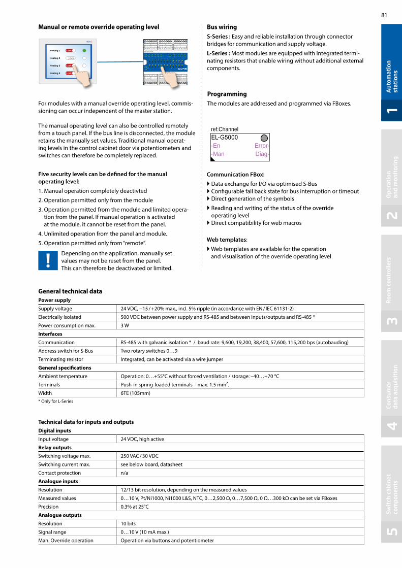
81
12
34
5
ref:Channel -En Error--Man Diag-
Heating 1 Lock
Heating 2 Auto
Heating 3 Lock
Heating 4 Lock
Aut
omat
ion
stat
ions
Ope
rati
on
and
mon
itor
ing
Roo
m c
ontr
olle
rsCo
nsum
er
data
acq
uisi
tion
Swit
ch c
abin
et
com
pone
nts
Manual or remote override operating level
For modules with a manual override operating level, commis-sioning can occur independent of the master station. The manual operating level can also be controlled remotely from a touch panel. If the bus line is disconnected, the module retains the manually set values. Traditional manual operat-ing levels in the control cabinet door via potentiometers and switches can therefore be completely replaced.
Five security levels can be defined for the manual operating level:
1. Manual operation completely deactivted
2. Operation permitted only from the module
3. Operation permitted from the module and limited opera-tion from the panel. If manual operation is activated at the module, it cannot be reset from the panel.
4. Unlimited operation from the panel and module.
5. Operation permitted only from “remote”.
Depending on the application, manually set values may not be reset from the panel. This can therefore be deactivated or limited.
ProgrammingThe modules are addressed and programmed via FBoxes.
Bus wiringS-Series : Easy and reliable installation through connector bridges for communication and supply voltage.
L-Series : Most modules are equipped with integrated termi-nating resistors that enable wiring without additional external components.
Communication FBox:
Data exchange for I/O via optimised S-Bus Configurable fall back state for bus interruption or timeout Direct generation of the symbols
Reading and writing of the status of the override operating level Direct compatibility for web macros
Web templates:
Web templates are available for the operation and visualisation of the override operating level
General technical dataPower supply
Supply voltage 24 VDC, −15 / +20% max., incl. 5% ripple (in accordance with EN / IEC 61131-2)
Electrically isolated 500 VDC between power supply and RS-485 and between inputs/outputs and RS-485 *
Power consumption max. 3 W
Interfaces
Communication RS-485 with galvanic isolation * / baud rate: 9,600, 19,200, 38,400, 57,600, 115,200 bps (autobauding)
Address switch for S-Bus Two rotary switches 0…9
Terminating resistor Integrated, can be activated via a wire jumper
General specifications
Ambient temperature Operation: 0…+55°C without forced ventilation / storage: –40…+70 °C
Terminals Push-in spring-loaded terminals – max. 1.5 mm².
Width 6TE (105mm)* Only for L-Series
Technical data for inputs and outputsDigital inputs
Input voltage 24 VDC, high active
Relay outputs
Switching voltage max. 250 VAC / 30 VDC
Switching current max. see below board, datasheet
Contact protection n/a
Analogue inputs
Resolution 12/13 bit resolution, depending on the measured values
Measured values 0…10 V, Pt/Ni1000, Ni1000 L&S, NTC, 0…2,500 Ω, 0…7,500 Ω, 0 Ω…300 kΩ can be set via FBoxes
Precision 0.3% at 25°C
Analogue outputs
Resolution 10 bits
Signal range 0…10 V (10 mA max.)
Man. Override operation Operation via buttons and potentiometer

82
Mounting and labelling in the automation control cabinetThe modules can be mounted in the standard automation control cabinet as well as mounting in the electrical sub-distributor. Covers are available for this for easy labelling. They also serve as contact protection for the buttons and terminals to prevent faulty operation.
S-SeriesType Digital input (DI),
universal input (UI) Relay, triac,
digital output (DO)Analogue
outputManual override operation
PCD1.A1000-A20 – 10 DO 24 VDC, 0.5 A – Yes
PCD1.A2000-A20 – 6 relays 230 V, 16 A – Yes
PCD1.B1100-A20 4 DI 10 relays (6 NO, 4 CO) – Yes
PCD1.B1120-A20 16 DI 4 relays change over – Yes
PCD1.B5000-A20 6 DI 230 V 3 relays 230 V, 6 A – Yes
PCD1.B5010-A20 6 DI 24 VAC/DC 3 relays 230 V, 6 A – Yes
PCD1. E1000-A10 12 DI 24 VDC – – –
PCD1.G2000-A20 6 UI 2 triacs 24…230 VAC, 1 A 2 Yes
PCD1.G2100-A10 8 UI – – –
PCD1.G2200-A20 8 UI – 4 Yes
PCD1.W5200-A20 – – 8 Yes
L-SeriesType Digital input Relay (NO / changeover) Analogue
inputAnalogue
outputManual override operation
PCD1.B1000-A20 4 10 (6 / 4), 4A --- --- Yes
PCD1.B1010-A20 24 10 (6 / 4), 4A --- --- Yes
PCD1.B1020-A20 16 4 (0 / 4), 4A --- --- Yes
PCD1.G5000-A20 16 8 (4 / 4), 4A 8 4 Yes
PCD1.G5010-A20 12 4 (0 / 4), 4A 12 8 Yes
PCD1.G5020-A20 8 4 (0 / 4), 4A 16 4 Yes
Accesories Type Short text Description Weight
32304321-003-S Terminal set – S+L-Serie 6-pin terminal. Set of 6 terminal blocks 40 g
AccessoriesType Short text Description Weight
PCD1.K0206-005 E-Line Cover Set 5×6 HP* E-Line cover and labelling set consisting of 5× covers (6 HP=105 mm) and labelling sheets for installation in automation control cabinets
365 g
PCD1.K0206-025 E-Line Cover Set 5×6 HP* w.h. E-Line cover and labelling set w.h. consisting of 5× covers (6 HP =105 mm) with holes for the manual priority operating level and labelling sheets for installation in automation control cabinets
365 g
* Horizontal pitch: 1 HP corresponds to 17.5 mm

83
12
34
5
89 mm
54 mm
59 mm
B
Aut
omat
ion
stat
ions
Ope
rati
on
and
mon
itor
ing
Roo
m c
ontr
olle
rsCo
nsum
er
data
acq
uisi
tion
Swit
ch c
abin
et
com
pone
nts
1.6.5 E-Line system components
System properties Short-circuit protection and constant overload limiter Protection class II (in closed switch cabinet) dual isolation Power failure bypass up to 100 ms LED for output voltage OK display Stabilised and adjustable output voltage for the conductor
resistance compensation Parallel operation possible to increase max. output current IP20 housing for mounting on DIN rail
The compact Q.PS-PEL-240x power units with 24 VDC output voltage can be installed in a very restricted space and therefore the installation in cost-effective electrical distributor boxes in accordance with DIN 43880 is possible. They are therefore ideally suited for combining with the E-Line family. Modern push-in terminals enable efficient and fast wiring without the use of tools.
Mounting in the sub-distributor
The design of the Q.PS-PEL2-40x power units complies with the required standard dimensions according to DIN 43880. The power units can therefore be easily integrated in electrical distribution boxes and are ideally suited to supply the components of the E-Line family with voltage
Input terminals
Output terminals
Output voltage OK LED
Setting of the output voltage
Power unit overview
Single phase 110/230 VAC Q.PS-PEL-2401: 24 VDC / up to 1.3 A Q.PS-PEL-2403: 24 VDC / up to 4.0 A
Standards and certifications
Compliant certifications CE DNV GL (shipping approval) UL (cURus, cULus) EAC
EMC EN61204-3 Immunity pursuant to EN61000-6-2 (for the industrial sector) Emitted interference in accordance with EN61000-6-4 (for the
domestic sector)
Dimensions
Terminal technology
Push-in terminals for efficient and fast wiring without tools for single wire conductors with a cross section of up to 2.5 mm² or fine wire ferrules up to 1.5 mm². However fine wire
conductors up to 2.5 mm² can also be connected directly by simply applying pressure (screwdriver).
Installation information
Distance to adjacent parts: Right/left: no minimum distance
required Top/bottom: min. 50 mm
Electrical safety EN61558 EN60950 (SELV)
Power units for installation in electrical distributor boxes
Model Q.PS-PEL-2401 Q.PS-PEL-2403
Width (W) 54 mm 90 mm

84
Output derating curve
Q.PS-PEL-2401
0.5
1
1.3
–25 –10 0 10 20 30 40 50 60–20
0.9
045
1.5
100
70
55
Load [A] Load [%]
Temp [°C]
Input rated voltage 230 VAC
Q.PS-PEL-2403
1
3
4
–25 –10 0 10 20 30 40 50 60–20
2.8
045
100
70
55
2
Input rated voltage 230 VAC
Load [A] Load [%]
Output characteristics
Voltage/current characteristic curve for short-circuit and overload protection
Uout(V)Output Charac
Iout(A)
teristic (U/I Chara teristic)c
1,1× INNI
The current overload protection limits the current to a constant value of 1.1 × nominal current
Input data Q.PS-PEL-2401 Q.PS-PEL-2403Input voltage 100…240 VAC
Permitted input voltage range 85…264 VAC
Nominal frequency range 44…66 Hz
Nominal input current for nominal load (110 / 230 VAC) 0.7 / 0.5 A 1.6 / 0.9 A
Internal input fuse 2 AT 4 AT
Recommended external pre-fuse 6 A, 10 A, 16 A, characteristics B, C
Power failure bypass for nominal load (110 / 230 VAC) 10 / 80 ms 15 / 100 ms
Output dataOutput voltage (VN) 24 VDC ± 2%
Output voltage range (VADJ) 22.8…26.4 VDC
Output current (IN) at ≤ 45°C 1.3 A 4 A
Output current (IN) at ≤ 55°C 0.9 A 2.8 A
Current load rating for any installation system max. 0.9 A max. 2.4 A
Efficiency typical 82% typical 88%
Residual ripple (for nominal load) ≤ 100 mVpp
Overload behaviour Constant current (U/I characteristic curve)
Short-circuit protection Yes
Overvoltage output protection Yes (max. 30 VDC)
Parallel connection Yes
StatusOperating indicator LED green
Environment Ambient temperature (operation) –25°C to +55°C (load reduction >45°C, 3%/°C)
Storage temperature –25°C to +80°C
Permitted humidity 30–85% relative humidity, no condensation permitted
Areas of use Use in areas with contamination level 2
Connection terminals Connections Push-in
Input/output terminals Single wire and fine wire conductors up to max. 2.5 mm²/ conductors with wire ferrules up to max. 1.5 mm²
Technical data

85
12
34
5
Saia PCD® COSinus
steuern
A2
Aut
omat
ion
st
atio
nsO
pera
tion
an
d m
onit
orin
gR
oom
con
trol
lers
Cons
umer
da
ta a
cqui
siti
onSw
itch
cab
inet
co
mpo
nent
s
Operation and monitoring SBC microbrowser devices form the core and main part of the HMI range. Windows-based systems complete the range.
2.1 Overview of types, dimensions and resource
2.2 Web Panels MB | Web technology
2.3 Web Panels MB | Standard device
2.4 pWeb Panels MB
2.5 Room Panels
2.7 Cyber secure HTML5 touch Web panels
Device series from 5 to 12”es. SBC microbrowser and standard IT interfaces with onboard.
Trending, alarming and system images for the operator. Specific websites for maintenance and service. Local data storage in Excel-compatible CSV format with FTP access for monitoring and logging functions. Saia PCD COSinus dedicated operating system for automation/MSR technology developed by Saia Burgess Controls.
The operation of HMI applications is also possible from multiple connected Saia PCD automation stations. The applications are created using the Saia PG5® Web Editor and made available in webserver of Saia PCD automation devices for the web panel microbrowser (MB).
Device series accessories: Chapter 2.6 – Page 94
In addition to the functions of the standard MB panel, a fully programmable logic controller is integrated. It can be used to realize specific, complex operating and local data processing logic. It can be used as a management/control station for large and distributed systems.
Accessories for the device series: Chapter 2.6 – Page 94
Attractively designed and fully programmable, the panels will fit beautifully into any room. Autonomous room applications with the integrated logic controller enable users to control the room functions without a head-end station.
Latest HMI generation of Saia PCD with elegant and robust design for control cabinet installati-ons. Modern HTML5 browser based on Linux. HTML5 touch panel provides high cyber security level to prevent from unauthorized access. Controllers, HMI and tools are harmonized while the compatibility with HTML5 Web-Editor is ensured. Saia PCD web Panels are ready to use.
Page 86
87
88
90
92
98

86
12.1"10.4"5" 7"
+
10.4"12.1"
+
21.5" 15.6" 10.1" 7.0" 4.3"
Saia PCD® pWeb Panels MB | with programmable logic controller
Saia PCD® Web Panels MB – Functional HMI|Visualisation and operation with ready-to-use functions
Saia PCD® Web Panels MB – room
Cyber secure HTML5 touch Web panels
Modern HTML5 browser based on Linux . Chromium Browser to access PCD Web-Server or Saia PCD Supervisor . High cyber security level with protection from unauthorized accesses
Display sizes 4.3” / 7.0”/ 10.1”/ 15.6”/ 21.5” Up to 3× Ethernet & USB 800 MHz and 1 GHz CPU 4 GB flash memory Resistive & True Glass Projected Capacitive Multitouch Screens Brilliant up to 2,100,000 pixels display Compatible with HTML5 Web-Editors projects.
Saia PCD® Web Panels MB|Standard devices Robust control panel for displaying web visualisations created with the Saia PG5® Web Editor.Ready to use with no software installation required.
Display sizes 5.0" / 7.0" / 10.4" / 12.1" Ethernet, USB and serial FTP server File system
HTM
L5 -
Linu
x D
evic
es w
ith S
aia
PCD
® CO
Sinu
s – co
ntro
l ope
ratin
g sy
stem
Saia PCD® pWeb Panels MB|with programmable logic controllerThe programmable Web Panels combine an automation server for visualisation with control and management functions in a single device.
Display sizes 10.4" / 12.1" 2× Ethernet (switch), USB and RS-485 Integrated logic controller Programmable with Saia PG5® Automation server 128 MB of flash memory
One step closer to the applicationFunctional HMI systems provide functions that support the user in the implementation of complex applications such as recording and visualis-ing data records. The devices come with a preinstalled application. This application can be modified or expanded.
For more information, see Chapter 4
2.1 Overview of types, sizes and resources
Saia PCD® Web Panels MB|Standard devices
+ Function
Fully programmable devices in a high-quality design for use in room applications. The visualisation can be custom-designed with the web editor.
Display size 4.3" 1 × Ethernet, 1 × RS-485, USB PCAP touch technology User file system 4…128 MB Temperature and ambient sensors

87
12
34
5
Ethernet
http
http
http
Hardw
are
Saia PCD® COSinus
Application
COSinus
Aut
omat
ion
st
atio
nsO
pera
tion
an
d m
onit
orin
gR
oom
con
trol
lers
Cons
umer
da
ta a
cqui
siti
onSw
itch
cab
inet
co
mpo
nent
s
2.2 Web Panels MB | Web technology Combination of openness, international standards and universality
The operation/monitoring project is created once using the Saia PG5® Web Editor and saved to the associated Saia PCD web server. Each browser can freely access any web server of the automation devices recognised in the network and run its web HMI application. A web server can handle multiple browsers simultaneously. Web HMI eliminates complex engineering, duplication of project expenses, software licensing problems and system breaks during operation/monitoring.
The web pages generated in Saia PG5® Web Editor are saved in a binary file format. This reduces communication costs to allow efficient visualisation even for lower power connections. Therefore, only the process points of the current view be-tween the Web Panel and the automation server are cyclically exchanged via a CGI interface.
Visualisation of different parts of the system at one location
The control devices and servers can be connected across the globe via any physical
connection, which the http protocol can transport.
Systems are often expanded or equipped with new functions and must be maintained throughout their entire service life. The Saia PCD COSinus operating system was specifically developed from scratch
in-house for use in automation environments. It is there-fore possible to ensure the industrial service life without being pressurised by large companies that influence the market. The top priority for Saia PCD COSinus is a reli-able and continuous operation. The SBC microbrowser Panel series are essentially based on this reliable system which has been expanded with the microbrowser ap-plication. This allows the visualisation and operation of web projects which have been created with Saia PG5® Web Editor. Here, the visualisation project can be saved locally or on a remote server.
Saia PCD® COSinus
A system for operation/monitoring with web technology consists of essentially just two functional elements: a web server and a browser. The protocol linking them is http. These two functional elements can be combined in the same automation device or located on opposite sides of the globe.
Hardware
Kernel
Virtual Saia PCD maschine
User application
Automation Server
Communication protocols

88
PS/2 Ethernet
RS-485
USBRS-232
5.0“
10.4“ 12.1"
2.3 Web Panels MB | Standard devices
The microbrowser standard device series is the visualisation and control interface for automations with Saia PCD controllers. The panels – finished to industrial quality – are available in various sizes to handle various requirements. The internal memory allows all devices to display data trending and alarm history so that dynamic visualisation can be implemented. An application saved in the controller can be displayed on the panel without any additional configuration tool.
Main features Large selection of display sizes, colour TFT display,
in VGA or SVGA resolution Fast and easy commissioning without additional
applications with an internal setup menu Connection to the web server via Ethernet
Setup menuThe panel is configured in two stages via the setup menu directly on the panel. No additional software or a connection to a laptop is required for commissioning.
1st Stage: Network configuration 2nd Stage: Web server configuration
Device design
EPLAN macros
EPLAN macros are available for project planning and engineering
Device installation
24 VDC USB 2 × Ethernet(switch)
Earth24 VDC
SBC MB AppOperation and monitoring on iPhone, iPad and Android
Ethernet
USB
24 VDC
The eplan® electric P8 macros are available on the support page. The macros and article data are also provided on the eplan® data portal.

89
12
34
5
60 6
56 6
40 5.6
44 5
PCD7.D410VTCF
PCD7.D412DTPF
PCD7.D450WTPF
PCD7.D470WTPF
Aut
omat
ion
st
atio
nsO
pera
tion
an
d m
onit
orin
gR
oom
con
trol
lers
Cons
umer
da
ta a
cqui
siti
onSw
itch
cab
inet
co
mpo
nent
s
Technical Data PCD7.D450WTPF PCD7.D470WTPF PCD7.D410VTCF PCD7.D412DTPF
Display size 5.0" TFT 7.0" TFT 10.4" TFT 12.1" TFT
Resolution (pixels) WVGA 800 × 480 WVGA 800 × 480 VGA 640 × 480 SVGA 800 × 600
Touch screen Resistive touch screen Resistive touch screen Resistive touch screen Resistive touch screen
Background lighting LED LED LED LED
Colours: 65,536 65,536 65,536 65,536
Onboard file system 128 MB 128 MB 4 MB 128 MB
Processor 240 MHz 240 MHz 66 MHz 240 MHz
Interfaces USB 1.1/2.0 Device Ethernet 10/100 M
USB 1.1/2.0 Device Ethernet 10/100 M
RS-232, RS-485USB 1.1 Device
Ethernet 10/100 M
USB 1.1/2.0 DeviceEthernet 10/100 M
Current requirements approx. 350 mA approx. 400 mA approx. 500 mA approx. 600 mA
Real-time clock (RTC) Yes (Supercap) Yes (Supercap) No Yes (Supercap)
Dimensions (W × H × D) and cut-out (W × H) mm
Front panel W × H, 319 × 264Display 12.1" W × H, 245 × 185
Cut-out W × H, 300 × 244
Front panel W × H, 281 × 221 Display 10.4" W × H, 211 × 150
Cut-out W × H, 262 × 202Front panel W × H, 166 × 126 Display 5.0" W × H, 109.4 × 66.2
Cut-out W × H, 157 × 117
General specificationsOperating system Saia PCD COSinus with microbrowser expansion
Protection type (front) IP 65
Temperature range Operation 0 … +50 °C (7.0“: –20…70 °C) Storage –25 … +70 °C
Humidity Operation 10 … 80 % Storage 10 … 80 % non-condensing
Contrast adjustment Yes
FTP server Yes
Supply voltage 24 VDC ±20 %
Front panel W × H, 204 × 157 Display 7.0" W × H, 154.08 × 85.92
Cut-out W × H, 189 × 142

90
USB
steuern
kWh kWh
bedienen/managen
steuern
A + B + C
2.4 pWeb Panels MB
Data concentrator
The logic enables users to collect and link the data and status of multiple connected Saia PCD control-lers and to visualise the data at a higher level.
Acquire and visualise data
Values of any type can be counted and displayed by loading the S-monitoring application. Each system’s consumption is thereby made transparent. For more information, see chapter 4 "Acquisition of Consumption Data"
The high priority given to visualisation in the program workflow offers the best basis for displaying data from various devices. Simple control tasks can also be implemented directly in the panel. It is not advisable to use pWeb panels when constructing closed control loops or utilising HVAC and DDC Suite controllers. In these cases, a Saia PCD controller is recom-mended.
In addition to the functions of the standard MB panel, a programmable logic controller is integrated into the pWeb Panels. Based on the COSinus operating system of the Saia PCD, specific, complex control logic and local data processing logic can be implemented in one device. The priority here are the operating and visualisation functions that enable small control systems to be implemented. The control functions have a lower priority.
Main features
Ethernet interfaces (2 port switch) RS-485 interface 240 MHz processing power Expandable via PCD7.F1xxS modules Can be used as a RIO Master
Application examples
Device installation
Supply voltageEthernet
(2 port switch)Earth
connectionRS-485PCD7.F1xxS Reset
switch
Data
A
Data
B
Data
C

91
12
34
5
62 6
62 6
PCD7.D410VT5F
PCD7.D412DT5F
Aut
omat
ion
st
atio
nsO
pera
tion
an
d m
onit
orin
gR
oom
con
trol
lers
Cons
umer
da
ta a
cqui
siti
onSw
itch
cab
inet
co
mpo
nent
s
Dimensions (W × H × D) and cut-out (W × H) mm
General specifications
Operating system Saia PCD COSinus with microbrowser extensions
Protection class IP65
User program, ROM/DB/Text
1 MB
RAM/DB/Text 1 MB
Media 16,384 flags / 16,384 registers
Backup for users The user program is saved on the integrated microSD card
File system for users 128 MB onboard
Program cycle time 10 cycles/sec. maximum
Field level protocols Serial S-Bus, Ether S-Bus, Ether S-IO, Modbus RTU or TCP
Internet services SBC microbrowser, automation server
Interfaces
Ethernet 2 × RJ45 (Switch)
USB 1 × (1.1 / 2.0)
Serial interfaces RS-485 1 slot for PCD7.F1xxS
Temperature range Operation: 0 … 50°C typicallyStorage: –25 …70°C
Humidity Operation 10 … 80 % Storage 10 … 80 % non-condensing
Processor Coldfire CF5373L, 240 MHz
Battery Lithium Renata CR 2032 (service life of 1…3 years)
Real-time clock (RTC) with battery buffer
Technical Data PCD7.D410VT5F PCD7.D412DT5F
Display size 10.4" TFT 12.1" TFT
Resolution / pixels VGA 640 × 480 SVGA 800 × 600
Touch screen Resistive touch screen Resistive touch screen
Contrast adjustment Yes Yes
Background lighting LED LED
Power supply 24 VDC ±20% 24 VDC ±20%
Current draw approx. 500 mA approx. 600 mA
Status front LED –– Yes
Communication
The Saia PCD pWeb Panel MB units can be expanded with one slot for various communication modules PCD7.F1xxS and memory modules PCD7.Rxxx. The modules are described in the section Saia PCD1.
Front panel W × H, 319 × 264Display W × H, 245 × 185
Cut-out W × H, 300 × 244
Front panel W × H, 281 × 221Display W × H, 211 × 150
Cut-out W × H, 262 × 202

92
RS-485Ethernet
2.5 Room PanelsAttractively designed, in the housing colour white or black, the panels will fit beautifully into any room. Autonomous room applications with the integrated logic controller (fully programmable) enable users to control the room functions without a head-end station and therefore the associated delays through long communication channels.
Main features Fully programmable visualisation with the Web Editor 8 Fully programmable logic controller for autonomous room applications Mounting in standard wall boxes Onboard temperature sensor TFT colours with a colour depth of 65,000 Capacitive touch screen technology for a very sensitive response
Temperature sensor
Ambient sensor
RS-485Ethernet
Supply voltage
Mounting
The installation of the panels is carried out using an adapter included in the package on standardised, double wall boxes.
Such as electrical material Type No. L 8102 HSB-Weibel AG No. 372 104 747 Agro No. 9922 Blass-Elektro No. 22031 Bticino No. 504E
The panel is anchored in the adapter, and can only be removed with the use of tools.
Application examples
Operation and regulation of autono-mous room applications. Imple-mentation using the programmable microbrowser room panel and the E-Line RIO modules. Connection based on the RS-485 interface to the E-line modules in the room, and Ethernet connection to the floor controller.
You will find more examples in Chapter B4 "Room Automation"
Room applications

93
12
34
5
PCD7.D443WTxRx
18
Aut
omat
ion
st
atio
nsO
pera
tion
an
d m
onit
orin
gR
oom
con
trol
lers
Cons
umer
da
ta a
cqui
siti
onSw
itch
cab
inet
co
mpo
nent
s
To restrict the maintenance there is no internal battery on the devices and therefore the Media are non-retentive. However, the “EL Backup Restore Media” FBox from the E-Suite Library allows to eas-ily backup in the non-volatile registers the values which has to be stored, like the adjust parameters.
Dimensions
The panel can also be mounted transversely
steuern
+
Technical Data White case PCD7.D443WTPRW PCD7.D443WT5RW
Black case PCD7.D443WTPR PCD7.D443WT5R
File system 4 MB 128 MB
Logic controller (no remanence) No Yes
User program, ROM/DB/Text No 128 KB
RAM/DB/Text No 128 KB
Media No 16,384 flags / 16,384 registers
Memory for parameter (media) backup No 1,000 non-volatile registers
Serial interfaces No RS-485
General technical data PCD7.D443WTxR PCD7.D443WTxRW
Operating system Saia PCD COSinus with micro browser expansion
Display
Display size [inch] 4.3”
Resolution [pixels] WQVGA / 480 × 272 pixels
Contrast adjustment Yes
Background lighting LED (dimming in 20 steps)
Touchscreen PCAP technology
Interfaces
USB 1 × (1.1 / 2.0)
Ethernet Ethernet 10/100 full-duplex, auto-sensing/auto-crossing
Real-time clock Yes (SuperCap)
Sensors
Temperature Accuracy: ±1°C easy calibration
Power supply
Supply voltage 24 VDC ±20 %
Current draw Approx. 4 watts / 160 mA
Environment
Temperature range Operation: 0…50°C typically Storage: –25…+70°C
Humidity Operation: 10…80%, storage: 10…80%, non-condensing
Protection class IP20
Mechanic
Weight approx. 200 g
The location of the panel can slightly influence the temperature measurement, an easy calibration allows to remedies this and so increases the accuracy.
In any case ensure that the ventilation slots are not obstructed (LED on the left side !).
Front panel W × H, 90 × 152 mmDisplay 4.3“
Cut-out W × H, 60 × 120

94
The correct mounting kit for all Web HMI devicesThe microbrowser panel series not only fits in a switch cabinet, but also enables this modern technology to be easily and correctly integrated into the area in close proximity to the user using industrial in-wall and off-wall mounting kits. The mounting kits therefore enable simple wall mounting, which is consistently available for all panels. These kits minimise logistics and mounting costs.
2.6 Accessories for microbrowser panels
Cut-out W × H, 309 × 245Minimum depth For solid walls 75 mmFor cavity walls 65 mm
In-wall PCD7.D457-IWS2
On-wall PCD7.D457-OWS2
In-wall PCD7.D410-IWS
On-wall PCD7.D410-OWS
In-wall PCD7.D412-IWS
On-wall PCD7.D412-OWS
Cut-out W × H, 270 × 211Minimum depth For solid walls 75 mmFor cavity walls 65 mm
Cut-out W × H, 270 × 211Minimum depth For solid walls 75 mmFor cavity walls 65 mm
7”
10.4”
12.1”
2.6.1 Installation systems for the microbrowser family

95
12
34
5
PCD7.D457-OWS1
255 mm
75 m
m30
4 m
m
73,5 mm
219
mm
266 mm
Aut
omat
ion
st
atio
nsO
pera
tion
an
d m
onit
orin
gR
oom
con
trol
lers
Cons
umer
da
ta a
cqui
siti
onSw
itch
cab
inet
co
mpo
nent
s
On-wall mounting kit 7”
on-wall PCD7.D457-OWS
Wall mounting kit 7”
OEM or proprietary design
Width 266 mmHeight 219 mmDepth 73.5 mm
Order detailsType Description
3230 9178-001 Fixation set (4 pieces) for the models PCD7.D450, 2 sets necessary for the model PCD7.D412
3230 9178-002 Fixation set (6 pieces) for the models PCD7.D470, PCD7.D410
2.6.2 Fixation sets for Web Panels MB
The standard Micro Browser Panel provide space for your own creativity. In large quantities, the panels can be visually adapted to individual room needs, with customized front foils.
Panels with neutral front PCD7.D450WTPZ11PCD7.D470WTPZ11PCD7.D410VTCZ11PCD7.D412DTPZ11PCD7.D410VT5Z11PCD7.D412DT5Z11
Panels with a neutral front can also be delivered in small quantities.

96
2.6.3.1 SBC Micro-Browser App for Apple and Android
Technical Data SBC MB LITE SBC MB SBC MB LITE SBC MB
Operating system version
> iOS Version 3.2 > Android V.2.2
Resolution / pixels Depending on the devices used
Update management AppStore Google Play
Restrictions No station listNo URL skipping
No limitations
No station listNo URL skipping
No limitations
The SBC microbrowser apps overcome the limitations of the industrial world. Most tablets or smartphones are optimised for a long mobile runtime with high performance. The microbrowser app is therefore the ideal way to plug the gap between stationary and mobile areas of use. This provides the foundation for 24-hour monitoring and direct intervention in system operation.
2.6.3 SBC Micro-Browser App
The SBC Micro Browser App is a small browser application that allows to display and operate web based applications created with the Saia PG5® Web Editor5/Web Editor8 and stored on a Saia PCD Device. The Micro Browser App behaves like a browser using Java (IMaster.jar). The “look and feel” of the visualisation is similar to Micro-Browser panels PCD7.D4xx.Of course, web based Alarming and Trending functionality’s are included. The integrated station list makes it easy to navigate fast be-tween different web servers, or allows to create user specific access on one overview page to different parts in an application, system or device.
2.6.2.2 SBC Micro-Browser App for Windows
The SBC Micro Browser App for Windows runs on Windows based operating systems (W7, W8, W10, …). The Micro Browser App for Windows includes following specific additional features:
Print of the current visible window content Screen Capture of the current visible window content Different scaling modes “Auto resize”, “Best fit” and “Fixed size”

97
12
34
5A
utom
atio
n
stat
ions
Ope
rati
on
and
mon
itor
ing
Roo
m c
ontr
olle
rsCo
nsum
er
data
acq
uisi
tion
Swit
ch c
abin
et
com
pone
nts
Using S-Web technology combined with the microbrowser panel systems, operation can be transparent and clear for all users. Each individual operating side has a fully flexible design and can be created using the standard objects or existing function templates.
My HMI: Web pages created with Saia PG5® Web Editor 8 For further information, see the chapter "S-Web technology"
2.6.4 Ways of using the Web Panels with S-Web technology
DDC Suite / HVAC templates created with Saia PG5® Web Editor 8
The Windows operating system allows users to confront the constant challenges of the world of automation. This is made possible by the vast application landscape (apps) which provides quick solutions for any application. Should you find no application on the market for your purposes, you can create a high-level language quickly and effectively based on .Net.
2.6.5 Extensive visualisation options with Windows-based devices
However, please exercise caution when using Windows-based systems. Development of the Windows operating systems is constantly progressing to meet the variety of different requirements. As a result, applications may have to be constantly adjusted for changes in the system. The maintenance requirements of Windows-based systems are greater compared to microbrowser devices, but provide increased functionality.
High maintenance costs High maintenanceLow service life
Extensive functional-ity options

98
21.5" 15.6" 10.1" 7.0" 4.3"
2.7 New Cyber secure HTML5 touch Web Panels | PCD7.D5
High cyber security and HTML5 Web-Editor projects: The new HMI generation of Saia PCD offers an elegant and robust design for control cabinet installations. With its modern HTML5 browser based on Linux, the touch panel provides high cyber security level to prevent from unauthorized access. High quality, industrial grade and long life cycles (>10 years) are at the core of the panels.
Controllers, HMI and tools are harmonized while the compatibility with HTML5 Web-Editor is ensured.
Main features
Powerful and fast ARM Cortex-A9 Processor
Interfaces: Ethernet, USB
Power supply: 24 VDC
HTML5 Chromium Browser to access PCD Webserver or any other webserver
Compatible with HTML5 Web-Editor projects
Brilliant up to 2,100,000 pixels display
Wide angle visibility
Capacitive touch versions in total glass design. Resistant to scratches, UV and chemicals
IP66 protection from the front
Operating temperature –20°C to +60°C
Real Time Clock, RTC Back-up, Buzzer
Certifications: IECEx, ATEX, DNV-GL, Lloyd’s Register, UL

99
12
34
5A
utom
atio
n
stat
ions
Ope
rati
on
and
mon
itor
ing
Roo
m c
ontr
olle
rsCo
nsum
er
data
acq
uisi
tion
Swit
ch c
abin
et
com
pone
nts
Ethernet port 2 (10/100 Mb)
Serial port(Not supported) Power supply
USB ports 1 and 2
Ethernet port 1 (10/100 Mb)
Ethernet port 0 (10/100/1000 Mb)
SD Card slot(Not supported)
2 Expansion slots for plugin modules (Not supported)
Power supply
Serial port(not supported)
Ethernet portPower supply
USB port (vers. 2.0-1.1)
Dimensions (W × H × D) and cut-out (A × B) mm
Technical Data PCD7.D543RF PCD7.D570RF PCD7.D570CF1
Resistive touch Capacitive (multi touch)
Display size (inch) 4.3” TFT, 16:9, LED, 64 K 7” TFT, 15:9, LED, 64 K 7” TFT, 15:9, LED, 16 M
Operating system Linux Linux Linux
Resolution (pixels) 480 × 272 800 × 480, WVGA 800 × 480, WVGA
Brightness 200 cd/m2 200 cd/m2 500 cd/m2
Touchscreen Resistive Resistive True Glass projected Capacitive, Multi touch
USB Port 1× (Host v. 2.0, max. 500 mA) 1× (Host v. 2.0, max. 100 mA) 2× (Host v. 2.0, max. 500 mA)
CPU ARM Cortex-A8, 1 GHz ARM Cortex-A9, dual core, 800 MHz i.MX8M Mini Quad ARM Cortex-A53
RAM 512 MB 1 GB 2 GB
Flash 4 GB 4 GB 4 GB
Power Supply 24 Vdc (10… 32 Vdc) 24 Vdc (10… 32 Vdc) 24 Vdc (10… 32 Vdc)
Current consumption 0.25 A max. at 24 Vdc 0.3 A max. at 24 Vdc 0.7 A max. at 24 Vdc
Operating temp. 0…+50°C 0…+50°C –20…+60°C
PCD7.D543RF | 4,3“ HTML5 Web Panel, resistive touch
PCD7.D570RF | 7“ HTML5 Web Panel, resistive touch
PCD7.D570CF1 | 7“ HTML5 Web Panel, capacitive touch
4.3” 7” 7”
W187 mm
A176 mm
D47 mm
D18…8.5 mm
H147 mm
B136 mm
A176 mm
B136 mm
W187 mm
H147 mm
D29 mm
D15 mm
A136 mm
B96 mm
D29 mm
D15 mm
W147 mm
H107 mm

100
P52 mm
Ethernet port 2 (10/100 Mb)
Serial port (Not supported) Power supply
Ethernet port 1
(10/100 Mb)
Ethernet port 0
(10/100/1000 Mb)USB ports
1 and 2
Ethernet port 2 (10/100 Mb)
Serial port(Not supported) Power supply
Ethernet port 1
(10/100 Mb)
Ethernet port 0
(10/100/1000 Mb)USB ports
1 and 2
Cut-out
Ethernet port 2 (10/100 Mb)
Serial port(Not supported)
Power supply
Ethernet port 1
(10/100 Mb)Ethernet port 0
(10/100/1000 Mb)
2 Expansion slots for plugin modules (Not supported)
SD Card slot(Not supported)
USB ports 1 and 2
Technical Data PCD7.D510CF1 PCD7.D515CF1 PCD7.D521CF1
Capacitive (multi touch)
Display size (inch) 10.1“TFT, 16:9, LED, 16 M 15,6“TFT, LED, 16 M 21,5“TFT, LED, 16 M
Operating system Linux Linux Linux
Resolution (pixels) 1280 x 800, WXGA 1366 x 768, HD 1920 x 1080, Full HD
Brightness 500 cd/m2 400 cd/m2 300 cd/m2
Touchscreen True Glass projected Capacitive, Multi touch
True Glass projected Capacitive, Multi touch
True Glass projected Capacitive, Multi touch
USB Port 2× (Host v. 2.0, max. 500 mA) 2× (Host v. 2.0, max. 500 mA) 2× (Host v. 2.0, max. 500 mA)
CPU i.MX8M Mini Quad ARM Cortex-A53 i.MX8M Mini Quad ARM Cortex-A53 i.MX8M Mini Quad ARM Cortex-A53
RAM 2 GB 2 GB 2 GB
Flash 4 GB 4 GB 4 GB
Power Supply 24 Vdc (10… 32 Vdc) 24 Vdc (10… 32 Vdc) 24 Vdc (10… 32 Vdc)
Current consumption 1.0 A max. at 24 Vdc 1.2 A max. at 24 Vdc 1.7 A max. at 24 Vdc
Operating temp. –20…+60°C –20…+60°C –20…+60°C
Dimensions (W × H × D) and cut-out (A × B) mm
PCD7.D510CF1 | 10,1“ HTML5 Web Panel, capacitive touch
PCD7.D515CF1 | 15,6“ HTML5 Web Panel, capacitive touch
PCD7.D521CF1 | 21,5“ HTML5 Web Panel, capacitive touch
10.1” 15.6” 21.5”
W552 mm
A541 mm
D56 mm
D18…8.5 mm
H347 mm
B336 mm
W422 mm
A411 mm
D56 mm
D18…8.5 mm
H267 mm
B256 mm
W282 mm
A271 mm
D18…8.5 mm
H197 mm
B186 mm

101
12
34
5
A3
Aut
omat
ion
st
atio
nsO
pera
tion
an
d m
onit
orin
gR
oom
con
trol
lers
Cons
umer
da
ta a
cqui
siti
onSw
itch
cab
inet
co
mpo
nent
s
Programmable and configurable room controllers
3.2 PCD7.LRxx BACnet room controllers can be configured and commissioned via an Android app
3.1 PG5 freely programmable S-Bus/Modbus room controllers for flexible and individual room solutions
3.2.1 Overview and advantages of the PCD7.LRxx system
3.2.2 Set-up information with RoomUp and integration with the PG5
3.2.3 Application overview
3.2.4 Product overview and wiring examples
3.2.5 PCD7.LRxx accessories
3.1.1 Overview and advantages of the PCD7.LRxx-P5 system
3.1.2 Programming
3.1.3 Product overview
3.1.4 Connection examples
3.1.5 Accessories for PCD7.LRxx-P5
3.1.6 Project planning information
From room controllers with integrated, configurable applications to the Saia PG5 freely programmable room controller allowing flexible and individual room solutions, a range of room controller products with various communication protocols is available. Even without a bus connection, full, independent functionality is guaranteed.
Page
Page
109
110
113
114
116
102
104
105
106
107
108

102
PG5
3.1 PG5 freely programmable S-Bus/Modbus room controllers for flexible and individual room solutions
3.1.1 Overview and advantages of the PCD7.LRxx-P5 system
Advantages
2 × RS-485 interfaces for S-Bus or Modbus communication and option of I/O expansion with E-Line RIO modules
Room and building management requirements can be jointly controlled and fulfilled via one software tool (PG5)
Programmable DALI and expansion modules which can be used for lighting and shading can easily be integrated
Battery and maintenance-free wireless EnOcean sensor integration
Reliable products with straightforward installation and maintenance processes thanks to removable terminals
Thanks to their form factor, they can be installed in an electrical sub-distribution system.
Geared to individual customer requirementsWith the help of the new room controller, HVAC, lighting and shading solu-tions become freely programmable. As a result, individual, cross-discipline plans, aimed at for example optimising energy consumption, can be drawn up for state-of-the-art hotel, hospital and office concepts. In order to create a tailored solution geared to the needs of customers and buildings, additional sensors and modules can be integrated – from programmable DALI modules and motion sensors to hotel-card reading devices. This high level of flexibility also allows special room and user experiences like those that play a role in the room concepts of hotels.
Efficient engineeringVia a USB connection, the room controller can be programmed in the Saia PG5 Controls Suite. Because SBC automation stations are compatible with this software, building management and room control can be done on a joint platform. This simplifies the programming process and increases its efficien-cy. Additional software solutions or hardware is not required.
Flexibility thanks to free programming capabilityThe freely programmable PCD7.LRxx-P5 room controller offers a high level of flexibility for scalable HVAC, lighting and shading solutions, allowing indi-vidual applications to be created. The programming is done via the Saia PG5 Controls Suite where the room controller can be teamed with other Saia PCD products and operated together. This means that a single software tool can be used to meet different requirements, from room management to building management, for efficient engineering.
INPUT OUTPUT
FREELY PROGRAMMABLE

103
12
34
5A
utom
atio
n
stat
ions
Ope
rati
on
and
mon
itor
ing
Roo
m c
ontr
olle
rsCo
nsum
er
data
acq
uisi
tion
Swit
ch c
abin
et
com
pone
nts
Easily retrofittable
InterfacesTwo interfaces that can be configured as S-Bus or Modbus allow connection to higher-level building automation control systems as well as the integration of digital room operating devices and expansion modules. As a result, the room controller can be combined with existing SBC E-Line RIO modules which can be used as an I/O expansion for HVAC, lighting or shading control. In addition, a Sylk bus interface allows the integration of corresponding room operating devices with integrated sensors.
EnOceanThe RS-485 interface can also be used as an EnOcean gateway in order to connect a PEHA EnOcean antenna (PEHA ANT 450). As a result, battery and maintenance-free (PEHA Easyclick) EnOcean sensors (such as hotel-card switches, window contacts, movement sensors and operating devices) can be used.
In this system architecture, En-Ocean switches should not be used for lighting or blinds via E-Line RIO modules connected to the primary RS-485 interface. If too many loads are connected to the RS-485 interface, the reaction time for a switching command could exceed 250 ms and would therefore be perceived as a disturbance.
Planning noteNo more than 10 S-Bus slaves or 10 Modbus slaves, such as E-Line modules, can be connected via the second RS-485 interface of the PCD7.LRxx-P5 room controller. The following points must be observed in order to determine the feasible number of S-Bus/Modbus slaves:
Bus cycle time Use only for HVAC or, alternatively, lighting or shading Application program resource requirement The more E-Line modules there are connected to the second RS-485 interface of the PCD7.LRxx-P5, the less memory space there is for the application program. Further information and calculation aids can be found in the manual.

104
USBPG5
PG5
RS-485
Out Blind- En Err- Sync Busy- Set Up-- Pos Down-- IUp LastCmd-- IDown- Cmd0
In PushButton 1- En Cmd- In LastCmd-
In addition to these libraries, a new library “E-Suite V2” is availa-ble for specific applications that can be implemented using the Saia PCD1 E-Line modules. For electrical building services, for example: blind control, dimming of lighting etc.
Further information, including which FBoxes are supported can be found on our support page www.sbc-support.com.
Program blocks
COB COB 0
XOB XOB 10, 12, 13 and 16
PB / FB 100 with maximum hierarchy on 8 levels
Data types
ROM text / DB 50
Memory
Program memory 128 kB
ProgramFlash memory
Compared to a PCDx.Mxxxx controller, not all functions are available. For example, these modules do not have an automation server.
3.1.2 Programming
The modules are programmed with Saia PG5® using a master controller or directly via Micro-USB.
Programming directly via USB PCD7.LRxx-P5 controllers have a Micro-USB port on the front of the module. Using a direct USB connection from the PC to the module, the user program can be loaded to the con-nected module or the firmware for the module can be updated. It is advisable to configure the S-Bus address prior to installation in the room controller to allow commissioning of the room controller and the downloading of the application program (and possibly a firmware update) via the RS-485 bus after installation.
Programming using a master controller (PCDx.Mxxxx)The master controller, which is connected to the freely programmable PCD7.LRxx-P5 room controller, uses the RS-485 bus (S-Bus) to load the user program or a firmware update for example to the corresponding modules. The master controller is used as a gateway in this case.
Binary Blinker Block Control (no SB) Buffers Com.Text (not interpreted) Converter Counter DALI E-Line Driver (new) Data Block Data Buffer EIB Driver (partly) EnOcean (partly)
List of supported libraries:
The modules are project-engineered with Saia PG5® using FBoxes or IL. A selection of FBoxes which make engineering easier is available for this purpose.
Flip-Flop Floating Point (IEEE only) HVC (partly) Indirect Integer Ladder Move In/Out Modbus (E-Suite) Regulation (partly) Special, Sys Info (partly) Timer PHC
Media Volatile memory (RAM) without battery backup
Data types
Registers 4000
Flag 4000
Timer / counter 400
Memory
Memory (RAM) for 50 texts / DB 10 kB
Memory (EEPROM) for parameter (media) backup 256 bytes
Cyclical synchronisation with PCD controller Real time clock (RTC)
PG5 standard FBox libraries
In order to be able to use the PCD7.LRxx-P5 controller with E-Line devices, the E-Line library V1.3 (or higher) must be installed in PG5. The required PCD, IRM and E-Line firmware versions are described in the FBox «Library Help».Further information can be found in the V1.3 library help.
PCD- controller

105
12
34
5A
utom
atio
n
stat
ions
Ope
rati
on
and
mon
itor
ing
Roo
m c
ontr
olle
rsCo
nsum
er
data
acq
uisi
tion
Swit
ch c
abin
et
com
pone
nts
Order number Pow
er
supp
ly
Ana
logu
e
outp
uts
Uni
vers
al
inpu
ts
Rela
ys
Tria
cs
(24/
230
VAC)
Tota
l I/O
s
LED
out
put
24 V
AC
outp
uts
for fi
eld
devi
ces
Sylk
USB
2nd
RS-4
85
Gol
d Ca
p
72 h
ours
Term
inal
s
Large room controller 198 × 110 × 59 mm
PCD7.LRL2-P5 230 VAC 2 6 4 4 16 1 300 mA Yes Yes Yes Yes
All
term
inal
s re
mov
able
PCD7.LRL4-P5 230 VAC 6 10 4 4 24 0 300 mA Yes Yes Yes Yes
PCD7.LRL5-P5 24 VAC 6 10 4 4 24 0 600 mA Yes Yes Yes Yes
IRM-RLC Package including 10 large terminal covers
Small room controller 162 × 110 × 59 mm
PCD7.LRS4-P5 230 VAC 4 4 4 2 14 0 300 mA Yes Yes Yes Yes
PCD7.LRS5-P5 24 VAC 4 4 4 2 14 0 600 mA Yes Yes Yes Yes
IRM-RSC Package including 10 small terminal covers
3.1.3 Product overview
Controller example PCD7.LRL4-P56 × analogue outputs
0…10 VDC+24 VAC outputs for
field devicesSylk
room operating device
RS-485 bus for connecting to higher-lever floor controller
Outputs for 3-speed fan 230 VAC
10 × multifunctional inputs (analogue & digital)
with programmable function
1 x relayoutput
4 × triac outputs 230 VAC / 24 VAC
Optional terminal covers can be attached
230 V AC power supply 24 V AC output
for triacs or field devices
Status LEDs
RS-485 bus for connecting to digital room operating devices or expansion modules
Programming with Saia PG5®

106
V
PCD7.LRL2-P5
LN
230 VAC
TEMP SETUP FAN
WALL MODULEPCD7.LR-TR42
room operating devices
* OPTIONAL FUSE (TO PROTECT THECONTROLLER‘S INTERNAL TRANSFORMER,WHICH HAS ONLY A NON-RESETTABLE FUSE).
RS-485Port 1
RS-485Port 0
! Note grounding concept !see „27-653 Manual IRM-PG5“
max. 1.25 Aslow blow (IEC)
RN = Reserve terminals serveas distributors
digitalanalog
OUTPUTSanalog
OUTPUTS - RELAYS
max. 10 A15…253 V AC
OUTPUTS - TRIACS
max. 4 A15…253 V AC
max. 4 A15…253 V AC
max. 10 A15…253 V AC
UNIVERSAL INPUTS
24VDC
1 2 3 4 5
F1*
TN T~ TN TO1 TO2 TN TO3L N TO024 V~ 24 V07 8 10 11 12 13 149
47UI0
49 51UI3
53UI4
55 57UI7
59UI8
6145LED
44 46 48UI1
50UI2
52 54UI5
56UI6
58 60UI9
RO3 IN3 RN RN IN0 RO0 IN1 RO1 IN2 RO216 17 18 19 20 21 22 23 24 25
32AO0
34AO1
36AO2
38AO3
40AO4
42AO5
30WM1
31WM2
39 4337 41353324 V~ 24 V~ 24 V~
NL
LED
5 61 2
Micro-USB
/DA+ DB- /DA+ DB-63 6462
24 V~29
24 V~27 2826
SylkBus
GND GNDGND
GND
GND GND GND
GNDGND GNDGND
GND
230 V AC
24 V~24 V0
PCD7.LRS4-P5 wiring example
PCD7.LRL2-P5 wiring example
3.1.4 Connection examples
NL
NL
V
PCD7.LRS4-P5
TR42Wall module
RS-485Port 1
RS-485Port 0
DIGITALANALOGsignal source
0…10 V
ANALOG OUTPUT
max. 1.25 Aslow blow (IEC)
! Note grounding concept !see „27-653 Manual IRM-PG5“
RN = reserveterminals serveas distributors
max. 10 A15…253 V AC
max. 4 A15…253 V AC
OUTPUTS - RELAYS
OUTPUTS - TRIACSmax. 4 A
15…253 V ACmax. 4 A
15…253 V AC* OPTIONAL FUSE (TO PROTECT THECONTROLLER‘S INTERNAL TRANSFORMER,WHICH HAS ONLY A NON-RESETTABLE FUSE).
Outputmax. 300 mA
24VDC
UNIVERSAL INPUTS
/DA+ DB- /DA+ DB-
Micro-USB
WM1 WM2
SylkBus
GND GNDGNDGNDGNDGND3230 333120 26
AO034UI0
36UI1
37UI2
29AO1 AO2 AO3
282724V~ 24V~
39UI3
35 38 40 41 4221 2224V~
5TN
6T~
7TO0
8TN
10RO3
11IN3
12RN
13RN IN0
15RO0
16IN1
17RO1
18IN2
19RO2
324V~
424V0
24 2523
TO114
F1*
1 2
230 V AC
9
PCD7.LR-TR42 Room operating device
PCD7.LR-TR42 Room operating device
PCD7.LRL4-P5

107
12
34
5
161.
65
198
54
58.3
2558
.325
54
59
IRM-RLC(BULK PACK, 10 pcs.)
PCD7.LRLxPCD7.LRxx
PCD
7.LR
xx
IRM-RxL(BULK PACK, 10 pcs.)
Aut
omat
ion
st
atio
nsO
pera
tion
an
d m
onit
orin
gR
oom
con
trol
lers
Cons
umer
da
ta a
cqui
siti
onSw
itch
cab
inet
co
mpo
nent
s
IRM-RSC/IRM-RLCTerminal covers
Sylk bus room operating devices
Polarity-independent 2-wire bus with power and data transmission
Types with integrated sensors for temperature, humidity and CO2 sensor in one device
Up to 4 room operating devices per PCD7.LRxx-P5 with a total cable length of up to 150 m
PCD7.LR-TR42
Room temperature sensor + setting option for setpoint,
presence and fan speed + LCD display (+ humidity and CO2 sensor) Order number: PCD7.LR-TR42PCD7.LR-TR42-HPCD7.LR-TR42-CO2PCD7.LR-TR42-H-CO2
Compatible room operating devices
Clip-on terminal covers (IP30 contact protection) for small or large controllers to prevent the user touching the 230 VAC terminals.
Optional for IP30
3.1.5 Accessories for PCD7.LRxx-P5
PCD7.D1000
S-Bus / Modbus room operating device for room temperature measurement, setpoint offset setting
Design in accordance with PEHA Dialog Aluminium
Room temperature sensor 0…40 °C
Setpoint offset control ± 3 K in 0.5 K steps
7 LEDs to indicate the setpoint offset
2 plug-in RJ9 connections for Daisy Chain and up to 6 room operating devices.
PCD7.LR-TR40
Room temperature sensor (+ humidity and CO2 sensor) with Sylk bus connection to the controller.
Order number: PCD7.LR-TR40PCD7.LR-TR40-HPCD7.LR-TR40-CO2PCD7.LR-TR40-H-CO2

108
0 h
2 h
4 h
6 h
8 h
10 h
12 h
14 h
16 h
18 h
20 h
22 h
24 h
Bus terminating resistor and bus cable for serial S-Net (S-Bus/RS-485)S-Bus cables must be installed as a line. Stub lines are not permitted and both ends of the cable must be terminated with a resistor (approx. 120 Ω) between the D and /D cables. The best signal quality is achieved using an active bus con-nection with a resistor to +5V and GND.
Schematic illustration of an S-Bus/ RS-485 bus
An external PCD7.T161/2 termination box can be used as bus termination resistor. Bus cable: A 2-strand twisted and shielded bus cable with cable strands of at least 0.5 mm2 must be used. Bus shielding: The shielding of each S-Bus segment may only be connected with the electrical system ground at one
point. To avoid problems with large potential differences between the room controllers, the shielding of the S-Bus cable should be connected with the GND of the room controller. For more information, see S-Bus manual 26-739 (at www.sbc-support.com).
Start station End stationIntermediate stations
Pull down Pull down
Terminating resistor
Terminating resistor
Pull up Pull up
RS-485S-Bus
+5V +5V/D D /D D /D D /D D
Types of use and modes of operation The function of the room controller is based on various types of use or modes of operation. Each of the selectable modes of operation can be assigned different control parameters.
Window contact openPresence detectionRoom use time program
Comfort
Standby
Reduced
Frost protection
Example: Operating mode switchover
Safety mode/Frost protection No heating or cooling energy is fed into the room. This state is desirable if a window is open. The room controller keeps the room temperature above the preset frost line of 8° C.
Non-use/reducedReduced operation mode which is used when the room is un-occupied for long periods. The specified setpoint value offset is not active in this operation mode.
StandbyThe room is prepared for use but no presence has yet been registered in the room. As long as the room is not classified as occupied by the presence function, the room controller maintains the room temperature within the specified limits at the standby temperature.
Use/comfortThe room is used and should be brought to the comfort temperature. This state can be reached by pressing the presence button, reacting to an external presence detector or a parameter on the network side.
Compact room controller installation information
Do not install the compact room controller near windows or doors due to potential draughts. The recommended position is on an opposite wall at a height of approx. 1.5 m.
Do not install it near to heat sources such as heating sys-tems, fridges, lights, etc. Avoid direct sunlight or direct light from bright lighting.
Do not locate the compact room controller in draughts pro-duced by air conditioning and ventilation systems.
3.1.6 Project planning information

109
12
34
5
PCD7.LRxx
T7460x
BACnet-MS/TP
Aut
omat
ion
st
atio
nsO
pera
tion
an
d m
onit
orin
gR
oom
con
trol
lers
Cons
umer
da
ta a
cqui
siti
onSw
itch
cab
inet
co
mpo
nent
s
TR42 Sylk bus
BACA-ABACnet WiFi adapter
Standard Ethernet patch cable
PCD7.L RoomUp app
BTL®-listed PCD7.LRxx BACnet room controller A new, easy way to commission room applications – via an Android device and the RoomUp app The new BACnet room controller in the PCD7.LRxx series allows efficient, quick commissioning and testing of the connected actuators and sensors. The room controllers have universal inputs that can be con-figured for a variety of functions, and their form factors also allow them to be installed in electrical sub-distribution systems. They also have a Sylk bus interface for connecting digital room operating devices.The following applications can be configured:
Fan convectors, fans with 1–3 speeds or fans with a variable speed
Inlet air flap control with combined air quality monitoring and temperature control
Cooled ceiling
Under-floor heating
Radiator heating
A combination of the aforementioned applications
Advantages No programming needed Applications can be created quickly and easily because the controller comes supplied with pre-installed applications which can be configured via the app. Quick installation of applications across projects – as soon as an individual room is configured, the application configuration can be extended to other rooms via the RoomUp app ("template concept").
Easier installation In order to cater for various installation requirements, the controller can be mounted universally on DIN top hat rails, in small installation housings and on walls (including optional terminal covers). Triac outputs can be controlled with 24 VAC or 230 VAC.
Easier commissioning The solutions allow very efficient "commissioning by one person" via the "RoomUp" app with quick, straightforward and reliable test procedures on location thanks to the "RoomUp" app's guided testing and reporting. Automatic MS/TP-MAC addressing by scanning a barcode.
Commissioning and testing by one person
3.2 PCD7.LRxx BACnet room controllers can be configured and commissioned via an Android app
3.2.1 Overview and advantages of the PCD7.LRxx system

110
3.2.2 Set-up information with RoomUp and integration with the PG5
RoomUp
A unique commissioning experience RoomUp is used to configure, commission and test the application. RoomUp offers an entirely new way of commissioning room systems and carrying out final tests:
Quick and easy commissioning by one person via a smart-phone or tablet
Easier, reliable tests on location thanks to the wireless con-nection with guided testing and integrated reporting
Efficient, automatic device addressing
Wireless communication allows commissioning before bus installation is complete
A template concept helps the user to determine the standard room types used in the building (templates). The template is used on all controllers for the relevant room type. A change to the template can easily be applied to all controllers with the same template.The RoomUp app can be downloaded from the Google Play Store.In order to activate the downloaded RoomUp app, a RoomUp licensing key with the order number PCD7.L-ROOMUP is required.RoomUp is an Android app for smartphones and tablets run-ning Android 5.0 or higher.
AddressingThe person commissioning the system does not need to set addresses via address switches. PCD7.LRxx automatically uses an unused BACnet address (automatic MS/TP-MAC address-ing). Assignment to a specific room is easily possible via the service button or by scanning the barcode label. 1 barcode label is placed on the controller and 1 barcode label can be removed and stuck to the layout.
Recommended system size with RoomUp
Buildings can be analysed on the basis of the layout in order to select suitable divisions with system controllers
The project is subdivided into a number of BACnet MS/TP segments with a maximum of 30 devices per segment
Large systems should be subdivided into a number of RoomUp projects with 300 devices per project (maximum permitted size)
A RoomUp project should be commissioned by one person
See for yourself the advantages.RoomUp videohttp://sbc.do/Tc2kPraY

111
12
34
5BACnet MS/TP BACnet MS/TP
PCD7.L-RoomUpBACnet IP
PCD7.LRL2 PCD7.LRL2PCD7.LRL2 PCD7.LRL2
PCD3
BACn
et-W
iFi-A
dapt
er
Aut
omat
ion
st
atio
nsO
pera
tion
an
d m
onit
orin
gR
oom
con
trol
lers
Cons
umer
da
ta a
cqui
siti
onSw
itch
cab
inet
co
mpo
nent
s
Wiring and device testing as well as an automatic test report for the project handover
If necessary, the reports generated can be sent straight to an e-mail address.
I/O report
Test report
Typical system architecture
For BACnet MS/TP communication, the PCD requires the following modules (see chapter B2.6.1): BACnet MS/TP communication interface: PCD3.F215 or PCD2.F2150 (and an additional PCD7.F110S for a second BACnet MS/TP interface)
BACnet optional module for firmware expansion: PCD7.R562 or PCD3.R562
Port Signal Comment
3 24 V 24 VAC supply inp./outp.
4 24 V0 24 VAC zero supply inp./outp.
5 TN TN
6 T T
7 TO1 RCU cooling
8 TN Triacs N
Port Signal Comment
9 TO2 FCU heating
10 RO4
11 IN4 Relay 4 L in
12 RN Line N switched on/off
13 RN Line N switched on/off
14 IN1 Relay 1 L in
15 RO1 1-speed fan
16 IN2 Relay 2 L in
Connection point type
Connection name
Data point name Last value Units Sensor offset
Test status Tested by Test date Re-marks
Error message
Analogue input Sylk RmTemp 26.85674 °C Passed Johann Klempner 26.07.2016 16:24:48
Analogue input Sylk RmTempSp 2.5 °C Passed Johann Klempner 26.07.2016 16:24:48
Multi-level value Sylk WMFanManSwCmd 3 Johann Klempner 26.07.2016 16:24:48
Analogue output AOPWMTO1 FCUClgCtl 100 % Passed Johann Klempner 26.07.2016 16:24:48
Analogue output AOPWMTO2 FCUHtgCtl 0 % Passed Johann Klempner 26.07.2016 16:24:48
Multi-level value FCUFanStgCmd 2 Passed Johann Klempner 26.07.2016 16:24:48
Sylk bus Standard Ethernet patch cable

112
Restrictions and performanceA maximum of 30 PCD7.LRxx controllers can be connected to an MS/TP line. Per PCD, up to 4 MS/TP lines can be used to connect the PCD7.LRxx controllers.
Performance of PCD3.M5560 at a communication speed of 38.4 kbits/s:
Communication cycle time: With 30 PCD7.LRxx controllers on an MS/TP line, the token cycle time is 1.64 seconds
With 30 PCD7.LRxx controllers, the maximum change of value per minute (COV/min) is 1,100 COV/min (this maximum value depends on the limits of the MS/TP network and the communication cycle time)
The following PCDs are compatible with the PCD7.LRxx controller:
PCD1 PCD1.M2160 PCD1.M2220-C15
PCD2 PCD2.M4160, PCD2.M4560
PCD3 PCD3.M3160, PCD3.M3360, PCD3.M5360 PCD3.M5560 PCD3.M6860, PCD3.M6880
You can select the properties which are automatical-ly assigned to flags and registered.
Importing the .ede file created by BACShark or BACeye
Importing application BACnet objects using the .ede file in PG5
Version PG5.2.2.200 or higher must be used. This version includes the BACnet Stack Rev. 14, the automatic assignment and creation of symbols and the BACShark tool for generating an .ede file.
Multiple .ede files to be imported together into the BACnet Configurator can be selected. This automatically creates the global symbols for all BACnet objects in the "BAC" folder with the following structure: BAC.Device Name.Object Name
Creating a BACnet configurator page
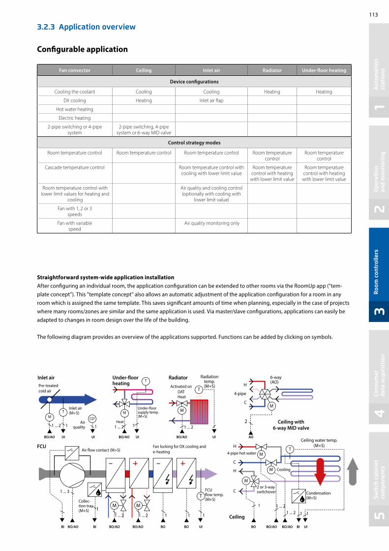
113
12
34
5A
utom
atio
n
stat
ions
Ope
rati
on
and
mon
itor
ing
Roo
m c
ontr
olle
rsCo
nsum
er
data
acq
uisi
tion
Swit
ch c
abin
et
com
pone
nts
Configurable application
Fan convector Ceiling Inlet air Radiator Under-floor heating
Device configurations
Cooling the coolant Cooling Cooling Heating Heating
DX cooling Heating Inlet air flap
Hot water heating
Electric heating
2-pipe switching or 4-pipe system
2-pipe switching, 4-pipe system or 6-way MID valve
Control strategy modes
Room temperature control Room temperature control Room temperature control Room temperature control
Room temperature control
Cascade temperature control Room temperature control with cooling with lower limit value
Room temperature control with heating
with lower limit value
Room temperature control with heating
with lower limit value
Room temperature control with lower limit values for heating and
cooling
Air quality and cooling control (optionally with cooling with
lower limit value)
Fan with 1, 2 or 3 speeds
Fan with variable speed
Air quality monitoring only
Straightforward system-wide application installationAfter configuring an individual room, the application configuration can be extended to other rooms via the RoomUp app ("tem-plate concept"). This "template concept" also allows an automatic adjustment of the application configuration for a room in any room which is assigned the same template. This saves significant amounts of time when planning, especially in the case of projects where many rooms/zones are similar and the same application is used. Via master/slave configurations, applications can easily be adapted to changes in room design over the life of the building.
The following diagram provides an overview of the applications supported. Functions can be added by clicking on symbols.
3.2.3 Application overview
Pre-treated cold air
Inlet air(M+S)
Air quality
Under-floor supply temp.(M+S)
Heat1 ... 2 1 ... 2
Activated on OAT
Radiation temp.(M+S)
Heat
Under-floor heating
RadiatorInlet air
BO/AOBO/AOBO/AO UIUIUI UI
1 ... 2Ceiling with
6-way MID valve
Ceiling water temp. (M+S)
Condensation (M+S)
Ceiling
FCUAir flow contact (M+S)
Fan locking for DX cooling and e-heating
FCU flow temp. (M+S)Collec-
tion tray (M+S)
1 ... 3VarSpd
1 ... 3
1 ... 2 1 ... 2 1 1 1
BO/AO BO/AO BO/AO BO/AO BO/AOBO BOBO UI UIBIBIBI
1 ... 21 ... 2
1
1 1
AO
4-pipe hot water
Cooling
2 or 3-way switchover
H
H
C
C
2
H
4-pipe
6-way(AO)
1 1 1
dP
1
C
M
M
M
M
MM
MM
MT
T
T
T
T
CO2
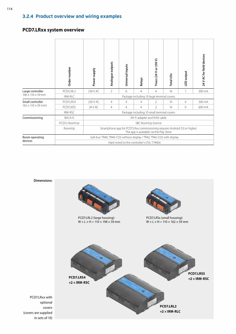
114
3.2.4 Product overview and wiring examples
Ord
er n
umbe
r
Pow
er s
uppl
y
Ana
logu
e ou
tput
s
Uni
vers
al in
puts
Rela
ys
Tria
cs (2
4 V
or 2
30 V
)
Tota
l I/O
s
LED
out
put
24 V
AC
for fi
eld
devi
ces
Large controller 198 × 110 × 59 mm
PCD7.LRL2 230 V AC 2 6 4 4 16 1 300 mA
IRM-RLC Package including 10 large terminal covers
Small controller162 × 110 × 59 mm)
PCD7.LRS4 230 V AC 4 4 4 2 14 0 300 mA
PCD7.LRS5 24 V AC 4 4 4 2 14 0 600 mA
IRM-RSC Package including 10 small terminal covers
Commissioning BACA-A Wi-Fi adapter and RJ45 cable
PCD7.L-RoomUp SBC RoomUp licence
RoomUp Smartphone app for PCD7.LRxx commissioning requires Android 5.0 or higher. The app is available via the Play Store
Room operating devices
Sylk bus: TR40, TR40-CO2 without display / TR42, TR42-CO2 with display
Hard-wired to the controller's I/Os: T7460x
PCD7.LRxx system overview
PCD7.LRxx with optional
covers (covers are supplied
in sets of 10)
Dimensions:
PCD7.LRSx (small housing): W × L × H = 110 × 162 × 59 mm
PCD7.LRL2 (large housing): W × L × H = 110 × 198 × 59 mm
PCD7.LRL2 +2 × IRM-RLC
PCD7.LRS4 +2 × IRM-RSC
PCD7.LRS5 +2 × IRM-RSC

115
12
34
58 7 6 5 4 3 2 1
20WM1
21WM2
26AO1
32 34UI1
36UI2
37UI3
29AO2
30AO3
33AO4
TIN N N FINN
5TN
6T~
7T01
8TN
9T02
NL
10RO4
11IN4
12RN
13RN
14IN1
15RO1
16IN2
17RO2
18IN3
19RO3
2827 31 39UI4
35 38 40C1+
41C1-
42
7 8 2,3,5,6 4
3 41L
2N
RIN
N N LL
F1*
230 VAC
PROP.COOL
24V~ 24V0 24V~ GND GND GND
THERM.HEAT
ELECTR.REHEATER
3-SPEEDFAN
RJ45 INTERFACE
GND
RJ45PLUG
LINE VOLTAGE
24V~ 24V0
Aut
omat
ion
st
atio
nsO
pera
tion
an
d m
onit
orin
gR
oom
con
trol
lers
Cons
umer
da
ta a
cqui
siti
onSw
itch
cab
inet
co
mpo
nent
s
Wiring example for a PCD7.LRS4 controller
Controller example: PCD7.LRS4
*Optional fuse (to protect the controller's internal transformer which only has a non-resettable fuse).
TR42 room operating devices
RoomUp app on smartphone
"Key card" contact layout
BACnet WiFi adapter
Optional terminal covers can be attached
4× AOplus 24 V AC
output for field devices
Sylk bus for room operating devices
4× UICan be config-ured for various
sensors BACnet- MS/TP
BACnet-MS/TP and power supply for RJ-45 WIFI adapter
230 V AC power supply 24 V AC
output for triacs
Status LEDs
Service button
3 barcode stickers with SNR for automatic MS/ TP-MAC addressing
2× triacs24 V AC/ 230 V AC
triacs
4× relays230 V AC
plus input connections for power supply

116
161.
65
198
54
58.3
2558
.325
54
59
IRM-RLC(BULK PACK, 10 pcs.)
PCD7.LRLxPCD7.LRxx
PCD
7.LR
xx
IRM-RSC/IRM-RLCTerminal covers
BACA-AMobile BACnet MS/TP access point for RoomUp
3.2.5 PCD7.LRxx accessories
Sylk bus room operating devices
Types with integrated sensors for temperature, humidity and CO2 sensor in one device
PCD7.LR-TR42Room temperature sensor + setting option for setpoint,
presence and fan speed + LCD display (+ humidity and CO2 sensor) Order number: PCD7.LR-TR42PCD7.LR-TR42-HPCD7.LR-TR42-CO2PCD7.LR-TR42-H-CO2
PCD7.LR-TR40Room temperature sensor (+ humidity and CO2 sensor) with Sylk bus connection to the controller.
Order number: PCD7.LR-TR40PCD7.LR-TR40-HPCD7.LR-TR40-CO2PCD7.LR-TR40-H-CO2
Compatible room operating devices
Wired room operating devices from Honeywell
T7460xRoom temperature sensor + setpoint setter + occupancy button + fan speed adjuster
Order number: T7460A1001 T7460D1005 T7460B1009 T7460F1000T7460C1007
Room operating devices with connectors for connecting to the controller inputs.
Clip-on terminal covers (IP30 contact protection) for small or large controllers to prevent the user touching the 230 VAC terminals.
Optional for IP30
Straightforward one-cable connection to the PCD7.LRxx controller
Additional option for connecting MS/TP cables and power supply via mini-USB
Wi-Fi-protected setup (WPS) for quick device connection
Web interface for device configuration
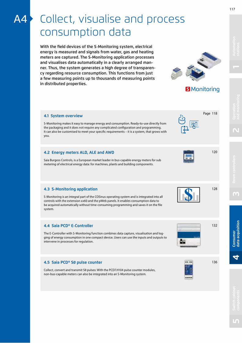
117
12
34
5
bedienen/managen
A4
Aut
omat
ion
st
atio
nsO
pera
tion
an
d m
onit
orin
gR
oom
con
trol
lers
Cons
umer
da
ta a
cqui
siti
onSw
itch
cab
inet
co
mpo
nent
s
Collect, visualise and process consumption dataWith the field devices of the S-Monitoring system, electrical energy is measured and signals from water, gas and heating meters are captured. The S-Monitoring application processes and visualises data automatically in a clearly arranged man-ner. Thus, the system generates a high degree of transparen-cy regarding resource consumption. This functions from just a few measuring points up to thousands of measuring points in distributed properties.
4.1 System overview
4.2 Energy meters ALD, ALE and AWD
4.3 S-Monitoring application
4.4 Saia PCD® E-Controller
4.5 Saia PCD® SØ pulse counter
Page
S-Monitoring makes it easy to manage energy and consumption. Ready-to-use directly from the packaging and it does not require any complicated configuration and programming. It can also be customised to meet your specific requirements – it is a system, that grows with you.
Saia Burgess Controls, is a European market leader in bus-capable energy meters for sub metering of electrical energy data: for machines, plants and building components.
S-Monitoring is an integral part of the COSinus operating system and is integrated into all controls with the extension xx60 and the pWeb panels. It enables consumption data to be acquired automatically without time-consuming programming and saves it on the file system.
The E-Controller with S-Monitoring function combines data capture, visualisation and log-ging of energy consumption in one compact device. Users can use the inputs and outputs to intervene in processes for regulation.
Collect, convert and transmit S0 pulses: With the PCD7.H104 pulse counter modules, non-bus-capable meters can also be integrated into an S-Monitoring system.
118
128
120
136
132

118
4.1 System overview
S-Monitoring makes it easy to manage energy and consumption. Ready-to-use directly from the packaging and it does not require any complicated configuration and programming. It can also be customised to meet your specific requirements – it is a system, that grows with you.The system includes devices and components for capturing, recording and displaying consumption. With the Web Panel installed on-site, analysis can be carried out on the office PC or remotely via the Internet web browser. The open IT interfaces make it possible to connect the system to a superordinate data management system at any time. There is no need to replace the hardware to do this.
Ready for use immediately on delivery
Example of external software

119
12
34
5A
utom
atio
n
stat
ions
Ope
rati
on
and
mon
itor
ing
Roo
m c
ontr
olle
rsCo
nsum
er
data
acq
uisi
tion
Swit
ch c
abin
et
com
pone
nts
Remote visualisation and evaluation of consumption
Reading and operating via LAN/Internet with web browser and mobile devices Integration into other systems via standard interfaces
If the Web Panel and controller are connected to a network (LAN), meter readings and operation can be carried out using commercially available PCs with standard browsers. Special software installations are not required and apps are available for mobile devices. This can even be carried out across locations if there is an Internet connection.Databases, energy management software or control systems can be connected via standard interfaces (e.g. FTP, CGI, HTTP, etc.).
With step-by-step introduction, findings from the learning curve are incorporated and lead to optimum results
Record consumption
Wide range of single and 3-phase energy meters and network analyzers S0 interface for the integration of commercially available meters for gas, water, oil, etc.
Saia PCD energy meters and network analyzers follow established installation technology and are suitable for DIN rails of commercially available distribution boxes. Integrated into a bus system covering a distance of up to 1 km, the measured values are transmitted to the Web Panel and controllers for the purpose of analysis and logging. Via pulse counters with an interface, commercial available meters with S0 output can be connected to the bus system.
Logging consumption
Historical consumption readings (Day / Week / Month / Year) Logging in Excel-readable files
The Web Panel and controllers read consumption values of the connected meters and display them in the form of a web visualisation. This can be called up either directly on the Web Panel or via the controller’s web server with a web browser. Consumption and costs can be called up in meaningful diagrams via an intuitive user interface. In addition, the Web Panel and controllers record captured values in Excel-readable CSV files, which can be easily transferred to a PC via FTP. The function can be activated on any new controller.
Continuous optimisation in calculable steps:Sustainable resource management means a continuous gain in knowledge in a changing environment. The optimum solution is different for each business, and must be developed with careful consideration. S-Monitoring supports a cautious approach in small, controllable steps and starts with the basics. It is possible to start resource management without external help using cost-effec-tive, easy-to-install components. Even after just a few days, initial results are set and point the way for further optimisation steps. The investment risk is negligible and remains limited to each individual development step.
Effect
Cost
Risk
Time

120
82
27
62
4,5
6
70
65 x 11,7 = (58,5)
768
4,5930,5 9
11
57,7
22,7
35
69,5
3162
70
9
57.7
30.5
22.7
4.5
1135
5 x 11.7 = [58.5] 6
4.5
27
31
458269.5
768
6
9
CT Select
Many energy meters in the smallest space
4.2 Energy meters ALD, ALE and AWD small, robust, reliable and accurate
The very compact design makes the SBC energy meters ideally suited to ac-commodate a large number of measuring instruments in the smallest space. The small size means the meters can also be fitted in existing switch cabinets without having to install new switch cabinets. The robust design has certainly proven itself under tough industrial conditions. The design of the energy meters is specifically designed for such applications, as is shown by a high level of reli-ability and durability. The display shows energy, current, voltage and active output.
Single-phase Saia PCD® energy meters
3-phase Saia PCD® energy meters
Single-phase
Direct measurement 0.25…32 A
Interface Unidirectional Bidirectional
ALD1D5FM00A3A00 –
ALD1D5FD00A3A00 ALD1B5FD00A3A00
ALD1D5FS00A3A00 ALD1B5FS00A3A00
S0 interface ALD1D5F10KA3A00 –
3-phase
Direct measurement 0.5…65 A Converter connection up to 1500:5 A
Interface Unidirectional Bidirectional Unidirectional Bidirectional
ALE3D5FM10C3A00 ALE3B5FM00C3A00 AWD3D5WM00C3A00 –
ALE3D5FD10C3A00 ALE3B5FD00C3A00 AWD3D5WD00C3A00 –
ALE3D5FS10C3A00 ALE3B5FS00C3A00 AWD3D5WS00C3A00 AWD3B5WS00C3A00
S0 interface ALE3D5F11KC3A00 ALE3B5F10KC3A00 AWD3D5W10MC3A00 AWD3B5W10MC3A00

121
12
34
5
M15
L1L2L3N
(PEN)
Aut
omat
ion
st
atio
nsO
pera
tion
an
d m
onit
orin
gR
oom
con
trol
lers
Cons
umer
da
ta a
cqui
siti
onSw
itch
cab
inet
co
mpo
nent
s
4.2.1 General information on energy meters
Reliable directly from the factory. The design and production of energy meters are such that the meters also exhibit high levels of reliability and durability even under extreme industrial conditions. The high quality standards of the production site guarantee high accuracy and enable the production of MID-approved energy meters, which have a guaranteed accuracy immediately following delivery and for their entire calibration period. This approval means that the measured values are considered totally accurate and can be used throughout Europe for billing purposes.
Production cell for energy meters
Meters for converter connectionThe use of current converters makes costly shutdowns of entire machines for meter installation a thing of the past. The replace-ment of an energy meter or current converter while the system is running is possible with the consistent use of flap current converters, since the faulty parts can be replaced easily without disconnecting the entire system from the power supply.
Three-phase energy meters – secondary current 5 A
5:5 50:5 100:5 150:5
200:5 250:5 300:5 400:5
500:5 600:5 750:5 1000:5
1250:5 1500:5 --- ---
Available converter ratios in Saia PCD® energy meters
Energy meters in tough industrial environment
Connected converters Current converter in switch cabinet
Built-in current converter directly in the cable duct
MTBF values at 25 °C
Energy meters without communication interface: 410 years
Energy meters with communication interface: 200 years
MTBF values for Saia PCD® energy metersThe quality, robustness and reliability of the energy meters is also shown by the MTBF values, which have been calculated in accordance with the Siemens standard SN 29500.
Marking on an MID meter

122
Modbus
Modbus
Saia PCD®
kWh
L1L2L3N
(PEN)
D /D
Measuring energy in both directions
With the bidirectional energy meters, energy can be measured in both directions of flow. The energy counters work in a balancing out fashion (mode 2), which means that they form the sum of all measured phase outputs analogue to the old Ferraris meters with a rotating disc. The main area of use of bidirectional meters is wherever both energy flow directions occur (energy consump-tion and feed), such as in photovoltaic systems. FBoxes are installed for connection to the PCD world to capture the measured values.
Integrating the energy meter as a component in an existing, external system
The M-Bus energy meters can be integrated into any M-Bus system and can be read out with any M-Bus Master. This enables use in existing systems with an existing M-Bus infrastructure or even in new projects with various other M-Bus components. The energy meters with integrated serial Modbus RTU interface enable fast and secure communication with superordinate systems. The market offers many components for data transfer, backup and visualiation of the measured data. Simple integration via various transmission channels is possible owing to the wide variety. With Modbus, existing equipment can be used without making costly new acquisitions.
EPLAN macros are available for project planning and engineering
Energy measurement of both current directions with one Saia PCD for further processing of the measured values
Level converter/ M-Bus Master
Electrical energy meter3-phase
HeatMeter
Gas meter
Water meter
PC
Single-phase
Electrical energy meter
Energy meterwith Modbus
HMI with Modbus Master
S-Bus, twisted wire pair
Backup: T 250 mA (3×)
3 ×
230/
400
VAC The eplan® electric P8 macros are
available on the support page. The macros and article data are also provided on the eplan® data portal.
max. 1200 m
RS-485 wireless gateway

123
12
34
5
ref.ChannelALD1
―En Total―Partial―
ComErr―
ref.ChannelALE3
―En T1―T1part―
T2―T2part―
Tariff― ComErr―
ref.ChannelAWD3
―En Total―Partial―CRatio―
ComErr―
Saia PCD®
L1L2L3N
(PEN)
D /D
N
L
L1L2L3N
(PEN)
Aut
omat
ion
st
atio
nsO
pera
tion
an
d m
onit
orin
gR
oom
con
trol
lers
Cons
umer
da
ta a
cqui
siti
onSw
itch
cab
inet
co
mpo
nent
s
4.2.2 Energy meters with SBC S-Bus interface
The energy meters with integrated S-Bus interface offer all relevant data such as energy, current, voltage, out-put (active and reactive) and cosφ, which can be read out through the bus connection. The serial S-Bus interface (based on RS-485) can be connected directly to the Saia PCD range of devices. There are ready-made FBoxes for every meter type for this connection, which are available free of charge. The S-Bus energy meters are also avail-able in a 2-way design (bidirectional). The bus address can be set on the display and the energy, current, voltage and active output can be read directly.
ALD1 ALE3 AWD3
ALD
1D5F
S00A
3A00
ALD
1B5F
S00A
3A00
ALE
3D5F
S10C
3A00
ALE
3B5F
S00C
3A00
AWD
3D5W
S00C
3A00
AWD
3B5W
S00C
3A00
Tariff 1 tariff –
2 tariffs – – – – –
Meter type Unidirectional design – – –
Bidirectional design – – –
Approvals With MID
Rated/max. current Current
Imin = 0.05 A, IN = 5 A, Imax = 6 A – – – –
Imin = 0.25 A, IN = 5 A, Imax = 32 A – – – –
Imin = 0.5 A, IN = 10 A, Imax = 65 A – – – –
Measurement type Direct measurement – –
Conversion up to 1500 A – – – –
Operating voltage 230 VAC, 50 Hz – – – –
3 × 230/400 VAC, 50 Hz – –
Partial meter Resettable – –
FBoxes available for every S-Bus meter type
SBC S-Bus
Bus system Serial RS-485 interface
Log S-Bus data mode
Transmission rate
4,800, 9,600, 19,200, 38,400, 57,600, 115,200 baud. The transmission rate is detected automatically.
Bus cable Twisted, shielded, 2 × 0.5 mm2, max. 1200 m
Response time
Write: up to 60 msRead: up to 60 ms
Technical Data
Converter meter 3-phase AWD3
Direct measurement 3-phase ALE3
Connection diagram for M-Bus energy meters
Direct measurement single-phase ALD1

124
ref.ChannelALE
―En T1tot――Res 1 T1part――Res 2 T2tot―
T2part―Tariff―
ComErr―
ref.ChannelAWD
―En T1tot――Res T1part―
ComErr―
ref.ChannelALD
―En Ttot――Res Tpart―
Pa―Pr―U―I―
ComErr―
ref.ChannelAWD/ALE
―En U_L1― U_L2―
U_L3―I_L1―I_L2―I_L3―
Pa_L1―Pa_L2―Pa_L3―Pr_L1―Pr_L2―Pr_L3―
CTratio―ComErr―
Saia PCD®
L1L2L3N
(PEN)
L1L2L3N
(PEN)
N
L
4.2.3 Energy meter with M-Bus interface
The M-Bus interface enables the connection and reading of measured data through any Saia PCD or any M-Bus Master. The meters correspond to M-Bus standard EN 13757. For connection to Saia PCD systems, prefabricated FBoxes are available free of charge for Saia PCD energy meters. The relevant measurement data, such as energy, current, voltage and output (active and reactive) can be read out via the M-Bus interface. On the display, the bus primary address can be set and the energy, current, voltage and active output can be read directly.
ALD1 ALE3 AWD3
ALD
1D5F
M00
A3A
00
ALE
3D5F
M10
C3A
00
ALE
3B5F
M00
C3A
00
AWD
3D5W
M00
C3A
00
Tariff 1 tariff –
2 tariffs – – –
Meter type Unidirectional design –
Bidirectional design – – –
Approvals With MID
Rated/max. current Current
Imin = 0.05 A, IN = 5 A, Imax = 6 A – – –
Imin = 0.25 A, IN = 5 A, Imax = 32 A – – –
Imin = 0.5 A, IN = 10 A, Imax = 65 A – –
Measurement type Direct measurement –
Conversion up to 1500 A – – –
Operating voltage 230 VAC, 50 Hz – – –
3 × 230/400 VAC, 50 Hz –
Partial meter Resettable
FBoxes available for every M-Bus meter type
Technical Data
Connection diagram for M-Bus energy meters
Converter meter 3-phase AWD3
Direct measurement 3-phase ALE3
Direct measurement single-phase ALD1
M-Bus
Bus system M-Bus
Transmission rates 300, 2,400, 9,600 Baud. The transmission rate is detected automatically
Addressing Primary and secondary
Bus length (max.) In accordance with M-Bus specifications
Response time Write: up to 60 msRead: up to 60 ms

125
12
34
5
ref.ChannelALE3
―En T1― T1part― T2―
T2part―Tariff―
ComErr―
ref.ChannelALD1
―En Total― Partial―
ComErr―
ref.ChannelAWD3
―En Ttot― Partial―
CRatio―ComErr―
Saia PCD®
L1L2L3N
(PEN)
D /D
L1L2L3N
(PEN)
N
L
Aut
omat
ion
st
atio
nsO
pera
tion
an
d m
onit
orin
gR
oom
con
trol
lers
Cons
umer
da
ta a
cqui
siti
onSw
itch
cab
inet
co
mpo
nent
s
4.2.4 Energy meter with Modbus interface
ALD1 ALE3 AWD3
ALD1
D5F
D00
A3A0
0
ALD1
B5FD
00A3
A00
ALE3
D5F
D10C
3A00
ALE3
B5FD
00C3
A00
AWD
3D5W
D00
C3A0
0
Tariff 1 tariff –
2 tariffs – – – –
Meter type Unidirectional design – –
Bidirectional design – – –
Approvals With MID
Rated/max. current Current
Imin = 0.05 A, IN = 5 A, Imax = 6 A – – – –
Imin = 0.25 A, IN = 5 A, Imax = 32 A – – –
Imin = 0.5 A, IN = 10 A, Imax = 65 A – – –
Measurement type Direct measurement –
Conversion up to 1500 A – – – –
Operating voltage 230 VAC, 50 Hz – – –
3 × 230/400 VAC, 50 Hz – –
Partial meter Resettable –
The integrated Modbus RTU interface complies with the IDA specification and is based on an RS-485 interface. The measurement data from the energy meter can be connected to any Modbus Master to read out the measured values. The relevant measurement data, such as energy, current, voltage, output (active and reactive) and cosφ can be read out via the interface. The bus address can be set and the energy, current, voltage and active output can be read direct on the display. Prefabricated FBoxes are available to connect the energy meters to Saia PCD systems, which are supplied free of charge.
FBoxes available for every M-Bus meter type
Technical Data
Connection diagram for Modbus energy meters
Converter meter 3-phase AWD3
Direct measurement 3-phase ALE3
Direct measurement single-phase ALD1
The following devices are available for Modbus parity 8N1: ALD1D5FD00A3A44 ALE3D5FD10C3A44 AWD3D5WD00C3A44 Modbus
Bus system Serial RS-485 interface
Log Modbus RTU as per IDA specification
Transmission rates
4,800, 9,600, 19,200, 38,400, 57,600, 115,200 baud. The transmission rate is detected automatically
Bit settings f 8 databit, even parity, 1 stop bit f 8 databit, odd parity, 1 stop bit f 8 databit, no parity, 2 stop bit
The parity is automatically detected
Bus cable Twisted, shielded, 2 × 0.5 mm2, max. 1200 m
Response time Write: up to 60 msRead: up to 60 ms

126
L1L2L3N
(PEN)
NN
LL
L1L2L3N
(PEN)
S0+ S0–
4.2.5 Energy meter with SØ pulse output
Energy meters with integrated S0 interface enable the transfer of measured energy to the devices of the Saia PCD family via pulses. With the S0 pulse counter PCD7.H104, the pulses can be requested via the RS-485 interface (S-Bus or Modbus).
ALD1 AAE1 ALE3 AWD3
ALD
1D5F
10KA
3A00
AAE1
D5F
10KR
3A00
ALE3
D5F
11KC
3A00
ALE3
B5F1
0KC3
A00
AWD
3D5W
10M
C3A0
0
AWD
3B5W
10M
C3A0
0
Tariff 1 tariff
2 tariffs – – – – –
Meter type Unidirectional design – –
Bidirectional design – – – –
Approvals With MID
Without MID – – – – – –
Rated/max. current Current
Imin = 0.05 A, IN = 5 A, Imax = 6 A – – – –
Imin = 0.25 A, IN = 5 A, Imax = 32 A – – – – –
Imin = 0.5 A, IN = 10 A, Imax = 65 A – – –
Measurement type Direct measurement – –
Conversion up to 1500 A – – – –
Operating voltage
230 VAC, 50 Hz – – – –
3 × 230/400 VAC, 50 Hz – –
S0 output 1000 Imp./kWh – –
10 Imp./kWh – – – –
Partial meter Resettable – –
Converter meter 3-phase AWD3
Direct measurement 3-phase ALE3
Direct measurement single-phase ALD1
Direct measurement single-phase AAE1
Connection diagram of S0 pulse energy meters, with S-Bus connection via PCD7.H104SE

127
12
34
5A
utom
atio
n
stat
ions
Ope
rati
on
and
mon
itor
ing
Roo
m c
ontr
olle
rsCo
nsum
er
data
acq
uisi
tion
Swit
ch c
abin
et
com
pone
nts
Accessories Order no.
Sealing cover for single-phase Saia PCD® energy meter EMD1 and ALD1
2 units are recommended for contact protection.
(Also for termination boxes PCD7.T161 and PCD7.T162, see Section 5.5)
4104 74200
ALD1 with assembled sealing cover
Sealing cover for– Single-phase Saia PCD® energy meter AAE1 – 3-phase Saia PCD® energy meter ALE3,
and AWD3
2 units are recommended for contact protection on AAE1.
4 units are recommended for contact protection on ALE3 and AWD3.
4104 74850
ALE3 or AWD3 with sealing cover
Mounting frame for 3-ph energy meters of the families ALE3/AWD3
PMK-EEM400
ALE3 or AWD3 mounted in panel kit
4.2.6 Energy meter – sealing cover
4.2.7 Application notes
Application notes on the subject of "energy" can be found on the support page (www.sbc-support.com) under the section "energy meters".

128
Hardw
are
Saia PCD® COSinus
Application
The S-Monitoring COSinus function comprises the following three parts:
1. Autoscan of S-Bus energy meters and pulse countersIf the S-Bus Autoscan is activated, meters connected to the RS-485 interface are automatically detected and read. By permanently requesting the meter data, remote diagnosis of the S-Bus meters and bus connection is possible.
S-Monitoring COSinus function
S-Monitoring is an integral part of the COSinus operating system and is integrated into all Saia PCD controllers ending with xx60 and having the pWeb Panel MB. It is activated in the PG5 Device Configurator and it scans connected meters automatically. The data is saved on the file system. In addition to connected S-Bus meters, any meter values available in the program can also be integrated.
The S-Monitoring function can read three different types of meters:
f Connected S-Bus energy meters and S0pulse counters (PCD7.H104SE)
f Other incremental meter values (M-Bus, Modbus, etc. are referred to as "custom meters" and captured via FBoxes in the Fupla program)
f Groups of meters
Excel Report ToolWhen the COSinus function is activated, the data can simply be imported into Excel without programming.
Download: www.sbc-support.com
4.3 Basic functions of the S-Monitoring application Function for automatic capturing and saving of energy meter values – integrated into the operating system of the Saia PCD®
The S-Monitoring application works on all controllers ending in xx60 and on the pWeb Panels. The applica-tion consists of a COSinus function and an associated Web Editor project. This makes it possible to capture, save and visualise data without significant programming effort. With S-Bus meters, this works without any program in the controller.
3. Saving the meter values in CSV files The values of the energy meters connected are saved once a day at midnight in a CSV file on the internal file system of the PCD. The daily, weekly and monthly consumption can be calculated from this data. If an additional memory card is inserted, the values can be saved at 5-60 minute intervals. This makes it possible to visualise consumption over a day.
2. Provision of meter values via NT-EM tags (CGI interface)All data and basic functions can be called up via CGI tags. These functions can therefore be accessed via the web interface or by other programs (e.g. Excel). The controller does not need a Fupla or IL program (see document 27-623).
NT-EM tag (CGI command) in the web browser:
Command Value

129
12
34
5
Navigation
www.s-monitoring.com
see back
Main Menu
Energy meter Consumption TODAY
Energy meter extended Consumption WEEK
Trend
Energy meter Display
Consumption MONTH
Consumption YEAR
Functions
Setup
1
Cost TODAY
Cost WEEK
Cost MONTH
Cost YEAR
Advanced Functions need to be enabledin Setup!
Basic Function
Saia-Burgess Controls AGBahnhofstrasse 18 | 3280 Murten, Switzerland T +41 26 580 30 00 | F +41 26 580 34 99 [email protected] | [email protected] | www.sbc-support.com
PP26-582 EN05 03. 2015 Subject to changes to technical details and figures.
NavigationMain Menusee front
Setup
Setup System
Energy meter
Setup TCP / IP address
Setup Security
Name
Setup Info
Groups
Setup Memory Setup Unit Setup Mode
Meter unit Faktor
Setup User Setup Time and Date
Scan S-Bus
Setup Language
Selection
2 Setup
Navigation
Main Menu
Digital I/O
Alarm Email
Interval
Analog Inputs Log data Email Peak
Outputs 1/2
Load profile parameter
Load profil
Outputs 2/2
Functions
E-Mail Mail-Server
Advanced Function3
Advanced Functions need to be enabledin Setup!
Aut
omat
ion
st
atio
nsO
pera
tion
an
d m
onit
orin
gR
oom
con
trol
lers
Cons
umer
da
ta a
cqui
siti
onSw
itch
cab
inet
co
mpo
nent
s
S-Monitoring web project
SBC delivers a PG5 project, which also includes a web visualisation. The project is based on the COSinus functions and enables saved data to be visualised on the PC immediately. As only the S-Monitoring COSinus function is accessed in the web project, it does not need a PG5 program. It can therefore be easily integrated into existing projects. In addition, the most important websites are available as macros in Web Editor 8.
In the PG5 application for the E-Controller products supplied ready for use on delivery from the factory, additional "Advanced" functions are programmed in PG5. These cannot therefore be used without the program.
S-Monitoring is also supported by pWeb Panel PCD7.DxxxxT5F, PCD1.M2160 and PCD3.Mxx60
Complete overview of the basic application
Advanced
Setup
Representation of historical energy consumption Overview of the live values

130
Technical data for SBC S-MonitoringSBC S-Monitoring COSinus function integrated in
PCD1.M0160E0 (E-Controller) PCD3.Mxx60 PCD1.M2160 PCD7.DxxxxT5F (pWeb Panel MB)
Supported meters – Saia PCDS-Bus energy meters, PCD7.H104SE S0 pulse counters– Incremental meter values (M-Bus, Modbus, etc. are referred to as "custom meters" and captured via FBoxes in the Fupla program)– Meter groups
Maximum number of meters 128 Saia PCD® S-Bus meters* / 256 custom meters* / 32 groups* *in total max. 256
Data storage time 4 years maximum; a recording per day
saved data max. 4 meter values with 4 tariffs per meter are saved once a day (at midnight)
Recording of energy values
Plug & count Automatic detection of connected energy meters Display of the energy meter status
Grouping of energy meters Comparison between meter and periods
Connection of bidirectional meters Connection PCD7.H104SE S0 impulse counter (for S0 meters)
Display and analysis of energy values
Current meter values such as consumption, volt-age, current, active and reactive power and cosφ Evaluation and presentation of the costs
Visualisation in bar charts and trend charts Consumption and costs presentation per day/week/month/year1)
Data storage in Excel-readable CSV files
Remote access via network and Internet
Operation at the PC with standard browser (IE, Chrome, Firefox) Operation via smartphone and tablet
Access to log data and web project with FTP Integrated USB port for update and maintenance
User support
User administration ?
!. . . Control interface in several languages
1) Daily view only available if memory extension is plugged in
Basic functions of the S-Monitoring application

131
12
34
5A
utom
atio
n
stat
ions
Ope
rati
on
and
mon
itor
ing
Roo
m c
ontr
olle
rsCo
nsum
er
data
acq
uisi
tion
Swit
ch c
abin
et
com
pone
nts
4.3.1 S-Monitoring Web Editor 8 Templates
High initial costs for energy management are one of the largest barriers against investment, and the S-Monitoring application was developed as a door-opener to minimise these costs as far as possible. The basic functions of this S-Monitoring application were integrated in Web Editor 8. The programmer can therefore extend his project in accordance with individual requirements with energy monitoring functions. Improved and faster engineering enables added value that delivers a significant competitive advantage. For system integrators who want to visualise the energy consumption, the free S-Monitoring templates provide a saving of up to 2 weeks of engineering time.
Name of the library in Web Editor 8: S-Monitoring
Available templates Barograph day, week, month, year Navigation counter and period Live values of the energy counter Setup configuration
Monthly consumption Comparison of weekly consumption
Counter information Overview of energy consumption

132
M1
Slot A
X2 X1 X0
X3
142 61
142
The E-Controller is an SBC functions PCD, which can be used immediately on delivery with no additional programming. It combines data capture, decentralised visualisation and logging in one compact device. Energy meters and pulse counters connected via the S-Bus interface are automatically detected and read. Historical data and the web visualisation can be accessed from anywhere via the integrated automation server using FTP and HTTP. This is also possible with mobile devices using SBC apps. In addition to the basic functions described in Section 4.6, simple control functions are already realised on the E-Controller. These include sending alarm emails and the parameterisation of outputs according to the meter values. The pre-installed S-Monitoring application can be adjusted, extended or replaced as required using PG5 and Web Editor. Additional protocols and data (e.g. from an M-Bus meter) can therefore be integrated using the optional communication interfaces. The design of the controller is suitable for installation in the distribution board next to the energy meters.
Device installation
Power supply and connection plan
For more information, please see Chapter 1.2.1 Saia PCD3 power supply and connection plan, and in Manual 26-875.
Power supply 24 VDC Watchdog relay
RS-485 interface
Terminals for integral inputs and outputs
Terminals for optional connection (slot A)
Ethernet connection (2-port switch)
USB port
Operating LEDs
Slot for communication
interfaces
Battery
RUN/STOP button
Slot for memory modules
Supply
earth rail
1.5mm2 / max. 25 cm
4.4 Saia PCD® E-Controller Operational on delivery with local IOs
S-Monitoring application loaded
Load profile measurement of 8 consumption values
Sending of alarm and data emails to up to 5 email addresses
Parameterisation of outputs via min. and max. values
Advanced functionsIn addition to the basic functions of the web application (4.6), the E-Controller includes the following functions, which are programmed with Saia PG5®:
Load profile measurement
Mounting Dimensions
on a level surface on a 35-mm top-hat rail (in accordance with DIN EN 60715 TH35)
compact dimensions:142 × 142 × 61 mm

133
12
34
5
RS-232
M-Bus
RS-485
M-Bus
S-Bus
kWhkWh
Aut
omat
ion
st
atio
nsO
pera
tion
an
d m
onit
orin
gR
oom
con
trol
lers
Cons
umer
da
ta a
cqui
siti
onSw
itch
cab
inet
co
mpo
nent
s
Summary of E-Controller functions
1) programming required
Both the automatic detection of the meters and the E-Monitoring functionality can be switched off in the PG5 Device Configurator for unrestricted use of PCD1.M0160E0.
Connection example of M-Bus with external interface1)
Additional memoryEnables logs in 5–60 min. Interval and daily figures are illustrated for all meters in a bar chart.
PCD7.R610Holder module for microSD card
PCD7.R-MSD1024 MicroSD memory card 1 GB, PCD formatted
Optional interface (programming required)
Saia PG5®Fully programmable and extendable
SBC MB AppOperation and monitoring on iPhone, iPad and Android
InternetIntranet

134
WWW EMAILFTP SNMP
Onboard inputs/outputs
Inputs:6 Digital inputs (4 + 2 interrupts) 15…30 VDC, 8 ms / 0.2 ms input filter Terminal X12 Analogue inputs, selectable via DIP switch,
preconfigured for Ni1000 in the default setup–10…+10 VDC, 0…±20 mA, Pt1000, Ni1000, Ni1000 L&S, 0…2.5 kΩ, 12 bit resolution Terminal X1
Outputs:4 digital outputs 24 VDC / 0.5 A Terminal X01 PWM output 24 VDC / 0.2 A Terminal X0
selectable/configurable via PG54 Digital inputs or outputs,
preconfigured for digital inputs in the default setup24 VDC/data such as digital inputs or digital outputs Terminal X0
1 Watchdog relay or as a make contact 48 VAC or VDC, 1 A mount a freewheeling diode over the load when switching DC tension Terminal X3
General specificationsOperating voltage 24 VDC, –20/+25% max. incl. 5% ripple (as defined by EN/IEC 61131-2)Battery for data backup (replaceable) Lithium battery with a service life of 1 to 3 yearsOperating temperature 0…55 °CDimensions (W x H × D) 142 × 142 × 60 mmMounting type Top-hat rail in accordance with DIN EN 60715 TH35 (1 x 35 mm) or on a level surfaceProtection type IP 20Capacity 5 V/+V (24 V) internal max. 500 mA/200 mAPower consumption typically 12 WAutomation server Flash memory, file system, FTP and web server, email, SNMP
Installation notes and recommendations
Assembly in the distribution boardThe Saia PCD1.M0160E0 has the dimensions 142 x 142 × 60 mm excluding terminals and connections. For easy assembly, a gap of 55 mm above the DIN rail and 75 mm below it is recommended.
Ethernet cableFor installation in the sub-distributor, an angled or flexible network cable (e.g. SlimWire PRO) is recommended. The installation of a conventional network cable cannot guarantee the assembly of the sub-distributor cover.
Technical Data
Memory and file systemProgram memory, DB/text (Flash) 1 MbyteUser memory, DB/text (RAM) 1 Mbyte
User flash file system onboard 128 Mbyte
Integrated communicationEthernet connection (2-port switch) 10/100 Mbit/s, full-duplex, auto-sensing, auto-crossing
Yes
USB connection USB 1.1 device, 12 Mbit/s Yes
RS-485 (terminal X3), up to 115 kbit/s Yes
Overview of Saia PCD® E-Controller PCD1.M0160E0
AUTOMATION SERVER INTEGRATED IN THE BASE UNIT
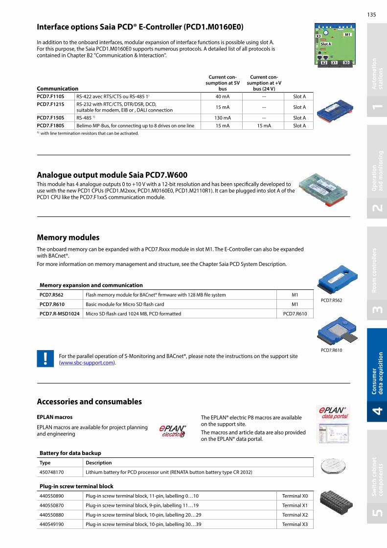
135
12
34
5
PCD7.R562
PCD7.R610
Aut
omat
ion
st
atio
nsO
pera
tion
an
d m
onit
orin
gR
oom
con
trol
lers
Cons
umer
da
ta a
cqui
siti
onSw
itch
cab
inet
co
mpo
nent
s
Plug-in screw terminal block
440550890 Plug-in screw terminal block, 11-pin, labelling 0…10 Terminal X0
440550870 Plug-in screw terminal block, 9-pin, labelling 11…19 Terminal X1
440550880 Plug-in screw terminal block, 10-pin, labelling 20…29 Terminal X2
440549190 Plug-in screw terminal block, 10-pin, labelling 30…39 Terminal X3
Battery for data backup
Type Description
450748170 Lithium battery for PCD processor unit (RENATA button battery type CR 2032)
Accessories and consumables
Memory modulesThe onboard memory can be expanded with a PCD7.Rxxx module in slot M1. The E-Controller can also be expanded with BACnet®. For more information on memory management and structure, see the Chapter Saia PCD System Description.
For the parallel operation of S-Monitoring and BACnet®, please note the instructions on the support site (www.sbc-support.com).
Communication
Current con-sumption at 5V
bus
Current con-sumption at +V
bus (24 V)PCD7.F110S RS-422 avec RTS/CTS ou RS-485 1) 40 mA --- Slot APCD7.F121S RS-232 with RTC/CTS, DTR/DSR, DCD,
suitable for modem, EIB or , DALI connection 15 mA --- Slot A
PCD7.F150S RS-485 1) 130 mA --- Slot APCD7.F180S Belimo MP-Bus, for connecting up to 8 drives on one line 15 mA 15 mA Slot A1) with line termination resistors that can be activated.
In addition to the onboard interfaces, modular expansion of interface functions is possible using slot A. For this purpose, the Saia PCD1.M0160E0 supports numerous protocols. A detailed list of all protocols is contained in Chapter B2 "Communication & Interaction".
Interface options Saia PCD® E-Controller (PCD1.M0160E0) M1
Slot A
X0X1X2
X3
EPLAN macros
EPLAN macros are available for project planning and engineering
The EPLAN® electric P8 macros are available on the support site. The macros and article data are also provided on the EPLAN® data portal.
Memory expansion and communication
PCD7.R562 Flash memory module for BACnet® firmware with 128 MB file system M1
PCD7.R610 Basic module for Micro SD flash card M1
PCD7.R-MSD1024 Micro SD flash card 1024 MB, PCD formatted PCD7.R610
Analogue output module Saia PCD7.W600 This module has 4 analogue outputs 0 to +10 V with a 12-bit resolution and has been specifically developed to use with the new PCD1 CPUs (PCD1.M2xxx, PCD1.M0160E0, PCD1.M2110R1). It can be plugged into slot A of the PCD1 CPU like the PCD7.F1xxS communication module.

136
kWh
kWh
58
85 45
35
28
43
1)
4.5 SØ impulse counter PCD7.H104 SØ Collect, convert and transmit pulses
If already installed meters, which are not bus-capable, are to be integrated into an automation system, the Saia PCD7.H104 S0 pulse counter is the easiest way. This is the case for refurbishments, for example, if the existing meter infrastructure has to be made bus-capable and there is no question of buying new meters. With this S0 pulse counter, meters (electricity, water, heat, etc.) with an S0 pulse output from any manufacturer can be connected directly using a serial RS-485 S-Bus or Modbus connection to the Saia PCD or any controller. This enables efficient transfer, evaluation and forwarding of energy data without additional complicated coupler modules. For connection to Saia PCD systems, there are ready-made FBoxes. Via the interfaces, the number or valence of pulses can be transmitted.
FBoxes for integration into FUPLA
General technical data Operating voltage 230 VAC (–20/+15 %)
Current draw < 12 mA
Power consumption < 3 W
Number of S0 inputs 4, in accordance with S0 IEC 62053-31
Frequency max. 17 Hz
Pulse low/high Min. 30 ms
S-Bus version
Order number PCD7.H104SE
Log S-Bus data mode
Bus system Serial RS-485 interface
Transmission rate 2,400, 4,800, 9,600, 19,200, 38,400, 57,600, 115,200The transmission rate is detected automatically
Bus length (max.) 1,200 m (without amplifier)
Response time Write: 30 ms
System response time Read: 20 ms
Modbus version
Order number PCD7.H104D
Log Modbus RTU as per IDA specification
Bus system Serial RS-485 interface
Transmission rate (bit/s)
2,400, 4,800, 9,600, 19,200, 38,400, 57,600, 115,200The transmission rate is detected automatically
Bit settings 8 databit, even parity, 1 stop bit8 databit, odd parity, 1 stop bit8 databit, no parity, 2 stop bit
Maximum bus length 1,200 m (without amplifier)
Response time Type 5 characters
System response time max. 60 ms
S0 pulses
S0 pulses
Size
Device PCD7.H104DZ44 must be used for parity 8N1!

137
12
34
5
A5
Aut
omat
ion
stat
ions
Ope
rati
on
and
mon
itor
ing
Roo
m c
ontr
olle
rsCo
nsum
er
data
acq
uisi
tion
Swit
ch c
abin
et
com
pone
nts
Switch cabinet components The comprehensive range of accessories for automation technology from Saia Burgess Controls (SBC) ensures a reliable operation of the systems. Modules such as S-Bus RIO modules, isolating amplifiers, coupler modules and relays are available in addition to power supplies and Ethernet switches.
5.1 Power units for installation in control cabinets PageDifferent types of 24 VDC power supplies with diverse output power
5.2 Power supplies for installation in electric distributor boxes24 VDC power supplies for installation in electrical sub-distribution
5.3 Industrial VPN RoutersLAN and 3G/HSPA industrial router for DIN rail mounting
5.4 Industrial Ethernet switchs Industry-quality compact switches for DIN rail mounting with 5 or 8 ports
5.5 RS-485 bus termination box PCD7.T16xTermination box for the termination of RS-485 networks for DIN rail mounting with a 24 V or 230 V power supply
5.7 Interface modules with local overrideCoupler modules to control drives, valves or flap systems
5.8 I/O module integration into the switch cabinet Pre-assembled system cables and terminal adapter modules support the fast integration of the integration of the Saia PCD I/O modules into the switch cabinet.
139
142
144
146
147
149
150

138

139
12
34
5A
utom
atio
n st
atio
nsO
pera
tion
an
d m
onit
orin
gR
oom
con
trol
lers
Cons
umer
da
ta a
cqui
siti
onSw
itch
cab
inet
co
mpo
nent
s
5.1 Power units for installation in control cabinets
SBC power units with 24 VDC output provide an ideal power supply for automation solutions owing to their high level of resistance to interference. They can also be used to operate high-output loads, as they can be heavily overloaded for short periods. The full extent of their flexibility is demonstrated by the option to connect multiple devices in parallel to increase the maximum output current or to connect them in series to achieve different voltage levels.
Power unit overviewSBC Power Flex single-phase 110/230 VAC Q.PS-AD2-2402F (up to 3 A) Q.PS-AD2-2405F (up to 7.5 A) Q.PS-AD2-2410F (up to 14 A)
Uninterruptible power unit single-phase 110/230 VAC with intelligent battery charger Q.PS-ADB-2405-1 (5 A)
SBC single-phase 24 VAC/40 VDC Q.PS-AD1-2403 (3 A)
System properties in general Short-circuit protection Overload protection IP 20 housing for mounting on DIN rail
Properties of Flex types 24xxF Power boost: +40% additional output current up to 60 °C for at
least 3 minutes With AD2-2405F and 2410F, a range of short-circuit modes
available “Power good” relay for status display With 2410F, simple parallel connection (via jumper)
to increase max. output current Output voltage up to 150 VDC possible in serial mode Extremely compact
Properties of the uninterruptible power unit 3-stage automatic charging curve to compensate
the self-discharge of the battery Automatic real-time diagnostics of the battery status
and test function for the battery service life Any battery fault can be easily identified via blinking
codes of the diagnostics LED Option of status and battery fault reporting in the control
system via 2 potential-free contacts Adjustable charging current 1…5 A
Standards and certifications In accordance with
– CE – cULus Listed 508 Industrial Control Equipment
Electrical safety:For the assembly devices in accordance with IEC/EN 60950 (VDE 0805) and EN 50178 (VDE0160). The unit must be installed in accordance with IEC/EN 60950.
EMC GenericImmunity in accordance with EN 61000-6-2 Noise emission in accordance with EN 61000-6-4
From left to right: Q.PS-ADB, Q.PS-AD2, Q.PS-AD1
W D
H
Dimensions Q.P
S-A
D2-
2402
F
Q.P
S-A
D2-
2405
F
Q.P
S-A
D2-
2410
F
Q.P
S-A
DB-
2405
-1
Q.P
S-A
D1-
2403
Width (W) 50 mm 55 mm 72 mm 65 mm 50 mmHeight (H) 120 mm 110 mm 115 mm 115 mm 95 mmDepth (D) 50 mm 105 mm 135 mm 135 mm 61 mmWeight 0.3 kg 0.6 kg 0.6 kg 0.6 kg 0.2 kg

140
Technical Data
Overload protection
Input data Q.PS-AD2-2402F Q.PS-AD2-2405F Q.PS-AD2-2410F Q.PS-AD1-2403 Q.PS-ADB-2405-1Battery type
Input voltage 115…230 VAC 24 VAC / 40 VDC 115…230 VAC
Permitted voltage range: 90…264 VAC 90…135 / 180…264 VAC 24…32 VAC / 33…45 VDC 93…264 VAC
Inrush current (at Vn and In) ≤ 7 A ≤ 5 ms ≤ 11 A ≤ 5 ms ≤ 16 A ≤ 5 ms --- ≤ 14 A ≤ 5 ms
Frequency range 47…63 Hz (± 6%) 47…63 Hz (± 6%) 47…63 Hz (± 6%)
Input current (for operating voltage 110 / 230 VAC) 1.0 / 0.7 A 2.8 / 1.0 A 3.3 / 2.2 A --- 1.5 / 0.9 A
Internal input fuse 4 A 6.3 A --- 4 A
External preliminary fuse recommended Fast-acting 6 A Fast-acting 10 A Fast-acting 14 A Fast-acting 10 A Fast-acting 6 A
Output dataOutput voltage (Vn) / nominal current (In) 24 VDC ± 3% / 2.5 A 24 VDC ± 3% / 5 A 24 VDC ± 3% / 10 A 24 VDC ± 2% / 3 A 24 VDC / 5 A
Adjustment range (Vadj) 22…27 VDC --- ---
Switch-on delay 2 s (max.) 1 s (max.) ≤ 100 ms 2.5 s (max.)
Startup with capacitive load ≤ 50,000 μF ≤ 30,000 μF / 1.5 A ≤ 30,000 μF
Continuous running at ≤ 40 °C 3 A (230 VAC)/2 A (115 VAC) 7.5 A 14 A --- ---
Continuous running at ≤ 50 °C 2.5 A (230 VAC)/1.5 A (115 VAC) 6.0 A 12 A 3 A ---
Continuous running at ≤ 60 °C --- 5.0 A 10 A --- ---
Maximum continuous current --- --- --- 1.05 × In ± 7% 1.1 × In ± 5%
Reserve out current (within 3 minutes at ≤60 °C) 3.5 A 7.5 A 14 A --- ---
Short-circuit current (Icc) 7 A 16 A 30 A --- ---
Residual ripple ≤ 80 mVpp ≤ 60 mVpp ≤ 60 mVpp
Efficiency (at 50% In) ≥ 88% ≥ 91% ≥ 91% ≥ 81%
Short-circuit protection Yes Yes + 3 modes Yes Yes
Overload protection Yes Yes Yes
Overvoltage output protection Yes (max. 35 VDC) --- Yes
Parallel connection Yes Yes – simple --- ---
Signal output (floating switch contacts)Switching capacity --- 1 A / 30 VDC --- 1 A / 30 VDC
Voltage drop > 10% --- Yes --- ---
Climate dataAmbient temperature (operation) –25…+70 °C
(load reduction >50 °C, 2.5%/°C)–25…+70 °C
(load reduction >60 °C, 2.5%/°C)–0…+50 °C –25…+70 °C
(load reduction >50 °C, 2.5%/°C)
Ambient temperature (storage) –40…+85 °C –25…+85 °C –40…+85 °C
Permissible humidity 95% at +25 °C; no moisture condensation permitted 95% at +25 °C; no moisture condensation permitted
Mode Jumper Characteristics
Hiccup mode Automatic restart (default setting) Attempts to switch on the output volt-age again every 2 seconds.
HICCUPMODE
24
16
8
4 0 2 6 8 10 12
20
4
12
28
Icc
In × 1.5
In (60 °C)
4 0 2 6 8 10 12
Output Voltage [V]
Load [A]
Time [sec]
Time [sec]
I overload
Manual reset modeFor a restart, it is nec-essary to switch off the input voltage for approx. 1 minute.
MANUALRESET
24
16
8
4 0 2 6 8 10 12
20
4
12
28
Icc
In × 1.5
In (60 °C)
4 0 2 6 8 10 12
1 Min.
Output Voltage [V]
Load [A]Timet [sec]
Time [sec]
Mode Jumper Characteristics
Continuous out modeThe output current remains at a high value and the output voltage is almost 0 volts.
CONTINUOUSOUT MODE
24
16
8
40 2 6 8 10 12
20
4
12
28
Icc
In × 1.5
In (60 °C)
40 2 6 8 10 12
Output Voltage [V]
Load [A]
Time [sec]
Time [sec]
I overload

141
12
34
5A
utom
atio
n st
atio
nsO
pera
tion
an
d m
onit
orin
gR
oom
con
trol
lers
Cons
umer
da
ta a
cqui
siti
onSw
itch
cab
inet
co
mpo
nent
s
Output characteristics
Battery output (battery type 3 … 50 Ah) Boost charge (25 °C) (at In) 28.8 VDC
Trickle charge (25 °C) (at In) 27.5 VDC
Output 2: Battery charging current max. IBatt
5 A ± 5%
Setting range of charging current 20…100% of In
Recovery charge after deep discharge Yes
Configuration jumper: Battery type Yes
Reverse polarity protection Yes
Monitoring of the sulfation of the battery cells Yes
Detection of an element in short-circuit Yes
Load outputOutput voltage (at In) 22…28.8 VDC
Max. nominal current In= Iload + Ibatt (120 W) 1.1 × 5 A ± 5%
Output 1: Load current (main) Iload 15 A max.
Output 1: Load current (backup) Iload 10 A max.
Signal output (floating switch contacts)Switching capacity 1 A / 30 VDC
Main or backup power unit Yes
Defective battery/low battery Yes
Output derating curveQ.PS-AD2-2402F
Output derating curveQ.PS-ADB-2405-1
3.5 A
3 A
2 A
1 A
–10 Temp.
(°C) –25–20
100 %
0 10 20 30 40 50 60 70
2.5 A
50 %1.25 A
Power boost (3 min.)
At Input Rated Voltage 230 VAC Load [%]Load [A]
100 %
50 %
–10 Temp.
(°C) 0 10 20 30 40 50 60 70
Load [%]
Output derating curveQ.PS-AD2-2405F
Output derating curveQ.PS-AD2-2410F
7,5 A
6 A
4 A
2 A
–10 Temp.
(°C) –25–20
100 %
0 10 20 30 40 50 60 70
5 A
75 %
1 A
Power boost (3 min.)
3 A
7 A
Load [A] Load [%]At Input Rated Voltage 230 VAC
12 A
8 A
4 A
–10 Temp.
(°C) –25–20
100 %
0 10 20 30 40 50 60 70
10 A
75 %
2 A
Power boost (3 min.)
6 A
14 A
Load [A] At Input Rated Voltage 230 VAC Load [%]
Input data Q.PS-AD2-2402F Q.PS-AD2-2405F Q.PS-AD2-2410F Q.PS-AD1-2403 Q.PS-ADB-2405-1Battery type
Input voltage 115…230 VAC 24 VAC / 40 VDC 115…230 VAC
Permitted voltage range: 90…264 VAC 90…135 / 180…264 VAC 24…32 VAC / 33…45 VDC 93…264 VAC
Inrush current (at Vn and In) ≤ 7 A ≤ 5 ms ≤ 11 A ≤ 5 ms ≤ 16 A ≤ 5 ms --- ≤ 14 A ≤ 5 ms
Frequency range 47…63 Hz (± 6%) 47…63 Hz (± 6%) 47…63 Hz (± 6%)
Input current (for operating voltage 110 / 230 VAC) 1.0 / 0.7 A 2.8 / 1.0 A 3.3 / 2.2 A --- 1.5 / 0.9 A
Internal input fuse 4 A 6.3 A --- 4 A
External preliminary fuse recommended Fast-acting 6 A Fast-acting 10 A Fast-acting 14 A Fast-acting 10 A Fast-acting 6 A
Output dataOutput voltage (Vn) / nominal current (In) 24 VDC ± 3% / 2.5 A 24 VDC ± 3% / 5 A 24 VDC ± 3% / 10 A 24 VDC ± 2% / 3 A 24 VDC / 5 A
Adjustment range (Vadj) 22…27 VDC --- ---
Switch-on delay 2 s (max.) 1 s (max.) ≤ 100 ms 2.5 s (max.)
Startup with capacitive load ≤ 50,000 μF ≤ 30,000 μF / 1.5 A ≤ 30,000 μF
Continuous running at ≤ 40 °C 3 A (230 VAC)/2 A (115 VAC) 7.5 A 14 A --- ---
Continuous running at ≤ 50 °C 2.5 A (230 VAC)/1.5 A (115 VAC) 6.0 A 12 A 3 A ---
Continuous running at ≤ 60 °C --- 5.0 A 10 A --- ---
Maximum continuous current --- --- --- 1.05 × In ± 7% 1.1 × In ± 5%
Reserve out current (within 3 minutes at ≤60 °C) 3.5 A 7.5 A 14 A --- ---
Short-circuit current (Icc) 7 A 16 A 30 A --- ---
Residual ripple ≤ 80 mVpp ≤ 60 mVpp ≤ 60 mVpp
Efficiency (at 50% In) ≥ 88% ≥ 91% ≥ 91% ≥ 81%
Short-circuit protection Yes Yes + 3 modes Yes Yes
Overload protection Yes Yes Yes
Overvoltage output protection Yes (max. 35 VDC) --- Yes
Parallel connection Yes Yes – simple --- ---
Signal output (floating switch contacts)Switching capacity --- 1 A / 30 VDC --- 1 A / 30 VDC
Voltage drop > 10% --- Yes --- ---
Climate dataAmbient temperature (operation) –25…+70 °C
(load reduction >50 °C, 2.5%/°C)–25…+70 °C
(load reduction >60 °C, 2.5%/°C)–0…+50 °C –25…+70 °C
(load reduction >50 °C, 2.5%/°C)
Ambient temperature (storage) –40…+85 °C –25…+85 °C –40…+85 °C
Permissible humidity 95% at +25 °C; no moisture condensation permitted 95% at +25 °C; no moisture condensation permitted

142
89 mm
54 mm
59 mm
B
5.2 Power units for installation in electrical distributor boxes
System properties Short-circuit protection and constant overload limiter Protection class II (in closed switch cabinet) g dual
isolation Power failure bypass up to 100 ms LED for output voltage OK display Stabilised and adjustable output voltage for the conductor
resistance compensation Parallel operation possible to increase max. output current IP20 housing for mounting on DIN rail
The compact Q.PS-PEL-240x power units with 24 VDC output voltage can be installed in a very restricted space and therefore the installation in cost-effective electrical distributor boxes in accordance with DIN 43880 is possible. They are therefore ideally suited for combining with the E-Line family. Modern push-in terminals enable efficient and fast wiring without the use of tools.
Mounting in the sub-distributor The design of the Q.PS-PEL2-40x power units complies with the required standard dimensions according to DIN 43880. The power units can therefore be easily integrated in electrical distribution boxes and are ideally suited to supply the components of the E-Line family with voltage
Input terminals
Output terminals
Output voltage OK LED
Setting of the output voltage
Power unit overview Single phase 110/230 VAC Q.PS-PEL-2401: 24 VDC / up to 1.3 A Q.PS-PEL-2403: 24 VDC / up to 4.0 A
Standards and certificationsCompliant certifications CE DNV GL (shipping approval) UL (cURus, cULus) EAC
EMC EN61204-3 Immunity pursuant to EN61000-6-2 (for the industrial sector) Emitted interference in accordance with EN61000-6-4 (for the
domestic sector)
Dimensions
Model Q.PS-PEL-2401 Q.PS-PEL-2403Width (W) 54 mm 90 mm
Terminal technology Push-in terminals for efficient and fast wiring without tools for single wire conductors with a cross section of up to 2.5 mm² or fine wire ferrules up to 1.5 mm². However fine wire
conductors up to 2.5 mm² can also be connected directly by simply applying pressure (screwdriver).
Installation information Distance to adjacent parts: Right/left: no minimum distance
required Top/bottom: min. 50 mm
Electrical safety EN61558 EN60950 (SELV)

143
12
34
5A
utom
atio
n st
atio
nsO
pera
tion
an
d m
onit
orin
gR
oom
con
trol
lers
Cons
umer
da
ta a
cqui
siti
onSw
itch
cab
inet
co
mpo
nent
s
Output derating curve
Q.PS-PEL-2401
0.5
1
1.3
–25 –10 0 10 20 30 40 50 60–20
0.9
045
1.5
100
70
55
Last [A] Last [%]
Temp [°C]
Eingangspannung: 230 VAC
Q.PS-PEL-2403
1
3
4
–25 –10 0 10 20 30 40 50 60–20
2.8
045
100
70
55
2
Last [A] Last [%]Eingangspannung: 230 VAC
Output characteristicsVoltage/current characteristic curve for short-circuit and overload protection
Uout(V)Output Charac
Iout(A)
teristic (U/I Chara teristic)c
1,1× INNI
The current overload protection limits the current to a constant value of 1.1 × nominal current
Input data Q.PS-PEL-2401 Q.PS-PEL-2403Input voltage 100…240 VAC
Permitted input voltage range 85…264 VAC
Nominal frequency range 44…66 Hz
Nominal input current for nominal load (110 / 230 VAC) 0.7 / 0.5 A 1.6 / 0.9 A
Internal input fuse 2 AT 4 AT
Recommended external pre-fuse 6 A, 10 A, 16 A, characteristics B, C
Power failure bypass for nominal load (110 / 230 VAC) 10 / 80 ms 15 / 100 ms
Output dataOutput voltage (VN) 24 VDC ± 2 %
Output voltage range (VADJ) 22.8…26.4 VDC
Output current (IN) at ≤ 45°C 1.3 A 4 A
Output current (IN) at ≤ 55°C 0.9 A 2.8 A
Current load rating for any installation system max. 0.9 A max. 2.4 A
Efficiency typical 82% typical 88%
Residual ripple (for nominal load) ≤ 100 mVpp
Overload behaviour Constant current (U/I characteristic curve)
Short-circuit protection Yes
Overvoltage output protection Yes (max. 30 VDC)
Parallel connection Yes
StatusOperating indicator LED green
Environment Ambient temperature (operation) –25°C to +55°C (load reduction >45°C, 3%/°C)
Storage temperature –25°C to +80°C
Permitted humidity 30–85% relative humidity, no condensation permitted
Areas of use Use in areas with contamination level 2
Connection terminals Connections Push-in
Input/output terminals Single wire and fine wire conductors up to max. 2.5 mm²/ conductors with wire ferrules up to max. 1.5 mm²
Technical data

144
5.3 Industrial VPN Routers
The EBW industrial routers allows you an easy, reliable and secure connection of different applications located on different sites. Using the quick start wizard, the EBW routers can be quickly and easily integrated in the “SBC Connectivity service” VPN network.Theses industrial routers enable professional IP routing and provide highest-possible IT security.
Features Broadband 3G/HSPA Dial-in and dial-out router VPN security Two local Ethernet ports Prepared for INSYS Connectivity Service
The industrial high speed router EBW-H100 combines a modem and a router in one device. It connects to the internet over mobile networks (3G/HSPA, GPRS/EDGE).The dial-in and dial-out functionality enables remote maintenance and operation of devices in an Ethernet network. A firewall and integrated VPNs (openVPN, IPsec) care about data security.
Typical applications
Access to control network with PLC, HMI, data logger Modem substitute for devices with Ethernet interface Remote desktop Video monitoring Displays
5.3.1 Industrial 3G/HSPA router for VPN connection
Technical data EBW-H100
Mobile Communication
Networks 2G: 900/1 800 MHz; CSD, GPRS/EDGE Class 123G: 850/800, 900, 1 900, 2 100 MHz; UMTS, HSDPA, HSUPA
Antenna SMA connection
SIM 1 slot for Mini-SIM card
Router
Funktion Dial-In, dial-out, callback, connection management, DHCP server and client, full NAT (port forwarding, netmapping), DNS relay, dynDNS support, SNMP, NTP client and server, buffered real-time clock
Security OpenVPN (client and server), IPsec, PPTP, MAC firewall, 10 user for dial-in, authentication over PAP/CHAP/MS-CHAP/MS-CHAP 2, dial fi lter for dial-out, linkloss detection, failed login detection, GRE
Redundancy 2 dial-out targets, 2 OpenVPN server targets
LAN
Ports 2 × RJ45
Operating mode 10 / 100 MBit/s for full and half duplex operation
Function Automatic detection of patch cable / cross-over cable, Automatic speed adjustment; MDI/MDI-X
Messages
Hardware watchdog, system messages via e-mail, SNMP traps, SNMP V1 / V2c / V3
Additional features
Update of firmware and configuration (local and remote), daily auto update
Supply
Connections 10 … 48 V DC (± 20 %)
Input/output terminals Approx. 2 W (logged in), max. 5 W (during communication)
Physical features
Dimensions (L × W × H) 110 × 45 × 70 mm
Operating temperature –30 … +70 °C –30 … +85 °C under limited conditions (refer to www.insys-icom.com/restricted)
Humidity 0 … 95 % (non-condensing)

145
12
34
5A
utom
atio
n st
atio
nsO
pera
tion
an
d m
onit
orin
gR
oom
con
trol
lers
Cons
umer
da
ta a
cqui
siti
onSw
itch
cab
inet
co
mpo
nent
s
Features LAN-to-LAN industrial router (1× LAN int., 1× LAN ext.) Professional IP routing Comprehensive security: Firewall, VPN, SNMP Easy consistent concept of operation Quick start for SBC Connectivity Service (VPN service
The industrial high-speed router EBW-E100 allows secure connections between local and remote networks.EBW-E100 decouples manufacturing cells with remote access from the surrounding company IT for example. Also many subnetworks with identical local IP addresses can be distinguished and addressed targeted.The firewall and VPN via OpenVPN and IPsec provide data security.
Typical applications
Manufacturing cell decoupling Secure remote maintenance in customer network Access to a control network from PLC, HMI, data logger Remote desktop Video monitoring Displays
5.3.2 Industrial LAN router for VPN connection
Technical data EBW-E100
Router
Function Connection management, DHCP server and client, full NAT (port forwarding, netmapping), DNS relay, dynDNS support, PPPoE client for ADSL, SNMP, NTP client and server, buffered real-time clock
Security OpenVPN (client and server), IPsec, PPTP, MAC firewall, linkloss detection, failed login detection, GRE
Redundancy 2 OpenVPN server targets
LAN
Ports 2 × RJ45
Operating mode 10 / 100 MBit/s for full and half duplex operation
Function Automatic detection of patch cable / cross-over cable, Automatic speed adjustment; MDI/MDI-X
Messages
Hardware watchdog, system messages via e-mail, SNMP traps, SNMP V1 / V2c / V3
Additional features
Update of firmware and configuration (local and remote), daily auto update
Supply
Connections 10 … 48 V DC (± 20 %)
Input/output terminals Approx. 2 W
Physical features
Dimensions (L × W × H) 110 × 45 × 70 mm
Operating temperature –30 … +70 °C –30 … +85 °C under limited conditions (refer to www.insys-icom.com/restricted)
Humidity 0 … 95 % (non-condensing)
Order details
Q.NET-EBW-E100 Industrial LAN router for VPN connection
Q.NET-EBW-H100 Industrial 3G/HSPA router for VPN connection
Q.NET-CON Annual license for the “SBC Connectivity Service” portal
PCD7.K840 GSM/UMTS (700/800/850/900/1’700/1’800/1’900/2’100/2’600 MHz) antenna with magnetic foot, 3 m cable and SMA (m) connector

146
13,7
70
63,3
23
8,5
100
36,4
P xP x
25
System properties
DIN rail mounting and 24 VDC supply for flawless operation in infrastructure automation and in harsh industrial environments Fast network diagnosis, due to integral LEDs at TCP ports Entry level industrial Ethernet rail switch, with store-and-
forward switching mode Allows construction of Ethernet networks in accordance with
IEEE 802.3 with copper technology The device has five or eight 10/100 Mbit/s twisted pair ports
(RJ45 connections) Up to five or eight end devices or additional TCP segments
can be connected to the TCP ports using twisted pair Extremely light, compact construction with IP 30 protection
level Simple commissioning with ‘plug-and-work’ via auto-
negotiation, auto-polarity and auto-crossing
Technical data Q.NET-5TX and Q.NET-8TXOperationPort type and number
Network line lengths Network cascade depth Operating voltage Current draw at 24 VDC Displays/diagnostics
Ethernet 10/100 MBit/s, 5× RJ45 (Q.NET-5TX) or 8× RJ45 (Q.NET-8TX)Twisted pair (TP), 0…100 mLinear/star structure – any depth9.6 VDC…32.0 VDCmax. 100 mA1× green LED; power5× / 8× yellow LED; data rate5× / 8× green LED; data, link status
Environmental conditions Operating temperature Storage temperature Humidity
0 °C … +60 °C –40 °C … +70 °Cup to 95% (non-condensing)
Standards/approvals EMC noise immunity: EMC noise emission:
Safety for Industrial Control Equipment
Mechanical stability
Protection type
EN 61000-4EN 55022 Class A, FCC CFR47 Part 15 Class A
cUL508, CSA22.2 No. 142, E 175531
IEC 60068-2 (shock, vibration)
IP30
Order details Q.NET-5TX
Q.NET-8TX
5-port rail switch, terminal block, patch cable and operating instructions8-port rail switch, terminal block, patch cable and operating instructions
Dimensions
Connection options
Status LED for power Plug-in terminal block, 3-pin
Q.NET-5TX Q.NET-8TX
Status LEDsEthernet port
DIN rail mounting
5.4 Industrial Ethernet switchs
This compact, unmanaged switch operates based on the plug-and-work principle. The mounted switch is equal in height to Saia PCD3 systems, which saves space when it is snapped onto the DIN rail. The PCD controller is connected with the patch cable provided. With its robust construction, this switch is suitable for use in harsh industrial environments and in infrastructure automation.
Linear structure
Star structure

147
12
34
5
0 V
L
N
RS-485
Aut
omat
ion
stat
ions
Ope
rati
on
and
mon
itor
ing
Roo
m c
ontr
olle
rsCo
nsum
er
data
acq
uisi
tion
Swit
ch c
abin
et
com
pone
nts
5.5 RS-485 bus termination box PCD7.T16x
The PCD7.T16x termination boxes are used for RS-485 network termination. Each RS-485 network segment must be terminated at the end of the network. The PCD7.T16x termination boxes ensure that the RS-485 signals are set at the correct signal level and the integrat-ed 120 Ohm resistor prevents signal reflection in the RS-485 cable. With their robust and compact construction and electrically isolated power supply with either 230 VAC or 24 VAC/DC, the PCD7.T16x termination boxes are suitable for use in harsh industrial environments and in infrastructure automation. An LED indicates the presence of the supply voltage of the PCD7.T16x termination box.
System properties
35 mm DIN rail mounting 17.5 mm wide housing 230 VAC +15% /–20% for PDC7.T161 24 VAC / DC –15% /+15% for PDC7.T162 Current consumption of 0.4 W Electrically isolated power supply Fixed-line terminator resistance of 120 Ω LED operating indicator
Dimensions Connection diagram PCD7.T161 PCD7.T162
Connection example
RS485
3N
4N
1L
2L
+5V
0V
1103
120
Ω
/D
D
L
N
PCD7.T161230 VAC, 50Hz
230
VAC
RS485
3N
4N
1L
2L
+5V
0V
1103
120
Ω
/D
D
L/0VDC
N/24VDC
PCD7.T16224 VAC/DC, 50Hz
24 V
AC/D
C
230 VAC
PCD7.T161 PCD7.T162 CommentsPower supply 230 VAC 24 VAC / DC
Housing 17.5 × 85 × 64 mm 17.5 × 85 × 64 mm PCD7.T161 and PCD7.T162 comply with the standards for switch cabinets
Terminating resistor Fixed 120 Ω Fixed 120 Ω
Display LED for 230 VAC LED for 24 V
Lead sealing cap as an accessory, see section 4.2.6 (ALD1)
24 VAC

148

149
12
34
5
PCD7.L291
PCD7.L490 / PCD7.L290
Aut
omat
ion
stat
ions
Ope
rati
on
and
mon
itor
ing
Roo
m c
ontr
olle
rsCo
nsum
er
data
acq
uisi
tion
Swit
ch c
abin
et
com
pone
nts
PCD7.L252: Coupler modules with manual operating level Auto/OFF/ON
PCD7.L452: Analogue value transmitter for manual correcting variables
1 changeover contact Local override operation Auto acknowledge LED display Test contacts for each terminal Spring terminals (push-in)
Potentiometer 0…10 V Local override operation Auto acknowledge LED brightness in proportion to control variable Test contacts for each terminal Spring terminals (push-in)
Single-stage coupler component with local override operation, acknowledgement of switch position and an LED for status indication. Coupler modules are used for safe potential isolation between logic and load.Spring terminals allow for quick and easy wire connection. The supply voltage can be connected across jump-ers using additional terminals with no wiring or additional time required.
The analogue data encoder is used as a variable encoder for manual variable specification, e. g. mix-ing valves, valve positions, temperature values, etc. It has three operating modes: ON, OFF and AUTO. In switch position AUTO, the control variable will be looped unchanged via the YR terminal to the control variable output Y. In switch position ON, the control variable can be set using the potentiometer on the front of the device. The output signal will be avail-able at terminal Y.
Input side PCD7.L252 PCD7.L452
Supply voltage 24 VDC / VAC, –15% / +10% 24 VDC / VAC, –15% / +20%
Current draw 13 mA, protection wiring with recovery diode 19 mA at 24 VDC 30 mA at 24 VAC
Input current --- 2 mA at 10 VDC (input YR)
Response / release time 10 ms / 5 ms --- / ---
Input voltage 24 VDC / VAC 0…10 VDC
Operating indicator Green LED to indicate relay state Red LED (brightness in proportion to control variable)
Output sideOutput contact 1 changeover ---
Turn-on voltage max. 250 VDC / VAC ---
On/off switching current max. 8 A --- / ---
Output voltage --- 0…10 VDC, 10 mA, output Y in switch position Auto/ON
Continuous current 8 A ---
Breaking capacity (ohmic load) 24 VDC / 180 W 50 VDC / 65 W 230 VDC / 50 W 250 VAC / 2000 VA
--- --- --- —
Breaking capacity min. 24 VDC / 20 mA —
Service life mechanical electrical (at maximum switching load)
2 × 10⁷ switch cycles 1 × 10⁵ hystereses
--- ---
Switching frequency MAX: 300 hystereses / h at max. current ---
5.6 Interface modules with local override to control drives, valves or flap systems
Accessories
PCD7.L291 Jumper for connection of the supply voltage of up to 10 PCD7.L252 and PCD7.L452 modules
PCD7.L490 Labelling plate for PCD7.L452 (in packs of 10)
PCD7.L290 Labelling plate for PCD7.L252 (in packs of 10)
60
11.2
88
44
43
67.3
PCD7.L252/452
Dimensions

150
..E16x
..A46x
100 mm50 mm
..E16x
..A46x
50 mm50 mm
..E16x
..A46x
300 mm50 mm
5.7 I/O module integration into switch cabinet
Pre-assembled system cables and terminal adapter modules support the fast integration of the integration of the Saia PCD I/O modules into the switch cabinet. I/O modules with ribbon connections, in particular, can be installed quickly and easily in the switch cabinet. The modules with terminals can also be connected to the adapters using traditional stranded wires. The adapters either are available for galvanic separation of the outputs with relays or as simple I/O adapters with voltage distribution.
System properties Available as I/O terminal adapter or relay interface
Relay interface with manual mode
Compatible with Saia PCD2 and PCD3 systems
For connection with system cable or stranded wire
For DIN rail mounting
PCD2.K241 / K242 cable Sheathed, round ribbon cable with 34 strands of 0.09 mm², 34-pin ribbon connector at the PCD endProcess end divided into 2 branches, each 300 mm in length, leading to 16-pin ribbon connectorsCable length PCD2.K241 = 1.0 m PCD2.K242 = 2.0 m
PCD2.K221 / K223 cable Sheathed, round cable with 32 strands of 0.25 mm² (AWG 24), 34-pin ribbon connector at the PCD end Free, unsheathed 100 mm ends at the process endStranded wires, colour-codedCable length PCD2.K221 = 1.5 m PCD2.K223 = 3.0 m
Pluggable ribbon cables with connector at the Saia PCD end
PCD2.K231 / K232 cableSheathed, round ribbon cable with 34 strands of 0.09 mm², 34-pin ribbon connector at both endsCable length PCD2.K231 = 1.0 m PCD2.K232 = 2.0 m
Cable for the digital modules with 16 inputs/outputs
Terminal adapter for digital inputs/outputs
Length
Diameter = 11 mm
Length
Diameter = 11 mm
Length
Diameter = 11 mm

151
12
34
5A
utom
atio
n st
atio
nsO
pera
tion
an
d m
onit
orin
gR
oom
con
trol
lers
Cons
umer
da
ta a
cqui
siti
onSw
itch
cab
inet
co
mpo
nent
sRelay interface PCD2.K551 for 8 PCD transistor outputs with 24 screw terminals and LEDSwitching capacity of the changeover contacts 10 A / 250 VAC or 10 A / 24 VDC (ohmic), 24 VDC spool 16-pin ribbon connector or screw terminals at the PCD end24 screw terminals 0.5…1.5 mm² at the process endMechanical data Diameter of the screw terminals: M 2.6 mm Starting torque: 0.4 Nm
Terminal adapter PCD2.K520 / K521 34-pin ribbon connector at the PCD endProcess end 2 × 10 screw termi-nals 0.5…1.5 mm² PCD2.K520 without LEDs PCD2.K521 with LEDs (source operation)
Terminal adapter for 16 inputs/outputs Terminal adapter PCD2.K525 34-pin ribbon connector at the PCD endProcess end 3 × 16 Screw terminals 0.5…1.5 mm² with LEDs (source operation)
Terminal adapter for 16 inputs/outputs
Relay interface PCD2.K552 for 8 PCD transistor outputs with 24 screw terminals, LED and manual operation mode (switch on-off-auto) and 1 out-put as feedback for the manual mode Switching capacity of the changeover contacts 10 A / 250 VAC or 10 A / 24 VDC (ohmic), 24 VDC spool 16-pin ribbon connector or screw terminals at the PCD end24 screw terminals 0.5…1.5 mm² at the process endMechanical data Diameter of the screw terminals: M 2.6 mm Starting torque: 0.4 Nm
To facilitate and speed up the installation of controllers, various adapters are available that can be connected direct to the Saia PCD I/O modules via system cables. Apart from terminal adapters, there are also relay interfaces available which enable simple galvanic separation. The relay interfaces can be connected with ribbon cables or with stranded wires.
Terminator adapter for I/O modules with ribbon connection
Screw terminals on process side
Ribbon connector (to the PCD) LED status
Adapter relay interface Adapter relay interface with manual operation
Mechanical design
Dimensions: 94 × 82 × 72 mm (W × H × D)Dimensions: 65 × 82 × 60 mm (W × H × D)
Dimensions: 128 × 82 × 55 mm (W × H × D) Dimensions: 128 × 82 × 44 mm (W × H × D)
H
W
For DIN rail mounting

152

B Basic systems
B1 SBC Software
B2 Communication & Interaction
B3 SBC S-Web technology
B4 Room automation
153
187
217
237


153
12
34
B1
SBC
Soft
war
eCo
mm
unic
atio
n
and
Inte
ract
ion
SBC
S-W
eb t
echn
olog
yR
oom
aut
omat
ion
SBC SoftwareSaia PG5® Controls Suite contains everything required to realise and operate automation solutions with MSR devices. This includes programming and engineering tools as well as libraries and turnkey logic, regulation and automation modules. It also comes with an application software for Windows PCs. PC-Tools Application
softwareApplication components
1.1 Saia PG5® Controls Suite: Engineering & programming1.1.1 Saia PG5® Core – everything you need, available at all times
1.1.1.1 Saia PG5® Core | Basic propertiesFunctions and applications of the Saia PG5® CoreWhat is the licence policy and what about software maintenance
1.1.1.2 Saia PG5® Core | ComponentsPresentation of the individual components and overview of the Saia PG5® Core.
1.1.2 Saia PG5® HVAC modules
1.1.2.1 HVAC libraryThe HVAC library simplifies the engineering of technical systems for buildings.
1.1.3 Increase in engineering efficiency through SBC system template
1.1.3.1 DDC SuiteReduce engineering time with DDC Suite and web templates.
1.1.4 Saia PG5® Controls Suite
1.1.4.1 My Controls SuiteCreate your own templates or FBoxes with Saia PG5® FBox Builderfor a perfect fit with your applications and workflow
1.1.4.2 Overview of the tools and licence packagesBetter understanding and overview of the engineering and programming tools. From a wide range of software combinations, 3 packages are defined for the global standard.
1.2 Application software for Windows PCs1.2.1 Saia PCD® Supervisor
1.2.1.1 Saia PCD® Supervisor The complete solution for intelligently managing buildings and infrastructures.
1.2.1.2 Saia PCD® Supervisor EM Complete solution for energy management in the Saia PCD Supervisor.
1.2.2 SBC OPC Server
Industrial bus systems and protocols provide universal communication capabilities.
1.2.3 SBC Network tools
BACnet explorer software for professional analysis and diagnostics of building automation networks.
Page 154
154
157
164
165
168
170
173
185
186
182

154
Saia PG5® Controls Suite
100%
0%
</>
Wide range for large and complex projects
Saia PG5® Project Manager enables users to manage projects with a single set of controls or very large networks.OEM manufacturers can use it with just one Saia PCD® per machine, just as it can be used for large properties such as tunnels with over a thousand installed Saia PCD® controllers.
Saia PG5® Core provides to all groups of persons involved in MSR and automation technology suitable functions for performing tasks reliably and well.As an application engineering tool, users can also implement the most demanding automation projects using graphic application modules in the Fupla Editor without requiring programming in IL, Graftec or Kopla, etc. As a development tool, dedicated control and logic functions, communication drivers and IT functions can be programmed in the Instructions List.
Saia PG5® offers a wide range of solutions, the right product for everyone
1.1 Saia PG5® Controls Suite: Engineering & programming1.1.1 Saia PG5® Core – everything you need at all times
1.1.1.1 Saia PG5® Core | Basic properties
The Saia PG5® Project Manager for individual devices and large control networks.
The time required to achieve solution competence
Software tool with broad user profile – all users can quickly master it
The Saia PG5® Core is central key element of Saia PG5® Controls Suite. It is used to create Saia PCD® projects. The Saia PG5® Core is included in every software package and it is identical throughout.
Large projects Small projects
Process engineer Software developer
My
expe
rtis
e
Basis
Advanced
Experte
3 days 1/2/3/4/... days Time3 days
The training program by Saia-Burgess Controls AG

155
12
34
PCD3.Mx6x
PCD3.M3/5PCD4
PCD2
PCD1
PCD2.M5
PCD2.M4x6x
PCD1.M2
PCD7.DxxxVTSF
PCD1.M2220
199
0
199
1
199
2
199
3
199
4
199
5
199
6
199
7
199
8
199
9
200
0
20
01
20
02
20
03
20
04
20
05
20
06
20
07
20
08
20
09
20
10
20
11
20
12
20
13
20
14
20
15
20
16
20
17
20
18
20
19
20
20
SBC
Soft
war
eCo
mm
unic
atio
n
and
Inte
ract
ion
SBC
S-W
eb t
echn
olog
yR
oom
aut
omat
ion
A standardised software – for all device types – now and in the future
The control electronics should have the same service life as the systems technology. It must be possible to adapt and expand at any point in this cycle. The compatibility and free portability of systems/machine software is guaranteed for 18–25 years across the entire
Old application programs can be used with new Saia PCD® controllers and further edited with Saia PG5® Core
Service life planning of Saia PCD® control devices. Enables maximum profitability of your investment in expertise and systems. Long service life without expensive reinvestment and no high service costs.
product generation. This can only be achieved if we develop all the engineering software ourselves and systematically use "interpreted program code". This requires more hardware resources, but enables the portability of user software across multiple generations of controllers.
Product maintenance phase > 10 years
Service phase > 5 years
Introduction phase 3–5 years
Changeover phase
The next generation is compatible with the program
18 years < service life of Saia PCD® control device < 25 years
– A tool for all platforms

156
PG5 1.2
PG5 1.0
PG5 1.1
PG5 2.2
PG5 1.4
PG5 1.3
PG5 2.1
PG5 2.0
2001 2002 2003 2004 2005 2006 2007 2008 2009 2010 2011 2012 2013 2014 2015 2016 2017 2018 2019
PG5 2.3
In principle, any company can acquire the licence for Saia PG5®. There are no market-related exclusions as is the case with other providers. The only requirement is the ability to imple-ment the products professionally.
With the acquisition of a Saia PG5® licence, a company can register any number of its employ-ees as users. There are no costs per place or per user. However, a company must at least have verifiably one qualified Saia PG5® programmer. The qualification can be obtained via training by SBC.
There is a special end user licence for operators of Saia PCD® automation systems. This in-cludes all SBC software tools and SBC application libraries which an external service provider or OEM has used in a system/property to create an automation system. The end user licence only applies to the Saia PCD® devices installed by the operator and cannot be used to devel-op automation solutions for third parties.
This certification as Saia PCD® system integrator demonstrates that a company can verifiably implement auto-mation solutions in a reliable and professional manner with Saia PCD®. We recommend that operators, investors and planners consider certification when selecting service providers.
Licensing procedure The Saia PG5® licence mechanism offers more flexibility and simplicity when installing licence expansions. The licence is distributed as a "user key" file which defines the user's permission for the software applications. A licence expansion can be quickly assigned by sending the customer an e-mail with a "user key" file or a password. SBC can create customer-specific user keys using the licence manager. The keys can be tailored to any requests. It is possible to define editors or libraries which the customer is authorised to use. The scope, number and size of the projects are irrelevant here.
Software maintenance
We are continually advancing our software in logical and easy-to-manage innovation steps. The following diagram shows the major version changes over the past 15 years. Patches are used to manage identified errors. Version changes are not required. New functions are first tested in beta versions before the sum of all the new functions is made official in a major new version. A moderate fee is charged for major version steps with substantial additional functions. This happens every 2 to 3 years.
Milestones in software development and maintenance
Licence policy for maximum security, flexibility and independence
Licence as a "user key"

157
12
34
Saia PG5® Web Editor
Saia PG5® Fupla
Saia PG5® S-Edit
Saia PG5® Graftec
SBC
Soft
war
eCo
mm
unic
atio
n
and
Inte
ract
ion
SBC
S-W
eb t
echn
olog
yR
oom
aut
omat
ion
Saia PG5® Core contains the following components
Project Manager (manages complex installations of networked Saia PCD® controllers including documentation)
Network Configurator (integrated network editors for the con-figuration of devices and communications networks)
Device Configurator (configuration of hardware parameters on the controller)
Symbol Editor (manages all local, global and network symbols and symbol groups. Thanks to the automatic allocation, no fixed addressing is needed)
The following pages illustrate Saia PG5® Core and explain the components individually in detail.
1.1.1.2 Saia PG5® Core | Components
Programming methods (integrated programming environ-ments: Fupla [function block diagram], S-Edit [instruction list IL] and Graftec [flowchart] )
Libs (standard libraries which quickly and easily enable all the core functions of the MSR/automation technology)
Web Editor (for WebSCADA functions in each controller)
Saia PG5® Core in a nutshell
Visualization Programming
Libr
ary
Libr
ary
Libr
ary
Saia PG5® Symbol Editor
Saia PG5® Project
manager
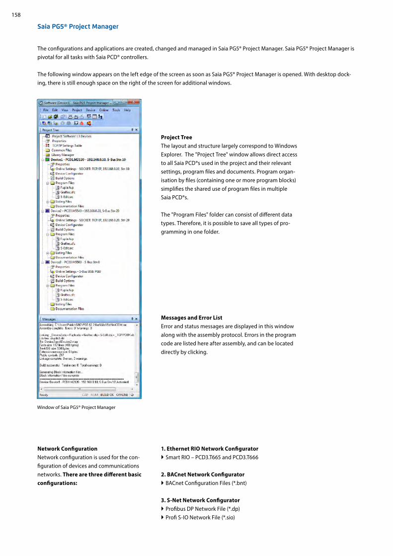
158
Saia PG5® Project Manager
Project Tree The layout and structure largely correspond to Windows Explorer. The "Project Tree" window allows direct access to all Saia PCD®s used in the project and their relevant settings, program files and documents. Program organ-isation by files (containing one or more program blocks) simplifies the shared use of program files in multiple Saia PCD®s.
The "Program Files" folder can consist of different data types. Therefore, it is possible to save all types of pro-gramming in one folder.
Messages and Error List Error and status messages are displayed in this window along with the assembly protocol. Errors in the program code are listed here after assembly, and can be located directly by clicking.
Window of Saia PG5® Project Manager
Network Configuration Network configuration is used for the con-figuration of devices and communications networks. There are three different basic configurations:
The configurations and applications are created, changed and managed in Saia PG5® Project Manager. Saia PG5® Project Manager is pivotal for all tasks with Saia PCD® controllers.
The following window appears on the left edge of the screen as soon as Saia PG5® Project Manager is opened. With desktop dock-ing, there is still enough space on the right of the screen for additional windows.
1. Ethernet RIO Network Configurator Smart RIO – PCD3.T665 and PCD3.T666
2. BACnet Network Configurator BACnet Configuration Files (*.bnt)
3. S-Net Network Configurator Profibus DP Network File (*.dp) Profi S-IO Network File (*.sio)

159
12
34
SBC
Soft
war
eCo
mm
unic
atio
n
and
Inte
ract
ion
SBC
S-W
eb t
echn
olog
yR
oom
aut
omat
ion
Device Configurator The hardware and physical functions of the controller are defined in the Device Configurator; e.g. device type, memory modules, communication channels, associated modules and I/Os. The I/O configuration, parameterisation and designation, as well as the configuration of the Ethernet protocols, e.g. DNS, DHCP, etc. takes place here. The Device Configurator also controls the use of input/output modules in the internal power supply of PCDs and prints the labels which are placed on the I/O modules.
All parameters and modules can be viewed at a glance and printed out as system documentation in the Device Configurator
Symbol Editor The Symbol Editor is the heart of Saia PG5® Core. It defines and documents all the symbols used by the program. The various editors are connected with the Symbol Editor. New symbols used in the program code are incorporated directly by the Symbol Editor.
The import/export function allows the reuse of pre-defined I/O lists in electrical diagrams and visualisation tools.
Symbols can be grouped together. All the symbols re-quired for a function form one group. This makes it easier to use functions and recognise symbols in the program code, and also gives a clearer overview in the Symbol Editor.
Overview of all symbols used in the Symbol Editor

160
Saia PG5® Fupla (function block diagram)Fupla is the SBC proprietary function block diagram editor. It differs in many respects from other graphic programming interfaces:
One Fupla file may contain several program blocks. This means that one file can encompass an entire machine func-tion. In symbolic programming, each program block is given an individual symbol name. This prevents collisions during the build.
Fupla blocks are organised into pages. Each page can pro-duce several outputs so that entire functions can be viewed at a glance on one page.
Graphic functions (FBoxes) not only have inputs and out-puts, but also parameter windows for configuration and online modification.
Saia PG5® Fupla (function block diagram)
Comment: The Kopla Editor (contact plan) is an integral part of Saia PG5® Fupla Editor. Unlike conventional graphic programming environ-ments, FBoxes and contact plan elements can be combined in a single graphic.
Saia PG5® S-Edit (instruction list IL)
Saia PG5® S-Edit (instruction list IL)The editor for the strong instruction set of Saia PCD®. S-Edit combines an editor and online debugger in one interface.
The colour syntax function detects valid instructions and applies a colour to them. The program code is thus much easier to read and typographic errors are detected immedi-ately.
The "Bookmarks", "Goto Line", "Find and Replace" editor functions make it easier to navigate through extensive programs.
The code built can be displayed directly in the original code. The function is also used by the integrated debugger.
Complete functions can be copied from a library using drag & drop.
Saia PG5® Graftec (sequential function chart)
Saia PG5® Graftec (sequential function chart)Graftec (sequential function chart) is particularly suited to sequential processes. Sequential blocks are a fixed component of the PCD firmware and are processed by it efficiently.
Steps and transitions can be programmed in IL and graphi-cally in Fupla.
To also ensure a good overview with extensive sequential processes, division into sub-pages is possible.
In online mode, the active transition is permanently dis-played.
Option to process the code step-by-step in step mode.
Programming methods in the Saia PG5® Core

161
12
34
SBC
Soft
war
eCo
mm
unic
atio
n
and
Inte
ract
ion
SBC
S-W
eb t
echn
olog
yR
oom
aut
omat
ion
Structure of the Fupla Editor
The Saia PG5® Fupla Editor is the quickest and most reliable method of implementing applications. This editor can also be easily used by those with no software programming experience. It is the right tool for optimising and modifying systems. All complex functions have been implemented by specialists in Saia PG5® S-Edit or Saia PG5® Graftec and packaged into graphic function blocks (FBoxes). "Ready and simple to use" also by service technicians and process engineers. > 95% of all applications can be implemented in the automation infrastructure through engineering using Saia PG5® Fupla alone. No line of code is written here.
Programming is facilitated with pre-programmed function blocks (FBoxes) for all standard functions
Creation of complex user programs by simply positioning and linking FBoxes without requiring extensive program-ming knowledge.
Extensive and high-performance FBox families for communi-cation and building automation tasks
Features of the libraries The clearly arranged tree structure simplifies FBox selection. Parameters are conveniently entered via adjust windows in the Fupla editor, without losing the program overview
Detailed context-sensitive FBox information, clear parameter descriptions and graphic presentation in the function block diagram editor (Fupla) make user programs easy to read and understand
Online display of process values and parameter adjustment makes commissioning considerably easier and saves mainte-nance costs
Obvious differentiation between data types by using different colours
Library selection
Process input values
Page overview
Process output values
Process values used
Benefits of using the Fupla Editor
Saia PG5® Fupla
Each data type is identified by a colour. This makes programs easier to read.Binary data PurpleInteger data BlueFloating point data YellowTexts (TX) and data blocks (DB) Green

162
Clear grouping into familiesAll FBoxes (function boxes) are grouped into families. This provides a better overview and makes it easier to find individual FBoxes. A distinction is also made between standard, application and user FBox:
Standard: Shows the FBox libraries of the basic application components
Application: Shows the FBox libraries of the engineering application components
User: Only shows the FBox libraries which the user himself has created
All: Shows all available FBox libraries
Favourites: On this page the user can group together the most frequently used FBoxes (from all libraries). This means that it is no longer necessary to search for FBoxes or to switch between library tabs.
FBoxes in the Saia PG5® CoreThe standard and application FBoxes are readily available for users in the Saia PG5® Core.The standard FBox libraries are basic families which offer normal logical and arithmetic operations and numerous useful system functions. In addition to the standard FBoxes, the Saia PG5® Core contains additional FBoxes. These include application FBox libraries which comprise engineering families. The search function (Filter) in the Selector enables a specific FBox to be found quickly.
So that Engineering can access the correct FBoxes, their function and parameters must be known. The online user manual integrat-ed into the PG5 Core is the ideal way to get a quick overview of the relevant FBoxes.Clicking on the FBox makes information such as a brief description of the FBox, an explanation of inputs and outputs, information on the parameter settings and a function description of the FBox accessible to all.
HVAC online user manual

163
12
34
SBC
Soft
war
eCo
mm
unic
atio
n
and
Inte
ract
ion
SBC
S-W
eb t
echn
olog
yR
oom
aut
omat
ion
Web Editor – a powerful software tool The production of web-based visualisation and control interfaces is an essential element of the engineering effort. Appealing, functionally designed web pages are the public face of the system, supporting operational efficiency and safety. A powerful tool for generating the web pages is therefore crucial.
Saia PG5® Web Editor: simple, intuitive and efficientDesigning dynamic web pages with a normal HTML editor is laborious and requires specific expertise (in-depth HTML and Java programming knowledge). With the Saia PG5® Web Editor, SBC provides the user with an easy-to-use software tool for generating web pages to ensure that this innovative technology does not remain the preserve of a small number of specialists. The Web Editor is used to create web pages in HTML5 or in TEQ-format simply and efficiently by placing and parameterising objects. Operation of the editor is intuitive, and rquires no HTML or Java programming knowledge. With optimum integration into the Saia PG5® Controls Suite and the associated direct access to all symbols, powerful macro management to generate your own reusable macros and many other useful functions for efficient generation of web pages, the engineering costs are significantly reduced compared to other editors.The tool is designed for the automation environment. Applications include system visualisations, alarming and trending functions, or just one service page. The full integration into the Saia PG5® Core combined with Saia PCD® controllers guarantees a particularly efficient working method.
The Saia PG5® Web Editor produces appealing web visualisations with no web designer skills required.
Start screen for Saia PG5® Web Editor 8
The Web Editor includes a transparent and adjustable workspace for efficient operation. The workspace essentially comprises the menu/command bar, the View Editor (drawing area) and windows. With docking window technology, the user can position and show/hide the windows as required.

164
Saia PG5® Web Editor
Saia PG5® Fupla
Saia PG5® S-Edit
PG5® HVAC Lib
Saia PG5® Graftec
Saia PG5® Core + HVAC library. The visualisation is created using the Web Editor.
The majority of the program functions can be implemented using the FBoxes included the Saia PG5® Core Package. In addition, additional libraries for specific applications are available. The HVAC library, for example, has an efficient collection of complex control modules (FBoxes) for the heating, ventilation and air conditioning systems area. These functions simplify the engineering of the technical systems of buildings.
The HVAC library contains the following FBox groups General: FBoxes for numeric functions, binary functions, alarms, monitoring, motor, blocking and frost protection, process states, switches and the conversion of data types
Analog: Function blocks for individual scaling of each individual analog input or output Electrical: FBoxes for lighting control, window blind control and step switches Energy: Energy meters, pulse counters, monthly statement, enthalpy, switching heating on/off, load cut-out Filters: Filter, limitation, ramp limitation, average of measurement values, dead zone, dead range with delay, zero zone, hysteresis Init: Initialisation of the sub-functions for the HVAC library Controllers: Two-point controller, three-point controller, boiler loading, P, PZ, PI, PID, P-PI, P-PID controllers, incoming air mixers, controller sequences, mixer sequences
Setpoint: Heat curve, heating demand, setpoint device, setpoint ramp, setpoint adjustment Test: Simulation of values and states Clocks: Daily program, weekly program, annual program, clock with multiple switching periods in one FBox, national holidays, monthly switch-offs or switching periods one after the other on the same day, as well as FBoxes for reading and writing clock data
1.1.2 Saia PG5® HVAC modules1.1.2.1 HVAC library
Libr
ary
Libr
ary Saia PG5®
Project manager
Saia PG5® Symbol Edito
r
Libr
ary

165
12
34
Saia PG5® Symbol Editor
PG5® HVAC Lib PG5® DDC Suite
Saia PG5® Web Editor
Saia PG5® Fupla
Saia PG5® S-Edit
Saia PG5® Graftec
SBC
Soft
war
eCo
mm
unic
atio
n
and
Inte
ract
ion
SBC
S-W
eb t
echn
olog
yR
oom
aut
omat
ion
Saia PG5® Core + DDC Suite library
Using the Saia PG5® DDC Suite library and templates makes the creation of HVAC applications even simpler. Complex program structures and application elements such as complete pump controllers, incl. hour meters or entire control tasks for ventilation systems are grouped together as templates in individual function boxes and optimally add to the current HVAC library. This means that projects can be implemented efficiently.
Total pump control with HVAC library
Total pump control with DDC Suite library
We can already see a number of benefits when comparing the two Fupla pages (HVAC and DDC Suite).
It is easier to read and understand the Fupla program – fewer FBoxes and links on one page. Clear and transparent layout – easier to handle, e.g. for new colleagues in the developer or service team Easy to maintain
1.1.3 Increasing engineering efficiency through installation templates1.1.3.1 DDC Suite
Libr
ary
Libr
ary
Libr
ary Saia PG5®
Project manager
Saia PG5® Symbol Edito
r

166
DDC general: general FBoxes such as manual information, media access
DDC analog values: FBoxes for capturing measurement values
DDC BACnet: Scheduler, Trendlog, Loop, Notification Class DDC Releases: clocks, systems and aggregate switches DDC Initialisation: modules which must be inserted once into a Fupla and which provide basic functions.
1. Integrated trending (offline history) If data has to be recorded along with the actual control and regulation of a system, this is easily implemented with Saia PG5® DDC Suite. Data acquisi-tion for trending can be initiated by defining the memory size in the object parameter window. When the automation system is in operation, data will be constantly saved in the Saia PCD® and available for evaluation. In addi-tion, documentation (.txt) will be created in the Saia PG5® Project Manager of all the measured historical data. A list of the trend settings can be seen in this file. There is one entry for each trend with all the details.
The unique features of the DDC Suite are listed in 5 points:
Trending
Alarming
BACnet configurator
2. The principle of the trend function also applies to alarm functions. By defining the alarm number in the object parameter window, the alarms are listed in a CSV file with numbers and text. With Version 2.5 of the DDC Suite, the system identification key can be cre-ated completely freely directly from Fupla. The aim is to create the system identification key for the S-Web alarm texts and BACnet® completely freely according to the specifications from the Fupla program.
3. Automatic generation of BACnet® configurations For BACnet® projects, the BACnet® object list is created automatically, which saves a great deal of error-prone manual work. The automatic gen-eration of the BACnet® objects is the main reason why so many customers use the DDC Suite. In building automation, it is normal for all systems to map relevant hardware and software data points to BACnet® objects. This may mean that multiple data points are used in a BACnet® object. Thus, for example, a binary output could receive exactly the same return message and be monitored via intrinsic alarming. The control templates for the DDC Suite already contain all BACnet® definitions which can be activated by clicking, Thus BACnet® originates at the click of a button.
This FBox library with highly integrated FBoxes uses individual data points and creates groups and symbols automatically.
DDC controllers: control modules for components such as coolers, heat recovery systems and heaters
DDC setpoints: conversions, setpoints DDC Controls: Triggering of motors, pumps, covers and drives
DDC Fault: Fault modules for motors, fire protection and various components
The following FBox families are available to the DDC Suite library user:

167
12
34
SBC
Soft
war
eCo
mm
unic
atio
n
and
Inte
ract
ion
SBC
S-W
eb t
echn
olog
yR
oom
aut
omat
ion
4. The engineering documentation can be created quickly at the click of a button.
The documentation on all DDC Suite FBoxes is created as an HTML file. This file contains a general description with all parameters and settings. The documentation can be saved in the PCD and, for example, be used for viewing via the web. It is, however, also possible to post-edit the documen-tation using a text processing tool and to add images from the SCADA/web application.
HTML document
5. Templates for Fupla, Web Editor and Saia PCD® Supervisor The Saia PG5® DDC Suite largely comprises a highly integrated FBox librarywhich is supplemented by a growing number of ready-made, tested and ready-to-use Fupla pages which fully map the typical parts of the system in terms of function. The Saia PG5® DDC Suite also provides the control and visualisation function for each FBox. Operation and visualisation using the web browser or Saia PCD Supervisor is already integrated and ready for use. Fupla templatesIn order to reduce the system programming time, entire applications (heating circuit, water heating, ventilation systems, etc.), in-cluding the calendar and control tasks, are fully integrated for free selection. Some suggestions for control settings and for system control can thus be freely added, changed or integrated. Web Editor templates The DDC Suite is also includes template objects for Web Editor. Graphic and control objects are available for every FBox. There are also templates for predefined systems. Saia PCD® Supervisor templatesWhen importing data from Fupla into the Saia PCD Supervisor, the FBoxes are recognized with the help of the integrated map-ping table and structured by the Saia PCD Supervisor according to the specifications of the FBoxes. Not only are the information points imported - units, min-max values, alarms and historical trends are also created automatically during import. In addition, the Saia PCD Supervisor user is provided with suitable template objects analogous to the Web Editor templates.
System display

168
Saia PG5® Symbol Editor
PG5® HVAC Lib PG5® DDC Suite My Suite
Saia PG5® Web Editor
Saia PG5® Fupla
Saia PG5® S-Edit
Saia PG5® Graftec
1.1.4 Saia PG5® Controls Suite
1.1.4.1 My Controls Suite
The use of predefined FBoxes and/or templates is not mandatory. Saia PG5® Core enables users to create individual templates and even define the templates with purely graphic engineering, with no IL programming required.
Create templatesUsing templates significantly simplifies processes and reduces engineering time. To implement projects more efficiently, users can not only implement existing templates, but also incorporate user-specific engineering projects as templates. Users who have built their standard Fupla pages can export and save them as .fxp files (a .fxp file includes any number of Fupla pages). To reuse the pag-es, the .fxp files must be located and then imported.
In addition to the templates which can be easily created and reused, you can also create your own FBoxes and/or FBox library (My FBox Lib). The FBox Builder, contained in the Saia PG5® Core, is used for this.
Libr
ary
Libr
ary
Libr
ary Saia PG5®
Project manager
Saia PG5® Symbol Editor

169
12
34
Saia PG5® Symbol Editor
Saia PG5® Symbol Editor
Saia PG5® Fupla
Saia PG5® S-Edit
Saia PG5® FBox Builder
Saia PG5® Graftec
My
FBox
Lib
s
Saia PG5® Fupla
Saia PG5® S-Edit
Saia PG5® Graftec
My
FBox
Lib
s
Saia PG5® FBox Builder
SBC
Soft
war
eCo
mm
unic
atio
n
and
Inte
ract
ion
SBC
S-W
eb t
echn
olog
yR
oom
aut
omat
ion
The Saia PG5® FBox Builder has additional functions that enable programmers to develop totally new FBoxes and to maintain them in their own library. The FBox Builder advanced version is required if the user wishes to integrate existing IL functions, modify ex-isting FBoxes or even create totally new FBoxes. In addition to importing export pages (1), this version enables extensive functions such as:
Importing existing FBoxes (2) Creating FBoxes "from scratch" (3) Importing IL code (4)
The advanced FBox Builder is suitable for experienced Saia PG5® IL programmers who have attended a workshop and own a licence for the FBox Builder Advanced add-on tools.
Using the Saia PG5® FBox Builder in projects with the Saia PG5® software technology
Creating your own FBoxes with the FBox Builder
Create FBoxesThe process of exporting Fupla pages and then reimporting them is simplified by the Saia PG5® FBox Builder. Users can import their .fxp files into the FBox Builder and then archive them as FBoxes. This function (importing Fupla export pages/files) enables a structured group of FBoxes to be assembled into one large macro FBox. The Saia PG5® FBox Builder can then be used to document, maintain and export the new macro FBox as a new "product". This capability allows users to build customised libraries for any other application. The FBox Builder enables users to develop their own FBoxes without writing a single line of instruction list code.
Libr
arySaia PG5®
Project manager
Saia PG5® Symbol Editor
Libr
ary
Libr
ary
Libr
ary
1: Export pages 2: existing FBoxes
Saia PG5® Project
managerSaia PG5® Symbol Editor
4: Il Code
3: New FBox

170
The combined platform of the SBC software is the Saia PG5® Controls Suite DVD. It contains software tools for project management, engineering, programming and service. The DVD also includes application components with which you can increase your pro-ductivity when using Saia PCD® products. There is also a wide range of system software on the Saia PG5® Controls Suite DVD. This software is predominantly driver software to ensure easy and secure integration into a system environment.
Saia PG5® Controls Suite contains everything you need for automation
1.1.4.2 Overview of the tools and licence packages
PC tools
Saia PG5® Core Project Manager Application Programming Application Engineering Network Management Service
Saia PG5® Web EditorTool for creating web pages for the Saia PCD® Web Server
Saia PG5® HMI EditorTool for Saia PCD® Text Panels
Saia PG5® FBox BuilderTool for creating and managing Saia PG5® Fupla FBoxes
Saia PG5® Online-ToolsDownloading PG5 programs without installing the Saia PG5® Core
Application components
Standard FBoxesProgram modules for Saia PG5® Fupla, the graphic engineering tool
Arithmetic and logical FBoxes Analog FBoxes Communication FBoxes
Application FBoxesProgram modules for Saia PG5® Fupla, the graphic engineering tool.FBoxes Alarm, DALI, DDC Suite, EIB, Energy Meter, EnOcean, Historical Data Capture, HVAC, Blinds/Lighting, JCI N2-Bus, e-mail Communication, Modbus, Modem, MP-Bus, Room Controller
IL librariesFunction blocks for counter modules, drive modules and analog modules can be integrated into IL programs
List of tools in the Saia PG5® Controls Suite
Application software
SBC Web ConnectThe PC program enables access to the PCD WebServer via any communication interface (RS-232, RS-485, Profibus, Ethernet, etc.)
Saia PG5® SD Flash ExplorerWith SD Flash Explorer, the content of the SBC file system can be extracted to the PC.

171
12
34
SBC
Soft
war
eCo
mm
unic
atio
n
and
Inte
ract
ion
SBC
S-W
eb t
echn
olog
yR
oom
aut
omat
ion
Saia PG5® options – Add-on libraries: Tool is separated from libs. The FBox libraries can also be ordered.
Licence packages We have defined three packages as a global standard from the wide range of possible software combinations with the Saia PG5® Controls Suite. The training programs, online training and documentation are based on these.
Saia PG5® Core PackageWith this package, all types of ICA tasks can be initiated on machines and systems. The graphic application components supplied support the use of the Saia PCD® Automation Server (Web + IT) and simple calculation and logic functions.
Saia PG5® HVAC PackageIn addition to the Saia PG5® Core Package, additional graphic control module assemblies (FBoxes) are included which are oriented to the needs of HVAC primary systems. Template pages can be created from the basic collection of HVAC ICA modules which map any kind of system configuration.
Saia PG5® Extended PackageIn addition to the Saia PG5® HVAC package, highly integrated graphic modules (DDC Suite) are included as well as a collection of templates which map the current system design of the HVAC technology.
g For details see order information
Saia PG5® Programming Tool
PG5 – Demo version with all functions. Runtime limited to 90 days
PCD8.PG5–DEMO
Saia PG5® Core PackageProgramming software with editors (IL, Fupla, Graftec), network configurators,standard libraries (Analog, Communication, Arithmetic & Logic), application libraries (Alarming, Blinds-Lighting, e-mail, Trending [HDLog], Energy Meter, DALI, Modbus, EIB, EnOcean, JCI N2-Bus), Web Editor and FBox Builder (basic version)
PCD8.PG5–CORE
Saia PG5® HVAC PackageSimilar to Saia PG5® Core Package and associated libraries (HVAC, Belimo MP-Bus, room controllers and modem), BACnet
PCD8.PG5–HVAC
Saia PG5® Extended PackageSame as Saia PG5® HVAC Package and associated DDC Suite library
PCD8.PG5–EXTENDED
Saia PG5® Software UpgradeUpgrade according to customer’s keyVersion 2.2 to 2.3
PCD8.PG5–UPGRADE
Saia PG5® Software UpgradeUpgrade from Core to HVAC package
PCD8.PG5-UPGR-HVAC
Saia PG5® Software UpgradeUpgrade from HVAC to Extended package
PCD8.PG5-UPGR-EXTD
End user licence for Saia PG5®End user licence for PG5. The customer is supported by the requisitioner (in accordance with the customer key)
PCD8.PG5–ENDUSER
Saia PG5® options – Add-on tools
PG5 – FBox Builder ("advanced version") Software package for Saia PG5® FBox Builder. IL knowledge needed and 1 day’s training included
PCD8.PG5-FBOXBLD
Order information | Saia PG5® Controls Suite


173
12
34
SBC
Soft
war
eCo
mm
unic
atio
n
and
Inte
ract
ion
SBC
S-W
eb t
echn
olog
yR
oom
aut
omat
ion
1.2 Application software for Windows PCs1.2.1 Saia PCD® Supervisor
1.2.1.1 Saia PCD® Supervisor
The scalable Saia PCD Supervisor software platform monitors and controls simple HVAC regulating systems as well as company-wide control stations in larger building complexes or infrastructure systems.
The complete solution for intelligently managing buildings and infrastructures
Main properties of the Saia PCD Supervisor
Complete solution: controlling, monitoring, reporting and visualising with just one centralised software platform
Compatibility: allows integration of all Saia PCD controllers, third-party devices and smart devices via IT protocols and numerous drivers
Flexibility: can easily be adapted to individual customer requirements
Technology standard: based on robust Tridium N4 technology with HTML5 and Cyber security
SBC: brand-specific additional services (S-Bus driver, Import Wizard and Icon Gallery) + ready-made S-Bus and BACnet DDC suite templates and intuitive HTML5 project visualisation templates
Cyber security
Alarm management
Trend logs
Report & data analysis
Dynamic dashboards
Mobile operation
Energy monitoring
Intuitive scheduler
User management
Communication protocols
Efficient engineering
API connection with JSON toolkit
FDA's 21 CFR Part 11
Automatic project documentation
Simple creation of templates

174
CSV
SQL
OPC
1. VisualisationThe Saia PCD Supervisor sets new standards: whether you use a desktop PC, a tablet or a smartphone – thanks to HTML5, real-time visualisations can be displayed without problems on virtually all devices. You can take advantage of the adjustable, predefined templates and responsive design.
Complete solution
2. System monitoring The Saia PCD Supervisor conveniently presents system data in freely definable graphical system diagrams, as a trend diagram or in table form – all directly in a web browser, regardless of protocol, data point type, controller and operating system.
As a modern, scalable monitoring and management solution, the Saia PCD Supervisor bundles visualisation, interaction, monitor-ing and reporting in a user-friendly, high-performance software platform. Designed to offer compatibility regardless of brands, it allows the integration of all building systems across disciplines – even thirdparty systems. By bringing together all relevant data and displaying them in a way which is easy to understand, the Saia PCD Supervisor helps to optimise building systems and thus improve building efficiency significantly.
3. ReportingData can be exported as reports in CSV or PDF format at any time – this can also be done automatically. Thanks to the optional SQL and OPC inter-face, integration with other systems is easily possible.
4. DashboardsKeep track of key performance indicators at all times: Users create and modify the dashboards themselves and save their own specific dash-boards.
5. MonitoringThe Saia PCD Supervisor from SBC is a high-performance integration and monitoring platform with central data display for all building sub-systems. With Saia PCD Supervisor EM (see chapter 1.2.1.2), the energy monitoring software from SBC, the energy consumption of buildings is also analysed and monitored. As a result, it can be optimised.

175
12
34
OPC
OPC
SBC
Soft
war
eCo
mm
unic
atio
n
and
Inte
ract
ion
SBC
S-W
eb t
echn
olog
yR
oom
aut
omat
ion
Large selection of driversOpen communication, a factor which is relevant in today's building auto-mation, is supported by various protocols including BACnet, LON, Modbus, M-Bus, KNX, OPC and SNMP. Most open systems are based on the TCP/IP communication standards and can be integrated directly into the Saia PCD Supervisor. Optionally, external systems can also be connected via SQL interface or a freely configurable API interface.
Compatibility
Designed to offer compatibility regardless of brands, the Saia PCD Supervisor allows the integration of all building systems across disciplines. The platform monitors and controls all HVAC and non-HVAC systems such as lighting, shading or security systems. The Saia PCD Supervisor also supports all established communication protocols and integrates all systems and applications in a stand-ardised structure, even across a number of buildings.
BACnet driverThe Saia PCD Supervisor is a BACnet-certified control centre which satisfies the BACnet profiles B-OWS (Operator Workstation) and B-AWS (Advanced Workstation). It is also certified in accordance with BTL "Revision 14". BACnet guarantees interoperability between devices from various manufacturers. A BIBB (BACnet Interoperability Building Block) defines which services and procedures need to be supported on the server and client side in order to achieve a specific system requirement. The PICS (Protocol Implementation Conformance Statement) document belonging to a device lists all support-ed BIBBs, object types, character sets and communication options. With the Saia PCD Supervisor, it is possible to scan for BACnet objects within the network or import them via EDE files.
Faster, more efficient developmentThe open Niagara Framework on which the Saia PCD Supervisor is based allows developers to extend the framework and program their own unique applications, drivers, plug-ins, data displays and application logics for business applications. In addition to this, there is detailed documentation, a comprehensive, open API library and ready-made tools which provide support during development.
Tool
s
DocAPI
BACnetBACnetCONFORMANCECONFORMANCECERTIFICATECERTIFICATE

176
F1
F3
F4
F1 F2 F3 F4
F4
F1
F2
F5
F5
High level of flexibility
The system can be extended almost unrestrictedly and adapted to meet the individual requirements of integrators, planners or operators.
Higher-level functionsThe Saia PCD Supervisor provides a level for higher-level functions with the Wire Sheet (similar to the PG5 Fupla).
Creating cross-building data sets
Preparing data for reports and visualisation
Creating alarm escalations and e-mail recipients
Modular and scalableIndividual buildings can be managed in the same way as larger building complexes and facilities spread across various sites. All important SCADA functions are already included in the basic packages. Thanks to data point extensions – even for open protocols – the system can be adapted to the particular project size at any time. The customer can therefore select any package as a basis and add various data points at any time in order to give the Supervisor system the capacity it needs for the points to be monitored and controlled. All Saia PCD Supervisor basic packages also include an 18-month maintenance package and with this warranty, a free upgrade of older versions. Continuous maintenance is necessary in order to keep the system up to date. This can be extended by purchasing maintenance upgrade options. Our partners also get an engineering licence (annual contract) which can be used to configure, test and demonstrate the Saia PCD Supervisor. With this annual contract, partners also receive support from SBC (training and technical assistance) in order to ensure that the Saia PCD Supervisor can be operated properly.
Normalised data pointsThe data of connected devices and networks are normalised in the Saia PCD Supervisor and are then available throughout the system. Normalised means that the data read by the driver are packaged in a standardised data structure and can be used in the same way in any function and visualisation. Each data point in the Saia PCD Supervisor can provide a priority array. S-Bus, M-Bus or BACnet data points are also supplemented with a priority array in the Saia PCD Supervisor. The priority array makes it possible to execute various operating states on the same data point with a different priority.
Tailored visualisationEach user logged in to the system focuses on various individual tasks. The information in a system is therefore user-specific. With the Saia PCD Supervisor, each user sees exactly what is relevant to them: system technicians see the system diagrams and MSR technicians see additional control parameters. The facility manager can also change time plans while the security personnel receive security-related messages. Naturally, all of this can be set up in accordance with specific user requirements. The status reports too can be personalised. The Saia PCD Supervisor offers sophisticated functions for filtering, processing, escalating and forwarding alarms. It is also possible to send alarms via e-mail.
177
12
34
SBC
Soft
war
eCo
mm
unic
atio
n
and
Inte
ract
ion
SBC
S-W
eb t
echn
olog
yR
oom
aut
omat
ion
The Saia PCD Supervisor is based on the proven Niagara 4 Framework which is already used in over half a million applications around the world.
HTML 5The Saia PCD Supervisor features an intuitive user interface for comprehensive building management. It uses the HTML5 standard in order to provide nu-merous reliable functions and thus combines maximum control with the very highest data security.
Technological standard
Cyber securityThe Saia PCD Supervisor is secure as standard and uses the "Defence in Depth" approach for the security architecture on the Internet of Things which is based on the security concept of the Niagara Framework. For authentication, users must select secure login information. In addition, both transmission data and data on network drives must be encrypted. The Saia PCD Supervisor also uses role-based access authorisations. As a result, user authorisations can be configured easily and are less susceptible to errors. The user concept is based on categories, roles and users. This setup allows a very detailed description of the rights of a user within a system up to individual data point features. Each user is assigned a role which defines their access rights and locations. If a user is given a new role in the system, the rights needed for this are added immediately. Each user can also be assigned an individual start page and an individual language. The Saia PCD Supervisor can also be integrated into existing systems for identification and access management such as LDAP or Kerberos. All user activities and security-relevant events are recorded in the Niagara Audit Log and can be traced.
System requirements
The Saia PCD Supervisor supports the following operating systems:
Windows 10 (64 bit)
Windows Server 2016
Windows Server 2019 (64 bit)
In addition to the operating system requirements for the Saia PCD Supervisor, the following requirements must also be met:
Processor: Intel® Xeon® CPU E5-2640 x64 (or more powerful), compatible with dual and quad core processors
Memory: at least 6 GB; for larger systems, 8 GB or more recommended
Free hard disk space: at least 4 GB; 10 GB recommended for any supervisor; more may be required depending on the archiving requirements
Display: Video card and monitor capable of displaying 1024 × 768 pixel resolution, minimum of 1920 × 1080 recom-mended
Supported networks: Ethernet adapter (10/100 MB with RJ-45 connection)
Connectivity: permanent ISP high-speed connection for remote site access recommended (e.g. T1, ADSL, cable modem)
If data archiving is necessary on a company level (optional), one of the following compatible database applications must be installed: MS SQL Server 2012, 2016, 2017 and 2019,
MySQL Server 5.7 and MySQL Server 8.0 Oracle Express 11g, Oracle 12c, 18c, 19c.

178
SBC
3D
SBC Icon GalleryThe Saia PCD Supervisor supports all common image formats such as PNG, SVG, GIF and JPG. In addition to 3D graphics, the graphics in the SBC Icon Gallery on the basis of SVG files are available as usual. Graphics and system diagrams are created in the Saia PCD Supervisor graphics editor. Systems are often made up of the same system parts. These can be created in the Saia PCD Supervisor on a one-off basis and reused. In order to reuse a creat-ed object, it is dragged to a page using drag and drop. In the process, data points are automatically connected with the correct system. Changes to an object are made immediately to all usage instances. This is possible both with individual objects and with complete views.
SBC-specific benefits
Saia PG5® Import WizardThe Import Wizard extends the Saia PCD Supervisor with an efficient and fault-free data import of the existing PG5 data point structure with the help of a pre-defined and adjustable mapping table. This can be modified for every FBox and enhanced with the features of all Saia PCD Supervisor com-ponents. For instance, in the DDC-Suite 2.7 FBoxes, all features and enhance-ments are therefore added to the data points directly during the import.Via the Saia PG5® Import Wizard, symbols and alarm lists with alarm texts from a Web Editor 8 project as well as HDLog lists previously defined in PG5 projects can be imported into the Saia PCD Supervisor quickly and easily. The filter functions can be used if only selected symbols are to be imported. During the import process, the Ether-S-Bus driver is created and configured. All CPUs in a PG5 project where data points were selected are automatically created under the driver as a device and configured for communication. From this moment, data point communication begins automatically when the PCD is available in the network and the device configuration is correct.
Efficient engineeringA wizard simplifies migration (Ether-S-Bus, S-Bus-Gateway) of all PCD con-trollers incl. backwards compatibility. An adjustable mapping table defines features and enhancements to data points. Users’ own templates can be created independently of protocol and individually visualised via library for S-Bus and BACnet (compatible with PG5 templates). Users can generate their own HTML5 structure for web visualisation with a project template. The Database Manager extension allows an overview of the existing / used licence data points at any time. In addition, it allows you to automatically delete all unused data points from the project. With the additional JSON toolkit, it is possible to integrate any application / device via freely definable API interfaces.
Saia PCD Easy Templating
Import Visualization

179
12
34
SBC
Soft
war
eCo
mm
unic
atio
n
and
Inte
ract
ion
SBC
S-W
eb t
echn
olog
yR
oom
aut
omat
ion
S-Bus driverComplete solution for integrating a Saia PCD controller via the proprietary S-Bus: the SBC S-Bus-over-IP driver is ideal for connection to PCD1, PCD2, PCD3, PCD7 and gateways. Supported functions:
Reading and writing all Saia PCD media Reading the Saia PCD status and the firmware version Reading out the HDLog data Receiving and acknowledging alarms from the PCD system
It is possible to use a number of PCD controllers under an SBC IP network driver. A number of SBC IP network drivers can also be managed in one system. The systems can thus be separated or optimised. It is also possible to place PCD sub-stations under PCD devices which cannot be connected directly via an Ethernet interface (S-Bus gateway).
Supported PCD devicesSaia PCD devices are connected directly to the Saia PCD Supervisor via an Ethernet interface. Devices with an RS-485 interface can communicate with the management system via a gateway station which is connected to the Saia PCD Supervisor via Ethernet. The following devices are supported:
Training and technical assistanceA four-day engineering training course provides all the knowledge needed for successful project work. On the basis of an extensive demo project, participants are taught how to work with the Saia PCD Supervisor in a practical context. And if questions or problems arise later on, our technical support department would be happy to help!
PCD with RS-485 interface for connection to a gateway station which is connected to Saia PCD Supervisor via Ethernet: PCD1.G/F/Wxxx-xx5 with RS-485 (as slave of a gateway station).
PCD1.M0160E0 PCD1.M2xx0 PCD2.M4x60
PCD2.M5xx0 PCD3.Mxxx0 PCD7.D4xxxT5x

180
S-Bus points These are points controlled by SBC manufactured controllers (PCD1, PCD2, PCD3 and PCD7) and accessed using the S-Bus Protocol. For this category of device the license is sized on the points you want to monitor. Point discovery is an embedded feature available through the Saia PG5® Import Wizard embedded in the S-Bus driver. SBC devices and networks are not counted for licensing purposes.
S-Bus extensions In case more points are needed to meet system requirements, the desired Saia PCD® Supervisor database size can be reached with any combination of Starter Kit and Point Extensions.
Open points These are points from open protocol equipped devices or subsystems that you wish to integrate straight into Saia PCD® Supervisor. The Saia PCD® Supervisor open driver packs include a selection of standard drivers that you can select to be used to perform head end integration. Standard drivers are: BACnet IP, EIB/KNX IP, LON IP, Modbus IP master and slave, M-Bus IP, SNMP and OPC client.
Please note that open protocol license management is delivered in a way that as soon as you reach the limit for point count customers need to request license upgrade accordingly.
Maintenance upgrade options Saia PCD® Supervisor basic packages include an 18 months maintenance and free upgrade package. This can be extended by purchasing maintenance upgrade options.
The licensing scheme for the Saia PCD Supervisor is geared to the number of points. A point is an individual infor-mation element which is stored in the Saia PCD Supervisor database. With Saia PCD controllers, these are flags, reg-isters, inputs, outputs etc. which can be read or written by the Saia PCD Supervisor via S-Bus. There are also open points, e.g. BACnet IP, EIB/KNX IP, LON IP, Modbus IP, M-Bus IP, OPC and SNMP.
Extended connectivity optionsUpgrade connectivity for communication from Saia PCD® Supervisor to another.
Extended support optionsThese options extend the Supervisor's ability to communicate with Excel, My SQL Server, SQL Server, Oracle Server, JSON Toolkit for Supervisor (Valid SMA Required) and Micros Fidelio IP Driver.
Video integration optionsDevice drivers for various camera types for up to 128 connected cameras.
Energy Management optionsComprehensive solution for energy monitoring in the Saia PCD® Supervisor. Moni-tor and optimize the energy consumption of your entire building.
Security optionsProvides interface to integrate the Niagara Enterprise Security Supervisor database to active Directory/LDAP.
Cloud connection optionsAllows Supervisor to access the Niagara Cloud Honeywell Sentience Driver.
Partner license agreementsPartner license agreements can be signed and renewed annually, for single or multiple engineers. Maximum felxibility is provided by the license for one month limited to one engineer (workstation).
Products and licences

181
12
34
SBC
Soft
war
eCo
mm
unic
atio
n
and
Inte
ract
ion
SBC
S-W
eb t
echn
olog
yR
oom
aut
omat
ion
Basic S-Bus packages
PCD8.SUP-500PCD8.SUP-2500PCD8.SUP-10000PCD8.SUP-25000PCD8.SUP-50000PCD8.SUP-100000
Saia PCD® Supervisor basic package including SBC S-Bus driver and 500 points database sizeSaia PCD® Supervisor basic package including SBC S-Bus driver and 2,500 points database sizeSaia PCD® Supervisor basic package including SBC S-Bus driver and 10,000 points database sizeSaia PCD® Supervisor basic package including SBC S-Bus driver and 25,000 points database sizeSaia PCD® Supervisor basic package including SBC S-Bus driver and 50,000 points database sizeSaia PCD® Supervisor basic package including SBC S-Bus driver and 100,000 points database size.
S-Bus extensions
PCD8.SUP-100EXTPCD8.SUP-2500EXTPCD8.SUP-5000EXTPCD8.SUP-15000EXTPCD8.SUP-50000EXT
Saia PCD® Supervisor additional 100 SBC database pointsSaia PCD® Supervisor additional 2,500 SBC database pointsSaia PCD® Supervisor additional 5,000 SBC database pointsSaia PCD® Supervisor additional 15,000 SBC database pointsSaia PCD® Supervisor additional 50,000 SBC database points.
Extensions with open protocols
PCD8.SUP-500OPENPCD8.SUP-2500OPENPCD8.SUP-5000OPENPCD8.SUP-10000OPENPCD8.SUP-25000OPENPCD8.SUP-50000OPEN
Extend base license with additional 500 open protocols pointsExtend base license with additional 2,500 open protocols pointsExtend base license with additional 5,000 open protocols pointsExtend base license with additional 10,000 open protocols pointsExtend base license with additional 25,000 open protocols pointsExtend base license with additional 50,000 open protocols points.
Maintenance upgrade options
PCD8.SUP-MNT1PCD8.SUP-MNT3PCD8.SUP-MNT5
Saia PCD® Supervisor maintenance upgrade - additional 1 yearSaia PCD® Supervisor maintenance upgrade - additional 3 yearsSaia PCD® Supervisor maintenance upgrade - additional 5 years.
Extended connectivity options
PCD8.SUP-1N-UPPCD8.SUP-10N-UP
Upgrade connectivity for communication from Supervisor to another one by 1 Upgrade connectivity for communication from Supervisor to another one by 10.
Extended support options
PCD8.SUP-DB-CSVPCD8.SUP-DB-MYSQLPCD8.SUP-DB-ORCLPCD8.SUP-DB-SQLPCD8.SUP-JSONPCD8.SUP-HTTPPCD8.SUP-FID
Extend the capability for the supervisor to interact with Microsoft ExcelExtend the capability for the supervisor to communicate with MySQL ServerExtend the capability for the supervisor to communicate with Oracle ServerExtend the capability for the supervisor to communicate SQL serverExtend the capability for the supervisor to enable JSON Toolkit for Supervisor (Valid SMA Required)HTTP service interaction as web services and RESTFul APIExtend the capability for the supervisor to interact with Micros Fidelio IP Driver.
Video integration options
PCD8.SUP-MLS-16PCD8.SUP-MLS-64PCD8.SUP-MAXP-16PCD8.SUP-MAXP-64PCD8.SUP-MAXP-128PCD8.SUP-AXIS-16PCD8.SUP-AXIS-64
Milestone Driver to connect 16 Camera DevicesMilestone Driver to connect 64 Camera DevicesMaxpro Driver to connect 16 Camera DevicesMaxpro Driver to connect 64 Camera DevicesMaxpro Driver to connect 128 Camera DevicesAxis camera driver included HTML5 video streaming and alarming for 16 videosAxis camera driver included HTML5 video streaming and alarming for 64 videos.
Energy Management options
PCD8.SUP-EM25PCD8.SUP-EM50EXTPCD8.SUP-EM100EXTPCD8.SUP-EM500EXTPCD8.SUP-EM1KEXTPCD8.SUP-NA-250PCD8.SUP-NA-1000PCD8.SUP-NA-10000
Saia PCD® Supervisor EM base license for Saia PCD Supervisor with max. 25 meter pointsSaia PCD® Supervisor EM license for additional 50 meter pointsSaia PCD® Supervisor EM license for additional 100 meter pointsSaia PCD® Supervisor EM license for additional 500 meter pointsSaia PCD® Supervisor EM license for additional 1000 meter pointsNiagara Analytics Framework license for 250 analytic pointsNiagara Analytics Framework license for 1000 analytic pointsNiagara Analytics Framework license for 10000 analytic points.
Security options
PCD8.SUP-LDAPPCD8.SUP-ESIG-1000PCD8.SUP-ESIG-UNLPCD8.SUP-ESIG-UP1K
Provides interface to integrate the Niagara Enterprise Security Supervisor database to active Directory/LDAPE-Signature Application with 1’000 secured pointsE-Signature Application with unlimited secured pointsE-Signature Application upgrade to add 1’000 additional secured points.
Cloud connection options
PCD8.SUP-CLO-500PCD8.SUP-CLO-2500PCD8.SUP-CLO-10000
Niagara Cloud Honeywell Sentience Driver 500 pointsNiagara Cloud Honeywell Sentience Driver 2500 pointsNiagara Cloud Honeywell Sentience Driver 10000 points.
Partner license agreements
PCD8.SUP-NAA-MONPCD8.SUP-NAA-STK1PCD8.SUP-NAA-STK5PCD8.SUP-NAA-RENPCD8.SUP-NAA-ENG
Saia PCD® Supervisor Starter kit, monthly agreement for 1 engineer*Saia PCD® Supervisor Starter kit, annual agreement for 1 engineerSaia PCD® Supervisor Starter kit, annual agreement for 5 engineersSaia PCD® Supervisor annual agreement renewalSaia PCD® Supervisor one additional engineering license.
* PCD8.SUP-NAA-MON licenses can only be purchased by new partners. From purchase’s month until renewal. You must always purchase as many monthly licenses as you need for the period until November 30th. After November 30th, they will be renewed for 1 year with the normal PCD8.SUP-NAA-REN.
Licence model and order codes for end users
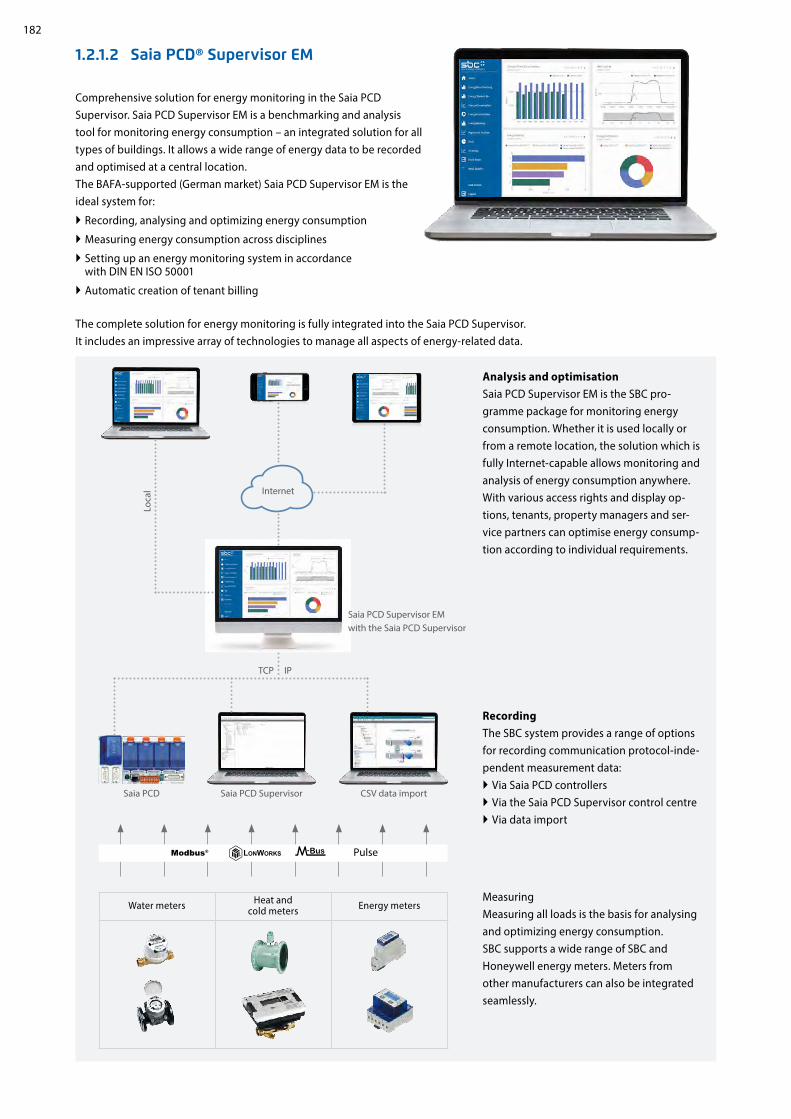
182
Internet
Comprehensive solution for energy monitoring in the Saia PCD Supervisor. Saia PCD Supervisor EM is a benchmarking and analysis tool for monitoring energy consumption – an integrated solution for all types of buildings. It allows a wide range of energy data to be recorded and optimised at a central location. The BAFA-supported (German market) Saia PCD Supervisor EM is the ideal system for:
Recording, analysing and optimizing energy consumption
Measuring energy consumption across disciplines
Setting up an energy monitoring system in accordance with DIN EN ISO 50001
Automatic creation of tenant billing
1.2.1.2 Saia PCD® Supervisor EM
Analysis and optimisationSaia PCD Supervisor EM is the SBC pro-gramme package for monitoring energy consumption. Whether it is used locally or from a remote location, the solution which is fully Internet-capable allows monitoring and analysis of energy consumption anywhere. With various access rights and display op-tions, tenants, property managers and ser-vice partners can optimise energy consump-tion according to individual requirements.
MeasuringMeasuring all loads is the basis for analysing and optimizing energy consumption. SBC supports a wide range of SBC and Honeywell energy meters. Meters from other manufacturers can also be integrated seamlessly.
RecordingThe SBC system provides a range of options for recording communication protocol-inde-pendent measurement data:
Via Saia PCD controllers Via the Saia PCD Supervisor control centre Via data import
Saia PCD Supervisor EM with the Saia PCD Supervisor
Saia PCD Supervisor CSV data importSaia PCD
The complete solution for energy monitoring is fully integrated into the Saia PCD Supervisor. It includes an impressive array of technologies to manage all aspects of energy-related data.
Water meters Heat and cold meters Energy meters
Loca
l
TCP IP

183
12
34
SBC
Soft
war
eCo
mm
unic
atio
n
and
Inte
ract
ion
SBC
S-W
eb t
echn
olog
yR
oom
aut
omat
ion
Energy rankingVisualise and compare the performance of your sites, buildings and systems. Increase energy efficiency by optimizing your biggest loads.
Energy benchmarkingCompare consumption in various areas during similar periods and thus identify areas with low energy efficiency.
Energy consumption analysesGain an overview of energy consumption and the corresponding costs in various areas, buildings and periods.
Daily load profileIdentify inefficient energy use by comparing 24-hour periods on different days.
Heat mapBring up a heat map view of annual data for a load. Would you like to see the profile for a specific day? Simply click on the relevant part of the overview. Configure the heat map according to your specific needs.
Stacked barsStacked bar diagrams show how individual loads contribute to total energy consumption over time – within a day, a week or a year – as well as the corresponding costs. On this basis, you can also define specific or general targets or budgets.
Saia PCD Supervisor EM converts technical data into easy-to-understand graphics, including diagrams with details of the costs in CHF, EUR, GBP or USD. Automatically generated PDF reports can also be sent via e-mail.

184
Order codes
Type Description
PCD8.SUP-EM25 Saia PCD® Supervisor EM: Basic licence for the Saia PCD Supervisor with a maximum of 25 measured values
PCD8.SUP-EM50EXT Saia PCD® Supervisor EM: Licence for an additional 50 measured values
PCD8.SUP-EM100EXT Saia PCD® Supervisor EM: Licence for an additional 100 measured values
PCD8.SUP-EM500EXT Saia PCD® Supervisor EM: Licence for an additional 500 measured values
PCD8.SUP-EM1KEXT Saia PCD® Supervisor EM: Licence for an additional 1,000 measured values
Order information Saia PCD Supervisor EM offers the Core licence as standard. With this licence, 3 measured values are permanently available free of charge. In addition, Core users can test the functions of the Pro licence for 60 minutes. During this trial period, data from aggregators is randomised.
Energy Temperature Curve (ET Curve)ET Analysis helps determine how the energy consumption of a site varies with temperature. For a given time period, the kWh/m2 of a site and temperature can be superimposed onto a graph showing the ideal consumption for the period.
Data QualityUsers can now view the integrity of the data displayed within charts via a ‘Data Quality’ icon placed to the top right of most charts (not applicable to Regression and the HeatMap charts). The button's colour changes based on the minimum integrity value returned from the data set being displayed on the chart. A simple colour code system [red, amber, green] is used to show the integrity of the data between 80-100% scale. An integrity level below 80% remains red.
Colour scale example:
100% 95% 80%
Regression analysisCompare energy consumption with outside temperature, degree days or another value on the basis of regression lines.

185
12
34
SBC
Soft
war
eCo
mm
unic
atio
n
and
Inte
ract
ion
SBC
S-W
eb t
echn
olog
yR
oom
aut
omat
ion
Order information | Saia OPC Server for SBC S-Bus
SBC OPC Server – Full version, for one PC and one application PCD8.OPC-1
SBC OPC Server – Full version, for 3 PCs with the same application PCD8.OPC-3
SBC OPC Server – Full version, for 5 PCs with the same application PCD8.OPC-5
The standardised OPC interface eliminates the need for specialist knowledge of the manufacturer-specific protocols. This results in significantly lower costs and effort for development, commissioning and maintenance.
OPC servers in combination with the SBC S-Bus
OPC project: All OPC data for networked controllers is brought together in a single project. This produces a clear data structure and simplifies the proper definition of data points
Import of PLC variables: Symbols and data points previously defined for the PLC program with the Saia PG5® Controls Suite soft-ware tool can be carried over and used unmodified by the OPC Server. Data formats for import functions include: *.src (PG3, PG4), *.pcd (PG4, PG5), *.sy5 (PG5), *.csv (comma separated values; e.g. from Excel)
OPC Server / Saia PCD®: Visualisation and management systems with OPC client interfaces can be connected to any Saia PCD® controller via the OPC Server. This enables every OPC client, via the OPC Server, to read data from the PCD or write data to the PCD. PLC data that can be displayed in OPC Server includes: Inputs, outputs, flags, registers, data blocks, texts, timers, counters, date-time, firmware version
1.2.2 SBC OPC Server
Providers of various automation systems trigger the communication between the user and automation through dedicated manu-facturer-specific protocols. Each device requires its own software installation on the operator’s computers/end devices. If several different devices are to be accessed with one end device, this generally requires a very complex PC installation. With the following consequences: Complex systems, high costs for investment and maintenance as well as limited flexibility for changes/enhance-ments.
Supported OPC data access standards 1.01a, 2.05a
Supported PC operating systems Windows Server 2008, Windows Server 2012, Windows 7, Windows 8, Windows 8.1, Windows 10
Communication by all routes Communication between the OPC Server and the Saia PCD® can take place via RS-232, RS-485, modem, TCP/IP, Profibus or USB. Several OPC clients can access the OPC Server simultaneously via multiple PC interfaces
Supported protocols S-Bus Data, Parity and Break mode, S-Bus via UDP/IP (Ether-S-Bus), S-Bus via Profibus (Profi-S-Bus), PGU-Mode
Solving the software driver problemPresentation of devices with various software drivers
Trend application
OPC
Display application
OPC
Report application
OPC
OPCSoftware
driver
OPCSoftware
driver
OPCSoftware
driver
OPCSoftware
driver
OPC-Clients
OPC-Server
Display application
Software driver
Software driver
Software driver
Software driver
Trend application
Report application

186
1.2.3 BACnet Explorer
BACeye provides an overview in a BACnet network. BACeye can be connected to any BACnet network for easy analysis and switching and for testing events and alarms.
Monitoring list The monitoring list displays the most important properties of the selected objects. The objects can be compiled from the same or from different devices.
AlarmsAll objects are displayed together with their status information (Status_Flags). Users can of course filter and search for status functions at any time.
BACnet networksWith the BACnet Who-Is/I-Am services, devices in the network can be conveniently identified and an image of the device properties and objects can be read in BACeye.A detailed display of all objects allows access to the object properties.
EDE filesGenerate EDE files quickly and easily. The EDE file (Engineering Data Exchange) is a format for a BACnet data point list speci-fied by BACnet Interest Group Europe (BIG-EU).
SchedulesBACnet calendar and schedule objects can be conveniently displayed and edited with BACeye.The weekly program (Weekly Schedule) and the Exception Schedule can be edited separately. The combined display enables an overview of the actual effective value.The Weekly Schedule and Exception Schedule can be edited separately. The combined display enables an overview of the actual effective schedules.
Ordering information
BACnet explorer software tool for professional analysis and diagnostics of building automation networks. License valid for 1 user
PCD8.BACnet-Eye-1

12
34
187
B2
SBC
Soft
war
eCo
mm
unic
atio
n
and
Inte
ract
ion
SBC
S-W
eb t
echn
olog
yR
oom
aut
omat
ion
Communication & InteractionWith Saia PCD devices, all common communica-tion channels in properties are open. Interaction within a Saia PCD system is inherently guaran-teed (S-Net). Interacting with external devices is easy. This enables total integration with all systems and building services. It is the basis on which the full optimisation of operational effici-ency and reliability is built.
2.1 The basic features of Saia PCD® communication systems
2.2 Overview of Saia PCD® communication systems
2.3 Saia Web/IT protocols
2.4 Wide Area Automation with Saia PCD®
2.5 S-Net
2.6 BA communication systems
Page
Onboard protocols, communications options for expanding operating systems, communication drivers in the application program, IP-based protocols, serial protocols with standard inter-faces, dedicated communication systems
An overview of Saia PCD controllers with onboard interfaces and modular expansion capabilities
Web and IT protocols for easy integration into the following IT architectures: DHCP, DNS, SNTP, SMTP, SNMP, FTP, HTTP, …
Protocols and services for the integration of a Saia PCD into public networks. Internet, ADSL, GSM, GPRS, UMTS, modem, … security
S-Net for communicating between SBC devices
Communication standards for all building services
2.5.1 The basic features of S-Net 2.5.2 Ether S-Net: Ether S-Bus, Ether S-IO 2.5.3 Serial S-Net: S-Bus on serial RS-xxx interfaces
2.5.4 Profi S-Net: Profi S-Bus, Profi S-IO2.5.5 Profibus
2.6.1 BACnet 2.6.2 Modbus 2.6.3 KNX/EIB
2.6.4 EnOcean2.6.5 M-Bus 2.6.6 DALI
2.6.7 MP-Bus 2.6.8 Additional communication drivers for connecting to external systems
188
190
192
198
200
206

188
KNX
S-IO
saia-pcd.com
KNX
KNX
Kom
mun
ikat
ion
& In
tera
ktio
n
FTP
SNMP
HTTP
Serial protocols with standard interfaces
IP-based protocols
Dedicated communication systems
Saia PCD systems provide communication protocols suitable for all levels of the automation pyramid to integrate a PCD into the communication infrastructure of a building. In addition to performing regulation and control tasks, the PCD is often used for connecting different systems from different building services. Regardless of the type of interface, it is recommended to use only standardised communication systems for heterogeneous systems. From experience, compatibility and sustainability are better solved using standard technologies rather than closed solutions from a single manufacturer. The following diagram illustrates the essential differences between communication systems, from the field to the management level.
IP-based protocols are mainly used for connecting controllers to management systems. IP proto-cols are also used to exchange data between automation devices and with local control devices. For example, BACnet is very good for communicating between automation devices and the management system. Web and IT services such as DHCP, DNS, SNTP, SNMP and SMTP (emails) are reliable tools in the integration of automation devices into the IT infrastructure. Web-based visuali-sations with suitable web servers and a CGI-bin interface in the automation device also provide a sustainable basis for operation and service over the entire service life of a system.
Field components mainly use serial protocols equipped with standardised interfaces such as RS-232, RS-485 or RS-422. Despite the low baud rate, these interfaces have the advantage over Ethernet as they are easy to install. Cable and infrastructure components such as repeaters are cheaper than a complete IT infrastructure. Field bus systems are also easier to service and maintain.
It is practical to use a dedicated hardware interface for certain field devices. These systems are optimised for particular tasks. DALI is suitable for controlling lighting for example, and M-Bus is designed for connecting meters. However, these systems should not be used for communication between automation stations.
Numerous protocols can be used simultaneously across all levels
2.1 The basic features of Saia PCD® communication systems
Management level
Automation level
Field level

12
34
189
KNX
SBC
Soft
war
eCo
mm
unic
atio
n
and
Inte
ract
ion
SBC
S-W
eb t
echn
olog
yR
oom
aut
omat
ion
Dedicated communication systems
Saia PCD® systems
Onboard protocols
Saia PCD systems are based on SBC's proprietary Saia PCD COSinus operating system. The operating system makes certain protocols directly available, in particular Web and IT services as well as S-Net. These protocols can be used on every Saia PCD controller. Depending on the protocol, FBox libraries are available in the application program.
Communication drivers in the application program
At the core of every Saia PCD is a PLC controller. The application program can be fully configured to enable numerous infrastructure automation protocols to be integrated direct into the application program. This provides almost limitless flexibility.
Communication options as an operating system expansion
For many protocols it is worth offering them as an option, particularly if the protocols are not required globally in every application and require a large amount of memory in the controller. For example, BACnet® are available to expand the operating system. These are software components which are used as integral components of the operating system, which differentiates them from gateways.
Saia PCD systems offer solutions for almost all conventional building automation system protocols. Depending on the protocol and interface, they are supplied with the Saia PCD operating system or can be installed in the application program. Saia PCD controllers can therefore also be used as gateways between building services and plant which would otherwise remain separate.

190
Fully modularCompact modular
pWeb Panel
PCD3 RIO PCD2 PCD1 PCD7
I/O data points PCD
3.M
3160
PCD
3.M
3360
PCD
3.M
5360
PCD
3.M
5560
PCD
3.M
6860
/M68
80
PCD
3.T6
65
PCD
3.T6
66/T
668
PCD
2.M
4160
PCD
2.M
4560
PCD
2.M
5540
PCD
1.M
2120
/M21
60
PCD
1.M
0160
E0
PCD
1.M
2110
R1
PCD
1.M
2220
-C15
PCD
7.D
410V
T5F
PCD
7.D
412D
T5F
Onboard (data points) – – – – – – – 4 4 – 18 18 24 7 – –
Onboard I/O slots 1) 4 4 4 4 4 4 4 4 4 8 2 – 1 2 – –
Optional I/O slots using expansion modules 1) – 60 60 60 60 3 3 – 60 56 – – – – – –
Maximum number of I/Os 1) 64 1023102310231023 256 256 64 10231023 50 18 40 50 – –
Maximum number of interfaces (incl. PGU, USB, Ethernet) 11 11 13 13 12 2 11 6 10 15 8 4 6 8 4 4
Onboard interfaces
RS-232, PGU up to 115 kBit/s (Port #0) – – – – – – – – – – –
USB 1.1 device, PGU
Ethernet TCP/IP 10/100 MBit Fullduplex, autosensing/crossing 1 1 1 1 2 1 1 1 1 1 1 1 1 1 1 1
RS-485 up to 115 kBit/s or – – – – – – Profi S-Net up to 187.5 kBit/s – – – – – – – –
RS-422/485 up to 115 kBit/s (Port #3) or – – – – – – – – – – – – – – –RS-485 up to 115 kBit/s electrically isolated (Port #3) or – – – – – – – – – – – –Profi DP slave, Profi S-Net up to 1.5 MBit/s (Port #10) – – – – – – – – – – – –
Optional interfaces
Slot C, Profibus DP master 12 MBit/s – – – – – – – – – – – – – –
BACnet® IP (with PCDx.R56x modules) 2) – –
BACnet® MS/TP 3) (with PCDx.R56x and PCDx.F215x modules) – – – – –
Modbus RTU serial or IP
Slot for PCD7.F1xxS (A1/A2) – – – – – – – 1 1 2 1 1 1 – 1 1
I/O slot #0 for PCD3.F1xx RS-232 (RTS/CTS, DTR/DSR, CD, RI) 5) PCD3.F121 – – – – – – – – – – RS-485/RS-422 elec. connected 5) PCD3.F110 – – – – – – – – – – RS-485/RS-422 elec. isolated 6) PCD3.F150 – – – – – – – – – – Belimo MP Bus 5) PCD3.F180 – – – – – – – – – – I/O slot #0… #3 for PCD3 PCD3.F210 RS-485/422 5) + opt. PCD7.F1xxS 4 4 4 4 4 – – – – – – – – – – – PCD3.F215 BACnet MS/TP...5) + opt. PCD7.F1xxS 4 4 4 4 4 – – – – – – – – – – – PCD3.F221 RS-232 full 5) + opt. PCD7.F1xxS 4 4 4 4 4 – – – – – – – – – – – PCD3.F261 DALI incl. Bus power supply 6) 4 4 4 4 4 – 4 – – – – – – – – – PCD3.F27x M-Bus Master 5) 4 4 4 4 4 – 4 – – – – – – – – – PCD3.F281 Belimo MP Bus + opt. PCD7.F1xxS 5) 4 4 4 4 4 – – – – – – – – – – –
I/O slot #0… #3 for PCD2 and slot #0… #1 for PCD1 and PCD2.F2100 RS-485/422 5) + opt. PCD7.F1xxS – – – – – – – 2 4 4 2 – 1 2 – – PCD2.F2150 BACnet MS/TP...5) + opt. PCD7.F1xxS – – – – – – – 2 4 4 2 – 1 2 – – PCD2.F2210 RS-232 full 5) + opt. PCD7.F1xxS – – – – – – – 2 4 4 2 – 1 2 – – PCD2.F2610 DALI incl. Bus power supply 6) – – – – – – – 2 4 4 2 – 1 2 – – PCD2.F27x0 M-Bus Master 5) – – – – – – – 2 4 4 2 – 1 2 – – PCD2.F2810 Belimo MP Bus 5) + opt. PCD7.F1xxS – – – – – – – 2 4 4 2 – 1 2 – –
Slots for modem (A1/A2) – – – – – – – – – 2 – – – – – –
Using an external modem via RS-232 interfaces – –
2.2 An overview of Saia PCD®communication systems

12
34
191
SBC
Soft
war
eCo
mm
unic
atio
n
and
Inte
ract
ion
SBC
S-W
eb t
echn
olog
yR
oom
aut
omat
ion
CompactPCD1 E-Line
programmable RIO 7)
I/O data points PCD
1.G
1100
-C15
PCD
1.F2
611-
C15
PCD
1.W
5300
-C15
Onboard (data points) 8 4 8
Maximum number of I/Os 1) 8 4 8
Maximum number of interfaces (incl. PGU) 2 3 2
Onboard interfaces
RS-485, S-Bus, PGU up to 115 kBit/s (Port #0)
USB 1.1 device, PGU
RS-485 up to 115 kBit/s (Port #2) – 8) –
Optional interfaces
DALI-Master
1) I/O slots can be fitted with I/O modules as required (see pages 21 and 29). The number of data points processed by a PLC depends on the number of I/O data points per module. A max. 16 data points per module are possible. A PCD can therefore process a maximum number of data points of 64 I/O slots × 16 data points/slot = 1024 I/O data points.
2) A PCDx.R56x memory module is always required to use BACnet®. Controllers support BACnet MS/TP using optional PCD2.F2150 or PCD3.F215 communication modules.
Controller Memory module max. free I/O slots
PCD3.M3xx0 PCD3.R562 3
PCD3.M5xx0 PCD2.M5xx0 PCD2.M4560
PCD7.R562 4
PCD2.M4160 PCD1.M2xx0
PCD7.R562 2
PCD1.Mxxx0 PCD7.R562 ---
PCD1.Room PCD7.R562 1
5) Electrically connected
6) Electrically isolated
7) Programmable E-Line modules are optimised for your applica-tion and therefore do not have all the functions of a Saia PCD system available with the COSinus operating system. For speci-fications on the program memory and available PLC media (flags, registers, etc.), see data sheet.
8) The second onboard RS-485 interface supports "Mode C" with no interpreted text, for example EnOcean, …

192
Saia PCD3.M5 Saia PCD2.M5
WWW EMAILFTP SNMP
Internet
Intranet
VPN
DHCP DNS HTTP FTP SMTP SNTP SNMP
Ethernet
DHCP-Server
2
1
2.3 Web and IT protocols for integration into IT infrastructures
The standard Web/IT protocols enable Saia PCD systems to be universally integrated across all levels in existing IT
infrastructures with no additional outlay required.
An overview of Web/IT protocols supported by the automa-tion server. Access is provided via the Ethernet interface or via serial interfaces using the PPP protocol.
All Saia PCD controllers have an integrated automation server with open standard Web/IT interfaces. Saia PCD are easy to in-tegrate into existing software infrastructures with no additional outlay required using the standard communication protocols. Specific drivers or systems are not required. Standard tools such as web browsers, FTP clients and SNMP managers, etc., are used to access the data in the PCD controllers.
DHCP: Dynamic Host Configuration Protocol Protocols for automatically configuring the Ethernet communication. It is no longer necessary to enter the communication parameters manually as they are assigned directly from a central server.A DHCP client automatically receives the IP address, subnet mask, gateway and DNS address parameters on request. The devices in the existing network are integrated automatically.The devices are integrated in the existing network with no knowledge of the network parameters. Service personnel can also exchange devices with no technical background or knowledge of the specific network data required.
Standard RFC-2131
Port UDP 68 for client
Assigned attributes
IP address subnet mask standard gate-way (optional) DNS address (optional)
Web browser FTP Client Mailbox PG5/Supervisor
IP addressSubnet maskGatewayDNS address
AUTO CON
FIGU
RA
TION
QUERY

12
34
193
Ping― Start Busy― ― IPAdd IPAdd―― Abort RRcv―
RErr―RLeft―TAver―Error―
Status―
Query IP-Name Query Con―
IPAddr―Bsy―
Error―Status―
Name ???
Saia
PCD
PCD_02 PCD_02.sbc.com 192.163.22.2
Ethernet
Saia
PCD
PCD_03
Saia
PCD
PCD_01
Saia
PCD
PCD_04
Name IP PCD_01.sbc.com 192.163.22.1 PCD_02.sbc.com 192.163.22.2 PCD_03.sbc.com 192.163.22.3 PCD_04.sbc.com 192.163.22.4 PCD_05.sbc.com 192.163.22.5
http://pcd_02.6bc.com?
192.163.22.21
2
43
PC
Saia
PCD A_PCD_01.sbc.com
192.163.22.134
Saia
PCD A_PCD_02.sbc.com
192.163.22.122
Saia
PCD A_PCD_03.sbc.com
192.163.22.116
Saia
PCD B_PCD_01.sbc.com
192.163.22.90
Saia
PCD B_PCD_02.sbc.com 192.163.22.138
Saia
PCD B_PCD_03.sbc.com
1
2
3
SBC
Soft
war
eCo
mm
unic
atio
n
and
Inte
ract
ion
SBC
S-W
eb t
echn
olog
yR
oom
aut
omat
ion
Configuration Basic activation and configuration of DHCP/DNS in the PG5 device configurator.
FBoxesSpecific network administration FBoxes can be used to distribute the DNS names of other stations via the application program and verify communication with the PING FBox.
DNS: Domain Name SystemAccess to the controllers using set naming conventions. When establishing communication between two controllers, there is no need to know the IP address of the target controller, only its name. The IP address can be requested from a DNS server using this name. Devices are no longer controlled using meaningless IP addresses. The structure and availability of individual networks is specified once, and need not be constantly adjusted in accordance with the available IP addresses. This makes the systems easier and more intuitive to use. Networks involving several participants can be documented more clearly.
Examples using DHCP and DNSIntegrating devices into networks is easy. A DHCP client automatically receives the network parameters from a DHCP server. This means that controllers can be integrated into existing networks with no knowledge of the network parameters required. The controller is simply accessed using the name.
Standard RFC-1035Port UDP 53
DNS Server
DNS Server DHCP ServerIP address request
Response with IP address, Subnet mask, Standard Gateway, DNS Server
Communication

194
Reset SNTP―Res Busy―
Error―Status―
Status SNTP―En StatSNTP―
LifeBit―CSAddr―
LST―Error―
Status―
Saia PCD®
RTC Client SNTP
SNTP-Server
Internet Intranet
Ethernet
VPN
FBoxes The status of the SNTP function can be read and/or reset using specific FBoxes.
HTTP: Protocol for accessing the PCD Web Server
PG5 device configurator settings Activating/deactivating the HTTP port Advanced settings (buffer, sessions, keep alive timeout, etc.)
Technical dataHTTP standard 1.0 and 1.1 (RFC 2616)
2 adjustable listener ports Standard 80 and 81
Number of sessions 8 parallel with keep alive (standard setting, max. 32 adjustable)
Interfaces Ethernet, serial RS-232 with PPP, the HTTP protocol can also be encapsulated in the S-Bus and therefore used via other interfaces such as USB. Please refer to chapter B3 S-Web technology for details
Hypertext Transfer Protocol (HTTP) is a protocol used for trans-ferring data over a network. With Saia PCD, the protocol is used for accessing the PCD web server.
SNTP: Simple Network Time Protocol
The Simple Network Time Protocol is a standard used to synchronise the time across several devices in IP networks. The protocol enables the transmission of the current time of servers in the Internet or Intranet.Sophisticated algorithms ensure that the different run times are balanced out across a network.The internal system clocks (RTC) and the changeovers between summertime and wintertime are synchronised automatically for all network participants at the same time.
Standard RFC-2030
Port UDP 123
SNTP mode Unicast point-to-point (SNTP client initiates a time request) Broadcast point-to-point (the time is sent from the NTP server simultaneously to all clients)
Time format UTC (Greenwich Mean Time), adjustable time zone
Timing accuracy 500 ms for Unicast point-to-point 1 s for Broadcast point-to-point (without run time correction)
Request interval 10 s
Interfaces Ethernet or serial RS-232 via PPP
Websites PCD data
HTTP
Ethernet
Internet
Intranet
IP protocols

12
34
195
Server Client
20Data
21Cmd
1026Cmd
1027Data
11
22
33
44
FTP
Ethernet
Internet
Intranet
VPN
SBC
Soft
war
eCo
mm
unic
atio
n
and
Inte
ract
ion
SBC
S-W
eb t
echn
olog
yR
oom
aut
omat
ion
The File Transfer Protocol (FTP) is used to load files into or read files from PCD devices via the network. Files (websites, log data, documents, etc.) are saved in the file system of the PCD devices. User groups and passwords can be set up to protect access to the FTP server and individual files (e.g. read only).
PG5 device configurator settings Activating/deactivating the FTP server Configuring port numbers (standard port: 21),
user and access rights Advanced settings (no. of connections, timeout, etc.)
Active/passive FTP mode PCD devices only support the active connection mode! The client establishes a connection to server port 21 and
provides the server with the port number for the data channel. Unlike in passive mode (here the port for the data channel is always 20), this port number is not specified and can be in the range > 1023. This often causes problems with firewalls, as these port numbers are not approved.
Another means of transferring files is to use FTP CGI (Common Gate-way Interface) interfaces in the web server. If the respective syntax is known, it is also possible to transfer data between a web client and PCD devices via this interface. For more information on this please refer to Chapter B3 S-Web.
Technical dataFTP standard RFC 959
Standard port number 21 (can be set) plus dynamic port (> 1023) for data
Connection mode PCD devices only support the active FTP mode
Number of FTP connections per PCD Standard 3 (max. 5 adjustable)
Interfaces Ethernet, serial RS-232 with PPP
FTP: Protocol for transferring files
IP protocols
Flash cards File system
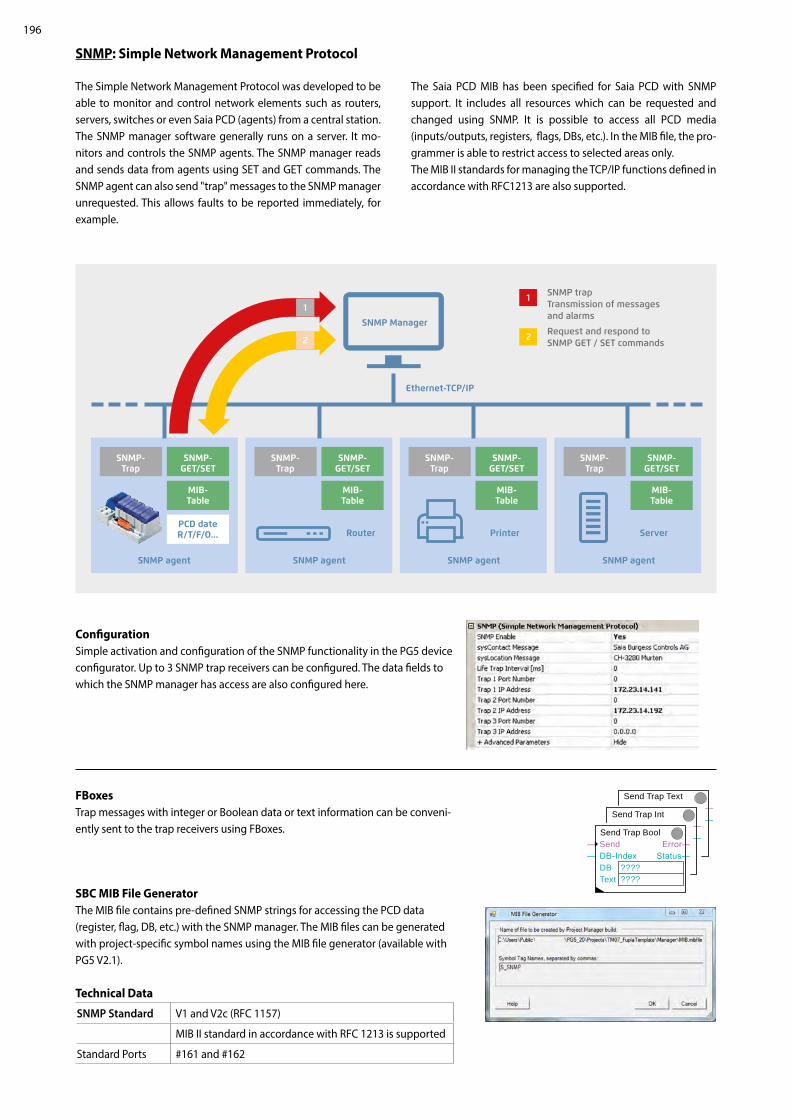
196
Send Trap Text ― ―Send Trap Int
― ― Send Trap Bool
― Send Error―― DB-Index Status― DB ???? Text ????
1
2
1
2
Configuration Simple activation and configuration of the SNMP functionality in the PG5 device configurator. Up to 3 SNMP trap receivers can be configured. The data fields to which the SNMP manager has access are also configured here.
FBoxes Trap messages with integer or Boolean data or text information can be conveni-ently sent to the trap receivers using FBoxes.
SBC MIB File Generator The MIB file contains pre-defined SNMP strings for accessing the PCD data (register, flag, DB, etc.) with the SNMP manager. The MIB files can be generated with project-specific symbol names using the MIB file generator (available with PG5 V2.1).
Technical Data
SNMP Standard V1 and V2c (RFC 1157)
MIB II standard in accordance with RFC 1213 is supported
Standard Ports #161 and #162
SNMP: Simple Network Management Protocol
The Simple Network Management Protocol was developed to be able to monitor and control network elements such as routers, servers, switches or even Saia PCD (agents) from a central station. The SNMP manager software generally runs on a server. It mo-nitors and controls the SNMP agents. The SNMP manager reads and sends data from agents using SET and GET commands. The SNMP agent can also send "trap" messages to the SNMP manager unrequested. This allows faults to be reported immediately, for example.
The Saia PCD MIB has been specified for Saia PCD with SNMP support. It includes all resources which can be requested and changed using SNMP. It is possible to access all PCD media (inputs/outputs, registers, flags, DBs, etc.). In the MIB file, the pro-grammer is able to restrict access to selected areas only. The MIB II standards for managing the TCP/IP functions defined in accordance with RFC1213 are also supported.
SNMP Manager
SNMP agent SNMP agentSNMP agent SNMP agent
SNMP- Trap
SNMP- GET/SET
MIB- Table
PCD date R/T/F/O...
SNMP- Trap
SNMP- GET/SET
MIB- Table
SNMP- Trap
SNMP- GET/SET
MIB- Table
SNMP- Trap
SNMP- GET/SET
MIB- Table
Printer ServerRouter
Ethernet-TCP/IP
SNMP trap Transmission of messages and alarms
Request and respond to SNMP GET / SET commands

12
34
197
Ethernet
VPN
Saia PCD3.M5 Saia PCD2.M5
Saia PCD®
WebCMailAMail Init
―En Busy―En―
ErrNum―SMTP ????Name ????Pwd ????Sender ????To1 ????To2 ????To3 ????To4 ????To5 ????
ref.WebCMailAMail Send
― Send Busy―Subject ????Text ????File ????
VPN
SBC
Soft
war
eCo
mm
unic
atio
n
and
Inte
ract
ion
SBC
S-W
eb t
echn
olog
yR
oom
aut
omat
ion
The email function and integrated SMTP client (Simple Mail Transfer Protocol) can be used to send PCD device process and system information to an email server. This enables alarm, service and status messages, log data or any form of process information to be sent via email to a control centre or service personnel.
FBoxesFBoxes are available for sending emails using the application program. The email function is configured (mail server, port number, user and password, etc.) via these F boxes. It is also possible to send file attachments (e.g. log data) of up to 1 MByte.
Technical Data
SMTP Standard RFC 821, 822
Standard port number 25 (adjustable) + 587
Server authentication "AUTH LOGIN" or "AUTH PLAIN" in accordance with RFC 2595 (unencrypted transmission of password)
Email format Text or HTML
Interfaces Ethernet, serial RS-232 with PPP
SMTP: Protocol for sending emails
SMTP
Ethernet
Internet
Intranet
IP protocols
E-Mail clientE-Mail server E-Mail client
Files from file system
PCD media text messages
Internet
Intranet
IP protocols
Web browser FTP client Mailbox PG5/Supervisor
PPP: Point-to-point protocolThis is a protocol established along a communica-tion route from one point (location) to another. PPP is a protocol that is mainly used to transport TCP/IP protocols via a serial cable or modem connection. CHAP (Challenge Authentication Protocol) was in-troduced to meet the greater security requirements when dialling into company networks or systems with critical tasks.The user has access to the web and FTP server via a telecom interface (PSTN, ISDN, GSM/GPRS) in the Saia PCD controller. This also applies to applications with more economical devices and no Ethernet con-nection.
Standard RFC-1661
Authentication PAP, CHAP and MS CHAP
Simultaneous PPP connections Only one PPP connection (client or server) can be active per Saia PCD® controller.
PPP via Ethernet No

198
EBW-E100 EBW-E100 EBW-H100
RS-485
RS-485
VPN
Ethernet
Networks for Wide Area Automated Systems PCD controllers support the connection to the WAN (Wide Area Network) via all established telecommunication technologies. The IP-based protocols (automation servers) are used to connect direct to the Internet either wired via Ethernet interfaces and DSL broadband routers or wirelessly with GPRS/UMTS routers. Non-IP based connections with analogue, digital (ISDN) or GSM modems are also sup-ported.
Protocols and services The WEB/IT protocols are used to support access to the automation server functions (web/FTP server, email, SNMP, etc.). The S-Bus protocol enables communication with the PG5 programming device, the SBC OPC server or Saia PCD® Supervisor. S-Bus is also used to exchange data between PCD controllers via the WAN. Other IP-based protocols such as Modbus TCP and BACnet® are also supported.
2.4 Wide Area Automation with Saia PCD®Spanning geographical distances with a larger number of substations often places significant demands on a system. The integrated automation server can be used to combine geographically distributed systems easily using the Internet and Intranet. This allows the systems to be monitored and controlled remotely. It is possible to access the controllers directly during commissioning or servicing.
Connection of Saia PCD® controllers to the InternetWhen Saia PCD controllers are connected directly to the internet, they are also a potential target of cyber attacks. Appropriate protective measures must always be taken to ensure secure operation.Saia PCD PCD controllers include simple, integrated protection features. However, secure operation on the internet is only ensured if external routers, like the industrial Routers EBW-E100 and EBW-H100 are used with a firewall and encrypt-ed VPN connections.For more information, please refer to our support site: http://sbc.do/Me4rLqwE
Management Level

12
34
199
SBC
Soft
war
eCo
mm
unic
atio
n
and
Inte
ract
ion
SBC
S-W
eb t
echn
olog
yR
oom
aut
omat
ion
Saia PCD® secure on Internet with VPN-Routers and “SBC Connectivity Portal”
With the “SBC Connectivity Service“, you will get your own encrypted VPN. In just a few steps, you’ll integrate locally connected PCD controllers, Web panels MB as well as PCs, tablets or smartphones. All your devices can be accessed across all networks and addressed at any time with this.
The necessary certificates are generated and assigned to the EBW router by the “SBC Connectivity Portal” directly. The routers get the complete VPN con-figuration transmitted automatically using a quick start wizard. It couldn’t be simpler and more comfortable!
With the “SBC Connectivity service” you have your VPN under complete control - with minimum investment. It starts to pay off with the first device already. Furthermore, the new web proxy enables secure access to web services in your VPN without a licence.
Keys features: Allows a M2M communication between systems located on different sites Provides a secure data transmission No needs of public IP address Doesn’t require deep IT knowledge
Of course, the EBW industry routers could also be used independently of «SBC Connectivity Portal», for example for a point to point connection.
Communication via GSM, PSTN or ISDN modems is supported via a comprehensive FBox library. SMS messages can be sent and received.
ref.CallSMSSend SMS
― Cal Msg ????
FBoxes are available for sending emails using the application program. Alarm, status and text messages can be sent. Sending file attachments (e.g. log data) is also supported.
WebCMailAMail Init
―En Busy―Err―
ErrNum―SMTP ????Name ????Pwd ????Sender ????To1 ????To2 ????To3 ????To4 ????To5 ????
FBoxes for modem communication and sending emails
*In preparation, see Chapter C1 “Product status”
Products for Wide Area Automation
Q.NET-CON Annual license for one VPN connection on the “SBC Connectivity Service” portal
Q.NET-EBW-E100 Industrial LAN router for VPN connection
Q.NET-EBW-H100 Industrial 3G/HSPA Router for VPN connection
PCD7.K840 Antenna with magnetic footGSM/UMTS (700/800/850/900/1’700/1’800/1’900/2’100/2’600 MHz)
Height7,2 cm
Diameter3,1 cm
Cable3 m
ConnectorSAM (male)
Protection classIP65

200
S-IO
SCADA
OPC PG5
2.5 S-Net for communicating between Saia PCD® devices
2.5.1 The basic features of S-Net
S-Net incorporates the S-Bus and S-I/O system protocols for com-municating between SBC devices. Both protocols are optimised for SBC devices and compared to other standard protocols (e.g. Modbus) offer more functionality and can be used more simply and efficiently in the application.
S-Bus supports all services and functions regarding the exchange of data, programming, commissioning and service of Saia PCD controllers. The S-Bus protocol does not depend on the physical aspects and can be used on Ethernet, USB, Profibus-FDL and serial interfaces (RS-232, RS-422, RS-485).
The S-IO protocol supports the operation of SBC remote I/O sta-tions with Ethernet (PCD3.T66x).
S-Net for communication between SBC devices across all levels
Services and functions using S-Bus
Programming and commissioningS-Bus is the programming device system protocol. It supports all programming, commissioning and diagnostic functions.
Access with the programming device via Ethernet, USB or serial interface
Exchanging data between PCD controllers via Ethernet, Profibus or serial interfaces
Connecting to SCADA systems via Ethernet, USB, Profibus or serial interfaces
Access to the PCD web server is also possible via USB and Serial interfaces
Visualisation with web browsers S-Bus supports HTTP protocol transmission. This also allows websites to be transmitted together with “SBC Web.Connect” via USB and serial interfaces and displayed on a Windows PC with the standard web browser or a micro browser web panel.
Visualisation with OPC servers and SCADA systems S-Bus together with an OPC Server or the SBC.Net-Suite supports access (reading and writing) to all PCD data with a Windows SCADA system.
Exchanging data between PCD controllers S-Bus supports the transmission of all PCD media (register, flags, timer/counter, database and text) and is optimised for the exchange of data between PCD control-lers, whereby Ethernet and Profibus allow multi-master operation. Serial interfaces (RS-232, RS-422, RS-485) enable “single”-master slave mode or S-Bus master multiple slave mode.
Management level
Automation level
Field level

12
34
201
IPChannel S-Bus Master IP
― Cir Err―
ref.ChannelSEND
―En Err――D0 ―D1―D1
SBC
Soft
war
eCo
mm
unic
atio
n
and
Inte
ract
ion
SBC
S-W
eb t
echn
olog
yR
oom
aut
omat
ion
The Ether S-Bus and Ether S-IO protocols support the operation of Saia PCD controllers and Smart RIOs on Ethernet. The PCD devices can be integrated and operated in a standard Ethernet network (along with other devices). Multi-protocol operation is supported on the same connector and cable. That means that all IP protocols (e.g. access to the automation server) can be used in parallel with S-Bus and/or S-IO.
Ether S-Bus for operating PCD controllers with Ethernet
Properties, functions
Ether S-Bus supports communication between PCD controllers in multi-master operation a PCD controller and the PG5 programming device a PCD controller and the OPC server or SCADA system with Ether S-Bus drivers a PCD controller (PCD WebServer) and web browser with Web Connect software Programming the data transfer between PCD controllers with FBoxes for cyclic or
event-controlled data transfer Multi-protocol operation on the same Ethernet connection
(e.g. Ether S-Bus, Ether S-IO and other protocols such as Modbus TCP) Gateway function for gateways
(Ether S-Net Serial S-Net, Ether S-Net 1 Ether S-Net 2, Ether S-Net Profi S-Net) The PCD3.M6860 CPU can be used to construct separate networks
or redundant Ethernet networks The network can be constructed using standard Ethernet components IP protocol: UDP Port number: 5050 (a firewall may require this port to be activated)
Ether S-IO protocol for operating Smart RIOs with Ethernet
Ether S-Bus protocol in the multi-master operation on a standard Ethernet network
Ether S-IO for operating Smart RIOs PCD3.T66x
Properties, functions
Ether S-IO supports the exchange of data between Smart RIO Manager and the Smart RIOs. Ether S-Bus is used to transfer the configuration and all programs It uses broadcast or unicast telegrams (adjustable) The data transfer is configured by the RIO network
configurator Multi-protocol operation is supported The network can be constructed using standard Ethernet
components IP protocol: UDP Port number: 6060
2.5.2 Ether S-Net: S-Bus and S-IO protocol with Ethernet
EthernetEthernet
Ethernet 2
Ether-S-Bus
PG5, SCADA, OPC, Web browser
PCD3.M6860
Internet Intranet
PG5, SCADA, OPC, Web browser
Ethernet Ether-S-10
Smart RIO Manager
Smart-RIOs PCD3.T66x

202
Ethernet2
Ethernet1
Ethernet 2
Ethernet 1
Other
Ethe
rnet
1.1
Ethernet 2
Ethe
rnet
1.2
SCADA 1 SCADA 2Constructing redundant Ethernet networks Network redundancy is often required by systems with high demands placed on them in terms of operational availability, such as tunnel controllers in traffic technology or on ships, for example. The two Ethernet connections provide the PCD3.M6860 with connection redundancy. Standard com-ponents (switches and cables) can be used to construct two separate, redundant networks. The networks and choice of interfaces are monitored by the application program. The network availability can be expanded further by creating a fibre optic ring combined with specific switches and fibre optic cables. The switches automatically identify any interrup-tions in the ring and reroute the data traffic accordingly.
The automation network can be divided into several physical networks for improved structuring and an increase in availability and performance.
Highly available Ethernet with two fibre optic rings. In the event of an interrup-tion, the switches automatically reroute the data traffic via the ring, which is still functioning. A defective switch or ring can be detected in the application program and the data traffic transmitted via the second ring or second interface.
Constructing Ethernet networks separately or redundantly with PCD3.M6860
The PCD3.M6860 CPU has two independent Ethernet interfaces which are used to construct physically separate networks (e.g. company or automated system networks) or redundant networks. The second interface has an additional 2-port switch.
Properties, functions The technical data of the PCD3.M6860 are identical to those of a PCD3.M5560, apart from the second Ethernet interface
(instead of the serial interfaces) The Ethernet interfaces are separate and both have an independent IP configuration. The IP addresses must not be in the same
subnet. IP routing between the two interfaces is not supported. All IP protocols are supported on both interfaces. This enables access to the automation server and the PCD data via both interfaces.
Access to the PG5 programming tool is also supported on both interfaces. BACnet is only supported on one interface (1 or 2) The S-Bus gateway function between the two Ethernet interfaces is also supported
Separating Ethernet networks It is worth physically separating networks when:
The automation devices and the standard IT devices (PC, server, etc.) must not be operated on the same network for security reasons. In this instance, the PCD3.M6860 functions like a “firewall” as only S-Bus telegrams can be transmitted from one interface to another. Other IP telegrams are not routed.
The data traffic cannot take place in the same physical network for performance reasons
The infrastructure (e.g. network cabling) must be isolated
The automated system and company networks are physically separate
Company network
Automated system network
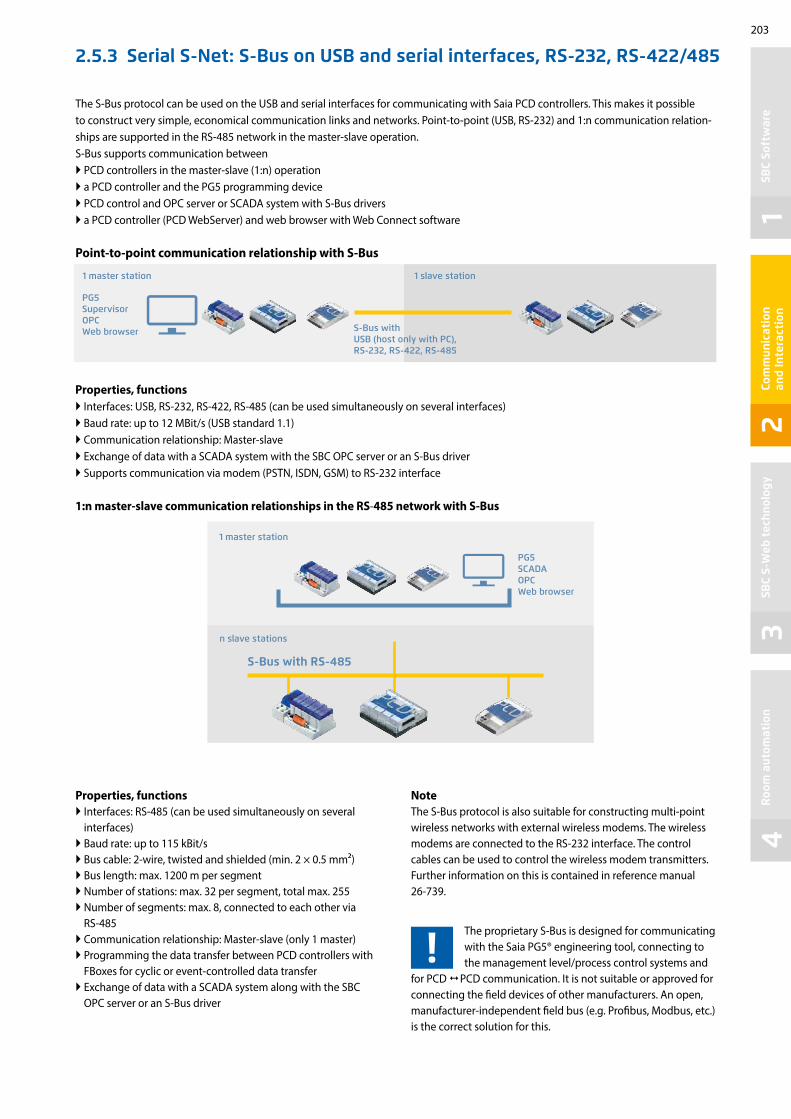
12
34
203
SBC
Soft
war
eCo
mm
unic
atio
n
and
Inte
ract
ion
SBC
S-W
eb t
echn
olog
yR
oom
aut
omat
ion
The S-Bus protocol can be used on the USB and serial interfaces for communicating with Saia PCD controllers. This makes it possible to construct very simple, economical communication links and networks. Point-to-point (USB, RS-232) and 1:n communication relation-ships are supported in the RS-485 network in the master-slave operation. S-Bus supports communication between PCD controllers in the master-slave (1:n) operation a PCD controller and the PG5 programming device PCD control and OPC server or SCADA system with S-Bus drivers a PCD controller (PCD WebServer) and web browser with Web Connect software
Point-to-point communication relationship with S-Bus
Properties, functions Interfaces: USB, RS-232, RS-422, RS-485 (can be used simultaneously on several interfaces) Baud rate: up to 12 MBit/s (USB standard 1.1) Communication relationship: Master-slave Exchange of data with a SCADA system with the SBC OPC server or an S-Bus driver Supports communication via modem (PSTN, ISDN, GSM) to RS-232 interface
1:n master-slave communication relationships in the RS-485 network with S-Bus
Properties, functions Interfaces: RS-485 (can be used simultaneously on several
interfaces) Baud rate: up to 115 kBit/s Bus cable: 2-wire, twisted and shielded (min. 2 × 0.5 mm2) Bus length: max. 1200 m per segment Number of stations: max. 32 per segment, total max. 255 Number of segments: max. 8, connected to each other via
RS-485 Communication relationship: Master-slave (only 1 master) Programming the data transfer between PCD controllers with
FBoxes for cyclic or event-controlled data transfer Exchange of data with a SCADA system along with the SBC
OPC server or an S-Bus driver
2.5.3 Serial S-Net: S-Bus on USB and serial interfaces, RS-232, RS-422/485
1 master station 1 slave station
S-Bus with USB (host only with PC), RS-232, RS-422, RS-485
PG5 Supervisor OPC Web browser
PG5 SCADA OPC Web browser
1 master station
S-Bus with RS-485
n slave stations
NoteThe S-Bus protocol is also suitable for constructing multi-point wireless networks with external wireless modems. The wireless modems are connected to the RS-232 interface. The control cables can be used to control the wireless modem transmitters. Further information on this is contained in reference manual 26-739.
The proprietary S-Bus is designed for communicating with the Saia PG5® engineering tool, connecting to the management level/process control systems and
for PCD PCD communication. It is not suitable or approved for connecting the field devices of other manufacturers. An open, manufacturer-independent field bus (e.g. Profibus, Modbus, etc.) is the correct solution for this.

204
ref.PSBChannel Profi-S-Net Life PAdd ????
ref.PSBChannelProfi-S-Bus
―En Busy―ConS―
PAdd ???? Stn ????
ref.Channel Send
― En Err ― ―Do
Ethernet
ProfibusProfi-S-Bus
The Profi S-Bus and Profi S-IO protocols support the operation of Saia PCD controllers on the Profibus FDL network. The protocols can be operated up to 1.5 MBit/s via the RS-485 interfaces integrated in the base unit. This enables economic and fast communication net-works in multi-master operation. Multi-protocol operation is supported on the same connector and cable. The same selection of the bus parameters (baud rate, timing, etc.) enables the PCD devices to be operated along with devices from other manufacturers on one Profibus DP network.
Profi S-Bus for operating PCD controllers on Profibus FDL networks
Properties and functions Profi S-Bus supports the communication between PCD controllers in multi-master operation a PCD controller and the PG5 programming device (via Profi S-Link) PCD control and OPC server or SCADA system with Profi S-Bus driver (via Profi S-Link) a PCD controller (PCD Web Server) and web browser with Web Connect software (via Profi S-Link) Multi-protocol operation on the same Profibus network (e.g. Profi S-Bus mixed with
other Profibus DP devices) Gateway function for gateways (Profi S-Bus Serial S-Bus, Profi S-Bus Ether S-Bus) Programming the exchange of data between PCD controllers with FBoxes for cyclic or
event-controlled data transfer – baud rate: up to 1.5 MBit/s Network infrastructure and topology: in accordance with the Profibus specification
Profi S-Bus protocol in multi-master operation on a standard Profibus network.
2.5.4 Profi S-Net: S-Bus and S-IO protocols on Profibus FDL
Profi S-link adapter
PG5 SCADA OPC Web browser
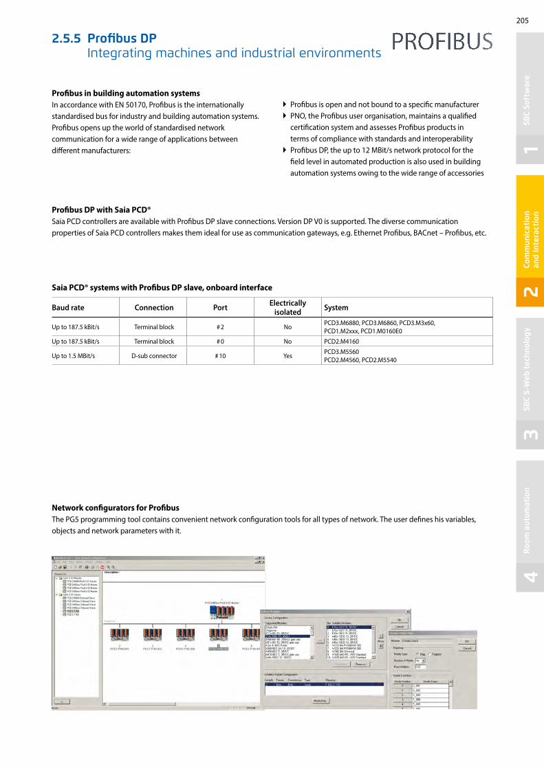
12
34
205
SBC
Soft
war
eCo
mm
unic
atio
n
and
Inte
ract
ion
SBC
S-W
eb t
echn
olog
yR
oom
aut
omat
ion
2.5.5 Profibus DP Integrating machines and industrial environments
Saia PCD® systems with Profibus DP slave, onboard interface
Baud rate Connection Port Electrically isolated System
Up to 187.5 kBit/s Terminal block # 2 No PCD3.M6880, PCD3.M6860, PCD3.M3x60, PCD1.M2xxx, PCD1.M0160E0
Up to 187.5 kBit/s Terminal block # 0 No PCD2.M4160
Up to 1.5 MBit/s D-sub connector # 10 Yes PCD3.M5560 PCD2.M4560, PCD2.M5540
Profibus in building automation systems In accordance with EN 50170, Profibus is the internationally standardised bus for industry and building automation systems. Profibus opens up the world of standardised network communication for a wide range of applications between different manufacturers:
Network configurators for ProfibusThe PG5 programming tool contains convenient network configuration tools for all types of network. The user defines his variables, objects and network parameters with it.
Profibus DP with Saia PCD® Saia PCD controllers are available with Profibus DP slave connections. Version DP V0 is supported. The diverse communication properties of Saia PCD controllers makes them ideal for use as communication gateways, e.g. Ethernet Profibus, BACnet – Profibus, etc.
Profibus is open and not bound to a specific manufacturer PNO, the Profibus user organisation, maintains a qualified
certification system and assesses Profibus products in terms of compliance with standards and interoperability Profibus DP, the up to 12 MBit/s network protocol for the
field level in automated production is also used in building automation systems owing to the wide range of accessories

206
PCD2.M5
BACnet MS/TP
BACnet/IP
PCD3 PCD3
2.6 BA communication systems
2.6.1 BACnet®
Recommendations/system limitsType Option Interface PG5 configuration, system limits
PCD3.M5560/M6xx0 1× PCD7.R5624× PCD3.F215
IPMS/TP Recommended for configurations of up to 1000 BACnet objects
PCD3.M5360 1× PCD7.R5624× PCD3.F215
IPMS/TP Recommended for configurations of up to 800 BACnet objects
PCD3.M3160PCD3.M3360
1× PCD3.R5623× PCD3.F215
IPMS/TP Recommended for configurations of up to 500 BACnet objects
PCD2.M4160 1× PCD7.R562 2× PCD2.F2150
IPMS/TP Recommended for configurations of up to 800 BACnet objects
PCD2.M4560 PCD2.M5540
1× PCD7.R5624× PCD2.F2150
IPMS/TP Recommended for configurations of up to 800 BACnet objects
PCD1.M0160E0 1× PCD7.R562 IP Recommended for configurations of up to 800 BACnet objects
PCD1.M2xx0PCD1.M2220-C15
1× PCD7.R5622× PCD2.F2150
IPMS/TP Recommended for configurations of up to 800 BACnet objects
PCD7.D410VT5F PCD7.D412DT5F 1× PCD7.R562 IP Recommended for configurations of up to 250 BACnet objects
Typical applications of a BACnet infrastructure Heating, climate and ventilation control Room automation Networking dispersed sites Recording energy data
The standard for building servicesBACnet is a manufacturer-independent, globally standardised communication protocol which is well-established in building automation systems. BACnet is particularly suitable for hetero-geneous structures involving automation stations of various manufacturers. The server/client architecture allows each of the BACnet devices to exchange data with one another without hav-ing to adjust to the parameterisation of the other devices. BACnet is far more than a protocol for merely transferring data; BACnet itself defines important building automation functions, such as the recording of historic trends or the monitoring of values against set limit values, for example. Communication services (BIBBs, BACnet Interoperable Building Blocks), such as those for reading and writing content, event-controlled trans-mission following changes and the handling of alarms/informa-tion (events) are available.
PCD systemsBACnet is available for all classic PCD systems with the Saia PCD COSinus operating system as a communication option. The con-nection is usually direct via BACnet IP (Ethernet). BACnet MS/TP (RS-485) is also possible via a communication module.BACnet always requires a BACnet option module for firmware expansion. A PCD7.R56x is used for memory slots M1 and M2 for PCD3.M5, PCD2.M5, PCD1.M2 and PCD1.M0 controllers. The PCD3.R562 module is available for I/O slots 0…3 for PCD3.M3 controllers with no M1/2 slots.PCD2.M5 and PCD1.M2 controllers also require a PCD2.F2150 for connecting BACnet MS/TP, and PCD3 controllers require a PCD3.F215 communication interface. This module also provides controllers with no Ethernet with a BACnet interface. Controllers with Ethernet also take on the function of a BACnet IP MS/TP router. External gateways for connecting MS/TP devices direct to the management system or other BACnet IP devices, for exam-ple, are therefore no longer required.
BACnet certificates for PCD1, PCD2, PCD3 controllers; see www.sbc-support.com, Certificates, PCD
Third party system

12
34
207
BACnet®
SBC
Soft
war
eCo
mm
unic
atio
n
and
Inte
ract
ion
SBC
S-W
eb t
echn
olog
yR
oom
aut
omat
ion
BACnet®
Order details
Type Description
PCD7.R562 BACnet® optional module for PCD1.M0, PCD1.M2, PCD2.M5, PCD3.M5 and PCD3.M6 for M1 or M2 slots incl. 128 MB for program backup and file system
PCD3.R562 BACnet® optional module for PCD3.M3, PCD3.M5 and PCD3.M6 for I/O slot 0…3 incl. 128 MB for program backup and file system
Efficient engineering through automatic generationThe application FBox libraries from DDC Suite v2.0 and Room Controller v2.0 and above make the system integrator even more efficient. An FBox parameter can be used to automatically generate a suitable BACnet® configuration when creating the application program. All the relevant settings are implemented within the application FBoxes.
Fully programmable BACnet configurationThe application can be created as normal using the Saia PG5® Controls Suite.The BACnet® configurator it contains allows the completely free parameterisation of all BACnet® objects. This makes it possible to solve all conceivable tasks.Clearly structured dialogues make the parameterisation of schedules, trends and alarms easy to understand.
BACnet® configurator in the Saia PG5® Controls SuitePG5 Fupla Editor
BACnet® Adjust Window
Automatic creation of BACnet® objects and PCD resources using FBoxes and templates.
EDE file export for connecting the PCD to master SCADA systems.
EDE file import for the simple creation of BACnet® clients

208
Modbus-TCP
Modbus-ASCII/RTU
Ethernet
PCD1 PCD2 PCD3
2.6.2 Modbus
Modbus is a communication protocol based on a master/slave or client/server architecture. It is widespread and supported by many manufacturers and devices. In many cases, Modbus is therefore the common denominator for transferring data between different devices and systems.
Modbus with Saia PCD®Modbus comes in three forms: Modbus ASCII data are transmitted in ASCII format via serial
interfaces (RS-232, RS-485).
Modbus RTU data are transmitted in binary format via serial interfaces (RS-232, RS-485).
Modbus TCP data are transferred in TCP/IP or UDP/IP packets via Ethernet.
Supported Modbus function codes1 Read Coils2 Read Discrete Inputs3 Read Holding Registers4 Read Input Registers5 Write Single Coil6 Write Multiple Coils7 Write Single Holding Register8 Write Multiple Holding Registers
Convenient Fulpa FBoxes or CSF commands are available for configuring and programming the exchange of data.
With the integrated automation server, external systems can also be easily linked to master Web+IT automation environments via Modbus.
Application example
The Modbus protocol is supported in the Saia PCD COSinus operating system by all Saia PCD1.M0_, Saia PCD1.M2_, Saia PCD2.M5_ and Saia PCD3 controllers. Client and server functionalities are available for all types of protocol.Ethernet interfaces and serial interfaces (RS-232 and/or RS-485) are already included in the PCD controller basic devices. Additional plug-in interface modules can be used to operate up to 9 serial Modbus interfaces per PCD system.
Number of connectionsEach Saia PCD system is able to establish up to a maximum of 26 connections. Of these, the Saia PCD controller is able to use a maximum of 10 for client connections. The remaining connections can be used as server connections to the same Saia PCD controller.
Media Mapping: adjustable by the userMapping Areas: max. 10 per UIDNumber of servers: max. 4 per PCD systemNumber of unit IDs: max. 10 per PCD systemNumber of channels: max. 10 per PCD system

12
34
209
KNX
KNX
Saia PCD1
Saia PCD3
RS-232
Ethernet UDP/IP KNX IP Tunneling
SBC
Soft
war
eCo
mm
unic
atio
n
and
Inte
ract
ion
SBC
S-W
eb t
echn
olog
yR
oom
aut
omat
ion
2.6.3 KNX Communication drivers for electrical systems and room automation
Ethernet GatewaysWhen planning, it is important to bear in mind that some Ethernet gateways only support one communication channel.Every PCD or service tool, ETS for example, therefore requires its own interface to the KNX Bus.
Serial converterHowever, it is inadvisable to connect using BCU-1 protocols. The BCU-1 protocol can cause telegrams to be lost between the gateway and the controller.
Communication driversAn efficient networking of building services requires multi- service functions and components for communicating with external devices. The KNX communication driver is a PG5 FUPLA library with comprehensive function modules (FBoxes) for sending and receiving almost all KNX data types (DPT). Depending on which interface is available for accessing the KNX network (RS-232 or Ethernet), the selected components can be linked to Saia PCD systems.The direct connection via Ethernet makes access to KNX data even quicker and more powerful.
Features Use of drivers for all SBC automation stations
Simple communication connection with FUPLA modules
Comprehensive support of KNX Data Point Types (DPT)
The drivers support the simple restructuring of existing systems with KNX BCU1 on the KNX BCU2 interface
Standard UDP/IP port: #3671
Communication drivers for:
Serial KNX BCU-1 interfaces via RS-232 (not recommended for new products)
Serial KNX BCU-2 interfaces via RS-232
KNXnet/IP (EIBnet/IP) communication
Order details
Type Description
PG5 EIBPG5 KNX/EIB (KNX standard) communication library for Saia PCD® controllers for serial and IP-based communication
Components of other providers
Weinzierl KNX IP Interface 730 (www.weinzierl.de) KNXnet/IP GatewayWeinzierl KNX IP Router 750 (www.weinzierl.de) KNXnet/IP incl. router useABB IPS/S2.1 EIB/KNX IP Interface (www.abb.com) KNXnet/IP GatewayABB IPR/S2.1 EIB/KNX IP Router (www.abb.com) KNXnet/IP incl. router useWeinzierl KNX BAOS 870 (www.weinzierl.de) Serial (RS-232) KNX interface with BCU-2 protocol
Euro
pean
Inst
alla
tion
Bus
KN
X
RS-232/BCU 2 function box
KNX/IP function box

210
RS-485
S-Net / MPI
Saia PCD3.M5560
E110
E110
A400
A400
2.6.4 EnOcean Communication driver for wireless sensors and actuators
The number of required wireless gateways depends heavily on the structural conditions. Pillars and furniture can create “dead spots” and walls can dampen the wireless signal depending on their design. Additional information and a brief planning guide are contained in the EnOcean manual (see www.sbc-support.com) EnOcean V3 is the latest version. The FBox library "EnOcean bidirectional" is only to be used for existing projects.
EnOcean is the inventor and manufacturer of the patented basic “self-powered wireless sensor technology”. EnOcean was recognised as the first ISO/IEC wireless standard (ISO/IEC 14543-3-10) for optimised solutions with low energy consumption. The “EnOcean alliance” is a manufacturers’ interest group which, over time, has developed a wide range of self-powered components for building automation systems based on EnOcean technology, such as switches, sensors, actuators and gateways.
Connection diagram for the RS-485 wireless receiver
Order details
Type Description
PG5 – EnOcean V3 PG5 – EnOcean communication library for Saia PCD® controllers for serial (EVC mode) and IP-based communication.
Components from PEHA recommended (www.peha.de)
D450ANT EnOcean wireless receiver with RS-485 interface (bidirectional), IP 20 casing with internal aerialOther EnOcean components such as switches, hotel card switches, window contacts, radiator actuators… are recommended by PEHA.
Components from Thermokon (www.thermokon.ch)
SRC65-RS-485E EnOcean wireless receiver with RS-485 interface (unidirectional), IP65 casing with external antennaSTC65-RS-485E EnOcean wireless receiver/transmitter with RS-485 interface (bidirectional), IP65 casing with external antenna
Sensortec components (www.sensortec.ch)
EOR700EVC EnOcean wireless receiver with RS-485 interface (unidirectional), IP20 casing with internal antennaEOR710EVC EnOcean wireless receiver/transmitter with RS-485 interface (bidirectional), IP 20 casing with internal antenna
Communication driversThe EnOcean components are connected to the Saia PCD controllers via external wireless gateways via serial RS-485 or IP interfaces. The FBox library provides communication modules for transmitting and receiving EnOcean telegrams. Generic FBoxes are available for standard EnOcean devices. Device-specific FBoxes are available for a selection of manufacturer-specific devices such as room control units (PEHA Sensortec, Thermokon, etc.). Universal communication FBoxes also offer the option of processing any EnOcean telegram in the PLC program.
Wireless
max. 64 receivers
The number of transmitters per receiver is limited only by the distance and the reception quality.

12
34
211
PCD2.F27x0 PCD3.F27x
M-Bus
kWhSB
C So
ftw
are
Com
mun
icat
ion
an
d In
tera
ctio
nSB
C S-
Web
tec
hnol
ogy
Roo
m a
utom
atio
n
2.6.5 M-Bus field bus module for capturing consumption data
M-Bus master interface moduleM-Bus (EN 1434-3) is an international standard for remote meter reading. The M-Bus connection is formed using the PCD2.F27x0 / PCD3.F27x communication modules in slots 0…1 on the PCD1.M2* and 0…3 on the PCD2.M5 and PCD3. This enables all volumes of water, heat or energy to be captured in an automa-tion station. The measurement data is subsequently processed in an FBox library in the Saia PCD FUPLA. The interface modules are fitted with a power supply and two separate M-Bus interfaces. Depending on the design, the inte-grated power supply is sufficient for up to 120 M-Bus standard slave modules whereby it can be distributed as required across the two ports. The PCD2.F2710…F2720 and PCD3.F271…F272 master mod-ules require the Engiby M-Bus library.FBoxes for SBC energy meters with M-Bus are supported by the Engiby library.
PCD1/PCD2 ordering informationType Description Weight
PCD2.F2700 M-Bus master interface for up to 240 slaves 60 g
PCD2.F2710 M-Bus master interface for up to 20 slaves 60 g
PCD2.F2720 M-Bus master interface for up to 60 slaves 60 g
PCD3 ordering informationType Description Weight
PCD3.F270 M-Bus master interface for up to 240 slaves 80 g
PCD3.F271 M-Bus master interface for up to 20 slaves 80 g
PCD3.F272 M-Bus master interface for up to 60 slaves 80 g
M-Bus via serial interfaceIn PCD controllers, M-Bus is connected with no slot for M-Bus master modules via an external signal converter. RS-232 or RS-485 interfaces are used depending on the converter.
Driver settingsThe respective PCD communication interface is specified in the M-Bus driver FBox in the Engiby library. Note the converter interface parameters such as baud rate, timeout, etc.
Secondary addressingSecondary addressing is supported from Library Version 2.7.200 or higher for SBC energy meters and generic FBoxes. Primary addressing must be used for the product-specific FBoxes.
Application example: PCD1.M2120 with M-Bus activation.* PCD1.M2110R1 slot 0 only
M-Bus Port 1M-Bus Port 2 a total of up to 120 slaves
up to 4 modules
Driver licence free
Saia Energy Meters licence free
Engiby M-Bus Library, licence required

212
PCD1.M2xx0
PCD3.F261 PCD2.F2610 PCD1.F2611-C15
2.6.6 DALI field bus module for lighting systems
Please observe the information for the PCD firmware version and the PG5 version on the support page.
DALI master interface moduleDALI is a communication system for lighting control, standard-ised in accordance with IEC 62386-101/102. Installation is easy. The DALI Bus simply needs 2 unshielded wires which can be threaded through the same cable along with the power supply, generally 230 V. The light parameters are standardised. All upstream devices therefore have the same parameters for dimming, grouping and scenes, irrespective of the type of lighting.
The DALI master module includes the Bus power supply for up to 64 DALI participants. The extensive PG5 FBox library has func-tion modules for commissioning, operating and servicing with the PLC program. External software tools or other components are not required.
Smaller DALI controls can be implemented with the PCD1.F2611-C15 E-Line DALI module. Detailed information about this small controller can be found in the E-Line chapter.
Order details
Type Description Application note Weight
PG5 – DALI F26x PG5 – DALI communication library for connecting DALI lighting control systems
– –
PCD3.F261 DALI master interface for up to 64 DALI participants incl. bus power supply (200 mA/12…13.5 V)
PCD3.Mxxx0: I/O slot 0-3 PCD3.T666: I/O slot 0-3
80 g
PCD2.F2610 DALI master interface for up to 64 DALI participants incl. bus power supply (200 mA/12…13.5 V)
PCD1.M2110R1: I/O slot 0 PCD1.M2xx0: I/O slot 0-1 PCD2.M4160: I/O slot 0-1PCD2.M4560: I/O slot 0-3PCD2.M5xx0: I/O slot 0-3
60 g
PCD1.F2611-C15 DALI master interface for up to 64 DALI participants incl. bus power supply (160 mA/13…15.5 V)
– 130 g
PG5 – DALI F26x FBox library
Incl. DALI BusPower supply

12
34
213
SBC
Soft
war
eCo
mm
unic
atio
n
and
Inte
ract
ion
SBC
S-W
eb t
echn
olog
yR
oom
aut
omat
ion
DALI communication library
The current DALI standard does not guarantee a genuine multi-master function. Multi-master capable products such as those of Tridonic, Osram or Zumtobel are either based on the new draft DALI extension E DIN 62386-103 (2011-08) or accept the loss of telegrams in bus collisions. Permanent polling, e.g. of the status, should therefore be avoided in “multi-master” projects. The maximum number of DALI master devices can be restricted to 8 units, for example, depending on the product and hardware manufacturer.
Commissioning and servicing made easyWhen initialising, the “DALI F26x Driver” FBox is positioned once only when the program starts. The “Configuration Manager” FBox then parameterises all the DALI participants on the bus. The FBox also provides predefined symbols for further use, e.g. in S-Web. The parameters can also be used securely in the PCD file system. The “Backup to Flash” FBox stores all DALI para- meters in parallel in two files. This guarantees the retention of data in PCD systems with no batteries, e.g. in the Smart RIO PCD3.T666, required.
When commissioning DALI systems, it is usual to install all DALI participants then issue the ad-dresses and set the parameters via the DALI commissioning software. The "Random addressing" and "Exchange addresses" modules are in the Saia PG5® – DALI library.
Parameterisation takes place after the addressing process using the “Configuration manager” FBox. Group and scene parameters can alternatively be set using the “Edit Groups” and “Edit Scene Levels” FBoxes to provide a better overview.
Web visualisation for commissioning
OperationThe “Send Command Inputs”, “Send Command Online”, “Send Power Control” and “Send Scene” FBoxes are available for transmitting DALI commands. These FBoxes cover all standard DALI commands.
The receipt of master telegrams is also supported by the “Receive Commands” and “Receive Raw” FBoxes. “Receive Raw” is useful for receiving non-standard telegrams. The raw data can then be processed further in the application program.
The lamp status can be requested using the “Read Status” FBox. The “Query numeric” FBox pro-vides the application program with access to a further 21 DALI standard data points such as the current light level.
The “Read Memory” FBox is used to read any data from a DALI device. It is therefore possible to request brightness and presence information from one sensor, which would not be accessible with the DALI standard methods.
DALI controller with PCD1.F2611-C15:There are also different FBoxes within the "DALI E-Line Driver" rubric for commissioning and operation for this interface.
Driver module
Status monitoring
Lighting control on/off, dimmable
Direct lighting control
Scene controller
E-Line gateway driver

214
2.6.7 MP Bus field bus module for Belimo MP Bus devices
MP Bus master interface moduleMP Bus is a Belimo communication system used to con-nect Belimo MP* field devices such as valve and shutter position drives or VAV controllers and room air sensors in building automation systems. Installation is easy. In addi-tion to the 24 V AC/DC power supply, the MP Bus needs just one unshielded wire which can be run through the same cable.Up to 8 drives can be attached to one communication channel. The total length of the mains cable depends on the diameter of the selected cable and the number and output of the connected drives**. A total length of approx. 100 m is usually reached. Since the length of the connection and the number of drives is limited, no other demands such as termination resistors or shielded cable are placed on the bus topology. In addition to the con-nected drives, sensors can be connected direct via a drive or MP Bus add-on modules. The extensive Saia PG5® FBox library has function modules for communicating with the PLC program. The drives are addressed using the commu-nication driver FBox and can then exchange data with the application program via the respective FBoxes. The Belimo components are generally commissioned from the application program using the SBC FBoxes. Only a few components such as VAV controllers require additional Belimo parameterisation tools to adjust their operational parameters.
* MP is a Belimo designation. MP = multi-point ** For further information on the system layout, see the Belimo documentation, www.belimo.com
Application example: HVAC system with a PCD3.M5 and up to 64 MP Bus drive units on 8 MP interfaces
Overview
PCD1, PCD2, PCD3 compact controller with MP Bus module
Ethernet TCP / IP, Profibus, etc.
Fire dampers
VAV boxes
Air dampers
Globe valves
Regulator ball valves
Automation station
Onboard; Slot A, A1 and A2 I/O slot #0…#3
MP Bus module Total
Number of MP Bus MP Bus module Total
Number of MP Bus
Cables Drives Cables DrivesPCD3.M3x60 / PCD3.M5x60 / PCD3.M6x60 – – – – PCD3.F21x, PCD3.F221
4 – –
+ PCD7.F180S + 4 + 32
PCD3.F2814 4 32
+ PCD7.F180S* + 2 + 16
PCD2.M5540 / PCD2.M4560PCD7.F180S 2 2 16 PCD2.F21x0, PCD2.F2210
4 – –
+ PCD7.F180S + 4 + 32
PCD2.F28104 4 32
+ PCD7.F180S + 4 + 32
PCD1.M2x20 / PCD1.M2x60 / PCD1.M2220-C15 / PCD2.M4160
PCD7.F180S 1 1 8 PCD2.F21x0, PCD2.F2210 2 – –
+ PCD7.F180S + 2 + 16
PCD2.F28102 2 16
+ PCD7.F180S + 2 + 16
PCD1.M2110R1 - RoomPCD7.F180S 1 1 8 PCD2.F21x0, PCD2.F2210
1 – –
+ PCD7.F180S + 1 + 8
PCD2.F28101 1 8
+ PCD7.F180S + 1 + 8
PCD1.M0160E0 PCD7.F180S 1 1 8 – – – –
* With 4 PCD3.F281 only 2 additional PCD7.F180S can be used, because the load on +V would be too large

12
34
215
SBC
Soft
war
eCo
mm
unic
atio
n
and
Inte
ract
ion
SBC
S-W
eb t
echn
olog
yR
oom
aut
omat
ion
MP Bus | Function modules (FBox)
All Belimo MP drives can exchange data with the PCD application program via a suitable FBox from the MP Bus FBox library. The master communication FBox must be positioned once at the start of the application program. It controls the communication and fault recogni-tion and creates ways of addressing the MP drives available for commissioning and service. Some MP drives also have an input for con-necting sensors. R: Temperature sensor NI1000, PT1000…, U:voltage 0–32 V or 0–10 V and DI: Potential-free contact.
* only active sensors and switches can be connected
Type/performance categories Sensors MP Bus FBox
Communication drivers MP Single
Ventilation applications
Damper drives with no safety function: LM24A-MP (5 Nm), NM24A-MP (10 Nm), SM24A-MP (20 Nm), GM24A-MP (40 Nm)
Damper drives with safety function: TF24-MFT (2 Nm), LF24-MFT2 (4 Nm), SF24A-MP (20 Nm)
Linear damper drives: LH24A-MP100 / 200 / 300 (150 N), SH24A-MP100 / 200 / 300 (450 N)
Damper drives rotary: LU24A-MP (3 Nm)
R, U, DI MP Air
Safety applications
Drives for fire dampers: BF24TL-T-ST (18 Nm), BFG24TL-T-ST (11 Nm)
Gateway for conventional fire damper drives: BKN230-24-C-MP
Thermo- element
MP BS
Room and system applications
VAV compact controller: LMV-D3-MP (5 Nm), NMV-D3-MP (10 Nm), SMV-D3-MP (20 Nm)
VAV compact controller linear: LHV-D3-MP (150 N)
R, U, DI MP VAV…
VAV universal controller: VRP-M R, U, DI VRP-M
Water applications
Lift drives with no emergency function: LV24A-MP-TPC (500 N), LVC24A-MP-TPC (500 N), NV24A-MP-TPC (1000 N), NVC24A-MP-TPC (1000 N), SV24A-MP-TPC (1500 N), SVC24A-MP-TPC (1500 N), EV24A-MP-TPC (2500 N)
Lift drives with emergency function: NVK24A-MP-TPC (1000 N), NVKC24A-MP-TPC (1000 N), AVK24A-MP-TPC (2000 N), adjustable closing point, adjustable emergency setting
R, U, DI MP Linear
Drives for control ball valve with no emergency function: LR24A-MP (5 Nm), NR24A-MP (10 Nm), SR24A-MP (20 Nm)
Drives for control ball valve with emergency function: TRF24-MFT* (2 Nm), LRF24-MP (4 Nm), NRF24A-MP (10 Nm)
Drives for butterfly valves with no emergency function: SR24A-MP-5 (20 Nm), GR24A-MP-5/-7 (40 Nm)
R, U, DI MP Air
Drives for 6-way control ball valve: LR24A-MP (5 Nm), NR24A-MP (10 Nm) R, U, DI MP 6 Way
Electronic pressure-independent control ball valve (EPIV): P6…W…E-MP*, EP0..R+MP* U, DI MP EPIV…
Belimo EnergyValve: EV..R+BAC, P6..W..EV-BAC U, DI Energy Valve P6
Rotary actuator: CQ24A-MPL (MP-Bus light) — MP MPL
Room sensors
Room combi-sensor, depending on design with temperature, CO2, VOC and relative humidity: MS24A R… MPX
R, DL, U (0–10 V)
MP THC24MP THCV
Generic data transfer
For reading and transmitting data points not contained in the device-specific FBox. This FBox is used as a functional extension for MP Bus FBoxes and can only be used with a device FBox specific to that device or a generic device FBox.
MP GenericMP PEEKMP POKE
Third party devices
FBoxes are available for the following third party MP Bus devices: PTH sensor from wmag AG, Switzerland, UST-3, UST-5 from wmag AG, Switzerland.
Each MP Bus device can also be connected via generic devices and peek/poke FBoxes in PCD application programs.
MP PTHMP UST-3
MP GenericMP PEEKMP POKE
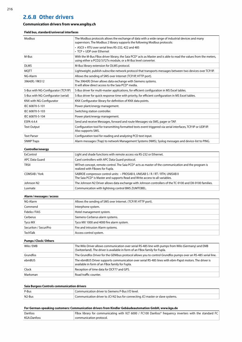
216
2.6.8 Other driversCommunication drivers from www.engiby.ch
Field bus, standard/universal interfaces
Modbus The Modbus protocols allows the exchange of data with a wide range of industrial devices and many supervisors. The Modbus 2 library supports the following Modbus protocols:
• ASCII + RTU over serial lines RS-232, 422 and 485 • TCP + UDP over Ethernet
M-Bus With the M-Bus FBox driver library, the Saia PCD® acts as Master and is able to read the values from the meters, using either a PCD2/3.F27x module, or a M-Bus level converter.
DLMS M-Bus library extension for DLMS protocol.
MQTT Lightweight, publish-subscribe network protocol that transports messages between two devices over TCP/IP.
NG-Alarm Allows the sending of SMS over Internet (TCP/IP, HTTP port).
3964(R) / RK512 The 3964(R) Driver allows data exchange with Siemens systems. It will allow direct access to the Saia PCD® media.
S-Bus with NG-Configurator (TCP/IP) S-Bus driver for multi-master applications, for efficient configuration in MS Excel tables.
S-Bus with NG-Configurator (serial) S-Bus driver for quick response time with priority, for efficient configuration in MS Excel tables.
KNX with NG-Configurator KNX Configurator library for definition of KNX data points.
IEC 60870-5-101 Power plant/energy management.
IEC 60870-5-103 Switching station controller.
IEC 60870-5-104 Power plant/energy management.
ESPA 4.4.4 Send and receive Messages, forward and route Messages via SMS, pager or TAP.
Text Output Configuration tool for transmitting formatted texts event triggered via serial interfaces, TCP/IP or UDP/IP. Also supports SMS.
Text Parser Configuration tool for reading and analyzing PCD text input.
SNMP Traps Alarm messages (Trap) to network Management Systems (NMS), Syslog messages and device-list to PING.
Controller/energy
ExControl Light and shade functions with remote access via RS-232 or Ethernet.
APC Data Guard Carel controllers with APC Data Guard protocol.
TRSII WITnet concept, remote control. The Saia PCD® acts as master of the communication and the program is realized with FBoxes for Fupla.
COMSAB / York SABROE compressor control units: – PROSAB II, UNISAB S / R / RT / RTH, UNISAB II The Saia PCD® is Master and supports Read and Write access to all variables.
Johnson N2 The Johnson N2 Driver allows data exchange with Johnson controllers of the TC-9100 and DX-9100 families.
Luxmate Communication with lightning control BMS ZUMTOBEL.
Alarm / messages / access
NG-Alarm Allows the sending of SMS over Internet. (TCP/IP, HTTP port).
Commend Interphone system.
Fidelio / FIAS Hotel management system.
Cerberus Siemens-Cerberus alarm systems.
Tyco MX Tyco MX 1000 and 4000 fire alarm system.
Securiton / SecuriPro Fire and intrusion Alarm systems.
TechTalk Access control system.
Pumps / Clock / Others
Wilo / EMB The Wilo Driver allows communication over serial RS-485 line with pumps from Wilo (Germany) and EMB (Switzerland). The driver is available in form of an FBox family for Fupla.
Grundfos The Grundfos Driver for the GENIbus protocol allows you to control Grundfos pumps over an RS-485 serial line.
ebmBUS The ebmBUS Driver supports communication over serial RS-485 lines with ebm-Papst motors. The driver is available in form of an FBox family for Fupla.
Clock Reception of time data for DCF77 and GPS.
Marksman Road traffic counter.
Saia Burgess Controls communication drivers
P-Bus Communication driver to Siemens P-Bus I/O level.
N2-Bus Communication driver to JCI-N2 bus for connecting JCI master or slave systems.
For German-speaking customers: Communication drivers from Kindler Gebäudeautomation GmbH, www.kga.de
DanfossKGA.Danfoss
FBox library for communicating with VLT 6000 / FC100 Danfoss® frequency inverters with the standard FC communication protocol.

217
12
34
B3
SBC
Soft
war
eCo
mm
unic
atio
n
and
Inte
ract
ion
SBC
S-W
eb t
echn
olog
yR
oom
aut
omat
ion
SBC S-Web technologyAutomation systems with sophisticated SCADA functions “embedded” in every device. – Alarming– Trending– Visualisation– Standard web browser
as service interface software
3.1 The aim of S-Web: To use what you know and what already exists
3.2 The S-Web system architecture: SCADA in every automation device
3.3 Real-life examples of SBC S-Web
3.4 Engineering Information
3.5 Tender information – what changes with S-Web
3.6 SBC S-Web system tools and products
3.7 Using Automation Server as a technical basis
Page
No need to continue using proprietary SCADA/management PC software. Each interest group gets exactly what it needs and no extraneous elements will confuse the user. Current end devices and existing technology used on site will be sufficient.
The functional basic structure of a single automation device is used to illustrate how SBC S-Web systems are designed for machines, plants and distributed properties.
Four projects illustrate how thousands of S-Web systems have been implemented in the field. They explain how the systems progress from design to implementation and operation.
What should you bear in mind when implementing and integrating SBC S-Web systems? How do they differ from conventional PC-based SCADA / HMI solutions?
The typical tender for automation / ICA systems still involves the current strict separation of control engineering and process control and management functions on separate levels. SBC S-Web combines different functions in a single device. This can also be seen in the tenders.
What is available from SBC? How are system components of other manufacturers incorporated? What software tools are available for creating projects?
Automation Server functions in every SBC device are the technical requirements for SBC S-Web systems. What sort of functions are they? What benefits do they provide?
218
219
221
223
227
231
235

218
WWW
IT
As a company, we focus on being as lean as possible. The aim of being lean is to achieve ever more using less. That is only possible by exploiting what you already have. As little as possible should be added to this. SBC S-Web is dedicated to this principle.
3.1 The objective of S-Web using the known and existing components. Use fewer unknown and complex elements.
It is worth exploiting what already exists on-site.
SBC S-Web systems Make special SCADA software unnecessary Reduce the need for trained personnel
in the operation Make an investment project simpler and more
cost-effective
SBC S-Web optimises use of Existing software Existing human resources Existing infrastructure and end devices
Software: Management functions can be performed using dedicated software. This has to be purchased, installed, configured, maintained and personnel must receive training. It can usually perform far more functions than it is actu-ally used for, and is therefore complex. SBC S-Web makes this dedicated management/SCADA software unnecessary. It simply uses the software which is already available everywhere.
Human resources: Monitoring, control and management functions are possible for all interest groups/individuals. Users can optimise their area of responsibility in a way that is tailored to their requirements. No users have to be an automation specialist, no specific tools are required, and there is no waiting time to carry out analysis or improve-ments.
Infrastructure and end devices: SBC S-Web can be integrated simply and safely into existing LAN/WAN infrastruc-tures. Practically all the existing end devices can be used. This increases acceptance and reduces costs. This is because each control unit has sophisticated SCADA functions via many globally recognised technical standards.
In order to implement SCADA/management/operating functions using SBC S-Web, only technologies that are used and already exist have been implemented on site. They are globally recognised, non-proprietary Web+IT standards. The required functions can be flexibly adapted over the entire service life of a system and kept simple to master. This is possible because the basic characteristics of the classic PLC technology are also integrated into the S-Web systems. A unique combination!
Use as few new, unknown and complex elements as possible
Using what already exists?
Electrician Maintenance Supervisor
Operator Operations Manager
Programmer Service Engineer
WLAN Uplink

219
12
34
WWW EMAILFTP SNMP
SBC
Soft
war
eCo
mm
unic
atio
n
and
Inte
ract
ion
SBC
S-W
eb t
echn
olog
yR
oom
aut
omat
ion
3.2 S-Web system structure SCADA function in every automation device
The conventional regulation/control unit of automation only regulates and controls. The third essential core component, the SCADA function, is outsourced and implemented “elsewhere”. This was a practical solution 2008 ago, as memory and processor power were expensive and limited. Since then, costs have reduced in terms of both memory and performance. All the functions required for the automated system can now be implemented in one device as a single project.
Automation systems with sophisticated SCADA functions embedded in every automation station and control unit. Alarming Trending Visualisation Service interface
Already provided by the Saia PCD web server for a diverse range of browser devices.
Functional structure of Saia PCD® control units: The entire automation application is onboard. The combination of globally standard-ised, non-proprietary Web+IT functions known as Automation Servers form the interface to the environment. The fully programmable design and modular expansion of the controller ensure the “perfect fit” for current task formulation over a service life of 15-20 years with no need for new investment.
Fully programmable and expandable!

220
To the benefit of the users and operators of plants / properties
Technological advancement creates massive structural changes in the automation pyramid
Previously only PCs had the necessary resources for management/control func-tions. The SCADA/management software was loaded onto them. The automation/field levels were closely linked using bus systems. This is now outdated.
Today with SBC S-Web: Each unit has its own fully integrated automation function. Even simple field installations now have their own SCADA function which guarantees local optimisation and reliable operation. There are short paths and direct influ-ence on processes. Control/management func-tions need not be laborious and expensive through the data transfer running through the automation level to the management level and back.
BACnet has a comparable system model: BACnet is the only globally recognised and widely spread standard for building automation systems. It is based on exactly the same system model as Saia PCD units. However, SBC S-Web implements the management/control function in buildings with the combination of the known = PLC+Web+IT; without introducing another standard to the building.
SBC S-Web Trending SBC S-Web System Visualisation SBC S-Web Alarming SBC S-Web Service Interface
Saia
PCD
dev
ices
can
be
fully
pro
gram
med
and
exp
ande
d w
ith S
aia
PG5
acro
ss a
ll le
vels
and
thro
ugho
ut th
e en
tire
serv
ice
life.
All automation functions (control and management functions) are
integrated into every device
Management level
Automation level
Field level

221
12
34
Saia PCD3.M5560
VPN
SBC
Soft
war
eCo
mm
unic
atio
n
and
Inte
ract
ion
SBC
S-W
eb t
echn
olog
yR
oom
aut
omat
ion
Marc Cain Building Bodelhausen/GermanyPOM-certified (peace of mind) HVAC system and room control technology for the head office of this international fashion company provides a better climate and low energy consumption.
The performance requirements for the automation of the building were set at a high level right from the beginning to achieve “peace of mind” certification from the German standards authority, TÜV. Using this approach, the design study integrated all the HVAC aspects of the building into a single, flexible control project. The thermal energy, for example, is produced by various sources and its distribution is controlled to minimise energy consumption. In a complex installation, this is only possible because the control system can seamlessly integrate all devices independent of their communication capabilities.
Lucerne Conference Centre Lucerne/SwitzerlandThe renovation and expansion of the Lucerne Conference Centre achieved the Minergie Standard and revitalised this important meeting place.
The 13,000 m2 of the four halls of the Lucerne Conference Centre provide the most modern technological exhibition area, in order to be able to meet all usage require-ments. The range of different events also require a flexible architecture for lighting, ventilation and air conditioning in order to comply with the energy efficiency require-ments of "Minergie" certified conference centres. The extensive use of bus technology in the planned building services, such as DALI for the lighting and MP Bus for the HVAC, enables it to be integrated into the Saia PCD controller with little effort and operated using web technology. The very high level of flexibility of our programmable controllers and a design based on open-web technology, which made high levels of investment in expensive visualisation systems superfluous, were crucial to the award.
8 PCD3.M3330 automation devices
3.3 Real-life examples of SBC S-Web
The Marc Cain system comprises 25 automation devices. 24 Saia PCD3.M5x40 cover
the individual system components/sub-sections. One Saia PCD3.M5x60 forms a master control/management level for the entire property. Any browser device in the network
(LAN/WAN) can now be used to access the local operator application of each individual system or even directly access the control/management application of the master
Saia PCD3.M5x60. Complex system schematics naturally require adequate display sizes; a PDA/mobile phone is not large enough for this.
The Lucerne Conference Centre operating and monitoring concept is based entirely on
SBC S-Web. It does not require a PC/Windows-based control or management system. Trend data are recorded directly in the automation device and visualised using the available
web templates. The system comprises 2000 physical data points distributed among eight PCD3.M3330 automation devices. There are eight 10” micro browser devices installed per
system component for operational purposes. There are three 15” web panels with the Windows CE operating system for providing a global overview.
8 touch panels (10" ) with micro browser
3 touch panels (15" ) with micro browser
Server: control/management functions implemented with Saia PCD3.M5x60; no PC and no Windows!
Remote maintenance
Client: Touch panel with micro browser
24 Saia PCD3.M5 for systems/sub-sections
Internet Intranet

222
39 × PCD1.M2xxx
254 × PCD2.M5xxx
17 × PCD3.M5xxx
iFix 4.0
Internet Intranet
VPN
AMC wanted to refurbish and expand the control systems gradually over a period of several years without incurring costs and problems arising from po-tential changes in automation station generation. They started using Saia PCD controllers in their buildings, processes and utilities in 2000. More than 10 years later, the choice is still considered as the correct one. This is supported by the transparent integration of the newest Saia PCD generation, the general use of Ethernet, data capture on the Flash memory and the reliability of the installed base. The communication capabilities of Saia PCDs enable users to connect to all systems and make the life of the system integrator simpler.
Academic Medical Centre Amsterdam/NetherlandsOne of the top ten academic hospitals in the world relies on Saia PCD controllers for improved air-conditioning and reduced energy consumption
European Research Centre CERN Geneva/SwitzerlandThe entire enormous CERN site consisting of 430 operational buildings relies entirely on SBC S-Web. The Web+IT standards mean it needs no dedicated central office or master control/management level.
Around 10,000 people work in the 430 buildings at CERN. Each building is fully independent. SBC S-Web forms their control/management level. There is no need for dedicated SCADA software/PC hardware. The existing and already mastered CERN Web+IT technology is sufficient for integrating the consumption data across the site and for monitoring purposes. Operation of the building technology does not require the purchase of, installation of or training on, dedicated Windows software. Automation projects are awarded by CERN throughout Europe. Thanks to SBC S-Web, system integrators all over Europe are able to implement autonomous projects for CERN or improve existing systems. There is no need to involve or reintegrate a central BMS application.
With S-Web, CERN benefits from a technology it invented itself in 1989. Source: Wikipedia
The local conditions in the individual parts of the system and
building were resolved in this application using S-Web. A total of 310 automation stations (Saia PCD) are integrated into the prop-erty automation system. The entire clinic is operated, controlled and managed as a functional unit. In hospitals, the high volume of visitors and the ventilation/cooling system are “mission criti-
cal”. In this respect, it is therefore preferable to operate a central iFIX 4.0 PC/Windows-based control/management system parallel
to SBC S-Web. In this instance, SBC S-Web cannot make the classic SCADA software totally superfluous.
20 touch panels with micro browser

223
12
34
Client Server
URL saia-pcd.com
KNX
KNX
Kom
mun
ikat
ion
& In
tera
ktio
n
saia-pcd.com
KNX
KNX
Kommunikation & Interaktion
FTPFTP WWW EMAIL SNMP
SBC
Soft
war
eCo
mm
unic
atio
n
and
Inte
ract
ion
SBC
S-W
eb t
echn
olog
yR
oom
aut
omat
ion
The basic structure of an operational S-Web systemThe basic structure is simple. Enter the device addresses in the client. The Automation Server of the Saia PCD devices provides the application/data of the Saia PCD. How large and comprehensive can this be in the various types of Saia PCD devices?
The browser device is usually determined by the mounting/installation location and the requirements in terms of display size and resolution.
The type of controller is determined by the number of required inputs/outputs, the range of functions and the memory requirements.
Basic orientation: Device selectionEvery fully independent functional automation system can be illustrated as a hierarchy in the classic form of a pyramid. The differences between systems lie in the scope/power of the respective applications. In other words, the range of required functions and connected field levels.Pyramids with 2-3 hierarchy levels can be created in the case of large, complex properties. The resources must be designed in accordance with the size of the pyramid and the position at which a Saia PCD automation device is used. The ability to move Saia PCD applications to all three basic platforms and the high modularity even in terms of expanding the memory capacity means that SBC S-Web systems can be continuously expanded even after commissioning. The following illustrates a good basic orientation to ensure the initial installation is compatible.
Basic applications
Up to 50 I/Os Up to 20 trends Up to 100 alarms Up to 30 web pages
The Saia PCD controls and visualises a machine, a simple building with a ventilation system, a heating circuit or a complex room, etc.
3.4 Engineering information Which resources does a Saia PCD® require for SBC S-Web?
Browser device Which display size?Which display resolution?Which device type?
Saia PCD controller application server
How many data points? How many trends?How many images/elements?
Saia PCD® controller
Max I/O
Program memory
Onboard flash memory Additional memory
PCD1.M2120 50 128 kByte 8 MB1) 1× PCD7.R562 1× 128 MByte
PCD1.M2160 50 1 MB 128 MB2) 1× PCD7.R562 1× 128 MByte
PCD3.M3xxx 1023 512 kByte --- 4× PCD7.R-SDxxxx1) 4× 1 GB1) 900 files per memory module 2) 2400 files per onboard memory
Fully programmable
Generic Web IT Interface
Inte
rfac
e Fi
eld
leve
l
BA
Cne
t In
terf
ace

224
AC5051
AC5050
AC5040
AC5030
AC5020
AC5010AC5000
GE0308CSVCSVCSV
GE0307
GE0306GE0305GE0304
GE0303GE0302GE0301
GE0206GE0205GE0204
GE0203GE0202GE0201
GE0308CSVCSVCSV
GE0307
GE0306GE0305GE0304
GE0303GE0302GE0301
GE0206GE0205GE0204
GE0203GE0202GE0201
GE0308CSVCSVCSV
GE0307
GE0306GE0305GE0304
GE0303GE0302GE0301
GE0206GE0205GE0204
GE0203GE0202GE0201
GE0001 GE0001_1 GE0002 GE0003 GE0004
GE0011 GE0012 GE0013 GE0014 GE0015
GE0021 GE0022 GE0022_1 GE0022_2
GE0023 GE0023_1
GE0031 GE0032 GE0033 GE0034 GE0035
GE0036 GE0037 GE0038 GE0039 GE0040
GE0041 GE0042 GE0043 GE0044 GE0045
GE0046
+ + =
Mid-level applications
Up to 500 I/Os Up to 60 trends Up to 1000 alarms Up to 100 web pages
Die Saia PCD controls several system components and includes the SCADA/ visualisation functions of the entire system/all parts of the building
Top-level applications Up to 2500 I/O (entire system) Up to 120 trends Up to 2000 alarms Up to 300 web pages
The Saia PCD contains the master control and management functions for many dis-tributed systems or large integrated buildings.
Client and server in one device: The Saia PCD7.D4xxxT5F micro browser panels are simultaneously server and client. The demanding control function can be implemented using the Saia PG5® software tool.
Saia PCD® controller
Max I/O
Program memory
Onboard flash memory Additional memory
PCD3.M5xxx 1023 1 MB --- 2× PCD7.R5621) 4× PCD7.R-SDxxxx1)
2× 128 MB4× 1 GB
PCD2.M5xxx 1023 1 MB --- 2× PCD7.R5621) 4× PCD7.R-SDxxxx1)
2× 128 MB4× 1 GB
1) 900 files per memory module
Saia PCD® controller
Max I/O
Program memory
Onboard flash memory
Additional memory
PCD3.Mxx60 1023 2 MB 128 MB2) 2× PCD7.R5621) 4× PCD7.R-SDxxxx1)
2× 128 MB4× 1 GB
PCD7.D4xxxT5F --- 1 MB 128 MB2) --- ---1) 900 files per memory module2) 2400 files per onboard memory
Dimensioning the data storage for S-Web applicationsThe dimensioning of the data storage must take into consideration the size of the web project and the historical data (trend data) that needs to be stored. The following reference values can be used as a guideline to provide a rough estimate.
Memory requirement for S-Web pages:The calculation of the memory requirements for web pages is based on the number of web pages, number of GIF graphics used and the IMaster Java applets. The following reference values can be used as a guideline to provide a rough estimate.
S-Web page approx. 10 kByte/page
GIF graphics 1…10 kByte Java Applet approx. 350 kByte
A project with 30 HMI pages will therefore need approx. the following memory requirement:(30 × 10 kByte) + (100 × 5 KByte GIF graphics) + 350 kByte = memory requirement for web project approx. 1150 kByte
Memory require-ment for web projects

225
12
34
PCD7.R-SDxxxx
PCD7.R562
Header,ref.MemoryM1 HDLog File 3.0―En Busy――Val0 WrOK――Val1 Error――Val2 Buffer――Val3 DelRdy――Val4 IdxStat― Val5 Val6 Val7―Val8―Val9–Store –WrFile–DelFile Dir ????
SBC
Soft
war
eCo
mm
unic
atio
n
and
Inte
ract
ion
SBC
S-W
eb t
echn
olog
yR
oom
aut
omat
ion
Memory requirement for trend data
Recorded using CSV files in flash file system
The trend data are saved in groups of max. 10 data points per Saia PG5® Fupla FBox and CSV file.
Saia PG5® Fupla FBox records and saves up to 10 data points
A CSV file is generated for each FBox with max. 10 data point values per entry. The memory requirement for one entry: approx. 30 Byte (time stamp) + 10 Byte/data point
Trend display in the web browser. A max. of 10 trend curves can be displayed per window
In the following sample calculation, 20 data points are recorded for visualisation in trend curves. 10 data points should be recorded for the optimisation phase at intervals of 1 minute and a further 10 data points should be recorded for long-term monitoring at intervals of 15 minutes.
The memory requirement for 10 data points at 1 minute intervals in one day:
60 (mins) × 24 (hours) × [30 Byte (timestamp) + 10 (data points) × 10 Byte] = 187.2 kByte per day
With this quantity of data it is worth creating a new file every day. The data should be stored in the controller for a month. This produces a memory requirement of approx. 30 × 187.2 kByte = 5.616 MB per month divided among 30 files.
The memory requirement for 10 data points at 15 minute intervals in one day:
4 (15 min.) × 24 (hours) × [30 Byte (timestamp) + 10 (data points) × 10 Byte] = 12.48 kByte per day
With this quantity of data, a new file can be created each week 7 × 12.48 = 87.36 kByte per week The data should be stored in the PCD for a year.This produces a memory requirement of approx. 52 (weeks)× 87.36 kByte = 4.53 MB per year divided among 52 files.
A Saia PCD3.Mxx60 CPU can record 10 data points for up to 6 years for long-term monitor-ing in the 128 MB onboard flash memory. The programmable PCD7.D4xxxT5F micro-browser panel and the PCD1.M2160 both also have a large onboard flash memory and are ideal for monitoring tasks. The plug-in PCD7.R-SDxxxx SD flash card with a memory capacity of up to 1 GB lasts even longer and can store data for decades in a Saia PCD controller.
Onboard memory for 6 years of data moni-toring
What type of memory modules should be used?Web pages and log data can be stored in the onboard flash memory and/or the plug-in flash cards.
The web projects and basic data logging with small quanti-ties of data can be stored on the onboard flash memory (depending on the type of CPU) or the plug-in PCD7.R562 flash memory module. Unlike the onboard memory, flash cards can be exchanged and replaced with new cards. It is therefore easy to archive data or transfer it from one control-ler to another.
Only the PCD7.R-SDxxxx SD flash card module should be used for intensive data logging.
Important information for using the flash memory moduleA max. 900 files are supported in a memory module.S-Web uses up to 70% of the nominal physical memory.
The size of a single file should not exceed 1 MB. This guarantees that all the files can be sent via the Saia PCD as email attachments.
The calculation examples are reference values without BACnet or Lon communication.

226
3360
Saia PCD3.M3360
Saia PCD3.M3360
Saia PCD3.M
N
S
E
NW
NE
N
S
E
NW
NE
N
SE
NW
NE
N
SE
NW
NE
N
SE
NW
NE
SBC Web Connect can also be used to access the PCD Web Server in the local network even without public IP addresses. The user interface is always the same whether it is operated locally or remotely.
Local or “remote” operation The same user interface with the same current data from the remote PCD Web Servers is available anytime, everywhere. The remote operation of the data and functions considerably reduces the cost of developing the application, administration and support.
The S-Web operation and monitoring interface is partially independent of the ICA applicationThe Saia PG5® Web Editor and the Saia PG5® are two independent, autonomous applications. However, the Saia PG5® Web Editor 8 can access the Saia PG5® defined symbols/names direct in the background. Symbols/names that are only used locally can also be defined in the Web Editor application. The ICA application created in the Saia PG5® does not have to be modified or recreated if the visualisation ap-plication is modified. The Web Editor automatically links the defined symbols to the physical addresses used on the automation device.
If the ICA application is modified so that the physical addresses change (which is the case if Clean All Files is activated, for example), the web application does not have to be adjusted. However, a download is required to link the new symbolic addresses.
Internet access without public IP addresses and reducing the load timesThe S-Web concept with the SBC Web connect software (part of Saia PG5® Controls Suite) enables access to all web servers, even with no public IP addresses. This is achieved by installing the SBC Web Connect software on a local frontend PC. In this case, the frontend PC simply requires a registered IP address. This provides all browser PCs (without additional software) on the Intranet and Internet access to the web servers in all PCD devices, and the gateway function also enables this over several network levels. This makes the SBC Web Connect software fully transparent for the user. The connection is established in the browser as usual by entering the URL (e.g. www.frontend.com/PCD-controller/web-page.html). Large files such as images or summary pages can also be stored on the frontend PC to unburden the memory in the PCD controller and to optimise download times. If required, OPC servers or a SCADA system can also be operated on the frontend PC in addition to the web application.
Browser
Browser
Internet
System 1 System 2 System 3
Web panel PCD3.Mxxxx Web panel PCD3.Mxxxx Web panel PCD3.Mxxxx
SBC Web Connect software as local "address manager" and
website cache
Web Server Web Server Web Server
Libs
Saia PG5® FUPLA
Saia PG5® Project Manager
Saia PG5 SymbolEditor
Saia PG5® S-Web Editor
Libs
ICA and Web HMI applications can be loaded independent of one another in the PCD controller
Dow
nloa
d
Dow
nloa
d

227
12
34
N
S
ENW
NE
+ + =
bedienen/managen
SBC
Soft
war
eCo
mm
unic
atio
n
and
Inte
ract
ion
SBC
S-W
eb t
echn
olog
yR
oom
aut
omat
ion
3.5 Tender information What changes with S-Web?
Management level
Field level
Automation level
The on-site technology is mainly determined by the planning and tender specification processes. In single incremental develop-ments, it is enough to continue maintaining existing planning and design specification standards. However, if the technological development results in large structural changes, the planning process also requires significant changes that can then affect the resulting tender specification. This chapter is a guide for planners who want to further develop their tender specification stand-ard in this sense.
Technical basis of the “old” automation pyramid Replacement of the analogue
control technology Master Slave MHz/MB PC technology Proprietary/closed technology
Functional structure of “old” automation pyramidsCore functions of the automation are distrib-uted to various levels and different devices Proprietary bus diversity, gateways and expensive integration.“Total integration” is propagated as an “emergency” solution by large manufacturers.
Total integrated system pyramid Everything from a single source. Single operator. Opposite of lean.
Functional structure of “lean” automation pyramidsAll core functions of the automation together in one unit is possible.Interaction of all devices via Web+IT standards. Integration from field to control level provided via LAN/WAN.
Technical basis of “lean” auto-mation pyramids: Replacement of dedicated
control/management PCs Client Server/local remote GHz/GByte technology in auto-
mation device Web + IT technology/open
to all
SBC S-Web is an innovative system comprising a combination of technical innovations and non-proprietary, globally recognised technologies. It has therefore been steadily developing for more than 10 years.SBC S-Web is causing a paradigm change in automation technology in terms of operation, monitoring and management. It makes the boundaries of the classic automation pyramids transparent and integrated, both internally and externally.
Structure of lean automa-tion systemsAll the measuring, regulat-ing and control devices of this structure have the same functional structure and capabilities = SPS + Web + IT Each automation device can be included in the client and server relationship with any other automation device and other web/IT technology in the property.
This makes it possible to maximise use, reduce opera-tional expenses and create a highly flexible service life. But how does this impact on tender specifications?
Lean automation system: all core functions of the automation
(PLC+Web+IT) integrated into that automation device enable the
integration and interaction of all devices from the field level to the
control level.

228
1. Should the PC be included in the automation pyramid? Specifically designed control PC (Windows PC) and control/management software are no longer required for recording and for the regular operation of the ICA technology of a property/site. Each device and system already has its own integrated control/management function.
2. Local versus central – bottom-up versus top-down In the individual systems, the control/management function is already de-signed as part of the “automation levels”. This is implemented in the form of SCADA web pages which are loaded via the automation device web servers and displayed in the browser. This allows the maintenance, optimisation and monitoring of a system and all connected devices/equipment. The historical operating data and alarms are stored locally in the automation devices.Analogy: As with SBC S-Web, with BACnet the “SCADA” function is integrated as an object in the BACnet automation device!
3. The end of extremes: Text displays in the field - 21” system images in the control centre A single text display on the system does not meet the operator’s needs. A large screen in the remote control centre is also of little help: its complexity is also slightly daunting for non-specialists. S-Web provides usable, practical system conditions “on site” and anywhere a network connection is available. Depending on the complexity of the application, a 5…10“ touch panel with web browser is designed for the system control cabinet. A text display is not suitable for the web technology. The local browser panel works only as a client and loads its applications from the control devices (server) as required. Each browser device connected to the LAN/WLAN (PC/mobile device) also has access to the plant operating/monitoring.
S-Web requires fewer fixed on-site panels compared to classic technology. This reduces costs and saves space.
Example of a real design specification for lean automation: Each system already has a SCADA function embedded.
This separate item is no longer required with SBC S-Web. Browser touch panels require no dedicated software.
What changes for Lean Automation tender specifications with S-Web?
Extract: Structure of a conventional tender specification

229
12
34
Saia PCD® Supervisor
SBC
Soft
war
eCo
mm
unic
atio
n
and
Inte
ract
ion
SBC
S-W
eb t
echn
olog
yR
oom
aut
omat
ion
Saia PCD® Supervisor: The PC-based management/SCADA software with ideal fit for SBC S-Web. The Saia Visi.Plus objects/templates are visually/graphically identical to those of SBC S-Web. This means it has the same look and feel both for Windows and browser applications. This makes the boundaries seamless. In practice, SBC S-Web and Saia PCD® Supervisor are often used in parallel. This is particularly the case when optimising the operation of many systems and large properties. Saia PCD® Supervisor can be used with no licence fees required for these tasks. (For more details please see Chapter B1.2 "Application software for Windows PCs")
The PC application undertakes the useful task of automatically capturing the remotely distributed operating data/applica-tions of a property. If the remote data files are not deleted, the backup has a heterogeneous data redundancy.
Classic PC-based control and management systems can be easily com-bined with S-Web. Existing control/management/SCADA software can be used in parallel with S-Web by using tried-and-tested mechanisms (e.g. OPC, BACnet). SBC S-Web also allows access to data direct via the web server CGI calls; with no middleware such as OPC (for more infor-mation on this, see page 260 “Web server standard CGI interface“)
Saia PCD® Supervisor: ideally integrated with Saia PCD and S-Web.
4. Quo Vadis: PC-based control/management software?
With S-Web, the entire automated system/ICA operation of a property is ensured without PC/Windows applications. However, classic PC applications are still useful and necessary in many cases. The autonomy of the automation level enables
these PC applications to be less closely coupled to the automation pyramid and therefore more “replaceable”. The use of S-Web reduces the service expense associated with integrating PC applications. It is only necessary to implement
the truly over-arching, global process views. The system- and object-specific views are already implemented by S-Web and can be requested via a browser.
PC
Application
Automation level

230
N
S
ENW
NE
+ + =
N
S
ENW
NE
N
S
ENW
NE
N
S
ENW
NE
Saia PG5 Controls SuiteArt-Nr: 4 717 4882 0
VersionV 2.3
Saia-Burgess Controls AG © 2013www.saia-pcd.com
www.sbc-support.com
Saia PG5 Controls SuiteArt-Nr: 4 717 4882 0
VersionV 2.3
Saia-Burgess Controls AG © 2013www.saia-pcd.com
www.sbc-support.com
Management/control system software
Communication middleware e.g. OPC/BACnet stack etc.
Windows version xxxx
Management/control system hardware PC
Local operating unit
ICA unit automation station
Local operating unit
ICA unit automation station
ICA unit automation station
ICA unit automation station
Software operating unit
Software automation station
Software operating unit
Software automation station
Software automation station
Software automation station
System 1
System 1
System 2
System 2
System 3
System 3
System X
System X
The results of lean automation system design specifications with S-Web
The control/management function will be used where it is required. The automated system uses minimal additional software/hardware. Direct coupling of all devices via Web+IT standards – without middleware/special products.
Superior standard systems and operating stations have access to the system data via special drivers and middleware.
The results of classic tenders
This technology is installed in properties and then has to be maintained and expanded over the subsequent 15–20 year service life!
Superior standard systems and operating stations have direct access to the system data anytime, anywhere.
Lean automation with slimline structures: Web/IT interfaces and SCADA functions integrated into the ICA device high degree of flexibility and easy to maintain and expand.
Optional local control panel
Conventional structure with complex hierarchies consuming installation, inflexible and expensive in maintenance and care.

231
12
34
+ + =N
S
ENW
NE
Activity
Busy
Write Prot
Diag
User
5"
5.7"
7"
21"
12.1"Éditeur
S-Web SBC
4.3"
10.4"
15"
SBC
Soft
war
eCo
mm
unic
atio
n
and
Inte
ract
ion
SBC
S-W
eb t
echn
olog
yR
oom
aut
omat
ion
3.6 Products/tools
Using a SBC S-Web system with devices belonging to the existing infrastructureEach PC can be used to visualise the Saia PG5® Web HMI pages. The web HMI pages created using the Web Editor are interpreted by a Java applet in the browser on the PC.
Office PC with browser and Java on board
Operating system Browser Java Virtual Machine JVM
Any device made available by an operating system with the support of a browser and Java engine can be used with SBC S-Web.
PC Software
Saia PG5® Web Editor Efficient engineering of graphic interaction interfaces
SBC Micro Browser Dedicated web browser for automation with SBC S-Web. Integrated into Saia PCD Web Panel MB
SBC micro browser apps for “third-party hardware”
Apple App Android AppSBC.Net Gateway and proxy server functions
Detailed information in Chapter B1 Software Detailed information
in Chapter A2 Operation and monitoring
Detailed information in Chapter A1.1 Saia PCD System Description
S-Web accessoriesMemory for the automa- tion station to store historical data. Base module for the SD flash memory
PCD3.R600
SD flash memory 512 MBPCD7.R-SD512
1024 MBPCD7.R-SD1024
Memory module PCD7.R562

232
S-Web pages and S-Web projects are created using Saia PG5® Web EditorThe Saia PG5® Web Editor is designed with simplicity and efficiency in mind. Suitable using web technology. The Web Editor also places no limitation on the number of pages and allows maximum freedom in terms of function and design. If that is what you want and need. A large standard library with graphic objects and templates is provided for normal users.
No specifications for the placement of visible elements. Free graphic design possible.
Create once, use on many devicesAn S-Web project which has been created using the Saia PG5® Web Editor can be used simultaneously by various browser devices.The appearance of the page and the operating philosophy do not change. The S-Web application is executed using a standard web browser and Java applet. With Saia PCD Web Panel the application runs in the SBC Micro Browser, which has been developed specifically for ICA technology/automation.
Projects created using the Web Editor can be used across various devices.
Implementing management and optimisation functionsThe trending and alarming functions are stored as templates in the libraries of the Web Editor and can be used direct in this form.Various templates are available for displaying trend curves. All the media in the automation device can be historically recorded and visualised in an online trend curve.The alarming function records and stores alarms and events and visualises current and historical alarms with different template objects.The templates consist of a collection of standard elements. They can be adjusted at any time as required to the applica-tion conditions using Saia PG5® Web Editor. They can also be used as a basis for creating your own collection of templates.
Trending template adjusted to meet the specific needs of the customer
Historical trending with the default template
Alarming with the default template
In Web Editor you are not bound to a fixed grid and are free to structure the design and structure of the web HMI pages. Visualisation elements can be arranged freely. System images can aid the user during operation. The entire application can be split into smaller sectional views across several pages.

233
12
34
SBC
Soft
war
eCo
mm
unic
atio
n
and
Inte
ract
ion
SBC
S-W
eb t
echn
olog
yR
oom
aut
omat
ion
Adjustment of S-Web projects after acceptance The S-Web applications of a Saia PCD automation station can be adjusted and expanded independently of the local regulation/logic project. The core ICA functions are implemented using the Saia PG5 software tool and loaded into the Saia PCD. The Saia PG5® Web Editor can also be used to load new S-Web applications into the Saia PCD. It is also possible for several S-Web projects to work on the same automation device in parallel. This enables users to create sub-projects for specific user groups (e.g. for service or operators). It is therefore possible to influence the diversity of the browser devices being used.
Several HMI applications adjusted/optimised to the respective user groups are possible on one controller.
Using Saia PCD® HVAC Lib and Saia PG5® DDC Suite templatesThe Saia PCD HVAC and Saia PG5® DDC Suite library provide the user with a collection of pre-assembled function and system objects with graphic templates. They are designed for primary HVAC technologies and general building automation systems. The templates can be transferred unmodified and adjusted to the requirements of the application if necessary. A detailed de-scription of the libraries can be found in Chapter B1 Software.
Templates
The Web Editor provides the programmer with a comprehensive template and graphics library for efficient engineering. It is also possible to create your own templates.
Minimal time required to create a successful resultSaia PG5® Web Editor makes it possible to achieve a “basic fit” quickly and efficiently. This means that the basic necessary functions for acceptance are implemented.
The SBC S-Web application can be adjusted at any time during the initial optimisation phase of the system, and subsequently during continuous op-eration to meet actual, individual requirements. The way to good fit and perfect is always open, nothing is installed and nothing is closed off.
Maintenance supervisor
in the officeMobile service
engineerICA
specialist
Graphic icon library
My Templates
HVAC Lib DDC_Suite
Libs
SBC S-Web Editor
The maximum degree of engineering freedom is provided over the entire service life for optimisation and adjustment; for operators, installers and service providers.
15–20 years
Operation requirement
Automation solution
Basic Fit
Automation solution
Good Fit
Operation requirement
Automation solution
Perfect Fit
Operation requirement
Ex Works
Plan Implement Optimise Operate

234
CGI Interface
CGI Interface
kWh
SBC Micro Browser
Standard PCD Web Server CGI interfaceThe COSinus integrated HTTP web server has a standardised Common Gateway Interface (CGI). The CGI interface supports the direct access (reading and writing) to all PCD media (register, flags, DB/texts, I/Os, etc.) as well as on the file system (up/download, delete, …)A client (browser, Java or MS.Net application) can then access the data on a PCD controller by entering the URL and corresponding CGI command direct (with no specific drivers required).
The Saia PCD Web Server pro-cesses requests/orders via the CGI interface and sends the client the relevant information.
Microsoft.Net or Java already have the categories “WebRequest” and “WebResponse” available for re-quests made to a web server.
Java, .Net Application URL command in web browser
PCD data File system
The Saia PCD Web Server provides an open CGI interface in addition to the HTTP server.
SBC.Net SuiteThe SBC.Net Suite includes components and class libraries for communicating via S-Bus (master and slave) or the CGI interface. It enables the basic integration of Saia PCD data in a Windows application without worrying about communication drivers (middleware) or CGI syntax. Further information is contained in Chapter B1 Software.
Accessing the Saia PCD® Web Server with MS Office applicationsMicrosoft Office products support the integration of external web sources. This makes it very easy to visualise the data of a Saia PCD controller in an MS Office application. The MS Office products can also access via the CGI interface of a Saia PCD Web Server to read or write data using the VBA programming language.
Saia PCD data can be linked to a cell using Micro-soft Excel. The data in the linked Saia PCD will be
permanently updated while the Excel application is running. All this with no specific driver software/
middleware required by other systems.
R, F, DB/Text, etc.
PCD data File system
R, F, DB/Text, etc.
Energy 2
Energy 1
DayMonday Tuesday Wednesday Thursday Friday Saturday Sunday
Weekly consumption
Connect

235
12
34
SBC
Soft
war
eCo
mm
unic
atio
n
and
Inte
ract
ion
SBC
S-W
eb t
echn
olog
yR
oom
aut
omat
ion
3.7 Using an Automation Server as a technical basis for S-Web
Electrician
Maintenance Supervisor
Operator Operations Manager
Programmer
Service Engineer
Users are able to access theautomation device direct for operation and maintenance purposes . There is no need for any extra software, as it simply uses your standard software tools.
Ideally, every automation device will have an Automation Server: each device can be accessed equally, and complex communication hierarchies are unnecessary.
Web Server The system and process are visualised in the form of web pages and can be requested from the web server using browsers such as Internet Explorer, Firefox, etc.
File system Process data, records, etc. are stored in easy-to-access files. Standard formats make it easy to process them further, e.g. with Microsoft Excel
Flash memory Their large storage capacity means Saia PCD con-trollers do not rely on a master PC system, even over a long period. The data storage capacity of the Saia PCD controller can be expanded to up to 4 GB by installing a SD flash card.
FTP Server Load files into or select files in the automation device over the network using a standard FTP client (e.g. Filezilla).
Email Critical system statuses, alarms and log data can be sent by email.
SNMP agent Messages and alarms are transmitted in accord-ance with IT standards. Access to automation data using the IT management system.
SNTP, DHCP, DNS, etc. Other standard protocols for simple integration into existing IT infrastructures
Automation Server components
An Automation Server is part of the COSinus operating system and is therefore integrated into all Saia PCD controllers. It com-prises common web/IT technologies and guarantees the exchange of data between the operator/user and automation without any proprietary hardware or software. Specifically adjusted automation functions and objects form the relevant counterpiece in the controller application. The IT/web functions are therefore seamlessly and optimally integrated into the automation device and can be used efficiently.
Automation Server
Fully programmable and expandable
Automation Server
Fully programmable and expandable
Automation Server
Fully programmable and expandable

236

237
12
34
B4
A
B
C
D
SBC
Soft
war
eCo
mm
unic
atio
n
and
Inte
ract
ion
SBC
S-W
eb t
echn
olog
yR
oom
aut
omat
ion
Room automationRoom automation is a crucial component for room comfort and also reduces operating costs to efficient levels. Energy efficiency therefore plays a vital role along with a comfortable interior temperature and the intuitive operation of the various room functions. This can be achieved by room automation from SBC.
4.1 The objective of room automation
4.2 Room automation with SBC components
4.3 Examples of application
The objective is to maintain a comfortable interior temperature for the user, which should be achieved by consuming a minimal amount of energy. The optimisation potential of occupancy and changes of use can therefore be exploited.
All the SBC components suitable for room automation will be displayed. They will be assigned to various segments and areas of use for a better overview.
The various practical examples of application clearly demonstrate the versatility and efficiency of SBC room automation.
Page 238
240
245

238
Save building operating costs, lower CO2 emissions and increase user comfortThe objective is to maintain a comfortable interior temperature for the user, which should be achieved by consuming a minimal amount of energy. The optimisation potential of occupancy and changes of use can therefore be exploited. Energy efficiency and conserving resources will become increasingly important in the future and play a decisive role in the implementation of projects. New standards, regulations and laws are constantly being introduced to increase awareness of this.
4.1 Objectives of room automation
The existing potential is also demonstrated through a study by the University of Hannover for Applied Science and Art. In air-conditioning technology, energy savings of over 30% can be achieved and this figure rises to 60% for lighting. Further inves-tigations and studies also demonstrate an immense potential for savings.
Standards and regulationsThe challenges of changing energy policies and increasingly strict CO2 constraints have resulted in new guidelines. One example is the EPBD, which stipulates the improvement of the overall energy efficiency of new buildings.
European Energy Performance of Buildings Directive – EPBDThe latest European Directives (2010/31/EU and 2012/27/EU) required Member States to introduce, implement and monitor the quality of building energy efficiency in various areas. The guidelines include a method of calculating overall energy efficiency. Calculation of the energy requirement with additional specifications for heating, ventilation, cooling and electrical energy.
Extract: Technical building systems, such as heating systems, warm water systems, air-conditioning and large ventilation systems, must meet the requirements for overall energy efficiency, regardless of whether they involve new systems or the replacement or modernisation of such systems.
Certain regulations and recommendations exist for room automation in various countries. A brief extract:– DIN EN 15232 “Energy Performance of Buildings: Impact
of Building Automation and Building Management”– VDI 3813-1 “Fundamentals of Room Control”– DIN V 18599 “Energy Efficiency of Buildings”– EnEV Energy Saving RegulationThis topic is described in greater detail based on the following example.
Objectives of room automation Ensure a reasonable level of comfort during occupancy Cut the cost of energy required for operation Protect the environment and conserve energy resourcesA crucial factor here is monitoring, and the user's ability to intervene.
Comfort with room automationWe spend most of our time in closed rooms. This is why the quality of the temperature and conditions in the room is vital for our health and wellbeing and, for functional buildings, the environment also influences productivity at work. In this case, the factors are influenced by various services. These are, for example, the HVAC services (pleasant room tempera-ture and good air quality) and the electrical services (e.g. light for sufficient brightness or blinds to prevent glare, the effects of daylight and thermal radiation). An interdiscipli-nary cooperation of various services and plants is required to control these influencing factors. This can be achieved using cross-plant automation functions and the appropriate components.
Energy and room automationThe building sector accounts for 40% of overall energy consumption in the European Union (EU). Of this, 85% is for room heating and cooling and 15% for electrical energy (particularly lighting).There is enormous potential for energy optimisation here.
Building automation plays a decisive role in this, along with thermal isolation and the use of energy-efficient devices.The complete networking of heating, cooling, ventilation, lighting, shade and additional systems make the building intel-ligent. This is the key to energy efficiency and optimises the operating costs of a building. The operating phase of a build-ing is crucial, as 80% of the service life costs are accumulated in the operating phase. 50% of this figure is energy costs that could be reduced with intelligent building automation.
Operating costs per annum in % of the construction costs
9%
10%
10%
15%
17%
21%
26%
31%
Source: Helbing Study
Administration building
Production building
Traffic facilities
Open-air swimming pools
Indoor sports centres
Indoor swimming pools
Hospitals
Schools / Nursery schools

239
12
34
0.87
0.93
1
1.10
0.86
0.93
1
1.07
0.90
0.95
1
1.07
0.70
0.80
1
1.51
0.80
0.88
1
1.20
0.68
0.85
1
1.31
24h22h20h18h16h14h12h10h8h6h4h2h0h
1.0
0.9
0.8
0.7
0.6
0.5
0.4
0.3
0.2
0.1
0.0
t24h22h20h18h16h14h12h10h8h6h4h2h0h
1.0
0.9
0.8
0.7
0.6
0.5
0.4
0.3
0.2
0.1
0.0
t
A
B
C
D
SBC
Soft
war
eCo
mm
unic
atio
n
and
Inte
ract
ion
SBC
S-W
eb t
echn
olog
yR
oom
aut
omat
ion
EN 15232 “Energy Performance of Buildings – Impact of Building Automation and Building Management”
The EU Directive EPBD includes the standard EN15232, which contains the following: A structured list of the control, BA and TGM functions that influence the energy efficiency of buildings. A simplified method to obtain an initial assessment of the influence of these functions on the energy efficiency in typical buildings.
Energy efficiency classes of building automationClass A: High-energy efficiency room automation and networked
plants and servicesClass B: Optimal solutions for each plant or service, partially networked Class C: Standard room automation, reference documentClass D: No room automation, not energy efficient
Room automation and its implementation is an important aspect of the assessment!
21%30% 20%20% 16%32%
Office build-ing
Office build-ing SchoolSchool HotelHotel
Energy-saving potentialSavings with electrical energy (lighting/sun protection)
Energy-saving potentialSavings with thermal energy (heating/cooling)
Saving potential by retrofitting Class D in accordance with ASaving potential by retrofitting Class C in accordance with A
Examples of essential measures for the EN 15232 rating:
Class C: Central control of the room temperature Lighting with manual setting/dimming Simple sun-protection automation
Energy-saving potential
The EN 15232 clearly shows for the first time and in a standardised form the enormous energy-saving potential that exists when managing building technology systems. The amount of energy saved can vary for different building types using a range of user profiles (EN 15217):
Class A: Networked temperature control for individual rooms Light control in accordance with requirements Networking of blinds and light control with heating,
ventilation and air-conditioning systems For VAV: Load-dependent control via an air quality sensor
in the room
HotelOffice
Occ
upan
cy
Occ
upan
cy

240
SBC has various products available for room automation. Depending on the task, various components are used for this that were de-scribed in section A. The product groups will be briefly presented again below, and subsequently subdivided. The objective is to assess as quickly as possible when and where certain products can be used to meet the relevant requirements.
4.2 Room automation with SBC components
The products in section A, which lists their technical specifications, will be split into controllers and control units for room automation, and will be described briefly.
4.2.1 Product overview for room automation applications
Controllers:
PCD7.LRxx BACnet-Room controllers configurable via Android-app
PCD7.LRxx-P5 Room controllers freely programmable with PG5
DALI64SYLKPSUx DALI lighting system with BLE and Sylkbus interface
PCD1 E-Line freely programmable E-Line modules and E-Line RIOs for I/O extension
PCD1.M2220-C15 PCD1 with Ethernet TCP/IP for room automation applications
PCD controllers all additional Saia PCD automation stations
Control units:
Sylk-Bus Room control units with Sylk-Bus connection
EnOcean Wireless Room control units from PEHA (EnOcean)
PCD7.D1000 Room control units with ModBus or S-Bus connection
PCD7.D443 Room Panel
PCD7.D4xx Web Panel MB and pWeb Panel MB

241
12
34
SBC
Soft
war
eCo
mm
unic
atio
n
and
Inte
ract
ion
SBC
S-W
eb t
echn
olog
yR
oom
aut
omat
ion
Controllers
PCD7.LRxx – BACnet room controllers configurable via Android-app The configurable BACnet room controllers of the PCD7.LRxx have integrated applications for stand-ard fan coil, inlet air dampers with air quality control, radiator or chilled ceiling control and enable efficient and time-saving commissioning and testing of the connected actuators and sensors via an Android-App.
They have a SYLK bus interface for connecting digital room control units.
PCD7.LRxx-P5 – Room controllers freely programmable with PG5The S-Bus/Modbus room controllers freely programmable with Saia PG5®, can be fully integrated into the Saia PG5 ® controls suite and are suitable for flexible and individual space solutions. Two interfaces that can be configured as S-Bus or Modbus enable the integration of digital room control units or expansion modules - this is how the room controller can be combined with existing SBC PCD1 E-Line modules.
This allows more complex applications and trades to create comprehensive HVAC, lighting and shad-ing room control solutions which makes it ideal for the realization of energy-efficient and individual room automation. It also provides a good basis for achieving energy efficiency classes according to EN 15232: 2012.. In addition, it has a Sylk bus interface for connecting digital room control units.
PCD1.M2220-C15The Saia PCD1.M2220-C15 has been specially designed for installation in electrical sub-distribution. It is a freely programmable room controller for sophisticated solutions with different commu-nication options and acts as a master for the attached controllers and modules. It can take on more complex regulations as well as form the interface to the management level. The integrated Automation server and the Web + IT functions can be used directly to visualize the control via web panel or browser. With the support of numerous protocols such as BACnet, LON, Modbus, etc., the Saia PCD E-Line CPU is the ideal interface to other trades.
PCD1 E-Line (PCD1.Xxxx-xxx)The PCD1 PG5 freely programmable E-line modules and E-Line RIO which can be used for I/O expan-sion for HVAC, lighting or shading control.
Saia PCD controllersSaia PCD controllers have sufficient system resources to operate up to 13 communication interfaces in the same device. Even the most demanding tasks, such as simultaneous communication via BAC-net® and Lon IP, can be managed reliably. Any challenge can be met with a Saia PCD owing to its flexible operation and high level of reliability.
DALI64SYLKPSUx - DALI64 lighting system configurable over Light touch appDALI64 is a fully featured standalone DALI lighting control system embedded into a state of the art PIR sensor with an advanced lens design.
The DALI64 natively integrates over Sylk-bus with PCD7.LRxx-P5 freely programmable room controller and BMS to create integrated room control systems and enables with that smart integrated building solutions.
A simplified commissioning will be enabled with the intuitive Light Touch commissioning App.

242
bedienen/managen
steuern
PCD7.D443WTxR Room Panels The programmable panels have an attractive design. Independent room applications with the integrated logic controller enable the control of room functions without a head station. Delays through long communication channels associated with this are eliminated. The temperature of the room or zone can also be determined and transmitted to another controller. The graph-ics can be customised and therefore adjusted for any requirement.
PCD7.D4xx Web Panels MB and pWeb Panels MB The Saia PCD7.D4xx Web Panel MB and pWeb Panel MB are equally suitable for room auto-mation. This is particularly true when executing and displaying tasks of greater complexity. The use of the S-Web technology combined with the micro browser panel systems is a great advantage. The operation can be displayed transparently and clearly for every user. Each indi-vidual control side has a flexible design and can be created with Saia PG5 using the standard objects or existing function templates.
MENÜ
KLIMAKLIMA
21°C23°C
Raumtemperatur
Lüftung
Aus
Stufe 3
Ist
Soll
Control units
Sylk bus room control unitsRoom control units with polarity-independent 2-wire Sylk bus connection for power and data transmission. 8 different variants of integrated sensors for temperature, humidity and CO2 sensor and LCD display with function keys in maximum configuration can be used with the configurable room controllers PCD7.LRxx and with PG5 freely programmable room controllers PCD7.LRxx-xx.
Wireless room controllers from PEHAControl units from the PEHA are an outstanding addition to the Saia PCD controllers. The room control units using EnOcean combined with the fully programmable PCD1 E-Line products or the PG5 programmable room controllers for example, are ideally suited for room automation applications. A wide range of control units is available which are easy to operate.
PCD7.D1000 ModBus / S-Bus room control unitsRoom control unit with Modbus/s-Bus connection via 2 RJ9 plugs for series connection of up to 6 de-vices. Can be used for room temperature detection and setpoint adjustment. PEHA Dialog Aluminum design with 7 LEDs for signaling the setpoint shift.
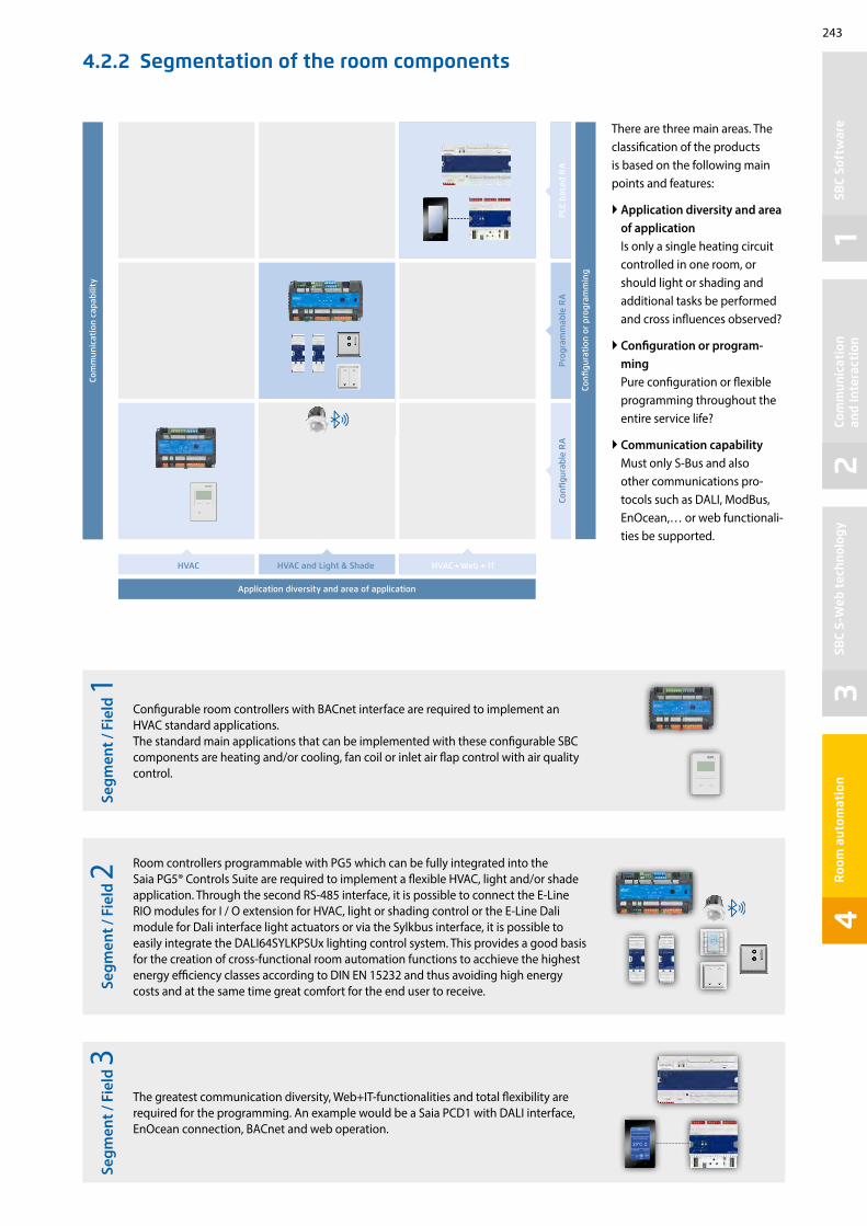
243
12
34
AIR CONDITIONING
Room temperature
Level 3
Aus
Ventilation
MENU
SBC
Soft
war
eCo
mm
unic
atio
n
and
Inte
ract
ion
SBC
S-W
eb t
echn
olog
yR
oom
aut
omat
ion
4.2.2 Segmentation of the room components
There are three main areas. The classification of the products is based on the following main points and features:
Application diversity and area of application Is only a single heating circuit controlled in one room, or should light or shading and additional tasks be performed and cross influences observed?
Configuration or program-ming Pure configuration or flexible programming throughout the entire service life?
Communication capability Must only S-Bus and also other communications pro-tocols such as DALI, ModBus, EnOcean,… or web functionali-ties be supported.
Configurable room controllers with BACnet interface are required to implement an HVAC standard applications.The standard main applications that can be implemented with these configurable SBC components are heating and/or cooling, fan coil or inlet air flap control with air quality control.
Room controllers programmable with PG5 which can be fully integrated into the Saia PG5® Controls Suite are required to implement a flexible HVAC, light and/or shade application. Through the second RS-485 interface, it is possible to connect the E-Line RIO modules for I / O extension for HVAC, light or shading control or the E-Line Dali module for Dali interface light actuators or via the Sylkbus interface, it is possible to easily integrate the DALI64SYLKPSUx lighting control system. This provides a good basis for the creation of cross-functional room automation functions to acchieve the highest energy efficiency classes according to DIN EN 15232 and thus avoiding high energy costs and at the same time great comfort for the end user to receive.
The greatest communication diversity, Web+IT-functionalities and total flexibility are required for the programming. An example would be a Saia PCD1 with DALI interface, EnOcean connection, BACnet and web operation.
Segm
ent /
Fie
ld 1
Segm
ent /
Fie
ld 2
Segm
ent /
Fie
ld 3
Application diversity and area of application
Com
mun
icat
ion
capa
bilit
y
HVAC HVAC and Light & Shade
Confi
gura
tion
or
prog
ram
min
g
Confi
gura
ble
RA
Pro
gram
mab
le R
AP
LC b
ased
RA
HVAC + Web + IT

244
The example shows a room with 3 different applications.
4.2.3 Examples of application for the individual segments
Example of a simple HVAC application
Room controller PCD7.LRS4 + PCD7.LR-TR42:
Heating: Radiator with electrothermal valve drive
Cooling: Cooling ceiling with constant valve drive (0…10 V)
Room temperature measurement: NTC10K integrated in the controller
Local user prompting: Directly on the controller via presence and setpoint offset setting
S-Bus connection to floor control for, among others: control of operating mode changeover, setpoint specification and reading of actual values.
Example of a cross-service/plant application with HVAC, light and shade
Room controller system: PCD7.LRL4-P5 + DALI64SYLKPSUF + PCD7.LR-TR42-CO2
Heating 1st stage: Floor heating with electrothermal valve drive
Heating 2nd stage: FanCoil unit
Cooling: FanCoil unit
Room temperature measurement: NTC20K in PCD7.LR-TR42-CO2 control unit or external NTC sensor
Light and shade: Control of 6 group and sceens of up to 32 DALI lamps and 1 blind
Local user prompting: Sylk-Bus room control unit for setpoint offset setting and fan speed adjustment and DALI switches and Sceen plates for activation of lights and switches for blinds
S-Bus connection to floor control for, among others, control of operating mode changeover, setpoint specification, activation of lights and blinds, read back occupancy state, lamp running hours and failure states, and reading of controller actual values.
Example of a flexible PLC-based room automation with Web&IT
Components: PCD7.D443WT5R + PCD1.F2611-C15 + PCD1.G1100-C15
Heating: Floor heating with electrothermal valve drive and via fan coil system
Cooling: Cooling ceiling and VAV system
Ventilation: VAV system
Air quality control CO2, VOC, measurement via externally connected sensor
Light and shade Activation of 1…10 V lamps, DALI lamps and blinds
Room temperature measurement: via a room control unit
Local user prompting: Room control unit for setpoint offset setting, activation of lights and blinds
Web user prompting: everything also can be controlled via web
Presence recognition and brightness measurement: via sensor for automatic control of light and shade
S-Bus or other protocol (for example BACnet): Connection to the floor distributor or direct to the GLT
Segment/Field 1
Segment/Field 2
Segment/Field 3

245
12
34
Room 1 Room 2 Room 1 Room 2
TV
PC
TV
Room 1 Room 2
TV
PC
TV
Room 1 Room 2
SBC
Soft
war
eCo
mm
unic
atio
n
and
Inte
ract
ion
SBC
S-W
eb t
echn
olog
yR
oom
aut
omat
ion
4.3 Examples of application
In addition to the right selection of components, the architectural structure and the basic concept play a decisive role. There are many possibilities and approaches for implementing room automation. However, there is no “single” solution for all areas of application. Depending on the purpose, the choice of the best concept will vary. Some approaches and features:
Example of a room box for hotel rooms:Fully pre-assembled, easy commissioning and replaceable if defective.
For example the operation of a conference room:Each browser and every mobile device can now serve as a control station. Each room is thereby represented accurately and shows each user group only what it requires.
Networked room automation Full networking of all plants and services is increasingly required. One example of application is that the cooling requirement (HVAC service) in summer can be reduced with controlled blinds (electrical plant). All plants also only require a single control unit rather than several different devices. A web-based control concept can be created using Saia PCD including Web + IT functionalities. This can be used subsequently for commissioning, operation and service.
Room boxesThese are ideal if the rooms or their applications are largely identical and/or are numerous, i.e. in hotels and office rooms. The boxes are manufactured and tested prior to installation in accordance with the requirements. The commissioning can thereby be 100% planned and controlled based on the installation time. Only the mounting, connection (usually with finished cable), testing, etc. is carried out on site. …The simple and efficient maintenance and servicing of the system is also possible. The plug-in system of box A ensures quick and seamless “plug & play” installation and replacement. Servicing is less time-consuming.
Room automation with distributed intelligenceComponents are distributed throughout the floor or room. These are also installed where they are needed, i.e. the controller for fan coil control located near the fan coils. The cabling takes less time, the devices also function independently (= secure operation).
Room automation from a central pointA sub-distribution per floor or section supplies several rooms. The control of lighting with DALI for several rooms would be a practical example of application. More cabling is involved with this variant. However, all components are located at a central point, which makes maintenance work more efficient.

246

C Annex
C1 Status: Product launch and availability
C2 Abbreviations
C3 Type Index
247
251
253


247
12
3
C1
100% 95%
70%
33%
%
1 2 3 4 5
Pro
duct
Lau
nch
Abb
revi
atio
ns
Type
Inde
x
Release status of products
Product maturation is an evolutionary process and fol-lows a maturation and learning curve. It starts with a product idea, which many people and divisions within the company then work on for a long time to reach all the new product’s various targets. These targets represent the function and design of the product. The manufacturer’s performance and quality stand-ards must also be achieved.
At Saia Burgess Controls the product maturation process is represented with colour codes. These are described in the table below. These colour codes are used on a dedicated web-page: http://sbc.do/We6uKnmS. They document the actual status of all products currently in field trials or market launch. Please consult the web-page if you wish to use a roduct marked in this catalogue as „* Not released at time of printing“.
Natural learning curve when introducing products into manufacturing, logistics, support, documentation and function
Target delivery performance– 80 % of deliveries in 2 working days– 95 % of deliveries in < 1 week– On-time delivery > 98.5 %
Meaning of product status colour codes
Function/design Logistics/availability Support
Blu
e Series production improvements have been incorporated. Final polish applied to design and function.
Product quantities have reached target volume and flow smoothly even when demand surges.
Training for product is standardized. Online support and FAQs established.
Gre
en
Products are available in series produc-tion quality and may be used with no particular technical constraints or risks.
Unrestricted sale. Products from our own production are available ex stock. Shipping volume is on the rise.
All SBC sales and support organizations have the necessary product skills. Its use can be fully supported.
Ora
nge
Products are available in series pro-duction quality. In the pilot phase, any deficits of function or design are found and corrected.
Products for ‘restricted’ sale. Delivery not yet ex stock. Quantity limited. Customers are informed about pilot status of product.
Product is known throughout organiza-tion. Support capability is still limited to a few individuals.
Red
Laboratory and functional models are available for laboratory and field trials. Not for sale. Not for use in customer production setting.
No product orders accepted. Scheduling in a new key project may well be possi-ble. Inquire about delivery dates!
Developers and product managers advise on function and look after laboratory and field trials.
Target level Functional scopeFreedom from errorsAdvisory performance Delivery performance
Del
iver
y ti
me
in d
ays
Time
Product information Product status: Product launch and availability

248
RO3 IN3 RN RN IN0 RO0 IN1 RO1 IN2 RO2
RUN/HALT
Sylk BusRS485 / Port 1
UI0…0-10V
GNDDig. NTC V
TN T~ TO0TNTO1 TO2 TNTO3
RS485 / Port 0C1+/D A +
D B -GNDC1-
AO0…
GND0-10VV
Power Supply24 VAC
Out---
230 V24 VAC
---
USB
T2 R2 T1 R1 !
1L
2N
324V~
424V0
524V~
624V0
7TN
8T~
9TO0
10TN
11TO1
12TO2
13TN
14TO3
15RC3
16RO3
17IN3
18RN
19RN
20IN0
21RO0
22IN1
23RO1
24IN2
25RO2
/DA+
26DB-
27GND
2824V~
29/DA+
62DB-
63GND
64WM1
30WM2
31
AO032
AO134
AO236
AO338
AO440
AO542
GND33
24V~35
GND37
24V~39
GND41
24V~43
24V~44
GND46
UI148
UI250
GND52
UI554
LED45
UI047
GND49
UI351
UI453
GND55
UI656
GND58
UI960
UI757
UI859
GND61
1 2 5 6 7 8 9 10 11 12 13 14 16 17 18 19 20 21 22 23 24 25
33 35 37 39 41 43 47 49 53 55 57 59 6151
26 27 28 29 30 31 32 34 36 38 40 42 46 48 52 54 56 58 6050 62 63 64
?https://hwll.co/t9tgl
Switch from paper to QR-Codes
As we transition our business to become more eco-friendly, we continue to look for opportunities to reduce printed materials whe-re possible. One area that we have been looking at is the reduction in printed installation instructions, data sheets and manuals that are inclu-ded with our products – many of which end up in waste never having been used, creating an unnecessary and significant impact on our environment. We are informing you that we will no longer include printed installation instructions or data sheets with our manufactured pro-ducts, instead replacing them with a QR code on both the product and outer box labels for easy lookup, should your installers need them. Going forward we will look to extend this to all other products we supply. The use of QR codes is very simple – just align your phone camera with the QR code and a pop-up notification will provide a link to the product landing page, where you can select the language and the manual needed.

249
12
3P
rodu
ct L
aunc
hA
bbre
viat
ions
Ty
pe In
dex
Our targets: Supply 3D-data with the format STEP (.stp- or .step-files) and Autodesk Revit (.rfa-files)
Other data formats are also provided if available
The objects are neither suitable for the design nor for the production. They are only designed as placeholders for the planning of facilities and trades
Accordingly, the objects are simplified, not complete and have only limited dimensional accuracy (height, width and depth).
Files in STEP 3D model format are identified by the STEP extension. If you want to open a STEP file (STP), you can do so with a variety of programs. This format is a standard that allows three-dimensional graphics to be displayed in a variety of applications.
Building information modelling (BIM) is a process involving the generation and management of digital representations of phy-sical and functional characteristics of the built environment. Building Information Modelling is used both in the building in-dustry for construction planning and execution (architecture, engineering, building services) and in facility management.
3D-data
STEP-files BIM-obejcts
The files are provided free of charge and can be downloaded from our support web page using the following link: https://sbc-support.com/en/services/bim-building-information-model/

250

251
12
3
C2
Pro
duct
Lau
nch
Abb
revi
atio
ns
Type
Inde
x
AbbreviationsAbbreviation Written out / Explanation
3G Third generation of mobile telecommunications technology
ADSL Asymmetric digital subscriber line (ADSL)
ASCII The American Standard Code for Information Interchange, is a 7 bit character-encoding scheme
CCFL Cold cathode fluorescent lamp (CCFL) are used for backlighting of LCDs, for example computer monitors and television screens
CGI Common Gateway Interface (CGI) is a standard method used to generate dynamic content on Web pages and Web applications
CO2 / CO2
Carbon dioxide (chemical formula CO2) is a naturally occurring chemical compound composed of 2 oxygen atoms each covalently double bonded to a single carbon atom.
COBA Saia PCD program is a tree-like structure of organization blocks which contain the application‘s code. Each block provides a particular service: cyclical programming (COB), sequential programming (SB), sub-programs (PB), functions with parameters (FB), and exception routines (XOB)
CPU A central processing unit (CPU) is the electronic circuitry within a computer that carries out the instruc-tions of a computer program by performing the basic arithmetic
CSV A comma-separated values (CSV) (also sometimes called character-separated values, because the separa-tor character does not have to be a comma) file stores tabular data (numbers and text) in plain-text form
DHCPThe Dynamic Host Configuration Protocol (DHCP) is a standardized network protocol used on Internet Protocol (IP) networks for dynamically distributing network configuration parameters, such as IP address-es for interfaces and services
DIN Deutsches Institut für Normung e.V. (DIN; in English, the German Institute for Standardization) is the Ger-man national organization for standardization and is the German ISO member body
DSLDigital subscriber line (DSL; originally digital subscriber loop) is a family of technologies that provide in-ternet access by transmitting digital data using a local telephone network which uses the public switched telephone network
DTMFDual-tone multi-frequency signaling (DTMF) is used for telecommunication signaling over analog telephone lines in the voice-frequency band between telephone handsets and other communications devices and the switching center
FBA Saia PCD program is a tree-like structure of organization blocks which contain the application‘s code. Each block provides a particular service: cyclical programming (COB), sequential programming (SB), sub-programs (PB), functions with parameters (FB), and exception routines (XOB)
FBox
The graphical function boxes (FBoxes) have inputs and outputs, and can also have configurable properties using parameter windows which can also be modified online. Around 250 FBoxes are already provided in the basic PG5 package. The range of functions goes far beyond the normal binary and arithmetic functions.
EHA Exhaust air
FTP The File Transfer Protocol (FTP) is a standard network protocol used to transfer computer files from one host to another host over a TCP-based network, such as the Internet
FUPLA FUPLA is SBC’s own function block diagram editor
FW Firmware
BA Building Automation
BMS Building management system
HVAC HVAC (heating, ventilating, and air conditioning) is the technology of indoor and vehicular environmental comfort
HVACSE Heating, ventilating, air conditioning, sanitary and electric
HMI Human Machine Interface
HP A horizontal pitch, short HP, is a unit of measurement to describe the width of assemblies. Electrical installation switchboards corresponds a HP to 17,5 mm according to DIN 43880
HTML HTML or HyperText Markup Language is the standard markup language used to create Web pages
HTTP The Hypertext Transfer Protocol (HTTP) is an application protocol for distributed, collaborative, hypermedia information systems
HW Hardware
ICA technology Instrumentation, Control and Automation technology
IL Instruction List

252
Abbreviation Written out / Explanation
IR Infrared
LD Ladder diagram a method of drawing electrical logic schematics. A ladder diagram represents a program in ladder logic
MB The Micro-Browser application allows the visualization and operation of web projects which have been created with Saia PG5® Web Editor
MID Measurement Instrument Directive
MTBF Mean time between failure
OEM Original equipment manufacturer (OEM) is a term used when one company makes a part or subsystem that is used in another company‘s end product
OPC OLE for Process Control (OPC), which stands for Object Linking and Embedding (OLE) for Process Control. The standard specifies the communication of real-time plant data between control devices from different manufacturers
PBA Saia PCD program is a tree-like structure of organization blocks which contain the application‘s code. Each block provides a particular service: cyclical programming (COB), sequential programming (SB), sub-programs (PB), functions with parameters (FB), and exception routines (XOB)
PGUProGramming Unit This term designates the programming console, but also by extension the port where the console must be connected. The PGU designates also the protocol used by the programming console.
RC-bus Internal data bus to connect digital room control devices or extension modules (Remote Control Bus)
RIO Remote Inout/Output
RTU Remote Terminal Unit or Remote Telemetry Unit, a microprocessor controlled electronic device
SCADA Supervisory Control and Data Acquisition
S-IO The S-IO protocol supports the operation of SBC remote I/O stations
SMTP Simple Mail Transfer Protocol (SMTP) is an Internet standard for electronic mail (e-mail) transmission
SNMP Simple Network Management Protocol (SNMP) is an „Internet-standard protocol for managing devices on IP networks“.
SNTP Is known as the Simple Network Time Protocol (SNTP). It is used in some embedded devices and in applications where high accuracy timing is not required
PLCA programmable logic controller, PLC or programmable controller is a digital computer used for automation of typical-ly industrial electromechanical processes, such as control of machinery on factory assembly lines, amusement rides, or light fixtures
SRC Single Room Controller
STN A super-twisted nematic display (STN) is a type of monochrome passive-matrix liquid crystal display (LCD)
SUP Supply air
SW Software
TCP/IPThe Internet protocol suite is the computer networking model and set of communications protocols used on the Internet and similar computer networks. It is commonly known as TCP/IP, because its most important protocols, the Transmission Control Protocol (TCP) and the Internet Protocol (IP)
TFT A thin-film-transistor liquid-crystal display (TFT LCD) is a variant of a liquid-crystal display (LCD) that uses thin-film transistor (TFT) technology to improve image qualities such as addressability and contrast
URL A uniform resource locator (abbreviated URL; also known as a web address, particularly when used with HTTP) is a specific character string that constitutes a reference to a resource
VAV Variable Air Volume (VAV) is a type of heating, ventilating, and/or air-conditioning (HVAC) system
VOC Volatile Organic Compounds
VPN A virtual private network (VPN) extends a private network across a public network, such as the Internet
WAN A wide area network (WAN) is a network that covers a broad area (i.e., any telecommunications network that links across metropolitan, regional, national or international boundaries) using leased telecommunication lines
XOBA Saia PCD program is a tree-like structure of organization blocks which contain the application‘s code. Each block provides a particular service: cyclical programming (COB), sequential programming (SB), sub-programs (PB), functions with parameters (FB), and exception routines (XOB)
Sources: our manuals and www.wikipedia.org

253
12
3
C3
32304321-003-S 40 82
32309178-001 24 95
32309178-002 36 95
410474200 1 127
410474850 4 127
410474930 10 33
410475150 8 33
410477190 187 57
431087230 98 32, 32
440548470 17 57
440549160 20 57
440549170 20 57
440549180 20 57
440549190 20 57, 63, 135
440549340 8 33
440549360 11 33
440549520 15 33
440549540 15 33
440549560 16 33
440549950 12 33
440549980 13 33
440550480 6 33, 57
440550540 9 57
440550870 8 63, 67, 135
440550880 9 71, 75, 151
440550890 10 71, 75, 151
450748170 3 33, 55, 57, 63, 67, 135
463948980 10 33, 47, 55, 57
AAE1D5F10KR3A00 128 126
ALD1B5FD00A3A00 80 120, 125
ALD1B5FS00A3A00 95 120, 123
ALD1D5F10KA3A00 87 120, 126
ALD1D5FD00A3A00 80 120, 125
ALD1D5FD00A3A44 80 125
ALD1D5FM00A3A00 96 120, 124
ALD1D5FS00A3A00 78 120, 123
ALE3B5F10KC3A00 213 120, 126
ALE3B5FD00C3A00 228 120, 125
ALE3B5FM00C3A00 188 120, 124
ALE3B5FS00C3A00 228 120, 123
ALE3D5F11KC3A00 217 120, 126
ALE3D5FD10C3A00 230 120, 125
ALE3D5FD10C3A44 230 125
ALE3D5FM10C3A00 224 120, 124
ALE3D5FS10C3A00 230 120, 123
AWD3B5W10MC3A00 217 120, 126
AWD3B5WS00C3A00 190 120, 123
AWD3D5W10MC3A00 216 120, 126
AWD3D5WD00C3A00 224 120, 125
AWD3D5WD00C3A44 224 125
AWD3D5WM00C3A00 221 120, 124
AWD3D5WS00C3A00 226 120, 123
BACA-A 120 109, 114, 116
IRM-RLC 62 105, 107, 114, 116
IRM-RSC 55 105, 107, 114, 116
Pro
duct
Lau
nch
Abb
revi
atio
nTy
pe In
dex
Type IndexArticle Weight Catalogue [g] page
Article Weight Catalogue [g] Page

254
PCD2.A460 40 52
PCD2.A465 30 52
PCD2.B100 45 52
PCD2.B160 50 52
PCD2.C1000 500 47, 50, 52
PCD2.C2000 1040 47, 50, 52
PCD2.E110 35 52
PCD2.E111 35 52
PCD2.E160 40 52
PCD2.E161 40 652
PCD2.E165 40 52
PCD2.E166 40 52
PCD2.E610 40 52
PCD2.F2100 60 54, 62, 66, 74, 190, 214
PCD2.F2150 60 54, 62, 66, 67, 74, 111, 190, 191, 216
PCD2.F2210 60 54, 62, 66, 74, 190, 214
PCD2.F2610 40 54, 62, 64, 66, 74, 190, 212
PCD2.F2700 40 54, 62, 66, 74, 190, 211
PCD2.F2710 40 54, 62, 66, 74, 190, 211
PCD2.F2720 40 54, 62, 66, 74, 190, 211
PCD2.F2810 60 54, 62, 66, 74, 190, 211, 214
PCD2.G200 80 53
PCD2.H112 24 52
PCD2.H114 27 52
PCD2.K010 40 50, 57
PCD2.K106 100 50, 57
PCD2.K221 240 33, 57, 150
PCD2.K223 330 33, 57, 150
PCD2.K231 140 33, 57, 150
PCD2.K232 220 33, 57, 150
PCD2.K241 120 33, 57, 150
PCD2.K242 200 33, 57, 150
PCD1.A1000-A20 210 82
PCD1.A2000-A20 270 82
PCD1.B1000-A20 385 82
PCD1.B1010-A20 385 82
PCD1.B1020-A20 353 82
PCD1.B1100-A20 360 82
PCD1.B1120-A20 330 82
PCD1.B5000-A20 220 82
PCD1.B5010-A20 220 82
PCD1.E1000-A10 180 82
PCD1.F2611-C15 129 69, 79, 179, 191, 224
PCD1.G1100-C15 140 69, 77, 179, 191, 224
PCD1.G2000-A20 210 80, 82
PCD1.G2100-A10 210 80, 82
PCD1.G2200-A20 220 80, 82
PCD1.G5000-A20 389 80, 82
PCD1.G5010-A20 362 80, 82
PCD1.G5020-A20 360 80, 82
PCD1.K0206-005 365 82
PCD1.K0206-025 365 82
PCD1.M0160E0 300 61, 65, 130, 132, 179, 190, 205, 206, 208, 214
PCD1.M2110R1 450 35, 36, 64, 135, 190, 212, 214
PCD1.M2120 400 35, 36, 60, 135, 190, 211, 212, 214, 223
PCD1.M2160 400 35, 36, 60, 112, 129, 135, 190, 212, 214, 223, 225
PCD1.M2220-C15 550 14, 73, 112, 135, 155, 190, 206, 214, 240, 241
PCD1.W5200-A20 220 80, 82
PCD1.W5300-C15 120 69, 78, 191
PCD2.A200 60 52
PCD2.A220 60 52
PCD2.A250 60 52
PCD2.A400 40 52
PCD2.A410 40 52
Article Weight Catalogue [g] Page
Article Weight Catalogue [g] Page

255
12
3
PCD2.K520 150 33, 57, 151
PCD2.K521 250 33, 57, 151
PCD2.K525 280 33, 57, 151
PCD2.K551 340 33, 57, 151
PCD2.K552 400 33, 57, 151
PCD2.M4160 890 36, 46, 52, 57, 73, 112, 155, 179, 190, 191, 205, 206, 212, 214
PCD2.M4560 920 36, 46, 52, 57, 73, 112, 155, 179, 190, 191, 205, 206, 212, 214
PCD2.M5540 1460 14, 15, 18, 35, 48, 52, 57, 74, 155, 179, 190, 191, 192, 197, 205, 206, 208, 211, 212, 214, 222, 224
PCD2.W200 35 53
PCD2.W210 35 53
PCD2.W220 40 53
PCD2.W300 40 53
PCD2.W310 40 53
PCD2.W315 45 53
PCD2.W340 40 53
PCD2.W350 40 53
PCD2.W360 40 53
PCD2.W380 40 53
PCD2.W400 40 53
PCD2.W410 45 53
PCD2.W525 50 53
PCD2.W600 40 53
PCD2.W605 45 53
PCD2.W610 45 53
PCD2.W615 45 53
PCD2.W745 40 53
PCD3.A200 100 26
PCD3.A210 120 26
PCD3.A220 100 26
PCD3.A251 120 26
PCD3.A300 100 26
PCD3.A400 100 26
PCD3.A410 100 26
PCD3.A460 80 26
PCD3.A465 80 26
PCD3.A810 100 26
PCD3.B100 100 26
PCD3.B160 100 26
PCD3.C100 420 21, 28, 34
PCD3.C110 260 21, 28, 34
PCD3.C200 440 21, 26, 27, 28, 34
PCD3.E009 40 33
PCD3.E110 80 26
PCD3.E111 80 26
PCD3.E160 80 26
PCD3.E161 80 26
PCD3.E165 80 26
PCD3.E166 80 26
PCD3.E610 80 26
PCD3.F110 100 23, 24, 29, 30, 36, 42, 44, 190
PCD3.F121 100 23, 24, 29, 30, 36, 42, 44, 190
PCD3.F150 100 23, 24, 29, 30, 36, 42, 44, 111, 190
PCD3.F180 100 23, 24, 29, 30, 36, 42, 44, 190
PCD3.F210 100 23, 24, 29, 30, 36, 42, 190
PCD3.F215 100 23, 24, 29, 30, 42, 190, 191, 206
PCD3.F221 100 23, 24, 29, 30, 42, 190
PCD3.F261 100 23, 24, 29, 30, 36, 42, 44, 190, 212
PCD3.F270 80 23, 24, 29, 30, 36, 42, 44, 190, 211
PCD3.F271 80 23, 24, 29, 30, 36, 42, 44, 190, 211
PCD3.F272 80 23, 24, 29, 30, 36, 42, 44, 190, 211
PCD3.F281 100 23, 24, 29, 30, 42, 190, 214
PCD3.H112 80 20, 26, 29, 36, 44
PCD3.H114 100 20, 26, 29, 36, 44
Pro
duct
Lau
nch
Abb
revi
atio
nTy
pe In
dex
Article Weight Catalogue [g] Page
Article Weight Catalogue [g] Page

256
PCD3.K010 40 21, 28, 34
PCD3.K106 140 21, 28
PCD3.K116 180 21, 28
PCD3.M3160 64014, 15, 18, 20, 24, 26, 27, 33, 35, 36, 74, 112, 129, 130, 155, 179, 190, 191, 205, 206, 207, 212, 223,
224, 225, 226
PCD3.M3360 64014, 15, 18, 20, 24, 26, 27, 33, 35, 36, 74, 112, 129, 130, 155, 179, 190, 191, 205, 206, 207, 212, 223,
224, 225, 226
PCD3.M5360 80014, 15, 18, 20, 22, 23, 26, 27, 33, 35, 36, 74, 112, 129,
130, 155, 179, 190, 191, 192, 197, 205, 206, 207, 212, 222, 224, 225, 226
PCD3.M5560 82014, 15, 18, 20, 22, 23, 26, 27, 28, 33, 35, 36, 74, 112,
129, 130, 155, 179, 190, 191, 192, 197, 205, 206, 207, 212, 221, 222, 224, 225, 226
PCD3.M6860 82014, 15, 20, 22, 23, 26, 27, 33, 35, 36, 74, 112, 129, 130, 155, 179, 190, 191, 201, 202, 205, 206, 207,
212, 224, 225, 226
PCD3.M6880 820 38, 39, 41, 42, 112, 179, 190, 191, 205, 206, 207, 212
PCD3.R010 60 33
PCD3.R562 80 31, 35, 111, 191, 206, 207
PCD3.R600 80 31, 35, 231
PCD3.S100 180 ---
PCD3.T665 460 22, 34, 36, 48, 60, 158, 190, 200, 201
PCD3.T666 480 22, 34, 36, 48, 60, 158, 190, 200, 201, 212, 213
PCD3.T668 480 38, 39, 43, 190
PCD3.W200 100 27
PCD3.W210 80 27
PCD3.W220 80 27
PCD3.W300 100 27
PCD3.W305 100 27
PCD3.W310 80 27
PCD3.W315 100 27
PCD3.W325 100 27
PCD3.W340 80 27
PCD3.W350 80 27
PCD3.W360 80 27
PCD3.W380 80 27
PCD3.W400 80 27
PCD3.W410 100 27
PCD3.W525 100 27
PCD3.W600 80 27
PCD3.W605 80 27
PCD3.W610 100 27
PCD3.W615 100 27
PCD3.W625 100 27
PCD3.W745 100 27
PCD3.W800 80 27
PCD7.D410-IWS 850 94
PCD7.D410-OWS 1300 94
PCD7.D410VT5F 2000 36, 91, 190, 206
PCD7.D410VT5Z11 2000 95
PCD7.D410VTCF 2000 89
PCD7.D410VTCZ11 2000 95
PCD7.D412DT5F 2700 36, 91, 190, 206
PCD7.D412DT5Z11 2700 95
PCD7.D412DTPF 2700 89
PCD7.D412DTPZ11 2700 95
PCD7.D412-IWS 1200 94
PCD7.D412-OWS 1600 94
PCD7.D443WT5R 250 93, 240, 242, 244
PCD7.D443WT5RW 250 93, 240, 242
PCD7.D443WTPR 250 93, 240, 242
PCD7.D443WTPRW 250 93, 240, 242
PCD7.D450WTPF 475 89, 95
PCD7.D450WTPZ11 475 95
PCD7.D457-IWS2 1500 94
PCD7.D457-OWS 2420 95
PCD7.D457-OWS1 1500 95
PCD7.D457-OWS2 1500 94
PCD7.D470WTPF 750 89
PCD7.D470WTPZ11 750 95
PCD7.D543RF 400 99
Article Weight Catalogue [g] Page
Article Weight Catalogue [g] Page

257
12
3
PCD7.D570CF1 1500 99
PCD7.D570RF 875 99
PCD7.D510CF1 2500 100
PCD7.D515CF1 4100 100
PCD7.D521CF1 6100 100
PCD7.F110S 7 30, 46, 47, 48, 54, 55, 61, 62, 64, 65, 66, 74, 90, 91, 111, 135, 190
PCD7.F121S 7 30, 46, 47, 48, 54, 55, 61, 62, 64, 65, 66, 74, 90, 91, 135, 190
PCD7.F150S 7 30, 46, 47, 48, 54, 55, 61, 62, 64, 65, 66, 74, 90, 91, 135, 190
PCD7.F180S 7 30, 46, 47, 48, 54, 55, 61, 62, 64, 65, 66, 74, 90, 91, 135, 190, 214
PCD7.H104D 180 126, 136
PCD7.H104DZ44 180 126, 136
PCD7.H104SE 183 126, 128, 130, 136
PCD7.K840 60 145, 199
PCD7.L252 100 67, 149
PCD7.L290 25 149
PCD7.L291 25 149
PCD7.L452 250 149
PCD7.L490 20 149
PCD7.L-RoomUP --- 110, 111, 114
PCD7.LRL2 1005 109, 111, 114, 115, 240, 241, 242
PCD7.LRL2-P5 1055 105, 240, 241, 242
PCD7.LRL4-P5 1055 105, 106, 240, 241, 242
PCD7.LRL5-P5 645 105, 240, 241, 242, 244
PCD7.LRS4 930 109, 114, 115, 240, 241, 242, 244
PCD7.LRS4-P5 975 105, 106, 240, 241, 242
PCD7.LRS5 525 109, 114, 240, 241, 242
PCD7.LRS5-P5 565 105, 240, 241, 242
PCD7.LR-TR40 120 107, 116
PCD7.LR-TR40-CO2 145 107, 116
PCD7.LR-TR40-H 135 107, 116
PCD7.LR-TR40-H-CO2 155 107, 116
PCD7.LR-TR42 135 107, 116, 244
PCD7.LR-TR42-CO2 155 107, 116, 244
PCD7.LR-TR42-H 135 107, 116
PCD7.LR-TR42-H-CO2 155 107, 116
PCD7.R562 10 9, 16, 31, 35, 46, 55, 62, 66, 67, 74, 91, 111, 135, 191, 206, 207, 223, 224, 225, 231
PCD7.R610 9 9, 16, 31, 35, 46, 55, 62, 66, 74, 91, 133, 135, 231
PCD7.R-MSD1024 10 16, 31, 35, 55, 62, 66, 74, 91, 133, 135, 231
PCD7.R-SD1024 10 16, 31, 35, 223, 224, 225, 231
PCD7.R-SD512 10 16, 31, 35, 223, 224, 225, 231
PCD7.T161 80 108, 127, 147
PCD7.T162 80 108, 127, 147
PCD7.W600 10 61, 65, 135
PCD8.BACnet-Eye-1 --- 186
PCD8.OPC-1 300 185
PCD8.OPC-3 300 185
PCD8.OPC-5 300 185
PCD8.PG5-CORE 300 171
PCD8.PG5-DEMO 400 171
PCD8.PG5-ENDUSER 400 171
PCD8.PG5-EXTENDED 400 171
PCD8.PG5-FBOXBLD --- 171
PCD8.PG5-HVAC 400 171
PCD8.PG5-UPGRADE 400 171
PCD8.PG5-UPGR-EXTD 400 171
PCD8.PG5-UPGR-HVAC 400 171
PCD8.SUP-500 --- 181
PCD8.SUP-2500 --- 181
PCD8.SUP-10000 --- 181
PCD8.SUP-25000 --- 181
PCD8.SUP-50000 --- 181
PCD8.SUP-100000 --- 181
PCD8.SUP-100EXT --- 181
PCD8.SUP-2500EXT --- 181
PCD8.SUP-5000EXT --- 181
Pro
duct
Lau
nch
Abb
revi
atio
nTy
pe In
dex
Article Weight Catalogue [g] Page
Article Weight Catalogue [g] Page

258
PCD8.SUP-15000EXT --- 181
PCD8.SUP-50000EXT --- 181
PCD8.SUP-500OPEN --- 181
PCD8.SUP-2500OPEN --- 181
PCD8.SUP-5000OPEN --- 181
PCD8.SUP-5000OPEN --- 181
PCD8.SUP-25000OPEN --- 181
PCD8.SUP-50000OPEN --- 181
PCD8.SUP-MNT1 --- 181
PCD8.SUP-MNT3 --- 181
PCD8.SUP-MNT5 --- 181
PCD8.SUP-1N-UP --- 181
PCD8.SUP-10N-UP --- 181
PCD8.SUP-DB-CSV --- 181
PCD8.SUP-DB-MYSQL --- 181
PCD8.SUP-DB-ORCL --- 181
PCD8.SUP-DB-SQL --- 181
PCD8.SUP-JSON --- 181
PCD8.SUP-FID --- 181
PCD8.SUP-MLS-16 --- 181
PCD8.SUP-MLS-64 --- 181
PCD8.SUP-MAXP-16 --- 181
PCD8.SUP-MAXP-64 --- 181
PCD8.SUP-MAXP-128 --- 181
PCD8.SUP-AXIS-16 --- 181
PCD8.SUP-AXIS-64 --- 181
PCD8.SUP-EM25 --- 181
PCD8.SUP-EM50EXT --- 181
PCD8.SUP-EM100EXT --- 181
PCD8.SUP-EM500EXT --- 181
PCD8.SUP-EM1KEXT --- 181
PCD8.SUP-NA-250 --- 181
PCD8.SUP-NA-1000 --- 181
PCD8.SUP-NA-10000 --- 181
PCD8.SUP-LDAP --- 181
PCD8.SUP-ESIG-1000 --- 181
PCD8.SUP-ESIG-UNL --- 181
PCD8.SUP-ESIG-UP1K --- 181
PCD8.SUP-CLO-500 --- 181
PCD8.SUP-CLO-2500 --- 181
PCD8.SUP-CLO-10000 --- 181
PCD8.SUP-HTTP --- 181
PCD8.SUP-NAA-MON --- 181
PCD8.SUP-NAA-STK1 --- 181
PCD8.SUP-NAA-STK5 --- 181
PCD8.SUP-NAA-REN --- 181
PCD8.SUP-NAA-ENG --- 181
PMK-EEM400 --- 127
Q.NET-5TX 230 35, 146
Q.NET-8TX 270 35, 146
Q.NET-CON --- 145, 199
Q.NET-EBW-E100 130 145, 199
Q.NET-EBW-H100 135 145, 199
Q.PS-AD1-2403 200 139
Q.PS-AD2-2402F 300 139
Q.PS-AD2-2405F 600 139
Q.PS-AD2-2410F 600 139
Q.PS-ADB-2405-1 700 139
Q.PS-PEL-2401 300 83, 142
Q.PS-PEL-2403 330 83, 142
T7460A1001 120 109, 114, 116
T7460B1009 140 109, 114, 116
T7460C1007 155 109, 114, 116
T7460D1005 155 109, 114, 116
T7460F1000 160 109, 114, 116
Article Weight Catalogue [g] Page
Article Weight Catalogue [g] Page

259
12
3P
rodu
ct L
aunc
hA
bbre
viat
ion
Type
Inde
x
Notes

260
Notes

261
12
3P
rodu
ct L
aunc
hA
bbre
viat
ion
Type
Inde
x
Notes

262
Notes

Publisher
Saia-Burgess Controls AG Route Jo-Siffert 4 | 1762 Givisiez, Switzerland T +41 26 580 30 00 | F +41 26 580 34 99 www.saia-pcd.com | [email protected]
Subject to change without notice. The latest version is available at: www.sbc-support.com
Imprint

Saia-Burgess Controls AG
Route Jo-Siffert 4 1762 Givisiez, Switzerland
T +41 26 580 30 00 F +41 26 580 34 99
www.saia-pcd.com [email protected] 26-215 ENG18d 03.2022

26-2
15 E
NG
18d
Syst
em
Ca
talo
gu
e 2
02
2 |
20
23