Samjung Tech A company with Samsung's reliable technology ...
84
-
Upload
khangminh22 -
Category
Documents
-
view
1 -
download
0
Transcript of Samjung Tech A company with Samsung's reliable technology ...


Samjung Tech has been growing and developing into a leading company since it separated fromSamsung group in January 2000. On the basis of its abundant experience and high technologies,Samjung Tech has expanded its businesses into the various fields such as refrigeration & airconditioning system, parking system, platform screen doors system, construction, and all kinds offacility construction works. Samjung Tech comprises headquarters in Seoul, five nationwide branches located in metropolitans, andfactories and research institutes established in Gimpo and Changwon, Korea. Through closecollaboration of each part, Samjung Tech is willing to satisfy customers. Also Samjung Tech provides its top-notch products for foreign customers through overseas agentsnetwork worldwide.
Samjung Tech A company with Samsung’s reliable technology and people
Parking system
Construction
Refrigeration & airconditioning system
Platform screen doorssystem
FacilityconstructionEnvironment-friendly new
& renewable energy
180717 3-10 복사 1904.1.23 1:44 AM 페이지3 C M Y K

Refrigeration & air conditioning system of Samjung Tech
Close to customers at all time - Samjung Tech is at the center of beautiful and convenient life.
Refrigeration & air conditioning system of Samjung Tech has lead a pure and pleasant green life-culture.
Samjung Tech has directly produced and supplied various equipments such as absorption chiller& heater, air handling unit, heat recovery ventilation system, cooling tower, fan coil unit, EHP, etc.
Especially, absorption chiller & heater has become the best items of the industry because we havesupplied about 3,000 units to domestic and foreign countries until now through continuous R&Dand stable after-sale service.
In addition, we were proudly approved our Quality Control System by being awarded the certificatefor the quality competitiveness enterprise from MKE.
Samjung Tech has been approved of the researchand development of a new & renewable energytechnology from the government and has, as amajor company, successfully completed a task ofdeveloping hybrid solar energy absorption chillerwith 30RT level. Based on this, it has led manyprojects related to technical development in thesolar energy field.
Hybrid solar energy absorption chiller
Certification for a newtechnology
01. High Efficiency Direct Fired Absorption Chiller & Heater 11
02. High Efficiency Steam Driven Absorption Chiller 27
03. Single Effect Double Lift Hot Water Driven Absorption Chiller 43
04. Single Effect Hot Water Driven Absorption Chiller 51
05. Fan Coil Unit (F.C.U.) 63
CONTENTSAbsorption Chiller & Fan Coil UnitAbsorption Chiller & Fan Coil Unit
Absorption Chiller SAMJUNG TECH4
180717 3-10 복사 1904.1.23 1:44 AM 페이지4 C M Y K

Products Line-Up
No MODEL UseDriven Capacity Characte-
Ref.Energy Range ristics
01
02
03
04
05
Direct Fired
Absorption
Chiller&Heater
M-SeriesCooling
&
Heating
Cooling
Gas
or
Oil
50 ~
1500RT
COP
1.44
(on LHV)
11P
Direct Fired
Absorption
Chiller&Heater
TA-Series
50 ~
1500RT
COP
1.48
(on LHV)
Steam Driven
Absorption
Chiller
Single Effect
Double Lift
Hot WaterDriven
AbsorptionChiller
Steam50 ~
1500RT
SteamConsumption
3.5~
3.9kg/h.RT
@8bar
27P
※ Rupture Disc
Safety Device
■ Protection the body of chiller
■ This Safety Device protect the body of chiller from theaccidents that the Electric Safety Devices can not preventsuch as tube freezing or poor quality of tubes.
Hot Water80 ~
1000RT
COP
0.64~0.74
Hot WaterTemp.
95/55℃
43P
Single Effect
Hot WaterDriven
AbsorptionChiller
Hot Water 65 ~
1000RT
COP 0.72
Hot WaterTemp.
95/80℃
51P
Absorption Chiller SAMJUNG TECH5
180717 3-10 복사 1904.1.23 1:44 AM 페이지5 C M Y K

Direct Fired Double Effect Absorption Chiller & Heater, M-Series
Based on accumulated technical know-how along with the technical cooperation with Hitachi in thepast, Samjung has achieved the high efficiency and most compactness, as well as excellent reliabilityand simplicity in maintenance by developing next generation Direct Fired Double Effect AbsorptionChiller & Heater M-Series, which are equipped with a highly functional PLC panel and high efficientenergy saving technology. This high efficient and energy saving type produces heat source forheating and cooling with excellent capability at low costs. Samjung's absorption chiller and heater hasbeen advanced to the new dimension of chiller and heater and it realizes energy saving as well ascost saving of total air-conditioning system.
TOPENERGY SAVING
Save annual cooling costto about 23%
with new technology
TOPSIMPLE OPERATION &
MAINTENANCEOperate chiller easily andreduce cost and time for
maintenance with wide colortouchscreen and various
function
TOPHIGH RELIABILITY& COMPACTNESSAttached high reliable
PLC panel and achievedthe most compactness
Triple TOPSatisfactionTriple TOP
Satisfaction
6 Absorption Chiller SAMJUNG TECH
180717 3-10 복사 1904.1.23 1:44 AM 페이지6 C M Y K

Major characteristics
The Top energy saving is realized with the newest technology and perfectperformance test facilities
1. Applied optimum cycle design technologyand two stage Evaporator and Absorber
2. Applied new developed High Efficiencyspecial type tubes to improve the HeatTransfer effects
3. Adopted High Efficient SUS-Plate andwelded type Solution Heat Exchanger ofSWEP to compact and improve the HeatTransfer effects
4. Adopted High Efficient SUS-Plate andwelded type Condensing Refrigerant HeatExchanger of SWEP to use the CondensingWaste Heat of Refrigerant
5. Applied optimum combustion technologyand Exhaust Gas Heat Exchanger toimprove the Heat Transfer effects throughthe Waste Heat Recovery
6. Applied intelligent touch screen type PLCPanel (Please see page)
7. Save 23% Running Cost for cooling per year
8. World-best level compact size
9. Qualified and acquiredthe Certificate of HighEfficiency Chiller of allmodels by GovernmentOffice
10. Equipped the perfect Performance TestFacility in factory
I Reduced Installation Area I
Above graph is based on followings.1. Cooling capacity 500 usRT 2. 800 hours of cooling operation time per year 3. Korea gas tariff standard
I Saving for Running Cost I I Reduced CO2 Emission I
Absorption Chiller SAMJUNG TECH7
180717 3-10 복사 1904.1.23 1:44 AM 페이지7 C M Y K

Double Effect Direct Fired Absorption Chiller & Heater
Exquisite control
Highly efficient operation and energy saving is realized with delicate andperfect operating control
1. 10% Increase in Partial Load CharacteristicCompared to the Average Load Rate ofExisting Model by Control of Whole SolutionCirculation Flow Rate
Optimal condition for solution circulation is maintainedfor the highly efficient operation.
<Characteristic Comparison for Partial Load>
Cooling Capacity (%)
Characteristics of the Whole Load Operation
Time20 min. 40 min.
Chiller & Heater Booting
2. Energy Savings through Ideal Control ofDilution Operation Time
Stopping time has shortened compared to theconventional model through dilution operationtime calculated by PLC. Also, the whole system'senergy is saved by shortened operation time ofpump and cooling tower during the dilutionoperation time.
3. Characteristics of the Partial Load
Samjung Absorption Chiller and Heater isadvantageous in energy saving not only undernormal condition but also under the partial loadcondition.
The figure below indicates the relationshipbetween cooling capacity (%) and energyconsumption (%) at the cooling water's inlettemperature of 32℃, 28℃, 24℃, respectively.
5. Caution for stopping the Chiller and Heater
The circulating solution's temperature must below enough from crystallization, and from thepoint of stopping to the complete stop byreaching the non crystallization area is known asthe dilution operation. During the dilutionoperation, it is necessary to load the chiller andheater in order to prevent the refrigerant freezingand solution crystallization. Therefore, in caseboth stop at the same time, it is necessary toconfigure an interlock operation circuit to havechiller & heater to stop before the airconditioning unit where the air conditioning unitstops even after the completion of dilutionoperation.
4. Characteristics of Starting and Stopping
● Example of Starting Characteristics
Whole Load Stop
Complete Stop
Time
Chiller & heater Stop It is set on 7~20 minutes for dilutionoperation time depending on thedensity of high temperature generatorduring the stopping operation.
Average cooling capacityduring the dilutionoperation time after thewhole load stop* The shaded portionindicates the coolingcapacity during thedilution operation time.
Ordinary Operation
DilutionOperationCooling
Capacity (%)
● Example of Stopping Characteristics
ENERGY CONSUMPTION RATE(%)
ENERGYCONSUMPTION
(%)
COOLING CAPACITY(%)
COOLING CAPACITY(%)
EXISTING SYSTEM
COOLING WATER’S INLETTEMP. 32℃
COOLING WATER’S INLETTEMP. 24℃
COOLING WATER’SINLET TEMP. 28℃
E-SERIES
Absorption Chiller SAMJUNG TECH8
180717 3-10 복사 1904.1.23 1:44 AM 페이지8 C M Y K

9 Absorption Chiller SAMJUNG TECH
1. Energy saving and rapid control for the change of load is realized by the more accurate andadvanced PID control.
2. High quality color touch screen and highest SIEMENS PLC controller
- High resolution level 65,000 color, 7″wide color touch screen and the high reliable PLC ofSIEMENS
3. Provide all of convenient and advanced functions for operating
- Easily see and check the operating status of important parts and the operating trend of importantvalues in real time at [Status], [Cycle] and [Graph] screen
- Scheduling and remote operating / Operating history / Failure and alarm history / Setup functionof the important target values etc.
- Save all data for 5 years and print the operating report with USB memory
4. Various Interface Solution
- The chiller can be interfaced with theBMS (Building Management System)
- The operator can easily control andmonitor the chiller with a remote PC andsmart phone via RS-485 MODBUS-RTUprotocol and VNC (Virtual NetworkComputing) server as a basis./ MODBUS-TCP/IP and BACnet-IP protocol as aoption
5. Safety operation through the pre-alarm, preventive maintenance and protection of system
List of preventive protection and detection
Preventive control of super cooled chilled water
Limiting load control
Frequency of purge
Automatic anti - crystallization
Abnormal temperature of the cooling water
Pollution of cooling water tube
Pollution of HTG tube
Refrigerant over freezing prevention control
High Efficient - Smart Control Panel
The high efficient touch screen type PLC panel make possible more energysaving, safety control and convenient maintenance of chiller
180717 3-10 복사 1904.1.23 1:44 AM 페이지9 C M Y K

10 Absorption Chiller SAMJUNG TECH
M/E/M/O
180717 3-10 복사 1904.1.23 1:44 AM 페이지10 C M Y K

0112 Cooling/Heating Cycle
13 Automatic Sensing & Safety Apparatus
14 Specifications
20 Foundation
21 Control Panel & Wiring
22 Thermal Insulation
23 Chimney Size
24 Piping Plan
25 Supply Scope(Standard)
High Efficiency Direct Fired Absorption Chiller & Heater
180717 11-26최종-s 1904.1.25 4:55 AM 페이지11 C M Y K

12 Absorption Chiller SAMJUNG TECH
1. Cooling Cycle
2. Heating Cycle
[Cooling/Heating Cycle]
180717 11-26최종-s 1904.1.25 4:55 AM 페이지12 C M Y K
13SAMJUNG TECH Absorption Chiller
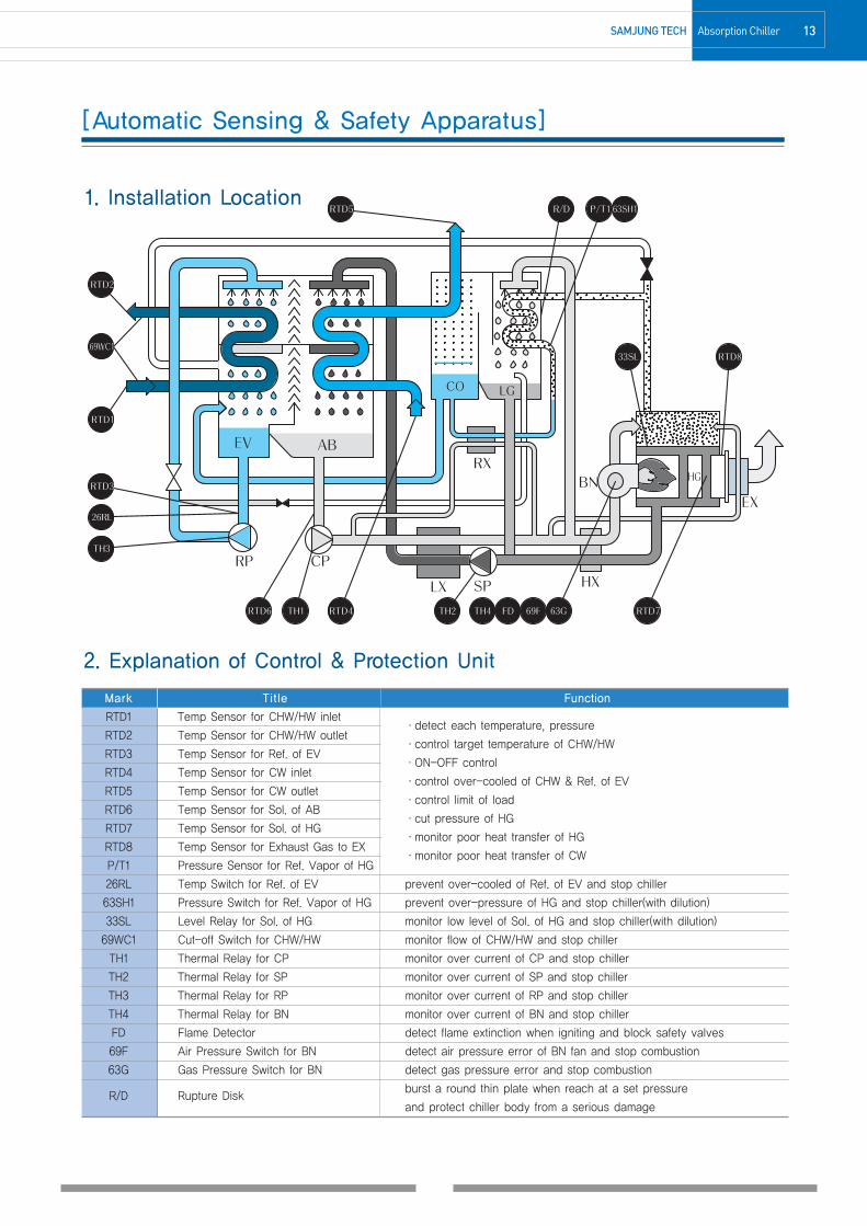
[Automatic Sensing & Safety Apparatus]
2. Explanation of Control & Protection Unit
Mark Title Function
RTD1 Temp Sensor for CHW/HW inlet·detect each temperature, pressure
RTD2 Temp Sensor for CHW/HW outlet·control target temperature of CHW/HW
RTD3 Temp Sensor for Ref. of EV·ON-OFF control
RTD4 Temp Sensor for CW inlet·control over-cooled of CHW & Ref. of EV
RTD5 Temp Sensor for CW outlet·control limit of load
RTD6 Temp Sensor for Sol. of AB·cut pressure of HG
RTD7 Temp Sensor for Sol. of HG·monitor poor heat transfer of HG
RTD8 Temp Sensor for Exhaust Gas to EX·monitor poor heat transfer of CW
P/T1 Pressure Sensor for Ref. Vapor of HG
26RL Temp Switch for Ref. of EV prevent over-cooled of Ref. of EV and stop chiller
63SH1 Pressure Switch for Ref. Vapor of HG prevent over-pressure of HG and stop chiller(with dilution)
33SL Level Relay for Sol. of HG monitor low level of Sol. of HG and stop chiller(with dilution)
69WC1 Cut-off Switch for CHW/HW monitor flow of CHW/HW and stop chiller
TH1 Thermal Relay for CP monitor over current of CP and stop chiller
TH2 Thermal Relay for SP monitor over current of SP and stop chiller
TH3 Thermal Relay for RP monitor over current of RP and stop chiller
TH4 Thermal Relay for BN monitor over current of BN and stop chiller
FD Flame Detector detect flame extinction when igniting and block safety valves
69F Air Pressure Switch for BN detect air pressure error of BN fan and stop combustion
63G Gas Pressure Switch for BN detect gas pressure error and stop combustion
R/D Rupture Diskburst a round thin plate when reach at a set pressure
and protect chiller body from a serious damage
1. Installation Location
180717 11-26최종-s 1904.1.25 4:55 AM 페이지13 C M Y K

14 Absorption Chiller SAMJUNG TECH
M-SERIES(COP 1.44 on LHV)
SPECIFICATIONS
50M 60M 70M 80M 100M 120M 130M 150M 180M
USRT 50 60 70 80 100 120 130 150 180
kW 176 211 246 281 352 422 457 527 633
HEATING CAPACITYkcal/h 111,900 134,300 156,700 179,100 223,800 268,600 291,000 335,700 402,800
kW 130 156 182 208 260 312 338 390 468
CHILLED WATER℃
12 ℃ → 7 ℃
HOT WATER 56.3 ℃ → 60 ℃
FLOW RATE m3/h 30.2 36.3 42.3 48.4 60.5 72.6 78.6 90.7 108.9
PRESSURE DROP mAq 5.9 6.4 5.8 5.8 6.1 6.2 5.6 5.7 5.6
PIPE CONNECTION SIZE A 65 80 100 125
NO. of PASS EA EVEN
TEMP. ℃ 32 ℃ → 37 ℃
FLOW RATE m3/h 50 60 70 80 100 120 130 150 180
PRESSURE DROP mAq 6.4 6.9 7.4 7.4 7.6 7.6 7.9 7.6 5.8
PIPE CONNECTION SIZE A 80 100 125 150
NO. of PASS EA EVEN
POWER SUPPLY - 3Ø 380V 50Hz
ELECTRIC CAPACITY KVA 8.2 9.4 9.7 11.4
SOLUTION PUMP 1.1(4.0)+1.2(4.0) 1.5(5.5)+1.2(4.0) 2.0(6.5)+1.5(5.5)
REFRIGERANT PUMP kW/(A) 0.2(1.1) 0.3(1.6)
VACUUM PUMP 0.75(2.0)
BURNER FAN(GAS) kW/(A) 0.45(1.3) 0.75(1.7)
COOLINGNm3/h
11.2 13.4 15.7 17.9 22.4 26.8 29.1 33.6 40.3
HEATING 12.2 14.6 17.1 19.5 24.4 29.3 31.7 36.6 43.9
PIPE CONNECTION SIZE A 25 40
GAS PRESSURE mmAq 200
LENGTH(L) mm 2,640 2,910 3,168 3,323 4,063
WIDTH(W) mm 1,670 1,876 2,041 1,946
HEIGHT(H) mm 1,910 2,099
SHIPPING WEIGHT ton 3.8 3.9 4.4 4.5 4.9 5.0 5.5 5.5 6.5
OPERATION WEIGHT ton 4.1 4.2 4.8 4.9 5.2 5.3 5.7 5.8 7.1
CHILLED WATERℓ
88 97 108 120 159 181 228 247 250
COOLING WATER 119 131 146 162 215 246 304 330 337
EXHAUST GAS DUCT SIZE mm 520x447 600x489
EXCHANGE SPACE OF TUBE mm 1,700 2,300 2,500 3,600
1. 1USRT = 3024kcal/h(3.516kW)2. Fouling factor of chilled water, cooling water, hot water : 0.0001 m2h℃/kcal(0.000086m2K/W)3. The maximum working pressure for chilled water, cooling water, hot water : 10 kg/cm2G(0.98MPaG)4. The capacity control range for standard specification.(capacity, chilled water, cooling water) : 100 ~ 25%(Gas proportional control)5. The standard of fuel consumption - GAS(LNG) : High Heating Value 10,400kcal/Nm3(43.5MJ/Nm3), Low Heating Value 9,390kcal/Nm3
6. Pipe connection size of gas can be changed according to the gas pressure of site.7. The power supply can be applied 3Ø 220V/380V/440V 50Hz also.8. These specification can be changed without notice for technical improvements.
TEMP.
REFRIGERATIONCAPACITY
GAS
LNG
SACH-G/K/DITEM(UNIT)
CHILLED/
HOT
WATER
COOLING
WATER
ELECTRIC
POWER
DIMENSIO-NS
WEIGHT
WATERQUANTITY
FUELCONSU-MPTION
180717 11-26최종-s 1904.1.25 4:55 AM 페이지14 C M Y K

15SAMJUNG Tech Absorption Chiller
SPECIFICATIONS
M-SERIES(COP 1.44 on LHV)
210M 240M 280M 320M 360M 400M 450M 500M 560M
USRT 210 240 280 320 360 400 450 500 560
kW 738 844 985 1125 1266 1407 1582 1758 1969
HEATING CAPACITYkcal/h 470,000 537,100 626,600 716,100 805,600 895,200 1,007,000 1,118,900 1,253,200
kW 547 625 729 833 937 1041 1171 1301 1457
CHILLED WATER℃
12 ℃ → 7 ℃
HOT WATER 56.3 ℃ → 60 ℃
FLOW RATE m3/h 127.0 145.2 169.3 193.5 217.7 241.9 272.2 302.4 338.7
PRESSURE DROP mAq 5.4 5.8 5.1 5.5 5.3 5.4 5.4 5.4 4.9
PIPE CONNECTION SIZE A 125 150 200
NO. of PASS EA EVEN ODD
TEMP. ℃ 32 ℃ → 37 ℃
FLOW RATE m3/h 210 240 280 320 360 400 450 500 560
PRESSURE DROP mAq 6.1 6.2 6.7 6.8 5.2 5.2 5.3 5.3 5.0
PIPE CONNECTION SIZE A 150 200 250 300
NO. of PASS EA EVEN ODD
POWER SUPPLY - 3Ø 380V 50Hz
ELECTRIC CAPACITY KVA 13.3 14.7 16.3 20.8 24.4
SOLUTION PUMP 2.4(7.5)+1.5(5.5) 2.4(7.5)+2.0(6.5) 3.4(10.0)+2.0(6.5) 3.7(13.0)+2.2(7.0)
REFRIGERANT PUMP kW/(A) 0.3(1.6) 0.4(1.5) 0.8(3.5)
VACUUM PUMP 0.75(2.0)
BURNER FAN(GAS) kW/(A) 1.5(3.6) 2.2(4.7) 3.7(8.1) 5.5(11.6)
COOLINGNm3/h
47.0 53.7 62.6 71.6 80.5 89.5 100.7 111.9 125.3
HEATING 51.2 58.5 68.3 78.1 87.8 97.6 109.8 122.0 136.6
PIPE CONNECTION SIZE A 50 40
GAS PRESSURE mmAq 200 4000
LENGTH(L) mm 4,063 4,998 5,005 5,392 5,430
WIDTH(W) mm 2,020 2,149 2,435 2,530
HEIGHT(H) mm 2,147 2,534 2,555 2,643
SHIPPING WEIGHT ton 7.3 7.4 8.8 8.9 10.7 10.8 13.1 13.3 15.6
OPERATION WEIGHT ton 8.1 8.3 9.7 9.9 11.9 12.0 14.3 14.5 17.6
CHILLED WATERℓ
308 337 388 426 492 537 636 700 821
COOLING WATER 410 449 516 568 701 762 898 981 1,153
EXHAUST GAS DUCT SIZE mm 600x489 740x573 818x657
EXCHANGE SPACE OF TUBE mm 3,600 4,600
1. 1USRT = 3024kcal/h(3.516kW)2. Fouling factor of chilled water, cooling water, hot water : 0.0001 m2h℃/kcal(0.000086m2K/W)3. The maximum working pressure for chilled water, cooling water, hot water : 10 kg/cm2G(0.98MPaG)4. The capacity control range for standard specification.(capacity, chilled water, cooling water) : 100 ~ 25%(Gas proportional control)5. The standard of fuel consumption - GAS(LNG) : High Heating Value 10,400kcal/Nm3(43.5MJ/Nm3), Low Heating Value 9,390kcal/Nm3
6. Pipe connection size of gas can be changed according to the gas pressure of site.7. The power supply can be applied 3Ø 220V/380V/440V 50Hz also.8. These specification can be changed without notice for technical improvements.
TEMP.
REFRIGERATIONCAPACITY
GAS
LNG
SACH-G/K/DITEM(UNIT)
CHILLED/
HOT
WATER
COOLING
WATER
ELECTRIC
POWER
DIMENSIO-NS
WEIGHT
WATERQUANTITY
FUELCONSU-MPTION
180717 11-26최종-s 1904.1.25 4:55 AM 페이지15 C M Y K

16 Absorption Chiller SAMJUNG TECH
SPECIFICATIONS
M-SERIES(COP 1.44 on LHV)
630M 700M 800M 900M 1000M 1100M 1250M 1500M
USRT 630 700 800 900 1000 1100 1250 1500
kW 2215 2461 2813 3165 3516 3868 4395 5274
HEATING CAPACITYkcal/h 1,409,800 1,566,500 1,790,300 2,014,000 2,237,800 2,461,600 2,797,200 3,356,700
kW 1639 1822 2082 2342 2602 2862 3253 3903
CHILLED WATER℃
12 ℃ → 7 ℃
HOT WATER 56.3 ℃ → 60 ℃
FLOW RATE m3/h 381.0 423.4 483.8 544.3 604.8 665.3 756.0 907.2
PRESSURE DROP mAq 6.9 8.9 8.3 11.0 4.7 4.6 11.4 6.1
PIPE CONNECTION SIZE A 200 250 300 350
NO. of PASS EA ODD EVEN ODD EVEN
TEMP. ℃ 32 ℃ → 37 ℃
FLOW RATE m3/h 630 700 800 900 1000 1100 1250 1500
PRESSURE DROP mAq 6.7 8.8 6.9 9.0 11.8 11.6 9.1 14.2
PIPE CONNECTION SIZE A 300 350 400
NO. of PASS EA ODD
POWER SUPPLY - 3Ø 380V 50Hz
ELECTRIC CAPACITY KVA 24.4 26.4 29.2 34.8 45.5 47.8
SOLUTION PUMP 3.7(13.0)+2.2(7.0) 4.5(16.0)+2.2(7.0) 5.5(20.0)+3.0(11.0) 7.5(25.0)+3.7(13.0) 7.5(25.0)+4.5(16.0)
REFRIGERANT PUMP kW/(A) 0.8(3.5) 1.5(4.0) 1.8(6.5) 2.2(7.0)
VACUUM PUMP 0.75(2.0)
BURNER FAN(GAS) kW/(A) 5.5(11.6) 7.5(15.8) 11(22.6)
COOLINGNm3/h
140.9 156.6 179.0 201.3 223.7 246.1 279.6 335.6
HEATING 153.7 170.7 195.1 219.5 243.9 268.3 304.9 365.9
PIPE CONNECTION SIZE A 50 65
GAS PRESSURE mmAq 4,000
LENGTH(L) mm 5,930 6,430 6,310 6,785 7,285 7,500 6,968 7,709
WIDTH(W) mm 2,530 2,760 2,912 3,390
HEIGHT(H) mm 2,643 2,875 3,085 3,599
SHIPPING WEIGHT ton 17.3 19.2 21.3 23.7 26.0 28.7 33.5 37.9
OPERATION WEIGHT ton 19.8 22.0 24.9 28.0 31.1 34.8 40.3 46.0
CHILLED WATERℓ
903 985 1,157 1,289 1,387 1,553 1,796 2,029
COOLING WATER 1,268 1,382 1,719 1,916 2,061 2,294 2,785 3,174
EXHAUST GAS DUCT SIZE mm 818x657 970x783 1200x946
EXCHANGE SPACE OF TUBE mm 5,100 5,600 6,400 6,900 6,500 7,500
1. 1USRT = 3024kcal/h(3.516kW)2. Fouling factor of chilled water, cooling water, hot water : 0.0001 m2h℃/kcal(0.000086m2K/W)3. The maximum working pressure for chilled water, cooling water, hot water : 10 kg/cm2G(0.98MPaG)4. The capacity control range for standard specification.(capacity, chilled water, cooling water) : 100 ~ 25%(Gas proportional control)5. The standard of fuel consumption - GAS(LNG) : High Heating Value 10,400kcal/Nm3(43.5MJ/Nm3), Low Heating Value 9,390kcal/Nm3
6. Pipe connection size of gas can be changed according to the gas pressure of site.7. The power supply can be applied 3Ø 220V/380V/440V 50Hz also.8. These specification can be changed without notice for technical improvements.
TEMP.
REFRIGERATIONCAPACITY
GAS
LNG
SACH-G/K/DITEM(UNIT)
CHILLED/
HOT
WATER
COOLING
WATER
ELECTRIC
POWER
DIMENSIO-NS
WEIGHT
WATERQUANTITY
FUELCONSU-MPTION
180717 11-26최종-s 1904.1.25 4:55 AM 페이지16 C M Y K

17SAMJUNG TECH Absorption Chiller
SPECIFICATIONS
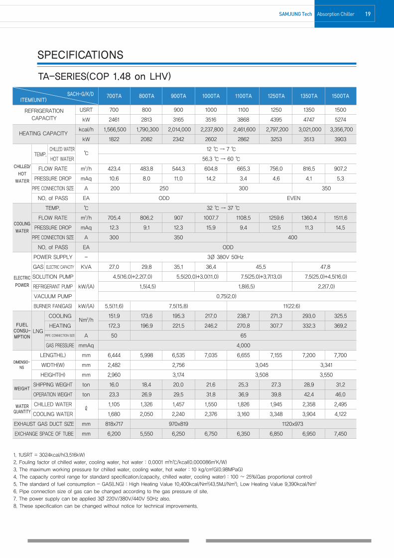
TA-SERIES(COP 1.48 on LHV)
50TA 60TA 70TA 80TA 100TA 120TA 140TA 150TA 180TA
USRT 50 60 70 80 100 120 140 150 180
kW 176 211 246 281 352 422 492 527 633
HEATING CAPACITYkcal/h 111,900 134,300 156,700 179,100 223,800 268,600 313,300 335,700 402,800
kW 130 156 182 208 260 312 364 390 468
CHILLED WATER℃
12 ℃ → 7 ℃
HOT WATER 56.3 ℃ → 60 ℃
FLOW RATE m3/h 30.2 36.3 42.3 48.4 60.5 72.6 84.7 90.7 108.9
PRESSURE DROP mAq 4.4 5.1 4.4 4.7 4.4 5.0 5.5 5.4 6.3
PIPE CONNECTION SIZE A 65 80 100 125
NO. of PASS EA EVEN ODD
TEMP. ℃ 32 ℃ → 37 ℃
FLOW RATE m3/h 50.4 60.5 70.5 80.6 100.8 120.9 141.1 151.2 181.4
PRESSURE DROP mAq 6.2 7.0 6.5 6.7 6.8 7.3 7.6 7.2 8.8
PIPE CONNECTION SIZE A 80 100 125 150
NO. of PASS EA EVEN ODD
POWER SUPPLY - 3Ø 380V 50Hz
ELECTRIC CAPACITY KVA 8.4 9.8 11.4
SOLUTION PUMP 1.1(4.0)+1.2(4.0) 1.5(5.5)+1.2(4.0) 2.0(6.5)+1.5(5.5)
REFRIGERANT PUMP kW/(A) 0.2(1.1) 0.3(1.6)
VACUUM PUMP 0.75(2.0)
BURNER FAN(GAS) kW/(A) 0.75(1.7)
COOLINGNm3/h
10.9 13.0 15.2 17.4 21.7 26.0 30.4 32.6 39.1
HEATING 12.3 14.8 17.2 19.7 24.6 29.5 34.5 36.9 44.3
PIPE CONNECTION SIZE A 25 40
GAS PRESSURE mmAq 200
LENGTH(L) mm 2,634 2,892 3,039 3,157 3,505
WIDTH(W) mm 1,707 1,755 1,800 1,949 1,949
HEIGHT(H) mm 2,091 2,126 2,504
SHIPPING WEIGHT ton 3.5 3.6 4.2 4.2 5.0 5.1 5.5 5.5 6.3
OPERATION WEIGHT ton 4.4 4.5 5.2 5.3 6.6 6.6 7.2 7.3 8.5
CHILLED WATERℓ
114 122 143 153 216 230 258 272 340
COOLING WATER 155 166 195 210 312 333 384 406 488
EXHAUST GAS DUCT SIZE mm 520x468 600x518 600x517
EXCHANGE SPACE OF TUBE mm 1,850 2,450 2,550 3,220
1. 1USRT = 3024kcal/h(3.516kW)2. Fouling factor of chilled water, cooling water, hot water : 0.0001 m2h℃/kcal(0.000086m2K/W)3. The maximum working pressure for chilled water, cooling water, hot water : 10 kg/cm2G(0.98MPaG)4. The capacity control range for standard specification.(capacity, chilled water, cooling water) : 100 ~ 25%(Gas proportional control)5. The standard of fuel consumption - GAS(LNG) : High Heating Value 10,400kcal/Nm3(43.5MJ/Nm3), Low Heating Value 9,390kcal/Nm3
6. Pipe connection size of gas can be changed according to the gas pressure of site.7. The power supply can be applied 3Ø 220V/380V/440V 50Hz also.8. These specification can be changed without notice for technical improvements.
TEMP.
REFRIGERATIONCAPACITY
GAS
LNG
SACH-G/K/DITEM(UNIT)
CHILLED/
HOT
WATER
COOLING
WATER
ELECTRIC
POWER
DIMENSIO-NS
WEIGHT
WATERQUANTITY
FUELCONSU-MPTION
180717 11-26최종-s 1904.1.25 4:55 AM 페이지17 C M Y K

18 Absorption Chiller SAMJUNG TECH
SPECIFICATIONS
210TA 240TA 280TA 320TA 360TA 400TA 450TA 500TA 560TA 630TA
USRT 210 240 280 320 360 400 450 500 560 630
kW 738 844 985 1125 1266 1407 1582 1758 1969 2215
HEATING CAPACITYkcal/h 470,000 537,100 626,600 716,100 805,600 895,200 1,007,000 1,118,900 1,253,200 1,409,800
kW 547 625 729 833 937 1041 1171 1301 1457 1639
CHILLED WATER℃
12 ℃ → 7 ℃
HOT WATER 56.3 ℃ → 60 ℃
FLOW RATE m3/h 127.0 145.2 169.3 193.5 217.7 241.9 272.2 302.4 338.7 381.0
PRESSURE DROP mAq 5.3 5.8 4.8 5.3 4.4 4.7 5.3 5.7 7.9 7.9
PIPE CONNECTION SIZE A 125 150 200
NO. of PASS EA EVEN ODD
TEMP. ℃ 32 ℃ → 37 ℃
FLOW RATE m3/h 211.6 241.9 282.2 322.5 362.8 403.1 453.5 503.9 564.3 634.9
PRESSURE DROP mAq 7.0 7.5 6.5 6.9 6.6 6.6 7.2 7.5 9.5 9.2
PIPE CONNECTION SIZE A 150 200 250 300
NO. of PASS EA EVEN ODD
POWER SUPPLY - 3Ø 380V 50Hz
ELECTRIC CAPACITY KVA 13.3 14.7 16.4 22.8 25.1
SOLUTION PUMP 2.4(7.5)+1.5(5.5) 2.4(7.5)+2.0(6.5) 3.4(10.0)+2.0(6.5) 3.7(13.0)+2.2(7.0)
REFRIGERANT PUMP kW/(A) 0.3(1.6) 0.4(1.6) 1.5(4.5)
VACUUM PUMP 0.75(2.0)
BURNER FAN(GAS) kW/(A) 1.5(3.6) 2.2(4.7) 3.7(8.1) 5.5(11.6)
COOLINGNm3/h
45.6 52.1 60.8 69.4 78.1 86.8 97.7 108.5 121.5 136.7
HEATING 51.7 59.1 68.9 78.8 88.6 98.5 110.8 123.1 137.9 155.1
PIPE CONNECTION SIZE A 50 40 50
GAS PRESSURE mmAq 200 4,000
LENGTH(L) mm 3,930 4,588 4,696 5,071 5,783
WIDTH(W) mm 1,949 1,955 2,159 2,369 2,482
HEIGHT(H) mm 2,504 2,516 2,960
SHIPPING WEIGHT ton 7.3 7.3 8.4 8.6 10.4 10.5 12.0 12.1 14.2 14.6
OPERATION WEIGHT ton 9.9 10.0 11.7 11.8 14.3 14.6 16.9 17.2 20.5 21.1
CHILLED WATERℓ
392 414 456 483 603 634 768 801 922 1,001
COOLING WATER 559 594 646 690 837 888 1,079 1,133 1,405 1,532
EXHAUST GAS DUCT SIZE mm 600x517 704x617 818x717
EXCHANGE SPACE OF TUBE mm 3,870 4,670 4,600 4,800 5,500
1. 1USRT = 3024kcal/h(3.516kW)2. Fouling factor of chilled water, cooling water, hot water : 0.0001 m2h℃/kcal(0.000086m2K/W)3. The maximum working pressure for chilled water, cooling water, hot water : 10 kg/cm2G(0.98MPaG)4. The capacity control range for standard specification.(capacity, chilled water, cooling water) : 100 ~ 25%(Gas proportional control)5. The standard of fuel consumption - GAS(LNG) : High Heating Value 10,400kcal/Nm3(43.5MJ/Nm3), Low Heating Value 9,390kcal/Nm3
6. Pipe connection size of gas can be changed according to the gas pressure of site.7. The power supply can be applied 3Ø 220V/380V/440V 50Hz also.8. These specification can be changed without notice for technical improvements.
TEMP.
REFRIGERATIONCAPACITY
GAS
LNG
SACH-G/K/DITEM(UNIT)
CHILLED/
HOT
WATER
COOLING
WATER
ELECTRIC
POWER
DIMENSIO-NS
WEIGHT
WATERQUANTITY
FUELCONSU-MPTION
TA-SERIES(COP 1.48 on LHV)
180717 11-26최종-s 1904.1.25 4:55 AM 페이지18 C M Y K
19SAMJUNG Tech Absorption Chiller
SPECIFICATIONS
TA-SERIES(COP 1.48 on LHV)
700TA 800TA 900TA 1000TA 1100TA 1250TA 1350TA 1500TA
USRT 700 800 900 1000 1100 1250 1350 1500
kW 2461 2813 3165 3516 3868 4395 4747 5274
HEATING CAPACITYkcal/h 1,566,500 1,790,300 2,014,000 2,237,800 2,461,600 2,797,200 3,021,000 3,356,700
kW 1822 2082 2342 2602 2862 3253 3513 3903
CHILLED WATER℃
12 ℃ → 7 ℃
HOT WATER 56.3 ℃ → 60 ℃
FLOW RATE m3/h 423.4 483.8 544.3 604.8 665.3 756.0 816.5 907.2
PRESSURE DROP mAq 10.6 8.0 11.0 14.2 3.4 4.6 4.1 5.3
PIPE CONNECTION SIZE A 200 250 300 350
NO. of PASS EA ODD EVEN
TEMP. ℃ 32 ℃ → 37 ℃
FLOW RATE m3/h 705.4 806.2 907 1007.7 1108.5 1259.6 1360.4 1511.6
PRESSURE DROP mAq 12.3 9.1 12.3 15.9 9.4 12.5 11.3 14.5
PIPE CONNECTION SIZE A 300 350 400
NO. of PASS EA ODD
POWER SUPPLY - 3Ø 380V 50Hz
ELECTRIC CAPACITY KVA 27.0 29.8 35.1 36.4 45.5 47.8
SOLUTION PUMP 4.5(16.0)+2.2(7.0) 5.5(20.0)+3.0(11.0) 7.5(25.0)+3.7(13.0) 7.5(25.0)+4.5(16.0)
REFRIGERANT PUMP kW/(A) 1.5(4.5) 1.8(6.5) 2.2(7.0)
VACUUM PUMP 0.75(2.0)
BURNER FAN(GAS) kW/(A) 5.5(11.6) 7.5(15.8) 11(22.6)
COOLINGNm3/h
151.9 173.6 195.3 217.0 238.7 271.3 293.0 325.5
HEATING 172.3 196.9 221.5 246.2 270.8 307.7 332.3 369.2
PIPE CONNECTION SIZE A 50 65
GAS PRESSURE mmAq 4,000
LENGTH(L) mm 6,444 5,998 6,535 7,035 6,655 7,155 7,200 7,700
WIDTH(W) mm 2,482 2,756 3,045 3,341
HEIGHT(H) mm 2,960 3,174 3,508 3,550
SHIPPING WEIGHT ton 16.0 18.4 20.0 21.6 25.3 27.3 28.9 31.2
OPERATION WEIGHT ton 23.3 26.9 29.5 31.8 36.9 39.8 42.4 46.0
CHILLED WATERℓ
1,105 1,326 1,457 1,550 1,826 1,945 2,358 2,495
COOLING WATER 1,680 2,050 2,240 2,376 3,160 3,348 3,904 4,122
EXHAUST GAS DUCT SIZE mm 818x717 970x819 1120x973
EXCHANGE SPACE OF TUBE mm 6,200 5,550 6,250 6,750 6,350 6,850 6,950 7,450
1. 1USRT = 3024kcal/h(3.516kW)2. Fouling factor of chilled water, cooling water, hot water : 0.0001 m2h℃/kcal(0.000086m2K/W)3. The maximum working pressure for chilled water, cooling water, hot water : 10 kg/cm2G(0.98MPaG)4. The capacity control range for standard specification.(capacity, chilled water, cooling water) : 100 ~ 25%(Gas proportional control)5. The standard of fuel consumption - GAS(LNG) : High Heating Value 10,400kcal/Nm3(43.5MJ/Nm3), Low Heating Value 9,390kcal/Nm3
6. Pipe connection size of gas can be changed according to the gas pressure of site.7. The power supply can be applied 3Ø 220V/380V/440V 50Hz also.8. These specification can be changed without notice for technical improvements.
TEMP.
REFRIGERATIONCAPACITY
GAS
LNG
SACH-G/K/DITEM(UNIT)
CHILLED/
HOT
WATER
COOLING
WATER
ELECTRIC
POWER
DIMENSIO-NS
WEIGHT
WATERQUANTITY
FUELCONSU-MPTION
180717 11-26최종-s 1904.1.25 4:55 AM 페이지19 C M Y K

20 Absorption Chiller SAMJUNG TECH
[Foundation]
NOTE1. Smooth the concrete foundation surface and the horizontal levelmust become below 1/500.
2. The horizontal level of chiller installed must become below 1/1000.
3. (▨) symbol indicates [BASE LEG] of chiller.4. Make a drainage ditch around the chiller.
Model G1 G2 G3 G4 B1 B2 B3 B4 L1 L2 L3 W
50M300 912 350 826 100 712 150 626 1460 630 700 877
60M
70M912 826 712 626 474 877
80M1538 1026
100M936 736 512 973
120M906 706
130M1072 872 1580 533 1047 1033
150M 400 400 200 200
180M 952 912 752 712 2370 979 1276 976
210M2370 665 1705
240M1072 920 872 720 1040
280M3300 1267 1913
320M
360M1077 1040 877 840 3440 1067 2245 1114
400M
450M1237 1037 3440 1117 2195 1257
500M 450 450 250 250
560M 1166 966 3440 417 2563
630M 1317 1117 3940 917 2761 1315
700M 4440 1219 2959
800M 3870 1300 2700
900M 1317 1322 1117 1122 4370 1300 3000 1428
1000M 550 550 350 350 4870 1300 3400
1100M 1357 1322 1157 1122 4870 1300 3400 1448
1250M 1466 1566 1266 1366 4370 1411 3600 1585
1500M 1466 1566 1266 1366 5370 1411 3959 1585
(unit : mm)
180717 11-26최종-s 1904.1.25 4:55 AM 페이지20 C M Y K

21SAMJUNG Tech Absorption Chiller
[Control Panel & Wiring]
180717 11-26최종-s 1904.1.25 4:55 AM 페이지21 C M Y K
22 Absorption Chiller SAMJUNG TECH
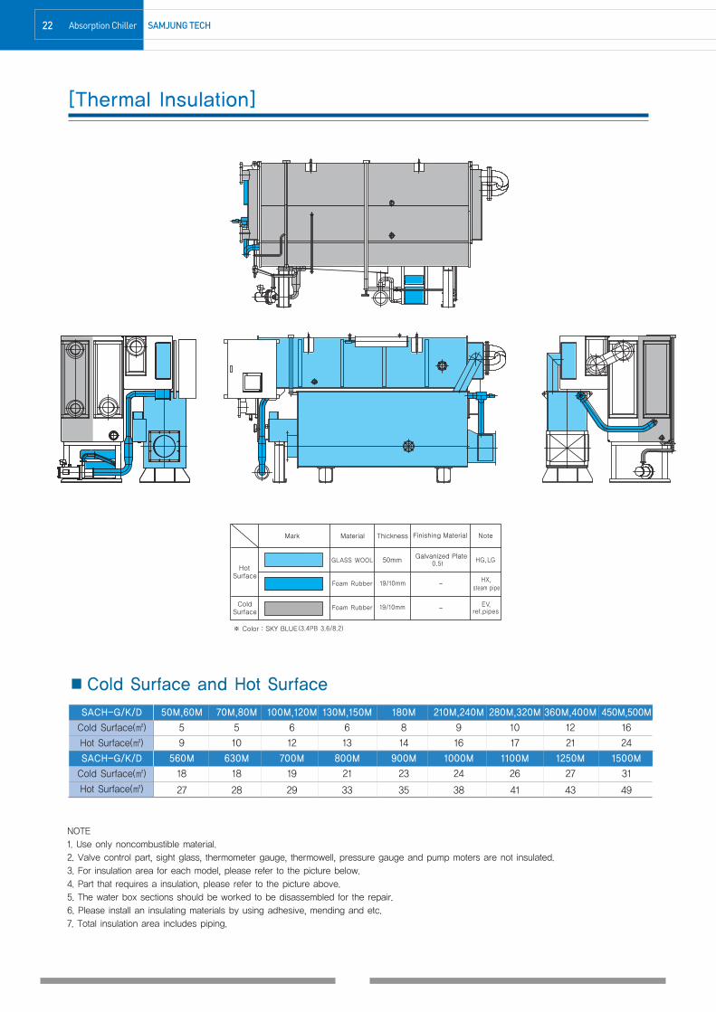
[Thermal Insulation]
NOTE1. Use only noncombustible material.2. Valve control part, sight glass, thermometer gauge, thermowell, pressure gauge and pump moters are not insulated.3. For insulation area for each model, please refer to the picture below.4. Part that requires a insulation, please refer to the picture above.5. The water box sections should be worked to be disassembled for the repair.6. Please install an insulating materials by using adhesive, mending and etc. 7. Total insulation area includes piping.
■Cold Surface and Hot Surface
SACH-G/K/D 50M,60M 70M,80M 100M,120M 130M,150M 180M 210M,240M 280M,320M 360M,400M 450M,500M
Cold Surface(㎡) 5 5 6 6 8 9 10 12 16
Hot Surface(㎡) 9 10 12 13 14 16 17 21 24
SACH-G/K/D 560M 630M 700M 800M 900M 1000M 1100M 1250M 1500M
Cold Surface(㎡) 18 18 19 21 23 24 26 27 31
Hot Surface(㎡) 27 28 29 33 35 38 41 43 49
180717 11-26최종-s 1904.1.25 4:55 AM 페이지22 C M Y K

23SAMJUNG Tech Absorption Chiller
[Chimney Size]
NOTE1. Above table apply to [ standard T-TYPE ] high efficiency direct fired absorption chiller & heater.2. The standard of gas consumption - LNG : High Heating Value 10,400kcal/Nm3(43.5MJ/Nm3)3. Recommended velocity for exhaust gas in chimney : 4m/s ~ 6m/s4. Above data is counted by following preconditions.- duct length 50m- excess air factor 1:2- average temperature of duct 157.5℃
5. Therefore constructor must count exact chimney size again according to on-site conditions.
Heating Cross-Section Area(m2) Square Duct(mm x mm) Round Duct(mm)Model GasCon.
4m/s 5m/s 6m/s 4m/s 5m/s 6m/s 4m/s 5m/s 6m/srate(Nm3/h)
50M 14.5 0.022 0.018 0.015 150 130 120 170 150 140
60M 17.4 0.026 0.021 0.018 160 140 130 180 160 150
70M 20.3 0.031 0.025 0.020 180 160 140 200 180 160
80M 23.2 0.035 0.028 0.023 190 170 150 210 190 170
100M 29.0 0.044 0.035 0.029 210 190 170 240 210 190
120M 34.8 0.053 0.042 0.035 230 210 190 260 230 210
130M 37.7 0.057 0.046 0.038 240 210 190 270 240 220
150M 43.5 0.066 0.053 0.044 260 230 210 290 260 240
180M 52.2 0.079 0.063 0.053 280 250 230 320 280 260
210M 60.9 0.092 0.074 0.061 300 270 250 340 310 280
240M 69.6 0.105 0.084 0.070 320 290 260 370 330 300
280M 81.2 0.123 0.098 0.082 350 310 290 400 350 320
320M 92.8 0.140 0.112 0.093 370 330 310 420 380 340
360M 104.4 0.158 0.126 0.105 400 360 320 450 400 370
400M 116.0 0.175 0.140 0.117 420 370 340 470 420 390
450M 130.5 0.197 0.158 0.131 440 400 360 500 450 410
500M 145.0 0.219 0.175 0.146 470 420 380 530 470 430
560M 162.4 0.245 0.196 0.163 500 440 400 560 500 460
630M 182.7 0.276 0.221 0.184 530 470 430 590 530 480
700M 203.0 0.307 0.245 0.204 550 500 450 620 560 510
800M 232.0 0.350 0.280 0.234 590 530 480 670 600 550
900M 261.0 0.394 0.315 0.263 630 560 510 710 630 580
1000M 290.0 0.438 0.350 0.292 660 590 540 750 670 610
1100M 319.0 0.482 0.385 0.321 690 620 570 780 700 640
1250M 362.5 0.547 0.438 0.365 740 660 600 830 750 680
1500M 435.0 0.657 0.525 0.438 810 720 660 910 820 750
180717 11-26최종-s 1904.1.25 4:55 AM 페이지23 C M Y K

24 Absorption Chiller SAMJUNG TECH
[Piping Plan]
1. Piping Work
Fuel channels
Please install agasmeter or flowmeter(in case of oil) close tothe chiller & heater
Drain channels
Install the drain for airvent and the drain pipe.
Exhaust gas channels
Design the exhaustgas duct andchimney to become0~-5mmAq of thepressure at theexhaust gas outletof the Chiller &Heater.
Cooling water channels
※ Please prepare a flange,gasket, and bolt.
※ Examples
Thermometer Drain Valve
Pressure Guage Pump
Strainer 3-Way Valve
Stop Valve 2-Way Valve
Chilled(Hot) water channels
AHUexpansion
tank
Back&Forth
In case of Oil
Drain
Vinyl hose (attached on the main body)
Please control the coolingwater temperature by threeway valve starting andstopping and the coolingtower fan.
supply header
return header
bypass valve
2. Attention for the execution of piping work forchilled(hot) water and cooling water
3. Power Supply for Chiller & Heater
❶ Water piping should be installed as shown in the picture.
❷ Please refer to approval drawing of our company for the directions forwater inlet/outlet. It may vary depending on the capacity size.
❸ Make sure chiller & heater does not get the pressure over 10kg/cm2G(Please consult our company in case the pressure is over10kg/cm2G).
❹ Please install the drain valve at the lowest point between the valveand chiller & heater.
❺ Please install the air vent valve higher than the chiller & heater.
❻ Please install the thermometer and pressure gauge as shown in thepicture.
❼ Please install the expansion tank as shown in the picture in case ofchilled(hot) water channels do not open.
❽ Please install the cooling tower where the exhaust gas from thechimney does not reach. Otherwise it may cause the corrosion byhaving the contaminated materials from the exhaust gas to thecooling water.
❾ Please install 20MESH strainer. Too much contaminated materials inthe chilled water channel may cause the freezing of chilled water in thetube and blockage of cooling water channel may cause too muchpressure during operation and corrode the tube.
❿ Please secure water supply source for cleaning the tube.
Power supply for the chiller & Heater is designed forthree phase/three wire as the standard. Please referto the picture for the supplying method.
In case of three
phase/three wire,
S wire should
be earthed.
In case of power
supply of three
phase/four wire, and
S wire cannot be
earthed,
please install high
sensitivity Earth
Leakage Breaker
operating under 50mA
in order to prevent
malfunction of
combustion apparatus.
EARTH
CHILLER & HEATERCONTROL PANEL
ELB
CHILLER & HEATERPANEL
SENSITIVITY E.L.B(Option)
SCOPE of
SUPPLY
SCOPE of
SUPPLY
180717 11-26최종-s 1904.1.25 4:55 AM 페이지24 C M Y K

25SAMJUNG Tech Absorption Chiller
[Supply Scope(Standard)]
Division Description Scope
1) 2-stage Evaporator, 2-stage Absorber, Condenser, Low temp. Generator, High temp. Generator
2) Low/high temp. Sol. Heat Exchanger, Condensated Ref. Heat Exchanger,
Exhaust Gas Heat Exchanger
3) Sol. Circulation Pump, Sol. Spray Pump, Ref. Spray Pump, Purge Pump
4) Burner
5) Control Panel
- Panel unit
Chiller Assembly - Lamps(Operation, Stop, Alarm), Button(Reset, Operation, Stop), Touch Screen
- Circuit Brakers, Relays, PLC controller
6) Purge device Vendor
- Purge storage tank, Ejector, Oil trap, Manometer, Piping and manual valves
7) Interconnecting piping and wiring
- Refrigerant & Solution Piping for internal mechanical components
- Control & Power wiring for internal electrical components
Initial charge Absorbent Solution(Lithium Bromide) with inhibitor, Refrigerant(distilled water)
Painting for chiller assembly and control panel
Painting - Chiller body : Sky Blue ( Munsel No. 7.3B 5.1/9.0 )
- Control panel : Light Yellow ( Munsel No. 5Y 7.0/1.0 )
Insulation Insulation of cold surface and hot surface for absorption chiller Option
1) Check of external dimensions
Test & Inspection2) Hydraulic pressure test for water boxes
3) Leak test ( Vacuum side )Vendor
4) Function test for electric circuit and safety device
Performance Test Factory test Option
1. Foundation of chiller
Installation & 2. Installation of chiller ( Only, vendor supply vibration-proof rubber, base plate)Buyer
wiring work 3. Piping and wiring connections out of chiller
4. Interlock wiring of chilled water pump, cooling water pump
Start-up
operation testAt site with vendor Option
※ Items to be confirmed when ordering① Purpose : General air conditioning, Process cooling, etc.② Specification·Cooling/Heating Capacity : usRT, Kw·Chilled/Cooling/Hot water : inlet/outlet temperature(℃), flowrate(m3/h)·Power supply : voltage, frequency·Fuel : kind, heating value(gas:high, oil:low), supply pressure in case of gas
③ Installation condition : indoor, outdoor, special consideration(ex. Sea water, etc.), having noise or gas(Nox, etc.) emission regulation④ Operation condition : year-round operating, 24-hour operating
180717 11-26최종-s 1904.1.25 4:55 AM 페이지25 C M Y K
26 Absorption Chiller SAMJUNG TECH
M/E/M/O
180717 11-26최종-s 1904.1.25 4:55 AM 페이지26 C M Y K

0228 Cooling Cycle
29 Automatic Sensing & Safety Apparatus
30 Specifications
33 Foundation
34 Control Panel & Wiring
35 Thermal Insulation
36 Steam Control Valve
37 Piping Plan
39 Performance Curve
40 Supply Scope(Standard)
High Efficiency Steam Driven Absorption Chiller
180717 27-42 1904.1.25 5:1 AM 페이지27 C M Y K

28 Absorption Chiller SAMJUNG TECH
[Cooling Cycle][Cooling Cycle]
■Symbol Explanation
■Solution Flow
EV evaporator
AB absorber
CO condenser
LG low temperature generator
HG high temperature generator
LX low heat exchanger
HX high heat exchanger
RX condensed refrigerant heat exchanger
DX1 drain heat exchanger #1
DX2 drain heat exchanger #2
CP solution circulation pump
SP solution spray pump
RP refrigerant spray pump
CV steam control valve
AB ABCP
RX DX1
HX
LGSPLX
DX2
HG HXLX
180717 27-42 1904.1.25 5:1 AM 페이지28 C M Y K
29SAMJUNG TECH Absorption Chiller
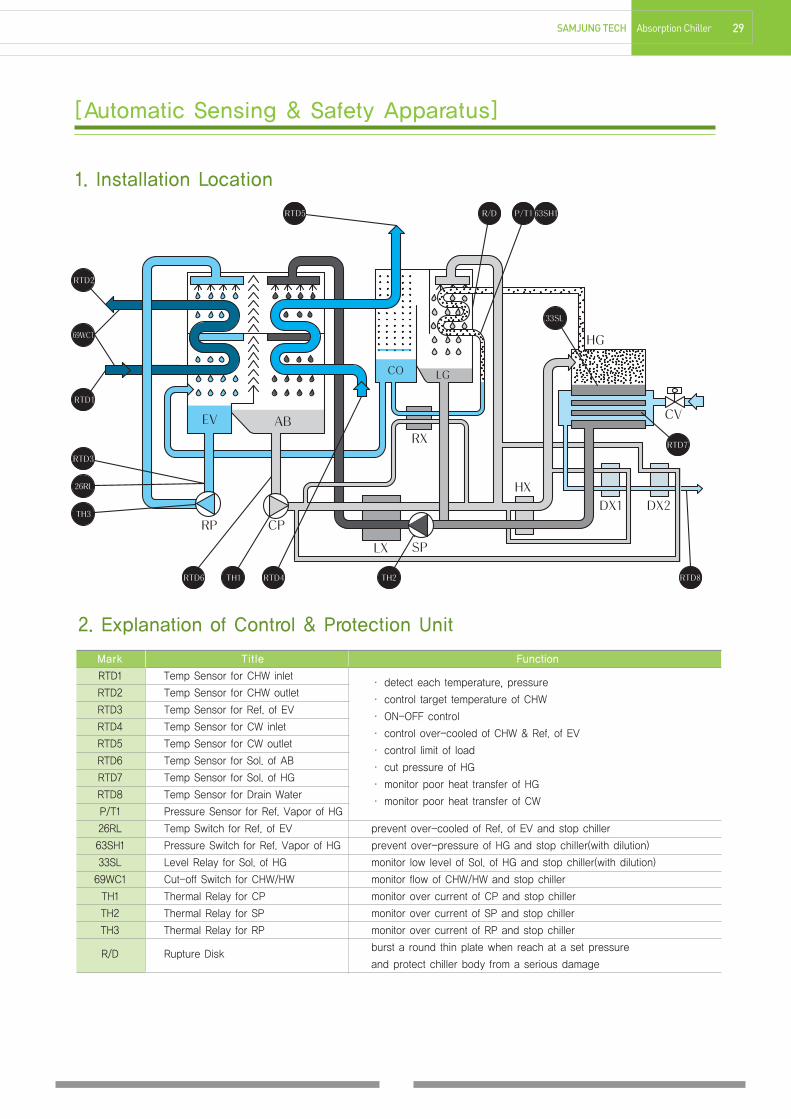
[Automatic Sensing & Safety Apparatus]
2. Explanation of Control & Protection Unit
Mark Title Function
RTD1 Temp Sensor for CHW inlet· detect each temperature, pressure
RTD2 Temp Sensor for CHW outlet· control target temperature of CHW
RTD3 Temp Sensor for Ref. of EV· ON-OFF control
RTD4 Temp Sensor for CW inlet· control over-cooled of CHW & Ref. of EV
RTD5 Temp Sensor for CW outlet· control limit of load
RTD6 Temp Sensor for Sol. of AB· cut pressure of HG
RTD7 Temp Sensor for Sol. of HG· monitor poor heat transfer of HG
RTD8 Temp Sensor for Drain Water· monitor poor heat transfer of CW
P/T1 Pressure Sensor for Ref. Vapor of HG
26RL Temp Switch for Ref. of EV prevent over-cooled of Ref. of EV and stop chiller
63SH1 Pressure Switch for Ref. Vapor of HG prevent over-pressure of HG and stop chiller(with dilution)
33SL Level Relay for Sol. of HG monitor low level of Sol. of HG and stop chiller(with dilution)
69WC1 Cut-off Switch for CHW/HW monitor flow of CHW/HW and stop chiller
TH1 Thermal Relay for CP monitor over current of CP and stop chiller
TH2 Thermal Relay for SP monitor over current of SP and stop chiller
TH3 Thermal Relay for RP monitor over current of RP and stop chiller
R/D Rupture Diskburst a round thin plate when reach at a set pressure
and protect chiller body from a serious damage
1. Installation Location
180717 27-42 1904.1.25 5:1 AM 페이지29 C M Y K

30 Absorption Chiller SAMJUNG Tech
SPECIFICATIONS
50T 60T 70T 80T 100T 120T 140T 150T 180T
USRT 50 60 70 80 100 120 140 150 180
kW 176 211 246 281 352 422 492 527 633
TEMP. ℃ 12 ℃ → 7 ℃
FLOW RATE m3/h 30.2 36.3 42.3 48.4 60.5 72.6 84.7 90.7 108.9
PRESSURE DROP mAq 4.4 5.1 4.4 4.7 4.4 5.0 5.5 5.4 6.3
PIPE CONNECTION SIZE A 65 80 100 125
NO. of PASS EA EVEN ODD
TEMP. ℃ 32 ℃ → 37 ℃
FLOW RATE m3/h 50.4 60.5 70.5 80.6 100.8 120.9 141.1 151.2 181.4
PRESSURE DROP mAq 6.2 7.0 6.5 6.7 6.8 7.3 7.6 7.2 8.8
PIPE CONNECTION SIZE A 80 100 125 150
NO. of PASS EA EVEN ODD
POWER SUPPLY - 3Ø 380V 50Hz
ELECTRIC CAPACITY KVA 7.3 8.6 10.3
SOLUTION PUMP 1.1(4.0)+1.2(4.0) 1.5(5.5)+1.2(4.0) 2.0(6.5)+1.5(5.5)
REFRIGERANT PUMP kW/(A) 0.2(1.1) 0.3(1.6)
VACUUM PUMP 0.75(2.0)
PRESSURE kg/㎠G 8
MAX. CONSUMPTION kg/h 195 234 273 312 390 468 546 585 702
INLET PIPE DIAMETER A 65
OUTLET PIPE DIAMETER A 20
LENGTH(L) mm 2,286 2,766 2,836 3,226
WIDTH(W) mm 1,664 1,712 1,763 1,949
HEIGHT(H) mm 2,091 2,126 2,504
SHIPPING WEIGHT ton 3.0 3.0 3.5 3.6 4.3 4.4 4.7 4.7 5.4
OPERATION WEIGHT ton 3.9 3.9 4.4 4.5 5.6 5.7 6.2 6.3 7.3
CHILLED WATERℓ
114 122 143 153 216 230 258 272 340
COOLING WATER 155 166 195 210 312 333 384 406 488
EXCHANGE SPACE OF TUBE mm 1,850 2,450 2,550 3,220
1. 1USRT = 3024kcal/h(3.516kW)2. Fouling factor of chilled water, cooling water : 0.0001 m2h℃/kcal(0.000086m2K/W)3. The maximum working pressure for chilled water, cooling water : 10 Kg/cm2G(0.98MPaG)4. The capacity control range for standard specification.(capacity, chilled water, cooling water) : 100 ~ 25%(Steam proportional control)5. The power supply can be applied 3Ø 220V/380V/440V 50Hz also.6. These specification can be changed without notice for technical improvements.
REFRIGERATIONCAPACITY
SAC-BWITEM(UNIT)
CHILLED
WATER
COOLING
WATER
ELECTRIC
POWER
WEIGHT
STEAM
WATERQUANTITY
DIMENSIO-NS
180717 27-42 1904.1.25 5:1 AM 페이지30 C M Y K
31SAMJUNG TECH Absorption Chiller
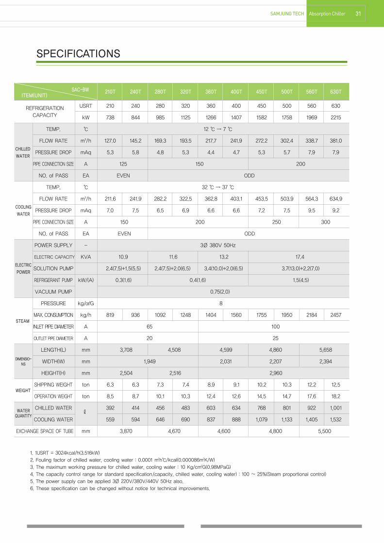
SPECIFICATIONS
1. 1USRT = 3024kcal/h(3.516kW)2. Fouling factor of chilled water, cooling water : 0.0001 m2h℃/kcal(0.000086m2K/W)3. The maximum working pressure for chilled water, cooling water : 10 Kg/cm2G(0.98MPaG)4. The capacity control range for standard specification.(capacity, chilled water, cooling water) : 100 ~ 25%(Steam proportional control)5. The power supply can be applied 3Ø 220V/380V/440V 50Hz also.6. These specification can be changed without notice for technical improvements.
210T 240T 280T 320T 360T 400T 450T 500T 560T 630T
USRT 210 240 280 320 360 400 450 500 560 630
kW 738 844 985 1125 1266 1407 1582 1758 1969 2215
TEMP. ℃ 12 ℃ → 7 ℃
FLOW RATE m3/h 127.0 145.2 169.3 193.5 217.7 241.9 272.2 302.4 338.7 381.0
PRESSURE DROP mAq 5.3 5.8 4.8 5.3 4.4 4.7 5.3 5.7 7.9 7.9
PIPE CONNECTION SIZE A 125 150 200
NO. of PASS EA EVEN ODD
TEMP. ℃ 32 ℃ → 37 ℃
FLOW RATE m3/h 211.6 241.9 282.2 322.5 362.8 403.1 453.5 503.9 564.3 634.9
PRESSURE DROP mAq 7.0 7.5 6.5 6.9 6.6 6.6 7.2 7.5 9.5 9.2
PIPE CONNECTION SIZE A 150 200 250 300
NO. of PASS EA EVEN ODD
POWER SUPPLY - 3Ø 380V 50Hz
ELECTRIC CAPACITY KVA 10.9 11.6 13.2 17.4
SOLUTION PUMP 2.4(7.5)+1.5(5.5) 2.4(7.5)+2.0(6.5) 3.4(10.0)+2.0(6.5) 3.7(13.0)+2.2(7.0)
REFRIGERANT PUMP kW/(A) 0.3(1.6) 0.4(1.6) 1.5(4.5)
VACUUM PUMP 0.75(2.0)
PRESSURE kg/㎠G 8
MAX. CONSUMPTION kg/h 819 936 1092 1248 1404 1560 1755 1950 2184 2457
INLET PIPE DIAMETER A 65 100
OUTLET PIPE DIAMETER A 20 25
LENGTH(L) mm 3,708 4,508 4,599 4,860 5,658
WIDTH(W) mm 1,949 2,031 2,207 2,394
HEIGHT(H) mm 2,504 2,516 2,960
SHIPPING WEIGHT ton 6.3 6.3 7.3 7.4 8.9 9.1 10.2 10.3 12.2 12.5
OPERATION WEIGHT ton 8.5 8.7 10.1 10.3 12.4 12.6 14.5 14.7 17.6 18.2
CHILLED WATERℓ
392 414 456 483 603 634 768 801 922 1,001
COOLING WATER 559 594 646 690 837 888 1,079 1,133 1,405 1,532
EXCHANGE SPACE OF TUBE mm 3,870 4,670 4,600 4,800 5,500
REFRIGERATIONCAPACITY
SAC-BWITEM(UNIT)
CHILLED
WATER
COOLING
WATER
ELECTRIC
POWER
WEIGHT
STEAM
WATERQUANTITY
DIMENSIO-NS
180717 27-42 1904.1.25 5:1 AM 페이지31 C M Y K

32 Absorption Chiller SAMJUNG TECH
SPECIFICATIONS
1. 1USRT = 3024kcal/h(3.516kW)2. Fouling factor of chilled water, cooling water : 0.0001 m2h℃/kcal(0.000086m2K/W)3. The maximum working pressure for chilled water, cooling water : 10 Kg/cm2G(0.98MPaG)4. The capacity control range for standard specification.(capacity, chilled water, cooling water) : 100 ~ 25%(Steam proportional control)5. The power supply can be applied 3Ø 220V/380V/440V 50Hz also.6. These specification can be changed without notice for technical improvements.
700T 800T 900T 1000T 1100T 1250T 1350T 1500T
USRT 700 800 900 1000 1100 1250 1350 1500
kW 2461 2813 3165 3516 3868 4395 4747 5274
TEMP. ℃ 12 ℃ → 7 ℃
FLOW RATE m3/h 423.4 483.8 544.3 604.8 665.3 756.0 816.5 907.2
PRESSURE DROP mAq 10.6 8.0 11.0 14.2 3.4 4.6 4.1 5.3
PIPE CONNECTION SIZE A 200 250 300 350
NO. of PASS EA ODD EVEN
TEMP. ℃ 32 ℃ → 37 ℃
FLOW RATE m3/h 705.4 806.2 907 1007.7 1108.5 1259.6 1360.4 1511.6
PRESSURE DROP mAq 12.3 9.1 12.3 15.9 9.4 12.5 11.3 14.5
PIPE CONNECTION SIZE A 300 350 400
NO. of PASS EA ODD
POWER SUPPLY - 3Ø 380V 50Hz
ELECTRIC CAPACITY KVA 19.4 24.7 26.0 30.6 32.9
SOLUTION PUMP 4.5(16.0)+2.2(7.0) 5.5(20.0)+3.0(11.0) 7.5(25.0)+3.7(13.0) 7.5(25.0)+4.5(16.0)
REFRIGERANT PUMP kW/(A) 1.5(4.5) 1.8(6.5) 2.2(7.0)
VACUUM PUMP 0.75(2.0)
PRESSURE kg/㎠G 8
MAX. CONSUMPTION kg/h 2730 3120 3510 3900 4290 4875 5265 5850
INLET PIPE DIAMETER A 100 125 150
OUTLET PIPE DIAMETER A 25 32 40
LENGTH(L) mm 6,358 5,779 6,479 6,979 6,514 7,014 7,514
WIDTH(W) mm 2,394 2,666 2,998 3,319
HEIGHT(H) mm 2,960 3,174 3,508 3,550
SHIPPING WEIGHT ton 13.9 15.8 17.1 18.4 20.1 21.7 22.9 24.6
OPERATION WEIGHT ton 20.1 23.1 25.3 27.3 30.6 33.5 34.7 37.4
CHILLED WATERℓ
1,105 1,326 1,457 1,550 1,826 1,945 2,358 2,495
COOLING WATER 1,680 2,050 2,240 2,376 3,160 3,348 3,904 4,122
EXCHANGE SPACE OF TUBE mm 6,200 5,550 6,250 6,750 6,350 6,850 6,950 7,450
REFRIGERATIONCAPACITY
SAC-BWITEM(UNIT)
CHILLED
WATER
COOLING
WATER
ELECTRIC
POWER
WEIGHT
STEAM
WATERQUANTITY
DIMENSIO-NS
180717 27-42 1904.1.25 5:1 AM 페이지32 C M Y K
33SAMJUNG TECH Absorption Chiller
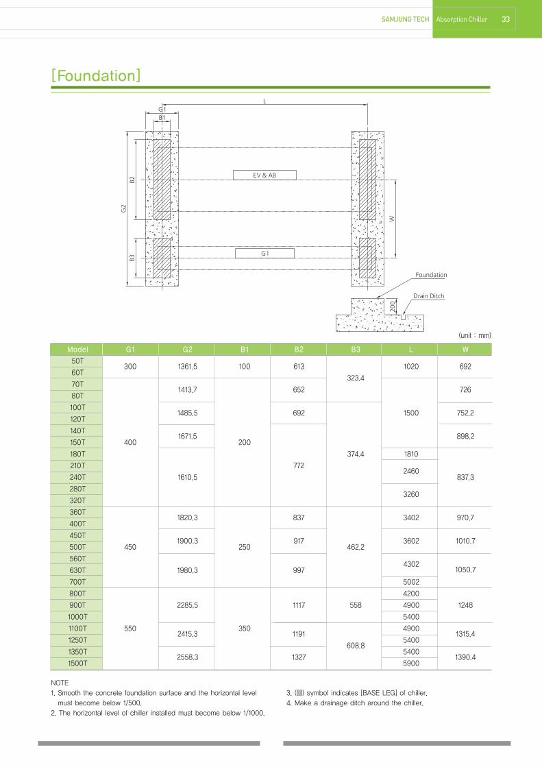
[Foundation]
NOTE1. Smooth the concrete foundation surface and the horizontal levelmust become below 1/500.
2. The horizontal level of chiller installed must become below 1/1000.
3. (▨) symbol indicates [BASE LEG] of chiller.4. Make a drainage ditch around the chiller.
Model G1 G2 B1 B2 B3 L W
50T300 1361.5 100 613 1020 692
60T323.4
70T1413.7 652 726
80T
100T1485.5 692 1500 752.2
120T
140T1671.5 898.2
150T 400 200
180T 374.4 1810
210T 7722460
240T 1610.5 837.3
280T3260
320T
360T1820.3 837 3402 970.7
400T
450T1900.3 917 3602 1010.7
500T 450 250 462.2
560T4302
1050.7630T 1980.3 997
700T 5002
800T 4200
900T 2285.5 1117 558 4900 1248
1000T 5400
1100T 5502415.3
3501191
49001315.4
1250T608.8
5400
1350T2558.3 1327
54001390.4
1500T 5900
(unit : mm)
180717 27-42 1904.1.25 5:1 AM 페이지33 C M Y K

34 Absorption Chiller SAMJUNG TECH
[Control Panel & Wiring]
180717 27-42 1904.1.25 5:1 AM 페이지34 C M Y K

35SAMJUNG TECH Absorption Chiller
[Thermal Insulation]
NOTE1. Use only noncombustible material.2. Valve control part, sight glass, thermometer gauge, thermowell, pressure gauge and pump moters are not insulated.3. For insulation area for each model, please refer to the picture below.4. Part that requires a insulation, please refer to the picture above.5. The water box sections should be worked to be disassembled for the repair.6. Please install an insulating materials by using adhesive, mending and etc. 7. Total insulation area includes piping.
SAC-BW 50T,60T 70T,80T 100T,120T 140T,150T 180T 210T,240T 280T,320T 360T,400T 450T,500T
Cold Surface(㎡) 5 6 7 8 10 12 14 16 18
Hot Surface(㎡) 6 7 9 10 11 12 13 15 17
SAC-BW 560T,630T 700T 800T 900T 1000T 1100T 1250T 1350T 1500T
Cold Surface(㎡) 20 22 23 25 26 27 28 30 33
Hot Surface(㎡) 20 21 23 25 27 29 30 31 34
■Cold Surface and Hot Surface
180717 27-42 1904.1.25 5:1 AM 페이지35 C M Y K

36 Absorption Chiller SAMJUNG TECH
1. DIMENSIONS
2. Standard Electronics
[Steam Control Valve]
CHILLER VALVE H H1 H2 K L1 L2 L3 B D D1 D2 GMODEL SIZE [mm] [mm] [mm] [mm] [mm] [mm] [mm] [mm] [mm] [mm] [mm] [kg]
50T~140T 25A 638 63 159.5 85 160 80 104.5 15 115 65 14(4x) 6.1
150T~320T 40A 635 60 156.5 110 200 100 129 16 150 84 19(4x) 10.2
360T~500T 50A 675 100 196.5 125 230 115 146 16 165 99 19(4x) 13.7
560T~800T 65A 690 115 231.5 145 290 145 178 17 185 118 19(8x) 21.8
900T~1350T 80A 690 115 231.5 160 310 155 190 17 200 132 19(8x) 28.1
1500T 100A 721 146 262.5 190 350 175 212.5 17 235 156 28(8x) 38.0
NOTE1. This page is specifications of SIEMENS. (SIEMENS is standard valve supplier of our company.)2. These specifications can be changed with notice for technical improvements.3. Please receive approval documents of vendor before starting the construction.
Connectionterminals
DIL switchesFunctions see below
Stroke calibration
LEDstatus indication
180717 27-42 1904.1.25 5:1 AM 페이지36 C M Y K

37SAMJUNG TECH Absorption Chiller
[Piping Plan]
�
180717 27-42 1904.1.25 5:1 AM 페이지37 C M Y K

38 Absorption Chiller SAMJUNG TECH
[Piping Plan]
1. Attention for the execution of piping work for chilled water andcooling water
① Water piping should be installed as shown in the picture.
② Please refer to approval drawing of our company for the directions for water inlet/outlet.
③ Make sure chiller does not get the pressure over 8 kg/㎠G.
(Please consult our company in case the pressure is over 8 kg/㎠G.)
④ Please install the drain valve at the lowest point between the valve and chiller.
⑤ Please install the air vent valve higher than the chiller.
⑥ Please install the thermometer, pressure gauge, valve and etc. as shown in the picture.
⑦ Please install the expansion tank as shown in the picture in case of chiller water channels do not open.
⑧ Please install 20MESH strainer. Too much contaminated materials in the chiller water channel may cause the
freezing of chilled water in the tube and blockage of cooling water channel may cause too much pressure during
operation and corrode the tube.
⑨ Please secure water supply source for cleaning the tube.
⑩ Please install the chilled water pump and cooling water pump in front of the chiller, to prevent the heat loss due
to infiltration air.
⑪ Please refer to the water quality management of cooling water.
Please keep the water quality standard by install a device for blowing the cooling water in order to prevent
deterioration of water quality due to concentration of the cooling water.
2. Attention for the execution of piping work for steam and steam drain① Steam drain piping should be installed as shown in the picture.
② Steam supply pressure should plan to be in the specification pressure at the inlet of the steam control valve.
A permissible range of pressure variation (Specification pressure -1 ~ Specification pressure +0.5kgf/cm2G) If the
pressure variation is large, control becomes unstable and it has failure in the chiller. Also, it can influence life of
pumps and control panel.
③ Please install the steam control valve, shut-off valve and pressure gauge in the position as shown in the picture
and please to construction the wiring work up the control panel.
④ Such as foreign object is stuck in the steam control valve cause failure in control valve and they can cause
chiller failure of not be able to control the steam flow rate.
Please install 60~70MESH strainer in the position as shown in the picture.
Also, after installing the piping, please perform sufficient flashing.
⑤ During the chiller stopped by shutting off the steam, please prevent the inflow of steam at high temp. generator.
If manual operation is difficult, please install the automatic shut off valve interlocked with chiller.
(ex. Remote auto pause signal and operating number pause signal and etc.)
⑥ Please connect the start interlock prevents operation without steam.
When operating a long time in a state that steam is not flowing, the chiller will failure.
⑦ Please install the back pressure valve and pressure gauge in the position as shown in the picture in drain pipe
and it can adjust drain back pressure.
(STANDARD DRAIN BACK PRESSURE Max. 1 kgf/cm2G)
⑧ The drain pipe does not require a drain trap.
Because drain from the chiller are sufficiently supercooled condensate.
⑨ Drain piping should be installed a separate piping for each chiller.
⑩ Please refer to installing plan of our company for the directions for steam and drain inlet/outlet.
180717 27-42 1904.1.25 5:1 AM 페이지38 C M Y K

39SAMJUNG TECH Absorption Chiller
[Performance Curve]
*It can be changed according to the operation condition.
180717 27-42 1904.1.25 5:1 AM 페이지39 C M Y K

40 Absorption Chiller SAMJUNG Tech
[Supply Scope(Standard)]
Division Description Scope
1) 2-stage Evaporator, 2-stage Absorber, Condenser, Low temp. Generator, High temp. Generator
2) Low/high temp. Sol. Heat Exchanger, Condensated Ref. Heat Exchanger, 2-Drain Heat Exchanger
3) Sol. Circulation Pump, Sol. Spray Pump, Ref. Spray Pump, Purge Pump
4) Control Panel
- Panel unit
Chiller Assembly - Lamps(Operation, Stop, Alarm), Button(Reset, Operation, Stop), Touch Screen
- Circuit Brakers, Relays, PLC controller
5) Purge device Vendor
- Purge storage tank, Ejector, Oil trap, Manometer, Piping and manual valves
6) Interconnecting piping and wiring
- Refrigerant & Solution Piping for internal mechanical components
- Control & Power wiring for internal electrical components
Initial charge Absorbent Solution(Lithium Bromide) with inhibitor, Refrigerant(distilled water)
PaintingPainting for chiller assembly and control panel
- Chiller body : Sky Blue ( Munsel No. 7.3B 5.1/9.0 )
- Control panel : Light Yellow ( Munsel No. 5Y 7.0/1.0 )
Insulation Insulation of cold surface and hot surface for absorption chiller Option
1) Check of external dimensions
Test & Inspection2) Hydraulic pressure test for water boxes
3) Leak test ( Vacuum side )Vendor
4) Function test for electric circuit and safety device
1. Foundation of chiller
2. Installation of chiller (Only, vendor supply vibration-proof rubber, base plate)Installation &
3. Piping and wiring connections out of chiller Buyerwiring work
4. Interlock wiring of chilled water pump, cooling water pump
5. Installation and wiring of control valve
Start-up
operation testAt site with vendor Option
※ Items to be confirmed when ordering① Purpose : General air conditioning, Process cooling, etc.② Specification· Cooling Capacity : usRT, Kw· Chilled/Cooling water : inlet/outlet temperature(℃), flowrate(m3/h)· Power supply : voltage, frequency· Steam supply pressure
③ Installation condition : indoor, outdoor, special consideration(ex. Sea water, etc.), having copper emission regulation④ Operation condition : year-round operating, 24-hour operating
180717 27-42 1904.1.25 5:1 AM 페이지40 C M Y K

41SAMJUNG Tech Absorption Chiller
M/E/M/O
180717 27-42 1904.1.25 5:1 AM 페이지41 C M Y K

42 Absorption Chiller SAMJUNG TECH
M/E/M/O
180717 27-42 1904.1.25 5:1 AM 페이지42 C M Y K
0344 Cooling Cycle
45 Specifications
47 Foundation
48 Control Panel & Wiring
49 Thermal Insulation
Single Effect Double Lift Hot Water Driven Absorption Chiller
180717 43-50 1904.1.25 5:4 AM 페이지43 C M Y K

44 Absorption Chiller SAMJUNG TECH
■Symbol Explanation
■Solution Flow
1) Main Line
EV evaporator
AB absorber
AA aux. absorber
CO condenser
G1 generator #1
G2 generator #2
GA aux. generator
LX low heat exchanger
HX high heat exchanger
AX aux. heat exchanger
CP solution circulation pump
SP1 solution spray pump #1
SP2 solution spray pump #2
ACP aux. solution circulation pump
ASP aux. solution spray pump
RP refrigerant spray pump
AB ABCP LX SP1HX G1 HX LXG2 SP2
2) Aux. Line
AA ACP AX AXGA ASP AA
Chilled WaterInlet
Chilled WaterOutlet
Cooling WaterOutlet
CoolingWaterInlet
Hot WaterOutlet
Hot WaterInlet
CP
CO
LX
AX
G1
G2 AA
GA
HX
EV AB
RPSP1SP2
ASP
ACP
[Cooling Cycle]
180717 43-50 1904.1.25 5:4 AM 페이지44 C M Y K

45SAMJUNG TECH Absorption Chiller
SPECIFICATIONS
M-SERIES(COP 0.74)
1. 1USRT = 3024kcal/h(3.516kW)2. Fouling factor of chilled water, cooling water, hot water : 0.0001 m2h℃/kcal(0.000086m2K/W)3. The maximum working pressure for chilled water, cooling water : 10 kg/cm2G(0.98MPaG)The maximum working pressure for hot water : 16 kg/cm2G(1.57MPaG)
4. The capacity control range for standard specification.(capacity, chilled water, cooling water) : 100 ~ 25%5. The power supply is can apply 3Ø 220/380/440V 50Hz also.6. These specifications can be changed without notice for technical improvements.
80M 100M 120M 140M 160M 180M 210M 240M 270M 300M
USRT 80 100 120 140 160 180 210 240 270 300
kW 281 352 422 492 563 633 738 844 949 1,055
TEMP. ℃ 12 ℃ → 7 ℃
FLOW RATE m3/h 48.4 60.5 72.6 84.7 96.8 108.9 127.0 145.2 163.3 181.4
PRESSURE DROP mAq 6.1 6.7 5.5 5.4 5.3 5.3 4.9 5.0 5.3 5.2
PIPE CONNECTION SIZE A 80 100 125 150
NO. of PASS EA 짝수 홀수
TEMP. ℃ 32 ℃ → 37 ℃
FLOW RATE m3/h 113.8 142.2 170.7 199.1 227.5 256 298.6 341.3 384 426.6
PRESSURE DROP mAq 9.7 9.9 7.6 7.5 7.3 7.4 7.7 8.0 7.0 6.9
PIPE CONNECTION SIZE A 125 150 200 250
NO. of PASS EA 홀수 짝수
TEMP. ℃ 95 ℃ → 55 ℃
FLOW RATE m3/h 8.5 10.6 12.7 14.9 17 19.1 22.3 25.5 28.7 31.9
PRESSURE DROP mAq 1.3 1.4 3.1 3.2 3.1 3.1 2.4 2.6 2.8 2.9
PIPE CONNECTION SIZE A 50 65 80
NO. of PASS EA 짝수
CONTROL VALVE A 40 50 65
POWER SUPPLY - 3Ø 380V 60Hz
ELECTRIC CAPACITY KVA 9.4 12.0 16.7
SOLUTION PUMP(1) 1.8(7.4) 3.4(11.6) 4.3(15.0)
SOLUTION PUMP(2) 0.6(3.4) 0.8(3.2) 1.6(7.0)
REFRIGERANT PUMPkW/(A)
0.3(1.6)
VACUUM PUMP 0.4(1.3)
SOLUTIONPUMP? 0.2(0.5)
LENGTH(L) mm 3,115 4,115 4,310 5,342 5,544
WIDTH(W) mm 1,904 2,049 2,238
HEIGHT(H) mm 2,577 2,964 2,809
SHIPPING WEIGHT ton 4.9 5.0 6.6 6.7 7.3 7.5 9.0 9.2 10.6 10.9
OPERATION WEIGHT ton 6.6 6.7 8.8 8.9 10.2 10.4 12.2 12.4 14.7 15.0
CHILLED WATER 105 132 175 191 219 244 277 310 353 390
COOLING WATER ℓ 281 333 468 523 619 678 775 854 1,058 1,159
HOT WATER 188 234 298 340 392 437 498 558 640 697
EXCHANGE SPACE OF TUBE mm 2,550 3,550 4,600
REFRIGERATIONCAPACITY
SAC-HDLITEM(UNIT)
CHILLED
WATER
COOLING
WATER
HOT
WATER
WEIGHT
WATERQUANTITY
ELECTRIC
POWER
DIMENSIO-NS
180717 43-50최종-s 1904.1.23 6:4 AM 페이지45 C M Y K

46 Absorption Chiller SAMJUNG TECH
1. 1USRT = 3024kcal/h(3.516kW)2. Fouling factor of chilled water, cooling water, hot water : 0.0001 m2h℃/kcal(0.000086m2K/W)3. The maximum working pressure for chilled water, cooling water : 10 kg/cm2G(0.98MPaG)The maximum working pressure for hot water : 16 kg/cm2G(1.57MPaG)
4. The capacity control range for standard specification.(capacity, chilled water, cooling water) : 100 ~ 25%5. The power supply is can apply 3Ø 220/380/440V 50Hz also.6. These specifications can be changed without notice for technical improvements.
350M 400M 450M 500M 560M 630M 700M 800M 900M 1000M
USRT 350 400 450 500 560 630 700 800 900 1,000
kW 1,231 1,407 1,582 1,758 1,969 2,215 2,461 2,813 3,165 3,516
TEMP. ℃ 12 ℃ → 7 ℃
FLOW RATE m3/h 211.7 241.9 272.2 302.4 338.7 381.0 423.4 483.8 544.3 604.8
PRESSURE DROP mAq 5 5.1 7.0 9.1 6.6 8.8 8.9 3.7 4.5 6.0
PIPE CONNECTION SIZE A 200 250 300
NO. of PASS EA 홀수 짝수
TEMP. ℃ 32 ℃ → 37 ℃
FLOW RATE m3/h 497.7 568.8 639.9 711 796.4 895.9 995.5 1137.7 1279.9 1422.1
PRESSURE DROP mAq 7.1 7 9.4 12.3 9.0 12.1 12.1 9.9 12.7 15.9
PIPE CONNECTION SIZE A 300 350 400
NO. of PASS EA 짝수 홀수
TEMP. ℃ 95 ℃ → 55 ℃
FLOW RATE m3/h 37.2 42.5 47.8 53.1 59.5 66.9 74.3 85 95.6 106.2
PRESSURE DROP mAq 3 3 3.2 4.4 3.2 4.2 3.4 3.1 4.0 4.1
PIPE CONNECTION SIZE A 100 125
NO. of PASS EA 짝수 홀수 짝수 홀수
CONTROL VALVE A 80 100 125
POWER SUPPLY - 3Ø 380V 60Hz
ELECTRIC CAPACITY KVA 18.4 23.7 25.7 29.0 38.8
SOLUTION PUMP(1) 5.2(17.0) 5.8(20.0) 5.8(20.0) 7.0(24.5) 9.7(36.0)
SOLUTION PUMP(2)kW/(A)
1.6(7.0) 3.0(10.0) 3.6(13.0) 4.4(14.0)
REFRIGERANT PUMP 0.4(1.5) 0.8(3.5) 1.5(4.0) 1.8(6.5)
VACUUM PUMP 0.75(2.0)
SOLUTIONPUMP?? 0.2(0.5)
LENGTH(L) mm 5,747 6,284 6,778 6,350 6,850 6,975 7,379 7,879 8,479
WIDTH(W) mm 2,448 2,629 2,698 3,070 3,010
HEIGHT(H) mm 3,140 3,128 3,330 3,577 3,592 3,692
SHIPPING WEIGHT ton 12.4 12.8 14.6 16.1 18.5 20.0 20.7 24.4 26.3 28.5
OPERATION WEIGHT ton 17.4 17.7 20.9 23.3 26.9 29.4 31.1 37.2 40.6 43.7
CHILLED WATER 485 536 590 645 786 857 949 1,104 1,185 1,283
COOLING WATER ℓ 1,421 1,579 1,737 1,893 2,296 2,496 2,775 3,216 3,450 3,731
HOT WATER 838 944 1,049 1,146 1,315 1,442 1,627 1,878 2,028 2,208
EXCHANGE SPACE OF TUBE mm 4,700 5,200 5,800 5,300 5,800 5,700 6,600 7,200 7,800
REFRIGERATIONCAPACITY
SAC-HDLITEM(UNIT)
CHILLED
WATER
COOLING
WATER
HOT
WATER
WEIGHT
WATERQUANTITY
ELECTRIC
POWER
DIMENSIO-NS
SPECIFICATIONS
M-SERIES(COP 0.74)
180717 43-50최종-s 1904.1.23 6:4 AM 페이지46 C M Y K

47SAMJUNG TECH Absorption Chiller
[Foundation]
NOTE1. Smooth the concrete foundation surface and the horizontal levelmust become below 1/500.
2. The horizontal level of chiller installed must become below 1/1000.
3. (▨) symbol indicates [BASE LEG] of chiller.4. Make a drainage ditch around the chiller.
Model G1 G2 B1 B2 B3 L W
HDL80M1498
HDL100M
HDL120M400
1853200
882 5062498
935
HDL140M
HDL160M1781 867 616 2498 818
HDL180M
HDL210M1786 872 616 842
HDL240M
HDL270M450 1956 250 972 696 3310 898
HDL300M
HDL350M2176 1052 796 1028
HDL400M
HDL450M2176 1052 796
36101052
HDL500M 4110
HDL560M 3750
HDL630M550
2391350
1212 891 4250 1140
HDL700M 4250
HDL800M 4750
HDL900M 2563 1292 968 5250 1233
HDL1000M 5850
(unit : mm)
180717 43-50 1904.1.25 5:4 AM 페이지47 C M Y K
48 Absorption Chiller SAMJUNG Tech
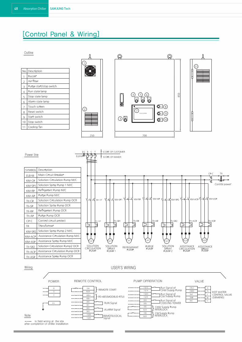
[Control Panel & Wiring]
180717 43-50 1904.1.25 5:4 AM 페이지48 C M Y K

49SAMJUNG Tech Absorption Chiller
[Thermal Insulation]
NOTE1. Use only noncombustible material.2. Valve control part, sight glass, thermometer gauge, thermowell, pressure gauge and pump moters are not insulated.3. For insulation area for each model, please refer to the picture below.4. Part that requires a insulation, please refer to the picture above.5. The water box sections should be worked to be disassembled for the repair.6. Please install an insulating materials by using adhesive, mending and etc. 7. Total insulation area includes piping.
■Cold Surface and Hot Surface
SAC-HDL 80M,100M 120M,140M 160M,180M 210M,240M 270M,300M 350M,400M 450M
Cold Surface(㎡) 6 8 8 10 11 12 14
Hot Surface(㎡) 12 14 17 19 22 26 29
SAC-HDL 500M 560M 630M 700M 800M 900M 1000M
Cold Surface(㎡) 15 16 17 18 20 21 23
Hot Surface(㎡) 32 34 36 38 40 43 46
180717 43-50 1904.1.25 5:4 AM 페이지49 C M Y K

50 Absorption Chiller SAMJUNG Tech
M/E/M/O
180717 43-50 1904.1.25 5:4 AM 페이지50 C M Y K

0452 Cooling Cycle
53 Automatic Sensing & Safety Apparatus
54 Specifications
56 Foundation
57 Control Panel & Wiring
58 Thermal Insulation
59 Piping Plan
60 Supply Scope(Standard)
Single Effect Hot Water Driven Absorption Chiller
180715 51~62 1904.1.25 5:7 AM 페이지51 C M Y K

52 Absorption Chiller SAMJUNG TECH
■Symbol Explanation
■Solution Flow
EV evaporator
AB absorber
CO condenser
GEN generator
HEX heat exchanger
CP solution circulation pump
SP solution spray pump
RP refrigerant spray pump
AB ABCP HEX HEXGEN SP
[Cooling Cycle]
180715 51~62 1904.1.25 5:7 AM 페이지52 C M Y K

53SAMJUNG TECH Absorption Chiller
[Automatic Sensing & Safety Apparatus]-Similar to Double Lift DLT-TYPE
2. Explanation of Control & Protection Unit
Mark Title Function
RTD1 Temp Sensor for CHW inlet
RTD2 Temp Sensor for CHW outlet
RTD3 Temp Sensor for Ref. of EV
RTD4 Temp Sensor for CW inlet
RTD5 Temp Sensor for CW outlet
RTD6 Temp Sensor for Sol. of AB
RTD7 Temp Sensor for HW inlet
RTD8 Temp Sensor for HW outlet
RTD9 Temp Sensor for Sol. of GEN
RTD10 Temp Sensor for Ref. of CO
26RL Temp Switch for Ref. of EV prevent over-cooled of Ref. of EV and stop chiller
69WC1 Cut-off Switch for CHW/HW monitor flow of CHW/HW and stop chiller
TH1 Thermal Relay for CP monitor over current of CP and stop chiller
TH2 Thermal Relay for SP monitor over current of SP and stop chiller
TH3 Thermal Relay for RP monitor over current of RP and stop chiller
R/D Rupture Diskburst a round thin plate when reach at a set pressure
and protect chiller body from a serious damage
·detect each temperature
·control target temperature of CHW
·ON-OFF control
·control over-cooled of CHW & Ref. of EV
·control limit of load
·monitor poor heat transfer of CW
1. Installation Location
180715 51~62 1904.1.25 5:7 AM 페이지53 C M Y K

54 Absorption Chiller SAMJUNG TECH
SPECIFICATIONS
65E1 80E1 100E1 120E1 140E1 160E1 190E1 210E1 240E1 270E1 310E1 340E1
USRT 65 80 100 120 140 160 190 210 240 270 310 340
kW 229 281 352 422 492 563 668 738 844 949 1,090 1,196
TEMP. ℃ 12 ℃ → 7 ℃
FLOW RATE m3/h 39.3 48.4 60.5 72.6 84.7 96.8 114.9 127.0 145.2 163.3 187.5 205.6
PRESSURE DROP mAq 4.8 5.2 7.2 5.2 6.2 4.8 5.5 4.1 4.3 4.4 5.9 5.9
PIPE CONNECTION SIZE A 80 100 125 150
NO. of PASS EA ODD EVEN ODD
TEMP. ℃ 31 ℃ → 36.5 ℃
FLOW RATE m3/h 85.0 104.7 130.8 157.0 183.2 209.3 248.6 274.7 314.0 353.2 405.5 444.8
PRESSURE DROP mAq 5.4 5.8 6.7 7.1 8.6 3.2 3.8 5.7 6.4 5.9 7.9 7.9
PIPE CONNECTION SIZE A 125 150 200 250
NO. of PASS EA EVEN ODD
TEMP. ℃ 95℃ → 80℃
FLOW RATE m3/h 18.1 22.3 27.8 33.4 38.9 44.5 52.8 58.4 66.7 75.1 86.2 94.5
PRESSURE DROP mAq 1.1 1.1 1.3 1.4 1.5 2.3 2.6 2.5 2.6 2.5 3.4 3.4
PIPE CONNECTION SIZE A 65 100 125
NO. of PASS EA ODD EVEN ODD EVEN
POWER SUPPLY - 3Ø 380V 50Hz
ELECTRIC CAPACITY KVA 7.4 10.1 11.5 13.6
SOLUTION PUMP(CIR.) 1.1(4.0) 2.0(6.5) 2.4(7.5) 3.4(10.0)
SOLUTION PUMP(SPRAY)kW/(A)
1.1(4.0) 1.5(5.5) 2.0(6.5) 2.2(7.0)
REFRIGERANT PUMP 0.2(1.3) 0.2(1.3) 0.3(1.5) 0.4(1.6)
VACUUM PUMP 0.75(2.0) 0.75(2.0) 0.75(2.0) 0.75(2.0)
LENGTH(L) mm 2,620 3,138 3,888 4,388 4,328 4,628
WIDTH(W) mm 1,736 1,736 1,819 2,153
HEIGHT(H) mm 2,146 2,224
SHIPPING WEIGHT ton 4.0 4.1 4.3 5.2 5.4 5.8 5.9 6.5 6.6 8.0 8.5 8.7
OPERATION WEIGHT ton 4.6 4.7 4.9 5.8 6.0 6.7 6.9 7.5 7.8 9.4 9.9 10.2
CHILLED WATER 114 130.3 135.3 159.5 168.2 204.5 226.6 232.4 257.9 284.1 304.9 332.6
COOLING WATER ℓ 278.4 305.1 333 378.5 392.3 458.8 491.7 518.5 547.9 680.9 722.5 779.2
HOT WATER 117.4 134.8 147.7 179.4 198.1 240.4 262.3 273 299.2 343.4 368.4 398.6
EXCHANGE SPACE OF TUBE mm 2,350 2,850 3,550 4,050 4,300
1. 1USRT = 3024kcal/h(3.516kW)2. Fouling factor of chilled water, cooling water, hot water : 0.0001 m2h℃/kcal(0.000086m2K/W)3. The capacity control range for standard specification.(capacity, chilled water, cooling water) : 100 ~ 25%4. The maximum working pressure for chilled water, cooling water, hot water- Chilled water & Cooling water : 10 kg/cm2G(0.98MPaG)- Hot water : 16 kg/cm2G(1.57MPaG)
5. The power supply is can apply 3Ø 220/380/440V 50Hz also.6. These specifications can be changed without notice for technical improvements.
REFRIGERATIONCAPACITY
SAC-MITEM(UNIT)
CHILLED
WATER
COOLING
WATER
HOT
WATER
WEIGHT
ELECTRIC
POWER
WATERQUANTITY
DIMENSIO-NS
180715 51~62 1904.1.25 5:7 AM 페이지54 C M Y K
55SAMJUNG TECH Absorption Chiller
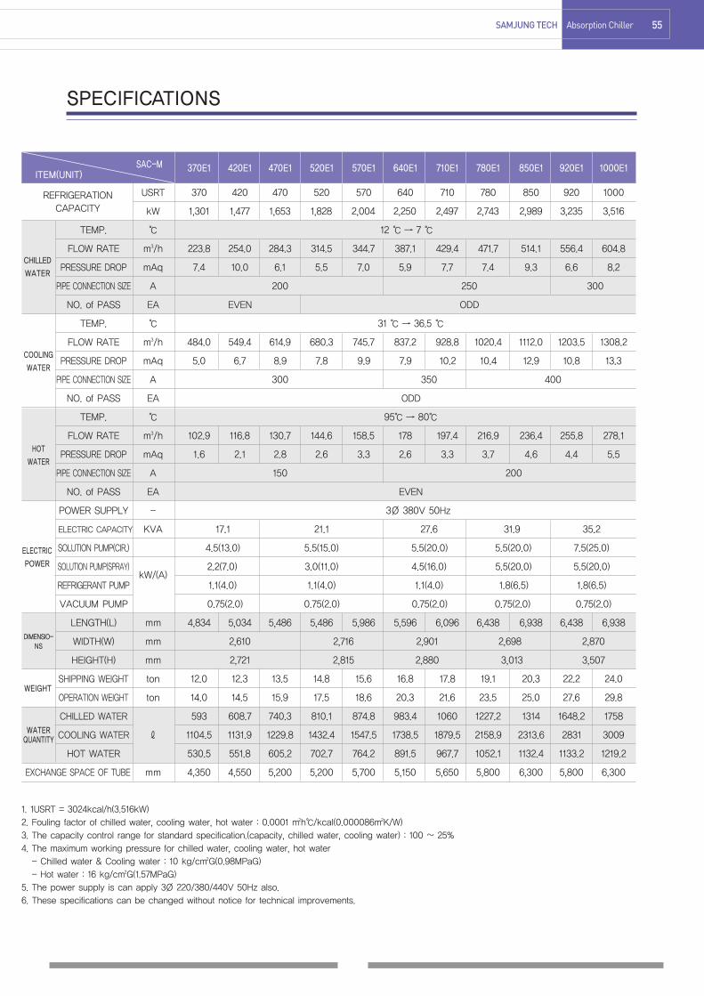
SPECIFICATIONS
370E1 420E1 470E1 520E1 570E1 640E1 710E1 780E1 850E1 920E1 1000E1
USRT 370 420 470 520 570 640 710 780 850 920 1000
kW 1,301 1,477 1,653 1,828 2,004 2,250 2,497 2,743 2,989 3,235 3,516
TEMP. ℃ 12 ℃ → 7 ℃
FLOW RATE m3/h 223.8 254.0 284.3 314.5 344.7 387.1 429.4 471.7 514.1 556.4 604.8
PRESSURE DROP mAq 7.4 10.0 6.1 5.5 7.0 5.9 7.7 7.4 9.3 6.6 8.2
PIPE CONNECTION SIZE A 200 250 300
NO. of PASS EA EVEN ODD
TEMP. ℃ 31 ℃ → 36.5 ℃
FLOW RATE m3/h 484.0 549.4 614.9 680.3 745.7 837.2 928.8 1020.4 1112.0 1203.5 1308.2
PRESSURE DROP mAq 5.0 6.7 8.9 7.8 9.9 7.9 10.2 10.4 12.9 10.8 13.3
PIPE CONNECTION SIZE A 300 350 400
NO. of PASS EA ODD
TEMP. ℃ 95℃ → 80℃
FLOW RATE m3/h 102.9 116.8 130.7 144.6 158.5 178 197.4 216.9 236.4 255.8 278.1
PRESSURE DROP mAq 1.6 2.1 2.8 2.6 3.3 2.6 3.3 3.7 4.6 4.4 5.5
PIPE CONNECTION SIZE A 150 200
NO. of PASS EA EVEN
POWER SUPPLY - 3Ø 380V 50Hz
ELECTRIC CAPACITY KVA 17.1 21.1 27.6 31.9 35.2
SOLUTION PUMP(CIR.) 4.5(13.0) 5.5(15.0) 5.5(20.0) 5.5(20.0) 7.5(25.0)
SOLUTION PUMP(SPRAY)kW/(A)
2.2(7.0) 3.0(11.0) 4.5(16.0) 5.5(20.0) 5.5(20.0)
REFRIGERANT PUMP 1.1(4.0) 1.1(4.0) 1.1(4.0) 1.8(6.5) 1.8(6.5)
VACUUM PUMP 0.75(2.0) 0.75(2.0) 0.75(2.0) 0.75(2.0) 0.75(2.0)
LENGTH(L) mm 4,834 5,034 5,486 5,486 5,986 5,596 6,096 6,438 6,938 6,438 6,938
WIDTH(W) mm 2,610 2,716 2,901 2,698 2,870
HEIGHT(H) mm 2,721 2,815 2,880 3,013 3,507
SHIPPING WEIGHT ton 12.0 12.3 13.5 14.8 15.6 16.8 17.8 19.1 20.3 22.2 24.0
OPERATION WEIGHT ton 14.0 14.5 15.9 17.5 18.6 20.3 21.6 23.5 25.0 27.6 29.8
CHILLED WATER 593 608.7 740.3 810.1 874.8 983.4 1060 1227.2 1314 1648.2 1758
COOLING WATER ℓ 1104.5 1131.9 1229.8 1432.4 1547.5 1738.5 1879.5 2158.9 2313.6 2831 3009
HOT WATER 530.5 551.8 605.2 702.7 764.2 891.5 967.7 1052.1 1132.4 1133.2 1219.2
EXCHANGE SPACE OF TUBE mm 4,350 4,550 5,200 5,200 5,700 5,150 5,650 5,800 6,300 5,800 6,300
1. 1USRT = 3024kcal/h(3.516kW)2. Fouling factor of chilled water, cooling water, hot water : 0.0001 m2h℃/kcal(0.000086m2K/W)3. The capacity control range for standard specification.(capacity, chilled water, cooling water) : 100 ~ 25%4. The maximum working pressure for chilled water, cooling water, hot water- Chilled water & Cooling water : 10 kg/cm2G(0.98MPaG)- Hot water : 16 kg/cm2G(1.57MPaG)
5. The power supply is can apply 3Ø 220/380/440V 50Hz also.6. These specifications can be changed without notice for technical improvements.
REFRIGERATIONCAPACITY
SAC-MITEM(UNIT)
CHILLED
WATER
COOLING
WATER
HOT
WATER
WEIGHT
ELECTRIC
POWER
WATERQUANTITY
DIMENSIO-NS
180715 51~62 1904.1.25 5:7 AM 페이지55 C M Y K

56 Absorption Chiller SAMJUNG TECH
[Foundation]
NOTE1. Smooth the concrete foundation surface and the horizontal levelmust become below 1/500.
2. The horizontal level of chiller installed must become below 1/1000.
3. (▨) symbol indicates [BASE LEG] of chiller.4. Make a drainage ditch around the chiller.
Model G1 G2 B1 B2 B3 L W
M65E1
M80E1 1800
M100E1 1454.7 1254.7
M120E12350
M140E1 - -
M160E1500
M190E11531.8
300 3000
M210E1 1331.8
M240E1 3500
M270E1
M310E1 1872 817 8003800
863.5
M340E1
M370E1 3700
M420E1 2438.3 1097.8 995.5 3900 1191.7
M470E1 4400
M520E12264.4 992.9 926.5
32501104.7
M570E1 3750
M640E1 6002515.6
4001084.5
32501230.3
M710E11086.1
3750
M780E12556.6 1115.5
39501255.8
M850E1 4450
M920E12678.8 1133.8 1190
39501316.9
M1000E1 4450
(unit : mm)
180715 51~62 1904.1.25 5:7 AM 페이지56 C M Y K

57SAMJUNG TECH Absorption Chiller
[Control Panel & Wiring]
180715 51~62 1904.1.25 5:7 AM 페이지57 C M Y K

58 Absorption Chiller SAMJUNG TECH
NOTE1. Use only noncombustible material.2. Valve control part, sight glass, thermometer gauge, thermowell, pressure gauge and pump moters are not insulated.3. For insulation area for each model, please refer to the picture below.4. Part that requires a insulation, please refer to the picture above5. The water box sections should be worked to be disassembled for the repair.6. Please install an insulating materials by using adhesive , mending and etc. 7. Total insulation area includes piping.
SAC-M 65E1~100E1 120E1,140E1 160E1,190E1 210E1,240E1 270E1 310E1,340E1 370E1 420E1 470E1
Cold Surface(㎡) 7 8 10 11 12 13 15 16 17
Hot Surface(㎡) 5 6 7 8 9 10 12 13 14
SAC-M 520E1 570E1 640E1 710E1 780E1 850E1 920E1 1000E1
Cold Surface(㎡) 18 19 20 21 24 26 27 29
Hot Surface(㎡) 15 16 17 18 19 20 21 22
■Cold Surface and Hot Surface
[Thermal Insulation]
180715 51~62 1904.1.25 5:7 AM 페이지58 C M Y K
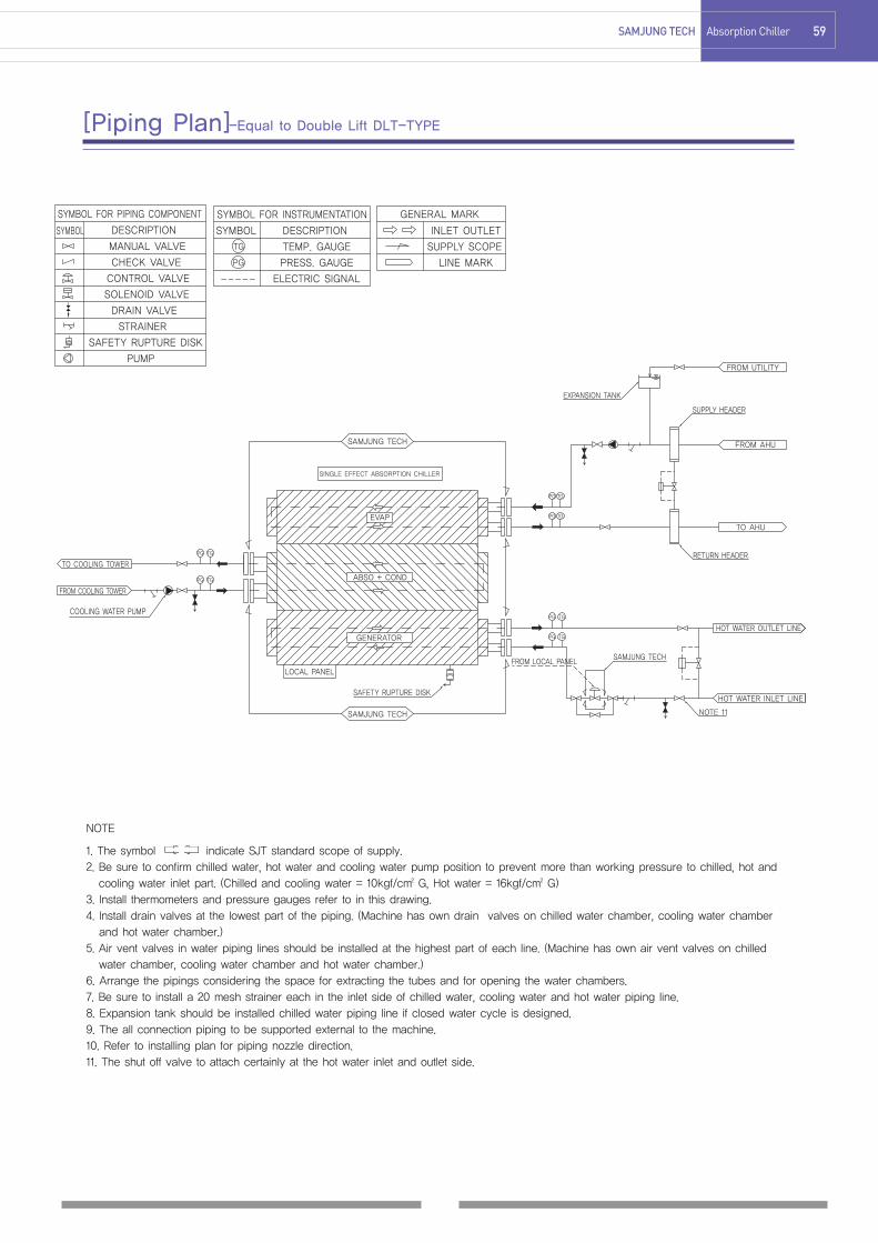
59SAMJUNG TECH Absorption Chiller
[Piping Plan]-Equal to Double Lift DLT-TYPE
1. The symbol indicate SJT standard scope of supply.2. Be sure to confirm chilled water, hot water and cooling water pump position to prevent more than working pressure to chilled, hot andcooling water inlet part. (Chilled and cooling water = 10kgf/cm2 G, Hot water = 16kgf/cm2 G)
3. Install thermometers and pressure gauges refer to in this drawing.4. Install drain valves at the lowest part of the piping. (Machine has own drain valves on chilled water chamber, cooling water chamberand hot water chamber.)
5. Air vent valves in water piping lines should be installed at the highest part of each line. (Machine has own air vent valves on chilledwater chamber, cooling water chamber and hot water chamber.)
6. Arrange the pipings considering the space for extracting the tubes and for opening the water chambers.7. Be sure to install a 20 mesh strainer each in the inlet side of chilled water, cooling water and hot water piping line.8. Expansion tank should be installed chilled water piping line if closed water cycle is designed.9. The all connection piping to be supported external to the machine.10. Refer to installing plan for piping nozzle direction.11. The shut off valve to attach certainly at the hot water inlet and outlet side.
NOTE
180715 51~62 1904.1.25 5:7 AM 페이지59 C M Y K

60 Absorption Chiller SAMJUNG TECH
Division Description Scope
1) Evaporator, Absorber, Condenser, Generator
(If DLT-TYPE, additional 2nd Generator, Aux. Absorber, Aux. Generator)
2) Low/high temp. Sol. Heat Exchanger
(If DLT-TYPE, additional Aux. Sol. Heat Exchanger)
3) Sol. Circulation Pump, Sol. Spray Pump, Ref. Spray Pump, Purge Pump
(If DLT-TYPE, additional 2nd Sol. Spray Pump, Aux. Sol. Circulation Pump, Aux. Sol. Spray Pump)
4) Control Panel
Chiller Assembly - Panel unit
- Lamps(Operation, Stop, Alarm), Button(Reset, Operation, Stop), Touch Screen
- Circuit Brakers, Relays, PLC controller
5) Purge device Vendor
- Purge storage tank, Ejector, Oil trap, Manometer, Piping and manual valves
6) Interconnecting piping and wiring
- Refrigerant & Solution Piping for internal mechanical components
- Control & Power wiring for internal electrical components
Initial chargeAbsorbent Solution(Lithium Bromide) with inhibitor, Refrigerant(distilled water)
Painting for chiller assembly and control panel
Painting - Chiller body : Sky Blue ( Munsel No. 7.3B 5.1/9.0 )
- Control panel : Light Yellow ( Munsel No. 5Y 7.0/1.0 )
Insulation Insulation of cold surface and hot surface for absorption chiller Option
1) Check of external dimensions
Test & Inspection2) Hydraulic pressure test for water boxes
Vendor3) Leak test ( Vacuum side )
4) Function test for electric circuit and safety device
Performance Test Factory test Option
1. Foundation of chiller
Installation & 2. Installation of chiller ( Only, vendor supply vibration-proof rubber, base plate)
3. Piping and wiring connections out of chiller Buyerwiring work
4. Interlock wiring of chilled water pump, cooling water pump
5. Installation and wiring of control valve
Start-up
operation testAt site with vendor Option
※ Items to be confirmed when ordering① Purpose : General air conditioning, Process cooling, etc.② Specification·Cooling Capacity : usRT, Kw·Chilled/Cooling/Hot water : inlet/outlet temperature(℃), flowrate(m3/h)·Power supply : voltage, frequency
③ Installation condition : indoor, outdoor, special consideration(ex. Sea water, etc.)④ Operation condition : year-round operating, 24-hour operating
[Supply Scope(Standard)]
180715 51~62 1904.1.25 5:7 AM 페이지60 C M Y K

61SAMJUNG Tech Absorption Chiller
M/E/M/O
180715 51~62 1904.1.25 5:7 AM 페이지61 C M Y K

62 Absorption Chiller SAMJUNG Tech
M/E/M/O
180715 51~62 1904.1.25 5:7 AM 페이지62 C M Y K

0564 Characteristics
65 Ceiling 4-Way Cassette Type
66 Ceiling 2-Way Cassette Type
67 Ceiling 1-Way Cassette Type
68 Ceiling Exposed Type
69 Ceiling Concealed Type
70 Ceiling High Static Pressure Type
71 Floor Exposed, Front Discharge Type
72 Floor Exposed, Top Discharge Type
73 Floor Exposed, Slant Discharge Type
74 Floor Exposed, Lowboy Top Discharge Type
75 Floor Concealed, Front Discharge Type
76 Floor Concealed, Top Discharge Type
77 Floor Concealed, Slant Discharge Type
78 Floor Concealed, Front Suction Type
79 Floor Concealed, Lowboy Top Discharge Type
80 Floor Stand Front Discharge Type
81 Floor Stand Top Duct Type
Fan Coil Unit(F.C.U.)
180717 63-82 1904.1.25 5:10 AM 페이지63 C M Y K

Samjung tech's diversified and economical fan coil units create pleasant space with optimumtemperature. Comfortable indoor living for highly sophisticated and diversified buildings isguaranteed. They are designed with energy saving, space saving and easy installation inmind. Also, with Samjung's distinct interior know-how, fan coil units present natural ambiancewith their elegant shapes and colors. Samjung's fan coil units are designed with radiator andventilator in one compact unit realizing an excellent air-conditioning system for any types ofenvironments and spaces. Samjung has been researching with unceasing effort for highefficiency, low noise, simple operation and expanding model selections.
The recent models with a digitalcontroller make simple operationpossible. The existing models also canbe converted into one-touch system bythree steps.
Simple operation
Quiet indoor atmosphere is guaranteedby applying low-noise fan whichminimizes the operating sound.
Low-noise operation
Installation space is minimized withcompact design which is effectivelycomposed of high mechanism.
Compact design
A heat exchanger is manufactured withour own unique expanding method, andsuper high-efficient SINE WAVE and SLITFIN are applied.
Application of the superhigh-efficient SLIT FIN
There are variety of models according topurpose and condition. It is easy tochoice suitable to wind, waves andinstallation condition.
Diversification of models
64 Fan Coil Unit SAMJUNG TECH
FAN COIL UNIT (F.C.U)
180717 63-82 1904.1.25 5:10 AM 페이지64 C M Y K
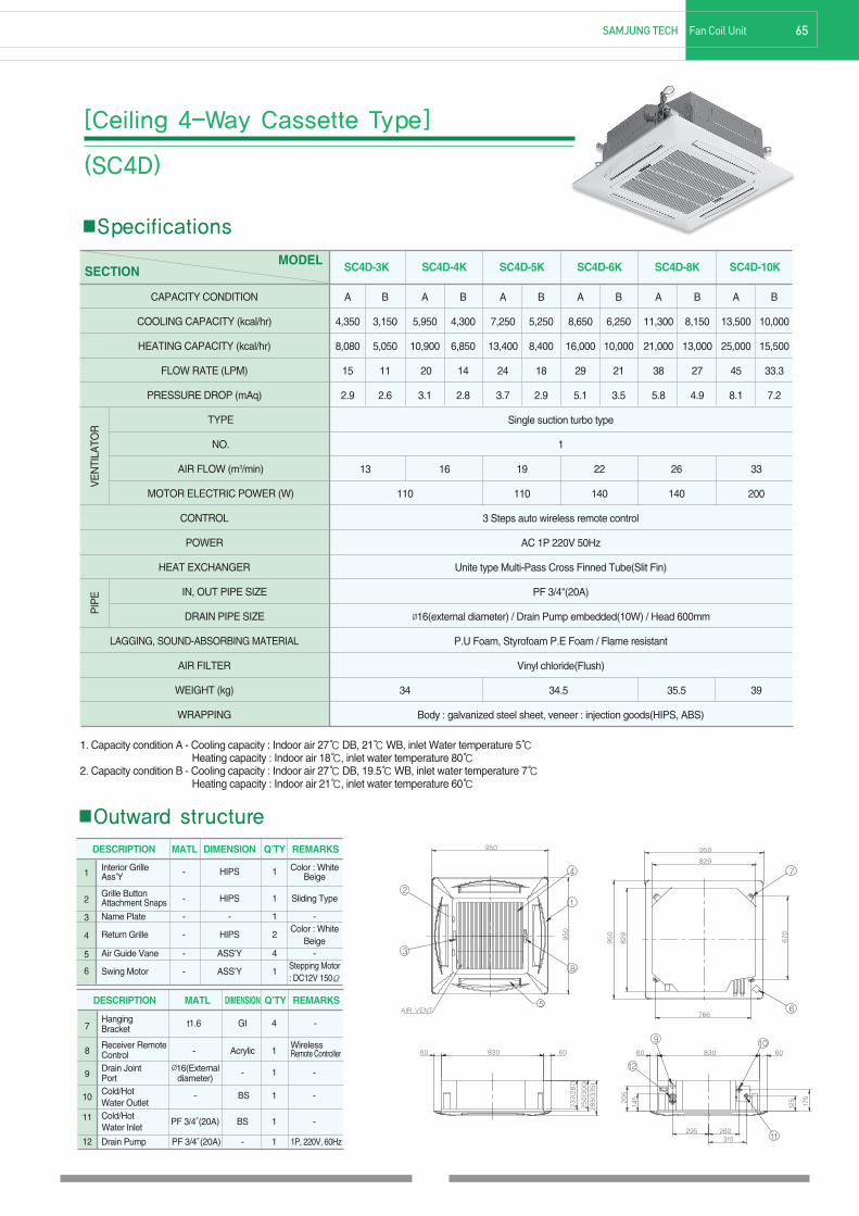
65SAMJUNG TECH Fan Coil Unit
■Specifications
MODELSECTION
A B A B A B A B A B A B
4,350 3,150 5,950 4,300 7,250 5,250 8,650 6,250 11,300 8,150 13,500 10,000
8,080 5,050 10,900 6,850 13,400 8,400 16,000 10,000 21,000 13,000 25,000 15,500
15 11 20 14 24 18 29 21 38 27 45 33.3
2.9 2.6 3.1 2.8 3.7 2.9 5.1 3.5 5.8 4.9 8.1 7.2
Single suction turbo type
1
13 16 19 22 26 33
110 110 140 140 200
3 Steps auto wireless remote control
AC 1P 220V 50Hz
Unite type Multi-Pass Cross Finned Tube(Slit Fin)
PF 3/4"(20A)
Ø16(external diameter) / Drain Pump embedded(10W) / Head 600mm
P.U Foam, Styrofoam P.E Foam / Flame resistant
Vinyl chloride(Flush)
34 34.5 35.5 39
Body : galvanized steel sheet, veneer : injection goods(HIPS, ABS)
CAPACITY CONDITION
COOLING CAPACITY (kcal/hr)
HEATING CAPACITY (kcal/hr)
FLOW RATE (LPM)
PRESSURE DROP (mAq)
TYPE
NO.
AIR FLOW (m3/min)
MOTOR ELECTRIC POWER (W)
CONTROL
POWER
HEAT EXCHANGER
IN, OUT PIPE SIZE
DRAIN PIPE SIZE
LAGGING, SOUND-ABSORBING MATERIAL
AIR FILTER
WEIGHT (kg)
WRAPPING
VE
NTI
LATO
RP
IPE
SC4D-3K SC4D-4K SC4D-5K SC4D-6K SC4D-8K SC4D-10K
1. Capacity condition A - Cooling capacity : Indoor air 27℃DB, 21℃WB, inlet Water temperature 5℃Heating capacity : Indoor air 18℃, inlet water temperature 80℃
2. Capacity condition B - Cooling capacity : Indoor air 27℃DB, 19.5℃WB, inlet water temperature 7℃Heating capacity : Indoor air 21℃, inlet water temperature 60℃
[Ceiling 4-Way Cassette Type]
(SC4D)
■Outward structure
Interior Grille - HIPS 1 Color : White Ass’Y Beige
Grille ButtonAttachment Snaps - HIPS 1 Sliding Type
Name Plate - - 1 -
Return Grille - HIPS 2Color : White
BeigeAir Guide Vane - ASS’Y 4 -
Swing Motor - ASS’Y 1Stepping Motor: DC12V 150Ω
1
2
3
4
5
6
DESCRIPTION MATL DIMENSION Q’TY REMARKS
Hanging t1.6 GI 4 -Bracket
Receiver RemoteControl - Acrylic 1
WirelessRemote Controller
Drain Joint Ø16(ExternalPort diameter)
- 1 -
Cold/Hot - BS 1 -Water OutletCold/Hot
PF 3/4″(20A) BS 1 - Water Inlet
Drain Pump PF 3/4″(20A) - 1 1P, 220V, 60Hz
7
8
9
10
11
12
DESCRIPTION MATL DIMENSION Q’TY REMARKS
180717 63-82 1904.1.25 5:10 AM 페이지65 C M Y K

[Ceiling 2-way Cassette Type]
(SC2D)
■Specifications
MODELSECTION
A B A B A B
4,850 3,150 5,700 4,200 6,435 5,000
8,900 5,050 10,400 6,335 11,900 7,300
15 11 20 14 24 18
0.7 0.6 2.0 1.0 2.9 1.6
Single suction turbo type
1
11 13 16
80 95 110
3 steps rotary switch
AC 1P 220V 50Hz
Unite type Multi-Pass Cross Finned Tube(Slit Fin)
PF 3/4" (20A)
Ø16(external diameter) / Drain Pump embedded(10W) / Head 600mm
P.U Foam, Styrofoam P.E Foam / Flame resistant
Vinyl chloride(wash)
31 31 33
Galvanized steel sheet
CAPACITY CONDITION
COOLING CAPACITY (kcal/hr)
HEATING CAPACITY (kcal/hr)
FLOW RATE (LPM)
PRESSURE DROP (mAq)
TYPE
NO.
AIR FLOW (m3/min)
MOTOR ELECTRIC POWER (W)
CONTROL
POWER
HEAT EXCHANGER
IN, OUT PIPE SIZE
DRAIN PIPE SIZE
LAGGING, SOUND-ABSORBING MATERIAL
AIR FILTER
WEIGHT (kg)
WRAPPING
VE
NTI
LATO
RP
IPE
SC2D-3K SC2D-4K SC2D-5K
1. Capacity condition A - Cooling capacity : Indoor air 27℃DB, 21℃WB, inlet Water temperature 5℃Heating capacity : Indoor air 18℃, inlet water temperature 80℃
2. Capacity condition B - Cooling capacity : Indoor air 27℃DB, 19.5℃WB, inlet water temperature 7℃Heating capacity : Indoor air 21℃, inlet water temperature 60℃
66 Fan Coil Unit SAMJUNG TECH
■Outward structure
Interior Grille - HIPS 1 Color : White Ass’Y Beige
Grille ButtonAttachment Snaps - HIPS 2 Sliding Type
Name Plate - - 1 -
Return Grille - HIPS 1 Color : WhiteBeige
Air Guide Vane - ASS’Y 4 -Hanging
t1.6 GI 4 -Bracket
1
2
3
4
5
6
DESCRIPTION MATL DIMENSION Q’TY REMARKS
Receiver Remote Black (WirelessControl - Acrylic 4 Remote Controller)
Drain Joint Ø16(ExternalPort diameter)
- 1 -
Cold/HotPF 3/4″(20A) - 1 -
Water OutletCold/Hot
PF 3/4″(20A) - 1 - Water Inlet
Drain Pump PF 3/4″(20A) - 1 1P, 220V, 60Hz
Swing Motor DC12V 150Ω - 2 Stepping Motor
7
8
9
10
11
12
DESCRIPTION MATL DIMENSION Q’TY REMARKS
180717 63-82 1904.1.25 5:10 AM 페이지66 C M Y K

■Outward structure
Interior Grille - HIPS 1 Color : White Ass’Y Beige
Grille ButtonAttachment Snaps - HIPS 1 Sliding Type
Name Plate - - 1 -
Return Grille - HIPS 2 Color : white Beige
Air Guide Vane - ASS’Y 2 -
Hanging Bracket - GI 4 -
1
2
3
4
5
6
DESCRIPTION MATL DIMENSION Q’TY REMARKS
Receiver Remote - Acrylic 4 Black (WirelessControl Remote Controller)
Drain Joint Ø16(External Port diameter) - 1 -
Cold/HotWater outlet PF 3/4″(20A) - 1 -
Cold/Hot PF 3/4″(20A) - 1Water Inlet
Drain Pump - - 1 1P, 220V, 60Hz
Swing Motor DC 12V 15Ω - 2 Stepping Motor
7
8
9
10
11
12
DESCRIPTION MATL DIMENSION Q’TY REMARKS
■Specifications
MODELSECTION
A B A B A B A B A B
2,240 1,600 2,700 2,100 3,020 2,500 4,000 3,100 4,550 3,500
4,400 2,560 5,000 3,200 5,780 3,700 7,300 4,500 8,450 5,300
7.5 5.3 9.0 7.0 10.1 8.3 13.3 10.3 15.2 11.7
0.43 0.22 0.62 0.38 0.78 0.53 2.05 1.24 2.64 1.56
Double suction turbo type
1
5.6 7 9 9 11
50 50 65 65 65
3 steps rotary switch
AC 1P 220V 50Hz
Unite type Multi-Pass Cross Finned Tube(Slit Fin)
PF 3/4"(20A)
Ø16(external diameter) / Drain Pump embedded(10W) / Head 600mm
P.U Foam, Styrofoam P.E Foam / Flame resistant
Vinyl chloride(Flush)
28 28 28 30 30
Galvanized steel sheet
CAPACITY CONDITION
COOLING CAPACITY (kcal/hr)
HEATING CAPACITY (kcal/hr)
FLOW RATE (LPM)
PRESSURE DROP (mAq)
TYPE
NO.
AIR FLOW (m3/min)
MOTOR ELECTRIC POWER (W)
CONTROL
POWER
HEAT EXCHANGER
IN, OUT PIPE SIZE
DRAIN PIPE SIZE
LAGGING, SOUND-ABSORBING MATERIAL
AIR FILTER
WEIGHT (kg)
WRAPPING
VE
NTI
LATO
RP
IPE
SC1D-1.5K SC1D-2K SC1D-2.5K SC1D-3K SC1D-3.5K
1. Capacity condition A - Cooling capacity : Indoor air 27℃DB, 21℃WB, inlet Water temperature 5℃Heating capacity : Indoor air 18℃, inlet water temperature 80℃
2. Capacity condition B - Cooling capacity : Indoor air 27℃DB, 19.5℃WB, inlet water temperature 7℃Heating capacity : Indoor air 21℃, inlet water temperature 60℃
67SAMJUNG TECH Fan Coil Unit
[Ceiling 1-way Cassette Type]
(SC1D)
180717 63-82 1904.1.25 5:10 AM 페이지67 C M Y K

■Outward structure
Water Outlet PF 3/4″(20A) BS 1 - Air Vent PT 1/8″ BS 1 -
Inner Side t1.2 GI 2 -Casing
Water Inlet PF 3/4″(20A) BS 1 ManualDrain Pan - GI 1 -Air Filter - Vinyl Chloride 1 Viny ChlorideFan Impeller Ø145 ABS F -Fan Housing - ABS F -Motor 1P, 220V, 60Hz ASS’Y M -Drain Connection Nipple 1/2″(15A) - 1 -Heat & Cooling
OD3/8×t0.35 CU-AL 1 Slit Fin AdoptCoil
Grille 120×120Heat-Resisting
G -ABS
Access Door 120×200 ABS 2 -Outer Air Panel t1.0 CR 1 -
12
3
45
678910
11
12
1314
DESCRIPTION MATL DIMENSION Q’TY REMARKS
■Specifications
MODELSECTION
A B A B A B A B A B A B
2,670 1,820 3,500 2,420 4,730 3,480 6,370 4,720 9,320 6,770 12,020 8,820
4,630 2,980 6,790 4,100 9,250 5,770 12,500 7,530 18,310 11,140 20,530 12,330
10 6 12 8 15 11.5 20 15.7 30 22.4 40 29.3
1.5 0.72 2.4 1.5 4.1 2.9 1.9 1.3 4.1 2.7 4.1 2.3
Double suction turbo type
1 1 2 2 3 4
5.7 8.5 11.3 17 22.6 34
40 50 65 80 40 + 50 80 x 2
3 steps rotary switch
AC 1P 220V 50Hz
Unite type Multi-Pass Cross Finned Tube(Slit Fin)
PF 3/4"(20A)
Nipple 3/4"(20A)
P.U Foam, Styrofoam P.E Foam / Flame resistant
Vinyl chloride(Flush)
23 26 29 34 41 49
Cold-reduced carbon steel sheet
CAPACITY CONDITION
COOLING CAPACITY (kcal/hr)
HEATING CAPACITY (kcal/hr)
FLOW RATE (ℓ/min)
PRESSURE DROP (mAq)
TYPE
NO.
AIR FLOW (m3/min)
MOTOR ELECTRIC POWER (W)
CONTROL
POWER
HEAT EXCHANGER
IN, OUT PIPE SIZE
DRAIN PIPE SIZE
LAGGING, SOUND-ABSORBING MATERIAL
AIR FILTER
WEIGHT (kg)
WRAPPING
VE
NTI
LATO
RP
IPE
SCO-20A SCO-30A SCO-40A SCO-60A SCO-80A SCO-120A
1. Capacity condition A - Cooling capacity : Indoor air 27℃DB, 21℃WB, inlet Water temperature 5℃Heating capacity : Indoor air 18℃, inlet water temperature 80℃
2. Capacity condition B - Cooling capacity : Indoor air 27℃DB, 19.5℃WB, inlet water temperature 7℃Heating capacity : Indoor air 21℃, inlet water temperature 60℃
68 Fan Coil Unit SAMJUNG TECH
[Ceiling Exposed Type]
(SCO)
20A 940 120×4=480 4 1 1
30A 1060 120×5=600 5 1 1
40A 1180 120×6=720 6 1 2
60A 1420 120×8=960 8 1 2
80A 1660 120×10=1200 10 2 3
120A 1900 120×12=1440 12 2 4
1
2
3
4
5
6
MODEL A B G M F
180717 63-82 1904.1.25 5:10 AM 페이지68 C M Y K

■Specifications
MODELSECTION
A B A B A B A B A B A B
2,670 1,620 3,500 2,420 4,730 3,480 6,370 4,720 9,320 6,770 12,020 8,820
4,630 2,980 6,790 4,100 9,250 5,770 12,500 7,530 18,310 11,140 20,530 12,330
10 6 12 8 15 11.5 20 15.7 30 22.4 40 29.3
1.5 0.72 2.4 1.5 4.1 2.9 1.9 1.3 4.1 2.7 4.1 2.3
Double suction turbo type
1 1 2 2 3 4
5.7 8.5 11.3 17 22.6 34
40 50 65 80 40 + 50 80 x 2
3 steps rotary switch
AC 1P 220V 50Hz
Unite type Multi-Pass Cross Finned Tube(Slit Fin)
PF 3/4"(20A)
Nipple 3/4"(20A)
P.U Foam, Styrofoam P.E Foam / Flame resistant
Vinyl chloride(Flush)
15 17 20 24 32 40
Cold-reduced carbon steel sheet
CAPACITY CONDITION
COOLING CAPACITY (kcal/hr)
HEATING CAPACITY (kcal/hr)
FLOW RATE (ℓ/min)
PRESSURE DROP (mAq)
TYPE
NO.
AIR FLOW (m3/min)
MOTOR ELECTRIC POWER (W)
CONTROL
POWER
HEAT EXCHANGER
IN, OUT PIPE SIZE
DRAIN PIPE SIZE
LAGGING, SOUND-ABSORBING MATERIAL
AIR FILTER
WEIGHT (kg)
WRAPPING
VE
NTI
LATO
RP
IPE
SCR-20A SCR-30A SCR-40A SCR-60A SCR-80A SCR-120A
■Outward structure
1. Capacity condition A - Cooling capacity : Indoor air 27℃DB, 21℃WB, inlet Water temperature 5℃Heating capacity : Indoor air 18℃, inlet water temperature 80℃
2. Capacity condition B - Cooling capacity : Indoor air 27℃DB, 19.5℃WB, inlet water temperature 7℃Heating capacity : Indoor air 21℃, inlet water temperature 60℃
69SAMJUNG TECH Fan Coil Unit
[Ceiling Concealed Type]
(SCR)
1
2
3
4
5
6
DESCRIPTION MAT’L DIMENSION Q’TY REMARK
123456789
10
Water OutletAir VentWater InletDrain PanAir FilterFan ImpellerFan HousingMotorDrain ConnectionHeat & CoolingCoil
BSBSBSGI
Vinyl ChlorideABSABS
ASS’Y-
CU-AL
PF 3/4″(20A)PT 1/8″
PF 3/4″(20A)--
Ø145-
1P, 220V, 60HzNipple 1/2″(15A)
OD3/8″×t0.35
11111FFM1
1
-Manual
--
FlushSirocco
---
Slit Fin T
MODEL A B M F
540
660
780
1020
1260
1500
1
1
1
1
2
2
1
1
2
2
3
4
20A
30A
40A
60A
80A
120A
480
600
720
960
1200
1440
180717 63-82 1904.1.25 5:10 AM 페이지69 C M Y K

■Outward structure
70 Fan Coil Unit SAMJUNG TECH
[Ceiling High Static Pressure Type]
(SCHP)
■Specifications
MODELSECTION
A B A B A B A B A B A B A B A B A B
4,450 3,230 5250 3,990 8,400 4,520 11,650 6,830 12,900 8,140 15,000 9,090 16,800 11,530 21,000 15,700 23,100 17,580
8,400 5,200 10,000 6,000 15,500 8,600 21,000 12,600 23,400 14,000 27,000 15,830 30,200 18,000 38,000 24,700 42,000 26,200
14.8 10.8 17.5 13.3 28.0 15.1 38.8 22.8 43.0 27.1 50.0 30.3 56.0 38.4 70.0 52.3 77.0 58.6
2.4 1.3 3.3 1.9 4.2 1.1 4.8 1.6 6.4 2.6 10.2 3.8 4.4 2.1 2.7 1.5 3.6 2.1
Double suction turbo type
1 1 1 1 1 2 2 2 2
13 17 21 28 31 35 40 50 55
145 200 380 460 460 550 630 880 880
3 steps rotary switch
AC 1P 220V 50Hz
Unite type Multi-Pass Cross Finned Tube(Slit Fin)
F3/4"(20A) PT 1"(25A)
Nipple 3/4"(20A)
Styrofoam, P.E Foam / Flame resistance
Vinyl chloride(Flush)
37 37 38 14 43 45 54 62 64
Body : Galvanized steel sheet, veneer : injection Goods(HIPS, ABS)
CAPACITY CONDITION
COOLING CAPACITY (kcal/hr)
HEATING CAPACITY (kcal/hr)
FLOW RATE (LPM)
PRESSURE DROP (mAq)
TYPE
NO.
AIR FLOW (m3/min)
MOTOR ELECTRIC POWER (W)
CONTROL
POWER
HEAT EXCHANGER
IN, OUT PIPE SIZE
DRAIN PIPE SIZE
LAGGING, SOUND-ABSORBING MATERIAL
AIR FILTER
WEIGHT (kg)
WRAPPING
VE
NTI
LATO
RP
IPE
1. Capacity condition A - Cooling capacity : Indoor air 27℃DB, 21℃WB, inlet Water temperature 5℃Heating capacity : Indoor air 18℃, inlet water temperature 80℃
2. Capacity condition B - Cooling capacity : Indoor air 27℃DB, 19.5℃WB, inlet water temperature 7℃Heating capacity : Indoor air 21℃, inlet water temperature 60℃
SCHP-132 SCHP-172 SCHP-212 SCHP-282 SCHP-312 SCHP-352 SCHP-402 SCHP-502 SCHP-552
123
MODEL 132 172 212 282 312 352 402 502 552
560510350
560510350
610560400
850800640
910860700
1,0501,000840
1,2001,150990
1,5001,4501,240
1,6301,5801,240
W1W2W3
DESCRIPTION MAT’L DIMENSION Q’TY REMARK
1234567
8
Water OutletAir VentWater InletDrain PanAir FilterFan MotorDrain ConnectionHeat & CoolingCoil
BSBSBSGI
Vinyl ChlorideASS’Y
-
CU-AL
PF 3/4″(20A)PT 1/8″
PF 3/4″(20A)--
1P, 220V, 60HzNipple 1/2″(15A)
OD3/8″×t0.35
11111M1
1
-Manual
--
Flush--
Slit Fin T
180717 63-82 1904.1.25 5:10 AM 페이지70 C M Y K

■Specifications
MODELSECTION
A B A B A B A B A B A B
2,670 1,820 3,500 2,420 4,730 3,480 6,370 4,720 9,320 6,770 12,020 8,820
4,630 2,980 6,790 4,100 9,250 5,770 12,500 7,530 18,310 11,140 20,530 12,330
10 6 12 8 15 11.5 20 15.7 30 22.4 40 29.3
1.5 0.72 2.4 1.5 4.1 2.9 1.9 1.3 4.1 2.7 4.1 2.3
Double suction turbo type
1 1 2 2 3 4
5.7 8.5 11.3 17 22.6 34
25 35 45 65 40+50 65×2
3 steps rotary switch
AC 1P 220V 50Hz
Unite type Multi-Pass Cross Finned Tube(Slit Fin)
PF 3/4"(20A)
Soft vinyl hose(IDØ14, ODØ18)
P.U Foam, Styrofoam P.E Foam / Flame resistant
Vinyl chloride(Flush)
24 27 31 36 40 49
Cold-reduced carbon steel sheet
CAPACITY CONDITION
COOLING CAPACITY (kcal/hr)
HEATING CAPACITY (kcal/hr)
FLOW RATE (ℓ/min)
PRESSURE DROP (mAq)
TYPE
NO.
AIR FLOW (m3/min)
MOTOR ELECTRIC POWER (W)
CONTROL
POWER
HEAT EXCHANGER
IN, OUT PIPE SIZE
DRAIN PIPE SIZE
LAGGING, SOUND-ABSORBING MATERIAL
AIR FILTER
WEIGHT (kg)
WRAPPING
VE
NTI
LATO
RP
IPE
SFOA-20A SFOA-30A SFOA-40A SFOA-60A SFOA-80A SFOA-120A
1. Capacity condition A - Cooling capacity : Indoor air 27℃DB, 21℃WB, inlet Water temperature 5℃Heating capacity : Indoor air 18℃, inlet water temperature 80℃
2. Capacity condition B - Cooling capacity : Indoor air 27℃DB, 19.5℃WB, inlet water temperature 7℃Heating capacity : Indoor air 21℃, inlet water temperature 60℃
71SAMJUNG TECH Fan Coil Unit
[Floor Exposed, Front Discharge Type]
(SFOA)
■Outward structure
Water Outlet PF 3/4″(20A) BS 1 - Air Vent PT 1/8″ BS 1 ManualInner Side t1.2 GI 2 -Casing
Water Inlet PF 3/4″(20A) BS 1 -Drain Pan - ABS 1 Plastic
Air Filter - Vinyl Chloride 1 FlushFan Impeller Ø145 ABS F SiroccoFan Housing - ABS F -Motor 1P, 220V, 60Hz ASS’Y M -Drain Hose IDØ14,ODØ18 Soft Vinyl 1 -Heat & Cooing
3/8″×t0.35 CU-AL 1 Slit FinCoil
Grille 120×120Heat-Resisting
G -ABS
Control S/WHigh, Medium,
- 1 RotaryLow 3-steps
Access Door 120×200 ABS 2 -Exterior Panel t1.0 CR 1 CoatingBase t3.0 Complex pp 2 T/K 30%
12
3
45
678910
11
12
13
141516
DESCRIPTION MATL DIMENSION Q’TY REMARKS
20A 940 120×4=480 4 1 1
30A 1060 120×5=600 5 1 1
40A 1180 120×6=720 6 1 2
60A 1420 120×8=960 8 1 2
80A 1660 120×10=1200 10 2 3
120A 1900 120×12=1440 12 2 4
1
2
3
4
5
6
MODEL A B G M F
180717 63-82 1904.1.25 5:10 AM 페이지71 C M Y K

■Specifications
MODELSECTION
A B A B A B A B A B A B
2,670 1,820 3,500 2,420 4,730 3,480 6,370 4,720 9,320 6,770 12,020 8,820
4,630 2,980 6,790 4,100 9,250 5,770 12,500 7,530 18,310 11,140 20,530 12,330
10 6 12 8 15 11.5 20 15.7 30 22.4 40 29.3
1.5 0.72 2.4 1.5 4.1 2.9 1.9 1.3 4.1 2.7 4.1 2.3
Double suction turbo type
1 1 2 2 3 4
5.7 8.5 11.3 17 22.6 34
25 35 45 65 40+50 65×2
3 steps rotary switch
AC 1P 220V 50Hz
Unite type Multi-Pass Cross Finned Tube(Slit Fin)
PF 3/4"(20A)
Soft vinyl hose(IDØ14, ODØ18)
P.U Foam, Styrofoam P.E Foam / Flame resistant
Vinyl chloride(Flush)
24 27 31 36 41 49
Cold-reduced carbon steel sheet t1.0 (Color : white beige)
CAPACITY CONDITION
COOLING CAPACITY (kcal/hr)
HEATING CAPACITY (kcal/hr)
FLOW RATE (ℓ/min)
PRESSURE DROP (mAq)
TYPE
NO.
AIR FLOW (m3/min)
MOTOR ELECTRIC POWER (W)
CONTROL
POWER
HEAT EXCHANGER
IN, OUT PIPE SIZE
DRAIN PIPE SIZE
LAGGING, SOUND-ABSORBING MATERIAL
AIR FILTER
WEIGHT (kg)
WRAPPING
VE
NTI
LATO
RP
IPE
SFOB-20A SFOB-30A SFOB-40A SFOB-60A SFOB-80A SFOB-120A
1. Capacity condition A - Cooling capacity : Indoor air 27℃DB, 21℃WB, inlet Water temperature 5℃Heating capacity : Indoor air 18℃, inlet water temperature 80℃
2. Capacity condition B - Cooling capacity : Indoor air 27℃DB, 19.5℃WB, inlet water temperature 7℃Heating capacity : Indoor air 21℃, inlet water temperature 60℃
72 Fan Coil Unit SAMJUNG TECH
[Floor Exposed, Top Discharge Type]
(SFOB)
■Outward structure
Water Outlet PF 3/4″(20A) BS 1 - Air Vent PT 1/8″ BS 1 ManualInner Side t1.2 GI 2 -Casing
Water Inlet PF 3/4″(20A) BS 1 -Drain Pan - ABS 1 Plastic
Air Filter - Vinyl Chloride 1 FlushFan Impeller Ø145 ABS F SiroccoFan Housing - ABS F -Motor 1P, 220V, 60Hz ASS’Y M -Drain Hose IDØ14,ODØ18 Soft Vinyl 1 -Heat & Cooing
3/8″×t0.35 CU-AL 1 Slit FinCoil
Grille 120×120Heat-Resisting
G -ABS
Control S/WHigh, Medium,
- 1 RotaryLow 3-steps
Access Door 120×200 ABS 2 -Exterior Panel t1.0 CR 1 CoatingBase t3.0 Mixed pp 2 T/K 30%
12
3
45
678910
11
12
13
141516
DESCRIPTION MATL DIMENSION Q’TY REMARKS
20A 940 120×4=480 4 1 1
30A 1060 120×5=600 5 1 1
40A 1180 120×6=720 6 1 2
60A 1420 120×8=960 8 1 2
80A 1660 120×10=1200 10 2 3
120A 1900 120×12=1440 12 2 4
1
2
3
4
5
6
MODEL A B G M F
180717 63-82 1904.1.25 5:10 AM 페이지72 C M Y K

■Specifications
MODELSECTION
A B A B A B A B A B A B
2,670 1,820 3,500 2,420 4,730 3,480 6,370 4,720 9,320 6,770 12,020 8,820
4,630 2,980 6,790 4,100 9,250 5,770 12,500 7,530 18,310 11,140 20,530 12,330
10 6 12 8 15 11.5 20 15.7 30 22.4 40 29.3
1.5 0.72 2.4 1.5 4.1 2.9 1.9 1.3 4.1 2.7 4.1 2.3
Double suction turbo type
1 1 2 2 3 4
5.7 8.5 11.3 17 22.6 34
25 35 45 65 40+50 65×2
3 steps rotary switch
AC 1P 220V 50Hz
Unite type Multi-Pass Cross Finned Tube(Slit Fin)
PF 3/4"(20A)
Soft vinyl hose(IDØ14, ODØ18)
P.U Foam, Styrofoam P.E Foam / Flame resistant
Vinyl chloride(Flush)
23 26 29 34 39 47
Cold-reduced carbon steel sheets
CAPACITY CONDITION
COOLING CAPACITY (kcal/hr)
HEATING CAPACITY (kcal/hr)
FLOW RATE (LPM)
PRESSURE DROP (mAq)
TYPE
NO.
AIR FLOW (m3/min)
MOTOR ELECTRIC POWER (W)
CONTROL
POWER
HEAT EXCHANGER
IN, OUT PIPE SIZE
DRAIN PIPE SIZE
LAGGING, SOUND-ABSORBING MATERIAL
AIR FILTER
WEIGHT (kg)
WRAPPING
VE
NTI
LATO
RP
IPE
SFOC-20A SFOC-30A SFOC-40A SFOC-60A SFOC-80A SFOC-120A
1. Capacity condition A - Cooling capacity : Indoor air 27℃DB, 21℃WB, inlet Water temperature 5℃Heating capacity : Indoor air 18℃, inlet water temperature 80℃
2. Capacity condition B - Cooling capacity : Indoor air 27℃DB, 19.5℃WB, inlet water temperature 7℃Heating capacity : Indoor air 21℃, inlet water temperature 60℃
73SAMJUNG TECH Fan Coil Unit
[Floor Exposed, Slant Discharge Type]
(SFOC)
■Outward structure
Water Outlet PF 3/4″(20A) BS 1 - Air Vent PT 1/8″ BS 1 ManualInner Side t1.2 GI 2 -Casing
Water Inlet PF 3/4″(20A) BS 1 -Drain Pan - ABS 1 Plastic
Air Filter - Vinyl Chloride 1 FlushFan Impeller Ø145 ABS F SiroccoFan Housing - ABS F -Motor 1Ø, 220V, 60Hz ASS’Y M -Drain Hose IDØ14,ODØ18 Soft Vinyl 1 -Heat & Cooing
3/8″×t0.35 CU-AL 1 Slit FinCoil
Grille 120×120 G -ABS
Control S/WHigh, Medium,
- 1 RotaryLow 3-steps
Access Door 120×200 ABS 2 CoatingExterior Panel t1.0 CR 1 T/K 30%Base t3.0 Complex pp 2 -
12
3
45
678910
11
12
13
141516
DESCRIPTION MATL DIMENSION Q’TY REMARKS
20A 940 120×4=480 4 1 1
30A 1060 120×5=600 5 1 1
40A 1180 120×6=720 6 1 2
60A 1420 120×8=960 8 1 2
80A 1660 120×10=1200 10 2 3
120A 1900 120×12=1440 12 2 4
1
2
3
4
5
6
MODEL A B G M F
180717 63-82 1904.1.25 5:10 AM 페이지73 C M Y K

■Specifications
MODELSECTION
A B A B A B A B A B A B
2,670 1,820 3,500 2,420 4,730 3,480 6,370 4,720 9,320 6,770 12,020 8,820
4,630 2,980 6,790 4,100 9,250 5,770 12,500 7,530 18,310 11,140 20,530 12,330
10 6 12 8 15 11.5 20 15.7 30 22.4 40 29.3
1.5 0.72 2.4 1.5 4.1 2.9 1.9 1.3 4.1 2.7 4.1 2.3
Double suction turbo type
1 1 2 2 3 4
5.7 8.5 11.3 17 22.6 34
25 35 45 65 40+50 65×2
3 steps rotary switch
AC 1P 220V 50Hz
Unite type Multi-Pass Cross Finned Tube(Slit Fin)
PF 3/4"(20A)
Soft vinyl hose(IDØ14, ODØ18)
P.U Foam, Styrofoam P.E Foam / Flame resistant
Vinyl chloride(Flush)
24 27 31 36 41 49
Cold-reduced carbon steel sheet
CAPACITY CONDITION
COOLING CAPACITY (kcal/hr)
HEATING CAPACITY (kcal/hr)
FLOW RATE (ℓ/min)
PRESSURE DROP (mAq)
TYPE
NO.
AIR FLOW (m3/min)
MOTOR ELECTRIC POWER (W)
CONTROL
POWER
HEAT EXCHANGER
IN, OUT PIPE SIZE
DRAIN PIPE SIZE
LAGGING, SOUND-ABSORBING MATERIAL
AIR FILTER
WEIGHT (kg)
WRAPPING
VE
NTI
LATO
RP
IPE
SFOL-20A SFOL-30A SFOL-40A SFOL-60A SFOL-80A SFOL-120A
1. Capacity condition A - Cooling capacity : Indoor air 27℃DB, 21℃WB, inlet Water temperature 5℃Heating capacity : Indoor air 18℃, inlet water temperature 80℃
2. Capacity condition B - Cooling capacity : Indoor air 27℃DB, 19.5℃WB, inlet water temperature 7℃Heating capacity : Indoor air 21℃, inlet water temperature 60℃
74 Fan Coil Unit SAMJUNG TECH
[Floor Exposed, Lowboy Top Discharge Type]
(SFOL)
■Outward structure
Water Outlet PF 3/4″(20A) BS 1 - Air Vent PT 1/8″ BS 1 ManualInner Side 1.2T GI 2 -Casing
Water Inlet PF 3/4″(20A) BS 1 -Drain Pan - ABS 1 Plastic
Air Filter - Vinyl Chloride 1 WashFan Impeller Ø145 ABS F SiroccoMotor 1P, 220V, 60Hz ASS’Y M -Drain Hose IDØ14,ODØ18 Soft Vinyl 1 -Heat & Cooing
OD3/8″×t0.35 CU-AL 1 Slit FinCoil
Grille 120×120Heat-Resisting
G -ABS
Control S/WHigh, Medium,
- 1 RotaryLow 3-steps
Access Door 120×200 ABS 2 CoatingExterior Panel t1.0 CR 1 -
12
3
45
678910
11
12
1314
DESCRIPTION MATL DIMENSION Q’TY REMARKS
20A 940 120×4=480 4 1 1
30A 1060 120×5=600 5 1 1
40A 1180 120×6=720 6 1 2
60A 1420 120×8=960 8 1 2
80A 1660 120×10=1200 10 2 3
120A 1900 120×12=1440 12 2 4
1
2
3
4
5
6
MODEL A B G M F
180717 63-82 1904.1.25 5:10 AM 페이지74 C M Y K
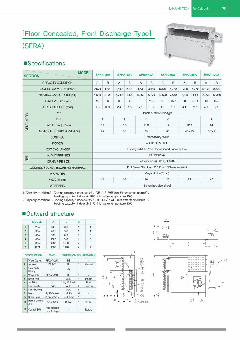
■Specifications
MODELSECTION
A B A B A B A B A B A B
2,670 1,820 3,500 2,420 4,730 3,480 6,370 4,720 9,320 6,770 12,020 8,820
4,630 2,980 6,790 4,100 9,250 5,770 12,500 7,530 18,310 11,140 20,530 12,330
10 6 12 8 15 11.5 20 15.7 30 22.4 40 29.3
1.5 0.72 2.4 1.5 4.1 2.9 1.9 1.3 4.1 2.7 4.1 2.3
Double suction turbo type
1 1 2 2 3 4
5.7 8.5 11.3 17 22.6 34
25 35 45 65 40+50 65×2
3 steps rotary switch
AC 1P 220V 50Hz
Unite type Multi-Pass Cross Finned Tube(Slit Fin)
PF 3/4"(20A)
Soft vinyl hose(IDØ14, ODØ18)
P.U Foam, Styrofoam P.E Foam / Flame resistant
Vinyl chloride(Flush)
14 16 20 25 32 40
Galvanized steel sheet
CAPACITY CONDITION
COOLING CAPACITY (kcal/hr)
HEATING CAPACITY (kcal/hr)
FLOW RATE (ℓ/min)
PRESSURE DROP (mAq)
TYPE
NO.
AIR FLOW (m3/min)
MOTOR ELECTRIC POWER (W)
CONTROL
POWER
HEAT EXCHANGER
IN, OUT PIPE SIZE
DRAIN PIPE SIZE
LAGGING, SOUND-ABSORBING MATERIAL
AIR FILTER
WEIGHT (kg)
WRAPPING
VE
NTI
LATO
RP
IPE
SFRA-20A SFRA-30A SFRA-40A SFRA-60A SFRA-80A SFRA-120A
1. Capacity condition A - Cooling capacity : Indoor air 27℃DB, 21℃WB, inlet Water temperature 5℃Heating capacity : Indoor air 18℃, inlet water temperature 80℃
2. Capacity condition B - Cooling capacity : Indoor air 27℃DB, 19.5℃WB, inlet water temperature 7℃Heating capacity : Indoor air 21℃, inlet water temperature 60℃
75SAMJUNG TECH Fan Coil Unit
[Floor Concealed, Front Discharge Type]
(SFRA)
■Outward structure
Water Outlet PF 3/4″(20A) BS 1 - Air Vent PT 1/8″ BS 1 Manual
Inner Side t1.2 GI 2 -Casing
Water Inlet PF 3/4″(20A) BS 1 -Drain Pan - ABS 1 PlasticAir Filter - Vinyl Chloride 1 FlushFan Impeller Ø145 ABS F SiroccoFan Housing - ABS F -Motor 1P, 220V, 60Hz ASS’Y M -Drain Hose IDØ14,ODØ18 Soft Vinyl 1 -Heat & Cooling
3/8×t0.35 CU-AL 1 Slit FinCoil
Control S/WHigh, Medium,
- 1 RotaryLow 3-steps
12
3
45
678910
11
12
DESCRIPTION MATL DIMENSION Q’TY REMARKS
1
2
3
4
5
6
MODEL A B M F
540
660
780
1020
1260
1500
1
1
1
1
2
2
1
1
2
2
3
4
20A
30A
40A
60A
80A
120A
480
600
720
960
1200
1440
180717 63-82 1904.1.25 5:10 AM 페이지75 C M Y K

■Specifications
MODELSECTION
A B A B A B A B A B A B
2,670 1,820 3,500 2,420 4,730 3,480 6,370 4,720 9,320 6,770 12,020 8,820
4,630 2,980 6,790 4,100 9,250 5,770 12,500 7,530 18,310 11,140 20,530 12,330
10 6 12 8 15 11.5 20 15.7 30 22.4 40 29.3
1.5 0.72 2.4 1.5 4.1 2.9 1.9 1.3 4.1 2.7 4.1 2.3
Double suction turbo type
1 1 2 2 3 4
5.7 8.5 11.3 17 22.6 34
25 35 45 65 40+50 65×2
3 steps rotary switch
AC 1P 220V 50Hz
Unite type Multi-Pass Cross Finned Tube(Slit Fin)
PF 3/4"(20A)
Soft vinyl hose(IDØ14, ODØ18)
P.U Foam, Styrofoam P.E Foam / Flame resistant
Vinyl chloride(Flush)
14 16 20 25 32 40
Galvanized steel sheet
CAPACITY CONDITION
COOLING CAPACITY (kcal/hr)
HEATING CAPACITY (kcal/hr)
FLOW RATE (ℓ/min)
PRESSURE DROP (mAq)
TYPE
NO.
AIR FLOW (m3/min)
MOTOR ELECTRIC POWER (W)
CONTROL
POWER
HEAT EXCHANGER
IN, OUT PIPE SIZE
DRAIN PIPE SIZE
LAGGING, SOUND-ABSORBING MATERIAL
AIR FILTER
WEIGHT (kg)
WRAPPING
VE
NTI
LATO
RP
IPE
SFRB-20A SFRB-30A SFRB-40A SFRB-60A SFRB-80A SFRB-120A
1. Capacity condition A - Cooling capacity : Indoor air 27℃DB, 21℃WB, inlet Water temperature 5℃Heating capacity : Indoor air 18℃, inlet water temperature 80℃
2. Capacity condition B - Cooling capacity : Indoor air 27℃DB, 19.5℃WB, inlet water temperature 7℃Heating capacity : Indoor air 21℃, inlet water temperature 60℃
76 Fan Coil Unit SAMJUNG TECH
[Floor Concealed, Top Discharge Type]
(SFRB)
■Outward structure
Water Outlet PF 3/4″(20A) BS 1 - Air Vent PT 1/8″ BS 1 ManualInner Side t1.2 GI 2 -Casing
Water Inlet PF 3/4″(20A) BS 1 -Drain Pan - ABS 1 Plastic
Air Filter - Vinyl Chloride 1 FlushFan Impeller Ø145 - F SiroccoFan Housing - ABS F -Motor 1P, 220V, 60Hz ABS M -Drain Hose IDØ14,ODØ18 ASS’Y 1 -Heat & Cooing
3/8″×t0.35 Soft Vinyl 1 Slit FinCoil
Control S/W High, Medium, CU-AL 1 RotaryLow 3-steps
12
3
45
678910
11
12
DESCRIPTION MATL DIMENSION Q’TY REMARKS
1
2
3
4
5
6
MODEL A B M F
540
660
780
1020
1260
1500
1
1
1
1
2
2
1
1
2
2
3
4
20A
30A
40A
60A
80A
120A
480
600
720
960
1200
1440
180717 63-82 1904.1.25 5:10 AM 페이지76 C M Y K

■Specifications
MODELSECTION
A B A B A B A B A B A B
2,670 1,820 3,500 2,420 4,730 3,480 6,370 4,720 9,320 6,770 12,020 8,820
4,630 2,980 6,790 4,100 9,250 5,770 12,500 7,530 18,310 11,140 20,530 12,330
10 6 12 8 15 11.5 20 15.7 30 22.4 40 29.3
1.5 0.72 2.4 1.5 4.1 2.9 1.9 1.3 4.1 2.7 4.1 2.3
Double suction turbo type
1 1 2 2 3 4
5.7 8.5 11.3 17 22.6 34
25 35 45 65 40+50 65×2
3 steps rotary switch
AC 1P 220V 50Hz
Unite type Multi-Pass Cross Finned Tube(Slit Fin)
PF 3/4"(20A)
Soft vinyl hose(IDØ14, ODØ18)
P.U Foam, Styrofoam P.E Foam / Flame resistant
Vinyl chloride(Flush)
14 16 20 25 32 40
Galvanized steel sheet
CAPACITY CONDITION
COOLING CAPACITY (kcal/hr)
HEATING CAPACITY (kcal/hr)
FLOW RATE (LPM)
PRESSURE DROP (mAq)
TYPE
NO.
AIR FLOW (m3/min)
MOTOR ELECTRIC POWER (W)
CONTROL
POWER
HEAT EXCHANGER
IN, OUT PIPE SIZE
DRAIN PIPE SIZE
LAGGING, SOUND-ABSORBING MATERIAL
AIR FILTER
WEIGHT (kg)
WRAPPING
VE
NTI
LATO
RP
IPE
SFRC-20A SFRC-30A SFRC-40A SFRC-60A SFRC-80A SFRC-120A
1. Capacity condition A - Cooling capacity : Indoor air 27℃DB, 21℃WB, inlet Water temperature 5℃Heating capacity : Indoor air 18℃, inlet water temperature 80℃
2. Capacity condition B - Cooling capacity : Indoor air 27℃DB, 19.5℃WB, inlet water temperature 7℃Heating capacity : Indoor air 21℃, inlet water temperature 60℃
77SAMJUNG TECH Fan Coil Unit
[Floor Concealed, Slant Discharge Type]
(SFRC)
■Outward structure
Water Outlet PF 3/4″(20A) BS 1 - Air Vent PT 1/8″ BS 1 ManualInner Side t1.2 GI 2 -Casing
Water Inlet PF 3/4"(20A) BS 1 -Drain Pan - ABS 1 Plastic
Air Filter - Vinyl Chloride 1 FlushFan Impeller Ø145 - F SiroccoFan Housing - ABS F -Motor 1P, 220V, 60Hz ABS M -Drain Hose IDØ14,ODØ18 ASS’Y 1 -Heat & Cooing
3/8″×t0.35 Soft Vinyl 1 Slit FinCoil
Control S/W High, Medium, CU-AL 1 RotaryLow 3-steps
12
3
45
678910
11
12
DESCRIPTION MATL DIMENSION Q’TY REMARKS
1
2
3
4
5
6
MODEL A B M F
540
660
780
1020
1260
1500
1
1
1
1
2
2
1
1
2
2
3
4
20A
30A
40A
60A
80A
120A
480
600
720
960
1200
1440
180717 63-82 1904.1.25 5:10 AM 페이지77 C M Y K

■Specifications
MODELSECTION
A B A B A B A B A B A B
2,670 1,820 3,500 2,420 4,730 3,480 6,370 4,720 9,320 6,770 12,020 8,820
4,630 2,980 6,790 4,100 9,250 5,770 12,500 7,530 18,310 11,140 20,530 12,330
10 6 12 8 15 11.5 20 15.7 30 22.4 40 29.3
1.5 0.72 2.4 1.5 4.1 2.9 1.9 1.3 4.1 2.7 4.1 2.3
Double suction turbo type
1 1 2 2 3 4
5.7 8.5 11.3 17 22.6 34
25 35 45 65 40+50 65×2
3 steps rotary switch
AC 1P 220V 50Hz
Unite type Multi-Pass Cross Finned Tube(Slit Fin)
PF 3/4"(20A)
Soft vinyl hose(IDØ14, ODØ18)
P.U Foam, Styrofoam P.E Foam / Flame resistant
Vinyl chloride(Flush)
14 16 20 25 32 40
Galvanized steel sheet
CAPACITY CONDITION
COOLING CAPACITY (kcal/hr)
HEATING CAPACITY (kcal/hr)
FLOW RATE (LPM)
PRESSURE DROP (mAq)
TYPE
NO.
AIR FLOW (m3/min)
MOTOR ELECTRIC POWER (W)
CONTROL
POWER
HEAT EXCHANGER
IN, OUT PIPE SIZE
DRAIN PIPE SIZE
LAGGING, SOUND-ABSORBING MATERIAL
AIR FILTER
WEIGHT (kg)
WRAPPING
VE
NTI
LATO
RP
IPE
SFRI-20A SFRI-30A SFRI-40A SFRI-60A SFRI-80A SFRI-120A
1. Capacity condition A - Cooling capacity : Indoor air 27℃DB, 21℃WB, inlet Water temperature 5℃Heating capacity : Indoor air 18℃, inlet water temperature 80℃
2. Capacity condition B - Cooling capacity : Indoor air 27℃DB, 19.5℃WB, inlet water temperature 7℃Heating capacity : Indoor air 21℃, inlet water temperature 60℃
78 Fan Coil Unit SAMJUNG TECH
[Floor Concealed, Front Suction Type]
(SFRI)
■Outward structure
Water Outlet PF 3/4″(20A) BS 1 - Air Vent PT 1/8″ BS 1 ManualInner Side t1.2 GI 2 -Casing
Water Inlet PF 3/4″(20A) BS 1 -Drain Pan - ABS 1 Plastic
Air Filter - Vinyl Chloride 1 FlushFan Impeller Ø145 ABS F SiroccoFan Housing - ABS F -Motor 1P, 220V, 60Hz ASS’Y M -Drain Hose IDØ14,ODØ18 Soft Vinyl 1 -Heat & Cooing
OD3/8″×t0.35 CU-AL 1 Slit FinCoil
Control S/W High, Medium, - 1 RotaryLow 3-steps
12
3
45
678910
11
12
DESCRIPTION MATL DIMENSION Q’TY REMARKS
1
2
3
4
5
6
MODEL A B M F
540
660
780
1020
1260
1500
1
1
1
1
2
2
1
1
2
2
3
4
20A
30A
40A
60A
80A
120A
480
600
720
960
1200
1440
180717 63-82 1904.1.25 5:10 AM 페이지78 C M Y K
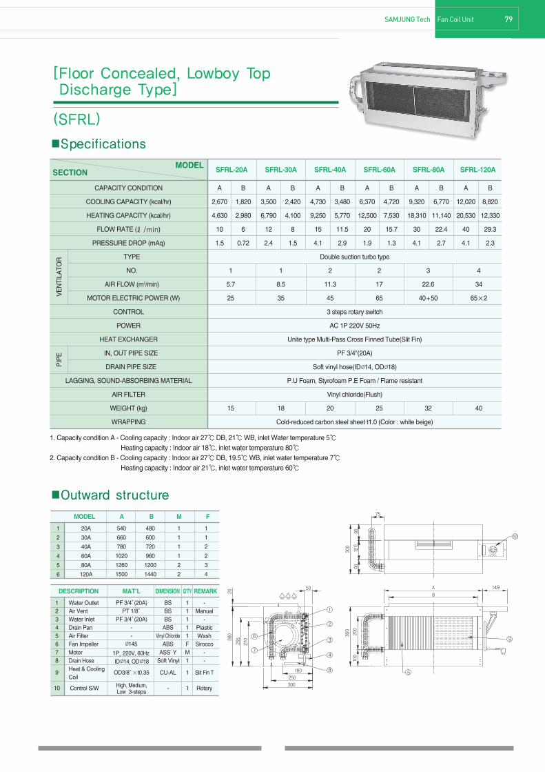
79SAMJUNG Tech Fan Coil Unit
■Specifications
MODELSECTION
A B A B A B A B A B A B
2,670 1,820 3,500 2,420 4,730 3,480 6,370 4,720 9,320 6,770 12,020 8,820
4,630 2,980 6,790 4,100 9,250 5,770 12,500 7,530 18,310 11,140 20,530 12,330
10 6 12 8 15 11.5 20 15.7 30 22.4 40 29.3
1.5 0.72 2.4 1.5 4.1 2.9 1.9 1.3 4.1 2.7 4.1 2.3
Double suction turbo type
1 1 2 2 3 4
5.7 8.5 11.3 17 22.6 34
25 35 45 65 40+50 65×2
3 steps rotary switch
AC 1P 220V 50Hz
Unite type Multi-Pass Cross Finned Tube(Slit Fin)
PF 3/4"(20A)
Soft vinyl hose(IDØ14, ODØ18)
P.U Foam, Styrofoam P.E Foam / Flame resistant
Vinyl chloride(Flush)
15 18 20 25 32 40
Cold-reduced carbon steel sheet t1.0 (Color : white beige)
CAPACITY CONDITION
COOLING CAPACITY (kcal/hr)
HEATING CAPACITY (kcal/hr)
FLOW RATE (ℓ/min)
PRESSURE DROP (mAq)
TYPE
NO.
AIR FLOW (m3/min)
MOTOR ELECTRIC POWER (W)
CONTROL
POWER
HEAT EXCHANGER
IN, OUT PIPE SIZE
DRAIN PIPE SIZE
LAGGING, SOUND-ABSORBING MATERIAL
AIR FILTER
WEIGHT (kg)
WRAPPING
VE
NTI
LATO
RP
IPE
SFRL-20A SFRL-30A SFRL-40A SFRL-60A SFRL-80A SFRL-120A
1. Capacity condition A - Cooling capacity : Indoor air 27℃DB, 21℃WB, inlet Water temperature 5℃Heating capacity : Indoor air 18℃, inlet water temperature 80℃
2. Capacity condition B - Cooling capacity : Indoor air 27℃DB, 19.5℃WB, inlet water temperature 7℃Heating capacity : Indoor air 21℃, inlet water temperature 60℃
■Outward structure
[Floor Concealed, Lowboy Top Discharge Type]
(SFRL)
1
2
3
4
5
6
DESCRIPTION MAT’L DIMENSION Q’TY REMARK
12345678
9
10
Water OutletAir VentWater InletDrain PanAir FilterFan ImpellerMotorDrain HoseHeat & CoolingCoil
Control S/W
BSBSBS
ABSVinyl Chloride
ABSASS’Y
Soft Vinyl
CU-AL
-
PF 3/4″(20A)PT 1/8″
PF 3/4″(20A)--
Ø145
1P, 220V, 60HzIDØ14,ODØ18
OD3/8″×t0.35
High, Medium,Low 3-steps
11111FM1
1
1
-Manual
-PlasticWash
Sirocco--
Slit Fin T
Rotary
MODEL A B M F
540
660
780
1020
1260
1500
1
1
1
1
2
2
1
1
2
2
3
4
20A
30A
40A
60A
80A
120A
480
600
720
960
1200
1440
180717 63-82 1904.1.25 5:10 AM 페이지79 C M Y K

■Specifications
[Floor Stand Front Discharge Type](SFFA)
MODELSECTION
A B A B A B A B A B A B A B
6,000 4,400 9,000 6,600 17,500 15,000 26,700 22,500 35,550 30,000 53,500 45,000 72,000 60,000
11,600 7,100 17,400 10,560 34,000 22,100 51,000 33,000 68,000 43,300 102,000 66,000 136,500 84,000
20 15 30 21.5 58 50 88 75 120 100 180 150 240 200
1.5 0.72 2.4 1.5 4.1 2.9 1.9 1.3 4.1 2.7 4.1 2.3 4.1 2.3
Double suction turbo type
1 1 1 2 2 2 2
23 34 48 70 90 130 180
145 420 420 840 900 1100 1500
MICOM SWITCH (AUTO & 3 STEPS)
AC 1P 220V 50Hz
Unite type Multi-Pass Cross Finned Tube(Slit Fin)
20A 25A 32A 40A 40A 50A 50A
Nipple (25A)
P.U Foam, P.E Foam / Flame resistant
Vinyl chloride(Flush)
Cold-reduced carbon steel sheet t1.0 (Color : white beige)
CAPACITY CONDITION
COOLING CAPACITY (kcal/hr)
HEATING CAPACITY (kcal/hr)
FLOW RATE (ℓ/min)
PRESSURE DROP (mAq)
TYPE
NO.
AIR FLOW (m3/min)
MOTOR ELECTRIC POWER (W)
CONTROL
POWER
HEAT EXCHANGER
IN, OUT PIPE SIZE
DRAIN PIPE SIZE
LAGGING, SOUND-ABSORBING MATERIAL
AIR FILTER
WRAPPING
VE
NTI
LATO
RP
IPE
SFFA-20S SFFA-30S SFFA-50S SFFA-75S SFFA-100S SFFA-150S SFFA-200S
1. Capacity condition A - Cooling capacity : Indoor air 27℃DB, 21℃WB, inlet Water temperature 5℃Heating capacity : Indoor air 18℃, inlet water temperature 80℃
2. Capacity condition B - Cooling capacity : Indoor air 27℃DB, 19.5℃WB, inlet water temperature 7℃Heating capacity : Indoor air 21℃, inlet water temperature 60℃
80 Fan Coil Unit SAMJUNG TECH
■Outward structure
20S
30S
50S
75S
100S
150S
200S
1800
1950
1950
1950
1950
2150
2200
800
800
1000
1200
1400
1600
1700
500
500
500
500
500
750
750
790
790
990
1190
1390
1590
1690
490
490
490
490
490
740
740
390
420
420
460
370
450
410
1050
1100
1100
1140
1050
1100
1140
260
330
330
430
430
450
450
334
334
334
314
314
317
317
730
730
875
915
963
1073
1073
125
125
125
157
157
252
252
90
90
90
120
120
222
222
264
264
303
306
326
566
566
-
600
800
1000
1200
1400
1500
-
390
390
390
390
640
640
20
25
32
40
40
50
50
MODEL A B C D E F G H I J K L M N O
1
2
3
4
5
6
7
DESCRIPTION MAT’L DIMENSION Q’TY REMARK
1234567891011
Air Out GrilleControl SwitchCasingAir InletFan & MotorBaseHeat & Cooling CoilDrain PanelScrew BoltName PlateTerminal Block
AL-
CRCR-
CRCU-AL
CRSUS
--
-4-contacts touch-type
t1.2t1.2
-t2.3
OD 3/8″×t0.35t1.2
--
20A 8P
11111111211
Coating
1P, 220V, 60HzCoatingCoating
Sirocco FanCoating
Hot and Cold CoilCoating
--
-
180717 63-82 1904.1.25 5:10 AM 페이지80 C M Y K

■SpecificationsMODEL
SECTION
A B A B A B A B A B A B A B
6,000 4,400 9,000 6,600 17,500 15,000 26,700 22,500 35,550 30,000 53,500 45,000 72,000 60,000
11,600 7,100 17,400 10,560 34,000 22,100 51,000 33,000 68,000 43,300 102,000 66,000 136,500 84,000
20 15 30 21.5 58 50 88 75 120 100 180 150 240 200
1.5 0.72 2.4 1.5 4.1 2.9 1.9 1.3 4.1 2.7 4.1 2.3 4.1 2.3
Double suction turbo type
1 1 1 2 2 2 2
23 34 48 70 90 130 180
145 420 420 840 900 1100 1500
MICOM SWITCH (AUTO & 3 STEPS) MICOM SWITCH
AC 1P 220V 50Hz AC 3Φ 380V 50Hz
Unite type Multi-Pass Cross Finned Tube(Slit Fin)
20A 25A 32A 40A 40A 50A 50A
Nipple (25A)
P.U Foam, P.E Foam / Flame resistant
Vinyl chloride(Flush)
Cold-reduced carbon steel sheet t1.0 (Color : white beige)
CAPACITY CONDITION
COOLING CAPACITY (kcal/hr)
HEATING CAPACITY (kcal/hr)
FLOW RATE (ℓ/min)
PRESSURE DROP (mAq)
TYPE
NO.
AIR FLOW (m3/min)
MOTOR ELECTRIC POWER (W)
CONTROL
POWER
HEAT EXCHANGER
IN, OUT PIPE SIZE
DRAIN PIPE SIZE
LAGGING, SOUND-ABSORBING MATERIAL
AIR FILTER
WRAPPING
VE
NTI
LATO
RP
IPE
SFFA-20S SFFA-30S SFFA-50S SFFA-75S SFFA-100S SFFA-150S SFFA-200S
1. Capacity condition A - Cooling capacity : Indoor air 27℃DB, 21℃WB, inlet Water temperature 5℃Heating capacity : Indoor air 18℃, inlet water temperature 80℃
2. Capacity condition B - Cooling capacity : Indoor air 27℃DB, 19.5℃WB, inlet water temperature 7℃Heating capacity : Indoor air 21℃, inlet water temperature 60℃
81SAMJUNG TECH Fan Coil Unit
[Floor Stand Top Duct Type](SFFD)
■Outward structure
20S
30S
50S
75S
100S
150S
200S
1800
1950
1950
1950
1950
2150
2200
800
800
1000
1200
1400
1600
1700
500
500
500
500
500
750
750
790
790
990
1190
1390
1590
1690
490
490
490
490
490
740
740
390
420
420
460
370
450
410
1050
1100
1100
1140
1050
1100
1140
260
330
330
430
430
450
450
334
334
334
314
314
317
317
730
730
875
915
963
1073
1073
125
125
125
157
157
252
252
90
90
90
120
120
222
222
264
264
303
306
326
566
566
-
600
800
1000
1200
1400
1500
-
390
390
390
390
640
640
20
25
32
40
40
50
50
MODEL A B C D E F G H I J K L M N O
1
2
3
4
5
6
7
DESCRIPTION MAT’L DIMENSION Q’TY REMARK
1234567891011
Supply AirControl SwitchCasingAir InletFan & MotorBaseHeat & Cooling CoilDrain PanelScrew BoltName PlateControl Block
CR-
CRCR-
CRCU-AL
CRSUS
--
-4-contacts touch-type
t1.2t1.2
-t2.3
OD 3/8″×t0.35t1.2
--
20A 8P
11111111211
Coating
1Φ, 220V, 60HzCoating
CoatingSirocco FanCoating
Hot and Cold CoilCoating
--
-
180717 63-82 1904.1.25 5:10 AM 페이지81 C M Y K

82 Fan Coil Unit SAMJUNG TECH
M/E/M/O
180717 63-82 1904.1.25 5:11 AM 페이지82 C M Y K