Safer House Construction Guidelines - AWS
94
Safer House Construction Guidelines Bureau TNM
-
Upload
khangminh22 -
Category
Documents
-
view
1 -
download
0
Transcript of Safer House Construction Guidelines - AWS

Safer House Construction GuidelinesBureau TNM

Authors:
Matilde Cassani, architect and urban planner, BureauTNM. Maria Chiara Pastore, architect and urban planner, BureauTNM. Francesca Benedetto, architect and landscape designer, BureauTNMVassilis Mpampatsikos, Structural engineerFrancesco Librizzi Studio, architectPietro Vallone, administration consultantBianca Fabbri, layout
Contacts:
Bureau TNMvia Nino Bixio 47,20129 Milano, Italy. [email protected],
Acknowledgments:
Task team Francis Nkoka, World Bank, GFDRR country coordinator Esau Mwambira, Department of Lands, Housing and Urban DevelopmentGlyn Chirwa, Buildings Department John Chome, UN- HABITATMadalitso Mwale, Dipartment od Disaster Risk Management Affairs, DODMA
Core TeamThe Director, Department of Housing;The Director, Department of Building;The Director, DODMA;Mr Kaisi, Malawi Institute of Architects;Mr Mshali, MHC, BlantyreMr Chilipunde, The Polytechnic, BlantyreCharles I.M. Chiocha – The Polytechnic, BlantyreMr Manda – Mzuzu UniversityMr Bulukutu Chirwa, Department of Housing, Mzuzu
Stakeholders:Office of the President and Cabinet; The Secretary and Commissioner for Disaster Management Affairs; World Bank; The President and Secretary General, Malawi Red Cross Society; Habitat For Humanity; CCODE (Centre for Community Organisation and Development); Christian Aid; CADECOM, Malawi Building Contractors and Allied Traders Association; Lilongwe City Council; Mzuzu City Council; Blantyre City Council; Zomba City Council; Lilongwe District Commissioner; Mzuzu Technical College; Buildings Department; The Surveyor General; The Controller of Lands; The Commissioner for Physical Planning; Geological Surveys Department; National Construction Council; Local Government and Rural Development; Malawi Institute of Engineers; Malawi Institute of Architects; TEVETA; UN-Habitat; Government Contracting Unit; Malawi Polytechnic (Innocent Kafodya, Terence Namaona, Ignasio Ngoma, Maxwell Chisala, Charles Chiocha, Rodrick Chilipunde); Faculty of Built Environment; Department of Environmental Affairs; Evangelical Association of Malawi; Secretary for Education Science and Technology, Projects Implementation Unit; Malawi Housing Corporation; Action Aid; Lafarge Cement; Regional Sales Rep. Lilongwe; COOPI; Department of Land; Housing and Urban Development.
FUNDED BY GFDRR, World Bank
SAFER HOUSE CONSTRUCTION
GUIDELINES
Technical manual
Bureau TNM
Department of Lands,Housing and Urbandevelopment


1. Absence of damp proof course. Moisture reduces wall resistance
3. Erosion of the foundation. Protection with cement is required
4. Soil erosion due to absence of trees
5. Termites reaching the wood structure of the roof 6. Soil erosion due to brickmaking
7. Cracks damage the wall because of the earthquake 8. Absence of protection at the wall base towards water erosion.
9. Blown off roof 10. Blown off roof
13. Poor damp proof membrane – exposed wall base to water
14. Wall collapse after landslide
15. Cracks damage the wall because of the earthquake 16. Blown off roof
17 Safer house construction guidelines
Recurrent deficiencies:
2. Mud pavement erosion due to water exposition
11. House collapsed because of the earthquake 12. Small elevation of the floor level in floods prone areas.

Malawi has been traditionally vulnerable to disasters because of its unique geo-climatic conditions.Thus Malawi’s vulnerability is primarly linked to specifi geo-climatic factors: (i) the influence of the El Nino and la Nina phenomena on the country’ s climate, and the tropical cyclones developing in the Mozambique Channel, resulting in erratic rainfall patterns; and (ii) the location of the country along tectonically active boundary between two major African plates within the great East African Rift Valley System, causing earthquakes and landslides.From 1979 to 2008, natural disasters affected nearly 21,7 million people and killed about 2.596 people. The main types of natural harards include floods, droughts, eartquakes, windstorms and landslides. The country also faces human- induced and biological disasters, such as environmental degradation and epidemics respectively. Their intensity and frequency is likely to increase in the light of climate change, population growth and continued environmental degradation as evident in the earthquake disaster that hit Karonga and Chitipa in 2009/2010 as well as the floods of 2014/2015 that caused severe damage to houses, property and loss of lives. The most effective measure to protect human lives and property is by building better and safer houses, particularly in rural areas, in order to minimize damage. In rural areas, construction is mainly done by local artisans with limited knowledge and technical skills. They construct houses without guiding manuals, regulation and standards. Consequently, initial construction guidelines were developed in 2010 by the Government of Malawi, trough the Ministry of Lands, Housing and Urban Development, following a series of earthquakes that occurred in Karonga and parts of Chitipa Districts to provide the needed guidance.However, a number of gaps in the guidelines were identified (World Bank Mission, 2012), a number of lessons were gathered by stakeholders, and the limited stakeholder awareness of the first guidelines nacessitated the revision. The revised Safer House Construction Guidelines promote local practices, low-cost technologies and identify strategies for multi-hazard risk reduction by proposing both affordable and appropriate solutions trough a user-friendly manual. Nevertheless, the manual remains a living document and should form the basis for mainstreaming disaster risk reduction in construction and human settlmenets planning in Malawi.The Malawi Government recongnizes with gratitude the technical and financial support of the World Bank, with funding from the Global Facility for Disaster Reduction and recovery (GFDRR). Government further acknowledges the contribution from BureauTNM consulting firm that facilitated the review process and all stakeholders who contributed to the development of the revised guidelines.
I.Foreword
Honourable Paul Chibingu, M.PMinistry of Lands, Housing and Urban Development
19 Safer house construction guidelines

Malawi faces different hazards throughout the entire country. Floods of various nature, heavy storms, droughts, landslides, and earthquakes affected a total of 21,731,581 people in the time period from 1980 to 2010. Due to global climate changes the number of extreme events have risen in the last decades. The flood that took place in early January 2015 has shown the increased severity of the hazards. Preliminary assessments indicate that the flood hit a quarter of a million people, killing more than 110 people, with 15 districts affected. Houses, schools, roads, bridges, livestock and crops were washed away, leaving bare lands to those returning after the disaster. Diseases, malnutrition and insecurity are just some of the issues related to such catastrophes. In fact, hazards emphasise socio-economic and environmental vulnerability as they mark an increase in poverty of rural and urban households, compromise investments, increase unaccounted expenditure, and the cost of reconstruction is a substantial burden for the economy.
Making risk reduction a central goal for the development of Malawi is a key way of ensuring that disasters do not affect the development progress. Promoting safer housing ensures that the new housing stock does not inadvertedly create new risks for Malawians.In 2014, the Malawi Government through the Ministry of Lands and Housing decided to review the safer house construction guidelines, initially developed in the year 2010, immediately after the earthquake in Karonga. A multidisciplinary team of International Consultants has been working towards the formulation of the Review of the Existing Safer House Construction Guidelines of Malawi together with a Task team formed by members of the World Bank, the Department of Housing, the Department of Building, DODMA and UN Habitat.
The Project investigates the construction typologies that form the housing stock in Malawi. Its aim is to interpret the actual trend of present construction techniques and the recurring deficiencies. The review of the “Safer Houses Construction Guidelines” is built upon current construction practices, taking into account local skills and materials; it addresses the future development of the built environment focusing on multi hazard risk reduction following a participatory planning process.
The present manual is addressed to the different stakeholders involved in the construction practices in Malawi. Accompanying this manual, a series of illustrated sheets. will be issued, in order to be used by the artisans, and all those involved in the construction sectors in Malawi.
II. The need for safer housing: Introduction, context, scope.
Bureau TNM
21 Safer house construction guidelines

The “safer house construction guidelines” contains a framework of guiding principles to develop context-specific solutions in order to ensure the construction of safer houses. The guidelines are based on the previous version of the guidelines prepared in response to the Malawi earthquake of 2009.The new guidelines are designed to meet four main objectives:• Guidelines will be Multi-hazard responsive• Guidelines will be Adaptive and Sustainable• Guidelines will address incremental solutions • Guidelines will be addressed to different target audiencesThe occurrence of hazards may be, as in the case of earthquakes, impossible to predict and control. For most other hazards, it is possible to take action in order to minimise the impact of such adverse situations. In order to mitigate and prevent possible major disasters it is important to consider all the different hazards affecting the country of Malawi, and to address them in a multi hazard approach. It is in fact mandatory not to take into account a single hazard, but to adapt the construction to all the different hazards that may affect the safety of the building.In order to adapt to the availability of the resources, the climate, and the geo-morphological conditions, the buildings’ construction materials, construction techniques, and shape need to be adjusted. In particular, a safe house is able to withstand severe natural hazards without threatening lives and without exhibiting major signs of deterioration. The guidelines promote adaptive and sustainable solutions, addressing the different risks, discussing the necessary procedures in the selection of the building sites, suggesting materials and construction techniques.The different results proposed in the guidelines stem from solutions already in use in the Malawian context, from traditional constructions or from examples seen in public buildings, in order to provide affordable and appropriate housing. These indications have been revised to improve the application of materials already in use on the territory, and to introduce slight variations in the technology and in the construction techniques in order to strengthen constructions and to lengthen the buildings’ lifespan.A set of different proposals are presented to offer a wide range of alternatives to accommodate the different conditions and the diverse economic difficulties of the Malawian population.Policymakers and planners of local, regional and national government bodies, NGOs, engineers and architects, and all other organisations engaged in improving safety in the construction industry should refer to these guidelines. A series of illustrated sheets is provided to be distributed to the artisans, dealers of the construction sector , and to all those who are in need of information about building safer houses.The guidelines were developed through a participation process involving the Task team, and a hundred stakeholders engaged in the construction industry, in the NGO sector and in public administrations, who contributed with suggestions drawn from experience and from acquired knowledge. An extensive field survey throughout the country has helped to define the different hazards affecting Malawi, the best practices already in use, the current construction techniques, and to explore and discuss possible solutions to achieve safer results. The result of these guidelines is the consequence of a joint effort on behalf of consultants and different stakeholders, including the government, the donor, engineers and architects, planners, construction managers, UN agencies, NGOs, academic institutions and educators.
III. Executive summary
23 Safer house construction guidelines

IV.Glossary
Natural hazardA natural hazard is a geophysical, atmospheric or hydrological event (e.g. earthquake, landslide, tsunami, windstorm, wave or surge, flood or drought) that has the potential to cause harm or loss.
VulnerabilityVulnerability is the potential to suffer harm or loss, related to the capacity to anticipate a hazard, cope with it, resist it and recover from its impact. Both vulnerability and its antithesis, resilience, are determined by physical, environmental, social, economic, political, cultural and institutional factors.
DisasterA disaster is the occurrence of an extreme hazard event that impacts vulnerable communities causing substantial damage, disruption and possible casualties, leaving the affected communities unable to function normally without outside assistance.
Disaster riskDisaster risk is a function of the characteristics and frequency of hazards experienced in a specified location, the nature of the elements at risk, and their inherent degree of vulnerability or resilience.
MitigationMitigation is any structural (physical) or non-structural (e.g. land use planning, public education) measure undertaken to minimise the adverse impact of potential natural hazard events.
PreparednessPreparedness refers to the activities and measures taken before hazard events occur to forecast and warn against them, evacuating people and properties when they threatened and ensuring effective responses (e.g. stockpiling food supplies).
Relief, rehabilitation and reconstruction Relief, rehabilitation and reconstruction are any measures undertaken in the aftermath of a disaster to, respectively, save lives and address immediate humanitarian needs, restore normal activities and restore physical infrastructure and services.
Climate changeClimate change is a statistically significant change in measurements of either the mean state or variability of the climate for a place or region over an extended period of time, either directly or indirectly due to the impact of human activity on the composition of the global atmosphere or due to natural variability.
It is widely acknowledged within the disaster community that hazard and disaster terminology are used inconsistently across the sector, reflecting the involvement of practitioners and researchers from a wide range of disciplines. Key terms are used as follows for the purpose of this guidance note series1.
1 Benson, C., Twigg, J., Rossetto, T., (2007) Tools for Mainstreaming Disas-ter Risk Reduction Guidance Notes for Development Organisations, Internation-al Federation of Red Cross and Red Cres-cent Societies / the ProVention Consorti-um, Geneva Switzerland pagg. 15-16
25 Safer house construction guidelines

Table of contents
I. Foreword .......................................................................................................................................19II. The need for Safer Houses: Introduction, context, scope ....................................................21III. Executive Summary.................................................................................................................... 23IV. Glossary ....................................................................................................................................... 25
1 UNDERSTANDING RISK 35
1. 1 Floods (including flash floods) ................................................................................................. 36 1. 2 Landslides .................................................................................................................................... 381. 3 Fires ..............................................................................................................................................401. 4 Hailstorms and strong winds .................................................................................................... 421. 5 Earthquake ..................................................................................................................................441. 6 Soil Erosion ..................................................................................................................... 461. 7 Termites .......................................................................................................................... 48
2 SITE SELECTION 53
3 LAYOUT AND ORIENTATION OF THE BUILDING 57 4 MATERIALS 63
4.1 Soil as construction material .................................................................................................... 634.1.1 Physical stabilisation (proper soil selection and mixture) ...................................................644.1.2 Tests to estimate the particle size distribution of the soil ................................................... 654.1.3 Properly modify the soil texture .............................................................................................. 704.1.4 Mechanical stabilisation (compaction at optimum moisture content) ..............................714.1.5 Chemical stabilisation (addition of materials) ....................................................................... 724.1.6 Soil preparation .......................................................................................................................... 734.2 Sun-dried (adobe) bricks ........................................................................................................... 744.2.1 Fabrication process .................................................................................................................... 744.2.2 Check for appearance ............................................................................................................... 764.3 Rammed Earth ............................................................................................................................ 764.4 Burnt (fired) bricks...................................................................................................................... 774.5 SSBs (stabilised soil blocks) ...................................................................................................... 784.5.1 Correct mix for SSBs .................................................................................................................. 794.5.2 Compression through light mechanical presses ...................................................................804.5.3 Curing and Drying ......................................................................................................................804.5.4 Appearance ..................................................................................................................................814.6 Mud mortar for joints ................................................................................................................ 824.7 Cement mortar for joints .......................................................................................................... 824.8 Concrete ...................................................................................................................................... 834.8.1 Components ................................................................................................................................ 834.8.2 Mixing ........................................................................................................................................... 834.9 Mud plaster .................................................................................................................................844.10 Sand – cement plaster ...............................................................................................................844.11 Timber .......................................................................................................................................... 85 4.12 Summary ...................................................................................................................................... 86
5 CONSTRUCTION DETAILS 91
5.1 Foundations ..................................................................................................................................915.1.1 Foundation soil selection ...........................................................................................................915.1.2 Foundation details .......................................................................................................................915.1.3 Slab on grade .............................................................................................................................. 935.2 Walls .............................................................................................................................................985.2.1 Sun-dried brick (adobe) walls ...................................................................................................985.2.2 Rammed earth walls ................................................................................................................ 1035.2.3 Burnt (fired) brick walls ........................................................................................................... 1055.2.4 SSBs (stabilised soil block) walls ............................................................................................ 1135.3 Openings ..................................................................................................................................... 1215.3.1 Timber lintel ...............................................................................................................................1225.3.2 Reinforced concrete lintel ....................................................................................................... 1245.4 Ring beam at lintel and roof level .......................................................................................... 1265.4.1 Reinforced concrete ring beam ..............................................................................................1285.4.2 Timber/wooden ring beam ..................................................................................................... 1295.5 Roof ............................................................................................................................................. 1305.5.1 Configuration ............................................................................................................................ 1305.5.2 Metal sheet roof ........................................................................................................................1325.5.3 Thatch roof ................................................................................................................................ 1405.6 Khonde ................................................................................................................................... ....1455.7 Summary .................................................................................................................................... 148
6 MAINTENANCE AND STRENGTHENING 153
6.1 Drainage system ....................................................................................................................... 1546.2 Sun-dried brick walls and rammed earth walls ....................................................................1556.3 Burnt (fired) brick walls and SSB walls ................................................................................. 1566.4 Gable-end walls (gable roof) ...................................................................................................1586.5 Roof structure ............................................................................................................................ 1616.6 Roof to wall connection ........................................................................................................... 1616.7 Metal sheet cover ...................................................................................................................... 1616.8 Thatch roof ................................................................................................................................ 1626.9 Khonde ....................................................................................................................................... 1636.10 Summary .................................................................................................................................... 164
7 ILLUSTRATED SHEETS 168
1. Sun-dried brick walls/thatch roof ......................................................................................... 1682. Burnt brick walls/metal roof ....................................................................................................1723. SSB wall/metal roof ..................................................................................................................176
8 BIBLIOGRAPHY 180
27 Safer house construction guidelines

Table of figuresFigure Page
1. Floods – including flash floods .....................................................................................................372. Landslides .........................................................................................................................................393. Fires ..................................................................................................................................................414. Hailstorms and strong winds .........................................................................................................435. Earthquake .......................................................................................................................................456. Soil Erosion .......................................................................................................................................477. Termites ............................................................................................................................................498. Position of the latrine ......................................................................................................................589. Raised latrine ....................................................................................................................................5910. Touch and wash tests .....................................................................................................................6511. Sedimentation test ..........................................................................................................................6612. Linear shrinkage test .......................................................................................................................6713. Ball drop test ....................................................................................................................................6814. Dry strength test ..............................................................................................................................6915. Cracking control test ......................................................................................................................7016. Optimum moisture content ...........................................................................................................7117. Ball drop test ....................................................................................................................................7218. Brick curing under grassy straw ...................................................................................................7519. Brick strength test ...........................................................................................................................7520. Cracking control test ......................................................................................................................7921. Compression of bricks ....................................................................................................................8022. SSBs curing under plastic sheets ..................................................................................................8123. Anti-termites coating ......................................................................................................................8524. Field stone foundation – lower cost solution ..............................................................................9425. Brick foundation – lower cost solution ........................................................................................9526. Brick foundation – medium cost solution ....................................................................................9627. Reinforced concrete foundation – higher cost solution ...........................................................9728. Maximum distance between walls ...............................................................................................9829. One brick wall – brick texture – lower cost solution .................................................................10030. One brick wall – corner intersection – lower cost solution ......................................................10131. One brick wall – T intersection – lower cost solution ...............................................................10232. Maximum distance between walls – lower cost solution .........................................................10333a. Rammed earth wall – lower cost solution/ ..................................................................................10433b. Rammed earth wall and bamboo cane reinforcement – medium cost solution/ ..................10434. Maximum distance between walls – medium/higher cost solution .......................................10635. One brick wall – Brick texture – Medium/higher cost solution ...............................................107 36. One brick wall – corner intersection – medium cost solution .................................................10837. One bricks wall – T intersection – medium cost solution.........................................................10938. One brick wall – horizontal reinforcement – higher cost solution ..........................................11039. One brick wall –vertical reinforcement – higher cost solution ...............................................11140. One brick wall – vertical reinforcement –higher cost solution ...............................................11241. Maximum distance between walls – higher cost solution .......................................................11342. Half brick wall – brick texture – higher cost solution ................................................................11543. Half brick wall – corner intersection – higher cost solution ....................................................11644. Half brick wall – T Intersection – higher cost solution ..............................................................11745. Half brick wall – horizontal reinforcement – higher cost solution ..........................................11846. Half brick wall – vertical reinforcement –higher cost solution................................................11947. Half brick wall – vertical reinforcement – higher cost solution ...............................................120
Figure Page
48. Timber lintel – lower cost solution ...............................................................................................12349. Reinforced concrete lintel – medium cost solutio .....................................................................12550. Reinforced concrete lintel / ring beam – higher cost solution ......................................................12751a. Reinforced concrete lintel – detail ..........................................................................................................12751b. Reinforced concrete ring beam – detail ................................................................................................12752. Reinforced concrete ring beam – detail ................................................................................................12853. Timber ring beam – medium cost solution ...........................................................................................12954. Gable roof vs hipped roof ..........................................................................................................................13055. Khonde roof structure .................................................................................................................................13056. Roof overhang ................................................................................................................................................13157. Roof structure – corrugated galvanized steel sheet .........................................................................13258. Metal sheet roof structure – plan view ..................................................................................................13459. Roof structure – transversal section .......................................................................................................13560. Roof structure – purlins to rafters connection ....................................................................................13661a. Roof structure – wall plate to wall connection – lower/medium cost solution .......................13761b. Roof structure – wall plate to wall connection – higher cost solution .......................................13762. Roof structure – roof to wall connection – lower /medium cost solution .................................13863. Roof structure – roof to wall connection – higher cost solution ..................................................13964. Thatch roof structure ...................................................................................................................................14165. Roof structure – transversal section .......................................................................................................14266a. Thatch roof structure – purlins to rafters connection ......................................................................14366b. Thatch roof structure – wall plate to wall connection .....................................................................14367. Thatch roof structure – roof to wall connection – lower cost solution ......................................14468. Khonde – transversal section ....................................................................................................................14769. Cleaning the drainage system ..................................................................................................................15470. Renovation of the plaster............................................................................................................................15671. Replacement of mortar joints ...................................................................................................................15772. Gable roof ........................................................................................................................................................15973. Replacement of the wrappings of steel wire .......................................................................................16074. Thatch inspection and renovation ...........................................................................................................16275. Rain protection – roof overhang ..............................................................................................................163
29 Safer house construction guidelines

SAFER HOUSE CONSTRUCTIONGUIDELINESTechnical manual
Bureau TNM

1.
UNDERSTANDINGRISK

1 Managing Disaster Risks for a Resil-ient Future, A Strategy for the Global Fa-cility for Disaster Reduction and Recovery 2013 – 2015. 2012 GFDRR https://www.gfdrr.org/sites/gfdrr/files/publication/GF-DRR_Strategy_Endorsed_2012.pdf last accessed 01.12.2014.
Disasters are an increasing threat to sustainable development. Evidence suggests that disaster risks are rising at a rate that significantly outstrips progress in building resilience.Disasters exacerbate inequity because they impact vulnerable groups the most, which can in turn exacerbate fragility and conflict1.
UNDERSTANDING RISK
In order to address safer construction solutions it is necessary to determine the different hazards that affect the country. Hazards affect lives and development. By analysing the different hazards and considering them in relation to the construction sector, public authorities, communities, and citizens can effectively reduce the risk of disasters. It is very important that each risk described in the following paragraphs is not considered as a single factor that might impinge the safety of the house, in fact, the different risks have to be considered all together. The safer house is the house that is able to adapt to the different risks and resist to different hazards that might occur frequently or occasionally in the areas.
Information on hazards help communities, authorities and citizens to:a. Be aware of the different hazards occurring in the area;b. Identify the most suitable areas for settlement purposes;c. Assess the best construction solutions in order to minimise the risks and possible losses;d. Determine the best options in order to deal with the different possible risks;
The main hazards that affect the construction sector in Malawi are the following: Floods, Landslides, Wind Storm (also enhanced by deforestation); Earthquakes, Soil erosion due to deforestation and brick making, Termites, Fires, Subsidence.
1.
Safer house construction guidelines 35

1.1. Floods including flash floods
1. IT IS UNSAFE TO BUILD THE HOUSE IN AREAS PRONE TO FLOODING
DURING THE RAINY SEASON OR IN CASE OF FLOOD, WATER CAN REACH THE HOUSE
BUILD YOUR HOUSE AT A MINIMUM DISTANCE OF 50 M FROM THE RIvER / RAISE FLOOR LEvEL
1 Floods mainly occur in all rivers and streams in Chickhwa-wa and Nsanje districts in the Lower Shire Valley in the South-ern Region. In Phalombe and Zomba districts flooding is com-mon around the Lake Chilwa along Likangala, Thondwe, Pha-lombe, and Domasi rivers. In Machinga, Mangochi, and Balaka districts, floods commonly occur in areas around the confluences of the Shire river with its tributaries of Nasenga, Nkasi, masanje, and Chimwalira streams. Floods also occur along the lakeshore plains in Bwanje and Livulezi Rivers in Ntcheu, Nadzipulu, an Ngozi Rivers in Dedza district and Lifidzi, Linthipe, and Lipin-di Rivers in Salima district and Kaombe in Kkhotakota district in the central region. In the Northern Region, floods are exten-
sive in Karonga district in Wovwe, Nyungwe, Wayi, North Ruku-ru, Lufirya, Kyungu and Songwe Rivers and in Kibwe and Ka-sisi streams. Rare floods also occur in rivers like North Rumphi and South Rukuru at the lakeshore in Rumphi district. In Nkha-ta Bay district, floods occur along Nawika, Kande, and Lweya rivers near the lakeshore, and along Bua and Dwangwa rivers in Nkhotakota.
2 Department of Disaster Management Affairs, “Disaster Risk Management Handbook, A Handbook for practitioners, commu-nities, educators and learners in Malawi”, 2013, pag. 38
Floods are the main hazard that affects Malawi1. As noted by the “Disaster Risk Management Handbook”, by DODMA, “a flood is a natural process that occurs when the quantity of water in a watershed exceeds the capacity of a stream, river and lake. Usually it is a temporary overflow of water onto normally dry land as a result of heavy rainfall or river back-flows. Floods can be slow or fast rising, but generally develop over a period of days”2.The main cause of floods in Malawi is the heavy rainfall that occurs annually and results in excessive runoffs in the rivers and consequent overflow.
Floods are usually enhanced by:a. incorrect site selection (too close to the river/ stream/lake or placement in the floodplain area)b. deforestationc. lack of a correct drainage systemd. incorrect interventions on river banks,e. lack of maintenance of the riverbeds
In order to respond to the risk of flooding it is recommended to:a. Consider local knowledge, historical data, information provided by local authorities, and relevant stakeholders in order to select a safe site for the settlementb. Build at a minimum distance of 50 metres from the river;c. Choose the adequate foundation (burnt bricks, elevated foundation, use water proof damp)d. Implement afforestation strategies;
Safer house construction guidelines 3736 Understanding risk

1.2. Landslides2. EvALUATE THE HILL CONDITIONS BEFORE SETTLING IN PROXIMITY OF A STEEP SLOPE
YOUR HOUSE MAY COLLAPSE IN CASE OF LANDSLIDE
DO NOT BUILD THE HOUSE ON THE BOTTOM OF A HILL, IF NOT PROvIDED WITH RETAINING WALLS
THE HILL MAY SLIDE DOWN AND DESTROY THE HOUSE
A landslide is an hazard that affects specific topographic conditions. Specifically “landslide is a geological term covering a wide variety of mass-movement of landforms and processes involving the down slope movement of soil and rock material under the influence of gravity. Usually the displaced material moves over a relatively confined zone. Although landslides are primarily associated with mountainous terrains, they can also occur in areas where activities such as surface excavations for highways, buildings and open pit mines take place”¹. There are different factors that make areas vulnerable to landslides, usually a combination of natural characteristics and human actions such as:a. Soil type (natural) b. Mineral composition (natural) c. Soil erosion (natural) d. Load changes on the slope (natural) e. Intense rainfall (natural) f. Earthquake (natural) g. Deforestation (human action) h. Mining activities / soil excavation (human action) i. Inappropriate land use (human action)
In order to respond to the risk of landslides it is recommended to:a. Consider local knowledge, historical data, information provided by local authorities, and relevalders in order to select a safe site for the settlement. b. Evaluate the hill conditions: if the slope is steeper than 30° with no drainage and systems, no soil stabilisation through vegetation, no proper retaining walls, in loose soil conditions, it is recommended not to settle on the top nor at the bottom of the hill. c. Implement afforestation strategies d. Enhance the resistance of the slope by building retaining walls, e. Provide proper drainage systems
1 Department of disaster management affairs, “Disaster Risk Management Handbook, A Handbook for practitioners, commu-nities, educators and learners in Malawi” 2013, pag.146.
Safer house construction guidelines 3938 Understanding risk

Fire disasters can affect small portions of an area or expand to larger areas, if not controlled and extinguished. Considering that the housing stock in Malawi includes thatch roof houses, the risk of fire needs to be accordingly addressed. A fire is by definition “the event of something burning, producing either flames or smoke and often destructive. Fire can also be considered as combustion or burning, in which substances combine chemically with oxygen from the air and typically give out bright light, heat, and smoke”1 .
There are different factors that make areas vulnerable to fires, they can be natural or human provoked such as: a. Failure in the electric/gas system b. Lightning c. Non-Extinguished fires (cooking, camping, heating) d. Uncontrolled burning for agricultural purposes
In order to respond to the risk of fires and wildfires it is recommended to: a. Define the appropriate safety distance from forests in order to protect against wildfires b. Verify the status of electrical devices c. Control and safely position kitchen equipment when charcoal/wood is used (possibly 6 metres away from the main house) d. Do not place flammable material close to heat sources/fires
3. IF THE HOUSE IS TOO CLOSE TO NEIGHBOURING HOUSES, THE RISK OF FIRE SPREAD INCREASES
IF THE HOUSE IS TOO CLOSE TO NEIGHBOURING HOUSES, THE RISK OF FIRE SPREAD INCREASES
WHEN BUILDING YOUR HOUSE PROvIDE SOME DISTANCE FROM THE SURROUNDING HOUSES
1.3. Fires
1 Department of Disaster Management Affairs, “Disaster Risk Management Handbook, A Handbook for practitioners, commu-nities, educators and learners in Malawi”, 2013, pag. 178
Safer house construction guidelines 4140 Understanding risk
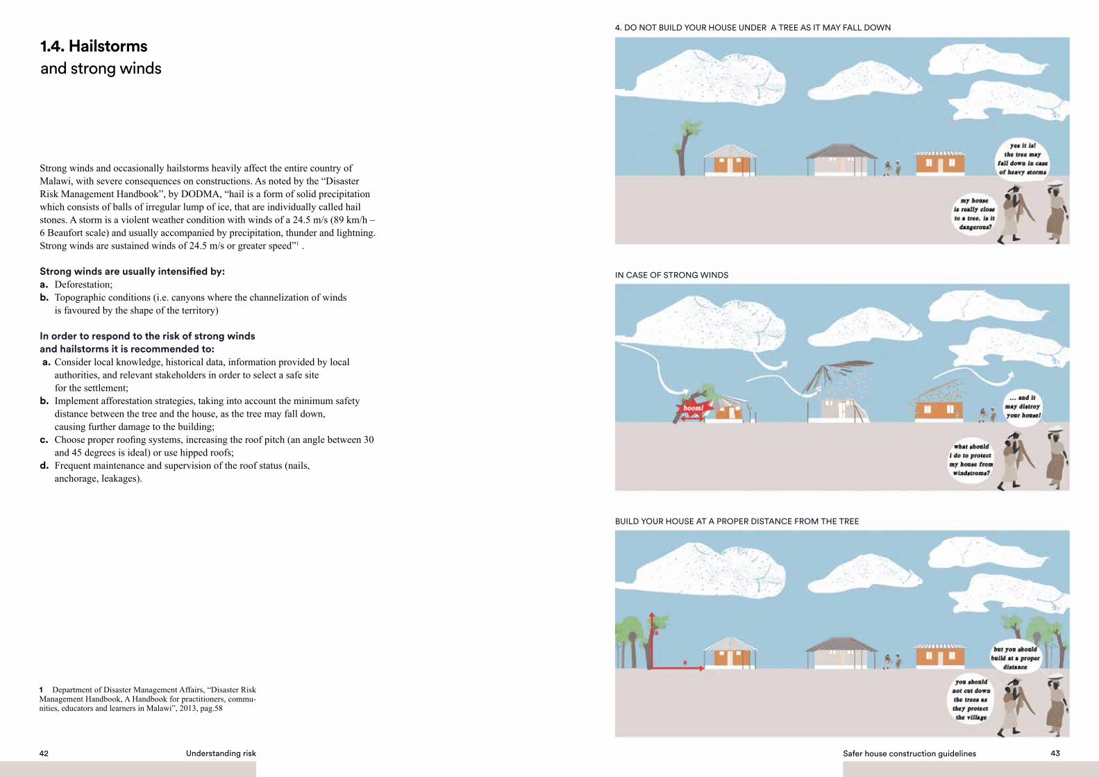
1.4. Hailstorms and strong winds
4. DO NOT BUILD YOUR HOUSE UNDER A TREE AS IT MAY FALL DOWN
IN CASE OF STRONG WINDS
BUILD YOUR HOUSE AT A PROPER DISTANCE FROM THE TREE
Strong winds and occasionally hailstorms heavily affect the entire country of Malawi, with severe consequences on constructions. As noted by the “Disaster Risk Management Handbook”, by DODMA, “hail is a form of solid precipitation which consists of balls of irregular lump of ice, that are individually called hail stones. A storm is a violent weather condition with winds of a 24.5 m/s (89 km/h – 6 Beaufort scale) and usually accompanied by precipitation, thunder and lightning. Strong winds are sustained winds of 24.5 m/s or greater speed”1 . Strong winds are usually intensified by: a. Deforestation; b. Topographic conditions (i.e. canyons where the channelization of winds is favoured by the shape of the territory)
In order to respond to the risk of strong winds and hailstorms it is recommended to: a. Consider local knowledge, historical data, information provided by local authorities, and relevant stakeholders in order to select a safe site for the settlement; b. Implement afforestation strategies, taking into account the minimum safety distance between the tree and the house, as the tree may fall down, causing further damage to the building;c. Choose proper roofing systems, increasing the roof pitch (an angle between 30 and 45 degrees is ideal) or use hipped roofs; d. Frequent maintenance and supervision of the roof status (nails, anchorage, leakages).
1 Department of Disaster Management Affairs, “Disaster Risk Management Handbook, A Handbook for practitioners, commu-nities, educators and learners in Malawi”, 2013, pag.58
Safer house construction guidelines 4342 Understanding risk

Being on the East African Rift Valley System, the entire country of Malawi is prone to earthquakes. The occurrence and impact can differ in each occasion, nevertheless the whole construction sector needs to take appropriate measures to face this hazard. By definition, an earthquake “is the shaking and vibration at the surface of the earth resulting from sudden underground movement along a fault plane or from volcanic activity. Earthquakes are normally caused by tectonic activities. These activities include volcanism, converging, sliding and rupture of rock masses or plates. In most cases, vulnerability of an area is subject to presence of faults, joints and activeness of the plate’s movements. The great Africa rift valley system is the main cause of earthquakes in Malawi” 1.
In order to respond to the risk of earthquakes it is recommended to: Follow the building regulations and the construction guidelines in order to properly address the safe construction of the house, paying special attention to the correct use of the materials and to construction techniques.
5. THE WHOLE MALAWI CAN BE AFFECTED BY EARTH QUAKE. BE PREPARED!
1.5 Earthquake
1 Department of Disaster Management Affairs, “Disaster Risk Management Handbook, A Handbook for practitioners, commu-nities, educators and learners in Malawi”, 2013, pag.164
Safer house construction guidelines 4544 Understanding risk

1.6. Soil erosion6. DEFORESTATION IS ONE OF THE LEADING CAUSES OF SOIL EROSION
SOIL BECOMES WEAK AND HOUSES CAN BE AFFECTED BY SUBSIDENCE
IMPLEMENT AFFORESTATION STRATEGIES. TREES PROTECT SOIL AGAINST EROSION
Soil erosion takes place when the loss of soil, due to wind or water activity, occur at a higher rate than its formation.Soil erosion leaves the land vulnerable and unprotected, resulting in loss of fertility and strength. Human action enhances soil erosion in three main ways:a. uncontrolled earth movement without correct anchorage (refer to landslides risk)b. deforestationc. soil extraction (particularly for brick-making)
In order to prevent soil erosion it is recommended to:a. Enhance afforestation strategiesb. Avoid soil extraction (particularly for brick-making) in proximity of urbanised areas, instead restrain this activity to the designated zones.
Safer house construction guidelines 4746 Understanding risk

Termites are a natural hazard that affects the construction sector in Malawi. They attack the wooden parts of buildings passing through the foundations, entering in the walls, and reaching the roofs and all the structural parts of the house made of wooden material.
In order to respond to the termites’ attacks it is recommended to:a. Use proper pesticides in the construction process, paying close attention to using the exact amount indicated by the different brands. b. Use, if possible, resistant and treated wooden material; c. Preserve the wooden parts of the building by frequently applying the treatment to avoid possible attacks.
7. TERMITES ARE A SERIOUS DANGER IN MALAWI
TERMITES CAN AFFECT THE STRUCTURE OF THE HOUSE
PROTECT YOUR HOUSE WITH PROPER TREATMENT AGAINST TERMITES!
1.7. Termites
Safer house construction guidelines 4948 Understanding risk
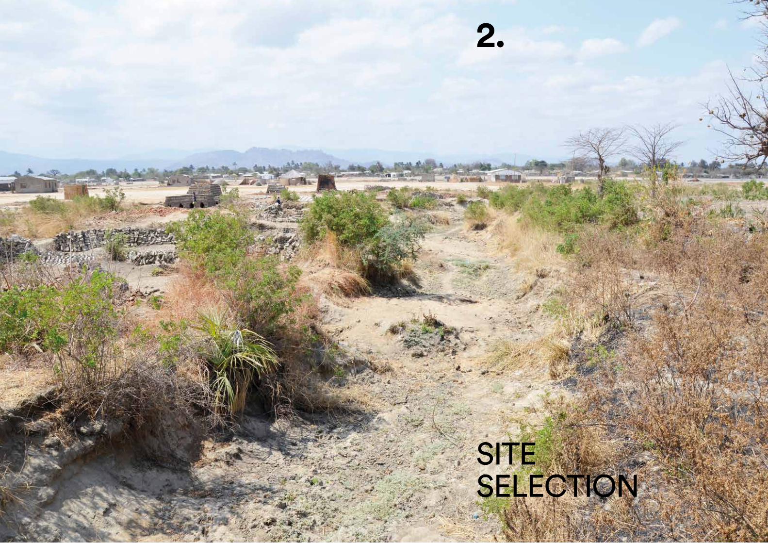
SITESELECTION
2.
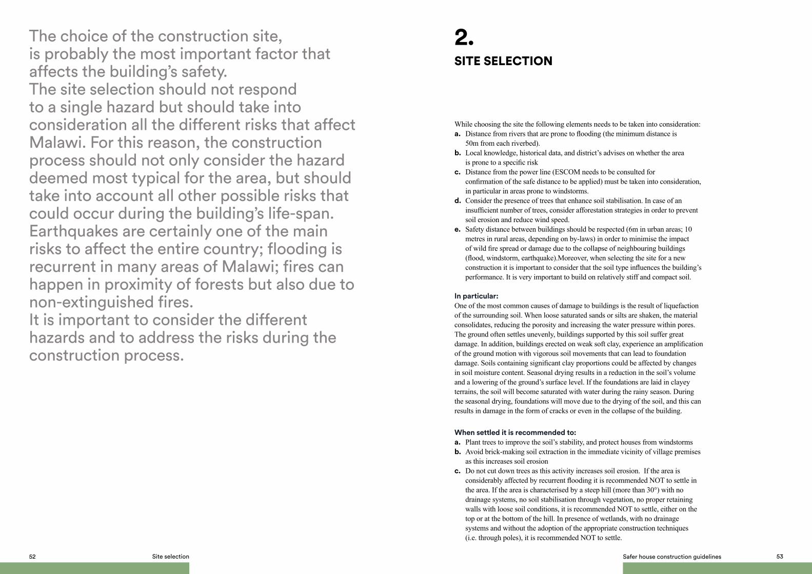
The choice of the construction site, is probably the most important factor that affects the building’s safety. The site selection should not respond to a single hazard but should take into consideration all the different risks that affect Malawi. For this reason, the construction process should not only consider the hazard deemed most typical for the area, but should take into account all other possible risks that could occur during the building’s life-span. Earthquakes are certainly one of the main risks to affect the entire country; flooding is recurrent in many areas of Malawi; fires can happen in proximity of forests but also due to non-extinguished fires. It is important to consider the different hazards and to address the risks during the construction process.
While choosing the site the following elements needs to be taken into consideration: a. Distance from rivers that are prone to flooding (the minimum distance is 50m from each riverbed). b. Local knowledge, historical data, and district’s advises on whether the area is prone to a specific risk c. Distance from the power line (ESCOM needs to be consulted for confirmation of the safe distance to be applied) must be taken into consideration, in particular in areas prone to windstorms. d. Consider the presence of trees that enhance soil stabilisation. In case of an insufficient number of trees, consider afforestation strategies in order to prevent soil erosion and reduce wind speed. e. Safety distance between buildings should be respected (6m in urban areas; 10 metres in rural areas, depending on by-laws) in order to minimise the impact of wild fire spread or damage due to the collapse of neighbouring buildings (flood, windstorm, earthquake).Moreover, when selecting the site for a new construction it is important to consider that the soil type influences the building’s performance. It is very important to build on relatively stiff and compact soil.
In particular:One of the most common causes of damage to buildings is the result of liquefaction of the surrounding soil. When loose saturated sands or silts are shaken, the material consolidates, reducing the porosity and increasing the water pressure within pores. The ground often settles unevenly, buildings supported by this soil suffer great damage. In addition, buildings erected on weak soft clay, experience an amplification of the ground motion with vigorous soil movements that can lead to foundation damage. Soils containing significant clay proportions could be affected by changes in soil moisture content. Seasonal drying results in a reduction in the soil’s volume and a lowering of the ground’s surface level. If the foundations are laid in clayey terrains, the soil will become saturated with water during the rainy season. During the seasonal drying, foundations will move due to the drying of the soil, and this can results in damage in the form of cracks or even in the collapse of the building.
When settled it is recommended to: a. Plant trees to improve the soil’s stability, and protect houses from windstorms b. Avoid brick-making soil extraction in the immediate vicinity of village premises as this increases soil erosionc. Do not cut down trees as this activity increases soil erosion. If the area is considerably affected by recurrent flooding it is recommended NOT to settle in the area. If the area is characterised by a steep hill (more than 30°) with no drainage systems, no soil stabilisation through vegetation, no proper retaining walls with loose soil conditions, it is recommended NOT to settle, either on the top or at the bottom of the hill. In presence of wetlands, with no drainage systems and without the adoption of the appropriate construction techniques (i.e. through poles), it is recommended NOT to settle.
SITE SELECTION
2.
Safer house construction guidelines 5352 Site selection

LAYOUT & ORIENTATION OF THE BUILDING
3.

The building’s shape and orientation play a significant role in reducing possible damages to the house as consequence to hazard. It is very important to consider the different natural components of the surrounding environment before choosing the khonde’s position, where to locate the openings, and choosing the most suitable house layout. It is also important to consider the settlement of the house in relation to the surrounding buildings. The distance between buildings is important for air circulation, wind protection, and for safety reasons. The toilet should be placed in a safe area at a reasonable distance from the house; in particular, it should be sufficiently distant from the water source in order to protect the spring from possible contamination.
The building plan should be kept symmetrical along both axes. Constructions with asymmetrical plans are more vulnerable to earthquakes; in fact, the lack of symmetry leads to torsional effects, inducing severe concentrated damages. Regular shaped buildings such as square, rectangular, or circular configurations are more resistant to earthquakes compared to irregular shaped buildings, and are therefore preferable. Symmetry, as far as possible, is also desirable in the placing and sizing of door and window openings. The building’s length should not exceed 3 times its width, in order to limit the torsional effects, which are more pronounced in case of narrow rectangular plans. The shorter elevation of a building should face towards the dominant direction of strong winds to reduce wind pressure on the construction.
LAYOUT AND ORIENTATION OF THE BUILDING
3
Safer house construction guidelines 57

Safer house construction guidelines 5958 Layout and orientation of the building
* WEDC Developing knowledge and capacity in water and sanitation Poster 20 (2007)
8. THE LATRINE SHOULD BE PLACED IN A SAFE AREA AT A REASONABLE DISTANCE FROM THE HOUSE, IN PARTICULAR IT SHOULD BE FAR FROM THE WATER SOURCE IN ORDER TO PROTECT THE SPRING FROM POSSIBLE CONTAMINATION*.
9. IT IS RECOMMENDED TO RAISE THE FOUNDATION OF THE LATRINE AND IN PARTICULAR TO RAISE THE LATRINE
ITSELF IN THOSE AREAS PRONE TO FLOODS. RAISED LATRINES PREvENT THE OUTFALL OF HUMAN WASTE,
DANGEROUS FOR THE HEALTH*.
* WEDC Developing knowledge and capacity in water and sanitation Poster 20 (2007)

MATERIALS
4.

The choice of the different materials for construction is another core element for the safety of the building.Testing and choosing among the different components (from soil to type of mortar for example) significantly improves or weakens the structure of the building.The choice of materials and of the particular combinations of components for the production of the different elements (foundations, bricks, mortar, plaster), affect the durability of the house.
4.1. Soil as construction material
The soil should be properly selected and treated, before using it as a construction material, in order to ensure sufficient strength and durability. The operations performed to enhance the soil’s properties are called stabilisation processes.The main objective of the stabilisation processes is to improve the soil’s resistance to the erosive effects of the local weather conditions, including variations in temperature, humidity and rainwater. The use and adoption of the right stabilisation methods can considerably improve the compressive strength of soil along with its resistance to erosion.
The stabilisation processes are summarised as follows:a. Physical stabilisation. The properties of a soil can be modified by treating and selecting its texture: a controlled mix of the various particle fractions;b. Mechanical stabilisation. The properties of the soil are modified by treating its structure: compaction of the soil increases its density and reduces its permeability and porosity;c. Chemical stabilisation. The properties of the soil are modified by adding other materials or chemical products.
The main objectives being pursued are:a. Obtaining better mechanical performances: increasing dry and wet compressive strength;b. Reducing porosity and volume variations: swelling and shrinking with moisture content variations;c. Improving the ability to withstand weathering by wind and rain: reducing surface abrasion and increasing waterproofing.
Physical and mechanical stabilisations have a minor economic impact and therefore should be applied to all construction techniques, including both adobe and rammed earth walls.
Good resistance to erosion can be obtained in one or more of the following ways: a. Increasing the density of the soil;b. Adding a stabilising agent that either reacts with, or binds the soil grains together;c. Adding a stabilising agent, which acts as a waterproofing medium.
MATERIALS
4.
Safer house construction guidelines 63

The manufacture of good quality, durable earth blocks requires the use of soil containing fine gravel and sand for the body of the block, together with silt and clay to bind the sand particles together. Gravels and sands are stable in presence of water. On the other hand, they show little to no cohesion when dry, and therefore cannot be used on their own as building materials.Clay, and to a lesser extent silts, endow the soil with cohesion properties, acting as a kind of natural binding agent between the coarser particles that form its skeleton. However, clays are unstable and are very sensitive to variations in humidity; they experience considerable changes in volume with variation of water content, resulting in significant cracks during shrinkage, which occurs as they dry out. Soils with low clay content should not be used, as their mechanical resistance is too low. On the other hand, a clay content that is too high will result in a non-durable building material.
The soil for earth bricks should contain:• 25% - 35% of combined clay and silt;• 50% - 75% of combined sand and fine gravels.
Particular attention should be paid to the following aspects:• The presence of organic matter is hazardous and must be avoided. Therefore, the top soil must in all cases be discarded.
• Water containing salts must in all cases be avoided. Verify that water is soft and not salty. Let it evaporate completely and check for any deposits. These could include organic matter, which are acceptable only in very small quantities, or salt crystals, which are unacceptable.
The field tests above can be performed to estimate the particle size distribution of the soil and the suitability of the soil as building material.
• Smell test. If the soil smells musty, it contains organic matter. This smell will become stronger if the soil is heated or soaked. Soil containing organic matter is not suitable for the production of earth blocks.
• Nibble test: Nibble a pinch of soil, crushing it lightly between the teeth. If it grinds between the teeth with a disagreeable sensation, the soil is sandy. If it can be ground between the teeth, without a disagreeable sensation the soil is silty. If it has a smooth or floury texture, and sticks when applied to the tongue, the soil is clayey.
• Touch test: Crumble the soil by rubbing the sample between the fingers and the palm of the hand. If it feels rough and has no cohesion when moist, the soil is sandy. If it feels slightly rough and is moderately cohesive when moistened, the soil is silty. If, when dry, it contains lumps or concretions, which resist crushing, and if it becomes plastic and sticky when moistened the soil is clayey.
• Wash test: Rub the hands with some slightly moistened soil. If the grains can be clearly felt and the hands are easy to rinse clean, the soil is sandy; if the soil appears to be powdery and the hands can be rubbed clean when dry, it is indicative of silty soil. If the soil is sticky with a soapy feel making it necessary to use water to clean the hands, it indicates a clayey soil.
4.1.1. Physical stabilisationproper soil selection and mixture
4.1.2. Tests to estimate the particle size distribution of the soil
Safer house construction guidelines 6564 Materials
SAND SILT CLAY
1
2
3
10. TOUCH AND WASH TESTS

• Sedimentation test: Take a transparent cylindrical jar or bottle of at least 1/2 litre capacity and fill it with one-third clean water and one-third dry soil passed through a 6mm sieve. Add a teaspoon full of common salt. Firmly close the lid of the bottle and shake until the soil and water are well mixed. Allow the bottle to stand on a flat surface for about half an hour. Shake the bottle again for two minutes and let it stand on a levelled surface for a further 45 minutes until the water starts to clear: the lowest layer will contain fine gravel, the central layer will contain the sand fraction and the top layer will contain silt and clay. The relative proportions and hence percentages of each fraction can be determined by measuring the depth of each layer.
• Linear shrinkage test: Get a wooden box, 600 mm long, 40 mm wide and 40 mm deep. Grease the inside surfaces of the box before filling it with moist soil with an optimum moisture content (OMC). Press the soil into all corners of the box using a small wooden spatula that can also be used to smooth the surface. Expose the filled box to the sun for a period of three days or in the shade for seven days.After this period measure the length of the hardened and dried soil. The linear shrinkage should be < 2.5%. Otherwise, the soil is too clayey and needs to be modified in order to be used as building material.
wet soil le
nght
40 mm
40 mm
600 mm
dry soil lenght
12. LINEAR SHRINKAGE TEST
Safer house construction guidelines 6766 Materials
organic materialclaysiltsandgravel
11. SEDIMENTATION TEST

• Ball drop test: This test measures the clay content in the soil for earth constructions. Make balls 40 mm in diameter. Use soil just moist enough to hold together. Drop the balls one at a time from a 1.5 m height onto a flat and hard surface. If the ball breaks into many little pieces when dropped, the soil’s clay content is too low, and cannot be used as building material, as it is too weak. If the ball splits into a few pieces when dropped, the soil contains enough clay and is suitable to be used as a building material, as it is strong enough. If the ball flattens only a little bit and shows hardly any or no cracks, it has a high binding force, which is due to the very high clay content. In this case the mixture should be thinned by adding sand, to reduce the tendency to shrink.
13. BALL DROP TEST
FEW OR NO CRACKS=
TOO HIGH CLAY CONTENT
FEW PIECES=
GOOD CLAY/SAND MIX
MANY PIECES=
TOO LOW CLAYCONTENT
• The dry strength test Should be performed to verify if the soil’s clay content is sufficient. This test is important for all soils, which are not stabilised with cement or other binding agents. It consists in making at least five mud balls with a diameter of about 20 mm from the selected soil. After drying the balls for at least 24 hours (preferably 48 hours) in the shade, try to crush each ball between the thumb and the index finger. If none of the balls can be broken, the soil contains enough clay to be used as building material, provided that cracking of the mortar due to drying shrinkage is controlled. If some of the balls can be crushed, the soil is clay deficient and should be discarded.
14. DRY STRENGHT TEST
MAKE AT LEAST
5 MUD BALLS
IMPOSSIBLE TO BREAK THE BALL=
STRONG SOIL
BALL BREAKS=
WEAK SOIL
Safer house construction guidelines 6968 Materials

Once the particle size distribution of the soil is understood, the texture must be properly modified in the following ways:• Soil with a high stone or gravel content: if the soil contains too many coarse particles with very well graded fine particles, passing it through a 5–6 mm sieve, it will be enough to obtain a good soil;• Soil with a high clay content: if the soil has too many fine particles, it will be necessary to add coarser grains, sand and/or gravel, or even another soil containing mainly sand and gravel but very little clay. The best proportion of soil and coarse sand can be determined by performing the cracking control test.
The cracking control test: consists in making two or more sandwiches using bricks and mortar made from the soil under study. After drying for 48 hours in the shade, the sandwiches are carefully opened and the mortar is examined. If the mortar does not show visible cracking, then it is adequate for construction. Otherwise, the use of coarse sand (0.5 to 5 mm approx.) is necessary as an additive to control cracking. In the latter case, at least eight sandwich units are to be manufactured with mortars made with mixtures in different proportions of soil and coarse sand, in order to determine the most suitable soil-coarse sand proportion. It is recommended that the proportions of soil to coarse sand vary between 1:0 and 1:3 in volume. The sandwich having the least content of coarse sand which, when opened after 48 hours, does not show visible fissures in the mortar, will indicate the most adequate proportion of soil/sand for adobe constructions, giving the highest strength.
+
+
+
+
+
+
+
+
=
=
=
=
BUCKETOF SOIL
BUCKETOF SAND
CURINGPROCESS
CURED BLOCK
bad block
bad block
good block
bad block
OBSERVATIONS
Not smooth Very large crackNot brittleVery difficult to break
Not smooth Large crackNot brittleVery difficult to break
Smooth Large crackNot very brittleDifficult to break
Fairly rough No crackBrittleEasy to break
15. CRACKING CONTROL TEST
The resistance and durability are strongly influenced not only by the texture or particle size distribution of the soil (i.e. the quantity of stones, gravels, sands, silts and clays present), but also by the density of the soil. The more the density of a soil can be increased, the lower its porosity will be and the more difficult it will be for water to penetrate. This involves tamping or compacting the soil by using a mechanical rammer to bring about a reduction of air void volume, thus leading to an increase in soil density. The main effects of soil compaction are the increase of its strength and reduction of its permeability. The type of soil used, the compression effort applied and the moisture content affects the degree of compaction greatly during compaction. The moisture content must be high enough to lubricate the particles and enable them to move around in such a way as to occupy as little space as possible. On the other hand, the moisture content must not be too high, as the voids would be full of water, and therefore impossible to compress. It is therefore important to determine the optimum moisture content (OMC), i.e. the percentage of moisture in soil at which the soil can be compacted to its greatest density.
dry soil
adding water
adding water
easy to mouldand very dense
easy to mouldbut too plasticand less dense
lowcompaction
bestcompaction
lowcompaction
impossibleto mould
16. OPTIMUM MOISTURE CONTENT
4.1.3. Properly modify the soil texture 4.1.4. Mechanical stabilisation compression at optimum moisture content
Safer house construction guidelines 7170 Materials

The optimum moisture content of the proper mix is so minimal that it never really seems wet. The OMC can be estimated, once the soil texture has been properly selected, using the “ball drop test”. Take a handful of soil mix and squeeze it into a ball as tight as possible. If the mix stays in a ball once the hand is opened, the moisture content is good. If it falls apart, it must be moistened even more. When the ball stays intact in the hand, drop it from a 1.5 m height onto a flat and hard surface. If it sticks together or breaks into only two or three parts, it is too wet. In this case, some dryer ingredients must be added, keeping the texture of soil equal to the original mix. If it breaks into dozens of pieces, a little water must be added. If the ball breaks into four or five major lumps, the soil is close to its optimum moisture content.
The major drawback of mechanically compressed stabilised earth blocks is their lack of durability, especially in areas with moderate to high rainfall. Therefore, earth blocks without chemical stabilisation (adobe and rammed earth) will require protection from direct contact with water (rains and floods) and increase in moisture content.
4.1.5. Chemical stabilisation addition of materials
FibresIn order to control the cracking effect caused by drying shrinkage in clayey soils, besides adding coarse sand, it is possible to add fibres (straw, etc.). The amount of sand and / or fibres must be the minimum required to control the fissures (≈ 2% straw by weight of dry soil), as both sand and fibres will negatively affect the compressive strength of the soil. Determine the minimum quantity of sand and / or straw needed to control the fissures by performing the above described cracking control test. Adding fibres to reinforce the soil could
17. BALL DROP TEST
FEW OR NO CRACKS=
TOO WET
FEW PIECES=
OPTIMUM MOISTURE CONTENT
MANY PIECES=
TOO DRY
be suitable for adobes and rammed earth walls, but it is incompatible with the compression process of SSBs, as they make the mixture too elastic. CementThe basic function of Ordinary Portland cement is to make the soil water-resistant by reducing swelling and increasing its compressive strength. The cementation process results in the deposition of an insoluble binder between soil particles, which is capable of embedding soil particles in a matrix of cementitious gel. Cement is considered a good stabiliser for granular soils but is unsatisfactory for soils high in clay content (> 20%). For this reason it is advisable to control cracking in the production of SSBs (stabilised soil blocks) characterised by a low moisture content and medium clay content.
4.1.6. Soil preparation
Drying the soil: after extraction from the quarry or pit, the soil must be dried by spreading it in thin layers. Breaking up soil: lumps larger than 200mm in diameter after excavation must be broken up. Grains with a homogeneous structure, such as gravel and stones, must be left intact, and those having a composite structure (clay binder) must be broken up so that at least 50% of the grains are less than 5mm in diameter. The soil must be dry.Screening: This operation is intended to eliminate all undesirable components: any roots, leaves, stones, limestone, etc. should be removed. Sieving: The oversized material (but not lumps of clay) should be removed by sieving. A 5 to 6mm mesh sieve is suitable to produce compressed earth blocks and rammed earth. The simplest sieving device is a screen made from a wire mesh, nailed to a supporting wooden frame and inclined at approximately 45º-50° to the ground. The material is thrown against the screen, fine material passes through and the coarse, oversized material runs down the front. Proportioning: Before starting production, tests should be performed to establish the right proportion of soil and water for the production of good quality blocks. Mixing: In order to produce good q uality blocks, mixing must be as thorough as possible. Dry materials should be mixed first until they are uniform in colour, then water is added and mixing continued until a homogeneous mix is obtained. It is much better to add small amounts of water at a time, sprinkled over the top of the mix. The wet mix should be turned over several times. A little more water may then be added, and the whole mixture turned over again. This process should be repeated until all the water corresponding to the optimum moisture content has been mixed in. The optimum duration is generally 1 to 2 minutes for each mix.If cement is used for stabilisation, it is advisable to use the mix as soon as possible, because cement starts to hydrate immediately after it is wetted and delays will result in the production of poor quality blocks. The quantity of cement-sand mix should not exceed what is needed for one hour of operation.“Sleeping” the mud: before preparing the soil for the adobe bricks or mortar, it is strongly advised to leave the soil with water to set for one day. This procedure improves the integration and distribution of water with the clay particles, thus activating their cohesive properties.
Safer house construction guidelines 7372 Materials

The size of sun-dried bricks should be 290 mm long by 140 mm wide by 90 mm high. This will allow for the building of a 300 mm thick wall. The bricks should be strong enough (both when dry and wet) and durable enough (with limited cracks).
The soil used to fabricate the sun-dried bricks must: a. be verified with the dry strength test to ensure a minimum strength;b. have a sufficient amount of clay, according to the ball drop test;c. show limited shrinkage effect and cracks, according to the linear shrinkage test and the cracking control test (refer to section 4.1.3 “Properly modify the soil texture” for details). Coarse sand and / or straw could be added in order to reduce shrinkage during the drying process. The amount of coarse sand and / or straw added to the soil should not exceed the minimum required to obtain satisfying results in tests. The soil components should be mixed at the optimum moisture content, determined through the ball drop test. It is advisable to store the soil for at least one day, although longer periods of storage are preferable, before the fabrication of adobe bricks. This practice is called “sleeping the mud” and allows for a better dispersion and thus for a more uniform action of the clay particles.
4.2.1 Fabrication processThe detailed fabrication process is described below:1. Once the soil has been prepared, it should dry for two days;2. After drying, water corresponding to the OMC must be added to make the soil malleable enough to place into the moulds;3. The mixture is compressed to eliminate any air and smoothed off at the top of the brick by a trowel and the mould removed vertically in one brisk movement. Increase in strength and resistance to erosion can be obtained by increasing the density of the soil.4. If the block is left exposed to hot dry weather conditions, the surface material will lose its moisture and the clay particles will tend to shrink. This will cause surface cracks on the blocks’ faces. Therefore, the bricks must be left to dry in the shade, on a level surface, which should preferably be covered with either sand or sandy loam. The bricks should be placed on their narrow edge in order to minimise their exposure to the sun. The bricks should remain in this position for a minimum of 3 days, covered with grass or damp straw. This will slow down the drying process and prevent bricks from cracking. 5. Within at least 3 days of being laid out, the bricks should be rotated and covered again with grass / straw, until all surfaces are totally dry (at least 10 days). 6. The dry bricks must then be moved into a storage area to protect them from rainwater and further drying.
7. Perform the load test: the strength of an adobe brick can be qualitatively ascertained as follows: after 4 weeks of sun drying the adobe, it should be strong enough to support, in bending, the weight of a man. If it breaks, more clay material is to be added and / or a better compression should be applied to increase the density. Perform the test on a sample of 10 bricks: if at least 7 bricks do not break, the bricks can be used. 8. Perform the drop test: this test consists in the dropping of a well dried brick on one of its corners, from a height of about 1 meter onto firm ground. If the brick is of good quality, only minimal damage on the corner will occur from the impact. If the brick is of poor quality, the brick will break or shatter. 9. Perform the soak test: soak a sample of 10 bricks in water for 24 hours. If they do not crumble or break apart, the bricks can be used.
Before building the wall, the bricks should be: a. cleaned (dust should be removed);b. moistened, by soaking them in water for less than 1 minute, in order to avoid their absorbing of the water content from the mud mortar.
18. BRICK CURING UNDER GRASS/ STRAW
1/4 1/2 1/41/4 1/2 1/4
× √
19. BRICK STRENGHT TEST
4.2. Sun–driedadobe – bricks
Safer house construction guidelines 7574 Materials

4.2.2 Check for appearance
Cracks are not acceptable on faces to be exposed to water. On other faces, they should not exceed 1 mm in width or depth or 10 mm in length and there should be no more than 3 cracks on each face. Lamination (due to too much clay or too high a moisture content) is not acceptable. Chipped corners should not exceed 10 mm. Holes or scratches should not exceed 1% of the surface area for smooth blocks, but can be as high as 10-15% of the surface area for rough blocks.Blocks must not display any significant and lasting efflorescence covering more than 1/3 for the total surface. The size of burnt (fired) bricks should be 230 mm long by 115 mm wide by 75
mm high, in compliance with International and Malawian Standards. This will allow for the building of a 230 mm thick wall.The bricks should be sufficiently strong (both when dry and wet) and durable (limited cracks).
The soil used to fabricate the bricks must: a. be verified with the dry strength test to ensure minimum strength;b. have a sufficient amount of clay, according to the ball drop test.The clay must be plastic, in order to be shaped into the moulds. The amount of water to be added is the minimum required to provide enough soil plasticity and to allow for maximum compaction (OMC – optimum moisture content). Adding too much water will result in low-density bricks (increased porosity and reduced durability) and increased shrinkage during the drying process. The optimum moisture content of the soil is determined through the ball drop test described above. Increase in strength and resistance to erosion can be obtained by increasing the density of the soil. Therefore, after being placed into the moulds, the soil must be compressed, to eliminate any air, smoothed off at the top of the brick with a trowel, and the mould removed vertically in one brisk movement.Before the firing process, the bricks should dry in the shade for a minimum of 10 days, until all surfaces are totally dry. They should be covered with grass or dampened straw, in order to minimise the cracks due to fast shrinkage. If green bricks contain high amounts of water when placed in the kiln, energy will be wasted for drying. Fired bricks are burned in a kiln, at temperatures between 900 and 1,200 °C, in order to fuse the clay particles and form ceramic bonds, giving bricks strength and resistance to water erosion. The temperature at which bricks are fired is of critical importance: if it is too low, the bonds are poor, resulting in a weak product, if it is too high, the brick slumps or melts. The load test, drop test, soak test will be required to determine the mechanical properties and durability of bricks (refer to section 4.2 “Sun-dried (adobe) bricks” for detailed information), in order to check if they are suitable to be used as construction material. A square-shaped kiln should be preferred, as it is more efficient than a rectangular-shaped kiln because of reduced heat loss. The square kiln, in fact, has a smaller cooling area than a rectangular one of the same volume.Plastering the kiln with mud is necessary to reduce heat loss. Fuel other than wood should be used if available, including rice husk, sawdust, straw, maize cobs, and animal dung.The practice of pointing the vertical and horizontal joints with cement mortar could enhance the durability of masonry.
4.4. Burnt - fired - bricks
4.3. Rammed earth
The same processes of soil selection and identification, preparation, mixing, casting and curing discussed for sun-dried bricks should be followed. The use of the optimum moisture content (ball drop test) and the regulation of the amount of clay, by adding coarse sand to the soils, are required to control the shrinkage fissures in drying. If the amount of coarse sand is excessive, the strength is significantly reduced. It is recommended to make the tests with increasing percentages of sand, until fissuring is reasonably acceptable.The use of excessive amounts of straw in the mud mixture, more than “1 : 1/4” in volume, is counterproductive, as it leads to strength reduction.
Safer house construction guidelines 7776 Materials

The SSBs are earth blocks stabilised through:1. mechanical compaction at optimum moisture content;2. addition of a low amount of ordinary Portland cement.
The higher density obtained through compaction significantly increases the compressive strength of the blocks, as well as their resistance to erosion.Adding cement before compaction causes considerable improvements that include the reduction of the shrinkage/swelling effect (directly related to waterproofing), and the increase in density, strength and durability.Due to the presence of cement, termites do not represent a particular hazard for SSBs. Nearly all soils can be stabilised with cement and have significant improvement in their properties. However, cement stabilisation works best on sandy soils; therefore, it is not advisable to use soils with too high a clay content (> 20%). At least 5% cement must be needed to obtain satisfactory results. Low proportions (2-3%) are not recommended, since certain soils perform less well than when left unstabilised. The presence of organic matter is hazardous and must be avoided.Water containing salts must be avoided.Sulphates are very harmful, especially calcium sulphate (anhydride and gypsum).Typically, the size of an SSB is 290 mm long, 140 mm thick and 90 mm high. 10 mm thick mortar joints should be used to create a module length of 300 mm. A 140 mm thick wall could be considered sufficient to carry the vertical and lateral loads,
only if the following aspects are observed: a. The foundations are adequate;b. The cement ratio is consistent with the soil texture;c. The mechanical compaction is performed correctly, leading to dense blocks, characterised by a minimum wet compressive strength of 2.8 N/mm2;d. The wall is properly connected to perpendicular walls, well tied at intersections;e. The top of the walls are all connected through a ring beam;f. The roof structure is provided with horizontal ties, which absorb horizontal forces. If even one of the above conditions is not met, the single brick wall must be regarded as too slender.
A SSB wall does not require plastering. However, the application a brick sealer is advisable.The practice of pointing the vertical and horizontal joints with cement mortar is advised to enhance the durability of masonry as well.
4.5.1. Correct mix for SSBs
Even with a well-prepared soil, the cement must be mixed in as thoroughly as possible; otherwise, as it is generally used in low proportions (5 to 8%), it will not be evenly distributed. Mixing should take place in two stages: dry and wet mixing at the OMC. The cement will begin to act on contact with water, which is why water should be added to the dry mix at the last moment before compaction in order to maintain the time before it is used (retention time) to a minimum, as this greatly affects the quality of the blocks.
4.5. SSBs - stabilised soil blocks
+
+
+
+
+
+
+
+
+
+
+
+
=
=
=
=
BUCKETOF SOIL
WHEELBARROWOF SOIL
BUCKETOF SAND
CEMENT(10 Kg)
CURED BLOCK
bad block
bad block
good block
bad block
OBSERVATIONS
Not smooth Very large crackNot brittleVery difficult to break
Not smooth Large crackNot brittleVery difficult to break
Smooth Large crackNot very brittleDifficult to break
Fairly rough No crackBrittleEasy to break
10 Kg
10 Kg
10 Kg
10 Kg
20. CRACKING CONTROL TEST
Safer house construction guidelines 7978 Materials

4.5.2 Compression through light mechanical presses
Light mechanical presses are sturdy, low cost, simple to manufacture and repair. Since they can perform relatively low compression forces, limiting the brick dimension will allow exerting high pressures.
4.5.3 Curing and Drying
Cement stabilised blocks must be kept in a humid environment for at least 7 days. The surface of the blocks must not be allowed to dry out too quickly, as this causes shrinkage cracks. The blocks must be sheltered from direct sun and wind and kept in conditions of relative humidity (RH) approaching 100% by covering them with waterproof plastic sheets. After 28 days there will be no further significant increase in the strength of the cement. High temperatures will increase the strength obtained and temperature can be raised by using black plastic sheeting.After curing, water must be allowed to evaporate and the clay fraction to shrink. To prevent shrinkage occurring too quickly, exposure to wind and direct sun must be reduced. The drying process will take approximately 14 days.
4.5.4 Appearance
Cracks are not acceptable on faces to be exposed to water. On other faces, they should not exceed 1 mm in width or depth or 10 mm in length and there should be no more than 3 cracks on each face. Lamination (due to too much clay or too high a moisture content) is not acceptable. Chipped corners should not exceed 10 mm. Holes or scratches should not exceed 1% of the surface area for smooth blocks, but can be as high as 10-15% of the surface area for rough blocks.Blocks must not display any significant and lasting efflorescence covering more than 1/3 for the total surface.
21. COMPRESSION OF BRICKS
22. SSBs CURING UNDER PLASTIC SHEETS
Safer house construction guidelines 8180 Materials

Adobe construction joints should be in mud mortar, using the same soil as that used to manufacture the sun-dried bricks. Straw could be added to the mortar until an acceptable degree of workability is attained (nearly “1 : 1” by volume), as well as some coarse sand, will help to control the shrinkage during the drying process. The adequate proportion of coarse sand and straw will be given by the cracking control test (refer to section 4.1.3 “Properly modify the soil texture” for details). It is advised to store the soil for a minimum of one day, although storage for more days is to be preferred, before the fabrication of mud mortar. This practice is called “sleeping the mud” and allows for a better dispersion and thus for a more uniform action of the clay particles.The conditions of the mortar drying are very strict, as the mortar comes in contact with blocks that readily absorb moisture and also restrict the drying contraction. This produces micro-fissures, which consequently weaken the masonry. Thus, it is fundamental to soak the blocks before placing them into the masonry.
4.8.1 Components
Aggregates. The aggregate shall generally be angular in shape. Flaky, elongated pieces are to be avoided.The aggregates must be from 20 mm diameter downwards.
Sand. Coarse sand should be sieved to remove stones, fine particles and dust. If the sand comes from a dirty or seawater source, it must be washed.
Cement. All cement used shall be Ordinary Portland Cement.Cement must be as fresh as possible. Any cement stored for more than two months from the date of receipt from the factory should either be avoided or used only if the test results are found to be satisfactory. Any cement, which has been deteriorated or hardened, cannot be used.
Water. The water used for concrete must be free of salt, algae or any other vegetable matter. Check that the water is clear and that it is not salty. Let it evaporate completely and check for any deposits. These could include organic matter, which are acceptable only in very small quantities, or salt crystals, which are totally unacceptable.Sulphates are very harmful, especially calcium sulphate (anhydride and gypsum).
4.8.2 Mixing
The proportions of the concrete mix must be kept “1 : 2 : 4” by volume of “cement : sand : aggregate”.a. The material should first be mixed thoroughly in a dry state so as to become uniform in colour and then water must be added. The quantity of water should be enough to make a soft ball of the mixed concrete in hand. A slightly wetter mix is better for hand compaction, where as a drier mix is preferable when a vibrator is used for compaction.b. Hand compaction must be performed by rodding through the freshly placed concrete. Simply levelling the surface with trowels will leavevoids in the mass: lack of compaction results in large reduction in concrete strength.c. Mixed concrete should not be allowed to stay on the platform for more than 45 minutes and must be placed in the forms and compacted continually Concrete should normally be cast in a single, continuous operation. Covering any concrete surface with polyethylene sheets after wetting the surface will help retain the moisture. Concrete requires water curing for a minimum of 14 days, or better, for 28 days.
4.6. Mud mortar for joints
4.7. Cement mortar for joints
Cement mortar is strongly advised for burnt (fired) brick walls and SSB walls, while it is not advised for unstabilised adobe walls. A mortar mix “cement : sand” equal to 1 : 6 by volume should be the minimum for vertical and horizontal joints of structural walls. A mix “cement : sand” equal to 1 : 4 by volume would be more appropriate.Use cement mortar within 45 minutes of mixing. Use as little water as possible for best workability. The bricks must be appropriately moistened prior to placing, as dry bricks adsorb the mortar’s moisture too rapidly, resulting in a too rapid and pronounced shrinkage of the mortar, which leads to micro-fissures that weaken the masonry.
4.8. Concrete
Safer house construction guidelines 8382 Materials

Mud plaster is useful to protect sun-dried brick walls and rammed earth walls from erosion and moisture penetration. In fact, the mud plaster naturally binds to sun-dried brick walls and rammed earth walls, as they are made of the same materials. Mud plaster is composed of clay, sand and water. Natural additives like straw and cow manure could be added to make the plaster more durable.Sand can be added to clay in order to reduce the cracks during the drying process. Plastering based on natural additives can be formed in two layers. The first, about 12 to 15mm thick, is a mixture of mud and straw of “1 : 1” in volume, plus a natural additive like cow dung, used to increase the resistance to moisture of the mud, thus preventing the occurrence of fissures during the drying process. The natural additive helps to withstand the shrinkage tensions of the restricted drying process. The second and last layer is made with fine mud, which when dried, should be rubbed with small, hard, rounded pebbles.
23. ANTI - TERMITES COATING
For environmental and mechanical reasons, pine tree is recommended for structural use. When selecting timber for structural use, the following aspects should be observed:a. Accuracy of section dimensions;b. Straightness and absence of twist;c. Absence of cracks and splits;d. Absence of large knots on the outer edges of the timber is preferable. If knots are present, then ensure they are on the load side;e. Grain along the length of the timber and not to the side. All timber (and wooden) elements have to be treated against termites and insects in general. Timber should be coated with a preservative treatment before mounting. In the absence of a specific product, used motor oil can be applied. The timber must be well dried before applying the preservative treatment.
4.9. Mud plaster
4.10. Sand – cement plaster
The sand-cement plaster provides protection to the walls against erosion and moisture penetration. The sand – cement plaster should not be applied to adobe walls or to rammed earth walls, as plaster cannot bind properly to such walls. Therefore, using the sand – cement plaster is suitable only in case of burnt brick or SSB walls with cement mortar joints. The plaster shall have a cement : sand ratio not leaner than 1:6.The thickness of the plaster must not be less than 10 mm.Prior to applying the plaster, it is necessary to scarp the support in order to remove any materials/particles, which are not well fixed to the surface.Dust must be removed from the wall’s surface with a dry or slightly moist brush in order to guarantee the adherence of the plastering to the wall section.
4.11. Timber
Safer house construction guidelines 8584 Materials
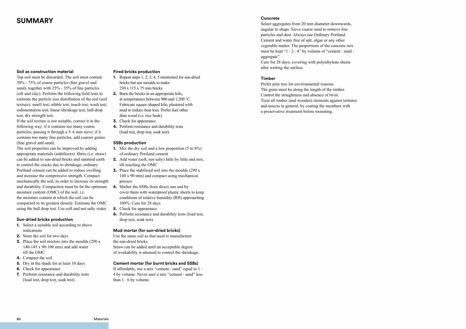
SUMMARY
Soil as construction materialTop soil must be discarded. The soil must contain 50% - 75% of coarse particles (fine gravel and sand), together with 25% - 35% of fine particles (silt and clay). Perform the following field tests to estimate the particle size distribution of the soil (soil texture): smell test; nibble test; touch test; wash test; sedimentation test; linear shrinkage test; ball drop test; dry strength test.If the soil texture is not suitable, correct it in the following way: if it contains too many coarse particles, passing it through a 5–6 mm sieve; if it contains too many fine particles, add coarser grains (fine gravel and sand). The soil properties can be improved by adding appropriate materials (stabilizers): fibres (i.e. straw) can be added to sun-dried bricks and rammed earth to control the cracks due to shrinkage; ordinary Portland cement can be added to reduce swelling and increase the compressive strength. Compact mechanically the soil, in order to increase its strength and durability. Compaction must be fat the optimum moisture content (OMC) of the soil, i.e. the moisture content at which the soil can be compacted to its greatest density. Estimate the OMC using the ball drop test. Use soft and not salty water.
Sun-dried bricks production1. Select a suitable soil according to above indications2. Store the soil for two days3. Place the soil mixture into the moulds (290 x 140-145 x 90-100 mm) and add water till the OMC4. Compact the soil5. Dry in the shade for at least 10 days6. Check for appearance 7. Perform resistance and durability tests (load test, drop test, soak test).
Fired bricks production1. Repeat steps 1, 2, 3, 4, 5 mentioned for sun-dried bricks but use moulds to make 230 x 115 x 75 mm bricks2. Burn the bricks in an appropriate kiln, at temperatures between 900 and 1,200 °C. Fabricate square-shaped kiln, plastered with mud to reduce heat loss. Prefer fuel other than wood (i.e. rice husk)3. Check for appearance 4. Perform resistance and durability tests (load test, drop test, soak test).
SSBs production1. Mix the dry soil and a low proportion (5 to 8%) of ordinary Portland cement2. Add water (soft, not salty) little by little and mix, till reaching the OMC3. Place the stabilized soil into the moulds (290 x 140 x 90 mm) and compact using mechanical presses4. Shelter the SSBs from direct sun and by cover them with waterproof plastic sheets to keep conditions of relative humidity (RH) approaching 100%. Cure for 28 days5. Check for appearance 6. Perform resistance and durability tests (load test, drop test, soak test).
Mud mortar (for sun-dried bricks)Use the same soil as that used to manufacture the sun-dried bricks. Straw can be added until an acceptable degree of workability is attained to control the shrinkage.
Cement mortar (for burnt bricks and SSBs)If affordable, use a mix “cement : sand” equal to 1 : 4 by volume. Never user a mix “cement : sand” less than 1 : 6 by volume.
ConcreteSelect aggregates from 20 mm diameter downwards, angular in shape. Sieve coarse sand to remove fine particles and dust. Always use Ordinary Portland Cement and water free of salt, algae or any other vegetable matter. The proportions of the concrete mix must be kept “1 : 2 : 4” by volume of “cement : sand : aggregate”.Cure for 28 days, covering with polyethylene sheets after wetting the surface.
TimberPrefer pine tree for environmental reasons. The grain must be along the length of the timber. Control the straightness and absence of twist.Treat all timber (and wooden) elements against termites and insects in general, by coating the members with a preservative treatment before mounting.
86 Materials

CONSTRUCTIONDETAILS
5.

The different elements of the house, combined together, characterise the building and its safety. It is therefore fundamental to analyse, study and choose the best technological solution in order to make the right choice in terms of the construction technique. This choice depends not only on the material availability, but is also heavily influenced by the different budgets.
5.1.1. Foundation soil selection
Avoid building on loose sands soils, soft silt and poorly compacted clays, as they may undergo large differential settlements during an earthquake. In particular, if loose sands soils are saturated with water, they could liquefy during shaking.Avoid building on filled soil, as the weight of the building could cause large differential settlements. Avoid building on soils with very high water table (i.e. above the base of the foundation). Therefore, the construction of buildings in wetlands is strongly discouraged.
5.1.2. Foundation details
Always use continuous spread footing foundations. Avoid rammed earth, sun-dried bricks and mud mortar as construction materials for foundations, as they are not durable and readily lose their mechanical properties, if in contact with water. Plinths in burnt (fired) bricks with cement mortar joints are strongly recommended, not only for buildings made of burnt (fired) brick or SSB walls, but also for buildings made of sun-dried brick walls. Concrete with field stones can be used as an alternative, particularly for buildings made of rammed earth walls.
Depth
The digging depth must always exceed the layer of topsoil, miscellaneous fill, tree roots etc.The base of the foundation must go below the weathering zone. In cases where the ground has previously been excavated and filled, it is necessary to dig down to a level beneath the area of the fill.
5.CONSTRUCTION DETAILS
5.1. Foundations
Safer house construction guidelines 9190 Construction details

All foundations should reach a minimum depth of 500 mm below natural ground level.The depth of the foundation is chosen based on the type of soil.• In case of clayey soils, penetration into the soil has to be below the zone where shrinkage and swelling due to seasonal weather changes and to trees and shrubs are likely to cause significant movements, a minimum depth of 1000 mm is recommended.• For dry compact gravel, or gravel and sand soils a minimum depth of 700 mm is recommended.• Peat and loose sand are very poor soils and must be discarded, unless a reinforced concrete raft foundation is feasible.
Footing
Build continuous spread footings on a bed of compacted sand, 50 mm thick.If possible, the footing should consist of a continuous reinforced concrete element, 700 mm wide and 250 mm thick. The reinforced concrete footing is fundamental in soft soils, in order to avoid any differential settlement, which could result in severe damage to the building. The footing is to be reinforced with 4 longitudinal bars (diameter = 12 mm) at the bottom and 4 longitudinal bars (diameter = 12 mm) at the top of the section. The minimum overlap in longitudinal bars should be 72 mm (60 times the diameter of the bar). Stirrups of 6 mm in diameter should be placed every 200 mm. The stirrups should be hooked by bending at a 135º angle. Any vertical reinforcement located in the wall should be anchored inside the reinforced concrete footing.If the reinforced concrete footing is not viable, a pyramidal footing made of burnt bricks and cement mortar joints should be build, characterised by base width equal to 700 mm approximately, rested on a 50 – 75 mm thick pad of lean concrete. If possible, a thick polyethylene sheet (1000 gauge) could be placed at the base of the foundation as damp proof membrane. If affordable, a liquid asphalt layer (or other waterproofing coatings) could be applied to waterproof the surface of the foundation.
Plinth
The plinth above the continuous spread footing must be built using burnt bricks and cement mortar joints.For rammed earth walls buildings, it is recommended to build the foundation plinth in concrete with field stones. Select big natural stones (30% in volume) and mix with concrete (70% in volume, 10 buckets of aggregate and 1.5 buckets of water for every bucket of cement). The plinth should be 350 mm thick (1.5 brick thick). The height of the plinth should be above the flood water line or at least 300 mm above ground level. The height of plinth must not be more than 700 mm. If more than 700 mm above ground level are required to avoid penetration of floodwater inside the building, it would be strongly advised to select a more suitable site for construction. The external face of the burnt brick plinth can be covered with sand-cement plaster, in order to increase its durability.A durable artificial slope of compacted soil should connect the natural ground level with the building ground level, as it increases the durability of the building due to the following reasons:
a. It protects the foundation and the plinth, in particular from direct contact with water;
b. It drains the rainwater.The slope should be covered by a 25 mm thick sand-cement layer. If unattainable, outside the adobe and rammed earth buildings, a platform of compacted mud should be built in order to protect walls and foundations from direct contact with rainwater.The external slope / platform does not allow to avoid placing the damp proof course, which is crucial, since moisture may rise from the ground, even without any direct contact with rainwater.
Ring beam at plinth level
The ring beam is a continuous runner of reinforced concrete (RC) going into all plinths (external and internal walls) with appropriate connections at corners and T-junctions. In those cases where the foundation soil is soft, the RC ring beam at plinth level helps at absorbing the differential settlements.However, since the presence of the reinforced concrete footing is more effective at absorbing differential settlements, the presence of a reinforced concrete ring beam just under the plinth level is not crucial. Therefore, considering that a reinforced concrete beam could have a strong negative impact on the cost of the building, the use of a ring beam at plinth level is generally not advised.
5.1.3. Slab on grade
If affordable, the slab on grade should consist of a 75 – 100 mm thick concrete layer reinforced with 6 mm mesh at 200 x 200 mm spacing. The slab should continue over the plinth and overhang for a few centimetres (30 – 50 mm) in order to provide good protection against termites.If the concrete slab is unrealisable, it can be substituted with a layer of burnt bricks set on the edge and cement mortar joints.A 25 mm thick sand-cement screed should be placed above the slab.The slab (made of bricks or concrete) should rest over a 50 – 100 mm thick compacted sand layer, placed above a layer of compacted soil / gravel / broken bricks (hardcore filling).Under the slab, a waterproofing layer should be applied in the form of thick polyethylene sheet (1000 gauge). The waterproofing layer must continue above the plinth until outside the building, before starting the construction of superstructure wall. It is crucial that the floor level of the interior of the building will not be lower than the level of the plinth, as during severe floods water may enter and remain trapped inside the building for days. In these conditions, the inner face of the base of the walls is continuously exposed to water, with the high risk of collapse, especially for sun-dried brick walls and rammed earth walls.
Safer house construction guidelines 9392 Construction details

Safer house construction guidelines 9594 Construction details
21
4 6
8
7 513
700 mm
300-
700
mm
H d
epen
ding
on
soil
type
Compacted sand bedding, 50-75 mm thick
Field stone foundation
D.P.M. (Damp Proof Membrane)
Hardcore, 150-500 mm thick
Field stone paving
Sand-cement screed, 25 mm thick
Rammed earth wall, 300 mm thick
Mud screed
1
4
6
8
7
5
2
3
Natural ground
Rammed earth
Sand
Masonry
Sand-cement screed
Concrete
Mud plaster / screed
Hardcore
24. FIELD STONE FOUNDATION - LOWER COST SOLUTION ●○○ SCALE 1:10
0 500mm
0 300mm
0 500mm
0 1000mm
0 300
Natural ground
Back filling
Sand
Masonry
Sand-cement screed
Concrete
Mud plaster / screed
Hardcore
21
3 4 6
9
7
8
51
700 mm
300-
700
mm
H d
epen
ding
on
soil
type
Compacted sand bedding, 50-75 mm thick
Burnt brick - cement mortar foundation
D.P.M. (Damp Proof Membrane)
Hardcore, 150-500 mm thick
Brick on edge paving
Sand-cement screed, 25 mm thick
Sun-dried brick - mud mortar wall, 300 mm thick
Mud plaster
Gravel drainage
1
4
6
8
9
7
5
2
3
25. BRICK FOUNDATION - LOWER COST SOLUTION ●○○ SCALE 1:10
0 500mm
0 300mm
0 500mm
0 1000mm
0 300

Safer house construction guidelines 9796 Construction details
321
76
4
700 mm
Concrete
Sand-cement plaster
Hardcore
5 3
10
8
9
1
300-
700
mm
H d
epen
ding
on
soil
type
Compacted sand bedding, 50-75 mm thick
Lean concrete, 50 mm thick
Burnt brick - cement mortar foundation
D.P.M. (Damp Proof Membrane)
Hardcore, 150-500 mm thick
Reinf. concrete slab, 75-100 mm thick
Sand-cement screed, 25 mm thick
Burnt brick - cement mortar wall, 230 mm thick
Sand-cement plaster
Gravel drainage
1
4
6
8
9
10
7
5
2
3
Natural ground
Back filling
Sand
Masonry
Sand-cement screed
26. BRICK FOUNDATION - MEDIUM COST SOLUTION ●●○
0 500mm
0 300mm
0 500mm
0 1000mm
SCALE 1:10 0 300
321
5 2 7
11
9
10
8
6
4
1
700 mm
300-
700
mm
H d
epen
ding
on
soil
type
Compacted sand bedding, 50-75 mm thick
D.P.M. (Damp Proof Membrane)
Burnt brick - cement mortar plinth
Reinf. concrete footing, 250 mm thick
Hardcore, 150-500 mm thick
Reinf. concrete slab, 75-100 mm thick
Sand-cement screed, 25 mm thick
Waterproofing coating
Burnt brick - cement mortar wall, 230 mm thick
Sand-cement plaster
Concrete drainage
1
4
6
8
9
10
11
7
5
2
3
Natural ground
Back filling
Sand
Masonry
Sand-cement screed
Concrete
Sand-cement plaster
Hardcore
27. REINFORCED CONCRETE FOUNDATION HIGHER COST SOLUTION ●●●
SCALE 1:10
0 500mm
0 300mm
0 500mm
0 1000mm
0 300

5.2.1. Sun-dried brick - adobe - walls
A typical size of 290 – 300 mm long by 140 – 145 mm wide by 90 – 100 mm high is recommended for sun-dried (adobe) bricks. The sun-dried bricks (adobe) wall height should be less than 8 – 10 times its thickness. Considering a 2.5 m high wall from slab on grade to roof connection, the minimum allowed thickness is 300 mm. Therefore, all structural walls must be one-brick walls. Half-brick walls should not be allowed.All the walls should be well tied up with each other, so the building can act as a box during earthquake vibration. In order to obtain an effective box-like action, the maximum unsupported length of wall between cross walls must be limited. The unsupported length of an adobe wall between cross walls should not exceed 13 – 14 times its thickness. Therefore, for a 300 mm thick wall, the maximum distance between cross walls should not exceed 4 meters.
Safer house construction guidelines 9998 Construction details
28. MAXIMUM DISTANCE BETWEEN WALLS - LOWER COST SOLUTION ●○○
<= 4 m
<= 4 m
<= 4 m
5.2. Walls It is fundamental when building an adobe wall to pay attention to the following aspects:
a. Bond between building units. The vertical joints must not be aligned. For one-brick walls (300 mm in the case of adobe walls), blocks should be arranged according to an effective transversal bond: 1 course of header should be placed every 3 courses of stretchers, in order to achieve a bond between the two layers of the wall. As an alternative, a classical English bond (1 course of header + 1 course of stretchers) can be used;b. Horizontal and vertical mortar joints must be uniform and completely filled;c. Walls must be plumb in the vertical plane;d. Wetting the adobe bricks prior to construction is good practice. This can be achieved by soaking adobe bricks in water for a few minutes. It can also be useful to moisten the previous layer of blocks before placing the joint mortar;e. A galvanised metal sheet termite shield should be used at the base of the wall, right above the top of the plinth. As an alternative, one or two con secutive courses of bricks in the external walls can be placed such that a 30 mm overhang with respect to the external wall surface will be created. This overhang combined with a thick polyethylene sheet (1000 gauge) will protect the wall from termites;f. The external surface of the sun-dried brick (adobe) walls must be covered with mud plaster. Plaster increases the stiffness and the strength of adobe walls and provides environmental protection;g. The sun-dried brick (adobe) walls must not remain soaked in water during floods. The maximum expected water level during severe floods must be lower than the wall base;h. The foundations and plinths of an adobe wall building should be in burnt bricks and cement mortar. As an alternative, field stones and cement mortar can be used.
Joint mortar
Both horizontal and vertical joints should be 10 mm thick. Joints thicker than 15 mm are not allowed. Cement mortar is incompatible with sun-dried bricks, because the two have different thermal expansion and contraction rates. Cement mortar thereby accelerates the deterioration of adobe bricks, since the mortar is stronger than the adobe. The horizontal and vertical joints should be in mud mortar, using the same soil as that used to manufacture the blocks. Adding some straw to the mortar until an acceptable degree of workability is obtained (nearly “1 : 1” by volume), as well as some coarse sand, will help control the shrinkage during the drying process. The adequate coarse sand and straw proportion will be determined by the cracking control test. Do not spread the mortar for a bed joint too far ahead of laying: four or five brick lengths is best. Mortar spread out too far ahead dries out before the bricks are bedded leading to poor bonding.Always use fresh mortar. Do not use mortar that is starting to harden.

Safer house construction guidelines 101100 Construction details
PLAN VIEW 3D VIEW
1 course of headers
1 course of headers
1 course of stretchers
1 course of stretchers
1 course of stretchers
29. ONE BRICK WALL - BRICKS TEXTURE - LOWER COST SOLUTION ●○○
PLAN VIEW 3D VIEW
30. ONE BRICK WALL - CORNER INTERSECTION - LOWER COST SOLUTION ●○○

Safer house construction guidelines 103102 Construction details
PLAN VIEW 3D VIEW
31. ONE BRICK WALL - T INTERSECTION - LOWER COST SOLUTION ●○○
32. MAXIMUM DISTANCE BETWEEN WALLS - LOWER COST SOLUTION ●○○
<= 4 m
<= 4 m
<= 4 m
5.2.2. Rammed earth walls
The rammed earth wall height should be less than 8 – 10 times its thickness. Considering a 2,5 m high wall from slab on grade to roof connection, the minimum allowed thickness is 300 mm.The unsupported length of a rammed earth wall between cross walls should not exceed 13 – 14 times its thickness. Therefore, for a 300 mm thick wall, the maximum distance between cross walls should not exceed 4 meters.During the building process, each compacted layer should not exceed 100 mm.The best way to ensure the monolithic structure of the rammed walls is to pour a sufficient quantity of water at the sub-joints every 100 mm. Bamboo canes can be used as internal (within the wall) vertical reinforcement, placed every 400 – 800 mm. The reinforcement must be attached to the foundation and connected to the ring beam (if present) at the top of the wall.

Safer house construction guidelines 105104 Construction details
100 mm
Bamboo cane reinf.embedded in foundations
100 mm
400-800 mm
300 mm
33a. RAMMED EARTH WALL - LOWER COST SOLUTION ●○○
33b. RAMMED EARTH WALL & BAMBOO CANE REINF. MEDIUM COST SOLUTION ●●○
5.2.3. Burnt - fired - brick walls
The height of a burnt brick wall should be less than 12 times its thickness. Considering a 2,5 m high wall from slab on grade to roof connection, the minimum allowed thickness is 230 mm. Therefore, all structural walls must be one-brick walls. Half-brick walls are not allowed.In order to obtain an effective box-like behaviour, the maximum unsupported length of walls between cross walls must be limited. The unsupported length of a burnt brick wall between cross walls should not exceed 18 times the wall thickness. Therefore, for a 230 mm thick wall, the maximum distance between cross walls should not exceed 4 meters.It is fundamental when building a burnt brick wall to pay attention to the following aspects:a. Bond between building units. The vertical joints should not be aligned. For one-brick walls (230 mm thick in the case of burnt brick walls), blocks should be arranged according to an effective transversal bond: 1 course of header should be placed every 3 courses of stretchers, in order to achieve a bond between the two layers of the wall. As an alternative, a classical English bond (1 course of header + 1 course of stretchers) can be used;b. Horizontal and vertical mortar joints must be uniform and completely filled;c. Walls must be plumb in vertical plane;d. Wetting the adobe bricks prior to the construction is good practice. This can be achieved by soaking bricks in water for a few minutes. It can also be useful to moisten the previous layer of bricks before placing the joint mortar;e. A galvanised metal sheet termite shield should be used at the base of the wall, right above the top of the plinth. As an alternative, one or two consecutive courses of bricks in the external walls can be placed such that a 30 mm overhang with respect to the external wall surface will be created. This overhang combined with a thick polyethylene sheet (1000 gauge) will protect the wall from termites;f. It is recommended to protect the most exposed parts (corners, wall-base, etc.) of burnt brick walls with sand-cement plaster, in order to increase the wall’s durability.
Joint mortarBoth horizontal and vertical joints should be 10 mm thick. Joints thicker than 15 mm are not allowed. Cement mortar should be used, in order to increase the strength and durability of the wall. Do not spread the mortar for a bed joint too far ahead of laying: four or five brick lengths is best. Mortar spread out too far ahead dries out before the bricks can be bedded, causing a poor bond.Always use fresh mortar. Do not use mortar that is starting to harden.

Safer house construction guidelines 107106 Construction details
35. ONE BRICK WALL - BRICK TEXTURE - MEDIUM / HIGHER COST SOLUTION ●●○ / ●●●
PLAN VIEW 3D VIEW
1 course of headers
1 course of headers
1 course of stretchers
1 course of stretchers
1 course of stretchers
34. MAXIMUM DISTANCE BETWEEN WALLS - MEDIUM / HIGHER COST SOLUTION ●●○ / ●●●
<= 4 m
<= 4 m
<= 4 m

Safer house construction guidelines 109108 Construction details
PLAN VIEW 3D VIEW
36. ONE BRICK WALL - CORNER INTERSECTION - MEDIUM COST SOLUTION ●●○
PLAN VIEW 3D VIEW
37. ONE BRICK WALL - T INTERSECTION - MEDIUM COST SOLUTION ●●○

Safer house construction guidelines 111110 Construction details
Horizontal reinforcement - enhancement of seismic response
Horizontal joint reinforcement built into the walls improves the seismic resistance of the masonry. The horizontal joint reinforcement should consist of Brick Force Wire at every 4th course.
Vertical reinforcement - enhancement of seismic response
In order to improve the seismic response of the building, 1 steel bar 16 mm of diameter can be positioned at wall intersections (i.e. at every corner and T-junctions of walls).The vertical bars should be covered with cement concrete in cavities made around them during masonry construction. Vertical reinforcement should be properly embedded in the plinth masonry of foundations and roof slab or roof band, so as to develop its tensile strength in bonding.
Brick Force Wire at every 4th course
38. ONE BRICK WALL - HORIZONTAL REINFORCEMENT - HIGHER COST SOLUTION ●●●
PLAN VIEW 3D VIEW
1 Ø 16 mm at every corner embedded in concrete
39. ONE BRICK WALL - vERTICAL REINFORCEMENT - HIGHER COST SOLUTION ●●●

Safer house construction guidelines 113112 Construction details
PLAN VIEW 3D VIEW
1 Ø 16 mm at every corner embedded in concrete
40. ONE BRICK WALL - vERTICAL REINFORCEMENT - HIGHER COST SOLUTION ●●● 5.2.4. SSB – Stabilised Soil Block – walls
If all SSB walls are provided with a ring beam that ties them together, the height of a SSB wall should be less than 18 times its thickness. Considering a 2,5 m high wall from slab on grade to roof connection, the minimum allowed thickness will be 140 mm. Therefore, a half-block wall (140 mm thick) is sufficient to carry the vertical and lateral loads. In order to obtain an effective box-like behaviour, the unsupported length of a SSB wall (140 mm thick) between cross walls should not exceed 25 times the wall thickness. Therefore, for a 140 mm thick wall, the maximum distance between cross walls should not exceed 3.5 meters.
<= 3.5 m
<= 3.5 m
<= 3.5 m
41. MAXIMUM DISTANCE BETWEEN WALLS - HIGHER COST SOLUTION ●●●

Safer house construction guidelines 115114 Construction details
PLAN VIEW 3D VIEW
If a ring beam is not present at the top of all SSB walls, the height of a SSB wall should be less than 12 times its thickness. Considering a 2.5 m high wall from slab on grade to roof connection, the minimum allowed thickness is 230 mm. Therefore, all structural walls must be one-brick walls. In this case, half-brick walls are not allowed, they must be regarded as too slender. In order to obtain an effective box-like behaviour, the unsupported length of a SSB wall (230 mm thick) between cross walls should not exceed 18 times the wall thickness. Therefore, for a 230 mm thick wall, the maximum distance between cross walls should not exceed 4 meters.
It is fundamental when building a SSB wall to pay attention to the following aspects:a. Bond between building units. The vertical joints should not be aligned;b. Horizontal and vertical mortar joints must be uniform and completely filled;c. Walls must be plumb in the vertical plane;d. Wetting the adobe bricks prior to the construction is good practice. This can be achieved by soaking SSBs in water for a few minutes. It can also be useful to moisten the previous layer of bricks before placing the joint mortar;e.Even if the SSBs are not subject to termite attacks, a termite shield of galvanised steel sheets should be used at the base of the wall, right above the top of the plinth, in order to protect the wooden roof from termites. As an alternative, one or two consecutive courses of bricks in the external walls can be placed such that a 30 mm overhang with respect to the external wall surface will be created. This overhang combined with a thick polyethylene sheet (1000 gauge) will protect the wall from termites;f. It is recommended to protect the most exposed parts (corners, wall-base, etc.) of SSB walls with sand-cement plaster, in order to increase the wall’s durability;g.SSB walls do not require extensive plastering. However, the application of a brick sealer is advised.h. The foundations and plinths of a SSB building should be in burnt bricks and cement mortar.
Joint mortarBoth horizontal and vertical joints should be 10 mm thick. Joints thicker than 15 mm are not allowed. Cement mortar should be used, in order to increase the strength and durability of the wall. Do not spread the mortar for a bed joint too far ahead of laying: four or five brick lengths is best. Mortar spread out too far ahead dries out before the bricks can be bedded, causing a poor bond.Always use fresh mortar. Do not use mortar that is starting to harden.
42. HALF BRICK WALL - BRICK TEXTURE - HIGHER COST SOLUTION ●●●

Safer house construction guidelines 117116 Construction details
PLAN VIEW 3D VIEW PLAN VIEW 3D VIEW
43. HALF BRICK WALL - CORNER INTERSECTION - HIGHER COST SOLUTION ●●● 44. HALF BRICK WALL - T INTERSECTION - HIGHER COST SOLUTION ●●●
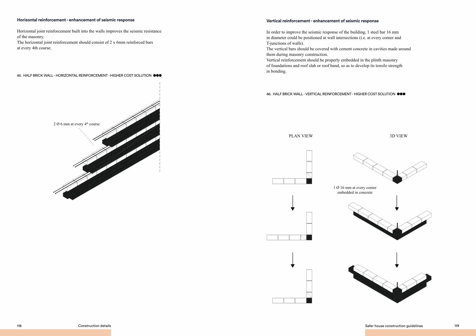
Safer house construction guidelines 119118 Construction details
PLAN VIEW 3D VIEW
Horizontal reinforcement - enhancement of seismic response
Horizontal joint reinforcement built into the walls improves the seismic resistance of the masonry.The horizontal joint reinforcement should consist of 2 x 6mm reinforced bars at every 4th course.
2 Ø 6 mm at every 4th course
45. HALF BRICK WALL - HORIZONTAL REINFORCEMENT - HIGHER COST SOLUTION ●●●
Vertical reinforcement - enhancement of seismic response
In order to improve the seismic response of the building, 1 steel bar 16 mm in diameter could be positioned at wall intersections (i.e. at every corner and T-junctions of walls).The vertical bars should be covered with cement concrete in cavities made around them during masonry construction. Vertical reinforcement should be properly embedded in the plinth masonry of foundations and roof slab or roof band, so as to develop its tensile strength in bonding.
1 Ø 16 mm at every corner embedded in concrete
46. HALF BRICK WALL - vERTICAL REINFORCEMENT - HIGHER COST SOLUTION ●●●

Safer house construction guidelines 121120 Construction details
PLAN VIEW 3D VIEW 1 Ø 16 mm at every corner
embedded in concrete
47. HALF BRICK WALL - vERTICAL REINFORCEMENT - HIGHER COST SOLUTION ●●●
Large unstiffened openings lead to excessive deformations of the building during earthquakes. To prevent such effects the size and location of the openings should be controlled: a. The openings should not exceed 1200 mm width;b. The sum of the widths of all openings in a wall should not exceed 1/3 of the total wall length;c. The minimum distance between openings should not be less than 600 mm;d. Openings should be inset at a minimum of 600 mm from the edge of the wall.
The top of the openings should all be at the same horizontal level.Openings should be located symmetrically with respect to building configuration in plan, in both directions of the building.Openings should be located outside the areas of direct influence of concentrated loads at beam support. Opening must be provided with rigid steel or timber frames in order to avoid concentrated cracks located on the corners of the openings.
Every opening must be provided with a lintel, in order to resist flexure and shear due to the load of the above masonry and roof.
The lintel could be either a:1. timber lintel;2. reinforced concrete lintel;3. continuous lintel at roof level: for a typical 2.5 m high wall, the building of a continuous reinforced concrete beam at lintel level, could prove to be a very efficient solution. This beam will serve both as lintel for all the openings and as ring beam at roof level to tie together all the structural walls (refer to section 5.4 “Ring beam at lintel and roof level” for the details of this solution).
5.3. Openings
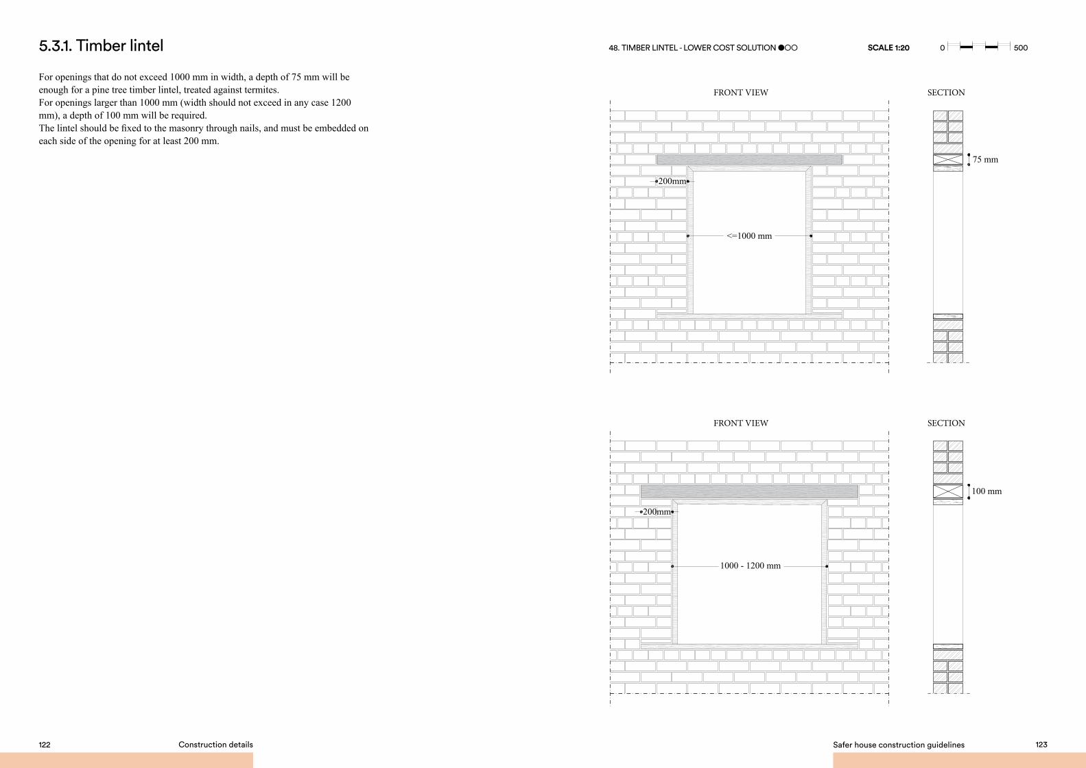
Safer house construction guidelines 123122 Construction details
5.3.1. Timber lintel
For openings that do not exceed 1000 mm in width, a depth of 75 mm will be enough for a pine tree timber lintel, treated against termites.For openings larger than 1000 mm (width should not exceed in any case 1200 mm), a depth of 100 mm will be required. The lintel should be fixed to the masonry through nails, and must be embedded on each side of the opening for at least 200 mm.
100 mm
75 mm
<=1000 mm
1000 - 1200 mm
200mm
200mm
FRONT VIEW
FRONT VIEW
SECTION
SECTION
48. TIMBER LINTEL - LOWER COST SOLUTION ●○○ SCALE 1:20 0 500
0 500mm
0 300mm
0 500mm
0 1000mm

Safer house construction guidelines 125124 Construction details
5.3.2. Reinforced concrete lintel
For openings that do not exceed 1000 mm in width, a depth of 75 mm will be enough for a reinforced concrete lintel. If the opening is larger than 1000 mm (width should not exceed in any case 1200 mm), a depth of 100 mm will be required.The lintel should be provided with 2 bars, 12 mm in diameter, as longitudinal reinforcement, and stirrups, 6 mm diameter, as transversal reinforcement, positioned 150 mm apart. Stirrups should be hooked by bending through a 180º angle.The clear cover of the reinforcement should be kept at no less than 25 mm.The lintel should be embedded on each side of the opening for at least 200 mm.
100 mm
75 mm
<=1000 mm
1000 - 1200 mm
200mm
200mm
FRONT VIEW
FRONT VIEW
SECTION
SECTION
49. REINFORCED CONCRETE LINTEL MEDIUM COST SOLUTION ●●○
SCALE 1:20 0 500
0 500mm
0 300mm
0 500mm
0 1000mm

Safer house construction guidelines 127126 Construction details
A very effective way in improving the seismic response of masonry buildings is the provision of horizontal seismic bands, called ring beams. A ring beam is a continuous runner of reinforced concrete (or wood) going into all external and internal walls with appropriate connections at the corners and T-junctions of the walls.The ring beams at lintel and roof level offer the following important functions:a. Ensuring box-like action of the individual rooms as well as that of the whole building by preventing the separation of perpendicular walls;b. Providing out-of-plane bending resistance to the wall by forming a rigid horizontal frame with continuity at the corners.
In particular:c. At lintel level, the ring beam incorporates all door and window lintels;d. At roof level, the ring beam is required when flexible timber/wooden roofing is used. It should be built just below the roof, serving also as support for the roof’s timber/wooden structure, which should be properly connected to this band to ensure stability during earthquakes. No bricks should be placed over the roof ring beam. Since the external wall height of houses generally does not exceed 2.5 m, the lintel band may be merged with the roof band, thus reducing the complexity of the building process and the cost required to build a seismic-resistant construction. Therefore, it is strongly advised to place a ring beam at the top of all walls, which can serve both as lintel and as seismic belt.The ring beam can be either a reinforced concrete ring beam or a timber / wooden ring beam. If the mechanical properties of the masonry are poor (sun-dried bricks + mud mortar joints or rammed earth), the use of a rigid and heavy reinforced concrete ring beam is not advised, a timber / wooden ring beam should be preferred.
5.4. Ring beam at lintel and roof level
150 mm
<=1200 mm>=600 mm<=1200 mm
75 mm
2 waves
150 mm overlapping
75 mm
100 mm
Wall thickness
Wall thickness
150 mm
Wall thickness
75 mm
2 waves
150 mm overlapping
75 mm
100 mm
Wall thickness
Wall thickness
150 mm
Wall thickness
75 mm
2 waves
150 mm overlapping
75 mm
100 mm
Wall thickness
Wall thickness
150 mm
Wall thickness
SECTIONFRONT VIEW
50. REINFORCED CONCRETE LINTEL / RING BEAM - HIGHER COST SOLUTION ●●●
stirrup Ø 6 mm at 150 mm c/c
stirrup Ø 6 mm at 150 mm c/c
stirrup Ø 6 mm at 150 mm c/c
2 Ø 12 mm longitudinal bars
2 Ø 12 mm longitudinal bars
2+2 Ø 12 mm longitudinal bars
51a. REINFORCED CONCRETE LINTEL - DETAILS ●●●
51b. REINFORCED CONCRETE RING BEAM
SCALE 1:10
SCALE 1:20 0 500
0 500mm
0 300mm
0 500mm
0 1000mm
0 500mm
0 300mm
0 500mm
0 1000mm
0

Safer house construction guidelines 129128 Construction details
5.4.1. Reinforced concrete ring beam
The width of the reinforced concrete (RC) band should be equal to the wall’s thickness.The depth of the RC band is to be kept to a minimum of 75 mm, for openings narrower than 1000 mm, and 100 mm for openings larger than 1000 mm (but in any case narrower than 1200 mm). In this case:a. 2 longitudinal bars, 12 mm in diameter, should be fitted;b. The longitudinal bars must be held in position by steel stirrups, 6 mm in diameter, positioned 150 mm apart;c. Stirrups should be hooked by bending through a 180º angle.
If affordable, the thickness of the RC band should be kept equal to 150 mm. In this case:a. 4 longitudinal bars, 12 mm in diameter, should be provided, 2 at the bottom and 2 at the top of the beam;b. The longitudinal bars must be held in position by steel stirrups, 6 mm in diameter, positioned 150 mm apart;c. Stirrups should be hooked by bending through a 135º angle.
The minimum clear cover from the external faces of the beam to the reinforcement should be 25 mm.Full continuity should be provided at corners and junctions.The minimum overlap in longitudinal bars should be 60 times the diameter of the bar. The overlapping portion should preferably be wound with binding wire.
5.4.2. Timber/wooden ring beam
As an alternative to reinforced concrete, the ring beam can be timber (treated against termites, pine tree is recommended) or wood (blue gum is recommended).This solution is recommended for buildings characterised by poor mechanical properties of the masonry (adobe and rammed earth walls). The timber ring beam should be built using two longitudinal timber members (base = 50 mm; thickness = 100 mm) placed in parallel, with halved joints at corners and junctions of the walls. Transverse pieces (50 x100 mm section) should be placed at 400 mm distance. The wooden ring beam should be built using two longitudinal wooden members (diameter ≥ 80 mm) placed in parallel, with halved joints at corners and junctions of the walls. Transverse pieces (diameter ≥ 80 mm) should be placed at 400 mm distance. All the joints must be nailed together and firmly tied to the walls with galvanised steel wire: at least 2 wrappings will be required for every transverse piece (400 mm) around no less than 600 mm of masonry.
stirrup Ø 6 mm at 150 mm c/c
stirrup Ø 6 mm at 150 mm c/c
2+2 Ø 12 mm longitudinal bars
2+2 Ø 12 mm longitudinal bars
1 Ø 16 mm vertical bar 1 Ø 16 mm vertical bar
T - INTERSECTION CORNER INTERSECTION
52. REINFORCED CONCRETE RING BEAM - DETAILS SCALE 1:10
0 500mm
0 300mm
0 500mm
0 1000mm
0 300
400 mm
Longitudinal / Transversaltimber elements
50
100
53. TIMBER RING BEAM - MEDIUM COST SOLUTION ●●○

Safer house construction guidelines 131130 Construction details
5.5.1. Configuration
Hipped roofs should be preferred to gable roofs.Gable roofs are characterised by unrestrained masonry gables, which behave as unstable vertical cantilevers and can easily be subject to out-of-plane collapse during seismic motion.
5.5. Roof
√
If there is a khonde (veranda, porch) attached to the main building, make sure it has an independent roof structure, so that if its roof lifts due to high winds, the damage will not extend to the roof of the main building (for more details refer to Section 5.6 “Khonde”).
54. GABLE ROOF vs. HIPPED ROOF
√
55. KHONDE ROOF STRUCTURE
A roof pitch of 20° – 30° is advised for metal sheet roofs, in order to reduce the effects of suction and uplift caused by strong winds. A roof pitch of 35° – 45° is advised for traditional thatch roofs, in order to reduce effects of suction and uplift caused by strong winds.
>= 500 mm <= 750 mm
56. ROOF OvERHANG SCALE 1:20 0 500
0 500mm
0 300mm
0 500mm
0 1000mm

Safer house construction guidelines 133132 Construction details
75 mm
2 waves
150 mm overlapping
75 mm
100 mm
Wall thickness
Wall thickness
150 mm
Wall thickness
Roofing screws / nails at 150 mm c/c
5.5.2. Metal sheet roof – Corrugated metal sheet
The roofing structure must be light. Heavy roofs increase the seismic forces acting on the top of structural walls, increasing considerably the seismic vulnerability of the building. For this reason, a corrugated metal sheet roof supported by a timber structure is a suitable solution.
It is fundamental that: a. The corrugated metal sheet is galvanised or properly protected from rust through painting;b. The corrugated metal sheet must be sufficiently thick: if affordable, the optimum sheet thickness is gauge 26 (0.5 mm). In no case should sheets thinner than gauge 30 (0.3 mm) be used for roofing;c. Two adjacent corrugated metal sheets will overlap for at least two complete corrugations (150 mm);d. The corrugated metal sheet roof will be fixed with roofing screws or large-cap roofing nails placed at least every two corrugations.e. A ridge cap should be placed on every ridge, connected to the corrugated metal sheets with roofing screws or large-cap roofing nails placed at least every two corrugations.
57. ROOF STRUCTURE - CORRUGATED GALvANIZED STEEL SHEET SCALE 1:10
0 500mm
0 300mm
0 500mm
0 1000mm
0 300
Roof structure
The roof structure should consist of softwood timber elements (the use of pine tree is recommended), coated with a preservative treatment or used motor oil to prevent decay due to insect action (primarily termites). If the shorter length of the building is not larger than 4 meters, the primary structure will consist of appropriately spaced transverse inclined rafters, connected at one end to the ridge board (top of the roof) or to one of the hip rafters (the top of the hip), and rested at the opposite end on a continuous timber wall plate located on the top of the wall. If the shorter length of the building is larger than 4 meters, timber trusses will be required. The trusses must be braced with diagonal bracing elements. The trusses will rest on a continuous timber wall plate located on the top of the walls. The longitudinal timber wall plates will distribute the load on the masonry, avoiding the development of vertical cracks. Do not place brick courses over the wall plate, as the bond between masonry and wall plate is weak. Horizontal timber ties must connect the inclined rafters, in order to absorb horizontal forces and stiffen the roof. Purlins need to rest on the top of the rafters / trusses.
The following dimensions are recommended for the roof elements: a. Minimum dimensions of the purlins’ section: base = 50 mm; height = 75 mmb. Maximum spacing between purlins: 700 mm centre to centrec. Minimum dimensions of the rafters’ section: base = 50 mm; height = 150 mmd. Maximum spacing between rafters: 1100 mm centre to centree. Minimum dimensions of the horizontal ties’ section: base = 50 mm; height = 100 mm.
Attention should be paid not to mistake the base with the height of the section.

Safer house construction guidelines 135134 Construction details
<=1100 mm
<=70
0mm
<=1100 mm
<=70
0mm
<=700 mm
<= 4000 mm >=500mm <=750mm
<=700 mm
> 4000 mm >=500mm <=750mm
<=700 mm
<= 4000 mm >=500mm <=750mm
<=700 mm
> 4000 mm >=500mm <=750mm
Hip rafters Rafters Wall plate
Galvanized corrugated metal sheet, gauge < 30
Purlins
Ridge board
75
200
11075
50
150
50
75
2
4
5
1
3
1 4 5
2
3
0 500mm
0 300mm
0 500mm
0 1000mm58. METAL SHEET ROOF STRUCTURE - PLAN vIEW SCALE 1:50 0 1000 SCALE 1:50
Horizontal tie
Trusses
Galvanized corrugated metal sheet, gauge < 30
50
100
86
7
Hip rafters Rafters Wall platePurlins
Ridge board
75
200
110
75
50
150
50
75
1 4 5
2
3
1
1
3
3
7
4
4
6
6
8
8
5
5
59. ROOF STRUCTURE - TRANSvERSAL SECTION
0 500mm
0 300mm
0 500mm
0 1000mm0 1000

Safer house construction guidelines 137136 Construction details
<=1100 mm
<=400 mm
<=700 mm
<=700 mm
35°-4
5°
20°-3
0°
75 mm
500 mm
150 mm
75 mm
500 mm
75 mm
4 brick headers
75 mm
500 mm
150 mm
75 mm
500 mm
75 mm
4 brick headers
The roof elements
The roof elements must be well connected to each other, while the whole roof structure must be adequately tied to the walls, to prevent uplift in case of strong windstorms. Do not place any object and / or built brickwork on the roof, in order to increase the load to prevent the roof uplift in case of strong winds. Such elements are extremely unstable and prone to collapse and / or falling. The only way to prevent uplift of the roof is through appropriate connections.Purlins and rafter should be connected through appropriate screws / nails and at least two wrappings of galvanised metal wire. The recommended screw / nail diameter is 6 mm and the length should not be less than 150 mm. Every rafter should be nailed to the horizontal tie and the wall plate through two screws / nails (recommended diameter = 8 mm), one inclined and one vertical. Every wall plate should be connected to the wall though screws nails (recommended diameter = 8 mm, length ≥ 150 mm, maximum spacing 4 brick headers”), embedded in the vertical joints of the masonry during the construction process.
Ø 6 mm at every purlin
2 wrappings of steel wire
60. ROOF STRUCTURE - PURLINS TO RAFTERS CONNECTION
Ø 8 mm, length >= 150 mmat 500 mm c/c
Ø 8 mm, length = 150 mmat every 4th brick header
61a. ROOF STRUCTURE - WALL PLATE TO WALL CONNECTION - LOWER / MEDIUM COST SOLUTION ●○○/●●○
61b. ROOF STRUCTURE - WALL PLATE TO WALL CONNECTION - HIGHER COST SOLUTION ●●●

Safer house construction guidelines 139138 Construction details
20°-
30°
20°-
30°
Ø 8 mm, L = 200 mm at every rafter
Ø 8 mm, L = 150 mm at every 4th brick header
3 wrappings of steel wirearound at least 8 brick courses
62. ROOF STRUCTURE - ROOF TO WALL CONNECTIONLOWER / MEDIUM COST SOLUTION ●●○/●●●
SCALE 1:10
0 500mm
0 300mm
0 500mm
0 1000mm
0 300
3 wrappings of steel wirearound at least 6 brick courses
Ø 8 mm, L = 200 mm at every rafter
Ø 8 mm, L >= 150 mm at 500 mm c/c
63. ROOF STRUCTURE - ROOF TO WALL CONNECTIONHIGHER COST SOLUTION ●●●
SCALE 1:10
In order to prevent roof uplift in case of strong windstorms, every rafter must be tied to the wall through no less than 3 wrappings of galvanised metal wire, around no less than 600 mm of masonry. Attention should be paid not to wrap the metal wire in correspondence to vertical mortar joints. A more expensive solution would be to fasten purlins to the rafters and connect rafters to the horizontal ties and wall plate through L-shaped galvanised metal elements and bolts.
0 500mm
0 300mm
0 500mm
0 1000mm
0 300

Safer house construction guidelines 141140 Construction details
5.5.3. Thatch roof
Thatch roofs represent a valid alternative to corrugated metal sheet roofs. All wooden elements and thatch itself must be treated against insects and in particular, termites.Spraying of insect treatment is to be performed every 6 months - 1 year. The thatch should be thick enough and properly positioned on the wooden structure to obtain a waterproof roof.
Roof structureThe roof structure should consist of circular wooden elements (the use of bluegum tree is recommended), coated with a preservative treatment or used motor oil to prevent decay due to insect action (primarily termites).If the shorter length of the building is not larger than 4 meters, the primary structure will consist of appropriately spaced transverse inclined rafters, connected at one end to the ridge board (top of the roof) or to one of the hip rafters (the top of the hip), and rested at the opposite end on a continuous wall plate located on the top of the wall. If the shorter length of the building is larger than 4 meters, wood trusses will be required. The trusses must be braced with diagonal bracing elements. The trusses will rest on a continuous wall plate located on the top of the walls.The primary structure will consist of appropriately spaced transverse inclined rafters, connected at one end to the ridge board (top of the roof) or to one of the hip rafters (the top of the hip), and rested at the opposite end on a continuous wooden wall plate located on the top of the wall.The longitudinal wooden wall plates will distribute the load on masonry, avoiding the development of vertical cracks. Horizontal wooden ties will connect the inclined rafters, in order to absorb horizontal forces and stiffen the roof. Purlins will rest on the top of the rafters / trusses.
The following dimensions are recommended for the roof elements: a. Minimum diameter of the purlins section: 60 mm.b. Maximum spacing between purlins: 400 mm centre to centrec. Minimum diameter of the rafters section: 120 mm. d. Maximum spacing between rafters: 700 mm centre to centree. Minimum dimensions of the wall plate section: base = 150 mm; height = 75 mm.
<=700 mm
<=40
0mm
<=700 mm
<=40
0mm
Thatch th.>= 150 mm
Hip rafters Rafters Wall platePurlins
Ridge board
150
75
1 4 5
2
3Ø 120 Ø 120 Ø 60
2
4
5
1
3
64. THATCH ROOF STRUCTURE - PLAN vIEW
0 500mm
0 300mm
0 500mm
0 1000mmSCALE 1:50 0 1000

Safer house construction guidelines 143142 Construction details
<=400 mm
<=400 mm
<= 4000 mm >=500mm <=750mm
>=500mm <=750mm
> 4000 mm
<=400 mm
<=400 mm
<= 4000 mm >=500mm <=750mm
>=500mm <=750mm
> 4000 mm
The roof elementsThe roof elements must be well connected to each other, while the whole roof structure must be adequately tied to the walls, to prevent uplift in case of strong windstorms. Do not place any object on roof in order to increase the load to prevent the roof uplift in case of strong winds. Such elements are extremely unstable and prone to collapse and / or falling. The only way to prevent uplift of the roof is through appropriate connections. Purlins and rafter should be connected through appropriate screws / nails and at least two wrappings of galvanised metal wire. The recommended screw / nail diameter is 6 mm and the length should not be less than 120 mm. Every rafter should be nailed to the horizontal tie and the wall plate through two screws / nails (recommended diameter = 8 mm), one inclined and one vertical. Every wall plate should be connected to the wall though screws / nails (recommended diameter = 8 mm, length ≥ 200 mm, maximum spacing 500 mm). In order to prevent roof uplift in case of strong windstorms, every rafter must be tied to the wall through no less than three wrappings of galvanised metal wire. A longitudinal bar (12-16 mm diameter) is to be inserted in the middle of the wall, at 500 mm depth from the top of the wall. The galvanised metal wire should be wrapped around the longitudinal bar.
75 mm
500 mm
150 mm
75 mm
500 mm
75 mm
4 brick headers
Horizontal tie
Trusses
Thatch, 150 mm thick86
7
Hip rafters Rafters Wall platePurlins
Ridge board
150
75
1 4 5
2
3
1
1
3
3
4
4
6
6 7
8
8
5
5
Ø 120
Ø 120
Ø 120 Ø 60
65. ROOF STRUCTURE - TRANSvERSAL SECTION
0 500mm
0 300mm
0 500mm
0 1000mmSCALE 1:50 0 1000
<=1100 mm
<=400 mm
<=700 mm
<=700 mm
35°-4
5°
20°-3
0°
Ø 6 mm at every purlin
2 wrappings of steel wire
Ø 8, length = 200 mmat 500 mm c/c
66a. THATCH ROOF STRUCTURE - PURLINS TO RAFTERS CONNECTION
66b. THATCH ROOF STRUCTURE - WALL PLATE TO WALL CONNECTION

Safer house construction guidelines 145144 Construction details
500
mm
35°-
45°
The khonde (veranda / porch), if present, presents a structure characterised by a roof, which is supported on one side by one external building wall and, on the other side, by a longitudinal beam rested on columns.
In order to assure a good seismic response of the building it is important that:a The khonde be located externally with respect to the plan of the structural walls of the building;b. The roof of the khonde should be light: the use of galvanised metal sheet roofing is advised (refer to section 5.5.2 “Metal sheet roof” for the details).
The roof of the khonde should be structurally independent from the main roof of the building, in order to avoid damage to the main building roof during strong windstorms. The roof should be characterised by same elements and connections described for the metal sheet roof structure of the building (refer to section 5.5.2 “Metal sheet roof” for the details). Due to the small span of the khonde, the rafters’ height may be reduced from 150 to 100 mm. The rafters are supported by a timber/wooden longitudinal beam with dimensions dependant on the clear span between the columns. If the clear span between the columns is less than 3 m, the minimum section dimensions of the timber beam supporting the rafters should be the following: base = 100 mm, height = 150 mm or, if a wooden circular beam is used, diameter = 150 mm. If the clear span between the columns is larger than 3 m, the minimum section dimensions of the timber beam supporting the rafters should be the following: base = 120 mm, height = 200 mm or, if a wooden circular beam is used, diameter = 200 mm. The columns could be either wooden poles or masonry columns. In case of masonry columns, their section will be squared, 230 x 230 mm, built using burnt (fired) bricks and cement mortar joints. In case of wooden poles, their diameter should not be less than 120 mm, for clear span between poles inferior to 3 m. The wooden pole diameter should not be less than 150 mm, for clear span between poles larger than 3 m. Every rafter should be nailed to a wall plate located above the building wall, through a screw / nail (recommended diameter = 8 mm). Every rafter should be nailed to the longitudinal timber / wooden beam through a screw / nail (recommended diameter = 8 mm). The longitudinal timber / wooden beam supporting the rafters should be connected to the wooden poles through a vertical screw / nail (recommended diameter = 10 mm).
5.6. Khonde
3 wrappings of steel wire
1 Ø 16 mm longitudinal bar
Ø 8 mm, L = 200 mm at every rafter
Thatch th. >= 150 mm
Ø 8 mm, L = 200 mm at 500 mm c/c
67. THATCH ROOF STRUCTURE - ROOF TO WALL CONNECTION LOWER COST SOLUTION ●○○
SCALE 1:10
0 500mm
0 300mm
0 500mm
0 1000mm
0 300
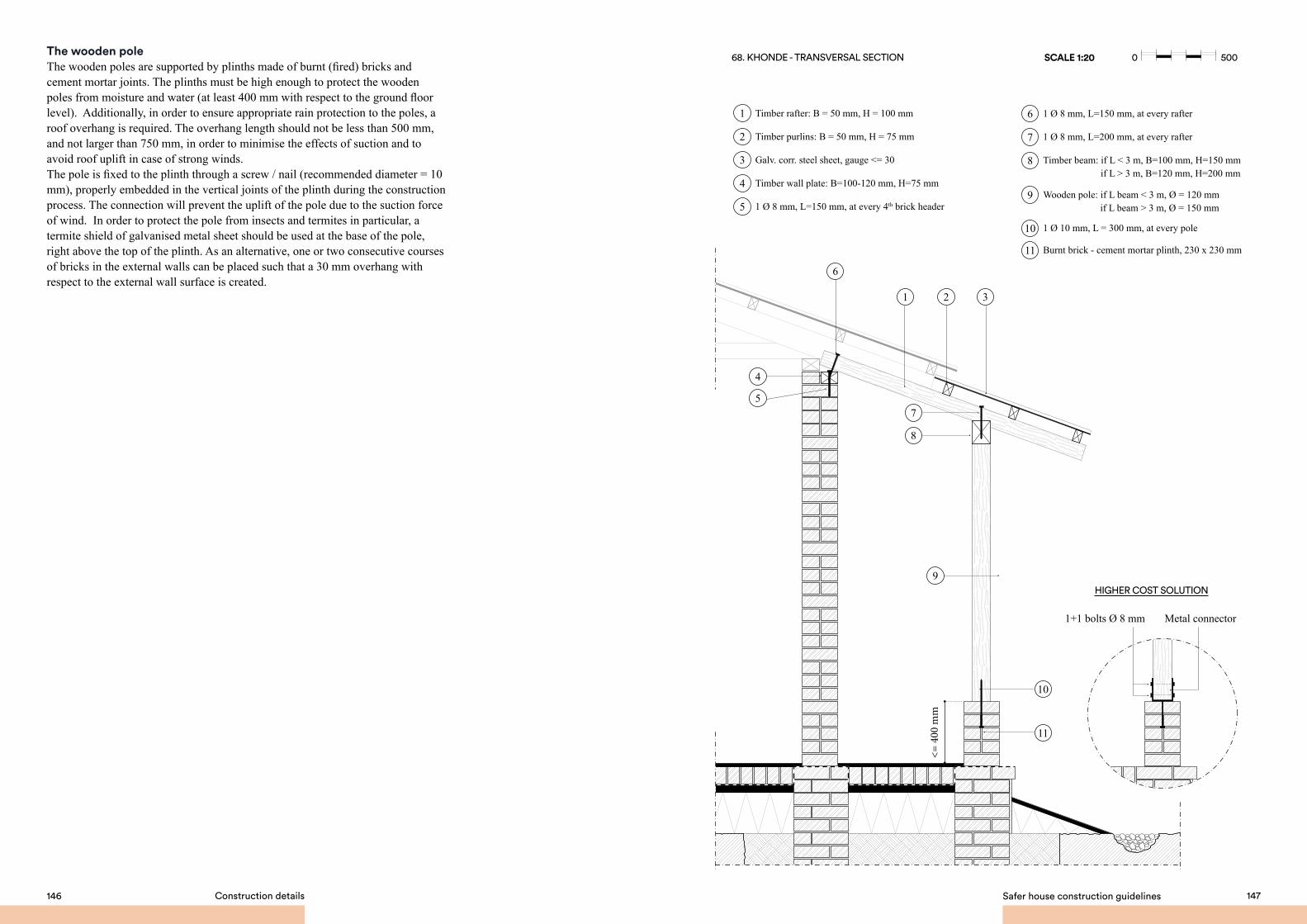
Safer house construction guidelines 147146 Construction details
The wooden poleThe wooden poles are supported by plinths made of burnt (fired) bricks and cement mortar joints. The plinths must be high enough to protect the wooden poles from moisture and water (at least 400 mm with respect to the ground floor level). Additionally, in order to ensure appropriate rain protection to the poles, a roof overhang is required. The overhang length should not be less than 500 mm, and not larger than 750 mm, in order to minimise the effects of suction and to avoid roof uplift in case of strong winds.The pole is fixed to the plinth through a screw / nail (recommended diameter = 10 mm), properly embedded in the vertical joints of the plinth during the construction process. The connection will prevent the uplift of the pole due to the suction force of wind. In order to protect the pole from insects and termites in particular, a termite shield of galvanised metal sheet should be used at the base of the pole, right above the top of the plinth. As an alternative, one or two consecutive courses of bricks in the external walls can be placed such that a 30 mm overhang with respect to the external wall surface is created.
Timber rafter: B = 50 mm, H = 100 mm
Timber purlins: B = 50 mm, H = 75 mm
Timber wall plate: B=100-120 mm, H=75 mm
Galv. corr. steel sheet, gauge <= 30
1 Ø 8 mm, L=150 mm, at every 4th brick header
1 Ø 8 mm, L=150 mm, at every rafter
Wooden pole: if L beam < 3 m, Ø = 120 mm
Timber beam: if L < 3 m, B=100 mm, H=150 mm
if L beam > 3 m, Ø = 150 mm
if L > 3 m, B=120 mm, H=200 mm
1 Ø 8 mm, L=200 mm, at every rafter
1 Ø 10 mm, L = 300 mm, at every pole
Burnt brick - cement mortar plinth, 230 x 230 mm
1
4
6
9
8
10
11
7
5
2
3
11
10
9
<= 4
00 m
m
21 3
6
HIGHER COST SOLUTION
8
57
4
1+1 bolts Ø 8 mm Metal connector
68. KHONDE - TRANSvERSAL SECTION SCALE 1:20 0 500
0 500mm
0 300mm
0 500mm
0 1000mm

SUMMARY
FoundationsAvoid building on loose sands soils, soft silt, poorly compacted clays, filled soil and soils with very high water table. Minimum foundation depth: for gravel and sandy soils, 700 mm; for clayey soils, 1000 mm.Use continuous spread footing foundations. In soft soils, the footing should consist of a continuous reinforced concrete element, 700 x 250 mm. If not affordable or in hard soils, use a pyramidal footing made of burnt bricks and cement mortar, 700 mm wide. Concrete with field stones can be an alternative. Use plinths in burnt (fired) bricks with cement mortar joints. Concrete with field stones can be an alternative. The plinth should be 350 mm thick. The height of the plinth should be above the expected flood water line and at least 300 mm above ground level. If affordable, the slab on grade should consist of a 75 – 100 mm thick reinforced concrete layer. Otherwise, a layer of burnt bricks set on the edge and cement mortar joints is recommended. Place a 25 mm thick sand-cement screed above the slab. A waterproofing layer should be applied in the form of thick polyethylene sheet.
WallsSun-dried brick wallsThe minimum allowed thickness is 300 mm. The maximum distance between cross walls is 4 meters. The vertical joints must not be aligned. Bricks should be arranged according to an effective transversal bond. Create an effective barrier to stop insects rising (place one or two consecutive courses of bricks in the external walls to form a 30 mm overhang). Both horizontal and vertical joints should be 10 mm thick, uniformly and completely filled, made in mud mortar, using the same soil as that used to manufacture the bricks.The external surface of outside walls must be covered with mud plaster.
Rammed earth wallsThe minimum allowed thickness is 300 mm. The maximum distance between cross walls is 4 meters. Each compacted layer should not exceed 100 mm.Bamboo canes can be used as internal vertical reinforcement, placed every 400 – 800 mm.
Burnt brick wallsThe minimum allowed thickness is 230 mm. The maximum distance between cross walls is 4 meters. The vertical joints must not be aligned. Bricks should be arranged according to an effective transversal bond. Both horizontal and vertical joints should be 10 mm thick, uniformly and completely filled, in cement mortar.Create an effective barrier to stop insects rising (place one or two consecutive courses of bricks in the external walls to form a 30 mm overhang). Horizontal joint reinforcement (Brick Force Wire at every 4th course) and / or vertical reinforcement (1 x 16 mm diameter at wall intersections) can be placed to improve the seismic resistance. Protect the most exposed parts (corners, wall-base, etc.) with sand-cement plaster.
SSB wallsIn case of ring beam at walls top, the minimum allowed thickness is 140 mm. The maximum distance between cross walls is 3.5 meters. The vertical joints must not be aligned. Both horizontal and vertical joints should be 10 mm thick, uniformly and completely filled, in cement mortar.Create an effective barrier to stop insects rising (place one or two consecutive courses of bricks in the external walls to form a 30 mm overhang). Horizontal joint reinforcement (2 x 6 mm diameter at every 4th course) and / or vertical reinforcement (1 x 16 mm diameter at wall intersections) can be placed to improve the seismic resistance. Protect the most exposed parts (corners, wall-base, etc.) with sand-cement plaster or brick sealer.
OpeningsThe openings should not exceed 1200 mm width. The sum of the widths of all openings in a wall should not exceed 1/3 of the total wall length. The minimum distance between openings should not be less than 600 mm. Openings should be inset at a minimum of 600 mm from the edge of the wall. Openings must be provided with rigid steel or timber frames. Every opening must be provided with a lintel:a. timber lintel: depth 75 – 100 mm depending on opening’s width;b. Reinforced concrete lintel: depth 75 – 100 mm depending on opening’s width.
Ring beam at lintel and roof levelPlace ring bands (beams) at lintel and roof level, in order to tie together the walls. The lintel band may be merged with the roof band, thus reducing the complexity of the building process and the cost required to build a seismic-resistant construction. Place a reinforced concrete ring beam for medium to high quality walls (burnt bricks and SSBs). If affordable, the thickness should be kept equal to 150 mm. Place a timber /wooden ring beam for low quality walls (sun-dried bricks and rammed earth). Firmly tie the ring beam to the walls with steel wire wrappings.
RoofPrefer hipped roofs to gable roofs. Prefer light roofs (metal sheet cover with timber structure / thatch with wooden structure). Recommended roof slope: 20° – 30° for metal sheet roofs; 35° - 45° for thatch roofs. The structure of the roof of the khonde should be independent from the roof structure of the building. The overhang length should be between 500 mm and 750 mm. If the shorter length of the building is < 4 m, place transverse inclined rafters, connected at one end to the ridge board or to a hip rafter, and rested at the opposite end on a continuous wall plate. Otherwise, trusses will be required, braced with diagonal bracing elements. All timber / wooden elements must be coated with a preservative treatment to prevent decay due to insect action
Metal sheet roofThe corrugated metal sheets must be galvanised or properly protected from rust through painting. Minimum sheet thickness is gauge 30 (0.3 mm). The roof structure should consist of softwood timber elements (pine tree is recommended). Minimum
cross-sectional dimensions: purlins 50 x 75 mm, at max 700 mm c/c; rafters 50 x 150 mm, at max 1100 mm c/c. Purlins to rafter connection: 6 mm diameter nail + 2 wrappings of steel wire. Rafter to horizontal tie and wall plate connection: 2x 8 mm diameter nails. Roof to wall connection: 3 wrappings of steel wire at every rafter.
Thatch roofMinimum thatch thickness is 15 cm. Spraying of insect treatment is to be performed every 6 months - 1 year. The roof structure should consist of wooden elements (bluegum tree is recommended). Minimum cross-sectional dimensions: purlins 60 mm diam., at max 400 mm c/c; rafters 120 mm diam., at max 700 mm c/c. Purlins to rafter connection: 6 mm diameter nail + 2 wrappings of steel wire. Rafter to horizontal tie and wall plate connection: 2x 8 mm diameter nails. Roof to wall connection: 3 wrappings of steel wire at every rafter.
KhondeThe khonde should be located externally with respect to the plan of the structural walls of the building.The roof of the khonde should be structurally independent from the main roof of the building.The rafters are supported by a timber/wooden longitudinal beam. Minimum cross-sectional dimensions: if columns span > 3 m, 120 x 200 mm (200 mm diameter); otherwise, 100 x 150 mm (150 mm diameter).The columns could be either wooden poles (120 – 150 mm diameter) or masonry columns (230 x 230 mm) in burnt bricks and cement mortar. The wooden poles are supported by plinths in burnt bricks and cement mortar, with minimum high with respect to the ground floor level = 400 mm.
Safer house construction guidelines 149148 Construction details

MAINTENANCE AND STRENGTHENING
6.

Once the construction has been completed, it is necessary to schedule regular maintenance of it. In fact, choice of the proper site, correct use of the materials, good construction techniques, are not enough to guarantee the long term quality of the house. Provision of regular maintenance of the different parts of the building is the only solution against deterioration and aging of the different components.Maintenance may be at the structural level or imply minor works, but each action devoted to the strengthening of the house will positively impact in the longevity of the house.
6.MAINTENANCE AND STRENGTHENING
Safer house construction guidelines 153152 Maintenance and strengthening
Routine maintenance is essential to ensure the longevity of the building, as it prevents the increase of vulnerability to natural disasters, such as floods, severe windstorms and earthquakes.Routine maintenance consists in all the operations needed to avoid building deterioration.
The main reasons of building deterioration are:a. The effects of weathering, and in particular the direct or indirect exposure to water and moisture;b. Insect attack. Any routine maintenance work should include measures to prevent deterioration from any of the above-mentioned reasons.
In particular: a. The drainage system must be kept clean and free from objects that may hinder the flow of water;b. The walls must be protected from weathering;c. The roof (timber / wooden elements, connections and cover) must be suitable and not deteriorated.Beside routine maintenance, strengthening operations will be required to repair construction errors (i.e. inadequate or insufficient connections between elements) and weaknesses due to the presence of vulnerable elements (i.e. gable-end walls). Unfortunately, for most of the errors and construction weaknesses, it is not advised to retrofit the building, because the operations required would be either too complicated or too expansive and, in most cases, the result could be questionable.
In particular, if the weakness is due toa. incorrect building location or,b. inadequate foundations (depth, low quality materials, etc.) or,c. inadequate masonry (low quality materials, low quality texture and bonding, masonry too slender, etc.),it will be strongly recommended to reconstruct the building according to the present Guidelines.
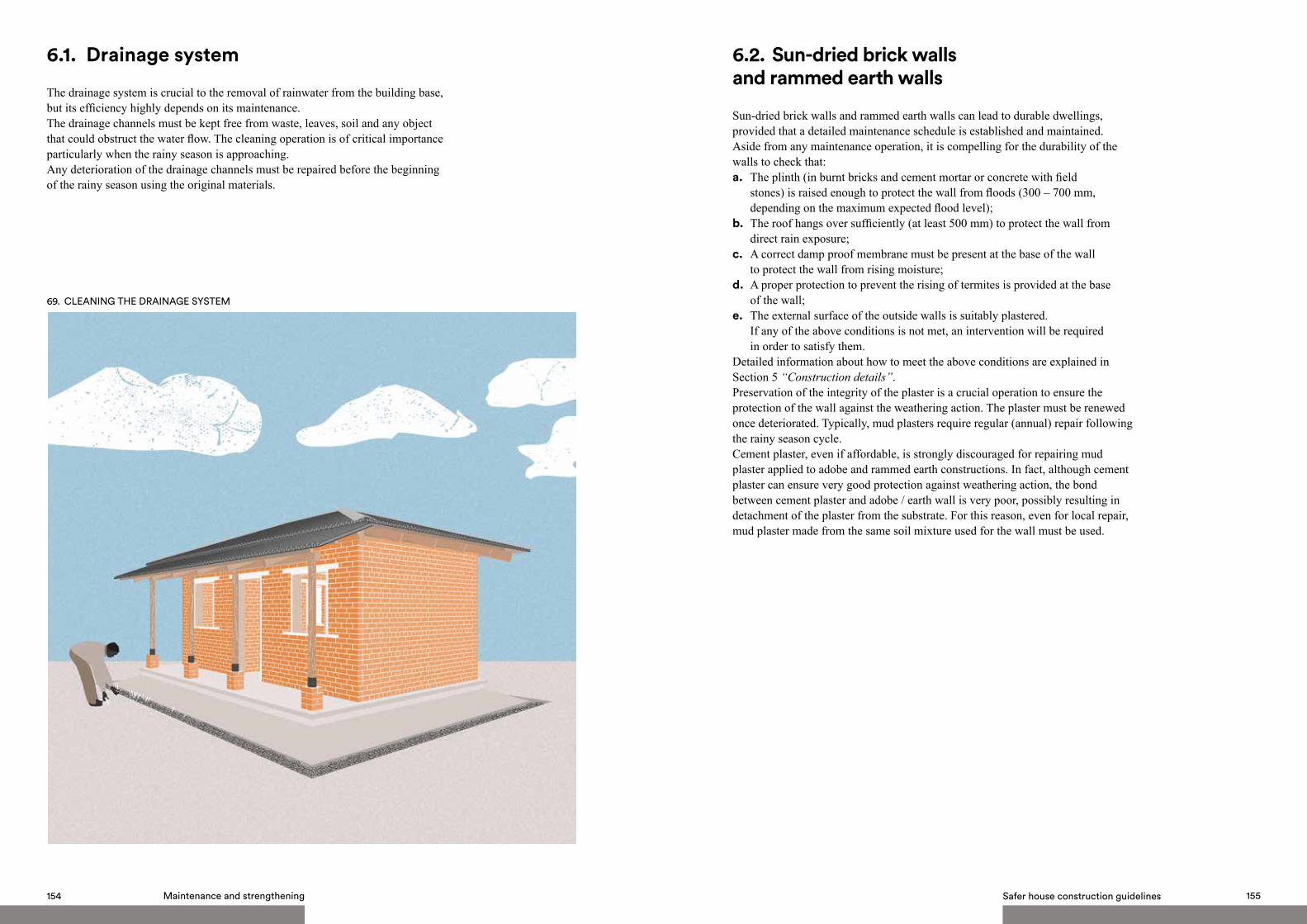
Safer house construction guidelines 155154 Maintenance and strengthening
69. CLEANING THE DRAINAGE SYSTEM
6.1. Drainage system
The drainage system is crucial to the removal of rainwater from the building base, but its efficiency highly depends on its maintenance. The drainage channels must be kept free from waste, leaves, soil and any object that could obstruct the water flow. The cleaning operation is of critical importance particularly when the rainy season is approaching.Any deterioration of the drainage channels must be repaired before the beginning of the rainy season using the original materials.
6.2. Sun-dried brick walls and rammed earth walls
Sun-dried brick walls and rammed earth walls can lead to durable dwellings, provided that a detailed maintenance schedule is established and maintained. Aside from any maintenance operation, it is compelling for the durability of the walls to check that: a. The plinth (in burnt bricks and cement mortar or concrete with field stones) is raised enough to protect the wall from floods (300 – 700 mm, depending on the maximum expected flood level);b. The roof hangs over sufficiently (at least 500 mm) to protect the wall from direct rain exposure;c. A correct damp proof membrane must be present at the base of the wall to protect the wall from rising moisture;d. A proper protection to prevent the rising of termites is provided at the base of the wall;e. The external surface of the outside walls is suitably plastered. If any of the above conditions is not met, an intervention will be required in order to satisfy them. Detailed information about how to meet the above conditions are explained in Section 5 “Construction details”.Preservation of the integrity of the plaster is a crucial operation to ensure the protection of the wall against the weathering action. The plaster must be renewed once deteriorated. Typically, mud plasters require regular (annual) repair following the rainy season cycle. Cement plaster, even if affordable, is strongly discouraged for repairing mud plaster applied to adobe and rammed earth constructions. In fact, although cement plaster can ensure very good protection against weathering action, the bond between cement plaster and adobe / earth wall is very poor, possibly resulting in detachment of the plaster from the substrate. For this reason, even for local repair, mud plaster made from the same soil mixture used for the wall must be used.

Safer house construction guidelines 157156 Maintenance and strengthening
6.3. Burnt - fired - brick walls and SSB walls
Besides any maintenance operation, it is crucial for the durability of the walls to check that:a. The plinth is raised sufficiently to protect the wall from floods (300 – 700 mm, depending on the maximum expected flood level);b. The roof hangs over enough (at least 500 mm) to protect the wall from direct rain exposure;c. A proper damp proof membrane is present at the base of the wall to protect the wall from rising moisture;
70. RENOvATION OF THE PLASTER d. A proper protection to prevent the rising of termites is provided at the base of the wall. In fact, although burnt (fired) brick walls and SSB walls are not particularly vulnerable to insect attack, the insects must not be allowed to climb on the walls and to reach vulnerable elements (i.e. timber / wooden elements).If any of the above conditions is not met, an intervention will be required in order to satisfy them.Detailed information about how to meet the above conditions are explained in Section 5 “Construction details” Burnt (fired) brick walls and SSB walls are more durable than adobe walls and rammed earth walls, particularly regarding the resistance to water erosion and insects attack (due to the presence of cement content in the mortar joints and in the SSB). Thus, unlike adobe walls and rammed earth walls, the external surface of outside burnt (fired) brick walls and SSB walls do not required to be plastered, although protecting the most vulnerable parts (i.e. plinths, base of walls and corners) with sand – cement plaster is strongly recommended. The plaster should be restored and repaired as soon as deterioration signs are detected. In addition, it is fundamental to preserve the integrity of mortar joints, where the masonry is not protected by plaster. Deteriorated mortar joints can be restored through pointing, using the same sand – cement mortar used to build the brickwork.
71. REPLACEMENT OF MORTAR JOINTS

Safer house construction guidelines 159158 Maintenance and strengthening
6.4. Gable-end walls - gable roof
Gable-end walls (the triangular shaped area of wall at the lateral ends of the pitched roof) are the most vulnerable parts of the building to earthquakes and severe windstorms, as they are prone to outward collapse.
The reasons are the following:a. Gable-end walls are typically non-load-bearing and do not benefit from the lateral support that the roof framing provides against out-of-plane failure, unless they are joined by structural members or connectors. Thus, the gable end section of the wall will rock as a cantilever, when subject to lateral loads (seismic or wind loads);b. Gable-end walls are much more slender than other walls. In fact, Gable- end walls are taller than all the other walls in the building, but are usually characterised by the same thickness.For the above reasons, in case of new constructions, it is strongly recommended to build hipped roofs, although they are characterised by a more complex structure. For existing buildings with gable roofs, it is fundamental to provide a lateral restrain to the outward motion of gable-ends.
The following operations should be performed, in order to anchor the gable-end walls to the building for out-of-plane stability:a. Where a trussed roof adjoins a masonry gable, the gable end masonry must be fastened to the adjacent trusses beam through widespread wrappings of steel wire;b. A timber / wooden gable band could be useful to tie the gable end together. The gable band is a runner at the top of the gable end walls, placed between the gable end walls and the roof. It must be structurally connected to the roof band (reinforced concrete or timber / wooden ring beam). Avoid installing a reinforced concrete gable band, unless the masonry is characterised by high mechanical properties;c. One or two pairs of diagonal bracings should be installed, to laterally restrain the truss beam that lies adjacent to the masonry gable. In this way, the masonry gable (connected to the adjacent truss beam through widespread wrappings of steel wire) will be in turn restrained laterally.
Timber element at the top of gable end
Diagonal timber brace:B = 50 mm, H = 100 mm
72. GABLE ROOF

Safer house construction guidelines 161160 Maintenance and strengthening
73. REPLACEMENT OF THE WRAPPINGS OF STEEL WIRE 6.5. Roof structure
All timber / wooden members of the roof structure have to be treated against insects (termites in particular): they must be coated with an appropriate preservative treatment or, if not available, with used motor oil, before installation. The treatment must be renewed, before its effect expires. Make sure that the roof elements and connections match the recommendations provided in these Guidelines. In particular: a. All steel connecting elements (nails / screws / bolts) must be of suitable section and length;b. All steel connecting elements (nails / screws / bolts) must be accurately protected from rust;c. The number of wrappings of steel wire must be appropriate;d. All timber / wooden members must be of suitable section.
Further more observe the following:a. The timber / wooden members do not show local cracks or any sign of insect attack;b. The timber / wooden members are placed correctly (height is not mistaken with base).
If any of the above conditions is not met, the timber / wooden member or the steel connection that does not meet the requirements must be replaced. Detailed information about how to meet the above conditions are explained in Section 5 “construction details”.
6.6. Roof to wall connection
Control that all rafters rest on a continuous timber wall plate, properly connected to the wall. Otherwise, a timber wall plate should be placed below every rafter in order to avoid localised high stresses on the underlying masonry. Check that no rafters are located too close to the wall edges; contrarily, relocate the rafter. Check that the wrappings of steel wire are placed correctly and the number of wrappings is appropriate.
6.7. Metal sheet cover
The metal sheet cover must not be rusted. If widespread rust is present, the rusted sheets must be substituted. In order to avoid this problem, always choose galvanised steel sheets or correctly painted steel sheets.Verify that the metal sheets are sufficiently thick (gauge ≤ 30). Otherwise, replace the metal sheet cover with a more suitable one. The metal sheet cover must be waterproof. Therefore, the connection between adjacent sheets must meet the recommendations provided in these Guidelines. Otherwise, they must be replaced or, where possible, repositioned correctly.

Safer house construction guidelines 163162 Maintenance and strengthening
74. THATCH INSPECTION AND RENOvATION
6.8. Thatch roof
The thatch requires continuous inspection in order to check the integrity, particularly after every rainy season cycle, and renewed if necessary. Spraying for insects is required every 6 months - 1 year.
MOISTURE RISINGUPWARDS INTO TIMBER
MEMBER CAUSING DAMAGE
75. RAIN PROTECTION - ROOF OvERHANG
6.9. Khonde
Protect timber elements from direct exposition to rainwater: an overhang is required to ensure appropriate rain protection to timber poles. The overhang length should not be less than 500 mm, and no larger than 750 mm, in order to minimise the effects of suction and to avoid roof uplift in case of strong winds. If the overhang is not sufficient, a waterproof coating should be applied to protect the timber pole. Protect the timber / wooden pole against moisture rising from the ground. It is strongly recommended to detach the roof structure of the khonde from the main roof of the building, in order to avoid large suction forces acting on the main roof of the building during strong windstorms.

SUMMARY
MaintenanceThe drainage channels must be kept free from waste, leaves, soil and any object that could obstruct the water flow.In case of sun-dried brick and rammed earth walls, keeping the plaster integer is crucial to preserve the protection of the wall from the weathering action. Typically, mud plasters require regular (annual) repair following the rainy season cycle, using the same mud used to plaster the wall originally.In case of burnt brick and SSB walls, preserve the integrity of mortar joints, where the masonry is not protected by plaster. Deteriorated mortar joints can be restored through pointing, using the same sand – cement mortar used to build the brickwork.Renew the treatment against insects (termites in particular) on the surface of all timber and wooden members, before its effect expires. Replace all rusted metal connections and corrugated metal sheets.
In case of thatch roof:a. spraying for insects is required every 6 months - 1 year;b. the thatch cover must be repaired annually to preserve waterproofing.
Strengthening Provide appropriate lintels to each opening.Every timber / wooden member and every connection between roof members should be appropriate to resist external loads (wind suction in particular). If not, they must be replaced with suitable ones. Verify that the metal sheets are sufficiently thick (gauge ≤ 30). If not, they must be replaced with suitable ones. The roof-to-wall connections should be appropriate: all rafters must rest on a continuous timber wall plate, properly connected to the wall; the wrappings of steel wire must be properly installed.Assure that the roof overhang is between 500 and 750 mm at every side of the building.
In case of gable roof, provide a lateral restrain to the outward motion of gable ends. In order to ensure out-of-plane stability to the gable end walls: a. they must be fastened to the adjacent truss beam through wrappings of steel wire;b. a timber / wooden gable band should tie the gable end together and support the purlins;c. one or two pairs of diagonal braces should connect the gable end to an inner truss.
It is strongly recommended to detach the roof structure of the khonde from the main roof of the building. Assure that the wooden / timber poles of the khonde are properly protected from rising moisture and rainfall.
164 Maintenance and strengthening

ILLUSTRATEDSHEETS
7.

1.SUN-DRIED BRICK WALLS/THATCH ROOF
Low cost solution ●○○
PERSPECTIvE SECTION
Elements:
a. Brick foundation p. 95b. Sundried brick-adobe-walls p. 98–102c. Timber lintel p. 122–123d. hipped thatch roof p. 140–144
Safer house construction guidelines 169168 Illustrated sheets

A
A'
SECTION A–A' FRONT vIEW
PLAN
Safer house construction guidelines 171170 Illustrated sheets
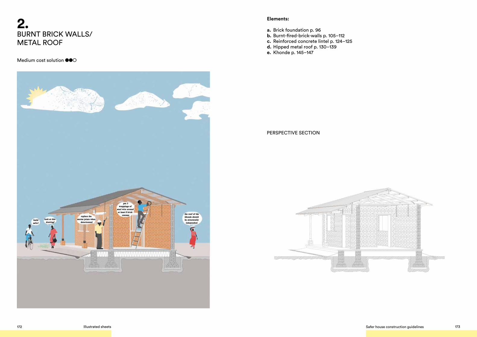
2.BURNT BRICK WALLS/METAL ROOF
Medium cost solution ●●○
Elements:
a. Brick foundation p. 96b. Burnt-fired-brick-walls p. 105–112c. Reinforced concrete lintel p. 124–125d. Hipped metal roof p. 130–139e. Khonde p. 145–147
PERSPECTIvE SECTION
Safer house construction guidelines 173172 Illustrated sheets
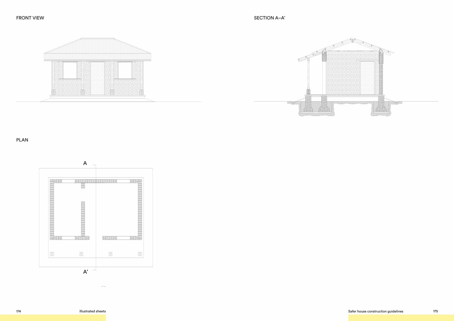
SECTION A–A' FRONT vIEW
PLAN
A
A'
Safer house construction guidelines 175174 Illustrated sheets

3. SSB WALLS/ METAL ROOF
Higher cost solution ●●●
Elements:
a. Reinforced concrete foundation p. 97b. SSB-stabilized-soil block-walls p. 113–120c. Reinforced concrete lintel/Ring beam p. 126–128d. Hipped metal roof p. 130–139e. Khonde p. 145–147
PERSPECTIvE SECTION
Safer house construction guidelines 177176 Illustrated sheets

SECTION A–A' FRONT vIEW
PLAN
A
A'
Safer house construction guidelines 179178 Illustrated sheets

1. Adam E.A., Agib A.R.A. (2001), Compressed Stabilised Earth Block Manufacture in Sudan. United Nations Educational, Scientific and Cultural Organization, Division for Educational Policies and Strategies, Paris UNESCO
2. Akpokodje, E.G. (1985) The stabilization of some arid zone soils with cement and lime, Quarterly Journal of Engineering Geology and Hydrogeology, 18: 173-180
3. Alley, P. J. (1948) Rammed earth construction, New Zealand Engineering, June 10 1948, 582
4. Arya Anand S., Boen T., Ishiyama Y. (2013), Guidelines For Earthquake Resistant Non-Engineered Construction, United Nations Educational, Scientific and Cultural Organization
5. Asian Disaster Preparedness Center (2005), Handbook on Design and Construction of Housing for Flood-Prone Rural Areas of Bangladesh. Bangladesh
6. Benson, C., Twigg, J., Rossetto, T., (2007) Tools for Mainstreaming Disaster Risk Reduction Guidance Notes for Development Organisations, International Federation of Red Cross and Red Crescent Societies / the ProVention Consortium, Geneva Switzerland
7. Blondet, M., Villa Garcia G., Brzev, S. 2003, Earthquake-Resistant Construction of Adobe, Earthquake Engineering Research Institute, Oakland, California.
8. Blondet, M., (2005), Construction and Maintenance of Masonry Houses, for Masons and craftsmen, Sencico, Lima, Peru
9. Bothara, J.K., Guragain, R., Dixit, A., (2002) Protection Of Educational Buildings Against
Earthquakes. A Manual For Designers And Builders. National Society for Earthquake Technology-Nepal (NSET-Nepal) Book publication Series 5
10. British Standards Code of Practice CP 112: Part 2. “The structural use of timber”. The Council for Codes of Practice British Standards Institution11. Bryan, A.J. (1988) Criteria for the suitability of soil for cement stabilization, Building and Environment, 23(4): 309-319
12. British Standards (1997), Loading for Buildings – Part 2: Code of Practice for Wind Loads, 6399-2:1997
13. Bui, Q.B, Morel, J.C., Venkatarama Reddy, B.V., Ghayad W., (2009) Durability of rammed earth walls exposed for 20 years to natural weathering, Building and Environment 44: 912–919
14. Burroughs, S. (2008) Soil property criteria for rammed earth stabilization, Journal of Materials in Civil Engineering, 20: 264-273
15. Chapola, L.S., (2001), Seismology in Malawi, in I.I.o.S.a.E. Engineering (ed.) vol. 35, Ministry of Construction, Building Research Institute, Malawi.
16. Chapola, L.S., (1993) An Estimation of Earthquake Hazards and Risks in Malawi, Geological Surveys Department, P.O. Box 27, Zomba
17. Chapola, L.S., (1994)., Seismicity and Tectonics of Malawi, (for National Atlas of Malawi), Geological Survey Department, P.O. Box 27, Zomba
18. Chapola, L.S., (1997), State of Stress in East and Southern Africa and Seismic Hazard Analysis of Malawi, M.Sc. Thesis, Institute of Solid Earth Physics, University of Bergen, Norway
BIBLIOGRAPHY 19. Christie, J. (1989), The seismic resistance of traditional earthen building, University of Canterbury, Christchurch
20. Christie, J. (1990), Improving the seismic resistance of earth buildings, Earth building for the ‘90s, University of Auckland, university of Auckland, pp. 43-58
21. CRATerre, (1990), Building with Earth, Mud Village Society, Delhi, India
22. CRATerre-EAG, Guillaud. H. Joffroy,Th., Odul P., (1995) - Compressed Earth Blocks - Vol 2. Manual of design and construction, Aus der Arbeit von GATE, Friedrich Vieweg & Sohn, Germany
23. CRATerre-EAG, Houben, H., Guillaud, H (1994), Earth Construction - a comprehensive guide, Intermediate Technology Publications, London, 1994
24. CRATerre (1991) The basics of compressed earth blocks, GTZ, Eschborn, Germany
25. Department of Disaster Management Affairs (DODMA) (2013), Disaster Risk Management Handbook, a Handbook for practitioners, communities, educators and learners in Malawi, Malawi.
26. Department of Housing and Urban Development, Ministry of Lands, Housing, and Urban Development (2010), Guidelines for Safer House Construction - Technical Manual, Malawi.
27. Department of Housing and Urban Development, Ministry of Lands, Housing, and Urban Development, United Nations Human Settlement Programme (UN-HABITAT), (2012) Living with Floods, Technical Report, Malawi
28. Earthquake Reconstruction Rehabilitation Authority (ERRA), (2006), Guidelines for earthquake resistant construction of non-engineered rural and suburban masonry houses in cement sand mortar in earthquake affected areas, Pakistan
29. Fernandez, L., United Nations Human Settlements Programme (2014), Consultancy Final Report, Maputo, Mozambique
30. (The) Government of Malawi, The World Bank, United Nations Development Programme (2012), Nsanje District Floods, Disaster Impact Assessment and Transitional Recovery Framework, Malawi
31. Gupta,H.K., The Malawi Earthquake of March 10, 1989: A Report of Macroseismic Survey, Tectonophy 209, No. 1-4, 165-166 1992
32. Harris V. (2006), Disaster Risk Reduction in Practice. The Architecture of Earthquake Resistant Housing in Pakistan. An introduction to disaster risk reduction and seismic mitigation for non-engineered structures: Case Study - Reconstruction following Pakistan earthquake of October 8th 2005 (http://www.ucl.ac.uk/drrconference/presentations/VHarris.pdf)
33. International Association of Earthquake Engineering (IAEE), National Information Center of Earthquake Engineering (2004), Guidelines for Earthquake Resistant Non-Engineered Construction, Indian Institute of Technology Kanpur, Kanpur, India
34. Jiminéz Delgado, M.C. & Guerrero, I.C (2007) The selection of soils for unstabilised earth building: A normative review, Construction and Building Materials, 21: 237-251
35. Kable, J., Keable, R., (2011), Rammed Earth Structures, A Code of Practice, Practical Action Publishing, United Kingdom.
36. Kamwanja, G.A., (1988), Low Cost Building Materials in Malawi, Ph.D. Thesis, University of Malawi 1988
37. Malawi Bureau Of Standards, Catalogue Of Malawi Standards, 2013. Malawi Bureau of Standards
38. Maniatidis, V., Walker, P., (2003) A Review of Rammed Earth Construction, Natural Building Technology Group, Department of Architecture & Civil Engineering, University of Bath, United Kingdom
39. Middleton, G. F. (1952) Earth-wall construction. Pisé or rammed earth; Adobe or puddled earth; stabilised earth. Bulletin No. 5, First edition, Department of Works and Housing, Sydney, Australia
Safer house construction guidelines 181180 Illustrated sheets

40. Middleton, G.F., Schneider, L.M. (1987) Bulletin 5: Earth-Wall Construction, 4th edn, CSIRO, Sydney
41. Ministère de l’Education Nationale, Bureau des Projets Education, Republique du Mali (1990), Manuel de Construction, Mali
42. Ministère des Travaux Publics, Transports et Communications (MTPTC), (2013), Code National Du Bâtiment D’Haïti (CNBH) 2012 - République D’Haïti.
43. Ministère des Travaux Publics, Transports et Communications (MTPTC), Ministère De L’Intérieur et des Collectivités Territoriales (MICT), 2010, Guide De Bonnes Pratiques Pour La Construction De Petits Bâtiments En Maçonnerie Chaînée En Haïti, Éd. MTPTC, Bibliothèque Nationale d’Haïti.
44. Mrema G. C., Gumbe L. O., Chepete H. J., Agullo, J. O,. Rural structures in the Tropics. Design and development – FAO, Rome, 2011
45. Mukerji K., (1991) Soil Preparation Equipment (product information), GTZ, Eschborn, Germany
46. Mukerji K., (1994) Stabilisers and Mortars (for stabilised soil blocks) CRATerre, GTZ.
47. National Housing Policy, Malawi Government 1999
48. Grobbelaar, A., Building construction and graphic standards, Anglo Rand Publications, South Africa, 2006.
49. Norton, J., Intermediate Technology Development Group. (1986), Building with earth: a handbook, IT Publications, Rugby, U.K.
50. Norton, J., (1997), Building with Earth, A handbook, 2nd Ed., Practical Action Publishing.
51. Papanikolaou, A., Taucer, (2004) F., Review of Non-Engineered Houses in Latin America with Reference to Building Practices and Self-Construction Projects. EUR 21190 EN© European Communities, Institute for the Protection and Security of the Citizen European Laboratory for Structural Assessment (ELSA) Ispra (VA), Italy
52. Review of Sustainable Building Materials & Design 2012. Build it International
53. Rigassi Vince, Compressed Earth Blocks: Vol. 1, Manual of Production, CRATerre-EAG, GTZ, 1995
54. Sassu M., Ngoma I., (2002), Housing Report: Rural mud wall building (nyumba yo mata or ndiwula).World Housing Encyclopedia, an Encyclopedia of Housing Construction in Seismically Active Areas of the World.
55. Sassu M., Ngoma I., (2002), Housing Report: Rammed earth house with pitched roof (Nyumba yo dinda or Nyumba ya mdindo) World Housing Encyclopedia, an Encyclopedia of Housing Construction in Seismically Active Areas of the World.
56. Sassu M., Ngoma I., (2002) Housing Report: Unburnt brick wall building with pitched roof (nyumba ya zidina), World Housing Encyclopedia, an Encyclopedia of Housing Construction in Seismically Active Areas of the World.
57. South African National Standard (2011), The application of the National Building Regulations Part L: Roofs, SABS Standards Division
58. Standards Australia (2001) AS 1289: Methods of testing soils for engineering purposes, Standards Australia International Ltd, Sydney
59. Standards New Zealand (1998) NZS 4298:1998 Materials and Workmanship for Earth Buildings, Standards New Zealand, Wellington
60. Standards New Zealand (1998) NZS 4299:1998 Earth Buildings Not Requiring Specific Design, Willington
61. Standards New Zealand (1998) NSW 4298: 1998, Materials and Workmanship for Earth Buildings, Earth Brick Drop Test
62. Stulz R., Mukerji K., (1993) Appropriate Building Materials, A Catalogue of Potential Solutions, Practical Action Publishing/SKAT
63. United Nations Human Settlement Programme (UN-HABITAT), (2012), Housing, Shelter & Basic Infrastructures Resistant to Disasters in Southern
Africa. Malawi, Mozambique, Madgascar, Nairobi, Kenya
64. United Nations Human Settlement Programme (UN-HABITAT), (2010), Malawi, Urban Housing Sector Profile, Nairobi, Kenya
65. United Nations Developmetn Programme (Malawi) (2013) Annual Report 2012, Malawi.
66. Department of Economic and Social Affairs, United Nations (1975), Low-cost construction resistant to earthquakes and hurricanes, United Nations Publication, Sales N. E.75.IV.7 New York
67. Walker, P., Standards Australia (2002) HB 195: The Australian Earth Building Handbook, Standards Australia International Ltd, Sydney
68. Walker, P., Keable, R., Martin, J., Maniatidis, V. (2005) Rammed earth: Design and construction guidelines, BRE Bookshop, United Kingdom
69. WEDC, 2007 (Developing Knowledge and capacity in Water and sanitation) Poster 56 (After SKAT).
70. WEDC Developing knowledge and capacity in water and sanitation Poster 20 (2007)
71. (The) World Bank (2011), Disaster Risk Management Programs for Priority Countries, GFDRR, Washington
72. (The) World Bank, Global Facility for Disaster Reduction and Recovery (GFDRR) (2012), Managing Disaster Risks for a Resilient Future, A strategy for the Global Facility for Disaster Reduction and Recovery 2013-2015, Washington D.C.
183 Safer house construction guidelines

SAFER HOUSING CONSTRUCTION GUIDELINES WORKSHOP 27th AUGUST SEGECOA GOLDEN PEACOCK HOTEL, LILONGWE.
Department of Lands,Housing and Urbandevelopment
Build Safer!
A Safe House is able to withstand severe natural hazards without threatening lives. These guidelines promote adaptive and sustainable solutions, address the various risks, discuss the necessary procedures in the selection of the building site, and suggest materials and construction techniques.