GLOSI taxonomy guide.pdf - Global Program for Safer Schools
28
Taxonomy Guide GPSS Global Program for Safer Schools October 2019 GLOSI THE GLOBAL LIBRARY OF SCHOOL INFRASTRUCTURE GPSS
-
Upload
khangminh22 -
Category
Documents
-
view
0 -
download
0
Transcript of GLOSI taxonomy guide.pdf - Global Program for Safer Schools

Taxonomy Guide
GPSS Global Program for Safer Schools
October 2019
GLOSI THE GLOBAL LIBRARY OF SCHOOL INFRASTRUCTURE
GPSS

October 2019
GLOSI THE GLOBAL LIBRARY OF SCHOOL INFRASTRUCTURE
GPSS Global Program for Safer Schools
Taxonomy Guide

© 2019 International Bank for Reconstruction and Development / The World Bank 1818 H Street NW Washington DC 20433 Telephone: 202-473-1000 Internet: www.worldbank.org
This work is a product of the staff of The World Bank with external contributions. The findings, interpretations, and conclusions expressed in this work do not necessarily reflect the views of The World Bank, its Board of Executive Directors, or the governments they represent.
The World Bank does not guarantee the accuracy of the data included in this work. The boundaries, colors, denominations, and other information shown on any map in this work do not imply any judgment on the part of The World Bank concerning the legal status of any territory or the endorsement or acceptance of such boundaries.
Rights and Permissions The material in this work is subject to copyright. Because The World Bank encourages dissemination of its knowledge, this work may be reproduced, in whole or in part, for noncommercial purposes as long as full attribution to this work is given.
Any queries on rights and licenses, including subsidiary rights, should be addressed to World Bank Publications, The World Bank Group, 1818 H Street NW, Washington, DC 20433, USA; fax: 202-522-2625; e-mail: [email protected].
Graphic and design: Miki Fernández

Acknowledgements
The Global Library of School Infrastructure (GLOSI) was created by Fernando Ramirez Cortes (Senior Disaster Risk Management Specialist), Carina Fonseca Ferreira (Disaster Risk Management Specialist), Laisa Daza Obando (Consultant), and Jingzhe Wu (Consultant) from the World Bank’s Global Program for Safer Schools (GPSS).
The original analytical framework and content of the GLOSI was prepared by a technical team led by Dina D’Ayala (Project Director) from University College London, United Kingdom, and Luis Eduardo Yamin (Project Director) from Universidad de Los Andes, Bogotá, Colombia. The technical team comprised Rohit Kumar Adhikari (Project Specialist) from University College London, Rafael Ignacio Fernández (Project Specialist), Angie Garcia (Project Specialist), Miguel Rueda (Project Specialist) and Gustavo Fuentes (Project Specialist) from Universidad de Los Andes.
The GLOSI was developed with grant support from the Global facility for Disaster Reduction and Recovery (GFDRR), including the Japan-World Bank Program for Mainstreaming Disaster Risk Management in Developing Countries. The team is especially thankful to Francis Ghesquiere, Julie Dana, Luis Tineo, Sameh Naguib Wahba, Maitreyi B Das, and David Sislen who provided overall guidance and support in the preparation of the GLOSI. The team would also like to thank Juan Carlos Atoche Arce, Diana Katharina Mayrhofer, Maria De Los Angeles Martinez Cuba, Nathalie Judith Karine Tchorek, and World Bank Rapid Application Development Team who provided valuable input and contributions to this document.
GLOSI THE GLOBAL L IBRARY OF SCHOOL INFRASTRUCTURE
GLOSI Taxonomy Guide • iii

iv • GPSS Global Program for Safer Schools
Contents
Global Library of School Infrastructure ............................................................................................... 1
1. Taxonomy – Classification of Seismic Safety .......................................................................................... 3
2. How to Build the GLOSI Taxonomy? ...................................................................................................... 4
2.1 GLOSI: Taxonomy Parameters ........................................................................................................ 5
2.1.1 Main Structural System ....................................................................................................... 6
2.1.2 Height Range ...................................................................................................................... 8
2.1.3 Seismic Design Level .......................................................................................................... 9
2.1.4 Diaphragm Type ................................................................................................................. 11
2.1.5 Structural Irregularity .......................................................................................................... 12
2.1.6 LBM: Wall Panel Length; RC: Span Length ......................................................................... 13
2.1.7 LBM: Wall Openings; RC: Pier Type ................................................................................... 14
2.1.8 Foundation Type ................................................................................................................. 15
2.1.9 Seismic Pounding Risk ........................................................................................................ 16
2.1.10 Effective Seismic Retrofitting .............................................................................................. 16
2.1.11 Structural Health Condition ................................................................................................ 17
2.1.12 Non-Structural Components .............................................................................................. 17
2.2 Building the GLOSI Taxonomy String ............................................................................................. 18
References ............................................................................................................................................... 19

Taxonomy Guide • 1
Global Library of School Infrastructure
The World Bank’s Global Program for Safer Schools (GPSS) launched in 2019 the Global Library of School Infrastructure (GLOSI). The GLOSI is a live global repository of evidence-based knowledge and data about school infrastructure and its performance against natural hazard events. A one-stop-shop with open access to global indicators on school infrastructure exposure and risk to natural hazards, taxonomy of school
buildings, catalog of building types, fragility and vulnerability information, case studies on vulnerability reduction solutions applied around the world, and data collection tools. In-country data is also available with restricted access. The GLOSI is updated over time through World Bank-funded safer school projects and contributions from development partners with interest in this field.
Why do we need GLOSI?Safer school projects have taught us that there are three main challenges to global dissemination of knowledge surrounding school building performance: communication to decision makers, the lack of a common language, and facilitation of quantitative risk assessment.
Global knowledge about school infrastructure performance needs to reach decision makers
The engineering community has achieved immense progress in the past few decades towards understanding building performance against natural hazards and devising scalable risk-reduction solutions. However, this knowledge has not reached decision makers nor has it been used to drive school infrastructure investments. Without this knowledge, the opportunity to maximize benefits from intervention and optimize investments in school safety can be lost.
The first objective is to create a universal “language”
School buildings tend to follow standard designs, yet buildings with similar vulnerability are still difficult to identify in different countries, or even within a country. This is largely due to the lack of a systematic classification system and consistent vulnerability assessment framework. The GLOSI offers a solution by making a taxonomy and vulnerability assessment framework for school buildings globally applicable, and oriented to produce quantitative risk information that will inform large investments in school safety and resilience.
The GLOSI is a tool to mainstream quantitative risk assessment in investment planning
By using a systematic taxonomy, the GLOSI includes a catalog of typical school building types found in different parts of the world with the respective vulnerability data needed to conduct quantitative risk assessments. Countries can map their school facility portfolios with the catalog and use the GLOSI data to perform quantitative risk assessments or vulnerability analyses to identify cost-efficient retrofitting solutions. The availability of this information will ensure that results are scalable across countries and safer school engagements in each country begin with a solid existing technical foundation.
GLOSI THE GLOBAL L IBRARY OF SCHOOL INFRASTRUCTURE

2 • GPSS Global Program for Safer Schools
Global Library of School Infrastructure (GLOSI)
VULNERABILITYREDUCTION SOLUTIONS
VULNERABILITY AND FRAGILITY DATA
COUNTRY DATA
DATA COLLECTION
TOOL
TAXONOMY
GLOSI
CATALOG OF BUILDING TYPES
GLOBAL BASELINE OF SCHOOL INFRASTRUCTURE
TAXONOMY
Taxonomy Guide • 3
1. Taxonomy—Classification of Seismic Safety
• Building types classify seismic performance
The performance of a building construction during an earthquake depends not only on the intensity of the earthquake, but also on its construction characteristics, including the main structural system, lateral load resisting mechanisms, materials used, building height, and quality of construction. Different characteristics help categorize constructions into different types. There is enough statistical evidence from past destructive earthquakes to conclude that some types of construction are more vulnerable than others. For example, adobe buildings are likely to experience more damage than brick masonry buildings given the same seismic intensity. Since it is not possible to study the seismic vulnerability of individual buildings one by one, buildings which share similar construction characteristics (i.e. main structural system, building height and seismic design level) are classified into distinct categories called building types.
• The taxonomy supports seismic vulnerability/risk assessments
A building type represents a large class of buildings bearing similar attributes of the main construction characteristics (i.e. main structural system, height range and seismic design level), yet showing a variation in the attributes of other construction characteristics such as diaphragm type, or structural irregularities. The full classification system based on all the attributes of the construction characteristics is termed as taxonomy. The construction characteristics can also be termed as taxonomy parameters. The identification and selection of the representative attributes of these characteristics result in one or more index buildings for a building type. An index building is a representative building of a building type which has fixed attributes for all the
construction characteristics. Through detailed seismic analyses of the index buildings for a building type, the seismic performance of the building type can be collectively defined. The development of a structural taxonomy is of great importance, as it enables the identification of index buildings, seismic vulnerability/risk assessment, and school infrastructure risk reduction planning/implementation for safer communities.
Most school buildings worldwide are made of load bearing masonry (LBM) (unreinforced, partially reinforced, confined, reinforced, etc.) and reinforced concrete (RC) (moment resistant frames with or without masonry infills, combined systems, etc.) construction. Other construction types like steel framed, timber framed, or prefabricated structures are also locally present in some countries or regions but not at a global level. Some of these buildings are very old and show very poor seismic performance, while others have been recently designed and constructed using the most up-to-date building codes and practices, leading to a very good expected seismic behavior. Thus, the development of a taxonomy will make it easier to distinguish each school building in terms of its seismic performance, and assist in the overall process of seismic risk assessment and intervention prioritization.
• Objectives of taxonomy development
> A common language for seismic vulnerability and risk communication with respect to school infrastructure
> Identification of the distinct global construction types of school buildings
> Ranking of the vulnerability parameters from generic to specific, and also by relative importance based on the definition and characterization of the seismic response
> Identification and description of various taxonomy parameters (and their associated attributes) that affect the seismic performance of school buildings
> Characterization of different school building types

4 • GPSS Global Program for Safer Schools
> Identification and definition of different index buildings representing different building types for the seismic vulnerability assessment of a population of school buildings
> Acceleration of the school infrastructure risk assessment process by using the results of some building types that have already been thoroughly studied in the past
> Development and adoption of the possible economical retrofitting options of school buildings per building type
2. How to Build the GLOSI Taxonomy?
Since there are many different school building construction types along with several variations in construction characteristics within a country and/or in different countries, the development of a global taxonomy for the building classification of these buildings is a complex process. For this reason, it should be comprehensive, yet comprised of simple steps. The overall steps to develop the GLOSI taxonomy are shown in Figure 1, and each of them is discussed in detail in the following sub-sections.
The first step involves the data collection and analysis of school building construction characteristics at a national level in each country, and the comparison of construction types along with similarities and regional differences (if any). This allows the identification of the main global construction types of school buildings. Under GLOSI, the data collection tools are designed based on the taxonomy parameters, requiring different efforts depending on the level of information available and the level of detail required. The data collection tools under GLOSI are consistent and standardized for both the initial building type and the more detailed index building characterization, which ensures:
> A flexible format for the data collection template which can apply to a large number of building types;
> A relatively short process to limit time on site;> To record observable quantities, which are not
subject to judgement and interpretation (to avoid implicit biases by the surveyor).
The next step involves the identification and definition of the taxonomy parameters that affect the seismic performance of these school construction types. In each taxonomy parameter, the possible variations and ranges of attributes at a global level are also identified and summarized in the following section
Identification of Construction Types
Development of GLOSI Taxonomy
Data Collection
Identification of Taxonomy Parameters and Attributes
Figure 1. Steps to develop the GLOSI taxonomy.
Taxonomy Guide • 5
2.1. The final step involves the development of the comprehensive taxonomy (section 2.2) with all the taxonomy parameters which appropriately indicate associated attributes, resulting in a specific taxonomy string for each school building. This taxonomy string will then define the building classification of the school construction.
2.1 GLOSI: Taxonomy Parameters
The taxonomy parameters (i.e. seismic vulnerability parameters) are the construction and functional characteristics of a building structure that affect the seismic performance of the structure. Based on literature and experiences, 12 taxonomy parameters which affect the seismic performance of school buildings have been identified in GLOSI. These parameters can be broadly categorized into the following three types:
a) Primary parametersb) Secondary parametersc) Intrinsic parameters
Primary parameters
The primary parameters are the main parameters that highly affect and govern the expected seismic behavior of a school building. The attributes associated with the primary parameters collectively define a building type. The three primary parameters, which will be discussed in greater detail in the following sub-sections 2.1.1 – 2.1.3, are listed below:
> Main structural system: It defines fundamental aspects of the expected seismic behavior, such as the flexibility, lateral strength, and ductility (i.e. the capacity of inelastic deformation) of the structural system.
> Height range: The height of the building controls the vibrational characteristics of the building structure.
> Seismic design level: It corresponds to the quality of construction materials, level of workmanship, structural detailing, and integrity of the structural elements in the construction of the building in terms of earthquake resistance. A poorly designed building will certainly perform less than a well-designed one given the same seismic event.
Secondary parameters
The secondary parameters are a group of characteristics that will play a key role in modifying the usual expected behavior of a building type, which is classified according to the three main parameters. These are: diaphragm type, structural irregularity, wall panel length/span length, wall openings/pier type, foundation type and flexibility, seismic pounding risk, structural health condition, and non-structural components. A more detailed discussion can be found in sub-sections 2.1.4 – 2.1.12.
Intrinsic parameters
The intrinsic parameters are the building-specific characteristics, like the geometrical dimensions, architectural layout, and mechanical properties of the construction materials/structural elements. Even though they are not explicitly included in the taxonomy string, these parameters are required for the complete definition of index buildings and the development of reliable analytical models. The seismic analysis of these index buildings allows the assessment of the seismic capacity with respect to different levels of earthquake intensity. The analysis and assessment will then support the derivation of representative fragility/vulnerability functions of different building types.
Twelve different taxonomy parameters (3 primary and 9 secondary parameters) are listed in Table 1 along with a brief description of each parameter. They are further discussed in the sub-sections 2.1.1 to 2.1.12.
6 • GPSS Global Program for Safer Schools
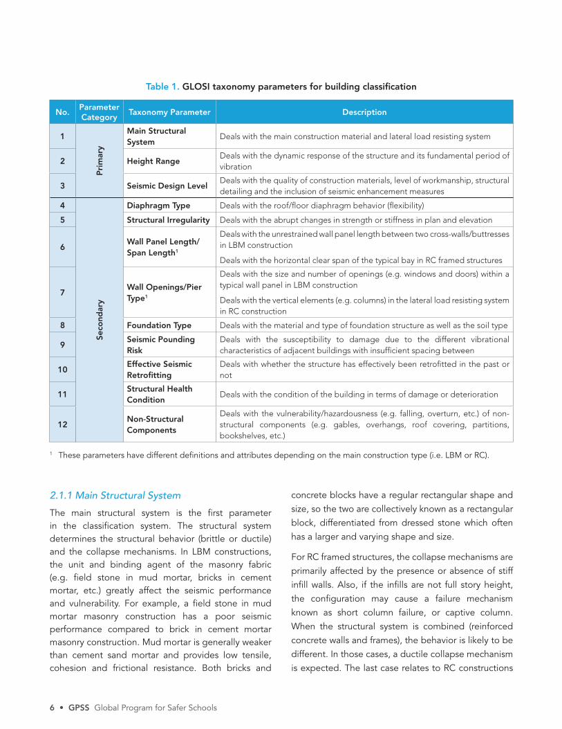
Table 1. GLOSI taxonomy parameters for building classification
No.Parameter Category
Taxonomy Parameter Description
1
Pri
mar
y
Main Structural System
Deals with the main construction material and lateral load resisting system
2 Height RangeDeals with the dynamic response of the structure and its fundamental period of vibration
3 Seismic Design LevelDeals with the quality of construction materials, level of workmanship, structural detailing and the inclusion of seismic enhancement measures
4
Seco
ndar
y
Diaphragm Type Deals with the roof/floor diaphragm behavior (flexibility)
5 Structural Irregularity Deals with the abrupt changes in strength or stiffness in plan and elevation
6Wall Panel Length/Span Length1
Deals with the unrestrained wall panel length between two cross-walls/buttresses in LBM construction
Deals with the horizontal clear span of the typical bay in RC framed structures
7Wall Openings/Pier Type1
Deals with the size and number of openings (e.g. windows and doors) within a typical wall panel in LBM construction
Deals with the vertical elements (e.g. columns) in the lateral load resisting system in RC construction
8 Foundation Type Deals with the material and type of foundation structure as well as the soil type
9Seismic Pounding Risk
Deals with the susceptibility to damage due to the different vibrational characteristics of adjacent buildings with insufficient spacing between
10Effective Seismic Retrofitting
Deals with whether the structure has effectively been retrofitted in the past or not
11Structural Health Condition
Deals with the condition of the building in terms of damage or deterioration
12Non-Structural Components
Deals with the vulnerability/hazardousness (e.g. falling, overturn, etc.) of non-structural components (e.g. gables, overhangs, roof covering, partitions, bookshelves, etc.)
1 These parameters have different definitions and attributes depending on the main construction type (i.e. LBM or RC).
2.1.1 Main Structural System
The main structural system is the first parameter in the classification system. The structural system determines the structural behavior (brittle or ductile) and the collapse mechanisms. In LBM constructions, the unit and binding agent of the masonry fabric (e.g. field stone in mud mortar, bricks in cement mortar, etc.) greatly affect the seismic performance and vulnerability. For example, a field stone in mud mortar masonry construction has a poor seismic performance compared to brick in cement mortar masonry construction. Mud mortar is generally weaker than cement sand mortar and provides low tensile, cohesion and frictional resistance. Both bricks and
concrete blocks have a regular rectangular shape and size, so the two are collectively known as a rectangular block, differentiated from dressed stone which often has a larger and varying shape and size.
For RC framed structures, the collapse mechanisms are primarily affected by the presence or absence of stiff infill walls. Also, if the infills are not full story height, the configuration may cause a failure mechanism known as short column failure, or captive column. When the structural system is combined (reinforced concrete walls and frames), the behavior is likely to be different. In those cases, a ductile collapse mechanism is expected. The last case relates to RC constructions

Taxonomy Guide • 7
with no clear definition of structural systems, usually non-engineered and built by non-professional builders.
In the particular case where a previously retrofitted building is to be classified, GLOSI requires that the present structural system and characteristics (not the original ones) are considered in the classification process.
The main structural systems for the GLOSI taxonomy are summarized in Table 2 and discussed in detail below.
AThese are generally unreinforced masonry buildings having adobe masonry (sun-dried mud bricks with mud mortar) walls as the main lateral load resisting system.
UCM-URMThese are masonry school buildings with unconfined/unreinforced masonry walls in the main lateral load resisting system. They are sub-divided into different categories (see Table 2) depending on the type of units and mortar material used in the masonry, considering that different combinations of different units and mortars result in different seismic performance of the building.
CM These are confined masonry school buildings in which the masonry walls are confined with RC columns and beams (known as tie-columns and tie-beams) of a relatively small cross-section to improve the integrity of the walls. The level (density) of confinement can vary within a country or at a regional level, which affects the seismic performance. For example, in confined masonry school buildings in El Salvador, the confinement is applied around the openings as well as walls; while in India, this school building construction type commonly lacks confinements around the openings.
RMThese are reinforced masonry school buildings which have reinforced masonry walls in the main lateral load resisting system. The reinforcement material considered in GLOSI is steel reinforcement bars. The type of reinforcement (whether it is horizontal only, vertical only, or both) and the density of reinforcement (amount and spacing of reinforcement) affect the seismic performance of these buildings.
SFMThis school building construction type has a light steel framed structure with load bearing masonry walls. This construction type is further sub-divided into different categories (see Table 2) depending on the type of load bearing masonry walls, and considering that different load bearing wall types result in different seismic performance of the building.
RC1Reinforced concrete moment resistant frames with/without infill walls that do not contribute to lateral stiffness. Masonry infill walls are well separated from the columns by expansion joints. Joints are usually filled with elastic sealer. Also, in some cases, partitions are made using light and/or flexible infills such as drywall.
RC2Reinforced concrete moment resistant frame with infill walls as a stiffening element. In this kind of structure, the masonry walls usually go from the floor to the roof. The walls may have window openings. Infill walls are not separated from the RC structure. Since the masonry walls are not attached to the columns and usually have no internal reinforcement, walls may present an out-of-plane type failure.
RC3Reinforced concrete moment resisting frames with masonry infill walls in contact with the structure. Masonry walls include uniform openings along the longitudinal direction of the building generating the possibility of a “short column” type of failure (“captive column”). This type of failure occurs when the lateral displacements are concentrated in the free portion of the column, generating greater shear forces and hence an anticipated column failure mechanism. Since the masonry walls are not attached to the columns and usually have no internal reinforcement, walls may present an out-of-plane failure mechanism.
RC4Reinforced concrete combined or dual system. These are structures which include two different main lateral load resisting systems. It is usually a reinforced concrete moment frame with steel braces or reinforced concrete walls to increase the stiffness of the system. The moment resistant frame can be designed to withstand only gravity loads or gravity loads and a percentage of lateral loads.

8 • GPSS Global Program for Safer Schools
RC5Non-engineered reinforced concrete structure. It usually includes a certain distribution of columns that may not be continuous in all floors. Slabs usually consist of a solid slab or one-way joists without beams or girders. The structural elements may not conform to standard or continuous moment resistant frames. Partition walls and facades are usually built with unreinforced masonry in contact with the structural elements, providing some initial apparent stiffness but with a potential out-of-plane type failure.
2.1.2 Height Range
Building height is one of the most important characteristics of a building as it controls the dynamic
behavior during earthquake ground motions. It affects the natural period of vibration and mode shapes of vibration of a building during earthquakes. Under similar seismic intensity, high-rise buildings of similar design are subjected to more deformation (they are more flexible) and higher modes come into play during seismic excitation (they are susceptible to a wider range of seismic spectrum and therefore subjected to more earthquake energy, leading to larger acceleration/drift response), which makes them more vulnerable. The LBM school buildings are mostly single-storied, while a few 2–5 story masonry school buildings are also present, especially in urban areas. Most RC school buildings are usually 2 stories, but some could be up to 6 stories or more. In order to develop a uniform classification system which considers that most of the
Table 2. Main Structural Systems
No. Parameter Attributes Commentaries
1
Mai
n St
ruct
ural
Sys
tem
For
LBM
A: Adobe
UCM/URM: Unconfined/Unreinforced Masonry
UCM-URM1: Dry Stone Masonry
UCM-URM2: Rubble Stone in Mud Mortar Masonry
UCM-URM3: Dressed Stone in Mud Mortar Masonry
UCM-URM4: Rectangular Block in Mud Mortar Masonry
UCM-URM5: Rubble Stone in Cement Mortar Masonry
UCM-URM6: Dressed Stone in Cement mortar Masonry UCM-URM7: Rectangular Block in Cement Mortar Masonry
CM: Confined Masonry with Rectangular Block in Cement Mortar Wall
RM: Reinforced Masonry with Rectangular Block in Cement Mortar Wall
SFM: Light Steel Frame with LBM walls
SFM1: Light Steel Frame with Stone in Mud Mortar Wall
SFM2: Light Steel Frame with Rectangular Block in Mud Mortar Wall
SFM3: Light Steel Frame with Stone in Cement Mortar Wall
SFM4: Light Steel Frame with Rectangular Block in Cement Mortar Wall
SFM5: Light Steel Frame with Confined Masonry Wall
SFM6: Light Steel Frame with Reinforced Masonry Wall
A description of each attribute is given after the table
For
RC
fra
mes RC1: Bare Frame
RC2: Infilled Frame
RC3: Short Column Frame
RC4: Dual or Combined Frame
RC5: Non-Engineered Frame
Taxonomy Guide • 9
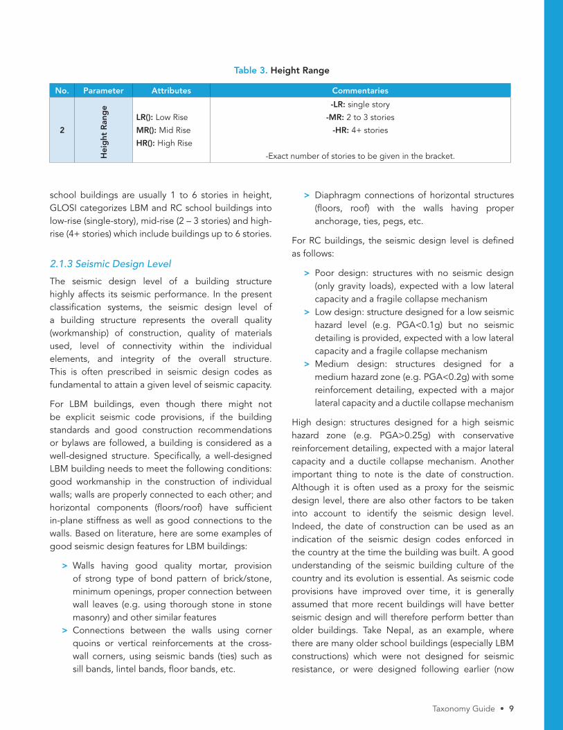
school buildings are usually 1 to 6 stories in height, GLOSI categorizes LBM and RC school buildings into low-rise (single-story), mid-rise (2 – 3 stories) and high-rise (4+ stories) which include buildings up to 6 stories.
2.1.3 Seismic Design Level
The seismic design level of a building structure highly affects its seismic performance. In the present classification systems, the seismic design level of a building structure represents the overall quality (workmanship) of construction, quality of materials used, level of connectivity within the individual elements, and integrity of the overall structure. This is often prescribed in seismic design codes as fundamental to attain a given level of seismic capacity.
For LBM buildings, even though there might not be explicit seismic code provisions, if the building standards and good construction recommendations or bylaws are followed, a building is considered as a well-designed structure. Specifically, a well-designed LBM building needs to meet the following conditions: good workmanship in the construction of individual walls; walls are properly connected to each other; and horizontal components (floors/roof) have sufficient in-plane stiffness as well as good connections to the walls. Based on literature, here are some examples of good seismic design features for LBM buildings:
> Walls having good quality mortar, provision of strong type of bond pattern of brick/stone, minimum openings, proper connection between wall leaves (e.g. using thorough stone in stone masonry) and other similar features
> Connections between the walls using corner quoins or vertical reinforcements at the cross-wall corners, using seismic bands (ties) such as sill bands, lintel bands, floor bands, etc.
> Diaphragm connections of horizontal structures (floors, roof) with the walls having proper anchorage, ties, pegs, etc.
For RC buildings, the seismic design level is defined as follows:
> Poor design: structures with no seismic design (only gravity loads), expected with a low lateral capacity and a fragile collapse mechanism
> Low design: structure designed for a low seismic hazard level (e.g. PGA<0.1g) but no seismic detailing is provided, expected with a low lateral capacity and a fragile collapse mechanism
> Medium design: structures designed for a medium hazard zone (e.g. PGA<0.2g) with some reinforcement detailing, expected with a major lateral capacity and a ductile collapse mechanism
High design: structures designed for a high seismic hazard zone (e.g. PGA>0.25g) with conservative reinforcement detailing, expected with a major lateral capacity and a ductile collapse mechanism. Another important thing to note is the date of construction. Although it is often used as a proxy for the seismic design level, there are also other factors to be taken into account to identify the seismic design level. Indeed, the date of construction can be used as an indication of the seismic design codes enforced in the country at the time the building was built. A good understanding of the seismic building culture of the country and its evolution is essential. As seismic code provisions have improved over time, it is generally assumed that more recent buildings will have better seismic design and will therefore perform better than older buildings. Take Nepal, as an example, where there are many older school buildings (especially LBM constructions) which were not designed for seismic resistance, or were designed following earlier (now
Table 3. Height Range
No. Parameter Attributes Commentaries
2
Hei
ght
Ran
ge
LR(): Low Rise
MR(): Mid Rise
HR(): High Rise
-LR: single story
-MR: 2 to 3 stories
-HR: 4+ stories
-Exact number of stories to be given in the bracket.
>
10 • GPSS Global Program for Safer Schools
outdated) seismic design codes. However, in many cases local seismic enhancement measures (such as the use of through stones, timber tying elements, infill wall isolation, concrete wall addition, etc.) have been included in these older constructions. Such local seismic enhancement measures should be accounted for in the assessment of the seismic design level. In countries like Nepal or Perú, it has been found that school buildings had been mostly constructed by local communities without adherence to published seismic codes or guidelines. If so, the date of construction may
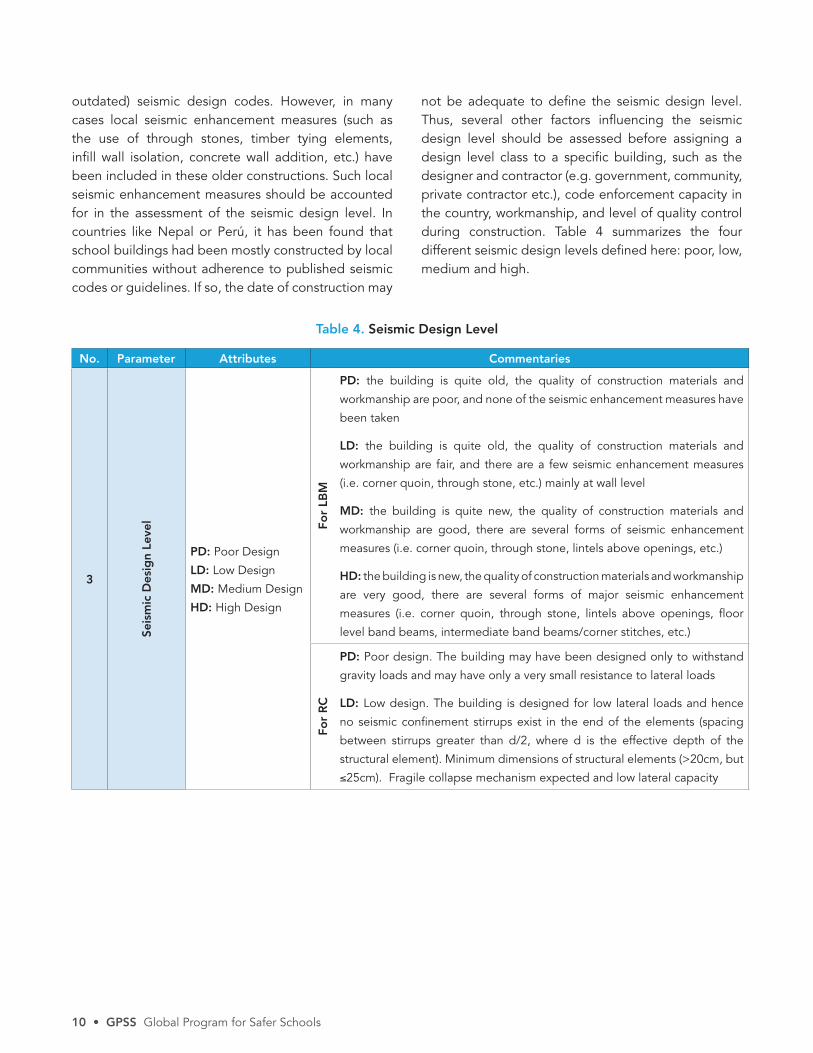
not be adequate to define the seismic design level. Thus, several other factors influencing the seismic design level should be assessed before assigning a design level class to a specific building, such as the designer and contractor (e.g. government, community, private contractor etc.), code enforcement capacity in the country, workmanship, and level of quality control during construction. Table 4 summarizes the four different seismic design levels defined here: poor, low, medium and high.
Table 4. Seismic Design Level
No. Parameter Attributes Commentaries
3
Seis
mic
Des
ign
Leve
l
PD: Poor Design
LD: Low Design
MD: Medium Design
HD: High Design
For
LBM
PD: the building is quite old, the quality of construction materials and
workmanship are poor, and none of the seismic enhancement measures have
been taken
LD: the building is quite old, the quality of construction materials and
workmanship are fair, and there are a few seismic enhancement measures
(i.e. corner quoin, through stone, etc.) mainly at wall level
MD: the building is quite new, the quality of construction materials and
workmanship are good, there are several forms of seismic enhancement
measures (i.e. corner quoin, through stone, lintels above openings, etc.)
HD: the building is new, the quality of construction materials and workmanship
are very good, there are several forms of major seismic enhancement
measures (i.e. corner quoin, through stone, lintels above openings, floor
level band beams, intermediate band beams/corner stitches, etc.)
For
RC
PD: Poor design. The building may have been designed only to withstand
gravity loads and may have only a very small resistance to lateral loads
LD: Low design. The building is designed for low lateral loads and hence
no seismic confinement stirrups exist in the end of the elements (spacing
between stirrups greater than d/2, where d is the effective depth of the
structural element). Minimum dimensions of structural elements (>20cm, but
≤25cm). Fragile collapse mechanism expected and low lateral capacity

Taxonomy Guide • 11
No. Parameter Attributes Commentaries
3
Seis
mic
Des
ign
Leve
l
PD: Poor Design
LD: Low Design
MD: Medium Design
HD: High Design
MD: Medium design. The building is designed for a medium seismic
hazard zone with specific requirements like continuity in the longitudinal
reinforcement of the elements, confinement of stirrups at the ends of the
elements with a separation equal to or less than d/2 but more than d/4,
and minimum dimensions in structural elements (>25cm, but ≤30cm).
Nonstructural elements are designed to withstand seismic forces. Ductile
collapse mechanism expected, high capacity and ductility
HD: High design. The building is designed for a high seismic hazard zone
with specific requirements like continuity in the longitudinal reinforcement
of the elements, confinement of stirrups at the ends of the elements with a
separation equal to or less than d/4 and minimum dimensions in structural
elements (>30cm). Nonstructural elements are designed to withstand
seismic forces. Ductile collapse mechanism expected, very high capacity and
ductility
Table 4. Seismic Design Level (cont.)
2.1.4 Diaphragm Type
Since the floors and roof which constitute the diaphragm are key horizontal components of the seismic load resisting system, the seismic performance of a building is influenced by the flexibility of these elements. If the floors/roof have significantly greater in-plane stiffness comparing to the lateral stiffness of the vertical resisting system (e.g. walls, columns.) and are properly connected to the vertical load resisting elements (e.g. LBM walls or RC frame system), it can be assumed that the lateral displacement at the floor/roof level is constant for all structural elements connected to that floor level. This in turns provides a more equal redistribution of the lateral forces among all structural elements in proportion of their stiffness, and hence the structures are best suited to resist the lateral forces and have a robust behavior. Such types of floor/
roof structures are referred to as rigid diaphragms. A rigid diaphragm can be realized by building reinforce concrete slabs or a steel beam system sufficiently braced to avoid relative in-plane displacements. The stiffness of the horizontal structure (i.e. floor/roof structures) plays an important role in controlling the global box-type seismic behavior (i.e. all the columns or walls acting simultaneously). On the other hand, a floor/roof structure with low in-plane stiffness and/or poor connection to the lateral load resisting elements is unable to impose a common lateral displacement at the floor level, leading to the independent behavior of individual lateral load resisting elements during earthquakes. These structures are categorized as flexible diaphragms (e.g. unbraced timber/steel or prefabricated concrete slabs) and often induce poor seismic performance. These are listed in Table 5.
For
RC
: (c
ont
.)

12 • GPSS Global Program for Safer Schools
Table 5. Diaphragm Type
No. Parameter Attributes Commentaries
4
Dia
phr
agm
Typ
e
FD: Flexible diaphragm
RD: Rigid diaphragm
A rigid diaphragm should have:
1. A floor/roof structure with sufficient in-plane stiffness, such as:
> RC flat slab
> Reinforced Brick Concrete (RBC) slab
> Conventional slabs supported by concrete joists
> Composite (steel and RC) deck if properly braced and connected
> Braced timber or steel framework
2. A good connection of the floors/roof to the lateral load resisting system:
> Monolithically connected to the walls or columns and beams with
proper anchorage (e.g. tied with the reinforcing bars)
• If a floor/roof structure does not meet both of the above-mentioned
criteria, it is considered to be a flexible diaphragm.
2.1.5 Structural Irregularity
Horizontal and vertical structural irregularities tend to make structures more vulnerable than simple and regular structures. Horizontal (plan) irregularity refers to the building’s irregular (e.g. rectangular long, T-, C- or H-shaped) footprint or unsymmetrical positioning of lateral load resisting elements. Vertical irregularity includes the variation in story height/mass/stiffness
over building height. A common deficiency is the torsional effect introduced in seismic shear increments during earthquakes, which is due to the fact that the building plan shape is irregular/longer in one direction or that openings are distributed unevenly. Table 6 indicates the attributes of the parameter and summarizes common structural irregularities of school buildings.
Table 6. Structural Irregularity
No. Parameter Attributes Commentaries
5
Stru
ctur
al Ir
reg
ular
ity
NI: No irregularities
HI: Horizontal
VI: Vertical
HV: Both Horizontal and Vertical
HI might include:
> Torsional Irregularity
> Reentrant corner
> Diaphragm discontinuity
> Out-of-Plane Offset
> Non-parallel system
VI might include:
> Stiffness-Soft Story
> Mass Irregularity
> Vertical Geometric Irregularity
> In-Plane Discontinuity in
lateral load resisting elements
> Weak Story
Taxonomy Guide • 13
2.1.6 LBM: Wall Panel Length; RC: Span Length
This taxonomy parameter is considered separately for LBM and RC as follows:
LBM In LBM buildings, wall panels are susceptible to out-of-plane damage under seismic loading. Their vulnerability is directly proportional to the unrestrained length of a wall. This is mainly due to the low moment resistance (i.e. flexibility) of the wall along the out-of-plane direction under the two-way bending introduced by an earthquake. For example, in the 2008 Wenchuan earthquake, the main building of a primary school collapsed, while the adjacent dormitory of the same construction type survived as it had smaller rooms and therefore more cross-walls to provide more constraints along the length of the wall.
Masonry walls are generally restrained by cross-walls, piers or buttresses. Several studies and seismic design codes (see reference list) have thus suggested a limit on the permissible length as a function of thickness of the URM walls (usually less than 12 times the wall thickness). Similarly, for confined masonry, it is recommended to be less than 4 m. Thus, the unrestrained wall panels are categorized into two types: long panel and short panel. In stone masonry school buildings, the wall is generally thicker (more than 400 mm), usually resulting
in short panels. On the other hand, in brick masonry construction where the wall thickness is generally low (250 mm to 400 mm), similar lengths of walls make them long panels. However, attention needs to be paid to the connection of the masonry leaves (i.e. layers of masonry units) across the thickness of the wall for stone masonry walls. Indeed, if there are several leaves and they are not well connected with regularly spaced through stones, then the wall slenderness should be computed with reference to one leaf instead of the whole thickness of the wall. For LBM walls, the unrestrained wall panel length thus has two possible attributes: Short Panel or Long Panel, as presented in Table 7.
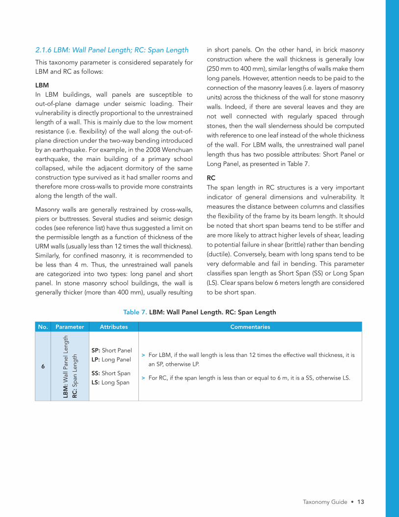
RC The span length in RC structures is a very important indicator of general dimensions and vulnerability. It measures the distance between columns and classifies the flexibility of the frame by its beam length. It should be noted that short span beams tend to be stiffer and are more likely to attract higher levels of shear, leading to potential failure in shear (brittle) rather than bending (ductile). Conversely, beam with long spans tend to be very deformable and fail in bending. This parameter classifies span length as Short Span (SS) or Long Span (LS). Clear spans below 6 meters length are considered to be short span.
Table 7. LBM: Wall Panel Length. RC: Span Length
No. Parameter Attributes Commentaries
6
LBM
: Wal
l Pan
el L
eng
th
RC
: Sp
an L
eng
th SP: Short Panel
LP: Long Panel
SS: Short Span
LS: Long Span
> For LBM, if the wall length is less than 12 times the effective wall thickness, it is
an SP, otherwise LP.
> For RC, if the span length is less than or equal to 6 m, it is a SS, otherwise LS.
14 • GPSS Global Program for Safer Schools
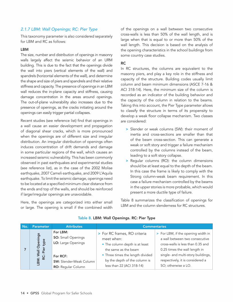
Table 8. LBM: Wall Openings. RC: Pier Type
No. Parameter Attributes Commentaries
7
LBM
: W
all O
pen
ing
s
RC
: P
ier
typ
e
For LBM:
SO: Small Openings
LO: Large Openings
For RCF:
SW: Slender-Weak Column
RO: Regular Column
> For RC frames, RO criteria meet when: • The column depth is at least
the same as the beam
• Three times the length divided
by the depth of the column is
less than 22 (ACI 318-14)
> For LBM, if the opening width in
a wall between two consecutive
cross-walls is less than 0.35 and
0.25 times the wall length in
single- and multi-story buildings,
respectively, it is considered a
SO; otherwise a LO.
2.1.7 LBM: Wall Openings; RC: Pier Type
This taxonomy parameter is also considered separately for LBM and RC as follows:
LBMThe size, number and distribution of openings in masonry walls largely affect the seismic behavior of an URM building. This is due to the fact that the openings divide the wall into piers (vertical elements of the wall) and spandrels (horizontal elements of the wall), and determine the shape and size of piers and spandrels and their relative stiffness and capacity. The presence of openings in an LBM wall reduces the in-plane capacity and stiffness, causing damage concentration in the areas around openings. The out-of-plane vulnerability also increases due to the presence of openings, as the cracks initiating around the openings can easily trigger partial collapses.
Recent studies (see reference list) find that openings in a wall cause an easier development and propagation of diagonal shear cracks, which is more pronounced when the openings are of different size and irregular distribution. An irregular distribution of openings often induces concentration of drift demands and damage in some particular regions of the wall, which causes an increased seismic vulnerability. This has been commonly observed in past earthquakes and experimental studies (see reference list), as in the case of the 2002 Molise earthquake, 2007 Cameli earthquake, and 2009 L’Aquila earthquake. To limit the seismic damage, openings need to be located at a specified minimum clear distance from the ends and top of the walls, and should be reinforced if large/irregular openings are unavoidable.
Here, the openings are categorized into either small or large. The opening is small if the combined width
of the openings on a wall between two consecutive cross-walls is less than 50% of the wall length, and is large when that is equal to or more than 50% of the wall length. This decision is based on the analysis of the opening characteristics in the school buildings from some country case studies.
RC In RC structures, the columns are equivalent to the masonry piers, and play a key role in the stiffness and capacity of the structure. Building codes usually limit column and beam minimum dimensions (ASCE 7-16 & ACI 318-14). Here, the minimum size of the column is recorded as an indicator of the building behavior and the capacity of the column in relation to the beams. Taking this into account, the Pier Type parameter allows to classify the structure in terms of its propensity to develop a weak floor collapse mechanism. Two classes are considered:
> Slender or weak columns (SW): their moment of inertia and cross-sections are smaller than that of the beam cross-section. This can generate a weak or soft story and trigger a failure mechanism controlled by the columns instead of the beam, leading to a soft story collapse.
> Regular columns (RO): the column dimensions should be at least equal to the depth of the beam. In this case the frame is likely to comply with the Strong column-weak beam requirement. In this case a failure mechanism controlled by the beams in the upper stories is more probable, which would present a more ductile type of failure.
Table 8 summarizes the classification of openings for LBM and the column slenderness for RC structures.

Taxonomy Guide • 15
2.1.8 Foundation Type
The type of foundation influences the seismic performance of a building by controlling the settlements, cracking, deformations and overturning at the base of the main lateral load resisting systems. In fact, all the foundation structures have some flexibility. Depending on the foundation structure and the underlying soil properties, a foundation structure can be categorized as flexible or rigid compared to the flexibility of the superstructure. A rigid type foundation usually prevents large foundation deformations as well as anticipated failures. On the other hand, flexible foundations contribute to the horizontal deformations of the building, generating the possibility of anticipated failures both at the foundation level and in upper structural elements.
Masonry walls usually have continuous stone masonry, a brick masonry strip type foundation, or reinforced concrete strip footings below the ground level. These foundation structures are usually thicker than the masonry walls. If these foundations are at least 1 m deep and the site soil is medium or hard, the foundation can be categorized as a rigid foundation type.
In the case of RC buildings, the foundation is usually built in reinforced concrete. Their behavior depends greatly on the soil type and on the presence of foundation beams. The most common foundation is isolated footings, which may be very rigid in hard soils but flexible in soft soils. On the other hand, a deep mat foundation can be considered rigid in hard or soft soil. Table 9 summarizes the various types of foundations for both LBM and RC structures and classifies them into either flexible or rigid.
Table 9. Foundation Type
No. Parameter Attributes Commentaries
8
Foun
dat
ion
Typ
e
FF: Flexible Foundation
RF: Rigid Foundation
The foundation type depends on two factors:1. The foundation details: materials, structure and depth below the ground
level
> The material can be RC, Brick Masonry or Stone Masonry or Dry-Stone
Masonry
> The structure type can be Isolated Footing, Combined Footing, Strip
Footing, Mat Foundation, etc.
> Foundation depth can be Shallow, Medium or Deep
2. The soil type in the site, which can be soft, medium or hard
The combination of these two factors determines the type of foundation. For
example, a RC Mat foundation in a hard soil is considered as a rigid foundation.

16 • GPSS Global Program for Safer Schools
2.1.9 Seismic Pounding Risk
Seismic pounding occurs when two adjacent building which have different vibration characteristics collide with each other during earthquakes. Although this is not a significant issue in the case of low-rise building structures, if the gap between the buildings is very small, it can cause damage to structural or non-structural elements of the building due to hammering, and eventually cause partial collapse. The minimum gap recommended by FEMA (see reference list) and other codes is at least 4% of the height of the shorter building.
2.1.10 Effective Seismic Retrofitting
Effective seismic retrofitting is a process of strengthening a building structure, by which its seismic resistance is increased. Seismic strengthening can be mainly categorized into two types: the strengthening of the vertical load resisting system, and the strengthening of horizontal structures. The strengthening of vertical load resisting elements includes the different measures to increase the strength and ductility of the vertical members (e.g. walls or frames), or improving the connections among the vertical load resisting elements. The jacketing of LBM walls or RC columns
and the installation of bracings are examples of these interventions. On the other hand, the strengthening of horizontal structures entails increasing the in-plane stiffness or floors/roof and improving the connections of these with the vertical load resisting system. These retrofitting interventions can improve the seismic performance of poorly designed school buildings in future earthquakes. For example, several retrofitted LBM school buildings in Nepal survived without any damage during the 2015 earthquake. In the studied countries, the retrofitting interventions had been applied to very few school buildings.
As the retrofitting work is usually covered (with non-structural elements like plaster), it is often necessary to talk to the school administrators to know more about the seismic retrofitting history of the school building.
It is also important to note that for each school building, the main structural system and all other taxonomy parameters will be classified for the retrofitted structures. The knowledge of previous retrofitting works helps recognize that this particular building is not of the same quality as an equivalent new one.
The attributes for this parameter are either Original Structure or Retrofitted Structure as shown in Table 11.
Table 10. Seismic Pounding Risk
No. Parameter Attributes Commentaries
9
Seis
mic
Po
und
ing
Ris
k PR: Pounding Risk
NP: No Pounding
Seismic gap between buildings is at least 4% of the critical height. Critical height
is the height of the shorter building where the expected collision occurs.
Table 11. Effective Seismic Retrofitting
No. Parameter Attributes Commentaries
10
Eff
ecti
ve
Seis
mic
Ret
rofi
ttin
g
OS: Original Structure
RS: Retrofitted
Structure
If a building has been retrofitted effectively so that the seismic behavior
improved considerably with respect to its original situation, it is a retrofitted
structure (RS). Minor non-structural improvements and/or maintenance do not
make it a retrofitted structure.

Taxonomy Guide • 17
2.1.11 Structural Health Condition
The structural health condition describes a building’s current physical condition with respect to the material deterioration and existing damages in the structure. Masonry materials such as brick and mortar can deteriorate over time. Similarly, steel reinforcement bars in confined, reinforced masonry or reinforced concrete may get corroded or exposed over time due to the disintegration of the concrete cover. Existing damages (e.g. building out of plumb, delaminated walls, corner separation, cracks in the walls/columns etc.) contribute more to the seismic vulnerability of a building. Based on these analyses, buildings can be categorized in terms of the health condition as good or poor.
Examples of factors that determine the structural health condition of LBM buildings are:
> Deteriorated materials (units and mortar)> Deteriorated connections among structural and
non-structural elements (e.g. between walls and floors/roofs, between roof structure and roof covering tiles/sheets)
> Exposed reinforcement bars or corrosion in the reinforcement bars in reinforced or confined masonry
> Existing structural damages (cracks in the walls, corner separation, tilted building/walls etc.)
Examples of factors that determine the structural health condition of RC buildings are:
> Disintegration/deterioration of concrete > Exposed rebars> Corroded rebars> Existing cracks
2.1.12 Non-Structural Components
In school buildings, several forms of non-structural components, such as gables, heavy roof covering (e.g. tiles), parapets, in-class furniture and others, may impose special vulnerability conditions during earthquakes. For example, if not secured properly, heavy masonry gables are one of the most vulnerable non-structural components, since they act like cantilever walls and are subjected to larger inertia force from higher levels of acceleration.
The vulnerability can be reduced using light gable materials (such as CGI sheet) or tying masonry gables using RC tie beams. Also, the proper tying of the roof tiles to the purlins greatly reduces the hazard that is inherent to the unsecured roof tiles during a seismic event. Unsecured furniture, blackboards, covers, divisions, equipment, pipes, installations or windows can topple down during earthquakes, which can be hazardous to the building occupants.
The presence, location, self-weight and connection details of non-structural elements may be assessed and rated as Vulnerable or Non-Vulnerable.
Table 12. Building health condition
No. Parameter Attributes Commentaries
11
Stru
ctur
al
Hea
lth
Co
ndit
ion
PC: Poor Condition
GC: Good Condition
Engineering judgement is required to evaluate the health condition of the
building which may affect its structural behavior.
Table 13. Vulnerable non-structural elements
No. Parameter Attributes Commentaries
12
No
n-St
ruct
ural
Co
mp
one
nts VN: Vulnerable Non-
Structural Components
NN: Non-Vulnerable Non-
Structural Components
This refers to components that can produce economic losses or human
casualties like parapets, ceilings, tiles, and pipe infill. This parameter is
rather qualitative, and the selection of associated attributes depends on
the assessment of all the non-structural components with respect to the
location, self-weight, connection to the main structural elements, etc.

18 • GPSS Global Program for Safer Schools
2.2 Building the GLOSI Taxonomy String
The 12 GLOSI taxonomy parameters discussed above will make it easier to systematically and clearly classify school buildings into categories of different seismic characteristic. The classification using GLOSI provides a specific taxonomy string to each school building. The string consists of the 12 taxonomy parameters, starting with primary parameters and moving to secondary parameters, with an increasing influence on the seismic performance of the school building.
For example, an old low-rise adobe school building with no seismic enhancement features and a flexible
diaphragm is identified with a string containing the corresponding attributes of the taxonomy parameters, ultimately resulting in a taxonomy string given as: A/LR(1)/PD/FD/…… The length of the string depends on the extent of information on the building characteristics. The strings become longer as more information is gathered. Additionally, when limited information is available, any element in the string can be omitted or truncated depending on the availability of the information, or priorities given to different taxonomy parameters. More detailed examples can be found under “Learn How to Apply the Taxonomy”.
Taxonomy Guide • 19
References
Abrams, D. P. et al. (2017) Out-of-Plane Seismic Response of Unreinforced Masonry Walls: Conceptual Discussion, Research Needs, and Modeling Issues, International Journal of Architectural Heritage. Taylor & Francis, 11(1), pp. 22–30. doi: 10.1080/15583058.2016.1238977.
ASCE (2013) ASCE/SEI 41-13: Seismic Evaluation and Retrofit of Existing Buildings, American Society of Civil Engineers, Virginia, USA.
Applied Technology Council (1985) ATC-13: Earthquake Damage Evaluation Data for California, Applied Technology Council, California, USA.
Arya, S., Boen, T., & Ishiyama, Y. (2013) Guidelines for Earthquake Resistant Non-Engineered Construction, UNESCO, France.
ASI (2018) Extreme Loading for Structures, Applied Science International, LLC, North Carolina, USA.
ATC (1985) ATC-13 Earthquake Damage Evaluation Data for California. Applied Technology Council, USA.
Augenti, N. and Parisi, F., (2010) Learning from construction failures due to the 2009 L’Aquila, Italy, earthquake. Journal of Performance of Constructed Facilities, 24(6), pp.536-555.
Bhagat S. Samith Buddika, H.A.D., Adhikari, R.K., Shrestha, A., Bajracharya, S., Singh, J., Maharjan, R., Wijeyewickrema, A.C. (2017) Damage to Cultural Heritage Structures and Buildings Due to the 2015 Nepal Gorkha Earthquake, Journal of Earthquake Engineering, pp. 1–20. doi: 10.1080/13632469.2017.1309608.
Bothara, J.K., Dhakal, R.P. and Mander, J.B., (2010) Seismic performance of an unreinforced masonry building: An experimental investigation. Earthquake Engineering & Structural Dynamics, 39(1), pp.45-68.
Bothara, J. K., Guragain, R., and Dixit, A., (2002) Protection of Educational Buildings against Earthquakes: A Manual for Designers and Builders. National Society for Earthquake Technology-Nepal, Kathmandu, Nepal.
Brzev, S., Scawthorn, C., Charleson, A.W., Allen, L., Greene, M., Jaiswal, K.S. and Silva, V., (2013) GEM Building Taxonomy (Version 2.0). GEM Technical Report 2013-02, GEM Foundation.
CEN (2004) EC 8: Design of structures for earthquake resistance—Part 1: General rules, seismic actions and rules for buildings (EN 1998-1: 2004).
Coburn, A. and Spence, R., (2003) Earthquake Protection. John Wiley & Sons.
Chopra Anil, K. (1995) Dynamics of structures: Theory and Application to Earthquake Engineering. Prentice Hall, New Jersey, USA.
D’Ayala, D., Spence, R., Oliveira, C. and Pomonis, A., (1997) Earthquake loss estimation for Europe’s historic town centres. Earthquake Spectra, 13(4), pp.773-793.
D’Ayala, D.F. and Paganoni, S., (2011) Assessment and analysis of damage in L’Aquila historic city centre after 6th April 2009. Bulletin of Earthquake Engineering, 9(1), pp.81-104.
Decanini, L., De Sortis, A., Goretti, A., Langenbach, R., Mollaioli, F. and Rasulo, A., (2004) Performance of masonry buildings during the 2002 Molise, Italy, earthquake. Earthquake Spectra, 20(S1), pp.S191-S220.
Dixit, A.M., Yatabe, R., Dahal, R.K. and Bhandary, N.P., (2014) Public School Earthquake Safety Program in Nepal. Geomatics, Natural Hazards and Risk, 5(4), pp.293-319.
Erberik, M.A. (2008) Generation of fragility curves for Turkish masonry buildings considering in-plane failure modes. Earthquake Engineering & Structural Dynamics, 37(3), pp.387-405.
FEMA (1997) FEMA 273: NEHRP Guidelines for the seismic rehabilitation of buildings. Federal Emergency Management Agency Washington, D.C., USA.
FEMA (2013) Hazus®-MH 2.1 Advanced Engineering Building Module (AEBM), Technical and User’s Manual, Federal Emergency Management Agency, Washington, D.C., USA.
Grünthal, G., (1998) European macroseismic scale 1998. European Seismological Commission (ESC).
GEM (2018) The OpenQuake-engine User Manual. Global Earthquake Model (GEM) Open-
Quake Manual for Engine version 3.1.0. doi: 10.13117/GEM.OPENQUAKE.MAN.ENGINE.3.1.0, 198 pages.
GLOSI THE GLOBAL L IBRARY OF SCHOOL INFRASTRUCTURE
20 • GPSS Global Program for Safer Schools
Jaiswal, K.S. and Wald, D.J., (2008) Creating a Global Building Inventory for Earthquake Loss Assessment and Risk Management. U.S. Geological Survey Open-File Report 2008-1160, 103 p.
Jaiswal, K., Wald, D. and D’Ayala, D., (2011) Developing empirical collapse fragility functions for global building types. Earthquake Spectra, 27(3), pp.775-795.
Kaplan et al., (2008) 29 October 2007, Çameli earthquake and structural damages at unreinforced masonry buildings. Natural Hazards and Earth System Sciences, 8(4), pp.919-926.
Moon, L., Dizhur, D., Senaldi, I., Derakhshan, H., Griffith, M., Magenes, G., & Ingham, J. (2014) The demise of the URM building stock in Christchurch during the 2010–2011 Canterbury earthquake sequence. Earthquake Spectra, 30(1), 253-276.
Murty, C.V.R. (2003) How do Brick Masonry Houses behave during Earthquakes? IITK-BMTPC Earthquake Tip 12, Indian Institute of Technology Kanpur, Kanpur, India
NBC (1994) NBC 203: 1994 Guidelines for Earthquake Resistant Building Construction: Low Strength Masonry, Nepal National Building Code, Department of Urban Development and Building Construction, Kathmandu, Nepal.
Meli et al., (2011) Seismic Design Guide for Low-Rise Confined Masonry Buildings, The Confined Masonry Network, EERI & IAEE.
Penna, A., Morandi, P., Rota, M., Manzini, C. F., Da Porto, F., & Magenes, G. (2014) Performance of masonry buildings during the Emilia 2012 earthquake. Bulletin of Earthquake Engineering, 12(5), 2255-2273.
Paquette, J. and Bruneau, M., (2003) Pseudo-dynamic testing of unreinforced masonry building with flexible diaphragm. Journal of structural engineering, 129(6), pp.708-716.
Rodgers, J.E. (2012) Why schools are vulnerable to earthquakes. In Proceedings, 15th world conference on earthquake engineering, Lisbon (pp. 24-28).
Yamin, L.E., Rincón, J.R., Hurtado, Á.I., Becerra, A.F., Reyes J.C., López L.L., Dorado, J.F., Estrada, J., Cortez, F.R., Atoche J.C., and Obando, L.D. (2015) la Evaluación del Riesgo Sísmico del Portafolio de Edificaciones En Locales Escolares del Perú a Partir De Los Resultados del CIE. Universidad de los Andes, Bogota, Columbia. (In Spanish)

GPSS Global Program for Safer Schools
GLOSI THE GLOBAL L IBRARY OF SCHOOL INFRASTRUCTURE
Learn more about usgpss.worldbank.org
Contact [email protected]