Citabria Assembly Guide.pdf
7
CHAMPION CITABRIA FOR FAC MODERN CIVILIAN EVENTS BY PAUL BRADLEY ASSEMBLY GUIDE OCTOBER 2019 A RUBBER POWERED 25" WING SPAN MODEL WITH REMOVABLE WINGS AND LANDING GEAR
-
Upload
khangminh22 -
Category
Documents
-
view
0 -
download
0
Transcript of Citabria Assembly Guide.pdf
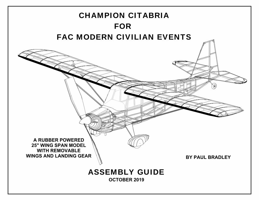
CHAMPION CITABRIAFOR
FAC MODERN CIVILIAN EVENTS
BY PAUL BRADLEY
ASSEMBLY GUIDEOCTOBER 2019
A RUBBER POWERED25" WING SPAN MODEL
WITH REMOVABLEWINGS AND LANDING GEAR

1.
Tape the four fuselage plan pages together to form two building planpages. Use the "+" marks for alignment of the pages.
Build a left and right fuselage side as shown. After the glue is setremove the sides from the plan and sand a bevel at the rear on theinside face of each side. Use the plan as a guide.
2. 3.
4. 5. 6.
8. 9.
Using the fuselage assembly template shown on the plan and thewing spar carry through, landing gear mount plate, and the bottomcross piece behind the landing gear mount plate, assemble the twofuselage sides over the fuselage bottom plan as shown.
Make up the wing spar carry through as shown.
Place the fuselage bottom plan on your building board so the plancan be bent down over the edge along the fold line. Pin the fuselageassembly down over the plan. Pull the forward ends of the fourlongerons in and glue former F3 in place. Use the plan to keepthings centered. Also glue F4 in place. Use the instrument panelcover pattern as a location guide.
Using the fuselage bottom longeron and cross pieces plan, cut outthe landing gear plate and the first bottom cross piece. They shouldhave a slight vertical taper on the edges. Use the cross sectiondrawings for a taper guide.
Add pieces F8 and F9 to the assembly. Also glue a piece of1/16" x 1/8" balsa strip to the notches forward of F8.
Pull the fuselage sides together at the rear. Use the plan as a guideto keep things centered and symmetrical. Once the glue is set,install the bottom cross pieces and the top F lettered pieces. Notewhere part F7 is used in place of a bottom cross piece. The top ofthe fuselage is narrower than the bottom.
Install the bottom fuselage F number pieces that fit on the crosspieces and the landing gear plate. Also glue the tail wheel mount tothe bottom of the fuselage as shown.Once the glue is set, install thebottom stringers as shown.
5/32"x1/16"Balsa Strips
F18
F18
5/32" AluminumTubing
Note 1/16" gap
Do not includethe window filletsat this time
Taper the ends
Taper
AssemblyTemplate
Spar CarryThrough
F8
F9
1/16" x 1/8"
F3
F4
Cross Piece
7.
F7
F5
F5
F6
Tail wheel mount
LandingGear Plate

Sand the top of the three C1 pieces and the top of formers F1 andF2 flat. Glue the 3/32" balsa part C11 to the top of cowl pieces C1.When the glue is set, shape C11 using the plan as a guide. Sand theentire assembly to smooth the edges and to blend the exhaust stackwell to the cowl contour.
10. 11. 12.
13. 14. 15.
16. 17. 18.
Remove the cowl assembly from the building board. Glue theopposite sides of formers F1 and F2 to the cowl assembly. Once theglue is set glue in the remaining cowl supports as shown.
Install part F15 at the rear of the fuselage. When the glue has set,install the two top stringers.
Assemble one half of the cowl over the fuselage side plan.
Mark the location of the side stringers on each fuselage side. Installthe side stringers. Also install the two short tissue support stringersas shown.
Make up tapered fill pieces from 1/16" square balsa for the cabinwindow area as shown. Once the glue is set, install the cabinwindow fillets.
Glue parts F17 to each side of the fuselage as shown. Sand partsF17 so their outer face is parallel to the forward portion of partsF16.
Cut out the instrument panel cover from 1/32" balsa. Glue the coverto the assembly. Some water on the outside face of the cover willhelp it bend. Also glue the tissue support stringers to each side of thenose as shown.
F1
F2
C10
F1 F2
C1
C2
C3C4
C5C6
C7
C8C9
C10
F15
Taperhere
Tapered fill pieces
Corner Fillets
F17
F17
Sand the flats on parts C9 so they are flush wih the edge of F2. Gluethe exhaust stack well assembly to the bottom of the cowl.
Sand flush
F2
C11
F16
Tissue supportstringers
Tissue supportstringers
19. 20. 21.
22. 23. 24.
25. 26. 27.
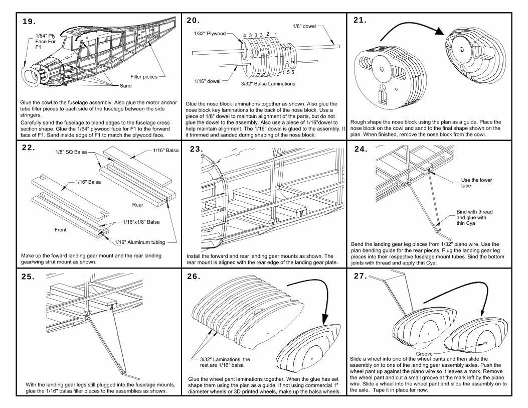
Glue the nose block laminations together as shown. Also glue thenose block key laminations to the back of the nose block. Use apiece of 1/8" dowel to maintain alignment of the parts, but do notglue the dowel to the assembly. Also use a piece of 1/16"dowel tohelp maintain alignment. The 1/16" dowel is glued to the assembly. Itit trimmed and sanded during shaping of the nose block.
Rough shape the nose block using the plan as a guide. Place thenose block on the cowl and sand to the final shape shown on theplan. When finished, remove the nose block from the cowl.
Make up the foward landing gear mount and the rear landinggear/wing strut mount as shown.
Install the forward and rear landing gear mounts as shown. Therear mount is aligned with the rear edge of the landing gear plate.
Glue the wheel pant laminations together. When the glue has setshape them using the plan as a guide. If not using commercial 1"diameter wheels or 3D printed wheels, make up the balsa wheels.
Carefully sand the fuselage to blend edges to the fuselage crosssection shape. Glue the 1/64" plywood face for F1 to the forwardface of F1. Sand inside edge of F1 to match the plywood face.
With the landing gear legs still plugged into the fuselage mounts,glue the 1/16" balsa filler pieces to the assemblies as shown.
Bend the landing gear leg pieces from 1/32" piano wire. Use theplan bending guide for the rear pieces. Plug the landing gear legpieces into their respective fuselage mount tubes. Bind the bottomjoints with thread and apply thin Cya.
Slide a wheel into one of the wheel pants and then slide theassembly on to one of the landing gear assembly axles. Push thewheel pant up against the piano wire so it leaves a mark. Removethe wheel pant and cut a small groove at the mark left by the pianowire. Slide a wheel into the wheel pant and slide the assembly on tothe axle. Tape it in place for now.
Bind with threadand glue withthin Cya
Use the lowertube
Glue the cowl to the fuselage assembly. Also glue the motor anchortube filler pieces to each side of the fuselage between the sidestringers.
Filler pieces
Sand
123334
5 5 5
1/8" dowel
1/16" dowel
1/32" Plywood
3/32" Balsa Laminations
Front
1/16" Aluminum tubing
Rear
1/8" SQ Balsa 1/16" Balsa
1/16" Balsa
1/16"x1/8" Balsa
3/32" Laminations, therest are 1/16" balsa
Groove
1/64" PlyFace ForF1

Follow the procedure in step 28 for the other wheel pant. Whenfinished plug both landing gear assemblies in to the fuselagemounts. Looking from the side, align the wheel pants with eachother. When satsified with the aignment, glue the wheel pants to thelanding gear assemblies.
28. 29. 30.
31. 32.
34. 35. 36.
The tail surfaces are made from 1/16"x3/32" balsa strip stock. Sandthe tail surfaces to a symmetrical profile after they are assembled.
Using the plan as a guide, cut two 1/8" diameter aluminum wingspar tubes to length. Glue a .1" diameter magnet in one end of eachwing tube. Make sure the polarty of the magnets is set so they willattract each other. You may have to drill out the tube ends to receivethe magnets.
Orient the magnets sothey will attract each other
Build the wing panels over the plan. Do not install the wing spartubes at this time.
Remove the wing panels from the building surface after the gluesets. Trim the outlines and sand the leading and trailing edgesalong with the wing tips.
Slide the wing spar tubes into the fuselage tube with the magnetsfacing the center of the fuselage. Slide each wing panel on the spartubes. Make sure the root ribs are a tight fit wih the fuselage wingplates. Glue the spar tubes to the wing panels. GLUE THE ROOTRIB/SPAR TUBE JOINT AFTER THE PANELS ARE REMOVED.
Remove the wing panels from the fuselage. Make up some triangular1/16" square balsa strip stock. Glue lengths of the triangular stripstock to the top and bottom of the spar tubes and the main sparbetween the wing ribs as shown.
Make up the wing strut mounting pads as shown. Install the pads ineach wing panel in the notches at the bottom of rib W3.
Slide each wing panel spar tube into the fuselage tubes. Carefullyalign each wing panel with the top of the fuselage wing mount plates.Drill 1/16" diameter holes through the root ribs and the wing mountplates as shown. Insert a length of 1/16" diameter dowel oraluminum tubing in each hole and glue it to the wing root rib. Becareful not to glue to the wing mount plate. Glue a 1/64" plywooddisk on each side of the pin as shown. Be careful not to get glue inthe wing root fuselage joint.
Drill here
1/64" plywooddisks
33.

37. 38. 39.
40. 41. 42.
43. 44. 45.
Glue the fin to the stab as shown. Make sure the fin is square to thestab by measuring the distance between the rear fin tip and the endsof the stab spar.
Install the windshield and side windows. Use thin (something like.003") clear plastic for the side windows and windshield. Note thatthe windshield wraps around the leading edge carry through.
Make the wing struts from 1/16" x 1/8" and 1/16"x3/32"balsa stripstock. Bend the 1/32" piano wire joiners using the plan patterns.
Sand the struts to a symmetrical cross section. Insert the joiners inthe struts but do not glue yet. Check the fit of each strut on themodel. Make any necessary adjustments. When satisfied with the fitand with the struts installed, make a pin hole in the struts over thepiano wire joiners. Apply a small drop of thin Cya to each hole.Remove the struts and apply more Cya to each joiner.
Drop of thinCya in these
holes
PinHole
Cover the components of the model with tissue. The tissue is notshown in this or subsequent illustrations.
When the stab/fin joint glue is dry, glue the assembly to thefuselage. Make sure the distance between the stab spar ends andthe wing spar carry through tube is equal on each side.
Make up the exhaust stacks from 1/8" aluminum tubing using the planas a guide. Also make up the exhaust stack cowl shield part C14.The two exhaust stacks are inserted in the well plate. The shield fitsinside the well opening.
1/16"x1/8"
1/16"x3/32"
Equal Lengths
Equal Lengths
Bend the tail wheel leg from .025" piano wire. Install a 1/2" wheel andthen glue the assembly to the bottom of the fuselage using the tailwheel mount plate.
C14
Glue the 1/32" balsa webs to each wing panel as shown.
1/32" BalsaWeb

A braided motor is suggested for this model. The prototype used a motor of 6strands of 3/32" rubber with 30" loops before braiding. Make up a motor andinstall it in the model. Wind it enough for the braiding to take effect when themotor unwinds. With the motor in the model and no slack between the prophook and the rear motor peg, check the CG. The model should balance with CGlocated as shown. If necessary, add ballast to the nose or tail to get the modelto balance at the designated CG location.
46.
CG is 1 1/4" back from the wing leading edgeThe propeller nose plug assembly is set up as shown. The propshaft hook can be your preferred style. An 8" diameter prop issuggested. The landing light should also be installed as shown.
Landing Light
Clear plastic disk
46.