S32 SDK for Power Architecture RTM 3.0.3 Release Notes
27
© 2020 NXP Semiconductors N.V. S32 SDK for Power Architecture Release Notes Version 3.0.3 RTM
-
Upload
khangminh22 -
Category
Documents
-
view
0 -
download
0
Transcript of S32 SDK for Power Architecture RTM 3.0.3 Release Notes

© 2020 NXP Semiconductors N.V.
S32 SDK for Power Architecture Release Notes
Version 3.0.3 RTM

© 2020 NXP Semiconductors N.V. 2
Contents
1. DESCRIPTION ..........................................................................................................................................3
2. NEW IN THIS RELEASE ..........................................................................................................................4
2.1 General ............................................................................................................................................4 2.2 Drivers ..............................................................................................................................................4 2.3 Libraries ...........................................................................................................................................4 2.4 Examples .........................................................................................................................................4 2.5 Fixed from RTM 3.0.2 ......................................................................................................................4
3. SOFTWARE CONTENTS .........................................................................................................................6
3.1 Drivers ..............................................................................................................................................6 3.2 PAL ..................................................................................................................................................7 3.3 RTOS ...............................................................................................................................................7 3.4 Middleware.......................................................................................................................................7 3.5 Libraries ...........................................................................................................................................7
4. DOCUMENTATION ...................................................................................................................................8
5. EXAMPLES ...............................................................................................................................................9
6. SUPPORTED HARDWARE AND COMPATIBLE SOFTWARE ........................................................... 13
6.1 CPUs ............................................................................................................................................. 13 6.2 Boards ........................................................................................................................................... 14 6.3 Compiler and IDE versions: .......................................................................................................... 14 6.4 Debug Probes ............................................................................................................................... 14
7. KNOWN ISSUES AND LIMITATIONS .................................................................................................. 15
7.1 S32 Design Studio integration ...................................................................................................... 15 7.2 Drivers ........................................................................................................................................... 15 7.3 Examples ...................................................................................................................................... 18 7.4 Libraries ........................................................................................................................................ 18
8. COMPILER OPTIONS ........................................................................................................................... 19
8.1 GCC Compiler/Linker/Assembler options ..................................................................................... 19 8.2 GHS Compiler/Linker/Assembler options ..................................................................................... 21 8.3 DIAB Compiler/Linker/Assembler options .................................................................................... 24
9. ACRONYMS ........................................................................................................................................... 26
10. VERSION TRACKING .......................................................................................................................... 27

© 2020 NXP Semiconductors N.V. 3
1. Description
The S32 Software Development Kit (S32 SDK) is an extensive suite of peripheral drivers, RTOS, stacks and middleware designed to simplify and accelerate application development on NXP MPC574x-B-C-G, MPC574x-P, MPC577xB-E-C, MPC574xR, S32R264K-J, S32R274K-J and S32R372 Power Architecture based microcontrollers.
This release has RTM quality status in terms of testing and quality documentation. RTM releases contain all planned features implemented and tested.
RTM releases are candidates that can be used in production.
This SDK can be used as is (see Documentation) or it can be used with S32 Design Studio IDE.
Refer to License(License.txt) for licensing information and Software content register(SW-Content-Register-S32-SDK.txt) for the Software contents of this product. The files can be found in the root of the installation directory.
For support and issue reporting use the following ways of contact:
NXP Support to https://www.nxp.com/support/support:SUPPORTHOME NXP Community https://community.nxp.com/community/s32/s32sdk

© 2020 NXP Semiconductors N.V. 4
2. New in this release
2.1 General
Support for creating projects for S32R264K-J.
2.2 Drivers
Clock_manager
MPC5746R added constraint for FXBAR_CLK. This clock only is programmed to be divided by 1.
CPU
Supported RAppID Boot Loader Utility.
FLEXCAN
Changed the function type from "void FLEXCAN_DRV_GetDefaultConfig()" to "uint32_t FLEXCAN_DRV_GetDefaultConfig()".
FreeRTOS
On S32R264, S32R274 and S32R372 updated FreeRTOS version 10.3.1
2.3 Libraries
Updated AMMCLib to version 1.1.21
2.4 Examples
Power_mode_switch_S32R274, S32R372: When the user selects SAFE mode from PC Terminal, the CPU will enter SAFE mode then automatically switch to DRUN mode
Enet_ping: Updated guide for enable ARP command in the WINDOW OS of PC.
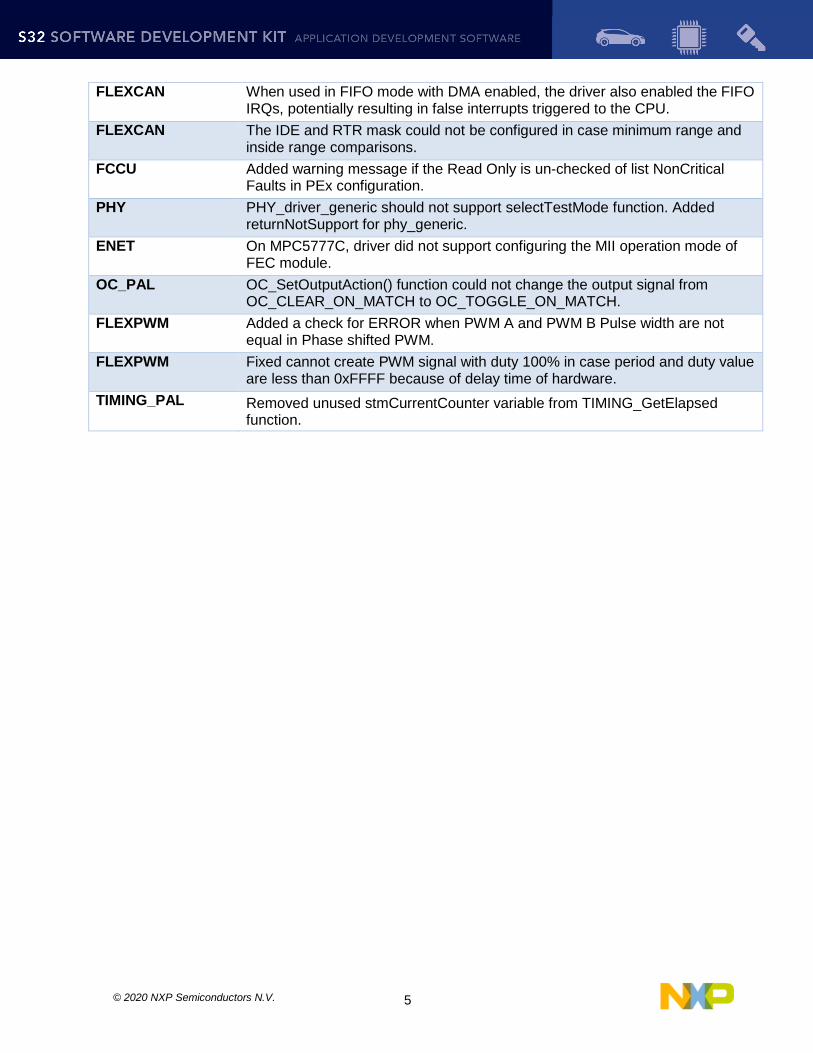
2.5 Fixed from RTM 3.0.2
Component Description
CLOCK_MANAGER S32R274, S32R372: MC_CLK returned 0Hz when MC_CLK was enabled and selected SDPLL as source.
PINS Fixed cannot generate configuration for GPIO143 and some interrupt pins on MPC5777C/75B/75E.
PINS On MPC574xP, PEx PinSettings Routing tab did not support configuring SPI SCK and CS0 pins as input for slave mode support.
I2C I2C_DRV_MasterSetBaudRate function did not check the last divider clock value.
EDMA Another transfer on a different channel cannot work before the first one is completed with minor loop mapping enabled.
DSPI PEx configuration did not select serial clock continuous mode.
ADC_PAL Added ERROR check to prevent multiple ADC instances in the same group index.
FLEXCAN Fixed driver issue that FLEXCAN_DRV_RxFifoBlocking can be corrupted when OSIF_SemaWait timeout occurs
FLEXCAN FLEXCAN_EnterFreezeMode got stuck when entering freeze mode. To avoid infinite loop, a time out is added. CAN soft reset will be used when the time out is reached.
© 2020 NXP Semiconductors N.V. 5
FLEXCAN When used in FIFO mode with DMA enabled, the driver also enabled the FIFO IRQs, potentially resulting in false interrupts triggered to the CPU.
FLEXCAN The IDE and RTR mask could not be configured in case minimum range and inside range comparisons.
FCCU Added warning message if the Read Only is un-checked of list NonCritical Faults in PEx configuration.
PHY PHY_driver_generic should not support selectTestMode function. Added returnNotSupport for phy_generic.
ENET On MPC5777C, driver did not support configuring the MII operation mode of FEC module.
OC_PAL OC_SetOutputAction() function could not change the output signal from OC_CLEAR_ON_MATCH to OC_TOGGLE_ON_MATCH.
FLEXPWM Added a check for ERROR when PWM A and PWM B Pulse width are not equal in Phase shifted PWM.
FLEXPWM Fixed cannot create PWM signal with duty 100% in case period and duty value are less than 0xFFFF because of delay time of hardware.
TIMING_PAL Removed unused stmCurrentCounter variable from TIMING_GetElapsed function.
© 2020 NXP Semiconductors N.V. 6
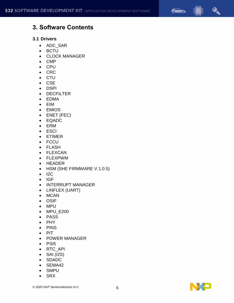
3. Software Contents
3.1 Drivers
ADC_SAR
BCTU
CLOCK MANAGER
CMP
CPU
CRC
CTU
CSE
DSPI
DECFILTER
EDMA
EIM
EMIOS
ENET (FEC)
EQADC
ERM
ESCI
ETIMER
FCCU
FLASH
FLEXCAN
FLEXPWM
HEADER
HSM (SHE FIRMWARE V.1.0.5)
I2C
IGF
INTERRUPT MANAGER
LINFLEX (UART)
MCAN
OSIF
MPU
MPU_E200
PASS
PHY
PINS
PIT
POWER MANAGER
PSI5
RTC_API
SAI (I2S)
SDADC
SEMA42
SMPU
SRX

© 2020 NXP Semiconductors N.V. 7
STM
SWI2C
SWT
TDM
USDHC
WKPU
ZIPWIRE
3.2 PAL
ADC_PAL
CAN_PAL
I2C_PAL
I2S_PAL
IC_PAL
MPU_PAL
OC_PAL
PWM_PAL
SECURITY_PAL
SPI_PAL
TIMING_PAL
UART_PAL
WDG_PAL
3.3 RTOS
MPC5748G, MPC5746C, MPC5744P, MPC5746R, MPC5777C
FreeRTOS version 10.0.1
S32R264, S32R274, S32R372
FreeRTOS version 10.3.1
3.4 Middleware
EEE
FATFS
SDHC
TCP/IP
USB
SBC
3.5 Libraries
AMMCLIB RTM 1.1.21
SBOOT RTM 1.0.2
© 2020 NXP Semiconductors N.V. 8
4. Documentation
Quick start guide available in “doc” folder.
User and integration manual available at “doc\Start_here.html”.
Driver user manuals available in “doc” folder.
Release notes for Middleware available in “doc” folder.
Release notes for SDHC available in “middleware\sdhc\documentation” folder.
Documentation for the Middleware can be found in the respective folder.

© 2020 NXP Semiconductors N.V. 9
5. Examples
Type Name Description
Driv
er e
xa
mp
les
adc_pal Shows the usage of the ADC_PAL.
adc_pal_eqadc Shows the usage of the ADC_PAL over EQADC.
adc_pal_sdadc Shows the usage of the ADC_PAL over SDADC.
adc_swtrigger Shows the usage of the ADC MPC574xx.
bctu_trigger Shows the usage of BCTU cross triggering.
can_pal Shows the usage of the CAN_PAL.
cmp_dac Shows how to use CMP with the internal DAC.
crc_checksum Calculates CRC using the peripheral driver for multiple standards.
cse_keyconfig Configures CSE non-volatile keys.
ctu_trigger
This is an application created to demonstrate triggering of a set of multiple ADC conversions via software trigger (SW->CTU->ADC) and hardware trigger via ETIMER (ETIMER->CTU->ADC).
decfilter Shows the usage of the DECFILTER driver.
dspi_master Shows the usage of the DSPI/SPI module in master mode.
dspi_slave Shows the usage of the DSPI/SPI module in slave mode.
edma_transfer Show multiple usage scenarios of DMA.
eim_injection Shows the usage of EIM driver.
emios_ic Shows the usage of the eMIOS IC functionality.
emios_oc Shows the usage of the eMIOS OC functionality.
emios_pwm Shows the usage of the eMIOS PWM functionality.
enet_loopback Shows the usage of the ENET module configured in loopback.
enet_ping Shows the usage of the ENET module by implementing an application which responds to ping requests.
eqadc Shows the usage of EQADC driver.
erm_report Shows the usage of ERM driver.
esci_transfer Shows the usage of ESCI driver.
etimer Shows the usage of the ETIMER module.
fccu_fault_injection Show the usage of FCCU driver.
flash_program_erase Shows the usage of the flash driver how to program or erase the flash memory.
flexpwm_pwm Shows the usage of the PWM functionality of FlexPWM.
hsm_key_config Demonstrates the non-volatile key update procedure.
i2c_pal Shows the usage of the I2C_PAL.

© 2020 NXP Semiconductors N.V. 10
i2c_pal_master_transfer Shows the usage of the I2C_PAL in master mode.
i2c_pal_slave_transfer Shows the usage of the I2C_PAL slave mode.
I2c_transfer Shows the usage of the I2C driver in master and slave modes.
i2c_master_transfer Shows the usage of the I2C driver in master mode.
i2c_slave_transfer Shows the usage of the I2C driver in slave mode.
i2s_pal Shows the usage of the I2S_PAL.
ic_pal Shows the usage of the I2C_PAL.
input_glitch_filter Shows the usage of the IGF driver.
interrupt_control_multicore Shows the usage of the Interrupt Manager in a multicore environment.
linflexd_uart Shows the usage of LINFlexD_UART driver in interrupt based mode.
mcan Shows the usage of MCAN driver.
mpu_e200_memory_protection Shows the usage of MPU_E200 driver.
mpu_memory_protection Shows the usage of MPU driver.
mpu_pal_memory_protection Shows the usage of the MPU_PAL.
oc_pal Shows the usage of the OC_PAL.
pass_lock_unlock Shows the usage of the PASS module.
phy_autoneg Shows the usage of the PHY module with auto negotiation
pit_periodic_interrupt Shows the usage of the PIT.
power_mode_switch Transitions the MCU into all available power modes.
psi5_async_rx Shows the usage of PSI5 in ASYNCHRONOUS mode with a PSI5-A16CRC-500_1L sensor.
pwm_pal Shows the usage of PWM_PAL.
rtc_alarm Shows the usage of the RTC.
sai_transfer Shows the usage of the SAI driver in both master and slave modes.
sdadc_swtrigger Shows the usage of the SDADC driver.
security_pal Shows the usage of the SECURITY_PAL.
sema42_multicore Shows the usage of SEMA42 driver simultaneous over all available cores.
smpu_protection Shows how to configure SMPU to protect a region of memory.
spi_pal Shows the usage of the SPI_PAL.
spi_pal_master Shows the usage of the SPI_PAL in master mode.
spi_pal_slave Shows the usage of the SPI_PAL in slave mode.
srx_fast_dma Shows the usage of SRX in DMA based mode.

© 2020 NXP Semiconductors N.V. 11
stm_periodic_interrupt Shows the usage of the STM.
swi2c_master Shows the usage of the SWI2C.
swt_interrupt Shows the usage of the SWT.
timing_pal Shows the usage of the TIMING_PAL.
uart_pal_echo Shows the usage of UART PAL over LinFlexD.
wdg_pal_interrupt Shows the usage of the WDOG_PAL.
wkpu_interrupt Shows the usage of the WKPU driver.
zipwire_master Shows the usage of the zipwire driver, configured as LFAST master – works in conjunction with zipwire_slave.
zipwire_slave Shows the usage of the zipwire driver, configured as LFAST slave – works in conjunction with zipwire_master.
Dem
os
ammcLib Shows the integration with AmmcLib.
eeprom_emulation Shows basic use cases of the EEPROM Emulation middleware.
etpu_pwm Shows the usage of the ETPU module.
Flexcan Shows the usage of FlexCAN driver configured as both bus master and slave.
Freertos Shows the usage of the FreeRTOS
hello_world This is a simple application created to show the basic configuration with S32DS.
hello_world_mkf This is a simple application created to show the basic configuration with makefile for the supported compilers
hsm_freertos Shows the usage of HSM driver using two tasks (one for encryption, one for decryption).
lwip Shows the usage of TCP IP stack.
sbc_fs65 Shows the integration with FS6500 SBC.
Sboot Shows the integration with sBoot.
sdhc_fatfs Shows the usage of FAT FS over uSDHC driver.
sdhc_freertos Shows the usage of SHDC with FATFS over FreeRTOS.
usb_msd_fatfs This is a simple FATFS application created to access USB mass storage device.
usb_cdc_lwip Shows the usage of the TCP/IP stack over USB Ethernet.
© 2020 NXP Semiconductors N.V. 12
© 2020 NXP Semiconductors N.V. 13
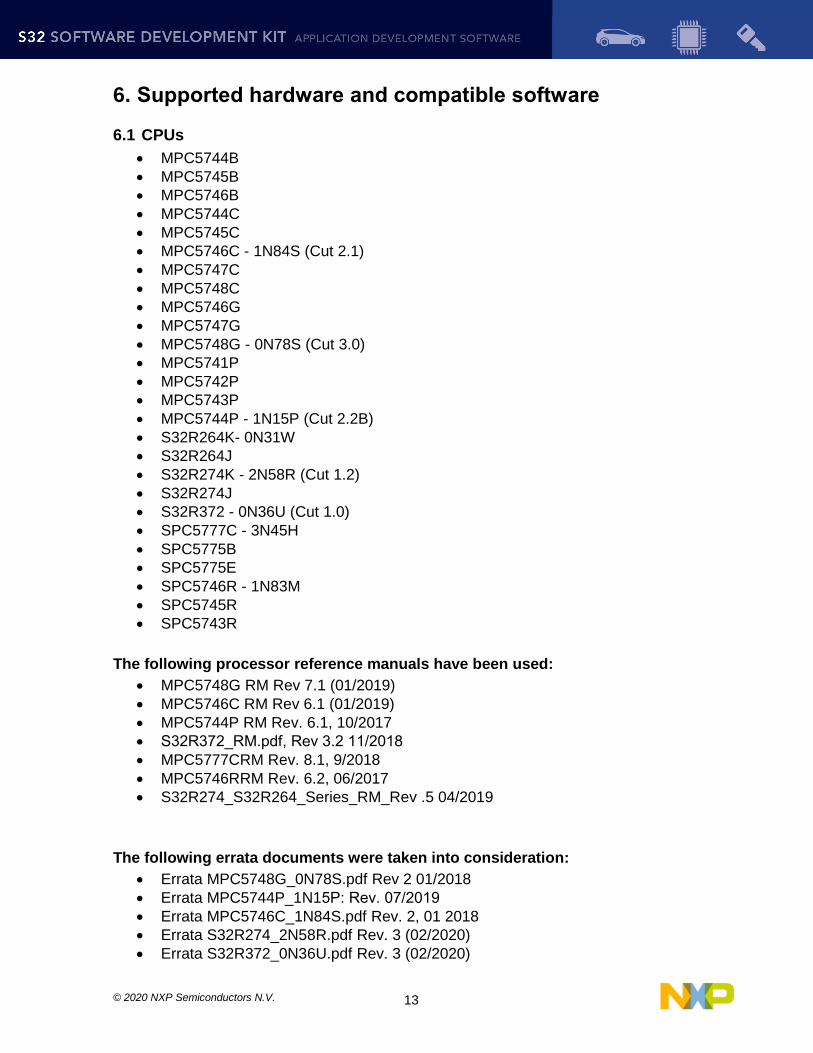
6. Supported hardware and compatible software
6.1 CPUs
MPC5744B
MPC5745B
MPC5746B
MPC5744C
MPC5745C
MPC5746C - 1N84S (Cut 2.1)
MPC5747C
MPC5748C
MPC5746G
MPC5747G
MPC5748G - 0N78S (Cut 3.0)
MPC5741P
MPC5742P
MPC5743P
MPC5744P - 1N15P (Cut 2.2B)
S32R264K- 0N31W
S32R264J
S32R274K - 2N58R (Cut 1.2)
S32R274J
S32R372 - 0N36U (Cut 1.0)
SPC5777C - 3N45H
SPC5775B
SPC5775E
SPC5746R - 1N83M
SPC5745R
SPC5743R
The following processor reference manuals have been used:
MPC5748G RM Rev 7.1 (01/2019)
MPC5746C RM Rev 6.1 (01/2019)
MPC5744P RM Rev. 6.1, 10/2017
S32R372_RM.pdf, Rev 3.2 11/2018
MPC5777CRM Rev. 8.1, 9/2018
MPC5746RRM Rev. 6.2, 06/2017
S32R274_S32R264_Series_RM_Rev .5 04/2019
The following errata documents were taken into consideration:
Errata MPC5748G_0N78S.pdf Rev 2 01/2018
Errata MPC5744P_1N15P: Rev. 07/2019
Errata MPC5746C_1N84S.pdf Rev. 2, 01 2018
Errata S32R274_2N58R.pdf Rev. 3 (02/2020)
Errata S32R372_0N36U.pdf Rev. 3 (02/2020)

© 2020 NXP Semiconductors N.V. 14
Errata MPC5746R_1N83M Rev. 3.0 (12/2019)
Errata MPC5777C_3N45H Rev. 12/2019
Errata S32R264_0N31W Rev. 2, 02/2020
6.2 Boards
DEVKIT-MPC5744P PCB Rev E1 SCH Rev A
DEVKIT-MPC5748G PCB Rev D SCH Rev D1
Daughter Card MPC574XG-256DS Rev B
Daughter Card X-MPC574XG-324DS Rev A
Motherboard X-MPC574XG-MB Rev D
Daughter Card MPC5744P-257DS Rev B1
Motherboard MPC57XX Rev C
S32R274RRUEVB 700-28921 REV B SCH-28921 REV D
Daughter Card MPC5777C-516DS Rev D
Daughter Card MPC5777C-416DS Rev D (just for SBC FS65 example)
Daughter Card MPC5746R-252DS Rev A
6.3 Compiler and IDE versions:
GCC E200 VLE GNU Compiler 4.9.4 o 20160726 bld=1607 rev=gceb1328 (1 February 2019) o included in S32DS for Power Architecture 2.1
Green Hills Multi 7.1.4 / Compiler 2017.1.4
Windriver DIAB Compiler v5.9.6.2
6.4 Debug Probes
Lauterbach TRACE32 JTAG Debugger
P&E Multilink (with P&E GDB Server)

© 2020 NXP Semiconductors N.V. 15
7. Known issues and limitations
7.1 S32 Design Studio integration
Some warnings might be observed after project creation or import.
Project creation takes a considerable amount of time.
On multicore projects, it might take a greater amount of time to debug the projects in FLASH target.
7.2 Drivers
CLOCK
On S32R264, S32R274: the configuration component issues warnings when the core frequency for Z7 is above 240MHz on S32R264K, S32R274K. On S32R264J, S32R274J maximum allowed frequency is 266MHz. For more details, please refer to part specification in DataSheet.
On MPC5746R: The device could be stuck in reset if FXBAR_CLK is programmed to be divided by more than div_by_1
CRC
When generating CRC-32 for the ITU-T V.42 standard the user needs to set SWAP_BYTEWISE together with INV and SWAP.
When generating CRC-16 the user needs to set SWAP_BITWISE bit.
EDMA
When using Single-block transfer or Multi-block transfer, NBYTES (Number of bytes to be transferred in each service request of the channel) shall be always
configurable on 30 bits instead of 32 bits.
EEE
The EEE_DRV_ReportEepromStatus() function will return the erasing cycles of the current ACTIVE block. This number is not an accurate value. Because if brownout occurs during updating erase cycle, this erasing cycle will be re-counted from the erase cycle value of the other block.
The user needs to ensure that EEE_DRV_MainFunction() function is called after every write operation. The user can check the status of g_eraseStatusFlag global variable after writing data record to decide when needs to call this function.
When ECC errors occur during the read operation from flash, the driver only supports to get the failing address in the C55FMC_ADR register.
EQADC
Digital filter for external triggers cannot be bypassed
FCCU
For S32R264, S32R274, S32R372, S32V234, MPC5777C and MPC5746R devices: When injecting a fake fault to transition FCCU from Normal to Alarm then to Fault, the time configured for Alarm to Fault transition must be lower than the FOSU time. Otherwise, FOSU timeout might expire and it will trigger a CPU reset.
For MPC5777C: The NCF 43 was present if Error Input Pin is pulled down to low signal level.
When configuring FCCU in debug mode on MPC5746R, it will not initialize properly. Workaround: Set .debugEnable field to false.

© 2020 NXP Semiconductors N.V. 16
FLASH
It is recommended that the D-cache of the core should be disabled at the initialization code to make sure the program or erase functions work properly.
Flash controller buffer shall be disabled in the beginning of application for reading and writing to flash.
FLEXCAN
In the DMA mode, the user need to read all pending frames in RxFiFo for handling all current dma requests before using FLEXCAN_DRV_Deinit function.
FLEXPWM
When using more than one submodule and configuring any of the sub-modules from 1 to 3 to have the reload signal from Master Reload, the LDOK bit for sub-modules 1 to 3 is not cleared. Workaround: The user must make sure to manually clear the LDOK bit in this situation using the dedicated function: FLEXPWM_DRV_ClearLDOK.
When using FlexPWM with DMA enabled on input capture and the trigger configured for watermarks being AND’ed, the user might encounter spurious DMA requests when starting the DMA channel. Workaround: use the option OR on watermark levels and add logic for AND functionality inside the DMA callback.
Deactivating the DMA from the FlexPWM module in input capture mode sometimes still issues DMA requests. Workaround: disable FlexPWM DMA requests also from the DMA driver.
Cannot create PWM signal with duty 100% in case period and duty value are equal to 0xFFFF because of delay time of hardware.
I2C
Aborting a transfer with the function I2C_DRV_MasterAbortTransferData() can't be done safely due to device limitation; there is no way to know the exact stage of the transfer, and if we disable the module in the middle of the transfer of a character the slave may hold the SDA line forever low and block the I2C bus. Same situation may happen if a blocking transfer function is used and TIMEOUT occurs.
IC_PAL over FLEXPWM
When IC PAL is used over FlexPWM with multi-channels combined in multi-capture modes, the measured result will not work as expected with high frequency as input signal for capture modes.
IC_PAL and OC_PAL
PEx component limitation: Multiple PEx components, either IC_PAL or OC_PAL, cannot share the same EMIOS module instance.
LINFLEXD UART
In DMA mode, bytesRemaining parameter is not always 0 after calling LINFLEXD_UART_GetReceive/TransmitStatus, although all data is successfully transferred.
MPU
MPU driver will not report violation on the EBI Region for MPC5777C.
OC_PAL over EMIOS
Using of internal buses, or bus B, C, D, E with channel 0, 8, 16, 24, respectively, or bus A with channel 23, or bus F with channel 22, must configure period value with the maximum available value of counter register.
EMIOS_OC

© 2020 NXP Semiconductors N.V. 17
On MPC5777C, When the user uses EMIOS_MODE_SAOC with EMIOS_OUTPUT_ACTIVE_DISABLE mode, the configured time base will be disabled. That means any channels using said time base will also be disabled.
OC_PAL
On MPC5777C, When OC_PAL is used over eMIOS with OC_DISABLE_OUTPUT mode, the configured time base will be disabled.
PINS
Generation of the pin configuration using the PEx component is slow.
POWER MANAGER
The core must execute code from RAM memory when switching to a mode in which the flash is in power down or low power state.
MCU cannot enter STOP0, STANDBY, HALT0 mode while debugger is connected. In addition, STOP0, HALT0, STANBY are not supported while CPU executes code from RAM.
The user does not use the internal ballast in applications using any of the STOP, HALT or STANDBY mode. The user must ensure the device is set up to use external ballast (INT_BAL_SELECT pin tied to ground on board). Because the interrupt or wakeup event is activated while transition to HALT, STOP or STANDBY mode, the transition is aborted.
LPU modes are not supported.
The driver code will switch to RUN0 mode before entering STOP0 or HALT0 mode from DRUN mode. If CPU is in STOP0, HALT0 and a wake-up signal is detected it will switch to RUN0 mode.
FXOSC clock source must be turn on in all mode except SAFE mode when CMU is enabled. Before entering SAFE mode, the divider of clock source monitor in CMU should be reset. If the clock condition is not true, CPU will be reset when the user switches mode.
PWM_PAL over ETIMER
When generating signals with 0% or 100% duty cycle, a pulse of length equal to one clock tick is generated on the output which has inverted polarity. Consequently, true 0% or 100% duty cycles cannot be achieved.
PWM_PAL over FLEXPWM
Cannot create PWM signal with duty 100% in case period and duty value are equal to 0xFFFF because of delay time of hardware.
RTC
Driver does not support using all prescalers when 32KHz clock is selected. The application should either disable prescalers, or use a higher clock frequency.
Driver supports only frequencies below 40MHz.
SBC FS6500
After transitioning between modes, a delay needs to be added, in order to allow settling and avoid altering frames.
SDADC
The SDADC flags for data valid and watchdog crossover, do not trigger corresponding eTPU channels.
SRX
If the driver is reinitialized, the peripheral can't resynchronize with the sensor.
SWI2C

© 2020 NXP Semiconductors N.V. 18
The SWI2C driver doesn't support multi-master mode.
Detection of bus busy is not supported.
Baud rate of SWI2C depends on CPU frequency, optimizations, compiler, pull-up resistors that are used, the user should check the baud rate and timing of the SCL and SDA for his application.
The driver can't ensure a fix baud rate.
SWT
The driver does not support timer reset in Fixed Execution Address mode and Incremental Execution Address mode (The watchdog is serviced by executing code at the address loaded into the designated IAC register).
TDM
TDM driver is not supported on Rainier platform.
UART PAL, LINFLEXD UART
For S32R264, S32R274 and S32R372 (S32R274RRUEVB), LIN1_RX pin on daughter board will not work if J13 and J14 are connected on motherboard.
7.3 Examples
WKPU example runs in FLASH only if the reset button in pressed after the download to the target.
Some examples may display warning messages with unresolved includes.
PASS example can only be run using Lauterbach debug support. S32 Design Studio debug plugins do not support flash access unlocking on secured chips.
usb_cdc_lwip_mpc5748g is not supported on MPC5748G DEVKIT Rev.D1
usb_msd_fatfs example: the user can debug with P&E Micro Multilink and use OpenSDA to debug (see prints trace).
7.4 Libraries
AMMCLIB
The methods displayed in the configurator component might be different from the ones in the actual library.
Missing the 16 and 32 bit fixed point pre-processor macros in the header files on version 1.1.21. The 16 and 32 bit fixed point always are enabled in the UI and it does not impact the code size, since the library is configured to allow the linker to discard unused code.

© 2020 NXP Semiconductors N.V. 19
8. Compiler options
8.1 GCC Compiler/Linker/Assembler options
Table 8-1 GCC Compiler options
Option Description
-mcpu=e200z7/e200z4/-mcpu=e200z2 Selects target processor
-funsigned-char Let the type char be unsigned, like unsigned char
-funsigned-bitfields Bit-fields are by default signed
-fshort-enums Allocate to an enum type only as many bytes as it
needs for the declared range of possible values.
-ffunction-sections Place each function into its own section in the
output file
-fdata-sections Place data item into its own section in the output file
-fno-jump-tables Do not use jump tables for switch statements
-save-temps=obj Save temp files for debugging purposes
-mbig Big endian
-mvle Enable variable-length encoding
-std=c99 Use C99 standard
-msoft-float/-msingle-float Select the Floating Point type
-g3 Generate debug information
-O1 Optimization level one
-Wall Produce warnings about questionable constructs
-D<cpu_name> Define a preprocessor symbol for MCU
-DTURN_ON_CPUX Define for turning on different CPUs. X should be replaced with the desired CPU to be turned on.
-DSTART_FROM_FLASH Mandatory define when flash target is used
-fno-common Allocates uninitialized global variables to a section and initializes them to zero at program startup
-msdata=eabi Enables RAM and ROM SDA with default threshold is 8 byte
-mlra Use local register allocation
-D__cpux_boot_addr__=<address> Optional define when specific boot address is used. X should be replaced with the desired CPU to be updated.
Table 8-2 GCC Linker options
Option Description
-gc-sections Remove unused sections
-lc Link C library
-lgcc Link libgcc

© 2020 NXP Semiconductors N.V. 20
-lm Link Math library
-T <linker_script_file.ld> Use the specified linker file
--entry= Reset_Handler
Make the symbol Reset_Handler be treated as a root symbol and the start label of the application
-Wl, -Map=<map_file_name> Produce a map file
-Wl,--defsym,__sram_base_addr__=<address>
-Wl,--defsym,__sram_size__=<size>
Optional define when specific RAM base address and size is used (if RAM available)
-Wl,--defsym,__flash_base_addr__=<address>
-Wl,--defsym,__flash_size__=<size>
Optional define when specific Flash base address and size is used (if Flash available)
-Wl,--defsym,__local_dmem_base_addr__=<address>
-Wl,--defsym,__local_dmem_size__=<size>
Optional define when specific Local Data Memory base address and size is used (if Local Data Memory available)
-Wl,--defsym,__local_imem_base_addr__=<address>
-Wl,--defsym,__local_imem_size__=<size>
Optional define when specific Local Instruction Memory base address and size is used (if Local Instruction Memory available)
Table 8-3 GCC Assembler options
Option Description
-mcpu=e200z7/e200z4/-mcpu=e200z2 Selects target processor
-mregnames Emit register names in the assembly language output using symbolic forms
-mbig Big endian
-mvle Enable variable-length encoding
-msoft-float/-msingle-float Select the Floating Point type
-g3 Generate debug information
-O1 Optimization level
-DTURN_ON_CPU0 Mandatory define for the boot core(Z4_0)
-DTURN_ON_CPUX Define for turning on different CPUs. X should be replaced with the desired CPU to be turned on.

© 2020 NXP Semiconductors N.V. 21
8.2 GHS Compiler/Linker/Assembler options
Table 8-4 GHS Compiler options
Option Description
-cpu=ppc574xcz4204/-cpu=ppc574xcz210/-cpu=ppc574xgz4204/-cpu=ppc574xgz210/-cpu=ppc5744pz425/-cpu=ppc5775kz7260/-cpu=ppc5775kz4201/-cpu=ppc5746r/-cpu=ppc5777c
Selects target processor
--gnu_asm Enables GNU extended asm syntax support
-G Generate debug information
-vle Enable variable-length encoding
-C99 Use C99 standard
-noSPE Do not generate SPE or vector floating point instructions
-nostartfiles Do not add start-up files to link
-fno-common Allocates uninitialized
-fnone/ -fsoft / -fsingle Select the Floating Point type
-sda=0 Enables the Small Data Area optimization with a 0 threshold
-dual_debug Generates the DWARF debugging information in the object file
-Ogeneral Optimization level
-D<cpu_name> Define a preprocessor symbol for MCU
-DTURN_ON_CPUX Define for turning on different CPUs. X should be replaced with the desired CPU to be turned on.
-DSTART_FROM_FLASH Mandatory define when flash target is used
-sda=8 Enables the Small Data Area optimization with threshold is 8 byte
-D__cpux_boot_addr__=<address>
Optional define when specific boot address is used. X should be replaced with the desired CPU to be updated.
Table 8-5 GHS Linker options
Option Description
-nostartfiles Do not add start-up files to link
-nostdlib Do not use standard libraries
-entry= Reset_Handler
Make the symbol Reset_Handler be treated as a
root symbol and the start label of the
application
-T <linker_script_file.ld> Use the specified linker file
-Map=<map_file_name> Produce a map file

© 2020 NXP Semiconductors N.V. 22
-keepmap Controls the retention of the map file in the event
of a link error
-Mn Generates a listing of symbols sorted numerically
by address
-delete -ignore_debug_references Ignores relocations from DWARF debug sections when using -delete
-D__sram_base_addr__=<address> -D__sram_size__=<size>
Optional define when specific RAM base address and size is used (if RAM available)
-D__flash_base_addr__=<address> -D__flash_size__=<size>
Optional define when specific Flash base address and size is used (if Flash available)
-D__local_dmem_base_addr__=<address> -D__local_dmem_size__=<size>
Optional define when specific Local Data Memory base address and size is used (if Local Data Memory available)
-D__local_imem_base_addr__=<address> -D__local_imem_size__=<size>
Optional define when specific Local Instruction Memory base address and size is used (if Local Instruction Memory available)
--preprocess_linker_directive_full
The C preprocessor preprocesses linker directives files
Table 8-6 GHS Assembler options
Option Description
-cpu=ppc574xcz4204/-cpu=ppc574xcz210/-cpu=ppc574xgz4204/-cpu=ppc574xgz210/-cpu=ppc5744pz425/-cpu=ppc5775kz7260/-cpu=ppc5775kz4201/-cpu=ppc5746r/-cpu=ppc5777c
Selects target processor
-preprocess_assembly_files Enable the run of the C preprocessor over the assembler files
-nostartfiles Do not add start-up files to link
-noSPE Do not generate SPE or vector floating point instructions
-gnu_asm Enables GNU extended asm syntax support
-vle Enable variable-length encoding
-C99 Use C99 standard
-gdwarf-2 Enables the generation of DWARF debugging information
-sda=0 Enables the Small Data Area optimization with a 0 threshold
-G Generate debug information
-fnone/ -fsoft / -fsingle Select the Floating Point type
-dual_debug Generates the DWARF debugging information in the object file
-Ogeneral Optimization level
-DTURN_ON_CPU0 Mandatory define for the boot core(Z4_0)

© 2020 NXP Semiconductors N.V. 23
-DTURN_ON_CPUX Define for turning on different CPUs. X should be replaced with the desired CPU to be turned on.

© 2020 NXP Semiconductors N.V. 24
8.3 DIAB Compiler/Linker/Assembler options
Table 8-7 DIAB Compiler options
Option Description
-tPPCE200Z210N3VEN:simple/-
tPPCE200Z4204N3VEN:simple/-
tPPCE200Z4201N3VEN:simple/-
tPPCE200Z7260N3VEN:simple/-
tPPCE200Z425N3VEN:simple/-
tPPCE200Z759N3VEN:simple
Selects target processor. The last N in the target processor name shall be replaced by S/F/G for software FPU/Single Hardware, Double Software FPU/All Single Hardware Floating Point.
-Xdialect-c99 Use C99 standard
-Xsection-split Generate a separate section for each function/variable
-g3 Add debug information to the executable
-Xdebug-local-all Emit debug information for unused local variables
-Xdebug-local-cie Generate a local Common Information Entry (CIE) for each unit.
-Xdebug-struct-all Disable debug optimization of type information
-Xdebug-dwarf2 Generate DWARF 2 debug information
-XO Enable extra optimizations
-Xsmall-data=0 Disable small data
-Xsmall-const=0 Disable small const data
-D<cpu_name> Define a preprocessor symbol for MCU
-DTURN_ON_CPUX Define for turning on different CPUs. X should be replaced with the desired CPU to be turned on.
-DSTART_FROM_FLASH Mandatory define when flash target is used
-Xno-common
Allocates uninitialized global variables to a section and initializes them to zero at program startup
-Xsmall-data=8 Set size limit for “small data” variables is 8 byte
-Xsmall-const=8 Set size limit for “small const” variables is 8 byte
-D__cpux_boot_addr__=<address>
Optional define when specific boot address is used. X should be replaced with the desired CPU to be updated.
Table 8-8 DIAB Linker options
Option Description
-tPPCE200Z210N3VEN:simple/-
tPPCE200Z4204N3VEN:simple/-
tPPCE200Z4201N3VEN:simple/-
tPPCE200Z7260N3VEN:simple/-
tPPCE200Z425N3VEN:simple/-
tPPCE200Z759N3VEN:simple
Selects target processor. The last N in the target processor name shall be replaced by S/F/G for software FPU/Single Hardware, Double Software FPU/All Single Hardware Floating Point.
-Xremove-unused-sections Removes unused code sections

© 2020 NXP Semiconductors N.V. 25
-lc
Link the standard C library to the project in order to support elementary operations that are used by the drivers
-lm
Link the standard math library to the project in order to support elementary math operations that are used by the drivers
<linker_script_file.dld> Use the specified linker file
-e Reset_Handler Make the symbol Reset_Handler be treated as a root symbol and the start label of the application
-m6 <map_file_name> Produce a linker map
-Xremove-unused-sections remove unused section
-Xpreprocess-lecl Perform pre-processing on linker scripts
-MD__sram_base_addr__=<address> -MD__sram_size__=<size>
Optional define when specific RAM base address and size is used (if RAM available)
-MD__flash_base_addr__=<address> -MD__flash_size__=<size>
Optional define when specific Flash base address and size is used (if Flash available)
-MD__local_dmem_base_addr__=<address> -MD__local_dmem_size__=<size>
Optional define when specific Local Data Memory base address and size is used (if Local Data Memory available)
-MD__local_imem_base_addr__=<address> -MD__local_imem_size__=<size>
Optional define when specific Local Instruction Memory base address and size is used (if Local Instruction Memory available)
Table 8-9 DIAB Assembler options
Option Description
-tPPCE200Z210N3VEN:simple/-
tPPCE200Z4204N3VEN:simple/-
tPPCE200Z4201N3VEN:simple/-
tPPCE200Z7260N3VEN:simple/-
tPPCE200Z425N3VEN:simple/-
tPPCE200Z759N3VEN:simple
Selects target processor. The last N in the target processor name shall be replaced by S/F/G for software FPU/Single Hardware, Double Software FPU/All Single Hardware Floating Point.
-g3 Add debug information to the executable
-Xdebug-local-all Emit debug information for unused local variables
-Xdebug-local-cie Generate a local Common Information Entry (CIE) for each unit.
-Xdebug-struct-all Disable debug optimization of type information
-Xdebug-dwarf2 Generate DWARF 2 debug information
-D<cpu_name> Define a preprocessor symbol for MCU
-DTURN_ON_CPU0 Mandatory define for the boot core(Z4_0)
-DTURN_ON_CPUX Define for turning on different CPUs. X should be replaced with the desired CPU to be turned on.
-DSTART_FROM_FLASH Mandatory define when flash target is used
© 2020 NXP Semiconductors N.V. 26
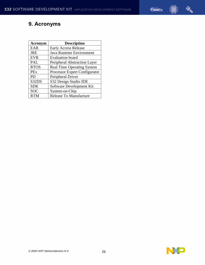
9. Acronyms
Acronym Description
EAR Early Access Release
JRE Java Runtime Environment
EVB Evaluation board
PAL Peripheral Abstraction Layer
RTOS Real Time Operating System
PEx Processor Expert Configurator
PD Peripheral Driver
S32DS S32 Design Studio IDE
SDK Software Development Kit
SOC System-on-Chip
RTM Release To Manufacture

© 2020 NXP Semiconductors N.V. 27
10. Version Tracking
Date (dd-Mmm-YYYY)
Version Comments Author
28-Apr-2017 1.0 Initial version for EAR 0.8.0 Iulian T.
15-Jun-2017 1.1 Updated known integration issues Iulian T.
28-Jul-2017 1.2 Update for EAR 0.8.1 Rares V.
14-Dec-2017 1.3 Update for EAR 0.8.2 Cezar D.
28-Mar-2018 1.4 Update for BETA 0.9.0 Cezar D.
19-Jul-2018 2.0 Update for RTM 1.0.0 Cezar D.
17-Sep-2018 2.1 Update for BETA 1.9.0 Cezar D.
11-Dec-2018 3.0 Update for RTM 2.0.0 Cezar D.
21-Mar-2019 3.1 Update for BETA 2.9.0 Vlad L.
24-May-2019 4.0 Update for RTM 3.0.0 Vlad L.
31-Jul-2019 5.0 Update for RTM SR 3.0.1 Rares V
22-Nov-2019 6.0 Update for RTM 3.0.2 Razvan T
17-Aug-2020 7.0 Update for RTM 3.0.3 Cuong Nguyen
Van