Ensuring Security, Public Order, and Safety - - Philippine ...
Upload
khangminh22Category
view
0download
0
XA9952594
Russian Standards and Design Practice of BisuringNPP Reliability under Severe External Loading Conditions
A.N. Birbraer
St.Petersburg Research & Design Institute ATOMENERGOTROJECTSyvoroveklj pr., 2a, 193036 St.Petersburg, Russia
Russian Standards and design practice of ensuring NPP reli-ability under severe external loading oonditions are descri-bed. The main attention is paid to the seismic design requi-rements. Explosions, aircraft impact, and tornado are brieflyexamined too.
1 . INTRODUCTION
This report deals with the brief survey of Russian Standards andpraotioe of NPP design under severe external loading oonditions.Loadings that shall be taken into account are listed in the Stan-dard [1]: ipa-Htmim design earthquake; extreme snow, wind and clima-tic temperatures; hurricane; tornado; tzunami waves (ooourance ti-me interval of all these events is taken to be equal to 10000 ye-ars); aircraft impact; explosions. The main attention in this re-port will be paid to the seismio design requirements. Explosions,aircraft impact, and tornado will be briefly examined too.
>
2. NPP SEISMIC DESIGN
NPP seismic design requirements are provided by the Standard [2]approved in 1987. Before that (since 1979) the Temporal Standard[3] was used. It was based on the same general prinoiples as thepresent-day Standard.
2.1. Seismic Site Suitability Criteria
Below-mentioned limitations are imposed on the choice of oonstruc-tion site for NPP.NPP can not be built on the site if maximum design earthquake
intensity is more than 8 of MSK-64 Soale. Sites that include cap-able faults are not suitable too.There are some peculiarities characterizing a site as unfavour-
able one, and NPP may be built there only if appropriate measuresare undertaken to ensure its safety.These peculiarities are: land-slide and mud flow danger; mountaine workings; coast or bank ero-
13

sion; coast slow sinking (with the sinking rate more than 10 mmper year); ground strength under foundations less than 0,2 MPa;tzunami waves induced flood.
2.2. Seismic Input Data
Several stages of seismic and geologic investigations shall becarried out to provide seismic input data. Previous earthquake in-tensity is established by use of the USSR Territory Seismio Map.It is presented in the Standard [41 regulating seismic design ofusual (non-nuclear) structures. Then the data shall be made morepreoise on the basis of the region seismio investigations, and fi-nally - by carrying out of investigations on the site.
Design input data shall comprise following information.
2.2.1. Earthquake intensity I ol MSK-64 Skale.
Design horisontal peak ground acceleration A used for NPP seismicanalyses, depends on earthquake intensity. Two levels of seismichazard shall be taken into account:
(a) Design Earthquake (DE) whose occurance time interval is ta-ken to be equal to 100 years. This earthquake corresponds to S1level of IEAE Recommendations [5].
(b) Maximum Design Earthquake (MDE) whoBe ocouranoe time inter-val is taken to be equal to 10000 years. This earthquake corres-ponds to S2 level of the same Recommendations.
2.2.2. Design Response Spectra.
Standard acceleration response spectra (dynamic factors 6(T)) spe-cified by the Standard [43 are used. They correspond to horisontalpeak ground acceleration value A=1. There are three Bpeotra in theStandard depending on ground stiffness (stiff, middle or soft).They are represented in fig.1. One may note their following speci-fic features. %
(a) The same spectra are used both for horisontal and for verti-cal ground motions.
(b) The spectra are not dependent on system damping.(c) The spectra do not have any phisical sense both in shortand
in long-period ranges, because their zero-period accelerati-ons are not equal to 1, and they do not become less than 0.8for any large period T values.
Por the purpose of comparison response spestra specified by USAEC Regulatory Guide 1.60 [7] are plotted in fig.1 too. It may beseen that in period range 0.4<T<1.5 s Russian Spectra for Btiffand middle grounds are close enough to American ones, and out ofthis range Russian Spectra provide larger accelerations.
2.2.3. Ground Motion Time Histories
Set of recorded, modified, or syntetic earthquake ground motionsshall be specified. The Standard [2] does not apply any requere-
14

merits on them (e.g., on their compatibility with response spectra,on number of components and their mutual statistical independanse,etc). Time histories compatibility with response spectra can notbe achieved by phisical reason bearing in mind abovementioned pe-culiarities of spectra (see 2.2.2.o)
2.3. NPP Seismic Criteria
The safety of NPP must be ensured during and after any earthquakeincluding MDE. Safety conditions are established by the Standard[73.Requirement to maintain capacity to produce electric power and/
/or heat after DE may be applied too at KPP Customer's request.
2.4. Seismic Design Classification
NPP components (structures, equipment, pipes, instruments, etc)"shall be divided into three Seismic Categories depending on theirimportance to safety. Classification criteria and seismic resis-tance requirements for them are presented in the Tab. 1 (see thenext page). Some comments are given below.First of all Category of a component depends on potential radio-
active dose load on the public and NPP staff in the case of thecomponent failure. Then it depends on its functions related to re-actor safe shut down and maintaining it in safe shutdown conditi-ons, to prevention of Maximum Design Accident and to localisationof released radioactive produots. But if requirement to maintaincapacity to produce electric power and/or heat after DE is to besatisfied then all requisite NPP components (i.e. almost all itsnon-nuclear part) shall be included in Category II too. BesideBthe last Category is divided into two subcategories: Ila is loca-ted in reactor building tight room, and lib - out of it.Components of the same system may be classified into different
Categories, provided their separation is ensured. Separating ele-ments are classified into higher Category.
If failure of lower Category component oan lead to failure ofhigher Category components then Category of the former shall beclassified into higher Category.
2.5. Seismic Design and Analysis of Safety-Related Structures
In general safety-related NPP structures design shall be carriedout acciording to non-nuclear Standard [4], which was supplementedby some additional requirements increasing seismic inertia forceson Categories I and II.There are some general design recommendations and rules in the
Standard, which shall be taken into account for NPP structures too(naturally, if they are not in contradiction with techology andsafety requirements). For example, building shall be divided intounits by anti-seismic outs (their width is to be enough to preventmutual impacts of the next units); prefabricated reinforced conc-rete floors and roof shall be made stiff by joining plates togeth-
15

Table 1. Seismio Design Classif ioation and Requirements
Seis- NPP components classified intomic the CategoryCateg.
Seismio Requirements
DE MDE
Normal operation systems orportions of systems whose failu-re can lead to release of radio-active products in amounts whichcan cause dose loads on the pub-lic exceeding the limits for Ma-ximum Design Accident conditionsestablished by the Standard [8].
Systems and components requi-site for maintaining the reactorcore in subcritical state, emer-gency heat removing and locali-sation of raleased radioaotiveproduots.
Buildings, oonstruotions, equ-ipment, etc., whose failure cancause the failure of the above-mentioned systems
To maintainthe capabi-lity towork duringand afterthe earth-quake
To performthe safe-ty relatedfunctionsduring andafter theearthquake
Components not included in Ca-tegory I whose failure can leadto radioactive produots releasein amounts which can cause doseloads on the public exceedingthe annual limits for NormalOperating Conditions establishedby the Standard [8].
II v and/orComponents requisite for elec-
tric power and heat production.
Divided into two Subcategories:
Ila - components located in thereactor building tightroom
lib - other Category II oompo-nents
To maintainthe capabi-lity towork afterthe earth-quake
KPP components not inoluded inIII Categories I and II.
Aooordingto non-nuc-lear Stan-dards
16

er and concreting their butts; floors and roof shall be joinedwith walls; for masonry walls requirements on brick and mortarstrength dependent on earthquake intensity are established; steelreinforcement of masonry walls shall be made, etc
2.5.1. Seismic Inertia Forces Calculation
Seismic loads on building shall be calculated by means of theresponse-spectrum method. Column vector {S.} of seismic inertia
th *forces for j mode of the system is the following:
{S^} = A g pj [M] {T)j} K, k^ k8. (1)^ j j ^ 8.
where:A = design peak ground acceleration dependent on earthquake in-
tensity I:
Earthquake c c 7 »intensity I b b ' 8
A (1/g) 0.025 0.05 0.1 0.2
g = acceleration of gravity;P = spectral acceleration corresponding to jth mode period T.
(i.e. p[M] = mass matrix;{TK} = normalized 3 mode shape:
<J
{TK} = {$,} I" (2)J J J
where:th v
i®,} = 3 mode shape;T, = modal participation factor for 3th mode:J
}[{
r = —i-_ , O)where:
{cos} = column vector of cosines of the angles between directi-ng ons of degrees of freedom and seismic exoitation;
{} = means transpose of a vector.
Seismic inertia foroes values are oorreoted by following factors:
kg = factor depending on building night (usually value of kp=1is taken for NPP);
k. = damping dependent faotor; it varies in range from 1 to 1.5
17
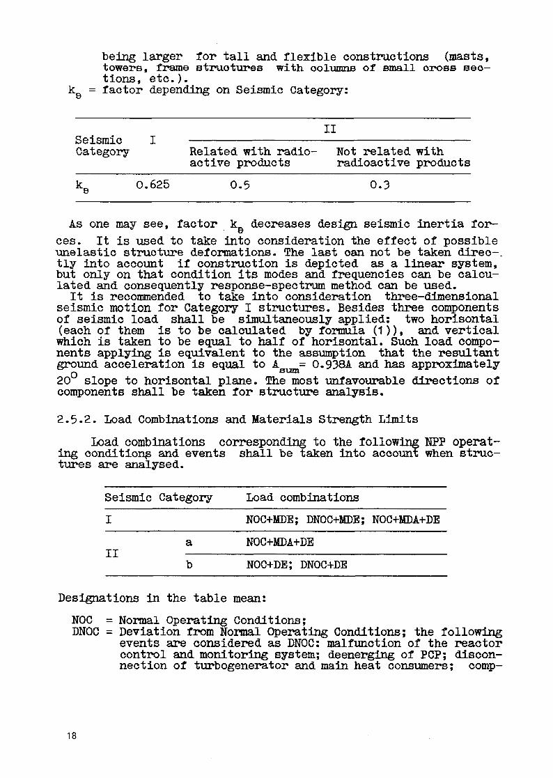
being larger for tall and flexible constructions (masts,towers, frame BtruotupeB with, oolumns of small oross sec-tions, etc.).
k = factor depending on Seismic Category:
IISeismicCategory Related with radio- Not related with
active products radioactive products
ko 0.625 0.5 0.3
As one may see, factor k_ decreases design seismic inertia for-
ces. It is used to take into consideration the effect of possibleunelastic structure deformations. The last oan not be taken direo-.tly into account if construction is depicted as a linear system,but only on that condition its modes and frequencies can be calcu-lated and consequently response-spectrum method can be used.It is recommended to take into consideration three-dimensional
seismic motion for Category I structures. Besides three componentsof seismic load shall be simultaneously applied: two horisontal(each of them is to be calculated by formula (1)), and verticalwhich is taken to be equal to half of horisontal. Such load compo-nents applying is equivalent to the assumption that the resultantground acceleration is equal to A = 0.938A and has approximatelyn sum
20 slope to horisontal plane. The most unfavourable directions ofcomponents shall be taken for structure analysis.
2.5.2. Load Combinations and Materials Strength Limits
Load combinations corresponding to the following NPP operat-ing conditions and events shall be taken into account when struc-tures are analysed.
Seismic
I
II
Category
a
b
Load combinations
NOC+MDE; DNOC+MDE; NOC+MDA+DE
NOC+MDA+DE
NOC+DE; DNOC+DE
Designations in the table mean:
NOC = Normal Operating Conditions;DNOC = Deviation from Normal Operating Conditions; the following
events are considered as DNOC: malfunction of the reactorcontrol and monitoring system; deenerging of POP; discon-nection of turbogenerator and main heat consumers; comp-
18

lete loss of off-site power supply; primary circuit leak-age which can be compensited by normal makeup systems;
MDA = Maximum Design Accident;DE = Design Earthquake;MDE = Maximum Design Earthquake.
Load combinations for above-mentioned operation conditions shallbe formed in oonformanoe with the Standard [9]- Depending on loadsduration they are divided into four groups, namely: "permanent","long-lived", "short-lived" and "extreme" ones. List of loads inc-luded into any group is presented in the Standard. For example,permanent loads include dead load, soil pressure on earthretainingwalls, prestressing loads, etc; long-lived loads are weight of theequipment, stored materials, people, cranes, NOC thermal and liveloads, etc.; short-lived loads include snow, wind and ice, clima-tic temperatures, cranes braking and equipment transient regimesloads, etc. Extreme loads are DE, MDE and MDA.Two types of load combinations are considered, namely: "main"
and "extreme" ones. The first consists of permanent, long-lived"and short-lived loads. Any of the "extreme" combinations includesin addition one of the extreme loads (there is an exception ofthis rule, which is discussed below). Loads of any group includedin combination are multiplied by the same factor. These factorsfor seismic load combination are: 0.9 for permanent loads, 0.8 forlonglived loads, 0.5 for short-lived loads, 1.0 for seismic loads(as for any other exstreme load).The load combination of two extreme loads, namely MDA+DE is con-
sidered as an exception for NPP constructions. It is made by thefollowing reason. Although NPP pipeB and equipment shall be desig-ned to withstand the effects of MDE and therefore they can not befailed by DE, nevertheless probability of DE and MDA occasionalooouranoe at the same time is too large. Indeed, DE ooouranoe pro-bability is equal to 10 1/year, for MDA it is estimated as 10 --10 1/year, consiquenily probability of their coincidence is mo-re than limit value 10 1/year. Prooeed from the same probabilis-tic reason MDE+MDA load combination is not considered. Moreoverload combinations of MDE with loads of short duration and rare oc-curanoe may be neglected too (if ratio of load duration to its oc-curance interval is less than 10 ).Materials strength limits for styress analyses of structures un-
der seismic loads are established by the Standard [4J. Accordingto them materials strength limits under static loadings multipliedby the factor n ^ shall be used. The factor is used to take into
account a short duration of earthquake. It varies from 0.9 (analy-ses of multi-storey building's reinforoed concrete columns subjeo-ted to shear forces) to 1.4 (steel constructions).
2.6 Generation of In-Structure Response Spectra and Time Histories
According to the Standard [2] in-struoture response spectra andtime histories shall be generated, but any additional specific re-quirements on this subject are not applied.In praotioal analyses different building models, from the simp-
lest lumped-mass beam ones to the space finite-element models are
19

used. Soil-structure interaction is usually taken into account by-means of effective springs and dashpots whose ends are connectedto foundation slab. The opponent ends are excited by seismic gro-und motion. Spring stiffness for rock bases was obtained by solv-ing the problem of vibrations of stamp embedded on elastic half-space. In this case M.I. Gorbunov-Posadov's formulas [10] are of-ten used which supply for square and circular foundations the samestiffness values as, for example, ASCE Standard [11]. But it isexperimentally established that similar formulas provide too lowstiffness values for soft soils. In this case O.A. Savinov's semi-experimental formulas or similar to them given in the Standard[13] are often used. To take into account the energy dissipationdue to radiation into foundation, different damping properties ofsubsistems, etc., formulas published in different issues and simi-lar to those established by the Standard [11] are used. A surveyof used methodologies and formulas are presented in the book [14].More complicated methodologies taking into account coupled struc-ture/base motion are also used in current practice.
2.7. Seismic Qualification of the Equipment
Requirements on the seismic qualification of the equipment and pi-pes concerned with radioactive products are established by theStandard [15]. But as a special lecture devoted to that subject ispresented at this seminar, this problem will not be examined inthis paper.General requirements on the seismic qualification of Category I
and II electric, automatic and communication equipment are provid-ed by the Standard [2]. Their strength and maintaining capacity towork shall be checked. Both analytic methods and tests are permit-ted. If shaking-table tests are carried out the device shall beswitched on and its work regime shall be imitated. General requi-rements to electric devices are established by the Standard [16],and shaking-table test regimes for their seismic qualification aregiven in the Standard [17J.
2.8. Earthquake Instrumentation
According to the Standard [2] the seismic control and signallingsystem shall be installed to provide automatic safe shutdown ofreactor in the case of earthquake occurence. Seismic instrumenta-tion for any other purposes is not required.
3. EXPLOSIONS
"Explosion overpressure-time" curve established by the Standard[1] is shown in fig. 2. Its duration is equal to 1 s.According to the Standard [18] for Nuclear Heating Plants. pe-
ak overpressure shall be taken Ap=50 kPa.For NPP of other type Ap values depend on the place of a poten-
tial explosion which can occurs either inside or outside its ter-ritiry. In the first case a possibility of explosions of such ob-
20

jects as hydrogen receivers, acetylene production installations,etc, is considered. Design value Ap=IQ kPa shall be taken. Plac-ing of any objects whose explosion can cause higher peak overpres-sure is forbidden in the NPP territory during all its life. If po-tential explosive objects exist or are planned to be placed nearerthan 5 km of reactor building (e.g., oil distilleries, stores ofpetrol and explosives, main gaB-pipes, heat accumulators, navigab-le river, railways, etc.) then peak overpressure Ap shall be esta-blished by means of analysis or be taken equal to Ap=30 kPa.At least one train of protection systems and one barrier of the
accident localisation system shall remain operation after explosi-on. Methods of structures analyses under explosions are regulatedby the Standard [193- The increased strength limits of the materi-als are used in order to take into aocount an influenoe of the lo-ading rate.
4. AIRCRAFT IMPACT
Aooording to the Standard [18] airoraft impaot shall be taken wi-thout fail into consideration for Nuclear Heating Plants. For NPPof other types this event shall be taken into account in. dependen-ce on the airoraft situation in the site neighbourhood or on Cus-tomer requirements.Aircraft of 20000kg mass and 200 m/s velocity is considered. Us-
ed "force-time" and "impaot area-time" diagramms are plotted infig. 3 0 The most unfavourable impact angle in the range from 10to 45 to horisontal plane shall be used.At least one train of protection systems and one barrier of the
accident localisation system shall remain operation after aircraftijnpaot. Nonlinear behaviour of reinforced concrete is admitted;the width of the oraoks ie not limited (provided they oan not leadto the release of the radioactive products); spalling of concreteinside of structure is not admitted; any requerement concerningthe maintain of a tight of the inside layer is not applied.Strength limits of concrete and reinforcement materials are takenaccording to %the Standard [183, i.e. they are increased as for ex-plosions.Dynamic analysis of structure shall be carried out to generate
in-structure response spectra.
5. TORNADO
Except requirement of Standart [13 to take tornado into accountthere are no other regulations concerning this subject. Analysismethodologies published in technical literature (e.g., [203) areused nowadays.
21

[1 ] ITHH A9 - 5.6. HopMH CTpoHTejitHoro npoeKTiapoBaHHfl AC c peaKTo-paMH pa3JiH^Horo THna / rocaTOMeHeproHa,H3op CCGP. 1986 r.
PiN AE-5.6. Structures Design Standard for NPPs of DifferentTypes. / Approved by the USSR State Athomio Energy Supervisi-on in 1986.
[2] IH A8 37-5-006-87. HbpMH npoeKTHpoBamifl cefiCMOCToftKHZ STOMHHZ/ rocaTOM8HeproHa;n;3op CCCP, 1987 r.
PN AE G-5-006-87- NPP Seismic Design Standard. / Approved bythe USSR State Athomic Energy Supervision in 1987.
[3] BCH-15-78. BpeMeHHHe HOPMU npoeKTHpoBaHHfl aTOMHHx eHepre-ra^ec-KKK yCTaHOBOK flJIH CefliCMineCKHX paftOHOB./ MHHBHeprO CCCP. 1979
VSN-15-78. Temporal Standard for Design of NPPs in Seismic Re-gions / Approved by the USSR Energetics Ministry In 1979
[4] CHHII II-7-81. CTpoHTejibCTBo B ceftcMBraecKHX paftoHaz / roccTpofl:CCCP. 1982 r.
SNiP II-7-81. Building in Seismio Regions / Approved by theUSSR State Building Committee in 1981)
[ 5 ] IAEA Recommendat ions * 5O-SG-S1. y^ieT 3eMJieTpflceHHft H cBfi3aH-HHX C HHMH HBJieHHfi WpSL BHCope nJIOma^OK flJIH aTOMHHX
PyKOBO^CTBo no 0"e3onacHOCTH. BeHa: MATAT9. 1981
[6] IIHA9 r-1-011-89. O(5nqse nojioaeHHfl odecne^eHHfl 6e3onacHocTH a-ro-MHHX CTaHuaft (OIIB-88). / rocaTOMeHeproHa,53op CCCP. 1990 r .
PN AE G-1-011-89. General Regulations on NPP Safety Ensuring(OPB-88) / Approved by the USSR S ta t e Athomio Energy Supervi-s ion in 19*90
[7] US AEC Regulatory Guide 1.60. Design Response Spectra for S e i -smic Design of Nuolear Power P l a n t s . Approved Deo. 1973.
[8] CII A9C-79. CaHHTapHHe npaBHJia npoeKTHpoBaHHfl H eKcruiyaTaujmaTOMHHx BJieKTpocTaHUHft. / MuHHCTepcTBO 3^paBooxpaHeHHfl CCCP,1979 r .
SP AES-79. NPP Design and Operation Sanitary Rules / Approvedby the USSR Ministry of Public Helth In 1979
[9] CHsdl 2 .01.07-85. Harpy3KH H BO3fleftcTBHfl /roccTpoft CCCP. 1978 r
SNiP 2.01.07-85. Loads and Effects / Approved by the USSR Sta-te Building Committee in 1978
[ 1 0 ] ropdyHOB-IIocaflOB M.M. (1953) Pac^eT KOHCTpyicujift Ha ynpyroM- MocKBa: CTpofiH3,2];aT.
22

Gorbunov-Posadov M.I. (1953) Analyses of Elastic Bedded Cons-tructions. Moskow, Strojizdat.
[11] ASCE Standard "Seismic Analysis of Safety-Related NuclearStructures and Commentary on Standard for Safety Related Nuc-lear Structures". Approved September 1986.
[12] CaBHHOB O.A. (1979) CoBpeMeHHbie KOHCTpyKunn <$yH,a;aMeHTOB no,n;H H Z pac-qeT. - JfeHHHrpafl: CTpoflH3.ua T.
Savinov O.A. (1979) Modern Foundations of Mashines and theirAnalyses. - Leningrad, Strojizdat.
[13] CHMI 2.02.05-87. yHflaMeHTH Mannra c pjmatJarieQKHMH/ ToccTpofi CCCP. 1988 r.
SNIP 2.02.05-87. Foundations of Mashines under Dynamic Loads/ Approved by the USSR State Building Committee in 1988.
[14] Enp<5paep A.H., Wyju>MaH C.r. (1989) IIPO^HOCTB H Ha^eaHOCTt KOH-A9C npH ocoCtix HHaMH^ecKHX Harpy3Kax - MocKBa: 3He-
Birbraer A.N., Shulman S.G. (1989) Strength and Reliabilityof NPP Structures under Extreme Dynamic Loads. - Moskow, En-ergoatomizdat.
[15] IIHA3 r-7-002-86. HopMH pac ieTa Ha npo^mocTB oCopyflOBaHHfl HTpyConpoBOflOB aTOMHHZ 8HepreTH*iecKHX ycTaHOBOK. / PocaTOM-8HeproHa,]];3op CCCP. 1987 r.
PNAE G-7-002-86. Standard of Strength Analyses of Nuclear Po-wer Installations Equipment and Pipes / Approved by the USSRState Athomic Energy Supervision in 1987.
[16] TOCT I 7 5 I 6 . I - 9 0 . M3#ejnjfl BJieKTpoTeiHHqecKHe. 0<5imaeB ^aCTH CTOfiKOCTH K MexaHBraeCKHM BHemHHMTopaM / ToccTaHflapT CCCP, 1990 r.
GOST 17516.1-90. Electrotechnical Devices. General Regulati-ons on Resistance to External Mechanical Loads / Approved bythe USSR State Standardization Committee in 1990.
[17] TOCT 16962.2-90. JfeflejiHtf ejieKTpoTexHEreecKHe. UeromHa CTO&COCTB K MexaHsraecKHM BHemHHM B03,neftcTByionpiM $aKTopaM /T CCCP, 1990 r .
GOST 16962.2-90. Electrotechnioal Devices. Methods of Testsof Resistance to External Mechanical Loads / Approved by theUSSR State Standardization Committee in 1990)
[18] TSBH. Py AC-89. npaBmia a^epHofl: (5e3onacHOCTH peaKTopHHX ycTaHO-BOK aTOMHHX cTaHtqafi / yTBepx^eHH rocaTOMHafl3opoM CCCP. 1990 r
23
PBJa RU AS-89- Nuclear Safety Rules for Reactors of NuclearPlants / Approved by the USSR Sta te Athomic Energy Supe rv i s i -on in 1990
[19] CHMI 11-11-77 - 3anpiTHHe coopyaemifl rpaacflaHCKoft o6opoHH/ Foc-CTpofi CCCP. 1985 r .
SNiP I I - 7 - 8 1 . C iv i l Defenoe Shield Struotures / Approved bythe USSR S t a t e Building Committee in 1981 )
[20] Simiu E . , Soanlan R.H. (1978) Wind Effects on S t ruc tu res -John Wiley & Sons.
CHMHV 9 . , CKaHJiaH P. (1984) Bo3,n;eftcTBne BeTpa Ha 3«aHHfl H CO-opyxemia - M.: CTpoflH3flaT.
24

stiff ground
2.0
10'
Russian Standard
US AEC RegulatoryGuide 1.60
i 1%i 10% damping
—I 1 1 1 1 r
0 . 0.5-i—| 1 1 1 r-r-j 1 1 1 1—j < =•*""
10 .1.5 2.0 T,S
Fig.l
105 MH
0 0.01. 0.02 0.03 0.04 0.05 0.0S 0.07
Fig2
0 0.5
Fig3
25
Copyright © 2022 FDOKUMEN