Robot League Team RescueRobots Freiburg (Germany)
17
RoboCupRescue - Robot League Team RescueRobots Freiburg (Germany) Alexander Kleiner, B. Steder, C. Dornhege, D. Höfer, D. Meyer-Delius, J. Prediger, J. Stückler, K. Glogowski, M. Thurner, M. Luber, M. Schnell, R. Kuemmerle, T. Burk, T. Bräuer and B. Nebel Post Print N.B.: When citing this work, cite the original article. Original Publication: Alexander Kleiner, B. Steder, C. Dornhege, D. Höfer, D. Meyer-Delius, J. Prediger, J. Stückler, K. Glogowski, M. Thurner, M. Luber, M. Schnell, R. Kuemmerle, T. Burk, T. Bräuer and B. Nebel, RoboCupRescue - Robot League Team RescueRobots Freiburg (Germany), 2005, RoboCup 2005 (CDROM Proceedings), Team Description Paper, Rescue Robot League. Postprint available at: Linköping University Electronic Press http://urn.kb.se/resolve?urn=urn:nbn:se:liu:diva-72564
-
Upload
khangminh22 -
Category
Documents
-
view
3 -
download
0
Transcript of Robot League Team RescueRobots Freiburg (Germany)

RoboCupRescue - Robot League Team
RescueRobots Freiburg (Germany)
Alexander Kleiner, B. Steder, C. Dornhege, D. Höfer, D. Meyer-Delius, J. Prediger,
J. Stückler, K. Glogowski, M. Thurner, M. Luber, M. Schnell, R. Kuemmerle, T. Burk,
T. Bräuer and B. Nebel
Post Print
N.B.: When citing this work, cite the original article.
Original Publication:
Alexander Kleiner, B. Steder, C. Dornhege, D. Höfer, D. Meyer-Delius, J. Prediger, J.
Stückler, K. Glogowski, M. Thurner, M. Luber, M. Schnell, R. Kuemmerle, T. Burk, T.
Bräuer and B. Nebel, RoboCupRescue - Robot League Team RescueRobots Freiburg
(Germany), 2005, RoboCup 2005 (CDROM Proceedings), Team Description Paper, Rescue
Robot League.
Postprint available at: Linköping University Electronic Press
http://urn.kb.se/resolve?urn=urn:nbn:se:liu:diva-72564

RoboCupRescue - Robot League TeamRescueRobots Freiburg (Germany)
Alexander Kleiner, Bastian Steder, Christian Dornhege, Daniel Hoefler, DanielMeyer-Delius, Johann Prediger, Joerg Stueckler, Kolja Glogowski, Markus Thurner,Mathias Luber, Michael Schnell, Rainer Kuemmerle, TimothyBurk, Tobias Brauer,
and Bernherd Nebel
Institut fur Informatik,Universitat Freiburg, 79110 Freiburg, Germanyhttp://www.informatik.uni-freiburg.de/∼rrobots
Abstract. This paper describes the approach of theRescueRobots Freiburg team.RescueRobots Freiburg is a team of students from the university of Freiburg, thatoriginates from the former CS Freiburg team (RoboCupSoccer) and theResQFreiburg team (RoboCupRescue Simulation).Due to the high versatility of the RoboCupRescue competition we tackle the threearenas by a a twofold approach: On the one hand we want to introduce robustvehicles that can safely be teleoperated through rubble and building debris whileconstructing three-dimensional maps of the environment. On the other hand wewant to introduce a team of autonomous robots that quickly explore a largeterrainwhile building a two-dimensional map. This two solutions are particularly well-suited for the red and yellow arena, respectively. Our solution for the orange arenawill finally be decided between these two, depending on the capabilities of bothapproaches at the venue.In this paper, we introduce some preliminary results that we achieved so far frommap building, localization, and autonomous victim identification. Furthermorewe introduce a custom made 3D Laser Range Finder (LRF) and a novel mecha-nism for the active distribution of RFID tags.
1 Introduction
RescueRobots Freiburg is a team of students from the university of Freiburg. The teamoriginates from the former CS Freiburg team[6], which won three times the RoboCupworld championship in the RoboCupSoccer F2000 league, and the ResQ Freiburg team[2],which won the last RoboCup world championship in the RoboCupRescue Simulationleague. The team approach proposed in this paper is based on experiences gathered atRoboCup during the last six years.
Due to the high versatility of the RoboCupRescue competition we tackle the threearenas by a twofold approach: On the one hand we want to introduce a vehicle thatcan safely be teleoperated through rubble and building debris while constructing three-dimensional maps of the environment. On the other hand we want to introduce an au-tonomous team of robots that quickly explore a large terrainwhile building a two-dimensional map. This two solutions are particularly well-suited for the red and yellowarena, respectively. Our solution for the orange arena willfinally be decided betweenthese two, depending on the capabilities of both approachesat the venue.

1.1 Teleoperated 3D mapping (large robots)
We suppose that the orange and red arenas are only passable bymaking use of 3Dsensors. Hence we decided to deploy large robots that are able to carry heavier sensors,such as a 3D Laser Range Finder (LRF). and are able of driving on steep ramps andrubble.
The robots are teleoperated by an operator that also has to create a map of theenvironment and to augment this map with locations of victims that are detected duringnavigation. Mapping and victim detection has to be assistedby the system as good aspossible, since the navigation task of the operator is challenging on its own. Hence thesystem is designed to suggest plausible locations for scanning the environment withthe 3D LRF, as well as to detect various evidences for the presence of victims, such asmotion and heat, and indicate those to the operator.
1.2 Autonomous exploration of a team of robots (small robots)
We suppose that the yellow arena will be large and driveable by a team of small robots.The ”office-environment-style” of the yellow arena makes mapping comparable simplesince 2D sensors suffice. Therefore we intend to deploy fast and agile robots that com-municate with each other. Our idea is to simplify the 2D mapping problem by RFIDtags that our robots distribute with a newly developed tag-deploy-device, as describedin Section 10. In general, this has mainly two advantages forUrban Search and Res-cue (USAR): Firstly, RFID tags provide a world-wide unique number that can be readfrom distances up to a few meters. To detect these tags and thus to uniquely identifylocations, is significantly computational cheaper and lessambiguous than identifyinglocations from camera images and range data1. Secondly, travel paths to victims candirectly be passed to human ambulance teams as complete plans that consist of RFIDtag locations and walking directions. In fact, tags can be considered as signposts sincethe map provides for each tag the appropriate direction. Given a plan of tags, ambulanceteams could find a victim by directly following tags, which ismuch more efficient thanfinding a path from a map. However, in order of being in one linewith the rules, ourteam will also deliver hard copies of printed maps.
2 Team Members and Contributions
– Team Leader: Alexander Kleiner– Simulation and Behaviors: Christian Dornhege– 2D Sensors and Localization: Johann Prediger– 3D Mapping and Localization: Tobias Braeuer– Controller Design: Johann Prediger, Joerg Stueckler– Mechanical Design: Mathias Luber– Victim Identification: Daniel Meyer-Delius, Daniel Hoefler, Markus Thurner, Tim-
othy Burk
1 Note that even for humans the unique identification of a location is hard, when for exampleexploring a large office building

– Teleoperation: Bastian Steder, Kolja Glogowski, Rainer Kuemmerle, Michael Schnell– Advisor: Bernhard Nebel
These are all team members that contributed to the approaches introduced in this paper.The team which will finally be present at the venue is not decided by now, however,will consist of any subset from the upper list.
3 Operator Station Set-up and Break-Down (10 minutes)
Our robots are controlled from a lightweight laptop via a force-feedback joystick whichall can be transported together in a backpack. It is possiblefor the operator to selectbetween different robots as well as between different views/cameras from a single roboton the fly.
Our largest robot can be transported by a moveable case with wheels, whereas thesmall robots can even be backpacked. The whole setup and breakdown procedure canbe accomplished within less than ten minutes, including to boot the computers, to checkthe network connection, and to check whether all sensors work properly.
4 Communications
Autonomous as well as teleoperated vehicles are communicating via wireless LAN. Weuse a D-Link DI-774 access point that is capable to operate inthe 5GHz as well as inthe 2.4GHz band. All communications are based on the Inter Process Communication(IPC) framework which has been developed by Reid Simmons [3]. The simultaneoustransmission of multiple digital video streams is carried out by an error-tolerant proto-col, which we developed based on the IPC framework.
Moreover, the small robots are equipped with radio modules that operate in theEuropean 433MHz band with 10mW. This low-bandwidth communication is intendedas a backup solution for short-range communication in case the wireless communicationfails.
5 Control Method and Human-Robot Interface
The overall goal of our team is to build autonomous robots. Webelieve that this goalcan possibly be achieved for the yellow arena, however quiteunlikely for the red arena.Therefore our control approach is twofold: teleoperation in the red arena (large robots)and autonomous operation in the yellow arena (team of small robots) and a combinationof both in the orange arena.
Teleoperation is carried out with a force-feedback joystick which is connected toa portable Laptop (see figure 1(b)). Besides images from the cameras mounted on therobot, the operator receives readings from other sensors, such as range readings froma LRF, compass measurements, and the battery state of the robot. Data from the LRFis used to simplify the operator’s task of avoiding obstacles. The 3D force-feedbackjoystick indicates accurately the directions of incoming obstacle. This is carried out by

(a) (b)
Fig. 1. (a) The teleoperation window: range readings from a LRF (lower left corner), compassmeasurements (upper edge) , and the view of the surrounding area from an omni-directionalcamera (lower right corner) are overlayed onto the front view. (b) Force Feedback controller
applying a small force on the joystick that points into the opposite direction in whichobstacles are detected. This feature makes it intuitively harder for the operator to driveinto obstacles.
The Graphical User Interface (GUI) is realized by a similar approach as proposedby the RoBrno team at RoboCup 2003[7]. Images from video cameras are shown in fullsize on the screen and additional sensor information is overlayed via a Head Up Display(HUD). The operator might change the kind of information andthe transparency (alphavalue) of the displayed information via the joystick.
We designed a special omni-directional vision system that provides a complete viewof the robot’s surroundings. This is particularly important for the operator to avoid ob-stacle collisions while operating through narrow passages. Besides the omni-directionalview, the operator can select between a rear-view and front-view camera. It is possibleto select one camera as ”active” camera. Images from the active camera are shown infull-screen to the operator, whereas images from all other cameras are sized-down anddisplayed as an smaller overlays on the screen (see figure 1 (a)).
Besides teleoperation, the operator has to construct a map of the arena. Optimally,map generation takes place automatically in the backgroundand the operator has not tocare about. However, since 3D scanning needs time, the operator has at least to initiatethis process manually in order not to be disturbed while navigating. Our system indi-cates good locations for taking 3D scans to the operator and displays the result of thematching process on the screen. At any time, the operator is able to access the current3D model of the environment. This is helpful if, for example,lighting conditions arebad. Additionally, the resulting map can also be used by a path planning algorithm forrecommending an optimal path to the operator’s current destination.
Autonomous control of robots is one of the most challenging goals in robotics,which we are planning to achieve at least in the yellow arena.For this purpose we

are going to utilize techniques that we have already appliedsuccessfully in theF2000league [6]. However, the autonomous control of robots in RoboCupRescue requires avery detailed world model in 2D, or even in 3D if approaching the orange arena. Inthe orange arena, conventional control methods for autonomous robots might fail sincethey are tailored for operation in the plane with specific ground properties (e.g. a soccerfield). Hence we are currently working on control methods that can be executed withrespect to different conditions of the ground.
6 Map generation/printing
Our team develops simultaneously two different approachesfor mapping and local-ization. The choice for two localization approaches is due to the versatility of rescuearenas: The yellow arena has to be explored and mapped as fastas possible, likewisein 2D, whereas the orange and red arena can only be mapped by making use of 3Dsensors. Hence we plan to deploy fast and numerous robots forautonomous 2D explo-ration and a larger one, equipped with a 3D scanner, for the automatic, operator assistedgeneration of maps.
(a) (b)
Fig. 2. A 3D map generated from various scans in our lab (a). A 2D Map generated from the 3Dmap (b). The location of the robot while mapping is shown by a blue trajectory.
On the one hand, we are working on an automatic map generationsoftware that pro-cesses data from a 3D LRF based on the ICP scan registration method that recently hasbeen proposed by theKurt3D team[4] to the rescue league. Therefore, we constructeda new system for taking 3D scans, which is described in Section 7. A preliminary resultof the successful registration by the ICP method of 3D scans taken in our Lab is shownin figure 2 (a) and a 2D localization within this map is shown infigure 2 (b).
On the other hand we are working on a method for the autonomousmulti-robotmapping supported by the active distribution of RFID tags. For this purpose we con-structed a special aperture, further described in Section 10, that can be triggered torelease tiny RFID tag into the environment. Tags are detectable by a RFID reader thatcan be mounted on any robot. The deployment of tags, the sensing of environmentalstructure, the absolute orientation and odometry, and evidence of victim whereaboutsare communicated between the robots. From this information, each robot is able to in-tegrate a world model, which is consistent with those of the other robots, whereas the

RFID tags, which are detectable with nearly no noise, are supporting the alignment ofthe individual maps build by each robot.
From the collected information a topological map emerges, which can be passed toa human operator. The topological map consists of RFID tags as vertices and naviga-tion directions and lengths as edges. The map is augmented with structural and victimspecific information. Human ambulance teams that are also equipped with a RFID tagreader might find the locations of victims more efficient thandirectly from a 2D/3Dmap, since RFID tags can be used as signposts. However, also conventional maps canbe printed by our system and handed out to the human team.
7 Sensors for Navigation and Localization
As already stated in the previous section, our team has started to develop a 3D LRFdevice for the automatic mapping of rescue arenas. A model ofthe sensor can be seenin figure 3. The LRF sensor is rotated by a strong servo motor that allows a fast andaccurate vertical positioning of the device. As can be seen from figure 3, the devicecan be rotated by more than 200 degrees. This allows to take 3Dscans from the frontas well as from behind the robot. The design of this system differs from the design ofother 3D scanners in that it is capable of collecting sparse data from a large field ofview rather than dense data from a small field of view. We believe that the sparse datacollection will improve the speed of 3D mapping and the larger field of view will leadto a larger overlap of scan points, which in turn, will increase the robustness of the scanregistration process. Robust scan registration is the basis for autonomous2 mapping.
(a) (b)
Fig. 3.A hand-made 3D Laser Range Finder (LRF) device, shown from the front (a), and shownfrom the back (b).
Also the autonomous exploration of robots requires an accurate modeling of theenvironment. In RoboCupRescue this environment is three-dimensional and thus re-quires highly developed sensors for the navigation tasks. As can be seen in figure 7(a),Section 9, our base for autonomous operation is equipped with 9 infrared and 3 ul-trasonic sensors. Furthermore, we added a compass, an acceleration sensor, and twowheel-encoders for counting the revolution of each wheel.
2 Note that we distinguishautomatic mapping from autonomous mapping in that the latter alsoincludes the task of autonomous navigation

(a) (b)
Fig. 4. The 3D camera ”SwissRanger” from CSEM (a), and the accurate orientation sensor ”In-ertiaCube2” from InterSense (b).
These sensors provide sufficient information on the structure of 2D environments.However, in order to explore autonomously 3D environments,higher sophisticated sen-sors are necessary. Therefore we are planning to detect local 3D structures, such asramps and stairs, with a 3D camera (see figure 4 (a)), and to track reliably the 3D ori-entation (yaw, roll and pitch) of the robot with a 3DOF sensorfrom InterSense (seefigure 4 (b)).
8 Sensors for Victim Identification
Victim identification is crucial for both autonomous operation and teleoperation. Thelatter can be simplified by augmenting video streams with useful information gatheredby image processing techniques or sensors that detect motion, heat, orCO2 emission.
We utilized the Eltec 442-3 pyroelectric sensor to detect the motion of victims. Thissensor can measure changes of the infrared radiation over time. Therefore the sensor hasto be in motion in order to detect heat sources. For that purpose we mount the sensor on aservo which allows a rotation of nearly180 degrees. Due to the high thermal sensitivityof the sensor, changes of the background radiation are detected as well, which lead toa noise contaminated signal. In order to separate the usefulsignal from noise, somefiltering techniques are used. Preliminary tests have shownthat it is possible to safelydetect human bodies within a distance of four meters.
Fig. 5. Series of pictures that demonstrates motion detection based on noise reduced differenceimages.

Fig. 6.Series of pictures that demonstrates victim face detection based on ADABoost with simplefeatures.
Moreover, we examine image processing techniques for victim detection. In contrastto the RoboCupSoccer domain, there is no color coding withinRoboCupRescue. Thismeans that image processing algorithms have to be capable ofdealing with the fullcolor space, rather than with a small subset of pre-defined colors, such as for example,the ball color and the field color.
We utilized a fast approach for detecting motion within video streams which isbased on the analysis of differences between subsequent images. After filtering thedifference information from noise, a clustering is calculated that is used for estimatingthe probability of human motion. The whole process is shown by the image series infigure 5.
Besides motion, victims can also be detected from single video images by theirfaces or fingers. Although this detection is hard under varying illumination conditionsand different view angles, a recent approach, originally introduced by Viola and col-leagues [5], produces also in the rescue domain promising results, as can be seen infigure 6. This approach combines the classification results of multiple, simple classi-fiers by ADA boosting[1], which is contrary to former approaches that favored onecomplex model for the classification.
9 Robot Locomotion
Locomotion is carried out by three different robot platforms (not necessarily one foreach arena). In figure 7 all robots that will be deployed are shown. Figure 7(a) shows afast and agile robot that will be used for the autonomous teamexploration. Figure 7(b)shows a larger robot that is equipped with a LRF for mapping and obstacle avoidance,

(a) (b) (c)Fig. 7.Three of our robots: (a) an autonomous and agile robot, (b) a teleoperated, large robot thatcan drive ramps, (c) a teleoperated, large robot that can drive on rubble.
and multiple cameras in order to provide a good overview to the operator. Figure 7(c)shows a toy-robot that is capable of climbing a pallet as shown in the figure. The lattertwo robots are supposed to be controlled by an operator.
10 Other Mechanisms
Figure 8 shows the prototype of a novel mechanism for the active distribution of RFIDtags. The mechanism can easily be mounted on a robot or a R/C car and can be trig-gered by setting the appropriate angles of a servo motor. Theservo motor opens a smallopening that releases a1.3cmx1.3cm small chip, carrying the RFID tag. The chip canbe detected by a RFID tag reader that has to be mounted on the vehicle. Since the tagsare transported on the robot within a metal box, they are onlydetectable after beingreleased. By this it can be guaranteed that a tag has been released by the mechanismsuccessfully. The shown device is capable of holding 50 tags, which we plan to improvetowards a capacity of 100. Tags once deployed by robots can easily be collected by avacuum cleaner.
(a) (b) (c)Fig. 8. A novel mechanism (a) for the active distribution of RFID tags (b). The mechanism inaction while mounted on a R/C car (c).

11 Team Training for Operation (Human Factors)
The teleoperation of rescue robots requires a long period oftraining, since communi-cation delays but also the restricted field of view have to be learned by the operator.We plan to perform regular competitions between our team members in order to deter-mine the person most suitable for teleoperation. Competingmembers will have to buildchallenging arenas in order to make the current operators task more difficult.
Furthermore, a large amount of practicing is necessary for training a team of au-tonomous robots. Since this is a very tedious task, we decided to utilized the USARSimsimulation system, which is based on the Unreal2003 game engine (see figure 9(a)).The simulation of the robots is crucial in order to speed-up the development of multi-agent behaviors as well as providing data for learning approaches. Figure 9(b) showsan occupancy grid and Vector Field Histogram (VFH) of one of our robots simulated inthe yellow arena.
(a) (b)
Fig. 9. Robot simulation with USARSim, based on the Unreal2003 game engine (a) and thecorresponding Vector Field Histogram (VFH) for obstacle avoidance (b).
12 Possibilities for Practical Application to Real Disaster Site
Our team has no experience with any practical application inthe context of real disastersites. Anyway, we are confident that some of the techniques utilized by our team arelikely helpful for supporting real rescue teams.
A mobile device for the automatic generation of 3D maps mightbe very helpfulif, for example, rescue teams have to decide optimal locations for starting excavations.The generated maps could also be used for providing a better view of the situation inthe field to an outside operator/instructor.
Our approach of autonomous exploration with RFID tags mightbe very helpful incase the disaster site is large and little blocked with rubble, such as the yellow arena.

Since our robots are small and cheap, they can be a real benefitto an human team thatcould focus more on victim healing and transport.
13 System Cost
Generally, our philosophy is to provide solutions that are good as possible but also cheapas possible. Hence some of our robots are based on R/C cars that can be bought for lessthan 100 USD. The following three tables list the approximate costs of each robot type.A detailed description of each robot part that we use, is found in the appendix.
Name Part Price in USDNumberPrice Total in USD
Robot Base 50 1 50Micro Controller MC9S12DG256 120 1 120IR Sensor GP2D12 12 9 108Sonic Sensor SRF08 53 3 159Compass Sensor CMPS03 53 1 53Flex Sensor FLEXS 18 2 36Pyroelectric Sensor R3-PYRO01 64 1 64Odometry Sensor R238-WW01-KIT 60 1 60Acceleration Sensor ADXL202 100 1 100Radio Modul ER400TRS 45 1 45WLAN Adapter ADL-AG650 77 1 77CPU Board speedMOPSlcdCE 390 1 390RFID Reader Medio S002 370 1 370Sum: 1 1582Sum Total: 3 4746
Table 1.Costs for Team of small robots.
Name Part Price in USDNumberPrice Total in USD
Robot Base Pioneer II 4000 1 4000FireWire Camera Sony DFW-V500 1000 4 4000FireWire HUB 60 1 60Laser Range Finder Sick LMS200 4000 1 4000LRF 3D Extension 900 1 9003 DOF Orientation SensorIS Inertia Cube 1500 1 1500Laptop MP-XP731DE 1900 1 1900Sum Total: 3 16360
Table 2.Costs for Large Robot I.

Name Part Price in USDNumberPrice Total in USD
Robot Base Tarantula 99 1 99FireWire CameraSony DFW-V500 1000 2 2000FireWire HUB 60 1 60Laptop MP-XP731DE 1900 1 1900Sum Total: 3 4059
Table 3.Costs for Large Robot II.
References
1. Y. Freund and R. E. Schapire. Experiments with a new boosting algorithm. In InternationalConference on Machine Learning, pages 148–156, 1996.
2. A. Kleiner, M. Brenner, T. Braeuer, C. Dornhege, M. Goebelbecker, M. Luber, J. Prediger,J. Stueckler, and B. Nebel. Successful search and rescue in simulated disaster areas. InProc.Int. RoboCup Symposium ’05. Osaka, Japan, 2005. submitted.
3. Reid Simmons.http://www-2.cs.cmu.edu/afs/cs/project/TCA/www/ipc/ipc.html, 1997.
4. H. Surmann, A. Nuechter, and J. Hertzberg. An autonomous mobilerobot with a 3d laserrange finder for 3d exploration and digitalization of indoor environments.Journal Roboticsand Autonomous Systems, 45(3-4):181–198, 2003.
5. P. Viola and M. Jones. Robust real-time object detection.International Journal of ComputerVision, 2002.
6. T. Weigel, J.-S. Gutmann, M. Dietl, A. Kleiner, and B. Nebel. CS-Freiburg: Coordinat-ing robots for successful soccer playing.IEEE Transactions on Robotics and Automation,18(5):685–699, 2002.
7. L. Zalud. Orpheus - universal reconnaissance teleoperated robot. In Proc. Int. RoboCupSymposium ’04. Lisboa, Portugal, 2004. To appear.
14 Appendix
NUMBER: 1KEY PART NAME: MC9S12DG256PART NUMBER: CARDS12DG256MANUFACTURER: Elektronik LadenCOST: 120 USDWEBSITE: http://www.elektronikladen.de/cards12.htmlDESCRIPTION: Micro Controller mit 256KB Flash, 4KB EEPROM,12KB RAM
NUMBER: 2KEY PART NAME: IR SensorPART NUMBER: GP2D12MANUFACTURER: SharpCOST: 12 USDWEBSITE: http://www.roboter-teile.deDESCRIPTION: IR Sensor

NUMBER: 3KEY PART NAME: Ultra Sonic SensorPART NUMBER: SRF08MANUFACTURER:COST: 53 USDWEBSITE: http://www.roboter-teile.deDESCRIPTION: Ultra Sonic Sensor
NUMBER: 4KEY PART NAME: Compass modulPART NUMBER: CMPS03MANUFACTURER:COST: 48 USDWEBSITE: http://www.roboter-teile.deDESCRIPTION: Compass
NUMBER: 5KEY PART NAME: Flexsensor Age Inc.PART NUMBER: FLEXSMANUFACTURER:COST: 18WEBSITE: http://www.roboter-teile.deDESCRIPTION: Sensor that detects deformation
NUMBER: 6KEY PART NAME: Pyroelectric sensor packagePART NUMBER: R3-PYRO1MANUFACTURER: AcronameCOST: 64 USDWEBSITE: http://www.acroname.com/robotics/parts/R3-PYRO1.htmlDESCRIPTION: Sensor that detects human motion
NUMBER: 7KEY PART NAME: OdometryKEY PART NAME: Two Wheel Servo Encoder KitPART NUMBER: R238-WW01-KITMANUFACTURER: AcronameCOST: 60 USDWEBSITE: http://www.acroname.com/robotics/parts/R238-WW01-KIT.htmlDESCRIPTION: Sensor that counts wheel revolution
NUMBER: 8KEY PART NAME: Acceleration Sensor
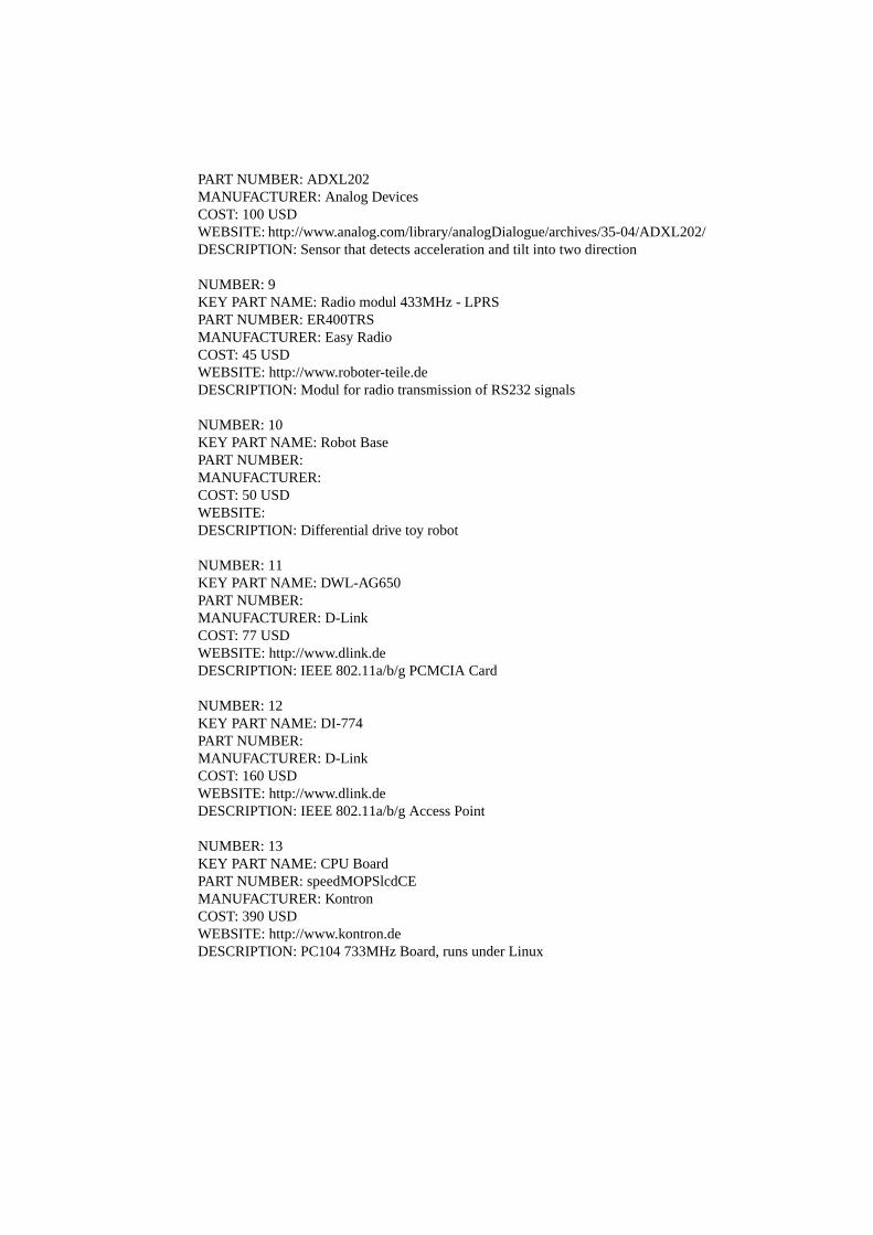
PART NUMBER: ADXL202MANUFACTURER: Analog DevicesCOST: 100 USDWEBSITE: http://www.analog.com/library/analogDialogue/archives/35-04/ADXL202/DESCRIPTION: Sensor that detects acceleration and tilt into two direction
NUMBER: 9KEY PART NAME: Radio modul 433MHz - LPRSPART NUMBER: ER400TRSMANUFACTURER: Easy RadioCOST: 45 USDWEBSITE: http://www.roboter-teile.deDESCRIPTION: Modul for radio transmission of RS232 signals
NUMBER: 10KEY PART NAME: Robot BasePART NUMBER:MANUFACTURER:COST: 50 USDWEBSITE:DESCRIPTION: Differential drive toy robot
NUMBER: 11KEY PART NAME: DWL-AG650PART NUMBER:MANUFACTURER: D-LinkCOST: 77 USDWEBSITE: http://www.dlink.deDESCRIPTION: IEEE 802.11a/b/g PCMCIA Card
NUMBER: 12KEY PART NAME: DI-774PART NUMBER:MANUFACTURER: D-LinkCOST: 160 USDWEBSITE: http://www.dlink.deDESCRIPTION: IEEE 802.11a/b/g Access Point
NUMBER: 13KEY PART NAME: CPU BoardPART NUMBER: speedMOPSlcdCEMANUFACTURER: KontronCOST: 390 USDWEBSITE: http://www.kontron.deDESCRIPTION: PC104 733MHz Board, runs under Linux

NUMBER: 14KEY PART NAME: RFID ReaderPART NUMBER: Medio S002MANUFACTURER: AdesCOST: 370 USDWEBSITE: http://www.ades.chDESCRIPTION: Universal RFID Reader
NUMBER: 15KEY PART NAME: InertiaCube2PART NUMBER:MANUFACTURER: InterSenseCOST: ca. 1800 USDWEBSITE: http://www.roboter-teile.deDESCRIPTION: Modul for radio transmission of RS232 signals
NUMBER: 16KEY PART NAME: FireWire CameraPART NUMBER: Sony DFW-V500MANUFACTURER: SonyCOST: 1000 USDWEBSITE: http://www.ccddirect.com/online-store/scstore/p-114100.htmlDESCRIPTION: Sony FireWire Camera
NUMBER: 17KEY PART NAME: FireWire HUBPART NUMBER: IEEE 1394 6-PORT REPEATERMANUFACTURER:COST: 60 USDWEBSITE: www.conrad.deDESCRIPTION: FireWire HUB
NUMBER: 18KEY PART NAME: 3D CameraPART NUMBER: SwissRangerMANUFACTURER: CSEMCOST: ca. 7000 USDWEBSITE: http://www.swissranger.chDESCRIPTION: 3D Camera
NUMBER: 19KEY PART NAME: Robot BasePART NUMBER: Pioneer IIMANUFACTURER: ActiveMedia

COST: ca. 4000 USDWEBSITE: http://www.activmedia.comDESCRIPTION: Robot Platform
NUMBER: 20KEY PART NAME: Robot BasePART NUMBER: Tarantula Toy RobotMANUFACTURER:COST: 99 USDWEBSITE: http://www.amazon.comDESCRIPTION: Robot Platform
NUMBER: 21KEY PART NAME: LRFPART NUMBER: LMS 200MANUFACTURER: SickCOST: 4000 USDWEBSITE: http://www.sick.deDESCRIPTION: Laser Range Finder
NUMBER: 22KEY PART NAME: LRF 3D ExtensionPART NUMBER:MANUFACTURER: Uni FreiburgCOST: ca. 800 USDWEBSITE:DESCRIPTION: Device for rotating a LRF
NUMBER: 23KEY PART NAME: JVC LaptopPART NUMBER: MP-XP731DEMANUFACTURER: JVCCOST: 1900 USDWEBSITE:DESCRIPTION: Laptop