Robot for Monitoring Hazardous Environments as a ...
8
Journal of Automation, Mobile Robotics & Intelligent Systems VOLUME 6, N° 4 2012 Articles 57 Robot for Monitoring Hazardous Environments as a Mechatronic Product Leszek Kasprzyczak, Stanisław Trenczek, Maciej Cader Submited 10 th July 2012; accepted 7 th September 2012 Abstract: The mining mobile inspective robot is designed for monitoring explosive hazardous environments, where unknown gas mixtures consisting of explosive, toxic and suffocating gases can be present. This situation is often observed in mining hard coal excavations where inertia processes are carried out during or after a fire. Then the gas mixtures include, among others, significant concentrations of carbon monoxide, carbon dioxide and methane. In the paper the principle of operations and the robot assemblies which consist of mechanical, electronic, pneumatic and software elements were de- scribed. Furthermore in the paper initial traction tests of the robot were discussed. Keywords: mobile robot, hazardous environments, mine. 1. Introduction In the hard coal excavations, toxic and explosive gas mixtures can exist. In order to isolate the hazard zone from the remaining parts of a mine it is necessary to build isolated dams in the inlet and outlet sides. Fig. 1 shows the longwall as an example of isolated exca- vation, where valuable mining machines were trapped, like a shearer, conveyor belts, powered roof supports. In order to enable accurate measurements of dan- gerous gases in an isolated excavation, the Institute of Innovative Technologies EMAG and the Industrial Re- search Institute for Automation and Measurement PIAP elaborated a mobile inspective mining robot GMRI for working in explosive hazardous zones. The robot, as a vehicle, is equipped with appropriate sensors for measurements of some gases concentration, cameras, transmission system, control and visualization systems as well as electrical accumulators. The device is built according to explosion-proof techniques [13–15]. The first and most important issue which had to be solved was determining the functional assumptions and the robot technical concepts solutions. In the pa- per [1] minimal dimensions of the robot were specified, as well as the dimensions of solid and water obstacles. Moreover the range of operation, kinds of analyzed gases, extreme climatic conditions and selection of suit- able materials were discussed. Selection of sensors for measuring parameters of a mining atmosphere and the analysis of regulations and standards concerning the measurements accuracy and explosion-proof aspects were described in the paper [2]. 2. The review of existing mining robots The leading world organizations attempt to construct mining inspection and rescue robots. The most recog- nized solutions are the following: 1. NUMBAT a mine reconnaissance robot designed in the 1990s by the Australian Commonwealth Scien- tific and Industrial Research Organization (Fig. 2) [3–5], Fig. 1. Scheme of the isolated excavation monitored by the mobile robot A/B – explosion-proof inlet/outlet dams with the 80 cm diameter sluice, C – shearer, D – conveyor belts, E – powered roof supports, F – operator’s console, G – mobile robot A B C D G F E Fig. 2. NUMBAT [3] 2. REMOTEC WOLVERINE V-2 robot developed by the Mine Safety and Health Administration of Amer- ica (Fig. 3) [5, 6], 3. GROUNDHOG robot developed by Carnegie Mel- lon University Robot Research Center USA (Fig. 4) [5, 7]
-
Upload
khangminh22 -
Category
Documents
-
view
0 -
download
0
Transcript of Robot for Monitoring Hazardous Environments as a ...
Journal of Automation, Mobile Robotics & Intelligent Systems VOLUME 6, N° 4 2012
Articles 57
Robot for Monitoring Hazardous Environments as a Mechatronic Product
Leszek Kasprzyczak, Stanisław Trenczek, Maciej Cader
Submited 10th July 2012; accepted 7th September 2012
Abstract: The mining mobile inspective robot is designed for monitoring explosive hazardous environments, where unknown gas mixtures consisting of explosive, toxic and suffocating gases can be present. This situation is often observed in mining hard coal excavations where inertia processes are carried out during or after a fire. Then the gas mixtures include, among others, significant concentrations of carbon monoxide, carbon dioxide and methane. In the paper the principle of operations and the robot assemblies which consist of mechanical, electronic, pneumatic and software elements were de-scribed. Furthermore in the paper initial traction tests of the robot were discussed.
Keywords: mobile robot, hazardous environments, mine.
1. Introduction In the hard coal excavations, toxic and explosive
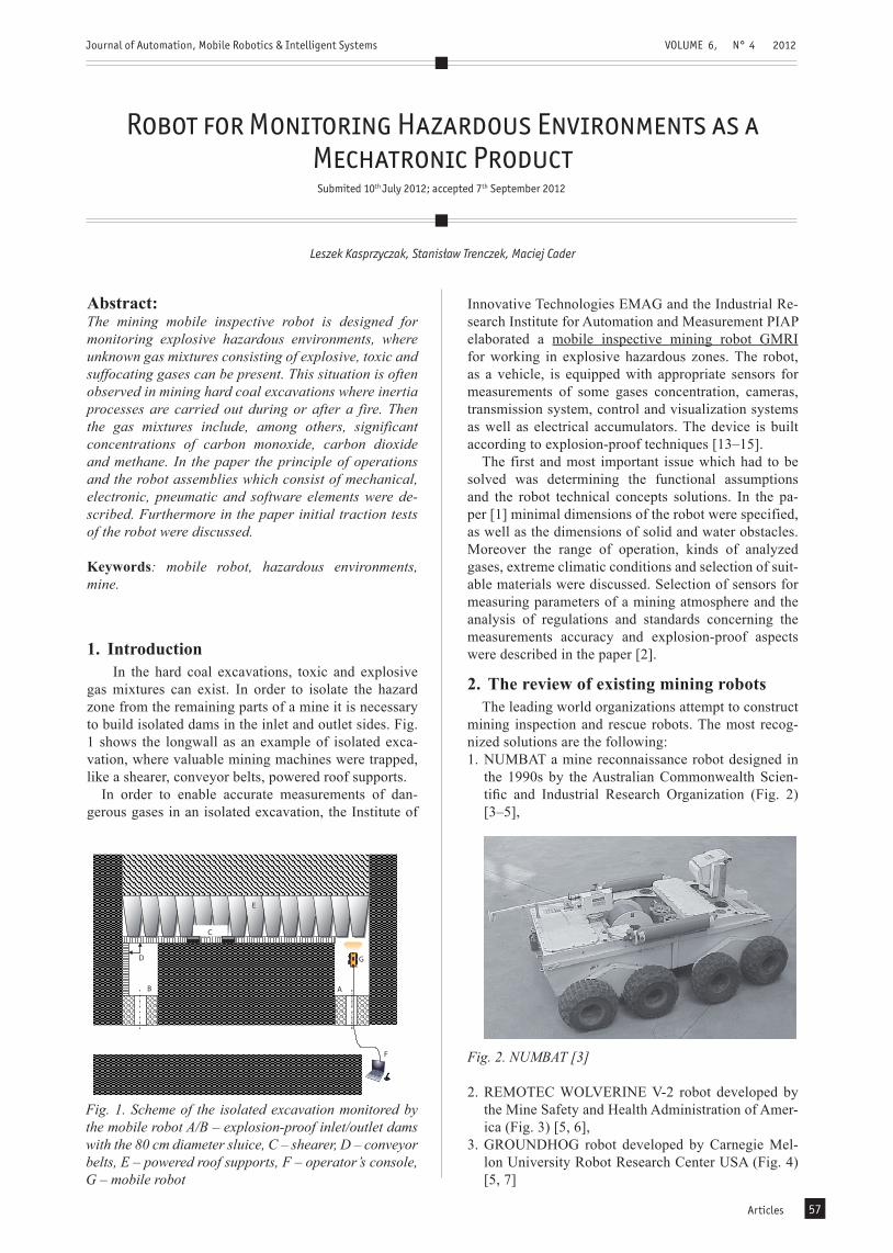
gas mixtures can exist. In order to isolate the hazard zone from the remaining parts of a mine it is necessary to build isolated dams in the inlet and outlet sides. Fig. 1 shows the longwall as an example of isolated exca-vation, where valuable mining machines were trapped, like a shearer, conveyor belts, powered roof supports.
In order to enable accurate measurements of dan-gerous gases in an isolated excavation, the Institute of
Innovative Technologies EMAG and the Industrial Re-search Institute for Automation and Measurement PIAP elaborated a mobile inspective mining robot GMRI for working in explosive hazardous zones. The robot, as a vehicle, is equipped with appropriate sensors for measurements of some gases concentration, cameras, transmission system, control and visualization systems as well as electrical accumulators. The device is built according to explosion-proof techniques [13–15].
The first and most important issue which had to be solved was determining the functional assumptions and the robot technical concepts solutions. In the pa-per [1] minimal dimensions of the robot were specified, as well as the dimensions of solid and water obstacles. Moreover the range of operation, kinds of analyzed gases, extreme climatic conditions and selection of suit-able materials were discussed. Selection of sensors for measuring parameters of a mining atmosphere and the analysis of regulations and standards concerning the measurements accuracy and explosion-proof aspects were described in the paper [2].
2. The review of existing mining robots
The leading world organizations attempt to construct mining inspection and rescue robots. The most recog-nized solutions are the following:1. NUMBAT a mine reconnaissance robot designed in
the 1990s by the Australian Commonwealth Scien-tific and Industrial Research Organization (Fig. 2) [3–5],
Fig. 1. Scheme of the isolated excavation monitored by the mobile robot A/B – explosion-proof inlet/outlet dams with the 80 cm diameter sluice, C – shearer, D – conveyor belts, E – powered roof supports, F – operator’s console, G – mobile robot
A B
C
D G
F
E
Fig. 2. NUMBAT [3]
2. REMOTEC WOLVERINE V-2 robot developed by the Mine Safety and Health Administration of Amer-ica (Fig. 3) [5, 6],
3. GROUNDHOG robot developed by Carnegie Mel-lon University Robot Research Center USA (Fig. 4) [5, 7]
Journal of Automation, Mobile Robotics & Intelligent Systems VOLUME 6, N° 4 2012
Articles58
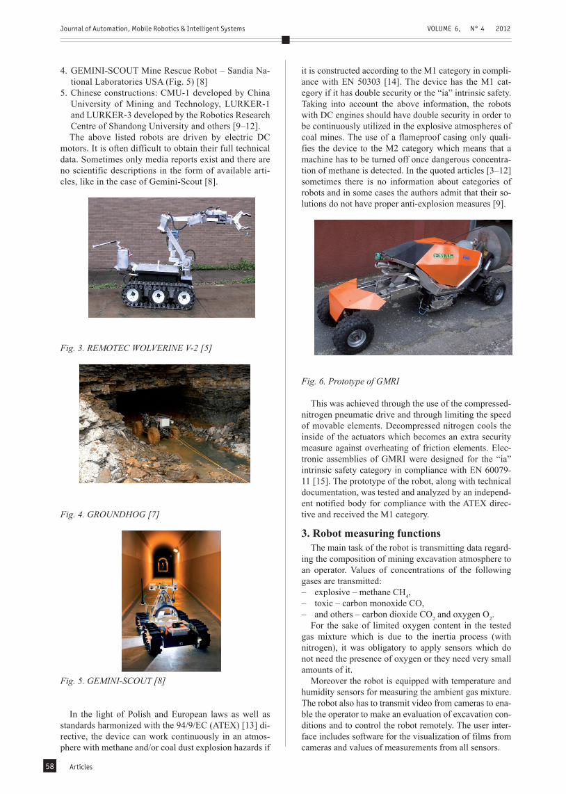
4. GEMINI-SCOUT Mine Rescue Robot – Sandia Na-tional Laboratories USA (Fig. 5) [8]
5. Chinese constructions: CMU-1 developed by China University of Mining and Technology, LURKER-1 and LURKER-3 developed by the Robotics Research Centre of Shandong University and others [9–12].The above listed robots are driven by electric DC
motors. It is often difficult to obtain their full technical data. Sometimes only media reports exist and there are no scientific descriptions in the form of available arti-cles, like in the case of Gemini-Scout [8].
Fig. 3. REMOTEC WOLVERINE V-2 [5]
Fig. 4. GROUNDHOG [7]
Fig. 5. GEMINI-SCOUT [8]
In the light of Polish and European laws as well as standards harmonized with the 94/9/EC (ATEX) [13] di-rective, the device can work continuously in an atmos-phere with methane and/or coal dust explosion hazards if
it is constructed according to the M1 category in compli-ance with EN 50303 [14]. The device has the M1 cat-egory if it has double security or the “ia” intrinsic safety. Taking into account the above information, the robots with DC engines should have double security in order to be continuously utilized in the explosive atmospheres of coal mines. The use of a flameproof casing only quali-fies the device to the M2 category which means that a machine has to be turned off once dangerous concentra-tion of methane is detected. In the quoted articles [3–12] sometimes there is no information about categories of robots and in some cases the authors admit that their so-lutions do not have proper anti-explosion measures [9].
Fig. 6. Prototype of GMRI
This was achieved through the use of the compressed-nitrogen pneumatic drive and through limiting the speed of movable elements. Decompressed nitrogen cools the inside of the actuators which becomes an extra security measure against overheating of friction elements. Elec-tronic assemblies of GMRI were designed for the “ia” intrinsic safety category in compliance with EN 60079-11 [15]. The prototype of the robot, along with technical documentation, was tested and analyzed by an independ-ent notified body for compliance with the ATEX direc-tive and received the M1 category.
3. Robot measuring functionsThe main task of the robot is transmitting data regard-
ing the composition of mining excavation atmosphere to an operator. Values of concentrations of the following gases are transmitted:– explosive – methane CH4,– toxic – carbon monoxide CO,– and others – carbon dioxide CO2 and oxygen O2.
For the sake of limited oxygen content in the tested gas mixture which is due to the inertia process (with nitrogen), it was obligatory to apply sensors which do not need the presence of oxygen or they need very small amounts of it.
Moreover the robot is equipped with temperature and humidity sensors for measuring the ambient gas mixture. The robot also has to transmit video from cameras to ena-ble the operator to make an evaluation of excavation con-ditions and to control the robot remotely. The user inter-face includes software for the visualization of films from cameras and values of measurements from all sensors.

Journal of Automation, Mobile Robotics & Intelligent Systems VOLUME 6, N° 4 2012
Articles 59
Fig. 7 presents a view of the robot chassis model with the jib as a pipe, through which the tested atmosphere is sucked into the gases meter.
In the isolated region there is high humidity usually close to 100%. If we do not fulfil the requirement of 95% RH without condensation, then the life expectancy and accuracy of sensors will decrease. Therefore a drier system was elaborated in EMAG which dries the test-ed gas mixture before introducing it to the sensors. The block scheme of the system is shown in Fig. 8.
In the elaborated equipment (E) the mining atmos-phere (MA) is sucked in from the jib thanks to a gas pump (GP). The gas mixture is at first dried in the dryer (D). Then the tested gas is introduced to the sensors (S) and leaves the equipment.
Fig. 7. Model of the GMRI robot chassis with jib (de-signed by PIAP)
D
S
GP
MA MA MA
E
MA
Fig. 8. Block scheme of a drier system for measuring gases concentrations of mining atmospheres with high humidity (designed by EMAG)
In table 1 the measuring ranges of the robot sensors were given. The non-dispersive infrared sensors (NDIR) for measuring methane and carbon dioxide were applied. Electrochemical sensors were used for detecting oxygen and carbon monoxide. In the next sections of the paper the operating principles of the sensors were described.
Table 1. Measuring ranges of the GMRI sensors
Tested gas Measuring range
Methane CH4 0 … 100%
Carbon dioxide CO2 0 …5%
Carbon monoxide CO 0 … 1000 ppm
Oxygen O2 0 … 25%
Temperature -40 … ~+120°C
Humidity … 100%
3.1. Infrared sensorsThe range of infrared radiation which is typically used in the sensors, it is between 3-5 μm. In this band there are absorption lines of many essential gases, and for 4 μm there is no absorption line. The radiation of 4 μm wave-length is used as a reference signal in NDIR sensors. Be-sides, simple bulbs with filaments emit radiation between 2 to 5 μm (depending on the filament temperature and bulb enclosure material). Moreover within the range 3-5 μm there is a “water window”, which means that water steam does not absorb radiation in this band and thereby does not influence the measurements values.
Table 2 shows the lengths of waves of infrared ra-diation which are absorbed by gases typically occurred in mining atmospheres. The sensors manufacturers give different values because an absorption line of a gas is usually not a single value but a narrow band.
Table 2. Values of absorption lines/bands of selected gases [16-19]
Gas Wave length [μm]
Methane CH4 3,32 or 3,4
Hydrocarbons CxHy 3,0 – 3,5
Carbon dioxide CO2 4,2 – 4,3
Gases, with particles consisting of two or more differ-ent atoms, absorb appropriate infrared wave lengths which are compatible with their natural frequency vibra-tions. The amplitude of the interatomic bonds vibrations increases along with the temperature of the particles (Fig. 9). However other gases, like nitrogen, oxygen and noble gases cannot be detected using this method.
a)
b)
Fig. 9. Increase of the amplitude of interatomic bonds vibrations after absorption of the IR radiation [16]

Journal of Automation, Mobile Robotics & Intelligent Systems VOLUME 6, N° 4 2012
Articles60
An operating principle of gas sensors which uses a bulb as the radiation source and a pyroelectric detector is shown in Fig. 10. The bulb is supplied with a rectan-gular signal with frequency between 1 to 10 Hz. At the pyroelectric detector output, near sinusoidal voltage ap-pears with the same frequency as the rectangular signal. When the concentration of the target gas increases, the amplitude of the output signal decreases, according to exponential expression described by the Beer-Lambert law [17–21].
Fig. 10. Principle of operations of gas sensors with the IR radiation [19]
Pyroelectricity is the ability of certain materials to generate a temporary electrical potential when they are heated or cooled. The electric potential disappears after a relaxation time, that is why the fallen radiation has to be changeable. Thus the bulb command signal is a pe-riod rectangular one. All pyroelectric materials are also piezoelectric ones, so it is necessary to protect sensors against forces.
In Fig.11 the structure of an IR gas sensor with two measuring channels is shown. In the active channel there is an optical filter which passes radiation with wave length as the wave length for the target gas. In the refer-ence channel the optical filter passes radiation with wave length 4 μm.
The signal amplitude of the active sensor decreases together with the increasing concentration because more energy is absorbed by the gas particles. The reference channel is used to compensate for changes in source in-tensity, optical degradation and temperature to some de-gree. The amplitude of this detector will not show any changes due to the effects of the target gas. The target
gas concentration is calculated from the ratio of the two output peak to peak signals. In practice more complicated equations are used for measuring concentrations, which compensate the influence of temperature and sometimes pressure.
3.2. Electrochemical sensorsElectrochemical sensors use chemical reactions for
measuring target gas concentrations. A typical electro-chemical sensor consists of a sensing electrode (work-ing) and a counter electrode which are separated by an electrolyte (Fig. 12). At first a gas passes through the dif-fusion barrier, charcoal filter and hydrophobic membrane and then the reaction on the sensing electrode begins.
Fig. 12. Structure of a typical electrochemical sensor [16]
The target gas reacts at the surface of the working elec-trode involving either oxidation or reduction reactions. These mechanisms are catalyzed by the electrode materi-als specifically selected for the tested gas. Through an external resistor which connects working and counter electrodes proportional to the concentration electrical current flows [16, 17, 22].
It is required to have a stable and constant potential at the working electrode. In reality the sensing electrode potential does not remain constant due to the continuous electrochemical processes. That is why the metrological parameters deteriorate. In order to improve the perform-ance of the sensor, a reference electrode is introduced between the sensing and counter electrodes, and to the working electrode, a fixed stable constant potential is ap-plied. No current flows between the sensing and refer-ence electrodes.
The hydrophobic membrane enables a protection against humidity and prevents the sensor from drying out as well as leaking the liquid electrolyte. Moreover it allows enough gas molecules to reach the working elec-trode. The membrane is made of thin, porosity Teflon. The filter is installed in order to eliminate cross-sensi-tivity for unwanted gases. It is usually made of activated charcoal, which filters out most chemical compounds except carbon monoxide and hydrogen gases. By cor-rectly selecting the filter, the sensor is more selective. The electrodes are usually made of noble metals such as gold or platinum. Every electrode can be made of differ-ent material, which enables suitable chemical reactions with a target gas. The electrolyte allows to carry the ionic charge across the electrodes.
Typical chemical reactions for the measurement of oxygen and carbon monoxide are as follows:– for an oxygen sensor [17]:– cathode: 4H+ + O2 + 4e- → 2H2O,Fig. 11. Structure of an IR gas sensor [17]
Journal of Automation, Mobile Robotics & Intelligent Systems VOLUME 6, N° 4 2012
Articles 61
– anode: 2H2O → 4H+ + O2 + 4e-,– for a carbon monoxide sensor [22]:– anode: CO + 2OH-→ CO2 + H2O+2e-,– cathode: ½ O2 + H2O + 2e- → 2OH-,– total reaction: CO + ½ O2 → CO2.
As we can see from the above reactions, the carbon monoxide sensor needs small amounts of oxygen for cor-rect functioning. Too low an amount of oxygen causes significant shortening of the sensor life (even to several hours). The oxygen sensor fills up with water thanks to absorption of steam water from an ambient environment. Temperature is a factor which has a big influence on the measurement accuracy. So it is necessary to compensate it [16, 17, 22].
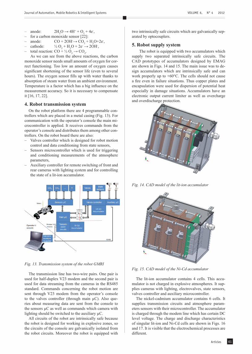
4. Robot transmission systemOn the robot platform there are 4 programmable con-
trollers which are placed in a metal casing (Fig. 13). For communication with the operator’s console the main mi-crocontroller is applied. It receives commands from the operator’s console and distributes them among other con-trollers. On the robot board there are also:– Valves controller which is designed for robot motion
control and data conditioning from state sensors,– Sensors microcontroller which is used for triggering
and conditioning measurements of the atmosphere parameters,
– Auxiliary controller for remote switching of front and rear cameras with lighting system and for controlling the state of a lit-ion accumulator.
Fig. 13. Transmission system of the robot GMRI
The transmission line has two-wire pairs. One pair is used for half-duplex V23 modem and the second pair is used for data streaming from the cameras in the RS485 standard. Commands concerning the robot motion are sent through V23 modem from the operator’s console to the valves controller (through main µC). Also que-ries about measuring data are sent from the console to the sensors µC as well as commands which camera with lighting should be switched to the auxiliary µC.
All circuits of the robot are intrinsically safe because the robot is designed for working in explosive zones, so the circuits of the console are galvanically isolated from the robot circuits. Moreover the robot is equipped with
two intrinsically safe circuits which are galvanically sep-arated by optocouplers.
5. Robot supply systemThe robot is equipped with two accumulators which
supply two separated intrinsically safe circuits. The CAD prototypes of accumulators designed by EMAG are shown in Figs. 14 and 15. The main issue was to de-sign accumulators which are intrinsically safe and can work properly up to +60°C. The cells should not cause a fire even in failure situations. Thus copper plates and encapsulation were used for dispersion of potential heat especially in damage situations. Accumulators have an electronic output current limiter as well as overcharge and overdischarge protection.
Fig. 14. CAD model of the lit-ion accumulator
Fig. 15. CAD model of the Ni-Cd accumulator
The lit-ion accumulator contains 4 cells. This accu-mulator is not charged in explosive atmospheres. It sup-plies cameras with lighting, electrovalves, state sensors, valves controller and auxiliary microcontroller.
The nickel-cadmium accumulator contains 6 cells. It supplies transmission circuits and atmosphere param-eters sensors with their microcontroller. The accumulator is charged through the modem line which has certain DC level voltage. The charge and discharge characteristics of singular lit-ion and Ni-Cd cells are shown in Figs. 16 and 17. It is visible that the electrochemical processes are different.

Journal of Automation, Mobile Robotics & Intelligent Systems VOLUME 6, N° 4 2012
Articles62
6. Traction testsThe drive structure of the robot is based on system of
movable supports (legs) and system consists of wheels – two widely spaced wheels in the back and two narrowly spaced ones in the front (Fig. 16). This solution was elab-orated by PIAP and submitted to the Polish Patent Office.
Drive system of the robot GMRI are supplied by com-pressed nitrogen from a tank placed in the robot plat-form (Fig. 17). Pneumatic actuators of the drive system are controlled by 2-state valves. Nitrogen is a neutral gas which does not have any influence on fire progress and measurements. The reserve of the bottle volume is enough for the distance of 500 m.
Fig. 16. Motion systems: 1 – wheel system, 2 – support system
Fig. 17. Pneumatic scheme of the robot drive system
The robot is able to widen/narrow the back wheels in-dependently (Fig. 18). When the back wheels are wid-ened, the stability of the robot is better on an irregular floor of an excavation (max. width is 1.1 m). When the back wheels are narrowed, the robot can be transported along an 80-cm diameter pipe.
The support system enables to lift or lower the plat-form evenly or non-evenly. The even lift is performed when the whole mobile body is lifted parallel to the floor up to the given height (max 0.5 m). The platform can be positioned in 4 heights – minimal, maximal and two medium ones. The non-even lift enables to lift only one side of the mobile body – back or front, left or right (Fig. 19). This functionality meets the requirements of the floor conditions (longitudinal and lateral slopes) which the robot has to cope with. Thanks to this functionality the mobile platform of the robot can remain in a horizon-tal position irrespective of the floor conditions in a mine.
Additionally, the robot has the jib for taking samples of a gas mixture. The probe is driven by a rotational pneu-matic drive. The length of the probe is 1 meter. The robot can lift its whole body so the range of the probe is ex-tended. Manipulating the robot body is aimed at directing two immovable wide-angle cameras to a desired place.
The robot can lift its front wheels with the use of its front legs and a special actuator connected with the
Fig. 18. Widening back wheels of GMRI Fig. 20. GMRI turns left
Fig. 19. GMRI with a platform in a first medium position
Journal of Automation, Mobile Robotics & Intelligent Systems VOLUME 6, N° 4 2012
Articles 63
structure of the front bridge. Thanks to that the robot can pass over the obstacle or mount it with the front wheels. The turning of the robot is performed by the front bridge which is connected with linear actuators by means of joints. When the robot turns left (Fig. 20), the piston rod of the right actuator is moved forward and the left one retracted simultaneously.
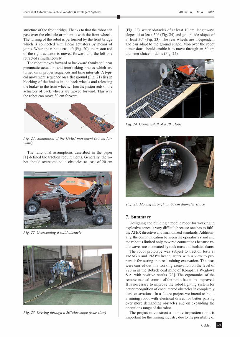
The robot moves forward or backward thanks to linear pneumatic actuators and interlocking brakes which are turned on in proper sequences and time intervals. A typi-cal movement sequence on a flat ground (Fig. 21) lies in blocking of the brakes in the back wheels and releasing the brakes in the front wheels. Then the piston rods of the actuators of back wheels are moved forward. This way the robot can move 30 cm forward.
Fig. 21. Simulation of the GMRI movement (30 cm for-ward)
The functional assumptions described in the paper [1] defined the traction requirements. Generally, the ro-bot should overcome solid obstacles at least of 20 cm
(Fig. 22), water obstacles of at least 10 cm, lengthways slopes of at least 30° (Fig. 24) and go up side slopes of at least 30° (Fig. 23). The rear wheels are independent and can adapt to the ground shape. Moreover the robot dimensions should enable it to move through an 80 cm diameter sluice of dams (Fig. 25).
Fig. 22. Overcoming a solid obstacle
Fig. 23. Driving through a 30º side slope (rear view)
Fig. 24. Going uphill of a 30° slope
7. SummaryDesigning and building a mobile robot for working in
explosive zones is very difficult because one has to fulfil the ATEX directive and harmonized standards. Addition-ally, the communication between the operator’s stand and the robot is limited only to wired connections because ra-dio waves are attenuated by rock mass and isolated dams.
The robot prototype was subject to traction tests at EMAG’s and PIAP’s headquarters with a view to pre-pare it for testing in a real mining excavation. The tests were carried out in a working excavation on the level of 726 m in the Bobrek coal mine of Kompania Węglowa S.A. with positive results [23]. The ergonomics of the remote manual control of the robot has to be improved. It is necessary to improve the robot lighting system for better recognition of encountered obstacles in completely dark excavations. In a future project we intend to build a mining robot with electrical drives for better passing over more demanding obstacles and on expanding the operations range of the robot.
The project to construct a mobile inspection robot is important for the mining industry due to the possibility of
Fig. 25. Moving through an 80 cm diameter sluice

Journal of Automation, Mobile Robotics & Intelligent Systems VOLUME 6, N° 4 2012
Articles64
using the robot to assess the state of the excavation and atmospheric parameters. Thanks to this, it will be possi-ble to make faster and more accurate decisions about fur-ther operations related to the dangerous area of the mine.
AUTHORSLeszek Kasprzyczak* – Institute of Innovative Tech-nologies EMAG, Leopolda St. 31, 40-189 Katowice, Po-land, E-mail: [email protected] Expert in mechatronics, functional safety, measurement systems, construction and operation of machinery
Stanisław Trenczek – Institute of Innovative Technolo-gies EMAG, Leopolda St. 31, 40-189 Katowice, Poland.E-mail: [email protected] Deputy Director for Research, a specialist in the field of mining aerology.
Maciej Cader – Industrial Research Institute for Auto-mation and Measurements, Al. Jerozolimskie 202, 02-486 Warsaw, Poland. E-mail: [email protected] Expert in mobile systems construction, simulation and Rapid Prototyping technology.
*Corresponding author
References
[1] L. Kasprzyczak, S. Trenczek, Z. Borkowicz, M. Cader, “Functional assumptions and concepts of technical solutions of mobile inspective robot for working in explosive hazardous environments”. In: Proc. of EMTECH 2009 Conf. ”Supply, computer science and automatics in excavation industry”, Po-land, 2009, pp.99-105 (in Polish).
[2] L. Kasprzyczak, P. Dzierżak, “Sensors for measure-ment mining atmosphere parameters of mobile in-spective robot, Mechanizacja i Automatyzacja Gór-nictwa, vol. 466, no. 12, 2009, pp.19–30.
[3] D. W. Hainsworth, “Teleoperation user interfaces for mining robotics”, Autonomous Robots, no. 11, 2011, pp. 19-28.
[4] J.C. Ralston, D. Hainsworth, “Recent advances in remote coal mining machine sensing, guidance, and teleoperation”, Robotica, no. 19, 2001, pp. 513-526.
[5] R. Murphy, J. Kravitz, S. Stover, R. Shoureshi, “Mo-bile robots in mine rescue and recovery”, IEEE Ro-botics & Automation Magazine, 2009, pp. 91–103.
[6] R. Murphy, J. Kravitz, “Preliminary report: Rescue robot at Crandall Canyon”, Utah, mine disaster. IEEE Int. Conf. on Robotics & Automation, Pasa-dena, 2008, pp. 19-23.
[7] S. Thruny, D. Hahnel, “A System for Volumetric Robotic Mapping of Abandoned Mines”. In: Proc. of ICRA 2003.
[8] https://share.sandia.gov/news/resources/news_re-leases/miner-scou/
[9] X. Rongb, R. Songb, “Mechanism and explosion-proof design for a coal mine detection robot”, Ad-vanced in Control Engineering and Information Sci-ence, no. 5, 2011, pp.100-104.
[10] YunWang Li, Shirong Ge, Hua Zhu, “Explosion-proof design for coal mine rescue robots”, Advanced Materials Research, 2011, pp. 1194-1198.
[11] W. Wang, Z. Du, L. Sun, “Kinematics Analysis for Obstacle-climbing Performance of a Rescue Ro-bot”, IEEE Int. Conf. on Robotics and Biomimetics, 2007, pp.1612-1617.
[12] J. Gao, X. Gao, J. Zhu, “Coal mine detect and res-cue robot technique research”, IEEE Int. Conf. on Information and Automation, 2009, pp. 1068–1073.
[13] Directive 94/9/EC of the European Parliament and the Council of 23 March 1994 on the approxima-tion of the laws of the Member States concerning equipment and protective systems intended for use in potentially explosive atmospheres (ATEX)
[14] EN 50303 Group I, Category M1 equipment intend-ed to remain functional in atmospheres endangered by firedamp and/or coal dust
[15] EN 60079-11 Explosive atmospheres. Equipment protection by intrinsic safety „i”
[16] www.intlsensor.com[17] www.e2v.com[18] www.citytech.com[19] www.dynament.com[20] S. Lang, “Pyroelectricity: from ancient curiosity to
modern imaging tool”, Physics Today, vol. 58, no. 8, 2005, pp. 31-36.
[21] J. Piotrowski, A. Rogalski, “Semiconductor infra-red detectors”, WNT, Warszawa 1985 (in Polish)
[22] www.figaro.co.jp[23] Report from traction tests of the GMRI mobile in-
spection robot, Mining Rescue Center, 2010, p. 9 (in Polish).