Riadh Karchoud - ADDI
189
Universidad del País Vasco (UPV) Université de Pau et des Pays de l'Adour (UPPA) Ecole Doctorale des Sciences Exactes et Leurs Applications LABORATOIRE INFORMATIQUE – LIUPPA Long Life Application dedicated to smart-* usage Présenté par Riadh Karchoud Pour obtenir le grade de DOCTEUR de l’UPPA et l’UPV Spécialité : Informatique Soutenance le 14 Décembre 2017 Devant le jury composé de M. Philippe ROOSE Directeur de thèse M. Marc DALMAU Directeur de thèse Mme. Arantza ILLARRAMENDI Directeur de thèse M. Jean-Louis PAZAT Rapporteur M. Noel DE PALMA Rapporteur M. Sergio ILARRI Examinateur M. Alfredo Goni Examinateur M. Jean-Paul ARCANGELI Examinateur (cc)2017 RIADH KARCHOUD (cc by 4.0)
-
Upload
khangminh22 -
Category
Documents
-
view
8 -
download
0
Transcript of Riadh Karchoud - ADDI

Universidad del País Vasco (UPV)
Université de Pau et des Pays de l'Adour (UPPA)
Ecole Doctorale des Sciences Exactes et Leurs Applications
LABORATOIRE INFORMATIQUE – LIUPPA
Long Life Application dedicated to smart-* usage
Présenté par
Riadh Karchoud
Pour obtenir le grade de DOCTEUR de l’UPPA et l’UPV
Spécialité : Informatique
Soutenance le 14 Décembre 2017
Devant le jury composé de
M. Philippe ROOSE Directeur de thèse M. Marc DALMAU Directeur de thèse Mme. Arantza ILLARRAMENDI Directeur de thèse
M. Jean-Louis PAZAT Rapporteur M. Noel DE PALMA Rapporteur
M. Sergio ILARRI Examinateur M. Alfredo Goni Examinateur M. Jean-Paul ARCANGELI Examinateur
(cc)2017 RIADH KARCHOUD (cc by 4.0)
ii
.
Long Life Application dedicated to smart-* usage
By
Riadh Karchoud

iii Dédicaces
. Dédicaces
J’adresse mes sincères remerciements au professeur Jean-Louis PAZAT et au professeur Noel
DE PALMA pour avoir consacré leur temps pour rapporter mon travail de thèse.
Je remercie également M. Alfredo GONI, M. Jean-Pierre ARCANGELI et M. Sergio ILARRI
d’avoir bien voulu faire partie des membres de mon jury. Merci à Sergio pour sa bienveillance, ses
conseils et aussi son amabilité.
Mes plus sincères remerciements à Monsieur Marc DALMAU et Monsieur Philippe ROOSE,
Maîtres de Conférences (HDR) à l’Université de Pau et des Pays de l’Adour, mes directeurs de
thèse, pour leur encadrement et leur soutien. La confiance que vous m’accordez m’a permis de
mener à bon bien cette thèse. Vous m’avez donné suffisamment de liberté pour choisir la direction
de cette thèse. Je remercie également Madame Arantza ILLARRAMENDI pour son encadrement
de valeur et son apport considérable à mon travail. Elle n’a jamais cessé d'accroître ma capacité de
produire et en même temps celle qui fut capable de me tirer vers le haut quand j’en avais besoin.
J’ai rencontré pendant la thèse ceux qui sont devenus depuis mes meilleurs amis. J’ai apprécié
tout ce qu'on a de commun, mais aussi tout ce qu'on a de différent. L’échange culturel que j’ai vécu
avec eux, entre la Chine, le Pérou, le Liban, l’Ethiopie, la Thaïlande, le Venezuela, l’Argentine,
l’Espagne et la France, je ne l’aurai jamais vécu ailleurs.
Merci à mon amour Meriem pour son écoute, sa patience, sa compréhension et son support
inestimable qui m’a permis d’avancer pendant les moments difficiles.
Merci à mes parents Taoufik et Wassila qui m’ont donné l’exemple de comment aimer sans
mesure, donner sans raison et se soucier sans attentes. Je vous dois tous!
À toutes ces personnes qui ne m’ont apporté que du bonheur, merci de faire partie de ma vie!

iv AKNOWLEDGEMENT
. AKNOWLEDGEMENT
.
This work was supported by the the embassy of France in Spain and by the TIN2013-46238-
C(1/4)-4-R, FEDER/TIN2016-78011-C4-(2/3)-R (AEI/FEDER, UE), FEDER/TCVPYR, and
DGA-FSE.
v Résumé
. Résumé
De nos jours, les appareils mobiles hébergent de nombreuses applications directement
téléchargées et installées à partir d'un "Store" d'applications mobiles. L'existence d'une telle quantité
d'applications pour une multitude d'objectifs impose une énorme surcharge sur les utilisateurs, qui
doivent sélectionner, installer, supprimer et exécuter les applications appropriées.
En outre, ces applications ont négligé la prise en compte du contexte de l'utilisateur. Elles
proposent des scénarios d'utilisation statiques et non évolutifs. Ces applications servent à des fins
spécifiques et sont supprimées ou oubliées, la plupart du temps, après la première utilisation. De
plus, ces applications ne tiennent pas compte du monde des objets connectés en raison de leur
architecture monolithique mise en œuvre pour fonctionner sur des appareils individuels.
La solution proposée et intitulée "Long Life Application" offre une nouvelle façon de répondre
aux besoins de l'utilisateur de façon dynamique et distribuée. Elle propose une évolution continue
des applications (encours d'exécution) en ajoutant, supprimant, et déplaçant des fonctionnalités sur
les appareils utilisés par l’utilisateur. Elle permet, aussi, de modifier le mode d'interaction en
distribuant les exécutions sur plusieurs appareils en fonction des besoins de l'utilisateur.
Pendant que l’utilisateur se déplace dans son environnement, l'application détecte des
événements environnementaux et construit des situations contextuellement décrites. Ainsi, ce
travail vise à offrir un nouveau type d'applications mobiles capables de détecter, de formuler et de
comprendre le contexte des utilisateurs puis de réagir en conséquence.

vi Abstract
. Abstract
Nowadays, mobile devices host many applications that are directly downloaded and installed
from mobile application stores. The existence of such a large amount of apps for a myriad of
purposes imposes a huge overhead on users, who are in charge of selecting, installing, and executing
the appropriate apps, as well as deleting them when no longer needed.
Moreover, these applications have mostly neglected to take into account the user’s context, as
they propose static non-evolving scenarios. These applications serve for specific purposes and get
deleted or forgotten most of the time after the first use. Furthermore, these apps fail to consider
the, soon coming, connected world due to their monolithic architecture implemented to work on
single devices.
The proposed long-life application provides a new way to respond to the user’s needs
dynamically and distributedly. It evolves at runtime by including/excluding business functionalities,
updating the interaction mode, and migrating executions on multiple devices according to the user’s
preferences.
While he/she moves in his/her surroundings, the app detects the occurring events and builds
contextually-described situations. So, this work aims to offer a new type of mobile application able
to detect, formulate and understand the users’ context then react accordingly.

vii Contents
. Contents
. DEDICACES .......................................................................................................................................... III
. AKNOWLEDGEMENT ........................................................................................................................ IV
. RESUME .................................................................................................................................................. V
. ABSTRACT ............................................................................................................................................ VI
. CONTENTS.......................................................................................................................................... VII
. LIST OF FIGURES ............................................................................................................................. XII
. LIST OF TABLES................................................................................................................................. XV
CHAPTER 1 INTRODUCTION .................................................................................................................. 1
1. THESIS CONTEXT ................................................................................................................................ 2
2. CHALLENGES ..................................................................................................................................... 3
3. OBJECTIVES ....................................................................................................................................... 4
4. MOTIVATING SCENARIO ..................................................................................................................... 5
5. ORGANIZATION OF THE THESIS .......................................................................................................... 7
CHAPTER 2 RELATED WORK ................................................................................................................. 9
1. INTRODUCTION ................................................................................................................................ 10
2. DISTRIBUTION ASPECT IN MOBILE COMPUTING ................................................................................ 11
2.1. Middleware dedicated to pervasive applications ................................................................... 12
2.1.1. Background ........................................................................................................................................ 12
2.1.2. Existing middleware solutions ........................................................................................................... 14
2.1.3. Comparison and discussion ............................................................................................................... 21
2.2. Cloud solutions for distributed applications .......................................................................... 22
2.2.1. Background ........................................................................................................................................ 22
2.2.2. Existing cloud solutions ..................................................................................................................... 24
2.2.3. Comparison and discussion ............................................................................................................... 28
3. CONTEXT AWARENESS IN MOBILE COMPUTING ................................................................................ 30
3.1. Contextual-awareness representation models and approaches .............................................. 31
viii Contents
3.1.1. Key value models .............................................................................................................................. 31
3.1.2. Markup Scheme models..................................................................................................................... 31
3.1.3. Graphical models ............................................................................................................................... 32
3.1.4. Object-oriented models ...................................................................................................................... 32
3.1.5. Logic-based models ........................................................................................................................... 32
3.1.6. Ontology-based models ..................................................................................................................... 33
3.1.7. Comparison and discussion ............................................................................................................... 34
3.2. Modeling situation-awareness for Context-aware applications ............................................. 34
3.3. Platforms dedicated to generating context-aware applications ............................................. 35
4. USER-CENTERED CONTEXT-AWARE MOBILE APPLICATIONS ............................................................. 39
4.1. Existing solutions.................................................................................................................... 39
4.2. Discussion .............................................................................................................................. 43
5. CONCLUSION .................................................................................................................................... 43
CHAPTER 3 LONG LIFE APPLICATION PROPOSAL ....................................................................... 44
1. INTRODUCTION ................................................................................................................................ 45
2. APPROACH OVERVIEW ..................................................................................................................... 46
3. CONTRIBUTIONS............................................................................................................................... 47
3.1. A rich and user-friendly contextual model ............................................................................. 47
3.2. A cross-device context detection ............................................................................................. 48
3.3. A modular orchestration of services ....................................................................................... 49
3.4. A collaborative situation injection.......................................................................................... 49
4. APPLICATION’S GENERAL ARCHITECTURE ...................................................................................... 50
4.1. The User Domain ................................................................................................................... 51
4.2. Kalimucho .............................................................................................................................. 53
4.3. Input ....................................................................................................................................... 53
4.4. Output ..................................................................................................................................... 53
4.5. The Injector ............................................................................................................................ 54
4.6. The Persistence layer ............................................................................................................. 54
4.7. The LLA Core ......................................................................................................................... 54
4.7.1. The Parser .......................................................................................................................................... 54

ix Contents
4.7.2. The Event Manager (EM) .................................................................................................................. 55
4.7.3. The Condition Evaluator (CE) ........................................................................................................... 55
4.7.4. The Action Orchestrator (AO) ........................................................................................................... 55
4.8. The ACL filter ......................................................................................................................... 55
5. APPLICATION’S GLOBAL WORKFLOW AND DISTRIBUTION STRATEGY ............................................... 56
5.1. The deployment strategy of LLA ............................................................................................. 56
5.2. The workflow of LLA .............................................................................................................. 58
6. CONCLUSIONS .................................................................................................................................. 59
CHAPTER 4 SITUATION-BASED CONTEXTUAL MODEL .............................................................. 60
1. INTRODUCTION ................................................................................................................................ 61
2. SITUATION-BASED CONTEXTUAL MODEL ......................................................................................... 61
2.1. Abstract modeling level .......................................................................................................... 62
2.1.1. Concepts ............................................................................................................................................ 63
2.1.2. Operations .......................................................................................................................................... 67
2.1.3. Situations families ............................................................................................................................. 67
2.1.4. Representations .................................................................................................................................. 68
2.1.5. Complexity and data formats ............................................................................................................. 69
2.2. Service level ............................................................................................................................ 71
3. CONCLUSIONS .................................................................................................................................. 71
CHAPTER 5 - CROSS-DEVICE SITUATION DETECTION ................................................................ 72
1. INTRODUCTION ................................................................................................................................ 73
2. CROSS-DEVICE SITUATION DETECTION MECHANISM......................................................................... 73
2.1. The Input Component (IC) ...................................................................................................... 74
2.1.1. Frequency Manager (FM) .................................................................................................................. 75
2.1.2. Extractor ............................................................................................................................................ 77
2.1.3. Trigger ............................................................................................................................................... 77
2.2. The Event Manager (EM) ....................................................................................................... 78
2.2.1. Dispatcher Component (DC) ............................................................................................................. 79
2.2.2. Axes Management Components ........................................................................................................ 79
2.2.3. Situation Manager Component (SMC) .............................................................................................. 80

x Contents
3. CONCLUSIONS .................................................................................................................................. 84
CHAPTER 6 – SITUATION CONTROL AND REACTION STRATEGY ........................................... 86
1. INTRODUCTION ................................................................................................................................ 87
2. SITUATION CONTROL AND REACTION STRATEGY .............................................................................. 87
3. CONDITION EVALUATION (CE) ........................................................................................................ 88
3.1. The situation priority model and constraints .......................................................................... 88
3.2. Condition Evaluator module’s components ............................................................................ 93
3.2.1. The User Constraints Component (UCC) .......................................................................................... 94
3.2.2. The Situation Holder Component (SHC) ........................................................................................... 94
3.2.3. The Priority Component (PC) ............................................................................................................ 95
3.2.4. Example ............................................................................................................................................. 95
4. ACTION ORCHESTRATOR (AO) AND ACCESS CONTROL LIST (ACL) DEVICE FILTER ........................ 98
4.1. Device capabilities ................................................................................................................. 99
4.2. Service composition model and component requirements .................................................... 100
4.2.1. Service Composition ........................................................................................................................ 101
4.2.2. Component requirements ................................................................................................................. 102
4.3. Matching services to situations ............................................................................................ 105
4.4. Orchestration and control components ................................................................................ 106
4.4.1. Situation Tracker Component (STC) ............................................................................................... 107
4.4.2. Orchestration Component (OC) ....................................................................................................... 108
4.4.3. Device Management Component (DMC) ........................................................................................ 108
4.4.4. Example ........................................................................................................................................... 109
5. CONCLUSIONS ................................................................................................................................ 117
CHAPTER 7 – SITUATION INJECTION MECHANISM ................................................................... 118
1. INTRODUCTION .............................................................................................................................. 119
2. SITUATION INJECTION MECHANISM ................................................................................................ 119
2.1. User's Injection Process ....................................................................................................... 120
2.2. Collaborative Social Environment's Injection Process ........................................................ 121
2.3. External Providers' Injection Process .................................................................................. 122
2.3.1. Government providers ..................................................................................................................... 123

xi Contents
2.3.2. Businesses and private companies ................................................................................................... 123
2.3.3. Institutions/Organizations/Associations ........................................................................................... 124
3. CONCLUSIONS ................................................................................................................................ 125
CHAPTER 8 – PROTOTYPE AND VALIDATION .............................................................................. 126
1. INTRODUCTION .............................................................................................................................. 127
2. ESTABLISHING AND TESTING THE SCENARIO .................................................................................. 127
2.1. Pre-Conditions ..................................................................................................................... 127
2.2. John’s travel scenario .......................................................................................................... 130
2.2.1. John sets-up LLA ............................................................................................................................. 131
2.2.2. LLA injects the necessary data ........................................................................................................ 137
2.2.3. John starts the journey ..................................................................................................................... 141
3. RESULTS AND VALIDATION ............................................................................................................ 153
3.1. Performance validation ........................................................................................................ 153
3.2. Time and storage gain .......................................................................................................... 155
4. CONCLUSION .................................................................................................................................. 156
CHAPTER 9 – CONCLUSIONS AND FUTURE WORK ..................................................................... 157
BIBLIOGRAPHY ...................................................................................................................................... 160
APPENDIX 1 .............................................................................................................................................. 168

xii List of Figures
. List of Figures
Figure 1 – Computing evolution towards ubiquity [65] ................................................................................... 10
Figure 2 – Relationship between sensor-networks and IoT [82] .................................................................... 11
Figure 3 - Middleware basic architecture [34] ................................................................................................. 13
Figure 4 - Reference model of WSN middleware [104] .................................................................................... 14
Figure 5 - The XMIDDLE architecture [13] ..................................................................................................... 16
Figure 6 - Aura's system [58] ............................................................................................................................. 16
Figure 7 - The architecture of MUSIC [86] ...................................................................................................... 18
Figure 8 - Overview of the MuScADeL process [12] ........................................................................................ 19
Figure 9 - The Osagaia component [32] ............................................................................................................ 20
Figure 10 - Cloud layered Architecture ............................................................................................................ 23
Figure 11 - CHOReOS architecture [8] ............................................................................................................. 24
Figure 12 - BlueMix Architecture [38] .............................................................................................................. 25
Figure 13 - Flybits workflow [36]....................................................................................................................... 26
Figure 14 - Context-aware Provisioning Architecture [66] ............................................................................. 27
Figure 15 - Computation architecture for context-aware citizen services for smart-cities [64] ................... 28
Figure 16 - Context and Context-aware provisioning [66] .............................................................................. 30
Figure 17 - Class hierarchy diagram for [47] context ontology....................................................................... 33
Figure 18 – Cyberdesk’s runtime architecture diagram [27] .......................................................................... 36
Figure 19 - Care droid's architecture [30] ........................................................................................................ 36
Figure 20 - WildCAT's logical model [25]......................................................................................................... 37
Figure 21 - Class diagram of the application Places2Go and its relationship [26] ........................................ 38
Figure 22 - LLA PROPOSAL OVERVIEW ..................................................................................................... 46
Figure 23 - LLA's General Architecture ........................................................................................................... 51
Figure 24 - User's domains ................................................................................................................................. 52
Figure 25 - LLA running across devices ........................................................................................................... 56
Figure 26 - Deployment strategy for starting LLA .......................................................................................... 57
Figure 27 - Deployment strategy for stopping LLA ......................................................................................... 58
Figure 28 - Situation representation model ...................................................................................................... 62
xiii List of Figures
Figure 29 - Situation's projection axes .............................................................................................................. 65
Figure 30 - Exception's representation model .................................................................................................. 66
Figure 31 - First-level situation representation ................................................................................................ 67
Figure 32 - Second-level situation representation ............................................................................................ 68
Figure 33 - Third-level situation representation............................................................................................... 68
Figure 34 - House alarm situation representation ............................................................................................ 69
Figure 35 - Situation branching ......................................................................................................................... 70
Figure 36 - Cross-device situation detection component architecture ............................................................ 74
Figure 37 - The input component internal process ........................................................................................... 75
Figure 38 - Situation identification process ...................................................................................................... 78
Figure 39 - The dispatcher component .............................................................................................................. 79
Figure 40 - Time Manager Component ............................................................................................................. 80
Figure 41 - The Situation Manager Component ............................................................................................... 81
Figure 42 - Filtering layers of situations ........................................................................................................... 89
Figure 43 - Lock zones and priorities ................................................................................................................ 90
Figure 44 - Graphical representation of lock zones ......................................................................................... 91
Figure 45 - Morning Busy Zone representation ............................................................................................... 92
Figure 46 - Work Busy Zone representation .................................................................................................... 92
Figure 47 - Sleeping Dead Zone representation................................................................................................ 93
Figure 48 - Condition Evaluator's internal architecture ................................................................................. 93
Figure 49 - User Constraints Component ......................................................................................................... 94
Figure 50 - Situation Holder Component .......................................................................................................... 94
Figure 51 - Priority Component ......................................................................................................................... 95
Figure 52 - Example scenario representation ................................................................................................... 96
Figure 53 - Service composition architecture ................................................................................................. 101
Figure 54 - Video chat service composition graphical representation .......................................................... 104
Figure 55 - Monthly Work Meeting full representation ................................................................................ 106
Figure 56 - AO and ACL internal architecture .............................................................................................. 107
Figure 57 - Situation Tracker Component ...................................................................................................... 107
Figure 58 - Orchestration Component ............................................................................................................ 108

xiv List of Tables
Figure 59 - Device Management Component .................................................................................................. 108
Figure 60 - Scenario portion ............................................................................................................................. 109
Figure 61 - Situations service layers ................................................................................................................ 111
Figure 62 - The Injector's workflow ................................................................................................................ 119
Figure 63 - Concert event situation ................................................................................................................. 122
Figure 64 - Border closing situation ................................................................................................................ 123
Figure 65 - Parking situation ........................................................................................................................... 124
Figure 66 - Training situation .......................................................................................................................... 124
Figure 67 – Authentification UI in LLA .......................................................................................................... 128
Figure 68 – Defining the encryption key ......................................................................................................... 128
Figure 69 – Defining home location using LLA .............................................................................................. 129
Figure 70 – Adding a new situation using LLA’s UI ...................................................................................... 130
Figure 71 – John’s travel scenario steps .......................................................................................................... 131
Figure 72- John's defined locations ................................................................................................................. 131
Figure 73 – News Situation and Wakeup Alarm Situation graphical representations ............................... 133
Figure 74 - House Alarm Situation graphical representation ....................................................................... 133
Figure 75 – Morning Preparation Situation graphical representation ......................................................... 133
Figure 76 – LLA web application for injecting situations from external sources ....................................... 137
Figure 77 - Print screens of LLA's output for step 1 ...................................................................................... 142
Figure 78 - Print screens of LLA's output for step 2 and 3 ........................................................................... 143
Figure 79 - Print screens of LLA's output for step 5 ...................................................................................... 145
Figure 80 - Print screens of LLA's output for step 6 ...................................................................................... 146
Figure 81 - Print screens of LLA's output for step 7 ...................................................................................... 148
Figure 82 - Print screens of LLA's output for step 12 .................................................................................... 151
Figure 83: Overtime performance of LLA (10 situations) ............................................................................. 154
Figure 84: Overtime performance of LLA (100 situations) ........................................................................... 154
Figure 85: Overtime performance of LLA (1000 situations) ......................................................................... 154
.
xv List of Tables
List of Tables
Table 1: Comparing middleware ....................................................................................................................... 21
Table 2: Comparing Cloud platforms ............................................................................................................... 29
Table 3: Comparing context modeling approaches .......................................................................................... 34
Table 4: Comparing context-aware end-user applications .............................................................................. 42
Table 5: Time primitives .................................................................................................................................... 63
Table 6: Location primitives .............................................................................................................................. 64
Table 7: Activity primitives ................................................................................................................................ 64
Table 8: Time*Activity primitives ..................................................................................................................... 64
Table 9: Time*Location primitives ................................................................................................................... 65
Table 10: Location*Activity primitives ............................................................................................................ 65
Table 11: Situation analysis by the Event Manager's components ................................................................. 83
Table 12: Situation filtering by the Condition Evaluator’s components ........................................................ 97
Table 13: Samsung Gear S3 capabilities ......................................................................................................... 100
Table 14: Example of User-Domain ................................................................................................................ 112
Table 15: Situation analysis by the Event Manager's components ............................................................... 114
Table 16: John’s locations data ........................................................................................................................ 132
Table 17: John’s external injectors .................................................................................................................. 132
Table 18: John’s defined lock zones ................................................................................................................ 134
Table 19: John’s user-domain .......................................................................................................................... 135
Table 20: LLA's core modules on step 1 ......................................................................................................... 141
Table 21: LLA's main modules results for step 2 and 3 ................................................................................ 142
Table 22: LLA's core modules on step 4 ........................................................................................................ 144
Table 23: LLA's core modules on step 5 ......................................................................................................... 144
Table 24: LLA's main modules results for step 6 ........................................................................................... 146
Table 25: LLA's main modules results for step 7 ........................................................................................... 147
Table 26: LLA's main modules results for step 8 ........................................................................................... 147
Table 27: LLA's main modules results for step 9 ........................................................................................... 149
Table 28: LLA's main modules results for step 10 ......................................................................................... 149

xvi List of Tables
Table 29 : LLA's main modules results for step 11 ........................................................................................ 150
Table 30 : LLA's main modules results for step 12 ........................................................................................ 150
Table 31: LLA's main modules results for step 13, 14, and 15...................................................................... 151
Table 32: Measurements of performance, accuracy, and sustainability ...................................................... 154
Table 33: Comparison of LLA and classical mobile store approach ............................................................ 156

1 Chapter 1 Introduction
Chapter 1 Introduction

2 Chapter 1 Introduction
1. Thesis context
Nowadays, mobile devices are hosting a large amount of applications for multiple purposes.
These applications try, in their own categories (social, work, entertainment, etc.), to fulfill the
needs of the user. But the diversity of those needs and the conditions surrounding them makes
it a challenge for mobile applications to accurately understand users and respond to their needs.
Since the appearance of the first native mobile application (mobile apps) on the Apple Store
in 2008 and the Android OS later that year, the mobile apps world has seen three major
transformations [71]. It started, between 2008 and 2010, by the information appliance era where
the apps transformed the phone into a mono-purpose device serving as a tool for a specific need
(calculator, agenda, emails, etc.). In 2011 came the era of `Home apps', where applications
struggled to gain the focus of the user by being filled with tabs of multiple functionalities and
services (news, entertainment, social, etc.) but with no consideration to what the user needs.
The third phase of apps as service layers, or “the new age of mobile apps”, is the “Era of no
apps” where applications are hidden in the background taking advantage of the computing
power of mobile devices and waiting for the right moment to manifest. This era started in 2014
but is still transforming the market and pushing the technology towards a connected ecosystem
where applications are modular, distributed and intelligent. Apps show up only when necessary,
without making the user go to a specific store or install pre-packaged bundles (applications).
Current mobile applications, like the ones we download now, serve for specific purposes and
get deleted or forgotten most of the time after the first use. Anindya Datta says that “An app
that's retained by 30 percent of downloaders is considered sticky” [108]. When speaking to
USA Today, he stated that an estimated 80 to 90 percent of apps are eventually deleted from
users' phones for being stale and static. In a more recent study [99], statistics show that only 25
percent of users return to any given application after the first use.
Moreover, in pervasive environments (e.g. smart-homes and smart-cities), the number of
devices, sensors, GPS modules, services, and applications are strongly multiplying. This rise is
consequently raising a considerable challenge regarding data management and systems
heterogeneity. This challenge will provoke a huge multiplicity of applications (to
install/uninstall), configurations, redundant data and profiles and duplicated functions.
Finally, the growth of this network of smart connected devices obliges app developers to
consider ubiquitous and pervasive computing. Nowadays, many users own more than one
mobile device but with the rise of the Internet of Things (IoT) and smart-* (cities, home,

3 Chapter 1 Introduction
buildings, etc.), users will be confronted and be expected to handle multiple devices
simultaneously (6.58 devices per person in 2020 [24]).
2. Challenges
In this context, the need to have mobile applications, able to understand the user and manage
his/her daily situations regardless of their nature or categories, arises. Nevertheless, before we
propose our solution to these problems, we should understand the nature of everyday end-users
needs. The problem comes from the fact that users have repetitive habits that they perform on
a regular time basis, and evolving needs, that continuously change and shift according to their
physical and social environment. These reasons raise the issue of the relevance of the services
that are automatically offered by this type of applications in order to respond to certain
situations.
Contextual engagement is the key to overcome this challenge. In the specialized literature,
we can find different proposals in the area of context-aware applications. But in general, they
only partially cover the users’ needs because:
Firstly, they focus their work on understanding his/her context under a specific limited area
of expertise (museum guided tours [16], context-aware healthcare, smart-transportation, etc.)
in which users and developers, with no expertise in those domains, could not either improve or
adapt the application to behave accordingly to the actual requirements of the user.
Secondly, for the lack of dynamicity in the predefined rule-based systems that cannot be
either extended to cover wider use cases or enriched to handle more precisely specific personal
situations.
Finally, most of the context-aware applications focus either solely on one device (on which
they are installed) or on a complex network of sensors that should be installed all around the
user in order for their solutions to run correctly.
With a large variety of use cases, diversity of needs and multiplicity of devices, it becomes
a necessity to have one solution to manage everything. We call this kind of solutions “Long
Life Application” (LLA) or “Eternal Applications” as they run ubiquitously, and evolve
constantly by changing their behavior and offering a variety of services according to the user’s
needs.

4 Chapter 1 Introduction
3. Objectives
Lately, end-users are getting accustomed to a high level of comfort (responsive design,
optimized user experience, fast internet, etc.) and expect applications to make their daily life
easier. Studies on computer-human interactions lead the developers to optimize and minimize
the user’s intervention by adapting their applications’ design and workflow towards offering
the easiest and fastest User eXperience (UX). Therefore, comes the need to focus the attention
of the mobile user on one application to manage other applications (services); to offer the widest
range of possibilities; to exploit the biggest number of interactions and shared knowledge
available to the user.
This proposal combines the strength of two important research areas: Ubiquitous Distributed
Computing and Context-Awareness dedicated to the mobile user. For that purpose, we re-think
the architecture of applications dedicated to stand-alone devices and target liquid applications
[4, 7]. We reconsider also the dynamicity and reactivity of mono purposed applications and aim
towards situation-aware applications. Our solution proposes improving the user's mobile
experience by overcoming the rigidness of existing mobile applications and by handling the
user’s multiple expectations in various domains.
Overall, the objective of this proposal is to present a user-centered, context-aware (situation-
based) mobile application able to manage everyday situations and react to them by adapting the
application to the needs of the user.
Our proposal is dedicated to everyday use. It offers its services to the consumers of mobile
applications that until now search, find, install, update and delete their applications on their
devices. Therefore, we propose a Long Life Application that would provide the suitable services
and applications in a transparent way for the user, according to his/her needs and to the current
context.
Our vision of this application is centered on one user in his/her connected environment, that
we call user-domain, making it a distributed mobile application by definition. This app needs
to give the user a new level of comfort and mobile user experience by replying reactively and
proactively to his/her every need and without being confused between the large diversity of
apps and devices.
This solution allows the user to properly use his/her soon-coming smart environment
(composed by his/her own computing devices and other surrounding devices in the Internet of
5 Chapter 1 Introduction
Things) without any confusion due to the multiplicity of devices and the heterogeneity of
systems available.
Moreover, we cannot ignore the exponential growth of the number of apps, the time spent
on apps and the money made by apps [5]. This growth is due to the adoption of the best software
practices in engineering, particularly software reuse practices, which contributed to this rise
despite the lack of efficiency of mobile app developers. According to [56], 17.109 mobile apps
were a direct copy of another app.
This confuses users and pushes them to question the reliability and performance of the
downloaded apps. Besides that, this increasing number is unnecessarily overloading app
markets, users, and devices. Rather than reinventing the wheel, Android and iOS developers
became comfortable turning to the “lazy” work [20] for building blocks for software. This
practice made programmers more pragmatic and more focused on app ideas rather than getting
all the credit for the software stack on which it’s built. In this scope, our solution proposes to
the developers to build their services from a stack of already built components which can be
orchestrated, on demand, to provide the wanted experience to the user.
4. Motivating scenario
Paul Féval said in Le Bossu (1857): « Si tu ne viens pas à Lagardère, Lagardère ira à toi!”
This citation translates to: if you do not come to Lagardère, he will come to you. It inspired us
to make the app go for the user even if he/she does not go for it.
With the rapid growth in the use of smartphones and mobile applications, new ways for the
tourism industry to connect with their visitors while traveling has been created [14]. We apply
our proposal to this area by presenting the following scenario.
Consider John, a 52 years old History teacher from London, who plans a one-week trip to
the Basque Country on the 22nd of November 2017.The main reason for this trip is to take a
relaxing vacation and discover the beauty of the region. But John also plans to use this vacation
time to treat his thoracic trauma condition by visiting the thermal sources across the area. He
plans also to write a paper on the history of these thermal cities and its patrimony.
In order to organize this trip, John needs to do three tasks; He must inform the university
(his employer) about this trip and about its academic value and its benefits on his health. The
university frees his schedule and informs him of the important meetings and tasks that he should
not neglect. He must also contact a travel agency and give them all the details related to this

6 Chapter 1 Introduction
trip and his preferences (period, preferred accommodations, health status, budget, etc.) in order
to have the most optimal and interesting vacation; Finally, John must notify his family and
friends.
On Day 1, John will travel from his house to the hotel (in his destination) city while passing
by different locations and environments. Upon leaving his house, the application activates the
security alarm and shows him the map to the airport on his smart-car monitor. When arriving
at the airport, the airport parking services guide John to the nearest empty spot. As he enters the
airport terminal, it shows him a map of the building and information about his flight
registration/boarding gates. At 11 am (flight time), the application puts the phone into airplane
mode and proposes some entertainment services (games, music, reading, etc.). Upon arrival,
the application deploys the same services for the arrival airport. John goes to the nearest rental
car service to take the car that the agency rented for him. The application allows John to add
the car as one of his connected personal devices for those days in order to be used when needed.
While driving to the hotel, he receives a notification from the university about an urgent meeting
that starts when he arrived at the hotel’s parking. When he enters to the hotel, the app launches
the automatic check-in service on John’s phone. With this service, he can receive all needed
information breakfast time, Wi-Fi code, etc. He agrees to the terms and signs digitally to finalize
the check-in. He gives his luggage to the hotel and goes immediately outside since it is still
early.
John goes to Bayonne’s Office of Tourism. He scans a QR code in front of the office which
provides the application with information about the nearby events and provides John with a free
ticket to the Basque Museum. John decides to go to the museum. When he arrives there, the
app provides him with his free ticket and helps him to navigate inside the museum.
On this day, John has his first thermal session recommended by his doctor. He goes to
“Cambo-les-Bains”, a nearby thermal city, where he does his session. While he is there, the
application monitors his health data and stops all other notifications in order to not disturb him.
After the session is over, John heads back to the hotel.
When he gets exactly in front of his room, an NFC key service is deployed on his smart-
watch to open the door. John takes a shower and stays in his room. He adds the room TV to his
devices and uses it to watch his favorite show. Each evening, John usually takes dinner, drinks
his medicine, and watches some news and a movie before going to sleep. The application is
used to recognize his habits and to give him the needed services to do so. But now it recognizes
7 Chapter 1 Introduction
that he is in a different place, surrounded by different devices so it adapts accordingly. Finally,
it calls his daughter via video chat before he goes to sleep.
This first day gives a clear idea of what to expect from the application. The rest of the days
go as planned.
This scenario illustrates the change of needs, multiplicity of devices and evolution of the
application. It shows the real need for such kind of application to facilitate most of our
redundant tasks and handle new ones all day long. In order to offer these features to John, the
LLA should be aware of his situational and physical context. Situational awareness provides
John with a clear understanding of his needs and therefore responds accordingly. Physical
awareness offers him the freedom and power of using his connected environment and provides
him with a full management over his wide range of different devices. This need for awareness
raises a number of challenges and requires technological and theoretical competencies related
to mobile applications.
5. Organization of the Thesis
The chapters of this report are organized as follows:
Chapter 2: Related Work
We need to specify that our related work tackle apps dedicated to single end-users
for everyday scenarios. Therefore we study the tools necessary to build these
applications and we compare some finished works offering this kind of applications.
Chapter 3: Long Life Application proposal
We define clearly what we mean by Long Life Application and how it improves the
limitations of other works. In this section, we describe our approach to implement
LLA by describing the workflow and major concepts that will enable the application
to respect our objectives and contributions.
Chapter 4: Situation-based contextual mode
This chapter presents our contextual model thoroughly. We redefine clearly what we
mean by the situation and how it could represent a big variety of needs and events
for an end-user in his daily life.
Chapter 5: Cross-device context detection
Here we present how we extract context from multiple devices in order to detect a
situation. We explain the mechanisms behind this detection.

8 Chapter 1 Introduction
Chapter 6: Service control and reaction strategy
In this chapter, we continue to explain the part of our approach dedicated to managing
the running situations, their priorities, and their services by monitoring the user’s
devices and controlling their accessibility.
Chapter 7: Situation injection
Here we present how we propose to enrich the situations to make the application
more dynamic by showing the various sources and examples where this is useful.
Chapter 8: Prototype and validation
In this chapter, we re-introduce the motivating scenario briefly and then proceed to
show how we use our proposal to answer to the needs of the user in the presented
scenario. We also show the obtained results that demonstrate the validity of our
solution.
Chapter 9: Conclusion and future work
Finally, we provide a summary of our work and suggests possible future research
directions.

9 Chapter 2 Related Work
Chapter 2 Related Work

10 Chapter 2 Related Work
1. Introduction
The technological advancements, related generally to hardware and more specifically to
semiconductors, pushed the computing world to a high-speed evolution (see Figure 1) that gave
birth to areas that until a decade ago were considered as science-fiction. From mainframe
computing to ubiquitous computing, researchers kept pushing the boundaries in order to achieve
higher, faster and better use of these technologies.
Currently, we are living in the era of ubiquitous computing which provided the possibility
to have more and more mobile applications on more competent devices. Consequently, the
continuous rise of mobile applications opened the door for an unmatched number of diverse
possibilities of what users can do and expect to do. Due to the high demand of apps and the
unstoppable growth of app stores, the computing world is slowly shifting towards an
interconnected, distributed, and context-aware digital ecosystem.
Meanwhile, the hardware is becoming cheaper, faster and more available. The Internet is
getting faster and accessible almost everywhere. Cloud is offering more storage, more
possibilities, and more flexibility. All these factors combined influenced developers and
researchers to re-think mobile applications each in their own vision of a ‘future application’
that will revolutionize the user experience and harness the power of this diverse connected
world. The idea of our work tackles the edge of the computing technology as shown in Figure
1 by combining context awareness with IoT.
Figure 1 – Computing evolution towards ubiquity [65]

11 Chapter 2 Related Work
By 2020, there will be up to 50 to 100 billion devices connected to the Internet [81]. This
huge number raises the crucial question of how applications can be beneficial for the users in
handling the multiplicity of devices and in backward, how these devices might contribute to
constructing more efficient applications. Building these applications requires understanding the
relationship between the lower levels of sensors and actuators, which construct the main entities
of the IoT, the middleware, which provides the management and harmonization of those entities
and, finally, the application and service layer visible to users (see Figure 2).
Figure 2 – Relationship between sensor-networks and IoT [82]
2. Distribution aspect in mobile computing
The massive use of new technologies has led to a dramatic multiplication of a wide range of
applications, different usages, and a huge amount of information. Using many different devices
(home and professional PCs, smart-tv, smartphones, etc.) made the user quite confused.
Therefore, we have to consider the fact that the user will continuously be using various personal
devices, switching from his PC to his phone, from his phone to the TV set, etc.
Thus, the first pillar of our proposal is distribution. The central architectural challenge in
supporting computational needs of mobile users is to satisfy two competing goals. The first one
is to maximize the use of available resources that is, effectively exploiting the increasingly
pervasive computing and communication resources in our environments. The second one is to
minimize user distraction and drains on user attention.
Today, a major source of user distraction arises from the need for users to manage their
computing resources in each new environment, and from the fact that the resources in a
particular environment may change dynamically and frequently.

12 Chapter 2 Related Work
Moreover, the issue that users face now is that their applications are
downloaded/installed/ran on one device. As a Java application, which is compiled as a single
JAR file where all the code base is tightly coupled, mobile applications currently follow the
same logic. For Android, an app is an APK artifact compiled and installed on only one device
with no possibility of being broken into modules that could be distributed and communicated
with remotely. This Monolithic Architecture [102] obliges the user to install (duplicate), fully,
the same app on all of his devices in order to have an instance of this app everywhere. To answer
to this challenge, researchers realized the need to build distributed applications able to run
simultaneously on multiple devices regardless of OS, hardware or network. These applications
are based on the theory of decomposing features (service/component = feature/purpose).
Distributed Mobile Applications (DMA) are designed, developed and assembled in order to
provide the desired final product. Their decomposition ensures that each entity is only used to
perform a specific task in a particular context. These entities must comply with a more abstract
architecture (Framework) to manifest when they are needed and disappear after having served
their purpose. They must be able to communicate in a transparent way and transfer data through
the network. DMA trades traditional monolithic architectures with micro-services architectures
that allow a complete flexibility, autonomy, and continuity to the overall application. Beneath
this DMA, two families arise; the first is cloud distributed computing solutions that offer
services reachable from different terminals and the second is Middleware solutions that are
dedicated to ensuring the sustainability of pervasive applications. Each has its advantages and
drawbacks, but both serve the same purposes (sharing computing power, running regardless of
the heterogeneity, sharing data, decomposing the application, fault tolerance etc.).
2.1. Middleware dedicated to pervasive applications
2.1.1. Background
In mobile computing architectures, a distributed platform (middleware) is “a layer of
software above the operating system but below the application program that provides a common
programming abstraction across a distributed system” [10] (see Figure 3). The network is
implemented by the use of the same technique for exchanging information involved in all
applications using mobile components. These components provide communication between the
involved terminals regardless of the hardware and software features, of network protocols, and

13 Chapter 2 Related Work
of operating systems. The most common technical information exchange is the exchange of
messages, calling remote procedures and manipulation of remote objects.
Figure 3 - Middleware basic architecture [34]
Using middleware changes the way how developers construct their applications by
considering a new kind of architecture. When working in heterogeneous environment, the
modularity of the proposed application becomes crucial. Therefore, the implementation process
of the produced applications should respect the paradigm of the middleware on which it is based
on.
Thus, the need for Component-Based Software Engineering (CBSE) arises. In software
engineering, components are viewed as a part of the starting platforms which are service-
oriented. Components are the cornerstone in Service-Oriented Architectures (SOA).
This procedure highlights the separation of concerns in respect of the wide-ranging
functionalities available throughout a given software system. This approach reflects the code
reuse practice to define, implement and compose independent components into overall
applications. This practice aims to bring about an equally to extensive degree of benefits for the
software itself and for organizations that support such software.
For this purpose, middleware emerged. Middleware is a software used to bridge the gap
between applications and low-level constructs is a novel approach to resolve many Wireless
Sensor Network (WSN) issues and enhance application development [50]. As shown in Figure
4, every middleware incorporates four major components:
Programming abstractions: APIs providing the programmer with the tools
needed to use the middleware.
System/domain services: Ready-to-use services providing implementations to
achieve the wanted abstractions.
Runtime support: Extension allowing the operating system to support the
middleware services by providing basic middleware features.

14 Chapter 2 Related Work
QoS mechanisms: Mechanism ensuring the respect of the quality of services
related to the constraints of the system.
Figure 4 - Reference model of WSN middleware [104]
Adding context-awareness to middleware became a necessity in order to face the new
challenges related to the dynamicity of devices’ availability and capabilities. The context-aware
middleware platforms are an answer to challenges associated with service discovery, mobility,
environmental changes and context retrieval [84]. Nonetheless, contextual data retrieval in
middleware is usually focused on low-level raw data from devices, sensors, and network
(battery level, processing power, network status, etc.).
2.1.2. Existing middleware solutions
In this area, researchers took the challenge to propose the middleware of the future that could
best unify and harmonize devices, OSs, and networks. Studying these works implies
understanding their aim, application domain, advantages, and limitations. In the following, we
present the middleware solutions that offer relevant features to our work.
The Sirac [85] project, developed at INRIA, provides the needed tools to develop and
execute distributed applications. It focuses the developments on two different levels.
The first level considers the distribution aspect of the applications built on this middleware.
On this level, Sirac offers the methods and tools to create adaptable distributed applications
providing the applications with the needed continuity, maintainability and quality of service in
a changing environment (new functions, restructuring, etc.). The second level is the

15 Chapter 2 Related Work
development of software infrastructure for clustering servers built from interconnected
computers. This is relevant when they are used for applications such as Internet data servers.
Even though Sirac has interesting ideas and allows a wide range of possibilities, if the use
of clusters grows, because of their cost/performance, it presents a scaling problem and an un-
efficient use of global resources.
SATIN [110] middleware uses components as the core of its architecture. It proposes a
container where various components, or capabilities, of the middleware, are registered. A
capability, in SATIN, can take various forms. It can be a library providing some functionalities
(e.g. TCP/IP connectivity or compression) or a full application composed of a group of
capabilities. Components that contain functionalities that the developer wants to reuse, should
be encapsulated in a capability. SATIN also provides a versioning and dependency scheme for
capabilities using its capability identifier. Moreover, SATIN is able to dynamically send and
receive Logical Mobile Units (LMU), through the use of the Logical Mobility Deployment
Capability (LMDC).
SATIN relies on a completely modular architecture. With the exception of the core
component, it can be statically/dynamically configured. This allows SATIN to register new
capabilities at runtime. In order to develop an application based on SATIN, it is crucial to
decompose it into separate capabilities. This decomposition promotes maintenance, code-reuse,
and interoperability between applications running on the same or on different terminals. On its
domain service layer, SATIN provides applications with multiple useful capabilities like XML
parsers and communication paradigms. If not, alternative functionality should be provided in
the form of a capability. Its main issue, nonetheless, resides on its dependence on the main core
component. If lost, the application could not be sustained. In LLA’s case, the sustainability is
the most important factor because of dynamic nature of the user, his/her context, and his/her
devices.
Xmiddle [13] is a data sharing mobile middleware created by the University College of
London. It allows mobile hosts a real physical mobility without losing communication threads
and information sharing. It does not require, necessarily, the existence of any fixed network
infrastructure underneath. Mobile hosts are free to move (physically) at any moment, allowing
complicated ad-hoc network configurations in order to recover communication and reconnect
to the other hosts in a symmetric (not transitive) way as it depends mainly on distance.
Data is the main focus of Xmiddle, therefore, it allows mobile devices to store their data in
a tree-structured and useful way. Tree data models offer a refined accessibility and manipulation

16 Chapter 2 Related Work
of data thanks to the ability to define; a hierarchy/relation among the different/same level of
nodes; a set of primitives for tree manipulation. Figure 5, presents the architecture of Xmiddle.
Figure 5 - The XMIDDLE architecture [13]
The contribution that Xmiddle proposes is primarily an approach to sharing that allows
online collaboration, offline data manipulation, synchronization, and application dependent
data reconciliation. When hosts connect to each other in order to communicate, Xmiddle
provides a set of possible access points for the owned data tree needed so that other devices can
link to these points to gain access to this information. Basically, the access points link to
branches of trees that can be modified and read by other hosts so the host could be able to share
data. However, this middleware neglects the four-layered architecture and focuses too much on
data without providing sophisticated services or giving developers the possibility to customize
their use of this middleware. This work motivated us to give a high importance for the data
shared between LLA’s components. It also made us consider a collaborative extendable
contextual data model (see Chapter 7).
In Project Aura [58] at Carnegie Mellon University, they developed a new creative solution
based on the concept of personal “Aura”. The insight that brought this idea revolves around the
idea of personal Aura. This Aura acts as a proxy for the mobile user. In fact, when a user arrives
into a new environment, his/her Aura arranges the appropriate resources to help the user to
perform the wanted task. Additionally, an Aura comprehends the constraints of the user in the
physical context surrounding him/her which relate to the nature of his/her task. Each task may
imply/involve different information sources and applications depending on what it is.
Figure 6 - Aura's system [58]

17 Chapter 2 Related Work
To enable the action of such a personal Aura, an architectural framework (see Figure 6), that
translates the needs to new features and interfaces, is needed. The framework defines
placeholders that capture the nature of the user’s tasks, personal preferences, and intentions.
This information is needed to monitor the environment in order to hide the heterogeneity (OS,
network, hardware) from the user and to accordingly build the reaction strategy. This work
influenced our proposal by considering the importance of user’s tasks while building the
context.
The issue of this middleware resides in the lack of modularity of applications. It adapts the
way to use the application but not the application itself.
LIME [3] is a middleware that follows two principles. It displays physical mobility of hosts
and logical mobility of agents, or both when developing applications. LIME adopts a
coordination perspective inspired by works on the Linda model [28].
In Linda, processes communicate through a shared tuple space (a multiset of tuples that can
be concurrently accessed by several processes) that acts as a repository of elementary data
structures, or tuples [3]. This model provides multiple levels of abstractions that allow
developers a fast, easy and dependable development of mobile applications. LIME offers
control over the context. This context is detected using the mobile units provided by extending
Linda operations with parameters (e.g. location) that handle the projections of the user provided
by a shared tuple space. Tuple location parameters are expressed in terms of agent identifiers
or host identifiers.
Even though LIME is a strong middleware, combining physical and logical mobility it fails
to re-adapt to different scenarios. This bounds the number of use cases and applications that
could help the user in a fast-changing environment.
The MUSIC [86] middleware is an extension of the MADAM [35] planning framework,
which supports the adaptation of component-based architectures. MADAM follows an
architecture-centric approach that manages the architecture while the application is running.
This feature allows the components themselves to be able to control and reason on adaptation
aspects in order to provide fully adaptable applications. These applications, built by developers
based on the MADAM model, are modeled as component frameworks that give the possibility
to dynamically configure functionalities defined by the MUSIC framework (see Figure 7)
respecting their implementations.

18 Chapter 2 Related Work
Figure 7 - The architecture of MUSIC [86]
The concept of adaptation-planning frameworks is used to compute and evaluate the utility
of alternative configurations in response to context changes and evaluates discovered remote
services as alternative configurations for the functionalities required by an application. The
MUSIC extension supports self-adaptation of ubiquitous applications to changes in the service
provider landscape.
MUSIC motivated our work specifically on the service level of our approach. This means
that components and services can be plugged in interchangeably to provide an implementation
of functionalities defined by the component framework.
The drawback of this solution is the complexity to build final user-oriented applications due
to a large number of parameters that should be taken into account and implemented.
CARISMA [63], on the other side, follows a peer-to-peer architecture. It is a mobile
computing middleware that uses the principle of reflection in order to build context-aware
adaptive applications that install/uninstall services and adaptation policies on the fly. When a
contextual change is detected, CARISMA triggers the adaptation automatically for the
deployed applications.
In CARISMA, application profiles are used to choose the appropriate plan of action
accordingly to the detected context and to select application profiles in order to use utility
functions. In the case of a conflict between profiles of different or same application, CARISMA

19 Chapter 2 Related Work
starts an auction-like procedure to resolve conflicts. The auction-like procedure could present
a potential added value when integrated into the MUSIC middleware which provides richer
context awareness and therefore a better adaptability. Nonetheless, CARISMA’s is limited
compared to MUSIC because it does not deal with the discovery of remote services that can
trigger application reconfigurations.
MuScADeL [12] (Multi-Scale Autonomic Deployment Language) is different from other
works because it considers a larger and wider scale of devices. It offers a domain-specific
language (DSL) dedicated to building autonomic software deployment of multi-scale systems.
MuScADeL focuses on multi-scale deployment properties without exact knowledge of the
deployment domain. It gives app designers, who are not necessarily experts in a specific
domain, the possibility to build an adaptable application by following their process (see Figure
8) and taking into account the scale and targets of deployments (e.g. servers).
Figure 8 - Overview of the MuScADeL process [12]
Through a model-driven approach, MuScADeL respects a scale awareness foundation called
MuScA framework (Multiscale distributed systems Scale Awareness framework). This
framework includes a multi-scale characterization process and multi-scale probe generation
software. The problem with large-scale systems is that they raise too many challenges and
uncertainties related to the quality, relevance, continuity, reachability of deployed services.
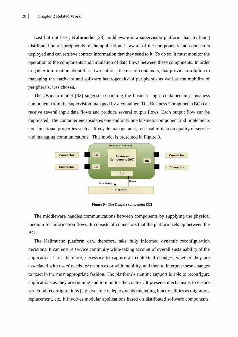
20 Chapter 2 Related Work
Last but not least, Kalimucho [23] middleware is a supervision platform that, by being
distributed on all peripherals of the application, is aware of the components and connectors
deployed and can retrieve context information that they send to it. To do so, it must monitor the
operation of the components and circulation of data flows between these components. In order
to gather information about these two entities, the use of containers, that provide a solution to
managing the hardware and software heterogeneity of peripherals as well as the mobility of
peripherals, was chosen.
The Osagaia model [32] suggests separating the business logic contained in a business
component from the supervision managed by a container. The Business Component (BC) can
receive several input data flows and produce several output flows. Each output flow can be
duplicated. The container encapsulates one and only one business component and implements
non-functional properties such as lifecycle management, retrieval of data on quality of service
and managing communications. This model is presented in Figure 9.
Figure 9 - The Osagaia component [32]
The middleware handles communications between components by supplying the physical
medium for information flows. It consists of connectors that the platform sets up between the
BCs.
The Kalimucho platform can, therefore, take fully informed dynamic reconfiguration
decisions. It can ensure service continuity while taking account of overall sustainability of the
application. It is, therefore, necessary to capture all contextual changes, whether they are
associated with users' needs for resources or with mobility, and then to interpret these changes
to react in the most appropriate fashion. The platform’s runtime support is able to reconfigure
applications as they are running and to monitor the context. It presents mechanisms to ensure
structural reconfigurations (e.g. dynamic redeployments) including functionalities as migration,
replacement, etc. It involves modular applications based on distributed software components.

21 Chapter 2 Related Work
This modularity offers hot-reconfigurable ad hoc solutions guaranteeing the continuity and
sustainability of applications over time. Applications based in Kalimucho are designed as a set
of interconnected functionalities. Each one is itself made up of a set of software components
linked by connectors. These functionalities can be achieved in different ways using different
component assemblies. The platform can then manage several functional decompositions
corresponding to the various configurations.
2.1.3. Comparison and discussion
In table 1, a comparison of the existing middleware is described based on six different
criteria. Application models represent the key components of these middleware. It is the entity
that the platform deploys and controls. The communication link is the communication
mechanism enabling the components to communicate and exchange data. Context management
shows the way that these middleware consider context awareness in their approach. As for the
Adaptation criteria, it describes how the middleware react to contextual changes or other factors
(Network status, device capabilities, etc.) by either structurally adapting the application or by
making behavioral changes only. Finally, we compare them according to their strengths and
weaknesses.
Table 1: Comparing middleware
Middleware
Application
models
Communication
link
Context
Management
Structural/
Behavioral
Adaptation
Strengths Weaknesses
SIRAC Participants
(nodes)
Connection
request
Operation
context
Static,
behavioral
Collaborative
work
Rigid
architecture
SATIN Capabilities LMU Yes, type not
specified
Dynamic,
structural
Flexible
mobility of
services
The
dependence on the
core component
xmiddle DOM
components
Tree linking via
primitives
Location-
based Static
Safe efficient
data sharing
Limited
context
Aura Aura
components Aura connectors
Situation
recognition proxy
Dynamic,
structural
Dynamic
Distributed
computation
Application
composition
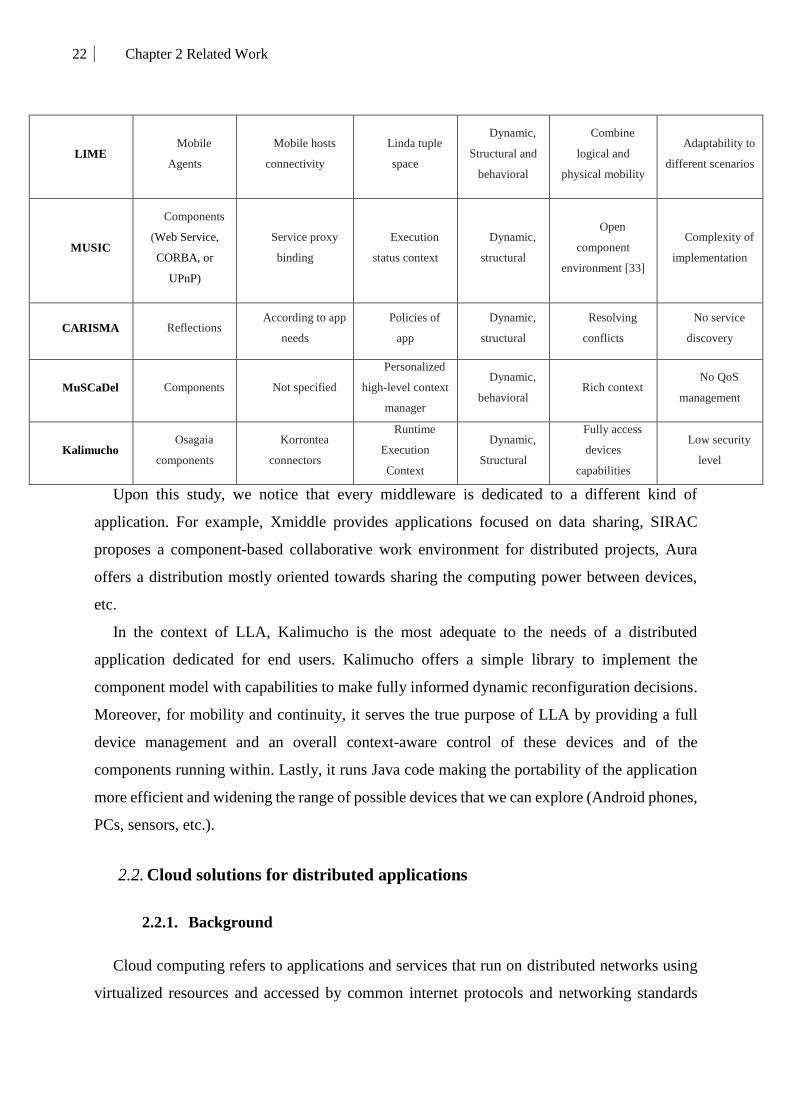
22 Chapter 2 Related Work
LIME Mobile
Agents
Mobile hosts
connectivity
Linda tuple
space
Dynamic,
Structural and
behavioral
Combine
logical and
physical mobility
Adaptability to
different scenarios
MUSIC
Components
(Web Service,
CORBA, or
UPnP)
Service proxy
binding
Execution
status context
Dynamic,
structural
Open
component
environment [33]
Complexity of
implementation
CARISMA Reflections According to app
needs
Policies of
app
Dynamic,
structural
Resolving
conflicts
No service
discovery
MuSCaDel Components Not specified
Personalized
high-level context
manager
Dynamic,
behavioral Rich context
No QoS
management
Kalimucho Osagaia
components
Korrontea
connectors
Runtime
Execution
Context
Dynamic,
Structural
Fully access
devices
capabilities
Low security
level
Upon this study, we notice that every middleware is dedicated to a different kind of
application. For example, Xmiddle provides applications focused on data sharing, SIRAC
proposes a component-based collaborative work environment for distributed projects, Aura
offers a distribution mostly oriented towards sharing the computing power between devices,
etc.
In the context of LLA, Kalimucho is the most adequate to the needs of a distributed
application dedicated for end users. Kalimucho offers a simple library to implement the
component model with capabilities to make fully informed dynamic reconfiguration decisions.
Moreover, for mobility and continuity, it serves the true purpose of LLA by providing a full
device management and an overall context-aware control of these devices and of the
components running within. Lastly, it runs Java code making the portability of the application
more efficient and widening the range of possible devices that we can explore (Android phones,
PCs, sensors, etc.).
2.2. Cloud solutions for distributed applications
2.2.1. Background
Cloud computing refers to applications and services that run on distributed networks using
virtualized resources and accessed by common internet protocols and networking standards

23 Chapter 2 Related Work
over different layers (see Figure 10). It is distinguished by the notion that resources are virtual
and limitless and that details of the physical systems on which they run are abstract from the
user [94].
Figure 10 - Cloud layered Architecture
In this scope, we focus on SaaS. Under SaaS, the software publishers/providers run and
maintain all necessary hardware and software of their proposed services while users obtain
access to these services using the Internet. It uses common resources in order to support
different clients simultaneously by providing a single instance of the application’s code and
data support behind it.
The Economist (2006, p. 61) states simply, “SaaS is quicker, easier and cheaper to deploy
than traditional software, which means technology budgets can be focused on providing a
competitive advantage, rather than maintenance”.
With the exponential rise of mobile apps, Cloud architecture aimed to overlay a new level
called Mobile Applications as a Service (MAaaS). MAaaS, Features as a Service (FaaS) or
simply Apps as a Service (AaaS) are built with cloud tools and often use both cloud-based and
on-device simulators to help the app builder view and test the app prior to deployment. In most
cases, the app is built “code-free” or “code-lite” using some form of the object-oriented design
process that abstracts most, if not all of the coding from the builder [72].
Once complete, the app is packaged for the target destination by the platform either as
completely native code or, in some cases, using a hybrid wrapper. The app is then published
from the cloud by the client with their own credentials and with no need to understand complex
programming languages.
This concept motivated engineers and researchers to race towards providing their vision of
a Cloud platforms and frameworks aimed to facilitate the creation of cloudified applications

24 Chapter 2 Related Work
dedicated to multiple domains. These frameworks differ in the way they consider the user, their
usability, and their application domains.
2.2.2. Existing cloud solutions
We studied a number of different platforms that provide the cloud infrastructure to deploy
fast, packaged applications on multiple devices for users. These platforms are dedicated to both
single end-users and companies. They aim to accompany the soon coming connected smart-
cities by delivering orchestrated deployments respecting their programming paradigms and
their layered architectures.
CHOReOS [8] implements a framework for scalable choreography development. The goal
of CHOReOS is to provide the possibility for app designers, who should be domain experts but
with no IT or engineering skills, to develop decentralized Ultra-Large-Scale (ULS) solutions
composed of heterogeneous services that are adaptable and QoS-aware.
CHOReOS follows a number of principles for formally grounded abstractions and models
(see Figure 11). First, it provides a dynamic choreography-centric development process.
Second, it offers a governance and a service-oriented middleware manipulation via an
Integrated Development Runtime Environment (IDRE) aimed at overcoming the ULS impact
on software system development dedicated to smart-cities.
Figure 11 - CHOReOS architecture [8]
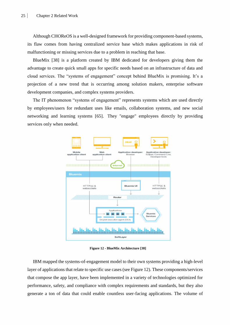
25 Chapter 2 Related Work
Although CHOReOS is a well-designed framework for providing component-based systems,
its flaw comes from having centralized service base which makes applications in risk of
malfunctioning or missing services due to a problem in reaching that base.
BlueMix [38] is a platform created by IBM dedicated for developers giving them the
advantage to create quick small apps for specific needs based on an infrastructure of data and
cloud services. The “systems of engagement” concept behind BlueMix is promising. It’s a
projection of a new trend that is occurring among solution makers, enterprise software
development companies, and complex systems providers.
The IT phenomenon “systems of engagement” represents systems which are used directly
by employees/users for redundant uses like emails, collaboration systems, and new social
networking and learning systems [65]. They "engage" employees directly by providing
services only when needed.
Figure 12 - BlueMix Architecture [38]
IBM mapped the systems-of-engagement model to their own systems providing a high-level
layer of applications that relate to specific use cases (see Figure 12). These components/services
that compose the app layer, have been implemented in a variety of technologies optimized for
performance, safety, and compliance with complex requirements and standards, but they also
generate a ton of data that could enable countless user-facing applications. The volume of
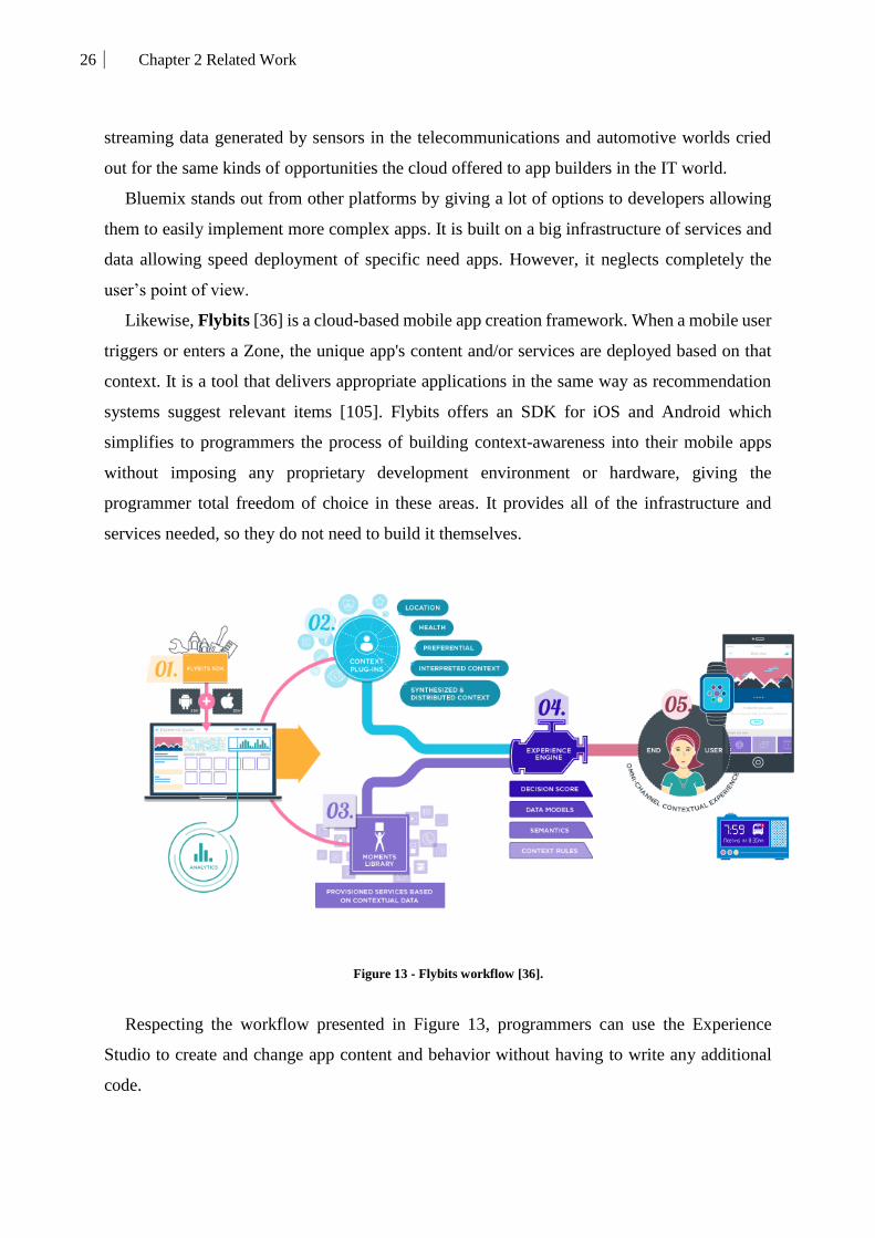
26 Chapter 2 Related Work
streaming data generated by sensors in the telecommunications and automotive worlds cried
out for the same kinds of opportunities the cloud offered to app builders in the IT world.
Bluemix stands out from other platforms by giving a lot of options to developers allowing
them to easily implement more complex apps. It is built on a big infrastructure of services and
data allowing speed deployment of specific need apps. However, it neglects completely the
user’s point of view.
Likewise, Flybits [36] is a cloud-based mobile app creation framework. When a mobile user
triggers or enters a Zone, the unique app's content and/or services are deployed based on that
context. It is a tool that delivers appropriate applications in the same way as recommendation
systems suggest relevant items [105]. Flybits offers an SDK for iOS and Android which
simplifies to programmers the process of building context-awareness into their mobile apps
without imposing any proprietary development environment or hardware, giving the
programmer total freedom of choice in these areas. It provides all of the infrastructure and
services needed, so they do not need to build it themselves.
Figure 13 - Flybits workflow [36].
Respecting the workflow presented in Figure 13, programmers can use the Experience
Studio to create and change app content and behavior without having to write any additional
code.

27 Chapter 2 Related Work
The limitation of this work is that, although the services are aimed at the user, this platform
is dedicated to businesses giving them the hand on what the user should see.
Hyun Jung La and Soo Dong Kim present a different approach in [66] which is more focused
on context awareness. The presented framework allows the produced application of firstly
capturing context, secondly determining what context-specific adaptation is needed, thirdly
selecting and adapting services for the captured context, and finally running the adapted service.
Figure 14 - Context-aware Provisioning Architecture [66]
The architecture of this framework, presented in Figure 14, consists of three layers; User
Layer, Agent Layer, and Service Layer. The User layer consists of multiple Mobile Internet
Devices (MIDs) on which applications are deployed. The Agent Layer has the task of adapting
services by taking into account the preferences of the user and his/her context information. The
Service Layer represents the cloud infrastructure running the services contained in the Service
Registry used to compose the user’s application. They are called on demand after detecting the
context and tailoring the services to the specific needs of the user.
Nonetheless, this solution lacks dynamicity as it is dependent on the service registry which
can cover a limited range of scenarios and pre-programmed mechanisms of adaptation.
Khan et al. presented the capabilities required in a Cloud environment to acquire integrated
intelligence for urban management systems. These capabilities provide a solid foundation to
respond to smart cities requirements by developing a context-aware component in a Cloud
environment [64].
In [64] the authors present a framework that attempts to define characteristics (what, why,
how and who) of the relevant artifacts and associated components. The artifacts are the main

28 Chapter 2 Related Work
building blocks for the development of cloud-based context-aware services architecture (see
Figure 15). This framework adopts, in a generic way, various artifacts, components, standards,
and technologies depending on the needs of different applications. It is flexible to provide new
artifacts and procedures and also include new technologies and standards for various different
users and use cases.
Figure 15 - Computation architecture for context-aware citizen services for smart-cities [64]
Although this framework is built on a multi-layered architecture and provides context
awareness to the users, the adaptation of the provided services is generic, which reduces their
ability to handle new needs in new application domains.
2.2.3. Comparison and discussion
After we studied some solutions, we categorized them according to some criteria that help
to show the differences between them. Table 2 summarizes a comparison between the existing
frameworks and our proposed Long Life Application.

29 Chapter 2 Related Work
Table 2: Comparing Cloud platforms
Platform Architecture Final product Strengths Weaknesses
Choreos Service Oriented
Architecture (SOA)
ULS app
deployment
choreography
Cover wide range of
scenarios on a wide
range of devices
Centralized
service base
BluMix Hybrid cloud
infrastructure
Event-driven
micro services
Fluid and rich
engagement system
(APIs, services, events,
etc.)
Enterprise-
oriented with a
need of high level
of expertise
Flybits Client/Server Context-aware
user application
Easy to use app
creator (Experience
studio)
Centralized
app provider
[66] User Layer, Agent
Layer, and Service Layer
Context-aware
user application
Dynamic context
awareness and
application adaptation on
run-time
Limited
scenarios
dependent on
existing services
[64] Hybrid cloud
infrastructure Smart-cities Apps
Rich context-aware
data extraction
Only generic
services offered
LLA Decentralized
Distributed
context-aware
mobile application
User-friendly,
Dynamic, Reactive
Considers multiple
scenarios, devices,
contexts.
No security
management
Compared to other works, LLA is based on a dynamic component architecture able to change
continuously in order to keep up with context changes. Thus, it is a dynamic proposal able to
detect the context, evaluate the existing conditions, and take action. Although it is a ready-to-
use application, LLA is also a framework that can be programmed by both, the final user and
other parties, in order to evolve the application and make it more personalized and reactive. It
combines the best advantages of the studied platforms. It covers an unlimited range of use cases,
it provides an easy way to customize and reshape itself as the app that the end-user needs.

30 Chapter 2 Related Work
3. Context awareness in mobile computing
“Mobile Apps need context to hit the right target” as stated by TechRepublic [88]. Indeed,
the main problem with existing mobile apps is their non-consideration for the status (busy, free,
working, etc.) of the user needs.
Therefore, these apps need context to aim in an intelligent way their user’s expectancies and
to avoid bothering them when no longer needed. The studied middleware and platforms have
all shown the potential of context awareness and still try to provide the best solution capable of
comprehending, analyzing and reacting to contextual changes, which brings us to the second
main pillar of our study: the context awareness.
Therefore, we start by defining the context. According to [17], the context is understood as
any information that can be used to characterize the situation of an entity, where an entity can
be a person, place, or physical or computation object”. Being aware of the context is termed
context-awareness.
In [91] context-awareness is defined as: “Computation is becoming increasingly coupled
with the physical world. It is now commonplace for mobile applications and systems to adapt
their functionality to user location, connectivity status, device orientation, and remaining
battery percentage. This ability for software to sense, react, and adapt to the physical
environment has been termed context-awareness”.
The goal of being aware of context is being able to offer the appropriate service accordingly.
This step is called context provisioning (see Figure 16) and is the main objective of context-
aware applications.
Figure 16 - Context and Context-aware provisioning [66]

31 Chapter 2 Related Work
3.1. Contextual-awareness representation models and approaches
When representing context, there is no shortage of diverse models and approaches. Each
researcher proposes their own model and considers different information which relates to the
final application that they aim for. Some consider only the location, whereas others focus on
sensors. Some use ontologies to represent it, while others propose geometrical-spacial
representations. Nonetheless, these representations fall under the specific categories described
thereafter. In the literature, several context modeling approaches can be found. Most relevant
ones have been classified by Strang & Linhoff-Popien [95] according to the scheme of data
structures which are used to exchange contextual information: key-value models, markup
scheme models, graphical models, object-oriented models, logic-based models, and ontology-
based models.
3.1.1. Key value models
This representation is the most basic model. It pairs a key and value tuple to represent simple
context. It uses matching algorithms to detect context when the stored key or value are
retrieved. An example of this model is presented in works like Schilit et al. [9]
3.1.2. Markup Scheme models
Like all markup scheme modeling approaches, this is a hierarchical data structure consisting
of markup tags with attributes and content. In particular, the content of the markup tags is
usually recursively defined by other markup tags.
These models are, usually, based upon a serialization of a more abstract standard called
Standard Generic Markup Language (SGML). SGML is the father of all markup languages such
as XML. Some of them are defined as an extension to the Composite Capabilities / Preferences
Profile (CC/PP) [103] and User Agent Profile (UAProf) [106] standards, which have the
expressiveness reachable by RDF/S and an XML serialization. Indeed, these kinds of context
modeling methods often extend/complete the basic CC/PP and UAProf vocabulary/procedures
to try to better manage complex dynamic contextual information as opposed to more static
representations used to represent static data.
An example of this approach is the Comprehensive Structured Context Profiles (CSCP) by
Held et al. [51].

32 Chapter 2 Related Work
3.1.3. Graphical models
Graphical models are used to generate a representation derived from an entity-relationship
(ER-model) [15]. This approach is efficient in structuring instruments for a relational database
in an information system based on context management architectures such as the one described
in [55]. Indeed, UML is the most common language used to represent this kind of models.
Context Spaces Theory (CST), for example, is a graphical approach for context awareness and
situation awareness. CST uses spatial models to achieve a meaningful and easy to understand
context representation.
CST aims towards a general context model to help thinking and to describe the context. It
offers various design operations for manipulating and utilizing context. The CST concepts use
insights from geometrical spaces and the state-space model to guide reasoning about context
using geometrical metaphors. The model provides a unified and general way to represent
context and enables effective reasoning to be applied over the modeled information.
The foundations of the context spaces theory are provided in the work of Padovitz et al. [17]
as an example of how to use this modeling method.
3.1.4. Object-oriented models
This representation illustrates the main pillars of oriented programming (Encapsulation,
Heritage, and Polymorphism). To describe the context and cover parts of the problems arising
from the dynamics of the context in ubiquitous environments, it employs these pillars to its
benefit. An example of this use would be shown by the fact that the details of context processing
are encapsulated on an object level. It is, therefore, hidden to other components. Therefore
contextual information is provided through specified interfaces only.
3.1.5. Logic-based models
The notion of context and the contextual logic originally developed by John McCarthy in
the field of Artificial Intelligence (AI) aims at providing a solution to the problem of generality,
the problem of representing ordinary knowledge and its integration into inferential processes
operating on knowledge bases [109].
This kind of representation requires a high level of formality, as the context is defined by a
variety of facts, expressions, and rules that need to be checked and validated. Therefore, context
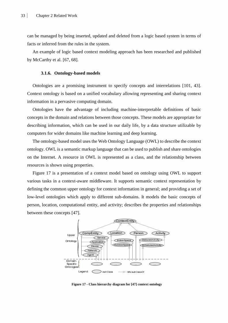
33 Chapter 2 Related Work
can be managed by being inserted, updated and deleted from a logic based system in terms of
facts or inferred from the rules in the system.
An example of logic based context modeling approach has been researched and published
by McCarthy et al. [67, 68].
3.1.6. Ontology-based models
Ontologies are a promising instrument to specify concepts and interrelations [101, 43].
Context ontology is based on a unified vocabulary allowing representing and sharing context
information in a pervasive computing domain.
Ontologies have the advantage of including machine-interpretable definitions of basic
concepts in the domain and relations between those concepts. These models are appropriate for
describing information, which can be used in our daily life, by a data structure utilizable by
computers for wider domains like machine learning and deep learning.
The ontology-based model uses the Web Ontology Language (OWL) to describe the context
ontology. OWL is a semantic markup language that can be used to publish and share ontologies
on the Internet. A resource in OWL is represented as a class, and the relationship between
resources is shown using properties.
Figure 17 is a presentation of a context model based on ontology using OWL to support
various tasks in a context-aware middleware. It supports semantic context representation by
defining the common upper ontology for context information in general; and providing a set of
low-level ontologies which apply to different sub-domains. It models the basic concepts of
person, location, computational entity, and activity; describes the properties and relationships
between these concepts [47].
Figure 17 - Class hierarchy diagram for [47] context ontology

34 Chapter 2 Related Work
The basic concept of this context model is based on an ontology which provides a vocabulary
for representing knowledge about a domain and for describing specific situations in a domain.
Ontology-based modeling is considered as the most promising approach, as it enables a
formal analysis of the domain knowledge, promoting contextual knowledge sharing and reuse
in a ubiquitous computing system, and context reasoning based on semantic web technologies
[39].
3.1.7. Comparison and discussion
In order to evaluate these approaches, we consider factors that are relevant in the context of
LLA. Therefore, the comparison (see Table 3) considers the efficiency of these models
regarding the distribution aspect. The composition and administration of contextual models and
vary considerably with high dynamics in terms of time, network topology and source.
Moreover, we consider the formality of the model and the richness of data supported by that
model. This aspect relates more to the context-awareness aspect of LLA.
Finally, we consider the applicability of these models to user-centered mobile applications
for everyday usage.
Table 3: Comparing context modeling approaches
Modeling Approach Distribution
efficiency
Formality/richness Applicability
Key-Value models - - +
Markup scheme models + - +
Graphical models - + +
Object oriented models + + +
Logic models + + -
Ontology-based models + + +
3.2. Modeling situation-awareness for Context-aware applications
This modeling approach distinguishes between the concepts of Context and of Situation.
Context is the information used in a model for representing real-world situations. On the other
hand, situations are perceived as a meta-level concept over context [2]. The process of assessing
the association and mapping between context and situations, or in other words, determining

35 Chapter 2 Related Work
occurrences of situations based on information in a model, is the task of reasoning. This
relationship between context and situations is represented in a general way by the concepts of
state and space.
Situation awareness modeling is generally used in the command and control domain for
situation assessment and decision support. It is based on the Endsley’s three-layer structure
(Endsley, 1995), but with the addition of a terrain model for the command and control domain.
Incoming data is first represented at the Perception layer (level 1) of the situation model.
The Comprehension layer (level 2) then interprets the data and provides an assessment of the
current situation. To support anticipatory decision-making, the Projection layer (level 3)
predicts future states based on the understanding of the current situation. At present, only some
basic projection functions have been implemented for illustration purpose. All three layers of
the situation awareness model function concurrently and iteratively.
For an end-user application, this model is the most suitable representation. It combines the
advantages of most representations. LLA uses a situation-aware model using the key-value
model to match context to services, markup scheme model to textually describe situations, logic
models to build Event-Condition-Action approach as a global workflow and graphical models
to represent and understand situations semantically. This modeling is a paradigm used by
context-aware platforms in order to build their vision of context-aware applications.
3.3. Platforms dedicated to generating context-aware applications
In this scope, many works provide a way to automatically generate context-aware
applications for users. These platforms are based on the studied contextual models and
approaches. Each of them has its own vision and features for the produced applications. On this
study, we focus mainly on mobile applications and services (see Figure 18).
CyberDesk [27] is a component-based framework written in Java that supports the automatic
integration of software applications. This framework is flexible and can be easily customized
and extended. In CyberDesk, components treat all data, in the same way regardless of the source
(PC, PDA, Phone, etc.).
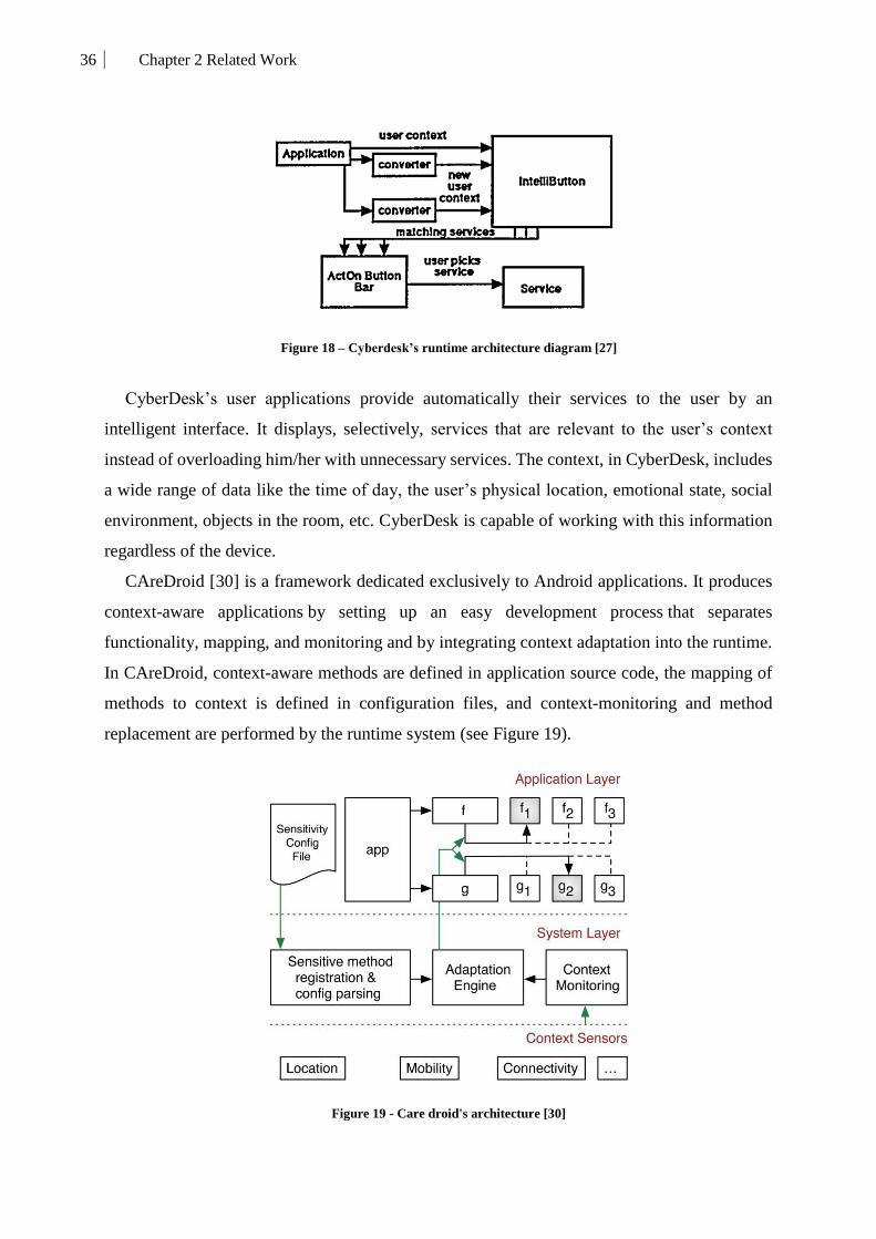
36 Chapter 2 Related Work
Figure 18 – Cyberdesk’s runtime architecture diagram [27]
CyberDesk’s user applications provide automatically their services to the user by an
intelligent interface. It displays, selectively, services that are relevant to the user’s context
instead of overloading him/her with unnecessary services. The context, in CyberDesk, includes
a wide range of data like the time of day, the user’s physical location, emotional state, social
environment, objects in the room, etc. CyberDesk is capable of working with this information
regardless of the device.
CAreDroid [30] is a framework dedicated exclusively to Android applications. It produces
context-aware applications by setting up an easy development process that separates
functionality, mapping, and monitoring and by integrating context adaptation into the runtime.
In CAreDroid, context-aware methods are defined in application source code, the mapping of
methods to context is defined in configuration files, and context-monitoring and method
replacement are performed by the runtime system (see Figure 19).
Figure 19 - Care droid's architecture [30]
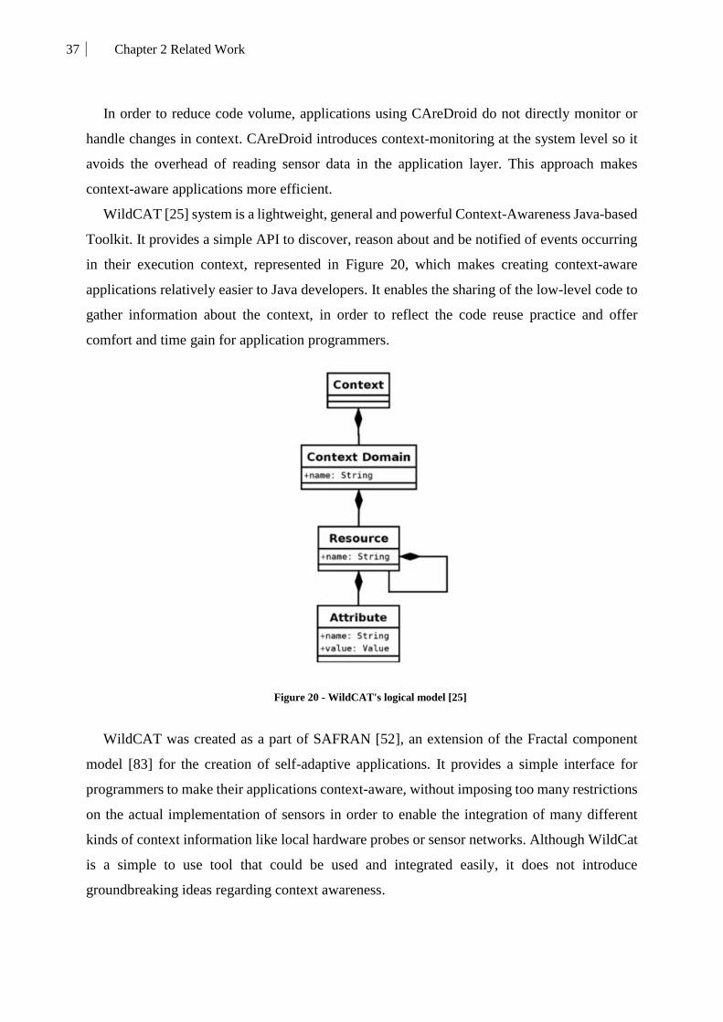
37 Chapter 2 Related Work
In order to reduce code volume, applications using CAreDroid do not directly monitor or
handle changes in context. CAreDroid introduces context-monitoring at the system level so it
avoids the overhead of reading sensor data in the application layer. This approach makes
context-aware applications more efficient.
WildCAT [25] system is a lightweight, general and powerful Context-Awareness Java-based
Toolkit. It provides a simple API to discover, reason about and be notified of events occurring
in their execution context, represented in Figure 20, which makes creating context-aware
applications relatively easier to Java developers. It enables the sharing of the low-level code to
gather information about the context, in order to reflect the code reuse practice and offer
comfort and time gain for application programmers.
Figure 20 - WildCAT's logical model [25]
WildCAT was created as a part of SAFRAN [52], an extension of the Fractal component
model [83] for the creation of self-adaptive applications. It provides a simple interface for
programmers to make their applications context-aware, without imposing too many restrictions
on the actual implementation of sensors in order to enable the integration of many different
kinds of context information like local hardware probes or sensor networks. Although WildCat
is a simple to use tool that could be used and integrated easily, it does not introduce
groundbreaking ideas regarding context awareness.

38 Chapter 2 Related Work
CodeDroid [26] aims to use the concept of a profile in the design of context-aware
applications. It helps a designer in the development of context-aware mobile applications for
different domains. The goal of the CodeDroid framework is to assist the development of mobile
context-aware applications for the Android platform.
Figure 21 - Class diagram of the application Places2Go and its relationship [26]
CodeDroid allows a user to add other features dynamically by implementing engineering
practices applied to the object-oriented contextual model, presented in Figure 21 (use case of a
tourism application). These practices are derived from programming and conception design
patterns: the adaptation of the MVC pattern to develop Android applications, a greater
modularity; a definition of an access point to the sensing services based on the Facade standard;
an implementation of notifications as a result of context changes based on the Observer design
pattern; a definition of the “entity” for representing context; a profile abstraction allowing its
management in a transparent manner; and providing services for the collection of context
sensing.
To summarize, these platforms propose interesting ideas. They simplify the process of
creating context-aware applications by providing code generators, context creators, and
toolkits. Nonetheless, the produced application still suffer limitations related to their reactivity
and richness.
When using these platforms, the programmers build applications with contextual awareness
related to only one domain. The reason behind this comes simply from the fact that
programmers cannot predict all the possible rules and situations for each different user.

39 Chapter 2 Related Work
4. User-centered Context-aware mobile applications
The final goal of our work is proposing an end-user context-aware dynamic context-aware
application. After studying all the areas that lead to build and run this kind of applications, we
present now both commercial and research applications providing the wanted features for
common usage on mobile devices. In the following, we present a set of existing application that
provides similar features to what we want to achieve.
4.1. Existing solutions
Google is one of the biggest companies putting an effort to aim their work in the area of
dynamic applications able to detect context and offer services to their users. Their main
application is called ‘Google’ [40] or ‘Google Now’. This application is triggered by contextual
changes or voice commands. It detects/gathers relevant data (home location, work location,
calendar events, Google+, etc.) about users and saves their Google searches using Google
knowledge graph. It uses other Google services (Google Maps, Google Images, and Google
Alert, etc.) to provide features like getting updates on sports, movies, and events. In a recent
build, Google fully integrated Google Now and combined it with an AI into the Android layer
of their first smartphone (Google Pixel). Google also took other interesting initiatives with
context-aware applications but in a different format with Google Instant Apps [41, 57]. They
offer the possibility for developers to decompose their applications into smaller apps dedicated
to specific needs and triggered by, either clicking on a link from the web or by NFC (example:
to buy an item on Amazon, the user reaches the item on Google and them when he/she are about
to pay, the Amazon payment instant app is launched with no installation required). The parking
micro-app is only launched when the user faces the parking machine and places their phone on
the machine to trigger the parking app. It uses an approach similar to Micro-apps [96]. The
strength of these solutions comes from the fact that they are built on the multiple services of
Google. Nonetheless, Google focuses their applications on predictive recommendations that
may be interesting to the user in a limited range of situations because they only use their tools
to achieve to respond (notification, alerts and Google applications) to the needs of the user.
Grokr [21] is the equivalent of Google Now for iOS focused on context-aware
recommendation (predictive search engine) and notification system. It notifies for nearby events
(concerts, sports events, and important occasions to the user (birthday, calendar events). These
services are also integrated into applications like Osito [22] and Tempo [97] but with a slight

40 Chapter 2 Related Work
difference in the way that they are presented and in the mechanisms behind them. The Grokr
advantage over Google Now by being able to pull information about the user from social graphs
(Facebook, Twitter, LinkedIn, and Google+) while Google links only with Google+. The
drawback of this application is that the same as Google Now, it has limited services and doesn’t
allow flexibility when inputting context.
Easily Do [94], 24me [1] and Tempo [97] are all personal assistants solution to productivity
planning and scheduling. Tempo is based on an AI able to pull user contextual information and
predict meeting places and attendees. 24me integrates the user’s calendar, tasks, notes and
personal accounts together in order to customize the application and have automated reminders
about paying bills, sending gifts and going to doctor appointments etc. The problem of these
application comes from the limitations of AI (redundancy of recommendations, lack of
dynamicity, get the control out of the user’s hands etc.) and lack of diversity of their services
(notifications, recommendations etc.).
IFTTT [80] is another interesting solution. It considers the user domain (devices) and
exploits it by using web services able to communicate, link and control remote devices
(connected lamps). Although its contextual model is poor, it offers pertinent useful scenarios
(turn on lights automatically at 7 pm). Therefore, IFTTT is dependent on those services and is
repetitive and not really aware of the user’s situations.
The applications, presented so far, are commercial apps created by companies. Now, our
focus is on research works tackling this area.
SECE [79] (Sense Everything, Control Everything) is an application for context-aware
service composition offering a rule-based approach in a more user-friendly way enabling users
to define the expected behavior of a set of web-based services under certain situations. These
situations are used to trigger the composed service execution. They are based on basic
contextual information like location, time. Even though it is user-friendly, inputting rules in a
written manner is always considered a boring task to mobile end-users.
DoTT [44] is another rules-based system using context providers in order to be aware of the
user situations instantly. It is built over a reasoning engine able to comprehend the adaptation
rules and react to the user’s context changes following those rules. As output, it has an
interactive interface that can host the services provided by the system. The difference between
this approach and other rule-based systems is that the rules in this work are presented in a natural
language following a specific grammar (sentences). The drawback of this work is the limit of
its basic services (messaging, calls, calendar and social).

41 Chapter 2 Related Work
Dig-Event [111] is a mashup service that allows the users to define and order activities like
trips and meetings by providing them with recommendations of a diversity of relevant services
for performing those activities. The service recommendations rely on context-based selection
criteria including time, type of activity, budget, etc. Nevertheless, this system lacks flexibility
in context acquiring. In this work, the user context is the result of the manually entered
information when declaring the activity but it doesn’t consider context changes when doing that
activity.
The last type of context-aware applications is called trail-based applications [18]. A trail is
a contextually scheduled collection of activities and represents a generic model that can be used
to satisfy the activity management requirements of a wide range of context-based time
management applications. Combining the trails concept with mobile, context-aware technology
creates opportunities for innovative activity-based application development. Hermes [19] is a
software framework for mobile, context-aware trails-based applications which will support
developers by providing generic components containing structure and behavior common to all
trails-based applications. It organizes, using a mathematical model, the activities of the user
according to his/her previous trails. The problem with this approach is that it is too much
focused on travel scenarios rather than everyday situations that can be indoors.
Table 4 compares the existing works to our proposal (LLA) based on different criteria:
contextual model variables, the existence of context detection mechanism and its type
(distributed or centralized on one device), whether contextual growth is considered and what
are the sources of that growth, services offered and finally the ubiquity of the offered services.
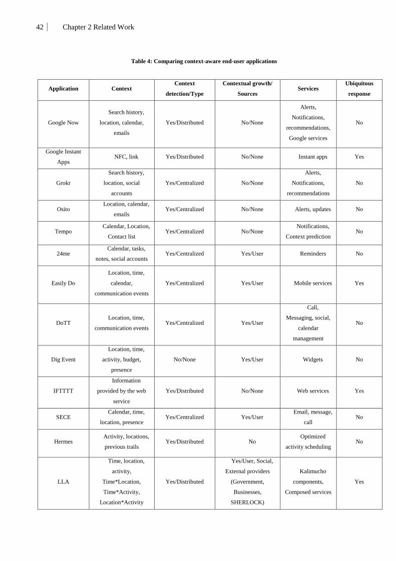
42 Chapter 2 Related Work
Table 4: Comparing context-aware end-user applications
Application Context Context
detection/Type
Contextual growth/
Sources Services
Ubiquitous
response
Google Now
Search history,
location, calendar,
emails
Yes/Distributed No/None
Alerts,
Notifications,
recommendations,
Google services
No
Google Instant
Apps NFC, link Yes/Distributed No/None Instant apps Yes
Grokr
Search history,
location, social
accounts
Yes/Centralized No/None
Alerts,
Notifications,
recommendations
No
Osito Location, calendar,
emails Yes/Centralized No/None Alerts, updates No
Tempo Calendar, Location,
Contact list Yes/Centralized No/None
Notifications,
Context prediction No
24me Calendar, tasks,
notes, social accounts Yes/Centralized Yes/User Reminders No
Easily Do
Location, time,
calendar,
communication events
Yes/Centralized Yes/User Mobile services Yes
DoTT Location, time,
communication events Yes/Centralized Yes/User
Call,
Messaging, social,
calendar
management
No
Dig Event
Location, time,
activity, budget,
presence
No/None Yes/User Widgets No
IFTTTT
Information
provided by the web
service
Yes/Distributed No/None Web services Yes
SECE Calendar, time,
location, presence Yes/Centralized Yes/User
Email, message,
call No
Hermes Activity, locations,
previous trails Yes/Distributed No
Optimized
activity scheduling No
LLA
Time, location,
activity,
Time*Location,
Time*Activity,
Location*Activity
Yes/Distributed
Yes/User, Social,
External providers
(Government,
Businesses,
SHERLOCK)
Kalimucho
components,
Composed services
Yes

43 Chapter 2 Related Work
4.2. Discussion
To summarize, our proposal called Long Life Applications is anchored in the center of
context-aware mobile applications. Our novel contribution is mainly focused on the contextual
situation injection (Contextual growth), the modularity and the ubiquity of our proposal.
Although some works consider injecting context (by rules, natural language or voice
commands), they only consider the user for this task. Our work proposes a richer injection
mechanism (see Chapter 7) that allows the user to have a more diverse experience and offers
him/her more freedom without having to rely on any programming skills (opposed to traditional
rule-based systems). Furthermore, the services offered by our proposal are limitless due to the
fact that they are related specifically to the situations. It means these services are specified by
the creator of the situation. Finally, our application is pervasive and built on a modular
architecture able to run simultaneously on many devices regardless of their capabilities, OS or
network.
5. Conclusion
Context-aware applications have been the topic of discussion for more than a decade and are
still being studied by a lot of researchers. Each of them presented their own views, brought their
own contributions and built their own solutions. The depth of this area stems from the diversity
of proposals and richness of factors to take into account when trying to offer the needed solution
that reflects the expectancies of the usage of this kind of applications.
Proposing a new kind of mobile applications for the future requires having a full
understanding of the state of art related mainly to the expectancies of the users and to the
technological advancements. Therefore we propose to incorporate context awareness to regain
the interest of users in mobile applications by proposing a fluid, dynamic application able to
understand their needs and evolve accordingly. We consider also the technological advances by
proposing to incorporate the distribution aspect into their applications in order to take advantage
of the ubiquity and computing power of the new coming smart connected age of technology.
In summary, in this chapter, we presented a thorough study of the areas surrounding our
work. We believed necessary to tackle this domain from its most important aspects that lay the
grounds to present our proposal.

44 Chapter 3 Long Life Application Proposal
Chapter 3 Long Life Application Proposal

45 Chapter 3 Long Life Application Proposal
1. Introduction
With so many possible use cases and such diverse user needs, is it desirable to have one
application that does it all? Has it become a necessity to have one application able to understand
users and eliminate the need for other applications? In order to answer these questions, we first
need to clearly define Long Life Application.
LLA is a context-aware distributed mobile application dedicated to everyday users. It offers
modular mobile services to the consumers of mobile applications that, until now, search, find,
install, update and delete their applications on their devices. This kind of applications is called
long-life Applications (or Eternal Applications) as it runs constantly and evolves by changing
its behavior and offering a variety of services according to the user’s needs.
Our vision of this application is centered on one user in his connected environment, that we
call user-domain, making it a distributed mobile application by definition. This app needs to
offer to the users a high level of comfort and a better-customized user experience by replying
both re-actively and pro-actively to the users’ needs without confusing them by the large
diversity of apps and devices.
This app needs to be contextually aware of the users and their surroundings giving them the
opportunity to be operationally connected entities in their future smart world. In our proposal,
the context awareness manifests in situations that represent the current context of the user.
These situations are the main entity of our application. They can represent the user’s everyday
life according to his contextual information (see Chapter 4 and 5).
After understanding the user’s situation, the application offers the appropriate services that
can answer to his need in the best dynamic distributed way. It deploys/migrates software
components on the devices of his smart-domain (his devices) and then deletes them when no
longer needed.
Nonetheless, no application can neither predict nor autonomously handle all the possible
situations that could happen to the user in all different areas (shopping, work, travel, etc.) due
to the infinite possibilities. Therefore, our proposal allows to dynamically add new situations,
from both non-experts (e.g. everyday users) and domain experts (e.g. travel agent), into the
user’s application (see Chapter 7).
In order to achieve these goals, we present in this chapter an overview of the proposed
approach and how it answers the raised issues with existing solutions (see Chapter 2). In this
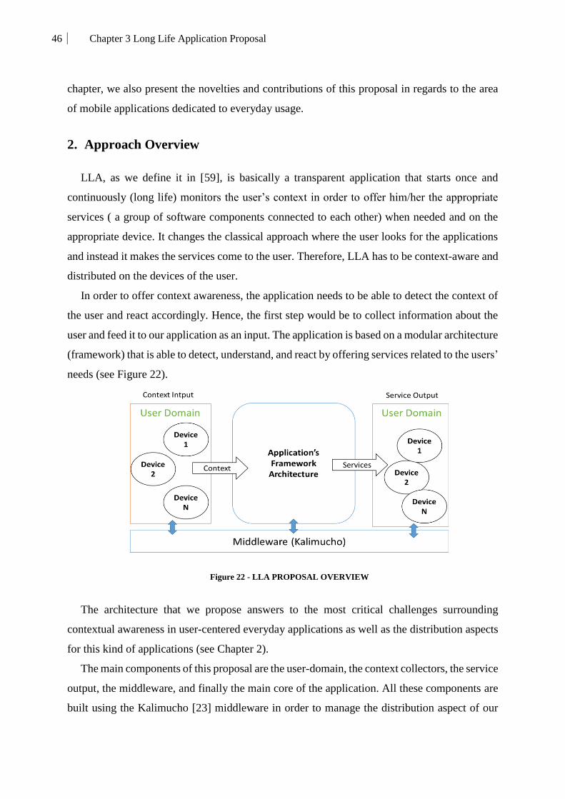
46 Chapter 3 Long Life Application Proposal
chapter, we also present the novelties and contributions of this proposal in regards to the area
of mobile applications dedicated to everyday usage.
2. Approach Overview
LLA, as we define it in [59], is basically a transparent application that starts once and
continuously (long life) monitors the user’s context in order to offer him/her the appropriate
services ( a group of software components connected to each other) when needed and on the
appropriate device. It changes the classical approach where the user looks for the applications
and instead it makes the services come to the user. Therefore, LLA has to be context-aware and
distributed on the devices of the user.
In order to offer context awareness, the application needs to be able to detect the context of
the user and react accordingly. Hence, the first step would be to collect information about the
user and feed it to our application as an input. The application is based on a modular architecture
(framework) that is able to detect, understand, and react by offering services related to the users’
needs (see Figure 22).
Figure 22 - LLA PROPOSAL OVERVIEW
The architecture that we propose answers to the most critical challenges surrounding
contextual awareness in user-centered everyday applications as well as the distribution aspects
for this kind of applications (see Chapter 2).
The main components of this proposal are the user-domain, the context collectors, the service
output, the middleware, and finally the main core of the application. All these components are
built using the Kalimucho [23] middleware in order to manage the distribution aspect of our

47 Chapter 3 Long Life Application Proposal
proposal. From the user’s perspective, the visible part of LLA (front -end) is only the deployed
services, the device possesses a screen, LLA provides (in addition to the deployed service) a
management UI that allows the user to manage the application (configurations) and use its
features. The rest of the components are completely transparent (back-end) but keep running
continuously so they can provide the user with the required services.
The general process of LLA starts by extracting contextual information from the user-
domain and then inputting it into the core architecture in order to animate it. Inside the core of
our proposal, we implement a process respecting the Event Condition Action (ECA) approach
[76, 9]. When fed to the core, this contextual information helps to construct an event, to verify
if conditions surrounding that event are met and to, finally, deploy services as an action for that
event. Through this process, the contextual information respects a defined situation-based
contextual model that structures and represents the data extracted from the devices in order to
build an entity (Situation), which can be understood by both the application and the users.
After defining the main components of our proposal and describing the workflow process,
we evaluate this proposal by comparison to existing solutions. This comparison (see Table 2,
3, and 4) shows that our solution improves on the limitation of existing applications by
providing a number of novel contributions on the theoretical and technical level. These
contributions are the solutions to the issues raised by the studied works.
3. Contributions
In the studied works, some issues appear to be common between these context-aware
distributed applications. These issues are of course related firstly to the awareness of the
application and secondly to the distribution aspects.
3.1. A rich and user-friendly contextual model
When dealing with context, one of the aspects that developers and researchers have to
consider is creating a contextual model that can be, on one hand, rich enough to express very
specific and detailed situations, and on the other hand, simple enough for users to comprehend
(user-friendly). Therefore, we present a user-friendly (for a non-expert), rich (for experts),
extendable, and situation-based contextual model [60, 61].
The context of LLA, as we defined it, is a variety of situations that occur to the user while
he/she evolves in his/her environment. The totality of these situations shapes the user’s
48 Chapter 3 Long Life Application Proposal
application. The main entity, called Situation, is the element defining the application’s behavior.
This model will define the rules of our representation of the user’s context and our answer for
context management challenge.
The situation, presented in chapter 4, in our system is the key component. It combines the
best benefits of the context representation models studied in chapter 2. It is an overlapping
between schema markup, graphical and logic models. We use scheme markup to textually write
these situations so they can be analyzed and parsed by the different modules of the application.
The graphical aspects of our model are reflected through the representation of the situations in
a multidimensional coordinate system with limits and restrictions. Last but not least, this model
follows rules that match the situations to services and reaction strategies.
In chapter 4, our proposed model is described thoroughly by presenting its main constituents
and by showing examples that illustrate the way that users and experts can easily exploit this
model to represent their needs.
3.2. A cross-device context detection
Context-awareness requires, by definition, a system able to detect the context and understand
it. An important drawback of existing applications comes from identifying the user with one
and only one device. These applications limit their detection on the user's mobile phone. This
issue motivated our work to be oriented to cross-device context detection dedicated to end-users
and enabling the application to accurately follow and detect context changes.
LLA allows the user to properly use his/her soon-coming smart environment (composed by
his/her own computing devices and other surrounding devices in the Internet of Things) without
any confusion due to the multiplicity of devices and the heterogeneity of systems available. For
that purpose, we re-think the architecture of traditional applications, dedicated to stand-alone
devices, and aim towards liquid applications [6, 100] by implementing a distributed context
detection mechanism [78] able to continuously query the user’s devices for the contextual data
needed in order to detect and evaluate his/her current context.
This mechanism presents advantages for monitoring contextual changes from every angle
by incorporating an innovative cross-device context detection in order to draw the bigger
picture of the user’s context. This support for multiple devices enhances the capability to detect
situations, anywhere and anytime, as data captured from different devices and sensors can be

49 Chapter 3 Long Life Application Proposal
combined. Besides, it is a suitable solution for the common case of a user with multiple devices,
as he/she is not obliged to manage only one specific device.
3.3. A modular orchestration of services
In the middle of this rapidly increasing connected world, users will be faced with a huge
overhead to manage their devices. Besides managing these devices, users are looking forward
to having a rich user experience that spans on multiple terminals making him/her feel as the
center of his/her environment.
Existing context-aware applications that consider distribution propose only generic services
that run specifically if a set of sensors and/or devices is present and fully functional. For
example, YouTube has distribution features that allow the user to project the videos on his/her
TV. Nonetheless, that requires having a Chromecast [107] device connected to the TV.
Moreover, the use cases of the distribution aspects are limited to streaming or sending simple
data between devices. This is due to the fact that current mobile applications are installed as an
enclosed runnable bundle (.apk, .ipa, .cab, .ipk, etc.) that contains all the compiled code base
which makes the modules of that application tightly-coupled.
In our work, we use a different more flexible approach. We consider a service as a set of
atomic, independent and connected mobile components able to run, stop, migrate, and
communicate with each other.
The benefit of this approach is the number of possibilities of different user experiences that
the application will provide for the user. By decomposing the services into software
components, LLA is able to target the deployment of these components to the best fitting device
that possesses the hardware capabilities required to run these components in an optimal and
useful way. Moreover, this approach ensures the continuity, sustainability, and scalability of
the application by being able to move components freely between devices at run-time if the host
is for example overwhelmed with the component processing requirements or if it has a low
battery level and about to go offline soon.
3.4. A collaborative situation injection
From a mobile application’s point of view, what users expect is an application that
understands what they expect and most importantly application that is dynamic and non-
repetitive. Therefore, we propose a semi-automatic collaborative injection mechanism to ensure
50 Chapter 3 Long Life Application Proposal
the growth of the user’s application in order to continuously provide the user with richer
contextual awareness, better-adapted user experience, and more adequate services. The real
motivation behind this mechanism is to overcome one of the most common limitations of
context-aware applications. This limitation is their dependence on knowledge about a certain
domain (hospitals, museums, supermarkets, etc.). This knowledge is usually provided by those
domains experts to the researchers or developers in order to build their applications rules and/or
ontologies that represent that specific knowledge base. This makes these applications consider
a limited area of expertise with limited pre-defined use cases and generic services.
LLA breaks that limitation by externalizing the definition of situations to enable the experts
of those domains to input their descriptions of their users’ needs following our situation
contextual model and providing the most fitting services for those needs.
Mainly, the injection mechanism [62] enables the application to keep evolving and be
customized exactly to what the user’s needs, likes and does. Using this approach, the application
is able to always enrich the user experience by adding, deleting or modifying the users’
situations. This mechanism (see Chapter 7) is based on our user-friendly situation model in
order to make the injection an easy and understandable mechanism that can be performed even
by end users with no understanding of context awareness. Consequently, the collaborative
injection makes context detection richer, more accurate and user-centered by giving him/her
the possibility to create his/her own situations or extract them automatically from his/her social
environment (Facebook, Calendar, Twitter, etc.). The user can also receive nation-wide
situations provided by the government (e.g., closing borders, hurricane alerts, and elections).
Moreover, he/she trust external developers, companies or businesses (shopping centers,
suppliers, restaurants, etc.) to inject new situations.
4. Application’s General Architecture
After defining the overall approach and the main contributions of this work, we introduce,
in this section, the global architecture of LLA. This architecture displays, in a general
presentation, the main modules constituting the application and running in the background
(back-end). Accordingly, these modules reflect and respect the claimed contributions.
Due to the distribution requirements of this kind of application, all the building blocks
(modules, components, files, etc.) are dynamic, functionally independent, and controlled by
Kalimucho middleware. This aspect ensures the continuity of the application in case one of the

51 Chapter 3 Long Life Application Proposal
core components faces some issues while running. In Figure 23, we present the global core
architecture of our back-end application.
Figure 23 - LLA's General Architecture
As described in Section 2, the process of the application starts by collecting contextual
information from different devices (user domain) as input, evaluates this data, determines the
current situation of the user, and ends by providing a distributed component-based output.
Each module of this architecture has its own internal architecture and workflow. They
interact with each other by exchanging data on runtime. Once started, these modules are
deployed on the user’s devices following a defined distribution strategy (see Section 5). After
that, they keep running continuously (thus the term “Long Life”) in order to go together with
the user in his/her fast changing everyday context and react accordingly.
4.1. The User Domain
The User-Domain is used to collect data for building contextual situations and host the
adequate services. This concept defines the list of the user’s available devices that host an
instance of LLA and which are accessible to the user.
Hosting LLA: The device needs to have LLA installed on an Operating
System (OS) able to run the Java Virtual Machine (JVM). This requirement does not
mean that the application will run entirely (in the same way) on all the devices. The
deployment strategy of the application (see Section 5) organizes the modules

52 Chapter 3 Long Life Application Proposal
between the devices that have an instance of LLA. This solves the issue of
duplication of current mobile applications on users’ devices.
Availability: In order for the application to function properly on these
devices, it needs to recognize the other devices. This means that when the user
wishes to use the application the device should be turned on, connected to any
network (Wi-Fi, 3G, 4G, Wired-networks, etc.) and allowing data-exchange on
those networks.
Accessibility: In LLA we define two types of accessibility level in order
to organize the user-domain, avoid confusion between the devices of different users
and ensure the security of the user and the protection of his/her data (see Figure 24).
The user has the possibility to fully manage the devices surrounding him/her. Using
the LLA Management UI, he/she can add new devices, delete existing devices,
monitor connected devices, modify accessibility and configure security preferences.
Figure 24 - User's domains
o The Private Domain: This level of accessibility represents the user’s own
personal devices that are accessible only to him/her. This means that no other
user is able to extract data from or deploy component on those devices. In order
to securely use this domain, the user defines a Shared Secure Key (SSK) between
all his/her private devices in order to have a closed and protected domain.
o The Public Domain: These devices are accessible to any user at any time.
The motivation of adding this layer comes from the multiplicity and availability
of this kind of public devices everywhere (e.g. airports, bus stations, hospitals,
etc.). Nonetheless, these terminals are solely used to deploy services. It makes no
sense to extract contextual data from these devices since they do not represent the
personal context of the user (except the location).
53 Chapter 3 Long Life Application Proposal
The User-Domain enables LLA to keep the user’s devices organized and categorized. In
respect to the stated contributions (3 and 4), the User-Domain helps LLA to clearly identify the
devices, surrounding its user, in order to properly extract relevant context and optimally run the
expected services.
4.2. Kalimucho
In order to manage the devices in the user-domain, LLA needs to use software components
able to communicate regardless of the differences between these devices. Thus comes the need
to use a middleware offering a component model suitable for the requirements of LLA (see
Chapter 2).
4.3. Input
The first step of detecting context is extracting relevant data from the user’s devices.
Therefore, we introduce on the input level a cross-device contextual data extraction. This
mechanism, continuously and optimally, provides LLA with pertinent information about the
current context of the user from multiple sources (User Private Domain) simultaneously. It is
the starting point of the workflow.
The data extracted on this level is used to verify the occurrence of the user’s situations
respecting the situation-based contextual model defined in Chapter 4.
4.4. Output
The goal of context awareness is to offer adequate services when the right context is verified.
Therefore the final output of LLA (front-end and/or back-end) are the services that it
deploys/stops/migrates in response to detecting a situation.
Consequently, the services are a group (or single) of Kalimucho components (see Chapter
6) able to run, communicate, stop, and migrate to any device on the domain. If the output
requires running/stopping a new component, that component could be either ran/stopped on the
background (with no UI) or added to/removed from the main LLA management UI (with UI).
Migrating components is the process that can be done manually by the user or automatically by
the app if the quality of service (QoS) is not ensured. It combines stopping the component on
the one device and running it on the other while keeping its status.

54 Chapter 3 Long Life Application Proposal
4.5. The Injector
The Injector is a mechanism (see Chapter 7) that allows a collaborative dynamic injection of
new high-level context (situations described using the proposed situation-based contextual
model) into the user’s LLA [62].
The main novelty of this mechanism is a cooperative workflow that enables users and other
external sources to continuously and pro-actively contribute to the growth of the user’s
application, in order to improve its understanding and reliability and overcome the lack of
dynamicity in current context-aware applications, which causes that only 25 percent of users
return to any given application after the first use [3].
Our proposal for situation injection and detection is a hybrid approach that combines both
high-level context (top-down approach), by injecting user-related context, and low-level
context (bottom-up approach), by inferring it from sensor data.
4.6. The Persistence layer
The persistence layer is a cloud and local storage dedicated to storing data about the user
(situations, conditions, mapping, Kalimucho components, and services descriptions). Each
device has a local persistence layer that communicates and synchronizes with his/her private
cloud storage.
4.7. The LLA Core
LLA’s core represents the application’s engine. It is based on an Event-Condition-Action
[76, 110] approach. This approach is adequate to context-aware applications due to its reactivity
and ability to adapt to changing conditions.
The core is the center of our proposal. It receives data from the input, deploys services as an
output and communicates with the user’s persistence layer.
4.7.1. The Parser
Communicating with the persistence layer requires a module able to parse and construct data
into the appropriate situation-based format. This module acts as a monitor and manager for the
files in the persistence layer. It notifies LLA if there are any changes in those files. This
optimizes the access time and the efficiency of the overall application.

55 Chapter 3 Long Life Application Proposal
4.7.2. The Event Manager (EM)
The Event Manager is in charge of receiving the input of current relevant contextual data
(e.g. time, location and activity) from different devices, scanning the situations repository in
order to find out if the received data triggers a new situation or ends an existing one. Triggered
and ending situations are transferred to the next module (Condition Evaluator).
4.7.3. The Condition Evaluator (CE)
The Condition Evaluator evaluates the conditions, limitations and the priority levels between
situations. The CE receives, from the EM, the list of ending and starting situations and filters
them by verifying whether they violate any user limitation and by calculating their priority
levels.
4.7.4. The Action Orchestrator (AO)
The Action Orchestrator is the module that will respond to the situations using the available
services and devices by consulting the device filter. It orchestrates the deployment of those
services following an optimal deployment strategy in regards to the capabilities of the available
devices.
It also keeps track of the currently happening situations so it can be able to stop them when
they are no longer needed by sending the appropriate commands to the Kalimucho platform in
order to run or stop any service in the user’s domain through the ACL filter.
4.8. The ACL filter
This layer is a filter mechanism based on the Access Control Lists (ACL) approach [90]. It
helps the AO to get information (hardware capabilities, processing power, memory usage, etc.)
about available devices in the network considering their accessibility. It handles the user-
domain and secures the transference of data between them and hides devices from non-
authorized access.
After passing through the Condition Evaluator, Action Orchestrator and Access Control
Lists (ACL), the application sends commands to the Kalimucho platform in order to launch or
remove the appropriate components.
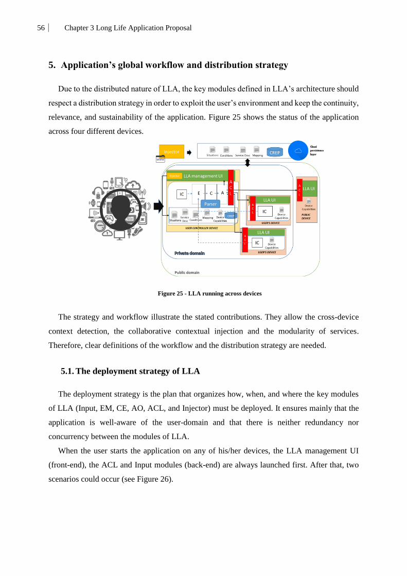
56 Chapter 3 Long Life Application Proposal
5. Application’s global workflow and distribution strategy
Due to the distributed nature of LLA, the key modules defined in LLA’s architecture should
respect a distribution strategy in order to exploit the user’s environment and keep the continuity,
relevance, and sustainability of the application. Figure 25 shows the status of the application
across four different devices.
Figure 25 - LLA running across devices
The strategy and workflow illustrate the stated contributions. They allow the cross-device
context detection, the collaborative contextual injection and the modularity of services.
Therefore, clear definitions of the workflow and the distribution strategy are needed.
5.1. The deployment strategy of LLA
The deployment strategy is the plan that organizes how, when, and where the key modules
of LLA (Input, EM, CE, AO, ACL, and Injector) must be deployed. It ensures mainly that the
application is well-aware of the user-domain and that there is neither redundancy nor
concurrency between the modules of LLA.
When the user starts the application on any of his/her devices, the LLA management UI
(front-end), the ACL and Input modules (back-end) are always launched first. After that, two
scenarios could occur (see Figure 26).

57 Chapter 3 Long Life Application Proposal
Figure 26 - Deployment strategy for starting LLA
The first scenario happens if that device is the first device (Device 1), which is private,
available on the network and meets the requirements (see Section 4.1), that started LLA. This
means that no other device (Device 2) has an instance of LLA already running. In this case,
LLA deploys all the modules on Device 1. Device 1 becomes, for now, the user’s controller
device. After that, this device keeps running LLA and monitoring the user’s domain for new
devices to join in.
The second scenario happens when the device is not the first one to start LLA. This means
that when the user starts the application on this device (Device 1), there is another instance of
LLA already running on another device (Device 2). In this case, two things can happen. If
Device 1 has better hardware capabilities than Device 2 (Device 1> Device 2), LLA migrates
the architecture, already running on Device 2, to Device 1. Otherwise, Device 1 links its Input
to the EM of Device 2.
When stopping (see Figure 27) the application on one device, LLA verifies if that device
hosts the whole architecture (ECA) and asks the user whether he/she wants to fully stop the
application on all devices or just on this one. If the user chooses to stop it just on that device
the architecture is migrated to the best available device and reconnects the inputs from the rest
of the devices. In case the architecture is hosted on another device, LLA simply stops on that
device by stopping the ACL and the Input making that device unavailable for the User’s
Domain.
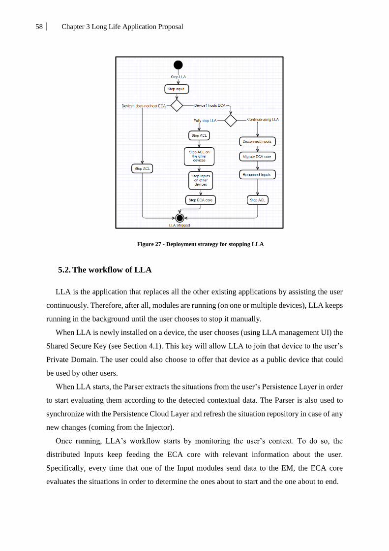
58 Chapter 3 Long Life Application Proposal
Figure 27 - Deployment strategy for stopping LLA
5.2. The workflow of LLA
LLA is the application that replaces all the other existing applications by assisting the user
continuously. Therefore, after all, modules are running (on one or multiple devices), LLA keeps
running in the background until the user chooses to stop it manually.
When LLA is newly installed on a device, the user chooses (using LLA management UI) the
Shared Secure Key (see Section 4.1). This key will allow LLA to join that device to the user’s
Private Domain. The user could also choose to offer that device as a public device that could
be used by other users.
When LLA starts, the Parser extracts the situations from the user’s Persistence Layer in order
to start evaluating them according to the detected contextual data. The Parser is also used to
synchronize with the Persistence Cloud Layer and refresh the situation repository in case of any
new changes (coming from the Injector).
Once running, LLA’s workflow starts by monitoring the user’s context. To do so, the
distributed Inputs keep feeding the ECA core with relevant information about the user.
Specifically, every time that one of the Input modules send data to the EM, the ECA core
evaluates the situations in order to determine the ones about to start and the one about to end.
59 Chapter 3 Long Life Application Proposal
If LLA needs to start a new service to respond to a newly detected situation, the AO looks
for the needed service and deploys it on the best fit devices available. LLA looks for the services
(a group of executable jar files) first in the Local Service Repository (LSR), the on the LSR of
other available devices, and finally on the Cloud Service Repository (CSR) (see Figure 25).
Once it finds the needed services, the AO consults the ACL filter about the accessibility and
capabilities of the available devices on the network in order to run those services on the most
adequate devices. If the services have a visible UI, they are added to the LLA management UI
of their respective devices. Otherwise, they run on the background of those devices.
Ending situations trigger the opposite process. When LLA detects the end of a situation,
which is already active, it looks for the services that are related to that situation in order to stop
them on their respective devices. Stopping those services stops consequently the components
by removing their UI from the LLA UI or simply stopping them transparently if they run in the
background.
6. Conclusions
When dealing with context-aware distributed mobile applications, the challenges are
multiple and the solutions are different. In our proposal, we tackled those problems by
presenting the idea of LLA.
To summarize, LLA is a modular distributed mobile application that spans across a network
of connected devices in order to understand its user’s context and provide him/her with the most
adequate services while offering an open user experience that could be enriched continuously.
Following the distribution strategy and workflow, LLA is able to work harmoniously on the
user-domain and changes the way that he/she interacts with his/her applications, devices, and
overall experience.
LLA modules, interactions, rules, strategies, and mechanisms embody the stated
contributions. These contributions are the solutions to the limitations of current mobile
applications. Therefore, the next chapters are dedicated to showing a detailed presentation of
the modules constituting LLA. These modules are all composed of sub-modules, components,
and mechanisms that reflect our contributions and the behavior of the application.
The next chapter is dedicated to present the first contribution of this work. It focused on the
modeling aspects of situation-based context.

60 Chapter 4 Situation-based contextual model
Chapter 4 Situation-based contextual model

61 Chapter 4 Situation-based contextual model
1. Introduction
The fundamental objective of context-awareness is to provide services not only to people at
any time, anywhere, with any media but specifically to communicate the right thing at the right
time in the right way [53]. To achieve this, applications should be aware of their context [48,
49, 74].
All context-aware applications have their own ideas, methods, and techniques to represent
and understand the user’s context. The common factor between all of them is that they all follow
the same patterns. They, first, select the type and source of relevant data needed to build the
context of the user. They categorize and normalize that data. They build their
rules/representations/models which will later be used to evaluate and react to the user’s current
context.
All things considered, the context representation is the first step and the determining factor
in how context-aware applications react to changes and adapt to the user's needs. In LLA, it is
crucial to be aware of the user’s behavior and the environment surrounding him/her.
Consequently, LLA needs a contextual representation model centered on the user and
considering his/her needs in all circumstances.
When LLA succeeds in obtaining the data it needs at the time it needs them, the challenge
of extracting actionable intelligence out of that raw data appears. We need to find a simple way
to extract useful knowledge out of basic data, so as to construct different contexts of usage for
the application to react. Defining the context rules and the associated actions is our main goal.
The main question is whether this should be automatically learned by the system (based on the
user's actions) or specified by the user by using a rule-and-action language.
Our focus is offering a user-friendly, understandable, concise yet open model able describe
the daily needs of users over multiple scenarios.
2. Situation-based contextual model
Situation awareness is commonly defined as the perception of environmental elements with
respect to time or space, the comprehension of their meaning, and the projection of their future
behavior (e.g. Endsley, 1988, 1995).
The situation is the key component in our system [78]. According to the Cambridge
dictionary, a situation is: «The set of things that are happening and the conditions that exist at
a particular time and place”.
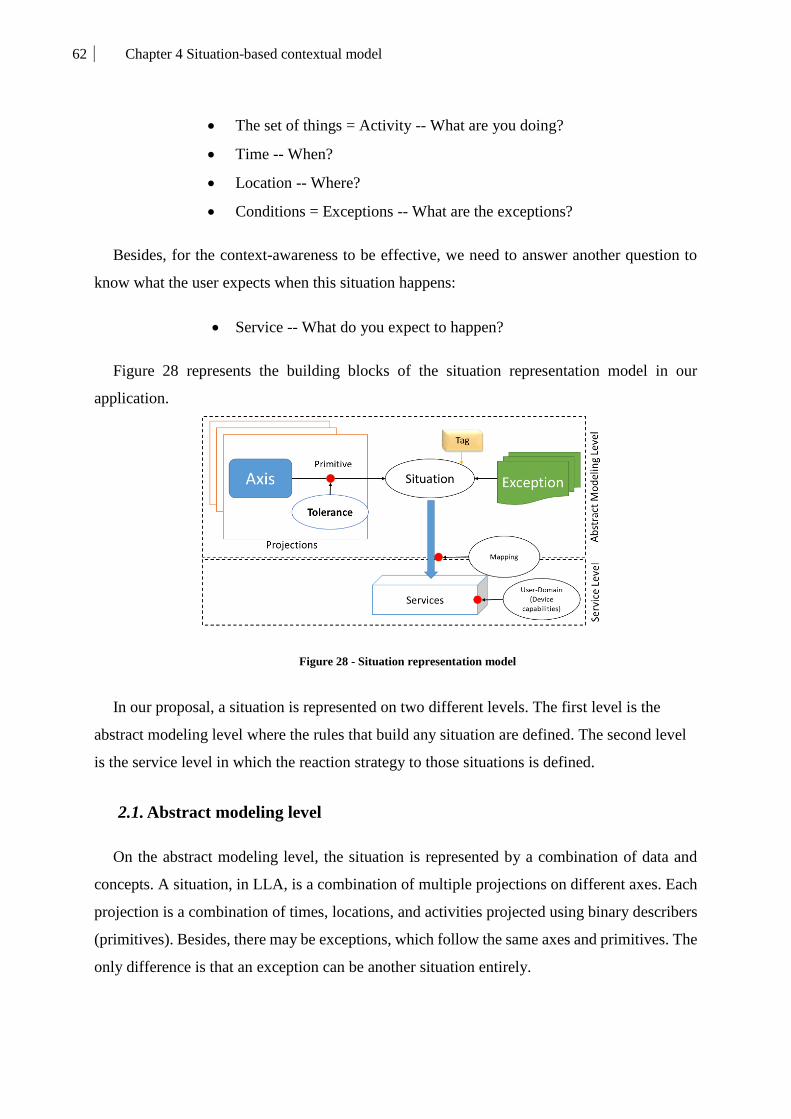
62 Chapter 4 Situation-based contextual model
The set of things = Activity -- What are you doing?
Time -- When?
Location -- Where?
Conditions = Exceptions -- What are the exceptions?
Besides, for the context-awareness to be effective, we need to answer another question to
know what the user expects when this situation happens:
Service -- What do you expect to happen?
Figure 28 represents the building blocks of the situation representation model in our
application.
Figure 28 - Situation representation model
In our proposal, a situation is represented on two different levels. The first level is the
abstract modeling level where the rules that build any situation are defined. The second level
is the service level in which the reaction strategy to those situations is defined.
2.1. Abstract modeling level
On the abstract modeling level, the situation is represented by a combination of data and
concepts. A situation, in LLA, is a combination of multiple projections on different axes. Each
projection is a combination of times, locations, and activities projected using binary describers
(primitives). Besides, there may be exceptions, which follow the same axes and primitives. The
only difference is that an exception can be another situation entirely.

63 Chapter 4 Situation-based contextual model
Before getting into describing a situation, we need to define our key concepts and variables.
The following variables are related to the axes of our situation:
2.1.1. Concepts
Tag: The tag represents the information related to the priority and source of this situation
(see Chapter 6).
Projection: It represents the set of primitives (on axes) that combined together trigger the
situation. For example, the house alarm of the user is activated if he/she is outside the house or
if the time is after 10 pm. These are two different projections using different axes for the same
situation (see Figure 29).
Tolerance: It represents the accuracy of a certain value related to the primitive. This
tolerance can be interesting in scenarios where the user is not precise about his/her situations.
For example, if the user wants his/her garage door to open if he/she is more or less about 10
meters from his/her house, then the tolerance, in this case, would be 10 meters related to his/her
house.
Axis: Axes represent the dimensions of our situations (see Figure 29). For example, the time
axis is one of the dimensions that can represent a situation.
Primitive: It is an atomic operation on a given axis (e.g., before, while, and after, for the time
axis). The result of this operation is a Boolean value. For example, to represent a situation where
the user is inside a location we use an inside primitive on the location axis. Tables 5, 6, 7, 8, 9,
and 10 describe the primitives related to each axis. Since primitives are atomic, their output
should be unique, therefore, they cannot be derived from more than two axes simultaneously.
A primitive derived from three axes is the situation itself.
Table 5: Time primitives
Primitives Parameters Abbreviation Description
Before Date-Time,
DTPrecision B
Returns true if the date-time given in the
parameters is before the current date-time.
After Date-Time,
DTPrecision A
Returns true if the date-time given in the
parameters is after the current date-time.
While Date-Time,
DTPrecision W
Returns true if the date-time given in the
parameters is equal to the current date-time.
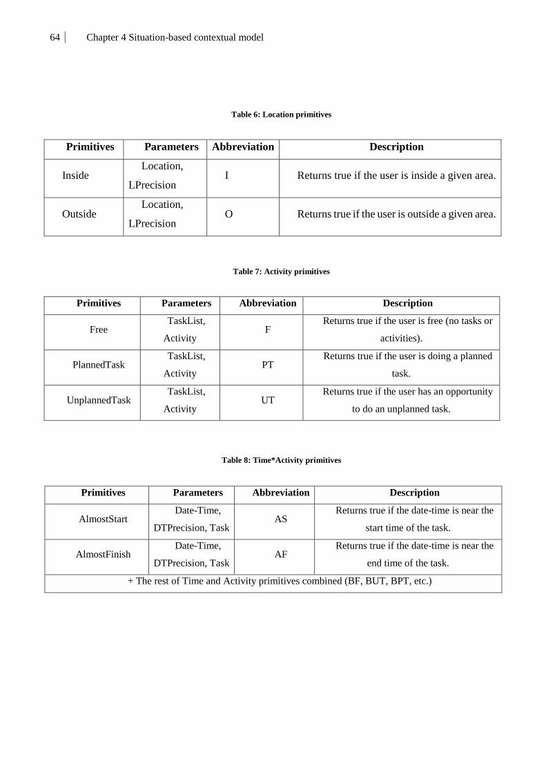
64 Chapter 4 Situation-based contextual model
Table 6: Location primitives
Primitives Parameters Abbreviation Description
Inside Location,
LPrecision I Returns true if the user is inside a given area.
Outside Location,
LPrecision O Returns true if the user is outside a given area.
Table 7: Activity primitives
Primitives Parameters Abbreviation Description
Free TaskList,
Activity F
Returns true if the user is free (no tasks or
activities).
PlannedTask TaskList,
Activity PT
Returns true if the user is doing a planned
task.
UnplannedTask TaskList,
Activity UT
Returns true if the user has an opportunity
to do an unplanned task.
Table 8: Time*Activity primitives
Primitives Parameters Abbreviation Description
AlmostStart Date-Time,
DTPrecision, Task AS
Returns true if the date-time is near the
start time of the task.
AlmostFinish Date-Time,
DTPrecision, Task AF
Returns true if the date-time is near the
end time of the task.
+ The rest of Time and Activity primitives combined (BF, BUT, BPT, etc.)

65 Chapter 4 Situation-based contextual model
Table 9: Time*Location primitives
Primitives Parameters Abbreviation Description
Closer Location, Date-Time,
DTPrecision, LPrecision, Speed C
Returns true if the user is getting closer to
a certain location in a given time frame.
Further Location, Date-Time,
DTPrecision, LPrecision, Speed F
Returns true if the user is getting further
from a certain location in a given time frame.
+ The rest of Time and Location primitives combined (BI, BO, WI, etc.)
Table 10: Location*Activity primitives
Figure 29 - Situation's projection axes
Value: Values are used to evaluate if the required primitives are verified (i.e., the conditions
are evaluated to true) by comparing them to the current user context values (i.e., values for the
time, location, etc.). For example, we consider that for the primitive After (Time axis) and the
current time of the user 11 pm, if the value given to the primitive is 10 pm then the primitive
returns true.
Primitives Parameters Abbreviation Description
Opportunity
Location,
LPrecision,
Task
Op Returns true if an opportunity to do a certain
task in a certain location arises.
+ The rest of Location and Activity primitives combined (IF, OF, IUT, etc.)

66 Chapter 4 Situation-based contextual model
DTPrecision: It is the accuracy of the time and date that will allow
primitives to leave a margin of tolerance. It must be provided in the same form
as the date, in order to ensure time calculations.
LPrecision: It is the tolerance for the localization.
TaskList: It is the schedule of the user, that contains all the tasks planned
(or unplanned).
Date-Time: It is the date and time value.
Location: It is the physical location (coordinates, address, etc.).
Activity: It is the task (meeting, sleeping, running, etc.) that the user is
doing. There is no precision tolerance value for the Activity because it not a
continuous axis, compared to time and location.
Exception: Exceptions can be related to the axes of the situation or can be represented by a
whole situation. They follow a similar logic as situations, as they can be represented by (axes)
primitives (see Figure 30). The difference lies in the fact that they can be represented by
complete situations. This helps the application to handle multiple situations happening at the
same time, by verifying if they are exceptions for each other.
Figure 30 - Exception's representation model
For example, in an everyday scenario, we can imagine a user having a breakfast situation
every day at 7 am except on Sundays.

67 Chapter 4 Situation-based contextual model
2.1.2. Operations
Combination: Combines two concepts (projections, axes), through a logic AND operation.
For example, combining two axes (Axis*Axis) allows us to extract new primitives related to
that combination. This operation applies also on primitives and exceptions. For example, if we
combine Time and Location we obtain a Time*Location axis that allows the user to express
situations related to speed and relativity to a location. For example, the user can use this to
express a situation that can be detected if he/she is getting closer to his/her house.
Selection: Acts as an OR operator (i.e., it verifies whether at least one of the variables is
true).Our model uses it in order to represent a situation with multiple independent different
projections or multiple different exceptions. For example, considering an aged user, the doctor
can create a situation that sends him an alert when the user comes to his/her medical weekly
check-up OR if he/she runs out of medication.
2.1.3. Situations families
First-level Situations: In this level, the most basic and general situations, that involve only
one of the axes are represented (see Figure 31).
Figure 31 - First-level situation representation
Second-level Situations: It combines two axes to represent a situation. In fact, combining
axes generates richer situations (see Figure 32). The combination is produced by using basic
primitives like, for example, Before (B) and Outside (O), combined to produce BO, which
returns true if the user is before a given date/time & outside a given location. The combination
produces also new primitives related to the combination of the combined axes.
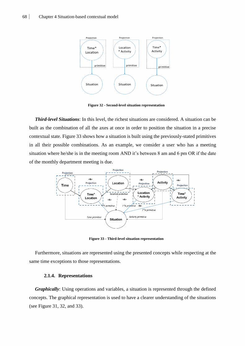
68 Chapter 4 Situation-based contextual model
Figure 32 - Second-level situation representation
Third-level Situations: In this level, the richest situations are considered. A situation can be
built as the combination of all the axes at once in order to position the situation in a precise
contextual state. Figure 33 shows how a situation is built using the previously-stated primitives
in all their possible combinations. As an example, we consider a user who has a meeting
situation where he/she is in the meeting room AND it’s between 8 am and 6 pm OR if the date
of the monthly department meeting is due.
Figure 33 - Third-level situation representation
Furthermore, situations are represented using the presented concepts while respecting at the
same time exceptions to those representations.
2.1.4. Representations
Graphically: Using operations and variables, a situation is represented through the defined
concepts. The graphical representation is used to have a clearer understanding of the situations
(see Figure 31, 32, and 33).

69 Chapter 4 Situation-based contextual model
Textually: A situation S is presented textually in the following format, where P is a
projection (the Tag will be discussed in Chapter 6):
S : Tag ; Pn [ Axis(Primitive(values, tolerance)...); ...] [ ..] .. EXCEPT [Situation/Axis(..)]
In the persistence layer (see Chapter 3), these textual representations are translated into XML
and injected into the user’s application (Situation Repository) in order to define his/her
situations.
For example, we present a 3rd level situation S1 (House Alarm Situation) that happens when
the user is either outside his/her home with a 20 meters tolerance value (Projection1) or if the
time is between 10 pm and 6 am with a 20 minutes tolerance (Projection2). The exception to
this is being in only on Sundays. For our example, the graphical representation is shown in
Figure 34. Textually it is presented like: S1: Projection1[ Time( A(22,20) B(6,20) ); Location(
I(Home,5) ) ] OR Projection2 [ Location( O(Home,20) ) ] EXCEPT [ ( Time(Sunday) ) ]
Figure 34 - House alarm situation representation
2.1.5. Complexity and data formats
Even though this representation is user-friendly regarding the way it is expressed, its
management is complex. The complexity of detecting a specific situation can be estimated by
considering the number of primitives involved in its computation by counting the number of
projections and exceptions and multiplying the number of axes, primitives, and values involved
(( ∑˅pi # primitives pj ) + # exceptions). As different data get involved and the application
grows, the situations can get detailed and complex. In Figure 35, we show how a situation can
branch using all the concepts that we defined. It shows the richness and completeness of this
modeling approach.
For the different axes, the data (values) are represented differently:

70 Chapter 4 Situation-based contextual model
Time-related values (Date-Time, DTPrecision): These values use the
time DD.MM.YYYY.hh.mm;ss
Location related values (Location, LPrecision): They are represented
through geometrical geographical zones (GZ) delimited by points defined using
GPS coordinates.
Activity related values (Task, TaskList): An entity extracted from the
user’s calendars.
Speed: This value is represented in the metric system (KmH).
Figure 35 - Situation branching

71 Chapter 4 Situation-based contextual model
2.2. Service level
On this level (see Chapter 6), our model allows describing the behavior expected when LLA
detects situations. In order to react properly to these situations, the application needs to find the
appropriate services.
Service: Services are the product of the application and its way to respond to contextual
changes. They are the way the system responds when detecting that situation.
Component: The components are entities composing the service. The components can be
divided into 3 categories: Input, Core, and Output (see Chapter 6). These components run
simultaneously in a distributed environment composed of the users' devices. Each component
serves a specific need and has hardware requirements (CPU load, RAM, camera, etc.) that need
to be provided in order to run in an optimal way. Therefore, the representation on this level
includes also the capabilities needed for components to run correctly.
Mapping: Mappings are associated with each situation. The mapping, (stored in the
persistence layer) links the situations to the services. It describes the list of Kalimucho
components needed to build the service.
3. Conclusions
A relevant aspect of the proposed application is the adequate detection of the context. For
that purpose, the Long Life Application incorporates a rich situation model that considers any
type of combination of three dimensions (Time, Location, and Activity) to represent different
context situations where users can be involved, as well as exceptions for those situations.
For users, defining situations implies a simple understanding of the basic concepts.
Therefore, using this model, they can easily define their basic situations and select/download
the services adequate to those situations. For more experienced experts, the proposed model
allows representing accurate specific situations related to their area of expertise using multiple
projections, combined actions, specific tolerances, etc.
The next chapter is dedicated to present the second contribution of this work. It is focused
on explaining in details the internal behavior of the cross-device context detection mechanism
which is based on our situation-based contextual model.

72 Chapter 5 - Cross-device situation detection
Chapter 5 - Cross-device situation detection

73 Chapter 5 - Cross-device situation detection
1. Introduction
Context detection is the process of detecting changes in the context. In order to capture the
context of the user, the application needs to collect the available information (such as time,
location, and activity). This information needs to be extracted continuously, mostly by using
the devices around the user.
In ubiquitous computing, context is often captured from one or more specialized
sensor/device that could be physically close or attached to the user (phone, watch, tablet, etc.)
or distributed around the user in his/her smart-environment.
LLA raises some challenges, due to its specific design requirements and the lack of an
existing methodology and appropriate tools. The main important difficulties are related to the
problem of context detection, software/hardware heterogeneity management, and the need to
distribute the application around the available user's devices.
In this chapter, we present our proposal for a cross-device situation detection mechanism
dedicated to the user’s domain (see Chapter 3).
2. Cross-device situation detection mechanism
Context-awareness requires, by definition, a system able to detect the context and understand
it. An important drawback of existing applications comes from identifying the user with one
and only one device or from a pre-installed sensor network. Also, these applications limit their
detection on the user's mobile phone. This issue motivated our work to be oriented to cross-
device context detection dedicated to end-users and enabling the application to accurately
follow and detect context changes.
In LLA, the context is represented by situations (see Chapter 4). Therefore, the proposed
context detection mechanism considers the situation-based contextual model that we defined
[78]. In order to detect situations (starting or ending), LLA starts by collecting contextual data
input and then identifying situations.
From a technical and architectural point of view, the cross-device situation detection
mechanism is composed of two main modules (see Figure 36).

74 Chapter 5 - Cross-device situation detection
Figure 36 - Cross-device situation detection component architecture
The first module is the distributed Input module which is deployed on the user-domain (see
Chapter 3). The second one is the Event Manager which evaluates the received data in order to
identify possible situations that started and/or ended.
In Figure 36, the IC is the Input Component, the DC is the Dispatcher Component, the TLMC
is the Time*Location Manager Component, the LMC is the Location Manager Component, the
LAMC is the Location*Activity Manager Component, the AMC is the Activity Manager
Component, the TAMC is the Time*Activity Manager Component, and the SMC is the
Situation Manager Component.
2.1. The Input Component (IC)
The first step in the process of detecting the context is to extract relevant data from the user's
devices. In order to achieve this, LLA duplicates the IC on all the available and accessible
devices of the user. The main objective of this component is to collect contextual information
(current time, location, and activity) and send it to the Event Manager module.
This component is always running and waiting for contextual changes that can be interesting
to trigger and send contextual data to the Event Manager (EM). The problem resides in the
frequency at which this component should extract and deliver those data due to the hardware
limitations of the device (e.g. battery). The simplest answer would be to perform it continuously

75 Chapter 5 - Cross-device situation detection
with a high frequency (e.g., every second), but this would require more processing power and
drain the battery life faster.
Therefore, we propose a different mechanism, able to optimize its performance and not
overload the EM. The modules that constitute the IC are shown in Figure 37.
Figure 37 - The input component internal process
2.1.1. Frequency Manager (FM)
The IC orders the Extractor to extract data. Therefore, it takes into account the user's situation
list. From this list, the FM calculates and optimizes the frequency at which the contextual data
should be extracted from each device. In order to achieve this, granularities regarding the
situation axes are taken into account by our proposal. Calculating these granularities, which
affects the frequency, requires monitoring the situations for each axis separately. Any situation
could have projections on each axis (time, place, activity) and must, therefore, trigger the
extraction in time.
For the time axis, it is enough to awaken the process at certain well-chosen moments using
awake(S,D,Td):
S = set of known situations for one day
D = set of start and end dates for these situations
Td = set of tolerances on these dates
We do not need a frequency because we know the dates. If D is ordered by growth dates and
T is ordered in accordance with D, it is sufficient to wake up the process at each extraction time
ETime = start date - the associated tolerance and each ETime = end date + the associated
tolerance.
76 Chapter 5 - Cross-device situation detection
For the activity axis, the FM uses the same process used with the time axis, awake(S,A,C):
A = set of activities for these situations
C = planned and non-planned tasks of the user
When considering planned tasks we need to define any frequency because we know their
details (time, location). However, for non-planned tasks, there is no way to predict if the user
is potentially interested in doing that task in a specific time/location frame.
For the location axis, we do not have a defined order since we do not know when the user
will enter/leave these places (L). All we have are localizations (geographical areas with a
tolerance).
L = The set of places at the beginning and end of these situations
Tl = set of tolerances on these places
A Geographical Zone (GZ = zone + a tolerance) is a greater geographical area, therefore,
one reduces to geographical zones only (L and Tl are combined to form a single set L). These
areas may overlap.
It is necessary to monitor the position of the user permanently to know when he/she is
coming in / out of one or more of these zones. The extraction frequency, in this case, is
complicated to define. Other works, consider a maximum extraction frequency and leave the
GPS running all the time.
We propose to sample the accelerometer to detect the beginning of movements and launch
the GPS using awake(L, T1). If two position measurements are taken separated by a known
delay, it is possible to determine the position and the speed of movement of the user. As the
current speed is known, it is possible to calculate the Minimal Time (MT) to reach/leave the
geographical zone.
For each of the graphical zones (the shortest distance to get in/out of this zone), the minimal
distance is calculated "on the fly" so the user cannot get in/out of that zone faster than the
estimated minimum time. A new position and speed sampling will then be triggered within this
period to see if this has occurred or not. The result will determine whether the situation begins
or ends or a new delay to repeat the operation.
Each time the accelerometer gives a new value, the above process is repeated so that this
delay is adjusted according to the new position/speed of the user. If the accelerometer does not
77 Chapter 5 - Cross-device situation detection
give anything, it means that the speed is constant and that the last calculation (MT) remains
valid.
The last issue with this process is to determine the frequency at which the accelerometer is
consulted. If it is awoken at a slow rate, we risk missing beginnings/end of movements and thus
missing inputs/outputs of zones. Therefore, we decided to consider a high rate frequency
because there is no way to predict that the user will move. This choice is justified by the
comparison of power consumption of the accelerometer compared to that of the GPS, which
proves that the accelerometer uses 7 times less the amount of energy used by a GPS [11].
2.1.2. Extractor
The extractor receives notifications from the FM to retrieve the current time, location and
activity on its device. The retrieved data could differ from one device to another. In a scenario
where the user is traveling, some of his/her devices might be at home and therefore have a
different time set on them.
This is interesting to ensure the continuity of the user situations even when he/she is in a
different time zone. Locations are also different from one device to another, which is interesting
but raises a problem of knowing where the user is physically located. For activities, the retrieved
data will be the same between devices. Finally, the extractor transfers this data to the Trigger.
2.1.3. Trigger
The trigger is the sub-module in charge of sending the data to the EM. Nevertheless, before
sending that data, it verifies two important things.
First, it checks the real location of the user and the device with which the user is interacting
(the one with which he interacts at that moment or he has lastly interacted with) by verifying if
its screen is active or has been active lately.
The reason behind this is due to the fact that the IC is duplicated, and therefore it will be
sending multiple times, locations and activities to the EM. This might cause the application to
detect a situation without the user being really in that situation. This problem is related to the
difficulty of creating a user experience that spans multiple devices [57].
For example, if the user is at work with his/her smartphone but he/she left his/her tablet at
home, the context detected from the tablet is irrelevant to the user because of his/her current
position. If the tablet detects a situation and reacts to it, the user will not be part of that situation.

78 Chapter 5 - Cross-device situation detection
The application should be able to understand that the user is actually at work and therefore
detect only situations relevant to his/her true context.
In order to achieve this, the Trigger verifies first if the device where it is hosted has changed
its position. If the device changed its position it means that it is moving with the user and
therefore it is eligible to detect situations.
The second step is verifying whether the device being used by the user (active device). In
case we have no position changes and no active devices, the application considers data only
from the last used device or the devices in proximity of that device in order to have a relevant
context.
Finally, the IC sends the collected relevant data to the EM in order to start the process of
identifying the situations that are possibly beginning or ending.
2.2. The Event Manager (EM)
The EM is the entry point to our application’s core and represents the E in our ECA approach.
Overall, this module is dedicated to detecting context changes. For that purpose, it first receives
the input coming from the IC and then runs a discovery process on the potential situations. As
output, it delivers lists of situations that are about to start and those about to finish.
The Event Manager module (see Figure 36) is in charge of detecting contextual information
from around the user (from his/her devices), analyzing these data, and defining a context
respecting the situation model.
The situation identification process (see Figure 38), integrated into the Event Manager, is
the mechanism that monitors the different axes and creates the appropriate situations by using
collected data from around the user and combining them with primitives.
Figure 38 - Situation identification process
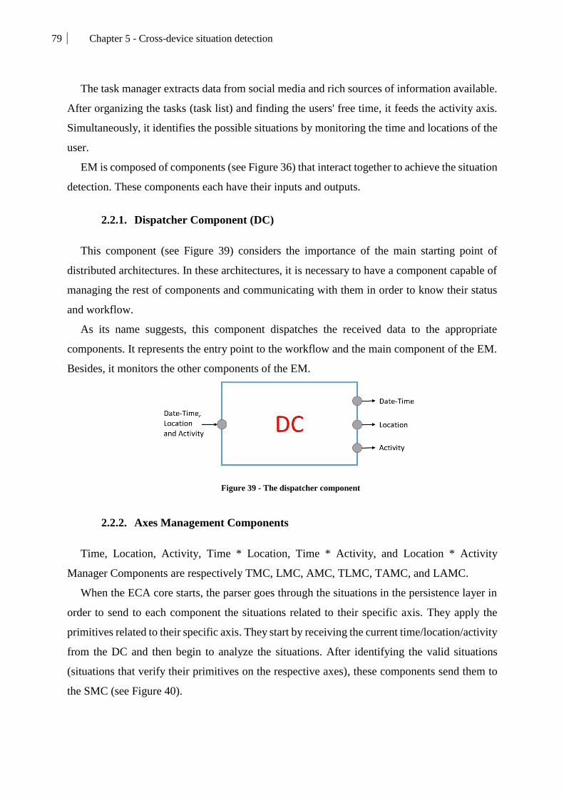
79 Chapter 5 - Cross-device situation detection
The task manager extracts data from social media and rich sources of information available.
After organizing the tasks (task list) and finding the users' free time, it feeds the activity axis.
Simultaneously, it identifies the possible situations by monitoring the time and locations of the
user.
EM is composed of components (see Figure 36) that interact together to achieve the situation
detection. These components each have their inputs and outputs.
2.2.1. Dispatcher Component (DC)
This component (see Figure 39) considers the importance of the main starting point of
distributed architectures. In these architectures, it is necessary to have a component capable of
managing the rest of components and communicating with them in order to know their status
and workflow.
As its name suggests, this component dispatches the received data to the appropriate
components. It represents the entry point to the workflow and the main component of the EM.
Besides, it monitors the other components of the EM.
Figure 39 - The dispatcher component
2.2.2. Axes Management Components
Time, Location, Activity, Time * Location, Time * Activity, and Location * Activity
Manager Components are respectively TMC, LMC, AMC, TLMC, TAMC, and LAMC.
When the ECA core starts, the parser goes through the situations in the persistence layer in
order to send to each component the situations related to their specific axis. They apply the
primitives related to their specific axis. They start by receiving the current time/location/activity
from the DC and then begin to analyze the situations. After identifying the valid situations
(situations that verify their primitives on the respective axes), these components send them to
the SMC (see Figure 40).

80 Chapter 5 - Cross-device situation detection
Figure 40 - Time Manager Component
2.2.3. Situation Manager Component (SMC)
While receiving a list of valid situations from the other components TMC, LMC, AMC,
etc.), the SMC (see Figure 41) constructs one final list containing the situations (received from
the other components) according to their occurrences and their projections. In this way, this
component delivers two final lists of situations as a final output of the EM. These situations
could be either situations that will be starting or situations that are no longer valid and need to
end.
In order to identify the starting situations, the SMC calculates for each received situation the
number of projections and axes represented in that projection and compares them with the input
of the other components (TMC, TLC, etc.). If the number of incoming instances of a situation
(verified by the primitives) matches one of the projections, it is considered as a possible
situation to start (to start a situation, it should verify at least all the primitives of one projection).
For example, if a situation S0 happens when the first projection is verified (user is home at 5
pm), the SMC should receive 2 instances of S0 coming from TMC and LMC.
For ending situations, the SMC uses the opposite mechanism: if at least, one occurrence is
not sent to the SMC, it considers that situation as a stopping situation (to break the situation, it
is enough that one primitive verification fails). Using the same example of S0, if the user leaves
the house and the SMC receives only one instance (coming from TMC), it means that the
projection of S0 is no longer verified then it should be stopped.
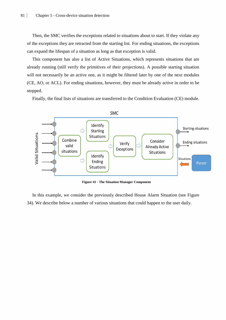
81 Chapter 5 - Cross-device situation detection
Then, the SMC verifies the exceptions related to situations about to start. If they violate any
of the exceptions they are retracted from the starting list. For ending situations, the exceptions
can expand the lifespan of a situation as long as that exception is valid.
This component has also a list of Active Situations, which represents situations that are
already running (still verify the primitives of their projections). A possible starting situation
will not necessarily be an active one, as it might be filtered later by one of the next modules
(CE, AO, or ACL). For ending situations, however, they must be already active in order to be
stopped.
Finally, the final lists of situations are transferred to the Condition Evaluation (CE) module.
Figure 41 - The Situation Manager Component
In this example, we consider the previously described House Alarm Situation (see Figure
34). We describe below a number of various situations that could happen to the user daily.

82 Chapter 5 - Cross-device situation detection
In Table 11, we present an example of a user having the situations described above. In this
example, the user has three devices where LLA is installed. We follow him/her on three steps
where the user changes time, location and activity over the day. We consider that the IC only
extracts data those three times. Initially, we propose that S0 (House Alarm Situation in Figure
34) is an active situation, the time is 6 am; the day is Monday and he/she is at home.
In table 11:
T: Time;
L: Location;
A: Activity;
Sits: Situations;
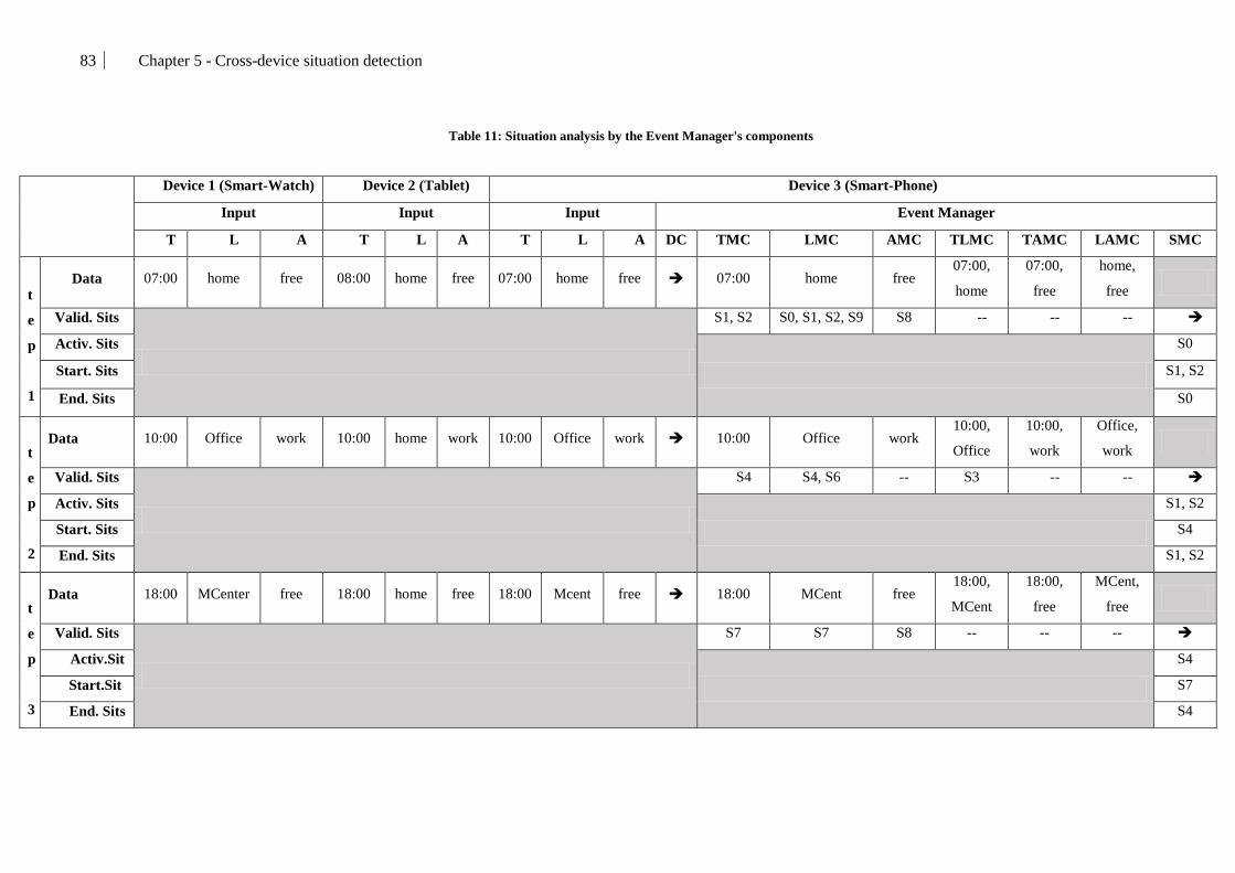
83 Chapter 5 - Cross-device situation detection
Table 11: Situation analysis by the Event Manager's components
Device 1 (Smart-Watch) Device 2 (Tablet) Device 3 (Smart-Phone)
Input Input Input Event Manager
T L A T L A T L A DC TMC LMC AMC TLMC TAMC LAMC SMC
S
t
e
p
1
Data 07:00 home free 08:00 home free 07:00 home free 07:00 home free 07:00,
home
07:00,
free
home,
free
Valid. Sits
S1, S2 S0, S1, S2, S9 S8 -- -- --
Activ. Sits
S0
Start. Sits S1, S2
End. Sits S0
S
t
e
p
2
Data 10:00 Office work 10:00 home work 10:00 Office work 10:00 Office work 10:00,
Office
10:00,
work
Office,
work
Valid. Sits
S4 S4, S6 -- S3 -- --
Activ. Sits
S1, S2
Start. Sits S4
End. Sits S1, S2
S
t
e
p
3
Data 18:00 MCenter free 18:00 home free 18:00 Mcent free 18:00 MCent free 18:00,
MCent
18:00,
free
MCent,
free
Valid. Sits
S7 S7 S8 -- -- --
Activ.Sit
S4
Start.Sit S7
End. Sits S4

84 Chapter 5 - Cross-device situation detection
84
In Step 1, the data extracted from all the devices is the same (07:00, Home, Free). The DC
distributes the data to the rest of components (running on the Smart-Phone). We considered that
S0 (House Alarm Situation) was already active. After all, components send the valid situations
to the SMC, it calculates the starting and ending situations. It decides to stop S0, because one
of its primitives (Before(6,20)) is no longer verified, and to start S1 (Sleep/Wakeup) and S2
(Breakfast Situation) because all the primitives in their respective projection are verified.
In Step 2, the user left home but left his/her tablet there. Therefore, the data extracted from
that tablet will not be sent to the EM. The data considered comes from the Smart-Phone and
Smart-Watch (10:00, Office, Work). The DC distributes the data to the rest of components.
After all, components send the valid situations to the SMC, it calculates the starting and ending
situations. It decides to stop S1 and S2 (already active), because their primitives are no longer
verified, and to start S4 (First work shift situation) because all the primitives in its projection P1
are verified.
In Step 2, the data considered still comes from the Smart-Phone and Smart-Watch (18:00,
MCenter, Free). The DC distributes the data to the rest of components. After all, components
send the valid situations to the SMC, it calculates the starting and ending situations. It decides
to stop S4 (already active) and to start S7 (Massage session situation).
This example presents the workflow of the cross-device detection mechanism. The output
(Staring situations, Ending situations) of this mechanism is sent to the rest of the architecture
(CE, AO, ACL) in order to finish the rest of the process.
3. Conclusions
To summarize, our proposal provides a mechanism able to detect, formalize and understand
the user context. The EM provides a set of components working simultaneously and
independently in order to detect events and understand situations regardless of the source.
However, detecting situations is not our main goal. In related works, most application use rule-
based languages to detect events and to understand the context, others use information collected
from sensors in order to formalize a context from that raw data.
Our approach differs in the way we address context detection as we aim our model to be
centered on the user daily needs in a connected environment. This means that our mechanism
can handle both basic and complex representations of everyday situations. It considers high-

85
85
level context understandable by the user and that does not need necessarily the presence of, a
sensor network or a huge set of complex rules.
Our approach provides a light, dynamic and open to growth contextual model. The second
phase of responding to the contextual change is handling this change on the service layer of the
application. Therefore, the next chapter presents the situation control and handling strategy
which is integrated into LLA and dedicated to offering an improved user experience.

86 Chapter 6 – Situation Control and Reaction strategy
86
Chapter 6 – Situation Control and Reaction strategy
87 Chapter 6 – Situation Control and Reaction strategy
87
1. Introduction
After defining the modules specialized in modeling, understanding, and detecting context,
we present in this chapter the way that LLA handles the contextual changes.
In context-aware applications, handling contextual changes comes in various and different
ways and forms (see Table 4). The common aspect between these applications is that they offer
services in response to contextual changes. Using the same logic, LLA translates situations to
use cases that are submitted to conditions and that could trigger a change in the service layer if
needed.
Nonetheless, when it comes to reacting to context, applications struggle to provide the
adequate services that users expect because they limit their architectures to pre-packaged
features that are already coded inside the applications. This limitation bounds their application
and narrows the range of use cases that could be handled.
Moreover, they do not usually consider the user’s preferences, constraints, and priorities
when it comes to overlapping situations and handling priorities. Works like [31] use preset goal
hierarchies that they deem relevant and interesting to their users.
In this chapter, we present the rest of the architecture (see Figure 23), discussed in chapter
3, by showing the interactions between the modules dedicated to offering a response when the
context of the user changes.
2. Situation control and reaction strategy
This part represents the reactive aspect of our proposal. It is the combination of different
mechanisms and modules that work simultaneously inside the main application. The main goal
of these modules is to respond to the detected situation in the best way possible for the user.
The process of reacting to these situations starts by evaluating them. The Condition
Evaluator (CE) acts as an organizer and a filter for new situations. It considers the user’s
constraints and restrictions (e.g. the user does not want to be bothered between 5 and 10 pm)
and manages the concurrency of situations by following a defined priority model.
The second level is the Action Orchestrator (AO) module. It takes as input both starting and
ending situations and launches/stops the appropriate services for that specific situation by using
the Kalimucho platform commands (see Appendix 1). Nonetheless, before launching/stopping
the services on the user domain, the AO needs to be aware of the available and accessible
devices in the user-domain.

88 Chapter 6 – Situation Control and Reaction strategy
88
Therefore, the last module is a domain management filter based on ACL [89] which scans
the environment continuously for new connected devices, secures the data transfer, and keeps
monitoring the user-domain.
3. Condition Evaluation (CE)
Condition evaluation is the second constituent of the ECA core. This module is required to
consider the user as the main interest of his/her application by giving him/her the upper hand
(control) and making him/her define the constraints that bind LLA.
As he/she is constantly moving and evolving in his/her surroundings (Time, Location and
Activity), multiple situations could be detected simultaneously which will trigger the
application to react automatically in order to respond to those situations.
Thus, the user could be overwhelmed with situations and deployed services. In order to
remedy this problem, the Condition Evaluator module respects a priority model that calculates
the situations’ priorities in order to filter the least important ones or put the other ones on hold
until LLA detects a change in context.
Moreover, it considers constraints described by the user in order to stop, filter, hold situations
if the user does not want to be disturbed. In our vision of LLA, it is necessary to consider the
status of the user. The status represents if the user is free, busy or wants to not be disturbed at
all. Most users have different schedules through the day. For example, a person with a daily job
in an office is usually busy working from 9 am to 5 pm and does not want to be disturbed at
night. This motivated us to implement the CE module that takes into account all these
parameters. This module complements the contextual awareness of our proposal.
3.1. The situation priority model and constraints
Context-aware applications are, most of the time, dynamic and autonomous. LLA is centered
on the user and dedicated to his/her needs and constraints. Therefore, our proposal implements
the CE module in order to consider the user’s constraints and give him/her the ability to fully
control what happens.
In order to achieve this, the CE follows the constraints and priority model expressed by the
user. Expressing this information is done following three steps:

89 Chapter 6 – Situation Control and Reaction strategy
89
Tagging the situation with an importance level. This tag is defined when injecting
the situation for the first time. The Tag is described textually in this format:
[priority=P(x); source=”Source”]. It serves as the default priority value of a situation.
This value could be altered for specific conditions (see Figure 42). LLA considers
three different importance levels:
o Casual situations: Situations with the least priority (1) representing the
user’s everyday situations.
o Important situations: Situations with medium priority (2) representing use
cases related to work, travel, etc.
o Urgent situations: Highest priority situations (3) representing urgent use
case that need to be handled immediately.
Creating and activating “lock zones” (see Figure 43) that allow filtering situations
considering their level of priority. These zones can be described only on Time and
Location axes because they define the status of the user (free, busy, to not be
disturbed) and this status cannot be linked to the human activity of the user. This
means that a zone can be timely or geographically defined. We defined three levels
of zones:
o Free zone: This zone is the default level where any situation is equal and
able to be handled. If no other zone is defined, this zone will be considered
as the default state if no other zone is active.
o Busy zone: This level allows only important and urgent situations to be
handled.
o Dead zone: This is the highest level zone where only urgent situations are
allowed. It represents the zone where the user does not want to be bothered
with anything unless it is urgent.
Figure 42 - Filtering layers of situations

90 Chapter 6 – Situation Control and Reaction strategy
90
Defining the priority level for the different sources (see Chapter 7) of situations.
These values are needed to calculate the relative importance of any given situation
to the user of the application. As every user is different, these values will reflect how
he/she presents his/her understanding of the importance of his/her situations. In
Chapter 7, we introduce the concept of situation sources (User, Social, and External).
The Situation Source Priorities shown in Figure 43 are the default values used if the
user does not specify any different values. The calculated priorities help the CE to
manage situation concurrency when and if it happens. In figure 43, we show the
relation between priorities, dynamicity, and privacy. When going from the free to the
dead zone we gain in privacy. In the other way, the user gains in dynamicity and
reactivity. By implementing this concept we allow the user to choose the way he/she
wished his/her application reacts.
Figure 43 - Lock zones and priorities
Inside the conditions repository of LLA, all information related to zones and priorities are
stored into a Conditions file that is synchronized with his/her cloud storage. Using the LLA
management UI, the user can, at any time, modify/delete/add/activate/de-activate lock zones.
He/she also can redefine any priority for any specific situation or injection source inside a
defined zone. These zones and priorities (conditions) are described using the same rules,
primitives, and operations as the contextual model (see Chapter 4) in order to keep the
coherency of the approach. Therefore, conditions can be described both graphically and
textually, except for the free zone because it represents the default state where no description is
needed and LLA is freely running.

91 Chapter 6 – Situation Control and Reaction strategy
91
Graphically: This representation (see Figure 44) shows that for each zone, except
the free zone, the user could redefine the priorities regarding his/her sources and
situations.
Figure 44 - Graphical representation of lock zones
Textually: The lock zone could be also defined textually using the following
representation where Z is a zone, D is a description, ISP is Injection Sources
Priorities, SSP is Specific Situations Priorities, and P is a priority:
Z: [Time/Location (Primitive (values, tolerance)...)]; [ISP [(Source, P)…]; SSP
[[(situation, P)…]]
The constraints and situation model helps LLA fully understand the user’s preferences and
filter situations in order to only consider pertinent ones.
An example for this could be shown by a user who represents his/her constraints in order to
reflect his/her habits. Let’s consider that this user splits his/her day into four zones. In the
following paragraph, we describe these zones graphically and textually.
The first zone (see Figure 45) is a busy zone defined on the time axis starting
from 6 am to 8 am with 10 minutes tolerance. In this zone, the user wants to
prioritize situation injected by himself/herself and his/her social environment
and related to his morning habits.
Morning Busy Zone: [Time (After (6am, 10m); Before (8am, 10m))]; [ISP [(User, 3);
(Facebook, 3); (Google, 2)]; SSP [[(Coffee Situation, 3); (Weather Situation, 3); (Email
Situation, 2)]]

92 Chapter 6 – Situation Control and Reaction strategy
92
Figure 45 - Morning Busy Zone representation
The second zone (see Figure 46) represents his work environment. It is
represented using the location axis (workplace) with 50 meters tolerance. In
this zone, he/she prioritizes work-related situations injected from his/her
employer.
Work Busy Zone: [Location (Inside (Workplace, 50m))]; [ISP [(User, 1); (Boss, 3); (Google,
1)]; SSP [[(Work Situation, 3); (Meeting Situation, 3); (Email Situation, 2)]]
Figure 46 - Work Busy Zone representation
The third zone is a dead zone (see Figure 47) that highly limits and filters
situations in order to not disturb the user unless something urgent happens
(Government). This zone is defined from 10 pm until 6 am at the user’s house.
Sleeping Dead Zone: [Time (After (10pm, 10m); Before (6am, 10m)); Location (Inside
(Home, 50m))]; [ISP [(User, 1); (Government, 3); (Security Company, 3)]; SSP [[(Alarm
Situation, 3); (Wakeup Situation, 3); (Email Situation, 1)]]

93 Chapter 6 – Situation Control and Reaction strategy
93
Figure 47 - Sleeping Dead Zone representation
The fourth zone represents the rest of the day. It is, by default, a free zone.
According to what the user has defined, in a free zone, situations coming from
social and external sources are prioritized.
3.2. Condition Evaluator module’s components
This CE, presented in Figure 48, is composed of three kalimucho components running
simultaneously in order to provide the wanted result.
Figure 48 - Condition Evaluator's internal architecture
The process of evaluating conditions starts by the User Constraints Component (UCC) which
monitors if the detected situations (from the Event Manager) violate the user’s constraints then
transfers them either to the Situation Holder Component (SHC) or the Priority Component (PC).
If the situation has the needed priority and does not violate the user’s constraints, it is
transmitted to the Action Orchestrator in order to deploy the appropriate services. This module

94 Chapter 6 – Situation Control and Reaction strategy
94
follows the condition repository where the application stores the user’s constraints and priority
model.
3.2.1. The User Constraints Component (UCC)
Figure 49 - User Constraints Component
The UCC (see Figure 49) has one input which consists of a list of situations that are detected
and th1at are about to start (coming from the Event Manager). This component verifies that
these situations do not violate the user’s zones (see Figure 42). It ensures that only situations
that are eligible to start are transferred to the PC. The ones violating these zones are sent to
another component that keeps them on hold (see SHC). This component also notifies the SHC
when there is a change in the current lock zone (e.g. from Free to Busy) so the SHC can re-send
the held situations to be re-evaluated by this component.
3.2.2. The Situation Holder Component (SHC)
Figure 50 - Situation Holder Component
This component (see Figure 50) acts as a holder for two types of situations: Situations
violating constraints; Situations that are valid but could not be handled due to the lack of a
required resource (camera, micro etc.). This component is a thread continuously verifying if the
held situations are still valid, which means that those situations didn’t overflow their respective
projections.
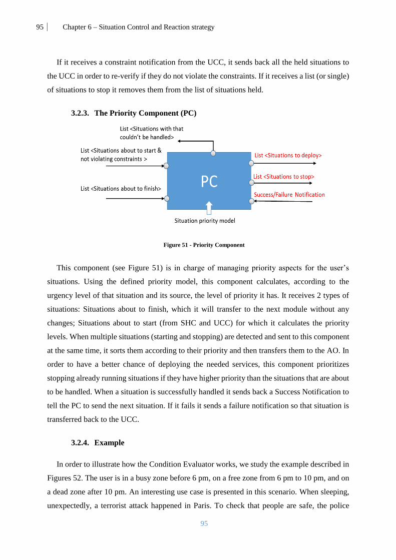
95 Chapter 6 – Situation Control and Reaction strategy
95
If it receives a constraint notification from the UCC, it sends back all the held situations to
the UCC in order to re-verify if they do not violate the constraints. If it receives a list (or single)
of situations to stop it removes them from the list of situations held.
3.2.3. The Priority Component (PC)
Figure 51 - Priority Component
This component (see Figure 51) is in charge of managing priority aspects for the user’s
situations. Using the defined priority model, this component calculates, according to the
urgency level of that situation and its source, the level of priority it has. It receives 2 types of
situations: Situations about to finish, which it will transfer to the next module without any
changes; Situations about to start (from SHC and UCC) for which it calculates the priority
levels. When multiple situations (starting and stopping) are detected and sent to this component
at the same time, it sorts them according to their priority and then transfers them to the AO. In
order to have a better chance of deploying the needed services, this component prioritizes
stopping already running situations if they have higher priority than the situations that are about
to be handled. When a situation is successfully handled it sends back a Success Notification to
tell the PC to send the next situation. If it fails it sends a failure notification so that situation is
transferred back to the UCC.
3.2.4. Example
In order to illustrate how the Condition Evaluator works, we study the example described in
Figures 52. The user is in a busy zone before 6 pm, on a free zone from 6 pm to 10 pm, and on
a dead zone after 10 pm. An interesting use case is presented in this scenario. When sleeping,
unexpectedly, a terrorist attack happened in Paris. To check that people are safe, the police

96 Chapter 6 – Situation Control and Reaction strategy
96
urgently notify anybody near the attack location to change their direction, Facebook also sends
their safety verification service to check if people around the attack area are safe. At the same
time, the app detects that there is an important situation to John, injected by his boss, but cannot
handle the situation because the situation is not urgent.
Figure 52 - Example scenario representation
For the purpose of focusing on condition evaluation, in the textual description below, we
only show the default tag of priorities and sources (see Chapter 6) of situations (no textual
contextual representation).
** New Movie (S0): [priority=P(1); source=External/cinema]
** Parking situation (S1): [priority=P(1); source=External/Carrefour]
** Shopping situation (S2): [priority=P(1); source=User]
** Home preparation situation (S3): [priority=P(1); source=User]
** Dinner situation: S4: [priority=P(1); source=User]
** Health situation (S5): [priority=P(2); source=External/Doctor]
** Family call situation (S6): [priority=P(2); source=User]
** Showtime (S7): [priority=P(1); source=External/Netflix]
** Home security situation (S8): [priority=P(3); source=External/SecurityCompany]
** Attack Alert situation (S9): [priority=P(3); source=Social/Facebook]
** Work situation (S10): [priority=P(2); source=External/Boss]
Table 12 presents the evolution of the user’s situation and priorities relative to his/her current
lock zones. It shows the inputs and outputs of the CE components.

97 Chapter 6 – Situation Control and Reaction strategy
97
Table 12: Situation filtering by the Condition Evaluator’s components
Busy
zone Free zone Dead zone
--6pm 6pm-7pm 7pm- 8pm 8pm-9pm 9pm-10pm 10pm--
UCC
Inputs Starting
situations S0 S1, S2 S1, S3 S4, S5 S6,S7 88 S9, S10
Outputs
Constraint
notification -- Free -- -- -- Dead zone
Starting
Situations
violating
constraints
S0 -- -- -- -- -- S10
Starting
Situations not
violating
constraints
-- S1,S2 S1, S3 S4, S5 S6, S7 S8 S9
SHC
inputs
Stopping
situations
--
-- S0, S1
(first) S1, S3 S4, S5 S6, S7
Starting
Situations
violating
constraints
S0 -- -- -- -- S10
Constraint
notification -- Free -- -- -- Dead zone
Situations
that cannot
be handled
-- -- -- -- -
- S7 --
outputs Situations
still valid -- S0 -- --
-
- S7 --
PC inputs
Starting
Situations not
violating
constraints
-- S0,S1,S2 S1, S3 S4, S5 S6, S7 S8, S9
Finishing
situations -- --
S0, S1
(first) S1, S3 S4, S5 S6, S7
Success
notification --
S0,S1,S2
success
S1, S3
success
S4, S5
Success
S6 success
S7 failure
S8, S9
success

98 Chapter 6 – Situation Control and Reaction strategy
98
outputs
Situations
that cannot
be handled
-- -- -- -- -
- S7
--
Situations to
deploy --
S0 then
S1 then S0
S1
then S3
S4 then
S5 S6 then S7 S8, S9
Situations to
stop -- --
S0, S1
(first) S1, S3 S4, S5 S6, S7
AO -- S0, S1,
S2 S1, S3 S4, S5 S6, S7 S8, S9
The most interesting output of this module comes from the PC, which decides the order of
the situations eligible to be handled and those that will be stopped. This output is linked to the
action module of the ECA core.
4. Action orchestrator (AO) and Access Control List (ACL) device filter
After detecting the user’s context and considering his/her constraints and conditions, the
process of LLA comes to the final step. This step is focused on the devices instead of the user
in order to illustrate our fourth and final contribution of this work (see Chapter 3).
In this part, we present two mechanisms that work simultaneously to exploit the user-domain
(see Figure 26). These modules allow LLA to react to the detected situations in the way that the
user expects.
LLA handles the received situations (to start or to stop) by deploying or removing services
on/from the devices in a user-centered yet distributed way. This approach guarantees the
continuity, sustainability, and scalability of the services integrated into LLA by being able to
move their components freely between devices at run-time. In order to apply this approach,
LLA needs to implement the concepts of the service level of the situations (see Chapter 4).
Thus comes the need to categorize and specify the capabilities of the devices that will host
the services of the user. This also helps LLA in the matching process which links situations to
services expected by the user. Moreover, we need a modular service composition allowing the
needed dynamicity for LLA and providing a clear definition of the requirements and goals of
the components. Finally, we present the components composing the AO and ACL filter by
defining their inputs/outputs and workflow.

99 Chapter 6 – Situation Control and Reaction strategy
99
4.1. Device capabilities
The distributed nature of LLA imposes that we consider a great number of devices
simultaneously. These devices are usually different in terms of hardware and capabilities. This
factor is very important for LLA because it affects directly where and how services run inside
the user-domain.
Therefore, for each device, LLA should have a clear full description of its capabilities and
accessibility (see Chapter 3). To do so, every device on the domain must provide to the rest of
the devices its description (capabilities and accessibility). This information is stored into the
“DeviceCapabilities” file when LLA is first installed. This file contains three categories of
information.
Dynamic capabilities: These capabilities represent the hardware specifications that
have different states (Status). For example, the Battery level is a changing value that
could be interesting to be monitored on the run in order to sustain LLA and have no
interruptions. This is represented by the “Status” column.
Static capabilities: These capabilities represent hardware specifications that cannot
evolve (Model, Power, Unit, Returned data type). A camera with 12MG, for
example, will always retain that feature all the time.
Concurrency capabilities: The concurrency (Availability) represents the availability
of the resources that cannot support multiple usages or be shared between different
services. The Microphone, for example, is a resource that requires being used only
by one process (component) at a time.
This information is presented in a structured way that helps the AO to know the full status
of the device and decide if it is eligible to deploy the component.
Capability Model Power Unit Returned data type Status Availability
As an example, we consider a Samsung Gear S3 [45] (smart-watch) that has LLA installed
and running. Table 13 represents its capabilities at a random time when the user is making a
phone call using it.

100 Chapter 6 – Situation Control and Reaction strategy
100
Table 13: Samsung Gear S3 capabilities
Capability Model Power Unit Returned data
type
Status Availability
Microphone -- -- -- Sound -- Taken
GPS GLONASS -- -- GPS
coordinates
-- Free
Accelerometer -- -- -- Acceleration -- Free
Gyroscope -- -- Degrees Angular
position
-- Free
Heart-rate
sensor
-- -- BPM Heart frequency -- Free
Barometer -- -- Pa Atmospheric
pressure
-- Free
Battery Li-Ion 380 mAh Charging Level 35% Free
Processor Dual-core 1.0 GHz Processing
power
80% Free
RAM -- 768 MB Memory usage 300 Free
Storage -- 4 GB Storage capacity 1.5 Free
Network Wi-Fi 802.11 -- Bandwith -- Free
Display Super
AMOLED
1.3 inches -- -- Free
Audio -- -- -- Sound -- Taken
Vibration -- -- -- -- -- --
4.2. Service composition model and component requirements
LLA services are expected to run on connected rich environments. Therefore, they should
be mobile, adaptable, and most importantly modular. The mobility aspect is ensured by the
Kalimucho middleware. The adaptability aspect comes from the awareness of the devices that
host these services. The modularity aspect is ensured by the de-composition aspect that we
propose. Indeed, LLA services, are composed by Kalimucho components that are mutually
exclusive and atomic and who communicate only by exchanging relevant data.
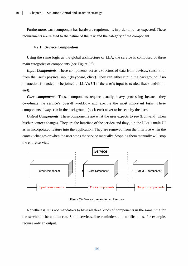
101 Chapter 6 – Situation Control and Reaction strategy
101
Furthermore, each component has hardware requirements in order to run as expected. These
requirements are related to the nature of the task and the category of the component.
4.2.1. Service Composition
Using the same logic as the global architecture of LLA, the service is composed of three
main categories of components (see Figure 53).
Input Components: These components act as extractors of data from devices, sensors, or
from the user’s physical input (keyboard, click). They can either run in the background if no
interaction is needed or be joined to LLA’s UI if the user’s input is needed (back-end/front-
end).
Core components: These components require usually heavy processing because they
coordinate the service’s overall workflow and execute the most important tasks. These
components always run in the background (back-end) never to be seen by the user.
Output Components: These components are what the user expects to see (front-end) when
his/her context changes. They are the interface of the service and they join the LLA’s main UI
as an incorporated feature into the application. They are removed from the interface when the
context changes or when the user stops the service manually. Stopping them manually will stop
the entire service.
Figure 53 - Service composition architecture
Nonetheless, it is not mandatory to have all three kinds of components in the same time for
the service to be able to run. Some services, like reminders and notifications, for example,
require only an output.

102 Chapter 6 – Situation Control and Reaction strategy
102
4.2.2. Component requirements
Due to the different tasks performed by the components, the hardware requirements vary
greatly. For each category of components, LLA focuses on a specific set of requirements. In
order to present this into LLA, the general query rule is:
!Ressource: This query means that the component request and needs the
presence of a specific resource. For example, “!GPS” means that the device
should have a GPS in order to run that component.
We use the following query rules for static capabilities:
S!Ressource = “M”: This query means that the component request and needs
the presence of a specific resource with the specific model M.
S!Ressource >, <, >= or <= Power unit: This query means that the component
request and needs the presence of a specific resource and preferably with a power
value greater than a value (Power unit). For example, “(S!Processor = ARMv7)
> 1.5Ghz” or “S!DISPLAY < 12inch” .
For dynamic resources, which can change their status during runtime, LLA understands the
following rules:
D!Ressource >, <, >= or <= Status unit: This query means that the component
request the presence of a specific resource that has the required status. For
example, “D!Ram>200MB” means that the device should have a RAM which
has more than 200MB of free memory.
D!Ressource is Free: This query means that the component needs a resource
which is either free or taken.
These rules consider binary “&” and “||” binary operations. For example, if the component
requires the presence of a camera and 4GB RAM, the rule is defined like: ((!Camera)&(s!RAM
> 4GB)). The different categories of components have a variety of requirements.
Firstly, input components focus on extracting data from devices which makes them require
the presence of a specific set of resources. The data could be in any format (video, sound, text,
etc.) and extracted from any device meeting the requirements. Therefore, we identified 2
categories of hardware requirements:

103 Chapter 6 – Situation Control and Reaction strategy
103
Service related: Camera, Microphone, Keyboard, Mouse, Fingerprint scanner,
and GPS.
Sensor related: Accelerometers, Gravity Sensors, Gyroscopes, Rotational
Vector Sensors, Barometers, Photometers, Thermometers, Orientation Sensors,
Magnetometers, Heart rate, etc.
Secondly, core components focus on running the heavy calculations and handling the most
important components of the service. Therefore, they consider, most importantly, the hardware
specification related to calculation time and space. For these components, we identify the
following requirements:
Battery: Even though having a battery is not mandatory for all devices (e.g. computer),
for portable devices this feature is useful in knowing the level of charge and therefore
knowing the state of the device.
Processor: These components ask the device for their processor’s type, capacity in
terms of processing power and current status.
RAM: For components that require an important amount of memory usage, this resource
is very important.
Cache: This requirement represents the ability to store data so future requests for that
data can be served faster; the data stored in a cache might be the result of an earlier
computation or the duplicate of data stored elsewhere.
Storage: Some services might require storing data on the device thus the need for a
physical memory storage.
Network: This feature presents the connectivity options on the device.
Graphics: For components with 3D animations, like video games, for example, this
feature could be required and helpful.
Finally, output components focus on running UI and other forms of feedback like sound
and vibrations. Since LLA is running in a distributed environment that might be filled
with different devices, choosing the best form of feedback is an important factor to
ensure a fluent and interesting user experience. For these components, we identify the
following requirements:
Display: This is the main feature for interacting with the user. The devices possessing a
screen will host the UI of LLA and the services.

104 Chapter 6 – Situation Control and Reaction strategy
104
Audio: For components that require an audio output, this requirement is very important.
Vibration: Most devices, nowadays, are able to vibrate. Therefore, this is considered an
important type of feedback.
LED: This is the most primitive, yet still used, type of feedback. Illuminating a led in a
different color could be a good indication of the type of feedback.
OTHER: This category is for any other non-conventional format of output like, for
example, temperature coming from a connected heating system.
The service composition and requirements are specified by the developer of the service and
added in the description of the service in the Services description & requirements file in the
persistence layer (see Chapter 3). The description is presented both textually and graphically.
Graphically: The graphical representation is used to have a clearer understanding of the
composition strategy for the service (see Figure 53).
Textually: A description for service is presented textually in the following format.
Service: [Input [Component (Component requirements &,||…); ...]; Core […]; Output
[…] | Links (ComponentN -> ComponentN+1;…)]
For example, a video chat service (see Figure 54) that uses our modular composition would
contain 5 components: Picture feed component, Sound feed component, Text feed component,
Video chat core component, and Video chat UI component.
Figure 54 - Video chat service composition graphical representation

105 Chapter 6 – Situation Control and Reaction strategy
105
Textually, this service is presented as follows:
Video chat service: [Input [Picture feed component (!Camera); Sound feed component
(!Microphone); Text feed component ((!Keyboard)||(!Display))]; Core [Video chat core
component (D!RAM>1GB)]; Output [Video chat UI component (S!Display>10inch);] | Links
(Picture feed component -> Video chat core component; Sound feed component -> Video chat
core component; Text feed component -> Video chat core component; Video chat component -
> Video chat UI component;)]
These components are linked to each other, via Kalimucho connectors, yet work separately
on their specific tasks in order to form the overall behavior of the service. Naturally, these
components have hardware requirements that the devices need to provide in order for the
service to be executed in a functional state.
4.3. Matching services to situations
In LLA, for each situation, a mapping is considered. The mapping matches situations to
services in order to respond to contextual changes when needed. Using the service composition
and component requirement concepts, the matching defines clearly the needs of the service in
terms of optimal distribution. A mapping M is presented textually in the following format,
where P is a projection and Sn is a situation.
M : Sn [ P(1..n) [ Service; …]]
In the persistence layer (see Chapter 3), these textual representations are translated into XML
and injected into the user’s application (Mapping) in order to define his/her responses to the
detected situations.
Having defined the service layer (see Chapter 4), we have the full description of the situation
(context and service). For example, in figure 55, a graphical full description is shown. This
representation shows an example of an important (P(2)) monthly work meeting situation done
remotely using a video chat service.

106 Chapter 6 – Situation Control and Reaction strategy
106
Figure 55 - Monthly Work Meeting full representation
Using the same video chat service example (see Figure 55), the textual representation of the
mapping is as follows:
M1: Monthly work meeting [Projection1 [Video chat service]]
This indicates that when the Monthly Work Meeting situation is detected and is about to
start, LLA will deploy the video chat service. If the situation is ending, LLA stops the service
by stopping all its components.
4.4. Orchestration and control components
After explaining the concepts related to service composition, situation mappings, and device
capabilities, the focus of this part is to define the internal components that work inside the
Action Orchestrator and ACL filter. These components use the defined concepts (Mappings,
Service descriptions, Requirements, Device capabilities, and User-Domain) in order to launch
or stop the services needed in the best way possible while taking into account their requirements
and the status of the user-domain.
This internal architecture, represented in Figure 56, is composed of multiple components
each performing a task separately and simultaneously while communicating the results to each

107 Chapter 6 – Situation Control and Reaction strategy
107
other. The Parser is the module enabling these components to access the data stored in the files
in the persistence layer.
Figure 56 - AO and ACL internal architecture
The process of orchestrating services starts by receiving the results of the previous module
(CE). Using these results, it adapts LLA to the needs of the user by stopping and starting
services.
4.4.1. Situation Tracker Component (STC)
Figure 57 - Situation Tracker Component
This component (see Figure 57) keeps track of all the situations that are currently running.
It consults the mapping file in order to know how to respond to a certain situation.
It takes as input the list of situations that are able to start (organized according to their
priorities). It receives also from the Situation Manager component a list of ending situations. It
consults the mappings, received from the Parser, and then identifies the service that needs to be
started and stopped. For each starting services that this component sends to the Orchestrator
component, it receives a success/failure notification indicating if that service was successfully
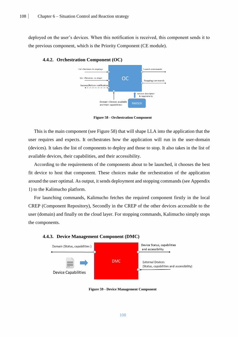
108 Chapter 6 – Situation Control and Reaction strategy
108
deployed on the user’s devices. When this notification is received, this component sends it to
the previous component, which is the Priority Component (CE module).
4.4.2. Orchestration Component (OC)
Figure 58 - Orchestration Component
This is the main component (see Figure 58) that will shape LLA into the application that the
user requires and expects. It orchestrates how the application will run in the user-domain
(devices). It takes the list of components to deploy and those to stop. It also takes in the list of
available devices, their capabilities, and their accessibility.
According to the requirements of the components about to be launched, it chooses the best
fit device to host that component. These choices make the orchestration of the application
around the user optimal. As output, it sends deployment and stopping commands (see Appendix
1) to the Kalimucho platform.
For launching commands, Kalimucho fetches the required component firstly in the local
CREP (Component Repository), Secondly in the CREP of the other devices accessible to the
user (domain) and finally on the cloud layer. For stopping commands, Kalimucho simply stops
the components.
4.4.3. Device Management Component (DMC)
Figure 59 - Device Management Component

109 Chapter 6 – Situation Control and Reaction strategy
109
This component (see Figure 59) scans the domain and receives the status, capabilities, and
accessibilities of all the other devices around the user. It considers the same things for the
internal device hosting this instance of the platform. It sends the information about the internal
device to the other devices in the domain.
4.4.4. Example
In order to demonstrate how the Action Orchestrator and ACL filter both work, we study a
portion of the example described in Figures 60. The focus on this example is to show the
evolution of actions of LLA by adding and removing services on multiple devices.
Figure 60 - Scenario portion
The considered situations all happen consecutively while the user is at home. For each one,
LLA deploys different services and closes others. The mapping for these situations is textually
represented as follows.
** M1: Dinner Situation [Projection1 [News service]]
** M2: Health Situation [Projection1 [Health check service]; Projection2 [Medicine
Reminder Service]]
** M3: Family Call Situation [Projection1 [Skype service]]
The service description for these mappings is textually represented as follows.

110 Chapter 6 – Situation Control and Reaction strategy
110
**News Service: [Input [Remote Control component ((S!Display>=5inch)&
(S!Network=Infrared||Bluetooth\\Wifi))]; Core [News Stream component (S!RAM>2GB;
S!Network=Infrared&WiFi)]; Output [Image output component (S!Display>28inch); Sound
output component (S!Audio>50dB)]) | Links [Remote Control component -> News Stream
component; News Stream component -> Image output component; News Stream component -
> Sound output component)]
**Health Check Service: [Input [Health data collector component ((!Heart rate sensor)&
(!Accelerometer)&(!Gyroscope))]; Core [Health data analyzer component (D!RAM>1GB)];
Output [Results component (S!Display>5inch)] | Links (Health data collector component ->
Health data analyzer component; Health data analyzer component -> Results component;)]
**Medicine Reminder service: [Output [Results component (!Display;)]]
**Skype service: [(Input [Picture feed component (S!Camera=”CMOS-High Def”); Sound
feed component (!Microphone); Text feed component ((!Keyboard)||(!Display))]; Core [Skype
core component (D!RAM>2.5GB)]; Output [Image output component (S!Display>16inch);
Text UI component (S!Display>10inch); Sound output component (S!Audio<40dB)] | Links
(Picture feed component -> Skype core component; Sound feed component -> Skype core
component; Text feed component -> Skype core component; Skype core component -> Image
output component; Skype core component -> Sound output component; Skype core component
-> Text UI component;)]
Graphically, the service layers of these situations are represented in Figure 61.
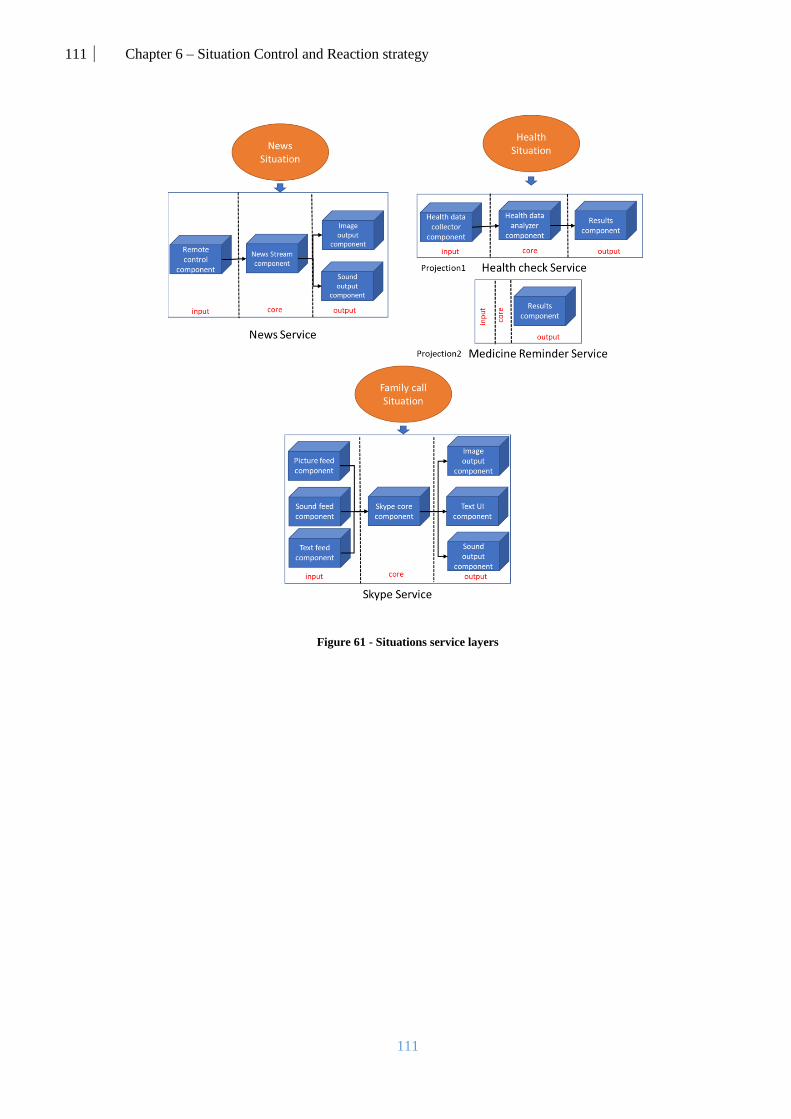
111 Chapter 6 – Situation Control and Reaction strategy
111
Figure 61 - Situations service layers

112 Chapter 6 – Situation Control and Reaction strategy
112
Table 14: Example of User-Domain
Device Capability Model Power Unit Returned data type Status Availability
Samsung
Gear S3
See Table 13.
HP Envy
Laptop [54]
Processo
r
Intel® Core™
i7-7500U-Dual
3,5 GH
z
Processing power 90% Free
RAM DDR4 12 GB Memory usage 6.8 Free
Storage SSD 256 GB Storage capacity 160 Free
Camera -- 8 MP Photo/Video -- Free
Display -- 15,6 inc
hes
-- -- Free
Keyboar
d
-- -- -- Text -- Free
Home
audio
system [75]
Audio Pro 7.1Ch
400W
104 dB Sound -- Free
Display -- 2 inc
hes
-- -- Free
Network Wi-Fi,
Infrared,
Bluetooth
-- -- -- -- Free
Sony
KDL-
43W805C
Smart-TV
[93]
Display X-Reality 43 inc
hes
-- -- Free
Network Wi-Fi,
Infrared,
Bluetooth
-- -- -- -- Free
Audio -- 40 dB Sound -- Free
Microsof
t Kinect 2
[69]
Camera CMOS- High
Def
3.5 MP Photo/Video -- Free
Color,
Tilt, Depth
sensors
-- -- -- -- -- --
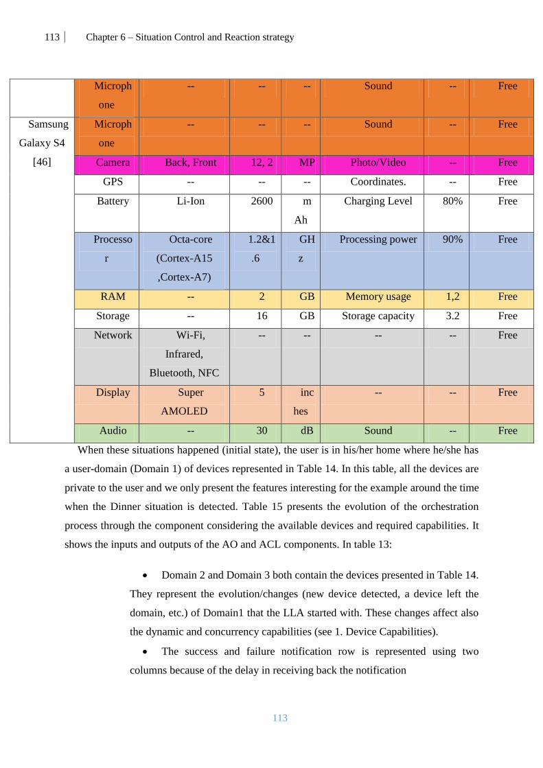
113 Chapter 6 – Situation Control and Reaction strategy
113
When these situations happened (initial state), the user is in his/her home where he/she has
a user-domain (Domain 1) of devices represented in Table 14. In this table, all the devices are
private to the user and we only present the features interesting for the example around the time
when the Dinner situation is detected. Table 15 presents the evolution of the orchestration
process through the component considering the available devices and required capabilities. It
shows the inputs and outputs of the AO and ACL components. In table 13:
Domain 2 and Domain 3 both contain the devices presented in Table 14.
They represent the evolution/changes (new device detected, a device left the
domain, etc.) of Domain1 that the LLA started with. These changes affect also
the dynamic and concurrency capabilities (see 1. Device Capabilities).
The success and failure notification row is represented using two
columns because of the delay in receiving back the notification
Microph
one
-- -- -- Sound -- Free
Samsung
Galaxy S4
[46]
Microph
one
-- -- -- Sound -- Free
Camera Back, Front 12, 2 MP Photo/Video -- Free
GPS -- -- -- Coordinates. -- Free
Battery Li-Ion 2600 m
Ah
Charging Level 80% Free
Processo
r
Octa-core
(Cortex-A15
,Cortex-A7)
1.2&1
.6
GH
z
Processing power 90% Free
RAM -- 2 GB Memory usage 1,2 Free
Storage -- 16 GB Storage capacity 3.2 Free
Network Wi-Fi,
Infrared,
Bluetooth, NFC
-- -- -- -- Free
Display Super
AMOLED
5 inc
hes
-- -- Free
Audio -- 30 dB Sound -- Free

114 Chapter 6 – Situation Control and Reaction strategy
114
Table 15: Situation analysis by the Event Manager's components
STC Inputs Situations about to start Dinner Situation (projection1) Health Situation (projection1) Family call Situation
Situations about to finish -- Dinner Situation Health Situation
Success/failure notification -- Dinner situation Success -- Health situation Success -- Family call Success
Outputs Services to deploy News Service Health Check Service Skype Service
Services to stop -- News Service Health Check Service
Success/failure notification -- Dinner situation Success -- Health situation Success -- Family call Success
DMC Inputs Other Devices cap, access Devices in domain 1 Device in domain 2 Devices in domain 3
Outputs Domain (device list) Domain1 (see Table 14) Domain 2 Domain 3
Device status, cap, access HP Envy Laptop HP Envy Laptop HP Envy Laptop
OC Inputs Domain Domain 1 Domain 2 Domain 3
Services to deploy News Service Health Check Service Skype Service
Services to stop -- News Service Health Check Service
Outputs Success/failure notification Dinner situation Success Health situation Success Family call Success
Launch commands Commands 1 Commands 2 Commands 4
Stopping commands -- Commands 3 Commands 5
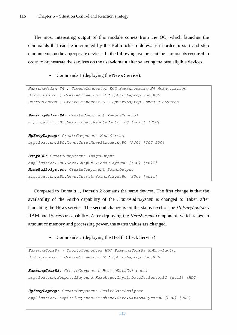
115 Chapter 6 – Situation Control and Reaction strategy
115
The most interesting output of this module comes from the OC, which launches the
commands that can be interpreted by the Kalimucho middleware in order to start and stop
components on the appropriate devices. In the following, we present the commands required in
order to orchestrate the services on the user-domain after selecting the best eligible devices.
Commands 1 (deploying the News Service):
SamsungGalaxyS4 : CreateConnector RCC SamsungGalaxyS4 HpEnvyLaptop
HpEnvyLaptop ; CreateConnector IOC HpEnvyLaptop SonyKDL
HpEnvyLaptop : CreateConnector SOC HpEnvyLaptop HomeAudioSystem
SamsungGalaxyS4: CreateComponent RemoteControl
application.BBC.News.Input.RemoteControlBC [null] [RCC]
HpEnvyLaptop: CreateComponent NewsStream
application.BBC.News.Core.NewsStreamingBC [RCC] [IOC SOC]
SonyKDL: CreateComponent ImageOutput
application.BBC.News.Output.VideoPlayerBC [IOC] [null]
HomeAudioSystem: CreateComponent SoundOutput
application.BBC.News.Output.SoundPlayerBC [SOC] [null]
Compared to Domain 1, Domain 2 contains the same devices. The first change is that the
availability of the Audio capability of the HomeAudioSystem is changed to Taken after
launching the News service. The second change is on the status level of the HpEnvyLaptop’s
RAM and Processor capability. After deploying the NewsStream component, which takes an
amount of memory and processing power, the status values are changed.
Commands 2 (deploying the Health Check Service):
SamsungGearS3 : CreateConnector HDC SamsungGearS3 HpEnvyLaptop
HpEnvyLaptop : CreateConnector HSC HpEnvyLaptop SonyKDL
SamsungGearS3: CreateComponent HealthDataCollector
application.HospitalBayonne.Karchoud.Input.DataCollectorBC [null] [HDC]
HpEnvyLaptop: CreateComponent HealthDataAnalyzer
application.HospitalBayonne.Karchoud.Core.DataAnalyzerBC [HDC] [HSC]

116 Chapter 6 – Situation Control and Reaction strategy
116
SonyKDL: CreateComponent HealthStatus
application.HospitalBayonne.Karchoud.Output.ResultsBC [HSC] [null]
Commands 3 (stopping the News Service):
SamsungGalaxyS4 : RemoveConnector RCC
HpEnvyLaptop : RemoveConnector IOC
HpEnvyLaptop : RemoveConnector SOC
SamsungGalaxyS4: RemoveComponent RemoteControl
HpEnvyLaptop: RemoveComponent NewsStream
SonyKDL: RemoveComponent ImageOutput
HomeAudioSystem: RemoveComponent SoundOutput
The change in Domain 3 happens on the availability level of the Audio capability of the
HomeAudioSystem is changed back to Free after stopping the News service. The RAM and
Processor statuses are also affected accordingly. The HealthDataAnalyzer affects also the RAM
and Processor of the HpEnvyLaptop.
Commands 4 (deploying the Skype Service)
MicrosoftKinekt1520 : CreateConnector PFC MicrosoftKinekt1520 HpEnvyLaptop
HpEnvyLaptop : CreateConnector SFC SamsungGalaxyS4 HpEnvyLaptop
HpEnvyLaptop : CreateConnector TFC HpEnvyLaptop HpEnvyLaptop
HpEnvyLaptop : CreateConnector TUIC HpEnvyLaptop HpEnvyLaptop
HpEnvyLaptop : CreateConnector IOC HpEnvyLaptop SonyKDL
HpEnvyLaptop : CreateConnector SOC HpEnvyLaptop SamsungGalaxyS4
MicrosoftKinekt1520: CreateComponent PictureFeed
application.Skype.Input.PictureFeedBC [null] [PFC]
SamsungGalaxyS4: CreateComponent SoundFeed
application.Skype.Input.SoundFeedBC [null] [SFC]
HpEnvyLaptop: CreateComponent TextFeed
application.Skype.Input.TextFeedBC [null] [TFC]
HpEnvyLaptop: CreateComponent SkypeCore
application.Skype.Core.SkypeCoreBC [PFC SFC TFC] [IOC TUIC SOC]

117 Chapter 6 – Situation Control and Reaction strategy
117
SonyKDL: CreateComponent ImageOutput
application.Skype.Output.ImageOutputBC [IOC] [null]
SamsungGalaxyS4: CreateComponent SoundOutput
application.Skype.Output.SoundPlayerBC [SOC] [null]
HpEnvyLaptop: CreateComponent ChatUIOutput
application.Skype.Output.ChatUiBC [TUIC] [null]
Commands 5 (stopping the Health Check Service) :
SamsungGearS3 : RemoveConnector HDC
HpEnvyLaptop : RemoveConnector HSC
SamsungGearS3: RemoveComponent HealthDataCollector
HpEnvyLaptop: RemoveComponent HealthDataAnalyzer
SonyKDL: RemoveComponent HealthStatus
After Kalimucho runs Command 4 and Commands 5, Domain 3 has the following changes:
the availability of the Sound and Microphone capabilities of SamsungGalaxyS4 is changed to
Taken; the availability of the Camera capability of MicrosoftKinekt1520 is also changed to
Taken.
5. Conclusions
User preferences and user experience are major factors that developers and designers should
consider when implementing their applications if they want to keep up with the evolution of the
user’s connected world and evolving needs.
LLA incorporates a mechanism that enables the user to have a better, distributed, and hands-
free experience using a distributed adaptable service layer tailored to his/her specific needs and
hardware limitations.
In our proposal, we highly consider the user’s status and conditions by incorporating a Lock
Zone approach capable of filtering the user’s possible situations according to his/her current
availability status (free, busy, etc.). We also provide a dynamic priority management feature
that handles the concurrency of situations and organizes them while considering their own
importance level, the user’s status, and their sources importance level.
These sources are presented in the next chapter, which is dedicated to showing how LLA
enables furthermore dynamicity by offering a new concept called context injection.

118 Chapter 7 – Situation Injection Mechanism
118
Chapter 7 – Situation Injection Mechanism

119 Chapter 7 – Situation Injection Mechanism
119
1. Introduction
A major issue with mobile applications in general and context-aware applications, in
particular, is their repetitiveness and limitation to restricted application domains or closed
spaces equipped with sensors [52].
With the aim of overcoming this issue, the LLA application handles a semi-automatic,
collaborative, open injection mechanism that continuously provides the user with richer
contextual awareness and more suitable services. In this way, we ensure the continuous growth
of LLA by making it able to enhance and enrich the user experience by managing (adding,
deleting, or modifying) new situations introduced through the injection mechanism. This
mechanism is based on a user-friendly situation model in order to make the injection an easy
and understandable procedure that can be performed even by end-users with no understanding
of technical issues.
The injection mechanism has multiple sources of injection and communicates directly with
the persistence layer of the application.
2. Situation injection mechanism
One main novelty of LLA is a collaborative mechanism [62] that enables users and other
external sources to continuously and proactively introduce new situations into the user's
application, in order to improve its understanding and reliability and overcome the lack of
dynamicity in current context-aware applications.
Figure 62 - The Injector's workflow

120 Chapter 7 – Situation Injection Mechanism
120
The injector acts as an input (inserter) dedicated to enriching the context awareness
considered for the user from diverse sources. It can inject/modify/delete/update situations
and/or services without having to access directly the devices of the user. These sources can
inject the situation's description into the user's app by interacting with the persistence layer of
the user (see Figure 62). The data of this layer is stored in a cloud storage and is shared among
all the user's devices. This solution avoids redundancy and inconsistencies among user devices
regarding his/her situations in order to keep the coherence of LLA.
One benefit of using this high-level contextual injection mechanism, which extracts context
data from multiple sources, is the capability to provide a way of increasing continuously the
repository of monitored situations and thus be more customized to the user.
The LLA needs to be aware of the user's habits, needs, and social environment. Three main
categories of context injection sources are considered by the application. Each main source of
injection uses a different process to collaboratively update the application of the user in a
transparent way that does not require any unnecessary downloads.
The advantage of this mechanism resides in eliminating the time and network usage usually
needed, by current existing applications, to do regular heavy updates for even the simplest
changes in the code base. Using our approach, the updates will be occasional and probably
affect only the situation's file or the mapping file by using already-stored components. Even on
the service level, developers will be able to modify components separately and therefore have
fewer and lighter updates.
2.1. User's Injection Process
The first source of situations is the user himself/herself, and more precisely his/her needs
and habits. What motivated us to propose this is the repetitiveness that users feel while they set
their alarm every night or while they open their emails every morning. These habits can be
automated in order to help the user to have the same experiences without having to always
perform those same tasks again and again.
To do so, the user has the possibility to use either the injector's UI, which is accessible from
his/her LLA's Manager UI (mobile version) or the Web Injector. In the first case (see Figure 62
“Uses (2)''), the mobile injector is dedicated to building simple and fast situations by working
on only 1 projection and 3 axes per situation.
In the second case (see Figure 62 ``Uses (3)''), the web application allows a more precise
and rich description of situations and services using multiple projections and 6 axes.
121 Chapter 7 – Situation Injection Mechanism
121
In both cases, the user can either create, delete or modify a situation by inputting/modifying
the required values (like the time, location and activity) and then update or create a matching
by selecting a service or a set of services to be deployed when the situation is detected. The user
can also decide to share these situations with other users.
After selecting the service/services, the user verifies if the components composing the
selected service exist in his/her repository. A possible extension from this end would be to have
a store for services instead of applications, where users can select services to download into
their local or cloud storage in order to use them willingly when needed. Nonetheless, if the user
wishes for the required service to not stay on his/her storage space, he/she could specify to
trigger the download only when the situation is detected and ask to be deleted when that
situation finishes.
Finally, the user has the possibility to subscribe to, or unsubscribe from, other injection
sources freely, giving these sources the possibility to provide him/her with new situations,
mappings, and services.
2.2. Collaborative Social Environment's Injection Process
Social media has become the largest source of information about users' activities,
preferences, etc. Moreover, we live nowadays in the age of media sharing.
In this scope, the injector incorporates into the LLA's architecture a transparent component
running in the background, which monitors the user's social media (if the user subscribes to it
and allows this monitoring) in order to suggest/recommend new situations.
In order to build these suggestions, the injector follows a specific process (see Figure 62
``Monitors (4)''). After extracting events and birthdays from Facebook, tasks from Google
Calendar, etc., the injector mechanism asks the user to specify the tolerance and the expected
reaction to these potential situations. The user can select services from the Services Repository
to be deployed automatically when the situation is detected.
If the monitor detects a new shared situation coming from another user, it suggests it to the
user and allows him/her to choose whether to download the services that other users recommend
for that specific situation or select his/her own services. Otherwise, if the user does not specify
any reaction strategy, the application creates a situation and assigns a reminder service by
default. This widens the applicability of contextual engagement by giving the user the
possibility to create/share his/her own situations or extract them automatically from his/her
social environment (using data from Facebook, Google Calendar, Twitter, etc.).

122 Chapter 7 – Situation Injection Mechanism
122
For example (see Figure 63), if the user received an invitation to a concert event on Facebook
(Tuesday 25th July 2017 at Bayonne Center) and he/she chooses to participate, the injector's
recommendation component, which is monitoring the user's social media, detects this event,
builds a situation, and proposes to the user to add it to his/her own situations; then, the user
accepts this situation; finally, he/she also selects a ticket provider service and a video streaming
service that he/she wishes to use when the concert situation happens.
Figure 63 - Concert event situation
2.3. External Providers' Injection Process
This is a very important source of injection in this proposal, as it completes the mechanism
with an open system that can provide endless possibilities to the user by continuously proposing
new situations and services. Whereas the other sources of injection (user and social) handle
private and social situations, this source covers a wider range of situations related to a variety
of domains that otherwise could not be considered. The providers are external sources that the
user can subscribe to in order to allow them to inject his/her application with situations and
provide him/her with services.
For these sources, the process of injecting situations (see Figure 62 ``Uses (1)'') is done with
the help of the web application. Providers can create situations (like users), and then select
among their subscribers the ones that are concerned by that situation. Nonetheless, they should
implement their own services and components using the Kalimucho framework. Finally, the
injector broadcasts those situations, mappings, and services, to the concerned users.

123 Chapter 7 – Situation Injection Mechanism
123
The situations and mappings are described via a web application and then injected to the
subscribers of the provider along with the appropriate services (software components). The
providers are classified into three main categories;
2.3.1. Government providers
The first category is formed by government organisms and services (universities, hospitals,
the police, etc.). If the user subscribes to these organisms, he/she allows them to inject
situations.
For example (see Figure 64), if the police decide to close the borders due to an emergency,
it injects that situation to all the users in the vicinity, in order to notify them and propose another
road when the user gets close to the borders on that specific date.
Figure 64 - Border closing situation
2.3.2. Businesses and private companies
Any business (MacDonald, Carrefour, a gas station, etc.) can offer its situations and allow
users to subscribe and use its services. Considering other applications that use context
awareness to aim advertisements for users, our proposal provides a new way to engage those
users, not limited to texts and notifications but enhanced by the possibility to offer dedicated
customizable services instead.
For example (see Figure 65), a parking company can construct and inject a situation into the
users' situation repository that, upon detecting that the user entered one of its parking areas,

124 Chapter 7 – Situation Injection Mechanism
124
deploys a parking service to help the user find the closest empty space and remind him/her
where he/she parked when he/she gets back to leave.
Figure 65 - Parking situation
2.3.3. Institutions/Organizations/Associations
These providers represent the non-governmental entities that do not necessarily have a
financial gain from the user.
An example (see Figure 66) of this would be a football team that injects training sessions
situations to its players' applications. When the defined primitives are verified and service
hardware requirements are met, LLA deploys the Biometric Monitor Service.
Figure 66 - Training situation
125 Chapter 7 – Situation Injection Mechanism
125
3. Conclusions
In a world where users are surrounded by smart objects, fast Internet, and almost-unlimited
data storage, users have higher expectations from their apps. Contextual awareness is essential
to the survival of mobile applications. However, current context-aware applications have
multiple limitations in terms of dynamicity and evolution.
The LLA surpasses these limitations by offering a dynamic injection mechanism allowing
users, developers, and other entities, to expand the application and customize it according to
the user's needs.
At this level, we already presented how situations are injected, detected, stored and
manipulated. The next chapter presents the prototype that we implemented in order to study the
feasibility and applicability of our proposal.

126 Chapter 8 – Prototype and Validation
126
Chapter 8 – Prototype and Validation
127 Chapter 8 – Prototype and Validation
127
1. Introduction
In the previous chapters, we presented our proposal following a sequential order starting by
injecting and capturing context and ending by deploying or stopping services. This process is
clearly defined (on both a technical and abstract level) step by step which makes following the
workflow of LLA a simple task. Moreover, when implementing LLA, we inserted logging
events in all the components in order to effortlessly follow the functioning and evolution of the
process.
Due to the huge amount of possibilities and parameters considered by LLA, we propose to
present the whole process by implementing the scenario described in Chapter 1. This scenario
will help to validate our proposal, exhibit our claimed contributions, test the feasibility of our
approach, and demonstrate the sustainability of our prototype.
In order to achieve this, we firstly present in this chapter, the evolution of LLA when applied
to John’s travel scenario. Secondly, we show and discuss the limits, metrics, measures, and
results of our proposal.
2. Establishing and testing the scenario
When using LLA, users do not have to worry about installing/deleting/updating/configure
multiple applications. Nonetheless, for LLA to function properly, some preconditions need to
be verified.
In the following sub-section, we present the pre-conditions that John needs to set up in order
to LLA to provide him with the expected behavior.
2.1. Pre-Conditions
The most basic pre-condition that needs to be met is, of course, installing LLA on all
the devices that the user wishes to use. All the installed instances communicate with
each other and work collectively as one application (see Figure 26).
A newly installed LLA is an empty application. When installing it for the first time, the
user should provide a set of information necessary to enable the application to work
properly. This set information is the following:
o User account: Authenticating the user with a Facebook or a Google account (see
Figure 67). This authentication will help LLA recognize the user and

128 Chapter 8 – Prototype and Validation
128
synchronize his/her devices and cloud persistence layer. Moreover, linking LLA
with Facebook and Google will help the Injector to extract the bio information
(age, birthdate, birthplace, picture, etc.), events, and interests of the user which
helps the Injector to propose new situations and start to fill the Situations file in
the persistence layer.
Figure 67 – Authentification UI in LLA
o User private Encryption Key and Device Name: This key is a text provided by
the user and used by LLA to discover other instances installed on other devices
and to encrypt the exchanged data between them (see Figure 68). The Device
Name is an optional value that names the device as the user prefers to name it.
Figure 68 – Defining the encryption key
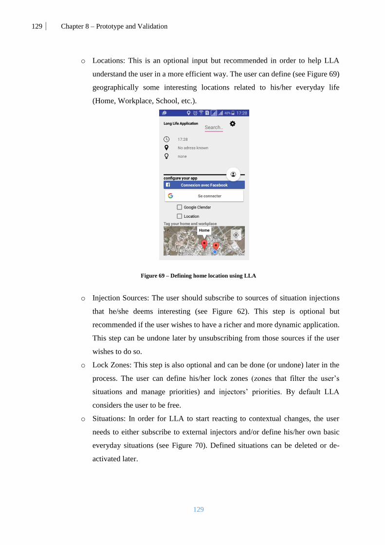
129 Chapter 8 – Prototype and Validation
129
o Locations: This is an optional input but recommended in order to help LLA
understand the user in a more efficient way. The user can define (see Figure 69)
geographically some interesting locations related to his/her everyday life
(Home, Workplace, School, etc.).
Figure 69 – Defining home location using LLA
o Injection Sources: The user should subscribe to sources of situation injections
that he/she deems interesting (see Figure 62). This step is optional but
recommended if the user wishes to have a richer and more dynamic application.
This step can be undone later by unsubscribing from those sources if the user
wishes to do so.
o Lock Zones: This step is also optional and can be done (or undone) later in the
process. The user can define his/her lock zones (zones that filter the user’s
situations and manage priorities) and injectors’ priorities. By default LLA
considers the user to be free.
o Situations: In order for LLA to start reacting to contextual changes, the user
needs to either subscribe to external injectors and/or define his/her own basic
everyday situations (see Figure 70). Defined situations can be deleted or de-
activated later.

130 Chapter 8 – Prototype and Validation
130
Figure 70 – Adding a new situation using LLA’s UI
The user should verify the connectivity and stability of his/her devices. Although LLA
is able to function off-line, it is highly recommended to keep the devices reachable at
all time in order to have a richer user experience and ensure the sustainability and
dynamicity of the application.
Finally, the user has the possibility to select a preferred device to run LLA’s
architecture. This device should preferably the most stable and efficient regarding
connectivity and performance. If the user doesn’t specify this device, LLA will
dynamically select the most capable device whenever it is started/re-started (see Figure
26).
After verifying these pre-conditions, LLA starts to run continuously to monitor the user’s
context and help him/her throughout their everyday life.
2.2. John’s travel scenario
Now that our architecture and the concepts of LLA are clearly defined, we take the scenario
(see Figure 71) described in Chapter 1 and we apply to LLA by feeding it all the necessary
information in order to have the anticipated behavior. The information presented in this section
is all fictitious and is only considered as a simulation.
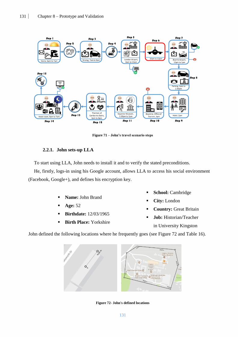
131 Chapter 8 – Prototype and Validation
131
Figure 71 – John’s travel scenario steps
2.2.1. John sets-up LLA
To start using LLA, John needs to install it and to verify the stated preconditions.
He, firstly, logs-in using his Google account, allows LLA to access his social environment
(Facebook, Google+), and defines his encryption key.
Name: John Brand
Age: 52
Birthdate: 12/03/1965
Birth Place: Yorkshire
School: Cambridge
City: London
Country: Great Britain
Job: Historian/Teacher
in University Kingston
John defined the following locations where he frequently goes (see Figure 72 and Table 16).
Figure 72- John's defined locations

132 Chapter 8 – Prototype and Validation
132
Table 16: John’s locations data
Place Owner Address Shape Coordinates
Home John 59 Southbury Road
London EN1 1PJ Circle
Center: 51.637818, -0.063590
Radius: 50 meters
University
Campus Public
Kingston University
London, Kingston Hill
Campus, Kingston Hill,
Kingston upon Thames
KT2 7LB
Polygon
Point 1: 51.430595, -0.265797
Point 2 : 51.430383, -0.261499
Point 3: 51.428940, -0.261417
Point4 : 51.427568, -0.262367
Point 5 : 51.428302, -0.267347
Point 6 : 51.429822, -0.266934
John subscribes to the injection sources (see Table 17) which will help him in the travel’s
organization. He also called Trailfinder travel agency to book the plane tickets and rent a car
for him. He calls the Regina Hotel to book a room for the length of the trip. He calls his doctor
to organize the thermal session for him. Finally, John’ daughter Patrice suggested injecting a
family call situation in his application.
Table 17: John’s external injectors
Injector’s Name Category Importance
Trailfinder Travel agency External/Business P(2)
London Heathrow Airport External/Government P(1)
Biarritz Airport External/ Government P(1)
Regina Hotel External/Business P(2)
Bayonne Office of tourism External/ Government P(1)
Doctor Michal Prager External/Business P(3)
Kingston University External/ Government P(2)
Patrice Social P(1)
Since John wants to use LLA also for personal needs, he injected his daily situations and
selected the services that he wishes to use for those situations. In figures 73, 74, and 75, we
present the graphical representations of the situations injected by John.
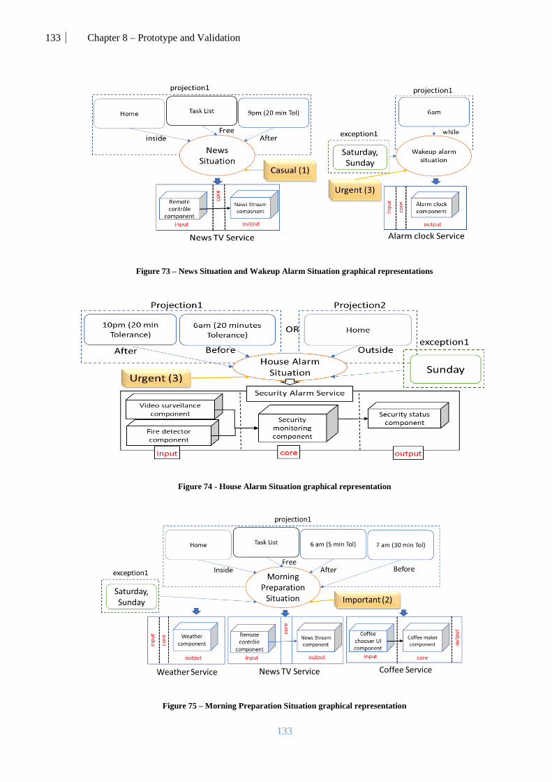
133 Chapter 8 – Prototype and Validation
133
Figure 73 – News Situation and Wakeup Alarm Situation graphical representations
Figure 74 - House Alarm Situation graphical representation
Figure 75 – Morning Preparation Situation graphical representation

134 Chapter 8 – Prototype and Validation
134
The next step is defining the Lock Zones. Since he is traveling, John defines his zones (see
Table 18) according to his availability on that day. These zones could be changed later when
John comes back from the travel.
Table 18: John’s defined lock zones
Zone Time Location Injection Source Priorities Special Situation
Priorities
Morning Busy
Zone
7 am -
10 am --
Trailfinder Travel agency: P(3)
London Heathrow Airport: P(2)
John: P(2)
Kingston University: P(1)
--
Flight Dead Zone
10 pm
- 12
pm
-- John: P(3) --
Evening Busy
Zone
12 pm
- 4 pm --
Trailfinder Travel agency: P(3)
Biarritz Airport: P(2)
Regina Hotel: P(3)
--
Relaxation Dead
Zone
6 pm -
8 pm
Center: 51.637818,
-0.063590
Radius: 3600 m
John: P(1)
Kingston University: P(1)
Facebook: P(1)
--
Initially, John possesses a list of devices that he added into LLA. But we consider the public
devices that he used along the journey. All the devices are described in Table 19. Since these
devices are hard to acquire, some of them will be simulated in this experiment.

135 Chapter 8 – Prototype and Validation
135
Table 19: John’s user-domain
Device Private/
Public Capability Model Power Unit
Returned
data type Status Availability
Samsung
Gear S3 Private See Table 13.
iMac [6] Private
Network Wifi
802.11ac -- -- -- -- --
Network Ethernet -- -- -- -- --
Processor Intel
Core i5 3,6
G
Hz --
90
% Free
RAM DDR4 32 G
B
Memory
usage -- Free
Storage Fusion 1000 G
B
Storage
capacity 820 Free
Camera 4K 8 M
P
Photo/Vi
deo -- Free
Display Retina 21,5 inc
hes -- -- Free
Keyboard Magic -- -- Text -- Free
Mouse Magic 2 -- -- -- -- Free
Graphic Raedon 4 G
B -- -- Free
Audio Pro 7.1Ch
400W 104 dB Sound -- Free
Nest 2nd
G [77] Private
SmokSensor -- -- -- -- -- --
Heat-
sensor -- -- -- -- -- --
Humidity
-sensor -- -- -- -- -- --
Presence-
sensor -- -- -- -- -- --
Light-
sensor -- -- -- -- -- --
Network Wi-Fi -- -- -- -- --
Network Bluetooth -- -- -- -- --
Sony
KDL-
43W805
C Smart-
TV [93]
Public
(Hotel)
Display X-Reality 43 inc
hes -- -- Free
Network Wi-Fi, -- -- -- -- --
Network Infrared -- -- -- -- --
Network Bluetooth -- -- -- -- --
Audio -- 40 dB Sound -- Free
Model S
Tesla
[98]
Private Display LCD 17
inc
hes -- -- Free
GPS-sensor -- -- -- -- -- Free

136 Chapter 8 – Prototype and Validation
136
Processor AMD -- -- -- -- Free
Network Cellular -- -- -- -- --
Network Bluetooth -- -- -- -- --
Sound -- -- dB -- -- --
Samsung
Galaxy
S4 [46]
(Preferre
d device)
Microphone -- -- -- Sound -- Free
Camera Back, Front 12, 2 MP Photo/Video -- Free
GPS -- -- -- Coordinat
es. -- Free
Battery Li-Ion 2600 mAh Charging
Level 80% Free
Processor
Octa-core
(Cortex-A15
,Cortex-A7)
1.2&1.6 GHz Processin
g power 90% Free
RAM -- 2 GB Memory
usage 1,2 Free
Storage -- 16 GB Storage
capacity 3.2 Free
Network Wi-Fi -- -- -- -- --
Network Infrared -- -- -- -- --
Network Bluetooth -- -- -- -- --
Network NFC -- -- -- -- --
Network Cellular -- -- -- -- --
Display Super
AMOLED 5 inches -- -- Free
Audio -- 30 dB Sound -- Free
Mr.
Coffee
Smart
[73]
Private
Network Wifi
802.11ac -- -- -- -- --
Cofee-engine -- -- -- -- -- --
Nest
Cam IQ
[78]
Private
Network Wi-Fi -- -- -- -- --
Network Bluetooth -- -- -- -- --
Camera -- 8 MP Photo/Video -- Free
Microsof
t surface
pro 4
[70]
Private
Microphone -- -- -- Sound -- Free
Camera Front 5 MP Photo/Video -- Free
GPS -- -- -- Coordinates. -- Free
Battery -- -- mAh Charging
Level -- --
Processor Intel Core i5 2.6 GHz -- -- Free
RAM -- 4 GB Memory
usage -- Free
Storage -- 512 GB Storage
capacity -- Free
Network Wi-Fi -- -- -- -- --
Light-sensor -- -- -- -- -- --
Network Bluetooth -- -- -- -- --

137 Chapter 8 – Prototype and Validation
137
Camera Back 8 MP Photo/Video -- --
Network Cellular -- -- -- -- --
Display PixelSense 12.3 inches -- -- Free
Audio -- 30 dB Sound -- Free
GPS-
sensor -- -- -- -- -- Free
Vibration -- -- -- -- -- Free
Audi A3
2016 [7]
Public
(Hertz)
Display LCD 12 inches -- -- Free
GPS-sensor -- -- -- -- -- Free
Network Wifi -- -- -- -- --
Network Cellular -- -- -- -- --
Interacti
ve
Display
Screen
[87]
Public
airport
Display LCD 50 inches -- -- Free
Network Wi-Fi -- -- -- -- --
Network Bluetooth -- -- -- -- --
2.2.2. LLA injects the necessary data
After finishing setting up LLA, and preparing the trip, the injection process starts in order to
fill John’s persistence layer and allow the core modules (ECA) to start functioning. The injector
inserts the situations, mappings, conditions, services description, and services.
In order for external providers to inject data into the user’s persistence layer, they need the
approval of the user and his subscription. In order to define the situations easily, we propose a
web (see Figure 76) application enabling to define situations, mappings, descriptions, and
upload the services as Jars.
Figure 76 – LLA web application for injecting situations from external sources

138 Chapter 8 – Prototype and Validation
138
- Injected Situations: They are injected using LLA’s injection UI and web app.
** Morning Preparation situation (S1): [priority=P(2); source=”User/John”]; Projection1 [
Time(After(6,5), Before(7,30)); Location(Inside(Home, 0)); Activity(Free(TaskList))] EXCEPT [ (
Time(While(Sunday,0)) ; Time(While(Satuday,0))) ]
** News Situation (S2): [priority=P(1); source=”User/John”]; Projection1 [
Time(After(21,15)); Location(Inside(Home, 0)); Activity(Free(TaskList))]
** Wakeup Alarm Situation (S3): [priority=P(3); source=”User/John”]; Projection1[
Time(While(6,0))] EXCEPT [ ( Time(While(Sunday,0)) ; Time(While(Satuday,0)) ]
** Drive to the airport situation (S4): [priority=P(2); source=”External/Business/
TrailfinderTravel Agency”]; Projection1 [Time( After(22/11/2016-7:0:0,20) Before(22/11/2016-
8:0:0,20)); Time*Location(Closer(Heathrow Airport, 22/11/2016-7:0:0, 22/11/2016-
8:0:0,100,25))]
** Heathrow Airport Parking Situation (S5): [priority=P(2); source=”External/Government/
Heathrow Airport”] Projection1 [Location (Inside (Heathrow airport parking, 10))]
** Heathrow Airport Navigation Situation (S6): [priority=P(2); source=”External/
Government/Heathrow Airport”] ; Projection1 [ Location(Inside(Heathrow airport, 10))]
** Biarritz Airport Navigation Situation (S7): [priority=P(2); source=”External/
Government/Biarritz Airport”] ; Projection1 [ Location(Inside(Heathrow airport, 10))]
** Boarding Situation (S8): [priority=P(3); source=” External/ Business//TrailfinderTravel
Agency”]; Projection1 [Time( After(22/11/2016-9:30:0,30) Before(22/11/2016-10:0:0,30));
Location(Inside(Heathrow airport, Terminal 1, 10))]
** Flight Situation (S9): [priority=P(3); source=” External/ Business//Trailfinder Travel
Agency”]; Projection1 [Time( After(22/11/2016-10:0:0,60) Before(22/11/2016-12:0:0,60));
** Landing Situation (S10): [priority=P(2); source=” External/ Business//Trailfinder Travel
Agency”]; Projection1 [Time( After(22/11/2016-12:0:0,30) Before(22/11/2016-13:0:0,30));
Location(Inside(Biarritz Airport, 60))]
** Urgent Department Meeting Situation (S11): [priority=P(3);
source=”External/Governement/KingstonUniversity”]; Projection1 [ Time(After(22/11/2016-
13:0:0,5), Before(22/11/2016-13:30:0,5)); Activity(PlannedTask(“Dpt meeting”,TaskList))]
** Check-in Situation (S12): [priority=P(3); source=”External/Business/ReginaHotel”] ;
Projection1[ Time(While(22/11/2016,0)); Location (Inside(Regina Hotel Biarritz, 60))]
** Room Unlocking situation (S13): [priority=P(3); source=”External/Heathrow Airport”] ;
Projection1 [Time( After(22/11/2016-12:0:0,30) Before(27/11/2016-12:0:0,30));
Location(Inside(Regina Hotel, Floor 3, Room 51, 5))]
** Thermal Sessions situation (S14): [priority=P(3); source=”External/Business/
DoctorPaiger”] ; Session1 [Time( After(22/11/2016-18:0:0,20) Before(22/11/2016-20:0:0,20));
Location(Inside(Cambo-les-bain, SpaResort, 20))] OR Session2 [Time( After(24/11/2016-
18:0:0,20) Before(24/11/2016-20:0:0,20)); Location(Inside(Cambo-les-bain, SpaResort,, 20))] OR
Session3 [Time (After(26/11/2016-18:0:0,20) Before(26/11/2016-20:0:0,20));
Location(Inside(Cambo-les-bain, SpaResort,, 20))]
**Medication Reminder Situation (S15): [priority=P(3); source=”External/Business/
DoctorPaiger”] Projection1[ Time(While(21,30))]; Activity(Free(TaskList))]
** Free Basque Museum Visit Situation (S16): [priority=P(1);
source=”External/Government/ BayonneOfficeOfTourism”]; Projection1 [Time(
After(22/11/2016) Before(27/11/2016)); Location(Inside(Basque Museum, 10)); ]
** BAB Local Event Situation (S17): [priority=P(1); source=”External/Government/
BayonneOfficeOfTourism”]; Projection1 [ Location(Inside(Basque Country, 1000));]
** Family Call Situation (S18): [priority=P(2); source=”Social/Patrice”]; Projection1 [Time(
While(22/11/2016-21:0:0,10));]

139 Chapter 8 – Prototype and Validation
139
- Defined Conditions: These conditions are the lock zones defined using LLA.
** Work Busy Zone (Z0): [Time( After(7,0) Before(10,0)]); [ISP [(Trailfinder Travel agency,3);
(London Heathrow Airport,2); (John,2); (Kingston University,1)]; SSP[]]
** Flight Dead Zone (Z1): [Time( After(10,0) Before(12,0))]; [ISP [ (John,2)]; SSP[]]
** Evening Busy Zone (Z2): [Time( After(12,0) Before(16,0))]; [ISP (Trailfinder Travel
agency,3);(Biarritz Airport,2);(Regina Hotel,3)]; SSP[]]
** Relaxation Dead Zone (Z3): [Time( After(18,0) Before(20,0); Location(Inside(Cambo-Les-
Bains, SpaZone, 0))]; [ISP [(John,1);(Kingston University,1);(Facebook,1)]; SSP[]]
- Injected Mappings: The mappings are also injected along the situations to link them
to services.
** M0: House Alarm Situation [Projection1 [Security Alarm Service]]
** M1: Wake Alarm Situation [Projection1 [Alarm Clock Service]
** M2: Morning Preparation Situation [Projection1 [Weather Service, News Tv Service,
Coffee Service]]
** M3: News Situation [Projection1 [News Tv Service]]
** M4: Drive to airport situation [Projection1 [Road Service]
** M5: Heathrow Airport Parking Situation [Projection1 [Parking Service]]
** M6: Heathrow Airport Navigation Situation [Projection1 [Airport Navigation Service]]
** M7: Biarritz Airport Navigation Situation [Projection1 [Airport Navigation Service]]
** M8: Boarding Situation [Projection1 [Boarding Pass Service]]
** M9: Flight Situation [Projection1 [Music Service]]
** M10: Landing Situation [Projection1 [Car Rental Service]
** M11: Urgent Department Meeting Situation [Projection1 [Skype Service]]
** M12: Check-in Situation [Projection1 [Check-in Service]]
** M13: Room Unlocking Situation [Projection1 [Door Lock Service]
** M14: Thermal Session Situation [Session1 [Health Monitor Service]; Session2 [Skype
Service]; Session3 [BioMetric Measuring Service]]
** M15: Medication Reminder Situation [Projection1 [Reminder Service]]
** M16: Free Basque Museum Visit Situation [Projection1 [Entry Ticket Service; Museum
Guide Service]
** M17: BAB Local Event Situation [Projection1 [Event Recommender Service]]
** M18: Family Call Situation [Projection1 [Skype Service]]
- Injected Services descriptions: The services composition and requirements are
defined by the developer of those services using the web app.
**News Tv Service: [Input [Remote Control component ((S!Display>=5inch)&
(S!Network=”Infrared”||”Bluetooth”\\”Wifi”))]; Output [News Stream component
(S!Display>28inches)) | Links [Remote Control component -> News Stream component]
**Road Service: [Input [Tracker Component (!GPS-sensor))]; Output [Map component
(S!Display>7inches)) | Links [Tracker Component -> Map component]
**Car Rental Service: [Input [Tracker Component (!GPS-sensor))]; Output [Rental
component (S!Display>=5inches)) | Links [Tracker Component -> Rental component]
**Airport Navigation Service: [Input [Tracker Component (!GPS-sensor))]; Output
[Airport Map component (S!Display>7inches)) | Links [Tracker Component -> Airport Map
component]
**Museum Guide Service: [Input [Tracker Component (!GPS-sensor))]; Output [Museum
Map component (S!Display>7inches)) | Links [Tracker Component -> Airport Map
component]

140 Chapter 8 – Prototype and Validation
140
**Parking Service: [Input [Tracker Component (!GPS-sensor))]; Output [Parking
Payment component ((S!Display>7inches)&(S!Network=”Wifi)) | Links [Tracker Component
-> Parking Payment component]
**Event Recommender Service: [Input [Tracker Component (!GPS-sensor))]; Output
[Near By Events component ((S!Display>7inches)&(S!Network=”Wifi)) | Links [Tracker
Component -> Near By Events component]
**Door Lock Service: [Core [Locker Component (S!Network=”NFC”))]; Output [Lock UI
component (S!Display>7inches) | Links [Tracker Component -> Lock UI component]
**Health Monitor Service: [Input [Health data collector component ((!Heart rate
sensor)& (!Accelerometer)&(!Gyroscope))]; Core [Health data analyzer component
(D!RAM>1GB)]; Output [Results component (S!Display>5inch)] | Links (Health data
collector component -> Health data analyzer component; Health data analyzer component ->
Results component;)]
**BioMetric Measuring Service: [Input [Heat component (!Heat-sensor))]; Core [Health
data analyzer component (S!RAM>2GB)]; Output [Results Sender (S!Display>5inch)] | Links
(Heat component -> Health data analyzer component; Health data analyzer component ->
Results Sender component;)]
** Reminder Service: [Output [Reminder component (!Display)]]
** Reminder Service: [Output [Music component ((!Sound)&(!Display))]]
** Weather Service: [Output [Weather component (!Display)]]
** Boarding Service: [Output [Boarding Pass component (!Display)]]
** Landing Service: [Output [Rental Contract component (!Display)]]
** Check-in Service: [Output [Check-in Signature component (!Display)]]
** Entry Ticket Service: [Output [Ticket component (S!Display<5)]]
** Alarm Clock Service: [Output [Alarm Clock Component ((!Display)& (S!Sound>20dB)
&(!Vibration))]]
**Skype Service: [(Input [Picture feed component (!Camera); Sound feed component
(!Microphone); Text feed component ((!Keyboard)||(!Display))]; Core [Skype core component
(D!RAM>2.5GB)]; Output [Image output component (S!Display>16inch); Text UI component
(S!Display>10inch); Sound output component (S!Audio<40dB)] | Links (Picture feed
component -> Skype core component; Sound feed component -> Skype core component; Text
feed component -> Skype core component; Skype core component -> Image output component;
Skype core component -> Sound output component; Skype core component -> Text UI
component;)]
**Security Alarm Service: [Input [Video Surveillance component ((!Camera)&
(S!Network=”Wifi); Fire detector component(!Smoke-sensor)]; Core [Security monitoring
component (D!RAM>1GB)]; Output [Security status component (S!Display<5inches)] | Links
(Video Surveillance component -> Security monitoring component; Fire detector component -
> Security monitoring component; Security monitoring component -> Security status
component;)]
**Coffee Service: [Input [Coffee Chooser UI Component (S!Display=5inches))]; Core
[Coffee Maker component (!Coffee-engine)) | Links [Coffee Chooser UI Component -> Coffee
Maker component]

141 Chapter 8 – Prototype and Validation
141
2.2.3. John starts the journey
LLA evolves following John’s movements. As the scenario involves different locations,
times, and activities, we chose to simulate them in order to facilitate the testing process. For
locations, we use a mock location application called Mock Locations [42]. For activities, we
use a dedicated Google Calendar where we inserted the required activities. Some of the figures
in this section are created only to show the potential of LLA but were not really tested on those
devices (car, interactive panel, and smart-watch) due to lack of resources.
In order to respond to his needs, LLA needs to be aware of his context at all times. We
provide for each step (see Figure 71) of the travel the inputs and outputs of the main modules
and we show, using some screenshots, how LLA deploys and integrates services into its UI so
John can be able to use them. John starts the day with all his available devices (User-Domain)
(see Table 19) except for his car which is turned off in the garage.
Step 1: John woke up and started the morning (see Figure 77).
Table 20: LLA's core modules on step 1
Input
Component
Event Manager Condition Evaluation Action
Orchestration
Time: 06:00
Location:
Home
Activity:
Free
Starting Situations: S1, S2,
S3
Ending Situations: --
Active Situations: --
Lock Zone: Free Zone
Sorted Starting Situations:
S3, S1, S2
Ending Situations: --
Starting
Commands 1
Starting Commands 1 (deploying Alarm Clock Service, Weather Service, News Tv
Service, and Coffee Service):
SamsungGalaxyS4 : CreateConnector UICM SamsungGalaxyS4 iMAC
SamsungGalaxyS4 : CreateConnector RCTV SamsungGalaxyS4 MrCoffeeSmart
MicrosoftSurfacePro: CreateComponent AlarmClock
application.User.Morning.output.AlarmClockBC [null] [null]
SamsungGalaxyS4: CreateComponent CoffeeChooserUI
application.User.Morning.Input.CoffeeUIBC [null] [UICM]
MrCoffeeSmart: CreateComponent CoffeeMaker
application.User.Morning.core.CoffeeMakerBC [UICM] [null]
iMAC: CreateComponent AccuWeather application.Accu.output.AccuWeatherBC
[null] [null]

142 Chapter 8 – Prototype and Validation
142
SamsungGalaxyS4: CreateComponent RemoteControl
application.BBC.News.Input.RemoteControlBC [null] [RCTV]
iMAC: CreateComponent NewsStream application.BBC.News.Output.VideoPlayerBC
[RCTV] [null]
User-Domain: After John uses these services and is about to leave
the house, he starts his car which is added to his domain and turned
off his tablet and put it on his bag.
Figure 77 - Print screens of LLA's output for step 1
Step 2 and 3: John leaves his house and heads to the airport (see Figure 78).
Table 21: LLA's main modules results for step 2 and 3
Input
Component
Event Manager Condition Evaluation Action
Orchestration
Time: 07:10
Location:
Driving
Activity: “To
the airport”
Starting Situations: S0,
S4
Ending Situations: S1,
S2, S3
Active Situations: --
Lock Zone: Z0
Sorted Starting Situations: S0,
S4
Ending Situations: S1, S2, S3
Starting
Commands 2
Stopping
Commands 1
Starting Commands 2 (deploying House Alarm Service, Road Service):
ModelSTesla : CreateConnector DAS ModelSTesla ModelSTesla
Nest2G : CreateConnector FCSA Nest2G iMAC
NestCamIq : CreateConnector PDSA NestCamIq iMAC
iMAC : CreateConnector SASM iMAC SamsungGearS3

143 Chapter 8 – Prototype and Validation
143
Nest2G: CreateComponent FireDetector
application.SafeCorp.input.FireDetectorBC [null] [FCSA]
Nest2G: CreateComponent VideoSurveilance
application.SafeCorp.input.SurveilanceBC [null] [PDSA]
iMAC: CreateComponent SecurityMonitor
application.SafeCorp.core.SecurityMonitorBC [FCSA PDSA] [SASM]
SamsungGearS3: CreateComponent SecurityStatus
application.SafeCorp.output.SecurityStatusBC [UICM] [null]
ModelSTesla: CreateComponent Tracker application.User.input.TrackerBC
[null] [DAS]
ModelSTesla: CreateComponent RoadMap application.User.input.MapBC [DAS]
[null]
Stopping Commands 1 (stopping Alarm Clock Service, Weather Service, News Tv
Service, and Coffee Service):
SamsungGalaxyS4 : RemoveConnector UICM
SamsungGalaxyS4 : RemoveConnector RCTV
SamsungGalaxyS4: RemoveComponent RemoteControl
iMAC: RemoveComponent NewsStream
SamsungGalaxyS4: RemoveComponent CoffeeChooserUI
MrCoffeeSmart: RemoveComponent CoffeeMaker
MicrosoftSurfacePro: RemoveComponent AlarmClock
iMAC: RemoveComponent AccuWeather
User-Domain: There has been no change in the user-domain after
these deployments.
Figure 78 - Print screens of LLA's output for step 2 and 3
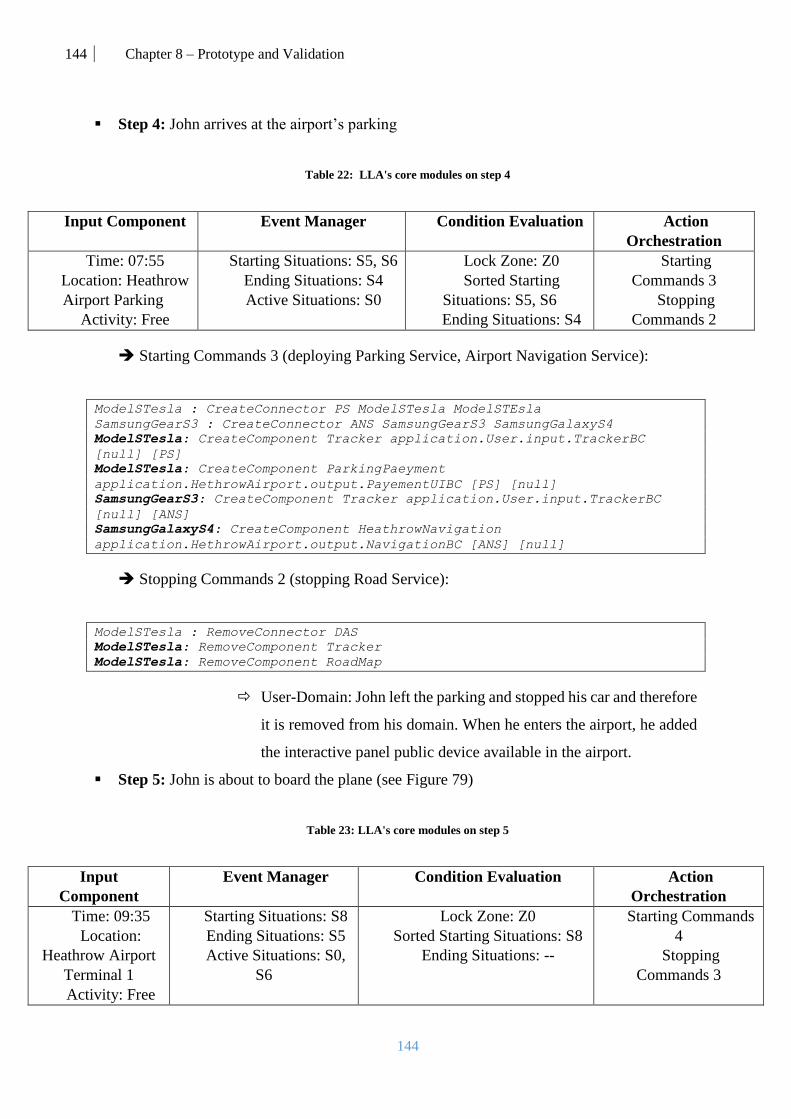
144 Chapter 8 – Prototype and Validation
144
Step 4: John arrives at the airport’s parking
Table 22: LLA's core modules on step 4
Input Component Event Manager Condition Evaluation Action
Orchestration
Time: 07:55
Location: Heathrow
Airport Parking
Activity: Free
Starting Situations: S5, S6
Ending Situations: S4
Active Situations: S0
Lock Zone: Z0
Sorted Starting
Situations: S5, S6
Ending Situations: S4
Starting
Commands 3
Stopping
Commands 2
Starting Commands 3 (deploying Parking Service, Airport Navigation Service):
ModelSTesla : CreateConnector PS ModelSTesla ModelSTEsla
SamsungGearS3 : CreateConnector ANS SamsungGearS3 SamsungGalaxyS4
ModelSTesla: CreateComponent Tracker application.User.input.TrackerBC
[null] [PS]
ModelSTesla: CreateComponent ParkingPaeyment
application.HethrowAirport.output.PayementUIBC [PS] [null]
SamsungGearS3: CreateComponent Tracker application.User.input.TrackerBC
[null] [ANS]
SamsungGalaxyS4: CreateComponent HeathrowNavigation
application.HethrowAirport.output.NavigationBC [ANS] [null]
Stopping Commands 2 (stopping Road Service):
ModelSTesla : RemoveConnector DAS
ModelSTesla: RemoveComponent Tracker
ModelSTesla: RemoveComponent RoadMap
User-Domain: John left the parking and stopped his car and therefore
it is removed from his domain. When he enters the airport, he added
the interactive panel public device available in the airport.
Step 5: John is about to board the plane (see Figure 79)
Table 23: LLA's core modules on step 5
Input
Component
Event Manager Condition Evaluation Action
Orchestration
Time: 09:35
Location:
Heathrow Airport
Terminal 1
Activity: Free
Starting Situations: S8
Ending Situations: S5
Active Situations: S0,
S6
Lock Zone: Z0
Sorted Starting Situations: S8
Ending Situations: --
Starting Commands
4
Stopping
Commands 3
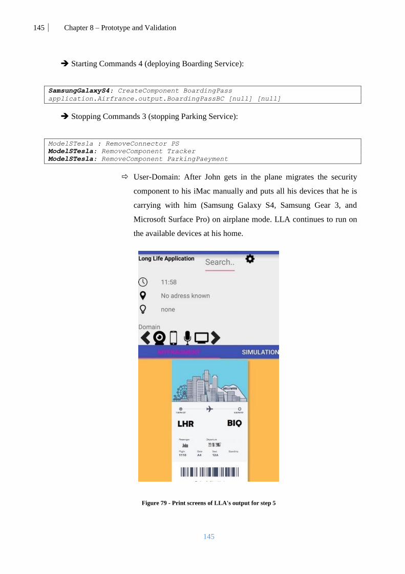
145 Chapter 8 – Prototype and Validation
145
Starting Commands 4 (deploying Boarding Service):
SamsungGalaxyS4: CreateComponent BoardingPass
application.Airfrance.output.BoardingPassBC [null] [null]
Stopping Commands 3 (stopping Parking Service):
ModelSTesla : RemoveConnector PS
ModelSTesla: RemoveComponent Tracker
ModelSTesla: RemoveComponent ParkingPaeyment
User-Domain: After John gets in the plane migrates the security
component to his iMac manually and puts all his devices that he is
carrying with him (Samsung Galaxy S4, Samsung Gear 3, and
Microsoft Surface Pro) on airplane mode. LLA continues to run on
the available devices at his home.
Figure 79 - Print screens of LLA's output for step 5

146 Chapter 8 – Prototype and Validation
146
Step 6: John is on the plane (see Figure 80).
Table 24: LLA's main modules results for step 6
Input
Component
Event Manager Condition Evaluation Action Orchestration
Time: 10:05
Location: Unknown
Activity: Flight to
Biarritz
Starting Situations: S9
Ending Situations: S8, S6
Active Situations: S0
Lock Zone: Z1
Sorted Starting Situations: S9
Ending Situations: S8, S6
Starting Commands 5
Stopping Commands 4
Migration Commands
1
Migration Commands 1 (migrating House Alarm Security; done manually by John):
SamsungGearS3 : SendComponent SecurityStatus iMac
Starting Commands 5 (deploying Music Service):
SamsungGalaxyS4: CreateComponent MusicPlayer
application.Deezer.output.MusicPlayerBC [null] [null]
Stopping Commands 4 (stopping Airport Navigation Service):
SamsungGearS3 : RemoveConnector ANS
ModelSTesla: CreateComponent Tracker
ModelSTesla: CreateComponent HeathrowNavigation
User-Domain: After John gets in the plane he puts all his devices that
he is carrying with him (Samsung Galaxy S4, Samsung Gear 3, and
Microsoft Surface Pro) on airplane mode. LLA continues to run on
the available devices at his home.
Figure 80 - Print screens of LLA's output for step 6
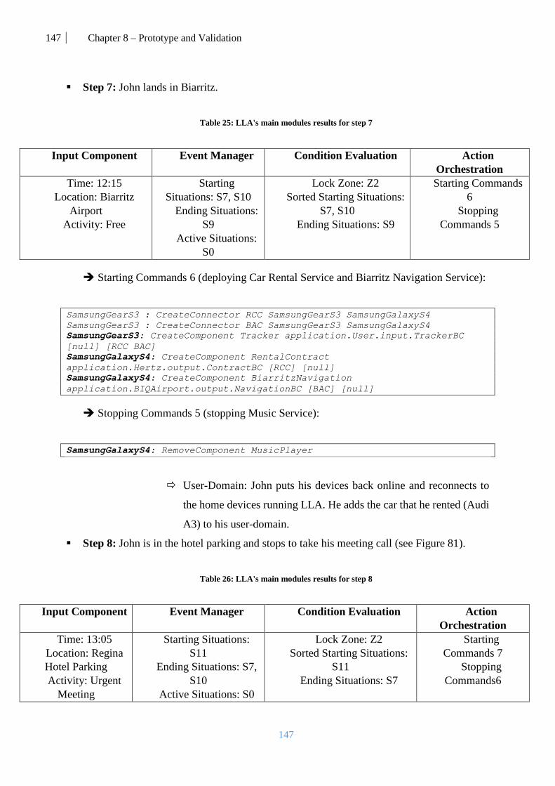
147 Chapter 8 – Prototype and Validation
147
Step 7: John lands in Biarritz.
Table 25: LLA's main modules results for step 7
Input Component Event Manager Condition Evaluation Action
Orchestration
Time: 12:15
Location: Biarritz
Airport
Activity: Free
Starting
Situations: S7, S10
Ending Situations:
S9
Active Situations:
S0
Lock Zone: Z2
Sorted Starting Situations:
S7, S10
Ending Situations: S9
Starting Commands
6
Stopping
Commands 5
Starting Commands 6 (deploying Car Rental Service and Biarritz Navigation Service):
SamsungGearS3 : CreateConnector RCC SamsungGearS3 SamsungGalaxyS4
SamsungGearS3 : CreateConnector BAC SamsungGearS3 SamsungGalaxyS4
SamsungGearS3: CreateComponent Tracker application.User.input.TrackerBC
[null] [RCC BAC]
SamsungGalaxyS4: CreateComponent RentalContract
application.Hertz.output.ContractBC [RCC] [null]
SamsungGalaxyS4: CreateComponent BiarritzNavigation
application.BIQAirport.output.NavigationBC [BAC] [null]
Stopping Commands 5 (stopping Music Service):
SamsungGalaxyS4: RemoveComponent MusicPlayer
User-Domain: John puts his devices back online and reconnects to
the home devices running LLA. He adds the car that he rented (Audi
A3) to his user-domain.
Step 8: John is in the hotel parking and stops to take his meeting call (see Figure 81).
Table 26: LLA's main modules results for step 8
Input Component Event Manager Condition Evaluation Action
Orchestration
Time: 13:05
Location: Regina
Hotel Parking
Activity: Urgent
Meeting
Starting Situations:
S11
Ending Situations: S7,
S10
Active Situations: S0
Lock Zone: Z2
Sorted Starting Situations:
S11
Ending Situations: S7
Starting
Commands 7
Stopping
Commands6

148 Chapter 8 – Prototype and Validation
148
Starting Commands 7 (deploying Skype Service):
SamsungGalaxyS4 : CreateConnector TFC SamsungGalaxyS4 AudiA3
SamsungGalaxyS4 : CreateConnector PFC SamsungGalaxyS4 AudiA3
SamsungGalaxyS4 : CreateConnector VFC SamsungGalaxyS4 AudiA3
AudiA3 : CreateConnector SOSC AudiA3 AudiA3
AudiA3 : CreateConnector UIOSC AudiA3 AudiA3
SamsungGalaxyS4: CreateComponent TextFeed
application.Skype.input.KeyboardBC [null] [TFC]
SamsungGalaxyS4: CreateComponent VoiceFeed
application.Skype.input.KeyboardBC [null] [VFC]
SamsungGalaxyS4: CreateComponent PictureFeed
application.Skype.input.KeyboardBC [null] [PFC]
AudiA3: CreateComponent SkypeCore application.Skype.core.SkypeBC [TFC VFC
PFC] [SOSC UIOSC]
AudiA3: CreateComponent ChatSound application.Skype.output.SoundBC [SOSC]
[null]
AudiA3: CreateComponent SkypeUI application.Skype.output.SkypeUIBC [UIOSC]
[null]
Stopping Commands 6 (stopping Car Rental Service):
SamsungGearS3 : RemoveConnector RCC
SamsungGearS3 : RemoveConnector BAC
SamsungGearS3: RemoveComponent Tracker
SamsungGalaxyS4: RemoveComponent RentalContract
SamsungGalaxyS4: RemoveComponent RentalContract
User-Domain: While the Skype Service is running, the
SamsungGalaxyS4 phone host components that take the camera and
microphone which changes these capabilities’ availability to Taken.
Figure 81 - Print screens of LLA's output for step 7
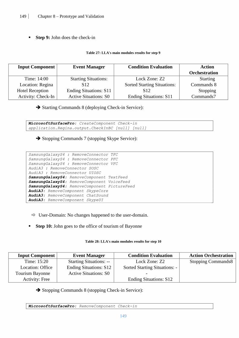
149 Chapter 8 – Prototype and Validation
149
Step 9: John does the check-in
Table 27: LLA's main modules results for step 9
Input Component Event Manager Condition Evaluation Action
Orchestration
Time: 14:00
Location: Regina
Hotel Reception
Activity: Check-In
Starting Situations:
S12
Ending Situations: S11
Active Situations: S0
Lock Zone: Z2
Sorted Starting Situations:
S12
Ending Situations: S11
Starting
Commands 8
Stopping
Commands7
Starting Commands 8 (deploying Check-in Service):
MicrosoftSurfacePro: CreateComponent Check-in
application.Regina.output.CheckInBC [null] [null]
Stopping Commands 7 (stopping Skype Service):
SamsungGalaxyS4 : RemoveConnector TFC
SamsungGalaxyS4 : RemoveConnector PFC
SamsungGalaxyS4 : RemoveConnector VFC
AudiA3 : RemoveConnector SOSC
AudiA3 : RemoveConnector UIOSC
SamsungGalaxyS4: RemoveComponent TextFeed
SamsungGalaxyS4: RemoveComponent VoiceFeed
SamsungGalaxyS4: RemoveComponent PictureFeed
AudiA3: RemoveComponent SkypeCore
AudiA3: RemoveComponent ChatSound
AudiA3: RemoveComponent SkypeUI
User-Domain: No changes happened to the user-domain.
Step 10: John goes to the office of tourism of Bayonne
Table 28: LLA's main modules results for step 10
Input Component Event Manager Condition Evaluation Action Orchestration
Time: 15:20
Location: Office
Tourism Bayonne
Activity: Free
Starting Situations: --
Ending Situations: S12
Active Situations: S0
Lock Zone: Z2
Sorted Starting Situations: -
-
Ending Situations: S12
Stopping Commands8
Stopping Commands 8 (stopping Check-in Service):
MicrosoftSurfacePro: RemoveComponent Check-in
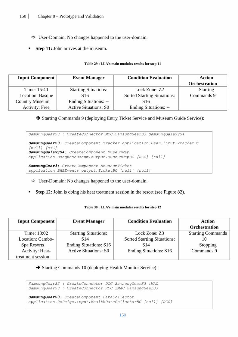
150 Chapter 8 – Prototype and Validation
150
User-Domain: No changes happened to the user-domain.
Step 11: John arrives at the museum.
Table 29 : LLA's main modules results for step 11
Input Component Event Manager Condition Evaluation Action
Orchestration
Time: 15:40
Location: Basque
Country Museum
Activity: Free
Starting Situations:
S16
Ending Situations: --
Active Situations: S0
Lock Zone: Z2
Sorted Starting Situations:
S16
Ending Situations: --
Starting
Commands 9
Starting Commands 9 (deploying Entry Ticket Service and Museum Guide Service):
SamsungGearS3 : CreateConnector MTC SamsungGearS3 SamsungGalaxyS4
SamsungGearS3: CreateComponent Tracker application.User.input.TrackerBC
[null] [MTC]
SamsungGalaxyS4: CreateComponent MuseumMap
application.BasqueMeuseum.output.MuseumMapBC [RCC] [null]
SamsungGear3: CreateComponent MeuseumTicket
application.BABEvents.output.TicketBC [null] [null]
User-Domain: No changes happened to the user-domain.
Step 12: John is doing his heat treatment session in the resort (see Figure 82).
Table 30 : LLA's main modules results for step 12
Input Component Event Manager Condition Evaluation Action
Orchestration
Time: 18:02
Location: Cambo-
Spa Resorts
Activity: Heat-
treatment session
Starting Situations:
S14
Ending Situations: S16
Active Situations: S0
Lock Zone: Z3
Sorted Starting Situations:
S14
Ending Situations: S16
Starting Commands
10
Stopping
Commands 9
Starting Commands 10 (deploying Health Monitor Service):
SamsungGearS3 : CreateConnector DCC SamsungGearS3 iMAC
SamsungGearS3 : CreateConnector RCC iMAC SamsungGearS3
SamsungGearS3: CreateComponent DataCollector
application.DePaige.input.HealthDataCollectorBC [null] [DCC]
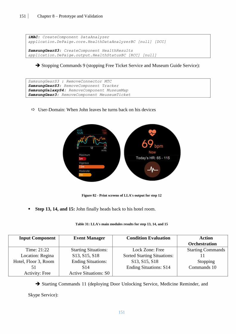
151 Chapter 8 – Prototype and Validation
151
iMAC: CreateComponent DataAnalyzer
application.DePaige.core.HealthDataAnalyzerBC [null] [DCC]
SamsungGearS3: CreateComponent HealthResults
application.DePaige.output.HealthStatusBC [RCC] [null]
Stopping Commands 9 (stopping Free Ticket Service and Museum Guide Service):
SamsungGearS3 : RemoveConnector MTC
SamsungGearS3: RemoveComponent Tracker
SamsungGalaxyS4: RemoveComponent MuseumMap
SamsungGear3: RemoveComponent MeuseumTicket
User-Domain: When John leaves he turns back on his devices
Figure 82 - Print screens of LLA's output for step 12
Step 13, 14, and 15: John finally heads back to his hotel room.
Table 31: LLA's main modules results for step 13, 14, and 15
Input Component Event Manager Condition Evaluation Action
Orchestration
Time: 21:22
Location: Regina
Hotel, Floor 3, Room
51
Activity: Free
Starting Situations:
S13, S15, S18
Ending Situations:
S14
Active Situations: S0
Lock Zone: Free
Sorted Starting Situations:
S13, S15, S18
Ending Situations: S14
Starting Commands
11
Stopping
Commands 10
Starting Commands 11 (deploying Door Unlocking Service, Medicine Reminder, and
Skype Service):

152 Chapter 8 – Prototype and Validation
152
MicrosoftSurfacePro :CreateConnector TFC MicrosoftSurfacePro
MicrosoftSurfacePro
MicrosoftSurfacePro : CreateConnector PFC MicrosoftSurfacePro
MicrosoftSurfacePro
MicrosoftSurfacePro : CreateConnector VFC MicrosoftSurfacePro
MicrosoftSurfacePro
MicrosoftSurfacePro : CreateConnector SOSC MicrosoftSurfacePro Sony-KDL-
43W805
MicrosoftSurfacePro : CreateConnector UIOSC MicrosoftSurfacePro Sony-KDL-
43W805
SamsungGalaxyS4: CreateComponent DoorLock
application.ReginaHotel.output.LockBC [null] [null]
SamsungGearS3: CreateComponent MedecineReminder
application.DrPaiger.output.ReminderBC [null] [null]
MicrosoftSurfacePro: CreateComponent TextFeed
application.Skype.input.KeyboardBC [null] [TFC]
MicrosoftSurfacePro: CreateComponent VoiceFeed
application.Skype.input.KeyboardBC [null] [VFC]
MicrosoftSurfacePro: CreateComponent PictureFeed
application.Skype.input.KeyboardBC [null] [PFC]
Sony-KDL-43W805: CreateComponent SkypeCore application.Skype.core.SkypeBC
[TFC VFC PFC] [SOSC UIOSC]
Sony-KDL-43W805: CreateComponent ChatSound application.Skype.output.SoundBC
[SOSC] [null]
Sony-KDL-43W805: CreateComponent SkypeUI application.Skype.output.SkypeUIBC
[UIOSC] [null]
Stopping Commands 10 (stopping Health Monitor Service):
SamsungGearS3 : RemoveConnector DCC
SamsungGearS3 : RemoveConnector RCC
SamsungGearS3: RemoveComponent DataCollector
iMAC: RemoveComponent DataAnalyzer
SamsungGearS3: RemoveComponent HealthResults
User-Domain: I the hotel room, John adds the Sony-Tv to his personal user-domain in
order to use it with LLA.
To summarize, this scenario proves the feasibility and usability of our proposal with all
its aspects (context-awareness, distribution, injection, etc.).

153 Chapter 8 – Prototype and Validation
153
3. Results and validation
3.1. Performance validation
The management of the scenario described in this Chapter involves many different
mechanisms. Thus, we present in this section the results obtained after implementing the
proposed architecture (see Chapter 3) and testing it on an Android device (Samsung Galaxy S4
running Android 5.0.1 on an ARMv7 processor and 2GB RAM).
For evaluation purposes, in the developed prototype we have included a generator that
creates a specified number of situations. We injected the considered scenario described above
into the situation generator, and we ran the application while simulating the location, time and
activity of the user.
For this experiment, we set up a time-frequency for data extraction (Input Component,
IC) of 20 seconds and a location frequency of 10 meters (i.e., the data extraction is triggered
when the user moves 10 meters). On the user's device, all other apps (except the mock location
app) were disabled, the GPS was activated, the Wi-Fi was activated, and the battery was
plugged.
We simulated a scalability experiment for different numbers of situations, and we
calculated and observed the following metrics: the average CPU usage when the app is launched
and while it is running later, the average memory usage while the app is running, the response
time values:
Start-Parse: The time that took the app to launch/generate/parse
Extract-Detect: The time that it took from the moment that the IC sent the
detected data until the situation was detected.
Detect-React: The time since the situation is detected until the services are
physically launched on the user’s devices.
We also present the accuracy of situation detection which represents the percentage of
detecting the correct situation. The main performance results are shown in Table 32. Besides,
we also verified that the situations were correctly detected.
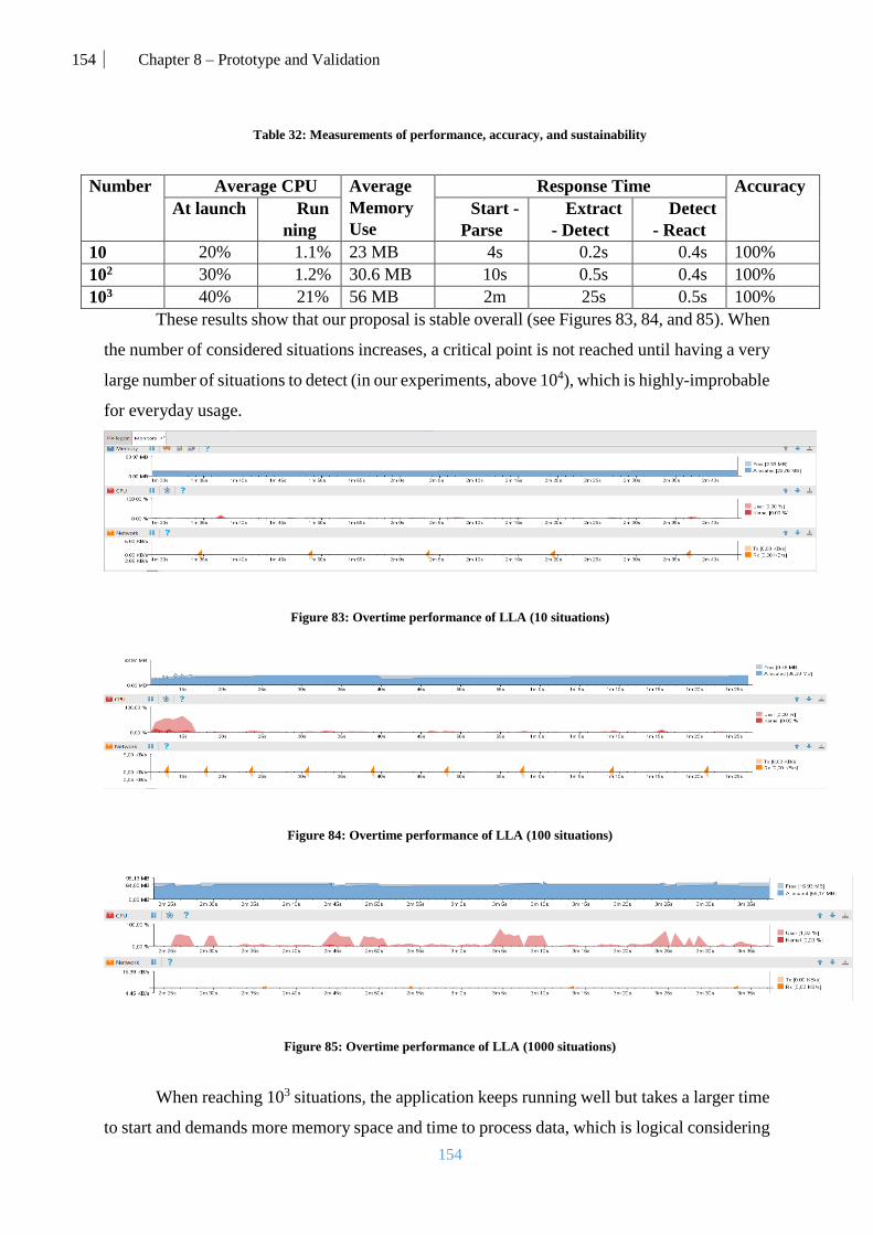
154 Chapter 8 – Prototype and Validation
154
Table 32: Measurements of performance, accuracy, and sustainability
Number Average CPU Average
Memory
Use
Response Time Accuracy
At launch Run
ning
Start -
Parse
Extract
- Detect
Detect
- React
10 20% 1.1% 23 MB 4s 0.2s 0.4s 100%
102 30% 1.2% 30.6 MB 10s 0.5s 0.4s 100%
103 40% 21% 56 MB 2m 25s 0.5s 100%
These results show that our proposal is stable overall (see Figures 83, 84, and 85). When
the number of considered situations increases, a critical point is not reached until having a very
large number of situations to detect (in our experiments, above 104), which is highly-improbable
for everyday usage.
Figure 83: Overtime performance of LLA (10 situations)
Figure 84: Overtime performance of LLA (100 situations)
Figure 85: Overtime performance of LLA (1000 situations)
When reaching 103 situations, the application keeps running well but takes a larger time
to start and demands more memory space and time to process data, which is logical considering

155 Chapter 8 – Prototype and Validation
155
the complexity and possible combinations of situations. Nonetheless, even if this number is
high (2 minutes) it is only done when starting the application for the first time or when there is
a major change in the situations file.
Besides, this is not a final product, but a prototype and the performance is expected to
increase when the architecture is deployed in a real user domain using more advanced devices
(e.g., high-end smartphones or computers). The experiments that we have performed show the
feasibility, scalability, and sustainability of our proposal.
3.2. Time and storage gain
Using LLA, users don’t have to download applications an all the devices that they
possess. This offers a considerable amount of data and memory gain compared to the classic
approach of duplicating the application everywhere, which requires the updates to be done on
all the devices.
In LLA, the component-based services require updates to be done separately and in a
centralized way towards the user’s cloud persistence layer. In order to calculate this gain, we
consider the services used in John’s scenario and we compared to using the current approach
of downloading those services as stand-alone applications.
In order to measure this gain, we compare LLA to the classical approach (currently used
mobile applications). This comparison is done by considering an estimate of the required
storage size and the time required for the different operations (install/update/delete).
For LLA the real storage size on the device is the size of the basic application (ECA
core components size = 10 MB) which is installed on John’s 11 devices (see Table 19). Even
though, the services that LLA uses come from the cloud persistence layer, we consider in this
calculation that the user downloaded locally all the services in order to use them offline across
his/her devices.
Size of LLA = (Size of core components* Number of devices) + Size of services.
For the classical approach, John has to download all the applications on all the devices.
For this calculation, we consider applications related to the services. For example, a Map
Service in LLA is equivalent to an application like Google Maps. We also consider an average
size of the application since the sizes vary according to the device it is installed on. For example,
Skype installed on Android require, on the estimate, 96.28 MB but 88.8 MB on a computer
(Windows) so we consider the round average of 92MB.
Size of Classical approach = Number of devices * Size of applications

156 Chapter 8 – Prototype and Validation
156
The operation time aspect represents the time taken by John to download, install LLA,
configure it, update it, and deleting it. For the classical approach, it represents the time taken
by John to download, install, update, and delete all the different applications on all the devices.
For these calculations, we consider the Samsung Galaxy S4 device and an internet speed of
4.29 MB/s.
Table 33: Comparison of LLA and classical mobile store approach
LLA Classical approach
Overall Size 374 MB 2904 MB
Total Download 01:29 11: 40
Installation Time 00:23 01:33:30
Total Delete Time 00:02 00:22
Total Update (Delete +
Download + Installation) Time 01:54 01:45:32
These results (see Table 33) demonstrate that using LLA offers a considerable amount
of time and storage gain due to its dynamicity and the distributed nature of its services.
4. Conclusion
In this chapter, we demonstrated the feasibility of our proposal. Long Life Application
is a concept that requires major changes in the way we consider mobile applications. Compared
to the currently used mobile store system of multiple stand-alone applications, our solution
targets specific services towards the users only when they need them.
These changes will push developers to think in terms of context awareness and therefore
provide more personalized user experiences. From the point of view of the user, LLA gives the
possibility to have a richer, open, and hands-free experience.
Another factor that we defended in this chapter is the sustainability and performance of
our proposal regardless of the large diversity of possibilities existing inside the connected-
environment of the user.

157 Chapter 9 – Conclusions and future work
157
Chapter 9 – Conclusions and future work

158 Chapter 9 – Conclusions and future work
158
The proposal presented in this Ph.D. work is an innovative concept. Proposing only
ONE application per user, to perform all his/her tasks and manage transparently all the
functionalities, is an ideal solution not available nowadays. The utopian future where mobile
apps will know what we need, even before we interact with them, is approaching. In this sense,
many research works are oriented to the development of those future apps and they found out
that contextual awareness is essential to the survival of mobile applications.
Our proposal for this is called Long-life Application, a name that reflects the nature of
the continuity and evolution that we demonstrate clearly in our scenario. This application will
evolve while running according to the users’ needs (personal and/or professional) and will
provide continuously relevant context-adapted services.
A relevant aspect of the proposed application is the adequate detection of the context.
For that purpose, the long-life application incorporates a rich situation model that considers any
type of combination of three dimensions (time, location, and activity) to represent different
context situations where users can be involved. Furthermore, it also incorporates an innovative
cross-device context detection mechanism. This support for multiple devices enhances the
capability to detect situations, anywhere and anytime, as data captured from different devices
and sensors can be combined.
Moreover, LLA incorporates a dynamic injection mechanism allowing users,
developers, and other entities, to expand the application and customize it according to the user’s
specific needs. This contribution presents the main novelty of our proposal in the mobile
context-aware mobile world.
In a world where users are surrounded by smart objects, users have higher expectations
from their apps. This evolution pushes the need to have an application able to consider the
connected-world of the user. In this scope, LLA is able to deploy and distribute its services, if
needed, among the different devices that the user is operating while hiding their heterogeneity
by using Kalimucho.
To summarize, our proposal provides a mechanism able to detect, formalize and
understand the user’s context. It provides a set of components working simultaneously and
transparently in order to inject, detect and understand situations regardless of its source. Also,
it is a suitable solution for the common case of a user with multiple devices, as he/she is not
obliged to manage only one specific device. It takes into account the multiplicity of devices and
orchestrates the services of the application accordingly. It offers a new user experience that
reflects the technological advances that we are witnessing every day.

159 Chapter 9 – Conclusions and future work
159
Nonetheless, there is much work that could be done to improve LLA and make even
more efficient for its users.
As future lines for this work, a process that identifies the semantics from either locations
or events could be integrated. It should categorize them according to different semantic domains
(sport, lifestyle, entertainment, etc.) in order to infer appropriate services.
Another major improvement that could be considered to improve the dynamicity of the
application would be to integrate an intelligent situation recommender based on machine/deep
learning based algorithm that digs deeper into the personality of the user in order to propose
more personal situations.
Moreover, with the advancement of technology and the riser of green and energy-aware
computing, we must take into consideration this important area which is in the center of smart-
environments. This perspective could bring LLA to next age of power-efficiency and present
to the world as an application that deeply cares about the environment.
Last but not least, we cannot discuss IoT without bringing the issue of security. The
security issue is a non-ending conflict between hackers and programmers. Although LLA uses
Kalimucho’s encryption-key system to securely transfer data, it lacks its own security layers
and protocols that ensure the anonymity and protection of a user possessing multiple devices
inside a non-secured network. This is an important issue to consider to its importance for every
user, especially when he is managing more than one device and when he relies most of the time
on information transfer between his/her devices.
LLA proposal, somehow, may imply a revolution in the way we interact with computers,
as we propose a single long-life application that adapts itself dynamically to the current
situation. This application is still on a prototype level based on thorough research on the related
domains. But the promising results that we acquired made us consider pushing it to a
commercial level and contacting possible investors and providers.

160 Bibliography
160
Bibliography
[1] 24me, https://www.twentyfour.me/ [Online; accessed 06-December-2017].
[2] Akman, Varol, and Mehmet. S. "The use of situation theory in context modeling." Computational
Intelligence: An International Journal 13.3: 427-438. 1997.
[3] Amy L. Murphy, Gian Pietro Picco, Gruia-Catalin Roman, LIME: A Middleware for Physical
and Logical Mobility, Proceedings of the 21st International Conference on Distributed Computing,
524—533, 2001.
[4] Antero. T, Tommi. M, and Kari Syst¨a. Liquid software manifesto: the era of multiple device
ownership and its implications for software architecture. In 38th Annual Computer Software and
Applications Conference (COMPSAC), pages 338–343. IEEE, 2014.
[5] AppAnnie, App Annie 2016 Retrospective Research\Analyze, 2017.
[6] Apple, https://www.apple.com/tn/imac/ [Online; accessed 06-December-2017].
[7] Audi, http://www.audi.fr/fr/web/fr/gamme/a3/a3.html [Online; accessed 06-December-2017].
[8] Autili, Marco, Paola Inverardi, and Massimo Tivoli. "CHOREOS: large scale choreographies for
the future internet." Software Maintenance, Reengineering and Reverse Engineering (CSMR-WCRE),
2014 Software Evolution Week-IEEE Conference on. IEEE, 2014.
[9] Bailey, James, et al. "An event-condition-action language for XML." Web Dynamics. Springer
Berlin Heidelberg. 223-248. 2004.
[10] Bakken, David. "Middleware." Encyclopedia of Distributed Computing 11” (2001).
[11] Ben Abdesslem, F., Phillips, A., & Henderson, T. (2009, August). Less is more: energy-efficient
mobile sensing with senseless. In Proceedings of the 1st ACM workshop on Networking, systems, and
applications for mobile handhelds (pp. 61-62). ACM.
[12] Boujbel, Raja, et al. "Muscadel: A deployment dsl based on a multiscale characterization
framework." Computer Software and Applications Conference Workshops (COMPSACW), 2014 IEEE
38th International. IEEE, 2014.
[13] Cecilia Mascolo, Licia Capra, Stefanos Zachariadis and Wolfgang Emmerich, xmiddle: A Data-
Sharing Middleware for Mobile Computing, Wireless Personal Communications, 77—103, 2002
[14] Cheverst, Keith and Davies, Nigel and Mitchell, Keith and Friday, Adrian and Efstratiou,
Christos. Developing a context-aware electronic tourist guide: some issues and experiences. Proceedings
of the SIGCHI conference on Human Factors in Computing Systems, pages 17—24. ACM, 2000.
[15] CHEN, P.-S. The entity-relationship model - toward a unified view of data. ACM Transaction
on Database Systems 1, 1, 9–36. 1976.
161 Bibliography
161
[16] Chia-Chen Chen and Tien-Chi Huang. Learning in a u-museum: Developing a context-aware
ubiquitous learning environment. Computers & Education, 59(3):873–883, 2012.
[17] CHTCHERBINA, E., AND FRANZ, M. Peer-to-peer coordination framework (p2pc): Enabler
of mobile ad-hoc networking for medicine, business, and entertainment. In Proceedings of International
Conference on Advances in Infrastructure for Electronic Business, Education, Science, Medicine, and
Mobile Technologies on the Internet (SSGRR2003w), 2003.
[18] Clarke, Siobhán, and Cormac Driver. "Context-aware trails [mobile
computing]." Computer 37.8: 97-99. 2004.
[19] Clarke, Cormac Driver Siobhán. "Hermes: Generic Designs for Mobile, Context-Aware Trails-
Based Applications.» 2004.
[20] Coding Horror, https://blog.codinghorror.com/lazyweb-calling/ [Online; accessed 06-
December-2017].
[21] Crunchbase, https://www.crunchbase.com/organization/grokr#/entity [Online; accessed 06-
December-2017].
[22] Crunchbase, https://www.crunchbase.com/organization/osito#/entity [Online; accessed 06-
December-2017].
[23] Da, Keling, Marc Dalmau, and Philippe Roose. "Kalimucho: Middleware for mobile
applications." Proceedings of the 29th Annual ACM Symposium on Applied Computing. ACM, 2014.
[24] Dave Evans. The internet of things: How the next evolution of the internet is changing
everything. Technical report, Cisco, 2011.
[25] David, Pierre-Charles, and Thomas Ledoux. "WildCAT: a generic framework for context-aware
applications." Proceedings of the 3rd international workshop on Middleware for pervasive and ad-hoc
computing. ACM, 2005.
[26] de Oliveira, L., and A. Loureiro. "CodeDroid: A Framework to Develop Context-Aware
Applications." The Fourth International Conferences on Advances in Human-oriented and Porsonalized
Mechanisms, Technologies, and Services. 2011.
[27] Dey, Anind K., Gregory D. Abowd, and Andrew Wood. "CyberDesk: A framework for
providing self-integrating context-aware services." Knowledge-Based Systems 11.1: 3-13. 1998.
[28] D. Gelernter. Generative Communication in Linda. ACM Computing Surveys, 7(1):80–112,
Jan. 1985.
[29] Edison.tech https://www.easilydo.com/ [Online; accessed 06-December-2017].
[30] Elmalaki, Salma, Lucas Wanner, and Mani Srivastava. "Caredroid: Adaptation framework for
android context-aware applications." Proceedings of the 21st Annual International Conference on
Mobile Computing and Networking. ACM, 2015.
[31] Endsley, M. R., Bolte, B., & Jones, D. G. Designing for situation awareness: an approach to
user-centered design. Boca Raton, FL: CRC Oress. 2003.
162 Bibliography
162
[32] E. Bouix, M. Dalmau, P. Roose F. Luthon - A Multimedia Oriented Component Model - AINA
2005 - The IEEE 19th International Conference on Advanced Information Networking and Applications
- Tamkang University, Taiwan - March 28 - March 30, 2005.
[33] E. Bruneton, T. Coupaye, M. Leclercq, V. Quema, and J.-B. Stefani, I. Crnkovic, J. A. Stafford,
H. W. Schmidt, and K. Wallnau, An open component model and its support in java. In Proceedings of
the 7th International Symposium on Component-Based Software Engineering (CBSE 2004), volume
3054, pages 7–22, Edinburgh, Scotland, Springer-Verlag. 2004.
[34] Fatoohi, Rod, David McNab, and David Tweten. "Middleware for Building Distributed
Applications Infrastructure." Report NAS-97-026, 1997.
[35] Floch, J., Hallsteinsen S., Stav E., Eliassen E., Lund K., Gjørven E.: Using architecture models
for runtime adaptability. IEEE Software, 23, 2, 62–70. 2006.
[36] Flybits, https://flybits.com/ [Online; accessed 06-December-2017]
[37] Forbes, https://www.forbes.com/sites/joshbersin/2012/08/16/the-move-from-systems-of-
record-to- systems-of-engagement/#72fdafe647f5 [Offline; accessed 06-December-2017].
[38] Gheith, A., et al. "IBM Bluemix Mobile Cloud Services." IBM Journal of Research and
Development 60.2-3: 7-1. 2016.
[39] Glassey, R., Stevenson, G., Richmond, M., Nixon, P., Terzis, S., Wang, F., Ferguson R. I.:
Towards a Middleware for Generalised Context Management. First International Workshop on
Middleware for Pervasive and Ad Hoc Computing, Middleware, 2003.
[40] Google, https://www.google.com/intl/fr/landing/now/ [Online; accessed 06-December-2017]
[41] Google, https://developer.android.com/topic/instant-apps/overview.html [Online; accessed 06-
December-2017].
[42] Google Play, https://play.google.com/store/apps/details?id= ru.gavrikov.mocklocations&hl=fr
[Online; accessed 06-December-2017].
[43] GRUBER, T. G. A translation approach to portable ontologies. Knowledge Acquisition 5, 2,
199–220. 1993.
[44] Chihani, B., Bertin, E., & Crespi, N. A user-centric context-aware mobile assistant.
In Intelligence in Next Generation Networks (ICIN), 2013 17th International Conference on (pp. 110-
117). IEEE. 2013.
[45] GsmArena, http://www.gsmarena.com/samsung_gear_s3_classic-8309.php [Online; accessed
06-December-2017].
[46] GsmArena, http://www.gsmarena.com/samsung_i9500_galaxy_s4-5125.php [Online; accessed
06-December-2017].
[47] Gu, Tao, et al. "An ontology-based context model in intelligent environments." Proceedings of
communication networks and distributed systems modeling and simulation conference. Vol. 2004. 2004.

163 Bibliography
163
[48] G. D. Abowd: “Software Engineering Issues for Ubiquitous Computing” Int. Conf. on Software
Engineering, Los Angeles, 1999.
[49] G. D. Abowd and E. D. Mynatt, “Charting past, present, and future research in ubiquitous
computing”, ACM Trans. Comput.-Hum. Interact. 7, 1, Pages 29 – 58, 2000.
[50] Hadim, Salem, and Nader Mohamed. "Middleware: Middleware challenges and approaches for
wireless sensor networks." IEEE distributed systems online 7.3: 2006.
[51] HALPIN, T. A. Information Modeling and Relational Databases: From Conceptual Analysis to
Logical Design. Morgan Kaufman Publishers, San Francisco, 2001.
[52] Harter, A., Hopper, A., Steggles, P., Ward, A., & Webster, P. (2002). The anatomy of a context-
aware application. Wireless Networks, 8(2/3), 187-197.
[53] Hofer, T., Schwinger, W., Pichler, M., Leonhartsberger, G., Altmann, J., & Retschitzegger, W.
Context-awareness on mobile devices-the hydrogen approach. In System Sciences, 2003. Proceedings
of the 36th Annual Hawaii International Conference on (pp. 10-pp). IEEE. 2003.
[54] Hp Customer Support, https://support.hp.com/ca-en/document/c05349072 [Online; accessed
06-December-2017].
[55] INDULSKA, J., ROBINSONA, R., RAKOTONIRAINY, A., AND HENRICKSEN, K.
Experiences in using cc/pp in context-aware systems. In LNCS 2574: Proceedings of the 4th
International Conference on Mobile Data Management (MDM2003), M.-S. Chen, P. K. Chrysanthis, M.
Sloman, and A. Zaslavsky, Eds., Lecture Notes in Computer Science (LNCS), Springer, pp. 247–261.
2003.
[56] Israel J. Mojica, Bram Adams, Meiyappan Nagappan, Steffen Dienst, Thorsten Berger, Ahmed
E. Hassan, A Large Scale Empirical Study on Software Reuse in Mobile Apps, IEEE Software Vol. 31
No. 2 Pg. 78--86, 2014.
[57] Jeffrey S. Pierce and Jeffrey Nichols. An infrastructure for extending applications' user
experiences across multiple personal devices. In Proceedings of the 21st annual ACM symposium on
User interface software and technology (UIST '08). ACM, New York, NY, USA, 101-110, 2008.
[58] João Pedro Sousa and David Garlan, Aura: An Architectural Framework for User Mobility in
Ubiquitous Computing Environments, Software Architecture: System Design, Development and
Maintenance, World Computer Congress, Conference on Software Architecture, August 25-30,
Montreal, Canada, 2002.
[59] Karchoud, R., Roose, P., Dalmau, M., de Courchelle, I., & Dibon, P. (2015, March). Kalimucho
for smart-∗: One step towards eternal applications. In Industrial Technology (ICIT), IEEE International
Conference on (pp. 2426-2432). 2015.
[60] Karchoud, R., Roose, P., Dalmau, M., Illaramendi, A., & Ilarri, S. Long Life Application:
Approach for User Context Management and Situation Understanding. In Ubiquitous Computing and

164 Bibliography
164
Communications and 2016 International Symposium on Cyberspace and Security (IUCC-CSS),
International Conference on (pp. 45-53). IEEE. 2016.
[61] Karchoud, R, ILLARRAMENDI, A, ILARRI, S, et al. Long-life application. Personal and
Ubiquitous Computing, p. 1-13, 2017.
[62] Karchoud, R, et al. "All for One and One For All: Dynamic Injection of Situations in a Generic
Context-Aware Application." Procedia Computer Science 113: 17-24, 2017.
[63] Ke Zhai and Boni Xu and W. K. Chan and T. H. Tse, CARISMA: a context-sensitive approach
to race-condition sample- instance selection for multithreaded applications, 221—231, International
Symposium on Software Testing and Analysis, {ISSTA}, 2012, Minneapolis, MN, USA, July 15-20,
2012.
[64] Khan, Zaheer, Saad Liaquat Kiani, and Kamran Soomro. "A framework for cloud-based context-
aware information services for citizens in smart cities." Journal of Cloud Computing 3.1 (2014): 14.
[65] Knappmeyer, Michael, et al. "Survey of context provisioning middleware." IEEE
Communications Surveys & Tutorials 15.3: 1492-1519, 2013.
[66] La, Hyun Jung, and Soo Dong Kim. "A conceptual framework for provisioning context-aware
mobile cloud services." Cloud Computing (CLOUD), 2010 IEEE 3rd International Conference on.
IEEE, 2010.
[67] MCCARTHY, J. Notes on formalizing contexts. In Proceedings of the Thirteenth International
Joint Conference on Artificial Intelligence, R. Bajcsy, Ed., Morgan Kaufmann, pp. 555–560, 1993.
[68] MCCARTHY, J., AND BUVACˇ. Formalizing context (expanded notes). In Working Papers of
the AAAI Fall Symposium on Context in Knowledge Representation and Natural Language, S. Buvacˇ
and Ł. Iwanska, ´ Eds., American Association for Artificial Intelligence, American Association for
Artificial Intelligence, pp. 99–135, 1997.
[69] Microsoft, https://developer.microsoft.com/fr-fr/windows/kinect/hardware [Online; accessed
06-December-2017].
[70] Microsoft, https://www.microsoft.com/fr-fr/surface/devices/surface-pro-4/overview [Online;
accessed 06-December-2017].
[71] Matthew Panzarino. Foursquares swarm and the rise of the invisible app.
https://www.techcrunch.com/2014/05/15/ foursquares-swarm-and-the-rise-of-the-invisible-app, 2014.
[Online; accessed 06-December-2017].
[72] Mobile News, John, 5th June 2014, http://www.appmachine.com/blog/apps-service-moving-
mobile-cloud/ [Online; accessed 06-December-2017].
[73] MrCoffee, http://www.mrcoffee.com/wemo-landing-page.html [Online; accessed 06-
December-2017].
[74] M. Weiser: "The Computer for the 21st Century", Scientific American, 265, 3, September 1991.
[75] Nakamichi, https://www.nakamichi-usa.com/ [Online; accessed 06-December-2017].
165 Bibliography
165
[76] Nakagawa, T., Doi, C., Ohta, K., & Inamura, H.. Customizable Context Detection for ECA rule-
based Context-aware Applications. ICMU, May, 30, 60. 2012.
[77] Nest, https://nest.com/smoke-co-alarm/tech-specs/ [Online; accessed 06-December-2017].
[78] Nest, https://nest.com/fr/cameras/nest-cam-iq-indoor/overview/ [Online; accessed 06-
December-2017].
[79] Omer B, Victoria B, and Henning S. Bridging communications and the physical world: Sense
everything, control everything. In GLOBECOM Workshops, pages 1735–1740. IEEE, 2010.
[80] Ovadia, S. "Automate the internet with “if this then that” (IFTTT)." Behavioral & Social
Sciences Librarian 33.4: 208-211, 2014.
[81] Perera, C, et al. "A survey on internet of things from industrial market perspective." IEEE
Access 2: 1660-1679, 2014.
[82] Perera, C, et al. "Context aware computing for the internet of things: A survey." IEEE
Communications Surveys & Tutorials 16.1, 414-454, 2014.
[83] P.-C. David. Développement de composants Fractal adaptatifs : un langage ddi l’aspect
d’adaptation. Phd thesis, Université de Nantes école des Mines de Nantes, July 2005.
[84] Romero, Daniel, et al. "An sca-based middleware platform for mobile devices." Enterprise
Distributed Object Computing Conference Workshops, 2008 12th. IEEE, 2008.
[85] R. Balter, S. Krakowiak , Bilan des activités du laboratoire et du pro jet Sirac , 18 décembre
2001, http://lig-membres.imag.fr/krakowia/Files/Publi/bilan-sirac.pdf [Online; accessed 06-December-
2017].
[86] Rouvoy, Romain, et al. "Composing components and services using a planning-based
adaptation middleware." International Conference on Software Composition. Springer Berlin
Heidelberg, 2008.
[87] Samsung, http://www.samsung.com/uk/business/interactive/education/ [Online; accessed 06-
December-2017].
[88] Scott Matteson, October 27, 2015 http://www.techrepublic.com/article/mobile-apps-need-
context-to-hit-the-right-targets/ [Online; accessed 06-December-2017]
[89] Shalabi, S. M., Doll, C. L., Reilly, J. D., & Shore, M. B. U.S. Patent Application No. 13/311,278,
2011.
[90] SHALABI, Sami M, DOLL, Cassandra Lynn, REILLY, James D., et al. Access control list.
U.S. Patent Application No 13/311,278, 5. 2011.
[91] Schilit B, Theimer M. Disseminating active map information to mobile hosts. Network,
IEEE. 8(5):22–32. 1994.
[92] SCHILIT, B. N., ADAMS, N. L., AND WANT, R. Context-aware computing applications. In
IEEE Workshop on Mobile Computing Systems and Applications (Santa Cruz, CA, US, 1994).

166 Bibliography
166
[93] Sony, https://www.sony.co.uk/electronics/support/televisions-projectors-lcd-tvs-android-/kdl-
43w805c/specifications, [Online; accessed 06-December-2017].
[94] Sosinsky, Barrie. Cloud computing bible. Vol. 762. John Wiley & Sons, 2010.
[95] Strang, T., Linnhoff-Popien, C.: A Context Modeling Survey. In: Workshop on Advanced
Context Modelling, Reasoning and Management, UbiComp, 2004
[96] Syer, Mark D., et al. "Exploring the development of micro-apps: A case study on the blackberry
and android platforms." Source Code Analysis and Manipulation (SCAM), 2011 11th IEEE
International Working Conference on. IEEE, 2011.
[97] Tempo, https://tempo.io/mobile/ [Online; accessed 06-December-2017].
[98] Tesla, https://www.tesla.com/models [Online; accessed 06-December-2017].
[99] Todd Grennan. Spring 2016 mobile customer retention report an analysis of retention by day.
Technical report, Appboy, 2016.
[100] Tommi Mikkonen, Kari Systa, and Cesare Pautasso. Towards liquid web applications. In
International Conference on Web Engineering (ICWE), pages 134–143. Springer, 2015.
[101] USCHOLD, M., AND GR¨UNINGER, M. Ontologies: Principles, methods, and applications.
Knowledge Engineering Review 11, 2, 93–155. 1996.
[102] Villamizar, Mario, et al. "Evaluating the monolithic and the microservice architecture pattern
to deploy web applications in the cloud." Computing Colombian Conference (10CCC), 2015 10th.
IEEE, 2015.
[103] W3C. Composite Capabilities / Preferences Profile (CC/PP). http://www.w3.org/Mo-
bile/CCPP [Online; accessed 06-December-2017]
[104] Wang, Miao-Miao, et al. "Middleware for wireless sensor networks: A survey." Journal of
computer science and technology 23.3: 305-326, 2008.
[105] Wasinger, Rainer, et al. "Scrutable user models and personalized item recommendation in
mobile lifestyle applications." International Conference on User Modeling, Adaptation, and
Personalization. Springer Berlin Heidelberg, 2013.
[106] WAPFORUM. User Agent Profile (UAProf). http://www.wapforum.org. [Online; accessed 06-
December-2017].
[107] Weber, S. Chromecast user’s manual: stream video, music, and everything else you love to
your TV. Weber Systems Inc. 2014.
[108] Yinmeng Zhang. 16 Mobile Mistakes That Plummet User Retention Rates.
https://apptimize.com/blog/2015/10/16-mobile-mistakes-that-plummet-user-retention-rates, 2015,
[Online; accessed 06-December-2017].
[109] Yves Bouchard, Contextual Logic and Epistemic Contexts, Springer, 2014.

167 Bibliography
167
[110] Zachariadis, Stefanos, Cecilia Mascolo, and Wolfgang Emmerich. "Satin: a component model
for mobile self organisation." On the Move to Meaningful Internet Systems 2004: CoopIS, DOA, and
ODBASE : 1303-1321, 2004.
[111] Zhao, Zhenzhen, Ji Liu, and Noel Crespi. "The design of activity-oriented social networking:
Dig-Event." Proceedings of the 13th International Conference on Information Integration and Web-
based Applications and Services. ACM, 2011.
168 Appendix 1
168
Appendix 1
Writing execution scripts Components in a Kalimucho application are not launched by themselves. This is achieved by
sending commands to the Kalimucho platform. This can be done either:
- By creating an initial deployment script file that will execute each time the
application is launched
- By creating a component that uses the platform service to send commands the
platforms.
The commands accepted by the platform are not solely to launch components, but can also
connect components, remove components, migrate components, etc. Below is the full list of
commands accepted by the platform and their parameters.
1. List of commands
a. Creating a component
CreateComponent name class [input input …] [output output …]
- name = the name of the component (symbolic name used by the platform to name it)
- class = the class of the component on the form: application.
package…nameOfTheClass
- [input …] = list of the names of the connectors linked to the inputs of the component
(will be [null] if the component as no input). Each element of the list can be :
- a name of connector if only one connector is linked to this input
- {c1 c2 ... cN} if connectors c1, c2, ... cN are connected to this input
- "not_used" if the input is, for the moment, not connected. It can be connected later.
- [output …] = list of the names of the connectors linked to the outputs of the component
(will be [null] if the component as no output). Each element of the list can be :
- a name of connector if only one connector is linked to this output
- {c1 c2 ... cN} if connectors c1, c2, ... cN are connected to this output
- "not_used" if the output is, for the moment, not connected. It can be connected later.
The component is created. The connectors can be indifferently created before or after the
component. A component with no input and no output can be also created (the two last
parameters are [null] [null]).
Remark: More connectors can be added later to the created component thanks to the
commands ReconnectInputComponent and DuplicateOutputComponent.

169 Appendix 1
169
Example: CreateComponent navigator application.nav.gps.Navigator [fromGPSReader
fromSupervisor] [{toLogger toSupervisor}]
b. Removing a component
RemoveComponent name
- name = the name of the component (symbolic name used by the platform to name it)
The component is stopped then removed; the connectors to which it was linked are only
disconnected and can be destroyed or connected again.
Example: RemoveComponent navigator
c. Component migration
SendComponent name to
- name = the name of the component (symbolic name used by the platform to name it)
- to = name of the device to send this component to. A name is constituted of a friendly
name
defined by the device's user followed by a : followed by the type of the device (PC or
Android) followed by a unique number.
The component is stopped then its internal state is sent by serialization. The platform which
sends the component also executes the redirection of all the linked connectors to the new device.
The sent component will not execute the init method but will directly start in the run_BC
method.
Example: SendComponent navigator Kalimucho:Android50CCF8C78679
d. Disconnection of an input of a component
DisconnectInputComponent name number designation
- name = the name of the component (symbolic name used by the platform to name it)
- number = the number of the input to reconnect (zero-based)
- designation = the name of the input connector to disconnect
An input connector of the component is disconnected. The component will be suspended if it
tries to read on this input and if there is no more linked connector remaining. It will be restarted
and terminate its reading when this input will be connected again and provides new data.
Example: DisconnectInputConnector navigator 1 fromSupervisor

170 Appendix 1
170
e. Reconnection of an input of a component
ReconnectInputComponent name number input
- name = the name of the component (symbolic name used by the platform to name it)
- number = the number of the input to reconnect (zero-based)
- input = the name of the connector to connect to this input
Adds a connector on an input of the component. If the component was suspended while reading
on this input, it will be restarted when a new data will be available on the connector.
Example: ReconnectInputComponent navigator 1 fromSupervisor
f. Disconnection of an output of the component
DisconnectOutputComponent name number output
- name = the name of the component (symbolic name used by the platform to name it)
- number = the number of the input to disconnect (zero-based)
- output = the name of the output connector to disconnect
An output connector of the component is disconnected. According to the method used by the
component to write on this output, it can be suspended if there is no more linked connector
remaining. It will be restarted and terminate its writing when this output will be connected
again.
Example: DisconnectOutputComponent navigator 2 toLogger
g. Reconnection or duplication of an output of the component
DuplicateOutputComponent name number output
- name = the name of the component (symbolic name used by the platform to name it)
- number : the number of the output to connect or duplicate (zero-based)
- output = the name of the connector to connect or add to this output
Adds a connector on an output of the component. If there was yet at least one connector linked
to this output, the platform only duplicates output date in this new connector.
Example: DuplicateOutputComponent navigator 0 toLogger
h. Creation of a connector
CreateConnector name input output
- name = the name of the connector (symbolic name used by the platform to name it)

171 Appendix 1
171
- input = "internal" or the name of the device from which this connector arrives.
- output = "internal" or the name of the device to which this connector goes
A device name is constituted of a friendly name defined by the device's user followed by a :
followed by the type of the device (PC or Android) followed by a unique number.
This command creates a connector. The word “internal” indicates that this end of the connector
is on the device that creates it. The name of a device is used when this connector comes or goes
to another device. In this case, the local platform sends a command to the distant one in order
it creates the other part of the connector.
Example: CreateConnector fromSupervisor internal Kalimucho:Android50CCF8C78679
i. Removing a connector
RemoveConnector name
- name = the name of the connector (symbolic name used by the platform to name it)
The connector is removed.
If the input or the output of this connector is on another device, the local platform sends a
command to the distant platform in order it removes its part of the connector.
Example: RemoveConnector toLogger
2. Writing an initial deployment file
An initial deployment file will be executed each time the application launches, inside this file,
you can define a list of commands that the platform will process when it starts.
The initial deployment file name is init.txt this file needs to be:
_ In the Kalimucho/KalimuchoInitialDeployment folder of a PC application
_ In the assets/Kalimucho/KalimuchoInitialDeployment folder of an Android
application
The file is constituted of blocks of commands describing deployments. The empty lines or the
lines starting with # are ignored. A block of commands can be put between tags indicating when
it must be executed. The tag normally contains the name of a device and the command will be
executed as soon as this device will be present on the network.
- An opening tag is the name of a device or * between < and >
- A closing tag is the name of a device or * between </ and >
Commands that are not enclosed in tags are non-conditional commands which will be
immediately executed.
172 Appendix 1
172
Commands enclosed in tags are executed as soon as the device named in the tag is present. If
the named device is * these commands are executed at each arrival of a new device.
A command a can be preceded by the name of a device or * followed by: (this command will
be executed by the platform of this device, * will be replaced by the name of the newly detected
device).
A command without a name of the device followed by: is a command executed by the local
platform. When a device is indicated in a command, it can be:
- The name of a machine (as defined by the user)
- * that will be replaced by the name of the new detected device
- localDevice that indicates the device which executes the initial deployment.
In order to avoid components and connector name duplications, a name that contains the
character * in a command will be replaced by this name completed by the name of the device
indicated in the tag in which this command is included or by the name of the newly detected
device if the tag is <*> or, at last, by "localDevice" if this command is outside of tags.
After what, the names really used by the platform will be, moreover, completed by the name of
the device that executes the initial deployment. This in order to avoid duplications of names
due to the execution of the same deployment file on several devices.
The usable commands are the following:
- CreateComponent namec classe [namek namek …] [namek namek …]
- CreateConnector namek device device
- DisconnectInputComponent namec namek
- DisconnectOutputComponent namec namek
- ReconnectInputComponent namec numero namek
- ReconnectOutputComponent namec numero namek
Remarks:
- In these commands the names (namec and namek) can include the character * in order
to be completed by the name of the device indicated in the tag.
- In these commands the names of devices (device) can be the name of a machine * that
is replaced by the name of the device indicated in the tag localDevice which is the name
of the device executing the deployment internal for an internal end of connector.
Example of initial deployment file:
# Command executed locally: creation of local components
CreateComponent display application.display.Display [not_used not_used] [null]

173 Appendix 1
173
CreateComponent transmit application.transmit.Transmitter [{c5}] [{c4}]
Remark: in these commands the names of the components (display and transmitter don't contain
* because this command is executed locally and only one time: at starting)
# Commands executed when the device called "Example" is present
# The first and the third are executed by the device called "Example"
<Example>
Nexus: CreateComponent rec application.receive.Receive [{c4}] [{c5}]
CreateConnector c5 Example internal
Example: CreateConnector c4 localDevice internal
</Example>
Remark: in these commands the names of components and connectors (rec, c4 and c5 don't
contain * because this command is executed only one time: when the device called Example is
present)
# Commands executed each time a new device is detected
# The first and the third are executed by the new device
# The others are executed by the local device
# In the last two commands the name of the component "display" matches the one
# created by a local command (see below), it does not change for each new device.
# On the other hand the connectors (c1 and c2) and the component (send) will have
# a different name for each detected device
<*>
*: CreateComponent send* application.send.Send [null] [{c1*} {c2*}]
CreateConnector c1* * internal
*: CreateConnector c2* internal localDevice
ReconnectInputComponent display 0 c1*
ReconnectInputComponent display 1 c2*
</*>