RGM Parameter Dictionary | Kollmorgen
59
RGM ® RGM Parameter Dictionary Edition: A, February 2019 Part Number XXXXXX Original Documentation For safe and proper use, follow these instructions. Keep them for future reference.
-
Upload
khangminh22 -
Category
Documents
-
view
3 -
download
0
Transcript of RGM Parameter Dictionary | Kollmorgen

RGM®
RGM Parameter Dictionary
Edition: A, February 2019
Part Number XXXXXX
Original Documentation
For safe and proper use, follow these instructions.Keep them for future reference.

RGMParameter Dictionary | 1 Table of Contents
1 Table of Contents
1 Table of Contents 22 About The Parameter Dictionary 32.1 Overview and Scope 32.2 Related Documentation 32.3 Copyrights 32.4 Document Validity 32.5 Product Warnings 3
3 Revision History 54 Introduction 64.1 Scope and Purpose of this Document 64.2 Organization of the Parameter Listings 64.3 Important Notes 6
5 Parameters 75.1 Parameters Sorted by ASCII Interface Parameter ID 7
6 Filter Coefficients 56
2 Kollmorgen | kdn.Kollmorgen.com | February 2019

2 About The Parameter Dictionary
2.1 Overview and ScopeThis documentation provides cross-referenced definitions of the parameters used to program and operateControls drives.
2.2 Related DocumentationCANopen-related documents:
l CANopen Programmer’s ManualCANopen Programmer’s Manuall WorkBench User GuideWorkBench User Guide- describes use of WorkBench to createmotion controlsequences
l ASCII Interface Programmer's GuideASCII Interface Programmer's Guide - describes how to sendASCII format commands over an RS232 serial bus to control one or more drives
Links to these publications, along with hardwaremanuals and data sheets, can be found under theDocuments heading at the Kollmorgen website.
software and related information can be found under the Software heading of the same page.
2.3 CopyrightsNo part of this document may be reproduced in any form or by any means, electronic or mechanical, includingphotocopying, without express written permission of .
2.4 Document ValidityWe reserve the right to modify our products. The information in this document is subject to change withoutnotice and does not represent a commitment by . assumes no responsibility for any errors that may appear inthis document.
2.5 Product WarningsObserve all relevant state, regional, and local safety regulations when installing and using Controls drives.For safety and to assure compliance with documented system data, only Controls should perform repairs todrives.
RGM Parameter Dictionary | 2 About The Parameter Dictionary
Kollmorgen | kdn.Kollmorgen.com | February 2019 3

RGMParameter Dictionary | 2 About The Parameter Dictionary
DANGER
Hazardous voltagesExercise caution when installing and adjusting drives.Risk of electric shock.On some drives, high-voltage circuits are connected tomains power. Refer to hardware doc-umentation.Risk of unexpected motion with non-latched faults.After the cause of a non-latched fault is corrected, the drive re-enables the PWM output stagewithout operator intervention. In this case, motionmay re-start unexpectedly. Configure faultsas latched unless a specific situation calls for non-latched behavior. When using non-latchedfaults, be sure to safeguard against unexpectedmotion.Latching an output does not eliminate the risk of unexpected motion with non-latchedfaults.Associating a fault with a latched, custom-configured output does not latch the fault itself. Afterthe cause of a non-latched fault is corrected, the drive re-enables without operator intervention.In this case, motionmay re-start unexpectedly.For more information, see "Fault Mask. This variable is used to configure which drive eventscause latching faults. " (➜ p. 27) (0xA7)When operating the drive as a CAN node, the use of or ASCII serial commands may affect oper-ations in progress. Using such commands to initiate motionmay cause network operations tosuspend.Operationmay restart unexpectedly when the commandedmotion is stopped.Use equipment as described.Operate drives within the specifications provided in the relevant hardwaremanual or data sheet.FAILURE TOHEED THESEWARNINGS CAN CAUSE EQUIPMENT DAMAGE, INJURY,OR DEATH.
4 Kollmorgen | kdn.Kollmorgen.com | February 2019
3 Revision HistoryRevision Date Comments
RGMParameter Dictionary | 3 Revision History
Kollmorgen | kdn.Kollmorgen.com | February 2019 5
RGMParameter Dictionary | 4 Introduction
4 Introduction
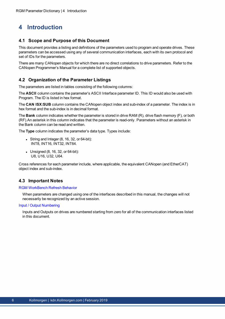
4.1 Scope and Purpose of this DocumentThis document provides a listing and definitions of the parameters used to program and operate drives. Theseparameters can be accessed using any of several communication interfaces, each with its own protocol andset of IDs for the parameters.
There aremany CANopen objects for which there are no direct correlations to drive parameters. Refer to theCANopen Programmer’s Manual for a complete list of supported objects.
4.2 Organization of the Parameter ListingsThe parameters are listed in tables consisting of the following columns:
TheASCII column contains the parameter’s ASCII Interface parameter ID. This ID would also be used withProgram. The ID is listed in hex format.
TheCAN ISX:SUB column contains the CANopen object index and sub-index of a parameter. The index is inhex format and the sub-index is in decimal format.
TheBank column indicates whether the parameter is stored in drive RAM (R), drive flashmemory (F), or both(RF).An asterisk in this column indicates that the parameter is read-only. Parameters without an asterisk inthe Bank column can be read and written.
The Type column indicates the parameter’s data type. Types include:
l String and Integer (8, 16, 32, or 64-bit):INT8, INT16, INT32, INT64.
l Unsigned (8, 16, 32, or 64-bit):U8, U16, U32, U64.
Cross references for each parameter include, where applicable, the equivalent CANopen (and EtherCAT)object index and sub-index.
4.3 Important NotesRGMWorkBench Refresh Behavior
When parameters are changed using one of the interfaces described in this manual, the changes will notnecessarily be recognized by an active session.
Input / Output Numbering
Inputs andOutputs on drives are numbered starting from zero for all of the communication interfaces listedin this document.
6 Kollmorgen | kdn.Kollmorgen.com | February 2019
5 Parameters
5.1 Parameters Sorted by ASCII Interface Parameter IDASCII CAN/ECAT
IDX:SUBBank Type Description
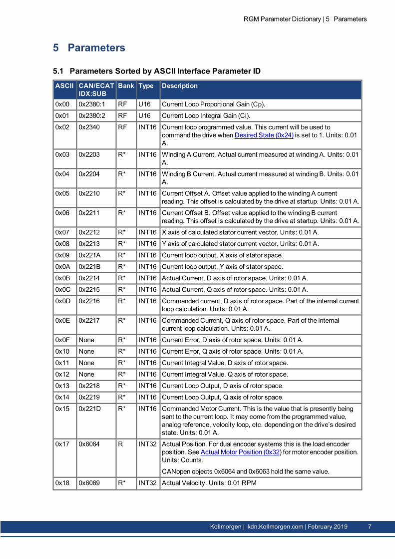
0x00 0x2380:1 RF U16 Current Loop Proportional Gain (Cp).
0x01 0x2380:2 RF U16 Current Loop Integral Gain (Ci).
0x02 0x2340 RF INT16 Current loop programmed value. This current will be used tocommand the drive when Desired State (0x24) is set to 1. Units: 0.01A.
0x03 0x2203 R* INT16 Winding A Current. Actual current measured at winding A. Units: 0.01A.
0x04 0x2204 R* INT16 Winding B Current. Actual current measured at winding B. Units: 0.01A.
0x05 0x2210 R* INT16 Current Offset A. Offset value applied to the winding A currentreading. This offset is calculated by the drive at startup. Units: 0.01 A.
0x06 0x2211 R* INT16 Current Offset B. Offset value applied to the winding B currentreading. This offset is calculated by the drive at startup. Units: 0.01 A.
0x07 0x2212 R* INT16 X axis of calculated stator current vector. Units: 0.01 A.
0x08 0x2213 R* INT16 Y axis of calculated stator current vector. Units: 0.01 A.
0x09 0x221A R* INT16 Current loop output, X axis of stator space.
0x0A 0x221B R* INT16 Current loop output, Y axis of stator space.
0x0B 0x2214 R* INT16 Actual Current, D axis of rotor space. Units: 0.01 A.
0x0C 0x2215 R* INT16 Actual Current, Q axis of rotor space. Units: 0.01 A.
0x0D 0x2216 R* INT16 Commanded current, D axis of rotor space. Part of the internal currentloop calculation. Units: 0.01 A.
0x0E 0x2217 R* INT16 Commanded Current, Q axis of rotor space. Part of the internalcurrent loop calculation. Units: 0.01 A.
0x0F None R* INT16 Current Error, D axis of rotor space. Units: 0.01 A.
0x10 None R* INT16 Current Error, Q axis of rotor space. Units: 0.01 A.
0x11 None R* INT16 Current Integral Value, D axis of rotor space.
0x12 None R* INT16 Current Integral Value, Q axis of rotor space.
0x13 0x2218 R* INT16 Current LoopOutput, D axis of rotor space.
0x14 0x2219 R* INT16 Current LoopOutput, Q axis of rotor space.
0x15 0x221D R* INT16 CommandedMotor Current. This is the value that is presently beingsent to the current loop. It may come from the programmed value,analog reference, velocity loop, etc. depending on the drive’s desiredstate. Units: 0.01 A.
0x17 0x6064 R INT32 Actual Position. For dual encoder systems this is the load encoderposition. See Actual Motor Position (0x32) for motor encoder position.Units: Counts.
CANopen objects 0x6064 and 0x6063 hold the same value.
0x18 0x6069 R* INT32 Actual Velocity. Units: 0.01 RPM
RGMParameter Dictionary | 5 Parameters
Kollmorgen | kdn.Kollmorgen.com | February 2019 7

RGMParameter Dictionary | 5 Parameters
ASCII CAN/ECATIDX:SUB
Bank Type Description
0x19 0x2310 RF INT32 Reserved
0x1A R* INT16 Reserved
Offset Values applied to analog reference input. Units: mV
0x1B R* INT16 Reserved
0x1C R* INT16 Reserved
0x1D R* INT16 Reserved
0x1E 0x2201 R* INT16 High Voltage A/D Reading. The voltage present on the high-voltagebus. Units: 100mV.
0x20 0x2202 R* INT16 Dive temperature A/D Reading. Units: degrees C.
0x21 0x2110 RF INT16 Peak Current Limit. Also known as Boost current on stepper drives.This value cannot exceed the peak current rating of the drive. Units:0.01 A.
0x22 0x2111 RF INT16 Continuous Current Limit. Also known as Run Current on stepperdrives. This value should be less than the User Peak Current Limit.Units: 0.01 A.
0x23 0x2112 RF U16 Time at Peak Current Limit. Also known as Time at Boost Current onstepper drives. Units: mS.
8 Kollmorgen | kdn.Kollmorgen.com | February 2019

ASCII CAN/ECATIDX:SUB
Bank Type Description
0x24 0x2300 RF U16 Desired State
Value Description0 Drive disabled.
1 The current loop is driven by the programmed current value.
2 The current loop is driven by the analog reference
3 The current loop is driven by the PWM input.
4 The current loop is driven by the function generator.
5 UV current mode.
6-10 Reserved for future use.
11 The velocity loop is driven by the programmed velocityvalue.
12 Reserved
13 Reserved
14 The velocity loop is driven by the function generator.
15-20 Reserved for future use.
21 The position loop is driven by the trajectory generator.
22 Reserved
23 Reserved
24 The position loop is driven by the function generator.
25 Reserved
26-29 Reserved.
30 The drive is controlled by the CANopen interface
31 Reserved
32 Reserved for future use.
33 Reserved
34 Reserved
35 Reserved
36-39 Reserved for future use.
40 Reserved
41 Reserved
42 Reserved
0x25 0x221E R* INT16 LimitedMotor Current Command. Units: 0.01 A.
0x26 0x2313 RF INT16 Analog Reference Input Deadband. Deadband window value appliedto the analog command input. Units: mV.
0x27 0x2381:1 RF U16 Velocity Loop Proportional Gain (Vp).
0x28 0x2381:2 RF U16 Velocity Loop Integral Gain (Vi).
RGM Parameter Dictionary | 5 Parameters
Kollmorgen | kdn.Kollmorgen.com | February 2019 9
RGMParameter Dictionary | 5 Parameters
ASCII CAN/ECATIDX:SUB
Bank Type Description
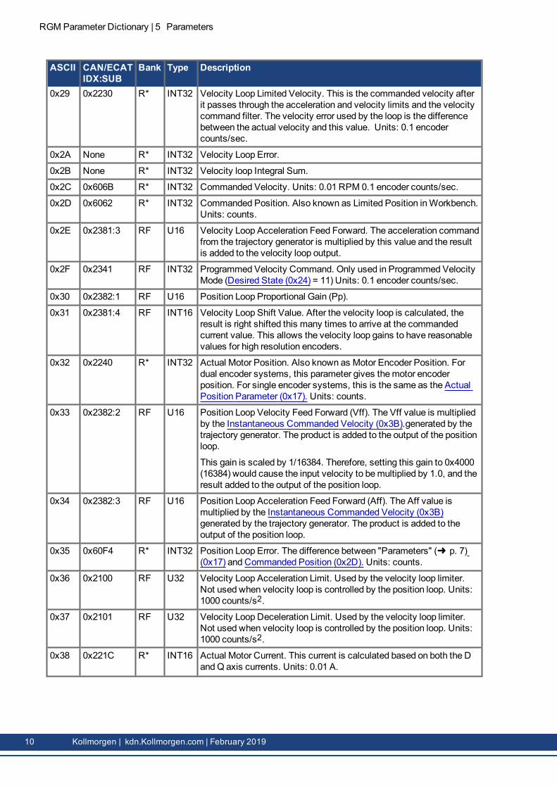
0x29 0x2230 R* INT32 Velocity Loop Limited Velocity. This is the commanded velocity afterit passes through the acceleration and velocity limits and the velocitycommand filter. The velocity error used by the loop is the differencebetween the actual velocity and this value. Units: 0.1 encodercounts/sec.
0x2A None R* INT32 Velocity Loop Error.
0x2B None R* INT32 Velocity loop Integral Sum.
0x2C 0x606B R* INT32 Commanded Velocity. Units: 0.01 RPM 0.1 encoder counts/sec.
0x2D 0x6062 R* INT32 Commanded Position. Also known as Limited Position inWorkbench.Units: counts.
0x2E 0x2381:3 RF U16 Velocity Loop Acceleration Feed Forward. The acceleration commandfrom the trajectory generator is multiplied by this value and the resultis added to the velocity loop output.
0x2F 0x2341 RF INT32 Programmed Velocity Command. Only used in Programmed VelocityMode (Desired State (0x24) = 11) Units: 0.1 encoder counts/sec.
0x30 0x2382:1 RF U16 Position Loop Proportional Gain (Pp).
0x31 0x2381:4 RF INT16 Velocity Loop Shift Value. After the velocity loop is calculated, theresult is right shifted this many times to arrive at the commandedcurrent value. This allows the velocity loop gains to have reasonablevalues for high resolution encoders.
0x32 0x2240 R* INT32 Actual Motor Position. Also known as Motor Encoder Position. Fordual encoder systems, this parameter gives themotor encoderposition. For single encoder systems, this is the same as the ActualPosition Parameter (0x17). Units: counts.
0x33 0x2382:2 RF U16 Position Loop Velocity Feed Forward (Vff). The Vff value is multipliedby the Instantaneous Commanded Velocity (0x3B).generated by thetrajectory generator. The product is added to the output of the positionloop.
This gain is scaled by 1/16384. Therefore, setting this gain to 0x4000(16384) would cause the input velocity to bemultiplied by 1.0, and theresult added to the output of the position loop.
0x34 0x2382:3 RF U16 Position Loop Acceleration Feed Forward (Aff). The Aff value ismultiplied by the Instantaneous Commanded Velocity (0x3B)generated by the trajectory generator. The product is added to theoutput of the position loop.
0x35 0x60F4 R* INT32 Position Loop Error. The difference between "Parameters" (➜ p. 7)(0x17) and Commanded Position (0x2D). Units: counts.
0x36 0x2100 RF U32 Velocity Loop Acceleration Limit. Used by the velocity loop limiter.Not used when velocity loop is controlled by the position loop. Units:1000 counts/s2.
0x37 0x2101 RF U32 Velocity Loop Deceleration Limit. Used by the velocity loop limiter.Not used when velocity loop is controlled by the position loop. Units:1000 counts/s2.
0x38 0x221C R* INT16 Actual Motor Current. This current is calculated based on both the DandQ axis currents. Units: 0.01 A.
10 Kollmorgen | kdn.Kollmorgen.com | February 2019

ASCII CAN/ECATIDX:SUB
Bank Type Description
0x39 0x2102 RF U32 Velocity Loop Emergency Stop Deceleration Rate.Units: 1000 counts/s2.
0x3A 0x2103 RF INT32 Velocity Loop Velocity Limit. This value is a limit on the commandedvelocity used by the velocity loop. Note that this limit is always ineffect. Units 0.1 counts/s.
0x3B 0x2250 R* INT32 Instantaneous Commanded Velocity. This velocity is the output of thetrajectory generator and is the value by which the position loop’svelocity feed forward is multiplied. Units: 0.1 encoder counts/s.
0x3C 0x2251 R* U32 Instantaneous Commanded Acceleration. This acceleration is theoutput of the trajectory generator and is the value by which theposition loop’s acceleration feed forward is multiplied. Units: 10encoder counts/s2.
0x3D 0x2122 R* INT32 Trajectory Destination Position. This is the position that the trajectorygenerator is using as its destination. Units: encoder counts.
0x3E 0x2104 RF INT32 Velocity Window. If the absolute value of the velocity loop errorexceeds this, then the velocity window bit in the event status wordwill be set. Units: 0.1 counts/s.
0x3F 0x2105 RF U16 Velocity Window Time. The velocity window bit in the event statuswill be cleared when the absolute velocity error is less than thevelocity window for this amount of time. Units: ms.
0x40 0x2383:1 F U16 Motor Type. The type of motor connected to the drive. Bit-mapped asfollows:
Bits Description0 Reserved
1-3 Reserved
4-5 Motor Architecture:
0. Not Specified1. Reserved2. Reserved3. Brushless servomotor
6-15
0x41 0x6404 F String Motor Manufacturer.
0x42 0x6403 F String Motor Model.
0x43 0x2383:27 F INT16 Motor Units. This is only used by CME for display. (0=metric,1=English).
0x44 0x2383:9 F INT32 Motor Inertia (Mass). Units: Rotary = 0.000001 Kg/cm2; Linear =0.0001 Kg.
0x45 0x2383:2 F INT16 Motor Poll Pairs (used only for rotary motors). Number of motor polepairs (electrical phases) per rotation. For stepper motors, Poll Pairs =(360 deg / Motor deg/step) / 4.
0x46 0x2383:16 F U16 Motor Brake Type. 0=present, 1=none.
0x47 0x2383:15 F U16 Motor Temperature Sensor Type. 0=none, 1=present.
0x48 0x2383:12 F INT32 Motor Torque Constant. Units: 0.00001 Nm/A.
RGM Parameter Dictionary | 5 Parameters
Kollmorgen | kdn.Kollmorgen.com | February 2019 11

RGMParameter Dictionary | 5 Parameters
ASCII CAN/ECATIDX:SUB
Bank Type Description
0x49 0x2383:7 F INT16 Motor Resistance. Units: 10mΩ.
0x4A 0x2383:8 F INT16 Motor Inductance. Units: 10 µH.
0x4B 0x2383:13 F INT32 Motor Peak Torque. Units: 0.00001 Nm units.
0x4C 0x2383:14 F INT32 Motor Continuous Torque. Units: 0.00001 Nm units.
0x4D 0x2383:11 F INT32 Motor Max Velocity. Units: 0.1 encoder counts/s.
0x4E 0x2383:3 F U16 MotorWiring. 0=standard, 1= drive’s U and V outputs are swapped.
0x4F 0x2383:6 RF INT16 Motor Hall Offset. Offset angle to be applied to the Hall sensors.Units: degrees.
0x50 0x2383:4 F INT16 Motor Hall Type.
The type of Hall effect sensors attached to themotor:
Value Description0 NoHall sensors available
1 Digital Hall sensors
2 Reserved
0x52 0x2383:5 F INT16 Motor Hall Wiring. Bit-mapped as follows:
Bits Description0-2 The Hall wiring code (value, Hall Ordering)
0. U V W1. U W V2. V U W3. V W U4. W V U5. W U V6. Reserved7. Reserved
3 Reserved
4 Invert W Hall input if set. Inversion occurs after Halls wiring ischanged by bits 0-2.
5 Invert V Hall input if set. Inversion occurs after Halls wiring ischanged by bits 0-2.
6 Invert U Hall input if set. Inversion occurs after Halls wiring ischanged by bits 0-2.
7 Reserved
8 Reserved
9-15 Reserved
0x53 0x2383:17 F U16 Motor Brake Activation Time. Units: ms.
0x54 0x2383:18 F U16 Motor Brake Delay Time. After the brake output is activated, the drivewill stay enabled for this amount of time to allow the brake to engage.Units: ms.
12 Kollmorgen | kdn.Kollmorgen.com | February 2019

ASCII CAN/ECATIDX:SUB
Bank Type Description
0x55 0x2383:19 F INT32 Motor Brake Activation Velocity. Also known as Motor Brake Velocity(CANopen). During theMotor Brake Activation Time (0x53), if themotor's actual velocity falls below this value the brake output isactivated immediately.Units: 0.1 counts/s.
0x56 0x2383:10 F U32 Motor Back EMF Constant. Back EMF velocity estimation can bedisabled by setting to zero. Units: rotary motor: 0.01 V/Krpm; linearmotor: 0.01 V/mps.
0x57 0x2383:29 F U32 Reserved
0x58 0x2383:33 F INT32 Motor Gear Ratio. This parameter may be used to store gear ratioinformation for dual encoder systems where a gearbox sits betweenthe two encoders. This parameter is not used by the firmware and issupported as a convenience to the CME program.
Gear ratio is a ratio of two 16-bit values. The first word gives thenumber of motor turns and is the numerator. The second word givesthe number of position turns and is the denominator.
0x59 0x2107 RF INT16 Hall Velocity Mode Shift Value. This parameter is only used in Hallvelocity mode. It specifies a left shift value for the position andvelocity information calculated in that mode.
0x5A Reserved
0x5B Reserved
0x5C Reserved
RGM Parameter Dictionary | 5 Parameters
Kollmorgen | kdn.Kollmorgen.com | February 2019 13

RGMParameter Dictionary | 5 Parameters
ASCII CAN/ECATIDX:SUB
Bank Type Description
0x5D 0x2383:30 F U16 Load Encoder Type. This parameter identifies the type of encoderused on the load when running in dual loopmode. The encoding of thisparameter has changed over time to support more encoder types thanwere originally envisioned when the parameter was first defined. Bit12 of the parameter is used to identify which encoding is active.
New encoding supported by Feature Set C (starting with version2.10), Feature Set D, and Feature Set E:
Bits Meaning0-11 Encoder hardware to use:
0-15 Reserved16 Reserved17 Reserved18 Reserved19 Reserved
12 Always set to identify new encoding.
13
14 If set, then don't use this encoder for position feedback.
15 Reserved
Original encoding (bit 12 not set)
0-3 Encoder hardware to use:0 No load encoder present.1 Primary (differential) quad encoder.2 Reserved3 Reserved4 Reserved5 Reserved11 Reserved12 Reserved13 BiSS absolute encoder.14 Reserved15 Reserved
4 Reserved
5 If set, then don't use this encoder for position feedback.
6-15 Must be zero.
0x5E 0x2231 R* INT32 Load Encoder Velocity. Units: 0.1 encoder counts/s
0x5F 0x2106 RF 9 or 14 Velocity LoopOutput Filter. A bi-quad filter which acts on the output ofthe velocity loop. 9 word parameter, see Velocity Loop Filters in theRGMWorkBench User Guide. 14 word parameter (Plus product only),see "Filter Coefficients" (➜ p. 56).
14 Kollmorgen | kdn.Kollmorgen.com | February 2019

ASCII CAN/ECATIDX:SUB
Bank Type Description
0x60 0x2383:20 F U16 Motor Encoder Type (value, meaning:
0. Primary (differential) quad encoder.1. Reserved2. Reserved3. Reserved4. Reserved5. Reserved6. Reserved7. Reserved8. Reserved9. Reserved10. Reserved11. Reserved12. BiSS13. Reserved14. Reserved15. Reserved16. Reserved17. Reserved18. Reserved19. Reserved
0x61 Reserved
0x62 0x2383:23 F INT32 Motor Encoder Counts/Rev.. Units: counts/rev.
0x63 0x2383:24 F INT16 Reserved
0x64 0x2383:25 F INT32 Reserved
0x65 0x2383:22 F U16 Motor Encoder Direction. 0=normal, 1=reverse.
0x67 0x2383:28 F INT16 Reserved
0x68 0x2402 R* INT32 Reserved
0x69 0x2232 R* INT32 UnfilteredMotor Encoder Velocity. Units 0.1 counts/s.
0x6A 0x2113 RF INT32 Commanded Current Ramp Limit. Setting this to zero disables slopelimiting.Units: mA/s.
0x6B 0x2108 RF 9 or 14 Velocity Loop Command Filter Coefficients. A bi-quad filter structurethat acts on the command input of the velocity loop just after velocity& acceleration limiting. 9 word parameter, see Velocity Loop Filters inthe RGMWorkBench User Guide. 14 word parameter (Plus productonly), see "Filter Coefficients" (➜ p. 56).
RGM Parameter Dictionary | 5 Parameters
Kollmorgen | kdn.Kollmorgen.com | February 2019 15
RGMParameter Dictionary | 5 Parameters
ASCII CAN/ECATIDX:SUB
Bank Type Description
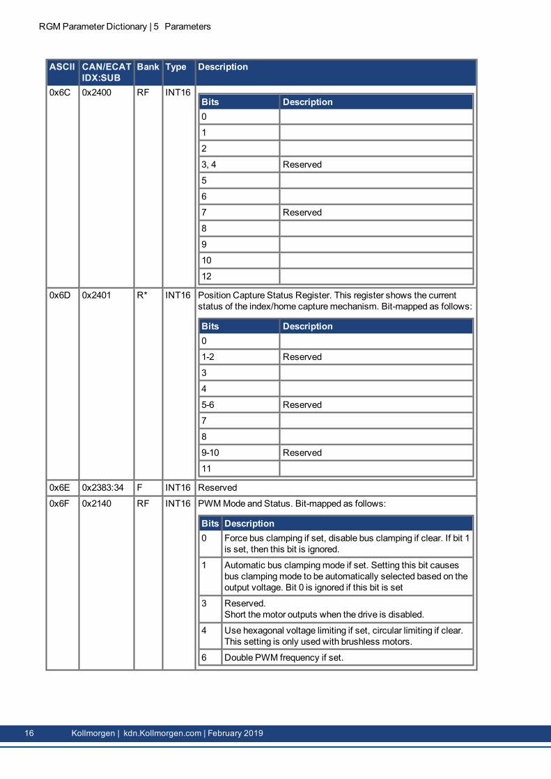
0x6C 0x2400 RF INT16Bits Description0
1
2
3, 4 Reserved
5
6
7 Reserved
8
9
10
12
0x6D 0x2401 R* INT16 Position Capture Status Register. This register shows the currentstatus of the index/home capturemechanism. Bit-mapped as follows:
Bits Description0
1-2 Reserved
3
4
5-6 Reserved
7
8
9-10 Reserved
11
0x6E 0x2383:34 F INT16 Reserved
0x6F 0x2140 RF INT16 PWMMode and Status. Bit-mapped as follows:
Bits Description0 Force bus clamping if set, disable bus clamping if clear. If bit 1
is set, then this bit is ignored.
1 Automatic bus clampingmode if set. Setting this bit causesbus clampingmode to be automatically selected based on theoutput voltage. Bit 0 is ignored if this bit is set
3 Reserved.Short themotor outputs when the drive is disabled.
4 Use hexagonal voltage limiting if set, circular limiting if clear.This setting is only used with brushless motors.
6 Double PWM frequency if set.
16 Kollmorgen | kdn.Kollmorgen.com | February 2019
ASCII CAN/ECATIDX:SUB
Bank Type Description
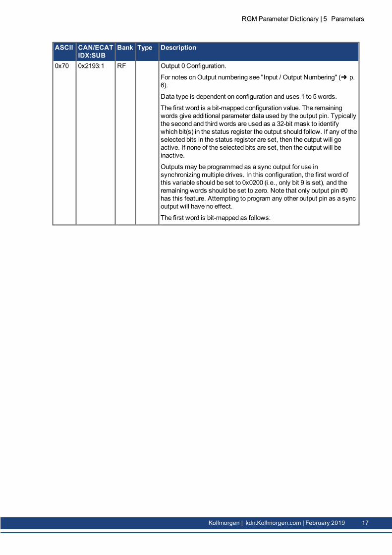
0x70 0x2193:1 RF Output 0 Configuration.
For notes onOutput numbering see "Input / Output Numbering" (➜ p.6).
Data type is dependent on configuration and uses 1 to 5 words.
The first word is a bit-mapped configuration value. The remainingwords give additional parameter data used by the output pin. Typicallythe second and third words are used as a 32-bit mask to identifywhich bit(s) in the status register the output should follow. If any of theselected bits in the status register are set, then the output will goactive. If none of the selected bits are set, then the output will beinactive.
Outputs may be programmed as a sync output for use insynchronizingmultiple drives. In this configuration, the first word ofthis variable should be set to 0x0200 (i.e., only bit 9 is set), and theremaining words should be set to zero. Note that only output pin #0has this feature. Attempting to program any other output pin as a syncoutput will have no effect.
The first word is bit-mapped as follows:
RGM Parameter Dictionary | 5 Parameters
Kollmorgen | kdn.Kollmorgen.com | February 2019 17

RGMParameter Dictionary | 5 Parameters
ASCII CAN/ECATIDX:SUB
Bank Type Description
Bits Configuration0-4 Define which internal register drives the output. The accept-
able values for these bits are as follows:Value Description0 Track bits in the event status.
1 Track bits in the latched event status.
2 Track bits in themanual output controlregister (seeOutput States and Program Con-trol ("0xAB" (➜ p. 29))).
3 Track bits in the trajectory status register(see Trajectory Status Register ("0xC9" (➜p. 37))).
4 Go active if position is between the two pos-itions specified in words 2, 3 (low) and 4, 5(high). If bit 12 is set, commanded position isused. If bit 12 is clear, actual position is used.
5 Go active on a low to high crossing of the pos-ition specified by words 2, 3. Stay high for thenumber of milliseconds specified by words 4,5. If bit 12 is set, commanded position isused. If bit 12 is clear, actual position is used.
6 Same as 5, but for high to low crossings.
7 Same as 5 but for any crossing.
8 Go active if motor phase angle (plus an off-set) is between 0 and 180 degrees. The offsetis set using the first word of extra data in unitsof 32k/180 degrees.
9 Pulse output each time a position is crossedfrom an array of positions stored in tracememory.
10 Use the output to trigger an external regen res-ister.
11 For EtherCAT drives, pulse on the SYNC0signal.
16 Track hardware position compare function ondrives supporting it.
5-7 Reserved for future use.
8 Inverts normal active state of output if set. E.g., outputs thatare normally active low become active high.
9 If set, program the output as a sync output. This bit isreserved for all output pins except pin 0.
10-11
Reserved for future use.
18 Kollmorgen | kdn.Kollmorgen.com | February 2019

ASCII CAN/ECATIDX:SUB
Bank Type Description
Bits Configuration12-13
Axis number for multi-axis drives.
14-15
Usage depends on output function selected.
0x71 0x2193:2 RF Seetext
Reserved
0x72 0x 2193:3 RF Seetext
Reserved
0x73 0x 2193:4 RF Seetext
Reserved
0x74 0x 2193:5 RF Seetext
Reserved
0x75 0x 2193:6 RF Seetext
Reserved
0x76 0x 2193:7 RF Seetext
Reserved
0x77 0x 2193:8 RF Seetext
Reserved
0x78 0x 2192:1 RF U16 Frequency for solenoid PWMUnits:Hz
Factory default is 16,000 kHz
0x79 0x2192:2 RF U16 Maximummotor temperature limit before fault of 75 Deg C.
0x7A 0x2192:3 RF U16 Maximum temperature for gear thermistor before fault occurs, 55 DegC Units:Deg C.
0x7B 0x2192:4 RF U16 Solenoid continuous voltage, Units: 0.1V/Volt. Setting this parameterto 50 yields 5.0 V
0x7C 0x2192:5 RF U16 Solenoid initial voltage, Units: 0.1V/Volt. Setting this parameter to480 yields 48.0 V
0x7D 0x2192:6 RF U16 Reserved
0x7E 0x2192:7 RF U16 Reserved
0x7F 0x2192:8 RF U16 Reserved
0x80 0x6503 F* String Model Number.
0x81 0x2384:1or0x1018:4
F* U32 Drive Serial Number.
0x82 0x2384:3 F* INT16 Drive’s rated Peak Current. Units: 0.01 A.
0x83 0x2384:4 F* INT16 Drive’s rated Continuous Current. Units: 0.01 A.
0x84 0x2384:14 F* INT16 Current Corresponding toMax A/D Reading. Units: 0.01 A.
0x85 0x2384:11 F* U16 PWMPeriod. Units: 10 ns.
0x86 0x2384:12 F* U16 Drive Servo Period (PWM periods). Servo loop update period as amultiple of the current loop period.
RGM Parameter Dictionary | 5 Parameters
Kollmorgen | kdn.Kollmorgen.com | February 2019 19
RGMParameter Dictionary | 5 Parameters
ASCII CAN/ECATIDX:SUB
Bank Type Description
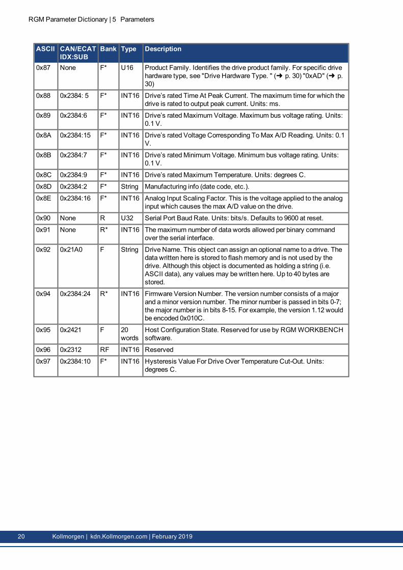
0x87 None F* U16 Product Family. Identifies the drive product family. For specific drivehardware type, see "Drive Hardware Type. " (➜ p. 30) "0xAD" (➜ p.30)
0x88 0x2384: 5 F* INT16 Drive’s rated Time At Peak Current. Themaximum time for which thedrive is rated to output peak current. Units: ms.
0x89 0x2384:6 F* INT16 Drive’s ratedMaximum Voltage. Maximum bus voltage rating. Units:0.1 V.
0x8A 0x2384:15 F* INT16 Drive’s rated Voltage Corresponding ToMax A/D Reading. Units: 0.1V.
0x8B 0x2384:7 F* INT16 Drive’s ratedMinimum Voltage. Minimum bus voltage rating. Units:0.1 V.
0x8C 0x2384:9 F* INT16 Drive’s ratedMaximum Temperature. Units: degrees C.
0x8D 0x2384:2 F* String Manufacturing info (date code, etc.).
0x8E 0x2384:16 F* INT16 Analog Input Scaling Factor. This is the voltage applied to the analoginput which causes themax A/D value on the drive.
0x90 None R U32 Serial Port Baud Rate. Units: bits/s. Defaults to 9600 at reset.
0x91 None R* INT16 Themaximum number of data words allowed per binary commandover the serial interface.
0x92 0x21A0 F String Drive Name. This object can assign an optional name to a drive. Thedata written here is stored to flashmemory and is not used by thedrive. Although this object is documented as holding a string (i.e.ASCII data), any values may be written here. Up to 40 bytes arestored.
0x94 0x2384:24 R* INT16 Firmware Version Number. The version number consists of amajorand aminor version number. Theminor number is passed in bits 0-7;themajor number is in bits 8-15. For example, the version 1.12 wouldbe encoded 0x010C.
0x95 0x2421 F 20words
Host Configuration State. Reserved for use by RGMWORKBENCHsoftware.
0x96 0x2312 RF INT16 Reserved
0x97 0x2384:10 F* INT16 Hysteresis Value For Drive Over Temperature Cut-Out. Units:degrees C.
20 Kollmorgen | kdn.Kollmorgen.com | February 2019

ASCII CAN/ECATIDX:SUB
Bank Type Description
0x98 0x2330 RF INT16 Function Generator Configuration. Configures the drive’s internalfunction generator, which can drive the current, velocity, or positionloop. Bit-mapped as follows:
Bits Description0-1 Function code (type of waveform to generate):
Value Description0 None (disabled).
1 Square wave.
2 Sine wave.
2-7 Reserved for future use.
8 If set, the function generator frequency is in units of 0.01 Hz. Ifclear, the frequency is in units of Hz.
9-11 Reserved.
12 One-shot mode if set. If bit 12 is set and bit 13 is clear, thefunction code is reset to zero (disabled) after one completewaveform. If bits 12 and 13 are both set, the function code isreset to zero after two waveforms.
13 Invert every other period if set.
14-15
Reserved for future use.
The function code programmed into bits 0-1 defines the type ofwaveform to be generated:
Code Description0 None (disabled).
1 Square wave.
2 Sine wave.
Note that the drive is placed under control of the function generator bysetting"Desired State" (➜ p. 9) ("0x24" (➜ p. 9)) to one of the followingvalues:
4 (function generator drives current loop)
14 (function generator drives velocity loop)
24 (function generator drives position loop in servomode)
34 Reserved
Note that if one-shot mode is selected, then after one period (two ifinvert is selected) the function type will reset to zero.
0x99 0x2331 RF U16 Function Generator Frequency. Units: Hz. See bit 8 of FunctionGenerator Configuration (0x98).
RGM Parameter Dictionary | 5 Parameters
Kollmorgen | kdn.Kollmorgen.com | February 2019 21

RGMParameter Dictionary | 5 Parameters
ASCII CAN/ECATIDX:SUB
Bank Type Description
0x9A 0x2332 RF INT32 Function Generator Amplitude. The amplitude of the signal generatedby the internal function generator. The units depend on themode:
Mode UnitsCurrent 0.01 A.
Velocity 0.1 counts/s.
Position Counts.
0x9B 0x2333 RF U16 Function Generator Duty Cycle (square wave only).Units: 0.1% (for instance, 1000 for 100%).
0x9C 0x2384:8 F* U16 Hysteresis For Maximum Bus Voltage Cut-Out. Units: 0.1 V.
0x9D 0x2384:18 F* U16 PWMDead Time At Continuous Current Limit. This parameter givesthe PWM dead time used at or above the continuous current limit. Thedead time below the continuous current limit is a linear function of thisparameter and PWMDead Time At Zero Current (0x9F). Units: CPUcycles.
0x9E 0x2384:17 F* U16 DriveMinimum PWMOff Time. This parameter gives theminimumamount of time for which all PWM outputs must be disabled for eachcurrent loop cycle. Units: 10 ns.
0x9F 0x2384:19 F* U16 PWMDead Time At Zero Current. This parameter gives the PWMdead time at zero current. The dead time above zero current is definedby a linear function of this parameter and PWM_dead_time_at_continuous_currentlimit ("0x9D" (➜ p. 22)). Units: CPU cycles.
22 Kollmorgen | kdn.Kollmorgen.com | February 2019
ASCII CAN/ECATIDX:SUB
Bank Type Description
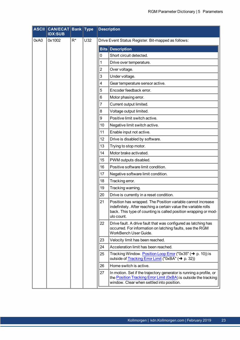
0xA0 0x1002 R* U32 Drive Event Status Register. Bit-mapped as follows:
Bits Description0 Short circuit detected.
1 Drive over temperature.
2 Over voltage.
3 Under voltage.
4 Gear temperature sensor active.
5 Encoder feedback error.
6 Motor phasing error.
7 Current output limited.
8 Voltage output limited.
9 Positive limit switch active.
10 Negative limit switch active.
11 Enable input not active.
12 Drive is disabled by software.
13 Trying to stopmotor.
14 Motor brake activated.
15 PWM outputs disabled.
16 Positive software limit condition.
17 Negative software limit condition.
18 Tracking error.
19 Tracking warning.
20 Drive is currently in a reset condition.
21 Position has wrapped. The Position variable cannot increaseindefinitely. After reaching a certain value the variable rollsback. This type of counting is called position wrapping or mod-ulo count.
22 Drive fault. A drive fault that was configured as latching hasoccurred. For information on latching faults, see the RGMWorkBench User Guide.
23 Velocity limit has been reached.
24 Acceleration limit has been reached.
25 TrackingWindow. Position Loop Error ("0x35" (➜ p. 10)) isoutside of Tracking Error Limit ("0xBA" (➜ p. 32))
26 Home switch is active.
27 Inmotion. Set if the trajectory generator is running a profile, orthe Position Tracking Error Limit (0xBA) is outside the trackingwindow. Clear when settled into position.
RGM Parameter Dictionary | 5 Parameters
Kollmorgen | kdn.Kollmorgen.com | February 2019 23

RGMParameter Dictionary | 5 Parameters
ASCII CAN/ECATIDX:SUB
Bank Type Description
Bits Description28 Velocity window. Set if the absolute velocity error exceeds the
velocity window value.
29 Phase not yet initialized. If the drive is phasing with no Halls,this bit is set until the drive has initialized its phase.
30 Command fault. PWM or other command signal (e.g., Ether-CATmaster) not present. If Allow 100% Output option isenabled by a setting Bit 3 of Digital Input CommandCon-figuration (0xA8) this fault will not detect amissing PWM com-mand.
31 Not defined.
0xA1 0x2181 R U32 Latched Event Status Register. This is a latched version of the DriveEvent Status Register (0xA0). Bits are set by the drive when eventsoccur. Bits are only cleared by writing to this parameter as explainedbelow: When writing to the Latched Event Status Register, any bit setwill cause the corresponding bit in the register to be cleared. Forexample, to clear the Over Voltage bit, write a 1 to the register. Toclear all bits, write 0x4 to the register.
0xA2 0x2261 R* INT16 Hall Input State. The lower three bits of the returned value give thepresent state of the Hall input pins. The Hall state is the value of theHall lines AFTER the ordering and inversions specified in the Hallwiring configuration have been applied.
24 Kollmorgen | kdn.Kollmorgen.com | February 2019

ASCII CAN/ECATIDX:SUB
Bank Type Description
0xA4 0x2183 R U32 Latching Fault Status Register. Bit-mapped to show which latchingfaults have occurred in the drive. When a latching fault has occurred,the fault bit (bit 22) of the Drive Event Status Register ("0xA0" (➜ p.23)) is set. The cause of the fault can be read from this register.
To clear a fault condition, write a 1 to the associated bit in thisregister. The events that cause the drive to latch a fault areprogrammable. See Fault Mask (0xA7) for details.
Latched FaultsBits Fault Description0 Data flash CRC failure. This fault is considered fatal and can-
not be cleared.
1 Drive internal error. This fault is considered fatal and cannotbe cleared.
2 Short circuit.
3 Drive over temperature.
4 Gear over temperature.
5 Over voltage.
6 Under voltage.
7 Feedback fault.
8 Phasing error.
9 Tracking error.
10 Current limited by I2T algorithm.
11 FPGA error type 1.
12 Command input lost.
13 FPGA error type 2.
14 Safety circuit fault.
15 Unable to control current.
16 Motor wiring disconnected (seeOpenMotorWiring CheckCurrent (0x19D)).
17-31
Reserved.
0xA5 0x2191 RF U16 Reserved
RGM Parameter Dictionary | 5 Parameters
Kollmorgen | kdn.Kollmorgen.com | February 2019 25
RGMParameter Dictionary | 5 Parameters
ASCII CAN/ECATIDX:SUB
Bank Type Description
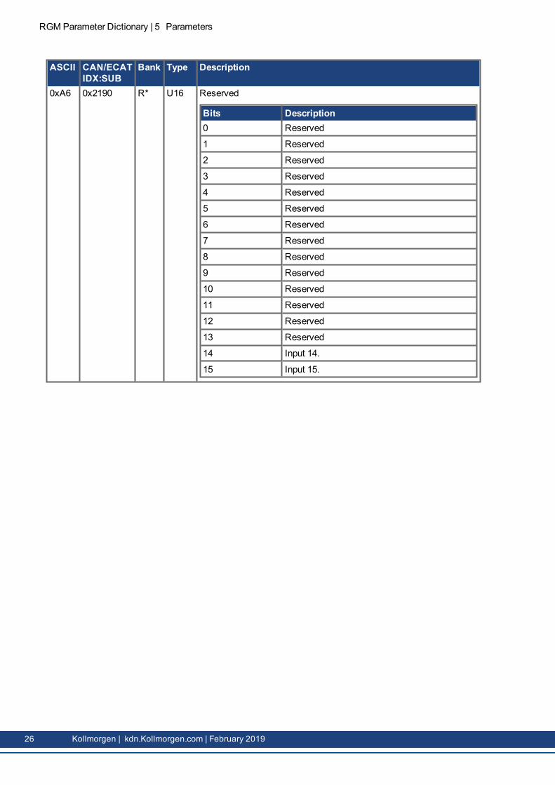
0xA6 0x2190 R* U16 Reserved
Bits Description0 Reserved
1 Reserved
2 Reserved
3 Reserved
4 Reserved
5 Reserved
6 Reserved
7 Reserved
8 Reserved
9 Reserved
10 Reserved
11 Reserved
12 Reserved
13 Reserved
14 Input 14.
15 Input 15.
26 Kollmorgen | kdn.Kollmorgen.com | February 2019

ASCII CAN/ECATIDX:SUB
Bank Type Description
0xA7 0x2182 RF U32 Fault Mask. This variable is used to configure which drive eventscause latching faults.
Setting a fault mask bit to 1 causes the associated drive event tocause a latching fault when it occurs. Setting a fault mask bit to 0disables fault latching on the associated event.
Latched faults may be cleared using the Latching Fault StatusRegister (0xA4).
Bits Fault Description0 Data flash CRC failure. This bit is read-only and will always
be set.If the drive detects corrupted flash data values on startup itwill remain disabled and indicate a fault condition.
1 Drive internal error. This bit is read-only and will always beset.If the drive fails its power-on self-test, it will remain disabledand indicate a fault condition.
2 Short circuit. If set: programs the drive to latch a fault con-dition when a short circuit is detected on themotor outputs.If clear: programs the drive to disable its outputs for 100msafter a short circuit and then re-enable.
3 Drive over temperature. If set: programs the drive to latch afault condition when a drive over temperature event happens.If clear: programs the drive to re-enable as soon as it cools suf-ficiently from an over temperature event.
4 Motor over temperature. If set: programs the drive to latch afault condition when amotor temperature sensor input activ-ates.If clear: programs the drive to re-enable as soon as the overtemperature input becomes inactive.
5 Over voltage. If set: programs the drive to latch a fault con-dition when excessive bus voltage is detected.If clear: programs the drive to re-enable as soon as the busvoltage is within normal range.
6 Under voltage. If set: programs the drive to latch a fault con-dition when inadequate bus voltage is detected.If clear: programs the drive to re-enable as soon as the busvoltage is within normal range.
7 Feedback fault. If set: programs the drive to latch a fault whenfeedback faults occur. Feedback faults occur if toomuch cur-rent is drawn from the 5 V source on the drive, a resolver oranalog encoder is disconnected, or a resolver or analogencoder has levels out of tolerance.
8 Phasing error. If set: programs the drive to latch a fault whenphasing errors occur.If clear: programs the drive to re-enable when the phasing erroris removed.
RGM Parameter Dictionary | 5 Parameters
Kollmorgen | kdn.Kollmorgen.com | February 2019 27

RGMParameter Dictionary | 5 Parameters
ASCII CAN/ECATIDX:SUB
Bank Type Description
Bits Fault Description9 Tracking error. If set: programs the drive to latch in the dis-
abled state when a tracking error occurs.If clear: programs the drive to abort the current move andremain enabled when a tracking error occurs.
10 If set: programs the drive to latch a fault when output current islimited by the I2T algorithm.
11 FPGA failure. This bit is read-only.
12 Command input lost fault. If set: programs the drive to latch inthe disabled state when the command input is lost.
13 Unable to initialize internal drive hardware. This bit is read-only.
14 If set, programs the drive to latch a fault when there is safetycircuit consistency check failure.
15 If set, programs the drive to latch a fault when the drive isunable to control motor current.
16 If set, programs the drive to latch a fault when themotor wiringis disconnected (seeOpenMotorWiring Check Current(0x19D).
17-31
Reserved.
28 Kollmorgen | kdn.Kollmorgen.com | February 2019

ASCII CAN/ECATIDX:SUB
Bank Type Description
0xA8 0x2320 RF INT16 Reserved
Bits Description0 Reserved
1 Reserved
2 Reserved
3 Reserved
4 Reserved
5 Reserved
6 Reserved
7 Reserved
8-9 Input pin interpretation for positionmode (see below).Value Description0 Reserved
1 Reserved
2 Reserved
3 Reserved
10-11 Reserved.
12 Reserved
13 Reserved
14-15 Identify which input pins to use.Value Description0 Reserved
1 Reserved
2 Reserved
3 Reserved
0xA9 0x2321 RF INT32 Reserved
0xAA 0x2196 R* U16 Reserved
0xAB 0x2194 R U16 Reserved
0xAC 0x2180 R* U32 Sticky Drive Event Status Register. This read-only parameter is bit-mapped in exactly the sameway as the Drive Event Status Register(0xA0), but instead of giving the present status of the drive, the stickyversion indicates any bits in the event status that have been set sincethe last reading of the sticky register.
The sticky register is similar to the Latched Event Status Register(0xA1), but the latched register must be cleared explicitly, whereasthe sticky register is cleared automatically each time it is read.
RGM Parameter Dictionary | 5 Parameters
Kollmorgen | kdn.Kollmorgen.com | February 2019 29

RGMParameter Dictionary | 5 Parameters
ASCII CAN/ECATIDX:SUB
Bank Type Description
0xAD 0x1018:2
or
0x2384:13
R* INT16 Drive Hardware Type.
Value Product0x2000 RGM: 5A
0x2010 RGM: 10A
0xAE 0x60F6:3 RF INT16 Current LoopOffset. This value is added to the commandedmotorcurrent. It can compensate for a directional bias affecting the currentloop. Units: 0.01 A.
0xAF 0x2420 RF INT32 Miscellaneous Drive Options Register. Factory default 0x100 Bit-mapped as follows:
Bits Option0 Reserved
1 Reserved.
2 Reserved
3 Reserved.
4 Reserved
8 delay brake activation even for faults that disable the driveimmediately.
5-31 Reserved.
0xB0 0x2260 R INT16 Motor Phase Angle. Writes are only useful when running in diagnosticmicro-steppingmode. Units: degrees.
0xB1 0x21C1 RF INT16 Increment Rate For Phase AngleWhen InMicro SteppingMode. Onlyused in diagnostic micro-steppingmode. Desired State ("0x24" (➜ p.9)) = 42 (microsteppingmode). Units: degrees/s.
30 Kollmorgen | kdn.Kollmorgen.com | February 2019

ASCII CAN/ECATIDX:SUB
Bank Type Description
0xB2 0x21C0 RF U16 CommutationMode. Also known as PhasingMode. Controls themechanism used by the drive to compute themotor phasing angle.Determines what inputs the drive uses to initialize andmaintain thephase angle, as follows:
Value Mode0 Standardmode. Encoder-based sinusoidal commutation for
brushless motors. Use digital Hall inputs to initialize phase,then switch to an encoder to maintain phase. The encoder isthe primary sensing device with the Hall effect sensors usedtomonitor and adjust the phase angle as necessary duringoperation.
1 Trapezoidal (Hall based) phasing. The Hall sensors are usedfor phasing all the time. This mode can be used if no encoderis available.
2 Likemode 0 except that the phase angle is not adjustedbased on the Hall inputs. Hall sensors are still required to ini-tialize the phase angle at startup.
3 Reserved
4 Reserved
5 Algorithmic Phase Initializationmode (wake & wiggle, noHalls).See the Kollmorgen RGMWorkbench User Guide for moreinformation on Algorithmic Phase Initialization.
6 Reserved
7 Trapezoidal commutation with phase angle interpolation.
0xB3 0x2384:23 F* INT16 Analog Encoder Scaling Factor. This parameter selects the resolutionof an analog encoder input. The parameter is not used for otherencoder types(factory default?)
0xB4 0x2263 R* INT16 Reserved.
0xB5 0x2353 R* INT32 Homing Adjustment. This parameter is updated after each successfulhoming operation. The value it contains is the size of the actualposition adjustment made in the last home sequence. Units: counts.
0xB6 0x2322 RF U16 Reserved
0xB7 0x2141 R* U32 System Time. Time since start up. Units: ms.
0xB8 0x607D:2 RF INT32 Positive Software Limit. This parameter is only available on drivesthat support trajectory generation and homing. Software limits areonly in effect after the drive has been referenced (i.e. homing hasbeen successfully completed). Set to less than negative softwarelimit to disable. Units: counts.
0xB9 0x607D:1 RF INT32 Negative Software Limit. Software limits are only in effect after thedrive has been referenced (i.e. homing has been successfullycompleted). Set to greater than positive software limit to disable.Units: counts.
RGM Parameter Dictionary | 5 Parameters
Kollmorgen | kdn.Kollmorgen.com | February 2019 31

RGMParameter Dictionary | 5 Parameters
ASCII CAN/ECATIDX:SUB
Bank Type Description
0xBA 0x2120 RF INT32 Position Tracking Error Limit. Also known as Tracking ErrorWindow. If the Position Loop Error (0x35) exceeds this value then the trackingerror bit (bit 18) of the Drive Event Status Register (0xA0) is set andthemotor is stopped. Using Fault Mask (0xA7), the tracking errorevent can be configured to either disable the drive immediately, orabort the present move and continue holding position. Units: counts.
0xBB 0x6065 RF INT32 Position TrackingWarning Limit. If the Position Loop Error (0x35)exceeds this value then the tracking warning bit (bit 19) of the DriveEvent Status Register (0xA0) is set. Units: counts.
0xBC 0x6067 RF INT32 Position TrackingWindow Limit. If the Position Loop Error (0x35)exceeds this value then the tracking window bit (bit 25) of the DriveEvent Status Register (0xA0) is set. Units: counts.
0xBD 0x6068 RF U16 TimeDelay For Position Tracking Error Limit (0xBA). The trackingwindow bit (bit 25) of the Drive Event Status Register (0xA0) will notbe cleared until the Position Loop Error (0x35) has been within thePosition Tracking Error Limit (0xBA) for at least this long. Units: ms.
0xBE 0x2253 RF U32 Software Limit Deceleration. The deceleration rate used to stop amotor when approaching a software limit. Units: 10 counts/s2.
0xBF 0x2351 RF U16 Homing Current Delay Time (used with home to hard stopmode only).When performing a home to hard stop, the amplifier will push againstthe stop for this long before sampling the home position. Units: ms.
0xC0 None R* INT16 Network Node ID. This is the drive’s present ID as read at systemstartup. The node ID is only read at system startup, so this value willnot change unless the drive is reset. See Network Node IDConfiguration (0xC1).
32 Kollmorgen | kdn.Kollmorgen.com | February 2019
ASCII CAN/ECATIDX:SUB
Bank Type Description
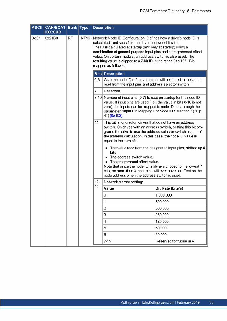
0xC1 0x21B0 RF INT16 Network Node ID Configuration. Defines how a drive’s node ID iscalculated, and specifies the drive’s network bit rate.The ID is calculated at startup (and only at startup) using acombination of general-purpose input pins and a programmed offsetvalue. On certain models, an address switch is also used. Theresulting value is clipped to a 7-bit ID in the range 0 to 127. Bit-mapped as follows:
Bits Description0-6 Give the node ID offset value that will be added to the value
read from the input pins and address selector switch.
7 Reserved.
8-10 Number of input pins (0-7) to read on startup for the node IDvalue. If input pins are used (i.e., the value in bits 8-10 is notzero), the inputs can bemapped to node ID bits through theparameter "Input PinMapping For Node ID Selection." (➜ p.41) (0x103).
11 This bit is ignored on drives that do not have an addressswitch. On drives with an address switch, setting this bit pro-grams the drive to use the address selector switch as part ofthe address calculation. In this case, the node ID value isequal to the sum of:
n The value read from the designated input pins, shifted up 4bits.
n The address switch value.n The programmed offset value.Note that since the node ID is always clipped to the lowest 7bits, nomore than 3 input pins will ever have an effect on thenode address when the address switch is used.
12-15
Network bit rate setting:Value Bit Rate (bits/s)0 1,000,000.
1 800,000.
2 500,000.
3 250,000.
4 125,000.
5 50,000.
6 20,000.
7-15 Reserved for future use
RGM Parameter Dictionary | 5 Parameters
Kollmorgen | kdn.Kollmorgen.com | February 2019 33

RGMParameter Dictionary | 5 Parameters
ASCII CAN/ECATIDX:SUB
Bank Type Description
0xC2 0x2352 RF INT16 HomingMethod Configuration. Bit-mapped as follows:
Bits Description0-3 Home function
0 If bit 5 is not set, then just set the current position ashome. If bit 5 is set, thenmove in the direction spe-cified by bit 4 and set the location of the first indexpulse as home. Bit 6 is not used in this mode.
1 Move in the direction specified by bit 4 until a limitswitch is encountered. Thenmove in the other dir-ection out of limit. If bit 5 is clear, then the edge loc-ation is home. If bit 5 is set, then the next index pulseis home. Bit 6 not used in this mode.
2 Home on a constant home switch. The initial move ismade in the direction specified by bit 4. When thehome switch is encountered, the direction is reversed.The edge of the home switch is set as home if bit 5 isclear. If bit 5 is set, then an index pulse is used as thehome position. Bit 6 is used to define which indexpulse is used.
3 Home on an intermittent home switch. This modeworks the same as mode 2 except that if a limit switchis encountered when initially searching for home, thenthe direction is reversed. In mode 2, hitting a limitswitch before finding homewould be considered anerror. Bit 8 identifies which edge of the home to searchfor (positive or negative).
4 Home to a hard stop. This moves in the direction spe-cified in bit 4 until the home current limit is reached. Itthen presses against the hard stop using that currentvalue until the home delay time expires. If bit 5 (index)is set, drive away from the hard stop until an index isfound.
15 Immediate home. This value causes the amp to be ref-erenced immediately on power-up. Once the encoderis initialized, the home offset value is added to theencoder position and the result is set as the current ref-erenced position. This is primarily useful with absoluteencoders.
4 Initial move direction (0=positive, 1=negative).
5 Home on index pulse if set.
6 Selects which index pulse to use. If set, use the pulse on theDIR side of the sensor edge. DIR is the direction specified bybit 4 of this word.
7 If set, capture falling edge of index. Capture rising edge ifclear.
34 Kollmorgen | kdn.Kollmorgen.com | February 2019

ASCII CAN/ECATIDX:SUB
Bank Type Description
Bits Description8 When using amomentary home switch, this bit identifies
which edge of the home switch to reference on. If set, thenthe negative edge is used; if clear the positive edge is used.
9 If set, make amove to the zero position when homing is fin-ished. If clear, the zero position is found, but not moved to.
10 If set, the homing sequence will run as normal, but the actualposition will not be adjusted at the end. Note that even thoughthe actual position is not adjusted, the parameter HomingAdjustment (0xB5) is updated with the size of the adjustment(in counts) that would have beenmade.Also, if bit 10 is set then nomove to zero is made regardlessof the setting of bit 9.
0xC3 0x6099:1 RF INT32 Homing Velocity (fast moves). This velocity value is used duringsegments of the homing procedure that may be handled at highspeed. Generally, this means moves in which the home sensor isbeing located, but the edge of the sensor is not being found. Units: 0.1counts/s.
0xC4 0x6099:2 RF INT32 Homing Velocity (slow moves). This velocity value is used for homingsegments that require low speed, such as cases where the edge of ahoming sensor is being sought. Units: 0.1 counts/s.
0xC5 0x609A RF U32 Homing Acceleration/Deceleration. This value defines theacceleration used for all homingmoves. The same value is used atthe beginning and ending of moves (i.e. there is no separatedeceleration value). Units: 10 counts/s2.
0xC6 0x607C RF INT32 HomeOffset. The home offset is the difference between the zeroposition for the application and themachine home position (foundduring homing). During homing the home position is found. Once thehoming is completed the zero position is offset from the home positionby adding the offset to the home position. All subsequent absolutemoves shall be taken relative to this new zero position. Units: counts.
0xC7 0x2350 RF INT16 Homing Current Limit (home to hard stopmode only). Home current inhard stopmode, in which the drive drives themotor to themechanicalend of travel (hard stop). End of travel is recognized when the driveoutputs the Hard StopMode HomeCurrent for the Homing CurrentDelay Time (0xBF).Units: 0.01 A.
RGM Parameter Dictionary | 5 Parameters
Kollmorgen | kdn.Kollmorgen.com | February 2019 35

RGMParameter Dictionary | 5 Parameters
ASCII CAN/ECATIDX:SUB
Bank Type Description
0xC8 None RF INT16 Trajectory Profile Mode. To set profile in CANopen see CAN object0x6086 in the CANopen Programmers Manual. Bit-mapped asfollows:
Bits Description0-2 Give the trajectory profile mode. The possible trajectory
modes are described below.Value Description0 Trapezoidal profile mode. Uses position/distance, velo-
city, acceleration and deceleration. Any of those para-meters may be changed during themove. Jerk is notused in this mode.
1 S-curve profile mode. Uses position/distance, velo-city, acceleration, and jerk. None of these parametersmay be changed while amove is in progress (althoughthemovemay be aborted). The acceleration parameterwill be used for deceleration.
2 Velocity mode. Uses velocity, acceleration, and decel-eration. Jerk is not used in this mode, and position isonly used to define the direction of move (zero or pos-itive tomove with a positive velocity, negative tomovewith a negative velocity). Any parameter may bechanged during themove. Set velocity to zero to stop.
3 PVT profile mode. Use of this mode through the serialinterface is not presently supported.
8 If set, this is a relativemove. If clear, this is an absolutemove.
Valid settings for this parameter:
Value Description0 Absolute move, trapezoidal profile.
1 Absolute move, S-curve profile.
256 Relativemove, trapezoidal profile.
257 Relativemove, S-curve profile.
2 Velocity profile.
36 Kollmorgen | kdn.Kollmorgen.com | February 2019

ASCII CAN/ECATIDX:SUB
Bank Type Description
0xC9 0x2252 R* INT16 Trajectory Status Register. This parameter gives status informationabout the trajectory generator. Bit-mapped as follows:
Bits Description0-8 Reserved for future use.
9 Cam table underflow.
10 Reserved for future use.
11 Homing error. If set, an error occurred in the last homeattempt. Cleared by a home command.
12 Referenced. Set when a homing command has been suc-cessfully executed. Cleared by a home command.
13 Homing. If set, the drive is running a home command.
14 Set when amove is aborted. Cleared at the start of the nextmove.
15 In-Motion Bit. If set, the trajectory generator is presently gen-erating a profile.
0xCA 0x607A RF INT32 Trajectory Generator Position Command. Units: Counts.Meaning depends onmove type as described below:
Move Type MeaningRelative Move distance.
Absolute Target position.
Velocity Direction: 1 for positive, -1 for negative.
0xCB 0x6081 RF INT32 Trajectory Maximum Velocity. The trajectory generator will attempt toreach this velocity during amove. Units: 0.1 counts/s.
0xCC 0x6083 RF U32 Trajectory Maximum Acceleration. The trajectory generator willattempt to reach this acceleration during amove. For s-curve profiles,this value is also used to decelerate at the end of amove. Units: 10counts/s2.
0xCD 0x6084 RF U32 Trajectory Maximum Deceleration. In trapezoidal trajectory mode,this value will be used to decelerate at the end of amove. Units: 10counts/s2.
0xCE 0x2121 RF U32 Trajectory Maximum Jerk. Also known as Trajectory Jerk Limit. TheS-curve profile generator uses this value as the jerk (rate of change ofacceleration/deceleration) duringmoves. Other profiles types do notuse jerk limit. Units: 100 counts/s3.
0xCF 0x6085 RF U32 Trajectory Abort Deceleration. If a move is aborted, this value will beused by the trajectory generator to decelerate to a stop. Units: 10counts/s2.
0xD0 0x2192:9 RF U16 Input 8 Configuration. See Input 0 Configuration (0x78).
0xD1 0x2192:10 RF U16 Input 9 Configuration. See Input 0 Configuration (0x78).
0xD2 0x2192:11 RF U16 Input 10 Configuration. See Input 0 Configuration (0x78).
0xD3 0x2192:12 RF U16 Input 11 Configuration. See Input 0 Configuration (0x78).
0xD4 0x2192:13 RF U16 Input 12 Configuration. See Input 0 Configuration (0x78).
RGM Parameter Dictionary | 5 Parameters
Kollmorgen | kdn.Kollmorgen.com | February 2019 37

RGMParameter Dictionary | 5 Parameters
ASCII CAN/ECATIDX:SUB
Bank Type Description
0xD5 0x2192:14 RF U16 Input 13 Configuration. See Input 0 Configuration (0x78).
0xD6 0x2192:15 RF U16 Input 14 Configuration. See Input 0 Configuration (0x78).
0xD7 0x2192:16 RF U16 Input 15 Configuration. See Input 0 Configuration (0x78).
0xD8 0x2150 RF U16 Regen Resistor Resistance. Units: 0.1 Ω.
0xD9 0x2151 RF U16 Regen Resistor, Continuous Power. Units: W.
0xDA 0x2152 RF U16 Regen Resistor, Peak Power. Units: W.
0xDB 0x2153 RF U16 Regen Resistor, Time At Peak. Units: ms.
0xDC 0x2154 RF INT16 Regen Turn On Voltage Units: 0.1 V.
0xDD 0x2155 RF INT16 Regen Turn Off Voltage. Units: 0.1 V.
0xDE 0x2384:20 F* INT16 Drive’s Peak Current Rating For Its Internal Regen Transistor. Units:0.01 A.
0xDF 0x2384:21 F* INT16 Drive's Continuous Current Rating For Its Internal Regen Transistor.
0xE0 0x2384:22 F* INT16 Drive's Time At Peak Current For Its Internal Regen Transistor.Units: ms.
0xE1 0x2156 F String Regen Resistor Model Number String.
0xE2 0x2157 R* INT16 Regen Resistor Status. Bit-mapped as follows:
Bits Description0 Set if the regen circuit is currently closed.
1 Set if regen is required based on bus voltage.
2 Set if the regen circuit is open due to an overload condition.The overloadmay be caused by either the resistor settings orthe internal drive protections.
3-15 Reserved.
0xE3 0x2382 RF U16 Position LoopOutput GainMultiplier. The output of the position loop ismultiplied by this value before being passed to the velocity loop. Thisscaling factor is calculated such that a value of 100 is a 1.0 scalingfactor.
This parameter is most useful in dual loop systems.
0xE4 0x21C2 RF INT16 Maximum Current to use with algorithmic phase initialization. Seecode 5 of CommutationMode (0xB2). Units: 0.01 A.
0xE5 0x21C3 RF U16 Algorithmic Phase Initialization Timeout. See code 5 of CommutationMode (0xB2). Units: ms.
0xE6 0x21D8 RF INT32 Maximum Velocity Adjustment. This is themaximum velocityadjustment made by the stepper outer position loop when enabled.This parameter is only used when the stepper outer loop is engaged(when bit 1 of Stepper Configuration & Status (0xEE) is set). Units:0.1 steps/s.
0xE7 0x21D7 RF U16 Proportional Gain For Stepper Outer Loop. This parameter gives thegain used for calculating a velocity adjustment based on PositionLoop Error (0x35). This parameter is only used when the stepper outerloop is engaged (when bit 1 of Stepper Configuration & Status (0xEE)is set).
38 Kollmorgen | kdn.Kollmorgen.com | February 2019

ASCII CAN/ECATIDX:SUB
Bank Type Description
0xE8 0x21D0 RF INT16 Holding Current For MicrosteppingMode. Units: 0.01 A.
0xE9 0x21D1 RF U16 Run to Hold Time ForMicrosteppingMode. Units: ms.
0xEA 0x21D2 RF U16 Detent Correction Gain Factor For MicrosteppingMode.
0xED 0x21D5 RF U16 Holding Current To Fixed VoltageOutput Time for MicrosteppingMode. Time delay from entering hold current before entering thespecial voltage control mode of operation. This mode trades thenormal tight control of current for very low jitter on themotor position.Used in stepper mode only. Set to 0 to disable this feature. Units: ms.
0xEE 0x21D6 RF INT16 Stepper Configuration & Status. Bit-mapped as follows:
Bits Description0 Use the encoder input for phase compensation if enabled.
Pure stepper mode if disabled.
1 Use on outer position loop to adjust the stepper position basedon Position Loop Error (0x35). When this bit is set, the gainvalueMaximum Velocity Adjustment (0xE6) is multiplied bythe Position Loop Error (0x35), and the result is a velocity thatis added to themicrostepping position.
2-15 Reserved.
0xF0 0x2195:1 RF U16 Dwell time (ms) for solenoid turn on. 300ms. Units: ms.
0xF1 0x2195:2 RF U16 Reserved
0xF2 0x2195:3 RF U16 Reserved
0xF3 0x2195:4 RF U16 Reserved
0xF4 0x2195:5 RF U16 Reserved
0xF5 0x2195:6 RF U16 Reserved
0xF6 0x2195:7 RF U16 Reserved
0xF7 0x2195:8 RF U16 Reserved
0xF8 0x2195:9 RF U16 Reserved
0xF9 0x2195:10 RF U16 Reserved
0xFA 0x2195:11 RF U16 Reserved
0xFB 0x2195:12 RF U16 Reserved
0xFC 0x2195:13 RF U16 Reserved
0xFD 0x2195:14 RF U16 Reserved
0xFE 0x2195:15 RF U16 Reserved
0xFF 0x2195:16 RF U16 Reserved
0x100 0x2184 RF U32 CANopen Limit Status Mask. This parameter defines which bits in theDrive Event Status Register (0xA0) can set the limit bit (bit 11) of theCANopen Status Word (CANopen index 0x6041 as described in theCANopen Programmer’s Manual). If a Drive Event Status Register(0xA0) bit and its corresponding Limit Mask bit are both set, then theCANopen Status Word limit bit is set. If all selected Drive EventStatus Register (0xA0) bits are clear, then the limit bit is clear.
RGM Parameter Dictionary | 5 Parameters
Kollmorgen | kdn.Kollmorgen.com | February 2019 39

RGMParameter Dictionary | 5 Parameters
ASCII CAN/ECATIDX:SUB
Bank Type Description
0x101 0x2197 R* INT16 Network Address Switch Value. This gives the current state of theCAN address switch. For drives without a switch, the value returnedis undefined.
0x102 0x21B4 R* INT16 Network Status Word. Bit-mapped as follows:
CANopen
Bits Meaning0-1 CANopen node status. This field will take one of the following
values:Value Meaning0 The CANopen interface is dis-
abled.
1 Stoppedmode.
2 Preoperational mode.
3 Operational mode.
4 Set if the CANopen SYNC message is missing.
5 Set on a CANopen guard error.
8 Set if the CAN port is in 'bus off' state.
9 Set if the CAN port is in 'transmit error passive' state.
10 Set if the CAN port is in 'receive error passive' state.
11 Set if the CAN port is in 'transmit warning' state.
12 Set if the CAN port is in 'receive warning' state.
DeviceNet
Bits Meaning0 Set if duplicate MAC ID check failed.
1 Set if device is online.
2 Set if at least one communication object timed out.
3 Set if at least one communication object has been estab-lished.
4-7 Reserved.
8-14 Same bit mapping as for CANopen.
15 Reserved.
MACRO
Bits Meaning0 Reserved.
1 Reserved.
2 Reserved.
3 Set on heartbeat error.
4-15 Reserved.
40 Kollmorgen | kdn.Kollmorgen.com | February 2019

ASCII CAN/ECATIDX:SUB
Bank Type Description
0x103 0x21B1 F U32 Input PinMapping For Node ID Selection.
When Network Node ID Configuration (0xC1) indicates that 1 or moreinput pins will be used to select the node ID, this parameter is used tomap input pins to ID bits.
Bits Meaning0-3 Identify the general-purpose input pin associated with ID bit
0.
4-7 Identify the general-purpose input pin associated with ID bit1.
8-11 Identify the general-purpose input pin associated with ID bit2.
12-15
Identify the general-purpose input pin associated with ID bit3.
16-19
Identify the general-purpose input pin associated with ID bit4.
20-23
Identify the general-purpose input pin associated with ID bit5.
24-27
Identify the general-purpose input pin associated with ID bit6.
28-30
Reserved.
31 Set to enable this register. Clear to use default mapping.
If bit 31 is zero, then a default bit mapping is used and the rest of thisregister is ignored. The default bit mapping uses the top N input pinsandmaps them such that the high numbered pins are used for highernumbered bits in the ID. For example; the Accelnet panel drive has 12general-purpose input pins (0 to 11). If 3 of these pins are used for IDconfiguration and the default mapping is used, then the highest 3 pins(9, 10 and 11) will be used for the ID. In this case, pin 9 will be bit 0,pin 10 will be bit 1, and pin 11 will be bit 2.
If bit 31 is set, then the rest of this register will be used to define whichinput pin will be assigned to which bit of the ID. The input pins arenumbered from 0 to 15 and each nibble of the register gives the inputpin number associated with one bit of the ID.
For example, if three input pins are configured for address selectionand themapping register is set to 0x80000012, then input pin 2 will beused for ID bit 0, input pin 1 will be used for ID bit 1, and input pin 0will be used for ID bit 2.
Note that the CAN node ID is calculated at startup only. The inputpins assigned to the node ID will be sampled once during power upand used to calculate the ID. These pins may be assigned other usesafter power up if necessary.
RGM Parameter Dictionary | 5 Parameters
Kollmorgen | kdn.Kollmorgen.com | February 2019 41

RGMParameter Dictionary | 5 Parameters
ASCII CAN/ECATIDX:SUB
Bank Type Description
0x104 0x21C4 RF INT16 Algorithmic Phase Initialization Config. See code 5 of CommutationMode (0xB2). This parameter is bit-mapped as follows:
Bits Meaning0 If clear, use algorithmic phase initialization. If set, force the
phase angle to zero degrees.
1 If set, increment the initial phase angle by 90 degrees on eachfailed attempt.
2 If set, useMotor Hall Offset (0x4F) as the initial angle for thefirst phase initialization attempt. If clear, the first phase angleis zero.
3 Ignore limit switches during phase initialization if the switch isconfigured as trajectory based. Available in Feature set Conly.
4-15 Reserved.
42 Kollmorgen | kdn.Kollmorgen.com | February 2019

ASCII CAN/ECATIDX:SUB
Bank Type Description
0x105 0x2360 RF U16 Camming Configuration. Bit-mapped as follows.For more information, see the Kollmorgen Camming User Guide.
Bits Description0-3 ID Number of the Cam Table to use (0-9).
4 Reserved.
5 If set, exit table in forward direction.
6 If set, use the Camming Internal Generator. The internal gen-erator runs at the constant velocity programmed in"Reserved." (➜ p. 43) (0x109).If clear, use digital command input as configured in using Koll-morgen’s RGMWORKBENCH software camming controls or"Reserved" (➜ p. 26) (0xA6).
7 If set, run tables stored in RAM. If clear, use tables stored inthe flash file system.
8-11 Input number to use as Cam Trigger. Note: a value of 0selects IN1, 1 selects IN2, etc.
12-14
Cam Trigger typeValue Type0 None (Continuous): The active Cam Table
is repeated continuously.
1 Use Input, Edge: The active Cam Tablebegins executing on the rising edge of theinput pin selected by bits 8-11.
2 Use Input, Level: The active Cam Table willrun as long as the input selected by bits 8-11 is high.
3 UseMaster (Secondary) Encoder Index:The active Cam Table is executed when thedrive receives an index pulse from theMaster encoder. Index pulses received dur-ing execution are ignored.
7 Never trigger. This can be used to stop aCAM currently in progress
0x106 0x2361 RF INT16 Reserved.
0x107 0x2362 RF INT16 Reserved.
0x108 None R INT16 Writing any value to this parameter will cause any CANopen PDOobjects configured with type code 254 to be sent. This parameter isprimarily useful for triggering a PDO from within a CVM program.
Reading this parameter does not return any useful information.
0x109 0x2363 RF INT 32 Reserved.
RGM Parameter Dictionary | 5 Parameters
Kollmorgen | kdn.Kollmorgen.com | February 2019 43

RGMParameter Dictionary | 5 Parameters
ASCII CAN/ECATIDX:SUB
Bank Type Description
0x10A 0x2403 R* INT 32 Captured HomePosition. Provides the position that the axis was inwhen an input pin configured as a home switch input became active.Configured by setting bits in the "" (➜ p. 16) (0x6C). Status of thecaptured data can be checked in the Position Capture Status Register(0x6D). Reading this variable resets bits 4 & 7 of the Position CaptureStatus Register (0x6D). Units: counts.
0x10B 0x2422 R* U32 Firmware Version Number (extended). The upper 16 bits give thesamemajor/minor version number as Firmware Version Number(0x94). The lower 16 bits hold a release number (upper byte) and areserved byte (lower).
0x10C 0x1017 RF U16 CANopen Heartbeat Time. The frequency at which the drive willproduce heartbeat messages. This parameter may be set to zero todisable heartbeat production. Note that only one of the two node-guardingmethods may be used at once. If the Heartbeat Time is non-zero, then the heartbeat protocol is used regardless of the settings ofthe CANopen NodeGuarding Llife Time Factor "0x10E" (➜ p. 44) andCANopen NodeGuarding Time (0x10D). Units: ms.
0x10D 0x100C RF U16 CANopen NodeGuarding Time. This parameter gives the timebetween node-guarding requests that are sent from the CANopenmaster to this drive. The drive will respond to each request with anode-guardingmessage indicating the internal state of the drive.
If the drive has not received a node-guarding request within the timeperiod defined by the product of the NodeGuarding Time and theCANopen NodeGuarding Life Time Factor (0x10E), the drive will treatthis lack of requests as a fault condition. Units: ms.
0x10E 0x100D RF U8 CANopen NodeGuarding Life Time Factor. This object gives amultiple of the CANopen NodeGuarding Time (0x10D). The driveexpects to receive a node-guarding request within the time perioddefined by the product of the Guarding Time and the Lifetime Factor. Ifthe drive has not received a node-guarding request within this timeperiod, it treats the lack of requests as a fault.
0x10F 0x2325 R INT 32 Registration Offset For Pulse & DirectionMode. When running inpulse & directionmode (Desired State (0x24) = 23), this parametermay be used to inject an offset into themaster position. The offset willimmediately be cleared once it has been applied to themasterposition, so this parameter will normally be read back as zero whenrunning in pulse and directionmode 23.
0x110 0x2404 R INT 32 Time Stamp of Last High Speed Position Capture.
If high speed position capture is enabled, this parameter gives thetime of the last capture.
Setting this parameter causes the drive to calculate its position at theset time if position capture is enabled and the time is recent enoughfor the data to be available. The calculated positionmay be read fromCaptured Position for High Speed Position Capture. Units:microseconds.
0x111 0x2405 R* INT 32 Captured Position for High Speed Position Capture. Units: counts.
0x112 0x2242 R INT 32 Position Encoder Position. This is also the passive load positionwhen used in passivemode. Units: counts.
44 Kollmorgen | kdn.Kollmorgen.com | February 2019

ASCII CAN/ECATIDX:SUB
Bank Type Description
0x113 0x1015 RF INT16 CANopen emergency inhibit time. Units: milliseconds.
0x114 0x2381:5 RF U16 Velocity loop Drain (integral bleed). Modifies the effect of velocity loopintegral gain. The higher the Vi Drain value, the faster the integral sumis lowered. Range: 0 to 32K Default: 0.
RGM Parameter Dictionary | 5 Parameters
Kollmorgen | kdn.Kollmorgen.com | February 2019 45

RGMParameter Dictionary | 5 Parameters
ASCII CAN/ECATIDX:SUB
Bank Type Description
0x115 0x2010 R 5Words
Trajectory buffer access. This object can be used to load data into thedrive's internal trajectory buffer, or send commands used to controlthe buffer. The trajectory buffer holds trajectory segments used inPVTmode. Data passed to the parameter consists of a 16-bitcommand code, followed by up to two 32-bit parameters. The firstword passed to this parameter is bit-mapped. The data contained inthis word identifies this access as either a buffer command, or atrajectory segment to be loaded into the buffer. If themost significantbit of the first word is set, then the write is treated as a commandcode. In this case no additional data is passed and the first word isformatted as follows:
Bits Description0-7 Command data.
8-9 Command code.
10-14 Reserved.
15 Always set for buffer commands.
The following command codes are supported:
Code Description0 Clear the buffer and abort any move in progress.
1 Pop the N most recently sent segments off the buffer. PVTprofiles will continue to run as long as the buffer doesn'tunderflow. The number of segments to pop (N) is passed inthe command data area. If there are less than N segmentson the buffer, this acts the same as a buffer clear, exceptthat the profile is not stopped except by underflow.
To write data to the trajectory buffer, theMSB of the first word shouldbe clear. In this case the first word is formatted as follows:
Bits Description0-7 Segment time inmilliseconds.
8-11 Reserved.
12 Set for relative positions; clear for absolute positions.
13-14 Reserved.
15 Always zero for data writes.
When writing a new PVT segment to the trajectory buffer, this firstword is always followed by a 32-bit position value. The position isspecified in units of encoder counts and can be interpreted as eitherabsolute or relative based on bit 12 of the commandword.
Optionally, the position can be followed by a 32-bit velocity value.Velocity is specified in units of 0.1 encoder counts / second. If thevelocity is supplied, then the drive will use cubic polynomialinterpolation between points when running the trajectory (PVT mode).If velocity is not supplied, then linear interpolation will be used (PTmode). It's legal to mix PVT and PT segments within the samemove.
Reading this parameter always returns three words of status
46 Kollmorgen | kdn.Kollmorgen.com | February 2019

ASCII CAN/ECATIDX:SUB
Bank Type Description
information about the trajectory buffer.
The first returned word is formatted as follows:
Bits Description0-7 Number of free locations in the trajectory buffer.
8-15 Reserved.
The second two words are reserved for future use.
0x116 0x605A RF INT16 CANopen quick stop option code.
0x117 0x605B RF INT16 CANopen shutdown option code.
0x118 0x605C RF INT16 CANopen disable option code.
0x119 0x605D RF INT16 CANopen halt option code.
0x11A 0x2080 F* U32 Drive scaling configuration. Defines the units used for current andvoltage readings from the drive:
Bits Description0-1 Identify units for current readings:
0 0.01 A
1 0.001 A
2 0.0001 A
3 0.00001 A
2-7 Reserved
8-9 Identify units for voltage readings:
0 0.1 V
1 0.01 V
2 0.001 V
3 0.0001 V
10-31 Reserved
0x120 0x2384:25 R* INT16 Returns the number of axis implemented by this drive.
RGM Parameter Dictionary | 5 Parameters
Kollmorgen | kdn.Kollmorgen.com | February 2019 47
RGMParameter Dictionary | 5 Parameters
ASCII CAN/ECATIDX:SUB
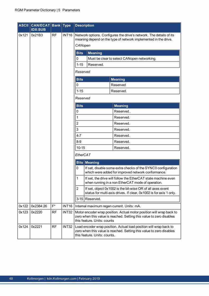
Bank Type Description
0x121 0x21B3 RF INT16 Network options. Configures the drive’s network. The details of itsmeaning depend on the type of network implemented in the drive.
CANopen
Bits Meaning0 Must be clear to select CANopen networking.
1-15 Reserved.
Reserved
Bits Meaning0 Reserved
1-15 Reserved.
Reserved
Bits Meaning0 Reserved..
1 Reserved.
2 Reserved.
3 Reserved.
4-7 Reserved.
8-9 Reserved.
10-15 Reserved.
EtherCAT
Bits Meaning0 If set, disable some extra checks of the SYNC0 configuration
which were added for improved network conformance.
1 If set, the drive will follow the EtherCAT statemachine evenwhen running in a non EtherCATmode of operation.
2 If set, object 0x1002 is the bit-wise OR of all axes eventstatus for multi-axis drives. If clear, 0x1002 is for axis 1 only.
3-15 Reserved.
0x122 0x2384:26 F* INT16 Internal maximum regen current. Units: mA.
0x123 0x2220 RF INT32 Motor encoder wrap position. Actual motor position will wrap back tozero when this value is reached. Setting this value to zero disablesthis feature. Units: counts
0x124 0x2221 RF INT32 Load encoder wrap position. Actual load position will wrap back tozero when this value is reached. Setting this value to zero disablesthis feature. Units: counts.
48 Kollmorgen | kdn.Kollmorgen.com | February 2019
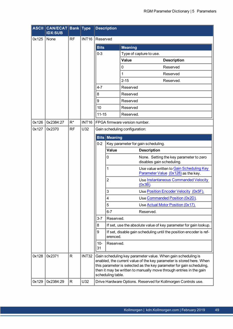
ASCII CAN/ECATIDX:SUB
Bank Type Description
0x125 None RF INT16 Reserved
Bits Meaning0-3 Type of capture to use.
Value Description0 Reserved
1 Reserved
2-15 Reserved.
4-7 Reserved
8 Reserved
9 Reserved
10 Reserved
11-15 Reserved.
0x126 0x2384:27 R* INT16 FPGA firmware version number.
0x127 0x2370 RF U32 Gain scheduling configuration:
Bits Meaning0-2 Key parameter for gain scheduling.
Value Description0 None. Setting the key parameter to zero
disables gain scheduling.
1 Use value written to Gain Scheduling KeyParameter Value (0x128) as the key.
2 Use Instantaneous Commanded Velocity(0x3B).
3 Use Position Encoder Velocity (0x5F).
4 Use Commanded Position (0x2D).
5 Use Actual Motor Position (0x17).
6-7 Reserved.
3-7 Reserved.
8 If set, use the absolute value of key parameter for gain lookup.
9 If set, disable gain scheduling until the position encoder is ref-erenced.
10-31
Reserved.
0x128 0x2371 R INT32 Gain scheduling key parameter value. When gain scheduling isenabled, the current value of the key parameter is stored here. Whenthis parameter is selected as the key parameter for gain scheduling,then it may be written tomanually move through entries in the gainscheduling table.
0x129 0x2384:29 R U32 Drive Hardware Options. Reserved for Kollmorgen Controls use.
RGM Parameter Dictionary | 5 Parameters
Kollmorgen | kdn.Kollmorgen.com | February 2019 49
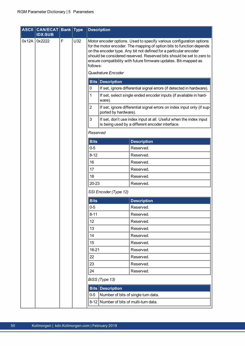
RGMParameter Dictionary | 5 Parameters
ASCII CAN/ECATIDX:SUB
Bank Type Description
0x12A 0x2222 F U32 Motor encoder options. Used to specify various configuration optionsfor themotor encoder. Themapping of option bits to function dependson the encoder type. Any bit not defined for a particular encodershould be considered reserved. Reserved bits should be set to zero toensure compatibility with future firmware updates. Bit-mapped asfollows:
Quadrature Encoder
Bits Description0 If set, ignore differential signal errors (if detected in hardware).
1 If set, select single ended encoder inputs (if available in hard-ware).
2 If set, ignore differential signal errors on index input only (if sup-ported by hardware).
3 If set, don’t use index input at all. Useful when the index inputis being used by a different encoder interface.
Reserved
Bits Description0-5 Reserved.
8-12 Reserved.
16 Reserved.
17 Reserved.
18 Reserved.
20-23 Reserved.
SSI Encoder (Type 12)
Bits Description0-5 Reserved.
8-11 Reserved.
12 Reserved.
13 Reserved.
14 Reserved.
15 Reserved.
16-21 Reserved.
22 Reserved.
23 Reserved.
24 Reserved.
BiSS (Type 13)
Bits Description0-5 Number of bits of single turn data.
8-12 Number of bits of multi-turn data.
50 Kollmorgen | kdn.Kollmorgen.com | February 2019

ASCII CAN/ECATIDX:SUB
Bank Type Description
Bits Description15 If set, assume the encoder position data wraps after the num-
ber of encoder counts programmed in parameter MotorEncoder Counts (0x62).
16 Set for mode-C encoder format.
20 Set if encoder error and warning bits are active low.
21 Set if encoder status bits are sent before position data. Clear ifstatus bits are sent after position data.
22 Set if encoder error bit is transmitted before warning bit. Clearfor warning bit sent first.
24-26
Number of alignment bits (reserved bits sent before positioninfo).
28 Usemulti-mode port if set. If clear use primary encoder inter-face.
30 Set for 2.5MHz baud rate, clear for 4MHz baud rate.
Reserved
Bits Description0-5 Reserved.
8-12 Reserved.
16-19 Reserved.
20-22 Reserved.
24-27 Reserved.
28 Reserved.
30 Reserved.
0x12B 0x2223 F U32 Load Encoder Options. Same as 0x12A, but affects load or positionencoder.
0x12C 0x2384:28 R* U32 Secondary firmware version for drives equipped with two processors.
0x12D 0x2109 RF 9 or 14words
Analog Input Filter Coefficients. A bi-quad filter which acts on theanalog reference input. 9 word parameter, see Analog Input Filters inthe RGMWorkBench User Guide. 14 word parameter (Plus productonly), see "Filter Coefficients" (➜ p. 56).
RGM Parameter Dictionary | 5 Parameters
Kollmorgen | kdn.Kollmorgen.com | February 2019 51

RGMParameter Dictionary | 5 Parameters
ASCII CAN/ECATIDX:SUB
Bank Type Description
0x12E 0x2224 R* U32 Motor encoder status. This parameter gives additional statusinformation for the encoder. Bits set in the status word are latched andcleared when the status value is read. The format of this status wordis dependent on the encoder type. Many error bits are taken directlyfrom encoder data stream. For a full description of what these errorbits mean, please consult the encoder manufacturer.
Quadrature
Bits Description0 Reserved.
1 Set on bad differential signal levels on any of the encoderinputs.
Reserved
Bits Description0 Reserved.
1 Reserved.
2 Reserved.
3 Reserved.
Reserved
Bits Description0-6 Reserved.
15 Reserved.
BiSS (Type 13)
Bits Description0 CRC error on data received from encoder.
1 Encoder failed to transmit data to amp.
2 Error bit on encoder stream is active.
3 Warning bit on encoder stream is active.
4 Encoder transmission delay is too long.
Tamagawa & Panasonic (Type 14)
Bits Description0 Reserved.
1 Reserved.
2 Reserved.
3 Reserved.
5 Reserved.
6 Reserved.
7 Reserved.
52 Kollmorgen | kdn.Kollmorgen.com | February 2019

ASCII CAN/ECATIDX:SUB
Bank Type Description
Bits Description8 Reserved.
9 Reserved.
10 Reserved.
11 Reserved.
15 Reserved.
Reserved
Bits Description0 Reserved.
1 Reserved.
3 Reserved.
4 Reserved.
5 Reserved.
6 Reserved.
7 Reserved.
8 Reserved.
9 Reserved.
15 Reserved.
0x12F 0x2225 R* U32 Load encoder status. Same as parameter 0x12E, but for the loadencoder.
0x130 0x2114 RF INT16 RMS current calculation period. This sets the period over which theRMS current is calculated. If this value is set to zero, then the RMScurrent will be updated each time it is read for the period since the lastread. In this case, the RMS current must be read at least once every65536 current loop periods (about every 4 seconds) for the returnedRMS values to be accurate. Units: milliseconds.
0x131 0x2115 R* INT16 RMS current over the period set in parameter 0x130. Units: 0.01 A.
0x132 0x2116 R* INT16 Running sum of user current limit in 0.01% units. (i.e., 0 to 10000).
0x133 0x2117 R* INT16 Running sum of amp current limit in 0.01% units. (i.e., 0 to 10000).
RGM Parameter Dictionary | 5 Parameters
Kollmorgen | kdn.Kollmorgen.com | February 2019 53

RGMParameter Dictionary | 5 Parameters
ASCII CAN/ECATIDX:SUB
Bank Type Description
0x134 0x21E0 RF U32 Analog output configuration. This parameter sets themode for theAnalog output on drives so equipped.
Bits Description0-3 Define themode of the Analog output.
16-17 Identify the axis associated with the Analog output.
Mode Description0 Manual configuration (set using parameter 0x135).
1 Actual current of configured axis.
2 Actual velocity of configured axis. The output is a +/- 5Vrange and is a ratio of the actual velocity to the velocity loopmaximum velocity.
0x135 0x21E1 R INT16 Analog output value. For drives that support an Analog output, thisparameter sets the output value in mV units when the D/A is inmanual mode. In other modes, the current value being output on theD/A can be read here.
0x136 0x2208 R* INT16 Secondary analog reference value. Units: millivolts
0x137 0x2314 RF INT16 Secondary analog reference offset. Offset for secondary analogreference input. Units: millivolts
0x138 0x2315 RF INT16 Calibration offset for second analog reference input. It is factory-calibrated to give a zero reading for zero input voltage. Units:millivolts
0x139 0x219D R INT32 Status of drive safety circuit. This parameter allows the status of thesafety circuit built into some drives to be queried. For drives without asafety circuit, this parameter is reserved.
Bits Description0 Set when safety input 0 is preventing the drive from enabling.
1 Set when safety input 1 is preventing the drive from enabling.
8 This read/write bit can be used to force the ‘drive is unsafe’ out-put of the safety circuit to go active for testing purposes. Write1 to force.
0x13A 0x2209 R* INT16 Present voltage at analogmotor temperature sensor. Units: millivolts.
0x13B 0x220A RF INT16 Limit for analogmotor temperature sensor.
If this parameter is set to zero, then the analogmotor temperaturesensor is disabled.
If this parameter is set to a positive value, then amotor temperatureerror will occur any time the voltage on themotor temperature inputexceeds this value (in millivolts).
If this parameter is negative, then amotor temperature error will occurany time the voltage on themotor temperature input is lower than theabsolute value of this limit in millivolts.
54 Kollmorgen | kdn.Kollmorgen.com | February 2019

ASCII CAN/ECATIDX:SUB
Bank Type Description
0x13C 0x2323 RF INT16 Minimum PWM pulse width in microseconds. Used when running inPWM positionmode. In this mode the PWM input pulse width iscaptured by the drive and used to calculate an absolute position usingthe following formula:
pos = ((PW-MIN) / (MAX-MIN)) * SCALE + OFFSET
where this parameter is theminimum pulse width (MIN), parameter0x13D is themaximum pulse width (MAX), parameter 0xA9 is thescaling factor (SCALE) and parameter 0x10F is the offset (OFFSET).
0x13D 0x2324 RF INT16 Maximum PWM pulse width used when running in PWM positionmode. Units: microseconds.
0x150 0x210A RF 14words
Second chained biquad filter on output of velocity loop, see "FilterCoefficients" (➜ p. 56).
0x151 0x210B RF 14words
Third chained biquad filter on output of velocity loop. 14 wordparameter, see "Filter Coefficients" (➜ p. 56).
0x152 0x210C RF 14words
First chained biquad filter on input of current loop. 14 word parameter,see "Filter Coefficients" (➜ p. 56).
0x153 0x210D RF 14words
Second chained biquad filter on input of current loop. 14 wordparameter, see "Filter Coefficients" (➜ p. 56).
0x154 0x2301 RF INT32 Servo loop configuration. This parameter allows various parts of thedrive servo loops to be enabled/disabled. Bit-mapped as follows:
Bits Description0 If set, this disables the velocity loop gains. The velocity loop
command feed forward gain (parameter 0x157) is still activeas are the velocity loop output filters.
1 If set, this enables the position loop I and D gains (parameters0x155 and 0x156). If clear, these parameters are treated aszeros.
2-31 Reserved for future use.
0x155 0x2382:5 RF INT16 Position loop integral gain (KI).
0x156 0x2382:6 RF INT16 Derivative gain for position loop (KD).
0x157 0x2381:6 RF INT16 Velocity loop command feed forward. The input command (afterlimiting) to the velocity loop is scaled by this value and added in to theoutput of the velocity loop.
0x158 0x2382:7 RF INT16 Integral drain for position loop.
0x159 0x6007 RF INT16 Abort option code for CANopen / EtherCAT drives.
RGM Parameter Dictionary | 5 Parameters
Kollmorgen | kdn.Kollmorgen.com | February 2019 55

RGMParameter Dictionary | 6 Filter Coefficients
6 Filter CoefficientsThere are several drive parameters which are used to define filters. These filters are implemented as genericbiquadratic filter structures. Filters of this type implement the following formula to transform the inputparameter x(n) at time n to an output parameter y(n):
y(n) = b0·x(n) + b1·x(n-1) + b2·x(n-2) + a1·y(n-1) + a2·y(n-2)
The values a1, a2, b0, b1, b2 are constants known as filter coefficients. They define the type of filter beingimplemented.
The values passed to these drive filter parameters are used to define the filter coefficients. The formatting ofthese parameters varies depending on the drive family being interfaced to.
All first generation drives use 16-bit integer math to implement their filters internally. Filter coefficients aregiven as 16-bit signed integer values. To increase the resolution of these coefficients, an additional unsignedscaling coefficient (k) is also specified. The actual filter formula used within these drives is as follows:
y(n) = K · (b0·x(n) + b1·x(n-1) + b2·x(n-2) + a1·y(n-1) + a2·y(n-2)) /32768 / 4096
To set the filter coefficients on drives of this category, 9 words of parameter data are passed. The first threewords of data are informational parameters which are used by the CME software to describe the filter. If theupper 3 bits of the first word are all set then the filter will be disabled. Other than that, the first three words ofdata are not used in any way by the firmware. These three words are reserved for CME use.
Word Description1 Filter info. Set to 0xFFFF to disable the filter. Otherwise, reserved for CME use.
2 Filter info. Reserved for CME use.
3 Filter info. Reserved for CME use.
4 b2 coefficient.
5 b1 coefficient.
6 b0 coefficient.
7 a2 coefficient.
8 a1 coefficient.
9 K scaler.
56 Kollmorgen | kdn.Kollmorgen.com | February 2019

Word Description1 Bits Usage
0-3 Filter family.
4 If set, filter will not be designed. Always set by firmware after successfully designing the fil-ter. This prevents the filter from being redesigned when copied from flash at startup.
5-7 Reserved.
8 Number of poles – 1 (i.e. 0 for single pole, 1 for two pole).
9-12 Reserved.
13-15
Filter type.
All reserved bits should be set to zero.The filter family should be one of the following values:Bits Usage0 Custom biquad filter. Coefficients must be passed; the firmware will not design the filter.
1 Butterworth filter.
2 Chebychev filter.
3 Elliptic filter.
4-15 Reserved.The filter type should be one of the following:Bits Usage0 Custom biquad filter. Coefficients must be passed; the firmware will not design the filter.
1 Low pass.
2 High pass.
3 Band reject (notch).
4 Band pass.
5-6 Reserved
7 Disabled. The filter will have no effect in the system.If legal values are passed for the filter type and family, the firmware will attempt to design the spe-cified filter and fill in the coefficient values itself. The firmware is capable of calculating 1 or 2 polelow pass or high pass filters. For notch and band pass filters the firmware can only calculate a twopole filter. For these filter types, bit 8 must be set.
2 This word gives the cut off frequency (in Hz) for low pass and high pass filters. For notch and bandpass filters this gives the first filter frequency.
3 This word gives the second filter frequency (in Hz) for notch and band pass filters.
4 Bits Usage0-7 Rp given in 0.1 dB units.
8-15 Rs given in dB units.Rp is the pass band ripple. This parameter is only used for Chebychev and Elliptic filters.Rs is only used with elliptic filters. It defines the stop band as Rs dB down from the peak value in thepass band.
5-6 Coefficient a1. All filter coefficients are passed as 32-bit IEEE floating point numbers. The upper 32-bits should be passed first.If the firmware designs the filter then the coefficients will be filled in by the firmware and need not bepassed.
RGM Parameter Dictionary | 6 Filter Coefficients
Kollmorgen | kdn.Kollmorgen.com | February 2019 57

RGMParameter Dictionary | 6 Filter Coefficients
Word Description7-8 Coefficient a2.
9-10 Coefficient b0.
11-12 Coefficient b1.
13-14 Coefficient b2.
58 Kollmorgen | kdn.Kollmorgen.com | February 2019

About Kollmorgen
Kollmorgen is a leading provider of motion systems and components for machine builders. Through world-classknowledge inmotion, industry-leading quality and deep expertise in linking and integrating standard and customproducts, Kollmorgen delivers breakthrough solutions that are unmatched in performance, reliability and ease-of-use, givingmachine builders an irrefutable marketplace advantage.
Join the Kollmorgen Developer Network for product support. Ask the community ques-tions, search the knowledge base for answers, get downloads, and suggest improve-ments.
North AmericaKollmorgen203A West Rock RoadRadford, VA 24141USA
Web: www.Kollmorgen.comMail: [email protected].: +1 - 540 - 633 - 3545Fax: +1 - 540 - 639 - 4162
EuropeKollmorgen Europe GmbHPempelfurtstraße 140880 RatingenGermanyWeb: www.Kollmorgen.comMail: [email protected].: +49 - 2102 - 9394 - 0Fax: +49 - 2102 - 9394 - 3155
South AmericaKollmorgenAvenida Tamboré, 1077 Tamboré -Barueri - SP BrasilCEP: 06460-000Web: www.Kollmorgen.comTel.: +55 11 4191-4771
China and Southeast AsiaKollmorgen AsiaRoom 302, Building 5,Lihpao Plaza, 88 Shenbin Road,Minhang District, Shanghai, ChinaWeb: www.Kollmorgen.cnMail: [email protected].: +86 - 400 - 668-2802Fax: +81 - 216 - 248-5367