Response to the NOTICE OF DEFICIENCY - env.nm.gov
108
ERID-215002 • LosAlamos NATIONAL LABORATORY - - - [5T. l'fO -- Environmental Protection Division Water Quality & RCRA Group (ENV-RCRA) P.O. Box 1663, M704 Los Alamos, New Mexico 87545 (505) 667-0666 National Nuclear Security Administration Los Alamos Site Office, A316 3747 West Jemez Road Los Alamos, New Mexico 87545 (505) 667-5794/FAX (505) 667-5948 Date: APR 1 6 2012 Refer To : ENV-RCRA-12-0076 LAUR: 12-20478, 12-20477 CERTIFIED MAIL - RETURN RECEIPT REOUESTED Mr. John E. Kieling Program Manager Permits Management Program Hazardous Waste Bureau New Mexico Environment Department 2905 Rodeo Park Drive East, Building 1 Santa Fe, NM 87505-6303 Dear Mr. Kieling: SUBJECT: RESPONSE TO NOTICE OF DEFICIENCY ADMINISTRATIVE COMPLETENESS AND FEE ASSESSMENT TA-63 TRANSURANIC WASTE FACILITY PERMIT MODIFICATION REQUEST LOS ALAMOS NATIONAL LABORATORY EPA ID# NM 0890010515 The purpose of this letter is to transmit the United States Department of Energy and Los Alamos National Security, LLC (Permittees) r esponse to the above referenced Notice of Deficiency (NOD) da ted February 2, 2012. 111e NOD requires additional information or clarification regarding the information pres ent ed in the Permit Modification Re ques t for Te chnical Area 63, Transuranic Waste Pacility, Ha zardous Wa s te Container Storage Unit originally submitted to the New Mexico Environment Department-Hazardous Waste Bureau (NMEO-HWB) on August 18, 2011. As request ed by the NOD, thi s respon se s ubmittal contains a number of documents. Enclosure 1 is the body of the re sponse to the NOD. In that submittal, the NMED-HWB comments are included verbatim in italics to help with review. The Permittees' responses follow eachNMED-HWB comment. There are several supporting attachments incluiling a copy of a report regarding additional seismic findings for the proposed site that was concurrently requested by your office. As requested in the NOD/ three oilier attachments are included with this submittal. They include revised versions of the original permit modification request incorporating the Permittees' . responses and proposed manges in redline revisions with a clean copy of the text in Word 2007 fonnat as electroruc files on a compact disc. A clean hard copy of the revised permit modification request (Enclosure 2) is also included in this submittal. A major factor regarding the design for the Transuranic Wa ste Facility is addressed in the responses to the NOD comments. This regards a concern included in the October 24, 2011 letter from David Martin, Cabinet Secretary for the NMED, transmitting his determination that the August 18, 2011 permit modification request should be processed as a Class 3 pennit modification. An Equal Opportunity Employer I Operated by Los Alamos National Security LLC for DOE/NNSA
-
Upload
khangminh22 -
Category
Documents
-
view
0 -
download
0
Transcript of Response to the NOTICE OF DEFICIENCY - env.nm.gov

ERID-215002
• LosAlamos NATIONAL LABORATORY - - - [5T. l'fO --
Environmental Protection Division Water Quality & RCRA Group (ENV-RCRA) P.O. Box 1663, M704 Los Alamos, New Mexico 87545 (505) 667-0666
National Nuclear Security Administration Los Alamos Site Office, A316 3747 West Jemez Road Los Alamos, New Mexico 87545 (505) 667-5794/FAX (505) 667-5948
Date: APR 1 6 2012 Refer To: ENV-RCRA-12-0076
LAUR: 12-20478, 12-20477
CERTIFIED MAIL - RETURN RECEIPT REOUESTED
Mr. John E. Kieling Program Manager Permits Management Program Hazardous Waste Bureau New Mexico Environment Department 2905 Rodeo Park Drive East, Building 1 Santa Fe, NM 87505-6303
Dear Mr. Kieling:
SUBJECT: RESPONSE TO NOTICE OF DEFICIENCY ADMINISTRATIVE COMPLETENESS AND FEE ASSESSMENT TA-63 TRANSURANIC WASTE FACILITY PERMIT MODIFICATION REQUEST LOS ALAMOS NATIONAL LABORATORY EPA ID# NM 0890010515
The purpose of this letter is to transmit the United States Department of Energy and Los Alamos National Security, LLC (Permittees) response to the above referenced Notice of Deficiency (NOD) dated February 2, 2012. 111e NOD requires additional information or clarification regarding the information presented in the Permit Modification Request for Technical Area 63, Transuranic Waste Pacility, Hazardous Waste Container Storage Unit originally submitted to the New Mexico Environment Department-Hazardous Waste Bureau (NMEO-HWB) on August 18, 2011.
As requested by the NOD, this response submittal contains a number of documents. Enclosure 1 is the body of the response to the NOD. In that submittal, the NMED-HWB comments are included verbatim in italics to help with review. The Permittees' responses follow eachNMED-HWB comment. There are several supporting attachments incluiling a copy of a report regarding additional seismic findings for the proposed site that was concurrently requested by your office. As requested in the NOD/ three oilier attachments are included with this submittal. They include revised versions of the original permit modification request incorporating the Permittees' . responses and proposed manges in redline revisions with a clean copy of the text in Word 2007 fonnat as electroruc files on a compact disc. A clean hard copy of the revised permit modification request (Enclosure 2) is also included in this submittal.
A major factor regarding the design for the Transuranic Waste Facility is addressed in the responses to the NOD comments. This regards a concern included in the October 24, 2011 letter from David Martin, Cabinet Secretary for the NMED, transmitting his determination that the August 18, 2011 permit modification request should be processed as a Class 3 pennit modification.
An Equal Opportunity Employer I Operated by Los Alamos National Security LLC for DOE/NNSA

Mr. John E. Kieling ENV-RCRA-12-0075
-2-
The issue was a potential for uncontrolled run-off management from the site associated with waste container loading on the southern portion of the concrete pad making up the base of the unit.
To address that concern, the hazardous waste management unit has been redesigned to include all the associated waste management functions within an area draining to a retention basin in the northenl portion of the site. This design revision will allow the collection of any potential contamination from those activities carried by potential emergency activities such as fires or spills at the site. The southern portion is no longer included within the boundary of the hazardous waste management unit, which also makes the tmit smaller than originally propo ed . The redesign of the TWF requires some ubstantial revision of the permit modification request and this is explained in the responses.
If you have comments or questions regarding this permit modification, please contact Gene Turner at (505) 667-5794 or Mark Haagenstad, at (505) 665-2014.
Sincerely, Sincerely,
Antl11;&f~ Group Leader
G~~~ Environmental Permitting Man.ager Environmental Projects Office Department of Ener~w
Water Quality & RCRA Group Los Alamos National Laboratory
Los Alamos Site Office
ARG:GET:GB/lm
Enclosures:
Cy:
(1)
(2)
Response to the Notice of Deficiency, Adminjstrative Completeness and Fee Assessment, TA-63 Transuranic Waste Facility Permit Modification Request. Permit Modification Request, Technical Area 63 Transuranic Waste Facility Hazardous Waste Container Storage Unit, Revision 1.0
Laurie King, USEPA/Region 6, Dallas, TX, w / enc. Tim Hall, NMED/HWB, Santa Fe, NM, w/enc. Kevin Smith, LASO-OOM, w / 0 enc., A316, (E-File) George Rael, LASO-NSM, w /0 enc., A906, (E-File) Gene E. Turner, LASO-EPO, w /0 enc., A316, (E-File) Carl A. Beard, PADOPS, w / 0 enc., AI02, (E-File) Michael T. Brandt, ADESH, w /0 ene., K491, (E-File) Michael J. Graham, ADEP, w /0 enc., M991, (E-File) Alison M. Dories, ENV-DO, w / 0 ene., K491, (E-File) Scotty W. Jones, ENV-DO, w / 0 ene., K49l, (E-File) Gregory Juerling, MOF-PM2, w / 0 ene., K482, (E-File) Mark P. Haagenstad, ENV-RCRA, w/o ene., K404, (E-File) Gian A. Bacigalupa, ENV-RCRA, w/enc., K404 Susan L. McMichael, LC-ESH, w /0 enc., AI87, (E-File) ENV-RCRA File, M704 IRM-RMMSO, w /ene., AlSO, (E-File)
An Equal Opportunity Employer I Operated by Los Alamos National Security LLC for DOE/NNSA

\
;QAlam05 NATIONAL LA'ORATORY
n T.l'~)
COpy Environmental Protection Division Water Quality & RCRA Group (ENV-RCRAJ P.O. Box 1663, M704
National Nuclear Security Administration Los Atamos Site Office, A316
Los Alamos, New Mexico 87545 (505) 667-0666
3747 West Jemez Road Los Alamos, New Mexico 87545 (505) 667-5794/FAX (505) 667-5948
Date: Refer To:
LAUR:
APR 1 6 2012 ENV-RCRA-12-0076 12-20478, 12-20477
CERTIFlED MAIL - RETURN RECEIPT REOUfSTED
Mr. John E. Kieling Program Manager Permits Management Program Hazardous Waste Bureau New Mexico Environment Department 2905 Rodeo Park Drive East, Building 1 Santa Fe, NM 87505-6303
Dear Mr. Kieling:
SUBJECT: RESPONSE TO NOTICE OF DEFIOENCY ADMINISTRATIVE COMPLETENESS AND FEE ASSESSMENT TA-63 TRANSURANIC WASTE FACILITY PERMIT MODIFICATION REQUEST LOS ALAMOS NATIONAL LABORATORY EpA 10# NM 0890010515
The purpose of this lette r is to transmit the United States Department of Energy and Los Alamos National Security, LLC (permittees) resp onse to the above referenced Notice of Deficiency (NOD) dated February 2, 2012. The NOD reqUlres additional information or clarification regarding the information presented in the Permit Modification Request Jar Tedmical Area 63, Trall5uranic Waste J:nrilH" I-'n'mrrlru u: Wn<:fp rn"tninp.r .~t()rave Unit ori2"Ulallv submitted to the New Mexico
• Completeltema 1, 2, and 3. Also complete Item 4 If Restrlcted Delivery Is desired.
• PrInt your name and address on the reverse so that we can return the card to you.
• Attach this card to the back of the mallp1ece, ()( on the front If space permits.
1. ArtIcle Ad<*'Imed to:
Mr. John E. Kicling Hazardous Waste Bul'Cau New Mexico Enyironment Depanment 2905 R.Odco Park Drivc East, Building I Santa Fe, NM 87!505
If YES, enter deIIveI'y address below: 0 No
o Express Mall o Retum ReceIpt for Mercttandtse
o
PS Form , February 2004 Domestic Retum R&eeipl
, , l re 1 is uded
ifice. Lelude
1007 cation
Itter Ie ication.

Response to the Notice of DeficiencyAdministrative Completeness and Fee Assessment
TA-63 Transuranic Waste Facility Permit Modification RequestLos Alamos National Laboratory
April 2012LA-UR-12-20478
Prepared by:Los Alamos National Laboratory
Water Quality & Resource Conservation and Recovery Act GroupLos Alamos, New Mexico 87545

Document: LANL TA-63 TWF NOD Response Date: April 2012
1
RESPONSE TO THE NOTICE OF DEFICIENCYADMINISTRATIVE COMPLETENESS AND FEE ASSESSMENT
TA-63 TRANSURANIC WASTE FACILITYPERMIT MODIFICATION REQUEST
LOS ALAMOS NATIONAL LABORATORYEPA ID# NM 0890010515
INTRODUCTIONThis document responds to the February 1, 2012, New Mexico Environment Department-Hazardous Waste Bureau (NMED-HWB) Notice of Deficiency (NOD) referenced above. The NOD was issued for the Permit Modification Request for Technical Area 63, Transuranic Waste Facility, Hazardous Waste Container Storage Unit (PMR) originally submitted to NMED-HWB on August 18, 2011, by the United States Department of Energy and Los Alamos National Security, LLC, collectively the Permittees. The Permittees are seeking to modify the Hazardous Waste Facility Permit (Permit) for Los Alamos National Laboratory (LANL) for approval of the construction of the Transuranic Waste Facility (TWF) at Technical Area 63 (TA-63) and permission to store mixed transuranic and hazardous waste there.
The NMED-HWB comments are included verbatim in italics to help with review. The Permittees’ responses follow each NMED-HWB comment.
This response contains information regarding the management of radioactive materials, including source, special nuclear, and byproduct material. Information on radioactive materials and radionuclides, including the results of sampling and analysis of radioactive constituents, is voluntarily provided to NMED-HWB in accordance with U.S. Department of Energy (DOE) policy.
There are four Attachments to this document. Attachment A includes a copy of the original NOD. Attachment B includes electronic files for the proposed revisions to the PMR resulting from the Permittees’ answers. Attachment C is a supporting study for the subsurface soil vapor plume from the nearby Solid Waste Management Unit at TA-50Material Disposal Area (MDA)-C. Attachment D of this submittal includes a report regarding further seismic interpretations for the TWF site that was concurrently requested by NMED-HWB. It is provided as supplementary information although no NOD comment specifically references it. Appendix E includes a facility certification for this document in accordance with 40 CFR §270.11(b).
Section Specific Comments:
1. Section 1.0 inaccurately identifies the permit modification request (PMR) as a Class 2 modification (see first sentence). In correspondence dated October 24, 2011, the Department informed the Permittees that the PMR is more appropriately processed as a

Document: LANL TA-63 TWF NOD Response Date: April 2012
2
Class 3 modification. Alter the PMR reference at this Section to reference a Class 3 modification and make a similar alteration at all other applicable locations.
LANL is in receipt of the October 24, 2011 letter from David Martin, Cabinet Secretary for the NMED, transmitting his determination that the August 18, 2011 TWF PMR should be processed as a Class 3 permit modification because of substantial public concern and complex technical issues. References to a Class 2 permit modification have been altered in the attached PMR revision to read Class 3, including Sections 1.0 and 1.1.
2. Section 1.0 inaccurately states that Table 1-1 provides a list of hazardous waste management unit regulatory requirements and the location in the PMR where the requirements are addressed (see second paragraph, third sentence). Table 1-1inappropriately suggests that the information requirements for containers required at 40 CFR § 270.15 is provided at PMR Section 2.5. PMR Section 2.5 (Hazards Prevention) states that it addresses the requirements at §270.14(b)(8). Revise the table to address the requirements at § 270.15 (i.e., §§ 264.175, 264.175(c), 264.176, 264.177(a), 264.177(b), 264. 177(c), 264.17(b), 264.17(c), and 270.27) for thoroughness and accuracy. If the PMR does not sufficiently address the information requirements at § 270.15, the PMR must be revised to address those issues. Please verify the following relationships:
264.175 - PMR Sections 2.2.1, 2.2.2, and 2.5.4264.175(c) - PMR Sections 2.2.1, and 2.2.2264.176 - PMR Section 2.8264.177(a) - PMR Section 2.8264.177(b) - PMR Section 2.8264.177(c) - PMR Section 2.8264.17(b) - PMR Section 2.8264.17(c) - PMR Section 2.8270.27 - PMR Sections 2.5.8 and 2.5.9
Table 1-1 was updated to provide a list of the regulatory requirements and the location in the PMR. The reference to PMR Section 2.5 was revised to Section 2.2. The following references were verified to address the noted regulatory requirements:
� 264.175 - PMR Sections 2.2.1 [40 CFR 264.175(b)], 2.2.2 [40 CFR 264.175(b)(1) &(2)], 2.2.6 [40 CFR 264.175(b)(5)]. and 2.5.4: [40 CFR 264.175(b)(3) & (4) ]
� 264.175(c) - PMR Section 2.2.2: Storage requirements for containers that do not include liquids.
� 264.176 - PMR Section 2.8: Special requirements for ignitable or reactive waste.� 264.177(a) - PMR Section 2.8: Requirements for incompatible wastes.� 264.177(b) - PMR Section 2.8: Requirement for clean containers.� 264.177(c) - PMR Section 2.8: Requirements for incompatible wastes.� 264.17(b) - PMR Section 2.8: Requirements for ignitable, reactive or incompatible wastes
and other materials.� 264.17(c) - PMR Section 2.2.7, Requirements for ignitable, reactive or incompatible waste
documentation.� 270.27 PMR Sections 2.5.8 & 2.5.9: Subpart CC applicability and standards.

Document: LANL TA-63 TWF NOD Response Date: April 2012
3
3. Section 1.3 specifies that the maximum design storage capacity of the Transuranic Waste Facility (TWF) is 105,875 gallons, but the Section does not provide the basis for that number (see second paragraph). Revise the PMR to provide all assumptions associated with the maximum storage capacity determination, e.g., the total square footage of storage space, the storage location limitations, and the container stacking limits.The discussion at Section 1.3 is intended to be a summarized introduction of the TWF. Subsequent portions of the PMR address the details associated with the facility. It is proposed that the following discussion be placed in Section 2.2.7.2, Storage. As stated in Response to Comment 8, the area of the hazardous waste management unit is 78,843 square feet. As also stated in Section 2.2.7.2 of the PMR, the storage locations for waste are subject to the requirements of Permit Section 3.5.1, Storage Configuration and Minimum Aisle Space. The section has been revised to include the following discussion:
“Four types of waste containers are planned to be used for storage of transuranic (TRU) waste at the TA-63 TWF. These waste container types are 55-gallon drums, Standard Waste Boxes (SWBs), Standard Large Boxes 2 (SLB2s), and Oversize Waste Boxes (OWBs). (It is also possible that a 55-gallon drum could be over-packed into an 85-gallon drum if a 55-gallon drum was damaged or there was some other concern for its integrity, but 85-gallon drums will not be used as primary waste containers.
Although 55-gallon drums and SWBs are expected to make up the majority of the containers by number, some TRU waste will also be stored in both SLB2s and OWBs. Numbers of the various types of waste containers will vary at any given time. Table 2-2(proposed for the PMR) presents a scenario for waste container storage that has a maximum number of SWBs, SLB2s, and OWBs that would likely be stored at the facility. Four of the waste storage buildings would store only 55-gallon drums, a fifth storage building would store primarily SWBs but some 55-gallon drums, the storage and characterization building would store primarily SLB2s but some 55-gallon drums, and OWBs would be stored outside under this scenario. This is discussed in more detail below. The total estimated storage capacity shown in the table was rounded to 105,875 gallons for the maximum design storage capacity of the Transuranic Waste Facility.
TABLE 2-2Waste Container Storage Capacity Example
Container Type Number of Containers
Nominal Container Dimensions (feet)
Nominal Container Capacity (gallons)
Total Gallons
55-Gallon Drum 992 Height = 2.79Diameter = 1.88
55 54,560
Standard Waste Box (SWB)
38 Height = 3.03Length = 5.73Width = 4.33
470 17,860
Standard Large Box 2 (SLB2)
5 Height = 5.38Length = 8.50Width = 5.25
1,790 8,950
Oversize Waste 4 Height = 7.0 6,126 24,504

Document: LANL TA-63 TWF NOD Response Date: April 2012
4
Box (OWB) Length = 13.0Width = 9.0
TOTAL CAPACITY 105,874
The layout of waste containers in the four storage buildings that would store only 55-gallon drums (no other container types) in this scenario consists of two rows of ten groups of pallets with four 55-gallon drums per pallet and pallets stacked three high (resulting in a total of 120 drums per row and 240 drums per waste storage building.) The layout of the rows with pallets is like that shown in Figure 2-9, Storage Building Floor Plan.
The layout of the storage building that would store primarily SWBs and some drums in this scenario consists of two rows of groups of pallets with a single SWB stacked two high. One row would consist of a total of 10 groups of pallets with one SWB per pallet stacked two high, and the other row would consist of a total of 9 groups of pallets with one SWB per pallet stacked two high (resulting in a total of 20 SWBs in one row and 18 SWBs in the second row). A single group of pallets with 55-gallon drums stacked three high would be located at the end of the row of 9 groups of pallets with SWBs two high. Total storage within this waste storage building would be a total of 38 SWBs and 12 55-gallon drums. The layout of the rows with pallets would be similar to that shown in Figure 2-9, except that groups of SWBs stacked two-high on pallets would replace all of the groups of drums stacked three high on pallets. The exception is for one group of pallets containing drums (this was done to ensure sufficient aisle space for emergency egress at each of the personnel doors in the storage building).
The layout of the storage and characterization building that would store SLB2s and some drums in this scenario consists of two rows of SLB2s (one high stacking) in the storage bay of the building, with two SLB2s in one row and three SLB2s in the other row. Five pallets of four 55-gallon drums (one high stacking) would be located in the Thermal Equilibration (T.E.) Room of the building. Total storage within the storage and characterization building would be a total of 5 SLB2s and 20 drums. The layout of containers under this scenario would be similar to that shown in the floor plan in Figure 2-19, Storage and Characterization Building Floor Plan, except that a row of three SLB2s would replace the row of drums on pallets in the storage bay, and a row of two SLB2s would replace the single large container shown in the figure. The layout of 55-gallon drums stored in the T.E. Room would be like that shown in the figure. Because the waste storage buildings would be filled to capacity under this scenario, the four OWBs would be stored outside on the concrete pad.”
4. Section 1.3 states that the boundaries of the pad designate the RCRA-permitted portion of the TWF (see third paragraph, third sentence). Yet Section 2.2, sixth paragraph, third sentence, states that “the pad will be surrounded by a security fence that will define the waste storage portion of the unit.” Though the Department believes that the boundaries of the pad and the fence are generally the same, the PMR must be revised to be consistent and precise with regard to the boundary of the permitted unit. Provide a figure that identifies the permitted container storage unit portion of the TWF in shading similar to Figure 37 in the Permit. The Section 2.2, sixth paragraph, description of Figure 2-5depicting “the location of areas where storage will occur highlighted” is not provided.

Document: LANL TA-63 TWF NOD Response Date: April 2012
5
Furthermore, the PMR Attachment G, Section A.6, sixth paragraph, discussion of a similar figure does not provide such a figure.
The design of the TWF has been revised to address a concern noted in the Response to Comment 10. As a result of that revision, the boundary of the TWF permitted unit has also been changed. The new boundary will be limited to the northern portion of the concrete pad defined by those areas that drain to the retention pond. Along the northern and western sides of the unit, this will be the edge of the concrete pad along the bottom of the retaining walls. On the east side, the edge of the curbing for the concrete pad will be the boundary. On the southern side, the elevated hump between the retention pond and the eastern fence will be the limit. Figure 55 providing this boundary and the highlighted storage areas has been revised and referenced in the PMR.
5. Table 1-1 is erroneous in its reference to § 270.3(b)(20). Alter the reference to § 270.14(b)(20) (see page 9).
Table 1-1 was revised to reference 40 CFR §270.14(b)(20), Considerations Under Federal Law.
6. Table 1-1 inappropriately omits reference to an applicable regulation, § 270.14(b)(22). Revise the table to address where in the PMR the regulation is addressed (see page 9).
The reference to 40 CFR §270.14(b)(22) has been added to Table 1-1. The information regarding public meetings for the PMR to meet the requirement was included in Attachment H of the PMR.
7. Section 2.2 identifies waste management activities that will occur at the TWF (i.e., long-term storage and characterization) and activities that will not occur at the TWF (i.e., waste repackaging). Section 2.2.8.1 states that “waste containers will not be opened at the TWF” and Section 2.2.8.5 commits to modifying the Permit should opening of containers at the TWF be necessary in the future. This information significantly clarifies the purpose of the TWF, its wastes management activities, and the risks associated with those activities. Revise PMR Attachment G, Section A.6, third paragraph, to explain that waste repackaging will not be occurring at the TWF and that waste containers will not be opened at the TWF. Revise Attachment G, Section 3.14.1 to prohibit the opening of containers.
Attachment G, Section A.6 has been revised by adding the following sentence:
”Waste containers will only be accepted at the TWF if they are closed and equipped with WIPP approved filter vents. Waste containers will not be opened during characterization

Document: LANL TA-63 TWF NOD Response Date: April 2012
6
or while in storage although their filter vents may be replaced if necessary. However, as noted in the contingency plan, provisions are in place to manage open containers on an emergency basis.”
The statement has also been added to Attachment G, Section 3.14.1.
8. Section 2.2 states that the surface area of the TWF will be approximately 28,100 ft2
(approximately 0.65 acres), yet PMR Attachment F, Table 1 suggests the footprint of the storage structures alone is approximately one-half that square footage and figures depicting the TWF suggest this relationship is incorrect (see sixth paragraph, first sentence). Furthermore, Section 2.2.6 states that a portion of the TWF has a footprint of 1.63 acres. Please verify the TWF total area calculation. Revise the PMR Attachment G, Table J-1 for consistency to include a total square footage of the TWF.
The area of the revised design for the hazardous waste management unit (see Response to Comment 10) is 1.81 acres or 78,843 square feet. The proposed Table J-1 in Attachment G of Rev.1 of the PMR has also been revised to show this value for total square footage of the TWF.
9. Section 2.2 references an automatic water sampler associated with the retention basin (see seventh paragraph). Section 2.2.1, second paragraph, describes drainage features and the retention basin as “providing containment for the site” and negating “the need for berms, dikes, or sumps around each storage building.” Section 2.2.6 and Attachment E also address this water sampler, however, nowhere does the PMR address in detail the purpose of the sampling, what parameters or constituents are to be sampled, or the frequency of sampling. Regulatory requirements at 40 CFR § 264.31 in part require the minimization of non-sudden releases of hazardous constituents to surface waters that could threaten human health or the environment. Permit Section D.7 addresses contingencies should there be an unplanned, non-sudden release from a permitted unit and associated surveillance sampling. Alter the PMR to reference § 264.31 and Permit Section D.7 as being applicable to the sampler and the stormwater and firewater management procedures proposed in the PMR. Alter the PMR by describing the purpose of an automated sampling, what parameters or constituents are to be sampled, and the frequency of sampling. Furthermore, alter the PMR with a proposal to notify the Department if there is any evidence of waste constituents entering the retention basin and with a proposal to maintain sample analysis information in the TWF operating record.
The information related to the presence of a storm water sampling station at the TWF was provided for informational purposes only in the PMR as part of the description of the retention basin. The reference to the sampler in Section 2.2 was intended to describe the purpose of the sampler to be installed for monitoring storm water under the applicable National Pollutant Discharge Elimination System (NPDES) Multi-Sector General Permit (MSGP), not to be used to meet the regulatory requirements of 40 CFR § 264.31. The

Document: LANL TA-63 TWF NOD Response Date: April 2012
7
references in Section 2.2.6 and Attachment E are consistent with that description. Storm water monitoring under the MSGP is conducted for specific pollutants associated with regulated industrial activities that have the potential to discharge to waters of the United States. Results from sample collections of storm water under the MSGP do not address releases of hazardous waste or hazardous constituents. In the event of such an initiating factor (a fire, spill or explosion), the Permit Contingency Plan may be implemented and arepresentative sample(s) of liquid contained in the retention basin would be collected and analyzed for hazardous constituents reasonably believed to be present. However, the automated storm water sampler would not be used to collect the sample.
The Multi-Sector General Permit For Stormwater Discharges Associated with Industrial Activity was issued by the U.S. Environmental Protection Agency (EPA) to control storm water discharges associated with specific categories of industrial activity. The TWF, once constructed and operable, will fall under Sector K, Hazardous Waste Treatment, Storage, or Disposal Facilities of the applicable MSGP. Per MSGP requirements, storm watermonitoring will be initiated upon commencement of operation at the TWF.
10. Section 2.2.1 suggests that the southern portion of the TWF will not be utilized to store hazardous wastes and therefore particular precautions in this portion of the Facility are unnecessary (see second paragraph, fifth sentence). Provide a figure for inclusion in the Permit that identifies the portions of the TWF where wastes may and may not be stored.
A concern noted in the October 24, 2011 permit modification classification change letter from David Martin, Cabinet Secretary for the NMED, was the potential for contamination of storm water runoff from the southern portion of the TWF. As a result of this concern, LANL has revised the design of the TWF to limit waste container loading and unloading to the northern portion of the unit. No container management will occur in the southern portion of the unit as this will be outside the permitted hazardous waste management unit.This limits storm water runoff from the waste management portions of the TWF to the area of the unit that only drains to the retention basin, where it can be collected in the event of a spill.
Additionally, this has required a minor revision to the placement of storage building 63-0149 and the removal of the loading and unloading canopy from the design. As a result, numerous figures in the PMR have been revised to show the new boundary of the permitted hazardous waste management unit and the portions of the TWF where wastes may be stored. The new boundary will be limited to the northern portion of the concrete pad area defined by those areas that drain to the retention pond. Along the northern and western sides of the unit, this will be the edge of the concrete pad along the bottom of the retaining walls. On the east side, the edge of the curbing for the concrete pad will be the boundary. The southern side of the revised boundary will be defined by a painted line in compliance with Permit Section 3.5(2), Management of Containers. The line will be situated approximately between the south east corner of the retention basin and the curb and gutter at the opposite corner of the fence line along the eastern side of the unit. This will be defined by the points at which run-off will flow to the retention basin (see Figure 2.5).

Document: LANL TA-63 TWF NOD Response Date: April 2012
8
A wide elevated hump will also be placed along that line to reinforce the drainage from the boundary. The elevated hump will be of sufficient height to allow forklifts and small vehicles (e.g., snow removal equipment) access to the site. Waste transport trucks will be loaded and unloaded within the area north of the elevated hump to ensure that any potential spills resulting from those operations will drain to and be collected within the retention basin as a backup if liquids are involved. This will be the area between the retention pond and Storage Building 63-0149. Waste staging from the unloading operations will occur on the concrete pad in the adjacent area until the waste can be transported to the appropriate storage buildings. In the event of inclement weather, loading and unloading operations will cease and the waste containers may be moved immediately to Storage Building 63-0149 or protected in place pursuant to Permit Section 3.5.1(5), Storage Configuration and Minimum Aisle Space.
Section 2.2 and Section A.6 of Attachment G of the PMR have been revised to include this new description. Proposed Permit Figure 55 provides an illustration of the storage locations at the permitted unit.
11. Section 2.2.2 references a “mat slab” as a type of a floor for storing containers of waste (see second paragraph, second sentence). Please define “mat slab.”
A “mat slab” is a concrete slab designed with reinforcement such as metal bars or mesh to resist the uplift forces created by hydrostatic pressure.
12. Section 2.2.2 references a document titled Minimum Design Loads for Buildings and Other Structures. This document must be provided as part of the PMR.
The reference to the American Society of Civil Engineers document ASCE 7-05,Minimum Design Loads for Buildings and Other Structures was only to state that the design requirements met that specification. The ASCE document is an approximately 400 page book and not appropriate for inclusion in the PMR as it is a general design standard and not specific to the TWF. The parenthetical reference is intended to be for the document that illustrates the incorporation of the factors described in the sentence into the TWF design. This is the LANL document TWF Storage Building Structural Design, 11-001-SCAL-001. That document was submitted to the NMED-HWB and placed in the LANL Electronic Public Reading Room as part of Attachment 1 of the Response to Request to Provide References from the Los Alamos National Laboratory Permit Modification Request for the Technical Area 63 Transuranic Waste Facility Hazardous Waste Container Storage Unit of January 12, 2012.
Section 2.2.2 was revised as follows:
“The document that illustrates the calculations for those loads is included in Part 6.0, References, of this document (LANL, 2011a).”

Document: LANL TA-63 TWF NOD Response Date: April 2012
9
13. Section 2.2.4 addresses characterization trailers but does not specify whether wastes will be stored long-term in these trailers. Note that Attachment G, proposed revision at Permit Section 3.14, states that Trailers 155, 156, and 157 will not utilize secondary containment pallets, suggesting that wastes will be stored long-term in the trailers. Note also that existing Permit Section 3.1(2) states that “for the purposes of compliance with secondary containment requirements, the holding of a hazardous waste container within a permitted unit for a period not to exceed 24 hours, for transportation, treatment, characterization, or packaging, shall not be deemed storage.” Revise the PMR to clarify whether wastes will be stored long-term, i.e., greater than 24 hours, in these trailers.
The WIPP verification procedures for the waste containers managed in the characterization trailers are generally completed within 24 hours. In some uncommon situations, there is a potential that a waste container could be left in the characterization trailer for greater than that time period and the option for storage should be retained to preserve operational flexibility. Examples that would require such an option include situations such as inclement weather, power outages, equipment malfunctions, evacuations, and Laboratory closures.
The basis for not requiring secondary containment pallets was that the containers are located inside the trailers and the internal radioassay equipment during the characterization process. These do not represent secondary containment although they are enclosed and provide a degree of containment. The containers are never opened during the process and the potential waste volumes involved in a spill from an individual drum would be minimal based on the typical transuranic waste streams involved and the waste characterization and packaging requirements for the generators to meet the LANL TRU Waste Acceptance Criteria. In the event of a spill during active management of the containers, the primary defense for containment would be detection and remediation of the spill by the on-site personnel at the trailers or, if necessary, by the provisions of the Contingency Plan. If a spill occurred that could not be remediated or during off hours in the facility, containment would ultimately be provided by the grading of the site to the retention pond and the confinement provided by the volume of the pond and the normally closed exit valve.
Additionally, in the event that a liquid containing waste item or free liquids such as condensation are discovered in a container through the waste verification process in the trailers, the item will routinely be transported back to a storage building and managed in compliance with the secondary containment requirement in the permit provision within 24 hours. This is based on the typical multiple daily container turn-around, the identification of the container as an anomaly meriting priority, and best management policy to avoid potential waste management problems.
Section 2.2.4 of the PMR has been revised to include this discussion.
14. Section 2.2.6 states that the retention basin is designed to collect storm water run-off from only a portion of the TWF (see first paragraph). NM’s hazardous waste regulations, incorporating 40 CFR § 264.31, require that hazardous waste management units bedesigned, constructed, maintained, and operated to minimize the possibility of a non-

Document: LANL TA-63 TWF NOD Response Date: April 2012
10
sudden release of hazardous waste or hazardous constituents to all environmental media that could threaten human health or the environment. Revise the PMR in all applicable places to appropriately address storm water run-off from the entire TWF.
The revised design for the hazardous waste management unit and procedures for waste container loading and unloading within the drainage area of the retention basin will simplify the applicable storm water run-off retention capability of the unit (See Response to Comment 10). This is a major design feature of the revised unit to meet the requirement. That design change will limit the necessary discussion of run-off provisions to the retention basin and the associated drainage area. Therefore, the following revisions to Section 2.2.6 (now Section 2.2.5 due to the removal of the canopy discussion in the previous Section 2.2.5) have been limited to additions clarifying the run-off management provisions and the decision process for releasing collected storm water and determining whether collected fire suppression water, a spill, or spill contaminated water requires alternative characterization, management and subsequent disposition. As discussed in Response to Comment #9, this discussion addressing run-off provisions under the storm water monitoring requirements is provided for informational purposes only.
Section 2.2.5 and Proposed Section A.5.6 in Attachment G of the PMR have been revised as follows:
� The second sentence in the third paragraph has added text to describe the purpose and operation of the automated sampler system to include the discussion addressed in the Response to Comment 9. The sentence will read: “The retention basin will also be equipped with an automated storm water sampler at a drainage point into the basin.This sampler will only be used to meet the requirements for storm water monitoringunder the The Multi-Sector General Permit For Stormwater Discharges Associated with Industrial Activity (MSGP) for the facility.”
� The paragraph will also be revised to describe the criteria used to determine when the basin will be drained of collected storm water. Added sentences include: “When only storm water has been contained in the retention basin, the decision to open the drain valve will be based upon standard MSGP processes including visual examination for surface sheens, discoloration or other obvious indicators of storm water pollution relative to the collected storm water.”
� The fourth paragraph will be revised to clarify the criteria used to determine when or whether the retention pond will be drained in the event of a firewater or potential waste spill that would contaminate any collected water. Added sentences include: “The collected water will be evaluated by obtaining a representative grab sample of the liquid and analyzing it for any hazardous waste constituents managed at the facility and reasonably expected to be present. This data will be compared to the surface water quality standards outlined in the Clean Water Act (33 U.S.C. §§ 1251 to 1387), the New Mexico WQCC Regulations (20.6.2 NMAC), and the State of New Mexico Standards for Interstate and Intrastate Surface Waters (20.6.4 NMAC) to determine whether the collected water can be released, a Notice of Intent needs to be submitted to the New Mexico Groundwater Bureau, or it will be characterized to the

Document: LANL TA-63 TWF NOD Response Date: April 2012
11
Permit Attachment C, Waste Analysis Plan, standards for collection and waste disposition determination.”
15. Section 2.2.6 states that water collected in the retention basin may be contaminated; however the PMR provides very limited basin design information that demonstrates its ability to minimize leakage. PMR Figures 2-32 and 2-33 provide limited information regarding the basin’s slab and walls and Section 2.2.2 implies that a sealant coating will only be applied to concrete floors of the storage buildings. Revise the PMR to address the retention basin design criteria that minimize leakage.
The following sentence has been added to the second paragraph of Section 2.2.6 (now 2.2.5) to address the addition of a concrete additive to the retention basin to improve the ability to prevent water leakage: “The concrete mixture used for construction of the retention basin will also be supplemented with an additive to improve the concrete’s water resistance.”
Section 2.2.5 has also been revised to reference the measures to ensure the basin does not leak. The following paragraph has been added: “The concrete structure, concrete waterproofing additives and associated valve will minimize the potential for leakage of collected water from the retention basin. Routine inspections of the retention basin pursuant to Permit Section 2.6, General Inspection Requirements and subsequent repairs as required by Permit Section 2.6.2, Repair of Equipment and Structures will ensure that the water collection capability of the retention basin is maintained or mitigated. In the case of a fire water or spill event that results in collected water, the level of water in the retention basin will also be checked for the potential of over-topping and inspected daily for water levels until final disposition of the water is determined.”
16. Section 2.2.8 states that “bulk liquid wastes will not be accepted at the TWF …” and continues to explain that only limited free liquids will be managed at the facility (see first paragraph, third sentence). Section 2.3 reiterates the commitment to not accept bulk liquid wastes at the TWF. Revise PMR Attachment G, Section 3.14, to include a Permit prohibition on the management of bulk liquid wastes at the TWF that includes a definition of “bulk liquid wastes.”
The term “bulk liquid waste” was intended to indicate a waste type including wastes that were mainly or solely made up of liquids in the waste containers (e.g., drums of spentsolvents). This was in contrast to containers that only contained limited quantities of free liquids (e.g., condensate, expressed liquids) or small intermediate containers (e.g., aerosol cans, paint cans). On further research, the term could be confused with the U.S. Department of Transportation (DOT) derived definition for “bulk liquid” that uses the term to address liquids packaged in large capacity vessels or tanks. Therefore LANL is proposing to drop this term from the PMR to avoid confusion.

Document: LANL TA-63 TWF NOD Response Date: April 2012
12
The PMR, and potentially the permit, needs to retain the distinction between containers with large and small quantities of liquids. One of the main functions of the TWF will be to identify liquids and segregate waste containers for further disposition prior to certification and transport to the WIPP facility. The sentence in Section 2.2.8 (now 2.2.7) has been revised as follows: “Wastes that are mainly or completely in liquid form within the volume of the waste container will not be accepted at the TWF but the potential exists that a small quantity of free liquid may be present in some containers (e.g., TRU waste determined to contain liquids such as condensation or in smaller internal containers by RTR characterization after waste receipt at the TWF).” In addition, a sentence has been added to Attachment G, Section 3.14 stating: “Wastes that are mainly or completely in liquid form within the volume of the approved waste containers will not be accepted at the TWF.”
17. Section 2.2.8 and other sections of the PMR reference a document titled LANL TRU Waste Acceptance Criteria. This document must be provided as part of the PMR. Furthermore, revise the PMR to define the acronym “WAC” in the text.
This is the LANL document LANL Waste Acceptance Criteria, Rev.3, No. P930-1, issued 09/30/10. The Waste Acceptance Criteria (WAC) is a large internal LANL procedure that addresses all waste types for management and is subject to revision. The document was submitted to the NMED-HWB and placed in the LANL Electronic Public Reading Room as a supplement to Attachment 1 of the Response to Request to Provide References from the Los Alamos National Laboratory Permit Modification Request for Technical Area 63 Transuranic Waste Facility Hazardous Waste Container Storage Unit of January 12, 2012.The acronym “WAC” was added to the PMR at the first use of the term in Sections 1.3 and 2.2.4.
18. Section 2.2.8 states that explosive wastes will not be accepted at the TWF, however Attachment A (Part A) states that the reactive (i.e., explosive) waste may be stored at the facility (see first paragraph, last sentence). Section 2.3 reiterates the prohibition on explosive wastes. Revise the PMR to resolve this inconsistency. The 40 CFR §261.23 definition of a reactive waste includes the following properties in addition to the inclusion of explosive waste:
a. It is normally unstable and readily undergoes violent change without detonatingb. It reacts violently with waterc. It forms potentially explosive mixtures with waterd. When mixed with water, it generates toxic gases, vapors or fumes in a quantity
sufficient to present a danger to human health or the environmente. It is a cyanide or sulfide bearing waste which, when exposed to pH conditions
between 2 and 12.5, can generate toxic gases, vapors or fumes in a quantity sufficient to present a danger to human health or the environment
f. It is capable of detonation or explosive reaction if it is subjected to a strong initiating source or if heated under confinement

Document: LANL TA-63 TWF NOD Response Date: April 2012
13
g. It is readily capable of detonation or explosive decomposition or reaction at standard room and temperature
h. It is a forbidden explosive as defined in 49 CFR 173.54, or is a Division 1.1, 1.2 or 1.3 explosive as defined in 49 CFR 173.50 and 173.53
Explosive wastes are not included in transuranic waste streams, but there is a relatively small potential that some wastes meeting other portions of the definition may need to be managed as a result of recharacterization of wastes from the WIPP verification process. Sections 2.2.8 (now 2.2.7) and 2.3 have been revised to reflect that explosive waste will not be accepted at the TWF from the generators. No reactive waste as characterized by the generators will be accepted at the TWF. However, the hazardous waste management unit may need to temporarily store these types of wastes (e.g., aerosol cans) that have been detected in TRU waste drums during the WIPP waste verification process.
See the Response to Comment #19.
19. Section 2.2.8 states that compressed gas wastes will not be accepted at the TWF; however Table 2-2 references gas cylinder waste in two locations (see first paragraph, last sentence). Section 2.3 reiterates the prohibition on compressed gas wastes. Revise the PMR to resolve this inconsistency.
The TWF will not accept compressed gas wastes from other facilities at LANL. However, compressed gases are used in the equipment for characterization of TRU waste. Therefore, there is a small possibility that the TWF facility may generate compressed gas wastes during normal operations. Aerosol cans may also be found inside the TRU waste drumsduring the RTR characterization process. The drums found to contain the aerosol cans will be returned to the generating facility where they will be remediated. Aerosol can waste may also be generated by normal operations like painting or equipment maintenance within the TWF facility. The TWF will maintain a waste prohibition for the acceptance ofcompressed gas wastes from generators with the exception of those generated at the facility during normal operations.
This contingency cannot be removed from the PMR because the ability to store these items needs to be retained. The following sentence has been added to the Section to help explain the previous sentence: “However, the hazardous waste management unit may need to temporarily store these types of wastes (e.g., aerosol cans) that have been detected in TRU waste drums during the RTR characterization process.”
20. Section 2.2.8.2 references the use of “metal” pallets during storage, yet other PMR references to pallets do not make this distinction. Explain the necessity of metal pallets, addressing at a minimum the use of alternative pallet construction materials (e.g., wood) and the pallet stacking limits proposed in the PMR.
All the pallets used for storage of TRU waste containers at the TWF will be made of metalto minimize the presence of combustible materials. The pallet stacking limits are consistent

Document: LANL TA-63 TWF NOD Response Date: April 2012
14
with those included in Permit Section 3.5(1), Storage Configuration and Minimum Aisle Space.
21. Section 2.2.8.2 addresses alternative storage configurations due to the segregation of incompatible wastes; however the paragraph does not recognize the Permit Section 2.8.2 requirements associated with the storage of incompatible wastes (see third paragraph). Revise the paragraph to reference the Permit Section 2.8.2 requirements.
A reference to the requirements of Permit Section 2.8.2 has been added to the first sentence in the last paragraph of Section 2.2.8.2 (now 2.2.7.2) to include the specification that there may be a different storage configuration for containers of incompatible waste as required by the Permit Section.
22. Section 2.2.8.5 inappropriately references Section 2.5.2 instead of Section 2.5.4 in association with run-on and run-off features (see first paragraph). Revise the PMR accordingly.
The PMR has been revised to reference Section 2.5.4.
23. Section 2.3 fails to reference the Permit limitations regarding authorized wastes specified at Permit Section 2.2. Revise the PMR accordingly.
Section 2.3 has been revised to state that the TWF shall accept, store, treat or otherwise manage only those wastes with EPA Hazardous Waste Numbers that were proposed in the LANL Facility Hazardous Waste Permit Attachment B (Part A Application) Permit Section 2.2, Authorized Wastes. This Part A Application is also included in Attachment A of the PMR. The EPA Hazardous Waste Numbers identified in Attachment A are those currently associated with the wastes stored at TA-54. Wastes that will not be accepted at the TWF are documented in the LANL TRU WAC, Attachment 2, Contact-Handled Transuranic (TRU) Waste.
24. Section 2.3.2 states that wastes to be managed at the TWF will be subject to the waste verification requirements in Permit Section 2.4.7 and Permit Attachment C. Permit Section 2.4.7(3) limits waste characterization verification of waste characterized solely by acceptable knowledge to wastes managed at TA-54. Revise Attachment G to include a proposed revision to Permit Section 2.4.7(3) to include reference to wastes managed at the TWF.
The great majority of wastes to be managed at the TWF will be mixed TRU waste. This type of waste is specifically excluded from the annual verification requirement at Permit

Document: LANL TA-63 TWF NOD Response Date: April 2012
15
Section 2.4.7, Waste Characterization Review. As described in Section 2.3, there may bewaste generated on-site that will most likely be transported to TA-54 Area L as mixed low-level or solely hazardous waste and, therefore, subject to this waste characterization provision at that facility rather than the TWF. A general permit modification will be required if this TA-54 function is moved in the future.
25. Section 2.5.1 references a document titled Standard for Reducing Structure Ignition Hazards from Wildland Fire (see second paragraph). This document must be provided as part of the PMR.
The reference to the National Fire Protection Association (NFPA) document NFPA 1144, Standard for Reducing Structure Ignition Hazards from Wildland Fire was only to state that the design requirements met the 75-foot specification. The entire NFPA document is not appropriate for inclusion in the PMR as it requires use under a subscription, is copyrighted, and subject to revision. Because of these issues, only a specific excerpt was provided with the PMR to illustrate the incorporation of the specification into the TWF design. That excerpt was submitted to the NMED-HWB as part of Attachment 2 of the Response to Request to Provide References from the Los Alamos National Laboratory Permit Modification Request for Technical Area 63 Transuranic Waste Facility Hazardous Waste Container Storage Unit of January 12, 2012. Further discussion of the 75-foot specification is given in the next comment response.
26. Section 2.5.1 proposes “[a]t least 75 feet of defensible space around the unit will be maintained for minimization of exposure to wildland fire per NFPA 1144, Standard for Reducing Structure Ignition Hazards from Wildland fire.” Explain whether NFPA 1144 specifically addresses structures managing hazardous and possibly ignitable materials or if it addresses all types of structures including residences.
The Section also proposes “some vegetation control including grass trimming and shrub cutting … during the growing season.” Given the considerable vegetated open space between the TWF and the rim of Two Mile Canyon, that prevailing winds come toward the TWF from the canyon, the north/south orientation of the canyon in the vicinity of the TWF focusing winds toward the TWF, the potential ignitable nature of the wastes stored at the TWF and that mixed TRU waste containers are vented to release explosive vapors, and the recent wildfires impacting LANL and the associated public concern regarding stored wastes, the Department requests an explanation as to why the Permittees are not committing to control all vegetation between the TWF and the canyon rim.
NFPA 1144 includes a statement of scope that includes: “This standard provides a methodology for assessing wildland fire ignition hazards around existing structures, residential developments, and subdivisions and improved property or planned property improvement that will be located in a wildland/urban interface area, and provides minimum requirements for new construction to reduce the potential of structure ignition

Document: LANL TA-63 TWF NOD Response Date: April 2012
16
from wildland fires.” Thus its intent is to address all types of structures including residences. While NFPA 1144 identifies that it can be used for wildland urban interface including residential developments, it does not restrict its application to residences. It can be applied to industrial construction as well.
The space between Two Mile Canyon and the TWF is taken up largely by roadway, parking lot, drainage pond, and a narrow band (approximately 50 feet or less) of scrub oak, isolated pine/pinon trees, and grassland. There is a deeper section of similar vegetation (approximately 300 feet wide) between the canyon rim and about 30 feet south of Pajarito Road, running roughly 300 feet along Pajarito Road. These vegetated areas are all located approximately100 feet or more from the TWF boundary, approximately 200 feet or more from the nearest location where TRU waste can be offloaded in the yard, and approximately 250 feet or more from the nearest storage building or characterization trailer. In no case do the trees/shrubs form a continuous canopy or line of vegetation from wildland to the buildings. The closest approaching vegetation is the section running approximately 300 feet along Pajarito Road. Large trees cannot be removed from that areaas it is habitat for the federally protected Mexican Spotted Owl. The vegetation is also considered to be a best management practice preventing storm water runoff from entering into Two-Mile Canyon.
The NFPA 1144 requirements for defensible space are met by the TWF site layout.Periodic vegetation control will become part of the TWF site fire protection program and can be modified as necessary based on growth rates of vegetation beyond the site boundary.
The most recent wildland fire affecting Los Alamos County was characterized by fire spread by burning brands lofted well beyond the main fire front. In some cases, high winds reportedly spread burning brands into the dry forestland up to a mile ahead of the main fire. The best way to prevent such a fire from adversely affecting the storage at TWF is not simply to provide good defensible space around the TWF, but to minimize exposed combustibles at the TWF so that if burning brands are dropped into the facility, they will not be able to grow into a larger fire. This will be done by providing the following as part of the site fire protection program:
� The yard will be maintained completely paved and any vegetation in the yard area will be eliminated (i.e., inside the TWF boundary).
� The yard will not be used for storage/staging of exposed combustible materials. (TRU waste storage containers stored or staged in the yard are vented but do not produce significant quantities of flammable vapors. Vapors venting from the waste containers are not expected to be within the flammable range outside of the vent, and the vent itself serves as a flame arrestor. Therefore a burning brand landing on a properly vented noncombustible container of TRU waste can be expected to self-extinguish and not to result in fire spread.)
� The construction of all site structures is designed as, and will be maintained as, noncombustible so that any burning brands lofted into the site will not result in a larger site fire. This includes the FM Class 1 or UL Class A roofing assembly for all structures; this type of roof is of a design that has been tested to ensure that a fire will
Document: LANL TA-63 TWF NOD Response Date: April 2012
17
not spread if a lofted burning brand lands on the roof.
27. Section 2.5.2 fails to reference Permit Section 2.8.1(5) as being relevant and applicable. Revise the PMR to specify whether the proposal conforms to Permit Section 2.8.1(5).
The following text has been added to Section 2.5.2 in response to this comment: “These protective measures for lightning protection are designed to meet the requirement of Permit Section 2.8.1(5).”
28. Section 2.5.6 fails to reference Permit Section 2.10.1, fifth paragraph, as being relevant and applicable. Revise the PMR to specify whether the proposal conforms to the paragraph in Permit Section 2.10.1.
The following text has been added to the end of the first paragraph in Section 2.5.6 in response to this comment: “These backup power supplies will be used to meet the requirements of Permit Section 2.10.1, Required Equipment.”
29. Section 2.5.8 fails to reference Permit Section 3.9 as being relevant and applicable. Revise the PMR to specify whether the proposal conforms to Permit Section 3.9.
The first paragraph of Section 2.5.8 contains a reference to Permit Section 3.9 being applicable for the case that a non-radioactive waste is managed. It is possible that this is confusing in that both the hazardous waste management standards for Subpart CC and the relevant exemptions are both contained in that section of the permit. The first sentence of the paragraph has been re-written to be more inclusive as follows: “The hazardous wastes that will be stored in containers at the TWF may be subject to 40 CFR Part 264, Subpart CC, “Air Emission Standards for Tanks, Surface Impoundments, and Containers” and Permit Section 3.9, Volatile Organic Air Emissions, implementing the Subpart CC requirements.”
30. Section 2.5.9 address monitoring systems capable of determining whether a hazardous waste release has occurred (see final two paragraphs). However, the Attachment G, Sections A.6.2, A.6.3, and A.6.4 do not mention the existence of these monitoring systems. Revise Attachment G, Sections A.6.2, A.6.3, and A.6.4 to reference these monitoring systems.
Upon review of NMED-HWB’s comment, it is apparent that LANL misunderstood the nature of the requested information and respectfully submits the following revision of PMR Section 2.5.9, Preventing Releases to the Atmosphere:

Document: LANL TA-63 TWF NOD Response Date: April 2012
18
“In summary, as described in Section 2.5.8, Air Emission Standards for Containers, the majority of the waste containers at the TWF will manage and store radioactive mixed waste. Containers that store radioactive mixed waste are not subject to air emission standards under Subpart CC. See 40 CFR § 264.1080(b)(6). These containers are not subject to RCRA air emission control requirements because these rules conflict with DOE technical requirements for containers holding radioactive mixed waste. Containers holding radioactive mixed waste cannot be sealed with “vapor leak-tight covers” as required under U.S. Environmental Protection Agency (EPA) rules due to unacceptable pressure buildup of hydrogen gas and the safety concerns associated with potential rupture of the container or serious explosion hazard. See U.S. EPA, 59 FR 62896, 62914 (1994). For this reason, containers holding radioactive mixed waste are exempt from EPA’s air emission standards.
This information, however, pertains solely to DOE and Occupational Safety and Health Administration (OSHA) requirements for vents and air monitoring applicable to radioactive waste containers. This information is not relevant to containers holding hazardous waste only, which, as previously stated, are required to meet Subpart CC standards for air emissions. DOE requirements, in turn, address container standards for preventing air releases from transuranic waste containers through engineered controls and operations. Transuranic waste containers must meet the U.S. Department of Transportation (DOT) Specification 7A, Type A, packaging requirements delineated in 49 CFR §173.465. These are the same container specifications for hazardous waste containers described by 40 CFR Part 264, Subpart CC §264.1086 standards.
As stated above, vent filters in radioactive waste containers are needed to meet DOE standards. All transuranic waste containers generated and in storage are required to be vented to avoid gas buildup in the containers by DOE Radioactive Waste Management Manual, M435.1-1, Item III. L(1)(b), implementing DOE Order 435.1, Radioactive Waste Management. This is also contained in the Waste Isolation Pilot Plant Hazardous Waste Facility Permit at Attachment A1, Section A1-1b[2]. The vents prevent the escape of particulate emissions from the containers and restrict the release of other gases at rates dependent on their molecular weight.
In addition to the waste container conditions subject to DOE, air sampling and monitoring commensurate with the hazards of the activities planned for the site must be performed to ensure that airborne radioactive is characterized in compliance with DOE Order 458.1, “Radiation Protection of the Public and the Environment” and 10 CFR 835, “Occupational Radiation Protection.” This may involve a range of monitoring options such as continuous air monitoring and routine swipe sampling for radioactive constituents determined by the waste management activities and locations.”
31. Section 2.6 explains that this Section regarding preparedness and prevention addresses the 40 CFR § 264.31 requirement that TWF be designed and operated to minimize the possibility of any unplanned, non-sudden release of hazardous waste or hazardous constituents to, among other things, air and surface water (see first paragraph). However, the remainder of Section 2.6 does not mention two monitoring systems designed to minimize releases; the air monitoring systems in the storage buildings and the water monitoring system at the retention basin. Revise the preparedness and prevention

Document: LANL TA-63 TWF NOD Response Date: April 2012
19
discussions at Section 2.6 and at Attachment G, Section A.6.9 to reference the air and water monitoring systems.
Please see the discussion in the response to Comment 30 regarding the applicability of the radionuclide monitoring at the TWF to the provisions of the Permit. A similar discussion is contained in the response to Comment 9 for storm water monitoring provisions authorized by the LANL MSGP and the Clean Water Act. For these reasons, including the discussion of these two monitoring systems in the Permit is not considered appropriate. The information regarding the monitoring systems was provided voluntarily for the purpose of addressing monitoring concerns and facility descriptions. It was not intended to be included in the Permit under RCRA and NM Hazardous Waste Management Regulations authority and was thus not included in the proposed Permit revisions in Attachment G.
32. Section 2.6.1 fails to reference Permit Section 2.10.1 as being relevant and applicable. Revise the PMR to specify whether the proposal conforms to Permit Section 2.10.1.
The permit modification request has been revised as follows in Section 2.6.1 at the beginning of the first paragraph:
“In accordance with Permit Section 2.10.1, Required Equipment, at a minimum, the TWF will be equipped with safety-alarm systems…”
33. Section 2.6.2 fails to reference Permit Section 2.10.2 as being relevant and applicable. Revise the PMR to specify whether the proposal conforms to Permit Section 2.10.2.
The permit modification request has been revised as follows in Section 2.6.2 at the beginning of the first paragraph:
“In accordance with Permit Section 2.10.2, Testing and Maintenance of Equipment, all communications and alarm systems…”
34. Section 2.6.2 inappropriately references Section 2.9 instead of Permit Section 2.10.2 in association with equipment testing and the associated inspection schedule. The result of this apparently inappropriate reference is that the referenced equipment would be tested either daily or weekly instead of the monthly requirement referenced at Permit Section 2.10.2. Revise the PMR accordingly.
Section 2.6.2 has been revised as follows and deletes the reference to Section 2.9:
“In accordance with Permit Section 2.10.2, Testing and Maintenance of Equipment, all communications and alarm systems, fire protection, and decontamination equipment at

Document: LANL TA-63 TWF NOD Response Date: April 2012
20
TWF will be inspected, tested, and/or maintained as provided according to the inspection schedule.”
35. Section 2.6.3 fails to reference Permit Section 2.10.3 as being relevant and applicable. Revise the PMR to specify whether the proposal conforms to Permit Section 2.10.3.
Section 2.6.3 has been revised as follows after the second sentence of paragraph 1: “As specified in Permit Section 2.10.3, Access to Communications or Alarm Systems.”
36. Section 2.6.4 fails to reference Permit Section 3.5.1 as being relevant and applicable. Revise the PMR to specify whether the proposal conforms to Permit Section 3.5.1.
Section 2.6.4 has been revised as follows in the first sentence:
“Waste containers in the TWF storage units will be arranged in accordance with Permit Section 3.5.1, Storage Configuration and Minimum Aisle Space. In addition, storage configuration within a row will depend upon the type of container…”
37. Section 2.7 inappropriately implies that emergency equipment at the TWF may be removed as easily as changing an evacuation route (see second paragraph, second sentence). Revise the sentence by either deleting the reference to emergency equipment or clarifying that removing emergency equipment will involve a Class 2 permit modification in accordance with 40 CFR § 270.42 Appendix I.
The reference to “emergency equipment” has been removed.
38. Section 2.8 references 40 CFR § 264.177(c) as being the applicable regulation but fails to reference Permit Section 2.8.2, which incorporates § 264.177(c) but includes additional relevant requirements (see first sentence). Revise the PMR to specify whether the proposal conforms to Permit Section 2.8.2.
The first sentence of Section 2.8 is revised to incorporate Permit Section 2.8.2,Incompatible Wastes Precautions. Compliance with the provisions of the Permit Section is discussed in Section 2.8 with one exception. This is the permit condition that Permittees will ensure that incompatible wastes or materials are not stored so that a release or spill of these wastes might commingle in fire suppression water holding area or tank.
As a performance based permit condition, it is very unlikely that this event would occur at the TWF. The majority of transuranic waste in containers is solid form and not liquid. There is no waste management process occurring at the TWF other than storage that would raise the potential for mixing of spills (e.g., such as waste treatment involving liquid

Document: LANL TA-63 TWF NOD Response Date: April 2012
21
processes). The fire suppression water holding area at the TWF is the retention pond and this is relatively far from the storage buildings. The enclosed nature of the buildings will act as confinement for solid waste forms in the event of a spill. The LANL Waste Acceptance Criteria (WAC) for transuranic waste will limit the presence of incompatible wastes. LANL implementation of the WAC prohibits the acceptance of waste at the TWF that exhibit the hazardous characteristics of ignitability, reactivity, or corrosivity. The WAC also prohibits explosives, compressed gases, liquids that exceed 1% of the volume of a waste container, and pyrophoric materials that exceed 1% by weight and are not generally dispersed in the waste. The probability of liquids in waste containers is therefore low based on generator packaging requirements for transuranic waste and the waste acceptance criteria. Any known liquid containing waste container will be stored in secondary containment pallets. The potential liquid amounts in individual containers are also relatively low and waste spill remediation activities such as spill kits or berms would have an excellent probability of blocking spills from reaching the retention pond.
In the event of a large spill or one that represented an immediate threat to the environment, the provisions and LANL Facility resources of the Contingency Plan would be implemented. In the event of a fire, the large amounts of collected firewater relative to the amount of potential wastes would serve to minimize the reactivity of waste mixing. A fire in a permitted unit would also involve the implementation of the Contingency Plan, including risk assessment of the runoff and resulting protective actions.
This discussion has been added to Section 2.8 to address the permit condition.
39. Section 2.9, including Subsection 2.9.1.2, misrepresents the daily and weekly inspection schedule requirements of Permit Sections E.1 and E.2. Section 2.9, first sentence, inappropriately uses the term “not in use” to refer to a period when wastes have not been actively managed or handled (e.g., waste received, moved, opened, treated, or removed (at the CSU)) and a weekly inspection is necessary. Permit Section E.1.1 implies that “not in use” is meant to refer to a situation where waste is not present at the CSU for the period. Subsection 2.9.1.2, first sentence, uses the word “or” resulting in the implication that a weekly inspection is not required to occur if waste handling occurred during the week. Permit Section E.2.2 requires a weekly inspection any week waste was present at the unit regardless of whether waste handling occurred. Revise the PMR using the same terminology and inspection scheduling requirements of Permit Section E.1 and E.2.
The following sentence has been added to Section 2.9:
“In accordance with the requirements of 40 CFR §264.15 and Permit Section 2.6, General Inspection Requirements, the TWF will incorporate the inspection requirements outlined in Attachment E, Inspection Plan, of the Permit.”
The following sentence has been added to Section 2.9.1.2:

Document: LANL TA-63 TWF NOD Response Date: April 2012
22
“Weekly inspections of the storage areas at the TWF will be conducted as long as waste remains in storage. Weekly inspections will be conducted in accordance with Attachment E, Inspection Plan, Section E.2.2 of the Permit.”
The following sentence has been added to Section 2.9.1.1:
“Inspections will be conducted daily, or the day after, waste handling activities are conducted at the TWF. Waste handling activities are outlined in Attachment E, Inspection Plan, Section E.2.1 of the Permit.”
40. Table 2-2 inappropriately references “Aqueous and Non-aqueous Liquids Contaminated with Heavy Metals and/or Organics (see row addressing low-level wastes, column addressing waste streams). Section 2.2.8 states that “bulk liquid wastes will not be accepted at the TWF …” Revise the PMR to resolve this inconsistency.
As stated in Section 2.2.8 of the PMR, one function of the TWF will be the identification of potential free liquids or liquid containing waste items within the approved waste containers that require remediation before certification and shipment to WIPP. This will not be a common waste stream at the facility but some waste items may fit this category if detected in the waste containers. They will require subsequent storage at TWF within the original container before it can be transported to other LANL hazardous waste management units for further disposition. Therefore, the inclusion of this potential waste stream should be retained in Table 2-2 (now Table 2-3).
Additionally, Section 2.2.8 (now 2.2.7) has been revised (see Response to Comment 16) to replace the term “bulk liquid waste” and clarify the distinction.
41. Figure 2-5’s key refers to a “CSMM Storage Building” (#22) however the figure fails to show the location of this building. Revise the figure appropriately and identify the acronym “CSMM” and the purpose of the building.
Figure 2-5 has been revised to identify the Calibration Source and Matrix Management Building as Keyed Note #8, “CSSM Storage Building.” As indicated in Section 2.2.6 of the revised PMR, the building will be used to store sealed radionuclide sources used to calibrate the equipment in the characterization trailers. The building will not be used for waste container storage.
42. Figure 2-26 includes an apparent floor drain in the lower right hand corner of the floor plan. Revise the PMR to explain the purpose of this floor drain and to justify its apparent lack of connection to the retention basin.

Document: LANL TA-63 TWF NOD Response Date: April 2012
23
Figure 2-26 in the original version of the PMR has been deleted because the loading/unloading canopy is no longer included in the revised design for the TWF (see Response to Comment 10).
43. Figure 2-34 identifies two drainage inlets at the southern end of the TWF concrete slab. This drainage system is inconsistent with the PMR proposal to capture storm water run-off from the northern portion of the TWF and test that fluid for contamination. NM’s hazardous waste regulations, incorporating 40 CFR § 264.31, require a hazardous waste management units be designed, constructed, maintained, and operated to minimize the possibility of a non-sudden release of hazardous waste or hazardous constituents to all environmental media that could threaten human health or the environment. Revise the PMR in all applicable places to appropriately address storm water run-off from the entire TWF.
The drainage inlets are no longer applicable to the spill or fire suppression water retention capability of the permitted hazardous waste management unit at the TWF as they are downstream of the retention basin and do not collect water from the revised permitted unit.The retention basin and its closure valve are now the point at which all storm water related potential contamination resulting from container management within the permitted hazardous waste management unit can be controlled for the revised design (see Response to Comment 10).
44. Section 4.0 describes two Solid Waste Management Units (SWMUs) located at TA-63,SWMU 63-001(a) and SWMU 63-001(b). Section 4 is submitted in response to the requirements at 40 CFR 270.14(d); however the Section does not explain why SWMUs at TA-63 are the only units addressed in the PMR. The PMR must be revised to address two additional SWMUs located near TA-63 that may or may not have a direct impact on the TWF, SWMU 50-009 (a.k.a. MDA-C) and SWMU 52-002(e). Regarding SWMU 50-009,LANL’s July 2011 MDA-C Phase III Investigation Report, Figure 6.2-1, suggests a organic vapor plume extends under the proposed TWF site. The PMR Section 4 discussion of the MDA-C vapor plume must at a minimum address the following; all evidence that the plume does or does not exist at the site, a listing of all measured or potential vapor plume contaminants that are or may impact the site, whether the Permittees propose to verify the existence of the plume at the site as depicted in various figures in the Report (e.g., Figure 6.2-1), the potential for the plume to continue migrating toward the site, the necessity of monitoring plume migration toward or within the site, existing or potential future risks to human health at the site including a discussion of potential pathways of human exposure to hazardous constituents and including vapor intrusion into a building, the potential magnitude and nature of human exposure associated with the plume, and the need to establish a contaminant baseline to be used in association with a hypothetical future release or during site closure.
Section 4.0 has been revised to include the following text:

Document: LANL TA-63 TWF NOD Response Date: April 2012
24
“4.0 CORRECTIVE ACTIONThis section describes four Solid Waste Management Units (SWMUs) located in, or potentially impacting, TA-63 at LANL. Information on the SWMUs at and near TA-63 is contained in LANL's Solid Waste Management Units Report (LANL, 1990), hereinafter referred to as the 1990 SWMU Report, and in the RFI Work Plan for Operable Unit 1129 (LANL, 1992), as well as other references cited below.
Section 4.2 has been revised as follows:
4.2 SWMU DESCRIPTIONSDescriptions of the SWMUs at and near TA-63 identified for corrective action in the Consent Order and Table K-1, SWMUs and AOCs Requiring Corrective Action, of the Permit are presented below. These descriptions were compiled from the RFI Work Plan for Operable Unit 1129 (LANL, 1992), the 1990 SWMU Report, the Addendum to “Sampling and Analysis Plan for the Middle Mortandad/Ten Site Aggregate” (LANL 2004), and the Phase III Investigation Report for Material Disposal Area C, Solid Waste Management Unit 50-009 at Technical Area 50 . Brief unit and waste descriptions are also provided in Table 4-1.
Section 4.2.1.1, SWMU 63.001(a)
The third paragraph has been revised as follows:
“Sampling was conducted at SWMU 63-001(a) in 1995. A total of 32 samples were collected from four locations and submitted for laboratory analysis of inorganic chemicals, organic chemicals, and radionuclides. Arsenic was detected below its background value (BV). Silver was detected slightly above its BV. Three inorganic chemicals with no established BVs were also detected. Nitrate (as NO3) and nitrite (as NO2) were also detected. Cesium-134 was detected in one sample. There is no established BV for this radionuclide. Plutonium-238 and plutonium-239 were detected below their surface BVs. However, because these compounds were detected at depth these results are considered greater than background. Two organic chemicals with no established BVs, xylene and di-n-butyl pthalate, were detected. The results of the 1995 sampling were not presented in areport, but were included in the Addendum to “Sampling and Analysis Plan for the Middle Mortandad/Ten Site Aggregate” (LANL 2004).”
The following discussion has been added to Section 4.2.2:
“The July 15, 2011 Investigation Report (LANL, 2011c) discussed the sampling performed to define a vapor plume made up of volatile organic compounds (VOCs) beneath MDA C. In particular, the concentration data for the most prevalent VOC, trichloroethylene (TCE), were modeled to illustrate the shape and extent of the vapor plume. The Investigation Report examined the vapor plume with respect to its potential for impacting groundwater and found that the plume is situated about 700 ft above the regional aquifer with vertical and horizontal extents shown in the figures in the report. These indicate the potential for a VOC plume near or within the boundaries of the TWF site. LANL has since developed an additional report to evaluate the potential impact of the plume on affected workers. The report is titled “The Vapor Plume at Material Disposal Area C in Relation to Pajarito Corridor Facilities,” Revised April 12, 2012, and is included in Appendix C of this Response.
Document: LANL TA-63 TWF NOD Response Date: April 2012
25
The vapor-monitoring network at MDA C is made up of 14 vapor monitoring wells with 129 sampling ports with sampling ports ranging from near the surface to 697 ft bgs. Two regional groundwater-monitoring wells, R-46 and R-60, are placed specifically to monitor for potential releases from MDA C. A total of 28 VOCs have been detected in the vapor plume beneath MDA C in the two years of quarterly monitoring data collected at the site. The maximum vapor-phase concentrations of these constituents were compared to their respective time-weighted threshold limit values (TLVs) defined by the American Conference of Governmental Industrial Hygienists (ACGIH). The time-weighted TLV is set so that a worker does not experience health effects even with daily exposure. Of the detected VOCs, only trichloroethylene (TCE) exceeds its TLV. The TLV for airborne TCE is 10 parts per million (ppm), a standard that is lower than the OSHA standard of 50 ppm.Based on the quarterly vapor monitoring data, the modeling described in the reports shows TCE concentrations at MDA C exceed the TLV at depths of 200 to 300 ft below ground surface (bgs), with a maximum of 118% of the TLV. However, TCE concentrations have been determined to be significantly lower than the TLV at the ground surface and at 20 feet below the surface (see Figure 3 of the report).
Based on two years of quarterly monitoring data, the TCE plume appears to be steady. The plume configuration suggests that the bulk of the VOCs present in the subsurface are from past releases with little or no contribution from ongoing releases from the waste disposed at MDA C. The present TCE plume is a vapor-phase plume; there is currently no evidence of liquid-phase TCE in the subsurface at MDA C. Continued investigation and monitoring of the plume will occur as a function of the continued corrective action process under the LANL Compliance Order on Consent of 2005 as it has been to this point.
The exposure pathway of concern at the TWF site would be air emissions related to the vapor phase concentration at the surface of the site. As discussed in the April 12, 2012 report and shown in Figures 3, 4 and 5, the proposed TWF project facilities are in locations in which the measured surface concentrations of TCE are less than 5 percent of the TLV beneath the TWF and specifically at levels of five feet and 24 feet beneath the existing soil surface. Those levels correspond to anticipated surface conditions and to account for the grading that will occur at the site as described in the report. The conclusion of the report is that the vapor plume does not pose a threat to the health of LANL workers at the site nor will it pose a threat to workers during construction.
The report does not assume any mitigating circumstances for worker exposure in developing its conclusion. The TWF site contains several additional factors that will minimize air emission exposures. Two main factors are that the modeled vapor concentrations are not present across the entire site. The majority of the site is below the 1% of TLV concentration level as shown in the figures. Only the farthest corner of the northwest portion of the site exceeds the 2% level for TLV concentrations or 50 times lower than the ACGIH value. The second major factor is that the majority of the site, and all of the portions of the site where waste management activities will occur, is capped with the 8 inch thick concrete pad. This will act as an almost impermeable barrier to migration of the relatively low levels of contaminant vapor to the air above the surface. The concrete slab foundations under the storage buildings are also 8 inches.
Other mitigating factors include design conditions such as ventilation of the storage buildings and the elevation of the characterization trailers above the concrete pad.

Document: LANL TA-63 TWF NOD Response Date: April 2012
26
Environmental factors that would minimize worker exposure include the dilution of vapors and weather conditions in the air above the pad surface and preferential VOC transport away from the unit toward more permeable areas of the mesa top. Operational procedures to limit worker time in the waste management areas will also minimize the total amount of exposure levels. Potential future remediation activities at MDA-C associated with the corrective action program may also reduce the source concentrations for the plume.”
The option of developing a contaminant baseline is being considered. The vapor plume data assessment continues under the corrective action program. Additionally, it is likely that some monitoring of construction related activities will occur that may provide more information about the actual site conditions. If it is attempted, such data will be included in the TWF unit’s operating record for assessment at the unit’s closure.”
45. Section 4 must also include a discussion of SWMU 52-002(e). This SWMU overlaps SWMU 63-001(a) (see Middle Mortandad/Ten Site Aggregate Investigation Report, Revision 2, dated February 2008, Figure F-82-11) and for consistency and thoroughness must be addressed to the same level of detail as SWMUs 63-001(a) and 63-001(b). Department records indicate this SWMU was deemed to require no further action (NFA) on December 8th, 1997.Section 4.0 has been revised to include the following text:
“4.2.1.3 SWMU 52-002(e)
In the SWMU Report (LANL1990), SWMU 52-002(e) is described as an active 1,000-gal. septic tank, TA-52-49, and its associated seepage pit, TA-52-50. The septic tank/seepage pit was located in the western portion of TA-52. In May of 1989, the western portion of TA-52 was reassigned as TA-63; septic tank TA-52-49 and its associated seepage pit, TA-52-50, were consequently reassigned as structures TA-63-12 and TA-63-13. The Structure Number Log maintained by LANL's Facility Engineering Department recorded that structures TA-52-49 and TA-52-50 were renumbered as TA-63-12 and TA-63-13. The SWMU Report, however, failed to consider the reassigned area as a portion of TA-52, but it also included that same area under its new designation of TA-63. As a component of TA-63, the septic tank and its associated seepage pit, TA-63-12, were assigned a second SWMU number, 63-001(a). Thus, the septic tank/seepage pit received two different SWMU numbers, 52-002(e) and 63-001(a).
Because this site was a duplicate of another SWMU, the Laboratory requested that it be approved for no further action and removed from the corrective action module (Module VIII) of the Laboratory’s Hazardous Waste Facility Permit (LANL 1996). NMED-HWBapproved this request and modified Module VIII to remove this site on December 8, 1997 (NMED 1997).”
46. Section 4.2 references two corrective action documents to describe the status of SWMUs 63-001(a) and 63-001(b) (LANL, 1990; LANL, 1992). The Section also references corrective actions that occurred in 1995 and 2004, but fails to identify documents

Document: LANL TA-63 TWF NOD Response Date: April 2012
27
associated with those actions (see Section 4.2.1.2, third paragraph, first sentence). The Section must be augmented to both accurately reflect the current corrective action status of the SWMUs and to reference all applicable documents. Include reference to the Middle Mortandad/Ten Site Aggregate Investigation Report, Revision 2, dated February 2008, summarizing the applicable findings of the Report regarding the SWMUs. Include also reference to the Department’s June 30, 2011 correspondence concurring with LANL’s certification that corrective action is complete for the SWMUs.
The Section has been updated to reflect the status of SWMUs 63-001(a) and 63-001(b) and to provide references documenting past corrective actions, including the Middle Mortandad/Ten Site Aggregate Investigation Report, Revision 2, and the Department’s June 30, 20011 certification of completion of corrective actions. As noted in the response to comment 44, the results of the 1995 sampling were not presented in a report, but were included in the Addendum to “Sampling and Analysis Plan for the Middle Mortandad/Ten Site Aggregate.”
47. Figure 4-1 includes the locations of SWMU 63-001(a) and SWMU 63-001(b). Revise the figure to include the locations of SWMU 50-009 and SWMU 52-002(e).
Figure 4-1 has been revised to include the addition of SWMUs 50-009 and 52-002(e)[this SWMU is the same identified as SWMU 63-001(a)]
48. Section 5.0 identifies the applicable permit parts and regulations associated with closure. The Section neglects to identify 40 CFR Part 264, Subpart I. Revise the section to reference the Subpart.
Section 5.0 has been modified as follows (second sentence first paragraph):
“The information provided in the closure plan addresses the closure requirements specified in Permit Part 9, 40 CFR Part 264, Subparts G and I for hazardous waste management units operated at LANL under RCRA and the NMHWA.”
49. Attachment A (Part A, Hazardous Waste Permit Information Form) fails to identify the applicable process code for the Technical Area 63 TWF. The Department assumes the applicable process code is S01, Container Storage. Revise the form appropriately.
The Part A application in Attachment A has been revised to identify the process code for Technical Area 63 as S01 for container storage.
Attachment F (Closure Plan) Comments:

Document: LANL TA-63 TWF NOD Response Date: April 2012
28
50. Section 1.0 fails to mention that all structures and equipment, including the concrete pad, will be removed from the permitted portion of the TWF at closure as specified at Section 5.3.2. As this is a major consideration at closure, the introduction section must be revised accordingly.
Section 1.0 of Attachment F of the PMR has been revised to indicate that the unit will be closed by removal of structures and equipment. The sentence has been added to the beginning of the second paragraph.
51. Section 2.0 is a brief description of the TA-63 TWF Unit; however the Section inappropriately does not reference the more extensive TA-63 TWF Unit description in Attachment A. Revise the Section to reference Attachment A.
Section 2.0 has been revised to include a reference to Attachment A.6 of the revised Permit.
52. Section 2.0 inappropriately references Figure 2-5 instead of Figure 55 (see first paragraph, last sentence). Because the Section is proposed to be included in the Permit together with Figure 55, whereas Figure 2-5 is not proposed to be included in the Permit, the PMR must be revised accordingly.
Section 2.0 has been revised to reference proposed Permit Figure 55 and Figure F-2 of the closure plan.
53. Section 2.0 distinguishes structures undergoing closure from those that will not undergo closure; however the two lists are inaccurate. The list titled Unit to be Closed inappropriately includes structures that will not manage hazardous wastes, i.e., the Forklift Charging Station, the Calibration Source and Matrix Module, and the Equipment Storage Shed. The list titled Other inappropriately includes structures that will manage hazardous wastes, i.e., the Canopy.
Section 2.0 has been revised to include two lists of structures at the TWF. These include structures to be closed that manage hazardous waste and other structures at the unit. The revisions for structures affected by the revised TWF design (see Response to Comment 10) have been included in the lists (i.e., the loading/unloading canopy has been removed). The following sentence has been added to describe the units in the list titled “OTHER TWF STRUCTURES TO BE REMOVED AT CLOSURE”: “The CSMM Building and the Retention Basin are the only structures that will be closed within the boundary of the TWF permitted hazardous waste management unit that are not used to manage hazardous waste.”

Document: LANL TA-63 TWF NOD Response Date: April 2012
29
54. Section 2.0 uses the term “intra-site waste receiving and shipping area” (see third paragraph, fourth sentence); however this is the only PMR reference to the term and the term is not defined or identified on a figure. Revise the PMR accordingly.
Section 2.0 has been revised to remove the term “intra-site waste receiving and shipping area” as the loading/unloading canopy is no longer part of the revised design for the TWF.
55. Section 2.0, list titled Other TWF Structures, references a “Canopy Building.” This is the only PMR reference to the canopy being a building, and, being a structure without walls, causes confusion when referred to as a “building.” Revise the PMR accordingly.
All references to the canopy have been removed from the PMR as it is no longer part of the revised design. Loading and unloading of waste containers will occur on the concrete pad.
56. Section 4.1 inappropriately does not include an “and” between subsections a and b. Revise the PMR accordingly.
Section 4.1 has been modified to include "and" between a and b.
57. Section 4.2 cites 40 CFR § 264.112(e) and its allowance for “removing hazardous wastes and decontaminating or dismantling equipment in accordance with an approved closure plan may be conducted at any time before or after notification of closure” (see first paragraph, second sentence). Because the portion of this sentence suggesting wastes may be removed at any time after notification conflicts with other scheduling commitments in the Section and with the schedule in Table 2, this sentence must be revised to remove the contradiction.
The provisions of 40 CFR §264.112(e) appear to only be in conflict with the conditions of 40 CFR §264.113(a) which require that an operator complete the removal, treatment, or disposal of hazardous waste during a closure within 90 days after receiving the final volume of hazardous wastes. Therefore, such an activity (in accordance with an approved closure plan) may occur at any point until that 90 day period ends. Section 4.2 has been revised to add a sentence stating: “Subject to the provisions of 40 CFR §264.113(a), such removal may only occur before the end of the allowed 90 day period to remove, treat or dispose of closure related hazardous waste after receiving the final volume of hazardous waste.”

Document: LANL TA-63 TWF NOD Response Date: April 2012
30
58. Section 4.2 proposes special closure considerations for “transportainers” (see first paragraph, third sentence). Transportainers are not referenced elsewhere in the PMR. Transportainers may be proposed in the future to be included at the TWF through a separate PMR and the sentence may be proposed at that time. Revise the PMR to remove the reference to “transportainers.”
Section 4.2 has been revised to remove the reference to “transportainers.”
59. Section 4.2 proposes to notify the Department of closure at least 45 days prior to beginning the closure process (see second paragraph, first sentence); however, Table 2 proposes to notify the Department of the initiation of closure at the time closure is initiated. Revise the Section to include the Permit definition of when closure begins (i.e., “initiating removal of waste from a permitted unit for the purpose of closure”) and revise the sentence to be consistent with Table 2.
A new Table 2 for the TWF closure plan is included to illustrate the schedule conditions imposed by the regulations and the Permit. The initiation of closure following the Permit definition is used to define the zero day determination. The following version of the newTable also includes references to the requirements as a basis for the allotted days although they are not included in the version in the closure plan.
Table 2Closure Schedule for the TA-63 TWF
Closure Activity Schedule Basis
Provide closure notification to NMED-HWB
-45 40 CFR §264.112(d)(1)
Receive known final volume of waste
-30 Permit Section 9.4.1, 40 CFR §264.112(d)(2)(i)
Begin closure activity –requirement to begin removal of hazardous waste from the permitted unit
0 Permit Section 9.4.1, 40 CFR §264.112(d)(2)(i)
Notification of structural assessment to NMED-HWB
40 Permit Section 9.4.6.2: notification to occur at least 30 days prior to the structural assessment.
Hazardous waste removed 60 Permit Section 9.4.1 and 9.4.2, 40 CFR §264.113(a): removal must be completed within 90 days of the receipt of known final volume of hazardous waste.
Completion of record review 70 Permit Section 9.4.6.1: record review will occur within 10 days of completed waste removal or treatment.

Document: LANL TA-63 TWF NOD Response Date: April 2012
31
Completion of structural assessment
70 Permit Section 9.4.6.2: structural assessment will occur within 10 days of completed waste removal or treatment.
Completion of closure activities 150 Permit Section 9.4.1.1, 40 CFR §264.113(b): closure activities must be completed within 180 days of the receipte of known final volume of hazardous waste.
Submittal of closure report to NMED-HWB
210 Permit Section 9.5, 40 CFR §264.115: report submitted within 60 days of closure completion
The schedule shown represents the maximum allowable time to complete the activity. Please see the Response to Comment 57 for the basis for earlier completion of waste removal in particular.
60. Section 4.2 includes schedules for the following; conducting a records review and structural assessment, removing all stored wastes, and beginning decontamination (see third paragraph). These proposed schedules are inconsistent with Permit Section 9.4 and conflict with PMR Attachment F, Table 2. Revise the PMR to state; that all wastes will be removed from the TWF within 90 days of initiating waste removal, that a records review will occur after initiating waste removal and before a structural assessment, and that a structural assessment will occur after removal of all wastes and before decontamination.
Section 4.2 has been revised to incorporate the provisions of the proposed closure schedule table outlined in the Response to Comment 59. This includes the following changes:
� The following phrase has been added to the third sentence in the second paragraph to incorporate the beginning of closure activities as required by 40 CFR § 264.112(d)(2) and Permit Section 9.4.1: “...no later than 30 days after the date on which the unit receives the known final volume of hazardous waste.”
� The following sentence has been added: “All hazardous wastes will be removed from the TWF within 90 days of the receipt of the known final volume of hazardous waste pursuant to Permit Section 9.4.1, Closure Schedule, Permit Section 9.4.2, Removal of Hazardous Waste, and 40 CFR §264.113(a).”
� The following sentence has been added: “A records review of the operating history of the unit will occur within ten days of the completed removal or treatment of all waste from the permitted unit as required by Permit Section 9.4.6.1, Records Review.”
� The following sentence has been added: “A structural assessment of the unit will occur within ten days of the completed removal or treatment of all waste from the permitted unit as required by Permit Section 9.4.6.2, Structural Assessment,”
� The third paragraph has been revised as follows to incorporate the closure modification procedures of Permit Section: “After completion of the records review and

Document: LANL TA-63 TWF NOD Response Date: April 2012
32
structural assessment, LANL will submit an amended closure plan, if necessary, to the NMED-HWB for review and approval as a permit modification to incorporate changes to the sampling and analysis plan. After approval of the modified closure plan, if applicable, LANL will continue with closure activities. Decontamination verification sampling activities, and soil sampling, will be conducted to demonstrate that removal of the TWF structures and any other closure activities included in this or a modified closure plan will meet the closure performance standards in Permit Section 9.2.
� The beginning of the fourth paragraph has been revised to set the final closure activities as follows: “All closure activities will be completed within 150 days of the beginning of closure activities or 180 days after the receipt of the known volume of hazardous waste in compliance with Permit Section 9.4.1.1. The final closure report and certification will be submitted to NMED-HWB for review and approval within 60 days of closure completion as required by Permit Section 9.5,” and
� The following sentence has been added: “In the event that the activities required under the closure plan cannot be completed within the allotted timeframe, the Permittees may request a permit modification to modify the schedule pursuant to the requirements of Permit Section 9.4.8, Amendment of the Closure Plan, referencing the conditions of 40 CFR §264.112(c)(2) or of 40 CFR§264.113(b) and (c).”
61. Section 4.2 states that closure processes demonstrate adherence to the closure performance standard at Permit Section 9.2 (see third paragraph, last sentence). Because that permit section addresses both clean closure at Section 9.2.1 and non-clean closure at Section 9.2.2, and because closure plans must initially be written to achieve clean closure, the PMR Section must be revised to reference Section 9.2.1 instead of 9.2.
Section 4.2 has been revised to reference Permit Section 9.2.1, Clean Closure.
62. Section 4.2 includes two conflicting sentences addressing the schedule for submitting a closure report; one sentence referencing 180 days after initiating closure activities and the other sentence referencing 240 days after initiating closure (see fourth paragraph, first two sentences). Permit Sections 9.4.1.1 and 9.5 together allow no more than 240 days after initiating closure to submit the report and this is consistent with Table 2. Revise the Section accordingly.
Please see Response to Comment 59.
63. Section 4.2 addresses the closure schedule as does Table 2, yet the Section does not reference the Table. Revise the Section to reference the Table as appropriate.

Document: LANL TA-63 TWF NOD Response Date: April 2012
33
A sentence has been added to the second paragraph of Section 4.2 as follows: “Closure activities will proceed according to the schedule discussed below and Table 2 of this closure plan.”
64. Section 5.2.2 identifies locations undergoing a structural assessment to include flooring or building materials (see second sentence). Permit Part 9 considers the TWF to be an outdoor pad consisting predominately of an outdoor area where waste are managed and occasionally stored long-term. This outdoor pad is considered equivalent to a floor and subject to a structural assessment. Furthermore, because the retention basin may hold fluids contaminated with hazardous constituents, and because a crack in that basin may cause significant environmental harm, the retention basin must also undergo a structural assessment. Revise the Section so that the structural assessment includes the outdoor pad and the retention basin.
Section 5.2.2 has been revised to include the following: “The TWF structural assessment will include the concrete pad (as an outdoor pad defined in Section 9.1.3(1) of the Permit)and the retention basin.”
65. Section 5.2.2 states “if evidence of a release or damage is present, a wipe sample or representative sample of the media (e.g., concrete chip) will be collected …,” suggesting verification sampling will occur immediately without an associated modification to the closure plan (see last sentence). Permit Sections 9.4.6 and 9.4.6.2 both require that if a structural assessment identifies a release or damage, the sampling and analysis plan of the closure plan will be modified through a permit modification request to include the location of the release or damage. Revise the sentence accordingly.
Section 5.2.2 has been revised to include a statement that LANL will submit a permit modification for the sampling and analysis plan in accordance with Permit Section 9.4.6,Records Review and Structural Assessment, upon determination that additional sampling locations are needed.
66. Sections 5.3.1 and 5.3.2 propose both to decontaminate equipment and structures at the TWF and to remove those equipment and structures. Because neither the regulations nor the Permit require the decontamination and decontamination verification of structures and equipment removed during closure, the commitment to perform these activities must be withdrawn from the closure plan and left to the Permittees’ discretion. Revise these and all related sections of the PMR accordingly.
40 CFR §264.114 requires that “...all contaminated equipment...must be properly disposed of or decontaminated...” and 40 CFR §264.112(b)(4) appears to indicate the closure procedures for decontaminating equipment should be included in the contents of a closure plan. In addition, Permit Section 9.4.3, Decontamination and Removal, references these

Document: LANL TA-63 TWF NOD Response Date: April 2012
34
regulations and addresses the decontamination of “related equipment.” Although the intent for the closure of the TWF is that the concrete pad and major related storage structures such as the buildings will be removed at closure, there is a potential that thecharacterization trailers and other equipment may be decontaminated for re-use at other facilities or recycling. As that option should stay in the closure plan, the descriptions for the decontamination procedures have been retained.
Sections 5.3.1 and 5.3.2 have been revised for clarity. The existing language has been deleted and the following text added to the sections.
Section 5.3.1:
“All structures and related equipment that are removed from the unit will require no further decontamination but will be considered solid waste and potentially, hazardous waste, as defined by the Permit, at removal. They will be disposed of in accordance with Permit Section 9.4.5 and Section 7.0 of this closure plan. The concrete pad, the materials associated with the pad (curbing and ramps), and a minimum of six inches of the base course and soil underlying the concrete pad will be removed. If the remaining soil surface shows evidence that the removal to this point has not gathered all appropriate soils and materials associated with the pad, additional soil removal will occur until the conditions of Permit Section 9.4.7.1.ii are met. The option of removing small areas of concrete at sampling locations where contamination is suspected (i.e., spill or staining sites) to allow sampling without disturbing the surrounding area prior to the general removal of the pad will be reviewed at the time of the structural assessment. If this option is used, the concrete removed at the sampling location and any concrete subsequently removed from the location during the general removal of the concrete pad to a radius to be determined during the structural assessment will be segregated to prevent potential cross contamination during the closure process.”
Section 5.3.2:
“All structures and related equipment that will be re-used by the Facility will be decontaminated in accordance with Permit Section 9.4.3.1. This may include the characterization trailers and any associated equipment removed at closure. The lists of equipment needing decontamination will be reviewed during the pre-closure and structural assessment described in Part 9 of this Permit (see Table 8).
Water resistant equipment at the permitted unit will be decontaminated by steam cleaning using water or pressure washing with a solution consisting of a surfactant detergent (e.g., Alconox®) and water. Wipe-down washing with a solution consisting of a surfactant detergent (e.g., Alconox®) and water may be conducted on equipment within the unit if containment cannot be established for the steam cleaning water or pressure wash solution or these methods will damage the equipment preventing further use or recycling. Thequantity of the wash solution will be minimized by dispensing from buckets, spray bottles, or other types of containers. Cheesecloth, rags, or other absorbent materials will be used to wipe down the equipment after being wetted in the wash solution or after spraying solution onto the equipment. If necessary, portable berms or other devices (e.g., absorbent socks, plastic sheeting, wading pools, or existing secondary containment) designed to collect and provide containment will collect excess wash water and provide containment during the

Document: LANL TA-63 TWF NOD Response Date: April 2012
35
decontamination process. Wash solution will not be allowed to enter the fire suppression water drains.”
67. Section 5.3.2 inappropriately references an asphalt pad (see second paragraph, first sentence). Revise the PMR accordingly.
The reference to an asphalt pad in Section 5.3.2 has been removed.
68. Section 5.3.2 addresses dust suppression procedures to restrict the spread of hazardous constituents (see third paragraph, first sentence). Because the concrete pad will be removed at closure as described earlier in this Section, it is unclear why the Section proposes to perform dust suppression. Furthermore, if small areas of concrete are to be removed to sample the substrate, the Section must include a commitment to prevent cross contamination during the removal process. Revise the Section accordingly.The reference to dust suppression assessment in Section 5.3.2 has been removed. The option of removing small areas of concrete to sample the location to determine potentialcontamination in the proposed Section 5.3.1 has been revised to include a provision that the concrete removed at the location and any concrete subsequently removed from the location during the general removal of the concrete pad in a radius to be determined during the structural assessment will be segregated to prevent potential cross contamination during the closure process.
69. Section 5.3.2 addresses removing the concrete pad but fails to address how areas of concern identified during the structural assessment will be located after pad removal. Revise the Section accordingly.Section 5.2.2 addressing additional soil sample locations has been revised to include the following sentence in the second paragraph: “The locations of any additional sampling locations will be determined using Global Positioning Satellite (GPS) coordinates.”
70. Section 5.4 addresses equipment used during decontamination activities. Because Permit Section 9.4.7 does not require closure plans address the decontamination of these materials, and because it appears that the process of decontamination is unnecessary during closure of the TWF (see Comment 62), this Section is unnecessary and should be removed from the closure plan. Revise the PMR accordingly.
Please see the Response to Comment 66.
71. Section 6.0 addresses the “verification criteria” to be used for closure of the TWF. This Section incorrectly replaces the closure performance standards identified at Section 4.1, it inappropriately introduces the concept of “baseline/background” levels, and it

Document: LANL TA-63 TWF NOD Response Date: April 2012
36
inappropriately addresses decontamination (see Comment 62). Revise the PMR accordingly.
Section 6.0 has been removed from Attachment F of the PMR.
72. Section 6.1 proposes that TWF soil contamination may be addressed through alternative requirements contained in a separate enforceable document. Permit Section 9.2.2.2 allows for the use of alternative requirements only at outdoor units collocated with regulated units. Permit Section 9.2.2.3 address outdoor units not collocated with regulated units (e.g., the TWF) and the Permit Section requires soil contamination be addressed through a modified closure plan, not a separate enforceable document. The only separate enforceable document addressing corrective action and contemplated to date is the 2005 Consent Order, and the SWMUs addressed in that CO associated with the TWF have been found to require no further action. Revise the PMR by removing the Section. Furthermore, in accordance with Permit Part 9, it is inappropriate to discuss “decontamination” in association with soils and instead decontamination should only refer to the process of cleaning structures and equipment.
Section 6.1 has been removed from Attachment F of the PMR.
73. Section 7.0 addresses the constituents to be analyzed during closure. Section 7.4 also addresses the constituents to be analyzed for during closure, however the two sections are inconsistent. The discussion of the issue is unnecessary at Section 7.0. Revise the Section accordingly.
The second paragraph in Section 7.0 (now 6.0 because the previous section was removed from the original PMR) has been deleted to address the inconsistency.
74. Section 7.1 inappropriately addresses decontamination procedures associated with structures and equipment (see Comment 62). Specifically, the first paragraph, the second sentence of the second paragraph, and the eighth paragraph address decontamination verification procedures. Furthermore, the title of the Section is inappropriate. Revise the PMR accordingly and alter the Section title to Soil Sampling Locations.
Section 7.1 has been revised to include the following:
� The title has been changed to “Soil Sampling Locations.”
� The first paragraph has been deleted to limit the discussion to only soil sampling locations

Document: LANL TA-63 TWF NOD Response Date: April 2012
37
� References to equipment decontamination in the second paragraph have been deleted.
75. Section 7.1 inappropriately references a nonexistent section, Section 7.5 (see second paragraph, third sentence). Revise the Section accordingly.
The reference to Section 7.5 has been deleted and replaced with a reference to Section 6.4.
76. Section 7.1 states that 30 samples will be taken from the concrete pad because 27000 divided by 900 is 30 (see fifth paragraph, fourth sentence). Figure F-2 suggests the collection of far more than 30 samples. Revise the PMR to resolve this discrepancy and specify the precise number of soil samples required.
Section 7.1 (now 6.1) has been revised to incorporate the provisions of the revised design change for the TWF (see Response to Comment 10). The revised permitted unit will consist of the northern portion of the TWF site encompassed by the fence and the concrete hump (immediately south of the valley gutter) that prevents run off. The new calculated area of the permitted unit is 1.81 acres (78,843 square feet).
The Section has been revised to incorporate the new design provisions and to match the format of the closure plans approved in the Permit. The revised text includes:
“In compliance with Permit Section 9.4.7.ii, this closure plan will ensure the collection of soil samples in the following locations:
a. One sample at each loading/unloading point for a total of 6 samples (see Permit Section 9.4.7.1.ii(1));
b. One sample every 900 square feet of the permitted unit for a total of 97 samples (see Permit Section 9.4.7.1.ii(2));
c. One sample to the south of the permitted unit at the storm water discharge drainage location (see Permit Section 9.4.7.1.ii(3)); and
d. One sample at 30 foot intervals, along the valley gutter for a total of 4 samples (see Permit Section 9.4.7.1.ii(8); and
e. Three additional samples along the long axis of the retention basin (see Permit Section 9.4.7.ii(5)). [See Response to Comment 81]
All soils sample locations are illustrated in Figure F-1 of this closure plan.”
77. Section 7.1 states that biased samples collected due to the structural assessment will replace the associated 900 ft2 random sample (see fifth paragraph, fifth sentence). Permit Part 9 requires biased samples be collected in addition to random sample (see Permit Section 9.4.7.1.ii) and existing closure plans similarly require biased samples be collected

Document: LANL TA-63 TWF NOD Response Date: April 2012
38
in addition to random sample (see G.5, Section 6.1, last paragraph, last sentence). Revise the PMR accordingly.
The text of Section 7.1 (now 6.1) has been revised to delete the referenced provision.
78. Section 7.1 addresses the valley gutter used to collect run-off from the northern portion of the TWF. The Section fails to reference the biased sampling requirement for open conveyance drainage systems at Permit Section 9.4.7.1.ii(8). Revise the PMR accordingly.
Section 7.1 (now 6.1) has been revised to state that:
“samples will be taken at 30 foot intervals, along the valley gutter for a total of 4 samples (see Permit Section 9.4.7.1.ii(8)).”
79. Section 7.1 references a nonexistent permit part number and a nonexistent permit condition (see sixth paragraph, first sentence). Revise the PMR accordingly.
Section 7.1 (now 6.1) has been revised to delete the Permit reference.
80. Section 7.1 states that “all regulated waste management will occur in permitted buildings” (see sixth paragraph, fourth sentence). This statement is inconsistent with other sections in the PMR and its purpose is unclear. Revise or remove the language from the PMR accordingly.
The following phrase has been deleted from Section 7.1 (now 6.1): “all regulated waste management will occur in permitted buildings.”
81. Section 7.1 implies that the retention basin will not be removed and instead a single wipe sample will be collected at the discharge point (see sixth paragraph, sixth sentence). PMR Section 5.3.2 discusses removal of all structures and the concrete pad at the TWF. With the removal of the structures and the pad there can be no use for the retention basin. Furthermore, because of the potential for contaminated soils beneath the basin caused by hydraulic forces and potentially contaminated fluids, the retention basin must be removed and appropriate soil samples must be collected. Revise the PMR Section accordingly with a minimum of three soil samples collected below the axis of the basin.
Section 7.1 (now 6.1) has been revised to state that three additional samples will be collected along the long axis of the retention basin.

Document: LANL TA-63 TWF NOD Response Date: April 2012
39
82. Section 7.1 references a nonexistent permit part number (see seventh paragraph, first sentence). Revise the PMR accordingly.
Section 7.1 (now 6.1) has been revised to include the correct reference: Permit Section9.4.7.1.ii(8).
83. Section 7.1 addresses soil sampling associated with liquid discharge points, concrete and rock drainage structures, an uncurbed portion of the pad, and Figure F-2 (see seventh paragraph). This description of pad drainage is unique and does not conform to Figure F-2. Furthermore, Figure 2-34 suggests that drainage from the southern portion of the TWF will be collected in storm water drains. Revise the PMR for consistency.
The sampling requirements of Section 7.1 (now 6.1) have been rewritten to incorporate the revised design for the TWF (see Response to Comment 10).
84. Section 7.2 references the Facility sampling plan. Section 7.4.2 also references the plan. This document must be provided as part of the PMR.
The LANL facility sampling plan is a large document of internal procedures and is subject to frequent revision. The more appropriate reference would be the requirements as provided by the relevant regulatory authorities. Therefore, Section 7.2 (now 6.2) has been revised to incorporate the discussion of sampling procedures used in previously approved closure plans in the Permit. The language includes: “Samples will be collected in accordance with Permit Section 9.4.7.1 and the procedures identified in this SAP which incorporates guidance from the United States Environmental Protection Agency (USEPA)(EPA, 1986 and EPA, 2003), DOE (DOE, 1995) and other Department-approved procedures.”
85. Sections 7.2.1 and 7.2.2 address liquid and wipe sampling procedures respectively. As addressed in comments above, decontamination verification samples appear unnecessary. Revise the PMR accordingly.
Please see Response to Comment 66.
86. Section 7.2.3 address the depths at which soil samples will be collected. The proposed soil sample depths are inconsistent with the requirement at Permit Section 9.4.7.1.ii to collect soil samples at the interface between the fill and native soil or tuff. Revise the PMR to conform to the permit condition.

Document: LANL TA-63 TWF NOD Response Date: April 2012
40
Section 7.2.3 (now 6.2.3) has been revised to state that “Soil samples will be collected in accordance with Permit Section 9.4.7.1.ii.”
87. Section 7.3.1.3 states that sample locations will be included in a sample logbook. The Section does not address how these sample locations will be determined. Due to the importance of correctly identifying sample locations, particularly considering all surface structures are to be removed prior to sampling, the PMR must specify how sample locations will be determined.
Section 7.3.1.3 (now 6.3.1.3) has been revised to state that the locations of sampling points using GPS coordinates will be recorded in the sample log book as identified by the structural assessment.
88. Section 7.3.2 references a nonexistent table (Table G.10-6). Revise the PMR accordingly.
Section 7.3.2 (now 6.3.2) has been revised to identify Table 3.
89. Section 7.4 addresses the chemical analytes to be measured at closure. The Section inappropriately references Table 4 as a list of hazardous constituents managed at the permitted unit over its operational history; the unit is new and has no operational history. Revise the Section to reference the list of hazardous constituents associated with the 449 waste codes proposed to be managed at the unit and included in Attachment A, the TA-63TWF Part A permit application. At the time of closure, the Permittees may submit a permit modification request to limit the list to the constituents actually managed at the unit if it can be demonstrated that unit’s operating record is complete (see Permit Section 9.4.7.1(3)). Furthermore, the Section must be revised to include a determination at the time of closure of all underlying hazardous constituents (as defined at 40 CFR § 268.2(i)) managed at the unit (see Permit Section 9.4.6.1, first paragraph).
Section 7.4 (now 6.4) has been revised to include the following text: “Samples will be analyzed for all hazardous constituents listed in Appendix VIII 40 CFR 261 and in Appendix IX of 40 CFR 264 that have been stored at the permitted unit during its operational history.”
90. Section 7.4.1 references a nonexistent Section (Section 7.5.2). Revise the PMR accordingly.
Section 7.4.1 (now 6.4.2.1) has been revised to reference Section 6.4.

Document: LANL TA-63 TWF NOD Response Date: April 2012
41
91. Section 7.4.2.1 identifies field quality control sample types that may be collected at closure. Revise the Section to affirmatively identify the field quality control sample types that will be collected at closure.
Section 7.4.2.1 (now 6.4.2.1) has been revised to include the following sentence: “The field QC samples that will be collected include trip blanks, field blanks, field duplicates, and equipment rinsate blanks as required by Permit Section 9.4.7.1(8).”
92. Section 7.4.2.1 refers to a nonexistent table (Table 7). Revise the PMR accordingly.
Section 7.4.2.1 (now 6.4.2.1) has been revised to reference Table 5.
93. Section 8.0 refers to two nonexistent tables (Table G.10-3 and G.10.4). Revise the PMR accordingly.
Section 8.0 (now 7.0) has been revised to remove the “G.10-“ portions of the table titles.
94. Section 9.0 addresses the closure certification report. The Section neglects to address all reporting requirements at Permit Section 9.5. Revise the PMR to reference adherence to the requirements at Permit Section 9.5.
Section 9.0 (now 8.0) has been revised to include the reporting requirements of Permit Section 9.5.
95. Section 11.0 references LANL’s Screening Level Ecological Risk Assessment Methods (LANL, 1999). This document is not otherwise referenced in the PMR. Revise the Section to remove the reference and remove all other referenced documents not referenced earlier in the PMR.
Section 11.0 (now 10.0) has been revised to remove the reference to the document.
96. Section 11.0 references NMED’s Technical Background Document for Development of Soil Screening Levels, Rev. 4.0 (NMED, 2006). Revise the Section to instead reference Revision 5.0 of said document, dated 2009 (see NMED/HWB web site, Guidance Documents), or the most current NMED guidance document.
Section 11.0 (now 10.0) has been revised to include the most current reference.

Document: LANL TA-63 TWF NOD Response Date: April 2012
42
97. Table 3 states that the disposal option for low-level radioactive solid waste is “[e]ither an authorized on-site radioactive waste disposal area that is not undergoing closure under RCRA, or an authorized off-site radioactive waste disposal facility.” As this disposal option is the subject of a LANL appeal of the November 2010 LANL Hazardous Waste Facility Permit, the PMR must include a commitment to revise this language in accordance with the final resolution of the appeal.
Table 6 has been revised to include a footnote to the applicable items that states: “This description of the disposal option for low level waste may be subject to revision pending the resolution of the LANL Appeal of the November 2010 LANL Hazardous Waste Facility Permit.”
98. Table 8 includes a reference to transportainers not otherwise referenced in the PMR and states that “[d]isposal of waste items may include recycle or re-use ….” The table contradicts a statement at PMR Section 5.3.1, “… portable equipment that can be used in other waste management units will not be decontaminated ….” As stated in an earlier comment, neither the regulations nor the Permit require the decontamination and decontamination verification of structures and equipment removed during closure and therefore the commitment to perform these activities must be withdrawn from the closure plan and left to the Permittees’ discretion. Revise the PMR by removing Table 8 and associated references.
Table 8 and associated references have been removed from the TWF closure plan.
99. Figure F-1 is a closure flowchart that includes a reference to decontamination and decontamination verification. As stated in comments above, neither the regulations nor the Permit require the decontamination and decontamination verification of structures and equipment removed during closure and therefore the reference to these procedures in the flowchart must be removed.
The figure has been removed to maintain consistency with the existing approved closure plans in the Permit.
Attachment G (Proposed Revisions) Comments:100. Proposed permit parts section fails to address the storage location limitations for
ignitable, reactive, or incompatible wastes at the TWF, as is done for all other permitted units at Permit Section 2.8. Revise the PMR accordingly by in part referencing Proposed Figure 54.

Document: LANL TA-63 TWF NOD Response Date: April 2012
43
The second sentence of Permit Section 2.8 as proposed in Attachment G has been revised to include Figure 54 in addition to the other TA location maps referenced for each of the TAs containing permitted hazardous waste management units.
101. Proposed Permit Section 1.5 misidentifies the date of the PMR. Revise the PMR to reference August instead of July.
The date has been changed from July to August. However, the revised PMR included as Revision 1.0 with this submittal is dated April, 2012.
102. Proposed Permit Section 3.14.1 identifies the permitted storage location at the TWF; however the Section must be revised to also reference the receiving canopy, the storage building, the storage and characterization building, and the characterization trailers. Revise the PMR accordingly.
Proposed Permit Section 3.14.1 of Attachment G of the PMR has been revised to include the following sentence: “This will include five storage buildings, the storage and characterization building, the characterization trailers, and the outside areas of the concrete pad within the unit boundary subject to the provisions of Permit Section 3.5.1, Storage Configuration and Minimum Aisle Space.” The loading/unloading canopy has been removed from the TWF revised design as described in Response to Comment 10.
103. Proposed Permit Section 3.14.1(1) requires that containers with free liquids be stored on secondary containment pallets except in the characterization trailers; however it does not explain why nor does it fully specify associated waste management requirements. Revise the proposed Section to reference Permit Condition 3.1(2), which is the basis for the proposal and includes additional associated waste management requirements.
The Section has been revised to reference Permit Section 3.1(2). Also see Response to Comment 13.
104. Proposed Attachment A language is inappropriately written in the future tense. The Permit generally describes current requirements and does not proscribe procedures to be implemented in the future unless specifically included in a compliance schedule. Revise the PMR so that proposed revised Permit language is in the current tense instead of future tense, similar to the remainder of the language in Attachment A.
The proposed Attachment A language has been revised from future tense to current tense.

Document: LANL TA-63 TWF NOD Response Date: April 2012
44
105. Proposed Section A.6 inappropriately references a “waste management unit” (see first paragraph, second sentence). Revise the PMR to instead reference a “hazardous waste management unit,” which is a defined term in Permit Section 1.8.
The second sentence of the first paragraph of Section A.6 in Attachment G of the PMR has been revised to describe a “hazardous waste management unit.”
106. Proposed Section A.6 states that the TWF will be approximately 28,100 ft2 (see sixth paragraph, first sentence). See previous comment regarding the surface area of the TWF.
The surface area of the permitted hazardous waste management unit (Permitted Unit) at the TWF is 1.81 acres or 78,843 square feet for the revised design. Section A.6 has been revised to include that area.
107. Proposed Section A.6 inappropriately references Figure 2-5 (see sixth paragraph, second sentence). First, Figure 2-5 is not a figure included in Attachment G and proposed to be included in the Permit. Second, Figure 2-5 contains unnecessary information and is inconsistent with other figures in the Permit. Revise the PMR by changing this reference to Figure 55 and altering Figure 55 at a minimum by highlighting areas where storage will occur and depicting the TWF security fence consistent with the Figure key, i.e., with cross hatching. Figure 55 could also be used to illustrate security fencing and gates at the TWF and so should be referenced in PMR Section 2.4 instead of Figure 2-36.Furthermore, propose a modification to Permit Section 2.5 that includes a reference to Figure 55.
The reference to Figure 2-5 of the PMR has been replaced by Figure 55 which will become part of the permit.
� Section A.6 has been revised to reference Figure 55. � Figure 55 has been revised to highlight the storage buildings and areas.� The fence is illustrated in Figure 55.� Gate locations are included in Figure 55.� The reference to Figure 2-36 in PMR Section 2.4 has been retained to illustrate all
other security features.� Insertion of Figure 55 at Attachment N of the Permit should follow the previous
figures to avoid disturbing the current numbering sequence. Permit Section 2.5, Security, has been revised to add a reference to Figure 55.
108. Proposed Section A.6.1 describes storm water control at the TWF (see second paragraph). The Section is inconsistent with the description of controls in Attachment F, Section 7.1, which discusses concrete and rock drainage structures and an uncurbed portion of the pad. Revise the PMR to resolve this inconsistency.

Document: LANL TA-63 TWF NOD Response Date: April 2012
45
Both Section 7.1 of Attachment F and Section A.6 of Attachment G of the PMR have been revised to include similar descriptions of the revised smaller TWF hazardous waste management unit and the associated storm water control measures. (See Response to Comment 10).
109. Proposed Section A.6.1 states that wastes will not be stored on the southern portion of the TWF (see second paragraph, last sentence). This description of where wastes will be stored is inconsistent with the remainder of the PMR which generally reference either the concrete pad or within the security fence. Furthermore, the canopy loading and unloading area is in the southern portion of the TWF and the PMR discusses storing wastes at or near the canopy. Revise the PMR to resolve this inconsistency.
Section A.6 of Attachment G of the PMR has been revised to include a description of the revised smaller hazardous waste management unit. The loading/unloading canopy has been removed and is no longer within the boundary of the hazardous waste management unit. (See Response to Comment 10.)
110. Proposed Section A.6.2 inappropriately references Figure 2-6. Figure 2-6 is not a figure included in Attachment G and proposed to be included in the Permit. Revise the PMR by identifying all figures that need incorporation into the Permit (e.g., TA-63 location map, TA-63 TWF, typical container storage building floor plan), number the figures consecutively following the last figure number in Permit Attachment N, and provide those figures in PMR Attachment G.
The following sentence in Attachment G, Proposed Section A.6.2 has been deleted:
"The storage building floor plan is presented in Figure 2-6."
The TA-63 location map and the site plan for the TWF are included in the revised PMR as Figures 54 and 55. Typical storage building plans were included in the revised PMR but are not being proposed as additional Permit figures to be consistent with the approach taken for other outdoor storage pad figures (e.g., Figure 31).
111. Proposed Section A.6.4 describes the physical and operational aspects of the characterization trailers. The Section does not specify whether regulated wastes will be stored long-term in these trailers. Revise the Section to clarify the use of these trailers to store wastes.
Proposed Section A 6.4 has been revised to include the following sentence:

Document: LANL TA-63 TWF NOD Response Date: April 2012
46
“Mixed waste containers may be stored for a period longer than 24 hours as a result of operational or weather related delays in the staging of the containers through the characterization trailers.”
112. Proposed Section A.6.6 describes the retention basin, an associated automated sampling system, and the potential for influent to be contaminated. The control of releases to surface water is required at 40 CFR § 264.31. Revise the Section to fully describe the purpose and operation of the automated sampling system. Furthermore, fully describe criteria used to determine when to drain the basin (e.g., contaminant levels, potential for overflow) and describe measures to ensure the basin does not leak.
Proposed Section A.6.5 in Attachment G of the PMR has been revised to reflect the changes described in the Responses to Comments 14 and 15.
113. Proposed Section A.6.7 addresses the Operations Support Building and references the monitoring of “key operational parameters” and “specific structure, system, and component (SSC) status.” Section A.6.9 references a “facility monitor/control system.” Revise the PMR to identify the operational parameters and SSCs necessary to ensure safe and appropriate waste management, and clarify whether these are same monitoring systems referenced in Section A.6.9.
Proposed Section A.6.6 has been revised to define key operational parameters as fire alarm systems, safety equipment status indicators and communication systems such as the public address system. The reference to SSC status has been deleted.
114. Proposed Section A.6.9 generally identifies the emergency equipment at the TWF. Revise the Section’s second paragraph to reference the applicable section of Permit Attachment D(Contingency Plan) as being the location in the Permit addressing the specific types and locations of emergency equipment at the TWF.
Proposed Section A.6.9 has been revised as follows:
“In accordance with Permit Attachment D.2, Contingency Plan, emergency equipment will be located throughout the TWF and will include fire alarms, fire response systems, alarm systems, internal communications, spill kits, and decontamination equipment. Detailed information on the required emergency and safety equipment located at the TWF is provided below.”
115. Proposed Section A.6.9 includes a paragraph addressing fire control equipment that references fire hydrants supplied with a minimum water volume and pressure (see sixth paragraph). The Section fails to mention the wet-pipe sprinkler system and the associated

Document: LANL TA-63 TWF NOD Response Date: April 2012
47
125,000 gallon storage tank and fire pumps referenced at PMR Section 2.5.1. Revise the PMR accordingly.Proposed Section A.6.9 in Attachment G of the PMR has been revised to address this issue. The following sentences have been added to the sixth paragraph of the section: “Fire protection systems for the TWF storage buildings, including the Storage and Characterization Building 63-0154 include a wet-pipe sprinkler system for fire suppression. Water will be supplied via the 150,000 gallon tank north of the operations support building, with a combination of electric- and diesel-powered fire pumps, the tank and its associated level detection, freeze protection, pumps, and power supply for the pumps. The fire suppression water will be pumped to automatic sprinkler systems in the buildings.”
116. Proposed Section A.6.9 states that MSDSs will be available at “operations areas.” This is the only reference to “operations areas” in the PMR. Revise the PMR to specify what and where these areas are.
A sentence was added to Proposed Section A.6.9 as follows:
“Material Safety Data Sheets MSDS (e.g., for cleaners, solvents, used on site) will be available at the Operations Support Building and will provide useful exposure information in accordance with OSHA requirements.”
117. Proposed Section A.6.10, third paragraph, second sentence, utilizes the abbreviation “e.g.,” which inappropriately implies that secondary containment for containers holding free liquids might be something other than secondary containment pallets. PMR Sections A.6.2 and 2.2.2 commitment to using secondary containment pallets as the sole method of secondary containment at the TWF. Revise the PMR by, in this instance, replacing “e.g.” with “i.e.”
Proposed Section A.6.10 has been revised in the third paragraph as follows:
“Secondary containment systems (i.e. pallets) will be utilized,…”
118. Proposed Attachment D (Contingency Plan) lists spill control equipment. Permit Section 2.10.1 requires particular types of spill control equipment and PMR Attachment G, Section A.6.9 also references spill control equipment not listed in Attachment D. Revise Attachment D to include all spill control equipment maintained at the TWF.
Proposed Attachment D has been been revised to include spill control equipment at the TWF as referenced for TA-54 Area G at Table D-2 in the Permit. The Area G reference is similar to the management of the same TRU mixed waste streams at the TWF. The text

Document: LANL TA-63 TWF NOD Response Date: April 2012
48
regarding spill kits included in PMR Attachment G, Section A.6.9 has been added to the Proposed Attachment D.
119. Proposed Attachment J includes a table with proposed general information associated with the TWF. So that the general information associated with the TWF is consistent with other permitted units, revise the table to include the total square footage of the unit.
The table in Attachment G pertaining to Proposed Attachment J of the Permit was updated to include the area of the hazardous waste management unit of the TWF to 78,843 square feet.
120. Proposed Figure 55 depicts the physical layout of the TWF. The Figure’s depiction of the TWF security fence is not consistent with the Figure’s key (i.e., no cross hatch). Revise the PMR accordingly and by referencing this figure in the PMR section on security (Section 2.4) instead of Figure 2-36, and propose a modification to Permit Section 2.5 (Security) that includes a reference to this Figure. Furthermore, because the Attachment G makes numerous references to building numbers, this Figure’s key must be revised to reference those numbers.
Figure 55 has been revised to illustrate the hazardous waste management unit of the TWF by the use of shading.

Document: LANL TA-63 TWF NOD Response Date: April 2012
Appendix A
Copy of the February 1, 2012 Notice of Deficiency


ATTACHMENT
NOTICE OF DEFICIENCY
PERMIT MODIFICATION REQUEST FOR TECHNICAL AREA 63, TRANSURANIC WASTE FACILITY, HAZARDOUS WASTE CONTAINER STORAGE UNIT
(AUGUST 18, 2011)
LOS ALAMOS NATIONAL LABORATORY
HAZARDOUS WASTE FACILITY PERMIT

LANL TWF PMRNOD AttachmentPage 2 Introduction:The New Mexico Environment Department (Department) provides the following comments regarding the Permit Modification Request for Technical Area 63, Transuranic Waste Facility, Hazardous Waste Container Storage Unit (PMR), dated August 18, 2011, from the United States Department of Energy and Los Alamos National Security, LLC, collectively the Permittees. The Permittees seek to modify the Hazardous Waste Facility Permit (Permit) for Los Alamos National Laboratory (LANL) for the construction of a new Transuranic Waste Facility (TWF) at Technical Area 63 (TA-63) to store mixed transuranic and hazardous waste.
Section Specific Comments:1. Section 1.0 inaccurately identifies the permit modification request (PMR) as a Class 2
modification (see first sentence). In correspondence dated October 24, 2011, the Department informed the Permittees that the PMR is more appropriately processed as a Class 3 modification. Alter the PMR reference at this Section to reference a Class 3 modification and make a similar alteration at all other applicable locations.
2. Section 1.0 inaccurately states that Table 1-1 provides a list of hazardous waste management unit regulatory requirements and the location in the PMR where the requirements are addressed (see second paragraph, third sentence). Table 1-1inappropriately suggests that the information requirements for containers required at 40CFR § 270.15 is provided at PMR Section 2.5. PMR Section 2.5 (Hazards Prevention)states that it addresses the requirements at § 270.14(b)(8). Revise the table to address the requirements at § 270.15 (i.e., §§ 264.175, 264.175(c), 264.176, 264.177(a), 264.177(b), 264. 177(c), 264.17(b), 264.17(c), and 270.27) for thoroughness and accuracy. If the PMR does not sufficiently address the information requirements at § 270.15, the PMR must be revised to address those issues. Please verify the following relationships:
264.175 - PMR Sections 2.2.1, 2.2.2, and 2.5.4264.175(c) - PMR Sections 2.2.1, and 2.2.2264.176 - PMR Section 2.8264.177(a) - PMR Section 2.8264.177(b) - PMR Section 2.8264.177(c) - PMR Section 2.8264.17(b) - PMR Section 2.8264.17(c) - PMR Section 2.8270.27 - PMR Sections 2.5.8 and 2.5.9
3. Section 1.3 specifies that the maximum design storage capacity of the Transuranic Waste Facility (TWF) is 105,875 gallons, but the Section does not provide the basis for that number (see second paragraph). Revise the PMR to provide all assumptions associated with the maximum storage capacity determination, e.g., the total square footage of storage space, the storage location limitations, and the container stacking limits.
4. Section 1.3 states that the boundaries of the pad designate the RCRA-permitted portion of the TWF (see third paragraph, third sentence). Yet Section 2.2, sixth paragraph, third sentence, states that “the pad will be surrounded by a security fence that will define the

LANL TWF PMRNOD AttachmentPage 3
waste storage portion of the unit.” Though the Department believes that the boundaries of the pad and the fence are generally the same, the PMR must be revised to be consistent and precise with regard to the boundary of the permitted unit. Provide a figure that identifies the permitted container storage unit portion of the TWF in shading similar to Figure 37 in the Permit. The Section 2.2, sixth paragraph, description of Figure 2-5depicting “the location of areas where storage will occur highlighted” is not provided.Furthermore, the PMR Attachment G, Section A.6, sixth paragraph, discussion of a similar figure does not provide such a figure.
5. Table 1-1 is erroneous in its reference to § 270.3(b)(20). Alter the reference to § 270.14(b)(20) (see page 9).
6. Table 1-1 inappropriately omits reference to an applicable regulation, § 270.14(b)(22). Revise the table to address where in the PMR the regulation is addressed (see page 9).
7. Section 2.2 identifies waste management activities that will occur at the TWF (i.e., long-term storage and characterization) and activities that will not occur at the TWF (i.e., waste repackaging). Section 2.2.8.1 states that “waste containers will not be opened at the TWF” and Section 2.2.8.5 commits to modifying the Permit should opening of containers at the TWF be necessary in the future. This information significantly clarifies the purpose of the TWF, its wastes management activities, and the risks associated with those activities. Revise PMR Attachment G, Section A.6, third paragraph, to explain that waste repackaging will not be occurring at the TWF and that waste containers will not be opened at the TWF. Revise Attachment G, Section 3.14.1 to prohibit the opening of containers.
8. Section 2.2 states that the surface area of the TWF will be approximately 28,100 ft2
(approximately 0.65 acres), yet PMR Attachment F, Table 1 suggests the footprint of the storage structures alone is approximately one-half that square footage and figures depicting the TWF suggest this relationship is incorrect (see sixth paragraph, firstsentence). Furthermore, Section 2.2.6 states that a portion of the TWF has a footprint of 1.63 acres. Please verify the TWF total area calculation. Revise the PMR Attachment G, Table J-1 for consistency to include a total square footage of the TWF.
9. Section 2.2 references an automatic water sampler associated with the retention basin (seeseventh paragraph). Section 2.2.1, second paragraph, describes drainage features and the retention basin as “providing containment for the site” and negating “the need for berms, dikes, or sumps around each storage building.” Section 2.2.6 and Attachment E also address this water sampler, however, nowhere does the PMR address in detail the purpose of the sampling, what parameters or constituents are to be sampled, or the frequency of sampling. Regulatory requirements at 40 CFR § 264.31 in part require the minimization of non-sudden releases of hazardous constituents to surface waters that could threaten human health or the environment. Permit Section D.7 addresses contingencies should there be an unplanned, non-sudden release from a permitted unit and associated surveillance sampling. Alter the PMR to reference § 264.31 and Permit Section D.7 as being applicable to the sampler and the stormwater and firewater management procedures

LANL TWF PMRNOD AttachmentPage 4
proposed in the PMR. Alter the PMR by describing the purpose of an automated sampling, what parameters or constituents are to be sampled, and the frequency of sampling. Furthermore, alter the PMR with a proposal to notify the Department if there isany evidence of waste constituents entering the retention basin and with a proposal to maintain sample analysis information in the TWF operating record.
10. Section 2.2.1 suggests that the southern portion of the TWF will not be utilized to store hazardous wastes and therefore particular precautions in this portion of the Facility are unnecessary (see second paragraph, fifth sentence). Provide a figure for inclusion in the Permit that identifies the portions of the TWF where wastes may and may not be stored.
11. Section 2.2.2 references a “mat slab” as a type of a floor for storing containers of waste(see second paragraph, second sentence). Please define “mat slab.”
12. Section 2.2.2 references a document titled Minimum Design Loads for Buildings and Other Structures. This document must be provided as part of the PMR.
13. Section 2.2.4 addresses characterization trailers but does not specify whether wastes will be stored long-term in these trailers. Note that Attachment G, proposed revision at Permit Section 3.14, states that Trailers 155, 156, and 157 will not utilize secondary containment pallets, suggesting that wastes will be stored long-term in the trailers. Note also that existing Permit Section 3.1(2) states that “for the purposes of compliance with secondary containment requirements, the holding of a hazardous waste container within a permitted unit for a period not to exceed 24 hours, for transportation, treatment, characterization, or packaging, shall not be deemed storage.” Revise the PMR to clarify whether wastes will be stored long-term, i.e., greater than 24 hours, in these trailers.
14. Section 2.2.6 states that the retention basin is designed to collect stormwater run-off from only a portion of the TWF (see first paragraph). NM’s hazardous waste regulations,incorporating 40 CFR § 264.31, require that hazardous waste management units be designed, constructed, maintained, and operated to minimize the possibility of a non-sudden release of hazardous waste or hazardous constituents to all environmental media that could threaten human health or the environment. Revise the PMR in all applicable places to appropriately address stormwater run-off from the entire TWF.
15. Section 2.2.6 states that water collected in the retention basin may be contaminated;however the PMR provides very limited basin design information that demonstrates its ability to minimize leakage. PMR Figures 2-32 and 2-33 provide limited information regarding the basin’s slab and walls and Section 2.2.2 implies that a sealant coating will only be applied to concrete floors of the storage buildings. Revise the PMR to address the retention basin design criteria that minimize leakage.
16. Section 2.2.8 states that “bulk liquid wastes will not be accepted at the TWF …” and continues to explain that only limited free liquids will be managed at the facility (see first paragraph, third sentence). Section 2.3 reiterates the commitment to not accept bulk liquid

LANL TWF PMRNOD AttachmentPage 5
wastes at the TWF. Revise PMR Attachment G, Section 3.14, to include a Permit prohibition on the management of bulk liquid wastes at the TWF that includes a definition of “bulk liquid wastes.”
17. Section 2.2.8 and other sections of the PMR reference a document titled LANL TRU Waste Acceptance Criteria. This document must be provided as part of the PMR. Furthermore, revise the PMR to define the acronym “WAC” in the text.
18. Section 2.2.8 states that explosive wastes will not be accepted at the TWF, however Attachment A (Part A) states that the reactive (i.e., explosive) waste may be stored at the facility (see first paragraph, last sentence). Section 2.3 reiterates the prohibition on explosive wastes. Revise the PMR to resolve this inconsistency.
19. Section 2.2.8 states that compressed gas wastes will not be accepted at the TWF; however Table 2-2 references gas cylinder waste in two locations (see first paragraph, last sentence). Section 2.3 reiterates the prohibition on compressed gas wastes. Revise the PMR to resolve this inconsistency.
20. Section 2.2.8.2 references the use of “metal” pallets during storage, yet other PMR references to pallets do not make this distinction. Explain the necessity of metal pallets,addressing at a minimum the use of alternative pallet construction materials (e.g., wood)and the pallet stacking limits proposed in the PMR.
21. Section 2.2.8.2 addresses alternative storage configurations due to the segregation of incompatible wastes; however the paragraph does not recognize the Permit Section 2.8.2requirements associated with the storage of incompatible wastes (see third paragraph).Revise the paragraph to reference the Permit Section 2.8.2 requirements.
22. Section 2.2.8.5 inappropriately references Section 2.5.2 instead of Section 2.5.4 in association with run-on and run-off features (see first paragraph). Revise the PMR accordingly.
23. Section 2.3 fails to reference the Permit limitations regarding authorized wastes specifiedat Permit Section 2.2. Revise the PMR accordingly.
24. Section 2.3.2 states that wastes to be managed at the TWF will be subject to the waste verification requirements in Permit Section 2.4.7 and Permit Attachment C. Permit Section 2.4.7(3) limits waste characterization verification of waste characterized solely by acceptable knowledge to wastes managed at TA-54. Revise Attachment G to include a proposed revision to Permit Section 2.4.7(3) to include reference to wastes managed at the TWF.
25. Section 2.5.1 references a document titled Standard for Reducing Structure Ignition Hazards from Wildland Fire (see second paragraph). This document must be provided as

LANL TWF PMRNOD AttachmentPage 6
part of the PMR.
26. Section 2.5.1 proposes “[a]t least 75 feet of defensible space around the unit will be maintained for minimization of exposure to wildland fire per NFPA 1144, Standard for Reducing Structure Ignition Hazards from Wildland fire.” Explain whether NFPA 1144 specifically addresses structures managing hazardous and possibly ignitable materials or if it addresses all types of structures including residences.
The Section also proposes “some vegetation control including grass trimming and shrub cutting … during the growing season.” Given the considerable vegetated open space between the TWF and the rim of Two Mile Canyon, that prevailing winds come toward the TWF from the canyon, the north/south orientation of the canyon in the vicinity of the TWF focusing winds toward the TWF, the potential ignitable nature of the wastes stored at the TWF and that mixed TRU waste containers are vented to release explosive vapors, and the recent wildfires impacting LANL and the associated public concern regarding stored wastes, the Department requests an explanation as to why the Permittees are notcommitting to control all vegetation between the TWF and the canyon rim.
27. Section 2.5.2 fails to reference Permit Section 2.8.1(5) as being relevant and applicable. Revise the PMR to specify whether the proposal conforms to Permit Section 2.8.1(5).
28. Section 2.5.6 fails to reference Permit Section 2.10.1, fifth paragraph, as being relevant and applicable. Revise the PMR to specify whether the proposal conforms to the paragraph in Permit Section 2.10.1.
29. Section 2.5.8 fails to reference Permit Section 3.9 as being relevant and applicable. Revise the PMR to specify whether the proposal conforms to Permit Section 3.9.
30. Section 2.5.9 address monitoring systems capable of determining whether a hazardous waste release has occurred (see final two paragraphs). However, the Attachment G, Sections A.6.2, A.6.3, and A.6.4 do not mention the existence of these monitoring systems. Revise Attachment G, Sections A.6.2, A.6.3, and A.6.4 to reference these monitoring systems.
31. Section 2.6 explains that this Section regarding preparedness and prevention addresses the 40 CFR § 264.31 requirement that TWF be designed and operated to minimize the possibility of any unplanned, non-sudden release of hazardous waste or hazardous constituents to, among other things, air and surface water (see first paragraph). However,the remainder of Section 2.6 does not mention two monitoring systems designed to minimize releases; the air monitoring systems in the storage buildings and the water monitoring system at the retention basin. Revise the preparedness and prevention discussions at Section 2.6 and at Attachment G, Section A.6.9 to reference the air andwater monitoring systems.

LANL TWF PMRNOD AttachmentPage 7 32. Section 2.6.1 fails to reference Permit Section 2.10.1 as being relevant and applicable.
Revise the PMR to specify whether the proposal conforms to Permit Section 2.10.1.
33. Section 2.6.2 fails to reference Permit Section 2.10.2 as being relevant and applicable. Revise the PMR to specify whether the proposal conforms to Permit Section 2.10.2.
34. Section 2.6.2 inappropriately references Section 2.9 instead of Permit Section 2.10.2 in association with equipment testing and the associated inspection schedule. The result of this apparently inappropriate reference is that the referenced equipment would be tested either daily or weekly instead of the monthly requirement referenced at Permit Section 2.10.2. Revise the PMR accordingly.
35. Section 2.6.3 fails to reference Permit Section 2.10.3 as being relevant and applicable. Revise the PMR to specify whether the proposal conforms to Permit Section 2.10.3.
36. Section 2.6.4 fails to reference Permit Section 3.5.1 as being relevant and applicable. Revise the PMR to specify whether the proposal conforms to Permit Section 3.5.1.
37. Section 2.7 inappropriately implies that emergency equipment at the TWF may be removed as easily as changing an evacuation route (see second paragraph, second sentence). Revise the sentence by either deleting the reference to emergency equipment or clarifying that removing emergency equipment will involve a Class 2 permit modification in accordance with 40 CFR § 270.42 Appendix I.
38. Section 2.8 references 40 CFR § 264.177(c) as being the applicable regulation but fails to reference Permit Section 2.8.2, which incorporates § 264.177(c) but includes additional relevant requirements (see first sentence). Revise the PMR to specify whether the proposal conforms to Permit Section 2.8.2.
39. Section 2.9, including Subsection 2.9.1.2, misrepresents the daily and weekly inspection schedule requirements of Permit Sections E.1 and E.2. Section 2.9, first sentence, inappropriately uses the term “not in use” to refer to a period when wastes have not been actively managed or handled (e.g., waste received, moved, opened, treated, or removed (at the CSU)) and a weekly inspection is necessary. Permit Section E.1.1 implies that “not in use” is meant to refer to a situation where waste is not present at the CSU for the period. Subsection 2.9.1.2, first sentence, uses the word “or” resulting in the implication that a weekly inspection is not required to occur if waste handling occurred during the week. Permit Section E.2.2 requires a weekly inspection any week waste was present at the unit regardless of whether waste handling occurred. Revise the PMR using the same terminology and inspection scheduling requirements of Permit Section E.1 and E.2.
40. Table 2-2 inappropriately references “Aqueous and Non-aqueous Liquids Contaminated with Heavy Metals and/or Organics (see row addressing low-level wastes, column addressing waste streams). Section 2.2.8 states that “bulk liquid wastes will not be

LANL TWF PMRNOD AttachmentPage 8
accepted at the TWF …” Revise the PMR to resolve this inconsistency.
41. Figure 2-5’s key refers to a “CSMM Storage Building” (#22) however the figure fails to show the location of this building. Revise the figure appropriately and identify the acronym “CSMM” and the purpose of the building.
42. Figure 2-26 includes an apparent floor drain in the lower right hand corner of the floor plan. Revise the PMR to explain the purpose of this floor drain and to justify its apparent lack of connection to the retention basin.
43. Figure 2-34 identifies two drainage inlets at the southern end of the TWF concrete slab. This drainage system is inconsistent with the PMR proposal to capture stormwater run-offfrom the northern portion of the TWF and test that fluid for contamination. NM’s hazardous waste regulations, incorporating 40 CFR § 264.31, require a hazardous waste management units be designed, constructed, maintained, and operated to minimize the possibility of a non-sudden release of hazardous waste or hazardous constituents to all environmental media that could threaten human health or the environment. Revise the PMR in all applicable places to appropriately address stormwater run-off from the entire TWF.
44. Section 4.0 describes two Solid Waste Management Units (SWMUs) located at TA-63,SWMU 63-001(a) and SWMU 63-001(b). Section 4 is submitted in response to the requirements at 40 CFR 270.14(d); however the Section does not explain why SWMUs at TA-63 are the only units addressed in the PMR. The PMR must be revised to address two additional SWMUs located near TA-63 that may or may not have a direct impact on the TWF, SWMU 50-009 (a.k.a. MDA-C) and SWMU 52-002(e). Regarding SWMU 50-009,LANL’s July 2011 MDA-C Phase III Investigation Report, Figure 6.2-1, suggests a organic vapor plume extends under the proposed TWF site. The PMR Section 4discussion of the MDA-C vapor plume must at a minimum address the following; all evidence that the plume does or does not exist at the site, a listing of all measured or potential vapor plume contaminants that are or may impact the site, whether the Permittees propose to verify the existence of the plume at the site as depicted in various figures in the Report (e.g., Figure 6.2-1), the potential for the plume to continue migrating toward the site, the necessity of monitoring plume migration toward or within the site,existing or potential future risks to human health at the site including a discussion of potential pathways of human exposure to hazardous constituents and including vapor intrusion into a building, the potential magnitude and nature of human exposure associated with the plume, and the need to establish a contaminant baseline to be used in association with a hypothetical future release or during site closure.
45. Section 4 must also include a discussion of SWMU 52-002(e). This SWMU overlaps SWMU 63-001(a) (see Middle Mortandad/Ten Site Aggregate Investigation Report, Revision 2, dated February 2008, Figure F-82-11) and for consistency and thoroughness must be addressed to the same level of detail as SWMUs 63-001(a) and 63-001(b). Department records indicate this SWMU was deemed to require no further action (NFA)

LANL TWF PMRNOD AttachmentPage 9
on December 8th, 1997.
46. Section 4.2 references two corrective action documents to describe the status of SWMUs 63-001(a) and 63-001(b) (LANL, 1990; LANL, 1992). The Section also references corrective actions that occurred in 1995 and 2004, but fails to identify documents associated with those actions (see Section 4.2.1.2, third paragraph, first sentence). The Section must be augmented to both accurately reflect the current corrective action status of the SWMUs and to reference all applicable documents. Include reference to the Middle Mortandad/Ten Site Aggregate Investigation Report, Revision 2, dated February 2008, summarizing the applicable findings of the Report regarding the SWMUs. Include also reference to the Department’s June 30, 2011 correspondence concurring with LANL’scertification that corrective action is complete for the SWMUs.
47. Figure 4-1 includes the locations of SWMU 63-001(a) and SWMU 63-001(b). Revise the figure to include the locations of SWMU 50-009 and SWMU 52-002(e).
48. Section 5.0 identifies the applicable permit parts and regulations associated with closure. The Section neglects to identify 40 CFR Part 264, Subpart I. Revise the section to reference the Subpart.
49. Attachment A (Part A, Hazardous Waste Permit Information Form) fails to identify the applicable process code for the Technical Area 63 TWF. The Department assumes the applicable process code is S01, Container Storage. Revise the form appropriately.
Attachment F (Closure Plan) Comments:50. Section 1.0 fails to mention that all structures and equipment, including the concrete pad,
will be removed from the permitted portion of the TWF at closure as specified at Section 5.3.2. As this is a major consideration at closure, the introduction section must be revised accordingly.
51. Section 2.0 is a brief description of the TA-63 TWF Unit; however the Section inappropriately does not reference the more extensive TA-63 TWF Unit description in Attachment A. Revise the Section to reference Attachment A.
52. Section 2.0 inappropriately references Figure 2-5 instead of Figure 55 (see first paragraph, last sentence). Because the Section is proposed to be included in the Permit together with Figure 55, whereas Figure 2-5 is not proposed to be included in the Permit, the PMR must be revised accordingly.
53. Section 2.0 distinguishes structures undergoing closure from those that will not undergo closure; however the two lists are inaccurate. The list titled Unit to be Closedinappropriately includes structures that will not manage hazardous wastes, i.e., the Forklift Charging Station, the Calibration Source and Matrix Module, and the Equipment Storage Shed. The list titled Other inappropriately includes structures that will manage hazardous

LANL TWF PMRNOD AttachmentPage 10
wastes, i.e., the Canopy.
54. Section 2.0 uses the term “intra-site waste receiving and shipping area” (see third paragraph, fourth sentence); however this is the only PMR reference to the term and the term is not defined or identified on a figure. Revise the PMR accordingly.
55. Section 2.0, list titled Other TWF Structures, references a “Canopy Building.” This is the only PMR reference to the canopy being a building, and, being a structure without walls, causes confusion when referred to as a “building.” Revise the PMR accordingly.
56. Section 4.1 inappropriately does not include an “and” between subsections a and b. Revise the PMR accordingly.
57. Section 4.2 cites 40 CFR § 264.112(e) and its allowance for “removing hazardous wastes and decontaminating or dismantling equipment in accordance with an approved closure plan may be conducted at any time before or after notification of closure” (see first paragraph, second sentence). Because the portion of this sentence suggesting wastes may be removed at any time after notification conflicts with other scheduling commitments in the Section and with the schedule in Table 2, this sentence must be revised to remove the contradiction.
58. Section 4.2 proposes special closure considerations for “transportainers” (see first paragraph, third sentence). Transportainers are not referenced elsewhere in the PMR. Transportainers may be proposed in the future to be included at the TWF through a separate PMR and the sentence may be proposed at that time. Revise the PMR to remove the reference to “transportainers.”
59. Section 4.2 proposes to notify the Department of closure at least 45 days prior to beginning the closure process (see second paragraph, first sentence); however, Table 2 proposes to notify the Department of the initiation of closure at the time closure is initiated. Revise the Section to include the Permit definition of when closure begins (i.e.,“initiating removal of waste from a permitted unit for the purpose of closure”) and revise the sentence to be consistent with Table 2.
60. Section 4.2 includes schedules for the following; conducting a records review and structural assessment, removing all stored wastes, and beginning decontamination (seethird paragraph). These proposed schedules are inconsistent with Permit Section 9.4 and conflict with PMR Attachment F, Table 2. Revise the PMR to state; that all wastes will be removed from the TWF within 90 days of initiating waste removal, that a records review will occur after initiating waste removal and before a structural assessment, and that a structural assessment will occur after removal of all wastes and before decontamination.
61. Section 4.2 states that closure processes demonstrate adherence to the closure performance standard at Permit Section 9.2 (see third paragraph, last sentence). Because that permit

LANL TWF PMRNOD AttachmentPage 11
section addresses both clean closure at Section 9.2.1 and non-clean closure at Section 9.2.2, and because closure plans must initially be written to achieve clean closure, the PMR Section must be revised to reference Section 9.2.1 instead of 9.2.
62. Section 4.2 includes two conflicting sentences addressing the schedule for submitting a closure report; one sentence referencing 180 days after initiating closure activities and the other sentence referencing 240 days after initiating closure (see fourth paragraph, first two sentences). Permit Sections 9.4.1.1 and 9.5 together allow no more than 240 days after initiating closure to submit the report and this is consistent with Table 2. Revise the Section accordingly.
63. Section 4.2 addresses the closure schedule as does Table 2, yet the Section does not reference the Table. Revise the Section to reference the Table as appropriate.
64. Section 5.2.2 identifies locations undergoing a structural assessment to include flooring or building materials (see second sentence). Permit Part 9 considers the TWF to be an outdoor pad consisting predominately of an outdoor area where waste are managed and occasionally stored long-term. This outdoor pad is considered equivalent to a floor and subject to a structural assessment. Furthermore, because the retention basin may hold fluids contaminated with hazardous constituents, and because a crack in that basin may cause significant environmental harm, the retention basin must also undergo a structural assessment. Revise the Section so that the structural assessment includes the outdoor pad and the retention basin.
65. Section 5.2.2 states “if evidence of a release or damage is present, a wipe sample or representative sample of the media (e.g., concrete chip) will be collected …,” suggesting verification sampling will occur immediately without an associated modification to the closure plan (see last sentence). Permit Sections 9.4.6 and 9.4.6.2 both require that if a structural assessment identifies a release or damage, the sampling and analysis plan of the closure plan will be modified through a permit modification request to include the location of the release or damage. Revise the sentence accordingly.
66. Sections 5.3.1 and 5.3.2 propose both to decontaminate equipment and structures at the TWF and to remove those equipment and structures. Because neither the regulations northe Permit require the decontamination and decontamination verification of structures and equipment removed during closure, the commitment to perform these activities must be withdrawn from the closure plan and left to the Permittees’ discretion. Revise these and all related sections of the PMR accordingly.
67. Section 5.3.2 inappropriately references an asphalt pad (see second paragraph, first sentence). Revise the PMR accordingly.
68. Section 5.3.2 addresses dust suppression procedures to restrict the spread of hazardous constituents (see third paragraph, first sentence). Because the concrete pad will be removed at closure as described earlier in this Section, it is unclear why the Section

LANL TWF PMRNOD AttachmentPage 12
proposes to perform dust suppression. Furthermore, if small areas of concrete are to be removed to sample the substrate, the Section must include a commitment to prevent cross contamination during the removal process. Revise the Section accordingly.
69. Section 5.3.2 addresses removing the concrete pad but fails to address how areas of concern identified during the structural assessment will be located after pad removal. Revise the Section accordingly.
70. Section 5.4 addresses equipment used during decontamination activities. Because Permit Section 9.4.7 does not require closure plans address the decontamination of these materials, and because it appears that the process of decontamination is unnecessary during closure of the TWF (see Comment 62), this Section is unnecessary and should be removed from the closure plan. Revise the PMR accordingly.
71. Section 6.0 addresses the “verification criteria” to be used for closure of the TWF. This Section incorrectly replaces the closure performance standards identified at Section 4.1, it inappropriately introduces the concept of “baseline/background” levels, and itinappropriately addresses decontamination (see Comment 62). Revise the PMR accordingly.
72. Section 6.1 proposes that TWF soil contamination may be addressed through alternative requirements contained in a separate enforceable document. Permit Section 9.2.2.2 allows for the use of alternative requirements only at outdoor units collocated with regulated units. Permit Section 9.2.2.3 address outdoor units not collocated with regulated units (e.g., the TWF) and the Permit Section requires soil contamination be addressed through a modified closure plan, not a separate enforceable document. The only separate enforceable document addressing corrective action and contemplated to date is the 2005 Consent Order, and the SWMUs addressed in that CO associated with the TWF have beenfound to require no further action. Revise the PMR by removing the Section. Furthermore, in accordance with Permit Part 9, it is inappropriate to discuss “decontamination” in association with soils and instead decontamination should only refer to the process of cleaning structures and equipment.
73. Section 7.0 addresses the constituents to be analyzed during closure. Section 7.4 also addresses the constituents to be analyzed for during closure, however the two sections are inconsistent. The discussion of the issue is unnecessary at Section 7.0. Revise the Section accordingly.
74. Section 7.1 inappropriately addresses decontamination procedures associated with structures and equipment (see Comment 62). Specifically, the first paragraph, the second sentence of the second paragraph, and the eighth paragraph address decontamination verification procedures. Furthermore, the title of the Section is inappropriate. Revise the PMR accordingly and alter the Section title to Soil Sampling Locations.

LANL TWF PMRNOD AttachmentPage 13 75. Section 7.1 inappropriately references a nonexistent section, Section 7.5 (see second
paragraph, third sentence). Revise the Section accordingly.
76. Section 7.1 states that 30 samples will be taken from the concrete pad because 27000 divided by 900 is 30 (see fifth paragraph, fourth sentence). Figure F-2 suggests the collection of far more than 30 samples. Revise the PMR to resolve this discrepancy and specify the precise number of soil samples required.
77. Section 7.1 states that biased samples collected due to the structural assessment will replace the associated 900 ft2 random sample (see fifth paragraph, fifth sentence). Permit Part 9 requires biased samples be collected in addition to random sample (see Permit Section 9.4.7.1.ii) and existing closure plans similarly require biased samples be collected in addition to random sample (see G.5, Section 6.1, last paragraph, last sentence). Revise the PMR accordingly.
78. Section 7.1 addresses the valley gutter used to collect run-off from the northern portion of the TWF. The Section fails to reference the biased sampling requirement for open conveyance drainage systems at Permit Section 9.4.7.1.ii(8). Revise the PMR accordingly.
79. Section 7.1 references a nonexistent permit part number and a nonexistent permit condition (see sixth paragraph, first sentence). Revise the PMR accordingly.
80. Section 7.1 states that “all regulated waste management will occur in permitted buildings”(see sixth paragraph, fourth sentence). This statement is inconsistent with other sections in the PMR and its purpose is unclear. Revise or remove the language from the PMR accordingly.
81. Section 7.1 implies that the retention basin will not be removed and instead a single wipe sample will be collected at the discharge point (see sixth paragraph, sixth sentence). PMR Section 5.3.2 discusses removal of all structures and the concrete pad at the TWF. With the removal of the structures and the pad there can be no use for the retention basin. Furthermore, because of the potential for contaminated soils beneath the basin caused by hydraulic forces and potentially contaminated fluids, the retention basin must be removed and appropriate soil samples must be collected. Revise the PMR Section accordingly with a minimum of three soil samples collected below the axis of the basin.
82. Section 7.1 references a nonexistent permit part number (see seventh paragraph, first sentence). Revise the PMR accordingly.
83. Section 7.1 addresses soil sampling associated with liquid discharge points, concrete androck drainage structures, an uncurbed portion of the pad, and Figure F-2 (see seventh paragraph). This description of pad drainage is unique and does not conform to Figure F-2. Furthermore, Figure 2-34 suggests that drainage from the southern portion of the TWF

LANL TWF PMRNOD AttachmentPage 14
will be collected in stormwater drains. Revise the PMR for consistency.
84. Section 7.2 references the Facility sampling plan. Section 7.4.2 also references the plan. This document must be provided as part of the PMR.
85. Sections 7.2.1 and 7.2.2 address liquid and wipe sampling procedures respectively. As addressed in comments above, decontamination verification samples appear unnecessary. Revise the PMR accordingly.
86. Section 7.2.3 address the depths at which soil samples will be collected. The proposed soil sample depths are inconsistent with the requirement at Permit Section 9.4.7.1.ii to collect soil samples at the interface between the fill and native soil or tuff. Revise the PMR to conform to the permit condition.
87. Section 7.3.1.3 states that sample locations will be included in a sample logbook. The Section does not address how these sample locations will be determined. Due to the importance of correctly identifying sample locations, particularly considering all surface structures are to be removed prior to sampling, the PMR must specify how sample locations will be determined.
88. Section 7.3.2 references a nonexistent table (Table G.10-6). Revise the PMR accordingly.
89. Section 7.4 addresses the chemical analytes to be measured at closure. The Section inappropriately references Table 4 as a list of hazardous constituents managed at the permitted unit over its operational history; the unit is new and has no operational history.Revise the Section to reference the list of hazardous constituents associated with the 449 waste codes proposed to be managed at the unit and included in Attachment A, the TA-63TWF Part A permit application. At the time of closure, the Permittees may submit a permit modification request to limit the list to the constituents actually managed at the unit if it can be demonstrated that unit’s operating record is complete (see Permit Section 9.4.7.1(3)). Furthermore, the Section must be revised to include a determination at the time of closure of all underlying hazardous constituents (as defined at 40 CFR § 268.2(i)) managed at the unit (see Permit Section 9.4.6.1, first paragraph).
90. Section 7.4.1 references a nonexistent Section (Section 7.5.2). Revise the PMR accordingly.
91. Section 7.4.2.1 identifies field quality control sample types that may be collected at closure. Revise the Section to affirmatively identify the field quality control sample types that will be collected at closure.
92. Section 7.4.2.1 refers to a nonexistent table (Table 7). Revise the PMR accordingly.

LANL TWF PMRNOD AttachmentPage 15 93. Section 8.0 refers to two nonexistent tables (Table G.10-3 and G.10.4). Revise the PMR
accordingly.
94. Section 9.0 addresses the closure certification report. The Section neglects to address all reporting requirements at Permit Section 9.5. Revise the PMR to reference adherence to the requirements at Permit Section 9.5.
95. Section 11.0 references LANL’s Screening Level Ecological Risk Assessment Methods(LANL, 1999). This document is not otherwise referenced in the PMR. Revise the Section to remove the reference and remove all other referenced documents not referenced earlier in the PMR.
96. Section 11.0 references NMED’s Technical Background Document for Development of Soil Screening Levels, Rev. 4.0 (NMED, 2006). Revise the Section to instead reference Revision 5.0 of said document, dated 2009 (see NMED/HWB web site, Guidance Documents), or the most current NMED guidance document.
97. Table 3 states that the disposal option for low-level radioactive solid waste is “[e]ither an authorized on-site radioactive waste disposal area that is not undergoing closure under RCRA, or an authorized off-site radioactive waste disposal facility.” As this disposal option is the subject of a LANL appeal of the November 2010 LANL Hazardous Waste Facility Permit, the PMR must include a commitment to revise this language in accordance with the final resolution of the appeal.
98. Table 8 includes a reference to transportainers not otherwise referenced in the PMR and states that “[d]isposal of waste items may include recycle or re-use ….” The table contradicts a statement at PMR Section 5.3.1, “… portable equipment that can be used in other waste management units will not be decontaminated ….” As stated in an earlier comment, neither the regulations nor the Permit require the decontamination and decontamination verification of structures and equipment removed during closure and therefore the commitment to perform these activities must be withdrawn from the closure plan and left to the Permittees’ discretion. Revise the PMR by removing Table 8 and associated references.
99. Figure F-1 is a closure flowchart that includes a reference to decontamination and decontamination verification. As stated in comments above, neither the regulations nor the Permit require the decontamination and decontamination verification of structures and equipment removed during closure and therefore the reference to these procedures in the flowchart must be removed.
Attachment G (Proposed Revisions) Comments:100. Proposed permit parts section fails to address the storage location limitations for ignitable,
reactive, or incompatible wastes at the TWF, as is done for all other permitted units at Permit Section 2.8. Revise the PMR accordingly by in part referencing Proposed Figure

LANL TWF PMRNOD AttachmentPage 16
54.
101. Proposed Permit Section 1.5 misidentifies the date of the PMR. Revise the PMR to reference August instead of July.
102. Proposed Permit Section 3.14.1 identifies the permitted storage location at the TWF; however the Section must be revised to also reference the receiving canopy, the storage building, the storage and characterization building, and the characterization trailers. Revise the PMR accordingly.
103. Proposed Permit Section 3.14.1(1) requires that containers with free liquids be stored on secondary containment pallets except in the characterization trailers; however it does not explain why nor does it fully specify associated waste management requirements. Revise the proposed Section to reference Permit Condition 3.1(2), which is the basis for the proposal and includes additional associated waste management requirements.
104. Proposed Attachment A language is inappropriately written in the future tense. The Permit generally describes current requirements and does not proscribe procedures to be implemented in the future unless specifically included in a compliance schedule. Revise the PMR so that proposed revised Permit language is in the current tense instead of future tense, similar to the remainder of the language in Attachment A.
105. Proposed Section A.6 inappropriately references a “waste management unit” (see first paragraph, second sentence). Revise the PMR to instead reference a “hazardous waste management unit,” which is a defined term in Permit Section 1.8.
106. Proposed Section A.6 states that the TWF will be approximately 28,100 ft2 (see sixth paragraph, first sentence). See previous comment regarding the surface area of the TWF.
107. Proposed Section A.6 inappropriately references Figure 2-5 (see sixth paragraph, second sentence). First, Figure 2-5 is not a figure included in Attachment G and proposed to be included in the Permit. Second, Figure 2-5 contains unnecessary information and is inconsistent with other figures in the Permit. Revise the PMR by changing this reference to Figure 55 and altering Figure 55 at a minimum by highlighting areas where storage will occur and depicting the TWF security fence consistent with the Figure key, i.e., with cross hatching. Figure 55 could also be used to illustrate security fencing and gates at the TWF and so should be referenced in PMR Section 2.4 instead of Figure 2-36. Furthermore, propose a modification to Permit Section 2.5 that includes a reference to Figure 55.
108. Proposed Section A.6.1 describes stormwater control at the TWF (see second paragraph). The Section is inconsistent with the description of controls in Attachment F, Section 7.1, which discusses concrete and rock drainage structures and an uncurbed portion of the pad. Revise the PMR to resolve this inconsistency.

LANL TWF PMRNOD AttachmentPage 17 109. Proposed Section A.6.1 states that wastes will not be stored on the southern portion of the
TWF (see second paragraph, last sentence). This description of where wastes will be stored is inconsistent with the remainder of the PMR which generally reference either the concrete pad or within the security fence. Furthermore, the canopy loading and unloading area is in the southern portion of the TWF and the PMR discusses storing wastes at or near the canopy. Revise the PMR to resolve this inconsistency.
110. Proposed Section A.6.2 inappropriately references Figure 2-6. Figure 2-6 is not a figure included in Attachment G and proposed to be included in the Permit. Revise the PMR by identifying all figures that need incorporation into the Permit (e.g., TA-63 location map, TA-63 TWF, typical container storage building floor plan), number the figures consecutively following the last figure number in Permit Attachment N, and provide those figures in PMR Attachment G.
111. Proposed Section A.6.4 describes the physical and operational aspects of the characterization trailers. The Section does not specify whether regulated wastes will be stored long-term in these trailers. Revise the Section to clarify the use of these trailers to store wastes.
112. Proposed Section A.6.6 describes the retention basin, an associated automated sampling system, and the potential for influent to be contaminated. The control of releases to surface water is required at 40 CFR § 264.31. Revise the Section to fully describe the purpose and operation of the automated sampling system. Furthermore, fully describe criteria used to determine when to drain the basin (e.g., contaminant levels, potential for overflow) and describe measures to ensure the basin does not leak.
113. Proposed Section A.6.7 addresses the Operations Support Building and references the monitoring of “key operational parameters” and “specific structure, system, and component (SSC) status.” Section A.6.9 references a “facility monitor/control system.”Revise the PMR to identify the operational parameters and SSCs necessary to ensure safe and appropriate waste management, and clarify whether these are same monitoring systems referenced in Section A.6.9.
114. Proposed Section A.6.9 generally identifies the emergency equipment at the TWF. Revise the Section’s second paragraph to reference the applicable section of Permit Attachment D (Contingency Plan) as being the location in the Permit addressing the specific types and locations of emergency equipment at the TWF.
115. Proposed Section A.6.9 includes a paragraph addressing fire control equipment that references fire hydrants supplied with a minimum water volume and pressure (see sixth paragraph). The Section fails to mention the wet-pipe sprinkler system and the associated 125,000 gallon storage tank and fire pumps referenced at PMR Section 2.5.1. Revise the PMR accordingly.

LANL TWF PMRNOD AttachmentPage 18 116. Proposed Section A.6.9 states that MSDSs will be available at “operations areas.” This is
the only reference to “operations areas” in the PMR. Revise the PMR to specify what and where these areas are.
117. Proposed Section A.6.10, third paragraph, second sentence, utilizes the abbreviation “e.g.,” which inappropriately implies that secondary containment for containers holding free liquids might be something other than secondary containment pallets. PMR Sections A.6.2 and 2.2.2 commitment to using secondary containment pallets as the sole method of secondary containment at the TWF. Revise the PMR by, in this instance, replacing “e.g.” with “i.e.”
118. Proposed Attachment D (Contingency Plan) lists spill control equipment. Permit Section 2.10.1 requires particular types of spill control equipment and PMR Attachment G, Section A.6.9 also references spill control equipment not listed in Attachment D. Revise Attachment D to include all spill control equipment maintained at the TWF.
119. Proposed Attachment J includes a table with proposed general information associated with the TWF. So that the general information associated with the TWF is consistent with other permitted units, revise the table to include the total square footage of the unit.
120. Proposed Figure 55 depicts the physical layout of the TWF. The Figure’s depiction of the TWF security fence is not consistent with the Figure’s key (i.e., no cross hatch). Revise the PMR accordingly and by referencing this figure in the PMR section on security(Section 2.4) instead of Figure 2-36, and propose a modification to Permit Section 2.5(Security) that includes a reference to this Figure. Furthermore, because the Attachment G makes numerous references to building numbers, this Figure’s key must be revised to reference those numbers.

Document: LANL TA-63 TWF NOD Response Date: April 2012
Appendix B
Proposed Revisions to the LANL TA-63 TWF Permit Modification Request
1) Revised PDF version of the TWF Permit Modification Request with changes tracked2) Revised Word version of the TWF Permit Modification Request without tracked
changes3) Revised Permit Modification Request, (Rev. 1.0 under separate cover)

Document: LANL TA-63 TWF NOD Response Date: April 2012
Appendix C
The Vapor Plume at Material Disposal Area C in Relation to Pajarito Corridor Facilities

LA-UR-12-20320 Revised: April 12, 2012Approved for public release;distribution is unlimited.
Title
The Vapor Plume at Material Disposal Area Cin Relation to Pajarito Corridor Facilities
Los Alamos, New Mexico 87545

The Vapor Plume at MDA C in Relation to Pajarito Corridor Facilities LA-UR-12-20320
Prepared by:
W. Bruce Masse (ENV-ES)Kay H. Birdsell (EES-16)Charles J. English (REGS-DO)Daniel M. Strobridge (Weston Solutions)
This report was prepared as an account of work sponsored by an agency of the U.S. Government. Neither Los Alamos National Security, LLC, the U.S. Government nor any agency thereof, nor any of their employees make any warranty,express or implied, or assume any legal liability or responsibility for the accuracy, completeness, or usefulness of any information, apparatus, product, or process disclosed, or represent that its use would not infringe privately owned rights.Reference herein to any specific commercial product, process, or service by trade name, trademark, manufacturer, or otherwise does not necessarily constitute or imply its endorsement, recommendation, or favoring by Los Alamos National Security, LLC, the U.S. Government, or any agency thereof. The views and opinions of authors expressed herein do not necessarily state or reflect those of Los Alamos National Security, LLC, the U.S. Government, or any agency thereof. The Los Alamos National Laboratory strongly supports academic freedom and a researcher’s right to publish; as an institution, however, the Laboratory does not endorse the viewpoint of a publication or guarantee its technical correctness.

The Vapor Plume at MDA C in Relation to Pajarito Corridor Facilities LA-UR-12-02320
iii
Contents
Executive Summary .......................................................................................................... 11.0 Introduction.............................................................................................................. 12.0 Worker Health and Safety ...................................................................................... 3
2.1 Comparison to Threshold Limit Values ........................................................ 32.2 Trichloroethylene............................................................................................. 4
3.0 Material Disposal Area C and Pajarito Corridor Facilities................................. 44.0 Distribution of the TCE Plume at MDA C and LANL Worker Safety .............. 65.0 Conclusions Regarding the Health Risks of the TCE Vapor Plume
at MDA C................................................................................................................ 11
List of FiguresFigure 1. The location of TA-50 at LANL...........................................................................2Figure 2. MDA C in relation to proposed and existing Pajarito Corridor facilities and
roads. The transect path (A—A') is used for the profile view depicted in Figure 3 .......5Figure 3. Profile view of the TCE vapor plume expressed as percent of the Threshold
Limit Value (TLV) .........................................................................................................7Figure 4. Threshold Limit Value (TLV) percentages for the TCE vapor plume at MDA
C in relation to those Pajarito Corridor construction activities with a maximum depth below surface of 5 feet....................................................................................................9
Figure 5. Threshold Limit Value (TLV) percentages for the TCE vapor plume at MDA C in relation to those Pajarito Corridor construction activities with a maximum depth below surface of 24 feet..................................................................................................10
Figure 6. An oblique slightly upward profile view of the trichloroethylene (TCE) vapor plume at MDA C, depicting the sampling locations for fifteen bore holes. The relative Threshold Limit Value (TLV) percentage of TCE for each sample is represented by the color gradient. White indicates a TLV of less than 10%, grading up through yellow and orange. The dark orange-brown sample location in the center of the plume represents a TLV greater than 100% at 200 to 300 ft below the surface .12

The Vapor Plume at MDA C in Relation to Pajarito Corridor Facilities LA-UR-12-02320
1
Executive SummaryA vapor plume made up of volatile organic compounds is present beneath Material Disposal Area C (MDA C) at Los Alamos National Laboratory (LANL). The location and concentrations within the vapor plume are discussed in relation to existing and planned facilities and construction activities along Pajarito Road (the “Pajarito Corridor”) and in terms of worker health and safety. This document provides information that indicates that the vapor plume does not pose a threat to the health of LANL workers nor will it pose a threat to workers during construction of proposed facilities along Pajarito Road.
1.0 IntroductionThe Los Alamos National Laboratory (LANL or the Laboratory) monitors emissions, effluents, and environmental media to meet environmental compliance requirements, determine actions to protect the environment, and monitor the long-term health of the local environment. LANL also studies and characterizes “legacy” waste from past Laboratory operations to make informed decisions regarding eventual corrective actions and the disposition of that waste. Starting in 1969, these activities have been annually reported in the LANL Environmental Report (formerly Environmental Surveillance Report), and are detailed in publicly accessible technical reports meeting environmental compliance requirements.
Included among the legacy sites being investigated are several formerly used material disposal areas (MDAs) set aside by the Laboratory for the general on-site disposal of waste from mission-related activities. One such area is MDA C located in Technical Area 50 (TA-50), which was used for waste disposal between 1948 and 1974. The location of TA-50 is depicted in Figure 1.
On July 15, 2011 the Phase III Investigation Report for Material Disposal Area C, Solid Waste Management Unit 50-009 at Technical Area 50 (EP2011-0223) was submitted by LANL and the Los Alamos Site Office of the Department of Energy to the New Mexico Environment Department (NMED). The report discussed the sampling performed todefine a vapor plume made up of volatile organic compounds (VOCs) beneath MDA C. In particular, the concentration data for the most prevalent VOC, trichloroethylene (TCE), were modeled to illustrate the shape and extent of the vapor plume.
The Investigation Report examined the vapor plume with respect to its potential for impacting groundwater and found that the plume is situated about 700 ft above the regional aquifer. In addition, the results from groundwater monitoring at two down gradient regional aquifer monitoring wells, R-46 and R-60, were included in the report(Figure 2). The results of sampling performed at wells R-46 and R-60 indicate no release of contaminants from MDA C to the regional aquifer. Water-level data collected from R-60 during the Phase III investigation were used to update an evaluation of the groundwater-monitoring network for MDA C. This evaluation showed that wells R-46 and R-60 have a high efficiency for detecting potential releases from MDA C.

The Vapor Plume at MDA C in Relation to Pajarito Corridor Facilities LA-UR-12-02320
2
Figure 1. The location of TA-50 at LANL.

The Vapor Plume at MDA C in Relation to Pajarito Corridor Facilities LA-UR-12-02320
3
As is standard practice, the Phase III Investigation Report was made available to the public on the NMED website. Following the release of the report, questions regarding the vapor plume were raised during the August 2011 public meeting for the Transuranic Waste storage facility (TWF) Project RCRA permit modification, and the September2011 biannual public meeting for the LANL Chemistry and Metallurgy Research Replacement-Nuclear Facility (CMRR-NF) Project. Both of these projects, along with the Radioactive Liquid Waste Treatment Facility (RLWTF) Project, are scheduled to perform construction-related activities in the general vicinity of MDA C (Figure 2), including the excavation of associated utility trenches. On February 14, 2012, it was announced that the construction activities for the CMRR-NF will likely be delayed for at least five years.
The present paper uses a series of maps and cross sections to address the public concerns raised about the vapor plume at MDA C. As illustrated here, extensive sampling and data interpretation indicate that the vapor plume at MDA C does not pose a threat to the health of LANL workers nor will it pose a threat to workers during construction of the proposed facilities and utility trenches. The public cannot be directly exposed to the vapor plume beneath MDA C because Pajarito Road is closed to the public.
2.0 Worker Health and Safety
2.1 Comparison to Threshold Limit Values
The main concern with the MDA C vapor plume with respect to worker health and safety is that workers might experience health effects from breathing vapors emanating from MDA C at the ground surface, into nearby buildings, or during excavation and construction of proposed facilities. The subsurface vapor concentrations of all the constituents in the plume are compared to the time-weighted threshold limit values (TLVs) defined by the American Conference of Governmental Industrial Hygienists (ACGIH). The time-weighted average TLV represents the level to which it is believed a worker can be exposed daily during an entire career, based on an 8 hour work day and 40 hours worked each week, without adverse health effects. The TLVs are guidelines that the ACGIH considers to be either as protective as or more protective than the regulatory limits set by the Occupational Safety and Health Administration (OSHA).
A total of 28 VOCs have been detected in the vapor plume beneath MDA C in the two years of quarterly monitoring data collected at the site. The maximum vapor-phase concentrations of these constituents were compared to their respective TLVs. Of these, only trichloroethylene (TCE) exceeds its TLV. The TLV for airborne TCE is 10 parts per million (ppm), a standard that is lower than the OSHA standard of 50 ppm. Based on two years of quarterly vapor monitoring, TCE concentrations at MDA C exceed the TLV at depths of 200 to 300 ft below ground surface (bgs), with a maximum of 118% of the TLV. However, TCE concentrations have been determined to be significantly lower than the TLV at the ground surface and at 20 feet below the surface (Figure 3). The TCE concentrations do not exceed the OSHA standard.

The Vapor Plume at MDA C in Relation to Pajarito Corridor Facilities LA-UR-12-02320
4
2.2 Trichloroethylene
Trichloroethylene (TCE) is a nonflammable and noncorrosive colorless or blue liquid. At room temperature TCE has a sweet odor and a burning taste. It is used as an ingredient in adhesives, paint removers, typewriter correction fluids, and spot removers, with its primary purpose being that of a solvent to remove grease from metal parts.
TCE is not thought to occur naturally in the environment. At various locations throughout the United States it has been found in underground water sources and many surface waters as a result of the manufacture, use, and disposal of the chemical. It is slightly soluble in water, soluble in other solvents such as ethanol and acetone, and readily mixes with oil. It is relatively stable, but oxidizes slowly when exposed to sunlight in air. TCE is a volatile organic compound (VOC), meaning it evaporates quickly and easily into the air.
The peak use of TCE as a solvent, including at LANL, was in the 1960s. As studies began to better define the toxic nature of TCE, its use was largely discontinued in favorof other solvents. Breathing small amounts of TCE can irritate the eyes and throat, cause headaches, dizziness and difficulty concentrating. Over the long term, it can cause nervous system, kidney and liver damage.
TCE is reasonably anticipated to be a human carcinogen based on limited evidence of carcinogenicity from studies in humans, sufficient evidence of carcinogenicity from studies in experimental animals, and information from studies on mechanisms of carcinogenesis. TCE is now considered to be "highly likely to produce cancer in humans" by the National Academy of Sciences, although its potency may be low.
The time-weighted TLV is set so that a worker does not experience these health effects even with daily exposure.
3.0 Material Disposal Area C and Pajarito Corridor Facilities
MDA C is located within the southern portion of TA-50 at the head of Ten Site Canyon(Figure 1). TA-50 is bounded on the north by Effluent and Mortandad Canyons, on the east by the upper reaches of Ten Site Canyon, on the south by Twomile Canyon, and on the west by TA-55.
MDA C is an inactive 11.8-acre landfill (Figure 2) consisting of 7 disposal pits (trenches)and 108 shafts. Solid waste containing hazardous constituents as well as radioactive waste was disposed of in the landfill between 1948 and 1974. The depths of the 7 pits at MDA C range from 12 to 25 ft below the original ground surface, and the depths of the 108 shafts range from 10 to 25 ft below the original ground surface. The original ground surface is defined as the surface beneath the cover that was placed over the site in 1984. The topography of MDA C is relatively flat, although the slope descends to the north where the northeast corner of MDA C abuts the south wall of Ten Site Canyon.

The Vapor Plume at MDA C in Relation to Pajarito Corridor Facilities LA-UR-12-02320
5
Figure 2. MDA C in relation to proposed and existing Pajarito Corridor facilities and roads. The transect path (A—A') is used for the profile view depicted in Figure 3.

The Vapor Plume at MDA C in Relation to Pajarito Corridor Facilities LA-UR-12-02320
6
MDA C was the primary disposal site at the Laboratory before waste disposal operations began at TA-54. Although information on the waste inventory at MDA C is limited, thewastes received at the site likely included waste solvents as well as solid wastes with incidental solvent contamination. The amount of TCE disposed at MDA C is unknown; however, the total mass of TCE currently in the subsurface environment is calculated to be equivalent to around 30 gallons based on the vapor concentrations measured at the site.
The vapor-monitoring network at MDA C is made up of 14 vapor monitoring wells with 129 sampling ports, with sampling ports ranging from near the surface to 697 ft bgs. The data from this dense network of vapor monitoring wells is used to define the TCE plume as described in section 4.0. Two regional groundwater-monitoring wells, R-46 and R-60,are placed specifically to monitor for potential releases from MDA C (Figure 2).
The facilities at TA-50 are part of what has become known as the “Pajarito Corridor.” The Pajarito Corridor represents that stretch of Pajarito Road between the security checkpoints east of TA-59 and west of White Rock. The Pajarito Corridor encompasses several technical areas that house a significant portion of LANL's nuclear operations.The infrastructure of these technical areas is in the process of being modernized to ensure continuous support of U.S. stockpile stewardship objectives. This effort is expected to continue through at least the next 10 years.
Three major infrastructure projects are within close proximity to MDA C (Figure 2). These include the new TWF around 500 feet to the east; upgrades to the RLWTF, including a new operations building and associated water tank just north of MDA C; and the future CMRR-NF facility to the west. The recently completed Radiological Laboratory, Utility and Office Building (RLUOB) is located directly west of MDA C. Temporary project offices for the overall CMRR Project (which includes both CMRR-NF and RLUOB) are located immediately south of MDA C and Pajarito Road.
4.0 Distribution of the TCE Vapor Plume at MDA C and LANLWorker Safety
Figure 3 represents a 1600-foot-deep cross-sectional view of the subsurface geology at MDA C with the superimposed TCE vapor plume. The cross-section transect line A-A'through MDA C and adjacent Pajarito Corridor facilities is depicted in Figure 2.
The data used to define the TCE vapor plume are based on vapor monitoring conducted in 2010 and 2011 reported in the previously mentioned 2011 Phase III Investigation Report. The vapor plume shown in Figure 3 is an extrapolated representation of the TCE concentration data. The TCE concentrations are scaled by the TLV for TCE (10 ppm) so that the concentration contour intervals represent percentage of the TLV. The portion of the plume within the dashed circle marked with 100% is the area that exceeds the TLV for TCE; this occurs at 200-300 feet below the ground surface (Figure 3).

The Vapor Plume at MDA C in Relation to Pajarito Corridor Facilities LA-UR-12-02320
7
Figure 3. Profile view of the TCE vapor plume expressed as percent of the Threshold Limit Value (TLV).

The Vapor Plume at MDA C in Relation to Pajarito Corridor Facilities LA-UR-12-02320
8
The MDA C pits and shafts are dug into the mesa top to a depth of 25 ft bgs. Over the history of MDA C, TCE has migrated out of the original pits and shafts. The present TCE plume is a vapor-phase plume; there is currently no evidence of liquid-phase TCE in the subsurface at MDA C. Vapor-phase migration of TCE within the tuff units can be described by diffusive behavior that spreads the vapor in all directions along concentration gradients that diminish with increasing distance from the highest concentrations in the center of the plume. The steepest concentration gradients are upward toward the surface, which leads to preferential VOC transport toward the mesa top and yields releases to the atmosphere. TCE vapors are present near the pits and shafts, but their concentrations are not as high as in the deeper units. This configuration of the vapor plume, particularly the depth where the maximum concentrations occur, indicatesthe plume is predominantly related to releases that occurred in the past rather than from ongoing releases.
Based on two years of quarterly monitoring (through December 2011), the TCE vapor emanation from the site and its release to the atmosphere appears to be steady. The plume configuration suggests that the bulk of the VOCs present in the subsurface is from past releases with little or no contribution from ongoing releases from the waste disposed at MDA C. Therefore, the plume is considered to be stable.
Figure 3 indicates that the RLUOB and the proposed CMRR-NF facilities are clearly outside of the modeled plume, while the proposed RLWTF and TWF Projects are in areas with low TCE concentrations in comparison to the TLV measurements. Specifically, the proposed RLWTF and TWF Project facilities are in locations in which the measuredsurface concentrations of TCE are less than 5 percent of the TLV. Utility trenches associated with these three projects are likewise in locations with surface measurements around 5 percent of the TLV.
These relationships can also be visualized in “at depth” plan views. Figure 4 represents the TCE vapor plume that would be encountered at a depth of 5 feet bgs. This is useful for understanding how the vapor plume might impact the future construction of the RLWTF building and a series of utility trenches that cross the plume but will not exceed a depth of 5 feet.
The maximum TCE vapor concentration at the 5-foot depth would be about 30 percent of the TLV in the southeastern corner of MDA C. In the case of the construction of the RLTWF building, it is expected that the TCE vapor concentration would not exceed 2 percent of the TLV at the construction site. The bottoms of the utility line trenches would encounter a TCE vapor concentration estimated at a maximum of around 10 percent of the TLV, and typically much less. Figure 4 also illustrates that TCE vapor plume concentrations in the vicinity of the temporary CMRR Project facilities south of Pajarito Road are anticipated to be minimal. The parking areas would be subject to a TCE vapor concentration less than 5% of the TLV, while the temporary office buildings would be less than 1%. The fact that the parking areas are paved greatly reduces the likelihood of detectable surface concentrations of TCE in the vicinity of the temporary facilities.

The Vapor Plume at MDA C in Relation to Pajarito Corridor Facilities LA-UR-12-02320
9
Figure 4. Threshold Limit Value (TLV) percentages for the TCE vapor plume at MDA C in relation to those Pajarito Corridor construction activities with a maximum depth below surface of 5 feet.

The Vapor Plume at MDA C in Relation to Pajarito Corridor Facilities LA-UR-12-20320
10
Figure 5. Threshold Limit Value (TLV) percentages for the TCE vapor plume at MDA C in relation to those Pajarito Corridor construction activities with a maximum depth below surface of 24 feet.

The Vapor Plume at MDA C in Relation to Pajarito Corridor Facilities LA-UR-12-20320
11
Figure 5 similarly depicts the modeled TCE vapor plume at a depth of 24 feet below the present ground surface. The modeled plume at this depth indicates that the highest concentration of TCE would be around 50% of the TLV in the southeastern corner of MDA C.
Construction of the TWF includes the leveling of the site to design grade, which will require the removal of fill to a depth of approximately 20 feet below the present surface in the northwestern upslope portion of the project area. The anticipated TCE vapor concentration at the bottom of the construction excavation would be less than 5% of the TLV. The construction of the foundation for the RLWTF water tower would encounter a TCE vapor concentration estimated at around 2% of the TLV.
Figure 6 depicts a three-dimensional view of the TCE vapor plume and pertinent vapor sampling locations. The oblique slightly upward view shows the relationship between the sampled boreholes, relative TLV concentrations for the measured TCE values at sampling stations within each borehole, and surface facilities including the CMRR Project temporary buildings, the utility trenches, and the TWF Project site. A similar but downward view is depicted on the cover page for this paper.
5.0 Conclusions Regarding the Health Risks of the TCE Vapor Plume at MDA C
Investigations at MDA C have defined a vapor plume beneath the site. The maximum trichloroethylene (TCE) concentrations in the plume exceed the American Conference of Governmental Industrial Hygienists Threshold Limit Value (TLV) for adversely affecting human health at a subsurface depth of between 200 and 300 feet. On the surface, the maximum is slightly more than 30% of the TLV in the southeastern corner of MDA C. These percentage values drop off below 10% of the TLV in all areas represented by present and planned Pajarito Corridor infrastructure projects. This document provides information that indicates that the vapor plume does not pose a threat to the health of LANL workers nor will it pose a threat to workers during construction of proposed facilities along Pajarito Road.

The Vapor Plume at MDA C in Relation to Pajarito Corridor Facilities LA-UR-12-20320
12
Figure 6. An oblique slightly upward profile view of the trichloroethylene (TCE) vapor plume at MDA C, depicting the sampling locations for fifteen bore holes. The relative Threshold Limit Value (TLV) percentage of TCE for each sample is represented by the color gradient. White indicates a TLV of less than 10%, grading up through yellow and orange. The dark orange-brown sample location in the center of the plume represents a TLV greater than 100% at 200 to 300 ft below the surface.

Document: LANL TA-63 TWF NOD Response Date: April 2012
Appendix D
Addressing concerns related to geologic hazards at the site of the proposed
Transuranic Waste Facility , TA-63, Los Alamos National Laboratory: Focus on the current Los Alamos Seismic Network earthquake catalog, proximity of identified seismic events to the proposed facility, and evaluation of previously misidentified
seismic events

LA-UR-12-20321Approved for public release; distribution is unlimited.
Title: Addressing concerns related to geologic hazards at the site of theproposed Transuranic Waste Facility , TA-63, Los Alamos NationalLaboratory: focus on the current Los Alamos Seismic Network earthquakecatalog, proximity of identified seismic events to the proposedfacility , and evaluation of prev
Author(s): Roberts, Peter M.Schultz-Fellenz, Emily S.Kelley, Richard E.
Intended for: ReportEnvironmental Regulatory Documents
Disclaimer:Los Alamos National Laboratory, an affirmative action/equal opportunity employer,is operated by the Los Alamos National Security, LLC for the National NuclearSecurity Administration of the U.S. Department of Energy under contract DE-AC52-06NA25396.By approving this article, the publisher recognizes that the U.S. Government retains nonexclusive, royalty-free license to publish or reproduce the published form of this contribution, or to allow others to do so, for U.S. Government purposes. Los Alamos National Laboratory requests that the publisher identify this article as work performed under the auspices of the U.S. Departmentof Energy. Los Alamos National Laboratory strongly supports academic freedom and a researcher's right to publish; as an institution, however, the Laboratory does not endorse the viewpoint of a publication or guarantee its technical correctness.

An Equal Opportunity Employer / Operated by Los Alamos National Security, LLC for the U.S. Department of Energy’s NNSA
To/MS: Greg Juerling, TWF Project Manager, MS M870From/MS: P. Roberts, EES-17, D443
E. S. Schultz-Fellenz, EES-16, D452R. Kelley, EES-16, D452
Phone/Fax: 7-1199/Fax 7-8487Symbol: EES-16-12-004
Date: March 8, 2012
memorandumEarth and Environmental Sciences Division Addressing concerns related to geologic hazards at the site of the proposed Transuranic Waste Facility , TA-63, Los Alamos National Laboratory: focus on the current Los Alamos Seismic Network earthquake catalog, proximity of identified seismic events to the proposed facility , and evaluation of previously misidentified seismic events
This technical paper presents the most recent and updated catalog of earthquakes measured by the Los Alamos Seismic Network at and around Los Alamos National Laboratory (LANL), with specific focus on the site of the proposed transuranic waste facility (TWF) at Technical Area 63 (TA-63). Any questions about the data presented herein, or about the Los Alamos Seismic Network, should be directed to the authors of this technical paper. General Structural Setting of the Pajarito Plateau LANL and the Los Alamos townsite sit atop the Pajarito Plateau, which is bounded on its western edge by the Pajarito fault system, a 35-mile-long system locally comprised of the down-to-the-east Pajarito fault (the master fault) and subsidiary down-to-the-west Rendija Canyon, Guaje Mountain, and Sawyer Canyon faults (Figure 1). This fault system forms the local active western margin of the Rio Grande rift near Los Alamos, and is potentially seismogenic (e.g., Gardner et al., 2001; Reneau et al., 2002; Lewis et al., 2009). The proposed TWF area at TA-63 is situated on an unnamed mesa in the north-central part of LANL between Twomile Canyon to the south, Ten Site Canyon to the north, and the headwaters of Cañada del Buey to the east (Figure 2). The local bedrock is the Quaternary Bandelier Tuff, formed in two eruptive pulses from nearby Valles caldera, the eastern edge of which is located approximately 6.5 miles west-northwest of the technical area. The older member (Otowi Member) of the Bandelier Tuff has been dated at 1.61 Ma (Izett and Obradovich 1994). The younger member (Tshirege Member) of the Bandelier Tuff has been dated at 1.256 Ma (age from Phillips et al. 2007) and is widely exposed as the mesa-forming unit around Los Alamos. Several discrete cooling units comprise the Tshirege Member. Commonly accepted stratigraphic nomenclature for the Tshirege Member is described in detail by Broxton and Reneau (1995), Gardner et al. (2001), and Lewis et al. (2009). The Tshirege Member cooling unit exposed at the surface at TA-63 is Qbt3. Understanding the subtle differences between Tshirege Member cooling units and the nature of the contacts between cooling units is critical to identifying the presence or absence of faults associated with the Pajarito fault system on the Pajarito Plateau. Clarification of Fault and Lineament Datasets The authors wish to clarify confusion imparted by a figure in a previous report where a fault dataset directly conflicted with other presented information. In our previous report, numbered EES16-SHG-2010-001 Revision 1, Figure 3 presented different geologic faults and lineaments than shown in other figures in the remainder of that report. Figure 3 of that report used an outdated fault and lineament database from the mid-1990s. This current report presents all faults and lineaments of the Pajarito fault system using the most-recent, detailed-scale, peer-reviewed and published fault mapping from Lewis et al. (2009). Seismic events occurring on the Pajarito Plateau and detected by LASN correlate to mapped faults of the Pajarito fault system (Figure 3).

An Equal Opportunity Employer / Operated by Los Alamos National Security, LLC for the U.S. Department of Energy’s NNSA
LANL Earthquake Monitoring The Los Alamos Seismic Network (LASN) continuously monitors local earthquake activity in the Los Alamos area in support of LANL’s Seismic Hazards program. Seismic monitoring of LANL facilities is a requirement of DOE Order 420.1B (Facility Safety). LASN currently consists of nine permanent seismic instrument field stations that telemeter real-time sensitive ground motion data to a central recording facility. Four of these stations are located on LANL property, with three of those within 2.5 miles of TA-63. The other five stations are in remote locations in the Jemez Mountains, Valles Caldera, St Peters Dome, and the Caja del Rio plateau across the Rio Grande from the Los Alamos area. Local earthquakes are defined as those with locations within roughly 100 miles of Los Alamos. Plate 1 shows the current LASN station locations and all local earthquakes recorded from 1973 through 2011. During this time period, LASN has detected and recorded over 850 local earthquakes in north-central New Mexico. Over 650 of these were located within about 50 miles of Los Alamos, and roughly 60 were within 10 miles. The apparent higher density of earthquakes close to Los Alamos, relative to the rest of north-central New Mexico, is due largely to the fact that LASN is a sensitive local seismic network, recording many very small nearby events (magnitude less than 1.0) that are undetectable at greater distances. Figure 3 shows LASN-detected seismicity in the vicinity of LANL overlain atop the most recent, detailed-scale, peer-reviewed and published fault mapping from Lewis et al. (2009). The large red circle indicates the five-mile buffer zone around TA-63, within which 7 earthquakes have occurred. The faults and earthquake locations in this figure have been updated after being first presented in a previous version of this report, numbered EES16-SHG-2010-001 Revision 1, without the most recent fault dataset. The majority of nearby earthquakes have magnitudes less than 1.5. There have been only a few events that were felt by Los Alamos residents (e.g., Gardner and House, 1994; 1999) and these caused no damage to any structures. Three of these were within the 5-mile buffer around TA-63. Two were magnitude 1.9 earthquakes that occurred in 1991 about 4 miles north of TA-63, near the Guaje Mountain and Rendija Canyon faults. The third was a magnitude 1.3, about 3.7 miles to the northwest on the Pajarito fault. The other 4 events within the 5-mile buffer zone were not felt. Two other felt earthquakes worth mentioning were a magnitude 1.7 in 1998 and a magnitude 1.6 in 2003. Both of these were located about 7 miles to the northwest of TA-63 and 2 miles north of mapped structures associated with the Pajarito Fault. Although the average LASN-detected seismicity rate for north-central New Mexico is 1 to 2 local earthquakes per month, the network occasionally detects bursts of increased seismicity, called “swarms”. The most recent of these swarms consisted of 24 earthquakes occurring over an 8-day period in December 2010 near Gallina, NM, roughly 45 miles northwest of Los Alamos (Roberts et al., 2011). It is also worth noting that these swarms contributed to an increased seismicity rate of 3 to 4 earthquakes per month over the last two years northwest of Los Alamos. Outside of Los Alamos County, LASN detected a notable large swarm west of metropolitan Albuquerque, near the Albuquerque Volcanoes. This swarm consists of 110 detected events, or roughly one-eighth (>12%) of the entire local LASN earthquake catalogue. The overwhelming majority of these 110 events occurred between 1978 and 1979 (cp. Jaksha et al., 1981), although approximately five of these events occurred in 2011. The LASN earthquake locations presented here represent 39 years of historic data, as well as mixed approaches to identifying and locating events performed by numerous data analysts. The focus of this report is on re-assessing only those events in the catalog located within about 5 miles of TA-63. There are likely numerous other events outside this area of interest that have been either mis-identified or mis-located and need to be removed. The data presented here represent the current state of knowledge, with the understanding that as new events are recorded and analyzed, past events are also reevaluated, and the catalog is continually being updated and vetted by seismologists. Summary of Events Near TA-63 Because the LASN station spatial coverage is limited, and stations on LANL property are plagued by cultural noise, there are frequent problems with earthquake identification and location errors. Misidentification of recorded events as local earthquakes is very rare. When it does occur, the most common cause is that LANL test explosions and distant earthquakes occasionally generate signals that can mimic the characteristics of local earthquakes. There are other more isolated cases where routine data analysis fails to screen unreliable, preliminary locations

An Equal Opportunity Employer / Operated by Los Alamos National Security, LLC for the U.S. Department of Energy’s NNSA
from the LASN catalog of local earthquakes. This summary discusses those issues for 4 specific events in the LASN earthquake catalogue that were previously identified as significant local earthquakes with locations close to TA-63. After reviewing these events, all four have been removed from the LASN catalog of confirmed local earthquakes. These events have been confirmed as misidentified or mis-located and are plotted as numbered purple stars on the attached map. Event 1 was recorded on April 8, 1975, Event 2 on September 22, 1992, Event 3 on November 05, 2001, and Event 4 on December 19, 2004. The signal characteristics and arrival times at the LASN stations for all of these events led to ambiguous interpretations of the origin and/or locations of the sources that generated them. We have recently taken a closer look at the signals and identified Event 1 as a local earthquake roughly 22 miles away to the north, Event 2 as a LANL explosion at TA-36, Event 3 as a distant earthquake roughly 5400 miles away, and Event 4 as a possible earthquake or mining blast roughly 80 miles away to the east-southeast. Therefore, no confirmed earthquakes detected by LASN have been located closer than about 3.7 miles from TA-63 during the network’s 39 years of operation. Earthquake Identification and Location Primer The vast majority of LASN events can be easily identified as local earthquakes (100 miles and closer), distant earthquakes (>100 miles), local man-made explosions (commercial mining or construction blasts and LANL test shots), or non-seismic noise (thunder, wind, sonic booms, etc.). Natural earthquake signals (fault generated) are generally characterized by the presence of two distinct types of wave arrivals, the P wave (compressional) and the S wave (shear). The P wave is the first (fastest) arrival, typically has a very sharp onset (first arrival ground motion), and is smaller in amplitude than the S wave. Because the P wave travels through the Earth at a faster velocity than the S wave, the time difference between the S and P arrivals (S-P time) is a measure of the distance from the earthquake source to the receiver station (roughly 5 miles per second of S-P time), similar to counting the seconds between a lightning flash and the following thunder clap. Explosions, on the other hand, usually generate P waves that have a gradual onset, and the S waves (if present) have similar or smaller amplitude than the P wave. Above ground or shallow explosions generate very little ground-coupled seismic P- or S-wave energy. Instead, most of the energy propagates as an additional sharp acoustic wave that travels through the air at the speed of sound (much slower than the P- or S-wave speeds). This acoustic wave is usually detected more strongly by the vertical component of the seismic sensor at the station than by the two horizontal components (north-south and east-west). It is also rarely seen for explosions further than about 5 to 10 miles away from the nearest station. Distant earthquakes are categorized as “regional” if their epicenters are between 100 and 600 miles away, and “teleseismic” if they are further than 600 miles. These distant earthquakes must be large to be recorded by LASN and are almost always located and listed by the USGS. We do not locate these events but we do identify them from the USGS catalogs and archive the data. Regional earthquakes are also easily identified by S-P times greater than about 20 s. Teleseisms similarly have large S-P times, the P waves usually arrive at all LASN stations simultaneously, and the frequency content of the recorded signals is significantly lower than for a local earthquake. When a given event has been identified as a possible local earthquake using the above criteria, its location and magnitude are then determined. Locations are specified by their latitude and longitude at the surface (called the “epicenter”) directly above the source and their depth. The combined subsurface location is called the “hypocenter”. The hypocenter is estimated by measuring the arrival times of the P and S wave at each station and performing a formal travel-time inversion using an estimated model for the seismic velocities in the Earth’s crust for the local region. Magnitude is estimated from the total duration of the recorded signals, which is longer for larger earthquakes. Typical standard location errors are +/- 3 miles for the epicenter and much larger for the depth, which is often undetermined. This is because the LASN stations are located at the surface and the array’s spatial coverage is limited to an area of about 10 by 20 miles. Examples of LASN Recorded Events Figures 4 and 5 shows example seismogram plots for two different types of events recorded at a single LASN station. The event shown in Figure 4 was a magnitude 0.7 local earthquake that occurred near the Sawyer Canyon and Guaje Mountain faults north of Los Alamos. The traces show 30 seconds of vertical, north-south and east-west ground motion recorded at a LASN station at Peralta Ridge, just south of the Valles Caldera. Notice the distinct, impulsive P wave arriving first with the largest amplitude on the vertical component (top trace). This is followed 4 seconds later by the larger S wave arrival on the two horizontal components. The S-P time indicates

An Equal Opportunity Employer / Operated by Los Alamos National Security, LLC for the U.S. Department of Energy’s NNSA
this earthquake occurred roughly 20 miles away from the station. Because the signals are so clear and impulsive and there is little background noise, this event was easily identified as a local earthquake. Typically local earthquake signals recorded by LASN are not nearly as ideal as these. Often both the P and S waves are smaller and grow gradually out of the background noise (a characteristic called “emergent”) and are therefore difficult to pick precisely. Figure 5 shows seismograms for a known explosive source that was detonated by LANL at TA-36. The data were recorded at a nearby station located at TA-49. Notice the small P wave arriving first and a much larger arrival about 6 seconds later. This later arrival is not the S wave. It is the acoustic sound wave generated by the explosion traveling through the air. Because this shot was detonated above ground, the seismic waves are very weak and the S wave in particular is barely noticeable. Details of Four Deleted Events (see Figure 3 for locations) Event 1 (1975) is almost certainly a local earthquake, but the location in the LASN catalog places it at TA-36, which is highly unlikely. Evidence for this claim is that the observed S-P time at the LASN station located at TA-49 indicates a distance of about 22 miles from the earthquake hypocenter to the station, whereas the distance from TA-49 to TA-36 is only about 1.5 miles. To fit the S-P time, the depth of the earthquake is forced to be 22 miles if the epicenter is at TA-36. This depth is unreasonable because the Earth’s crust is not that thick in this region (Olsen et al., 1979; Wilson et al., 2005). Also, the sequence of arrival times at the various LASN stations indicates the event is to the north, not east. The data for this earthquake are from the earliest years of the network’s operation. We will attempt to obtain a more reasonable location when the original archived data can be re-analyzed. Meanwhile, this event has been removed the catalog because it is not located at TA-36. Event 2 (1992) had signals that possessed a mixture of characteristics typical of both a local explosion and a local earthquake. It had a sharp P wave onset at the closest stations, typical of an earthquake. There was also a later, larger signal that could be interpreted as either an earthquake S wave or as an explosion acoustic wave. However, this event was barely detectable at the more distant stations in the Jemez Mountains, where a local earthquake would normally produce large, clear signals. Interpreted as an earthquake, it located roughly 12 miles northeast of TA-63, but the large signal amplitude at the station at TA-49 clearly indicates it cannot be that far away. When we ignore any possible S waves, and locate this event based only P wave arrivals, the location ends up within about 300 feet of the TA-49 firing site. However, when we assume the later arrival is the acoustic wave from an explosion, the event locates at the Minie firing site at TA-36, which we believe is the most reasonable interpretation. Although shot records for TA-36 activities do not go back as far as 1992, the event occurred on a weekday at a time that is typical for this type of activity. LANL Weapons Experiments (WX) Division personnel have confirmed this possibility. Weighing all the ambiguous evidence, we conclude that this was a LANL explosion and not a local earthquake. Comparing the archived signals recorded at TA-49, shown in Figure 6, with the example of a known explosion in Figure 5, this event is clearly a LANL test shot at TA-36. Event 3 (2001) possesses key characteristics of a distant (teleseismic) earthquake, but the event was not listed in the original 2001 earthquake catalog obtained from the USGS at the time. With that in mind, initial assessment of the signals indicated it might be another LANL explosion. The first arrival onset was gradual, there were no detectable S waves, and the signals were barely visible at the distant Jemez stations. However, the event occurred at roughly 6:30 PM MST on a Sunday. There are rarely LANL test shots after hours, let alone on weekends. Nonetheless, we consulted with personnel at TA-16 who have access to the historic shot records for all the areas where LANL performs tests. The records are complete back to 2001, and there is no record of a test shot at the time this event occurred. The event was assumed to be a local earthquake and the location shown on the attached map was obtained using only P wave arrivals. We recently looked at a more updated version of the USGS earthquake catalog for 2001 and discovered that a new event was listed that was not present in the original listing. It occurred in central Chile and the direct P wave from this earthquake would arrive at LANL at a time that matches the measured first arrival times at all of the LASN stations. Thus, this event is a teleseismic earthquake. Upon detailed re-analysis of event 4 (2004), its location has been moved. The signals have poor quality and when the data were originally processed, a preliminary location was obtained using only P-wave arrival times from 5 stations. The S wave was visible only at two stations and the arrivals were emergent. The arrival times were thus

An Equal Opportunity Employer / Operated by Los Alamos National Security, LLC for the U.S. Department of Energy’s NNSA
impossible to pick with any reasonable certainty. An approximate estimate of the S-P times at these two stations indicated the event was roughly 80 miles away, which is at the limit of the distance range where LASN locations become increasingly unreliable. Further analysis was abandoned and the event was categorized as a possible distant earthquake or explosion of uncertain origin. The preliminary location obtained with only P-wave picks placed the event at TA-54, which clearly is not consistent with the S-P distance or the order in which the event arrived at the LASN stations. To confirm this, the event was re-located using estimated, low-quality picks placed near the onset of the S-waves at the two stations where they were visible. The resulting event location was east-southeast of Santa Fe and south of Las Vegas, but the errors in the epicenter were very large and it is unclear if this is an earthquake or an explosion. It fails to meet the quality criteria for inclusion in the LASN catalog and is definitely not located at TA-54, so it has been deleted. Acknowledgements The authors thank Leigh House for carefully reviewing the LASN earthquake catalog, assisting with its update through 2011, and for providing valuable input on interpretations of the 4 deleted seismic events. Figure Captions Figure 1. Map of the Pajarito fault system in the vicinity of Los Alamos National Laboratory (green outline). Location of TA-63 is highlighted as an orange polygon; proposed TWF location represented as red polygon within TA-63. Proposed TWF area is shown in greater detail in Figure 2. PF = Pajarito fault; RCF = Rendija Canyon fault; GMF = Guaje Mountain fault; SCF = Sawyer Canyon fault. Fault mapping (bold black lines) from Lewis et al. (2009). Figure 2. Map view of the location of the proposed TWF within TA-63. The TA-63 technical area is shaded yellow with a green border. The region proposed for RCRA permitting is shown as a pink shaded area with a red ball-bar border. Some proposed support and operational structures are also shown as orange polygons within the proposed RCRA-permitted area. The 200 ft buffer is a bold red line surrounding the proposed TWF. Twomile Canyon lies to the southwest of the technical area; Ten Site Canyon heads along the northeastern corner of TA-63; and the headwaters of Cañada del Buey are along the eastern margin of TA-63. Figure 3. Localized map of earthquakes recorded by the Los Alamos Seismic Network (LASN) from 1973 through 2011, overlain on a shaded relief/LANDSAT image of the Pajarito Plateau. Red circle indicates the five-mile radius around TA-63 (shown as red polygon at center of radius). Individual earthquake epicenters shown as purple dots, circled, with magnitudes labeled; relative circle size represents earthquake magnitude. Fault database is the most recent, published state-of-knowledge from Lewis et al. (2009). See report text for further discussion. Figure 4. Example of “ideal” seismograms for a magnitude 0.7 local earthquake recorded at LASN station PER at Peralta Ridge in the Jemez Mountains (see Figure 3 for location of PER station). The X-axis indicates time in seconds from the start time of the traces. The Y-axis is in arbitrary units of scaled ground velocity amplitude. The 3 traces indicate vertical (top), north/south (middle) and eats/west (bottom) components of motion. The primary P wave and the secondary S wave arrivals are labeled, as well as the time difference (S-P) between these arrivals, which indicates the earthquake occurred roughly 18 miles from this station. Figure 5. Example seismograms for a confirmed LANL explosion detonated at TA-36 and recorded at a LASN station at TA-49, roughly 1.5 miles away. Axes and components of motion plotted are the same as in Figure 4. The P wave, possible S wave and acoustic wave arrivals are labeled. Figure 6. Seismograms recorded 1992 at TA-49 for deleted Event 2, originally identified as a local earthquake. See Figure 3 for location of Event 2. Comparison with the signals in Figure 5 indicates that this was actually a LANL explosion at TA-36.

An Equal Opportunity Employer / Operated by Los Alamos National Security, LLC for the U.S. Department of Energy’s NNSA
Plate 1. Seismic events recorded by the Los Alamos Seismic Network (LASN), 1973 to 2011. Scale 1:210,000. Dots indicate earthquake epicenters; size of surrounding circle indicates magnitude of event. Black lines represent faults. Fault source data from Lewis et al., 2009 (Pajarito fault system, Los Alamos area faults/lineaments), Goff et al., 2011 (Valles caldera-area faults and lineaments), and Anderson et al., 1997 (other regional faults and lineaments). References Anderson, OJ, GE Jones, and GN Green, 1997, Geologic map of New Mexico; USGS Open-File Report OF-97-52 plus
digital database, New Mexico Bureau of Mines and Mineral Resources in conjunction with the US Geological Survey.
Broxton, DE and SL Reneau, 1995, Stratigraphic nomenclature of the Bandelier Tuff for the Environmental Restoration Project at Los Alamos National Laboratory; Los Alamos National Laboratory report LA-13010-MS, 21 pp.
Gardner, JN and LS House, 1994, Surprisingly high intensities from two small earthquakes, northern Rio Grande rift, New Mexico; EOS, Trans. Am. Geophys. Union 75 (16), p. 128.
Gardner, JN and LS House, 1999, High modified Mercalli intensities from small shallow earthquakes, northern Rio Grande rift, New Mexico; EOS, Trans. Am. Geophys. Union 80 (46), p. F710.
Gardner, JN, A Lavine, D Vaniman, and G WoldeGabriel, 1998, High-precision geologic mapping to evaluate the potential for seismic surface rupture at TA-55, Los Alamos National Laboratory; Los Alamos National Laboratory report LA-13456-MS, 13 pp.
Gardner, JN, A Lavine, G WoldeGabriel, D Krier, D Vaniman, FA Caporuscio, CJ Lewis, SL Reneau, E Kluk, and MJ Snow, 1999, Structural geology of the northwestern portion of Los Alamos National Laboratory, Rio Grande rift, New Mexico: Implications for seismic surface rupture potential from TA-3 to TA-55; Los Alamos National Laboratory report LA-13589-MS, 112 pp.
Gardner, JN, ES Schultz-Fellenz, FA Caporuscio, CJ Lewis, RE Kelley, and MK Greene, 2008, Geology and structure of the Chemistry and Metallurgy Research Facility Replacement Site, Los Alamos National Laboratory, New Mexico; Los Alamos National Laboratory report LA-14378, 295 pp.
Goff, F, JN Gardner, SL Reneau, SA Kelley, KA Kempter, and JR Lawrence, 2011, Geologic map of the Valles caldera, Jemez Mountains, New Mexico; New Mexico Bureau of Geology and Mineral Resources, v. 79.
Izett, GA, and JD Obradovich, 1994, 40Ar/39Ar age constraints for the Jaramillo normal subchron and the Matuyama-Brunhes geomagnetic boundary; J Geophys Res 99 (B2), pp. 2925-2934.
Jaksha, LH, J Locke, and HJ Gebhart, 1981, Microearthquakes near the Albuquerque volcanoes, New Mexico; Geological Society of America Bulletin 92 (1), pp. 31-36.
Lewis, CJ, JN Gardner, ES Schultz-Fellenz, A Lavine, SL Reneau, and S Olig, 2009, Fault interaction and along-strike variation in throw in the Pajarito fault system, north-central New Mexico; Geosphere 5, pp. 252-269.
Olsen, KH, GR Keller, and JN Stewart, 1979, Crustal structure along the Rio Grande rift from seismic refraction profiles; in Rio Grande Rift: Tectonics and Magmatism, RE Riecker, ed.; American Geophysical Union, Washington, DC, 438 pp.
Phillips, EH, F Goff, PR Kyle, WC McIntosh, NW Dunbar, and JN Gardner, 2007, The 40Ar/39Ar age constraints on the duration of resurgence at the Valles caldera, New Mexico; J Geophys Res 112 (B09201), DOI: 10.1029/2006JB004511.
Reneau, SL, TR Kolbe, DT Simpson, JS Carney, JN Gardner, S Olig, and DT Vaniman, 1995, Surficial materials and structure at Pajarito Mesa; in Geological Site Characterization for the proposed Mixed Waste Disposal Facility, Los Alamos National Laboratory, SL Reneau and R Raymond, eds.; Los Alamos National Laboratory report LA-13089-MS, 31-69.
Roberts, PM, LS House, MD Romero-Yeske, JA Ten Cate, AJ Sussman, ES Schultz-Fellenz, 2011, Earthquake Swarms in North-Central New Mexico Recorded by the Los Alamos Seismic Network; Abstract S53B-2291 presented at 2011 Fall Meeting, AGU, San Francisco, Calif., 5-9 Dec.

An Equal Opportunity Employer / Operated by Los Alamos National Security, LLC for the U.S. Department of Energy’s NNSA
Wilson, D, R Aster, M West, J Ni, S Grand, W Gao, WS Baldridge, S Semken, and P Patel, 2005, Lithospheric structure of the Rio Grande rift; Nature 433, pp. 851-855.
Wong, I, K Kelson, S Olig, T Kolbe, M Hemphill-Haley, J Bott, R Green, H Kanakari, J Sawyer, W Silva, C Stark, C Haraden, C Fenton, J Unruh, J Gardner, S Reneau, and L House, 1995, Seismic hazards evaluation of the Los Alamos National Laboratory; unpublished consulting report prepared for Los Alamos National Laboratory by Woodward-Clyde Federal Services, Oakland, California.
Distribution Gian Bacigalupa, ENV-RCRA, LANL Mark Haagenstad, ENV-RCRA, LANL W. Bruce Masse, ENV-ES, LANL Jim Bossert, EES Division Leader, LANL Carl Gable, EES-16 Acting Group Leader, LANL EES-16 Group Office EES-17 Group Office Attachments (6 figures; 1 plate)

ProposedTWFTA-63
SCF
GM
F
RC
F
PF
PF
3000 ft.Buffer
1610000 1620000 1630000 1640000 1650000 1660000
1730
000
1740
000
1750
000
1760
000
1770
000
1780
000
1790
000
LegendPlanned TWF area
3000' buffer
Road
LANL boundary
TA-63 boundary
Identified Offsets
Faults
State Plane Coordinate SystemNew Mexico Central Zone1983 North American DatumGrid Provides Units in Feet
GISLab Map No. m202208, rev. 2GISLab Req. No. 14363Document No. EES-16-12-004Cartography by Richard E. KelleyFebruary 3, 2012
Figure 1:Map of the Pajarito Fault System in theVicinity of Los Alamos National Laboratory
0 1 2 3 Miles
0 1 2 3 4 5 Kilometers
Los Alamos
WhiteRock
Work Performed on Behalf of the TWF ProjectLos Alamos National LaboratoryLos Alamos, NM 87545Nei ther the Uni ted States Gover nment nor Los Alamos National Security (LANS), LLC nor any o f thei r em ployees m akes any warranty, express or im plied, includ ing the warranties o f m erchantabi lity and fi tness for a particu lar purpose, or assumes any legal l iabi lity or r esponsibi li ty fo r the accuracy, com pleteness, or usefulness of any infor mation, appar atus, p roduct, or p rocess d isc los ed, or represents that i ts use would not infringe priva tely owned righ ts.

Ten Site Canyon
Pajarito Road
Cañada del BueyTA-63
Two M
ile Canyon
1627000 1627500 1628000 1628500
1767
000
1767
500
1768
000
1768
500
LegendTA-63 area
Existing facility
Planned TWF structure
Existing fence
Proposed TWF area
200' buffer
Drainage
Paved road
Parking
Dirt road
Work Performed on Behalf of the TWF ProjectLos Alamos National LaboratoryLos Alamos, NM 87545Nei ther the Uni ted States Gover nment nor Los Alamos National Security (LANS), LLC nor any of thei r em ployees m akes any warranty, express or im plied, includ ing the warranties o f m erchantabi lity and fi tness for a particu lar purpose, or assumes any legal l iabi lity or r esponsibi li ty for the accuracy, com pleteness, or usefulness of any infor mation, appar atus, product, or process d isc los ed, or represents that i ts use would not infringe privately owned rights.
State Plane Coordinate SystemNew Mexico Central Zone1983 North American DatumGrid Provides Units in Feet
GISLab Map No. m202209, rev. 3GISLab Req. No. 14363Document No. EES16-12-04Cartography by Richard E. KelleyFebruary 3, 2012
Figure 2. Details of RCRA Permitted Area of Proposed TWF, TA-63
0 500 1,000Feet
0 100 200 300Meters
Contour interval = 10ft
200ft. buffer ofProposed TWF Area
ProposedTWF Area

SCF
GMF
RCF
PF
PF
TA-63
AMS
ATE
PFM
PLS
PPR
SPD
OTZ
R25C
1
2
3
4
1590000 1600000 1610000 1620000 1630000 1640000 1650000 166000017
2000
017
3000
017
4000
017
5000
017
6000
017
7000
017
8000
017
9000
018
0000
0
Figure 3.
MAGNITUDE< 0.50
0.5 - 1.0
1.0 - 1.5
1.5 - 2.0
2.0 - 2.5
Epicenter
Deleted event
LASN Station
Faults, Lewis et al, (2009)
Highway
TA-63 5-mile buffer
LANL boundary
TA boundary
0 1 2 3Miles
0 1 2 3 4 5Kilometers
Map projected in:State Plane Coordinate SystemNew Mexico Central Zone1983 North American DatumGrid units in feetGISLab Map No. m202316, rev. 2GISLab Req. No. 14363Document No. EES 16-12-004Cartography by R.E. Kelley, 2012-03-06

Vertical Component
North/South Component
East/West Component
S-P=4 secs
(~20 miles)
Local Earthquake, Magnitude 0.7
P Wave
S Wave
Time (seconds)Figure 4.
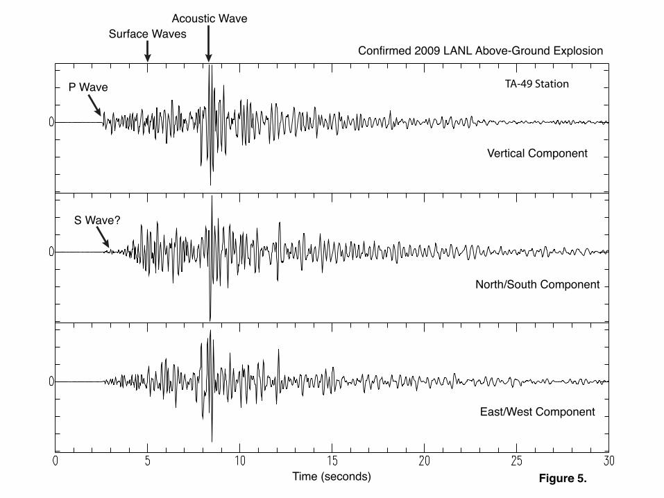
P Wave
S Wave?
Confirmed 2009 LANL Above-Ground Explosion
Surface WavesAcoustic Wave
Time (seconds)
Vertical Component
North/South Component
East/West Component
Figure 5.

P Wave
S Wave?
1992 Event Deleted From Catalog as Explosion
Acoustic Wave
Time (seconds)
Surface Waves
Vertical Component
North/South Component
East/West Component
Figure 6.

Los
Los
Ala
mos
Ala
mos
Whi
teW
hite
Rock
Rock
Sant
aSa
nta
FeFe
0.3
Espa
nola
Espa
nola
Alb
uque
rque
Alb
uque
rque
1.5
110
Eve
nts
Rio
Ranc
hoRi
o Ra
ncho
Bern
alill
oBe
rnal
illo
Las
Las
Vega
sVe
gas
AMS
ATE
PER
PFMPLS
PPR
SPD
OTZ
R25C
LKS
CDAB
2
2.11.7
2.3
1.3
1.4
1.1
1.1
1
0.6
3
0.7
1.6
0.7
2
0.7
0.8
0.6
1.4
1.2
1.3
1.7
1.9
1.4
0.5
1
0.7
1.5
2.7
0.9
1
1.1
0.7
21.5
2.32
0.7
0.5
0.5
1
1.4
1.3
1.4
0.3
1.8
2.3
1.3
0.7
0.5
0.9
1.4
1.2
1.1
0.9
0.7
0.3
1.8
0.9
1.2
1.2 0.8
0.9
1.7
0.9
10.6
0.9
0.9
1.5
1.4
0
0.5 1.2
0.5
-0.1
-0.3
-0.3
1.6
1.2
0.3
0.4
1.3
1.2
0.7
0.81
0.6
0.6
0.4
2
1.7
0.2
-0.6
1.9
0
0
0
0.90.6
0.3
0.6
0.3
0.2
0.3
-0.2
0.4
0.1
0.1
0.8
0.1
1.7
1.3
0.9
2.11.4
2.2 1.3
1.6
1.4
0.9
1.2
-0.1
1.1
0.8
1.3
0.8
0.5 0.8
0.3
0.8
0.3
1.9
0.6
1.1
1.6
0.2
1.5
1.1
1.8
1.2
0.5 1.5
1.7
0.2
0 0.1
1
1.5
0.5
0.9
1.3
1.7
1.1
0.7
1.2
2.71.9
2.2
1.5
1.7
1.1
1.2
0.3
2
2.6
1.6
1.3
1
1.41
0.7
0.3
-0.5
0.3
0.7
1
1.3
1.3
-0.4
0.6
2
1.5
1
1.2
-0.2
0.2
1
1.3
0.4
0.6
1.2
1
0.2
1.5
1
0.9
1.7
0.4
1.7
1.1
1.1
1.1
0.6
1.3
1.7
1.8
1.6
1.1
1.2
1.2
0.6
0.6
0.9
1
0.9
0.7
0.1
-0.3
1.2
0.4
0.5
0.1
1.1
1.3
0.2
0.6
1
-0.3
0.3
0.8 0
0.3
0.5
0.4
-0.1
0.4
0.2
1
-0.1
-0.1
0
1.9
00.6
-0.3
-0.2-0.3
-0.7
-0.2
1.1
0.5
0.6
0.6
0.8
0.4
0.1
1.3
1.6
0.5
0.1
0.4
0.5
0.3
1.1
-0.3
0.6
0.3
0.7
1
0.8
0.2
0.3
0.6 0.5
-0.5
1.5
1.1
1.7
0.9
0.1
-0.3
-0.3
0.3
0.3
0.2
-0.5
0.1
-0.6
0.8
0.5
0.9
0.6
0.9
0.9
1.7
0.6
1.3
-0.1
0.7
2.6
0.5
0.3
1
0.3
1.8
1.2
0.7
2.6
1.2
1.7
1.7
1.9
0.9
0.8 1.
8
1.5
1.5
0.5
1.1 1 0.7
1.1
1
0.5
0.5
0.4
0.8
1.6 1.1
1.5
1.8
1.8
1.1
1.7
1.5
1.5
0.9
2.1
1.5
1.8
0.4
0.8
1.1
1
1.1
1.8
0.1
0.7
1.2
1.3
2.5
1.1
1.3
0.8
0.9
1.7
0.9
0.5
0.9
2.2
0.9
1.9
0.6
0.5
0.6
0.7
1.3
0.2
1.3
0.1
1
-0.2
1.7
1.4
1.4
1.2
1.3
-0.1
0.4
0.7
0.7
0.6
0.3
0.7
0.2
1.2
1.1
21.2
1.3
0.9
2.1
1.1
0.8
0.1
-0.2
1.1
0.7
1.3
1.2
0.5
0.2
0.9
0.9
2.8
1.1
1.3
1
1
1.5
1.1
1
1
1.4
1.7
0.2
1.3
1.4
1.9 1.9
1.5
2.4
2
1.6
0.8
1.9
1.8
0.7
1.6
-0.6
-0.4
0.5
2
1.4
0.9
1.1
1.5
2
2.2
1.3
0.7
-0.2
0.2
0.5
1.5
1.2
1.6
0.9
0.7
1.1 1.5
1
1.2
0.9
0.7
1.4
1.5
0.8
0.9
1.6
0.1
11
2.3
1.5
1.3
0.8
1.5
1.6 1.7
1.7
0.8
1.11
1.3
0.8
1.1
0.9
0.8
0.5
0.3
-0.4
0.3
0.6
0.2
1.2
0.5
0.5
0
0.8
1.1
0.9
0.9
1.1
2
1.8
1.6
1.3
1.5
1.4
0.6
0.3
0.5
1.9
0.9
1.1
1.1
1.3
1.8
0.9
0.7
1.5
0.9
1.3
0.8
-0.1
0.5
1.3
11 1
1.1
1.1
1.2
1.8
0.7
1.4
0.71.4
1.4
1.6
1.2
1.2
2.2
1.8
1.9
1.7
2.2
1
1.5
1.4
2
1.2
1.8
1.5
0.4
1.2
0.8
0.7
0.7
0.4 -0.3
1.3
1.2
0.5
0.9
1.6
1.6
1.2
1.2
0.9
1.4
1.6
1.8
0.9
1.6
0.8
2.5
2.5
2.4
2.2
0
1.8
1.8
1.9
1.9
0.6
1.4
1.9
1.4
1
0.6
2.1
0.9
1.8
1.9
2.2
2.2
2.4
2.2
2
2.2
1.8
1.8
0.5
1.8
1.4
0.2
1.2
10.8
1.4
1
1.4
1.7
1.7
2.5
1.7
0.9
1
0.9
2.4
2.1
1.6
1.7
0.7
0.3
2.1
1.1
2.5
1.8
-0.4
2
2.1
1.7 2.9
1.9
2.4
1.4
2.4
2.6
1.6
1.1
1.1
1.5
2.4
2.3
0.4
0.7
0.7
1.5
0.6
0.4
1.8
1.2
2.1
1.2
1.1
1.5
2.7
1.7
0.9
1.3
2.1
1.8
0.1
1.3
1.5
-0.1
-0.3
0.3
1.4 0.5
1
1
1.31.9 1.4
0.9
1.3
1.2
1.1
0.6
0.4
1.4
1.9 1.6
1.5
1.5
2.3
1.9
1.5
0.9
1.2
1.1
1.6
1
1.8
0
2.3 1.7
1.9
2.5
1.6
1.9
1.7
2.5
0.5
1
-0.10
0.1
0.7
0.4-0
.1
0.9
1.1
1.3
2
0.6
0.2
0.9
0.3
0.7
0.4
0.5
0.7
1.5
1 0.8
1.4
1.5
1.8
1.7
1.4
1.4
1.1
0.4
3
1.4
1.3
Ber
nalil
loC
ount
y
Cib
ola
Cou
nty
Col
fax
Cou
nty
Gua
dalu
peC
ount
y
McK
inle
yC
ount
y
Mor
aC
ount
y
Rio
Arr
iba
Cou
nty
Sand
oval
Cou
nty
San
Juan
Cou
nty
San
Mig
uel
Cou
nty
Sant
a Fe
Cou
nty
Taos
Cou
nty
Torr
ance
Cou
nty
Vale
ncia
Cou
nty
104°
45'W
104°
45'W
105°
W
105°
W
105°
15'W
105°
15'W
105°
30'W
105°
30'W
105°
45'W
105°
45'W
106°
W
106°
W
106°
15'W
106°
15'W
106°
30'W
106°
30'W
106°
45'W
106°
45'W
107°
W107°
W
107°
15'W
107°
15'W
107°
30'W10
7°30
'W
107°
45'W10
7°45
'W
36°35'N
36°35'N
36°19'30"N
36°19'30"N
36°4'N
36°4'N
35°48'30"N
35°48'30"N
35°33'N
35°33'N
35°17'30"N
35°17'30"N
35°2'N
35°2'N
34°46'30"N
34°46'30"N
LAS
N S
tatio
n
Epic
ente
r
MA
GN
ITU
DE
Not
det
erm
ined
< -0
.5
0.51
- 1.
00
1.01
- 1.
50
1.51
- 2.
00
2.01
- 2.
50
> 2.
5
Faul
ts Expo
sed
Obs
cure
d
Con
ceal
ed
Unc
erta
in
Cou
nty
boun
dary
Urb
an a
rea
Roa
ds In
ters
tate
US
Hig
hway
Sta
te H
ighw
ay
Loc
al R
oad
Wor
k Pe
rfor
med
on
Beh
alf o
f the
TR
U P
roje
ctLo
s Al
amos
Nat
iona
l Lab
orat
ory
Los
Alam
os, N
M 8
7545
Nei
ther
the
Uni
ted
Stat
es G
over
nmen
t nor
Los
Al
amos
Nat
iona
l Sec
urity
(LAN
S), L
LC n
or a
ny o
f th
eir e
mpl
oyee
s m
akes
any
war
rant
y, e
xpre
ss o
r im
plie
d, in
clud
ing
the
war
rant
ies
of m
erch
anta
bilit
y an
d fit
ness
for a
par
ticul
ar p
urpo
se, o
r ass
umes
any
le
gal l
iabi
lity
or re
spon
sibi
lity
for t
he a
ccur
acy,
co
mpl
eten
ess,
or u
sefu
lnes
s of
any
info
rmat
ion,
ap
para
tus,
pro
duct
, or p
roce
ss d
iscl
osed
, or
repr
esen
ts th
at it
s us
e w
ould
not
infri
nge
priv
atel
y ow
ned
right
s.
05
1015
Mile
s
05
1015
2025
Kilo
met
ers
Plat
e 1
- Sei
smic
eve
nts
reco
rded
by
the
Los
Ala
mos
Ses
mic
Net
wor
k (L
ASN
) 19
73 -
2011
Nam
e: m
2023
08_L
ANL_
area
_seis
mic_
2012
0306
EE
S-16
-12-
004

Document: LANL TA-63 TWF NOD Response Date: April 2012
Appendix E
Certification