Notice No.1
19
Working together for a safer world Notice No.1 Rules and Regulations for the Classification of Ships, July 2017 The status of this Rule set is amended as shown and is now to be read in conjunction with this and prior Notices. Any corrigenda included in the Notice are effective immediately. Please note that paragraphs, Tables and Figures are not shown in their entirety. Please note that corrigenda amends to paragraphs, Tables and Figures are not shown in their entirety. Issue date: September 2017 Amendments to Effective date Mandatory Instrument Part 1, Chapter 3, Section 17 Corrigendum N/A Part 3, Chapter 1, Section 7 Corrigendum N/A Part 3, Chapter 3, Section 4 Corrigenda N/A Part 3, Chapter 4, Sections 6 & 7 Corrigenda N/A Part 3, Chapter 8, Section 1 Corrigendum N/A Part 3, Chapter 11, Section 9 Corrigendum N/A Part 3, Chapter 13, Sections 2, 7 & 8 Corrigenda N/A Part 3, Chapter 14, Sections 1 & 8 Corrigenda N/A Part 4, Chapter 1, Section 4 Corrigendum N/A Part 4, Chapter 2, Section 2 Corrigenda N/A Part 4, Chapter 4, Section 1 Corrigendum N/A Part 4, Chapter 8, Section 16 Corrigenda N/A Part 5, Chapter 1, Section 6 Corrigendum N/A Part 5, Chapter 2, Section 11 Corrigenda N/A Part 5, Chapter 5, Sections 3 & 5 Corrigenda N/A Part 5, Chapter 9, Section 5 Corrigenda N/A Part 5, Chapter 12, Sections 1 & 2 Corrigenda N/A Part 5, Chapter 16, Section 3 Corrigenda N/A Part 5, Chapter 19, Sections 2, 4, 6 & 7 Corrigenda N/A Part 5, Chapter 20, Section 2 Corrigenda N/A Part 6, Chapter 2, Sections 6 & 9 Corrigenda N/A Part 7, Chapter 11, Section 3 Corrigenda N/A Part 7, Chapter 12, Section 4 Corrigendum N/A Part 8, Chapter 2, Section 11 Corrigendum N/A
-
Upload
khangminh22 -
Category
Documents
-
view
1 -
download
0
Transcript of Notice No.1

Working together for a safer world
Notice No.1
Rules and Regulations for the Classification of Ships, July 2017 The status of this Rule set is amended as shown and is now to be read in conjunction with this and prior Notices. Any corrigenda included in the Notice are effective immediately. Please note that paragraphs, Tables and Figures are not shown in their entirety. Please note that corrigenda amends to paragraphs, Tables and Figures are not shown in their entirety.
Issue date: September 2017
Amendments to Effective date Mandatory Instrument Part 1, Chapter 3, Section 17 Corrigendum N/A Part 3, Chapter 1, Section 7 Corrigendum N/A Part 3, Chapter 3, Section 4 Corrigenda N/A
Part 3, Chapter 4, Sections 6 & 7 Corrigenda N/A Part 3, Chapter 8, Section 1 Corrigendum N/A Part 3, Chapter 11, Section 9 Corrigendum N/A
Part 3, Chapter 13, Sections 2, 7 & 8 Corrigenda N/A Part 3, Chapter 14, Sections 1 & 8 Corrigenda N/A
Part 4, Chapter 1, Section 4 Corrigendum N/A Part 4, Chapter 2, Section 2 Corrigenda N/A Part 4, Chapter 4, Section 1 Corrigendum N/A
Part 4, Chapter 8, Section 16 Corrigenda N/A Part 5, Chapter 1, Section 6 Corrigendum N/A
Part 5, Chapter 2, Section 11 Corrigenda N/A Part 5, Chapter 5, Sections 3 & 5 Corrigenda N/A
Part 5, Chapter 9, Section 5 Corrigenda N/A Part 5, Chapter 12, Sections 1 & 2 Corrigenda N/A
Part 5, Chapter 16, Section 3 Corrigenda N/A Part 5, Chapter 19, Sections 2, 4, 6 & 7 Corrigenda N/A
Part 5, Chapter 20, Section 2 Corrigenda N/A Part 6, Chapter 2, Sections 6 & 9 Corrigenda N/A
Part 7, Chapter 11, Section 3 Corrigenda N/A Part 7, Chapter 12, Section 4 Corrigendum N/A Part 8, Chapter 2, Section 11 Corrigendum N/A

1
Part 1, Chapter 3 Periodical Survey Regulations
■ Section 17
Screwshafts, tube shafts and propellers
17.2 Definitions
17.2.3 Lubricating oil analysis. Lubricating oil analysis is to be carried out at regular intervals not exceeding six months. The
documentation on lubricating oil analysis is to be available on board. Oil samples, to be submitted for the analysis, should are to be taken under service conditions.
2
Part 3, Chapter 1 General
■ Section 7
Equipment Number
7.1 Calculation of Equipment Number
7.1.1 The equipment of anchors and chain cables specified in Pt 3, Ch 13, 7 Equipment is based on an `Equipment Number' which is to be calculated as follows:
Equipment Number = 10
23
2 ABH Equipment Number =
10232 ABH /
Part 3, Chapter 3 Structural Design
■ Section 4
Bulkhead requirements
4.7 Separation and protection of tanks
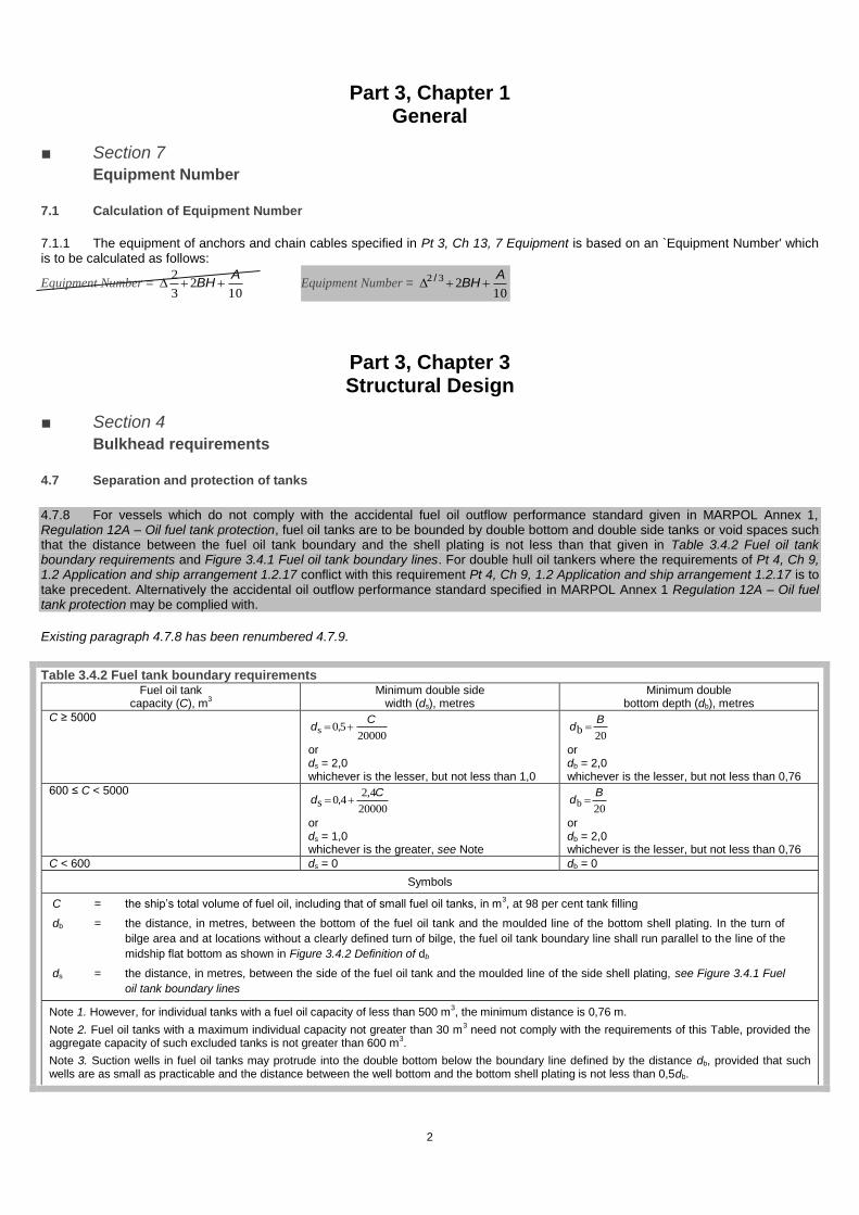
4.7.8 For vessels which do not comply with the accidental fuel oil outflow performance standard given in MARPOL Annex 1, Regulation 12A – Oil fuel tank protection, fuel oil tanks are to be bounded by double bottom and double side tanks or void spaces such that the distance between the fuel oil tank boundary and the shell plating is not less than that given in Table 3.4.2 Fuel oil tank boundary requirements and Figure 3.4.1 Fuel oil tank boundary lines. For double hull oil tankers where the requirements of Pt 4, Ch 9, 1.2 Application and ship arrangement 1.2.17 conflict with this requirement Pt 4, Ch 9, 1.2 Application and ship arrangement 1.2.17 is to take precedent. Alternatively the accidental oil outflow performance standard specified in MARPOL Annex 1 Regulation 12A – Oil fuel tank protection may be complied with.
Existing paragraph 4.7.8 has been renumbered 4.7.9.
Table 3.4.2 Fuel tank boundary requirements Fuel oil tank
capacity (C), m3
Minimum double side width (ds), metres
Minimum double bottom depth (db), metres
C ≥ 5000
2000050s
Cd ,
or ds = 2,0 whichever is the lesser, but not less than 1,0
20b
Bd
or db = 2,0 whichever is the lesser, but not less than 0,76
600 ≤ C < 5000
20000
4,240s
Cd ,
or ds = 1,0 whichever is the greater, see Note
20b
Bd
or db = 2,0 whichever is the lesser, but not less than 0,76
C < 600 ds = 0 db = 0
Symbols
C = the ship’s total volume of fuel oil, including that of small fuel oil tanks, in m3, at 98 per cent tank filling
db = the distance, in metres, between the bottom of the fuel oil tank and the moulded line of the bottom shell plating. In the turn of
bilge area and at locations without a clearly defined turn of bilge, the fuel oil tank boundary line shall run parallel to the line of the
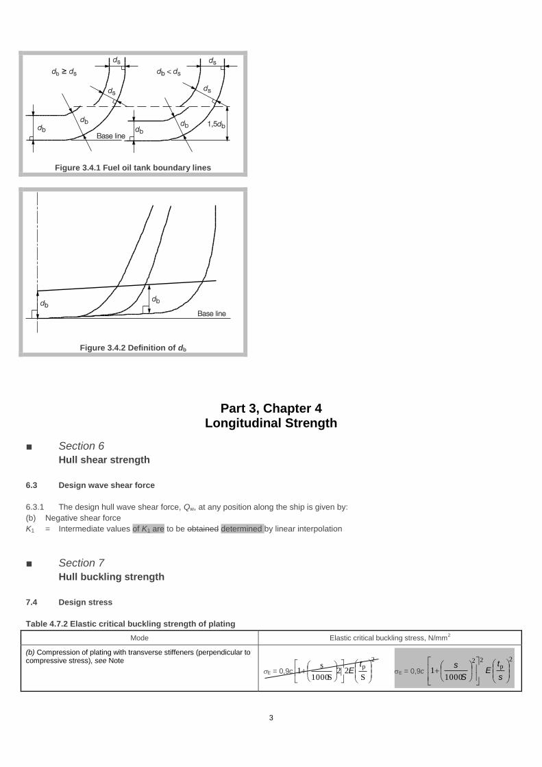
midship flat bottom as shown in Figure 3.4.2 Definition of db
ds = the distance, in metres, between the side of the fuel oil tank and the moulded line of the side shell plating, see Figure 3.4.1 Fuel
oil tank boundary lines
Note 1. However, for individual tanks with a fuel oil capacity of less than 500 m3, the minimum distance is 0,76 m.
Note 2. Fuel oil tanks with a maximum individual capacity not greater than 30 m3 need not comply with the requirements of this Table, provided the
aggregate capacity of such excluded tanks is not greater than 600 m3.
Note 3. Suction wells in fuel oil tanks may protrude into the double bottom below the boundary line defined by the distance db, provided that such wells are as small as practicable and the distance between the well bottom and the bottom shell plating is not less than 0,5db.
3
Figure 3.4.1 Fuel oil tank boundary lines
Figure 3.4.2 Definition of db
Part 3, Chapter 4 Longitudinal Strength
■ Section 6
Hull shear strength
6.3 Design wave shear force
6.3.1 The design hull wave shear force, Qw, at any position along the ship is given by:
(b) Negative shear force
K1 = Intermediate values of K1 are to be obtained determined by linear interpolation
■ Section 7
Hull buckling strength
7.4 Design stress
Table 4.7.2 Elastic critical buckling strength of plating
Mode Elastic critical buckling stress, N/mm2
(b) Compression of plating with transverse stiffeners (perpendicular to compressive stress), see Note
E = 0,9c
2p
S22
S1000
s1
tE E = 0,9c
2p
22
10001
s
tE
S
s

4
(c) Shear, see Note
τE = 3,6
2p
2S1000
3351
S
tE
s, τE = 3,6
2p
2
10003351
S
tE
S
s,
Part 3, Chapter 8 Superstructures, Deckhouses and Bulkwarks
■ Section 1
General
1.2 Symbols
1.2.1 The following symbols and definitions are applicable to this Chapter, unless otherwise stated: L, B, T and Cb = as defined in Pt 3, Ch 1, 6.1 Principal particulars b
Part 3, Chapter 11 Closing Arrangements for Shell, Deck and Bulkheads
■ Section 9
Watertight doors in bulkheads below the freeboard deck
9.2 Watertight doors
9.2.3 The scantlings of the frames of the watertight doors are to satisfy the requirements of watertight bulkheads given in item 5 of Table 1.9.1 Watertight and deep tank bulkhead scantlings in Pt 4, Ch 1, 9 Bulkheads taking into account the arrangement of door
stiffeners and securing arrangements.
Part 3, Chapter 13 Ship Control Systems
■ Section 2
Rudders
2.6 Rudder force
2.6.1 The lateral rudder force at the centre of pressure is to be determined for both ahead and astern conditions as follows:
K1 = aspect ratio correction factor
= 3
2but is not to be taken greater than 2.
λ = t
2R
A
hbut is not to be taken greater than 2.
5
2.11 Rudder blade
Table 13.2.8 Rudder blade permissible stresses
Item
Rudder blade, clear off of cut-outs
2.15 Cone couplings with special arrangements for mounting and dismounting the couplings
2.15.6 In case of hydraulic pressure connections the required push-up force Pe, for the cone may be determined by the following
formula:
Pe = 2
tmreq
dp + 0,02 N Pe =
020
2
tmreq ,dp N
■ Section 7
Equipment
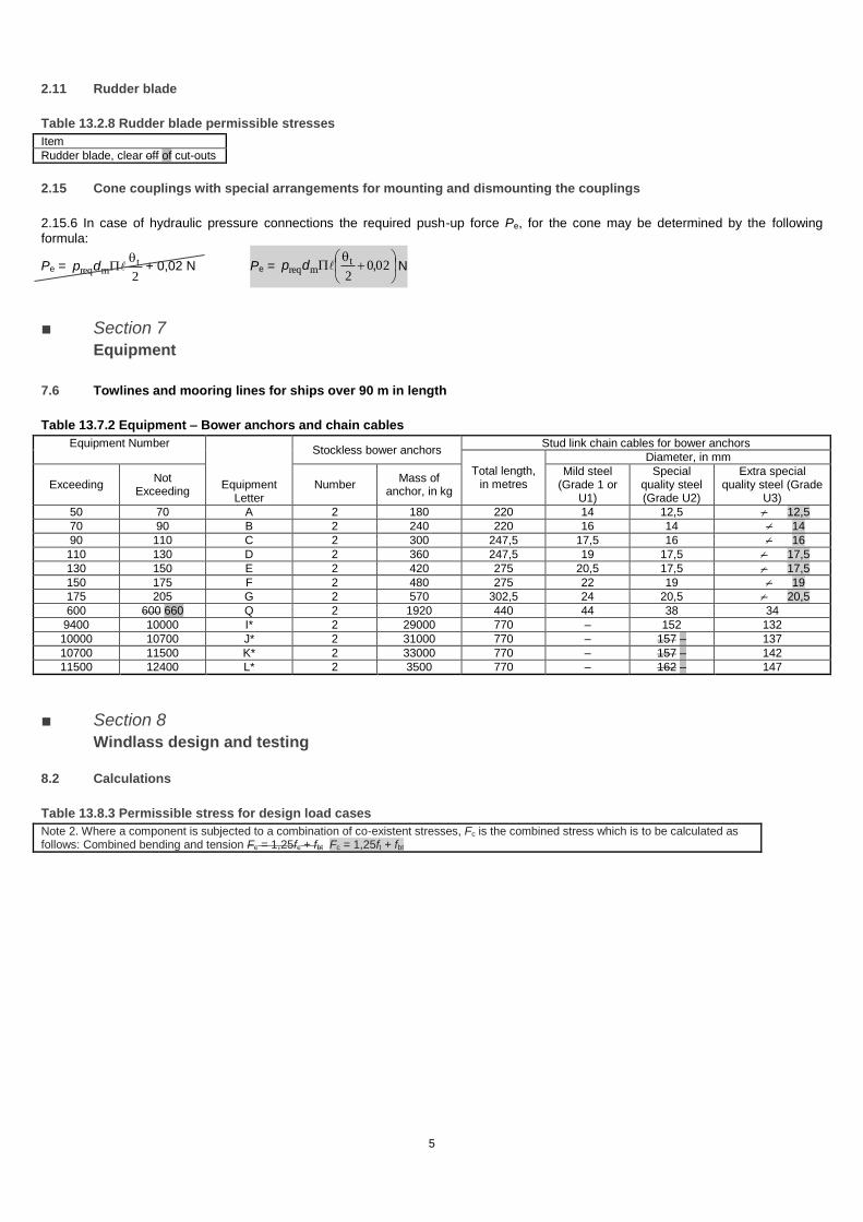
7.6 Towlines and mooring lines for ships over 90 m in length
Table 13.7.2 Equipment – Bower anchors and chain cables
Equipment Number
Equipment Letter
Stockless bower anchors Stud link chain cables for bower anchors
Total length, in metres
Diameter, in mm
Exceeding Not
Exceeding Number
Mass of anchor, in kg
Mild steel (Grade 1 or
U1)
Special quality steel (Grade U2)
Extra special quality steel (Grade
U3)
50 70 A 2 180 220 14 12,5 – 12,5
70 90 B 2 240 220 16 14 – 14
90 110 C 2 300 247,5 17,5 16 – 16
110 130 D 2 360 247,5 19 17,5 – 17,5
130 150 E 2 420 275 20,5 17,5 – 17,5
150 175 F 2 480 275 22 19 – 19
175 205 G 2 570 302,5 24 20,5 – 20,5
600 600 660 Q 2 1920 440 44 38 34
9400 10000 I* 2 29000 770 – 152 132
10000 10700 J* 2 31000 770 – 157 – 137
10700 11500 K* 2 33000 770 – 157 – 142
11500 12400 L* 2 3500 770 – 162 – 147
■ Section 8
Windlass design and testing
8.2 Calculations
Table 13.8.3 Permissible stress for design load cases
Note 2. Where a component is subjected to a combination of co-existent stresses, Fc is the combined stress which is to be calculated as follows: Combined bending and tension Fc = 1,25fc + fbt Fc = 1,25ft + fbt
6
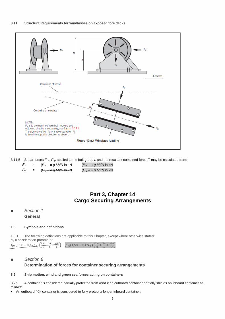
8.11 Structural requirements for windlasses on exposed fore decks
8.11.5 Shear forces F xi, F yi applied to the bolt group i, and the resultant combined force Fi may be calculated from:
Fxi = (P x – α g M)/N in kN (P x – g M)/N in kN
Fyi = (P y – α g M)/N in kN (P y – g M)/N in kN
Part 3, Chapter 14 Cargo Securing Arrangements
■ Section 1
General
1.6 Symbols and definitions
1.6.1 The following definitions are applicable to this Chapter, except where otherwise stated: a0 = acceleration parameter
𝑓𝐻𝑆(1,58 − 0,47𝐶𝑏) (2,4
√𝐿+
34
𝐿−
600
𝐿2) 𝑓HS(1,58 − 0,47𝐶b) (
2,4
√𝐿+
34
𝐿+
600
𝐿2)
■ Section 8
Determination of forces for container securing arrangements
8.2 Ship motion, wind and green sea forces acting on containers
8.2.9 A container is considered partially protected from wind if an outboard container partially shields an inboard container as follows:
An outboard 40ft container is considered to fully protect a longer inboard container.

7
An outboard 20ft container is considered to partially protect a longer inboard container from wind. In this case the full wind force is to be applied over the exposed portion of the longer inboard container when the overlap exposed length is more than 3m. The resulting wind force is to be applied solely to the end wall of the exposed portion.
8
Part 4, Chapter 1 General Cargo Ships
■ Section 4
Deck structure
4.5 Deck openings
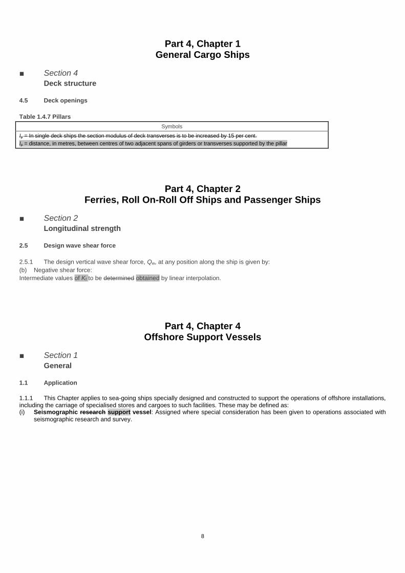
Table 1.4.7 Pillars
Symbols
lp = In single deck ships the section modulus of deck transverses is to be increased by 15 per cent.
lp = distance, in metres, between centres of two adjacent spans of girders or transverses supported by the pillar
Part 4, Chapter 2 Ferries, Roll On-Roll Off Ships and Passenger Ships
■ Section 2
Longitudinal strength
2.5 Design wave shear force
2.5.1 The design vertical wave shear force, Qw, at any position along the ship is given by:
(b) Negative shear force:
Intermediate values of Kf to be determined obtained by linear interpolation.
Part 4, Chapter 4 Offshore Support Vessels
■ Section 1
General
1.1 Application
1.1.1 This Chapter applies to sea-going ships specially designed and constructed to support the operations of offshore installations, including the carriage of specialised stores and cargoes to such facilities. These may be defined as: (i) Seismographic research support vessel: Assigned where special consideration has been given to operations associated with
seismographic research and survey.

9
Part 4, Chapter 8 Container Ships
■ Section 16
Longitudinal strength calculations
16.7 Design vertical wave shear force
16.7.3 The design hull wave shear force, Qw, at any position along the ship is to be taken as:
(b) Negative shear force
Intermediate values of Kf are to be obtained by linear interpolation.
Where
ffH and ffS are defined in Pt 4, Ch 8, 16.6 Design vertical wave bending moments 16.6.1 Intermediate values to be obtained by linear
interpolation
10
Part 5, Chapter 1 General Requirements for the Design and Construction of Machinery
■ Section 6 Quality Assurance Scheme for Machinery 6.4 Acceptance of purchased materials, components and equipment
6.4.1 The manufacturer is to establish and maintain procedures and controls to ensure compliance with LR’s requirements for certification of products from its suppliers. The manufacturer is to ensure that purchased products that are required to be certified in accordance with Ch 3 Rolled Steel Plates, Strip, Sections and Bars to Ch 10 Equipment for Mooring and Anchoring of the Rules for Materials are made at works which have been approved by LR for the type and grade of product being supplied. The manufacturer’s system for control of purchased products is to be based on one or a combination of the following alternatives: (c) Product certification by the manufacturer supplier in accordance with quality processes for control of suppliers of purchased
products included within the scope of the manufacturer’s QAM Scheme approval. These quality schemes are to ensure compliance with Rule requirements for the purchased products.
Part 5, Chapter 2 Reciprocating Internal Combustion Engines
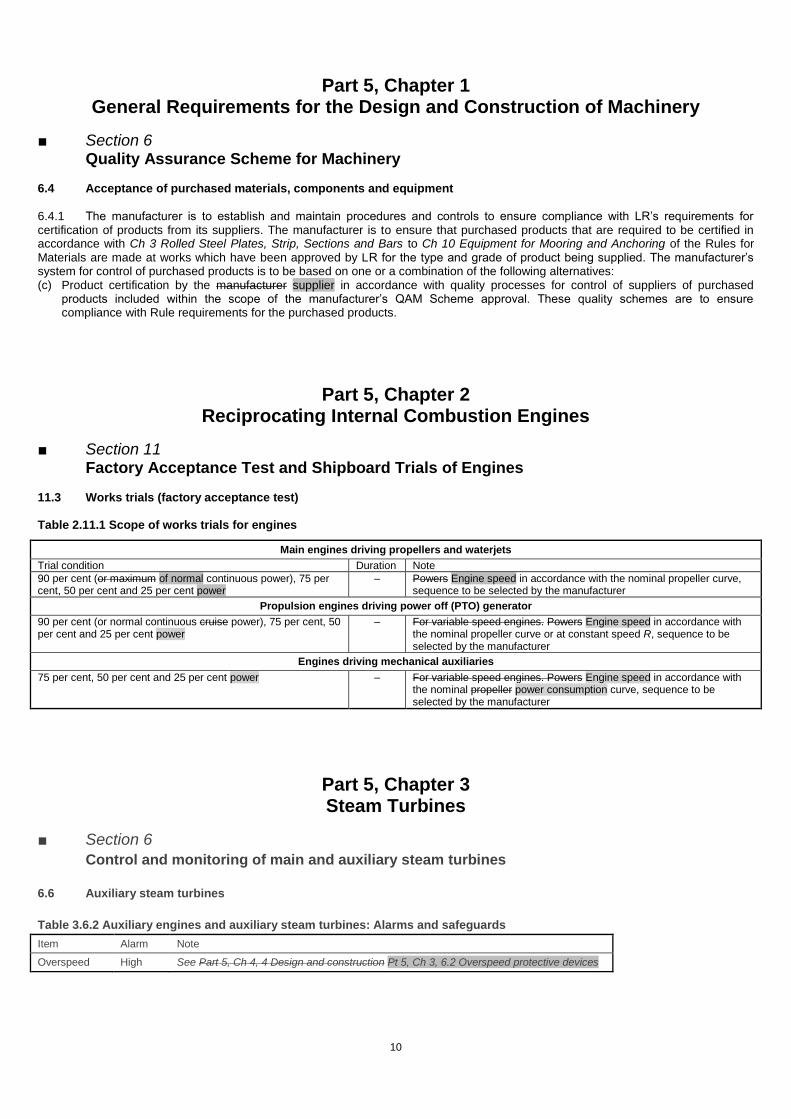
■ Section 11 Factory Acceptance Test and Shipboard Trials of Engines 11.3 Works trials (factory acceptance test) Table 2.11.1 Scope of works trials for engines
Main engines driving propellers and waterjets
Trial condition Duration Note
90 per cent (or maximum of normal continuous power), 75 per cent, 50 per cent and 25 per cent power
– Powers Engine speed in accordance with the nominal propeller curve, sequence to be selected by the manufacturer
Propulsion engines driving power off (PTO) generator
90 per cent (or normal continuous cruise power), 75 per cent, 50 per cent and 25 per cent power
– For variable speed engines. Powers Engine speed in accordance with the nominal propeller curve or at constant speed R, sequence to be selected by the manufacturer
Engines driving mechanical auxiliaries
75 per cent, 50 per cent and 25 per cent power – For variable speed engines. Powers Engine speed in accordance with the nominal propeller power consumption curve, sequence to be selected by the manufacturer
Part 5, Chapter 3 Steam Turbines
■ Section 6
Control and monitoring of main and auxiliary steam turbines
6.6 Auxiliary steam turbines
Table 3.6.2 Auxiliary engines and auxiliary steam turbines: Alarms and safeguards
Item Alarm Note
Overspeed High See Part 5, Ch 4, 4 Design and construction Pt 5, Ch 3, 6.2 Overspeed protective devices
11
Part 5, Chapter 5 Gearing
■ Section 3
Design
3.1 Symbols
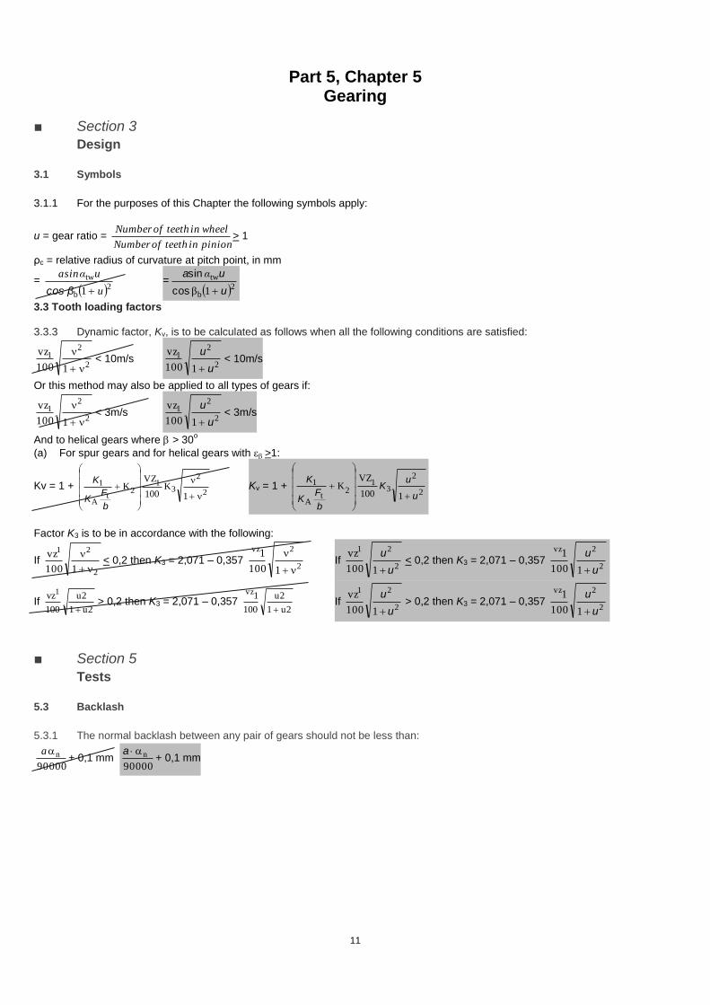
3.1.1 For the purposes of this Chapter the following symbols apply:
u = gear ratio = pinioninteethofNumber
wheelinteethofNumber> 1
ρc = relative radius of curvature at pitch point, in mm
= 2b
tw
1 u
uαasin
βcos =
2b
tw
1β u
ua
cos
sin α
3.3 Tooth loading factors
3.3.3 Dynamic factor, Kv, is to be calculated as follows when all the following conditions are satisfied:
2
21
1100
vz
< 10m/s
2
21
1100
vz
u
u
< 10m/s
Or this method may also be applied to all types of gears if:
2
21
1100
vz
< 3m/s
2
21
1100
vz
u
u
< 3m/s
And to helical gears where > 30o
(a) For spur gears and for helical gears with >1:
Kv = 1 + 2
2
31
2t
A
1
1K
100
VZK
b
FK
K Kv = 1 +
2
2
31
2t
A
1
1100
VZK
u
uK
b
FK
K
Factor K3 is to be in accordance with the following:
If 2
21
1100
vz
< 0,2 then K3 = 2,071 – 0,357
2
2vz
1100
1
If
2
21
1100
vz
u
u
< 0,2 then K3 = 2,071 – 0,357
2
2vz
1100
1
u
u
If 2u1
2u
100
vz1
> 0,2 then K3 = 2,071 – 0,357
2u1
2u
100
1vz
If
2
21
1100
vz
u
u
> 0,2 then K3 = 2,071 – 0,357
2
2vz
1100
1
u
u
■ Section 5
Tests
5.3 Backlash
5.3.1 The normal backlash between any pair of gears should not be less than:
00090
na+ 0,1 mm
00090
na+ 0,1 mm

12
Part 5, Chapter 9 Podded Propulsion Units
■ Section 5
Machinery design and construction requirements
5.5 Bearing lubrication system
5.5.2 In addition to the requirements detailed in this Section, the requirements of Pt 5, Ch 14 Machinery Piping Systems, sub-Sections Pt 5, Ch 9, 7.1 General, 8.5, 8.7 and 8.9 Pt 5, Ch 14, 8.1 General requirements, Pt 5, Ch 14, 8.5 Emergency supply for propulsion turbines and propulsion turbo-generators, Pt 5, Ch 14, 8.7 Filters and Pt 5, Ch 14, 8.9 Cleanliness of pipes and fittings are to be complied with. 5.6 Steering system
5.6.3 Where more than one podded propulsion unit is fitted, Pt 5, Ch 19, 2.1 Performance 2.1.2 is considered to be met when:
(b) Each podded propulsion unit is provided with the ability to position be positioned and lock the podded propulsion unit locked in a neutral position after a single failure of its power unit(s) and actuator(s). These arrangements are to be of sufficient strength to hold the podded propulsion unit in position at the ship's manoeuvring speed to be taken as not less than 7 knots, see also Pt 5, Ch 9, 5.3 Propulsion shafting 5.3.11. Operating instructions Instructions displayed at the locking mechanism’s operating position
are to include a direction directive to inform the bridge of any limitation in ship's speed required as a result of the securing mechanism being activated.
5.6.6 For vessels with more than one steerable podded propulsion unit, auxiliary steering gear need not be fitted provided that each podded propulsion unit is capable of being supplied by two identical power units (the podded propulsion unit may be supplied by shared or dedicated power units) and:
Part 5, Chapter 12 Piping Design Requirements
■ Section 1
General
1.1 Application
1.1.4 The cargo piping systems for chemical tankers are to comply with the relevant Sections of this Chapter where applicable, except where there are specific alternative or additional requirements provided in the Rules and Regulations for the Construction and Classification of Ships for the Carriage of Liquid Chemicals in Bulk, July 2017.
■ Section 2
Carbon and low alloy steels
2.2 Wrought steel pipes and bends
Table 12.2.4 Minimum thickness for steel pipes
External diameter, D, in mm
Pipes in general, in mm
Venting, overflow and sounding pipes for
structural tanks, in mm
Bilge, ballast and general sea-water
pipes, in mm
Bilge, air, overflow and sounding pipes through ballast and fuel tanks, ballast lines through fuel tanks and fuel lines through ballast tanks, in
mm
Air, overflow and sounding pipes for fuel
oil tanks passing through cargo holds of
bulk carriers, in mm
98,5-368 298,5-368
5,6 6,3 6,3 8,8 12,5
2406,4-457,2 406,4-457,2
6,3 6,3 6,3 8,8 12,5
2.13 Non-destructive testing
2.13.1 For details of non-destructive tests on piping systems, other than hydraulic tests, see Pt 5, Ch 13 Ship Piping Systems Ch 13, 5.5 Non-destructive examination of the Rules for Materials.
13
Part 5, Chapter 16 Water jet systems
■ Section 3 Design requirements
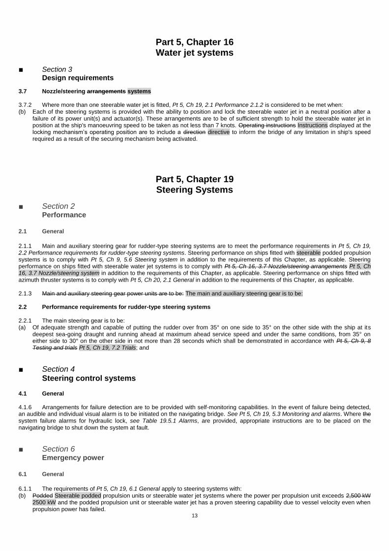
3.7 Nozzle/steering arrangements systems 3.7.2 Where more than one steerable water jet is fitted, Pt 5, Ch 19, 2.1 Performance 2.1.2 is considered to be met when: (b) Each of the steering systems is provided with the ability to position and lock the steerable water jet in a neutral position after a
failure of its power unit(s) and actuator(s). These arrangements are to be of sufficient strength to hold the steerable water jet in position at the ship's manoeuvring speed to be taken as not less than 7 knots. Operating instructions Instructions displayed at the locking mechanism’s operating position are to include a direction directive to inform the bridge of any limitation in ship's speed required as a result of the securing mechanism being activated.
Part 5, Chapter 19 Steering Systems
■ Section 2
Performance
2.1 General
2.1.1 Main and auxiliary steering gear for rudder-type steering systems are to meet the performance requirements in Pt 5, Ch 19, 2.2 Performance requirements for rudder-type steering systems. Steering performance on ships fitted with steerable podded propulsion systems is to comply with Pt 5, Ch 9, 5.6 Steering system in addition to the requirements of this Chapter, as applicable. Steering performance on ships fitted with steerable water jet systems is to comply with Pt 5, Ch 16, 3.7 Nozzle/steering arrangements Pt 5, Ch 16, 3.7 Nozzle/steering system in addition to the requirements of this Chapter, as applicable. Steering performance on ships fitted with azimuth thruster systems is to comply with Pt 5, Ch 20, 2.1 General in addition to the requirements of this Chapter, as applicable.
2.1.3 Main and auxiliary steering gear power units are to be: The main and auxiliary steering gear is to be: 2.2 Performance requirements for rudder-type steering systems
2.2.1 The main steering gear is to be: (a) Of adequate strength and capable of putting the rudder over from 35° on one side to 35° on the other side with the ship at its
deepest sea-going draught and running ahead at maximum ahead service speed and under the same conditions, from 35° on either side to 30° on the other side in not more than 28 seconds which shall be demonstrated in accordance with Pt 5, Ch 9, 8 Testing and trials Pt 5, Ch 19, 7.2 Trials; and
■ Section 4 Steering control systems 4.1 General
4.1.6 Arrangements for failure detection are to be provided with self-monitoring capabilities. In the event of failure being detected, an audible and individual visual alarm is to be initiated on the navigating bridge. See Pt 5, Ch 19, 5.3 Monitoring and alarms. Where the system failure alarms for hydraulic lock, see Table 19.5.1 Alarms, are provided, appropriate instructions are to be placed on the navigating bridge to shut down the system at fault.
■ Section 6
Emergency power
6.1 General
6.1.1 The requirements of Pt 5, Ch 19, 6.1 General apply to steering systems with:
(b) Podded Steerable podded propulsion units or steerable water jet systems where the power per propulsion unit exceeds 2,500 kW 2500 kW and the podded propulsion unit or steerable water jet has a proven steering capability due to vessel velocity even when propulsion power has failed.

14
■ Section 7
Testing and trials
7.2 Trials
7.2.1 The steering gear is to be tested on the trials trip in order to demonstrate to the Surveyor's satisfaction that the requirements of the Rules have been met. The trial is to include the operation of the following: (a) The steering gear, including demonstration of the performances required by: Pt 5, Ch 19, 2.2 Performance requirements for
rudder-type steering systems 2.2.1.(a) and Pt 5, Ch 19, 2.2 Performance requirements for rudder-type steering systems 2.2.1.(b) where a rudder type steering system is fitted, or by Pt 5, Ch 9, 5.6 Steering system 5.6.4.(a) and Pt 5, Ch 9, 5.6 Steering system 5.6.5.(b) where a podded propulsion steering system are fitted, or by Pt 5, Ch 16, 3.7 Nozzle/steering arrangements 3.7.3.(a) and Pt 5, Ch 16, 3.7 Nozzle/steering arrangements 3.7.4.(b) where water jets steering system is, or by Pt 5, Ch 20, 2.1 General 2.1.4.(a) Pt 5, Ch 20, 2.1 General 2.1.5.(b) where an azimuth thruster steering system is fitted: o For the main steering gear trial, the propeller pitch of controllable pitch propellers is to be at the maximum design pitch
approved for the maximum continuous ahead RPM; o If the ship cannot be tested at the deepest draught, then the loading condition can be accepted on the conditions that either
the rudder is fully submerged (at zero speed waterline) and the vessel is in an acceptable trim condition, or the rudder load and torque at the trial loading condition have been reliably predicted and extrapolated to the full load condition, to the satisfaction of the Administration. In any case, for the main steering gear trial, the speed of the ship corresponding to the maximum continuous revolutions of main engine and maximum design pitch applies;
(a) The steering gear:
For the main steering gear trial, the propeller pitch of controllable pitch propellers is to be at the maximum design pitch approved for the maximum continuous ahead RPM;
If the ship cannot be tested at the deepest draught, then the loading condition can be accepted on the conditions that either the rudder is fully submerged (at zero speed waterline) and the vessel is in an acceptable trim condition, or the rudder torque at the trial loading condition has been reliably predicted and extrapolated to the full load condition, to the satisfaction of the Administration. In any case, for the main steering gear trial, the speed of the ship corresponding to the maximum continuous revolutions of main engine and maximum design pitch applies;
Depending on the steering system type the performance required by the following is to be demonstrated: (i) Where a rudder type steering system is fitted see
Pt 5, Ch 19, 2.2 Performance requirements for rudder-type steering systems 2.2.1(a), and
Pt 5, Ch 19, 2.2 Performance requirements for rudder-type steering systems 2.2.2(b) (ii) Where a podded propulsion steering system is fitted see
Pt 5, Ch 9, 5.6 Steering system 5.6.4 (a) and
Pt 5, Ch 9, 5.6 Steering system 5.6.5 (b) (iii) Where a water jet steering system is fitted see
Pt 5, Ch 16, 3.7 Nozzle/steering systems 3.7.3(a), and Pt 5, Ch 16, 3.7 Nozzle/steering systems 3.7.4(b)
(iv) Where an azimuth thruster steering system is fitted see
Pt 5, Ch 20, 2.1 General 2.1.4(a), and
Pt 5, Ch 20, 2.1 General 2.1.5(b):
Part 5, Chapter 20 Azimuth Thrusters
■ Section 2
Performance
2.1 General
2.1.3 Where more than one azimuth thruster is fitted, Pt 5, Ch 19, 2.1 General 2.1.2 is considered to be met when:
(b) Each azimuth thruster is provided with the ability to position and lock the azimuth thruster in a neutral position after a failure of its own power unit(s) and actuator(s). These arrangements are to be of sufficient strength to hold the azimuth thruster in position at the ship's manoeuvring speed to be taken as not less than 7 knots. Operating instructions Instructions displayed at the locking mechanism’s operating position are to include a direction directive to inform the bridge of any limitation in ship's speed required as a result of the securing mechanism being activated.
15
Part 6, Chapter 2 Electrical Engineering
■ Section 1
General 1.1 General
1.1.7 Lloyd’s Register (hereinafter referred to as ‘LR’) will be prepared to give consideration to special cases or to arrangements which are equivalent to the Rules. For unconventional designs, see also Pt 7, Ch 15 Refrigeration Systems and Equipment Serving Provision Stores and Air-Conditioning Installations Pt 7, Ch 14 Requirements for Machinery and Engineering Systems of Unconventional Design. Consideration will also be given to electrical arrangements of small ships and ships to be assigned class notation for restricted or special services.
■ Section 6
System design – Protection
6.1 General
6.1.10 Overload protection may be omitted from the following: (a) one line of circuits of the insulated type;
■ Section 9
Rotating machines
9.1 General requirements
9.1.16 The reference insulation system, against which the test samples in Pt 6, Ch 2, 9.1 General requirements 9.1.15 are to be validated, is to be have been shown demonstrated to be suitable for use in the environmental conditions that the finished machine will be exposed to in service. Documented evidence of such suitability is to be available to the LR Surveyor, at the time these tests are conducted.
16
Part 7, Chapter 11 Arrangements and Equipment for Environmental Protection (ECO Class
Notation)
■ Section 3
Supplementary characters
3.5 Environmentally Acceptable Lubricants – EAL character
3.5.1 For assignment of the EAL character, the ship shall use Environmentally Acceptable Lubricants (EAL) that comply with the
EPA criteria, as defined in Section 2.2.9 of the 2013 Vessle Vessel General Permit (VGP).
3.6 Energy Efficiency Design Index – EEDI-1, EEDI-2, EEDI-3, characters
3.6.1 For assignment of the EAL character, the ship shall use Environmentally Acceptable Lubricants (EAL) Existing paragraphs 3.6.2 to 3.6.5 have been renumbered to 3.6.1 to 3.6.4.
Part 7, Chapter 12 Passenger and Crew Accommodation Comfort
■ Section 4
Testing
4.3 Noise measurements
4.3.1 Noise measurements are to be conducted in accordance with ISO 2923 and IMO Resolution MSC.337(91) – Adoption of the Code on Noise Levels on Board Ships – (Adopted on 30 November 2012)The Annex below is consolidated into Resolution MSC.337(91). Measurements of noise levels are to be carried out using precision grade sound level meters conforming to IEC 60651 IEC 60672-1, Type 1 or 2. Subject to demonstration, equivalent standards are acceptable.

17
Part 8, Chapter 2 Ice Operations – Ice Class
■ Section 11
Machinery strengthening requirements for navigation in multi-year ice conditions – Ice Classes
PC1, PC2, PC3, PC4, PC5, PC6 and PC7
11.19 Machinery fastening loading accelerations
11.19.4 The combined transverse impact acceleration, at, at any point along hull girder, is to be taken as:
Fi = total force normal to shell plating in the bow area due to oblique ice impact, defined in Pt 8, Ch 2, 10.19 Design vertical ice
force at the bow Pt 8, Ch 2, 10.4 Bow area 10.4.3(b)

© Lloyd’s Register Group Limited 2017 Published by Lloyd’s Register Group Limited
Registered office (Reg. no. 08126909) 71 Fenchurch Street, London, EC3M 4BS
United Kingdom
Lloyd’s Register and variants of it are trading names of Lloyd’s Register Group Limited, its subsidiaries and affiliates. For further details please see http://www.lr.org/entities Lloyd's Register Group Limited, its subsidiaries and affiliates and their respective officers, employees or agents are, individually and collectively, referred to in this clause as ‘Lloyd's Register’. Lloyd's Register assumes no responsibility and shall not be liable to any person for any loss, damage or expense caused by reliance on the information or advice in this document or howsoever provided, unless that person has signed a contract with the relevant Lloyd's Register entity for the provision of this information or advice and in that case any responsibility or liability is exclusively on the terms and conditions set out in that contract.