Required Contract Provision - Biznet
816
-
Upload
khangminh22 -
Category
Documents
-
view
4 -
download
0
Transcript of Required Contract Provision - Biznet


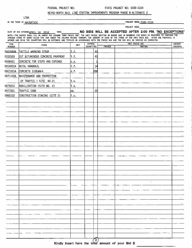


TABLE OF CONTENTS OF SPECIAL PROVISIONS Note: This table of contents has been prepared for the convenience of those using this contract with the sole express purpose of locating quickly the information contained herein; and no claims shall arise due to omissions, additions, deletions, etc., as this table of contents shall not be considered part of the contract.

Table of ContentsCONTRACT TIME AND LIQUIDATED DAMAGES ..................................................................................CONTRACT TIME AND LIQUIDATED DAMAGES – WILTON STATION................................................NOTICE TO CONTRACTOR – ALTERNATE BID PROPOSALS.............................................................NOTICE TO CONTRACTOR – CONSTRUCTION SIGNS.......................................................................NOTICE TO CONTRACTOR – PROJECT DESCRIPTION......................................................................NOTICE TO CONTRACTOR – STANDARD SPECIFICATIONS .............................................................NOTICE TO CONTRACTOR – GENERAL REQUIREMENTS AND ........................................................COVENANTS OF THE CONTRACT ........................................................................................................NOTICE TO CONTRACTOR – MEASUREMENT AND PAYMENT.........................................................NOTICE TO CONTRACTOR – FORM 816 REFERENCES ON STANDARD DRAWINGS.....................NOTICE TO CONTRACTOR – NOTICE OF INTENT TO CONSTRUCT.................................................NOTICE TO CONTRACTOR – LIMITATION OF CONTRACTOR OPERATIONS...................................NOTICE TO CONTRACTOR – BUILDING AND FIRE CODES ...............................................................NOTICE TO CONTRACTOR – POTENTIAL FOR ASBESTOS CONTAINING MATERIALS..................NOTICE TO CONTRACTOR – OFF-SITE STAGING AND STORAGE ...................................................NOTICE TO CONTRACTOR – PROJECT PHASING REQUIREMENTS................................................NOTICE TO CONTRACTOR – SUBMITTALS .........................................................................................NOTICE TO CONTRACTOR – PRE-INSTALLATION MEETINGS..........................................................NOTICE TO CONTRACTOR – CLOSEOUT DOCUMENTS....................................................................NOTICE TO CONTRACTOR – AMERICAN RECOVERY AND ...............................................................REINVESTMENT ACT OF 2009 ..............................................................................................................NOTICE TO CONTRACTOR – STATION OPERATION ..........................................................................NOTICE TO CONTRACTOR – WORK ON RAILROAD PROPERTY ......................................................NOTICE TO CONTRACTOR – PHOTO IDENTIFICATION......................................................................NOTICE TO CONTRACTOR – TACTILE WARNING STRIP ...................................................................NOTICE TO CONTRACTOR – HAZARDOUS MATERIALS INVESTIGATIONS.....................................NOTICE TO CONTRACTOR - CAMPAIGN CONTRIBUTION AND.........................................................SOLICITATION BAN ................................................................................................................................NOTICE TO CONTRACTOR - CODE OF ETHICS ..................................................................................NOTICE TO CONTRACTOR - GIFT CERTIFICATION DISCLOSURE....................................................NOTICE TO CONTRACTOR – CAMPAIGN CONTRIBUTION CERTIFICATION....................................NOTICE TO CONTRACTOR - AFFIDAVIT REGARDING CONSULTING AGREEMENTS.....................NOTICE TO CONTRACTOR - ETHICS SUMMARY ................................................................................NOTICE TO CONTRACTOR – CONTRACTOR TRAINING ....................................................................REQUIREMENT FOR 10-HOUR OSHA CONSTRUCTION SAFETY AND .............................................HEALTH COURSE ...................................................................................................................................NOTICE TO CONTRACTOR - VOLUNTARY PARTNERING ..................................................................NOTICE TO CONTRACTOR - REQUIREMENTS OF TITLE 49, CODE OF............................................FEDERAL REGULATIONS PART 26.......................................................................................................NOTICE TO CONTRACTOR - CONNECTICUT DEPARTMENT OF.......................................................TRANSPORTATION DISCLAIMER..........................................................................................................NOTICE TO CONTRACTOR - BIDRIGGING AND/OR FRAUDS ............................................................NOTICE TO CONTRACTOR - GORE AREAS.........................................................................................NOTICE TO CONTRACTOR - VEHICLE EMISSIONS ............................................................................NOTICE TO CONTRACTOR - SECTION 4.06 AND M.04 MIX................................................................DESIGNATION EQUIVALENCY ..............................................................................................................NOTICE TO CONTRACTOR - TRAFFIC DRUMS AND TRAFFIC CONES.............................................NOTICE TO CONTRACTOR - NCHRP 350 REQ. FOR WORK ZONE ...................................................TRAFFIC CONTROL DEVICES ...............................................................................................................SECTION 1.01 – DEFINITIONS OF TERMS AND PERMISSIBLE ABBREVIATIONS............................SECTION 1.02 – PROPOSAL REQUIREMENTS AND CONDITIONS....................................................SECTION 1.03 - AWARD AND EXECUTION OF CONTRACT................................................................SECTION 1.05 – CONTROL OF THE WORK..........................................................................................SECTION 1.06 – CONTROL OF MATERIALS.........................................................................................SECTION 1.07 - LEGAL RELATIONS AND RESPONSIBILITIES ...........................................................SECTION 1.08 - PROSECUTION AND PROGRESS ..............................................................................SECTION 1.11 - CLAIMS .........................................................................................................................
55789
10111112131415161720212426272828313238394042424654555555565656575858595960616264646566666768697492949698
State Project No. 300-154 1

SECTION 4.06 BITUMINOUS CONCRETE .............................................................................................SECTION 6.03 - STRUCTURAL STEEL ..................................................................................................SECTION 12.08 - SIGN FACE-SHEET ALUMINUM................................................................................SECTION M.06 - METALS .......................................................................................................................D.B.E. SUBCONTRACTORS AND MATERIAL SUPPLIERS OR ............................................................MANUFACTURERS .................................................................................................................................ITEM #0020801A – ASBESTOS ABATEMENT .......................................................................................ITEM #0020901A – LEAD ABATEMENT .................................................................................................ITEM #0062680A – TACTILE WARNING STRIP .....................................................................................ITEM #0063475A – ALUMINUM FRAMED WINDSCREENS...................................................................ITEM #0063511A – INTEGRAL ALUMINUM STAIR TREADS, RISERS AND NOSINGS.......................ITEM #0063510A – RAIL FACILITY UPGRADE ......................................................................................ITEM #0090007A – REPAIR BASE PLATE .............................................................................................ITEM #0100500A – CONSTRUCTION COMMUNICATION EQUIPMENT ..............................................ITEM #0101143A – HANDLING AND DISPOSAL OF REGULATED ITEMS...........................................ITEM #0202317A – DISPOSAL OF HAZARDOUS MATERIALS.............................................................ITEM #0406296A – MILLING ...................................................................................................................ITEM #0503900A – REMOVAL OF STRUCTURAL STEEL.....................................................................ITEM #0503904A – JACKING FOR BEARING REPLACEMENT ............................................................ITEM #0520907A – REPLACE JOINT SEAL ...........................................................................................ITEM #0522156A – REPLACE EXPANSION BEARINGS .......................................................................ITEM #0601270A – FULL DEPTH PATCH (HIGH EARLY STRENGTH CONCRETE) ..........................ITEM #0601307A – LATEX MODIFIED CONCRETE...............................................................................ITEM #0601318A - PARTIAL DEPTH PATCH .........................................................................................ITEM #0601993A – PRECAST CONCRETE DECK.................................................................................ITEM #0602910A - DRILLING HOLES AND GROUTING DOWELS .......................................................ITEM #0603142A – FIELD TOUCH UP PAINTING..................................................................................ITEM #0603861A – TEMPORARY SUPPORT SYSTEM.........................................................................ITEM #0714026A – TEMPORARY SHEET PILING (RAILROAD) .........................................................ITEM #0901003A – STEEL BOLLARD.....................................................................................................ITEM #0914001A – METAL HANDRAIL...................................................................................................ITEM #0921001A – CONCRETE SIDEWALK ..........................................................................................ITEM #0969062A – CONSTRUCTION FIELD OFFICE, MEDIUM...........................................................ITEM #0970006A - TRAFFICPERSON (MUNICIPAL POLICE OFFICER) ............................................ITEM #0971001A – MAINTENANCE AND PROTECTION OF TRAFFIC ................................................ITEM #1003597A – LIGHT POLE WITH DOUBLE FIXTURES................................................................ITEM #1003598A – LIGHT POLE AND FIXTURES .................................................................................ITEM #1003925A – REMOVE EXISTING LUMINAIRE............................................................................ITEM #1003997A – REMOVE POLE........................................................................................................ITEM #1006139A – WALL MOUNTED LUMINAIRE ................................................................................ITEM #1008011A – ¾” RIGID METAL CONDUIT-SURFACE..................................................................ITEM #1008012A – 1” RIGID METAL CONDUIT - SURFACE.................................................................ITEM #1008901A – REMOVE CONDUIT.................................................................................................ITEM #1012010A – NO. 10 SINGLE CONDUCTOR................................................................................ITEM #1012042A – NO. 12 SINGLE CONDUCTOR................................................................................ITEM #1014901A – REMOVE CABLE .....................................................................................................ITEM #1015034A - GROUNDING AND BONDING..................................................................................ITEM #1206023A – REMOVAL AND RELOCATION OF EXISTING SIGNS ...........................................ITEM #1220011A - CONSTRUCTION SIGNS – TYPE III REFLECTIVE SHEETING..............................CSI SPECIAL PROVISIONS ....................................................................................................................
103126136137140140154172186192209211212213214223230231232233235236240246254262264269270271272273274282285307312317318319323333343345349353354356358360
State Project No. 300-154 2

Rev. Date 10/08/08
SUPPLEMENTAL SPECIFICATIONS TO THE STANDARD SPECIFICATIONS FORM 816
REQUIRED CONTRACT PROVISIONS Form PR-1273 All Federal Aid Construction Contracts
CONNECTICUT REQUIRED CONTRACT PROVISIONS, STATE OF CONNECTICUT SUBSTITUTION OF SECURITIES FOR RETAINAGES ON STATE CONTRACTS AND SUBCONTRACTS NONDISCRIMINATION NONDISCRIMINATION (SEXUAL ORIENTATION) RESIDENTS’ PREFERENCE IN WORK ON OTHER PUBLIC FACILITIES CONSTRUCTION, ALTERATION OR REPAIR OF PUBLIC WORKS PROJECTS BY THE STATE OR POLITICAL SUBDIVISION LIMITATION ON AWARDING OF CONTRACTS RATE OF WAGES FOR WORK ON STATE HIGHWAYS ANNUAL ADJUSTMENTS TO PREVAILING WAGES AWARDING OF CONTRACTS TO OCCUPATIONAL SAFETY AND HEALTH LAW VIOLATORS PROHIBITED CONSTRUCTION SAFETY AND HEALTH STANDARDS SERVICE OF PROCESS AMERICANS WITH DISABILITIES ACT OF 1990 EXECUTIVE ORDER NO. THREE EXECUTIVE ORDER 7C EXECUTIVE ORDER 14 EXECUTIVE ORDER NO. 16/VIOLENCE IN THE WORKPLACE PREVENTION EXECUTIVE ORDER NO. SEVENTEEN/LISTING ALL EMPLOYMENT OPENINGS WITH THE CONNECTICUT STATE EMPLOYMENT SERVICE EXECUTIVE ORDER NO. 17 EXECUTIVE ORDER 18 CONNECTICUT REQUIRED CONTRACT/AGREEMENT PROVISIONS AFFIRMATIVE ACTION REQUIREMENTS A(76)
TABLE OF CONTENTS State Project No. 300-154 3

Rev. Date 10/08/08
TABLE OF CONTENTS
PRIVATIZED PUBLIC RECORDS OVERSIGHT OF LARGE STATE CONTRACTS CONSTRUCTION SAFETY AND HEALTH COURSE APPLICABLE TO FEDERAL TRANSIT ADMINISTRATION (FTA) PROJECTS FEDERAL OBLIGATION TO THIRD PARTY PROGRAM FRAUD CARGO PREFERENCE ENERGY CONSERVATION FEDERAL CHANGES CONTRACT WORK HOURS AND SAFETY STANDARDS ACT INCORPORATION OF FEDERAL TRANSIT ADMINISTRATION (FTA) TERMS ATTACHMENTS STANDARD FEDERAL EQUAL EMPLOYMENT OPPORTUNITY CONSTRUCTION SPECIFICATION (EXECUTIVE ORDER 11246) CONTRACTOR’S EXEMPT PURCHASE CERTIFICATE EXECUTIVE ORDER NO. THREE EXECUTIVE ORDER NO. 14 EXECUTIVE ORDER NO. 16 EXECUTIVE ORDER NO. SEVENTEEN EXECUTIVE ORDER NO. 17 EXECUTIVE ORDER NO. 18 CONNECTICUT REQUIRED CONTRACT/AGREEMENT PROVISIONS REVISED March 3, 2009
STATE AND FEDERAL WAGE SCHEDULE
State Project No. 300-154 4

Rev. Date 7-31-07
February 24, 2010 FEDERAL AID PROJECT NO.N/A
STATE PROJECT NO. 300-154
Metro North Rail Line Station Improvements Program Phase B
Towns of Greenwich, Darien Norwalk, Westport, Fairfield, Stratford, Wilton, Danbury, Waterbury, Naugatuck, Beacon Falls, Ansonia, and Ridgefield
Federal Aid Project No. N/A The State of Connecticut, Department of Transportation, Standard Specifications for Roads, Bridges and Incidental Construction, Form 816, 2004, as revised by the Supplemental Specifications dated January 2010 (otherwise referred to collectively as "ConnDOT Form 816") is hereby made part of this contract, as modified by the Special Provisions contained herein. . The State of Connecticut Department of Transportation's "Construction Contract Bidding and Award Manual" ("Manual"), August 21, 2000 edition or latest issue, is hereby made part of this contract. If the provisions of this Manual conflict with provisions of other Department documents (not including statutes or regulations), the provisions of the Manual will govern. The Manual is available upon request from the Transportation Manager of Contracts. The Special Provisions relate in particular to the Metro North Rail Line Station Improvements Program Phase B in the Towns of Greenwich, Darien Norwalk, Westport, Fairfield, Stratford, Wilton, Danbury, Waterbury, Naugatuck, Beacon Falls, Ansonia, and Ridgefield.
CONTRACT TIME AND LIQUIDATED DAMAGES One Hundred Eighty Five ( 185 ) calendar days will be allowed for completion of the work on this project and the liquidated damages charge to apply will be One Thousand Two Hundred Dollars ($ 1,200.00 ) per calendar day.
CONTRACT TIME AND LIQUIDATED DAMAGES – WILTON STATION In addition to the overall project Liquidated Damages described above, the Contractor shall complete construction activities on the Wilton Station in (111) calendar days. All construction activities related to the Wilton Station shall be completed including the Contractor addressing any remaining "Punch List" items for the Wilton Station. The Contractor shall grant
GENERAL State Project No. 300-154 5

Rev. Date 7-31-07
GENERAL
the Department occupancy and use of the Wilton Station in accordance with the provisions of the Contract. Construction activities on the new Wilton Station shall be defined to include items as shown on the contract plans and specifications. If the Contractor fails to complete construction activities on the new Wilton Station in (111) Calendar Days, the Contractor will be assessed liquidated damages of Seven Hundred and Fifty ($750.00) per calendar day.
State Project No. 300-154 6

Rev. Date 02/22/10
NOTICE TO CONTRACTOR – ALTERNATE BID PROPOSALS The Contractor is notified that the project contains 6 plan sets for various railroad station improvements. The first plan set labeled Phase B are the primary Metro North Rail Station Improvements, while the second through the sixth plan sets labeled Phase B – (Alternate 1-5) represent additional Metro North Rail Station Improvements that may be added to the contract based on the values of the low bid. The Department will issue 6 Bid Proposal Forms to prospective bidders, one for the main project and one for each of the alternates. Bid Alternate Bid Proposal Forms may contain pay items that are duplicated in other Bid Alternate Bid Proposal Forms and the Main Contract Bid Proposal Form. The Contractor must use the same unit price for duplicate pay items on all Bid Proposal Forms. If the Contractor does not use the same unit price for duplicate pay items on the Main Contract and Bid Alternate Bid Proposal Forms, then the lowest unit price quoted on any Bid Proposal Form shall be used as the unit price for all duplicate pay items on all Bid Proposal Forms. The Contractors Bid shall be adjusted accordingly and used to determine the apparent low bidder. The Contractor shall be bound by the adjusted bid. The award will be based on the low bid for the proposal labeled Phase B – Metro North Rail Station Improvements without Alternates 1-5. The Contractor must submit a bid for each alternative.
GENERAL State Project No. 300-154 7

Rev. Date 08/24/09
NOTICE TO CONTRACTOR – CONSTRUCTION SIGNS The Contractor must provide adequate signage that notifies commuters that the improvements are being completed under the American Recovery and Reinvestment Act (ARRA). The signs must contain both logos as described on the Federal Transit Administration’s (FTA) website (http://www.fta.dot.gov/index_9440_9482.html) and must contain the following statement: This Station Improvement is being funded by the American Recovery and Reinvestment Act. The minimum size required for the sign shall be (84”x64”). Information on other requirements is provided on the Federal Highway Administration’s (FHWA) website: (http://www.fhwa.dot.gov/economicrecovery/arrasigndetail.pdf). ARRA signing for all Railroad Stations is not provided. The intent is for the sign to be easily transported to and from construction sites as work is completed and staged. The method of payment for the construction signing will be handled under the Construction Signs Pay Item in accordance with Form 816.
GENERAL State Project No. 300-154 8

Rev. Date 10/02/07
NOTICE TO CONTRACTOR – PROJECT DESCRIPTION This project consist of various improvements and repairs to the railroad stations on the New Haven Line, Waterbury Branch Line, and Danbury Branch Line. The improvements and repairs will include platform pier and surface modifications and improvements, full and partial depth concrete patch repairs at various locations, repairs to platform stairs and lighting as shown and described in the contract. Improvements also include renovating the Wilton Station in order to bring the facility back in service. Renovations include repairs to the Building including foundation and roof drainage, ventilation, and upgrades to bathrooms and plumbing as well as improvement to ramps and sidewalks as shown and described in the contract. Additional improvements will be considered as bid alternates for the Waterbury Station (Driveway, Signing and Ramp Repairs), Naugatuck Station (Platform Repairs), Beacon Falls (Platform, Stairs, Signing and Concrete Patching), Ansonia Station (Platform Repairs) and Ridgefield - Branchville Railroad Station (Windscreens) as shown and described in the Contract. Work may include lead and asbestos abatement and the removal and disposal of regulated items removed during the facility renovation, such as lights, ballasts, thermostats, and other similar items as indicated in the NOTICE TO CONTRACTOR – HAZARDOUS MATERIALS INVESTIGATION.
GENERAL State Project No. 300-154 9

Rev. Date 8/13/09
NOTICE TO CONTRACTOR – STANDARD SPECIFICATIONS Whenever and wherever "ConnDOT Form 816," "Form 816," "Standard Specifications" are referenced herein, this shall mean and refer to "State of Connecticut, Department of Transportation, Standard Specifications for Roads, Bridges, and Incidental Construction, Form 816", including the Supplemental Specifications.
GENERAL State Project No. 300-154 10

Rev. Date 8/13/09
NOTICE TO CONTRACTOR – GENERAL REQUIREMENTS AND COVENANTS OF THE CONTRACT Division I of the document entitled “State of Connecticut, Department of Transportation, Standard Specifications for Roads, Bridges, and Incidental Construction, Form 816, 2004,” including the Division I Supplemental Specifications, shall collectively be known as the “General Requirements and Covenants of the Contract.” The Contractor is hereby advised of the potential for conflicts between provisions contained within Section 1.20 of the Form 816 with other Division I Sections of the Form 816. Where the aforementioned conflicts occur, Section 1.20 shall govern.
GENERAL State Project No. 300-154 11

Rev. Date 10/02/07
NOTICE TO CONTRACTOR – MEASUREMENT AND PAYMENT This Project is being bid with both lump sum and unit price items. The bid items include unit price and lump sum items which are IN ADDITION TO the Major Lump Sum Item (MLSI) of the Project, Item No. 0063510, titled "Rail Facility Upgrade". These separate items will be measured for payment on a unit price or lump sum basis (whichever is applicable) for which a separate bid price is required, at the quantities as indicated in the Bid Proposal Form. Each item to be measured is more specifically described in a corresponding Form 816 Standard Specification related to that item, or a special provision, as applicable. Standard Form 816 Items are referenced by their standard item numbers. Refer to the applicable article of Form 816 for the requirements for this item. Special Provisions included in this Contract are referenced by their item number followed by an "A" suffix. Refer to the Special Provisions contained within this Contract for requirements for this item. All work depicted on the Contract Plans and described in the Contract Specifications, including mobilization, is included in the MLSI of the Project, with the exception of the unit price or other lump sum items listed in the Bid Proposal Form. Any work incidental to an item which is not specifically described or included in the item, but which is required for performance and completion of the work required under the Contract, is included in the MLSI.
GENERAL State Project No. 300-154 12

Rev. Date 10/02/07
NOTICE TO CONTRACTOR – FORM 816 REFERENCES ON STANDARD DRAWINGS The Contract includes standard Connecticut Department of Transportation drawings with material and pay limit references to Form 816. For work shown on these drawings that is included under the Major Lump Sum Item (MLSI) for the Project, the Contractor shall disregard these references. Concrete shall comply with the requirements of CSI Specification Section 033000 under the MLSI. Pay limits for unit price and lump sum items other than the MLSI shall be in accordance with Method of Measurement (Part 4), and Basis of Payment (Part 5) of the appropriate special provision section. Concrete for unit price items other than the MLSI shall be in accordance with Form 816, unless specifically noted otherwise.
GENERAL State Project No. 300-154 13

Rev. Date 8/13/09
NOTICE TO CONTRACTOR – NOTICE OF INTENT TO CONSTRUCT The Contractor is hereby advised that a Notice of Intent to Construct (NOIC) will be issued as the Building Permit for this Project in accordance with CGS. The Contractor will not be required to apply for a Building Permit from the local Building Official.
GENERAL State Project No. 300-154 14

Rev. Date 08/24/09
NOTICE TO CONTRACTOR – LIMITATION OF CONTRACTOR OPERATIONS The Contractor shall repair at its own expense any and all damage caused by construction operations to existing buildings or structures unless said damage is scheduled as part of the Project work. The Contractor shall take all precautions necessary to protect the buildings, structures, and commuters during the construction period. This may require the construction of temporary barriers. There shall be no additional payment for the work associated with constructing temporary barriers. The cost associated with this work shall be included in the bid for each applicable pay item. The rail stations included in this project will remain in service during the entire project. The Contractor shall not perform any operations that will impede or restrict commuter traffic during peak operating hours. Peak hours are considered Monday through Friday 5am to 10am and 3pm to 10pm. Certain Contractor operations adjacent to the track or in the vicinity of electrified wires will require track and power outages. These outages must me coordinated in advance and will require nighttime operations. See “Notice to Contractor – Work on Railroad Property” for more information. All work specified in this contract will require Metro North Flag Protection. See “Notice to Contractor – Work on Railroad Property” for more information. Contractor access to station parking for company vehicles and deliveries will be restricted. See “Notice to Contractor – Off-Site Staging and Storage” for more information. Following each shift of work, the Contractor shall open the entire station platform to commuter traffic. This may require temporary decking, guardrails, barriers, signage, and support structures to be installed at the end of each shift. There shall be no additional payment for this work. The cost associated with this work shall be included in the bid for each applicable pay item.
GENERAL State Project No. 300-154 15

Rev. Date 10/02/07
NOTICE TO CONTRACTOR – BUILDING AND FIRE CODES The Contractor is hereby advised of the requirement to purchase one set of all building and fire codes listed in Form 816 Article 1.20-1.02.13 for the Engineer’s use. Upon receipt of a Notice to Proceed on the Project, these codes shall be provided to the Engineer. If any codes are not readily available, the Contractor shall provide the Engineer with a copy of the code order form along with an anticipated delivery date. At the end of the Project, the codes will remain the property of the Engineer. The Contractor shall bid the Project accordingly.
GENERAL State Project No. 300-154 16

Rev. Date 10/02/07
NOTICE TO CONTRACTOR – POTENTIAL FOR ASBESTOS CONTAINING MATERIALS The Contractor is hereby advised that it is the expressed intent of the Department that no materials containing asbestos of any kind or amount be installed in Department facilities as a result of any work being performed under this Contract. For all materials that have a probability of containing asbestos, the Contractor shall provide a certification letter on the manufacturer’s letterhead along with the regular submittal package to prove that asbestos is not contained in the materials. These materials will not be approved without the required manufacturer certification letter. The manufacturer certification letter shall be formatted in the following manner: [Addressed to:] Commissioner of Transportation Department of Transportation
P.O. Box 317546 Newington, Connecticut 06131-7546
Project Title and Number [We] hereby certify that all materials manufactured by [Insert Manufacturer Name] are asbestos-free. [Signature:] [Name of authorized signatory] [Title] The Contractor shall submit manufacturer certification letters for all materials specified in the following Contract provisions (including CSI-formatted specifications contained within a particular special provision): 1. Division 7 Section 072100, “Thermal Insulation.” 2. Division 7 Section 076200, “Sheet Metal Flashing and Trim.” 3. Division 7 Section 077200, “Roof Accessories.” 4. Division 7 Section 079200, “Joint Sealants.” 5. Glazing Strips and Sealants: Division 8 Section 085113, “Aluminum Windows.” 6. Sealants: Division 8 Section 087100, “Door Hardware.” 7. Glazing Tapes and Sealants: Division 8 Section 088000, “Glazing.” 8. Division 9 Section 092900, “Gypsum Board.” 9. Division 9 Section 096816, “Sheet Carpeting.” 10. Division 22 Section 220700, “Plumbing Insulation.” 11. Division 22 Section 223400, “Fuel-Fired, Domestic Water Heaters.” 12. Division 23 Section 230700, “HVAC Insulation.” 13. Division 23 Section 233113, “Metal Ducts.” 14. Division 23 Section 233300, “Air Duct Accessories.” 15. Division 26 Section 260519, “Low-Voltage Electrical Power Conductors and Cables.”
GENERAL State Project No. 300-154 17
Rev. Date 10/02/07
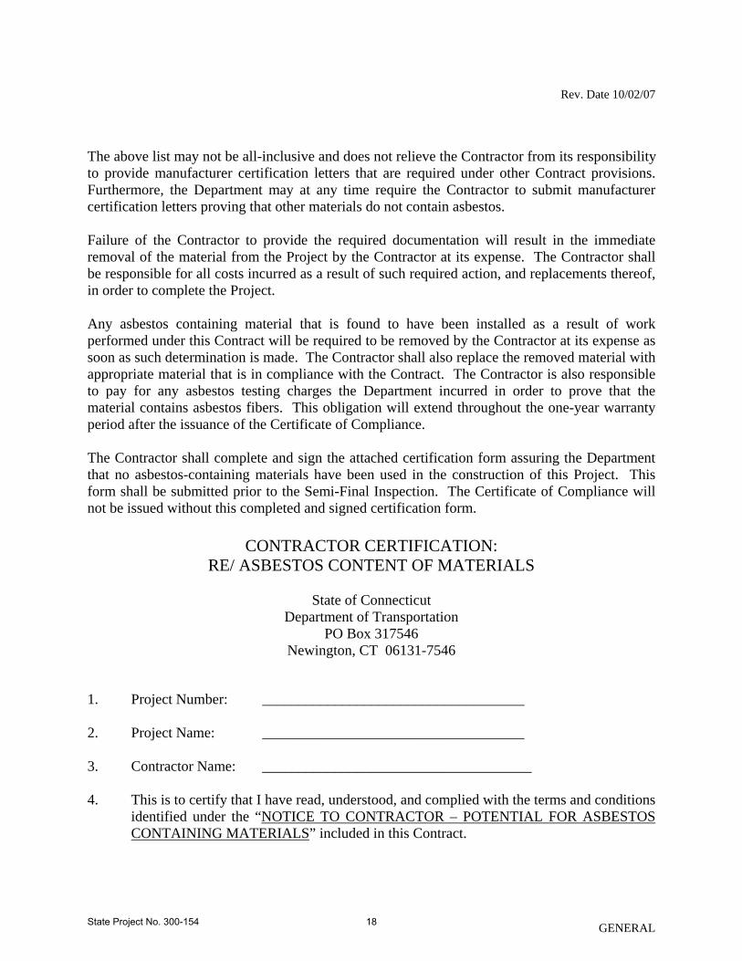
The above list may not be all-inclusive and does not relieve the Contractor from its responsibility to provide manufacturer certification letters that are required under other Contract provisions. Furthermore, the Department may at any time require the Contractor to submit manufacturer certification letters proving that other materials do not contain asbestos. Failure of the Contractor to provide the required documentation will result in the immediate removal of the material from the Project by the Contractor at its expense. The Contractor shall be responsible for all costs incurred as a result of such required action, and replacements thereof, in order to complete the Project. Any asbestos containing material that is found to have been installed as a result of work performed under this Contract will be required to be removed by the Contractor at its expense as soon as such determination is made. The Contractor shall also replace the removed material with appropriate material that is in compliance with the Contract. The Contractor is also responsible to pay for any asbestos testing charges the Department incurred in order to prove that the material contains asbestos fibers. This obligation will extend throughout the one-year warranty period after the issuance of the Certificate of Compliance. The Contractor shall complete and sign the attached certification form assuring the Department that no asbestos-containing materials have been used in the construction of this Project. This form shall be submitted prior to the Semi-Final Inspection. The Certificate of Compliance will not be issued without this completed and signed certification form.
CONTRACTOR CERTIFICATION:
RE/ ASBESTOS CONTENT OF MATERIALS
State of Connecticut Department of Transportation
PO Box 317546 Newington, CT 06131-7546
1. Project Number: ____________________________________ 2. Project Name: ____________________________________ 3. Contractor Name: _____________________________________ 4. This is to certify that I have read, understood, and complied with the terms and conditions
identified under the “NOTICE TO CONTRACTOR – POTENTIAL FOR ASBESTOS CONTAINING MATERIALS” included in this Contract.
GENERAL State Project No. 300-154 18

Rev. Date 10/02/07
GENERAL
I fully understand that it is the requirement of the Connecticut Department of Transportation that only materials that do not contain asbestos of any kind or amount are to be utilized in the construction of this Project.
I therefore certify that, to the best of my knowledge, all materials installed under this Contract are asbestos-free.
For the one-year warranty period after the issuance of the Certificate of Compliance, I agree to remove any asbestos-containing material identified by the Connecticut Department of Transportation and reinstall an approved, non-asbestos-containing material that is in compliance with the original Contract at no additional cost to the State.
5. Date of Certificate of Compliance: __________________ 6. Date of the Asbestos Certification: __________________ 7. Signature of Authorized Party Agreeing to the Terms & Conditions Identified Herein &
as Further Stated in the Contract:
____________________________ ____________________________ Signature Title
____________________________ ____________________________ Printed Name Date
State Project No. 300-154 19

Rev. Date 08/13/09
NOTICE TO CONTRACTOR – OFF-SITE STAGING AND STORAGE The Contractor is hereby advised that due to the restrictive Project Limits and the need to maintain the maximum number of parking spaces for commuters and other operational constraints identified in the Contract, off-site staging and storage of materials and equipment will be required. Arrangement for off-site staging and storage of materials and equipment shall be the responsibility of the Contractor. Payment for off-site staging and storage of materials and equipment shall be in accordance with Form 816 Article 1.09.06. The Contractor shall restrict its operations, including the need for parking for company vehicles, to the minimum space necessary to complete the work. The materials, tools and equipment necessary to complete the work for each shift shall be delivered to the site during that shift and removed from the site following the shift. No materials, tools, or equipment will be allowed to be stored on the site when work is not in progress. All construction debris must be trucked off-site by the competion of each shift of work. The Contractor can arrange for a limited number of parking spaces to be reserved for his use during a specific time frame at each station by contracting Mr. Craig M. Bordiere, Connecticut Department of Transportation, Office of Rail Operations, 50 Union Avenue, 4th Floor, New Haven, CT 06519, (203) 789-7656 x126. The Contractor shall provide a 14 day schedule indicating anticipated work locations and parking requirements. The Contractor shall bid the Project accordingly.
GENERAL State Project No. 300-154 20

Rev. Date 08/24/09
NOTICE TO CONTRACTOR – PROJECT PHASING REQUIREMENTS In order to complete the project within the time frame specified under “Contract Time and Liquidated Damages”, the Contractor will be required to provide multiple crews in order to work multiple shifts at multiple locations simultaneously. Metro North Protective Services may be requested for up to three (3) separate locations during any given shift. Metro North Protective Services will be required for any work on the station platforms. For more information regarding the scheduling and availability of Railroad Protective Services refer to “NOTICE TO CONTRACTOR – WORK ON RAILROAD PROPERTY”. Portions of the work under this contract that require personnel and equipment to be positioned within 10’ of the centerline of the track and/or within 10’ of electrified wires will be accomplished during a nighttime track and power outage. For more information on track outage times and scheduling see “Notice to Contractor – Work on Railroad Property”. Following any sequence of platform repairs or improvements that occur during nighttime offpeak periods, the platforms must be re-opened to passengers morning commute for boarding and de-boarding. Details for staging this are indicated below and on the contract drawings. Other work specified under this contract may be accomplished during off-peak hours, from 10am to 3pm, Monday through Friday. The Contractor shall take the necessary precautions, subject to the approval of the Engineer and Metro North Railroad, to prevent commuters from entering the work area and to protect commuters from the hazards associated with the construction activity. The Contractor must maintain a 5’ clear walking path along the track side of the entire platform at all times to allow commuters to board and de-board the train. The Contractor shall submit a plan to the Engineer and Metro North Railroad showing how commuter access to the trains will be maintained. The contractor is responsible for providing any temporary barricades to prevent commuters from entering the work area. There will be no extra payment for temporary decking, lighting, or barriers required to insure passenger safety and to bring the platform back in to full operation at the end of each shift of work. The cost of these items will be included in the bid price for the applicable pay item being accomplished. Temporary construction signs required to direct commuter traffic shall be paid for at the contract unit price for, “Construction Signs – Type III Reflective Sheeting”. The cost of temporary earth retaining structures required to support excavations adjacent to the track shall be paid for at the contract unit price for, “Temporary Sheet Piling (Railroad)”. All temporary barriers shall be approved by the Engineer and Metro North Railroad. All temporary barriers will be removed and the entire platform shall be made safe and opened to the public prior to the commencement of peak hour service. The following items indicate phasing requirements that shall apply: Greenwich It is anticipated that the work associated with the repair of the canopy columns and off-platform concrete repairs can be completed during the day, off-peak, by re-directing passenger flow on the platforms. The work associated with the repair of the platform piers will require a track outage and must be performed during nighttime operations. Placement of sheet piling or other
GENERAL State Project No. 300-154 21

Rev. Date 08/24/09
temporary earth retaining structures may require a power outage and therefore must be accomplished at night. All work will be supervised by a Metro North Flagman and work in the vicinity of electrified wires will be supervised by Metro North Class A Linemen. Noroton Heights The pedestrian bridge will have to be closed in order to repair the stairs. Pedestrians can be rerouted over the adjacent roadway bridge during the closure. The repairs to the nosings and platform milling will require a track outage and must be performed during nighttime operations. The contractor must install temporary bridge plates and plywood decking as necessary to bring the entire length of the platform in to service by the end of the shift. The replacement of the light poles may require a truck mounted crane to install. Therefore, this work will have to be done at night with a possible power outage. The contractor must maintain station lighting during normal business hours of station operations (4am – 12:00pm). This work will be accomplished under the supervision of a Metro North Flagmen and a Metro North Class A Lineman. South Norwalk: The repairs to the nosings and platform milling will require a track outage and must be performed during nighttime operations. The contractor must install temporary bridge plates and plywood decking as necessary to bring the entire length of the platform in to service by the end of the shift. This work will be accomplished under the supervision of a Metro North Flagmen. Westport The replacement of the light poles may require a truck mounted crane to install. Therefore, this work will have to be done at night with a possible power outage. The contractor must maintain station lighting during normal business hours of station operations (4am – 12:00pm). This work will be accomplished under the supervision of a Metro North Flagmen and a Metro North Class A Lineman. Southport The replacement of the light poles may require a truck mounted crane to install. Therefore, this work will have to be done at night with a possible power outage. The contractor must maintain station lighting during normal business hours of station operations (4am – 12:00pm).Work will be coordinated with the contractor performing Phase A. This work will be accomplished under the supervision of a Metro North Flagmen and a Metro North Class A Lineman. Stratford The replacement of the light poles may require a truck mounted crane to install. Therefore, this work will have to be done at night with a possible power outage. The contractor must maintain station lighting during normal business hours of station operations (4am – 12:00pm). Work will be coordinated with the contractor performing Phase A. This work will be accomplished under the supervision of a Metro North Flagmen and a Metro North Class A Lineman. Wilton Some work around the exterior of the building will be in the vicinity of the track and therefore will require flag protection. The Contractor shall limit excavations between the building and the
GENERAL State Project No. 300-154 22

Rev. Date 08/24/09
GENERAL
track to avoid the need for temporary earth retaining structures to support the adjacent track.. All work should be able to be accomplished during normal work hours. This work will be accomplished under the supervision of a Metro North Flagmen. Danbury Since this is an end of the line station with a limited schedule it is anticipated that the work could be accomplished during the day off-peak. This work will be accomplished under the supervision of a Metro North Flagmen.
State Project No. 300-154 23
Rev. Date 07/17/09
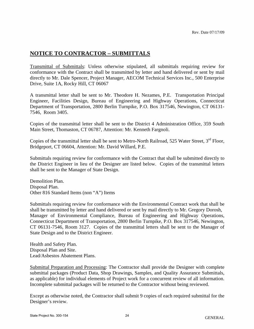
NOTICE TO CONTRACTOR – SUBMITTALS Transmittal of Submittals: Unless otherwise stipulated, all submittals requiring review for conformance with the Contract shall be transmitted by letter and hand delivered or sent by mail directly to Mr. Dale Spencer, Project Manager, AECOM Technical Services Inc., 500 Enterprise Drive, Suite 1A, Rocky Hill, CT 06067 A transmittal letter shall be sent to Mr. Theodore H. Nezames, P.E. Transportation Principal Engineer, Facilities Design, Bureau of Engineering and Highway Operations, Connecticut Department of Transportation, 2800 Berlin Turnpike, P.O. Box 317546, Newington, CT 06131-7546, Room 3405. Copies of the transmittal letter shall be sent to the District 4 Administration Office, 359 South Main Street, Thomaston, CT 06787, Attention: Mr. Kenneth Fargnoli. Copies of the transmittal letter shall be sent to Metro-North Railroad, 525 Water Street, 3rd Floor, Bridgeport, CT 06604, Attention: Mr. David Willard, P.E. Submittals requiring review for conformance with the Contract that shall be submitted directly to the District Engineer in lieu of the Designer are listed below. Copies of the transmittal letters shall be sent to the Manager of State Design. Demolition Plan. Disposal Plan. Other 816 Standard Items (non “A”) Items Submittals requiring review for conformance with the Environmental Contract work that shall be shall be transmitted by letter and hand delivered or sent by mail directly to Mr. Gregory Dorosh, Manager of Environmental Compliance, Bureau of Engineering and Highway Operations, Connecticut Department of Transportation, 2800 Berlin Turnpike, P.O. Box 317546, Newington, CT 06131-7546, Room 3127. Copies of the transmittal letters shall be sent to the Manager of State Design and to the District Engineer. Health and Safety Plan. Disposal Plan and Site. Lead/Asbestos Abatement Plans. Submittal Preparation and Processing: The Contractor shall provide the Designer with complete submittal packages (Product Data, Shop Drawings, Samples, and Quality Assurance Submittals, as applicable) for individual elements of Project work for a concurrent review of all information. Incomplete submittal packages will be returned to the Contractor without being reviewed. Except as otherwise noted, the Contractor shall submit 9 copies of each required submittal for the Designer’s review.
GENERAL State Project No. 300-154 24

Rev. Date 07/17/09
GENERAL
Shop Drawings: The Contractor shall submit 1 correctable translucent reproducible print and 8 blue- or black-line prints for the Designer's review. The Contractor shall add 1 blue- or black-line print for each of the above noted CSI Sections for outside agency review. Samples: Where Samples are for selection of color, pattern, texture or similar characteristics from a range of choices, submit 2 full sets of the standard and custom choices for the material or product. Where Samples illustrate assembly details, workmanship, fabrication techniques, connections, operation and similar characteristics, submit 1 sample (or set, if applicable). Designer’s Action: The Designer will return 3 copies marked with action taken and corrections or modifications required. Shop Drawings: The Designer will return the reproducible print. One of the prints returned shall be marked-up and maintained as a “Record Document.” Samples: The Designer will return one set of samples marked with the action taken. The set of samples shall be maintained at the Project office when returned. Maintenance manuals and warranties will not be returned unless they are Rejected.
State Project No. 300-154 25

Rev. Date 08/13/09
NOTICE TO CONTRACTOR – PRE-INSTALLATION MEETINGS The Engineer will conduct a pre-installation meeting before each of the following construction activities:
1. Tactile Warning Strip Installation 2. Lighting 3. Platform Pier Improvements and Repairs 4. Stair Tread Replacements 5. Wilton Station Renovations
The above list may not be all-inclusive and does not relieve the Contractor from its responsibility to provide pre-installation meetings that are required under other Contract provisions.
GENERAL State Project No. 300-154 26

Rev. Date 08/25/09
NOTICE TO CONTRACTOR – CLOSEOUT DOCUMENTS
General: The list of special provisions (including CSI-formatted specifications) in the Table below may not be all-inclusive and does not relieve the Contractor from its responsibility to provide spare parts, operation and maintenance manuals, training, and warranties that are required under other Contract provisions. This Table will be forwarded to Mr. Mark D. Neri, Office of Rails, for concurrence prior to the Semi-Final Inspection. Spare Parts: The Contractor shall deliver spare parts on products listed in the Table below to the Project Site. Coordinate with the Engineer prior to delivery to verify the delivery location. Operation and Maintenance Maunals: Submit 4 copies of each manual to the Designer. The Designer and Mr. Mark D. Neri, Office of Rails, will review the manuals for conformance to the Contract. The manuals will be processed in accordance with Form 816 Article 1.20-1.05.02, with 3 copies being forwarded to Mr. Mark D. Neri, Office of Rails and one copy being sent to the Engineer. Materials and Finishes Maintenance Manual: The Contractor shall provide complete information in the materials and finishes manual on products listed in the Table below. Equipment and Systems Maintenance Manuals: The Contractor shall provide complete information in the equipment and systems manual on products listed in the Table below. Warranties: Submit 4 copies of written warranties, including special warranties to the Designer. The Designer and Mr. Mark D. Neri, Office of Rails, will review the warranties for conformance to the Contract. The warranties will be processed in accordance with Form 816 Article 1.20-1.05.02, with 3 copies being forwarded to Mr. Mark D. Neri, Office of Rails and one copy being sent to the Engineer. The Contractor shall provide special warranties on products and installations listed in the Table below.
TABLE
Special Provision (including CSI-formatted Specifications) Warranties Spare
Parts
Operation and
Maintenance Manuals
ITEM #0603830A - Field Painting of Structure (Site No. 1-19) X
ITEM # Windscreens X X X ITEM # 0062680A Tactile Warning Strip X X X ITEM # 1003598A Light Pole and Fixtures X X X
GENERAL State Project No. 300-154 27

Rev. Date 07/30/09
NOTICE TO CONTRACTOR – AMERICAN RECOVERY AND REINVESTMENT ACT OF 2009 1. For the purposes of this NOTICE TO CONTRACTOR, “Contractor” means any prime contractor, consulting engineer, or other entity contracting with the State of Connecticut Department of Transportation (“DOT”) funded under the American Recovery and Reinvestment Act of 2009 (“Recovery Act”). 2. The Contractor agrees to accurately and timely record and report, in accordance with the requirements of the American Recovery and Reinvestment Act of 2009 (“Recovery Act”) and additional guidelines, policies and regulations issued or promulgated pursuant to the Recovery Act, information regarding jobs or positions created or retained in Connecticut, the United States and outlying areas as a result of funding provided through the Recovery Act for the Project. The Contractor’s subcontractor(s) and second-tier subcontractor(s) may likewise be required to submit information regarding jobs or positions created or retained. In accordance with the following requirements:
A. The Contractor shall accurately complete and submit to DOT on a monthly basis from commencement through completion of its work on the Project, an employment report indicating the direct jobs created or maintained by the Project and report of hours for direct on-site jobs, using the form and format provided by DOT (“Monthly Employment Report”).
(i) No later than five (5) calendar days after the last calendar day of the month being
reported (“Five Day Submission Requirement”), the Contractor shall submit the completed Monthly Employment Report in the specified format to DOT by e-mail to: [email protected], with a copy to [email protected] and [email protected], and also submit a hard copy to the applicable DOT District office for inclusion in the Project file, signed by an authorized representative of the Contractor.
(ii) The Contractor shall provide a consistent filename for each Monthly Employment
Report in the format: ContractNumberMonthYear.xls (e.g., ######SEPT09). (iii) The Contractor shall require each of the its subcontractors and second-tier
subcontractors (collectively, “Subcontractors”) to submit an employment report using the form provided by DOT (“Monthly Subcontractor Employment Report”) to the Contractor on a monthly basis within sufficient time to enable the Contractor, in turn, to submit such Monthly Subcontractor Employment Report(s) to DOT by the Contractor’s Five Day Submission Requirement. Failure by Subcontractors to timely submit Monthly Subcontractor Employment Report(s) to the Contractor does not excuse the Contractor’s obligation to submit its Monthly Employment Report by the required deadline.
GENERAL State Project No. 300-154 28

Rev. Date 07/30/09
3. The Contractor shall prepare quarterly progress reports including a detailed statement of the construction progress and overall Project budget, information on Project schedule and milestones (including, if applicable, an explanation of failure to meet milestones), and other Project information requested by the Federal Transit Administration (“FTA”) or DOT (“Quarterly Progress Reports”). The Contractor shall submit each Quarterly Progress Report within three (3) days after the end of the applicable quarterly period. 4. Receipt of funds pursuant to the Recovery Act under this Contract is contingent upon the Contractor meeting the reporting requirements of this Contract and any additional reporting requirements of the Recovery Act as may be required by the appropriate federal agency through its issuance of guidelines or promulgation of regulation(s). 5. DOT reserves the right to request any additional information from the Contractors and Subcontractors as may be necessary to comply with federal or state reporting requirements. The Contractor agrees that at any time during the Project, FTA and/or DOT, after notice, may modify the reporting requirements. In that event, the Contractor and its subcontractor(s) and second-tier subcontractor(s) shall comply with such requirements. 6. DOT may take any action that FTA authorizes for the non-compliance with the Recovery Act reporting requirements by the Contractor. 7. The Contractor agrees to comply with Sections 1605 and 1606 of Title XVI of Division A of the Recovery Act and any additional federal guidelines or regulations issued or promulgated thereunder. 8. The following language is made a part of this Contract and shall be made part of all subcontracts and second tier subcontracts:
A. Access of United States Government Accountability Office, Section 902 of Title IX of Division A of the Recovery Act. Pursuant to Section 902 of Title IX of Division A of the Recovery Act, the United States Comptroller General and its representatives may:
(i) examine any records of the Contractor or any of its subcontractors, or any State or
local agency administering such Contract, that directly pertains to, and involve transactions relating to, the Contract or Subcontract; and
(ii) interview any officer or employee of the Contractor or any of its subcontractors, or
of any State or local government agency administering the Contract, regarding such transactions.
Nothing in Section 902 shall be interpreted to limit or restrict in any way any other statutory or regulatory authority of the United States Comptroller General.
B. Office of the Inspector General’s Authority, Section 1515 of Title XV of Division A of
the Recovery Act. Pursuant to Section 1515, of Title XV of Division A of the
GENERAL State Project No. 300-154 29
Rev. Date 07/30/09
GENERAL
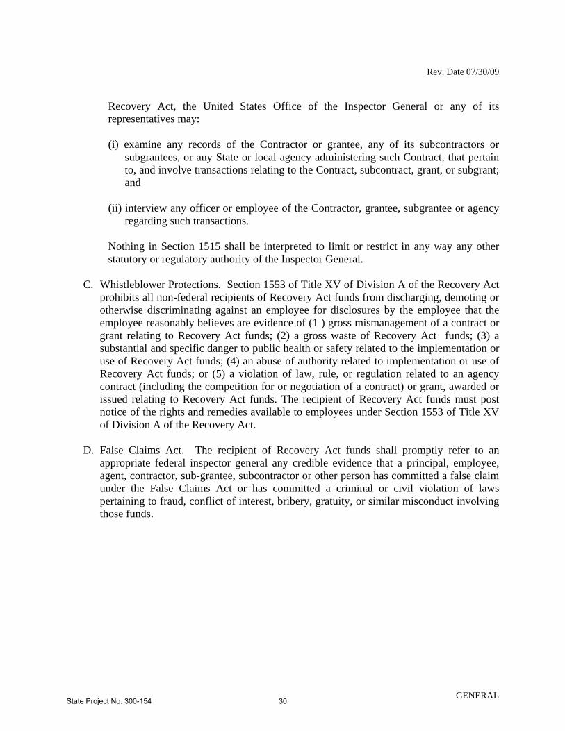
Recovery Act, the United States Office of the Inspector General or any of its representatives may:
(i) examine any records of the Contractor or grantee, any of its subcontractors or
subgrantees, or any State or local agency administering such Contract, that pertain to, and involve transactions relating to the Contract, subcontract, grant, or subgrant; and
(ii) interview any officer or employee of the Contractor, grantee, subgrantee or agency
regarding such transactions.
Nothing in Section 1515 shall be interpreted to limit or restrict in any way any other statutory or regulatory authority of the Inspector General.
C. Whistleblower Protections. Section 1553 of Title XV of Division A of the Recovery Act
prohibits all non-federal recipients of Recovery Act funds from discharging, demoting or otherwise discriminating against an employee for disclosures by the employee that the employee reasonably believes are evidence of (1 ) gross mismanagement of a contract or grant relating to Recovery Act funds; (2) a gross waste of Recovery Act funds; (3) a substantial and specific danger to public health or safety related to the implementation or use of Recovery Act funds; (4) an abuse of authority related to implementation or use of Recovery Act funds; or (5) a violation of law, rule, or regulation related to an agency contract (including the competition for or negotiation of a contract) or grant, awarded or issued relating to Recovery Act funds. The recipient of Recovery Act funds must post notice of the rights and remedies available to employees under Section 1553 of Title XV of Division A of the Recovery Act.
D. False Claims Act. The recipient of Recovery Act funds shall promptly refer to an
appropriate federal inspector general any credible evidence that a principal, employee, agent, contractor, sub-grantee, subcontractor or other person has committed a false claim under the False Claims Act or has committed a criminal or civil violation of laws pertaining to fraud, conflict of interest, bribery, gratuity, or similar misconduct involving those funds.
State Project No. 300-154 30

Rev. Date 08/13/09
NOTICE TO CONTRACTOR – STATION OPERATION The Contractor is advised that there will be no interruption of station services during construction. The Contractor shall provide a safe, accessible, well-marked route for commuters to reach all temporary facilities and all platforms at all times and shall maintain all temporary facilities so that they remain free of hazards. The Contractor shall schedule work that will require closure of a platform during night hours after station operations have ceased for the day. The Contractor shall put in place temporary barricades and safety devices as required to return the entire platform to operation the following morning. For further guidance refer to NOTICE TO CONTRACTOR – LIMITATION OF CONTRACTOR OPERATIONS, to Form 816 Section 1.08 – Prosecution of Work, and to Form 816 Article 1.20 – 1.08.03 – Prosecution of Work.
GENERAL State Project No. 300-154 31

Rev. Date 08/24/09
NOTICE TO CONTRACTOR – WORK ON RAILROAD PROPERTY The Contractor acknowledges that work to be accomplished under this Contract is to be performed on Railroad territory, which consists of territory operated by Metro-North Commuter Railroad. The Contractor's work must be accomplished simultaneously with ongoing daily railroad operations. Such operations include, but are not limited to, the passage of trains, storage of trains, flagging, inspection, repair, construction, reconstruction, and maintenance of the railroad right-of-way and facilities. The Contractor is advised that the Railroad controls all activity in their respective right-of-way, and the Department expects that these conditions may cause delays and possibly a complete suspension of construction activity. If the Contractor is delayed or suspended in the completion of the work by railroad operations, the Contractor will be entitled to a time extension for every day that he can demonstrate that the delays affected the completion date of the contract. This extension of time will be considered non-compensable and the Contractor will not be entitled to any additional compensation for damages incurred for all direct and indirect costs including, but not limited to, all delay and impact costs, and inefficiencies. The Contractor shall be responsible for the coordination of the work of his various subcontractors. The Contractor shall coordinate his operations with those of the Railroad Company in carrying out railroad force account work. The Contractor's employees, and the employees of all subcontractors, who will be entering the jobsite within Railroad territory, must undergo a Railroad safety training class, of approximately one hour, offered by Metro-North Railroad. The Engineer will arrange for the class; however, the Contractor is responsible for insuring that all employees on the jobsite have been trained. No additional compensation will be allowed to the Contractor for employees time for attending these classes. Refer to the special provisions and to Article 1.05.06 entitled "Cooperation with Utilities (Including Railroads)." The Contractor must make his own arrangements with the Railroad for the use of railroad equipment or changes in railroad facilities made solely to facilitate the Contractor's operations. The expense incurred by making such arrangements shall not be a part of this contract. Contractor Requirements for Work Affecting the Railroad The Contractor shall be governed by the State of Connecticut, Department of Transportation Standard Specifications for Roads, Bridges, and Incidental Construction, Form 816, dated 2004, and supplemental specifications thereto, with the following additions: 1. All matters requiring Railroad Company approval or coordination shall be directed to: Mr. David Willard, P.E.
Assistant Director Tunnels Bridges and Track - Capital Engineering
GENERAL State Project No. 300-154 32

Rev. Date 08/24/09
Metro-North Railroad Company 525 Water Street, 3rd Floor Bridgeport, CT 06601
2. In general, unless otherwise authorized by the Railroad, the contractor’s construction
activities and operations directly over and/or adjacent to operating railroad right-of-way shall be performed during the following track outage periods:
Location Outage Time CP234-CP241 Track 4 is scheduled to be out of service from April (Noroton Heights and through October due to the Catenary B replacement So. Norwalk) project. The contractor may perform work that would normally require a track outage on the Track 4 side during off-peak hours provided a 5’ clear path is is provided for commuters to reach the bridge plates. Contractor shall coordinate with the Cat. B project and adjust his schedule accordingly. Track 3 Either Fri.-Sat (Contractor shall coordinate or Sat.-Sun.
with the Cat. B project 0030-0430 and adjust his schedule
accordingly) CP241-CP248 Either Track 4 or 3 0030-0430 (Westport) CP248-CP256 Track 3 is scheduled to be out of service from May (Southport) through August and Track 2 and 4 are scheduled to be out of service from August through the completion of construction. The contractor may perform work
that would normally require a track outage on the effected side during off-peak hours provided a 5’ clear path is provided for commuters to reach the bridge plates. Contractor shall coordinate with the Cat. C1B project and adjust his schedule accordingly.
CP256-CP266 Track 4 or Track 3 0030-0430 (Stratford)
GENERAL State Project No. 300-154 33

Rev. Date 08/24/09
Notes: a. Contractor must also coordinate work/outages with the contractor for project 300-
153, Phase A Station Improvements. Track outages are to be coordinated during a weekly track outage meeting to be held on Mondays of each week for the duration of construction. The Contractor shall provide a 7 and 14 day schedule of requested outages at that time.
b. The contractor shall schedule his operations so that all the work that requires a track outage will occur along the same track within the blocks defined above.
c. No continuous outages will be granted on the New Haven Mainline nor the New Canaan Branch line for this project beyond the above. While there may be on-going outages in the work area there is no guarantee that the Contractor may utilize another projects track outages. If granted, the Contractor’s operations must not interfere with any aspect of the other projects work.
d. The above outages are not guaranteed at all times. e. The Contractor's plan for demolition, erection, and any operation adjacent to or
within the Railroad Right of Way shall be submitted to the Engineer for Railroad approval, prior to start of work.
f. No full track and/or power outages will be permitted on weekends either immediately before or after major holidays, nor any weekend between Thanksgiving and New Years day.
g. Refer to Article 1.05.06 — “Cooperation with Utilities (Including Railroads)”, paragraph (1)(e)(3) as supplemented for additional restrictions to the track outage periods shown above
h. The contractor is advised that the availability of the track outages listed above must be coordinated with other on going projects in the same railroad block area.
i. Power outages: 1. Catenary Power outages – A catenary power outage must be scheduled
concurrently with a track outage for the track and is restricted to the same period as specified in the plans and specifications.
2. Metro-North Railroad Power and Signal Distribution Feeder Outages – Outages for feeders can be allowed only during off-peak hours. These outages should be requested at a weekly Railroad Coordination meeting. One set (north or south) side of the railroad of power and signal feeders must be maintained energized at all times.
3. During peak (5:00am to 10:00am and 3:00pm to 10:00pm, Monday thru. Friday) hours of Railroad traffic, both sets (north and south) of power and signal feeders must be energized.
3. Temporary at-grade crossings across any tracks on the main line for vehicles and
equipment for ANY purpose WILL NOT be permitted. All vehicles, equipment and materials for demolition, stockpiling, and associated activities shall be delivered via the existing Railroad Station entrances.
4. All work involving rail, ties, and other track components on active tracks, unless
specifically designated otherwise within the contract, will be performed by Railroad
GENERAL State Project No. 300-154 34
Rev. Date 08/24/09
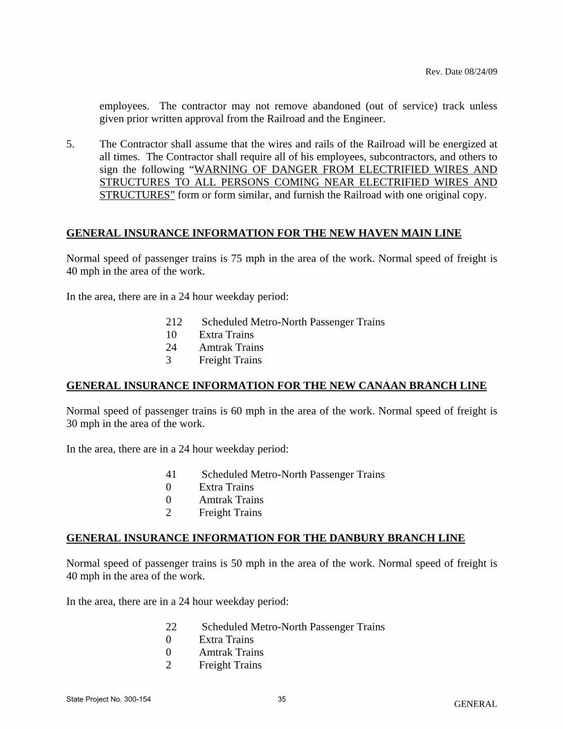
employees. The contractor may not remove abandoned (out of service) track unless given prior written approval from the Railroad and the Engineer.
5. The Contractor shall assume that the wires and rails of the Railroad will be energized at
all times. The Contractor shall require all of his employees, subcontractors, and others to sign the following “WARNING OF DANGER FROM ELECTRIFIED WIRES AND STRUCTURES TO ALL PERSONS COMING NEAR ELECTRIFIED WIRES AND STRUCTURES” form or form similar, and furnish the Railroad with one original copy.
GENERAL INSURANCE INFORMATION FOR THE NEW HAVEN MAIN LINE Normal speed of passenger trains is 75 mph in the area of the work. Normal speed of freight is 40 mph in the area of the work. In the area, there are in a 24 hour weekday period: 212 Scheduled Metro-North Passenger Trains 10 Extra Trains 24 Amtrak Trains 3 Freight Trains GENERAL INSURANCE INFORMATION FOR THE NEW CANAAN BRANCH LINE Normal speed of passenger trains is 60 mph in the area of the work. Normal speed of freight is 30 mph in the area of the work. In the area, there are in a 24 hour weekday period: 41 Scheduled Metro-North Passenger Trains 0 Extra Trains 0 Amtrak Trains 2 Freight Trains GENERAL INSURANCE INFORMATION FOR THE DANBURY BRANCH LINE Normal speed of passenger trains is 50 mph in the area of the work. Normal speed of freight is 40 mph in the area of the work. In the area, there are in a 24 hour weekday period: 22 Scheduled Metro-North Passenger Trains 0 Extra Trains 0 Amtrak Trains 2 Freight Trains
GENERAL State Project No. 300-154 35

Rev. Date 08/24/09
GENERAL INSURANCE INFORMATION FOR THE WATERBURY BRANCH LINE Normal speed of passenger trains is 59 mph in the area of the work. Normal speed of freight is 40 mph in the area of the work. In the area, there are in a 24 hour weekday period: 16 Scheduled Metro-North Passenger Trains 0 Extra Trains 0 Amtrak Trains 2 Freight Trains
GENERAL State Project No. 300-154 36

Rev. Date 08/24/09
GENERAL
WARNING OF DANGER FROM ELECTRIFIED WIRES AND STRUCTURES TO ALL PERSONS COMING NEAR ELECTRIFIED WIRES AND STRUCTURES Notice is hereby given that contact, direct or indirect, with any of the electrified wires or structures of this Railroad Company is apt to result in serious injury or death and you are warned to avoid all such contact. Dated____________________________ Job AFE No.__________________________________________________________ Title RECEIPT I have this day received and carefully read the warning of danger from electrified wires and structures issued by you, which was attached to this receipt. Print Name_________________________ Signature__________________________ Occupation______________________ Date____________________________ In the presence of _________________________ Witness Job AFE No._________________________________________________________
State Project No. 300-154 37

Rev. Date 08/13/09
NOTICE TO CONTRACTOR – PHOTO IDENTIFICATION The Contractor is hereby notified that all employees, including subcontractors, who will work on the Project will be required to carry personal photo identification, such as a valid driver’s license.
GENERAL State Project No. 300-154 38

Rev. Date 07/23/07
NOTICE TO CONTRACTOR – TACTILE WARNING STRIP The installation of the Tactile Warning Strip requires close coordination between the Contractor and the supplier/installer. This coordination is the sole responsibility of the Contractor and there will be no compensation for delays caused by a lack of coordination.
GENERAL State Project No. 300-154 39

Rev. Date 12/1/09
NOTICE TO CONTRACTOR – HAZARDOUS MATERIALS INVESTIGATIONS A hazardous building materials site investigation has been conducted at the various train stations along the New Haven Line & Branch Lines of the Metro-North Railroad located in Connecticut which are scheduled for renovation. The results of this investigation indicated the presence of asbestos containing materials (ACM), lead based paint (LBP), aboveground storage tank (AST), and additional hazardous or otherwise regulated items (mercury, PCBs, batteries, used electronics, smoke detectors, fire extinguishers, oils, chemicals, corrosives, ignitables, etc.). within proposed construction areas. The Contractor is hereby notified that these hazardous building materials requiring special management or disposal procedures will be encountered during various construction activities conducted within the project limits. The Contractor will be required to implement appropriate health and safety measures for all construction activities impacting these materials. These measures shall include, but are not limited to, air monitoring, engineering controls, personal protective equipment and decontamination, equipment decontamination and personnel training. WORKER HEALTH AND SAFETY PROTOCOLS WHICH ADDRESS POTENTIAL AND/OR ACTUAL RISK OF EXPOSURE TO SITE SPECIFIC HAZARDS ARE SOLELY THE RESPONSIBILITY OF THE CONTRACTOR. The Department, as Generator, will provide an authorized representative to sign all manifests and waste profile documentation required by disposal facilities for disposal of hazardous materials. The Sections which shall be reviewed by the Contractor include, but are not limited to, the following:
• Item No. 0020801A – Asbestos Abatement • Item No. 0020901A – Lead Abatement • Item No. 0101143A – Handling and Disposal of Regulated Items • Item No. 0202317A – Disposal of Hazardous Materials
The Contractor is alerted to the fact that a Department environmental consultant will be on site for abatement and related activities, to collect environmental samples (if necessary), and to observe site conditions for the State. Information pertaining to the results of the hazardous building materials investigation discussed can be found in the documents listed below. These documents shall be available for review at the Office of Contracts, 2800 Berlin Turnpike, Newington, Connecticut.
Pre-Renovation Investigative Survey for Hazardous Building Materials, Metro-North New Haven Line Railroad Stations Canopy Improvements (Phase B) TRC Environmental Corporation. December 2009.
GENERAL State Project No. 300-154 40

Rev. Date 12/1/09
GENERAL
Pre-Renovation Investigative Survey for Hazardous Building Materials, Metro-North New Haven Line Railroad Stations Canopy Improvements (Phase A) TRC Environmental Corporation. August 2009. Revised August 31, 2009.
State Project No. 300-154 41

Rev. Date 04/02/07
NOTICE TO CONTRACTOR - CAMPAIGN CONTRIBUTION AND SOLICITATION BAN With regard to a State contract as defined in P.A. 07-1 having a value in a calendar year of $50,000 or more or a combination or series of such agreements or contracts having a value of $100,000 or more, the authorized signatory to the bid proposal form in response to the State's solicitation expressly acknowledges receipt of the State Elections Enforcement Commission's notice advising prospective state contractors of state campaign contribution and solicitation prohibitions, and will inform its principals of the contents of the notice. The attached SEEC Form 11 is also made a part of this solicitation. For all State contracts as defined in P.A. 07-1 having a value in a calendar year of $50,000 or more or a combination or series of such agreements or contracts having a value of $100,000 or more, the authorized signatory to this Contract expressly acknowledges receipt of the State Elections Enforcement Commission's notice advising state contractors of state campaign contribution and solicitation prohibitions, and will inform its principals of the contents of the notice. The attached SEEC Form 11 is also made a part of this Contract.
GENERAL State Project No. 300-154 42

Rev. Date 04/02/07
SEEC FORM 11 NOTICE TO EXECUTIVE BRANCH STATE CONTRACTORS AND PROSPECTIVE STATE CONTRACTORS OF CAMPAIGN CONTRIBUTION AND SOLICITATION BAN This notice is provided under the authority of Connecticut General Statutes 9-612(g)(2), as amended by P.A. 07-1, and is for the purpose of informing state contractors and prospective state contractors of the following law (italicized words are defined below): Campaign Contribution and Solicitation Ban No state contractor, prospective state contractor, principal of a state contractor or principal of a prospective state contractor, with regard to a state contract or state contract solicitation with or from a state agency in the executive branch or a quasi-public agency or a holder, or principal of a holder of a valid prequalification certificate, shall make a contribution to, or solicit contributions on behalf of (i) an exploratory committee or candidate committee established by a candidate for nomination or election to the office of Governor, Lieutenant Governor, Attorney General, State Comptroller, Secretary of the State or State Treasurer, (ii) a political committee authorized to make contributions or expenditures to or for the benefit of such candidates, or (iii) a party committee; In addition, no holder or principal of a holder of a valid prequalification certificate, shall make a contribution to, or solicit contributions on behalf of (i) an exploratory committee or candidate committee established by a candidate for nomination or election to the office of State senator or State representative, (ii) a political committee authorized to make contributions or expenditures to or for the benefit of such candidates, or (iii) a party committee. Duty to Inform State contractors and prospective state contractors are required to inform their principals of the above prohibitions, as applicable, and the possible penalties and other consequences of any violation thereof. Penalties for Violations Contributions or solicitations of contributions made in violation of the above prohibitions may result in the following civil and criminal penalties: Civil penalties--$2000 or twice the amount of the prohibited contribution, whichever is greater, against a principal or a contractor. Any state contractor or prospective state contractor which fails to make reasonable efforts to comply with the provisions requiring notice to its principals of these prohibitions and the possible consequences of their violations may also be subject to civil penalties of $2000 or twice the amount of the prohibited contributions made by their principals. Criminal penalties—Any knowing and willful violation of the prohibition is a Class D felony, which may subject the violator to imprisonment of not more than 5 years, or $5000 in fines, or both. Contract Consequences Contributions made or solicited in violation of the above prohibitions may result, in the case of a state contractor, in the contract being voided. Contributions made or solicited in violation of the above prohibitions, in the case of a prospective state contractor, shall result in the contract described in the state contract solicitation not being awarded to the prospective state contractor, unless the State Elections Enforcement Commission determines that mitigating circumstances exist concerning such violation. The State will not award any other state contract to anyone
GENERAL State Project No. 300-154 43

Rev. Date 04/02/07
found in violation of the above prohibitions for a period of one year after the election for which such contribution is made or solicited, unless the State Elections Enforcement Commission determines that mitigating circumstances exist concerning such violation. Additional information and the entire text of P.A 07-1 may be found on the website of the State Elections Enforcement Commission, www.ct.gov/seec. Click on the link to “State Contractor Contribution Ban.” Definitions: "State contractor" means a person, business entity or nonprofit organization that enters into a state contract. Such person, business entity or nonprofit organization shall be deemed to be a state contractor until December thirty-first of the year in which such contract terminates. "State contractor" does not include a municipality or any other political subdivision of the state, including any entities or associations duly created by the municipality or political subdivision exclusively amongst themselves to further any purpose authorized by statute or charter, or an employee in the executive or legislative branch of state government or a quasi-public agency, whether in the classified or unclassified service and full or part-time, and only in such person's capacity as a state or quasi-public agency employee. "Prospective state contractor" means a person, business entity or nonprofit organization that (i) submits a response to a state contract solicitation by the state, a state agency or a quasi-public agency, or a proposal in response to a request for proposals by the state, a state agency or a quasi-public agency, until the contract has been entered into, or (ii) holds a valid prequalification certificate issued by the Commissioner of Administrative Services under section4a-100. "Prospective state contractor" does not include a municipality or any other political subdivision of the state, including any entities or associations duly created by the municipality or political subdivision exclusively amongst themselves to further any purpose authorized by statute or charter, or an employee in the executive or legislative branch of state government or a quasi-public agency, whether in the classified or unclassified service and full or part-time, and only in such person's capacity as a state or quasi-public agency employee. "Principal of a state contractor or prospective state contractor" means (i) any individual who is a member of the board of directors of, or has an ownership interest of five per cent or more in, a state contractor or prospective state contractor, which is a business entity, except for an individual who is a member of the board of directors of a nonprofit organization, (ii) an individual who is employed by a state contractor or prospective state contractor, which is a business entity, as president, treasurer or executive vice president, (iii) an individual who is the chief executive officer of a state contractor or prospective state contractor, which is not a business entity, or if a state contractor or prospective state contractor has no such officer, then the officer who duly possesses comparable powers and duties, (iv) an officer or an employee of any state contractor or prospective state contractor who has managerial or discretionary responsibilities with respect to a state contract, (v) the spouse or a dependent child who is eighteen years of age or older of an individual described in this subparagraph, or (vi) a political committee established or controlled by an individual described in this subparagraph or the business entity or nonprofit organization that is the state contractor or prospective state contractor. "State contract" means an agreement or contract with the state or any state agency or any quasi-public agency, let through a procurement process or otherwise, having a value of fifty thousand dollars or more, or a combination or series of such agreements or contracts having a value of one
GENERAL State Project No. 300-154 44

Rev. Date 04/02/07
GENERAL
hundred thousand dollars or more in a calendar year, for (i) the rendition of services, (ii) the furnishing of any goods, material, supplies, equipment or any items of any kind, (iii) the construction, alteration or repair of any public building or public work, (iv) the acquisition, sale or lease of any land or building, (v) a licensing arrangement, or (vi) a grant, loan or loan guarantee. "State contract" does not include any agreement or contract with the state, any state agency or any quasi-public agency that is exclusively federally funded, an education loan or a loan to an individual for other than commercial purposes. "State contract solicitation" means a request by a state agency or quasi-public agency, in whatever form issued, including, but not limited to, an invitation to bid, request for proposals, request for information or request for quotes, inviting bids, quotes or other types of submittals, through a competitive procurement process or another process authorized by law waiving competitive procurement. “Managerial or discretionary responsibilities with respect to a state contract” means having direct, extensive and substantive responsibilities with respect to the negotiation of the state contract and not peripheral, clerical or ministerial responsibilities. “Dependent child” means a child residing in an individual’s household who may legally be claimed as a dependent on the federal income tax of such individual. “Solicit” means (A) requesting that a contribution be made, (B) participating in any fund-raising activities for a candidate committee, exploratory committee, political committee or party committee, including, but not limited to, forwarding tickets to potential contributors, receiving contributions for transmission to any such committee or bundling contributions, (C) serving as chairperson, treasurer or deputy treasurer of any such committee, or (D) establishing a political committee for the sole purpose of soliciting or receiving contributions for any committee. Solicit does not include: (i) making a contribution that is otherwise permitted by Chapter 155 of the Connecticut General Statutes; (ii) informing any person of a position taken by a candidate for public office or a public official, (iii) notifying the person of any activities of, or contact information for, any candidate for public office; or (iv) serving as a member in any party committee or as an officer of such committee that is not otherwise prohibited in this section.
State Project No. 300-154 45

Rev. Date 6/08/07
NOTICE TO CONTRACTOR - CODE OF ETHICS The Contractor shall comply with the provisions contained in Section 1-86e of the Connecticut General Statutes, which provides as follows: (a) No person hired by the state as a Contractor or independent contractor shall: (1) Use the authority provided to the person under the contract, or any
confidential information acquired in the performance of the contract, to obtain financial gain for the person, an employee of the person or a member of the immediate family of any such person or employee;
(2) Accept another state contract which would impair the independent judgment of the person in the performance of the existing contract; or
(3) Accept anything of value based on an understanding that the actions of the person on behalf of the state would be influenced.
(b) No person shall give anything of value to a person hired by the state as a Contractor
or independent contractor based on an understanding that the actions of the Contractor or independent contractor on behalf of the state would be influenced.
The following clause is applicable to those contracts with a value of five hundred thousand dollars ($500,000) or more: The Contractor shall comply with the Code of Ethics for Public Officials, Conn. Gen. Stat. §§ 1-79 et seq., and Code of Ethics for Lobbyists, Conn. Gen. Stat. §§1-91 et seq., when and where applicable. Insofar as state contractors are concerned, a summary of the most relevant provisions of the Codes of Ethics is contained in the Summary of State Ethics Laws for Current and Potential State Contractors. The Contractor acknowledges receiving such Summary, which is incorporated herein by reference. The Summary may change from time to time and may be accessed via the Internet at www. ethics.state.ct.us. The Contractor agrees that the above clause will also be incorporated in all of its contracts with its subcontractors and consultants. The Contractor agrees that any instance of its violating the Code of Ethics or the Department of Transportation Ethics Policy will be sufficient cause for the Department to terminate any or all of the Contractor’s pending contracts with the Department. In addition, the Contractor hereby acknowledges and agrees to comply with the policies enumerated in "Connecticut Department of Transportation Policy Statement Policy No. F&A-10, Subject: Code of Ethics Policy", dated June 1, 2007, a copy of which is attached hereto and made a part hereof.
GENERAL State Project No. 300-154 46

Rev. Date 6/08/07
GENERAL State Project No. 300-154 47

Rev. Date 6/08/07
GENERAL State Project No. 300-154 48

Rev. Date 6/08/07
GENERAL State Project No. 300-154 49

Rev. Date 6/08/07
GENERAL State Project No. 300-154 50

Rev. Date 6/08/07
GENERAL State Project No. 300-154 51

Rev. Date 6/08/07
GENERAL State Project No. 300-154 52

Rev. Date 6/08/07
GENERAL
State Project No. 300-154 53

Rev. Date 8/29/08
NOTICE TO CONTRACTOR - GIFT CERTIFICATION DISCLOSURE Pursuant to Connecticut General Statutes, Section 4-252 and Executive Order No. 7C, paragraph 10, the Contractor is notified of subsections (c) and (d) of this Section as follows. The Contractor must incorporate the planning date indicated below under subsection (e) on Certification Form 1, at the time the Contract is executed. (c) The official of the person, firm or corporation awarded the contract, who is authorized to execute the contract, shall certify on such form as the State shall provide the following:
(1) That no gifts were made between the date that the state agency or quasi-public agency began planning the project, services, procurement, lease or licensing arrangement covered by the contract and the date of execution of the contract, by (A) such person, firm, corporation, (B) any principals and key personnel of the person, firm or corporation, who participated substantially in preparing the bid or proposal or the negotiation of the contract, or (C) any agent of such person, firm, corporation or principals and key personnel, who participated substantially in preparing the bid or proposal or the negotiation of the contract, to (i) any public official or state employee of the state agency or quasi-public agency soliciting bids or proposals for the contract, who participated substantially in the preparation of the bid solicitation or request for proposals for the contract or negotiation or award of the contract, or (ii) any public official or state employee of any other state agency, who has supervisory or appointing authority over such state agency or quasi-public agency;
(2) That no such principals and key personnel of the person, firm or corporation, or
agent of such person, firm or corporation or principals and key personnel, knows of any action by the person, firm or corporation to circumvent such prohibition on gifts by providing for any other principals and key personnel, official, employee or agent of the person, firm or corporation to provide a gift to any such public official or state employee; and
(3) That the person, firm or corporation made the bid or proposal without fraud or
collusion with any person. (d) Any bidder or proposer that does not make the certifications required under subsection (c) of this section shall be disqualified and the state agency or quasi-public agency shall award the contract to the next highest ranked proposer or the next lowest responsible qualified bidder or seek new bids or proposals. (e) The date that the Department of Transportation began planning the project, services, procurement, lease or licensing arrangement to be covered by this contract is January 27, 2010.
GENERAL State Project No. 300-154 54

Rev. Date 8/29/08
GENERAL
NOTICE TO CONTRACTOR – CAMPAIGN CONTRIBUTION CERTIFICATION
A certification of campaign contribution to accompany State Contracts with a value of $50,000 or more in a calendar or fiscal year, pursuant to Conn. Gen. Stat. §4-250 and Executive Orders No. I, paragraph 8 and No. 7C, paragraph 10, must be completed on the form provided by the Department of Transportation (DOT); and such certification shall cover the two year period preceding the execution of the contract. Each principal of a joint venture, if any, must submit a separate certification. The Department of Transportation will not accept a bid for a large state construction or procurement contract without such certification.
NOTICE TO CONTRACTOR - AFFIDAVIT REGARDING CONSULTING AGREEMENTS
The "Affidavit Regarding Consulting Agreements" must be completed and should be submitted in response to such a request for procurement or solicitation for those contracts having an anticipated total value to the State of more than fifty thousand dollars ($50,000) in a calendar or fiscal year. Contractors will not be selected if the required Affidavit is not submitted. This Affidavit is attached to all bid proposals when issued to prospective bidders. Bidders are responsible for the submission of this Affidavit.
NOTICE TO CONTRACTOR - ETHICS SUMMARY The current “Acknowledgment of Receipt of Summary of State Ethics Laws” must be completed by you and should be submitted with your bid for any large state construction or procurement contract as defined in Section 32 of Public Act 05-287. The Department of Transportation will not accept a bid for a large state construction or procurement contract without such Acknowledgment. In addition, if you are awarded such a contract, you will be required to obtain from your sub-contractors and consultants a fully and properly executed copy of the attached “Subcontractor and/or Consultant Acknowledgment of Receipt of Summary of State Ethics Laws,” and to submit said copies to the initiating unit.
State Project No. 300-154 55

Rev. Date 3/11/09
NOTICE TO CONTRACTOR – CONTRACTOR TRAINING REQUIREMENT FOR 10-HOUR OSHA CONSTRUCTION SAFETY AND HEALTH COURSE In accordance with Connecticut General Statute 31-53b and Public Act No. 08-83, the Contractor is required to furnish proof that any person performing the work of a mechanic, laborer or worker pursuant to the classifications of labor under section 31-53, has completed a course of at least ten hours in duration in construction safety and health approved by the Federal Occupational Safety and Health Administration or, has completed a new miner training program approved by the Federal Mine Safety and Health Administration in accordance with 30 CFR 48 or, in the case of telecommunications employees, has completed at least ten hours of training in accordance with 29 CFR 1910.268.
Proof of compliance with the provisions of the statute shall consist of a student course completion card issued by the federal Occupational Safety and Health Administration, or other such proof as deemed appropriate by the Commissioner of the Connecticut Department of Labor, dated no earlier than five years prior to the commencement of the project. Each employer shall affix a copy of the construction safety course completion card for each applicable employee to the first certified payroll submitted to the Department of Transportation on which the employee’s name first appears.
Any employee required to complete a construction safety and health course as required that has not completed the course, shall have a maximum of fourteen (14) days to complete the course. If the employee has not been brought into compliance, they shall be removed from the project until such time as they have completed the required training.
This section does not apply to employees of public service companies, as defined in section 16-1 of the 2008 supplement to the General Statutes, or drivers of commercial motor vehicles driving the vehicle on the public works project and delivering or picking up cargo from public works projects provided they perform no labor relating to the project other than the loading and unloading of their cargo.
The internet website for the federal Occupational Safety and Health Training Institute is http://www.osha.gov/fso/ote/training/edcenters.
Additional information regarding this statute can be found at the Connecticut Department of Labor website, http://www.ctdol.state.ct.us/wgwkstnd/wgemenu.htm.
Any costs associated with this notice shall be included in the general cost of the contract. In addition, there shall be no time granted to the contractor for compliance with this notice. The contractor’s compliance with this notice and any associated regulations shall not be grounds for claims as outlined in Section 1.11 – “Claims”.
GENERAL State Project No. 300-154 56

Rev. Date 06/16/00
NOTICE TO CONTRACTOR - VOLUNTARY PARTNERING
The Connecticut Department of Transportation (ConnDOT) intends to encourage the foundation of a cohesive partnership with the Contractor and its principal subcontractors on this project. This partnership will be structured to draw on the strengths of each organization to identify and achieve reciprocal goals. The objectives are effective and efficient contract performance and completion within budget, on schedule, and in accordance with plans and specifications.
This partnership will be bilateral in makeup, and participation will be totally voluntary. Any cost associated with effectuating this partnering will be agreed to by both parties and will be shared equally.
To implement this partner initiative, the Contractor and ConnDOT will meet and plan a partnering development seminar/team building workshop. At this planning session arrangements will be made to determine attendees at the workshop, agenda of the workshop, duration and location. Persons required to be in attendance will be the ConnDOT District Engineer and key project personnel, the Contractor's on-site project manager and key supervision personnel of both the prime and principal subcontractors. The project design engineers and key local government personnel will also be required to have Regional/District and Corporate/State level managers on the project team.
Follow-up workshops will be held periodically throughout the duration of the Contract as agreed by the Contractor and ConnDOT.
The establishment of a partnership charter on a project will not change the legal relationship of the parties to the Contract nor relieve either party from any of the terms of the Contract.
ConnDOT and the Contractor will jointly select a facilitator to conduct the partnering workshops. The Contractor will obtain the services of the chosen facilitator and ConnDOT will reimburse the Contractor for fifty percent (50%) of the costs agreed to between ConnDOT and the Contractor.
GENERAL State Project No. 300-154 57

Rev. Date 07/05/00
NOTICE TO CONTRACTOR - REQUIREMENTS OF TITLE 49, CODE OF FEDERAL REGULATIONS PART 26 The contractor, subrecipient or subcontractor shall not discriminate on the basis of race, color, national origin, or sex in the performance of this contract. The contractor shall carry out applicable requirements of 49 CFR Part 26 in the award and administration of DOT-assisted contracts. Failure by the contractor to carry out these requirements is a material breach of this contract, which may result in the termination of this contract or such other remedy as the recipient deems appropriate.
GENERAL State Project No. 300-154 58

Rev. Date 07/05/00
NOTICE TO CONTRACTOR - CONNECTICUT DEPARTMENT OF TRANSPORTATION DISCLAIMER Connecticut Department of Transportation bidding and other information and documents which are obtained through the Internet, World Wide Web Sites or other sources are not to be construed to be official information for the purposes of bidding or conducting other business with the Department. It is the responsibility of each bidder and all other interested parties to obtain all bidding related information and documents from official sources within the Department. Persons and/or entities which reproduce and/or make such information available by any means are not authorized by the Department to do so and may be liable for claims resulting from the dissemination of unofficial, incomplete and/or inaccurate information.
GENERAL State Project No. 300-154 59

Rev. Date 07/06/00
NOTICE TO CONTRACTOR - BIDRIGGING AND/OR FRAUDS The Connecticut Department of Transportation is cooperating with the U.S. Department of Transportation and the Justice Department in their investigation into highway construction contract bidrigging and/or frauds. A toll-free "HOT LINE" telephone number 800-424-9071 has been established to receive information from contractors, subcontractors, manufacturers, suppliers or anyone with knowledge of bidrigging and/or frauds either past or current. The "HOT LINE" telephone number will be manned during normal working hours (8 A.M. - 5 P.M. EST.), and information will be treated confidentially and anonymity respected.
GENERAL State Project No. 300-154 60

Rev. Date 06/26/02
NOTICE TO CONTRACTOR - GORE AREAS Gore areas will no longer be available for disposal of surplus material.
GENERAL State Project No. 300-154 61

Rev. Date 06/16/06
NOTICE TO CONTRACTOR - VEHICLE EMISSIONS
All motor vehicles and/or construction equipment (both on-highway and non-road) shall comply with all pertinent State and Federal regulations relative to exhaust emission controls and safety.
The contractor shall establish staging zones for vehicles that are waiting to load or unload at the contract area. Such zones shall be located where the emissions from the vehicles will have minimum impact on abutters and the general public.
Idling of delivery and/or dump trucks, or other equipment shall not be permitted during periods of non-active use, and it should be limited to three minutes in accordance with the Regulations of Connecticut State Agencies Section 22a-174-18(b)(3)(c):
No mobile source engine shall be allowed “to operate for more than three (3) consecutive minutes when the mobile source is not in motion, except as follows:
(i) When a mobile source is forced to remain motionless because of traffic conditions or mechanical difficulties over which the operator has no control,
(ii) When it is necessary to operate defrosting, heating or cooling equipment to ensure the safety or health of the driver or passengers,
(iii) When it is necessary to operate auxiliary equipment that is located in or on the mobile source to accomplish the intended use of the mobile source,
(iv) To bring the mobile source to the manufacturer’s recommended operating temperature,
(v) When the outdoor temperature is below twenty degrees Fahrenheit (20 degrees F),
(vi) When the mobile source is undergoing maintenance that requires such mobile source be operated for more than three (3) consecutive minutes, or
(vii) When a mobile source is in queue to be inspected by U.S. military personnel prior to gaining access to a U.S. military installation.”
All work shall be conducted to ensure that no harmful effects are caused to adjacent sensitive receptors. Sensitive receptors include but are not limited to hospitals, schools, daycare facilities, elderly housing and convalescent facilities. Engine exhaust shall be located away from fresh air intakes, air conditioners, and windows.
A Vehicle Emissions Mitigation plan will be required for areas where extensive work will be performed in close proximity (less than 50 feet (15 meters)) to sensitive receptors. No work will proceed until a sequence of construction and a Vehicle Emissions Mitigation plan is submitted in writing to the Engineer for review and all comments are addressed prior to the commencement of any extensive construction work in close proximity (less than 50 feet (15 meters)) to sensitive receptors. The mitigation plan must address the control of vehicle emissions from all vehicles and construction equipment.
GENERAL State Project No. 300-154 62

Rev. Date 06/16/06
GENERAL
If any equipment is found to be in non-compliance with this specification, the contractor will be issued a Notice of Non-Compliance and given a 24 hour period in which to bring the equipment into compliance or remove it from the project. If the contractor then does not comply, the Engineer shall withhold all payments for the work performed on any item(s) on which the non-conforming equipment was utilized for the time period in which the equipment was out of compliance.
Any costs associated with this “Vehicle Emissions” notice shall be included in the general cost of the contract. In addition, there shall be no time granted to the contractor for compliance with this notice. The contractor’s compliance with this notice and any associated regulations shall not be grounds for claims as outlined in Section 1.11 – “Claims”.
State Project No. 300-154 63

Rev. Date 1/13/09 English
NOTICE TO CONTRACTOR - SECTION 4.06 AND M.04 MIX DESIGNATION EQUIVALENCY
Sections 4.06 and M.04 have been replaced in their entirety with the Special Provisions included as part of this contract. These Special Provisions reflect changes in mix designations for various types of hot-mix asphalt (HMA). The following table is to be used to associate mix designations noted on the plans with that in the contract specifications and related documents. Mix designations on each row are equivalent and refer to a single mix, which shall be subject to the requirements of the Special Provisions replacing Sections 4.06 and M.04.
Mix Designation Equivalency Table
Official Mix Designation Equivalent Mix Designation (a)
Equivalent Mix Designation (b)
(c) Superpave 1.5 inch Superpave 37.5 mm HMA S1 Superpave 1.0 inch Superpave 25.0 mm HMA S0.5 Superpave 0.5 inch Superpave 12.5 mm HMA S0.375 Superpave 0.375 inch Superpave 9.5 mm HMA S0.25 Superpave 0.25 inch Superpave 6.25 mm (d) Superpave #4 Superpave #4 Bituminous Concrete Class 1 N/A* N/A* Bituminous Concrete Class 2 N/A* N/A* Bituminous Concrete Class 3 N/A* N/A* Bituminous Concrete Class 4 N/A* N/A* Bituminous Concrete Class 12 N/A* N/A*
(a) This mix designation is generally included with projects where the English measurement system is used. The mix designation may contain both the English measurement system designation and the SI (metric) measurement system designation, one of which would be in parenthesis. (b) This mix designation is generally included with projects where the SI (metric) measurement system is used. The mix designation may contain both the English measurement system designation and the SI measurement system designation, one of which would be in parenthesis. (c) This mix is no longer in use except by contract-specific Special Provision; if this mix is called for in the Plans but no such Special Provision is included for this contract a suitable substitute must be approved by the Engineer. (d) This mix is no longer in use except by contract-specific Special Provision; if this mix is called for in the Plans but no such Special Provision is included for this contract a suitable substitute must be approved by the Engineer. * N/A = Not applicable; mix designation has not changed.
GENERAL State Project No. 300-154 64
Rev. Date 04/19/05
NOTICE TO CONTRACTOR - TRAFFIC DRUMS AND TRAFFIC CONES Traffic Drums and 42-inch (1 m) Traffic Cones shall have four six-inch (150 mm) wide stripes (two - white and two - orange) of flexible bright fluorescent sheeting. The material for the stripes shall be one of the following, or approved equal: • 3M Scotchlite Diamond Grade Flexible Work Zone Sheeting, Model 3910 for the white stripes and Model 3914 for the orange stripes, • Avery Dennison WR-7100 Series Reboundable Prismatic Sheeting, Model WR-7100 for the white stripes and Model WR-7114 for the orange stripes.
GENERAL State Project No. 300-154 65

Rev. Date 04/19/05
NOTICE TO CONTRACTOR - NCHRP 350 REQ. FOR WORK ZONE TRAFFIC CONTROL DEVICES CATEGORY 1 DEVICES (traffic cones, traffic drums, tubular markers, flexible delineator posts)
Prior to using the Category 1 Devices on the project, the Contractor shall submit to the Engineer a copy of the manufacturer’s self-certification that the devices conform to NCHRP Report 350. CATEGORY 2 DEVICES (construction barricades, construction signs and portable sign supports) Prior to using Category 2 Devices on the project, the Contractor shall submit to the Engineer a copy of the Letter of Acceptance issued by the FHWA to the manufacturer documenting that the devices (both sign and portable support tested together) conform to NCHRP Report 350 (TL-3). Specific requirements for these devices are included in the Special Provisions. Information regarding NCHRP Report 350 devices may be found at the following web sites:
FHWA: http://safety.fhwa.dot.gov/roadway_dept/road_hardware/index.htm
ATSSA: http://www.atssa.com/resources/NCHRP350Crashtesting.asp NOTE: The portable wooden sign supports that have been traditionally used by most contractors in the State of Connecticut do NOT meet NCHRP Report 350 criteria and shall not be utilized on any project advertised after October 01, 2000. CATEGORY 3 DEVICES (Truck-Mounted Attenuators & Work Zone Crash Cushions) Prior to using Category 3 Devices on the project, the Contractor shall submit to the Engineer a copy of the Letter of Acceptance issued by the FHWA to the manufacturer documenting that the devices conform to NCHRP Report 350.
GENERAL State Project No. 300-154 66

Rev. Date 08/13/09
SECTION 1.01 – DEFINITIONS OF TERMS AND PERMISSIBLE ABBREVIATIONS 1.01.01--Definitions: Delete the following term: “SHOP DRAWINGS: Drawings, including . . . in the Contract.”
GENERAL State Project No. 300-154 67

Rev. Date 03/25/08
SECTION 1.02 – PROPOSAL REQUIREMENTS AND CONDITIONS Article 1.02.04 – Examination of Plans, Specifications, Special Provisions and Site of Work:
Replace the third sentence of the last paragraph with: The Department cannot ensure a response to inquiries received later than ten (10) days
prior to the original scheduled opening of the related bid.
GENERAL State Project No. 300-154 68

Rev. Date 04-11-08
SECTION 1.03 - AWARD AND EXECUTION OF CONTRACT Article 1.03.02 - Award and Execution of Contract:
In the second sentence of the only paragraph, "The award, if made, etc.", change "within 60 days after the opening of the proposals" to read " on or before May 14, 2010". 1.03.07--Insurance: Add the following to the first paragraph: "In addition, the contractor is required to file certificates of insurance with Metro-North Commuter Railroad at least 30 days prior to commencing any work within the Railroad right-of-way. Certificates are to be sent to: Mr. Richard Webster, Risk Analyst, Metro-North Railroad Risk and Insurance Management Department, 2 Broadway, 21st floor, New York, NY, 10004." Add the following paragraphs after the first paragraph: "The Contractor is warned that he will not be allowed on the railroad property by the Railroad Company if there are outstanding charges remaining against the contractor for Railroad Services rendered on prior projects. No request for an extension of time will be considered as a result of any delay to the Contractor's operations caused by the Contractor's indebtedness to the railroad. It is agreed that providing of any conductors, flagmen, or other employees shall not relieve the contractor from liability or payment for any damages caused by his operations. If any insurance specified within this Article shall be provided on a claims-made basis, then in addition to coverage requirements, such policy shall provide that: 1) The policy retroactive date must coincide with or precede the Contractor's start of work
(including subsequent policies purchased as renewals or replacements), 2) The Contractor will make every effort to maintain similar insurance for at least two years
following project completion, 3) If insurance is terminated for any reason, the Contractor agrees to purchase an extended
reporting provision of at least two years to report claims arising from Work performed in connection with this Contract, and,
4) The policy must allow for reporting of circumstances or incidents that might give rise to future claims.
"The Contractor shall assume any and all deductibles in the described insurance policies contained herein. The Contractor’s insurers shall have no right of recovery or subrogation against the State or the Railroad and the described insurance shall be primary coverage.” Delete the third paragraph and replace with the following:
GENERAL State Project No. 300-154 69

Rev. Date 04-11-08 “The State must be named as an additional insured party for the insurance required under paragraphs 2, 3, 5, 6, and 12 stipulated below. In the event that the Contractor secures Excess/Umbrella Liability Insurance to meet the minimum requirements specified in paragraph 2, 3, 6, and 12 below, the State shall be named as an additional insured. Insurance required under this Contract shall not contain a deductible clause.” 1. Worker's Compensation Insurance: after ". . . in accordance with the requirements of State law", add the following: ". . ., or with limits of liability of not less than $1,000,000 for each accident or illness, whichever is greater." 2. Commercial General Liability Insurance: Revise Item 2 as follows: delete the end of the first sentence after: ". . . which shall provide coverage . . ." (ie: "for each accident or occurrence . . . . . . destruction of property."), and replace with: ". . . which shall provide coverage under this policy, or policies, with limits of liability of not less than $2,000,000 per occurrence, combined single limit for bodily injury, (including disease or death), personal injury and property damage (including loss of use) liability." In the second sentence, after “aggregate coverage of at least,” substitute: “$3,000,000” for “$2,000,000.” Add the following after the first paragraph: "Products, completed operations, independent Contractors, and contractual liability coverages are to be included and all railroad exclusions are to be deleted. The named as an additional insured with respect to operations to be performed shall be as noted in Subarticle 14." 3. Automobile Liability Insurance: Add the following: "A policy is issued to and covering the Contractor's tools and equipment, including automotive equipment used by the Contractor in the work which is the subject of this contract. Coverage shall be on all-risk basis. The State of Connecticut is to be named as an additional insured as respects its interest in the covered property, and the insurance shall include an insurer's waiver of subrogation in favor of each Party insured thereunder."
GENERAL State Project No. 300-154 70

Rev. Date 04-11-08 4. Owner’s and Contractor’s Protective Liability Insurance for and in the Name of the State: Revise Item 4 as follows: In the second sentence, after “aggregate coverage of at least,” substitute: “$3,000,000” for “$2,000,000.” 5. Railroad Protective Liability Insurance: Delete Item 5 and replace with the following: “The Contractor shall carry this insurance with respect to the Project operations it performs, and also those performed by it’s subcontractors, on ISO/RIMA Form, for and on behalf of (in the name of) those appearing in Subarticle 14. Those entities under Subarticle 14, shall be listed and named as additional insured on all policies taken for this project. The policy shall carry combined single limits for both coverages A and B of not less than $2,000,000 per occurrence for losses arising out of bodily injury or death, and for damage to or destruction of railroad property. "Physical Damage to Property" under the Railroad Protective shall mean the direct and accidental loss of or damage to rolling stock and their contents, mechanical construction equipment or motive power equipment, railroad tracks, roadbed, catenaries, signals, bridges, or buildings. This policy shall be endorsed to the effect that for the purposes of this insurance, the employees of the Railroad Company, as listed below, shall be considered the same as regular employees of the Contractor: a) Any watchman, flagman, and similar employee who is employed by the Railroad and is specifically assigned or furnished by the Railroad for work in connection with the project, or, b) Any employee of the Railroad while operating the work trains or other equipment assigned to the project by the Railroad and while engaged in the performance of work directly involved in the Contract." 7. Termination or Change of Insurance: In the first sentence, after “…notify the Department…”, add “and the Railroad…”. Add Subarticle 11 after Subarticle 10, as follows: "11. Contractual Liability Insurance: The Contractor shall provide Insurance to indemnify the State against all claims as described in Article 1.07.10." Add Subarticle 12 after Subarticle 11, as follows:
GENERAL State Project No. 300-154 71

Rev. Date 04-11-08 "12. Structural Injury and Builders Risk: For vertical (building) construction work only, the Contractor shall furnish evidence of insurance to the Department with respect to the operations the Contractor performs, and also those performed by its subcontractors, it carries on its own behalf Structural Injury Insurance providing for a total limit of $1,500,000 for all damages arising out of bodily injuries to or death of all persons in any one accident or occurrence, and, subject to that limit per accident, a total (or aggregate) limit of $3,000,000 for all damages arising out of injury to or destruction of property in any one accident or occurrence. In addition to structural injury coverage for property damages caused by covered perils, the Contractor must carry builder's risk (fire extended coverage) insurance, at a level not less than Fifty Percent (50%) of the Total Bid Amount for this project. Coverage shall be All Risk and on a Completed Value basis, including labor and materials in place, on site, in storage off-site, or in transit. Those entities appearing in Subarticle 14 and the Construction Contractors shall be named as insured with respects to their interests in the property." Add Subarticle 13 after Subarticle 12, as follows: “13. Proof of Insurance: Upon receipt of written request, the contractor shall furnish to the Railroad, a signed copy of the policy for Contractor’s Commercial General Liability Insurance, Protective Liability Insurance and the Railroad Protective Liability Insurance. If any work is subcontracted, the Contractor shall furnish a signed copy of the policy for Contractor’s Public Liability Insurance for each subcontractor requested.” Add Subarticle 14 after Subarticle 13, as follows: “14. Additional Insured: Where required by the previous articles, the names of the “Additional Insured” shall be as indicated below:
Metro-North Commuter Railroad Metropolitan Transportation Authority of New York (MTA) Connecticut Department of Transportation (ConnDOT) CSX Corporation National Railroad Passenger Corporation (AMTRAK) Providence and Worcester Railroad Company Consolidated Railroad Corporation (CONRAIL) AECOM USA, Inc. AECOM Technical Services, Inc. Note: For projects with limits of construction that cross the Connecticut/New York State Line into New York, “American Premier Underwriters” shall also be shown as an additional insured.”
GENERAL State Project No. 300-154 72

Rev. Date 04-11-08
GENERAL
Article 1.03.08 - Notice to Proceed and Commencement of Work: Change the first and second paragraphs to read as follows: The Contractor will commence and proceed with the Contract work on the date specified in a written notice to proceed issued by the Engineer to the Contractor. The date specified will be on or before June 7, 2010.
State Project No. 300-154 73

Rev. Date 08/13/09
SECTION 1.05 – CONTROL OF THE WORK 1.05.02--Plans, Working Drawings, and Shop Drawings: Delete the entire subsection entitled “2. Working Drawings:” Delete the entire subsection entitled “3. Shop Drawings:” 1.05.06--Cooperation With Utilities (including Railroads): Add the following after the last paragraph: “Special Requirements Regarding Work in Metro-North territory: Description: This section covers authority, definitions, regulatory requirements, traffic regulation and coordination of the Contractor’s work schedule with the operation of train service, construction equipment and safety requirements for working within railroad right-of-way, and provisions for storage of materials and equipment and worker safety rules. Subsequent to the Engineer’s Pre-Construction Meeting and prior to commencement to Contract activities, the Engineer will hold a Working on the Railroad Meeting to emphasis these Specifications. Metro-North Commuter Railroad Company – Permission to Enter Upon Railroad Property Permission is hereby granted to the Contractor to enter property of the State of Connecticut, under the custody and control of the Connecticut Department of Transportation (hereinafter called "ConnDOT") and managed by Metro-North Commuter Railroad Company (hereinafter called "Railroad"), a public benefit corporation and subsidiary of Metropolitan Transportation Authority (hereinafter called "MTA"). The purpose of this permission shall be solely for the purposes outlined in this Contract and under the following terms and conditions: 1. Location and Access. Permission is hereby granted to the Contractor and its
subcontractor(s), if any, to enter the property within the Project Limits identified on the Contract Plans (hereinafter called the "Property").
2. Liability. The Contractor covenants and agrees to at all times indemnify, protect and save harmless MTA, Railroad, National Railroad Passenger Corporation ("AMTRAK"), Housatonic Railroad Company ("Housatonic"), Providence & Worcester Railroad Company ("P&W"), and ConnDOT from and against any and all losses, damages, detriments, suits, claims, demands, costs, and charges which MTA, Railroad, AMTRAK, Housatonic, P&W, or ConnDOT may directly or indirectly suffer, sustain, or be subjected to by or on account of Contractors entry upon, occupancy or use of the Property, or the conduct thereon of the Contractor, its subcontractors, officers, employees, agents or invitees, whether such loss or damage be suffered or sustained by MTA, Railroad, AMTRAK, Housatonic, P&W or ConnDOT directly or persons (including employees of
GENERAL State Project No. 300-154 74

Rev. Date 08/13/09
MTA, Railroad or ConnDOT or Corporations who may seek to hold MTA, Railroad, AMTRAK, Housatonic, P&W or ConnDOT liable therefor), and whether attributable to the fault, failure or negligence of MTA, Railroad, AMTRAK, Housatonic, P&W or ConnDOT or otherwise.
3. Consideration. The Contractor will pay to the Railroad, the sum of Zero Dollars ($0.00) for the right to enter upon the Property.
4. Terms of Permit. The Railroad reserves the right to revoke this permission at any time. Unless subsequently modified, this shall begin with notice to proceed and shall end at Contract completion at which time it shall expire automatically. Under no circumstances shall this temporary permission be construed as granting the Contractor any rights, title or interest of any kind or character in, on, or about the land or premises of MTA or Railroad thereafter. The Permittee agrees to notify the Railroad when use of the Property or work is completed.
DEFINITIONS: Railroad - Whenever the term "Railroad" is used without further qualification, it shall be taken to mean Metro-North Railroad. On or Adjacent to - shall be interpreted to include space on, above and below railroad right-of-way operated by Metro-North, as well as space on, above, and below adjacent property which Metro-North determines to affect the safe operations of railroad service. The Safety Rules - All work shall be performed in accordance with rules, regulations, procedures, and safe practices on the Railroad, FRA, OSHA, NESC and all other government agencies having jurisdiction over this Project. Authority of the Engineer - This supplements Article 1.05.01 in that all Contract work upon or affecting railroad property, right-of-way or facilities, shall also be subject to the approval of the Chief Engineer, Maintenance of Way of the Railroad or its duly authorized representative, through coordination with the Engineer. Coordination of Work - The Contractor shall be responsible for the coordination of the work of its subcontractors with respect to the railroad property, right-of-way or facilities. Track - The space between the rails plus not less than 4-ft outside each rail. Horizontal Clearance Point - A point 10-ft from the centerline of a track. Vertical Clearance Point - A point 22’-6” above the top of a running rail unless otherwise authorized by Metro-North. Traffic Envelope - The area encompassed by the vertical and the horizontal clearance points. Obstruction - An entering of the traffic envelope, also referred to as fouling. Occupancy - Any use of track other than direct crossing. Right-of-Way - The limits of railroad property on either side of tracks. Use of Track - Obtaining permission from the proper authority at Metro-North for track occupancy. Conductor/Flagman - A Metro-North employee qualified on the Rules of the Operating Department and qualified on the physical characteristics of the portion of the railroad involved. They are the contact employee qualified to obtain the use of track. Each conductor/flagman will have the proper flagging equipment, up-to-date Metro-North Operating Rules, Metro-North Timetables and Metro-North Safety Rules.
GENERAL State Project No. 300-154 75

Rev. Date 08/13/09
Groundman - Class “A” employee of Metro-North’s Power Department authorized to de-energize/re-energize and ground high-tension power lines. Qualified Metro-North Employee - For the purpose of these instructions, a qualified employee is a Metro-North employee qualified to remove track or tracks from service. 1.0 REQUIREMENTS FOR PERFORMING WORK ON OR ADJACENT TO THE RIGHT
OF WAY OF THE RAILROAD 1.1 General
1.1.1 The Contractor should note that the proposed work involves construction operations on or adjacent to property owned by ConnDOT and operated by Metro-North Railroad. In working near an operating Railroad, great care must be exercised and the Railroad’s safety rules must be strictly observed.
1.1.2 If while completing the work covered by this Contract, the tracks or other facilities of the Railroad are endangered, the Contractor shall immediately do such work as directed by the Railroad through the Engineer to restore safety. Upon failure of the Contractor to carry out such orders immediately, the Railroad may take whatever steps as are necessary to restore safe conditions. The cost and expense to the Railroad of restoring safe conditions, or of any damage to the Railroad’s trains, tracks or other facilities caused by the Contractor’s or subcontractor’s operations, shall be considered a charge against the Contractor and shall be paid for by him, or may be deducted from any monies due or that may become due him under this Contract.
1.2 Rules and Regulations
1.2.1 Railroad traffic shall be maintained at all times, and the Contractor shall conduct all of its operations on or adjacent to the Railroad right-of-way fully within the rules, regulations, and requirements of the Railroad. The Contractor shall be responsible for acquainting himself with such requirements as the Railroad may demand. The Contractor shall include in its bid any expenses occasioned by delay or interruption of its work by reason of the operation or maintenance of the Railroad facilities.
1.2.2 The Contractor shall obtain verification of the time and schedule of track occupancy from the Railroad before proceeding with any construction or demolition work on or adjacent to the Railroad right-of-way.
1.2.3 All work to be done on or adjacent to the Railroad right-of-way shall be performed by the Contractor in a manner satisfactory to the Railroad and shall be performed at such times and in such manner as not to interfere with the movement of trains or traffic upon the tracks of the Railroad. The Contractor shall use all necessary care to
GENERAL State Project No. 300-154 76

Rev. Date 08/13/09
avoid accidents, damage, delay or interference with the Railroad’s trains or property.
1.2.4 If deemed necessary by the Railroad, it may furnish or assign an inspector who will be placed on the work during the time the Contractor or any subcontractor is performing work under the Contract on Railroad property.
1.2.5 Before proceeding with any construction of demolition work on or adjacent to the Railroad’s property, a pre-construction meeting shall be held at which time the Contractor shall submit for approval of the Railroad, Plans, computations, and a detailed description of its method of procedure for accomplishing the specific construction work required under this Contract, including methods of protecting Railroad traffic. Such approval shall not serve in any way to relieve the Contractor of its complete responsibility for the adequacy and safety of its methods of procedures.
1.2.6 The Contractor shall conduct its work and handle its equipment and materials so that no part of any equipment shall foul an operated track or wire line without the written permission of the Railroad.
1.2.7 Equipment shall be considered to be potentially fouling the track when located in such a position that failure of same with or without load brings the equipment within the traffic envelope. No equipment shall be placed in this position without prior approval of the Railroad.
1.2.8 Equipment of the Contractor to be used:
1.2.8.1 Equipment of the Contractor to be used adjacent to the tracks shall be in first-class condition so as to fully prevent failures of defective equipment that might cause delay in the operations of trains or damage to Railroad facilities. Its equipment shall not be placed or put into operation adjacent to tracks without first obtaining permission from the Railroad. Under no circumstances shall any equipment or materials be placed or stored within 25-ft from the near rail of a track in operation, unless approved in advance by the Metro-North representative.
1.2.8.2 High rail equipment of the Contractor to be used on the tracks shall be subject to prior approval of the Railroad. The equipment must be inspected and approved in advance at Metro-North’s facility by Metro-North inspectors.
1.2.8.3 On track vehicles shall be equipped with a MNR approved tow bar and coupler. Multiple vehicles shall move in tandem and coupled when directed by Metro-North. Movement of on track vehicles shall proceed only under the direct supervision of a qualified MNR employee.
GENERAL State Project No. 300-154 77

Rev. Date 08/13/09
1.2.9 Materials and equipment belonging to the Contractor shall not be stored on Railroad property without first having obtained permission from the Engineer and Railroad, and such permission will be on the condition that the Engineer and Railroad will not be liable for damage to such materials and equipment from any cause. The Contractor shall keep the tracks adjacent to the site clear of all refuse and debris that may accumulate from its operations and shall leave the Railroad property in the condition existing before the start of its operations.
1.2.10 The Contractor shall coordinate with the Engineer and the Railroad in order to determine the type of protection required to insure safety and continuity of Railroad traffic incident to the particular methods of operation and equipment to be used on the work.
1.2.11 The Railroad will require protection during all periods when the Contractor is working on, or over, the right-of-way of the Railroad, or as may be found necessary in the opinion of the Railroad. When protection is required, refer to Paragraph 1.7.
1.2.12 It shall be expressly understood that this Contract includes no work for which the Railroad is to be billed by the Contractor, and it shall be further understood that the Contractor is not to bill the Railroad for any work which he may perform, unless the Railroad gives a written request that such work be performed at its expense.
1.2.13 Upon completion of the work, and before final payment is made, the Contractor shall remove from within the limits of the Railroad’s right-of-way, all machinery, equipment, surplus materials, falsework, rubbish and temporary buildings, and other property of the Contractor/sub-contractor, and shall leave the right-of-way in a condition satisfactory to the Railroad.
1.3 Railroad Protective Services: Railroad protective services will be provided
in accordance with the Roadway Worker's Protective Act, Title 49, Part 214, Sub-part C. Railroad protective services will also be performed to insure safe operations of trains when construction work would, in the Railroad’s opinion, be a hazard to Railroad operations.
1.4 Definition of Hazard: Metro-North has furnished the statements quoted below explaining when they consider a hazard to operations exists.
“Protective services will be required whenever the Contractor is performing work on or adjacent to the Railroad tracks or right-of-way, such as excavating, sheeting, shoring, erection and removal of forms, handling materials, using equipment which by swinging or by failure could foul the track, and when any other type of work being performed, in the opinion of the Railroad, requires such service.”
GENERAL State Project No. 300-154 78

Rev. Date 08/13/09
1.5 Contractor Requirements for Work Affecting the Railroad
1.5.1 All matters requiring Railroad Company approval or coordination shall be directed to the Engineer or a duly authorized representative thereof, for forwarding to Metro-North Railroad.
1.5.2 Detailed plans and appurtenant data and calculations for any operation which, in the opinion of Metro-North, affect the Railroad, must be submitted to the Engineer or a duly authorized representative thereof, for forwarding to Metro-North Railroad for approval prior to commencement of the work. A Connecticut registered Professional Engineer must stamp all plans and calculations submitted.
1.5.3 Permissible Track Outages: Permissible Track Outages are identified in the NOTICE TO CONTRACTOR – WORK ON RAILROAD PROPERTY contained within the Provisions of the Contract. The times identified are the times that the track can be removed from service. If power outages are required, the grounding of the wires will subtract approximately 30 minutes from the outage time.
1.5.4 The Contractor shall maintain a minimum of 12-in level shoulder from ends of ties to maintain lateral track support for all excavations and shall not excavate any slope steeper than 1 (vertical) on 2 (horizontal) from the edge of the shoulder. Sheeting shall be required on all excavations where the side of the excavation is intercepted by the Railroad live load influence line. The live load influence line is defined as a line originating at the bottom edge of tie and extending downward at a slope of 1 (vertical) on 1½ (horizontal). Such excavations must be designed to withstand, in addition to all common loads such as soil pressure and hydrostatic pressure, a railroad live load of Cooper E-80.
1.5.5 The Contractor shall be required to design and install protective scaffolding over the right-of-way where, at the sole discretion of the Railroad, such scaffolding is necessary to protect the Railroad from possible falling debris; paint or other materials; to protect personnel working about the right-of-way or to provide a platform for personnel, materials and/or equipment. Said scaffolding shall be designed for live load of 200 lbs./sq. ft applied uniformly over the entire structure and a 2 kips concentrated load placed anywhere on the structure. The two loads are not to be applied simultaneously for design purposes.
1.5.6 All excavation areas within or near interlocking limits shall be located by the Contractor and inspected by Metro-North Railroad for the purpose of determining conflicts with underground facilities.
GENERAL State Project No. 300-154 79

Rev. Date 08/13/09
Exploratory trenches, 36-in deep and 15-in wide in the form of an “H” with outside dimensions matching and outside of sheeting dimensions are to be hand dug, in areas where railroad underground installations are known to exist. These trenches are for exploratory purposes only and are to be backfilled and compacted immediately. All work outlined above must be done in the presence of a Railroad inspector.
1.5.7 Cavities adjacent to sheet piling, created by driving of sheet piling, shall be filled with sand and any distributed ballast must be restored and tampered immediately.
1.5.8 Sheet piling shall be cut off at top of tie during construction and at 36-in below bottom of tie after construction just prior to completion of back filling.
1.5.9 Plans and calculations for sheeting and scaffolding must be submitted to the Engineer for forwarding to the Railroad for approval prior to construction. A Connecticut registered Professional Engineer must stamp plans and calculations.
1.6 Requirements for Erection, Demolition and Other Rigging Operations On or
Adjacent to Railroad Right-of-Way: The Contractor shall be required to furnish the following information to the Engineer or a duly authorized representative thereof, for forwarding to Metro-North Railroad for their approval prior to the start of any rigging operation over or adjacent to the Railroad right-or-way:
1.6.1 Plan view showing locations of cranes, boom length and rigging
operating radii, with delivery or disposal locations shown. 1.6.2 Crane rating sheets showing crane(s) to be adequate or 150% of the
lift. Crane and boom nomenclature is to be indicated. 1.6.3 Plans and computations showing weight of pick. 1.6.4 Location plan showing obstructions, indicating that the proposed
swing is possible. 1.6.5 Plans showing locations and details of mats, planking or special
decking as may be required by the Railroad. 1.6.6 Written statement from crane owner giving date of last crane
condition and safety inspection and the results of said inspection. 1.6.7 Data sheet listing number, type, size and arrangement of slings,
spreader bars or other connecting equipment. Include copies of catalog or information sheets of specialized equipment. All such equipment shall be shown adequate to safely carry 150% of the calculated loading.
1.6.8 A complete procedure is to be included, indicating the order of lifts and repositioning or rehitching of the crane or cranes.
GENERAL State Project No. 300-154 80

Rev. Date 08/13/09
1.6.9 Temporary support of any components or intermediate stages is to be shown.
1.6.10 A time schedule of the various stages must be shown, as well as a
schedule for the entire lifting procedure. 1.6.11 A Connecticut licensed Professional Engineer must stamp all
erection, demolition and rigging plans and calculations submitted to the Railroad.
1.6.12 Operations directly on or adjacent to the operating right-of-way will be performed only at times and under conditions specified by the Railroad’s representative.
1.7 Ordering Protective Personnel: Metro-North will furnish protective
personnel (flagmen, inspectors, maintenance personnel and similar labor) to protect the operation of train traffic during the Contractor’s construction activities. Railroad protective services will also be provided in conformance with the Roadway Worker's Protective Act. There will be no charge to the Contractor for Metro-North protective personnel. It is agreed that the providing (or failure to provide) of any conductors, flagmen, groundmen or other employees shall not relieve the Contractor from liability or payment for any damage caused by its operations.
1.7.1 The Contractor must obey all instructions from Metro-North
representatives on the job site promptly. Failure to follow instructions shall be deemed sufficient cause for closing the job site to the Contractor and its employees.
1.7.2 The Railroad will at its sole discretion, determine the need for and the availability of protective, support personnel. The Railroad will provide protective forces to the extent possible considering operational and maintenance priorities. The Railroad makes no guarantee that protection personnel will be available to meet the Contractor’s preferred schedule. Further, no such work may actually commence until the assigned Railroad representative affirmatively advises the Contractor that the necessary protective forces are stationed and that he may proceed.
1.7.3 The assessment of the need for protective services will be based upon a Weekly Railroad Coordination Meeting. At these meetings the Contractor shall provide a Bi-weekly Schedule that will begin on the following Saturday. The furnishing of these schedules shall be in accordance with other Contract provisions. Based on that schedule the Railroad will determine the Protective Service required for the two-week period. Protective services will be reserved for the following week beginning on the Saturday and ordered for the second week of the schedule. It will be the Contractor’s responsibility to perform work in accordance with its approved
GENERAL State Project No. 300-154 81

Rev. Date 08/13/09
schedule. Variations from the approved schedule may result in additional and unnecessary costs to the Engineer, Railroad and Contractor.
The Contractor shall base its operations on a 5-consecutive-day work week. The hours of operation during this time shall remain constant. Multiple shifts may be worked.
The Contractor must demonstrate maximum use of protective service personnel ordered. Failure to do so may cause the inability to consistently obtain services.
1.7.4 Requests to cancel construction activities and subsequently, the
scheduled protective personnel will be also determined at the Weekly Railroad Coordination Meeting held on the Tuesday. At these meetings, the previously scheduled protective service for the week beginning on the following Saturday may be canceled. This will be the only time for cancellation. No ordering of Protective services for the following week will be allowed.
1.7.5 The Contractor shall be held responsible for its subcontractors and suppliers. Weather conditions are considered the only acceptable excuse for nonperformance and only on work items that have been identified and agreed to have been weather dependent when scheduled. Activities not presented on the Bi-weekly schedule at the Railroad Coordination Meeting will not be able to commence until it has been inserted into the schedule and presented at the next Protective Service Meeting.
1.7.6 Work that requires the support of Railroad personnel shall not be scheduled on the following days, unless the work is of an emergency nature:
New Year’s Day President’s Day Good Friday Memorial Day Independence Day Labor Day Thanksgiving Day Day Following Thanksgiving Day Christmas Eve Christmas Day New Year’s Eve The Saturday and Sunday preceding a Monday holiday. The Saturday and Sunday following a Friday holiday.
GENERAL State Project No. 300-154 82

Rev. Date 08/13/09
The Friday and Monday preceding and following a weekend holiday.
1.8 Requirements for Requesting Track Outages
Track outages as described in the plans and specifications must be requested at the weekly Railroad Construction Coordination Meeting held on the Tuesday for the following week (Saturday through Friday) in which the outage is requested.
1.8.1 All procedures, material and equipment must be approved and on
site prior to accepting the track outages request. 1.8.2 Track outages will be granted based on need for constructablity not
for convenience. 1.8.3 The Contractor must demonstrate the maximum use of track outages
by coordinating its activities and work so that various elements and multiple activities are performed during approved outages. Failure to consistently utilize track outages may cause the inability to gain approval of future requests for outages.
1.8.4 No new track outages may be initiated the weekend preceding or following the following holidays: Thanksgiving, Christmas, and New Year's. However, long-term continuous outages may extend through these periods.
1.9 Catenary and Transmission Systems/Power Outages
1.9.1 Catenary and Transmission Systems - The Contractor shall assume that all the wires on the Railroad Company are energized at all times and must be governed by the restrictions imposed by the Railroad with respect to such electrical circuits. Should it become necessary, in the opinion of the Railroad Engineer to de-energize any wire or wires to insure safety of operation, such wires will be de-energized by the Railroad only during such period that will not interfere with the Railroad’s operation. When the de-energizing and re-energizing of wires is deemed necessary, a representative of the Power Department of the Railroad must be on duty and present to arrange for the same. He will notify the Contractor in writing when the wires have been de-energized and also when said wires are to be re-energized.
1.9.1.1 The Contractor is advised that the overhead electrification
will remain in place for the duration of the entire project, except where called for on the drawings and in the specifications.
GENERAL State Project No. 300-154 83

Rev. Date 08/13/09
1.9.1.2 Track rails of the Railroad are energized. Particular care must be taken to see that no contact is made between adjoining rails with any material which is a good conductor of electricity when dry, or material of any nature when wet. Particular care is necessary when any work involving the use of chains, steel rods, cables, pipes, etc., is done. Since the Contractor shall assume the wires and rails of the Railroad will be energized at all times, the Contractor shall require all of its employees, sub-contractors, and others to sign a form similar to the form shown in the NOTICE TO CONTRACTOR – WORK ON RAILROAD PROPERTY contained within the Provisions of the Contract.
1.9.2 Power Outages
1.9.2.1 Catenary Power Outages - A catenary power outage must be
scheduled concurrently with a track outage for the track and is restricted to the same periods as specified in the plans and specifications.
1.9.2.2 Metro-North Railroad Power and Signal Distribution Feeder Outages - Outages for feeders can be allowed only during off-peak hours. These outages should be requested at the weekly Railroad Construction Coordination meeting held on the Tuesday for the following week (Saturday through Friday). One set (north or south) side of Railroad of power and signal feeders must be maintained energized at all times.
NOTE: During peak (5:00 a.m. to 10:00 a.m. and 3:30 p.m. to 10:00 p.m., Monday thru Friday) hours of Railroad traffic, both sets (north and south) of power and signal feeders must be energized.
1.10 Safety for Contractor’s Employees Working on or Adjacent to the Right-of-
Way of the Railroad
1.10.1 Personal Protection Equipment
1.10.1.1 Approved hard hats must be worn by all Contractor employees while on the right-of-way in yard, shop facilities, and construction and/or work sites. Approved safety eyewear must be worn by all Contractor employees while on right-of-way, in yard, shop facilities and construction and/or work sites and in the operating control cab of a moving locomotive or train. Department head and Director of Safety must jointly approve any exclusion.
GENERAL State Project No. 300-154 84

Rev. Date 08/13/09
1.10.1.2 Metro-North Safety Engineer approved reflectorized vest or clothing must be worn by all Contractor employees while on or about tracks and right-of-way and in yards.
1.10.1.3 Other protective equipment such as goggles, face shields, safety belts, floatation vests, gloves and respirators shall be issued by the Contractor when required. Protection devices for hearing conservation may be used when determined necessary and safe to do so.
1.10.2 Possession or use of Drinking Intoxicants and Narcotics
1.10.2.1 The use of intoxicants, narcotics, marijuana, amphetamines
or hallucinogens or while on duty, is prohibited and is sufficient cause for dismissal. Contract employees under medication before or while on duty, must be certain that such use will not affect the safe performance of their duties.
1.10.3 Surveying Equipment
1.10.3.1 Measuring tape must be non-metallic to avoid shunting the
signal system electric circuits. This will occur when a metallic object is laid across the top of two rails of any track.
1.10.3.2 Electrically rated fiberglass elevation rods are to be used to avoid injury in the event contact is made with energized catenary or signal/communication lines. Elevations of catenary wires must be obtained by or under direct supervision of a qualified Metro-North Class ”A” groundman.
1.10.4 On or About Track
1.10.4.1 Contractor employees must walk on tracks or cross tracks
only when necessary, and when accompanied by or with permission from a qualified Metro-North employee.
1.10.4.2 Contractor employees must not enter track unless it is necessary in performance of their duty.
1.10.4.3 The possession of an umbrella on or about tracks is prohibited.
1.10.4.4 Do not rest any object on shoulder while close to moving train.
1.10.4.5 Expect equipment to move on any track, in either direction, at any time. Contractor employees must look in both directions and have permission from a qualified Metro-North employee before:
GENERAL State Project No. 300-154 85
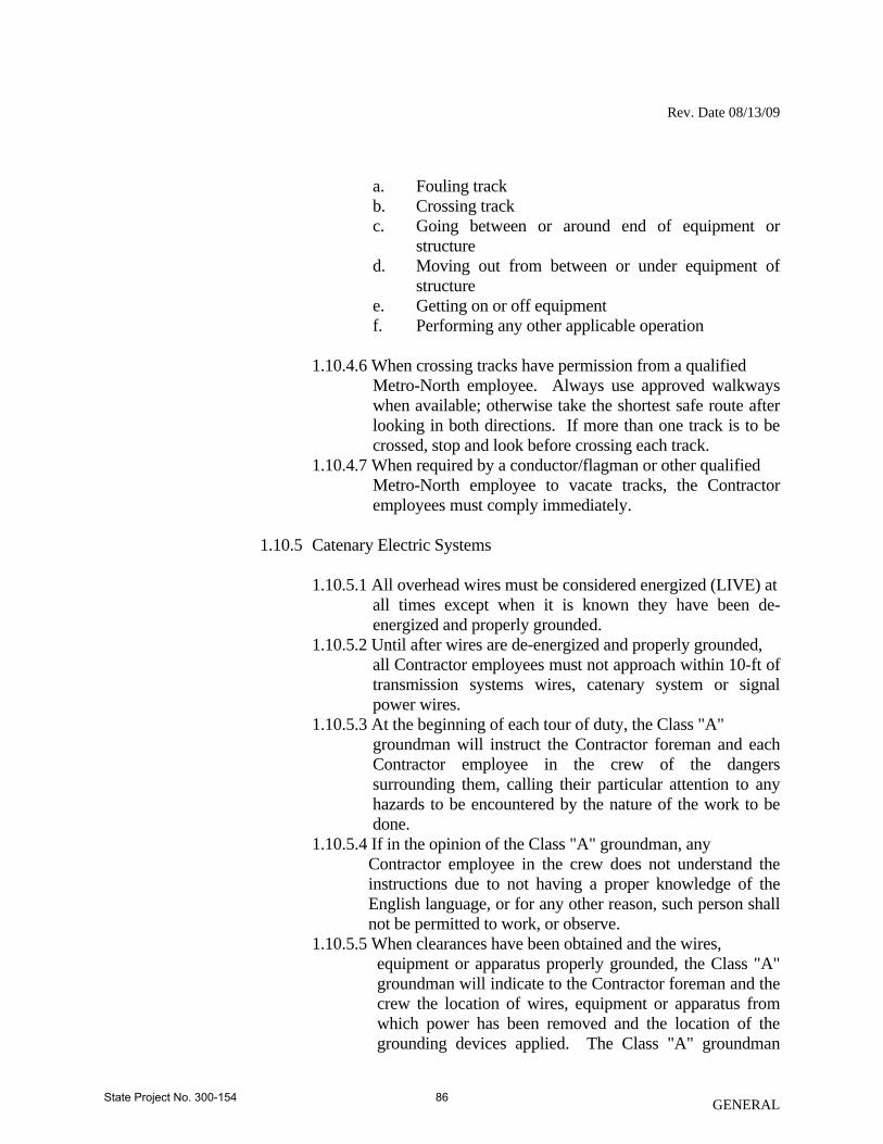
Rev. Date 08/13/09
a. Fouling track b. Crossing track c. Going between or around end of equipment or
structure d. Moving out from between or under equipment of
structure e. Getting on or off equipment f. Performing any other applicable operation
1.10.4.6 When crossing tracks have permission from a qualified
Metro-North employee. Always use approved walkways when available; otherwise take the shortest safe route after looking in both directions. If more than one track is to be crossed, stop and look before crossing each track.
1.10.4.7 When required by a conductor/flagman or other qualified Metro-North employee to vacate tracks, the Contractor employees must comply immediately.
1.10.5 Catenary Electric Systems
1.10.5.1 All overhead wires must be considered energized (LIVE) at
all times except when it is known they have been de-energized and properly grounded.
1.10.5.2 Until after wires are de-energized and properly grounded, all Contractor employees must not approach within 10-ft of transmission systems wires, catenary system or signal power wires.
1.10.5.3 At the beginning of each tour of duty, the Class "A" groundman will instruct the Contractor foreman and each Contractor employee in the crew of the dangers surrounding them, calling their particular attention to any hazards to be encountered by the nature of the work to be done.
1.10.5.4 If in the opinion of the Class "A" groundman, any Contractor employee in the crew does not understand the instructions due to not having a proper knowledge of the English language, or for any other reason, such person shall not be permitted to work, or observe.
1.10.5.5 When clearances have been obtained and the wires, equipment or apparatus properly grounded, the Class "A" groundman will indicate to the Contractor foreman and the crew the location of wires, equipment or apparatus from which power has been removed and the location of the grounding devices applied. The Class "A" groundman
GENERAL State Project No. 300-154 86

Rev. Date 08/13/09
must obtain on standard form, the signature of the Contractor foreman indicating that he and the crew have been so instructed, and will confine their work within the limits as outlined to them by the Class "A" groundman.
1.10.5.6 When the Class "A" groundman leaves its crew for any reason, he must notify the Contractor foreman and each person in the crew to stop all work in the vicinity of the wires, personally assuring himself that all persons have moved to a safe distance away from its departure. The Class "A" groundman will obtain the signature of the Contractor foreman on standard form, that he and the crew have been informed that the Class "A" groundman is leaving the gang and they will not resume work until advised to do so on return of the Class "A" groundman.
1.10.5.7 When the clearances are to be released, the Class "A" groundman will inform the Contractor foreman and each other Contractor employee and will personally observe that all persons have moved to a safe distance from the wires, equipment or apparatus to be energized, before removing the grounding devices. He will obtain the signature of the Contractor foreman, on a standard form, stating that he and the gang have been advised that the wires, equipment or apparatus will be energized, and that they will remain at a safe distance from them until informed otherwise by the Class "A" groundman.
1.10.5.8 The Class "A" groundman will inform the Contractor foreman if any Contractor employee on the job is unsafe and will not comply with instructions. If trouble is experienced with the Contractor foreman in maintaining safe working conditions, the Class "A" groundman will immediately notify its supervisor.
1.10.6 Aerial Catenary Construction by Qualified Contractor Employees
1.10.6.1 Aerial catenary work included in this Section shall include
all overhead wire work included in the portion of the Contract.
1.10.6.2 Aerial catenary work by the Contractor shall be done in accordance with the Railroad's safety rules and in accordance with the NEC.
1.10.6.3 Due to the specialty nature of the work, limited construction periods available, and high quality of work required, the aerial catenary construction included within the Contract is to be done only by qualified Contractor employees. Only Contractor employees that meet the
GENERAL State Project No. 300-154 87

Rev. Date 08/13/09
requirements of the International Brotherhood of Electrical Worker's standards for Journeyman Lineman and who have successfully completed a Metro-North power orientation class shall be considered for the work of this Section. The power orientation class will be given periodically and will require less than one-half day to complete. Approval for qualification shall be determined by Metro-North and that approval shall not be unreasonably withheld.
1.10.6.4 Metro-North approved Journeyman Lineman shall be issued identification as workers qualified to perform aerial catenary work. Qualified Contractor employees shall work according to the Railroad's MN-290 Electrical Operating Instructions. Qualified employees are authorized and expected to work to within 36-in of 13.5 kV energized overhead catenary. Contractor employees shall not de-energize circuits, place initial grounds, or provide protection for others.
1.10.6.5 Apprentice Lineman shall be permitted to assist qualified Journeyman Lineman and work under their direct supervision. Apprentice lineman are prohibited from coming closer than 10-ft from all overhead wires or circuits regardless of whether they have been de-energized or not.
1.10.7 Safety Program and Plan
1.10.7.1 Prior to the commencement of work the Contractor shall
submit a Working on the Railroad Safety Plan that will include a Program to implement the plan to the Engineer or a duly authorized representative for forwarding to the Railroad for review of compliance with this specification. This plan is separate to the Health and Safety Plan required for other aspects of the project (i.e., lead, excavations, etc.).
1.10.7.2 Each employee of the Contractor, subcontractor or others on site shall be given an initial training session prior to being allowed to work on the project, but not on the Railroad Right of Way, at this session the following will be furnished to the employee:
a. Safety Orientation for Contract Employees Working
on Metro-North Property produced by the Safety Engineer of Metro-North.
b. Safety Inspection Checklist c. List of the applicable publications referenced in these
specifications with respect to safety and where they are located for review if necessary. The list shall
GENERAL State Project No. 300-154 88

Rev. Date 08/13/09
include, but not be limited to, such regulatory standards and mandates, i.e., OSHA, NIOSH, DOL, NFPA, EPA, FRA, MSDS, etc.
d. Copy of the applicable corporate safety plan. e. Copy of the project Railroad Safety Plan or other
project related plans.
The employee shall sign the standard form for acknowledgement of the above-noted documents.
1.10.7.3 As soon as possible after the initial training, the employee
shall also be given a one-hour training session administered by Metro-North Safety Engineer or its representative. All employees receiving this training will receive a Registered Hard Hat sticker that will identify them from the employees with initial training on the project. No Contractor employees are permitted on the Railroad right-of-way without this training.
1.10.7.4 The Contractor shall hold "TOOL BOX" safety meetings for their employees at least once a week that will be documented and attendees listed.
1.10.7.5 The Contractor personnel shall attend a monthly Metro- North Safety Meeting.
2.0 INSURANCE REQUIREMENTS – METRO-NORTH RAILROAD
2.1 Submission of Insurance: The Contractor engaged in work on the project shall be required, before the Contractor begins work on the project, to provide and to maintain in force during the course of the project, at no cost to Metro-North, insurance described in Paragraph 2.2. These insurance policies are in addition to any other forms or insurance or bonds required under the Terms of the Contract.
2.2 Insurance: The Contractor shall furnish evidence that, with respect to the operations it performs, carries Workmen's Compensation Insurance and Public Liability and Property Damage Insurance covering all the Contractor's operations in any way connected with the project, and to furnish evidence of such policy to Metro-North.
2.2.1 Contractor's Public Liability and Property Damage Insurance – The
Contractor shall furnish evidence that, with respect to the operations it performs, it carries regular Contractor's Public Liability Insurance providing for a limit of not less than $2,000,000 single limit, bodily injury and/or property damage combined, for damages arising out of bodily injuries to or death of all persons in any one occurrence and for damage to or destruction of property, including the loss of use thereof, in any one occurrence.
GENERAL State Project No. 300-154 89

Rev. Date 08/13/09
2.2.2 Contractor's Protective Public and Property Damage Liability Insurance – The Contractor shall furnish evidence that, with respect to the operations performed by Subcontractors, it carries in its own behalf regular Contractor's Protective Public Liability Insurance providing for a limit of not less than $2,000,000, single limit, bodily injury and/or property damage combined, for damages arising out of bodily injuries to or death of all persons in any one occurrence and for damage to or destruction of property, including the loss of use thereof, in any one occurrence.
2.2.3 Railroad's Protective Public Liability Insurance – In addition to the above, the Contractor shall furnish evidence that, with respect to the operations it or any of its subcontractors perform, it has provided Railroad Protective Public Liability Insurance (AAR-AASHTO Form) in the name of the Metro-North Railroad providing for a limit of not less than $2,000,000 single limit, bodily injury and/or property damage combined, for damages arising out of bodily injuries to or death of all persons in any one occurrence for damage to or destruction of property, including the loss of use thereof, in any one occurrence. Such insurance shall be furnished with an aggregate of less than $6,000,000 for all damages as a result of more than one occurrence. The named insured shall include:
Metro-North Commuter Railroad Metropolitan Transportation Authority of New York Connecticut Department of Transportation Consolidated Rail Corporation National Railroad Passenger Corporation Providence and Worcester Railroad Company
The insurance hereinbefore specified shall be carried until all work on the project is satisfactorily completed and formally accepted. Failure to carry or keep such insurance in force until all work is satisfactorily completed shall constitute a violation of the project Contract.
The Contractor shall furnish to Metro-North a signed copy of the policy for Contractor's Public Liability Insurance and Protective Public Liability Insurance and the original copy of the Railroad Protective Public Liability Insurance. If any work is subcontracted, the Contractor shall furnish a signed copy of the policy for Contractor's Public Liability Insurance.
This policy shall be endorsed to the effect that for the purposes of this insurance, the employees of the Railroad Company, as listed below, shall be considered the same as regular employees of the Contractor:
2.2.3.1 Any watchman, flagman and similar employee who is employed
by the Railroad Company and is specifically assigned or furnished by the Railroad Company for work in connection with the Project.
GENERAL State Project No. 300-154 90

Rev. Date 08/13/09
GENERAL
2.2.3.2 Any employee of the Railroad Company while operating the work trains or other equipment while engaged in the performance of work directly involved in this Contract.
2.2.4 The insurance described in Paragraphs 2.2.1, 2.2.2 and 2.2.3 above, shall
be endorsed to provide for not less than 30 days advance written notice to Metro-North of any change or cancellation of policies. Said notice shall be sent to the individual identified in the NOTICE TO CONTRACTOR – WORK ON RAILROAD PROPERTY contained within the Provisions of the Contract. Work may not proceed on Metro-North property until all insurance requirements have been met to the satisfaction of Metro-North's Engineer.
3.0 COSTS ASSOCIATED WITH THIS SPECIFICATION
3.1 There shall be no direct payment for this work, regulatory requirements, traffic regulation, administering of the specification, coordination and incidentals to fulfill the requirements of this specification. The cost thereof will be considered as included in the general cost of the work and distributed in all items.
3.2 Any work, material’s supplied, inspections and protective services by Metro-North as described in the plans and specification expressly needed for the construction of the project will be compensated by the Engineer on a separate agreement.”
State Project No. 300-154 91

Rev. Date 08/13/09
SECTION 1.06 – CONTROL OF MATERIALS 1.06.01--Source of Supply and Quality: Delete the last paragraph: “When one manufacturer’s product . . . and Materials Certificate.” Article 1.06.05 - Shipping Materials: Add the following: All vehicles transporting materials on highways and bridges in the State shall comply with all the vehicle regulations of the Connecticut General Statutes and regulations of Connecticut State Agencies as they apply to vehicle length, width, height and weight. Any vehicle, either loaded or unloaded, will not be allowed to travel across any bridge or on any highway when such vehicle exceeds the legal limits or posted limits of such bridge or highway without a permit. The owner of the vehicle must apply to the Department for a permit for such travel, as provided in the statutes. The General Statutes include the following limitations:
Vehicle Width (Section 14-262(a)(1)) - The width of a vehicle and combination vehicle and trailer, including its load, is limited to 8 feet 6 inches, without a permit. Vehicle Length (Section 14-262(c)) - The length of the semitrailer portion of a tractor-trailer unit, including its load, is limited to 48 feet, without a permit. Vehicle Height (Section 14-264) - The height of a vehicle, with its load, is limited to 13 feet 6 inches, without a permit. Vehicle Weight (Section 14-267a(b)(7)) - The gross vehicle weight (weight of vehicle including its load) is limited to 80,000 pounds on 5 axles for vehicles with a 51 foot wheelbase, without a permit. Axle Weights of Vehicles (Section 14-267a) - For the above five axle vehicle, weight on a single axle may not exceed 22,400 pounds or in the case of axles spaced less than 6 feet apart, 18,000 pounds.
On Department projects, in accordance with the Commissioner’s policy, any member or component, either temporary or permanent, that measures 120 feet or less and weighs no greater than 120,000 pounds, is transportable via an authorized permit route established by the
GENERAL State Project No. 300-154 92

Rev. Date 08/13/09
GENERAL
Department provided the individual axle weights on the vehicle and trailer transporting the member or component do not exceed 20,000 pounds.
Members and components, shown in the contract documents, that exceed the above length and weight limits have been reviewed by the Department’s Oversize and Overweight Permits Section and are transportable via an authorized permit route established by the Department provided the individual axle weights on the vehicle and trailer transporting the member or component do not exceed 20,000 pounds.
All permits to transport materials are subject to shipping times established by the Department’s Oversize and Overweight Permits Section. Applications for permits, required to transport materials, shall be submitted a minimum of two weeks prior to their required use, to the Department's Oversize and Overweight Permits Section. 1.06.08--Warranties, Guarantees and Instruction Sheets: Delete the entire Article.
State Project No. 300-154 93

Rev. Date 5-21-08
SECTION 1.07 - LEGAL RELATIONS AND RESPONSIBILITIES Article 1.07.05 - Load Restrictions:
Delete all three paragraphs and replace them with the following:
“(a) Vehicle Weights: This sub article will apply to travel both on existing pavements and pavements under construction. The Contractor shall comply with all legal load restrictions as to vehicle size, the gross weight of vehicles, and the axle weight of vehicles while hauling materials. Throughout the duration of the contract, the Contractor shall take precautions to ensure existing and newly installed roadway structures and appurtenances are not damaged by construction vehicles or operations.
Unless otherwise noted in contract specifications or plans, on and off road equipment of the Contractor, either loaded or unloaded, will not be allowed to travel across any bridge or on any highway when such a vehicle exceeds the statutory limit or posted limit of such bridge or highway. Should such movement of equipment become necessary the Contractor shall apply for a permit from the Department for such travel, as provided in the Connecticut General Statutes (CGS). The movement of any such vehicles within the project limits or detour routes shall be submitted to the Engineer for project record. Such permit or submittal will not excuse the Contractor from liability for damage to the highway caused by its equipment.
The Contractor is subject to fines, assessments and other penalties that may be levied as a result of violations by its employees or agents of the legal restrictions as to vehicle size and weight.
(b) Storage of Construction Materials/Equipment on Structures: Storage is determined to be non-operating equipment or material. The Contractor shall not exceed the statutory limit or posted limit for either an existing or new structure when storing materials and/or construction equipment. When a structure is not posted, then the maximum weight of equipment or material stored in each 12 foot wide travel lane of any given span shall be limited to 750 pounds per linear foot combined with a 20,000 pound concentrated load located anywhere within the subject lane. If anticipated storage of equipment or material exceeds the above provision, then the Contractor shall submit his proposal of storage supported by calculations stamped by a Professional Engineer registered in the State of Connecticut, to the Engineer for approval 14 days prior to the storage operation. Operations related to structural steel demolition or erection shall follow the guidelines under Section 6.03. All other submittals shall include a detailed description of the material/equipment to be stored, the quantity of storage if it is stockpiled materials, the storage location, gross weight with supporting calculations if applicable, anticipated duration of storage, and any environmental safety, or traffic protection that may be required. Storage location on the structure shall be clearly defined in the field. If structures are in a state of staged construction or demolition, additional structural analysis may be required prior to authorization of storage.”
GENERAL State Project No. 300-154 94

Rev. Date 5-21-08
GENERAL
Article 1.07.10 - Contractor’s Duty to Indemnify the State against Claims for Injury or Damage:
Add the following after the only paragraph: “It is further understood and agreed by the parties hereto, that the Contractor shall not use
the defense of Sovereign Immunity in the adjustment of claims or in the defense of any suit, including any suit between the State and the Contractor, unless requested to do so by the State.”
State Project No. 300-154 95

Rev. Date 04/12/00
SECTION 1.08 - PROSECUTION AND PROGRESS Article 1.08.01 – Transfer of Work or Contract: Add the following after the last paragraph: The Contractor shall pay the subcontractor for work performed within thirty (30) days after the Contractor receives payment for the work performed by the subcontractor. Also, any retained monies on a subcontractor's work shall be paid to the subcontractor within thirty (30) days after satisfactory completion of all the subcontractor's work. For the purpose of this Item, satisfactory completion shall have been accomplished when: (1) The subcontractor has fulfilled the contract requirements of both the Department and the
subcontract for the subcontracted work, including the completion of any specified material and equipment testing requirement or plant establishment period and the submission of all submittals (i.e.: certified payrolls, material samples and certifications, required state and federal submissions, etc.) required by the specifications and the Department, and
(2) The work done by the subcontractor has been inspected and approved by the Department and the final quantities of the subcontractor's work have been determined and agreed upon.
If the Contractor determines that a subcontractor's work is not complete, the Contractor shall notify the subcontractor and the Engineer, in writing, of the reasons why the subcontractor's work is not complete. This written notification shall be provided to the subcontractor and the Engineer within twenty-one (21) days of the subcontractor's request for release of retainage. The Engineer will institute administrative procedures to expedite the determination of final quantities for the subcontractor’s satisfactorily completed work. The inspection and approval of a subcontractor's work does not eliminate the Contractor's responsibilities for all the work as defined in Article 1.07.12, "Contractor's Responsibility for Work." The inspection and approval of the subcontractor’s work does not release the subcontractor from its responsibility for maintenance and other periods of subcontractor responsibility specified for the subcontractor’s items of work. Failure of a subcontractor to meet its maintenance, warranty and/or defective work responsibilities may result in a finding that the subcontractor is non-responsible on future subcontract assignments. For any dispute regarding prompt payment or release of retainage, the alternate dispute resolution provisions of this article shall apply. The above requirements are also applicable to all sub-tier subcontractors and the above provisions shall be made a part of all subcontract agreements. Failure of the Contractor to comply with the provisions of this section may result in a finding that the Contractor is non-responsible on future projects.
GENERAL State Project No. 300-154 96

Rev. Date 04/12/00
GENERAL
Article 1.08.07 - Determination of Contract Time: Delete the second, third and fourth paragraphs and replace them with the following:
When the contract time is on a calendar day basis, it shall be the number of consecutive calendar days stated in the contract, INCLUDING the time period from December 1 through March 31 of each year. The contract time will begin on the effective date of the Engineer’s order to commence work, and it will be computed on a consecutive day basis, including all Saturdays, Sundays, Holidays, and non-work days.
1.08.08 - Extension of Time:
Delete the last paragraph, “If an approved extension of time…. the following April 1”.
Article 1.08.09 - Failure to Complete Work on Time: Delete the second paragraph, "If the last day...the project is completed" and replace it with "Liquidated damages as specified in the Contract shall be assessed against the Contractor per calendar day from that day until the date on which the project is completed.".
Replace 1.08.13 – “Termination of the Contractor's Responsibility” with the following:
1.08.13 - Acceptance of Work and Termination of the Contractor's Responsibility: The Contractor's responsibility for non-administrative Project work will be considered
terminated when the final inspection has been held, any required additional work and final cleaning-up have been completed, all final operation and maintenance manuals have been submitted, and all of the Contractor’s equipment and construction signs have been removed from the Project site. When these requirements have been met to the satisfaction of the Engineer, the Commissioner will accept the work by certifying in writing to the Contractor, that the non-administrative Project work has been satisfactorily completed.
State Project No. 300-154 97

Rev. Date 04/19/05
SECTION 1.11 - CLAIMS 1.11.01 – General: When filing a formal claim under Section 4-61 (referred to as “Section 4-61” below) of the Connecticut General Statutes (as revised), either as a lawsuit in the Superior Court or as a demand for arbitration, the Contractor must follow the procedures and comply with the requirements set forth in this Section of the Specifications. This Section does not, unless so specified, govern informal claims for additional compensation which the Contractor may bring before the Department. The Contractor should understand, however, that the Department may need, before the Department can resolve such a claim, the same kinds of documentation and other substantiation that it requires under this Section. It is the intent of the Department to compensate the Contractor for actual increased costs caused by or arising from acts or omissions on the part of the Department that violate legal or contractual duties owed to the Contractor by the Department. 1.11.02 – Notice of Claim: Whenever the Contractor intends to file a formal claim against the Department under Section 4-61, seeking compensation for additional costs, the Contractor shall notify the Commissioner in writing (in strict compliance with Section 4-61) of the details of said claim. Such written notice shall contain all pertinent information described in Article 1.11.05 below. Once formal notice of a claim under C.G.S. Section 4-61 (b) (as revised) has been given to the Commissioner, the claimant may not change the claim in any way, in either concept or monetary amount, (1) without filing a new notice of claim and demand for arbitration to reflect any such change and (2) without the minimum period of six months after filing of the new demand commencing again and running before any hearing on the merits of the claim may be held. The only exception to this limitation will be for damages that continue to accrue after submission of the notice, in ways described and anticipated in the notice. 1.11.03 – Record Keeping: The Contractor shall keep daily records of all costs incurred in connection with its construction-related activities on behalf of the Department. These daily records shall identify each aspect of the Project affected by matters related to any claim for additional compensation that the Contractor has filed, intends to file, or has reason to believe that it may file against the Department; the specific Project locations where Project work has been so affected; the number of people working on the affected aspects of the Project at the pertinent time(s); and the types and number of pieces of equipment on the Project site at the pertinent time(s). If possible, any potential or anticipated effect on the Project’s progress or schedule which may result in a claim by the Contractor should also be noted contemporaneously with the cause of the effect, or as soon thereafter as possible. 1.11.04 – Claim Compensation: The payment of any claim, or any portion thereof, that is deemed valid by the Engineer shall be made in accordance with the following provisions of this Article:
GENERAL State Project No. 300-154 98
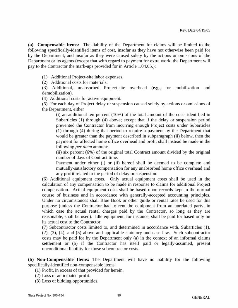
Rev. Date 04/19/05
(a) Compensable Items: The liability of the Department for claims will be limited to the following specifically-identified items of cost, insofar as they have not otherwise been paid for by the Department, and insofar as they were caused solely by the actions or omissions of the Department or its agents (except that with regard to payment for extra work, the Department will pay to the Contractor the mark-ups provided for in Article 1.04.05.):
(1) Additional Project-site labor expenses. (2) Additional costs for materials. (3) Additional, unabsorbed Project-site overhead (e.g., for mobilization and demobilization). (4) Additional costs for active equipment. (5) For each day of Project delay or suspension caused solely by actions or omissions of the Department, either
(i) an additional ten percent (10%) of the total amount of the costs identified in Subarticles (1) through (4) above; except that if the delay or suspension period prevented the Contractor from incurring enough Project costs under Subarticles (1) through (4) during that period to require a payment by the Department that would be greater than the payment described in subparagraph (ii) below, then the payment for affected home office overhead and profit shall instead be made in the following per diem amount: (ii) six percent (6%) of the original total Contract amount divided by the original number of days of Contract time. Payment under either (i) or (ii) hereof shall be deemed to be complete and mutually-satisfactory compensation for any unabsorbed home office overhead and any profit related to the period of delay or suspension.
(6) Additional equipment costs. Only actual equipment costs shall be used in the calculation of any compensation to be made in response to claims for additional Project compensation. Actual equipment costs shall be based upon records kept in the normal course of business and in accordance with generally-accepted accounting principles. Under no circumstances shall Blue Book or other guide or rental rates be used for this purpose (unless the Contractor had to rent the equipment from an unrelated party, in which case the actual rental charges paid by the Contractor, so long as they are reasonable, shall be used). Idle equipment, for instance, shall be paid for based only on its actual cost to the Contractor. (7) Subcontractor costs limited to, and determined in accordance with, Subarticles (1), (2), (3), (4), and (5) above and applicable statutory and case law. Such subcontractor costs may be paid for by the Department only (a) in the context of an informal claims settlement or (b) if the Contractor has itself paid or legally-assumed, present unconditional liability for those subcontractor costs.
(b) Non-Compensable Items: The Department will have no liability for the following specifically-identified non-compensable items:
(1) Profit, in excess of that provided for herein. (2) Loss of anticipated profit. (3) Loss of bidding opportunities.
GENERAL State Project No. 300-154 99

Rev. Date 04/19/05
(4) Reduction of bidding capacity. (5) Home office overhead in excess of that provided for in Article 1.11.04(a)(5) hereof. (6) Attorneys fees, claims preparation expenses, or other costs of claims proceedings or
resolution. (7) Any other consequential or indirect expenses or costs, such as tort damages, or any other
form of expense or damages not provided for in these Specifications or elsewhere in the Contract.
1.11.05 – Required Claim Documentation: All claims shall be submitted in writing to the Commissioner, and shall be sufficient in detail to enable the Engineer to ascertain the basis and the amount of each claim, and to investigate and evaluate each claim in detail. As a minimum, the Contractor must provide the following information for each and every claim and sub-claim asserted:
(a) A detailed factual statement of the claim, with all dates, locations and items of work pertinent to the claim.
(b) A statement of whether each requested additional amount of compensation or extension of time is based on provisions of the Contract or on an alleged breach of the Contract. Each supporting or breached Contract provision and a statement of the reasons why each such provision supports the claim, must be specifically identified or explained.
(c) Excerpts from manuals or other texts which are standard in the industry, if available, that support the Contractor’s claim.
(d) The details of the circumstances that gave rise to the claim. (e) The date(s) on which any and all events resulting in the claim occurred, and the date(s)
on which conditions resulting in the claim first became evident to the Contractor. (f) Specific identification of any pertinent document, and detailed description of the
substance of any material oral communication, relating to the substance of such claim. (g) If an extension of time is sought, the specific dates and number of days for which it is
sought, and the basis or bases for the extension sought. A critical path method, bar chart, or other type of graphical schedule that supports the extension must be submitted.
(h) When submitting any claim over $50,000, the Contractor shall certify in writing, under oath and in accordance with the formalities required by the contract, as to the following:
(1) That supporting data is accurate and complete to the Contractors best knowledge and belief; (2) That the amount of the dispute and the dispute itself accurately reflects what the Contractor in good faith believes to be the Departments liability; (3) The certification shall be executed by: a. If the Contractor is an individual, the certification shall be executed by that individual. b. If the Contractor is not an individual, the certification shall be executed by a senior company official in charge at the Contractor’s plant or location involved or an officer or general partner of the Contractor having overall responsibility for the conduct of the Contractors affairs.
1.11.06 – Auditing of Claims: All claims filed against the Department shall be subject to audit by the Department or its agents at any time following the filing of such claim. The Contractor
GENERAL State Project No. 300-154 100

Rev. Date 04/19/05
and its subcontractors and suppliers shall cooperate fully with the Department's auditors. Failure of the Contractor, its subcontractors, or its suppliers to maintain and retain sufficient records to allow the Department or its agents to fully evaluate the claim shall constitute a waiver of any portion of such claim that cannot be verified by specific, adequate, contemporaneous records, and shall bar recovery on any claim or any portion of a claim for which such verification is not produced. Without limiting the foregoing requirements, and as a minimum, the Contractor shall make available to the Department and its agents the following documents in connection with any claim that the Contractor submits:
(1) Daily time sheets and foreman's daily reports. (2) Union agreements, if any. (3) Insurance, welfare, and benefits records. (4) Payroll register. (5) Earnings records. (6) Payroll tax returns. (7) Records of property tax payments. (8) Material invoices, purchase orders, and all material and supply acquisition contracts. (9) Materials cost distribution worksheets. (10) Equipment records (list of company equipment, rates, etc.). (11) Vendor rental agreements (12) Subcontractor invoices to the Contractor, and the Contractor's certificates of payments
to subcontractors. (13) Subcontractor payment certificates. (14) Canceled checks (payroll and vendors). (15) Job cost reports. (16) Job payroll ledger. (17) General ledger, general journal (if used), and all subsidiary ledgers and journals,
together with all supporting documentation pertinent to entries made in these ledgers and journals.
(18) Cash disbursements journals. (19) Financial statements for all years reflecting the operations on the Project. (20) Income tax returns for all years reflecting the operations on the Project. (21) Depreciation records on all company equipment, whether such records are maintained
by the company involved, its accountant, or others. (22) If a source other than depreciation records is used to develop costs for the Contractor's
internal purposes in establishing the actual cost of owning and operating equipment, all such other source documents.
(23) All documents which reflect the Contractor's actual profit and overhead during the years that the Project was being performed, and for each of the five years prior to the commencement of the Project.
(24) All documents related to the preparation of the Contractor's bid, including the final calculations on which the bid was based.
(25) All documents which relate to the claim or to any sub-claim, together with all documents that support the amount of damages as to each claim or sub-claim.
(26) Worksheets used to prepare the claim, which indicate the cost components of each item of the claim, including but not limited to the pertinent costs of labor, benefits and
GENERAL State Project No. 300-154 101

Rev. Date 04/19/05
GENERAL
insurance, materials, equipment, and subcontractors’ damages, as well as all documents which establish the relevant time periods, individuals involved, and the Project hours and the rates for the individuals.
(27) The name, function, and pertinent activity of each Contractor’s or subcontractor’s official, or employee involved in or knowledgeable about events that give rise to, or facts that relate to, the claim.
(28) The amount(s) of additional compensation sought and a break-down of the amount(s) into the categories specified as payable under Article 1.11.04 above.
(29) The name, function, and pertinent activity of each Department official, employee or agent involved in or knowledgeable about events that give rise to, or facts that relate to, the claim.
State Project No. 300-154 102

Rev. Date 011309 English
SECTION 4.06 BITUMINOUS CONCRETE Section 4.06 is being deleted in its entirety and replaced with the following: 4.06.01—Description 4.06.02—Materials 4.06.03—Construction Methods 4.06.04—Method of Measurement 4.06.05—Basis of Payment 4.06.01—Description: Where reference is made to bituminous concrete, it shall also refer to hot-mix asphalt (HMA) mixtures using the Marshall or Superpave mix-design method. Work under this section shall consist of the production, delivery and placement of a non-segregated, smooth and dense bituminous concrete mixture brought to proper grade and cross section. This section shall also include the method and construction of longitudinal joints. The Contractor shall furnish Quality Control Plans for both plant production and placement of HMA mixtures. The terms listed below as used in this specification are defined as: Course: A lift or multiple lifts comprised of the same HMA mixture placed as part of the pavement structure. Dispute Resolution: A procedure used to resolve conflicts resulting from discrepancies between the Engineer and the Contractor’s density results that may affect payment. Hot Mix Asphalt (HMA): A bituminous concrete mixture. Disintegration: Wearing away or fragmentation of the pavement. Disintegration will be evident in the following forms: Polishing, weathering-oxidizing, scaling, spalling, raveling, potholes or loss of material. Lift: A single HMA mixture placed at a defined thickness. Marshall: A HMA mixture design designated as “Bituminous Concrete Class ( ).” Superpave: A HMA mixture design designated as “HMA S*.” Where “S” indicates Superpave and * indicates the sieve related to the nominal maximum aggregate size of the mix. For example Superpave 0.50 inch is now designated as HMA S0.5. Segregation: A non-uniform distribution of a HMA mixture in terms of volumetrics, gradation or temperature.
GENERAL State Project No. 300-154 103

Rev. Date 011309 English
Quality Assurance (QA): All those planned and systematic actions necessary to provide confidence that a product or facility will perform as designed. Quality Control (QC): The sum total of activities performed by the vendor (producer, manufacturer, and contractor) to ensure that a product meets contract specification requirements. 4.06.02—Materials: All materials shall conform to the requirements of Section M.04.
1. Materials Supply: The HMA mixture must be from one source of supply and originate from one HMA Plant unless authorized by the Engineer. 2. Recycle Option: The Contractor has the option of recycling reclaimed asphalt pavement (RAP) or Crushed Recycled Container Glass (CRCG) in HMA mixtures in accordance with Section M.04. CRCG shall not be used in the final lift of the surface course. 4.06.03—Construction Methods: 1. Material Documentation: All vendors producing bituminous concrete must have their truck-weighing scales, storage scales, and mixing plant automated to provide a detailed ticket. Delivery tickets must include the following information:
a. State of Connecticut printed on ticket. b. Name of producer, identification of plant, and specific storage bin (silo) if used. c. Date and time of day. d. Mixture Designation (If RAP is used, the plant printouts shall include RAP dry weight, percentage and daily moisture content.) Class 3 mixtures for machine-placed curbing must state "curb mix only". e. Net weight of mixture loaded into truck (When RAP is used, RAP moisture shall be
excluded from mixture net weight). f. Gross weight (Either equal to the net weight plus the tare weight or the loaded scale
weight). g. Tare weight of truck – Daily scale weight. h. Project number, purchase order number, name of contractor (if contractor other than
producer). i. Truck number for specific identification of truck. j. Individual aggregate, RAP, and virgin asphalt high/target/low weights shall be printed
on batch plant tickets (For drum plants and silo loadings, the plant printouts shall be printed out at 5 minute intervals maintained by the vendor for a period of three years after the completion of the project).
The net weight of mixture loaded into the truck must be equal to the cumulative measured weight of its components. The Contractor must notify the Engineer immediately if, during the production day, there is a malfunction of the weighing or recording system in the automated plant or truck-weighing
GENERAL State Project No. 300-154 104

Rev. Date 011309 English
scales. Manually written tickets containing all required information will be allowed for one hour, but for no longer, provided that each load is weighed on State-approved scales. At the Engineer’s sole discretion, trucks may be approved to leave the plant if a State inspector is present to monitor weighing. If such a malfunction is not fixed within forty-eight hours, mixture will not be approved to leave the plant until the system is fixed to the Engineer's satisfaction. No damages will be considered should the State be unable to provide an inspector at the plant. The State reserves the right to have an inspector present to monitor batching and /or weighing operations. 2. Transportation of Mixture: Trucks with loads of bituminous concrete being delivered to State projects must not exceed the statutory or permitted load limits referred to as gross vehicle weight (GVW). The Contractor shall furnish a list of all vehicles and allowable weights transporting mixture. The State reserves the right to check the gross and tare weight of any delivery truck. A variation of 0.4 percent or less in the gross or tare weight shown on the delivery ticket and the certified scale weight shall be considered evidence that the weight shown on the delivery ticket is correct. If the gross or tare weight varies from that shown on the delivery ticket by more than 0.4 percent, the Engineer will recalculate the net weight. The Contractor shall take action to correct discrepancy to the satisfaction of the Engineer. If a truck delivers mixture to the project and the ticket indicates that the truck is overweight, the load will not be rejected but a “Measured Weight Adjustment” will be taken in accordance with Sub-article 4.06.04. The mixture shall be transported from the mixing plant in trucks that have previously been cleaned of all foreign material and that have no gaps through which mixture might inadvertently escape. The use of kerosene, gasoline, fuel oil, or similar products for the coating of the inside of truck bodies is prohibited. Truck body coating and cleaning agents must not have a deleterious effect on the transported mixture. When acceptable coating or agents are applied, truck bodies shall be raised immediately prior to loading to remove any excess agent in an environmentally acceptable manner. The Contractor shall take care in loading trucks uniformly so that segregation is minimized. Loaded trucks shall be tightly covered with waterproof covers acceptable to the Engineer. Mesh covers are prohibited. The front and rear of the cover must be fastened to minimize air infiltration. The Contractor shall assure that all trucks are in conformance with this specification. Trucks found not to be in conformance shall not be allowed to be loaded until re-inspected to the satisfaction of the Engineer. 3. Paving Equipment: The Contractor shall have the necessary paving and compaction equipment at the project site to perform the work. All equipment shall be in good working order
GENERAL State Project No. 300-154 105

Rev. Date 011309 English
and any equipment that is worn, defective or inadequate for performance of the work shall be repaired or replaced by the Contractor to the satisfaction of the Engineer. The use of solvents or fuel oil as a release agent on any paving equipment (i.e., rollers, pavers, transfer devices, etc.) is strictly prohibited. Refueling of equipment is prohibited in any location on the paving project where fuel might come in contact with bituminous concrete mixtures already placed or to be placed. Solvents for use in cleaning mechanical equipment or hand tools shall be stored clear of areas paved or to be paved. Before any such equipment and tools are cleaned, they shall be moved off the paved or to be paved area; and they shall not be returned for use until after they have been allowed to dry. Pavers: Each paver shall have a receiving hopper with sufficient capacity to provide for a uniform spreading operation and a distribution system that places the mix uniformly, without segregation. The paver shall be equipped with and use a vibratory screed system with heaters or burners. The screed system shall be capable of producing a finished surface of the required evenness and texture without tearing, shoving, or gouging the mixture. Pavers with extendible screed units as part of the system shall have auger extensions and tunnel extenders as necessary. Automatic screed controls for grade and slope shall be used at all times unless otherwise authorized by the Engineer. The controls shall automatically adjust the screed to compensate for irregularities in the preceding course or existing base. The controls shall maintain the proper transverse slope and be readily adjustable, and shall operate from a fixed or moving reference such as a grade wire or floating beam.
Rollers: All rollers shall be self-propelled and designed for compaction of bituminous concrete. Rollers types shall include steel-wheeled, pneumatic or a combination there of and may be capable of operating in a static or dynamic mode. Rollers that operate in a dynamic mode shall have drums that use a vibratory or oscillatory system or combination of. The vibratory system achieves compaction through vertical amplitude forces. Rollers with this system shall be equipped with indicators that provide the operator with amplitude, frequency and speed settings/readouts to measure the impacts per foot during the compaction process. The oscillatory system achieves compaction through horizontal shear forces. Rollers with this system shall be equipped with frequency indicators. Rollers can operate in the dynamic mode using the oscillatory system on concrete structures such as bridges and catch basins if at the lowest frequency setting.
Pneumatic tire rollers shall be self-propelled and equipped with wide-tread compaction tires capable of exerting an average contact pressure from 60 to 90 pounds per square inch uniformly over the surface, adjusting ballast and tire inflation pressure as required. The Contractor shall furnish evidence regarding tire size; pressure and loading to confirm that the proper contact pressure is being developed and that the loading and contact pressure are uniform for all wheels.
Lighting: For paving operations, which will be performed during hours of darkness, the paving equipment shall be equipped with lighting fixtures as described below, or with approved lighting fixtures of equivalent light output characteristics. A sufficient number of spare lamps shall be available on site as replacements in the event of failures. The Contractor shall provide brackets
GENERAL State Project No. 300-154 106

Rev. Date 011309 English
and hardware for mounting light fixtures and generators to suit the configuration of the rollers and pavers. Mounting brackets and hardware shall provide for secure connection of the fixtures, minimize vibration, and allow for adjustable positioning and aiming of the light fixtures. Lighting shall be aimed to maximize the illumination on each task and minimize glare to passing traffic. The Contractor shall provide generators on rollers and pavers of the type, size, and wattage, to adequately furnish 120 V AC electric power to operate the specified lighting equipment. A sufficient amount of fuel shall be available on site. There shall be switches to control the lights. Wiring shall be weatherproof and installed to all applicable codes. The minimum lighting requirements are:
Paver Lighting
Fixture Quantity Remarks Type A 3 Mount over screed area
Type B (narrow) or Type C (spot) 2 Aim to auger and guideline Type B (wide) or Type C (flood) 2 Aim 25 feet behind paving machine
Roller Lighting
Fixture QuantityType B (wide) 2
Type B (narrow) 2 OR
Type C (flood) 2 Type C (spot) 2
All fixtures shall be mounted above the roller. Aim floodlights and wide beam lights 50 feet in front of and behind roller; aim spotlights and narrow beam lights 100 feet in front of and behind roller.
Type A: Fluorescent fixture shall be heavy-duty industrial type. It shall be enclosed and gasketed to seal out dirt and dampness. It shall be UL listed as suitable for wet locations. The fixture shall contain two 4-foot long lamps - Type "F48T12CWHO". The integral ballast shall be a high power factor, cold weather ballast, and 120 volts for 800 MA HO lamps. The housing shall be aluminum, and the lens shall be acrylic with the lens frame secured to the housing by hinging latches. The fixture shall be horizontal surface mounting, and be made for continuous row installation. Type B: The floodlight fixture shall be heavy-duty cast aluminum housing, full swivel and tilt mounting, tempered-glass lens, gasketed door, reflector to provide a wide distribution or narrow distribution as required, mogul lamp socket for 250 watt Metal Halide lamp, 120 volt integral ballast, suitable for wet locations. Type C: The power beam holder shall have ribbed die cast aluminum housing and a clear tempered-glass lens to enclose the fixture. There shall be an arm fully adjustable for aiming, with a male-threaded mount with serrated teeth and lock nuts. There shall be a
GENERAL State Project No. 300-154 107

Rev. Date 011309 English
120-volt heatproof socket with extended fixture wiring for an "Extended Mogul End Prong" lamp base. The fixture shall have gaskets, and shall be UL listed as suitable for wet locations. The lamps shall be 1000-watt quartz PAR64, both Q1000PAR64MFL (flood) and Q1000PARNSP (spot) will be required.
Material Transfer Vehicle (MTV): A MTV shall be used when placing a HMA surface course that is greater than 5,000 feet in length and 28 feet in width unless otherwise restricted as noted herein. A surface course is defined as the total thickness of the same HMA mix that extends up to and includes the final wearing surface whether it is placed in a single or multiple lifts, and regardless of any time delays between lifts.
The MTV must be a self-propelled vehicle specifically designed for the purpose of delivering the
HMA mixture from the delivery truck to the paver. The MTV must have the capability to remix the bituminous concrete mixture.
The use of a MTV will be subject to the requirements stated in Article 1.07.05- Load Restrictions. The Engineer may limit the use of the vehicle if it is determined that the use of the MTV may damage highway components, utilities, or bridges. The Contractor shall submit to the Engineer at time of pre-construction the following information:
- The make and model of the MTV to be used. - The axle weights and axle spacing for each separate piece of paving equipment (haul
vehicle, MTV and paver). - A working drawing showing the axle spacing in combination with all three pieces of
equipment that will comprise the paving echelon.
4. Seasonal Requirements: Paving shall be divided into two seasons, In-Season and Extended Season; In-Season shall be from May 1 – September 30, and Extended Season shall be from October 1- April 30. In no case shall the final lift of HMA be placed during the extended season unless otherwise authorized or directed by the Engineer. No HMA mixes shall be placed when the air or base temperature is below 32°F. HMA for temporary pavement will be subject to the seasonal requirements unless otherwise authorized or directed by the Engineer. Additional Requirements for Extended Season: - The minimum mixture temperature for all HMA mixtures in the delivery truck prior to
discharge into the paver or transfer vehicle hopper shall be 290°F. The temperature will be taken from the initial discharge of mixture from the truck. If found to be below the minimum requirement, the truck will not be allowed to unload remaining mixture.
- The Contractor shall use a minimum of 3 rollers with operators for paving lengths greater
than 1000 feet. Two rollers must be capable of operating in the dynamic mode. - The Contractor’s Quality Control Plan shall include a section on Extended Season Paving
and address paver speed, roller patterns and balancing mixture delivery and placement operations to meet specification requirements.
GENERAL State Project No. 300-154 108

Rev. Date 011309 English
5. Superpave Test Section: The Engineer may require the Contractor to place a test section whenever the requirements of this specification or M.04 are not met. The Contractor shall submit the quantity of mixture to be placed and the location of the test section for review and acceptance by the Engineer. The equipment used in the construction of a passing test section shall be used throughout production. If a test section fails to meet specifications, the Contractor shall stop production, make necessary adjustments to the job mix formula, plant operations, or procedures for placement and compaction. The Contractor shall construct test sections, as allowed by the Engineer, until all the required specifications are met. All test sections shall also be subject to removal as set forth in Section 1.06.04. 6. Transitions for Roadway Surface: Transitions shall be formed at any point on the roadway where the pavement surface deviates, vertically, from the uniform longitudinal profile as specified on the plans. Whether formed by milling or by bituminous concrete mixture, all transition lengths shall conform to the criteria below unless otherwise specified. Permanent Transitions: A permanent transition is defined as any transition that remains as a permanent part of the work. All permanent transitions, leading and trailing ends shall meet the following length requirements:
a) Roadways greater than 35 MPH = 30 feet per inch of vertical change (thickness)
b) Roadways 35 MPH or less = 15 feet per inch of vertical change (thickness). c) Bridge Overpass and underpass transition length will be 75 feet either (1) Before and after the bridge expansion joint, or (2) Before or after the parapet face of the overpass.
In areas where it is impractical to use the above described permanent transition lengths the use of a shorter permanent transition length may be permitted when approved by the Engineer.
Temporary Transitions: A temporary transition is defined as a transition that does not remain a permanent part of the work. All temporary transitions shall meet the following length requirements:
a) Roadways greater than 35 MPH (1) Leading Transitions = 15 feet per inch of vertical change (thickness)
(2) Trailing Transitions = 6 feet per inch of vertical change (thickness) b) Roadways 35 MPH or less (1) Leading and Trailing = 4 feet per inch of vertical change (thickness) Note: Any temporary transition to be in-place over the winter shutdown period, holidays, or during extended periods of inactivity (more than 7 calendar days) shall conform to the “Permanent Transition” requirements shown above.
GENERAL State Project No. 300-154 109

Rev. Date 011309 English
7. Spreading and Finishing of Mixture: Prior to the placement of the bituminous concrete, the underlying base course shall be brought to the plan grade and cross section within the allowable tolerance. Immediately before placing the mixture, the area to be surfaced shall be cleaned by sweeping or by other means acceptable to the Engineer. The HMA mixture shall not be placed whenever the surface is wet or frozen. The temperature of the mix at time of placement must be between 265°F and 325°F. The Engineer will verify the mix temperature by means of a probe or infrared type of thermometer. Rejection of mixture based on temperature will only be allowed if verified by means of a probe type thermometer. Placement: The HMA mixture shall be placed and compacted to provide a smooth, dense surface with a uniform texture and no segregation at the designed thickness and dimensions indicated in the plans and specifications. The maximum paver speed during placement shall not exceed 40 ft/min unless authorized by the Engineer. When unforeseen weather conditions prevent further placement of the mix, the Engineer is not obligated to accept or place the bituminous concrete mixture that is in transit from the plant. In advance of paving, traffic control requirements shall be set up daily, maintained throughout placement, and shall not be removed until all associated work including density testing is completed. The Contractor shall inspect the newly placed pavement for defects in the mixture or placement before rolling is started. Any deviation from standard crown or section shall be immediately remedied by placing additional mixture or removing surplus mixture. Such defects shall be corrected to the satisfaction of the Engineer. Where it is impractical due to physical limitations to operate the paving equipment, the Engineer may permit the use of other methods or equipment. Where hand spreading is permitted, the mixture shall be placed by means of suitable shovels and other tools, and in a uniformly loose layer at a thickness that will result in a completed pavement meeting the designed grade and elevation. Placement Tolerances: Each lift of HMA placed at a uniform design thickness shall meet the following requirements for thickness and area. Any pavement exceeding these limits shall be subject to an HMA adjustment or removal. Lift tolerances will not relieve the Contractor from meeting the final designed grade. Lifts of designed non-uniform thickness, i.e. wedge or shim course, shall not be subject to thickness and area adjustments.
a) Thickness- Where the total thickness of the lift of mixture exceeds that shown on the plans beyond the tolerances shown in Table 2, the longitudinal limits of such variation including locations and intervals of the measurements will be documented by the Engineer for use in calculating a HMA adjustment in 4.06.04-2.
GENERAL State Project No. 300-154 110

Rev. Date 011309 English
TABLE 2 - Thickness Tolerances Mixture Designation Lift Tolerance
Class 4 and HMA S1 +/- 3/8 inch Class 1, 2 and 12 and HMA S0.25, S0.375, S0.5 +/- ¼ inch
Where the thickness of the lift of mixture is less than that shown on the plans beyond the tolerances shown in Table 2, the Contractor, with the approval of the Engineer, shall take corrective action in accordance with this specification.
b) Area- Where the width of the lift exceeds that shown on the plans by more than the
designed thickness of each lift, the longitudinal limits of such variation including locations and intervals of the measurements will be documented by the Engineer for use in calculating a HMA adjustment in 4.06.04-2.
c) Delivered Weight of Mixture - When the delivery ticket shows that the truck exceeds the
allowable gross weight for the vehicle type the quantity of tons representing the over weight will be documented by the Engineer for use in calculating a HMA adjustment in 4.06.04-2.
Transverse Joints: All transverse joints shall be formed by saw-cutting a sufficient distance back from the previous run, existing bituminous concrete pavement or bituminous concrete driveways to expose the full thickness of the lift. A brush of tack coat shall be used on any cold joint immediately prior to additional bituminous concrete mixture being placed. Tack Coat Application: A thin uniform coating of tack coat shall be applied to the pavement immediately before overlaying and be allowed sufficient time to break (set). All surfaces in contact with the HMA that have been in place longer than 3 calendar days shall have an application of tack coat. The tack coat shall be applied by a non-gravity pressurized spray system that results in uniform overlapping coverage at a target application rate of 0.07 + 0.02 gallons per square yard for a non-milled surface and a target application rate of 0.12 + 0.02 gallons per square yard for a milled surface. For areas where both milled and un-milled surfaces occur, the tack coat shall be a target application rate of 0.07 + 0.02 gallons per square yard. The Engineer must approve the equipment and the method of measurement prior to use. The material for tack coat shall not be heated in excess of 160°F and shall not be further diluted. Compaction: The Contractor shall compact the mixture to meet the density requirements as stated in Section 4.06.03-11 and eliminate all roller marks without displacement, shoving, cracking, or aggregate breakage. The Contractor shall only operate rollers in the dynamic mode using the oscillatory system at the lowest frequency setting on concrete structures such as bridges and catch basins. The use of the vibratory system on concrete structures is prohibited. Rollers operating in the dynamic mode shall be shut off when reversing directions.
GENERAL State Project No. 300-154 111

Rev. Date 011309 English
If the Engineer determines that the use of compaction equipment in the dynamic vibratory mode may damage highway components, utilities, or adjacent property, the Contractor shall provide alternate compaction equipment. The Engineer may allow the Contractor to operate rollers in the dynamic mode using the oscillatory system at the lowest frequency setting. These allowances will not relieve the Contractor from meeting pavement compaction requirements.
Surface Requirements: The pavement surface of any lift shall meet the following requirements for smoothness and uniformity. Any irregularity of the surface exceeding these requirements shall be corrected by the Contractor.
a) Smoothness- Each lift of the surface course shall not vary more than ¼ inch from a Contractor-supplied 10 foot straightedge. For all other lifts of HMA, the tolerance shall be 3/8 inch. Such tolerance will apply to all paved areas.
b) Uniformity- The paved surface shall not exhibit segregation, rutting, cracking,
disintegration, flushing or vary in composition as determined by the Engineer. 8. HMA Longitudinal Joint Construction Methods: Unless noted on the plans or the contract documents or directed by the Engineer, the Contractor shall use Method I- Notched Wedge when constructing longitudinal joints where lift thicknesses are between 1½ and 3 inches. Method II shall be used for lifts less than 1½ inches or greater than 3 inches. During placement of multiple lifts of HMA, the longitudinal joint shall be constructed in such a manner that it is located at least 6 inches from the joint in the lift immediately below. The joint in the final lift shall be at the centerline or at lane lines. Method I - Notched Wedge Joint:
Hot side Cold Side
8” – 12” Taper
Top Vertical Notch
½” – 1” Tack coat
Bottom Vertical Notch
0 - ½”
Lift Thickness 1 ½” – 3”
Varies
A notched wedge joint shall be constructed, as shown in the figure using a device attached to the paver screed that is capable of producing a uniform slope. The taper portion of the joint must be placed over the longitudinal joint in the lift immediately below. The top vertical notch must be located at the centerline or lane line in the final lift. The
GENERAL State Project No. 300-154 112

Rev. Date 011309 English
requirement for paving full width “curb to curb” as described in Method II will be waived in those areas where the notched wedge joint is utilized. The taper portion of the wedge joint shall be compacted and not be exposed to traffic for more than 5 calendar days. The existing pavement surface under the wedge joint must have an application of tack coat material. Prior to placing completing pass (hot side), an application of tack coat must be applied to the tapered section. Any exposed wedge joint must be located to allow for the free draining of water from the road surface. The Engineer reserves the right to define the paving limits when using a wedge joint that will be exposed to traffic. Method II - Butt Joint:
When adjoining HMA passes are placed, the Contractor shall utilize equipment that creates a near vertical edge (refer to figure). The completing pass (hot side) shall have sufficient mixture so that the compacted thickness is not less than the previous pass (cold side). The end gate on the paver should be set so there is an overlap onto the cold side of the joint. The Contractor shall not allow any butt joint to be incomplete at the end of a work shift unless otherwise allowed by the Engineer. When using this method, the Contractor is not allowed to leave a vertical edge exposed at the end of a work shift and must complete paving of the roadway full width “curb to curb.”
Hot side Cold Side
Joint
Lift Thickness Less than 1 ½” Greater than 3”
GENERAL State Project No. 300-154 113

Rev. Date 011309 English
Method III- Butt Joint with Hot Poured Rubberized Asphalt Treatment: When required by the contract or allowed by the Engineer, Method III may be used.
Hot side Cold Side
Hot poured rubberized asphalt treatment
All of the requirements of Method II must be met with Method III. In addition, the longitudinal vertical edge must be treated with a hot poured rubberized asphalt material prior to placing a completing pass. The rubberized asphalt material shall be applied in accordance with the manufacturer’s recommendation so as to provide a uniform coverage and avoid excess bleeding onto the newly placed pavement. 9. Contractor Quality Control (QC) Requirements for HMA Placement: A Quality Control Plan (QCP) shall be required for any project that has a total of 2500 tons or more of HMA. Quality Control is defined as all those planned and specified actions or operations necessary to produce bituminous concrete that will meet contract specification requirements. The Contractor shall be responsible for quality control throughout the production and placement operations. Therefore, the Contractor must ensure that the materials, mixture and work provided by Subcontractors, Suppliers and Producers also meet contract specification requirements. Quality Control Plan: Prior to placement and production, the Contractor shall submit a QCP to the Engineer for approval. The QCP shall include separate sections for HMA Plant Production and for HMA Placement which shall describe the organization and procedures which the Contractor shall use to administer quality control. The QCP shall include the procedures used to control the HMA production and placement process, to determine when immediate changes to the processes are needed, and to implement the required changes. The QCP must address the actions, inspection, sampling and testing necessary to keep the production and placement operations in control, to determine when an operation has gone out of control and to respond to correct the situation and bring it back into control. The QCP shall also include the name and qualifications of a Quality Control Manager. The Quality Control Manager shall be responsible for the administration of the QCP, including compliance with the plan and any plan modifications. The Quality Control Manager shall be directly responsible to the Contractor and shall have the authority to make decisions where the quality of the work or product is concerned. All sampling, inspection and test reports shall be reviewed and signed by the Quality Control Manager prior to submittal to the Engineer.
GENERAL State Project No. 300-154 114

Rev. Date 011309 English
Approval of the QCP will be based on the inclusion of all of the required information. Approval of the QCP does not imply any warranty by the Engineer that adherence to the plan will result in production of HMA that complies with these specifications. It shall remain the responsibility of the Contractor to demonstrate such compliance. The Contractor may propose in writing a supplement to the QCP as work progresses and must propose a supplement whenever there are changes in production or placement of HMA or to quality control procedures or personnel. HMA production and placement may be suspended by the Engineer until the revisions to the QCP have been put into effect. The Quality Control Plan shall also include the name and qualifications of any outside testing laboratory performing any QC functions on behalf of the Contractor. Quality Control Inspection, Sampling and Testing: The Contractor shall perform all quality control sampling and testing, provide inspection, and exercise management control to ensure that HMA production and placement conforms to the requirements as outlined in its QCP during all phases of the work.
a) Control Charts: The Contractor shall develop and maintain control charts and shall be distributed as directed by the Engineer. The control charts shall identify the project, test number, test parameter, applicable upper and lower specification limits, and test data. The control charts shall be used as part of the quality control system to document variability of the HMA production and placement process. The control charts shall be kept current. The control charts shall be updated each day of HMA production, and up-to-date copies shall be distributed prior to the beginning of the next day's production of HMA. b) Records of Inspection and Testing: For each day of HMA production and placement, the Contractor shall document all test results and inspections on forms approved by the Engineer. The document shall be certified by the Quality Control Manager or his representative that the information in the document is accurate, and that all work complies with the requirements of the contract. The Contractor shall submit sampling, testing and inspection documents to the Engineer within 24 hours or by noon of the next day's HMA production. If the document is incomplete or in error, a copy of the document will be returned to the Contractor with the deficiencies noted by the Engineer. The Contractor shall correct the deficiencies and return the updated document to the Engineer by the start of the following working day. When errors or omissions in the sampling, inspection or testing documents repeatedly occur, the Contractor shall correct the procedures by which the documents are produced. If control charts, sampling, testing and inspection documents are not distributed or provided as required within the time specified the Engineer may require work to be suspended until the missing documents have been provided. Additional requirements for HMA plant production are defined in Section M.04.
GENERAL State Project No. 300-154 115

Rev. Date 011309 English
10. Core Correlation Procedure for Density Testing of HMA: Core correlation is required for all limited access highways and any other roadways in which 10,000 tons or more HMA mixture is placed. This procedure describes the frequency and the method the Contractor shall use to obtain pavement cores from the project. Coring shall be performed the first time a HMA lift requiring density testing is placed. Prior to receiving core results, the HMA density acceptance will be determined using a nuclear density gauge correlated to the standard block located at the Department’s Material Testing Laboratory. The gauge will be correlated to the core results once they are known. The Contractor shall provide a minimum of one set of cores (5 cores per set) for each lift that will be tested for density. The Contractor may be required to provide additional sets of cores under the following conditions:
a) A change in source of component aggregates. b) Any change in the average Gmm greater than 0.030 as indicated in the plant test results
representing cored mixture. c) Change in materials supplied in Section 4.06.02-1.
The Contractor shall extract 5 cores (6 inch diameter-wet sawed) from sampling locations determined by the Engineer. The Engineer will witness the extraction and labeling of cores. The cores shall be labeled by the Contractor with number, location, date and delivered in a safe manner to ensure no damage occurs (i.e., core 1M for first mat core; core 1J for first joint core, etc) to Department personnel as directed by the Engineer. The cores will be tested by the Engineer in accordance with AASHTO T 331(M). Any cores that are damaged or obviously defective while being obtained will be replaced with new cores from a location within a 2 foot radius. Core holes shall be filled immediately upon core extraction by removing any free water, applying tack coat to the cut surface, filling with same HMA mixture, and compacting with hand compactor or other mechanical means to the maximum compaction possible. The field mixture shall be compacted to 1/8 inch above the finished pavement prior to opening the roadway to traffic. 11. Acceptance Inspection, Sampling and Testing: Inspection, sampling, and testing to be used by the Engineer shall be performed at the minimum frequency specified in Section M.04 and stated herein. Sampling for acceptance shall be established using a statistically based procedure of random sampling approved by the Engineer. HMA Plant Material Acceptance: The Contractor shall provide the required acceptance sampling, testing and inspection during all phases of the work in accordance with Section M.04.
GENERAL State Project No. 300-154 116
Rev. Date 011309 English
HMA Density Acceptance: All acceptance testing will be performed by the Engineer for the completed pavement course on roadways and bridges in accordance with the Department’s density testing procedures. Each lift designed to a compacted lift of 1½ inches or more shall have the HMA pavement including the longitudinal joints compacted to 94.5 +/- 2.5 percent of the maximum theoretical gravity. Bituminous Concrete Class 4 and HMA S1 are excluded from the longitudinal joint density requirements. 12. Density Dispute Resolution Process: The Contractor and Engineer will work in partnership to avoid potential conflicts and to resolve any differences that may arise during quality control or acceptance testing for density. Both parties will review their sampling and testing procedures and results and share their findings. If the Contractor disputes the Engineer’s test results, the Contractor must submit in writing a request to initiate the Dispute Resolution Process within 10 calendar days of the placement of the mixture. No request for dispute resolution will be allowed unless the Contractor provides quality control results supporting its position. Should the dispute not be resolved through evaluation of existing testing data or procedures, the Engineer may authorize the Contractor to obtain representative core samples of the pavement. The core samples must be extracted no later than 30 calendar days from the date of Engineer’s authorization. Core samples shall be located using the stratified random sampling procedure in accordance with ASTM D 3665 as determined by the Engineer. Core samples shall be extracted and filled using the procedure outlined in the Core Correlation Procedure. The densities from the 5 representative cores will be averaged for determining the final HMA density acceptance including any payment adjustments, in accordance with Section 4.06.04-2, that may apply. 13. Corrective Work Procedures: Any portion of the completed pavement that does not meet the requirements of the specification shall be corrected at the expense of the Contractor. Any corrective courses placed as the final wearing surface shall not be less than 1½ inches in thickness after compaction. If pavement placed by the Contractor does not meet the specifications, and the Engineer requires its replacement or correction, the Contractor shall:
a) Propose a corrective procedure to the Engineer for review and approval prior to any
corrective work commencing. The proposal shall include: - Limits of pavement to be replaced or corrected, indicating stationing or other
landmarks that are readily distinguishable. - Proposed work schedule. - Construction method and sequence of operations. - Methods of maintenance and protection of traffic. - Material sources. - Names and telephone numbers of supervising personnel.
b) Perform all corrective work in accordance with the Contract and the approved corrective
procedure.
GENERAL State Project No. 300-154 117

Rev. Date 011309 English
14. Protection of the Work: The Contractor shall protect all sections of the newly finished pavement from damage that may occur as a result of the Contractor’s operations for the duration of the Project. Prior to the Engineer’s authorization to open the pavement to traffic, the Contractor is responsible to protect the pavement from damage. 15. Joints and Cracks in Bituminous Concrete Pavement: Work under this section shall consist of constructing new joints or repairing existing joints and cracks. Equipment: All equipment necessary for the work shall meet the following requirements:
a) Kettle: The unit shall be a combination melter and pressurized applicator of a double-
boiler type with space between the inner and outer shells filled with oil or other material not having a flash point of less than 600°F. The kettle shall include a temperature control indicator and mechanical agitator. The kettle shall be capable of maintaining the material at a temperature within 15°F of the manufacturer’s recommended temperature.
b) Compressor: The compressor shall have a sufficient capacity and length of hose to enable
a continuous sealing operation. c) Saw: The saw shall be capable of providing a straight cut of uniform depth and width.
Joint Seal Material: Material that is heated or cooled beyond the manufacturer’s recommended temperature range shall be discarded. Sawing and Sealing Joints in Bituminous Concrete Pavement: Work under this item shall consist of making a straight-line saw cut transversely across the final lift of HMA pavement directly over the new and existing Portland Cement concrete (PCC) transverse joints. The sawing and sealing of joints shall be completed for HMA pavements with a total depth of 3 inches or greater. The saw cut shall be immediately cleaned and sealed with a joint seal material. The sawing and sealing shall commence within one week of the completion of the final lift of pavement and be a continuous operation until all joints have been completed. Prior to the paving operation, the Contractor shall establish sufficient controls to locate each transverse joint. This work shall include setting markers at each joint to reference its location and alignment, and having each of these markers tied and referenced. A written procedure for this work shall be submitted to the Engineer for review prior to commencement of such work. The saw cut will be made by using diamond saw blades with a gang blade arrangement in order to achieve the joint detail as shown on the plans. The saw cut will be in a straight line across the pavement directly over the joint. Transverse joints shall extend to a point 2 feet beyond the underlying PCC pavement. The sawed joints shall be cleaned with compressed air to the satisfaction of the Engineer. Immediately following the cleaning, the joint seal material shall be installed. When cooled, the top of the sealant material shall be recessed a minimum of 1/16 inch but not greater than 1/8 inch
GENERAL State Project No. 300-154 118

Rev. Date 011309 English
below the adjacent pavement surface. The roadway shall not be opened to traffic until the material has become tack free. Any depression in the sealer greater than 1/8 inch shall be brought up to the specified limit by further addition of joint seal material. Care shall be taken during the sealing operation to ensure that overfilling and spilling of material is avoided. Any reflective cracking attributable to improper joint referencing or construction shall be repaired at the expense of the Contractor, in a manner approved by the Engineer for a period of one year from the date of completion of any sawed and sealed portion of final pavement. Cleaning and Sealing Joints and Cracks in Pavement: Work under this item shall consist of cleaning existing joints and cracks of all dirt, dust, loose joint material, and all deleterious matter with compressed air as directed by and to the satisfaction of the Engineer. After a sufficient number of joints and cracks have been cleaned so as to ensure a continuous operation, all joints and cracks shall be sealed with joint seal material. Cutting and Sealing Joints in the Bituminous Concrete Shoulder: When PCC pavement is the final wearing surface a longitudinal saw cut at the interface of the bituminous concrete shoulder and PCC pavement shall be made. The saw cut shall be made in the bituminous concrete shoulder to expose the abutting edge of the PCC pavement. The size of the saw cut shall be ½ inch wide by 1½ inches deep. Kerf Cut in Bituminous Concrete Pavement: If the final lift of pavement will not be completed prior to winter shutdown, each exposed course shall have a ¼ inch by ¼ inch kerf cut above the new and existing transverse joints. The kerf shall be cut with a saw or abrasive wheel approved by the Engineer. The kerf cut shall not be sealed.
16. Cut Bituminous Concrete Pavement: Work under this item shall consist of making a straight-line cut in the bituminous concrete pavement to the lines delineated on the plans or as directed by the Engineer. The cut shall provide a straight, clean, vertical face with no cracking, tearing or breakage along the cut edge. 4.06.04—Method of Measurement: 1. Bituminous Concrete Class ( ) or HMA S* : The quantity of bituminous concrete measured for payment will be determined by the documented net weight in tons accepted by the Engineer in accordance with this specification and Section M.04. 2. HMA Adjustments: Adjustments may be applied to bituminous concrete quantities and will be measured for payment using the following formulas:
Yield Factor for Adjustment Calculation = 0.0575 Tons/SY/inch
Actual Area = [(Measured Length (ft)) x (Avg. of width measurements (ft))]
Actual Thickness (t) = Total tons delivered / [Actual Area (SY) x 0.0575 Tons/SY/inch]
GENERAL State Project No. 300-154 119

Rev. Date 011309 English
a) Area: If the average width exceeds the allowable tolerance, an adjustment will be made using the following formula. The tolerance for width is equal to the designed thickness (in.) of the lift being placed.
Tons Adjusted for Area (TA) = [(L x Wadj)/9] x (t) x 0.0575 Tons/SY/inch = (-) Tons
Where: L = Length (ft) (t) = Actual thickness (inches)
Wadj = (Designed width (ft) + tolerance /12) - Measured Width)
b) Thickness: If the actual thickness is less than the allowable tolerance, the Contractor shall submit a repair procedure to the Engineer for approval. If the actual thickness exceeds the allowable tolerance, an adjustment will be made using the following formula:
Tons Adjusted for Thickness (TT) = A x tadj x 0.0575 = (-) Tons
Where: A = Area = {[L x (Designed width + tolerance (lift thickness)/12)] / 9} tadj = Adjusted thickness = [(Dt + tolerance) - Actual thickness] Dt = Designed thickness (inches)
c) Weight: If the quantity of bituminous concrete representing the mixture delivered to the
project is in excess of the allowable gross vehicle weight (GVW) for each vehicle, an adjustment will be made using the following formula:
Tons Adjusted for Weight (TW) = GVW – DGW= (-) Tons
Where: DGW = Delivered gross weight as shown on the delivery ticket or
measured on a certified scale.
d) Mixture Adjustment: If the quantity of bituminous concrete representing the produced mixture exceeds one or more of the production tolerances for Marshall (Table 3) or Superpave mix designs (Table 3A & 3B) , an adjustment will be made using the following formulas. The Department’s Division of Material Testing will calculate the daily adjustment values for TMD and TSD.
(1) Marshall Design- The tolerances shown in Table 3 for gradation and binder
content will be used to determine whether a mixture adjustment will apply. If the mixture does not meet the requirements of Section M.04, an adjustment will be computed using the following formula:
Tons Adjusted for Marshall Design (TMD) = M x 0.10
Where: M= Tons of bituminous concrete mixture exceeding tolerances in Table 3
GENERAL State Project No. 300-154 120

Rev. Date 011309 English
TABLE 3 TOLERANCES FOR CONSECUTIVE TESTS (MARSHALL)
Classes Criteria % Tolerances (+/-) - Binder 0.4
1, 2, 4, 5, 5A & 5B #200 2.0 1, 2, 4 #50 4
1, 2, 5, 5A & 5B #30 5 1, 2, 4, 5, 5A & 5B #8 6 1, 2, 4, 5, 5A & 5B #4 7 1, 2, 4, 5, 5A & 5B 3/8 & ½ inch 8
(2) Superpave Design- The adjustment values in Table 3A & 3B shall be calculated for
each sub lot based on the Air Void and Liquid Binder Content test results for that sub lot. The total adjustment for each day’s production (lot) will be computed using tables and the following formulas:
Tons Adjusted for Superpave Design (TSD) = (AVa + APb) x Tons
Adjustment for Air Void = AVa = [(Va1 + Va2 + Vai +…+ Van)] / n
Where: Va = Total air void adjustment value for the lot Vai = Adjustment value from Table 3A resulting from each sub lot
n = number of air void tests in a production lot
TABLE 3A ADJUSTMENT VALUES FOR AIR VOIDS (SUPERPAVE)
Adjustment Value (AVa)(%)
HMA S0.25, S0.375, S0.5, S1 Air Voids (Va)
+2.5 3.5 - 4.5 0.0 3.0 - 3.4 or 4.6 - 5.0
- 5.0 2.7 - 2.9 or 5.1 - 5.3 - 10.0 2.3 – 2.6 or 5.4 – 5.7 -20.0 < 2.2 or > 5.8
Adjustment for Liquid Binder = APb = [(APb1 + APb2 + APbi + …+ APbn)] / n
Where: APb = Total liquid binder adjustment value for the lot APbi = Adjustment value from Table 3B resulting from each sub lot n = number of binder tests in a production lot
GENERAL State Project No. 300-154 121

Rev. Date 011309 English
TABLE 3B ADJUSTMENT VALUES FOR LIQUID BINDER (SUPERPAVE)
Adjustment Value(APb)
(%) HMA S0.25, S0.375, S0.5, S1
Pb (refer to Table M.04.03-5) 0.0 Equal to or above the min. liquid content
- 10.0 Below the min. liquid content
e) Density Adjustment: The quantity of bituminous concrete measured for payment for a designed compacted lift of pavement 1½ inches or greater may be adjusted for density. Separate density adjustments will be made for each lot and will not be combined to establish one density adjustment.
Tons Adjusted for Density (TD) = {[PAM x .40] + [PAJ x .60]} X Tons accepted
Where: TD = Total tons adjusted for density for each lot
PAM = Mat density percent adjustment from Table 4 PAJ = Joint density percent adjustment from Table 4
TABLE 4 ADJUSTMENT VALUES FOR PAVEMENT DENSITY
Average % Density % Adjustment for non-bridge lots
% Adjustment for bridge lots
97.1 – 100 -2.5 - 2.5 94.5 – 97.0 +2.5 +2.5 92.0 – 94.4 0.0 0.0 91.0 – 91.9 -2.5 - 10.0 89.1 – 90.9 -15.0 - 30.0 87.0 – 89.0 -30.0 - 50 or Remove and Replace 86.9 or less Remove and Replace Remove and Replace
3. Transitions for Roadway Surface: The installation of permanent transitions shall be measured under the appropriate item used in the formation of the transition. - The quantity used for the installation of temporary transitions shall be measured for payment under the appropriate HMA item used in the formation of the transition. The installation and removal of a bond breaker, and the removal and disposal of any temporary transition formed by milling or with bituminous concrete pavement is not measured for payment. 4. Cut Bituminous Concrete Pavement: The quantity of bituminous concrete pavement cut will be measured in accordance with Article 2.02.04. 5. Sawing and Sealing Joints: The quantity of sawed and sealed joints measured for payment will be the actual number of linear feet of joints sawed and sealed in the bituminous concrete pavement surface approved by the Engineer.
GENERAL State Project No. 300-154 122
Rev. Date 011309 English
6. Kerf Cut in Bituminous Concrete Pavement: The quantity of kerf cuts measured for payment will be the actual number of linear feet of kerf cuts in the bituminous concrete pavement surface approved by the Engineer. 7. Cleaning and Sealing Joints and Cracks: The quantity of cleaned and sealed joints and cracks measured for payment will be the actual number of pounds of joint seal material accepted by the Engineer. Weights as marked on the shipping containers shall be used; or if directed by the Engineer, scales shall be furnished by and at the expense of the Contractor, and the joint seal material weighed in a manner satisfactory to the Engineer. 8. Cutting and Sealing Joint in the Bituminous Concrete Shoulder: The quantity of cut and sealed joints measured for payment will be the actual number of linear feet of joints cut and sealed in the bituminous concrete shoulder and approved by the Engineer. 9. Material for Tack Coat: The quantity of tack coat will be measured for payment by the number of gallons furnished and applied on the Project and approved by the Engineer. Method of Measurement:
a. Container Method- Material furnished in a container will be measured to the nearest ½ gallon. The volume will be determined by either measuring the volume in the original container by a method approved by the Engineer or using a separate graduated container capable of measuring the volume to the nearest ½ gallon. The container in which the material is furnished must include the description of material, including lot number or batch number and manufacturer or product source.
b. Truck Method- The Engineer will establish a weight per gallon of the bituminous
material based on the specific gravity at 60ºF for the material furnished. The number of gallons furnished will be determined by weighing the material on scales furnished by and at the expense of the Contractor.
10. Material Transfer Vehicle (MTV) - The furnishing and use of a MTV will be measured separately for payment based on the actual number of tons of HMA surface course delivered to a paver using the MTV. 4.06.05—Basis of Payment: 1. Bituminous Concrete Class ( ), HMA S*: The furnishing and placing of bituminous concrete will be paid for at the Contract unit price per ton for "Bituminous Concrete, Class ( )" or “HMA S* ( ).” - All costs associated with providing illumination of the work area are included in the general cost of the work. - All costs associated with constructing the notched wedge joint are included in the general cost of the work.
GENERAL State Project No. 300-154 123

Rev. Date 011309 English
- All costs associated with obtaining cores for core correlation and dispute resolution are included in the general cost of the work. 2. HMA Adjustment Cost: The “HMA Adjustment Cost" will be calculated using the formula shown below if all of the measured adjustments in 4.06.04 do not equal a value of zero. A payment will be made for an increase in costs. A deduction from monies due the Contractor will be made for a decrease in costs. Formula: [TT + TA + TW + (TMD or TSD) + TD] x Unit Price = Est. Where: Unit Price = Contract unit price per ton per type of mixture TT = Total tons of each adjustment calculated in 4.06.04
Est. = Pay Unit represented in dollars representing HMA incentive or disincentive.
The estimated cost figure if included in the bid proposal or estimate is not to be altered in any manner by the bidder. If the bidder should alter the amount shown, the altered figure will be disregarded and the original cost figure will be used to determine the amount of the bid for the Contract.
3. Transitions for Roadway Surface: The installation of permanent transitions shall be paid under the appropriate item used in the formation of the transition. The quantity used for the installation of temporary transitions shall be paid under the appropriate HMA item used in the formation of the transition. The installation and removal of a bond breaker, and the removal and disposal of any temporary transition formed by milling or with bituminous concrete pavement is included in the general cost of the work. 4. The cutting of bituminous concrete pavement will be paid in accordance with Article 2.02.05. 5. The sawing and sealing of joints will be paid for at the Contract unit price per linear foot for "Sawing and Sealing Joints". 6. Kerf cuts will be paid for at the Contract unit price per linear foot for "Kerf Cut in Bituminous Concrete Pavement". 7. The cleaning and sealing of joints and cracks will be paid for at the Contract unit price per pound for "Cleaning and Sealing Joints and Cracks". 8. The cutting and sealing of joints in the bituminous concrete shoulders will be paid for at the Contract unit price per linear foot for "Cutting and Sealing Joint in the Bituminous Concrete Shoulder". 9. Material for tack coat will be paid for at the Contract unit price per gallon for "Material for Tack Coat". 10. The Material Transfer Vehicle (MTV) will be paid at the Contract unit price per ton for a "Material Transfer Vehicle”.
GENERAL State Project No. 300-154 124

Rev. Date 011309 English
GENERAL
Pay Item* Pay Unit* Bituminous Concrete, Class ( ) ton HMA S* ton HMA Adjustment Cost est. Sawing and Sealing Joints l.f. Kerf Cut in Bituminous Concrete Pavement l.f. Cleaning and Sealing Joints and Cracks lb. Cutting and Sealing Joint in the Bituminous Concrete Shoulder l.f. Material for Tack Coat gal. Material Transfer Vehicle ton *For contracts administered by the State of Connecticut, Department of Administrative Services, the pay items and pay units are as shown in contract award price schedule.
State Project No. 300-154 125

Rev. Date 03/01
SECTION 6.03 - STRUCTURAL STEEL Delete Subarticle 6.03.03-19 - Bolted Connections and replace with the following: 19 - Connections Using High-Strength Bolts: 19 (a) General: This Subarticle covers the assembly of structural joints using ASTM A325 or ASTM A490
high-strength bolts installed so as to develop the minimum required bolt tension specified in Table A.
19 (b) Bolted Parts: All material within the grip of the bolt shall be steel, there shall be no compressible material,
such as gaskets or insulation, within the grip. Bolted steel shall fit solidly together after the bolts are tensioned. The slope of the surfaces of parts in contact with the bolt head or nut shall not exceed 1:20 with respect to a plane normal to the bolt axis. The length of the bolts shall be such that the end of the bolt will be flush with or outside of the face of the nut when properly installed.
19 (c) Surface Conditions: At the time of assembly, all joint surfaces, including surfaces adjacent to the bolt head and nut,
shall be free of scale, except tight mill scale, and shall be free of dirt or other foreign material. Burrs that would prevent solid seating of the connected parts in the snug tight condition shall be removed.
Paint is permitted on the faying surface, including slip critical joints, when shown on the plans.
The faying surfaces of slip-critical connections shall meet the requirements of the following paragraphs, as applicable:
(1) In joints specified to have un-coated faying surfaces, any paint, including any inadvertent
over spray, shall be excluded from areas closer than one bolt diameter, but not less than one inch, from the edge of any hole and all areas within the bolt pattern.
(2) Joints specified to have painted faying surfaces shall be blast cleaned and coated in
accordance with Article 6.03.03 - Construction Methods. (3) Joints with coated faying surfaces shall not be assembled before the coating has cured for
the minimum time used in the qualifying test.
GENERAL State Project No. 300-154 126

Rev. Date 03/01
(4) Faying surfaces specified to be galvanized shall be hot-dip galvanized in accordance with ASTM A123, and shall subsequently be roughened by means of hand wire brushing. Power wire brushing is not permitted.
19 (d) Installation: (1) General: A "fastener assembly" is defined as a bolt, a nut, and a washer. Only complete
fastener assemblies of appropriately assigned lot numbers shall be installed. Fastener assemblies shall be stored in an area protected from dirt and moisture. Only as many fastener assemblies as are anticipated to be installed and tensioned during a work shift shall be taken from protected storage. Fastener assemblies not used shall be returned to protected storage at the end of the shift. Fastener assemblies shall not be cleaned of lubricant that is required to be present in as-delivered condition. Fastener assemblies which accumulate rust or dirt resulting from site conditions shall be cleaned, relubricated and tested for rotational-capacity prior to installation. All galvanized nuts shall be lubricated with a lubricant containing a visible dye. Plain bolts must be oily to touch when delivered and installed. Lubricant shall be removed prior to painting.
A bolt tension measuring device (a Skidmore-Wilhelm calibrator or other acceptable bolt
tension indicating device) shall be provided by the Contractor at all locations where high-strength fasteners are being installed and tensioned. The tension measuring device shall be used to perform the rotational-capacity test and to confirm (1) the suitability of the fastener assembly to satisfy the requirements of Table A, including lubrication if required, (2) calibration of the wrenches, if applicable, and (3) the understanding and proper use by the bolting crew of the method of tensioning to be used.
To perform the calibrated wrench verification test for short grip bolts, direct tension
indicators (DTI) with solid plates may be used in lieu of a tension measuring device. The DTI lot shall be first verified with a longer grip bolt in the tension measuring device. The frequency of confirmation testing, the number of tests to be performed and the test procedure shall be as specified in Subarticles 19(e) through 19(g), as applicable. The accuracy of the tension measuring device shall be confirmed by an approved testing agency at least annually.
Complete fastener assemblies with washers of size and quality specified, located as
required below, shall be installed in properly aligned holes then tensioned and inspected by any of the methods described in Subarticles 19(e) through 19(g) to at least the minimum tension specified in Table A. Tensioning may be done by turning the bolt while the nut is prevented from rotating when it is impractical to turn the nut. Impact wrenches, if used, shall be of adequate capacity and sufficiently supplied with air to perform the required tensioning of each bolt in approximately 10 seconds.
Bolts shall be installed in all holes of the connection and brought to a snug condition.
Snug is defined as having all the plies of the joint in firm contact. Bolt torquing to develop a snug condition shall progress systematically from the most rigid part of the
GENERAL State Project No. 300-154 127

Rev. Date 03/01
connection to the free edges. The bolts of the connection shall then be retorqued in a similar manner as necessary until the connection is snug.
Nuts shall be located, whenever practical, on the side of the connection which will not be
visible from the traveled way. ASTM A490 fasteners and galvanized ASTM A325 fasteners shall not be reused. Other
ASTM A325 bolts may be reused if approved by the Engineer. Touching up or retorquing previously tensioned bolts which may have been loosened by the tensioning of adjacent bolts shall not be considered as reuse provided the retorquing (snugging up) continues from the initial position and does not require greater rotation, including the tolerance, than that required by Table B.
(2) Rotational-Capacity Tests: Rotational-capacity tests are required and shall be performed
at the location where the fasteners are installed and tensioned for all fastener assemblies. The following shall apply:
(a) Except as modified herein, the rotational capacity test shall be performed in
accordance with the requirements of ASTM A325. (b) Each combination of bolt production lot, nut lot and washer lot shall be tested as an
assembly. (c) A rotational-capacity lot number shall have been assigned to each combination of
lots tested. (d) The minimum frequency of testing shall be two assemblies per rotational-capacity
lot. (e) For bolts that are long enough to fit in a Skidmore-Wilhelm Calibrator, the bolt, nut
and washer assembly shall be assembled in a Skidmore-Wilhelm Calibrator or an acceptable equivalent device.
(f) Bolts that are too short to test in a Skidmore-Wilhelm Calibrator may be tested in a
steel joint. The tension requirement of Section (g) need not apply. The maximum torque requirement, torque < 0.25 PD, shall be computed using a value of P equal to the turn test tension (1.15 times the fastener tension in Table A).
(g) The tension reached at the rotation below (turn test tension) shall be equal to or
greater than 1.15 times the required fastener tension (installation tension) shown in Table A.
(h) The minimum rotation, from an initial tension of 10% of the "Minimum Required
Tension" listed in Table A, shall be two times the required number of turns indicated
GENERAL State Project No. 300-154 128

Rev. Date 03/01
in Table B in a Skidmore-Wilhelm Calibrator or an equivalent device without stripping or failure.
(i) After the required installation tension listed above has been exceeded, one reading of
tension and torque shall be taken and recorded. The torque value shall conform to the following:
Torque < 0.25 PD Where: Torque = measured torque (foot-pounds) P = measured bolt tension (pounds) D = bolt diameter (feet). (3) Washer Requirements: All bolts shall have a hardened washer under the turned element
(nut or bolt head), irrespective of the tension inspection method. Where the outer face of the bolted parts has a slope greater than 1:20 with respect to a
plane normal to the bolt axis, a hardened beveled washer shall be used to compensate for the lack of parallelism. Hardened beveled washers for American Standard Beams and Channels shall be square or rectangular, taper in thickness and conform to the requirements of ASTM F436.
Where necessary, washers may be clipped on one side to a point not closer than 7/8 of the
bolt diameter from the center of the washer. Circular and beveled washers, when used adjacent to direct tension indicator washers shall not be clipped. Direct tension indicator washers shall not be clipped.
Additionally, hardened washers shall be placed in connections as follows: • Hardened washers shall be used under both the head and the nut when ASTM A490
bolts are to be installed in material having a specified yield point less than 40 ksi. • Where ASTM A325 bolts of any diameter or ASTM A490 bolts equal to or less than
one inch in diameter are to be installed in oversize or short-slotted holes in an outer ply, a hardened washer conforming to ASTM F436 shall be used.
• When ASTM A490 bolts over one inch in diameter are to be installed in an oversize or
short-slotted hole in an outer ply, hardened washers conforming to ASTM F436 except with 5/l6-inch minimum thickness shall be used under both the head and the nut in lieu of standard thickness hardened washers. Multiple hardened washers with combined thickness equal to or greater than 5/16-inch do not satisfy this requirement.
• Where ASTM A325 bolts of any diameter or ASTM A490 bolts equal to or less than
one inch in diameter are to be installed in a long slotted hole in an outer ply, a plate washer or continuous bar of at least 5/16-inch thickness with standard holes shall be
GENERAL State Project No. 300-154 129

Rev. Date 03/01
provided. These washers or bars shall have a size sufficient to completely cover the slot after installation and shall be of structural grade material, but need not be hardened, except as follows. When ASTM A490 bolts over one inch in diameter are to be used in long slotted holes in external plies, a single hardened washer conforming to ASTM F436 but with 5/16-inch minimum thickness shall be used in lieu of washers or bars of structural grade material. Multiple hardened washers with combined thickness equal to or greater than 5/16-inch do not satisfy this requirement.
19 (e) Turn-of-Nut Inspection Method: Verification testing using a representative sample of not less than three complete fastener
assemblies of each diameter, length and grade to be used in the work shall be performed at the start of work in a device capable of indicating bolt tension. This verification test shall demonstrate that the method used to develop bolt tensions necessary to snug the condition and controlling the turns subsequently applied by the bolting crew develops a tension not less than five percent greater than the tension required by Table A. Periodic retesting shall be performed when ordered by the Engineer.
After snugging the connection, the applicable amount of rotation specified in Table B shall be
achieved. During the torquing operation there shall be no rotation of the part not turned by the wrench. Torquing shall progress systematically from the most rigid part of the joint to its free edges.
19 (f) Calibrated Wrench Inspection Method: Calibrated wrench inspection may be used only when wrenched are calibrated on a daily basis.
Standard torques determined from tables or from formulas which are assumed to relate torque to tension shall not be acceptable.
When calibrated wrenches are used for installation, they shall be set to deliver a torque which
has been calibrated to produce a tension not less than 5 percent in excess of the minimum tension specified in Table A. The installation procedures shall be calibrated by verification testing at least once each working day for each bolt diameter, length and grade using fastener assemblies that are being installed in the work. This verification testing shall be accomplished in a device capable of indicating actual bolt tension by tensioning three complete fastener assemblies of each diameter, length and grade from those being installed with a hardened washer under the element turned.
Wrenches shall be recalibrated when significant difference is noted in the surface condition of
the bolts, threads, nuts or washers. It shall be verified during actual installation in the assembled steel work that the wrench adjustment selected by the calibration does not produce a nut or bolt head rotation from snug greater than that permitted in Table B. If manual torque wrenches are used, nuts shall be turned in the tensioning direction when torque is measured.
GENERAL State Project No. 300-154 130

Rev. Date 03/01
When calibrated wrenches are used to install and tension bolts in a connection, bolts shall be installed with hardened washers under the element turned to tension the bolts. Once the connection has been snugged, the bolts shall be torqued using the calibrated wrench. Torquing shall progress systematically from the most rigid part of the joint to its free edges. The wrench shall be returned to "touch up" previously torqued bolts which may have been relaxed as a result of the subsequent torquing of adjacent bolts until all bolts are torqued to the prescribed amount.
19 (g) Direct Tension Indicator Inspection Method: When Direct Tension Indicators (DTI) meeting the requirements of Subarticle M.06.02-5.1 are
to be used with high-strength bolts to indicate bolt tension, they shall be subjected to the verification testing described in Subarticle 19(g)(1) and installed in accordance with the method specified in Subarticle 19(g)(2). Unless otherwise approved by the Engineer, the DTI shall be installed under the head of the bolt and the fastener assembly torqued by turning the nut. The manufacturer's recommendations shall be followed for the proper orientation of the DTI and additional washers, if any, required for the correct use of the DTI.
(1) Verification - Verification testing shall be performed in a calibrated bolt tension
measuring device. A special flat insert shall be used in place of the normal bolt head holding insert. Three verification tests are required for each combination of fastener rotational-capacity lot, DTI lot, and DTI position relative to the turned element (bolt head or nut) to be used on the project. The fastener shall be torqued by turning the element not against the DTI. The element (bolt head or nut) against the DTI shall be prevented from rotating. The purpose of the verification testing is to ensure that the fastener will be at or above the desired installation tension when half or more of the spaces in the DTI have a gap less than 0.005 inches and that the fastener will not undergo excessive plastic deformation at the minimum gap allowed on the project.
The verification tests shall be conducted in two stages. The bolt, nut and DTI assembly
shall be installed in a manner so that at least three and preferably not more than five threads are located between the bearing face of the nut and the bolt head. The bolt shall be tensioned first to the load equal to that listed in Table C under "Verification Tension" for the grade and diameter of bolt. If an impact wrench is used, the tension developed shall be no more than two thirds the required tension. Subsequently a manual wrench shall be used to attain the required tension. Determine and record the number of refusals of a 0.005 inch tapered feeler gage in the spaces between the protrusions. The number of refusals shall not exceed the number listed under "Maximum Verification Refusals" in Table C for the grade and diameter of bolt used. The maximum number of refusals for coated DTIs (galvanized, painted or epoxy coated), when used under the turned element shall be no more than the number of spaces on the DTI less one. The DTI lot is rejected if the number of refusals exceeds the values in the table or, for coated DTIs if the gage is refused in all spaces.
After the number of refusals is recorded at the verification load, the turned element shall
be further torqued until the 0.005 inch feeler gage is refused at all the spaces and a visible
GENERAL State Project No. 300-154 131

Rev. Date 03/01
gap exists in at least one space. The load at this condition shall be recorded and the bolt removed from the tension measuring device. The nut must be able to be turned down the bolt by hand for the complete thread length of the bolt excluding thread runout. If the nut cannot be rundown for this thread length, the DTI lot shall be rejected unless the load recorded is less than 95% of the average load measured in the rotational capacity test for the fastener lot as specified in Subarticle 19(d)(2)(g).
If the bolt is too short to be tested in the calibration device, the DTI lot shall be verified on
a long bolt in a calibrator to determine the number of refusals at the "Verification Tension" listed in Table C. The number of refusals shall not exceed the values listed under "Maximum Verification Refusals" in Table C. Another DTI from the same lot shall then be assembled with the short bolt in a convenient hole in the work. The bolt shall be tensioned until the 0.005 inch feeler gage is refused in all spaces and a visible gap exists in at least one space. The fastener shall then be disassembled. Subsequently, the nut shall be able to be rundown by hand for the complete thread length of the bolt excluding thread runout. The DTI lot shall be rejected if the nut cannot be rundown for this thread length.
(2) Installation - Installation of fasteners using DTIs shall be performed in two stages. The
element against the DTI shall be held against rotation during each stage of the installation. The connection shall be first snugged with bolts installed in all the holes of the connection and tensioned sufficiently to bring all the plies of the connection into firm contact. The number of spaces in which a 0.005 inch feeler gage is refused in the DTI after snugging shall not exceed those listed under "Maximum Verification Refusals" in Table C. If the number exceeds the values in the table, the fastener assembly shall be removed and another DTI installed followed by retensioning to snug the connection.
The bolts shall be further tensioned until the number of refusals of the 0.005 inch feeler
gage is equal to or greater than the number listed under "Minimum Installation Refusals" in Table C. If the fastener is tensioned so that no visible gap in any space remains, the bolt and DTI shall be removed, and replaced by a new properly tensioned bolt and DTI.
19 (h) Inspection: (1) The Contractor shall provide all the material, equipment, tools and labor necessary for the
inspection, including access, of the bolted parts and fasteners both before and after the fasteners are installed and tensioned.
The Engineer shall determine that the requirements of Subarticles 19(h)(2) and 19(h)(3),
following, are met in the work. (2) Before the installation of fasteners in the work, the Engineer shall check the marking,
surface condition and storage of fastener assemblies and the faying surfaces of joints for compliance with the requirements of Subarticles M.06.02-5, 19(a) and 19(d)(1). He shall observe calibration and/or testing procedures required in Subarticles 19(e) through 19(g) as applicable, to confirm that the selected procedure is properly used and that, when so
GENERAL State Project No. 300-154 132

Rev. Date 03/01
used with the fastener assemblies supplied, the tensions specified in Table A are provided. He shall monitor the installation of fasteners in the work to assure that the selected procedure, as demonstrated in the initial testing to provide the specified tension, is routinely properly applied.
(3) Either the Engineer or the Contractor, in the presence of the Engineer at the Engineer's
option, shall inspect the tensioned bolts using an inspection torque wrench, unless alternate fasteners or direct tension indicator devices are used, allowing verification by other methods. Inspection tests should be within 24 hours of bolt tensioning to prevent possible loss of lubrication or corrosion influence on tensioning torque.
Three bolts of the same grade, size, and condition as those under inspection shall be
placed individually in a device calibrated to measure bolt tension. This calibration operation shall be done at least once each inspection day. There shall be a washer under the part turned in torquing each bolt. In the calibrated device, each bolt shall be tightened by any convenient means to the specified tension. The inspecting wrench shall then be applied to the tensioned bolt to determine the torque required to turn the nut or head five degrees in the tightening direction. The average of the torque required for all three bolts shall be taken as the job-inspection torque.
Ten percent (at least two) of the tensioned bolts on the structure represented by the test
bolts shall be selected at random in each connection. The job-inspection torque shall then be applied to each with the inspecting wrench turned in the tightening direction. If this torque turns no bolt head or nut, the bolts in the connection shall be considered to be properly tensioned. But if the torque turns one or more bolt heads or nuts, the job-inspection torque shall then be applied to all bolts in the connection. Any bolt whose head or nut turns at this stage shall be retorqued and reinspected. The Contractor may, however, retension all the bolts in the connection and resubmit it for inspection, so long as bolts are not over tensioned or damaged by this action.
GENERAL State Project No. 300-154 133

Rev. Date 03/01
TABLE A Minimum Bolt Tension in kips*
Bolt Size (Inches) ASTM A325 ASTM A490
5/8 19 24
¾ 28 35
7/8 39 49
1 51 64
11/8 56 80
1¼ 71 102
13/8 85 121
1½ 103 148 * Equal to 70% of specified minimum tensile strength of bolts (as specified in ASTM Specifications for tests of full-size A325 and A490 bolts with UNC threads, loaded in axial tension) rounded to the nearest kip. TABLE C
Bolt Dia. (in.)
Verification Tension
Maximum Verification
Refusals
DTI Spaces Minimum Installation
Refusals
A325 A490 325 490 325 490 325 490
5/8 20 25 1 2 4 5 2 3
¾ 29 37 2 2 5 6 3 3
7/8 41 51 2 2 5 6 3 3
1 54 67 2 3 6 7 3 4
1 1/8 59 84 2 3 6 7 3 4
1¼ 75 107 3 3 7 8 4 4
1 3/8 89 127 3 3 7 8 4 4
1½ 108 155 3 4 8 9 4 5
GENERAL State Project No. 300-154 134

Rev. Date 03/01
GENERAL
TABLE B Nut Rotation from the Snug Condition Geometrya,b of Outer Faces of Bolted Parts
Bolt Length
(measured from underside of head to
end of bolt)
Both Faces Normal to Bolt Axis
One Face Normal to Bolt Axis and Other
Face Sloped Not More Than 1:20,
Bevel Washer Not Used
Both Faces Sloped Not More Than 1:20
From Normal to Bolt Axis, Bevel
Washer Not Used
Up to and including 4 diameters
1/3 turn 1/2 turn 2/3 turn
Over 4 diameters but not exceeding 8
diameters
1/2 turn 2/3 turn 5/6 turn
Over 8 diameters but not exceeding 12
diameters
2/3 turn 5/6 turn 1 turn
(a) Nut rotation, as used in Table B, shall be taken as relative to the bolt, regardless of the element
(nut or bolt) being turned. For bolts installed by 1/2 turn and less, the tolerance should be plus or minus 30 degrees; for bolts installed by 2/3 turn and more, the tolerance should be plus or minus 45 degrees.
To determine the nut rotation for installation and inspection of the fasteners, the nut and the end
of the bolt or the head of the bolt and the adjacent steel shall be match marked. (b) The values, given in Table B, shall be applicable only to connections in which all material
within grip of the bolt is steel. (c) No research work has been performed by the Research Council Riveted and Bolted Structural
Joints to establish the turn-of-nut procedure when bolt lengths exceed 12 diameters. For situations in which the bolt length, measured from the underside of the head to the end of the bolt, exceeds 12 diameters, the required rotation shall be determined by actual tests in a suitable tension device simulating the actual conditions.
State Project No. 300-154 135

11/03
SECTION 12.08 - SIGN FACE-SHEET ALUMINUM Work under this item shall conform to the requirements of Section 12.08 amended as follows: General: Delete all references to parapet mounted sign supports. Article M.18.15 – Sign Mounting Bolts: Replace with the following: Bolts used for sign mounting shall be stainless steel and conform to ASTM F593, Group 1 or 2 (Alloy Types 304 or 316). Locking nuts shall be stainless steel and shall conform to ASTM F594 (Alloy Types 304 or 316). Washers shall also be stainless steel and shall conform to ASTM A240 (Alloy Types 304 or 316).
GENERAL State Project No. 300-154 136

Rev. Date 10/96
SECTION M.06 - METALS
Work under this item shall conform to the requirements of Section M.06 amended as follows:
Subarticle M.06.02-5 - High Strength Bolts: Delete the entire subarticle and replace it with the following: 5 - High Strength Bolts:
High strength bolts, including suitable nuts and hardened washers, shall conform to the requirements of the appropriate ASTM specifications as amended and revised herein. 5 (a) Bolts, Nuts, Washers and Load Indicator Devices: High strength bolts shall conform to ASTM A325 or ASTM A490 as shown on the plans. When high-strength bolts are used with coated steel, the bolts shall be mechanically galvanized. When high-strength bolts are used with uncoated weathering grades of steel, the bolts shall be Type 3. Nuts for ASTM A325 bolts shall conform to ASTM A563, grades DH, DH3, C, C3 and D or ASTM A194, grades 2 or 2H. Where galvanized high-strength bolts are used, the nuts shall be galvanized, heat treated grade 2H, DH or DH3. Where Type 3 high-strength bolts are used, the nuts shall be grade C3 or DH3. Nuts for ASTM A490 bolts shall conform to the requirements of ASTM A563, grades DH and DH3 or ASTM A194, grade 2H. Where Type 3 high-strength bolts are used, the nuts shall be grade DH3. All galvanized nuts shall be lubricated with a lubricant containing a visible dye of any color that contrasts with the color of the galvanizing. Black bolts must be oily to the touch when delivered and installed. Circular flat and square or rectangular beveled, hardened steel washers shall conform to ASTM F436. Unless otherwise specified, galvanized washers shall be furnished when galvanized high-strength bolts are specified, and washers with atmospheric corrosion resistance and weathering characteristics shall be furnished when Type 3 high-strength bolts are specified. Compressible-washer-type direct tension indicator washers, used in conjunction with high strength bolts, shall conform to ASTM F959. Where galvanized high-strength bolts are used, the washers shall be galvanized in accordance with ASTM B695, Class 50. Where Type 3 high-strength bolts are used, the washers shall be galvanized in accordance with ASTM B695, Class 50 and coated with epoxy.
GENERAL State Project No. 300-154 137

Rev. Date 10/96
5 (b) Identifying Marks: ASTM A325 for bolts and the specifications reference therein for nuts require that bolts and nuts manufactured to the specification be identified by specific markings on the top of the bolt head and on one face of the nut. Head markings must identify the grade by the symbol "A325", the manufacturer and the type, if type 3. Nut markings must identify the grade, the manufacturer and if type 3, the type. Markings on direct tension indicators must identify the manufacturer and type "325". Other washer markings must identify the manufacturer and if type 3, the type. ASTM A490 for bolts and the specifications reference therein for nuts require that bolts and nuts manufactured to the specification be identified by specific markings on the top of the bolt head and on one face of the nut. Head markings must identify the grade by the symbol "A490", the manufacturer and the type, if type 2 or 3. Nut markings must identify the grade, the manufacturer and if type 3, the type. Markings on direct tension indicators must identify the manufacturer and type "490". Other washer markings must identify the manufacturer and if type 3, the type. 5 (c) Dimensions: Bolt dimensions shall conform to the requirements for Heavy Hexagon Structural Bolts and for Heavy Semi-Finished Hexagon Nuts given in ANSI Standard B18.2.1 and B18.2.2, respectively. 5 (d) Galvanized High Strength Bolts: Galvanized bolts shall conform to ASTM A325, Type 1 and shall be mechanically galvanized in accordance with ASTM B695, Class 50. Bolts, nuts, and washers of any assembly shall be galvanized by the same process. The nuts shall be overtapped to the minimum amount required for the fastener assembly, and shall be lubricated with a lubricant containing a visible dye so a visual check can be made for the lubricant at the time of field installation. Galvanized bolts shall be tension tested after galvanizing. ASTM A490 bolts shall not be galvanized. 5 (e) Test Requirements: The hardness of A325 bolts of 1/2" through 1" in diameter shall be as follows: Brinell - Min. 248; Max. 311 Rockwell C - Min. 24; Max. 33 Plain, ungalvanized nuts shall have a minimum hardness of 89 HRB. Proof load tests, in accordance with the requirements of ASTM F606 Method 1, shall be required for the bolts. Wedge tests of full-size bolts are required in accordance with Section 8.3 of ASTM A325. Galvanized bolts shall be wedge tested after galvanizing. Proof load tests of
GENERAL State Project No. 300-154 138

Rev. Date 10/96
GENERAL
ASTM A563 are required for nuts. Proof load tests for nuts used with galvanized bolts shall be performed after galvanizing, overtapping and lubricating. Rotational-capacity tests are required and shall be performed on all plain or galvanized (after galvanizing) bolt, nut and washer assemblies by the manufacturer or distributor prior to shipping and by the Contractor at the job site. The testing procedure is described in the special provision "Section 6.03 - Structural Steel". Bolts, nuts and washers from each rotational-capacity lot shall be shipped in the same container. If there is only one production lot number for each size of nut and washer, the nuts and washers may be shipped in separate containers. Each container shall be permanently marked with the rotational-capacity lot number such that identification will be possible at any stage prior to installation. Assemblies of bolts, nuts and washers shall be installed from the same rotational-capacity lot. The thickness of galvanizing on bolts, nuts and washers shall be measured. On bolts, it shall be measured on the wrench flats or on top of the bolt head, and on nuts it shall be measured on the wrench flats. 5 (g) Certified Test Reports and Materials Certificates: The Contractor shall submit notarized copies of Certified Test Reports and Materials Certificates in conformance with Article 1.06.07 for bolts, nuts and washers. The Certified Test Reports and Materials Certificates shall include the following:
a. Mill test reports shall indicate the place where the material was melted and manufactured.
b. Test reports for proof load tests, wedge tests, and
rotational-capacity tests shall indicate where the tests were performed, date of tests, location of where the components were manufactured and lot numbers.
c. The test report for galvanized components shall indicate the
thickness of the galvanizing.
State Project No. 300-154 139
5-27-09
D.B.E. SUBCONTRACTORS AND MATERIAL SUPPLIERS OR MANUFACTURERS
Revised – May 2000 NOTE: Certain of the requirements and procedures stated in this special provision are applicable
prior to the award and execution of the contract document. I. ABBREVIATIONS AND DEFINITIONS AS USED IN THIS SPECIAL PROVISION
A. “CDOT” means the Connecticut Department of Transportation. B. “DOT” means the U.S. Department of Transportation, including the Office of the
Secretary, the Federal Highway Administration (“FHWA”), the Federal Transit Administration (“FTA”), and the Federal Aviation Administration (“FAA”).
C. "Broker" is acting as an agent for others in negotiating contracts, agreements, purchases,
sales, etc., in return for a fee or commission.
D. “Contract,” “agreement” or “subcontract” means a legally binding relationship obligating a seller to furnish supplies or services (including, but not limited to, construction and professional services) and the buyer to pay for them. For the purposes of this provision a lease for equipment or products is also considered to be a contract.
E. “Contractor,” means consultant, second party or any other entity doing business with
CDOT or, as the context may require, with another contractor.
F. "Disadvantaged Business Enterprise" (“DBE”) means a small business concern:
1. That is at least 51 percent owned by one or more individuals who are both socially and economically disadvantaged or, in the case of a corporation, in which 51 percent of the stock of which is owned by one or more such individuals; and
2. Whose management and daily business operations are controlled by one or more of
the socially and economically disadvantaged individuals who own it. G. “DOT-assisted contract” means any contract between a recipient and a contractor (at
any tier) funded in whole or in part with DOT financial assistance, including letters of credit or loan guarantees.
GENERAL State Project No. 300-154 140

5-27-09
H. “Good Faith Efforts" means efforts to achieve a DBE goal or other requirement of this part which, by their scope, intensity, and appropriateness to the objective, can reasonably be expected to fulfill the program requirement. Refer to Appendix A of 49 CFR Part 26 – "Guidance Concerning Good Faith Efforts," a copy of which is attached to this provision, for guidance as to what constitutes good faith efforts.
I. "Small Business Concern" means, with respect to firms seeking to participate as DBEs
in DOT-assisted contracts, a small business concern as defined pursuant to Section 3 of the Small Business Act and Small Business Administration (“SBA”) regulations implementing it (13 CFR Part 121) that also does not exceed the cap on average annual gross receipts specified in 49 CFR Part 26 Section 26.65(b).
J. "Socially and Economically Disadvantaged Individuals" means any individual who is a
citizen (or lawfully admitted permanent resident) of the United States and who is—
1. Any individual who CDOT finds on a case-by-case basis to be a socially and economically disadvantaged individual.
2. Any individuals in the following groups, members of which are rebuttably
presumed to be socially and economically disadvantaged:
i. “Black Americans,” which includes persons having origins in any of the Black racial groups of Africa;
ii. “Hispanic Americans,” which includes persons of Mexican, Puerto Rican,
Cuban, Dominican, Central or South American, or other Spanish or Portuguese culture or origin, regardless of race;
iii. “Native Americans,” which includes persons who are American Indians,
Eskimos, Aleuts, or Native Hawaiians;
iv. “Asian-Pacific Americans,” which includes persons whose origins are from Japan, China, Taiwan, Korea, Burma (Myanmar), Vietnam, Laos, Cambodia (Kampuchea), Thailand, Malaysia, Indonesia, the Philippines, Brunei, Samoa, Guam, the U.S. Trust Territories of the Pacific Islands (Republic of Palau), the Commonwealth of the Northern Marianas Islands, Macao, Fiji, Tonga, Kirbati, Juvalu, Nauru, Federated States of Micronesia, or Hong Kong;
v. “Subcontinent Asian Americans,” which includes persons whose origins are
from India, Pakistan, Bangladesh, Bhutan, the Maldives Islands, Nepal or Sri Lanka;
vi. Women;
GENERAL State Project No. 300-154 141

5-27-09
vii. Any additional groups whose members are designated as socially and economically disadvantaged by the SBA, at such time as the SBA designation becomes effective.
II. GENERAL REQUIREMENTS
A. The Contractor, sub recipient or subcontractor shall not discriminate on the basis of race, color, national origin, or sex in the performance of this Contract. The Contractor shall carry out applicable requirements of 49 CFR Part 26 in the award and administration of DOT-assisted contracts. Failure by the Contractor to carry out these requirements is a material breach of this Contract, which may result in the termination of this Contract or such other remedy, as the DOT deems appropriate.
B. The Contractor shall cooperate with CDOT and DOT in implementing the requirements
concerning DBE utilization on this contract in accordance with Title 49 of the Code of Federal Regulations, Part 26 entitled Participation by Disadvantaged Business Enterprises in Department of Transportation Financial Assistance Programs (“49 CFR Part 26”) as revised. The Contractor shall also cooperate with CDOT and DOT in reviewing the Contractor's activities relating to this provision. This Special Provision is in addition to all other equal opportunity employment requirements of this Contract.
C. The Contractor shall designate a liaison officer who will administer the Contractor's DBE
program. Upon execution of this contract, the name of the liaison officer shall be furnished to the Division of Contract Compliance of CDOT, in writing.
D. For the purpose of this Special Provision, DBEs to be used to satisfy the DBE goal must
be certified by CDOT's Division of Contract Compliance for the type(s) of work they will perform.
E. If the Contractor allows work designated for DBE participation required under the terms
of this Contract and required under Paragraph III-B to be performed by other than the named DBE organization without concurrence from the Office of Construction, CDOT will not pay the Contractor for the value of the work performed by organizations other than the designated DBE.
F. At the completion of all Contract work, the Contractor shall submit a final report to
CDOT's unit administering the Contract indicating the work done by, and the dollars paid to DBEs. If the Contractor does not achieve the specified Contract goals for DBE participation, the Contractor shall also submit written documentation to the CDOT unit administering the Contract detailing its good faith efforts to satisfy the goal that were made during the performance of the Contract. Documentation is to include but not be limited to the following:
GENERAL State Project No. 300-154 142

5-27-09
1. A detailed statement of the efforts made to select additional subcontracting opportunities to be performed by DBEs in order to increase the likelihood of achieving the stated goal.
2. A detailed statement, including documentation of the efforts made to contact and
solicit bids with CDOT certified DBEs, including the names, addresses, dates and telephone numbers of each DBE contacted, and a description of the information provided to each DBE regarding the scope of services and anticipated time schedule of work items proposed to be subcontracted and nature of response from firms contacted.
3. Provide a detailed statement for each DBE that submitted a subcontract proposal,
which the Contractor considered not to be acceptable stating the reasons for this conclusion.
4. Provide documents to support contacts made with CDOT requesting assistance in
satisfying the Contract specified goal.
5. Provide documentation of all other efforts undertaken by the Contractor to meet the defined goal.
G. Failure of the Contractor at the completion of all Contract work to have at least the
specified percentage of this Contract performed by DBEs as required in Paragraph III-B will result in the reduction in Contract payments to the Contractor by an amount determined by multiplying the total Contract value by the specified percentage required in Paragraph III-B and subtracting from that result, the dollar payments for the work actually performed by DBEs. However, in instances where the Contractor can adequately document or substantiate its good faith efforts made to meet the specified percentage to the satisfaction of CDOT, no reduction in payments will be imposed.
H. All records must be retained for a period of three (3) years following acceptance by
CDOT of the Contract and shall be available at reasonable times and places for inspection by authorized representatives of CDOT and Federal agencies. If any litigation, claim, or audit is started before the expiration of the three (3) year period, the records shall be retained until all litigation, claims, or audits findings involving the records are resolved.
I. Nothing contained herein, is intended to relieve any Contractor or subcontractor or
material supplier or manufacturer from compliance with all applicable Federal and State legislation or provisions concerning equal employment opportunity, affirmative action, nondiscrimination and related subjects during the term of this Contract.
GENERAL State Project No. 300-154 143

5-27-09
III. SPECIFIC REQUIREMENTS: In order to increase the participation of DBEs, CDOT requires the following:
A. The Contractor shall assure that certified DBEs will have an opportunity to compete for
subcontract work on this Contract, particularly by arranging solicitations, time for the preparation of proposals for services to be provided so as to facilitate the participation of DBEs regardless if a Contract goal is specified or not.
B. Contract goal for DBE participation equaling 15 percent of the total Contract value has been established for this Contract. Compliance with this provision may be fulfilled when a DBE or any combination of DBEs perform work under contract in accordance with 49 CFR Part 26 Subpart C Section 26.55, as revised. Only work actually performed by and/or services provided by DBEs which are certified for such work and/or services can be counted toward the DBE goal. Supplies and equipment a DBE purchases or leases from the prime contractor or its affiliate can not be counted toward the goal.
If the Contractor does not document commitments, by subcontracting and/or procurement of material and/or services that at least equal the goal, it must document the good faith efforts that outline the steps it took to meet the goal in accordance with VII.
C. The low bidder shall indicate, in writing on the forms provided by CDOT, to the
Manager of Contracts within 7 days after the bid opening, the DBE(s) it will use to achieve the goal indicated in III-B. The submission shall include the name and address of each DBE that will participate in this Contract, a description of the work each will perform, the dollar amount of participation, and the percentage this is of the bid amount. This information shall be signed by the named DBE and the low bidder. The named DBE shall be from a list of certified DBEs available from CDOT. In addition, the named DBE(s) shall be certified to perform the type of work they will be contracted to do.
D. The prime Contractor shall submit to the Manager of Construction Operations all
requests for subcontractor approvals on the standard forms provided by CDOT.
If the request for approval is for a DBE subcontractor for the purpose of meeting the Contract DBE goal, a copy of the legal contract between the prime and the DBE subcontractor must be submitted along with the request for subcontractor approval. Any subsequent amendments or modifications of the contract between the prime and the DBE subcontractor must also be submitted to the Manager of Construction Operations with an explanation of the change(s). The contract must show items of work to be performed, unit prices and, if a partial item, the work involved by all parties. In addition, the following documents are to be attached:
GENERAL State Project No. 300-154 144

5-27-09
1. An explanation indicating who will purchase material.
2. A statement explaining any method or arrangement for renting equipment. If rental is
from a prime, a copy of the Rental Agreement must be submitted.
3. A statement addressing any special arrangements for manpower.
E. The Contractor is required, should there be a change in a DBE they submitted in III-C, to submit documentation to CDOT's Office of Construction which will substantiate and justify the change, (i.e., documentation to provide a basis for the change for review and approval by CDOT's Office of Construction) prior to the implementation of the change. The Contractor must demonstrate that the originally named DBE is unable to perform in conformity to the scope of service or is unwilling to perform, or is in default of its contract, or is overextended on other jobs. The Contractor's ability to negotiate a more advantageous agreement with another subcontractor is not a valid basis for change. Documentation shall include a letter of release from the originally named DBE indicating the reason(s) for the release.
F. Contractors subcontracting with DBEs to perform work or services as required by this Special Provision shall not terminate such firms without advising CDOT's Office of Construction in writing, and providing adequate documentation to substantiate the reasons for termination if the DBE has not started or completed the work or the services for which it has been contracted to perform.
G. When a DBE is unable or unwilling to perform or is terminated for just cause the contractor shall make good faith efforts to find other DBE opportunities to increase DBE participation to the extent necessary to at least satisfy the goal required by III-B.
H. In instances where an alternate DBE is proposed, a revised submission to CDOT's Office of Construction together with the documentation required in III-C, III-D, and III-E, must be made for its review and approval.
I. Each quarter after execution of the Contract, the Contractor shall submit a report to CDOT's unit administering the Contract indicating the work done by, and the dollars paid to the DBE for the current quarter and to date.
IV. MATERIAL SUPPLIERS OR MANUFACTURERS A. If the Contractor elects to utilize a DBE supplier or manufacturer to satisfy a portion or
all of the specified DBE goal, the Contractor must provide the CDOT with:
1. An executed Affidavit "Connecticut Department of Transportation (Office of Construction) Bureau of Highway" (sample attached), and
GENERAL State Project No. 300-154 145

5-27-09
2. Substantiation of payments made to the supplier or manufacturer for materials used on the project.
B. Credit for DBE suppliers is limited to 60% of the value of the material to be supplied, provided such material is obtained from a regular DBE dealer. A regular dealer is a firm that owns, operates, or maintains a store, warehouse or other establishment in which the materials or supplies required for the performance of the contract are bought, kept in stock and regularly sold or leased to the public in the usual course of business. To be a regular dealer, the firm must engage in, as its principal business, and in its own name, the purchase and sale of the products in question. A regular dealer in such bulk items as steel, cement, gravel, stone and petroleum products, need not keep such products in stock if it owns or operates distribution equipment. Brokers and packagers shall not be regarded as material suppliers or manufacturers.
C. Credit for DBE manufacturers is 100% of the value of the manufactured product. A manufacturer is a firm that operates or maintains a factory or establishment that produces on the premises the materials or supplies obtained by the Department of Transportation or contractor.
V. NON-MANUFACTURING OR NON-SUPPLIER DBE CREDIT:
Contractors may count towards its DBE goals the following expenditures with DBEs that are not manufacturers or suppliers:
1. Reasonable fees or commissions charged for providing a bona fide service such as
professional, technical, consultant or managerial services and assistance in the procurement of essential personnel, facilities, equipment materials or supplies necessary for the performance of the contract provided that the fee or commission is determined by the CDOT to be reasonable and consistent with fees customarily allowed for similar services.
2. The fees charged for delivery of materials and supplies required on a job site (but not
the cost of the materials and supplies themselves) when the hauler, trucker, or delivery service is a DBE but is not also the manufacturer of or a regular dealer in the materials and supplies, provided that the fee is determined by the CDOT to be reasonable and not excessive as compared with fees customarily allowed for similar services.
3. The fees or commissions charged for providing bonds or insurance specifically required
for the performance of the contract, provided that the fee or commission is determined by the CDOT to be reasonable and not excessive as compared with fees customarily allowed for similar services.
GENERAL State Project No. 300-154 146

5-27-09
VI. BROKERING
A. Brokering of work by DBEs who have been approved to perform subcontract work with their own workforce and equipment is not allowed, and is a contract violation.
B. DBEs involved in the brokering of subcontract work that they were approved to perform
may be decertified.
C. Firms involved in the brokering of work, whether they are DBEs and/or majority firms who engage in willful falsification, distortion or misrepresentation with respect to any facts related to the project shall be referred to the U.S. Department of Transportation's Office of the Inspector General for prosecution under Title 18, U.S. Code, Section 10.20.
VII. REVIEW OF PRE-AWARD GOOD FAITH EFFORTS
A. If the Contractor does not document pre-award commitments, by subcontracting and/or procurement of material and/or services that at least equal the goal stipulated in III-B, the Contractor must document the good faith efforts that outline the specific steps it took to meet the goal. The Contract will be awarded to the Contractor if its good faith efforts are deemed satisfactory and approved by CDOT. To obtain such an exception, the Contractor must submit an application to CDOT’s Manager of Contracts, which documents the specific good faith efforts that were made to meet the DBE goal. Application forms for Review of Pre-Award Good Faith Efforts are available from CDOT’s Division of Contract Administration. The application must include the following documentation:
1. a statement setting forth in detail which parts, if any, of the contract were reserved
by the contractor and not available for bid from subcontractors; 2. a statement setting forth all parts of the contract that are likely to be sublet.
3. a statement setting forth in detail the efforts made to select subcontracting work in
order to likely achieve the stated goal. 4. copies of all letters sent to DBEs;
5. a statement listing the dates and DBEs that were contacted by telephone and the
result of each contact;
GENERAL State Project No. 300-154 147

5-27-09
GENERAL
6. a statement listing the dates and DBEs that were contacted by other means other than telephone and the result of each contact;
7. copies of letters received from DBEs in which they decline to bid;
8. a statement setting forth the facts with respect to each DBE bid received and the
reason(s) any such bid was declined; 9. a statement setting forth the dates that calls were made to CDOT’s Division of
Contract Compliance seeking DBE referrals and the result of each such call; and 10. any information of a similar nature relevant to the application.
The review of the Contractor’s good faith efforts may require an extension of time for award of the Contract. In such a circumstance and in the absence of other reasons not to grant the extension or make the award CDOT will agree to the needed extension(s) of time for the award of the Contract, provided the Contractor and the surety also agree to such extension(s).
B. Upon receipt of the submission of an application for review of pre-award good faith efforts,
CDOT’s Manager of Contracts shall submit the documentation to the Division of Contract Compliance who will review the documents and determine if the package is complete and accurate and adequately documents the Contractor’s good faith efforts. Within 14 days of receipt of the documentation the Division of Contract Compliance shall notify the Contractor by certified mail of the approval or denial of its good faith efforts.
C. If the Contractor’s application is denied, the Contractor shall have seven (7) days upon
receipt of written notification of denial to request administrative reconsideration. The Contractor’s request for administrative reconsideration should be sent in writing to: Manager of Contracts, P.O. Box 317546, Newington, CT 06131-7546. The Manager of Contracts will forward the Contractor’s reconsideration request to the DBE Screening Committee. The DBE Screening Committee will schedule a meeting within 14 days from receipt of the Contractors request for administrative reconsideration and advise the Contractor of the date, time and location of the meeting. At this meeting the Contractor will be provided with the opportunity to present written documentation and/or argument concerning the issue of whether it made adequate good faith efforts to meet the goal. Within seven (7) days following the reconsideration meeting, the chairperson of the DBE Screening Committee will send the contractor via certified mail a written decision on its reconsideration request, explaining the basis of finding either for or against the request. If the reconsideration is denied the Contractor shall indicate in writing to the Manager of Contracts within 14 days of receipt of written notification of denial, the DBEs it will use to achieve the goal indicated in III-B.
State Project No. 300-154 148

5-27-09
D. Approval of pre-award good faith efforts does not relieve the Contractor from its obligation to make additional good faith efforts to achieve the DBE goal should contracting opportunities arise during actual performance of the Contract work.
GENERAL State Project No. 300-154 149

5-27-09
APPENDIX A TO 49 CFR PART 26 -- GUIDANCE CONCERNING GOOD FAITH EFFORTS I. When, as a recipient, you establish a contract goal on a DOT-assisted contract, a bidder
must, in order to be responsible and/or responsive, make good faith efforts to meet the goal. The bidder can meet this requirement in either of two ways. First, the bidder can meet the goal, documenting commitments for participation by DBE firms sufficient for this purpose. Second, even if it doesn't meet the goal, the bidder can document adequate good faith efforts. This means that the bidder must show that it took all necessary and reasonable steps to achieve a DBE goal or other requirement of this part which, by their scope, intensity, and appropriateness to the objective, could reasonably be expected to obtain sufficient DBE participation, even if they were not fully successful.
II. In any situation in which you have established a contract goal, part 26 requires you to use
the good faith efforts mechanism of this part. As a recipient, it is up to you to make a fair and reasonable judgment whether a bidder that did not meet the goal made adequate good faith efforts. It is important for you to consider the quality, quantity, and intensity of the different kinds of efforts that the bidder has made. The efforts employed by the bidder should be those that one could reasonably expect a bidder to take if the bidder were actively and aggressively trying to obtain DBE participation sufficient to meet the DBE contract goal. Mere pro forma efforts are not good faith efforts to meet the DBE contract requirements. We emphasize, however, that your determination concerning the sufficiency of the firm’s good faith efforts is a judgment call: meeting quantitative formulas is not required.
III. The Department also strongly cautions you against requiring that a bidder meet a contract
goal (i.e., obtain a specified amount of DBE participation) in order to be awarded a contract, even though the bidder makes an adequate good faith efforts showing. This rule specifically prohibits you from ignoring bona fide good faith efforts.
IV. The following is a list of types of actions which you should consider as part of the
bidder's good faith efforts to obtain DBE participation. It is not intended to be a mandatory checklist, nor is it intended to be exclusive or exhaustive. Other factors or types of efforts may be relevant in appropriate cases.
A. Soliciting through all reasonable and available means (e.g. attendance at pre-bid
meetings, advertising and/or written notices) the interest of all certified DBEs who have the capability to perform the work of the contract. The bidder must solicit this interest within sufficient time to allow the DBEs to respond to the solicitation. The bidder must determine with certainty if the DBEs are interested by taking appropriate steps to follow up initial solicitations.
B. Selecting portions of the work to be performed by DBEs in order to increase the
likelihood that the DBE goals will be achieved. This includes, where appropriate, breaking out contract work items into economically feasible units to facilitate DBE
GENERAL State Project No. 300-154 150

5-27-09
participation, even when the prime contractor might otherwise prefer to perform these work items with its own forces.
C. Providing interested DBEs with adequate information about the plans, specifications,
and requirements of the contract in a timely manner to assist them in responding to a solicitation.
D. (1) Negotiating in good faith with interested DBEs. It is the bidder's responsibility to
make a portion of the work available to DBE subcontractors and suppliers and to select those portions of the work or material needs consistent with the available DBE subcontractors and suppliers, so as to facilitate DBE participation. Evidence of such negotiation includes the names, addresses, and telephone numbers of DBEs that were considered; a description of the information provided regarding the plans and specifications for the work selected for subcontracting; and evidence as to why additional agreements could not be reached for DBEs to perform the work.
(2) A bidder using good business judgment would consider a number of factors in
negotiating with subcontractors, including DBE subcontractors, and would take a firm's price and capabilities as well as contract goals into consideration. However, the fact that there may be some additional costs involved in finding and using DBEs is not in itself sufficient reason for a bidder's failure to meet the contract DBE goal, as long as such costs are reasonable. Also, the ability or desire of a prime contractor to perform the work of a contract with its own organization does not relieve the bidder of the responsibility to make good faith efforts. Prime contractors are not, however, required to accept higher quotes from DBEs if the price difference is excessive or unreasonable.
E. Not rejecting DBEs as being unqualified without sound reasons based on a thorough
investigation of their capabilities. The contractor's standing within its industry, membership in specific groups, organizations, or associations and political or social affiliations (for example union vs. non-union employee status) are not legitimate causes for the rejection or non-solicitation of bids in the contractor's efforts to meet the project goal.
F. Making efforts to assist interested DBEs in obtaining bonding, lines of credit, or
insurance as required by the recipient or contractor.
G. Making efforts to assist interested DBEs in obtaining necessary equipment, supplies, materials, or related assistance or services.
H. Effectively using the services of available minority/women community organizations;
minority/women contractors' groups; local, state, and Federal minority/women business assistance offices; and other organizations as allowed on a case-by-case basis to provide assistance in the recruitment and placement of DBEs.
GENERAL State Project No. 300-154 151

5-27-09
GENERAL
V. In determining whether a bidder has made good faith efforts, you may take into account the performance of other bidders in meeting the contract. For example, when the apparent successful bidder fails to meet the contract goal, but others meet it, you may reasonably raise the question of whether, with additional reasonable efforts, the apparent successful bidder could have met the goal. If the apparent successful bidder fails to meet the goal, but meets or exceeds the average DBE participation obtained by other bidders, you may view this, in conjunction with other factors, as evidence of the apparent successful bidder having made good faith efforts.
State Project No. 300-154 152

5-27-09
CONNECTICUT DEPARTMENT OF TRANSPORTATION (OFFICE OF CONSTRUCTION)
BUREAU OF ENGINEERING AND HIGHWAY OPERATIONS
This affidavit must be completed by the State Contractor's DBE notarized and attached to the contractor's request to utilize a DBE supplier or manufacturer as a credit towards its DBE contract requirements; failure to do so will result in not receiving credit towards the contract DBE requirement.
State Project No.
Federal Aid Project No.
Description of Project I, _______________________________________ , acting in behalf of ________________________________________________________ (Name of person signing Affidavit) (DBE person, firm, association or corporation) of which I am the ______________________________ certify and affirm that ____________________________________________________ (Title of Person) (DBE person, firm, association or corporation) is a certified Connecticut Department of Transportation DBE. I further certify and affirm that I have read and understand 49 CFR, Sec. 26.55(e)(2), as the same may be revised. I further certify and affirm that _____________________________________________________________________ will assume the actual and (DBE person, firm, association or Corporation) for the provision of the materials and/or supplies sought by ___________________________________________________________________ . (State Contractor) If a manufacturer, I produce goods from raw materials or substantially alter them before resale, or if a supplier, I perform a commercially useful function in the supply process. I understand that false statements made herein are punishable by Law (Sec. 53a-157), CGS, as revised). (Name of Corporation or Firm) (Signature & Title of Official making the Affidavit) Subscribed and sworn to before me, this day of 20 . Notary Public (Commissioner of the Superior Court)
My Commission Expires
CERTIFICATE OF CORPORATION I, , certify that I am the
(Official) of the Corporation named in the foregoing instrument; that I have been duly authorized to affix the seal of the Corporation to such papers as require the seal; that , who signed said instrument on behalf of the Corporation, was then of said corporation; that said instrument was duly signed for and in behalf of said Corporation by authority of its governing body and is within the scope of its corporation powers. ___________________________ __________________ (Signature of Person Certifying) (Date)
GENERAL State Project No. 300-154 153
Rev. Date 1/26/10
ITEM #0020801A – ASBESTOS ABATEMENT Description: Work under this item shall include the abatement of asbestos containing materials (ACM) and associated work by persons who are knowledgeable, qualified, trained and licensed in the removal, treatment, handling, and disposal of ACM and the subsequent cleaning of the affected environment. ACM shall include material composed of any type of asbestos in amounts greater than one percent (1%) by weight. The Contractor performing this work shall possess a valid Asbestos Abatement Contractor license issued by the Connecticut Department of Public Health (CTDPH). These Specifications govern all work activities that disturb asbestos containing materials. All activities shall be performed in accordance with, but not limited to, the current revision of the OSHA General Industry Standard for Asbestos (29 CFR 1926.1001), the OSHA Asbestos in Construction Regulations (29 CFR 1926.1101), the USEPA Asbestos National Emission Standards for Hazardous Air Pollutants (NESHAP) Regulations (40 CFR Part 61 Subpart M), the CTDPH Standards for Asbestos Abatement, Licensure and Training (19a-332a-1 through 16, 20-440-1 through 9 & 20-441), and the CTDEP Special Waste Disposal Regulations (22a-209-8(i)). The asbestos abatement work shall include the removal and disposal of all ACM as identified on the Contract Plans and Specifications prior to the planned renovation/demolition project. Deviations from these Specifications require the written approval of the Engineer. The Contractor may elect to utilize an Alternative Work Practice (AWP), if approved by the CTDPH and the Engineer prior to the initiation of the abatement activities. An AWP is a variance from certain CTDPH asbestos regulatory requirements, which must provide the equivalent or a greater measure of asbestos emission control than the standard work practices prescribed by the CTDPH. Materials: All materials shall be delivered to the job site in the original packages, containers, or bundles bearing the name of the manufacturer, the brand name and product technical description. No damaged or deteriorating materials shall be used. If material becomes contaminated with asbestos, the material shall be decontaminated or disposed of as asbestos-containing waste material. The cost to decontaminate and dispose of this material shall be at the expense of the Contractor. Fire retardant polyethylene sheet shall be in roll size to minimize the frequency of joints, with factory label indicating four (4) or six (6) mil thickness.
ITEM #0020801A State Project No. 300-154 154

Rev. Date 1/26/10
Six (6) mil polyethylene disposable bags shall have pre-printed OSHA/EPA/DOT labels and shall be transparent. Tape (or equivalent) capable of sealing joints in adjacent polyethylene sheets and for the attachment of polyethylene sheets to finished or unfinished surfaces must be capable of adhering under both dry and wet conditions. Surfactant is a chemical wetting agent added to water to improve penetration and shall consist of fifty (50) percent polyoxyethylene ether and fifty (50) percent polyoxyethylene ester, or equivalent. The surfactant shall be mixed with water to provide a concentration one (1) ounce surfactant to five (5) gallons of water, or as directed by the manufacturer. Spray equipment must be capable of mixing necessary chemical agents with water, generating sufficient pressure and volume; and equipped with adequate hose length to access all necessary work areas. Mechanical mastic removal equipment shall be suitable for the application and shall be operated in a manner which prevents damage to the underlying floor. Sanders, grinders, wire brushes and needle-gun type removal equipment shall be equipped with a High Efficiency Particulate Air (HEPA) filtered vacuum dust collection system. Containers for storage, transportation and disposal of asbestos containing waste material shall be impermeable and both air and watertight. Labels and warning signs shall conform to OSHA 29 CFR 1926.1101, USEPA 40 CFR Part 61.152, and USDOT 49 CFR Part 172 as appropriate. Encapsulant, a material used to chemically entrap asbestos fibers to prevent these fibers from becoming airborne, shall be of the type which has been approved by the Engineer. Use shall be in accordance with manufacturer's printed technical data. The encapsulant shall be clear and must be compatible with new materials being installed, if any. Glovebag assembly shall be manufactured of six (6) mil transparent polyethylene or PVC with two (2) inward projecting long sleeve gloves, an internal pouch for tools, and an attached labeled receptacle for waste. Mastic removal chemicals shall be low odor and non-citrus based, with a flash point in excess of 140° F. Any planking, bracing, shoring, barricades and/or temporary sheet piling, necessary to appropriately perform work activities shall conform to all applicable federal, state and local regulations. Air filtration devices and vacuum units shall be equipped with HEPA filters.
ITEM #0020801A State Project No. 300-154 155

Rev. Date 1/26/10
Construction Methods: (1) Pre-Abatement Submittals and Notices (a) The Contractor shall submit, in accordance with CTDPH Standard 19a-332a-3, proper
notification using the prescribed form, to the Commissioner, State of Connecticut, Department of Public Health not fewer than ten (10) days prior to the commencement of work as follows:
1. Asbestos abatement projects involving greater than ten (10) linear feet (LF) or
twenty-five (25) square feet (SF) of ACM (friable or non-friable) within a facility (i.e. interior abatement) and/or greater than 10 LF or 25 SF of friable ACM outside a facility, require an Asbestos Abatement Notification.
2. At sites scheduled for demolition, asbestos abatement of exterior non-friable
ACM or interior abatement involving less than 10 LF or 25 SF of ACM (friable or non-friable), and/or exterior abatement involving less than 10 LF or 25 SF of friable ACM require a Demolition Notification. In most cases, the Demolition Contractor is responsible for filing the Demolition Notification not fewer than ten (10) days prior to the commencement of demolition. However, if a portion of the demolition activities are scheduled to be conducted in conjunction with and/or under the supervision of an Asbestos Abatement Contractor (i.e. in the event of a structure which has been condemned, structurally damaged, and/or deemed unsafe for asbestos abatement activities); then it is the responsibility of the Asbestos Abatement Contractor to submit the Demolition Notification.
3. In the event that an Asbestos Abatement Notification has been submitted and the
subject facility is scheduled for demolition, a separate Demolition Notification form does not need to be submitted. In such cases, the submission of the Asbestos Abatement Notification form shall be deemed as satisfying the requirement for the notification of the demolition of the facility.
4. The Contractor filing the proper notification is responsible for all associated fees.
5. If the Contractor intends to dispose of ACM waste within the State of
Connecticut, a copy of the Asbestos Abatement/Demolition Notification must also be submitted to the Department of Environmental Protection, Solid Waste Management Unit, and the Contractor must obtain a CTDEP Special Waste Disposal authorization.
(b) Any AWP specifically described in these Specifications is pre-approved and is to be
utilized at all times. Additional AWP methods may be used if approved by CTDPH and the Engineer. Should the Contractor desire to use AWP procedures that have not been pre-approved, the Contractor shall submit in writing a description of the proposed methods to the Engineer and CTDPH for review and approval. Alternative procedures
ITEM #0020801A State Project No. 300-154 156

Rev. Date 1/26/10
shall provide equivalent or greater protection than procedures which they replace. The Contractor is responsible for all fees associated with filing AWP applications which have not been pre-approved. Submission of AWP applications requires a CTDPH Project Designer License. The Contractor shall not proceed with any AWP other than those listed in this Specification without approval from both the CTDPH and the Engineer.
(c) Fifteen (15) working days prior to the commencement of asbestos abatement work, the
Contractor shall submit to the Engineer for review and acceptance and/or acknowledgment of the following:
1. Copies of all required notifications.
2. AWP applications/approvals.
3. Permits and licenses for the removal, transport, and disposal of asbestos-
containing or contaminated materials, including a CTDPH valid asbestos removal contractor’s license.
4. Documentation dated within the previous twelve (12) months, certifying that all
employees have received USEPA Model Accreditation Plan approved asbestos worker/supervisor training in the proper handling of materials that contain asbestos; understand the health implications and risks involved, including the illnesses possible from exposure to airborne asbestos fibers; understands the use and limits of respiratory equipment to be used; and understands the results of monitoring of airborne quantities of asbestos as related to health and respiratory equipment as indicated in 29 CFR 1926.1101 on an initial and annual basis, and copies of all employees CTDPH asbestos worker and/or supervisor licenses.
5. Documentation from the Contractor, typed on company letterhead and signed by
the Contractor, certifying that all employees listed therein have received the following:
a. medical monitoring within the previous twelve (12) months, as
required in 29 CFR 1926.1101; b. respirator fit testing within the previous twelve (12) months as
detailed in 29 CFR 1910.134 (for all employees who must also don a tight-fitting face piece respirator).
6. Copies of the EPA/State-approved certificates for the proposed asbestos landfill.
(d) No abatement shall commence until a copy of all required submittals have been received
and found acceptable to the Engineer. Those employees added to the Contractor's original list will be allowed to perform work only upon submittal to, and receipt of, all required paperwork by the Engineer.
ITEM #0020801A State Project No. 300-154 157

Rev. Date 1/26/10
(2) Asbestos Abatement Provisions: (a) General Requirements The Abatement Contractor/Subcontractor shall possess a valid State of Connecticut Asbestos Contractor License. Should any portion of the work be subcontracted, the subcontractor must also possess a valid State of Connecticut Asbestos Contractor License. The Asbestos Abatement Site Supervisor employed by the Contractor shall be in control on the job site at all times during asbestos abatement work. All employees of the Contractor who shall perform work (i.e. Asbestos Abatement Site Supervisor, Asbestos Abatement Worker) shall be properly certified/licensed by the State of Connecticut to perform such duties. All labor, materials, tools, equipment, services, testing, insurance (with specific coverage for work on asbestos), and incidentals which are necessary or required to perform the work in accordance with applicable governmental regulations, industry standards and codes, and these Specifications shall be provided by the Contractor. The Contractor shall be prepared to work all shifts and weekends throughout the course of this project. Prior to beginning work, the Engineer and Contractor shall perform a visual survey of each work area and review conditions at the site for safety reasons. In addition, the Contractor shall instruct all workers in all aspects of personnel protection, work procedures, emergency evacuation procedures and use of equipment including procedures unique to this project. The Contractor shall:
Shutdown and isolate heating, cooling, and ventilating air systems to prevent contamination and fiber dispersal to the other areas of the building.
Shut down and lock out electrical power, including all receptacles and light fixtures, when feasible. The use or isolation of electrical power will be coordinated with all other ongoing uses of electrical power at the site.
Coordinate all power and fire alarm isolation with the appropriate representatives.
When necessary, provide temporary power and adequate lighting and ensure safe installation of electrical equipment, including ground fault protection and power cables, in compliance with applicable electrical codes and OSHA requirements. The Contractor is responsible for proper connection and installation of electrical wiring.
If sufficient electrical service is unavailable, the Contractor may need to supply electrical power to the site by fuel operated generator(s). Electrical power supply shall be sufficient for all equipment required for this project in operation throughout the duration of the project. If the Contractor elects to supply electrical power to the work site through the use of generators, the Contractor shall ensure that each work area is a manageable size such that removal, final
ITEM #0020801A State Project No. 300-154 158

Rev. Date 1/26/10
cleaning and reoccupancy testing can be accomplished within one work shift while negative air machines are operating. Negative pressure must be continuously maintained in each work area, until the area achieves satisfactory reoccupancy criteria and is approved by the Project Monitor to be deregulated. If phases cannot be subdivided into manageable work areas that can be completed within one shift, negative air pressure must be maintained twenty-four (24) hours per day and the Contractor shall establish temporary electrical service to the site, rather than utilize generators. Water service may not be available at the site. Contractor shall supply sufficient water for each shift to operate the decontamination shower units as well as to maintain the work areas adequately wet. Ladders and/or scaffolds shall be in compliance with OSHA requirements, and of adequate length, strength and sufficient quantity to support the scope of work. Use of ladders/scaffolds shall be in conformance with OSHA 29 CFR 1926 Subpart L and X requirements. Work performed at heights exceeding six feet (6’) shall be performed in accordance with the OSHA Fall Protection Standard 29 CFR 1926 Subpart M including the use of fall arrest systems as applicable. Data provided regarding asbestos sampling conducted throughout the structure(s) is for informational purposes only. Under no circumstances shall this information be the sole means used by the Contractor for determining the presence and location of all asbestos containing materials. The Contractor shall verify all field conditions affecting performance of the work as described in these Specifications in accordance with OSHA, USEPA, USDOT, DEP standards. Compliance with the applicable requirements is solely the responsibility of the Contractor. The Engineer will provide a Project Monitor to oversee the activities of the Contractor. No asbestos work shall be performed until the Project Monitor is on-site. Pre-abatement, during abatement and post-abatement air sampling will be conducted as deemed necessary by the Project Monitor. Waste stream testing will be performed, as necessary, by the Project Monitor prior to waste disposal. (b) Set-Up Pre-clean the work areas using HEPA filtered equipment (vacuum) and/or wet methods as appropriate, collecting and properly containing all dust and debris as asbestos-containing/asbestos contaminated waste. Vacuum units, of suitable size and capabilities for the project, shall have HEPA filters capable of trapping and retaining at least 99.97 percent of all monodispersed particles of three micrometers in diameter or larger. Do not use methods that raise dust, such as dry sweeping or vacuuming with equipment not equipped with HEPA filters. After pre-cleaning, movable objects shall be removed from the work areas with the utmost care to prevent damage of any kind and relocated to a temporary storage location coordinated with the
ITEM #0020801A State Project No. 300-154 159

Rev. Date 1/26/10
Engineer. The Contractor is responsible for protecting all fixed objects that are permanent fixtures or are too large to remove and remain inside the Regulated Area. Fixed objects shall be enclosed with one layer of six (6) mil polyethylene sheeting sealed with tape. Where non-ACM insulation exists within a Regulated Area, the Contractor has the option of removing the non-ACM insulation material and disposing of as ACM debris, or decontaminating and protecting non-ACM insulation material with two (2) layers of six (6) mil polyethylene sheeting. Any non-ACM insulation removed shall be replaced with new material of equal or better quality at the Contractor’s expense. The Contractor shall establish contiguous to the Regulated Area, a Worker Decontamination Enclosure System consisting of Equipment Room, Shower Room and Clean Room in series, as detailed below. Access to the Regulated Area shall only be through this enclosure. Access between rooms in the Worker Decontamination Enclosure System shall be through airlocks. Other effective designs are permissible. The Clean Room, Shower Room and Equipment Room located within the Worker Decontamination Enclosure, shall be contiguously connected with taped airtight edges, thus ensuring the sole source of airflow originates from outside the regulated areas, once the negative pressure differential within the Regulated Area is established. The Clean Room shall be adequately sized to accommodate workers and shall be equipped with a suitable number of hooks, lockers, shelves, etc., for workers to store personal articles and clothing. Changing areas of the Clean Room shall be suitably screened from areas occupied by the public. The Shower Room shall be of sufficient capacity to accommodate the number of workers. One shower stall shall be provided for each eight (8) workers. Showers shall be equipped with hot and cold or warm running water through the use of electric hot water heaters supplied by the Contractor. No worker or other person shall leave a Regulated Area without showering. Shower water shall be collected and filtered using best available technology and dumped down an approved sanitary drain. Shower stalls and plumbing shall include sufficient hose length and drain system or an acceptable alternate. The Contractor shall establish contiguous to the Regulated Area an Equipment/Waste Removal Decontamination Enclosure System consisting of two (2) totally enclosed chambers divided by a double flap curtained opening. Other effective designs are permissible. This enclosure must be constructed so as to ensure that no personnel enter or exit through this unit. The Contractor shall ensure that no personnel or equipment be permitted to leave the Regulated Area until proper decontamination procedures (including HEPA vacuuming, wet wiping and showering) to remove all asbestos debris have occurred. No asbestos-contaminated materials or persons shall enter the Clean Room.
ITEM #0020801A State Project No. 300-154 160

Rev. Date 1/26/10
Seal off all windows, doorways, skylights, ducts, grilles, diffusers, vents, light fixtures, electrical receptacles, suspended ceiling tile systems and any other openings between the Regulated Area and the uncontaminated areas outside of the Regulated Area, including the outside of the building, with critical barriers consisting of a minimum of one (1) layer of six (6) mil polyethylene sheeting securing the edges with tape. Doorways and corridors which will not be used for passage during work and separate the regulated areas from occupied areas must be sealed with fixed critical barriers constructed of 2" x 4" wood or metal framing 16" O.C., with ½" plywood on the occupied side and two layers of six (6) mil polyethylene sheeting on the Regulated Area side to prevent unauthorized access or air flow. The Contractor shall create a negative pressure differential in the range of 0.02 to 0.04 inches of water column between the Regulated Area and surrounding areas by the use of acceptable negative air pressure equipment. Exhaust air filtration units shall be equipped with HEPA filters capable of providing sufficient air exhaust to create a minimum pressure differential of 0.02 inches of water column, and to allow a sufficient flow of air through the area providing 4 air changes per hour. The Contractor shall provide a sufficient quantity of HEPA air filters to maintain the pressure differential throughout the duration of the project. An automatic warning system shall be incorporated into the equipment to indicate pressure drop or unit failure. Continuously monitor the pressure differential between the Regulated Area and surrounding area to ensure exhaust air filtration equipment maintains a minimum pressure differential of 0.02 inches of water column. The Contractor shall provide actual air flow measurement of filtration units while the unit is in place and calculate actual air exchange rates. No air movement system or air filtering equipment shall discharge unfiltered air outside the Regulated Area. A Negative Pressure Enclosure (NPE) shall be constructed via covering of floor and wall surfaces with polyethylene sheeting sealed with tape. Polyethylene shall be applied alternately to floors and walls. Cover floors first, with a layer of six (6) mil polyethylene sheeting, so that polyethylene extends at least twelve (12) inches up on wall. Cover wall with a layer of four (4) mil polyethylene sheeting to twelve (12) inches beyond the wall/floor intersection, thus overlapping the floor material by a minimum of twenty-four (24) inches. Repeat the process for the second layer of polyethylene. There shall be no seams at wall-to-floor joints. Protect carpet and floor tile with two additional layers of six (6) mil reinforced polyethylene in addition to the prior two layers required. Conspicuously label and maintain emergency and fire exits from the Regulated Area satisfactory to fire officials. Post warning signs meeting the specifications of OSHA 29 CFR 1910.1001 and 29 CFR 1926.1101 at each Regulated Area. In addition, signs shall be posted at all approaches to Regulated Areas so that an employee or building occupant may read the sign and take the necessary protective steps before entering the area. Additional signs may require posting following construction of workplace enclosure barriers. (c) Alternate set up requirements for exterior non-friable asbestos abatement procedures
ITEM #0020801A State Project No. 300-154 161

Rev. Date 1/26/10
In lieu of the establishment of a negative pressure enclosure (NPE) system as described by CTDPH Sections 19a-332a-5(c), 5(d), 5(e), and 5(h), non-friable ACM will be removed from exterior work areas within an outdoor Regulated Area(s). The regulated work area will be established by the use of appropriately labeled barrier tape and postings in compliance with CTDPH 19a-332a-5(a) as well as OSHA 29 CFR 1926.1101. A remote personnel decontamination unit as specified in Section 19a-332a-6 will be required. This method shall only be utilized provided exposure assessment air sampling data collected during the removal of the exterior non-friable materials indicates that the exposure levels during removal of such materials do not exceed 0.1 asbestos f/cc. Should exposure assessment air sampling data exceed this level, and engineering efforts to reduce the airborne fiber levels not be successful in reducing the levels to less than 0.1 f/cc, removal shall occur within these areas under full containment conditions. (d) Alternate set up requirements for “spot repair” asbestos abatement procedures on less
than three (3) linear or square feet of asbestos containing material In lieu of the establishment of a negative pressure enclosure (NPE) system as described by CTDPH Sections 19a-332a-5(c), 5(d), 5(e), and 5(h), less than 3 LF or 3 SF of ACM will be removed as a “spot repair” in accordance with CTDPH Section 19a-332a-10. A regulated area will be established by the use of appropriately labeled barrier tape and postings in compliance with CTDPH 19a-332a-5(a) as well as OSHA 29 CFR 1926.1101. A remote personnel decontamination unit as specified in Section 19a-332a-6 will be required. Air-tight barriers will be constructed to assure that asbestos fibers released during abatement activities are contained within the work area. (Glovebags are permitted, as specified below.) ACM will be adequately wet prior to disturbance and remain wet until placed in leak-tight container. Following abatement, clean-up methods within the work area will include HEPA-filtered vacuuming or wet cleaning techniques until no visible residue remains. Glovebags utilized to perform “spot repair” activities on asbestos containing pipe insulation/mudded fitting insulation, in conformance with OSHA 29 CFR 1926.1101(g)(5)(ii), shall be:
1. constructed of 6 mil poly, seamless at bottom, unmodified 2. installed so that it completely covers the circumference of pipe or other structure
where work is to be done, with impermeable dropcloths placed on all surfaces beneath the work area
3. smoke-tested for leaks and sealed, as needed 4. used only once, may not be moved 5. used only on surfaces with temperatures <150ºF 6. collapsed by removing air via HEPA-vacuum, prior to disposal 7. adhered to surfaces which are intact, surfaces with loose and friable material shall be
sealed in two layers of 6 mil poly or otherwise rendered intact 8. capable of sustaining integrity at connection site to attached waste bag, which must
have equivalent of sliding valve for disconnection (as applicable) 9. performed by a minimum of two (2) persons
ITEM #0020801A State Project No. 300-154 162

Rev. Date 1/26/10
Glovebags may also be used for “spot repair” abatement procedures involving additional materials (e.g. floor tile/linoleum, transite, etc.) provided that the glovebag is capable of fully enclosing the material to be removed. (e) Personnel Protection The Contractor shall utilize all appropriate engineering controls and safety and protective equipment while performing the work in accordance with OSHA, USEPA, USDOT, CTDEP and CTDPH regulations. The Contractor shall provide and require all workers to wear protective clothing in the Regulated Areas where asbestos fiber concentrations may reasonably be expected to exceed the OSHA established Permissible Exposure Limits (PEL) or where asbestos contamination exists. Protective clothing shall include impervious coveralls with elastic wrists and ankles, head covering, gloves and foot coverings. Respiratory protection shall be provided and shall meet the requirements of OSHA as required in 29 CFR 1910.134, and 29 CFR 1926.1101 as well as the requirements of the CTDPH regulations. A formal respiratory protection program must be implemented in accordance with 29 CFR 1926.1101 and 29 CFR 1910.134. The Contractor shall provide respirators from among those approved as being acceptable for protection by the National Institute for Occupational Safety and Health (NIOSH) under the provisions of 30 CFR Part ll. All other necessary personnel protective equipment (i.e. hardhat, work boots, safety glasses, hearing protection, etc.) required to perform the asbestos abatement work activities shall conform to all applicable federal, state and local regulations. All other qualified and authorized persons entering into a Regulated Area (i.e. Project Monitor, Regulatory Agency Representative) shall adhere to the requirements of personnel protection as stated in this section. (f) Asbestos Abatement Procedures The Asbestos Abatement Site Supervisor, as the OSHA Competent Person shall be at the site at all times. The Contractor shall not begin abatement work until authorized by the Project Monitor, following a pre-abatement visual inspection. All workers and authorized persons shall enter and leave the Regulated Area through the Worker Decontamination Enclosure System, leaving contaminated protective clothing in the Equipment Room for reuse or disposal of as asbestos contaminated waste. No one shall eat, drink, smoke, chew gum or tobacco, or apply cosmetics while in a Regulated Area.
ITEM #0020801A State Project No. 300-154 163

Rev. Date 1/26/10
The following details the extent of each phase of operation designated for this project. Phase areas may be combined or divided at the direction of the Engineer. Proceed through the sequencing of the work phases under the direction of the Engineer.
WILTON TRAIN STATION Phase 1 – 1st Floor (Ticket Office, Kitchen – including Serving Area) Phase 1 includes the removal of:
12”x12” dark tan multi-spec floor tile (FT1) and mastic (Ticket Office – top layer; Kitchen – top layer; Serving Area – bottom layer under non-ACM flooring)
12”x12” off-white floor tile (FT2) and mastic (Kitchen – patch area, Ticket Office – patch area)
Contractor shall be responsible for removal of all walls, counters, cabinets, sinks, appliances, trim work, carpeting, etc., necessary in order to access the ACM. Asbestos removal shall be performed in accordance with the November 30, 2009 CTDPH approved blanket ConnDOT alternative work practice (AWP) Scenario 2 for containment via critical barriers and a single layer of 6 mil polyethylene sheeting covering or comprising the wall surfaces and covering the floor surfaces, with a pressure differential and contiguous decontamination system as well as CTDPH 19a-332a-5, 6 and 7, OSHA Class II and USEPA NESHAP requirements. Phase 1 reoccupancy air clearance testing shall utilize PCM analysis in accordance with CTDPH 19a-332a-12. Phase 2 – Exterior Roof Flashing Phase 2 includes the removal of:
roof flashing cement (chimney)
Roof flashing cement may be located at any roof penetration, height change, junction, patch, chimney, flue, vent, etc. A regulated area(s) shall be established at the perimeter of the work area(s), and access shall be controlled by the Contractor. A remote personnel decontamination unit shall be utilized. Removal shall be undertaken in accordance with OSHA Class II and USEPA Asbestos NESHAP requirements. Upon discovery of any previously unidentified suspect ACM material during construction activities, work shall cease immediately until the Engineer can determine the extent of any ACM impact and implement proper procedures. Additionally, any general labor workers who may be required to work in direct contact with the existing ACM and may contact, but not disturb, the ACM, should be given OSHA Class IV asbestos awareness training in accordance with the OSHA Asbestos Standards.
ITEM #0020801A State Project No. 300-154 164

Rev. Date 1/26/10
During removal, the Contractor shall spray asbestos materials with amended water using airless spray equipment capable of providing a "mist" application to reduce the release of airborne fibers. Spray equipment shall be capable of mixing wetting agent with water and capable of generating sufficient pressure and volume. Hose length shall be sufficient to reach all of the Regulated Area. Do not “flood” the area with hose type water supply equipment with the potential to create water releases from the regulated area. The Contractor shall continue to spray the asbestos materials with amended water, as necessary, throughout removal activities to ensure the asbestos materials remain adequately wet. The asbestos materials shall not be allowed to dry out. In order to minimize airborne asbestos concentrations inside the Regulated Area, the Contractor shall remove the adequately wetted asbestos in manageable sections. In addition, asbestos materials removed from any elevated level shall be carefully lowered to the floor. The Contractor shall promptly place the adequately wet asbestos material in disposal containers (six (6) mil polyethylene bags/fiber drum/poly-lined dumpsters, etc.) as it is removed. Large components removed intact may be wrapped in two (2) layers of six (6) mil polyethylene sheeting secured with tape. As the disposal containers are filled, the Contractor shall promptly seal the containers, apply caution labels and clean the containers before transportation to the equipment decontamination area. Bags shall be securely sealed to prevent accidental opening and leakage by taping in gooseneck fashion. Small components and asbestos-containing waste with sharp-edged components (e.g. nails, screws, metal lath, tin sheeting) which could tear polyethylene bags and sheeting shall be placed in clean drums and sealed with locking ring tops. All waste containers shall be leak-tight, (typically consisting of two layers of 6 mil poly (or bags)), and shall be properly labeled and placarded with OSHA Danger labels, DOT shipping labels, markings and placards and USEPA NESHAP generators labels. Containers shall be decontaminated by wet cleaning and HEPA vacuuming within the equipment decontamination area prior to exiting the regulated area. Wet clean each container thoroughly before moving to Holding Area. If at any time during asbestos removal, the Project Monitor should suspect contamination of areas outside the Regulated Area, the Contractor shall immediately stop all abatement work and take steps to decontaminate these areas and eliminate causes of such contamination. Unprotected individuals shall be prohibited from entering contaminated areas until air sampling and/or visual inspections determine decontamination. After completion of abatement work, all surfaces from which asbestos has been removed shall be wet brushed, using a nylon brush, wet wiped and sponged or cleaned by an equivalent method to remove all visible material (wire brushes are not permitted). During this work the surfaces being cleaned shall be kept wet. Cleaning shall also include the use of HEPA filtered vacuum equipment.
ITEM #0020801A State Project No. 300-154 165

Rev. Date 1/26/10
The Contractor shall also remove and containerize all visible accumulations of asbestos-containing and/or asbestos-contaminated debris which may have splattered or collected on the polyethylene engineering controls/barriers. The Contractor shall clean surfaces of contaminated containers and equipment thoroughly by vacuuming with HEPA filtered equipment and wet sponging or wiping before moving such items into the Equipment Decontamination Enclosure System for final cleaning and removal to uncontaminated areas. The Contractor shall remove contamination from the exteriors of the air filtration devices, scaffolding, ladders, extension cords, hoses and other equipment inside the Regulated Area. Cleaning may be accomplished by brushing, HEPA vacuuming and/or wet cleaning. The Contractor shall wet wipe the Regulated Area beginning at the point farthest away from the negative air filtration units using cotton rags or lint free paper towels. Rags and towels shall be disposed of after each use. Workers should avoid the use of dirty rags to insure proper cleaning of surfaces. Mop the entire floor with a clean mop head and amended water. Water shall be changed frequently. For those Regulated Areas where lead is also disturbed, the cleaning shall also include a wet washing with a high phosphate detergent solution and HEPA vacuuming. Waste water shall be filtered using best available technology into leak-proof containers prior to being transported to a sanitary sewer for discharge. Once the Regulated Area surfaces have dried, the Project Monitor shall perform a thorough post abatement visual inspection utilizing protocols from the ASTM Standard E1368-90 Standard Practice for Visual Inspection of Asbestos Abatement Projects. All surfaces within the Regulated Area, including but not limited to ledges, beams, and hidden locations shall be inspected for visible residue. Evidence of asbestos contamination identified during this inspection will necessitate further cleaning as heretofore specified. The area shall be re-cleaned at the Contractor's expense, until the standard of cleaning is achieved. Once the area has received a satisfactory post-abatement visual inspection, any equipment, tools or materials not required for completion of the work, shall be removed by the Contractor from the Regulated Area. Negative air filtration devices shall remain in place and operating for the remainder of the clean-up operation. Following the post-abatement visual, the Contractor shall apply a lock-down encapsulant to all surfaces within the Regulated Area from which asbestos has been removed and the cleaned inner layer of polyethylene. (g) Air Monitoring Requirements
1. The Contractor shall:
a. Provide air monitoring equipment including sample filter cassettes of the type and quantity required to properly monitor operations and personnel exposure surveillance throughout the duration of the project.
ITEM #0020801A State Project No. 300-154 166

Rev. Date 1/26/10
b. Conduct personnel exposure assessment air sampling, as necessary, to
assure that workers are using appropriate respiratory protection in accordance with OSHA Standard 1926.1101. Documentation of air sampling results must be recorded at the work site within twenty-four (24) hours and shall be available for review until the job is complete.
2. The Project Monitor, acting as the representative of the Engineer during
abatement activities, will:
a. Collect air samples in accordance with the current revision of the NIOSH 7400 Method of Air Sampling for Airborne Asbestos Fibers while overseeing the activities of the Abatement Contractor. Frequency and duration of the air sampling during abatement will be representative of the actual conditions at the abatement site. The size and configuration of the asbestos project will be a factor in the number of samples required to monitor the abatement activities and shall be determined by the Project Monitor. The following schedule of samples may be collected by the Project Monitor:
1. Pre-Abatement (Optional)
a. Background areas b. Area(s) adjacent to Work Area(s) c. Work Area(s)
2. During Abatement (Optional)
a. At the exhaust of air filtering device b. Within Regulated Area(s) c. Area(s) adjacent to Regulated Areas(s) (exterior to critical barriers) d. At the Decontamination Enclosure System
3. Post-Abatement (reoccupancy air clearance testing) (REQUIRED)
a. Interior Regulated NPE Area - At least five (5) per homogenous area
Abatement Activity Pre-Abatement
During Abatement
Post-Abatement
Greater than 1500 SF/500 LF - Interior PCM PCM TEM Greater than 3 LF/3 SF and Less than 1500 SF/500 LF - Interior PCM PCM PCM
Spot Repair and Glovebag Procedures (<3 LF/3 SF) --- PCM ---
Exterior Friable/Non-Friable --- PCM ---
ITEM #0020801A State Project No. 300-154 167

Rev. Date 1/26/10
If air samples collected outside of the Regulated Area during abatement activities indicate airborne fiber concentrations greater than original background levels, or greater than 0.1 f/cc, as determined by Phase Contrast Microscopy, whichever is larger, an examination of the Regulated Area perimeter shall be conducted and the integrity of barriers shall be restored. Cleanup of surfaces outside the Regulated Area using HEPA vacuum equipment or wet cleaning techniques shall be done prior to resuming abatement activities. (h) Post-Abatement Reoccupancy Procedures For interior NPE Regulated Areas, clearance air sampling will be performed by the Project Monitor as specified in the Air Sampling Schedule. Clearance sampling will be undertaken using aggressive sampling techniques. Sampling and analysis of clearance samples will follow State of Connecticut Regulations, Section 19a-332a-12. Areas which do not comply shall continue to be cleaned by and at the Contractors expense, until the specified Standard of Cleaning is achieved as evidenced by results of air testing. When the Regulated Area passes the re-occupancy clearance, controls established by these Specifications may be removed.
1. Air sampling will not begin until after the area has received an acceptable post abatement visual inspection, encapsulation has been completed, and no visible water, liquid encapsulant or condensation remain in the Regulated Area.
2. Sampling equipment will be placed at random throughout the Regulated Area. 3. The following aggressive air sampling procedures will be used within the
Regulated Area during all air clearance monitoring:
a. Before starting the sampling pumps, direct the exhaust from forced air equipment (such as a 1 horsepower leaf blower) against all walls, ceilings, floors, ledges and other surfaces in the Regulated Area.
b. Pre-calibrate the sampling pump flow rates through the use of a rotameter calibrated to a primary standard.
c. Start the sampling pumps and sample for the required time. d. Post-calibrate the sampling pump flow rates.
4. Air volumes taken for clearance sampling shall be sufficient to accurately determine (to a 95 percent probability) fiber concentrations to 0.010 f/cc of air (1,200 liters).
5. Analysis shall follow the requirements of CTDPH 19a-332a-12. 6. Each homogeneous Regulated Area which does not meet the clearance criteria
shall be thoroughly recleaned using HEPA vacuuming and/or wet cleaning, with the negative pressure ventilation system in operation. New samples shall be collected in the Regulated Area as described above. The process shall be repeated
ITEM #0020801A State Project No. 300-154 168

Rev. Date 1/26/10
until the Regulated Area passes the test, with the cost of repeat sampling being borne entirely by the Contractor.
7. For an asbestos abatement project with more than one homogeneous Regulated
Area, the release criterion shall be applied independently to each Regulated Area. 8. These clearance sampling procedures may also be implemented for exterior NPE
work areas at the discretion of the Engineer. (i) Post Abatement Work Area Deregulation The Contractor shall remove all remaining polyethylene, including critical barriers, and Decontamination Enclosure Systems leaving negative air filtration devices in operation. HEPA vacuum and/or wet wipe any visible residue which is uncovered during this process. All waste generated during this disassembly process shall be discarded as ACM waste. A final visual inspection of the work area shall be conducted by the Competent Person and the Project Monitor to ensure that all visible accumulations of suspect materials have been removed and that no equipment or materials associated with the abatement project remain. The Contractor shall restore all work areas and auxiliary areas utilized during work to conditions equal to or better than original. Any damage caused during the performance of the work activity shall be repaired by the Contractor at no additional expense to the Engineer. (j) Waste Disposal Unless otherwise specified, all removed materials and debris resulting from execution of this project shall become the responsibility of the Contractor and removed from the premises. Materials not scheduled for reuse shall be removed from the site and disposed of in accordance with all applicable Federal, State and Local requirements. Waste removal dumpsters and cargo areas of transport vehicles shall be lined with a layer of six (6) mil polyethylene sheeting to prevent contamination from leaking or spilled containers. Floor sheeting shall be installed first, and shall be extended up sidewalls 12-inches. Wall sheeting shall overlap floor sheeting 24-inches and shall be taped into place. OSHA “Danger” signs must be attached to vehicles used to transport asbestos-containing waste prior to loading ACM waste. The signs must be posted so that they are plainly visible. Waste haulers and disposal facilities utilized shall match those indicated on the submitted CTDPH notification. Ensure all waste containers (bags, drums, etc.) are properly packed, sealed and labeled with USEPA NESHAP generator labels, OSHA danger labels and DOT shipping labels. For each
ITEM #0020801A State Project No. 300-154 169
Rev. Date 1/26/10
shipment of ACM waste, the Contractor shall complete an EPA-approved asbestos waste shipment record. Authorized representatives signing waste shipment records on behalf of the generator must have USDOT Shipper Certification training in accordance with HMR 49 CFR Parts 171-180. Transport vehicles hauling ACM waste shall have appropriate USDOT placards visible on all four (4) sides of the vehicle. The Contractor shall dispose of asbestos-containing and/or asbestos contaminated material at an EPA authorized site and must be in compliance with the requirements of the Special Waste Provisions of the Office of Solid Waste Management, Department of Environmental Protection, State of Connecticut, or other designated agency having jurisdiction over solid waste disposal. Any asbestos-containing and/or asbestos-contaminated waste materials which also contain other hazardous contaminants shall be disposed of in accordance with the EPA’s Resource Conservation and Recovery Act (RCRA), CTDEP and ConnDOT requirements. Materials may be required to be stored on-site and tested by the Project Monitor to determine proper waste disposal requirements. (k) Project Closeout Data:
1. Provide the Engineer, within 30 days of completion of asbestos abatement, a compliance package; which shall include, but not be limited to, the following:
a. Asbestos Abatement Site Supervisor job log; b. OSHA personnel air sampling data; c. Completed waste shipment records.
The Contractor shall submit the original completed waste shipment records to the Engineer. Method of Measurement: No measurement will be made for the work in this Section. The completed work shall be paid as a lump sum. Basis of Payment: The lump sum bid price for this item shall include the specialty services of the Asbestos Removal Contractor including: labor, materials, equipment, insurance, permits, notifications, submittals, personal air sampling, personal protection equipment, temporary enclosures, utility costs, incidentals, fees and labor incidental to the removal, transport and disposal of ACM, including close out documentation.
ITEM #0020801A State Project No. 300-154 170

Rev. Date 1/26/10
ITEM #0020801A
Final payment for asbestos abatement will not be made until all the project closeout data submittals have been completed (including waste shipment record(s) signed by an authorized disposal facility representative) and provided to the Engineer. Once the completed package has been received in its entirety, the Engineer will make the final payment to the Contractor.
Pay Item Pay Unit
Asbestos Abatement Lump Sum
State Project No. 300-154 171

Rev. Date 11/25/09
ITEM #0020901A – LEAD ABATEMENT Description: Work under this item shall include activities impacting various materials containing or covered by lead paint and associated work by persons who are knowledgeable, qualified, and trained in the removal, treatment and handling of lead contaminated materials, including the transportation and disposal of non-hazardous lead construction and demolition bulky waste containing or contaminated with lead, the recycling of metallic components covered with lead paint, and the subsequent cleaning of the affected environment. Lead paint includes paint found to contain any detectable amount of lead by Atomic Absorption Spectrophotometry (AAS) or X-Ray Fluorescence (XRF). All activities shall be performed in accordance with, but not limited to, the current revision of the OSHA Lead in Construction Regulations (29 CFR 1926.62), the USEPA RCRA Hazardous Waste Regulations (40 CFR Parts 260 through 274), and the CTDEP Hazardous Waste Regulations (22a-209-1 and 22a-449(c). The lead paint activity shall include the demolition/renovation, removal and/or disposal of building components coated with lead painted surfaces as identified on the Contract Plans and Specifications. Deviations from these Specifications require the written approval of the Engineer. Materials: All materials shall be delivered to the job site in the original packages, containers, or bundles bearing the name of the manufacturer, the brand name and product technical description. No damaged or deteriorating materials shall be used. If material becomes contaminated with lead, the material shall be decontaminated or disposed of as lead-containing waste material. The cost to decontaminate and dispose of this material shall be at the expense of the Contractor. Fire retardant polyethylene sheet shall be in roll size to minimize the frequency of joints, with factory label indicating four (4) or six (6) mil thickness. Six (6) mil polyethylene disposable bags shall have pre-printed OSHA/EPA/DOT labels and shall be transparent. Tape (or equivalent) capable of sealing joints in adjacent polyethylene sheets and for the attachment of polyethylene sheets to finished or unfinished surfaces must be capable of adhering under both dry and wet conditions. The cleaning agent detergent shall be lead specific, such as TriSodium Phosphate (TSP).
ITEM #0020901A State Project No. 300-154 172

Rev. Date 11/25/09
Any chemical stripper and chemical neutralizer to be utilized shall be compatible with the substrate as well as with each other. Labels and warning signs shall conform to OSHA 29 CFR 1926.62, USEPA 40 CFR 260 through 274 and USDOT 49 CFR 172 as appropriate. Any planking, bracing, shoring, barricades and/or temporary sheet piling, necessary to appropriately perform work activities shall conform to all applicable federal, state and local regulations. Air filtration devices and vacuum units shall be equipped with HEPA filters. Construction Methods: (1) Pre-Abatement Submittals and Notices A. Prior to the start of any work that will generate hazardous lead waste above conditionally exempt small quantities, the Contractor shall obtain from the Engineer a temporary EPA Hazardous Waste Generators ID number, in accordance with Item 0202317A – Disposal of Hazardous Materials, unless otherwise directed by the Engineer. B. Fifteen (15) working days prior to beginning work that impacts lead paint, the Contractor shall submit the following to the Engineer:
1. For projects when the intent is to mitigate lead hazards and provide lead-safe conditions for building occupants, a valid CTDPH Lead Abatement Contractor License and copies of employee certifications/licenses as CTDPH Lead Abatement Supervisors or Workers.
2. Copies of all employee certificates, dated within the previous twelve (12) months,
relating to OSHA lead awareness and hazard communication training and training in the use of lead-safe work practices.
3. Documentation from the Contractor, typed on company letterhead and signed by
the Contractor, certifying that all employees listed therein have received the following:
a. medical monitoring within the previous twelve (12) months, as
required in 29 CFR 1926.62; b. biological monitoring within the previous six (6) months, as required
in 29 CFR 1926.62; c. respirator fit testing within the previous twelve (12) months, as
required in 29 CFR 1910.134 (for those who don a tight-fitting face piece respirator).
ITEM #0020901A State Project No. 300-154 173

Rev. Date 11/25/09
4. Copies of state-approved certificates for the proposed non-hazardous construction
and demolition (C&D) lead debris disposal facility and any concrete/wood or scrap metal recycling facilities.
No activity shall commence until a copy of all required submittals have been received and found acceptable to the Engineer. Those employees added to the Contractor's original list will be allowed to perform work only upon submittal of all required paperwork to, and review by, the Engineer.
(2) Lead Abatement Provisions (a) General Requirements:
All employees of the Contractor who perform work impacting lead paint shall be properly trained to perform such duties. All labor, materials, tools, equipment, services, testing, insurance (with specific coverage for work on lead), and incidentals which are necessary or required to perform the work in accordance with applicable governmental regulations, industry standards and codes, and these Specifications shall be provided by the Contractor. The Contractor shall be prepared to work all shifts and weekends throughout the course of this project. Prior to beginning work, the Engineer and Contractor shall perform a visual survey of each work area and review conditions at the site for safety reasons. In addition, the Contractor shall instruct all workers in all aspects of personnel protection, work procedures, emergency evacuation procedures and use of equipment including procedures unique to this project. The Contractor shall:
Shutdown and isolate heating, cooling, and ventilating air systems to prevent contamination and particulate dispersal to the other areas of the building.
Shut down and lock out electrical power, including all receptacles and light fixtures, when feasible. The use or isolation of electrical power will be coordinated with all other ongoing uses of electrical power at the site.
Coordinate all power and fire alarm isolation with the appropriate representatives.
When necessary, provide temporary power and adequate lighting and ensure safe installation of electrical equipment, including ground fault protection and power cables, in compliance with applicable electrical codes and OSHA requirements. The Contractor is responsible for proper connection and installation of electrical wiring.
ITEM #0020901A State Project No. 300-154 174
Rev. Date 11/25/09
Ladders and/or scaffolds to be utilized throughout this project shall be in compliance with OSHA requirements, and of adequate length, strength and sufficient quantity to support the scope of work. Use of ladders/scaffolds shall be in conformance with OSHA 29 CFR 1926 Subpart L and X requirements. Work performed at heights exceeding six feet (6’) shall be performed in accordance with the OSHA Fall Protection Standard 29 CFR 1926 Subpart M including the use of fall arrest systems as applicable. Electrical service may not be available at the site. Costs for supplying electrical service shall be the responsibility of the Contractor. Water service may not be available at the site. The Contractor shall supply sufficient water for each shift to operate the wash facility/decontamination shower units in addition to the water needed at the work area. Data for random lead testing conducted on surfaces throughout the buildings as well as hazardous waste characterization results are available from the Engineer for informational purposes only. Under no circumstances shall this information be the sole means used by the Contractor for determining the extent of lead painted materials. The Contractor shall be responsible for verification of all field conditions affecting performance of the work as described in these Specifications in accordance with OSHA, USEPA, USDOT and CTDEP standards. Compliance with the applicable requirements is solely the responsibility of the Contractor. Activity impacting lead painted surfaces shall be performed in a manner which minimizes the spread of lead dust contamination and generation of airborne lead. The Engineer will provide a Project Monitor to oversee the activities of the Contractor. No activity impacting lead paint shall be performed until the Project Monitor is on-site. Environmental sampling, including ambient air sampling, TCLP waste stream sampling and/or dust wipe sampling, shall be conducted throughout the project as deemed necessary. (b) Set-Up The Contractor shall prepare a Regulated Area as follows: In all areas where airborne exposures may exceed the OSHA PEL, post warning signs meeting the requirements of OSHA 29 CFR 1926.62 at each regulated area. In addition, signs shall be posted at all approaches to regulated areas so that an employee may read the sign and take the necessary protective steps before entering the area. These signs shall read:
WARNING LEAD WORK AREA
POISON
ITEM #0020901A State Project No. 300-154 175

Rev. Date 11/25/09
NO SMOKING OR EATING Establish a Regulated Area, through the use of appropriate barrier tape, etc. and control unauthorized access into the area throughout the lead paint related activity. Implement appropriate engineering controls such as critical barriers, poly drop cloths, negative pressure, local exhaust ventilation, wet dust suppression methods, etc. to prevent the spread of lead contamination from the Regulated Area. For exterior work areas, the Contractor shall use a High Efficiency Particulate Air (HEPA) filtered vacuum dust collection system to remove any visible existing paint chips from the ground to a distance of 20' out from the base of the exterior surface scheduled for lead paint activity prior to commencement of work and extend a 6 mil polyethylene sheet drop cloth on the ground adjacent to the exterior surface scheduled for lead paint activity to contain debris/contamination. The Contractor shall provide handwash facilities in compliance with 29 CFR 1926.51(f) and 29 CFR 1926.62 regardless of airborne lead exposure. This wash facility will consist, at least, of potable water, towels, soap, and a HEPA vacuum. If air monitoring data by the Contractor or Project Monitor shows that employee exposure to airborne lead exceeds the OSHA PEL (50 μg/m3), shower rooms must be utilized. The Shower Room shall be of sufficient capacity to accommodate the number of workers. One shower stall shall be provided for each eight (8) workers. Showers shall be equipped with hot and cold or warm running water through the use of electric hot water heaters supplied by the Contractor. Shower water shall be collected and filtered using best available technology and dumped down an approved sanitary drain. Shower stalls and plumbing shall include sufficient hose length and drain system or an acceptable alternate. (c) Personal Protection: The Contractor shall initially determine if any employee performing construction tasks impacting lead paint may be exposed to lead at or above the OSHA Action Level of 30 micrograms per cubic meter (30 μg/m3). Assessments shall be based on initial air monitoring results as well as other relevant information. The Contractor may rely on historical air monitoring data obtained within the past 12 months under workplace conditions closely resembling the process, type of material, control methods, work practices and environmental conditions used and prevailing in the Contractors current operations to satisfy the exposure assessment requirements. Monitoring shall continue as specified in the OSHA standard until a negative exposure assessment is developed. Until a negative exposure assessment is developed for the required tasks impacting lead paint, the Contractor shall ensure that all workers and authorized person entering the Regulated Area wear protective clothing and respirators in accordance with OSHA 29 CFR 1926.62. Protective clothing shall include impervious coveralls with elastic wrists and ankles, head covering, gloves
ITEM #0020901A State Project No. 300-154 176

Rev. Date 11/25/09
and foot coverings. Sufficient quantities shall be provided to last throughout the duration of the project. Protective clothing provided by the Contractor and used during chemical removal operations shall be impervious to caustic materials. Gloves provided by the Contractor and used during chemical removal shall be of neoprene composition with glove extenders. Respiratory protective equipment shall be provided and selection shall conform to 30 CFR Part 11, 29 CFR Part 1910.134, and 29 CFR Part 1926.62. A formal respiratory protection program must be implemented in accordance with 29 CFR Part 1926.62 and Part 1910.134. (d) Lead Abatement Procedures Ensure that the Competent Person is on the job at all times. Do not begin abatement work until authorized by the Engineer, following a pre-abatement visual inspection by the Project Monitor. The Contractor shall ensure proper entry and exit procedures for workers and authorized persons who enter and leave the Regulated Area. All workers and authorized persons shall leave the Regulated Area and proceed directly to the wash or shower facilities where they will HEPA vacuum gross debris from work suit, remove and dispose of work suit, wash and dry face and hands, and vacuum clothes. Do not remove lead chips or dust by blowing or shaking of clothing. Wash water shall be collected, filtered, and disposed of in accordance with federal, state and local water discharge standards. No one shall eat, drink, smoke, chew gum or tobacco, or apply cosmetics while in the Regulated Area. The following details the extent of each phase of operation designated for this project. Phase areas may be combined or divided at the direction of the Engineer. Proceed through the sequencing of the work phases under the direction of the Engineer. Phase 1 – Non-metallic Components To Be Impacted
Lead paint has been identified and/or assumed on various non-metallic components associated with the canopy structures and train stations. All renovation/demolition work specified in other areas of these Specifications impacting painted non-metallic materials shall be conducted within an established lead control (regulated) area with a remote handwash facility/decontamination system in accordance with OSHA Lead in Construction Standards. Engineering controls and work practices shall be utilized to prevent the spread of lead dust and debris beyond the work area and limit the generation of airborne lead. Lead painted debris generated from the renovation/demolition of those materials, shall be containerized and stored on-site with the remainder of the non-metallic building waste materials. The Engineer will
ITEM #0020901A State Project No. 300-154 177

Rev. Date 11/25/09
conduct TCLP testing or mass balance calculations on a representative sample of the stored waste materials to determine if the materials shall be disposed of as hazardous or non-hazardous construction waste. Should the waste material be determined to be hazardous, it shall be handled and disposed of in accordance with USEPA/CTDEP Hazardous Waste Regulations, these Specifications and Item 0020317A – Disposal of Hazardous Materials. Building structures waste stream characterized as non-hazardous shall be disposed of as non-hazardous construction and demolition (C&D) bulky waste at an approved CTDEP Solid Waste landfill.
Phase 2 – Metal Components To Be Impacted
Lead paint has been identified and/or assumed on various metal components associated with the canopy structures and train stations. All renovation/demolition work specified in other areas of these Specifications impacting painted metallic materials shall be conducted within an established lead control (regulated) area with a remote handwash facility/decontamination system in accordance with OSHA Lead in Construction Standards. Engineering controls and work practices shall be utilized to prevent the spread of lead dust and debris beyond the work area and limit the generation of airborne lead. All steel and metal generated from the renovation/demolition of the building shall be segregated and recycled as scrap metal at an approved facility. The recycling of scrap metal (regardless of lead paint concentration) is exempt from USEPA RCRA and CTDEP Hazardous Waste Regulation.
Phase 3 – Surface Preparations
Contractor shall be responsible for any surface preparation required in areas where repainting or refinishing is specified. Surface preparation techniques such as sanding, sandblasting, scraping, powerwashing, etc. which are utilized on surfaces coated with lead paint must be conducted in accordance with the OSHA worker protection and USEPA RCRA/CTDEP waste disposal standards. All work shall be conducted within an established lead control (regulated) area with a remote handwash facility/decontamination system. Engineering controls and work practices shall be utilized to prevent the spread of lead dust and debris beyond the work area and limit the generation of airborne lead. Lead painted debris generated from the renovation/demolition of those materials, shall be containerized and stored on-site with the remainder of the non-metallic building waste materials. The Engineer will conduct TCLP testing or mass balance calculations on a representative sample of the stored waste materials to determine if the materials shall be disposed of as hazardous or non-hazardous construction waste. Should the waste material be determined to be hazardous, it shall be handled and disposed of in accordance with USEPA/CTDEP Hazardous Waste Regulations, these Specifications and Item 0020317A – Disposal of Hazardous Materials. If the waste material is determined to be non-hazardous, it shall be disposed of as non-
ITEM #0020901A State Project No. 300-154 178

Rev. Date 11/25/09
hazardous construction and demolition (C&D) bulky waste at an approved CTDEP Solid Waste landfill.
Segregate all steel and metal components generated from the renovation/demolition of the buildings, regardless of lead content, for recycling as scrap metal. Recycling of lead painted metal is exempt from regulation by the USEPA and CTDEP as hazardous waste.
Waste characterization sampling (TCLP)/mass balance calculations for leachable lead have not been previously performed by the Engineer on the non-metallic waste building material debris expected to be generated during the renovation/demolition. The Contractor shall segregate and containerize those materials for TCLP testing/mass balance calculations by the Engineer. Based on the results of the sampling/calculations the materials may be characterized as hazardous waste, and if so, must be handled in accordance with CTDEP and USEPA RCRA regulations and Item 0020317A – Disposal of Hazardous Materials. The Contractor shall conduct exposure assessments for the tasks required which impact lead paint in accordance with OSHA 29 CFR 1926.62(d) and shall implement appropriate personal protective equipment until negative exposure assessments are developed. Utilize appropriate engineering controls (e.g. wet methods) as directed by 29 CFR 1926.62 to control lead emissions and contamination. Properly contain wastes containing lead paint for appropriate transport/disposal. Stop all work in the regulated area and take steps to decontaminate non-work areas and eliminate causes of such contamination should lead contamination be discovered in areas outside of the regulated area.
Special Requirements:
1. Demolition/Renovation:
a. Demolish/renovate in a manner which minimizes the spread of lead contamination and generation of lead dust.
b. Implement dust suppression controls, such as misters, local exhausts
ventilation, etc. to minimize the generation of airborne lead dust. c. Segregate work areas from non-work areas through the use or barrier tape,
poly criticals, etc. d. Clean up immediately after renovation/demolition has been completed
2. Chemical Removal:
ITEM #0020901A State Project No. 300-154 179

Rev. Date 11/25/09
a. Apply chemical stripper in quantities and for durations specified by manufacturer.
b. Scrape lead paint from surface down to bare substrate with no trace of
residual pigment. Use sanding, hand scraping, and dental picks to supplement chemical methods as required to remove residual pigment.
c. Apply neutralizer compatible with substrate and chemical agent to
substrate following removal in accordance with manufacturer's instructions.
d. Protect adjacent surfaces from damage from chemical removal. e. Maintain a portable eyewash station in the work area. f. Wear respirators that will protect workers from chemical vapors. g. Do not apply caustic agents to aluminum surfaces.
3. Paint Stabilization/Liquid Encapsulation:
a. Remove surface dust, dirt, mildew, scale, rust or other debris by scrubbing with detergent (lead-specific detergent solution) and rinsing. Remove loose paint using wet scraping methods until a sound surface is achieved. Remove unsound substrate not firmly adhered and repair with an appropriate patching material.
b. Remove and reinstall or protect electrical receptacles, hardware, and wall
mounted objects from being painted-over by encapsulant. Protect adjacent finishes from paint splatter or other damage.
c. Apply encapsulant in a continuous coat. Number of coats is as specified
in the manufacturer’s instructions for application. Encapsulant shall be approved by the CTDPH for use. Use encapsulants only on substrates and locations approved for use in the manufacturers instructions.
d. Do not use new coats of paint or primer, wall paper cover and contact
paper as encapsulants. e. Do not apply encapsulants to friction or impact surfaces. f. Prior to application of encapsulants, perform the tape, X-cut tape and
patch tests in accordance with the CTDPH guidance document information on Applying Liquid Encapsulants to Interior Surfaces for
ITEM #0020901A State Project No. 300-154 180

Rev. Date 11/25/09
Property Owners and Lead Professionals to determine if the surface is suitable for encapsulation.
4. Mechanical Paint Removal:
a. Provide sanders, grinders, rotary wire brushes, or needle gun removers equipped with a HEPA filtered vacuum dust collection system. Cowling on the dust collection system for orbital-type tools must be capable of maintaining a continuous tight seal with the surface being abated. Cowling on the dust collection system for reciprocating-type tools shall promote an effective vacuum flow of loosened dust and debris. Inflexible cowlings may be used on flat surfaces only. Flexible contoured cowlings are required for curved or irregular surfaces.
b. Provide HEPA vacuums that are high performance designed to provide
maximum static lift and maximum vacuum system flow at the actual operating vacuum condition with the shroud in use. The HEPA vacuum shall be equipped with a pivoting vacuum head.
c. Remove all lead paint from surface down to bare substrate with no trace of
residual pigment. Use chemical methods, hand scraping, and dental picks to supplement abrasive removal methods as required to remove residual pigment.
d. Protect adjacent surfaces from damage from abrasive removal techniques. e. “Sandblasting” type removal techniques should be performed within full
containment negative pressure enclosures.
5. Component Removal/Replacement:
a. Wet down components which are to be removed to reduce the amount of dust generated during the removal process.
b. Remove components utilizing hand tools, and follow appropriate safety
procedures during removal. Remove the building components by approved methods which will provide the least disturbance to the substrate material. Do not damage adjacent surfaces.
c. Clean up immediately after component removals have been completed.
Remove any dust located behind the component removed.
(e) Prohibited Removal Methods: The use of heat guns in excess of 700 degrees Fahrenheit to remove lead paint is prohibited.
ITEM #0020901A State Project No. 300-154 181

Rev. Date 11/25/09
The use of sand, steel grit, water, air, CO2, baking soda, or any other blasting media to remove lead or lead paint without the use of a HEPA ventilated contained negative pressure enclosure is prohibited. Power tool assisted grinding, sanding, cutting, or wire brushing of lead paint without the use of cowled HEPA vacuum dust collection systems is prohibited. Lead paint burning, busting of rivets painted with lead paint, welding of materials painted with lead paint, and torch cutting of materials painted with lead paint is prohibited. Where cutting, welding, busting, or torch cutting of materials is required, pre-remove the lead paint in the area affected. Use of chemical strippers containing Methylene Chloride is prohibited. Compressed air shall not be utilized to remove lead paint. (f) Air Monitoring Requirements
1. The Contractor shall:
a. Provide air monitoring equipment including sample filter cassettes of the type and quantity required to properly monitor operations and personnel exposure surveillance throughout the duration of the project.
b. Conduct initial exposure monitoring to determine if any employee
performing construction tasks impacting lead paint may be exposed to lead at or above the OSHA Action Level of 30 micrograms per cubic meter. Monitoring shall continue as specified in the OSHA standard until a negative exposure assessment is developed.
c. Conduct personnel exposure assessment air sampling, as necessary, to
assure that workers are using appropriate respiratory protection in accordance with OSHA Standard 1926.62. Documentation of air sampling results must be recorded at the work site within twenty-four (24) hours and shall be available for review until the job is complete.
2. The Project Monitor will:
a. Collect air samples in accordance with the current revision of the NIOSH
7082 or 7702 Method of Air Sampling for Airborne Lead while overseeing the activities of the Contractor. Frequency and duration of the air sampling during abatement will be representative of the actual conditions at the site. The size and configuration of the project will be a
ITEM #0020901A State Project No. 300-154 182

Rev. Date 11/25/09
factor in the number of samples required to monitor the activities and shall be determined by the Project Monitor.
As determined by AAS, XRF, or equivalent analysis, if air samples collected outside of the Regulated Area during abatement activities indicate airborne lead concentrations greater than original background levels or greater than 30 ug/m3, whichever is larger, an examination of the Regulated Area perimeter shall be conducted and the integrity of barriers shall be restored. Cleanup of surfaces outside the Regulated Area using HEPA vacuum equipment or wet cleaning techniques shall be done prior to resuming abatement activities. Abatement outside the initial designated work area(s) will not be paid for by the Engineer. The Contractor will be responsible for all costs incurred from these abatement activities. (g) Clean-up and Visual Inspection: Remove and containerize all lead waste material and visible accumulations of debris, paint chips and associated items. During clean up the Contractor shall utilize rags and sponges wetted with lead-specific detergent and water as well as HEPA filtered vacuum equipment. The Engineer will conduct a visual inspection of the work areas in order to document that all surfaces have been maintained as free as practicable of accumulations of lead in accordance with OSHA 29 CFR 1926.62(h). If visible accumulations of waste, debris, lead paint chips or dust are found in the work area, the Contractor shall repeat the cleaning, at the Contractor's expense, until the area is in compliance. The visual inspection will detect incomplete work, damage caused by the abatement activity, and inadequate clean up of the work site. Dust wipe clearance testing, in accordance with CTDPH/USEPA/HUD protocols, will also be performed by the Engineer if so detailed in the Scope of Work; Construction Methods – Lead Abatement Provisions – Lead Abatement Procedures. If lead dust wipe levels are above CTDPH/EPA/HUD clearance criteria, the Contractor shall re-clean the work area and retesting shall be conducted at the Contractors expense. The testing and cleaning sequence shall be repeated until the clearance criteria levels have been achieved. (h) Post-Abatement Work Area Deregulation: Following the visual inspection, (and clearance testing if appropriate,) any engineering controls implemented may be removed and the Work Area deregulated. A final visual inspection of the work area shall be conducted by the Competent Person and the Project Monitor to ensure that all visible accumulations of suspect materials have been removed and that no equipment or materials associated with the abatement project remain.
ITEM #0020901A State Project No. 300-154 183

Rev. Date 11/25/09
The Contractor shall restore all work areas and auxiliary areas utilized during work to conditions equal to or better than original. Any damage caused during the performance of the work activity shall be repaired by the Contractor at no additional expense to the Engineer. (I) Waste Disposal/Recycling: Non-metallic building debris waste materials tested and found to be non-hazardous Construction and Demolition (C&D) bulky waste shall be disposed of properly at a CTDEP approved Solid Waste landfill. Metallic debris shall be segregated and recycled as scrap metal at an approved metal recycling facility. The Contractor shall submit to the Engineer all documentation necessary to demonstrate the selected recycling facility is able to accept lead-painted scrap metal. Concrete, brick, etc. coated with any amount of lead paint cannot be crushed, recycled or buried on-site to minimize waste disposal unless tested and found to meet the CT RSR standards as “clean fill”. Only CTDEP defined “clean fill” can be recycled on-site or sent to a recycling facility. Hazardous lead debris shall be disposed of in accordance with Item 0202317A, “Disposal of Hazardous Material.” (j) Project Closeout Data:
1. Provide the Engineer, within thirty (30) days of completion of the project site
work, a compliance package; which shall include, but not be limited to, the following:
a. Competent persons (supervisor) job log; b. OSHA-compliant personnel air sampling data; c. Completed waste shipment papers for non-hazardous lead construction
and demolition (C&D) bulky waste and/or concrete/wood/scrap metal recycling.
Method of Measurement: No measurement will be made for the work in this Section. The completed work shall be paid as a lump sum. Basis of Payment: The lump sum price bid for this item shall include: services, materials, equipment, insurance, all permits, notifications, submittals, personal air sampling, personal protection equipment, temporary enclosures, incidentals, fees and labor incidental to activities impacting lead removal,
ITEM #0020901A State Project No. 300-154 184

Rev. Date 11/25/09
ITEM #0020901A
treatment and handling of lead contaminated materials, and the transport and disposal of any non-hazardous lead construction and demolition (C&D) bulky waste. Final payment for lead abatement will not be made until all project closeout data submittals have been completed and provided to the Engineer. Once the completed package has been received in its entirety and accepted by the Engineer, final payment will be made to the Contractor.
Pay Item Pay Unit Lead Abatement Lump Sum
END OF SECTION
State Project No. 300-154 185

ITEM #0062680A – TACTILE WARNING STRIP Description: Work under this item shall consist of furnishing and installing surface applied composite tactile tiles for passenger platforms as indicated on plans, using an exterior grade tactile warning surface tile. This designation is the “Basis of Design” to which a Contractor’s submittal must meet or exceed in terms of quality, finish, operation and appearance. Work shall also include the removal of any existing tactile warning strip as indicated on the plans. Materials: All component materials used for this system shall be accompanied by a Materials Certificate and a certified test report, in accordance with Article 1.06.07. SUBMITTALS A. Submit the following in accordance with Form 816 Article 1.20-1.05.02 and
Notice to Contractor – Submittals.
B. Product Data: Submit manufacturer's literature describing products, installation procedures and routine maintenance.
C. Samples for Verification Purposes: Submit three (3) samples of full size surface
applied composite tactile tiles of the kind proposed for use. D. Shop drawings are required for products specified showing fabrication details; tile
surface profile; fastener type and locations; plans of tile placement including joints, installation procedure and material to be used as well as outlining installation materials and procedure.
E. Material Test Reports: Submit test reports from qualified independent testing
laboratory indicating that materials proposed for use are in compliance with requirements and meet the properties indicated.
F. Maintenance Instructions: Submit copies of manufacturer's specified maintenance
practices for each type of tactile tile and accessory as required. QUALITY ASSURANCE A. Provide surface applied tactile tiles and accessories as produced by a single
manufacturer. B. Installer's Qualifications: Engage an experienced Installer certified in writing by
tactile flooring manufacturer as qualified for installation, who has successfully completed tile installations similar in material, design, and extent to that indicated for Project. Manufacturer's supervisor shall be present at all times.
ITEM #0062680A State Project No. 300-154 186

REGULATORY REQUIREMENTS Comply with provisions of the following:
A. Americans with Disabilities Act: Provide tactile warning surfaces which comply with the detectable warnings on walking surfaces section of the Americans with Disabilities Act (Title 49 CFR TRANSPORTATION, Part 37.9 STANDARDS FOR ACCESSIBLE TRANSPORTATION FACILITIES, Appendix A, Section 4.29.2 DETECTABLE WARNINGS ON WALKING SURFACES. In addition products must comply with CALIFORNIA TITLE 24 requirements regarding patterns, color and sound on cane contact.
B. Comply with all local, municipal, state and federal agencies and their regulations
having jurisdiction over the project. MANUFACTURERS A. Basis of Design: The Vitrified Polymer Composite (VPC) Surface Applied Tactile
Tiles specified and shown on the plans is based on “Armor-Tile” manufactured by Engineered Plastics, Inc. (800-682-2525). Existing engineered ADA and California Title 24 field tested products in service for a minimum of 2 years which are subject to compliance with requirements, may be incorporated in the work and shall meet or exceed the specified test criteria and characteristics.
B. Available Manufacturers: Subject to compliance with requirements, manufacturers
offering products that may be incorporated in the Work include, but are not limited to, the following:
1. Engineered Plastics, Inc., “Armor-Tile” 2. Approved Equal VITRIFIED POLYMER COMPOSITE (VPC) TACTILE TILES A. Vitrified Polymer Composite (VPC) Surface Applied Tactile Tiles: An epoxy
polymer composition with an ultra-violet coating employing aluminum oxide particles in the truncated domes and the following:
1. Tile Dimensions: Nominal 2ft. by 4 ft. by 0.125 inches thick; 0.325 inches
thick at the domes, with a 1/2" inch deep front edge flange and 1/2 inch deep back flange. Tiles shall be formed with holes for anchors in the dome; minimum of 14 holes per tile. Three of the holes shall be in the first row of domes which overlaps and fastens through a 1 inch lap-flange in the next tile.
2. Water Absorption of Tile when tested by ASTM-D 570 not to exceed 0.35%.
ITEM #0062680A State Project No. 300-154 187
3. Slip Resistance of Tile when tested by ASTM-C 1028 the combined wet/dry
static co-efficient of friction not to be less than 0.80.
4. Compressive Strength of tile when tested by ASTM-D 695-91 not to be less than 18,000 psi.
5. Tensile Strength of Tile when tested by ASTM-D 638-91 not to be less than
10,000 psi.
6. Flexural Strength of Tile when tested by ASTM - C293-94 not to be less than 24,000 psi.
7. Gardner Impact to geometry "GE" of the standard when tested by ASTM-D
5420-93 to have a mean failure energy expressed as a function of specimen thickness of not less than 450 in. lbf/in. A failure is noted if a hairline fracture is visible in the specimen.
8. Chemical Stain Resistance of Tile when tested by ASTM-D 543-87 to
withstand without discoloration or staining - 1% hydrochloric acid, urine, calcium chloride, stamp pad ink, gum and red aerosol paint.
9. Abrasive Wear of Tile when tested by BYK - Gardner Tester ASTM-D 2386
with reciprocating linear motion of 37+/- cycles per minute over a 10" travel. The abrasive medium, a 40 grit Norton Metallite sand paper, was fixed and leveled to a holder. The combined mass of the sled, weight and wood block is 3.2 lb. Average wear depth shall not exceed 0.030 after 1000 abrasion cycles measured on the top surface of the dome representing the average of three measurement locations per sample.
10. Fire Resistance: When tested to ASTM E84 flame spread shall be less than
25.
11. Accelerated Weathering of Tile when tested by ASTM-G26-95 for 2000 hours shall exhibit the following result - no deterioration, fading or chalking of surface of tile.
12. Accelerated Aging and Freeze Thaw Test of Tile and Adhesive System when
tested to ASTM-D 1037 shall show no evidence of cracking, delamination, warpage, checking, blistering, color change, loosening of tiles or other defects.
ITEM #0062680A State Project No. 300-154 188

13. Salt and Spray Performance of Tile and Adhesive System when tested to ASTM-B 117 not to show any deterioration or other defects after 100 hours of exposure.
14. Color: Yellow conforming to Federal Color No. 33538. Color shall be
homogenous throughout the tile. MISCELLANEOUS MATERIALS A. Stainless steel low profile expansion anchors 1/4 inch diameter by 2-1/8 inch long to
be positioned in the molded recess of fourteen truncated domes per tile minimum. B. Heavy-duty elastomeric polyurethane adhesive
1. Available Manufactures: a. Boiardi b. Mapei c. Bostik d. Approved equal.
C. Fasteners: Provide Type 304 or 316 stainless-steel fasteners for exterior use.
Select fasteners for type, grade, and class required Construction Methods: The tactile warning strip shall be installed in accordance with the following: INSTALLATION D. During all surface preparation and tile installation procedures ensure adequate safety
guidelines are in place and that they are in accordance with the applicable industry and government standards.
B. The application of all adhesives, sealants and mechanical fasteners shall be in strict
accordance with the guidelines set by their respective manufacturers. C. Throughout the installation phases of surface preparation and tile setting, ensure that
care is taken to prevent damage to any work. D. Work with the Contractor to ensure that the surfaces being prepared and fabricated
to receive the tiles is constructed correctly and adequately for the tile installation. Review the plans with the Contractor prior to construction and refer any and all discrepancies to the Engineer and Designer.
ITEM #0062680A State Project No. 300-154 189

E. Ensure all dimensions and tolerances are as shown on the contract drawing. Use two of the tactile tiles shipped as a template to check all tolerances are within that of the contract drawing.
F. The surface is to be vacuumed and flushed with clean clear water, free from all dirt
and debris. Visually inspect all surface for obtrusions or foreign matter. If obtrusions are present, promptly grind away, making sure edges are not chipped or damaged.
G. Immediately prior to installing the surface applied tactile tiles, all surfaces must be
inspected to ensure that they are clean, dry, free of voids, curing compounds, projections, loose material, dust, oils, grease, sealers and determined to be structurally sound before the application of the setting adhesive. The setting adhesive requires that the substrate and the ambient temperature are 40 degree F minimum.
H. On planed (milled) concrete surfaces:
1. Spread the adhesive to provide complete coverage over the planed concrete surface and platform edge, using a clean, well-maintained 1/4" x 1/4" V notch trowel. The adhesive is also to be applied to the leading edge to a depth of 1/2" for proper tile embedment.
2. Inspect the tile and clean with acetone all dust and other contaminants from the
surfaces to be adhered, then set the tile in place, true and square to the platform edge. Drill holes true and straight to the depth required using the recommended bit with holes located by the molded recesses provided in the tile. Clean dust from the holes to provide clear passage for the anchor.
3. Mechanically fasten tiles to the floor surface using a punch pin and hammer to
set the stainless steel impact anchors provided. Ensure the fastener has been set to full depth, straight and true. Care should be taken when setting the fastener to avoid any inadvertent blows with the hammer to the tile surface.
4. Following the installation of the tiles and allowing the tile setting adhesive 12
hours for curing, the urethane sealant system color matched to the adjacent floor finish should be applied to the leading edge to finish the tile flush with the adjacent floor finish. Follow the manufacturer's recommendations when mixing or applying the sealant system and ensure that the joint is clean and free of debris, and any excess adhesive is cut away to provide sufficient depth for the sealant in the saw cut in accordance with the plans.
I. On the aluminum fold-up edge: Mechanically fasten tiles to aluminum surface using
stainless steel set screws in each of the pre-drilled dome holes, as required by the Manufacturer.
ITEM #0062680A State Project No. 300-154 190
ITEM #0062680A
J. The leading edge of the tile should be checked to ensure that the tolerance provided is in accordance with the plans. Adjustment to the tiles leading edge is accomplished with a small shim driven into the leading edge saw cut to wedge the tile flange against the side walls of the groove and hold the tile to the desired elevation.
K. All subsequent tiles are set following the same procedures as outlined above. The
gap of 1/8" allowed between tiles for expansion and contraction is mandatory. L. After the platform edge has been fully tiled and sealant system applied, the tile
surface shall be cleaned, following the recommended maintenance and cleaning procedures.
CLEANING AND PROTECTING A. Protect panels against damage during construction period to comply with tactile
panel manufacturer's specification. B. Protect panels against damage from rolling loads following installation by covering
with plywood or hardwood. C. Clean tactile panels not more than four days prior to date scheduled for inspection
intended to establish date of substantial completion in each area of project. Clean tactile panel by method specified by tactile panel manufacturer.
Method of Measurement: This work will be measured for payment by the number of linear feet of new tactile warning strip installed and accepted. Removal of existing tactile warning strip, as indicated on the plans, shall not be measured for payment. Basis of Payment: This work will be paid for at the contract unit price per linear foot for "Tactile Warning Strip", complete in place, which price shall include removal of existing tactile warning strip as indicated on the plans, furnishing and installing the new tactile warning strip and all materials, equipment, tools, and labor incidental thereto.
State Project No. 300-154 191

ITEM #0063475A – ALUMINUM FRAMED WINDSCREENS Description: Work under this item shall consist of the installation new windscreens at the Branchville Railroad Station as shown on the plans, as directed by the Engineer and as specified herein.
PART 1 - GENERAL
1.1 SUMMARY
A. This Section includes the following:
1. Exterior aluminum-framed windscreens. 2. Removal and disposal of guardrail. 3. Removal and relocation of station identification signs. 4. Removal and replacement of platform bench. 5. Patching holes in concrete platform.
1.2 DEFINITIONS
A. Deterioration of Laminated Glass: Defects developed from normal use that are attributed to the manufacturing process and not to causes other than glass breakage and practices for maintaining and cleaning laminated glass contrary to manufacturer's written instructions. Defects include edge separation, delamination materially obstructing vision through glass, and blemishes exceeding those allowed by referenced laminated-glass standard.
1.3 PERFORMANCE REQUIREMENTS
A. General: Provide aluminum-framed or curtainwall systems, including glazing, and anchorage, capable of withstanding, without failure, the effects of the following:
1. Structural loads. 2. Thermal movements. 3. Movements of supporting structure indicated on Drawings including, but not
limited to, deflection from uniformly distributed and concentrated live loads. 4. Dimensional tolerances of frame and other adjacent construction. 5. Failure includes the following:
a. Deflection exceeding specified limits. b. Framing members transferring stresses, including those caused by thermal
and structural movements, to glazing.
ITEM #0063475A State Project No. 300-154 192

c. Glazing-to-glazing contact. d. Noise or vibration created by wind and thermal and structural movements. e. Loosening or weakening of fasteners, attachments, and other components. f. Failure of sealants or gaskets to remain watertight and airtight. g. Glass breakage, loss or deterioration of glazing materials.
B. Structural-Sealant Joints: Designed to produce tensile or shear stress in structural-sealant joints of less than 20 psi.
C. Structural Loads:
1. Wind Loads: 120 MPH
D. Deflection of Framing Members Normal to Wall Plane: Limited to 1/175 of clear span for spans up to 13 feet 6 inches and to 1/240 of clear span plus 1/4 inch for spans greater than 13 feet 6 inches or an amount that restricts edge deflection of individual glazing lites to 3/4 inch, whichever is less.
E. Structural-Test Performance: Systems tested according to ASTM E 330 as follows:
1. When tested at positive and negative wind-load design pressures, systems do not evidence deflection exceeding specified limits.
2. When tested at 150 percent of positive and negative wind-load design pressures, systems, including anchorage, do not evidence material failures, structural distress, and permanent deformation of main framing members exceeding 0.2 percent of span.
3. Test Durations: As required by design wind velocity but not less than 10 seconds.
F. Glass Design: Glass thicknesses indicated are minimums and are for detailing only. Confirm glass thicknesses by analyzing Project loads and in-service conditions. Provide glass lites for various size openings in nominal thicknesses indicated, but not less than thicknesses and in strengths (annealed or heat treated) required to meet or exceed the following criteria:
1. Glass Thicknesses: Select minimum glass thicknesses to comply with ASTM E 1300, according to the following requirements:
a. Specified Design Wind Loads: Determine design wind loads applicable to Project from basic wind speed indicated in miles per hour at 33 feet above grade, according to ASCE 7, "Minimum Design Loads for Buildings and Other Structures": Section 6.4.2, "Analytic Procedure," based on mean roof heights above grade indicated on Drawings or 120 MPH, whichever is greater.
b. Probability of Breakage for Vertical Glazing: 8 lites per 1000 for lites set
vertically or not more than 15 degrees off vertical and under wind action.
ITEM #0063475A State Project No. 300-154 193

1) Load Duration: 60 seconds or less.
c. Maximum Lateral Deflection: For the following types of glass supported on all four edges, provide thickness required that limits center deflection at design wind pressure to 1/50 times the short side length or 1 inch, whichever is less. 1) For laminated-glass lites.
d. Minimum Glass Thickness for Exterior Lites: Not less than 6 mm.
G. Thermal Movements: Provide glazing that allows for thermal movements resulting from the following maximum change (range) in ambient and surface temperatures acting on glass framing members and glazing components. Base engineering calculation on surface temperatures of materials due to both solar heat gain and nighttime-sky heat loss.
1. Temperature Change (Range): 120 deg F, ambient; 180 deg F, material surfaces.
H. Optical Performance Properties: Provide glass with performance properties specified based on manufacturer's published test data, as determined according to procedures indicated below:
1. For monolithic-glass lites, properties are based on units with lites 6 mm thick. 2. For laminated-glass lites, properties are based on products of construction
indicated.
1.4 SUBMITTALS
A. Submit the following in accordance with Form 816 Article 1.20-1.05.02 and NOTICE TO CONTRACTOR – SUBMITTALS.
B. Product Data: For each type of product indicated.
C. Shop Drawings: Include plans, elevations, sections, details, and attachments to other work.
1. Include structural analysis data signed and sealed by the qualified professional engineer, licensed in the state of Connecticut, responsible for their preparation.
D. Samples: For each exposed finish (12” length), extrusion (12” length including typical corner connection) and glass (12” square).
E. Preconstruction Sealant Test Reports: For structural-sealant-glazed systems.
F. Product test reports.
ITEM #0063475A State Project No. 300-154 194

G. Product Certificates: Signed by manufacturers of glass and glazing products certifying that products furnished comply with requirements.
H. Qualification Data: For firms and persons specified in "Quality Assurance" Article to demonstrate their capabilities and experience. Include lists of completed projects with project names and addresses, names and addresses of designers and engineers, and other information specified.
I. SWRI Validation Certificate: For each elastomeric glazing sealant specified to be validated by SWRI's Sealant Validation Program.
J. Warranties: Special warranties specified in this Section.
K. Field quality-control test and inspection reports.
1.5 QUALITY ASSURANCE
A. Installer Qualifications: Acceptable to manufacturer and capable of preparation of data for aluminum-framed systems including Shop Drawings based on testing and engineering analysis of manufacturer's standard units in assemblies similar to those indicated for this Project.
B. Preconstruction Sealant Testing: For structural-sealant-glazed systems, perform sealant manufacturer's standard tests for compatibility and adhesion of sealants with each material that will come in contact with sealants and each condition required by aluminum-framed systems.
1. Determine corrective measures required to prepare each material to ensure compatibility with and adhesion of sealants, including, but not limited to, specially formulated primers.
C. Structural-Sealant Glazing: Comply with recommendations in ASTM C 1401, "Guide for Structural Sealant Glazing."
D. Source Limitations for Laminated Glass: Obtain laminated-glass units from one manufacturer using the same type of glass lites and interlayers for each type of unit indicated.
E. Source Limitations for Glazing Accessories: Obtain glazing accessories from one source for each product and installation method indicated.
F. Glass Product Testing: Obtain glass test results for product test reports in "Submittals" Article from a qualified testing agency based on testing glass products.
ITEM #0063475A State Project No. 300-154 195

1. Glass Testing Agency Qualifications: An independent testing agency with the experience and capability to conduct the testing indicated, as documented according to ASTM E 548.
G. Elastomeric Glazing Sealant Product Testing: Obtain sealant test results for product test reports in "Submittals" Article from a qualified testing agency based on testing current sealant formulations within a 36-month period.
1. Sealant Testing Agency Qualifications: An independent testing agency qualified according to ASTM C 1021 to conduct the testing indicated, as documented according to ASTM E 548.
2. Test elastomeric glazing sealants for compliance with requirements specified by reference to ASTM C 920, and where applicable, to other standard test methods.
H. Glazing Publications: Comply with published recommendations of glass product manufacturers and organizations below, unless more stringent requirements are indicated. Refer to these publications for glazing terms not otherwise defined in this Section or in referenced standards.
1. GANA Publications: GANA'S "Glazing Manual" and "Laminated Glass Design Guide."
I. Mockups: Build mockups to demonstrate aesthetic effects and set quality standards for fabrication and installation.
1. Approved mockups may become part of the completed Work if undisturbed at time of Substantial Completion.
1.6 DELIVERY, STORAGE, AND HANDLING
Protect glazing materials according to manufacturer's written instructions and as needed to prevent damage to glass and glazing materials from condensation, temperature changes, direct exposure to sun, or other causes.
1.7 WARRANTY
A. Refer to Form 816 Article 1.20-1.06.08 and NOTICE TO CONTRACTOR - WARRANTIES for additional information.
B. Special Assembly Warranty: Manufacturer's standard form in which manufacturer agrees to repair or replace components of aluminum-framed systems that do not comply with requirements or that deteriorate as defined in this Section within specified warranty period.
1. Failures include, but are not limited to, the following:
ITEM #0063475A State Project No. 300-154 196

a. Structural failures including, but not limited to, excessive deflection. b. Noise or vibration caused by thermal movements. c. Deterioration of metals, metal finishes, and other materials beyond normal
weathering. d. Adhesive or cohesive sealant failures.
2. Warranty Period: Five years from date of Substantial Completion.
C. Special Finish Warranty: Manufacturer's standard form in which manufacturer agrees to repair or replace components on which finishes fail within specified warranty period. Warranty does not include normal weathering.
1. Warranty Period: 20 years from date of Substantial Completion.
PART 2 - PRODUCTS
2.1 MANUFACTURERS
A. Available Manufacturers: Subject to compliance with requirements, manufacturers offering products that may be incorporated into the Work include, but are not limited to, the following:
1. Arch Aluminum & Glass Co., Inc. 2. CMI Architectural Products, Inc. 3. Commercial Architectural Products, Inc. 4. EFCO Corporation. 5. Kawneer. 6. Pittco Architectural Metals, Inc. 7. Tubelite Inc. 8. United States Aluminum. 9. Vistawall Architectural Products. 10. YKK AP America Inc.
2.2 MATERIALS
A. Aluminum: Alloy and temper recommended by manufacturer for type of use and finish indicated.
1. Sheet and Plate: ASTM B 209. 2. Extruded Bars, Rods, Profiles, and Tubes: ASTM B 221. 3. Extruded Structural Pipe and Tubes: ASTM B 429. 4. Structural Profiles: ASTM B 308/B 308M.
ITEM #0063475A State Project No. 300-154 197
2.3 FRAMING SYSTEMS
A. Framing Members: Manufacturer's standard extruded-aluminum framing members of thickness required and reinforced as required to support imposed loads.
1. Construction: Nonthermal.
B. Brackets and Reinforcements: Manufacturer's standard high-strength aluminum with nonstaining, nonferrous shims for aligning system components.
C. Fasteners and Accessories: Manufacturer's standard corrosion-resistant, nonstaining, nonbleeding fasteners and accessories compatible with adjacent materials.
1. Where fasteners are subject to loosening or turning out from thermal and structural movements, wind loads, or vibration, use self-locking devices.
2. Reinforce members as required to receive fastener threads. 3. Use exposed fasteners with countersunk Phillips screw heads fabricated from
stainless steel.
D. Framing System Gaskets and Sealants: Manufacturer's standard recommended by manufacturer for joint type.
2.4 BASIC LAMINATED/SECURITY GLAZING PRODUCTS
A. Float Glass: Type I (transparent glass, flat), Quality q3 (glazing select), complying with the following standards.
1. Clear Annealed Glass: ASTM C 1036, Class 1 (clear). 2. Clear Heat-Strengthened Glass: ASTM C 1048, Condition A (uncoated surfaces),
Class 1 (clear), Kind HS (heat-strengthened). 3. Clear Tempered Glass: ASTM C 1048, Condition A (uncoated surfaces), Class 1
(clear), Kind FT (fully tempered).
B. Polycarbonate Sheet: Rigid, flat polycarbonate sheet; thicknesses as indicated.
1. Relative Burning Characteristics: Average extent of burning less than 1 inch, when tested per ASTM D 635, using the thickness of material indicated for Project.
2. Mar-Resistant Coating: Apply on surfaces exposed to air.
C. Laminated Units: Multiple plies laminated together with interlayer, using heat and pressure, without air pockets or contaminants between plies.
1. Interlayer for Polycarbonate Units: Polyurethane or other material recommended by glazing manufacturer, specifically designed for lamination and with
ITEM #0063475A State Project No. 300-154 198

demonstrated long-term ability to maintain physical and visual properties under installed conditions.
D. Available Manufacturers: Subject to compliance with requirements, manufacturers offering products that may be incorporated in the Work include, but are not limited to, the following:
1. Laminated Glass and Polycarbonate/Glass Laminate Products:
a. Falconer-Lewistown, Inc. b. Globe-Amerada Glass Co. c. Laminated Glass Corporation. d. Tempglass Southern. e. Viracon, Inc.
2. Polycarbonate Sheet Products:
a. CYRO Industries. b. General Electric Company. c. Sheffield Plastics, Inc.
2.5 ELASTOMERIC GLAZING SEALANTS
A. General: Provide products of type indicated, complying with the following requirements:
1. Compatibility: Select glazing sealants that are compatible with one another and with other materials they will contact, including glass products, seals of insulating-glass units, and glazing channel substrates, under conditions of service and application, as demonstrated by sealant manufacturer based on testing and field experience.
2. Suitability: Comply with sealant and glass manufacturers' written instructions for selecting glazing sealants suitable for applications indicated and for conditions existing at time of installation.
3. Colors of Exposed Glazing Sealants: As selected by Designer from manufacturer's full range for this characteristic.
B. Elastomeric Glazing Sealant Standard: Comply with ASTM C 920 and other requirements indicated for each liquid-applied, chemically curing sealant in the Glazing Sealant Schedule at the end of Part 3, including those referencing ASTM C 920 classifications for type, grade, class, and uses.
1. Additional Movement Capability: Where additional movement capability is specified in the Glazing Sealant Schedule, provide products with the capability, when tested for adhesion and cohesion under maximum cyclic movement per ASTM C 719, to withstand the specified percentage change in the joint width
ITEM #0063475A State Project No. 300-154 199

existing at time of installation and remain in compliance with other requirements in ASTM C 920 for uses indicated.
2.6 GLAZING TAPES
A. Back-Bedding Mastic Glazing Tape: Preformed, butyl-based elastomeric tape with a solids content of 100 percent; nonstaining and nonmigrating in contact with nonporous surfaces; with or without spacer rod as recommended in writing by tape and glass manufacturers for application indicated; packaged on rolls with a release paper backing; and complying with ASTM C 1281 and AAMA 800 for products indicated below:
1. AAMA 804.3 tape, where indicated.
B. Expanded Cellular Glazing Tape: Closed-cell, PVC foam tape; factory coated with adhesive on both surfaces; packaged on rolls with release liner protecting adhesive; and complying with AAMA 800 for the following types:
1. Type 1, for glazing applications in which tape acts as the primary sealant. 2. Type 2, for glazing applications in which tape is used in combination with a full
bead of liquid sealant.
2.7 GLAZING GASKETS
A. Lock-Strip Gaskets: Neoprene extrusions in size and shape indicated, fabricated into frames with molded corner units and zipper lock strips, complying with ASTM C 542, black.
B. Dense Compression Gaskets: Molded or extruded gaskets of material indicated below, complying with standards referenced with name of elastomer indicated below, and of profile and hardness required to maintain watertight seal:
1. Neoprene, ASTM C 864. 2. EPDM, ASTM C 864. 3. Silicone, ASTM C 1115. 4. Thermoplastic polyolefin rubber, ASTM C 1115. 5. Any material indicated above.
C. Soft Compression Gaskets: Extruded or molded, closed-cell, integral-skinned gaskets of material indicated below; complying with ASTM C 509, Type II, black; and of profile and hardness required to maintain watertight seal:
1. Neoprene. 2. EPDM. 3. Silicone. 4. Thermoplastic polyolefin rubber.
ITEM #0063475A State Project No. 300-154 200

5. Any material indicated above.
2.8 MISCELLANEOUS GLAZING MATERIALS
A. General: Provide products of material, size, and shape complying with referenced glazing standard, requirements of manufacturers of glass and other glazing materials for application indicated, and with a proven record of compatibility with surfaces contacted in installation.
B. Cleaners, Primers, and Sealers: Types recommended by sealant or gasket manufacturer.
C. Setting Blocks: Elastomeric material with a Shore A durometer hardness of 85, plus or minus 5.
D. Spacers: Elastomeric blocks or continuous extrusions with a Shore A durometer hardness required by glass manufacturer to maintain glass lites in place for installation indicated.
E. Edge Blocks: Elastomeric material of hardness needed to limit glass lateral movement (side walking).
F. Cylindrical Glazing Sealant Backing: ASTM C 1330, Type O (open-cell material), of size and density to control glazing sealant depth and otherwise produce optimum glazing sealant performance.
G. Perimeter Insulation for Fire-Resistive Glazing: Identical to product used in test assembly to obtain fire-resistance rating.
2.9 ACCESSORY MATERIALS
A. Bituminous Paint: Cold-applied asphalt-mastic paint complying with SSPC-Paint 12 requirements except containing no asbestos, formulated for 30-mil (0.762-mm) thickness per coat.
2.10 FABRICATION OF GLASS AND OTHER GLAZING PRODUCTS
A. Fabricate glass and other glazing products in sizes required to glaze openings indicated for Project, with edge and face clearances, edge and surface conditions, and bite complying with written instructions of product manufacturer and referenced glazing standard, to comply with system performance requirements.
B. Clean-cut or flat-grind vertical edges of butt-glazed monolithic lites in a manner that produces square edges with slight kerfs at junctions with indoor and outdoor faces.
ITEM #0063475A State Project No. 300-154 201

C. Grind smooth and polish exposed glass edges.
2.11 FABRICATION OF FRAMING
A. Form aluminum shapes before finishing.
B. Weld in concealed locations to greatest extent possible to minimize distortion or discoloration of finish. Remove weld spatter and welding oxides from exposed surfaces by descaling or grinding.
C. Framing Members, General: Fabricate components that, when assembled, have the following characteristics:
1. Profiles that are sharp, straight, and free of defects or deformations. 2. Accurately fitted joints with ends coped or mitered. 3. Means to drain water passing joints or moisture within framing members. 4. Physical isolation of glazing from framing members. 5. Accommodations for thermal and mechanical movements of glazing and framing
to maintain required glazing edge clearances. 6. Provisions for field replacement of glazing. 7. Fasteners, anchors, and connection devices that are concealed from view to
greatest extent possible.
D. Structural-Sealant-Glazed Framing Members: Include accommodations for using temporary support device (dutchman) to retain glazing in place while structural sealant cures.
E. After fabrication, clearly mark components to identify their locations in Project according to Shop Drawings.
2.12 ALUMINUM FINISHES
A. High-Performance Organic Finish: Two-coat thermocured system with fluoropolymer topcoats containing not less than 70 percent polyvinylidene fluoride resin by weight; complying with AAMA 2604.
1. Color and Gloss: As selected by Architect from manufacturer's full range.
PART 3 - EXECUTION
3.1 INSTALLATION
A. General:
ITEM #0063475A State Project No. 300-154 202

1. Fit joints to produce hairline joints free of burrs and distortion. 2. Install anchors with separators and isolators to prevent metal corrosion and
electrolytic deterioration. 3. Seal joints watertight, unless otherwise indicated.
B. Metal Protection:
1. Where aluminum will contact dissimilar metals, protect against galvanic action by painting contact surfaces with primer or by applying sealant or tape or installing nonconductive spacers as recommended by manufacturer for this purpose.
2. Where aluminum will contact concrete or masonry, protect against corrosion by painting contact surfaces with bituminous paint.
C. Install components to drain water passing joints or moisture occurring within framing members.
D. Install components plumb and true in alignment with established lines and grades, without warp or rack.
E. Erection Tolerances: Install aluminum-framed systems to comply with the following maximum tolerances:
1. Location and Plane: Limit variation from true location and plane to 1/8 inch in 12 feet; 1/4 inch over total length.
2. Alignment:
a. Where surfaces abut in line, limit offset from true alignment to 1/16 inch. b. Where surfaces meet at corners, limit offset from true alignment to 1/32
inch.
3. Diagonal Measurements: Limit difference between diagonal measurement to 1/8 inch.
3.2 EXAMINATION
A. Examine framing glazing, with Installer present, for compliance with the following:
1. Manufacturing and installation tolerances, including those for size, squareness, and offsets at corners.
2. Presence and functioning of weep system. 3. Minimum required face or edge clearances. 4. Effective sealing between joints of glass-framing members.
B. Proceed with installation only after unsatisfactory conditions have been corrected.
ITEM #0063475A State Project No. 300-154 203

3.3 PREPARATION
A. Clean glazing channels and other framing members receiving glass immediately before glazing. Remove coatings not firmly bonded to substrates.
3.4 GLAZING, GENERAL
A. Comply with combined written instructions of manufacturers of glass, sealants, gaskets, and other glazing materials, unless more stringent requirements are indicated, including those in referenced glazing publications.
B. Glazing channel dimensions, as indicated on Drawings, provide necessary bite on glass, minimum edge and face clearances, and adequate sealant thicknesses, with reasonable tolerances. Adjust as required by Project conditions during installation.
C. Protect glass edges from damage during handling and installation. Remove damaged glass from Project site and legally dispose of off Project site. Damaged glass is glass with edge damage or other imperfections that, when installed, could weaken glass and impair performance and appearance.
D. Apply primers to joint surfaces where required for adhesion of sealants, as determined by preconstruction sealant-substrate testing.
E. Install setting blocks in sill rabbets, sized and located to comply with referenced glazing publications, unless otherwise required by glass manufacturer. Set blocks in thin course of compatible sealant suitable for heel bead.
F. Do not exceed edge pressures stipulated by glass manufacturers for installing glass lites.
G. Provide spacers for glass lites where the length plus width is larger than 50 inches as follows:
1. Locate spacers directly opposite each other on both inside and outside faces of glass. Install correct size and spacing to preserve required face clearances, unless gaskets and glazing tapes are used that have demonstrated ability to maintain required face clearances and to comply with system performance requirements.
2. Provide 1/8-inch minimum bite of spacers on glass and use thickness equal to sealant width. With glazing tape, use thickness slightly less than final compressed thickness of tape.
H. Provide edge blocking where indicated or needed to prevent glass lites from moving sideways in glazing channel, as recommended in writing by glass manufacturer and according to requirements in referenced glazing publications.
I. Set glass lites in each series with uniform pattern, draw, bow, and similar characteristics.
ITEM #0063475A State Project No. 300-154 204

J. Where wedge-shaped gaskets are driven into one side of channel to pressurize sealant or gasket on opposite side, provide adequate anchorage so gasket cannot walk out when installation is subjected to movement.
K. Square cut wedge-shaped gaskets at corners and install gaskets in a manner recommended by gasket manufacturer to prevent corners from pulling away; seal corner joints and butt joints with sealant recommended by gasket manufacturer.
3.5 TAPE GLAZING
A. Position tapes on fixed stops so that, when compressed by glass, their exposed edges are flush with or protrude slightly above sightline of stops.
B. Install tapes continuously, but not necessarily in one continuous length. Do not stretch tapes to make them fit opening.
C. Where framing joints are vertical, cover these joints by applying tapes to heads and sills first and then to jambs. Where framing joints are horizontal, cover these joints by applying tapes to jambs and then to heads and sills.
D. Place joints in tapes at corners of opening with adjoining lengths butted together, not lapped. Seal joints in tapes with compatible sealant approved by tape manufacturer.
E. Do not remove release paper from tape until just before each glazing unit is installed.
F. Apply heel bead of elastomeric sealant.
G. Center glass lites in openings on setting blocks and press firmly against tape by inserting dense compression gaskets formed and installed to lock in place against faces of removable stops. Start gasket applications at corners and work toward centers of openings.
H. Apply cap bead of elastomeric sealant over exposed edge of tape.
3.6 GASKET GLAZING (DRY)
A. Fabricate compression gaskets in lengths recommended by gasket manufacturer to fit openings exactly, with stretch allowance during installation.
B. Insert soft compression gasket between glass and frame or fixed stop so it is securely in place with joints miter cut and bonded together at corners.
C. Center glass lites in openings on setting blocks and press firmly against soft compression gasket by inserting dense compression gaskets formed and installed to lock in place against faces of removable stops. Start gasket applications at corners and work
ITEM #0063475A State Project No. 300-154 205

toward centers of openings. Compress gaskets to produce a weathertight seal without developing bending stresses in glass. Seal gasket joints with sealant recommended by gasket manufacturer.
D. Install gaskets so they protrude past face of glazing stops.
3.7 SEALANT GLAZING (WET)
A. Install continuous spacers, or spacers combined with cylindrical sealant backing, between glass lites and glazing stops to maintain glass face clearances and to prevent sealant from extruding into glass channel and blocking weep systems until sealants cure. Secure spacers or spacers and backings in place and in position to control depth of installed sealant relative to edge clearance for optimum sealant performance.
B. Force sealants into glazing channels to eliminate voids and to ensure complete wetting or bond of sealant to glass and channel surfaces.
C. Tool exposed surfaces of sealants to provide a substantial wash away from glass.
3.8 LOCK-STRIP GASKET GLAZING
A. Comply with ASTM C 716 and gasket manufacturer's written instructions. Provide supplementary wet seal and weep system, unless otherwise indicated.
3.9 PROTECTION AND CLEANING
A. Protect exterior glass from damage immediately after installation by attaching crossed streamers to framing held away from glass. Do not apply markers to glass surface. Remove nonpermanent labels, and clean surfaces.
B. Protect glass from contact with contaminating substances resulting from construction operations, including weld splatter. If, despite such protection, contaminating substances do come into contact with glass, remove them immediately as recommended by glass manufacturer.
C. Examine glass surfaces adjacent to or below exterior concrete and other masonry surfaces at frequent intervals during construction, but not less than once a month, for build-up of dirt, scum, alkaline deposits, or stains; remove as recommended by glass manufacturer.
D. Remove and replace glass that is broken, chipped, cracked, abraded, or damaged in any way, including natural causes, accidents, and vandalism, during construction period.
ITEM #0063475A State Project No. 300-154 206

E. Wash glass on both exposed surfaces in each area of Project not more than four days before date scheduled for inspections that establish date of Substantial Completion. Wash glass as recommended by glass manufacturer.
3.10 GLAZING SCHEDULE
A. Wind Screens: Provide laminated float glass and polycarbonate sheet, with glass on both outer surfaces; 9/16-inch minimum nominal thickness. Typical use at high wind velocity areas along platform.
3.11 GLAZING SEALANT SCHEDULE
A. Low-Modulus Nonacid-Curing Silicone Glazing Sealant: Where glazing sealants of this designation are indicated, provide products complying with the following:
1. Products: Available products include the following:
a. 790; Dow Corning. b. Silpruf; GE Silicones. c. UltraPruf SCS2300; GE Silicones. d. HiFlex 331; NUCO Industries, Inc. e. NuFlex 309; NUCO Industries, Inc. f. VP 275; Ohio Sealants, Inc. g. 864; Pecora Corporation. h. PSI-641; Polymeric Systems, Inc. i. Omniseal; Sonneborn, Div of ChemRex, Inc. j. Spectrem 1; Tremco.
2. Type and Grade: S (single component) and NS (nonsag). 3. Class: 25. 4. Additional Movement Capability: 100 percent movement in extension and 50
percent movement in compression for a total of 150 percent movement. 5. Use Related to Exposure: NT (nontraffic). 6. Uses Related to Glazing Substrates: M, G, A, and, as applicable to glazing
substrates indicated, O.
a. Use O Glazing Substrates: Metal coated with a high-performance coating.
3.12 FIELD QUALITY CONTROL
A. Testing Agency: The State reserves the right to engage the services of a qualified testing agency to inspect the manufacturing process, perform field tests and inspections, and prepare test reports.
ITEM #0063475A State Project No. 300-154 207

ITEM #0063475A
B. Structural-Sealant Compatibility and Adhesion: Structural sealant shall be tested according to recommendations in ASTM C 1401.
1. Destructive test method, Method A, Hand Pull Tab (Destructive) in ASTM C 1401, Appendix X2 shall be used.
a. A minimum of two areas on each building face shall be tested. b. Repair installation areas damaged by testing.
C. Structural-Sealant Glazing Inspection: After installation of aluminum-framed systems is complete, structural-sealant glazing shall be inspected and evaluated according to ASTM C 1401 recommendations.
D. Repair or remove work where test results and inspections indicate that it does not comply with specified requirements.
E. Additional testing and inspecting, at Contractor's expense, will be performed to determine compliance of replaced or additional work with specified requirements.
Method of Measurement: This work will be measured for payment by the number of square feet of windscreens installed and accepted. Basis of Payment: This work will be paid for at the contract unit price per square foot for "Aluminum Framed Windscreens", complete in place, which price shall include the installation, materials, removal and disposal of existing railing, relocation of signage, removal and replacement of platform bench, and all other materials, equipment, tools, and labor incidental thereto.
State Project No. 300-154 208

ITEM #0063511A – INTEGRAL ALUMINUM STAIR TREADS, RISERS AND NOSINGS Description: Work under this item shall consist of furnishing all labor, materials, tools and equipment, and perform all operations necessary to install abrasive stair treads, set in locations as indicated on the contract drawings and herein specified. Materials: All component materials used for this rub rail system shall be accompanied by a Materials Certificate and a certified test report, in accordance with Article 1.06.07. SUBMITTALS A. Submit the following in accordance with Form 816 Article 1.20-1.05.02 and
Notice to Contractor – Submittals.
B. Product Data: Submit manufacturer's literature describing products, installation procedures and routine maintenance.
C. Shop drawings are required showing fabrication details and dimensions; materials;
fastener type and locations; and any other additional information required to properly approve the drawings as conforming to this specification.
E. Material Test Reports: Submit test reports from qualified independent testing
laboratory indicating that materials proposed for use are in compliance with requirements and meet the properties indicated.
F. Material Provide Cast Aluminum abrasive stair treads, 1/2” thick, from the
following manufacturer’s or Engineer’s approved equal:
• Safe-T-Metal Company, Inc., Aluminum Style ITR-100 • Wooster Products Inc., ALUMOGRIT Type 103 • American Safety Tread Co, Inc., ALUMACAST Style 803 • Or Architect’s Approved Equal (integral styles only)
1. Abrasive shall be #20 virgin grain Aluminum Oxide (AL2O3) abrasive,
integrally cast into the walking surface to a minimum depth of 1/32 inch (0.79 mm).
2. All treads shall be coated with a primer corrosion low moisture zinc
chromate yellow (MIL-P-8585A TT-P-1757).
3. Concealed type anchors shall be slotted rivet type, integrally cast into the body of the nosing a minimum of 3/8". (Not mushroom type.)
ITEM #0063511A State Project No. 300-154 209

ITEM #0063511A
4. Cast metals used shall conform to the following specification:
Abrasive Cast Aluminum: No. 43 prime and secondary ignot; low copper content; corrosion resitant.
5. Any holes or countersinks shall be machine-made; cored holes or countersinks are not acceptable. Screwheads shall not protrude above tread surface.
6. All Metal types shall have shot-blasted finish; treads and nosings to have
one coat shop-black paint.
8. Cross hatching and fluting shall be 1/16 inch (1.59 mm) deep minimum and shall be clean and well defined; treads and nosings shall be manufactured, packed and shipped so as to arrive at the jobsite in good condition.
Construction Methods: The integral aluminum stair treads, risers and nosings shall be installed in accordance with the contract drawings or as ordered by the Engineer. Method of Measurement: This work will be measured for payment by the number of integral aluminum stair treads, risers and nosings installed and accepted. Basis of Payment: This work will be paid for at the contract unit price each for "Integral Aluminum Stair Treads, Risers and Nosings", complete in place, which price shall include furnishing and installing the integral aluminum stair treads, risers and nosings and all materials, equipment, tools, and labor incidental thereto. Pay Item Pay Unit
Integral Aluminum Stair Treads, Risers and Nosings EA.
State Project No. 300-154 210

Rev. Date 1/13/10
ITEM #0063510A – RAIL FACILITY UPGRADE Description: Under this item, the Contractor shall complete all work depicted on the Contract Plans and described in the CSI-formatted Specifications that make up this Major Lump Sum Item (MLSI). Refer to Form 816 Article 1.20-1.02.04 for additional information in this regard. Any work incidental to another bid item which is not specifically described or included in the bid item, but which is required for performance and completion of the work required under the Contract, shall be considered to be included under this item. Site No. 1 is defined as the Wilton Railroad Station Building Materials: All materials shall be as required by the Contract Plans and as described in the CSI-formatted Specifications that make up this MLSI. Construction Methods: All methods of construction shall conform to the requirements as stipulated in the CSI-formatted Specifications that make up this MLSI. Method of Measurement: This item will be paid for at the contract lump sum price for “Rail Facility Upgrade” complete. Basis of Payment: This item will be paid for at the contract lump sum price for “Rail Facility Upgrade”, which price shall include all administrative and procedural requirements, material, equipment, labor, and work incidental thereto for the Seymour Station building or the Wilton Station building, respectively. PAY ITEM PAY UNIT Rail Facility Upgrade LS
ITEM # 0063510A State Project No. 300-154 211

Rev. Date 1/10
ITEM #0090007A – REPAIR BASE PLATE Description: This item shall consist of removing the existing base plates and anchor bolts and installing new plates and anchorages as shown on the details and in accordance with these specifications, or as directed by the Engineer. Material: Material for this work shall conform to the following requirements: Base Assemblies: Base assemblies shall be stainless steel. Aluminum Tube: The aluminum tube shall conform to ASTM B221. Hardware: Bolts, nuts and washers shall be stainless steel. Bolts shall conform to ASTM A193, nuts shall conform to ASTM A194, and washers shall conform to ASTM A276. Construction Methods: Base plate repairs shall be performed as detailed on the plans. Care shall be taken to ensure that the existing railing system or concrete deck is not damaged during the repair of the base plates. Any damage caused to the railing by the Contractor’s operations shall be repaired to the satisfaction of the Engineer at no additional cost to the state. Welds: Aluminum welding shall conform to AWS D1.2. Stainless steel welding shall conform to AWS D1.6. Submittals: Shop Drawings: Shop drawings shall be provided in conformance with SECTION 1.05.02-3 detailing the new base assemblies. Method of Measurement: This work shall be measured for payment by the number of repaired base plates installed and accepted in place. Basis of Payment: This work will be paid for at the contract unit price each for "Repair Base Plates", which price shall include all necessary materials, tools, equipment and labor required for the repairs.
ITEM #0090007A State Project No. 300-154 212

ITEM #0100500A – CONSTRUCTION COMMUNICATION EQUIPMENT Description: The Contractor shall provide authorized radio communication equipment for use by inspection personnel. This item shall include all necessary equipment, accessories, material and labor to put the system into operation. Provisions shall also be made to maintain all provided communication equipment and any additional communication equipment assigned to the project by the Department, as directed by the Engineer. Materials: Within ten (10) days after the contract is awarded, the Engineer will provide the Contractor with specifications and quantities of communication equipment required. Construction Methods: The Contractor, upon receipt of the specifications from the Engineer shall have ten (10) working days to simultaneously submit three (3) proposals for each item specified. The three proposals may be for either the rental or purchase, of new or reconditioned radio equipment. The Engineer will inform the Contractor of his selection within ten (10) days of receipt of the proposals.
The communication equipment shall be installed and operating within forty five (45) days from the date of authorization from the Engineer to order the equipment. Method of Measurement: Measurement for payment of Construction Communication Equipment shall be provided for under Article 1.09.04 Extra and Cost Plus work. The sum of the money shown on the estimate and in the itemized proposal as “Estimated Cost” for this work will be considered the bid price even though payment will be made only for actual cost of equipment, material, accessories and labor.
The estimated cost figure is not to be altered in any manner by the bidder. Should the bidder alter the amount shown, the altered figures will be disregarded, and the original price will be used to determine the total bid for the contract.
Basis of Payment: The item “Construction Communication Equipment” shall be paid as cost plus work in accordance with Article 1.09.04 (b) Specialized Work. Payment shall include all authorized materials, equipment, labor and maintenance incidental thereto.
ITEM #0100500A State Project No. 300-154 213

Rev. Date 1/26/10
ITEM #0101143A – HANDLING AND DISPOSAL OF REGULATED ITEMS Description: Work under this item shall include the management (handling and disposal) of regulated items and all associated work by persons who are employed by a CTDEP permitted Spill Contractor and trained/certified in accordance with OSHA Hazard Communication regulations. Regulated items include hazardous and other materials and wastes, the disposal of which is restricted by Federal and/or State laws and regulations, and which may be a component of equipment or other items located on-site. Regulated items include those listed herein, or additional similar items identified on site by the Engineer. Work under this item does not include asbestos containing materials, lead paint, contaminated or hazardous soils. Activities shall be performed in accordance with, but not limited to, the current revision of the USEPA & DEP Hazardous Waste Regulations (40 CFR 260-282, 22a-209 and 22a-449(c)), USEPA PCB Regulations (40 CFR 761), USEPA Protection of Stratospheric Ozone (40 CFR 82), OSHA Hazard Communication (29 CFR 1910.1200), OSHA Hazardous Waste & Emergency Response Regulations (29 CFR 1910.120), USDOT Hazardous Materials Regulation (49 CFR 171-180), OSHA, RCRA, CERCLA, CAA, TSCA, and all other laws and regulations. The work activities include the removal, handling, packing, labeling, transport, manifesting, and recycling or disposal of various regulated items at the Project site prior to beginning planned renovation/demolition activities. The Contractor is responsible for verifying actual locations and quantities of the items with hazardous/regulated material/waste constituents and for their proper handling and disposal. The recycling or proper disposal, as appropriate, of all regulated items shall be completed prior to the initiation of any demolition or renovation activities. Materials: All materials shall be suitable for the management of regulated items and shall meet all applicable federal, state and local regulations. Such materials include, but are not limited to, proper containers, packing materials, labels, signs, shipping papers, personnel protective equipment (PPE) and spill kits. Construction Methods: (1) Allowable Disposal/Recycling Facilities Disposal facilities for RCRA-hazardous, TSCA-hazardous, Connecticut Regulated, and Universal wastes shall be chosen from among those listed below. No other facility shall be used for these types of wastes without the written approval of the Engineer.
ITEM #0101143A State Project No. 300-154 214

Rev. Date 1/26/10
Allied Waste Niagara Falls Landfill, LLC 5600 Niagara Falls Blvd. Niagara, NY 14304 Phone: (716) 285-3344 Fax: (716) 285-3398 Non-hazardous wastes, industrial solid wastes, municipal sewage treatment sludges, contaminated soil & debris, asbestos waste, C&D debris, industrial process sludges American Lamp Recycling, LLC 26 Industrial Way Wappingers Falls, NY 12590 Phone: (845) 896-0058 Fax: (845) 896-1520 Mercury containing device, universal waste Bridgeport United Recycling, Inc. 50 Cross Street, Bridgeport, CT 06610 Phone: (203) 334-1666 Fax: (203) 334-1439 RCRA & CRW waste oil, fuel, wastewater Clean Earth of Philadelphia, Inc. 3201 South 61 St., Philadelphia, PA 19153 Phone: (215) 724-5520 Fax: (215) 724-2939 Petroleum contaminated soil Clean Earth of New Jersey, Inc. (CENJ) 115 Jacobus Ave, South Kearny, NJ 07105 Phone: (973) 344-4004 Fax: (973) 344-8652 RCRA liquid and solid Clean Earth of Southeast Pennsylvania, Inc. 7 Steel Road, East Morris, PA 19067 Phone: (732) 541-8909 Fax: (732) 541-8105 Petroleum contaminated soil Clean Harbors Environmental Services, Inc. 2247 South Hwy. 71, Kimball, NE 69145 Phone: (308) 235-8212 Fax: (308) 235-4307 RCRA liquid, solid & sludge Clean Harbors Environmental Services, Inc. 2900 Rockefeller Ave., Cleveland, OH 44115 Phone: (216) 429-2402 Fax: (216) 883-1918 RCRA liquid: aqueous organic & inorganic wastewater
Clean Harbors of Baltimore, Inc. 1910 Russell St, Baltimore, MD 21230 Phone: (410) 244-8200 Fax: (410)685-3061 RCRA liquid: aqueous organic & inorganic wastewater Clean Harbors of Braintree, Inc. 1 Hill Avenue, Braintree, MA 02184 Phone: (781) 380-7134 Fax: (781) 380-7193 RCRA & TSCA liquid & solid Clean Harbors of Connecticut, Inc. 51 Broderick Road, Bristol, CT 06010 Phone: (860) 583-8917 Fax: (860)583-3696 RCRA & CRW liquid Clean Harbors of Woburn (Murphy's Waste Oil Services, Inc.) 252 Salem Street, Woburn, MA 01801 Phone: (781) 935-9066 Fax: (781) 935-8615 RCRA liquid: oil, oil/water mixtures; CRW oil filters, oily soil & debris, F001/F002 contaminated oils, antifreeze Cycle Chem (General Chemical Corp) 217 South First Street, Elizabeth, NJ 07206 Phone: (908) 355-5800 Fax: (908) 355-0562 RCRA, TSCA liquid and solid Environmental Soil Management of New York, LLC (ESMI of New York) 304 Towpath Road, Fort Edward, NY 12828 Phone: (518) 747-5500 Fax: (518) 747-1181 Petroleum contaminated soil Environmental Soil Management of NH 67 International Dr., Loudon, NH 03307 Phone: (603) 783-0228 Fax: (603) 783-0104 Petroleum contaminated soil
ITEM #0101143A State Project No. 300-154 215

Rev. Date 1/26/10
Environmental Quality Company: Wayne Disposal Facility 49350 North I-94 Service Drive Belleville, MI 48111 Phone: (800) 592-5489 Fax: (800) 592-5329 RCRA & TSCA liquid and solid Environmental Quality Detroit Inc. 1923 Frederick Street, Detroit MI 48211 Phone: (800) 495-6059 Fax: (313) 923-3375 RCRA & CRW liquid wastewater EnviroSafe Corporation Northeast (formerly Jones Environmental Services (NE), Inc.) 263 Howard St, Lowell, MA 01852 Phone: (978) 453-7772 Fax: (978) 453-7775 RCRA & TSCA liquid and solid Greenwood Street Landfill (NEWS of Worcester, LLC/Casella) 30 Nipp Napp Trail, Worcester, MA 01607 Phone: (508) 755-4604 Fax: (508) 755-8587 Non-hazardous solid waste including contaminated soils Northeast Lamp Recycling, Inc. 250 Main Street, East Windsor, CT 06088 Phone: (860) 292-1992 Fax: (860) 292-1114 CRW solid waste, mercury containing devices & universal waste Northland Environmental, Inc. (PSC Environmental Systems) 275 Allens Ave., Providence RI 02905 Phone: (401) 781-6340 Fax: (401) 781-9710 RCRA & TSCA liquid and solid Paradise Heating Oil, Inc. Quimby Street, Ossining, NY 10562 Phone: (631) 926-2576 Fax: (718) 294-2226 CRW waste oil liquid
Phoenix Soil Inc. 130 Freight Street, Waterbury, CT 06721 Phone: (800) 586-4774 Fax: (203) 759-4933 Soil contaminated with virgin petroleum, waste oil or coal tar residue Republic Environmental Systems (Philip Svc. Corporation (PSC) Republic) 2869 Sandstone Dr., Hatfield PA 19440 Phone: (215) 822-8995 Fax: (215) 997-1293 RCRA & TSCA industrial solid & sludges, aqueous wastes, contaminated soil, PCB wastes, oil & petroleum wastes, organic wastes Soil Safe, Inc. 378 Route 130, Logan Township, Bridgeport NJ 08085 Phone: (410) 872-3990 Fax: (410) 872-9082 Soil contaminated with petroleum or metals, some industrial waste solids South Hadley Landfill, Inc. (Operated by Interstate Waste Services) 12 Industrial Dr, South Hadley, MA 01075 Phone: (413) 535-3095 Fax: (413) 535-2147 Petroleum contaminated soil (limited) Stablex Canada, Inc. 760 Industrial Blvd. Blainville Quebec J7C 3V4 Phone: (450) 430-9230 Fax: (450) 430-4642 RCRA liquid and solid, industrial wastes Ted Ondrick Company, LLC 58 Industrial Road, Chicopee, MA 01020 Phone: (413) 592-2566 Fax: (413) 592-7451 Petroleum contaminated soil Tunnel Hill Reclamation 2500 Township Road, 205 Route 2 New Lexington, OH 43764 Phone: (740) 342-1180 Fax: (740) 342-1180 Non-hazardous waste, contaminated soils
ITEM #0101143A State Project No. 300-154 216

Rev. Date 1/26/10
ITEM #0101143A
United Oil Recovery, Inc. 136 Gracey Avenue, Meriden, CT 06451 Phone: (203) 238-6745 Fax: (203) 238-6772 Liquid: RCRA & CRW waste oil & fuel, wastewater Waste Management of NH TLR III Refuse Disposal Facility 90 Rochester Neck Road, PO Box 7065 Rochester, NH 03839 Phone: (603) 330-2197 Fax: (603) 330-2130 Solid: MSW, C&D, PCB remediation waste (<50ppm), virgin petroleum contaminated soil, CRW solid waste Waste Management: (CT Valley Sanitary Waste Disposal, Chicopee Sanitary Landfill & Waste Management of MA, Inc.) 161 New Lombard Rd Chicopee, MA 01020 Phone: (413) 534-8741 Fax: (413) 493-1547 CRW solid waste, contaminated soil
Waste Management (CWM Chemical Services, LLC, CWM of New York) 1550 Balmer Road, Model City, NY 14107 Phone: (800) 843-3604 Fax: (716) 754-0211 RCRA & TSCA liquid and solid Waste Management Granby Sanitary Landfill 11 New Ludlow Rd., S. Hadley, MA 01033 Phone: (413) 467-3200 Fax: (413) 467-3400 CRW solid waste, contaminated soil
The category of material accepted by each facility listed above is for informational purposes only. The Contractor shall verify facility acceptance of each type of regulated item. (2) Submittals Thirty (30) days prior to commencement of work involving the management of regulated items, the Contractor shall submit to the Engineer for approval, the following documentation: 1. Copy of Spill Contractor Permit registration issued by the DEP.
2. Ozone depleting substance service technician certification (as applicable).
3. Hazard communication training for all employees performing this work.
4. Names of the treatment facilities, recycling facilities and/or disposal facilities the Contractor intends to use to receive each type of regulated item.
5. Hazardous Material Transporter USDOT Certificate of Registration for each transporter.
6. Hazardous Waste Transporter Permit for the State of Connecticut, the destination state(s), and all other applicable states for each transporter.
7. Request for an EPA Hazardous Waste Generators ID number, for use in manifesting hazardous waste above conditionally exempt small quantities (as applicable).
State Project No. 300-154 217

Rev. Date 1/26/10
(3) Regulated Item Management Provisions (a) General Requirements The Contractor’s OSHA Competent Person shall be in control on the job site at all times during hazardous material management work activities. This person must be capable of identifying existing hazards, possess the authority to implement corrective measures to reduce/eliminate the hazards, comply with applicable Federal, State and Local regulations that mandate work practices, and be capable of performing the work of this contract. All employees who perform regulated material management related work shall be properly trained and qualified to perform such duties. All labor, materials, tools, equipment, services, testing, insurance, and incidentals which are necessary or required to perform the work in accordance with applicable governmental regulations, industry standards and codes, and these specifications, shall be provided by the Contractor. Ladders and/or scaffolds shall be in compliance with OSHA requirements, and of adequate length, strength and sufficient quantity to support the scope of work. Use of ladders/scaffolds shall be in conformance with OSHA 29 CFR 1926 Subpart L and X requirements. Work performed at heights exceeding six feet (6’) shall be performed in accordance with the OSHA Fall Protection Standard 29 CFR 1926 Subpart M including the use of fall arrest systems as applicable. Inventory data from investigative surveys throughout the buildings are included herein and are presented for informational purposes only. Under no circumstances shall this information be the sole means used by the Contractor for determining the quantities or extent of the regulated items to be managed. The Contractor shall be responsible for verification of all field conditions affecting performance of the work. The Contractor shall submit to the Engineer for concurrence any additional items not listed herein that it believes to be regulated items included under this item. However, compliance with applicable requirements is solely the responsibility of the Contractor. The Engineer will provide a Project Monitor to monitor the activities of the Contractor and inspect the work required. Environmental sampling shall be conducted as deemed necessary by the Engineer. Spill areas shall be cleaned by the Contractor until accepted by the Engineer. The Engineer may sample the spill area to demonstrate Contractor compliance with an acceptable standard. (b) Personnel Protection Prior to commencing work, the Contractor shall provide hazard communication training to all employees as necessary in accordance with OSHA 29 CFR 1926.59 and 29 CFR 1910.1200 and instruct all workers in all aspects of personnel protection, work procedures, emergency
ITEM #0101143A State Project No. 300-154 218

Rev. Date 1/26/10
procedures and use of equipment including procedures unique to this project. Worker health and safety protocols that address potential and/or actual risk of exposure to site specific hazards are solely the responsibility of the Contractor. The Contractor shall provide respiratory protection that meets the requirements of OSHA as required in 29 CFR 1910.134 and 29 CFR 1926.1000. A formal respiratory protection program, including appropriate medical surveillance, must be implemented in accordance with OSHA standards. The Contractor shall, as necessary, conduct exposure assessment air sampling, analysis and reporting to ensure the workers are afforded appropriate respiratory protection. The Contractor shall provide and require all workers to wear appropriate personnel protective equipment, including protective clothing and respiratory protection, as required, within regulated work areas which exceed OSHA Personnel Exposure Limits (PELs) or when handling hazardous materials. (c) Regulated Item Management Work Procedures The Contractor shall not begin work until the Project Monitor is on-site. Prior to beginning work on-site, the Contractor shall prepare waste characterization profile forms for each type of waste stream to be generated and forward such forms to the Engineer for review, approval and signature. Upon approval, the Contractor shall forward such forms to the appropriate disposal facilities for acceptance. The Contractor shall utilize all appropriate engineering controls and safety and protective equipment while performing the work in accordance with OSHA, USEPA, USDOT, DEP and Connecticut Department of Public Health DPH regulations. The Contractor shall employ work practices so as to minimize the disturbance of the constituents in the regulated items, and prevent breakage and spills. In the event of a spill, the Contractor shall cordon off the area and notify the Engineer. The Contractor is responsible to have spills and the effected areas decontaminated to the acceptance of the Engineer by personnel trained in hazardous waste operator emergency response. The Contractor shall carefully and properly remove, handle, pack, label and manifest all of the regulated items in waste containers specified and suitable to contain the waste in accordance with all federal and state regulations. Prior to transportation and recycling and/or disposal, all proper USEPA, OSHA, DEP and USDOT labels and placards shall be affixed to the waste containers and hazardous materials shipping papers such as waste manifests/bills of lading shall be completed.
ITEM #0101143A State Project No. 300-154 219

Rev. Date 1/26/10
The following regulated items are located at the various train stations/platforms/canopies scheduled for renovations under Phase B of the project:
Fluorescent/halogen light bulbs (Hg lamps) Fluorescent light ballasts (PCB ballasts) Speakers (UW – printed circuit boards) Digital (LED) display signs (UW – printed circuit boards; Hg lamps) Security cameras (UW – printed circuit boards) Thermostat (Hg ampoule) Fire extinguisher Exit sign (UW – printed circuit boards; Hg lamp) Smoke detectors (low-level ionizing radiation source) Motion sensors (UW – printed circuit boards) Emergency light fixtures (UW – printed circuit boards; Hg lamps; Pb-acid or NiCad
batteries) Refrigerator (CFC’s/Freon) Aboveground storage tank (CRW – fuel oil) Miscellaneous loose ignitable, corrosive, toxic or otherwise regulated “household
hazardous waste” (HHW) items: (cleaners, solvents, paints, thinners, stains, chemicals, aerosols, disinfectants, pesticides, insecticides, sealants, putty, compound, cements, adhesives, oils, engine fluids, grease, gasoline, antifreeze, acids, etc.)
Not all of the hazmat items listed above are expected to be impacted during construction activities, and only those items specified in the renovation plans to be impacted should be handled by the Contractor. The Contractor should take precautions so as not to disturb items that are not scheduled for impact while performing renovation activities. The Contractor shall coordinate with the Engineer regarding salvage of any of the above listed items scheduled to be impacted, in accordance with the renovation plans. Items designated as salvage by the Engineer shall be properly removed and handled. The Engineer shall direct the Contractor as to where the items will be stored or relocated.
For items that will be impacted during renovation activities and are scheduled for disposal; prior to renovation activities, the Contractor shall properly remove, handle, pack, label, transport, manifest and recycle or dispose of the regulated items in accordance with these specifications. Upon discovery of any previously unidentified hazmat items during construction activities, work shall cease immediately until the Engineer can determine the extent of any impact and implement proper procedures. (d) Waste Disposal Efforts shall be made to recycle the constituents of the regulated items rather than dispose of them in accordance with the waste minimization efforts required under RCRA.
ITEM #0101143A State Project No. 300-154 220

Rev. Date 1/26/10
RCRA hazardous waste shall not be stored on the job site in excess of 90 calendar days from the accumulation start date. Connecticut Regulated Waste shall not be transported to a RCRA or TSCA permitted facility for disposal, unless otherwise allowed by the Engineer in writing. All non-RCRA hazardous waste materials, regulated waste materials and recyclable waste items shall be manifested separately from RCRA and TSCA hazardous waste, and documented properly on non-hazardous waste manifests, waste shipment records, bills of lading or other appropriate shipping papers for transportation to the recycling and/or disposal facility. The Contractor shall prepare each lab pack list and shipping document (manifests, waste shipment records, bills of lading, etc.) with all of the required information completed (including types of waste, proper shipping name, categories, packing numbers, amounts of waste, etc.) in accordance with applicable federal and state regulations. The document will be signed by an authorized agent representing ConnDOT as the Generator for each load that is packed to leave the site. The Contractor shall forward the appropriate original copies of shipping papers to the Engineer the same day the regulated items leave the project site. All vehicles departing the site transporting hazardous materials shall display proper USDOT placards, as appropriate for the type of waste being transported. (e) Project Closeout Documents: Within thirty (30) days after completion of the on-site project work, the Contractor shall submit to the Engineer copies of the following completed documents:
1. Hazardous Waste Manifests 2. Waste Shipment Records/Bills of Lading 3. Recycling Receipts
Documents 1. through 3. must include the signature of an authorized disposal facility representative acknowledging receipt of hazardous materials. Method of Measurement: The work of “Handling and Disposal of Regulated Items” shall be provided for in accordance with Article 1.04.05 – Extra Work. Basis of Payment:
ITEM #0101143A State Project No. 300-154 221

Rev. Date 1/26/10
ITEM #0101143A
The work of “Handling and Disposal of Regulated Items” shall be paid for in accordance with Article 1.04.05 – Extra Work, which price shall include the management, removal, handling, packing, labeling, transport, manifesting, recycling or disposal of the regulated constituents in the specific equipment/items scheduled for impact at the project site, and all equipment, materials, tools and labor incidental to the work. Final payment will not be made until completed copies of the Project Closeout Documents have been provided to the Engineer. Once completed and facility-signed copies have been received in their entirety, the Engineer will make the final payment.
Pay Item Pay Unit Handling and Disposal of Estimate Regulated Items
State Project No. 300-154 222

Rev. Date 11/25/09
ITEM #0202317A – DISPOSAL OF HAZARDOUS MATERIALS Description: Work under this item shall include the loading, transportation and final off-site disposal of hazardous lead painted debris which has been generated in conjunction with work conducted under Item 0020901A – Lead Abatement. Prior sampling has demonstrated that these building materials are coated with lead paint. After Toxicity Characteristic Leaching Procedure (TCLP) testing is conducted by the Engineer for proper waste characterization, if the debris is characterized as hazardous waste, this material shall be transported from the Project by a licensed hazardous waste transporter approved by the Department and disposed of at an EPA-permitted and Department-approved hazardous waste landfill within 90 days from the date of generation. Exact dimensions of lead painted materials to be demolished/removed should be confirmed by the Contractor to obtain accurate volumes and tonnage of potentially hazardous material to be generated for the purpose of calculating potential disposal costs. The Contractor must use one or more of the following Department-approved disposal facilities for the disposal of hazardous waste:
Clean Earth of North Jersey, Inc., (CENJ) 115 Jacobus Avenue, South Kearny, NJ 07105 Phone: (973) 344-4004; Fax: (973) 344-8652
Clean Harbors Environmental Services, Inc. 2247 South Highway 71, Kimball, NE 69145 Phone: (308) 235-8212; Fax: (308) 235-4307
Clean Harbors of Braintree, Inc. 1 Hill Avenue, Braintree, MA 02184 Phone: (781) 380-7134; Fax: (781) 380-7193
Cycle Chem (General Chemical Corp.) 217 South First Street, Elizabeth, NJ 07206 Phone: (908) 355-5800; Fax (908) 355-0562
EnviroSafe Corporation Northeast (former Jones Environmental Services (NE), Inc.) 263 Howard Street, Lowell, MA 01852 Phone: (978) 453-7772; Fax: (978) 453-7775
Environmental Quality Detroit, Inc. 1923 Frederick Street, Detroit, MI 48211 Phone: (800) 495-6059; Fax: (313) 923-3375
Republic Environmental Systems 2869 Sandstone Drive, Hatfield, PA 19440 Phone: (215) 822-8995; Fax: (215) 997-1293
Chemical Waste Management of New York 1550 Balmer Rd., Model City, NY 14107 Phone: (800) 843-3604; Fax: (716) 754-0211
Environmental Quality Company: Wayne Disposal Facility 49350 North I-94 Service Drive Belleville, MI 48111 Phone: (800) 592-5489; Fax: (800) 592-5329
Northland Environmental, Inc. (PSC Environmental Systems) 275 Allens Avenue, Providence, RI 02905 Phone: (401) 781-6340; Fax: (401) 781-9710
Materials: Not used
ITEM #0202317A State Project No. 300-154 223

Rev. Date 11/25/09
ITEM #0202317A
Construction Methods: A. Submittals The apparent low bidder shall submit in writing, within fourteen (14) days after Bid opening the following documentation:
1. List of the names of the hazardous waste disposal facilities (from the above list) that the bidder, if it is awarded the Contract, will use to receive hazardous material from this Project;
2. Copies of the attached “Disposal Facility Material Acceptance Certification” form
from each facility, which shall be signed by an authorized representative of each disposal facility;
3. Copies of each facility’s acceptance criteria and sampling frequency
requirements. Any other Contractor which the Department may subsequently designate as the apparent low bidder shall make the aforementioned submissions within fourteen (14) days from the date on which the Department notifies the Contractor that it has become the apparent low bidder. If, however, the Department deems it is necessary for such a subsequent-designated Contractor to make said submissions within a shorter period of time, the Contractor shall make those submissions within the time designated by the Department. Failure to comply with all of the above requirements may result in the rejection of the bid. No facility may be substituted for the one(s) designated in the Contractor’s submittal without the Engineer’s prior approval. If the material cannot be accepted by any of the Contractor’s designated facilities, the Department will supply the Contractor with the name(s) of other acceptable facilities. Prior the generation any hazardous waste, the Contractor shall notify the Engineer of its selected hazardous waste transporter and disposal facility. The Contractor must submit to the Engineer the following documentation:
1. Transporter’s current US DOT Certificate of Registration;
2. Transporter’s current Hazardous Waste Transporter Permits for the State of Connecticut, the hazardous waste destination state and any other applicable states.
The Engineer will then obtain an EPA ID number that he will forward to the Contractor. Any changes in transporter or facility shall be immediately forwarded to the Engineer for review.
State Project No. 300-154 224

Rev. Date 11/25/09
Disposal Facility Materials Acceptance Certification Project Number __________________________________ Project Location__________________________________ Facility Name____________________________________ Telephone____________________ Facility Address__________________________________ Fax________________________ __________________________________ __________________________________ The Contractor has supplied the analytical data contained in the report concerning the site investigation performed by the Department. I have personally reviewed this data and intend to accept the following: Hazardous materials as described in Item # 0202317A Disposal of Hazardous Materials for the subject Project at a cost of $ _________________per ton for disposal and an additional $___________ per ton for transportation from the Project to the facility (if applicable). This intent to accept the material will be subject to and dependent upon the facility's subsequent evaluation of the waste characterization documentation to be provided to the Contractor by the Engineer. Authorized Facility Representative _________________________________/____________________ Printed/Typed Name Title
_________________________________/____________________
Signature Date Note: The facility shall attach the acceptance criteria and facility sampling frequency requirements to this document. DO NOT ALTER FORM IN ANY WAY. FORM MUST BE COMPLETED IN ENTIRETY.
ITEM 0202317A State Project No. 300-154 225

Rev. Date 11/25/09
B. General: Handling, transportation and disposal of hazardous waste materials generated as a result of execution of this project shall comply with all Federal, State and Local regulations including the USEPA RCRA Hazardous Waste Regulations (40 CFR Parts 260-271), the CTDEP Hazardous Waste Regulations (22a-209 and 22a-449(c)), and the USDOT Hazardous Materials Regulations (49 CFR Part 171-180). The Engineer will sample materials of lead painted waste stream debris for final waste characterization at a frequency established by the selected disposal facilities. The Contractor shall designate to the Engineer which facility it intends to use prior to samples being taken. The Contractor is hereby notified that laboratory turnaround time is expected to be fifteen (15) working days. Turnaround time is the period of time beginning when the Contractor has completed generating the building material debris with lead paint and notifies the Engineer which facility it intends to use and that the material ready for sampling. The turnaround time ends with the Contractor’s receipt of the laboratory analytical results. Any change of intended disposal facility may prompt the need to resample and will therefore restart the time required for laboratory turnaround. The laboratory will furnish such results to the Engineer. Upon receipt, the Engineer will make available to the Contractor the results of the final waste characterization determinations. No delay claim will be considered based upon the Contractor’s failure to accommodate the laboratory turnaround time as identified above. The Contractor shall obtain and complete all paperwork necessary to arrange for material disposal, including disposal facility waste profile sheets. It is solely the Contractor’s responsibility to co-ordinate the disposal of hazardous materials with its selected treatment/recycling/disposal facility(s). Upon receipt of the final approval from the facility, the Contractor shall arrange for the loading, transport and treatment/recycling/disposal of the materials in accordance with all Federal and State regulations. No claim will be considered based on the failure of the Contractor’s disposal facility(s) to meet the Contractor’s production rate or for the Contractor’s failure to select sufficient facilities to meet its production rate. The Contractor shall process the hazardous waste such that the material conforms with the requirements of the selected treatment/disposal facility, including but not limited to specified size and dimension. Refusal on the part of the treatment/disposal facility to accept said material solely on the basis of non-conformance of the material to the facility’s physical requirements is the responsibility of the Contractor and no claim for extra work shall be accepted for reprocessing of said materials to meet these requirements. Hazardous waste materials are to be properly packed and labeled for transport by the Contractor is accordance with EPA, CTDEP and USDOT regulations. All hazardous waste manifests utilized to accompany the transportation of the waste material shall be prepared by the Contractor and signed by an authorized agent representing ConnDOT, as Generator, for each load of material that is packed to leave the site. The Contractor shall forward
ITEM 0202317A State Project No. 300-154 226

Rev. Date 11/25/09
the appropriate original copies of all manifests to the Engineer the same day the material leaves the Project site. A load-specific certificate of disposal (i.e. completed uniform hazardous waste manifest) signed by the authorized agent representing the waste disposal facility, shall be obtained by the Contractor and promptly delivered to the Engineer for each load. C. Material Transportation Materials determined to be hazardous shall be transported in compliance with the applicable federal/state regulations. Transport vehicles shall not have any indentations or damage and must be free from leaks, and discharge openings must be securely closed during transportation. In addition to all pertinent Federal, State and local laws or regulatory agency polices, the Contractor shall adhere to the following precautions during the transport of hazardous materials off-site:
• All vehicles departing the site are to be properly logged to show the vehicle identification, driver’s name, time of departure, destination, and approximate volume, and contents of materials carried. Vehicles shall display the proper USDOT placards for the type and quantity of waste;
• No materials shall leave the site unless a disposal facility willing to accept all of the material being transported has agreed to accept the type and quantity of waste;
• Documentation must be maintained indicating that all applicable laws have been satisfied and that the materials have been successfully transported and received at the disposal facility; and,
• The Contractor shall segregate the waste streams (i.e. concrete, wood, etc.) as directed by the receiving disposal facility.
D. Equipment Decontamination: All equipment shall be provided to the work site free of gross contamination. The Engineer may prohibit from the site any equipment that in his opinion has not been thoroughly decontaminated prior to arrival. Any decontamination of the Contractor’s equipment prior to arrival at the site shall be at the expense of the Contractor. The Contractor is prohibited from decontaminating equipment on the Project that has not been thoroughly decontaminated prior to arrival. The Contractor shall furnish labor, materials, tools and equipment for decontamination of all equipment and supplies that are used to handle Hazardous Materials. Decontamination shall be conducted at an area designated by the Engineer and shall be required prior to equipment and supplies leaving the Project, between stages of the work, and between work in different AOEC’s.
ITEM 0202317A State Project No. 300-154 227

Rev. Date 11/25/09
The Contractor shall use dry decontamination procedures. Residuals from dry decontamination activities shall be collected and managed as Hazardous Materials. If the results from dry methods are unsatisfactory to the Engineer, the Contractor shall modify decontamination procedures as required. The Contractor shall be responsible for the collection and treatment/recycling/disposal of any liquid wastes that may be generated by its decontamination activities in accordance with applicable regulations. E. Project Closeout Documents: The Contractor shall provide the Engineer, within 30 days of completion of the work, a compliance package; which shall include, but not be limited to, the following:
1. Completed Hazardous Waste Manifests (signed by authorized disposal facility representative)
2. Completed Waste Shipment Records/Bills of Lading (signed by authorized disposal facility representative)
3. Completed Weigh Bills (indicating each loads net weight). Method of Measurement: The work of “DISPOSAL OF HAZARDOUS MATERIALS” shall be measured for payment as the actual net weight in tons of material delivered to the treatment/disposal facility. Such determinations shall be made by measuring each hauling vehicle on the certified permanent scales at the treatment/recycling facility. Total weight shall be the summation of weigh bills issued by the facility specific to this project and waste stream. The disposal of lead painted debris, originally anticipated to be hazardous, but determined by characterization sampling not to contain hazardous concentrations of lead will not be measured for payment under this Item. Disposal of these materials will be handled in accordance with the provisions of Item 0020901A – Lead Abatement. The collection and treatment/disposal of materials and liquids generated during equipment decontamination activities or personal protective equipment (PPE) shall be considered incidental to work under this Item and will not be measured for separate payment. Basis of Payment: This work shall be paid for at the contract unit price per ton, which price shall include the processing, loading and transportation of said materials from the waste stockpile area to the treatment/disposal facility; the treatment/disposal or recycling of said materials; the preparation of manifests and fees paid; and all equipment, materials, tools, and labor incidental to loading, transporting, treating/recycling and disposal of materials.
ITEM 0202317A State Project No. 300-154 228

Rev. Date 11/25/09
ITEM 0202317A
No separate payment shall be made under this Item for the on-site processing, transportation and treatment/disposal of materials not found to be hazardous based upon characterization sampling results. No separate payment shall be made for the disposal of wastes generated in conjunction with equipment decontamination or the disposal of personal protective equipment (PPE). The cost of such disposal shall be considered incidental to the work under this Item. Final payment will not made until completed copies of all Manifest(s) and Bills of Lading signed by an authorized disposal facility representative and all associated weigh bills indicating each loads net weight have been provided to the Engineer. Once completed and facility-signed copies of all Manifest(s), Bills of Lading, and associated weigh bills have been received in their entirety, the Engineer will review and make the final payment to the Contractor.
Pay Item Pay Unit
Disposal of Hazardous Material Ton
State Project No. 300-154 229

ITEM #0406296A – MILLING Description: This work shall consist of the milling, removal, and disposal of existing concrete. It shall be performed in accordance with these specifications and in conformity with the depth and typical cross-section shown on the plans. Unless otherwise specified, the milled material shall become the property of the Contractor. Milling Equipment: The equipment for milling the concrete surface shall be designed and built for milling concrete. It shall have sufficient power, traction, and stability to maintain depth and shall be capable of removing the existing concrete per the typical cross-section shown on the plans. Small milling machines shall be used. The Contractor shall submit the proposed milling machine to the Engineer for approval. It is the Contractor’s responsibility to select the proper size and weight of the milling machine to ensure the platforms are not overstressed during the milling of the concrete surface.
The machine shall be equipped with a means of effectively limiting the amount of dust escaping from the milling and removal operation in accordance with local, State, and Federal air pollution control laws and regulations. Means of removing millings and loose debris shall be approved by the Engineer. Construction Methods: The concrete shall be removed to the depth and typical cross-section shown on the plans.
The milled surface shall be free from gouges, excessive longitudinal grooves and ridges, oil film, and other imperfections that are a result of defective equipment, improper use of equipment, or poor workmanship. Any unsatisfactory surfaces produced are the responsibility of the Contractor and shall be corrected at the Contractor’s expense and to the satisfaction of the Engineer. Method of Measurement: This work will be measured for payment by the number of square yards of area from which the milling of concrete has been completed and the work accepted. Basis of Payment: This work will be paid for at the contract unit price per square yard for “Milling”. This price shall include all equipment, tools, labor, and materials incidental thereto. No additional payments will be made for multiple passes with the milling machine. Pay Item Pay Unit Milling S.Y.
ITEM #0406296A State Project No. 300-154 230
ITEM #0503900A – REMOVAL OF STRUCTURAL STEEL Description: Work under this item shall consist of the removal and satisfactory disposal of the existing stair treads, risers, support materials and miscellaneous steel as shown on the plans or directed by the Engineer. Construction Methods: All work shall proceed as directed by and to the satisfaction of the Engineer in accordance with the details shown on the plans. The removal shall not result in damage to any permanent construction (new or existing) or utilities. If any damage occurs it shall be repaired by the Contractor to the satisfaction of the Engineer at no additional expense to the State. Method of Measurement: Removal of Structural Steel, being paid for on a lump sum basis, will not be measured for payment. Basis of Payment: This work will be paid for at the contract lump sum price for “Removal of Structural Steel” which price shall include all equipment, tools and labor necessary thereto.
Pay Item Pay Unit Removal of Structural Steel Lump Sum
ITEM #0503900A State Project No. 300-154 231

ITEM #0503904A – JACKING FOR BEARING REPLACEMENT Description: Work under this item shall consist of the design of the jacking system and the jacking of existing platform ends for the replacement of bearings with new elastomeric bearings. Construction Methods: The ends of platforms shall be jacked a maximum of ¼” to allow for the removal of the existing expansion bearings. All work shall proceed as directed by and to the satisfaction of the Engineer in accordance with the details shown on the plans. The Contractor shall prepare and submit to the Engineer for review in accordance with Article 1.05.02 working drawings, computations and written procedures for the jacking of existing platform ends. Any permanent modifications to the existing structure must be clearly depicted. These plans shall be sealed by a Professional Engineer licensed in the State of Connecticut. Accepting of the Contractor’s plans shall not be considered as relieving the Contractor of any responsibility. Jacks of sufficient capacity and number shall be used to raise the platforms the minimum amount necessary to allow for bearing replacement. Jacks or other lifting equipment shall be equipped with pressure gages or other load measuring devices that will enable the applied lifting force to be monitored at all times. Should any damage occur to the structure or utilities as a result of the Contractor's operations, the Contractor shall make repairs at his own expense. The repair work shall be approved in advance and shall be of a quality acceptable to the Engineer. Method of Measurement: This work will be measured for payment by the number of platform ends that are jacked, had the associated bearings replaced, and subsequently lowered into final position. Basis of Payment: Payment will be made at the contract unit price each “Jacking for Bearing Replacement” which price shall include all materials, equipment, tools and labor necessary thereto. Pay Item Pay Unit Jacking for Bearing Replacement Each
ITEM #503904A State Project No. 300-154 232

ITEM #0520907A – REPLACE JOINT SEAL Description: Work under this item shall consist of removing existing joint seal, cleaning the joint surfaces, and replacing with new backer rod and joint seal as shown on the plans, directed by the Engineer and as specified herein. Materials: All component materials used for this system shall be accompanied by a Materials Certificate and a certified test report, in accordance with Article 1.06.07. Platform Joint Sealant: The Contractor shall select one of the following silicone joint sealants or an approved equal: Dow Corning 902RCS or 888 manufactured by: The Dow Corning Corporation 3901 S. Saginaw Road Midland, MI 48686-0994 Other silicone joint sealants expressly manufactured for use with concrete will be considered for use provided they are submitted in advance for approval to the Engineer. Other joint sealants will be considered for use only if a complete product description is submitted, as well as documentation describing at least five installations of the product. These documented installations must demonstrate that the product has performed successfully for at least three years under traffic conditions. Backer Rod: The backer rod used in conjunction with the joint sealant shall be a closed cell rod with an impervious skin that will not outgas when ruptured. The Contractor shall select one that meets the requirements as determined by the Engineer. Construction Methods: Joint Sealing: Before placement of any sealing materials in the platforms, the joints shall be thoroughly cleaned of all scale, loose concrete, dirt, dust, or other foreign matter by abrasive blast cleaning. Residual dust shall then be removed by blasting with oil free compressed air. Projections of concrete into the joint space shall also be removed. The backer rod shall be placed in the joint as shown on the plans. The joint shall be clean and dry before the joint sealant is applied. The joint sealant shall be prepared and placed in accordance with the manufacturer's instructions and with the equipment prescribed by the manufacturer. Extreme care shall be taken to insure that the sealant is placed in accordance with the manufacturer’s recommended thickness requirements. The joint sealant shall be tooled, if required, in accordance with the manufacturer's instructions.
ITEM #0520907A State Project No. 300-154 233

ITEM #0520907A
Primer, if required, shall be supplied by the sealant manufacturer and applied in accordance with the manufacturer's instructions. When the sealing operations are completed, the joints shall be effectively sealed against infiltration of water. Any sealant which does not effectively seal against water shall be removed and replaced at the Contractor's expense. Method of Measurement: This work will be measured for payment by the number of linear feet of joint seal installed. Basis of Payment: This work will be paid for at the contract unit price per linear foot for "Replace Joint Seal", complete in place, which price shall include the removal and disposal of existing joint material, cleaning the joint, furnishing and placement joint sealant in platform joints, and all other materials, equipment, tools, and labor incidental thereto. Pay Item Pay Unit Replace Joint Seal LF
State Project No. 300-154 234

ITEM #0522156A – REPLACE EXPANSION BEARINGS Work under this item shall conform to the requirements of Section 5.21 of the Standard Specifications, Form 816, amended as follows: Description: Delete Article 5.21.01 and replace with the following: Work under this item shall consist of the removal and satisfactory disposal of the existing expansion bearings and portions of anchor bolts, grouting the anchor bolt areas, and furnishing and installing elastomeric bearing pads and all other necessary materials and equipment to complete the work as shown on the plans. Construction Methods: The following is added to Article 5.21.03: Field welding shall be in conformance to the ANSI/AASHTO/AWS D1.5 – Bridge Welding Code. Method of Measurement: Delete the entire article and add the following to Article 5.21.04: This work will be measured for payment by the number of new bearing pads that are installed and accepted. Basis of Payment: Delete the entire article and add the following to Article 5.21.05: Payment will be made at the contract unit price each “Replace Expansion Bearings”, complete in place, which price shall include all materials, equipment, tools and labor necessary thereto. Jacking to allow for bearing replacement shall be included in the pay item “Jacking Existing Beams.” Pay Item Pay Unit Replace Expansion Bearings Each
ITEM #0522156A State Project No. 300-154 235

ITEM #0601270A – FULL DEPTH PATCH (HIGH EARLY STRENGTH CONCRETE)
Description: This item shall consist of the saw cutting concrete, removal of all deteriorated concrete for the full depth of the platform deck slab, furnishing and installing deformed steel bars, and reconstructing the slab with new concrete, where directed by the Engineer and as hereinafter specified. Materials: The materials shall conform to the following requirements: 1. High Early Strength Concrete – The high early strength concrete shall conform to one of the
following:
A. The Contractor shall design and submit to the Engineer for approval a high early strength concrete mix. This mix shall be air-entrained, and shall be composed of Portland cement, fine and coarse aggregates, approved admixtures and additives, and water. The mix shall contain between 4 and 7 percent-entrained air, and shall attain a 6-hour compressive strength of 2,500 psi. Additionally, the mix shall contain shrinkage compensating additives such that there will be no separation of the patched area from the parent concrete. This shrinkage-compensating additive shall be utilized so as to produce expansion in the high early strength concrete of no more than 3 percent.
B. In lieu of the above high early strength concrete mix, the Contractor may propose the use
of a proprietary type mix that will meet the same physical requirements as those stated above. A mix design shall be submitted for this material, stating the percentage of each component to be utilized.
2. Regardless of the type of high early strength concrete proposed by the Contractor,
substantive data that demonstrates the ability of the material to meet the specification requirements shall be submitted with the proposed mix design at least two weeks prior to its use.
3. Deformed Steel Bars: Section 6.02. Construction Methods: Construction methods shall conform to the following requirements: 1. Inspection of the Structural Slab: Before any existing concrete is removed from the
platforms, the Engineer will perform an inspection of the platforms and designate areas where concrete removal will be required.
ITEM #0601270A State Project No. 300-154 236

The Contractor will not be allowed to do any further work to the structural slab, until all necessary inspection operations have been performed, unless given permission by the Engineer. The Contractor will include any costs related to the allowance for this inspection in the general cost of the work.
2. Removal of Deteriorated Concrete: All deteriorated concrete shall be removed within the limits
shown on the plans and where ordered by the Engineer. The lateral limits of each area to be repaired will be delineated by the Engineer and suitably marked. Where several areas to be repaired are very close together, the Engineer may combine these individual patches into a large area. The outlines of each such area shall first be cut to a depth of one-half (1/2) inch with an approved power-saw capable of making straight cuts. In the event that reinforcing steel is encountered within the upper 1/2 inch depth during sawing operations, the depth of saw-cut shall immediately be adjusted to a shallower depth so as not to damage the steel bars. If so directed by the Engineer, saw cutting shall again be carried down to the 1/2 inch depth at other locations of repair provided reinforcing steel is not again encountered. Where over-breakage occurs resulting in a featheredge, the featheredge shall be squared up to a vertical edge in an approved manner. Where sawing is impractical, the areas shall be outlined by chisel or other approved means. The removal of concrete shall be by pneumatic hammer methods and shall be governed by the requirements set forth in the special provision Item “Partial Depth Patch” and as directed by the Engineer. All debris shall be promptly cleaned up and removed from the site. All material removed shall be satisfactorily disposed of by the Contractor. Where existing reinforcing steel is damaged or has insufficient cover as determined by the Engineer, it shall be cut out and replaced with new reinforcing steel the same size, with a minimum length for lap splices as indicated on the plans or as directed by the Engineer.
3. Surface Preparation: Sound reinforcing steel which is in the proper position in the slab shall be left in place and cleaned of all concrete. The smaller fragments shall be removed with hand tools or by water blast cleaning. The newly exposed reinforcing steel and concrete faces shall be cleaned of loose or powder-like rust, oil solvent, grease, dirt, dust, bitumen, loose particles, and foreign matter just prior to patching. Existing concrete surfaces against which the new patch will be placed shall be dampened. All free water shall be removed from the surface. Forms shall conform to the pertinent requirements of Article 6.01.03-3.
ITEM #0601270A State Project No. 300-154 237

The cleaned concrete surface area to receive patching material shall be wetted for a one hour period immediately prior to placement of the concrete patch. Any standing water shall be blown out with compressed air prior to application of binding grout and patch material. After wetting of the deck patch area to receive patching, and removal of the standing water, cement binding grout shall be scrubbed into the concrete patch bonding surface with stiff bristled brushes. All bonding surfaces in the patch area shall receive a coating of bonding grout within a time period not to exceed five (5) minutes prior to placement of the concrete patch material.
4. Mixing, Placing, and Finishing: Mixing and placing concrete shall be done in accordance with the applicable portions of Article 6.01.03. Mixing and placing shall not be executed unless the ambient temperature is above 40 degrees F. and rising.
The concrete mix shall be properly placed to ensure complete contact around all reinforcing steel and against existing concrete at patch edges and compacted to a level slightly above the surrounding deck surface. Vibrators of the appropriate size shall be used for all consolidation of the concrete, regardless of the size of the patch area, with no hand tamping or rodding allowed. Concrete may be moved horizontally with the aid of hand tools, but not with the use of vibrators (excessive vibration shall be avoided). Vibrating plates or vibrating screed shall be used on the surface of all patches for strike off and consolidation. After the concrete has been spread evenly and compacted to a level slightly above the adjacent concrete surface, the vibrating plate or screed shall be drawn over the surface at a uniform speed without stopping, in order to finish the surface smooth and even with adjacent concrete. Finishing operations shall be completed before initial set takes place.
5. Curing: Immediately after finishing of the patch area, a sheet of 4 mil polyethylene shall be placed over the repair area, in conjunction with insulating curing material. This material shall be a minimum of 2-inch thick closed cell extruded polystyrene insulation board that conforms with the requirements of ASTM C578. It shall have a minimum certified R-value of ten (10). The insulating material shall extend a minimum of 12 inches beyond the limits of the patch area, and shall be kept in intimate contact with the surrounding payment surface to prevent lifting of the material. It shall be weighted down with sandbags that weight at least 15 pounds each. The sandbags shall be placed a minimum of two (2) feet on center around the patch area. Cured patches, having a hollow sound when chain dragged or tapped (indicating delamination), shall be replaced by the Contractor at his expense until a patch acceptable to the Engineer is in place.
6. Tolerances in Finished Patch Surfaces: The surface profile of the patched area shall not vary more than one-eighth inch in a distance of 10 feet, when a 10 foot long straightedge is placed on the surface at any angle relative to the centerline of the platform. Humps in the patch that exceed the one-eighth inch tolerance shall be ground down by approved machinery. Sags or
ITEM #0601270A State Project No. 300-154 238

ITEM #0601270A
depressions in the surface of the patch area that exceed one-eighth inch tolerance as determined by the Engineer shall be repaired by removal of the concrete in the depression to a depth of one inch and repaired in the previously described manner.
7. Testing: The Contractor shall form, cure and test all concrete test cylinders under supervision of a representative of the Department. The dimensions, type of cylinder mold, number of cylinders, and method of curing shall be as directed by the Engineer. The Contractor shall provide a portable compressive testing machine, on site, for the purpose of testing all compressive strength cylinders. All testing shall be in accordance with the requirements of ASTM C39. NOTE: This compressive testing machine must be calibrated in accordance with the provisions of Section 5, ASTM C39.
8. Time Schedule: The platform may not be opened to pedestrian traffic and not be allowed on any areas where the Contractor has placed and finished concrete until the material has properly cured as specified, and has developed the required strength of 2,500 psi as determined by the compressive strength test, or until authorization by the Engineer.
Method of Measurement: This work will be measured for payment by the actual volume in cubic yards of replacement concrete, complete and accepted. No deduction will be made for the volume of reinforcing steel. Removal of concrete will not be measured for payment. Basis of Payment: This work will be paid for at the contract unit price per cubic yard for “Full Depth Patch (High Early Strength Concrete)” complete in place, which price shall include sawcutting and removal of concrete, surface preparation installation and furnishing and installing deformed steel bars, concrete replacement, all equipment, tools, labor and work incidental thereto. Pay Item Pay Unit Full Depth Patch (High Early Strength Concrete) C.Y.
State Project No. 300-154 239

Rev. Date 01/13/10
ITEM #0601307A – LATEX MODIFIED CONCRETE Description:
This work consists of furnishing and placing an overlay of latex modified concrete over conventional existing concrete or repair concrete on the existing precast concrete double tee platforms. Perform this work in accordance with this Special Provision and the applicable parts of the Standard Specifications. Materials:
Use materials that meet the requirements for the respective items in the Standard Specifications with the following exceptions:
Cement - Do not use Type III (high early strength).
Aggregate – shall conform to M.03.01, except coarse aggregate shall be no greater than ½ inch, satisfying the gradation requirements of M.01.01.
Fine Aggregate –shall conform to M.03.01.
Latex Emulsion Admixture – Use a formulated latex admixture that is a non-hazardous, film forming, polymeric emulsion in water and is homogeneous and uniform in composition. Add all stabilizers at the point of manufacture. Use a latex modifier conforming to the following requirements: Polymer Type................................................................................................. Styrene Butadiene 68 ±4% Styrene 32 ±4% Butadiene Average Polymer Particle Size ............................................................1500 to 2500 Angstroms Emulsion Stabilizers ............................................................. Anionic and non-ionic surfactants Percent Solids........................................................................................................... 46.5 to 49.0 Weight per gallon, lbs at 75°F ................................................................................. 8.40 to 8.60 (per liter, kg at 25°C) ........................................................................................(1.007 to 1.031) pH............................................................................................................................... 9.5 to 11.0 Shelf Life ........................................................................................................................ 2 Years Color. .................................................................................................................................White
Provide a Certified Test Report and Certification of Compliance in conformance with requirements set forth in Article 1.06.07, for each load of latex emulsion admixture in accordance withrequirements specified in FHWA Report RD 78-35, Chapter 6. Test admixture samples to verify compliance with the specification requirements before use. Allow 7 days for sampling and testing after delivery to the project.
Do not allow the temperature of latex emulsion admixture to fall below 35°F (2°C) at any time or exceed 85°F (29°C) after delivery to the project.
ITEM #0601307A State Project No. 300-154 240

Rev. Date 01/13/10
For latex emulsion that has been in storage, use a transfer pump and lines to recirculate it before using.
Latex Modified Concrete – Use a workable mixture that meets the following requirements: Cement Content, lbs/yd3 (kg/m3) .................................................................................658 (390) Latex Emulsion Admixture, gal/yd3 (liters/m3) ..........................................................24.5 (121) Air Content of Plastic Mix, %........................................................................................ 3.5 - 6.5 Slump, inches (mm) ...........................................................................................3 – 6 (75 – 150) % Fine Aggregate as percent of total aggregate by weight ............................................. 50 - 55 Minimum 7 day compressive strength, psi (MPa) ....................................................3000 (20.7) Water-Cement Ratio by weight, maximum ..........................................................................0.40 Measure the slump 4 to 5 minutes after discharge from the mixer. Submit the latex modified concrete mix design, completed by the latex emulsion manufacturer,
to the Engineer for review.
Construction Methods: 1 – Quality Assurance: Contractor/Subcontractor(installer) shall have successfully completed three LMC overlay projects. 2 – Technical Representation: The Contractor shall provide the services of a technical representative of the latex manufacturer. This representative shall be on the project the day of the first LMC operations and remain until released by the resident engineer. This representative shall be experienced in the use of latex modified concrete (LMC) and shall be approved by the Engineer. The representative shall provide advice on the mixing, placement, and curing of the LMC overlay. 3 – Equipment:
Prior to beginning any work, obtain approval for all equipment to be used for deck preparation, mixing, placing, finishing, and curing the latex modified concrete. Use sandblasting equipment capable of removing all clay, salt deposits, oil and grease deposits and all other foreign matter. Provide traps or separators to remove oil and water from the compressed air. Use traps or separators of adequate size and drain them periodically during operations.
For proportioning and mixing, use self-contained, mobile, and continuously mixing equipment that meets the following requirements:
Use a self-propelled mixer that is capable of carrying sufficient unmixed dry, bulk cement, sand, coarse aggregate, latex modifier, and water to produce at least 6 yd3 (4.6 m3) of concrete on site.
ITEM #0601307A State Project No. 300-154 241

Rev. Date 01/13/10
Use a mixer that is capable of positive measurement of cement introduced into the mix. Use a recording meter that is visible at all times and equipped with a ticket printout to indicate the quantity of cement.
Calibrate the mixers to accurately proportion the specified mix. Prior to placing latex modified concrete,, perform calibration and yield tests under the Engineer’s supervision in accordance with the Department’s written instructions. Copies of these written instructions are available from the Materials and Tests Unit. Perform the calibration and yield tests using the material to be used on the project. Recalibrate the mixer after any major maintenance operation, on the mixer, anytime the source of materials changes, or as directed. Furnish all materials and equipment necessary to perform the calibrations and yield tests.
Use a mixer that controls the flow of water and latex emulsion into the mix. Measure the flow rate of water and the latex emulsion with a calibrated flowmeter coordinated with both the cement and aggregate feeding mechanisms and the mixer. Adjust the flow rate, as necessary, to control the slump and ensure that the water-cement ratios are met. In addition to flowmeters, use mixers with accumulative water and latex meters capable of indicating the number of gallons (liters), to the nearest 0.1 gallon (0.4 liters), introduced into the mixer. Filter water and latex with a suitable mesh filter before it flows through the accumulative water and latex meters.
Calibrate the mixer to automatically proportion and blend all components of the indicated composition on a continuous or intermittent basis as the finishing operation requires. Provide a mixer that discharges mixed material through a conventional chute and is capable of spraying water over the placement width as it moves ahead to ensure that the surface to be overlaid is wet prior to receiving the modified material.
Mount a tachometer on the unit to indicate the drive shaft speed. Use adequate hand tools for placing and leveling concrete down to approximately the correct level for striking off with the screed.
Use a finishing machine that meets the approval of the Engineer and the requirements of this Special Provision. Use a self-propelled finishing machine capable of forward and reverse movement under positive control. Use a machine with at least two finishing devices, one that is a vibrating screed and the other either a vibrating screed, oscillating screed, or one or more rotating cylindrical drums 48 inches (1.2 m) long or less and operating between 1500 and 2500 vpm. Make certain the finishing machine can finish the surface to within 1 foot (0.3 m) of the edges of the area being placed. Raise all screeds when the finishing machine is moving backwards over the screeded surface.
Use screeds with a vibration frequency that is variable between 3,000 and 6,000 vpm with positive controls. Use screeds with a metal covered bottom face not less than 4 inches (100 mm) wide. Provide screeds with positive control of the vertical position.
Use supporting rails for travelling of the finishing machine rigid enough to eliminate deflection from the weight of the machine.
4 – Preparation of Surface:
ITEM #0601307A State Project No. 300-154 242

Rev. Date 01/13/10
Completely clean all surfaces within the 48 hours prior to placing the overlay unless otherwise approved.
Thoroughly soak the clean surface for at least 2 hours immediately prior to placing the latex modified concrete. After soaking the surface for at least 2 hours, cover it with a layer of white opaque polyethylene film that is at least 4 mils (0.100 mm) thick. Immediately prior to placing the latex modified concrete, remove standing water from the surface. 5 – Proportioning and Mixing of Modified Compositions:
Meet the following requirements when proportioning and mixing modified materials:
Use mobile continuous mixers that accurately proportion all materials for the specified mixture. Operate the proportioning equipment at the manufacturer’s recommended speed verified with the tachometer during calibration and normal operations.
Yield checks and other checks are permitted. 5 – Placing and Finishing:
Prior to placing modified material, install a bulkhead of easily compressible material at expansion joints to the required grade and profile. Placing material across expansion joints and sawing it later is not permitted.
Place and fasten screed rails in position to ensure finishing the new surface to the required profile. Do not treat screed rails with parting compound to facilitate their removal.
Separate screed rails and/or construction dams from the newly placed material by passing a pointing trowel along their inside face. Carefully make this trowel cut for the entire depth and length of rails or dams after the modified composition has sufficiently stiffened and cannot flow back.
Brush a latex cement mixture onto the wetted, prepared surface. Carefully give all vertical and horizontal surfaces a thorough, even coating and do not let the brushed material dry before it is covered with the additional material required for the final grade.
Construction joints other than those shown on the plans are not permitted.
When a tight, uniform surface is achieved and before the concrete becomes non-plastic, further finish the surface of the floor by burlap dragging or another acceptable method that produces an acceptable uniform surface texture.
Do not allow more than 15 feet (4.5 m) of exposed latex concrete behind the screed. In the event of a delay of 10 minutes or more, temporarily cover all exposed latex concrete with wet burlap and white opaque polyethylene.
ITEM #0601307A State Project No. 300-154 243

Rev. Date 01/13/10
As soon as the surface supports burlap without deformations, cover the surface with a single layer of clean, wet burlap.
Do not place the latex modified concrete before the burlap is saturated and approved by the Engineer. Drain excess water from the wet burlap before placement.
Within 1 hour of covering with wet burlap, place a layer of 4 mil (0.100 mm) white opaque polyethylene film on the wet burlap and cure the surface for 48 hours. Then remove the curing material for an additional 96 hours air cure.
As soon as practical, after the concrete has hardened sufficiently, test the finished surface with an approved rolling straightedge that is designed, constructed, and adjusted so that it will accurately indicate or mark all floor areas which deviate from a plane surface by more than 1/8 inch in 10 feet (3 mm in 3 m). Remove all high areas in the hardened surface in excess of 1/8 inch in 10 feet (3 mm in 3 m) with an approved grinding or cutting machine. Where variations are such that the corrections extend below the limits of the top layer of grout, seal the corrected surface with an approved sealing agent if required by the Engineer. If approved by the Engineer, correct low areas in an acceptable manner. Limitations of Operations:
The mixer is not permitted on the platform unless otherwise approved.
Do not place latex modified concrete if the temperature of the concrete surface on which the overlay is to be placed is below 40°F (4°C) or above 85°F (29°C). Measure the surface temperature by placing a thermometer under the insulation against the surface.
Prior to placing latex modified concrete, the Engineer determines the air temperature and wind speed. Do not place latex modified concrete if the ambient air temperature is below 45°F (7°C) or above 85°F (29°C), or if the wind velocity is in excess of 10 mph (16 km/h). If working at night, provide approved lighting. Provide aggregates for use in the latex modified concrete that are free from ice, frost and frozen particles when introduced into the mixer.
Do not place latex modified concrete when the temperature of the latex modified concrete is below 45°F (7°C) or above 85°F (29°C).
Do not place latex modified concrete if the National Weather Service predicts the air temperature at the site to be below 35°F (2°C) during the next 72 hours. If this predicted air temperature is above 35°F (2°C) but below 50°F (10°C), then use insulation to protect the latex modified concrete for a period of at least 48 hours.
Use insulation that meets the requirements of Standard Specifications and, if required, place it on the latex modified concrete as soon as initial set permits.
ITEM #0601307A State Project No. 300-154 244

Rev. Date 01/13/10
ITEM #0601307A
When using insulation to protect latex modified concrete during the wet curing period, do not remove the insulation until the ambient air temperature is at least 40°F (4°C) and rising. Leave the latex modified concrete uncovered for the 96 hour air curing period.
Assume all risks connected with the placement of latex modified concrete under cold weather conditions referred to above.
Stop all placement operations during periods of precipitation. Take adequate precautions to protect freshly placed latex modified concrete from sudden or unexpected precipitation. Keep an adequate quantity of protective coverings at the worksite to protect the freshly placed pavement from precipitation. Method of Measurement:
The quantity of “Latex Modified Concrete Overlay” paid for will be the number of cubic yards (cubic meters) of latex modified concrete satisfactorily placed in the completed deck. Basis of Payment:
The pay item “Latex Modified Concrete Overlay” will be paid for at the contract unit price bid per cubic yard (cubic meter) which price will be full compensation for furnishing all latex modified concrete.
Pay Item Pay Unit
Latex Modified Concrete CY
State Project No. 300-154 245

ITEM #0601318A - PARTIAL DEPTH PATCH
Description: Work under this item shall consist of the removal of spalled, delaminated or otherwise deteriorated concrete from existing platforms and replacement with fast setting patching material as shown on the plans, as directed by the Engineer, and hereinafter specified. Where ordered by the Engineer, work under this item shall also include repairing pop-outs on the underside of the platforms caused by the removal of deteriorated concrete. Work under this item shall also include the furnishing and installation of reinforcing bar wire ties and vertical supports on inadequately supported and/or vibrating reinforcing steel within deck patch areas, as ordered by the Engineer. Materials: The materials shall conform to the following requirements: 1) Patching Material: The patching material shall be a concrete composed of a quick setting cement, fine aggregate, coarse aggregate and water. This concrete shall harden within 40 minutes, and develop minimum compressive strengths of 1,000 psi within one hour after set and 3,000 psi within three days. The Contractor shall design and submit a quick setting mix to the engineer for approval. The mix proportions and method of application shall be in accordance with the manufacturer’s recommendations. Sources of supply of all the materials shall be clearly indicated. Fine aggregate shall conform to the requirements of Subarticle M.03.01-2.
The coarse aggregate shall conform to the requirements of Subarticle M.03.01-1. The required grading shall be obtained by using 100 percent of No. 67 size coarse aggregate. Grading of the aggregate shall conform to the gradation table of Article M.01.01. Water shall conform to the requirements of Subarticle M.03.01-4. Unless otherwise approved by the Engineer, the quick setting cement shall be one of the following materials:
Gypsum Based Materials:
Duracal Five Star Concrete Patch United States Gypsum Co. U.S. Grout Corporation Chicago, IL 60680 Fairfield, CT 06430 800-296-6770 203-336-7900
ITEM #0601318A State Project No. 300-154 246

FOX 928 IFSCEM 110 Fox Industries, Inc. American Stone Mix, Inc. Baltimore, MD 21211 8320 Bellona Avenue 410-243-8856 Towson, MD 21204
410-296-6770
Cementitous Based Materials:
Emaco T-415 Perma-Patch Master Builders, Inc. Dayton Superior Corporation 23700 Chagrin Blvd. PO Box 355 Cleveland, OH 44122 Oregon, IL 61061 800-628-7378 800-745-3707
Rapid Set DOT Cement Speed Crete Green Line CTS Cement Manufacturing Tamms Industries 1023 Dogwood Lane 730 Casey Ave. West Chester, PA 19382 Wilkes-Barre, PA 18702 215-429-4956 800-218-2667
Fastcrete Silpro Corporation 2 New England Way Ayer, MA 01432 508-772-4444 Other patching products not currently approved by the Department may also be substituted provided that the Contractor submits to the Department the manufacturer’s literature and a sufficient quantity of the proposed patching materials for field testing and evaluation. Further information regarding approval procedures may be obtained by contacting the Department’s Research and Materials Testing Laboratory at 280 West Street, Rocky Hill, CT 06067. No substituted patching material shall be used until it has been approved in writing by the Department. 2) Epoxy Resin: The epoxy resin shall be a two component system. The base polymer shall be a thermosetting resin of the epoxy type. The epoxy resin shall be composed of 100% reactive constituents, which are a condensation product of the reaction of epichlorohydrin with bisphenol ether of bisphenol A, containing no more than trace amounts of hydrolyzable chloride. The epoxy resin shall have an epoxide equivalent between 465 and 530. The reacting system shall consist of a blend of condensation polymers of dimerized and trimerized unsaturated fatty acids and an aliphatic polyamine.
ITEM #0601318A State Project No. 300-154 247

Unless otherwise specified, pigmentation shall be required in the system so that the cured coating shall conform to the Federal Color Standard 595, No. 16357.
a) Physical Requirements of (Mixed) Epoxy Resin System: A mixture of both components in the proportions recommended by the manufacturer shall conform to the following requirements:
Viscosity - 500 to 800 centipoises at 77°F Pot life - 7 hours minimum at 75°F Minimum solids content - 48%
The cured system shall not exhibit amine blushing or sweating. When testing for abrasion by ASTM Designation D968, the pigmented finish coats shall require a minimum of 50 liters of sand to abrade a one mil thickness of coating. A 2 ½ mil dry film thickness of the coating tested according to ASTM Designation D522 shall pass a 1/8 inch diameter mandrel test without splitting the film or causing loss of bond.
b) Sampling: A representative sample of each component sufficient for the test specified shall be taken by a Department representative either from a well-blended bulk lot prior to packaging or by withdrawing 3 fluid ounce samples from no less than 5 percent by random selection of the containers comprising the lot or shipment. Unless the samples of the same component taken from containers show evidence of variability, they may be blended into a single composite sample to represent that component. The entire lot of both components may be rejected if samples submitted for test fail to meet any requirements of this specification.
c) Packaging and Marking:
The two components of the epoxy resin system furnished under these specifications shall be supplied in separate containers, which are non-reactive with the materials contained therein. The size of the container shall be such that the recommended proportions of the final mixture can be obtained by combining one container of one component with one or more whole containers of the other component. Containers shall be identified as base polymer and reacting system, and shall show the mixing directions and usable temperature range as defined by these specifications. Each container shall be marked with the name of the manufacturer, the lot or batch number, the date of packaging, pigmentation if any, and the quantity contained therein in pounds and gallons. Printed instructions from the manufacturer for mixing and applying the material shall be included.
ITEM #0601318A State Project No. 300-154 248

Potential hazards shall be so stated on the package in accordance with the Federal Hazardous Products Labeling Act.
d) Control of Materials: A Materials Certificate will be required in accordance with Article 1.06.07, certifying the conformance of the epoxy resin to the requirements set forth in this specification. Construction Methods: Inspection of the Platforms: Before any existing concrete is removed, the Contractor will provide the Engineer clear access to the bridge deck. During this time, the Engineer will perform an inspection of the platforms and designate areas where concrete removal will be required. causing delay to the work. It shall be the responsibility of the Contractor to inform the Engineer, in writing, of the date that a structure will be available for inspection operations. Notification shall be given to the Engineer at least seven (7) days prior to the date that the area in question will be in a condition acceptable to the Engineer. The Contractor will not be allowed to do any further work to the structural slab, until all necessary inspection operations have been performed, unless given permission by the Engineer. The Contractor will include any costs related to the allowance for this inspection in the general cost of the work. Removal of Deteriorated Concrete: All deteriorated concrete designated for removal under this construction item shall be removed within the limits shown on the plans and where ordered by the Engineer. The lateral limits of each area to be repaired will be delineated by the Engineer and suitably marked. Where several areas to be repaired are very close together, the Engineer may combine these individual patches into a large area. The outlines of each such area shall first be cut to a depth of one-half (1/2) inch with an approved powersaw capable of making straight cuts. In the event that reinforcing steel is encountered within the upper 1/2 inch depth during sawing operations, the depth of saw-cut shall immediately be adjusted to a shallower depth so as not to damage the steel bars. If so directed by the Engineer, saw cutting shall again be carried down to the 1/2 inch depth at other locations of repair provided reinforcing steel is not again encountered. Where over-breakage occurs resulting in a featheredge, the featheredge shall be squared up to a vertical edge in an approved manner. Where sawing is impractical, the area shall be outlined by chisel or other approved means. All deteriorated concrete shall be removed by small milling machines or pneumatic hammers may be used when approved by the Engineer.
ITEM #0601318A State Project No. 300-154 249

The weight of pneumatic hammers when used shall not exceed 30 pounds for concrete removal above the top reinforcing steel nor 15 pounds for concrete removal below the top reinforcing steel. The depth of concrete removal shall be at least 1 inch below the top reinforcing steel mat but shall be such as to include all spalled, delaminated, or otherwise deteriorated concrete. The Engineer will be sole determiner of what constitutes deteriorated concrete, using sounding methods or other evaluation measures at his discretion. Within one hour following the initiation of the concrete removal operation in any patch area, all loose concrete debris should be removed, followed by water flushing of the existing concrete bonding surface to completely remove all traces of concrete debris and cement residue so that rebonding to the surface of the remaining sound concrete will be prevented. If it is not convenient to clean and flush the patch area within this time framework, all steel reinforcing and concrete bonding surfaces shall be cleaned subsequently by high pressure water blasting at a nozzle pressure not less than 3,000 psi with a sufficient volume to completely remove all rebonded debris and laitance. Where the existing reinforcing steel is damaged or corroded, it shall be cut out and replaced with new reinforcing steel of the same size. Any sound reinforcing steel damaged during the concrete removal operations, shall be repaired or replaced by the Contractor at his expense as directed by the Engineer. New steel shall be attached beneath or beside existing steel with a minimum splice length as indicated on the plans, or as directed by the Engineer. The concrete shall be removed to a minimum depth of 1 inch below the new steel. 6) Surface Preparation: Sound reinforcing steel which is in the proper position in the slab shall be left in place and cleaned of all concrete, the smaller fragments to be removed with hand tools in patch areas where pneumatic hammers were used. Reinforcing bar wire ties and vertical supports shall be installed on inadequately supported and/or vibrating reinforcing steel, as directed by the Engineer. The concrete surface and reinforcing steel to receive patching material shall be either sandblasted or water blasted, followed by air blasting in order to remove all loose particles and dust. All blasting operations shall be performed using techniques approved by the Engineer, taking care to protect all pedestrians, traffic, and adjacent property. All compressed air sources shall have properly sized and designed oil separators, attached and functional, to allow delivered air at the nozzle to be oil-free. The patch area shall be cleaned of all additional loose or powder-like rust, oil, solvent, grease, dirt, dust, bitumen, loose particles, and foreign matter just prior to patching. If the patch area was not cleaned and flushed with clean water immediately following demolition all affected concrete and steel reinforcing bonding surfaces shall be water blast cleaned at a nozzle pressure not less than 3,000 psi as directed by the Engineer, to assure that all remaining bond inhibiting laitance is completely removed.
ITEM #0601318A State Project No. 300-154 250

The entire concrete surface to be patched shall be dampened. All free water shall be removed from the patch area. 7) Mixing, Placing, and Finishing: Mixing and placing concrete should not be done unless the ambient temperature is above 35°F. All mixing shall be accomplished by means of a standard drum-type portable mixer. A continuous type mobile mixer may be used if permitted by the Engineer. The Contractor shall calibrate the mobile mixer under supervision of the Engineer. Calibration shall be in accordance with the applicable sections of ASTM method C685. The total mix shall be limited to the quantity that can be mixed and placed in 15 minutes. The concrete mix shall be spread evenly and compacted to a level slightly above the pavement surface. Vibration, spading or rodding shall be used to thoroughly compact concrete and fill the entire patch area. Where practical, internal vibration shall be used in cases where concrete has been removed below the reinforcing steel. Hand tamping shall be used to consolidate concrete in smaller patches, including popouts. Vibrating plates or vibrating screeds shall be used on the surface of all patches for strike off and consolidation. After the concrete has been spread evenly and compacted to a level slightly above the pavement surface, the vibrating plate or screed shall be drawn over the surface at a uniform speed without stopping, in order to finish the surface smooth and even with adjacent concrete. Finishing operations shall be completed before initial set takes place. Cured patches, having a hollow sound when chain dragged or tapped (indicating delamination), shall be replaced by the Contractor at his expense until a patch acceptable to the Engineer is in place.
8) Tolerances in Finished Patched Surfaces: The surface profile of the patched area shall not vary more than one-eighth inch in a distance of 10 feet, when a 10 foot long straightedge is placed on the surface at any angle relative to the centerline of the bridge. Humps in the patch that exceed the one-eighth inch tolerance shall be ground down by approved machinery. Sags or depressions in the surface of the patch area that exceed one-eighth inch tolerance shall be repaired by removal of the concrete in the depression over an area determined by the Engineer to a depth of one inch and repaired in the previously described manner. 9) Underside of Platform Treatment: The Engineer shall examine the underside of the platforms for pop-outs caused by the removal of deteriorated concrete. The surface area of pop-outs shall be coated with epoxy resin where ordered by the Engineer. The concrete surface and exposed reinforcing steel, if any, which is to receive the coating material shall be cleaned of all loose or powder-like rust, oil, dust, dirt, loose particles, and other bond inhibiting matter just prior to coating. The epoxy resin shall be mixed in accordance with the manufacturer's instructions. Also in accordance with the manufacturer’s instructions, two coats of the mixed material shall be applied in uniform coats of approximately 2 to 3 mil dry film thickness each.
ITEM #0601318A State Project No. 300-154 251

If the pop-outs extend beyond the bottom layer of reinforcing steel, the pop-outs shall be repaired as ordered by the Engineer. 10) Test Cylinders: The Contractor shall make and perform compressive strength tests on representative cylinders under the supervision of the Engineer. The dimensions, type of cylinder mold and number of cylinders shall be specified by the Engineer. Traffic shall not be permitted on patched surfaces until the patch material attains a strength of 1800 psi, as determined by breaks of the test cylinders. A portable compression testing machine shall be provided by the Contractor and available on site for cylinder testing. All testing and equipment shall conform to ASTM C39. Note: This compression machine must be calibrated in accordance with the provisions of Section 5, ASTM C39. 11) Time Schedule: Work under this item begun on any specific bridge during a construction season shall be completed, at least, to include this item, membrane waterproofing and placing of first course of wearing surface as soon as possible and specifically before the beginning of the construction season’s winter shutdown. All work shall proceed as required by the “Maintenance and Protection of Traffic” and “Prosecution and Progress” specifications elsewhere within the contract documents. Traffic will not be allowed on any areas where the Contractor has removed deteriorated concrete until a minimum of 1.5 hours after the placing and finishing operations on the areas are complete as required by this specification. Method of Measurement: This work will be measured for payment by the actual number of cubic feet of patching material used in acceptable concrete deck patches, except where the Engineer determines that the Contractor has unnecessarily removed sound concrete. Where sound concrete has been unnecessarily removed, the replacement concrete will not be measured for payment. The actual number of cubic feet of patching material will be determined by the actual product yield per bag based upon the Contractor’s mix design as determined by the Department’s Material Testing Lab. The Contractor shall provide the Engineer with a statement certifying the number of bags of patching material incorporated into the work.
Basis of Payment: This work will be paid for at the contract unit price per cubic foot of deck concrete repaired for “Partial Depth Patch”, complete in place and accepted, which price shall include removal of deteriorated concrete, surface preparation of patch areas, epoxy resin coating of the underside of deck pop-out surfaces, concrete replacement, the furnishing and installation of reinforcing bar wire ties and vertical supports for inadequately supported existing reinforcing
ITEM #0601318A State Project No. 300-154 252

ITEM #0601318A
steel, all materials, equipment, including the portable compression testing machine required for the testing of the repair material, tools, labor and work incidental thereto. Pay Item Pay Unit Partial Depth Patch CF
State Project No. 300-154 253
ITEM #0601993A – PRECAST CONCRETE DECK Description: Work under this item shall consist of the manufacture, transportation, erection and related operations for the installation of precast, concrete deck and accessory items as shown on the plans, directed by the Engineer and as specified herein.
The Work shall include but not be limited to the following:
A. Preparing concrete mixes to meet the requirements of precast concrete
B. Design mix, sampling and testing of concrete
C. Placing, finishing and curing concrete
D. Handling and transporting precast products to the job site E. Assembling and erecting precast products into final work
Materials: All component materials used for this system shall be accompanied by a Materials Certificate and a certified test report, in accordance with Article 1.06.07. Concrete:
A. Cement shall conform to the requirements for either Type II or Type IIA Portland Cement in accordance with ASTM C150. Type I cement will not be allowed.
1. C3A content to be eight percent maximum.
2. Alkali content Na20 + 0.658 K20 less than 0.60 percent. 3. Minimum cement content shall be 7.5 sacks/ cy. 4. Cast-in-place platforms and slabs and all precast concrete shall have 45
lbs./cy of microsilica added to the mix, for a total cementitious content of 20 lbs./cy. Microsilica admixture shall be Force 10,000, as manufacture by W.R. Grace & Co., or approved equal.
5. Concrete shall contain DCI Corrosion Inhibitor, as manufactured by W.R.
Grace & Co., or approved equal. The dosage rate for the corrosion inhibitor shall be 3 gal/cy.
6. Air-entraining admixtures shall be in accordance with ASTM 260 and ASTM C138. The following manufacturers' products or approved equal shall be used:
ITEM #0601993A State Project No. 300-154 254

"Air Mix" or "AEA 92" by Euclid Chemical Co.
"Sika AER or AEA 15" by Sika Corp.
"MBVR" or "Micro-Air" by Master Builders
"Daravair" or "Daravair 1000” by Grace Construction
a. Air-entrained concrete, as placed and consolidated, shall have an air content of 5%, plus or minus 1%, of the volume of the concrete when tested in accordance with ASTM C231.
b. In the event that the air content of the concrete in the mixer is lower than 4 percent, the concrete shall be rejected. No air entrainer shall be permitted to be added at the site.
c. Water-reducing admixture shall conform to the requirements of ASTM C494, Type A. The following admixtures or approved equal shall be used:
"Eucon WR75" or "WR89" by Euclid Chemical Co.
"Pozzolith 322-N" by Master Builders.
"Plastocrete 161" by Sika Corp. 7. Accelerating admixtures, if required and approved, shall be in accordance
with ASTM C494.
8. Fine aggregate for concrete shall be sand having clean, hard, strong, uncoated grains and shall be free from soft or flaky particles, loam, alkali, organic matter or other deleterious substances. Fine aggregate shall be graded in accordance with ASTM C33. Sand shall not contain more than 10 percent finer material passing #100 sieve by volume as determined by decantation.
9. Coarse aggregate for concrete shall consist of sound, strong, hard, clean gravel or sound, strong, hard, clean broken limestone, traprock, or any other appropriate stone. Coarse aggregate shall be screened or washed, or both, if required.
10. Coarse aggregate for concrete shall be graded in accordance with ASTM C33. Unless otherwise noted, maximum size of the coarse aggregates shall meet the grading requirements of size number 67 in Table 2 of ASTM C33.
11. Coarse aggregate with maximum size smaller than 3/4 inch will be allowed in special conditions, where thickness of concrete is less than 3" such as around steel beams and columns, topping, etc.
ITEM #0601993A State Project No. 300-154 255

12. Water shall be fresh, clean, and potable and conform to ASTM C94. It shall not contain more than 500 parts per million of chlorides as Cl or more than 1000 parts per million sulfates as SO4.
13. Water-cement ratio by weight shall be in accordance with ACI 211.1 Standard Practice for Selecting Proportions for Normal, Heavyweight and Mass Concrete. Water cement ratio by weight shall be 0.40 maximum.
14. Nonslip finish: Precast platforms shall have a "dry shake" application of
aluminum oxide grits lightly troweled into the concrete surfaces. Surfaces shall have a minimum of 4 ounces of fused aluminum oxide grits applied to each square foot. Grits shall be applied in accordance with the manufacturers written instructions, including the blending of grits with Portland cement prior to application.
A.H. Emery "Emerundum" (Spec. No. 5-1, Rev. 2/85), by Anti Hydro Company, Newark, New Jersey Master Plate 220 Dry Shake Metallic Surface Hardener by Master Builders, Cleveland, Ohio Euco Metallic Floor Hardener by Euclid Chemical Company, Cleveland, Ohio, or Engineer's approved equal
Quality Assurance:
1. The manufacture, transportation and erection shall be by a company specializing in providing precast products and services normally associated with precast concrete construction. The Contractor shall obtain and submit evidence from the manufacturer of successful completion of similar and comparable work. Written evidence shall be submitted to the Engineer to show manufacturer’s experience qualifications and adequacy of plant, and capability and facilities for performance of Contract requirements.
2. Plant and facilities shall have been regularly and continually engaged in the
manufacturer of precast concrete members similar to those indicated on the plans for a minimum of three years and be approved by the State of Connecticut Department of Transportation.
3. Plant and facilities shall have equipment and capacity suitable to produce all
precast members required for this Contract within the time allowed.
4. Plant production and engineering shall be under the direct control of a Professional Engineer licensed in the State of Connecticut with at least five years of documented experience in this field.
5. The manufacturer shall be an active member of the Prestressed Concrete
Institute or the American Concrete Institute, and be an approved supplier to a
ITEM #0601993A State Project No. 300-154 256

state transportation department, or equivalent. Personal references and contacts must be provided.
6. The Engineer shall, upon request, have access to the Plant and facilities to
observe and inspect operations.
Precast Concrete shall be proportioned and mixed for a minimum compressive strength of 5000 psi at 28 days.
Unless otherwise indicated, all embedments including end bearing plates and all threaded inserts shall be stainless steel.
Construction Methods: Submittals:
A. Submit the following in accordance with Form 816 Article 1.20-1.05.02 and Notice to Contractor – Submittals.
B. Submit shop drawings and calculations for approval prior to fabrication. Show
the setting plan, method of handling, openings required, type, size and location of reinforcing, concrete strengths required and other details required to complete this work. Identify each unit by a standard mark number to be listed in the schedule, shown in the erection plan, and placed legibly on each unit at the time of manufacture.
C. Indicate on shop drawings details of all block-outs, embedments, connections,
fittings, lifting devices, champers, radii, and other features. D. Product Data: Submit manufacturer’s specifications and instructions for
manufactured materials and products. Include manufacturer’s certifications and laboratory test reports, as required.
E. Concrete mix designs.
F. Certificates for admixtures. (Conforms to ASTM C260 and/or C494).
G. Certificates for cement. (Conforms to ASTM C150). H. Certificates for aggregates. (Conforms to ASTM C33).
Design: A. Design live load for platforms shall be 150 pounds per square foot.
ITEM #0601993A State Project No. 300-154 257

B. Platforms shall be cast with adequate camber to account for long-term dead load
deflection, strand relaxation and creep. C. Calculations for complete design of precast products as shown on the plans shall
be performed by a licensed Professional Engineer and submitted to the Engineer for review. No physical work shall commence until calculations have been reviewed and found acceptable.
Design Mix, Sampling and Testing of Concrete:
A. The Contractor shall engage the services of an independent testing laboratory to perform services required by these specifications, subject to the Engineer's approval.
B. Design mixes shall be proportioned in accordance with Section 5.3, of ACI-318
"Proportioning on the Basis of Field Experience and/or Trial Mixtures". C. When Pozzolans (Fly Ash or Silica Fume) are used, they shall be considered as an
addition to and not as a partial replacement of cement in concrete. D. The Contractor may use previously accepted mix proportions of aggregates
having the same specific gravity, size and gradation, cements of the same type and batch-weight, admixtures of the same type of quality, other ingredients of the same or equal and having the same water-cement ratio. If any of the mix proportions or ingredients are changed, a separate submission for acceptance shall be required.
E. When the concrete is placed by pumping, trial mixes shall be prepared and tested
in the laboratory in accordance with ASTM C39 and C192. The coarse and fine aggregates shall have the grading as per ACI 304.1R. The mix design shall include slumps at the pump and at the discharge end, and the pumping scheme. All pumped concrete shall contain super-plasticizer.
F. The testing laboratory will perform the following services as directed by the
Engineer:
1. Prepare design mixes to meet the strength and durability requirements of concrete as indicated on the plans and as specified herein. Tests and trial mixes shall be performed in accordance with ASTM C39 and ASTM C192. The design mix and test data, including the proportions of cement, fine aggregate, coarse aggregate, water and admixtures, shall be submitted.
2. Conduct strength tests of the concrete during construction by securing
samples, molding, curing and testing specimens in accordance with
ITEM #0601993A State Project No. 300-154 258

applicable ASTM procedures. The number of cylinders taken shall be as indicated below. One set of samples, for strength test of each strength class of concrete, shall be taken not less than once a day nor less than once for each 50 cubic yards of concrete or once for each major pour.
3. Compression strength tests will be made as follows:
a. Two (2) at two (2) days Two (2) at seven (7) days.
Two (2) at twenty-eight (28) days. Two (2) in reserve.
b. Each strength test result shall be the average of the two cylinders
tested from the same set.
4. Be present during concrete placement to determine air content, slump and temperature of concrete from each batch in which cylinders have been taken for strength testing or any other batch as directed by the Engineer. Information shall be obtained in accordance with applicable ASTM standards or as ordered by the Engineer.
5. Submit written test reports confirming results of all tests and inspections.
Reports shall be made promptly with three copies to the Engineer and one copy to the Contractor.
Manufacture: A. The manufacture, quality and dimensional tolerances of all precast concrete shall
be in general accordance with the requirements of the “Manual for Quality Control for Plants and Production of Precast Prestressed Concrete Products” published by the Prestressed Concrete Institute, 205 Wacker Drive, Chicago, Illinois.
Specific tolerances required for this project are as follows. Any tolerance not indicated is as stipulated in the “Manual for Quality Control for Plants and Production of Precast Prestressed Concrete Products”.Overall length: +1/4”, -1/4”
• Cut-outs: +1/4”, -0” • Bearing plate with threaded inserts: +1/8”, -1/8”
B. Precast Concrete Members: Cast members in smooth rigid steel forms to size and length as required by the plans.
ITEM #0601993A State Project No. 300-154 259

C. Exposed Surfaces: Provide smooth, clean surfaces without honeycomb. Unless otherwise shown, chamfer exposed edges 3/4 inch. Vibrate concrete properly when placed.
D. Surfaces which will remain exposed in finished work: Provide Architectural grade
B finish in accordance with PCI Publication and as follows. Air pockets and holes over 5/8 inch in diameter shall be filled with a sand-cement paste, form offsets, or fins over 1/8 inch, shall be ground smooth.
E. Surfaces to be covered may have standard finish, free of major or unsightly
imperfections, honeycomb and structural defects.
F. Chipped, broken, or uneven corners will not be acceptable.
G. Slab surfaces shall be given a float and Broom finish. Broom striations shall be perpendicular to the length of platform
H. Welding plates and welding shoes where indicated on the plans shall be
incorporated into the precast members at time of manufacturing. I. Precast members shall be cured as described in Section 03300, Part 3.10. Transportation and Erection:
A. Lift and support members during transportation and erection at designated lifting and support points. Use lifting devices embedded in the members by the manufacturer.
B. Coordinate all construction operations with the precast concrete erector, and
provide suitable access for the trucks and cranes in the delivery, receipt and placing of the precast material.
C. Prior to erection, check all bearing surfaces and location and alignment of inserts
and anchorage items cast in the structure. Correct deficiencies before installation.
D. Erect members in a workmanlike manner using competent, experienced workmen in accordance with previously specified standards and codes, and best accepted practice.
E. Make all connections and welds in accordance with approved shop drawings, and in accordance with accepted industry standards and best accepted practice. Where required, remove lifting devices, cut back and patch Method of Measurement: Precast Concrete Deck being paid for on a lump sum basis, will not be measured for payment.
ITEM #0601993A State Project No. 300-154 260

ITEM #0601993A
Basis of Payment: This work will be paid for at the contract lump sum price for “Precast Concrete Deck” which price shall include all design, submittals, fabrication, materials, equipment, er3ection, tools and labor incidental thereto. Pay Item Pay Unit Precast Concrete Deck Lump Sum
State Project No. 300-154 261
ITEM #0602910A - DRILLING HOLES AND GROUTING DOWELS Description: Work under this item shall consist of drilling holes in concrete and grouting dowels at the locations shown on the plans, in accordance with the plans, the manufacturer's recommendations, and as directed by the Engineer. For the purposes of this specification, a dowel may be a reinforcing bar, anchor bolt or threaded rod. Materials: The chemical anchoring material shall conform to Subarticle M.03.01-15. Construction Methods: Before fabricating any materials, the Contractor shall submit manufacturer’s specifications and installation for the chemical anchoring material to the Engineer for review in accordance with Article 1.05.02. Holes for the dowels shall be located as shown on the plans. The holes shall clear the existing reinforcement and provide the minimum cover as shown on the plans. A pachometer shall be used to locate existing reinforcing steel. If existing reinforcing is encountered during the drilling operation, the holes shall be relocated and the uncompleted holes shall be filled with the chemical anchoring material and finished smooth and flush with the adjacent surface. The depth and diameter of each hole shall be as shown on the plans. If the diameter of a hole is not shown, the diameter of the hole shall conform to the manufacturer's recommendations for the diameter of the dowel being anchored. If the depth and diameter of a hole are not shown, the hole shall conform to the manufacturer's recommendations for the diameter of the dowel being anchored such that the grouted dowels will be able to develop in tension 100 percent of its specified yield strength. Hole drilling methods shall not cause spalling, cracking, or other damage to the existing concrete. The weight of the drill shall not exceed 20 pounds. Those areas damaged by the Contractor shall be repaired by him in a manner suitable to the Engineer and at no expense to the State. Prior to placing the chemical anchoring material in the holes, the holes shall be cleaned of all dirt, moisture, concrete dust and other foreign material. The dowel and the chemical anchoring material shall be installed in the holes in accordance with the chemical anchoring material manufacturer's recommendations. The Contractor, as directed by the Engineer, shall take adequate precautions to prevent any materials from dropping to the area below, which may result in damage to any existing construction or to adjoining property. Should any damage occur to the structure as a result of the Contractor's operations, the Contractor shall make repairs at his own expense. The repair work shall be approved in advance and shall be of a quality acceptable to the Engineer.
ITEM #0602910A State Project No. 300-154 262

ITEM #0602910A
Method of Measurement: This work will be measured for payment by the actual number of drilled holes in which dowels are embedded and accepted. Basis of Payment: This work will be paid for at the contract unit price each for "Drilling Holes and Grouting Dowels," which price shall include drilling and preparing holes, furnishing and installing the chemical anchoring material in the holes and all material, equipment, tools and labor. incidental thereto. Pay Item Pay Unit Drilling Holes and Grouting Dowels Each
State Project No. 300-154 263

Rev. Date 03/05
ITEM #0603142A – FIELD TOUCH UP PAINTING Description: Work under this item shall consist of field touch up painting steel at localized areas. The work shall include containment, surface preparation, and collection of all paint debris. Localized areas include: areas specifically designated on the plans, areas where construction activities required the removal of the existing coatings to accomplish other contract work (i.e., arc gouging, welding) and areas where the Engineer directs the touch up work. Materials: The paint shall be one of the following systems: Single Coat systems: No. 4400 Series, manufactured by: Keeler and Long 856 Echo Lake Road Watertown, CT 06795 (860) 274-6701 Tower-Guard, manufactured by: Con-Lux Talmadge Road Edison, NJ 08818 (732) 287-4000 Ameron (formally, Valspar) 17-GKR Ameron (formally, Valspar) and 17-F-115K, manufactured by: 1401 Severn Street Baltimore, MD 21230 (800) 638-7756 Chemotex Bridge Coat, manufactured by: CPC Corporation 15 Commerce Drive Durham, CT 06422 (800) 544-6845 Three Coat Systems: Noxyde, manufactured by: Martin Mathys S.A.
Kolenberg 23 3545 Zelem/Halen Belgium National Distributor Advanced Coating Technology 43 North Lawn Ave. P.O. Box 271 Elmsford, NY 10523 (203) 268-2965
ITEM # 0603142A State Project No. 300-154 264

Rev. Date 03/05 The coating thickness shall be in accordance with the Manufacturer's printed instructions. Control of Materials: A Materials Certificate will be required for the selected paint system in accordance with Article 1.06.07, confirming the conformance of the paint to the requirements set forth in these specifications. Construction Methods: All Contractor activities associated with the work described and specified herein shall be conducted in accordance with all applicable Federal, State of Connecticut and local safety regulations and guidelines. In addition, SSPC-PA Guide No. 3, "A Guide to Safety in Paint Application", shall be followed. 1 - Certification: The Contractor or subcontractor who performs the painting under this item is required to be certified by the SSPC Qualification Procedure No. 1 (QP-1) and No. 2 (QP-2), entitled "Standard Procedure for Evaluating Qualifications of Painting Contractors" and “Standard Procedure for Evaluating the Qualifications of Painting Contractors to Remove Hazardous Paint", respectively. The Contractor or subcontractor who performs the painting shall be certified for the duration of the project. 2 - Limits of Field Painting: The exact locations of the field painting shall be reviewed and accepted by the Engineer prior to commencement of the work. 3 - Containment of Paint Debris: A containment enclosure or enclosures shall be erected to collect the paint debris. This containment enclosure shall be designed and erected to contain, as well as facilitate the collection of debris from the paint removal operations. The containment enclosure shall conform to the requirements found within the SSPC Guide for "Containing Debris Generated During Paint Removal Operations" (SSPC Guide 6-CON). The class of the containment enclosure shall be a minimum of Class 3P, modified to include paragraphs A) through E). A) The containment materials shall be air and water impenetrable and fire resistant. B) With the exception of the entryways, all seams in the containment enclosure shall be
lapped a minimum of two (2) feet and shall be tied off at intervals not to exceed twelve (12) inches.
C) All attachments to bridge parapets and/or the underside of the bridge deck shall be
sealed to prevent the escape of dust and debris D) The area between beams under the bridge deck shall be sealed to prevent the escape of
dust and debris. E) Drawings and details of the containment enclosure shall be submitted to the Engineer
for review prior to any paint removal. Review of the containment enclosure by the Engineer shall in no way relieve the Contractor of his responsibility for the containment enclosure.
ITEM # 0603142A State Project No. 300-154 265

Rev. Date 03/05 4 - Preparation of Steel Surfaces: Steel surfaces which are to receive the field touch up paint shall be cleaned as described in the SSPC Steel Structures Painting Manual Volume 2-Systems and Specifications, latest Edition and these specifications. The applicable SSPC specifications are: SP 1 "Solvent Cleaning" SP 2 "Hand Tool Cleaning" SP 3 "Power Tool Cleaning" All loose mill scale, loose paint, loose rust, detrimental welding deposits (i.e. visible oxides) and other foreign matter shall be removed in areas to be painted, and the edges of remaining paint shall be feathered. Cleaning shall be conducted in a manner, which will minimize damage to sound paint. No coating work shall be done when the relative humidity is above 80%, or when there is falling rain or dew present, or anticipated, before a prepared surface can be coated. The cleaned surface shall be approved by the Engineer prior to any painting. Such approval does not relieve the Contractor of responsibility for any later failures of the new paint. The Contractor shall report any cracks in the structural steel to the Engineer so the cracks may be examined before being painted over. The Contractor shall notify the Engineer when section loss is observed during the cleaning of structural steel. Significant section loss shall be noted and measured by the Engineer, who shall promptly notify the Office of Bridge Safety and Evaluation. All foreign materials such as dirt, dust, rust scale, sand, bird droppings, and all materials loosened or deposited on the steel surface by cleaning operations shall also be completely removed by vacuuming before any painting operations commence. All dissolvable foreign matter, such as oil and grease, shall be removed in accordance with the provisions of SSPC-SP 1 "Solvent Cleaning" Method 4.1.1 only. Solvent cleaned surfaces shall be primed before any detrimental recontamination or corrosion occurs. Failure by the Contractor to properly prepare and clean surfaces to be painted in accordance with the specifications shall be cause for rejection by the Engineer. All surfaces that are rejected shall be cleaned and painted to the satisfaction of the Engineer in accordance with the specifications, at no additional cost to the State. 5 - Storage of Collected Debris: All of the debris resulting from the paint removal operations shall be contained and collected. Debris within containment enclosures shall be removed by vacuum collection prior to disassembly of the enclosures. The debris, rust, and paint chips shall be
ITEM # 0603142A State Project No. 300-154 266

Rev. Date 03/05 stored in leakproof storage containers at the project site. Debris storage shall be in accordance with Connecticut Hazardous Waste Management Regulations. The storage containers and storage locations shall be reviewed by the Engineer and shall be located in areas not subject to ponding. Storage containers shall be placed on pallets and closed and covered with tarps at all time except during placement, sampling, and disposal of the debris. 6 - Application of Field Touch-Up Paint: Storage, opening, mixing, thinning and application of the paint shall be accomplished in strict accordance with the written requirements and procedures published by the paint manufacturer and supplier. The Contractor shall have at the project site, at all times, the current copies of all technical data, recommendations and procedures published by the paint manufacturer. Paint shall be applied by brush or roller only. All painters shall demonstrate proficiency on a test patch to the satisfaction of the Engineer prior to commencing full-scale application. The paint shall be applied to produce a uniform smooth coat without runs, streaks sags, wrinkles, or other defects. The Contractor shall provide a suitable facility for the storage of paint, which is in accordance with the latest Federal and State regulations. This facility must provide protection from the elements and insure that the paint is not subjected to temperatures outside the manufacturer's recommended extremes. Storage for paint must be located in reasonable proximity to the painting locations. The Engineer shall be provided access to the stored paint at any time, for inspection and to witness removal of the materials. The Contractor's facility for the storage of paint is subject to the approval of the Engineer. Paint shall be furnished in the manufacturer's original sealed and undamaged containers. The Contractor is liable for any fines, costs, or remediation costs incurred as a result of his failure to be in compliance with this special provision and all federal, state, and local laws. Method of Measurement: This work will be measured for payment by the actual square feet of steel surfaces cleaned, painted and accepted. Basis of Payment: This work will be paid for at the unit price per square foot for "Field Touch Up Painting", complete in place, which price shall include all materials, containers, equipment, tools, labor, services of the technical service advisor, and work incidental for the touch up painting of the structure. There will be no direct payment for the cost of storage or hauling of the paint and other materials to and from the bridge or bridges to be painted, or for the containment, collection, and storage of hazardous or contaminated materials within the work areas, but the cost thereof shall be included in the square foot price as noted above. Disposal of collected paint debris shall be paid for under item "Disposal of Lead Debris".
ITEM # 0603142A State Project No. 300-154 267

Rev. Date 03/05
ITEM # 0603142A
Pay Item Pay Unit Field Touch Up Painting S.F.
State Project No. 300-154 268

ITEM #0603861A – TEMPORARY SUPPORT SYSTEM Description: Work under this item shall consist of the design and installation of the temporary support system for the substructure modifications detailed on the plans. Construction Methods: The platforms and ramps shall be supported at the locations shown on the plans in order for substructure modifications to be performed. All work shall proceed as directed by and to the satisfaction of the Engineer in accordance with the details shown on the plans. The Contractor shall prepare and submit to the Engineer for review in accordance with Article 1.05.02 working drawings, computations and written procedures for the supporting of platforms and ramps. Any permanent modifications to the existing structure must be clearly depicted. These plans shall be sealed by a Professional Engineer licensed in the State of Connecticut. Accepting of the Contractor’s plans shall not be considered as relieving the Contractor of any responsibility. Should any damage occur to the structure or utilities as a result of the Contractor's operations, the Contractor shall make repairs at his own expense. The repair work shall be approved in advance and shall be of a quality acceptable to the Engineer. Method of Measurement: Temporary support system, being paid for on a lump sum basis, will not be measured for payment. Basis of Payment: This work will be paid for at the contract lump sum price for “Temporary Support System” which price shall include all materials, equipment, tools and labor incidental thereto. Pay Item Pay Unit Temporary Support System Lump Sum
ITEM #0603861A State Project No. 300-154 269

Rev. Date 01/13/10
ITEM #0714026A – TEMPORARY SHEET PILING (RAILROAD) Description: This specification covers the design and construction of a temporary sheet piling system in the area of railroad live load influence. Submittals: Within 45 days of the award of the contract, the Contractor or the subcontractor chosen for the design and construction of this item shall submit the following design information. 1. Calculations and working drawings prepared, stamped and signed by a civil or structural
engineer registered as a Professional Engineer in the State of Connecticut. The drawings and calculations shall include but not be limited to:
a. Sheet pile sizes and grade; and embedment depths.
b. Material designations of all materials.
2. Design Criteria:
a. The temporary excavation support system shall be designed to retain and provide support for adjacent soil, tracks, and other features and protect them from damage due to settlement, lateral movement, loss of ground, or any other causes related to this construction in accordance to Metro-North Railroad requirements.
Materials: Materials shall conform to the following requirements. 1. Sheet piles shall have a minimum yield strength of 50,000 psi. Construction Methods: The Contractor shall perform this work in accordance with Metro-North Railroad requirements as shown on the contract plans or as directed by the Engineer. Method of Measurement: This work will be measured for payment by the number of square feet of exposed sheet piling, completed and accepted. Basis of Payment: This work will be paid for at the contract unit price per square foot for “Temporary Sheet Piling (Railroad)” complete in place, which price shall include all materials, equipment and labor incidental to the construction and removal of the work. Pay Item Pay Unit Temporary Sheet Piling (Railroad) S.F.
ITEM #0714026A State Project No. 300-154 270

Rev. Date 01/13/10
ITEM #0901003A – STEEL BOLLARD Description: This item shall consist of furnishing and installing a bollard in a concrete footing, of the type specified, at the location, to the dimensions and details as shown on the plans in accordance with these specifications, or as directed by the Engineer. The purpose of the bollard is to protect a traffic control device against incidental damage from a motor vehicle. Material: Material for this work shall conform to the following requirements: Concrete Article M.03.01 Class "A" Concrete. 8" Steel Post ASTM A 53 Schedule 80.Galvanized in accordance with ASTM A 123. If the steel post is not galvanized it shall be painted. Painting shall consist of one primer coat conforming to Federal Specification TT-P-615d, Type II. There shall be two finished coats of paint. The final finish coat shall conform to Federal Specification TT-E-527 Air Drying, and the color shall be traffic signal green conforming to Article M.07.01 Construction Methods: The steel post shall have an exposed length of 4.5’. The post shall be installed to a depth of 3’, set in a concrete footing of at least 18” in diameter and 3’ deep. In lieu of a footing, the entire hole shall be filled with concrete. If installed in a grass area, the top 6” of the hole shall be backfilled with a comparable material. The post shall be filled with concrete. The top shall be rounded to a convex surface. No sharp edges, burrs, threads or other defects shall be exposed. Method of Measurement: This work shall be measured for payment by the number of steel bollards installed and accepted in place. Basis of Payment: This work will be paid for at the contract unit price each for "Steel Bollard", which price shall include the steel post, concrete footing, painting, all necessary tools, equipment and labor required for installation. Concrete sidewalk shall be paid for at the contract "Square Foot" price. Pay Item Pay Unit Steel Bollard Each
ITEM #0901003A State Project No. 300-154 271

ITEM #0914001A – METAL HANDRAIL 9.14.05-Basis of Payment: Delete the entire section and replace with: This work will be paid for at the contract unit price per linear foot for “Metal Handrail,” complete in place, which price shall include all materials, including sleeves and fastening devices in which the posts are set, removal of existing handrail, painting, and all equipment, tools and labor incidental thereto.
ITEM #0914001A State Project No. 300-154 272

Rev. Date 05/18/05
ITEM #0921001A
ITEM #0921001A – CONCRETE SIDEWALK Concrete sidewalks shall be constructed in accordance with Article 9.21, supplemented as follows: Article 9.21.01 - Description: Add the following: This item shall include furnishing and installing Detectable Warning Strips in the locations and to the dimensions and details shown on the plans or as ordered by the Engineer. Article 9.21.02 – Materials: Add the following: The Detectable Warning Strip shall be a prefabricated detectable warning surface tile as manufactured from Engineered Plastics Inc. 300 International Drive, Suite 100 Williamsville, NY 14221, telephone number (800) 682-2525 or the approved equal from ADA Fabricators, INC. P.O Box 179 North Billerica, MA 01862 telephone number (978) 262-9900. The tile shall conform to the dimensions shown on the plans and have a brick red homogeneous color throughout in compliance with Federal Standard 595A Color #22144 or approved equal. Article 9.21.03 – Construction Methods: Add the following: The Detectable Warning Strip for new construction shall be set directly in poured concrete according to the plans and the manufacturer’s specifications or as directed by the Engineer. The contractor shall place two 25 pound concrete blocks or sandbags on each tile to prevent the tile from floating after installation in wet concrete. Article 9.21.04 - Method of Measurement: Add the following: The Detectable Warning strip will not be measured for payment. All materials, equipment, tools and labor incidental thereto shall be included in the Bid price for Concrete Sidewalk.
State Project No. 300-154 273

Rev. Date 4/20/09
ITEM #0969062A – CONSTRUCTION FIELD OFFICE, MEDIUM Description: Under the item included in the bid document, adequate weatherproof office quarters will be provided by the Contractor for the duration of the work, and if required, for a maximum of ninety days thereafter for the exclusive use of ConnDOT forces and others who may be engaged to augment ConnDOT forces with relation to the contract. The office quarters shall be located convenient to the work site and installed in accordance with Article 1.08.02, this office shall be separated from any office occupied by the Contractor. Ownership and liability of the office quarters shall remain with the Contractor. Materials: Materials shall be in like new condition for the purpose intended and shall be approved by the Engineer. Office Requirements: The Contractor shall furnish the office quarters and equipment as described below. Description:
400 SF Sq. Ft. of floor space with a minimum ceiling height of 7 ft. and shall be partitioned as shown on building floor plan as provided by the Engineer.
2 EA Minimum number of exterior entrances. 7 EA Minimum number of parking spaces.
Office layout: The office shall have a minimum square footage as indicated in the table above, and shall be partitioned as shown on building floor plan as provided by the Engineer. The underside of the office shall be fully skirted to the ground. Lavatory Facilities: The Contractor shall furnish lavatory and toilet facilities at a location convenient to the office quarters for the use of Department personnel and such assistants as they may engage. He shall also supply lavatory and sanitary supplies as required. Windows and Entrances: The windows shall be of a type that will open and close conveniently, shall be sufficient in number and size to provide adequate light and ventilation, and shall be fitted with locking devices, blinds and screens. The entrances shall be secure, screened, and fitted with a lock for which four keys shall be furnished. All keys to the construction field office shall be furnished to the Department and will be kept in their possession while State personnel are using the office. Any access to the entrance ways shall meet applicable building codes and be slip resistant, with appropriate handrails. Lighting: The Contractor shall equip the office interior with electric lighting that provides a minimum illumination level of 100 foot-candles at desk level height, and electric outlets for each desk and drafting table. The Contractor shall also provide exterior lighting that provides a minimum illumination level of 2 foot-candles throughout the parking area and for a minimum distance of 10 ft. on each side of the field office.
ITEM #0969062A State Project No. 300-154 274

Rev. Date 4/20/09
The Contractor shall provide the following additional equipment, facilities, and/or services at the Field Office on this project to include at least the following to the satisfaction of the Engineer: Parking Facility: Adequate parking spaces with adequate illumination on a paved surface, with surface drainage if needed. If paved parking does not exist adjacent to the field office, the Contractor shall provide a parking area of sufficient size to accommodate the number of vehicles indicated in the table above. Construction of the parking area and driveway, if necessary, will consist of a minimum of 6 inches of processed aggregate base graded to drain. The base material will be extended to the office entrance. Field Office Security: Physical Barrier Devices - This shall consist of physical means to prevent entry, such as: 1) All windows shall be barred or security screens installed; 2) All field office doors shall be equipped with dead bolt locks and regular day operated door locks; and 3) Other devices as directed by the Engineer to suit existing conditions. Electric Service: The field office shall be equipped with an electric service panel to serve the electrical requirements of the field office, including: lighting, general outlets, computer outlets, calculators etc., and meet the following minimum specifications: A. 120/240 volt, 1 phase, 3 wire. B. Ampacity necessary to serve all equipment. Service shall be a minimum 100 amp
dedicated to the construction field office. C. The electrical panel shall include a main circuit breaker and branch circuit breakers of the
size and quantity required. D. Additional 120 volt, single phase, 20 amp, isolated ground dedicated power circuit with
dual NEMA 5-20 receptacles will be installed at each computer workstation location. E. Additional 120 volt, single phase, 20 amp, isolated ground dedicated power circuit with
dual NEMA 5-20 receptacles will be installed, for use by the Telephone Company. F. Additional 120-volt circuits and duplex outlets as required meeting National Electric
Code requirements. G. One exterior (outside) wall mounted GFI receptacle, duplex, isolated ground, 120 volt,
straight blade. H. After work is complete and prior to energizing, the State’s ConnDOT electrical inspector,
must be contacted at 860-594-2240. (Do Not Call Local Town Officials) I. Prior to field office removal the ConnDOT Data Communications office must be notified
to deactivate the communications equipment. Heating, Ventilation and Air Conditioning (HVAC): The field office shall be equipped with sufficient heating, air conditioning and ventilation equipment to maintain a temperature range of 68o-80o Fahrenheit within the field office. The Following Furnishings and Equipment Shall Be Provided In The Applicable Field Office Type:
Qty Description: 3 EA Office desks (2.5 ft x 5 ft) with drawers, locks, and matching desk chairs that have
ITEM #0969062A State Project No. 300-154 275

Rev. Date 4/20/09
Qty Description: pneumatic seat height adjustment and dual wheel casters on the base.
2 EA Office Chairs. 1 EA Fire resistant cabinets (legal size/4 drawer), locking. 1 EA Drafting type tables (3 ft x 6 ft) and supported by wall brackets and legs; and
matching drafters stool that have pneumatic seat height adjustment, seat back and dual wheel casters on the base.
2 EA Personal computer tables (4 ft x 2.5 ft). 1 EA Hot and cold water dispensing unit and supply of cups and bottled water shall be
supplied by the Contractor for the duration of the project. 2 EA Electronic office type printing calculators capable of addition, subtraction,
multiplication and division with memory and a supply of printing paper. 2 EA Telephone. 1 EA Telephone answering machine. 1 EA Plain paper facsimile (FAX) machine capable of transmitting via telephone credit
card. All supplies, paper and maintenance shall be provided by the Contractor. 1 EA Copier/Scanner - dry, plain paper with automatic feeder and reducing capability. All
supplies, paper and maintenance shall be provided by the Contractor. 2 EA Computer systems as specified below under Computer Hardware and Software. All
supplies and maintenance shall be provided by the Contractor. 1 EA Laser printer as specified below under Computer Hardware and Software. All
supplies, paper and maintenance shall be provided by the Contractor. 2 EA Digital Camera as specified below under Computer Hardware and Software. All
supplies and maintenance shall be provided by the Contractor. 1 EA Wastebaskets - 30 gal., including plastic waste bags. 3 EA Wastebaskets - 5 gal., including plastic waste bags. 2 EA Electric pencil sharpeners. * EA Fire extinguishers - provide and install type and number to meet applicable State
and local codes for size of office indicated, including a fire extinguisher suitable for use on a computer terminal fire.
1 EA Vertical plan racks for 2 sets of 2 ft x 3 ft plans for each rack. 1 EA Infrared Thermometer, including certified calibration, case, cleaning wipes. 1 EA Concrete Curing Box as specified below under Concrete Testing Equipment. 1 EA Concrete Air Meter as specified below under Concrete Testing Equipment. 1 EA Concrete Slump Cone as specified below under Concrete Testing Equipment.
The furnishings and equipment required herein shall remain the property of the Contractor. Any supplies required to maintain or operate the above listed equipment or furnishings shall be provided by the Contractor for the duration of the project. Telephone Service: This shall consist of the installation of two (2) telephone lines: one (1) line for phone/voice service and one (1) line dedicated for the facsimile machine. The Contractor shall pay all charges except for out-of-state toll calls made by State personnel.
ITEM #0969062A State Project No. 300-154 276

Rev. Date 4/20/09
Data Communications Facility Wiring: Contractor shall install a Category 5e 468B patch panel in a central wiring location and Cat 5e cable from the patch panel to each PC station, terminating in a (category 5e 468B) wall or surface mount data jack. The central wiring location shall also house either the data circuit with appropriate power requirements or a category 5 cable run to the location of the installed data circuit. The central wiring location will be determined by the ConnDOT Data Center staff in coordination with the designated field office personnel as soon as the facility is in place. The ConnDOT Project Engineer will provide the Contractor with a copy of the current PC specifications, approved printer list and data wiring schematic as soon as possible after the contract is awarded. Contractor to run a CAT 5e LAN cable a minimum length of 25 feet for each computer to LAN switch area leaving an additional 10 feet of cable length on each side with terminated RJ45 connectors. Each run / jack shall be clearly labeled with an identifying Jack Number. The installation of a data communication circuit between the field office and the ConnDOT Data Communication Center in Newington will be coordinated between the ConnDOT District staff, ConnDOT Office of Information Systems and the local phone company. The ConnDOT District staff will coordinate the installation of the data communication service with ConnDOT PC Support once the field office phone number is issued. The Contractor shall provide the field office telephone number(s) to the ConnDOT Project Engineer as soon as possible to facilitate data line and computer installations.
Computer Hardware and Software: The ConnDOT Project Engineer will provide the Contractor with a copy of the current PC specifications, approved printer list and data wiring schematic as soon as possible after the contract is awarded. Before ordering the computer hardware and software, the Contractor must submit a copy of their proposed PC specifications and the type of printer to the ConnDOT Project Engineer for review by the ConnDOT Data Center. If the specification meets or exceeds the minimum specifications listed below, then the Contractor will be notified that the order may be placed. Before any equipment is delivered to the Data Center, arrangements must be made a minimum of 24 hours in advance by contacting 860-594-3500. All software, hardware and licenses listed below shall be clearly labeled, specifying the (1) Project No., (2) Contractor Name, (3) Project Engineer’s Name and (4) Project Engineer’s Phone No., and shall be delivered to the ConnDOT Data Center, 2710 Berlin Turnpike, Newington, CT, where it will be configured and prepared for field installation. Installation will then be coordinated with ConnDOT field personnel and the computer system specified will be stationed in the Department’s project field office. The computer system furnished shall have all software and hardware necessary for the complete installation of the latest versions of the software listed, and therefore supplements the minimum specifications below. The Engineer reserves the right to expand or relax the specification to adapt to the software and hardware limitations and availability, the compatibility with current
ITEM #0969062A State Project No. 300-154 277

Rev. Date 4/20/09
agency systems, and to provide the Department with a computer system that can handle the needs of the project. This requirement is to ensure that the rapid changing environment that computer systems have experienced does not leave the needs of the project orphan to what has been specified. There will not be any price adjustment due to the change in the minimum system requirements. The Contractor shall provide the Engineer with a licensed copy registered in the Department’s name of the latest versions of the software listed and maintain customer support services offered by each software producer for the duration of the Contract. The Contractor shall deliver to the Engineer all supporting documentation for the software and hardware including any instructions or manuals. The Contractor shall provide original backup media for the software. The Contractor shall provide the computer system with all required supplies, maintenance and repairs (including labor and parts) throughout the Contract life. Once the Contract has been completed, the computer will remain the property of the Contractor. Prior to the return of any computer(s) to the Contractor, field personnel will coordinate with the Data Center personnel for the removal of Department owned equipment, software, data, and associated equipment. A) Computer – Minimum Specification:
Processor – Intel® Core 2 Duo Processor (2.00 GHz, 800 MHz FSB 2MB L2 Cache) Memory – 2 GB DIMM DDR2 667MHz. Monitor – 19.0 inch LCD color monitor. Graphics – Intel Graphics Media Accelerator 3100. or equivalent. Hard Drive – 160 GB Ultra ATA hard drive (Western Digital, IBM or Seagate). Floppy Drive – 3.5 inch 1.44MB diskette drive. Optical Drive – CD-RW/DVD-RW Combo. Multimedia Package – Integrated Sound Blaster Compatible AC97 Sound and speakers. Case – Small Form or Mid Tower, capable of vertical or horizontal orientation. Integrated Network Adapter – comparable to 3COM PCI 10/100 twisted pair Ethernet. Keyboard – 104+ Keyboard. Mouse – Optical 2-button mouse with scroll wheel. Operating System – Windows XP Professional Service Pack 2; Windows Vista Capable. Application Software – MS Office 2007 Professional Edition. Additional Software (Latest Releases, including subscription services for the life of the
Contract.– • Norton Anti-Virus and CD/DVD burning software (ROXIO or NERO), • Adobe Acrobat Standard
Resource or Driver CD/DVD – CD/DVD with all drivers and resource information so that computer can be restored to original prior to shipment back to the contractor.
Uninterrupted power supply – APC Back-UPS 500VA. Note A1: All hardware components must be installed before delivery. All software documentation and CD-ROMs/DVD for Microsoft Windows XP Professional, Microsoft
ITEM #0969062A State Project No. 300-154 278

Rev. Date 4/20/09
Office 2007 Professional Edition, and other software required software must be provided. Computer Brands are limited to Dell, Gateway and HP brands only. No other brands will be accepted. The ConnDOT Project Engineer will provide the Contractor with a copy of the current PC specifications and approved printer list as soon as possible after the contract is awarded. Note A2: As of June 30, 2008, Microsoft will no longer distribute Windows XP for retail sale, although the date for specific computer manufacturers may be different. Please consult your manufacturer for details. The Department still requires Windows XP on all PCs. Microsoft has stated that any PCs that are purchased with either Windows Vista Business, or Vista Ultimate are automatically entitled to “downgrade rights”, which allow the PC to be rolled back to Windows XP. Please consult the specific manufacturer for details on downgrading new PCs to Microsoft Windows XP after June 30, 2008.
B) Laser Printer – Minimum Specification: Print speed – 20 ppm. Resolution – 1,200 x 1,200 dpi. Paper size – Up to 216 mm x 355 mm (8.5 in x 14 in). RAM – 16 MB. Print Drivers – Must support HP PCL6 and HP PCL5e. Printer cable – 1.8 m (6 ft). Note B1: Laser printer brands are limited to Hewlett-Packard and Savin brands only. The ConnDOT Project Engineer will provide the Contractor with a copy of the current PC specifications and approved printer list as soon as possible after the contract is awarded. Note B2: It is acceptable to substitute a multi-function all-in-one printer/copier/scanner/fax machine listed on the approved printer list in place of the required laser printer and fax machine.
C) Digital Camera – Minimum Specification: Optical – 5 mega pixel, with 3x optical zoom. Memory – 2 GB. Features – Date/time stamp feature. Connectivity – USB cable or memory card reader. Software – Must be compatible with Windows XP and Vista. Power – Rechargeable battery and charger.
The Contractor is responsible for service and repairs to all computer hardware. All repairs must be performed with-in 48 hours. If the repairs require more than a 48 hours then a replacement must be provided. All supplies, paper and maintenance for the computers, laptops, printers, copiers, and fax machines shall be provided by the Contractor. Concrete Testing Equipment: If the Contract includes items that require compressive strength cylinders for concrete, in accordance with the Schedule of Minimum Testing Requirements for
ITEM #0969062A State Project No. 300-154 279

Rev. Date 4/20/09
Sampling Materials for Test, the Contractor shall provide the following. All testing equipment will remain the property of the Contractor at the completion of the project. A) Concrete Cylinder Curing Box – meeting the requirements of Section 6.12 of the Standard
Specifications. B) Air Meter – The air meter provided shall be in good working order and will meet the
requirements of AASHTO T 152. C) Slump Cone Mold – Slump cone, base plate, and tamping rod shall be provided in like-new
condition and meet the requirements of AASHTO T119, Standard Test Method for Slump of Hydraulic-Cement Concrete.
Insurance Policy: The Contractor shall provide a separate insurance policy, with no deductible, in the minimum amount of twenty thousand dollars ($20,000.00) in order to insure all State-owned data equipment and supplies used in the office against all losses. The Contractor shall be named insured on that policy, and the Department shall be an additional named insured on the policy. These losses shall include, but not be limited to: theft, fire, and physical damage. The Department will be responsible for all maintenance costs of Department owned computer hardware. In the event of loss, the Contractor shall provide replacement equipment in accordance with current Department equipment specifications, within seven days of notice of the loss. If the Contractor is unable to provide the required replacement equipment within seven days, the Department may provide replacement equipment and deduct the cost of the equipment from monies due or which may become due the Contractor under the contract or under any other contract. The Contractor's financial liability under this paragraph shall be limited to the amount of the insurance coverage required by this paragraph. If the cost of equipment replacement required by this paragraph should exceed the required amount of the insurance coverage, the Department will reimburse the Contractor for replacement costs exceeding the amount of the required coverage. Maintenance: During the occupancy by the Department, the Contractor shall maintain all facilities and furnishings provided under the above requirements, and shall maintain and keep the office quarters clean through the use of weekly professional cleaning to include, but not limited to, washing & waxing floors, cleaning restrooms, removal of trash, etc. Exterior areas shall be mowed and clean of debris. A trash receptacle (dumpster) with weekly pickup (trash removal) shall be provided. Snow removal, sanding and salting of all parking, walkway, and entrance ways areas shall be accomplished during a storm if on a workday during work hours, immediately after a storm and prior to the start of a workday. If snow removal, salting and sanding are not completed by the specified time, the State will provide the service and all costs incurred will be deducted from the next payment estimate. Method of Measurement: The furnishing and maintenance of the construction field office will be measured for payment by the number of calendar months that the office is in place and in operation, measured to the nearest month.
ITEM #0969062A State Project No. 300-154 280

Rev. Date 4/20/09
ITEM #0969062A
There will not be any price adjustment due to any change in the minimum computer system requirements. Basis of Payment: The furnishing and maintenance of the construction field office will be paid at the listed unit price per month for the item “Construction Field Office, Medium”, which price shall include all material, equipment, labor, utility services and work incidental thereto. The cost of providing the parking area, external illumination, trash removal and snow and ice removal shall be included in the monthly unit price bid for the respective item “Construction Field Office, Medium”. The State will be responsible for payment of data communication user fees and for toll calls by State personnel. Pay Item Pay Unit Construction Field Office, Medium Month
State Project No. 300-154 281

Rev. Date 1/2008
ITEM #0970006A - TRAFFICPERSON (MUNICIPAL POLICE OFFICER) 9.70.01—Description: Under this item the Contractor shall provide the services of Trafficpersons of the type and number, and for such periods, as the Engineer approves for the control and direction of vehicular traffic and pedestrians. Traffic persons requested solely for the contractor’s operational needs will not be approved for payment. 9.70.03—Construction Method: Prior to the start of operations on the project requiring the use of Trafficpersons, a meeting will be held with the Contractor, Trafficperson agency or firm, Engineer, and State Police, if applicable, to review the Trafficperson operations, lines of responsibility, and operating guidelines which will be used on the project. A copy of the municipality’s billing rates for Municipal Police Officers and vehicles, if applicable, will be provided to the Engineer prior to start of work. On a weekly basis, the Contractor shall inform the Engineer of their scheduled operations for the following week and the number of Trafficpersons requested. The Engineer shall review this schedule and approve the type and number of Trafficpersons required. In the event of an unplanned, emergency, or short term operation, the Engineer may approve the temporary use of properly clothed persons for traffic control until such time as an authorized Trafficperson may be obtained. In no case shall this temporary use exceed 8 hours for any particular operation. If the Contractor changes or cancels any scheduled operations without prior notice of same as required by the agency providing the Trafficpersons, and such that Trafficperson services are no longer required, the Contractor will be responsible for payment at no cost to the Department of any show-up cost for any Trafficperson not used because of the change. Exceptions, as approved by the Engineer, may be granted for adverse weather conditions and unforeseeable causes beyond the control and without the fault or negligence of the Contractor. Trafficpersons assigned to a work site are to only take direction from the Engineer. Trafficpersons shall wear a high visibility safety garment that complies with OSHA, MUTCD, ASTM Standards and the safety garment shall have the words "Traffic Control" clearly visible on the front and rear panels (minimum letter size 2 inches (50 millimeters). Worn/faded safety garments that are no longer highly visible shall not be used. The Engineer shall direct the replacement of any worn/faded garment at no cost to the State. A Trafficperson shall assist in implementing the traffic control specified in the Maintenance and Protection of Traffic contained elsewhere in these specifications or as directed by the Engineer. Any situation requiring a Trafficperson to operate in a manner contrary to the Maintenance and Protection of Traffic specification shall be authorized in writing by the Engineer. Trafficpersons shall consist of the following types:
ITEM #0970006A ITEM #0970007A State Project No. 300-154 282

Rev. Date 1/2008
1. Uniformed Law Enforcement Personnel: Law enforcement personnel shall wear the high visibility safety garment provided by their law enforcement agency. If no high visibility safety garment is provided, the Contractor shall provide the law enforcement personnel with a garment meeting the requirements stated for the Uniformed Flaggers’ garment. Law Enforcement Personnel may be also be used to conduct motor vehicle enforcement operations in and around work areas as directed and approved by the Engineer. Municipal Police Officers: Uniformed Municipal Police Officers shall be sworn Municipal Police Officers or Uniformed Constables who perform criminal law enforcement duties from the Municipality in which the project is located. Their services will also include an official Municipal Police vehicle when requested by the Engineer. Uniformed Municipal Police Officers will be used on non-limited access highways. If Uniformed Municipal Police Officers are unavailable, other Trafficpersons may be used when authorized in writing by the Engineer. Uniformed Municipal Police Officers and requested Municipal Police vehicles will be used at such locations and for such periods as the Engineer deems necessary to control traffic operations and promote increased safety to motorists through the construction sites. 9.70.04—Method of Measurement: Services of Trafficpersons will be measured for payment by the actual number of hours for each person rendering services approved by the Engineer. These services shall include, however, only such trafficpersons as are employed within the limits of construction, project right of way of the project or along detours authorized by the Engineer to assist the motoring public through the construction work zone. Services for continued use of a detour or bypass beyond the limitations approved by the Engineer, for movement of construction vehicles and equipment, or at locations where traffic is unnecessarily restricted by the Contractor’s method of operation, will not be measured for payment. Trafficpersons shall not work more than twelve hours in any one 24 hour period. In case such services are required for more than twelve hours, additional Trafficpersons shall be furnished and measured for payment. In cases where the Trafficperson is an employee on the Contractor’s payroll, payment under the item “Trafficperson (Uniformed Flagger)” will be made only for those hours when the Contractor’s employee is performing Trafficperson services. Travel time will not be measured for payment for services provided by Uniformed Municipal Police Officers. Mileage fees associated with Trafficperson services will not be measured for payment. Safety garments and STOP/SLOW paddles will not be measured for payment. 9.70.05—Basis of Payment: Trafficpersons will be paid in accordance with the schedule described herein.
ITEM #0970006A ITEM #0970007A State Project No. 300-154 283

Rev. Date 1/2008
ITEM #0970006A ITEM #0970007A
There will be no direct payment for safety garments or STOP/SLOW paddles. All costs associated with furnishing safety garments and STOP/SLOW paddles shall be considered included in the general cost of the item. 1. Uniformed Law Enforcement Personnel: The sum of money shown on the Estimate and in the itemized proposal as "Estimated Cost" for this work will be considered the bid price even though payment will be made as described below. The estimated cost figure is not to be altered in any manner by the bidder. Should the bidder alter the amount shown, the altered figures will be disregarded and the original price will be used to determine the total amount for the contract. The Department will pay the Contractor its actual costs for “Trafficperson (Municipal Police Officer)” plus an additional 5% as reimbursement for the Contractor’s administrative expense in connection with the services provided. The invoice must include a breakdown of each officer’s actual hours of work and actual rate applied. Mileage fees associated with Trafficperson services are not reimbursable expenses and are not to be included in the billing invoice. The use of a municipal police vehicle authorized by the Engineer will be paid at the actual rate charged by the municipality. Upon receipt of the invoice from the municipality, the Contractor shall forward a copy to the Engineer. The invoice will be reviewed and approved by the Engineer prior to any payments. Eighty (80%) of the invoice will be paid upon completion of review and approval. The balance (20%) will be paid upon receipt of cancelled check or receipted invoice, as proof of payment. The rate charged by the municipality for use of a uniformed municipal police officer and/or a municipal police vehicle shall not be greater than the rate it normally charges others for similar services. Pay Item Pay Unit Trafficperson (Municipal Police Officer) est.
State Project No. 300-154 284

Rev. Date 02-04-10
ITEM #0971001A – MAINTENANCE AND PROTECTION OF TRAFFIC Article 9.71.01 – Description is supplemented by the following: The Contractor shall maintain and protect traffic as follows and as limited in the Special Provision "Prosecution and Progress":
MEADOW STREET The Contractor will not be allowed to perform any work that will interfere with the existing number of lanes of traffic, including turning lanes, each lane on a paved travelpath not less than 11 feet in width.
COMMERCIAL AND RESIDENTIAL DRIVEWAYS The Contractor shall maintain access to and egress from all commercial and residential driveways throughout the project limits. The Contractor will be allowed to close said driveways to perform the required work during those periods when the businesses are closed unless permission is granted from the business owner to close the driveway during business hours. If a temporary closure of a residential driveway is necessary, the Contractor shall coordinate with the owner to determine the time period of the closure. Article 9.71.03 - Construction Method is supplemented as follows:
SIGNING The Contractor shall maintain all existing overhead and side-mounted signs throughout the project limits during the duration of the project. The Contractor shall temporarily relocate signs and sign supports as many times as deemed necessary and install temporary sign supports and foundations if necessary and as directed by the Engineer. The temporary relocation of signs and supports, and the furnishing, installation and removal of any temporary supports and foundations, shall be paid for under the item “Maintenance and Protection of Traffic.” Temporary overhead sign supports and foundations shall be paid for under the appropriate item(s). When the necessary construction is completed, the Contractor shall remove existing signs and install new signs as shown on the Signing Plans contained in the contract plans.
REQUIREMENTS FOR WINTER The Contractor shall schedule a meeting with representatives of the Engineer, Maintenance, Traffic, and the Town/City to determine what interim traffic control measures the Contractor
ITEM #0971001A State Project No. 300-154 285

Rev. Date 02-04-10
must accomplish for the winter to provide safety to the motorist and permit adequate snow removal procedures. This meeting shall be held prior to October 31 of each year and will include, but not be limited to, discussion of the status and schedule of the following items: lane and shoulder widths, pavement restoration, traffic signal work, pavement markings, and signing.
SIGNING PATTERNS The Contractor shall erect and maintain all signing patterns in accordance with the traffic control plans contained herein. Proper distances between advance warning signs and proper taper lengths are mandatory. 42 Inch Traffic Cones or Traffic Drums are to be utilized to continue a lane closure on expressways. Pavement Markings -Non-Limited Access Multilane Roadways Secondary and Local Roadways During construction, the Contractor shall maintain all pavement markings on paved surfaces on all roadways throughout the limits of the project. Interim Pavement Markings The Contractor shall install painted pavement markings, which shall include centerlines, shoulder edge lines, lane lines (broken lines), lane-use arrows, and stop bars, on each intermediate course of bituminous concrete pavement and on any milled surface by the end of the work day/night. If the next course of bituminous concrete pavement will be placed within seven days, shoulder edge lines are not required. The painted pavement markings will be paid under the appropriate items. If the Contractor will install another course of bituminous concrete pavement within 24 hours, the Contractor may install Temporary Plastic Pavement Marking Tape in place of the painted pavement markings by the end of the work day/night. These temporary pavement markings shall include centerlines, lane lines (broken lines) and stop bars; shoulder edge lines are not required. Centerlines shall consist of two 4 inch wide yellow markings, 2 feet in length, side by side, 4 to 6 inches apart, at 40-foot intervals. No passing zones should be posted with signs in those areas where the final centerlines have not been established on two-way roadways. Stop bars may consist of two 6 inch wide white markings or three 4 inch wide white markings placed side by side. The Contractor shall remove and dispose of the Temporary Plastic Pavement Marking Tape when another course of bituminous concrete pavement is installed. The cost of furnishing, installing and removing the Temporary Plastic Pavement Marking Tape shall be at the Contractor’s expense. If an intermediate course of bituminous concrete pavement will be exposed throughout the winter, then Epoxy Resin Pavement Markings should be installed unless directed otherwise by the Engineer.
ITEM #0971001A State Project No. 300-154 286

Rev. Date 02-04-10
Final Pavement Markings In accordance with Section 12.10 entitled “Epoxy Resin Pavement Markings, Symbols, and Legends,” the Contractor should install permanent Epoxy Resin Pavement Markings on the final course of bituminous concrete pavement by the end of the work day/night. If the permanent pavement markings are not installed by the end of the work day/night, then Temporary Plastic Pavement Marking Tape shall be installed as described above and the permanent Epoxy Resin Pavement Markings shall be installed by the end of the work day/night on Friday of that week. If Temporary Plastic Pavement Marking Tape is installed, the Contractor shall remove and dispose of these markings when the permanent Epoxy Resin Pavement Markings are installed. The cost of furnishing, installing and removing the Temporary Plastic Pavement Marking Tape shall be at the Contractor’s expense. NOTE: Painted pavement markings will not be allowed as a substitution for either the permanent Epoxy Resin Pavement Markings or the Temporary Plastic Pavement Marking Tape on the final course of bituminous concrete pavement.
ITEM #0971001A State Project No. 300-154 287

Rev. Date 02-04-10
TRAFFIC CONTROL DURING CONSTRUCTION OPERATIONS The following guidelines shall assist field personnel in determining when and what type of traffic control patterns to use for various situations. These guidelines shall provide for the safe and efficient movement of traffic through work zones and enhance the safety of work forces in the work area. TRAFFIC CONTROL PATTERNS: Traffic control patterns shall be used when a work operation requires that all or part of any vehicle or work area protrudes onto any part of a travel lane or shoulder. For each situation, the installation of traffic control devices shall be based on the following:
Speed and volume of traffic Duration of operation Exposure to hazards
Traffic control patterns shall be uniform, neat and orderly so as to command respect from the motorist. In the case of a horizontal or vertical sight restriction in advance of the work area, the traffic control pattern shall be extended to provide adequate sight distance for approaching traffic. If a lane reduction taper is required to shift traffic, the entire length of the taper should be installed on a tangent section of roadway so that the entire taper area can be seen by the motorist. Any existing signs that are in conflict with the traffic control patterns shall be removed, covered, or turned so that they are not readable by oncoming traffic. When installing a traffic control pattern, a Buffer Area should be provided and this area shall be free of equipment, workers, materials and parked vehicles. Typical traffic control plans 20 through 25 may be used for moving operations such as line striping, pot hole patching, mowing, or sweeping when it is necessary for equipment to occupy a travel lane. Traffic control patterns will not be required when vehicles are on an emergency patrol type activity or when a short duration stop is made and the equipment can be contained within the shoulder. Flashing lights and appropriate trafficperson shall be used when required. Although each situation must be dealt with individually, conformity with the typical traffic control plans contained herein is required. In a situation not adequately covered by the typical traffic control plans, the Contractor must contact the Engineer for assistance prior to setting up a traffic control pattern. PLACEMENT OF SIGNS: Signs must be placed in such a position to allow motorists the opportunity to reduce their speed prior to the work area. Signs shall be installed on the same side
ITEM #0971001A State Project No. 300-154 288

Rev. Date 02-04-10
of the roadway as the work area. On multi-lane divided highways, advance warning signs may be installed on both sides of the highway. On directional roadways (on-ramps, off-ramps, one-way roads), where the sight distance to signs is restricted, these signs should be installed on both sides of the roadway.
Allowable Adjustment of Signs and Devices Shown on the Traffic Control Plans
The traffic control plans contained herein show the location and spacing of signs and devices under ideal conditions. Signs and devices should be installed as shown on these plans whenever possible. The proper application of the traffic control plans and installation of traffic control devices depends on actual field conditions. Adjustments to the traffic control plans shall be made only at the direction of the Engineer to improve the visibility of the signs and devices and to better control traffic operations. Adjustments to the traffic control plans shall be based on safety of work forces and motorists, abutting property requirements, driveways, side roads, and the vertical and horizontal curvature of the roadway. The Engineer may require that the traffic control pattern be located significantly in advance of the work area to provide better sight line to the signing and safer traffic operations through the work zone.
Table I indicates the minimum taper length required for a lane closure based on the posted speed limit of the roadway. These taper lengths shall only be used when the recommended taper lengths shown on the traffic control plans cannot be achieved.
TABLE I – MINIMUM TAPER LENGTHS
POSTED SPEED LIMIT MILES PER HOUR
MINIMUM TAPER LENGTH IN FEET FOR A SINGLE LANE CLOSURE
30 OR LESS 35 40 45 50 55 65
180 250 320 540 600 660 780
ITEM #0971001A State Project No. 300-154 289

Rev. Date 02-04-10
SECTION 1. WORK ZONE SAFETY MEETINGS 1.a) Prior to the commencement of work, a work zone safety meeting will be conducted with
representatives of DOT Construction, Connecticut State Police (Local Barracks), Municipal Police, the Contractor (Project Superintendent) and the Traffic Control Subcontractor (if different than the prime Contractor) to review the traffic operations, lines of responsibility, and operating guidelines which will be used on the project. Other work zone safety meetings during the course of the project should be scheduled as needed.
1.b) A Work Zone Safety Meeting Agenda, (see Section 9), shall be developed and used at the meeting to outline the anticipated traffic control issues during the construction of this project. Any issues that can’t be resolved at these meetings will be brought to the attention of the District Engineer and the Office of Construction.
SECTION 2. INSTALLING AND REMOVING TRAFFIC CONTROL PATTERNS
2.a) Lane Closures shall be installed beginning with the advanced warning signs and proceeding forward toward the work area.
2.b) Lane Closures shall be removed in the reverse order, beginning at the work area, or end of the traffic control pattern, and proceeding back toward the advanced warning signs.
2.c) Stopping traffic may be allowed:
• As per the contract for such activities as blasting, steel erection, etc.
• During paving, milling operations, etc. where, in the middle of the operation, it is necessary to flip the pattern to complete the operation on the other half of the roadway and traffic should not travel across the longitudinal joint or difference in roadway elevation.
• To move slow moving equipment across live traffic lanes into the work area.
2.d) Under certain situations when the safety of the traveling public and/or that of the workers may be compromised due to conditions such as traffic volume, speed, roadside obstructions, or sight line deficiencies, as determined by the Engineer and/or State Police, traffic may be briefly impeded while installing and/or removing the advanced warning signs and the first ten traffic cones/drums only. Appropriate measures shall be taken to safely slow traffic. If required, State Police may use traffic slowing techniques, including the use of Truck Mounted Impact Attenuators (TMAs) as appropriate, for a minimum of one mile in advance of the pattern starting point. Once the advanced warning signs and the first ten traffic cones/drums are installed/removed, the two TMAs and sign crew should continue to install/remove the pattern as described in Section 4c and traffic shall be allowed to resume their normal travel.
ITEM #0971001A State Project No. 300-154 290

Rev. Date 02-04-10
2.e) The Contractor must adhere to using the proper signs, placing the signs correctly, and ensuring the proper spacing of signs.
2.f) Additional devices are required on entrance ramps, exit ramps, and intersecting roads to warn and/or move traffic into the proper travelpath prior to merging/exiting with/from the main line traffic. This shall be completed before installing the mainline pattern past the ramp or intersecting roadway.
2.g) Prior to installing a pattern, any conflicting existing signs shall be covered with an opaque material. Once the pattern is removed, the existing signs shall be uncovered.
2.h) On limited access roadways, workers are prohibited from crossing the travel lanes to install and remove signs or other devices on the opposite side of the roadway. Any signs or devices on the opposite side of the roadway shall be installed and removed separately.
SECTION 3. USE OF HIGH MOUNTED INTERNALLY ILLUMINATED FLASHING ARROW
3.a) On limited access roadways, one Flashing Arrow shall be used for each lane that is closed. The Flashing Arrow shall be installed concurrently with the installation of the traffic control pattern and its placement shall be as shown on the traffic control plan. For multiple lane closures, one Flashing Arrow is required for each lane closed. If conditions warrant, additional Flashing Arrows should be employed (i.e.: curves, major ramps, etc.).
3.b) On non-limited access roadways, the use of a Flashing Arrow for lane closures is optional. The roadway geometry, sight line distance, and traffic volume should be considered in the decision to use the Flashing Arrow.
3.c) The Flashing Arrow shall not be used on two lane, two-way roadways for temporary alternating one-way traffic operations.
3.d) The Flashing Arrow board display shall be in the “arrow” mode for lane closure tapers and in the “caution” mode (four corners) for shoulder work, blocking the shoulder, or roadside work near the shoulder. The Flashing Arrow shall be in the “caution” mode when it is positioned in the closed lane.
3.e) The Flashing Arrow shall not be used on a multi-lane roadway to laterally shift all lanes of traffic, because unnecessary lane changing may result.
3.f) If the required number of Flashing Arrows is not available, the traffic control pattern shall not be installed.
ITEM #0971001A State Project No. 300-154 291

Rev. Date 02-04-10
SECTION 4. USE OF TRUCK MOUNTED IMPACT ATTENUATOR VEHICLES (TMAs)
4.a) For lane closures on limited access roadways, a minimum of two TMAs shall be used to install and remove traffic control patterns. If two TMAs are not available, the pattern shall not be installed.
4.b) On non-limited access roadways, the use of TMAs to install and remove patterns closing a lane(s) is optional. The roadway geometry, sight line distance, and traffic volume should be considered in the decision to utilize the TMAs.
4.c) Generally, to establish the advance and transition signing, one TMA shall be placed on the shoulder and the second TMA shall be approximately 1,000 feet ahead blocking the lane. The flashing arrow board mounted on the TMA should be in the “flashing arrow” mode when taking the lane. The sign truck and workers should be immediately ahead of the second TMA. In no case shall the TMA be used as the sign truck or a work truck. Once the transition is in place, both TMAs shall travel in the closed lane until all Changeable Message Signs, signs, Flashing Arrows, and cones/drums are installed. The flashing arrow board mounted on the TMA should be in the “caution” mode when traveling in the closed lane.
4.d) A TMA shall be placed prior to the first work area in the pattern. If there are multiple work areas within the same pattern, then additional TMAs may be positioned at each additional work area as needed. The flashing arrow board mounted on the TMA should be in the “caution” mode when in the closed lane.
4.e) TMAs shall be positioned a sufficient distance prior to the workers or equipment being protected to allow for appropriate vehicle roll-ahead in the event that the TMA is hit, but not so far that an errant vehicle could travel around the TMA and into the work area. For additional placement and use details, refer to the specification entitled “Type ‘D’ Portable Impact Attenuation System”. Some operations, such as paving and concrete repairs, do not allow for placement of the TMA(s) within the specified distances. In these situations, the TMA(s) should be placed at the beginning of the work area and shall be advanced as the paving or concrete operations proceed.
4.f) TMAs should be paid in accordance with how the unit is utilized. When it is used as a TMA and is in the proper location as specified, then it should be paid at the specified hourly rate for “Type ‘D’ Portable Impact Attenuation System”. When the TMA is used as a Flashing Arrow, it should be paid at the daily rate for “High Mounted Internally Illuminated Flashing Arrow”. If a TMA is used to install and remove a pattern and then is used as a Flashing Arrow, the unit should be paid as a “Type ‘D’ Portable Impact Attenuation System” for the hours used to install and remove the pattern, typically 2 hours (1 hour to install and 1 hour to remove), and is also paid for the day as a “High Mounted Internally Illuminated Flashing Arrow”.
4.g) If the required number of TMAs is not available, the pattern shall not be installed.
ITEM #0971001A State Project No. 300-154 292

Rev. Date 02-04-10
SECTION 5. USE OF STATE POLICE OFFICERS
5.a) On limited access highways, the Engineer may determine that State Police Officers will be utilized for regional work zone traffic safety and enforcement operations in addition to project-related work zone assignments. State Police Officers shall be uniformed off-duty sworn Connecticut State Police Officers. Their services will also include the use of official State Police vehicles and associated equipment. State Police Officers will be used on all limited access highways. State Police Officers will not be used on non-limited access highways unless specifically under their jurisdiction or authorized in writing by the Engineer. State Police Officers with official State Police vehicles will be used at such locations and for such periods as the Engineer deems necessary to control traffic operations and promote increased safety to motorists through the construction sites.
5.b) On a weekly basis, the Contractor shall submit to the Engineer the state police request form (DPS-0691-C) as an indication of their scheduled operations for the following week. This form shall be submitted no later than Wednesday Morning of the week prior to the scheduled operations. The Engineer shall review this schedule and approve the type and number of Officers required by signing off under the “Completed by DOT’s Authorized Representative” line on Department of Public Safety Form DPS-0691-C. Once the Engineer has approved the number of Officers requested the Engineer will fax the order to the Department of Public Safety’s Overtime Office.
5.c) Prior to the start of operations, a meeting will be held with the Contractor, Trooper in charge and Engineer to review the Trafficperson operations, lines of responsibility, and operating guidelines which will be used for the scheduled work.
5.d) At least one Officer should be used per critical sign pattern. Shoulder closures and right lane closures can generally be implemented without the presence of a State Police Officer. Likewise in areas with moderate traffic and wide, unobstructed medians, left lane closures can be implemented without State Police presence. Certain situations may require State Police presence, if one is available, even though the general guidelines above indicate otherwise. Examples of this include: nighttime lane closures; left lane closures with minimal width for setting up advance signs and staging; lane and shoulder closures on turning roadways/ramps or mainline where sight distance is minimal; and closures where extensive turning movements or traffic congestion regularly occur.
5.e) Once the pattern is in place, the State Police Officer should be positioned in a non- hazardous location at the beginning of the pattern or at one of the work areas not protected by a TMA. If traffic backs up beyond the beginning of the pattern, then the State Police Officer should be repositioned prior to the backup to give warning to the oncoming motorists. Where State Police Officer and TMA are in close proximity to each other, the TMA should be placed to protect the State Police Officer’s vehicle from oncoming traffic.
5.f) Other functions of the State Police Officer(s) shall include:
ITEM #0971001A State Project No. 300-154 293

Rev. Date 02-04-10
• *Assisting entering/exiting construction vehicles within the work area.
• *Enhancing worker visibility/safety for workers in close proximity to the open travel lane(s).
• Speed control of traffic within the work area.
• Enforcement of speed and other motor vehicle laws within the work area.
Typically, the State Police Officer should be out of the vehicle for the functions marked with an asterisk (*).
5.g) State Police Officers assigned to a work site are to only take direction from the Engineer.
5.h) There will be no separate payment to the Contractor for State Police Services. The direct cost of such services will be paid by the Department. Indirect costs associated with scheduling and coordinating State Police shall be included under the Item – Maintenance and Protection of Traffic.
SECTION 6. USE OF (REMOTE CONTROLLED) CHANGEABLE MESSAGE SIGNS 6.a) For lane closures on limited access roadways, one Changeable Message Sign shall be used in advance of the traffic control pattern. Prior to installing the pattern, the Changeable Message Sign shall be installed and in operation, displaying the appropriate lane closure information (i.e.: Left Lane Closed - Merge Right). The Changeable Message Sign shall be positioned ½ - 1 mile ahead of the lane closure taper. If the nearest Exit ramp is greater than the specified ½ - 1 mile distance, than an additional Changeable Message Sign shall be positioned a sufficient distance ahead of the Exit ramp to alert motorists to the work and therefore offer them an opportunity to take the exit.
6.b) On non-limited access roadways, the use of Changeable Message Signs for lane closures is optional. The roadway geometry, sight line distance, and traffic volume should be considered in the decision to use the Changeable Message Sign.
6.c) The advance Changeable Message Sign is typically placed off the right shoulder, 5 feet from the edge of pavement. In areas where the Changeable Message Sign cannot be placed beyond the edge of pavement, it may be placed on the paved shoulder with a minimum of five (5) traffic drums placed in a taper in front of it to delineate its position. The advance Changeable Message Sign shall be adequately protected if it is used for a continuous duration of 36 hours or more.
6.d) When the Changeable Message Signs are no longer required, they should be removed from the clear zone and have the display screen cleared and turned 90° away from the roadway.
6.e) The Changeable Message Sign generally should not be used for generic messages (ex: Road Work Ahead, Bump Ahead, Gravel Road, etc.).
ITEM #0971001A State Project No. 300-154 294

Rev. Date 02-04-10
6.f) The Changeable Message Sign should be used for specific situations that need to command the motorist’s attention which cannot be conveyed with standard construction signs (Examples include: Exit 34 Closed Sat/Sun - Use Exit 35, All Lanes Closed - Use Shoulder, Workers on Road - Slow Down).
6.g) Messages that need to be displayed for long periods of time, such as during stage construction, should be displayed with construction signs. For special signs, please coordinate with the Office of Construction and the Division of Traffic Engineering for the proper layout/dimensions required.
6.h) Section 11 contains the messages that are allowed on the Changeable Message Sign. For any other message(s), approval must be received from the Office of Construction prior to their use. No more than two (2) displays shall be used within any message cycle.
6.i) If the required number of Changeable Message Signs is not available, the pattern shall not be installed.
SECTION 7. USE OF (REMOTE CONTROLLED) CHANGEABLE MESSAGE SIGNS WITH RADAR
7.a) (Remote Controlled) Changeable Message Signs with Radar shall be used when specified, or as directed by the Engineer.
7.b) The typical placement of a (Remote Controlled) Changeable Message Sign with Radar is in the work zone portion of the traffic control pattern.
7.c) The typical usage of the (Remote Controlled) Changeable Message Sign with Radar is to display a message when a preset speed is exceeded. The sign will blank when no vehicles are present.
7.d) The preset speed for activating the message should be set 5-10 MPH above the posted, or desired, speed.
7.e) Section 12 contains the messages that are allowed on the (Remote Controlled) Changeable Message Sign with Radar. For any other message(s), approval must be received from the Office of Construction prior to their use. No more than two (2) displays shall be used within any message cycle.
SECTION 8. USE OF TRAFFIC DRUMS AND TRAFFIC CONES
8.a) Traffic drums shall be used for taper channelization on limited-access roadways, ramps, and turning roadways and to delineate raised catch basins and other hazards.
8.b) Traffic drums shall be used in place of traffic cones in traffic control patterns that are in effect for more than a 72-hour duration.
ITEM #0971001A State Project No. 300-154 295

Rev. Date 02-04-10
8.c) Traffic Cones less than 42 inches in height shall not be used on limited-access roadways or on non-limited access roadways with a posted speed limit of 45 mph and above.
8.d) Typical spacing of traffic drums and/or cones shown on the Traffic Control Plans in the Contract are maximum spacing and may be reduced to meet actual field conditions as required.
SECTION 9. GENERAL
9.a) If the required minimum number of signs and equipment (i.e. one High Mounted Internally Illuminated Flashing Arrow for each lane closed, two TMAs, Changeable Message Sign, etc.) are not available, the traffic control pattern shall not be installed.
9.b) The Contractor shall have back-up equipment (TMAs, High Mounted Internally Illuminated Flashing Arrow, Changeable Message Sign, construction signs, cones/drums, etc.) available at all times in case of mechanical failures, etc. The only exception to this is in the case of sudden equipment breakdowns in which the pattern may be installed but the Contractor must provide replacement equipment within 24 hours.
9.c) Failure of the Contractor to have the required minimum number of signs and equipment, which results in the not being installed, shall not be a reason for a time extension.
9.d) In cases of legitimate differences of opinion between the Contractor and the Inspection staff, the Inspection staff shall err on the side of safety. The matter shall be brought to the District Office for resolution immediately or, in the case of work after regular business hours, on the next business day.
SECTION 10. WORK ZONE SAFETY MEETING AGENDA 1) Review Project scope of work and time.
2) Review Section 1.08, Prosecution and Progress of the Special Provisions.
3) Review Section 9.70, Trafficperson of the Specifications.
4) Review Section 9.71, Maintenance and Protection of Traffic of the Special Provisions, including “Work Zone Safety Procedures”.
5) Review Contractor’s schedule and method of operations.
6) Review areas of special concern: ramps, turning roadways, medians, lane drops, etc.
7) Open discussion of work zone questions and issues.
ITEM #0971001A State Project No. 300-154 296

Rev. Date 02-04-10
8) Discussion of review and approval process for changes in contract requirements as they relate to work zone areas.
ITEM #0971001A State Project No. 300-154 297

Rev. Date 02-04-10
SECTION 11. WORK ZONE SAFETY PROCEDURES - ALLOWABLE MESSAGES FOR CHANGEABLE MESSAGE SIGNS
Message No. Frame 1 Frame 2 Message No. Frame 1 Frame 2
1 LEFT
LANE CLOSED
MERGE RIGHT
9 LANES CLOSED AHEAD
REDUCE SPEED
2 2 LEFT
LANES CLOSED
MERGE RIGHT
10 LANES CLOSED AHEAD
USE CAUTION
3 LEFT
LANE CLOSED
REDUCE SPEED
11 WORKERSON
ROAD
REDUCE SPEED
4 2 LEFT
LANES CLOSED
REDUCE SPEED
12 WORKERSON
ROAD
SLOW DOWN
5 RIGHT
LANE CLOSED
MERGE LEFT
13 EXIT XX CLOSED
USE EXIT YY
6 2 RIGHT
LANES CLOSED
MERGE LEFT
14 EXIT XX CLOSED USE YY
FOLLOW DETOUR
7 RIGHT
LANE CLOSED
REDUCE SPEED
15 2 LANES SHIFT
AHEAD
USE CAUTION
8 2 RIGHT
LANES CLOSED
REDUCE SPEED
16 3 LANES SHIFT
AHEAD
USE CAUTION
ITEM #0971001A State Project No. 300-154 298

Rev. Date 02-04-10
SECTION 12. WORK ZONE SAFETY PROCEDURES - ALLOWABLE MESSAGES FOR CHANGEABLE MESSAGE SIGN WITH RADAR
Message No. Frame 1 Frame 2 Message No. Frame 1 Frame 2
1 TOO
FAST
SLOW DOWN
4
2 TOO FAST
SLOW DOWN
5
3 YOU’RE
SPEEDING FINES
DOUBLE
6
ITEM #0971001A State Project No. 300-154 299

Rev. Date 02-04-10
ITEM #0971001A State Project No. 300-154 300

Rev. Date 02-04-10
ITEM #0971001A State Project No. 300-154 301

Rev. Date 02-04-10
ITEM #0971001A State Project No. 300-154 302

Rev. Date 02-04-10
ITEM #0971001A State Project No. 300-154 303

Rev. Date 02-04-10
ITEM #0971001A State Project No. 300-154 304

Rev. Date 02-04-10
ITEM #0971001A State Project No. 300-154 305

Rev. Date 02-04-10
ITEM #0971001A
Article 9.71.05 – Basis of Payment is supplemented by the following: The contract lump sum price for “Maintenance and Protection of Traffic” shall also include furnishing, installing, and removing the material for the temporary traversable slope in those areas where a longitudinal dropdown exists.
State Project No. 300-154 306

Rev. Date 01/13/10
ITEM #1003597A – LIGHT POLE WITH DOUBLE FIXTURES Description: The work under this item consists of furnishing and installing light poles with double fixtures as shown on the plans and specified herein for improvements at various rail line stations. This item shall consist of a double luminaire of the type and size called for on the plans with integral ballast, lamp, fuses, fuseholders, and conductors from the luminaire to the distribution circuit, in accordance with these specifications. The light poles and fixtures shall meet the requirements of the National Electrical Code and the technical and safety recommendations of ANSI, IEEE, and IESNA. Applicable Standards: Pertinent provisions of the following listed standards (latest edition) shall apply to the work of this Section, except as they may be modified herein, and are hereby made a part of this Specification to the extent required. Organization Number Title NFPA 70 National Electrical Code ANSI C78.379 Electric Lamps – Incandescent and HID Reflector Lamps - Classification of Beam Patterns ANSI C82.4 Ballasts for HID and Low Sodium Lamps CBM Certified Ballast Manufacturers UL 57 Electric Lighting Fixtures UL 924 Emergency Lighting and Power Equipment UL 1029 High Intensity Discharge Lamp Ballasts
UL 1572 High Intensity Discharge Lighting Fixtures Materials: Ballast: All ballasts shall be high-power factor type. Ballasts shall be directly mounted to housing without spacers or washers, and shall be removable to facilitate repairs. Ballasts shall meet Underwriters' Laboratories, Inc., Specifications and shall be certified by Electrical Testing Laboratories (ETL) for compliance with Certified Ballast Manufacturer (CBM). Ballasts shall be 430ma, high power factor, low heat rise, with "A" rated sound level. All ballasts shall be individually equipped with a built-in automatic resetting thermal protector in accordance with NEC. Ballasts shall be "trigger" start for lamps 20 watts or smaller, and rapid start for lamps 30 watts or larger. Fixtures and ballasts shall be designated and constructed to limit the ballast case temperature to 90 degrees C when installed in an ambient temperature of 104 degrees F.
ITEM #1003597A State Project No. 300-154 307

Rev. Date 01/13/10
Provide "low temperature" ballasts rated for reliable starting to minimum 0 degrees F for all fixtures located in exterior areas, including canopies, platforms, shelters, underpass, overpass, and unheated rooms. Fixtures: Metal Halide Fixtures Except as otherwise indicated on the Contract Drawings, all metal halide lighting fixtures furnished and installed under this Contract shall be as indicated on the lighting fixture schedule and shall be provide with IES type I reflectors. Metal halide lamp ballasts shall be high power factor and shall be manufactured for operation on 277V A.C., 60 Hertz and shall be UL approved. Outdoor ballasts shall be rated for minimum 0 degrees F (low temperature). Lamp wattage shall be 70W only or as shown on Contract drawings and all fixtures shall be suitable for outdoor use and vandal-resistant installation. Fixture wire shall be type AF of voltage rating as required and as follows: No. 10 AWG minimum All glassware shall be high quality, homogeneous in texture, uniform in quality, free from defects, of uniform thickness throughout, and properly annealed. Edges shall be well rounded and free from chips or rough edges. These fixtures are intended as ones subject to abuse, and damp locations, and as such shall bear listing with the Underwriters' Laboratories as a damp-location fixture, enclosed and gasketed. Electrical feeds shall be through hubs at the end of the fixture. Vandal resistant construction shall consist of a 0.125 inch minimum uninterrupted thickness, color corrective, acrylic lens, retained by concealed stainless steel spring-loaded fasteners and interlocking extrusions. Entire mechanism shall be concealed within the extruded outer housing, such that the tamper resistant stainless hardware is flush with the outer wall of the luminaire.
All fixtures shall be complete with hangers, supports, lamps, ballasts, shielding, diffusers, insulation and all other accessories required for mounting and proper operation. All fixtures shall be UL labels. Verify color of exposed trim and shielding medium with Engineer before ordering fixtures. All fixture assemblies to be factory pre-wired to prescribed circuitry. Metal Halide Pole Light Fixture: The metal halide lighting fixtures shall be furnished and installed as shown on the Contract Drawings and as directed by Metro-North. The 70W metal halide pole mounted fixtures shall have a cast aluminum housing utilizing three independent spring-loaded pressure points to provide watertightness through uniform pressure distribution on a continuous silicone gasket. The globe shall be of a one piece seamless injected, round tipped, U.V. stabilized, polycarbonate cylinder and the optical system shall consist of a round borosilicate refractor offering a Type IV asymmetrical distribution. Pole shall be construction from a seamless 4" extruded aluminum shaft welded to both the top and bottom of a reinforced cast-aluminum base. Pole shall be furnished with a 42" high aluminum reinforcement inside sleeve and with holes and plates for loudspeaker and receptacle mounting as required. Pole shall have a handhole for access that shall be large enough to accommodate power and lighting conduit, communications conduit, and speaker transformer. Poles shall have a secure base and shall be anchor-bolted to a raised concrete pedestal to avoid damage. Poles must be strong
ITEM #1003597A State Project No. 300-154 308

Rev. Date 01/13/10
enough to mount speaker and station identification signage. Poles shall have a dedicated raceway to allow installation of a public address system. Exterior finish of fixture and pole assembly shall be corrosion-resistant and U.V. resistant; color shall be black. All fitters and joints shall be Heliarc welded. All hardware used for mounting the fixture and pole shall be weather-resistant and tamper-resistant recessed stainless steel screws. Fixture and pole assembly shall be manufactured by the same manufacturer, providing consistency in finish and material. Fixture and pole assembly shall be manufactured of the same material to prevent problems with dissimilar metals. Fixtures: The Contractor shall furnish and install lamps in all fixtures. H.I.D. metal halide fixtures should have a rated output of 5,600 lumens for a 70W lamp, 9000 lumens for a 100W lamp, or 14,000 lumens for a 175W lamp. Acceptable Manufacturers: The Contractor shall provide fixtures as specified in fixture schedule, and/or for the following fixture categories: 1. H.I.D. Fixtures shall be as manufactured by Philips, Sternberg; Lumec;
General Electric; Lithonia; Holophane; or approved equal. B. Ballasts shall be as manufactured by General Electric Bonus Line; Universal;
Advance; Jefferson; or approved equal. C. Lamps shall be as manufactured by General Electric; Westinghouse; Sylvania; or
approved equal. Construction Methods: 1-Submittals: Test Reports: Reports of all field tests shall be submitted to the Engineer as required by these specifications and reference standards. Certified copies of test results on cables and other materials, supplied under this Section, as per relevant standards. Certified laboratory test reports for the following: Computerized candlepower distribution data taken in perpendicular plane in angles of every five degrees between 0 and 90 degrees. Data shall have a mean deviation of 10 percent and a maximum deviation of 20 percent. As well as, certificates of conformance or compliance per Certified Ballast Manufacturers Underwriter’s Laboratory Testing (UL) for all ballasts. Computerized candlepower distribution data taken in perpendicular plane in angles of every five degrees between 0 and 90 degrees. Data shall have a mean deviation of 10 percent and a maximum deviation of 20 percent. The Contractor shall submit product data for all components of this Section, which shall include shop/working drawings, material/procurement specifications and other related information for each component. Shop drawings and data for lighting fixtures. Drawings shall show types, size, accessories, installation details, and other details of construction. Data accompanying shop drawings shall include aiming diagram and computerized footcandle array.
ITEM #1003597A State Project No. 300-154 309

Rev. Date 01/13/10
2-Methods: All fixtures shall be made clean and free of dust and all other foreign matter both on visible surfaces and on surfaces that affect the lighting performance of the fixture including diffusers, lenses, louvers, reflectors and lamps. Lighting fixtures shall be located as shown on the Contract Drawings subject to coordination with other trades. Where the existing lighting fixtures and other equipment is obstructed or is in physical interference with the installation, such equipment shall be removed and reinstalled as required. Voltage drop to the most remote lighting fixture shall be limited to 2 percent. All lighting units, when installed, shall be set true and be free of light leaks, warps, dents, and other irregularities. All hangers, cables, supports, channels, and brackets of all kinds for safely erecting this equipment in place, shall be furnished and erected in place by the Contractor. The Contractor shall install fixtures at mounting heights indicated or as instructed by the Engineer. The Contractor shall support each fixture securely. Each H.I.D. fixture shall be secured to the building/wall structure. The Contractor shall not secure fixtures to the work of other trades, unless specified or noted otherwise, and shall not support fixtures to plaster. The Contractor shall furnish and install all steel members and supports as required to fasten and suspend fixtures from the structure. All fixtures that require physical adjustment shall be so adjusted in accordance with the directions of the Engineer. The Contractor shall also adjust angular direction of fixtures and/or lamps, as directed. Install continuous rows of fixtures in a straight line and at the same level. Fixtures must not be rotated about longitudinal axis with respect to one another. Mount surface fixtures tight to surface without distorting it. Exterior fixtures shall be installed with non-ferrous metal screws finished to match the fixture. Provide weatherproof flashing for or otherwise thoroughly seal feeders to exterior fixtures where passing through building walls. Cables shall be installed in accordance with the requirements of NFPA 70. If paving or Railroad track is already in place wrought-iron or galvanized steel pipes shall be driven under it. Where rigid steel conduit installed underground without concrete encasement is indicated, the conduit shall have a factory-applied coating with minimum thickness not less than the following: 1. Low-density or medium- density plastic 0.040-inch 2. Epoxy resin 0.08-inch 3. Coal-tar enamel 0.63-inch After installation has been completed, the Contractor shall conduct an operating test. The equipment shall be demonstrated to operate in accordance with the requirements of this Section. Show by demonstration in service that circuits, fixtures, and equipment are in good operating condition. Tests shall be such that each piece of control equipment shall function not less than 5 times. The Contractor shall give the Engineer 5 days advance notice of the dates and times for tests and inspections. Method of Measurement: This work will be measured for payment by each of the light pole with double fixtures, installed and accepted.
ITEM #1003597A State Project No. 300-154 310

Rev. Date 01/13/10
ITEM #1003597A
Basis of Payment: This work will be paid for at the Contract unit price each for “Light Pole with Double Fixtures” of the type and size specified completed and accepted in place, which price shall include all materials, including luminaire, ballast, conductors, connectors, lamp, brass slug, fuses, fuseholders, identification sticker, photoelectric control where required, and all labor, tools, equipment and work incidental thereto. Pay Item Pay Unit
Light Pole with Double Fixtures EA.
State Project No. 300-154 311

Rev. Date 01/13/10
ITEM #1003598A – LIGHT POLE AND FIXTURES Description: The work under this item consists of furnishing and installing light poles and fixtures as shown on the plans and specified herein for improvements at various rail line stations. This item shall consist of a luminaire of the type and size called for on the plans with integral ballast, lamp, fuses, fuseholders, and conductors from the luminaire to the distribution circuit, in accordance with these specifications. The light poles and fixtures shall meet the requirements of the National Electrical Code and the technical and safety recommendations of ANSI, IEEE, and IESNA. Applicable Standards: Pertinent provisions of the following listed standards (latest edition) shall apply to the work of this Section, except as they may be modified herein, and are hereby made a part of this Specification to the extent required. Organization Number Title NFPA 70 National Electrical Code ANSI C78.379 Electric Lamps – Incandescent and HID Reflector Lamps - Classification of Beam Patterns ANSI C82.4 Ballasts for HID and Low Sodium Lamps CBM Certified Ballast Manufacturers UL 57 Electric Lighting Fixtures UL 924 Emergency Lighting and Power Equipment UL 1029 High Intensity Discharge Lamp Ballasts
UL 1572 High Intensity Discharge Lighting Fixtures Materials: Ballast: All ballasts shall be high-power factor type. Ballasts shall be directly mounted to housing without spacers or washers, and shall be removable to facilitate repairs. Ballasts shall meet Underwriters' Laboratories, Inc., Specifications and shall be certified by Electrical Testing Laboratories (ETL) for compliance with Certified Ballast Manufacturer (CBM). Ballasts shall be 430ma, high power factor, low heat rise, with "A" rated sound level. All ballasts shall be individually equipped with a built-in automatic resetting thermal protector in accordance with NEC. Ballasts shall be "trigger" start for lamps 20 watts or smaller, and rapid start for lamps 30 watts or larger. Fixtures and ballasts shall be designated and constructed to limit the ballast case temperature to 90 degrees C when installed in an ambient temperature of 104 degrees F.
ITEM #1003598A State Project No. 300-154 312

Rev. Date 01/13/10
Provide "low temperature" ballasts rated for reliable starting to minimum 0 degrees F for all fixtures located in exterior areas, including canopies, platforms, shelters, underpass, overpass, and unheated rooms. Fixtures: Metal Halide Fixtures Except as otherwise indicated on the Contract Drawings, all metal halide lighting fixtures furnished and installed under this Contract shall be as indicated on the lighting fixture schedule and shall be provide with IES type I reflectors. Metal halide lamp ballasts shall be high power factor and shall be manufactured for operation on 277V A.C., 60 Hertz and shall be UL approved. Outdoor ballasts shall be rated for minimum 0 degrees F (low temperature). Lamp wattage shall be 70W only or as shown on Contract drawings and all fixtures shall be suitable for outdoor use and vandal-resistant installation. Fixture wire shall be type AF of voltage rating as required and as follows: No. 10 AWG minimum All glassware shall be high quality, homogeneous in texture, uniform in quality, free from defects, of uniform thickness throughout, and properly annealed. Edges shall be well rounded and free from chips or rough edges. These fixtures are intended as ones subject to abuse, and damp locations, and as such shall bear listing with the Underwriters' Laboratories as a damp-location fixture, enclosed and gasketed. Electrical feeds shall be through hubs at the end of the fixture. Vandal resistant construction shall consist of a 0.125 inch minimum uninterrupted thickness, color corrective, acrylic lens, retained by concealed stainless steel spring-loaded fasteners and interlocking extrusions. Entire mechanism shall be concealed within the extruded outer housing, such that the tamper resistant stainless hardware is flush with the outer wall of the luminaire.
All fixtures shall be complete with hangers, supports, lamps, ballasts, shielding, diffusers, insulation and all other accessories required for mounting and proper operation. All fixtures shall be UL labels. Verify color of exposed trim and shielding medium with Engineer before ordering fixtures. All fixture assemblies to be factory pre-wired to prescribed circuitry. Metal Halide Pole Light Fixture: The metal halide lighting fixtures shall be furnished and installed as shown on the Contract Drawings and as directed by Metro-North. The 70W metal halide pole mounted fixtures shall have a cast aluminum housing utilizing three independent spring-loaded pressure points to provide watertightness through uniform pressure distribution on a continuous silicone gasket. The globe shall be of a one piece seamless injected, round tipped, U.V. stabilized, polycarbonate cylinder and the optical system shall consist of a round borosilicate refractor offering a Type IV asymmetrical distribution. Pole shall be construction from a seamless 4" extruded aluminum shaft welded to both the top and bottom of a reinforced cast-aluminum base. Pole shall be furnished with a 42" high aluminum reinforcement inside sleeve and with holes and plates for loudspeaker and receptacle mounting as required. Pole shall have a handhole for access that shall be large enough to accommodate power and lighting conduit, communications conduit, and speaker transformer. Poles shall have a secure base and shall be anchor-bolted to a raised concrete pedestal to avoid damage. Poles must be strong enough to mount speaker and station identification signage. Poles shall have a dedicated
ITEM #1003598A State Project No. 300-154 313

Rev. Date 01/13/10
raceway to allow installation of a public address system. Exterior finish of fixture and pole assembly shall be corrosion-resistant and U.V. resistant; color shall be black. All fitters and joints shall be Heliarc welded. All hardware used for mounting the fixture and pole shall be weather-resistant and tamper-resistant recessed stainless steel screws. Fixture and pole assembly shall be manufactured by the same manufacturer, providing consistency in finish and material. Fixture and pole assembly shall be manufactured of the same material to prevent problems with dissimilar metals. Fixtures: The Contractor shall furnish and install lamps in all fixtures. H.I.D. metal halide fixtures should have a rated output of 5,600 lumens for a 70W lamp, 9000 lumens for a 100W lamp, or 14,000 lumens for a 175W lamp. Acceptable Manufacturers: The Contractor shall provide fixtures as specified in fixture schedule, and/or for the following fixture categories: 1. H.I.D. Fixtures shall be as manufactured by Philips, Sternberg; Lumec;
General Electric; Lithonia; Holophane; or approved equal. B. Ballasts shall be as manufactured by General Electric Bonus Line; Universal;
Advance; Jefferson; or approved equal. C. Lamps shall be as manufactured by General Electric; Westinghouse; Sylvania; or
approved equal. Construction Methods: 1 - Submittals: Test Reports: Reports of all field tests shall be submitted to the Engineer as required by these specifications and reference standards. Certified copies of test results on cables and other materials, supplied under this Section, as per relevant standards. Certified laboratory test reports for the following: Computerized candlepower distribution data taken in perpendicular plane in angles of every five degrees between 0 and 90 degrees. Data shall have a mean deviation of 10 percent and a maximum deviation of 20 percent. As well as, certificates of conformance or compliance per Certified Ballast Manufacturers Underwriter’s Laboratory Testing (UL) for all ballasts. Computerized candlepower distribution data taken in perpendicular plane in angles of every five degrees between 0 and 90 degrees. Data shall have a mean deviation of 10 percent and a maximum deviation of 20 percent. The Contractor shall submit product data for all components of this Section, which shall include shop/working drawings, material/procurement specifications and other related information for each component. Shop drawings and data for lighting fixtures. Drawings shall show types, size, accessories, installation details, and other details of construction. Data accompanying shop drawings shall include aiming diagram and computerized footcandle array. 2 - Methods:
ITEM #1003598A State Project No. 300-154 314

Rev. Date 01/13/10
All fixtures shall be made clean and free of dust and all other foreign matter both on visible surfaces and on surfaces that affect the lighting performance of the fixture including diffusers, lenses, louvers, reflectors and lamps. Lighting fixtures shall be located as shown on the Contract Drawings subject to coordination with other trades. Where the existing lighting fixtures and other equipment is obstructed or is in physical interference with the installation, such equipment shall be removed and reinstalled as required. Voltage drop to the most remote lighting fixture shall be limited to 2 percent. All lighting units, when installed, shall be set true and be free of light leaks, warps, dents, and other irregularities. All hangers, cables, supports, channels, and brackets of all kinds for safely erecting this equipment in place, shall be furnished and erected in place by the Contractor. The Contractor shall install fixtures at mounting heights indicated or as instructed by the Engineer. The Contractor shall support each fixture securely. Each H.I.D. fixture shall be secured to the building/wall structure. The Contractor shall not secure fixtures to the work of other trades, unless specified or noted otherwise, and shall not support fixtures to plaster. The Contractor shall furnish and install all steel members and supports as required to fasten and suspend fixtures from the structure. All fixtures that require physical adjustment shall be so adjusted in accordance with the directions of the Engineer. The Contractor shall also adjust angular direction of fixtures and/or lamps, as directed. Install continuous rows of fixtures in a straight line and at the same level. Fixtures must not be rotated about longitudinal axis with respect to one another. Mount surface fixtures tight to surface without distorting it. Exterior fixtures shall be installed with non-ferrous metal screws finished to match the fixture. Provide weatherproof flashing for or otherwise thoroughly seal feeders to exterior fixtures where passing through building walls. Cables shall be installed in accordance with the requirements of NFPA 70. If paving or Railroad track is already in place wrought-iron or galvanized steel pipes shall be driven under it. Where rigid steel conduit installed underground without concrete encasement is indicated, the conduit shall have a factory-applied coating with minimum thickness not less than the following: 1. Low-density or medium- density plastic 0.040-inch 2. Epoxy resin 0.08-inch 3. Coal-tar enamel 0.63-inch After installation has been completed, the Contractor shall conduct an operating test. The equipment shall be demonstrated to operate in accordance with the requirements of this Section. Show by demonstration in service that circuits, fixtures, and equipment are in good operating condition. Tests shall be such that each piece of control equipment shall function not less than 5 times. The Contractor shall give the Engineer 5 days advance notice of the dates and times for tests and inspections. Method of Measurement: This work will be measured for payment by the number of luminaires of the type and size specified, installed and accepted.
ITEM #1003598A State Project No. 300-154 315

Rev. Date 01/13/10
ITEM #1003598A
Basis of Payment: This work will be paid for at the Contract unit price each for "Roadway Luminaire" of the type and size specified completed and accepted in place, which price shall include all materials, including luminaire, ballast, conductors, connectors, lamp, brass slug, fuses, fuseholders, identification sticker, photoelectric control where required, and all labor, tools, equipment and work incidental thereto.
Pay Item Pay Unit
Light Pole and Fixtures EA.
State Project No. 300-154 316

Rev. Date 01/13/10
ITEM #1003925A – REMOVE EXISTING LUMINAIRE Description: Work under this item shall consist of removal of existing luminaire used for lighting as shown on the plans or as directed by the Engineer and in conformity with these specifications. Materials: All materials required for this work shall conform to the requirements of these specifications or the special provisions for the material in question; or if not so specified, they shall be of a quality satisfactory to the Engineer. Construction Methods: Existing luminaire shall be carefully removed in such a manner as to safeguard all parts from damage or loss. The Contractor shall replace, at his own expense, all equipment which becomes damaged due to his operations.
Removal of existing luminaire shall be coordinated with the installation of new luminaires and lighting equipment so as to maintain the appropriate lighting levels and safety for those pedestrians using the railroad station. The Contractor shall furnish and install temporary lights or other equipment necessary to provide safe lighting levels as directed by the Engineer.
Luminaire and all other materials shall be removed in their entirety.
Equipment shall be removed in such a manner as to cause no hazard to pedestrians, traffic or property. If necessary, flagmen shall be used to halt traffic briefly while work is in progress.
All removed luminaires and all other materials shall be removed to a suitable dump. Existing items or surfaces to remain which are damaged as a result of this Work shall be re-finished, repaired, or replaced in accordance with the appropriate sections of the Standard Specifications.
Method of Measurement: This work will be measured for payment by the number of luminaires removed. Basis of Payment: This work will be pair for at the Contract unit price each for the “Remove Existing Luminaire” which price shall include all removals, all material, equipment and labor incidental to completion of this item. Pay Item Pay Unit
Remove Existing Luminaire Each
ITEM #1003925A State Project No. 300-154 317

Rev. Date 01/13/10
ITEM #1003997A – REMOVE POLE Description: Work under this item shall consist of removal of pole used for lighting as shown on the plans or as directed by the Engineer and in conformity with these specifications. Materials: All materials required for this work shall conform to the requirements of these specifications or the special provisions for the material in question; or if not so specified, they shall be of a quality satisfactory to the Engineer. Construction Methods: Existing pole shall be carefully removed in such a manner as to safeguard all parts from damage or loss. The Contractor shall replace, at his own expense, all equipment which becomes damaged due to his operations.
Removal of existing pole shall be coordinated with the installation of new poles and lighting equipment so as to maintain the appropriate lighting levels and safety for those pedestrians using the railroad station. The Contractor shall furnish and install temporary lights or other equipment necessary to provide safe lighting levels as directed by the Engineer.
Poles and all other materials shall be removed in their entirety. For those lighting poles that have a speaker attached to it. Remove and save the speaker and it’s associated wiring to be re-used upon installation of a new pole and luminaire.
Equipment shall be removed in such a manner as to cause no hazard to pedestrians, traffic or property. If necessary, flagmen shall be used to halt traffic briefly while work is in progress.
All removed poles and all other materials shall be removed to a suitable dump. Existing items or surfaces to remain which are damaged as a result of this Work shall be re-finished, repaired, or replaced in accordance with the appropriate sections of the Standard Specifications.
Method of Measurement: This work will be measured for payment by the number of poles removed. Basis of Payment: This work will be paid for at the Contract unit price each for the “Removal of Poles” which price shall include all removals, all material, equipment and labor incidental to completion of this item. Pay Item Pay Unit
Removal of Poles Each
ITEM #1003997A State Project No. 300-154 318

Rev. Date 01/13/10
ITEM #1006139A – WALL MOUNTED LUMINAIRE Description: The work under this item consists of furnishing and installing canopy mount fixtures as shown on the plans and specified herein for improvements at various rail line stations. This item shall consist of a luminaire of the type and size called for on the plans with integral ballast, lamp, fuses, fuseholders, and conductors from the luminaire to the distribution circuit, in accordance with these specifications. The canopy mount fixtures shall meet the requirements of the National Electrical Code and the technical and safety recommendations of ANSI, IEEE, and IESNA. Applicable Standards: Pertinent provisions of the following listed standards (latest edition) shall apply to the work of this Section, except as they may be modified herein, and are hereby made a part of this Specification to the extent required. Organization Number Title NFPA 70 National Electrical Code ANSI C78.379 Electric Lamps – Incandescent and HID Reflector Lamps - Classification of Beam Patterns ANSI C82.4 Ballasts for HID and Low Sodium Lamps CBM Certified Ballast Manufacturers UL 57 Electric Lighting Fixtures UL 924 Emergency Lighting and Power Equipment UL 1029 High Intensity Discharge Lamp Ballasts
UL 1572 High Intensity Discharge Lighting Fixtures Materials: Ballast: All ballasts shall be high-power factor type. Ballasts shall be directly mounted to housing without spacers or washers, and shall be removable to facilitate repairs. Ballasts shall meet Underwriters' Laboratories, Inc., Specifications and shall be certified by Electrical Testing Laboratories (ETL) for compliance with Certified Ballast Manufacturer (CBM). Ballasts shall be 430ma, high power factor, low heat rise, with "A" rated sound level. All ballasts shall be individually equipped with a built-in automatic resetting thermal protector in accordance with NEC. Ballasts shall be "trigger" start for lamps 20 watts or smaller, and rapid start for lamps 30 watts or larger. Fixtures and ballasts shall be designated and constructed to limit the ballast case temperature to 90 degrees C when installed in an ambient temperature of 104 degrees F.
ITEM #1006139A State Project No. 300-154 319

Rev. Date 01/13/10
Provide "low temperature" ballasts rated for reliable starting to minimum 0 degrees F for all fixtures located in exterior areas, including canopies, platforms, shelters, underpass, overpass, and unheated rooms. Fixtures: Metal Halide Fixtures Except as otherwise indicated on the Contract Drawings, all metal halide lighting fixtures furnished and installed under this Contract shall be as indicated on the lighting fixture schedule and shall be provide with IES type I reflectors. Metal halide lamp ballasts shall be high power factor and shall be manufactured for operation on 277V A.C., 60 Hertz and shall be UL approved. Outdoor ballasts shall be rated for minimum 0 degrees F (low temperature). Lamp wattage shall be 70W only and all fixtures shall be suitable for outdoor and vandal-resistant installation. Fixture wire shall be type AF of voltage rating as required and as follows: No. 10 AWG minimum All glassware shall be high quality, homogeneous in texture, uniform in quality, free from defects, of uniform thickness throughout, and properly annealed. Edges shall be well rounded and free from chips or rough edges. These fixtures are intended as ones subject to abuse, and damp locations, and as such shall bear listing with the Underwriters' Laboratories as a damp-location fixture, enclosed and gasketed. Electrical feeds shall be through hubs at the end of the fixture. Vandal resistant construction shall consist of a 0.125 inch minimum uninterrupted thickness, color corrective, acrylic lens, retained by concealed stainless steel spring-loaded fasteners and interlocking extrusions. Entire mechanism shall be concealed within the extruded outer housing, such that the tamper resistant stainless hardware is flush with the outer wall of the luminaire.
All fixtures shall be complete with hangers, supports, lamps, ballasts, shielding, diffusers, insulation and all other accessories required for mounting and proper operation. All fixtures shall be UL labels. Verify color of exposed trim and shielding medium with Engineer before ordering fixtures. All fixture assemblies to be factory pre-wired to prescribed circuitry. Fixtures: The Contractor shall furnish and install lamps in all fixtures. H.I.D. metal halide fixtures should have a rated output of 5,600 lumens for a 70W lamp, 9000 lumens for a 100W lamp, or 14,000 lumens for a 175W lamp. Acceptable Manufacturers: The Contractor shall provide fixtures as specified in fixture schedule, and/or for the following fixture categories:
A. H.I.D. Fixtures shall be as manufactured by Philips, Sternberg; Lumec; General Electric; Lithonia; Holophane; or approved equal.
ITEM #1006139A State Project No. 300-154 320

Rev. Date 01/13/10
B. Ballasts shall be as manufactured by General Electric Bonus Line; Universal; Advance; Jefferson; or approved equal.
C. Lamps shall be as manufactured by General Electric; Westinghouse; Sylvania; or approved equal.
Construction Methods: 1 - Submittals: Test Reports: Reports of all field tests shall be submitted to the Engineer as required by these specifications and reference standards. Certified copies of test results on cables and other materials, supplied under this Section, as per relevant standards. Certified laboratory test reports for the following: Computerized candlepower distribution data taken in perpendicular plane in angles of every five degrees between 0 and 90 degrees. Data shall have a mean deviation of 10 percent and a maximum deviation of 20 percent. As well as, certificates of conformance or compliance per Certified Ballast Manufacturers Underwriter’s Laboratory Testing (UL) for all ballasts. Computerized candlepower distribution data taken in perpendicular plane in angles of every five degrees between 0 and 90 degrees. Data shall have a mean deviation of 10 percent and a maximum deviation of 20 percent. The Contractor shall submit product data for all components of this Section, which shall include shop/working drawings, material/procurement specifications and other related information for each component. Shop drawings and data for lighting fixtures. Drawings shall show types, size, accessories, installation details, and other details of construction. Data accompanying shop drawings shall include aiming diagram and computerized footcandle array. 2 - Methods: All fixtures shall be made clean and free of dust and all other foreign matter both on visible surfaces and on surfaces that affect the lighting performance of the fixture including diffusers, lenses, louvers, reflectors and lamps. Lighting fixtures shall be located as shown on the Contract Drawings subject to coordination with other trades. Where the existing lighting fixtures and other equipment is obstructed or is in physical interference with the installation, such equipment shall be removed and reinstalled as required. Voltage drop to the most remote lighting fixture shall be limited to 2 percent. All lighting units, when installed, shall be set true and be free of light leaks, warps, dents, and other irregularities. All hangers, cables, supports, channels, and brackets of all kinds for safely erecting this equipment in place, shall be furnished and erected in place by the Contractor. The Contractor shall install fixtures at mounting heights indicated or as instructed by the Engineer. In areas with exposed ducts and/or piping, installation of lighting fixtures shall be adapted to field conditions as determined by the Engineer. The Contractor shall support each fixture securely. Each H.I.D. fixture shall be secured to the building/wall structure. The Contractor shall not secure fixtures to the work of other trades, unless specified or noted otherwise, and shall not support fixtures to plaster. The Contractor
ITEM #1006139A State Project No. 300-154 321

Rev. Date 01/13/10
ITEM #1006139A
shall furnish and install all steel members and supports as required to fasten and suspend fixtures from the structure. All fixtures that require physical adjustment shall be so adjusted in accordance with the directions of the Engineer. The Contractor shall also adjust angular direction of fixtures and/or lamps, as directed. Install continuous rows of fixtures in a straight line and at the same level. Fixtures must not be rotated about longitudinal axis with respect to one another. Mount surface fixtures tight to surface without distorting it. Exterior fixtures shall be installed with non-ferrous metal screws finished to match the fixture. Provide weatherproof flashing for or otherwise thoroughly seal feeders to exterior fixtures where passing through building walls. Cables shall be installed in accordance with the requirements of NFPA 70. If paving or Railroad track is already in place wrought-iron or galvanized steel pipes shall be driven under it. Where rigid steel conduit installed underground without concrete encasement is indicated, the conduit shall have a factory-applied coating with minimum thickness not less than the following: 1. Low-density or medium- density plastic 0.040-inch 2. Epoxy resin 0.08-inch 3. Coal-tar enamel 0.63-inch After installation has been completed, the Contractor shall conduct an operating test. The equipment shall be demonstrated to operate in accordance with the requirements of this Section. Show by demonstration in service that circuits, fixtures, and equipment are in good operating condition. Tests shall be such that each piece of control equipment shall function not less than 5 times. The Contractor shall give the Engineer 5 days advance notice of the dates and times for tests and inspections. Method of Measurement: This work will be measured for payment by the number of luminaires of the type and size specified, installed and accepted. Basis of Payment: This work will be paid for at the Contract unit price each for “Roadway Luminaire” of the type and size specified completed and accepted in place, which price shall include all materials, including luminaire, ballast, conductors, connectors, lamp, brass slug, fuses, fuseholders, identification sticker, photoelectric control where required, and all labor, tools, equipment and work incidental thereto.
Pay Item Pay Unit
Wall Mounted Luminare Each
State Project No. 300-154 322

Rev. Date 01/13/10
ITEM #1008011A – ¾” RIGID METAL CONDUIT-SURFACE
Description:
The work under this item consists of furnishing and installing the ¾” rigid metal conduit as shown on the plans and specified herein for improvements at various rail line stations. The ¾” rigid metal conduit shall meet the requirements of the National Electrical Code and the technical and safety recommendations of ANSI and IEEE.
Applicable Standards: Pertinent provisions of the following listed standards (latest edition) shall apply to the work of this Section, except as they may be modified herein, and are hereby made a part of this Specification to the extent required.
Organization Number Title
ANSI C.80.1 Rigid Steel Conduit – Zinc Coated
ANSI C.80.3 Electrical Metallic Tubing – Zinc Coated
NFPA 70 National Electrical Code UL 1 Flexible Metal Conduit
UL 6 Rigid Metal Conduit
UL 50 Cabinets and Boxes
UL 67 Panelboards
UL 98 Test for Flammability of Plastic Materials for Parts for Devices and Appliances
UL 360 Liquid-Tight Flexible Steel Conduit
UL 467 Grounding and Bonding Equipment
UL 514A Metallic Outlet Boxes
UL 514B Fittings for Conduit and Outlet Boxes
Materials:
Materials, equipment, and devices shall, as a minimum, meet the requirements of UL where UL standards are established for those items and the requirements of the National Electrical Code (NEC), NFPA-70 and all state and local codes having jurisdiction.
Further, each item shall meet the requirements of these specifications and of the specifications
ITEM #1008011A State Project No. 300-154 323

Rev. Date 01/13/10
and publications referenced herein.
All items shall be new unless specified or indicated otherwise.
Rigid hot-dip galvanized Steel Conduit (Zinc-Coated): ANSI standard C80.1. Where to be embedded in concrete or run exposed, use rigid hot-dip galvanized steel conduit as manufactured by Wheatland Tube Company or Allied Tube & Conduit, or approved equal.
Flexible Metal Conduit: UL standard 1, zinc-coated steel only with liquid tight jacket.
Fittings for Rigid Hot-Dip Galvanized Metal Conduit, Electrical Metallic Tubing, and Flexible Metal Conduit: UL standard 514. All ferrous fittings shall be cadmium or zinc-coated per UL 514 as manufactured by Wheatland Tube Company or Allied Tube & Conduit, or approved equal.
Fittings for rigid hot-dip galvanized metal conduit shall be the threaded type. Split couplings are not acceptable.
The conduits of all feeders and branch circuits shall be properly designated at all panelboards, switches and other equipment by an approved round yellow plastic tag, of 0.040-inch minimum thickness and one inch in diameter, Actioncraft Products, or approved equal. The lettering shall be black, 1/8-inch high. No. 18 monel wire, doubled, shall be used to secure the tag. A list of tag descriptions shall be submitted to the Engineer for approval before any lettering is done.
All conduits within enclosures shall be properly identified by Seton Name Plate Corporation "Setmark" markers, Brady Snap-On Pipe Markers, or approved equal. The lettering and color coding of the markers shall be black on an orange background or in conformance with the latest revision of the ANSI Z53.1 Scheme for Identification of Piping Systems.
UL standard 514, cadmium or zinc coated if of ferrous metal. Exterior outlet boxes and covers shall be coated with 40 mils of PVC, interiors shall be coated with 2 mil urethane and shall use Type 316 stainless steel screws as manufactured by Robroy Industries, Plastibond Series, or OCAL, Inc., OCAL Blue Series, or approved equal.
Clock outlet shall consist of an outlet box, a plaster cover where required, and a single receptacle with clock-outlet plate. The receptacle shall be recessed sufficiently within the box to allow the complete insertion of a standard cap, flush with the plate. A suitable clip or support for hanging the clock shall be secured to the top plate. Material and finish of the plate shall be as specified in paragraph 2.09, Device Plates.
Construction Methods: The conduit shall be installed in the locations and to the dimensions shown on the plans or as directed by the Engineer. All conduit runs shall be installed in a neat and workmanlike manner in accordance with recognized trade practices. Trenching and backfilling of conduit shall conform to Article 10.01. All conduit shall be installed in strict accordance with the current NEC. Where conduit is to be capped, a commercial pipe or conduit
ITEM #1008011A State Project No. 300-154 324

Rev. Date 01/13/10
cap shall be used. An expansion fitting shall be used wherever required by an expansion joint in the structure. Upon completion of the work, all conduits shall be cleaned, swabbed and free from obstructions and burrs. For buried conduit, marking tape shall be installed in the trench at the depth and to the requirements as set forth in the Article 1.05.15. After all cable has been installed, U.L. approved duct sealing compound shall be installed in the ends of all conduit which terminates in foundations, handholes, junction boxes and manholes.
1. Conduit Surface: Beam clamps or conduit strips with back spacers shall be provided at intervals in accordance with the NEC. Expansion fittings shall be installed at all expansion joints. All surface mounted conduit on wood poles shall be bonded to a driven ground rod. Stand-offs shall be installed in accordance with serving utility company regulations.
2. Conduit in Trench: Trenches shall be of the depth and cross section shown on the plans or as directed by the Engineer. All conduit shall have a minimum covering of 2 feet (600 millimeters).
3. Conduit Under Roadway: Installations shall be such as to avoid pockets in runs. Conduit shall have a minimum cover of 2 feet (600 millimeters). Each end of conduit runs shall terminate with a cap in a concrete handhole as shown on the plans. The Contractor shall coordinate the placement of the conduit prior to the placement of the pavement.
Where conduit is to be installed under an existing roadway a trench shall be opened and conduit installed as shown on plans, or as directed by the Engineer. The trench shall be backfilled with suitable material and the surface shall be restored to original condition.
4. Conduit in Structure: It shall be the Contractor's responsibility to coordinate the setting of all conduit in structure prior to pouring concrete. Expansion fittings shall be installed at all expansion joints. Where shown on the plans, outlet boxes with the conduits properly connected and conduit hanger inserts with proper sized nuts installed, shall be accurately and securely placed in the forms for concrete. Care shall be taken during the placing of the concrete around these boxes and inserts to consolidate the concrete thoroughly, preventing voids and honeycomb and to prevent any material displacement of the boxes or inserts. Sealed bonding bushing shall be provided at each conduit outlet in all boxes.
5. Conduit Under Slope Protection: Conduit shall be installed in trench under bridge slope protection or between the slope protection and the edge of pavement at the locations and to the dimensions shown on the plans or as directed by the Engineer. The conduit shall have a minimum cover of two feet (600 millimeters) under finish grade and each end of the conduit shall extend 10 feet (3 meters) beyond the limits of the slope protection. All conduit shall terminate with a standard pipe cap and the trench shall be backfilled with suitable material. The Contractor shall coordinate the placement of the conduit prior to the placement of slope protection.
ITEM #1008011A State Project No. 300-154 325

Rev. Date 01/13/10
Unless indicated otherwise, all conduit shall be concealed within finished walls, ceilings, under platforms and floors. Conduit that will be visible after completion of project shall be installed parallel with or at right angles to ceilings, walls, and structural members.
Keep conduit at least 12 inches away from parallel runs of flues and steam or water pipes.
For Exterior Installations
1. Conduit shall be supported by Type 316 stainless steel wall brackets, hangers, or ceiling trapeze. Fastenings shall be by Type 316 stainless steel wood screws or screw-type nails to wood; by Type 316 stainless steel toggle bolts on hollow masonry units; by concrete inserts or Type 316 stainless steel expansions bolts on concrete or brick; by Type 316 stainless steel machine screws, welded threaded studs, or spring-tension clamps on steel work. Threaded studs driven in by a powder charge and provided with lock washers and nuts may be used in lieu of expansion bolts or machine or wood screws. Type 316 stainless steel threaded C-clamps may be used on 40 mil PVC coated rigid steel conduit only. Conduits or pipe straps shall not be welded to steel structures. The load applied to fasteners shall not exceed one fourth of the proof test load. Fasteners attached to concrete ceiling shall be vibration and shock resistant. Holes cut to a depth of more than 1-1/2 inches in reinforced concrete beams or to a depth of more than 3/4 inch in concrete. Joints shall not cut the main reinforcing bars. Holes not used shall be filled. In partitions of light steel construction, sheet-metal screws shall be used. Exposed risers in wire shafts of multistory buildings shall be supported by Type 316 stainless steel U-clamp hangers at each floor level and at intervals not to exceed 10 feet.
For Interior Installations
1. Conduit shall be supported by pipe straps, wall brackets, hangers, or ceiling trapeze. Fastenings shall be by wood screws or screw-type nails to wood; by toggle bolts on hollow masonry units; by concrete inserts or expansion bolts on concrete or brick; by machine screws, welded threaded studs, or spring-tension clamps on steel work. Threaded studs driven in by a powder charge and provided with lock washers and nuts may be used in lieu of expansion bolts or machine or wood screws. Threaded C-clamps may be used on rigid steel conduit only. Conduits or pipe straps shall not be welded to steel structures. The load applied to fasteners shall not exceed one fourth of the proof test load. Fasteners attached to concrete ceiling shall be vibration and shock resistant. Holes cut to a depth of more than 1-1/2 inches in reinforced concrete beams or to a depth of more than 3/4 inch in concrete. Joints shall not cut the main reinforcing bars. Holes not used shall be filled. In partitions of light steel construction, sheet-metal screws shall be used. In suspended-ceiling construction, conduit shall be run above the ceiling. Spring steel fasteners may be used for lighting branch-circuit conduit supports in suspended ceilings in dry locations. Exposed risers in wire shafts of multi-story buildings shall be supported by U-clamp hangers at each floor level and at intervals not to exceed 10 feet.
ITEM #1008011A State Project No. 300-154 326
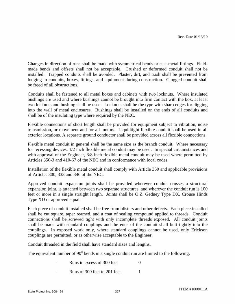
Rev. Date 01/13/10
Changes in direction of runs shall be made with symmetrical bends or cast-metal fittings. Field-made bends and offsets shall not be acceptable. Crushed or deformed conduit shall not be installed. Trapped conduits shall be avoided. Plaster, dirt, and trash shall be prevented from lodging in conduits, boxes, fittings, and equipment during construction. Clogged conduit shall be freed of all obstructions.
Conduits shall be fastened to all metal boxes and cabinets with two locknuts. Where insulated bushings are used and where bushings cannot be brought into firm contact with the box. at least two locknuts and bushing shall be used. Locknuts shall be the type with sharp edges for digging into the wall of metal enclosures. Bushings shall be installed on the ends of all conduits and shall be of the insulating type where required by the NEC.
Flexible connections of short length shall be provided for equipment subject to vibration, noise transmission, or movement and for all motors. Liquidtight flexible conduit shall be used in all exterior locations. A separate ground conductor shall be provided across all flexible connections.
Flexible metal conduit in general shall be the same size as the branch conduit. Where necessary for recessing devices, 1/2 inch flexible metal conduit may be used. In special circumstances and with approval of the Engineer, 3/8 inch flexible metal conduit may be used where permitted by Articles 350-3 and 410-67 of the NEC and in conformance with local codes.
Installation of the flexible metal conduit shall comply with Article 350 and applicable provisions of Articles 300, 333 and 346 of the NEC.
Approved conduit expansion joints shall be provided wherever conduit crosses a structural expansion joint, is attached between two separate structures, and wherever the conduit run is 100 feet or more in a single straight length. Joints shall be O.Z. Gedney Type DX, Crouse Hinds Type XD or approved equal.
Each piece of conduit installed shall be free from blisters and other defects. Each piece installed shall be cut square, taper reamed, and a coat of sealing compound applied to threads. Conduit connections shall be screwed tight with only incomplete threads exposed. All conduit joints shall be made with standard couplings and the ends of the conduit shall butt tightly into the couplings. In exposed work only, where standard couplings cannot be used, only Erickson couplings are permitted, or as otherwise acceptable to the Engineer.
Conduit threaded in the field shall have standard sizes and lengths.
The equivalent number of 90o bends in a single conduit run are limited to the following.
- Runs in excess of 300 feet 0
- Runs of 300 feet to 201 feet 1
ITEM #1008011A State Project No. 300-154 327

Rev. Date 01/13/10
- Runs of 200 feet to 101 feet 2
- Runs of 100 feet and less 3
Factory bent elbows or field bent elbows with approved tools may be used. Heating of conduit to facilitate bending is prohibited.
All exposed conduit shall be installed either parallel or perpendicular to structural members, unless impractical, and shall be grouped wherever possible. Conduit shall be attached to structural components with approved supports spaced a maximum of six (6) feet apart and shall form a neat rigid installation. Conduit supported from building walls shall be installed with at least 1/4 inch clearance from the walls to prevent the accumulation of dirt and moisture behind the conduit.
Conduit shall be protected immediately after installation by installing flat non-corrosive metallic discs and steel bushings, designed for this purpose, at each end. Discs shall not be removed until it is necessary to clean the conduit and pull wire and cable. Before wire or cable is pulled, insulated bushings shall be installed at each end of the conduit.
Where all thread nipples are used between fittings and electrical equipment, they shall be so installed that no threads are exposed.
Connections from rigid conduit to light fixtures, switches, etc., shall be made with short lengths of liquid-tight flexible PVC jacketed metal conduit equal to Type "LA" Electri-Flex, Type "ULTRATITE" Alflex Corporation, or Type "VA" Annaconda. These lengths shall be provided with appropriate connectors with devices which will provide an excellent electrical connection between equipment and the rigid conduit for the flow of ground current.
All threaded ends of conduits shall be coated with an approved conducting compound such as Thomas Betts prior to making up the point.
Conduit attachment to all electrical equipment, such as stainless steel junction boxes, pullboxes, switches, etc., shall be made with double steel locknuts. Threaded insulated bushings shall be used on the end of each conduit terminating in such equipment.
Conduits passing through sleeves in walls and floors shall be tightly caulked.
he use of two (2) locknuts and a grounding bushing will be required at all conduit terminations.
Conduit expansion fitting shall be equal to Crouse Hinds Type XD, OZ Gedney Type DX or equal for non-explosive areas.
Conduit penetrating fire rated wall shall be provided with fire seals equal to OZ Gedney Type CFS.
Conduits shall be supported with approved fittings. The support system shall not permit deflections to exceed 1/100 of the span.
ITEM #1008011A State Project No. 300-154 328

Rev. Date 01/13/10
All conduit and ducts, where indicated on the Contract Drawings, shall be caulked and sealed immediately after the wires and cables have been installed. The conduit bushings shall be thoroughly caulked with oakum, using wooden tools with rounded edges, and sealed with "Duxseal" waterproofing compound, Johns-Manville Corp. or approved equal. The compound shall be painted with one coat of approved insulated paint.
All conduits and their connections to electrical equipment shall be installed to make a continuous ground, except as indicated on the Contract Drawings, or as directed by the Engineer. All conduits connected to service end boxes, meter pans, panelboard boxes, current transformer cabinets, motor control center cabinets, automatic transfer switch enclosures, safety switch boxes, sheet metal boxes, troughs, etc., shall be installed on the outside of the box with electrogalvanized steel or malleable iron conduit locknuts, Thomas & Betts Corp. "42.56" series, or approved equal, and secured inside the box with electrogalvanized steel or malleable iron, 150 degree C. insulated grounding bushings, with solid copper alloy cradle lug type termination for copper ground conductor and hexagonal head screw (for conductors larger than No. 4) or slotted head screw (for No. 4 conductor or smaller), with a smooth spherical point and screw shank diameter equal in size to the largest diameter of copper conductor within the lug capacity, O.Z./GEDNEY Type IBC-L-BC series, or approved equal. Stranded copper conductors, with insulation colored dark green shall be used to bond the conduits to the boxes. No. 4/0 AWG, TYPE THWN ground wire shall be used on all service and distribution equipment, and panelboards.
Waterproof ferrules for electrical conduits shall be provided in the exterior walls, ceilings or floors of the enclosures. The Contractor shall submit drawings showing method of installation.
Ferrules shall consist of extra heavy galvanized steel pipe with flanges set in the wall or floor of the enclosures, waterproofed with brick in mastic in an approved manner. Sufficient membrane waterproofing shall be provided to properly lap over the waterproofing of the existing structure and to act as a base for the brick-in-mastic. Membrane waterproofing shall consist of three layers of treated cotton fabric mopped with asphalt.
Steel feed conduits shall be provided through ferrules. The space between the conduit and the ferrule shall be caulked with oakum and lead wool. The conduit shall be encased in concrete and shall extend to locations indicated on the Contract Drawings.
Boxes shall be provided in the wiring or raceway systems wherever required for pulling of wires, making connections, and mounting of devices or fixtures. Boxes for metallic raceways shall be of the cast-metal hub type coated with 40 mils of PVC when located in all wet locations, when surface mounted on outside of exterior surfaces, and when installed exposed up to 7 feet above interior floors and walkways. Each box shall have the volume required by the NEC for the number of conductors exposed in the box. Boxes for mounting lighting fixtures shall be not less than 4 inches square or octagonal except that smaller boxes may be installed as required by fixture configurations, as approved. Boxes installed for concealed wiring shall be provided with suitable extension rings or plastic covers, as required. Boxes for use in masonry-block or tile walls shall be square-cornered tile-type, or standard boxes having square-cornered tile-type
ITEM #1008011A State Project No. 300-154 329

Rev. Date 01/13/10
covers. Cast metal PVC coated cast-metal boxes installed in all wet locations and boxes installed flush with the outside of exterior surfaces shall be gasketed.
Separate boxes shall be provided for flush or recessed fixtures when required by the fixture terminal operating temperature, and fixtures shall be readily removable for access to the boxes unless ceiling access panels are provided. Boxes and pendants for surface-mounted fixtures on suspended ceilings shall be supported independently of the ceiling supports, or adequate provisions shall be made for distributing the load over the ceiling support members in an approved manner.
For Exterior Installations
1. Boxes and supports shall be fastened to wood with type 316 stainless steel wood screws or screw-type nails of equal holding strength, with Type 316 stainless steel bolts and expansion shields on concrete or brick, with Type 316 stainless steel toggle bolts on hollow masonry units, and with Type 316 stainless steel machine screws or welded studs on steel work. Threaded studs driven in by powder charge and provided with lockwashers and nuts may be used in lieu of wood screws, expansion shields, or machine screws. In open overhead spaces, PVC coated cast boxes threaded to raceways need not be separately supported except where used for fixture support; PVC coated cast-metal boxes having threadless connectors shall be supported directly from the building structure or by Type 316 stainless steel bar hangers. Where bar hangers are used, the bar shall be attached to raceways on opposite sides of the box and the raceway shall be supported with an approved fastener not more than 24 inches from the box. Penetration into reinforced concrete members shall avoid cutting any reinforcing steel.
2. Boxes for use with raceway systems shall not be less than 1-1/2 inches deep except where s hallower boxes required by structural conditions are approved. Boxes for other than lighting-fixture outlets shall be not less than 4 inches square except that 4-inch-by-2-inch boxes may be used where only one raceway enters the outlet. Telephone outlets shall be a minimum of 4 inches square by 1-1/2 inches deep.
3. Pull boxes of not less than the minimum size required by the NEC shall be constructed of PVC coated cast-metal boxes. Boxes shall be furnished with Type 316 stainless steel screw-fastened covers. Where several feeders pass through a common pull box, the feeders shall be tagged to indicate clearly the electrical characteristics, circuit number, and panel designation.
For Interior Installations
1. Boxes and supports shall be fastened to wood with wood screws or screw-type nails of equal holding strength, with bolts and expansion shields on concrete or brick, with toggle bolts on hollow masonry units, and with machine screws or welded studs on steel work. Threaded studs driven in by powder charge and provided with lockwashers and nuts may be used in lieu of wood screws, expansion shields, or machine screws. In open overhead
ITEM #1008011A State Project No. 300-154 330

Rev. Date 01/13/10
spaces, cast boxes threaded to raceways need not be separately supported except where used for fixture support; cast-metal boxes having threadless connectors shall be supported directly from the building structure or by bar hangers. Where bar hangers are used, the bar shall be attached to raceways on opposite sides of the box and the raceway shall be supported with an approved fastener not more than 24 inches from the box. Penetration into reinforced concrete members shall avoid cutting any reinforcing steel.
2. Boxes for use with raceway systems shall not be less than 1-1/2 inches deep except where shallower boxes required by structural conditions are approved. Boxes for other than lighting-fixture outlets shall be not less than 4 inches square except that 4-inch-by-2-inch boxes may be used where only one raceway enters the outlet. Telephone outlets shall be a minimum of 4 inches square by 1-1/2 inches deep.
3. Pull boxes of not less than the minimum size required by the NEC shall be constructed of code-gauge galvanized sheet steel except where cast-metal boxes are required in locations specified above. Boxes shall be furnished with screw-fastened covers. Where several feeders pass through a common pull box, the feeders shall be tagged to indicate clearly the electrical characteristics, circuit number, and panel designation.
4. Where conduits are connected to boxes or equipment enclosures through drilled holes or full size knockout openings, electrical continuity for grounding shall be assured by the use of bonding type locknuts or copper grounding wedges having set screws made up tight to bushings. Where connections are at eccentric or concentric knockouts, jumper type grounding bushings and wire jumpers shall be installed. At pull and junction boxes having any box dimension in excess of 18 inches and having a total of more than 4 conduit terminations, jumper type grounding bushings shall be installed on conduit ends and jumper wires shall be installed to bond all conduits and to bond conduits to boxes.
5. Should any structural difficulties prevent the setting of boxes at points shown on the plans, deviations therefrom as determined by the Engineer will be permitted and shall be made without additional cost.
6. A run of conduit between outlet and outlet, between fitting and fitting or between outlet and fitting shall not contain more than the equivalent of four quarterbends, including those bends located immediately at the outlet or fitting.
7. All junction boxes and pullboxes shall have identifying nameplates attached thereto, which when installed on sidewalk type boxes shall not extend above the surrounding concrete slabs.
Methods of Measurement: Conduit will be measured for payment by the actual number of linear feet (meters) of the type and size installed and accepted. The measured length shall be from end to end along the centerline through all fittings.
ITEM #1008011A State Project No. 300-154 331

Rev. Date 01/13/10
ITEM #1008011A
Basis of Payment: This work will be paid for at the Contract unit price per linear foot (meter) for "(Size) (Kind) Conduit-(Type)."
This price shall include all materials required including expansion fittings, conduit fittings, locknuts, bonding bushings, bonding wire, hangers, clamps, duct seal, caps, inserts, equipment, tools, labor and work incidental thereto.
Trenching and backfilling shall be paid under Article 10.01.
No payment for trenching and backfilling will be made for conduit installed during construction under new pavement or in the fill area of new median barrier curb installations.
Pay Item Pay Unit
(Size) (Kind) Conduit (Type) l.f.
State Project No. 300-154 332

Rev. Date 01/13/10
ITEM #1008012A – 1” RIGID METAL CONDUIT - SURFACE
Description:
The work under this item consists of furnishing and installing the 1” rigid metal conduit as shown on the plans and specified herein for improvements at various rail line stations. The 1” rigid metal conduit shall meet the requirements of the National Electrical Code and the technical and safety recommendations of ANSI and IEEE.
Applicable Standards: Pertinent provisions of the following listed standards (latest edition) shall apply to the work of this Section, except as they may be modified herein, and are hereby made a part of this Specification to the extent required.
Organization Number Title
ANSI C.80.1 Rigid Steel Conduit – Zinc Coated
ANSI C.80.3 Electrical Metallic Tubing – Zinc Coated
NFPA 70 National Electrical Code UL 1 Flexible Metal Conduit
UL 6 Rigid Metal Conduit
UL 50 Cabinets and Boxes
UL 67 Panelboards
UL 98 Test for Flammability of Plastic Materials for Parts for Devices and Appliances
UL 360 Liquid-Tight Flexible Steel Conduit
UL 467 Grounding and Bonding Equipment
UL 514A Metallic Outlet Boxes
UL 514B Fittings for Conduit and Outlet Boxes
Materials:
Materials, equipment, and devices shall, as a minimum, meet the requirements of UL where UL standards are established for those items and the requirements of the National Electrical Code (NEC), NFPA-70 and all state and local codes having jurisdiction.
Further, each item shall meet the requirements of these specifications and of the specifications
ITEM #1008012A State Project No. 300-154 333

Rev. Date 01/13/10
and publications referenced herein.
All items shall be new unless specified or indicated otherwise.
Rigid hot-dip galvanized Steel Conduit (Zinc-Coated): ANSI standard C80.1. Where to be embedded in concrete or run exposed, use rigid hot-dip galvanized steel conduit as manufactured by Wheatland Tube Company or Allied Tube & Conduit, or approved equal.
Flexible Metal Conduit: UL standard 1, zinc-coated steel only with liquid tight jacket.
Fittings for Rigid Hot-Dip Galvanized Metal Conduit, Electrical Metallic Tubing, and Flexible Metal Conduit: UL standard 514. All ferrous fittings shall be cadmium or zinc-coated per UL 514 as manufactured by Wheatland Tube Company or Allied Tube & Conduit, or approved equal.
Fittings for rigid hot-dip galvanized metal conduit shall be the threaded type. Split couplings are not acceptable.
The conduits of all feeders and branch circuits shall be properly designated at all panelboards, switches and other equipment by an approved round yellow plastic tag, of 0.040-inch minimum thickness and one inch in diameter, Actioncraft Products, or approved equal. The lettering shall be black, 1/8-inch high. No. 18 monel wire, doubled, shall be used to secure the tag. A list of tag descriptions shall be submitted to the Engineer for approval before any lettering is done.
All conduits within enclosures shall be properly identified by Seton Name Plate Corporation "Setmark" markers, Brady Snap-On Pipe Markers, or approved equal. The lettering and color coding of the markers shall be black on an orange background or in conformance with the latest revision of the ANSI Z53.1 Scheme for Identification of Piping Systems.
UL standard 514, cadmium or zinc coated if of ferrous metal. Exterior outlet boxes and covers shall be coated with 40 mils of PVC, interiors shall be coated with 2 mil urethane and shall use Type 316 stainless steel screws as manufactured by Robroy Industries, Plastibond Series, or OCAL, Inc., OCAL Blue Series, or approved equal.
Clock outlet shall consist of an outlet box, a plaster cover where required, and a single receptacle with clock-outlet plate. The receptacle shall be recessed sufficiently within the box to allow the complete insertion of a standard cap, flush with the plate. A suitable clip or support for hanging the clock shall be secured to the top plate. Material and finish of the plate shall be as specified in paragraph 2.09, Device Plates.
Construction Methods: The conduit shall be installed in the locations and to the dimensions shown on the plans or as directed by the Engineer. All conduit runs shall be installed in a neat and workmanlike manner in accordance with recognized trade practices. Trenching and backfilling of conduit shall conform to Article 10.01. All conduit shall be installed in strict accordance with the current NEC. Where conduit is to be capped, a commercial pipe or conduit
ITEM #1008012A State Project No. 300-154 334

Rev. Date 01/13/10
cap shall be used. An expansion fitting shall be used wherever required by an expansion joint in the structure. Upon completion of the work, all conduits shall be cleaned, swabbed and free from obstructions and burrs. For buried conduit, marking tape shall be installed in the trench at the depth and to the requirements as set forth in the Article 1.05.15. After all cable has been installed, U.L. approved duct sealing compound shall be installed in the ends of all conduit which terminates in foundations, handholes, junction boxes and manholes.
1. Conduit Surface: Beam clamps or conduit strips with back spacers shall be provided at intervals in accordance with the NEC. Expansion fittings shall be installed at all expansion joints. All surface mounted conduit on wood poles shall be bonded to a driven ground rod. Stand-offs shall be installed in accordance with serving utility company regulations.
2. Conduit in Trench: Trenches shall be of the depth and cross section shown on the plans or as directed by the Engineer. All conduit shall have a minimum covering of 2 feet (600 millimeters).
3. Conduit Under Roadway: Installations shall be such as to avoid pockets in runs. Conduit shall have a minimum cover of 2 feet (600 millimeters). Each end of conduit runs shall terminate with a cap in a concrete handhole as shown on the plans. The Contractor shall coordinate the placement of the conduit prior to the placement of the pavement.
Where conduit is to be installed under an existing roadway a trench shall be opened and conduit installed as shown on plans, or as directed by the Engineer. The trench shall be backfilled with suitable material and the surface shall be restored to original condition.
4. Conduit in Structure: It shall be the Contractor's responsibility to coordinate the setting of all conduit in structure prior to pouring concrete. Expansion fittings shall be installed at all expansion joints. Where shown on the plans, outlet boxes with the conduits properly connected and conduit hanger inserts with proper sized nuts installed, shall be accurately and securely placed in the forms for concrete. Care shall be taken during the placing of the concrete around these boxes and inserts to consolidate the concrete thoroughly, preventing voids and honeycomb and to prevent any material displacement of the boxes or inserts. Sealed bonding bushing shall be provided at each conduit outlet in all boxes.
5. Conduit Under Slope Protection: Conduit shall be installed in trench under bridge slope protection or between the slope protection and the edge of pavement at the locations and to the dimensions shown on the plans or as directed by the Engineer. The conduit shall have a minimum cover of two feet (600 millimeters) under finish grade and each end of the conduit shall extend 10 feet (3 meters) beyond the limits of the slope protection. All conduit shall terminate with a standard pipe cap and the trench shall be backfilled with suitable material. The Contractor shall coordinate the placement of the conduit prior to the placement of slope protection.
ITEM #1008012A State Project No. 300-154 335

Rev. Date 01/13/10
Unless indicated otherwise, all conduit shall be concealed within finished walls, ceilings, under platforms and floors. Conduit that will be visible after completion of project shall be installed parallel with or at right angles to ceilings, walls, and structural members.
Keep conduit at least 12 inches away from parallel runs of flues and steam or water pipes.
For Exterior Installations
1. Conduit shall be supported by Type 316 stainless steel wall brackets, hangers, or ceiling trapeze. Fastenings shall be by Type 316 stainless steel wood screws or screw-type nails to wood; by Type 316 stainless steel toggle bolts on hollow masonry units; by concrete inserts or Type 316 stainless steel expansions bolts on concrete or brick; by Type 316 stainless steel machine screws, welded threaded studs, or spring-tension clamps on steel work. Threaded studs driven in by a powder charge and provided with lock washers and nuts may be used in lieu of expansion bolts or machine or wood screws. Type 316 stainless steel threaded C-clamps may be used on 40 mil PVC coated rigid steel conduit only. Conduits or pipe straps shall not be welded to steel structures. The load applied to fasteners shall not exceed one fourth of the proof test load. Fasteners attached to concrete ceiling shall be vibration and shock resistant. Holes cut to a depth of more than 1-1/2 inches in reinforced concrete beams or to a depth of more than 3/4 inch in concrete. Joints shall not cut the main reinforcing bars. Holes not used shall be filled. In partitions of light steel construction, sheet-metal screws shall be used. Exposed risers in wire shafts of multistory buildings shall be supported by Type 316 stainless steel U-clamp hangers at each floor level and at intervals not to exceed 10 feet.
For Interior Installations
1. Conduit shall be supported by pipe straps, wall brackets, hangers, or ceiling trapeze. Fastenings shall be by wood screws or screw-type nails to wood; by toggle bolts on hollow masonry units; by concrete inserts or expansion bolts on concrete or brick; by machine screws, welded threaded studs, or spring-tension clamps on steel work. Threaded studs driven in by a powder charge and provided with lock washers and nuts may be used in lieu of expansion bolts or machine or wood screws. Threaded C-clamps may be used on rigid steel conduit only. Conduits or pipe straps shall not be welded to steel structures. The load applied to fasteners shall not exceed one fourth of the proof test load. Fasteners attached to concrete ceiling shall be vibration and shock resistant. Holes cut to a depth of more than 1-1/2 inches in reinforced concrete beams or to a depth of more than 3/4 inch in concrete. Joints shall not cut the main reinforcing bars. Holes not used shall be filled. In partitions of light steel construction, sheet-metal screws shall be used. In suspended-ceiling construction, conduit shall be run above the ceiling. Spring steel fasteners may be used for lighting branch-circuit conduit supports in suspended ceilings in dry locations. Exposed risers in wire shafts of multi-story buildings shall be supported by U-clamp hangers at each floor level and at intervals not to exceed 10 feet.
ITEM #1008012A State Project No. 300-154 336
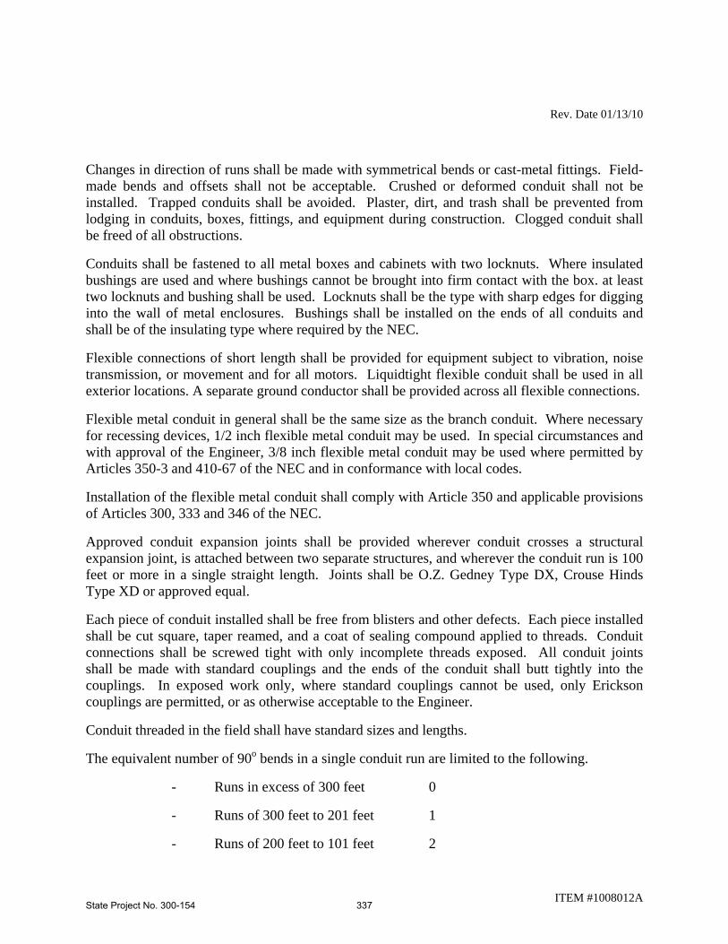
Rev. Date 01/13/10
Changes in direction of runs shall be made with symmetrical bends or cast-metal fittings. Field-made bends and offsets shall not be acceptable. Crushed or deformed conduit shall not be installed. Trapped conduits shall be avoided. Plaster, dirt, and trash shall be prevented from lodging in conduits, boxes, fittings, and equipment during construction. Clogged conduit shall be freed of all obstructions.
Conduits shall be fastened to all metal boxes and cabinets with two locknuts. Where insulated bushings are used and where bushings cannot be brought into firm contact with the box. at least two locknuts and bushing shall be used. Locknuts shall be the type with sharp edges for digging into the wall of metal enclosures. Bushings shall be installed on the ends of all conduits and shall be of the insulating type where required by the NEC.
Flexible connections of short length shall be provided for equipment subject to vibration, noise transmission, or movement and for all motors. Liquidtight flexible conduit shall be used in all exterior locations. A separate ground conductor shall be provided across all flexible connections.
Flexible metal conduit in general shall be the same size as the branch conduit. Where necessary for recessing devices, 1/2 inch flexible metal conduit may be used. In special circumstances and with approval of the Engineer, 3/8 inch flexible metal conduit may be used where permitted by Articles 350-3 and 410-67 of the NEC and in conformance with local codes.
Installation of the flexible metal conduit shall comply with Article 350 and applicable provisions of Articles 300, 333 and 346 of the NEC.
Approved conduit expansion joints shall be provided wherever conduit crosses a structural expansion joint, is attached between two separate structures, and wherever the conduit run is 100 feet or more in a single straight length. Joints shall be O.Z. Gedney Type DX, Crouse Hinds Type XD or approved equal.
Each piece of conduit installed shall be free from blisters and other defects. Each piece installed shall be cut square, taper reamed, and a coat of sealing compound applied to threads. Conduit connections shall be screwed tight with only incomplete threads exposed. All conduit joints shall be made with standard couplings and the ends of the conduit shall butt tightly into the couplings. In exposed work only, where standard couplings cannot be used, only Erickson couplings are permitted, or as otherwise acceptable to the Engineer.
Conduit threaded in the field shall have standard sizes and lengths.
The equivalent number of 90o bends in a single conduit run are limited to the following.
- Runs in excess of 300 feet 0
- Runs of 300 feet to 201 feet 1
- Runs of 200 feet to 101 feet 2
ITEM #1008012A State Project No. 300-154 337

Rev. Date 01/13/10
- Runs of 100 feet and less 3
Factory bent elbows or field bent elbows with approved tools may be used. Heating of conduit to facilitate bending is prohibited.
All exposed conduit shall be installed either parallel or perpendicular to structural members, unless impractical, and shall be grouped wherever possible. Conduit shall be attached to structural components with approved supports spaced a maximum of six (6) feet apart and shall form a neat rigid installation. Conduit supported from building walls shall be installed with at least 1/4 inch clearance from the walls to prevent the accumulation of dirt and moisture behind the conduit.
Conduit shall be protected immediately after installation by installing flat non-corrosive metallic discs and steel bushings, designed for this purpose, at each end. Discs shall not be removed until it is necessary to clean the conduit and pull wire and cable. Before wire or cable is pulled, insulated bushings shall be installed at each end of the conduit.
Where all thread nipples are used between fittings and electrical equipment, they shall be so installed that no threads are exposed.
Connections from rigid conduit to light fixtures, switches, etc., shall be made with short lengths of liquid-tight flexible PVC jacketed metal conduit equal to Type "LA" Electri-Flex, Type "ULTRATITE" Alflex Corporation, or Type "VA" Annaconda. These lengths shall be provided with appropriate connectors with devices which will provide an excellent electrical connection between equipment and the rigid conduit for the flow of ground current.
All threaded ends of conduits shall be coated with an approved conducting compound such as Thomas Betts prior to making up the point.
Conduit attachment to all electrical equipment, such as stainless steel junction boxes, pullboxes, switches, etc., shall be made with double steel locknuts. Threaded insulated bushings shall be used on the end of each conduit terminating in such equipment.
Conduits passing through sleeves in walls and floors shall be tightly caulked.
he use of two (2) locknuts and a grounding bushing will be required at all conduit terminations.
Conduit expansion fitting shall be equal to Crouse Hinds Type XD, OZ Gedney Type DX or equal for non-explosive areas.
Conduit penetrating fire rated wall shall be provided with fire seals equal to OZ Gedney Type CFS.
Conduits shall be supported with approved fittings. The support system shall not permit deflections to exceed 1/100 of the span.
ITEM #1008012A State Project No. 300-154 338

Rev. Date 01/13/10
All conduit and ducts, where indicated on the Contract Drawings, shall be caulked and sealed immediately after the wires and cables have been installed. The conduit bushings shall be thoroughly caulked with oakum, using wooden tools with rounded edges, and sealed with "Duxseal" waterproofing compound, Johns-Manville Corp. or approved equal. The compound shall be painted with one coat of approved insulated paint.
All conduits and their connections to electrical equipment shall be installed to make a continuous ground, except as indicated on the Contract Drawings, or as directed by the Engineer. All conduits connected to service end boxes, meter pans, panelboard boxes, current transformer cabinets, motor control center cabinets, automatic transfer switch enclosures, safety switch boxes, sheet metal boxes, troughs, etc., shall be installed on the outside of the box with electrogalvanized steel or malleable iron conduit locknuts, Thomas & Betts Corp. "42.56" series, or approved equal, and secured inside the box with electrogalvanized steel or malleable iron, 150 degree C. insulated grounding bushings, with solid copper alloy cradle lug type termination for copper ground conductor and hexagonal head screw (for conductors larger than No. 4) or slotted head screw (for No. 4 conductor or smaller), with a smooth spherical point and screw shank diameter equal in size to the largest diameter of copper conductor within the lug capacity, O.Z./GEDNEY Type IBC-L-BC series, or approved equal. Stranded copper conductors, with insulation colored dark green shall be used to bond the conduits to the boxes. No. 4/0 AWG, TYPE THWN ground wire shall be used on all service and distribution equipment, and panelboards.
Waterproof ferrules for electrical conduits shall be provided in the exterior walls, ceilings or floors of the enclosures. The Contractor shall submit drawings showing method of installation.
Ferrules shall consist of extra heavy galvanized steel pipe with flanges set in the wall or floor of the enclosures, waterproofed with brick in mastic in an approved manner. Sufficient membrane waterproofing shall be provided to properly lap over the waterproofing of the existing structure and to act as a base for the brick-in-mastic. Membrane waterproofing shall consist of three layers of treated cotton fabric mopped with asphalt.
Steel feed conduits shall be provided through ferrules. The space between the conduit and the ferrule shall be caulked with oakum and lead wool. The conduit shall be encased in concrete and shall extend to locations indicated on the Contract Drawings.
Boxes shall be provided in the wiring or raceway systems wherever required for pulling of wires, making connections, and mounting of devices or fixtures. Boxes for metallic raceways shall be of the cast-metal hub type coated with 40 mils of PVC when located in all wet locations, when surface mounted on outside of exterior surfaces, and when installed exposed up to 7 feet above interior floors and walkways. Each box shall have the volume required by the NEC for the number of conductors exposed in the box. Boxes for mounting lighting fixtures shall be not less than 4 inches square or octagonal except that smaller boxes may be installed as required by fixture configurations, as approved. Boxes installed for concealed wiring shall be provided with suitable extension rings or plastic covers, as required. Boxes for use in masonry-block or tile walls shall be square-cornered tile-type, or standard boxes having square-cornered tile-type
ITEM #1008012A State Project No. 300-154 339

Rev. Date 01/13/10
covers. Cast metal PVC coated cast-metal boxes installed in all wet locations and boxes installed flush with the outside of exterior surfaces shall be gasketed.
Separate boxes shall be provided for flush or recessed fixtures when required by the fixture terminal operating temperature, and fixtures shall be readily removable for access to the boxes unless ceiling access panels are provided. Boxes and pendants for surface-mounted fixtures on suspended ceilings shall be supported independently of the ceiling supports, or adequate provisions shall be made for distributing the load over the ceiling support members in an approved manner.
For Exterior Installations
1. Boxes and supports shall be fastened to wood with type 316 stainless steel wood screws or screw-type nails of equal holding strength, with Type 316 stainless steel bolts and expansion shields on concrete or brick, with Type 316 stainless steel toggle bolts on hollow masonry units, and with Type 316 stainless steel machine screws or welded studs on steel work. Threaded studs driven in by powder charge and provided with lockwashers and nuts may be used in lieu of wood screws, expansion shields, or machine screws. In open overhead spaces, PVC coated cast boxes threaded to raceways need not be separately supported except where used for fixture support; PVC coated cast-metal boxes having threadless connectors shall be supported directly from the building structure or by Type 316 stainless steel bar hangers. Where bar hangers are used, the bar shall be attached to raceways on opposite sides of the box and the raceway shall be supported with an approved fastener not more than 24 inches from the box. Penetration into reinforced concrete members shall avoid cutting any reinforcing steel.
2. Boxes for use with raceway systems shall not be less than 1-1/2 inches deep except where s hallower boxes required by structural conditions are approved. Boxes for other than lighting-fixture outlets shall be not less than 4 inches square except that 4-inch-by-2-inch boxes may be used where only one raceway enters the outlet. Telephone outlets shall be a minimum of 4 inches square by 1-1/2 inches deep.
3. Pull boxes of not less than the minimum size required by the NEC shall be constructed of PVC coated cast-metal boxes. Boxes shall be furnished with Type 316 stainless steel screw-fastened covers. Where several feeders pass through a common pull box, the feeders shall be tagged to indicate clearly the electrical characteristics, circuit number, and panel designation.
For Interior Installations
1. Boxes and supports shall be fastened to wood with wood screws or screw-type nails of equal holding strength, with bolts and expansion shields on concrete or brick, with toggle bolts on hollow masonry units, and with machine screws or welded studs on steel work. Threaded studs driven in by powder charge and provided with lockwashers and nuts may be used in lieu of wood screws, expansion shields, or machine screws. In open overhead
ITEM #1008012A State Project No. 300-154 340

Rev. Date 01/13/10
spaces, cast boxes threaded to raceways need not be separately supported except where used for fixture support; cast-metal boxes having threadless connectors shall be supported directly from the building structure or by bar hangers. Where bar hangers are used, the bar shall be attached to raceways on opposite sides of the box and the raceway shall be supported with an approved fastener not more than 24 inches from the box. Penetration into reinforced concrete members shall avoid cutting any reinforcing steel.
2. Boxes for use with raceway systems shall not be less than 1-1/2 inches deep except where shallower boxes required by structural conditions are approved. Boxes for other than lighting-fixture outlets shall be not less than 4 inches square except that 4-inch-by-2-inch boxes may be used where only one raceway enters the outlet. Telephone outlets shall be a minimum of 4 inches square by 1-1/2 inches deep.
3. Pull boxes of not less than the minimum size required by the NEC shall be constructed of code-gauge galvanized sheet steel except where cast-metal boxes are required in locations specified above. Boxes shall be furnished with screw-fastened covers. Where several feeders pass through a common pull box, the feeders shall be tagged to indicate clearly the electrical characteristics, circuit number, and panel designation.
4. Where conduits are connected to boxes or equipment enclosures through drilled holes or full size knockout openings, electrical continuity for grounding shall be assured by the use of bonding type locknuts or copper grounding wedges having set screws made up tight to bushings. Where connections are at eccentric or concentric knockouts, jumper type grounding bushings and wire jumpers shall be installed. At pull and junction boxes having any box dimension in excess of 18 inches and having a total of more than 4 conduit terminations, jumper type grounding bushings shall be installed on conduit ends and jumper wires shall be installed to bond all conduits and to bond conduits to boxes.
5. Should any structural difficulties prevent the setting of boxes at points shown on the plans, deviations therefrom as determined by the Engineer will be permitted and shall be made without additional cost.
6. A run of conduit between outlet and outlet, between fitting and fitting or between outlet and fitting shall not contain more than the equivalent of four quarterbends, including those bends located immediately at the outlet or fitting.
7. All junction boxes and pullboxes shall have identifying nameplates attached thereto, which when installed on sidewalk type boxes shall not extend above the surrounding concrete slabs.
Methods of Measurement: Conduit will be measured for payment by the actual number of linear feet (meters) of the type and size installed and accepted. The measured length shall be from end to end along the centerline through all fittings.
ITEM #1008012A State Project No. 300-154 341

Rev. Date 01/13/10
ITEM #1008012A
Basis of Payment: This work will be paid for at the Contract unit price per linear foot (meter) for "(Size) (Kind) Conduit-(Type)."
This price shall include all materials required including expansion fittings, conduit fittings, locknuts, bonding bushings, bonding wire, hangers, clamps, duct seal, caps, inserts, equipment, tools, labor and work incidental thereto.
Trenching and backfilling shall be paid under Article 10.01.
No payment for trenching and backfilling will be made for conduit installed during construction under new pavement or in the fill area of new median barrier curb installations.
Pay Item Pay Unit
(Size) (Kind) Conduit (Type) l.f.
State Project No. 300-154 342

Rev. Date 01/13/10
ITEM #1008901A – REMOVE CONDUIT
Description:
Work under this item shall consist of removal of conduit used for lighting as shown on the plans or as directed by the Engineer and in conformity with these specifications.
Materials:
All materials required for this work shall conform to the requirements of these specifications or the special provisions for the material in question; or if not so specified, they shall be of a quality satisfactory to the Engineer.
Construction Methods:
Existing conduit shall be carefully removed together with all fittings and attachments in such a manner as to safeguard all parts from damage or loss. The Contractor shall replace, at his own expense, all equipment which becomes damaged due to his operations.
Removal of existing conduit shall be coordinated with the installation of new conduit and lighting equipment so as to maintain the appropriate lighting levels and safety for those pedestrians using the railroad station. The Contractor shall furnish and install temporary lights or other equipment necessary to provide safe lighting levels as directed by the Engineer.
Conduit, fittings, supports, and all other materials shall be removed in their entirety.
Equipment shall be removed in such a manner as to cause no hazard to pedestrians, traffic or property. If necessary, flagmen shall be used to halt traffic briefly while work is in progress.
All removed conduit, fittings, supports and all other materials shall be removed to a suitable dump. Existing items or surfaces to remain which are damaged as a result of this Work shall be re-finished, repaired, or replaced in accordance with the appropriate sections of the Standard Specifications.
Method of Measurement: This work shall be measured by the actual number of linear feet of conduit removed. The measured length shall be from end to end along the centerline through all fittings.
Basis of Payment: This work will be paid for at the Contract unit price per linear foot for "Remove Conduit" which price shall include all removals, all material, equipment and labor incidental to completion of this item.
Pay Item Pay Unit
ITEM #1008901A
State Project No. 300-154 343

Rev. Date 01/13/10
ITEM #1008901A
Remove Conduit l.f.
State Project No. 300-154 344

Rev. Date 01/13/10
ITEM #1012010A – NO. 10 SINGLE CONDUCTOR Description: The work under this item consists of furnishing and installing the No. 10 single conductors as shown on the plans and specified herein for improvements at various rail line stations. The No. 10 single conductors shall be placed in conduit and shall comply with the specifications for conduits, outlet boxes, pull and junction boxes, wires and cables, grounding, etc. and meet the requirements of the National Electrical Code and the technical and safety recommendations of ANSI and IEEE. Applicable Standards: Pertinent provisions of the following listed standards (latest edition) shall apply to the work of this Section, except as they may be modified herein, and are hereby made a part of this Specification to the extent required. Organization Number Title NFPA 70 National Electrical Code UL 44 Rubber-Insulated Wires and Cables UL 83 Thermoplastic-Insulated Wires and Cables UL 98 Test for Flammability of Plastic Materials for Parts for Devices and Appliances UL 486A Wire Connector and Soldering Lugs for Use with Copper Conductors UL 486C Splicing Wire Connectors UL 514A Metallic Outlet Boxes UL 514B Fittings for Conduit and Outlet Boxes UL 719 Nonmetallic-Sheathed Cables ASTM B1 1990 Hard-Drawn Copper Wire ASTM B8 Concentric lay-stranded copper conductors, hard, medium hard or soft Materials: Conductor's for lighting shall be ASTM B8, Class B stranded annealed copper and sized as indicated on the plans. Conductor’s for lighting shall be 600 volt and shall be annealed, uncoated, stranded copper conductors with a polyvinyl chloride (PVC) insulation. The cables shall be Type THHN, THWN, VW-1 with a 90°C dry/75°C wet rating. A nylon jacket shall be applied over the insulation. The conductors shall be annealed, uncoated copper with Class B stranding per ASTM B-8. The insulation shall be PVC, shall meet UL 83 and shall have the following thicknesses: Cable Size Insulation Thickness 10 AWG 20 Mils The jacket shall be nylon and shall meet UL 83. The jacket shall have the following thicknesses: Cable Size Jacket Wall Thickness 12-8 AWG 4 Mils
ITEM #1012010A State Project No. 300-154 345

Rev. Date 01/13/10
Manufacturers and their particular products are as follows; Okonite "N-Type", Rome "THWN or THHN", Other Manufacturers who meet the above requirements, or approved equal. Construction Methods: 1 - Submittals: Test Reports: Reports of all field tests shall be submitted to the Engineer as required by these specifications and reference standards. Certified copies of test results on cables and other materials, supplied under this Section, as per relevant standards. The Contractor shall submit product data for all components of this Section, which shall include shop/working drawings, material/procurement specifications and other related information for each component. Certifications: The Contractor shall furnish from each manufacturer supplying cable certification that the cable shall have a qualified life equal to 40 years. Certifications shall be signed by an officer of the manufacturing company. The Contractor shall, as part of the shop drawings required for each cable type, submit basic type tests. These tests shall comply with all applicable standards. Test acceptance criteria is established in the applicable standard unless otherwise specified. 2 - Methods: Electrical installation shall, as a minimum, meet the requirements of the National Electrical Code (NEC), local codes and the requirements specified herein. The locations and routings of conduit, unless specifically dimensioned, are diagrammatic. The Contractor shall make adjustments to conduit routings to suit field conditions as required. The locations shown on drawings of electrical equipment may be adjusted to suit specific dimensions of a particular manufacturer. Wiring method shall be insulated conductors installed in conduit except where specifically indicated or specified otherwise or required by the NEC to be installed otherwise. Where stranded wires are terminated at panels, and/or devices connections shall be made by solderless lug, crimp type ferrule or solder dipped. Cable shall not be flexed or pulled when the temperature of the insulation or of the jacket is such that damage will occur due to low temperature embrittlement. When cable will be pulled with an ambient temperature within a three day period prior to pulling of 40oF or lower, cable reels shall be stored during the three day period prior to pulling in a protected storage with an ambient temperature not lower than 55oF and pulling shall be completed during the work day for which the cable is removed from the protected storage. Conductor jacket shall be color coded as follows: AC Power 480V and above 208Y/120V System Phase A - Brown Phase A - Black Phase B - Orange Phase B - Red Phase C - Yellow Phase C - Blue Neutral - White Neutral - White Ground - Green Ground - Green
ITEM #1012010A State Project No. 300-154 346

Rev. Date 01/13/10
The wires and cables shall be installed in conduits along the underside of rail line platforms, racked on walls, on columns, between columns, as specified herein and as indicated on the Contract Drawings or as directed by the Engineer. The method of pulling cable through conduits shall be subject to the approval of the Engineer. Cable reels shall be set upon jacks in such position that the cable can be fed from them freely, without distortion or injury, into the ducts or conduits through an approved type bell or shield. Extreme care must be used in installing cable so as to avoid twisting, kinking, or in any way injuring the cable or its sheath. Cables must not be installed until all supports and housings are in place, completely installed. Where required, shields of heavy fiberglass or approved equal, shall be provided to prevent cables from touching or rubbing against walls, concrete surfaces or columns. The heavy phenoic boards shall be painted with two coats of approved fire retardant paint. Where more than one wire or cable is installed in any one conduit run, all such wires and cables shall be pulled in at the same time. Cable pulling compounds shall be non-injurious to the cable and shall be approved by the Engineer. After the cable has been installed, the ends of the cable shall be immediately sealed until such time as the cable is spliced or otherwise terminated. Cables entering at the top of vertical conduits shall be held rigidly in place by the use of O.Z./Gedney Company type cable wedges, or approved equal, oakum and insulating compound, or other approved means. Horizontal runs and bottoms of vertical conduits shall be packed with oakum only. The ends of all conduits shall be terminated by means of suitable bushings. Where cables emerge from ducts, said ducts shall be effectively blocked by approved means to prevent access of rodents. A nonmetallic sheathed cable shall not be bent to a radius less than eight times its diameter, a lead covered cable shall not be bent to a radius less than ten times its diameter and a shielded power or control cable shall not be bent to a radius less than fifteen times its diameter. Wire and cable less than one-half inch diameter may be bent to smaller radii if so directed by the Engineer. Making short bends in any cable, or bending such cable over corners of structures, timbers, or the ends of conduit, will not be permitted. All wire and cable lengths shall be continuous and without splices in conduits between the points of connections, and sufficient slack shall be provided for the proper make-up of such connections. In duct manholes, splices shall be provided as required by the Engineer. Where cables are installed in ducts or conduits from manholes to other manholes or enclosures, splices in manholes shall be centrally located, except where otherwise specified. Splices shall not be made in any wires or cables unless approved by the Engineer. Every splice shall have a conductivity at least equal to that of the wire or cable. New and existing cables shall be spliced or otherwise connected as indicated on the Contract Drawings. Splices shall be made in accordance with Metro-North Railroad standards, copies of which may be obtained at the office of Metro-North. Where no such standards exist, splices shall be made in accordance with the cable manufacturer's recommendations and shall be approved by the Engineer. The Contractor shall submit for approval splicing kits, and also drawings if required, in accordance with such standards or recommendations. Solid conductors, and stranded conductors, No. 4 AWG and smaller, shall have their ends neatly stripped of insulation, and the said ends shall be provided with self-insulated, mechanical
ITEM #1012010A State Project No. 300-154 347

Rev. Date 01/13/10
ITEM #1012010A
terminals, T&B "Sta-Kon", or approved equal, and securely fastened to study by clamping nuts or other approved means. An individual nut shall be used for each conductor. These terminals shall be installed with a tool which automatically insures the correct depth of indentation, T&B No. WT-145A, or approved equal. All wiring to terminal connectors shall be neatly dressed, and there shall be no nicks in the conductors where the insulation has been stripped. All terminal connections shall be made up in such manner that no loose connections shall exist or develop when the wires or cables are put into service. Cable connections shall be made in accordance with the connection diagrams in the Contract Drawings. Where required, wires shall be bundled together with non-combustible nylon tie straps, T&B, or approved equal. Before cutting any existing cable, the Contractor shall make sure the cable has been properly identified, deenergized and grounded or otherwise made safe. The ends of cables that are cut, made idle and left in place shall be sealed in an approved manner. Lead covered splices or other connections shall become the property of the Contractor. Where necessary, existing cables will be tested before any work is done on them by the Contractor. These tests and any phase rotation tests before and proof tests after will be made by the forces and with the equipment of Metro-North. Splices failing under proof tests shall be replaced at the Contractor's expense. Where the Contractor disturbs existing circuits, all wires shall be disconnected in the boxes and the exposed ends taped and tagged. Field testing shall be thorough, continuing throughout the installation, and fully documented, with the following as a minimum: The Contractor shall show by demonstration in service that all circuits and devices are in operating condition. Tests shall be such that each item of control equipment will function not less than 5 times. Test all 600-volt wiring to verify that no short circuits or accidental grounds exist. Tests shall be made using an instrument that applies a voltage of approximately 500 volts to provide a direct reading of resistance. Method of Measurement: The quantity of No. 10 single conductor will be measured for payment by the actual number of linear feet (meters) of conductor installed and accepted. Basis of Payment: This work will be paid for at the Contract unit price per linear foot (meter) for “No. 10 Single Conductor” complete in place, which price shall include all materials, tools, connections, equipment, labor and work incidental thereto. Pay Item Pay Unit No. 10 Single Conductor LF
State Project No. 300-154 348

Rev. Date 01/13/10
ITEM #1012042A – NO. 12 SINGLE CONDUCTOR Description: The work under this item consists of furnishing and installing the No. 12 single conductors as shown on the plans and specified herein for improvements at various rail line stations. The No. 12 single conductors shall be placed in conduit and shall comply with the specifications for conduits, outlet boxes, pull and junction boxes, wires and cables, grounding, etc. and meet the requirements of the National Electrical Code and the technical and safety recommendations of ANSI and IEEE. Applicable Standards: Pertinent provisions of the following listed standards (latest edition) shall apply to the work of this Section, except as they may be modified herein, and are hereby made a part of this Specification to the extent required. Organization Number Title NFPA 70 National Electrical Code UL 44 Rubber-Insulated Wires and Cables UL 83 Thermoplastic-Insulated Wires and Cables UL 98 Test for Flammability of Plastic Materials for Parts for Devices and Appliances UL 486A Wire Connector and Soldering Lugs for Use with Copper Conductors UL 486C Splicing Wire Connectors UL 514A Metallic Outlet Boxes UL 514B Fittings for Conduit and Outlet Boxes UL 719 Nonmetallic-Sheathed Cables ASTM B1 1990 Hard-Drawn Copper Wire ASTM B8 Concentric lay-stranded copper conductors, hard, medium hard or soft Materials: Conductor's for lighting shall be ASTM B8, Class B stranded annealed copper and sized as indicated on the plans. Conductor’s for lighting shall be 600 volt and shall be annealed, uncoated, stranded copper conductors with a polyvinyl chloride (PVC) insulation. The cables shall be Type THHN, THWN, VW-1 with a 90°C dry/75°C wet rating. A nylon jacket shall be applied over the insulation. The conductors shall be annealed, uncoated copper with Class B stranding per ASTM B-8. The insulation shall be PVC, shall meet UL 83 and shall have the following thicknesses: Cable Size Insulation Thickness 12 AWG 15 Mils The jacket shall be nylon and shall meet UL 83. The jacket shall have the following thicknesses: Cable Size Jacket Wall Thickness 12-8 AWG 4 Mils
ITEM #1012042A State Project No. 300-154 349

Rev. Date 01/13/10
Manufacturers and their particular products are as follows; Okonite "N-Type", Rome "THWN or THHN", Other Manufacturers who meet the above requirements, or approved equal. Construction Methods: 1 - Submittals: Test Reports: Reports of all field tests shall be submitted to the Engineer as required by these specifications and reference standards. Certified copies of test results on cables and other materials, supplied under this Section, as per relevant standards. The Contractor shall submit product data for all components of this Section, which shall include shop/working drawings, material/procurement specifications and other related information for each component. Certifications: The Contractor shall furnish from each manufacturer supplying cable certification that the cable shall have a qualified life equal to 40 years. Certifications shall be signed by an officer of the manufacturing company. The Contractor shall, as part of the shop drawings required for each cable type, submit basic type tests. These tests shall comply with all applicable standards. Test acceptance criteria is established in the applicable standard unless otherwise specified. 2 - Methods: Electrical installation shall, as a minimum, meet the requirements of the National Electrical Code (NEC), local codes and the requirements specified herein. The locations and routings of conduit, unless specifically dimensioned, are diagrammatic. The Contractor shall make adjustments to conduit routings to suit field conditions as required. The locations shown on drawings of electrical equipment may be adjusted to suit specific dimensions of a particular manufacturer. Wiring method shall be insulated conductors installed in conduit except where specifically indicated or specified otherwise or required by the NEC to be installed otherwise. Where stranded wires are terminated at panels, and/or devices connections shall be made by solderless lug, crimp type ferrule or solder dipped. Cable shall not be flexed or pulled when the temperature of the insulation or of the jacket is such that damage will occur due to low temperature embrittlement. When cable will be pulled with an ambient temperature within a three day period prior to pulling of 40oF or lower, cable reels shall be stored during the three day period prior to pulling in a protected storage with an ambient temperature not lower than 55oF and pulling shall be completed during the work day for which the cable is removed from the protected storage. Conductor jacket shall be color coded as follows: AC Power 480V and above 208Y/120V System Phase A - Brown Phase A - Black Phase B - Orange Phase B - Red Phase C - Yellow Phase C - Blue Neutral - White Neutral - White Ground - Green Ground - Green
ITEM #1012042A State Project No. 300-154 350

Rev. Date 01/13/10
The wires and cables shall be installed in conduits along the underside of rail line platforms, racked on walls, on columns, between columns, as specified herein and as indicated on the Contract Drawings or as directed by the Engineer. The method of pulling cable through conduits shall be subject to the approval of the Engineer. Cable reels shall be set upon jacks in such position that the cable can be fed from them freely, without distortion or injury, into the ducts or conduits through an approved type bell or shield. Extreme care must be used in installing cable so as to avoid twisting, kinking, or in any way injuring the cable or its sheath. Cables must not be installed until all supports and housings are in place, completely installed. Where required, shields of heavy fiberglass or approved equal, shall be provided to prevent cables from touching or rubbing against walls, concrete surfaces or columns. The heavy phenoic boards shall be painted with two coats of approved fire retardant paint. Where more than one wire or cable is installed in any one conduit run, all such wires and cables shall be pulled in at the same time. Cable pulling compounds shall be non-injurious to the cable and shall be approved by the Engineer. After the cable has been installed, the ends of the cable shall be immediately sealed until such time as the cable is spliced or otherwise terminated. Cables entering at the top of vertical conduits shall be held rigidly in place by the use of O.Z./Gedney Company type cable wedges, or approved equal, oakum and insulating compound, or other approved means. Horizontal runs and bottoms of vertical conduits shall be packed with oakum only. The ends of all conduits shall be terminated by means of suitable bushings. Where cables emerge from ducts, said ducts shall be effectively blocked by approved means to prevent access of rodents. A nonmetallic sheathed cable shall not be bent to a radius less than eight times its diameter, a lead covered cable shall not be bent to a radius less than ten times its diameter and a shielded power or control cable shall not be bent to a radius less than fifteen times its diameter. Wire and cable less than one-half inch diameter may be bent to smaller radii if so directed by the Engineer. Making short bends in any cable, or bending such cable over corners of structures, timbers, or the ends of conduit, will not be permitted. All wire and cable lengths shall be continuous and without splices in conduits between the points of connections, and sufficient slack shall be provided for the proper make-up of such connections. In duct manholes, splices shall be provided as required by the Engineer. Where cables are installed in ducts or conduits from manholes to other manholes or enclosures, splices in manholes shall be centrally located, except where otherwise specified. Splices shall not be made in any wires or cables unless approved by the Engineer. Every splice shall have a conductivity at least equal to that of the wire or cable. New and existing cables shall be spliced or otherwise connected as indicated on the Contract Drawings. Splices shall be made in accordance with Metro-North Railroad standards, copies of which may be obtained at the office of Metro-North. Where no such standards exist, splices shall be made in accordance with the cable manufacturer's recommendations and shall be approved by the Engineer. The Contractor shall submit for approval splicing kits, and also drawings if required, in accordance with such standards or recommendations. Solid conductors, and stranded conductors, No. 4 AWG and smaller, shall have their ends neatly stripped of insulation, and the said ends shall be provided with self-insulated, mechanical
ITEM #1012042A State Project No. 300-154 351

Rev. Date 01/13/10
ITEM #1012042A
terminals, T&B "Sta-Kon", or approved equal, and securely fastened to study by clamping nuts or other approved means. An individual nut shall be used for each conductor. These terminals shall be installed with a tool which automatically insures the correct depth of indentation, T&B No. WT-145A, or approved equal. All wiring to terminal connectors shall be neatly dressed, and there shall be no nicks in the conductors where the insulation has been stripped. All terminal connections shall be made up in such manner that no loose connections shall exist or develop when the wires or cables are put into service. Cable connections shall be made in accordance with the connection diagrams in the Contract Drawings. Where required, wires shall be bundled together with non-combustible nylon tie straps, T&B, or approved equal. Before cutting any existing cable, the Contractor shall make sure the cable has been properly identified, deenergized and grounded or otherwise made safe. The ends of cables that are cut, made idle and left in place shall be sealed in an approved manner. Lead covered splices or other connections shall become the property of the Contractor. Where necessary, existing cables will be tested before any work is done on them by the Contractor. These tests and any phase rotation tests before and proof tests after will be made by the forces and with the equipment of Metro-North. Splices failing under proof tests shall be replaced at the Contractor's expense. Where the Contractor disturbs existing circuits, all wires shall be disconnected in the boxes and the exposed ends taped and tagged. Field testing shall be thorough, continuing throughout the installation, and fully documented, with the following as a minimum: The Contractor shall show by demonstration in service that all circuits and devices are in operating condition. Tests shall be such that each item of control equipment will function not less than 5 times. Test all 600-volt wiring to verify that no short circuits or accidental grounds exist. Tests shall be made using an instrument that applies a voltage of approximately 500 volts to provide a direct reading of resistance. Method of Measurement: The quantity of No. 12 single conductor will be measured for payment by the actual number of linear feet (meters) of conductor installed and accepted. Basis of Payment: This work will be paid for at the Contract unit price per linear foot (meter) for “No. 12 Single Conductor” complete in place, which price shall include all materials, tools, connections, equipment, labor and work incidental thereto. Pay Item Pay Unit No. 12 Single Conductor LF
State Project No. 300-154 352

Rev. Date 01/13/10
ITEM #1014901A – REMOVE CABLE Description: Work under this item shall consist of removal of cable used for lighting as shown on the plans or as directed by the Engineer and in conformity with these specifications. Materials: All materials required for this work shall conform to the requirements of these specifications or the special provisions for the material in question; or if not so specified, they shall be of a quality satisfactory to the Engineer. Construction Methods: Existing cable shall be carefully removed in such a manner as to safeguard all parts from damage or loss. The Contractor shall replace, at his own expense, all equipment which becomes damaged due to his operations.
Removal of existing cable shall be coordinated with the installation of new cable and lighting equipment so as to maintain the appropriate lighting levels and safety for those pedestrians using the railroad station. The Contractor shall furnish and install temporary lights or other equipment necessary to provide safe lighting levels as directed by the Engineer.
Cable and all other materials shall be removed in their entirety.
Equipment shall be removed in such a manner as to cause no hazard to pedestrians, traffic or property. If necessary, flagmen shall be used to halt traffic briefly while work is in progress.
All removed cable and all other materials shall be removed to a suitable dump. Existing items or surfaces to remain which are damaged as a result of this Work shall be re-finished, repaired, or replaced in accordance with the appropriate sections of the Standard Specifications. Method of Measurement: The quantity of “Remove Cable” will be measured for payment by the actual number of linear feet (meters) of cable removed. Basis of Payment: This work will be paid for at the Contract unit price per linear foot (meter) for “Remove Cable” which price shall include all removals, all material, equipment and labor incidental to completion of this item.
Pay Item Pay Unit
Remove Cable LF
ITEM #1014901A State Project No. 300-154 353

Rev. Date 01/13/10
ITEM #1015034A - GROUNDING AND BONDING Description: The work under this item consists of furnishing and installing the grounding and bonding systems as shown on the plans and specified herein for improvements at various rail line stations. The grounding and bonding systems shall meet the requirements of the National Electrical Code and the technical and safety recommendations of ANSI and IEEE. Applicable Standards: Pertinent provisions of the following listed standards (latest edition) shall apply to the work of this Section, except as they may be modified herein, and are hereby made a part of this Specification to the extent required. Organization Number Title NFPA 70 National Electrical Code NFPA 78 Lighting Protection Code IEEE 81 Ground Resistance and Potential Gradients in the Earth, Recommended Guide for Measuring IEEE 142 IEEE Recommend Practice for Grounding of Industrial and Commercial Power Systems UL 467 Grounding and Equipment ASTM B8 Concentric lay-stranded copper conductors, hard, medium hard or soft Materials: Conductor's for grounding, bonding and rail return cables shall be ASTM B8, Class B stranded annealed copper and sized as indicated on the plans. Connector's and Clamps: Bolts, washers and stop nuts shall be of high-copper alloy, Everdur, Durium, Duronze or silicone bronze Ferrous hardware will not be acceptable. Ground wire shall be 4/0 AWG HD stranded copper conductor. Construction Methods: 1 - Submittals: Test Reports: Reports of all field tests shall be submitted to the Engineer as required by these specifications and reference standards. Certified copies of test results on cables and other materials, supplied under this Section, as per relevant standards. The Contractor shall submit product data for all components of this Section, which shall include shop/working drawings, material/procurement specifications and other related information for
ITEM #1015034A State Project No. 300-154 354

Rev. Date 01/13/10
ITEM #1015034A
each component. 2 - Methods: Ground tap connections from the equipment to the grounding structural members shall be provided as required. All paint, scale, rust, oxidation, or other foreign material shall be thoroughly removed from the points of contact on all metal surfaces before any ground connections are made. Field testing shall be thorough, continuing throughout the installation, and fully documented, with the following as a minimum: Electrical resistance tests shall be made during installation to verify continuity of the grounding system. Measure, record, and report the ground resistance at each location where grounding system is installed. The required ground resistance of the completed system shall be 5 ohms or less. Corrective measures shall be taken by the Contractor to achieve the specified ground resistance. Resistance-to-earth tests shall be witnessed by the Engineer and written results of these tests shall be submitted to him for evaluation. Method of Measurement: Grounding and Bonding, being paid for on a lump sum basis, will not be measured for payment. Basis of Payment: This work will be paid for at the contract lump sum price for "Grounding and Bonding," completed and accepted, which price shall include all materials, equipment, tools and labor incidental thereto for' all work under this item on the project.
State Project No. 300-154 355

Rev. Date 2/16/09
ITEM #1206023A – REMOVAL AND RELOCATION OF EXISTING SIGNS Section 12.06 is supplemented as follows: Article 12.06.01 – Description is supplemented with the following: Work under this item shall consist of the removal and/or relocation of designated side-mounted extruded aluminum and sheet aluminum signs, sign posts, sign supports, and foundations where indicated on the plans or as directed by the Engineer. Work under this item shall also include furnishing and installing new sign posts and associated hardware for signs designated for relocation. Article 12.06.03 – Construction Methods is supplemented with the following: The Contractor shall take care during the removal and relocation of existing signs, sign posts, and sign supports that are to be relocated so that they are not damaged. Any material that is damaged shall be replaced by the Contractor at no cost to the State. All state-owned sheet aluminum signs designated for removal are to be salvaged if they are in suitable condition as determined by the Engineer. All Town-owned sheet aluminum signs designated for removal are to be salvaged. The Contractor shall sort all salvaged sheet aluminum signs by size and owner and shall stack ten signs to a bundle. Each bundle shall be bound by tape or metal strap and the bundles shall be stacked on pallets. The Contractor shall confirm intended delivery of the salvaged State-owned sheet aluminum signs at least seven days in advance and shall deliver the signs to the following address: D.O.T. Sign Shop 1107 Cromwell Avenue Rocky Hill, CT 06067 Attention: Jeffrey Adams (Phone # (860) 258-4675) The Contractor shall confirm intended delivery of the salvaged town-owned sheet aluminum signs at least seven days in advance by contacting the Traffic Engineering Office at (203) 574-6851 and shall deliver the signs to the following address:
John P. Lawlor, Jr. Director of Public Works City of Waterbury 26 Kendrick Ave., 2nd floor Waterbury, CT 06702
Extruded aluminum signs, sheet aluminum signs not suitable for salvage as determined by the Engineer, sign posts, and sign supports designated for removal shall be returned to the Department for scrap. Scrap signs shall be cut to be no larger than 4’ by 8’. Scrap steel shall be separated from scrap aluminum and delivered to the Department. The Contractor shall confirm intended delivery
ITEM #1206023A State Project No. 300-154 356

Rev. Date 2/16/09
ITEM #1206023A
of the scrap material at least seven days in advance and shall deliver the scrap material to the following address: Connecticut Department of Transportation Division of Purchasing and Materials Management Stores Central Warehouse 660 Brook Street Rocky Hill, CT 06067 Attention: Fred Connors (Phone # (860) 258-1976) Foundations and other materials designated for removal shall be removed and disposed of by the Contractor as directed by the Engineer and in accordance with existing standards for Removal of Existing Signing. Sheet aluminum signs designated for relocation are to be re-installed on new sign posts. Article 12.06.04 – Method of Measurement is supplemented with the following: Payment under Removal and Relocation of Existing Signs shall be at the contract lump sum price which shall include all extruded aluminum and sheet aluminum signs, sign posts, and sign supports designated for relocation, all new sign posts and associated hardware for signs designated for relocation, all sheet aluminum signs designated for salvage, all extruded aluminum signs, sheet aluminum signs, sign posts and sign supports designated for scrap, and foundations and other materials designated for removal and disposal, and all work and equipment required. Article 12.06.05 – Basis of Payment is supplemented with the following: This work will be paid for at the contract lump sum price for “Removal and Relocation of Existing Signs” which price shall include relocating designated extruded aluminum and sheet aluminum signs, sign posts, and sign supports, providing new posts and associated hardware for relocated signs, removing and disposing of foundations and other materials, and all equipment, material, tools and labor incidental thereto. This price shall also include removing, loading, transporting, and unloading of sheet aluminum signs designated for salvage and all equipment, material, tools and labor incidental thereto. This price shall also include removing, loading, transporting, and unloading of extruded aluminum signs, sheet aluminum signs not suitable for salvage, sign posts, and sign supports designated for scrap and all equipment, material, tools and labor incidental thereto. Pay Item Pay Unit Removal and Relocation of Existing Signs L.S.
State Project No. 300-154 357

Rev. Date 1/17/01
ITEM #1220011A - CONSTRUCTION SIGNS – TYPE III REFLECTIVE SHEETING Article 12.20.01 – Description: The Contractor shall furnish construction signs with Type III reflective sheeting and their required portable supports or metal sign posts that conform to the requirements of NCHRP Report 350 (TL-3) and to the signing requirements stated in Article 9.71 “Maintenance and Protection of Traffic,” as shown on the plans and/or as directed by the Engineer. Article 12.20.02 – Materials: Prior to using the construction signs and their portable supports, the Contractor shall submit to the Engineer a copy of the Letter of Acceptance issued by the FHWA to the manufacturer documenting that the devices (both sign and portable support tested together) conform to NCHRP Report 350 (TL-3). Portable sign supports shall be designed and fabricated so that the signs do not blow over or become displaced by the wind from passing vehicles. Portable sign supports shall be approved by the Engineer before they are used. Mounting height of signs on portable sign supports shall be a minimum of 1 foot and a maximum of 2 feet, measured from the pavement to the bottom of the sign. All sign faces shall be rigid and reflectorized. Reflective sheeting shall conform to the requirements of Article M.18.09.01 (Type III). Sheet aluminum sign blanks shall conform to the requirements of Article M.18.13. Metal sign posts shall conform to the requirements of Article M.18.14. Application of reflective sheeting, legends, symbols, and borders shall conform to the requirements specified by the reflective sheeting manufacturer. Attachments shall be provided so that the signs can be firmly attached to the portable sign supports or metal posts without causing damage to the signs. The following types of construction signs shall not be used: mesh, non-rigid, roll-up. The following portable sign support systems or equivalent systems that meet the above requirements may be used:
• Korman Model #SS548 flexible sign stand with composite aluminum sign substrate (APOLIC)
• Traffix “Little Buster” dual spring folding sign stand with corrugated polyethylene
(0.4 in. thick) sign substrate (InteCel) Article 12.20.03 – Construction Methods: Ineffective signs, as determined by the Engineer and in accordance with the ATSSA guidelines contained in “Quality Standards for Work Zone Traffic Control Devices”, shall be replaced by the Contractor at no cost to the State.
ITEM #1220011A State Project No. 300-154 358

Rev. Date 1/17/01
ITEM #1220011A
Signs and their portable supports or metal posts that are no longer required shall be removed from the project and shall remain the property of the Contractor. Article 12.20.04 – Method of Measurement: Construction Signs - Type III Reflective Sheeting will be measured for payment by the number of square feet of sign face. Sign supports will not be measured for payment. Article 12.20.05 – Basis of Payment: “Construction Signs – Type III Reflective Sheeting” required and used on the project will be paid for at the Contract unit price per square foot. This price shall include the furnishing and maintenance of the signs, portable sign supports, metal sign posts and all hardware. Each sign and support or posts will be paid for once, regardless of the number of times it is used. Pay Item Pay Unit Construction Signs – Type III Reflective Sheeting S.F.
State Project No. 300-154 359

Rev. Date 2/6/10
CSI SPECIAL PROVISIONS
GENERAL State Project No. 300-154 360

GENERAL
0BINDEX OF CSI-FORMATTED SPECIFICATION
VARIOUS STATION IMPROVEMENTS WILTON - PHASE B
1BSTATE PROJECT NO. 300-0154 UCSI Sect.U UDescription 06100C0 Rough Carpentry 06402C0 Interior Architectural Woodwork 08143C3 Stile and Rail Wood Doors 08710C0 Door Hardware 09290C0 Gypsum Board 09300C0 Floor Tile 09912C0 Painting 10281C3 Toilet Accessories 21131C3 Wet-Pipe Sprinkler Systems Specifications 22050C0 Mechanical Specifications 22053C3 Heat Tracing for Plumbing Piping 22340C0 Plumbing Specifications 26050C0 Electrical General Requirements 26051C9 Low Voltage Electrical Power Conductors and Cables 26052C6 Grounding & Bonding for Electrical Systems 26052C9 Hangers and Supports for Electrical Systems 26053C3 Raceway and Boxes for Electrical Systems 26055C3 Identification for Electrical Systems 26510C0 Interior Lighting

SECTION 061000 - ROUGH CARPENTRY
PART 1 - GENERAL
1.1 SUMMARY
A. This Section includes the following:
1. Framing with dimension lumber. 2. Wood blocking and nailers. 3. Wood furring. 4. Wood sleepers. 5. Plywood backing panels.
1.2 DEFINITIONS
A. Dimension Lumber: Lumber of 2 inches nominal (38 mm actual) or greater but less than 5 inches nominal (114 mm actual) in least dimension.
B. Lumber grading agencies, and the abbreviations used to reference them, include the following:
1. NeLMA: Northeastern Lumber Manufacturers' Association. 2. NLGA: National Lumber Grades Authority. 3. RIS: Redwood Inspection Service. 4. SPIB: The Southern Pine Inspection Bureau. 5. WCLIB: West Coast Lumber Inspection Bureau. 6. WWPA: Western Wood Products Association.
1.3 SUBMITTALS
A. Submit the following in accordance with Form 816 Article 1.20-1.05.02 and NOTICE TO CONTRACTOR – SUBMITTALS.
B. Product Data: For each type of process and factory-fabricated product. Indicate component materials and dimensions and include construction and application details.
C. Material Certificates: For dimension lumber specified to comply with minimum allowable unit stresses. Indicate species and grade selected for each use and design values approved by the ALSC Board of Review.
ROUGH CARPENTRY 061000 - 1

1.4 QUALITY ASSURANCE
A. Source Limitations for Engineered Wood Products: Obtain each type of engineered wood product through one source from a single manufacturer.
1.5 DELIVERY, STORAGE, AND HANDLING
A. Stack lumber flat with spacers between each bundle to provide air circulation. Provide for air circulation around stacks and under coverings.
PART 2 - PRODUCTS
2.1 WOOD PRODUCTS, GENERAL
A. Lumber: DOC PS 20 and applicable rules of grading agencies indicated. If no grading agency is indicated, provide lumber that complies with the applicable rules of any rules-writing agency certified by the ALSC Board of Review. Provide lumber graded by an agency certified by the ALSC Board of Review to inspect and grade lumber under the rules indicated.
1. Factory mark each piece of lumber with grade stamp of grading agency. 2. Where nominal sizes are indicated, provide actual sizes required by DOC PS 20
for moisture content specified. Where actual sizes are indicated, they are minimum dressed sizes for dry lumber.
3. Provide dressed lumber, S4S, unless otherwise indicated.
2.2 WOOD-PRESERVATIVE-TREATED LUMBER
A. Preservative Treatment by Pressure Process: AWPA C2 except that lumber that is not in contact with the ground and is continuously protected from liquid water may be treated according to AWPA C31 with inorganic boron (SBX).
1. Preservative Chemicals: Acceptable to authorities having jurisdiction and containing no arsenic or chromium.
B. Kiln-dry lumber after treatment to a maximum moisture content of 19 percent. Do not use material that is warped or does not comply with requirements for untreated material.
C. Mark lumber with treatment quality mark of an inspection agency approved by the ALSC Board of Review.
D. Application: Treat items indicated on Drawings, and the following:
1. Wood sills, sleepers, blocking, furring, and similar concealed members in contact with masonry or concrete.
ROUGH CARPENTRY 061000 - 2

2. Wood framing and furring attached directly to the interior of below-grade exterior masonry or concrete walls.
3. Wood framing members that are less than 18 inches (460 mm) above the ground in crawlspaces or unexcavated areas.
4. Wood floor plates that are installed over concrete slabs-on-grade.
2.3 DIMENSION LUMBER FRAMING
A. Maximum Moisture Content: 15 percent for 2-inch nominal (38-mm actual) thickness or less, 19 percent for more than 2-inch nominal (38-mm actual) thickness.
B. Interior Partitions: Construction, Stud, or No. 3 grade and any of the following species:
1. Hem-fir (north); NLGA. 2. Mixed southern pine; SPIB. 3. Spruce-pine-fir; NLGA. 4. Hem-fir; WCLIB, or WWPA. 5. Spruce-pine-fir (south); NeLMA, WCLIB, or WWPA. 6. Northern species; NLGA. 7. Eastern softwoods; NeLMA. 8. Western woods; WCLIB or WWPA.
2.4 MISCELLANEOUS LUMBER
A. General: Provide miscellaneous lumber indicated and lumber for support or attachment of other construction, including the following:
1. Blocking. 2. Nailers. 3. Furring. 4. Sleepers.
B. For items of dimension lumber size, provide Construction or No. 2 grade lumber with 15 percent maximum moisture content and any of the following species:
1. Hem-fir (north); NLGA. 2. Mixed southern pine; SPIB. 3. Spruce-pine-fir; NLGA. 4. Hem-fir; WCLIB, or WWPA. 5. Spruce-pine-fir (south); NeLMA, WCLIB, or WWPA. 6. Western woods; WCLIB or WWPA. 7. Northern species; NLGA. 8. Eastern softwoods; NeLMA.
ROUGH CARPENTRY 061000 - 3

C. For blocking not used for attachment of other construction, Utility, Stud, or No. 3 grade lumber of any species may be used provided that it is cut and selected to eliminate defects that will interfere with its attachment and purpose.
D. For blocking and nailers used for attachment of other construction, select and cut lumber to eliminate knots and other defects that will interfere with attachment of other work.
E. For furring strips for installing plywood or hardboard paneling, select boards with no knots capable of producing bent-over nails and damage to paneling.
2.5 PLYWOOD
A. Under flooring Backing Panels: DOC PS 1, Exterior, AC in thickness indicated or, if not indicated, not less than 1/2-inch (13-mm) nominal thickness.
2.6 FASTENERS
A. General: Provide fasteners of size and type indicated that comply with requirements specified in this Article for material and manufacture.
1. Where rough carpentry is exposed to weather, in ground contact, pressure-preservative treated, or in area of high relative humidity, provide fasteners with hot-dip zinc coating complying with ASTM A 153/A 153M.
B. Nails, Brads, and Staples: ASTM F 1667.
C. Power-Driven Fasteners: NES NER-272.
D. Wood Screws: ASME B18.6.1.
2.7 MISCELLANEOUS MATERIALS
A. Adhesives for Gluing Sleepers to Concrete or Masonry: Formulation complying with ASTM D 3498 that is approved for use indicated by adhesive manufacturer.
1. Use adhesives that have a VOC content of 70 g/L or less when calculated according to 40 CFR 59, Subpart D (EPA Method 24).
ROUGH CARPENTRY 061000 - 4

PART 3 - EXECUTION
3.1 INSTALLATION, GENERAL
A. Set rough carpentry to required levels and lines, with members plumb, true to line, cut, and fitted. Fit rough carpentry to other construction; scribe and cope as needed for accurate fit. Locate furring, nailers, blocking, and similar supports to comply with requirements for attaching other construction.
B. Framing Standard: Comply with AF&PA's "Details for Conventional Wood Frame Construction," unless otherwise indicated.
C. Metal Framing Anchors: Install metal framing to comply with manufacturer's written instructions.
D. Do not splice structural members between supports, unless otherwise indicated.
E. Provide blocking and framing as indicated and as required to support facing materials, fixtures, specialty items, and trim.
1. Provide metal clips for fastening gypsum board or lath at corners and intersections where framing or blocking does not provide a surface for fastening edges of panels. Space clips not more than 16 inches (406 mm) o.c.
F. Sort and select lumber so that natural characteristics will not interfere with installation or with fastening other materials to lumber. Do not use materials with defects that interfere with function of member or pieces that are too small to use with minimum number of joints or optimum joint arrangement.
G. Comply with AWPA M4 for applying field treatment to cut surfaces of preservative-treated lumber.
1. Use inorganic boron for items that are continuously protected from liquid water. 2. Use copper naphthenate for items not continuously protected from liquid water.
H. Securely attach rough carpentry work to substrate by anchoring and fastening as indicated, complying with the following:
1. NES NER-272 for power-driven fasteners. 2. Table 2304.9.1, "Fastening Schedule," in ICC's International Building Code.
I. Use common wire nails, unless otherwise indicated. Select fasteners of size that will not fully penetrate members where opposite side will be exposed to view or will receive finish materials. Make tight connections between members. Install fasteners without splitting wood; do not countersink nail heads, unless otherwise indicated.
ROUGH CARPENTRY 061000 - 5

3.2 WOOD SLEEPER, BLOCKING, AND NAILER INSTALLATION
A. Install where indicated and where required for attaching other work. Form to shapes indicated and cut as required for true line and level of attached work. Coordinate locations with other work involved.
B. Attach items to substrates to support applied loading. Recess bolts and nuts flush with surfaces, unless otherwise indicated.
3.3 WOOD FURRING INSTALLATION
A. Install level and plumb with closure strips at edges and openings. Shim with wood as required for tolerance of finish work.
B. Furring to Receive Plywood or Hardboard Paneling: Install 1-by-3-inch nominal- (19-by-63-mm actual-) size furring horizontally at 24 inches (610 mm) o.c.
C. Furring to Receive Gypsum Board: Install 1-by-2-inch nominal- (19-by-38-mm actual-) size furring vertically at 16 inches (406 mm) o.c.
3.4 WALL AND PARTITION FRAMING INSTALLATION
A. General: Provide single bottom plate and double top plates using members of 2-inch nominal (38-mm actual) thickness whose widths equal that of studs, except single top plate may be used for non-load-bearing partitions. Fasten plates to supporting construction, unless otherwise indicated.
1. For interior partitions and walls, provide 2-by-4-inch nominal- (38-by-89-mm actual-) size wood studs spaced 16 inches (406 mm) o.c., unless otherwise indicated.
2. Provide continuous horizontal blocking at mid-height of partitions more than 96 inches (2438 mm) high, using members of 2-inch nominal (38-mm actual) thickness and of same width as wall or partitions.
B. Construct corners and intersections with three or more studs, except that two studs may be used for interior non-load-bearing partitions.
C. Frame openings with multiple studs and headers. Provide nailed header members of thickness equal to width of studs. Support headers on jamb studs.
1. For non-load-bearing partitions, provide double-jamb studs and headers not less than 4-inch nominal (89-mm actual) depth for openings 48 inches (1200 mm) and less in width.
ROUGH CARPENTRY 061000 - 6

ROUGH CARPENTRY 061000 - 7
3.5 PROTECTION
A. Protect wood that has been treated with inorganic boron (SBX) from weather. If, despite protection, inorganic boron-treated wood becomes wet, apply EPA-registered borate treatment. Apply borate solution by spraying to comply with EPA-registered label.
B. Protect rough carpentry from weather. If, despite protection, rough carpentry becomes wet, apply EPA-registered borate treatment. Apply borate solution by spraying to comply with EPA-registered label.
END OF SECTION 061000

SECTION 064020 - INTERIOR ARCHITECTURAL WOODWORK
PART 1 - GENERAL
1.1 SUMMARY:
A. This Section includes interior woodwork including for the following applications:
1. Interior standing and running trim. 2. Interior frames and jambs. 3. Wood paneling and wainscots. 4. Wood shelving.
B. Interior architectural woodwork includes wood furring, blocking, shims, and hanging strips, unless concealed within other construction before woodwork installation.
C. Related Sections:
1. Division 08 Section “Stile and Rail Wood Doors” 2. Division 09 Section “Painting”
1.2 SUBMITTALS:
A. Submit the following in accordance with Form 816 Article 1.20-1.05.02 and NOTICE TO CONTRACTOR – SUBMITTALS.
B. Product Data: For each type of product indicated.
C. Shop Drawings: Include location of each item, plans and elevations, large-scale details, attachment devices, and other components.
D. Quality Assurance Submittals:
1. Provide AWI certification labels or compliance certificate indicating that woodwork complies with requirements of grades specified.
1.3 QUALITY ASSURANCE:
A. Installer Qualifications: Fabricator of woodwork.
B. Quality Standard: Unless otherwise indicated, comply with AWI "Architectural Woodwork Quality Standards" for grades of interior architectural woodwork, construction, finishes, and other requirements.
INTERIOR ARCHITECTURAL WOODWORK 064020 - 1

1.4 PROJECT CONDITIONS:
A. Field Measurements: Where woodwork is indicated to fit to other construction, verify dimensions of other construction by field measurements before fabrication, and indicate measurements on Shop Drawings. Coordinate fabrication schedule with construction progress to avoid delaying the Work.
1. Locate concealed framing, blocking, and reinforcements that support woodwork by field measurements before being enclosed, and indicate measurements on Shop Drawings.
2. Established Dimensions: Where field measurements cannot be made without delaying the Work, establish dimensions and proceed with fabricating woodwork without field measurements. Provide allowance for trimming at site, and coordinate construction to ensure that actual dimensions correspond to established dimensions.
1.5 COORDINATION:
1. Coordinate sizes and locations of framing, blocking, furring, reinforcements, and other related units of Work specified in other Sections to ensure that interior architectural woodwork can be supported and installed as indicated.
PART 2 - PRODUCTS
2.1 MATERIALS:
A. General: Provide materials that comply with requirements of AWI's quality standard for each type of woodwork and quality grade specified, unless otherwise indicated.
2.2 INTERIOR STANDING AND RUNNING TRIM:
A. Grade: Custom.
B. Wood Species: Any closed-grain hardwood or match species of existing architectural wood trim located in same area of building.
C. Match profile and style of existing interior trim.
2.3 INTERIOR FRAMES AND JAMBS:
A. Grade: Custom.
INTERIOR ARCHITECTURAL WOODWORK 064020 - 2

B. Wood Species: Any closed-grain hardwood or match species of existing architectural wood frames and jambs located in same area of building.
C. Match profile and style of existing interior frames and jambs.
2.4 WOOD PANELING AND WAINSCOTS:
A. Grade: Custom.
B. Wood Species: Any closed-grain hardwood or match species of existing architectural paneling and wainscots located in same area of building.
C. Match profile and style of existing architectural paneling and wainscots.
2.5 WOOD SHELVING:
A. Grade: Custom.
B. Wood Species: Any closed-grain hardwood or match species of existing architectural shelving located in same area of building.
C. Match profile and style of existing architectural shelving.
PART 3 - EXECUTION
3.1 INSTALLATION:
A. Verify profile, style and species of existing interior architectural woodwork at Project site prior to fabrication and installation.
B. Condition woodwork to average prevailing humidity conditions in installation areas and examine and complete work as required, including removal of packing and backpriming before installation.
C. Quality Standard: Install woodwork to comply with AWI Section 1700 for the same grade specified in this Section for type of woodwork involved.
D. Scribe and cut woodwork to fit adjoining work, and refinish cut surfaces and repair damaged finish at cuts.
E. Anchor woodwork to anchors or blocking built in or directly attached to substrates. Secure with countersunk, concealed fasteners and blind nailing as required for complete installation. Use fine finishing nails or finishing screws for exposed fastening, countersunk and filled flush with woodwork.
INTERIOR ARCHITECTURAL WOODWORK 064020 - 3

INTERIOR ARCHITECTURAL WOODWORK 064020 - 4
F. Install woodwork level, plumb, true, and straight. Shim as required with concealed shims. Install level and plumb (including tops) to a tolerance of 1/8 inch in 96 inches (3 mm in 2400 mm).
END OF SECTION 064020

SECTION 081433 - STILE AND RAIL WOOD DOORS
PART 1 - GENERAL
1.1 SUMMARY
A. Section Includes:
1. Interior stile and rail wood doors. 2. Priming stile and rail wood doors. 3. Fitting stile and rail wood doors to frames and machining for hardware. 4. Pre-hanging doors in frames.
B. Related Sections:
1. Division 08 Section “Door Hardware” 2. Division 09 Section “Painting” for field finishing stile and rail doors. 3. Division 06 Section “Interior Architectural Woodwork”
1.2 SUBMITTALS
A. Submit the following in accordance with Form 816 Article 1.20-1.05.02 and NOTICE TO CONTRACTOR – SUBMITTALS.
B. Product Data: For each type of product indicated.
C. Shop Drawings: For stile and rail wood doors. Indicate location, size, and hand of each door; elevation of each kind of door; construction details not covered in Product Data, including those for stiles, rails, panels, and moldings (sticking); and other pertinent data including the following:
1. Dimensions of doors for factory fitting. 2. Locations and dimensions of mortises and holes for hardware. 3. Doors to be factory finished, and finish requirements.
D. Product Certificates: For each type of door, from manufacturer.
E. Provide WI-Certified Compliance Certificate for Installation.
1.3 QUALITY ASSURANCE
A. Manufacturer Qualifications: A qualified manufacturer that is certified for chain of custody by an FSC-accredited certification body.
STILE AND RAIL WOOD DOORS 081433 - 1

B. Source Limitations: Obtain stile and rail wood doors from single manufacturer.
C. Forest Certification: Provide doors made with wood products obtained from forests certified by an FSC-accredited certification body to comply with FSC STD-01-001, "FSC Principles and Criteria for Forest Stewardship."
D. Quality Standard: Unless otherwise indicated, comply with WDMA I.S.6, "Industry Standard for Wood Stile and Rail Doors" and AWI "Architectural Woodwork Quality Standards" for grades of stile and rail wood doors, construction, finishes, and other requirements.
1.4 PROJECT CONDITIONS
A. Field Measurements: Where doors are indicated to fit to other construction, verify dimensions of other construction by field measurements before fabrication, and indicate measurements on Shop Drawings.
1.5 WARRANTY
A. Special Warranty: Manufacturer's standard form in which manufacturer agrees to repair or replace doors that fail in materials or workmanship, or have warped (bow, cup, or twist) more than 1/4 inch (6.4 mm) in a 42-by-84-inch (1067-by-2134-mm) section.
1. Warranty shall also include installation and finishing that may be required due to repair or replacement of defective doors.
2. Warranty shall be in effect during the following period of time from date of Substantial Completion:
a. Interior Doors: Five years.
PART 2 - PRODUCTS
2.1 MATERIALS
A. General: Use only materials that comply with referenced standards and other requirements specified.
1. Assemble interior doors and frames, including components, with either dry-use or wet-use adhesives complying with ASTM D 5572 for finger joints and with ASTM D 5751 for joints other than finger joints.
B. Low-Emitting Materials: Provide doors made with adhesives and composite wood products that do not contain urea-formaldehyde resins.
C. Panel Products: Any of the following:
STILE AND RAIL WOOD DOORS 081433 - 2

1. Particleboard made from wood particles with binder containing no urea-formaldehyde resin, complying with ANSI A208.1, Grade M-2.
2. Particleboard made from straw, complying with ANSI A208.1, Grade M-2, except for density.
3. Medium-density fiberboard made from wood fiber with binder containing no urea-formaldehyde resin, complying with ANSI A208.2, Grade 130.
4. Hardboard, complying with AHA A135.4. 5. Veneer core plywood, made with adhesive containing no urea-formaldehyde
resin.
2.2 INTERIOR STILE AND RAIL WOOD DOORS
A. Interior Stile and Rail Wood Doors: Stock interior doors complying with WDMA I.S.6, "Industry Standard for Wood Stile and Rail Doors," and with other requirements specified.
1. Manufacturers: Subject to compliance with requirements, available manufacturers offering products that may be incorporated into the Work include, but are not limited to, the following:
a. Belentry Doors LLC. b. International Door and Latch. c. Jeld-Wen, Inc. d. Karona, Inc. e. McPhillips Manufacturing Company. f. QSM Doors, Inc. g. Simpson Door Company.
2. Finish and Grade: Prime and Paint; Standard Grade. 3. Wood Species: Manufacturer's standard softwood species and cut. 4. Stile and Rail Construction: Edge-glued solid lumber. 5. Raised-Panel Construction: Edge-glued solid lumber. 6. Flat-Panel Construction: Veneered panel product. 7. Raised-Panel Thickness: Manufacturer's standard, but not less than that required
by WDMA I.S.6 for design group indicated. 8. Flat-Panel Thickness: Manufacturer's standard, but not less than that required by
WDMA I.S.6 for design group indicated. 9. Molding Profile (Sticking): Manufacturer's standard. 10. WDMA Design Group: 1-3/8 Interior Panel Doors.
a. Panel Design: Match profile, style and dimensions of existing stile and rail doors.
11. Mark, label, or otherwise identify stile and rail wood doors as complying with WDMA I.S.6 and grade specified. Include panel design number if applicable.
STILE AND RAIL WOOD DOORS 081433 - 3

2.3 STILE AND RAIL WOOD DOOR FABRICATION
A. Fabricate stile and rail wood doors in sizes indicated for field fitting.
B. Factory fit doors to suit frame-opening sizes indicated, with the following uniform clearances and bevels unless otherwise indicated:
1. Clearances: Provide 1/8 inch (3 mm) at heads, jambs, and between pairs of doors. Provide 1/2 inch (13 mm) from bottom of door to top of decorative floor finish or covering. Where threshold is shown or scheduled, provide not more than 3/8 inch (10 mm) from bottom of door to top of threshold.
2. Bevel non-fire-rated doors 1/8 inch in 2 inches (3-1/2 degrees) at lock and hinge edges.
C. Factory machine doors for hardware that is not surface applied. Locate hardware to comply with DHI-WDHS-3. Comply with final hardware schedules, door frame Shop Drawings, DHI A115-W Series standards, and hardware templates.
D. Prehung Doors: Provide stile and rail doors as prehung units including doors, frames, and hardware.
1. Provide wood door frames that comply with Division 06 Section “Interior Architectural Woodwork."
2. Provide hardware that complies with Division 08 Section "Door Hardware."
2.4 SHOP PRIMING
A. Doors for Opaque Finish: Shop prime doors with one coat of wood primer specified in Division 09 Section "Painting." Seal all four edges, edges of cutouts, and mortises with primer.
2.5 FINISHING
A. Finish faces and all four edges of doors, including mortises and cutouts.
PART 3 - EXECUTION
3.1 INSTALLATION
A. Hardware: For installation, see Division 08 Section "Door Hardware."
B. Install wood doors to comply with manufacturer's written instructions, WDMA I.S.6, "Industry Standard for Wood Stile and Rail Doors," and AWI's "Architectural Woodwork Quality Standards” and other requirements specified.
STILE AND RAIL WOOD DOORS 081433 - 4

STILE AND RAIL WOOD DOORS 081433 - 5
1. Provide WI-Certified Compliance Certificate for Installation.
C. Field-Fitted Doors: Align and fit doors in frames with uniform clearances and bevels as indicated below; do not trim stiles and rails in excess of limits set by manufacturer. Machine doors for hardware. Seal cut surfaces after fitting and machining.
1. Clearances: Provide 1/8 inch (3 mm) at heads, and jambs. Provide 1/2 inch (13 mm) from bottom of door to top of decorative floor finish or covering. Where threshold is shown or scheduled, provide 3/8 inch (10 mm) from bottom of door to top of threshold.
2. Bevel non-fire-rated doors 1/8 inch in 2 inches (3-1/2 degrees) at lock and hinge edges.
3.2 ADJUSTING
A. Operation: Rehang or replace doors that do not swing or operate freely.
B. Finished Doors: Replace doors that are damaged or do not comply with requirements. Doors may be repaired or refinished if Work complies with requirements and shows no evidence of repair or refinishing.
END OF SECTION 081433

SECTION 087100 -DOOR HARDWARE
PART 1 - GENERAL
1.1 SUMMARY
A. This Section includes the following:
1. Commercial door hardware.
B. Related Sections:
1. Division 06 Section “Interior Architectural Woodwork”. 2. Division 08 Section “Stile and Rail Wood Doors”.
1.2 SUBMITTALS
A. Submit the following in accordance with Form 816 Article 1.20-1.05.02 and NOTICE TO CONTRACTOR – SUBMITTALS.
B. Product Data: For each type of product indicated.
C. Samples: For each exposed finish.
D. Product certificates.
E. Other Action Submittals:
1. Door Hardware Sets: Prepared by or under the supervision of Architectural Hardware Consultant, detailing fabrication and assembly of door hardware, as well as procedures and diagrams.
a. Format: Use same scheduling sequence and format and use same door numbers as in the Contract Documents.
b. Content: Include the following information:
1) Identification number, location, hand, fire rating, and material of each door and frame.
2) Type, style, function, size, quantity, and finish of each door hardware item. Include description and function of each lockset and exit device.
3) Complete designations of every item required for each door or opening including name and manufacturer.
2. Keying Schedule: Prepared by or under the supervision of Architectural Hardware Consultant, detailing Owner's final keying instructions for locks.
DOOR HARDWARE 087100 - 1

1.3 QUALITY ASSURANCE
A. Installer Qualifications: An employer of workers trained and approved by lock manufacturer.
1. Installer's responsibilities include supplying and installing door hardware and providing a qualified Architectural Hardware Consultant available during the course of the Work to consult with Contractor, Architect, Owner and Engineer about door hardware and keying.
B. Architectural Hardware Consultant Qualifications: A person who is currently certified by DHI as an Architectural Hardware Consultant and who is experienced in providing consulting services for door hardware installations that are comparable in material, design, and extent to that indicated for this Project.
C. Keying Conference: Conduct conference at Project site. Incorporate keying conference decisions into final keying schedule after reviewing door hardware keying system.
D. Preinstallation Conference: Conduct a Pre-Installation Meeting at the Project Site in compliance with the requirements of Form 816 Article 1.20-1.05.24 subsection 2.
E. Hardware shall meet applicable State, City, Underwriters Laboratories and ADA/ADAAG/ANSI requirements; Grade 1 product.
1.4 DELIVERY, STORAGE, AND HANDLING
A. Refer to Form 816 Article 1.06.03 and Form 816 Article 1.20-1.06.03 for additional information.
B. Tag each item or package separately with identification related to final hardware schedule, and include basic installation instructions with each item or package.
C. Packaging of door hardware is responsibility of supplier. As material is received by hardware supplier from various manufacturers, sort and repackage in containers clearly marked with appropriate hardware set number to match set numbers of approved hardware schedule. Two or more identical sets may be packed in same container.
D. Deliver individually packaged door hardware items promptly to place of installation (shop or Project site).
E. Provide secure lock-up for door hardware delivered to the Project, but not yet installed. Control handling and installation of hardware items that are not immediately replaceable so that completion of the Work will not be delayed by hardware losses both before and after installation.
F. Deliver keys to manufacturer of key control system for subsequent delivery to Engineer.
DOOR HARDWARE 087100 - 2

G. Deliver keys and permanent cores to Engineer by registered mail or overnight package service.
1.5 COORDINATION
A. Templates: Distribute door hardware templates for doors, frames, and other work specified to be factory prepared for installing door hardware. Check Shop Drawings of other work to confirm that adequate provisions are made for locating and installing door hardware to comply with indicated requirements.
1.6 WARRANTY
A. Special Warranty: Manufacturer's standard form in which manufacturer agrees to repair or replace components of door hardware that fail in materials or workmanship within specified warranty period.
1. Warranty Period: Three years from date of Substantial Completion, except as follows: a. Closers: 10 years from date of Substantial Completion.
PART 2 - PRODUCTS
2.1 SCHEDULED DOOR HARDWARE
A. Provide door hardware for each door to comply with requirements in this Section, door hardware sets indicated in door and frame schedule and door hardware sets indicated in Part 3 "Door Hardware Sets" Article.
1. Door Hardware Sets: Provide quantity, item, size, finish or color indicated. Provide named manufacturers' products, products equivalent in function and comparable in quality to named products, or products complying with BHMA standard referenced.
B. Designations: Requirements for design, grade, function, finish, size, and other distinctive qualities of each type of door hardware are indicated in Part 3 "Door Hardware Sets" Article. Products are identified by using door hardware designations, as follows:
1. Named Manufacturers' Products: Manufacturer and product designation are listed for each door hardware type required for the purpose of establishing minimum requirements. Manufacturers' names are abbreviated in Part 3 "Door Hardware Sets" Article.
2. References to BHMA Standards: Provide products complying with these standards and requirements for description, quality, and function.
DOOR HARDWARE 087100 - 3

2.2 FABRICATION
A. Items of hardware not specifically mentioned herein but necessary for the completion of the work shown on the drawings shall be provided. Such items shall be of type and quality suitable for the required service and comparable to and matching adjacent hardware.
B. Where size and type of openings is such as to prevent the use of the types specified, hardware shall be furnished of suitable type, having as near as practicable the same operation quality as specified type; size shall be adequate for required service and comparable to and matching adjacent hardware.
C. ANSI/BHMA/FS designations used elsewhere in this Section are derived from the following standards. Provide products complying with these standards and requirements specified elsewhere in this Section.
1. Butts and Hinges: BHMA A156.1-97 (ANSI) (FS FF-H-116C). 2. Locks and Lock Trim: BHMA A156.2 –96 (ANSI) (FS FF-H-1068). 3. Exit Devices: BHMA A156.3. –94 (ANSI). 4. Door Controls - Closers: BHMA A156.4 –92 (ANSI) (FS FF-H-121C). 5. Auxiliary Locks: BHMA A156.5-92 (ANSI). 6. Architectural Door Trim: BHMA A156.6 -94 (ANSI). 7. Template Hinge Dimensions: BHMA A156.7 –88 (ANSI). 8. Mortise Locks and Latches: BHMA A156.13 –94 (ANSI). 9. Closer Holder Release Devices: BHMA A156.15 -95(ANSI). 10. Auxiliary Hardware: BHMA A156.16 -89 (ANSI) (FS FF-H-11A). 11. Materials and Finishes: BHMA A156.18 -93(ANSI).
2.3 MATERIALS
A. Base Metals: Produce door hardware units of base metal, fabricated by forming method indicated, using manufacturer's standard metal alloy, composition, temper, and hardness. Furnish metals of a quality equal to or greater than that of specified door hardware units and BHMA A156.18. Do not furnish manufacturer's standard materials or forming methods if different from specified standard.
B. Fasteners: Provide screws according to commercially recognized industry standards for application intended, except aluminum fasteners are not permitted. Provide Phillips flat-head screws with finished heads to match surface of door hardware, unless otherwise indicated.
2.4 FINISHES
A. Provide matching finishes for hardware units at each door or opening, to the greatest extent possible, and except as otherwise indicated. Reduce differences in color and textures as much as commercially possible where the base metal or metal forming process
DOOR HARDWARE 087100 - 4

is different for individual units of hardware exposed at the same door or opening. In general, match items to the manufacturer's standard finish for the latch and lock set (or push-pull units if no latch or locks sets) for color and texture.
B. Hardware shall have a BHMA 606, Satin Brass finish unless indicated otherwise.
C. Provide quality of finish, including thickness of plating or coating (if any), composition, hardness, and other qualities complying with manufacturer's standards, but in no case less than specified by referenced standards for the applicable units of hardware.
2.5 HINGES
A. Template Requirements: Except for hinges to be installed entirely (both leaves) into wood doors and frames, provide only template-produced units.
B. Hinge Base Metal: Unless otherwise indicated, provide the following: 1. Interior Hinges: Brass, with stainless-steel pin body and brass protruding heads. 2. Exterior Hinges: Brass, with stainless-steel pin body and brass protruding heads.
C. Nonremovable Pins: Provide set screw in hinge barrel that, when tightened into a groove in hinge pin, prevents removal of pin while door is closed; for outswinging exterior doors.
D. Fasteners: Comply with the following:
1. Wood Screws: For wood doors and frames. 2. Threaded-to-the-Head Wood Screws: For fire-rated wood doors. 3. Screws: Phillips flat-head; wood screws for wood doors and frames. Finish
screw heads to match surface of hinges.
E. Butts and Hinges: BHMA A156.1.
F. Template Hinge Dimensions: BHMA A156.7.
G. Manufacturers:
1. Baldwin Hardware Corporation (BH). 2. Bommer Industries, Inc. (BI). 3. Cal-Royal Products, Inc. (CRP). 4. Hager Companies (HAG). 5. Lawrence Brothers, Inc. (LB). 6. McKinney Products Company; an ASSA ABLOY Group company (MCK). 7. PBB, Inc. (PBB). 8. Stanley Commercial Hardware; Div. of The Stanley Works (STH).
DOOR HARDWARE 087100 - 5

2.6 LOCKS AND LATCHES
A. Accessibility Requirements: Provide operating devices that do not require tight grasping, pinching, or twisting of the wrist and that operate with a force of not more than 5 lbf (22 N).
B. Latches and Locks for Means of Egress Doors: Comply with NFPA 101. Latches shall not require more than 15 lbf (67 N) to release the latch. Locks shall not require use of a key, tool, or special knowledge for operation.
C. Lock Trim:
1. Levers: Sargent 10 Line, Coastal Yarmouth Lever, Satin Brass Finish (BHMA 606)
D. Lock Throw: Comply with testing requirements for length of bolts required for labeled fire doors.
E. Backset: 2-3/4 inches, unless otherwise indicated.
F. Strikes: Manufacturer's standard strike with strike box for each latchbolt or lock bolt, with curved lip extended to protect frame, finished to match door hardware set.
G. Lock Functions: Function numbers and descriptions indicated in door hardware sets comply with the following:
1. Bored Locks: BHMA A156.2.
H. Bored Locks: BHMA A156.2, Grade 1, Series 4000
1. Manufacturers:
a. Arrow USA; an ASSA ABLOY Group company (ARW). b. Best Access Systems; Div. of The Stanley Works (BAS). c. Cal-Royal Products, Inc. (CRP). d. Corbin Russwin Architectural Hardware; an ASSA ABLOY Group
company (CR). e. Falcon Lock; an Ingersoll-Rand Company (FAL). f. Marks USA (MKS). g. Medeco Security Locks, Inc.; an ASSA ABLOY Group company (MED). h. PDQ Manufacturing (PDQ). i. SARGENT Manufacturing Company; an ASSA ABLOY Group company
(SGT). j. Schlage Commercial Lock Division; an Ingersoll-Rand Company (SCH). k. Security Door Controls (SDC). l. Weiser Lock; a Masco Company (WEI). m. Yale Commercial Locks and Hardware; an ASSA ABLOY Group company
(YAL).
DOOR HARDWARE 087100 - 6

2.7 AUXILIARY LOCKS AND LATCHES
A. Auxiliary Locks: BHMA A156.5, Grade 1.
1. Manufacturers:
a. ABLOY Security, Inc.; an ASSA ABLOY Group company (ABL). b. Accurate Lock & Hardware Co. (ALH). c. Adams Rite Manufacturing Co. (ARM). d. Arrow USA; an ASSA ABLOY Group company (ARW). e. Best Access Systems; Div. of The Stanley Works (BAS). f. Cal-Royal Products, Inc. (CRP). g. Falcon Lock; an Ingersoll-Rand Company (FAL). h. Marks USA (MKS). i. Medeco Security Locks, Inc.; an ASSA ABLOY Group company (MED). j. PDQ Manufacturing (PDQ). k. SARGENT Manufacturing Company; an ASSA ABLOY Group company
(SGT). l. Schlage Commercial Lock Division; an Ingersoll-Rand Company (SCH). m. Weiser Lock; a Masco Company (WEI). n. Yale Commercial Locks and Hardware; an ASSA ABLOY Group company
(YAL).
2.8 LOCK CYLINDERS
A. Standard Lock Cylinders: BHMA A156.5, Grade 1.
B. Cylinders: Manufacturer's standard tumbler type, constructed from brass or bronze, stainless steel, or nickel silver, and complying with the following:
1. Number of Pins: Seven. 2. High-Security Grade: BHMA A156.5, Grade 1A, listed and labeled as complying
with pick- and drill-resistant testing requirements in UL 437 (Suffix A).
C. Permanent Cores: Manufacturer's standard; finish face to match lockset.
D. Construction Keying: Comply with the following:
1. Construction Master Keys: Provide cylinders with feature that permits voiding of construction keys without cylinder removal. Provide 10 construction master keys.
2. Construction Cores: Provide construction cores that are replaceable by permanent cores. Provide 10 construction master keys.
a. Furnish permanent cores to Owner for installation.
E. Manufacturer: Same manufacturer as for locks and latches.
DOOR HARDWARE 087100 - 7

2.9 KEYING
A. Keying System: Factory registered, complying with guidelines in BHMA A156.28, Appendix A. Incorporate decisions made in keying conference into key system.
1. Existing System: Master key locks to Owner's existing system.
B. Keys: Nickel silver ; permanently inscribed with a visual key control number and including the notation "DO NOT DUPLICATE."
1. Quantity: In addition to one extra key blank for each lock, provide three cylinder change keys and five master keys.
2.10 OPERATING TRIM
A. Standard: BHMA A156.6.
B. Materials: Fabricate from brass, unless otherwise indicated.
C. Manufacturers:
1. Burns Manufacturing Incorporated (BM). 2. Don-Jo Mfg., Inc. (DJO). 3. McKinney Products Company; an ASSA ABLOY Group company (MCK). 4. Hager Companies (HAG). 5. Hiawatha, Inc. (HIA). 6. IVES Hardware; an Ingersoll-Rand Company (IVS). 7. Rockwood Manufacturing Company (RM). 8. Trimco (TBM).
2.11 CLOSERS
A. Accessibility Requirements: Comply with the following maximum opening-force requirements:
1. Interior, Non-Fire-Rated Hinged Doors: 5 lbf (22.2 N) applied perpendicular to door.
B. Door Closers for Means of Egress Doors: Comply with NFPA 101. Door closers shall not require more than 30 lbf (133 N) to set door in motion and not more than 15 lbf (67 N) to open door to minimum required width.
C. Size of Units: Unless otherwise indicated, comply with manufacturer's written recommendations for size of door closers depending on size of door, exposure to weather, and anticipated frequency of use. Provide factory-sized closers, adjustable to meet field conditions and requirements for opening force.
DOOR HARDWARE 087100 - 8

D. Surface Closers with overhead stop and holder: BHMA A156.4, Grade 1. Provide type of arm required for closer to be located on non-public side of door, unless otherwise indicated.
1. Manufacturers:
a. Arrow USA; an ASSA ABLOY Group company (ARW). b. Corbin Russwin Architectural Hardware; an ASSA ABLOY Group
company (CR). c. DORMA Architectural Hardware; Member of The DORMA Group North
America (DAH). d. Dor-O-Matic; an Ingersoll-Rand Company (DOR). e. LCN Closers; an Ingersoll-Rand Company (LCN). f. Norton Door Controls; an ASSA ABLOY Group company (NDC). g. Rixson Specialty Door Controls; an ASSA ABLOY Group company (RIX). h. SARGENT Manufacturing Company; an ASSA ABLOY Group company
(SGT). i. Yale Commercial Locks and Hardware; an ASSA ABLOY Group company
(YAL).
2.12 STOPS AND HOLDERS
A. Stops and Bumpers: BHMA A156.16, Grade 1
1. Provide floor or wall stops for doors unless other type stops are scheduled or indicated. Do not mount floor stops where they will impede traffic. Where floor or wall stops are not appropriate, provide overhead holders.
B. Manufacturers:
1. Architectural Builders Hardware Mfg., Inc. (ABH). 2. Baldwin Hardware Corporation (BH). 3. Burns Manufacturing Incorporated (BM). 4. Cal-Royal Products, Inc. (CRP). 5. Don-Jo Mfg., Inc. (DJO). 6. Door Controls International (DCI). 7. DORMA Architectural Hardware; Member of The DORMA Group North
America (DAH). 8. Dor-O-Matic; an Ingersoll-Rand Company (DOR). 9. Glynn-Johnson; an Ingersoll-Rand Company (GJ). 10. Hager Companies (HAG). 11. HES, Inc.; an ASSA ABLOY Group company (HES). 12. Hiawatha, Inc. (HIA). 13. IVES Hardware; an Ingersoll-Rand Company (IVS). 14. Rixson Specialty Door Controls; an ASSA ABLOY Group company (RIX). 15. Rockwood Manufacturing Company (RM). 16. SARGENT Manufacturing Company; an ASSA ABLOY Group company (SGT).
DOOR HARDWARE 087100 - 9

17. Stanley Commercial Hardware; Div. of The Stanley Works (STH). 18. Trimco (TBM).
2.13 DOOR GASKETING
A. Standard: BHMA A156.22.
B. General: Provide continuous weather-strip gasketing on exterior doors. Provide noncorrosive fasteners for exterior applications and elsewhere as indicated.
1. Perimeter Gasketing: Apply to head and jamb, forming seal between door and frame. 2. Door Bottoms: Apply to bottom of door, forming seal with threshold when door is
closed.
C. Smoke-Labeled Gasketing: Assemblies complying with NFPA 105 that are listed and labeled by a testing and inspecting agency acceptable to authorities having jurisdiction, for smoke-control ratings indicated, based on testing according to UL 1784.
1. Provide smoke-labeled gasketing on 20-minute-rated doors and on smoke-labeled doors.
D. Replaceable Seal Strips: Provide only those units where resilient or flexible seal strips are easily replaceable and readily available from stocks maintained by manufacturer.
E. Gasketing Materials: ASTM D 2000 and AAMA 701/702.
F. Manufacturers:
1. Hager Companies (HAG). 2. M-D Building Products, Inc. (MD). 3. National Guard Products (NGP). 4. Pemko Manufacturing Co. (PEM). 5. Reese Enterprises (RE). 6. Sealeze; a unit of Jason Incorporated (SEL). 7. Zero International (ZRO).
2.14 THRESHOLDS
A. Standard: BHMA A156.21.
B. Cast or extruded brass.
C. Thresholds for Means of Egress Doors: Comply with NFPA 101 and ADA. Maximum 1/2 inch (13 mm) high.
D. Manufacturers:
1. Hager Companies (HAG). 2. M-D Building Products, Inc. (MD). 3. National Guard Products (NGP).
DOOR HARDWARE 087100 - 10
4. Pemko Manufacturing Co. (PEM). 5. Reese Enterprises (RE). 6. Rixson Specialty Door Controls; an ASSA ABLOY Group company (RIX). 7. Sealeze; a unit of Jason Incorporated (SEL). 8. Zero International (ZRO).
PART 3 - EXECUTION
3.1 INSTALLATION
A. Wood Doors: Comply with DHI A115-W Series.
B. Mounting Heights: Mount door hardware units at heights indicated as follows unless otherwise indicated or required to comply with governing regulations. 1. Wood Doors: DHI WDHS.3, "Recommended Locations for Architectural
Hardware for Wood Flush Doors."
C. Install each door hardware item to comply with manufacturer's written instructions. Where cutting and fitting are required to install door hardware onto or into surfaces that are later to be painted or finished in another way, coordinate removal, storage, and reinstallation of surface protective trim units with finishing work specified in Division 9 Sections. Do not install surface-mounted items until finishes have been completed on substrates involved.
D. Thresholds: Set thresholds for exterior in full bed of sealant.
E. Adjustment: Adjust and check each operating item of door hardware and each door to ensure proper operation or function of every unit. Replace units that cannot be adjusted to operate as intended. Adjust door control devices to compensate for final operation of heating and ventilating equipment and to comply with referenced accessibility requirements.
1. Door Closers: Unless otherwise required by authorities having jurisdiction, adjust
sweep period so that, from an open position of 70 degrees, the door will take at least 3 seconds to move to a point 3 inches from the latch, measured to the leading edge of the door.
3.2 FIELD QUALITY CONTROL
A. Independent Architectural Hardware Consultant: Owner will engage a qualified independent Architectural Hardware Consultant to perform inspections and to prepare inspection reports.
DOOR HARDWARE 087100 - 11

3.3 DOOR HARDWARE SETS
A. Hardware Set No. 1: Door Nos. 1 and 3
1-1/2 pair Butts 1- Latchset (Levers, Passage ANSI F75) – Sargent 10U15 LL 1- Single Cylinder Deadbolt (Key outside, Turn lever inside ANSI EO 161) – Sargent 487 1- Automatic Closer - LCN 4110 CUSH 1- Set Weatherstripping 1- Kick Plate 1- Threshold
B. Hardware Set No. 2: Door No. 2
1-1/2 pair Butts 1- Pull / Push Plate 1- Single Cylinder Deadbolt (Key outside, Turn lever inside ANSI EO 161) – Sargent 487 1- Automatic Closer - LCN 4110 CUSH 1- Set Weatherstripping 1- Kick Plate 1- Threshold
C. Hardware Set No. 3: Door No. 4
1-1/2 pair Butts 1- Pull / Push Plate 1- Single Cylinder Deadbolt (Key outside, Turn lever inside ANSI EO 152) – Sargent 485 1- Automatic Closer - LCN 4110 CUSH 1- Set Weatherstripping 1- Kick Plate 1- Threshold
D. Hardware Set No. 4: Door Nos. 5, 6 and 7
1-1/2 pair Butts 1- Lockset (Levers, Storeroom or Closet ANSI F86) – Sargent 10G04 LL 1- Door Stop
E. Hardware Set No. 5: Door No. 8
1-1/2 pair Butts 1- Latchset (Levers, Privacy/Bathroom ANSI F76) – Sargent 10U65 LL 1- Automatic Closer - LCN 4010 1- Door Stop
F. Hardware Set No. 6: Door No. 9
1-1/2 pair Butts 1- Latchset (Levers, Privacy/Bathroom ANSI F76) – Sargent 10U65 LL 1- Automatic Closer - LCN 4110 CUSH
DOOR HARDWARE 087100 - 12

DOOR HARDWARE 087100 - 13
END OF SECTION

SECTION 092900 - GYPSUM BOARD
PART 1 - GENERAL
1.1 SUMMARY
A. This Section includes the following:
1. Interior gypsum board.
B. Related Sections include the following:
1. Division 06 Section "Rough Carpentry" for wood framing and furring that supports gypsum board.
2. Division 09 Section “Painting” for primers applied to gypsum board surfaces.
1.2 SUBMITTALS
A. Submit the following in accordance with Form 816 Article 1.20-1.05.02 and NOTICE TO CONTRACTOR – SUBMITTALS.
B. Product Data: For each type of product indicated.
1.3 STORAGE AND HANDLING
A. Store materials inside under cover and keep them dry and protected against damage from weather, condensation, direct sunlight, construction traffic, and other causes. Stack panels flat to prevent sagging.
1.4 PROJECT CONDITIONS
A. Environmental Limitations: Comply with ASTM C 840 requirements or gypsum board manufacturer's written recommendations, whichever are more stringent.
B. Do not install panels that are wet, those that are moisture damaged, and those that are mold damaged.
1. Indications that panels are wet or moisture damaged include, but are not limited to, discoloration, sagging, or irregular shape.
2. Indications that panels are mold damaged include, but are not limited to, fuzzy or splotchy surface contamination and discoloration.
GYPSUM BOARD 092900 - 1

PART 2 - PRODUCTS
2.1 PANELS, GENERAL
A. Size: Provide in maximum lengths and widths available that will minimize joints in each area and that correspond with support system indicated.
2.2 INTERIOR GYPSUM BOARD
A. General: Complying with ASTM C 36/C 36M or ASTM C 1396/C 1396M, as applicable to type of gypsum board indicated and whichever is more stringent.
1. Available Manufacturers: Subject to compliance with requirements, manufacturers offering products that may be incorporated into the Work include, but are not limited to, the following:
a. American Gypsum Co. b. BPB America Inc. c. G-P Gypsum. d. Lafarge North America Inc. e. National Gypsum Company. f. USG Corporation.
B. Type X:
1. Thickness: 5/8 inch (15.9 mm). 2. Long Edges: Tapered.
C. Ceiling Type: Manufactured to have more sag resistance than regular-type gypsum board.
1. Thickness: 1/2 inch (12.7 mm). 2. Long Edges: Tapered.
D. Moisture- and Mold-Resistant Type: With moisture- and mold-resistant core and surfaces.
1. Core: 5/8 inch (15.9 mm), Type X. 2. Long Edges: Tapered.
2.3 TRIM ACCESSORIES
A. Interior Trim: ASTM C 1047.
1. Material: Galvanized or aluminum-coated steel sheet, rolled zinc, plastic, or paper-faced galvanized steel sheet.
GYPSUM BOARD 092900 - 2

2. Shapes:
a. Cornerbead. b. LC-Bead: J-shaped; exposed long flange receives joint compound.
2.4 JOINT TREATMENT MATERIALS
A. General: Comply with ASTM C 475/C 475M.
B. Joint Tape:
1. Interior Gypsum Wallboard: Paper.
C. Joint Compound for Interior Gypsum Wallboard: For each coat use formulation that is compatible with other compounds applied on previous or for successive coats.
1. Prefilling: At open joints, rounded or beveled panel edges, and damaged surface areas, use setting-type taping compound.
2. Embedding and First Coat: For embedding tape and first coat on joints, flanges of trim accessories, and fasteners, use drying-type, all-purpose compound.
3. Fill Coat: For second coat, use drying-type, all-purpose compound. 4. Finish Coat: For third coat, use drying-type, all-purpose compound.
2.5 AUXILIARY MATERIALS
A. General: Provide auxiliary materials that comply with referenced installation standards and manufacturer's written recommendations.
B. Laminating Adhesive: Adhesive or joint compound recommended for directly adhering gypsum panels to continuous substrate.
1. Use adhesives that have a VOC content of 50 g/L or less when calculated according to 40 CFR 59, Subpart D (EPA Method 24).
PART 3 - EXECUTION
3.1 APPLYING AND FINISHING PANELS, GENERAL
A. Comply with ASTM C 840.
B. Install ceiling panels across framing to minimize the number of abutting end joints and to avoid abutting end joints in central area of each ceiling. Stagger abutting end joints of adjacent panels not less than one framing member.
GYPSUM BOARD 092900 - 3

C. Install panels with face side out. Butt panels together for a light contact at edges and ends with not more than 1/16 inch (1.5 mm) of open space between panels. Do not force into place.
D. Locate edge and end joints over supports, except in ceiling applications where intermediate supports or gypsum board back-blocking is provided behind end joints. Do not place tapered edges against cut edges or ends. Stagger vertical joints on opposite sides of partitions. Do not make joints other than control joints at corners of framed openings.
E. Wood Framing: Install gypsum panels over wood framing, with floating internal corner construction. Do not attach gypsum panels across the flat grain of wide-dimension lumber, including floor joists and headers. Float gypsum panels over these members, or provide control joints to counteract wood shrinkage.
3.2 APPLYING INTERIOR GYPSUM BOARD
A. Install interior gypsum board in the following locations:
1. Type X: Vertical surfaces, unless otherwise indicated. 2. Ceiling Type: Ceiling surfaces. 3. Moisture- and Mold-Resistant Type: Toilet Rooms.
B. Single-Layer Application:
1. On ceilings, apply gypsum panels before wall/partition board application to greatest extent possible and at right angles to framing, unless otherwise indicated.
2. On partitions/walls, apply gypsum panels vertically (parallel to framing) unless otherwise indicated or required by fire-resistance-rated assembly, and minimize end joints.
a. Stagger abutting end joints not less than one framing member in alternate courses of panels.
b. At stairwells and other high walls, install panels horizontally, unless otherwise indicated or required by fire-resistance-rated assembly.
3. Fastening Methods: Apply gypsum panels to supports with steel drill screws.
C. Laminating to Substrate: Where gypsum panels are directly adhered to a substrate (other than studs, joists, furring members, or base layer of gypsum board), comply with gypsum board manufacturer's written recommendations and temporarily brace or fasten gypsum panels until fastening adhesive has set.
GYPSUM BOARD 092900 - 4

GYPSUM BOARD 092900 - 5
3.3 INSTALLING TRIM ACCESSORIES
A. General: For trim with back flanges intended for fasteners, attach to framing with same fasteners used for panels. Otherwise, attach trim according to manufacturer's written instructions.
B. Interior Trim: Install in the following locations:
1. Cornerbead: Use at outside corners. 2. LC-Bead: Use at exposed panel edges.
3.4 FINISHING GYPSUM BOARD
A. General: Treat gypsum board joints, interior angles, edge trim, control joints, penetrations, fastener heads, surface defects, and elsewhere as required to prepare gypsum board surfaces for decoration. Promptly remove residual joint compound from adjacent surfaces.
B. Prefill open joints, rounded or beveled edges, and damaged surface areas.
C. Apply joint tape over gypsum board joints, except those with trim having flanges not intended for tape.
D. Gypsum Board Finish Levels: Finish panels to levels indicated below and according to ASTM C 840:
1. Level 4: At panel surfaces that will be exposed to view.
a. Primer and its application to surfaces are specified in other Division 09 Section “Painting”.
3.5 PROTECTION
A. Protect installed products from damage from weather, condensation, direct sunlight, construction, and other causes during remainder of the construction period.
B. Remove and replace panels that are wet, moisture damaged, and mold damaged.
1. Indications that panels are wet or moisture damaged include, but are not limited to, discoloration, sagging, or irregular shape.
2. Indications that panels are mold damaged include, but are not limited to, fuzzy or splotchy surface contamination and discoloration.
END OF SECTION 092900

SECTION 093000 – FLOOR TILE
PART 1 - GENERAL
1.1 SUMMARY
A. Section Includes:
1. Installation of interior quarry tile to match existing in building.
1.2 SUBMITTALS
A. Submit the following in accordance with Form 816 Article 1.20-1.05.02 and NOTICE TO CONTRACTOR – SUBMITTALS.
B. Product Data: For each type of product indicated, submit manufacturer's product data, installation instructions, use limitations and recommendations for each material used. Provide certifications stating that materials comply with requirements.
C. Samples:
1. Each type and composition of tile and for each color and finish required. 2. Assembled samples, with grouted joints, for each type and composition of tile and
for each color and finish required.
1.3 QUALITY ASSURANCE
A. Mockups: Build mockups to verify selections made under sample submittals and to demonstrate aesthetic effects and set quality standards for materials and execution.
1. Approved mockups may become part of the completed Work if undisturbed at time of Substantial Completion.
1.4 EXTRA MATERIALS
A. Furnish extra materials that match and are from same production runs as products installed and that are packaged with protective covering and identified with labels describing contents.
1. Tile Units: Furnish quantity of full-size units equal to 5 percent (10 tiles minimum) of amount installed for each type, composition, color, pattern, and size indicated.
FLOOR TILE 093000 - 1

1.5 JOB CONDITIONS
A. Perform work only when conditions are within the limits established by manufacturers of the materials and products used. Maintain manufacturer's recommended curing/setting temperatures for at least 7 days after installation.
B. Proceed with work only when substrate construction and penetrating work is complete.
1.6 PRODUCT HANDLING
A. Deliver materials in sealed containers and bundles, fully identified with manufacturer's name, brand, type and grade; store in a dry, well-ventilated space, protected from the weather, under cover and off the ground.
PART 2 - PRODUCTS
2.1 QUARRY TILE
A. Quarry Tile: Provide factory mounted 6" x 6" x 1/2".
1. Acceptable Manufacturers offering tile products which comply with the requirements shall include the following:
a. American Olean Tile Company b. Daltile c. Or approved equal
2. Colors and Textures: Provide quarry tile as designated below. Samples of all tile systems shall be submitted for approval by Architect prior to installation.
a. Quarry Tile, to match existing in size, color, texture and finish.
B. Grout: Sand-Portland Cement Grout: ANSI A108.10, composed of white or gray cement and white or colored aggregate as required producing color indicated and approved by Architect. Color to match existing.
C. Standard Cement Grout: ANSI A118.6.
1. Manufacturers: Subject to compliance with requirements, available manufacturers offering products that may be incorporated into the Work include, but are not limited to, the following:
a. Boiardi Products; a QEP company. b. Bonsal American; an Oldcastle company. c. Bostik, Inc. d. C-Cure.
FLOOR TILE 093000 - 2
e. Custom Building Products. f. Jamo Inc. g. Laticrete International, Inc. h. MAPEI Corporation. i. Southern Grouts & Mortars, Inc. j. Summitville Tiles, Inc. k. TEC; a subsidiary of H. B. Fuller Company. l. Or approved equal.
D. Tile Cleaner: Provide tile cleaner which is acceptable to tile manufacturer.
E. Thinset Latex Portland Cement Mortar: Provide factory packaged latex thinset Portland cement mortar complying with ANSI 118.84 specifications.
F. Organic Adhesive: Provide adhesive complying with ANSI A136.1 type I for wet areas and type II for dry locations.
PART 3 - EXECUTION
3.1 EXAMINATION
A. Verify size, color, texture and finish of existing floor tile at Project site prior to fabrication and installation.
B. Examine substrates, areas, and conditions where tile will be installed, with Installer present, for compliance with requirements for installation tolerances and other conditions affecting performance of installed tile.
1. Verify that substrates for setting tile are firm, dry, clean, free of coatings that are incompatible with tile-setting materials including curing compounds and other substances that contain soap, wax, oil, or silicone; and comply with flatness tolerances required by ANSI A108.01 for installations indicated.
3.2 PREPARATION
A. Blending: For tile exhibiting color variations, use factory blended tile or blend tiles at Project site before installing.
B. Field-Applied Temporary Protective Coating: If indicated under tile type or needed to prevent grout from staining or adhering to exposed tile surfaces, precoat them with continuous film of temporary protective coating, taking care not to coat unexposed tile surfaces.
FLOOR TILE 093000 - 3

C. All existing coatings and/or surface contaminants shall be completely removed. All existing finishes shall be removed and the existing substrate shall be mechanically scarified, as recommended by the manufacturer and approved by the Engineer.
3.3 INSTALLATION
A. Manufacturer's Instructions: Strictly comply with manufacturer's instructions and recommendations, except where more restrictive requirements are specified in this section.
B. General Installation Requirements: Center tile in both directions to avoid use of less than ½ tile units. Tiles cut in less than ½ units shall not be acceptable and shall be removed and replaced at Contractor’s expense.
1. Extend tilework into recesses and under and behind fixtures.
2. Terminate work neatly at obstructions, edges and corners without disrupting pattern or joint alignment.
3. Cut and drill tile without damaging decorative surfaces. Fit tile closely to fixtures, piping and other work.
C. Tile Installation Standards: Comply with requirements of the Tile Council of America Handbook for Ceramic Tile Installation and ANSI 108 series Standard Specifications for the Installation of Ceramic Tile. Provide complete installations including expansion joints as recommended by these standards even if not shown or otherwise indicated.
D. Grouting: Mix and install grout in strict conformance with manufacturer's instructions and recommendations. Protect work from foot traffic for at least 7 days after grouting.
1. Following surface preparation, as approved by Engineer, the clean, roughened surface shall be leveled using a factory blended mortar mix (Laticrete 226 Thick Bed Mortar Mix guaged with Laticrete 3701 Mortar Admix), as recommended by the manufacturer and approved by the Engineer.
2. Following the proper curing of the leveling bed, Contractor shall apply a two-part liquid rubber and reinforcing fabric membrane system (Laticrete Blue 92 Anti-Fracture Membrane), as recommended by the manufacturer and approved by the Engineer.
3. New tile shall be installed using a factory blended adhesive (Laticrete 211 Crete Filler Powder guaged with Laticrete 4237 Latex Thin-Set Mortar Additive), as recommended by the manufacturer and approved by the Engineer.
4. Grout new tile using a factory blended, tri-poly, fortified sanded cement grout (Laticrete 1500 Series Tri-Poly Fortified Sanded Grout guaged with Laticrete 1776 Grout Admix Plus), as recommended by the manufacturer and approved by
FLOOR TILE 093000 - 4

FLOOR TILE 093000 - 5
the Engineer. Color of grout shall be chosen by Owner/Engineer at time of sample submittal.
E. Expansion and Control Joints: Provide sealant filled crack and control joints matching width of standard grout joints at all inside vertical corners or where tile abuts a restraining surface such as perimeter walls, columns, and dissimilar materials.
1. Joints shall be installed in the tilework between 8’-0” to 12”-0” in each direction.
2. All expansion, control, construction, cold, and seismic joints in the slab shall continue through the tilework, including such joints at vertical surfaces.
3.4 REPAIR, CLEANING AND PROTECTION
A. Repair: Repair minor damage to eliminate all evidence of repair. Remove and replace work which cannot satisfactorily repaired. Leave work free of broken, chipped and loose tile.
B. Cleaning: Clean exposed surfaces using materials and methods recommended by manufacturer of tile being cleaned. Remove and replace work that cannot be successfully cleaned. Do not use acid cleaners unless specifically permitted by tile manufacturer and only after completely curing tile and grout. Protect adjacent surfaces from contact with acid cleaners and thoroughly flush with clean water.
C. Protection: Protection: Provide temporary protection to ensure work being without damage or deterioration at time of final acceptance. Remove protections and reclean as necessary immediately before final acceptance.
END OF SECTION 093000

SECTION 099120 - PAINTING
PART 1 - GENERAL
1.1 SUMMARY
A. This Section includes surface preparation and field painting of exposed exterior and interior items and surfaces.
1. Surface preparation, priming, and finish coats specified in this Section are in addition to shop priming and surface treatment specified in other Sections.
B. Paint exposed surfaces, except where these Specifications indicate that the surface or material is not to be painted or is to remain natural. If an item or a surface is not specifically mentioned, paint the item or surface the same as similar adjacent materials or surfaces. If a color of finish is not indicated, Architect will select from standard colors and finishes available.
1. Painting includes field painting of exposed bare and covered pipes and ducts (including color coding), hangers, exposed steel and iron supports, and surfaces of mechanical and electrical equipment that do not have a factory-applied final finish.
C. Do not paint factory prefinished items, concealed surfaces, finished metal surfaces, operating parts, and labels.
1. Labels: Do not paint over UL, FMG, or other code-required labels or equipment name, identification, performance rating, or nomenclature plates.
1.2 DEFINITIONS
A. General: Standard coating terms defined in ASTM D 16 apply to this Section.
1. Flat refers to a lusterless or matte finish with a gloss range below 15 when measured at an 85-degree meter.
2. Eggshell refers to low-sheen finish with a gloss range between 20 and 35 when measured at a 60-degree meter.
3. Semigloss refers to medium-sheen finish with a gloss range between 35 and 70 when measured at a 60-degree meter.
4. Full gloss refers to high-sheen finish with a gloss range more than 70 when measured at a 60-degree meter.
PAINTING 099120 - 1

1.3 SUBMITTALS
A. Submit the following in accordance with Form 816 Article 1.20-1.05.02 and NOTICE TO CONTRACTOR – SUBMITTALS.
B. Product Data: For each paint system indicated. Include block fillers and primers.
1. Material List: An inclusive list of required coating materials. Indicate each material and cross-reference specific coating, finish system, and application. Identify each material by manufacturer's catalog number and general classification.
2. Manufacturer's Information: Manufacturer's technical information, including label analysis and instructions for handling, storing, and applying each coating material.
C. Samples for Verification: For each color and material to be applied, with texture to simulate actual conditions, on representative Samples of the actual substrate.
1. Provide stepped Samples, defining each separate coat, including block fillers and primers. Use representative colors when preparing Samples for review. Resubmit until required sheen, color, and texture are achieved.
2. Provide a list of materials and applications for each coat of each Sample. Label each Sample for location and application.
3. Submit Three Samples on the following substrates for Architect's review of color and texture only: a. Concrete Unit Masonry: 4-by-8-inch (100-by-200-mm) Samples of
masonry, with mortar joint in the center, for each finish and color. b. Painted Wood: 8-inch- (200-mm-) square Samples for each color and
material on hardboard. c. Stained or Natural Wood: 4-by-8-inch (100-by-200-mm) Samples of
natural- or stained-wood finish on representative surfaces. d. Ferrous Metal: Provide two 4-inch- (100-mm-) square samples of flat metal
and two 8-inch- (200-mm-) long samples of solid metal for each color and finish.
D. Qualification Data: For Applicator.
1.4 QUALITY ASSURANCE
A. Applicator Qualifications: A firm or individual experienced in applying paints and coatings similar in material, design, and extent to those indicated for this Project, whose work has resulted in applications with a record of successful in-service performance.
B. Source Limitations: Obtain block fillers and primers for each coating system from the same manufacturer as the finish coats.
PAINTING 099120 - 2

C. Benchmark Samples (Mockups): Provide a full-coat benchmark finish sample for each type of coating and substrate required. Comply with procedures specified in PDCA P5. Duplicate finish of approved sample Submittals.
1. Architect will select one room or surface to represent surfaces and conditions for application of each type of coating and substrate.
a. Wall Surfaces: Provide samples on at least 30 sq. ft. b. Small Areas and Items: Architect will designate items or areas required.
2. Apply benchmark samples, according to requirements for the completed Work, after permanent lighting and other environmental services have been activated. Provide required sheen, color, and texture on each surface.
a. After finishes are accepted, Architect will use the room or surface to evaluate coating systems of a similar nature.
3. Final approval of colors will be from benchmark samples.
1.5 DELIVERY, STORAGE, AND HANDLING
A. Deliver materials to Project site in manufacturer's original, unopened packages and containers bearing manufacturer's name and label and the following information:
1. Product name or title of material. 2. Product description (generic classification or binder type). 3. Manufacturer's stock number and date of manufacture. 4. Contents by volume, for pigment and vehicle constituents. 5. Thinning instructions. 6. Application instructions. 7. Color name and number. 8. VOC content.
B. Store materials not in use in tightly covered containers in a well-ventilated area at a minimum ambient temperature of 45 deg F (7 deg C). Maintain storage containers in a clean condition, free of foreign materials and residue.
1. Protect from freezing. Keep storage area neat and orderly. Remove oily rags and waste daily.
1.6 PROJECT CONDITIONS
A. Apply waterborne paints only when temperatures of surfaces to be painted and surrounding air are between 50 and 90 deg F (10 and 32 deg C).
PAINTING 099120 - 3

B. Apply solvent-thinned paints only when temperatures of surfaces to be painted and surrounding air are between 45 and 95 deg F (7 and 35 deg C).
C. Do not apply paint in snow, rain, fog, or mist; or when relative humidity exceeds 85 percent; or at temperatures less than 5 deg F (3 deg C) above the dew point; or to damp or wet surfaces.
1. Painting may continue during inclement weather if surfaces and areas to be painted are enclosed and heated within temperature limits specified by manufacturer during application and drying periods.
1.7 EXTRA MATERIALS
A. Furnish extra paint materials from the same production run as the materials applied and in the quantities described below. Package with protective covering for storage and identify with labels describing contents. Deliver extra materials to Owner.
1. Quantity: Furnish Owner with an additional 5 percent, but not less than 1 gal. (3.8 L) or 1 case, as appropriate, of each material and color applied.
PART 2 - PRODUCTS
2.1 MANUFACTURERS
A. Available Products: Subject to compliance with requirements, products that may be incorporated into the Work include, but are not limited to, products listed in other Part 2 articles.
B. Products: Subject to compliance with requirements, provide one of the products listed in other Part 2 articles.
C. Manufacturers' Names: Shortened versions (shown in parentheses) of the following manufacturers' names are used in other Part 2 articles:
1. Benjamin Moore & Co. (Benjamin Moore). 2. ICI Dulux Paint Centers (ICI Dulux Paints). 3. PPG Industries, Inc. (Pittsburgh Paints). 4. Sherwin-Williams Co. (Sherwin-Williams).
2.2 PAINT MATERIALS, GENERAL
A. Material Compatibility: Provide block fillers, primers, and finish-coat materials that are compatible with one another and with the substrates indicated under conditions of service and application, as demonstrated by manufacturer based on testing and field experience.
PAINTING 099120 - 4

B. Material Quality: Provide manufacturer's best-quality paint material of the various coating types specified that are factory formulated and recommended by manufacturer for application indicated. Paint-material containers not displaying manufacturer's product identification will not be acceptable.
1. Proprietary Names: Use of manufacturer's proprietary product names to designate colors or materials is not intended to imply that products named are required to be used to the exclusion of equivalent products of other manufacturers. Furnish manufacturer's material data and certificates of performance for proposed substitutions.
C. Colors: Match Existing Colors as indicated on drawings. As selected by Architect from manufacturer's full range if not matching existing.
2.3 CONCRETE UNIT MASONRY BLOCK FILLERS
A. Concrete Unit Masonry Block Filler: Factory-formulated high-performance latex block fillers.
1. Benjamin Moore; Moorcraft Super Craft Latex Block Filler No. 285: Applied at a dry film thickness of not less than 8.1 mils (0.206 mm).
2. Benjamin Moore; Moore's IMC Latex Block Filler No. M88: Applied at a dry film thickness of not less than 8.1 mils (0.206 mm).
3. ICI Dulux Paints; Bloxfil 4000-1000 Interior/Exterior Heavy Duty Acrylic Block Filler: Applied at a dry film thickness of not less than 7.0 to 14.5 mils (0.178 to 0.368 mm).
4. Pittsburgh Paints; 6-7 SpeedHide Interior/Exterior Masonry Latex Block Filler: Applied at a dry film thickness of not less than 6.0 to 12.5 mils (0.152 to 0.318 mm).
5. Sherwin-Williams; PrepRite Interior/Exterior Block Filler B25W25: Applied at a dry film thickness of not less than 8.0 mils (0.203 mm).
2.4 EXTERIOR PRIMERS
A. Exterior Wood Primer for Acrylic Enamels: Factory-formulated alkyd or latex wood primer for exterior application.
1. Benjamin Moore; Moorcraft Super Spec Alkyd Exterior Primer No. 176: Applied at a dry film thickness of not less than 1.8 mils (0.046 mm).
2. ICI Dulux Paints; 2000-1200 Dulux Professional Exterior 100 Percent Acrylic Latex Primer: Applied at a dry film thickness of not less than 1.6 mils (0.041 mm).
3. Pittsburgh Paints; 6-609 SpeedHide Exterior House & Trim Wood Primer 100 Percent Acrylic Latex: Applied at a dry film thickness of not less than 1.6 mils (0.041 mm).
PAINTING 099120 - 5

4. Sherwin-Williams; A-100 Exterior Latex Wood Primer B42W41: Applied at a dry film thickness of not less than 1.4 mils (0.036 mm).
B. Exterior Ferrous-Metal Primer: Factory-formulated rust-inhibitive metal primer for exterior application.
1. Benjamin Moore; Moore's IMC Alkyd Metal Primer No. M06: Applied at a dry film thickness of not less than 2.0 mils (0.051 mm).
2. ICI Dulux Paints; 4160-XXXX Devguard Multi-Purpose Tank & Structural Primer. Applied at a dry film thickness of not less than 2.0 mils (0.051 mm).
3. Pittsburgh Paints; 90-712 Pitt-Tech One Pack Interior/Exterior Primer Finish DTM Industrial Enamel: Applied at a dry film thickness of not less than 3.0 mils (0.076 mm).
4. Sherwin-Williams; Kem Kromik Universal Metal Primer B50NZ6/B50WZ1: Applied at a dry film thickness of not less than 3.0 mils (0.076 mm).
C. Exterior Galvanized Metal Primer: Factory-formulated galvanized metal primer for exterior application.
1. Benjamin Moore; Moore's IMC Acrylic Metal Primer No. M04: Applied at a dry film thickness of not less than 2.0 mils (0.051 mm).
2. ICI Dulux Paints; 4020-XXXX Devflex DTM Flat Interior/Exterior Waterborne Primer & Finish: Applied at a dry film thickness of not less than 2.2 mils (0.056 mm).
3. ICI Dulux Paints; 4160-XXXX Devguard Multi-Purpose Tank & Structural Primer: Applied at a dry film thickness of not less than 2.0 mils (0.051 mm).
4. Pittsburgh Paints; 90-709 Pitt-Tech One Pack Interior/Exterior Primer/Finish DTM Industrial Enamel: Applied at a dry film thickness of not less than 3.0 mils (0.076 mm).
5. Sherwin-Williams; primer not required over this substrate. 6. Sherwin-Williams; Galvite HS Paint B50WZ3: Applied at a dry film thickness of
not less than 2.0 mils (0.051 mm).
2.5 INTERIOR PRIMERS
A. Interior Gypsum Board Primer: Factory-formulated latex-based primer for interior application.
1. Benjamin Moore; Moorcraft Super Spec Latex Enamel Undercoater & Primer Sealer No. 253: Applied at a dry film thickness of not less than 1.2 mils (0.030 mm).
2. ICI Dulux Paints; 1000-1200 Dulux Ultra Basecoat Interior Latex Wall Primer: Applied at a dry film thickness of not less than 1.2 mils (0.031 mm).
3. ICI Dulux Paints; 1030-1200 Ultra-Hide PVA Interior Primer Sealer General Purpose Wall Primer: Applied at a dry film thickness of not less than 1.9 mils (0.048 mm).
PAINTING 099120 - 6

4. Pittsburgh Paints; 6-2 SpeedHide Interior Quick-Drying Latex Sealer: Applied at a dry film thickness of not less than 1.0 mil (0.025 mm).
5. Sherwin-Williams; PrepRite 200 Latex Wall Primer B28W200 Series: Applied at a dry film thickness of not less than 1.6 mils (0.041 mm).
B. Interior Wood Primer for Acrylic-Enamel and Semigloss Alkyd-Enamel Finishes: Factory-formulated alkyd- or acrylic-latex-based interior wood primer.
1. Benjamin Moore; Moorcraft Super Spec Alkyd Enamel Underbody and Primer Sealer No. 245: Applied at a dry film thickness of not less than 1.5 mils (0.038 mm).
2. ICI Dulux Paints; 3210-1200 Ultra-Hide Aquacrylic GRIPPER Stain Killer Primer Sealer: Applied at a dry film thickness of not less than 1.8 mils (0.046 mm).
3. Pittsburgh Paints; 6-855 SpeedHide Latex Enamel Undercoater: Applied at a dry film thickness of not less than 1.0 mil (0.025 mm).
4. Sherwin-Williams; PrepRite Wall and Wood Primer B49W200 Series: Applied at a dry film thickness of not less than 1.6 mils (0.041 mm).
5. Sherwin-Williams; PrepRite Classic Interior Primer B28W101 Series: Applied at a dry film thickness of not less than 1.6 mils (0.041 mm).
2.6 EXTERIOR FINISH COATS
A. Exterior Semigloss Acrylic Enamel: Factory-formulated semigloss waterborne acrylic-latex enamel for exterior application.
1. Benjamin Moore; Moorcraft Super Spec Latex House & Trim Paint No. 170: Applied at a dry film thickness of not less than 1.1 mils (0.028 mm).
2. ICI Dulux Paints; 2406-XXXX Dulux Professional Exterior 100 Percent Acrylic Semi-Gloss Finish: Applied at a dry film thickness of not less than 1.3 mils (0.033 mm).
3. Pittsburgh Paints; 6-900 Series SpeedHide Exterior House & Trim Semi-Gloss Acrylic Latex Paint: Applied at a dry film thickness of not less than 1.5 mils (0.038 mm).
4. Sherwin-Williams; A-100 Latex Gloss A8 Series: Applied at a dry film thickness of not less than 1.3 mils (0.033 mm).
B. Exterior Full-Gloss Acrylic Enamel for Ferrous and Other Metals: Factory-formulated full-gloss waterborne acrylic-latex enamel for exterior application.
1. Benjamin Moore; Moore's IMC Acrylic Gloss Enamel M28: Applied at a dry film thickness of not less than 2.0 mils (0.051 mm).
2. ICI Dulux Paints; 3028-XXXX Dulux Interior/Exterior Acrylic Gloss Finish: Applied at a dry film thickness of not less than 1.6 mils (0.041 mm).
3. Pittsburgh Paints; 90-300 Series Pitt-Tech One Pack Interior/Exterior High Performance Waterborne High Gloss DTM Industrial Enamels: Applied at a dry film thickness of not less than 3.0 mils (0.076 mm).
PAINTING 099120 - 7

4. Sherwin-Williams; DTM Acrylic Coating Gloss (Waterborne) B66W100 Series: Applied at a dry film thickness of not less than 2.4 mils (0.061 mm).
2.7 INTERIOR FINISH COATS
A. Interior Semigloss Acrylic Enamel: Factory-formulated semigloss acrylic-latex enamel for interior application.
1. Benjamin Moore; Moorcraft Super Spec Latex Semi-Gloss Enamel No. 276: Applied at a dry film thickness of not less than 1.2 mils (0.031 mm).
2. ICI Dulux Paints; 1406-XXXX Dulux Professional Acrylic Semi-Gloss Interior Wall & Trim Enamel: Applied at a dry film thickness of not less than 1.5 mils (0.038 mm).
3. Pittsburgh Paints; 6-500 Series SpeedHide Interior Semi-Gloss Latex: Applied at a dry film thickness of not less than 1.0 mil (0.025 mm).
4. Sherwin-Williams; ProMar 200 Interior Latex Semi-Gloss Enamel B31W200 Series: Applied at a dry film thickness of not less than 1.3 mils (0.033 mm).
PART 3 - EXECUTION
3.1 EXAMINATION
A. Examine substrates, areas, and conditions, with Applicator present, for compliance with requirements for paint application.
1. Proceed with paint application only after unsatisfactory conditions have been corrected and surfaces receiving paint are thoroughly dry.
2. Start of painting will be construed as Applicator's acceptance of surfaces and conditions within a particular area.
B. Coordination of Work: Review other Sections in which primers are provided to ensure compatibility of the total system for various substrates. On request, furnish information on characteristics of finish materials to ensure use of compatible primers.
3.2 PREPARATION
A. General: Remove hardware and hardware accessories, plates, machined surfaces, lighting fixtures, and similar items already installed that are not to be painted. If removal is impractical or impossible because of size or weight of the item, provide surface-applied protection before surface preparation and painting.
1. After completing painting operations in each space or area, reinstall items removed using workers skilled in the trades involved.
PAINTING 099120 - 8

B. Cleaning: Before applying paint or other surface treatments, clean substrates of substances that could impair bond of the various coatings. Remove oil and grease before cleaning.
1. Schedule cleaning and painting so dust and other contaminants from the cleaning process will not fall on wet, newly painted surfaces.
C. Surface Preparation: Clean and prepare surfaces to be painted according to manufacturer's written instructions for each particular substrate condition and as specified.
1. Provide barrier coats over incompatible primers or remove and re-prime. 2. Cementitious Materials: Prepare concrete unit masonry surfaces to be painted.
Remove efflorescence, chalk, dust, dirt, grease, oils, and release agents. Roughen as required to remove glaze. If hardeners or sealers have been used to improve curing, use mechanical methods of surface preparation.
a. Use abrasive blast-cleaning methods if recommended by paint manufacturer.
b. Determine alkalinity and moisture content of surfaces by performing appropriate tests. If surfaces are sufficiently alkaline to cause the finish paint to blister and burn, correct this condition before application. Do not paint surfaces if moisture content exceeds that permitted in manufacturer's written instructions.
c. Clean concrete floors to be painted with a 5 percent solution of muriatic acid or other etching cleaner. Flush the floor with clean water to remove acid, neutralize with ammonia, rinse, allow to dry, and vacuum before painting.
3. Wood: Clean surfaces of dirt, oil, and other foreign substances with scrapers, mineral spirits, and sandpaper, as required. Sand surfaces exposed to view smooth and dust off.
a. Scrape and clean small, dry, seasoned knots, and apply a thin coat of white shellac or other recommended knot sealer before applying primer. After priming, fill holes and imperfections in finish surfaces with putty or plastic wood filler. Sand smooth when dried.
b. Prime, stain, or seal wood to be painted immediately on delivery. Prime edges, ends, faces, undersides, and back sides of wood, including cabinets, counters, cases, and paneling.
c. If transparent finish is required, backprime with spar varnish. d. Backprime paneling on interior partitions where masonry, plaster, or other
wet wall construction occurs on back side. e. Seal tops, bottoms, and cutouts of unprimed wood doors with a heavy coat
of varnish or sealer immediately on delivery.
PAINTING 099120 - 9

4. Galvanized Surfaces: Clean galvanized surfaces with nonpetroleum-based solvents so surface is free of oil and surface contaminants. Remove pretreatment from galvanized sheet metal fabricated from coil stock by mechanical methods.
D. Material Preparation: Mix and prepare paint materials according to manufacturer's written instructions.
1. Maintain containers used in mixing and applying paint in a clean condition, free of foreign materials and residue.
2. Stir material before application to produce a mixture of uniform density. Stir as required during application. Do not stir surface film into material. If necessary, remove surface film and strain material before using.
3. Use only thinners approved by paint manufacturer and only within recommended limits.
E. Tinting: Tint each undercoat a lighter shade to simplify identification of each coat when multiple coats of same material are applied. Tint undercoats to match the color of the finish coat, but provide sufficient differences in shade of undercoats to distinguish each separate coat.
3.3 APPLICATION
A. General: Apply paint according to manufacturer's written instructions. Use applicators and techniques best suited for substrate and type of material being applied.
1. Paint colors, surface treatments, and finishes are indicated in the paint schedules. 2. Do not paint over dirt, rust, scale, grease, moisture, scuffed surfaces, or conditions
detrimental to formation of a durable paint film. 3. Provide finish coats that are compatible with primers used. 4. The term "exposed surfaces" includes areas visible when permanent or built-in
fixtures, grilles, convector covers, covers for finned-tube radiation, and similar components are in place. Extend coatings in these areas, as required, to maintain system integrity and provide desired protection.
5. Paint surfaces behind movable equipment and furniture the same as similar exposed surfaces. Before final installation of equipment, paint surfaces behind permanently fixed equipment or furniture with prime coat only.
6. Paint interior surfaces of ducts with a flat, nonspecular black paint where visible through registers or grilles.
7. Paint back sides of access panels and removable or hinged covers to match exposed surfaces.
8. Finish exterior doors on tops, bottoms, and side edges the same as exterior faces. 9. Finish interior of wall and base cabinets and similar field-finished casework to
match exterior. 10. Sand lightly between each succeeding enamel coat.
PAINTING 099120 - 10

B. Scheduling Painting: Apply first coat to surfaces that have been cleaned, pretreated, or otherwise prepared for painting as soon as practicable after preparation and before subsequent surface deterioration.
1. The number of coats and film thickness required are the same regardless of application method. Do not apply succeeding coats until previous coat has cured as recommended by manufacturer. If sanding is required to produce a smooth, even surface according to manufacturer's written instructions, sand between applications.
2. Omit primer over metal surfaces that have been shop primed and touchup painted. 3. If undercoats, stains, or other conditions show through final coat of paint, apply
additional coats until paint film is of uniform finish, color, and appearance. Give special attention to ensure that edges, corners, crevices, welds, and exposed fasteners receive a dry film thickness equivalent to that of flat surfaces.
4. Allow sufficient time between successive coats to permit proper drying. Do not recoat surfaces until paint has dried to where it feels firm, and does not deform or feel sticky under moderate thumb pressure, and until application of another coat of paint does not cause undercoat to lift or lose adhesion.
C. Application Procedures: Apply paints and coatings by brush, roller, spray, or other applicators according to manufacturer's written instructions.
1. Brushes: Use brushes best suited for type of material applied. Use brush of appropriate size for surface or item being painted.
2. Rollers: Use rollers of carpet, velvet-back, or high-pile sheep's wool as recommended by manufacturer for material and texture required.
3. Spray Equipment: Use airless spray equipment with orifice size as recommended by manufacturer for material and texture required.
D. Minimum Coating Thickness: Apply paint materials no thinner than manufacturer's recommended spreading rate to achieve dry film thickness indicated. Provide total dry film thickness of the entire system as recommended by manufacturer.
E. Mechanical and Electrical Work: Painting of mechanical and electrical work is limited to items exposed in interior occupied spaces or visible on the exterior including conduit, and the oil tank and related piping.
F. Block Fillers: Apply block fillers to concrete masonry block at a rate to ensure complete coverage with pores filled.
G. Prime Coats: Before applying finish coats, apply a prime coat, as recommended by manufacturer, to material that is required to be painted or finished and that has not been prime coated by others. Recoat primed and sealed surfaces where evidence of suction spots or unsealed areas in first coat appears, to ensure a finish coat with no burn-through or other defects due to insufficient sealing.
H. Completed Work: Match approved samples for color, texture, and coverage. Remove, refinish, or repaint work not complying with requirements.
PAINTING 099120 - 11

3.4 FIELD QUALITY CONTROL
A. The Connecticut DOT reserves the right to invoke the following procedure at any time and as often as deemed necessary during the period when coatings are being applied:
1. Engage the services of a qualified testing agency to sample coating material being used. Samples of material delivered to Project site will be taken, identified, sealed, and certified in presence of Contractor.
2. Testing agency will perform appropriate tests for characteristics as required by the Connecticut DOT.
3.5 CLEANING
A. Cleanup: At the end of each workday, remove empty cans, rags, rubbish, and other discarded paint materials from Project site.
1. After completing painting, clean glass and paint-spattered surfaces. Remove spattered paint by washing and scraping without scratching or damaging adjacent finished surfaces.
3.6 PROTECTION
A. Protect work of other trades, whether being painted or not, against damage from painting. Correct damage by cleaning, repairing or replacing, and repainting, as approved by Architect.
B. Provide "Wet Paint" signs to protect newly painted finishes. After completing painting operations, remove temporary protective wrappings provided by others to protect their work.
1. After work of other trades is complete, touch up and restore damaged or defaced painted surfaces. Comply with procedures specified in PDCA P1.
3.7 EXTERIOR PAINT SCHEDULE
A. Smooth Wood: Provide the following finish systems over smooth wood siding, wood trim, and other smooth exterior wood surfaces:
1. Semigloss Acrylic-Enamel Finish: Two finish coats over a primer.
a. Primer: Exterior wood primer for acrylic enamels. b. Finish Coats: Exterior semigloss acrylic enamel.
B. Wood Trim: Provide the following finish systems over exterior wood trim:
1. Semigloss Acrylic-Enamel Finish: Two finish coats over a primer.
PAINTING 099120 - 12

PAINTING 099120 - 13
a. Primer: Exterior wood primer for acrylic enamels. b. Finish Coats: Exterior semigloss acrylic enamel.
C. Ferrous Metal: Provide the following finish systems over exterior ferrous metal. Primer is not required on shop-primed items.
1. Semigloss Acrylic-Enamel Finish: Two finish coats over a rust-inhibitive primer.
a. Primer: Exterior ferrous-metal primer. b. Finish Coats: Exterior semigloss acrylic enamel.
D. Zinc-Coated Metal (including conduit): Provide the following finish systems over exterior zinc-coated metal surfaces:
1. Semigloss Acrylic-Enamel Finish: Two finish coats over a galvanized metal primer.
a. Primer: Exterior galvanized metal primer. b. Finish Coats: Exterior semigloss acrylic enamel.
3.8 INTERIOR PAINT SCHEDULE
A. Concrete Unit Masonry (exposed to exterior): Provide the following finish systems over interior concrete masonry:
1. Semigloss Acrylic-Enamel Finish: Two finish coats over a block filler.
a. Block Filler: Concrete unit masonry block filler. b. Finish Coats: Exterior semigloss acrylic enamel.
B. Gypsum Board: Provide the following finish systems over interior gypsum board surfaces:
1. Semigloss Acrylic-Enamel Finish: Two finish coats over a primer.
a. Primer: Interior gypsum board primer. b. Finish Coats: Interior semigloss acrylic enamel.
C. Wood and Hardboard: Provide the following paint finish systems over new interior wood surfaces:
1. Semigloss Acrylic-Enamel Finish: Two finish coats over a wood undercoater.
a. Primer: Interior wood primer for acrylic-enamel and semigloss alkyd-enamel finishes.
b. Finish Coats: Interior semigloss acrylic enamel. END OF SECTION 099120

SECTION 102813 - TOILET ACCESSORIES
PART 1 - GENERAL
1.1 SUMMARY:
A. This Section includes the following Toilet accessories:
1. Combination Towel (Folded) Dispenser/Waste Receptacle
2. Toilet tissue dispensers
3. Liquid-Soap dispensers
4. Grab bars
5. Mirror units
6. Baby changing station
7. Under-lavatory guard
1.2 SUBMITTALS:
A. Submit the following in accordance with Form 816 Article 1.20-1.05.02 and NOTICE TO CONTRACTOR – SUBMITTALS.
B. Product Data: For each product indicated.
C. Setting Drawings: Where cutouts are required in other work, provide templates, substrate preparation instructions, and directions for preparing cutouts and for installation of anchorage devices.
1.3 QUALITY ASSURANCE:
A. Source Limitations: obtain appliances through one source from a single manufacturer in accordance with Form 816 Article 1.20-1.06.01
B. Installer Qualifications: An experienced installer who is an authorized representative of the appliance manufacturer for both installation and maintenance of appliances required for this Project.
TOILET ACCESSORIES 102813 - 1

1.4 WARRANTY:
A. Refer to Form 816 Article 1.20-1.06.08 and NOTICE TO CONTRACTOR – WARRANTIES for additional information.
1. Special Mirror Warranty: Manufacturer's standard form in which manufacturer agrees to repair or replace mirrors that develop visible silver spoilage defects within ten (10) years from the issuance of the Certificate of Compliance.
1.5 PROJECT CONDITIONS:
A. Coordination: Coordinate accessory locations, installation, and sequencing with other work to avoid interference and to assure proper installation, operation, adjustment, cleaning, and servicing of toilet accessory items.
PART 2 - PRODUCTS
2.1 MANUFACTURERS:
A. Available Manufacturers: Subject to compliance with requirements, manufacturers offering toilet accessories that may be incorporated in the Work include, but are not limited to, the following:
1. Toilet Accessories:
a. A & J Washroom Accessories, Inc. b. American Specialties, Inc. c. Bobrick Washroom Equipment, Inc. d. Bradley Corporation. e. General Accessory Manufacturing Co.
2.2 MATERIALS:
A. Stainless Steel: ASTM A666, Type 304, No. 4 finish (satin), 0.0312-inch minimum nominal thickness, unless otherwise indicated.
B. Mirror Glass: ASTM C1036, Type I, Class 1, Quality q2, nominal 6.0 mm thick, with silvering, electroplated copper coating, and protective organic coating complying with FS DD-M-411.
C. Galvanized Steel Mounting Devices: ASTM A153, hot-dip galvanized after fabrication.
D. Fasteners: Screws, bolts, and other devices of same material as accessory unit, tamper and theft resistant when exposed, and of galvanized steel when concealed.
TOILET ACCESSORIES 102813 - 2

E. Keys: Provide universal keys for internal access to accessories for servicing and supplying. Provide minimum of six keys to Owner's representative.
2.3 TOILET ACCESSORIES:
A. Combination Towel (Folded) Dispenser/Waste Receptacle:
1. Basis-of-Design Product: Bobrick Model B-38034 2. Description: Combination unit for dispensing C-fold or multifold towels, with
removable waste receptacle. 3. Mounting: Recessed.
a. Designed for nominal 4-inch (100-mm) wall depth.
4. Minimum Towel-Dispenser Capacity: 600 C-fold or 800 multifold paper towels. 5. Minimum Waste-Receptacle Capacity: 3.8 gal. (14.4 L). 6. Material and Finish: Type-304, 18-gauge stainless steel with satin finish. 7. Liner: Reusable, vinyl waste-receptacle liner. 8. Lockset: Tumbler type for towel-dispenser compartment and waste receptacle.
B. Toilet Tissue Dispensers:
1. Basis-of-Design Product: Bobrick Model B-2888 2. Description: Double-roll dispenser. 3. Mounting: Surface mounted. 4. Operation: Extra roll automatically drops in place when bottom roll is depleted.
Depleted rolls can only be removed after unlocking door. 5. Spindles: Heavy-duty, one-piece, molded ABS. Theft-resistant. Retained in
dispensing unit when door is locked. 6. Capacity: Designed for two standard-core toilet tissue rolls up to 5-1/4” diameter
(1800 sheets). 7. Material and Finish: Type-304, 18-gauge stainless steel with satin finish.
C. Liquid-Soap Dispensers:
1. Basis-of-Design Product: Bobrick Model B-2111 2. Description: Designed for dispensing soap in liquid or lotion form. 3. Mounting: Vertically oriented, surface mounted. 4. Operation: Valve shall be operable with one hand and with less than 5 pounds of
force. 5. Capacity: 40 - fl oz. (1.2 L). 6. Materials: Container: Type-304, 22-gauge stainless steel with satin finish. Valve:
Black molded plastic push button and spout. Soap head-holding mushroom valve. 7. Lockset: Tumbler type. 8. Refill Indicator: Window type.
D. Grab Bars:
TOILET ACCESSORIES 102813 - 3

1. Basis-of-Design Product: Bobrick Model B-5806.99 2. Mounting: Flanges with concealed fasteners with snap flange covers. Clearance
between the grab bar and wall shall be 1-1/2 inches (38mm). 3. Material: Type-304, 18-guage stainless steel
a. Finish: Smooth, No. 4, satin finish on ends and slip-resistant texture in grip area.
4. Outside Diameter: 1-1/4 inches (32 mm). 5. Configuration and Length: As indicated on Drawings.
E. Mirror Units:
1. Basis-of-Design Product: Bobrick Model B-165 1836 2. Frame: Type-430 Stainless-steel channel with bright polish finish. One piece
frame with 90 degree mitered corners. Galvanized steel back. Mirror corners protected by friction-absorbing filler strips and back protected by full-size, shock-absorbing, water-resistant, non-abrasive 3/16 inch (5mm) polyethylene padding.
3. Hangers: Concealed 20-guage galvanized steel. Produce rigid, tamper- and theft-resistant installation, using method indicated below.
a. One-piece, galvanized steel, wall-hanger device with spring-action locking mechanism to hold mirror unit in position with no exposed screws or bolts.
b. Wall bracket of galvanized steel, equipped with concealed locking devices requiring a special tool to remove.
4. Size: 18 inches wide by 36 inches high.
F. Baby-Changing Station:
1. Basis-of-Design Product: Koala Kare KB 100-00 2. Description: Horizontal unit that opens by folding down from stored position and with
child-protection strap.
a. Engineered to support a minimum of 250-lb (113-kg) static load when opened.
3. Mounting: Surface mounted, with unit projecting not more than 4 inches (100 mm) from wall when closed.
4. Material and Finish: High-density polyethylene in manufacturer's standard color.
G. Underlavatory Guard:
1. Basis-of-Design Product: Plumberex Handy-Shield Maxx 2. Description: Insulating pipe covering for supply and drain piping assemblies, that
prevent direct contact with and burns from piping, and allow service access without removing coverings.
3. Material and Finish: Antimicrobial, molded-plastic, white.
TOILET ACCESSORIES 102813 - 4

TOILET ACCESSORIES 102813 - 5
2.4 FABRICATION:
A. Only a maximum 1 1/ 2 inch diameter, unobtrusive stamped logo of manufacturer, as approved by Designer, shall be permitted on exposed face of toilet accessory units. On either interior surface not exposed to view or back surface, provide additional identification by means of either a printed, waterproof label or a stamped nameplate, indicating manufacturer's name and product model number.
B. Surface Mounted Toilet Accessories: Except where otherwise indicated, fabricate units with tight seams and joints, exposed edges rolled. Hang doors or access panels with continuous stainless steel piano hinge. Provide concealed anchorage unless unavoidable due to installation conditions.
PART 3 - EXECUTION
3.1 INSTALLATION:
A. Install accessories using fasteners appropriate to substrate indicated and recommended by unit manufacturer. Install units level, plumb, and firmly anchored in place.
1. Install grab bars to withstand a downward load of at least 250 lbf, when tested according to method in ASTM F446.
B. Secure mirrors to walls in concealed, tamperproof manner with special hangers, toggle bolts, or screws. Set units plumb, level, and square at locations indicated, in accordance with manufacturer's instructions for type of substrate involved.
C. Adjust accessories for unencumbered, smooth operation and verify that mechanisms function properly. Replace damaged or defective items. Remove temporary labels and protective coatings.
END OF SECTION 102813

SECTION 211313 - WET-PIPE SPRINKLER SYSTEMS SPECIFICATIONS
PART 1 - GENERAL
1.01 SUMMARY
A. Section Includes:
1. Pipes, fittings, and specialties. 2. Sprinklers.
2.01 DEFINITIONS
A. Standard-Pressure Sprinkler Piping: Wet-pipe sprinkler system piping designed to operate at working pressure of 175 psig (1200 kPa) maximum.
3.01 COORDINATION
A. Coordinate layout and installation of sprinklers with other construction that penetrates ceilings, including light fixtures, HVAC equipment, and partition assemblies.
4.01 SUBMITTALS
A. Submit the following in accordance with Form 816 Article 1.20-1.05.02 and NOTICE TO CONTRACTOR – SUBMITTALS:
B. Piping and sprinkler heads shop-drawings and catalogue cuts of piping, fittings and sprinkler heads shall be submitted to the engineer for approval.
PART 2 - PRODUCTS
1.01 STEEL PIPE AND FITTINGS
A. Schedule 40, Black-Steel Pipe: ASTM A 135 or ASTM A 795/A 795M, Schedule 10 in NPS 5 (DN 125) and smaller; and NFPA 13-specified wall thickness in NPS 6 to NPS 10 (DN 150 to DN 250), plain end. Provide dielectric connection for piping cu/steel.
PART 3 - EXECUTION
1.01 PREPARATION
A. Report test results promptly and in writing.
WET-PIPE SPRINKLER SYSTEM SPECIFICATIONS 211313-1

WET-PIPE SPRINKLER SYSTEM SPECIFICATIONS 211313-2
2.01 SERVICE-ENTRANCE PIPING
A. Connect sprinkler piping to water-service piping as shown on the drawings.
B. Install shutoff valve, check valve, pressure gage, and drain at connection to water service.
C. Install unions adjacent to each valve in pipes NPS 2 (DN 50) and smaller.
D. Install "Inspector's Test Connections" in sprinkler system piping, complete with shutoff valve, and sized and located according to NFPA 13.
E. Install sprinkler piping with drains for complete system drainage.
F. Install hangers and supports for sprinkler system piping according to NFPA 13. Comply with requirements for hanger materials in NFPA 13.
3.01 WARRANTY
A. Refer to Form 816 Article 1.20-1.06.08 and NOTICE TO CONTRACTOR - WARRANTIES for additional information.
B. The entire sprinkler system shall be guaranteed to the Owner as free from manufacturing or installation defects for a period of one year following final acceptance of the system.
END OF SECTION

SECTION 220500 - MECHANICAL SPECIFICATIONS
PART 1 - GENERAL
1.01 DESCRIPTION
A. The work shall include providing all material, labor required to provide all mechanical work specified herein and shown on the drawings. Without limiting the generality of the foregoing sentence, the major categories of the mechanical work as indicated on drawings.
B. The work shall also include obtaining all permits and paying all permit fees.
C. The work shall also include scheduling of all required inspections and paying all inspection fees.
2.01 SUBMITTALS
A. Submit the following in accordance with Form 816 Article 1.20-1.05.02 and NOTICE TO CONTRACTOR – SUBMITTALS:
B. Comply with pertinent provisions of specifications relating to shop drawings.
C. Submit shop drawings for the following:
1. Oil detecting sensor
2. Exhaust fans
3. Ductwork layout and sizing
4. Duct insulation and jacketing
5. Registers, diffusers and grilles
6. Dampers
3.01 QUALITY ASSURANCE
A. Use adequate numbers of skilled tradesmen who are thoroughly trained and experienced in the mechanical trades.
B. All materials shall be new and shall be of the best grade.
C. Comply with the State and local codes.
D. Comply with the applicable requirements of the Occupational Safety and Health Act (OSHA).
MECHANICAL SPECIFICATIONS
220500-1

4.01 DEFINITIONS
A. Furnish: To purchase, procure, acquire and deliver complete with related accessories.
B. Install: To erect, mount and connect complete with related accessories.
C. Work or the Work: Labor, materials, equipment, apparatus, controls accessories and other items required for a complete installation and proper operation.
D. Mechanical Contractor, the Contractor, this Contractor: The Contractor for mechanical work which is specified herein and shown on the drawings.
5.01 DRAWINGS
A. The Contractor shall submit detail shop drawings showing the locations of equipment, ductwork, diffusers, registers, grills, etc.
B. Provide all necessary miscellaneous incidental materials and accessories required to make the work complete in all respects, even if not particularly shown or specified.
6.01 TESTING
A. At the completion of the work completely test the entire mechanical installation for proper operation. Correct all deficiencies found and retest.
PART 2 - PRODUCTS
1.01 SHEET METAL
A. All ductwork, dampers, turning vanes, hangers, access doors, plenum chambers, connections to air outlets and equipment and all other miscellaneous sheet metal components required or specified for use in the air handling and distribution system shall be fabricated from galvanized sheet steel.
B. Sheet metal gauges and construction details shall be in accordance with SMACNA standards for 1” pressure.
C. Duct dampers shall be constructed rigidly and shall be tight fitting. Duct dampers shall be provided with a means of adjustment including stops and quadrants, external to the duct.
D. Back-draft dampers shall be constructed rigidly and shall be tight fitting. They shall be gravity operated and shall provide a tight positive seal when in the closed position.
2.01 FLEXIBLE CONNECTIONS
A. Flexible duct connections shall be airtight fabricated from two thicknesses of chemically impregnated flameproof 10 ounce canvas. Materials shall be approved by the National Board of
MECHANICAL SPECIFICATIONS
220500-2

Fire Underwriters and NYC Fire Department. Flexible duct connection materials shall have a flame spread rating of 25.
3.01 DIFFUSERS, REGISTERS AND GRILLES
A. General: Diffusers, registers and grills shall be tested and rated in accordance with ADC Equipment Test Code 1062, ARI Standard 650, AMCA Standard 500 and shall be constructed in accordance with NFPA 90A and 90B.
B. Register and Grills: Provide registers and grills of configuration and capacity as shown on the drawings. Registers and grills shall be all steel construction. Registers shall have parallel adjustable blades set at manufacturer’s standard spacing. Registers and grills shall be finished semi-gloss white enamel.
PART 3 - EXECUTION
1.01 INSTALLATION
A. Flexible Connections 1. Install flexible connections at the point where ductwork connects to fans and AC units.
Do not paint flexible connections.
B. Diffusers, Registers and Grills 1. Provide diffusers, registers and grills of size as required.
C. Rooftop HVAC Units 1. Install HVAC equipment where indicated on the drawings in accordance with the
equipment manufacturer’s installation instructions.
D. Exhaust and Ceiling Fans 1. Install exhaust and ceiling fans where indicated in accordance with the equipment
manufacturer’s installation instructions.
E. Automatic Temperature Controls 1. Provide automatic temperature controls as specified. Install automatic temperature
controls in accordance with the manufacturer’s installation instructions. 2. Upon completion of the work, test and adjust the controls for proper operation.
F. Supports 1. Provide supports for all mechanical equipment. All equipment, ductwork and piping
shall be supported directly from the building structural supports.
G. Insulation 1. Duct insulation is to be installed by impaling the insulation over 12 gauge pins secured
with self-locking caps pushed over the pin. Cover all joints with joint sealing tape.
MECHANICAL SPECIFICATIONS
220500-3

MECHANICAL SPECIFICATIONS
220500-4
H. Testing and Balancing 1. Testing and balancing work shall not begin until the installation work is complete. 2. Test, adjust and balance environmental systems in accordance with industry standard
procedures and drawing requirements.
I. Warranty
Warranty shall be one year from date of substantial completion. Refer to Form 816 Article 1.20-1.06.08 and NOTICE TO CONTRACTOR - WARRANTIES for additional information.
END OF SECTION

HEAT TRACING FOR PLUMBING PIPING 220533-1
SECTION 220533 - HEAT TRACING FOR PLUMBING PIPING PART 1 - GENERAL 1.01 SECTION INCLUDES A. This Section covers heat trace work for plumbing and drainage. B. The heat trace work shall consist of the following: 1. Furnishing and installing new heat tracing equipment including control
devices, conduit, wire, heat trace cables, supports, etc. making all changes, additions and connections as indicated on the Contract Drawings or required for a complete heat trace system tested and ready for operation. The general details of construction and the location of the work are indicated more particularly on the Contract Drawings.
2. Installed heat trace materials, devices, components, and assemblies shall be
new and listed by UL wherever standards have been established by the agency. Instead of listing by UL consideration shall be given to certified test reports of Associated Factory Mutual Fire Insurance Corporation or a similar recognized independent testing laboratory.
3. The installed heat tracing systems shall meet applicable Federal, State, and
local codes. The heat trace system shall conform to applicable requirements of the NEC, Article 427.
4. Heat tracing equipment shall be provided by one supplier and be responsible
for proper operation of the system. 1.02 REFERENCED SECTIONS A. Electrical General Requirements - Section 260500. B. Low Voltage Electrical Power Conductors and Cables - Section 260519. C. Power shall be obtained from the indicated panel board as shown on the Contract
Drawings. 1.03 CITED STANDARDS A. NFPA 70 - National Electrical Code (NEC). B. Underwriters Laboratories Inc. (UL) 1.04 NOTED RESTRICTIONS None Noted 1.05 QUALITY CONTROL

HEAT TRACING FOR PLUMBING PIPING 220533-2
A. The equipment covered by these Specifications shall be standard equipment of proven performance as manufactured by reputable concerns. Equipment shall be designed, constructed and installed in accordance with the best practices of the trade, and shall operate satisfactorily when installed as shown on the Contract Drawings.
B. Requirements of Regulatory Agencies: In addition to the requirements listed in
Section 260500 and herein, maintain the cleanliness of the Work and surrounding premises within the Work limits to comply with Federal, State, and local fire and safety laws, ordinances, codes and regulations. Comply with all Federal, State, and local anti-pollution laws, ordinances, codes, and regulations when disposing of waste materials, debris, and rubbish.
1.06 SUBMITTALS
A. Each submittal shall be identified by the applicable Equipment Identification Number and Specification Section. Submit the following in accordance with Form 816 Article 1.20-1.05.02 and NOTICE TO CONTRACTOR – SUBMITTALS:
1. Shop Drawings 2. Preliminary Operation and Maintenance Manuals 3. Heat Loss Calculations B. Contractor shall submit, for the approval of the Engineer, a complete set of working
drawings and a schedule of procedures showing a step-by-step method of performing the heat tracing work under this Contract. No work shall be performed until directed by the Engineer.
1.07 DELIVERABLES A. Final Operation and Maintenance Manuals B. Spare Parts List C. Special Tools List D. Installation Drawings E. Point-To-Point Wiring Diagrams Detailing Completed Project As-Built Condition PART 2 - PRODUCTS 2.01 SELF REGULATING HEAT TRACE CABLE A. The self-regulating heat tracing cables shall be three conductors, flat matrix core
type, Raychem Frostex, or approved equal. The two-wire matrix core shall be covered with a seamless, flame retardant, radiation cross-linked modified fluoropolymer dielectric jacket. The two-wire matrix heater shall consist of two - No. 22 AWG nickel plated copper bus wires embedded in parallel in a self

HEAT TRACING FOR PLUMBING PIPING 220533-3
regulating polymer core that varies its power output to respond to temperature, all along its lengths. The cable shall be rated at 120-volts AC with a nominal output of 3-watts per foot at 50-degrees Fahrenheit and maximum circuit length of 50ft.
B. The power connection kit shall be Raychem Frostex 9800 FlexFit Plug Kit, or
approved equal with gel-filled end seal. C. Heat trace cable shall be attached to the pipe at 2-foot intervals, with fiberglass tape,
Raychem Frostex 9610, or approved equal. PART 3 - EXECUTION 3.01 GENERAL A. Install all electrical systems as indicated and in accordance with manufacturer's
written instructions. All complete systems shall comply with the NEC. 3.02 PREPARATION A. Review installation procedures under other sections and contracts and coordinate
them with the work specified herein. Notify other contractors in advance of the installation of the work included herein to provide them with sufficient time for the installation and coordination of inter-related items that are included in their contracts and that must be installed in conjunction with the work included.
3.03 HEAT TRACING INSTALLATION A. Heat Tracing shall be provided where shown on the Contract Drawings: 1. Contractor is referred to the Contract Drawings to aid him in his
determination of the lengths, equipment required, etc. Contractor is cautioned that the Contract Drawings do not attempt to depict every bit of pipe that shall ultimately constitute the cold & hot water, and waste piping systems. Nonetheless, this Contractor shall be responsible for a complete installation, ready for operation.
B. Heat trace cable shall be installed per linear foot of pipe. Additional heat trace cable
shall be installed at valves and fittings. Contractor shall coordinate his work with all other trades. The heat tracing installation shall be installed and tested before the pipe insulation is installed. The heat tracing installation shall be re-tested after the installation of pipe insulation. All testing shall be done in the presence of Metro-North’s representative.
C. Contractor shall determine the number of independent heat tracing circuits
controlled by a preset thermostat with a sending bulb attached to the pipe. Contractor shall survey each system location to ascertain actual length of heat trace cables required. Each heat trace circuit shall have separate relays, indicator units, thermostats, conduit, wire, and associated accessories. The maximum length per cable circuit shall be as per manufacturer's recommendations or as directed by the Engineer. Upon special approval of the Engineer, heat trace cable may be spliced or joined above insulation, section hot to cold, with junction boxes and connection kits, Raychem, or approved equal.

HEAT TRACING FOR PLUMBING PIPING 220533-4
D. After being properly insulated, each system shall be identified by typing an
approved caution tag as indicated on the Contract Drawings. The word "CAUTION" shall be 1/2-inch high and 0.067-inch thick. The words "ELECTRIC TRACED" shall be 1/4-inch high and 0.35-inch thick. Letters shall be of black print on white plastic tag of 0.04-inch minimum thickness, having brass hollow rivets at the center of each of the four sides, Thermon Manufacturing No. CL, or approved equal. No 18 Monel wire, doubled, shall be used to secure the tag. Contractor shall submit samples before installation for approval by the Engineer.
E. The Contractor shall utilize the existing heat trace panel as indicated on the Contract
Drawings. 3.04 CLEAN UP A. Contractor shall execute cleaning, during progress of the Work, including periods
when Work is suspended and at completion of the Work. B. Contractor shall schedule cleaning and disposal operations so that dust, wash water,
or other contaminants generated during such operations do not damage or mar painted or finished surfaces. To prevent accumulation of dust, dirt, debris, rubbish, and waste materials on or within the Work or on the premises surrounding the Work.
C. Waste Material Disposal: Dispose of all waste materials, surplus materials, debris,
and rubbish off the Project site. Do not burn or bury rubbish and waste materials on the Project site. Do not dispose of volatile or hazardous wastes such as mineral spirits, oil, or paint thinner in storm or sanitary drains.
D. Cleaning Materials: Use only cleaning materials recommended by manufacturer of
surface to be cleaned. Use each type of cleaning material on only those surfaces recommended by the cleaning material manufacturer. Use only materials that will not create hazards to health or property.
E. During construction keep the Work and surrounding premises within work limits
free of accumulations of dirt, dust, waste materials, debris, and rubbish. Keep dust generating areas wetted down. Provide suitable containers for storage of waste materials, debris, and rubbish until time of disposal. Dispose of waste, debris, and rubbish off site at legal disposal areas.
F. When the Project is completed, Contractor shall remove and dispose of all excess or
waste materials, debris, rubbish, and temporary facilities from the site, structures, and all facilities. Repair pavement, roads, sod, and all other areas affected by construction operations and restore them to original condition or to minimum condition specified. Remove spatter, grease, stains, fingerprints, dirt, dust, labels, tags, packing materials and other foreign items or substances from interior and exterior surfaces, equipment, signs and lettering. Repair, patch, and touch-up chipped, scratched, dented, or otherwise marred surfaces to match specified finish. Remove paint, clean and restore all equipment and material nameplates, labels and other identification markings. Clean all floors, slabs, pavements, and ground surfaces. Maintain cleaning until acceptance and occupation Metro-North.
3.05 TESTING
HEAT TRACING FOR PLUMBING PIPING 220533-5
A. All tests shall be performed in accordance with the requirements of Division 1. The following tests are required.
1. Witness Shop Tests: None required. 2. Field Acceptance Tests END OF SECTION

SECTION 223400- PLUMBING SPECIFICATIONS
PART 1 - GENERAL
1.01 DESCRIPTION
A. The work shall include all material and labor required to provide all plumbing work specified herein and shown on the drawings.
B. The work shall also include obtaining all permits and paying all permit fees.
C. The work shall also include scheduling of all required inspections and paying all inspection fees.
D. Related Work: Documents affecting work of this section include, but are necessarily limited to, general conditions, supplementary conditions, and other divisions of these specifications.
E. Coordinate the location, material and installation of all utilities and associated work for services to the building with the appropriate suppliers, local authorities and site contractors.
2.01 SUBMITTALS
A. Submit the following in accordance with Form 816 Article 1.20-1.05.02 and NOTICE TO CONTRACTOR – SUBMITTALS:
B. Comply with pertinent provisions of the specifications relating to shop drawings.
C. Submit shop drawings for the following: 1. Pipe, fittings and valves 2. Plumbing fixtures and/or trim 3. Plumbing equipment
a. Pump b. Pressure tank c. Acid neutralizer
4. Insulation 5. Floor drains, clean-outs & specialties
3.01 QUALITY ASSURANCE
A. Use adequate numbers of skilled tradesmen who are thoroughly trained and experienced in their respective mechanical trades.
B. All materials shall be new and shall be of the best grade.
C. Comply with the State Code, and all referenced codes.
D. Comply with the applicable requirements of the Occupational Safety and Health Act (OSHA).
PLUMBING SPECIFICATIONS 223400-1

E. Comply with the applicable standards referenced in the “PRODUCTS” Section and “EXECUTION” Section which follow.
4.01 DEFINITIONS
A. Furnish: To purchase, procure, acquire and deliver complete with related accessories.
B. Install: To erect, mount and connect complete with related accessories.
C. Work or the Work: Labor, materials, equipment, apparatus, controls accessories and other items required for a complete installation and proper operation.
D. Plumbing Contractor, the Contractor, this Contractor: The Contractor for Plumbing work which is specified herein and shown on the drawings.
5.01 DRAWINGS
A. The drawings issued with these specifications are diagrammatic and show the approximate location of equipment, fixtures, piping, etc. Precise locations shall be coordinated in the field as construction progresses.
B. Furnish and install all necessary miscellaneous incidental materials and accessories required to make the work complete in all respects, even if not particularly shown or specified.
6.01 TESTING
A. At the completion of the work completely test the entire plumbing installation for proper operation. Correct all deficiencies found and retest.
PART 2 - PRODUCTS
1.01 PIPE, TUBE AND FITTINGS
A. Domestic hot and cold water: Piping shall be copper tube, Type L hard drawn temper with wrought copper soldered fittings above grade, Type K annealed copper with wrought fittings and mains and compression fittings on run-outs below grade.
B. Water Service: Piping shall be Type “K” soft annealed copper with wrought fittings and brazed joints. Furnish and install thrust blocks and piping restraints as required system use and pressure.
C. Sanitary Waste and Vent Piping: All PVC Schedule 40 pipe shall be manufactured from a Type I, Grade I Polyvinyl Chloride (PVC) compound with a cell classification of 12454 per ASTM D1784. The pipe shall be manufactured in strict compliance to ASTM D1785 and D2665 (where applicable), consistently meeting or exceeding the quality assurance test requirements of these standards with regard to material, workmanship, burst pressure, flattening, and extrusion
PLUMBING SPECIFICATIONS 223400-2

quality. The pipe shall be manufactured in the USA, using domestic materials, by an ISO 9001 certified manufacturer.
D. Dee-well Design, Jet Well Pump: Self-priming; centrifugal pump capable of continuous operation; with the following features: 1. Housing: Cast Iron. 2. Impeller: Centrifugal; fabricated of corrosion-resistant materials. 3. Seals: Mechanical. 4. Shaft: Stainless Steel. 5. Motor: Manufacturer’s standard, NEMA*MG*1 motor, panel, and accessories.
E. Pump Accessories: 1. Compression Tanks: Precharged butyl rubber diaphragm, steel shell, fused polymeric
lining. 2. Pressure Switches: For pump control; for installation in piping.
F. Capacities and Characteristics: 1. Pump:
a. Pump: 1) Capacity: 408 GPH 2) Discharge Head: 50 PSIG 3) Discharge Size: ¾” NPS 4) Motor Horsepower: 3/4 5) Volts: Dual Voltage 120/240. 6) Minimum Circuit Ampacity: 20
a) Compression Tank: 7) Capacity: 81 Gal. 8) Pump Cut In/Out: 40/60 PSI.
2.01 SANITARY PLUMBING FIXTURES
A. Provide sanitary plumbing fixtures as scheduled on the drawings. Fixtures shall be complete with all trim, fittings, hanger and accessories as specified and as required for complete installation.
B. Vitreous china fixtures shall be first quality with smooth glaze surface free from imperfections.
C. Except as otherwise noted, all fixtures are to be of the same manufacturer. All trim and accessory items such as water supplies, stop valves, traps and escutcheons are to be of the manufacturer’s top quality line.
D. All fixtures are to be white unless specifically noted otherwise.
E. All fixtures shall be guaranteed against defective materials and workmanship for one year after final acceptance by the Owner.
PLUMBING SPECIFICATIONS 223400-3

3.01 VALVES
A. Provide on all plumbing systems all valves called for on the drawings or these specifications, or as otherwise required for complete control of all the systems.
B. All valves to the extent possible shall be of the same manufacturer: Crane, Hammond, Milwaukee or NIBCO.
4.01 DRAINS AND CLEANOUT DECK PLATES
A. Provide all floor drains and cleanout deck as shown and specified on the drawings.
B. Drains and cleanout deck plates shall be J.R. Smith, Zurn, Josam, or equal.
5.01 INSULATION
A. Pipe insulation shall consist of ½” fiberglass, preformed into cylindrical shape with factory applied white fire retardant vapor barrier jacket Include fitting and valve insulation with jacket, adhesives, bands, tapes, anchor pins, etc. as required for a completed insulation job. Insulation shall be manufactured by Schuller or equal.
6.01 HANGERS AND SUPPORTS
A. All piping shall be rigidly supported by hangers and rods securely fastened to the building structure. Where multiple pipes are run together, group piping on unistrut members with matching fasteners and hang with threaded rods from building structure. Include insulation shields and protection to allow continuous insulation and vapor barrier without damage to insulation. Hangers shall be Grinnell, Mason, B-Line or equal.
PART 3 - EXECUTION
1.01 PIPE, TUBE AND FITTINGS INSTALLATION
A. Carefully coordinate the installation with Architectural, Structural, HVAC, and Electrical Drawings.
B. Promptly install all piping which is to be concealed in floors for walls so as not to cause delay to other work, and to allow ample time for the necessary tests and approval.
C. Hang all horizontal piping runs from construction above, and locate as close as possible to structural members so as to provide maximum head room.
D. Run all horizontal drainage piping 4” and larger at a uniform pitch of 1/8” per foot minimum. 3” piping and smaller shall pitch at ¼” per foot minimum. Above grade and service weight cast iron pipe with hub and spigot drainage pattern.
PLUMBING SPECIFICATIONS 223400-4

E. Install all water piping so as to be free from traps, grades and valved to provide for the complete drainage and control of the system with valved drips at all low points. Schedule 40 galvanized steel and galvanized malleable iron threaded fittings.
F. Use reducing fittings wherever a change in pipe size occurs. The use of bushings is not permitted.
G. Provide unions at piping connections to all equipment, ground joint type with screwed ends.
H. Provide drip pockets at all low points in all gas lines including the base of all risers.
I. PVC joints shall be made with appropriate primer and solvent cement approved for use with PVC.
J. Soldered joints shall be made with 95 – 5 tin antimony solder.
K. Make up threaded joints withy approved compounds or Teflon tape suitable for the particular service, applied to the male threads only.
2.01 INSTALLATION OF SANITARY PLUMBING FIXTURES
A. Make sanitary waste and vent and hot and cold water connections to all sanitary fixtures. Provide all required trim.
B. All exposed piping to be chrome plated brass.
C. Insulate all exposed hot and cold water.
D. Provide stop valves on water supply branches to each individual fixture.
E. All fixtures of a given type are to be set at a uniform height.
3.01 INSTALLATION OF INSULATION
A. Pipe insulation shall be installed on the following services within the building above grade. Insulate entire length of piping including fittings and valves continuous through hangers with appropriate insulation protection. 1. All hot water piping. 2. All cold water piping.
B. All fittings, valves, flanges, etc. shall be insulated with fiberglass molded pipe fittings or miltered segments. Finish with 8 ounces canvas and white vapor barrier lap cement.
4.01 TESTS
A. Perform all tests specified herein and as may be required by the New York City Building Code.
B. All tests are to be performed before covering or concealing piping.
PLUMBING SPECIFICATIONS 223400-5

PLUMBING SPECIFICATIONS 223400-6
C. Correct all deficiencies found during testing and retest to demonstrate a satisfactory installation.
D. Test all systems for proper functioning of equipment and controls.
E. Period of 2 hours. Remove or blank off any items or fixtures which may be damaged by the testing.
F. Building drainage and vent systems are to be subjected to water and smoke tests.
G. Gas piping shall be tested in accordance with the requirements of the National Standard Plumbing Code.
H. At the completion of testing, hot and cold water piping systems shall be flushed and sanitized in accordance with the National Standards Plumbing Code and the requirements of the plumbing sub-code official. All gas piping shall be blown free of debris with compressed air.
5.01 GUARANTEE
A. Refer to Form 816 Article 1.20-1.06.08 and NOTICE TO CONTRACTOR - WARRANTIES for additional information.
B. The entire plumbing system; sanitary, storm, water, natural gas, fixtures, equipment and specialties shall be guaranteed to the Owner as free from manufacturing or installation defects for a period of one year following final acceptance of the system.
END OF SECTION

SECTION 260500 - ELECTRICAL GENERAL REQUIREMENTS PART 1 - GENERAL 1.01 APPLICATION A. This Section applies to all sections of Division 26 of this Contract, except as
specified otherwise in the individual section. B. Electrical work, equipment and material shall be only that suitable for a commuter
railroad station and shall be of the highest class, and shall be applied in the best manner and according to the best rules and usages of electric work. Where no specific requirements are given, the work and materials shall conform to the latest applicable standards of material and construction of nationally recognized associations.
1.02 SUBMITTALS
A. In accordance with the General and Special Conditions, specific items requiring submittals are specified in each individual section of Division 26. Shop drawings shall be submitted for review before procurement, fabrication, or delivery of such items to the jobsite. Partial submittals are not acceptable; such submittals will be returned without review. All submittals shall be in accordance with Form 816 Article 1.20-1.05.02.
B. Manufacturer's Data: Submittals for each manufactured item shall be manufacturer's
descriptive literature, equipment drawings, diagrams, performance and characteristic curves, and catalog cuts. Each submittal shall include the manufacturer's name, trade name, catalog model or number, nameplate data, size, layout dimensions, capacity, specification reference, applicable Federal and industry specification references, and all other information necessary to establish Contract compliance.
C. Shop Drawings: Shop drawings shall show types, sizes, accessories, elevations, floor
plans, sectional views, installation details, elementary diagrams, and interconnection wiring diagrams. Wiring diagrams shall identify circuit terminals and shall indicate the internal wiring for each item of equipment and the interconnection between the items both internal and external. Point to point wiring diagrams are required. Elementary wiring diagrams shall be in the Joint Industrial Council (JIC) format and shall contain a sequence of equipment operation. Contractor shall submit conduit routing drawings and station composite drawings detailing electrical, HVAC, Plumbing and Structural equipment installation layouts for approval by Metro-North prior to performing construction work. Drawings shall also indicate adequate clearance for operation, maintenance, and replacement of operating equipment devices. If any equipment is nonconforming, the drawings shall be revised to show
ELECTRICAL GENERAL REQUIREMENTS 260500-1

ELECTRICAL GENERAL REQUIREMENTS 260500-2
acceptable equipment and be resubmitted. D. Standards Compliance: When materials or equipment are required to conform to the
standards or organizations such as the American National Standards Institute (ANSI), American Society for Testing and Materials (ASTM), National Electrical Manufacturer's Association (NEMA), or Underwriters Laboratories (UL), proof of such conformance shall be submitted to the Engineer for approval. If an organization uses a label or listing to indicate compliance with a particular standard, the label or listing will be acceptable evidence, unless otherwise specified in the individual sections. In lieu of the label or listing, the Contractor shall submit a certificate from an independent testing organization competent to perform acceptable tests and approved by the Engineer. The certificate shall state that the item has been tested in accordance with the specified organization's test methods, and that the item conforms to the specified organization's standard. For materials and equipment whose compliance with organizational standards or specifications is not regulated by an organization using its own listing or label as proof of compliance, a certificate of compliance from the manufacturer shall be submitted for approval. The certificate shall identify the manufacturer, the product, and the referenced standard and shall state that the manufacturer certifies that the product conforms to all requirements of the project specification and of the referenced standards listed.
E. Certified Test Reports: Before delivery of materials and equipment, certified copies
of all test reports specified in the individual sections shall be submitted for approval. F. Operation and Maintenance Manual: Conform to the requirements of Division 1,
Operation and Maintenance Data. 1.03 POSTED OPERATING INSTRUCTIONS A. Operating instructions approved by Metro North shall be provided for each system
and each principal piece of equipment for the use of operation and maintenance personnel. The operating instructions shall include wiring and control diagrams showing the complete layout of the entire system, including equipment, devices, and control sequence. Operating instructions shall be printed or engraved and shall be framed under glass or in approved laminated plastic and posted where directed by the Engineer. Operating instructions shall be attached to or posted adjacent to each principal piece of equipment and shall include such instructions as startup, proper adjustment, operating lubrication, shutdown, safety precautions, procedure in the event of equipment failure, and any other necessary items of instruction as recommended by the manufacturer of the unit. Operating instructions exposed to the weather shall be made of weather-resisting materials or shall be suitably enclosed to be weather protected. Operating instructions shall not fade when exposed to sunlight and shall be secured to prevent easy removal or peeling.
1.04 DELIVERY AND STORAGE

A. Equipment and materials shall be properly stored, adequately protected and carefully handled to prevent damage before and during installation. Equipment and materials shall be handled, stored, and protected in accordance with the manufacturer's recommendations and as approved by the Engineer. Electrical conduit shall be stored to provide protection from the weather and accidental damage. Cables shall be sealed, stored, and handled carefully to avoid damage to the outer covering or insulation and damage from moisture and weather. Outdoor storage of cable will not be permitted. Damaged or defective items, in the opinion of the Engineer, shall be replaced with new items at no additional cost to Metro-North.
1.05 CATALOGED PRODUCTS A. Materials and equipment shall be the cataloged products of manufacturers regularly
engaged in production of such materials or equipment and shall be manufacturer's latest standard design that complies with the specification requirements. When two or more units of the same type, class, and size of equipment are required, these units shall be products of a single manufacturer; however, the component parts of the system need not be the products of the same manufacturer. Each major component of equipment shall have the manufacturer's name, address and the model and serial number on a nameplate securely affixed in a conspicuous place, the nameplate of the distributing agent will not be acceptable.
1.06 MANUFACTURER'S RECOMMENDATIONS A. Where installation procedures are specified to comply with the recommendations of
the manufacturer of the material or equipment being installed, printed copies of these recommendations shall be furnished to the Engineer prior to installation. Installation of the item will not be allowed to proceed until the recommendations are received. Failure to furnish these recommendations can be cause for rejection of the material.
1.07 MECHANICAL REQUIREMENTS A. The interconnecting power wiring and conduit, control wiring and conduit as
indicated on the drawings, and the electrical power circuits are included under this division. The electrical components of mechanical equipment, such as motors, motor starters, control or push-button stations, float or pressure switches, solenoid valves, and other devices functioning to control mechanical equipment, and control wiring and conduit not indicated on the drawings are specified in the appropriate sections covering such work rather than in Division 26.
1.08 COORDINATION A. Electrical work shall be coordinated with other trades involved in the construction
project. All work shall be carefully laid out in advance, coordinating electrical features with architectural, structural, and mechanical features of construction.
ELECTRICAL GENERAL REQUIREMENTS 260500-3

1.09 COORDINATION WITH UTILITIES AND RAILROAD A. Contractor shall comply with all local power company requirements. 1.10 CODES, LISTINGS AND STANDARDS A. Electrical Codes: All electrical work covered by the Contract Documents shall
conform to the requirements the National Electrical Code. B. Listings: All equipment and materials for which Underwriters' Laboratories, Inc.
provides product listing service shall be Underwriters' Laboratories' approved and bear the U.L. Label.
C. Standards: Equipment and materials wherever applicable shall conform to the
following standards: 1. Federal Specifications (Fed. Spec.). 2. Illuminating Engineering Society (IES). 3. National Electrical Manufacturers Association (NEMA). 4. Institute of Electrical and Electronic Engineers (IEEE). 5. American National Standards Institute (ANSI). 6. Insulated Cable Engineers Association (ICEA). D. References as specified in Section 260519. 1.11 EXISTING CIRCUITS A. Where the Contractor disturbs existing circuits, all wires shall be disconnected in the
boxes and the exposed ends taped and tagged as specified in Section 260553. 1.12 EXISTING CONDITIONS AND RELOCATIONS A. The Contractor, before submitting his proposal, shall visit the site and shall be
responsible for having ascertained local conditions, such as location, accessibility and general character of the site, the character and extent of any existing work within or adjacent to the site, and any other work being performed on the site at the time of submitting his proposal. The Contractor shall fully examine all the drawings relating to the work and shall become completely informed as to the extent and character of the work required and prevailing existing conditions. No allowances will be made for the Contractor's failure to avail himself of such information.
ELECTRICAL GENERAL REQUIREMENTS 260500-4
B. It is anticipated that several branch circuit conduits and/or lights may have to be routed, extended, relocated or temporarily removed and replaced, to permit the installation or removal of equipment. Review all contract drawings and allow for the rerouting or relocation of wiring systems and devices to remain which must be relocated or rerouted. This Contractor shall allow for and accomplish these rework items to suit field requirements and conditions.
C. When working with existing equipment or wiring systems, care shall be taken to
avoid damage, and shutdown of process equipment as station will be in operation 24 hours a day during renovation. Prior to working in an area, Contractor shall examine existing conditions and such defects may result in the Contractor being held liable for damage to existing equipment.
D. Where new construction involves connecting to or using existing equipment, the
Contractor shall include all work and materials required to adapt, extend or rework the prevailing existing "As Is" condition, to the new work. Should an existing condition prove to be grossly deteriorated or inadequate for modification, such condition shall be reported to the Engineer for a remedy.
1.13 REMOVALS A. Unless otherwise indicated on the Contract Drawings, all equipment and wiring
systems are being taken out of active service permanently and the Contractor shall perform all work required to remove or safely abandon existing systems.
B. The following describes the intended work scope for removals. 1. The Contractor shall arrange for the safe de-energization of all electrical
equipment. 2. Feeder and branch wiring, conduits and boxes routed exposed shall be
removed in their entirety by the Electrical Contractor in areas where the General Contractor is not reusing the equipment (or as shown on the Contract Drawings).
3. Feeder and branch wiring and conduits in earth, concrete slabs or masonry
shall be abandoned in place, except that wiring ends shall be cut off (or removed) at the conduit mouth by the Electrical Contractor. When feeder and branch wiring and conduits interfere with the installation of any new project work they shall be removed in their entirety by the Electrical Contractor. Conduits which exit floor slabs and walls shall be cut or hammered down 1" below floor level or wall.
4. Void shall be filled with epoxy concrete to floor or wall level to match the
surrounding concrete finish by the Electrical Contractor.
ELECTRICAL GENERAL REQUIREMENTS 260500-5

ELECTRICAL GENERAL REQUIREMENTS 260500-6
5. Generally, all equipment, boxes, fixtures, etc., shall be removed from the site and disposed of at Contractor's expense, or delivered to an on-site storage area when directed by Metro North.
1.14 LOCATIONS - APPROXIMATE A. The locations of equipment, boxes, switches, outlets, and similar matters as shown
on the Contract Drawings are approximate only and exact locations shall be determined in the field. In case of interference with other work or of erroneous locations with respect to equipment or structures the Contractor shall furnish all labor and materials to complete the work in an approved manner, at no additional cost to Metro-North.
1.24 DRAWINGS - DIAGRAMMATIC A. Conduits and wiring are shown diagrammatically only and in some cases only
homeruns are shown. Contractor shall furnish, install, and place in satisfactory condition ready for operation, all conduits, cables, and all other material needed for lighting, power, and other electrical systems shown or indicated in the Contract Documents. Additional conduits and the required wiring shall be installed by the Contractor wherever needed to complete the installation of the specific equipment furnished and to meet NEC requirements at no additional cost to the Metro-North.
1.25 PAINTING A. All shop painting shall be accomplished at the manufacturer facilities meeting ANSI
standards and shall be included in the bid price for equipment and materials furnished under this division. All scratched or base surfaces of factory painted equipment shall be touched up with the same color paints as used originally.
1.26 CLOSEOUT PROCEDURES A. General coordination is required. Closeout procedures shall be sequenced properly
so that work will not be endangered or damaged, and that every required performance will be fully tested and demonstrated.
B. System performance test runs are required. Test runs of electrical systems shall be
coordinated with test runs of equipment served. C. During test runs, the Contractor shall make final corrections or adjustments of
systems to refine and improve performances where possible, including noise and vibration reductions, elimination of hazards, better response of controls, signals and alarms, and similar system performance improvements.
D. Cleaning and lubrication is required. After final performance test run of each
electrical system, the Contractor shall clean system both externally and internally and

shall comply with manufacturer's instructions for lubrication. Contractor shall remove excess lubrication, touch up minor damage to factory-painted finishes.
1.27 DOCUMENTATION PROCEDURES
A. Signed commitments are required. The transfer of the electrical system to Metro-North for operation will not proceed until guarantees, warranties, performance certifications, maintenance agreements and similar commitments to be signed by Contractor and other entities have been executed and transmitted to Metro North for placement in records. Refer to Form 816 Article 1.20-1.06.08 and NOTICE TO CONTRACTOR - WARRANTIES for additional information.
1.28 GUARANTEE
A. The Contractor shall guarantee and service the entire installation for a period of one (1) year from the date of the final acceptance of the installation by Metro-North. Refer to Form 816 Article 1.20-1.06.08 and NOTICE TO CONTRACTOR - WARRANTIES for additional information.
B. The Contractor shall, during the period of the guarantee, replace or repair at his own expense any piece of equipment and/or material which is found to be defective. The replacement or repair shall be done as soon as notified by Metro-North or its authorized representative. The Contractor shall also repair all damage to surrounding work caused by the failure, repair or replacement of the defective equipment or material.
1.29 CONTRACTOR'S RESPONSIBILITIES A. The Contractor shall furnish and install all electrical equipment, materials and also
labor, machinery, tools, transportation, procurement of all necessary permits, certificates and other incidental services, whether described in these specifications and drawings or not, to provide a satisfactory operating electrical installation.
B. The Contractor shall familiarize himself with the installation requirements of the
local electrical utilities, and shall furnish and install the equipment in complete accordance therewith.
C. Contractor shall perform all operations necessary to install, adjust and put into
satisfactory operation all electrical equipment. D. Contractor shall provide and install conduits, cable and electrical connections,
adjustments, and testing of mechanical equipment that requires electrical power. E. Providing and installing all required system and equipment grounding as required to
ELECTRICAL GENERAL REQUIREMENTS 260500-7

properly ground all system and equipment in conformance with the latest requirements of the NEC and best modern practice.
F. The specifications and Contract Drawings are complimentary; items shown in one,
but not in the other shall be as binding as if included in both. Where there is a discrepancy, the Contractor shall assume the most expensive material and/or method of installation for bidding purposes and refer the discrepancy to the Engineer for a decision.
G. The Contractor shall remove existing electrical equipment, consisting of switches,
lighting fixtures, conduits, boxes, fittings, wire and cable, etc., which are not to remain in service from rooms, etc., as shown on the Contract Drawings and also as directed by Metro North. Where fixtures are removed from recessed boxes, blank covers shall be installed. All existing equipment removed, in connection with the work under this Section and not reinstalled as indicated on the Contract Drawings, shall become the property of the Contractor and shall be disposed of by him.
H. Before cutting or removing any existing cable, Contractor shall make sure the cable
has been properly identified, de-energized, grounded or otherwise made safe. Inform affected divisions such as power, signal and lighting division and verify prior to start of work. Contractor is responsible for maintaining the existing lighting, telephone and public address systems until its construction phase is underway.
J. Remove all abandoned conduits along the stair walls and ceilings and conceal active
conduits in walls and ceilings whenever possible. If structure will be affected, relocate active conduits to intersection of wall and ceiling and conceal in soffit.
1.30 RECORD DRAWINGS A. The Contractor shall furnish to the Engineer two (2) CD’s of record drawing in
AutCadd2000 format and two (2) sets of black-on-white prints, satisfactory to Metro North, of all electrical equipment installed under this Contract, showing:
1. Electrical equipment as finally installed. 2. The Contractor's approved working drawings. 3. The Manufacturer's name and address. B. These reproductions and black-on-white prints shall be 26 inches by 32 inches. C. Drawings: 1. Individual detail wiring drawings shall be furnished showing all connections
to all equipment in the final systems furnished or modified under this contract, and drawings showing cable and conduit runs as installed.
ELECTRICAL GENERAL REQUIREMENTS 260500-8

ELECTRICAL GENERAL REQUIREMENTS 260500-9
2. Final as-built layout drawings of field equipment, for the various types of
installations, shall be furnished by the Contractor. D. Before field installation work shall commence, the Contractor shall submit for
approval the drawings that he is required to furnish as specified elsewhere herein. E. There shall be no substantial completion until all final drawings and manuals have
been received Metro-North. F. There shall be no final acceptance of contract until all final drawings and manuals
have been received by Metro-North. G. The guarantee shall not start until all final drawings and manuals have been delivered
to Metro-North. H. The Contractor shall be responsible for and shall correct all wiring diagrams of
existing telephone terminal boxes where work was performed. I. All manuals provided by the Contractor shall be originals. Copies of original
manuals will not be acceptable. 1.31 CLEAN UP A. The Contractor shall execute cleaning, during progress of the Work, including
periods when Work is suspended and at completion of the Work. B. Requirements of Regulatory Agencies: 1. In addition to the requirements herein, maintain the cleanliness of the Work
and surrounding premises within the Work limits so as to comply with federal and local fire and safety laws, ordinances, codes and regulations.
2. Comply with all federal and local anti-pollution laws, ordinances, codes and
regulations when disposing of waste materials, debris and rubbish. C. The Contractor shall schedule cleaning and disposal operations: 1. So that dust, wash water or other contaminants generated during such
operations do not damage or mar painted or finished surfaces. 2. To prevent accumulation of dust, dirt, debris, rubbish and waste materials on
or within the Work or on the premises surrounding the Work.

D. Waste Material Disposal: 1. Dispose of all waste materials, surplus materials, debris and rubbish off the
Project site. 2. Do not burn or bury rubbish and waste materials on the Project site. 3. Do not dispose of volatile or hazardous wastes such as mineral spirits, oil, or
paint thinner in storm or sanitary drains. 4. Do not discharge wastes into streams or waterways. E. Cleaning Materials: 1. Use only cleaning materials recommended by manufacturer of surface to be
cleaned. 2. Use each type of cleaning material on only those surfaces recommended by
the cleaning material manufacturer. 3. Use only materials which will not create hazards to health or property. F. During Construction: 1. Keep the Work and surrounding premises within work limits free of
accumulations of dirt, dust, waste materials, debris and rubbish. 2. Keep dust generating areas wetted down. 3. Provide suitable containers for storage of waste materials, debris and rubbish
until time of disposal. 4. Dispose of waste, debris and rubbish off site at legal disposal areas. G. When the Project is completed, the Contractor shall: 1. Remove and dispose of all excess or waste materials, debris, rubbish, and
temporary facilities from the site, structures and all facilities. 2. Repair pavement, roads, sod, and all other areas affected by construction
operations and restore them to original condition or to minimum condition specified.
3. Remove spatter, grease, stains, fingerprints, dirt, dust, labels, tags, packing
materials and other foreign items or substances from interior and exterior surfaces, equipment, signs and lettering.
ELECTRICAL GENERAL REQUIREMENTS 260500-10

4. Repair, patch and touch-up chipped, scratched, dented or otherwise marred
surfaces to match specified finish. 5. Remove paint, clean and restore all equipment and material nameplates,
labels and other identification markings. 6. Clean all floors, slabs, pavements, and ground surfaces. 7. Maintain cleaning until acceptance and occupation by Metro-North. PART 2 - PRODUCTS Not Used. PART 3 - EXECUTION Not Used END OF SECTION
ELECTRICAL GENERAL REQUIREMENTS 260500-11

SECTION 260519 - LOW-VOLTAGE ELECTRICAL POWER CONDUCTORS AND CABLES PART 1 - GENERAL 1.01 DESCRIPTION OF WORK A. The extent of wiring systems shall be as indicated on the drawings and consists of
wiring of new electrical equipment and lighting. B. The electrical work will, in general, consist of the following: 1. Lighting shall be in accordance with the latest requirements of the
Illuminating Engineering Society, and lighting fixture shall have the Underwriters' Laboratories label of approval.
2. All wiring shall be placed in conduit and shall comply with the
specifications for conduits, outlet boxes, pull and junction boxes, wires and cables, grounding, etc., as set forth in these specifications and as noted herein.
3. The Contractor shall submit, for approval, catalog cuts showing
performance and construction details of standard fixtures, and complete working drawings showing all proposed construction details for special or modified standard fixtures, and shall submit ETL photometric curves.
5. Manufacturer's catalog number and description in the fixture schedule
establishes quality, style, finish, etc. The use of catalog number describing the various types of fixtures shall be used as a guide only, and does not exclude all the required accessories or hardware that may be required for a complete installation.
1.02 QUALITY ASSURANCE A. The equipment covered by these specifications shall be standard equipment of
proven performance as manufactured by reputable concerns. Equipment shall be designed, constructed and installed in accordance with the best practices of the trade, and shall operate satisfactorily when installed as shown on the Contract Drawings.
LOW VOLTAGE ELECTRICAL POWER CONDUCTORS AND CABLES 260519-1

1.03 REFERENCES A. Requirements of Regulatory Agencies: 1. All lighting equipment shall be UL listed, and shall conform to the
applicable NEC, NEMA, and Federal Standards and Specifications. Materials and components shall be new, and shall conform to grades, qualities, and standards as specified herein and on the Contract Drawings.
2. All equipment furnished under this specification shall comply with, but
shall not be limited to, the latest edition of the following standards and supplements thereto.
3. The publications listed below form a part of this specification to the extent
referenced. The publications are referred to in the text by the basic designation only.
AMERICAN NATIONAL STANDARDS INSTITUTE (ANSI)
ANSI C.80.1 1990 Rigid Steel Conduit - Zinc Coated ANSI C.80.3 1983 Electrical Metallic Tubing - Zinc Coated ANSI C37.13 Low Voltage AC Power Circuit Breakers Used in
Enclosures. ANSI C37.16 Preferred Ratings, Related Requirements and
Application Recommendations for Low Voltage Power Circuit Breakers and AC Power Service Protectors
ANSI C37.17 Trip Devices for AC and General Purpose DC Low
Voltage Power Circuit Breakers ANSI/IEEE C57.12.01 Standard General Requirements for Dry-Type
Distribution and Power Transformers ANSI C57.13 Requirements for Instrument Transformers
AMERICAN SOCIETY FOR TESTING AND MATERIALS (ASTM)
ASTM B 1 1990 Hard-Drawn Copper Wire ASTM B 81990 Concentric-Lay-Stranded Copper Conductors, Hard,
Medium-Hard, or Soft
LOW VOLTAGE ELECTRICAL POWER CONDUCTORS AND CABLES 260519-2

FEDERAL SPECIFICATIONS (FS)
FS L-P-387 (Rev. A) (Int Am 2) Plastic Sheet, Laminated
Thermosetting (for Designation Plates) FS W-C-375 (Rev. B) (Valid Notice 1) Circuit Breaker, Molded
Case; Branch Circuit and Service FS W-S-896 (Rev. E) (Valid Notice 1) Switches, Toggle (Toggle
and Lock), Flush Mounted
NATIONAL ELECTRICAL MANUFACTURERS ASSOCIATION (NEMA) NEMA AB 1 1991 Molded Case Circuit Breakers and Molded
Case Switches NEMA BU 1 1988 Busways NEMA FU 1 1986 Low Voltage Cartridge Fuses NEMA KS 1 1990 Enclosed and Miscellaneous Distribution
Equipment Switches (600 Volts Maximum) NEMA ST 20 1986 Dry-Type Transformers for General
Applications NEMA WD 1 1983 (R 1989) Wiring Devices NEMA ICS 3 Indicating Light Lenses NEMA PB1 Panelboards
NATIONAL FIRE PROTECTION ASSOCIATION (NFPA) NFPA 70 2008 National Electrical Code NFPA 72 2010 National Fire Alarm Code NFPA 101 Life Safety Code NFPA 1221 Installation, Maintenance and Use of Public Fire
Service Communication Systems
UNDERWRITERS LABORATORIES INC. (UL)
LOW VOLTAGE ELECTRICAL POWER CONDUCTORS AND CABLES 260519-3

LOW VOLTAGE ELECTRICAL POWER CONDUCTORS AND CABLES 260519-4
UL 1 1985 Flexible Metal Conduit, Eighth Edition UL 6 Rigid Metal Conduit, Ninth Edition
UL 44 Rubber-Insulated Wires and Cables, Twelfth Edition
UL 50 Cabinets and Boxes, Ninth Edition UL 67 Panelboards, Tenth Edition UL 83 Thermoplastic-Insulated Wires and Cables, Ninth
Edition UL 98 Test for Flammability of Plastic Materials for Parts
for Devices and Appliances UL 360 Liquid-Tight Flexible Steel Conduit, Third Edition UL 467 Grounding and Bonding Equipment, Sixth Edition UL 486A Wire Connector and Soldering Lugs for Use with
Copper Conductors, Seventh Edition UL 486C Splicing Wire Connectors, First Edition UL 514A Metallic Outlet Boxes, Seventh Edition UL 514B Fittings for Conduit and Outlet Boxes, Second
Edition UL 719 Nonmetallic-Sheathed Cables, Ninth Edition UL 943 Ground-Fault Circuit Interrupters, Second Edition 1.04 GENERAL REQUIREMENTS A. As specified in Section 260500 and hereinafter. 1.05 SUBMITTALS
A. In accordance with the procedures and requirements set forth in the General Conditions and Division 1, the Contractor shall obtain from the equipment manufacturer and submit the following in accordance with Form 816 Article 1.20-1.05.02 and NOTICE TO CONTRACTOR – SUBMITTALS:

: 1. Shop Drawings 2. Preliminary Operation and Maintenance Manuals 3. Final Operation and Maintenance Manuals 4. Circuit Breaker and Panelboard Data 5. Spare Parts List 6. Special Tools List B. Each submittal shall be identified by the applicable Equipment Identification
Number and Specification Section. C. Shop drawings of each panel shall show type, rating and location of fusible
switches or circuit breakers, circuit breaker locking devises, main bus size, main bus and terminal connections, type of connectors used, wiring diagrams, dimensions of cabinets, gutter space, gauge of box and front.
D. Interrupting rating of fused switches or circuit breakers and short circuit current
capacity of main buses shall be included. PART 2 - PRODUCTS 2.01 MATERIALS AND EQUIPMENT A. Materials, equipment, and devices shall, as a minimum, meet the requirements of
UL where UL standards are established for those items and the requirements of the National Electrical Code (NEC), NFPA-70 and all state and local codes having jurisdiction.
B. Further, each item shall meet the requirements of these specifications and of the
specifications and publications referenced herein. C. All items shall be new unless specified or indicated otherwise. 2.02 WIRES AND CABLES A. Wires and cables shall be copper and meet all the applicable requirements of the
NEC and UL for the type of insulation, jacket and conductor specified. Wires and cables manufactured more than 6 months prior to date of delivery to the site shall not be used.
LOW VOLTAGE ELECTRICAL POWER CONDUCTORS AND CABLES 260519-5

B. Color coding is required for all service, feeder, branch, control, and signaling
circuit conductors. Insulation color shall be white for neutrals and green for grounding conductors. The color of the insulation of the undergrounded conductors in different voltage systems shall be as follows:
1. 120/208 volt, 3 phase: red, black, and blue. C. Connectors and terminals shall be designated and UL approved for use with the
associated conductor material and shall provide a uniform compression over the entire contact surface. Solderless terminal lugs shall be used on all stranded conductors.
D. Conductor sizes shall be not less than indicated. Minimum size for branch
circuits shall be No. 12 AWG; for class 1 remote-control and signal circuits-No. 14 AWG; for class 2 low-energy remote control and signal-circuits-No. 16 AWG.
E. Certifications: The Contractor shall furnish from each manufacturer supplying
cable certification that the cable shall have a qualified life equal to 40 years. Certifications shall be signed by an officer of the manufacturing company. The Contractor shall, as part of the shop drawings required for each cable type, submit basic type tests. These tests shall comply with all applicable standards. Test acceptance criteria is established in the applicable standard unless otherwise specified.
F. Work Included: 1. The Contractor shall furnish, install, connect, test, and place in satisfactory
operating condition, ready for service, all cable and wire indicated on the Contract Drawings and as specified herein or required for proper operation of the installation, with the exception of internal wiring provided by electrical equipment manufacturers. The work of connecting cables to equipment, machinery, and devices shall be considered a part of this section. All hardware such as cable hangers, racks, brackets, structural steel details, wall inserts, junction boxes, bolts, clamps, insulators, and fittings required for the installation of cable and wire system shall be furnished and installed under this section.
G. Manufacturers: 1. The cables covered by these specifications are intended to be standard
equipment of proven performance as manufactured by Cablec, Okonite, Rome, or approved equal. Cables shall be designed, constructed and installed in accordance with the best practices of the trade, and shall operate satisfactorily when installed as shown on the Contract Drawings. Only one manufacturer for each cable type shall be permitted.
LOW VOLTAGE ELECTRICAL POWER CONDUCTORS AND CABLES 260519-6

H. Testing: 1. All tests shall be performed in accordance with the requirements of the
General Conditions. The following tests are required: a. Shop Tests I. Cables Without EPR/Hypalon Insulation/Jacket: 1. Prior to the shipment of 600V power cable, 600V control and lighting
cable, and 300V instrumentation cable to be furnished and installed under this Contract, samples of each size of cable shall be subjected to complete physical and electrical factory production tests at the manufacturer's plant.
J. Cables With EPR/Hypalon Insulation/Jacket: 1. In addition to the standard factory production tests performed on all
cables, all 600V cables with ethylene propylene insulation/chlorosulfonated polyethylene jacket (EPR/Hypalon) shall be shop tested in accordance with ICEA S-68-516 (NEMA WC-8-1988).
2. The testing and test methods are detailed in Part 6 of the above publication.
All tests pertaining to EPR/Hypalon cables, on both samples and entire cable lengths, shall be performed as detailed in ICEA S-68-516. Where specific tests may be performed by different methods, the manufacturer may select one and shall note the method used.
K. Certified Reports: 1. Certified test data sheets shall be submitted to Metro-North Railroad for
approval prior to installation at the site. Subsequent shipment of each size of wire shall be covered by certificates of compliance which shall list Contractor's name, point of delivery, reel numbers, size of wire, length of wire and date of shipment.
2. Certificate shall attest that the wires and cables comply with the specification
requirements, that the wires and cables have passed all routine shop tests, all specified shop tests and what tests have been performed. All test data and certificates shall be notarized and submitted for approval.
L. Field Testing 1. General
LOW VOLTAGE ELECTRICAL POWER CONDUCTORS AND CABLES 260519-7

a. Wires and cables shall be tested before being connected to motors, devices or terminal blocks.
b. If tests reveal defects or deficiencies, the Contractor shall make the
necessary repairs or shall replace the cable as directed by the Engineer, without additional cost to Metro-North.
c. All tests shall be made by and at the expense of the Contractor who
shall supply all testing equipment. M. Continuity Tests All cables, wires and shields shall be tested for continuity. Testing for continuity
shall be by test light or buzzer. 1. Insulation-Resistance Tests: a. 600V power and control cables and wires shall be tested for their
insulation-resistance values. Test shall utilize a megohmeter with applied voltage to be 1000VDC for one (1) minute. Insulation-resistance test shall be performed on each conductor with all other conductors grounded. The resistance value shall be 20 megohms or greater.
N. Submittals
1. In accordance with the procedures and requirements set forth in the General Conditions, the Contractor shall obtain from the equipment manufacturer and submit the following:
a. Shop Drawings
b. Reports of Certified Shop Tests
c. Reports of Field Tests
2. Each submittal shall be identified by the applicable Equipment Identification
Number and Specification Section.
3. Shop Drawings
a. Each submittal shall be complete in all respects, incorporating all information and data listed herein and all additional information
LOW VOLTAGE ELECTRICAL POWER CONDUCTORS AND CABLES 260519-8

required for the evaluation of the proposed equipment's compliance with the Contract Documents.
b. Partial, incomplete or illegible submissions will be returned to the
Contractor without review for resubmittal.
c. Shop drawings shall include but not be limited to:
1) Material specifications and data sheets identifying all materials used and methods of fabrication.
2) Weights of all component parts, assembled weight of units and
approximate total shipping weight.
O. 600 Volt Power Cable
1. For Indoor Installation
a. 600 volt power cable for indoor use shall consist of a stranded, coated copper conductor with an ethylene propylene (EPR) insulation. Cables shall be Type RHH, RHW-2, VW-1 with a 90°C continuous, 130°C emergency overload and 250°C short circuit rating.
b. Conductors shall be annealed, tin-coated copper per ASTM B-33,
with Class B stranding per ASTM B-8. Minimum size conductor shall be AWG No. 12.
c. Insulation shall be flame retardant ethylene propylene and shall meet
the following standards:
UL 44 ICEA S-68-516 IEEE 383
d. The insulation thickness shall be as follows:
Cable Insulation
Size Wall Thickness
12-10 AWG 45 mils 8-2 AWG 60 mils
1-4/0 AWG 80 mils 250-500 MCM 95 mils
LOW VOLTAGE ELECTRICAL POWER CONDUCTORS AND CABLES 260519-9

LOW VOLTAGE ELECTRICAL POWER CONDUCTORS AND CABLES 260519-10
e. Manufacturers and their particular products shall be as follows;
Cablec "Unicon-FREP", Okonite "FMR", Rome "FR-EPR", or approved equal.
P. 600 Volt Lighting and Receptacle Cables
1. For Indoor Installation
a. The 600 volt lighting and receptacle cables shall be annealed,
uncoated, stranded copper conductors with a polyvinyl chloride (PVC) insulation. The cables shall be Type THHN, THWN, VW-1 with a 90°C dry/75°C wet rating. A nylon jacket shall be applied over the insulation.
b. The conductors shall be annealed, uncoated copper with Class B
stranding per ASTM B-8. Minimum size conductor shall be AWG No. 12.
c. The insulation shall be PVC, shall meet UL 83 and shall have the
following thicknesses: Insulation
Cable Size Thickness
12 AWG 15 Mils 10 AWG 20 Mils 8-6 AWG 30 Mils 4-2 AWG 40 Mils
d. The jacket shall be nylon and shall meet UL 83. The jacket shall have
the following thicknesses:
Jacket Cable Size Wall Thickness
12-8 AWG 4 Mils 6 AWG 5 Mils
4-2 AWG 6 Mils
e. Manufacturers and their particular products are as follows; Okonite "N-Type", Rome "THWN or THHN", Other Manufacturers who meet the above requirements, or approved equal.
Q. Installation

1. General
The cables and wires shall be installed as shown on the Contract Drawings.
The cables shall be terminated in accordance with cable manufacturer's instructions for the particular type of cable.
2. Wire and Cable Sizes
The sizes of wire and cable shall be as shown on the Contract Drawings, or if not shown, as approved by the Engineer. Minimum size wire shall be No. 12 AWG for all power, lighting and receptacle circuits. Wires for control circuits shall be No. 14 AWG minimum. Wire for instrumentation circuits shall not be smaller than No. 16 AWG. If due to field routing the voltage drop exceeds 2.5%, the size of conductors shall be increased such that 2.5% is the maximum voltage drop incurred.
3. Number of Wires
The number of wires indicated on the Contract Drawings for the various control, indications, and metering circuits were determined for general schemes of control and for particular indication and metering systems. The actual number of wires installed for each circuit shall, in no case, be less than the number required; however, the Contractor shall add as many wires as may be required for control and indication of the actual equipment selected for installation at no additional cost to Metro-North.
4. Wiring Identification
All wiring shall have a unique wire number and be labeled at both ends. Wire numbers shall correspond with the equipment terminal wire numbers. Where no wire numbers are indicated, the Contractor shall assign wire numbers. Wire numbers shall not be duplicated.
5. Cable Identification Tags
The Contractor shall furnish all labor and materials and affix in a permanent way to each cable in manholes, cable compartments and vaults, junction boxes, pull boxes and points of termination, a laminated plastic tag, bearing clearly printed, the cable number indicated on the Contract Drawings or some other approved identification number or symbol. All cables shall be temporarily tagged with its full ID number immediately after it has been pulled.
LOW VOLTAGE ELECTRICAL POWER CONDUCTORS AND CABLES 260519-11

6. Cable Installation
All interior cable not protected by a compartment enclosure shall be run in rigid galvanized steel conduit.
7. Wiring Supplies
Only electrical wiring supplies manufactured under high standards of production and meeting the approval of the Engineer shall be used. Rubber insulating tape shall be in accordance with ASTM Des. D119 Friction tape shall be in accordance with ASTM Des. D69.
8. Connections at Control Panels, Limit Switches and Similar Devices
Where stranded wires are terminated at panels, and/or devices connections shall be made by solderless lug, crimp type ferrule or solder dipped.
Where enclosure sizes and sizes of terminals at limit switches, solenoid valves, float switches, pressure switches, temperature switches, and other devices make 7-strand, No. 12 AWG, wire terminations impractical, the Contractor shall terminate external circuits in an adjacent junction box of proper size and shall install No. 14 AWG stranded wires to the junction box in a conduit.
9. Pulling Temperature
Cable shall not be flexed or pulled when the temperature of the insulation or of the jacket is such that damage will occur due to low temperature embrittlement. When cable will be pulled with an ambient temperature within a three day period prior to pulling of 40�F or lower, cable reels shall be stored during the three day period prior to pulling in a protected storage with an ambient temperature not lower than 55�F and pulling shall be completed during the work day for which the cable is removed from the protected storage.
10. Color Coding
Conductor jacket shall be color coded as follows:
AC Power
480V and above 208Y/120V System Phase A - Brown Phase A - Black Phase B - Orange Phase B - Red Phase C - Yellow Phase C - Blue Neutral - White Neutral - White
LOW VOLTAGE ELECTRICAL POWER CONDUCTORS AND CABLES 260519-12

Ground - Green Ground - Green
Equipment Ground - GREEN PART 3 - EXECUTION 3.01 GENERAL
A. Electrical installation shall, as a minimum, meet the requirements of the National Electrical Code (NEC), local codes and the requirements specified herein.
B. The locations and routings of conduit, unless specifically dimensioned, are
diagrammatic. The Contractor shall make adjustments to conduit routings to suit field conditions as required.
C. The locations shown on drawings of electrical equipment may be adjusted to suit
specific dimensions of a particular manufacturer.
D. The exact locations of ceiling mounted devices shall be coordinated with the architectural reflected ceiling plans.
3.02 WIRING METHODS
A. Wiring method shall be insulated conductors installed in conduit except where specifically indicated or specified otherwise or required by the NEC to be installed otherwise.
B. The wires and cables shall be installed in conduits and duct lines, racked on walls, on
columns, between columns, and suspended on insulators, as specified herein, as indicated on the Contract Drawings or as directed by the Engineer.
C. The method of pulling cable through conduits shall be subject to the approval of the
Engineer. Cable reels shall be set upon jacks in such position that the cable can be fed from them freely, without distortion or injury, into the ducts or conduits through an approved type bell or shield. Extreme care must be used in installing cable so as to avoid twisting, kinking, or in any way injuring the cable or its sheath.
D. Cables must not be installed until all supports and housings are in place, completely
installed. Where required, shields of heavy fiberglass or approved equal, shall be provided to prevent cables from touching or rubbing against walls, concrete surfaces or columns. The heavy phenoic boards shall be painted with two coats of approved fire retardant paint.
LOW VOLTAGE ELECTRICAL POWER CONDUCTORS AND CABLES 260519-13

LOW VOLTAGE ELECTRICAL POWER CONDUCTORS AND CABLES 260519-14
E. Where more than one wire or cable is installed in any one conduit run, all such wires and cables shall be pulled in at the same time.
F. Cable pulling compounds shall be non-injurious to the cable and shall be approved
by the Engineer.
G. After the cable has been installed, the ends of the cable shall be immediately sealed until such time as the cable is spliced or otherwise terminated.
H. Cables entering at the top of vertical conduits shall be held rigidly in place by the use
of O.Z./Gedney Company type cable wedges, or approved equal, oakum and insulating compound, or other approved means. Horizontal runs and bottoms of vertical conduits shall be packed with oakum only. The ends of all conduits shall be terminated by means of suitable bushings. Where cables emerge from ducts, said ducts shall be effectively blocked by approved means to prevent access of rodents.
I. A nonmetallic sheathed cable shall not be bent to a radius less than eight times its
diameter, a lead covered cable shall not be bent to a radius less than ten times its diameter and a shielded power or control cable shall not be bent to a radius less than fifteen times its diameter. Wire and cable less than one-half inch diameter may be bent to smaller radii if so directed by the Engineer. Making short bends in any cable, or bending such cable over corners of structures, timbers, or the ends of conduit, will not be permitted.
J. All wire and cable lengths shall be continuous and without splices in conduits
between the points of connections, and sufficient slack shall be provided for the proper make-up of such connections. In duct manholes, splices shall be provided as required by the Engineer. Where cables are installed in ducts or conduits from manholes to other manholes or enclosures, splices in manholes shall be centrally located, except where otherwise specified.
K. Splices shall not be made in any wires or cables unless approved by the Engineer.
Every splice shall have a conductivity at least equal to that of the wire or cable. New and existing cables shall be spliced or otherwise connected as indicated on the Contract Drawings.
L. Splices shall be made in accordance with Metro-North Railroad standards, copies of
which may be obtained at the office of Metro-North. Where no such standards exist, splices shall be made in accordance with the cable manufacturer's recommendations and shall be approved by the Engineer. The Contractor shall submit for approval splicing kits, and also drawings if required, in accordance with such standards or recommendations.

M. In each manhole or other enclosure, not less than two approved stamped tags shall be securely affixed to each cable installed under these Specifications. The tags shall be in accordance with Metro-North Railroad standards. The tag designations shall properly identify each cable in accordance with the duct assignment drawings. The cable tags shall be fastened to the cable with No. 18 United States Standard Wire Gauge (0.0475 inch diameter) monel wire lead seals, 9/16-inch in diameter by 3/16-inch thick, by means of an approved seal press. The press shall include a die which will emboss the letters MNR on one side of the lead seal.
N. Solid conductors, and stranded conductors, No. 4 AWG and smaller, shall have their
ends neatly stripped of insulation, and the said ends shall be provided with self-insulated, mechanical terminals, T&B "Sta-Kon", or approved equal, and securely fastened to study by clamping nuts or other approved means. An individual nut shall be used for each conductor. These terminals shall be installed with a tool which automatically insures the correct depth of indentation, T&B No. WT-145A, or approved equal.
O. All wiring to terminal connectors shall be neatly dressed, and there shall be no nicks
in the conductors where the insulation has been stripped. All terminal connections shall be made up in such manner that no loose connections shall exist or develop when the wires or cables are put into service. Cable connections shall be made in accordance with the connection diagrams in the Contract Drawings. Where required, wires shall be bundled together with non-combustible nylon tie straps, T&B, or approved equal.
P. Before cutting any existing cable, the Contractor shall make sure the cable has been
properly identified, deenergized and grounded or otherwise made safe. The ends of cables that are cut, made idle and left in place shall be sealed in an approved manner. Lead covered splices or other connections shall become the property of the Contractor. Where necessary, existing cables will be tested before any work is done on them by the Contractor. These tests and any phase rotation tests before and proof tests after will be made by the forces and with the equipment of Metro-North. Splices failing under proof tests shall be replaced at the Contractor's expense.
3.03 EXISTING CIRCUITS
A. Where the Contractor disturbs existing circuits, all wires shall be disconnected in the boxes and the exposed ends taped and tagged as specified in Section 260553.
3.04 CONNECTIONS TO LIVE CIRCUITS
A. All disconnections and connections to live circuits of the existing electrical system shall be carried out only when and as directed by the Engineer, who will arrange to have the circuits de-energized for sufficient periods of time to permit the making of cuts, disconnections and connections.
LOW VOLTAGE ELECTRICAL POWER CONDUCTORS AND CABLES 260519-15

3.05 WIRE AND CABLE SAMPLES AND TEST REPORTS
A. For all classifications of wire and cable other than National Electrical Code Type Wire and Cable, the Contractor shall submit to the Engineer for approval, prior to delivery, a twelve-inch sample of the wire or cable and six copies of the certified test reports of each type and size of wire and cable to be furnished by the Contractor.
B. For National Electrical Code Type Wire and Cable, the Contractor shall submit to
the Engineer for approval, prior to delivery, a twelve-inch sample of the wire or cable and three copies of a notarized letter from the manufacturer stating that the wire or cable has been tested and conforms to the requirements of the appropriate Underwriters' Laboratories, Inc. Standards.
3.06 MOUNTING HEIGHTS
A. Panelboards shall be mounted so the height of the top operating handle will not exceed 72 inches from the floor.
B. Light switches shall be mounted 48 inches above finished floor
C. Receptacles, in general, shall be mounted 24 inches above finished floor except
where unable, due to obstructions, receptacles may be mounted at a minimum of 18 inches above finished floor. Receptacles in the same room, space or area are required to be at the same elevation. Pole mounted and weatherproof receptacles shall be mounted 84 inches above finished floor.
D. Heights given are from finished floor to centerline of outlet or device.
3.07 CONDUCTOR IDENTIFICATION
A. Provide conductor identification within each enclosure where a tap, splice, or termination is made. Identification shall be by color-coded insulated conductors, plastic-coated self-sticking printed markers, colored nylon cable ties and plates, or heat-shrink sleeves as specified in paragraph 3.08. Control circuit terminations shall be properly identified.
3.08 SPLICES
A. Splices shall be accessible. Splices in wires No. 10 AWG and smaller shall be made with an insulated pressure type connector. Splices for wires No. 8 AWG and larger shall be made with a solderless connector and shall be covered with an insulation material equivalent to the conductor insulation. Splicing devices shall be UL listed
LOW VOLTAGE ELECTRICAL POWER CONDUCTORS AND CABLES 260519-16

600 volt building wire, 1000 volt sign and fixture wire and 105 degrees C temperature rating.
3.09 REPAIR AND ALTERATION OF EXISTING WORK
A. The work shall be carefully laid out in advance; and where cutting, channeling, chasing, or drilling of floors, walls, partitions, ceilings, or other surfaces is necessary for the proper installation, support, or anchorage of the conduit, raceways, or other electrical work, this work shall be carefully done. Any damage to buildings, piping, and equipment shall be repaired by skilled mechanics of the trades involved, at no additional cost to Metro-North.
B. The Contract Drawings indicate existing conduits and boxes installed under other
contracts. The Contractor shall furnish all labor and material to furnish and install all additional conduits, exposed and concealed, and all necessary pull, outlet and bottomless boxes and all supporting steel, and shall connect the conduits installed by him to an existing conduit system as indicated on the Contract Drawings. The Contractor shall restore the surface of the structure where it has been damaged or removed to permit conduit connections necessary to make a complete and finished installation as indicated on the Contract Drawings, or specified herein.
C. The cost of the replacement of existing conduits or boxes found to be defective or
inadequate for use in connection with the work under this Contract may be paid for under Chapter 4 of the Contract Terms and Conditions, if, in the opinion of the Engineer, such defective or inadequate parts could not have been discovered by a reasonably careful inspection of the existing system by the Contractor.
3.10 FIELD TESTS AND INSPECTION
A. The Contractor shall show by demonstration in service that all circuits and devices are in operating condition. Tests shall be such that each item of control equipment will function not less than 5 times.
B. Test all 600-volt wiring to verify that no short circuits or accidental grounds exist.
Tests shall be made using an instrument that applies a voltage of approximately 500 volts to provide a direct reading of resistance.
C. The Contractor shall perform all field tests and inspections in accordance with
Division 1, except that Metro-North will provide electric power required for the tests at no charge when available.
END OF SECTION
LOW VOLTAGE ELECTRICAL POWER CONDUCTORS AND CABLES 260519-17

GROUNDING AND BONDING FOR ELECTRICAL SYSTEMS 260526-1
SECTION 260526 - GROUNDING AND BONDING FOR ELECTRICAL SYSTEMS
PART 1 - GENERAL
1.1 RELATED DOCUMENTS
A. Drawings and general provisions of the Contract, including General and Supplementary Conditions and Division 1 Specification Sections, apply to this Section.
1.2 SUMMARY
A. This Section includes grounding of electrical systems and equipment. Grounding requirements specified in this Section may be supplemented by special requirements of systems described in other Sections.
B. Related Sections include the following: 1. Not used
1.3 SUBMITTALS
A. Submit the following in accordance with Form 816 Article 1.20-1.05.02 and NOTICE TO CONTRACTOR – SUBMITTALS:
B. Product Data: For the following:
1. Ground cables.
C. Qualification Data: For firms and persons specified in "Quality Assurance" Article.
D. Field Test Reports: Submit written test reports to include the following:
1. Test procedures used. 2. Test results that comply with requirements. 3. Results of failed tests and corrective action taken to achieve test results that
comply with requirements.
1.4 QUALITY ASSURANCE
A. Testing Agency Qualifications: Testing agency as defined by OSHA in 29 CFR 1910.7 or a member company of the InterNational Electrical Testing Association and that is acceptable to authorities having jurisdiction.

GROUNDING AND BONDING FOR ELECTRICAL SYSTEMS 260526-2
1. Testing Agency's Field Supervisor: Person currently certified by the InterNational Electrical Testing Association to supervise on-site testing specified in Part 3.
B. Electrical Components, Devices, and Accessories: Listed and labeled as defined in NFPA 70, Article 100, by a testing agency acceptable to authorities having jurisdiction, and marked for intended use.
1. Comply with UL 467.
C. Comply with NFPA 70; for overhead-line construction and medium-voltage underground construction, comply with IEEE C2.
D. Comply with NFPA 780 and UL 96 when interconnecting with lightning protection system.
PART 2 - PRODUCTS
2.1 MANUFACTURERS
A. Available Manufacturers: Subject to compliance with requirements, manufacturers offering products that may be incorporated into the Work include, but are not limited to, the following:
B. Manufacturers: Subject to compliance with requirements, provide products by one of the following:
1. Grounding Conductors, Cables, Connectors, and Rods: a. Copperweld Corp. b. Erico Inc.; Electrical Products Group. c. Burndy Electrical. d. Lyncole XIT Grounding. e. O-Z/Gedney Co.; a business of the EGS Electrical Group. f. Raco, Inc.; Division of Hubbell. g. Thomas & Betts, Electrical. h. Approved Equal
2.2 GROUNDING CONDUCTORS
A. For insulated conductors, comply with Division 26 Section "Low Voltage Electrical Power Conductors and Cables."
B. Material: copper.
C. Equipment Grounding Conductors: Insulated with green-colored insulation.
D. Isolated Ground Conductors: Insulated with green-colored insulation with yellow stripe. On feeders with isolated ground, use colored tape, alternating bands of green

GROUNDING AND BONDING FOR ELECTRICAL SYSTEMS 260526-3
and yellow tape to provide a minimum of three bands of green and two bands of yellow.
E. Grounding Electrode Conductors: Stranded cable.
F. Underground Conductors: Bare, tinned, stranded, unless otherwise indicated.
G. Bare Copper Conductors: Comply with the following:
1. Solid Conductors: ASTM B 3. 2. Assembly of Stranded Conductors: ASTM B 8. 3. Tinned Conductors: ASTM B 33.
H. Copper Bonding Conductors: As follows:
1. Bonding Cable: 28 kcmil, 14 strands of No. 17 AWG copper conductor, 1/4 inch in diameter.
2. Bonding Conductor: No. 4 or No. 6 AWG, stranded copper conductor. 3. Bonding Jumper: Bare copper tape, braided bare copper conductors, terminated
with copper ferrules; 1-5/8 inches wide and 1/16 inch thick. 4. Tinned Bonding Jumper: Tinned-copper tape, braided copper conductors,
terminated with copper ferrules; 1-5/8 inches wide and 1/16 inch thick.
I. Grounding Bus: Bare, annealed copper bars of rectangular cross section, with insulators.
2.3 CONNECTOR PRODUCTS
A. Comply with IEEE 837 and UL 467; listed for use for specific types, sizes, and combinations of conductors and connected items.
B. Bolted Connectors: Bolted-pressure-type connectors, or compression type.
C. Welded Connectors: Exothermic-welded type, in kit form, and selected per manufacturer's written instructions.
2.4 GROUNDING ELECTRODES
A. Ground Rods: Copper-clad steel.
B. Ground Rods: Sectional type; copper-clad stainless steel.
1. Size: 3/4 inches outside diameter x 10 feet long.

GROUNDING AND BONDING FOR ELECTRICAL SYSTEMS 260526-4
PART 3 - EXECUTION
3.1 APPLICATION
A. Use only copper conductors for both insulated and bare grounding conductors in direct contact with earth, concrete, masonry, crushed stone, and similar materials.
B. In raceways, use insulated equipment grounding conductors.
C. Exothermic-Welded Connections: Use for connections to structural steel and for underground connections, except those at test wells.
D. Equipment Grounding Conductor Terminations: Use bolted pressure clamps.
E. Ground Rod Clamps at Test Wells: Use bolted pressure clamps with at least two bolts.
F. Grounding Bus: Install in electrical and telephone equipment rooms, in rooms housing service equipment, and elsewhere as indicated.
1. Use insulated spacer; space 1 inch from wall and support from wall 6 inches above finished floor, unless otherwise indicated.
2. At doors, route the bus up to the top of the door frame, across the top of the doorway, and down to the specified height above the floor.
G. Underground Grounding Conductors: Use copper conductor, No. 4/0 AWG minimum. Bury at least 24 inches below grade or bury 12 inches above duct bank when installed as part of the duct bank.
3.2 EQUIPMENT GROUNDING CONDUCTORS
A. Comply with NFPA 70, Article 250, for types, sizes, and quantities of equipment grounding conductors, unless specific types, larger sizes, or more conductors than required by NFPA 70 are indicated.
B. Install equipment grounding conductors in all feeders and circuits.
C. Install insulated equipment grounding conductor with circuit conductors for the following items, in addition to those required by NEC:
1. Feeders and branch circuits. 2. Lighting circuits. 3. Receptacle circuits. 4. Single-phase motor and appliance branch circuits. 5. Three-phase motor and appliance branch circuits. 6. Flexible raceways to motors.
D. Nonmetallic Raceways: Install an equipment grounding conductor in nonmetallic raceways unless they are designated for telephone or data cables.

GROUNDING AND BONDING FOR ELECTRICAL SYSTEMS 260526-5
E. Air-Duct Equipment Circuits: Install an equipment grounding conductor to duct-mounted electrical devices operating at 120 V and more, including air cleaners and heaters. Bond conductor to each unit and to air duct.
3.3 INSTALLATION
A. Grounding Conductors: Route along shortest and straightest paths possible, unless otherwise indicated. Avoid obstructing access or placing conductors where they may be subjected to strain, impact, or damage.
B. Bonding Straps and Jumpers: Install so vibration by equipment mounted on vibration isolation hangers and supports is not transmitted to rigidly mounted equipment. Use exothermic-welded connectors for outdoor locations, unless a disconnect-type connection is required; then, use a bolted clamp. Bond straps directly to the basic structure taking care not to penetrate any adjacent parts. Install straps only in locations accessible for maintenance.
C. Bond interior metal piping systems and metal air ducts to equipment grounding conductors of associated pumps, fans, blowers, electric heaters, and air cleaners. Use braided-type bonding straps.
D. Install one test well for each service at the ground rod electrically closest to the service entrance. Set top of well flush with finished grade or floor.
3.4 CONNECTIONS
A. General: Make connections so galvanic action or electrolysis possibility is minimized. Select connectors, connection hardware, conductors, and connection methods so metals in direct contact will be galvanically compatible.
1. Use electroplated or hot-tin-coated materials to ensure high conductivity and to make contact points closer to order of galvanic series.
2. Make connections with clean, bare metal at points of contact. 3. Coat and seal connections having dissimilar metals with inert material to prevent
future penetration of moisture to contact surfaces.
B. Exothermic-Welded Connections: Comply with manufacturer's written instructions. Welds that are puffed up or that show convex surfaces indicating improper cleaning are not acceptable.
C. Equipment Grounding Conductor Terminations: For No. 8 AWG and larger, use pressure-type grounding lugs. No. 10 AWG and smaller grounding conductors may be terminated with winged pressure-type connectors.
D. Noncontact Metal Raceway Terminations: If metallic raceways terminate at metal housings without mechanical and electrical connection to housing, terminate each conduit with a grounding bushing. Connect grounding bushings with a bare grounding conductor to grounding bus or terminal in housing. Bond electrically noncontinuous

GROUNDING AND BONDING FOR ELECTRICAL SYSTEMS 260526-6
conduits at entrances and exits with grounding bushings and bare grounding conductors, unless otherwise indicated.
E. Tighten screws and bolts for grounding and bonding connectors and terminals according to manufacturer's published torque-tightening values. If manufacturer's torque values are not indicated, use those specified in UL 486A.
F. Compression-Type Connections: Use hydraulic compression tools to provide correct circumferential pressure for compression connectors. Use tools and dies recommended by connector manufacturer. Provide embossing die code or other standard method to make a visible indication that a connector has been adequately compressed on grounding conductor.
G. Moisture Protection: If insulated grounding conductors are connected to ground rods or grounding buses, insulate entire area of connection and seal against moisture penetration of insulation and cable.
3.5 FIELD QUALITY CONTROL
A. Testing: Engage a qualified testing agency to perform the following field quality-control testing:
B. Testing: Perform the following field quality-control testing:
1. After installing grounding system but before permanent electrical circuitry has been energized, test for compliance with requirements.
2. Test completed grounding system at each location where a maximum ground-resistance level is specified, at service disconnect enclosure grounding terminal, and at ground test wells. Measure ground resistance not less than two full days after the last trace of precipitation, and without the soil being moistened by any means other than natural drainage or seepage and without chemical treatment or other artificial means of reducing natural ground resistance. Perform tests, by the fall-of-potential method according to IEEE 81.
3. Excessive Ground Resistance: If resistance to ground exceeds specified values, notify Engineer promptly and include recommendations to reduce ground resistance.
END OF SECTION

SECTION 260529 - HANGERS AND SUPPORTS FOR ELECTRICAL SYSTEMS PART 1 - GENERAL 1.01 DESCRIPTION OF WORK
A. This section specifies the furnishing and installation of electrical equipment hangers and supporting devices complete in place.
1.02 SUBMITTALS
A. In accordance with the General and Special Conditions, the Contractor shall Ssbmit the following in accordance with Form 816 Article 1.20-1.05.02 and NOTICE TO CONTRACTOR – SUBMITTALS:
B. Shop drawings for all supporting devices.
PART 2 - PRODUCTS 2.01 MATERIALS
A. Fasteners: Furnish all fasteners and hardware compatible with the materials and methods required for attachment of supporting devices.
B. Masonry Anchorage Devices: Expansion shields shall be of Type 316 stainless
steel as follows:
1. Furnish lead expansion shields for machine screws and bolts 1/4 inch and smaller; head-out embedded nut type, multiple unit class, Group I, Type 1, Class 1.
2. Furnish lead expansion shields for machine screws and bolts large than 1/4
inch in size; head-out embedded nut type, multiple unit class, Group I, Type 1, Class 1.
3. Furnish bolt anchor expansion shield for lag bolts, zinc alloy, long-shield
anchors class, Group II, Type 1, Class 1.
4. Furnish bolt anchor expansion shields for bolts, closed-end bottom bearing class, Group II, Type 2, Class 1.
5. Toggle Bolts: Type 316 stainless steel tumblewing type. Type, class and
style as required.
HANGERS AND SUPPORTS FOR ELECTRICAL SYSTEMS 260529-1

HANGERS AND SUPPORTS FOR ELECTRICAL SYSTEMS 260529-2
D. Nuts, Bolts, Screws and Washers:
1. General: Furnish Type 316 stainless steel fasteners for exterior use or where built into exterior walls. Furnish fasteners for the type, grade and class required for the particular installation.
2. Standard Nuts and Bolts: Regular hexagon head type, complying with
ASTM A307, Grade A, Type 316 stainless steel material.
3. Lag Bolts: Square head type of Type 316 stainless steel.
4. Machine Screws: Type 316 stainless steel.
5. Wood Screws: Flat head Type 316 stainless steel.
6. Plain Washers: Round, general assembly grade Type 316 stainless steel.
7. Lock Washers: Helical spring Type 316 stainless steel.
8. "C" Beam Clamps: for conduit size and loading.
9. Pipe Straps: 2 hole steel conduit straps Type 316 stainless steel.
10. Pipe Clamps: 1 hole malleable iron type clamps with Type 316 stainless steel.
11. Channel Support System and Accessories: Provide 12 gage Type 316
stainless steel channel and accessories. 12. "C" beam clamps for hanger rods: 1. For 3/8" Hanger Rods: Caddy/Erico Products Inc.'s BC, Kindorf's
231-3/8, 502, or Unistrut Corp's P1649AS, P2401S, P2675, P2576. 2. For 1/2" Rods: Appleton Electric Co., BH-500 Series, Kindorf's
500 Series, 231-1/2, OZ/Gedney Co.s IS-500 Series, or Unistrut Corp's P1650AS, P2403S, P2676.
3. For 5/8" Rods and 3/4" Rods: Beam clamps and anchor clips by
Unistrut, Caddy/Erico Products, Inc., Kindorf, Thomas Industries, Inc., Appleton Electric Co., OZ/Gedney Co. sized as required by load.

2.02 HARDWARE FOR MOUNTING EQUIPMENT
A. Hardware for mounting equipment shall be high strength (100 percent rust resistant) and conform with the latest American Standards and Practices. Samples shall be submitted for approval. The Engineer will decide on one or more types and he will direct the Contractor to guide himself accordingly in the usage thereof at specific locations.
B. All anchor bolts shall be "Phillips Red Head Stud Anchor" type, or approved
equal. C. All screws and bolts shall be stainless steel with stainless steel nuts where
required. D. Bolts, nuts and washers used for mounting fluorescent fixtures shall be cadmium
plated and installed with proprietary screws to reduce vandalism. Heavy duty cadmium plated steel flat washers and lock washers shall be provided with all screws and bolts. If required, and/or as shown on the drawings, equipment mounted in signal enclosures shall be attached to the walls, ceilings, floors, etc., of the enclosures by clamps as manufactured by "Kindorf" or "Unistrut" or approved equal.
E. "Everdur 651", or approved equal, hexagonal head machine screws, bolts and nuts
with cadmium plated steel flat washers shall be used for installing copper ground bus.
PART 3 - EXECUTION 3.01 INSTALLATION
A. Attachment of Conduit System:
1. Masonry Construction: Attach conduit to masonry construction by means of pipe straps or pipe clamps and masonry anchorage devices.
2. Steel Beams: Attach conduit to steel beams by means of "C" beam clamps
and hangers.
B. A bracket and channel type support of PVC coated galvanized steel construction shall be provided wherever required for the support of starters, switches, panels and miscellaneous equipment. Such supports shall be rigidly bolted together and braced to make a substantial supporting framework. Where possible, control equipment shall be grouped together and mounted on a single framework. Wherever this occurs, a pro vision shall be made for ready access to the wiring for connections to the equipment by means of boxes with screw covers.
HANGERS AND SUPPORTS FOR ELECTRICAL SYSTEMS 260529-3

HANGERS AND SUPPORTS FOR ELECTRICAL SYSTEMS 260529-4
C. Actual designs for supporting framework should take the nature of a picture frame of channels and bracket with a plate for mounting components. The Contractor is responsible for the design of supporting structure; he shall submit design details to the Engineer for acceptance before proceeding with the fabrication.
D. PVC coated galvanized steel support systems shall be utilized in all areas.
E. The Contractor shall be responsible for the furnishing and installation of all
conduit sleeves, anchor bolts, masonry inserts, and similar devices required for installation of equipment furnished under this Contract.
F. If a time delay for the arrival of any special inserts, or equipment drawings, etc.,
occurs, the Contractor may, if permitted by the Engineer, make arrangements for providing approved recesses and openings in the concrete or masonry and upon subsequent installation the Contractor shall be responsible for filling in such recesses and openings. Any additional costs that may be incurred by this procedure shall be borne by the Contractor.
G. Where the weight of equipment exceeds 50 pounds and is supported from walls,
ceilings, columns and/or beams, such supporting steel sizes, methods and locations shall be approved in writing by a Professional Engineer registered in the State of New York.
END OF SECTION

RACEWAY AND BOXES FOR ELECTRICAL SYSTEMS 260533-1
SECTION 260533 - RACEWAY AND BOXES FOR ELECTRICAL SYSTEMS PART 1 - GENERAL 1.1 DESCRIPTION
A. The Contractor shall furnish all labor, materials and equipment necessary for the installation of Rigid Galvanized Steel (RGS) conduit, liquid-tight flexible metallic conduit, together with all necessary fittings and conduit bodies. Provide and install junction and pull boxes as required for a complete electrical installation in compliance with the applicable Codes and Regulations, regardless whether or not such required electrical boxes are indicated on the Contract Drawings. All exposed conduit run in outdoor and indoor locations shall be Rigid Galvanized Steel (RGS) type.
1.2 RELATED SECTIONS A. Section 260526 – Grounding and Bonding for Electrical Systems. B. Section 260529 – Hangers and Supports for Electrical Systems. C. Section 260553 – Identification for Electrical Systems. 1.3 REFERENCES A. ANSI C80.1 - Rigid Steel Conduit, Zinc Coated.
B. ANSI C80.3 - Electrical Metallic Conduit, Zinc Coated. C. NEMA RN 1 - Polyvinyl-Chloride (PVC) Externally Coated Galvanized Rigid
Steel Conduit and Intermediate Metal Conduit. D. ANSI/NEMA FB 1 - Fittings, Cast Metal Boxes, and Conduit Bodies for Conduit
and Cable Assemblies.
E. NEMA OS 1 - Sheet-steel Outlet Boxes, Device Boxes, Covers, and Box Supports.
F. NECA "Standard of Installation."
G. The Building Code of New York State
H. NFPA 70, National Electrical Code 1.4 DESIGN REQUIREMENTS

RACEWAY AND BOXES FOR ELECTRICAL SYSTEMS 260533-2
A. Boxes and Conduit Size: NFPA 70, National Electrical Code.
B. Provide Products listed and classified by Underwriters laboratories, Inc as suitable
for the purpose specified and indicated. 1.5 SUBMITTALS
A. Submit the following in accordance with Form 816 Article 1.20-1.05.02 and NOTICE TO CONTRACTOR – SUBMITTALS:
B. Product Data: Provide for metallic conduit, liquid tight flexible metal conduit, fittings, conduit bodies and boxes.
1.6 PROJECT RECORD DOCUMENTS
A. Accurately record actual routing of conduits larger than 2 inches and location of the junction and pull boxes.
1.7 REGULATORY REQUIREMENTS
A. Conform to the requirements of The Building Code of New York State and NFPA 70, National Electrical Code.
B. Furnish products listed and classified by Underwriters Laboratories, Inc. as suitable
for purpose specified and shown. 1.8 FIELD SAMPLES
A. Provide field sample of conduit 2 feet long, each. B. Provide field sample of expansion/deflection fitting each.
1.9 DELIVERY, STORAGE, AND HANDLING
A. Accept conduit on site. Inspect for damage.
B. Protect conduit from corrosion and entrance of debris by storing above grade. Provide appropriate covering.
1.10 PROJECT CONDITIONS
A. Verify that field measurements are as shown on Drawings.
B. Verify routing and termination locations of conduit prior to rough-in.

RACEWAY AND BOXES FOR ELECTRICAL SYSTEMS 260533-3
C. Conduit routing is shown on Drawings in approximate locations unless dimensioned.
Route as required to complete wiring system.
D. Verify location and space requirements for installation of pull and junction boxes. PART 2 PRODUCTS 2.1 CONDUIT REQUIREMENTS
A. Minimum Size: 3/4 inch, unless otherwise specified.
B. Outdoor Locations, Above Grade: Use rigid galvanized steel, PVC-coated. C. Wet and Damp Locations: Use rigid galvanized steel. D. Dry Locations: Use rigid galvanized steel conduit
2.2 RACEWAYS A. Rigid Ferrous Metal Conduit: Steel, hot dipped galvanized on the outside and
inside, UL categorized as Rigid Ferrous Metal Conduit (identified on UL Listing Mark as Rigid Metal Conduit - Steel or Rigid Steel Conduit), by Allied Tube & Conduit Corp., LTV Copperweld, or Wheatland Tube Co.
B. Flexible Metal Conduit: Galvanized steel strip shaped into interlocking
convolutions, UL categorized as Flexible Metal Conduit (identified on UL Listing Mark as Flexible Steel Conduit or Flexible Steel Conduit Type RW), by AFC Cable Systems Inc., Anamet Electrical Inc., Electri-Flex Co., or International Metal Hose Co.
C. Liquid-tight Flexible Metal Conduit: UL categorized as liquid-tight flexible metal
conduit (identified on UL Listing Mark as Liquid-Tight Flexible Metal Conduit, also specifically marked with temperature and environment application data), by AFC Cable Systems Inc., Anamet Electrical Inc., Electri-Flex Co., or Universal Metal Hose Co.
2.3 RACEWAYS FITTINGS AND ACCESSORIES A. Insulated Bushings: 1. Threaded, malleable iron/zinc electroplate with 105 degrees C minimum
plastic insulated throat; Appleton Electric Co.’s BU50I Series, Cooper/Crouse-Hinds’ 1031 Series, OZ/Gedney Co.’s IBC-50 Series, Raco Inc.’s 1132 Series, Steel City/T & B Corp.’s BI-901 Series, or Thomas & Betts Corp.’s 1222 Series.

RACEWAY AND BOXES FOR ELECTRICAL SYSTEMS 260533-4
2. Threaded malleable iron with 150 degrees C plastic throat; Appleton Electric Co.’s BU501 Series, Cooper/Crouse-Hinds’ H1031 Series, or OZ/Gedney Co.’s IBC-50 Series.
B. Plastic Bushings for 1/2 and 3/4 Inch Conduit: 1. 105 degrees C minimum temperature rating; Appleton Electric Co.’s
BBU50, BBU75, Blackburn (T & B Corp.’s) 50 BB, 75 BB, Cooper/Crouse-Hinds’ 931,932, or OZ/Gedney Co.’s IB-50, IB-75, Raco Inc.’s 1402, 1403, Steel City/T & B Corp.’s BU-501, BU-502, or Thomas & Betts Corp.’s 222, 223.
2. 150 degrees C temperature rating; Appleton Electric Co.’s BBU50H, BBU75H, Cooper/Crouse-Hinds’ H-931, H-932, or OZ/Gedney Co.’s A-50, A-75.
C. Insulated Grounding Bushings: 1. Threaded, malleable iron/zinc electroplate with 105 degrees C minimum
plastic insulated liner, and ground lug; Appleton Electric Co.’s GIB-50 Series, Cooper/Crouse-Hinds’ GLL Series, OZ/Gedney Co.’s IBC-50L Series, Raco Inc.’s 1212 Series, Steel City/T & B Corp.’s BG-801 (1/2 to 2”) Series, or Thomas & Betts Corp.’s 3870.
2. Threaded malleable iron/zinc electroplate with 150 degrees C plastic insulated liner, and ground lug; Appleton Electric Co.’s GIB Series, Cooper/Crouse-Hinds’ HGLL Series, or OZ/Gedney Co.’s IBC-50L Series, or Thomas & Betts Corp.’s 3870.
D. Connectors and Couplings: 1. Locknuts: UL, steel/zinc electroplate; Appleton Electric Co.’s BL-50
Series, Cooper/Crouse-Hinds’ 11 Series, OZ/Gedney Co.’s 1-50S Series, Raco Inc.’s 1002 Series, Steel City/T&B Corp.’s LN-101 Series, or Thomas & Betts Corp.’s 141 Series.
2. Grounding Wedge: Thomas & Betts Corp.’s 3650 Series. 3. Couplings For Rigid Metal and IMC Conduit: Standard galvanized
threaded couplings as furnished by conduit manufacturer, Allied Tube & Conduit Corp.’s Kwik-Couple, or Thomas & Betts Corp.’s Shamrock.
4. Three Piece Conduit Coupling For Rigid Metal and IMC Conduit: Steel, malleable iron, zinc electroplate; Allied Tube & Conduit Corp.’s Kwik-Couple, Appleton Electric Co.’s EC-50 Series, Cooper/Crouse-Hinds’ 190M Series, OZ/Gedney Co.’s 4-50 Series, Raco Inc.’s 1502 Series, Steel City/T & B Corp.s EK-401 Series, or Thomas & Betts Corp.’s 675 Series.
5. Electrical Metallic Tubing Couplings and Insulated Connectors: Compression type, steel/zinc electroplate; Appleton Electric Co.’s TW-50CS1, TWC-50CS Series, Cooper/Crouse-Hinds’ 1650, 660S Series, Raco Inc.’s 2912, 2922 Series, Steel City/T & B Corp.’s TC-711 Series, or Thomas & Betts Corp.’s 5120, 5123 Series.
6. Flexible Metal Conduit Connectors: Arlington Industries Inc.’s Saddle-Grip, OZ/Gedney Co.’s C-8T, 24-34T, ACV-50T Series, or Thomas & Betts Corp.’s Nylon Insulated Tite-Bite Series.

RACEWAY AND BOXES FOR ELECTRICAL SYSTEMS 260533-5
7. Liquid-tight Flexible Metal Conduit Connectors: Steel, malleable iron, zinc electroplate, insulated throat; Appleton Electric Co.’s STB Series, Cooper/Crouse-Hinds’ LTB Series, OZ/Gedney Co.’s 4Q-50T Series, Raco Inc.’s 3512 Series, Steel City/T & B Corp.’s LT-701 Series, or Thomas & Betts Corp.’s 5332 Series.
E. Conduit Bodies (Threaded): 1. Malleable Iron/Zinc Electroplate: Zinc electroplate malleable iron or cast
iron alloy bodies with zinc electroplate steel covers; Appleton Electric Co.’s Unilets, Cooper/Crouse-Hinds’ Condulets, OZ/Gedney Co.’s Conduit Bodies, or Thomas & Betts Corp.’s Conduit Bodies.
F. Expansion Fittings: 1. Malleable Iron, Zinc Electroplate Finish: Appleton Electric Co.’s XJ or
OZ/Gedney Co.’s AX (TX for EMT), with external bonding jumper. 2. Electrogalvanized Steel: Cooper/Crouse-Hinds’ XJG (XJG-EMT for
EMT), or Thomas & Betts Corp.’s XJG, with internal grounding. G. Deflection Fittings: Appleton Electric Co.’s DF, Cooper/Crouse-Hinds’ XD, or
OZ/Gedney Co.’s Type DX. H. Sealant for Raceways Exposed to Different Temperatures: Sealing compounds
and accessories to suit installation; Appleton Electric Co.’s DUC, or Kwiko Sealing Compound with fiber filler, Cooper/Crouse-Hinds’ Chico A Sealing Compound with Chico X fiber, Electrical Products Division 3M Scotch products, OZ Gedney Co.’s DUX or EYC sealing compound with EYF damming fiber, or Thomas & Betts Corp.’s Blackburn DX.
I. Vertical Conductor Supports: Kellems/Hubbell Inc.’s Conduit Riser Grips, or
OZ/Gedney Co.’s Type M, Type R. J. Pulling-In-Line For Installation in Spare and Empty Raceways: Polypropylene
monofilament utility line; Greenlee Textron Inc.’s Poly Line 430, 431, or Ideal Industries Powr-Fish Pull-Line 31-340 Series.
2.4 THREADED TYPE BOXES A. Outlet Boxes: 1. For Dry, Damp Locations: Zinc electroplate malleable iron or cast iron
alloy boxes by Appleton Electric Co., Cooper/Crouse-Hinds Co., or OZ/ Gedney Co., with zinc electroplate steel covers to suit application.
2. For Wet Locations: Malleable iron or cast iron alloy boxes with hot dipped galvanized or other specified corrosion resistant finish as produced by Cooper/Crouse-Hinds (hot dipped galvanized or Corro-free epoxy powder coat), or OZ/Gedney Co. (hot dipped galvanized), with stainless steel cover screws, and malleable iron covers gasketed to suit application.
RACEWAY AND BOXES FOR ELECTRICAL SYSTEMS 260533-6
B. Junction And Pull Boxes: 1. For Dry, Damp Locations: Zinc electroplate cast iron boxes by Appleton
Electric Co., Cooper/Crouse-Hinds, or OZ/Gedney Co., with zinc electroplate steel or cast iron cover.
2. For Wet Locations: Cast iron boxes by Cooper/Crouse-Hinds’ (hot dipped galvanized or Corro-free epoxy powder coat), or OZ/Gedney Co. (hot dipped galvanized), with stainless steel cover screws and cast iron cover gasketed to suit application.
C. Conduit Bodies, Threaded (Provided with a Volume Marking): 1. For Dry, Damp Location: Zinc electroplate malleable iron or cast iron
alloy bodies with zinc electroplate steel covers; Appleton Electric Co.’s Unilets, Cooper/Crouse-Hinds’ Condulets, or OZ/Gedney Co.’s Conduit Bodies.
2. For Wet Locations: Malleable iron or cast iron alloy bodies with hot dipped galvanized or other specified corrosion resistant finish; Cooper/Crouse-Hinds’ Condulets (hot dipped galvanized or Corro-free epoxy power coat), or OZ/Gedney Co.’s Conduit Bodies (hot dipped galvanized) with stainless steel cover screws and malleable iron covers gasketed to suit application.
2.5 CORROSION RESISTANT BOXES A. Plastic Coated Outlet and Junction Boxes: Threaded type malleable iron boxes
coated with 40 mils thick polyvinylchloride coating; Ocal/T&B Corp.’s Ocal-Blue System, PCD Inc.’s KorKap, KorKap XL, or Robroy Industries’ Plastibond or Perma-Cote System.
PART 3 EXECUTION 3.1 RACEWAY INSTALLATION – GENERAL A. Number of Raceways: Do not change number of raceways to less than the
number indicated on the drawings. 1. Each raceway shall enclose one circuit unless otherwise indicated on the
drawings. B. Number of Raceways: Do not change number of raceways to less than the
number indicated on the drawings except when appropriate for advantageous reuse of existing exposed and concealed raceways (the contract documents do not indicate location, number, size or condition of existing raceways). Existing raceways may be reused if the following conditions are met:
1. The existing raceway must be of adequate size for the new conductors to be installed therein (NFPA 70 Chapter 9, Tables 1, 4, & 5; Appendix C, Tables C1-C12a). More circuits may be enclosed by existing raceways than the circuiting shown on the drawings provided conductor sizes are

RACEWAY AND BOXES FOR ELECTRICAL SYSTEMS 260533-7
increased to compensate for derating (adjustment factors) and other considerations required by NFPA 70 Article 310-15.
2. Remove existing conductors. 3. Demonstrate to the Director’s Representative that the existing raceway is
clear of obstructions and in good condition. 4. Check ground continuity. When ground continuity of existing raceway is
inadequate install insulated grounding bushings, grounding wedges, bonding straps, grounding jumpers or equipment grounding conductors to establish effective path to ground.
5. Install insulated bushings to replace damaged or missing bushings. Replace non-insulated bushings with insulated bushings on raceway sizes 1 inch and larger.
6. Install vertical conductor supports to replace existing or missing vertical conductor supports.
7. Install extension rings on existing boxes when the number of new conductors installed therein exceeds NFPA 70 requirements.
8. Furnish the Director’s Representative with marked up drawings showing size and routing of existing raceways with number and size of new conductors installed therein. The drawings will be forwarded to the design engineer for verification of NFPA 70 compliance.
C. Raceways for Future Use (Spare Raceways and Empty Raceways): Draw fish
tape through raceways in the presence of the Director’s Representative to show that the raceway is clear of obstructions.
1. Leave a pulling-in line in each spare and empty raceway. D. Conduit Installed Exposed: 1. Install conduit exposed where indicated on the drawings. 2. Install conduit tight to the surface of the building construction unless
otherwise indicated or directed. 3. Install vertical runs perpendicular to the floor. 4. Install runs on the ceiling perpendicular or parallel to the walls. 5. Install horizontal runs parallel to the floor. 6. Do not run conduits near heating pipes. 7. Installation of conduit directly on the floor will not be permitted. E. Conduit Size: Not smaller than 3/4 inch electrical trade size. Where type FEP,
THHN, THWN, THWN-2, XHH, XHHW, or XHHW-2 conductors are specified for use under Section 16121, the minimum allowable conduit size for new Work shall be based on Type THW conductors.
F. Conduit Bends: For 3/4 inch conduits, bends may be made with manual benders.
For all conduit sizes larger than 3/4 inch, manufactured or field fabricated offsets or bends may be used. Make field fabricated offsets or bends with an approved hydraulic bender.

RACEWAY AND BOXES FOR ELECTRICAL SYSTEMS 260533-8
3.3 RACEWAY SCHEDULE A. Rigid Ferrous Metal Conduit: Install in all locations unless otherwise specified or
indicated on the drawings. B. Flexible Metal Conduit: Install equipment grounding conductor in the flexible
metal conduit and bond at each box or equipment to which conduit is connected: 1. Use for final conduit connection to recessed lighting fixtures in suspended
ceilings. Use 4 to 6 feet of flexible metal conduit, minimum size 1/2 inch, between junction box and fixture. Locate junction box at least 1 foot from fixture and accessible if the fixture is removed.
2. Use 1 to 3 feet of flexible metal conduit for final conduit connection to: a. Emergency lighting units. 3. Use for concealed branch circuit conduits above existing non-removable
suspended ceilings where rigid type raceways cannot be installed due to inaccessibility of space above ceiling.
4. May be installed concealed as branch circuit conduits in drywall construction with sheet metal studs, except where studs are less than 3-1/2 inches deep.
C. Wireways: May be used indoors in dry locations for exposed raceway between
grouped, wall mounted equipment. 3.4 FITTINGS AND ACCESSORIES SCHEDULE A. General: 1. Use fittings and accessories that have a temperature rating equal to, or
higher than the temperature rating of the conductors to be installed within the raceway.
2. Use zinc electroplate or hot dipped galvanized steel/malleable iron or cast iron alloy fittings and accessories in conjunction with ferrous raceways in dry and damp locations unless otherwise specified or indicated on the drawings.
3. Use insulated grounding bushings or grounding wedges on ends of conduit for terminating and bonding equipment grounding conductors, when required, if cabinet or boxes are not equipped with grounding/bonding screws or lugs.
4. Use caps or plugs to seal ends of conduits until wiring is installed to exclude foreign material.
5. Use insulated grounding bushings on the ends of conduits that are not directly connected to the enclosure, such as stub-ups under equipment, etc., and bond between bushings and enclosure with equipment grounding conductor.
6. Use expansion fittings where raceways cross expansion joints (exposed, concealed, buried).

RACEWAY AND BOXES FOR ELECTRICAL SYSTEMS 260533-9
7. Use deflection fittings where raceways cross expansion joints that move in more than one plane.
8. Use 2 locknuts and an insulated bushing on end of each conduit entering sheet metal cabinet or box in dry or damp locations.
a. Plastic bushing may be used on 1/2 and 3/4 inch conduit in lieu of insulated bushing.
b. Terminate conduit ends within cabinet/box at the same level. B. For Flexible Metal Conduit: Use flexible metal conduit connectors.
C. Install conduit in accordance with NECA "Standard of Installation."
D. Install conduit in accordance with manufacturer's instructions.
E. Arrange supports to prevent misalignment during wiring installation.
F. Support conduit using coated steel or malleable iron straps, lay-in adjustable hangers, clevis hangers, and split hangers.
G. Group related conduits; support using conduit rack. Construct rack using steel channel;
provide space on each for 25 percent additional conduits. H. Fasten conduit supports to building structure and surfaces under provisions of Section
260533. I. Do not support conduit with wire or perforated pipe straps. Remove wire used for
temporary supports J. Do not attach conduit to ceiling support wires.
K. Arrange conduit to maintain headroom and present neat appearance.
L. Route exposed conduit parallel and perpendicular to walls.
M. Maintain adequate clearance between conduit and piping.
N. Maintain 12 inch clearance between conduit and surfaces with temperatures exceeding
104 degrees F. O. Cut conduit square using saw or pipecutter; de-burr cut ends.
P. Bring conduit to shoulder of fittings; fasten securely.
Q. Use conduit hubs or sealing locknuts to fasten conduit to sheet metal boxes in damp and
wet locations. R. Install no more than equivalent of three 90-degree bends between boxes. Use conduit

RACEWAY AND BOXES FOR ELECTRICAL SYSTEMS 260533-10
bodies to make sharp changes in direction, as around beams. Use factory elbows for bends in metal conduit larger than 2-inch size.
S. Avoid moisture traps; provide junction box with drain fitting at low points in conduit
system. T. Provide suitable fittings to accommodate expansion and deflection where conduit
crosses expansion joints. U. Provide suitable pull string in each empty conduit except sleeves and nipples.
V. Use suitable caps to protect installed conduit against entrance of dirt and moisture.
W. Ground and bond conduit under provisions of Section 260526.
X. Identify conduit under provisions of Section 260553.
Y. Install boxes in locations as shown on Contract Drawings, and as required for splices,
taps, wire pulling, equipment connections and compliance with regulatory requirements. Z. Set wall mounted boxes at elevations to accommodate mounting heights indicated.
AA. Maintain headroom and present neat mechanical appearance.
BB. Install boxes to preserve fire resistance rating of partitions and other elements, using
suitable and approved materials and methods. CC. Support boxes independently of conduit.
DD. Use gang box where more than one device is mounted together. Do not use sectional
box. EE. Large Pull Boxes: Use hinged enclosure in interior dry locations, surface-mounted cast
metal box in other locations. 3.5 OUTLET, JUNCTION, AND PULL BOX INSTALLATION A. Mounting Position of Wall Outlets For Wiring Devices: Unless otherwise
indicated, install boxes so that the long axis of each wiring device will be vertical. B. Height of Wall Outlets: Unless otherwise indicated, locate outlet boxes with their
center lines at the following elevations above finished floor: Exit Lights 8’-0” where ceiling height allows a minimum of 6 inch
clearance between ceiling and top of exit light. Otherwise mount exit light so that it’s top is 6 inches below finished ceiling. Adjust height and clearances as

RACEWAY AND BOXES FOR ELECTRICAL SYSTEMS 260533-11
required to suit installation over doors. Switches 4’-0” Single & Duplex Receptacles 1’-6”* Special Purpose Receptacles 4’-0” *In areas containing heating convectors, install outlets above convectors at height indicated on drawings. C. Supplementary Junction and Pull Boxes: In addition to junction and pull boxes
indicated on the drawings and required by NFPA 70, provide supplementary junction and pull boxes as follows:
1. When required to facilitate installation of wiring. 2. At every third 90 degree turn in conjunction with raceway sizes over 1
inch. 3. At intervals not exceeding 100 feet in conjunction with raceway sizes over
1 inch. 3.6 OUTLET, JUNCTION, AND PULL BOX SCHEDULE
A. Boxes For Concealed Conduit System: 1. Non-Fire Rated Construction: a. Depth: To suit job conditions and comply with NFPA 70 Article
370. b. For Lighting Fixtures: Use galvanized steel outlet boxes designed
for the purpose. 1) For Fixtures Weighing 50 lbs. or Less: Box marked “FOR
FIXTURE SUPPORT”. 2) For Fixtures More Than 50 lbs: Box listed and marked
with the weight of the fixture to be supported (or support fixture independent of the box).
c. For Junction and Pull Boxes: Use galvanized steel boxes with flush covers.
e. For Switches, Receptacles, Etc: 1) Plaster or Cast-In-Place Concrete Walls: Use 4 inch or 4-
11/16 inch galvanized steel boxes with device covers. 2) Walls Other Than Plaster or Cast-In-Place Concrete: Use
type of galvanized steel box which will allow wall plate to cover the opening made for the installation of the box.
2. Recessed Boxes in Fire Rated (2 hour maximum) Bearing and Nonbearing Wood or Steel Stud Walls (Gypsum Wallboard Facings):
a. Use listed single and double gang metallic outlet and switch boxes. The surface area of individual outlet or switch boxes shall not exceed 16 square inches.
b. The aggregate surface area of the boxes shall not exceed 100 square inches per 100 square feet of wall surface.

RACEWAY AND BOXES FOR ELECTRICAL SYSTEMS 260533-12
c. Securely fasten boxes to the studs. Verify that the opening in the wallboard facing is cut so that the clearance between the box and the wallboard does not exceed 1/8 inch.
d. Separate boxes located on opposite sides of walls or partitions by a minimum horizontal distance of 24 inches. This minimum separation distance may be reduced when wall opening protective materials are installed according to the requirements of their classification.
e. Use wall opening protective material in conjunction with boxes installed on opposite sides of walls or partitions of staggered stud construction in accordance with the classification requirements for the protective material.
3. Other Fire Rated Construction: Use materials and methods to comply with the listing requirements for the classified construction.
B. Boxes For Exposed Conduit System: 1. Dry and Damp Locations: Use zinc electroplate or hot dipped galvanized
threaded type malleable iron or cast iron alloy outlet, junction, and pullboxes or conduit bodies provided with a volume marking in conjunction with ferrous raceways unless otherwise specified or indicated on the drawings.
a. Galvanized steel boxes may be used in conjunction with conduit sizes over 1 inch in non-hazardous dry and damp locations.
b. Galvanized steel boxes may be used in conjunction with electrical metallic tubing where it is allowed (specified) to be installed exposed as branch circuit conduits at elevations over 10’-0” above finished floor.
2. Wet Locations: Use threaded type malleable iron or cast iron alloy outlet junction, and pullboxes or conduit bodies (provided with a volume marking) with hot dipped galvanized or other specified corrosion resistant coating in conjunction with ferrous raceways unless otherwise specified or indicated on the drawings.
a. Use corrosion resistant boxes in conjunction with plastic coated rigid ferrous metal conduit.
3. Finishing Collar or Combination Finishing Collar/Outlet Box (Surface Mounted Equipment Used With Exposed Raceway):
a. Use finishing collar where surface mounted equipment is installed on an exposed raceway outlet box and the equipment base is larger than the outlet box.
b. Use combination finishing collar/outlet box where surface mounted equipment is not indicated to be installed on an exposed raceway outlet box, but raceway cannot be run directly into equipment body due to equipment design.
END OF SECTION

SECTION 260553 - IDENTIFICATION FOR ELECTRICAL SYSTEMS PART 1 - GENERAL 1.01 DESCRIPTION OF WORK A. Provide identification as specified herein for all indicated items. B. Work Included: 1. Nameplates to identify disconnect switches, starting devices, control
switches, pushbutton stations. 2. Wire tags at each end of all feeders and control wiring, and feeder wires
only in all junction and pull boxes. 3. Labels for exposed conduits, conduits containing feeders, fire alarm and
communications. 1.02 SUBMITTALS
A. In accordance with the General and Special Conditions, the Contractor shall submit the following in accordance with Form 816 Article 1.20-1.05.02 and NOTICE TO CONTRACTOR – SUBMITTALS:
1. Descriptive literature for materials specified. PART 2 - PRODUCTS 2.01 MATERIALS A. Nameplates: 1. Nameplates shall be black core, white laminated plastic having engraved
letters. 2. Letter size and nomenclature shall be as directed by Metro-North
Railroad.
LABELING AND IDENTIFICATION 260553-1

LABELING AND IDENTIFICATION 260553-2
B. Labels: 1. Wire tags shall be of adhesive backed cloth material with printed
identifying numbers and letters which come in strips of individual characters to be wrapped around the conductor in sequence to comprise the identification. Nomenclature shall be as directed by the Metro-North Railroad.
PART 3 - EXECUTION 3.01 PREPARATION A. All surfaces to receive labels shall be carefully prepared in accordance with the
manufacturer's instructions. 3.02 APPLICATION A. Labels: 1. Labels shall be painted and stencilled on clean dry surfaces. 2. All conduit systems shall require identification when exposed or
concealed above accessible ceilings. B. Nameplates: 1. Nameplates shall be secured to painted surface with suitable Torx
Tamperproof stainless steel screws. 2. Nameplates shall be secured to unpainted surfaces with epoxy cement.
Surface shall be properly cleaned before application. END OF SECTION

SECTION 265100 – INTERIOR LIGHTING PART 1 - GENERAL 1.01 WORK INCLUDED A. The Contractor shall provide all lighting fixtures, labor, material, etc., in
accordance with the preceding specifications, the requirements of this Section and as shown on the Contract Drawings.
B. Lighting shall be in accordance with the latest requirements of the Illuminating
Engineering Society, and all lighting fixtures shall have the Underwriters' Laboratories label of approval.
C. All wiring shall be placed in conduit and shall comply with the specifications for
conduits, outlet boxes, pull and junction boxes, wires and cables, grounding, etc., as set forth in these specifications and as noted herein.
D. The Contractor shall submit for approval, catalog cuts showing performance and
construction details of standard fixtures, and complete working drawings showing all proposed construction details for special or modified standard fixtures, and shall submit ETL photometric curves.
E. Manufacturer's catalog number and description in the fixture schedule establishes
quality, style, finish, etc. The Contractor shall provide pigtails and flexible conduit where required and connections to the outlet box. The use of catalog number describing the various types of fixtures shall be used as a guide only, and does not exclude all the required accessories or hardware that may be required for a complete installation.
F. Accept responsibility for the coordination and proper relation of his work to the
site lighting layout and to the work of all trades. Visit the premises and become thoroughly familiarized with all details of the work and working conditions, verify all dimensions in the field, and advise the Engineer of any discrepancy before performing any work.
G. Replace or repair defective equipment damaged in the course of installation or
test. H. Protect metallic materials against corrosion. All equipment intended for outdoor
use shall be given corrosion-inhibiting treatment and standard finish by the manufacturer. Aluminum shall not be used in contact with the earth, and where
INTERIOR LIGHTING 265100-1

INTERIOR LIGHTING 265100-2
connected to dissimilar metal shall be protected by approved fittings and treatment.
I. Compliance of the above specification shall be done according to the following: 1. Ray-trace diagrams by computer graphics for each and every individual
prism design for the lens shall be provided. 2. Photometric test for compliance must be performed by an independent
testing laboratory. 3. Compliance of specifications must be certified by a registered Professional
Electrical Engineer with at least 10 years experience in design of lens optics for luminaries.
4. Successful supplier must have at least 10 years experience in
manufacturing of ornamental luminaries, and demonstrate successful installations in at least two major mass transit projects.
5. The Contractor shall not proceed with the manufacturer or installation of
any lighting fixtures before approval is obtained. 6. The following engineering data for the fixtures to be installed under this
Contract shall be submitted: distribution data and brightness characteristics of luminaire, photometric candle power charts for the mounting heights required, and as specified herein.
1.02 MANUFACTURERS A. The equipment covered by these specifications shall be standard equipment of
proven performance as manufactured by reputable concerns. Equipment shall be designed, constructed and installed in accordance with the best practices of the trade, and shall operate satisfactorily when installed as shown on the Contract Drawings.
1.03 TESTING A. All tests shall be performed in accordance with the requirements of the General
Conditions. The following tests are required: 1. Witnessed Shop Tests None required.

2. Field Acceptance Tests Required, refer to section 3.02 Field Tests and Inspections 1.04 SUBMITTALS
A. In accordance with the procedures and requirements set forth in the General Conditions, the Contractor shall obtain from the equipment manufacturer and submit the following in accordance with Form 816 Article 1.20-1.05.02 and NOTICE TO CONTRACTOR – SUBMITTALS:
1. Shop drawings and data for lighting fixtures. Drawings shall show types,
size, accessories, installation details, and other details of construction. Data accompanying shop drawings shall include aiming diagram and computerized footcandle array.
2. Manufacturer's data for all fixtures indicating mechanical and electrical
construction. 3. Certificates of conformance or compliance for the following: Ballast per Certified Ballast Manufacturers Underwriters' Laboratory
Testing UL5. 4. Certified laboratory test reports for the following: Computerized candlepower distribution data taken in perpendicular plane
in angles of every five degrees between 0 and 90 degrees. Data shall have a mean deviation of 10 percent and a maximum deviation of 20 percent.
5. Sample of each lighting fixture (one sample for each type). B. Each submittal shall be identified by the applicable Equipment Identification
Number and Specification Section. 1.05 SHOP DRAWINGS A. Each submittal shall be complete in all respects, incorporating all information and
data listed herein and all additional information required for evaluation of the proposed equipment's compliance with the Contract Documents.
B. Partial, incomplete or illegible submissions will be returned to the Contractor
without review for resubmittal.
INTERIOR LIGHTING 265100-3

C. Shop drawings shall include but not be limited to: 1. Equipment specifications and data sheets identifying all materials used
and methods of fabrication. 2. Complete assembly, layout, and installation drawings with clearly marked
dimensions. 3. Example equipment nameplate data sheet. 4. Interconnecting wiring diagrams. 5. All fixture photometric data and site footcandle printout. 1.06 OPERATION AND MAINTENANCE MANUALS A. The Contractor shall submit operation and maintenance manuals in accordance
with the procedures and requirements set forth in the General Conditions. 1.07 TOOLS, SUPPLIES AND SPARE PARTS A. The panels and accessories shall be furnished with all special tools necessary to
disassemble, service repair and adjust the equipment, all spare parts as recommended by the equipment manufacturer and the following spare parts:
1. 5 Ballasts shall be provided for each type supplied. B. Spare parts lists, included with the shop drawing submittal shall indicate specific
sizes, quantities, and parts numbers of the items to be furnished. Terms such as "1 lot of packing material" are not acceptable.
C. Parts shall be completely identified with a numerical system to facilitate parts
inventory control and stocking. Each part shall be properly identified by a separate number. Those parts which are identical for more than one size, shall have the same parts number.
1.08 IDENTIFICATION A. Each unit of equipment shall be identified with the equipment item numbers given
on the Contract Drawings. A corrosion resistant tag or nameplate, securely affixed in a conspicuous place on each unit shall give the equipment item number, manufacturer's name or trademark and such other information as the manufacturer may consider necessary, or as specified, to complete identification.
1.09 REFERENCES
INTERIOR LIGHTING 265100-4

INTERIOR LIGHTING 265100-5
A. Section 260529 – Hangers and Supports for Electrical Systems 1.10 ILLUMINATION (LIGHTING) LEVELS A. Lighting levels shall be as per latest edition of the Metro North Station Guidelines
and Standards and as specified and shown on the Contract Drawings. 1.11 FIXTURE DATA A. The Contractor shall not proceed with the manufacture or installation of any
lighting fixtures before approval is obtained. B. The following engineering data for all lighting fixtures to be installed under this
Contract shall be submitted: distribution data and brightness characteristics of luminaire and photometric candle power charts for the mounting heights required.
PART 2 - PRODUCTS 2.01 BALLASTS A. All ballasts shall be high-power factor type. B. Ballasts shall be directly mounted to housing without spacers or washers, and
shall be removable to facilitate repairs. C. Ballasts shall meet Underwriters' Laboratories, Inc., Specifications and shall be
certified by Electrical Testing Laboratories (ETL) for compliance with Certified Ballast Manufacturer (CBM). Ballasts shall be 430ma, high power factor, low heat rise, with "A" rated sound level. All ballasts shall be individually equipped with a built-in automatic resetting thermal protector in accordance with NEC. Ballasts shall be "trigger" start for lamps 20 watts or smaller, and rapid start for lamps 30 watts or larger.
D. Fixtures and ballasts shall be designated and constructed to limit the ballast case
temperature to 90 degrees C when installed in an ambient temperature of 104 degrees F.
E. Provide "low temperature" ballasts rated for reliable starting to minimum 0
degrees F for all fixtures located in exterior areas, including canopies, platforms, shelters, underpass, overpass, and unheated rooms.
2.02 FIXTURES A. Fixture wire shall be type AF of voltage rating as required and as follows: 1. No. 12 AWG minimum for 100W fixtures or less B. All glassware shall be high quality, homogeneous in texture, uniform in quality,
free from defects, of uniform thickness throughout, and properly annealed. Edges shall be well rounded and free from chips or rough edges.
C. These fixtures are intended as ones subject to abuse, and damp locations, and as
such shall bear listing with the Underwriters' Laboratories as a damp-location fixture, enclosed and gasketed. Electrical feeds shall be through hubs at the end of the fixture.
1. Vandal resistant construction shall consist of a 0.125 inch minimum
uninterrupted thickness, color corrective, acrylic lens, retained by concealed stainless steel spring-loaded fasteners and interlocking extrusions. Entire mechanism shall be concealed within the extruded outer housing, such that the tamper resistant stainless hardware is flush with the outer wall of the luminaire.
D. All fixtures shall be complete with hangers, supports, lamps, ballasts, shielding,
diffusers, insulation and all other accessories required for mounting and proper operation. All fixtures shall be UL labels. Check architectural drawings to verify ceiling types. Verify color of exposed trim and shielding medium with Engineer before ordering fixtures.
E. All fixture assemblies to be factory pre-wired to prescribed circuitry. F. Fluorescent Fixtures Except as otherwise indicated on the Contract Drawings, all fluorescent lighting
fixtures furnished and installed under this contract shall be as given in the Lighting Fixture Schedule or as shown on the Contract Drawings.
Fluorescent lamp ballasts shall be high power factor and shall be manufactured
for operation on 120 volts A.C., 60 hertz, and shall be ETL and CBM approved. The ballasts shall be selected and mounted so that they will produce no high temperature rise or objectionable hum.
The Contractor shall equip all fluorescent lighting fixtures installed under this
Contract with the required number and size of "Cool White" fluorescent lamps, General Electric Company, Westinghouse Electric Corporation, or approved equal.
INTERIOR LIGHTING 265100-6

Wire to be used for the wiring between ballasts, fuseholders and lamp sockets of fluorescent fixtures shall be No. 14, single conductor, stranded, thermoplastic insulated for 0-600 volt service to withstand an operating temperature of 90 degrees C, ITT Royal Electric Division Type AWM, or approved equal.
G. Metal Halide Fixtures Except as otherwise indicated on the Contract Drawings, all metal halide lighting
fixtures furnished and installed under this Contract shall be as indicated on the lighting fixture schedule and shall be provide with IES type V reflectors.
Metal halide lamp ballasts shall be high power factor and shall be manufactured
for operation on 120V A.C., 60 Hertz and shall be UL approved. Outdoor ballasts shall be rated for minimum 0 degrees F (low temperature).
Lamp wattage shall be 100W only and all fixtures shall be suitable for outdoor
and vandal-resistant installation. 2.03 LAMPS A. The Contractor shall furnish and install lamps in all fixtures. Incandescent lamps
shall be inside frosted with minimum rated life of 750 hours. Fluorescent lamps shall be cool-white, rapid start with minimum rated life of 18,000 hours and rated output of 3,150 lumens for 40 watt sized and 2900 lumens for 32 watt sized. Prior to acceptance of the work by Engineer, the Contractor shall clean all fixtures and replace all lamps.
B. H.I.D. metal halide fixtures should have a rated output of 9000 lumens for a
100W lamp and 14,000 lumens for a 175W lamp. 2.04 ACCEPTABLE MANUFACTURERS A. The Contractor shall provide fixtures as specified in fixture schedule, and/or for
the following fixture categories: 1. H.I.D. Fixtures shall be as manufactured by Sternberg; Lumec; General
Electric; Lithonia; Holophane; or approved equal. 2. Industrial Incandescent shall be as manufactured by Appleton;
Crouse-Hinds; Russel-Stoll or approved equal. 3. Fluorescent Fixtures shall be as manufactured by Day Brite; Holcor;
Lithonia, Lightolier; or approved equal.
INTERIOR LIGHTING 265100-7

B. Ballasts shall be as manufactured by General Electric Bonus Line; Universal; Advance; Jefferson; or approved equal.
C. Lamps shall be as manufactured by General Electric; Westinghouse; Sylvania; or
approved equal. 2.05 LIGHTING FIXTURE SCHEDULE
A. Refer to Fixture Schedule on Drawings. 2.11 EXIT LIGHTING A. Exiting lighting units, self-contained, shall have an automatic power-failure
device, test switch, pilot light and fully automatic high/low trickle charger in a self-contained powerpack. Battery shall be sealed wet or gelled electrolyte type and shall be maintenance free for a period of not less than 10 years under normal operating conditions. Exit lighting units shall be manufactured by Dual-Lite, Exide, or approved equal.
PART 3 - EXECUTION 3.01 INSTALLATION A. All lighting fixtures shall be installed in a neat and workmanlike manner and shall
be mounted evenly and in line as indicated on the Contract Drawings. If, at any point, the construction will not permit the installation of the type of fixture shown on the Contract Drawings, the Contractor shall install a fixture of such type in such manner as directed by the Engineer. Where bracket fixtures are required, each fixture shall be adjusted to suit local conditions. Where pendant fixtures are required, approved suspension devices or rigid fittings shall be supplied and installed. Support pendant mounted fixtures with stems, 3/8" in diameter minimum, vertically attached to structural steel, concrete, beams, joists, and trusses. Contractor shall provide channel supports required to support the pendant fixtures. Where approved, channel supports may span and be attached to the underside of beams, joists, or trusses. Wiring to pendant fixtures shall be run through the stem and iron bushing. All stem to box connections shall be secured with double nuts. All fixtures and hardware to be installed with Torx tamperproof screws. Stems for pendant fixtures shall be provided where necessary to make the height of all lamps uniform and in the same plane being dependent upon the minimum height of the ceiling in the areas indicated on the Contract Drawings. All steel and ceiling heights shall be verified in the field. All steel parts for the attachment of fixtures shall be hot-dip galvanized. Lead gaskets shall be provided between dissimilar metal mounting surfaces and metal to masonry interfaced.
INTERIOR LIGHTING 265100-8

B. All fixtures shall be made clean and free of dust and all other foreign matter both on visible surfaces and on surfaces that affect the lighting performance of the fixture including diffusers, lenses, louvers, reflectors and lamps.
C. Lighting fixtures shall be located as shown on the Contract Drawings subject to
coordination with other trades. Where the existing lighting fixtures and other equipment is obstructed or is in physical interference with the installation, such equipment shall be removed and reinstalled as required.
D. The Contractor shall provide and install all inserts, conduit, structural supports as
required, fluorescent tubes, mercury and sodium vapor lamps and ballasts as specified, wiring, etc., and properly adjust and test, to the satisfaction of the Engineer, the entire lighting system.
E. The Contractor shall protect all fixtures at all times from damage, dirt, dust, etc.
Before final acceptance, all fixtures and devices shall be cleaned of all dust, dirt or other material, be fully relamped and in operating condition to the satisfaction of the Engineer.
F. Circuiting shall be as shown on the Contract Drawings and as follows: 1. Voltage drop to the most remote lighting fixture shall be limited to
2 percent. G. The Contractor shall supply all pendant trapezes and pendant stem hangers with
durable swivel or equivalent trapeze hangers permitting normal fixture motion and self-alignment. Fixture pendants shall be Appleton Type UNJ ball type flexible hanger at the fixture and supports from an Appleton JBLX junction box with JBLX hub cover or equal. Pendant lengths shall be adequate and adjusted to provide uniformity of installation heights above the reference datum. Stems shall be one piece, with matching canopies and fittings. Fixtures located on the exterior of the building shall be provided with neoprene gasket and non-ferrous metal screws finished to match the fixtures. The finish or exposed metal parts of lighting fixtures and finish trims of all recessed lighting fixtures shall be as directed by the Engineer. Flush mounting ceiling trims for rectangular or square recessed incandescent fixtures shall have mitered corners, continuously welded and smooth before shop finish is applied. No lapping of trim metal will be permitted.
H. All lighting units, when installed, shall be set true and be free of light leaks,
warps, dents, and other irregularities. All hangers, cables, supports, channels, and brackets of all kinds for safely erecting this equipment in place, shall be furnished and erected in place by the Contractor.
I. The Contractor shall install fixtures at mounting heights indicated or as instructed
by the Engineer. In areas with exposed ducts and/or piping, installation of
INTERIOR LIGHTING 265100-9

lighting fixtures shall be adapted to field conditions as determined by the Engineer.
J. The Contractor shall support each fixture securely. Each H.I.D. fixture shall be
secured to the building/wall structure. The Contractor shall not secure fixtures to the work of other trades, unless specified or noted otherwise, and shall not support fixtures to plaster. The Contractor shall furnish and install all steel members and supports as required to fasten and suspend fixtures from the structure.
K. Relamping access shall require no special tools. All optical control surfaces such
as lenses and reflectors shall be safely and securely attached to fixtures and shall be easily and quickly removed and replaced for cleaning without the use of tools. No fixture part that may be removed, for maintenance, shall be held in place by metal tabs that must be bent to remove said part.
L. The Contractor shall install switches 4 ft. above the floor at the locations shown,
and shall be single pole or double pole, as indicated. M. All switches shall be enclosed in cast boxes and shall be furnished with
waterproof, cast covers having external operating arms equal to Russell and Stoll; Appleton Electric; or equal, for surface mounting. The Contractor shall provide all covers with rubber or neoprene gaskets.
N. Evenly proportion all fixtures in the room except where adjusted to conform with
ceiling pattern as described below and where otherwise shown on drawings. Edges of the fixture shall be parallel with the walls.
O. All fixtures must hang true to vertical, free from finger marks, flaws, scratches,
dents or other imperfections. Take care when hanging fixtures not to deface in any way, ceiling or walls.
P. Install continuous rows of fixtures in a straight line and at the same level.
Fixtures must not be rotated about longitudinal axis with respect to one another. Mount surface fixtures tight to surface without distorting it.
Q. Securely support all ceiling fixtures, hangers, and outlet boxes from structural
members, not ceiling members. Plastic inserts are not permitted. Supports for each fixture shall be capable of supporting four times fixture weight.
R. Exterior fixtures shall be installed with non-ferrous metal screws finished to
match the fixture. Provide weatherproof flashing for or otherwise thoroughly seal feeders to exterior fixtures where passing through building walls.
S. Install fixtures at intersections of ceiling tile joints or centered on ceiling panels in
rooms with acoustic tile or other patterned type of ceiling materials.
INTERIOR LIGHTING 265100-10

INTERIOR LIGHTING 265100-11
3.02 FIELD TESTS AND INSPECTIONS A. Perform all field tests and provide all labor, equipment, and incidentals required
for testing, except that Metro-North will provide electric power required for field tests when available.
B. After installation has been completed, the Contractor shall conduct an operating
test. The equipment shall be demonstrated to operate in accordance with the requirements of this Section.
C. Show by demonstration in service that circuits, fixtures, and equipment are in
good operating condition. Tests shall be such that each piece of control equipment shall function not less than 5 times. The Contractor shall give the Engineer 5 days advance notice of the dates and times for tests and inspections.
D. Interior installations shall be tested for insulation resistance after all wiring is
completed and connected, ready for the attachment of fixtures and equipment, and again when fixtures and equipment are connected, ready for use. Test shall be as specified in Section 260519. All defective material and workmanship disclosed as the result of the tests given herein shall be corrected at no cost to Metro-North. Demonstrate in service that all circuits and devices are in good operating condition.
E. Deficiencies shall be rectified and work affected by such deficiencies shall be
completely retested at the Contractor's expense. END OF SECTION

State of Connecticut
Department of Transportation
SUPPLEMENTAL SPECIFICATIONS
TO
THE STANDARD SPECIFICATIONS
FOR
ROADS, BRIDGES AND INCIDENTAL CONSTRUCTION
FORM 816
2004
JANUARY 2010

January 2009
DIVISION I GENERAL REQUIREMENTS AND COVENANTS
SECTION SPECIFICATION NUMBER 1.01 Definition of Terms and Permissible Abbreviations 101 1.05 Control of the Work 105 1.08 Prosecution and Progress 108 1.09 Measurement and Payment 109 1.10 Environmental Compliance 110 1.20 General Clauses for Facilities Construction 120

January 2010
DIVISION II CONSTRUCTION DETAILS
SECTION SPECIFICATION NUMBER 2.02 Roadway Excavation, Formation of Embankment and Disposal of Surplus Material 202 2.05 Trench Excavation 205 3.04 Processed Aggregate Base 304 4.01 Concrete Pavement 401 5.14 Prestressed Concrete Members 514 6.01 Concrete for Structures 601 6.03 Structural Steel 603 6.12 Concrete Cylinder Curing Box 612 6.51 Culverts 651 7.02 Piles 702 8.22 Temporary Precast Concrete Barrier Curb 822 9.10 Metal Beam Rail 910 9.18 Three-Cable Guide Railing (I-Beam Post) and Anchorages 918 9.22 Bituminous Concrete Sidewalk Bituminous Concrete Driveway 922 9.44 Topsoil 944 9.49 Furnishing, Planting and Mulching Trees, Shrubs, Vines and Ground Cover Plants 949 9.75 Mobilization 975 10.10 Concrete Handhole 1010 11.13 Control Cable 1113 12.10 Epoxy Resin Pavement Markings, Symbols and Legends 1210

January 2010
DIVISION III MATERIALS SECTION
SECTION SPECIFICATION NUMBER M.06 Metals M06 M.13 Roadside Development M13 M.16 Traffic Control Signals M16 M.17 Elastomeric Materials M17 M.18 Signing M18

July 2008 STANDARD SPECIFICATIONS
FOR ROADS, BRIDGES AND INCIDENTAL CONSTRUCTION
FORM 816
ERRATA ARTICLE OR LINE PG. SUBARTICLE NO. CORRECTION iv Table of Contents 11 Change “Guild” to “Guide” 4 1.01.01 8 After the end of the definition for “Plans,” insert as a subset, “A. Standard Sheets – Standardized plans containing details approved by the Department and the FHWA, for construction of a given type on any project, included in contracts on an as-needed basis.” 6 1.01.02 41 Change “Aluminum Association” to “Aluminum Association, Inc. (The)” 6 1.01.02 42 Delete “AAA – Aluminum Alloy Association” 7 1.01.02 1 Insert “AABC – Associated Air Balance Council” 7 1.01.02 1 Insert “AAMA – American Architectural Manufacturers Association” 7 1.01.02 12 Insert “ABMA – American Bearing Manufacturers Association” 7 1.01.02 12 Insert “ACGIH – American Council of Government Industrial Hygienists” 7 1.01.02 12 Change “American Concrete Institute” to “ACI International (American Concrete Institute)” 7 1.01.02 14 Insert “ADAAG – Americans with Disabilities Act (ADA) Accessibility Guidelines for Buildings and Facilities” 7 1.01.02 16 Change “Associated General Contractors of America” to “Associated General Contractors of America (The)” 7 1.01.02 19 Insert “AI – Asphalt Institute” 7 1.01.02 19 Change “American Institute of Architects” to “American Institute of Architects (The)” 7 1.01.02 20 Delete “AIEE – American Institute of Electrical Engineers “ 7 1.01.02 24 Delete “ALI – Associated Laboratories, Inc.” 7 1.01.02 26 Change “American Lumber Standard Committee” to “American Lumber Standards Committee, Incorporated” 7 1.01.02 27 Change “Air Movement and Control Association” to “Air Movement and Control Association International, Inc.” 7 1.01.02 31 Delete “AOEC – Area of Environmental Concern” 7 1.01.02 33 Change “The Engineered Wood Association” to “APA-The Engineered Wood Association” 7 1.01.02 37 Change “Air Conditioning” to “Air-Conditioning” 8 1.01.02 7 Change “Air Conditioning” to “Air-Conditioning” 8 1.01.02 8 Change “American Society of Mechanical Engineers” to “ASME International (The American Society of Mechanical Engineers International)” 8 1.01.02 18 Delete “ATA – American Transit Association” 8 1.01.02 20 Delete “AWG – American Wire Gauge” 8 1.01.02 22 Change “Wood-Preservers” to “Wood-Preservers’ “ 8 1.01.02 33 Delete “AZI – American Zinc Institute” 8 1.01.02 35 Change “Building Officials and Code Administrators International” to “BOCA International, Inc.”

ARTICLE OR LINE PG. SUBARTICLE NO. CORRECTION 8 1.01.02 38 Change “Library” to “Laboratory” 9 1.01.02 2 Change “CONNDOT” to “ConnDOT” 9 1.01.02 6 Delete “CPI – Clay Pipe Institute” 9 1.01.02 9 Delete “CS – Commercial Standard” 9 1.01.02 10 Change “Construction Specifications Institute” to “Construction Specifications Institute (The)” 9 1.01.02 12 Change “Tower” to ”Technology” 9 1.01.02 17 Delete “DFPA – Douglas Fir Plywood Association” 9 1.01.02 19 Change “Department of Defense” to “Department of Defense Military Specifications and Standards” 9 1.01.02 21 Change “Association” to “Alliance” 9 1.01.02 23 Delete “U.S. Department of Transportation” 9 1.01.02 28 Delete “U.S. Department of Transportation” 9 1.01.02 30 Insert “FMG – FM Global” 9 1.01.02 31 Delete “U.S. Department of Transportation” 10 1.01.02 2 Delete “HASP – Health and Safety Plan” 10 1.01.02 3 Delete “HMA – Hot Mix Asphalt or Bituminous Concrete” 10 1.01.02 4 Delete “HPMA – Hardwood Plywood Manufacturers Association” 10 1.01.02 5 Insert “HPVA – Hardwood Plywood & Veneer Association” 10 1.01.02 9 Insert “ICC – International Code Council” 10 1.01.02 9 Change “Insulated Cable Engineers Association” to “Insulated Cable Engineers Association, Inc.” 10 1.01.02 10 Change “Institute of Electrical and Electronics Engineers” to “Institute of Electrical and Electronics Engineers, Inc. (The)” 10 1.01.02 21 Change “Military Standardization Documents, U.S. Department of Defense” to “(MILSPEC) Military Specification and Standards” 10 1.01.02 24 Delete “MS – Military Specifications” 10 1.01.02 26 Change “Manufacturers Standardization Society of the Valve and Fittings Industry Inc.” to “Manufacturers Standardization Society of The Valve and Fittings the Valve Industry Inc.” 10 1.01.02 29 Change “National Association of Architectural Metal Manufacturers (The)” to “National Association of Architectural Metal Manufacturers” 10 1.01.02 31 Insert “NADCA – National Air Duct Cleaners Association” 10 1.01.02 34 Delete “NBS – National Bureau of Standards” 10 1.01.02 35 Delete “NC – National Course” 11 1.01.02 3 Delete “NCPRC – National Clay Pipe Research Corporation” 11 1.01.02 10 Change “International Electrical Testing Association” to “InterNational Testing Association” 11 1.01.02 12 Delete “NFS – NFS International” 11 1.01.02 13 Insert “NHLA – National Hardwood Lumber Association” 11 1.01.02 18 Insert “NLGA – National Lumber Grades Authority” 11 1.01.02 18 Delete “NLMA – National Lumber Manufacturers Association” 11 1.01.02 21 Insert “NSF – NSF International” 11 1.01.02 21 Change “National Terrazzo and Mosaic Association (The)” to “National Terrazzo and Mosaic Association, Inc.” 11 1.01.02 26 Delete “PCC – Portland Cement Concrete” 11 1.01.02 28 Delete “PLP – Plastic Laminate Producers” 11 1.01.02 29 Delete “PS – Product Standard of NBS, U.S. Department of Commerce” 11 1.01.02 32 Delete “RLMI – Reflector and Lamp Manufacturers’ Institute”

ARTICLE OR LINE PG. SUBARTICLE NO. CORRECTION 11 1.01.02 35 Delete “SAWP – Society of American Wood Preservers” 11 1.01.02 36 Insert “SDI – Steel Deck Institute” 11 1.01.02 36 Insert “S.D.I. – Steel Door Institute” 11 1.01.02 37 Insert “SJI – Steel Joist Institute” 11 1.01.02 37 Insert “SMACNA – Sheet Metal and Air Conditioning Contractors’ National Association” 11 1.01.02 37 Change “Southern Pine Inspection Bureau” to “Southern Pine Inspection Bureau (The)” 12 1.01.02 9 Change “Tile Council of America“ to “Tile Council of America, Inc.” 12 1.01.02 10 Insert “TIA – Telecommunications Industry Association” 12 1.01.02 10 Insert “TPI – Truss Plate Institute, Inc.” 12 1.01.02 10 Delete “UBC – Uniform Building Code” 12 1.01.02 11 Change “Underwriters Laboratories, Inc.” to “Underwriters Laboratories Inc.” 12 1.01.02 12 Delete “UMTA – Urban Mass Transportation Administration, U.S. Department of Transportation” 12 1.01.02 14 Delete “UPC – Uniform Plumbing Code” 12 1.01.02 15 Insert “USGBC – U.S. Green Building Council” 12 1.01.02 16 Delete “USS – United States Standard” 12 1.01.02 17 Delete “VOC – Volatile Synthetic Organic Chemicals” 12 1.01.02 19 Delete “WCLA – West Coast Lumberman’s Association” 12 1.01.02 20 Insert “WCSC – Window Covering Safety Council” 12 1.01.02 20 Delete “WSA – Temporary Waste Stockpile Area” 12 1.01.03 31 Insert “AOEC – Area of Environmental Concern” 12 1.01.03 31 Insert “AWG – American Wire Gauge” 13 1.01.03 16 Insert “HASP – Health and Safety Plan” 13 1.01.03 29 Insert “PCC – Portland Cement Concrete” 14 1.01.03 25 Insert “VOC – Volatile Organic Compound” 14 1.01.03 26 Insert “WSA – Temporary Waste Stockpile Area” 22 1.03.07 23 Change “$1,000,000” to “$2,000,000” 32 1.05.01 38 Change “Connecticut General Statutes” to “CGS” 45 1.05.15 29 Change “Department of Public Utility Control” to “DPUC” 105 1.20 29 Change “Workmen and Equipment” to “Personnel and Equipment” 105 1.20 31 Delete “Completion of Construction Work and” 107 1.20-1.02.13 15 Change “Americans with Disabilities Act Accessibility Guidelines” to “ADAAG” 108 1.20-1.04.01 26 Change “othewise” to “otherwise” 119 1.20-1.05.25 4 Change “Certificate of Compliance” to “C.O.C.” 122 1.20-1.06.08 3 Change “Certificate of Compliance” to “C.O.C.” 131 1.20-1.08.05 34 Change “Workmen and Equipment” to “Personnel and Equipment” 132 1.20-1.08.11 12 Change “Certificate of Compliance” to “C.O.C.” 133 1.20-1.08.13 7 Delete “Completion of Construction Work and” 133 1.20-1.08.13 9 Change “Certificate of Compliance” to “C.O.C.” 133 1.20-1.08.11 15 Change “Certificate of Compliance” to “C.O.C.” 133 1.20-1.08.11 20 Change “Certificate of Compliance” to “C.O.C.” 143 2.02.01 28 Insert “, swales” after “channels” 245 4.06.04 11 Change “Over weight (mass) Adjustments -” and replace with indented “Over weight (mass) Adjustments -” as a subsection of “1. Bituminous Concrete Class ( )”. 351 6.03.03 8 Change “MS MIL-C-11796B” to “MIL-C-11796B”

ARTICLE OR LINE PG. SUBARTICLE NO. CORRECTION 496 9.70.01 37 Change “CDOT” to “ConnDOT” 604 18.00.02 7 Change “National Cooperative Highway Research Program (NCHRP)” to “NCHRP” 623 M.03.01 9 Change “Cement and Concrete Reference Laboratory” to “CCRL” 623 M.03.01 13 Change “Cement and Concrete Reference Laboratory” to “CCRL” 626 M.03.01 2 Change “Cement and Concrete Reference Laboratory” to “CCRL” 626 M.03.01 3 Change “NBS” to “NIST” 632 M.03.01 18 Change “Cement and Concrete Reference Laboratory” to “CCRL” 638 M.04.02 37 Change “Asphalt Institute’s” to “AI’s” 735 M.13.03 22 Change “AOAC International” to “AOAC” 760 M.15.15 21 Change “non-fusible” to “fused” 780 M.16.08 41 Change “Americans With Disabilities Act (ADA)” to “ADA” 790 M.16.10 24 Change “Underwriter’s Laboratory” to “UL” 800 M.17.01 19 Change “AAA 6061-T6” to “AA 6061-T6” 845 Index 6 Add page 133 to “Acceptance of Project” 846 Index 13 Add page 107 to “Bids: Consideration of” 847 Index 28 Add page 132 to “Cleaning Up, Final” 849 Index 25 Add page 107 to “Consideration of Bids” 849 Index 39 Add page 108 to “Contract: Intent of” 850 Index 3 Add page 133 to “Contractor’s: Responsibility, Termination of the” 850 Index 13 Add page 114 to “Cooperation by Contractor” 850 Index 15 Add page 114 to “Coordination of Special Provisions, Plans, Supplemental Specifications and Standard Specifications and Other Contract Requirements” 850 Index 40 Add page 128 to “Cutting and Patching:” 852 Index 16 Add page 106 to “Examination of Plans, Specifications, Special Provisions and Site of Work” 852 Index 38 Insert “Facilities, Temporary…126” 853 Index 7 Add page 132 to “Final: Cleaning Up” 854 Index 35 Add page 115 to “Inspection” 855 Index 11 Add page 108 to “Intent of Contract” 855 Index 22 Add page 106 to “Knowledge of Applicable Laws” 855 Index 25 Add page 106 to “Laws: Knowledge of Applicable” 856 Index 27 Add page 120 to “Materials: Source of Supply and Quality” 856 Index 28 Add page 121 to “Materials: Storage of” 857 Index 33 Add page 133 to “Operation and Maintenance Manuals:” 857 Index 34 Change page 133 to 136 for “Equipment and Systems Maintenance Manual” 859 Index 2 Add page 131 to “Personnel and Equipment” 860 Index 6 Add page 114 to “Plans: Coordination of Special Provisions, Supplemental Specifications and Standard Specifications and Other Contract Requirements” 860 Index 7 Add page 106 to “Plans: Examination of” 860 Index 30 Change page 108 to 112 for “Product Data” 860 Index 31 Change page 108 to 112 for “Product Samples “ 860 Index 32 Add page 124 to “Product Selection:” 861 Index 12 Add page 126 to “Prosecution of Work” 861 Index 38 Change page 115 to 135 for “Record Drawings” 863 Index 3 Add page 125 to “Sanitary Provisions” 863 Index 18 Insert “Services, Temporary…126”

ARTICLE OR LINE PG. SUBARTICLE NO. CORRECTION 863 Index 23 Add page 111 to “Shop Drawings” 864 Index 4 Add page 106 to “Site of Work, Examination of” 864 Index 12 Add page 120 to “Source of Supply and Quality” 864 Index 19 Add page 114 to “Special Provisions: Coordination of Plans, Supplemental Specifications and Standard Specifications and Other Contract Requirements” 864 Index 20 Add page 106 to “Special Provisions: Examination of” 864 Index 26 Add page 114 to “Specifications: Coordination of Plans, Special Provisions and Other Contract Requirements” 864 Index 27 Add page 106 to “Specifications: Examination of” 864 Index 43 Add page 121 to “Storage” 865 Index 27 Delete page 108 from “Submittals: Shop Drawings” 865 Index 45 Insert “Temporary Utilities, Services, and Facilities…126” 866 Index 2 Add page 133 to “Termination of Contractor’s Responsibility” 866 Index 23 Insert “Training…137” 866 Index 45 Add page 133 to “Utility Services” 867 Index 8 Insert “Warranties…121” 867 Index 24 Add page 126 to “Work: Prosecution of”

January 2009
CONNECTICUT SUPPLEMENTAL SPECIFICATION
SECTION 1.01 DEFINITIONS OF TERMS AND
PERMISSIBLE ABBREVIATIONS 1.01.01 — Definitions: Add the following definition: SUBSTANTIAL COMPLETION: The date at which the performance of all work on the Project has been completed except minor or incidental items, final cleanup, work required under a warranty, and repair of unacceptable work, and provided the Engineer has determined that: A. The Project is safe and convenient for use by the public, and B. All traffic lanes including all safety appurtenances are in their final configuration, and C. Failure to complete the work and repairs excepted above does not result in the deterioration of other completed work; and provided further, that the value of work remaining to be performed, repairs, and cleanup is less than one percent (1%) of the estimated final Contract amount, and D. If applicable a Certificate of Compliance has been issued. 1.01.02 — Abbreviations, Publications, and Standards: Delete the like-named abbreviations and replace it with the following abbreviations: “AA – Aluminum Association, Inc. (The) ALSC – American Lumber Standard Committee, Incorporated AMCA – Air Movement and Control Association International, Inc. AOSA – Association of Official Seed Analysts, Inc. ASME – ASME International (The American Society of Mechanical Engineers International) CTI – Cooling Technology Institute EIA – Electronic Industries Alliance ICEA – Insulated Cable Engineers Association, Inc. IEEE – Institute of Electrical and Electronics Engineers, Inc. (The) NTMA – National Terrazzo & Mosaic Association, Inc. (The) TCA – Tile Council of America, Inc.” Delete the Following abbreviations: “ADA – Americans with Disabilities Act AFPA – American Forest and Paper Association DEFINITIONS OF TERMS AND PERMISSIBLE ABBREVIATIONS SHEET 1 OF 2 101

BOCA – Building Officials and Code Administrators International FM – Factory Mutual System ICBO – International Conference of Building Officials MIL – Military Standardization Documents, U.S Department of Defense MS – Military Specifications NWWDA – National Wood Window and Door Association NFS – NFS International” Add the following abbreviations: “ADAAG – Americans with Disabilities Act (ADA) AABC – Associated Air Balance Council AAMA – American Architectural Manufacturers Association ABMA – American Bearing Manufacturers Association AF&PA – American Forest & Paper Association AI – Asphalt Institute BIA – Brick Industry Association (The) CDA – Copper Development Association Inc. CGA – Compressed Gas Association FMG – FM Global HI – Hydraulic Institute HPVA – Hardwood Plywood & Veneer Association ICC – International Code Council ICC-ES – ICC Evaluation Service, Inc. IEC – International Electrotechnical Commission IGMA – Insulating Glass Manufacturers Alliance ISO – International Organization for Standardization MILSPEC – Military Specification and Standards NADCA –National Air Duct Cleaners Association NFRC – National Fenestration Rating Council NHLA – National Hardwood Lumber Association NSF – NSF International (National Sanitation Foundation International) PDI – Plumbing & Drainage Institute SDI – Steel Deck Institute or - Steel Door Institute SJI – Steel Joist Institute SMACNA – Sheet Metal and Air Conditioning Contractors’ National Association SPRI – Single Ply Roofing Industry SWRI – Sealant, Waterproofing, & Restoration Institute TIA/EIA – Telecommunications Industry Association/Electronic Industries Alliance TRB – Transportation Research Board UFAS – Uniform Federal Accessibility Standards USGBC – U.S. Green Building Council WDMA – Window & Door Manufacturers Association” DEFINITIONS OF TERMS AND PERMISSIBLE ABBREVIATIONS SHEET 2 OF 2 101

January 2009
CONNECTICUT SUPPLEMENTAL SPECIFICATION
SECTION 1.05 CONTROL OF THE WORK
Replace Article 1.05.08 – Vacant with the following: 1.05.08—SCHEDULES AND REPORTS: When a project coordinator is not required by the Contract the following shall apply: Baseline Bar Chart Construction Schedule: Within 20 calendar days after contract award the Contractor shall develop a comprehensive bar chart as a baseline schedule for the project. The bar chart schedule shall be submitted to the Engineer for approval and shall be based on the following guidelines: 1. The bar chart schedule shall contain a list of activities that represents the major activities of the project. At a minimum, this list should include a breakdown by individual structure or stage, including major components of each. The bar chart schedule shall contain sufficient detail to describe the progression of the work in a comprehensive manner. As a guide, 10 to 15 bar chart activities should be provided for each $1 million of contract value. The following list is provided as an example only and is not meant to be all-inclusive or all-applicable: General Activities Applicable to all projects Project Constraints -Winter shutdowns -Environmental permits/application time of year restrictions -Milestones -Third Party approvals -Long lead time items (procurement and fabrication of major elements) -Adjacent Projects or work by others Award Notice to Proceed Signing (Construction, temporary, permanent by location) Mobilization Permits as required Field Office Utility Relocations Submittals/shop drawings/working drawings/product data Construction of Waste Stock pile area Clearing and Grubbing Earthwork (Borrow, earth ex, rock ex etc.) Traffic control items (including illumination and signalization) Pavement markings Roadway Construction (Breakdown into components) Drainage (Breakdown into components) CONTROL OF THE WORK SHEET 1 OF 5 105

Culverts Plantings (including turf establishment) Semi-final inspection Final Cleanup As required the following may supplement the activities listed above for the specific project types indicated: a. For bridges and other structures, include major components such as abutments, wingwalls, piers, decks and retaining walls; further breakdown by footings, wall sections, parapets etc. Temporary Earth Retention Systems Cofferdam and Dewatering Structure Excavation Piles/test piles Temporary Structures Removal of Superstructure Bearing Pads Structural Steel (Breakdown by fabrication, delivery, installation, painting etc.) Bridge deck b. Multiple location projects such as traffic signal, incident management, lighting, planting and guiderail projects will be broken down first by location and then by operation. Other major activities of these types of projects should include, but are not limited to: Installation of anchors Driving posts Foundations Trenching and Backfilling Installation of Span poles/mast arms Installation of luminaries Installation of cameras Installation of VMS Hanging heads Sawcut loops Energizing equipment c. Facility Projects – Facilities construction shall reflect the same breakdown of the project as the schedule of values: Division 2 – Existing Conditions Division 3 – Concrete Division 4 – Masonry Division 5 – Metals CONTROL OF THE WORK SHEET 2 OF 5 105

Division 6 – Wood, Plastic, and Composites Division 7 – Thermal and Moisture Protection Division 8 – Openings Division 9 – Finishes Division 10 – Specialties Division 11 – Equipment Division 12 - Furnishings Division 13 – Special Construction Division 14 – Conveying Equipment Division 21 – Fire Suppression Division 22 – Plumbing Division 23 – Heating, Ventilating, and Air Conditioning Division 26 – Electrical Division 27 – Communications Division 28 – Electronic Safety and Security Division 31 – Earthwork Division 32 – Exterior Improvements Division 33 - Utilities 2. If the Engineer determines that additional detail is necessary, the Contractor shall provide it. 3. Each activity shall have a separate schedule bar. The schedule timeline shall be broken into weekly time periods with a vertical line to identify the first working day of each week. 4. The bar chart schedule shall show relationships among activities. The critical path for the Project shall be clearly defined on the schedule. The schedule shall show milestones for major elements of work, and shall be prepared on a sheet, or series of sheets of sufficient width to show data for the entire construction period. 5. If scheduling software is used to create the bar chart schedule, related reports such as a predecessor and successor report, a sort by total float, and a sort by early start shall also be submitted. 6. Project activities shall be scheduled to demonstrate that the construction completion date for the Project will occur prior to expiration of the Contract time. In addition, the schedule shall demonstrate conformance with any other dates stipulated in the Contract. 7. The Contractor is responsible to inform its subcontractor(s) and supplier(s) of the project schedule and any relevant updates. 8. There will be no direct payment for furnishing schedules, the cost thereof shall be considered as included in the general cost of the work. 9. For projects without a Mobilization item, 5% of the contract value will be withheld until such time as the Baseline Schedule is approved. Monthly Updates: No later than the 10th day of each month, unless directed otherwise by the Engineer, the Contractor shall deliver to the Engineer three copies of the schedule to show the work actually accomplished during the preceding month, the actual time spent on each activity, and the estimated time needed to complete any CONTROL OF THE WORK SHEET 3 OF 5 105

activity which has been started but not completed. Each time bar shall indicate, in 10% increments, the estimated percentage of that activity which remains to be completed. As the Project progresses, the Contractor shall place a contrasting mark in each bar to indicate the actual percentage of the activity that has been completed. The monthly update shall include revisions of the schedule necessitated by revisions to the Project directed by the Engineer (including, but not limited to extra work), during the month preceding the update. Similarly, any changes of the schedule required due to changes in the Contractor’s planning or progress shall also be included. The Engineer reserves the right to reject any such revisions. If the schedule revisions extend the contract completion date, due to extra or added work or delays beyond the control of the Contractor, the Contractor shall submit a request in writing for an extension of time in accordance with Article 1.08.08. This request shall be supported by an analysis of the schedules submitted previously. Any schedule revisions shall be identified and explained in a cover letter accompanying the monthly update. The letter shall also describe in general terms the progress of the Project since the last schedule update and shall identify any items of special interest. If the Contractor fails to provide monthly schedule updates, the Engineer has the right to hold 10% of the monthly estimated payment, or $5,000, whichever is less, until such time as an update has been provided in accordance with this provision. Biweekly Schedules: Each week, the Contractor shall submit to the Engineer a two week look-ahead schedule. This short-term schedule may be handwritten but shall clearly indicate all work planned for the following two week period. Recovery Schedules: If the updated schedule indicates that the Project has fallen behind schedule, the Contractor shall either submit a time extension request in accordance with 1.08.08 or immediately institute steps acceptable to the Engineer to improve its progress of the Project. In such a case, the Contractor shall submit a recovery plan, as may be deemed necessary by the Engineer, to demonstrate the manner in which an acceptable rate of progress will be regained. Add the following Article: 1.05.17 - WELDING The Contractor shall ensure that all welding of materials permanently incorporated into the work, and welding of materials used temporarily during construction of the work is performed in accordance with the following codes:
• American Welding Society (AWS) Structural Welding Code – Steel – ANSI/AWS D1.1: Miscellaneous steel items that are statically loaded including but not limited to columns, and floor beams in buildings, railings, sign supports, cofferdams, tubular items, and modifications to existing statically loaded structures.
• AWS Structural Welding Code – Aluminum – AWS D1.2/D1.2M: Any aluminum structure or member including but not limited to brackets, light standards, and poles.
CONTROL OF THE WORK SHEET 4 OF 5 105

• AWS Structural Welding Code – Sheet Steel – AWS D1.3/D1.3M: Sheet steel and cold-formed members 0.18 in.(4.6 mm) or less in thickness used as, but not limited, to decking and stay-in-place forms.
• AWS Structural Welding Code – Reinforcing Steel – AWS D1.4/D1.4M: Steel material used in the reinforcement of cast-in-place or pre-cast Portland cement concrete elements including but not limited to bridge decks, catch basin components, walls, beams, deck units, and girders.
• AASHTO/AWS – Bridge Welding Code, AASHTO/AWS D1.5/D1.5M: Steel highway bridges and other dynamically loaded steel structures. Also includes sign supports, and any other fracture critical structure.
The edition governing the work shall be in effect on the date the Contract was advertised for solicitation of bids. The Contractor is responsible to provide a Certified Welding Inspector in accordance with the above noted codes. The cost for this service is included in the general cost of the work. All welders shall be certified by the Engineer in accordance with Section 6.03. CONTROL OF THE WORK SHEET 5 OF 5 105

January 2009
CONNECTICUT SUPPLEMENTAL SPECIFICATION
SECTION 1.08 PROSECUTION AND PROGRESS
Article 1.08.01 – Transfer of Work or Contract: Replace the last paragraph with the following: The Contractor shall not sublet, sell, transfer, assign, or otherwise dispose of the Contract or any portion thereof, or of the work provided for therein, or of its right, title, or interest therein, to any individual or entity without the written consent of the Commissioner. No payment will be made for such work until written consent is provided by the Commissioner. Article 1.08.07 – Determination of Contract Time: Replace the fifth paragraph with the following: The total elapsed time in calendar days, computed as described above, from the commencement date specified in the Engineer's "Notice to Proceed" to the “Substantial Completion” date specified in the Engineer's "Notice of Substantial Completion" shall be considered as the time used in the performance of the Contract work. Article 1.08.09 – Failure to Complete Work on Time: Replace the second paragraph with the following: If the last day of the initial Contract time or the initial Contract date determined for Substantial Completion is before December 1 in the given year, liquidated damages as specified in the Contract shall be assessed against the Contractor per calendar day (including any days during a winter shutdown period) from that day until the date on which the Project is substantially completed.
1.08.12—Final Inspection: Replace the first paragraph with the following: If the Engineer determines that the work may be substantially complete, a Semi Final Inspection will be held as soon as practical. After the Semi Final Inspection is held and the Engineer determines that the requirements for Substantial Completion have been satisfied the Engineer will prepare a “Notice of Substantial Completion”.
PROSECUTION AND PROGRESS SHEET 1 OF 2 108

When the Contractor has completed all work listed in the “Notice of Substantial Completion” the Contractor shall prepare a written notice requesting a Final Inspection and a “Certificate of Acceptance of Work”. The Engineer will hold an Inspection of the Project as soon as practical after the Engineer determines that the Project may be completed. If the Engineer deems the Project complete, said inspection shall constitute the Final Inspection, and the Engineer will notify the Contractor in writing that the Final Inspection has been performed. PROSECUTION AND PROGRESS SHEET 2 OF 2 108

January 2009
CONNECTICUT SUPPLEMENTAL SPECIFICATION
SECTION 1.09 MEASUREMENT AND PAYMENT
Article 1.09.04 – Extra and Cost-Plus Work Delete the word “bonding” under section (a) Labor, (3).
Delete existing section (e) and replace with the following: (e) Administrative Expense: When extra work on a cost-plus basis is performed by an authorized subcontractor, the Department will pay the Contractor an additional 7.5% for that work; such payment will be in addition to the percentage payments described in (a), (b), (c) and (d) above, as a reimbursement for the Contractor's administrative expense in connection with such work. Approval of such additional payments will be given only after the Contractor provides to the Engineer receipted invoices for all relevant costs. Change Section designation for Miscellaneous from:
(f) Miscellaneous to: (g) Miscellaneous
Add the following as (f):
(f) Bonding Costs: For bonding on the total cost of the cost-plus work including administrative expenses as outlined in (e) above, the Contractor shall receive its actual cost. The Contractor shall provide to the Engineer documentation, satisfactory to the Engineer in form and substance, of all such costs.
MEASUREMENT AND PAYMENT SHEET 1 OF 1 109

January 2007
CONNECTICUT SUPPLEMENTAL SPECIFICATION
SECTION 1.10 ENVIRONMENTAL COMPLIANCE
Add the following Article: 1.10.08 – VEHICLE EMISSIONS
All motor vehicles and/or construction equipment (both on-highway and non-road) shall comply with all pertinent State and Federal regulations relative to exhaust emission controls and safety.
The Contractor shall establish staging zones for vehicles that are waiting to load or unload at the contract area. Such zones shall be located where the emissions from the vehicles will have minimum impact on abutters and the general public.
Idling of delivery trucks, dump trucks, and other equipment shall not be permitted in excess of 3 minutes during periods of non-activity except as allowed by the Regulations of Connecticut State Agencies Section 22a-174-18(b)(3)(c):
No mobile source engine shall be allowed “to operate for more than three (3) consecutive minutes when the mobile source is not in motion, except as follows: (i) When a mobile source is forced to remain motionless because of traffic
conditions or mechanical difficulties over which the operator has no control,
(ii) When it is necessary to operate defrosting, heating or cooling equipment to ensure the safety or health of the driver or passengers,
(iii) When it is necessary to operate auxiliary equipment that is located in or on the mobile source to accomplish the intended use of the mobile source,
(iv) To bring the mobile source to the manufacturer’s recommended operating temperature,
(v) When the outdoor temperature is below twenty degrees Fahrenheit (20 degrees F) [negative seven degrees Celsius (-7 degrees C)],
(vi) When the mobile source is undergoing maintenance that requires such mobile source be operated for more than three (3) consecutive minutes, or
(vii) When a mobile source is in queue to be inspected by U.S. military personnel prior to gaining access to a U.S. military installation.”
All work shall be conducted to ensure that no harmful effects are caused to adjacent sensitive receptors. Sensitive receptors include but are not limited to hospitals, schools, daycare facilities, elderly housing and convalescent facilities. Engine exhaust shall be located away from fresh air intakes, air conditioners, and windows.
ENVIRONMENTAL COMPLIANCE SHEET 1 OF 2 110

A Vehicle Emissions Mitigation plan will be required for areas where extensive
work will be performed within (less than 50 feet (15 meters)) to sensitive receptors. No work will proceed until a sequence of construction and a Vehicle Emissions Mitigation plan is submitted in writing to the Engineer for review and all comments are addressed in a manner acceptable to the Engineer. The mitigation plan must address the control of vehicle emissions from all vehicles and construction equipment.
Any costs associated with this “Vehicle Emissions” article shall be included in the general cost of the Contract. In addition, there shall be no time granted to the contractor for compliance with this notice. The contractor’s compliance with this notice and any associated regulations shall not be grounds for claims as outlined in Section 1.11 – “Claims”.
ENVIRONMENTAL COMPLIANCE SHEET 2 OF 2 110

January 2010
CONNECTICUT SUPPLEMENTAL SPECIFICATION
SECTION 1.20 GENERAL CLAUSES FOR FACILITIES CONSTRUCTION
1.20-1.00 – General: Delete the last sentence of the first paragraph and replace with the following: “Facilities Construction is defined as the type of construction that requires the issuance of a Certificate of Compliance (C.O.C.) by the State Building Inspector or his authorized representative at the completion of a project, and includes site work considered ancillary to this type of construction.” Add the following article: 1.20-1.01.01—Definitions: OWNER: Where used herein, it is synonymous with Department or State. 1.20-1.02.04 – Examination of Plans, Specifications, Special Provisions and Site of Work: Delete the first sentence of the first paragraph and replace with the following: “CSI-formatted specifications are organized into Divisions and Sections based on the CSI’s “MasterFormat” numbering system.” 1.20-1.02.13 – Knowledge of Applicable Laws: Delete Items 1 through 9 in their entirety and replace with the following: 1. “The 2003 International Building Code with the State Building Code, including
latest Connecticut Supplement and Amendments. 2. The 2003 International Plumbing Code. 3. The 2003 International Mechanical Code. 4. The 2003 International Existing Building Code. 5. The 2006 International Energy Conservation Code. 6. The 2005 NFPA 70 National Electrical Code. 7. The 2003 ICC/ANSI A117.1. GENERAL CLAUSES FOR FACILITIES CONSTRUCTION SHEET 1 OF 16 120
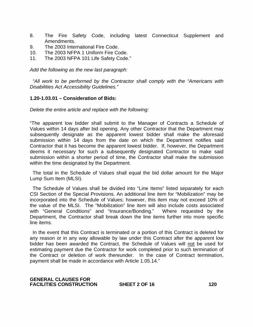
8. The Fire Safety Code, including latest Connecticut Supplement and Amendments.
9. The 2003 International Fire Code. 10. The 2003 NFPA 1 Uniform Fire Code. 11. The 2003 NFPA 101 Life Safety Code.” Add the following as the new last paragraph: “All work to be performed by the Contractor shall comply with the “Americans with Disabilities Act Accessibility Guidelines.” 1.20-1.03.01 – Consideration of Bids: Delete the entire article and replace with the following: “The apparent low bidder shall submit to the Manager of Contracts a Schedule of Values within 14 days after bid opening. Any other Contractor that the Department may subsequently designate as the apparent lowest bidder shall make the aforesaid submission within 14 days from the date on which the Department notifies said Contractor that it has become the apparent lowest bidder. If, however, the Department deems it necessary for such a subsequently designated Contractor to make said submission within a shorter period of time, the Contractor shall make the submission within the time designated by the Department.
The total in the Schedule of Values shall equal the bid dollar amount for the Major Lump Sum Item (MLSI).
The Schedule of Values shall be divided into “Line Items” listed separately for each CSI Section of the Special Provisions. An additional line item for “Mobilization” may be incorporated into the Schedule of Values; however, this item may not exceed 10% of the value of the MLSI. The “Mobilization” line item will also include costs associated with “General Conditions” and “Insurance/Bonding.” Where requested by the Department, the Contractor shall break down the line items further into more specific line items.
In the event that this Contract is terminated or a portion of this Contract is deleted for any reason or in any way allowable by law under this Contract after the apparent low bidder has been awarded the Contract, the Schedule of Values will not be used for estimating payment due the Contractor for work completed prior to such termination of the Contract or deletion of work thereunder. In the case of Contract termination, payment shall be made in accordance with Article 1.05.14.” GENERAL CLAUSES FOR FACILITIES CONSTRUCTION SHEET 2 OF 16 120

1.20-1.05.02--Shop Drawings, Product Data, Product Samples and Quality Assurance Submittals Delete the last sentence of the first paragraph and replace with the following: “All facsimiles or other electronic documents from the Contractor shall be followed by an official transmittal.” Delete the third paragraph and replace with the following: “The Contractor shall number each submittal consecutively: When resubmitting a “Revise and Resubmit” or “Rejected” submittal, the Contractor shall label the transmittal with the original submittal number followed by a letter to designate the additional submission. All submittals shall be numbered conforming to the following examples:” In column B of line 001, line 001a, and line 001b of the table in subsection 1, replace “07511” with “075110.” Add the following to the end of the first paragraph of subsection 2: “The Department reserves the right to return partial submittals unreviewed to the Contractor.” Revise the third paragraph of subsection 2 to read: “The Contractor shall allow at least 60 calendar days for review of any submittal requiring approval by FAA, FTA, any railroad, DEP, U.S. Coast Guard, Army Corps of Engineers, or any other outside agency.” Delete the third and fourth paragraphs of subsection 3 and replace with the following: “The Designer will not review submittals and the Engineer will not process payment estimates until the initial submittal schedule has been provided. Any delays in construction due to the Contractor's failure to provide a submittal schedule shall be the responsibility of the Contractor. The Contractor must update its submittal schedule at least once a month, and distribute and post each updated schedule in the manner described above. The Engineer reserves the right not to process payment estimates without a recently updated submittal schedule on file.” Replace the first sentence of the first paragraph of subsection 4 with the following: GENERAL CLAUSES FOR FACILITIES CONSTRUCTION SHEET 3 OF 16 120

“Shop Drawings consist of fabrication and installation drawings, roughing-in and setting drawings, schedules, patterns, templates and similar drawings, and wiring diagrams showing field-installed wiring, including power, signal, and control wiring.” Replace the second paragraph of subsection 4 with the following: “Shop drawings shall include the following information: Contract number, Project description, number and title of the drawing, date of drawing, revision number, name of Contractor and subcontractor submitting drawings, dimensions, identification of products, shopwork manufacturing instructions, design calculations, statement of compliance with Contractual standards, notation of dimensions established by field measurement, relationship to adjoining construction clearly indicated, seal and signature of a professional engineer if specified, and any other information required by individual Contract provisions.” Replace the first sentence of the first paragraph of subsection 5 with the following: “Product data consist of printed information such as manufacturer’s product specifications, manufacturer’s installation instructions, manufacturer’s catalog cuts, standard color charts, wiring diagrams showing factory-installed wiring, printed performance curves, operational range diagrams, and mill reports.” Replace the first sentence of the first paragraph of subsection 7 with the following: “Quality assurance submittals consist of qualification data, design data, certifications, manufacturer’s instructions, manufacturer’s field reports, test reports, Material Safety Data Sheets (MSDSs), and other quality assurance information required by individual Contract provisions.” 1.20-1.05.04—Coordination of Special Provisions, Plans, Supplemental Specifications and Standard Specifications and Other Contract Requirements: Delete the first and second paragraphs and replace with the following: “Industry Standards: Each entity engaged in construction of the Contract shall be familiar with industry standards applicable to that entity's construction activities. If printed standards have been established by organizations referenced in Article 1.01.02 or in the Contract, the Contractor shall obtain copies of said standards directly from the publication source. Unless the Special Provisions include more stringent requirements, applicable construction industry standards have the same force and effect as if bound or copied directly into the Special Provisions to the extent referenced. Such standards are made a part of the Contract by reference.” GENERAL CLAUSES FOR FACILITIES CONSTRUCTION SHEET 4 OF 16 120

Add the following article: 1.20-1.05.08—Schedules and Reports: Daily Construction Reports: The Contractor shall assist the Engineer in the preparation of a daily construction report, by ensuring that each of the Contractor’s employees and subcontractors working on the Project site on a given day signs the Engineer’s sign-in sheet for that day; and by keeping and providing to the Engineer its own daily list of employees and subcontractors who worked on the Project site on that day. Add the following article: 1.20-1.05.23—Requests for Information (RFIs): The Contractor shall forward all RFIs to the Engineer in writing (facsimile or other electronic document) for review. The Engineer will forward the RFI to the Designer for review. Upon receipt of an RFI, the Designer will attempt to determine if additional information is required from the Contractor to respond to the RFI, and request said information from the Engineer. All other RFIs will be responded to within 10 calendar days of receipt by the Designer. 1.20-1.05.24--Project Meetings: Delete the third paragraph under subsection 1. Delete the second paragraph under subsection 2 and replace with the following: “The meeting participants shall review progress of other construction activities and preparations for the particular activity under consideration, including requirements of Contract documents, related requests for interpretations, related construction orders, purchases, deliveries, submittals, review of mockups, possible conflicts, compatibility problems, time schedules, weather limitations, manufacturer’s written recommendations, warranty requirements, compatibility of materials, acceptability of substrates, temporary facilities and controls, space and access limitations, regulations of authorities having jurisdiction, testing and inspecting requirements, installation procedures coordination with other work, required performance results, protection of adjacent work, and protection of construction and personnel.” Delete the second, third and fourth paragraph under subsection 3 and replace with the following: “The Contractor shall provide the Engineer with a detailed agenda for the proposed GENERAL CLAUSES FOR FACILITIES CONSTRUCTION SHEET 5 OF 16 120

meeting, specifying what topics will be covered. In addition to representatives of the Engineer, each subcontractor, supplier or other entity concerned with current progress or involved in planning, coordination or performance of future activities shall attend these meetings. All participants at the meeting shall be familiar with the Project and authorized to conclude matters relating to the Project. At each progress meeting, the participants shall (1) review items of significance that could affect progress; (2) discuss topics appropriate to the current status of the Project; (3) review progress since the last meeting; (4) determine whether each activity is on time, ahead of schedule, or behind schedule, in relation to the Contractor's Construction Schedule; (5) determine how to expedite any Project work that may be behind schedule; (6) discuss whether or not schedule revisions are required to ensure that current and subsequent activities will be completed within the Contract time; and (7) review the present and future needs of each entity represented at the meeting, including such items as interface requirements, time, sequences, deliveries, off-site fabrication problems, access, site utilization, temporary facilities and controls, hours of work, hazards and risks, housekeeping, quality and work standards, status of correction of deficient items, field observations, requests for interpretations, status of proposal requests, pending changes, status of construction orders, and documentation of information for payment requests. The Engineer will distribute copies of minutes of the meeting to the Designer and the Contractor. The Contractor shall distribute copies to parties who were or should have been at the meeting.” Delete article 1.20-1.05.25—Schedules and Reports in its entirety 1.20-1.06.08 - Warranties: Delete the eighth and ninth paragraph and replace with the following: “The Contractor shall: (a) Bind warranties in heavy-duty, commercial-quality, durable 3-ring vinyl-covered loose-leaf binders, thick enough to accommodate the contents, and sized to receive 8 1/2-inch x 11-inch paper (216-millimeter x 279-millimeter) paper. (b) Identify the binder’s contents on the binder’s front and spine with the typed or printed title “WARRANTIES,” the Project title or name, and the name of the Contractor. (c) Provide a heavy paper divider with a tab for each separate warranty. (d) Mark the tab to identify the related product or installation. (e) Provide a typed description of the product or installation, including the name of the product, and the name, address and telephone number of the Contractor or pertinent subcontractor. (f) Furnish to the Department a written warranty for all Project work accompanied by a cover letter with the following contents: [Addressed to:] GENERAL CLAUSES FOR FACILITIES CONSTRUCTION SHEET 6 OF 16 120

Commissioner of Transportation Department of Transportation P.O. Box 317546 Newington, Connecticut 06131-7546 Project Title and Number [We] hereby warrant all materials and workmanship for all work performed under this Contract for a period of one (1) year from [date of issuance of C.O.C.] against failures of workmanship and materials in accordance with the Contract. Furthermore, as a condition of this warranty, [we] agree to have in place all insurance coverage identified in the Contract for the performance of any warranty work. [Signature:] [Name of authorized signatory] [Title] (g) Submit to the Engineer, upon completion of installation of materials or assemblies that are required to have either a flame-rating or a fire-endurance hourly rating, a detailed letter certifying that the required rating has been attained. Upon determination by the Engineer that Project work covered by a warranty has failed, the Contractor shall replace or rebuild the work to an acceptable condition complying with Contract requirements. The Contractor is responsible for the cost of replacing or rebuilding defective construction or components and those which may have needed to be damaged or removed in order to cure the defective work including costs of material, equipment, labor, and material disposal, regardless of whether or not the State has benefited from use of the work through a portion of its anticipated useful service life. The Contractor shall respond to the Project Site when Project work covered by a warranty has failed within 3 calendar days, unless in the Engineer’s opinion said failure is deemed to be an emergency, in which case the Contractor shall respond to the Project Site as directed by the Engineer.” 1.20-1.08.03—Prosecution of Work: Under subsection ‘3. Cutting and Patching,’ delete the heading ‘B. Protection of Structural Elements’ and replace with the following: “B. Protection:” Move the existing first and second paragraphs to under the following subparagraph: “1. Structural Elements:” GENERAL CLAUSES FOR FACILITIES CONSTRUCTION SHEET 7 OF 16 120

Add the following after the first paragraph under B: “2. Operational Elements: The Contractor shall not cut and patch operating elements and related components in a manner that results in their reducing their capacity to perform as intended or that results in increased maintenance or decreased operational life or safety. 3. Miscellaneous Elements: The Contractor shall not cut and patch miscellaneous elements or related components in a manner that could change their load-carrying capacity, that results reducing their capacity to perform as intended, or that results in increased maintenance or decreased operational life or safety.” Add the following after subsection 3: “4. Selective Demolition: A. Definitions: Remove: The Contractor shall detach materials from existing construction and legally dispose or recycle them off-site, unless indicated to be removed and salvaged or removed and reinstalled. Except for materials indicated to be reused, salvaged, reinstalled, or otherwise indicated to remain Engineer's property, demolished materials shall become Contractor's property and shall be removed from the Project Site. Remove and Salvage: The Contractor shall detach materials from existing construction and deliver them to Engineer. The Engineer reserves the right to identify other materials for salvage during the course of demolition. Remove and Reinstall: The Contractor shall detach materials from existing construction, prepare them for reuse, and reinstall them where indicated. Existing to Remain: Existing materials of construction that are not to be removed and that are not otherwise indicated to be removed, removed and salvaged, or removed and reinstalled. B. Approval Process: The Contractor shall submit pre-demolition photographs to the Engineer prior to the commencement of Project work to show existing conditions of adjoining construction and site improvements, including finish surfaces, that might be misconstrued as damage caused by selective demolition operations. GENERAL CLAUSES FOR FACILITIES CONSTRUCTION SHEET 8 OF 16 120

Well in advance of performing any selective demolition on the Project, the Contractor shall submit to the Engineer a proposal describing the procedures that the Contractor intends to use for same. The Contractor shall include the following information, as applicable, in its proposal: (1) detailed sequence of selective demolition and removal work with starting and ending dates for each activity while ensuring that the Engineer's on-site operations are not disrupted; (2) interruption of utility services; (3) coordination for shutoff, capping, and continuation of utility services; (4) use of elevators and stairs; (5) locations of temporary partitions and means of egress; (6) coordination of Engineer's continuing occupancy of portions of existing building and of Engineer's partial occupancy of completed Project work; and (7) means of protection for items to remain and items in path of waste removal from building. The Contractor shall comply with (1) governing EPA notification regulations before beginning selective demolition; (2) hauling and disposal regulations of authorities having jurisdiction; (3) ANSI A10.6; and (4) NFPA 241. The Engineer will conduct a Pre-Demolition Meeting at the Project site in accordance with Article 1.20-1.05.24. Said meeting will review the methods and procedures related to selective demolition including, but not limited to, the following: (1) an inspection and discussion of the condition of construction to be selectively demolished; (2) a review of the structural load limitations of the existing structure; (3) a review and finalization of the selective demolition schedule and a verification of the availability of materials, demolition personnel, equipment, and facilities needed to make progress and avoid delays; (4) a review of requirements of Project work performed by other trades that rely on substrates exposed by selective demolition operations; and (5) a review of areas where existing construction is to remain and requires protection. C. Repair Materials: The Contractor shall comply with Article 1.20-1.08.03 subsection 3E for repair materials and shall comply with material and installation requirements specified in other Contract provisions. D. Examination: The Contractor shall (1) verify that utilities have been disconnected and capped; (2) survey existing conditions and correlate with requirements indicated to determine extent of selective demolition required; (3) inventory and record the condition of items to be removed and reinstalled and items to be removed and salvaged; (4) investigate and measure the nature and extent of unanticipated mechanical, electrical, or structural elements that conflict with intended function or design and submit a written report to GENERAL CLAUSES FOR FACILITIES CONSTRUCTION SHEET 9 OF 16 120

Engineer; and (5) perform surveys as the Project work progresses to detect hazards resulting from selective demolition activities. E. Utility Services: The Contractor shall (1) maintain existing utility services indicated to remain and protect them against damage during selective demolition operations; (2) not interrupt existing utilities serving occupied or operating facilities unless authorized in writing by the Engineer; (3) provide temporary services during interruptions to existing utilities, as acceptable to Engineer; (4) provide at least 3 calendar days notice to the Engineer if shutdown of service is required during changeover; and (5) locate, identify, disconnect, and seal or cap off indicated utilities serving areas to be selectively demolished. The Contractor shall arrange to shut off indicated utilities with utility companies. If utility services are required to be removed, relocated, or abandoned, before proceeding with selective demolition the Contractor shall provide temporary utilities that bypass area of selective demolition and that maintain continuity of service to other parts of building. The Contractor shall cut off pipe or conduit in walls or partitions to be removed and shall cap, valve, or plug and seal remaining portion of pipe or conduit after bypassing. The Contractor shall refer to other Contract provisions for shutting off, disconnecting, removing, and sealing or capping utilities. The Contractor shall not start selective demolition work until utility disconnecting and sealing have been completed and verified by the Engineer in writing. F. Preparation: The Contractor shall conduct selective demolition and debris-removal operations to ensure minimum interference with adjacent occupied and used facilities on the Project site. The Contractor shall not disrupt the Owner’s operations without the Engineer’s permission. The Contractor shall protect existing site improvements, appurtenances, and landscaping to remain. The Contractor shall provide temporary barricades and other protection required to prevent injury to people and damage to adjacent buildings and facilities to remain. The Contractor shall provide temporary weather protection, during interval between selective demolition of existing construction on exterior surfaces and new construction, to prevent water leakage and damage to structure and interior areas. The Contractor shall protect walls, ceilings, floors, and other existing finish work that are to remain or that are exposed during selective demolition operations. The Contractor shall cover and protect furniture, furnishings, and equipment that have not been removed. The Contractor shall provide temporary enclosures for protection of existing building GENERAL CLAUSES FOR

FACILITIES CONSTRUCTION SHEET 10 OF 16 120 and construction, in progress and completed, from exposure, foul weather, other construction operations, and similar activities. The Contractor shall provide temporary weathertight enclosure for building exterior. Where heating is needed and permanent enclosure is not complete, the Contractor shall provide insulated temporary enclosures and shall coordinate enclosure with ventilating and material drying or curing requirements to avoid dangerous conditions and effects. The Contractor shall erect and maintain dustproof partitions and temporary enclosures to limit dust and dirt migration and to separate areas from fumes and noise. The Contractor shall provide and maintain interior and exterior shoring, bracing, or structural support to preserve stability and prevent movement, settlement, or collapse of construction to remain, and to prevent unexpected or uncontrolled movement or collapse of construction being demolished. The Contractor shall strengthen or add new supports when required during progress of selective demolition. G. Pollution Controls: The Contractor shall comply with governing regulations pertaining to environmental protection. The Contractor shall not use water when it may create a hazardous or objectionable condition such as ice, flooding, or pollution. The Contractor shall remove and transport debris in a manner that will prevent spillage on adjacent surfaces and areas. The Contractor shall remove debris from elevated portions of building by chute, hoist, or other device that will convey debris to grade level in a controlled descent. The Contractor shall clean adjacent structures and improvements of dust, dirt, and debris caused by selective demolition operations. The Contractor shall return adjacent areas to condition existing before selective demolition operations began. H. Performance: The Contractor shall not use explosives for demolition purposes. The Contractor shall demolish and remove existing construction only to the extent required by new construction and as indicated. The Contractor shall (1) proceed with selective demolition systematically; (2) neatly cut openings and holes plumb, square, and true to dimensions required; (3) use cutting methods least likely to damage remaining or adjoining construction; (4) use hand tools or small power tools designed for sawing or grinding, not hammering and chopping, to minimize disturbance of adjacent surfaces; (5) temporarily cover openings to remain; (6) cut or drill from the GENERAL CLAUSES FOR

FACILITIES CONSTRUCTION SHEET 11 OF 16 120 exposed or finished side into concealed surfaces to avoid marring existing finished surfaces; (7) not use cutting torches until work area is cleared of flammable materials; (8) verify condition and contents of concealed spaces such as duct and pipe interiors before starting flame-cutting operations; (9) maintain fire watch and portable fire-suppression devices during flame-cutting operations; (10) maintain adequate ventilation when using cutting torches; (11) remove decayed, vermin-infested, or otherwise dangerous or unsuitable materials and promptly dispose of off-site; (12) remove structural framing members and lower to ground by method suitable to avoid free fall and to prevent ground impact or dust generation; (13) locate selective demolition equipment and remove debris and materials so as not to impose excessive loads on supporting walls, floors, or framing; and (14) dispose of demolished items and materials promptly. The Contractor shall comply with the Engineer's requirements for using and protecting walkways, building entries, and other building facilities during selective demolition operations. The Contractor shall demolish and remove foundations and other below grade structures completely unless otherwise indicated on the plans. The Contractor shall fill below grade areas and voids resulting from demolition of structures with granular fill materials. Prior to placement of fill materials, the Contractor shall ensure that the areas to be filled are free of standing water, frost, frozen material, trash, and debris. After fill placement and compaction, grade surface to meet adjacent contours and provide flow to surface drainage structures. Backfilling and grading related to demolition is included in the Major Lump Sum Item (MLSI) for the Project. There will be no separate payment for this backfilling and grading. The Contractor shall (1) demolish concrete in sections; (2) cut concrete at junctures with construction to remain to the depth shown on the Contract plans and at regular intervals using power-driven saw; and (3) remove concrete between saw cuts. The Contractor shall (1) demolish masonry in small sections; (2) cut masonry at junctures with construction to remain using power-driven saw; and (3) remove masonry between saw cuts. The Contractor shall (1) saw-cut perimeter of concrete slabs-on-grade to be demolished as shown on the Contract plans; and (2) break up and remove concrete slabs-on-grade. The Contractor shall (1) remove floor coverings and adhesive according to recommendations in RFCI-WP and its Addendum; and (2) remove residual adhesive and prepare substrate for new floor coverings by one of the methods recommended by RFCI. The Contractor shall (1) only remove existing roofing in one day to the extent that it can GENERAL CLAUSES FOR

FACILITIES CONSTRUCTION SHEET 12 OF 16 120 be covered by new roofing; and (2) refer to other Contract provisions for new roofing requirements. The Contractor shall remove air conditioning equipment without releasing refrigerants. I. Reuse of Building Elements: The Contractor shall not demolish building elements beyond what is indicated on the plans without the Engineer’s approval. J. Removed and Salvaged Materials: Unless otherwise directed by the Engineer, the Contractor shall (1) store materials in a secure area until delivery to the owner; (2) transport materials to the owner’s storage area off-site; and (3) protect materials from damage during transport and storage. K. Removed and Reinstalled Materials: Unless otherwise directed by the Engineer, the Contractor shall (1) clean and repair materials to functional condition adequate for intended reuse; (2) paint equipment to match the color of new equipment; (3) protect materials from damage during transport and storage; and (4) reinstall items in locations indicated complying with installation requirements for new materials and equipment and providing connections, supports, and miscellaneous materials necessary to make item functional for use indicated. L. Existing Materials to Remain: The Contractor shall protect construction indicated to remain against damage and soiling during selective demolition. The Contractor shall drain piping and cap or plug piping with the same or a compatible piping material for piping to be abandoned in place. The Contractor shall cap or plug ducts with the same or a compatible ductwork material for ducts to be abandoned in place. The Contractor shall cut and remove concealed conduits and wiring to be abandoned in place 2-inches (50-mm) below the surface of the adjacent construction, cap the conduit end, and patch the surface to match the existing finish. The Contractor shall cut existing conduits installed in concrete slabs to be abandoned in place flush with the top of the slab and fill conduit end with a minimum of 4-inches (100-mm) of concrete. M. Patching and Repairing: The Contractor shall comply with Article 1.20-1.08.03 subsection 3H for patching and GENERAL CLAUSES FOR

FACILITIES CONSTRUCTION SHEET 13 OF 16 120 repairing damage to adjacent construction caused by selective demolition operations. N. Disposal of Demolished Materials: The Contractor shall (1) not allow demolished materials to accumulate or be sold on the Project Site; (2) not burn demolished materials on the Project Site; and (3) promptly and legally dispose or recycle demolished materials off the Project Site.” 1.20-1.08.05--Personnel and Equipment: Replace “FM with “FMG” in subsection (a) Add the following article: “1.20-1.08.12--Semi-Final and Final Inspections: 1. Semi-Final Inspection: Before requesting the Semi-Final Inspection, the Contractor shall show 100% completion for all Project work claimed as complete. The Contractor shall submit final test/adjust/balance records including the final air and water balance report. For all incomplete Project work, the Contractor shall prepare its own “Punch List” of the incomplete items and reasons the work is not complete. The Contractor shall submit final test/adjust/balance records including the final air and water balance report. On receipt of a Contractor request for inspection, the Engineer will proceed with inspection or notify the Contractor of unfulfilled requirements. The Engineer will prepare a “Punch List” of unfilled, substandard, or incomplete items. During this inspection, the Contractor shall have all technicians necessary to demonstrate the complete operation of all systems on-site. Examples of such systems include, but are not limited to, the following: boiler, HVAC, fire alarm, and building automation. The Engineer will advise the Contractor of the construction that must be completed or corrected before the issuance of the C.O.C. Results of the completed inspection will form the basis of requirements for the Final Inspection. The Engineer reserves the right to issue the C.O.C. after the Semi-Final Inspection if there are no Building Code or Fire Code compliance issues or any major “Punch List” items. 2. Final Inspection: Before requesting Final Inspection for issuance of the C.O.C., the Contractor shall: (1) submit specific warranties, maintenance service agreements, final certifications and similar documents; (2) submit Record Drawings, Record Specifications, operations and maintenance manuals, final project photographs, property surveys, and similar final record information; (3) deliver spare parts; (4) make final changeover of permanent locks and deliver the keys to the Engineer; (5) complete start-up testing of systems; (6) train the owner's operation and maintenance personnel; (7) discontinue or change over and remove temporary facilities from the Project Site, along with construction tools, mock-ups, and similar elements; (8) complete final GENERAL CLAUSES FOR

FACILITIES CONSTRUCTION SHEET 14 OF 16 120 cleaning requirements, including touch-up painting; (9) touch-up and otherwise repair and restore marred exposed finishes to eliminate visual defects; (10) submit a certified copy of the Engineer's “Punch List” of items to be completed or corrected, stating that each item has been completed or otherwise resolved for acceptance, and the list has been endorsed and dated by the Engineer; (11) submit final meter readings for utilities, a measured record of stored fuel, and similar data as of the date of Final Inspection, or when the Engineer took possession of and responsibility for corresponding elements of the Project work; and (12) install permanent electrical service. The Contractor shall install permanent electrical service prior to Semi-Final Inspection if requested by the Engineer, or if necessary for the Engineer or Contractor to perform testing of building and other related systems and equipment to certify acceptance and completion of Project work. The Contractor shall submit all outstanding items or unacceptable submissions from the Semi-Final Inspection, or other outstanding items required for submittal, prior to the Final Inspection. On receipt of a Contractor request for inspection, the Engineer will proceed with inspection and notify the Contractor of unfulfilled requirements.” 1.20 – 1.08.13 – Termination of the Contractor’s Responsibility: Add subsection 3 as follows: “3. Insurance Coverage: The Contractor shall have in place all insurance coverage identified in Article 1.03.07 for the performance of any warranty work.” 1.20-1.08.14--Acceptance of Project: Add the following to subsection 2 under the heading “Equipment and Systems Maintenance Manual:” “(j) Copies of maintenance agreements with service agent name and telephone number.” Add the following paragraph in subsection 3 after the second paragraph: “The Contractor shall provide a syllabus prior to the training to ensure that the appropriate owner’s operation and maintenance personnel are in attendance.” Delete the last paragraph and replace with the following: The Contractor shall submit to the Engineer for approval, a qualified commercial videographer to videotape the training sessions. The videographer shall be a firm or an individual of established reputation that has been regularly engaged as a professional videographer for not less than 3 years. GENERAL CLAUSES FOR

FACILITIES CONSTRUCTION SHEET 15 OF 16 120 The Contractor shall video record each training session and provide said video in DVD format to the Engineer for the owner’s future use.” Add the following section: “1.20-1.09.06—Partial Payments: With each payment request under the MLSI, the Contractor shall submit AIA Form G702 (Application and Certificate of Payment) and Form G703 (Continuation Sheet). The Contractor is not required to obtain the Architect’s signature on Form G702. Once approved by the Engineer, the Forms G702 and G703 become the basis of payment under the MLSI.” Add the following section: “1.20-9.75.04—Method of Measurement: Mobilization as defined in Article 1.20-1.03.01 will be paid in the manner described hereinafter; however, the determination of the total contract price earned shall not include the amount of mobilization earned during the period covered by the current monthly estimate – but shall include amounts previously earned and certified for payment: 1. When the first payment estimate is made, 25 percent of the “Mobilization” line item will be certified for payment. 2. When the Baseline Schedule, as specified under Section 1.05.08, is accepted, 50 percent of the “Mobilization” line item, minus any previous payments, will be certified for payment. 3. When 10 percent of the total original contract price is earned and the Baseline Schedule, as specified under Section 1.05.08, is accepted, 75 percent of the “Mobilization” line item, minus any previous payments, will be certified for payment. 4. When 30 percent of the total original contract price is earned and the Baseline Schedule, as specified under Section 1.05.08, is accepted, 100 percent of the “Mobilization” line item, minus any previous payments, will be certified for payment.” GENERAL CLAUSES FOR

FACILITIES CONSTRUCTION SHEET 16 OF 16 120

January 2010
CONNECTICUT SUPPLEMENTAL SPECIFICATION
SECTION 2.02 ROADWAY EXCAVATION, FORMATION OF
EMBANKMENT AND DISPOSAL OF SURPLUS MATERIAL
2.02.04 – Method of Measurement: Second to last Paragraph - replace the last sentence with the following: “Bituminous parking areas are considered as bituminous concrete pavement.”
ROADWAY EXCAVATION, FORMATION OF EMBANKMENT AND DISPOSAL OF SURPLUS MATERIAL SHEET 1 OF 1 202

January 2010
CONNECTICUT SUPPLEMENTAL SPECIFICATION
SECTION 2.05 TRENCH EXCAVATION
Delete the entire Section and replace with the following: 2.05.01--Description: Paragraph 2 - Delete the only sentence and replace with the following: 2) The removal of stormwater drainage structures, stormwater pipes and appurtenances beyond the limits of the roadway and structure excavation. Sub article 2 - Rock in Trench - Delete the only sentence and replace with the following: (2) Rock, insofar as it applies to trench excavation, shall be defined as rock in definite ledge formation, boulders, or portions of boulders, cement masonry structures, concrete structures, reinforced concrete pipe, Portland cement concrete pavement or base, of 1/2 cubic yard (0.5 cubic meters) or more in volume, removed as indicated or directed from within the payment lines for trench excavation. 2.05.05 -Basis of Payment Paragraph 13 - Delete the entire sentence “There will be no direct payment for the plugging of existing pipes....." and replace with the following: There will be no direct Payment for the plugging of existing pipes, removal and disposal of metal or plastic pipes or for the breaking up of floors in drainage structures being abandoned. The cost shall be included in the contract unit prices of the drainage and excavation items.
TRENCH EXCAVATION SHEET 1 OF 1 205

July 2005
CONNECTICUT SUPPLEMENTAL SPECIFICATION
SECTION 3.04 PROCESSED AGGREGATE BASE
Delete the entire Section and replace with the following: 3.04.01--Description: The base shall consist of a foundation constructed on the prepared subbase or subgrade in accordance with these specifications and in conformity with the lines, grades, compacted thickness and typical cross-section as shown on the plans. 3.04.02--Materials: All materials for this work shall conform to the requirements of Article M.05.01. 3.04.03--Construction Methods: Only one type of coarse aggregate shall be used on a project unless otherwise permitted by the Engineer.
Prior to placing the processed aggregate base, the prepared subbase or subgrade shall be maintained true to line and grade, for a minimum distance of 200 feet (60 meters) in advance of the work. None of the aggregate courses shall be placed more than 500 feet (150 meters) ahead of the compaction and binding operation on that particular course.
The processed aggregate base shall be spread uniformly by a method approved by the Engineer. The thickness of each course shall not be more than 4 inches (100 millimeters) after compaction, unless otherwise ordered.
After the aggregate is spread, it shall be thoroughly compacted and bound by use of equipment specifically manufactured for that purpose. Rollers shall deliver a ground pressure of not less than 300 pounds per lineal inch (52.5 newtons/millimeter) of contact width and shall have a weight (mass) not less than 10 tons (9100 kilograms). Vibratory units shall have a static weight (mass) of not less than 4 tons (3650 kilograms). Water may be used during the compaction and binding operation and shall be applied from an approved watering device. The compacting and binding operation shall begin at the outside edges, overlapping the shoulders for a distance of not less than 6 inches (150 millimeters) and progress towards the middle, parallel with the centerline of the pavement. The work shall cover the entire surface of the course with uniform overlapping of each preceding track or pass. Areas of super-elevation and special cross slope shall be compacted by beginning at the lowest edge and proceeding towards the higher edge, unless otherwise directed by the Engineer. The compacting and binding operation shall be continued until the voids in the aggregates have been reduced to provide a firm and uniform surface satisfactory to the Engineer. The amount of compactive effort shall in no case shall be less than four (4) complete passes of the compacting and binding operations. All aggregate shall be completely compacted and bound at the end of each day’s work or when traffic is to be permitted to operate on the
PROCESSED AGGREGATE BASE SHEET 1 OF 2 304

road. The dry density of each layer of processed aggregate base after compaction shall not be less than 95 percent of the dry density for that material when tested in accordance with AASHTO T180, Method D.
Should the subbase or subgrade material become churned up or mixed with the
processed aggregate base at any time, the Contractor shall, without additional compensation remove the mixture. The Contractor shall add new subbase material, if required, and reshape and recompact the subbase in accordance with the requirements of Article 2.12.03. New aggregate material shall be added, compacted and bound, as hereinbefore specified, to match the surrounding surface.
Any surface irregularities which develop during, or after work on each course, shall be corrected by loosening material already in place and removing or adding aggregate as required. The entire area, including the surrounding surface, shall be re-compacted and rebound until it is brought to a firm and uniform surface satisfactory to the Engineer.
3.04.04--Method of Measurement: Processed Aggregate Base will be measured horizontally in place after final grading and compaction. Materials placed beyond the horizontal limits indicated on the plans will not be measured for payment.
The total thickness shall be as indicated on the plans, or as ordered by the Engineer and within a tolerance of minus three-fourths of an inch (-3/4”) to plus one-half inch (+ 1/2”) (-19 millimeters to +13 millimeters).
Measurements to determine the thickness will be taken by the Engineer at
intervals of 500 feet (150 meters) or less, along lanes, and shall be considered representative of the lane. For the purpose of these measurements, a shoulder will be considered a lane.
If a thickness measurement is taken and found deficient, the Engineer will take
such additional measurements as he considers necessary to determine the longitudinal limits of the deficiency. Areas not within allowable tolerances shall be corrected, as ordered by the Engineer, without additional compensation to the Contractor. 3.04.05--Basis of Payment: This work will be paid for at the contract unit price per cubic yard for “Processed Aggregate Base”, complete in place, which price shall include all materials, tools, equipment and work incidental thereto. Pay Item Pay Unit Processed Aggregate Base c.y. (cu. m)
PROCESSED AGGREGATE BASE SHEET 2 OF 2 304

July 2006
CONNECTICUT SUPPLEMENTAL SPECIFICATION
SECTION 4.01 CONCRETE PAVEMENT
Article 4.01.03-A. Composition: Add the following new paragraph before the last paragraph: “The temperature of the concrete at the time of placement shall not be less than 60˚ F (15.5˚ C) or greater than 90˚ F (32˚ C). For pumped concrete, the temperature shall be determined at the placement end of the pump line. The temperature of the concrete shall be determined in accordance with ASTM C1064.”
CONCRETE PAVEMENT SHEET 1 OF 1 401

January 2009
CONNECTICUT SUPPLEMENTAL SPECIFICATION
SECTION 5.14 PRESTRESSED CONCRETE MEMBERS
Article 5.14.03 – Construction Methods: Change the last sentence of 5.14.03-16 – Methods and Equipment to read: “The results of this investigation, including computations, shall be submitted to the Engineer.”
PRESTRESSED CONCRETE MEMBERS SHEET 1 OF 1 514

July 2006
CONNECTICUT SUPPLEMENTAL SPECIFICATION
SECTION 6.01 CONCRETE FOR STRUCTURES
Article 6.01.03-8. Placing Concrete: Add the following new paragraph after the first paragraph: “The temperature of the concrete at the time of placement shall not be less than 60˚ F (15.5˚ C) or greater than 90˚ F (32˚ C). For pumped concrete, the temperature shall be determined at the placement end of the pump line. The temperature of the concrete shall be determined in accordance with ASTM C1064.”
CONCRETE FOR STRUCTURES SHEET 1 OF 1 601

July 2006
CONNECTICUT SUPPLEMENTAL SPECIFICATION
SECTION 6.03 STRUCTURAL STEEL
6.03.03 – Construction Methods: In the 5th paragraph of subsection 37 Shop Painting, replace “MS MIL” with “MILSPEC.”
STRUCTURAL STEEL SHEET 1 OF 1 603

July 2005
CONNECTICUT SUPPLEMENTAL SPECIFICATION
SECTION 6.12 CONCRETE CYLINDER CURING BOX
Delete the entire section and replace with it the following: 6.12.01 –Description: This item shall consist of furnishing a box for curing concrete test cylinders. The box shall be commercially available and manufactured specifically for curing concrete test cylinders. The box will remain the property of the Contractor at the conclusion of the project. The box shall be delivered to a location on the project as directed by the Engineer. 6.12.02 – Materials: A catalog cut listing detailed specifications of the box and operating instructions from the manufacturer must be submitted to the Engineer. The box and its components shall be constructed of non-corroding materials and shall be capable of storing a minimum of 18 test cylinders, 6” X 12” (152 mm X 305 mm) stored vertically with the lid closed. The lid must be watertight when closed and hinged in the back with security latches on the front that can be padlocked. The box must be capable of holding water to a maximum level of one inch above test cylinders placed in the box vertically. A drain hole must be provided in a wall of the box to allow manual drainage of the water that exceeds this level. A drain hole must also be provided at the bottom of the box so that it can be manually emptied. The temperature of the water must be controlled by heating and cooling device capable of maintaining the temperature of the water within a range of 60 to 80º F, +/- 2 ºF (15.5 to 26.7 ºC, +/- 1 ºC) within an outside ambient air temperature range of -10 to 120 º F (-23.3 to 49 ºC). The heating and cooling device must be positioned to allow free circulation of air and water around the cylinders and be rated at 120 volts and 15 amps. A rack must be provided within the box to support the cylinders above the pool of temperature controlled water. The device must be thermostatically controlled with a digital readout that is capable of displaying the high/low water temperature within the box since the last reading was taken. 6.12.03 - Construction Methods: The Contractor shall maintain the curing box in working order and shall provide all necessary electrical service and water so that the curing box can be used properly during the entire course of the project. Any curing box that is not operating properly, as determined by the Engineer, shall be replaced within 24 hours by the Contractor at no expense to the State. The Engineer reserves the right to prohibit placement of fresh concrete on the project until a curing box acceptable to the Engineer is operational on the project site. 6.12.04 - Method of Measurement: The furnishing of the concrete test cylinder curing box will be measured for payment by the number of boxes delivered by the Contractor and accepted by the Engineer. CONCRETE CYLINDER CURING BOX SHEET 1 OF 2 612

6.12.05 – Basis of Payment: This item will be paid for at the contract unit price each for “Concrete Cylinder Curing Box” ordered and accepted on the project, which price shall include all submittals, material, tools, equipment, and labor incidental thereto. The price shall also include all maintenance and operating costs related to the curing box for the duration of the project. CONCRETE CYLINDER CURING BOX SHEET 2 OF 2 612

July 2008
CONNECTICUT SUPPLEMENTAL SPECIFICATION
SECTION 6.51 CULVERTS
6.51.02 – Materials: In the 2nd paragraph replace “Gravel fill” with “Granular fill”. 6.51.03 – Construction Methods: In the 8th paragraph replace “gravel fill” with “granular fill”. Delete the 13th paragraph, “Bituminous fiber and … as the pipe.” 6.51.04 – Methods of Measurement: In the 7th paragraph replace “Gravel Fill” with “Granular Fill”. 6.51.05 – Basis of Payment: In the 8th paragraph replace “Gravel Fill” with “Granular Fill”.
CULVERTS SHEET 1 OF 1 651

July 2005
CONNECTICUT SUPPLEMENTAL SPECIFICATION
SECTION 7.02 PILES
Article 7.02.05- Basis of Payment: In the first sentence of the first paragraph of Section “2. Timber Piles” change “Furnishing Timber Piles Foot (Meter Length) and Furnishing Treated Timber Piles Foot (Meter Length)” to “Furnishing (Type) Timber Piles (Foot (Meter) Length)”. In the first sentence of the last paragraph of Section “2. Timber Piles” change “Driving Timber Piles” and “Driving Treated Timber Piles “ to “Driving (Type) Timber Piles”. Under Pay Items: Delete:
Pay Item Pay Unit Furnishing (Type) Piles (Lengths) lb. (kg) Add:
Pay Item Pay Unit Furnishing (Type) Timber Piles (Length) ea. (ea) Furnishing Steel Piles lb. (kg) Furnishing (Type) Prestressed Concrete Piles l.f. (m) Cast-in-Place Concrete Piles l.f. (m)
PILES SHEET 1 OF 1 702

January 2009
CONNECTICUT SUPPLEMENTAL SPECIFICATION
SECTION 8.22 TEMPORARY PRECAST CONCRETE BARRIER CURB
Article 8.22.04 – Method of Measurement: Add the following sentence to the end of the second paragraph: “Relocation of Temporary Precast Concrete Barrier Curb for access to the work area or for the convenience of the Contractor shall be considered incidental to Maintenance and Protection of Traffic and will not be measured for payment.”
TEMPORARY PRECAST CONCRETE BARRIER CURB SHEET 1 OF 1 822

January 2005
CONNECTICUT SUPPLEMENTAL SPECIFICATION
SECTION 9.10 METAL BEAM RAIL
Article 9.10.04 – Method of Measurement Subarticle 1 – Metal Beam Rail (Type)
Delete the only sentence and replace with the following:
The length of metal beam rail measured for payment will be the number of linear feet (meters) of accepted rail of the type or designation installed, including radius rail other than Curved Guide Rail Treatment, measured along the top of rail between centers of end posts in each continuous section.
METAL BEAM RAIL SHEET 1 OF 1 910

July 2006
CONNECTICUT SUPPLEMENTAL SPECIFICATION
SECTION 9.18 THREE CABLE GUIDE RAILING
(I-BEAM POSTS) AND ANCHORAGES 9.18.03 – Construction Methods: In the 10th paragraph, replace “MIL” with “MILSPEC.”
THREE CABLE GUIDE RAILING (I-BEAM POSTS) AND ANCHORAGES SHEET 1 OF 1 918

January 2010
CONNECTICUT SUPPLEMENTAL SPECIFICATION
SECTION 9.22 BITUMINOUS CONCRETE SIDEWALK BITUMINOUS CONCRETE DRIVEWAY
9.22.03 – Construction Methods: Replace the first paragraph with the following:
“1. Excavation: Excavation, including saw cutting, removal of any existing sidewalk, or driveway, shall be made to the required depth below the finished grade, as shown on the plans or as directed by the Engineer. All soft and yielding material shall be removed and replaced with suitable material.”
9.22.05 – Basis of Payment: Replace the only paragraph with the following: “This work will be paid for at the contract unit price per square yard (square meter) for "Bituminous Concrete Sidewalk" or "Bituminous Concrete Driveway," as the case may be, complete in place, which price shall include all saw cutting, excavation as specified above, backfill, disposal of surplus material, gravel or reclaimed miscellaneous aggregate base, and all equipment, tools, labor and materials incidental thereto.”
BITUMINOUS CONCRETE SIDEWALK BITUMINOUS CONCRETE DRIVEWAY SHEET 1 OF 1 922

January 2010
CONNECTICUT SUPPLEMENTAL SPECIFICATION
SECTION 9.44 TOPSOIL
Add the following paragraph to the beginning of article 9.44.03 – Construction Methods: “The Contractor shall notify the Engineer of the location of the topsoil at least 15 calendar days prior to delivery. The topsoil and its source shall be inspected and approved by the Engineer before the material is delivered to the project. Any material delivered to the project, which does not meet specifications or which has become mixed with undue amounts of subsoil during any operation at the source or during placing and spreading, will be rejected and shall be replaced by the Contractor with acceptable material.”
TOPSOIL SHEET 1 OF 1 944

January 2010
CONNECTICUT SUPPLEMENTAL SPECIFICATION
SECTION 9.49 FURNISHING, PLANTING and MULCHING
TREES, SHRUBS, VINES and GROUND COVER PLANTS 9.49.03 – Construction Methods: Replace subsection 5. Pits with the following:
“5. Pits: The pit diameters shall be twice the diameter of the root-spread or container diameters, and shall be 2- inches (50 millimeters) less than the height of the rootball measured from the bottom of the ball to the root collar. (i. e. A 12-inch (300 millimeters) measurement between the root collar and the bottom of the rootball will require a 10-inch (250 millimeters) deep pit). Any excavation in excess of that required shall be replaced with planting soil and compacted to the satisfaction of the Engineer.”
Add the following sentence to subsection 6. Obstructions Below Ground: “If removal of obstructions results in a deeper hole than needed for planting, backfill material shall be added and compacted to the satisfaction of the Engineer.” Replace subsection 7. Preparation of Backfill with the following:
“7. Backfill: Backfill shall conform to M.13.01-1 Planting Soil.” Replace subsection 8. Setting Plants with the following:
“8. Setting Plants: All plants shall be plumb and at a level that is 2-inches (50 millimeters) higher than the surrounding ground. Backfill material for all plants shall be thoroughly and properly settled by firming or tamping. Thorough watering shall accompany backfilling. Saucers capable of holding water shall be formed at individual plants (exclusive of plant beds) by placing ridges of planting soil around each, or as directed by the Engineer. a. Balled and Burlapped plants: Plants shall be handled in such manner so that the soil will not be loosened from the roots inside of the ball. Carefully place the plant into the prepared pits and backfill with planting soil to one - half the depth of the pit, thoroughly tamp to the satisfaction of the Engineer around the ball. Fill the remaining area of the pit with water. Once water has completely drained, loosen the burlap and peel down the top one third. If wire baskets are used, cut and bend down the top third of the basket. Roots that have been wrapped around the ball within the burlap shall be straightened and the remainder of the pit filled with planting soil tamped to ensure that no air pockets remain.
FURNISHING, PLANTING and MULCHING TREES, SHRUBS, VINES and GROUND COVER PLANTS SHEET 1 OF 3 949

b. Container Grown Plants: Carefully remove the plant from the container over the prepared pits. Gently loosen the soil and straighten all roots as naturally as possible. Place into the bottom of the pit. Backfill with planting soil to one - half the depth of the pit. Thoroughly tamp to the satisfaction of the Engineer. Fill remaining area of the pit with water. Once water has completely drained fill the remainder of the pit with planting soil tamped to ensure that no air pockets remain.
c. Bare-roots Plants: Carefully spread roots as naturally as possible and place into the bottom of the pit. All broken or frayed roots shall be cleanly cut off. Backfill with planting soil to one - half the depth of the pit. Thoroughly tamp to the satisfaction of the Engineer. Fill remaining area of the pit with water. Once water has completely drained fill the remainder of the pit with planting soil tamped to ensure that no air pockets remain.”
Replace subsection 10. Watering with the following:
“10. Watering: All plants shall be watered upon setting and as many times thereafter as conditions warrant. The following is a guide for minimum requirements: Trees: 2 ½” Caliper and less – Fifteen (15) gallons each. 3” to 5” Caliper – Twenty (20) gallon each. 5 ½” Caliper and above – Twenty-five (25) gallon each. Shrubs: 24” and less – Six (6) gallon each. More than 24”- Ten (10) gallon each. Vines, Perennials, and Ornamental Grasses – Three (3) gallons each. Groundcovers and Bulbs – Two (2) gallons per square foot. Water shall be applied at a controlled rate and in such a manner to ensure that the water reaches the root zone (saucer) of the plant or plant bed and does not run off to adjacent areas. Watering shall be applied in a manner that does not dislodge plants, erode soil or mulch, or cause damage to saucer. The Contractor may use slow-release, drip irrigation bags for watering in accordance with manufacturer’s instructions. The use of these portable/temporary irrigation bags will require the approval of the Engineer.
Overhead hydro-seeder spray nozzles shall not be used as watering devices.”
Replace subsection 17. Establishment Period with the following:
“17. One-Year Establishment Period: All plant material shall be subject to a One-Year Establishment Period. During this time, the Contractor shall use currently accepted horticultural practices to keep all plant material installed in a healthy, vigorous growing condition at the date of final acceptance. The date of final
FURNISHING, PLANTING and MULCHING TREES, SHRUBS, VINES and GROUND COVER PLANTS SHEET 2 OF 3 949

acceptance shall be one full calendar year following the satisfactory completion of the planting activities as confirmed by the Engineer. An inspection will be held one year from the date of installation with the Contractor, Engineer, and Landscape Designer to determine the acceptability of the plant establishment. An inventory of losses and rejected materials will be made and corrective and necessary clean up measures will be determined at the plant inspection.”
FURNISHING, PLANTING and MULCHING TREES, SHRUBS, VINES and GROUND COVER PLANTS SHEET 3 OF 3 949

January 2009
CONNECTICUT SUPPLEMENTAL SPECIFICATION
SECTION 9.75 MOBILIZATION
9.75.04 – Method of Measurement: Delete the entire section and replace with the following: This work will be measured for payment in the manner described hereinafter; however, the determination of the total contract price earned shall not include the amount of mobilization earned during the period covered by the current monthly estimate- but shall include amounts previously earned and certified for payment: 1. When the first payment estimate is made, 25 percent of the lump sum bid price for this item or 2.5 percent of the total original contract price, whichever is less, shall be certified for payment. 2. When the Baseline Schedule, as specified under Section 1.05.08, is accepted, 50 percent of the lump sum bid price or 5 percent of the total original contract price, whichever is less, minus any previous payments, will be certified for payment. 3. When 10 percent of the total original contract price is earned and the Baseline Schedule, as specified under Section 1.05.08, is accepted, 75 percent of the lump sum price of this item or 7.5 percent of the total original contract price, whichever is less, minus any previous payments, will be certified for payment. 4. When 30 percent of the total original contract price is earned and the Baseline Schedule, as specified under Section 1.05.08, is accepted, 100 percent of the lump sum price of this item or 10 percent of the total original contract price, whichever is less, minus any previous payments, will be certified for payment. Upon completion of all work on the project, payment of any amount bid for mobilization in excess of 10 percent of the original contract amount will be paid. Nothing herein shall be construed to limit or preclude partial payments otherwise provided for by the contract.
MOBILIZATION SHEET 1 OF 1 975

January 2005
CONNECTICUT SUPPLEMENTAL SPECIFICATION
SECTION 10.10 CONCRETE HANDHOLE
Article 10.10.05 – Basis of Payment Remove the words “ground wire”.
At the end of the paragraph add the following sentence:
The ground wire (bonding wire) is included in the Contract unit price under Section 10.08 – Electrical Conduit. Add the word “Cover” to the end of the pay item “Cast Iron Handhole”
CONCRETE HANDHOLE SHEET 1 OF 1 1010

July 2006
CONNECTICUT SUPPLEMENTAL SPECIFICATION
SECTION 11.13 CONTROL CABLE
11.13.03 – Construction Methods: In the 1st paragraph of subsection 2 replace “MIL” with “MILSPEC.”
CONTROL CABLE SHEET 1 OF 1 1113

January 2007
CONNECTICUT SUPPLEMENTAL SPECIFICATION
SECTION 12.10 EPOXY RESIN PAVEMENT MARKINGS, SYMBOLS AND LEGENDS
12.10.03 (2) – Procedures:
Insert the following after the sixth paragraph:
The epoxy shall be uniformly applied to the surface to be marked to ensure a wet film thickness of the applied epoxy, without glass beads, of 20 mils +/- 1 mil (500 um +/- 25 um).
EPOXY RESIN PAVEMENT MARKINGS, SYMBOLS AND LEGENDS SHEET 1 OF 1 1210

January 2010
CONNECTICUT SUPPLEMENTAL SPECIFICATION
SECTION M.06 METALS
Article M.06.01 – Reinforcing Steel: Subarticle 1. Bar Reinforcement: Delete the third paragraph and replace it with:
“Epoxy coated bar reinforcement shall conform to the requirements of ASTM A 615/A 615M, Grade 60 (420) and shall be epoxy coated to the requirements of ASTM A 775/A 775M. All field repairs of the epoxy coating shall conform to the requirements of ASTM D 3963/D 3963M.” METALS SHEET 1 OF 1 M.06

January 2010
CONNECTICUT SUPPLEMENTAL SPECIFICATION
SECTION M.13 ROADSIDE DEVELOPMENT
Delete article M.13.01 – Topsoil and replace it with the following: “Article M.13.01 – Topsoil: The term topsoil used herein shall mean a soil meeting the soil textural classes established by the USDA Classification System based upon the proportion of sand, silt, and clay size particles after passing a No. 10 (2 millimeter) sieve and subjected to a particle size analysis. The topsoil shall contain 5% to 20% organic matter as determined by loss on ignition of oven-dried samples dried at 221° F (105° C). The pH range of the topsoil shall be 5.5 to 7.0. The following textural classes shall be acceptable:
Loamy sand, including coarse, loamy fine, and loamy very fine sand, with not more than 80% sand Sandy loam, including coarse, fine and very fine sandy loam Loam Clay loam, with not more than 30% clay Silt loam, with not more than 60% silt Sandy clay loam, with not more than 30% clay All textural classes of topsoil with greater than 80% sand content will be rejected.
The topsoil furnished by the Contractor shall be a natural, workable soil that is screened and free of subsoil, refuse, stumps, roots, brush, weeds, rocks and stones over 1 1/4 inches (30 millimeters) in diameter, and any other foreign matter that would be detrimental to the proper development of plant growth. The Contractor shall notify the Engineer of the location of the topsoil at least 15 calendar days prior to delivery. The topsoil and its source shall be inspected and approved by the Engineer before the material is delivered to the project. Any material delivered to the project, which does not meet specifications or which has become mixed with undue amounts of subsoil during any operation at the source or during placing and spreading, will be rejected and shall be replaced by the Contractor with acceptable material. When topsoil is not furnished by the Contractor, it shall be material that is stripped in accordance with Section 2.02 or is furnished by the State, and will be tested as determined by the Engineer. 1. Planting Soil: Soil Material to be used for plant backfill shall be one of the following textural classes:
Loamy sand, with not more than 80% sand Sandy loam Loam Clay loam, with not more than 30% clay Silt loam, with not more than 60% silt Sandy clay loam, with not more than 30% clay
ROADSIDE DEVELOPMENT SHEET 1 OF 2 M.13

Planting soil shall be premixed, consisting of approximately 50 % topsoil, 25 % compost or peat, and 25% native soil. Planting soil shall be loose, friable, and free from refuse, stumps, roots, brush, weeds, rocks and stones 2 inches (50 millimeters) in diameter. In addition, the material shall be free from any material that will prevent proper development and plant growth.
(a) For ericaceous plants and broad-leaved evergreens requiring an acid soil, planting soil shall have a true pH of 4.5 to 5.5. If it has not, it shall be amended by the Contractor at his own expense to the proper pH range by mixing with sulphur.
(b) Planting soil for general planting of nonacid-loving plants shall have a true pH value of 5.6 to 6.5. If it has not, it shall be amended by the Contractor at his own expense to the proper pH range by mixing with dolomitic limestone.
The amount of either sulphur or limestone required to adjust the planting soil to the proper pH range (above) shall be determined by the Engineer based on agronomic tests. The limestone shall conform to the requirements of Article M.13.02. The sulphur shall be commercial or flour sulphur, unadulterated, and shall be delivered in containers with the name of the manufacturer, material, analysis, and net weight (mass) appearing on each container. The Engineer reserves the right to draw such samples and to perform such tests as he deems necessary to ensure that these specifications are met.”
ROADSIDE DEVELOPMENT SHEET 2 OF 2 M.13

July 2008
CONNECTICUT SUPPLEMENTAL SPECIFICATION
SECTION M.16 TRAFFIC CONTROL SIGNALS
Article M.16.04 – Poles: Subarticle 1. Steel Poles: (i) Wire Entrance Fitting:
In the second sentence, delete “required to accept the cables”.
Article M.16.06 – Traffic Signals: In the 1st paragraph of subsection 9 replace “MIL” with “MILSPEC”. Under the paragraph entitled Third Coat, replace the first two sentence with the following:
“ Dark Green Enamel: Shall be Dark Green exterior baked enamel and shall comply with FS A-A 2962. The color shall be No. 14056, FS No. 595.”
and in the third sentence replace “MIL” with “MILSPEC.”
Article M.16.08 – Pedestrian Push Button Subarticle – Painting
Delete the entire “Third Coat” paragraph and replace with the following:
Third Coat: Dark Green Enamel, shall be DARK GREEN exterior-baking enamel and shall comply with Federal Specifications A-A 2962. The color shall be No. 14056, Federal Standard No. 595.
TRAFFIC CONTROL SIGNALS SHEET 1 OF 1 M.16

July 2006
CONNECTICUT SUPPLEMENTAL SPECIFICATION
SECTION M.17 ELASTOMERIC MATERIALS
M.17.01 – Elastomeric Bearing Pads: In the 2nd paragraph of subsection 4(b), replace “MS MIL” with “MILSPEC.”
ELASTOMERIC MATERIALS SHEET 1 OF 1 M.17

July 2006
CONNECTICUT SUPPLEMENTAL SPECIFICATION
SECTION M.18 SIGNING
M.18.10 – Demountable Copy: In the chart under subsection 3H, replace “MS MIL” with “MILSPEC.”
SIGNING SHEET 1 OF 1 M.18


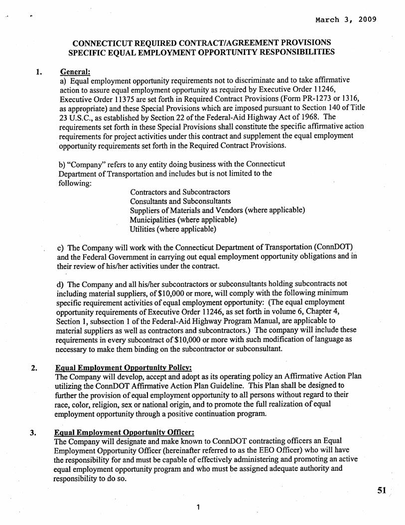


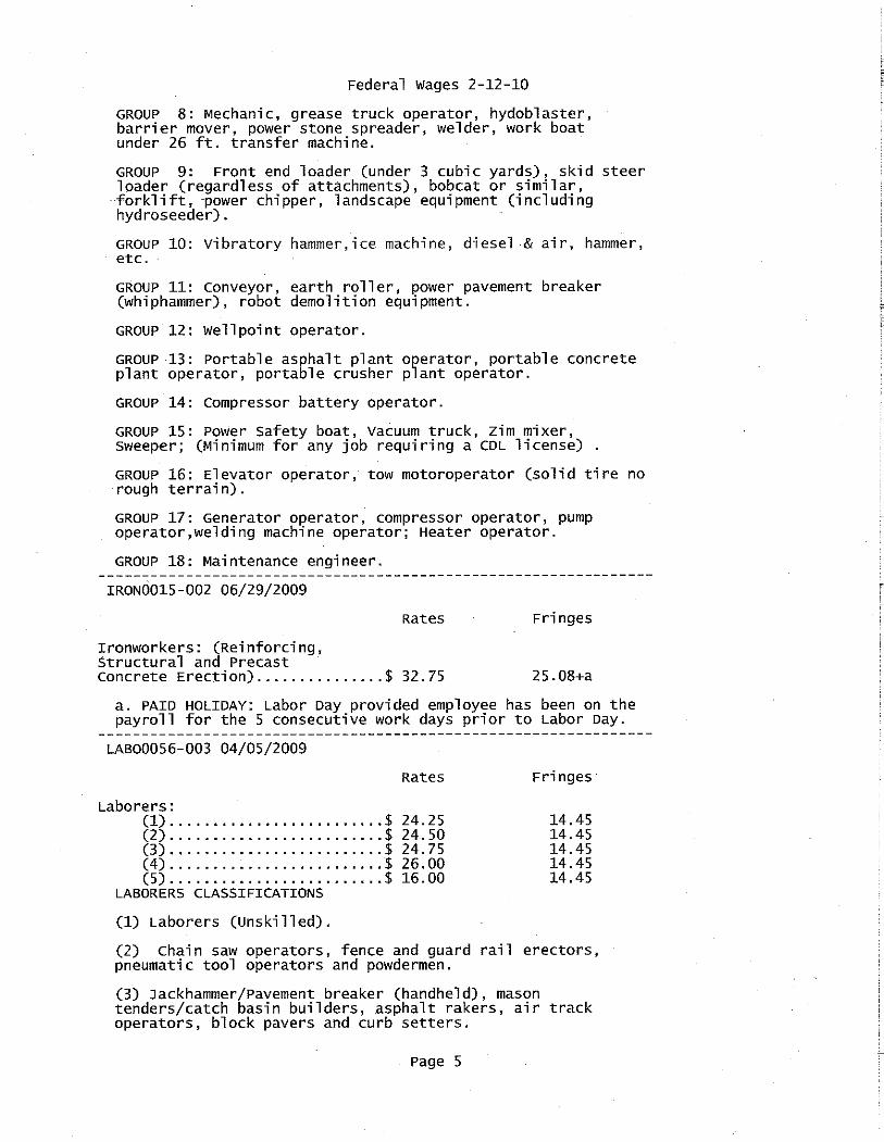


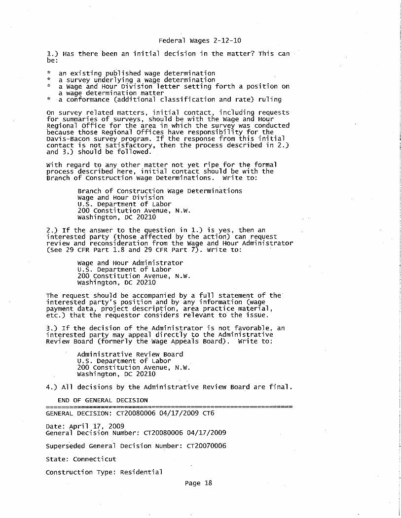


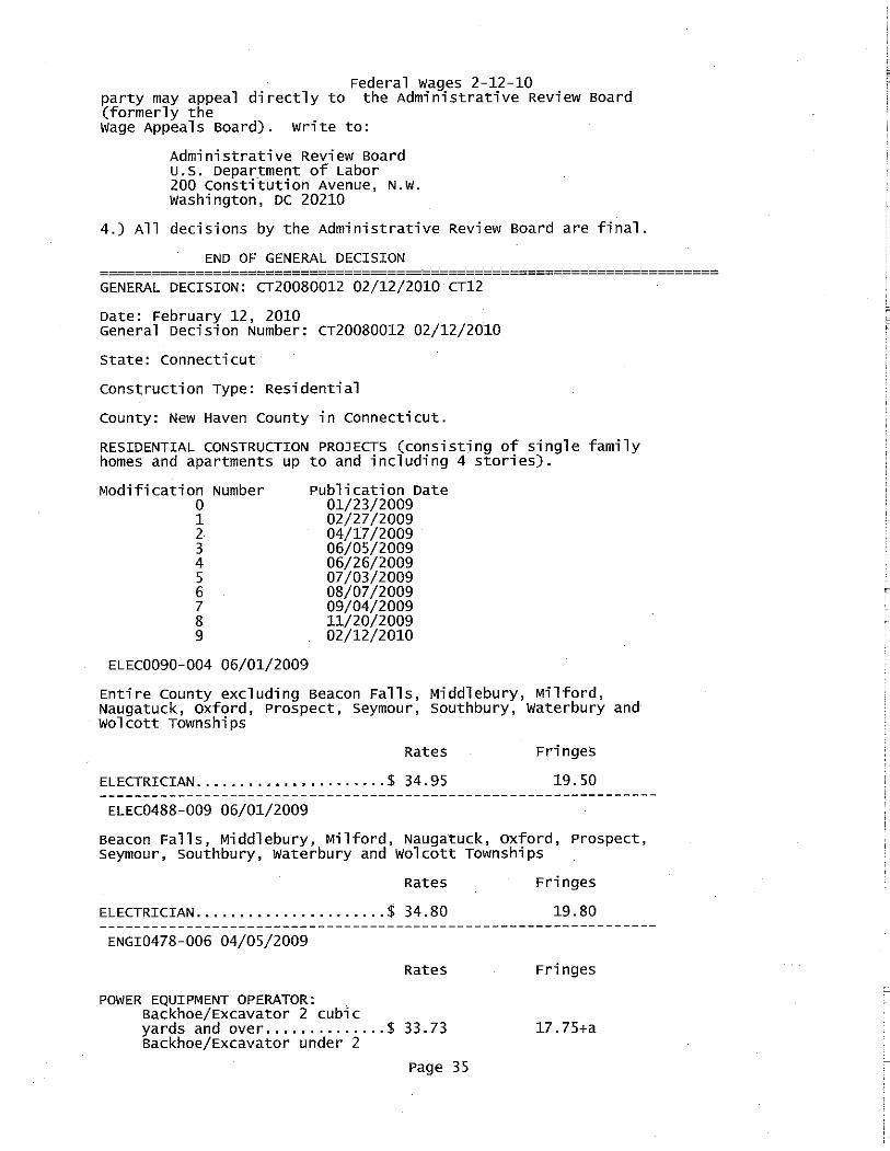


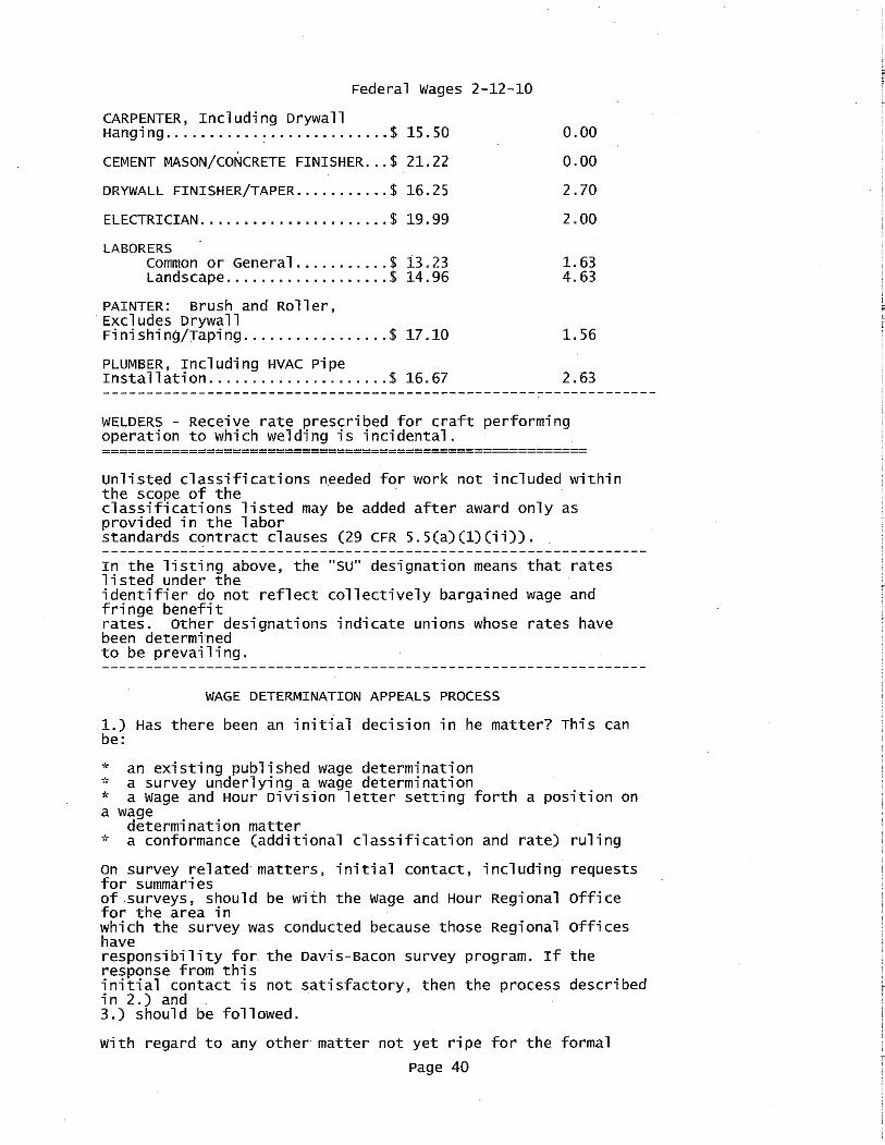


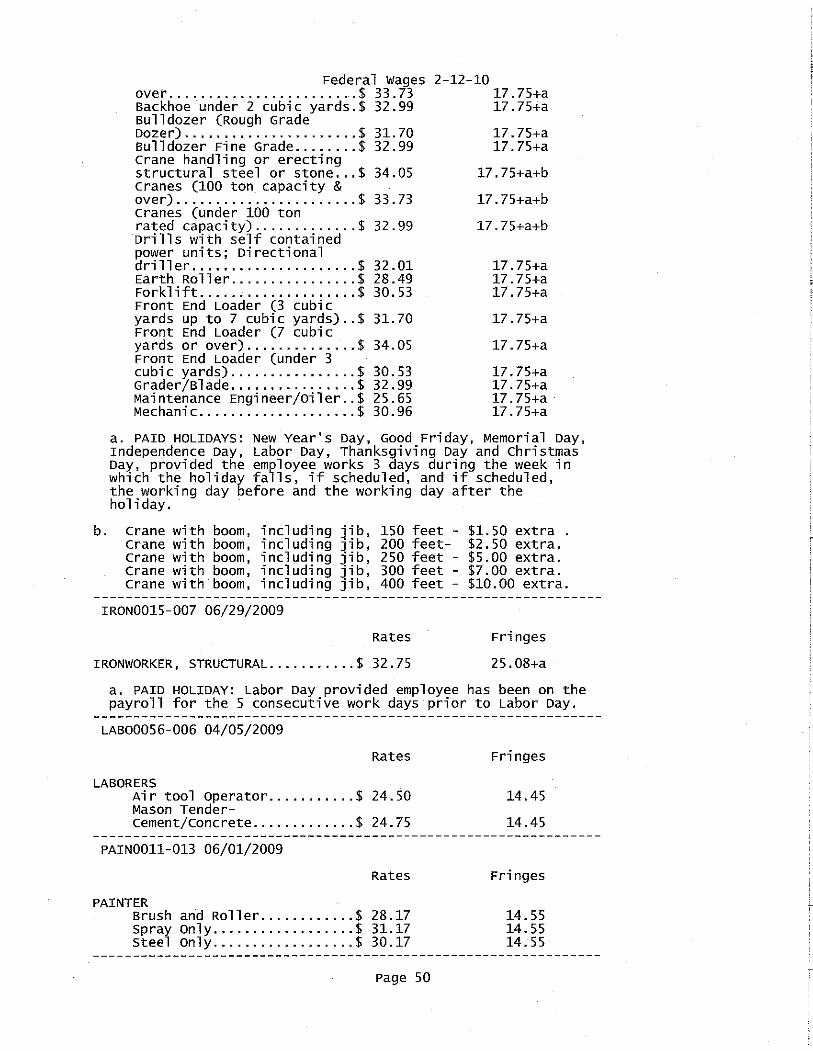


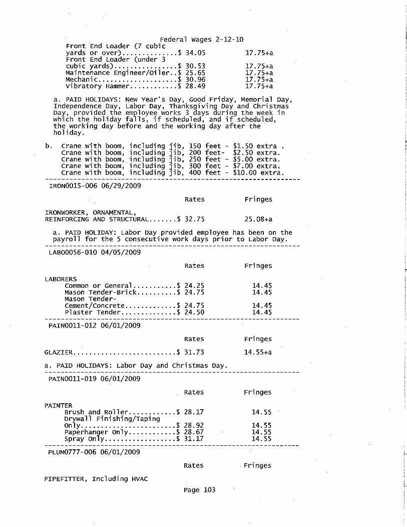


Project: Metro North Rail Line Station Improvements Program, Phase B
Minimum Rates and Classifications for Heavy/Highway Construction H 13361 Connecticut Department of Labor Wage and Workplace Standards Division By virtue of the authority vested in the Labor Commissioner under provisions of Section 31-53 of the General Statutes of Connecticut, as amended, the following are declared to be the prevailing rates and welfare payments and will apply only where the contract is advertised for bid within 20 days of the date on which the rates are established. Any contractor or subcontractor not obligated by agreement to pay to the welfare and pension fund shall pay this amount to each employee as part of his/her hourly wages. Project Number: Project Town: Fairfield FAP Number: CT96ARRA State Number: 300-154 Project: Metro North Rail Line Station Improvements Program, Phase B
CLASSIFICATION Hourly Rate Benefits 01) Asbestos/Toxic Waste Removal Laborers: Asbestos removal and encapsulation (except its removal from mechanical systems which are not to be scrapped), toxic waste removers, blasters. **See Laborers Group 7**
1) Boilermaker $33.79 34% + 8.96
1a) Bricklayer, Cement Masons, Cement Finishers, Plasterers, Stone Masons $32.18 19.79
2) Carpenters, Piledrivermen $29.00 17.80
2a) Diver Tenders $29.00 17.80
As of: Thursday, March 11, 2010

Project: Metro North Rail Line Station Improvements Program, Phase B
3) Divers $37.46 17.80
4) Painters: (Bridge Construction) Brush, Roller, Blasting (Sand, Water, $37.65 14.20 etc.), Spray
4a) Painters: Brush and Roller $28.17 14.55
4b) Painters: Spray Only $31.17 14.55
4c) Painters: Steel Only $30.17 14.55
4d) Painters: Blast and Spray $31.17 14.55
4e) Painters: Tanks, Tower and Swing $30.17 14.55
5) Electrician (Trade License required: E-1,2 L-5,6 C-5,6 T-1,2 L-1,2 $34.55 20.05 V-1,2,7,8,9)
As of: Thursday, March 11, 2010
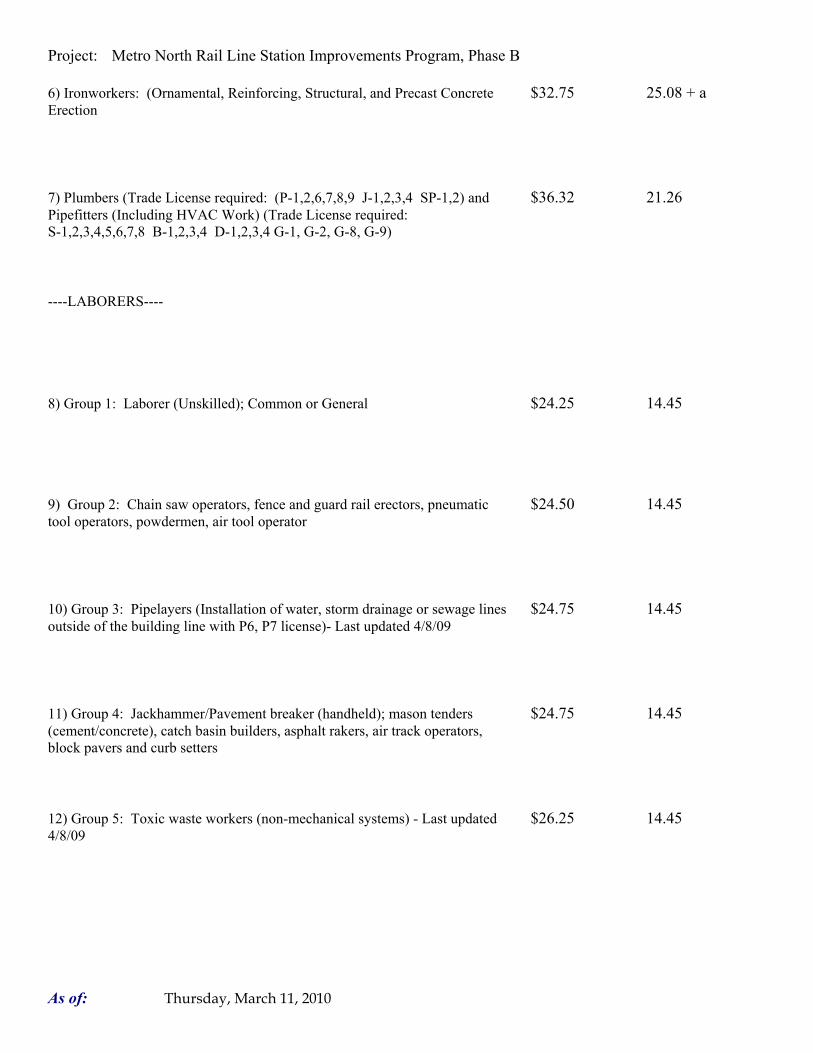
Project: Metro North Rail Line Station Improvements Program, Phase B
6) Ironworkers: (Ornamental, Reinforcing, Structural, and Precast Concrete $32.75 25.08 + a Erection
7) Plumbers (Trade License required: (P-1,2,6,7,8,9 J-1,2,3,4 SP-1,2) and $36.32 21.26 Pipefitters (Including HVAC Work) (Trade License required: S-1,2,3,4,5,6,7,8 B-1,2,3,4 D-1,2,3,4 G-1, G-2, G-8, G-9)
----LABORERS----
8) Group 1: Laborer (Unskilled); Common or General $24.25 14.45
9) Group 2: Chain saw operators, fence and guard rail erectors, pneumatic $24.50 14.45 tool operators, powdermen, air tool operator
10) Group 3: Pipelayers (Installation of water, storm drainage or sewage lines $24.75 14.45 outside of the building line with P6, P7 license)- Last updated 4/8/09
11) Group 4: Jackhammer/Pavement breaker (handheld); mason tenders $24.75 14.45 (cement/concrete), catch basin builders, asphalt rakers, air track operators, block pavers and curb setters
12) Group 5: Toxic waste workers (non-mechanical systems) - Last updated $26.25 14.45 4/8/09
As of: Thursday, March 11, 2010

Project: Metro North Rail Line Station Improvements Program, Phase B
13) Group 6: Blasters $26.00 14.45
Group 7: Asbestos Removal, non-mechanical systems (does not include $25.25 14.45 leaded joint pipe) - Last updated 4/8/09
Group 8: Traffic control signalmen $16.00 14.45
----LABORERS (TUNNEL CONSTRUCTION, FREE AIR). Shield Drive and Liner Plate Tunnels in Free Air.---- Last updated 4/5/09----
13a) Miners, Motormen, Mucking Machine Operators, Nozzle Men, Grout $28.58 14.45 + a Men, Shaft & Tunnel Steel & Rodmen, Shield & Erector, Arm Operator, Cable Tenders
13b) Brakemen, Trackmen $27.75 14.45 + a
----CLEANING, CONCRETE AND CAULKING TUNNEL----Last updated 4/5/09----
14) Concrete Workers, Form Movers, and Strippers $27.75 14.45 + a
As of: Thursday, March 11, 2010

Project: Metro North Rail Line Station Improvements Program, Phase B
15) Form Erectors $28.03 14.45 + a
----ROCK SHAFT LINING, CONCRETE, LINING OF SAME AND TUNNEL IN FREE AIR:----Last updated 4/5/09----
16) Brakemen, Trackmen, Tunnel Laborers, Shaft Laborers $27.75 14.45 + a
17) Laborers Topside, Cage Tenders, Bellman $27.65 14.45 + a
18) Miners $28.58 14.45 + a
----TUNNELS, CAISSON AND CYLINDER WORK IN COMPRESSED AIR: ----Last updated 4/5/09----
18a) Blaster $34.19 14.45 + a
19) Brakemen, Trackmen, Groutman, Laborers, Outside Lock Tender, Gauge $34.02 14.45 + a Tenders
As of: Thursday, March 11, 2010

Project: Metro North Rail Line Station Improvements Program, Phase B
20) Change House Attendants, Powder Watchmen, Top on Iron Bolts $32.30 14.45 + a
21) Mucking Machine Operator $34.70 14.45 + a
----TRUCK DRIVERS----(*see note below)
Two axle trucks $26.98 13.48 + a
Three axle trucks; two axle ready mix $27.08 13.48 + a
Three axle ready mix $27.13 13.48 + a
Four axle trucks, heavy duty trailer (up to 40 tons) $27.18 13.48 + a
Four axle ready-mix $27.23 13.48 + a
As of: Thursday, March 11, 2010

Project: Metro North Rail Line Station Improvements Program, Phase B
Heavy duty trailer (40 tons and over) $27.43 13.48 + a
Specialized earth moving equipment other than conventional type on-the road $27.23 13.48 + a trucks and semi-trailer (including Euclids)
----POWER EQUIPMENT OPERATORS----
Group 1: Crane handling or erecting structural steel or stone, hoisting $34.05 17.75 + a engineer (2 drums or over), front end loader (7 cubic yards or over), Work Boat 26 ft. & Over. (Trade License Required)
Group 2: Cranes (100 ton rate capacity and over); Excavator over 2 cubic $33.73 17.75 + a yards; Piledriver ($3.00 premium when operator controls hammer). (Trade License Required)
Group 3: Excavator; Cranes (under 100 ton rated capacity), Gradall; Master $32.99 17.75 + a Mechanic; Hoisting Engineer (all types of equipment where a drum and cable are used to hoist or drag material regardless of motive power of operation), Rubber Tire Excavator (Drott-1085 or similar);Grader Operator; Bulldozer Fine Grade (slopes, shaping, laser or GPS, etc.). (Trade License Required)
Group 4: Trenching Machines; Lighter Derrick; CMI Machine or Similar; $32.60 17.75 + a Koehring Loader (Skooper)
Group 5: Specialty Railroad Equipment; Asphalt Paver; Asphalt Spreader; $32.01 17.75 + a Asphalt Reclaiming Machine; Line Grinder; Concrete Pumps; Drills with Self Contained Power Units; Boring Machine; Post Hole Digger; Auger; Pounder; Well Digger; Milling Machine (over 24" Mandrell)
As of: Thursday, March 11, 2010

Project: Metro North Rail Line Station Improvements Program, Phase B
Group 5 continued: Side Boom; Combination Hoe and Loader; Directional $32.01 17.75 + a Driller.
Group 6: Front End Loader (3 up to 7 cubic yards); Bulldozer (rough grade $31.70 17.75 + a dozer).
Group 7: Asphalt Roller; Concrete Saws and Cutters (ride on types); Vermeer $31.36 17.75 + a Concrete Cutter; Stump Grinder; Scraper; Snooper; Skidder; Milling Machine (24" and Under Mandrel).
Group 8: Mechanic, Grease Truck Operator, Hydroblaster, Barrier Mover, $30.96 17.75 + a Power Stone Spreader; Welder; Work Boat under 26 ft.; Transfer Machine.
Group 9: Front End Loader (under 3 cubic yards), Skid Steer Loader $30.53 17.75 + a regardless of attachments (Bobcat or Similar); Fork Lift, Power Chipper; Landscape Equipment (including hydroseeder).
Group 10: Vibratory Hammer, Ice Machine, Diesel and Air Hammer, etc. $28.49 17.75 + a
Group 11: Conveyor, Earth Roller; Power Pavement Breaker (whiphammer), $28.49 17.75 + a Robot Demolition Equipment.
Group 12: Wellpoint Operator. $28.43 17.75 + a
As of: Thursday, March 11, 2010

Project: Metro North Rail Line Station Improvements Program, Phase B
Group 13: Compressor Battery Operator. $27.85 17.75 + a
Group 14: Elevator Operator; Tow Motor Operator (Solid Tire No Rough $26.71 17.75 + a Terrain).
Group 15: Generator Operator; Compressor Operator; Pump Operator; $26.30 17.75 + a Welding Machine Operator; Heater Operator.
Group 16: Maintenance Engineer/Oiler $25.65 17.75 + a
Group 17: Portable asphalt plant operator; portable crusher plant operator; $29.96 17.75 + a portable concrete plant operator.
Group 18: Power Safety Boat; Vacuum Truck; Zim Mixer; Sweeper; $27.54 17.75 + a (minimum for any job requiring CDL license).
**NOTE: SEE BELOW
----LINE CONSTRUCTION----(Railroad Construction and Maintenance)----Last updated 4/17/09----
As of: Thursday, March 11, 2010

Project: Metro North Rail Line Station Improvements Program, Phase B
20) Lineman, Cable Splicer, Dynamite Man $35.65 10.70 + 6.25%
21) Heavy Equipment Operator $22.09 10.70 + 6.25%
22) Equipment Operator, Tractor Trailer Driver, Material Men $30.30 10.70 + 6.25%
23) Driver Groundmen $26.74 10.70 + 6.25%
----LINE CONSTRUCTION----Last updated 4/17/09----
24) Driver Groundmen $30.92 6.5% + 9.70
25) Groundmen $22.67 6.5% + 6.20
26) Heavy Equipment Operators $37.10 6.5% + 10.70
As of: Thursday, March 11, 2010

Project: Metro North Rail Line Station Improvements Program, Phase B
27) Linemen, Cable Splicers, Dynamite Men $41.22 6.5% + 12.20
28) Material Men, Tractor Trailer Drivers, Equipment Operators $35.04 6.5% + 10.45
As of: Thursday, March 11, 2010

Project: Metro North Rail Line Station Improvements Program, Phase B
Welders: Rate for craft to which welding is incidental. *Note: Hazardous waste removal work receives additional $1.25 per hour for truck drivers. **Note: Hazardous waste premium $3.00 per hour over classified rate Crane with 150 ft. boom (including jib) - $1.50 extra Crane with 200 ft. boom (including jib) - $2.50 extra Crane with 250 ft. boom (including jib) - $5.00 extra Crane with 300 ft. boom (including jib) - $7.00 extra Crane with 400 ft. boom (including jib) - $10.00 extra
All classifications that indicate a percentage of the fringe benefits must be calculated at the percentage rate times the "base hourly rate".
Apprentices duly registered under the Commissioner of Labor's regulations on "Work Training Standards for Apprenticeship and Training Programs" Section 31-51-d-1 to 12, are allowed to be paid the appropriate percentage of the prevailing journeymen hourly base and the full fringe benefit rate, providing the work site ratio shall not be less than one full-time journeyperson instructing and supervising the work of each apprentice in a specific trade.
~~Connecticut General Statute Section 31-55a: Annual Adjustments to wage rates by contractors doing state work ~~ The Prevailing wage rates applicable to this project are subject to annual adjustments each July 1st for the duration of the project. Each contractor shall pay the annual adjusted prevailing wage rate that is in effect each July 1st, as posted by the Department of Labor. It is the contractor's responsibility to obtain the annual adjusted prevailing wage rate increases directly from the Department of Labor's website. The annual adjustments will be posted on the Department of Labor's Web page: www.ct.gov/dol. The Department of Labor will continue to issue the initial prevailing wage rate schedule to the Contracting Agency for the project. All subsequent annual adjustments will be posted on our Web Site for contractor access.
As of: Thursday, March 11, 2010

Project: Metro North Rail Line Station Improvements Program, Phase B
Effective October 1, 2005 - Public Act 05-50: any person performing the work of any mechanic, laborer, or worker shall be paid prevailing wage
All Person who perform work ON SITE must be paid prevailing wage for the appropriate mechanic, laborer, or worker classification. All certified payrolls must list the hours worked and wages paid to All Persons who perform work ON SITE regardless of their ownership i.e.: (Owners, Corporate Officers, LLC Members, Independent Contractors, et. al) Reporting and payment of wages is required regardless of any contractual relationship alleged to exist between the contractor and such person.
~~Unlisted classifications needed for work not included within the scope of the classifications listed may be added after award only as provided in the labor standards contract clause (29 CFR 5.5 (a) (1) (ii)).
Please direct any questions which you may have pertaining to classification of work and payment of prevailing wages to the Wage and Workplace Standards Division, telephone (860)263-6790.
As of: Thursday, March 11, 2010

Project: Metro North Rail Line Station Improvements Program, Phase B
Minimum Rates and Classifications for Heavy/Highway Construction H 13362 Connecticut Department of Labor Wage and Workplace Standards Division By virtue of the authority vested in the Labor Commissioner under provisions of Section 31-53 of the General Statutes of Connecticut, as amended, the following are declared to be the prevailing rates and welfare payments and will apply only where the contract is advertised for bid within 20 days of the date on which the rates are established. Any contractor or subcontractor not obligated by agreement to pay to the welfare and pension fund shall pay this amount to each employee as part of his/her hourly wages. Project Number: Project Town: Waterbury FAP Number: CT96ARRA State Number: 300-154 Project: Metro North Rail Line Station Improvements Program, Phase B
CLASSIFICATION Hourly Rate Benefits 01) Asbestos/Toxic Waste Removal Laborers: Asbestos removal and encapsulation (except its removal from mechanical systems which are not to be scrapped), toxic waste removers, blasters. **See Laborers Group 7**
1) Boilermaker $33.79 34% + 8.96
1a) Bricklayer, Cement Masons, Cement Finishers, Plasterers, Stone Masons $32.18 19.79
2) Carpenters, Piledrivermen $29.00 17.80
2a) Diver Tenders $29.00 17.80
As of: Thursday, March 11, 2010

Project: Metro North Rail Line Station Improvements Program, Phase B
3) Divers $37.46 17.80
4) Painters: (Bridge Construction) Brush, Roller, Blasting (Sand, Water, $37.65 14.20 etc.), Spray
4a) Painters: Brush and Roller $28.17 14.55
4b) Painters: Spray Only $31.17 14.55
4c) Painters: Steel Only $30.17 14.55
4d) Painters: Blast and Spray $31.17 14.55
4e) Painters: Tanks, Tower and Swing $30.17 14.55
5) Electrician (Trade License required: E-1,2 L-5,6 C-5,6 T-1,2 L-1,2 $34.55 20.05 V-1,2,7,8,9)
As of: Thursday, March 11, 2010

Project: Metro North Rail Line Station Improvements Program, Phase B
6) Ironworkers: (Ornamental, Reinforcing, Structural, and Precast Concrete $32.75 25.08 + a Erection
7) Plumbers (Trade License required: (P-1,2,6,7,8,9 J-1,2,3,4 SP-1,2) and $36.32 21.26 Pipefitters (Including HVAC Work) (Trade License required: S-1,2,3,4,5,6,7,8 B-1,2,3,4 D-1,2,3,4 G-1, G-2, G-8, G-9)
----LABORERS----
8) Group 1: Laborer (Unskilled); Common or General $24.25 14.45
9) Group 2: Chain saw operators, fence and guard rail erectors, pneumatic $24.50 14.45 tool operators, powdermen, air tool operator
10) Group 3: Pipelayers (Installation of water, storm drainage or sewage lines $24.75 14.45 outside of the building line with P6, P7 license)- Last updated 4/8/09
11) Group 4: Jackhammer/Pavement breaker (handheld); mason tenders $24.75 14.45 (cement/concrete), catch basin builders, asphalt rakers, air track operators, block pavers and curb setters
12) Group 5: Toxic waste workers (non-mechanical systems) - Last updated $26.25 14.45 4/8/09
As of: Thursday, March 11, 2010

Project: Metro North Rail Line Station Improvements Program, Phase B
13) Group 6: Blasters $26.00 14.45
Group 7: Asbestos Removal, non-mechanical systems (does not include $25.25 14.45 leaded joint pipe) - Last updated 4/8/09
Group 8: Traffic control signalmen $16.00 14.45
----LABORERS (TUNNEL CONSTRUCTION, FREE AIR). Shield Drive and Liner Plate Tunnels in Free Air.---- Last updated 4/5/09----
13a) Miners, Motormen, Mucking Machine Operators, Nozzle Men, Grout $28.58 14.45 + a Men, Shaft & Tunnel Steel & Rodmen, Shield & Erector, Arm Operator, Cable Tenders
13b) Brakemen, Trackmen $27.75 14.45 + a
----CLEANING, CONCRETE AND CAULKING TUNNEL----Last updated 4/5/09----
14) Concrete Workers, Form Movers, and Strippers $27.75 14.45 + a
As of: Thursday, March 11, 2010

Project: Metro North Rail Line Station Improvements Program, Phase B
15) Form Erectors $28.03 14.45 + a
----ROCK SHAFT LINING, CONCRETE, LINING OF SAME AND TUNNEL IN FREE AIR:----Last updated 4/5/09----
16) Brakemen, Trackmen, Tunnel Laborers, Shaft Laborers $27.75 14.45 + a
17) Laborers Topside, Cage Tenders, Bellman $27.65 14.45 + a
18) Miners $28.58 14.45 + a
----TUNNELS, CAISSON AND CYLINDER WORK IN COMPRESSED AIR: ----Last updated 4/5/09----
18a) Blaster $34.19 14.45 + a
19) Brakemen, Trackmen, Groutman, Laborers, Outside Lock Tender, Gauge $34.02 14.45 + a Tenders
As of: Thursday, March 11, 2010

Project: Metro North Rail Line Station Improvements Program, Phase B
20) Change House Attendants, Powder Watchmen, Top on Iron Bolts $32.30 14.45 + a
21) Mucking Machine Operator $34.70 14.45 + a
----TRUCK DRIVERS----(*see note below)
Two axle trucks $26.98 13.48 + a
Three axle trucks; two axle ready mix $27.08 13.48 + a
Three axle ready mix $27.13 13.48 + a
Four axle trucks, heavy duty trailer (up to 40 tons) $27.18 13.48 + a
Four axle ready-mix $27.23 13.48 + a
As of: Thursday, March 11, 2010

Project: Metro North Rail Line Station Improvements Program, Phase B
Heavy duty trailer (40 tons and over) $27.43 13.48 + a
Specialized earth moving equipment other than conventional type on-the road $27.23 13.48 + a trucks and semi-trailer (including Euclids)
----POWER EQUIPMENT OPERATORS----
Group 1: Crane handling or erecting structural steel or stone, hoisting $34.05 17.75 + a engineer (2 drums or over), front end loader (7 cubic yards or over), Work Boat 26 ft. & Over. (Trade License Required)
Group 2: Cranes (100 ton rate capacity and over); Excavator over 2 cubic $33.73 17.75 + a yards; Piledriver ($3.00 premium when operator controls hammer). (Trade License Required)
Group 3: Excavator; Cranes (under 100 ton rated capacity), Gradall; Master $32.99 17.75 + a Mechanic; Hoisting Engineer (all types of equipment where a drum and cable are used to hoist or drag material regardless of motive power of operation), Rubber Tire Excavator (Drott-1085 or similar);Grader Operator; Bulldozer Fine Grade (slopes, shaping, laser or GPS, etc.). (Trade License Required)
Group 4: Trenching Machines; Lighter Derrick; CMI Machine or Similar; $32.60 17.75 + a Koehring Loader (Skooper)
Group 5: Specialty Railroad Equipment; Asphalt Paver; Asphalt Spreader; $32.01 17.75 + a Asphalt Reclaiming Machine; Line Grinder; Concrete Pumps; Drills with Self Contained Power Units; Boring Machine; Post Hole Digger; Auger; Pounder; Well Digger; Milling Machine (over 24" Mandrell)
As of: Thursday, March 11, 2010

Project: Metro North Rail Line Station Improvements Program, Phase B
Group 5 continued: Side Boom; Combination Hoe and Loader; Directional $32.01 17.75 + a Driller.
Group 6: Front End Loader (3 up to 7 cubic yards); Bulldozer (rough grade $31.70 17.75 + a dozer).
Group 7: Asphalt Roller; Concrete Saws and Cutters (ride on types); Vermeer $31.36 17.75 + a Concrete Cutter; Stump Grinder; Scraper; Snooper; Skidder; Milling Machine (24" and Under Mandrel).
Group 8: Mechanic, Grease Truck Operator, Hydroblaster, Barrier Mover, $30.96 17.75 + a Power Stone Spreader; Welder; Work Boat under 26 ft.; Transfer Machine.
Group 9: Front End Loader (under 3 cubic yards), Skid Steer Loader $30.53 17.75 + a regardless of attachments (Bobcat or Similar); Fork Lift, Power Chipper; Landscape Equipment (including hydroseeder).
Group 10: Vibratory Hammer, Ice Machine, Diesel and Air Hammer, etc. $28.49 17.75 + a
Group 11: Conveyor, Earth Roller; Power Pavement Breaker (whiphammer), $28.49 17.75 + a Robot Demolition Equipment.
Group 12: Wellpoint Operator. $28.43 17.75 + a
As of: Thursday, March 11, 2010
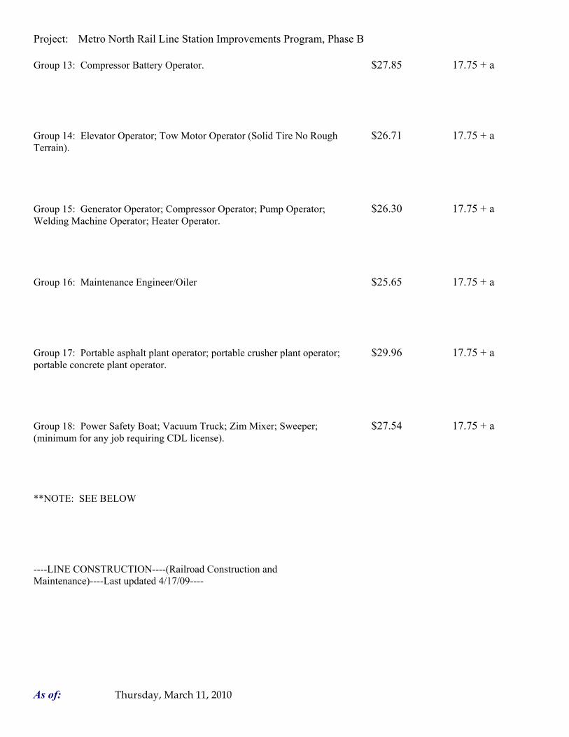
Project: Metro North Rail Line Station Improvements Program, Phase B
Group 13: Compressor Battery Operator. $27.85 17.75 + a
Group 14: Elevator Operator; Tow Motor Operator (Solid Tire No Rough $26.71 17.75 + a Terrain).
Group 15: Generator Operator; Compressor Operator; Pump Operator; $26.30 17.75 + a Welding Machine Operator; Heater Operator.
Group 16: Maintenance Engineer/Oiler $25.65 17.75 + a
Group 17: Portable asphalt plant operator; portable crusher plant operator; $29.96 17.75 + a portable concrete plant operator.
Group 18: Power Safety Boat; Vacuum Truck; Zim Mixer; Sweeper; $27.54 17.75 + a (minimum for any job requiring CDL license).
**NOTE: SEE BELOW
----LINE CONSTRUCTION----(Railroad Construction and Maintenance)----Last updated 4/17/09----
As of: Thursday, March 11, 2010

Project: Metro North Rail Line Station Improvements Program, Phase B
20) Lineman, Cable Splicer, Dynamite Man $35.65 10.70 + 6.25%
21) Heavy Equipment Operator $22.09 10.70 + 6.25%
22) Equipment Operator, Tractor Trailer Driver, Material Men $30.30 10.70 + 6.25%
23) Driver Groundmen $26.74 10.70 + 6.25%
----LINE CONSTRUCTION----Last updated 4/17/09----
24) Driver Groundmen $30.92 6.5% + 9.70
25) Groundmen $22.67 6.5% + 6.20
26) Heavy Equipment Operators $37.10 6.5% + 10.70
As of: Thursday, March 11, 2010

Project: Metro North Rail Line Station Improvements Program, Phase B
27) Linemen, Cable Splicers, Dynamite Men $41.22 6.5% + 12.20
28) Material Men, Tractor Trailer Drivers, Equipment Operators $35.04 6.5% + 10.45
As of: Thursday, March 11, 2010

Project: Metro North Rail Line Station Improvements Program, Phase B
Welders: Rate for craft to which welding is incidental. *Note: Hazardous waste removal work receives additional $1.25 per hour for truck drivers. **Note: Hazardous waste premium $3.00 per hour over classified rate Crane with 150 ft. boom (including jib) - $1.50 extra Crane with 200 ft. boom (including jib) - $2.50 extra Crane with 250 ft. boom (including jib) - $5.00 extra Crane with 300 ft. boom (including jib) - $7.00 extra Crane with 400 ft. boom (including jib) - $10.00 extra
All classifications that indicate a percentage of the fringe benefits must be calculated at the percentage rate times the "base hourly rate".
Apprentices duly registered under the Commissioner of Labor's regulations on "Work Training Standards for Apprenticeship and Training Programs" Section 31-51-d-1 to 12, are allowed to be paid the appropriate percentage of the prevailing journeymen hourly base and the full fringe benefit rate, providing the work site ratio shall not be less than one full-time journeyperson instructing and supervising the work of each apprentice in a specific trade.
~~Connecticut General Statute Section 31-55a: Annual Adjustments to wage rates by contractors doing state work ~~ The Prevailing wage rates applicable to this project are subject to annual adjustments each July 1st for the duration of the project. Each contractor shall pay the annual adjusted prevailing wage rate that is in effect each July 1st, as posted by the Department of Labor. It is the contractor's responsibility to obtain the annual adjusted prevailing wage rate increases directly from the Department of Labor's website. The annual adjustments will be posted on the Department of Labor's Web page: www.ct.gov/dol. The Department of Labor will continue to issue the initial prevailing wage rate schedule to the Contracting Agency for the project. All subsequent annual adjustments will be posted on our Web Site for contractor access.
As of: Thursday, March 11, 2010

Project: Metro North Rail Line Station Improvements Program, Phase B
Effective October 1, 2005 - Public Act 05-50: any person performing the work of any mechanic, laborer, or worker shall be paid prevailing wage
All Person who perform work ON SITE must be paid prevailing wage for the appropriate mechanic, laborer, or worker classification. All certified payrolls must list the hours worked and wages paid to All Persons who perform work ON SITE regardless of their ownership i.e.: (Owners, Corporate Officers, LLC Members, Independent Contractors, et. al) Reporting and payment of wages is required regardless of any contractual relationship alleged to exist between the contractor and such person.
~~Unlisted classifications needed for work not included within the scope of the classifications listed may be added after award only as provided in the labor standards contract clause (29 CFR 5.5 (a) (1) (ii)).
Please direct any questions which you may have pertaining to classification of work and payment of prevailing wages to the Wage and Workplace Standards Division, telephone (860)263-6790.
As of: Thursday, March 11, 2010

Project: Metro North Rail Line Station Improvements Program, Phase B
Minimum Rates and Classifications for Building Construction B 13361 Connecticut Department of Labor Wage and Workplace Standards Division By virtue of the authority vested in the Labor Commissioner under provisions of Section 31-53 of the General Statutes of Connecticut, as amended, the following are declared to be the prevailing rates and welfare payments and will apply only where the contract is advertised for bid within 20 days of the date on which the rates are established. Any contractor or subcontractor not obligated by agreement to pay to the welfare and pension fund shall pay this amount to each employee as part of his/her hourly wages.
Project Number: Project Town: Fairfield State#: 300-154 FAP# CT96ARRA Project: Metro North Rail Line Station Improvements Program, Phase B
CLASSIFICATION Hourly Rate Benefits 1a) Asbestos Worker/Insulator (Includes application of insulating 34.21 19.81 materials, protective coverings, coatings, & finishes to all types of mechanical systems; application of firestopping material for wall openings & penetrations in walls, floors, ceilings - Last updated 9/1/08
1b) Asbestos/Toxic Waste Removal Laborers: Asbestos removal and encapsulation (except its removal from mechanical systems which are not to be scrapped), toxic waste removers, blasters.**See Laborers Group 7**
2) Boilermaker 34.94 19.00
As of: Thursday, March 11, 2010

Project: Metro North Rail Line Station Improvements Program, Phase B
3a) Bricklayer, Cement Mason, Concrete Finisher (including 32.18 20.44 + a caulking), Stone Masons
3b) Tile Setter 30.78 16.98
3c) Terrazzo Workers, Marble Setters - Last updated 10/1/08 30.91 19.12
3d) Tile, Marble & Terrazzo Finishers 24.90 14.78
3e) Plasterer 32.18 20.44
------LABORERS------
As of: Thursday, March 11, 2010

Project: Metro North Rail Line Station Improvements Program, Phase B
4) Group 1: Laborers (common or general), carpenter tenders, 24.25 14.45 wrecking laborers, fire watchers.
4a) Group 2: Mortar mixers, plaster tender, power buggy operators, 24.50 14.45 powdermen, fireproofer/mixer/nozzleman, fence erector.
4b) Group 3: Jackhammer operators, mason tender (brick) and mason 24.75 14.45 tender (cement/concrete)
4c) **Group 4: Pipelayers (Installation of water, storm drainage or 25.25 14.45 sewage lines outside of the building line with P6, P7 license) (the pipelayer rate shall apply only to one or two employees of the total crew who primary task is to actually perform the mating of pipe sections)[If using this classification call the Labor Department for clarification] Last updated 4/8/09
4d) Group 5: Air track operators, Sand blasters - Last updated 4/8/09 25.00 14.45
4e) Group 6: Nuclear toxic waste removers, blasters - Last updated 27.25 14.45 4/8/09
As of: Thursday, March 11, 2010

Project: Metro North Rail Line Station Improvements Program, Phase B
4f) Group 7: Asbestos removal and encapsulation (except it's 25.25 14.45 removal from mechanical systems which are not to be scrapped) - Last updated 4/5/09
4g) Group 8: Bottom men on open air caisson, cylindrical work and 24.75 14.45 boring crew - Last updated 4/8/09
4h) Group 9: Top men on open air caisson, cylindrical work and 24.25 14.45 boring crew - Last updated 4/8/09
5) Carpenter, Acoustical Ceiling Installation, Soft Floor/Carpet 29.00 17.80 Laying, Metal Stud Installation, Form Work and Scaffold Building, Drywall Hanging, Modular-Furniture Systems Installers, Lathers, Piledrivers, Resilient Floor Layers.
5a) Millwrights 29.75 17.80
6) Electrical Worker (including low voltage wiring) (Trade License 34.55 20.05 required: E1,2 L-5,6 C-5,6 T-1,2 L-1,2 V-1,2,7,8,9)
As of: Thursday, March 11, 2010
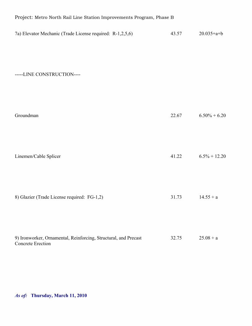
Project: Metro North Rail Line Station Improvements Program, Phase B
7a) Elevator Mechanic (Trade License required: R-1,2,5,6) 43.57 20.035+a+b
-----LINE CONSTRUCTION----
Groundman 22.67 6.50% + 6.20
Linemen/Cable Splicer 41.22 6.5% + 12.20
8) Glazier (Trade License required: FG-1,2) 31.73 14.55 + a
9) Ironworker, Ornamental, Reinforcing, Structural, and Precast 32.75 25.08 + a Concrete Erection
As of: Thursday, March 11, 2010

Project: Metro North Rail Line Station Improvements Program, Phase B
----OPERATORS----
Group 1: Crane handling or erecting structural steel or stone, 34.05 17.75 + a hoisting engineer 2 drums or over, front end loader (7 cubic yards or over); work boat 26 ft. and over. (Trade License Required)
Group 2: Cranes (100 ton rate capacity and over); 33.73 17.75 + a Backhoe/Excavator over 2 cubic yards; Piledriver ($3.00 premium when operator controls hammer). (Trade License Required)
Group 3: Excavator, Backhoe/Excavator under 2 cubic yards; Cranes 32.99 17.75 + a (under 100 ton rated capacity), Grader/Blade; Master Mechanic; Hoisting Engineer (all types of equipment where a drum and cable are used to hoist or drag material regardless of motive power of operation), Rubber Tire Excavator (Drott-1085 or similar);Grader Operator; Bulldozer Fine Grade. (slopes, shaping, laser or GPS, etc.).
Group 4: Trenching Machines; Lighter Derrick; Concrete Finishing 32.60 17.75 + a Machine; CMI Machine or Similar; Koehring Loader (Skooper).
Group 5: Specialty Railroad Equipment; Asphalt Paver; Asphalt 32.01 17.75 + a Reclaiming Machine; Line Grinder; Concrete Pumps; Drills with Self Contained Power Units; Boring Machine; Post Hole Digger; Auger; Pounder; Well Digger; Milling Machine (over 24" Mandrell)
As of: Thursday, March 11, 2010

Project: Metro North Rail Line Station Improvements Program, Phase B
Group 5 continued: Side Boom; Combination Hoe and Loader; 32.01 17.75 + a Directional Driller.
Group 6: Front End Loader (3 up to 7 cubic yards); Bulldozer (rough 31.70 17.75 + a grade dozer).
Group 7: Asphalt roller, concrete saws and cutters (ride on types), 31.36 17.75 + a vermeer concrete cutter, Stump Grinder; Scraper; Snooper; Skidder; Milling Machine (24" and under Mandrell).
Group 8: Mechanic, grease truck operator, hydroblaster; barrier 30.96 17.75 + a mover; power stone spreader; welding; work boat under 26 ft.; transfer machine.
Group 9: Front end loader (under 3 cubic yards), skid steer loader 30.53 17.75 + a regardless of attachments, (Bobcat or Similar): forklift, power chipper; landscape equipment (including Hydroseeder).
Group 10: Vibratory hammer; ice machine; diesel and air, hammer, 28.49 17.75 + a etc.
As of: Thursday, March 11, 2010

Project: Metro North Rail Line Station Improvements Program, Phase B
Group 11: Conveyor, earth roller, power pavement breaker 28.49 17.75 + a (whiphammer), robot demolition equipment.
Group 12: Wellpoint operator. 28.43 17.75 + a
Group 13: Compressor battery operator. 27.85 17.75 + a
Group 14: Elevator operator; tow motor operator (solid tire no rough 26.71 17.75 + a terrain).
Group 15: Generator Operator; Compressor Operator; Pump 26.30 17.75 + a Operator; Welding Machine Operator; Heater Operator.
Group 16: Maintenance Engineer/Oiler. 25.65 17.75 + a
As of: Thursday, March 11, 2010

Project: Metro North Rail Line Station Improvements Program, Phase B
Group 17: Portable asphalt plant operator; portable crusher plant 29.96 17.75 + a operator; portable concrete plant operator.
Group 18: Power safety boat; vacuum truck; zim mixer; sweeper; 27.54 17.75 + a (Minimum for any job requiring a CDL license).
------PAINTERS (Including Drywall Finishing)------
10a) Brush, Roller 28.17 14.55
10b) Taper/Drywall Finisher 28.92 14.55
10c) Paperhanger 28.67 14.55
As of: Thursday, March 11, 2010

Project: Metro North Rail Line Station Improvements Program, Phase B
10e) Spray 31.17 14.55
11) Plumber (excluding HVAC pipe installation) (Trade License 36.32 21.26 required: P-1,2,6,7,8,9 J-1,2,3,4 SP-1,2)
12) Post Digger, Well Digger, Pile Testing Machine 32.01 17.75 + a
Roofer: Cole Tar Pitch 33.50 12.25 + a
Roofer: Slate, Tile, Composition, Shingles, Singly Ply and 32.00 12.25 + a Damp/Waterproofing
15) Sheetmetal Worker (Trade License required for HVAC and 39.18 28.38 Ductwork: SM-1,SM-2,SM-3,SM-4,SM-5,SM-6)
As of: Thursday, March 11, 2010

Project: Metro North Rail Line Station Improvements Program, Phase B
16) Pipefitter (Including HVAC work) 36.32 21.26 (Trade License required: S-1,2,3,4,5,6,7,8 B-1,2,3,4 D-1,2,3,4, G-1, G-2, G-8 & G-9)
------TRUCK DRIVERS------
17a) 2 Axle 26.98 13.48 + a
17b) 3 Axle, 2 Axle Ready Mix 27.08 13.48 + a
17c) 3 Axle Ready Mix 27.13 13.48 + a
17d) 4 Axle, Heavy Duty Trailer up to 40 tons 27.18 13.48 + a
As of: Thursday, March 11, 2010

Project: Metro North Rail Line Station Improvements Program, Phase B
17e) 4 Axle Ready Mix 27.23 13.48 + a
17f) Heavy Duty Trailer (40 Tons and Over) 27.43 13.48 + a
17g) Specialized Earth Moving Equipment (Other Than Conventional 27.23 13.48 + a Type on-the-Road Trucks and Semi-Trailers, Including Euclids)
18) Sprinkler Fitter (Trade License required: F-1,2,3,4) 40.50 16.85 + a
As of: Thursday, March 11, 2010

Project: Metro North Rail Line Station Improvements Program, Phase B
Welders: Rate for craft to which welding is incidental. *Note: Hazardous waste removal work receives additional $1.25 per hour for truck drivers. **Note: Hazardous waste premium $3.00 per hour over classified rate Crane with 150 ft. boom (including jib) - $1.50 extra Crane with 200 ft. boom (including jib) - $2.50 extra Crane with 250 ft. boom (including jib) - $5.00 extra Crane with 300 ft. boom (including jib) - $7.00 extra Crane with 400 ft. boom (including jib) - $10.00 extra All classifications that indicate a percentage of the fringe benefits must be calculated at the percentage rate times the "base hourly rate".
Apprentices duly registered under the Commissioner of Labor's regulations on "Work Training Standards for Apprenticeship and Training Programs" Section 31-51-d-1 to 12, are allowed to be paid the appropriate percentage of the prevailing journeymen hourly base and the full fringe benefit rate, providing the work site ratio shall not be less than one full-time journeyperson instructing and supervising the work of each apprentice in a specific trade.
The Prevailing wage rates applicable to this project are subject to annual adjustments each July 1st for the duration of the project. Each contractor shall pay the annual adjusted prevailing wage rate that is in effect each July 1st, as posted by the Department of Labor. It is the contractor's responsibility to obtain the annual adjusted prevailing wage rate increases directly from the Department of Labor's website. The annual adjustments will be posted on the Department of Labor's Web page: www.ct.gov/dol The Department of Labor will continue to issue the initial prevailing wage rate schedule to the Contracting Agency for the project. All subsequent annual adjustments will be posted on our Web Site for contractor access.
As of: Thursday, March 11, 2010

Project: Metro North Rail Line Station Improvements Program, Phase B
Effective October 1, 2005 - Public Act 05-50: any person performing the work of any mechanic, laborer, or worker shall be paid prevailing wage All Person who perform work ON SITE must be paid prevailing wage for the appropriate mechanic, laborer, or worker classification. All certified payrolls must list the hours worked and wages paid to All Persons who perform work ON SITE regardless of their ownership i.e.: (Owners, Corporate Officers, LLC Members, Independent Contractors, et. al) Reporting and payment of wages is required regardless of any contractual relationship alleged to exist between the contractor and such person.
~~Unlisted classifications needed for work not included within the scope of the classifications listed may be added after award only as provided in the labor standards contract clause (29 CFR 5.5 (a) (1) (ii)).
Please direct any questions which you may have pertaining to classification of work and payment of prevailing wages to the Wage and Workplace Standards Division, telephone (860)263-6790.
As of: Thursday, March 11, 2010

Project: Metro North Rail Line Station Improvements Program, Phase B
Minimum Rates and Classifications for Building Construction B 13362 Connecticut Department of Labor Wage and Workplace Standards Division By virtue of the authority vested in the Labor Commissioner under provisions of Section 31-53 of the General Statutes of Connecticut, as amended, the following are declared to be the prevailing rates and welfare payments and will apply only where the contract is advertised for bid within 20 days of the date on which the rates are established. Any contractor or subcontractor not obligated by agreement to pay to the welfare and pension fund shall pay this amount to each employee as part of his/her hourly wages.
Project Number: Project Town: Waterbury State#: 300-154 FAP# CT96ARRA Project: Metro North Rail Line Station Improvements Program, Phase B
CLASSIFICATION Hourly Rate Benefits 1a) Asbestos Worker/Insulator (Includes application of insulating 34.21 19.81 materials, protective coverings, coatings, & finishes to all types of mechanical systems; application of firestopping material for wall openings & penetrations in walls, floors, ceilings - Last updated 9/1/08
1b) Asbestos/Toxic Waste Removal Laborers: Asbestos removal and encapsulation (except its removal from mechanical systems which are not to be scrapped), toxic waste removers, blasters.**See Laborers Group 7**
2) Boilermaker 34.94 19.00
As of: Thursday, March 11, 2010
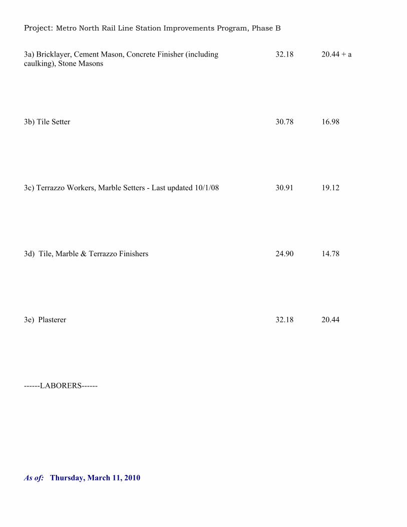
Project: Metro North Rail Line Station Improvements Program, Phase B
3a) Bricklayer, Cement Mason, Concrete Finisher (including 32.18 20.44 + a caulking), Stone Masons
3b) Tile Setter 30.78 16.98
3c) Terrazzo Workers, Marble Setters - Last updated 10/1/08 30.91 19.12
3d) Tile, Marble & Terrazzo Finishers 24.90 14.78
3e) Plasterer 32.18 20.44
------LABORERS------
As of: Thursday, March 11, 2010

Project: Metro North Rail Line Station Improvements Program, Phase B
4) Group 1: Laborers (common or general), carpenter tenders, 24.25 14.45 wrecking laborers, fire watchers.
4a) Group 2: Mortar mixers, plaster tender, power buggy operators, 24.50 14.45 powdermen, fireproofer/mixer/nozzleman, fence erector.
4b) Group 3: Jackhammer operators, mason tender (brick) and mason 24.75 14.45 tender (cement/concrete)
4c) **Group 4: Pipelayers (Installation of water, storm drainage or 25.25 14.45 sewage lines outside of the building line with P6, P7 license) (the pipelayer rate shall apply only to one or two employees of the total crew who primary task is to actually perform the mating of pipe sections)[If using this classification call the Labor Department for clarification] Last updated 4/8/09
4d) Group 5: Air track operators, Sand blasters - Last updated 4/8/09 25.00 14.45
4e) Group 6: Nuclear toxic waste removers, blasters - Last updated 27.25 14.45 4/8/09
As of: Thursday, March 11, 2010

Project: Metro North Rail Line Station Improvements Program, Phase B
4f) Group 7: Asbestos removal and encapsulation (except it's 25.25 14.45 removal from mechanical systems which are not to be scrapped) - Last updated 4/5/09
4g) Group 8: Bottom men on open air caisson, cylindrical work and 24.75 14.45 boring crew - Last updated 4/8/09
4h) Group 9: Top men on open air caisson, cylindrical work and 24.25 14.45 boring crew - Last updated 4/8/09
5) Carpenter, Acoustical Ceiling Installation, Soft Floor/Carpet 29.00 17.80 Laying, Metal Stud Installation, Form Work and Scaffold Building, Drywall Hanging, Modular-Furniture Systems Installers, Lathers, Piledrivers, Resilient Floor Layers.
5a) Millwrights 29.75 17.80
6) Electrical Worker (including low voltage wiring) (Trade License 34.55 20.05 required: E1,2 L-5,6 C-5,6 T-1,2 L-1,2 V-1,2,7,8,9)
As of: Thursday, March 11, 2010

Project: Metro North Rail Line Station Improvements Program, Phase B
7a) Elevator Mechanic (Trade License required: R-1,2,5,6) 43.57 20.035+a+b
-----LINE CONSTRUCTION----
Groundman 22.67 6.50% + 6.20
Linemen/Cable Splicer 41.22 6.5% + 12.20
8) Glazier (Trade License required: FG-1,2) 31.73 14.55 + a
9) Ironworker, Ornamental, Reinforcing, Structural, and Precast 32.75 25.08 + a Concrete Erection
As of: Thursday, March 11, 2010

Project: Metro North Rail Line Station Improvements Program, Phase B
----OPERATORS----
Group 1: Crane handling or erecting structural steel or stone, 34.05 17.75 + a hoisting engineer 2 drums or over, front end loader (7 cubic yards or over); work boat 26 ft. and over. (Trade License Required)
Group 2: Cranes (100 ton rate capacity and over); 33.73 17.75 + a Backhoe/Excavator over 2 cubic yards; Piledriver ($3.00 premium when operator controls hammer). (Trade License Required)
Group 3: Excavator, Backhoe/Excavator under 2 cubic yards; Cranes 32.99 17.75 + a (under 100 ton rated capacity), Grader/Blade; Master Mechanic; Hoisting Engineer (all types of equipment where a drum and cable are used to hoist or drag material regardless of motive power of operation), Rubber Tire Excavator (Drott-1085 or similar);Grader Operator; Bulldozer Fine Grade. (slopes, shaping, laser or GPS, etc.).
Group 4: Trenching Machines; Lighter Derrick; Concrete Finishing 32.60 17.75 + a Machine; CMI Machine or Similar; Koehring Loader (Skooper).
Group 5: Specialty Railroad Equipment; Asphalt Paver; Asphalt 32.01 17.75 + a Reclaiming Machine; Line Grinder; Concrete Pumps; Drills with Self Contained Power Units; Boring Machine; Post Hole Digger; Auger; Pounder; Well Digger; Milling Machine (over 24" Mandrell)
As of: Thursday, March 11, 2010

Project: Metro North Rail Line Station Improvements Program, Phase B
Group 5 continued: Side Boom; Combination Hoe and Loader; 32.01 17.75 + a Directional Driller.
Group 6: Front End Loader (3 up to 7 cubic yards); Bulldozer (rough 31.70 17.75 + a grade dozer).
Group 7: Asphalt roller, concrete saws and cutters (ride on types), 31.36 17.75 + a vermeer concrete cutter, Stump Grinder; Scraper; Snooper; Skidder; Milling Machine (24" and under Mandrell).
Group 8: Mechanic, grease truck operator, hydroblaster; barrier 30.96 17.75 + a mover; power stone spreader; welding; work boat under 26 ft.; transfer machine.
Group 9: Front end loader (under 3 cubic yards), skid steer loader 30.53 17.75 + a regardless of attachments, (Bobcat or Similar): forklift, power chipper; landscape equipment (including Hydroseeder).
Group 10: Vibratory hammer; ice machine; diesel and air, hammer, 28.49 17.75 + a etc.
As of: Thursday, March 11, 2010

Project: Metro North Rail Line Station Improvements Program, Phase B
Group 11: Conveyor, earth roller, power pavement breaker 28.49 17.75 + a (whiphammer), robot demolition equipment.
Group 12: Wellpoint operator. 28.43 17.75 + a
Group 13: Compressor battery operator. 27.85 17.75 + a
Group 14: Elevator operator; tow motor operator (solid tire no rough 26.71 17.75 + a terrain).
Group 15: Generator Operator; Compressor Operator; Pump 26.30 17.75 + a Operator; Welding Machine Operator; Heater Operator.
Group 16: Maintenance Engineer/Oiler. 25.65 17.75 + a
As of: Thursday, March 11, 2010

Project: Metro North Rail Line Station Improvements Program, Phase B
Group 17: Portable asphalt plant operator; portable crusher plant 29.96 17.75 + a operator; portable concrete plant operator.
Group 18: Power safety boat; vacuum truck; zim mixer; sweeper; 27.54 17.75 + a (Minimum for any job requiring a CDL license).
------PAINTERS (Including Drywall Finishing)------
10a) Brush, Roller 28.17 14.55
10b) Taper/Drywall Finisher 28.92 14.55
10c) Paperhanger 28.67 14.55
As of: Thursday, March 11, 2010

Project: Metro North Rail Line Station Improvements Program, Phase B
10e) Spray 31.17 14.55
11) Plumber (excluding HVAC pipe installation) (Trade License 36.32 21.26 required: P-1,2,6,7,8,9 J-1,2,3,4 SP-1,2)
12) Post Digger, Well Digger, Pile Testing Machine 32.01 17.75 + a
Roofer: Cole Tar Pitch 33.50 12.25 + a
Roofer: Slate, Tile, Composition, Shingles, Singly Ply and 32.00 12.25 + a Damp/Waterproofing
15) Sheetmetal Worker (Trade License required for HVAC and 31.57 25.92 Ductwork: SM-1,SM-2,SM-3,SM-4,SM-5,SM-6)
As of: Thursday, March 11, 2010

Project: Metro North Rail Line Station Improvements Program, Phase B
16) Pipefitter (Including HVAC work) 36.32 21.26 (Trade License required: S-1,2,3,4,5,6,7,8 B-1,2,3,4 D-1,2,3,4, G-1, G-2, G-8 & G-9)
------TRUCK DRIVERS------
17a) 2 Axle 26.98 13.48 + a
17b) 3 Axle, 2 Axle Ready Mix 27.08 13.48 + a
17c) 3 Axle Ready Mix 27.13 13.48 + a
17d) 4 Axle, Heavy Duty Trailer up to 40 tons 27.18 13.48 + a
As of: Thursday, March 11, 2010

Project: Metro North Rail Line Station Improvements Program, Phase B
17e) 4 Axle Ready Mix 27.23 13.48 + a
17f) Heavy Duty Trailer (40 Tons and Over) 27.43 13.48 + a
17g) Specialized Earth Moving Equipment (Other Than Conventional 27.23 13.48 + a Type on-the-Road Trucks and Semi-Trailers, Including Euclids)
18) Sprinkler Fitter (Trade License required: F-1,2,3,4) 40.50 16.85 + a
As of: Thursday, March 11, 2010

Project: Metro North Rail Line Station Improvements Program, Phase B
Welders: Rate for craft to which welding is incidental. *Note: Hazardous waste removal work receives additional $1.25 per hour for truck drivers. **Note: Hazardous waste premium $3.00 per hour over classified rate Crane with 150 ft. boom (including jib) - $1.50 extra Crane with 200 ft. boom (including jib) - $2.50 extra Crane with 250 ft. boom (including jib) - $5.00 extra Crane with 300 ft. boom (including jib) - $7.00 extra Crane with 400 ft. boom (including jib) - $10.00 extra All classifications that indicate a percentage of the fringe benefits must be calculated at the percentage rate times the "base hourly rate".
Apprentices duly registered under the Commissioner of Labor's regulations on "Work Training Standards for Apprenticeship and Training Programs" Section 31-51-d-1 to 12, are allowed to be paid the appropriate percentage of the prevailing journeymen hourly base and the full fringe benefit rate, providing the work site ratio shall not be less than one full-time journeyperson instructing and supervising the work of each apprentice in a specific trade.
The Prevailing wage rates applicable to this project are subject to annual adjustments each July 1st for the duration of the project. Each contractor shall pay the annual adjusted prevailing wage rate that is in effect each July 1st, as posted by the Department of Labor. It is the contractor's responsibility to obtain the annual adjusted prevailing wage rate increases directly from the Department of Labor's website. The annual adjustments will be posted on the Department of Labor's Web page: www.ct.gov/dol The Department of Labor will continue to issue the initial prevailing wage rate schedule to the Contracting Agency for the project. All subsequent annual adjustments will be posted on our Web Site for contractor access.
As of: Thursday, March 11, 2010

Project: Metro North Rail Line Station Improvements Program, Phase B
Effective October 1, 2005 - Public Act 05-50: any person performing the work of any mechanic, laborer, or worker shall be paid prevailing wage All Person who perform work ON SITE must be paid prevailing wage for the appropriate mechanic, laborer, or worker classification. All certified payrolls must list the hours worked and wages paid to All Persons who perform work ON SITE regardless of their ownership i.e.: (Owners, Corporate Officers, LLC Members, Independent Contractors, et. al) Reporting and payment of wages is required regardless of any contractual relationship alleged to exist between the contractor and such person.
~~Unlisted classifications needed for work not included within the scope of the classifications listed may be added after award only as provided in the labor standards contract clause (29 CFR 5.5 (a) (1) (ii)).
Please direct any questions which you may have pertaining to classification of work and payment of prevailing wages to the Wage and Workplace Standards Division, telephone (860)263-6790.
As of: Thursday, March 11, 2010

CONNECTICUT DEPARTMENT OF LABOR Wage and Workplace Standards Division
FOOTNOTES
Please Note: If the “Benefits” listed on the schedule for the following occupations
includes a letter(s) (+ a or + a+b for instance), refer to the information below. Benefits to be paid at the appropriate prevailing wage rate for the listed occupation. If the “Benefits” section for the occupation lists only a dollar amount, disregard the information below.
Bricklayers, Cement Masons, Cement Finishers, Plasters, Stone Masons (Building Construction)
(Residential- Hartford, Middlesex, New Haven, New London and Tolland Counties)
a. Paid Holiday: Employees shall receive 4 hours for Christmas Eve holiday provided the employee works the regularly scheduled day before and after the holiday. Employers may schedule work on Christmas Eve and employees shall receive pay for actual hours worked in addition to holiday pay.
Bricklayer (Residential- Fairfield County)
a. Paid Holiday: If an employee works on Christmas Eve until noon he shall be paid
for 8 hours.
Electricians Fairfield County: West of the Five Mile River in Norwalk a. $2.00 per hour not to exceed $14.00 per day.
Elevator Constructors: Mechanics a. Paid Holidays: New Year’s Day, Memorial Day, Independence Day, Labor Day, Thanksgiving Day, Christmas Day, plus the Friday after Thanksgiving.
b. Vacation: Employer contributes 8% of basic hourly rate for 5 years or more of service or 6% of basic hourly rate for 6 months to 5 years of service as vacation pay credit.

Glaziers a. Paid Holidays: Labor Day and Christmas Day.
Power Equipment Operators
(Heavy and Highway Construction & Building Construction)
a. Paid Holidays: New Year’s Day, Good Friday, Memorial day, Independence Day, Labor Day, Thanksgiving Day and Christmas Day, provided the employee works 3 days during the week in which the holiday falls, if scheduled, and if scheduled, the working day before and the working day after the holiday. Holidays falling on Saturday may be observed on Saturday, or if the employer so elects, on the preceding Friday.
Ironworkers
a. Paid Holiday: Labor Day provided employee has been on the payroll for the 5 consecutive workdays prior to Labor Day.
Laborers (Tunnel Construction)
a. Paid Holidays: New Year’s Day, Memorial Day, Independence Day, Labor Day, Thanksgiving Day and Christmas Day. No employee shall be eligible for holiday pay when he fails, without cause, to work the regular workday preceding the holiday or the regular workday following the holiday.
Roofers
a. Paid Holidays: July 4th, Labor Day, and Christmas Day provided the employee is employed 15 days prior to the holiday.
Sprinkler Fitters
a. Paid Holidays: Memorial Day, July 4th, Labor Day, Thanksgiving Day and Christmas Day, provided the employee has been in the employment of a contractor 20 working days prior to any such paid holiday.
Truck Drivers
(Heavy and Highway Construction & Building Construction)
a. Paid Holidays: New Year’s Day, Memorial Day, Independence Day, Labor Day, Thanksgiving Day, Christmas day, and Good Friday, provided the employee has at least 31 calendar days of service and works the last scheduled day before and the first scheduled day after the holiday, unless excused.
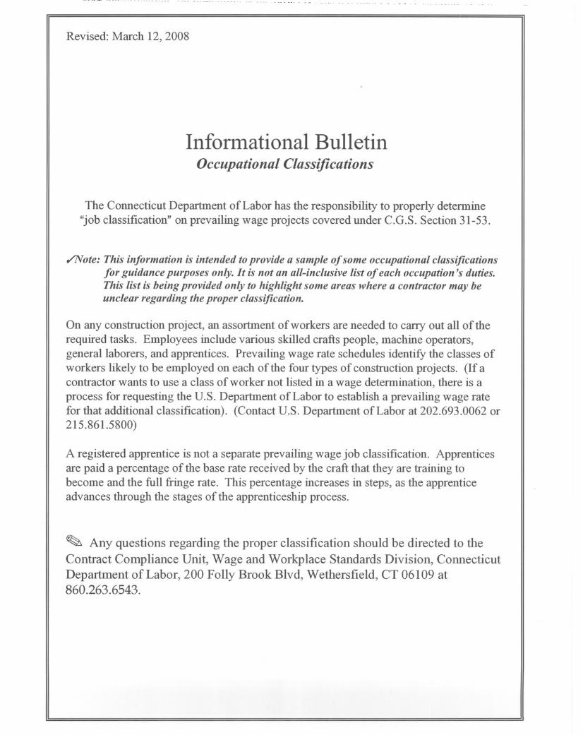
Revised: March 12, 2008
Informational BulletinOccupauonalClassij7cauons
The Connecticut Department of Labor has the responsibility to properly determine"job classification" on prevailing wage projects covered under C.G.S. Section 31-53.
,/Note: This information is intended to provide a sample of some occupational classificationsfor guidance purposes only. It is not an all-inclusive list of each occupation's duties.This list is being provided only to highlight some areas where a contractor may beunclear regarding the proper classification.
On any construction project, an assortment of workers are needed to carry out all of therequired tasks. Employees include various skilled crafts people, machine operators,general laborers, and apprentices. Prevailing wage rate schedules identify the classes ofworkers likely to be employed on each of the four types of construction projects. (If acontractor wants to use a class of worker not listed in a wage determination, there is aprocess for requesting the U.S. Department of Labor to establish a prevailing wage ratefor that additional classification). (Contact U.S. Department of Labor at 202.693.0062 or215.861.5800)
A registered apprentice is not a separate prevailing wage job classification. Apprenticesare paid a percentage of the base rate received by the craft that they are training tobecome and the full fringe rate. This percentage increases in steps, as the apprenticeadvances through the stages of the apprenticeship process.
~ Any questions regarding the proper classification should be directed to the
Contract Compliance Unit, Wage and Workplace Standards Division, ConnecticutDepartment of Labor, 200 Folly Brook Blvd, Wethersfield, CT 06109 at860.263.6543.

Below are additional clarifications of specific job dutiesperformed for certain classifications:
~ ASBESTOS WORKERSIINSULATORS:
~ Handle, install, apply, fabricate, distribute, prepare, alter, repair, or dismantle heat andfrost insulation, including penetration and fire stopping work on all penetration fire stopsystems.
~ BOILERMAKERS:
~ Erects hydro plants, incomplete vessels, steel stacks, storage tanks for water, fuel, etc.Builds incomplete boilers, repairs heat exchanges and steam generators.
~ BRICK LA YERS. CEMENT MASONS. CEMENT FINISHERS. MARBLE MASONS.PLASTERERS. STONE MASONS. PLASTERERS. STONE MASONS. TERRAZZOWORKERS. TILE SETTERS:
~ Lays building materials such as brick, structural tile and concrete cinder, glass, gypsum,terra cotta block. Cuts, tools and sets marble, sets stone, finishes concrete, appliesdecorative steel, aluminum and plastic tile, applies cements, sand, pigment and marblechips to floors, stairways, etc.
=!)CARPENTERS. MILL WRIGHTS. PILEDRIVERMEN. LA THERS. RESILEINT FLOORLAYERS. DOCK BUILDERS. DIVERS. DIVER TENDERS:
~ Constructs, erects, installs and repairs structures and fixtures of wood, plywood andwallboard. Installs, assembles, dismantles, moves industrial machinery. Drives pilinginto ground to provide foundations for structures such as buildings and bridges, retainingwalls for earth embankments, such as cofferdams. Fastens wooden, metal or rockboardlath to walls, ceilings and partitions of buildings, acoustical tile layer, concrete formbuilder. Applies fires topping materials on fire resistive joint systems only. Installation ofcurtain/window walls only where attached to wood or metal studs.
Assembly and installation of modular furniture/furniture systems.[New] a. Free-standing furniture is not covered. This includes: student chairs, studytop desks, book box desks, computer furniture, dictionary stand, atlas stand, woodshelving, two- position information access station, file cabinets, storage cabinets,tables, etc.
=!)CLEANINGLABORER:
~ The clean up of any construction debris and the general cleaning, including sweeping,wash down, mopping, wiping of the construction facility, washing, polishing, dusting,etc., prior to the issuance of a certificate of occupancy falls under the Laborclassification.

=/)DELIVERY PERSONNEL:
~ If delivery of supplieslbuilding materials is to one common point and stockpiled there,prevailing wages are not required. If the delivery personnel are involved in thedistribution of the material to multiple locations within the construction site then theywould have to be paid prevailing wages for the type of work performed: laborer,equipment operator, electrician, ironworker, plumber, etc.
An example of this would be where delivery of drywall is made to a building and thedelivery personnel distribute the drywall from one "stockpile" location to further sublocations on each floor. Distribution of material around a construction site is the job of alaborer/tradesman and not a delivery personnel.
=/)ELECTRICIANS:
~ Install, erect, maintenance, alteration or repair of any wire, cable, conduit, etc., whichgenerates, transforms, transmits or uses electrical energy for light, heat, power or otherpurposes. *License required per Connecticut General Statutes: E-l,2 L5,6 C-5,6 T-l,2 L-l,2 V-l,2,7,8,9.
=/)ELEVATOR CONSTRUCTORS:
~ Install, erect, maintenance and repair of all types of elevators, escalators, dumb waitersand moving walks. *License required by Connecticut General Statutes:R-l,2,5,6.
=/)FORK LIFT OPERA TOR:
~ Laborers Group 4) Mason Tenders - operates forklift solely to assist a mason to amaximum height of nine (9) feet only.Power Equipment Operator Group 9 - operates forklift to assist any trade, and to assist amason to a height over nine (9) feet.
=/)GLAZIERS: [updated]
~ Installs light metal sash, head sills, and 2-story aluminum commercial storefronts.
=/)IRONWORKERS:
~ Handling, sorting, and installation of reinforcing steel (rebar).~ Installation of aluminum window walls and curtain walls.
~ Metal bridge rail (traffic), metal bridge handrail, and decorative security fenceinstallation.
Installation of handrails, stairs, and platforms installed on Wastewater Treatment Plantprojects. [new]

cf>INSULA TOR:
~ Installing fire stopping systems/materials for "Penetration Firestop Systems": transit tocables, electrical conduits, insulated pipes, sprinkler pipe penetrations, ductwork behindradiation, electrical cable trays, fire rated pipe penetrations, natural polypropylene, HVACducts, plumbing bare metal, telephone and communication wires, and boiler roomceilings. Past practice using the applicable licensed trades, Plumber, Sheet Metal,Sprinkler Fitter, and Electrician, is not inconsistent with the Insulator classification andwould be permitted.
cf>LEAD PAINT REMOVAL:
~ Painter Rate -
1) Removal of lead paint from bridges.2) Removal of lead paint as preparation of any surface to be repainted.3) Where removal is on a Demolition project prior to reconstruction.
Laborer Rate-
1) Removal of lead paint from any surface NOT to be repainted.2) Where removal is on a TOTAL Demolition project only.
cf>LABORERS:
~ Acetylene burners, asphalt rakers, chain saw operators, concrete and power buggyoperator, concrete saw operator, fence and guard rail erector, hand operated concretevibrator operator, mason tenders, pipelayers (installation of water, storm drainage orsewage lines outside of the building line with P6, P7license), pneumatic drill operator,pneumatic gas and electric drill operator, powermen and wagon drill operator, air trackoperator, block paver, curb setters, blasters, concrete spreaders.
cf>PA INTERS:
~ Maintenance, preparation, cleaning, blasting (water and sand, etc.), painting orapplication of any protective coatings of every description on all bridges andappurtenances of highways, roadways, and railroads. Painting, decorating, hardwoodfinishing, paper hanging, sign writing, scenic art work and drywall finishing for any andall types of building and residential work.
cf>PLUMBERS AND PIPEFITTERS:
~ Installation, repair, replacement, alteration or maintenance of all plumbing, heating,cooling and piping. *License required per Connecticut General Stat:utes:P-1,2,6,7,8,9 J-1,2,3,4 SP-1,2. S-1,2,3,4,5,6, 7,8 B-1,2,3,4 D1,2,3,4.
cf>POWER EQUIPMENT OPERATORS:
~ Operates several types of power construction equipment such as compressors, pumps,hoists, derricks, cranes, shovels, tractors, scrapers or motor graders, etc. Repairs and
maintains equipment. *License required, crane operators only, perConnecticut General Stat:utes.

=f)ROOFERS:
~ Preparation of surface, tear-off and/or removal of any type of roofing, and/or clean-up ofany areas where a roof is to be relaid.
=f)SHEET METAL WORKER:
~ Fabrication, handling, assembling, erecting, altering, repairing, etc. of coated metalmaterial panels and composite metal material panels when used on building exteriors andinteriors as soffits, facia, louvers, partitions, wall panel siding, canopies, cornice, columncovers, awnings, beam covers, cladding, sun shades, lighting troughs, spires, ornamentalroofing, metal ceilings, mansards, copings, ornamental and ventilation hoods, vertical andhorizontal siding panels, trim, etc. The sheet metal classification also applies to the vastvariety of coated metal material panels and composite metal material panels that haveevolved over the years as an alternative to conventional ferrous and non-ferrous metalslike steel, iron, tin, copper, brass, bronze, aluminum, etc. Insulated metal and insulatedcomposite panels are still installed by the Iron Worker. Fabrication, handling,assembling, erecting, altering, repairing, etc. of architectural metal roof, standing seamroof, composite metal roof, metal and composite bathroom/toilet partitions, aluminumgutters, metal and composite lockers and shelving, kitchen equipment, and walk-incoolers.
=f)SPRINKLER FITTERS:
Installation, alteration, maintenance and repair of fire protection sprinkler systems. *Licenserequired per Connecticut General Statutes: F-l,2,3,4.
=f)TILE. MARBLE AND TERRAZZO FINISHERS:
Assists and tends the tile setter, marble mason and terrazzo worker in the performance of theirduties.
=f)TRUCK DRIVERS:
Truck Drivers delivering asphalt are covered under prevailing wage while on the site anddirectly involved in the paving operation.Material men and deliverymen are not covered under prevailing wage as long as they arenot directly involved in the construction process. If, they unload the material, they wouldthen be covered by prevailing wage for the classification they are performing work in:laborer, equipment operator, etc.Hauling material off site is not covered provided they are not dumping it at a locationoutlined above.
Driving a truck on site and moving equipment or materials on site would be consideredcovered work, as this is part of the construction process.

Sec. 31-55a
Statute 31-55a
Last Updated: June 02, 2008
You are here: DOL Web Site Wage and Workplace Issues Statute 31-55a
- Special Notice -
To All State and Political Subdivisions,Their Agents, and Contractors
Connecticut General Statute 31-55a - Annual adjustments to wage rates by contractors doing state work.
Each contractor that is awarded a contract on or after October 1, 2002, for (1) the construction of a state highway or bridge that falls under the provisions of section 31-54 of the general statutes, or (2) the construction, remodeling, refinishing, refurbishing, rehabilitation, alteration or repair of any public works project that falls under the provisions of section 31-53 of the general statutes shall contact the Labor Commissioner on or before July first of each year, for the duration of such contract, to ascertain the prevailing rate of wages on an hourly basis and the amount of payment or contributions paid or payable on behalf of each mechanic, laborer or worker employed upon the work contracted to be done, and shall make any necessary adjustments to such prevailing rate of wages and such payment or contributions paid or payable on behalf of each such employee, effective each July first.
● The prevailing wage rates applicable to any contract or subcontract awarded on or after October 1, 2002 are subject to annual adjustments each July 1st for the duration of any project which was originally advertised for bids on or after October 1, 2002.
● Each contractor affected by the above requirement shall pay the annual adjusted prevailing wage rate that is in effect each July 1st, as posted by the Department of Labor.
● It is the contractor’s responsibility to obtain the annual adjusted prevailing wage rate increases directly from the Department of Labor’s Web Site. The annual adjustments will be posted on the Department of Labor Web page: www.ctdol.state.ct.us. For those without internet access, please contact the division listed below.
● The Department of Labor will continue to issue the initial prevailing wage rate schedule to the Contracting Agency for the project. All subsequent annual adjustments will be posted on our Web Site for contractor access.
Any questions should be directed to the Contract Compliance Unit, Wage and Workplace
http://www.ctdol.state.ct.us/wgwkstnd/laws-regs/statute31-55a.htm (1 of 2) [6/20/2008 8:00:16 AM]

Sec. 31-55a
Standards Division, Connecticut Department of Labor, 200 Folly Brook Blvd., Wethersfield, CT 06109 at (860)263-6790.
Workplace Laws
Published by the Connecticut Department of Labor, Project Management Office
http://www.ctdol.state.ct.us/wgwkstnd/laws-regs/statute31-55a.htm (2 of 2) [6/20/2008 8:00:16 AM]

November 29, 2006
NoticeTo All Mason Contractors and Interested Parties
Regarding Construction Pursuant to Section 31-53 of theConnecticut General Statutes (Prevailing Wage)
The Connecticut Labor Department Wage and Workplace Standards Division is empowered toenforce the prevailing wage rates on projects covered by the above referenced statute.
Over the past few years the Division has withheld enforcement of the rate in effect for workerswho operate a forklift on a prevailing wage rate project due to a potential jurisdictional dispute.
The rate listed in the schedules and in our Occupational Bulletin (see enclosed) has been asfollows:
Forklift Operator:
- Laborers (Group 4) Mason Tenders - operates forklift solely to assist a mason to a maximumheight of nine feet only.
- Power Equipment Operator (Group 9) - operates forklift to assist any trade and to assist amason to a height over nine feet.
The U.S. Labor Department conducted a survey of rates in Connecticut but it has not beenpublished and the rate in effect remains as outlined in the above Occupational Bulletin.
Since this is a classification matter and not one of jurisdiction, effective January 1,2007 the Connecticut Labor Department will enforce the rate on each schedule inaccordance with our statutory authority.
Your cooperation in filing appropriate and accurate certified payrolls is appreciated.

Informational Bulletin
THE 10-HOUR OSHA CONSTRUCTION SAFETY AND HEALTH COURSE
(applicable to public building contracts entered into on or after July 1, 2007, where the total cost of all work to be performed is at least $100,000)
(1) This requirement was created by Public Act No. 06-175, which is codified in
Section 31-53b of the Connecticut General Statutes (pertaining to the prevailing wage statutes);
(2) The course is required for public building construction contracts (projects funded
in whole or in part by the state or any political subdivision of the state) entered into on or after July 1, 2007;
(3) It is required of private employees (not state or municipal employees) and
apprentices who perform manual labor for a general contractor or subcontractor on a public building project where the total cost of all work to be performed is at least $100,000;
(4) The ten-hour construction course pertains to the ten-hour Outreach Course
conducted in accordance with federal OSHA Training Institute standards, and, for telecommunications workers, a ten-hour training course conducted in accordance with federal OSHA standard, 29 CFR 1910.268;
(5) The internet website for the federal OSHA Training Institute is
http://www.osha.gov/fso/ote/training/edcenters/fact_sheet.html;
(6) The statutory language leaves it to the contractor and its employees to determine who pays for the cost of the ten-hour Outreach Course;
(7) Within 30 days of receiving a contract award, a general contractor must furnish
proof to the Labor Commissioner that all employees and apprentices performing manual labor on the project will have completed such a course;
(8) Proof of completion may be demonstrated through either: (a) the presentation of a
bona fide student course completion card issued by the federal OSHA Training Institute; or (2) the presentation of documentation provided to an employee by a trainer certified by the Institute pending the actual issuance of the completion card;
(9) Any card with an issuance date more than 5 years prior to the commencement
date of the construction project shall not constitute proof of compliance;

(10) Each employer shall affix a copy of the construction safety course completion card to the certified payroll submitted to the contracting agency in accordance with Conn. Gen. Stat. § 31-53(f) on which such employee’s name first appears;
(11) Any employee found to be in non-compliance shall be subject to removal from
the worksite if such employee does not provide satisfactory proof of course completion to the Labor Commissioner by the fifteenth day after the date the employee is determined to be in noncompliance;
(12) Any such employee who is determined to be in noncompliance may continue to
work on a public building construction project for a maximum of fourteen consecutive calendar days while bringing his or her status into compliance;
(13) The Labor Commissioner may make complaint to the prosecuting authorities
regarding any employer or agent of the employer, or officer or agent of the corporation who files a false certified payroll with respect to the status of an employee who is performing manual labor on a public building construction project;
(14) The statute provides the minimum standards required for the completion of a
safety course by manual laborers on public construction contracts; any contractor can exceed these minimum requirements; and
(15) Regulations clarifying the statute are currently in the regulatory process, and shall
be posted on the CTDOL website as soon as they are adopted in final form. (16) Any questions regarding this statute may be directed to the Wage and Workplace
Standards Division of the Connecticut Labor Department via the internet website of http://www.ctdol.state.ct.us/wgwkstnd/wgemenu.htm; or by telephone at (860)263-6790.
THE ABOVE INFORMATION IS PROVIDED EXCLUSIVELY AS AN EDUCATIONAL RESOURCE, AND IS NOT INTENDED AS A SUBSTITUTE FOR LEGAL INTERPRETATIONS WHICH MAY ULTMATELY ARISE CONCERNIG THE CONSTRUCTION OF THE STATUTE OR THE REGULATIONS.

Sec. 31-53b. Construction safety and health course. Proof of completion required for employees on public building projects. Enforcement. Regulations. (a) Each contract entered into on or after July 1, 2007, for the construction, remodeling, refinishing, refurbishing, rehabilitation, alteration or repair of any public building project by the state or any of its agents, or by an political subdivision of the state or any of its agents, where the total cost of all work to be performed by all contractors and subcontractors in connection with the contract is at least one hundred thousand dollars, shall contain a provision requiring that, not later than thirty days after the date such contract is awarded, each contractor furnish proof to the Labor Commissioner that all employees performing manual labor on or in such public building, pursuant to such contract, have completed a course of at least ten hours in duration in construction safety and health approved by the federal Occupational Safety and Health Administration or, in the case of telecommunications employees, have completed at least ten hours of training in accordance with 29 CFR 1910.268. (b) Any employee required to complete a construction safety and health course required under subsection (a) of this section who has not completed the course shall be subject to removal from the worksite if the employee does not provide documentation of having completed such course by the fifteenth day after the date the employee is found to be in noncompliance. The Labor Commissioner or said commissioner’s designee shall enforce this section. (c) Not later than January 1, 2007, the Labor Commissioner shall adopt regulations, in accordance with the provisions of chapter 54, to implement the provisions of subsections (a) and (b) of this section. Such regulations shall require that the ten-hour construction safety and health courses required under subsection (a) of this section be conducted in accordance with federal Occupational Safety and Health Administration Training Institute standards, or in accordance with 29 CFR 1910.268, as appropriate. The Labor Commissioner shall accept as sufficient proof of compliance with the provisions of subsection (a) or (b) of this section a student course completion card issued by the federal Occupational Safety and Health Administration Training Institute, or such other proof of compliance said commissioner deems appropriate, dated no earlier than five years before the commencement date of such public works project. (d) For the purposes of this section, “public building” means a structure, paid for in whole or in part with state funds, within a roof and within exterior walls or fire walls, designed for the housing, shelter, enclosure and support or employment of people, animals or property of any kind, including, but not limited to, sewage treatment plants and water treatment plants, “Public building” does not include site work, roads or bridges, rail lines, parking lots or underground water, sewer or drainage systems including pump houses or other utility systems.

CONNECTICUT DEPARTMENT OF LABOR WAGE AND WORKPLACE STANDARDS DIVISION
CONTRACTORS WAGE CERTIFICATION FORM
I, of Officer, Owner, Authorized Rep. Company Name
do hereby certify that the Company Name Street City and all of its subcontractors will pay all workers on the
Project Name and Number
Street and City
the wages as listed in the schedule of prevailing rates required for such project (a copy of which isattached hereto).
Signed
Subscribed and sworn to before me this day of , 2004.
Notary Public
L Return to: Connecticut Department of Labor
Wage & Workplace Standards Division 200 Folly Brook Blvd.
Wethersfield, CT 06109