
Request for Tender (RFT) for Yearly Supply of Office ... - icddr,b
Upload
khangminh22Category
view
0download
0
v.5
Request for Tender # T-1038-2019
for
Scugog Depot Expansion and Emergency
Generator, Scugog
Appendix D, D-1 and D-2
The Deliverables and Material Disclosures
Document 4 of 4
Electronic submission required

Scugog Depot Contract No. T-1147-2018
Section 00 01 07 Seals PagePage 1 of 1
CIVIL ENGINEER ARCHITECT STRUCTURAL ENGINEER
MECHANICAL ENGINEER ELECTRICAL ENGINEER
PROCESS ENGINEER

Scugog Depot Expansion and Emergency Generator Section 00 01 10 Contract No. T-1038-2019 Table of Contents
Page 1 of 5
Division 00 Procurement and Contracting Requirements 00 01 07 Seals Page 00 01 10 Table of Contents 00 01 15 List of Drawing Sheets 00 61 14 Bonds, Insurance and Warranty Security 00 65 36 One Year Extension of Contract Warranty Period
Division 01 General Requirements 01 11 00 Summary of Work 01 14 00 Work Restrictions 01 31 00 Project Management and Coordination 01 31 19 Project Meetings 01 32 00 Construction Progress Documentation 01 33 00 Submittal Procedures 01 35 29 Health and Safety Procedures 01 41 00 Regulatory Requirements 01 45 00 Quality Control 01 50 00 Temporary Facilities and Controls 01 51 00 Temporary Utilities 01 52 00 Construction Facilities 01 53 00 Temporary Construction 01 55 00 Vehicular Access and Parking 01 57 13 Temporary Erosion and Sediment Control 01 62 00 Product Options 01 65 00 Product Delivery Requirements 01 74 00 Cleaning and Waste Management 01 75 19 Testing and Balancing 01 78 00 Closeout Submittals 01 78 37 Extended Warranties 01 79 00 Demonstration and Training
Division 02 Existing Conditions 02 41 19 Selective Structure Demolition
Division 03 Concrete 03 11 00 Concrete Forming 03 20 00 Concrete Reinforcing

Scugog Depot Expansion and Emergency Generator Section 00 01 10 Contract No. T-1038-2019 Table of Contents Page 2 of 5
03 30 00 Cast-In-Place Concrete 03 35 00 Concrete Floors and Finishing
Division 04 Masonry 04 22 00 Unit Masonry
Division 05 Metals 05 12 00 Structural Steel Framing 05 20 00 Metal Joists 05 30 00 Metal Decking 05 50 00 Metal Fabrications
Division 06 Wood, Plastics, and Composites 06 10 00 Rough Carpentry 06 20 00 Finish Carpentry
Division 07 Thermal and Moisture Protection 07 21 00 Thermal Insulation 07 21 29 Sprayed Insulation 07 21 30 Waste Oil Tank Insulation and Topcoat System 07 42 43 Foam Insulated Metal Wall Panels 07 55 51 Modified Bituminous Membrane Roofing
- Appendix 07 55 51-RR - Total Roofing System Limited Warranty 07 60 00 Flashing and Sheet Metal 07 84 00 Firestopping and Smoke Seals 07 92 00 Joint Sealants
Division 08 Openings 08 11 13 Hollow Metal Doors and Frames 08 36 13 Sectional Doors 08 71 00 Finish Hardware 08 71 05 Installation of Doors and Finish Hardware 08 80 00 Glazing
Division 09 Finishes 09 60 10 General Requirements for Floor Finishes 09 91 00 Painting 09 96 56 Epoxy Floor Coating

Scugog Depot Expansion and Emergency Generator Section 00 01 10 Contract No. T-1038-2019 Table of Contents Page 3 of 5
Division 11 Equipment 11 14 00 Petroleum and Lube Dispensing Systems and Accessories
Division 21 Fire Suppression 21 05 00 Common Works For Fire Suppression
Division 22 Plumbing 22 05 00 Common Works For Plumbing 22 11 00 Facility Water Distribution 22 13 00 Facility Sanitary Sewerage 22 13 29 Sanitary Sewerage Pumps 22 33 00 Domestic Instantaneous Water Heaters 22 45 00 Emergency Plumbing Fixtures
Division 23 Heating, Ventilating and Air Conditioning 23 05 01 Basic Mechanical Requirements 23 05 13 Motors and Wiring For Mechanical 23 05 19 Pressure Piping 23 05 20 Valves – Pressure Piping 23 05 23 Pipes, Fittings and Valves 23 05 24 Piping Specialties 23 05 29 Hangers and Supports 23 05 48 Noise and Vibration Control 23 05 53 Mechanical Identification 23 07 13 Duct Insulation 23 07 16 Equipment Insulation 23 07 19 Piping Insulation 23 08 13 Start-Up and Performance Testing 23 08 16 Testing, Adjusting and Balancing 23 08 23 Mechanical Commissioning 23 31 00 HVAC Ducts and Casings 23 33 00 HVAC Duct Accessories 23 34 00 HVAC Fans 23 37 13 Diffusers, Registers and Grilles 23 51 00 Breechings, Chimneys and Stacks 23 55 00 Fuel Fired Heaters 23 73 23 Custom Air Handling Units 23 81 00 IT Room Air Conditioner

Scugog Depot Expansion and Emergency Generator Section 00 01 10 Contract No. T-1038-2019 Table of Contents Page 4 of 5
Division 26 Electrical 26 05 01 Common Work Results For Electrical 26 05 02 Electrical Basic Materials and Methods 26 05 04 Existing Building – Modifications 26 05 10 Power System Study 26 05 26 Grounding 26 05 53 Underground Ducts and Raceways
- Transformer Concrete Foundation 26 05 54 Identification for Electrical Systems 26 08 01 Pre-Test Inspection, Testing and Cleaning 26 08 06 Field Testing and Commissioning Low Voltage 26 20 02 Service and Distribution Equipment 26 32 14 Diesel Power Generation Over 200 kW 26 33 54 Uninterruptible Power System (UPS) 26 41 00 Lightning Protection for Structures 26 50 00 Lighting 26 50 05 Low Voltage Lighting Control System
Division 27 Communications 27 05 00 Common Work Results for Communications 27 05 53 Identification for Communications 27 08 00 Commissioning and Testing for Communications 27 11 00 Communications Equipment Room Fittings 27 15 00 Communications Horizontal Cabling 27 16 00 Communications Connecting Cords, Devices and Adapters 27 51 16 Public Address and Mass Notification Systems
Division 28 Electronic Safety and Security 28 23 00 Security and CCTV System
Division 31 Earthwork 31 00 00 Earthwork 31 10 00 Site Preparation 31 23 03 Excavation and Backfill for Structures 31 23 33 Trenching and Backfill for Site Utilities 31 46 18 Helical Piles

Scugog Depot Expansion and Emergency Generator Section 00 01 10 Contract No. T-1038-2019 Table of Contents Page 5 of 5
Division 32 Exterior Improvements 32 05 03 Miscellaneous Exterior Concrete 32 12 16 Asphalt Paving 32 92 00 Turf and Grasses 32 93 00 Plants
Division 33 Utilities 33 36 00 Septic Tank 33 37 00 Underground Water Tanks 33 41 00 Drains and Sewers
(with appended Piping Standard 001SW: Sanitary Drain and Vent Piping - Sitework, and Piping Standard 002SW: Storm Drain Piping - Sitework)
33 37 17 Pole Line
Division 41 Material Processing and Handling Equipment 41 22 13 Pantograph Lift Surface Mounted 41 22 14 5 Ton Bridge Crane 41 22 16 2 Ton Bridge Crane
Division 43 Process Gas and Liquid Handling, Purification, and Storage Equipment
43 40 00 Aboveground Welded Steel Storage Tank Appendices Appendix A Geotechnical Investigation, prepared by SPL Consultants Limited,
Project No. 1449-110, dated March 25, 2013.
End of Table of Contents

Scugog Depot Section 00 01 15 Contract No. T-1038-2019 List of Drawing Sheets Page 1 of 6 1 Drawings
.1 The Drawings upon which Tender and Contract are to be based include that listed below. The “SK Rev” column reflects revisions to the Drawings which are issued in a reduced sheet:
Dwg. No.
SK Rev.
Rev. No.
Title Date
02-G00-00-00 COVER PAGE, DRAWING LIST OCT-01-2018
02-C00-00-01 0 LEGEND AND NOTES OCT-01-2018
02-C00-00-02 0 TOPOGRAPHIC SURVEY OCT-01-2018
02-C10-00-01 0 SITE GRADING PLAN AND SEDIMENT EROSION CONTROL PLAN
JUN-03-2019
02-C20-00-01 0 SITE SERVICING PLAN JUN-03-2019
02-A00-00-01 0 CODE DATA MATRIX FIRE SEPARATION PLAN
OCT-01-2018
02-A10-00-00 0 SITE PLAN OCT-01-2018
02-A21-01-01 0 FIRST FLOOR PLAN OCT-01-2018
02-A23-00-01 0 ROOF PLAN OCT-01-2018
02-A30-00-01 0 BUILDING ELEVATIONS OCT-01-2018
02-A31-00-01 0 BUILDING CROSS SECTIONS OCT-01-2018
02-A40-00-01 0 WALL SECTIONS OCT-01-2018
02-A41-00-01 0 SECTION DETAILS OCT-01-2018
02-A42-00-01 0 PLAN DETAILS OCT-01-2018
02-A42-00-02 0 PLAN DETAILS OCT-01-2018

Scugog Depot Section 00 01 15 Contract No. T-1038-2019 List of Drawing Sheets Page 2 of 6
Dwg. No.
SK Rev.
Rev. No.
Title Date
02-A43-00-01 0 ROOF DETAILS OCT-01-2018
02-A45-00-01 0 DOOR DETAILS OCT-01-2018
02-A46-00-01 0 MISCELLANEOUS DETAILS OCT-01-2018
02-A83-00-01 0 LADDER DETAILS OCT-01-2018
02-A90-00-01 0 ROOM AND DOOR SCHEDULE OCT-01-2018
02-S00-00-01 0 GENERAL NOTES OCT-01-2018
02-S00-00-02 0 ROOF SNOW AND WIND LOAD DIAGRAMS
OCT-01-2018
02-S00-00-03 0 TYPICAL DETAILS OCT-01-2018
02-S00-00-04 0 TYPICAL DETAILS OCT-01-2018
02-S10-00-01 0 FOUNDATION PLAN OCT-01-2018
02-S11-00-01 0 SLAB ON GRADE PLAN OCT-01-2018
02-S20-00-01 0 ROOF FRAMING PLAN OCT-01-2018
02-S30-00-01 0 ELEVATIONS OCT-01-2018
02-S40-00-01 0 SECTIONS AND DETAILS FOOTING, PIER & COLUMN SCHEDULES
OCT-01-2018
02-S40-00-02 0 FOUNDATION DETAILS OCT-01-2018
02-S50-00-01 0 SECTIONS AND DETAILS OCT-01-2018
02-S50-00-02 0 SECTIONS AND DETAILS OCT-01-2018

Scugog Depot Section 00 01 15 Contract No. T-1038-2019 List of Drawing Sheets Page 3 of 6
Dwg. No.
SK Rev.
Rev. No.
Title Date
02-M01-00-01 0 MECHANICAL LEGEND AND SYMBOLS
OCT-01-2018
02-M10-00-01 0 MECHANICAL EQUIPMENT SCHEDULES
OCT-01-2018
02-M21-00-01 0 MECHANICAL U/G DRAINAGE FLOOR PLAN
OCT-01-2018
02-M21-01-01 0 MECHANICAL A/G PLUMBING & STORM DRAINAGE FLOOR PLAN
OCT-01-2018
02-M26-00-01 0 MECHANICAL PLUMBING AND DRAINAGE DETAILS
OCT-01-2018
02-M46-00-01 0 MECHANICAL FIRE PROTECTION DETAILS
OCT-01-2018
02-M51-01-01 0 MECHANICAL HVAC & FIRE PROTECTION FLOOR PLAN
OCT-01-2018
02-M51-03-01 0 MECHANICAL HVAC ROOF PLAN
OCT-01-2018
02-M56-00-01 0 MECHANICAL HVAC DETAILS
MAY-15-2019

Scugog Depot Section 00 01 15 Contract No. T-1038-2019 List of Drawing Sheets Page 4 of 6
Dwg. No.
SK Rev.
Rev. No.
Title Date
02-M63-00-01 0 MECHANICAL HVAC SECTIONS
OCT-01-2018
02-M74-00-01 0 MECHANICAL CONTROLS SCHEMATICS
MAY-15-2019
02-M74-01-01 0 MECHANICAL CONTROLS SCHEMATICS & BMS ARCHITECTURE
OCT-01-2018
02-M80-00-00 0 MECHANICAL DEMOLITION FLOOR PLAN
OCT-01-2018
02-Q20-01-01 0 PROCESS FLOW DIAGRAMS OCT-01-2018
02-Q40-01-01 0 REPAIR BAYS PROCESS LAYOUT
OCT-01-2018
02-E00-00-01 0 ELECTRICAL LAYOUT LEGEND
OCT-01-2018
02-E00-00-02 0 ELECTRICAL SINGLE LINE SYMBOLS
OCT-01-2018
02-E01-00-01 0 ELECTRICAL SITE PLAN OCT-01-2018
02-E09-00-01 0 ELECTRICAL SITE DETAILS
APR-25-2019
02-E09-00-02 0 ELECTRICAL SITE DETAILS
APR-25-2019
02-E10-00-01 0 SINGLE LINE DIAGRAM
APR-25-2019

Scugog Depot Section 00 01 15 Contract No. T-1038-2019 List of Drawing Sheets Page 5 of 6
Dwg. No.
SK Rev.
Rev. No.
Title Date
02-E11-01-01 0 MAIN BUILDING POWER LAYOUT
OCT-01-2018
02-E19-00-01 0 PANEL SCHEDULES & HAZARDOUS AREA LAYOUT
OCT-01-2018
02-E21-01-01 0 MAIN BUILDING LIGHTING LAYOUT
OCT-01-2018
02-E29-00-01 0 LIGHTING DETAILS LV CONTROL DIAGRAM
OCT-01-2018
02-E29-00-02 0 LUMINAIRE SCHEDULE LIGHTING CONTROL SEQUENCE
OCT-01-2018
02-E30-00-01 0 AUXILIARY SYSTEMS RISER DIAGRAM – 1
OCT-01-2018
02-E30-00-02 0 AUXILIARY SYSTEMS RISER DIAGRAM – 2
OCT-01-2018
02-E31-01-01 0 MAIN BUILDING FIRST FLOOR AUXILIARY SYSTEMS
OCT-01-2018
02-E39-00-01 0 TELECOM ROOM LAYOUT AND DETAILS
OCT-01-2018
02-E39-00-02 0 SECURITY SYSTEM DETAILS OCT-01-2018
02-E39-00-03 0 SECURITY SYSTEM DETAILS OCT-01-2018

Scugog Depot Section 00 01 15 Contract No. T-1038-2019 List of Drawing Sheets Page 6 of 6
Dwg. No.
SK Rev.
Rev. No.
Title Date
02-E61-01-01 0 MAIN BUILDING GROUNDING & LIGHTNING PROTECTION LAYOUT
OCT-01-2018
End of Section

Scugog Depot Expansion and Emergency Generator Section 00 61 14 Contract No. T-1038-2019 Bonds, insurance and warranty security
Page 1 of 3
1 General
1.1 Section includes
.1 This Section specifies requirements for the bonds, insurance and warranty security holdback.
1.2 Reference standards
.1 Appendix B – Supplementary Conditions to CCDC 2 General Conditions
.2 CCDC 2 General Conditions
1.3 Surety bonds
.1 Provide a performance bond in an amount equal to fifty per cent (50%) of the tendered price for the faithful performance of the Contract, including all obligations during the warranty period. The warranty period will be extended if known deficiencies are incomplete upon expiration of the two (2) year period. In any case, the performance bond shall continue until thefinal acceptance certificate has been issued by the Owner in accordancewith General Conditions.
.2 Provide a labour and material payment bond in an amount equal to fifty per cent (50%) of the tendered price for the faithful payment of all labour and materials related to this Contract.
.3 Bonds forms shall be as specified in Appendix B – Supplementary Conditions to CCDC 2 General Conditions.
.4 Bonds shall not be extended to cover any work beyond the original scope of the Work unless explicitly requested by the Owner. The Contractor shall not be entitled to claim for bonding on such additional work unless such additional bonding is requested by the Owner. The Owner accepts that all additional work performed by Change Order is not covered by the bonds. The Owner shall not be entitled to a credit related to the bonds if a change in the Work results in a reduction of the Contract Price.
.5 Any contract progress reports issued by the Contractor’s surety company must be issued directly to the Owner or Consultant at the address provided.

Scugog Depot Expansion and Emergency Generator Section 00 61 14 Contract No. T-1038-2019 Bonds, insurance and warranty security Page 2 of 3
1.4 Insurance
.1 Provide insurance as required by GC 11.1 of the CCDC 2 General Conditions, as amended by Appendix B – Supplementary Conditions to CCDC 2 General Conditions.
1.5 Warranty security holdback
.1 A warranty security holdback will be retained progressively, commencing on the first payment certificate, from monies that would otherwise be payable to the Contractor, up to a maximum value of $54,000.00
.2 The maximum Warranty Security Holdback will be held commencing on the Substantial Performance Payment Certificate.
.3 The Warranty Security Holdback withheld on progress payments prior to the Substantial Performance Payment Certificate will be based on the percentage of work completed up to the end of the payment period for the respective progress payment. For this purpose, the “percentage of work completed” will be calculated based on the originally tender scope of work. Change Orders will not be considered in the calculation of this “percentage of work completed”.
.4 The retained amount is strictly to be used as a warranty security and is in addition to the regular holdback and finishing holdback retained in accordance with the Construction Act, the Contractor's performance bond and any monies withheld due to known incomplete and/or deficient work.
.5 Where Change Orders are issued which increase the final Contract Price, the Owner reserves the right to withhold additional warranty security at the same rate (as is determined by dividing the specified maximum warranty security by the awarded Contract Price) on the value of such additional work. Payment for any additional warranty security costs shall be deemed to be included in the respective Change Order.
.6 Except as otherwise provided hereunder, the warranty security, less any deductions made therefrom as provided for in the Contract, shall be released to the Contractor following the issuance by the Owner of the Final Acceptance Certificate at the end of the warranty period.
.7 No substitute form of security will be permitted.

Scugog Depot Expansion and Emergency Generator Section 00 61 14 Contract No. T-1038-2019 Bonds, insurance and warranty security Page 3 of 3
1.6 Basis of payment
.1 Payment for bonds and insurance shall be included in the monthly payment certificate after submission of satisfactory documents.
.2 Payment for all carrying costs associated with the warranty security holdback, including interest thereon, shall be made under this Section on the appropriate line item in the payment certificate. No other compensation for warranty security holdbacks will be considered. Progress payments will be made as follows:
• 25% on the first progress payment certificate • 25% on the Substantial Performance Payment Certificate • 50% on the Final Payment Certificate, together with the release of
the warranty security holdback at the end of the warranty period, as may be extended in accordance with the Contract.
.3 The sum of prices bid for bonds, insurance and warranty security holdback carrying costs shall not exceed 2% of the lump sum tendered price.
2 Products – not used
3 Execution – not used
End of section

Scugog Depot Expansion and Emergency Generator Section 00 65 36 Contract No. T-1038-2019 One year extension of contract warranty period
Page 1 of 1
1 General
1.1 Section includes
.1 This Section specifies requirements for an extension of the Contract warranty period.
1.2 Related requirements
.1 CCDC 2 – 2008 General Conditions
.2 Supplementary Conditions
1.3 Extension of warranty period
.1 Provide extension of warranty period for one (1) additional year (for a total of two (2) years) according to Appendix B – Supplementary Conditions.
1.4 Basis of payment
.1 Payment for this Section shall be made on the Substantial Performance Payment Certificate.
2 Products – not used
3 Execution – not used
End of section

Scugog Depot Expansion and Emergency Generator Section 01 11 00 Contract No. T-1038-2019 Summary of Work
Page 1 of 4
1 General
1.1 Section Includes
.1 Documents and terminology.
.2 Associated requirements.
.3 Work expectations.
.4 Work by other parties.
.5 Premises usage.
1.2 Related Requirements
.1 Section 01 32 00 - Construction Progress Documentation.
.2 Section 01 78 00 - Closeout Submittals.
.3 Division 01 sections describe requirements applicable to all Sections within Divisions 02 to 43 inclusive.
.4 CCDC 2 – 2008 Agreement, Definitions and General Conditions
.5 Supplementary Conditions.
1.3 References – Words, Terms and Definitions
.1 Refer to and acknowledge other words, terms, and definitions in CCDC 2 Definitions.
1.4 Complementary Documents
.1 Drawings, Specifications, and schedules are complementary each to the other and what is called for by one to be binding as if called for by all. Should any discrepancy appear between documents which leave doubt as to the intent or meaning, abide by Precedence of Documents article below or obtain direction from the Consultant.
.2 Drawings indicate general location and route of conduit and wire/conductors. Install conduit or wiring/conductors and plumbing piping not shown or indicated diagrammatically in schematic or riser diagrams to provide an operational assembly or system.
.3 Install components to physically conserve headroom, to minimize furring spaces, or obstructions.

Scugog Depot Expansion and Emergency Generator Section 01 11 00 Contract No. T-1038-2019 Summary of Work Page 2 of 4
.4 Locate devices with primary regard for convenience of operation and usage.
.5 Examine all discipline Drawings, Specifications, and schedules and related Work to ensure that Work can be satisfactorily executed. Conflicts or additional work beyond work described to be brought to attention of Consultant.
1.5 Location
.1 The site of the Work is located at 10 Regional Road 21, RR #14, Port Perry, Ontario.
.2 The materials and/or services shall be delivered FOB Destination(s), Prepaid.
1.6 Description of the Work
.1 Work of this Contract comprises renovation of and addition to Scugog Depot including, but not limited to, the following:
.1 Civil:
.1 Relocation of existing below grade services
.2 Removal of existing in-ground oil tank
.3 Remove trees as required
.4 Construction of new asphalt paving
.5 Construction of new walkway .2 Architectural:
.1 Construction of 2 new repair bays, electrical and IT room on the west end of existing building
.3 Structural: .1 Foundations including screw piles .2 Concrete floor slab on grade including trenches/pits .3 Structure of new repair bays, electrical and IT room .4 Exterior concrete pads for mechanical, electrical and
process equipment and tanks .4 Mechanical:
.1 Relocation of existing below-grade services

Scugog Depot Expansion and Emergency Generator Section 01 11 00 Contract No. T-1038-2019 Summary of Work Page 3 of 4
.2 Relocation of existing oil tank complete with all attached piping and controls
.3 New above ground waste oil tank complete with one waste oil unloading station, piping and controls
.4 New fire water storage tanks .5 Electrical:
.1 Relocation of existing below-grade services
.2 New equipment, wiring, conduits, duct banks, transformer, generator and lighting
.6 Process: .1 New 2 ton bridge crane .2 New 5 ton bridge crane .3 New platform lift .4 New lube storage and dispensing system of lube storage
bench tanks, 55 gallons lube totes, compressed air displacement lube pumps, hose reels, piping and controls
.2 Division of the Work among Subcontractors, suppliers and vendors is solely the Contractor's responsibility. Neither the Owner nor Consultant assumes any responsibility to act as an arbiter to establish subcontract terms between sectors or disciplines of work.
.3 Refer to the Drawings and Specifications for the required Work.
.4 The Work also includes the examination of the site, submission of samples, scheduling and coordination, project meetings, protection of the existing facility, repair and preparation of surfaces, quality control, inspection reports, project cleanliness, maintenance of data, preparation of record drawings, final cleaning and warranty.
1.7 Contract Method
.1 Construct Work under single, stipulated price contract.
.2 Assume responsibility for assigned contracts as Subcontracts forming part of the Work.
.3 Contract Documents were prepared by the Consultant for the Owner. Any use which a third party makes of the Contract Documents, or any reliance

Scugog Depot Expansion and Emergency Generator Section 01 11 00 Contract No. T-1038-2019 Summary of Work Page 4 of 4
on or decisions to be made based on them, are the responsibility of such third parties. The Owner accepts no responsibility for damages, suffered by any third party as a result of decisions made or actions based on the Contract Documents.
1.8 Documents Provided
.1 Owner will supply the Contractor with additional sets of Contract Documents for construction purposes. Refer to Supplementary Conditions for number of copies to be provided.
1.9 Performance of the Work
.1 Refer to Supplementary Conditions for specified Contract Time.
1.10 Work Sequence
.1 Refer to Section 01 32 00 for construction schedule and phasing of the Work.
1.11 Basis of Payment
.1 There shall be no payment for this Section as no actual Work is specified herein.
.2 All payment for the Work of the Contract shall be included, properly balanced, in other Sections in Appendix – Schedule of Sections and Prices as agreed by the Owner prior to commencing the Work.
2 Products – Not Used
3 Execution – Not Used
End of Section

Scugog Depot Expansion and Emergency Generator Section 01 14 00 Contract No. T-1038-2019 Work Restrictions
Page 1 of 4
1 General
1.1 Section Includes
.1 Contractor’s use of site.
.2 Connecting to existing services.
.3 Site access.
.4 Continuity of existing service.
.5 Working hours.
.6 Special scheduling requirements.
1.2 Related Requirements
.1 Section 01 32 00 – Construction Progress Documentation
.2 Section 01 33 00 - Submittal Procedures.
.3 Section 01 50 00 – Temporary Facilities and Controls.
.4 Section 01 53 00 - Temporary Construction.
.5 Section 01 55 00 - Vehicular Access and Parking.
.6 This section describes requirements applicable to all Sections within Divisions 02 to 43.
1.3 Contractor’s Use of Site
.1 Accept full responsibility of assigned work and storage areas from the time of Contract award until completion of the Work.
.2 Do not unreasonably encumber site with materials or equipment.
.3 Use of site is limited to areas indicated on drawings.
.4 Do not obstruct entrances, stairs or fire exits.
.5 Do not prop open any doors.
.6 Maintain free access route for emergency vehicles, waste disposal trucks and delivery vehicles.
.7 Provide for all vehicular and pedestrian traffic.
.8 Parking will be permitted on site. Refer to Section 01 55 00.

Scugog Depot Expansion and Emergency Generator Section 01 14 00 Contract No. T-1038-2019 Work Restrictions Page 2 of 4
.9 The placement of a refuse bin will be allowed in an area agreed by the Owner.
.10 Repair all damage to paving, grass, walkways, curbs, trees, planting beds, and any other areas, caused by the Contractor’s operations.
1.4 Existing Services
.1 Notify Owner, Consultant and utility companies of intended interruption of services and obtain required permission.
.2 Where Work involves breaking into or connecting to existing services, give Owner and Consultant minimum 48 hours of notice for necessary interruption of mechanical or electrical service throughout course of work.
.3 Keep duration of interruptions minimum.
.4 Perform interruptions after normal working hours of occupants, preferably on weekends.
.5 Construct barriers in accordance with Section 01 53 00.
1.5 Site Access by Contractor
.1 Unless stated otherwise, the Contractor will be permitted reasonable access to the site from start of construction until Substantial Performance of the Contract.
.2 After Substantial Performance of the Contract, the Contractor shall not enter the facility without prior written authorization from the Owner and the Contractor's activities shall be restricted to the work duly authorized by the Owner, including modifications and rectification of deficiencies. If the Contractor proposes to perform additional work other than the authorized work, further written approval must be obtained by the Contractor from the Owner prior to proceeding with such additional work.
.3 Workers employed on the site shall sign a "Daily Register" provided showing "IN" and "OUT" times and number of hours worked on each shift. Times shall be recorded in 24-hour time (i.e. 00:00 to 23:59).
.4 All Contractor’s workers employed on site shall be orientated by the facility operator prior to start of work.

Scugog Depot Expansion and Emergency Generator Section 01 14 00 Contract No. T-1038-2019 Work Restrictions Page 3 of 4
1.6 Continuity of Existing Service
.1 Operation of existing facility shall take precedence over Contractor’s operations. Keep existing buildings in operation at all times.
.2 Arrange Work so that services to the existing buildings will not be unduly interrupted at any time. The time duration for an interruption must be kept to a minimum and must be arranged with the Owner and facility operator.
.3 Provide at least 48 hours’ advanced notice for all required interruptions to utility, heating, cooling, mechanical, electrical and life safety systems.
1.7 Working Hours
.1 Carry out Work between the hours of 7:00 a.m. and 5:00 p.m. local time, Monday through Friday except statutory holidays.
.2 If the Contractor wishes to complete any work outside of these regular hours, obtain permission from the facility operator through the Owner at least 48 hours prior.
.3 The Owner will not be responsible for additional costs associated with working after regular hours unless such after-hours work is ordered by the Owner and not specified as a requirement in the Contract Documents.
.4 The Owner will not be responsible for additional costs associated with working after regular hours if such after-hours work is required for the Contractor to return to the agreed upon construction schedule.
1.8 Special Requirements
.1 Perform Work at Owner-occupied areas:
.1 From Monday to Friday from 18:00 to 07:00 hours only.
.2 On Saturdays, Sundays, and statutory holidays to Owner approval.
.2 Perform noise generating Work:
.1 From Monday to Friday from 18:00 to 07:00 hours.
.2 On Saturdays, Sundays, and statutory holidays to Owner approval.
.3 Submit schedule of special requirements or disruptions in accordance with Section 01 33 00.

Scugog Depot Expansion and Emergency Generator Section 01 14 00 Contract No. T-1038-2019 Work Restrictions Page 4 of 4
2 Products – Not Used
3 Execution – Not Used
End of Section

Scugog Depot Expansion and Emergency Generator Section 01 31 00 Contract No. T-1038-2019 Project Management and Coordination
Page 1 of 11
1 General
1.1 Section Includes
.1 This Section includes administrative provisions for coordinating construction operations including, but not limited to, the following:
.1 General project coordination procedures
.2 Coordination of Drawings
.3 Administrative and supervisory personnel
.2 Each Subcontractor shall participate in coordination requirements. Certain areas of responsibility will be assigned to specific Subcontractors by Contractor.
1.2 Related Requirements
.1 Section 01 32 00 - Construction Progress Documentation
.2 Section 01 33 00 - Submittal Procedures
.3 Section 01 45 00 - Quality Control
.4 Section 01 78 00 - Closeout Submittals
.5 Divisions 21, 22 and 23 - Common Work Results: Common work results for fire suppression, plumbing, and heating, ventilating and air conditioning systems
.6 Division 25 - Common Work Results: Common work results for integrated automation.
.7 Divisions 26, 27 and 28 - Common Work Results: Common work results for electrical, communications, and electronic safety and security.
.8 This section describes requirements applicable to all Sections within Divisions 02 to 43.

Scugog Depot Expansion and Emergency Generator Section 01 31 00 Contract No. T-1038-2019 Project Management and Coordination Page 2 of 11
1.3 Administrative Requirements
.1 General Coordination: Coordination that generally applies to all components of the Contract Documents as follows:
.1 Subcontractor shall coordinate construction activities as required with Contractor’s Schedule to ensure efficient and orderly installation of each part of Work.
.2 Subcontractors shall notify Contractor where the Subcontractor’s installation of one part of Work is dependent on installation of other components.
.3 Schedule and coordinate construction activities of other Subcontractors in sequence required to obtain best results. Where availability of space is limited, Subcontractor shall coordinate installation of different components to assure maximum accessibility for required maintenance, service, and repair.
.4 Subcontractors shall make adequate provisions to accommodate items scheduled for later installation by other Subcontractors, under separate contract or by Contractor’s own forces.
1.4 Existing Site Conditions
.1 Existing construction shown has been taken from available information. When specific details are unavailable, assumptions have been made regarding probable construction. Any variance from construction, as shown on the Drawings shall be immediately brought to the attention to the Owner.
.2 Make careful examination of the site and investigate and be satisfied as to all matters relating to the nature of the Work to be undertaken.
.3 Check all site dimensions prior to fabrication of materials and construction.
.4 Confirm the exact location of all outlets with the Owner prior to their installation.
.5 Report any inconsistencies, discrepancies, omissions and errors between site conditions and Contract Documents to the Consultant prior to the commencement of Work. Ensure that each Subcontractor performing work related to the site conditions has examined it so that all are fully

Scugog Depot Expansion and Emergency Generator Section 01 31 00 Contract No. T-1038-2019 Project Management and Coordination Page 3 of 11
informed on all particulars which affect the Work thereon in order that construction proceeds competently and expeditiously.
1.5 Coordination
.1 The Contractor shall cooperate with the Owner's representatives at the place of work in order to minimize disruptions to the building operation and services.
.2 Coordinate with the Owner’s representative regarding access and use of site.
.3 Coordinate performance and sequencing of the Work with the Owner.
1.6 Owner Access
.1 The building and parking areas, which are not immediately affected by the Work, will remain occupied by the Owner during the Work.
.2 Ensure adequate access to areas not occupied for the Work.
1.7 Submittals
.1 Provide submittals in accordance with Section 01 33 00.
1.8 Dimensions
.1 Do not scale directly from Drawings. Obtain clarification from the Consultant if there is ambiguity or lack of information.
.2 Details and measurements of any Work which is to fit or to conform with Work installed shall be taken at the Place of the Work.
.3 Verify dimensions at the Place of the Work before commencing Shop Drawings or other submittals. Before fabrication commences report discrepancies to the Consultant in writing. Incorporate accepted variances on Shop Drawings and as-built records.
.4 In areas where equipment is scheduled to be installed, check dimensional data on equipment to ensure that the area and equipment, including future known equipment are compatible with necessary access and clearances provided. Equipment supplied shall be dimensionally suitable for space allocation.

Scugog Depot Expansion and Emergency Generator Section 01 31 00 Contract No. T-1038-2019 Project Management and Coordination Page 4 of 11
.5 Verify that the Work is executed in accordance with dimensions and positions indicated which maintain levels and clearances to adjacent Work, as set out in accordance with the requirements of the Contract Documents and ensure that Work installed in error is rectified at Contractor’s expense before construction continues.
.6 Owner will accept no claims for extra expense on the part of the Contractor for non-compliance.
1.9 Supervision of Work
.1 Provide all superintendence, labour, equipment, and materials necessary to complete the project in an orderly, competent, and expeditious manner.
.2 While work is in progress, maintain site superintendence capable of acting competently on site instructions given by the Owner.
.3 Maintain good order and discipline among workers engaged on the project.
1.10 Maintenance of Documents on Site
.1 Maintain at the job site, one copy of each of following:
.1 Drawings
.2 Specifications
.3 Addenda
.4 Change Orders and Change Directives
.5 Shop Drawings and samples
.6 Other modifications to the Contract
.7 Site instructions
.8 Copy of approved work schedule
.9 Copy of manufacturer’s installation instructions
.10 SDS sheets
.11 Contractor’s Health and Safety Policy
.12 Notice of Project through MOL (Form 1000)
.13 Building Permit
.2 Maintain documents in a clean, dry, legible condition and make documents available at all times for inspection by the Owner

Scugog Depot Expansion and Emergency Generator Section 01 31 00 Contract No. T-1038-2019 Project Management and Coordination Page 5 of 11
1.11 Security and Protection of Construction Site and Equipment
.1 Protect the construction site and equipment from damage. Repair any damage to the construction site or equipment to the satisfaction of the Owner.
.2 Take precautions to protect the site and equipment until final completion.
.3 The Owner shall not be responsible for damaged, lost or stolen materials and equipment. Contractor is responsible for all materials and equipment left on site until the work is complete. Provide for proper security or storage of any material or equipment left on site.
.4 When not at the Place of the Work, ensure that the work area is secured, and that all tools and materials are locked up.
1.12 Existing Utilities
.1 Protect all utilities at the Place of the Work for the duration of the work.
.2 Maintain all existing services including power and data to the entire building and occupied areas of the suites used by the Region. Any and all shutdowns or disruptions in service are to be approved by the Owner or building Owner.
.3 Have all utilities located and staked out and provide the Owner with all cable locations supplied by the utilities prior to commencing any excavation or demolition.
.4 Contact the local municipality, utilities or any other agencies for further information regarding the exact location of all existing utilities, to exercise the necessary care in excavation and demolition operations, and to take such precautions necessary to safeguard the utilities from damage.
.5 All utilities located within the limits of proposed excavations shall be exposed by hand excavation and carefully supported and protected by the Contractor.
.6 Removal, relocation, or supporting of existing utilities shall be carried out in consultation with the respective authorities:
.1 Bell Canada
.2 Hydro One Connections
.3 Enbridge Gas

Scugog Depot Expansion and Emergency Generator Section 01 31 00 Contract No. T-1038-2019 Project Management and Coordination
Page 6 of 11
.4 Rogers Cable
.5 any other utility/contractor as required.
.7 Be responsible for paying charges by the Utilities or Agencies for locating cables and the Contractor shall pay any charges for repairs and lost revenue if utility equipment, cables, pipes or other assets are damaged and is responsible to make good any ground and surface damages as well.
.8 Prior to the commencement of demolition, provide a sign-off sheet from the existing water, gas, electrical, telephone, and sewer service providers.
.9 Verify that services are cut off, capped, diverted and/or removed as required by local regulating authorities. Ensure all services are in the proper state prior to commencing work.
.10 Ensure all utilities are capped off at the property line and identify the termination locations on reference drawings.
.11 No claims will be considered which are based on delays or inconvenience resulting from the removal or relocation of services not being completed before the start of this Contract.
1.13 Contact for After-Hours or Emergency Services
.1 When after-hours work is permitted by the Owner, provide an after-hours phone or pager number to respond to emergencies or requirements that arise when offices are closed.
1.14 Police Information Check / Non-Disclosure Agreement (NDA)
.1 Not applicable for this Work.
1.15 Identification and Signs
.1 Display no signs or advertisements without the Owner's approval. When signs are permitted, maintain signs in good condition during the Work and remove signs as directed by the Owner upon completion of the Work.

Scugog Depot Expansion and Emergency Generator Section 01 31 00 Contract No. T-1038-2019 Project Management and Coordination Page 7 of 11
2 Products – Not Used
3 Execution
3.1 Coordination
.1 Coordinate all construction operations to verify efficient and orderly installation of each part of Work.
.2 Coordinate construction operations, included in different Sections, that depend on each other for proper installation, connection, and operation with Subcontractors as follows:
.3 Scheduling construction operations in sequence required to obtain best results where installation of one part of Work depends on installation of other components, before or after its own installation.
.4 Coordinating installation of different components with Subcontractors to verify maximum accessibility for required maintenance, service, and repair.
.5 Making adequate provisions to accommodate items scheduled for later installation.
.6 Prepare memoranda where necessary, for distribution to each party involved, outlining special procedures required for coordination. Include such items as required notices, reports, and list of attendees at meetings.
.7 Prepare similar memoranda for Owner where coordination of Owner-installed Work is required.
.8 Ensure all Subcontractors coordinate scheduling and timing of required administrative procedures with other construction activities, and activities of other contractors and Subcontractors, if any, to avoid conflicts and to verify orderly progress of Work.
3.2 General Installation Provisions
.1 Ensure that installer of each major component inspects both substrate and conditions under which Work is to be performed. Do not proceed until unsatisfactory conditions have been corrected in an acceptable manner.

Scugog Depot Expansion and Emergency Generator Section 01 31 00 Contract No. T-1038-2019 Project Management and Coordination Page 8 of 11
.2 Comply with manufacturer's installation instructions and recommendations, to extent that those instructions and recommendations are more explicit or stringent than requirements contained in Quotation Documents.
.3 Inspect Materials immediately upon delivery and again prior to installation. Reject damaged and defective items and arrange for replacement.
.4 Provide attachment and connection devices and methods necessary for securing Work. Secure Work true to line and level. Allow for expansion and building movement.
.5 Supervise all Subcontractor work. Provide uniform joint widths in exposed Work. Arrange joints in exposed Work to obtain the best visual effect. Refer questionable choices to Contractor for final decision.
.6 Install each component during weather conditions and project status that will ensure best possible results. Isolate each part of completed construction from incompatible material as necessary to prevent deterioration.
.7 Coordinate temporary enclosures with required inspections and tests, to minimize necessity of uncovering completed construction for that purpose.
.8 Install individual components at standard mounting heights recognized within the industry for particular applications indicated where mounting heights are not indicated. Refer questionable mounting height decisions to Contractor for final decision.
.9 Coordinate construction activities to ensure that no part of Work, completed or in progress, is subject to harmful, dangerous, damaging, or otherwise deleterious exposure during construction period.
3.3 Layout of Work
.1 Be responsible for laying out the work in compliance with the Drawings, Shop Drawings and schedules.
.2 Rectify any and all errors resulting from failure to follow or verify Products, Drawings or the proper layout of any element of the installation.

Scugog Depot Expansion and Emergency Generator Section 01 31 00 Contract No. T-1038-2019 Project Management and Coordination Page 9 of 11
3.4 Removal, Replacement and Relocation of Existing Items
.1 Remove and reinstall or permanently relocate all electrical fitments, outlets, telephone outlets, and mechanical equipment that interferes with construction and modify existing surfaces as indicated on Drawings. Provide new enclosures, as required.
.2 Be responsible for the removal of loose furniture and reinstall unless directed otherwise by the Owner.
3.5 Protection of Existing Facility and Personnel
.1 Do not endanger in any way the personnel, equipment, offices and existing structures of the Owner. Exercise caution to keep the existing facilities free from damage due to the Contractor’s work. If the measures observed by the Contractor are not considered sufficient, the Owner may order additional precautions to be taken.
.2 Take all necessary precautions to adequately protect the building and property from damage. Make good all damage at no extra cost.
.3 Erect suitable safety barriers as required for security and to make the site safe for pedestrians.
.4 Supply and erect temporary hoarding and barricades where required. Provide a temporary hoarding plan.
.5 Remove the barriers from the site at the completion of the work or when directed by the Owner.
.6 Adequately protect the Work at all stages, and maintain the protection until the Work is completed. Remove and replace any work and materials damaged that cannot be satisfactorily repaired at no extra cost.
.7 Secure construction area by erecting dust proof barriers, hoarding, as necessary to the approval of the Owner and the building Owner.
.8 Arrange dust proof partitions in such manner as not to eliminate fire exit-egress ways and provide safety directional signage to Owner's and Authorities approval.

Scugog Depot Expansion and Emergency Generator Section 01 31 00 Contract No. T-1038-2019 Project Management and Coordination Page 10 of 11
.9 Protect existing ventilation systems and ductwork interiors from dust contamination from construction area by placing filter media over all duct openings, grilles, diffusers and replacing filters in air handling units upon completion of the work.
.10 Motorized equipment shall be powered electrically or by battery only. Internal combustion powered equipment shall not be permitted within construction areas unless approved in writing by the Owner.
.11 All materials shall have a low V.O.C. rating.
3.6 Winter Construction
.1 Provide temporary heating when required during construction period, including attendance, maintenance and fuel to maintain minimum 10 C in areas where construction is in progress, unless otherwise indicated in the Specifications.
.2 Construction heaters used inside the building must be vented to the outside or be a flameless type. Solid fuel salamanders are not permitted.
.3 Ventilate heated areas and keep building free from exhaust combustion gases.
.4 Take care that heating units are placed in such a way that no material is damaged by excessive heat.
.5 The permanent heating system of the building or portions thereof may be used when available and when installed in conformance with the Contract Documents.
3.7 Restoration of Disturbed Areas
.1 Fill all holes left from mechanical and electrical services removed or relocated to maintain the required fire separations and to maintain the intended finished appearance of the surface.
.2 Patch and make good all existing floor, wall and ceiling materials and finishes disturbed by construction work.
3.8 Restoration Work for Uncovered Site Hazards
.1 Make restorations to uncovered or disrupted Mechanical or Electrical services where such services pose a potential health or safety risk.

Scugog Depot Expansion and Emergency Generator Section 01 31 00 Contract No. T-1038-2019 Project Management and Coordination Page 11 of 11
Restorations shall be an extra to the contract only where such work could not have been reasonably foreseen by examination at the time of bidding at the sole opinion of the Owner.
End of Section

Scugog Depot Expansion and Emergency Generator Section 01 31 19 Contract No. T-1038-2019 Project Meetings
Page 1 of 3
1 General
1.1 Pre-Construction Meeting
.1 Owner will arrange for a Pre-Construction Meeting. Owner’s project team, the Consultant and a representative from the facility user department will participate in the meeting.
.2 Coordinate and organize attendance at the Pre-Construction Meeting by representatives of major Subcontractors and other parties in contract with the Contractor.
.3 Owner will arrange attendance of other interested parties not responsible to the Contractor.
.4 Agenda will include, but not be limited to, the following topics as are pertinent to the Contract:
.1 Introduction of key personnel participating in the project
.2 Project communications procedures
.3 Restrictions on working hours, access, movements on site, etc.
.4 Reviewing the approved Work Schedule
.5 Contract administration requirements including submittals, payment procedures, and Change Order procedures
.6 Identify any product availability problems and substitution requests and procedures
.7 Review Consultant’s inspection requirements
.8 Schedule for project meetings
.9 Temporary services to be provided by the Contractor
.10 Emergency contact numbers
.11 Site-specific safety training
.12 Site security requirements
1.2 Schedules
.1 Submit preliminary construction progress schedule as specified in Section 01 32 00 to Owner.

Scugog Depot Expansion and Emergency Generator Section 01 31 19 Contract No. T-1038-2019 Project Meetings Page 2 of 3
.2 After review, revise and resubmit schedule to comply with revised project schedule.
.3 During progress of Work revise and resubmit as directed by Consultant.
1.3 Progress Meetings
.1 Consultant shall administer bi-weekly project meetings throughout progress of Work as required and provide agendas.
.2 Provide physical space and make arrangements for meetings.
.3 Consultant or Owner will prepare agenda for meetings.
.4 Agenda will include, but not be limited to, the following topics as are pertinent to the Contract.
.1 Review, approval of minutes of previous meeting.
.2 Construction safety
.3 Coordination
.4 Review of Work progress since previous meeting.
.5 Field observations, problems, conflicts.
.6 Problems which impede construction schedule.
.7 Review of off-site fabrication delivery schedules.
.8 Revision to construction schedule.
.9 Progress schedule, up to next scheduled meeting.
.10 Review submittal schedules: expedite as required.
.11 Maintenance of quality standards.
.12 Review proposed changes for effect on construction schedule and on completion date.
.13 Review site safety and security issues.
.14 Requests for information/clarification
.15 Contemplated changes
.16 Other business.
.5 Inform the Consultant and Owner in advance of meetings regarding any other items the Contractor wishes to be added to be added to the agenda.

Scugog Depot Expansion and Emergency Generator Section 01 31 19 Contract No. T-1038-2019 Project Meetings Page 3 of 3
.6 Ensure key project personnel attend regularly scheduled progress meetings to be held on site at times and dates that are mutually agreed to by the Region and Contractor.
.7 Coordinate and organize attendance of individual Subcontractors and material suppliers when requested. Relationships and discussions between Subcontractor participants are not the responsibility of the Consultant and do not form part of the meetings content.
.8 Ensure that Contractor representatives in attendance at meetings have required authority to commit Contractor to actions agreed upon. Assign same persons to attend such meetings throughout the contract period.
.9 Consultant and Owner will preside at meetings.
.10 Consultant will record minutes.
.11 Consultant will reproduce and distribute copies of minutes within 3 days after each meeting and transmit to meeting participants and affected parties not in attendance.
2 Products – Not Used
3 Execution – Not Used
End of Section

Scugog Depot Expansion and Emergency Generator Section 01 32 00 Contract No. T-1038-2019 Construction Progress Documentation Page 1 of 5
1 General
1.1 Section Includes
.1 Schedules, form, content, submission.
.2 Critical path scheduling.
.3 Progress photographs.
.4 Submittals schedule.
1.2 Related Sections
.1 Section 01 33 00 - Submittal Procedures.
.2 This section describes requirements applicable to all Sections within Divisions 02 to 43.
1.3 General Requirements
.1 Be responsible for planning and scheduling of the Work.
.2 Be responsible for ensuring that Subcontractors plan and schedule their respective portions of the Work within the overall project schedule.
.3 Owner shall include suggested phasing drawings covering main components for the Contractor including any special provisions and any special time-sensitive provisions.
1.4 Schedules
.1 Submit schedules as follows:
.1 Submittal schedule for Shop Drawings and Product data.
.2 Submittal schedule for samples.
.3 Submittal schedule for timeliness of Owner-furnished Products, where applicable.
.4 Product delivery schedule.
.5 Cash allowance schedule for acquiring Products only or Products and installation, or installation only.
.6 Shutdown or closure activity.

Scugog Depot Expansion and Emergency Generator Section 01 32 00 Contract No. T-1038-2019 Construction Progress Documentation Page 2 of 5
.2 Schedule Format.
.1 Prepare schedule in form of a horizontal Gantt bar chart.
.2 Provide a separate bar for each major operation and item of work.
.3 Split horizontally for projected and actual performance.
.4 Provide horizontal time scale identifying first Working Day of each week.
.3 Schedule Submission
.1 Submit initial format of schedules within 15 days of receipt of Order to Commence Work.
.2 Submit one opaque reproduction, plus two copies to be retained by Consultant.
.4 Consultant will review schedule and return review copy within 10 days after receipt.
.5 Resubmit finalized schedule within 7 days after return of review copy.
.6 Submit revised progress schedule with each application for payment.
.7 Distribute copies of revised schedule to:
.1 Job site office.
.2 Subcontractors.
.3 Other concerned parties.
.8 Instruct recipients to report to Contractor within 10 days, any problems anticipated by timetable shown in schedule.
1.5 Construction Progress Scheduling
.1 Submit initial schedule, in duplicate, within 15 days after date receipt of Order to Commence Work.
.2 Revise and resubmit as required.
.3 Submit revised schedules with each application for payment, identifying changes since previous version.
.4 Schedule Format
.1 Prepare schedules in form of a horizontal Gantt bar chart using Microsoft Office 2013 or newer.

Scugog Depot Expansion and Emergency Generator Section 01 32 00 Contract No. T-1038-2019 Construction Progress Documentation Page 3 of 5
.2 Provide a separate bar for each major operation and item of work.
.3 Split horizontally for projected and actual performance.
.4 Provide horizontal time scale identifying first Working Day of each week.
.5 Submit computer generated network analysis diagram using the critical path method.
.6 Show complete sequence of construction by activity, identifying Work of separate stages and other logically grouped activities. Indicate the early and late start, early and late finish, float dates, and duration.
.7 Indicate estimated percentage of completion for each item of Work at each submission.
.8 Indicate submittal dates required for Shop Drawings, Product data, samples, and Product delivery dates, including those furnished by Owner and required by allowances.
.9 Include dates for commencement and completion of each major element of construction including, but not limited to the following:
.1 Site clearing.
.2 Site utilities.
.3 Foundation Work.
.4 Structural framing.
.5 Special Subcontractor Work.
.6 Equipment Installations.
.7 Finishes.
.10 Indicate projected percentage of completion of each item as of first day of month.
.11 Indicate progress of each activity to date of submission schedule.
.12 Indicate changes occurring since previous submission of schedule:
.1 Major changes in scope.
.2 Activities modified since previous submission.
.3 Revised projections of progress and completion.
.4 Other identifiable changes.

Scugog Depot Expansion and Emergency Generator Section 01 32 00 Contract No. T-1038-2019 Construction Progress Documentation Page 4 of 5
.13 Provide a narrative report to define:
.1 Problem areas, anticipated delays, and impact on schedule.
.2 Corrective action recommended and its effect.
.3 Effect of changes on schedules of other prime contractors.
1.6 Critical Path Scheduling
.1 Include complete sequence of construction activities.
.2 Include dates for commencement and completion of each major element of construction including, but not limited to the following:
.1 Site clearing.
.2 Site utilities.
.3 Foundation Work.
.4 Structural framing.
.5 Special Subcontractor Work.
.6 Equipment Installations.
.7 Finishes.
.3 Show projected percentage of completion of each item as of first day of month.
.4 Indicate progress of each activity to date of submission schedule.
.5 Show changes occurring since previous submission of schedule:
.1 Major changes in scope.
.2 Activities modified since previous submission.
.3 Revised projections of progress and completion.
.4 Other identifiable changes.
.6 Provide a narrative report to define:
.1 Problem areas, anticipated delays, and impact on schedule.
.2 Corrective action recommended and its effect.
.3 Effect of changes on schedules of other prime contractors.

Scugog Depot Expansion and Emergency Generator Section 01 32 00 Contract No. T-1038-2019 Construction Progress Documentation Page 5 of 5
1.7 Progress Photographs
.1 Digital Photography:
.1 Submit electronic copy of colour digital photography in *.jpg format, minimum 10 Megapixel resolution.
.2 Identification: Name and number of project and date of exposure indicated.
.2 Submit digital photographs on a CD, DVD, USB flash drive or other Owner-approved storage media or transfer method.
.3 Number of Viewpoints: Locations of viewpoints determined by Consultant.
.4 Frequency: Submit monthly with progress statement.
1.8 Submittals Schedule
.1 Include schedule for submitting Shop Drawings, Product data and samples.
.2 Indicate dates for submitting, review time, resubmission time, and last date for meeting fabrication schedule.
.3 Include dates when delivery will be required for Owner-furnished products.
.4 Allow 10 Working Days for Consultant’s review of each submission.
2 Products – Not Used
3 Execution
3.1 Submission
.1 Submit Construction Schedule in the form of a Gantt chart clearly identifying the critical path and all project milestones.
End of Section

Scugog Depot Expansion and Emergency Generator Section 01 33 00 Contract No. T-1038-2019 Submittal Procedures Page 1 of 7
1 General
1.1 Section Includes
.1 Shop Drawings and Product data.
.2 Samples.
.3 Certificates and transcripts.
1.2 Related Sections
.1 Section 01 32 00 - Construction Progress Documentation.
.2 Section 01 78 00 - Closeout Submittals.
.3 Other sections requesting submittals.
.4 This section describes requirements applicable to all Sections within Divisions 02 to 43.
1.3 Administrative Requirements
.1 Submit to Consultant submittals listed for review. Submit with reasonable promptness and in orderly sequence so as to avoid delay in the Work. Failure to submit in ample time is not considered sufficient reason for an extension of Contract Time and no claim for extension by reason of such default will be permitted.
.2 Work affected by submittal shall not proceed until review is complete.
.3 Present Shop Drawings, Product data, samples and mock-ups in metric units.
.4 Where items or information is not manufactured or produced in SI metric units, converted values within the metric measurement tolerances are acceptable.
.5 Review submittals prior to submission to Consultant. This review represents that necessary requirements have been determined and verified, or will be, and that each submittal has been checked and coordinated with requirements of Work and Contract Documents.

Scugog Depot Expansion and Emergency Generator Section 01 33 00 Contract No. T-1038-2019 Submittal Procedures
Page 2 of 7
.6 Submittals not stamped, signed, dated, identified as to specific project, and attesting to their being reviewed will be returned without being examined and shall be considered rejected.
.7 Notify Consultant, in writing at time of submission, identifying deviations from requirements of Contract Documents stating reasons for deviations.
.8 Verify field measurements and affected adjacent Work are coordinated.
.9 Contractor's responsibility for errors and omissions in submission is not relieved by Consultant's review of submittals.
.10 Contractor's responsibility for deviations in submission from requirements of Contract Documents is not relieved by Consultant review.
.11 Keep one reviewed copy of each submission on site.
1.4 Shop Drawings, Product Data and Engineered Submission
.1 Indicate materials, methods of construction and attachment or anchorage, erection diagrams, connections, explanatory notes and other information necessary for completion of Work. Where articles or equipment attach or connect to other articles or equipment, indicate that such items have been coordinated, regardless of Section under which adjacent items will be supplied and installed. Indicate cross references to Drawings and Specifications.
.2 Shop Drawings shall carefully consider architectural intent, and shall be coordinated to ensure items to be exposed in finished work are located to provide best aesthetics as directed or required by the Consultant. Show orientation and relationships between materials where deemed necessary by the Consultant.
.3 Allow 10 Working Days for Consultant's review of each submission.
.4 Adjustments made on Shop Drawings by the Consultant are not intended to change Contract Price. If adjustments affect value of Work, state such in writing to Consultant prior, and obtain Consultant’s approval prior to proceeding with Work.
.5 Make changes in Shop Drawings as the Consultant may require, consistent with Contract Documents. When resubmitting, notify the Consultant in writing of any revisions other than those requested.

Scugog Depot Expansion and Emergency Generator Section 01 33 00 Contract No. T-1038-2019 Submittal Procedures Page 3 of 7
.6 Accompany submissions with transmittal letter, containing:
.1 Date
.2 Make
.3 Company
.4 Region’s project title and tender number.
.5 Contractor’s name and address.
.6 Identification and quantity of each Shop Drawing, Product data and sample.
.7 Other pertinent data
.8 Submissions shall include:
.9 Date and revision dates.
.10 Region’s project title and tender number.
.11 Name and address of: .1 Subcontractor. .2 Supplier. .3 Manufacturer.
.7 Contractor's stamp, signed by Contractor's authorized representative certifying approval of submissions, verification of field measurements and compliance with Contract Documents.
.8 Details of appropriate portions of Work as applicable:
.1 Fabrication.
.2 Layout, showing dimensions, including identified field dimensions, and clearances.
.3 Setting or erection details.
.4 Capacities.
.5 Performance characteristics.
.6 Standards.
.7 Operating weight.
.8 Wiring diagrams.
.9 Single line and schematic diagrams.
.10 Relationship to adjacent work.

Scugog Depot Expansion and Emergency Generator Section 01 33 00 Contract No. T-1038-2019 Submittal Procedures Page 4 of 7
.9 After Consultant's review, distribute copies.
.10 Submit Portable Data Files (PDF’s) of fully detailed and dimensioned Shop Drawings of the Work.
.11 Shop Drawings will be returned to the Contractor stamped and marked “Reviewed” or “Reviewed as Noted” or “Revise and Resubmit” or “Not Reviewed”. These stamps are defined as follows:
.1 Reviewed: Drawings reviewed without comments. Proceed with construction.
.2 Reviewed as noted: Incorporate corrections or comments and proceed with construction. No other alterations are to be made to the Drawings by the Contractor subsequent to receipt of Drawings stamped and marked as above. If further changes are made in addition to the Consultant’s notations, then the Drawings must be resubmitted for further review.
.3 Revise and resubmit: Revise Drawing in accordance with corrections or comments and resubmit to the Engineer for further review.
.4 Not Reviewed: Drawing does not require Engineer’s review.
.12 Coordinate Shop Drawing file sizes with Consultant in advance of submittal. Generally, submit up to 10 megabytes file size only.
.13 Drawings shall be blackline as much as possible to obtain good resolution when printed.
.14 Consultant may mark up the Shop Drawings electronically or may print and mark up manually.
.15 A copy of Shop Drawings with Consultant’s comments in colour and shall be emailed back to the Contractor or posted on a File Transfer Protocol (ftp) site or project website, if such site exists. The Consultant will retain on its electronic folder, a PDF copy of Shop Drawings returned to the Contractor. Original marked up copy if applicable will also be retained by the Consultant.
.16 Supplement standard information to provide details applicable to project.

Scugog Depot Expansion and Emergency Generator Section 01 33 00 Contract No. T-1038-2019 Submittal Procedures Page 5 of 7
.17 If upon review by the Consultant, no errors or omissions are discovered or if only minor corrections are made, a copy will be stamped “reviewed” or “reviewed as modified” and returned and fabrication and installation of Work may proceed. If Shop Drawings are returned stamped “not reviewed”, a re-submission of corrected Shop Drawings, through same procedure as indicated above, must be performed before fabrication and installation of Work may proceed.
.18 The review of Shop Drawings by the Consultant is for sole purpose of ascertaining conformance with general design concept. This review shall not mean that the Consultant approves detail design inherent in Shop Drawings, responsibility for which shall remain with Contractor submitting same, and such review shall not relieve Contractor of responsibility for errors or omissions in Shop Drawings or of his responsibility for meeting all requirements of the Contract Documents. The Contractor is responsible for dimensions to be confirmed and correlated at job site, for information that pertains solely to fabrication processes or to techniques of construction and installation and for co-ordination of Work of all sub-trades.
.19 Whenever there’s a requirement for the contractor to submit stamped engineered drawings, such submissions shall be with the timelines of the project.
1.5 Samples
.1 When requested by the Consultant, provide samples within 7 working days of such request.
.2 Submit for review samples as requested in respective Specification Sections. Label samples with origin and intended use.
.3 Deliver samples prepaid to the Consultant’s business address.
.4 Notify the Consultant in writing, at time of submission, of deviations in samples from requirements of Contract Documents.
.5 Where colour, pattern or texture is criterion, submit full range of samples.

Scugog Depot Expansion and Emergency Generator Section 01 33 00 Contract No. T-1038-2019 Submittal Procedures Page 6 of 7
.6 Adjustments made on samples by the Consultant are not intended to change Contract Price. If adjustments affect value of Work, state such in writing to Consultant, and obtain the Consultant’s approval prior to proceeding with Work.
.7 Make changes in samples which Consultant may require, consistent with Contract Documents.
.8 Reviewed and accepted samples will become standard of workmanship and material against which installed Work will be verified.
.9 Upon review of Contractor’s proposed Submittal Schedule, Consultant shall advise which samples are to be shipped to the job site for review rather than the Consultant’s office.
2 Products – Not Used
3 Execution
3.1 Submissions
.1 Upon notification of award of this project, submit the following to the Owner:
.1 Prior to Commencing Work .1 Performance and Labour and Materials Payment Bonds
Insurance in accordance with the Requirements of Section 00 61 14.
.2 Certificate(s) of Insurance in accordance with the Requirements of Section 00 61 14. Use the Owner’s Certificate of Insurance form.
.3 Clearance Certificate from Workplace Safety & Insurance Board (WSIB)
.4 Permits (if required)
.5 Workmen Trade Certificates (on request)
.6 Construction Schedule and Shop Drawing schedule
.7 Notice of Project

Scugog Depot Expansion and Emergency Generator Section 01 33 00 Contract No. T-1038-2019 Submittal Procedures Page 7 of 7
.2 During Construction .1 Progress Reports .2 Update of any Insurance Certificates about to expire .3 Current valid WSIB Clearance Certificate .4 Shop Drawings, Product data and samples .5 Minutes of Meetings .6 Inspection Reports .7 Change Orders and Change Directives .8 Requests for Information (RFI) .9 Updated construction drawings .10 Updated construction schedule
.3 At Substantial Performance, provide originals of: .1 Statutory Declaration .2 Occupancy Permit .3 Substantial Performance Release of Claims Letter .4 Update of any Insurance Certificates about to expire .5 Current Valid WSIB Clearance Certificate .6 Extended Warranties, if applicable .7 Closeout Submittals. Refer to Section 01 78 00.
.4 At Completion .1 Update of any Insurance Certificates about to Expire .2 Current Valid WSIB Clearance Certificates .3 Completion Release of Claims Letter .4 Region of Durham Standard Form for Property Owner’s
Release of and used by the Contractor .5 At end of Warranty Period
.1 Final Release of Claims Letter
End of Section

Scugog Depot Expansion and Emergency Generator Section 01 35 29 Contract No. T-1038-2019 Health and Safety Procedures Page 1 of 5
1 General
1.1 Section Includes
.1 Health and safety administrative requirements for contractors performing work for the Region of Durham.
1.2 Health and Safety Policy
.1 Obtain copies of all Subcontractors’ Health and Safety Policies and Programs prior to such Subcontractor commencing work on the site if and when requested.
.2 Provide a copy of Contractor’s current Health and Safety Policies and Program, to implement that policy prior to the commencement of construction.
1.3 Health and Safety Legislation and Requirements
.1 Comply with all Federal and Provincial Health and Safety Acts, Regulations and Lower Tier Municipality By-Laws and with all applicable industry safety standards.
.2 Comply with 213/91 (Construction Projects) made under the Occupational Health and Safety Act (OHSA) and all amendments thereto. Copies of the Regulations may be obtained from the Ministry of Labour at their Scarborough office, Publications Ontario at 880 Bay Street, Toronto, Ontario M7A 1N8 (Tel. 416-326-5300).
.3 Comply with legislative requirements for work performed including, but not limited to, qualifications of workers, training, supervision and use of onsite equipment.
.4 Provide any and all personal protective equipment for Contractor’s own workers where prescribed by legislation.
1.4 SDS
.1 Provide to the Consultant a list of Designated Substances that will be brought to the site prior to commencing work. Safety Data Sheets (SDS) and the hazardous material inventory for each substance listed must be kept on the Project.

Scugog Depot Expansion and Emergency Generator Section 01 35 29 Contract No. T-1038-2019 Health and Safety Procedures Page 2 of 5
.2 Maintain copies of current SDS at the Place of the Work at a location accessible to all workers, the Consultant, the Owner and the building operator.
1.5 List of Designated Substances at the Site
.1 In accordance with the requirements of Section 30(1) of the Occupational Health and Safety Act, the Bidder is hereby advised that the designated substances as listed hereunder are or may be present on the site and within the limits of this Contract:
Designated Substance
Identified on this Site?
Acrylonitrile No Arsenic No Asbestos No Benzene No Coke Oven Emissions No Ethylene Oxide No Isocyanate No Lead No Mercury No Silica No Vinyl Chloride No
.2 Comply with the governing Ministry of Labour Regulations respecting protection of workers, removal, handling and disposition of any Designated Substances encountered in carrying out the Work proposed on this contract.
.3 Prior to commencement of this work, provide written notification to the Ministry of the Environment, Conservation and Parks at their York-Durham District Office, 230 Westney Rd. S., 5th floor, Ajax, Ontario L1S 7J5, of the location(s) proposed for disposal of Designated Substances. Provide a copy of the notification to the Consultant a minimum of two weeks in advance of such work starting.

Scugog Depot Expansion and Emergency Generator Section 01 35 29 Contract No. T-1038-2019 Health and Safety Procedures Page 3 of 5
.4 In the event that the Ministry of the Environment, Conservation and Parks has concerns with any proposed disposal location, provide further notification until the Ministry’s concerns have been addressed.
.5 Should a Designated Substance not herein identified be encountered, immediately notify the Consultant and the Owner of the Contractor’s findings. Management of such substance shall be treated as Extra Work.
1.6 Health and Safety Warnings
.1 The Consultant and the Owner shall have the right to document all Contractors for all health and safety warnings and/or to stop any Contractor's work if the Contractor fails to comply with any requirements under this Section.
.2 Similarly, the Consultant and the Owner shall have the right to issue warnings and/or to stop work for any Contractor violations of the contract including Regional health and safety policy and programs and/or if the Contractor creates a health or safety hazard.
.3 Written warnings and/or stop work orders shall be given to the Contractor using the Owner’s Contractor Health and Safety Warning / Stop Work Order Form.
.4 If the Contractor fails to adequately respond to the Consultant’s or the Owner’s order to correct a hazard, the Owner reserves the right to have the hazard corrected by a third party at the Contractor’s expense. The Consultant’s or the Owner’s decision, as the case may be, as to the urgency for such correction shall be final.
1.7 Notice of Project
.1 Notify all regulatory bodies required for construction activities, (i.e., Notice of Project, employer notification, etc.). Notifications shall include, but not be limited to, the notification requirements laid out in OHSA Sec 51-53 and the requirements of Ontario Regulation 213/91 for Construction Projects, Sections 5, 6 and 7. For the purpose of this contract the Contractor shall be the “Constructor”.

Scugog Depot Expansion and Emergency Generator Section 01 35 29 Contract No. T-1038-2019 Health and Safety Procedures Page 4 of 5
1.8 Confined Space
.1 Persons intended to work in confined spaces, as defined by the Owner, must have formal training in performing work in confined spaces.
.2 Provide proof of valid certificates of such training for all workers prior to entry of such workers into confined spaces.
.3 Provide all necessary safety equipment for entry into confined spaces.
.4 Where workers are required to enter a confined space, as defined by the OHSA, O. Reg. 632/05 Section 221.2, ensure that workers of the Contractor and all Subcontractors follow the requirements of the above legislation, including but not limited to:
.1 having a method for recognizing each confined space to which the program applies
.2 having a method for assessing the hazards to which workers may be exposed
.3 having a method for the development of confined space entry plans (which include on-site rescue procedures)
.4 having a method for training workers
.5 having an entry-permit system.
.6 Supply the necessary tools and equipment to perform the confined space entry. These items include, but are not limited to, required documentation, gas detectors, breathing equipment, fall protection and rescue equipment.
.5 Fire Safety Requirements
.1 Protect persons and properties.
.2 Maintain operable fire protection equipment.
.3 Maintain fire fighters’ access.
.4 Provide temporary fire extinguishing equipment.
.5 Maintain existing and temporary fire exit.
.6 Where the work requires the Contractor to shut down fire and life safety systems, provide a fire watch for the duration of the shutdown.

Scugog Depot Expansion and Emergency Generator Section 01 35 29 Contract No. T-1038-2019 Health and Safety Procedures Page 5 of 5
.7 In occupied buildings, schedule the use of flame, such as torches and volatile substances well in advance with the approval of the Owner and the Consultant.
.8 Maintain a fire watch after all welding operations for a period of not less than 7 hours.
2 Products – Not Used
3 Execution
3.1 Pre-Start Health and Safety
.1 Obtain and provide a Pre-Start Health and Safety Review (PSR) report and submit a copy of the report to the Project Manager. Ensure the products ordered are compliant with the approved PSR Report. The PSR report shall be signed by an Professional Engineer licensed to practice Engineering in the Province of Ontario. Pay all costs associated with the preparation and completion of the PSR.
End of Section

Scugog Depot Expansion and Emergency Generator Section 01 41 00 Contract No. T-1038-2019 Regulatory Requirements Page 1 of 3
1 General
1.1 Section Includes .1 Laws, notices, permits and fees. .2 Discovery of hazardous materials. .3 Codes and standards. .4 Regulations. .5 Permits.
1.2 Related Requirements .1 This section describes requirements applicable to all Sections within
Divisions 02 to 43.
1.3 Laws, Notices, Permits and Fees .1 The laws of the Place of the Work shall govern the Work. .2 The Owner will obtain and pay for the building permit, permanent
easements and rights of servitude. .3 The Contractor shall be responsible for obtaining all permits, licenses and
certificates necessary for the performance of the Work which were in force at the date of executing the Agreement.
.4 Provide the required notices and comply with the laws, ordinances, rules, regulations or codes which are or become in force during the performance of the Work and which relate to the Work, to the preservation of the public health and to construction safety.
.5 Construction of the Work is subject to the approval, inspection, by-laws, and regulations of municipal, provincial and federal authorities and organizations concerned with roads, streets, railways, telephones, electrical supplies, gas supplies and other public services having jurisdiction in respect to any matter in the Contract.
.6 If the Contractor knowingly performs or allows work to be performed that is contrary to any laws, ordinances, rules, regulations or codes, the Contractor shall be responsible for and shall correct the violations thereof; and shall bear the costs, expenses and damages attributable to the failure to comply with the provisions of such laws, ordinances, rules, regulations or codes.
.7 Determine detailed requirements of authorities having jurisdiction.
.8 Pay all fees associated with applications, permits and inspections required by authorities having jurisdiction.

Scugog Depot Expansion and Emergency Generator Section 01 41 00 Contract No. T-1038-2019 Regulatory Requirements Page 2 of 3
.9 Pay construction damage deposits levied by municipality in connection with the issuance of a building permit.
.10 Keep a copy of all permits on site.
1.4 Hazardous Material Discovery .1 Asbestos: If material resembling asbestos is encountered which has not
been identified in the Contract Documents, immediately stop work and notify the Consultant.
1.5 Codes and Standards .1 Perform the Work in accordance with the requirements of the latest
editions of the following statutes and codes in force at the time of the Agreement: .1 Ontario Building Code .2 Municipal Building and Fire Codes and By-Laws .3 Electrical Safety Authority .4 Ontario Electrical Safety Code .5 National Fire Protection Association .6 National Building Code .7 Ontario Construction Safety Act .8 Ontario Fire Code .9 Ontario Hydro .10 WHIMS .11 Canadian Gas Association CSA/CGA B149.1-10 Natural Gas and
Propane Installation Code .12 Code book B139 for gas installations as per TSSA requirements.
.2 Comply with any applicable revisions to codes and regulations after the date of the Agreement. Costs of such revisions shall be compensated for through a Change Order.
.3 Complete all required electrical connections and provide Electrical Safety Authority (ESA) approval on such work.
.4 Be responsible for all variances and submit application to Technical Standards & Safety Authority (TSSA).
.5 Revise the installation and engineered drawings at no additional cost to the Owner until they meet the requirements and approval of the TSSA, the ESA and Township of Scugog Fire Department. Provide copies of all authority sign-offs.

Scugog Depot Expansion and Emergency Generator Section 01 41 00 Contract No. T-1038-2019 Regulatory Requirements Page 3 of 3
.6 Review Contract Drawings and specifications for any conflicts with the above regulations and where there are apparent discrepancies, notify the Owner in writing and obtain clarification before proceeding with the Work.
1.6 Precedence of Standards .1 Where applicable, ensure that all materials and equipment conform to the
applicable Standards listed. .2 Canadian standards take precedence over American standards in the
case of duplication or conflict.
2 Products
2.1 Equipment .1 Provide electronically powered equipment, components, and supplies that
are CSA and ULC approved.
3 Execution – Not Used
End of Section

Scugog Depot Expansion and Emergency Generator Section 01 45 00 Contract No. T-1038-2019 Quality Control
Page 1 of 5
1 General
1.1 Section Includes
.1 Inspection and testing, administrative and enforcement requirements.
.2 Tests and mix designs.
.3 Mock-ups.
.4 Mill tests.
.5 Written and electronic reports.
.6 Equipment and system adjust and balance.
1.2 Related Requirements
.1 This section describes requirements applicable to all Sections within Divisions 02 to 43.
1.3 Reference Standards
.1 ISO/IEC 17025-2005 - General Requirements for the Competence of Testing and Calibration Laboratories.
.2 SCC (Standards Council of Canada).
1.4 Review by Consultant
.1 Consultant may order any part of the Work to be reviewed or inspected if Work is suspected to be not in accordance with Contract Documents.
.2 If, upon review such work is found not in accordance with Contract Documents, correct such Work and pay cost of additional review and correction.
.3 If such Work is found in accordance with Contract Documents, Owner will pay cost of review and replacement.
1.5 Quality of Products and Materials
.1 All materials, fixtures, fittings, appliances and apparatus supplied and installed by the Contractor shall be new, the best of their kind for the application and free from any defects.

Scugog Depot Expansion and Emergency Generator Section 01 45 00 Contract No. T-1038-2019 Quality Control Page 2 of 5
1.6 Quality Control Inspection and Testing
.1 At reasonable times, and giving reasonable notice of at least 24 hours, the Owner may inspect the work site and/or those areas of the Contractor’s place of business that are related to the performance of a contract. If the Owner requires an inspection, the Contractor must provide reasonable assistance and arrangements for the inspection to take place.
.2 Where required by the Consultant, the Contractor shall supply certified copies of all tests upon, all materials to be used in the construction of the works, indicating that materials comply with the Specifications. Such tests shall be made by a testing company which has been approved by the Consultant and shall be at the Contractor's expense.
.3 Any and all materials or manufactured products, including pipe, may be tested by the Owner. The Contractor shall, at his own expense, supply samples for Quality Assurance (QA) testing as directed of any and all materials or manufactured products which he is using or proposes to use in the work, and he shall not be entitled to any extra remuneration nor any extension of the time allowed to complete the work, as a result of any delays which may be caused or occasioned as a result of compliance with these Specifications
.4 Materials whose test specimens fail to meet specified requirements and those materials which are rejected upon inspection shall not be permitted to remain on the site of the work, and shall be immediately removed there from by the Contractor at his own expense.
.5 In addition to the above items, the Contractor shall arrange and pay for the following:
.1 Edit this list to use whatever is applicable, delete points that are not applicable to the project, and add anything that’s missing.
.2 Inspection and testing required by law, ordinances, rules, regulations or Authorities having jurisdiction
.3 Inspection and testing performed exclusively for the Contractor's convenience
.4 Testing, adjustment and balancing of mechanical and electrical equipment and systems.

Scugog Depot Expansion and Emergency Generator Section 01 45 00 Contract No. T-1038-2019 Quality Control Page 3 of 5
.5 Mill tests and certificates of compliance
.6 Vibration monitoring
.7 Tests specified to be carried out by the Contractor under the supervision of the Consultant
.8 The cost of all specified testing of piping systems, tanks, etc. shall be included in the cost in the Contract
1.7 Designated Design Qualifications
.1 In all cases where delegated design services are specified to be performed under the Contract or where Work is specified to be performed by a “Professional Engineer” or “Engineer”, including but not limited to sealed shop drawings and quality verification services, the person providing such Work shall be a Professional Engineer, licensed by Professional Engineers Ontario (PEO), providing such services under a Certificate of Authorization issued by the PEO and who carries Errors and Omissions (Professional Liability) insurance coverage. The Owner reserves the right to demand proof of such qualifications and insurance coverage.
1.8 Receipt and Acceptance of Materials
.1 During the process of unloading any material, etc., it shall be inspected by the Contractor in the presence of the Consultant, for loss or damage in transit. The Contractor shall notify the agent of the carrier of any loss or damage to the shipment.
.2 All materials supplied by the Contractor and found faulty or defective upon delivery will be rejected by the Consultant and shall be replaced by the Contractor at his own expense, but failure to discover same shall not relieve the Contractor of responsibility for removing all faulty materials supplied by him and replacing same with good materials which he shall supply all at his own cost and expense. The unloading of all equipment shall be carefully done in an approved manner to avoid injury thereto. Ample facilities shall be provided by the Contractor for handling the equipment.

Scugog Depot Expansion and Emergency Generator Section 01 45 00 Contract No. T-1038-2019 Quality Control Page 4 of 5
1.9 Metric vs. Imperial Equipment
.1 Notwithstanding the requirements set out in the preceding paragraphs, because not all trades have adopted metric material or in cases of adapting to existing, where metric and Imperial types of equipment are to be installed under the same contract, the Contractor shall ensure that mating of metric and non-metric equipment is possible.
.2 Supply shop drawings of proposed transition couplings, etc., to the Consultant prior to assembly. The supply and installation of such couplings, adapters, etc., shall be at no additional cost to the Owner.
1.10 Quality Assurance Testing by the Owner
.1 The Owner may request any required samples at any reasonable time.
.2 The Owner will perform Quality Assurance testing using its own forces which are CSA certified. Alternatively, the Owner may appoint a CSA-certified agency to conduct QA testing on its behalf. Quality Assurance testing will be at a frequency determined by the Owner.
.3 The costs of all Quality Assurance testing, except as noted otherwise, shall be borne by the Owner.
.4 The Contractor may request that the Owner's, or his agent's, Quality Assurance equipment be tested for CSA compliance. All costs for such tests shall be at the Contractor's expense where such equipment is found to be in compliance.
.5 The Contractor shall provide clear access to work areas to be inspected and assist as required by providing safety equipment, ladders, materials, etc., for these inspections, including but not necessarily limited to, welding x-ray inspections, concrete testing, painting inspections and compaction tests.
.6 Additional testing required to prove the adequacy of construction shall be at the Contractor's expense, where the routine test shows the construction to be inadequate, or where the Contractor's materials and procedures have not been as specified, or when work has proceeded without approval or inspection.

Scugog Depot Expansion and Emergency Generator Section 01 45 00 Contract No. T-1038-2019 Quality Control Page 5 of 5
.7 Where the Owner's Quality Assurance testing differs from the Contractor's Quality Control results, the Owner's results shall govern and all additional Quality Assurance testing shall be billed to the Contractor at a rate of not less than $250 per re-test except where such re-tests are carried out by the Owner's agency in which case such re-tests shall be billed at a rate of 110% of the invoiced amount.
2 Products – Not Used
3 Execution – Not Used
End of Section

Scugog Depot Expansion and Emergency Generator Section 01 50 00 Contract No. T-1038-2019 Temporary Facilities and Controls Page 1 of 7
1 General
1.1 Section Includes
.1 The work under this Section includes, but is not limited to, provision of:
.1 Access to the site and the work.
.2 Temporary facilities including site office, building enclosures, storage areas, shelters and sanitary facilities.
.3 Temporary controls, including fire protection, first aid, security, traffic control.
.4 Siltation fence, straw barrier and other environmental protection facilities.
1.2 Related Requirements
.1 Section 01 51 00 - Temporary Utilities.
.2 This section describes requirements applicable to all Sections within Divisions 02 to 43.
2 Products
2.1 Site Office
.1 Supply and maintain a reasonably new field office trailer, in good condition for duration of Contract.
.2 Field office trailer shall be equipped with the following features:
.1 Minimum size, 25 m² with minimum ceiling height of 2.4 m.
.2 Weatherproof, insulated, electrically heated and electrically lighted.
.3 Minimum two windows to open complete with shades and fly screens.
.4 Temperature to be mechanically controlled at 20 °C to 24 °C year-round including air conditioning in summer and heating in fall/winter.
.5 Adequate lighting and ventilation.
.6 Doors to be fitted with cylinder locks.

Scugog Depot Expansion and Emergency Generator Section 01 50 00 Contract No. T-1038-2019 Temporary Facilities and Controls Page 2 of 7
.7 Exterior pressure treated wooden stairs and landing at each entrance.
.8 Provide the following items, as a minimum, in good condition, inside field office: .1 one meeting table, approximately 2400 mm L x 900 mm W x
740 mm H .2 six padded stackable chairs (Global Paramount Cypress
Point Stack Chair or equivalent) .3 furnishing as required for Contractor site staff use, regular
project meetings and display of site copy of Drawings and Specifications.
3 Execution
3.1 General
.1 Any disruption of facility operations must be accommodated by temporary facilities to the satisfaction of the Consultant.
.2 All schedules must indicate contingency and alternate date and times in the event of postponement for any reason, or breakdown of temporary by-pass equipment during the shutdown.
.3 Comply with local Police, Fire Department and EMS requirements regarding notification of all interested parties concerning the construction work and provisions for traffic movement.
3.2 Storage of Material and Equipment
.1 Storage areas are defined on the Drawings, or as designated by the Consultant. Store materials to ensure the preservation of their quality and fitness for the work. Store materials on wooden platforms or other hard, clean surfaces off the ground or in a watertight storage shed of sufficient size for the storage of materials that might be damaged by storage in the open. Provide the shed with a wood floor raised a minimum of 150 mm clear of the ground.
.2 Store materials to ensure the preservation of their quality and fitness for the work. Store materials on wooden platforms or other hard, clean

Scugog Depot Expansion and Emergency Generator Section 01 50 00 Contract No. T-1038-2019 Temporary Facilities and Controls Page 3 of 7
surface off the ground. Locate stored materials to facilitate prompt inspection.
.3 Provide weathertight heated storage sheds with raised floors for the storage of equipment, as required by the Consultant and/or equipment manufacturers. Supply to the Consultant all storage instructions from equipment suppliers well in advance of the scheduled delivery dates.
.4 Handle and store products in a manner to prevent damage, adulteration, deterioration and soiling and in accordance with manufacturer’s instructions.
.5 Store packaged or bundled products in original and undamaged condition with manufacturer’s seal and labels intact. Do not remove from packaging or bundling until required in the work.
.6 Store products subject to damage from weather in weatherproof enclosures.
.7 Store cementitious products clear of earth or concrete floors, and away from walls.
.8 Keep sand, when used for grout or mortar materials, clean and dry. Store sand on wooden platforms and cover with waterproof tarpaulins during inclement weather.
.9 Store sheet materials, lumber, etc. on flat, solid supports and keep clear of ground. Slope to shed moisture.
.10 Store and mix paints in a heated and ventilated room. Remove oily rags and other combustible debris from the site daily. Take every precaution necessary to prevent spontaneous combustion.
.11 Remove and replace damaged products to the satisfaction of the Consultant.
.12 Do not use private property for storage purposes without the written permission of the property owner. Pay rental charges and damages associated with occupying private lands.
3.3 Location of Temporary Facilities
.1 Coordinate the location of temporary facilities with the facility operators subject to the satisfaction of the Consultant.

Scugog Depot Expansion and Emergency Generator Section 01 50 00 Contract No. T-1038-2019 Temporary Facilities and Controls Page 4 of 7
.2 Contractor’s field office and storage facilities shall be located in an area approved by the Owner that will not affect facility operations.
3.4 Installation and Removal of Temporary Facilities
.1 Provide temporary utilities, facilities and controls to execute the work expeditiously.
.2 Remove temporary utilities, facilities and controls at the conclusion of Contract, unless otherwise directed by Consultant.
.3 Site to be left in tidy and clean condition after removal of temporary facilities.
3.5 Temporary Building Enclosures
.1 Provide temporary weathertight enclosures and protection for exterior openings until permanent sash and glazing, exterior doors, louvers, etc., are installed.
.2 Provide temporary enclosures for the work as required for weather protection and heating purposes.
.3 Erect enclosures to allow accessibility for installation of materials and working inside the enclosure.
.4 Keep temporary buildings in a clean and sanitary condition at all times and do not permit to become a health hazard or a nuisance to adjoining properties.
3.6 Temporary Shelter and Sanitary Facilities
.1 Provide and properly maintain in clean condition, a suitable privy or water closet for the Contractor’s personnel as required by the Construction Safety Act.
.2 Provide all required toilet supplies.
.3 Provide and maintain drinking water and washing facilities as required by the Construction Safety Act.
.4 Provide shelter for workers.

Scugog Depot Expansion and Emergency Generator Section 01 50 00 Contract No. T-1038-2019 Temporary Facilities and Controls Page 5 of 7
3.7 Temporary Fire Protection
.1 During the entire construction period provide fire extinguishers in each construction shed and temporary office, as well as in other locations reasonably required, and all other fire protection necessary to protect the project and to comply fully with the requirements of insurance underwriters for the project and local, provincial and federal authorities.
3.8 Temporary First Aid Facilities
.1 Provide and maintain the necessary first aid items and equipment as required.
.2 Designate employees who are properly instructed to be in charge of first aid. Ensure that at least one such employee is always available on the site while work is being conducted.
3.9 Temporary Site Enclosures
.1 Erect temporary site enclosures using new 2.4 m high plastic orange snow fence wired to rolled T-bar fence posts spaced at 2.4 m on center.
.2 Maintain all fences in good repair.
.3 Maintain siltation barriers and straw bale check dams in good repair.
3.10 Maintaining Existing Sewerage Flows
.1 Maintain existing sanitary sewerage flows, where applicable, and provide alternative interim service utilizing duplicate portable sewage pumps, tank trucks and other approved means. Prevent interruption to service throughout the construction period and until the new works are placed in service.
.2 Provide and install all temporary sumps, bulkheads and/or other works in existing sewers, maintenance holes and service connections and provide temporary pumps in duplicate and pipelines to dewater and control the sewage.
.3 Discharge sewerage flows only to those sanitary sewers remaining in service or to tank trucks for approved disposal. Under no circumstances shall contaminated water be discharged or permitted to enter any drainage or natural watercourse.

Scugog Depot Expansion and Emergency Generator Section 01 50 00 Contract No. T-1038-2019 Temporary Facilities and Controls Page 6 of 7
.4 Temporarily drain or pump any leakage to permit work to be performed in the dry. The Contractor’s method shall be subject to the approval of the Consultant.
3.11 Drainage Ditches and Storm Sewers
.1 All ditches, drainage channels and/or storm sewer systems, which may be affected by construction shall have their flows maintained at all times during construction, unless permission to the contrary has been obtained from the Consultant. No extra cost shall be incurred by the Owner for this work.
.2 Make allowance in prices for any problems that may be encountered as a result of ditch flows or storm sewer flows. Drainage shall not be impeded nor shall blockages or water backups be permitted. Any damage as a result of water or flooding shall be the responsibility of the Contractor.
3.12 Security
.1 Be responsible for the security of construction site materials, tools, equipment, temporary facilities and storage and all construction.
3.13 Removal and Restoration of Temporary Facilities and Controls
.1 Remove temporary facilities and controls from the site on completion of the works, or as otherwise ordered in writing by the Consultant. Unless specifically stated otherwise in the Contract Documents, maintain ownership over the temporary facilities including furnishings.
.2 As each portion of the work is completed, as determined by the Consultant, restore disturbed areas, roadways, fences, building, etc. equal to or better than the initial condition and clean up the construction area as instructed by the Consultant.
.3 Leave clean and in good order, roads, parking areas, walks, grassed areas and other areas disturbed by the construction and Contractor’s activities. Failure to make satisfactory progress in the execution of this work within 48 hours of receipt of written notice from the Consultant may result in the Consultant having the surplus material removed, or re-grading any area or performing any work necessary to leave the site in a

Scugog Depot Expansion and Emergency Generator Section 01 50 00 Contract No. T-1038-2019 Temporary Facilities and Controls Page 7 of 7
satisfactory condition and having the costs deducted from payments due under the Contract.
End of Section

Scugog Depot Expansion and Emergency Generator Section 01 51 00 Contract No. T-1038-2019 Temporary Utilities Page 1 of 5
1 General
1.1 Section Includes
.1 Temporary utilities.
.2 Salvaging products for reuse.
1.2 Related Requirements
.1 Section 01 52 00 - Construction Facilities.
.2 Section 01 53 00 - Temporary Construction.
1.3 Temporary Utilities
.1 Make arrangements for the supply of water, electrical power, gas, sanitary facilities, heat, and any other temporary services required during construction.
.2 Be responsible for all fees, permits and charges, including arrangements for all necessary applications, incurred throughout the construction period until the date of Substantial Performance.
.3 Provide power generators as required to maintain construction activities and all temporary facilities, if temporary electrical power supply is delayed or unavailable from the local authority at no extra cost to the Owner.
.4 Permanent utilities installed as part of the Work may be used for construction requirements provided that no warranties or guarantees are affected thereby. Make good any damage.
.5 Operate equipment according to the requirements of the Ontario Ministry of Labour under the Occupational Health and Safety Act and Regulations for Construction Projects.
.6 Arrange, pay for and maintain temporary electrical power supply until Substantial Performance as follows:
.7 Temporary facilities for power, where required outside the building, such as pole lines and underground cables with the approval of the local utility company.

Scugog Depot Expansion and Emergency Generator Section 01 51 00 Contract No. T-1038-2019 Temporary Utilities Page 2 of 5
.8 Connection to the existing power supply system in accordance with the Ontario Electrical Safety Code. Provide meters and switchgear as required by the utility company and the Consultant.
1.4 Installation and Removal
.1 Provide temporary utilities controls in order to execute work expeditiously.
.2 Salvage and assist in recycling products for potential reuse.
.3 Remove from site all such work after use.
.4 This section describes requirements applicable to all Sections within Divisions 02 to 43.
1.5 Dewatering
.1 Provide temporary drainage and pumping facilities to keep excavations and site free from standing water.
1.6 Water Supply
.1 Provide continuous supply of potable water for construction use.
.2 Arrange for connection with appropriate utility company and pay all costs for installation, maintenance and removal.
.3 Pay for utility charges at prevailing rates.
1.7 Temporary Heating and Ventilation
.1 Provide all temporary heat and ventilation used during the course of construction and include all costs of installation, fuel, operation, maintenance and removal of equipment.
.2 Construction heaters used inside building must be vented to outside or be non-flameless type. Solid fuel salamanders are not permitted.
.3 Provide temporary heat and ventilation in enclosed areas as required to:
.1 Facilitate progress of Work.
.2 Protect Work and products against dampness and cold.
.3 Prevent moisture condensation on surfaces.
.4 Provide ambient temperatures and humidity levels for storage, installation and curing of materials.

Scugog Depot Expansion and Emergency Generator Section 01 51 00 Contract No. T-1038-2019 Temporary Utilities Page 3 of 5
.5 Provide adequate ventilation to meet health regulations for safe working environment.
.4 Ventilating:
.1 Prevent accumulation of dust, fumes, mist, vapours or gases in areas occupied during construction.
.2 Provide local exhaust ventilation to prevent harmful accumulation of hazardous substances into atmosphere of occupied areas.
.3 Dispose of exhaust materials in manner that will not result in harmful exposure to persons.
.4 Ventilate storage spaces containing hazardous or volatile materials.
.5 Ventilate temporary sanitary facilities.
.6 Continue operation of ventilation and exhaust system for time after cessation of work process to assure removal of harmful contaminants.
.5 Maintain strict supervision of operation of temporary heating and ventilating equipment, to:
.1 Conform with applicable codes and standards.
.2 Enforce safe practices.
.3 Prevent abuse of services.
.4 Prevent damage to finishes.
.5 Vent direct-fired combustion units to the outside.
.6 Maintain temperatures of minimum 10 °C in areas where construction is in progress.
.7 Ensure date of Substantial Performance of the Work and warranties for heating system do not commence until entire system is in as near original condition as possible and is certified by Consultant.
.8 Owner will pay utility charges when temporary heat source is existing building equipment.
.9 Maintain strict supervision of operation of temporary heating and ventilating equipment to:
.1 Conform to applicable codes and standards.
.2 Enforce safe practices.

Scugog Depot Expansion and Emergency Generator Section 01 51 00 Contract No. T-1038-2019 Temporary Utilities Page 4 of 5
.3 Prevent abuse of services.
.4 Prevent damage to finishes.
.5 Vent direct-fired combustion units to outside.
.10 Be responsible for damage to Work due to failure in providing adequate heat and protection during construction.
1.8 Temporary Power and Light
.1 Arrange, pay for and maintain temporary electrical power supply until Substantial Performance as follows:
.1 Provide temporary facilities for power, where required outside the facility, such as pole lines and underground cables with the approval of the local utility company.
.2 Connect to the existing power supply system in accordance with the Ontario Electrical Safety Code.
.3 Provide meters and switchgear as required by the utility company and the Consultant.
.2 Provide and maintain temporary lighting throughout project.
.3 Electrical power and lighting systems installed under this Contract may be used for construction requirements only with prior approval of Consultant provided that guarantees are not affected. Make good damage to electrical system caused by use under this Contract. Replace lamps which have been used for more than 3 months.
.4 Existing electrical service may be used as a temporary service for lighting and the operation of electrical tools and motors during construction to the extent that there is sufficient capacity. Where capacity of exiting service is insufficient, provide a temporary electrical service.
.5 Arrange with the Owner for use of existing services prior to use and avoid overloading of circuits. Prior approval from the Owner is required.
.6 The Owner will pay for the cost of the power supply for the existing service only. Where existing service is not sufficient, provide for additional service at Contractor’s expense.

Scugog Depot Expansion and Emergency Generator Section 01 51 00 Contract No. T-1038-2019 Temporary Utilities Page 5 of 5
.7 Where existing lighting fixtures and conduits require removal to complete the Work, provide temporary lighting service. Re-install original lighting upon completion of the Work.
.8 Arrange for connection with appropriate utility company. Pay all costs for installation, maintenance and removal.
1.9 Temporary Communication Facilities
.1 Provide and pay for temporary high speed internet and telephone hook up, line/lines equipment necessary for own use and use of Consultant.
1.10 Temporary Water Supply
.1 Existing water service may be used as a temporary water supply for construction.
.2 Arrange with the Owner for use of existing services. Prior approval from the Owner is required.
.3 The Owner will pay for the cost of the water supply for the existing service only. Where existing service is not sufficient, provide for additional service at Contractor’s expense.
.4 Supply all hoses and water containers.
.5 Provide proper shut off valve and backflow preventer on all temporary connections between each existing and temporary service.
.6 Use of hydrants or fire hoses is not permitted without written consent from the Owner.
2 Products – Not Used
3 Execution – Not Used
End of Section

Scugog Depot Expansion and Emergency Generator Section 01 52 00 Contract No. T-1038-2019 Construction Facilities Page 1 of 2
1 General
1.1 Section Includes
.1 Construction aids.
1.2 Related Requirements
.1 Section 01 50 00 – Temporary Facilities and Controls.
.2 This section describes requirements applicable to all Sections within Divisions 02 to 43.
1.3 Installation and Removal
.1 Provide construction facilities in order to execute work expeditiously.
.2 Remove from site all such work after use.
1.4 Scaffolding
.1 Provide and maintain temporary scaffolding required to perform the Work.
1.5 Hoisting
.1 Provide, operate and maintain hoists and cranes required for moving of workers, materials and equipment.
.2 Cranes and hoists, if used, shall be operated by qualified operator.
1.6 Construction Parking
.1 Parking will be permitted on site provided it does not disrupt performance of Work and continuing operation of the facility.
.2 Provide and maintain adequate access to project site.
.3 If authorized to use existing roads for access to project site, maintain such roads for duration of Contract and make good damage resulting from Contractors' use of roads.
.4 Provide and pay for responsible security personnel to guard site and contents of site after working hours and during holidays.

Scugog Depot Expansion and Emergency Generator Section 01 52 00 Contract No. T-1038-2019 Construction Facilities Page 2 of 2
1.7 Temporary Shelter Sanitary Facilities
.1 Provide sanitary facilities for work force in accordance with governing regulations and ordinances.
.2 Keep sanitary facilities clean and fully stocked with the necessary supplies at all times.
.3 Provide and maintain drinking water and washing facilities as required by the Construction Safety Act.
.4 Post notices and take such precautions as required by local health authorities.
.5 When permanent water and drain connections are completed, provide temporary water closets and urinals complete with temporary enclosures, inside building.
.6 Except where connected to municipal sewer system, periodically remove wastes from Site.
.7 Existing permanent facilities may be used on approval of Owner.
.8 Provide shelter for workers.
2 Products
3 Execution
End of Section

Scugog Depot Expansion and Emergency Generator Section 01 53 00 Contract No. T-1038-2019 Temporary Construction Page 1 of 4
1 General
1.1 Section Includes
.1 Site enclosure.
.2 Guardrails and barriers.
.3 Weather enclosures.
.4 Dust tight barriers.
.5 Protection for off-site and public property.
.6 Protection of applied finishes.
.7 Protection of surrounding Work.
1.2 Related Requirements
.1 Section 01 51 00 - Temporary Utilities.
.2 This section describes requirements applicable to all Sections within Divisions 02 to 43.
1.3 Installation and Removal
.1 Provide temporary controls in order to execute Work expeditiously.
.2 Remove from site all such work after use.
1.4 Site Enclosure
.1 Erect temporary site enclosure (hoarding) using 38 x 89 mm construction grade lumber framing at 600 mm on centre, and 1200 x 2400 mm size, 13 mm thick exterior grade Fir plywood.
.2 Apply panels vertically flush and butt jointed.
.3 Provide one lockable truck entrance gate/gates and at least one pedestrian door as directed and conforming to applicable traffic restrictions on adjacent streets. Equip gates with locks and keys with restricted availability, in the project office.
.4 Erect and maintain pedestrian walkways including roof and side covers, complete with signs and electrical lighting as required by law.

Scugog Depot Expansion and Emergency Generator Section 01 53 00 Contract No. T-1038-2019 Temporary Construction Page 2 of 4
.5 Paint public side of site enclosure in selected colours with one coat of exterior alkyd primer and one coat of exterior alkyd paint. Maintain public side of enclosure in clean condition.
.6 Erect temporary site enclosure using new 1.2 m high snow fence wired to rolled steel "T" bar fence, posts spaced at 2.4 m on centre.
.7 Provide one (1) lockable truck gate.
.8 Maintain enclosure in good repair.
.9 Provide barriers around trees and plants designated to remain.
.10 Protect from damage by equipment and construction procedures.
1.5 Guard Rails and Barriers
.1 Provide secure, rigid guard rails and barricades around deep excavations, open shafts, open stair wells, open edges of floors and roofs.
1.6 Protection of Open Trenches and Excavations
.1 In addition to the provisions of Ontario Regulation 213/91 made under the Occupational Health and Safety Act, R.S.O. 1990, and in particular Part III - Excavations, employ the following protection measures for trenches and excavations left open at the end of the work day or where, during any work day, a trench or excavation is left unattended by the Contractor:
.2 Where the public has access to the perimeter of an excavation, install a barrier at least 1.1 m high around the complete perimeter of the excavation. Vertical supports must be secure, have a spacing of not more than 1.1 m and be a minimum distance of 300 mm from the top of the wall of the excavation. The barrier shall include a fencing fabric, with openings not exceeding 100 mm, securely attached to the vertical supports at the top, center and bottom and spacing not exceeding 100 mm. If the excavation is greater than 0.3 m in depth, install toe board with the fencing fabric securely fastened to it to prevent persons from slipping under the fabric and into the excavation. If an excavation is adjacent to a sidewalk or an area commonly used by the public as a walkway or recreation area, the fencing fabric shall be a metal mesh.

Scugog Depot Expansion and Emergency Generator Section 01 53 00 Contract No. T-1038-2019 Temporary Construction Page 3 of 4
.3 Where an excavation is greater than 1.0 m in depth, and the public has access to the perimeter, signs shall be posted indicating “Danger Due to Excavation”.
.4 Ensure barriers are in good condition and stable prior to vacating the project at the end of each work day.
.5 A Crowd Control Barrier meeting the requirements of Region of Durham Standard Drawing S-301.030 will be deemed an acceptable barrier for this purpose provided the barriers are satisfactorily secured to the ground so that they cannot be moved.
1.7 Weather Enclosures
.1 Provide weather tight closures to unfinished door and window openings, tops of shafts and other openings in floors and roofs.
.2 Close off floor areas where walls are not finished; seal off other openings; enclose building interior work for temporary heat.
.3 Design enclosures to withstand wind pressure.
1.8 Dust Tight Barriers
.1 Provide dust tight barriers and screens or [insulated] partitions to localize dust generating activities, and for protection of workers, finished areas of Work and public.
.2 Maintain and relocate protection until such work is complete.
1.9 Protection for Off Site and Public Property
.1 Protect surrounding private and public property from damage during performance of Work.
.2 Be responsible for damage incurred.
1.10 Protection of Applied Finishes
.1 Provide protection for finished and partially finished surfaces and equipment during performance of Work.
.2 Provide necessary screens, covers, and hoardings.
.3 Confirm with Consultant locations and installation schedule 3 days prior to installation.

Scugog Depot Expansion and Emergency Generator Section 01 53 00 Contract No. T-1038-2019 Temporary Construction Page 4 of 4
.4 Be responsible for damage incurred due to lack of or improper protection.
1.11 Protection of Surrounding Work
.1 Provide protection for finished and partially finished Work from damage.
.2 Provide necessary cover and protection.
.3 Be responsible for damage incurred due to lack of or improper or inappropriate protection.
2 Products – Not Used
3 Execution – Not Used
End of Section

Scugog Depot Expansion and Emergency Generator Section 01 55 00 Contract No. T-1038-2019 Vehicular Access and Parking
Page 1 of 3
1 General
1.1 Section includes
.1 Access to site.
.2 Informational and warning devices.
.3 Operational requirements.
.4 Parking.
.5 Fire routes.
1.2 Related requirements
.1 Section 01 50 00 - Temporary facilities and controls.
.2 This section describes requirements applicable to all Sections within Divisions 02 to 43.
1.3 Reference standards
.1 Ontario Traffic Manual (OTM), Book 7 - Temporary Conditions, current revision.
.2 Ontario Provincial Standard Specifications (OPSS), available for download at http://www.raqsa.mto.gov.on.ca/techpubs/ops.nsf/OPSHomepage.
.3 Traffic Control Guidelines of the Infrastructure Health and Safety Association.
1.4 Access to site
.1 Do not obstruct entrances, stairs or fire exits.
.2 Provide and maintain access roads, sidewalk crossings, ramps and construction runways as may be required for access to the work.
.3 Obtain approval from the Consultant before constructing temporary roads. Keep temporary road surfaces over backfilled excavations free from potholes.
.4 Provide for mud and snow removal and dust suppression, as required during the construction period.

Scugog Depot Expansion and Emergency Generator Section 01 55 00 Contract No. T-1038-2019 Vehicular Access and Parking Page 2 of 3
.5 Maintain vehicular access to all properties within and adjacent to the Place of the Work at all times except when Contractor’s operations reasonably necessitate a temporary restriction. Such restrictions shall be kept to a minimum and shall be coordinated with the affected property owner or occupant.
.6 All traffic arrangements shall be subject to the approval of the Consultant and the authority having jurisdiction.
.7 Plan and schedule the routes of vehicles transporting all materials to, from or within the Place of the Work, so that vehicular movements are accomplished with minimum interference and interruptions to traffic.
.8 The Owner reserves the right to alter or reject proposed delivery and trucking routes as considered necessary. The Contractor shall notify suppliers of materials and equipment of the above requirements.
1.5 Informational and warning devices
.1 Provide and maintain signs and other devices required to indicate construction activities or other temporary and unusual conditions resulting from the Contractor’s operations which requires road user response.
.2 Supply and erect signs, delineators, barricades and miscellaneous warning devices as specified in OTM Book 7.
.3 Place signs and other devices in locations recommended in OTM Book 7.
.4 Meet with Consultant prior to commencement of Work to prepare list of signs and other devices required for project. If situation on site changes, revise list for approval of Consultant.
.5 Continually maintain traffic control devices in use by:
.6 Checking signs daily for legibility, damage, suitability and location. Clean, repair or replace to ensure clarity and reflectance.
.7 Removing or covering signs which do not apply to conditions existing from day to day.
1.6 Parking for Consultant
.1 Locate and maintain in good order a parking area for the Consultant on the project site as directed by the Consultant.

Scugog Depot Expansion and Emergency Generator Section 01 55 00 Contract No. T-1038-2019 Vehicular Access and Parking Page 3 of 3
.2 Provide parking space to accommodate minimum 5 vehicles.
1.7 Parking for construction personnel
.1 Parking for construction personnel will be permitted on site provided it does not disrupt performance of Work and continuing operation of the facility.
.2 Provide and maintain adequate access to project site.
.3 If authorized to use existing roads for access to project site, maintain such roads for duration of Contract and make good damage resulting from Contractors' use of roads.
.4 Provide and pay for responsible security personnel to guard site and contents of site after working hours and during holidays.
1.8 Fire routes
.1 Maintain access to property including overhead clearances for use by emergency response vehicles.
2 Products – not used
3 Execution – not used
End of section

Scugog Depot Expansion and Emergency Generator Section 01 57 13 Contract No. T-1038-2019 Temporary Erosion and Sediment Control
Page 1 of 2
1 General
1.1 Section Includes
.1 Erosion and sediment control plan.
.2 Prevent loss of soil by storm water runoff and wind erosion.
.3 Protect stockpiled topsoil.
.4 Prevent sedimentation of storm water and receiving streams.
.5 Prevent pollution of the air with dust and particulate matter.
1.2 Reference Standards
.1 Ontario Provincial Standard Specifications (OPSS), available for download at http://www.raqsa.mto.gov.on.ca/techpubs/ops.nsf/OPSHomepage.
.1 OPSS.MUNI 805, November 2018 – Construction Specification For Temporary Erosion and Sediment Control Measures.
1.3 Definitions
.1 Reference Section 805.03 of OPSS.MUNI 805.
2 Products
2.1 Erosion and Sediment Control Measures
.1 Reference Section 805.05 of OPSS.MUNI 805.
3 Execution
3.1 Construction Erosion and Sediment Control Measures
.1 Construct temporary erosion and sediment control measures according to Contract Drawings and Section 805.07 of OPSS.MUNI 805.
.2 Prevent cleared topsoil and excavated earth stockpiled on site from being eroded by rain storm, snow melt or wind.
.3 Install erosion and sediment control measure prior to commencing any excavation.

Scugog Depot Expansion and Emergency Generator Section 01 57 13 Contract No. T-1038-2019 Temporary Erosion and Sediment Control Page 2 of 2
.4 Limit operation of vehicles on site to minimize disturbing soil.
.5 Clean vehicle tires before leaving Place of the Work in order to minimize tracking of soil onto roadways. Contractor is responsible for costs to clean roadway of tracked soil and debris.
3.2 Municipal Storm Water Systems
.1 Protect catch basins, drains, culverts and other points of entry into municipal storm water collection systems.
3.3 Maintenance of Erosion and Sediment Control Measures
.1 Each Week: Inspect for erosion and sediment control measures, to ensure proper functions are not damaged.
.2 Remove accumulated sediment according to Subsection 805.07.15 of OPSS.MUNI 805.
3.4 Removal of Erosion and Sediment Control Measures
.1 Remove temporary erosion and sediment control measures according to Subsection 805.07.16 of OPSS.MUNI 805.
End of Section

Scugog Depot Expansion and Emergency Generator Section 01 62 00 Contract No. T-1038-2019 Product Options
Page 1 of 2
1 General
1.1 Related Requirements
.1 Supplementary Conditions: Substitution procedures after award.
1.2 Specified Product Options
.1 Performance or Prescriptive Standards:
.1 Select any product, assembly or component material that meets or exceeds the specified standards for products specified only by referenced standards and performance criteria.
.2 Acceptable Products:
.1 Products specified by component material name, manufacturer, catalogue number, model number, or similar reference establishing the standard of acceptance that the Consultant will consider appropriate for the Work. Select any named Product, assembly or component material contained in the listing of Acceptable Products.
.3 Acceptable Manufacturers:
.1 Select any product, assembly or component material manufactured by the listed Manufacturers that meets or exceeds the specified standards and performance criteria.
.2 Submit required Shop Drawing and Product data submissions before starting any work of the relevant Specification Section for review by Consultant.
1.3 Product Substitutions
.1 Submit proposals for substitute Products or groups of Products in accordance with Appendix B – Supplementary Conditions.
.2 Owner is under no obligation to accept proposed substitute Products unless the Contractor can provide evidence satisfactory to the Consultant that such proposed substitute Product meets or exceeds the specified performance and other criteria.

Scugog Depot Expansion and Emergency Generator Section 01 62 00 Contract No. T-1038-2019 Product Options Page 2 of 2
.3 Upon acceptance of Contractor-proposed substitution, the Contractor is responsible for the coordination of the accepted Product and any costs required to make revisions to adjacent materials or assemblies.
1.4 Incorporation of Specified Products
.1 Contractor agrees to coordinate the installation of the selected Products into the Work:
.1 Make any changes in the Work as may be required to accommodate the selected Products.
.2 Notify Consultant where a selected Product is inconsistent with the layouts and configurations indicated on Drawings and Schedules.
.3 Bear costs and waive claims for additional compensation for costs that are implicit in the use of the selected Products.
2 Products – Not Used
3 Execution – Not Used
End of Section

Scugog Depot Expansion and Emergency Generator Section 01 65 00 Contract No. T-1038-2019 Product Delivery Requirements Page 1 of 1
1 General
1.1 Delivery Recommendations
.1 Fully indemnify the Region of Durham for all damages to persons or property resulting from the services and operations performed by employees of the Contractor and all Subcontractors and suppliers, and all contracted agents or carriers, including the delivery and unloading of goods or equipment at (and transfer and unloading of bulk chemicals or fuels to) Regional facilities.
.2 Employ delivery vehicles that are suitably licensed, insured, operated and maintained in accordance with the Contract requirements, the Contractor’s (and its agent’s or carrier’s) applicable policies and procedures, and all applicable federal, provincial and municipal legislation, statutes and by-laws.
.3 Ensure that the Contractor’s forces receive and sign off on all deliveries and shipments required for the Work. The Region of Durham will not be responsible for the sign off on any deliveries for the Contractor or unloading of materials and equipment.
.4 Equip all delivery vehicles with any other material handling equipment required for the delivery person to safely unload the shipment at the receiving location(s) at the Place of the Work and move the Products to the designated receiving area(s) identified in the Contract.
.5 Equip delivery vehicles, where required, with a hydraulic tailgate for unloading heavy equipment, packages, drums, pallets and similar large, heavy items at receiving locations which are not equipped with a truck loading dock.
2 Products – Not Used
3 Execution – Not Used
End of Section

Scugog Depot Expansion and Emergency Generator Section 01 74 00 Contract No. T-1038-2019 Cleaning and Waste Management Page 1 of 4
1 General
1.1 Section Includes
.1 Progressive cleaning.
.2 Cleaning prior to application for Substantial Performance.
.3 Cleaning prior to Completion.
1.2 Related Requirements
.1 This section describes requirements applicable to all Sections within Divisions 02 to 43.
2 Products
2.1 Cleaning Materials
.1 Cleaning Agents and Materials: Low VOC content.
3 Execution
3.1 Progressive Cleaning
.1 Maintain Work in tidy condition, free from accumulation of waste products and debris, other than that caused by Owner or other contractors.
.2 Remove waste materials from site or dispose of waste materials as directed by Consultant. Do not burn waste materials on site.
.3 Clear snow and ice from area of construction, bank or pile snow in designated areas only.
.4 Make arrangements with and obtain permits from authorities having jurisdiction for disposal of waste and debris.
.5 Make every reasonable effort to recycle or otherwise salvage the materials removed from the site. Submit a disposal plan to the Owner and do not commence work prior to the Owner’s approval of the disposal plan. Include all disposal costs in bid price.

Scugog Depot Expansion and Emergency Generator Section 01 74 00 Contract No. T-1038-2019 Cleaning and Waste Management Page 2 of 4
.6 Separate and recycle waste materials and dispose of them in accordance with local municipal requirements and policies.
.7 Dispose of unused paint material at official hazardous material collections site approved by Owner.
.8 Remove waste material and debris from site, or deposit in waste container(s), at end of each working day.
.9 Waste Containers, if allowed:
.1 Provide on-site steel framed, hinged lid containers for collection of waste materials and debris.
.2 Provide and use clearly marked, separate bins for recycling.
.3 Place waste containers in an area directed by the Owner. Pay for all associated costs and permits. Do not locate bins on a structural slab.
.4 Remove and replace waste containers promptly when full and upon completion of the work.
.10 Storage of waste material and debris outside of the waste containers is not be permitted.
.11 Clean interior areas prior to start of finish work and maintain areas free of dust and other contaminants during finishing operations.
.12 Store volatile waste in covered metal containers and remove from premises at end of each working day.
.13 Provide adequate ventilation during use of volatile or noxious substances. Use of enclosure ventilation systems is not permitted for this purpose.
.14 Use only cleaning materials recommended by manufacturer of surface to be cleaned, and as recommended by cleaning material manufacturer.
.15 Schedule cleaning operations so that resulting dust, debris and other contaminants will not fall on wet, newly painted surfaces nor contaminate building systems.
3.2 Cleaning Prior to Application for Substantial Performance
.1 Prior to applying for Substantial Performance of the Work, remove surplus products, tools, construction machinery and equipment not required for performance of remaining Work.

Scugog Depot Expansion and Emergency Generator Section 01 74 00 Contract No. T-1038-2019 Cleaning and Waste Management Page 3 of 4
.2 Remove waste products and debris other than that caused by others and leave Work clean and suitable for occupancy.
.3 Prior to final review, remove surplus products, tools, construction machinery and equipment.
.4 Remove waste products and debris other than that caused by Owner or other contractors.
.5 Remove waste materials from site at regularly scheduled times or dispose of as directed by Consultant. Do not burn waste materials on site.
.6 Make arrangements with and obtain permits from authorities having jurisdiction for disposal of waste and debris.
.7 Clean and polish glass, mirrors, hardware, wall tile, stainless steel, chrome, porcelain enamel, baked enamel, plastic laminate, and mechanical and electrical fixtures. Replace broken, scratched or disfigured glass.
.8 Remove stains, spots, marks and dirt from decorative work, electrical and mechanical fixtures, furniture fitments, walls and floors.
.9 Clean lighting reflectors, lenses, and other lighting surfaces.
.10 Vacuum clean and dust building interiors, behind grilles, louvres and screens.
.11 Clean and polish surface finishes, as recommended by manufacturer.
.12 Inspect finishes, fitments and equipment and ensure specified workmanship and operation.
.13 Broom clean and wash exterior walks, steps and surfaces; rake clean other surfaces of grounds.
.14 Remove dirt and other disfiguration from exterior surfaces.
.15 Clean and sweep roofs, gutters, areaways, and sunken wells.
.16 Sweep and wash clean paved areas.
.17 Clean equipment and fixtures to a sanitary condition; replace filters of mechanical equipment.
.18 Clean roof surfaces, down-spouts, and drainage components.

Scugog Depot Expansion and Emergency Generator Section 01 74 00 Contract No. T-1038-2019 Cleaning and Waste Management Page 4 of 4
.19 Remove debris and surplus materials from crawl areas and other accessible concealed spaces.
.20 Remove snow and ice from access to facilities.
3.3 Cleaning Prior to Completion
.1 Execute final cleaning prior to Completion Acceptance review.
.2 Clean interior and exterior glass, surfaces exposed to view; remove temporary labels, stains and foreign substances, polish transparent and glossy surfaces.
.3 Clean equipment and fixtures to a sanitary condition with cleaning materials appropriate to the surface and material being cleaned.
.4 Replace filters of operating equipment.
.5 Clean site; sweep paved areas, rake clean landscaped surfaces.
.6 Remove waste and surplus materials, rubbish, and construction facilities from the site.
End of Section

Scugog Depot Expansion and Emergency Generator Section 01 75 19 Contract No. T-1038-2019 Testing and Balancing Page 1 of 2
1 General
1.1 Section includes
.1 Adjusting products and equipment required by all specifications sections for this Project.
1.2 Related requirements
.1 Section 01 74 00 - Cleaning and Waste Processing
.2 This section describes requirements applicable to all Sections within Divisions 02 to 43.
1.3 Purpose
.1 Perform testing, adjusting and balancing of operating systems in contract by an agency that will be selected by the Owner and consigned to this Contract:
.2 Prior to start of balancing, ensure systems are:
.1 Piped, ducted, wired and wireless services and systems, including components and equipment forming part thereof.
.2 Manually and mechanically operated, including components and equipment forming any part.
.3 Testing, adjusting and balancing will not be started until after all static checks have been completed for the system being balanced and signed off on the commissioning report forms.
.4 Contractor to ensure systems are operated at designated times, under conditions required for proper testing, adjusting, and balancing.
.5 Report any deficiencies or defects which may affect the balancing or noted during testing, adjusting and balancing, which cannot be promptly corrected.

Scugog Depot Expansion and Emergency Generator Section 01 75 19 Contract No. T-1038-2019 Testing and Balancing Page 2 of 2
2 Products – not used
3 Execution
3.1 Preparation
.1 Prepare each system and item of equipment for testing, adjusting and balancing.
.2 Verify that each system and equipment installation is complete and in functional operation.
.3 Verify appropriate ambient conditions.
3.2 Testing
.1 Tests will be conducted to confirm compliance with requirements of Contract Documents. Take corrective action as necessary.
3.3 Adjusting
.1 Adjust operating Products and equipment to ensure smooth and unhindered operation.
.2 Provide equipment required to ensure proper, efficient and safe operation of all equipment including belts and sheaves.
3.4 Balancing
.1 Cooperate with, and assist the balancing agent to ensure that the various parts of system are in a proper state of equilibrium.
End of section

Scugog Depot Expansion and Emergency Generator Section 01 78 00 Contract No. T-1038-2019 Closeout Submittals Page 1 of 9
1 General
1.1 Section includes
.1 Inspections and declarations.
.2 Spare parts, maintenance materials and special tools.
.3 Operation and maintenance manual.
.4 Recording actual site conditions.
.5 Record (as-built) documents and samples.
.6 Record documents.
.7 Final survey.
.8 Extended Warranties.
1.2 Related requirements
.1 Section 01 31 00 - Project management and coordination
.2 Section 01 33 00 - Submittal Procedures
.3 Section 01 45 00 - Quality control
.4 Section 01 79 00 - Demonstration and training
.5 This section describes requirements applicable to all Sections within Divisions 02 to 43.
1.3 Inspections and declarations
.1 Contractor’s inspection: Contractor and all Subcontractors shall conduct an inspection of the Work, identify deficiencies and defects, issue list of deficiencies and repair as required to conform to the Contract Documents.
.2 Notify the Consultant in writing of satisfactory completion of the Contractor’s Inspection and that corrections have been made.
.3 Request the Consultant’s Inspection.
.4 Consultant’s inspection: Consultant and Contractor will perform an inspection of the Work to identify obvious defects or deficiencies.

Scugog Depot Expansion and Emergency Generator Section 01 78 00 Contract No. T-1038-2019 Closeout Submittals Page 2 of 9
Consultant will generate a list of deficiencies. Correct defective and deficient Work accordingly.
.5 Consultant will identify in inspection report all items deemed to affect issuance of Substantial Performance.
.6 Substantial Performance: Contractor shall submit a written certificate that the following has been performed:
.1 Work has been completed and inspected for compliance with Contract Documents.
.2 Defects have been corrected and deficiencies have been completed.
.3 Equipment and systems have been tested, adjusted, balanced and are fully operational.
.4 Certificates required by authorities having jurisdiction have been submitted.
.5 Operation of systems have been demonstrated to Owner's personnel.
.6 All required documentation has been submitted.
.7 Work is complete and ready for Substantial Performance Inspection.
.7 Substantial Performance inspection: When items noted in 1.3.6 above are completed, request Substantial Performance Inspection of the Work by the Consultant and the Owner. If Work is deemed incomplete by Consultant or Owner, complete all such outstanding items and request re-inspection.
.8 Declaration of Substantial Performance: When the Owner considers deficiencies and defects have been corrected and it appears requirements of the Construction Act with respect to Substantial Performance, as amended by the Supplementary Conditions, have been met, make application for Substantial Performance of the Work.
.9 Commencement of Warranty Period: The date of Substantial Performance of the Work, as certified by the Owner, shall be the date for commencement of the warranty period.

Scugog Depot Expansion and Emergency Generator Section 01 78 00 Contract No. T-1038-2019 Closeout Submittals Page 3 of 9
.10 Commencement of Lien Period: The date of publication of the certificate of Substantial Performance of the Work shall be the date for commencement of the lien period.
.11 Release of basic (statutory) holdback: After issuance of certificate of Substantial Performance of the Work, submit an application for payment of the basic holdback retained by the Owner under the Construction Act.
.12 Payment of finishing holdback: After issuance of Certificate of Completion, submit an application for payment of finishing holdback retained by the Owner under the Construction Act.
.13 Final inspection: Consultant and Owner will conduct a Final Inspection within 3 months of the end of the warranty period. If deficient or defective Work is identified by Owner, correct deficient or defective Work and request re-inspection.
.14 Final payment: When the Owner considers that all deficiencies and defects have been corrected and it appears all Contractor obligations under the Contract have been fulfilled, the Owner will issue a Final Acceptance Certificate and issue final payment.
1.4 Operation and maintenance manual
.1 Prepare an operation and maintenance manual during the course of construction for all equipment installed.
.2 Prepare instructions and data using personnel experienced in maintenance and operation of described products.
.3 At least 2 weeks prior to Substantial Performance of the Work, submit to the Consultant, 4 complete hard copies of the operation and maintenance manual in Canadian English.
.4 A copy will be returned after the Substantial Performance inspection with Consultant's comments.
.5 Revise content of documents of the operation and maintenance manual as required prior to final submittal.
.6 Provide a single PDF file of the complete, final Operation and Maintenance Manual after acceptance by the Owner of the hard copy.

Scugog Depot Expansion and Emergency Generator Section 01 78 00 Contract No. T-1038-2019 Closeout Submittals Page 4 of 9
The PDF file shall not have any security protection applied (i.e. no passwords).
.7 Substantial Performance will not be granted until an acceptable operation and maintenance manual has been submitted.
1.5 Operation and maintenance manual format
.1 Electronic files:
.1 Single file in PDF format duplicating hard copy manual.
.2 Organize PDF file same as hard copy binders.
.3 Use PDFs from original electronic files, combined into a single file. Avoid photocopying hard copy documents to PDF files.
.4 Provide scaled CAD .dwg files, compatible with AutoCAD Architecture 2018, on USB flash drive.
1.6 Operation and maintenance manual contents
.1 Each volume of the operation and maintenance manual shall include each item specified in this article.
.2 Provide table of contents including:
.1 Title of project.
.2 Date of submission.
.3 Names, addresses, and telephone numbers of Consultant and Contractor with name of responsible parties.
.4 Schedule of products and systems, indexed to content of volume.
.5 For each product or system, list names, addresses and telephone numbers of subcontractors and suppliers, including local source of supplies and replacement parts.
.3 Product Data:
.1 Mark each sheet to clearly identify specific products and component parts, and data applicable to installation; delete inapplicable information. Provide logical sequence of instructions for each procedure, incorporating manufacturer's instructions specified in Section 01 45 00.
.4 Drawings:
Scugog Depot Expansion and Emergency Generator Section 01 78 00 Contract No. T-1038-2019 Closeout Submittals
Page 5 of 9
.1 Supplement product data to illustrate relations of component parts of equipment and systems, to show control and flow diagrams.
.5 Certificates of Acceptance:
.1 Relevant certificates issued by authorities having jurisdiction, including code compliance certificate and life safety systems performance certificate.
.6 Training Manuals:
.1 Refer to Section 01 79 00.
.7 Copy of Pre-Start Health and Safety Reports.
1.7 Recording actual site conditions
.1 Record information on set of black line drawings, and within the project manual, provided by Owner.
.2 Annotate with red coloured felt tip marking pen, for recording changed information. As requested by the Consultant, use multiple colored marking pens to differentiate between systems.
.3 Record information concurrently with construction progress. Do not conceal Work until required information is accurately recorded.
.4 Contract Drawings and Shop Drawings:
.1 Legibly mark each item to record actual construction, including: .1 Measured depths of elements of foundation in relation to
finish first floor datum. .2 Measured horizontal and vertical locations of underground
utilities and appurtenances, referenced to permanent surface improvements.
.3 Measured locations of internal utilities and appurtenances, referenced to visible and accessible features of construction.
.4 Field changes of dimension and detail.
.5 Changes made by change orders.
.6 Details not on original Contract Drawings.
.7 References to related shop drawings and modifications.
.5 Specifications:

Scugog Depot Expansion and Emergency Generator Section 01 78 00 Contract No. T-1038-2019 Closeout Submittals Page 6 of 9
.1 Legibly mark each item to record actual construction, including: .1 Manufacturer, trade name, and catalogue number of each
product actually installed, particularly optional items and substitute items.
.2 Changes made by Addenda and change orders.
.6 Other Documents: Maintain manufacturer's certifications, field test records and inspection certifications required by individual specifications sections.
1.8 As-built Documents and Samples
.1 In addition to requirements in Section 01 31 00, maintain at the site one record copy of:
.1 Reviewed shop drawings, product data, and samples.
.2 Field test records.
.3 Inspection certificates.
.4 Manufacturer's certificates.
.2 Store as-built documents and samples in field office apart from documents used for construction. Provide files, racks, and secure storage.
.3 Label as-built documents and file in accordance with section number listings in List of Contents of the Quotation Documents. Label each document “As-Built Documents” in neat, large, printed letters.
.4 Maintain as-built documents in clean, dry and legible condition. Do not use as-built documents for construction purposes.
.5 Keep as-built documents and samples available for inspection by Consultant.
.6 Prior to Substantial Performance of the Work, provide final draft redline mark-up As-Built Drawings to the Consultant with as-built dimensions and spatial arrangements.
.7 Consultant will review the As-Built Drawings and send comments back to the Contractor with a copy to the Owner.
.8 Revise the As-Built Drawings taking the comments from the Consultant into account.

Scugog Depot Expansion and Emergency Generator Section 01 78 00 Contract No. T-1038-2019 Closeout Submittals Page 7 of 9
.9 Submit final As-Built Drawings to the Consultant.
.10 Substantial Performance will not be granted until final, acceptable As-Built Drawings have been submitted.
1.9 Extended warranties
.1 Refer to Section 01 78 37 - Extended Warranties.
2 Products
2.1 Materials and Finishes
.1 Building Products, Applied Materials, and Finishes: Provide product data, with catalogue number, size, composition, and colour and texture designations. Provide information for re-ordering custom manufactured products.
.2 Provide instructions for cleaning agents and methods; precautions against detrimental agents and methods; and recommended schedule for cleaning and maintenance.
.3 Moisture-Protection and Weather-Exposed Products: Include manufacturer's recommendations for cleaning agents and methods, precautions against detrimental agents and methods, and recommended schedule for cleaning and maintenance.
.4 Building Envelope: Include copies of drawings of building envelope components, illustrating the interface with similar or dissimilar items to provide an effective air, vapour and thermal barrier between indoor and outdoor environments. Include an outline of requirements for regular inspections and for regular maintenance to ensure that on-going performance of the building envelope will meet the initial building envelope criteria.
.5 Additional Requirements: as specified in individual specifications sections.

Scugog Depot Expansion and Emergency Generator Section 01 78 00 Contract No. T-1038-2019 Closeout Submittals Page 8 of 9
2.2 Spare parts, maintenance materials and special tools
.1 Receive and catalog all items. Check inventory against operation and maintenance manual. Include approved listing in operation and maintenance manual.
.2 If requested, furnish evidence as to type, source and quality of products provided.
.3 If requested, provide receipts for delivered spare parts, materials and tools prior to Substantial Performance of the Work.
.4 Defective products will be rejected regardless of previous inspections. Replace defective products at own expense.
.5 Pay all costs of transportation, duties, tariffs, etc.
2.3 Spare parts
.1 Provide spare parts, in quantities specified in individual specification sections.
.2 Provide identical items of same manufacturer, dye-lot or production run as items in the Work
.3 Receive and catalogue all items. Submit inventory listing to Consultant. Include approved listings in operation and maintenance manual.
.4 Obtain receipt for delivered products and submit prior to final payment.
2.4 Maintenance materials
.1 Provide maintenance and extra materials, in quantities specified in individual specification sections.
.2 Provide items of same manufacture and quality as items in Work.
.3 Receive and catalogue all items. Submit inventory listing to Consultant. Include approved listings in operation and maintenance manual.
.4 Obtain receipt for delivered products and submit prior to final payment.
2.5 Special tools
.1 Provide special tools, in quantities specified in individual specification section.

Scugog Depot Expansion and Emergency Generator Section 01 78 00 Contract No. T-1038-2019 Closeout Submittals Page 9 of 9
.2 Provide items with tags identifying their associated function and equipment.
.3 Receive and catalogue all items. Submit inventory listing to Consultant. Include approved listings in operation and maintenance manual.
3 Execution
3.1 Deliver to site
.1 Deliver spare parts, maintenance materials, and special tools to location as directed; place and store.
3.2 Storage, handling and protection
.1 Store spare parts, maintenance materials, and special tools in manner to prevent damage or deterioration.
.2 Store in original and undamaged condition with manufacturer's seal and labels intact.
.3 Store components subject to damage from weather in weatherproof enclosures.
.4 Store paints and freezable materials in a heated and ventilated room.
.5 Remove and replace damaged products at own expense and to satisfaction of Consultant.
End of section

Scugog Depot Expansion and Emergency Generator Section 01 78 37 Contract No. T-1038-2019 Extended Warranties Page 1 of 3
1 General
1.1 Section Includes
.1 The Section includes the requirements related to submission of extended warranties.
1.2 Related Requirements
.1 CCDC 2 General Conditions
.2 Appendix B - Supplementary Conditions to CCDC 2 General Conditions
.3 Section 01 31 00 - Project Management and Coordination
.4 Section 01 78 00 - Closeout Submittals
.5 Extended Warranties for specific Products and systems are specified in the relevant Technical Specification Sections of Divisions 02 through 43 as applicable.
1.3 Definitions
.1 Extended Warranties: Warranties which are required beyond the expiry of the Contract warranty period. Extended warranties commence upon the expiry of the Contract warranty period.
1.4 Administrative Requirements
.1 Inform all manufacturers providing extended warranties of all obligations required under such extended warranties.
1.5 Submittals
.1 Provide the following information with each extended warranty:
.1 Name and address of manufacturer
.2 Warranty description and length of warranty
.3 Procedure for failure or malfunction
.4 Instances which will affect warranty
.5 Certification of Contractor’s installation
.6 Manufacturer’s Certification

Scugog Depot Expansion and Emergency Generator Section 01 78 37 Contract No. T-1038-2019 Extended Warranties Page 2 of 3
.2 Extended warranties shall be submitted to the Consultant no later than 30 calendar days after the date of Substantial Performance of the Work. Failure to submit extended warranties may delay release of the 10% Construction Lien Act holdback.
1.6 Payment
.1 Payment for this Section shall be made upon submission of all required documentation as specified in this and related Sections.
2 Products
3 Execution
3.1 Contractor Requirements
.1 Inform all manufacturers providing extended warranties of all obligations required under such extended warranties.
.2 Provide access to the work site to all manufacturers required to provide extended warranties in order for such manufacturers to witness installation of equipment and systems requiring an extended warranty as well as related and interconnected products and systems.
3.2 Warrantor Requirements Under Extended Warranties
.1 Manufacturers shall provide extended warranties.
.2 Extended warranties shall provide the Owner with the same rights as the original contract warranty.
.3 All Work performed under an extended warranty shall be subject to the same warranty as the original work of the Contract, and such warranty shall remain in effect:
.1 for the remaining period of the extended warranty, or
.2 one year from the completion of such extended warranty work whichever is greater.
.4 Upon notification of defects in product or services under an extended warranty, remedy any defect identified by the Owner during the period specified in Clause 3.2.3.

Scugog Depot Expansion and Emergency Generator Section 01 78 37 Contract No. T-1038-2019 Extended Warranties Page 3 of 3
.5 Remedy any damage to Owner-owned or controlled real or personal property, when such damage is the direct result of any defect of equipment, material, workmanship, or design furnished.
.6 Commence repairs and replacements within 7 calendar days of notification of defect unless a shorter response time is specified elsewhere in the Contract Documents.
.7 Supplier’s/Manufacturer’s standard disclaimers and limitations on product and services warranties shall not relieve the warrantor of their obligations required under the specific extended warranty.
.8 The Warrantor shall not be liable for the repair of any defects of material nor resultant damage where such defect or damage results from any defect in Owner-furnished material or design.
End of Section

Scugog Depot Expansion and Emergency Generator Section 01 79 00 Contract No. T-1038-2019 Demonstration and Training Page 1 of 4
1 General
1.1 Section Includes
.1 Procedures for demonstration and instruction of Products, equipment and systems to Owner's personnel.
.2 Seminars and demonstrations.
1.2 Related Requirements
.1 Section 01 75 19 - Testing and Balancing
.2 This section describes requirements applicable to all Sections within Divisions 02 to 43.
1.3 Description
.1 Demonstrate operation and maintenance of equipment and systems to Owner's personnel a minimum of 2 weeks prior to handover.
.2 Owner will provide list of personnel to receive instructions and will coordinate their attendance at agreed-upon times.
1.4 Component Demonstration
.1 Manufacturer to provide authorized representative to demonstrate operation of equipment and systems.
.2 Coordinate training with Commissioning Agent.
.3 Instruct Owner's personnel and provide written report that demonstration and instructions have been completed.
1.5 Submittals
.1 Submit schedule of times and dates for demonstration of each item of equipment and each system two weeks prior to designated dates, for Consultant's approval.
.2 Submit reports within one week after completion of demonstration, that demonstration and instructions have been satisfactorily completed.
.3 Give time and date of each demonstration, with list of persons present.

Scugog Depot Expansion and Emergency Generator Section 01 79 00 Contract No. T-1038-2019 Demonstration and Training Page 2 of 4
1.6 Conditions for Demonstration
.1 Equipment has been inspected and put into operation.
.2 Testing, adjusting, and balancing have been performed in accordance with Section 01 75 19, and equipment and systems are fully operational.
.3 Provide copies of completed operation and maintenance manuals for use in demonstrations and instructions.
2 Products – Not Used
3 Execution
3.1 Preparation
.1 Verify that suitable conditions for demonstration and instructions are available.
.2 Verify that designated personnel are present.
.3 Prepare agendas and outlines.
.4 Establish seminar organization.
.5 Explain component design and operational philosophy and strategy.
.6 Develop equipment presentations.
.7 Present system demonstrations.
.8 Accept and respond to seminar and demonstration questions with appropriate answers.
3.2 Preparation of Agendas and Outlines
.1 Prepare agendas and outlines including the following:
.1 Equipment and systems to be included in seminar presentations.
.2 Name of companies and representatives presenting at seminars.
.3 Outline of each seminar's content.
.4 Time and date allocated to each system and item of equipment.
.2 Provide separate agenda for each system.

Scugog Depot Expansion and Emergency Generator Section 01 79 00 Contract No. T-1038-2019 Demonstration and Training Page 3 of 4
3.3 Seminar Organisation
.1 Coordinate content and presentations for seminars.
.2 Coordinate individual presentations and ensure representatives scheduled to present at seminars are in attendance.
.3 Arrange for presentation leaders familiar with the design, operation, maintenance and troubleshooting of the equipment and systems. Where a single person is not familiar with all aspects of the equipment or system, arrange for specialists familiar with each aspect.
.4 Coordinate proposed dates for seminars with Owner and select mutually agreeable dates.
3.4 Explanation of Design Strategy
.1 Explain design philosophy of each system. Include following information:
.2 An overview of how system is intended to operate.
.3 Description of design parameters, constraints and operational requirements.
.4 Description of system operation strategies.
.5 Information to help in identifying and troubleshooting system problems.
3.5 Demonstration and Instructions
.1 Demonstrate start-up, operation, control, adjustment, trouble-shooting, servicing, and maintenance of each item of equipment at agreed upon times, at the designated location.
.2 Instruct personnel in all phases of operation and maintenance using operation and maintenance manuals as the basis of instruction.
.3 Instruct personnel on control and maintenance of sensory equipment and operational equipment associated with maintaining energy efficiency and longevity of service.
.4 Review contents of manual in detail to explain all aspects of operation and maintenance.

Scugog Depot Expansion and Emergency Generator Section 01 79 00 Contract No. T-1038-2019 Demonstration and Training Page 4 of 4
.5 Prepare and insert additional data in operations and maintenance manuals when the need for additional data becomes apparent during instructions.
End of Section

Scugog Depot Expansion and Emergency Generator Section 02 41 19 Contract No. T-1038-2019 Selective Structure Demolition Page 1 of 8
1 General
1.1 Summary
.1 Section Includes
.1 Labour, Products, equipment and services necessary to complete the Work of this section.
.2 Restore damaged or disturbed Work.
.3 Be responsible for providing and performing items required and necessary other than specified, in order to complete the Work.
1.2 Submittals
.1 Submit a demolition plan for Consultant’s review in accordance with Section 01 33 00. Demolition plan shall be prepared by a qualified Professional Engineer licenced in Ontario.
.2 Submit copies of certified weigh bills receipts from authorized disposal sites and reuse and recycling facilities for all material removed from Site upon request of Consultant. Written authorization from the Consultant is required to deviate from the haulers facilities receiving organizations listed in waste reduction workplan.
1.3 Maintaining Access
.1 Maintain and preserve Owner's access requirements to and from existing buildings in areas where demolition and removal Work is carried out and throughout the existing structures.
.2 Do not close, obstruct, place or store material in Owner's driveways and passageways. Conduct operations with minimum interference to roads, streets, driveways and passageways.
.3 Provide and erect barriers, maintain lights, and traffic control as required by the Owner, municipal traffic regulations or building by-laws.
.4 Maintain access to fire exits.

Scugog Depot Expansion and Emergency Generator Section 02 41 19 Contract No. T-1038-2019 Selective Structure Demolition Page 2 of 8 1.4 Hauling Operations
.1 Haul and move machines, vehicles and equipment over designated route and within Work areas as designated by Consultant.
.2 Maintain roadways and paving in the hauling areas clean on a daily basis and as required by municipal authorities.
.3 Location of chutes, rubbish containers, hoisting equipment and the like shall be subject to approval by Owner and such that they will not unduly impede pedestrian or vehicular traffic and will not obstruct entrances and exits.
1.5 Interruptions to Owner's Operations
.1 There will be absolutely no interruptions to Owner's operations permitted. Execute machine and equipment movements, deliveries and removals at time or times that will permit uninterrupted Owner's operations in and around buildings, including parking, deliveries and Site access and egress.
.2 Carry out Work in such a manner to cause a minimum of noise or interference to adjoining operations and approval of Owner obtained before proceeding with any work which may cause interference.
.3 Service lines to be modified, if any, must be kept in service throughout the construction period except for brief change-over periods.
.4 Maintain such services. Prepare sketches and detailed schedule of Work and submit to Consultant for review.
1.6 Project/Site Conditions
.1 Existing Conditions
.1 The Drawings indicate the physical dimensions, existing levels and similar items being indicated where known.
.2 All information relative to existing conditions is offered to assist the Contractor in evaluation of the Work, but with no specific representation, either expressed or implied, as to completeness or accuracy. Be responsible for any deductions or conclusions made on the basis of this information and that of any additional Site inspections, if made.

Scugog Depot Expansion and Emergency Generator Section 02 41 19 Contract No. T-1038-2019 Selective Structure Demolition Page 3 of 8
.2 Prior to beginning field construction Work, survey and record the condition of existing conditions to remain in place that might be affected by the demolition operations. After demolition operations are completed, survey the conditions again and restore existing facilities to their pre-demolition condition.
.3 Protection
.1 Protect Work to remain against damage. Repair or replace damaged Work.
.2 Maintain in service and protect from damage, the existing utilities that are to remain.
.3 Conduct demolition operations to ensure safety of all persons and to prevent damage to existing structures and utilities, construction in progress, and other property.
.4 Conduct demolition operations and remove debris to disposal areas in a manner to ensure maximum safety and minimum interference with other operations.
.5 Protect building floor and roof against damage from operations under this section, including lifting, moving, rolling, etc., of materials. Use 13 mm thick plywood covers with ends mechanically joined, over floor for any such handling. Over roof, provide 19 mm thick plywood underlaid with 25 mm thick polystyrene insulation board adhered to same. Provide same when working from, or over roof surfaces. Be responsible for repairs of any damage caused.
.6 Provide temporary sheeting, shoring, bracing, underpinning and other protective measures, as required to prevent movement, collapse of, or damage to unsupported walls and other facilities as a result of demolition operations.
.7 Support affected structures and, if safety of structure being demolished or adjacent structures or services appears to be endangered, take preventative measures and then cease operations and notify Consultant.
.8 Remove and dispose of all temporary Work when no longer required.
.9 Should material resembling spray or trowel applied asbestos or any other designated substance listed be encountered in the course of

Scugog Depot Expansion and Emergency Generator Section 02 41 19 Contract No. T-1038-2019 Selective Structure Demolition Page 4 of 8
demolition, stop Work, take preventative measures, and notify Consultant immediately. Do not proceed until written instructions have been received.
.10 Prevent extraneous materials from contaminating air beyond application area, by providing temporary enclosures during demolition Work.
.11 Cover or wet down dry materials and waste to prevent blowing dust and debris. Control dust on temporary roads.
.12 Provide temporary means of exit as required for affected exits or entrances.
.13 Protect existing air intakes for existing building ventilation system. Carry out all operations so as to prevent dust entering these intakes, using dampening abatement measures and protection.
.14 Pay particular attention to prevention of fire and elimination of fire hazards which would endanger the Work or adjacent buildings and premises.
.15 Keep and maintain fire extinguishers throughout the Work at all times to the approval of the fire marshal and located at convenient and accessible points.
1.7 Coordination
.1 Mechanical
.1 Coordinate the Work to facilitate removal of walls and cutting of new openings. Disconnect, remove, cap off and relocate existing lines interfering with such Work. Remove and/or relocate equipment as required.
.2 Carry out alterations to existing mechanical systems as shown on Drawings and as required to interconnect new and existing systems.
.3 Do all cutting, patching and making good of existing structure required to complete mechanical Work.
.4 Refer to mechanical division for specific requirements.

Scugog Depot Expansion and Emergency Generator Section 02 41 19 Contract No. T-1038-2019 Selective Structure Demolition Page 5 of 8
.2 Electrical
.1 Coordinate to facilitate demolition, removals, and alteration in existing building, disconnecting, removing and/or relocating existing wiring, fixtures and devices interfering with such Work.
.2 Carry out all alterations to existing electrical, signal, and fire alarm systems as shown on Drawings and as required to interconnect new and existing systems.
.3 Do all cutting, patching, and making good of existing structure and finishes as required to complete electrical Work. Remove and replace existing acoustic tile ceilings where required. Be responsible for replacement of any tile soiled or marred as a result.
.3 Owner
.1 The Owner will remove, handle, store and/or temporarily relocate the following from areas undergoing renovations and alterations: .1 All furnishings, files, portable machines and office
equipment, records, storage cabinets, adjustable shelving, pictures and art works, clocks, signage, and the like.
.2 Drapery and track.
.3 Communications equipment.
2 Products
2.1 Materials
.1 Temporary wood studs: Construction grade spruce.
.2 Polyethylene sheet: 0.152 mm, thick, clear, stapled in place.
.3 Plywood: Douglas fir plywood.
3 Execution
3.1 Temporary Partitions or Screens
.1 Dust proof partitions or screens: Before any Work proceeds in any particular area in the existing building, temporarily enclose the area and access thereto, with light stud and clean polyethylene sheet material overlapped 100 mm and taped at floor, ceiling and doors, walls or

Scugog Depot Expansion and Emergency Generator Section 02 41 19 Contract No. T-1038-2019 Selective Structure Demolition Page 6 of 8
intersecting members, in a manner to prevent dust and dirt infiltration into the adjoining areas. Take every possible precaution to prevent dust and dirt resulting from the Contract operations from entering Owner's operational areas. Adjust and relocate such partitions or screens as required for the various operations under the Contract.
.2 Weather Protection
.1 Provide weather protection screens similar to above in areas where existing building interior is exposed to the elements.
.2 Provide protection in the form of tarpaulins, plywood or polyethylene for temporary roof and wall openings and other exposed areas, before final construction is in place.
3.2 Demolition and Removals
.1 Carry out demolition Work, removal of existing materials and equipment, and disposal of resultant debris. Proceed with demolition of, or alteration to, any portion of existing building ONLY after thorough protection of existing building has been achieved.
.2 During demolition operations, keep Work wetted down with fog sprays to prevent dust and dirt rising. Provide temporary water for this purpose. Use covered chutes, watered down.
.3 Where Work includes cutting of roof openings, provide a plywood catchboard immediately under the areas to be cut so as to protect the building interior from falling debris. Provide catchboard in combination with weather screens previously specified.
.4 Confine operations and workmen to those parts of the building which are defined on Drawings, and exercise great care not to damage existing construction beyond that necessary for carrying out new Work and make good any such damage in every respect.
.5 At end of each day’s Work:
.1 Leave Work in safe and stable condition. Protect interiors of parts not to be demolished from exterior elements at all times.
.2 Leave Work in safe condition so that no part is in danger of toppling or falling.

Scugog Depot Expansion and Emergency Generator Section 02 41 19 Contract No. T-1038-2019 Selective Structure Demolition Page 7 of 8
.3 Prevent debris from blocking surface drainage system, elevators, mechanical and electrical systems which must remain in operation.
.4 Ensure that demolition Work does not adversely affect adjacent watercourses, groundwater and wildlife, or contribute to excess air and noise pollution.
.5 Do not dispose of waste or volatile materials such as: mineral spirits, oil, petroleum-based lubricants, or toxic cleaning solutions into watercourses, storm or sanitary sewers. Ensure proper disposal procedures are maintained throughout Project.
.6 Materials to be reused: Where designated on Drawings to be removed and stored for future use, remove, handle and transport such items to point of storage. Perform such Work carefully and with diligence to prevent any damage to the items during removal and in storage.
.7 Cutting
.1 Use power operated cutting devices. Chipping will not be allowed. Commence breaking out operations only after sawcutting of the cut-off points has been performed in order to prevent damage to remainder of structure and to obtain straight and clean junctions of new and existing works.
.2 Use a saw blade which will achieve superior sawing performance. Spalling of remaining concrete at sawcut points will be judged as defective and shall be rectified at no increase in Contract Price. Do not overcut corners (i.e. avoid "intersecting" sawcuts).
.3 Demolish masonry and concrete in small sections.
.4 Coordinate with mechanical trade and sawcut and breakout existing floor or wall to accommodate new mechanical piping. Have mechanical trade lay out and supervise Work.
3.3 Disposal of Materials, Rubble and Debris
.1 Surplus materials: Take ownership of surplus materials and remove from Site daily, unless such materials are designated to be reused or turned over to Owner.
.2 Rubble and debris: Clean up rubble and debris as they are generated. Dispose of same at end of each day's Work or place in waste disposal bins and empty on a regular basis.

Scugog Depot Expansion and Emergency Generator Section 02 41 19 Contract No. T-1038-2019 Selective Structure Demolition Page 8 of 8
.3 Stockpiling of surplus materials, rubble and debris on Site will not be permitted.
.4 Do not burn material on Site.
3.4 Clean-Up
.1 Vacuum clean and wet mop floors and wipe clean wall surfaces free of dust on completion of Work.
End of Section

Scugog Depot Expansion and Emergency Generator Section 03 11 00 Contract No. T-1038-2019 Concrete Forming
Page 1 of 6
1 General
1.1 Summary
.1 Section Includes, but is not limited to, the following:
.1 Concrete forms and ties.
.2 Labour, Products, equipment and services necessary to complete the Work of this section.
1.2 Reference Standards
.1 Conform to the latest edition of the following:
.1 CAN/CSA-S136, North American Specification for the Design of Cold-Formed Steel Structural Members
.2 CSA-A23.1, Concrete Materials and Methods of Concrete Construction
.3 CSA O121-M, Douglas Fir Plywood
.4 CSA S269.1, Falsework for Construction Purposes
1.3 Product Delivery, Storage and Handling
.1 Store materials on Site in a manner to prevent damage thereto. Protect from the weather. Comply with CSA-A23.1.
.2 Protect Work of this section from damage. Protect other Work from damage resulting from this Work. Replace damaged Work which cannot be satisfactorily repaired.
1.4 Tolerances
.1 Construct forms to produce plumb and level concrete, and true to linear building lines. Maximum variations (not accumulative) shall conform to CSA-A23.1.
.2 A permitted variation in one part of the construction or in one section of the Specification shall not be construed as permitting violation of more stringent requirements for any other part of the construction, or in any other Specification section.

Scugog Depot Expansion and Emergency Generator Section 03 11 00 Contract No. T-1038-2019 Concrete Forming Page 2 of 6 2 Products
2.1 Materials
.1 Forms
.1 Plywood: CSA O121-M, G1S; Douglas fir plywood, sheets as large as practical, exterior grade, waterproof glue, edges sealed with oil-based sealer.
.2 Prefabricated steel forms: CAN/CSA S136-M; free of irregularities, dents, sags, rust, and materials that can discolour concrete finish.
.3 Used formwork may be used for surfaces which will be concealed.
.4 The use of premanufactured commercial "system formwork" is not permitted.
.2 Form ties: Adjustable snap ties, formed to break 25 mm from surface of concrete after form removal, with a minimum working strength of 13 kN. Do not use wire ties.
.3 Falsework materials: CSA S269.1. Where patented accessories, fabricated forms, shoring or scaffolding units are to be used, follow manufacturer's instructions for load carrying capacity and bracing.
.4 Bar type waterstops: Preformed bentonite and butyl rubber-based waterstop, "Waterstop RX 101" by DRE Industries Inc. or reviewed equal. Adhesive for concrete, steel, or PVC: water based "WB-Adhesive" by DRE Industries Inc. or reviewed equal.
.5 Chamfer strips: 13 x 13 mm triangular fillets milled from clear, straight grain pine, surfaced each side, or extruded vinyl type.
.6 Formwork release agent: Imperial Oil "Filmo No 40", Goodco "Noxcrete", W.R. Meadows "Duogard", Euclid "Super Slip", CPD Chemical Form Release Agent, Dayton Superior "Clean-Strip (J-1)" or reviewed equal.

Scugog Depot Expansion and Emergency Generator Section 03 11 00 Contract No. T-1038-2019 Concrete Forming Page 3 of 6 3 Execution
3.1 Formwork
.1 Construct formwork in accordance with CSA-A23.1, except where shown otherwise. Do not leave lumber in concrete.
.2 Construct falsework in accordance with CSA S269.1.
.3 Obtain Consultant's approval in writing for use of earth cuts as forms for vertical sides of footings and other Work not exposed to view. If approved, hand trim sides and bottoms and remove loose earth before placing concrete.
.4 Assume full responsibility for the complete design and engineering of formwork including shoring and bracing to resist loads due to wet concrete, forms, wind, etc. and other forces arising from use of equipment to place concrete.
.5 Do not set shoring and scaffolding on frozen subgrade. Continuously monitor safety of scaffolding.
.6 Apply formwork release agent by spray in accordance with manufacturer's recommendations. Ensure surfaces of form receive a uniform coating.
.7 Align form joints and make watertight. Keep form joints to a minimum.
.8 Form for depressions, recesses, chases, reglets, anchorages and keys required in concrete.
.9 Set floor screeds with true and straight top edge to proper elevation.
.10 Form 13 mm x 13 mm minimum chamfered edges on exposed concrete corners unless shown otherwise. Set chamfer strips to achieve a smooth finish and consistent chamfer size throughout length of concrete.
.11 Construct forms for concrete exposed in the finished Work to achieve the following:
.1 Grout-tight forms at corners, panel joints, recesses, arrises and at construction joints to prevent cement paste from leaking.

Scugog Depot Expansion and Emergency Generator Section 03 11 00 Contract No. T-1038-2019 Concrete Forming Page 4 of 6
.2 Accurate alignment of concrete surfaces.
.3 Surfaces without indentations other than those shown.
.4 Sharp and straight corners.
.12 Align forms to ensure no visible defects appear on finished Work.
.13 Locate wall form ties in accordance with reviewed Shop Drawings; align on a particular member both vertically and horizontally. Arrange reuse of forms so tie holes are also reused. Tighten form ties, particularly at corners.
.14 Take particular care in forming corners and openings. Ensure formwork is tight and braced so no movement occurs.
.15 Cleaning and tightening: Thoroughly clean forms and adjacent surfaces to receive concrete. Remove chips, wood, sawdust, dirt, or other debris just before placing concrete. Retighten forms and bracing before placing concrete, as required, to prevent mortar leaks and maintain proper alignment.
3.2 Construction Joints
.1 Form construction joints where required and where shown. Construction joints shall conform to CSA-A23.1.
.2 Form 50 mm x 100 mm bevelled shear keys full length on construction joints, unless detailed otherwise.
3.3 Wall Control Joints
.1 Form "vee" groove control joints to details shown.
3.4 Installation of Bar Type Bentonite Waterstops
.1 Install continuous waterstops in all pour joints (i.e. wall-to-slab joint) of a concrete structure that is waterproofed by a bentonite clay waterproofing system or as shown.
.2 Brush clean debris, dirt, and rocks from dry concrete surface. Verify surfaces are dry.

Scugog Depot Expansion and Emergency Generator Section 03 11 00 Contract No. T-1038-2019 Concrete Forming Page 5 of 6
.3 Ensure proper waterstop placement for sufficient concrete coverage. Install waterstop along interior side of the outer row of steel reinforcement to allow for minimum concrete cover.
.4 Apply adhesive by roller or brush to 125 microns thick x width of waterstop to prepared concrete surfaces.
.5 Allow adhesive to dry ten to fifteen minutes or until adhesive appears black in colour.
.6 Remove release paper from waterstop and press firmly into dried adhesive. Apply pressure for minimum fifteen seconds to ensure adhesion.
.7 Butt coil ends of waterstop together to form continuous installation. Do not overlap ends.
3.5 Stripping Formwork
.1 Strip formwork in accordance with CSA-A23.1. Forms may be removed any time after three days from date of placing concrete or otherwise as directed by Consultant.
.2 Strip formwork for slab sides and other concrete not supporting weight of concrete only when no damage will result from stripping operations.
.3 Be responsible for the safety of structure, both before and after removal of forms until concrete has reached its specified 28-day compressive strength.
.4 Take particular care when removing forms to ensure no damage occurs at corners, arris and the like.
.5 In hot weather, wood forms remaining in place are not adequate for curing purposes. Instead, loosen forms as soon as practical without damage to the concrete, and run a water sprayer such as a soil soaker hose on the inside face of forms so as to keep concrete moist. In any case, loosen forms only following time frames specified for stripping.

Scugog Depot Expansion and Emergency Generator Section 03 11 00 Contract No. T-1038-2019 Concrete Forming Page 6 of 6
.6 In cold weather, defer removal of formwork or replace formwork with insulation blankets, to avoid thermal shock and consequent cracking of concrete surface.
.7 When concrete is dry, install temporary polyethylene rope in reglets to prevent contamination of same.
End of Section

Scugog Depot Expansion and Emergency Generator Section 03 20 00 Contract No. T-1038-2019 Concrete Reinforcing
Page 1 of 4
1 General
1.1 Summary
.1 Section Includes, but is not limited to, the following:
.1 Reinforcing steel and epoxy.
.2 Labour, Products, equipment and services necessary to complete the Work of this section.
1.2 Reference Standards
.1 Conform to the latest edition of the following:
.1 CSA-A23.1, Concrete Materials and Methods of Concrete Construction
.2 CAN/CSA G30.18-M, Billet-Steel Bars for Concrete Reinforcement
1.3 Submittals
.1 Shop Drawings
.1 Submit Shop Drawings in the form of bar lists and placing drawings for review in accordance with Section 01 33 00.
.2 Draw placing drawings to a scale not smaller than 1:50 (1/4" equals 1'-0") and include plans, elevations, sections and details. Drawings shall be in accordance with the latest edition of Reinforcing Steel Institute of Canada's (RSIC) "Manual of Standard Practice".
.3 Show openings in walls as to position and size. Cooperate with trades requiring openings to ascertain necessary information.
.2 Test Reports
.1 Submit certification from reinforcing steel manufacturer confirming compliance of supplied Products to specified CSA standard.
1.4 Product Delivery, Storage and Handling
.1 Store materials on Site in a manner to prevent damage thereto. Protect from the weather. Comply with CSA-A23.1, clause 9.

Scugog Depot Expansion and Emergency Generator Section 03 20 00 Contract No. T-1038-2019 Concrete Reinforcing Page 2 of 4
.2 Protect Work of this section from damage. Protect other Work from damage resulting from this Work. Replace damaged Work which cannot be satisfactorily repaired.
1.5 Quality Assurance
.1 Contractor shall hire and pay for a third party testing and inspection agency to inspect concrete reinforcement and formwork.
1.6 Tests of Reinforcing
.1 Refer to Quality Control in Section 01 45 00.
.2 Owner will appoint and pay for the services of an independent inspection/testing company to conduct mill tests (physical and chemical analysis), of reinforcing steel supplied.
2 Products
2.1 Materials
.1 Reinforcing steel: Conforming to CAN/CSA G30.18-M, Grade 400.
.2 Chairs and spacers: As manufactured by Drummond and Reeves Ltd., Acrow Richmond, Superior Concrete Accessories Ltd., Max Frank GmbH & Co. or reviewed equal, of sufficient strength to rigidly support weight of reinforcement and construction loads.
.3 Use chairs with flat plate base for reinforcing over rigid insulation.
.4 Epoxy grout for dowels/rebars: conforming to ASTM C-881, 100% solids high modulus high strength epoxy gel adhesive; J-51 by Dayton Superior or Anchor Fix 3/Sikadur 35 by Sika Canada Inc or approved equal.
2.2 Fabrication of Reinforcing Steel
.1 Fabricate reinforcing steel in accordance with reviewed Shop Drawings.
.2 Bend steel cold; no heating will be permitted. Fabricate reinforcement conforming to CSA-A23.1, Clause 12.
.3 Ship bundles of reinforcing steel, clearly identified in accordance with reviewed bar lists.

Scugog Depot Expansion and Emergency Generator Section 03 20 00 Contract No. T-1038-2019 Concrete Reinforcing Page 3 of 4 3 Execution
3.1 Examination
.1 Inspect formwork to ensure it has been completed and adequately braced in place before commencing to place reinforcement.
3.2 Placing of Reinforcing Steel
.1 Place reinforcing in accordance with CSA-A23.1, Clause 12, and reviewed placing Drawings. Support with chairs or spacers in as close a spacing as possible to prevent displacement of reinforcement from intended bar position, before and during placing of concrete. Pieces of block, wood, etc. are not acceptable as chairs and spacers.
.2 Before placing, remove all loose scale, dirt, concrete residue from previous pours, oil or other coatings, which would reduce bond.
.3 Turn the ends of tie wire towards the interior of the concrete.
.4 Do not eliminate or displace reinforcement to accommodate hardware to be embedded in concrete.
.5 Replace kinked and bent bars not called for on Drawings.
.6 Bars shall be in lengths as long as possible. Where bars are joined, lap at least the length required by CSA-A23.1 unless shown otherwise.
.7 Lap wire mesh sections at least 150 mm and wire together securely.
.8 Unless shown otherwise on Drawings, provide reinforcing to housekeeping pads as follows:
.1 100 mm thick pad: 10M at 300 mm o.c. each way middle layer.
.2 150 mm thick pad: 15M at 300 mm o.c. each way middle layer.
3.3 Anchoring of Dowels or Reinforcing Bars
.1 Drill holes in accordance with grout manufacturer’s printed directions.
.2 Blow out dust and debris from holes with compressed air.

Scugog Depot Expansion and Emergency Generator Section 03 20 00 Contract No. T-1038-2019 Concrete Reinforcing Page 4 of 4
.3 Dispense grout cartridges with a dispensing gun, filling anchoring holes.
.4 Insert dowel or reinforcing bar, turning slowly during insertion. After insertion, holes should be full of epoxy.
End of Section

Scugog Depot Expansion and Emergency Generator Section 03 30 00 Contract No. T-1038-2019 Cast-In-Place Concrete
Page 1 of 10
1 General
1.1 Summary
.1 Section Includes, but is not limited to, the following:
.1 Aggregate, admixtures, grout and coatings.
.2 Labour, Products, equipment and services necessary to complete the Work of this section.
1.2 Reference Standards
.1 Conform to the latest edition of the following:
.1 ASTM A307, Carbon Steel Externally Threaded Standard Fasteners
.2 ASTM A563M, Carbon and Alloy Steel Nuts [Metric]
.3 ASTM C260, Specification for Air-Entraining Admixtures for Concrete
.4 ASTM C881, Specification for Epoxy-Resin-Base Bonding System for Concrete
.5 ASTM C494, Specification for Chemical Admixtures for Concrete
.6 ASTM C920, Standard Specification for Elastomeric Joint Sealants
.7 CAN/CSA-A3001, Cementitious Materials for Use in Concrete
.8 CSA-A23.1, Concrete Materials and Methods of Concrete Construction
.9 CSA-A23.2, Methods of Test for Concrete
.10 CAN/CSA G164-M, Hot Dip Galvanizing of Irregularly Shaped Articles
1.3 Product Delivery, Storage And Handling
.1 Store materials on Site in a manner to prevent damage thereto. Protect from weather. Comply with CSA-A23.1, Clause 5.1.
.2 Protect Work of this section from damage. Protect other Work from damage resulting from this Work. Repair damaged Work to the satisfaction of Consultant at no cost to Owner.

Scugog Depot Expansion and Emergency Generator Section 03 30 00 Contract No. T-1038-2019 Cast-In-Place Concrete Page 2 of 10 1.4 Environmental Conditions
.1 Conform to CSA-A23.1, Clause 7.4.
.2 During cold weather, Provide temporary heating and enclosures required. Mix, place and protect concrete in accordance with CSA-A23.1, Clause 7.4.
1.5 Tolerances
.1 Concrete in place shall be plumb, level and true to linear building lines. Maximum variations (not accumulative) shall conform to CSA-A23.1, Clause 6.4.
.2 A permitted variation in one part of the construction or in one section of the Specification shall not be construed as permitting violation of the more stringent requirements for any other part of the construction, or in any other Specification section.
1.6 Inspection and Tests
.1 Refer to Quality Control in Section 01 45 00.
.2 Materials and concrete Work will be inspected and tested for conformance to CSA-A23.1 and to Specifications by an independent inspection/testing company selected and paid for by the Owner.
.3 Tests include the following:
.1 Obtaining certification of cement.
.2 Tests of aggregates.
.3 Test for setting mixes of concrete and design of mixes.
.4 Concrete cylinder test. Three cylinders from each day's placement for each 75 m³ of concrete or for each 30 m³ of concrete placed in small amounts on successive days.
.5 Air entrainment test and slump test which will be made on same batch of concrete from which test cylinders are made.
.4 Tests will be made in accordance with CSA-A23.2.
.5 Inspection/testing company's reports of tests will be forwarded to Consultant and Contractor with an opinion or reason for any abnormalities noted thereon.

Scugog Depot Expansion and Emergency Generator Section 03 30 00 Contract No. T-1038-2019 Cast-In-Place Concrete Page 3 of 10
.6 Inspection/testing company will inspect and review placement of reinforcing steel bars and verify size of reinforcing in accordance with reviewed Shop and placing Drawings prior to concrete placement. Any and all irregularities may deem installation to be unacceptable and must be rectified prior to concrete placement. Reports of inspection will be forwarded by the inspection/testing company to Consultant and Contractor.
1.7 Submittals
.1 Product catalogues: Submit as Shop Drawings, up-to-date catalogue of Products proposed for use under this section in accordance with Section 01 33 00. Include the following in submittal:
.1 Specified admixtures
.2 Sealant
.3 Bonding agent
.2 Concrete mix design: Submit concrete supplier's latest statistical analysis of all concrete mixes to be used on this Project.
.3 Concrete producer’s certification: Certification that plant, equipment and materials to be used in concrete comply with requirements of CSA-A23.1.
.4 Contractor’s quality control: Proposed quality control procedures for hot or cold weather conditions, for ensuring correlation of concrete mix with strength or exposure classification for area of placement, and for finishing and curing methods.
.5 Anchor bolt setting diagrams: Submit detailed Drawings for anchor bolt setting.
1.8 Records
.1 Keep a written record of the following:
.1 Concrete placements, showing location of placement, date of placement and cubic yards or metres of concrete placed.
.2 Signed trip ticket for each truck.
.3 Ambient air temperature and unusual occurrences during each placement.

Scugog Depot Expansion and Emergency Generator Section 03 30 00 Contract No. T-1038-2019 Cast-In-Place Concrete Page 4 of 10
.2 Permit inspection of records by Consultant at any time. At completion of Work, submit a summary of such data in six copies to Consultant.
2 Products
2.1 Materials
.1 Select one Product from that specified under each material listing. Source liquid admixtures for concrete from one manufacturer.
.2 Portland cement: CAN/CSA-A3001 Normal, Type GU Portland Cement.
.3 Cementitious hydraulic slag: Conforming to CAN/CSA-A3001.
.4 Coarse aggregate: Conforming to CSA-A23.1, Clause 4.2.3.4 and Table 11, Group I, 20-5 mm. Coarse aggregate to be 100% crushed, in cubular size.
.5 Fine aggregate: Conforming to CSA-A23.1, Clause 4.2.3.3 and Table 10.
.6 Water: Conforming to CSA-A23.1, Clause 4.2.2.
.7 Water reducing admixture: Conforming to ASTM C494 Type A:
.1 Master Builders "Pozzolith 200N"
.2 Euclid "WR 75"
.3 Grace "WRDA” series or “Zyla” series
.4 Axim "Catexol 1000N"
.5 Or reviewed equal
.8 Air entraining admixture: Conforming to ASTM C260:
.1 Master Builders "Micro-Air"
.2 Euclid "Airextra"
.3 Grace "Darex AEA EH" or "Darex AEA ED"
.4 Axim "Catexol AE260"/"Catexol AE360" (for low slump concrete)
.5 Or reviewed equal
.9 Corrosion inhibiting admixture: Conforming to ASTM C494, Type C, 30% plus or minus 2% calcium nitrite:
.1 Euclid “Eucon CIA” at the rate of 10 litres/m³ of concrete
.2 Grace “DCI” or “DCI-S” at the rate of 10 litres/m³ of concrete

Scugog Depot Expansion and Emergency Generator Section 03 30 00 Contract No. T-1038-2019 Cast-In-Place Concrete Page 5 of 10
.3 Axim “Catexol 1000 CNCI” at the rate of 10 litres/m³ of concrete
.4 BASF Corporation “MasterLife CI 30” at the rate of 10 litres/m³ of concrete.
.5 Or reviewed equivalent
.10 Flowable construction grade grout: Pre-mixed, without aggregate fillers, non shrink, flowable type; complete with forms for flowing in place:
.1 Euclid "Euco NS"
.2 W.R. Meadows "CG-86"
.3 Sika "M-Bed Standard" or "Sika Grout 212"
.4 Master Builders "Construction Grout"
.5 CPD "Non-Shrink Construction Grout"
.6 Dayton Superior "1107 Advantage Grout"
.7 Five Star Products “FSP Construction Grout”
.8 Or reviewed equal
.11 Flowable premium grout: Pre-mixed, without aggregate fillers, non-shrink, flowable type; complete with forms for flowing in place:
.1 Master Builders "Masterflow 713"
.2 W.R. Meadows "V3 Grout"
.3 Sika "M-Bed Standard OH"
.4 Euclid "Euco Hi-Flow Grout"
.5 Dayton Superior "Sure-Grip HP Grout"
.6 CPD "Non-Shrink (Hi-Flo)"
.7 Five Star Products “Five Star Grout”
.8 Or reviewed equal
.12 Epoxy grout: Premixed, non-shrink, consisting of thermosetting resin base, with inert fillers, with minimum 7-day compressive strength of 10,000 psi, suitable for use on dry or damp surfaces:
.1 Dayton Superior "J-54 Sure-Grip Epoxy Grout"
.2 Euclid Chemical Company "E3-G"
.3 Sika Chemical Company "Sikadur 42 Grout Pak"
.4 W.R. Meadows, Inc. "EG-96 Plus"

Scugog Depot Expansion and Emergency Generator Section 03 30 00 Contract No. T-1038-2019 Cast-In-Place Concrete Page 6 of 10
.5 Five Star Products “DP Epoxy Grout”
.6 Or reviewed equal
.13 Bonding agent: Conforming to ASTM C881:
.1 Sika Chemical "Sika-Dur Hi-Mod"
.2 Euclid "452LV or MV"
.3 W.R. Meadows "Resi-Weld 1000"
.4 Master Builders "Concresive Liquid LPL"
.5 CPD "Epoxcrete (Hi-Mod)"
.6 Dayton Superior "Resi-Bond (J-58)"
.7 Five Star Products “Bonding Adhesive”
.8 Or reviewed equal
.14 Sealant for exposed V-joints: Grey in colour:
.1 Sika "RC-1"
.2 Euclid "Eucolastic I"
.3 Tremco "Vulkem 116"
.4 Sonneborn "NP-1"
.5 Or reviewed equal
.15 Asphalt coating: Henry "110-14" or reviewed equal, including primers recommended by coating manufacturer.
.16 Bond breaker coating: Dayton Superior "Sure-Lift WB (J5)”, Cresset "Crete-Lease 20-VOC" by Form and Build, or reviewed equal 2-coat application, brush applied.
.17 High density insulation: Dow Styrofoam "HI-40", Owens-Corning "Foamular 400" or reviewed equal unless shown or noted otherwise.
2.2 Concrete Mix Proportions
.1 Ready-mixed concrete and concrete proportions to be in accordance with CSA-A23.1, Clause 4.3.1, and as follows:
.1 Minimum allowable compressive strengths at twenty-eight days are as follows unless otherwise noted or shown. .1 7.5 MPa: for lean concrete fill

Scugog Depot Expansion and Emergency Generator Section 03 30 00 Contract No. T-1038-2019 Cast-In-Place Concrete Page 7 of 10
.2 30 MPa: for footings, pile caps, pits, and floor slab-on-grade
.3 35 MPa: for piers, grade beams, foundation walls, building perimeter curbs and exterior pads
.2 Minimum cement content: 25 MPa-265 kg/m³; 30 MPa-285 kg/m³; 35 MPa-375 kg/m³. If blended normal Portland cement/cementitious hydraulic slag is used, slag content to be not more than 25% of total volume of cement.
.3 Slump at point of deposit: 80 mm with a maximum tolerance of plus or minus 20 mm.
.4 Keep water-cement ratio to a minimum to increase strength and durability of concrete.
.5 Exposure classification: as defined in Table 2 of CSA-A23.1 and as follows:
.1 F-2 for exterior and building perimeter footings and pile caps
.2 N for interior footings, pile caps, grade beams, pits and floor slab-on-grade
.3 C-1 for building perimeter piers, foundation walls/curbs, and exterior reinforced concrete pads; C-2 for exterior non-reinforced concrete.
.6 Air content for exterior concrete: conforming to CSA-A23.1, Clause 4.3.3, Table 4.
2.3 Admixtures
.1 Add admixtures to concrete mix in accordance with manufacturer's recommendations. Have admixture manufacturer make available, at no cost, upon seventy-two hours notice, the services of a qualified, full-time field representative to assure proper use of admixtures.
.2 Except where specified otherwise herein, comply with CSA-A23.1.
.3 The use of calcium chloride or additional admixtures, other than that specified, is not acceptable.

Scugog Depot Expansion and Emergency Generator Section 03 30 00 Contract No. T-1038-2019 Cast-In-Place Concrete Page 8 of 10 3 Execution
3.1 Examination
.1 Confirm surfaces on which concrete is to be placed are free of frost, water, and debris before placing concrete.
.2 Confirm that reinforcement, inserts and other built-in Work are in place and secured before placing concrete.
.3 Prior to placement of concrete, confirm that reinforcement is secured in correct location.
.4 Replace incorrectly fabricated reinforcement, relocate misplaced reinforcement and install omitted reinforcement before concrete is placed, as directed by Consultant. Incorrectly fabricated, misplaced or omitted reinforcement will be considered defective Work performed by this section.
3.2 Setting And Building-In
.1 Set and build into formwork anchorage devices and other embedded items required for other Work that is attached to or supported by cast-in-place concrete. Use setting Drawings, diagrams, instructions, and directions provided by suppliers of items to be attached. Refer to CSA-A23.1 “Fabrication and Placement of Hardware and Other Embedded Items” for acceptable tolerances.
.2 Advise trades well in advance of scheduled concrete placements to allow adequate time for supply of items to be built in. Have respective trades verify location of items supplied by them.
.3 Set column anchor bolts to comply with the following tolerances:
.4 Tolerance of anchor bolt location: conform to CSA-A23.1, Clause 6.7.
.5 Allowable anchor bolt height tolerance: to within plus or minus 12 mm maximum.
.6 Tolerance for placing embedded items: conform to CSA-A23.1, Clause 6.7.
.7 Set bumper posts in concrete footings and fill with ram packed 20 MPa concrete. Form top of fill to a crown, smooth finish.

Scugog Depot Expansion and Emergency Generator Section 03 30 00 Contract No. T-1038-2019 Cast-In-Place Concrete Page 9 of 10 3.3 Placing Of Concrete
.1 Place concrete in accordance with CSA-A23.1, Clause 6.8.5.4.
.2 Install sluices to limit height of free fall of concrete to 1200 mm maximum. Place concrete to prevent layering and segregation and vibrate sufficiently to ensure thorough compaction, maximum density and according to CSA-A23.1, Clause 6.8.5.4. Hand spade concrete adjacent to forms.
.3 Before placing fresh concrete against set or partially set concrete, clean surfaces to remove dirt, scum, shavings, debris, laitance, etc. On set surfaces, brush generously with a bonding compound.
.4 Check work frequently with accurate instruments during placing of concrete.
3.4 Treatment Of Formed Concrete
.1 Treat and finish exposed formed surfaces in accordance with CSA-A23.1, Clause 7.7.
.2 Where top of foundation walls will be exposed to view in the finished Work, steel trowel same to a level, smooth finish.
.3 Treat and prepare surfaces to be waterproofed to a smooth and even finish free from projecting mortar, concrete fins, honeycombing and other irregularities and with juncture of wall and footing coved with masonry mortar. Patch as required in accordance with CSA-A23.1, Clause 7.7.2.
3.5 Finishing Of Concrete Pits
.1 Pit bottoms (floors) and rooftop: Screed, float and trowel surface to smooth level and dense condition free from trowel marks, ridges and depressions except where otherwise specified. Water cure as specified herein.
.2 Inside surfaces of perimeter walls: Finish to a smooth and even finish free from projecting mortar, concrete fins, honeycombing and other irregularities and with juncture of wall and footing coved with masonry mortar. Patch as required in accordance with CSA-A23.1, Clause 7.7.2.
.3 Outside surfaces of perimeter walls: Treat and prepare wall surfaces in accordance with "Treatment of Formed Concrete" article herein.

Scugog Depot Expansion and Emergency Generator Section 03 30 00 Contract No. T-1038-2019 Cast-In-Place Concrete Page 10 of 10 3.6 Grouting
.1 Grout column base plates prior to installation of siding or decking. Shims or double nuts alone are not structurally stable to carry the foregoing loads.
.2 Place grout in accordance with the grout manufacturer's printed directions. Form around bases, place grout in a manner which will ensure positive bearing of the full area of the steel plate on top of the supporting surface. Thoroughly compact, leaving no voids.
3.7 Sealant Application
.1 Sealant at V-joints: Prime, prepare substrate and apply sealant full joint depth in accordance with manufacturer's printed directions. Tool to a smooth semi-concave finish. Exclude joints in surfaces to receive waterproofing treatment.
3.8 Site Clean Up
.1 Remove excess materials including waste hardened concrete and other debris resulting from Work of this section from Site and leave premises in a condition acceptable to Consultant.
End of Section

Scugog Depot Expansion and Emergency Generator Section 03 35 00 Contract No. T-1038-2019 Concrete Floors and Finishing
Page 1 of 17
1 General
1.1 Summary
.1 Section Includes
.1 Labour, Products, equipment and services necessary to complete the Work of this section.
1.2 Reference Standards
.1 Conform to the latest edition of the following:
.1 ASTM A653/A653M, Standard Specification for Steel Sheet, Zinc Coated (Galvanized) or Zinc-Iron Alloy-Coated (Galvannealed) by the Hot-Dip Process
.2 ASTM C156, Test Method for Water Retention by Concrete Curing Materials
.3 ASTM C309, Standard Specification for Liquid Membrane-Forming Compounds for Curing Concrete
.4 ASTM C494, Standard Specification for Chemical Admixtures for Concrete
.5 ASTM C881, Specification for Epoxy-Resin-Base Bonding Systems for Concrete
.6 ASTM C920, Standard Specification for Elastomeric Joint Sealants
.7 ASTM C1018, Standard Test Method for Flexural Strength of Concrete
.8 ASTM D1752, Standard Specification For Preformed Sponge Rubber and Cork Expansion Joint Fillers for Concrete Paving and Structural Construction
.9 CAN/CSA-A3001, Cementitious Materials for Use in Concrete
.10 CSA-A23.1, Concrete Materials and Methods of Concrete Construction
.11 CSA-A23.2, Methods of Test for Concrete
.12 CAN/CSA G30.18-M, Billet-Steel Bars for Concrete Reinforcement
.13 CE, Conformite Europeene (European Conformity)

Scugog Depot Expansion and Emergency Generator Section 03 35 00 Contract No. T-1038-2019 Concrete Floors and Finishing Page 2 of 17 1.3 Submittals
.1 Submit in accordance with Section 01 33 00.
.2 Submit manufacturer's product data, performance criteria and other documentation for each material specified in this section that is proposed for use, including:
.1 Admixtures
.2 Liquid curing/sealing, curing/hardener
.3 Premoulded joint filler
.4 Joint sealant and primer
.5 Bonding agent
.3 Also submit the following:
.1 Proposed method for bulkheads and formwork
.2 Proposed placement equipment
.3 Schedule of events and casting plan regarding placement operations, and records of concrete casts
.4 Concrete mix design: Submit concrete supplier's latest statistical analysis of all concrete mixes to be used on this Project.
.5 In addition to that specified above, submit other documents as defined in the referenced CSA standards which are applicable to Work of this section.
1.4 Records
.1 Keep a written record of concrete placements, showing location, date, cubic metres of concrete including signed trip ticket for each truck, ambient air temperature, and unusual occurrences during each placement. Permit inspection of records by Consultant at any time. At completion of Work, submit a summary of such data in triplicate to Consultant.
1.5 Inspection and Tests
.1 Refer to Quality Control in Section 01 45 00.

Scugog Depot Expansion and Emergency Generator Section 03 35 00 Contract No. T-1038-2019 Concrete Floors and Finishing Page 3 of 17
.2 Materials and concrete Work will be inspected and tested for conformance to CSA-A23.1 and to Specifications by an independent inspection/testing company selected and paid for by Owner.
.3 Tests include the following:
.1 Obtaining certification of cement
.2 Tests of aggregates
.3 Test for setting mixes of concrete and design of mixes
.4 Concrete cylinder test. Three cylinders from each day's placement for each 75 m³ of concrete, or for each 30 m³ of concrete placed in small amounts on successive days.
.5 Slump tests made on the same batch of concrete from which test cylinders are made.
.4 Tests will be made for conformance of Work to CSA-A23.1 in accordance with CSA-A23.2.
.5 Inspection/testing company's reports of tests will be forwarded to Consultant and to Contractor with an opinion or reason for any abnormalities noted thereon.
1.6 Pre-Construction Meeting
.1 Prior to start of Work, arrange for a Project site meeting of all parties associated with Work of this section. Presided by Consultant, meeting to include Contractor, floor finishing Subcontractor, admixture manufacturer representative, floor products manufacturer representative, Owner's Representative, and testing company's representative.
.2 In the meeting, review Specifications for Work included under this section and determine a complete understanding of requirements and responsibilities relative to Work included, storage and handling of materials, materials to be used, placing of underslab vapour retarder or waterproofing, installation of materials, sequence and quality control, Project staffing, restrictions on areas of concrete placements, and other matters affecting the construction, so as to permit compliance with the intent of this section.

Scugog Depot Expansion and Emergency Generator Section 03 35 00 Contract No. T-1038-2019 Concrete Floors and Finishing Page 4 of 17 1.7 Product Delivery, Storage And Handling
.1 Store materials on Site in a manner to prevent damage thereto. Protect materials from inclement weather. Comply with CSA-A23.1, Clause 5.1.
.2 Protect materials and Work of this section from damage. Protect other Work from damage resulting from this Work. Replace damaged Work which cannot be satisfactorily repaired.
1.8 Environmental Conditions
.1 During hot weather, conform to CSA-A23.1 Clause 7.4.
.2 During cold weather, provide temporary heating and enclosures required. Mix, place and protect concrete in accordance with CSA-A23.1, Clause 7.4.
.3 Use insulated polyethylene blankets over top of interior concrete slabs in addition to geosynthetic cloth when curing concrete in periods of cold weather.
.4 Do not use propane heaters. All temporary heaters to be vented to outside. Do not use propane or gas powered vehicles during concrete placements.
1.9 Verification
.1 Verify actual sizes of equipment pads with the mechanical, process and/or electrical Contractors, in advance of placing concrete. If there is deviation from dimensions shown on Consultant's Drawings, inform the Consultant and request authorization to proceed.
1.10 Tolerances
.1 Concrete in place shall be plumb, level and true to linear building lines. Maximum variations (not accumulative) shall conform to CSA-A23.1, Clause 6.4.
.2 Slabs-on-grade: slab flatness tolerances in accordance with CSA-A23.1, Table 22, Class C: FF=35 and FL=25 specified overall, and FF=20 and FL=17 minimum local. Levelness tolerances (FL) do not apply to inclined surfaces. Refer to CSA-A23.1 Clause 7.5.1.3.

Scugog Depot Expansion and Emergency Generator Section 03 35 00 Contract No. T-1038-2019 Concrete Floors and Finishing Page 5 of 17
.3 A permitted variation in any part of the construction or in any section of Specification shall not be construed as permitting violation of more stringent requirements for any other part of construction or in any other Specification section.
1.11 Warranty
.1 Promptly make good defects and deficiencies which become apparent within the warranty period by replacing defective Work satisfactory to the Consultant and at no expense to the Owner.
.2 Defects shall include but are not limited to spalling and/or cracking.
2 Products
2.1 Materials
.1 Use one Product from that specified under each material. Source liquid admixtures for concrete from one manufacturer.
.2 Portland cement: Normal, type GU Portland cement conforming to CAN/CSA-A3001-03.
.3 Coarse aggregate: CSA-A23.1, Clause 4.2.3.4, Group I, and Table 11; 40-5 mm for Repair Bays; 20-5 mm for other areas. Coarse aggregate to be 100% crushed, in cubular size.
.4 Fine aggregate: Conforming to CSA-A23.1, Clause 4.2.3.3 and Table 10.
.5 Water: Conforming to CSA-A23.1, Clause 4.2.2.
.6 Formwork: Furnish formwork in accordance with Section 03 11 00.
.7 Steel dowels: round, smooth type bars conforming to CSA G40.21. Use at floor slab construction joints.
.8 Column isolators: 1 mm thick (20 ga) sheet metal with Z275 galvanized coating to ASTM A653/A653M.
.9 Chairs and spacers: Rigid type, as manufactured by Drummond and Reeves Ltd., Acrow Richmond, or Superior Concrete Accessories Ltd. Or approved equal of sufficient strength to rigidly support weight of reinforcement and construction loads. Use precast concrete chairs with

Scugog Depot Expansion and Emergency Generator Section 03 35 00 Contract No. T-1038-2019 Concrete Floors and Finishing Page 6 of 17
embedded tie wires for support of bottom and top reinforcing steel bar in slabs on grade.
.10 Water reducing, high range admixture (superplasticizer): Conforming to ASTM C494 Type A & F. Use one of the following:
.1 Master Builders, "Rheobuild 1000"
.2 Euclid "Eucon 37"
.3 Grace "Daracem” series or “ADVA" series
.4 Axim "Catexol 1000 SP-MN"
.5 Or reviewed equal
.11 Water reducing, high range, and retarding admixture: Conforming to ASTM C494 Type G. Use one of the following:
.1 Master Builders "Rheobuild 100XR"
.2 Euclid "Eucon 537"
.3 Grace "Daracem 100"
.4 Or reviewed equal
.12 Water reducing and retarding admixture (for set retarding in hot weather): Conforming to ASTM C494 Type B & D. Use one of the following:
.1 Master Builders "Pozzolith 100XR"
.2 Euclid "Eucon 727"
.3 Grace "Daratard 17"
.4 Axim "Catexol 1000 RX"
.5 Or reviewed equal
.13 Water Reducing Admixture: Conforming to ASTM C494 Type A. Use one of the following:
.1 Master Builders "Pozzolith 200N"
.2 Euclid "WR 75"
.3 Grace "WRDA" series or “Zyla” series
.4 Axim "Catexol 1000N"
.5 Or reviewed equal
.14 Water Reducing and Accelerating Admixture (For set accelerating in cold weather): Conforming to ASTM C494 Type C & E:

Scugog Depot Expansion and Emergency Generator Section 03 35 00 Contract No. T-1038-2019 Concrete Floors and Finishing Page 7 of 17
.1 Master Builders "Pozzutec 20"
.2 Euclid "Accelguard 90"
.3 Grace "Polarset", “Daraset” series, “DCI”
.4 Axim "Catexol 1000 RHE"
.5 Or reviewed equal
.15 Moisture vapour reduction admixture (MVRA): Non-toxic, liquid admixture, VOC free.
.1 Barrier One, Inc., “Barrier One Moisture Vapour Reduction Admixture”
.2 Or reviewed equal.
.16 Premoulded joint filler: Rigid grade, closed cell polyethylene or PVC foam, 6 mm thick, unless shown or noted otherwise, conforming to ASTM D1752, Type 1:
.1 W.R. Meadows “Deck-O-Foam” pre-scored, conforming to ASTM 1622 and ASTM 3575.
.2 CPD "Closed Cell Foam Joint Filler", conforming to ASTM D1056 and ASTM D1667.
.3 Or reviewed equal
.17 Premoulded joint filler adhesive: For securing joint filler to abutting adjacent structures, as recommended or supplied by manufacturer of joint filler used.
.18 Backer rod type "A": "Spal-Pro Rod" by Metzger-McGuire Co., "CRL Retainer Spline" by C.R. Laurence, Mississauga, Ontario or reviewed equal. Use with epoxy sawcut joint sealant for floor slab on grade only. Backer rod size to be slightly greater than joint width to ensure a snug, secure fit.
.19 Heavy duty sawcut joint filler - soft-cut sawcuts on grade: A choice of either epoxy or polyurea as follows:
.1 Epoxy: Two-component, 100% solids, self-levelling with minimum Shore "A" hardness of 80, tensile strength of 4.1 - 6.4 MPa and elongation of 60%. Install in sawcuts cut using a "Soff-Cut" saw by Soff-Cut International:

Scugog Depot Expansion and Emergency Generator Section 03 35 00 Contract No. T-1038-2019 Concrete Floors and Finishing Page 8 of 17
.1 Euclid "Euco 800”
.2 Sika "Loadflex"
.3 W.R. Meadows "Sealtight Rezi-Weld Flex"
.4 Dayton Superior "Poxy Fil Soff Cut (J-52)"
.5 Metzger/McGuire "Edge-Pro XL"
.6 Thoroc "EP280"
.7 Or reviewed equal .2 Polyurea: Two-component, 100% solids, self-levelling with
minimum Shore “A” hardness of 80 and tensile strength of 6 - 9.65 MPa: .1 Euclid “Euco QWIKjoint 200” .2 Thoroc “IC-2250” .3 Chemtron “2010” .4 Or reviewed equal
.20 Standard joint sealant: Two-component chemically reactive polyurethane-modified conforming to ASTM C920, Type M, Grade NS, Class 25, grey. Use one of the following:
.1 Euclid "Eucolastic II"
.2 Sika "Sikaflex 2C NS/SL"
.3 Tremco "Vulkem 245"
.4 Sonneborn "Sonolastic SL2"
.5 Or reviewed equal
.21 Traprock hardener: Factory pre-mixed dry shake:
.1 Sika “Traprock"
.2 CPD "Floor Hardener Pre-Mix (Premium)"
.3 Euclid "Surflex TR"
.4 Or reviewed equal
.22 Liquid curing/sealing compound - water based acrylic: Conforming to ASTM C309, Type 1, Class B and CSA-A23.1:
.1 Sonneborn "Kure-N-Seal WB"
.2 Euclid "Aqua-Cure"

Scugog Depot Expansion and Emergency Generator Section 03 35 00 Contract No. T-1038-2019 Concrete Floors and Finishing Page 9 of 17
.3 W.R. Meadows "Vocomp-20"
.4 Sika "Florseal W.B."
.5 CPD "Cure & Seal 20 (Water Based)"
.6 Dayton Superior "Safe Cure + Seal (J-18)"
.7 Or reviewed equal
.23 Water for curing: Conforming to CSA-A23.1, Clause 4.2.2, clear and entirely free from any elements which might cause staining of concrete.
.24 Liquid densifying/hardening compound: Proprietary blend of siliconate polymers:
.1 "Ashford Formula" by Duracon Consulting
.2 Euclid "Euco Diamond Hard"
.3 Dayton Superior "Day-Chem Sure Hard (J-17)"
.4 W.R. Meadows "Liqui-Hard"
.5 Sika "Sikafloor 3S"
.6 Master Builders “Mastertop CST”
.7 Or reviewed equal
.25 Geosynthetic cloth for wet curing: Terrafix 240R or reviewed equivalent.
.26 Polyethylene film for wet curing: Minimum 0.1 mm thick, complying with maximum allowable moisture loss requirements of ASTM C156.
.27 Bonding agent: Conforming to ASTM C881:
.1 Sika Chemical "Sika-Dur Hi-Mod"
.2 W.R. Meadows "Rezi-Weld 1000"
.3 Euclid "452 LV or MV"
.4 Cappar "Capbond E"
.5 CPD "Epoxcrete (Hi-Mod)"
.6 Dayton Superior "Resi-Bond (J-58)"
.7 Master Builders "Concresive Liquid LPL"
.8 Or reviewed equal
.28 Bond breaker: Dayton Superior "Sure-Lift WB (J5), Cresset "Crete-Lease 20-VOC" by Form and Build or reviewed equal, two-coat application, brush applied.

Scugog Depot Expansion and Emergency Generator Section 03 35 00 Contract No. T-1038-2019 Concrete Floors and Finishing Page 10 of 17
.29 Prefabricated Drainage Trenches: 100mm prefabricated precast polymer concrete complete with built-in ductile iron rails with boltless Powerlock system, “F” load rated ductile iron grates, catchbasin system complete with trash bucket and ductile iron grate and frame also “F” load rated. Trench shall have a 0.6% slope and installed with polyurethane sealant supplied by trench manufacturer. Trench drain shall be ACO S100K with 630 catch basin system as supplied by Unistrut Northstar or reviewed equal.
2.2 Floor Finishes Schedule
.1 Repair Bays
.1 Screed
.2 Power steel trowel finish
.3 Water cured.
.2 Electrical Room
.1 Screed
.2 Power steel trowel finish
.3 Waterbased curing/sealing compound.
2.3 Concrete Mix Proportions
.1 Furnish ready-mixed concrete conforming to CSA-A23.1, Clause 5.2.
.2 Concrete Proportions
.1 Proportion concrete in accordance with CSA-A23.1, Clause 4.3.1, and as follows: .1 Concrete member: Concrete slabs-on-grade .2 Minimum compressive strength at 28 days: 30 MPa .3 Minimum cement content: 325 kg/m3 .4 Maximum W-C ratio: 0.55
.2 Slump on arrival on Site prior to addition of superplasticizer: 60 mm with a maximum tolerance of ±20 mm for floors, 80 mm with maximum tolerance of ±20 mm for other concrete.
.3 Keep water-cementitious material ratio to a minimum to increase strength and durability of concrete, or as specified above.

Scugog Depot Expansion and Emergency Generator Section 03 35 00 Contract No. T-1038-2019 Concrete Floors and Finishing Page 11 of 17
.4 Add superplasticizer as required to both fibre-reinforced concrete and plain concrete.
.5 Confirm mix design to ensure conformance with requirements specified herein.
.3 Admixtures
.1 Add admixtures to concrete mix in accordance with manufacturer's recommendations. Have manufacturer make available, at no cost, upon seventy-two hours notice, services of a qualified, full-time field representative to assure proper use of admixtures.
.2 Except where specified otherwise, comply with CSA-A23.1.
.3 The use of calcium chloride or additional admixtures, other than those specified, is not permitted.
3 Execution
3.1 Examination
.1 Examine previously constructed Work including placement and compaction of underfloor materials. Check thicknesses and review compaction test results of sub-floor fill to receive this Work. Report to Consultant in writing any defects or discrepancies. Commencement of Work implies acceptance of existing conditions.
.2 Establish elevations of compacted underfloor base prior to commencing Work.
.3 Ensure that placing of limestone is sequenced with placing of concrete to avoid displacement of limestone by construction traffic.
3.2 Placing Of Reinforcing Steel
.1 Place reinforcing steel in accordance with reviewed Shop Drawings and Section 03 20 00.
3.3 Setting And Building-In
.1 Set and build in inserts, anchors, frames, angles, sleeves, plates, etc. supplied by other trades. Advise trades well in advance of scheduled

Scugog Depot Expansion and Emergency Generator Section 03 35 00 Contract No. T-1038-2019 Concrete Floors and Finishing Page 12 of 17
placements to allow adequate time for supply of items to be built in. Have respective trades verify location of items supplied by them.
3.4 Placing Concrete
.1 Check formwork immediately before placing concrete and make all adjustments as necessary.
.2 Place concrete in accordance with CSA-A23.1, Clause 6.8.5.4, except as specified otherwise.
.3 Place concrete in squares or rectangles. "L" shaped placements are not permitted.
.4 Work concrete into complete contact with forms and embedded items. Consolidate concrete adjacent to side forms along the entire length of forms and ensure smooth surface finish after stripping of formwork.
.5 Install sluices to limit height of free fall of concrete to 1.2 m maximum. Place concrete to prevent layering and segregation and vibrate sufficiently to ensure thorough compaction, maximum density and in accordance with CSA-A23.1, Clause 6.8.5.4. Hand spade concrete adjacent to forms with metal spatulas.
.6 Check Work frequently for lines and levels with accurate instruments during placing of concrete. Closely monitor and record floor elevations using laser instruments.
.7 Before placing fresh concrete against set concrete at construction joints, clean surfaces to remove dirt, scum, shavings, debris, laitance, etc.; grease dowels generously at construction joints. Provide bond break between pours.
.8 Where floor drains occur, level floor around walls and provide minimum uniform slope of 1.6 mm per 300 mm to drains.
.9 Install premoulded joint filler for full depth of slabs.
.10 Except in areas to receive subsequent architectural floor finish, knife score joint filler through 75% of its thickness 6 mm from top of material to be set at finish floor elevation.
.11 Set premoulded joint filler in adhesive.

Scugog Depot Expansion and Emergency Generator Section 03 35 00 Contract No. T-1038-2019 Concrete Floors and Finishing Page 13 of 17
.12 Set scored face of filler against existing structure and ensure no adhesive is applied to top 6 mm portion which will be stripped just prior to installation of sealant.
3.5 Construction Joints
.1 Form construction joints. Dowels occur on construction joints unless detailed otherwise. Grease dowels generously just prior to new pour. Place bond break to adjacent slabs. Place galvanized circular steel forms as column isolation joints as shown.
3.6 Floor Finishing
.1 Screed, machine float and machine trowel floor surfaces to smooth, level and dense surfaces free from trowel marks, ridges and depressions.
.2 Use hand-held vibrators and hand screed, float and trowel surfaces in areas inaccessible to power equipment, to same density and surface quality specified for floors finished with power operated equipment.
.3 Exterior Slabs
.1 Power screed exterior floor slabs with mechanical vibratory screeding equipment. Float surface to provide a sidewalk "swirl" texture.
.4 Do not contaminate or adulterate various floor finishing mixes.
3.7 Traprock Shake Hardener
.1 Over freshly floated concrete, apply premixed traprock shake in two equal applications at right angles to a total minimum application rate specified. Distribute evenly. Float between application of shake and after second shake applications with power floats. Machine trowel to smooth, level and dense surface, in uniform colour, free from trowel marks, ridges, pinholes and other defects.
3.8 Sawcutting Control and Construction Joints – Soft Cut Joints
.1 Sawcut control joints and construction joints in slab in straight lines, 3 mm wide.
.2 Perform "dry method" using "Soff-Cut saw" as soon as the slab will support the weight of the saw and operator without disturbing the final

Scugog Depot Expansion and Emergency Generator Section 03 35 00 Contract No. T-1038-2019 Concrete Floors and Finishing Page 14 of 17
finish. Perform sawcutting from zero to two hours after final floor finishing or within a concrete cutability window of 1.1 MPa/10.5 kg/cm2 to a maximum of 5.6 MPa/56.3 kg/cm2. Replace manufacturer's patented anti-ravel skid plate with each new blade to avoid spalling and ravelling.
.3 Take sawcut joints to face of columns.
.4 After sawcutting, vacuum clean joints to remove dust and debris.
.5 When cleaned joints are dry and prior to traffic being allowed over area, install temporary polyethylene backer rod in joints to prevent contamination of same.
3.9 Curing/Sealing of Slabs – General
.1 At premoulded joints to be subsequently caulked, and after curing/sealing operations are complete, remove scored strip from top of isolation joints in floor slab. Clean joints above premoulded joint filler and place temporary polyethylene rope to prevent contamination of joint until sealant is applied.
.2 Refer to "Floor Finishes Schedule" as specified previously herein for type of curing/sealing for various floor areas.
3.10 Water Curing and Liquid Densifying/Hardening Compound
.1 Winter Concreting
.1 After sawcutting operations have been completed, water down entire area and cover with geosynthetic cloth and overlay with insulated polyethylene blankets. Remove geosynthetic cloth and blanket after three consecutive days minimum and allow substrate to dry. On the fifth day, apply one coat of liquid densifying/hardening compound by method recommended by manufacturer.
.2 Immediately after first coat of liquid densifying/hardening compound has dried, and prior to traffic being allowed over area, apply a second coat at the rate of 25% of the volume of the first coat.
.3 Dry buff applied compound after it has cured for minimum twenty-four hours, to provide immediate gloss.

Scugog Depot Expansion and Emergency Generator Section 03 35 00 Contract No. T-1038-2019 Concrete Floors and Finishing Page 15 of 17
.2 Non-Winter Concreting
.1 After sawcutting operations have been completed, water down entire area and cover with filter cloth. Remove cloth after three consecutive days minimum and allow substrate to dry. On the fifth day, apply one coat of liquid densifying/hardening compound by method recommended by manufacturer.
.2 Immediately after first coat of liquid densifying/hardening compound has dried, and prior to traffic being allowed over area, apply a second coat at the rate of 25% of the volume of the first coat.
.3 Dry buff applied compound after it has cured for minimum twenty-four hours, to provide immediate gloss.
3.11 Liquid Compound Curing/Sealing
.1 After sawcutting operations have been completed, cure and seal floor with one coat of liquid curing/sealing compound at rate and by method recommended by manufacturer.
.2 Apply second coat at same rate as first coat immediately after first coat has dried, and prior to traffic being allowed over area.
3.12 Water Curing
.1 Water cure floors designated to be surfaced with ceramic or quarry tile, and epoxy or urethane. Do not use curing/sealing compound.
.2 Using geosynthetic cloth: Immediately after floors have been power trowelled and water sheen has dissipated, cover slabs with geosynthetic cloth for a minimum of seven days. Remove geosynthetic cloth in sections to execute required sawcutting of slabs, then replace as specified herein. Upon completion of curing period, remove and dispose of geosynthetic cloth cover, boards and ballast from the Site.
.3 Using polysheet: Immediately after floors have been power trowelled and water sheen has dissipated, cover slabs with polyethylene sheet for a minimum of seven days. Lap end and side laps between polyethylene sheets a minimum of 300 mm and apply wood boards over laps to prevent sheet from displacing. Apply additional wood boards or other form of ballast in field of sheet as required to prevent wind and other forms of displacement. Remove polyethylene sheet in sections to execute required

Scugog Depot Expansion and Emergency Generator Section 03 35 00 Contract No. T-1038-2019 Concrete Floors and Finishing Page 16 of 17
sawcutting of slabs, then replace as specified herein. Upon completion of curing period, remove and dispose of polyethylene sheet cover, boards and ballast from the Site.
3.13 Joint Filler
.1 Do not apply filler in areas of concrete slab which are to receive ceramic tile, carpet, resilient flooring or epoxy system.
.2 Do not fill isolation joints, construction joints, and control joints sooner than 120 days after concrete pours. Execute joint sealing during cool, dry ambient conditions when slab is in contracted state to minimize future joint separation at sealant-filled joints. Provide filler maintenance if filler must be applied sooner than specified as approved by Consultant.
.3 Clean sawcut joints with a high power industrial vacuum cleaner to remove dust and debris. Do a second pass of vacuum cleaner as required to render joints clean.
.4 Fill sawcuts in concrete floor slab on grade using heavy duty sawcut joint filler (epoxy or polyurea), as follows:
.1 Using epoxy: provide Type A backer rod in sawcut joints, push to the bottom of sawcut. Fill joint with filler, finish top flush with the surface of the slab.
.2 Using polyurea: fill joint full depth with filler, finish top flush with the surface of the slab.
.5 Prime walls of joint as recommended by filler manufacturer. Mix filler as directed by manufacturer. Coat surfaces of metal in contact with filler primer as recommended by filler manufacturer.
.6 Comply with sealant manufacturer's primer, application and temperature requirements. Mask floor to edge of joints and fill joint with joint filler. After initial set prime sealant surface and refill joints with sealant as required to produce slightly convex joint surface.
.7 Remove 6 mm scored strip from top of premoulded joint filler. Caulk over premoulded joint filler with standard joint sealant.
.8 Fill exterior sawn construction and control joints and over premoulded isolation joint filler with specified standard joint sealant (hydrocarbon resistant joint sealant).

Scugog Depot Expansion and Emergency Generator Section 03 35 00 Contract No. T-1038-2019 Concrete Floors and Finishing Page 17 of 17 End of Section

Scugog Depot Expansion and Emergency Generator Section 04 22 00 Contract No. T-1038-2019 Unit Masonry
Page 1 of 10
1 General
1.1 Summary
.1 Section Includes, but is not limited to, the following:
.1 Brick veneer, concrete blocks, mortar, anchors and air seals.
.2 Labour, Products, equipment and services necessary to complete the Work of this section.
1.2 Reference Standards
.1 Conform to the latest edition of the following:
.1 CAN/ULC-S102, Surface Burning Characteristics of Building Materials and Assemblies
.2 CSA A82.1-M, Burned Clay Brick
.3 CSA A165 Series, CSA Standards on Concrete Masonry Units
.4 CSA A179, Mortar and Grout for Unit Masonry
.5 CSA A370, Connectors for Masonry
.6 CSA S304.1, Design of Masonry Structures
.7 CSA A371, Masonry Construction for Buildings
.8 CSA W47.1, Certification of Companies for Fusion Welding of Steel Structures
.9 CSA W48.1-M, Carbon Steel Covered Electrodes for Shielded Metal Arc Welding
.10 CSA W59-M, Welded Steel Construction (Metal Arc Welding)
.11 CSA W117.2, Safety in Welding, Cutting, and Allied Processes
1.3 Submittals
.1 Product data: Submit as Shop Drawings, manufacturer's specifications and other data for masonry, in accordance with Section 01 33 00.
.2 Samples
.1 Submit to Consultant, two samples of brick in accordance with Contract requirements.
.2 If coloured mortar is specified, submit a sample board incorporating specified unit masonry in selected coloured mortar.

Scugog Depot Expansion and Emergency Generator Section 04 22 00 Contract No. T-1038-2019 Unit Masonry Page 2 of 10
.3 Ensure materials used do not vary in any respect from approved samples. If variations occur in materials delivered to Site, Consultant may, at its discretion, reject such materials.
1.4 Product Delivery, Storage And Handling
.1 Check materials for damage and carefully unload. Remove unsatisfactory materials from the Site and replace with new materials to satisfaction of Consultant at no increase in Contract Price.
.2 Store materials on Site in a manner to prevent damage thereto. Stockpile for easy heating if required. Protect from the weather. Do not concentrate storage on any part of the structure so as not to set up any strain beyond the designed load of any portion thereof.
.3 Take particular care so as not to overload unsupported portions of the structure which have not attained their full strength.
.4 Comply with CSA A371.
.5 Protect the following:
.1 Masonry materials during storage and construction from wetting by rain, snow or ground water, or inter-mixture with earth or other materials.
.2 Metal reinforcing or ties against corrosion or contamination, including ice, which will reduce or destroy bond.
.3 Other Work from damage resulting from this Work.
.4 Sills, ledges and projections from droppings of mortar.
.6 Cover tops of masonry walls not enclosed or sheltered during rain, at the end of each day's construction and at times when Work is not in progress, with waterproof covers temporarily secured against displacement, until flashings are completed. Drape cover over wall and extend 600 mm down both sides. Anchor securely in position. Protect exposed corners against droppings or damage from other trades, by boarding or other means.
.7 Prevent grout or mortar from staining the face of masonry to be left exposed or painted. Immediately remove grout or mortar in contact with such masonry.

Scugog Depot Expansion and Emergency Generator Section 04 22 00 Contract No. T-1038-2019 Unit Masonry Page 3 of 10
.8 Cold weather protection: Do not lay masonry at air temperatures below 5°C (41°F) without prior review by Consultant of proposed protective measures. Comply with CSA A371.
.9 Repair or replace damaged Work to satisfaction of Consultant at no increase in Contract Price.
1.5 Scaffolding
.1 Erect, maintain and remove on completion, scaffolding adequate for the proper execution of the Work.
.2 Conform to "Occupational Health and Safety Act". Lay masonry from scaffolds erected on same side as face Work. Do not support scaffolding from finished building surfaces.
1.6 Welding
.1 Retain a firm certified in accordance with CSA W47.1 Division 1 or 2.1 to perform welding of anchor clips.
.2 Employ welding operators licensed per CSA W47.1 for types of welding required by the Work.
1.7 Temporary Bracing
.1 Temporarily brace masonry Work during erection to prevent damage due to winds or other lateral loads until permanent structure provides adequate bracing.
2 Products
2.1 Materials
.1 Source each type of masonry unit from one manufacturer. Units to be of uniform texture and colour for each kind required.
.2 Brick face veneer: Metric modular, hard burned clay brick masonry units, conforming to CSA A82.1-M, Hanson Brick, Northern Collection, Ironspot MKII, MTM or approved equal. Finish exposed ends of brick at external corners, headers, control joints and openings same as the face.

Scugog Depot Expansion and Emergency Generator Section 04 22 00 Contract No. T-1038-2019 Unit Masonry Page 4 of 10
.3 Interior concrete blocks: Lightweight, metric modular moisture-controlled units conforming to CSA A165.1, Type H/15/C/M (and Type S/15/C/M). Do not use for walls in contact with earth or where exposed to the weather. For the purpose of fire-resistance rating, conform to the requirements of L220S as specified in the National Building Code.
.4 Exposed surfaces: Free of cracks, chips or other blemishes and broken corners. Include required sash blocks for control joints, solid block around openings for rolling steel doors or shutters where noted, and concrete block lintels over openings in concrete block walls unless steel lintels are shown.
.5 Units on external corners of exposed interior block and block at door jambs: bullnosed type.
.6 Special shapes: Manufacture to shape shown; do not field cut stretcher units to make special shapes.
.7 Mortar: Conforming to CSA A179-M, Type "S".
.8 Mortar (exterior wythe blocks in cavity wall): Conforming to CSA A179-M, Type "N", 1:1:6 ready mixed. Use pre-mixed/pre-bagged/pre-gauged cement-lime requiring water to be added in the mixer per mortar manufacturer's directions. No loose sand allowed on site. Mix colour pigment manufactured by Harcros Pigment Canada or Solomon Colours, Inc.or reviewed equal to produce coloured mortar colour; colour as selected by the Consultant.
.9 Pointing mortar: Mortar as specified with Sika, or reviewed equal, admixture added to mix according to manufacturer's specifications.
.10 Grout: Conforming to CSA A179-M, coarse.
.11 Horizontal masonry reinforcement: Welded wire, galvanized units in heavy duty truss or ladder two-side rod design by Dur-O-Wal, Blok-Lok, or Hohmann and Barnard, or reviewed equal, prefabricated in straight lengths of not less than 3 m with matching corner "L" and intersection "T" units. Overall width shall be such that side rods are positioned at the centreline of both face shells of the concrete block. Reinforcing gauge and finish to meet requirements of the Ontario Building Code and referenced CSA Standards. Wire reinforcing types as follows:

Scugog Depot Expansion and Emergency Generator Section 04 22 00 Contract No. T-1038-2019 Unit Masonry Page 5 of 10
.1 Single wythe: Standard truss or ladder heavy duty two-side rod design by Dur-O-Wal, Blok-Lok or Hohman & Barnard or reviewed equal.
.2 Cavity: Blok-Lok "Econo-Cavity Lok" ladder type heavy duty with additional bar for “Wedge-Lok" insulation wedges, or equivalent by Dur-O-Wal or Hohman & Barnard. Supply "Wedge-Lok" or approved equal, as part of the work.
.12 Masonry anchors: 6 mm thick steel plate anchors and clips to laterally support masonry walls from other walls or structural elements. For interior or dry locations, clean to SSPC-SP3 and prime with CISC/CPMA solvent reducible primer. For exterior or humid conditions, hot-dip galvanize to CSA G164. For non-structural anchorage, Blok-Lok "Flex-O-Lok" or approved equal, may be used.
.13 Vertical reinforcement: Conforming to CAN/CSA G30.18-M, Grade 400.
.14 Cavity wall insulation: As specified in Section 07 21 00.
.15 Compressible filler atop non-fire rated masonry walls: Where ceiling is used as a return air plenum use:
.1 "Zero Draft Z2-600" by Can-Am Building Envelope Systems, a foamed-in-place material with a flame spread rating of 25 or less in accordance with CAN/ULC-S102, or
.2 Fibreglass or mineral wool sealed with a firestop spray meeting the maximum flame spread and smoke ratings as above, as manufactured by 3M, Tremco or Johns Manville.
.16 Compressible filler atop non-fire-rated masonry walls: Where ceiling space is not used as a return air plenum, use soft grade closed cell foam joint filler strips by CPD.
.17 Premoulded control joint gasket: Dur-O-Wal "Rapid Control Joint" in "Wide-Flange", or approved equal, design of type to suit wall thickness. Use "Regular" design for control joints at pilasters or columns. For fire-rated control joint gaskets, use fire-rated closed cell neoprene conforming to ASTM D1056 or ASTM D2056.
.18 Dampproof course and through-wall flashings: "Blueskin SA" by Monsey Bakor, or "Sopraseal Stick" by Soprema, or reviewed equal self-adhesive grade.

Scugog Depot Expansion and Emergency Generator Section 04 22 00 Contract No. T-1038-2019 Unit Masonry Page 6 of 10
.19 Cavity wall ventilation inserts: Dur-O-Wal "Cell Vent Weep-Hole Ventilator" or reviewed equal. Colour as selected by the Consultant.
.20 Cavity wall drainage net: High density polyethylene or polypropylene, 25 mm thick x 250 mm high x manufacturer’s standard lengths "Mortar Net” with insect barrier.
.21 Brick and block vents: Titus "Model OXL-77" or reviewed equal complete with duct extension and birdscreen; exposed surfaces clear anodize finished.
.22 Anchor bolts: Minimum 9 mm diameter steel, in length shown on Drawings, hot-dip galvanized to CAN/CSA G164-M.
.23 Foamed-in-place air seals: Class 1, single component polyurethane foam conforming to CAN/ULC-S710.1, with flame spread rating of 20 or less and smoke developed of 25 or less. Density of 20.8 to 28.8 kg/m³, “Zerodraft Foam Sealant” by Canam Building Envelope Specialists Inc., “Great Stuff Pro” by Dow Chemical Company, “LEF” by Tremco or reviewed equal.
3 Execution
3.1 Mortar Mixing
.1 Mix mortar with the maximum amount of water consistent with workability to provide maximum tensile bond strength within the capacity of the mortar. Use a mechanical mixer. No hand mixing permitted.
.2 Do not use mortar which has begun to set or if more than 2½ hours has elapsed since initial mixing. Retemper mortar during the 2½ hour period only as required to restore workability.
.3 Retain the same brand and source of materials used to mix coloured mortar.
.4 Place a thoroughly experienced, reliable and competent person in charge of mortar mixing.

Scugog Depot Expansion and Emergency Generator Section 04 22 00 Contract No. T-1038-2019 Unit Masonry Page 7 of 10 3.2 General Masonry Construction
.1 Carefully and neatly lay masonry, truly vertical and horizontal, with joints of uniform size as required to suit requirements for design coursing and bonding.
.2 Tooth intersections of walls with alternating units, except as otherwise shown or where control joints and expansion joints occur.
.3 Lay blocks in running bond except where shown otherwise. Lay in full mortar beds with face shell vertical joints filled. Align block webs vertically and with thicker ends of face shells up.
.4 When thumbprint hard, tool exposed joints shallow concave with non-staining round jointer. Tool joints flush where shown and where gypsum wallboard, ceramic tile and resilient base are to be applied as finish.
.5 Keep masonry walls 25 mm clear of underside of steel building frame, roof or floor and deck over. For non-fire rated masonry walls used as air plenum, pack the clear space with the specified material of either fibrous filler and spray seal combination, or foam-in-place. For non-fire rated masonry walls that are not used as air plenum, fill the clear space with specified foam strips. Compress to 50% of original thickness.
.6 Lay brick in such a way that vertical joints in alternate brick courses are plumb from the top course to the bottom course.
.7 Cut masonry units using a motor-driven table saw designed to cut masonry with clean, sharp, unchipped edges. Cut units as required to provide pattern shown and to fit adjoining work neatly. Use full-size units without cutting wherever possible.
.8 Match coursing, bonding (colour and texture) of new masonry work with existing Work where indicated.
.9 Build movement joints in masonry walls at 6000 mm at exterior and 7500 mm at interior unless shown otherwise. Provide joints using sash block units. Fill chase and joint with premoulded gasket full height of control joints. Leave a depth of 12 mm for caulking. Locate control joints in modular dimensions.
.10 Coordinate building-in of anchors as required for the proper installation of the Work of other trades.

Scugog Depot Expansion and Emergency Generator Section 04 22 00 Contract No. T-1038-2019 Unit Masonry Page 8 of 10
.11 Provide solid block or provide metal lath under block and fill block cells solid for lintel bearing and as required to secure built-in anchor bolts and/or anchors.
.12 Build-in door frames, borrowed light and glazed screen frames, anchors, inserts, loose lintels, shelf angles, conduits and other items required to be built into masonry. Set anchors between frames and masonry and fill voids between metal frames and masonry walls with mortar.
.13 Build recesses to receive items recessed in masonry.
3.3 Reinforcing, Ties And Anchors
.1 Build-in continuous masonry reinforcement in horizontal courses terminating at vertical terminations such as control and expansion joints, full height of walls and partitions, at every second block course. Install reinforcing in first and second courses over door and window openings.
.2 Maintain continuity at corners and wall intersections by use of prefabricated "L" and "T" sections. Cut, bend and lap reinforcing units as per printed directions of manufacturer for continuity at returns, offsets, column fireproofing, pipe enclosures and other special conditions.
.3 Build-in dovetail anchors.
.4 Weld masonry anchor clips to structural steel in accordance with the following standards:
.1 CSA W48.1-M - for electrodes. If rods are used, only coated rods are allowed.
.2 CSA W59-M - for design of connections and workmanship.
.3 CSA-W117.2 - for safety.
.5 Thoroughly clean welded joints and expose steel for a sufficient space to perform welding operations. Touch-up disturbed primer paint with matching primer.
.6 Where shown, install vertical steel reinforcing and fill block cells with grout. At lintels, install reinforcing per schedule and fill with grout. Allow 200 mm minimum bearing on each lintel end up to 1.2 m span; 400 mm minimum bearing on each end for spans exceeding 1.2 m. Temporarily support lintels until concrete has cured.

Scugog Depot Expansion and Emergency Generator Section 04 22 00 Contract No. T-1038-2019 Unit Masonry Page 9 of 10 3.4 Cavity Wall Construction
.1 Lay block as specified under "General Masonry Construction".
.2 Tie exterior wythe to interior wythe using shear connectors spaced 600 mm vertically and 800 mm horizontally.
.3 Lay damp course and through-wall flashings. Lap joints 50 mm minimum. Roll with steel hand roller to ensure proper contact at laps. Carry through-wall-flashings continuous past exterior steel columns.
.4 Extend flashing membrane one block course up the back wall and return into mortar joint a minimum 25 mm.
.5 Install cavity wall ventilator inserts in vertical brick or block joints immediately over dampproof courses and through-wall flashings, at 600 mm o.c. Set 3 mm from the face of masonry unit. Ensure inserts are not plugged with mortar or debris. Slope flashings towards the exterior in order that any water that penetrates the exterior wythe and drains to the bottom, is directed back to the exterior through the inserts.
.6 Install through-wall flashings at any interruption of the air space behind the face veneer such as:
.1 Bottom of cavity walls
.2 Over shelf angles and lintels in exterior walls
.3 At other locations shown
.7 Flashing above windows and doors that is discontinuous shall be turned up at ends to form a dam.
.8 Place continuous run of drainage net on top of through-wall flashing.
.9 Keep exterior wall cavities free from mortar droppings. Strike mortar joints facing cavity flush.
.10 Coordinate masonry Work with the application of sprayed insulation on cavity side of inner masonry wythe.
3.5 Field Quality Control
.1 The Owner may engage an inspection and testing company to observe workmanship and to conduct block, mortar and grout strength tests in accordance with CSA A165.1, CSA A179, and CSA S304, and will pay all costs thereto.

Scugog Depot Expansion and Emergency Generator Section 04 22 00 Contract No. T-1038-2019 Unit Masonry Page 10 of 10 3.6 Repair, Pointing And Cleaning
.1 Remove and replace masonry units which are loose, chipped, broken, stained or otherwise damaged, or if units do not match adjoining units as intended. Provide new units to match adjoining units and install in fresh mortar or grout, point to eliminate evidence of replacement.
.2 Pointing: During the tooling of joints, enlarge any voids or holes, except weep holes, and completely fill with mortar.
.3 Point-up joints including corners, openings and adjacent work to provide a neat, uniform appearance, properly prepared for application of sealant compounds.
.4 Rake out to 12 mm depth, joints between sills and between ends of sills and masonry. Point to full 12 mm depth with pointing material specified. Tool pointing to a slightly concave smooth condition.
.5 Clean exposed masonry surfaces by wiping off excess mortar as the Work progresses. Dry brush at the end of each day's Work.
3.7 Final Cleaning
.1 After mortar is thoroughly set and cured, clean one-half of sample wall panel. Obtain Consultant's acceptance of sample wall panel cleaning before proceeding to clean building masonry Work.
.2 Dry clean to remove large particles of mortar using wood paddles and scrapers. Use chisel or wire brush if required.
.3 Scrub down wall with stiff fibre brush.
.4 Acid cleaning of masonry is not permitted.
End of Section

Scugog Depot Expansion and Emergency Generator Section 05 12 00 Contract No. T-1038-2019 Structural Steel Framing
Page 1 of 17
1 General
1.1 Summary
.1 Section Includes, but is not limited to, the following:
.1 Structural steel framing, primer, shapes and connections.
.2 Labour, Products, equipment and services necessary to complete the Work of this section.
1.2 Reference Standards
.1 Conform to the latest edition of the following:
.1 ASTM A325M, Standard Specification for High-Strength Bolts for Structural Steel Joints [Metric]
.2 ASTM A563M, Standard Specification for Carbon and Alloy Steel Nuts [Metric]
.3 ASTM A570, Specification for Steel, Sheet and Strip, Carbon, Hot-Rolled, Structural Quality
.4 ASTM B695, Specification for Coatings of Zinc Mechanically Deposited on Iron and Steel
.5 ASTM F1554, Standard Specification for Carbon Steel Bolts and Studs, 60 000 psi Tensile Strength
.6 CSA-G40.20/G40.21-M, General Requirements for Rolled or Welded Structural Quality Steel/Structural Quality Steel
.7 CAN/CSA S16.1, Limit States Design of Steel Structures
.8 CSA S136, Cold-Formed Structural Steel Members
.9 CAN/CGSB 1.181, Ready-Mixed Organic Zinc-Rich Coating
.10 CGSB 85-GP-16M, Painting Galvanized Steel
.11 CISC, Canadian Institute of Steel Construction, "Code of Standard Practice"
.12 CISC/CPMA 2.75, Canadian Institute of Steel Construction/Canadian Paint Manufacturers Association “A Quick-Drying Primer for Use on Structural Steel”
.13 CMAA No. 70, Crane Manufacturers Association of America, Specification #70

Scugog Depot Expansion and Emergency Generator Section 05 12 00 Contract No. T-1038-2019 Structural Steel Framing Page 2 of 17
.14 CSA W47.1, Certification of Companies for Fusion Welding of Steel Structures
.15 CSA W48 Series, Electrodes
.16 CSA W48.1-M, Carbon Steel Covered Electrodes for Shielded Metal Arc Welding
.17 CSA W59-M, Welded Steel Construction (Metal Arc Welding)
.18 CSA-W117.2, Safety in Welding, Cutting, and Allied Processes
.19 CSA W178.1, Certification of Welding Inspection Organizations
.20 CSA W178.2, Certification of Welding Inspectors
.21 SSPC, Steel Structures Painting Council, "Steel Structures Painting Manual, Vol. 2"
1.3 Design Criteria
.1 Framing Design
.1 Building has been designed on the basis of steel sections shown and it is the intent of Contract that designated shapes, thicknesses, arrangements and grades of material be used.
.2 If for any reason sections shown are not available, substitute sections may be proposed for use and must be accepted in writing by Consultant prior to use. Consultant may consider such substitutions only if proposed members provide equal or greater strength with deflection compatible with adjacent construction, and do not interfere in any way with the architectural construction or the installation of mechanical, process and electrical utilities. No increase in payment will be made because of substitutions. Proposed substitutions to Class IV sections must be accompanied by calculations which are to be sealed and signed by a Professional Engineer licensed to practice in the province of Ontario.
.2 Design Requirements
.1 Obtain written acceptance from Consultant before fabricating members with randomly located butt welded splices.
.2 Obtain location of maximum stresses in members where randomly located butt welded splices will occur.

Scugog Depot Expansion and Emergency Generator Section 05 12 00 Contract No. T-1038-2019 Structural Steel Framing Page 3 of 17
.3 If members with randomly located butt welded splices are used, have visual and non-destructive inspection/testing executed by an independent inspection/testing company, qualified in accordance with the Specifications, and pay all costs thereto. Refer to "Source Quality Control" herein for testing required. Identify unit costs for such testing as an attachment to the Tender. Submit test results to Consultant.
1.4 Submittals
.1 Shop Drawings
.1 In advance of preparation of detail Shop Drawings, submit for review, typical details of connections, special connections, and connections which do not meet requirements of "Beam Connections" article specified herein.
.2 Submit Shop Drawings for fabrication and erection of structural steel in accordance with Section 01 33 00.
.3 Clearly show and describe in detail, steel members, dimensions and connections, etc.
.4 Steel Data: In addition, submit mill test reports, equivalent test data or manufacturer's certification, that steel provided conforms to Specifications.
.5 Test Results and Certifications: Submit test reports, procedure Specifications and certifications as required to substantiate welded connection design, and welder qualifications.
.2 Diagrams/Templates: Submit to installing trade, anchor bolt diagrams and/or templates for anchor bolt locations, in accordance with installing trade's schedule requirements.
1.5 Quality Assurance
.1 Welding Qualifications
.1 Welding: executed by an organization certified in accordance with CSA W47.1 Division 1 or 2.1.
.2 Operators employed on the Work: qualified "Class O" per CSA W47.1 for work as required by Contract.

Scugog Depot Expansion and Emergency Generator Section 05 12 00 Contract No. T-1038-2019 Structural Steel Framing Page 4 of 17
.3 Inspection/testing company, and welding inspector and supervisors: meeting qualifications per CSA W178.1 and CSA W178.2 and are certified by the Canadian Welding Bureau in Category (a), Buildings.
.4 Have welding undertaken by companies and welders fully approved to CSA W47.1 and CSA W59-M.
.2 Testing and Inspection
.1 Refer to Quality Control in Section 01 45 00.
.2 Except for inspection/testing of splices introduced by fabricator in steel sections at random locations as specified herein, Owner will employ an inspection/testing company to perform other shop and field inspection/testing as specified herein, and will pay costs for same.
.3 Inspection/testing company's representative will visit fabrication plant and submit reports of each visit, with copies to Contractor and Consultant. Reports will show tonnage fabricated and inspected, with comments on conformity to Specifications, workmanship and listing of defects or inaccuracies encountered. Reports will also be submitted for inspection of field erection per CAN/CSA S16.1.
.4 Mill Inspection: Inspection will determine that materials conform to Specifications. Mill test reports, properly correlated to materials, will be accepted in lieu of physical tests.
.5 Shop Inspection: Inspection will establish that structural steel is fabricated within specified tolerances and in accordance with reviewed Shop Drawings and in conformance with specified fabrication and welding procedures; surface preparation and prime painting as specified herein. Steel will also be inspected in the shop prior to shipment to Site.
.6 Extent of inspection/testing during fabrication and erection will be as specifically detailed to inspection/testing company by Consultant. Cooperate with inspection/testing company personnel and allow access and facilities for inspection and testing.

Scugog Depot Expansion and Emergency Generator Section 05 12 00 Contract No. T-1038-2019 Structural Steel Framing Page 5 of 17
.7 Inspection and testing does not relieve Contractor of its responsibility for quality control but is a precaution against errors. Defective materials and/or workmanship may be rejected, regardless of previous inspection, whenever found.
.3 Welded Joints: Inspection/testing company will perform non-destructive testing of 25% of welded connections chosen at random as follows.
.4 Moment connections involving use of fillet welds: 100% magnetic particle inspection for fillet welds.
.5 Moment connections involving use of full penetration groove welds: 100% ultrasonic testing for groove welds.
.6 Where moments are transferred by either fillet welds or groove welds into end plates in "T" joint configurations, base metal is to be examined by Ultrasonics for lamellar tearing or cracking.
.7 Prime Painting
.1 Inspection/testing company will inspect cleaning and prime painting in fabricator's shop.
.2 Inspection/testing of surfaces will generally take place after preparation and cleaning of surfaces but prior to application of primer paint. Notify inspection/ testing company in advance of surface preparation and primer paint application. Preparation of substrate will be inspected and evaluated for conformance with the referenced SSPC specifications, in particular, peak profile.
.3 Primer paint system will be tested for dry film thickness using non-destructive method; it will be inspected for cure and film imperfections such as runs, sags and embedded foreign matter; inspection/testing company will also inspect field touch-up and preparation of surfaces to receive same.
.4 Correct deficiencies and have such corrected Work approved by inspection/ testing company before resumption of Work.
1.6 Product Delivery, Storage And Handling
.1 Handle and store materials in shop and at site in a manner to prevent damage to primer finish. Repair or replace damaged materials due to improper storage or handling at no cost to Owner.

Scugog Depot Expansion and Emergency Generator Section 05 12 00 Contract No. T-1038-2019 Structural Steel Framing Page 6 of 17
.2 Deliver anchor bolts, base, bearing and leveling plates, cast-in hardware and other material that is supplied only under Work of this section to section responsible for installation, to location directed at time required by construction schedule.
.3 Handle and store structural steel and cold-formed elements to prevent damage or corrosion to stored or erected Work, or to other property.
.4 Verify paint delivery dates with paint supplier to ensure primer paint is supplied to coincide with schedule of Work.
.5 Exercise care in handling shop-primed materials. Do not handle steel until primer paint has cured sufficiently to handle without damage to same.
.6 Prevent the formation of wet storage stain on galvanized articles by complying with the following measures:
.1 Stack articles or bundle to allow air between the galvanized surfaces during transport from supplier. Load materials in such a manner that continuous drainage can occur.
.2 Raise articles from the ground and separate with strip spacers to provide free access of air to most parts of the surface. Incline in a manner which will allow continuous drainage. Do not lay galvanized steel on cinders, clinkers, wet soil or decaying vegetation.
.3 Handle galvanized articles in such a manner as to avoid any mechanical damage and to prevent distortion.
1.7 Project Conditions
.1 Environmental requirements: Maintain ambient temperature and humidity conditions compatible to proper workability of primer paint material as specified by manufacturer and to a successfully completed installation. Keep a daily log of ambient temperature and humidity conditions during primer application. Have log made available for examination by the inspection/testing company.
.2 Existing conditions: Field verify existing Site conditions and measurements which could have affect on the Work.

Scugog Depot Expansion and Emergency Generator Section 05 12 00 Contract No. T-1038-2019 Structural Steel Framing Page 7 of 17 1.8 Warranty
.1 Submit a written warranty in a form approved by Owner, warranting primer-finish paint system against chipping, cracking, flaking, blistering, peeling on delamination from substrate for a period of two years, commencing from date of Substantial Performance.
2 Products
2.1 Materials
.1 Structural shapes, plates, etc.: New material conforming to CSA-G40.20/G40.21-M, Grade 350W for W and H shapes, and Grade 300W for other shapes, and plates.
.2 Hollow structural sections: New material conforming to CSA-G40.20/G40.21-M Grade 350W, Class C.
.3 Checker plate: to CSA G40.21, Grade 300W, with rolled in embossments to provide non-slip surface.
.4 High strength bolts, nuts and washers: Conforming to ASTM A325M, with each type and size of bolt and nut of same manufacture and of same lot.
.5 Bolts: Heavy, hexagon head high strength structural bolts, of standard size, of lengths required for thickness of members joined and for type of connection.
.6 Nuts: Heavy hexagon semi-finished nuts per ASTM A563M.
.7 Washers: Flat and smooth hardened washers, quenched and tempered.
.8 Direct tension indicator washers: Specially hardened washers with compressive protrusions on one face conforming to ASTM F959.
.9 Machine bolts and anchor rods: As specified below, complete with hexagon heads and nuts:
.1 Common bolts: Conforming to ASTM A307, Grade A, of lengths required to suit thickness of material being joined, but not projecting more than 6 mm beyond nut, without the use of washers.
.2 Anchor rods: Conforming to ASTM F1554, grade 36, of lengths noted, but projecting not less than 13 mm beyond nut unless otherwise noted.

Scugog Depot Expansion and Emergency Generator Section 05 12 00 Contract No. T-1038-2019 Structural Steel Framing Page 8 of 17
.3 Nuts: per ASTM A563M.
.10 Expansion bolts: Stud/wedge type; Carbon Steel Hilti Kwik Bolts, medium duty or Rawl-stud (threaded version) by Rawlplug Canada Ltd. Galvanize bolts per ASTM B695 or approved equal. Refer to Drawing for bolt diameter and length.
.11 Welding electrodes: To meet CSA W48 Series on welding electrodes. Any process which produces deposited weld metal meeting requirements of applicable CSA W48 series standard for any grade of arc welding electrodes shall be accepted as equivalent to use of such electrodes.
.12 Crane rail clips: Two interacting component system, self-locking and self-tightening, Weldlok Series by Gantrex, complete with Gantrex MK6 or MK4 rubber pads or approved equal.
.13 Girder tie back linkage: Integral linkage and bearing housing, to suit bolt diameter and working loads, "GP" or “GPA” series by Gantrex, configurations as shown.
.14 Crane girders: As shown, to sustain over 2,000,000 cycles of load. Proportion connections, welds and bolts in accordance with requirements of CAN/CSA S16.1, Clause 14 entitled "Fatigue", fatigue as illustrated in "Appendix K - Fatigue", and in accordance with requirements of Section 12 of CSA W59-M.
.15 Crane rails: Controlled, cooled carbon steel, US Steel with Brinnell Hardness of 280-320. Rails to have milled, tight end joints suitable for crane service and with related accessories required.
.16 Primer paint: Solvent-reducible alkyd, light grey, in fast drying, lead and zinc-chromate free formulation conforming to CISC/CPMA 2.75. Use one brand of primer paint throughout the Work, in any of the following, tinted to the specified colour:
.1 "97-680" by PPG Canada Inc.
.2 Selectone "MR-05-3" by Selectone Paints Ltd.
.3 ICI Devoe "Rustguard 4140-6120"
.4 "Kem Bond HS-B50WZ4" by Sherwin-Williams
.5 Or reviewed equal

Scugog Depot Expansion and Emergency Generator Section 05 12 00 Contract No. T-1038-2019 Structural Steel Framing Page 9 of 17
.17 Galvanizing: Hot-dip galvanizing with minimum zinc coating of 600 g/m2 to CAN/CSA G164-M.
.18 Galvanized primer: Zinc rich conforming to CGSB 1-GP-181M for new galvanized metal in compliance with CGSB 85-GP-16M. For galvanized fabrications touchup to remain unpainted in finished Work, use W.R. Meadows of Canada Ltd. "Galvafroid" or Kerry Industries "Z.R.C." or Niagara Paint Inc. "PL052898" zinc rich coating or approved equal.
2.2 Workmanship And Fabrication
.1 Design details and execute Work in accordance with CAN/CSA S16.1.
.2 Shop weld per welding requirements specified herein.
.3 Carefully make and fit details and take special care so finished Work presents a neat and workmanlike appearance.
.4 Assemble members true and without twists or open joints.
.5 Properly cut and size holes for connecting Work of other trades where such can be determined prior to fabrication. Where possible, show such holes on Shop Drawings.
.6 Allow for future expansion as shown.
.7 Beam Connections
.1 Of type to adequately resist reactions produced by framing or load conditions.
.2 Beam and girder to column connections to be of type which applies vertical reaction with negligible eccentricity at connecting face of column, such as double angle web connections or unstiffened seats, unless otherwise shown.
.3 Comply with requirements of CISC Handbook of Steel Construction, except that length of beam or girder web angles shall not be less than half the depth of beam or girder, and single angles shall not be used for beams or girders except as otherwise shown on the Drawings.
.4 Use direct connections to flanges of spandrel beams to restrain twisting.
.5 Do not use fish plate or shear plate connections.

Scugog Depot Expansion and Emergency Generator Section 05 12 00 Contract No. T-1038-2019 Structural Steel Framing Page 10 of 17
.8 Holes
.1 Cut holes and reinforce openings only where shown. Cutting of holes in structural members in the field will not be permitted except with written approval of Consultant.
.2 Prevent accumulation of water in tubular members by providing drainage holes.
.9 Columns and base plates: Sawcut bottom of columns and weld to flattened base plates. Size holes in base plates to allow for slight field adjustment to bring columns into line.
.1 Follow suggested anchor rod hole sizes by CISC Handbook of Steel Construction, latest edition.
.2 Provide washers with standard size holes, added beneath the nuts and sized to cover entire hole when anchor rod is located at the edge of the hole. Washer thickness must be adequate to prevent pulling through the hole and not less than 1/3 the anchor rod diameter.
.3 Weld washers appropriately to base plates of columns which belong to the braced bays and/or the moment frame.
.10 Beams, Girders, Purlins, Girts and Sag Rods
.1 Beams, purlins, girts and sag rods are as shown and as required to complete the Work. Machine bolts may be used for girts, and door frames not connecting to columns if they are not in a braced bay, and therefore not part of bracing system.
.2 Rolled sections and/or welded wide flange sections to be straight without camber, except for beams and girders exceeding 12 m in length, in which case, camber beams and girders 3 mm per 3 m of length. (Where beam or girder is parallel to adjacent joist, camber beam or girder to match joist camber).
.11 Door Frames
.1 Select frames for trueness of web and flange. Straighten sections as required so finished frames are uniform, square and true.
.2 Provide door frames with plates, extensions, stops, lintels, including required expansion bolts and anchors for field installation.

Scugog Depot Expansion and Emergency Generator Section 05 12 00 Contract No. T-1038-2019 Structural Steel Framing Page 11 of 17
.3 Fabricate and assemble frames by welding. Join built-up members by plug welding. Continuously weld exposed joints, with welds ground smooth.
.4 Tack weld temporary steel spreaders to prevent frames from springing out of shape. Grind welds smooth following removal of spreaders.
2.3 Surface Preparation And Prime Painting
.1 Clean structural steel to SSPC SP3 – Power Tool Cleaning.
.2 Prepare paint material in accordance with paint manufacturer's written directions. Material may be thinned if required, using materials recommended by paint manufacturer, using minimum amounts, but not exceeding paint manufacturer's maximum allowable mixing ratio. Provide for paint manufacturer representation in shop for application instructions. Comply with paint manufacturer's recommendations relative to equipment and application techniques.
.3 Prime Painting
.1 Shop prime steel with one coat of primer paint to a dry film thickness of 0.051 mm to 0.064 mm.
.2 Clean but do not paint surfaces to be field welded or buried in concrete or masonry (or surfaces to receive sprayed fireproofing).
.3 Paint on dry surfaces, free from rust, scale, grease. Do not paint when temperature is lower than 7oC.
.4 Paint surfaces which will be inaccessible after assembly with two coats of primer paint before assembly. Paint surfaces inaccessible during general painting of the building with two shop coats before erection.
.5 Paint materials under cover and leave under cover until paint is thoroughly dry. Thoroughly work paint into joints and open surfaces. Follow paint manufacturer's recommendations regarding application methods, equipment, temperature and humidity conditions.
.6 Use one brand of paint throughout the Work.

Scugog Depot Expansion and Emergency Generator Section 05 12 00 Contract No. T-1038-2019 Structural Steel Framing Page 12 of 17 2.4 Hot-Dip Galvanizing
.1 Galvanize specified steel members.
.2 Perform hot-dip galvanizing after fabrication. Provide relief and drain holes. After galvanizing, ream holes to proper size and re-tap threads. Straighten shapes and assemblies true to line and plane after galvanizing. Repair damaged galvanized surfaces with galvanize primer in accordance with manufacturer's printed directions.
.3 Wet storage stain: Remove wet storage stain that may have developed in the coating before installation so that premature failure of the coating does not occur. Remove wet storage stain in accordance with galvanizer's recommendations.
.4 Repair of galvanized items: Repair coatings damaged by welding, cutting, or during handling, transport or erection using cold galvanizing compound specified, and as follows:
.1 Ensure surface is clean, dry, and free of oil, grease and corrosion.
.2 Power clean surface to near white metal condition, extending into undamaged galvanized coating.
.3 Apply touch up material to a dry film thickness of 0.203 mm minimum. If touched up Work is to remain exposed in the finished Work, apply a finish coat of aluminum paint to provide a colour blend with the surrounding galvanizing.
.4 Coating shall be continuous, adherent, smooth and evenly distributed.
2.5 Source Quality Control
.1 Non-destructive testing of randomly located butt welded splices: Using ultrasonic, radiographic or other non-destructive test method acceptable to Consultant, test butt welded splices which are composed of random lengths of structural sections as follows:
.1 100% of splices in beams, beam columns, girts or any other member in the zone where tensile bending stresses are greater than 0.90 times the design maximum bending stress. For simply spanning members this may be taken to be any splice within the central third of span.

Scugog Depot Expansion and Emergency Generator Section 05 12 00 Contract No. T-1038-2019 Structural Steel Framing Page 13 of 17
.2 10% of splices located elsewhere, chosen at random.
3 Execution
3.1 Removals
.1 Take precautions to protect the existing structure from damage.
.2 Dismantle and cut existing structural steel as required. Provide temporary shoring and bracing required for these operations. Retain a Professional Engineer to design the temporary shoring and to review this Work on site.
.3 Remove and dispose of off site, existing steel which is dismantled but not designated for reuse. It shall become the property of the Contractor.
3.2 Examination
.1 Verify that location of concrete piers, foundations and anchor bolts are correct and at proper elevations to allow for subsequent grouting of structural steel base plates.
.2 Check location of anchor bolts in sufficient time to allow any required corrective Work to be performed by Contractor responsible before commencement of structural steel erection, to assure that schedule of steel erection is maintained.
3.3 Erection
.1 Erect structural steel Work conforming to CAN/CSA S16.1.
.2 Set steel accurately to lines and elevations shown. Set column bases and shim to proper elevations, ready for grouting.
.3 Obtain Consultant's written permission prior to any field cutting or altering of structural members.
.4 Only light drifting to draw parts together will be permitted; any enlargement of holes to execute bolted connections shall be done by reaming with a twist drill. Burning is not permitted for forming of holes, enlarging of holes, or matching of unfair holes.
.5 Guying and bracing: Structure has been designed to resist loads shown only in its completed, fully-clad state. Review the structure for loads, including wind and temperature effects, acting on frames under various

Scugog Depot Expansion and Emergency Generator Section 05 12 00 Contract No. T-1038-2019 Structural Steel Framing Page 14 of 17
stages of erection until completion of structure. Make provision for horizontal and vertical erection loads and for temporary guying and bracing to keep structural frame safe, plumb and in true alignment per CAN/CSA S16.1.
.6 Tolerance: Plumb and level individual pieces of structural steel frame in accordance with CAN/CSA S16.1.
.7 General Connections
.1 Weld or otherwise bolt main member connections with high tensile-strength bolts using CISC double angle header connections, except where specifically noted or shown otherwise. Provide high tensile-strength bolted connections per "Bolted Connection" paragraph specified herein using minimum 19 mm diameter bolts conforming to ASTM A325M.
.2 Do not permit connections to encroach on clearance lines required for the installation of Work of other contracts and subcontracts.
.3 Support the dead load of the steel structure plus the weight of the metal deck and siding on steel shims or double-nuts until grouting is completed.
.8 Bolted Connections
.1 Perform high tensile-strength bolted connections in accordance with CAN/CSA S16.1. Accurately space holes of size 2.0 mm larger than nominal diameter of bolt.
.2 Furnish compressors or electrical equipment capable of supplying and maintaining required pressure at wrench. Make connections without the use of erection bolts, some high tensile-strength bolts will serve that purpose. Nuts on bolts, except high tensile-strength bolts, shall be prevented from becoming loose by burring bolt thread or by lock washers or lock nuts. In the case of sag rods, connect each end with double nuts; in other words, one nut above and one nut below the web of the girt.
.9 Welded Connections
.1 Perform welding without causing damage or distortion to the Work. Should there be, in opinion of Consultant, inspection/testing company will test such welds for efficiency. Remove any Work not

Scugog Depot Expansion and Emergency Generator Section 05 12 00 Contract No. T-1038-2019 Structural Steel Framing Page 15 of 17
meeting CSA standards and replace with new Work satisfactory to Consultant. Execute welding in accordance with the following standards: .1 CSA W48.1-M - for electrodes (If rods are used, only coated
rods are allowed) .2 CSA W59-M - for design of connections and workmanship .3 CAN/CSA-W117.2-M - for safety
.2 Take necessary safety precautions in accordance with CSA standards when welding is carried out in cold weather.
3.4 Crane Rails
.1 Installation
.1 Install rails to tolerances specified in CMAA No. 70, Table 1.4.2-1 with a maximum deflection of 1/1000 of span. Install so that joints on opposite sides of the crane runway are staggered with respect to each other and with respect to the wheel base of the crane. Rail joints shall not occur at crane girder splices.
.2 Mill or grind crane rail ends to achieve a tight fit joint. Tight fit joint is 0.8 mm maximum gap between adjoining sections of rail at splices.
.3 Thermite weld all crane rails.
.4 The running surface and the side faces of adjoining rails at a splice shall be flush and in the same plane.
.2 Welding of Crane Rail Joints
.1 Weld all rail joints using thermite welding.
.2 Perform thermite field welds at the time of laying, regardless of temperature.
.3 Have all field welds made by qualified welders in accordance with latest Specifications.
.4 Ensure that the molds and thermite charges, chromium or carbon, correspond to the size and type of rail to be welded.
.5 Dry crucible thoroughly by preheating before making first weld, or when crucible has been exposed to moisture conditions, to prevent any possibility of erratic reaction.

Scugog Depot Expansion and Emergency Generator Section 05 12 00 Contract No. T-1038-2019 Structural Steel Framing Page 16 of 17
.6 Cut all rail ends and face near-square with abrasive cut-off saw or blade saw just prior to the welding operation.
.7 Properly align and space both rail ends with a gap of 22 mm plus or minus 2 mm.
.8 Preheat rail ends with a propane compressed air flame to a temperature of about 871 – 927oC (1600 – 1700oF) controlled by using a 260oC (500oF) Tempilstik which melts on the rail web for a distance of approximately 100 mm from the edge of the mold, usually after fifteen to twenty-five minutes of preheating time, depending on rail section size and ambient temperature.
.9 After igniting the thermite charge in the crucible, allow a reaction time of approximately twenty-four seconds before tapping. The slag impurities will float to the top of the crucible during the reaction period and will be excluded from the material forming the weld. Tapping can be controlled manually or by the use of self-tapping thimbles.
.10 Allow sufficient cooling time, approximately five minutes, before removing the mold, in order to prevent hot tears in the finished weld filler metal.
.11 Do not remove rail pullers or tensors before the thermite weld metal has cooled to below 371oC (700oF), as measured by applying a Tempilstik directly on the thermite weld metal. Remove the hydraulic pressure in the rail tensor or expander very slowly and with extreme care to avoid the possibility of hot tears.
.12 Carry out thermite welding on rail ends that have been rail end hardened, built up by welding or have rail end batter exceeding 0.25 mm.
.13 Use standard carbon rail thermite weld charges for joining chromium to carbon and carbon to carbon rail. Use special chromium rail thermite weld charges marked "chrome" for joining chromium to chromium rail.
.3 Special connections: Install crane rail clips and girder tie back linkages in accordance with manufacturer's printed instructions and to suit project conditions.

Scugog Depot Expansion and Emergency Generator Section 05 12 00 Contract No. T-1038-2019 Structural Steel Framing Page 17 of 17 3.5 Field Quality Control
.1 Field inspection by an inspection/testing company will be performed to meet requirements as specified under "Inspection/Testing" specified herein, and include:
.1 Inspection of erection and fit-up, including placing, plumbing, leveling and temporary and permanent bracing.
.2 Inspection of bolted connections.
.3 Inspection of welded joints.
.4 General inspection of field cutting and alterations.
.5 General inspection of preparation, prime painting and field touch up of prime painting.
3.6 Cleaning And Touch-Up
.1 As steel is erected, clean bolt heads, washers and nuts, previously unprimed connections, surfaces damaged during erection, welds and burned or scratched surfaces, with power wire brush to SSPC-SP3, then touch-up with same primer used in the shop, and to shop paint dry film thickness. Coverage of touch-up paint to a given area shall be concentrated to disturbed, damaged or unpainted portion, and extend to limits as required to maintain continuity and integrity of paint film and appearance.
.2 As steel is erected, thoroughly wash down with clean water, or other means as approved by paint manufacturer, to remove mud, erection marks and other foreign matter from steel.
End of Section

Scugog Depot Expansion and Emergency Generator Section 05 20 00 Contract No. T-1038-2019 Metal Joists
Page 1 of 7
1 General
1.1 Summary
.1 Section Includes, but is not limited to, the following:
.1 Structural shapes and sections, bolts and primer.
.2 Labour, Products, equipment and services necessary to complete the Work of this section.
1.2 Reference Standards
.1 Conform to the latest edition of the following:
.1 ASTM A307, Standard Specification for Carbon Steel Bolts and Studs, 60 000 psi Tensile Strength
.2 ASTM A325M, Standard Specification for High-Strength Bolts for Structural Steel Joints [Metric]
.3 ASTM A563M, Standard Specification for Carbon and Alloy Steel Nuts [Metric]
.4 CSA-G40.20/G40.21-M, General Requirements for Rolled or Welded Structural Quality Steel/Structural Quality Steel
.5 CAN/CSA-S16.1, Limit States Design of Steel Structures
.6 CISC, Canadian Institute of Steel Construction, "Code of Standard Practice”
.7 CISC/CPMA 1-73a, Canadian Institute of Steel Construction/Canadian Paint Manufacturers' Association, A Quick-Drying One-Coat Paint for use on Structural Steel
.8 CSA W47.1, Certification of Companies for Fusion Welding of Steel Structures
.9 CSA W48.1-M, Carbon Steel Covered Arc Electrodes for Shielded Metal Arc Welding
.10 CSA W59-M, Welded Steel Construction (Metal Arc Welding)
.11 CSA W117.2, Safety in Welding, Cutting, and Allied Processes
.12 CSA W178.1, Certification of Welding Inspection Organizations
.13 CSA W178.2, Certification of Welding Inspectors

Scugog Depot Expansion and Emergency Generator Section 05 20 00 Contract No. T-1038-2019 Metal Joists Page 2 of 7
.14 SSPC, Steel Structures Painting Council, "Steel Structures Painting Manual, Vol. 2"
1.3 Submittals
.1 Shop Drawings
.1 Submit in accordance with Section 01 33 00. Submit in one uniform size.
.2 Submit joist manufacturer's Shop Drawings and information per CAN/CSA-S16.1. Clearly show and describe in detail, steel members, dimensions, connections, etc., as required. Upon request of Consultant, submit calculations and such further proof necessary to show proposed joist design conforms to requirements shown and specified herein. Where joist manufacturer does not have published standards and where additional stresses will result from point loads, submit sufficient design data and calculations for proposed joist designs.
.3 Design calculations shall clearly show properties of joists, top and bottom chords, web member sizes, thicknesses, profiles, member properties such as moment of inertia, section modulus, etc.
.4 Shop drawings and design calculations must bear the seal of a Professional Engineer licenced in the province of Ontario.
1.4 Quality Assurance
.1 Welding Qualifications
.1 Welding: executed by organizations certified in accordance with CSA W47.1 Division 1 or 2.1.
.2 Welding operators: qualified "Class O" per CSA W47.1 for Work as required by Contract.
.3 Inspection/testing company, welding inspector and supervisors: to meet qualifications per CSA W178.1 and CSA W178.2 and are certified by the Canadian Welding Bureau in Category (a), Buildings.
.4 Have welding undertaken by companies and welders fully approved to CSA W47.1 and CSA W59-M.

Scugog Depot Expansion and Emergency Generator Section 05 20 00 Contract No. T-1038-2019 Metal Joists Page 3 of 7
.2 Joist Design: Performed by a Professional Engineer licensed to practice in the province of Ontario, to the parameters and loads noted on Drawings.
.3 Testing and Inspection
.1 Refer to “Quality Control” in Section 01 45 00.
.2 Submit mill test reports, equivalent test data or manufacturer's certification, that steel used in the Work conforms to the Specification herein.
.3 Owner will employ an inspection/testing company, prior to commencement of fabrication, to perform complete shop and field inspection, and will pay costs in connection therewith.
.4 Inspection/testing company's representative will visit mill and fabricating plants regularly and submit reports of each visit, with copies to Contractor and Consultant. Reports will show tonnage fabricated and inspected, with comments on conformity to Specifications, workmanship and listing of defects or inaccuracies encountered. Similar reports will be submitted for inspection of field erection, which covers identification of materials, connections, welding and bolting, plumbing and levelling, etc.
.5 Extent of inspection/testing during fabrication and erection will be as specifically detailed to inspection/testing company by Consultant. Cooperate fully to allow access and facilities for inspection/testing, including special tests as required.
1.5 Product Delivery, Storage And Handling
.1 Arrange schedule of delivery and erection to conform to building schedule and to avoid delays and interference.
.2 Cover joists to limit rusting and bleeding after joists are prime painted and during storage, transportation to Site and prior to erection.
.3 Handle and store materials at the Site in a manner to prevent damage. Repair or replace damaged materials due to faulty storage or handling without expense to Owner and to approval of Consultant.

Scugog Depot Expansion and Emergency Generator Section 05 20 00 Contract No. T-1038-2019 Metal Joists Page 4 of 7 2 Products
2.1 Materials
.1 Structural Shapes, Plates, Etc.: New material conforming to CSA-G40.20/G40.21-M, Grade 350W for W and H shapes, and Grade 300W for other shapes, and plates.
.2 Hollow Structural Sections: New material conforming to CSA-G40.20/G40.21-M, Grade 350W, Class C.
.3 Welding Electrodes: To meet CSA W48 series on welding electrodes. Any process which produces deposited weld metal meeting requirements of applicable CSA W48 series standard for any grade of arc welding electrodes shall be accepted as equivalent to use of such electrodes.
.4 High-Strength Bolts, Nuts and Washers: Conforming to ASTM A325M, with each type and size of bolt and nut of same manufacture and of same lot.
.1 Bolts: Heavy, hexagon head high-strength structural bolts, of standard size, of lengths required for thickness of members joined and for type of connection.
.2 Nuts: Heavy hexagon semi-finished nuts per ASTM A563M.
.3 Washers: Flat and smooth hardened washers, quenched and tempered.
.5 Primer Paint: Quick-drying alkyd conforming to CISC/CPMA 1-73a, same colour as structural steel primer paint.
2.2 Workmanship And Fabrication
.1 Design details and fabricate Work in accordance with CAN/CSA-S16.1.
.2 Execute shop welding to welding requirements specified under "Quality Assurance" and "Welding" specified herein.
.3 Carefully make and fit details and take special care so finished Work presents a neat and workmanlike appearance.
.4 Assemble members without twists or open joints.

Scugog Depot Expansion and Emergency Generator Section 05 20 00 Contract No. T-1038-2019 Metal Joists Page 5 of 7
.5 Cut holes to proper size for connecting Work of other trades where such holes can be determined prior to fabrication. Where possible, show such holes on Shop Drawings.
.6 Place holes in such a way as not to cause an appreciable reduction in the strength of member.
.7 Furnish baseplates and anchor bolts to other trades for building in.
.8 Make provision for future expansion as shown.
.9 Joists and Bridging
.1 Of type shown, conforming to design, fabrication, inspection and erection requirements of CAN/CSA-S16.1, with joist top and bottom chords of high strength steel. Upon request of Consultant, submit calculations and such further proof as may be necessary to show that proposed joist construction conforms to the Specifications. Where manufacturer does not publish standards and where additional stresses will result from point loads, submit sufficient design data and calculations for the joists proposed for Consultant's review.
.2 Include horizontal and diagonal bridging as required to conform to the latest edition of the Ontario Building Code and CAN/CSA-S16.1.
2.3 Surface Preparation And Prime Painting
.1 Clean joists to SSPC SP3 requirements. Wire brush and clean welds free of flux and contamination.
.2 Prime Painting
.1 Clean joists and apply one shop coat of primer paint specified, to minimum dry film thickness of 0.038 mm to 0.051 mm. (Do not paint surfaces to be field welded, and faying surfaces of friction connections.)
.2 Paint materials under cover and leave under cover until paint is thoroughly dry. Work paint into joints and open surfaces.

Scugog Depot Expansion and Emergency Generator Section 05 20 00 Contract No. T-1038-2019 Metal Joists Page 6 of 7 3 Execution
3.1 Erection
.1 Erect joists and associated Work in accordance with CAN/CSA-S16.1.
.2 Set steel accurately to the lines and elevations shown.
.3 Obtain written permission of Consultant if cutting or alteration of structural members is necessary.
.4 Assume full responsibility for correct alignment and setting of joists; guys, braces, etc., necessary to maintain the Work secure during erection.
.5 Only light drifting to draw parts together will be permitted. If enlargement of holes to execute bolted connections is required, do such enlargement by reaming with a twist drill. Burning is not permitted for forming of holes, enlarging of holes, or matching of unfair holes.
.6 Setting and Anchoring
.1 Set joists accurately and true to line. Anchor joists securely to supports with a minimum of 38 mm welds at each side of joist shoe and/or bolt to supporting members.
.2 Tie joists on column lines.
.3 Erect bridging and secure in place in accordance with CAN/CSA-S16.1 and as shown.
.4 Set and secure in place, extensions from joists to adjacent structure.
.7 Bracing: Structure as shown is not necessarily adequate for all erection purposes. Be solely responsible for providing and removing upon completion, supplementary or temporary bracing required to maintain the steel plumb and in true alignment. Provide protection against wind and other natural forces during fabrication and erection.
.8 Tolerance: Plumb and level individual pieces of joists to a tolerance not exceeding 1 to 500.

Scugog Depot Expansion and Emergency Generator Section 05 20 00 Contract No. T-1038-2019 Metal Joists Page 7 of 7 3.2 Connections
.1 Welding
.1 Perform welding in such a way as to preclude damage or distortion to the Work. Provide continuous welds on exterior Work to provide proper weathering. Should there be, in opinion of Consultant or inspection/testing company, reasonable doubt as to adequacy of welds, inspection/testing company will test such welds for efficiency. Replace Work not meeting standards with new Work satisfactory to Consultant. Execute welding in accordance with the following standards: .1 CSA W48.1-M - for electrodes (If rods are used, only coated
rods are allowed) .2 CSA W59-M - for design of connections and workmanship .3 CSA-W117.2-M - for safety
.2 Take necessary safety precautions in accordance with CSA standards when welding is carried out in cold weather.
.2 Bolted Connections: Execute high tensile-strength bolted connections in accordance with CAN/CSA-S16.1. Accurately space holes of size 2.0 mm larger than nominal diameter of bolt. Provide compressor or electrical equipment capable of supplying and maintaining required pressure at wrench. Make connections without use of erection bolts, some high tensile bolts will serve that purpose. Nuts on bolts, except high-strength tensile bolts, shall be prevented from becoming loose by burring bolt thread, or by lock washers or lock nuts.
3.3 Field Touch-Up
.1 Touch-up bolt heads, washers and nuts, previously unpainted connections, surfaces damaged during erection, welds and burned or scratched surfaces, with primer to match shop primer. Remove mud, dirt, and other foreign matter from joists by washing as the Work progresses.
End of Section

Scugog Depot Expansion and Emergency Generator Section 05 30 00 Contract No. T-1038-2019 Metal Decking
Page 1 of 9
1 General
1.1 Summary
.1 Section Includes, but is not limited to, the following:
.1 Metal deck, sheet steel accessories and miscellaneous accessories.
.2 Labour, Products, equipment and services necessary to complete the Work of this section.
1.2 Reference Standards
.1 Conform to the latest edition of the following:
.1 ASTM A123/A123M, Standard Specification for Zinc (Hot-Dip Galvanized) Coatings on Iron and Steel Products
.2 ASTM A153/A153M, Standard Specification for Zinc Coating (Hot-Dip) on Iron and Steel Hardware
.3 ASTM A653/A653M, Specification for Steel Sheet, Zinc Coated, (Galvanized) or Zinc-Iron Coated Alloy Coated (Galvannealed) by the Hot-Dip Process
.4 CSA-G40.20/G40.21-M, General Requirements for Rolled or Welded Structural Quality Steel/Structural Quality Steels
.5 CSA S136, Cold-Formed Steel Structural Members
.6 CSA W47.1, Certification of Companies for Fusion Welding of Steel Structures
.7 CSA W48 Series, Electrodes
.8 CSA W59-M, Welded Steel Construction (Metal Arc Welding)
.9 CSA W178.1, Certification of Welding Inspection Organizations
.10 CSA W178.2, Certification of Welding Inspectors
.11 CISC/CPMA 2.75, Canadian Institute of Steel Construction/Canadian Paint Manufacturers Association, A Quick-Drying Primer for Use on Structural Steel
1.3 Design Criteria
.1 Base design on CSA S136.

Scugog Depot Expansion and Emergency Generator Section 05 30 00 Contract No. T-1038-2019 Metal Decking Page 2 of 9
.2 Unit stress under full live and dead loads not to exceed 138 MPa and live load deflection of metal roof deck not to exceed L/240th of the span. Refer to structural Drawings for loadings, and related data. Minimum base steel thickness of all deck is as shown on Drawings.
.3 Roof deck to conform to Factory Mutual "Loss Prevention Data Sheets 1-28, Wind Design; 1-28R, Roofing Systems and 1-29, Roof Deck Securement and Above-Deck Roofing Components” for Zone 1 uplift pressures.
.4 Comply with roof deck requirements of the Ontario Building Code.
.5 Design metal deck to generally span over four or more supports (three or more spans). For one-span or two-span conditions, heavier gauge deck may be required.
1.4 Submittals
.1 Shop Drawings: Submit in accordance with Section 01 33 00. Show the following:
.1 Design loads
.2 Materials, gauges and dimensions
.3 Layout and installation details
.4 General notes indicating material and installation compliance with the Specifications
.2 The design and Shop Drawings shall bear the seal of a qualified Professional Engineer licensed to practice in the province of Ontario.
1.5 Quality Assurance
.1 Metal Deck Installer: Manufacturer's construction forces, or by an installer accredited by deck manufacturer.
.2 Welding Qualifications
.1 Welding: Executed by organizations certified in accordance with CSA W47.1 Division 1 or 2.1.
.2 Operators employed on the Work: Qualified "Class 0" per CSA W47.1 for Work as required by Contract.

Scugog Depot Expansion and Emergency Generator Section 05 30 00 Contract No. T-1038-2019 Metal Decking Page 3 of 9
.3 Inspection/testing company, welding inspector, and supervisors: Meeting qualifications per CSA W178.1 and CSA W178.2 and are certified by the Canadian Welding Bureau in Category (a), Buildings.
.4 Welding undertaken by companies and welders approved to CSA W47.1 and CSA W59-M.
.3 Testing/Inspection
.1 Refer to “Quality Control” in Section 01 45 00.
.2 The Owner may appoint and pay for an independent inspection/testing company to perform field inspection and testing.
.3 The inspector will inspect welded joints and will perform visual inspection of 25% of welded connections chosen at random. The inspector will also inspect button clinching, cutting, screws used, and to observe workmanship in general.
1.6 Product Delivery, Storage And Handling
.1 Comply with CSSBI guidelines, and the requirements specified herein.
.2 Protect the Work of this section from damage. Protect other Work from damage resulting from this Work. Replace damaged Work that cannot be satisfactorily repaired.
.3 Store materials on Site in a manner to prevent damage thereto, or deterioration of finish. Materials which show evidence of "white rust" will not be accepted.
.4 Stockpile panels tilted to provide water run-off, free from ground contact on firm, level, non-staining supports extending full width of sheet and spaced not more than 900 mm apart. Where possible, pile individual sheets or panel length and types separately. Cover components with non-plastic sheet coverings to protect from direct sunlight and moisture penetration. Tie coverings to prevent blow-off. Vent to allow air movement.
.5 Store panels away from chemically corrosive substances (e.g. salt, cement), away from materials that could contaminate the surface (e.g. diesel oil, paint, grease), and away from construction traffic.

Scugog Depot Expansion and Emergency Generator Section 05 30 00 Contract No. T-1038-2019 Metal Decking Page 4 of 9
.6 Transport materials to Site in a manner to prevent in-transit damage. These measures include, but are not limited to crating, polyethylene wrapping system, etc.
2 Products
2.1 Metal Deck
.1 General: Source deck from one manufacturer.
.2 Sheet Metal for Metal Deck and Accessories: Conforming to ASTM A653/A653M, having zinc coating in the following designations:
.1 ZF75 zinc coating: where deck is designated to be painted in the field
.2 Z275 zinc coating: where deck is to be left exposed.
.3 Roof Deck Profile: 38 mm depth, in any one of the following:
.1 VicWest "RD-938"
.2 Agway “RD 36”
.3 The Roll Form Group "S-15"
.4 Canam Steel Works "P3615"
.5 Or reviewed equal
2.2 Sheet Steel Accessories
.1 Closure Plates, Flute Closures: Sheet steel in base thickness of 0.914 mm (20 ga). Notch flute closures to fit flute profile.
.2 Ridge and Valley Plates: Fabricate from single width sheet steel in base thickness of 1.2 mm (18 ga.), in sections as long as possible. Fabricate to form transition slopes required, not less than 115 mm effective width per side, with 75 mm flange for securing to roof deck.
.3 Curbs Around Roof Openings: Sheet steel in base thickness of 1.6 mm (16 ga). For curb openings in excess of 1200 mm, use 1.9 mm thick (14 ga).
.4 Perimeter Curbs: Steel sheet in base thickness of 1.6 mm (16 ga.) unless specifically noted on the Drawings.
.5 Mechanical Equipment Curbs: By mechanical division.

Scugog Depot Expansion and Emergency Generator Section 05 30 00 Contract No. T-1038-2019 Metal Decking Page 5 of 9
.6 Deck Edge Supports: Steel sheet in base thickness and zinc coating same as deck, complete with welded anchor straps.
2.3 Deck Securement
.1 Welding Electrodes: To meet CSA W48 series on welding electrodes. Any process which produces deposited weld metal meeting requirements of applicable CSA W48 series standard for any grade or arc welding electrodes shall be accepted as equivalent to use of such electrodes.
.2 Mechanical Fasteners: Hilti or Construction Fasteners Limited, FM-approved fasteners for Class 1-60 Windstorm Resistance.
2.4 Miscellaneous Accessories
.1 Mechanical Fasteners (for sheet metal to sheet metal connections): Self drilling, self tapping sheet metal screws not less than No. 14.
.2 Zinc Rich Primer: For touch-up of galvanized metal, use W.R. Meadows "Galvafroid" or Kerry Industries "Z.R.C.".
.3 Compressible Flute Closures: Closed cell neoprene, moulded to fit flute profile.
.4 Structural Shapes and Plates, Etc.: Structural quality conforming to CSA-G40.20-M/ G40.21-M, primer to match that of structural steel and conforming to CISC/CPMA 2.75.
3 Execution
3.1 Installation
.1 Install deck in accordance with reviewed Shop Drawings.
.2 Roof deck to generally span over four or more supports. For one or two span conditions, a heavier gauge metal deck may be required.
.3 Roof deck and connections to steel framing shall be capable of resisting direct uplift due to wind immediately upon erection. (Wind uplift forces as shown on Drawings). Roof deck and connections to steel framing shall also be capable of resisting diaphragm action, if required.

Scugog Depot Expansion and Emergency Generator Section 05 30 00 Contract No. T-1038-2019 Metal Decking Page 6 of 9
.4 Roof deck acts as a diaphragm structurally. Mechanically fasten or weld decking to steel and button clinch interlocking rib joints in accordance with the structural steel Drawings. End joints between deck sections shall be on supports.
.5 Patching or replacement of less than full sheets of metal decking will not be permitted.
.6 Damaged, bent or dished sheets shall be rejected and removed from the Site.
.7 Place metal decking on supporting steel members so a continuous bearing is obtained. Minimum end bearing of any decking unit shall be 50 mm. Make end joints over supports. Where 50 mm bearing is not achievable, place metal deck supports as required. These deck supports shall be designed by a Professional Engineer licensed to practice in the province of Ontario, and shall be shown on Shop Drawings.
.8 Provide deck edge supports as required to support high deck flutes where deck runs parallel to structural steel at building perimeter, roof and floor openings, and at interface with walls.
.9 Align metal deck units end to end to provide accurate fit with corresponding units, with sections parallel, level and straight.
.10 Place closures and closure plates on ends of decks, around openings and along deck edges where walls and flute direction are parallel.
.11 Screw vertical closure plates to steel deck.
.12 Properly secure all deck sheets on the roof prior to leaving the jobsite at the end of each Working Day. Remove from the roof and lower to the ground, all steel deck cuttings, strapping, packaging material and other debris resulting from decking Work at the completion of each Working Day.
3.2 Deck Securement
.1 Secure deck to structural steel by mechanical fastening or by welding.

Scugog Depot Expansion and Emergency Generator Section 05 30 00 Contract No. T-1038-2019 Metal Decking Page 7 of 9
.2 Welding
.1 Thoroughly and securely weld decking to supporting steel by means of 19 mm effective diameter fusion welds at 300 mm on centre maximum or as noted or shown otherwise. End joints between deck sections shall be on supports.
.2 Conform to CSA Welding Standards W59-M, W48 Series and W117.2.
.3 Button clinch interlocking rib joints at 900 mm on centres or as noted or shown otherwise. Screw interlapping side joints at 900 mm o.c. or as noted or shown otherwise. To ensure that joints are fully engaged, stand on high flute of deck while clinching.
.4 Hold deck in contact with adjoining member while welding.
.3 Mechanical Fastening
.1 Secure decking to structural steel framing with mechanical fasteners.
.2 Type and frequency of fasteners shall be as specified by the deck manufacturer’s design engineer (to meet or exceed FM requirements for specified windstorm resistance).
.3 All end joints between deck sections shall be over structural steel support framing.
.4 Button clinch interlocking rib joints at maximum 900 mm on centres or as noted or shown otherwise. To ensure joints are fully engaged, stand on high flutes of deck while clinching.
3.3 Cutting And Fitting
.1 Field cut metal decking to fit around passage of mechanical or process equipment and other projections where indicated and/or required. Ensure that information on size and location of openings is obtained before fabrication commences. Have respective trades mark the location of cuts prior to cutting.
.2 Perform cutting using power operated devices without the use of torches. Accuracy of the opening shall be to within 3 mm of the opening size shown. Remove sharp burrs caused by cutting process and touch up with zinc rich primer.

Scugog Depot Expansion and Emergency Generator Section 05 30 00 Contract No. T-1038-2019 Metal Decking Page 8 of 9
.3 Cut circular openings for roof drains as coordinated with (mechanical trade) (roofing trade).
.4 Coordinate location and size of openings with mechanical trades to permit the hoisting of roofing materials. Cut openings and reinforce opening perimeter to suit. Provide safeguards and weather protection for each opening as required by the Work. Close openings with roof deck material to match existing installed as progress of roofing Work dictates.
.5 Provide protection around deck openings to meet Ministry of Labour requirements.
3.4 Reinforcing Deck Openings
.1 Reinforce roof openings up to maximum 450 mm in either dimension (square or diameter)
.1 For roof deck openings up to 150 mm across the flutes, no reinforcement is necessary provided that not more than two vertical deck webs are removed.
.2 For roof deck openings over 150 mm to 300 mm across the flutes, reinforce with not less than a 51 x 51 x 6 mm steel angle across each side of the opening in a direction perpendicular to the flutes. Weld angles to at least two flutes on each side of the opening. Alternatively, Provide reinforcing of design based on a structural analysis of the loads involved. Show this reinforcing on Shop Drawings.
.3 For roof deck openings over 300 mm to 450 mm across the flutes, Provide suitable reinforcement of design based on a structural analysis of the loads involved. Show this reinforcing on Shop Drawings.
3.5 Placement and Fastening Of Accessories
.1 Install equipment and roof penetration curbs. Fasten to metal deck at maximum 300 mm on centres with mechanical fasteners.

Scugog Depot Expansion and Emergency Generator Section 05 30 00 Contract No. T-1038-2019 Metal Decking Page 9 of 9 3.6 Field Touch-Up
.1 Touch up marred galvanized surfaces and welds after installation, with zinc rich primer, to the satisfaction of Consultant. Touch up welds at top surface of metal deck.
.2 Repair welding burn holes in metal deck that miss structural supports to the satisfaction of the Consultant.
.3 Remove and replace any deck panels with excessive welding burn holes at the discretion of the Consultant.
End of Section

Scugog Depot Expansion and Emergency Generator Section 05 50 00 Contract No. T-1038-2019 Metal Fabrications
Page 1 of 11
1 General
1.1 Summary
.1 Section Includes, but is not limited to, the following:
.1 Structural shapes, bolts, primer, bumpers, plates and grating.
.2 Labour, Products, equipment and services necessary to complete the Work of this section.
1.2 Reference Standards
.1 Conform to the latest edition of the following:
.1 ASTM A53, Pipe, Steel, Black and Hot-Dipped, Zinc-Coated Welded and Seamless
.2 ASTM F1554, Standard Specifications for Carbon Steel Bolts and Studs, 60,000 psi Tensile Strength
.3 ASTM A325M, High-Strength Bolts for Structural Steel Joints [Metric]
.4 ASTM A500, Cold Formed Welded and Seamless Carbon Steel Structural Tubing in Rounds and Shapes
.5 ASTM F436, Hardened Steel Washers (for Use with High Strength Bolts)
.6 CSA-G40.20/G40.21-M, General Requirements for Rolled or Welded Structural Quality Steel/Structural Quality Steel
.7 CAN/CSA-S16.1, Limit States Design of Steel Structures
.8 CAN/CGSB-1.181, Ready Mixed Organic Zinc Rich Coating
.9 CGSB 85-GP-16M, Painting Galvanized Steel
.10 CAN/CSA G164-M, Hot Dip Galvanizing of Irregularly Shaped Articles
.11 CSA W47.1, Certification of Companies for Fusion Welding of Steel Structures
.12 CSA W48 Series, Electrodes
.13 CSA W59-M, Welded Steel Construction (Metal Arc Welding)
.14 CSA-W117.2, Safety in Welding, Cutting and Allied Processes

Scugog Depot Expansion and Emergency Generator Section 05 50 00 Contract No. T-1038-2019 Metal Fabrications Page 2 of 11
.15 CISC/CPMA 2.75, Canadian Institute of Steel Construction/Canadian Paint Manufacturers Association “A Quick-Drying Primer for Use on Structural Steel”
.16 CISC, Canadian Institute of Steel Construction, "Code of Standard Practice"
.17 OPSS, Ontario Provincial Standard Specifications
.18 SSPC, Steel Structures Painting Council, "Steel Structures Painting Manual, Vol. 2"
1.3 Submittals
.1 Shop Drawings
.1 Submit Shop Drawings for fabrication and erection of miscellaneous metals in accordance with Section 01 33 00.
.2 Clearly show and describe all items; sections, dimensions, erection details, anchors and fastenings, connection and jointing details.
.3 Shop Drawings for stairs and handrails and support members shall bear the seal and signature of a licensed Ontario Professional Structural Engineer responsible for their design.
1.4 Quality Assurance
.1 Retain a firm certified in accordance with CSA W47.1 Division 1 or 2.1 to perform welding.
.2 Employ welding operators licensed per CSA W47.1 for types of welding required by the Work.
1.5 Product Delivery, Storage And Handling
.1 Coordinate deliveries to comply with construction schedule and arrange ahead for strategic off-the-ground, covered storage locations. Do not load areas beyond the designed limits.
.2 Handle and store metal materials at job Site in a manner to prevent damage to other materials, to existing buildings or property.

Scugog Depot Expansion and Emergency Generator Section 05 50 00 Contract No. T-1038-2019 Metal Fabrications Page 3 of 11
.3 Handle components with care, and Provide protection for surfaces against marring or other damage. Ship and store members with cardboard or other resilient spacers between surfaces. Use lifting chokers of material which will not damage surface of steel members.
.4 Use strippable coatings or wrappings to protect exposed surfaces of prefinished metal Work which does not receive Site finishing. Use materials recommended by finishers or manufacturers of metals, to ensure that method is sufficiently protective, easily removed, and harmless to the finish.
.5 Prevent the formation of wet storage stain on galvanized articles by complying with the following measures:
.1 Stack articles or bundle to allow air between the galvanized surfaces during transport from supplier. Load materials in such a manner that continuous drainage could occur.
.2 Raise articles from the ground and separate with strip spacers to provide free access of air to most parts of the surface. Incline in a manner which will allow continuous drainage. Do not lay galvanized steel on cinders, clinkers, wet soil or decaying vegetation.
.3 Handle galvanized articles in such a manner as to avoid any mechanical damage and to prevent distortion.
.6 Tag metal fabrications, including associated anchor bolts, sleeves, and bases, or otherwise mark for ease of identification at Project site.
1.6 Coordination
.1 Supply to concrete, masonry and/or other sections, materials requiring setting and/or building-in in concrete, masonry or other trades. This includes inserts, anchors, frames, sleeves, etc. Verify locations of said materials.
1.7 Project Conditions
.1 Field Measurements: Take measurements at the building to assure proper fitting, fabrication, and erection of the Work. Check dimensions in the field, whether or not shown, upon which the accurate fitting together and building-in of the metal fabrication Work may depend or which affects the proper installation of the Work of others.

Scugog Depot Expansion and Emergency Generator Section 05 50 00 Contract No. T-1038-2019 Metal Fabrications Page 4 of 11 2 Products
2.1 Materials
.1 General: Metals shall be free from defects which impair strength or durability, or which are visible. Metals shall be new, of best quality and free from rust, waves or buckles, and clean, straight throughout entire length, sharply defined profiles and true in web and flange.
.2 Structural Shapes, Plates, Etc.: New material conforming to CSA-G40.20/G40.21-M, Grade 350W for W and H shapes, and Grade 300W for other shapes, and plates.
.3 Hollow Structural Sections: New material conforming to CSA-G40.20/G40.21-M Grade 350W, Class H.
.4 Welding Materials: Conforming to CSA W48.1-M and CSA W59-M.
.5 High Strength Bolts, Nuts and Washers: Conforming to ASTM A325M, with each type and size of bolt and nut of same manufacture and of same lot.
.1 Bolts: Heavy, hexagon head high strength structural bolts, of standard size, of lengths required for thickness of members joined and for type of connection.
.2 Nuts: Heavy hexagon semi-finished nuts per ASTM A563M.
.3 Washers: Flat and smooth hardened washers, quenched and tempered.
.6 Machine bolts and anchor rods: as specified below, complete with hexagon heads and nuts:
.1 Common bolts: conforming to ASTM A307, Grade A, of lengths required to suit thickness of material being joined, but not projecting more than 6 mm beyond nut, without the use of washers.
.2 Anchor rods: conforming to ASTM F1554, Grade 36, of lengths noted, but projecting not less than 13 mm beyond nut unless otherwise noted.
.3 Nuts: per ASTM A563M.

Scugog Depot Expansion and Emergency Generator Section 05 50 00 Contract No. T-1038-2019 Metal Fabrications Page 5 of 11
.7 Primer Paint: Solvent reducible alkyd, light grey, in fast drying, lead and zinc-chromate free formulation conforming to CISC/CPMA 2.75. Use one brand of primer paint throughout the Work, in any of the following, tinted to the specified colour:
.1 "97-680" by PPG Canada Inc.
.2 Selectone "MR-05-3" by Selectone Paints Ltd.
.3 "Kem Bond HS-B50WZ4" by Sherwin-Williams
.4 Or reviewed equal
.8 Galvanizing: Hot dipped galvanizing with minimum zinc coating of 600 g/m2 to CAN/CSA G164-M.
.9 Galvanized Primer: Zinc rich conforming to CAN/CGSB-1.181 for new galvanized metal in compliance with CGSB 85-GP-16M. For galvanized fabrications touchup to remain unpainted in finished Work, use W.R. Meadows of Canada Ltd. "Galvafroid" or Kerry Industries "Z.R.C." or Niagara Paint Inc. "PL052898" zinc rich coating or approved equal.
.10 Steel Pipe Bumpers: Conforming to ASTM A500, cold rolled, bare, seamless steel pipe of sizes shown.
.11 Checkered Plate: to ASTM A36, 6 mm thick, with raised diamond floor surface pattern.
.12 Steel Bar Grating: As manufactured by Fisher & Ludlow, Armco Irving, Borden Metal Products or Ohio Gratings Inc or approved equal.
.13 Drilled Inserts: Ramset "Mega" or Hilti "HSL" or approved equal, heavy-duty anchors installed in accordance with manufacturer's directions, to sizes shown. Load capacity when embedded in 25 MPa concrete shall not be less than:
Diameter Pullout kN Shear kN
8 mm 30.0 36.0 10 mm 43.6 57.2 12 mm 53.6 82.8 16 mm 83.6 149.6 20 mm 119.6 205.6

Scugog Depot Expansion and Emergency Generator Section 05 50 00 Contract No. T-1038-2019 Metal Fabrications Page 6 of 11
.14 Epoxy Capsule Type Anchors: Hilti “HVA Adhesive Anchor”, two-part, threaded steel stud and epoxy adhesive filled capsule anchoring system or approved equal. Install per manufacturer’s recommendations.
2.2 Shop Fabrication
.1 Fabricate items that are to be built into masonry or concrete and deliver to Project site for setting; furnish items complete with bolts, anchors, clips, etc., ready to set. Furnish, completely install and connect other items. Erect items to proper lines and levels, plumb and true, and in correct relation to adjoining Work. Secure parts in a rigid and substantial manner using concealed connections where practicable.
.2 Where necessary to secure Work to the structure by means of expansion bolts, cinch anchors, and similar connections, lay out the Work and install such connections, install the Work and bolt up, unless otherwise noted.
.3 Provide bolts, shims, blocks, nuts, washers, wedging pieces, etc., required for complete installation, unless otherwise noted.
.4 Drill field holes for bolts or rivets. Do not burn holes.
.5 Furnish fitting-up bolts, drift pins, other tools and equipment and do necessary reaming of unfair holes found in field connections. New holes or enlargement of unfair holes by use of cutting torch is cause for rejection of the entire member. Replacement shall be made at Contractor’s expense.
.6 Mill joints to a tight, hairline fit; cope or miter corners. Form joints exposed to weather to exclude water.
.7 Remove burrs from all exposed cut edges.
.8 Execute shop welding conforming to welding requirements specified under "Quality Assurance" and "Welding" herein.
.9 Accurately cut, machine and fit joints so that finished Work presents a neat appearance.
.10 Assemble members without twists or open joints.
.11 Drill properly sized holes for connecting the Work of other trades where such can be determined prior to fabrication. Where possible, show such

Scugog Depot Expansion and Emergency Generator Section 05 50 00 Contract No. T-1038-2019 Metal Fabrications Page 7 of 11
holes on Shop Drawings. Place holes so not to cause an appreciable reduction in strength of member.
.12 Certain miscellaneous metal elements are listed with a corresponding description below. Such listing is intended to provide requirements or clarify the given elements and not to represent the scope of metal fabrications Work.
.13 Channel Door Frames
.1 Structural channel sections, selected for trueness of web and flange, with joints welded and ground smooth.
.2 Fit frames with temporary spreaders to prevent frame from springing out of shape.
.14 Steel Frames for Miscellaneous Openings
.1 Connections: Connect built-up members of frames by means of plug welding. Miter or cope and join members with continuous welding beads.
.2 Top of frames embedded in concrete: Fabricate frames so top of frames are flush with finish floor elevation.
.15 Lintels
.1 Weld pairs of members back to back together and in no case shall lintels be more than 25 mm less in width than wall they support.
.2 Extend lengths to allow 150 mm minimum end bearing on masonry. Unless otherwise shown, lintels in block walls shall be of steel furnished under this section.
.16 Lateral Supports For Masonry Walls
.1 Minimum size 100 x 100 x 150 x 6 mm thick, steel angles along top of concrete block walls as shown. Fasten angles to structure above and space at not over 1.8 m o.c. on both sides of the walls, staggering the angles, that when combined, angles are not over 900 mm o.c.
.17 Checkered Plate Covers: Diamond shaped raised pattern, of nominal thickness shown exclusive of raised pattern.

Scugog Depot Expansion and Emergency Generator Section 05 50 00 Contract No. T-1038-2019 Metal Fabrications Page 8 of 11
.18 Floor Plate: Shearing, cutting, or punching shall leave clean, true lines and surfaces. Drill countersunk holes in plate where it will be bolted in place.
2.3 Welding
.1 Execute welding to avoid damage or distortion to the Work. Should there be, in the opinion of Consultant or inspection and testing company, doubt as to adequacy of welds, such welds shall be tested for efficiency and any Work not meeting specified standards shall be removed and replaced with new Work satisfactory to Consultant. Execute welding in accordance with the following standards:
.1 CSA W48-M - for electrodes. If rods are used, only coated rods are allowed.
.2 CSA W59-M - for design of connections and workmanship.
.3 CAN/CSA-W117.2-M - for safety.
.2 Thoroughly clean welded joints and expose steel for a sufficient space to perform welding operations. Neatly finish welds. Where exposed to view and finish painted, apply weld continuously and grind to a uniformly smooth finish.
2.4 Cleaning, Shop Priming
.1 Clean steel to SSPC SP3 and remove loose mill scale, weld flux and splatter.
.2 Shop prime with one coat of primer paint to dry film thickness of 0.025 mm. Paint on dry surfaces, free from rust, scale, grease. Do not paint when temperature is lower than 7oC (45oF). Paint items under cover and leave under cover until primer is dry. Follow paint manufacturer's recommendations regarding application methods, equipment, temperature, and humidity conditions.
.3 Clean but do not paint surfaces being welded in field.
.4 Do not paint surfaces embedded in concrete.
.5 Do not paint surfaces in friction connections.

Scugog Depot Expansion and Emergency Generator Section 05 50 00 Contract No. T-1038-2019 Metal Fabrications Page 9 of 11 2.5 Hot Dip Galvanizing
.1 Galvanize members exposed to exterior elements when in final location; members embedded on the exterior side of exterior walls; members embedded in concrete; members specified in this section or noted on Drawings.
.2 Perform hot dip galvanizing after fabrication. Plug relief vents air tight. After galvanizing, remove plugs, ream holes to proper size and re-tap threads. Straighten shapes and assemblies true to line and plane after galvanizing. Repair damaged galvanized surfaces with galvanize primer in accordance with manufacturer's printed directions.
.3 Wet Storage Stain: Remove wet storage stain that may have developed in the coating before installation so that premature failure of the coating does not occur. Remove wet storage stain in accordance with galvanizer's recommendations.
.4 Repair of Galvanized Items: Repair coatings damaged by welding, cutting, or during handling, transport or erection using cold galvanizing compound specified, and as follows:
.1 Ensure surface is clean, dry, and free of oil, grease and corrosion.
.2 Power clean surface to near white metal condition, extending into undamaged galvanized coating.
.3 Apply touch up material to a dry film thickness of 0.203 mm minimum. If touched up Work is to remain exposed in the finished Work, apply a finish coat of aluminum paint to provide a colour blend with the surrounding galvanizing.
.4 Coating shall be continuous, adherent, smooth and evenly distributed.
3 Execution
3.1 Erection
.1 Fit joints and intersecting members accurately. Make Work in true planes with adequate fastenings. Build and erect Work plumb, true, square, straight, level and accurate to sizes detailed, free from distortion or defects detrimental to appearance or performance.

Scugog Depot Expansion and Emergency Generator Section 05 50 00 Contract No. T-1038-2019 Metal Fabrications Page 10 of 11
.2 Fit door frames and jambs with temporary steel spreaders to prevent springing frames and jambs out of shape.
.3 Weld as specified herein.
.4 Take adequate care to prevent damage to any material such as weld burns, etc.
.5 Include all cutting and patching of masonry walls where necessary. Obtain Contractor's approval of cutouts in advance.
.6 Insulate where necessary to prevent electrolysis due to dissimilar metal to metal contact, or metal to masonry and concrete. Use bituminous paint, butyl tape, building paper or other approved means.
.7 Install materials in a good and workmanlike manner, cleaning and grinding all welding laitance and touching up primer where necessary.
3.2 Connections
.1 Weld or high strength bolt main member connections. Use CISC double angle header connections wherever possible. High strength bolted connections shall be bearing type using 19 mm diameter bolts conforming to ASTM A325M. Secondary members may be bolted with machine bolts.
.2 Perform high tensile bolted connections in accordance with CSA-S16.1. Accurately space holes of size 1.6 mm larger than the nominal diameter of the bolt. Install bearing type high tensile bolted connections unless shown otherwise on Drawings. Provide compressor or electrical equipment capable of supplying and maintaining required pressure at the wrench. Make connections without the use of erection bolts; some high tensile bolts will serve that purpose. Prevent nuts on bolts, except high tensile bolts, from becoming loose by burring bolt thread, by welding or by lock washers or lock nuts.
.3 Execute welding as specified under shop welding in Part 2 and as follows:
.1 Provide continuous welds on exterior Work to provide proper weathering.
.2 Take necessary safety precautions in accordance with CSA standards when welding is carried out in cold weather.

Scugog Depot Expansion and Emergency Generator Section 05 50 00 Contract No. T-1038-2019 Metal Fabrications Page 11 of 11 3.3 Field Touch-Up
.1 Paint bolt heads, washers, nuts, field welds and previously unprimed items. Touch up shop primer and galvanizing damaged during transit and installation with material to match shop primer or galvanize coating.
.2 Clean off dirt on installed miscellaneous metal surfaces.
End of Section

Scugog Depot Expansion and Emergency Generator Section 06 10 00 Contract No. T-1038-2019 Rough Carpentry
Page 1 of 4
1 General
1.1 Summary
.1 Section Includes, but is not limited to, the following:
.1 Lumber and rough hardware.
.2 Labour, Products, equipment and services necessary to complete the Work of this section.
1.2 Reference Standards
.1 Conform to the latest edition of the following:
.1 CAN/CSA O80 Series, Wood Preservation
.2 CAN/ULC-S102, Standard Method of Test for Surface Burning Characteristics of Building Materials and Assemblies
.3 CSA O121-M, Douglas Fir Plywood
.4 NLGA, National Lumber Grades Authority
1.3 Product Delivery, Storage And Handling
.1 Store lumber in a dry area. Stack 150 mm clear of floor and with 6 mm spacers 1.2 m apart across each layer.
.2 Cover materials with tarpaulins or polyethylene sheets to prevent moisture absorption and impairment of structural and aesthetic properties. Vent to allow air movement. Tie covering to keep in place.
1.4 Roof Lumber Protection
.1 During transit, storage, and immediately following installation, protect roof lumber from rainwater and condensation to prevent decay. Likewise, Provide protection whenever work is interrupted for whatever reason. Use waterproof tarpaulins tied down to prevent wind blow-off. Moisture control must be properly practiced to prevent the occurrence of lumber decay. Pressure treated lumber is not used in this Project.

Scugog Depot Expansion and Emergency Generator Section 06 10 00 Contract No. T-1038-2019 Rough Carpentry Page 2 of 4 2 Products
2.1 Materials
.1 Dimension Lumber: Grade stamped, dressed, kiln dried lumber having a maximum moisture content at time of installation, of 15% for 50 mm or less in thickness, and 19% for stock over 50 mm thick in accordance with NLGA.
.1 Interior blocking, furring, nailers: NLGA, 122c - Standard Light Framing Grade Spruce, Pine or Fir (S-P-F), S4S.
.2 Roof lumber: NLGA, 122b - Construction Light Framing Grade Spruce, Pine or Fir (S-P-F), S4S.
.2 Plywood: Waterproof, grade stamped exterior grade Douglas fir plywood, select unsanded for concealed uses in accordance with CSA O121-M.
.3 Insulation Within Curbs and Parapets: "E'NRG'Y 3" by Johns Manville, or Atlas "AC Foam II" or IKO "IKOtherm", or reviewed equal, polyisocyanurate insulation, fully adhered with mastic adhesive. Cover with plywood mechanically fastened through insulation to steel curb.
.4 Loose Insulation: Loose type; fiberglass by Owens-Corning Canada, mineral wool by Roxul Inc., or basalt wool by Fibrex Insulations, Inc. or reviewed equal.
.5 Rough Hardware: Bolts, anchors, nails, screws, expansion shields and other fastenings required to frame and fix rough carpentry as follows:
.1 Hardware for lumber to lumber in exterior locations: steel screws or spiral nails hot dip galvanized to ASTM A-153. Wood screws shall be countersunk head, full thread type.
.2 Hardware for lumber to metal in exterior locations: self tapping with fluoropolymer type barrier coating.
.3 Hardware for lumber to masonry or concrete in exterior locations: drilled-in expansion shields or drilled in self-tapping masonry concrete screws with fluoropolymer type barrier coating.
.4 Hardware in interior locations: as specified above, but with electrogalvanized coating.

Scugog Depot Expansion and Emergency Generator Section 06 10 00 Contract No. T-1038-2019 Rough Carpentry Page 3 of 4 2.2 Selection Of Lumber Pieces
.1 Carefully select all members; select individual pieces so that knots and obvious defects will not interfere with placing bolts or proper nailing or making proper connections.
.2 Discard wood members with defects which will render a piece unable to serve its intended function; lumber may be rejected by Consultant whether or not it has been installed, for excessive warp, twist, bow, crook, mildew, fungus, or mould, as well as for improper cutting and fitting.
3 Execution
3.1 Roof Lumber
.1 Construct rough carpentry from wood pieces of longest available length.
.2 After cutting treated lumber, apply two liberal coats of preservative on cut surfaces of lumber.
.3 Fasten plywood, wood nailers and blocking at maximum 400 mm o.c. in staggered pattern unless noted otherwise, and in accordance with FM 1-49.
.4 Install vapour barrier under curb insulation and wood nailers, and in accordance with FM 1-60. Seal as required to provide vapour tight condition.
.5 Unless held in place by plywood, mechanically fasten insulation to vertical surfaces using screw and plate method. Substrate to receive insulation shall be completely dry.
3.2 Miscellaneous Woodwork
.1 Install miscellaneous wood blocking, strapping and nailers required for attachment of Work of all trades, in addition to roof woodwork. Set accurately so that they will be completely concealed.

Scugog Depot Expansion and Emergency Generator Section 06 10 00 Contract No. T-1038-2019 Rough Carpentry Page 4 of 4
.2 Install temporary wood protection strips at door jambs in high traffic areas.
End of Section

Scugog Depot Expansion and Emergency Generator Section 06 20 00 Contract No. T-1038-2019 Finish Carpentry
Page 1 of 2
1 General
1.1 Summary
.1 Section Includes, but is not limited to, the following:
.1 Erection of hollow metal frames.
.2 Labour, Products, equipment and services necessary to complete the Work of this section.
1.2 Coordination
.1 Coordinate with the frame Suppliers as to the time at which such items will be required for installation. Receive and store such items.
2 Products – Not Used
3 Execution
3.1 Examination
.1 Inspect existing conditions upon which Work of this section is dependent. Report to the Consultant in writing any defects or discrepancies. Commencement of Work implies acceptance of existing conditions.
3.2 Installation
.1 Hollow Metal Frames
.1 Erect door frames, plumb, square and level, maintaining widths and heights.
.2 Brace frames solidly in position while being built into masonry. Install temporary wood spreaders at mid-height of door frames, full width, until adjacent masonry Work is complete.
.3 Pack the door jamb and head voids which occur in exterior walls with specified insulation.
.4 Tap structural steel to coincide with fastener spacing on hollow metal door frame. Place spacer at each fastener location and install fastener.

Scugog Depot Expansion and Emergency Generator Section 06 20 00 Contract No. T-1038-2019 Finish Carpentry Page 2 of 2
.5 Tighten fastener, with head flush to frame. Apply metal filler to fastener head. Sand filler flush to frame and prepare for paint finish.
End of Section

Scugog Depot Expansion and Emergency Generator Section 07 21 00 Contract No. T-1038-2019 Thermal Insulation
Page 1 of 8
1 General
1.1 Summary
.1 Section Includes, but is not limited to, the following:
.1 Batt insulation, rigid insulation, air seals and adhesives.
.2 Labour, Products, equipment and services necessary to complete the Work of this section.
1.2 Reference Standards
.1 Conform to the latest edition of the following:
.1 CAN/ULC-S701, Standard for Thermal Insulation, Polystyrene, Boards and Pipe Covering
.2 CAN/ULC-S702, Standard for Thermal Insulation, Mineral Fibre, for Buildings
.3 ULC CAN4-S101-M, Standard Methods of Fire Endurance Tests of Building Construction and Materials
1.3 Delivery, Storage and Handling
.1 Deliver materials to Site, clean and undamaged, and in manufacturer's distinctly identified cartons or wrappings. Remove unsatisfactory materials from Site and replace at no cost to the Owner.
.2 Take precautionary measures to avoid fires and abide by fire protection regulations.
.3 Place suitable forms or skids under the insulation upon delivery to protect the insulation from absorbing dampness from the surrounding terrain or floor. Cover material with approved tarpaulins and secure. Do not store insulation in direct contact with the earth, road surface, or floors.
.4 Store materials indoors at Site, in an area at a temperature of not less than 4°C (39°F) for a minimum of twelve hours prior to use.
1.4 Protection
.1 Place protective covers, boards, tapes and take other measures to protect all surfaces, and in particular the building cladding, from being marred or contaminated.

Scugog Depot Expansion and Emergency Generator Section 07 21 00 Contract No. T-1038-2019 Thermal Insulation Page 2 of 8
.2 Supervise the Work of other trades where such Work is closely associated with the Work of this section and report any damage.
1.5 Submittals
.1 Submit the following in accordance with Section 01 33 00.
.1 Samples: Submit representative samples of each specified insulation material, insulation clips, adhesives, fasteners, and other material for review.
.2 Manufacturer's Product data: .1 Submit manufacturer’s Product data sheets for Products
proposed for use in the Work of this section. .2 Submit data and installation instructions for materials and
prefabricated devices, providing descriptions sufficient for identification at the place of the Works.
.3 Submit data from manufacturer's or independent laboratory indicating compatibility and adhesive results of proposed materials.
2 Products
2.1 Materials - Insulation
.1 Loose insulation: Loose glass fibre by Owens Corning Canada, basalt wool by Fibrex Insulations Inc. or mineral wool by Roxul Inc or reviewed equal.
.2 Batt insulation: Glass fibre vapour barrier faced batts by Owens Corning Canada, or Roxul Inc. or Fibrex Insulations, Inc. equivalents, 17 kg/m³ density or reviewed equal.
.3 Rigid Insulation (Below Grade Insulation at Vertical Conditions)
.1 Extruded polystyrene, closed-cell, smooth skin, to CAN/ULC S701-05, Type 4, 30 psi compressive strength.
.2 SM by Dow Chemical Co. or Foamular 300 by Owens Corning or reviewed equal.

Scugog Depot Expansion and Emergency Generator Section 07 21 00 Contract No. T-1038-2019 Thermal Insulation Page 3 of 8
.4 Rigid Insulation (Below Grade Insulation at Horizontal Conditions)
.1 Extruded polystyrene, closed-cell, smooth skin, to CAN/ULC S701-05, Type 4.
.2 Compressive strength, ASTM D1621-04a, 275 kPa (40 psi) minimum (measured at 5% deformation or at yield, whichever occurs first).
.3 HI-40 by Dow Chemical Co. or Foamular 400 by Owens Corning or reviewed equal.
.5 Rigid Insulation (Exterior Below-Grade)
.1 75 mm (RSI 2.64/R15) Styrofoam extruded polystyrene.
.2 Foundation walls exposed above grade shall be 75 mm CFI (cement faced insulation) wall panels as indicated on the Drawings.
.6 Rigid Insulation (Basement Ceiling)
.1 Rockboard 40 by Roxul or reviewed equal, density complying with ASTM C612, with factory applied white pin perforated polypropylene scrim/kraft facing; WMP-10 by Lamtec or VR10 by Compac Corporation or reviewed equal. Facing shall have a Class “A” flame spread rating in accordance with ULC CAN4-S101.
- or -
.7 Rigid Insulation (Basement Ceiling, Over Soffits)
.1 Polyisocyanurate foam rigid roof insulation board, 137 kPa, Type 3, Class 2, manufactured with HCFC-free blowing agent bonded to glass fibre reinforced facers on top and bottom surfaces and meeting the requirements of CAN/ULC-S126 and CAN/ULC-S107, and to CAN/ULC-S704 and CAN/ULC-S770 for Long Term Thermal Resistance (LTTR) R-values. Provide insulation with square edges. Acceptable Products: .1 E’NRG’Y 3 by Johns Manville .2 "IKOtherm" by IKO Industries Ltd. .3 “AC Foam II” by Atlas. .4 HP Insulation by Carlisle Syntec .5 or reviewed equal.

Scugog Depot Expansion and Emergency Generator Section 07 21 00 Contract No. T-1038-2019 Thermal Insulation Page 4 of 8
.8 Foil Faced Semi-Rigid Insulation (Behind Precast Panels)
.1 Foil faced, 703 Series FRK faced glass fibre by Owens Corning, RXL40 FSK faced mineral fibre board by Roxul or FBX 1260 faced basalt fibre board 75 mm thick by Fibrex. Use "Insulok" or "Bailey" metal retainer channels impaled in the insulation to secure insulation in place or reviewed equal.
.9 Rigid insulation: Owens-Corning Canada "703", Fibrex Insulations Inc. "FBX 1240", or Roxul Inc. "RXL40" or reviewed equal.
.10 Spray thermal insulation (exterior quality): Cafco "Heat-Shield", with "Miracote" water repellant topcoat. RSI value as indicated on Drawings.
.11 Foamed-in-place air seals: One component polyurethane foam for installation within closures and fillers; “Enerfoam” by Abisko Manufacturing Inc. or “Foam Sealant” by Zerodraft Products Inc or reviewed equal.
.12 Adhesives
.1 Polystyrene foam insulation adhesive: Canadian Adhesive "Lepage PL Premium" or reviewed equivalent.
.2 Glass fibre or mineral wool insulation adhesive: Henry "200-02".
.3 For installing insulation clips direct to masonry, concrete or metal: High strength, resilient adhesive having a drying time of zero to thirty minutes (rapid initial set), and twenty-four hours final set. Adhesive shall be compatible with insulation and air/vapour barrier and shall be non-corrosive to galvanized steel and membrane air/vapour barrier.
.4 Mechanical fasteners to concrete: Galvanized "Gripcon" screws with plastic plates. For use with vinyl faced insulation, use white head screws and white plastic plates to match vinyl.
.5 Insulation clips: Insul-Anchors, adhered to substrate with Tactoo adhesive, or reviewed equal, and with self-locking washers by Continental Stud Welding or reviewed equal. Clip size and type to suit application and insulation thickness. Alternative adhesive at obstructions: Air-Bloc 21 by Henry.

Scugog Depot Expansion and Emergency Generator Section 07 21 00 Contract No. T-1038-2019 Thermal Insulation Page 5 of 8 3 Execution
3.1 Mechanical Fasteners
.1 Install rigid insulation on masonry, concrete, metal, behind precast panels and where use of wedges is not possible using stick clips.
.2 Use five stick clips per 600 mm x 1200 mm x up to 75 mm thick. Use six stick clips per 600 mm x 1200 mm x 100 mm thick or thicker.
.3 Apply clips with mastic adhesive, allowing it to "ooze" out through the perforations and/or around the clip base.
.4 Install clips to liquid membrane by softening membrane with torch and installing fasteners into softened areas. Supplement with a small power activated pin fastener applied through fastener base to structure.
.5 Support adhesive-installed clips in place until adhesive has set.
3.2 Rigid Mineral Fibre Insulation
.1 Clean surfaces to receive rigid insulation free of moisture, grease and oil. Ensure surfaces are reasonably smooth and free of mortar projections.
.2 Knife cut and fit boards neatly around beams, pipes, ducts, openings and corners, reinforcing and bonding ties, and other obstructions.
.3 Butt insulation boards together and stagger joints to ensure thermal tight construction. Apply firm hand pressure to level insulation boards.
.4 Where cutting is necessary, use the largest module of insulation possible to reduce the number of joints. Patch holes and tears with the same material.
.5 Do not install insulation in any part of the building where protection against inclement weather has not yet been provided, and where the insulation could thereby be exposed to damage.
.6 Insulation on liquid membrane air/vapour barrier: Apply board in 100% bond to 3.2 mm thick liquid air/vapour barrier.
.7 Insulation on sheet membrane air/vapour barrier: Apply board using daubs of adhesive at 300 mm o.c.
.8 Air/vapour barrier covered by insulation: Install "stick clips" to concrete or masonry substrate. After clip adhesive has cured, apply liquid air/vapour

Scugog Depot Expansion and Emergency Generator Section 07 21 00 Contract No. T-1038-2019 Thermal Insulation Page 6 of 8
barrier to serve as insulation adhesive over the entire area to receive insulation. Apply to a uniform thickness of 3 mm. Press insulation against adhesive and stick clips. Install washers in stick clips to lock insulation in place.
.9 Insulation covered by air/vapour barrier (and no gypsum board is subsequently applied): Apply daubs of adhesive to substrate at 300 mm o.c. into which, press insulation board. To ensure positive adhesion of insulation, mechanically fasten insulation at the middle and at each end with galvanized fasteners with smooth plastic washer buttons, at the rate of 4 per 600 mm x 1200 mm board. Depress fastener heads slightly from surface of insulation. Double tape all fastener points with vapour barrier tape.
.10 Where more than one layer of insulation is required, stagger successive layer joints with the joints of the preceding layer and bed in adhesive trowelled solidly over the preceding layer.
3.3 Foundation Insulation
.1 Place boards dry against the face of the foundation wall. Butt joints tightly together without gaps. Use spot application of suitable mastic adhesive to hold insulation in place.
3.4 High Density Insulation
.1 Place high density insulation under or within poured-in-place concrete in accordance with the Drawings.
.2 Foamed-In-Place Insulation
.1 Install foam insulation at jambs of all doors and windows in pool in accordance with manufacturer's recommendations.
.2 Insulation will be inspected by the Consultant prior to the installation of the internal caulking seal.
3.5 Loose Insulation
.1 Install in exterior hollow metal frames, wall voids formed by metal closures, and at locations where loose insulation packing is shown on Drawings.

Scugog Depot Expansion and Emergency Generator Section 07 21 00 Contract No. T-1038-2019 Thermal Insulation Page 7 of 8 3.6 Sprayed Thermal Insulation
.1 Pre-wet surfaces to be sprayed with water; then spray the sprayed mineral fibre to required thickness, then lightly overspray with water.
.2 Apply adhesive, if required, in accordance with manufacturer's recommendation.
.3 Install pinned chicken wire reinforcing in accordance with standards of manufacturer of specified material.
.4 Patch and repair mineral fibre which has been damaged. Exposed finished walls and floor areas where fireproofing has been deposited shall be swept or scraped and left in a broom clean condition after completion of Work.
3.7 Wall Void Insulation
.1 Fill exterior wall voids, such as within and around beams, under metal closures at sills of openings, and other miscellaneous locations as shown, using specified glass fibre material.
3.8 Batt Insulation
.1 Install batt insulation between steel studs; at metal closures and where shown elsewhere. Extend nailing flanges over stud faces and secure with adhesive or sheet metal screws. Install batts with vapour barrier face on warm side. Tape at top and bottom of stud spaces and at junctions with other materials, provide a complete vapour seal.
3.9 Patching
.1 Perform cutting and patching necessary to accommodate irregularities in the Work including piping, ductwork and electrical conduit projecting through the insulation.
.2 Ensure the continuity of the insulation where such above items project through the insulation. Allow for expansion and contraction and linear movement of these items.
.3 Where there is a possibility of heat loss through ductwork or conduit which passes through the insulation, extend insulation around the duct or conduit a distance of 300 mm minimum on both sides of the barrier.

Scugog Depot Expansion and Emergency Generator Section 07 21 00 Contract No. T-1038-2019 Thermal Insulation Page 8 of 8
.4 After installation under other sections of heating equipment and other construction adjacent to the Work of this section, conduct an inspection and replace insulation as necessitated by unavoidable minor damage caused in the course of the Work of the other sections.
3.10 Field Quality Control
.1 Insulation installations will be inspected and approved by the Consultant prior to the installation of ceiling and wall finishing materials. Notify Consultant forty-eight hours in advance of inspection.
End of Section

Scugog Depot Expansion and Emergency Generator Section 07 21 29 Contract No. T-1038-2019 Sprayed Insulation
Page 1 of 7
1 General
1.1 Summary
.1 Section Includes, but is not limited to, the following:
.1 Spray air/vapour barrier, insulation, membrane and sprayed thermal barrier.
.2 Labour, Products, equipment and services necessary to complete the Work of this section.
1.2 Reference Standards
.1 Conform to the latest edition of the following:
.1 ASTM C920, Standard Specification for Elastomeric Joint Sealants
.2 ASTM-E84, Standard Test Method for Surface Burning Characteristics of Building Materials
.3 CAN/ULC-705.1, Standard for Thermal Insulation – Spray-Applied Rigid Polyurethane Foam, Medium Density: Material Specification
.4 CAN/ULC-705.2, Spray Application of Rigid Polyurethane Cellular Plastic Thermal Insulation for Building Construction
.5 CAN/ULC-S710.1, Standard for Thermal Insulation – Bead-Applied One Component Polyurethane Air Sealant Foam, Part 1: Material Specification
.6 CCMC, Canadian Construction Materials Centre
.7 CUFCA, Canadian Urethane Foam Contractors Association
1.3 Submittals
.1 Submit in accordance with Section 01 33 00.
.2 Submit manufacturer's product data, confirmation of compliance to requirements specified herein. Submit in addition, copy of Subcontractor's licence as specified under Quality Assurance.
1.4 Test Results
.1 Submit the following prior to commencing with the Work:
.1 Test reports verifying quantities of insulation meet or exceed requirements of this Specification.

Scugog Depot Expansion and Emergency Generator Section 07 21 29 Contract No. T-1038-2019 Sprayed Insulation
Page 2 of 7
.2 Submit the results of all air barrier system tests including transition membrane adhesion verification to an approved CCMC testing facility approved according to the CCMC’s Technical Manual #07272 conducted in order to prove that the air barrier system with transition membrane meets National Building Code requirements.
.3 Name of installer complete with proof that installer is licensed by CUFCA.
1.5 Protection
.1 Ensure the Work area is adequately ventilated.
.2 Install temporary partitions in order to prevent any effect on the ambient air – outside of the Work area – from the sprayed-on insulation material.
.3 Protect all adjacent structures in accordance with the manufacturer’s recommendations.
.4 Protect all adjacent surfaces and equipment against any damage that may be caused by dispersion and overspray of insulation material beyond prescribed limits.
.5 Clean equipment in areas designated for this purpose and neutralize the contents of the empty containers according to CAN/ULC-705.2.
.6 Provide adequate protection against possible overspray onto nearby vehicles or properties. Carry liability insurance for this purpose in amount mutually agreed upon with the Contractor.
1.6 Delivery, Storage And Handling
.1 All materials should be delivered and stored in their original packaging bearing the manufacturer’s name, quantity, CCMC numbers, and other appropriate technical indicators or references. The production and expiry date must also appear on the containers as per CAN/ULC-705.1.
1.7 Quality Assurance
.1 Contractor performing work under this section shall be licensed under CUFCA for a minimum of five years. Applicators shall be trained and certified by CUFCA. These certified individuals must have their certification cards in their possession and available for presentation upon request.

Scugog Depot Expansion and Emergency Generator Section 07 21 29 Contract No. T-1038-2019 Sprayed Insulation Page 3 of 7
.2 Keep a copy of the manufacturer’s installation manual or guide for the application of sprayed-on polyurethane foam and membrane on Site.
.3 Conduct tests daily on both core density and cohesion/adhesion to the substrate in accordance with CAN/ULC-S705.2. Enter the results of these tests in the daily report forms.
.1 Upon request submit copy of all completed forms to Consultant prior to making application for payment.
.4 Once the curing time required by the membrane manufacturer has elapsed, conduct a test to verify adhesion between the membrane and the substrate. Perform all adhesion tests using Com-Ten Industries Series 301N1M equipment or an equivalent. If adhesion is lower than the required minimum of 110 kPa, the membrane must be mechanically fastened.
.5 Perform adhesion tests on all corners and building angles, wall to concrete slab, and wall to roof intersection.
.6 Perform transition membrane adhesion tests at perimeter openings.
.7 Perform adhesion tests on the transition membranes at every tenth column or beam.
.8 Adhesion tests are not required if the membrane is mechanically attached.
.9 Permit access to the jobsite by manufacturer’s representative for the purpose of technical assistance, verification of operator certification or the confirmation of the quality of the polyurethane foam application.
.10 Submit a copy of all adhesion tests to Consultant prior to making application for payment.
1.8 Environmental Requirements
.1 Apply insulation material only within the manufacturer’s prescribed surface and ambient air temperature limits.
.2 Comply with requirements of the Workplace Hazardous Materials Information System (WHMIS) regarding use, handling, storage, and disposal of hazardous materials; and regarding labeling and provision of Material Safety Data Sheets acceptable to Labour Canada.

Scugog Depot Expansion and Emergency Generator Section 07 21 29 Contract No. T-1038-2019 Sprayed Insulation Page 4 of 7 2 Products
2.1 Materials
.1 Sprayed Air/Vapour Barrier/Insulation
.1 Polyurethane foam: a spray polyurethane foam listed under CAN / ULC-S705.1 and CAN/ULC S705.2, with CCMC listed as an air barrier system, according to CCMC technical manual #07272. Choose one from the following Products: .1 Walltite Eco by BASF .2 Heatlok Soya by Demilec. .3 Icynene MD-C-200 Foam by Icynene Inc. .4 Or reviewed equal
.2 Primers: as recommended by sprayed air/vapour barrier/insulation.
.2 Air Sealant Foam (for window installations and for gaps less than 50 mm wide): Bead applied, gun foam, one-component polyurethane sealant conforming to CAN/ULC-S710.1 (Material Specification), with flame spread of 25 and smoke developed of 50 as tested to CAN/ULC-S102 or ASTM-E84. Zerodraft Foam Sealant manufactured by Zerodraft and represented by Building Resource Inc., Handi Foam by Fomo Products or reviewed equal.
.3 Insulating Air Sealant (for window installations and for gaps greater than 50 mm wide): Bead applied, gun foam, two-component polyurethane sealant conforming to CAN/ULC-S711.1 (Material Specification), with flame spread of 25 and smoke developed of 50 as tested to CAN/ULC-S102 or ASTM-E84. Zerodraft Insulating Air Sealant manufactured by Zerodraft and represented by Building Resource Inc., Handi Foam by Fomo Products or reviewed equal.
.4 Sealant: Non-sag type, per ASTM C920, Type S, Grade NS, Class 25, Use NT, M and A. Novalink by ChemLink or reviewed equal. Furnish in standard colours as selected by the Contractor.
.5 Membrane Air/Vapour Barrier/Transition Membrane: 1 mm thick modified bituminous composite sheet, Perm-A-Barrier by W.R. Grace, Blueskin SA by Bakor Inc., Air-Shield by W.R. Meadows, Sopraseal Stick 1100 by

Scugog Depot Expansion and Emergency Generator Section 07 21 29 Contract No. T-1038-2019 Sprayed Insulation Page 5 of 7
Soprema, Tremco EXO AIR 110 or reviewed equal, complete with primer, mastic and liquid membrane as required or reviewed equal.
.6 Sprayed Thermal Barrier: Z3306 by Grace Canada, Cementitious Thermal Barrier by A/D Fire Protection or reviewed equal.
3 Execution
3.1 Preparation
.1 Ensure that surfaces to receive insulation are clean, dry, firm, straight, and free from loose material, projections, ice, frost, slick, grease, oil or other matter detrimental to bond of insulation.
.2 Check metallic surfaces to ensure oxidization has not occurred. Perform an adhesion test to determine bond strength. If bond is below prescribed requirements the use of a primer is strongly recommended.
.3 Maintain surface and ambient temperatures during application and curing of insulation at temperature recommended by insulation manufacturer.
3.2 Installation - Transition Membrane
.1 Install airseal transition membrane in width to properly bridge and seal joints around windows, door frames, dissimilar materials, and where indicated.
3.3 Installation - Foam Sealants
.1 Fill miscellaneous voids, hidden cavities, and penetrations with foam sealant of type suitable for the size of opening. Trim excess spray.
3.4 Installation - Sprayed Air/Vapour Barrier/Insulation
.1 Cover or fill all excessively wide joints before applying the polyurethane foam.
.2 Install transition membranes. Roll in place to ensure positive contact onto substrate.
.3 Install sealant at outside edge of transition membrane at vertical to horizontal membrane locations.

Scugog Depot Expansion and Emergency Generator Section 07 21 29 Contract No. T-1038-2019 Sprayed Insulation Page 6 of 7
.4 Spray polyurethane foam with a tolerance of +6/−0 mm in relation to the thickness indicated or specified.
.5 Avoid the formation of sub-layer air pockets when applying.
.6 Avoid spraying the foam on any surfaces other than those indicated. Use drop sheets or masking tape to protect other surfaces.
.7 Once the foam has hardened, remove all overspray from non-prescribed surfaces.
.8 Do not allow polyurethane foam, once applied, to be damaged during Work by other trades.
.9 Ensure the subsequent coverage of the applied insulating foam will be completed within the manufacturer’s prescribed timeframe.
.10 Spray polyurethane foam in overlapping layers, so as to obtain a smooth, uniform surface.
.1 When applying on a flat surface of more than 30 lineal meters in either direction, apply the first layer in 3 m strips at 1 m intervals. After the curing period (± 4 hrs.) has elapsed, spray the polyurethane foam on the unfilled spaces.
.2 In cold weather follow the same procedure for a minimum surface area of 15 lineal meters.
.11 Do not spray polyurethane foam any closer than 75 mm from heating vents, steam pipes, recessed lighting fixtures, and other heat sources. Do not spray the insides of any exit openings or electrical junction boxes.
.12 In temperatures below +10°C use transition membranes specifically formulated for low temperature application. If required, mechanically fasten transition membranes to achieve the required pull strength.
.13 Cover all mechanical fixation with polyurethane foam in order to reduce thermal bridging. This can be achieved through the use of a galvanized drywall corner bead, screwed 200 mm oc through the membrane.
.14 Spray under through-wall flashings to provide the same integrity of air/vapour barrier/insulation at such locations. Foam board is unacceptable as substitute.

Scugog Depot Expansion and Emergency Generator Section 07 21 29 Contract No. T-1038-2019 Sprayed Insulation Page 7 of 7 3.5 Sprayed Thermal Barrier
.1 Where exposed to open flame or welding, protect spray insulation in accordance with CAN/ULC S705.2.
.2 Cover exposed sprayed insulation above ceiling space (not covered with gypsum board) with a spray application of cementitious thermal barrier. Spray to provide complete cover, to a thickness of 18 mm in accordance with the manufacturer’s directions.
3.6 Site Tests
.1 Conduct daily visual inspection, adhesion/cohesion testing and density measurements as outlined by the CAN/ULC S705.2 installation standard.
.2 Complete the daily Work record and record all information required including the results of the testing. Keep the daily Work record on Site for routine inspection. Forward a copy of the daily Work record to the Consultant upon request. Submit a copy of the daily Work record or monthly summaries to the insulation manufacturer.
.3 Bear the costs incurred for daily testing and inspection and the completion of the daily Work record.
End of Section

Scugog Depot Expansion and Emergency Generator Section 07 21 30 Contract No. T-1038-2019 Waste Oil Tank Insulation and Topcoat System
Page 1 of 5
1 General
1.1 Summary
.1 Section Includes, but is not limited to the following:
.1 Polyurethane foam and topcoat system.
.2 Labour, products, equipment and services necessary to complete the work of this section.
1.2 Quality Assurance
.1 Application of foam insulation and topcoat system shall be performed by a Contractor who is experienced, accredited and approved by material manufacturers.
.2 Use only personnel trained in the proper handling and application, and knowledgeable relative to the limitations of polyurethanes and urethane topcoat system,
1.3 Submittals
.1 Submit in accordance with Section 01 33 00.
.1 Product data for foam insulation and topcoat system
.2 Sketch showing typical sections at ground termination and at penetrations
.3 Sketch and description of proposed temporary protection from rain
.4 Documented proof of compliance to "Quality Assurance" requirements specified herein
1.4 Delivery and Storage
.1 Deliver materials in their original, tightly sealed containers or unopened packages, all clearly labelled with manufacturer's name and Product identification.
.2 Store materials out of direct sunlight in a well ventilated location.
.3 Employ special handling of materials to prevent moisture ingestion into containers or loss of blowing agent, in the case of polyurethane.

Scugog Depot Expansion and Emergency Generator Section 07 21 30 Contract No. T-1038-2019 Waste Oil Tank Insulation and Topcoat System Page 2 of 5 1.5 Safety
.1 Obtain two copies of detailed safety manual from the Product manufacturers. Review contents of safety manuals and be fully cognizant of and comply with safety requirements.
.2 Prohibit open flames, cutting and welding torches, electric heaters, high intensity lamps and smoking from foam/silicone storage and installation areas. Maintain fire watch and have fire extinguishers readily available at both storage and application locations. Furnish thermal barriers to shield foam insulation from the occurrence of incidental sparks, flames, etc.
.3 Post clearly visible warning signs in sprayed foam and topcoat application areas. Signs shall read: "Warning - this product is combustible. do not expose to flames or other sources of intense heat".
.4 Open liquid chemical foam materials out of direct sunlight in a well-ventilated location. Open drums containing chemicals slowly to allow for the gradual release of vapours. Do not intermix liquid waste components for disposal because spontaneous combustion could occur. Decontaminate empty drums by filling with water out of doors and allow to stand forty-eight hours uncapped.
.5 Remove waste foam daily from the site. Cut open and douse large buns of waste foam with water while stockpiled on site awaiting off-site removal.
1.6 Inspection/Testing
.1 Owner will employ and separately pay for an inspection company to perform inspection and testing of applied insulation and topcoat system. Inspection company's work will include the following:
.1 Taking of core samples of completed foam as required for such inspection company to perform the following Work: .1 Visual inspection: Foam adhesion to substrate and foam
thickness. .2 Laboratory tests: Test physical properties (RSI value,
density, etc.)

Scugog Depot Expansion and Emergency Generator Section 07 21 30 Contract No. T-1038-2019 Waste Oil Tank Insulation and Topcoat System Page 3 of 5
.2 Dry film thickness testing of base coat and topcoat; testing shall be at the rate of three areas for each 464 sq.m.
.2 Fill test core sample holes by re-spraying with the same polyurethane foam, or by plugging with material cut from board stock of the same polyurethane foam formulation. Where the latter is used, cut, trim to proper depth, and fit tight into core.
1.7 Protection
.1 Provide on-site protection facilities of such mobility that applied Work can be sheltered immediately in the event of sudden rain.
.2 Provide other temporary protection to Work in progress or completed in accordance with material manufacturers' requirements.
1.8 Environmental Requirements
.1 Do not apply foam unless surface temperatures are above 10oC and below 65°C. Do not apply foam when relative humidity exceeds 80 percent.
.2 Do not perform Work during inclement weather or when precipitation appears imminent.
2 Products
2.1 Polyurethane Foam
.1 Class 1, two-component system formulated for spray application to produce a rigid urethane foam insulation with a nominal density of 44.8 to 48 kg/m³ and with compressive strength of 310 kPa - 345 kPa with 90% minimum closed cells.
.2 Polyurethane shall have a flame spread rating of 25 or less as determined by ASTM E84-77 or CAN4-S102 test procedures.
.3 Acceptable Products: Witco Chemical "Isofoam SS0658" or C.I.L. #6-84/2Y, or reviewed equivalent.

Scugog Depot Expansion and Emergency Generator Section 07 21 30 Contract No. T-1038-2019 Waste Oil Tank Insulation and Topcoat System Page 4 of 5 2.2 Topcoat System
.1 Base coat: Two-component 100% solids urethane elastomer "Futura-Thane 5007" by Futura Coatings Inc., or reviewed equivalent.
.2 Top coat: Two-component 65% solids aliphatic urethane elastomer "Futura-Flex 550" by Futura Coatings Inc., or reviewed equivalent, UL Class "A" rating as determined by Underwriters Laboratories UL790 (ASTM E108) test procedures. Furnish top coat in colour as selected by Consultant.
.3 Or 2” thick foamglass insulation covered with corrugated aluminum wrap.
3 Execution
3.1 Inspection of Job Conditions
.1 Inspect and verify that primed steel surfaces to receive insulation are clean, dry, frost free and free from dirt and other foreign elements. Verify that penetrations through tanks are installed and that all welding Work is complete.
3.2 Foam Application
.1 Spray polyurethane foam uniformly over surface to achieve an RSI value of 2.96 m2 deg C/W (R value of 16.8 f2 hr deg F/BTU) minimum. Allowable thickness tolerance: plus 6 mm, minus 0 mm.
.2 Apply foam in minimum 12 mm lifts until required thickness is obtained. Spray entire thickness within the same day.
.3 Apply foam so that finished surface is smooth and free of voids, pinholes, bumps, and crevices to provide sound substrate for topcoat system. Surface texture defined (in the urethane foam industry) as "coarse orange peel", "tree bark" or "popcorn" surfaces are not acceptable.
.4 At bottom, taper foam to a feathered edge and terminate 250 mm from finished grade.
.5 Apply foam only to areas which can be topcoated on the same day.

Scugog Depot Expansion and Emergency Generator Section 07 21 30 Contract No. T-1038-2019 Waste Oil Tank Insulation and Topcoat System Page 5 of 5 3.3 Topcoat System Application
.1 Inspect and verify that foam surfaces to receive base coat are clean, dry and sound.
.2 Apply base coat as soon as possible but not less than two hours nor more than twenty-four hours after application of polyurethane foam. If delay occurs and surface oxidation occurs, "skin" and re-foam affected area prior to base coat application.
.3 Apply base coat to a minimum dry film thickness of 508 to 559 microns (20 to 22 mils). Apply in such a way that all foam surfaces are covered.
.4 Extend base coat up protrusions at least 50 mm above or beyond termination point of polyurethane foam.
.5 Allow base coat to cure as recommended by material manufacturer depending on prevailing temperature and humidity conditions. After the curing period, inspect finished surface. Re-coat pinholes, voids, crevices, thin areas, or other defects with the same base coat material.
.6 Inspect and verify that base coat is clean, dry and sound before applying finish topcoat.
.7 Within 48 hours after base coat has cured apply finish topcoat to minimum dry-film thickness of 254 to 305 microns.
.8 Apply finish topcoat at right angle to direction of base coat application. Apply in such a way that all base coat is totally covered.
.9 Allow to cure same as for base coat. After curing period, inspect finished surface. Re-coat pinholes, crevices, voids, thin areas or other defects with the same finish topcoat material.
End of Section

Scugog Depot Expansion and Emergency Generator Section 07 42 43 Contract No. T-1038-2019 Foam Insulated Metal Wall Panels
Page 1 of 10
1 General
1.1 Summary
.1 Section Includes, but is not limited to, the following:
.1 Wall panels, fasteners and accessories.
.2 Labour, Products, equipment and services necessary to complete the work of this section.
1.2 Performance Requirements
.1 General: Provide wall panel assemblies complying with performance requirements indicated and capable of withstanding structural movement, thermally induced movement, and exposure to weather without failure or infiltration of water into building interior.
.2 Air Infiltration: Provide panel system with an air infiltration rate of not more than 0.06 cfm per square foot of fixed wall area when tested in accordance with ASTM E 283 at a static air pressure differential of 1.56 psf.
.3 Water Penetration: Provide panel system with no uncontrolled water penetration as defined in the test method when tested in accordance with ASTM E 331 at a minimum differential pressure of 20 percent of inward-acting wind-load design pressure which is an inward static air pressure differential of not less than 6.24 psf and not more than 12 psf.
.4 Structural Performance: Provide metal wall panel assemblies capable of withstanding the effects of gravity loads and the following loads and stresses within limits and under conditions indicated:
.5 Wind Load: Design to withstand the following specified (unfactored) wind loads:
.1 1.54 kN/m2 positive (inward, toward the interior of the building)
.2 1.68 kn/m2 negative (outward, toward the exterior)
.3 Deflection limits: No greater than L/180, and no evidence of material failure, structural distress, or permanent deformation exceeding 0.2 percent of the clear span at 150 percent of inward and outward wind load.
.4 Fastener configuration limitation: No back fastening permitted.

Scugog Depot Expansion and Emergency Generator Section 07 42 43 Contract No. T-1038-2019 Foam Insulated Metal Wall Panels Page 2 of 10
.6 Thermal Movements: Allow for noiseless thermal movements resulting from 49°C ambient, and 82°C surface temperature changes. Provide by preventing buckling, opening of joints, overstressing of components, failure of joint sealants, failure of connections, and other detrimental effects.
.7 Thermal Transmission: Provide sufficient insulation to have minimum thermal resistance of RSI 3.87 (R22).
1.3 Submittals
.1 Submit in accordance with Section 01 33 00.
.2 Shop Drawings: Submit details clearly indicating where deviations from Contract Drawings occur or those details explicitly required but not shown. Include:
.1 Layout of panels, including openings
.2 Edge conditions
.3 Joints
.4 Corners
.5 Panel profile(s), including material and dimensions
.6 Supports, including special sections and subgirts
.7 Anchorages, including locations and type of fasteners
.8 Trim
.9 Flashings
.10 Closures
.11 Special conditions
.3 Certification: A letter from manufacturer's representative attesting that:
.1 Installer is qualified to do this work.
.2 System will meet system performance requirements.
.3 System will specifically meet loading requirements.

Scugog Depot Expansion and Emergency Generator Section 07 42 43 Contract No. T-1038-2019 Foam Insulated Metal Wall Panels Page 3 of 10 1.4 Quality Assurance
.1 Field Measurements: Where possible prior to fabrication of panels, take field measurements of structure or substrate to receive panel system. Allow for trimming of panels where final dimensions cannot be established prior to fabrication.
.2 Installer Qualifications: Manufacturer to certify this Subcontractor as an experienced installer who has completed metal wall panel projects similar in material, design, and extent to that indicated for this Project and with not less than a five year record of successful in-service performance.
.3 Professional Engineer Qualifications: A professional Engineer licensed to practice in Ontario and who is experienced in providing engineering services of the kind indicated.
.4 Testing Agency Qualifications: An independent testing agency with the experience and capability to conduct the testing indicated without delaying the Work, as documented according to ASTM E 699.
.5 Building Code Acceptance: Provide wall panel system that complies with requirements established by the OBC for exterior wall assemblies.
1.5 Pre-Installation Meetings
.1 Conduct pre-installation meetings to verify Project requirements, substrate conditions, manufacturer’s installation instructions and manufacturer’s warranty requirements.
1.6 Delivery, Storage, And Handling
.1 Delivery: Deliver panels and other components so they will not be damaged or deformed. Package panels for protection against transportation damage.
.2 Storage: Stack materials on platforms or pallets, covered with tarpaulins or other suitable weathertight ventilated covering. Store panels so they will not accumulate water. Do not store panels in contact with other materials that might cause staining, denting, or other surface damage.
.3 Handling: Exercise care in unloading, storing, and erecting panels to prevent bending, warping, twisting, and surface damage.

Scugog Depot Expansion and Emergency Generator Section 07 42 43 Contract No. T-1038-2019 Foam Insulated Metal Wall Panels Page 4 of 10 1.7 Warranty
.1 Panel manufacturer's warranty: Written two-year limited warranty against defects in materials and workmanship from date of shipment of panels.
2 Products
2.1 Acceptable Products
.1 Kingspan Insulated Panels “Optimo Embossed”.
.2 Metl Span equivalent.
.3 Norbec Architectural equivalent
.4 Or reviewed equal
2.2 Metals
.1 Structural quality, hot-dip, zinc-coated (galvanized) steel sheet with coating designation Z275 (ASTM A 653), minimized spangle, chemically treated, and finish coated complying with ASTM A 755 and "Finishes" article in this section.
2.3 Core Material
.1 Foamed-in-Place Insulation: HCFC and HFC multi-component polyurethane or modified isocyanurate foam with at least 95 percent closed-cell structure and the following characteristics:
.1 Density: 35.3 – 44.9 kg/m³.
.2 Compressive strength: 165.4 kPa minimum.
.3 Tensile strength: 275.7 kPa minimum.
.4 Humid aging: 250 hours at 50°C, 100 percent humidity, 6 percent maximum increase.
.5 Heat aging: 250 hours at 82°C, 100 percent humidity, 4 percent maximum increase.

Scugog Depot Expansion and Emergency Generator Section 07 42 43 Contract No. T-1038-2019 Foam Insulated Metal Wall Panels Page 5 of 10 2.4 Wall Panel
.1 Provide factory-formed wall panel units consisting of specified core.
.1 Exterior face sheet: 0.60 mm thick minimum (24 ga), Z275 stucco embossed galvanized steel sheet with finish coating. .1 This metal gauge provides minimum pull-out required for the
use of self-drilling and self-tapping screws used for attaching coping and specialized flashings.
.2 Interior face sheet: 0.46 mm thick minimum (26 ga), Z275 stucco embossed galvanized steel sheet with finish coating. .1 This metal gauge meets the minimum metal thickness given
in the building code for foam plastics for buildings of this type.
.3 Panel thickness: 76 mm minimum.
.2 Design joints between panels to form weathertight seals. Provide two beads of factory applied butyl sealant at horizontal joint.
.3 Use exterior black neoprene gasket at vertical joints with sealed interior joint. Provide peel and stick membrane on double vertical cold rolled channels at vertical joints.
.4 Provide minimum 24 gauge prepainted flashing and prepainted starter strips where exposed to view.
2.5 Fasteners
.1 Self-tapping screws, self-locking rivets, and other suitable fasteners designed to withstand design loads.
.1 Material: Stainless steel.
.2 Exposed fasteners: Use only when concealed fasteners are not practicable. .1 Heads: Match color of panel by means of integral colored
head or factory-applied coating. .2 Provide seal to surface: Stainless steel backed neoprene
washers fit under fastener head.

Scugog Depot Expansion and Emergency Generator Section 07 42 43 Contract No. T-1038-2019 Foam Insulated Metal Wall Panels Page 6 of 10 2.6 Accessories
.1 Except as indicated as Work of another Specification section, Provide components required for a complete panel system, including trim, sills, clips, flashings, sealants, gaskets, fillers, closure strips, and similar items.
.1 General: Match materials and finishes of panels. .1 Color-coat visible outer faces of exterior accessories to
match exterior colour. .2 Closure strips: Closed-cell, self-extinguishing, expanded cellular
rubber or cross-linked polyolefin foam flexible closure strips. Cut or premold to match configuration of panels. Provide closure strips where indicated or necessary to ensure weathertight construction.
.3 Sealing tape: Pressure-sensitive, 100 percent solid polyisobutylene compound sealing tape with release paper backing. Provide permanently elastic, nonsag, nontoxic, nonstaining tape.
.4 Sealant: Non-sag type, one-component polyurethane compound conforming to ASTM C920, Type II, Class 25, Class A, colour to later selection by Consultant from manufacturer's standard colour range.
.5 Expandable foam sealant: Zero Draft, Abisko by Enerfoam, or reviewed equal.
.6 Peel and stick membrane: Henry "Blueskin SA", Soprema "Sopraseal Stick" or reviewed equal.
.7 Flashings and Trim .1 Fabricate items such as flashings in accordance with
applicable requirements of SMACNA “Architectural Sheet Metal Manual.”
.2 Provide members in minimum 3 m lengths, with lapped and sealed weathertight expansion-contraction connections between lengths. Incorporate drips at lower edge of members exposed to rain run-off. Hem or double-back exposed free edges to engage separate slip-type clips.
.3 Leg dimension: Equal to flute spacing minimum.

Scugog Depot Expansion and Emergency Generator Section 07 42 43 Contract No. T-1038-2019 Foam Insulated Metal Wall Panels Page 7 of 10
.4 Fabricate flashing and trim members to provide a complete neat-appearing finished weathertight installation, including for: .1 External corners. .2 Top and bottom edges. .3 Jamb, head, and sill closure trim at all openings such
as doors, windows, louvers, etc. .4 Trim at building wall expansion joints. .5 Fasteners: Provide a minimum 38 mm galvanized
fasteners. .8 Joints in metal accessories: Provide for expansion and contraction.
Hem with single lock seam. .9 Sheet stock for all parapet cap flashings: 0.60 mm (24 ga) thick,
same prepainted material as exterior face sheets. Supply to Section 07 60 0 for brakeforming and installation.
.10 Supplemental Steel .1 Hot-rolled steel framing: CSA G40.20/G40.21-M, Grade
350W/300W, prime and finish painted to match adjacent wall panel in exposed location.
.2 Cold-formed steel framing: ASTM A 1003/ A 1003M, structural grade, type H, metallic coated, grade ST50H, coating Z275, prime and finish painted to match adjacent wall panels in exposed locations. Design according to AISIs "Standard for Cold-Formed Steel Framing - General Provisions."
2.7 Finishes
.1 General: Apply coatings for maximum coating performance capability. Protect coating either by application of strippable film or by packing plastic film or other suitable material between panels in a manner to properly protect the finish. Furnish air-drying spray finish in matching color for touch-up.
.2 Base Finishes: Prefinished metal as indicated below:
.1 Visible Face of Exterior Panel

Scugog Depot Expansion and Emergency Generator Section 07 42 43 Contract No. T-1038-2019 Foam Insulated Metal Wall Panels Page 8 of 10
.1 Coating: Premium Colours – Category 5 – Kynar Metallic
.2 Colour: Silversmith .2 Visible Face of Interior Panel
.1 Coating: Polyester or acrylic, coil coating
.2 Colour: Manufacturer’s standard white colour .3 Visible Face of Exterior Trim/Closures
.1 Coating: Coil coating, to match exterior face sheets
.2 Colour: To match exterior face sheets .4 Visible Face of Interior Trim/Closures
.1 Coating: Polyester or acrylic, coil coating
.2 Colour: To match interior face sheets .5 Concealed Surfaces
.1 Coating: Polyester or acrylic, coil coating
.2 Colour: White
2.8 Wall Panel Fabrication
.1 General: Fabricate and finish panels and accessories at the factory to greatest extent possible, by manufacturer's standard procedures and processes, as required to fulfill indicated performance requirements demonstrated by laboratory testing. Comply with indicated profiles and dimensional requirements and with structural requirements.
.2 Fabricate panel joints with factory applied sealants that provide a tight seal and prevent metal-to-metal contact, in a manner that will minimize noise from movements within panel assembly.
.3 Plan number of fasteners per clip to resist positive and negative (suction) wind loading.
3 Execution
3.1 Examination
.1 Inspect Project conditions and supporting substrates. Notify Consultant, in writing, of conditions deleterious to proper installation.

Scugog Depot Expansion and Emergency Generator Section 07 42 43 Contract No. T-1038-2019 Foam Insulated Metal Wall Panels Page 9 of 10
.2 Do not proceed until steel substrates are aligned to tolerances established in the CISC Code of Standard Practice.
3.2 Panel Installation
.1 General: Comply with manufacturer's instructions and recommendations for installation as applicable to Project conditions and supporting substrates. Anchor panels and other components of the Work securely in place, with provisions for thermal and structural movement.
.1 Install panels with concealed fasteners. Use exposed fasteners only where absolutely necessary.
.2 Cut and fit to abutting surfaces and projecting obstructions.
.3 When exposed fasteners are used, locate and space in true vertical and horizontal alignment. Use proper tools to obtain controlled uniform compression for positive seal without rupture.
.4 Fastener length shall be sufficient to penetrate through structural steel and extend a minimum of 6 mm on opposite side.
.5 Use 1.6 mm galvanized "J" support at bottom of first or bottom panel.
.6 Isolate surfaces of dissimilar metals or corrosive substrates, including wood. Apply bituminous coating on concealed metal surfaces or Provide other permanent separation as recommended by flashing manufacturer.
.2 Accessories: Install components required for a complete panel system, including trim, sills, clips, flashings, sealants, fillers, closure strips, and similar items.
.3 Joint sealers: Joint fillers and sealants where indicated and where required for weatherproof performance of panel systems. Provide types of sealants, and fillers indicated or, if not otherwise indicated, types recommended by panel manufacturer.
.1 Apply elastomeric sealant continuously between metal sill angle or channel and sill flashing, and elsewhere as necessary for waterproofing. Handle and apply sealant and backup according to sealant manufacturer's recommendations.

Scugog Depot Expansion and Emergency Generator Section 07 42 43 Contract No. T-1038-2019 Foam Insulated Metal Wall Panels Page 10 of 10
.2 Seal and fasten flashings and trim around openings and similar elements.
.3 Provide weatherproof escutcheons for pipe and conduit penetrating exterior walls, and around steel plate penetration at canopies.
.4 Foam Sealant
.1 Fill voids and space around penetrations through panels with expandable foam sealant. Trim and remove excess foam.
3.3 Installation Tolerance
.1 Shim and align units within installed tolerance of 3 mm in 6 m on level/plumb and location/line as indicated, and within 1.6 mm offset of adjoining faces and of alignment of matching profiles.
.2 Delamination Limitation: Imperfection of surface not visible in diffuse light at a distance of 6 m from surface.
3.4 Cleaning
.1 Re-finish abraded surfaces to match finish. Use materials and methods recommended by panel manufacturer.
.2 Repaired Surface: Uniform and free of color variation and surface texture variation from that of adjacent, like surfaces.
.3 Damaged Units: Replace panels and other components of the work that have been damaged or that have deteriorated beyond successful repair by means of finish touch-up or similar minor repair procedures.
.4 Cleaning: Remove temporary protective coverings and strippable films (if any) as soon as each panel is installed. Upon completion of panel installation, clean finished surfaces as recommended by panel manufacturer, and maintain in a clean condition during construction.
End of Section

Scugog Depot Expansion and Emergency Generator Section 07 55 51 Contract No. T-1038-2019 Modified Bituminous Membrane Roofing
Page 1 of 18
1 General
1.1 Summary
.1 Section Includes
.1 Labour, Products, equipment and services necessary to complete the Work of this section including but not limited to the following: .1 Vapour retarder .2 Roof insulation .3 Fibreboard overlay .4 Tapered insulation .5 Two ply modified bitumen roofing and base flashings .6 Roof drains .7 Pipe/conduit flashing units, support units, walkway and other
roof accessories
1.2 Reference Standards
.1 Conform to the latest edition of the following:
.1 ASTM D92, Test Method for Flash and Fire Points by Cleveland Open Cup
.2 CAN/CGSB 37.29, Rubber - Asphalt Sealing Compound
.3 CAN/CGSB-51.26, Thermal Insulation, Urethane and Isocyanurate, Boards, Faced
.4 CAN/CGSB-51.33, Vapour Barrier Sheet, Excluding Polyethylene, for Use In Building Construction
.5 CRCA, Canadian Roofing Contractors Association
.6 CSA A123.4-M, Bitumen for Use in Construction of Built-Up Roof Coverings and Dampproofing and Waterproofing Systems
.7 CSA B111, Wire Nails, Spikes and Staples
.8 ULC, Underwriters' Laboratories of Canada "List of Equipment and Materials Volume II Building Construction"

Scugog Depot Expansion and Emergency Generator Section 07 55 51 Contract No. T-1038-2019 Modified Bituminous Membrane Roofing Page 2 of 18 1.3 Roofing Contractor
.1 Roofing Work is to be performed by Roofing Contractors, with minimum ten years experience in industrial roofing projects.
1.4 Quality Assurance
.1 Design Criteria for Materials, and Roofing System Construction: In accordance with the requirements of ULC Class A when determined in conformance with CAN/ULC S107 Standard Methods of Tests of Roof Coverings.
.2 Work Force: Skilled, competent and experienced roofing tradesmen and foremen supervisors fully conversant with standards, methods and techniques required for the installation of the roofing system specified.
1.5 Inspection and Testing
.1 Inspection and testing will be carried out by an independent testing and inspection company employed and paid for separately by the Owner.
.2 Be responsible for having the representative of the roofing warrantor on site to inspect installation at the start of installation, as Work proceeds and to certify the assembly as "Approved" upon completion.
1.6 Submittals
.1 Shop Drawings: Submit the following for review in accordance with Section 01 33 00:
.1 Product data for the following: .1 Sheathing board .2 Vapour retarder .3 Roof insulation .4 Fibreboard overlay .5 Insulation fasteners and layout .6 Tapered insulation boards .7 Two-ply modified bitumen roofing and base flashing
membrane .8 Roof accessories

Scugog Depot Expansion and Emergency Generator Section 07 55 51 Contract No. T-1038-2019 Modified Bituminous Membrane Roofing Page 3 of 18
.9 Sample Appendix "RR - Total Roofing System Limited Warranty" and OIRCA "Standard Form of Warranty"
.2 Layouts .1 Insulation fastener layout .2 Layout of tapered insulation .3 Layout of building area indicating roofing sequence,
equipment set up and material laydown area .3 Proposed method of exhausting smoke and fumes from the kettle
when set up inside the building. .4 Written certification on bill of lading from the manufacturer with
regard to physical properties of bitumen delivered to the site by bulk tanker, as specified herein.
.2 Submit cold weather construction procedures and methods of protection in writing which will be initiated, provided and maintained when ambient temperature falls below 0°C (32°F), to ensure proper application of the work, per the requirements of this section.
1.7 Delivery, Storage and Handling
.1 Deliver materials to the site, properly protected, with manufacturers' seals and labels intact. Carefully unload and place in temporary storage facilities in a manner to prevent damage thereto.
.2 Bitumen delivered in the form of cartons must have manufacturer's material identification label on each carton; if in the form of bulk tanker deliveries, each shipment must be accompanied by a written certificate or bill of lading from the manufacturer confirming material identification. Both means of identification must include the following information:
.1 Softening point per ASTM D312 or CSA 123.4-M
.2 Minimum Flash Point (FP) per ASTM D92
.3 Equiviscous Temperature (EVT)
.4 Final Blowing Temperature (FBT)
.3 Do not intermix different types or grades of bitumen in bulk shipments.
.4 Store materials at the site within temporary sheds or trailers. Do not use wet, damp, frozen or damaged materials. Storage sheds or trailers for the

Scugog Depot Expansion and Emergency Generator Section 07 55 51 Contract No. T-1038-2019 Modified Bituminous Membrane Roofing Page 4 of 18
following materials must be well sealed and heated to at least five degrees warmer than the exterior ambient temperature to ensure materials remain dry:
.1 Two-ply modified bitumen membrane
.2 Sealants
.3 Adhesives
.4 Other materials which are adversely affected by cold weather
.5 Do not store more than one day's supply of materials on the roof at any time. On roof, stack materials on pallets at least 100 mm above roof surface, and completely cover with incombustible waterproof tarpaulin whenever work is interrupted, or when there is precipitation of any kind.
.1 Securely tie covering to the pallets in such a way as to be weathertight and to prevent tarpaulin from blowing off in a windstorm.
.2 Plastic covers and shrinkwrap covers by manufacturers are not acceptable for project site storage and shall be removed upon delivery and prior to site storage.
.6 Distribute materials stored on the roof to stay within designated live load limits of the roof construction. Provide ample bases under equipment and materials to distribute the weight to conform to these live-load limits. Do not store materials on, or transport materials across, completed roof areas.
.7 Locate flame-heated equipment in locations that will not endanger the structure, other materials on site or adjacent property. Do not locate heating kettles on the roof or within 7.5 m of interior or exterior wall elements unless previously discussed with, and approved in writing by the Consultant.
.8 Do not lift rigid insulation in slings which will damage insulation edges. Remove damaged insulation and replace with new material at no cost to Owner.
1.8 Protection
.1 Protect workers and property in accordance with the Occupational Health and Safety Act.

Scugog Depot Expansion and Emergency Generator Section 07 55 51 Contract No. T-1038-2019 Modified Bituminous Membrane Roofing Page 5 of 18
.2 Protect the Work of this section from damage. Replace damaged Work which cannot be satisfactorily repaired, restored or cleaned, at no cost to the Owner.
.3 Where hoisting (or pumping) occurs adjacent to building surfaces, hang tarpaulins to protect walls and other surfaces. Locate kettle so smoke will not discolour adjacent building surfaces.
.4 Have a 9 kg dry chemical fire extinguisher fully charged and in operable condition at every location where open flames are used.
.5 Provide firewatch for minimum two hours after torching operations. Use infra-red heat sensors to check for hot spots.
.6 Protection Covering: Place a 19 mm thick plywood underlaid with 25 mm thick polystyrene insulation board adhered to same, over all roofed areas when working from, or over, such roof surfaces. Provide such protection below hoist rigs, ladders, pallets of material, and in other circumstances where the roofing membrane is exposed to potential damage.
.7 Do not store materials on new roofing.
1.9 Environmental Requirements
.1 Do not install materials in rain, cold, moisture, frost, snow or other climatic conditions which would incorporate moisture into the roof materials and prevent the proper application and adhesion of bitumen.
.2 When the ambient air temperature is less than 0°C taking into account wind chill factor, or when distance to transport asphalt to point of usage is unusually long, work will be permitted only upon written approval from Consultant, and then only after receipt of written assurance from Contractor that cold weather precautions will be implemented and that materials will be installed properly and in full compliance with Specifications.
.3 In any event, do not apply roofing when ambient air temperature is at -27°C (-18°F) or below, taking wind chill factor into account.
1.10 Coordination, Sequencing, Scheduling
.1 Prior to the start of work on site, arrange a Project site meeting of all parties concerned consisting of the parties listed below, to review the

Scugog Depot Expansion and Emergency Generator Section 07 55 51 Contract No. T-1038-2019 Modified Bituminous Membrane Roofing Page 6 of 18
Specifications and Drawings for the work included in this section, its requirements and responsibilities:
.1 General Contractor
.2 Roofing Subcontractor
.3 Roofing Warrantor
.4 Consultant
.5 Owner's Representative
.6 Inspection/Testing Agency
.7 Owner
.2 Notify the Owner and Consultant two weeks in advance of meeting.
.3 Phased construction of the roofing system is not an acceptable construction method and will not be allowed.
.4 Coordinate roofing Work with that of other trades whose work affects, or is affected by, the Work of this section, to conform to construction sequence and the Project schedule.
1.11 Warranty
.1 Submit in duplicate copies, two warranty provisions which shall run concurrently commencing from period specified in Division 01:
.1 Standard workmanship warranty (by Roofing Contractor): Warrant the roofing and flashing membranes against workmanship defects for a period of two years and agree to promptly make good any defects which occur or become apparent within the warranty period, such defects to include but not to be restricted to leakage, failure to stay in place, lifting and deformations. Temporary repairs done during inclement weather shall be replaced with permanent Work as soon as weather permits.

Scugog Depot Expansion and Emergency Generator Section 07 55 51 Contract No. T-1038-2019 Modified Bituminous Membrane Roofing Page 7 of 18
.2 Total systems warranty (by roofing material manufacturer): Warrant the roofing and flashing membranes and all components of the roofing system from defects caused by workmanship and material deficiencies for a period of 10 years and agree to promptly make good, at no increase in Contract Price, any defects which occur or become apparent within the warranty period, such defects to include but not to be restricted to leakage, failure to stay in place, lifting and deformations. Temporary repairs done during inclement weather shall be replaced with permanent Work as soon as weather permits. Warranty shall be on Appendix RR -Total Roofing System Warranty appended to this section or manufacturer's warranty. The warranty shall cover the cost of labour, workmanship and material to restore the roof to a watertight condition. Warranty shall be issued by the supplier of roofing components, herein referred to as "Roofing Warrantor". The roofing supplier shall be one from that listed below. In Part 2 of this section, roofing suppliers are referred to in their short form for simplicity: .1 Johns Manville Canada Inc. .2 Henry Company .3 IKO Industries .4 Or reviewed equal
2 Products
2.1 Roofing Materials
.1 Material Components – General: all components selected from those specified shall be acceptable to the Warrantor.
.2 Sheathing Board: 13 mm thick GP “Dens-Deck”, USG “Securock” or reviewed equal.
.3 Vapour Retarder: ULC and FM Approved Class 1 vapour retarder membrane and adhesive; membrane conforming to CAN/CGSB 51.33-M Type 2. Furnish adhesive grade to suit ambient installation temperatures. For winter construction, use winter grade adhesive:
.1 Johns Manville Canada Inc. "Permstop/Permstop Adhesive"

Scugog Depot Expansion and Emergency Generator Section 07 55 51 Contract No. T-1038-2019 Modified Bituminous Membrane Roofing Page 8 of 18
.2 IKO "Armourguard/Cutback Asphalt"
.3 Beacon Roofing Supply "Duro-Perm/Duro-Perm Adhesive"
.4 GAF Material Corporation – Permate
.5 Or reviewed equal
.4 Insulation: Polyisocyanurate foam rigid roof insulation board, Type 3, Class 2, manufactured with HCFC-free blowing agent meeting the requirements of CAN/ULC-S126 & CAN/ULC-S107, conforming to CAN/ULC-S704 and CAN/ULC-S770 for Long Term Thermal Resistance (LTTR) R-values. Provide two layers of insulation having a total LTTR R-value of RSI 5.38 (R30) with square edges. Acceptable Products:
.1 E’NRG’Y 3 as supplied by Johns Manville
.2 "IKOtherm" by IKO Industries Ltd.
.3 “AC Foam III” by Atlas.
.4 GAF Material Corporation – Energy Guard
.5 Firestone ISO 95 + GL
.6 Or reviewed equal
.5 Roof Insulation Around Roof Drains: Polyisocyanurate insulation in 115 mm thickness with 13 mm thick fibreboard cover.
.6 Cover Board: Factory laminated high density fire-resistant fibreboard. Sobrabase HD ISO by Soprema or reviewed equal.
.7 Mechanical Screw and Metal Plate Type Insulation Fasteners: "FM Class 1, Approved" insulation screw and "Galvalume" metal plate fasteners and which is approved by roof membrane manufacturer for warranty specified. Furnish fasteners of length required to penetrate insulation thickness plus a maximum 19 mm. Furnish screws with protective finish complying with Factory Mutual's Standard 4470, Appendix G:
.1 Johns Manville Canada Inc. "Ultrafast"
.2 IKO "Dekfast"
.3 Beacon Roofing Supply "Durolock"
.4 Perma-Grip "Tru-Fast Tru-Kote PC-3-DP"
.5 OMG (Olympic) Fasteners Standard/Heavy Duty

Scugog Depot Expansion and Emergency Generator Section 07 55 51 Contract No. T-1038-2019 Modified Bituminous Membrane Roofing Page 9 of 18
.6 GAF Material Corporation – “Drill Tel”
.7 Firestone “AP”
.8 Or reviewed equal
.8 Tapered Boards: Manufactured by Posi-Slope, Accu-Plane Systems Inc., JTech Tapered Insulation Limited, or reviewed equal, of wax impregnated fibreboard, minimum 310 kPa compressive strength, factory cut as required to provide slopes in areas shown.
.9 Bitumen: Asphalt conforming to CSA A123.4, and of the following types:
.1 Type 2 for mopping grade modified bitumen roofing.
.2 Type 3 for installation of tapered insulation, board overlay, and mopping grade modified bitumen flashings.
.10 Roofing and Flashing Membrane (Mop/Torch): Energy Star compliant (highly reflective) and high emissivity roofing (emissivity of at least 0.9 when tested in accordance with ASTM 408) for a minimum of 7% of the roof surface; two-ply modified bitumen reinforced membrane system, composed of mopping grade base ply and torch grade cap sheet with white reflective colour granule surface:
.1 Acceptable Products: .1 Soprema "Elastophene 180 PS" and "Soprastar GR" .2 Siplast "Paradiene 20" and "Paradiene 30 CR" .3 Or reviewed equal
.11 Roof Drains: Thaler Roofing Specialties "RD-4A-7A", or reviewed equal, aluminium type, one weir, complete with underdeck clamping ring and stainless steel securement bolts with double nuts.
.12 Roofing Nails: Conforming to CSA B111, Table 12, galvanized steel or aluminum, of sufficient length to penetrate wood blocking minimum 19 mm, and with minimum 10 mm diameter head.
.13 Drilled Anchors to Concrete: Ramset "Mega", Hilti "HSL" or reviewed equal, heavy duty anchors for use with specified support units requiring anchorage to concrete. Install in accordance with manufacturer's directions, to sizes shown. Load capacity when embedded in 25 MPa concrete shall not be less than:

Scugog Depot Expansion and Emergency Generator Section 07 55 51 Contract No. T-1038-2019 Modified Bituminous Membrane Roofing Page 10 of 18
Diameter Pullout kN Shear kN
8 mm 30.0 36.0 10 mm 43.6 57.2 12 mm 53.6 82.8 16 mm 83.6 149.6 20 mm 119.6 205.6
2.2 Roof Accessories
.1 Stack Flashing Units: Aluminum preinsulated stack jack; Thaler Roofing Specialties Products Inc. "SJ-27" or reviewed equal, of sizes, quantity and in locations as shown or required.
.2 Pipe/Conduit Flashing Units: Thaler "Model MEF-1A" or reviewed equal, with storm collar flashing as per Drawing, of size, quantity and in locations as shown or required.
.3 Miscellaneous Supports: Aluminum sheathed preinsulated miscellaneous support units complete with internal steel pipe support and base plate with adjustable cap; Thaler Roofing Specialties Products Inc. "ARS-550" or reviewed equal.
.4 Roof Walkway: 1 m wide x 5 mm thick "Soprawalk" or reviewed equal.
.5 Roof Hatch: Bilco "Type S-20", Lexsuco "R-100", or reviewed equal, 762 mm x 914 mm in size and as follows:
.1 1.9 mm (14 ga) thick galvanized steel cover with 25.4 mm thick fibrous glass insulation covered by 0.76 mm thick (22 ga) galvanized steel liner.
.2 Prefabricated curb of minimum 1.9 mm thick (14 ga) galvanized steel, 457 mm high. Equip curb with metal cap flashing to match curb and insulate with 25.4 mm thick rigid fibre board.
.3 Zinc plated and chromate sealed hardware.
.4 Grab rails of 38 mm O.D. diameter welded pipe grab rails on two corners of hatch for ease of entry to, or exit from the building, in compliance with Ministry of Labour requirements. Reinforce curb as required with four 6 mm thick through bolted hot dipped galvanized corner steel straps. Secure grab rails to same through flat bar brackets welded to bottom of rails.

Scugog Depot Expansion and Emergency Generator Section 07 55 51 Contract No. T-1038-2019 Modified Bituminous Membrane Roofing Page 11 of 18
.5 Galvanized inside grab rail.
.6 Roof Anchors: Thaler Metal Industries Inc. Model “FARA-14U” or reviewed equal, with Type 304 stainless steel U bolt assembly, all conforming to CSA Z91 and OHSA. Provide urethane insulated steel.
.7 Rail Supports: Thaler Roofing Specialties ARS-400, or reviewed equal.
3 Execution
3.1 Examination
.1 Ensure that lumber nailer plates and all other wood blocking are installed and secure, and that other similar elements on roof are properly placed and secure. If any defective work is covered, and roofing must be removed to correct such defects, execute corrections at no additional cost to Owner.
.2 Ensure that deck flutes are clear of water, ice or snow.
3.2 General Roofing Requirements
.1 Use full size insulation and overlay boards wherever possible, and minimum half boards at abutting vertical surfaces. Exceptions are on vertical or cant surfaces, and other such locations.
.2 Place insulation and overlay boards in tight contact at joints between boards and abutting surfaces. When cutting boards cut completely through the board thickness; do not break or tear board to fit a detail. Any areas of insulation system having voids will be rejected.
.3 Do not lay more insulation and overlay boards than can be completely covered as a finished roofing system on the same day.
.4 Control initial heating of bitumen at all times to prevent overheating. Provide an accurate, easily read thermometer at all times during heating. Provide the following bitumen heating tolerances:
.1 Maximum heating temperature: 246°C (475°F)
.2 Application temperature: Equiviscous temperature (EVT)
.3 Kettles: Holding time maximum 4 hours at maximum 176°C (350°F)

Scugog Depot Expansion and Emergency Generator Section 07 55 51 Contract No. T-1038-2019 Modified Bituminous Membrane Roofing Page 12 of 18
.4 Tankers: Holding time maximum 96 hours at maximum 190°C (375°F)
.5 Use heating equipment equipped with thermometers which show the temperature of asphalt at all times. During cold weather however, it may become necessary to heat bitumen beyond the normal temperatures specified herein, to obtain EVT temperature range at point of application on roof. If such conditions occur, implement cold weather procedures, and before proceeding with higher temperatures, obtain prior approvals from Consultant and inspection authorities, and take all necessary safety precautions. During cold weather, keep mop buckets hot. Use insulated asphalt haulers.
.6 Apply bitumen with mechanical bitumen applicators, mini-moppers or by hand mopping method. Use hand mopping method at surfaces inaccessible to mechanical applicators. Chain moppers are not permitted.
.7 Always apply bitumen within ±15°C (±59°F) of the EVT temperature range specified by bitumen manufacturer on bitumen container, or manufacturer's certificate of physical properties.
.8 Monitor temperature of bitumen at application points using hand-held thermometers and return unused bitumen to kettle or tanker should temperature fall below minimum EVT.
.9 Apply bitumen so that membrane is fully mopped in and with all laps sealed. Residual bitumen shall be evident continuously along laps. Laps shall be free of fishmouths or any other defect detrimental to the roof system.
.10 Membrane having air pocket voids, or which is applied at variance to these Specifications will be rejected. Remove such rejected Work and replace with Work which complies with Specifications, at no cost to Owner.
3.3 Sheathing Board
.1 Place panels perpendicular to the flutes of the metal deck and structurally support edges.
.1 Apply a continuous 12 mm ribbon of adhesive at each flute, or

Scugog Depot Expansion and Emergency Generator Section 07 55 51 Contract No. T-1038-2019 Modified Bituminous Membrane Roofing Page 13 of 18
.2 Mechanically fasten at full roof area using 8 fasteners with washers per sheathing board, and at roof perimeter to a distance of 1.5 m in from edges using 8 fasteners with washers per board.
.2 Cut sheathing cleanly and accurately at roof breaks and protrusions to provide smooth surface.
.3 Stagger end joints between rows minimum 610 mm.
.4 Lightly butt boards together with moderate contact. Long, uninterrupted runs of panels may require slight gapping due to higher surface temperature gain.
.5 Install transition tape at joints as required to prevent asphalt leakage into the building interior. Cover joints, holes and penetrations in the substrate using transition tape. Apply pressure using a roller to ensure perfect adhesion of the membrane to the surface. The overlap at edges and ends of the membrane strips shall be minimum 75 mm.
.6 Keep panels dry before, during and after installation. Install only as many panels as can be covered in the same day by a roof membrane system.
3.4 Vapour Retarder
.1 Install vapour retarder in conjunction with insulation placement. Overlap side laps 100 mm and end laps 150 mm and seal with full bed of adhesive. Use adhesive to seal laps only.
.2 Apply vapour retarder to deck areas taking care not to puncture or damage vapour retarder and extend vertically, mopped in Type 3 asphalt to top of abutting vertical projections including curbs, parapets, etc. Seal ends to substrates with adhesive to provide continuity of building air/vapour retarder envelope.
3.5 Roof Insulation
.1 Install insulation in straight parallel rows. Stagger side joints in adjacent rows 50% in the long dimension.
.2 Install insulation with the long dimension perpendicular to metal roof deck rib direction.
.3 Cut boards as required to achieve minimum 38 mm bearing of edges on metal deck ribs.

Scugog Depot Expansion and Emergency Generator Section 07 55 51 Contract No. T-1038-2019 Modified Bituminous Membrane Roofing Page 14 of 18
.4 Secure insulation to metal roof deck through sheathing board using screw and plate type fasteners as specified. Space fasteners in accordance with FM 1.28 Standard for 1-60 wind uplift conditions. Note: FM is referenced for guideline purposes. Building is not FM-insured.
.5 Generally, do not locate fasteners less than 150 mm from edge of insulation boards. Fasteners are only effective when they are driven through and engage the top flange of the steel deck. Snap chalk line on insulation over flange centres as required to ensure proper placement or fabricate a template to ensure proper placement of fasteners.
.6 Drive fasteners so that plate bears on the insulation without damage to, puncturing or deformation to board or board surface, and so that fastener threaded shank locks securely into deck ribs. Fasten partial pieces of board per FM requirements but in no case shall each cutboard piece have less than two fasteners.
3.6 Insulation Around Roof Drains
.1 Do not, in any case, use bare polyisocyanurate insulation at depressed area around roof drains.
.2 At such locations, use fibreglass insulation specified; core cut to fit around drain. Install same as for main insulation.
.3 If polyisocyanurate insulation is used in lieu of fibreglass, place fibreboard covering.
.4 Apply roofing membrane directly to fibreglass or fibreboard insulation.
3.7 Overlay Board
.1 Place overlay board to insulation in a full bedding of Type 3 asphalt bitumen. Apply and control bitumen within EVT temperature range specified.
.2 Terminate board overlay 1000 mm square from roof drain perimeter. Taper board 75 mm from edges down to 0 mm at edges.
.3 Press and move board overlay in place while asphalt is within its EVT temperature range, to obtain full adhesion without trapped air pockets. Butt joints tight to adjacent boards and abutting surfaces, cut to fit as required. Ensure that corners of insulation do not curl.

Scugog Depot Expansion and Emergency Generator Section 07 55 51 Contract No. T-1038-2019 Modified Bituminous Membrane Roofing Page 15 of 18
.4 Stagger all joints of overlay a minimum of 25% relative to joints of insulation below.
3.8 Tapered Board
.1 Install tapered board over board overlay to provide backslopes and crickets where indicated using Type 3 asphalt bitumen. Apply and control bitumen within EVT temperature range as specified herein.
.2 Press and move tapered board in place while asphalt is within its EVT temperature range to obtain full adhesion without trapped air pockets. Butt joints tight to adjacent boards and abutting surfaces, cut to fit as required. Ensure that all edges are fully adhered with asphalt.
3.9 Temporary Cut-Off Strips
.1 Plan and conduct work so that each area of roof system begun one day is completed the same day, including base flashing, and roof penetration flashings.
.2 Where entire roof area cannot be completed in a day's operations, install temporary roof cut-off strips.
.3 Provide temporary flute-filler strips in conjunction with cut-off strips, to preclude entry of water under finished roofing system. Ensure that flow of water is away from newly completed roofing areas.
.4 Remove all such temporary cut-off strips completely, including temporary flute-filler strip, prior to recommencement of roofing system construction operations.
3.10 Two-Ply Modified Bitumen Membrane Roofing And Flashing
.1 Base Sheet Roofing Installation
.1 Apply base sheet to insulation with Type 3 asphalt.
.2 Begin application of the base sheet at the lowest edge or drain. Proceed up the slope from the lowest point. Position and unroll base sheet to achieve correct overlap and alignment. Re-roll one end a minimum of 3 m and adhere membrane to substrate. Complete application of remainder of sheet.

Scugog Depot Expansion and Emergency Generator Section 07 55 51 Contract No. T-1038-2019 Modified Bituminous Membrane Roofing Page 16 of 18
.3 Apply asphalt hot, so that its mopping temperature is not below 204°C, when measured at the mop cart to facilitate correct interply thickness, adhesion and uniformity. Unroll roofing membrane into the hot asphalt immediately. Do not mop more than 1.2 m ahead of unrolling. Unroll into asphalt mopped at the rate of 1 to 1.5 kg/m², lapping 75 mm on sides and 150 mm on ends. Observe the presence of a bead of asphalt flowing out the seams.
.4 Install base sheet with cap sheet at roof drains as specified herein under "Roof Drains".
.2 Base Sheet Flashing Installation
.1 Lay base sheet flashing in vertical strips one metre wide to curb surfaces extending on to flat roof surface minimum 100 mm from toe of curb. Provide 75 mm side laps staggered minimum 100 mm from laps of base sheet of roof membrane.
.2 Adhere flashing directly to substrates with Type 3 asphalt, proceeding from bottom to top and therefore resulting in uniform adhesion over entire surface. Nail top leading edge to nailer at 300 mm on centre as applicable.
.3 Cap Sheet Roofing Installation
.1 Unroll cap sheet membrane dry over base sheet for alignment. Starting from lowest point on roof from perimeter curb, back torch cap sheet to adhere to base sheet. Extend cap sheet to base of curb. Observe the presence of asphalt bead pushed out in front of membrane interface as cap sheet is laid.
.2 Stagger cap sheet seams from base sheet seams minimum of 300 mm. Provide 75 mm side laps and 150 mm end laps. Embed surface granules on end laps by heating and use of round-nosed roofing trowel, prior to installation of next sheet.
.3 During installation take care to avoid asphalt seepage greater than 5 mm at seams.
.4 Install cap sheet with base sheet at roof drains as specified under "Roof Drains".

Scugog Depot Expansion and Emergency Generator Section 07 55 51 Contract No. T-1038-2019 Modified Bituminous Membrane Roofing Page 17 of 18
.4 Cap Sheet Flashing Installation
.1 Lay cap sheet flashing in strips one metre wide to curb surfaces as shown, extending on to flat roof surface minimum 150 mm from toe of cant. Provide 75 mm side laps staggered minimum 100 mm from cap sheet roofing laps and from base sheet flashing laps.
.2 Embed surface granules on laps over cap sheet roofing by heating and use of round-nosed roofing trowel. Use chalk lines to ensure straight interface line on flat of roof.
.3 Torch weld cap sheet flashing directly to cap sheet roofing, and to base sheet flashing, proceeding from bottom to top. Torch weld to extent required to soften membrane asphalt at sheet interface, providing uniform adhesion over entire surface of baseflashing. Extend cap sheet as shown and nail top leading edge to nailers 300 mm on centre as applicable.
3.11 Roof Accessories
.1 Install prefabricated roof accessory units in accordance with manufacturer's details and directions.
.2 Set prefabricated miscellaneous roof accessory units, in a full bed of roofing cement and cover with 2 plies of roofing membrane. Install removable cap in a full bed of sealant.
.3 Coordinate installation of skylights. Prior to flashing installation, check installed units and ensure correct seating to roof deck and that skylight curb is ready to receive membrane flashing.
3.12 Roof Drains
.1 Install in coordination with Division 22.
.2 Install roof drain centered in depressed roof area. Cut hole through insulation assembly to outside diameter and profile of drain body. Secure roof drain flange through insulation and roof deck with underdeck clamping ring.
.3 Install two-ply membrane on top of membrane flange, allowing flange securement bolts to pierce through membrane.

Scugog Depot Expansion and Emergency Generator Section 07 55 51 Contract No. T-1038-2019 Modified Bituminous Membrane Roofing Page 18 of 18
.4 Cut out membrane around roof drain opening. Set leading edge of membrane in bed of roofing cement. Secure cast aluminum dome with integral clamping ring with double nuts on threaded bolts.
3.13 Roof Walkways
.1 Secure roofing manufacturer's written acceptance of walkway installation method before beginning installation.
.2 Inspect underlying roof membrane before walkway installation.
.1 Consultant and roof membrane manufacturer inspection of these areas are required prior to walkway installation.
.3 Prepare and clean roof membrane for walkway installation in accordance with manufacturer's directions.
.4 Installation Method: Torched.
.5 Provide 45-degree corners at all walkway intersections.
.6 Provide 25 mm wide breaks in pad material for drainage at valley, cricket edges, and in runs perpendicular to roof slope at nor more than 6 m on center.
3.14 Cleaning
.1 Remove stains and/or droppings of asphalt, caulking or other adhesive from the work of other trades and adjacent site surfaces.
End of Section

Scugog Depot Expansion and Emergency Generator Section 07 60 00 Contract No. T-1038-2019 Flashing and Sheet Metal
Page 1 of 4
1 General
1.1 Summary
.1 Section Includes, but is not limited to, the following:
.1 Prepainted sheet steel, sealant and fastening.
.2 Labour, Products, equipment and services necessary to complete the Work of this section.
1.2 Reference Standards
.1 Conform to the latest edition of the following:
.1 ASTM A653/A653M, Specification for Steel Sheet, Zinc-Coated (Galvanized) or Zinc Coated Alloy with Improved Formability
.2 ASTM C920, Standard Specification for Elastomeric Joint Sealants
.3 CAN/CGSB-37.29-M, Rubber Asphalt Sealing Compound
.4 CSA B111-74, Wire Nails, Splices and Staples
1.3 Submittals
.1 Shop Drawings and Samples
.1 Submit in accordance with Section 01 33 00.
.2 Submit detailed Shop Drawings showing proposed method of shaping, forming, jointing, fastening, and application of sheet metal Work. Submit lists of materials to be used.
.3 Submit a representative sample section of prepainted metal flashing illustrating "S" lock jointing, minimum 600 mm long. Submit sample well in advance of material fabrication.
1.4 Delivery, Storage and Handling
.1 Protect the Work of this section from damage. Replace damaged Work which cannot be satisfactorily repaired, restored or cleaned, at no cost to Owner.

Scugog Depot Expansion and Emergency Generator Section 07 60 00 Contract No. T-1038-2019 Flashing and Sheet Metal Page 2 of 4 1.5 Warranty
.1 Warrant Work of this section for one year from damage including but not restricted to loosening and splitting of the flashing seams.
2 Products
2.1 Materials
.1 Prepainted sheet steel: 0.607 mm (24 ga) minimum thickness, commercial quality to ASTM A653/A653M, with Z275 zinc coating designation, prepainted with baked-on “WeatherX” or “Perspectra Series” or reviewed equal in colour selected by Consultant.
.2 Isolation coating: Henry "410-02" or accepted equal.
.3 Sealing compound: Rubber asphalt conforming to CAN/CGSB-37.29-M.
.4 Sealant: One-part polyurethane, Sika “RC-1”, Tremco “Dymonic”, Sonneborn "NP-1”, or accepted equal conforming to ASTM C920, Type S, Grade NS, Class 25.
.5 Starter strips: Furnish a continuous run of starter strips of Z275 galvanized sheet metal, 20 ga. thick, of height shown on Drawings, with metal flashing interlocked to the starter strip. Where shown on the Drawing or where starter strips are exposed to view, use same prepainted metal as for flashing.
.6 Fasteners: Conforming to CSA B111 of same material as sheet metal secured, of type, length and size suitable for the particular conditions. Where exposed fasteners are permitted, use colour matched nylon heads with cupped neoprene washers.
2.2 Sheet Metal Fabrication
.1 Brakeform prepainted sheet material to form copings shown on Drawings. End joints where adjacent length of metal flashing meet shall be made in accordance with jointing method specified hereinafter.

Scugog Depot Expansion and Emergency Generator Section 07 60 00 Contract No. T-1038-2019 Flashing and Sheet Metal Page 3 of 4
.2 Use competent tradesmen and work accurately to details indicated and as herein specified.
.3 Hem exposed edges at least 12 mm for appearance and stiffness. Mitre and seal corners with sealant. Provide 25 mm upstand joint at corners.
.4 Downspouts and Overflow Scuppers
.1 Fabricate scupper drains, gutters and downspouts in shapes and sizes indicated, with mitered and welded corners. Include steel straps formed from galvanized sheet of thickness indicated. Include hangers and other attachment devices, end plates, trim, and other accessories required for complete installation. .1 Gutters, scupper drains and downspouts: Form from
galvanized steel sheet not less than 1.5 mm thick before galvanizing, and prepainted.
.2 Profiles .1 Gutter: Three-sided, size and profile as indicated. .2 Downspout: Rectangular, four-sided. .3 Scupper drains: Four-sided.
.3 Additional Parts and Features .1 Downspout hangers: Rigid construction. .2 Downspout starters with downspout starter hole. .3 Transition for downspout to grade: Provide forty-five degree
section.
3 Execution
3.1 Installation
.1 Install Work to details shown on Drawings.
.2 Exposed fastenings will not be permitted on horizontal Work exposed to view from the building exterior.
.3 Install starter strips where indicated or required to present a true, non-waving, leading edge. Anchor to back-up to provide rigid, secure

Scugog Depot Expansion and Emergency Generator Section 07 60 00 Contract No. T-1038-2019 Flashing and Sheet Metal Page 4 of 4
installation. Secure starter strips with screws only, in accordance with FM 1-49 requirements.
.4 End joints where adjacent lengths of metal flashing meet shall be made using an “S-lock” joint. Execute by inserting the end of one coping length in a 25 mm deep “S” lock formed in the end of adjacent length. Extend concealed portion of the “S” lock 25 mm outwards and nail to substrate prior to installation of subsequent sheets. Face nailing of joints will not be permitted.
.5 Prepare and touch up scratches on prepainted material with air drying formulation of the coil coating paint. Replace material at no cost to Owner, if touching up is unacceptable to the Consultant.
3.2 Sealant
.1 Apply sealant where required to form weathertight seal between flashing and adjoining surface and between flashing and other Work of this section. Sealant Work consists of bedding between members where possible and with neatly formed sealant bead where exposed.
End of Section

Scugog Depot Expansion and Emergency Generator Section 07 84 00 Contract No. T-1038-2019 Firestopping and Smoke Seals
Page 1 of 5
1 General
1.1 Summary
.1 Section Includes
.1 Labour, Products, equipment and services necessary to complete the Work of this section.
.2 Work of this section includes but is not necessarily limited to, the following: .1 Firestopping and smoke seals at penetrations through fire
rated assemblies to match fire rating of such structures, in accordance with the Contract Documents, including but not limited to the following locations: .1 Penetrations through fire resistance rated masonry
and gypsum board .2 Top of fire resistance rated masonry walls and
gypsum board walls .3 Intersection of fire resistance rated masonry and
gypsum board .4 Control joints in fire resistance rated masonry and
gypsum board .5 Openings and sleeves installed for future use in fire
resistance rated separations
.2 Ensure firestopping system provides fire-resistance rating (flame and temperature) not less than fire resistance rating of surrounding floor, wall or assembly, in accordance with requirements of OBC.
.3 Firestop system rating: Comply with F, FH, FT, or FTH ratings as required by authorities having jurisdiction.
1.2 Reference Standards
.1 Conform to the latest edition of the following:
.1 ULC-S115, Standard Method of Fire Tests of Firestop Systems
1.3 Submittals
.1 Shop Drawings: Submit in accordance with Section 01 33 00.

Scugog Depot Expansion and Emergency Generator Section 07 84 00 Contract No. T-1038-2019 Firestopping and Smoke Seals
Page 2 of 5
.2 Submit manufacturer's product data for each material to be used, and fire test certifications for assemblies as applicable to the Work.
.3 Submit details of each type of penetration and materials to be incorporated as smoke stop and/or firestopping assembly.
1.4 Quality Assurance
.1 Job mock-up: Provide sample application at each type of penetration at the site, in the presence of Consultant. After approval, such mock-up to constitute standard of acceptance for remainder of Work.
.2 Firestopping assemblies through fire rated structures are to comply with ULC or Warnock Hersey approved assemblies.
1.5 Delivery, Storage and Handling
.1 Deliver materials in original unopened containers or unopened packages, with manufacturer's labels attached, installation instructions, and lot numbers intact and legible.
.2 Store materials in original containers, out of weather, and at a temperature below 32oC (90oF).
1.6 Jobsite Conditions
.1 Unmixed liquid components of foam are to rest in their original, unopened containers at a temperature between 18oC and 27oC (65oF and 80oF) for twelve hours before use.
.2 Sealant may be applied at temperatures ranging from -38oC to +71oC (-35oF to +160oF).
.3 Do not apply materials when temperature of substrate or ambient air exceeds manufacturer's stated limits.
2 Products
2.1 Materials
.1 Firestopping and smoke seal systems - general: Asbestos-free systems capable of maintaining an effective barrier against flame, smoke and

Scugog Depot Expansion and Emergency Generator Section 07 84 00 Contract No. T-1038-2019 Firestopping and Smoke Seals Page 3 of 5
gases in compliance with ULC-S115, and suitable to actual Project application and installation conditions.
.1 Acceptable manufacturers of rated systems: .1 A/D Fire Protection Systems .2 Electrovert .3 Tremco .4 GE Canada .5 Dow Corning .6 Hilti .7 3M .8 Or reviewed equal
.2 Damming materials, supports and anchorages: To firestopping/smoke and seal manufacturer's recommendations, as required by assembly.
.3 Sheet metal closures: Galvanized sheet metal closures and fasteners appropriate to adjacent structures to be secured to. Sheet metal to be in accordance with ASTM A653/A653M with ZF75 zinc coating designation.
3 Execution
3.1 Preparation
.1 Remove combustible materials and loose impediment from penetration opening and involved surfaces.
.2 Remove oil and other free liquids from penetration opening. Clean metal substrates with non-alcohol solvent.
3.2 Installation
.1 Install firestopping and smoke seal systems in accordance with manufacturer's instructions and fire rated assembly requirements to establish continuity and integrity of fire separations.
.2 Install primers as recommended by firestop Product manufacturers.
.3 Install temporary forming, damming and back-up as required. Remove after firestopping and smoke seal materials have achieve initial cure and able to resist displacement.

Scugog Depot Expansion and Emergency Generator Section 07 84 00 Contract No. T-1038-2019 Firestopping and Smoke Seals Page 4 of 5
.4 Use resilient, elastomeric firestopping systems in the following locations:
.1 Openings and sleeves for future use.
.2 Penetration systems subject to vibration or thermal movement.
.3 Penetration systems in acoustical containment enclosures.
.5 Trowel and tool exposed firestop product surfaces to uniform, smooth finish.
.6 Repair damaged firestopped surfaces to acceptance of Consultant.
3.3 Foam Installation
.1 Follow manufacturer's installation instructions for damming penetration.
.2 Seal gaps or cracks left after damming materials are in place.
.3 Immediately after mixing, dispense liquid foam into penetration opening in accordance with manufacturer's installation instructions.
.4 Do not overfill penetration openings with liquid foam. Foam expands approximately three times its original volume during cure. Comply with the following:
.1 When dispensing liquid foam continuously, be sure the thickness of liquid foam does not exceed 25 mm at any given spot.
.2 If opening is not filled when cured foam has completed its expansion, repeat injection and cure procedure until opening is filled to desired level.
.5 Leave temporary damming in place for twenty-four hours to allow foam to fully cure.
3.4 Sealant Installation
.1 Apply sealant from cartridge or with trowel or putty knife from pail as applicable to detail or condition. Ensure sealant contacts with substrates of opening.
3.5 Field Quality Control
.1 Perform manufacturer's in-line quality control check at least once daily, and upon changing to new lot of material, to ensure performance of both

Scugog Depot Expansion and Emergency Generator Section 07 84 00 Contract No. T-1038-2019 Firestopping and Smoke Seals Page 5 of 5
dispensing equipment and foam Product prior to installing penetration seals.
.2 Inspect cured penetration seal after twenty-four hour cure by removing temporary damming materials to examine seal.
.3 Cured foam should completely fill penetration. Fill remaining gaps with freshly mixed foam or fire stop sealant. Reinspect after added material has cured twenty-four hours.
.4 Damming materials required to achieve a specific fire rating must remain in penetration. Sheet metal closures which are shown on Drawings are to be reinstalled after inspections.
3.6 Identification
.1 Identify each firestop penetration assembly with permanent label listing following:
.1 Assembly and rating in hours.
.2 Date of installation.
.3 Installing company's name and telephone number.
3.7 Adjustment and Cleaning
.1 Clean up foam or sealant spills following manufacturer's instructions on container label.
.2 Trim excess cured foam with a sharp knife or blade if required for finished appearances.
.3 Remove equipment, materials and debris, leaving area in undamaged, clean condition.
End of Section

Scugog Depot Expansion and Emergency Generator Section 07 92 00 Contract No. T-1038-2019 Joint Sealants Page 1 of 6 1 General
1.1 Summary
.1 Section Includes
.1 Labour, Products, equipment and services necessary to complete the Work of this section, including but not limited to, the following:
.2 Type "A" conditions: All exposed joints on the exterior and interior of wall envelope and all joints throughout that are subject to movement. The principal locations are as follows: .1 Perimeter of exterior hollow metal frames and steel channel
frames at junctions with adjacent construction. .2 Control joints in exterior masonry walls. .3 Other locations indicated on the Drawings.
.3 Type "B" conditions: All joints on the building interior that are not subject to movement and that require filling for appearance or sanitary reasons. The principal locations are as follows: .1 Masonry control joints. .2 Joints between metal frames of all kinds and adjacent
construction, in interior partitions. .3 Other locations indicated on the Drawings.
1.2 Sealants Specified In Other Sections
.1 Section 03 30 00: Sealant in "vee" groove control joints.
.2 Section 03 35 00: Sealant in concrete slab joints.
.3 Section 07 42 43: Sealant within foam metal panels.
.4 Section 07 60 00: Sealant within roof flashings.
.5 Section 08 80 00: Sealant in conjunction with glazing.
.6 Division 23: Packing and sealant around pipe and ductwork penetrations.
.7 Division 26: Packing and sealant around electrical conduit and equipment penetrations.

Scugog Depot Expansion and Emergency Generator Section 07 92 00 Contract No. T-1038-2019 Joint Sealants
Page 2 of 6
1.3 Reference Standards
.1 Conform to the latest edition of the following:
.1 ASTM C920, Standard Specification for Elastomeric Joint Sealants
.2 SCAQMD, State of California’s South Coast Air Quality Management District
1.4 Submittals
.1 Shop Drawings
.1 Submit in accordance with Section 01 33 00.
.2 Submit as Shop Drawings, printed literature of each sealant Product specified describing composition, together with recommendations or directions for surface preparation, material preparation and material installation.
.3 Product data submitted to show validation by the Sealant Weatherproofing Restoration Institute (SWRI) for exterior sealants.
.4 In addition, submit colour charts for each sealant material for colour selection.
1.5 Quality Assurance
.1 Installer qualifications: The Work of this section shall be carried out by an installer having specialized in this Work as its primary business for at least five years, and having performed satisfactorily Work of this type, size and scope. Employ craftsmen who are thoroughly skilled and completely familiar with the specified requirements. Provide the services of a competent foreman or supervisor who shall be available at all times during the progress of the Work of this section.
.2 Single source: Provide sealants of each joint type from one manufacturer.
1.6 Delivery, Storage And Handling
.1 Deliver materials in manufacturers' original unopened containers with manufacturers' labels and seals intact. Labels to identify manufacturer's name, brand name, date of manufacture, grade and type, application directions, and expiry date or shelf life.

Scugog Depot Expansion and Emergency Generator Section 07 92 00 Contract No. T-1038-2019 Joint Sealants Page 3 of 6
.2 Handle and store materials in accordance with manufacturers' printed directions. Arrange for suitable storage areas. Store flammable materials in safe, approved containers to eliminate fire hazards.
1.7 Project Site Conditions
.1 Protect adjacent Work from damage resulting from Work of this section. Replace damaged Work at no increase in Contract Price.
.2 Do not install sealants when ambient air temperature is less than 4°C (-28°C for silicones) or when recesses are wet or damp; Provide temporary heated enclosures to comply with this requirement.
.3 Protect adjacent exposed finished surfaces from damage, by masking or other approved means, prior to performing Work. Remove protection when no longer required and clean adjacent, exposed surfaces of any sealant deposited upon such surfaces.
1.8 Warranty
.1 Warrant the Work for three years. Repair leakage, cracking, crumbling, melting, shrinkage, running, loss of adhesion or staining adjacent surfaces, occurring during the warranty period.
2 Products
2.1 Sealant
.1 General
.1 Low VOC: Use sealants with low volatile organic content to comply with SCAQMD Rule 1168.
.2 Validation: Sealants are to have the validation of Sealants and Weatherproofing Restoration Institute (SWRI).
.3 Provide joint sealants that are compatible with backing material, accessories, substrates and adjacent sealants for the intended uses based on the testing, recommendations, and experience and written instructions of the sealant manufacturer.
.4 Colours for exposed joint sealants caulking: Provide joint sealant colours as selected by the Consultant from the manufacturer’s full range of colours.

Scugog Depot Expansion and Emergency Generator Section 07 92 00 Contract No. T-1038-2019 Joint Sealants Page 4 of 6
.2 Sealant - type "A" conditions: One-component polyurethane or one-component silicone sealant to ASTM C920, Type S, Grade NS, Class 25, Use NT, M and A in standard colours as selected by the Consultant.
.1 Tremco "Dymonic"
.2 Sonneborn "NP 1"
.3 Dow Corning “CWS or CCS”
.4 Bondaflex “PUR 25” (polyurethane) or Bondaflex “SIL 199” (silicone)
.5 Or reviewed equal
.3 Sealant - type "B" conditions: Non-sag, one part, acrylic polymer caulk, in standard colours as selected by the Consultant.
.1 Tremco "Mono 555"
.2 DAP Inc. "Acrylic Polymeric Sealant"
.3 Or reviewed equal
2.2 Accessories
.1 Primers: As recommended by sealant manufacturers for various substrates, to allow proper adhesion and to prevent staining of adjacent surfaces.
.2 Joint backing: Round, solid section, skinned surfaced, soft polyethylene foam gasket stock, to be under compression and to suit joint width and anticipated movement. Skin shall be of proper consistency to prevent bonding to sealant.
.3 Bond breaker: Recommended by sealant manufacturers to prevent bonding of sealant to backing surface of recess.
.4 Cleaning agents: As recommended by sealant manufacturer.

Scugog Depot Expansion and Emergency Generator Section 07 92 00 Contract No. T-1038-2019 Joint Sealants Page 5 of 6 3 Execution
3.1 Preparation
.1 Prepare joints to receive sealant and verify suitability. Failure of sealant in the future, due to claimed unsuitability of joint, will not be valid. Installation of sealant is considered as evidence that joint is suitable to receive sealant.
.2 Clean recesses to receive sealant, free of dirt, dust, loose material, oil, grease, form release agents and other substances detrimental to sealant’s performance. Remove lacquer or other protective coatings from metal surfaces, without damaging metal finish, using oil-free solvents.
.3 Apply masking tape to metal surfaces adjacent to recesses to prevent smearing or staining of such metal surfaces.
.4 Depth of recess to receive sealants are not to exceed one-half the joint width up to a maximum of 12 mm and not less than 6 mm at centre of joint.
.1 Where depth of recess is in excess of specified depth, place back-up material in recess, forced into place under compression, to provide specified recess depth.
.2 Where recess is less than specified depth, cut the back surface of recess to specified recess depth.
.5 Recess to be dry when sealants are installed. Where recess for sealants is at proper depth, apply bond-preventative material to back surface of recess. Prime sides in accordance with sealant manufacturer's recommendations, to develop proper mechanical adhesion to negate laitant moisture.
3.2 Installation
.1 Use materials as received from manufacturers, without additives or adulterations. Use one manufacturer's Product for each kind of Product specified.
.2 Mix multi-component sealant until the sealant is thoroughly and uniformly blended and install sealant prior to start of hardening or curing cycle.

Scugog Depot Expansion and Emergency Generator Section 07 92 00 Contract No. T-1038-2019 Joint Sealants Page 6 of 6
.3 Fill joints completely, regardless of variation of joint widths, and to proper depth as specified. Install sealants under pressure, without smearing adjacent surfaces.
.1 Type "A" sealant must have full and uniform contact with, and adhesion to, side surfaces of recess.
.2 Type "B" sealants must have full and uniform contact with, and adhesion to, all surfaces of recess.
.4 Finish face of sealant smooth and even. At recesses in angular surfaces, finish sealant with a flat face, flush with face of material at each side. At recesses in flush surfaces, finish sealant with a concave face, flush with face of material at each side.
.5 Sealant may be tooled, provided that such tooling does not damage seal nor tear sealant. Surface of sealants to be free from dirt, stain or other defacements and be uniform in colour.
3.3 Adjusting and Cleaning
.1 Remove any sealants not complying with requirements specified herein. Re-prepare recesses and install new sealants to provide finish Work complying with requirements specified, at no increase in Contract Price.
.2 Clean surfaces adjacent to filled joints and remove sealant smears. At metal surfaces, remove masking tape and other residue. Exercise care in cleaning and removal operations, so as not to mar or damage finishes on materials adjacent to joints. Repair or replace marred or damaged materials, at no increase in Contract Price.
End of Section

Scugog Depot Expansion and Emergency Generator Section 08 11 13 Contract No. T-1038-2019 Hollow Metal Doors and Frames
Page 1 of 7
1 General
1.1 Summary
.1 Section Includes, but is not limited to, the following:
.1 Labour, Products, equipment and services necessary to complete the Work of this section.
1.2 Reference Standards
.1 Conform to the latest edition of the following:
.1 ASTM A653/A653M, Specification for Steel Sheet, Zinc-Coated (Galvanized) or Zinc-Iron Alloy Coated (Galvannealed) by the Hot-Dip Process
.2 CAN4-S104-M, Standard Method for Fire Tests of Door Assemblies
.3 CAN4-S105-M, Standard Specification for Fire Door Frames Meeting The Performance Required by CAN4-S104
.4 CSA W47.1, Certification of Companies for Fusion Welding of Steel Structures
.5 CSA W59-M, Welded Steel Construction (Metal Arc Welding)
1.3 Submittals
.1 Shop Drawings
.1 Submit in accordance with Section 01 33 00. Clearly show in detail, gauges of metal Work, assemblies, large screen frame sections and assembly details, fastenings, hardware cutouts and reinforcing, anchorage and finish.
.2 Indicate doors and frames which are fire rated.
.3 Submit manufacturer's product data brochure as part of Shop Drawing submittal.
1.4 Coordination
.1 Coordinate with finish hardware Supplier to ensure proper preparation of hollow metal doors and frames for finish hardware.
.2 Coordinate with electrical division for doors requiring conduits.

Scugog Depot Expansion and Emergency Generator Section 08 11 13 Contract No. T-1038-2019 Hollow Metal Doors and Frames Page 2 of 7 1.5 Delivery, Storage And Handling
.1 Protect Work against rust and damage during manufacture and delivery. Handle carefully to prevent distortion and wracking.
.2 Protect hollow metal Work from damage. Replace damaged Work which cannot be satisfactorily repaired, restored or cleaned. Store materials on site in a manner to prevent damage.
2 Products
2.1 Description And Source
.1 Doors are of the insulated/sound deadened, steel-stiffened type using the spot welding or adhesive method to attach face sheets to the rib stiffeners.
.2 Frames are of the welded type. Knockdown frames are not permitted.
.3 Source doors and frames from one of the following:
.1 Fleming Door Products Limited
.2 Artek Door
.3 Baron Metal Industries
.4 Daybar Industries Limited
.5 Or reviewed equal.
2.2 Materials
.1 Sheet steel: Commercial grade sheet steel conforming to ASTM A653/A653M, with ZF75 zinc-iron alloy coating designation. Sheet steel thicknesses specified are base metal thicknesses prior to galvanizing.
.2 Hollow Metal Doors
.1 Facings, rails, stiles: 1.5 mm thick (16 ga) steel.
.2 Interior stiffeners: 0.91 mm thick (20 ga) steel.
.3 Sound deadening and insulating material: Semi-rigid fibreglass, 24 kg/m3 minimum density, to fill core space.
.4 Top caps: Rigid PVC extrusions conforming to CGSB 41-GP-19Ma.
Scugog Depot Expansion and Emergency Generator Section 08 11 13 Contract No. T-1038-2019 Hollow Metal Doors and Frames Page 3 of 7
.5 Glazing stops: 1.5 mm thick (16 ga) steel, formed, drilled and countersunk for fastenings.
.6 Door louvres: Vee shaped sight tight, with double flat frames, with 25% minimum free area, of W25 galvanized steel sheet with manufacturer's standard shop primer finish in grey colour; Airvector "T20F", Kreuger "600A", K.N. Crowder "SDL-V90", M.W. McGill "DG 2000" or reviewed equal.
.3 Hollow Metal Door Frames
.1 Steel: 1.5 mm thick (16 ga) steel.
.2 Hardware reinforcement: 3.4 mm thick (10 ga) steel.
.3 Channel door spreaders: 1.2 mm thick (18 ga) steel.
.4 Glazed Screen and Borrowed Light Frames and Mullions
.1 Steel: 1.5 mm thick (16 ga) steel.
.2 Glazing stops: 1.5 mm thick (16 ga), formed, drilled and countersunk for fasteners.
.5 Frame Anchors
.1 Frames in masonry: Adjustable "T-strap" anchors and base anchor.
.2 Frames in steel channel sub-frames: Countersunk fluorocarbon coated self drilling screws complete with spacers behind hollow metal frame.
.3 Labeled frames: To conform to ULC or Warnock Hersey requirements.
.4 Frames in gypsum board partitions: Steel anchor clips and adjustable base anchors of suitable design securely welded inside each jamb.
.5 Floor anchors: Minimum 3.5 mm thick adjustable hot dipped galvanized base anchors with two holes for bolting to floor.
.6 Rubber bumpers: Glynn-Johnson GJ64 or reviewed equal.

Scugog Depot Expansion and Emergency Generator Section 08 11 13 Contract No. T-1038-2019 Hollow Metal Doors and Frames Page 4 of 7 2.3 Fabrication
.1 Arc weld joints in accordance with CSA W59-M to produce a finished unit, square, true and free of distortion. Continuous weld joints unless specified otherwise. Execute welding by a firm fully approved by Canadian Welding Bureau to requirements of CSA W47.1.
.2 Accurately form profiles.
.3 Perform all cutting in door fabricator's shop.
.4 Ream and remove burrs from cutouts and from drilled and punched holes.
.5 Finish Work free from warp, open seams, buckles, weld and grind marks and other surface defects detrimental to attainment of a good paint finish in field.
.6 Doors that do not require labels shall have label holes properly filled at the factory prior to shipping to site.
.7 Hollow Metal Doors
.1 Flush welded type, seamless, of sizes to conform to details and schedules, and reinforced to receive hardware fastenings.
.2 Provide cutouts for glass and door louvres.
.3 Vertically stiffen doors with galvanized metal stiffeners at 150 mm o.c. For bonded face sheets, apply continuous mastic adhesive to stiffeners into which, bond face sheets. For spot welded face sheets, apply welding at 150 mm o.c. Fill voids with fibreglass insulation. Fill and grind smooth weld marks.
.4 Weld doors on the hinge side with a minimum of ten points of 13 mm welds in the following locations: .1 Top and bottom .2 On either side of the hinge .3 At the intermediate points between the hinges
.5 Weld doors on the strike side with a minimum of eight 13 mm welds in the following locations: .1 Top and bottom

Scugog Depot Expansion and Emergency Generator Section 08 11 13 Contract No. T-1038-2019 Hollow Metal Doors and Frames Page 5 of 7
.2 On either side of the hinge
.3 Two welds above and below the strike, spread equally between the top and bottom welds
.6 After welding, dress and fill door joints. Clean, sand, flood coat with air drying paste filler and again sand to eliminate unevenness or irregularities.
.7 Using premoulded PVC, cap top of exterior doors.
.8 Blank, drill, reinforce and tap doors to receive hardware.
.9 Accurately fit and mitre glazing stops and loosely screw in position with cadmium plated countersunk tamperproof oval head screws, spaced 150 mm o.c. maximum.
.10 Install door louvres to fit tight and secure into framed openings.
.8 Hollow Metal Door Frames
.1 Assemble using welded construction only.
.2 Weld vertical centre mullion where indicated at double door openings.
.3 Cut frame mitres accurately and weld continuously on inside of frame profile.
.4 Grind welded frame corners to smooth finish, fill with metallic paste filler, sand smooth, and prime paint.
.5 Make cutouts to suit hardware. Blank, drill, tap and reinforce frames to receive template hardware. Protect mortised butts and strike cutouts with metal mortar guard boxes welded on inside of frames. Reinforce frames for installation of hardware.
.6 Weld, grind smooth and seal a continuous integral steel weather drip at head of exterior door frames.
.7 Provide three door bumpers per single door frame, two per double door frame without centre mullion, 6 per double door frame with centre door mullion.
.8 Provide mortar guard box at strike and header, and separate EMT conduit for each, extended 100 mm above header rebate with pull wire in all conduits.

Scugog Depot Expansion and Emergency Generator Section 08 11 13 Contract No. T-1038-2019 Hollow Metal Doors and Frames Page 6 of 7
.9 Tack weld two channel or angle spreaders on door jambs at bottom of door opening to prevent bending of frame and to maintain alignment when setting.
.10 If frame requires anchorage by mechanical fastening through exposed face of frame, determine spacing of fasteners and prepare frame for countersunk fasteners.
.9 Fire Rated Doors and Frames
.1 Fabricate doors and frames for hourly rating noted on door schedules in conformance with CAN4 S104-M and CAN4 S105-M. Furnish door and frames with the appropriate label of a testing organization accredited by Standard Council of Canada in conformance with the foregoing standards.
.2 Label the entire assembly of fire rated screens containing doors.
.3 Locate fire rating label on doors on hinged edge midway between top hinge and head of door. Locate fire rating label on frames in door rebate.
.4 Mortise, reinforce, drill and tap doors to receive template hardware and reinforce for surface mounted hardware, all as per requirements of foregoing standards.
.10 Preparation for security system: Hollow metal doors will be monitored to a central security system. Prepare frames and doors to accommodate concealed rotary switch hinge (C.R.S.) at the centre hinge point. Provide frame with metal mortar guard at back side of hinge and with a 19 mm diameter rigid galvanized steel conduit from top of mortar guard to 300 mm above door head.
.11 Masonry anchors: Fit specified anchors into frames. Furnish number of anchors on each jamb as follows:
.1 Frames up to 2285 mm height: Three "T" anchors.
.2 Frames 2285 mm to 2440 mm height: Four "T" anchors.
.3 Frames over 2440 mm height: One "T" anchor for each 600 mm or fraction thereof of height.

Scugog Depot Expansion and Emergency Generator Section 08 11 13 Contract No. T-1038-2019 Hollow Metal Doors and Frames Page 7 of 7
.12 Stud wall anchors: Fit specified anchors into frames. Furnish number of anchors for each jamb as follows:
.1 Frames up to 2285 mm height: Four anchors.
.2 Frames 2285 mm to 2440 mm height: Five anchors.
.3 Frames over 2440 mm height: Five anchors plus one additional for each 600 mm or fraction thereof over 2440 mm.
3 Execution
3.1 Installation
.1 Building-in of hollow metal frames in masonry is specified in Section 04 22 00 - Unit Masonry.
.2 Setting of hollow metal frames is specified in Section 06 20 00 - Finish Carpentry.
.3 Installation of doors and finish hardware is specified in Section 08 71 05 - Installation of Doors and Finish Hardware.
End of Section

Scugog Depot Expansion and Emergency Generator Section 08 36 13 Contract No. T-1038-2019 Sectional Doors Page 1 of 10 1 General
1.1 Summary
.1 Section Includes
.1 Labour, Products, equipment and services necessary to complete the Work of this section.
.2 Be responsible for supplying and installing a door system that is complete in all respects and smoothly operating. Provide all components and accessories as specified or as required to meet this requirement.
1.2 Related Sections
.1 Mechanical Division
.1 Door heaters, and wiring from door heater to the limit switch installed on the door to operate when the door is open 300 mm.
.2 Electrical Division
.1 Wiring from power source to the line side of the disconnect switch in the door control panels.
1.3 Definitions
.1 Operation cycle: One complete cycle of a door begins with the door in the closed position. The door is then moved to the open position and back to the closed position.
.2 NEMA ICS: National Electrical Manufacturers Association Industrial Control and Systems standard.
1.4 Design Criteria
.1 Design exterior doors to withstand the following specified (unfactored) wind loads in the closed position, with a maximum deflection under full design load of L/240 of the span:
.1 1.54 kN/m2 positive (inward, toward the interior of the building)
.2 1.68 kn/m2 negative (outward, toward the exterior)
.2 Design operators to function against loading consequential to the foregoing.

Scugog Depot Expansion and Emergency Generator Section 08 36 13 Contract No. T-1038-2019 Sectional Doors Page 2 of 10
.3 Use the same design criteria where interior doors can be subjected to wind forces due to building arrangement.
1.5 Codes And Regulations
.1 For electrical equipment and installation thereof, comply with all local and provincial laws, and with all other mandatory requirements. Be responsible to ensure an installation which is in compliance with all such laws and regulations, and all changes or alterations required by the authorized inspector of the authority having jurisdiction made without charge to the Owner.
.2 It is the door manufacturer's responsibility to ensure that specified colour coding is acceptable to local jurisdiction.
1.6 Quality Assurance
.1 Installer: Retain door manufacturer or an installation specialist company licensed or franchised by door manufacturer.
1.7 Submittals
.1 Shop Drawings
.1 Submit in accordance with Section 01 33 00.
.2 Show and describe in detail: .1 Detailed door assemblies .2 Door elevations, sections and details, tracks, hardware and
operating components, dimensions, gauges, finishes .3 Door operators, make, and horsepower rating .4 The relationship of the foregoing components to adjacent
construction. .5 Complete electrical schematics and wiring diagrams and
sequence of door operation. .3 Prepare Shop Drawings on one standard size drawing sheet.
Standard "cuts" or stock drawings will not be acceptable. .4 Confirm with a note that exterior doors meet the design
requirements specified.

Scugog Depot Expansion and Emergency Generator Section 08 36 13 Contract No. T-1038-2019 Sectional Doors Page 3 of 10
.2 Operation and Maintenance Data
.1 Submit printed operation instructions and maintenance data in accordance with Section 01 33 00.
.2 Indicate the following: .1 "As built" straight line wiring diagrams showing electrical
connections and control circuitry. .2 Instructions explaining operation. .3 Lubrication chart indicating lubrication points and type of
lubricant recommended for equipment.
1.8 Handling, Storage And Protection
.1 Handle components with care. Protect against damage, dirt, disfigurement and weather.
.2 Store on site off the ground, and in a covered location.
1.9 Warranty
.1 Warrant work of this section against defects and deficiencies for a period of three years from date Work is certified as substantially performed in accordance with the general conditions of the Contract.
.2 Promptly make good defects and deficiencies which become apparent within the warranty period by replacing defective Work satisfactory to the Consultant and at no expense to the Owner.
2 Products
2.1 Sectional Doors
.1 Sectional, steel faced, foam-in-place insulated, having a thermal value of minimum RSI 2.818 (R16), torsion spring counterbalanced, electrically operated and as follows:
.2 Acceptable Products
.1 Upwardor “Thermalex 2000” Series (44 mm thick)
.2 Richards-Wilcox "Thermatite 175/20" (44 mm thick)
.3 Steelcraft “Therm-O-Dor TD 134-20” (44 mm thick)

Scugog Depot Expansion and Emergency Generator Section 08 36 13 Contract No. T-1038-2019 Sectional Doors Page 4 of 10
.4 Garaga Inc. “G-3000” (44 mm thick)
.5 Overhead Door Corporation “Thermacore 595” (41 mm thick)
.6 Wayne Dalton "Thermospan 200" (41 mm thick)
.7 Or reviewed equal
.3 Component Minimum Requirements
.1 Facing panels: Embossed prepainted galvanized sheet steel complying with ASTM A653/A653M, core insulated with polyurethane foam, non-corrosive end caps and thermal break. Exterior: 20 gauge. Interior: 24 gauge.
.2 Vision lites: Full vision window sections with white aluminum extrusions (service station type).
.4 Hardware
.1 Track: 84 mm overall outside dimension, 3 mm thick steel with track hangers and brackets to suit, all in Z275 zinc coating.
.2 Track angle: Continuous 3 mm thick steel with Z275 zinc coating.
.3 Rollers: 75 mm diameter, ball bearing, with 11 mm diameter case hardened axles.
.4 Roller bracket hinges and intermediate hinges: Heavy duty 3 mm thick steel with Z275 zinc coating.
.5 Counterbalance: Job rated torsion springs helically wound from oil tempered steel wire for a minimum 50,000 cycle quality.
.6 Jack shaft: 25 mm diameter solid steel with die cast aluminum cable drums.
.7 Cables: Galvanized aircraft type with minimum 4 mm diameter and safety factor of 8:1.
.8 Locking device: Self locking through electric brake.
.9 Hand chain: "Endless", heavy chrome plated steel.
.10 Safety bottom bar: "Featheredge" by the Cookson Company or reviewed equal reversing safety bottom bar, electric type complete with neoprene weatherstripping combination able to withstand severe weather conditions. Use a heavy duty coil cord power cable.

Scugog Depot Expansion and Emergency Generator Section 08 36 13 Contract No. T-1038-2019 Sectional Doors Page 5 of 10
.11 Weatherstripping to head, jambs and meeting rails: Factory applied, of type to ensure a weathertight seal. Design weatherstripping assembly for easy replacement when weatherstrip is worn.
.12 Track guards: 1.5 m high formed from Z275 zinc coated steel.
.13 Hoisting mechanism: Power operator and controls as specified and emergency hand chain hoist with clutch release cable of design to operate doors to meet speed and cycle frequency specified herein.
.5 Supplementary steel supports: New material conforming to CAN/CSA-G40.20/ G40.21-M, hot dipped galvanized.
.6 Paint finish: exterior face shall be painted with a custom brown colour to match existing, in two-component polyurethane paint system or two-coat baked-on system (primer and acrylic or polyester finish). Custom colour as selected by the Consultant.
2.2 Door Fabrication
.1 Provide framing required to support doors, tracks and operators from structure.
.2 Fabricate section panels as follows, with:
.1 Exterior and interior ribbed steel facing or plain exterior and ribbed interior steel facing as dictated by specified panel thicknesses.
.2 Space between facings solidly filled with foamed-in-place insulation, fully face bonded to steel.
.3 All ends closed and sealed.
.4 Top and bottom edges rebated to fit tightly together, and to provide weathering.
.5 Top panel sufficiently stiffened to carry load of panels below.
.3 There shall be no visible welds, bolts, screws.
.4 Fabricate the work true to dimensions and square. Accurately fit joints and intersecting members with adequate fastenings.
2.3 Electric Operators And Controls
.1 Operators: For high lift and vertical lift doors, provide side mounted operators, Manaras MGH Jackshaft, Kinnear Modified Link GJ, Doorlec GH or reviewed equal. For standard lift doors, provide industrial grade

Scugog Depot Expansion and Emergency Generator Section 08 36 13 Contract No. T-1038-2019 Sectional Doors Page 6 of 10
trolley operators, Product of the same manufacturers specified above. Provide complete with emergency hand chain hoist with cleat and keeper, of type to operate doors at specified speed.
.1 Include motors, speed reducers with all gears running in oil, sheaves, adjustable gear ratio, racks, levers, cables and brakes, disconnect switches, reversing starters, controls, conduit and wiring to make all required connections.
.2 Assume all responsibility for the operators, size of motors, and all other mechanical devices.
.3 Make provision for emergency manual operation including reduction unit, sheaves, etc., operable from side of doors to suit conditions. Device to be such that when set for manual operation, the brake is automatically released and control circuit is broken, making doors electrically inoperable until device is set for motor operation.
.4 Chain gear operators to be easily removable, with chain installed within easy reach of floor.
.5 Operators to be of design which allows removal of electric motor without affecting manual operation of the door through chain operator.
.6 Provide a wall mounted disconnect lever with rubber handle; install such that pinch points are eliminated.
.2 Motor: 600 volt, 3 phase, 60 hertz, totally enclosed, ball bearing, continuous duty, of design and horsepower matched to the work load requirements, and of capacity sufficient to operate the door at a speed of 0.30 m/s.
.3 Control boxes: NEMA 12 in dry areas, by Allen Bradley, Ralston, Hammond or reviewed equal, of size that provides easy access for removal of all components, with a separate wall mounted fused disconnect switch.
.1 Interior pushbuttons: "Open-Close-Stop", momentary contact, mounted on control cabinet cover.
.2 Increase opening speed to maximum for fire trucks.
.3 Remote control for exterior doors 129A and 130.

Scugog Depot Expansion and Emergency Generator Section 08 36 13 Contract No. T-1038-2019 Sectional Doors Page 7 of 10
.4 Photo-electric control: Unit consisting of modulated light transmitter assembly and modulated light receiver assembly. The receiver shall feed modulated signal back to electric eye amplifier mounted in door control box. Provide two sets at each door, crossing beams to form an "X" through the door opening. Mount one set each side of door opening.
.5 Timer: Adjustable unit with range of one-half to ninety seconds. Reset each time an opening control is activated during timer cycle.
.6 Starter: Size 1 reversing starter with electro mechanical interlocks.
.7 Transformer: Step down type for 24V control voltage. Provide additional transformers if required for door operator and 120 V equipment.
.8 Door heater limit switch: To enable door heater to operate as soon as exterior door rises, provide 120V limit switch which will provide a dry contact closure when door is not in the fully closed position.
.4 Wire: Type RW90, 600 V, not less than #12 AWG for power wiring, and #14 AWG for control.
.5 Conduit: Rigid galvanized steel with compression fittings.
.6 Control voltage: 24 V.
2.4 Fabrication
.1 Fabricate Work with materials and with component dimensions and gauges, reinforcing, attached anchors and fastenings of adequate strength to prevent warping, buckling, opening of joints and seams, loosening of hardware, distortion and displacement within limits of intended and specified use.
.2 Conceal and weld connections wherever possible.
.3 Fit joints and junctions between components tightly and in true planes.
.4 Isolate from each other dissimilar metals, and metal from concrete or masonry to prevent electrolysis.

Scugog Depot Expansion and Emergency Generator Section 08 36 13 Contract No. T-1038-2019 Sectional Doors Page 8 of 10 2.5 Shop Finishing Of Door System
.1 Phosphatize all galvanized metal surfaces to provide for adhesion of finish paint. Clean ferrous metal surfaces except working parts of machinery and faying surfaces and prime with a rust inhibitive primer. Clean supplementary steel supports and likewise, prime with a rust inhibitive primer.
.2 Apply in the shop, specified paint system to a minimum dry film thickness of 100 microns in accordance with paint finisher's standards. For baked system, bake components prior to foam insulation application.
3 Execution
3.1 Installation
.1 Supply information and templates required for installation work. Assist and/or supervise setting of anchorage built into work of other sections.
.2 Drill, tap and cut frames and other work as required to install doors, tracks, operators, hardware, fittings, etc., and provide necessary bolts, anchors, inserts, and supplementary framing and supports required to complete the work.
.3 Bolt door tracks to supports. Welding is not permitted.
.4 Supply and install material required to suspend tracks from walls or roof steel including members between joists.
.5 Do not use fasteners which penetrate through walls.
.6 Furnish inserts and anchoring devices which must be set in concrete or built in masonry for the installation of doors. Provide setting drawings, templates and printed instructions for the installation of the anchorage devices.
.7 Install units to fit tight at edges of jambs and heads of frames and ensure smooth and free operation under all conditions of operation. Leave in proper condition in all respects.

Scugog Depot Expansion and Emergency Generator Section 08 36 13 Contract No. T-1038-2019 Sectional Doors Page 9 of 10 3.2 Electrical Work
.1 Provide wiring, conduit and fittings, and interconnect all electrical components of door system back to control box. Terminate wiring in control box.
.2 Where conduit is installed in slab, coordinate with Section 03 35 00.
.3 Identify control and indicating devices on front panel of door control box with lamacoid nameplates.
.4 Nameplates shall be laminated phenolic plastic, white front with black core, with lettering etched through the outer covering. Letters to be black.
.5 Tag motors, limit switches, etc, with brass tags indicating component number or function.
.6 Identify conductors at all points of connection with Wieland Type Z wire markers. The identification shall correspond to the shop drawings.
.7 Identify components, including inside of control box.
.8 Colour Coding: Utilize the following throughout:
.1 Red - Phase A
.2 Black - Phase B
.3 Blue - Phase C
.4 Green - Ground
.5 White - Neutral
.6 Orange - Control
.7 Yellow - Interlock
3.3 Field Touch-Up
.1 Touch up prepainted finishes disturbed during transport and installation using a spray formulation of the baked enamel paint.
3.4 Lubrication
.1 Upon completion of erection of units and operating equipment, lubricate moving parts before operation.
.2 Grease all sprockets, bearings, cables, link chains and guides. Lubricant shall be as recommended by the manufacturer.

Scugog Depot Expansion and Emergency Generator Section 08 36 13 Contract No. T-1038-2019 Sectional Doors Page 10 of 10 3.5 Adjustment And Demonstration
.1 Test-operate doors and demonstrate the operation of same at the time of acceptance of the completed Work.
.2 Adjust Work to provide free-running, tightly closing and properly counterbalanced operation. Ensure that installation is free from warp, twist, or other distortion.
.3 Clean Work on completion of installation.
End of Section

Scugog Depot Expansion and Emergency Generator Section 08 71 00 Contract No. T-1038-2019 Finish Hardware
Page 1 of 8
1 General
1.1 Summary
.1 Section Includes, but is not limited to, the following:
.1
.1 Labour, Products, equipment and services necessary to complete the Work of this section.
1.2 Finish Hardware
.1 Bidders are referred to the Owner’s documents for information regarding Cash Allowance for Finish Hardware. On the basis of such Finishing Hardware Allowance, the bidders shall add and include charges for overhead, profit, handling, installation and management in their tenders.
.2 Contractor shall prepare hardware schedule based on the hardware groups specified and indicated on the Door Schedule. Submit to Consultant for review, in accordance with Section 01 33 00. Prepare hardware in Door and Hardware Institute (DHI) format, indicating design, grade, function, finish, size, and other distinctive qualities, ANSI 156 reference numbers and manufacturer’s hardware model numbers.
.3 Supply finish hardware for this Project, complete with templates, installation instructions, screws, expansion shields, anchors and other related accessories, and schedule delivery to avoid delaying the progress of the work. Deliver hardware to the job site packaged, labelled and cross-referenced to the hardware schedule in such a manner that all items may be readily located to their scheduled location on the work.
1.3 Requirements Of Regulatory Agencies
.1 Use ULC listed and/or Warnock Hersey WH-ETL labelled hardware for doors in fire separations and exit doors.
1.4 Submittals
.1 Submit Shop Drawings in accordance with Section 01 33 00.
.2 Following review, the Consultant will return two copies to the Contractor. If copies are marked "Revised as Noted - Do Not Resubmit" or "Reviewed as Submitted", make photocopies and distribute to the following:

Scugog Depot Expansion and Emergency Generator Section 08 71 00 Contract No. T-1038-2019 Finish Hardware Page 2 of 8
.1 Owner - two copies
.2 Consultant - two copies
.3 Contractor - three copies
.4 Section 08 11 13 - one copy
.5 Section 08 71 05 - one copy
.3 Identify each hardware item by manufacturer, manufacturer's catalogue number, material, function, finish and location of item in Work.
.4 Review of hardware list by Consultant shall not relieve Contractor from responsibility for furnishing all required finish hardware.
1.5 Samples
.1 Within 15 calendar days deliver physical samples of reviewed finish hardware items to Consultant.
.2 Identify each sample by label indicating applicable specification paragraph or line number, brand name and number, finish and hardware package number.
.3 Substitute new samples for those rejected by Consultant.
.4 Consultant will retain samples until completion of Project, at which time, samples will be returned to supplier.
.5 Do not deliver any hardware to site until all samples have been reviewed.
1.6 Maintenance
.1 Maintenance Data: Submit maintenance data, parts list and manufacturer's instructions for each type of door closer, lockset, latchset, door holders and fire exit hardware for incorporation into maintenance manual specified in Section 01 33 00.
.2 Brief maintenance staff regarding proper care, cleaning and general maintenance.
.3 Supply four sets of wrenches for door closers, locksets and fire exit hardware.

Scugog Depot Expansion and Emergency Generator Section 08 71 00 Contract No. T-1038-2019 Finish Hardware Page 3 of 8 1.7 Hardware List
.1 The Supplier shall thoroughly check the Hardware List forming part of this section and shall bring to the attention of the Consultant any errors or omissions therein.
.2 Confirm degrees of swing for door holders and closers.
1.8 Hardware Schedules
.1 Prepare hardware schedule based on the following groups and as indicated on the Door Schedule:
.1 Group 1 .1 Hinges .2 Exit device .3 Cylinder/core .4 Electric strike .5 Closer (overhead stop) .6 Kick plate .7 Head/jamb seals .8 Sweep .9 Threshold
.2 Group 6 .1 Hinges .2 Lockset (store room) .3 Cylinder/core .4 Kick plate .5 Wall stop
1.9 Door Schedules
.1 The supplier shall thoroughly check the door schedules and working Drawings to ensure that hardware listed can be used as specified in accordance with building codes and function. Bring to attention of the Consultant any errors or omissions therein.
.2 Doors shown on drawings and omitted from the schedules shall be included on the detailed finish hardware list.

Scugog Depot Expansion and Emergency Generator Section 08 71 00 Contract No. T-1038-2019 Finish Hardware Page 4 of 8 1.10 Supervision And Inspection By Hardware Supplier
.1 Hardware supplier shall have in his employ an AHC member of the Door and Hardware Institute who shall provide consultation service at no additional cost to the Owner during the course of construction and to supervise the hardware installation by means of regular monthly inspection. Allow for total of three jobsite inspections prior to final inspection.
.2 Prior to delivery of hardware to site, the hardware supplier shall arrange an information seminar on Site, with all major manufacturers' representatives, the General Contractor, Electrical Contractor and Hardware Installer in attendance, and brief them on installation procedures.
.3 Upon completion of installation, the hardware supplier shall check and inspect all finish hardware accompanied by a technical factory representative if required and General Contractor and hardware installer for each make of hardware used. He shall list all unsatisfactory installation and materials and re-check these items after re-adjustment or replacement to ensure hardware is placed in optimum working condition.
.4 Upon completion of hardware installation, submit a written attestation, from the finish hardware supplier stating that all hardware has been correctly supplied in accordance with Drawings, Specifications, Schedules and Finish Hardware List for type, function and location and correctly and satisfactory installed, checked and adjusted.
.5 Submit the foregoing document in accordance with Section 01 33 00.
2 Products
2.1 General
.1 General:
.1 Hardware material shall be Grade 1.
.2 Manufacturers: Products listed in the Hardware Schedule are from the first manufacturers listed below. Alternative suppliers other than those listed will not be considered.

Scugog Depot Expansion and Emergency Generator Section 08 71 00 Contract No. T-1038-2019 Finish Hardware Page 5 of 8
Base Reviewed Equal
Hinges Stanley Hager
Closers LCN Sargent
Cylinders Schlage Sargent
Locksets Schlage L9000 series x 630
Sargent 8200 x LNL x 630
Exit devices Von Duprin 98 Series x 630
Sargent 80 Series x 630
Overhead stops Glynn Johnson Sargent
Flatware GSH CBH
Weatherstrip K.N. Crowder Pemko
Auto operators LCN Hunter Automatics HA8 or Horton 4000
2.2 Materials
.1 Full Mortise Hinges
.1 Non-removable stainless steel pins at outswinging exterior doors.
.2 Concealed bearing type "CB".
.2 Exit Devices/Mullions
.1 Exterior doors equipped with exit devices must have security deadlatching and cylindrical dogging.
.2 All doors equipped with exit devices to have lever trim to match lock/latchsets.
.3 Locksets/Latchsets/Strikes
.1 All mortise sets to come complete with three point anti-friction latchbolt, thru-bolted trim.
.2 All mortise levers to be solid stainless steel or forged brass as specified.

Scugog Depot Expansion and Emergency Generator Section 08 71 00 Contract No. T-1038-2019 Finish Hardware Page 6 of 8
.4 Door Closers
.1 Use full Through Bolt Fastening, "CTB". With "Top Jamb" application, supply arm Through Bolt Fastening.
.2 Spring power is to be of proper size to operate door efficiently. All door closers to be supplied as multi-sized. For exterior doors, supply closers multi-sized but pre-adjusted to size 4 for "Top Jamb" application, or size 5 for "Parallel Arm" application. For interior doors, supply closers multi-sized but pre-adjusted to size 3 for "Regular Mount" or "Top Jamb" application or size 4 for "Parallel Arm" application. It is the responsibility of Section 08 71 05 to make final adjustment on the door closers. This final adjustment is to include closing speed, latching speed and backcheck.
.3 All door closers are to be supplied with full cover and are to be of a complimentary design from one model type to the next. Door closers are to be of the same manufacturer throughout the project.
.4 Finish door closers supplied for all exterior door locations and for wet or damp interior door locations are to be with special rust inhibitor paint protection, "SRI".
.5 Where specified for labelled wood fire doors, supply through bolts "CTB" for installing closers.
.6 Supply screws for door closer arms/brackets of sufficient length to penetrate jamb head seals and still provide adequate securement to the frame surface.
.7 Protect all door closers, except those having a built-in stop system such as "DS (Door Saver) or "CUSH" (Cushion Stop) models, with an auxiliary door stop. Such auxiliary stops shall be as specified, and may include either overhead, floor or wall mounted types.
.5 Overhead Door Stops/Stays
.1 Where an overhead door holder is to be used in conjunction with a door closer, provide stop only, or stop with hold open as specified. Where a door closer is not required, use a friction type, non-friction type, or non-friction with hold open type device as specified.
.2 Supply screws for the jamb brackets for overhead door holders/stays of sufficient length to penetrate jamb head seals and still provide adequate securement to the frame surface.

Scugog Depot Expansion and Emergency Generator Section 08 71 00 Contract No. T-1038-2019 Finish Hardware Page 7 of 8
.3 All surface mounted overhead door holders/stays are to be supplied with through bolts for the door attachment.
.6 Kickplates/Armour Plates
.1 1.2 mm minimum thickness stainless steel, Type 304, #4 finish, rounded corners, free of rough or sharp edges; drill for countersunk fixing with stainless steel flat head screws flush with finished surface. Supply with 3M tape only where specified.
.2 Where door pulls are scheduled on one side of door and push plates on other side issue installation instructions so that the pull is secured through door from reverse side and countersunk flush with door prior to installation of push plate.
.7 Wall Stops
.1 Furnish wall stops of height to engage doors.
.2 Where wall stops cannot be used, use overhead door stops and/or floor stops as specified. Adjust to proper degree of stop.
3 Execution
3.1 Installation Instructions
.1 Furnish metal door and frame manufacturers with complete instructions and templates for preparation of their work to receive hardware.
.2 Furnish manufacturer's instructions for proper installation of each hardware component.
.3 Fully adjust all non-sized or universal door closers in strict accordance with the manufacturer's printed instructions for spring power closing speed, latching speed and backcheck at the time of installation.
3.2 Examination
.1 Confirm kickplate and threshold sizes before ordering.
.2 Do not use wall stops on drywall, demountable or moveable partitions.
3.3 Key Security
.1 Deliver to, and install all cylinders at the jobsite.

Scugog Depot Expansion and Emergency Generator Section 08 71 00 Contract No. T-1038-2019 Finish Hardware Page 8 of 8
.2 Key all doors to receive locks according to an approved key schedule.
3.4 Installation Notes
.1 Consider the published mounting heights as a general guide unless conditions such as intermediate rails, line of glass light, etc. dictate otherwise. Installer must carefully check manufacturers' installation instructions packed with hardware products. In particular, the installation heights when using mullions and/or vertical rod devices may be predetermined by certain manufacturers.
3.5 Adjustment and Cleaning
.1 Adjust all items of hardware to operate smoothly. If a manufacturer's representative has done this work, forward written confirmation of same.
.2 At final completion of this project, clean and polish all items of hardware and leave free from disfigurement. Prepare or replace any hardware found defective.
End of Section

Scugog Depot Expansion and Emergency Generator Section 08 71 05 Contract No. T-1038-2019 Installation Of Doors And Finish Hardware Page 1 of 4 1 General
1.1 Summary
.1 Section Includes
.1 Labour, Products, equipment and services necessary to complete the Work of this section, including but not limited to the following: .1 Receive and install hollow metal doors. .2 Receive and install finish hardware in all doors listed in finish
hardware schedule appended to Section 08 71 00. Receive templates from finish hardware Supplier.
.3 Final adjustment on door closers including closing speed, latching speed and backcheck.
.2 Obtain up-to-date finish hardware schedule and keep a copy in a 3-ring binder at the jobsite. Make schedule available to the Consultant upon request. Record any changes made to hardware schedule at the site.
.3 Keep a copy of all reviewed catalogue cuts and samples, if any, and have same readily available to the Consultant upon request.
1.2 Quality Assurance
.1 The Subcontractor performing the Work of this section shall be a firm specializing in the installation of commercial doors and high quality building finish hardware.
1.3 Delivery, Storage And Handling
.1 Receive and store doors and finish hardware. It must be noted that hollow metal doors are in two types, namely standard hollow metal with stiffened/insulated core, and fire rated hollow metal. Ensure that such units are identified accordingly to ensure installation at their intended points of usage.
.2 Jointly make an inventory of finish hardware with the hardware supplier.
.3 Handle, store and protect doors and finish hardware in accordance with requirements specified in Section 08 71 00.

Scugog Depot Expansion and Emergency Generator Section 08 71 05 Contract No. T-1038-2019 Installation Of Doors And Finish Hardware Page 2 of 4 1.4 Pre-Installation Meeting
.1 Prior to start of hardware installation, arrange for a project site meeting of all parties associated with Work of this section. Presided by Consultant, meeting to include General Contractor, Hardware Consultant, Hardware Supplier and Hardware Installer.
.2 In the meeting, review Specifications for Work included under this section and determine a complete understanding of requirements and responsibilities relative to Work included, storage and handling of materials, installation of materials, latest installation techniques, sequence and quality control, interfacing with Division 26, and other matters affecting the installation, so as to permit compliance with the intent of this section.
1.5 Warranty And Maintenance Documents
.1 Collect warranty and maintenance documents from finish hardware Supplier as specified in Section 08 71 00. Submit the foregoing documents upon Substantial Performance in accordance with Section 01 33 00.
2 Products – Not Used
3 Execution
3.1 Doors
.1 Install doors to swing shut with minimum clearances of 1.6 mm at heads, 2 mm at jambs and 6 mm over finished floor surfaces. Check with door schedule for conditions requiring greater clearance from floor for air movement.
.2 Install doors to swing freely but not loosely on their hinges, to close tightly and evenly on their frames without binding or rattling in the latched position.
.3 Do not install warped, twisted or other defective doors.

Scugog Depot Expansion and Emergency Generator Section 08 71 05 Contract No. T-1038-2019 Installation Of Doors And Finish Hardware Page 3 of 4 3.2 Finish Hardware
.1 Install building finish hardware in accordance with finish hardware schedule appended to Section 08 71 00. Carefully examine Section 08 71 00 for installation requirements specific to Section 08 71 05.
.2 Protect installed hardware from damage.
.3 Install kickplates on four sides with continuous pressure-sensitive two-sided adhesive tape supplied with hardware.
.4 Provide interconnecting wiring to power operators and controls back to panel in door framing for power connection by electrical division.
.5 Electric Strikes: Install electric strikes. All wiring shall be supplied and installed by Electrical Division including conduit, boxes and other electrical appurtenances, including connections and terminations.
.6 Thresholds: Site measure openings before cutting. Set thresholds on two continuous beads of sealant conforming to Section 07 92 00.
.7 Door Closers and Holders: Install door closers in such a manner that door opening is unaffected and that maximum swing is permitted. Prior to installing closer to the door, it is the responsibility of the installer to:
.1 Index the arm attachment so as to properly position the arm to the closer.
.2 Adjust the back check positioning valve in order to maintain an effective backcheck range.
.8 Weatherstripping of Doors
.1 Install weatherstripping effectively to tightly seal entire perimeter of doors. Secure in place with non-ferrous "Tec" screws, in accurate alignment.
.2 Maintain integrity of weatherseal at head of doors fitted with closers. Adapt weatherstripping as required to achieve specified performance and provide any necessary accessories.
3.3 Inspection
.1 Coordinate with finish hardware Supplier who provides inspection service during hardware installation and upon completion.

Scugog Depot Expansion and Emergency Generator Section 08 71 05 Contract No. T-1038-2019 Installation Of Doors And Finish Hardware Page 4 of 4
.2 Adjust or rectify finish hardware items found to be improperly installed. Remove defective materials and replace with new materials supplied by the finish hardware Supplier at no cost to the Owner.
3.4 Cleaning
.1 Wipe clean doors and frames of dust created from the door and hardware installation process.
End of Section

Scugog Depot Expansion and Emergency Generator Section 08 80 00 Contract No. T-1038-2019 Glazing
Page 1 of 3
1 General
1.1 Summary
.1 Section Includes
.1 Labour, Products, equipment and services necessary to complete the Work of this section.
.2 Work includes, but is not necessarily limited to, the following: .1 Glass in hollow metal doors .2 Glass in hollow metal frames for borrowed lights and
screens .3 Sliding glass pass-throughs
1.2 Reference Standards
.1 Conform to the latest edition of the following:
.1 CAN/CGSB-12.1-M, Tempered or Laminated Safety Glass
.2 CAN/CGSB-12.3-M, Flat, Clear Float Glass
.3 CAN/CGSB-12.8-M, Insulating Glass Units
.4 CAN/CGSB-12.11-M, Wired Safety Glass
.5 CAN/CGSB-19.2-M, Glazing Compound, Non-Hardening, Modified Oil Type
1.3 Delivery, Handling And Storage
.1 Deliver materials to the site in original crates and containers with the maker's name and brand distinctly marked thereon and with glass labeled as to types. Do not remove labels on glass until after work is accepted by the Consultant.
.2 Store materials within the building, in a clean, dry location. Fully protect materials from damage until ready for use.

Scugog Depot Expansion and Emergency Generator Section 08 80 00 Contract No. T-1038-2019 Glazing Page 2 of 3 2 Products
2.1 Materials
.1 Wired Glass: 6 mm thick polished wired glass with wires straight and true vertically and horizontally conforming to CAN/CGSB-12.11-M, Type 1, Style 3.
.2 Tempered Safety Glass: 6 mm thick, clear, conforming to CAN/CGSB-12.1-M, Type 2, Class B, free from roller and tong marks.
.3 Laminated Safety Glass: 6 mm thick, conforming to CAN/CGSB-12.1-M, Type 1, Class B, with clear polyvinyl butyral interlayer.
.4 Float Glass: 6 mm thick, conforming to CAN/CGSB-12.3-M, glazing quality, polished.
.5 Glazing Compound (fire doors): Putty.
.6 Glazing Tape: 440 polyisobutylene-butyl tape by Tremco Ltd. or reviewed equal
.7 Spacer Shims and Setting Blocks: Neoprene, Shore "A" Durometer hardness 70-90, 100 mm long, wide enough to extend from fixed stop to opposite face of glass and of height suitable to provide adequate glazing "bite" for setting blocks. Neoprene, Shore "A" 40 to 50 Durometer hardness, of adequate thickness to provide correct glass to face clearance of at least 3 mm for spacer shims. For glass in fire rated doors use ULC approved fire resistant setting blocks and spacer shims.
.8 Glazing Channel (for interior glazing): Black extruded neoprene or PVC channel gaskets, of size to suit glazing.
.9 Glazing Compound: One-part clear silicone. GE Canada "Silpruf SCS 2000", Dow Corning "795", Tremco "Spectrum 2" or reviewed equal.

Scugog Depot Expansion and Emergency Generator Section 08 80 00 Contract No. T-1038-2019 Glazing Page 3 of 3 3 Execution
3.1 Inspection Of Job Conditions
.1 Inspect openings and frames prepared by other trades into which glass is to be installed. Notify the Consultant in writing, of any conditions which will preclude proper installation. Do not glaze unsatisfactory locations until such conditions have been made good. Commencement of work implies acceptance of existing conditions.
.2 Obtain glass dimensions on the job site. Glass shall be 4 mm less than the rebate size in either dimension, with allowance for edge spacers, shims and setting blocks.
.3 Free rabbets, stops and glass edges of dirt, moisture, oil and other foreign matter detrimental to or obstructing glazing material.
3.2 Glass Installation
.1 Check that all openings and stops to be painted are primed before commencing Work.
.2 At completion of the Work, replace at own expense, glass provided under this section which is broken due to loose setting, binding in the frame, pinched by glazing clips, inadequate or improper use of setting blocks, improper workmanship or other causes.
End of Section

Scugog Depot Expansion and Emergency Generator Section 09 60 10 Contract No. T-1038-2019 General Requirements for Floor Finishes Page 1 of 4
1 General
1.1 Summary
.1 Section Includes
.1 Labour, Products, equipment and services necessary to complete the Work of this section.
.2 This section specifies testing of concrete floor slab on grade to guarantee a suitable substrate to receive the floor finishes specified in Division 9. Perform and pay for the following: .1 Moisture tests using calcium chloride quantitative test
method .2 Humidity tests .3 Dew point tests .4 pH tests .5 Verify twenty-eight day curing of concrete .6 Coordinate HVAC requirements for testing purposes .7 Notify all parties of test results
1.2 Quality Assurance
.1 Technicians: Individuals from a company engaged in the business of performing construction testing and inspection services of the type required by this section, for a minimum of two years within the past five years. Tasks involved include the following:
.1 Testing in accordance with specified ASTM testing standards.
.2 Keeping a record of testing inspection details.
.3 Coordination with floor finishes trades.
.4 Electronic reporting of test results to Consultant.
1.3 Applicable Testing Standards
.1 Perform tests in accordance with the latest edition of the following standards:
.1 ACI 302.2R-06, Guide for Concrete Slabs that Receive Moisture-Sensitive Flooring Materials

Scugog Depot Expansion and Emergency Generator Section 09 60 10 Contract No. T-1038-2019 General Requirements for Floor Finishes Page 2 of 4
.2 ASTM D4262, Test Method for pH of Chemically Cleaned or Etched Concrete
.3 ASTM D4263, Indicating Moisture in Concrete by Plastic Sheet Method
.4 ASTM F710, Practice for Preparing Concrete Floors to Receive Resilient Flooring
.5 ASTM F1869, Measuring Moisture Vapour Emission Rate of Concrete Subfloor Using Anhydrous Calcium Chloride
.6 ASTM F2170, Standard Test Method for Determining Relative Humidity in Concrete Floor Slabs Using In Situ Probes
.7 ASTM F2420, Standard Test Method for Determining Relative Humidity on the Surface of Concrete Floor Slabs Using Relative Humidity Probe Measurements and Insulated Hood
.8 CSA A23.2, Method of Test to Determine Adhesion by Tensile Load
.9 ICRI Guideline No. 03732, Selecting and Specifying Concrete Surface Preparation for Sealers, Coatings and Polymer Overlays
1.4 Submittals
.1 Technicians’ Qualifications: Submit the following in accordance with Section 01 33 00:
.1 Confirmation of technicians’ qualifications as specified.
.2 Confirmation of test method to be used.
.2 Test Reports
.1 Submit to the Consultant, summary of tests leading to satisfactory results, prior to floor finish installation. Report to follow specified contents and format. No floor finish installation shall proceed without satisfactory test results reported to, and acknowledged by, the Consultant.
2 Products – Not Used

Scugog Depot Expansion and Emergency Generator Section 09 60 10 Contract No. T-1038-2019 General Requirements for Floor Finishes Page 3 of 4
3 Execution
3.1 Floor Finishes Schedule Coordination
.1 Coordinate testing with the schedule of floor finishes operations. Installation of finishes is predicated upon a concrete substrate that is suitable for installation of finishes as proven by satisfactory test results.
3.2 Site Meeting
.1 Prior to start of Work, attend a site meeting with the Construction Manager and Consultant, Contractor and Floor Finishes Subcontractors. Purpose of the meeting is to ensure familiarity with the requirements of the work, common understandings reached, methodologies, relationships and protection of work criteria are understood.
3.3 Testing
.1 An appropriate environment is required during testing. Coordinate provision of HVAC during test periods.
.2 Remove curing compound and/or sealer at test locations using hand-held grinders.
.3 Perform moisture testing in accordance with ASTM F1869 methods. No alternative test methods accepted.
.4 Follow ASTM standards for number and frequency of tests. At any rate, satisfactory test results must be representative of the total floor.
.5 Perform relative humidity tests in accordance with ASTM F2170.
.6 Perform pH testing in accordance with ASTM D4262 and ASTM F710.
3.4 Reporting
.1 All reports shall be prepared by the technician conducting the test, who shall affix his/her signature to the reports. The reports shall confirm compliance of the Work with the Contract Documents and signed by the technician.

Scugog Depot Expansion and Emergency Generator Section 09 60 10 Contract No. T-1038-2019 General Requirements for Floor Finishes
Page 4 of 4
.2 Report format shall be columnar, containing the information listed below, and, where applicable, contain notations of the specified standard or other reference covering the items to be tested.
.3 Information required in the reports:
.1 Test location.
.2 Test method used (indicate passing result)
.3 Confirm surface for testing has been prepared.
.4 Start time and date of placing calcium chloride test.
.5 Relative humidity (RH) at start time.
.6 Ambient temperature (AT) at start time.
.7 Results after test period.
.8 Relative humidity (RH) at end of test.
.9 Ambient temperature (AT) at end of test.
.10 Satisfactory or unsatisfactory results. Repeat tests if results not satisfactory. Coordinate results with floor finishes trades.
.11 Observations or comments.
.12 Name and signature of technician; date report sent to Consultant.
End of Section

Scugog Depot Expansion and Emergency Generator Section 09 91 00 Contract No. T-1038-2019 Painting
Page 1 of 17
1 General
1.1 Section Includes
.1 Labour, Products, equipment and services necessary to complete the Work of this section.
.2 Work of this section includes but is not necessarily limited to, the following:
.1 Exterior Painting .1 Overhead door frames .2 Roof hatches .3 Hollow metal doors and frames .4 Pipe bumpers
.2 Interior Painting .1 Exposed building surfaces as indicated on room finish
schedule(s) .2 Overhead door frames, tracks, brackets, fenders and
supplementary steel supports .3 Hollow metal doors and frames .4 Borrowed light frames .5 Exposed steel items for the work of all trades .6 Steel ladder .7 Pipe bumpers .8 Access panels and doors .9 Natural gas piping .10 Finish painting of prime painted diffusers, registers and
grilles .11 Conduit, piping, ductwork, lighting panels, etc. exposed to
view in areas listed on the room finish schedule .12 Exposed building surfaces as indicated on room finish
schedule
.3 The following surfaces are not to be painted:
.1 Exterior concrete surfaces

Scugog Depot Expansion and Emergency Generator Section 09 91 00 Contract No. T-1038-2019 Painting
Page 2 of 17
.2 Concealed ceiling spaces and walls above gypsum wallboard ceilings and acoustic tile ceilings
.3 Surfaces scheduled as having “No Finish” in room finish schedules
.4 Exposed concrete floors
.5 Plywood backing panels in electrical, telephone and communication equipment rooms
1.2 Reference Standards
.1 Department of Justice Canada
.1 Canadian Environmental Protection Act (CEPA).
.2 Environmental Protection Agency (EPA)
.1 EPA Test Method for Measuring Total Volatile Organic Compound Content of Consumer Products, Method 24, (for Surface Coatings).
.3 Health Canada / Workplace Hazardous Materials Information System (WHMIS)
.1 Safety Data Sheets (MSDS).
.4 Master Painters Institute (MPI)
.1 MPI Architectural Painting Specifications Manual.
.5 National Fire Code of Canada
.6 Society for Protective Coatings (SSPC)
.1 SSPC Painting Manual, Volume Two, 8th Edition, Systems and Specifications Manual.
.7 Transport Canada (TC)
.1 Transportation of Dangerous Goods Act (TDGA).
1.3 Quality Assurance
.1 Qualifications
.1 Contractor: minimum of five years proven satisfactory experience. Provide list of last three comparable jobs including, job name and location, specifying authority, and project manager.

Scugog Depot Expansion and Emergency Generator Section 09 91 00 Contract No. T-1038-2019 Painting Page 3 of 17
.2 Journeymen: qualified journeymen who have "Tradesman Qualification Certificate of Proficiency" engaged in painting work.
.3 Apprentices: working under direct supervision of qualified tradesperson in accordance with trade regulations.
.2 Conform to the standards contained in the Master Painters Institute Architectural Painting Specification Manual, latest edition (hereafter referred to a MPI Painting Specification) for all painting procedures including preparation and application of materials. MPI Painting Specification Manual as issued by the local MPI Accredited Quality Assurance Association having jurisdiction.
.3 All paint manufacturers and Products used shall be as listed under the “Approved Products” section of the MPI Architectural Painting Specification Manual.
1.4 Submittals
.1 Product Data
.1 Submit Product data and instructions for each paint and coating Product to be used.
.2 Submit Product data for the use and application of paint thinner.
.3 Submit two copies of Workplace Hazardous Materials Information System (WHMIS) Safety Data Sheets (SDS). Indicate VOCs during application and curing.
.2 MPI Inspection
.1 Submit consent of surety with Bid submission as proof of ability to supply a 100% two year maintenance bond, if an MPI Accredited Assurance Association’s guarantee option is not used.
.2 Submit list of all painting materials to the Consultant and the paint inspection agency for review prior to ordering materials.
.3 When requested, submit invoice list of all paint materials ordered for Project work to paint inspection agency indicating manufacturer, types and quantities for verification and compliance with Specification and design requirements.

Scugog Depot Expansion and Emergency Generator Section 09 91 00 Contract No. T-1038-2019 Painting Page 4 of 17
.3 Samples
.1 Submit full range colour sample chips to indicate where colour availability is restricted.
.2 Submit duplicate 200 x 300 mm sample panels of each paint and stain with clear coating with specified paint or coating in colours, gloss/sheen and textures required to MPI Architectural Painting Specification Manual standards submitted on following substrate materials: .1 3 mm plate steel for finishes over metal surfaces. .2 13 mm Maple plywood for finishes over wood surfaces. .3 50 mm concrete block for finishes over concrete or concrete
masonry surfaces. .4 13 mm gypsum board for finishes over gypsum board and
other smooth surfaces. .3 Retain reviewed samples on-site to demonstrate acceptable
standard of quality for appropriate on-site surface. .4 Certificates: submit certificates signed by manufacturer certifying
that materials comply with specified performance characteristics and physical properties.
.5 Manufacturer's Instructions .1 Submit manufacturer's installation and application
instructions. .6 Closeout submittals: submit maintenance data for incorporation into
maintenance manual. Include following: .1 Product name, type and use. .2 Itemized list complete with manufacturer, Product number,
paint type and colour coding for all colours used for Owner’s later use in maintenance.
.3 MPI environmentally friendly classification system rating.
1.5 Delivery, Storage and Handling
.1 Packing, Shipping, Handling and Unloading
.1 Pack, ship, handle and unload materials to jobsite with containers and labels intact.

Scugog Depot Expansion and Emergency Generator Section 09 91 00 Contract No. T-1038-2019 Painting Page 5 of 17
.2 Acceptance at Site
.1 Identify products and materials with labels indicating: .1 Manufacturer's name and address. .2 Type of paint or coating. .3 Compliance with applicable standard. .4 Colour number in accordance with established colour
schedule.
.3 Remove damaged, opened and rejected materials from site.
.4 Storage and Protection
.1 Provide and maintain dry, temperature controlled, secure storage.
.2 Store materials and supplies away from heat generating devices.
.3 Store materials and equipment in well ventilated area with temperature range 7 degrees C to 30 degrees C.
.5 Store temperature sensitive Products above minimum temperature as recommended by manufacturer.
.6 Keep areas used for storage, cleaning and preparation clean and orderly. After completion of operations, return areas to clean condition.
.7 Remove paint materials from storage only in quantities required for same day use.
.8 Fire Safety Requirements
.1 Provide one 9 kg fire extinguisher adjacent to storage area.
.2 Store oily rags, waste products, empty containers and materials subject to spontaneous combustion in ULC approved, sealed containers and remove from site on a daily basis.
.3 Handle, store, use and dispose of flammable and combustible materials in accordance with National Fire Code of Canada requirements.
.9 Waste Management and Disposal
.1 Separate waste materials for reuse and recycling.
.2 Remove from Site and dispose of packaging materials at appropriate recycling facilities.

Scugog Depot Expansion and Emergency Generator Section 09 91 00 Contract No. T-1038-2019 Painting Page 6 of 17
.3 Collect and separate for disposal paper, plastic, polystyrene, corrugated cardboard packaging material in appropriate on-site bins for recycling in accordance with Waste Management Plan (WMP).
.4 Separate for reuse and recycling and place in designated containers steel, metal, plastic waste in accordance with WMP.
.5 Place materials defined as hazardous or toxic in designated containers.
.6 Handle and dispose of hazardous materials in accordance with CEPA, TDGA, regional and municipal regulations.
.7 Ensure emptied containers are sealed and stored safely.
.8 Unused paint and coating materials must be disposed of at legal hazardous material collections site.
.9 Paint, stain and wood preservative finishes and related materials (thinners, and solvents) are regarded as hazardous products and are subject to regulations for disposal. Information on these controls can be obtained from provincial Ministries of Environment and regional levels of government.
.10 Material which cannot be reused must be treated as hazardous waste and disposed of in an appropriate manner.
.11 Place materials defined as hazardous or toxic waste, including used sealant and adhesive tubes and containers, in containers or areas designated for hazardous waste.
.12 To reduce the amount of contaminants entering waterways, sanitary/storm drain systems or into ground follow these procedures: .1 Retain cleaning water for water-based materials to allow
sediments to be filtered out. .2 Retain cleaners, thinners, solvents and excess paint and
place in designated containers and ensure proper disposal. .3 Return solvent and oil soaked rags used during painting
operations for contaminant recovery, proper disposal, or appropriate cleaning and laundering.
.4 Dispose of contaminants in approved legal manner in accordance with hazardous waste regulations.

Scugog Depot Expansion and Emergency Generator Section 09 91 00 Contract No. T-1038-2019 Painting Page 7 of 17
.5 Empty paint cans are to be dry prior to disposal or recycling (where available).
.13 Where paint recycling is available, collect waste paint by type and provide for delivery to recycling or collection facility.
1.6 Site Conditions
.1 Heating, Ventilation and Lighting
.1 Provide heating facilities to maintain ambient air and substrate temperatures above 10 degrees C for twenty-four hours before, during and after paint application until paint has cured sufficiently.
.2 Provide continuous ventilation for seven days after completion of application of paint.
.3 Coordinate use of existing ventilation system with Consultant and ensure its operation during and after application of paint as required.
.4 Provide temporary ventilating and heating equipment where permanent facilities are not available or supplemental ventilating and heating equipment if ventilation and heating from existing system is inadequate to meet minimum requirements.
.5 Provide minimum lighting level of 323 Lux on surfaces to be painted.
.2 Temperature, Humidity and Substrate Moisture Content Levels
.1 Unless pre-approved written approval by product manufacturer, do not perform painting when: .1 Ambient air and substrate temperatures are below 10
degrees C. .2 Substrate temperature is above 32 degrees C unless paint is
specifically formulated for application at high temperatures. .3 Substrate and ambient air temperatures are not expected to
fall within MPI or paint manufacturer's prescribed limits. .4 The relative humidity is under 85% or when the dew point is
more than 3 degrees C variance between the air/surface temperature. Paint should not be applied if the dew point is less than 3 degrees C below the ambient or surface

Scugog Depot Expansion and Emergency Generator Section 09 91 00 Contract No. T-1038-2019 Painting Page 8 of 17
temperature. Use sling psychrometer to establish the relative humidity before beginning paint work.
.5 Rain or snow is forecast to occur before paint has thoroughly cured or when it is foggy, misty, raining or snowing at site.
.6 Ensure that conditions are within specified limits during drying or curing process, until newly applied coating can itself withstand 'normal' adverse environmental factors.
.2 Perform painting work when maximum moisture content of the substrate is below: .1 Allow new concrete and masonry to cure minimum of twenty-
eight days. .2 15% for wood. .3 12% for gypsum board.
.3 Test for moisture using calibrated electronic moisture meter. Test concrete floors for moisture using "cover patch test".
.4 Test concrete, masonry and plaster surfaces for alkalinity as required.
.3 Surface and Environmental Conditions
.1 Apply paint finish in areas where dust is no longer being generated by related construction operations or when wind or ventilation conditions are such that airborne particles will not affect quality of finished surface.
.2 Apply paint to adequately prepared surfaces and to surfaces within moisture limits.
.3 Apply paint when previous coat of paint is dry or adequately cured.
1.7 Maintenance
.1 Leave spare paint of one 4-litre can for each colour and paint type used for Owner’s future maintenance use.

Scugog Depot Expansion and Emergency Generator Section 09 91 00 Contract No. T-1038-2019 Painting Page 9 of 17 2 Products
2.1 Materials
.1 Paint materials (primers, paints, coatings, varnishes, stains, lacquers, fillers, thinners, solvents, etc.): as listed in the MPI Approved Products List (APL) are acceptable for use on this project.
.1 Painting shall be premium grade.
.2 Provide paint materials for paint systems from one manufacturer.
.2 Only qualified products with E2 or E3 "Environmentally Friendly" rating are acceptable for use on this Project.
.3 Conform to latest MPI requirements for exterior and interior painting Work including preparation and priming.
.4 Shellac and turpentine: highest quality product from approved manufacturer listed in MPI Architectural Painting Specification Manual, compatible with other coating materials as required.
.5 Provide paint products meeting MPI "Environmentally Friendly" ratings based on VOC (EPA Method 24) content levels.
.6 Use MPI listed materials having minimum E2 or E3 rating where indoor air quality (odour) requirements exist.
.7 Paints, coatings, adhesives, solvents, cleaners, lubricants, and other fluids:
.1 Water-based for concrete, concrete block and gypsum board
.2 Manufactured without compounds which contribute to ozone depletion in the upper atmosphere.
.3 Manufactured without compounds which contribute to smog in the lower atmosphere.
.8 Formulate and manufacture water-borne surface coatings with no aromatic solvents, formaldehyde, halogenated solvents, mercury, lead, cadmium, hexavalent chromium or their compounds.
.9 All materials and paints shall be lead and mercury free and shall have low VOC content where possible.

Scugog Depot Expansion and Emergency Generator Section 09 91 00 Contract No. T-1038-2019 Painting Page 10 of 17
.10 All paint materials shall have good flowing and brushing properties and shall dry or cure free of blemishes or sags.
.11 Where required, paints and coatings shall meet flame spread and smoke developed ratings designated by local code requirements and/or authorities having jurisdiction.
2.2 Colours
.1 Exterior Colours: unless noted otherwise, exterior colours are to match existing Scugog Depot colours
2.3 Paint Mixes
.1 Perform colour tinting operations prior to delivery of paint to site.
.2 Mix paste, powder or catalyzed paint mixes in accordance with manufacturer's written instructions.
.3 Use and add thinner in accordance with paint manufacturer's recommendations. Do not use kerosene or similar organic solvents to thin water-based paints.
.4 Thin paint for spraying in accordance with paint manufacturer's instructions.
.5 Re-mix paint in containers prior to and during application to ensure break-up of lumps, complete dispersion of settled pigment, and colour and gloss uniformity.
2.4 Gloss/Sheen Ratings
.1 Paint gloss is defined as sheen rating of applied paint, in accordance with following values:
Gloss @ 60 degrees
Sheen @ 85 degrees
Gloss Level 1 - Matte Finish (flat) Max. 5 Max. 10 Gloss Level 2 - Velvet-Like Finish Max.10 10 to 35 Gloss Level 3 - Eggshell Finish 10 to 25 10 to 35 Gloss Level 4 - Satin-Like Finish 20 to 35 min. 35 Gloss Level 5 - Traditional Semi-Gloss Finish
35 to 70

Scugog Depot Expansion and Emergency Generator Section 09 91 00 Contract No. T-1038-2019 Painting Page 11 of 17
Gloss @ 60 degrees
Sheen @ 85 degrees
Gloss Level 6 - Traditional Gloss 70 to 85 Gloss Level 7 - High Gloss Finish More than 85
2.5 Exterior Painting Systems
.1 Structural Steel and Metal Fabrications: Exposed steel, pipe bollards
.1 EXT 5.1D - Alkyd semi-gloss finish.
.2 Galvanized Metal: Exterior miscellaneous metal, hollow metal doors and pressed steel frames, rooftop ducts, vents, and piping, as indicated and as specified.
.1 EXT. 5.3B - Alkyd semi-gloss finish
.2 For hot dipped galvanized surfaces, apply polyamine epoxy tie-coat in lieu of cementitious primer before applying alkyd topcoat.
.3 Natural Gas Piping
.1 Paint surface of exterior natural gas piping
.2 EXT 5.1D - Alkyd, semi-gloss finish, yellow colour
2.6 Interior Painting Systems
.1 Concrete Vertical Surfaces
.1 INT 3.1C - Latex, semi-gloss finish.
.2 Concrete Masonry Units: Concrete block:
.1 INT 4.2D - High performance architectural latex, semi-gloss finish.
.3 Structural Steel and Metal Fabrications: Exposed structural and miscellaneous metals
.1 INT 5.1E Alkyd - semi-gloss finish.
.4 Galvanized Metal: Doors, frames, miscellaneous steel, pipes, exposed decking underside, and ducts.
.1 INT 5.3C - Alkyd, semi-gloss finish (over cementitious primer).
.2 For hot dipped galvanized surfaces, apply polyamine epoxy tie-coat in lieu of cementitious primer before applying alkyd topcoat.

Scugog Depot Expansion and Emergency Generator Section 09 91 00 Contract No. T-1038-2019 Painting Page 12 of 17
.5 Gypsum Board: Gypsum wallboard:
.1 INT 9.2B - High performance architectural latex, flat for ceilings; semi-gloss for walls.
.6 Cement/Board Ceilings (Showers)
.1 INT 9.2P – Epoxy high build gloss on skim coat.
.7 Canvas and Cotton Coverings
.1 INT 10.1A – Latex, flat finish.
.8 Interior of all Pipe Spaces and Ducts Visible Through Grilles, and all Surfaces Visible Through Louvres Occurring in Ceilings
.1 INT 10.1A – Latex, flat finish, black colour unless indicated otherwise. .1 Note: Prepare surfaces as required by applying proper
primers on the surface to which paint is applied. For surfaces above ceilings, paint surfaces after all services have been installed and prior to ceiling installation.
.9 Piping and Conduit (except gas piping)
.1 INT 5.1E Alkyd - semi-gloss finish.
.10 Natural Gas Piping
.1 Paint surface of interior natural gas piping
.2 INT 5.1E Alkyd - semi-gloss finish, yellow colour
3 Execution
3.1 Manufacturer’s Instructions
.1 Compliance: Comply with manufacturer's written recommendations or Specifications, including Product technical bulletins, handling, storage and installation instructions, and data sheet.
3.2 General
.1 Perform preparation and operations for interior painting in accordance with MPI Architectural Painting Specifications Manual except where specified otherwise.

Scugog Depot Expansion and Emergency Generator Section 09 91 00 Contract No. T-1038-2019 Painting Page 13 of 17
.2 Apply paint materials in accordance with paint manufacturer's written application instructions.
3.3 Examination
.1 Examine substrates for problems related to proper and complete preparation of surfaces to be painted. Report to Consultant damages, defects, unsatisfactory or unfavourable conditions before proceeding with Work.
.2 Conduct moisture testing of surfaces to be painted using properly calibrated electronic moisture meter, except test concrete floors for moisture using simple "cover patch test". Do not proceed with Work until conditions fall within acceptable range as recommended by manufacturer.
3.4 Preparation
.1 Protection
.1 Protect existing building surfaces and adjacent structures from paint spatters, markings and other damage by suitable non-staining covers or masking. If damaged, clean and restore surfaces as directed by Consultant.
.2 Protect items that are permanently attached such as fire labels on doors and frames.
.3 Protect factory finished Products and equipment.
.2 Surface Preparation
.1 Remove electrical cover plates, light fixtures, surface hardware on doors, bath accessories and other surface mounted equipment, fittings and fastenings prior to undertaking painting operations. Identify and store items in secure location and re-installed after painting is completed.
.2 Move and cover furniture and portable equipment as necessary to carry out painting operations. Replace as painting operations progress.
.3 Place "WET PAINT" signs in occupied areas as painting operations progress. Signs to approval of Consultant.

Scugog Depot Expansion and Emergency Generator Section 09 91 00 Contract No. T-1038-2019 Painting Page 14 of 17
.3 Clean and prepare surfaces in accordance with MPI Architectural Painting Specification Manual requirements. Refer to MPI Manual in regard to specific requirements and as follows:
.1 Remove dust, dirt, and other surface debris by vacuuming, wiping with dry, clean cloths or compressed air, as appropriate for the given condition.
.2 Wash surfaces with a biodegradable detergent and clean warm water using a stiff bristle brush to remove dirt, oil and other surface contaminants.
.3 Rinse scrubbed surfaces with clean water until foreign matter is flushed from surface.
.4 Allow surfaces to drain completely and allow to dry thoroughly.
.5 Prepare surfaces for water-based painting, water-based cleaners should be used in place of organic solvents.
.6 Use trigger operated spray nozzles for water hoses.
.7 Many water-based paints cannot be removed with water once dried. Minimize use of mineral spirits or organic solvents to clean up water-based paints.
.4 Prevent contamination of cleaned surfaces by salts, acids, alkalis, other corrosive chemicals, grease, oil and solvents before prime coat is applied and between applications of remaining coats. Apply primer, paint, or pretreatment as soon as possible after cleaning and before deterioration occurs.
.5 Where possible, prime non-exposed surfaces of new wood surfaces before installation. Use same primers as specified for exposed surfaces.
.1 Apply vinyl sealer to MPI #36 over knots, pitch, sap and resinous areas.
.2 Apply wood filler to nail holes and cracks.
.3 Tint filler to match stains for stained woodwork.
.6 Sand and dust between coats as required to provide adequate adhesion for next coat and to remove defects visible from a distance up to 1 m.
.7 Clean metal surfaces to be painted by removing rust, loose mill scale, welding slag, dirt, oil, grease and other foreign substances in accordance

Scugog Depot Expansion and Emergency Generator Section 09 91 00 Contract No. T-1038-2019 Painting Page 15 of 17
with MPI requirements. Remove traces of blast Products from surfaces, pockets and corners to be painted by brushing with clean brushes or other suitable means.
.8 Existing prepainted metal siding exterior walls and exterior masonry walls: Contractor shall clean all surfaces of dirt, contaminants, loose debris, flaking paint and insulation to insure adhesion of paint per the manufacturer’s specification. Paint to cover all the interior face of the building exterior walls identified.
.9 Touch up of shop primers with primer as specified.
3.5 Application
.1 Conform to manufacturer's application instructions unless specified otherwise.
.2 Brush and Roller Application
.1 Apply paint in uniform layer using brush and/or roller type suitable for application.
.2 Work paint into cracks, crevices and corners.
.3 Paint surfaces and corners not accessible to brush using spray, daubers and/or sheepskins. Paint surfaces and corners not accessible to roller using brush, daubers or sheepskins.
.4 Brush and/or roll out runs and sags, and over-lap marks. Rolled surfaces free of roller tracking and heavy stipple.
.5 Remove runs, sags and brush marks from finished work and repaint.
.3 Spray Application
.1 Provide and maintain equipment that is suitable for intended purpose, capable of atomizing paint to be applied, and equipped with suitable pressure regulators and gauges.
.2 Keep paint ingredients properly mixed in containers during paint application either by continuous mechanical agitation or by intermittent agitation as frequently as necessary.
.3 Apply paint in uniform layer, with overlapping at edges of spray pattern. Back roll first coat application.

Scugog Depot Expansion and Emergency Generator Section 09 91 00 Contract No. T-1038-2019 Painting Page 16 of 17
.4 Brush out immediately all runs and sags.
.5 Use brushes and rollers to work paint into cracks, crevices and places which are not adequately painted by spray.
.4 Use dipping, sheepskins or daubers only when no other method is practical in places of difficult access.
.5 Apply coats of paint continuous film of uniform thickness. Repaint thin spots or bare areas before next coat of paint is applied.
.6 Allow surfaces to dry and properly cure after cleaning and between subsequent coats for minimum time period as recommended by manufacturer.
.7 Sand and dust between coats to remove visible defects.
.8 Finish closets and alcoves as specified for adjoining rooms.
.9 Finish top, bottom, edges and cutouts of doors after fitting as specified for door surfaces.
3.6 Mechanical/Electrical Equipment
.1 Paint finished area exposed conduits, piping, hangers, ductwork and other mechanical and electrical equipment with colour and finish to match adjacent surfaces, except as indicated.
.2 Boiler room, mechanical and electrical rooms: paint exposed conduits, piping, hangers, ductwork and other mechanical and electrical equipment.
.3 Other unfinished areas: leave exposed conduits, piping, hangers, ductwork and other mechanical and electrical equipment in original finish and touch up scratches and marks.
.4 Touch up scratches and marks on factory painted finishes and equipment with paint as supplied by manufacturer of equipment.
.5 Do not paint over nameplates.
.6 Keep sprinkler heads free of paint.
.7 Paint inside of ductwork where visible behind grilles, registers and diffusers with primer and one coat of matt black paint.
.8 Paint fire protection piping red.

Scugog Depot Expansion and Emergency Generator Section 09 91 00 Contract No. T-1038-2019 Painting Page 17 of 17
.9 Paint disconnect switches for fire alarm system and exit light systems in red enamel.
.10 Paint natural gas piping yellow.
.11 Paint both sides and edges of backboards for telephone and electrical equipment before installation. Leave equipment in original finish except for touch-up as required, and paint conduits, mounting accessories and other unfinished items.
.12 Do not paint interior transformers and substation equipment.
3.7 Site Tolerances
.1 Walls: No defects visible from a distance of 1 m at ninety degrees to surface.
.2 Ceilings: No defects visible from floor at forty-five degrees to surface when viewed using final lighting source.
.3 Final coat to exhibit uniformity of colour and uniformity of sheen across full surface area.
3.8 Restoration
.1 Clean and re-install hardware items removed before undertaken painting operations.
.2 Remove protective coverings and warning signs as soon as practical after operations cease.
.3 Remove paint splashings on exposed surfaces that were not painted. Remove smears and spatter immediately as operations progress, using compatible solvent.
.4 Protect freshly completed surfaces from paint droppings and dust to approval of Consultant. Avoid scuffing newly applied paint.
.5 Restore areas used for storage, cleaning, mixing and handling of paint to clean condition as approved by Consultant.
End of Section

Scugog Depot Expansion and Emergency Generator Section 09 96 56 Contract No. T-1038-2019 Epoxy Floor Coating Page 1 of 6 1 General
1.1 Summary
.1 Section Includes, but is not limited to, the following:
.1
.1 Labour, Products, equipment and services necessary to complete the Work of this section.
1.2 Quality Assurance
.1 Subcontractor Qualifications: Performed by the material manufacturer or its trained licensed applicator. Applicator to have minimum five years of acceptable continuous experience in application of flooring systems similar in size and scope. Submit proof of this requirement to the Consultant.
.2 Furnish flooring system from a single manufacturing source.
.3 Preinstallation Meeting
.1 Before commencing the work of this section arrange a site meeting to be attended by representatives of the Contractor/applicator/manufacturer, the Consultant, and the Owner's Representative. Discuss design details, surface conditions, application procedures, and suitability of flooring systems for use intended and alternative recommendations.
.2 Prior to the start of the Work, submit letter from flooring manufacturer confirming qualifications of applicator and identifying flooring system to be applied for the Work of this section.
1.3 Submittals
.1 Submit in accordance with Section 01 33 00.
.2 Shop Drawings: Submit manufacturer's product data, confirming compliance with requirements specified herein. Submit in addition, proof of Subcontractor's qualifications specified. Submit adhesive product data confirming specified requirement.
.3 Submit on 300 x 300 mm rigid substrate, two samples of floor coating.

Scugog Depot Expansion and Emergency Generator Section 09 96 56 Contract No. T-1038-2019 Epoxy Floor Coating Page 2 of 6
.4 Identify samples with Project name, coating type, date of submission, colour, finish surface, manufacturer's name and Subcontractor's name.
1.4 Delivery, Storage and Protection
.1 Deliver materials to site in manufacturer's sealed, labelled containers in sequence to meet building schedule. Carefully unload material and deliver clean and undamaged.
.2 Remove defective or damaged materials from the site and replace at no additional cost to Owner.
.3 Avoid damage to this Work by other trades during application and curing period, as Work proceeds, and on completion of each area, install barricades and Provide signage at all entrances. Barricades shall remain in place during the curing process.
.4 Store containers of coating components and other volatile materials in well ventilated places where they will not be exposed to excessive heat or direct sun rays. Keep tightly closed when not in actual use. Remove used cloths from building at the end of every working shift and when not in use, take precautions against spontaneous combustion by drenching with water or placing in air-tight covered metal containers in a cool place.
.5 Be responsible for prevention of fire or explosion caused by improper storage of materials, rags, emptied containers, etc. during course of work. Vapours may be heavier than air and travel along floor and be ignited at locations distant from handling site and flash back. Post "No Smoking" signs in areas of storage and mixing and strictly enforce this requirement. Provide and maintain CO2 or appropriate fire extinguishers of minimum 9 kg capacity. Repair damage to storage area or surrounding area at no cost to Owner.
.6 Place covers over adjacent work before surface preparation and coating commences and keep in place until Work is complete.
.7 If required provide continuous ventilation and exhausting to exterior to convey fumes and vapours from Work area during coating application.
.8 Read and be familiar with manufacturer’s literature and comply with precautions, handling procedures and equipment requirements.

Scugog Depot Expansion and Emergency Generator Section 09 96 56 Contract No. T-1038-2019 Epoxy Floor Coating Page 3 of 6
.9 Use protective clothing and equipment as necessary to protect applicators during preparation and application.
.10 Remove and dispose of waste material in accordance with federal, provincial and local safety codes.
1.5 Qualification of Applicator
.1 Retain a subcontractor trained, licensed and approved by the material manufacturer, or by tradesmen in direct employ of material manufacturer.
1.6 Maintenance
.1 Leave spare coating of one 4-litre can for each colour for Owner’s future maintenance use.
1.7 Warranty
.1 Warrant Work of this section against defects and deficiencies for a period of three years from date Work is certified as substantially performed in accordance with the general conditions of the Contract.
.2 Promptly make good defects and deficiencies which become apparent within the warranty period by replacing defective Work satisfactory to the Consultant and at no expense to the Owner.
.3 Defects shall include but not limited to flooring showing loss of bond, cracking deterioration or wear.
2 Products
2.1 Materials
.1 Slab-on-grade system: high solids, low-voc, flexible and crack-bridging seamless waterproof epoxy membrane/coating. Top coat shall be two-component, high solids, silicone free, glossy epoxy resin coating for light to medium duty traffic.
.1 Sika Canada “Sikafloor 265” with “Sikafloor 261 – System 1” top coat.
.2 from Stonhard or Euclid Chemical or reviewed equal.

Scugog Depot Expansion and Emergency Generator Section 09 96 56 Contract No. T-1038-2019 Epoxy Floor Coating Page 4 of 6
.2 Non Slip Surfacing: Use 100% aluminum oxide particles utilizing #32 mesh coarse grain particles or natural silica aggregate. Texture: #32 mesh coarse grain particles by Sika or #2 by Stonhard or medium texture.
.3 Thinners and Cleaners: As recommended by floor coating manufacturer.
.4 Primer: If part of system, use material compatible with floor coating, as recommended by floor coating manufacturer.
.5 Sawcut/Expansion Joint Filler: As recommended by floor coating manufacturer, colour to match epoxy coating. Location of backer rod and depth of joint filler to be installed as per manufacturer's recommendation. Minimum depth of load bearing joint filler to be 25 mm.
.6 Colour: As selected by Consultant from the manufacturer's standard colour range.
3 Execution
3.1 Examination
.1 Confirm presence of vapour retarder under the floor slab.
.2 Comply with Section 09 60 10 - General Requirements for Floor Finishes. Be responsible for full compliance with such requirements and install flooring to stay in place without failure.
.3 Examine existing environmental and Project conditions under which flooring Work is to be applied. Report to Consultant in writing, any discrepancies or defects which will affect proper completion of Work. Commencement of Work implies acceptance of existing conditions.
.4 Quality of Concrete: Not less than twenty-one days old structurally sound, steel trowel finish, clean, dry and free of all contaminants.
3.2 Surface Preparation
.1 Mask all adjacent surfaces which could become marred or otherwise damaged.
.2 Lightly blast clean concrete floor to a depth of maximum 0.31 mm to receive epoxy coating, to provide a sound, roughened, irregular surface, with weak concrete removed and surface holes, and voids exposed.

Scugog Depot Expansion and Emergency Generator Section 09 96 56 Contract No. T-1038-2019 Epoxy Floor Coating Page 5 of 6
Ensure finished surface is hard and sound with the texture of medium to coarse sandpaper with some surface aggregate exposed.
.3 Equip dry blasting equipment with a self contained vacuum to eliminate airborne dusting. Use portable blast cleaning equipment, i.e. "Blastrac" wheelabrator system.
.4 Complete removal of dust and debris as soon as blast cleaning is completed by vacuum cleaning and magnetically brooming.
.5 Concrete Repairs: Repair deficiencies that have shown up in concrete surfaces after surface preparation has been completed. Remove any protruding steel reinforcing fibres which may interfere with or show through finished epoxy coating.
.6 Patching: Patch cracks, holes, joints and rough areas epoxy patching materials. Patching material shall consist of 100% solids epoxy mixed with patching materials to a paste consistency. Place patching materials as required using hand trowels or putty knives as recommended by manufacturer.
3.3 Inspection of Substrate
.1 Have the technical representative of the coating material manufacturer inspect the prepared substrate. Prior to coating installation, obtain a written confirmation from the coating material manufacturer that the prepared floor substrate is suitable to receive the coating material.
3.4 Mixing
.1 Mix and prepare materials in compliance with manufacturer's standards for the particular material to be applied.
.2 Clean containers used for storage, mixing and application of materials free of foreign materials and residue.
3.5 Application
.1 Provide a uniform temperature of not less than 16°C ambient during installation and for forty-eight hours following completion of the work.

Scugog Depot Expansion and Emergency Generator Section 09 96 56 Contract No. T-1038-2019 Epoxy Floor Coating Page 6 of 6
.2 Apply flooring to the minimum thickness of two coats at 203 microns dft per coat. Apply to a tightly compacted condition, and free from surface holes, depressions and ridges.
.3 Install base 100 mm in height.
3.6 Surface Protection
.1 Protect Work of other trades in progress or completed against contamination and make good at own expense any such damage. Provide adequate covering by drop cloths, masking or tarpaulins to adjacent surfaces which are to be left as is or which are to receive a different floor treatment.
3.7 Field Quality Control
.1 The Owner may retain an independent inspection and testing company to check material quality and application.
.2 Periodic review by flooring manufacturer's representative to be performed at each critical stage of application, such as; start of surface preparation, completion of surface preparation, priming substrate, and mixing and application of flooring system. Submit certified/signed field reports by flooring manufacturer's representative. Final report to indicate application is in accordance with flooring manufacturer's recommendations and instructions.
3.8 Cleaning Up
.1 Remove masking and other protection provided under this section.
.2 Flooring Work will not be considered complete until all spatters, drippings and smears have been cleaned and removed or made good to the satisfaction of the Consultant.
End of Section

Scugog Depot Expansion and Emergency Generator Section 11 14 00 Contract No. T-1038-2019 Petroleum and Lube Dispensing Systems and Accessories Page 1 of 15 1 General
1.1 Description of Work
.1 Specialized system provider to provide complete lube storage and dispensing systems with all material, equipment, labor, accessories, services, tests, start-up, commissioning and training necessary to completely execute the specialties work as herein specified and indicated on the Drawings.
.2 Services covered under this Specification shall include the following systems.
System Name Piping Designation
Automatic Transmission Fluid ATF Engine Oil, Diesel Engine Oil EO, DEO Grease GR Gear Oil GO Multi-grade Oil MO Waste Oil WO
.3 Read this specification in conjunction with Drawing 02-Q40-02-02 Process Equipment Layout and Drawing 02-Q20-01-01 Process Flow Diagrams for complete requirements.
.4 Lube systems supplier is responsible to provide complete and operational system including (but not limited to):
.1 Lubes storage totes and drums, waste oil tank and accessories
.2 Lubes distribution piping (tubing), valves and fittings.
.3 Lubes compressed air transfer pumps and controls.
.4 Waste Oil outdoor aboveground, double wall tank c/w monitoring system, concrete pad.
.5 Hose reels.
.5 Where details of fabrication are not shown on the Drawings or specified in this or other Specifications, fabrication shall be in accordance with applicable fabrication requirements of ANSI B31.3 "Code for Pressure Piping: Chemical Plant and Petroleum Refinery Piping."

Scugog Depot Expansion and Emergency Generator Section 11 14 00 Contract No. T-1038-2019 Petroleum and Lube Dispensing Systems and Accessories
Page 2 of 15
1.2 Codes and Standards
.1 References (Latest Editions)
.1 National Fire Protection Association (NFPA)
.2 Ontario Fire Code
.3 Underwriters’ Laboratories of Canada (ULC)
.4 Canadian Standards Association (CSA)
.5 Ontario Electrical Safety Code
.6 Liquid Fuels Handling Code
.7 Canadian Petroleum Product Institute
.8 ASTM A36, Specification for Structural Steel
.9 ASTM A53, Specification for Pipe, Steel, Black and Hot-Dipped, Zinc-Coated Welded and Seamless
.10 ASTM A283, Specification for Low and Intermediate Tensile Strength Carbon Steel Plates, Shapes and Bars
.11 CAN/CSA G40.40/G40.21-M, General Requirements for Rolled or Welded Structural Quality Steel/Structural Quality Steels
.12 SSPC, Steel Structures Painting Council "Steel Structures Painting Manual"
.13 CAN-S630, Shop Fabricated Steel Aboveground Vertical Tank for Flammable and Combustible Liquids
.14 ASTM A167-89A, Standard Specification for Stainless and Heat-Resisting Chromium Nickel Steel Plate, Sheet and Strip
.15 ASTM A276-89A, Standard Specification for Stainless and Heat Resisting Steel Bars and Shapes
.16 ASTM A209-88A, Standard Specification for Seamless and Welded Austenitic Stainless Steel Tubing for General Service
.17 ANSI/ASME B36.19M-85, Stainless Steel Pipe
.18 AW A5.4, Covered Corrosion-Resisting Chromium and Chromium Nickel Steel Welding Electrodes
.19 AW A5.9, Corrosion-Resisting Chromium and Chromium-Nickel Steel Bare and Composite Metal Cored and Stranded Welding Electrodes and Welding Rods

Scugog Depot Expansion and Emergency Generator Section 11 14 00 Contract No. T-1038-2019 Petroleum and Lube Dispensing Systems and Accessories Page 3 of 15
.20 AWS C5.5, Gas Tungsten Arc Welding, Recommended Practices for
.21 AWS C5.6, Gas Metal Arc Welding, Recommended Practices for
.22 CAN/CSA-G40.20/G40.21-M, General Requirements for Rolled or Welded Structural Quality Steel/Structural Quality Steels
.23 CSA W47.1, Certification of Companies for Fusion Welding of Steel Structures
.24 CSA W48.1-M, Carbon Steel Covered Electrodes for Shielded Metal Arc Welding
.25 CSA W59-M, Welded Steel Construction (Metal Arc Welding)
.26 CAN/CSA-W117.2-M, Safety in Welding, Cutting and Allied Processes
.27 CSA W178.1, Certification of Welding Inspection Organizations
.28 CSA W178.2, Certification of Welding Inspectors
1.3 Submittals
.1 Refer to Section 23 05 01 - Basic Mechanical Requirements.
1.4 Warranty
.1 Refer to Section 23 05 01 - Basic Mechanical Requirements.
2 Products
2.1 Acceptable Manufacturers
.1 Refer to section 23 05 20 - Valves - Pressure Piping for requirements.
.2 Ball Valves - NPS 2 and Smaller
.1 VCI
.2 Neles/Jamesbury
.3 NIBCO
.4 Worcester Valve Co.
.5 Or reviewed equal
.3 Ball Valves - NPS 2½ and Larger
.1 VCI

Scugog Depot Expansion and Emergency Generator Section 11 14 00 Contract No. T-1038-2019 Petroleum and Lube Dispensing Systems and Accessories Page 4 of 15
.2 Neles/Jamesbury
.3 NIBCO
.4 Worcester Valve Co.
.5 Or reviewed equal
.4 Check Valves
.1 VCI
.2 Crane
.3 Check-All
.4 Techno Corp.
.5 Or reviewed equal
.5 Fusible-Link Valve
.1 EBW
.2 Neles/Jamesbury
.3 Worcester Valve Co.
.4 Cashco
.5 Or reviewed equal
.6 Strainers
.1 VCI
.2 Mueller Steam Specialty
.3 Crane
.4 Apollo
.5 Or reviewed equal
.7 Gauge, Pressure and Differential Pressure (PDI)
.1 Ashcroft
.2 H.O. Trerice Co.
.3 Weksler Instrument (Zavada Diaphragm Seals)
.4 Marsh
.5 Helicoid Gage Division
.6 Or reviewed equal

Scugog Depot Expansion and Emergency Generator Section 11 14 00 Contract No. T-1038-2019 Petroleum and Lube Dispensing Systems and Accessories Page 5 of 15 2.2 Lube Dispensing Systems
.1 Summary
.1 This section includes the following types of equipment for permanent installation in mechanical fluid systems: .1 Oil and grease compressed air displacement pumps .2 Pump accessories .3 Hose reels .4 Hose reel accessories .5 Dispensing valves (nozzles)
.2 Submittals
.1 Product data including size, dimension, capacity, pressure rating, settings, and operating characteristics of selected models, for the following: .1 Each type and size of transfer or supply pump .2 Each system specialty .3 Special duty valves
.2 Coordination Drawings for piping systems, including required clearances and relationships to other services that serve the same work area.
.3 Wiring diagrams detailing wiring for power, signal, and control systems differentiating between manufacturer-installed wiring and field-installed wiring.
.4 Maintenance data for each type and size of equipment specified to include in the “Operating and Maintenance Manual”.
.3 Quality Assurance
.1 Regulatory Requirements: Comply with provisions of the following: .1 NFPA 31 & 32 for oil piping materials, components,
installations, inspection, and testing. .2 Provide listing/acceptance stamp, label, or other marking on
equipment made specified standards. .3 Listing and labeling: Provide equipment and accessories that
are listed and labeled.

Scugog Depot Expansion and Emergency Generator Section 11 14 00 Contract No. T-1038-2019 Petroleum and Lube Dispensing Systems and Accessories Page 6 of 15
.4 UL 778 “Standard for Motor Operated Water Pumps” for construction requirements. Include UL listing and labeling.
.5 NFPA 70 “National Electrical Code” for electrical components and installation.
.4 Delivery, Storage, and Handling
.1 Store equipment in a clean, dry location.
.2 Retain shipping protective covers and protective coatings during storage.
.3 Protect bearings and couplings against damage from sand, grit, or other foreign matter.
.4 Comply with equipment manufacturer’s rigging instructions for handling.
2.3 Pumps
.1 Heavy Duty Pump Package for Grease Applications
.1 Pump will be 50:1 ratio, 400 pound factory supplied grease container length.
.2 Includes primer and air powered lift assembly with follower plate attached to pump tube inlet.
.3 Includes 1/2”ID by 7 foot air line with air connection coupler.
.4 Includes 3/8”ID by 7 foot grease hose.
.5 Includes integral pump runaway air control.
.6 Integrated filter/regulator with gauge.
.2 Heavy Duty Integrated Air Motor and Pump Tube for Engine Oil, Diesel Engine Oil:
.1 Must be capable of supplying 2 gpm at dispense hose reel
.2 Oval tank mounted
.3 Minimum 3:1 ratio
.4 Low level cut off protection
.5 Thermal pressure relief valve
.6 Integrated filter/regulator with gauge
.7 Integrated muffler exceeds OSHA noise requirements.
Scugog Depot Expansion and Emergency Generator Section 11 14 00 Contract No. T-1038-2019 Petroleum and Lube Dispensing Systems and Accessories Page 7 of 15
.3 Heavy Duty Integrated Air Motor and Pump Tube for Transmission, Gear Oil, Multi Grade Oil:
.1 Must be capable of supplying 2 gpm at dispense hose reel.
.2 Wall mounted
.3 Minimum 3:1 ratio
.4 Low level cut off protection
.5 Thermal pressure relief valve
.6 Integrated filter/regulator with gauge
.7 Integrated muffler exceeds OSHA noise requirements
.4 Compressed Air Powered Diaphragm Pump – Waste Oil
.1 This pump shall be a double acting double diaphragm pump with a self-lubricating non-stalling air valve, 10 gpm capacity.
.2 This pump shall be of the self-priming design. This pump shall be compatible with waste oil.
.3 This pump shall be abrasion resistant, and able to handle suspended solids of up to 1/8” OD.
.4 This pump shall have dual inlet capability for 50-50 product mixture.
.5 This pump includes all accessories customarily incorporated into this model.
.5 Pump Accessories
.1 Service shut off valves .1 All pumps shall be equipped with a service shut off valve to
isolate the pump from the system for testing or service. This valve shall be rated for a working pressure greater than the maximum output pressure of the pump for which it is intended.
.2 All pumps shall be equipped with flexible hoses at inlet and outlet of pump to minimize shock transmitted to pump support brackets.
.3 Lube pumps shall be complete with drum suction kits or tank suction kits as applicable, low level cut off device. Refer to details in dwg. 02-Q20-01-01 with features requirements.

Scugog Depot Expansion and Emergency Generator Section 11 14 00 Contract No. T-1038-2019 Petroleum and Lube Dispensing Systems and Accessories Page 8 of 15
.4 Filters Regulators and Lubricators .1 Each compressed air powered pump shall have incorporated
into its supply line a filter regulator assembly. This assembly shall be securely mounted to the wall or the pump. The filter shall be equipped with an automatic drain and the regulator shall be equipped with an air gauge.
.5 When pump is wall mounted, provide wall mounting kit c/w neoprene isolation pads between support and building structure, to minimize the vibrations transmitted by the pump.
2.4 Hose Reels
.1 Features and Construction for Heavy Duty, High Pressure Reels for Grease Applications
.1 Bare reel working pressure rating of 8000 psig.
.2 Minimum 3/8” NPT thread inlet and outlet connections with 90° swivel.
.3 Minimum 3/8” I.D. hose by 60 feet in length suitable for system working pressure.
.4 Multi position, dual arm support.
.5 Low restriction fully ported swivel designed to be corrosion resistant when used with air and water.
.6 Components are individually powder coat painted prior to assembly.
.7 Strain relief for hose connection through reel sheave.
.8 Spring tension adjustable without disconnected hose, control valve or ball stop.
.9 180 degree opposed double ratchet non-sparking hose reel stop mechanism.
.10 Anti-lockout hose clamp.
.11 Rolled sheave edges.
.12 Dual needle bearings reduce friction to rotate reels providing smooth balanced operation during both hose extension and retraction.

Scugog Depot Expansion and Emergency Generator Section 11 14 00 Contract No. T-1038-2019 Petroleum and Lube Dispensing Systems and Accessories Page 9 of 15
.13 Easily accessible yet fully contained power springs designed for optimum performance at various operating pressures.
.2 Acceptable Manufacturers and Models
.1 Prime manufacturer or equal: Specifications are based on the equipment identified herein by manufacturers name to establish acceptable standards of quality, performance, features and construction.
.2 Lincoln Industrial; St. Louis, MO. #94553DS Hose Reel or reviewed equal.
.3 Features and Construction for Heavy Duty, Medium Pressure Reels for: Engine Oil, Diesel Engine Oil, Transmission Oil, Gear Oil, Multi Grade Oil:
.1 Working pressure rating of 2500 psig.
.2 1/2” NPT thread inlet and outlet connections with 90 degree swivel.
.3 1/2” I.D. hose by 50 feet in length.
.4 Multi position, dual arm support.
.5 Low restriction, fully ported swivel designed to be corrosion resistant when used with air and water.
.6 Components are individually powder coat painted prior to assembly.
.7 Strain relief for hose connection through reel sheave.
.8 Spring tension adjustable without disconnected hose, control valve or ball stop.
.9 180 degree opposed double ratchet non-sparking hose reel stop mechanism.
.10 Anti-lockout hose clamp.
.11 Rolled sheave edges.
.12 Dual needle bearings reduce friction to rotate reels providing smooth balanced operation during both hose extension and retraction.
.13 Easily accessible yet fully contained power springs designed for optimum performance at various operating pressures.

Scugog Depot Expansion and Emergency Generator Section 11 14 00 Contract No. T-1038-2019 Petroleum and Lube Dispensing Systems and Accessories Page 10 of 15
.14 Acceptable Manufacturers and Models .1 Prime manufacturer or reviewed equal: Specifications are
based on the equipment identified herein by manufacturers name to establish acceptable standards of quality, performance, features and construction.
.2 Lincoln Industrial; St. Louis, MO. #94354DS Hose Reel or reviewed equal.
.4 Features and Construction for Heavy Duty, Low Pressure Reels for Compressed Air Applications
.1 Maximum working pressure rating of 250 psig.
.2 3/8” NPT thread inlet and 3/8” outlet connections with 90 degree swivel.
.3 3/8” hose by 60 feet in length.
.4 Multi position, dual arm support.
.5 Suitable outlet for tool application.
.6 Low restriction, fully ported swivel designed to be corrosion resistant when used with air and water.
.7 Components are individually powder coat painted prior to assembly.
.8 Strain relief for hose connection through reel sheave.
.9 Spring tension adjustable without disconnected hose, control valve or ball stop.
.10 180 degree opposed double ratchet non-sparking hose reel stop mechanism.
.11 Anti-lockout hose clamp.
.12 Rolled sheave edges.
.13 Dual needle bearings reduce friction to rotate reels providing smooth balanced operation during both hose extension and retraction.
.14 Easily accessible yet fully contained power springs designed for optimum performance at various operating pressures.

Scugog Depot Expansion and Emergency Generator Section 11 14 00 Contract No. T-1038-2019 Petroleum and Lube Dispensing Systems and Accessories Page 11 of 15
.15 Acceptable manufacturers and models. .1 Prime manufacturer or equal: Specifications are based on
the equipment identified herein by manufacturers name to establish acceptable standards of quality, performance, features and construction.
.2 Lincoln Industrial; St. Louis, MO. #94154 Hose Reel
.3 Or reviewed equal
.5 Features and Construction of Dispense Gun
.1 Acceptable Manufacturers and Models: Graco PM5 Oil Gun
.2 Or reviewed equal
.6 Features and Construction of Grease Dispense Valves
.1 Heavy duty high pressure control valve with universal swivel.
.2 Working pressure up to 7500 psig
.3 Knurled handle for positive grip.
.4 Balanced design to reduce user fatigue.
.5 Trigger guard to prevent pinching.
.6 Reversible inlet check seat and hydraulic jaws to provide double the life.
.7 Acceptable Manufacturers and Models .1 Prime manufacturer or reviewed equal: Specifications are
based on the equipment identified herein by manufacturers name to establish acceptable standards of quality, performance, features and construction.
.2 Lincoln Industrial; St. Louis, MO. #740 Control Valve with #81387 Universal Swivel or reviewed equal.
.7 Reel Mounting Channels and Brackets
.1 Reel banks shall be mounted on a predrilled, powder coated carbon steel wall mounting frame.
.8 Inlet Connection Hose
.1 All reels shall be furnished with an inlet connection hose of identical construction as the previously specified outlet hoses to isolate the reel from the supply piping. The inlet connection hose shall be

Scugog Depot Expansion and Emergency Generator Section 11 14 00 Contract No. T-1038-2019 Petroleum and Lube Dispensing Systems and Accessories Page 12 of 15
minimum two feet in length and the same diameter as the outlet hose.
.9 Service Shut Off Valve
.1 All hose reels shall be equipped with a service shut off valve to isolate the reel from the system for testing or service. This valve shall be rated for a working pressure greater than the maximum output pressure of the pump which is supplying it.
2.5 Bulk Storage
.1 Provide 208 liters (55 gallons) storage drum for each of the fluids: transmission oil, gear oil, grease. Provide all accessories for compressed air displacement pump drum mounting.
.2 Provide two 1135 liter bench style tank, CSA and UL approved, for the engine oil storage. Provide all required tank fittings as per schematic diagrams and Drawings. Provide accessories required for tank installation of compressed air displacement pump.
2.6 Pressure Gauges
.1 Pressure Gauge Assembly (Interior)
.1 Gauge: Dry type with 114 mm dual-scale (kPa/psi) dial, solid front, blowout back, polypropylene case, brass movement with bronze bushings, phosphor bronze silver brazed Bourdon tube, ¼ NPT brass socket. Accuracy, 1 percent of scale range, Grade 1A, in accordance with ANSI B40.1.
.2 All gauges installed over 3.66 m above finished floor shall be remotely mounted on nearest column at 1.68 m above finished floor and tubing extended to gauge from piping or tank. Install gauge lock at pipe and at gauge. Each gauge remotely mounted shall have manufacturer compensate for elevation and temperature difference at factory.
.3 Impulse dampener: Brass body and insert, ¼ NPT.
.4 Gauge lock: Brass body and plug, "T" handle.
.5 Diaphragm seal: Plain design with removable 316 stainless steel diaphragm Teflon coated on process side. Flushing port, 316

Scugog Depot Expansion and Emergency Generator Section 11 14 00 Contract No. T-1038-2019 Petroleum and Lube Dispensing Systems and Accessories Page 13 of 15
stainless steel process housing, ¼ NPT instrument connection, 15 mm process connection.
.2 Pressure Gauge Assembly (Exterior)
.1 Gauge: Glycerin filled, with 12 mm dual-scale dial (kPa/psi), solid front, blowout back, polypropylene case, brass movement with bronze bushings, phosphor bronze silver brazed Bourdon tube, ¼ NPT brass socket. Accuracy, 1 percent of scale range, Grade 1A, in accordance with ANSI B40.1.
.2 Impulse dampener: Brass body and insert, ¼ NPT.
.3 Gauge lock: Brass body and plug, "T" handle.
.4 Diaphragm seal: Plain design with removable 316 stainless steel diaphragm Teflon coated on process side. Flushing port, 316 stainless steel process housing, ¼ NPT instrument connection, ½ NPT process connection.
.3 Differential Pressure Gauge Assembly (Exterior)
.1 Gauge: Glycerin filled, with 114 mm dual-scale dial (kPa/psi), solid front, blowout back, aluminum or polypropylene case, brass movement with bronze bushings, phosphor bronze silver brazed Bourdon tube, ¼ NPT brass socket. Accuracy, 1 percent of scale range, Grade 1A, in accordance with ANSI B40.1.
.2 Impulse dampener: Brass body and insert, ¼ NPT.
.3 Gauge lock: Brass body and plug, "T" handle.
.4 Diaphragm seals: Plain design with removable 316 stainless steel diaphragm Teflon coated on process side. Flushing port, 316 stainless steel process housing, ¼ NPT instrument connection, ½ NPT process connection.
3 Execution
3.1 Cleaning Of Piping Systems
.1 Refer to Section 23 05 01 - Basic Mechanical Requirements.
3.2 Testing Of Piping Systems
.1 Refer to Section 23 05 01 - Basic Mechanical Requirements.

Scugog Depot Expansion and Emergency Generator Section 11 14 00 Contract No. T-1038-2019 Petroleum and Lube Dispensing Systems and Accessories Page 14 of 15 3.3 Pipe and Valve Identification
.1 Refer to Section 23 05 53 - Mechanical Identification.
3.4 Piping Supports and Hangers
.1 Refer to Section 23 05 29 - Hangers and Supports.
3.5 Examination
.1 Examine areas, equipment foundations, and conditions with installer present for compliance with requirements for installation and other conditions affecting performance of equipment. Do not proceed with installation until unsatisfactory conditions have been corrected.
.2 Examine roughing-in of plumbing piping systems to verify actual locations of piping connections prior to equipment installation.
3.6 Installation
.1 General: Comply with equipment manufacturer’s written installation instructions.
.2 Install equipment in locations indicated and arrange to provide access for periodic maintenance.
.3 Support piping so that weight of piping is not supported by equipment.
3.7 Connections
.1 General: Connect piping to equipment as indicated. Install valves that are same size as piping connecting to equipment.
.2 Install pipe sizes as specified previously in sub-section 1.2.
.3 Install specified shut off valves on each pump discharge and component inlet.
.4 Install electrical connections for power, controls, and devices.
.5 Electrical power and control wiring and connections are specified in Division 26 sections.
3.8 Adjusting
.1 Controls: Set controls for operation as required for system application.

Scugog Depot Expansion and Emergency Generator Section 11 14 00 Contract No. T-1038-2019 Petroleum and Lube Dispensing Systems and Accessories Page 15 of 15 3.9 Commissioning
.1 Final Checks Before Startup: Perform the following preventive maintenance operations and checks before startup:
.1 Flush all fluid lines to remove all assembly and manufacturing debris and contamination.
.2 Check that pump controls are correct for required application.
.2 Starting Procedure for Pumps
.1 Open discharge valves slowly.
.2 Start pumps at low air pressure until primed.
.3 Check general mechanical operation of equipment and adjust for maximum performance.
End of Section

Scugog Depot Expansion and Emergency Generator Section 21 05 00 Contract No. T-1038-2019 Common Works for Fire Suppression
Page 1 of 9
1 General
1.1 Summary
.1 Section Includes, but is not limited to, the following:
.1 Nameplates, Fire Extinguishing Equipment, Signs.
.2 Labour, Products, equipment and services necessary to complete the Work of this section.
1.2 Codes, Regulations and Standards
.1 Comply with Municipal or Provincial Codes, Rules and Regulations and/or Authorities having jurisdiction.
.2 Revisions issue: latest version as amended to date.
1.3 Reference Standards
.1 Comply with applicable requirements of the latest issue of the following Standards:
.1 OFC, Ontario Fire Code
.2 NFPA 10, Portable Fire Extinguishers
.3 SMACNA, Seismic Restraint Manual Guidelines for Mechanical Systems
.4 ASHRAE, HVAC Applications, Seismic and Wind Restraint Design
.5 CAN/ULC-S508, Rating and Fire Testing of Fire Extinguishers
1.4 Working Drawings and Documents
.1 Design Drawing Intent
.1 The design Drawings are schematic in arrangement, and describe the general design intent but do not show the exact details for the installation. They are not fabrication or installation drawings.
.2 The Work is suitably outlined on the Drawings with regard to sizes, locations, general arrangements and installation details, and has been generally coordinated for routing of services. The routing of ductwork, piping and equipment arrangement are shown more or less in diagram except where in certain cases the Drawings may

Scugog Depot Expansion and Emergency Generator Section 21 05 00 Contract No. T-1038-2019 Common Works for Fire Suppression Page 2 of 9
include details giving the exact locations and arrangements required.
.3 The location of equipment, and the associated arrangement of piping, ductwork, and other material describes the general requirements of the Work. Final location is dependant on the actual equipment supplied. The Consultant reserves the right to make reasonable adjustment of up to 1 m to the location of equipment, floor drains, routing of major piping and ductwork, at no cost to the Owner.
.4 Where standard details are provided, these show the general installation requirements, and are applicable to each occurrence in the Work, unless otherwise specified or shown.
.2 Contractor Coordination Responsibilities
.1 Provide the services of a mechanical/electrical coordination supervisor, to coordinate this division of the Work, as well as providing coordination with other divisions and/or contracts. This supervisor may be full time or part time on site, as appropriate to the work stage and complexity of the work, at the discretion of the Owner.
.2 Where multiple trades are required, the mechanical coordinating supervisor shall be the lead coordinator.
.3 The Owner reserves the right to require the coordinating supervisor to increase their attendance at site, at no cost to the Owner, if in the Owner’s opinion the current level of coordination is not sufficient for the progress of the Work.
.4 Make changes and modifications as necessary to ensure coordination and to avoid interference and conflicts with other trades.
.5 Prepare construction/installation/fabrication drawings, coordinated with other trades and contracts, as required. .1 Provide sufficient detail to disclose critical interferences of
major equipment and services to ensure adequate accessibility.
.2 Provide these Drawings to other trades for coordination with their Work.

Scugog Depot Expansion and Emergency Generator Section 21 05 00 Contract No. T-1038-2019 Common Works for Fire Suppression Page 3 of 9
.3 Update these Drawings as part of the As-Built Drawings, showing actual locations of major equipment, services, access doors, shut-off valves, etc.
.6 The design drawings show the major requirements for the installation of equipment based on one manufacturer’s requirements, but may not show all installation requirements. The Contractor will include as part of the Work the specific manufacturer’s installation requirements for the equipment actually provided by the Contractor.
.7 The construction/installation/fabrication drawings are not to be submitted as Shop Drawings. Make them available for viewing at site when requested by the Consultant.
.3 Review Before Proceeding (HOLD)
.1 Where the word "HOLD" appears on Drawings and other Contract Documents, the Work is included in the Contract.
.2 Execute such Work only after verification of dimensions, verification of materials and obtaining Consultant's written permission to proceed.
1.5 Coordination and Examination
.1 Examination
.1 Carefully examine Work and Drawings of all related trades and thoroughly plan the Work so as to avoid interferences.
.2 Report defects which would adversely affect the Work. Do not commence installation until such defects have been corrected.
.2 Coordination
.1 Coordinate Work of Division 23 such that items will properly interface with Work of other divisions. Prepare installation drawings of critical locations and submit to Consultant for review.
.2 Architectural Drawings, or in their absence, Mechanical Drawings govern all locations.
1.6 Submittals
.1 Shop Drawings
Scugog Depot Expansion and Emergency Generator Section 21 05 00 Contract No. T-1038-2019 Common Works for Fire Suppression
Page 4 of 9
.1 Conform to Section 01 33 00 and the following.
.2 Shop Drawings showing more than one size or model will not be considered unless properly marked up.
.3 For all equipment, include the following: .1 Equipment dimensions and weights. .2 Itemized product description with optional items clearly
marked as being included.
1.7 “As-Built" Record Drawings
.1 Reference
.1 Conform to Section 01 33 00.
.2 Maintain an accurate dimensional record of all underground piping and all deviations and changes in aboveground piping and equipment.
1.8 Installation And Start-Up Instructions
.1 Reference
.1 Conform to Section 01 33 00.
.2 Submit copies of installation instructions and copies of start-up instructions for any item of equipment when requested by the Consultant.
1.9 Operating And Maintenance Instruction Manuals
.1 Reference
.1 Conform to Section 01 33 00.
.2 In addition, include the following in the manuals: .1 Non-dimensional layout showing location of all electrical
devices on mechanical equipment. .2 Operating instructions, including start-up and shut-down
procedure. .3 Lubricating instructions and recommended cycle of
lubrication for each item of equipment, including various types of lubricants.
.4 List of spare parts.

Scugog Depot Expansion and Emergency Generator Section 21 05 00 Contract No. T-1038-2019 Common Works for Fire Suppression
Page 5 of 9
.3 All the above applies to component parts of equipment whether they are manufactured by the supplier of the equipment or are supplied as a component part of an item of equipment.
1.10 Dimensions and Quantities
.1 Dimensions
.1 Dimensions shown on Drawings are approximate.
.2 Verify dimensions by reference to shop drawings and field measurement.
.2 Quantities
.1 Quantities or lengths indicated in any of the Contract Documents are approximate only and shall not be held to gauge or limit the Work.
1.11 Trade Qualifications
.1 Applicable to the following trades
.1 Fire Protection
2 Products
2.1 Materials
.1 Use new materials and equipment, free from defects impairing strength and durability, as specified or specified equivalent.
.2 Labelled or listed as required by code and/or inspection authorities.
.3 Design of mechanical systems has been based on the first listed supplier and model number/size stated on the equipment schedules on the Drawings. Bear all costs due to physical or performance differences between stated equipment and proposed equipment. These differences include but are not limited to size, layout, arrangement, connection size, location and/or quantity of connections, or performance differences such as noise, power requirements, flow, throw, etc.
2.2 Standard Specifications
.1 Product Quality

Scugog Depot Expansion and Emergency Generator Section 21 05 00 Contract No. T-1038-2019 Common Works for Fire Suppression Page 6 of 9
.1 Ensure that the chemical and physical properties, design, performance characteristics and methods of construction of all products provided comply with the latest issue of applicable Standard Specifications issued by authorities having jurisdiction.
.2 Do not apply such Standard Specifications to decrease the quality of workmanship, products and services required by the Contract Documents.
2.3 Manufacturer’s Nameplates
.1 Metal Nameplates
.1 Provided with raised or recessed lettering, on each piece of equipment.
.2 Mechanically fasten nameplate on a metal stand-off bracket arranged to clear insulation.
.3 Mount on same stand-off Underwriters Laboratories and/or CSA registration plates.
.2 Nameplate Data
.1 Indicate: .1 Size .2 Capacity .3 Equipment model .4 Manufacturer’s name .5 Serial number
2.4 Identification For Equipment And Piping
.1 In accordance with Section 23 05 53 Mechanical Identification.
2.5 Portable Fire Extinguishing Equipment
.1 Portable Fire Extinguishers
.1 Extinguishers to be complete with full operating charge and wall mounting bracket, and of the following class: .1 Dry Chemical Class ABC 2.3 kg
.2 Acceptable Manufacturers

Scugog Depot Expansion and Emergency Generator Section 21 05 00 Contract No. T-1038-2019 Common Works for Fire Suppression Page 7 of 9
.1 Levitt (Ansul)
.2 National
.3 Flag
.4 Reviewed equal
.2 Fire Extinguisher Cabinets
.1 1.6 mm steel tub
.2 2.8 mm hollow channel door and rebated frame
.3 Where flush mounted, return edges by 13 mm or bevel on outer edge of door trim
.4 Semi-concealed piano hinges
.5 Door latch and 5 mm plate glass in door
.6 Cabinet finish: grey primer to door, trim and full cabinet
.7 Door finish: (grey primer) (polished chrome plated)
.8 Acceptable Manufacturers .1 National Fire Equipment .2 Herbert Williams .3 Wilson and Cousins .4 Or reviewed equal
2.6 Signs
.1 Enamelled steel with fire department red enamel background, white letters, inscription in accordance with (NFPA) (FM) Standards.
3 Execution
3.1 General
.1 Execute work in accordance with requirements specified in the various sections of Division 22.
.2 Lay out work of each trade so that it does not interfere with work under other divisions of Specifications.
.3 Make good any damage to Owner’s property or other trade’s work caused by improperly locating or carrying out of work.

Scugog Depot Expansion and Emergency Generator Section 21 05 00 Contract No. T-1038-2019 Common Works for Fire Suppression Page 8 of 9
.4 Supply anchor bolts and templates for installation by other divisions.
3.2 Equipment Installation
.1 Set equipment in place, align, connect and place in operation with:
.1 Connections and required safety devices installed.
.2 Protect equipment from damage during and after installation, and on completion of work ensure that equipment is free from cracks, scratches, discolourations, tool marks, and other defects.
.3 Thoroughly clean finished surfaces before acceptance of work.
3.3 Painting
.1 With the exception of prime painting of miscellaneous steel or any other specific requirements as specified under the respective sections of Division 23, or equipment otherwise factory painted, all painting will be provided under Division 9.
.2 Factory Applied Finish Painting
.1 Factory prime and final coats applied to pumps, air moving units, uninsulated pressure vessels, unit ventilators, convectors and bare metal equipment items, in boiler, mechanical and fan rooms.
.2 Use heat resistant paint where conditions require.
.3 Protect factory finished equipment during construction, and clean at completion of work.
.3 Factory Applied Prime Painting
.1 Factory prime paint other equipment fabricated from iron or steel including access doors, grilles, diffusers, dampers, metal radiation enclosures, and fire hose cabinets.
.2 In occupied areas of the building, touch up any damage to prime coat resulting from shipping or installation and leave ready for final painting under Division 9.
.4 Field Painting
.1 Mechanical rooms: paint exposed galvanized metal surfaces with one coat of zinc dust galvanized primer and one coat of 100% alkyd base enamel.

Scugog Depot Expansion and Emergency Generator Section 21 05 00 Contract No. T-1038-2019 Common Works for Fire Suppression Page 9 of 9
.2 Clean rust and oil from exposed iron and steel work provided under this Division, whether or not it has been factory prime painted. Paint this equipment with one coat of chrome oxide phenolic base primer and one coat of 100% alkyd base enamel in an approved colour.
3.4 Fire Extinguishers
.1 Provide fire extinguishers as follows:
.1 As shown on Drawings
.2 Type: Class ABC unless shown otherwise
End of Section

Scugog Depot Expansion and Emergency Generator Section 22 05 00 Contract No. T-1038-2019 Common Works for Plumbing Page 1 of 16 1 General
1.1 Summary
.1 Section Includes
.1 Labour, Products, equipment and services necessary to complete the Work of this section including but not limited to that listed herein.
.2 The terms mechanical work, mechanical contractor or their derivatives includes the Work of Division 23, unless otherwise specified.
.3 Piping systems: .1 Storm drainage system within building(s) including roof
drains and connection to buried storm sewer 1.5 m outside building wall
.2 Sanitary drainage and venting system within building(s) including connection to buried sanitary sewer 1.5 m outside building wall
.3 Domestic cold, hot and recirculating water piping to plumbing fixtures within building
.4 Domestic cold water piping to 1.5 m outside building wall
.5 Natural gas piping
.6 Excavation, bedding, and backfilling of pipe trenches for buried piping inside building and to 1.5 m outside
.4 Equipment: .1 City water meter .2 Plumbing specialties .3 Drainage specialties .4 Plumbing fixtures and fittings .5 Hot water storage tank(s) and heater(s) .6 Pumps
1.2 Codes, Regulations And Standards
.1 Comply with municipal or provincial codes, rules and regulations and/or authorities having jurisdiction.

Scugog Depot Expansion and Emergency Generator Section 22 05 00 Contract No. T-1038-2019 Common Works for Plumbing Page 2 of 16
.2 Revisions issue: latest version as amended to date.
1.3 Permits And Inspections
.1 Material Approvals
.1 Obtain special inspection and approvals by CSA and/or local authorities, for materials where specified.
.2 Obtain such approval for the particular installation with the co-operation of the material Supplier.
.2 Permits
.1 Obtain permits required for the installation of mechanical trades Work including: .1 Plumbing inspection .2 Electrical inspection
.2 Arrange for inspections and tests and pay all fees and costs for the permits, inspections and tests. Obtain permits immediately after notification of award of Contract.
.3 Obtain copies of Drawings from the Consultant for submission with application for permits.
1.4 Working Drawings And Documents
.1 Design Drawing Intent
.1 The design Drawings are schematic in arrangement, and describe the general design intent but do not show the exact details for the installation. They are not fabrication or installation Drawings.
.2 The Work is suitably outlined on the Drawings with regard to sizes, locations, general arrangements and installation details, and has been generally coordinated for routing of services. The routing of ductwork, piping and equipment arrangement are shown more or less in diagram except where in certain cases the Drawings may include details giving the exact locations and arrangements required.

Scugog Depot Expansion and Emergency Generator Section 22 05 00 Contract No. T-1038-2019 Common Works for Plumbing Page 3 of 16
.3 The location of equipment, and the associated arrangement of piping, ductwork, and other material describes the general requirements of the Work. Final location is dependent on the actual equipment supplied. The Consultant reserves the right to make reasonable adjustment of up to 1 m to the location of equipment, floor drains, routing of major piping and ductwork, at no cost to the Owner.
.4 In order to provide clarity to the arrangement of the Work, not all details including valves, thermometers, pressure gauges, etc. are shown on the plan Drawings. Refer to schematic Drawings, standard details and the Specification for these requirements.
.5 Where specific installation dimensions for location of equipment and access space requirements are indicated on the Drawings, install to these requirements.
.6 Where standard details are provided, these show the general installation requirements, and are applicable to each occurrence in the Work, unless otherwise specified or shown.
.2 Contractor Coordination Responsibilities
.1 Provide the services of a mechanical/electrical coordination supervisor, to coordinate this division of the Work, as well as providing coordination with other divisions and/or contracts. This supervisor may be full time or part time on site, as appropriate to the work stage and complexity of the Work, at the discretion of the Owner.
.2 Where multiple trades are required, the mechanical coordinating supervisor shall be the lead coordinator.
.3 The Owner reserves the right to require the coordinating supervisor to increase their attendance at site, at no cost to the Owner, if in the Owner’s opinion the current level of coordination is not sufficient for the progress of the Work.
.4 Make changes and modifications as necessary to ensure coordination and to avoid interference and conflicts with other trades.

Scugog Depot Expansion and Emergency Generator Section 22 05 00 Contract No. T-1038-2019 Common Works for Plumbing Page 4 of 16
.5 Prepare construction/installation/fabrication Drawings, coordinated with other trades and contracts, as required. .1 Provide sufficient detail to disclose critical interferences of
major equipment and services to ensure adequate accessibility.
.2 Specific dimensions for equipment location or access which are shown on the Consultants’ Drawings.
.3 Indicate sleeves, openings and stress points (such as anchors, guides and inserts).
.4 Indicate deviation in sizes and weights and also in water, drainage, electric power or other service requirements for all equipment proposed which is different from those show on the design Drawings.
.5 Provide these drawings to other trades for coordination with their Work.
.6 Update these drawings as part of the As-Built Drawings, showing actual locations of major equipment, services, access doors, shut-off valves, etc.
.6 The design Drawings show the major requirements for the installation of equipment based on one manufacturer’s requirements, but may not show all installation requirements. The Contractor will include as part of the Work the specific manufacturer’s installation requirements for the equipment actually provided by the Contractor.
.7 The construction/installation/fabrication Drawings are not to be submitted as Shop Drawings. Make them available for viewing at site when requested by the Consultant.
.3 Review Before Proceeding (HOLD)
.1 Where the word "HOLD" appears on Drawings and other Contract Documents, the Work is included in the Contract.
.2 Execute such Work only after verification of dimensions, verification of materials and obtaining Consultant's written permission to proceed.

Scugog Depot Expansion and Emergency Generator Section 22 05 00 Contract No. T-1038-2019 Common Works for Plumbing Page 5 of 16 1.5 Coordination and Examination
.1 Examination
.1 Carefully examine Work and Drawings of all related trades and thoroughly plan the Work so as to avoid interferences.
.2 Report defects which would adversely affect the Work. Do not commence installation until such defects have been corrected.
.2 Coordination
.1 Coordinate Work of Division 23 such that items will properly interface with Work of other divisions. Prepare installation Drawings of critical locations and submit to Consultant for review.
.2 Architectural Drawings, or in their absence, Mechanical Drawings govern all locations.
1.6 Existing Service
.1 Tie-in to existing services
.1 Do not shut down or make tie-in connections to any existing service without written permission of the Owner and/or Consultant.
.2 Arrange work to minimize interruption to physical access to the building.
.3 Include for all costs associated with making connections to existing services, including but not limited to, cutting and patching of existing floors, partitions, ceilings and finishes.
.2 Work in existing buildings
.1 Route pipes, ducts, conduits and other services to avoid interference with existing installation.
.2 Relocate existing services and equipment to suit installation of new Work.
.3 Cut back and cap existing services not being used, so that finished Work presents a neat and clean appearance.
.4 Unless noted to be reused, fixtures and materials being removed become the property of the Contractor and are to be removed from site, unless otherwise noted.

Scugog Depot Expansion and Emergency Generator Section 22 05 00 Contract No. T-1038-2019 Common Works for Plumbing Page 6 of 16
.3 Continuity of Services
.1 Be responsible for any damage to existing systems, including insulation and coverings, when making connections.
.2 Keep existing buildings in operation with minimum length of shut-down periods.
.3 Include overtime work to tie-in piping or wiring at night or on weekends.
1.7 Provision For Future
.1 Future Equipment
.1 Where indicated as reserved for future equipment or services, leave identified space clear and install services and equipment so that connections can be made in the future.
1.8 Submittals
.1 Shop Drawings
.1 Conform to Section 01 33 00 and the following.
.2 Shop Drawings showing more than one size or model will not be considered unless properly marked up.
.3 For electrically driven, and fuel fired appliances, provide the following information: .1 Electrical characteristics including voltage, phase, frequency
and power rating. .2 For motors, NEMA, class and efficiency ratings. .3 Fuel input ratings, including flow rates and pressures. .4 Equipment performance ratings, including flow rates,
pressures, efficiencies, part load values and/or efficiencies (IPLV’s), plotted flow characteristics (pump and fan curves) with operating points clearly plotted.
.4 For other equipment include the following information: .1 Equipment performance ratings, including flow rates,
pressures drops. .2 Electrical control power requirements.

Scugog Depot Expansion and Emergency Generator Section 22 05 00 Contract No. T-1038-2019 Common Works for Plumbing
Page 7 of 16
.5 For all equipment, include the following: .1 Equipment dimensions and weights. .2 Itemized product description with optional items clearly
marked as being included. .6 Provide wiring Shop Drawings:
.1 Wiring diagrams and schematics for all equipment which has electrical controls or devices furnished with the equipment.
.2 Wiring diagrams alone are not sufficient; schematic and interconnecting Drawings, and sequence of operation of equipment are required for review.
.3 Clearly indicate the materials and/or equipment being supplied: .1 Details of construction, finish, accurate dimensions,
capacities and performance. .2 Certify Drawings correct for construction by the
manufacturer, before submission. .3 Identify equipment Shop Drawings with designations
as shown on the Drawings or in the Specifications. .4 If not complied with, Shop Drawings will not be
reviewed and will be returned to the Contractor. .4 Coordinate equipment which attaches to and/or where
external wiring provided connects to other equipment. .1 Do such coordination whether such equipment is
supplied under this or other contracts or subcontracts, for which relevant information will be provided by Owner/Consultant.
1.9 “As-Built" Record Drawings
.1 Reference
.1 Conform to Section 01 33 00.
.2 Maintain an accurate dimensional record of all underground piping and all deviations and changes in aboveground piping and equipment.

Scugog Depot Expansion and Emergency Generator Section 22 05 00 Contract No. T-1038-2019 Common Works for Plumbing
Page 8 of 16
1.10 Installation And Start-Up Instructions
.1 Reference
.1 Conform to Section 01 33 00.
.2 Submit copies of installation instructions and copies of start-up instructions for any item of equipment when requested by the Consultant.
1.11 Operating And Maintenance Instruction Manuals
.1 Reference
.1 Conform to Section 01 33 00.
.2 In addition, include the following in the manuals: .1 Non-dimensional layout showing location of all electrical
devices on mechanical equipment. .2 Operating instructions, including start-up and shut-down
procedure. .3 Lubricating instructions and recommended cycle of
lubrication for each item of equipment, including various types of lubricants.
.4 List of spare parts. .3 All the above applies to component parts of equipment whether
they are manufactured by the supplier of the equipment or are supplied as a component part of an item of equipment.
1.12 Cleaning, Testing And Approval Records
.1 Records
.1 Maintain records of all pressure tests and flushing and sterilization tests, glycol/water concentrations, inspections and approvals by the plumbing inspector.
.2 Forward these tests to the Owner on completion of the Work in accordance with Section 01 33 00.
.3 Forward to Consultant, copy of records on site on completion of each test, cleaning operation, etc.

Scugog Depot Expansion and Emergency Generator Section 22 05 00 Contract No. T-1038-2019 Common Works for Plumbing
Page 9 of 16
1.13 Dimensions and Quantities
.1 Dimensions
.1 Dimensions shown on Drawings are approximate.
.2 Verify dimensions by reference to Shop Drawings and field measurement.
.2 Quantities
.1 Quantities or lengths indicated in any of the Contract Documents are approximate only and shall not be held to gauge or limit the Work.
1.14 Trade Qualifications
.1 Applicable to the following trades:
.1 Plumbers
.2 Requirements
.1 Trade workers to have a Certificate of Qualification as Journeyman or Apprentice Registration for the province where the Work is performed or an Interprovincial Certificate.
.2 Ratio of journeyman to apprentice: not to exceed the defined ratio in the Apprenticeship Act of Ontario.
.3 On award of Contract, submit a list of trade journeyman and apprentices, together with their certificate and registration numbers.
.4 Certificates and registration must be provided to the Consultant on request.
.5 Maintain on-site an up-to-date record listing journeyman and apprentices working on site.
2 Products
2.1 Motors and Wiring
.1 In accordance with Section 23 05 13 Motors and Wiring for Mechanical

Scugog Depot Expansion and Emergency Generator Section 22 05 00 Contract No. T-1038-2019 Common Works for Plumbing Page 10 of 16 2.2 Pipe, Fittings and Valves
.1 In accordance with Section 23 05 23 Pipes, Fittings and Valves
2.3 Expansion Fittings and Loops
.1 In accordance with Section 23 05 24 Piping Specialties
2.4 Hangers and Supports
.1 In accordance with Section 23 05 29 Hangers and Supports
2.5 Vibration and Seismic Restraint
.1 In accordance with Section 23 05 48 Noise and Vibration Control
2.6 Identification for Equipment and Piping
.1 In accordance with Section 23 05 53 Mechanical Identification
2.7 Equipment Insulation
.1 In accordance with Section 23 07 16 Equipment Insulation
2.8 Piping Insulation
.1 In accordance with Section 23 07 19 Piping Insulation
2.9 Materials
.1 Use new materials and equipment, free from defects impairing strength and durability, as specified or specified equivalent.
.2 Labelled or listed as required code and/or inspection authorities.
.3 Design of mechanical systems has been based on the first listed supplier and model number/size stated on the equipment schedules on the Drawings. Bear all costs due to physical or performance differences between stated equipment and proposed equipment. These differences include but are not limited to size, layout, arrangement, connection size, location and/or quantity of connections, or performance differences such as noise, power requirements, flow, throw, etc.

Scugog Depot Expansion and Emergency Generator Section 22 05 00 Contract No. T-1038-2019 Common Works for Plumbing Page 11 of 16 2.10 Equipment/Structure Coordination
.1 Locations and dimensions of curbs and roof and floor opening framing, where indicated on the Drawings, are based on an arrangement to suit the above named Supplier.
.2 Be responsible to verify the actual size requirements of the openings, and notify the Consultant immediately in case the dimension of the unit supplied and the connecting ductwork/piping, etc. are at variance with the dimensions given on the Drawings.
.3 Bear all costs for modification of curbs and floor/roof openings resulting from failure to notify the Consultant prior to the fabrication or construction of opening framing and curb.
2.11 Standard Specifications
.1 Product Quality
.1 Ensure that the chemical and physical properties, design, performance characteristics and methods of construction of all products provided comply with the latest issue of applicable standard Specifications issued by authorities having jurisdiction.
.2 Do not apply such standard Specifications to decrease the quality of workmanship, products and services required by the Contract Documents.
2.12 Manufacturer’s Nameplates
.1 Metal Nameplates
.1 Provided with raised or recessed lettering, on each piece of equipment.
.2 Mechanically fasten nameplate on a metal stand-off bracket arranged to clear insulation.
.3 Mount on same stand-off Underwriters Laboratories and/or CSA registration plates.
.2 Nameplate Data
.1 Indicate:

Scugog Depot Expansion and Emergency Generator Section 22 05 00 Contract No. T-1038-2019 Common Works for Plumbing Page 12 of 16
.1 Size
.2 Capacity
.3 Equipment model
.4 Manufacturer’s name
.5 Serial number
.6 Voltage
.7 Cycle
.8 Phase and power of motors
3 Execution
3.1 General
.1 Execute work in accordance with requirements specified in the various sections of Division 23.
.2 Lay out work of each trade so that it does not interfere with work under other divisions of Specifications.
.3 Make good any damage to Owner’s property or other trade’s work caused by improperly locating or carrying out of Work.
.4 Supply anchor bolts and templates for installation by other divisions.
.5 Location of pipes, ductwork, raceways and equipment may be altered without extra cost provided alteration is made before installation.
3.2 Installation
.1 General
.1 Install complete plumbing, drainage and vent piping within washrooms, etc. in accordance with the Ontario Building Code, standard trade practice and as specified herein.
.2 Arrange piping within pipe spaces behind washroom fixtures to allow unimpeded access to piping for servicing.
.2 Balancing Valves

Scugog Depot Expansion and Emergency Generator Section 22 05 00 Contract No. T-1038-2019 Common Works for Plumbing Page 13 of 16
.1 Where two or more branches connect to a domestic hot water recirculating line, provide each return branch with a globe or circuit balancing valve.
.3 Air Handling Equipment Drains
.1 Provide drains for fan casings, air handling equipment, and low points in ductwork in locations and in arrangements as indicated on the Drawings, or as required by design.
.2 Drain piping is as specified for sanitary drainage, with deep seal copper trap.
.3 Install trap seal equivalent to not less than 1½ times the maximum static pressure in duct system.
3.3 Connections To Municipal Services
.1 Natural Gas Supply
.1 Make arrangements with local gas company for installation of an underground gas service, gas meter, main pressure reducing station, and connection thereto at location indicated.
.2 Include costs levied by the gas company for provision, installation, and connection of this service.
.2 Water Meter
.1 Make arrangements with Durham Region and pay transportation and calibration costs for a 65 mm water meter.
.2 Install meter in location shown on Drawings.
3.4 Equipment Installation
.1 Set equipment in place, align, connect and place in operation with:
.1 Controls set for efficient, stable operation.
.2 Initial lubrication and oil sumps filled.
.3 Connections and required safety devices installed.
.2 Protect equipment from damage during and after installation, and on completion of Work ensure that equipment is free from cracks, scratches, discolourations, tool marks, and other defects.

Scugog Depot Expansion and Emergency Generator Section 22 05 00 Contract No. T-1038-2019 Common Works for Plumbing Page 14 of 16
.3 Thoroughly clean finished surfaces before acceptance of Work.
.4 Install heater vents complete with necessary supports, hangers, braces, roof flashing, storm collar, and round top.
3.5 Flushing and Sterilization
.1 Sterilize water piping connected to municipal water supply in accordance with local municipal requirements.
.2 Flush each system after completion by allowing full flow of water through the system for a period of 15 minutes or longer when directed by the Consultant.
.3 After flushing of the system is completed, perform a twenty-four hour contact sterilization treatment by treating the water with 50 ppm of chlorine as recommended in AWWA Specification C-651.
.4 After sterilization period has elapsed, flush system to reduce chlorine content to an acceptable level, but not less than thirty minutes.
.5 Remove and clean strainer screens after flushing operation is completed. Repeat two weeks after initial operation of systems and within two weeks after Substantial Completion.
3.6 Spare Parts
.1 Furnish spare parts
.1 One set of packing glands for each size of pump gland.
.2 One casing joint gasket for each size pump.
.3 One glass for each gauge glass.
.4 One set of V-belts for each drive.
.5 One filter cartridge or set of filter media for each filter or filter bank installed.
3.7 Protection
.1 Protect work and materials before, during and after erection from weather and other hazards and keep in a clean and orderly manner.

Scugog Depot Expansion and Emergency Generator Section 22 05 00 Contract No. T-1038-2019 Common Works for Plumbing Page 15 of 16
.2 Protect pipe ends, valves and parts of equipment left unconnected to prevent damage or intrusion of foreign matter. Provide pipe caps for threaded male connections and plugs for threaded female connections.
.3 Protect plumbing fixtures or mechanical equipment having a baked enamel finish by covering with polyethylene sheet securely held in place.
3.8 Painting
.1 With the exception of prime painting of miscellaneous steel or any other specific requirements as specified under the respective sections of Division 23, or equipment otherwise factory painted, all painting will be provided under Division 09.
.2 Factory Applied Finish Painting
.1 Factory prime and final coats applied to pumps, air moving units, uninsulated pressure vessels, unit ventilators, convectors and bare metal equipment items, in boiler, mechanical and fan rooms.
.2 Use heat resistant paint where conditions require.
.3 Protect factory finished equipment during construction, and clean at completion of work.
.3 Factory Applied Prime Painting
.1 Factory prime paint other equipment fabricated from iron or steel including access doors, grilles, diffusers, dampers, metal radiation enclosures, and fire hose cabinets.
.2 In occupied areas of the building, touch up any damage to prime coat resulting from shipping or installation and leave ready for final painting under Division 09.
3.9 Maintenance Of Bearings
.1 During Construction
.1 Turn-over rotating equipment at least once a month after delivery; .1 Run-in sleeve type bearings in accordance with
manufacturer’s recommendations. .2 Drain, flush out and refill with new charge of oil or grease.

Scugog Depot Expansion and Emergency Generator Section 22 05 00 Contract No. T-1038-2019 Common Works for Plumbing Page 16 of 16
.3 Protect bearings, shafts and sheaves against damage, corrosion and dust accumulation.
.4 Provide extended grease nipples for bearing lubrication.
End of Section

Scugog Depot Expansion and Emergency Generator Section 22 11 00 Contract No. T-1038-2019 Facility Water Distribution
Page 1 of 4
1 General
1.1 Summary
.1 Section Includes, but is not limited to, the following:
.1 Backflow preventers and miscellaneous equipment.
.2 Labour, Products, equipment and services necessary to complete the Work of this section.
1.2 Submittals
.1 Shop Drawings
.1 Submit Shop Drawings in accordance with Section 01 33 00.
.2 Operation and Maintenance Data
.1 Submit printed operation instructions and maintenance data in accordance with Section 01 33 00.
1.3 Reference Standards
.1 Backflow Preventers: to CAN/CSA B64 standard series
2 Products
2.1 Back Flow Preventers
.1 General
.1 Products from Watts have been used as a guide to establish standard of construction. Comparable Products are acceptable from the following manufacturers: .1 Watts .2 Honeywell/Braukmann .3 Zurn Wilkins .4 Cla-Val .5 Apollo .6 Conbraco .7 Or reviewed equal.

Scugog Depot Expansion and Emergency Generator Section 22 11 00 Contract No. T-1038-2019 Facility Water Distribution Page 2 of 4
.2 Reduced Pressure Principle (RP) – For Non-Potable Water
.1 To CSA B64.4.
.2 Two independent check valves with captured springs, access for maintaining internals, replaceable valve seats, intermediate relief valve, shut-off valves and ball type test cocks.
.3 Working pressure: to 1200 kPa.
.4 NPS ½ to NPS 2: complete with quarter turn shut-off valves and bronze strainer.
.5 NPS 2½ to NPS 10: complete with non-rising stem, shut-off gate valves and strainer.
.6 Backflow preventer test kit: pressure gauge, colour coded needle valves and hose, adaptors, replaceable hose filters and valve stem seals, carrying case.
2.2 Miscellaneous Equipment
.1 Make-up Water Feeder Valves
.1 Line size, complete with adjustable pressure reducing valve, anti-siphon check and strainer. Products from the following manufacturers are acceptable. .1 Taco .2 Armstrong .3 Watts .4 Or approved equal
.2 Water Pressure Reducing Valve
.1 Spring loaded, field adjustable, strainer, replaceable seat. Access for servicing internal components. Products from the following manufacturers are acceptable. .1 Watts .2 Zurn .3 Conbraco .4 Or approved equal

Scugog Depot Expansion and Emergency Generator Section 22 11 00 Contract No. T-1038-2019 Facility Water Distribution Page 3 of 4
.3 Shock Absorbers
.1 Water hammer arrestor, sized in accordance with P.D.I.-WH201. Products from the following manufacturers are acceptable. .1 Watts .2 Zurn Shoktrol .3 PPP Inc. .4 Or approved equal
.4 Hose Bibbs (HB)
.1 Rough brass construction with hose end spout, size as indicated. .1 Emco .2 Cambridge Brass .3 Or approved equal.
3 Execution
3.1 Installation - Miscellaneous
.1 Backflow Preventers
.1 Provide backflow preventers selected in conformance to CSA B64.10, where a connection is made between any system conveying potable water and a system carrying non-potable water or any other liquid.
.2 Install backflow preventers where shown on Drawings, in accordance with manufacturers recommendations, and as follows: .1 Locate RPP devices at 1.2 m above finished floor. .2 Locate VB devices exposed as close to fixture connection as
possible. .3 Provide drain collector at relief valves and NPS 3/4 drain
from DCAP and RPP devices and run drain to nearest floor drain.
.3 Testing: .1 Provide the services of an independent inspection agency to
verify operation of all backflow prevention devices provided with testing ports.

Scugog Depot Expansion and Emergency Generator Section 22 11 00 Contract No. T-1038-2019 Facility Water Distribution Page 4 of 4
.2 Provide inspection tag on each such device.
.3 Submit test results to building plumbing inspector and Consultant.
.2 Make-up Water Valves
.1 Locate in domestic water lines to heating and cooling systems where shown.
.3 Water Pressure Reducing Valves
.1 Locate in domestic water lines as shown, with capacity and pressure reduction ratings as shown.
.2 Provide pressure gauge on downstream side of PRV, complete with pet-cock.
.3 Provide pressure relief valve suitably sized and pipe to drain.
.4 Shock Absorbers
.1 Locate shock absorbers in hot and cold water lines: .1 At far ends of mains .2 At branch lines to each flush valve and quick closing valve .3 At dead ends of branch piping or to groups of plumbing
fixtures .4 At isolated individual plumbing fixtures
.5 Hose Bibbs
.1 Mount 1050 mm above finished floor.
.2 Provide a line mounted vacuum breaker selected for continuous pressure.
End of Section

Scugog Depot Expansion and Emergency Generator Section 22 13 00 Contract No. T-1038-2019 Facility Sanitary Sewerage Page 1 of 5 1 General
1.1 Summary
.1 Section Includes, but is not limited to, the following:
.1 Floor drains and drainage cleanouts
.2 Labour, Products, equipment and services necessary to complete the Work of this section.
1.2 Submittals
.1 Shop Drawings
.1 Submit Shop Drawings in accordance with Section 01 33 00.
.2 Operation and Maintenance Data
.1 Submit printed operation instructions and maintenance data in accordance with Section 01 33 00.
2 Products
2.1 Drainage Specialties
.1 Acceptable Manufacturers
.1 Watts
.2 Zurn Industries Ltd.
.3 MI Fab
.4 Or reviewed equal
.2 Products from Watts have been used as a guide to establish the standard of construction. Comparable Products are acceptable from the above listed manufacturers. Sizes are as shown on Drawings.
2.2 Floor Drains
.1 General Construction
.1 Drain body to have tapped primer connection.
.2 The type letter allocated to the following list of floor drains identifies that particular drain on the Drawings.

Scugog Depot Expansion and Emergency Generator Section 22 13 00 Contract No. T-1038-2019 Facility Sanitary Sewerage Page 2 of 5
.2 FD-"A"
.1 Two-piece Dura coated cast iron body with double drainage flange, weep holes, non-puncturing flashing collar, adjustable 13 mm thick, 125,150,175 mm diameter polished nickel bronze strainer, and push-on, caulked or "MJ" bottom outlet.
.3 FD-"B"
.1 Two-piece Dura coated cast iron body with double drainage flange, weep holes, non-puncturing flashing collar, adjustable 13 mm thick, 125,150,175 mm diameter polished nickel bronze strainer, sediment bucket, and push-on, caulked or "MJ" bottom outlet.
.4 FD-"C"
.1 Three-piece Dura coated cast iron body with double drainage flange, weep holes, non-puncturing flashing collar, adjustable 200 mm diameter round 32 mm thick Dura coated heavy cast iron anti-tilting strainer and caulked or "MJ" bottom outlet.
.5 FD-"D"
.1 Two-piece Dura coated cast iron body with double drainage flange, weep holes, non-puncturing flashing collar, adjustable 125,150,175 mm diameter nickel bronze combination strainer and 100 mm x 225 mm oval funnel, and push on, caulked or "MJ" bottom outlet.
.6 FD-"E"
.1 Two-piece Dura coated cast iron body with double drainage flange, weep holes, non-puncturing flashing collar, adjustable 100 mm diameter cast iron above floor hub and push-on, caulked or "MJ" bottom outlet.
.7 FD-"F"
.1 Dura coated cast iron body with 300 mm square fixed top, double drainage flange, clamp device, weep holes, heavy duty Dura coated iron grate, removable sediment bucket, and push on, caulked or "MJ" bottom outlet.

Scugog Depot Expansion and Emergency Generator Section 22 13 00 Contract No. T-1038-2019 Facility Sanitary Sewerage Page 3 of 5
.8 Floor Drain Traps and Primers
.1 Trap seal primer valves: cast brass body, integral vacuum breaker and NPS ½ sweat connections.
.2 Automatic flush tank for priming of trap: automatic syphon, tank liner, concealed top cover, bottom supply and screw driver stop.
.3 As an alternative to automatic flush tanks electronic trap seal primer system with air gap and ½” solenoid valve.
.4 Trap seal primer line: .1 NPS ¼ polyethylene piping
2.3 Drainage Cleanouts
.1 Buried Piping
.1 Flush floor type: cast iron ferrule with inside caulked or spigot connection outlet, seal plug and nickel brass frame, cover suitable for type of floor in which it is to be installed, e.g. tile, terrazzo, carpet, concrete, etc. and push on, caulked or “MJ” bottom outlet. Provide membrane clamp if installed on membrane floors.
.2 Exposed Piping
.1 Cast iron piping in exposed location or in accessible pipe chases: cast iron body with straight threaded, coated plug having a tapered shoulder that seats against a lead seal.
.2 Copper stack piping in exposed locations or in accessible pipe chases: Bronze cleanout tee, bronze ferrule and cover, secured to ferrule by bronze cap screws.
.3 Access cover for cleanouts concealed in walls: type to suit wall surface and construction.
.4 Cover for cleanouts at base of vertical sanitary stacks or rainwater leaders: bolted type, neoprene gasket, and brass cap screws or bolt studs, unless shown otherwise on Drawings.

Scugog Depot Expansion and Emergency Generator Section 22 13 00 Contract No. T-1038-2019 Facility Sanitary Sewerage Page 4 of 5 3 Execution
3.1 Installation
.1 Floor Drains
.1 Provide each floor drain installation with a deep seal "P" trap unless otherwise shown, complete with trap primer connection tapping to conform to code requirements.
.2 Floor Drain Primers
.1 Provide each floor drain with a trap seal primer. .1 Exception: floor drains located in shower stalls, group
showers and other locations where the floor is exposed to water on a daily basis.
.2 Use trap seal primer valves where a domestic cold water line serving a washroom fixture (preferably a water closet) is within 50 feet of the floor drains. .1 Above ground floor drains: Provide an NPS ½ Type K
copper pipe to primer connection on drain body. .2 Below ground floor drains: Provide an NPS ½ Type K copper
pipe to within 300 mm of the floor line. Provide 3/8” white polybutylene tubing from this point and connect to drain body.
.3 Install trap primer in truss space or other accessible location, or as directed by Consultant.
.4 In other areas with remote floor drains, use an automatic flush tank.
.3 Cleanouts
.1 Locate drainage cleanout fittings in drainage piping: .1 At locations indicated on the Drawings .2 At base of each vertical stack .3 As required to comply with applicable plumbing code
.4 Expansion Joints
.1 Provide vertical expansion joints near top of drainage pipe risers where total riser height exceeds 10 metres from ground level.

Scugog Depot Expansion and Emergency Generator Section 22 13 00 Contract No. T-1038-2019 Facility Sanitary Sewerage Page 5 of 5
.2 Provide horizontal expansion joints on suspended drainage pipe which: .1 Is welded .2 Crosses a building expansion joint, whether the pipe is
welded or not
End of Section

Scugog Depot Expansion and Emergency Generator Section 22 13 29 Contract No. T-1038-2019 Sanitary Sewerage Pumps Page 1 of 4 1 General
1.1 Summary
.1 Section includes, but is not limited to, the following:
.1 Sanitary sump pumps, casings and seals.
.2 Labour, Products, equipment and services necessary to complete the Work of this section.
1.2 Submittals
.1 Shop Drawings
.1 Submit Shop Drawings in accordance with Section 01 33 00.
.2 Operation and maintenance data
.1 Submit printed operation instructions and maintenance data in accordance with Section 01 33 00.
2 Products
2.1 Pump General Requirements
.1 The following are minimum construction requirements, unless specified elsewhere.
.1 Pump casings: .1 Close grained cast iron or cast bronze as specified. .2 Fitted with casing or impeller wear rings, or both.
.2 Impellers: .1 Enclosed bronze or duralloy. .2 Dynamically balanced. .3 Mounted on carbon steel shaft fitted with stainless steel or
bronze sleeves. .3 Seals:
.1 Suction pressures less than 640 kPa (100 psi): Fitted with mechanical seals.

Scugog Depot Expansion and Emergency Generator Section 22 13 29 Contract No. T-1038-2019 Sanitary Sewerage Pumps Page 2 of 4
.2 Stuffing box pressure in excess of 690 kPa (100 psig): Balanced type seals.
.3 Pumps with packing glands: Fitted with stainless steel shaft sleeves for full length of stuffing box.
.4 Performance .1 Characteristic curve to be continuously rising to from run-out
to shut-off. .2 Select pump to operate within flow range from 30% below
point of maximum efficiency to 10% above that point for impeller diameter chosen.
.3 Installed impeller diameter not to exceed 90% of maximum impeller diameter catalogued for pump casing.
.4 Motors to be sized for continuous operation without motor overload at runout condition for impeller size and rotational speed selected.
2.2 Sanitary Sump Pumps
.1 Construction
.1 Simplex pump set.
.2 Centrifugal sewage pump, vertical, shaft driven, single stage, non-clog.
.3 Cast iron casing and cast iron semi-open impeller, alloy steel shaft.
.4 Ball thrust bearing, bronze guide bearings, grease lubrication.
.5 Cast iron motor support.
.6 Motor.
.7 Schedule 40 black steel pump leg and discharge pipe.
.2 Fitments
.1 Steel cover plate complete with structural steel curb frame suitable for grouting into a concrete sump, and heavy gasket.
.2 Coordinate delivery of curb frame to meet construction requirements. Frame will be installed by General Trades when pouring concrete sump.
.3 300 x 300 mm inspection cover in the cover plate.

Scugog Depot Expansion and Emergency Generator Section 22 13 29 Contract No. T-1038-2019 Sanitary Sewerage Pumps Page 3 of 4
.4 NPS 3 vent tapping.
.5 Sleeved holes for mounting float rods.
.3 Simplex pump control
.1 Simplex pump automatically controlled by liquid level switch mounted on a bracket attached to floor plate.
.2 Complete with brass float rod, limit stops, float rod guide, and seamless copper float.
.3 Single point power supply.
.4 Contact for high water alarm to BMS.
.4 Manufacturers
.1 Myers
.2 S.A. Armstrong
.3 ITT-Goulds
.4 Aurora
.5 Or approved equal
3 Execution
3.1 Installation
.1 General
.1 Make piping and electrical connections to pumps.
.2 Check pump rotation.
.3 Set up and adjust controls.
.4 Pipe drain tapping to drain.
.5 Install gauges.
.2 Sanitary sump pumps
.1 Power wiring between starters and pump motors. Line side wiring will be connected to starters under Division 26.
.2 Provide gate valve and non-slam counterweighted check valve and flexible metal hose just above cover plate, in discharge line from each pump. Set counterweight arm in horizontal position.

Scugog Depot Expansion and Emergency Generator Section 22 13 29 Contract No. T-1038-2019 Sanitary Sewerage Pumps Page 4 of 4
.3 Keep discharge piping clear of pumps to facilitate removal from sump.
.4 Align pump assembly after mounting and securing cover plate.
End of Section

Scugog Depot Expansion and Emergency Generator Section 22 33 00 Contract No. T-1038-2019 Domestic Instantaneous Water Heaters Page 1 of 4 1 General
1.1 Summary
.1 Section Includes, but is not limited to, the following:
.1 Gas water heater
.2 Labour, Products, equipment and services necessary to complete the Work of this section.
1.2 Codes and Regulations
.1 Conform to the latest edition of the codes and standards referenced herein.
.2 Pressure Ratings
.1 Suitable for working pressure of 860 kPa
.3 Efficiency and Stand-by Loss Ratings
.1 To ASHRAE/IES 90.1b-2004
.4 Gas fired hot water heaters to:
.1 CAN 1.4.1 or CAN 1.4.3
.2 CGA Certification requirements
.5 Relief Valves
.1 Temperature, pressure and combination to CAN1-4.4 or ANSI Z21.22
1.3 Submittals
.1 Shop Drawings
.1 Submit Shop Drawings in accordance with Section 01 33 00.
.2 Provide certification for compliance to ASHRAE 90.1 for efficiency and stand-by loss ratings.
.2 Operation and Maintenance Data
.1 Submit printed operation instructions and maintenance data in accordance with Section 01 33 00.

Scugog Depot Expansion and Emergency Generator Section 22 33 00 Contract No. T-1038-2019 Domestic Instantaneous Water Heaters Page 2 of 4 2 Products
2.1 General Requirements
.1 Minimum expected useful life is fifteen years.
.2 Connections up to NPS 3 to be screwed and over NPS 3 to be flanged.
.3 Water heaters to be factory pre-piped and pre-wired, except where devices are specified to be shipped loose to be installed by others.
.4 Instantaneous Gas Water Heater
.1 Certified .1 UL according to ANSZ 21.10 .2 Meets ASHRAE 90.1 .3 Meets SCAQMD RUCE 1146.2 for low NOx
.2 Construction .1 Water heater(s) shall be Model T-M50 as manufactured by
Takagi Industrial Company. Inc. The water heater(s) shall be a copper coil integral fin and tube construction with quick release brass or bronze waterways. Heater(s) will be factory assembled and tested. The heater shall be vented with 125 mm stainless steel Category III vent pipe a distance not to exceed 15.24 m·(equivalent) terminating vertically or horizontally as prescribed. Intake air with optional direct vent kit may be of such material as PVC not to exceed a total of 15.24 m (equivalent). The heater(s) shall be controlled by onboard solid state printed circuit board monitoring incoming and outgoing temperatures with factory installed thermistors, sensing and controlling flow rate to set point temperature with control both air and gas mixture inputs to maintain thermal combustion efficiency. Unit also consists of ground fault interrupter, in line fusing, spark ignition and sensor system, aluminized stainless steel burners, air-fuel ration rod, hi limit switch, modulating and proportional gas valves, freeze protection sensor and heating block and overhead cut-off fuses. The water heater(s) shall be CSA listed, shall

Scugog Depot Expansion and Emergency Generator Section 22 33 00 Contract No. T-1038-2019 Domestic Instantaneous Water Heaters Page 3 of 4
exceed the energy efficiency requirements of ASH RAE 90. 1 b-1992 and listed by SCAQMD rule 11 46.2 Low NOx.
.2 One water heater complete with easy link controls and provided with recirculating pump.
.3 Manufacturer .1 A.O. Smith (Takagi) model TM-RE-50 .2 Rinnai .3 Bosch .4 Or reviewed equivalent
3 Execution
3.1 Installation
.1 Instantaneous Water Heaters
.1 Install as shown on Drawings.
.2 Provide valved drain from tank to nearest funnel or hub drain.
.3 Pipe up T & P relief valve down to floor.
.4 Connect up to cold water supply lines and domestic hot water distribution piping.
.2 Gas Hot Water Heaters
.1 Make gas connections to heater.
.3 Vents (as per manufacturer recommendation)
.1 Vent pipes to extend from vent outlet on heater to a minimum of 1.8 m above roof or as shown on Drawing. Include all necessary supports, hangers, braces, roof flashing, storm collar, and round top. Protect vents above roof against physical damage, up to 510 mm above roof.
3.2 Testing
.1 Manufacturer’s Representative shall supervise installation, generate start-up report and commission the equipment.

Scugog Depot Expansion and Emergency Generator Section 22 33 00 Contract No. T-1038-2019 Domestic Instantaneous Water Heaters Page 4 of 4 3.3 Training
.1 Manufacturer training required as follows:
.1 Class room training by factory trained manufacturer representative for four (4) Owner HVAC technicians, one day training.
.2 Site training by manufacturer’s personnel, minimum half day required.
End of Section

Scugog Depot Expansion and Emergency Generator Section 22 45 00 Contract No. T-1038-2019 Emergency Plumbing Fixtures
Page 1 of 3
1 General
1.1 Summary
.1 Section Includes, but is not limited to, the following:
.1 Safety stations and thermostatic mixing valves.
.2 Labour, Products, equipment and services necessary to complete the Work of this section.
1.2 Related Work
.1 The following work will be performed by General Contractor:
.1 Caulking of fixtures.
1.3 Reference Standards
.1 Comply with applicable requirements of the latest issue of the following references:
.1 ANSI Z358.1-1998
1.4 Submittals
.1 Shop Drawings
.1 Submit Shop Drawings in accordance with Section 01 33 00.
.2 Operation and Maintenance Data
.1 Submit printed operation instructions and maintenance data in accordance with Section 01 33 00.
2 Products
2.1 Safety Stations
.1 Combination Eyewash/Safety Shower - Type ESS
.1 254 mm diameter ABS plastic shower head, quick opening stay open ball valve with lever and rigid pull rod, tempered water mixing valve, stainless steel receptor with two chrome plate aerator heads, separate flow control for each head and push-to-operate ball valve.

Scugog Depot Expansion and Emergency Generator Section 22 45 00 Contract No. T-1038-2019 Emergency Plumbing Fixtures Page 2 of 3
Mount shower fitting, valves and eye wash fountain on a common NPS 1¼ pipe standard with NPS 1¼ supply and NPS 1¼ drain connections, and floor flange. Floor drain to be Jay R. Smith to 2005A with P-trap, 100 mm diameter, or reviewed equal. .1 Haws .2 Bradley .3 Or reviewed equal
.2 Eyewash Fountain - Type EW1
.1 Eyewash fountain: Complete with stainless steel receptor, two chrome plated aerator heads, separate flow control for each head, tempered water mixing valve, mounted on NPS 1½ pipe standard with floor flange, NPS ½ supply, NPS 1½ drain and push-to-operate ball valve.
.2 Pipe Standard Mounted .1 Haws .2 Bradley .3 Or reviewed equal
2.2 Thermostatic Mixing Valve
.1 Each fixture to include thermostatic mixing valve with high temperature limit valve, fail-safe water supply and cold water bypass.
.1 Haws TWBS.SHE
.2 Bradley
.3 Or reviewed equal
3 Execution
3.1 Installation
.1 Emergency Eyewash and Shower Stations
.1 Install eyewash and shower stations in accordance with manufacturer’s instructions.

Scugog Depot Expansion and Emergency Generator Section 22 45 00 Contract No. T-1038-2019 Emergency Plumbing Fixtures Page 3 of 3
.2 On pipe standards, plug spare tee branches if not used.
End of Section

Scugog Depot Expansion and Emergency Generator Section 23 05 01 Contract No. T-1038-2019 Basic Mechanical Requirements Page 1 of 29 1 General
1.1 Summary
.1 Section includes
.1 Labour, Products, equipment and services necessary to complete the Work of this section.
.2 The terms “Mechanical Work”, “Mechanical Contractor” or their derivatives includes the work of Division 22, 23, 25 unless otherwise specified.
.3 Codes, Regulations And Standards
.4 Comply with municipal or provincial codes, rules and regulations and/or authorities having jurisdiction.
.5 Comply with the Occupational Health and Safety Act and Regulations for Construction Projects, Ontario Regulation 691.
.6 Revisions issue: latest version as amended to date.
1.2 Permits and Inspections
.1 Material approvals
.1 Obtain special inspection and approvals by CSA and/or local authorities, for materials where specified.
.2 Obtain such approval for the particular installation with the co-operation of the material Supplier.
.2 Permits
.1 Obtain permits required for the installation of mechanical trades Work including: .1 Plumbing inspection .2 Pressure vessel inspection .3 Piping and boiler inspection .4 Electrical inspection
.2 Arrange for inspections and tests and pay all fees and costs for the permits, inspections and tests. Obtain permits immediately after notification of Award of Contract.

Scugog Depot Expansion and Emergency Generator Section 23 05 01 Contract No. T-1038-2019 Basic Mechanical Requirements Page 2 of 29
.3 Obtain copies of Drawings from the Consultant for submission with application for permits.
1.3 Working Drawings and Documents
.1 Design drawing intent
.1 The design drawings are schematic in arrangement, and describe the general design intent but do not show the exact details for the installation. They are not fabrication or installation drawings.
.2 The Work is suitably outlined on the drawings with regard to sizes, locations, general arrangements and installation details, and has been generally coordinated for routing of services. The routing of ductwork, piping and equipment arrangement are shown more or less in diagram except where in certain cases the Drawings may include details giving the exact locations and arrangements required.
.3 The location of equipment, and the associated arrangement of piping, ductwork, and other material describes the general requirements of the Work. Final location is dependant on the actual equipment supplied. The Consultant reserves the right to make reasonable adjustment of up to 1 m to the location of equipment, floor drains, routing of major piping and ductwork, at no cost to the Owner.
.4 In order to provide clarity to the arrangement of the Work, not all details including valves, thermometers, pressure gauges, etc. are shown on the plan drawings. Refer to schematic drawings, standard details and the Specification for these requirements.
.5 Where specific installation dimensions for location of equipment and access space requirements are indicated on the drawings, install to these requirements.
.6 Where standard details are provided, these show the general installation requirements, and are applicable to each occurrence in the Work, unless otherwise specified or shown.

Scugog Depot Expansion and Emergency Generator Section 23 05 01 Contract No. T-1038-2019 Basic Mechanical Requirements Page 3 of 29
.2 Contractor coordination responsibilities
.1 Provide the services of a mechanical/electrical coordination supervisor, to coordinate this division of the Work, as well as providing coordination with other divisions and/or contracts. This supervisor may be full time or part time on site, as appropriate to the work stage and complexity of the Work, at the discretion of the Owner.
.2 Where multiple trades are required, the mechanical coordinating supervisor shall be the lead coordinator.
.3 The Owner reserves the right to require the coordinating supervisor to increase their attendance at site, at no cost to the Owner, if in the Owner’s opinion the current level of coordination is not sufficient for the progress of the Work.
.4 Make changes and modifications as necessary to ensure coordination and to avoid interference and conflicts with other trades.
.5 Prepare construction/installation/fabrication Drawings, coordinated with other trades and contracts, as required. .1 Provide sufficient detail to disclose critical interferences of
major equipment and services to ensure adequate accessibility.
.2 Specific dimensions for equipment location or access which are shown on the Consultants Drawings.
.3 Indicate sleeves, openings and stress points (such as anchors, guides and inserts)
.4 Indicate deviation in sizes and weights and also in water, drainage, electric power or other service requirements for all equipment proposed which is different from those shown on the design Drawings.
.5 Provide these drawings to other trades for coordination with their Work.
.6 Update these Drawings as part of the As-Built Drawings, showing actual locations of major equipment, services, access doors, shut-off valves, etc.

Scugog Depot Expansion and Emergency Generator Section 23 05 01 Contract No. T-1038-2019 Basic Mechanical Requirements Page 4 of 29
.6 The design drawings show the major requirements for the installation of equipment based on one manufacturer’s requirements, but may not show all installation requirements. The Contractor will include as part of the Work the specific manufacturer’s installation requirements for the equipment actually provided by the Contractor.
.7 The construction/installation/fabrication Drawings are not to be submitted as Shop Drawings. Make them available for viewing at site when requested by the Consultant.
.3 Review before proceeding (hold)
.1 Where the word hold appears on Drawings and other Contract Documents, the Work is included in the Contract.
.2 Execute such Work only after verification of dimensions, verification of materials and obtaining Consultant's written permission to proceed.
1.4 Coordination And Examination
.1 Examination
.1 Carefully examine Work and Drawings of all related trades and thoroughly plan the Work so as to avoid interferences.
.2 Report defects which would adversely affect the Work. Do not commence installation until such defects have been corrected.
.2 Coordination
.1 Coordinate Work of mechanical division such that items will properly interface with Work of other divisions. Prepare installation Drawings of critical locations and submit to Consultant for review.
.2 Architectural Drawings, or in their absence, Mechanical Drawings govern all locations.
.3 Measurements and deviations
.1 Where any parts of the mechanical Work are specifically located by dimensions on the Drawings, check and verify these dimensions on site prior to installation.

Scugog Depot Expansion and Emergency Generator Section 23 05 01 Contract No. T-1038-2019 Basic Mechanical Requirements Page 5 of 29
.2 Before installing piping, review architectural, structural and electrical Drawings with mechanical Drawings
.3 Where interference may occur and departures from arrangements as shown are required, consult with other trades involved, come to agreement as to changed locations or elevations and obtain approval of the Consultant for proposed changes before proceeding with the Work.
.4 Where site conditions require minor deviations from indicated arrangements or locations, make such changes on approval of the Consultant without additional cost to the Owner.
.5 Should any discrepancies occur during installation of mechanical Work which will necessitate major revisions to the mechanical trades Work or the work of other trades or contractors, notify the Consultant immediately and obtain written authorization before proceeding with the Work.
1.5 Scaffolding and Hoisting Equipment
.1 Building attachments
.1 Obtain prior written Consultant’s approval before drilling, cutting or welding of the building steel or building structure for erection of materials or equipment.
.2 Overloading
.1 During installation of mechanical Work, do not load any part of the building structure with a load greater than it is capable of bearing.
.2 Should any accident occur or damage result through the violation of this requirement, the Contractor shall be held solely responsible.
.3 Design temporary supports used during installation as being equivalent to permanent supports.
.4 Remove temporary supports at completion of Work.
1.6 Cutting and Patching
.1 Do not cut, remove or burn structural parts or sections of the building, whether they are steel, concrete or masonry without the written authorization of the Consultant.

Scugog Depot Expansion and Emergency Generator Section 23 05 01 Contract No. T-1038-2019 Basic Mechanical Requirements Page 6 of 29
.2 Should cutting, repairing, and patching of previously finished work of other trades be required to allow installation of mechanical work, pay all costs for the trade concerned to perform the Work.
1.7 Existing Service
.1 Tie-in to existing services
.1 Do not shut down or make tie-in connections to any existing service without written permission of the Owner and/or Consultant.
.2 Arrange work to minimize interruption to physical access to the building.
.3 Include for all costs associated with making connections to existing services, including but not limited to, cutting and patching of existing floors, partitions, ceilings and finishes.
.2 Work in existing buildings
.1 Route pipes, ducts, conduits and other services to avoid interference with existing installation.
.2 Relocate existing services and equipment to suit installation of new Work.
.3 Do not reuse existing fixtures in new locations.
.4 Cut back and cap existing services not being used, so that finished Work presents a neat and clean appearance.
.5 Unless noted to be reused, fixtures and materials being removed become the property of the Contractor and are to be removed from site, unless otherwise noted.
.3 Continuity of services
.1 Be responsible for any damage to existing systems, including insulation and coverings, when making connections.
.2 Keep existing buildings in operation with minimum length of shut-down periods.
.3 Include overtime work to tie-in piping or wiring at night or on weekends.

Scugog Depot Expansion and Emergency Generator Section 23 05 01 Contract No. T-1038-2019 Basic Mechanical Requirements Page 7 of 29 1.8 Provision For Future
.1 Future equipment
.1 Where indicated as reserved for future equipment or services, leave identified space clear and install services and equipment so that connections can be made in the future.
1.9 Submittals
.1 Shop Drawings
.1 Conform to Section 01 33 00 and the following.
.2 Shop Drawings showing more than one size or model will not be considered unless properly marked up.
.3 For electrically driven, and fuel fired appliances, provide the following information: .1 Electrical characteristics including voltage, phase, frequency
and power rating. .2 For motors, NEMA, class and efficiency ratings .3 Fuel input ratings, including flow rates and pressures .4 Equipment performance ratings, including flow rates,
pressures, efficiencies, part load values and/or efficiencies (IPLV’s), plotted flow characteristics (pump and fan curves) with operating points clearly plotted.
.4 For other equipment include the following information: .1 Equipment performance ratings, including flow rates,
pressures drops. .2 Electrical control power requirements.
.5 For all equipment, include the following: .1 Equipment dimensions and weights. .2 Itemized product description with optional items clearly
marked as being included. .6 Provide wiring Shop Drawings:
.1 Wiring diagrams and schematics for all equipment which has electrical controls or devices furnished with the equipment.

Scugog Depot Expansion and Emergency Generator Section 23 05 01 Contract No. T-1038-2019 Basic Mechanical Requirements
Page 8 of 29
.2 Wiring diagrams alone are not sufficient; schematic and interconnecting drawings, and sequence of operation of equipment are required for review.
.3 Clearly indicate the materials and/or equipment being supplied: .1 Details of construction, finish, accurate dimensions,
capacities and performance. .2 Certify Drawings correct for construction by the
manufacturer, before submission. .3 Identify equipment Shop Drawings with designations
as shown on the Drawings or in the Specifications. .4 If not complied with, Shop Drawings will not be
reviewed and will be returned to the Contractor. .4 Coordinate equipment which attaches to and/or where
external wiring provided connects to other equipment. .1 Do such coordination whether such equipment is
supplied under this or other contracts or subcontracts, for which relevant information will be provided by Owner/Consultant.
1.10 “As-Built” Record Drawings
.1 Reference
.1 Conform to Section 01 33 00.
.2 Maintain an accurate dimensional record of all underground piping and all deviations and changes in aboveground piping and equipment.
1.11 Installation And Start-Up Instructions
.1 Reference
.1 Conform to Section 01 33 00.
.2 Submit copies of installation instructions and copies of start-up instructions for any item of equipment when requested by the Consultant.

Scugog Depot Expansion and Emergency Generator Section 23 05 01 Contract No. T-1038-2019 Basic Mechanical Requirements Page 9 of 29 1.12 Operating And Maintenance Instruction Manuals
.1 Reference
.1 Conform to Section 01 33 00.
.2 In addition, include the following in the manuals: .1 Non-dimensional layout showing location of all electrical
devices on mechanical equipment. .2 Operating instructions, including start-up and shut-down
procedure. .3 Lubricating instructions and recommended cycle of
lubrication for each item of equipment, including various types of lubricants.
.4 List of spare parts. .3 All the above applies to component parts of equipment whether
they are manufactured by the Supplier of the equipment or are supplied as a component part of an item of equipment.
1.13 Cleaning, Testing And Approval Records
.1 Records
.1 Maintain records of all pressure tests and flushing and sterilization tests, glycol/water concentrations, inspections and approvals by the plumbing inspector.
.2 Forward these tests to the Owner on completion of the Work in accordance with Section 01 33 00.
.3 Forward to Consultant, copy of records on site on completion of each test, cleaning operation, etc.
1.14 Dimensions And Quantities
.1 Dimensions
.1 Dimensions shown on Drawings are approximate.
.2 Verify dimensions by reference to Shop Drawings and field measurement.
.2 Quantities

Scugog Depot Expansion and Emergency Generator Section 23 05 01 Contract No. T-1038-2019 Basic Mechanical Requirements Page 10 of 29
.1 Quantities or lengths indicated in any of the Contract Documents are approximate only and shall not be held to gauge or limit the Work.
1.15 Trade Qualifications
.1 Applicable to the following trades
.1 Sheet metal workers
.2 Plumbers
.2 Requirements
.1 Trade workers to have a Certificate of Qualification as Journeyman or Apprentice Registration for the province where the work is performed or an Interprovincial Certificate.
.2 Ratio of journeyman to apprentice: not to exceed the defined ratio in the Apprenticeship Act of Ontario.
.3 On award of Contract, submit a list of trade journeyman and apprentices, together with their Certificate and Registration numbers.
.4 Certificates and Registration must be provided to the Consultant on request.
.5 Maintain on-site an up-to-date record listing journeyman and apprentices working on site.
2 Products
2.1 Materials And Equipment
.1 Materials
.1 Use new materials and equipment, free from defects impairing strength and durability, as specified or specified equivalent.
.2 Labelled or listed as required code and/or inspection authorities.
.3 Design of mechanical systems has been based on the first listed supplier and model number/size stated on the equipment schedules on the Drawings. Bear all costs due to physical or performance differences between stated equipment and proposed equipment. These differences include but are not limited to size, layout,

Scugog Depot Expansion and Emergency Generator Section 23 05 01 Contract No. T-1038-2019 Basic Mechanical Requirements Page 11 of 29
arrangement, connection size, location and/or quantity of connections, or performance differences such as noise, power requirements, flow, throw, etc.
.2 Equipment/structure coordination
.1 Locations and dimensions of curbs and roof and floor opening framing, where indicated on the Drawings, are based on an arrangement to suit the above named Supplier.
.2 Be responsible to verify the actual size requirements of the openings, and notify the Consultant immediately in case the dimension of the unit supplied and the connecting ductwork/piping, etc. are at variance with the dimensions given on the Drawings.
.3 Bear all costs for modification of curbs and floor/roof openings resulting from failure to notify the Consultant prior to the fabrication or construction of opening framing and curb.
2.2 Standard Specifications
.1 Product quality
.1 Ensure that the chemical and physical properties, design, performance characteristics and methods of construction of all products provided comply with the latest issue of applicable standard Specifications issued by authorities having jurisdiction.
.2 Do not apply such standard Specifications to decrease the quality of workmanship, products and services required by the Contract Documents.
2.3 Manufacturer’s Nameplates
.1 Metal nameplates
.1 Provided with raised or recessed lettering, on each piece of equipment.
.2 Mechanically fasten nameplate on a metal stand-off bracket arranged to clear insulation.
.3 Mount on same stand-off Underwriters Laboratories and/or CSA registration plates.
.2 Nameplate data

Scugog Depot Expansion and Emergency Generator Section 23 05 01 Contract No. T-1038-2019 Basic Mechanical Requirements Page 12 of 29
.1 Indicate: .1 Size .2 Capacity .3 Equipment model .4 Manufacturer’s name .5 Serial number .6 Voltage .7 Cycle .8 Phase and power of motors
2.4 Phase and Power of Building Attachments
.1 Welding studs
.1 Maximum size: 10 mm for attaching miscellaneous materials and equipment to building steel.
.2 If the weight of materials or equipment require bolts or studs larger than 10 mm diameter, use steel clips or brackets, secured to building steel by (welding or) bolting as reviewed by the Consultant.
.3 Acceptable manufacturers: .1 Graham .2 Omark .3 Nelson .4 Or reviewed equivalent
.2 Self-drilling expansion type concrete inserts
.1 To secure miscellaneous equipment and materials to masonry or concrete construction already in place.
.2 Of sufficient number and size to prevent concrete from breaking away.
.3 The use of powder or power actuated fasteners will not be allowed unless prior written approval is obtained from the Consultant.
.4 Acceptable Manufacturers: .1 ITW "Redhead" .2 Star "SSS"

Scugog Depot Expansion and Emergency Generator Section 23 05 01 Contract No. T-1038-2019 Basic Mechanical Requirements Page 13 of 29
.3 USM "Parabolt"
.4 Or reviewed equivalent
.3 Supports for any suspended items
.1 Do not fasten/attach to or extend through steel pan type roofs or through concrete slab roofs.
.4 Beam clamps
.1 Two-bolt design and of such type that the rod load is transmitted only concentrically to the beam web centreline.
.2 The use of "C" and "I" beam side clamps, etc., will not be allowed without written consent of the Consultant.
.3 Acceptable Manufacturers: .1 Anvil .2 Myatt .3 Carpenter & Paterson .4 Taylor Pipe Supports .5 B-Line .6 Or reviewed equivalent
.5 Truss or steel joist roof or floor framing
.1 Locate hangers at or within 150 mm of the joist top or bottom chord panel points
.2 Otherwise provide additional structural steel as required where hanger spacing does not coincide with joist spacing.
.3 Transmit hanger load only concentrically to the supporting truss or joist.
.6 Secondary structural steel members between trusses and/or joists
.1 Locate at or within 150 mm of top or bottom chord panel points.
.2 Where the secondary structural steel member cannot be located at or near a truss or joist panel point, provide additional diagonal structural steel web member/members designed for the applicable load to the nearest panel point in the opposite chord member. .1 The above condition may be waived if the load to be
suspended between panel points is not in excess of 45 kg.

Scugog Depot Expansion and Emergency Generator Section 23 05 01 Contract No. T-1038-2019 Basic Mechanical Requirements Page 14 of 29
.3 Diagonal hangers which will induce lateral stresses in the chord members of the joist will not be permitted.
2.5 Drives And Accessories
.1 Drives
.1 V-belt drive selection: 150 percent of the motor size rating.
.2 Sheaves: cast iron construction with machined grooves. .1 Sheaves 75 mm size and larger diameter: taper lock
bushings. .2 Multi-belt drives: matched sets. .3 Statically and dynamically balance all sheaves as an
operating unit. .3 Adjustable sheaves:
.1 Motors less than 11 kW rating: adjustable pitch motor sheave with diameter range selected to obtain specified RPM of the driven equipment at approximately the mid-point setting of the sheave.
.4 Fixed sheaves: .1 Motors of 11 kW and greater: solid type. .2 Should such sheaves not provide design requirements under
operating conditions, supply and install a new drive sheave of proper size at no increase in Contract Price.
.2 Drive couplings
.1 Acceptable Manufacturers: .1 Falk .2 Fast .3 Thomas .4 Or reviewed equivalent
.3 Lubricating devices
.1 Equipment to have oil reservoirs with level indicators, or pressure grease fittings.
.2 Inaccessible fittings: provide extended tubes to an accessible location.

Scugog Depot Expansion and Emergency Generator Section 23 05 01 Contract No. T-1038-2019 Basic Mechanical Requirements Page 15 of 29
.3 Grease fittings: Zerk or Alemite. .1 All fittings of one type.
.4 Drive guards
.1 To OSHA requirements.
.2 Build guards of all welded construction on exposed rotating parts or elements and on all drives including the following: .1 V-belt drives .2 Flexible couplings .3 Gear drives
.3 Construction (except fan drives): .1 Total enclosure type fabricated of minimum 1.3 mm (18
gauge) black sheet steel. .2 Hinged side to allow access for lubrication, inspection or
removal of the drive parts. .3 Maximum clearance of openings in guards to rotating parts:
not to exceed 13 mm. .4 Make provision for slide rail adjustment.
.4 Construction for fan drives: .1 V-belt drives: total enclosure type as specified above. .2 Enclosure sides: 13 mm mesh, 2.7 mm wire screening. .3 Tachometer holes at shaft centres, reinforced as required to
maintain rigidity of guard. .5 Flexible drive coupling guards:
.1 Location: between motor and driven equipment.
.2 Minimum 1.3 mm (18 gauge) black sheet steel, securely fastened to the equipment baseplate and readily removable.
.3 Leave a clearance of approx. 13 to 25 mm between the guard and the coupling.
.4 Extend the guard to within 13 mm of both motor and driven equipment housing.
.6 Rework any substandard guards supplied with mechanical equipment to conform to the above requirements.

Scugog Depot Expansion and Emergency Generator Section 23 05 01 Contract No. T-1038-2019 Basic Mechanical Requirements Page 16 of 29 2.6 Sealants, Concrete And Grouts
.1 Pipe sleeve seals
.1 Acceptable Manufacturers: .1 Thunderline "Link-Seal" Series LS .2 Or reviewed equivalent
.2 Concrete
.1 Strength: 25 MPa concrete: to CSA-A23.1/A23.2
.3 Concrete grouts
.1 Acceptable Manufacturers: .1 Sternson "M-Bed Standard" .2 Sika "Sikagrout 212" .3 Master Builders "Construction Grout" .4 Meadows "CG-86" .5 Euclid "Euco NS Grout" .6 CPD "Non-Shrink Grout" .7 Or reviewed equivalent
.4 Bonding agents
.1 Acceptable Manufacturers: .1 Sika "Sikadur 32" Hi-Mod .2 Or reviewed equivalent
.5 Caulking compounds
.1 Acceptable Manufacturers: .1 Denso-Plast .2 Or reviewed equivalent
.6 Firestopping
.1 ULC listed firestopping assembly
.2 Rating to suit wall and floor penetrations
.3 Acceptable Manufacturers: .1 Fire Stop Systems .2 Dow Corning

Scugog Depot Expansion and Emergency Generator Section 23 05 01 Contract No. T-1038-2019 Basic Mechanical Requirements Page 17 of 29
.3 3M
.4 Tremco
.5 A/D Fire Protection System
.6 Johns Manville
.7 Hilti
.8 Or reviewed equivalent
2.7 Miscellaneous
.1 Access doors
.1 Minimum size: 200 mm x 200 mm size, unless otherwise specified on the Drawings or in other divisions of the Specifications, or as required to replace or repair said equipment.
.2 Material: .1 Fabricated of 2.5 mm (12 gauge) bonderized steel. .2 Fabricated of 2.5 mm (12 gauge) stainless steel in areas
finished with tile or marble surfaces. .3 Flush mounted, concealed hinges and screwdriver lock. .4 Plast lock and anchor straps. .5 Doors to be of a type and fire rating to suit the particular type
of wall or ceiling construction in which they are to be installed.
.3 Acceptable manufacturers: .1 E.H. Price .2 Titus .3 Controlled Air .4 Williams (S.M.S.) .5 Acudor .6 Or reviewed equivalent
.2 Isolating unions
.1 Acceptable manufacturers: .1 Epco .2 Marpac "Petro"

Scugog Depot Expansion and Emergency Generator Section 23 05 01 Contract No. T-1038-2019 Basic Mechanical Requirements Page 18 of 29
.3 Corrosion Service
.4 Or reviewed equivalent
.3 Fabricated equipment supports (floor stands and ceiling or wall mounted supports)
.1 Structural steel members of welded construction or steel pipe and fittings, suitably braced and secured to the floor by mild steel floor pads or pipe flanges with bolts or anchors.
3 Execution
3.1 General
.1 Execute work in accordance with requirements specified in the various sections of Division 23.
.2 Lay out Work of each trade so that it does not interfere with Work under other divisions of Specifications.
.3 Make good any damage to Owner’s property or other trade’s Work caused by improperly locating or carrying out of Work.
.4 Supply anchor bolts and templates for installation by other divisions.
.5 Location of pipes, ductwork, raceways and equipment may be altered without extra cost provided alteration is made before installation.
3.2 Equipment Installation
.1 General
.1 Install equipment in a compact, neat and workmanlike manner.
.2 Align, level and adjust for satisfactory operation.
.3 Install in such a manner that connecting and disconnecting of piping and accessories can be made readily and that all parts are easily accessible for inspection, operation, maintenance and repair.
.4 Install and start up items of equipment in accordance with the manufacturer's printed installation and operating instructions.

Scugog Depot Expansion and Emergency Generator Section 23 05 01 Contract No. T-1038-2019 Basic Mechanical Requirements Page 19 of 29
.2 Noise and vibration
.1 Noise and vibration levels of equipment and systems shall be within design intent.
.2 If noise or vibration levels created by any mechanical equipment and systems and transmitted to occupied portions of building or other mechanical work are over the limits, make all necessary changes and additions as reviewed by the Consultant without additional cost.
.3 Lubrication
.1 Lubricate all equipment prior to start up in accordance with the manufacturer's printed instructions.
.2 Supply all lubrication including sufficient quantity for drainage and refilling of oil sumps, etc., when required by manufacturer's instructions.
3.3 Equipment Supports
.1 Housekeeping bases and pads
.1 Construct bases and pads for all mechanical equipment as required to allow the proper performance of the equipment. .5 Exception: bases and pads detailed on the structural
Drawings are for purposes of design intent only. .2 Construction:
.1 20 m deformed dowel anchors to concrete slabs (six per base or pad).
.2 Drill slabs and grout dowels in place.
.3 Bond pads and bases to floor. Use grout and bonding agent according to manufacturer's printed instructions.
.4 Height of bases and pads: minimum of 150 mm or as shown.
.5 Width and length: sufficient to extend 75 mm beyond centreline of anchor bolts, or to extend a minimum of 50 mm beyond equipment base.
.6 Chamfer all upper perimeter edges of base.

Scugog Depot Expansion and Emergency Generator Section 23 05 01 Contract No. T-1038-2019 Basic Mechanical Requirements Page 20 of 29
.7 On approval of the Consultant, concrete pads of 150 mm maximum thickness may be poured under equipment after equipment is set in place, with concrete fully vibrated into place under the equipment base plate.
.3 Layout coordination: .1 Verify size of bases shown on structural Drawings with
actual requirements and advise the Consultant and the respective trades if change in size or shape of pad is required.
.4 Anchor bolts: .1 Supply anchor bolts required for mechanical equipment
unless indicated otherwise on the Drawings. .2 Sleeve anchor bolts. .3 Supply anchor bolts and sleeves to trade constructing bases
in sufficient time for setting in formwork prior to placing concrete and provide anchor bolt location drawing or template for locating anchor bolts.
.4 Check anchor bolt locations for proper position before concrete is poured.
.2 Setting and alignment of equipment - rotating equipment (fans, pumps, etc):
.1 Use millwrights to set and align to lines established with an Engineer's level.
.2 Shim equipment using standard brass or bronze shim stock of suitable thickness to provide proper level and alignment.
.3 Place 25 mm minimum thick grout between equipment base and concrete pad or foundation.
.4 Have Consultant approve equipment settings for equipment mounted on concrete pads or foundations prior to grouting.
.5 Re-check alignment prior to start-up of equipment.
.3 Floor stands
.1 Provide stands for floor mounted equipment.

Scugog Depot Expansion and Emergency Generator Section 23 05 01 Contract No. T-1038-2019 Basic Mechanical Requirements Page 21 of 29
.2 Secure to the floor by mild steel floor pads or pipe flanges with bolts or anchors.
.4 Ceiling or wall mounting
.1 Where ceiling or wall mounting is indicated or required, provide a suspended platform, bracket or shelf.
.2 Materials: standard steel members and steel plates of welded construction throughout.
.3 Attach to building steel with rod hangers and beam clamps, or attach to precast structure as the case may be.
.4 Place additional structural steel as required between building steel where beam spacing does not meet requirements.
.5 Do not use inserts unless specifically shown on the Drawings or reviewed by the Consultant for any particular item of equipment.
.6 Attach brackets or shelves to vertical member or sections of the building structure as hereinbefore specified.
.5 Suspended equipment support
.1 Provide double locknuts on suspended equipment supports as follows:
.2 Upper attachment .1 Beam clamp: provide a double nut on end of beam clamp tie
rod. .2 Supplemental steel: double nut all mechanical fasteners
fixing supplemental steel to building structural steel. .3 Middle attachment
.1 Upper load bearing point, to beam clamp: not applicable.
.2 Upper load bearing point, to supplemental steel: double nut on top of load bearing point, single locknut on underside of bearing point
.3 Lower load bearing point, all: double nut on underside of bearing point, single locknut on top of bearing point.
.4 Lower attachment .1 Trapeze hanger or equipment fastening: refer to middle
attachment requirements above.

Scugog Depot Expansion and Emergency Generator Section 23 05 01 Contract No. T-1038-2019 Basic Mechanical Requirements Page 22 of 29
.5 Apply Loctite 242 to the second nut (and matchmark both nuts).
3.4 Miscellaneous Steel
.1 Hang or support equipment, piping, ductwork etc., with miscellaneous structural supports, platforms, braces as may be required unless Drawings or other sections of the Specifications state otherwise.
.2 Materials and fabrication
.1 Conform to: .1 CAN/CSA-S16.1-M for materials, design of details and
execution of the work. .2 CSA-G40.20/G40.21 grade 300W for structural shapes,
plates, etc. .3 CSA W47.1 - for qualification of welders. .4 CSA W48.1-M - for electrodes (only coated rods allowed). .5 CSA W59-M - for design of connections and workmanship. .6 CSA W117.2 - for safety.
.3 Construction
.1 Welded construction wherever practicable.
.2 Chip welds to remove slag, and grind smooth.
.3 Bolted joints allowed for field assembly using high strength steel bolts.
.4 Painting and cleaning
.1 Clean steel to Steel Structures Painting Council SSPC-SP6, Commercial Blast Cleaning.
.2 Apply one coat of oil alkyd primer conforming to CISC/CPMA 2.75 to all miscellaneous steel.
.3 In the field, touch up all bolt heads and nuts, previously unpainted connections and surfaces damaged during erection with primer as hereinbefore specified.
.4 Apply two coats of primer to all surfaces which will be inaccessible after erection.
.5 Thoroughly remove all foreign matter from steelwork on completion of installation.

Scugog Depot Expansion and Emergency Generator Section 23 05 01 Contract No. T-1038-2019 Basic Mechanical Requirements Page 23 of 29 3.5 Concrete Inserts
.1 Install inserts required for attachment of hangers, either for suspension of piping or equipment.
.2 For masonry or poured concrete construction use expansion type units. Insert into the concrete after concrete has cured. Do not use anchors or inserts installed by explosive means.
3.6 Flashings
.1 Flash and counterflash all gas vent stacks through roof, with Thaler Model MEF-4A.
.2 Safety vents, plumbing vents and all other pipes passing through roofs, stack flashings will be supplied and installed by roofing trade, unless otherwise shown on Drawings.
3.7 Fire Stopping
.1 Submit Shop Drawings, including the following information:
.1 ULC/CUL listing number
.2 Installation drawings for each type of penetration
.3 Installation materials
.2 General
.1 Seal piping, ductwork, conduits and miscellaneous support steel penetrating fire separations
.2 Install fire stopping in accordance with manufacturer’s instructions and ULC listing requirements
.3 Provide a written report on completion of fire stopping, by area or floor if necessary, indicating the Work is completed and ready for inspection. Do not cover over fire stopping, including installation of walls and ceilings, until Work is inspected
3.8 Access Doors
.1 Supply access doors for installation by other trades in walls or ceilings where accessibility is required for the operation and/or maintenance of:
.1 Concealed valves

Scugog Depot Expansion and Emergency Generator Section 23 05 01 Contract No. T-1038-2019 Basic Mechanical Requirements Page 24 of 29
.2 Traps
.3 Cleanouts
.4 Dampers
.5 VAV boxes
.6 Control equipment
3.9 Spare Parts
.1 Furnish spare parts
.1 One set of packing glands for each size of pump gland
.2 One casing joint gasket for each size pump
.3 One head gasket for each heat exchanger
.4 One glass for each gauge glass
.5 One set of V-belts for each drive
.6 One filter cartridge or set of filter media for each filter or filter bank installed
3.10 Protection
.1 Protect work and materials before, during and after erection from weather and other hazards and keep in a clean and orderly manner.
.2 Protect pipe ends, valves and parts of equipment left unconnected to prevent damage or intrusion of foreign matter. Provide pipe caps for threaded male connections and plugs for threaded female connections.
.3 Protect plumbing fixtures or mechanical equipment having a baked enamel finish by covering with polyethylene sheet securely held in place.
3.11 Painting
.1 Reference
.1 With the exception of prime painting of miscellaneous steel or any other specific requirements as specified under the respective sections of the mechanical divisions, or equipment otherwise factory painted, all painting will be provided under Section 09 91 00.

Scugog Depot Expansion and Emergency Generator Section 23 05 01 Contract No. T-1038-2019 Basic Mechanical Requirements Page 25 of 29
.2 Factory applied finish painting: .1 Factory prime and final coats applied to pumps, air moving
units, uninsulated pressure vessels, unit ventilators, convectors and bare metal equipment items, in boiler, mechanical and fan rooms.
.2 Use heat resistant paint where conditions require.
.3 Protect factory finished equipment during construction, and clean at completion of Work.
.3 Factory applied prime painting: .1 Factory prime paint other equipment fabricated from iron or
steel including access doors, grilles, diffusers, dampers, metal radiation enclosures, and fire hose cabinets.
.2 In occupied areas of the building, touch up any damage to prime coat resulting from shipping or installation and leave ready for final painting under Division 09.
3.12 Maintenance Of Bearings
.1 During construction
.1 Turn-over rotating equipment at least once a month after delivery; .1 Run-in sleeve type bearings in accordance with
manufacturer’s recommendations. .2 Drain, flush out and refill with new charge of oil or grease. .3 Protect bearings, shafts and sheaves against damage,
corrosion and dust accumulation. .4 Provide extended grease nipples for bearing lubrication.
3.13 Construction Review
.1 The construction review will include milestone and periodic reviews.
.2 Milestone reviews
.1 Specific milestone reviews will be performed by the Consultant for compliance with the Ontario Building Code, including any or all of the following: .1 Buried drainage .2 Before installation of roofing membrane

Scugog Depot Expansion and Emergency Generator Section 23 05 01 Contract No. T-1038-2019 Basic Mechanical Requirements Page 26 of 29
.3 Before closure of service shafts and pipe chases
.4 Before closure of walls
.5 Before closure of ceilings
.6 Equipment demonstration and training
.7 Substantial Performance and deficiency review
.8 Total Performance .2 Some or all of these reviews are of portions of the Work which may
be concealed. If Work is enclosed before the Consultant can review the installation, the Consultant may direct the Contractor to expose the Work for it to be examined, at no additional cost to the Project including rework affecting other trades.
.3 If deficiencies are noted during any review where Work will be enclosed, correct noted deficiencies and have them reviewed by the Consultant prior to the Work being enclosed.
.4 Provide a minimum of seven (7) Calendar Days written notice to the Consultant when requesting each review date.
.5 The Consultant will provide a check-list to the Contractor of required milestone reviews which must be completed. Maintain this list on site along with identified test reports, and make available for Consultants review when requested. When completed, include this checklist form with the test reports forms specified in Section 23 08 16.
.3 Periodic reviews
.1 The Consultant will conduct periodic reviews, as required for the Project. These reviews are for the benefit of the Owner to describe the progress and workmanship of the Work, and are not intended as any form of quality assurance for the Contractor.
.2 Deficiencies will generally not be reported as part of this review, as the Work has not been reported by the Contractor as being complete. However, deficiencies may be reported where it may not be possible to correct the Work at a later date, or at great expense.
.3 The Contractor shall not relay on these periodic reviews to identify deficiencies during the progress of the Work.

Scugog Depot Expansion and Emergency Generator Section 23 05 01 Contract No. T-1038-2019 Basic Mechanical Requirements Page 27 of 29
.4 Deficiency review
.1 The Consultant will conduct a deficiency review only after the Contractor submits an application for Substantial Performance. As part of this application, the Contractor shall submit their own comprehensive deficiency list of incomplete or incorrect Work. Failure by the Contractor to list any deficiency does not relieve the Contractor from correcting or completing the Work.
.2 The Consultant shall review the work and any deficiencies noted will be classified as major or minor. .1 Major deficiencies are required to be corrected as part of
obtaining Substantial Performance. .2 Minor deficiencies may be corrected before or after
Substantial Performance.
.5 Final review
.1 The Consultant will conduct a final review only after the Contractor submits a declaration that all of the following has been completed: .1 Noted deficiencies have been corrected .2 Final As-Built Drawings have been submitted to the Owner .3 Final Operating and Maintenance Manuals have been
submitted to the Owner .4 Final test reports, including alternate season tests have been
submitted to the Owner. .2 The Consultant will only review the deficiency list to confirm these
deficiencies have been corrected.
3.14 Performance Testing And Balancing
.1 Refer to Section 23 08 16.
3.15 Adjustment And Operation Of Systems
.1 When the work is complete:
.1 Adjust equipment items of the various systems for proper operation within the framework of design intent, and the operating characteristics as published by the equipment manufacturer.

Scugog Depot Expansion and Emergency Generator Section 23 05 01 Contract No. T-1038-2019 Basic Mechanical Requirements Page 28 of 29
.2 Complete additional instructions are specified under the respective sections of Division 23.
.2 The Consultant reserves the right to require the services of an authorized representative of the manufacturer in the event that any item of equipment is not adjusted properly.
.1 Arrange for such services and pay all costs thereof.
.2 After completion of adjustments, place systems in full operating condition and advise Consultant that the work is ready for acceptance.
3.16 Acceptance
.1 After all equipment has been installed and adjusted and all systems balanced:
.1 Conduct performance tests in the presence of the Consultant and the Owner.
.2 Arrange the time for these tests at the convenience of the Consultant and Owner.
.3 Conduct tests under climatic circumstances to ensure complete and comprehensive tests and of such a manner and duration as the Consultant may deem necessary.
.2 During these tests:
.1 Demonstrate the correct performance of all equipment items and of the systems they comprise.
.2 Should any system or any equipment item fail to function as required, make such changes, adjustments or replacements necessary to meet performance requirements.
.3 Repeat tests until requirements have been fully satisfied and all systems accepted by the Consultant.

Scugog Depot Expansion and Emergency Generator Section 23 05 01 Contract No. T-1038-2019 Basic Mechanical Requirements Page 29 of 29 3.17 Mechanical Standard Details
.1 The following standard details form part of the Work and are appended to this section.
MSD Title 1004 Sleeve Through Rated Wall 1011 Pressure Gauges 1012 Temperature Gauges 1022 PS2 - Clevis Pipe Supports 1029 Insulation Shield Installation 1051 Piping Joist Strong Back Upper Supports 4002 Plumbing Fixture Schedule 7601 By-pass Type Chemical Pot Feeder 8002 Rectangular Duct Construction - Low Pressure 8003 Low Pressure Supply and Return Air Duct Take-offs 8004 Mitered Elbow Details 8101 Fresh/Exhaust Air Gooseneck - Roof Type AT-1 8102 Fresh Air Intake Hood - Roof Type AT-2 8103 Fresh Air Intake Hood - Wall Type AT-3 8104 Exhaust Stack Raincap Type AT-4 8105 Exhaust Stack Detail Type AT-5 8202 Underflow Automotive Exhaust System
End of Section

Scugog Depot Expansion and Emergency Generator Section 23 05 13 Contract No. T-1038-2019 Motors and Wiring for Mechanical Page 1 of 7 1 General
1.1 Summary
.1 Section includes, but is not limited to, the following:
.1 Motors, sensors, wiring and conduit, equipment service lights and corrosion protection anodes.
.2 Labour, Products, equipment and services necessary to complete the Work of this section.
1.2 Related Sections
.1 Division 26: Electrical
.1 Power wiring between the electrical distribution system and motor or equipment.
.2 Motor Control Centres (MCC).
.3 Motor starters including variable frequency drives and soft-start starters, except where specified as an integral component of the mechanical equipment.
.4 Fused or unfused disconnects, except where specified as an integral component of the mechanical equipment.
1.3 Reference Standards
.1 Standards
.1 CSA 390 M (Motor efficiency ratings).
.2 IEEE 112 (Motor efficiency ratings) for three phase motors.
.3 IEEE 114 (Motor efficiency ratings) for single phase motors.
1.4 Codes and Regulations; Permits, Costs And Fees
.1 Codes
.1 Electrical Safety Authority (ESA).
.2 Canadian Electrical Code.
.2 Permits
.1 Obtain electrical permits and inspections and pay all costs for the portion of the Work performed by this division.

Scugog Depot Expansion and Emergency Generator Section 23 05 13 Contract No. T-1038-2019 Motors and Wiring for Mechanical Page 2 of 7 1.5 Quality Assurance
.1 Contractor qualifications
.1 Electrical wiring for mechanical trades Work performed by a specialist firm with an established reputation in this field.
1.6 Submittals
.1 Shop Drawings
.1 Submit in accordance with Section 01 33 00.
.2 Include nameplate data, motor efficiencies, NEMA rating and insulation rating.
2 Products
2.1 Motors
.1 General
.1 Motor nameplate rating: .1 Not less than input brake horsepower of driven equipment
plus 5%, at specified operating conditions, and .2 Not less than the scheduled minimum horsepower. .3 Premium efficiency. .4 Selected for chemical duty or explosion proof where
scheduled. .5 Service factor: 1.15 minimum for three phase motors.
.2 Single phase motors
.1 Continuous duty, resilient mount. .1 Motor rating: less than 375 W. .2 Voltage, frequency and RPM as scheduled.
.3 Three phase motors, 350 W to 525 W
.1 EEMAC, Class B, Type F insulation, squirrel cage induction, continuous duty, ball bearing. .1 Voltage, frequency and RPM as scheduled.

Scugog Depot Expansion and Emergency Generator Section 23 05 13 Contract No. T-1038-2019 Motors and Wiring for Mechanical Page 3 of 7
.2 Motor type: ODP with 90°C temperature rise (TEFC with 80°C temperature rise) unless otherwise scheduled.
.3 1800 RPM or as scheduled.
.4 Three phase motors, 750 W and larger
.1 EEMAC, T-frame, Class B, Type F insulation, squirrel cage induction, continuous duty, ball or sleeve bearing. .1 Motor efficiency: equal to or greater than Ontario Hydro
motor efficiency ratings. .2 Voltage and frequency as scheduled.
.3 Motor type: TEFC with 80°C temperature rise unless otherwise scheduled.
.4 1800 RPM or as scheduled.
.5 Three phase motors, 750 W and larger, variable frequency drive applications
.1 EEMAC, T-frame, Class B, Type F triple build, form wound insulation, squirrel cage induction, continuous duty, ball bearing, 40°C temperature rise. .1 Motor efficiency: equal to or greater than Ontario Hydro
Enermark motor efficiency ratings. .2 Inverter duty rated. .3 Maximum speed turndown: 25%. .4 Voltage, and frequency as scheduled. .5 Motor type: ODP for variable torque applications, TEFC for
constant torque applications. .6 1800 RPM or as scheduled. .7 Start time to rated speed: Maximum twelve seconds.
.6 Multiple speed motors
.1 For 2:1 speed ratios: single winding consequent pole (two winding).
.2 For all other speed ratios: two winding.

Scugog Depot Expansion and Emergency Generator Section 23 05 13 Contract No. T-1038-2019 Motors and Wiring for Mechanical Page 4 of 7
.7 Grounding lug
.1 Motors less than 15 kW: .1 Ground lug on motor terminal box.
.2 Motors 15 kW and larger: .1 Directly bolted to motor frame .2 Located inside terminal box on motor.
.8 Winding temperature sensors - RTD’s
.1 Where required: .1 Motors greater than 224 kW. .2 Inverter duty motors greater than 112 kW.
.2 Type: .1 RTD sensor in each winding, wired to separate terminal box
on side of motor. .2 RTD relay/control circuit by others.
.9 Winding temperature sensor protection
.1 Where required: .1 Motors 37 kW up to 225 kW. .2 Motors 18.6 kW up to 30 kW located in air ducts, plenum
chambers or in air stream inside air conditioning equipment. .2 Type:
.1 Winding temperature sensor wired to disconnect motor on high temperature.
.2 120 V control transformer.
.3 “Push-to-Test” red pilot light (high winding temperature).
.4 Reset button.
.5 Supply control unit to the Contractor under Division 26 for installation in motor starter.
.6 Acceptable manufacturers: .1 Siemens Canada Limited - PTC Thermistor with 3-
UN2131 tripping unit .2 Or reviewed equal

Scugog Depot Expansion and Emergency Generator Section 23 05 13 Contract No. T-1038-2019 Motors and Wiring for Mechanical Page 5 of 7
.10 Winding temperature thermostat
.1 Where required: .1 Single phase, and three phase motors up to 15 kW located
in air ducts, plenum chambers or in air stream inside air conditioning equipment.
.2 Type: .1 Klixon Motor winding thermostats.
2.2 Wiring And Conduit
.1 Wire
.1 RW-90 X-link.
.2 Minimum No. 12 AWG for power.
.3 Colour coded No. 14 AWG for control power, 120VAC and lower.
.4 Individually identify conductors on each end with slip-on, plastic wire markers. Identification to match wiring diagrams.
.2 Conduit
.1 Thin wall conduit: .1 Up to 32 mm size in ceilings, furred spaces, in hollow walls
and partitions and where not exposed to mechanical injury. .2 Rigid galvanized steel:
.1 38 mm size and larger.
.2 Any size where located in poured concrete, and where exposed.
2.3 Equipment Service Lights
.1 Service lights
.1 Vapour tight, Pyrex globe, wire guard and LED source.
.2 Acceptable Manufacturers: .1 Hubbell .2 RAB .3 Crouse-Hinds .4 Or reviewed equal

Scugog Depot Expansion and Emergency Generator Section 23 05 13 Contract No. T-1038-2019 Motors and Wiring for Mechanical Page 6 of 7
.2 Switches
.1 Twenty (20) ampere, single pole, with neon pilot light, installed in cast metal box.
.2 Acceptable Manufacturers: .1 Smith & Stone - No. 4-4901 .2 Or reviewed equal
2.4 Corrosion Protection Anodes
.1 Sacrificial anode
.1 High grade electrolytic zinc, 99.99% pure: to ASTM B-418 Type II.
.2 Supplied with 5 mm diameter minimum steel core with #8 TWH stranded connecting wire or bolt-on strap connection where required.
3 Execution
3.1 Installation
.1 Motor and equipment control
.1 Motor control centre, starters and/or disconnect switch for each motor or electrically connected item: provided by electrical Division 26. .1 Exception: disconnects which are specified as part of the
equipment.
.2 Power conduit and wire
.1 Provided by mechanical division: .1 Line voltage thermostats, and wiring from thermostat to fan
coil units, unit heaters and cabinet unit heaters. .2 Hardwire interlock wiring between control devices (pressure
switches, temperature switches, limit switches, etc.) and motor starters.
.3 Between junction box provided by Division 26, to switch and equipment service lights.

Scugog Depot Expansion and Emergency Generator Section 23 05 13 Contract No. T-1038-2019 Motors and Wiring for Mechanical Page 7 of 7
.2 Provided by electrical division: .1 Power wiring at all voltages 120 VAC and higher to motors
or equipment. .2 To junction box on adjacent wall, column or ceiling for
equipment service lights (marine lights).
.3 Control conduit and wire
.1 Provided by mechanical division: .1 Control wiring, conduit and relays to interlock starters and
connect safety and operating controls. .2 Provided by electrical division:
.1 Fan shut-down and start-up relays and wiring for operation by the fire alarm system.
.2 Thermostats and wiring for electric heaters.
.4 Equipment service lights
.1 Mount switches in accessible location on outside of plenum.
.2 Provide one switch for each fan system.
.3 Provide minimum of one marine light per 3 m length of plenum.
.5 Grounding
.1 Ground electrical equipment and wiring in accordance with electrical safety authority and local authority’s rules and regulations.
.6 Corrosion protection anodes
.1 Provide external corrosion protection anodes for: .1 Buried ductile iron water mains, fittings, and hydrants .2 Metallic services as shown.
End of Section

Scugog Depot Expansion and Emergency Generator Section 23 05 19 Contract No. T-1038-2019 Pressure Piping
Page 1 of 24
1 General
1.1 Section Includes
.1 Labour, Products, equipment and services necessary for installation, testing, and certification of pressure piping systems Work in accordance with the Contract Documents and all applicable codes, including:
.1 Installation of pressure pipe systems by qualified pipe fitters and welders.
.2 High pressure pipe, fittings, and specialties.
.3 Testing piping systems.
.4 Inspection of piping systems by TSSA.
.5 Witnessing of pressure tests by TSSA.
.6 Certification of installed systems by the Contractor and TSSA.
.2 Pressure piping systems
.1 Grease distribution system.
.2 Engine oil and diesel engine oil distribution system.
.3 Automatic transmission fluid distribution system.
.4 Gear box oil and multi grade oil distribution system.
.5 Any other system governed by the Boilers and Pressure Vessels Act and Code.
.3 Work by the General Contractor or system supplier
.1 TSSA design registration: .1 Registration of piping system design with technical
standards and safety authority (boilers and pressure vessels division) completed by the General Contractor or system Supplier or as applicable.
1.2 Reference Standards
.1 Conform to the latest edition of the following:
.1 ANSI/ASME B1.20.1, Pipe Threads, General Purpose, Inch
.2 ANSI/ASME B31.1, Power Piping, Section IX, Welding and Brazing Qualifications

Scugog Depot Expansion and Emergency Generator Section 23 05 19 Contract No. T-1038-2019 Pressure Piping
Page 2 of 24
.3 ASME B16.3, Malleable Iron Thread Fittings
.4 ASME B16.5, Pipe Flanges and Flanged Fittings: NPS ½ through 24
.5 ASME B16.11, Forged Fittings, Socket-Welding and Threaded
.6 ASTM A53/A53M, Standard Specification for Pipe, Steel, Black and Hot-Dipped, Zinc Coated Welded and Seamless
.7 ASTM A105/A105M, Standard Specification for Carbon Steel Forgings for Piping Applications
.8 ASTM A106, Standard Specification for Seamless Carbon Steel Pipe for High Temperature Service
.9 Boilers and Pressure Vessels Act of Ontario
.10 CSA B51, Boiler, Pressure Vessel, and Pressure Piping Code
.11 Ontario Fire Code, Part 4
.12 SAE J515, Specification for Hydraulic O-Ring Materials, Properties and Sizes for Metric and Inch Stud Ends, Face Seal Fitting and Four Screw Flange Tube Connections
.13 SAE J516, Hydraulic Hose Fittings
.14 SAE J517, Hydraulic Hose
.15 SAE J343, Test and Test Procedures for SAE 100R Series – Hydraulic Hose and Hose Assemblies
1.3 Definitions
.1 Rusty: Piping that is covered by rust over more than 5% of its surface area.
1.4 Design/Performance Requirements
.1 All systems shall be free of leaks at maximum operating and test pressures.
.2 Piping shall be free of excessive vibration, hammer and sway.
.3 Select all pressure piping, valves, fittings, hoses and joining methods in strict accordance with this section to meet maximum working pressure in each system as noted on Contract Drawings, typically determined by maximum possible head on pump, compressor, expansion tank and/or pressure relief device.

Scugog Depot Expansion and Emergency Generator Section 23 05 19 Contract No. T-1038-2019 Pressure Piping
Page 3 of 24
1.5 Submittals
.1 Prior to submitting Shop Drawings and/or Product data for any system governed by the Boilers and Pressure Vessels Act, review Contract Drawings and Specifications for conformance with CSA B51 and related standards, and bring any discrepancies to attention of the Consultant well in advance so as not to delay construction. This review is intended to avoid installation of Products that may later be rejected by the TSSA.
.2 Submit results of radiographs, together with copy of welder's licence and description of procedures used, to TSSA inspector.
.3 Contractor’s qualifications
.1 For each worker, copies of valid welder’s certificates, pipe fitters certificates, and registration with TSSA Boilers and Pressure Vessels division.
.2 References of individual’s previous work completed over past five years involving pressure piping systems, including a detailed description of type and magnitude of work, and Contractor’s name work was completed with.
.4 Product data
.1 Submit, under separate index tab and cover, Product data for each piping system listed as follows: .1 Grease. .2 Engine oil. .3 Diesel Engine oil .4 Transmission oil. .5 Multi grade oil .6 Gear oil. .7 Compressed air
.2 Submit copies of manufacturer's product data for each Product contained herein indicating: .1 Performance criteria, dimensional and pressure rating data,
compliance with appropriate reference standard, characteristics, limitations and trouble-shooting protocol.

Scugog Depot Expansion and Emergency Generator Section 23 05 19 Contract No. T-1038-2019 Pressure Piping Page 4 of 24
.2 Product transportation, storage, handling and installation requirements.
.5 Shop Drawings
.1 Submit Shop Drawings where applicable indicating: .1 Elevations, sections and details of operating components,
dimensions, gauges, finishes and relationship of operating components to adjacent construction.
.2 Complete engineering design data to confirm design criteria specified met.
.3 Pipe hanging details and attachment to building structure.
.6 Quality control submittals
.1 Manufacturers’ Instructions: .1 Delivery and storage instructions piping.
.7 Reports
.1 Submit written inspection and test.
.8 Commissioning
.1 Submit commissioning plan, commissioning procedures, certificate of readiness, deficiency report and commissioning closeout report.
.9 Submittals to authorities having jurisdiction
.1 Prepare and submit all required forms to CSA B51 and TSSA requirements. Submit copies to both the Owner and the TSSA. Items include: .1 List of all welders working upon piping systems, including
each welder’s certification and welding procedure registration number(s). Submit welders’ credentials prior to beginning installation of any system governed by the Boilers and Pressure Vessels Act.
.2 TSSA form, “Piping Systems Installation and Test Data Report.”
.10 Documentation
.1 Maintain records and provide documentation to TSSA of all certified fittings and assemblies (CRN).

Scugog Depot Expansion and Emergency Generator Section 23 05 19 Contract No. T-1038-2019 Pressure Piping Page 5 of 24
.11 Closeout submittals
.1 Submit following for incorporation into Operations and Maintenance Manuals: .1 Identification: Manufacturing name, type, year, serial
number, number of units, capacity and identification of related systems.
.2 Functional description detailing operation and control of components.
.3 Performance criteria and maintenance data.
.4 Operating instructions and precautions.
.5 Safety precautions.
.6 Component parts availability including names and addresses of spare part suppliers.
.7 All TSSA test and inspection reports.
.8 Maximum allowable operating pressure of each system.
.9 Pressure rating of every device in each system, including pipes, fittings, hoses, flexible connectors, and valves.
.10 Actual working operating pressure of each system.
.11 Setting of each pressure regulator, PRV, etc.
.12 Copy of test certificate TSSA form “Piping Systems Installation and Test Data Report” completed and signed by the Contractor and TSSA inspector.
1.6 Approvals
.1 The General Contractor or system Supplier will register Contract design Drawings and Specifications, where required under Boilers and Pressure Vessels Act, with Technical Standards and Safety Authority (TSSA).
1.7 Quality Assurance
.1 Quality assurance requirements
.1 Installer’s qualifications: .1 Employ Contractor accepted by Technical Standards and
Safety Authority (boilers and pressure vessels division),

Scugog Depot Expansion and Emergency Generator Section 23 05 19 Contract No. T-1038-2019 Pressure Piping Page 6 of 24
province of Ontario to install systems listed herein. Contractor shall have a quality plan filed with the TSSA.
.2 Certified welders and valid procedures.
.3 Certified pipe fitters.
.4 Licensed petroleum mechanics (PM.1).
.2 Regulatory requirements
.1 Install all systems required to be registered under Boilers and Pressure Vessels Act in accordance with this section, to latest requirements of CSA B51 – Boiler, Pressure Vessel, and Pressure Piping Code, and all related codes and standards governing selection and installation of piping, fittings, joining methods, welding, valves, etc.
.2 Schedule and pay for regular general inspections with authority having jurisdiction at regular intervals throughout construction period including, but not limited to, the following: .1 Pre-construction material inspection. .2 Demonstration of welding procedure. .3 General installation inspections. .4 Other inspections as requested by authority having
jurisdiction.
1.8 General
.1 Refer to Section 23 05 01 for general requirements.
.2 Grease distribution systems are exempt under the Boiler and Pressure Vessels Act. Install and test grease distribution systems to requirements of ASME B31.1.
.3 All system components (including tanks, receivers, piping, fittings, hoses and valves) clearly identified and marked in accordance with Section 23 05 53 so their maximum operating pressure and temperature, manufacturer, and standard of manufacture easily determined.
.4 All pressure piping, valves, fittings, hoses, joints specified herein supplied from single manufacturer.

Scugog Depot Expansion and Emergency Generator Section 23 05 19 Contract No. T-1038-2019 Pressure Piping Page 7 of 24 1.9 Inspections
.1 Inspect new piping prior to hydrostatic test by design engineer and by authority having jurisdiction. Where Province has accepted Drawings, TSSA certified inspector to inspect installation.
.2 Costs for inspection to be paid by Contractor.
.3 Submit all inspection reports.
1.10 Delivery, Storage, And Handling
.1 Maintain piping clean and dry at all times.
.2 Cap pipe ends until ready to be installed.
.3 Remove piping from site, or reject delivery of piping, that is dirty or rusty.
1.11 Training
.1 Provide training as noted below.
.2 Operation training
.1 Allow for minimum of eight hours of total on-site time to train in all aspects of equipment and system(s) operation(s), per group to be trained.
.3 Maintenance training
.1 Shop maintenance – plumbers: .1 Allow for minimum of twelve hours of total in-class and on-
site time to train in all aspects of equipment and system(s) operation(s), repair and maintenance, per group to be trained.
.4 Training to include but not limited to:
.1 Setting normal operating pressure of system, with respect to operating ratio of associated pump.
.2 Explanation of maximum allowable operating pressure of each system; hazards associated with exceeding maximum.
.3 Function of pressure relief devices.
.4 Calibration of pressure relief devices.
.5 Hazards working with and around high pressure systems.

Scugog Depot Expansion and Emergency Generator Section 23 05 19 Contract No. T-1038-2019 Pressure Piping Page 8 of 24
.6 Routine inspection of equipment, parts, hoses, guns, etc. to prevent catastrophic failures and personal injuries.
2 Products
2.1 General Requirements
.1 Materials
.1 All piping, valves, fittings, hoses and joints free of leaks while operating at maximum rated operating pressure of delivery system and during pressure testing. All components rated for maximum rated operating pressure of delivery system. Maximum expected operating pressure for each system shown on the Contract Drawings.
.2 Select and size all components so rated working pressure is not exceeded.
.3 All valves serving flammable or combustible fluids shall be steel body in accordance with the Ontario Fire Code and Section 23 05 23 - Pipes, Fittings and Valves.
2.2 Fittings And Joints
.1 Butt welded fittings: to ASME B16.9
.1 Wall thickness to match pipe schedule used.
.2 Forged steel and socket-weld fittings: to ASME B16.11
.1 Threaded: .1 For schedule 80 or XS pipe: Class 2000 .2 For schedule 160 pipe: Class 3000 .3 For XXS pipe: Class 6000
.2 Socket welding fittings: .1 For schedule 80 or XS pipe: Class 3000 .2 For schedule 160 pipe: Class 6000 .3 For XXS pipe: Class 9000

Scugog Depot Expansion and Emergency Generator Section 23 05 19 Contract No. T-1038-2019 Pressure Piping Page 9 of 24
.3 Malleable iron fittings: to ASME B16.3
.1 Select fitting class to suit maximum pipe working pressure at listed pipe size and operating temperature as follows: .1 Class 150 fittings:
.1 NPS 3 and smaller: up to 300 psi maximum working pressure, operating temperature less than 150°F.
.2 Class 300 fittings: .1 NPS 1 and smaller: up to 2000 psi maximum working
pressure, operating temperature less than 150°F. .2 NPS 1¼ to 2: up to 1500 psi maximum working
pressure, operating temperature less than 150°F. .3 NPS 2½ to 3: up to 1000 psi maximum working
pressure, operating temperature less than 150°F. .2 Compressed air systems: Fittings and fabricated pipe work hot
dipped galvanized in accordance with ASTM A53/A53M.
.4 Flanged fittings (low pressure): To ASME 16.5
.1 Type: Raised face, class 150, to suit listed working pressure shown on Contract Drawings, gasket: full, material to suit liquid.
.5 Flanged fittings (high pressure): To SAE J515
.1 Code 61, 3000 psi flat socket pipe, SAE four-bolt pattern and O-ring gasket.
.2 Code 62, 6000 psi flat socket pipe, SAE four-bolt pattern and O-ring gasket.
.6 Pipe threads: To ANSI/ASME B31.1 and B1.20 using accepted oil resistant compound.
.7 Unions: To ASTM A197 and ANSI B2.1.
.8 Cast iron fittings (ASME B16.4): Not permitted.
2.3 Piping Systems
.1 Low pressure systems - (working pressure: Up to 150 psi)
.1 Application: Compressed air systems.

Scugog Depot Expansion and Emergency Generator Section 23 05 19 Contract No. T-1038-2019 Pressure Piping Page 10 of 24
.2 Pipe: All sizes: Galvanized carbon steel, schedule 40, ASTM A106, Grade B, seamless.
.3 Fittings: .1 NPS 2½ and smaller: Malleable iron, threaded, galvanized,
Class 150. .2 NPS 3 and larger: Butt-weld (compressed air header only).
.4 Joints: .1 NPS 2½ and smaller: Threaded. .2 NPS 3 and larger: Welded (compressed air header only).
.5 Flexible hoses: Refer to paragraph 2.4.
.6 Flanges: .1 NPS 3 and larger: Not applicable.
.2 Low pressure systems – (working pressure: Up to 150 psi)
.1 Application: Above-ground storage tank vents, suction piping and risers.
.2 Pipe: NPS 4 and smaller: Carbon steel, schedule 40, ASTM A106, Grade B, seamless.
.3 Fittings and joints: .1 NPS 4 and smaller: Threaded. .2 Valves: Section 23 05 23 - Pipes, Fittings and Valves.
.4 Flexible hoses: Refer to paragraph 2.4.
.5 Flanges: .1 NPS 3 and larger: 150 lb. raised face flanges.
.3 Medium pressure systems – (working pressure: Up to 500 psi)
.1 Application: .1 Engine oil. .2 Multi-grade oil. .3 Gear oil. .4 Transmission fluid. .5 Diesel Engine Oil

Scugog Depot Expansion and Emergency Generator Section 23 05 19 Contract No. T-1038-2019 Pressure Piping Page 11 of 24
.2 Pipe: .1 NPS 4 and smaller: Carbon steel, schedule 80, ASTM A106,
Grade B, seamless. .3 Fittings:
.1 NPS 3/4 and smaller: Forged steel socket weld.
.2 NPS 1: Forged steel socket weld or butt-weld.
.3 NPS 1¼ and larger: Butt-weld. .4 Joints:
.1 All sizes: Welded.
.2 NPS ¾ or smaller: Threaded, permitted only at branch end valves.
.5 Flexible hoses: Refer to paragraph 2.4.
.6 Flanges: .1 NPS 1½ or larger: SAE flanges, 3000 psi.
.4 High pressure systems – (working pressure: Up to 5000 psi)
.1 Application: Grease
.2 Pipe: .1 NPS 2 and smaller: Carbon steel, schedule XXS, ASTM
A106, Grade B, seamless. .3 Fittings:
.1 NPS 1 and smaller: Forged steel socket weld.
.2 NPS 1¼ and larger: Forged butt-weld. .4 Joints:
.1 All sizes: Welded.
.2 NPS ¾ and smaller: Threaded, permitted at branch end valves only.
.5 Flexible hose: Refer to paragraph 2.4.
.6 Flanges: .1 1½” and larger: SAE flanges, 6000 psi.

Scugog Depot Expansion and Emergency Generator Section 23 05 19 Contract No. T-1038-2019 Pressure Piping Page 12 of 24 2.4 Flexible Hoses (Pressure Piping)
.1 Requirements common to all flexible hose, unless specified otherwise.
.1 All flexible hoses supplied from single manufacturer.
.2 Banded clamp end and gear clamp connection fittings are not permitted for use.
.3 Each complete hose assembly (including hose and end connections) shall bear a Canadian Registration Number (CRN), or to SAE J343.
.4 Length: to suit installation arrangements shown on Contract Drawings unless noted otherwise. Excessive lengths not permitted. Sufficient length to achieve minimum required bend radius and installation as recommended by manufacturer.
.5 Hose size and end fittings to suit equipment connections.
.6 Complete with rated swivel unions.
.7 Burst pressure minimum four times working pressure.
.2 Hoses shall bear manufacturer’s identification and labelling as follows:
.1 SAE 100R classification or CRN.
.2 Working pressure.
.3 Manufacturer and model number.
.4 Date of fabrication.
.5 Application: Grease pump air .1 Diameter: 13 mm I.D. to suit pump connection. .2 Construction: Performance to SAE 100 R6, synthetic rubber
tube, textile braid reinforcement, polyester braid cover, crimped end connectors with NPT threaded male swivel skive nipple.
.3 Application: Piston pump compressed air supply.
.4 Vacuum service rating: 28” Hg vacuum.
.5 Minimum operating pressure rating: 400 psig.
.6 Minimum burst pressure rating: 1600 psig.
.7 Operating temperature rating: -40° to 71°C (air), or 100°C (liquid).

Scugog Depot Expansion and Emergency Generator Section 23 05 19 Contract No. T-1038-2019 Pressure Piping Page 13 of 24
.8 Manufacturer: Aeroquip Model No. FC466. .6 Application: Grease pump – outlet
.1 Diameter: 13 mm I.D. to suit pump connection.
.2 Construction: Performance exceeding SAE 100R11, synthetic rubber tube, wire braid reinforcement, synthetic rubber cover, crimped end connectors with NPT threaded male swivel skive nipple.
.3 Application: Petroleum based fluids.
.4 Vacuum service rating: Not suitable.
.5 Minimum operating pressure rating: 7500 psig.
.6 Minimum burst pressure rating: 30,000 psig.
.7 Operating temperature rating: -40° to 100°C.
.8 Manufacturer: Aeroquip Model No. FC254.
2.5 Hangers and Supports
.1 In accordance with Section 23 05 29.
2.6 Pressure Gauges
.1 Dial type, 90 mm diameter, self-indicating, liquid-filled.
.2 Accuracy: 0.5% over full range.
.3 Range: 1.5 times operating working pressure as shown on Contract Drawings.
.4 Accessories
.1 Shut-off valve: To suit operating pressure.
3 Execution
3.1 Installers
.1 Installation performed by certified pipe fitters.
3.2 Preparation
.1 Lay out Work in accordance with lines and grades as indicated.

Scugog Depot Expansion and Emergency Generator Section 23 05 19 Contract No. T-1038-2019 Pressure Piping Page 14 of 24
.2 Verify lines, levels, dimensions as indicated against established benchmarks. Report discrepancies to Consultant and obtain written instruction.
.3 Adjust pipe route and/or equipment location to avoid conflicts with new and/or existing.
.4 Provide sufficient clearance for routine maintenance of new and/or existing equipment.
.5 Where pipe/equipment is installed which obstructs maintenance access to other services relocate as instructed by Consultant at no additional cost to the Owner.
3.3 Inspections
.1 Leave joints in piping systems uncovered until tests completed and system inspected and reviewed by Consultant.
.2 Consultant and authority having jurisdiction to inspect new piping prior to hydrostatic pressure tests for compliance with reviewed Drawings and Specifications.
.3 TSSA’s certified inspector to inspect installation where Province has accepted the Drawings.
.4 Obtain from Consultant requirements for inspection and testing of system modifications, design changes and repairs performed in-house.
.5 Pay all costs for inspections performed by jurisdictional authority.
.6 Perform, at no additional cost to the Owner, radiographic or ultrasonic testing of all welds failing visual inspection by TSSA.
.7 Coordinate installation and testing activities with inspection requirements of TSSA. At minimum:
.1 Schedule regular TSSA inspection of any system component before installation.
.2 Schedule regular TSSA inspection of all welds and joints as they are made.
.3 Provide TSSA with credentials of all workers.
.4 Conduct all tests required by TSSA to prove welder qualified to perform applicable welding procedure(s).

Scugog Depot Expansion and Emergency Generator Section 23 05 19 Contract No. T-1038-2019 Pressure Piping Page 15 of 24
.5 Provide TSSA with any additional documentation requested to demonstrate piping system components are suitably rated.
.6 Schedule with TSSA to witness all pressure tests performed.
.7 Correct noted TSSA construction deficiencies to satisfaction of the TSSA at no additional cost to the Owner.
.8 Retest any system to satisfaction of TSSA at no additional cost to the Owner.
.9 Put no system governed by Boilers and Pressure Vessels Act into service until acceptance granted by TSSA and Consultant.
.8 Provide scissor lift and trained operator for inspection of installed Work. Provide safety harnesses to all personnel.
3.4 Installation - General
.1 Install all systems required governed by the Boilers and Pressure Vessels Act to latest requirements of CSA B51 – Boiler, Pressure Vessel, and Pressure Piping Code, and all related codes and standards governing selection and installation of piping, fittings, joining methods, welding, valves, etc.
.2 Clean piping before installation. Remove rust and scale. Deburr pipe after cutting and chips after threading.
.3 Clearances
.1 Maintain clearance around systems, equipment and components and between pipes and structures for operation and maintenance, as directed and to manufacturer's recommendations, for greater of: .1 Observation of operation, inspection, servicing,
maintenance. .2 Disassembly, removal of equipment and components without
interrupting operation of other system, equipment, components.
.2 Where required locate valves to permit installation of thermal insulation of pipes.

Scugog Depot Expansion and Emergency Generator Section 23 05 19 Contract No. T-1038-2019 Pressure Piping Page 16 of 24
.4 Coordinate location of piping, valves and reels with ductwork, lights, building structure, and all other services. Provide necessary clearance for maintenance. Identify potential interferences to the Consultant for resolution.
.5 Flanges: Use suitable graphite lubricant on bolts and nuts.
.6 Drain valves
.1 Install at all low points in piping systems, at equipment, at section isolating valves and elsewhere as required, whether shown on Contract Drawings or not.
.2 Weld couplings for drains into piping to ANSI/ASME B31.1M.
.7 Firestopping: Make provision for sealing piping passing through walls with accepted fire-stopping compatible with surface temperature of pipe or insulation.
.8 Brace piping securely to building structure, where pipe movement occurs due to valve and/or pump operation. Submit attachment details for acceptance.
.9 Branch take-offs
.1 Use welding tees, socket or butt only.
.2 Where reducing tees of proper size are unavailable, use available tees with reducers. Tees with increasers not acceptable.
.3 Weldolets not acceptable.
.10 Cap open ends of piping during installation. Remove foreign material from inside piping.
.11 Flanges: Tighten bolts evenly with torque wrench.
.12 Revisions to location of piping require acceptance of Consultant. Prepare and submit Drawings of all proposed revisions.
.13 Connections to equipment: Provide pressure-rated unions where hose assembly does not include a swivel joint.
3.5 Fabrication Of Piping
.1 Codes: Perform Work in accordance with ANSI/ASME B31.1M.

Scugog Depot Expansion and Emergency Generator Section 23 05 19 Contract No. T-1038-2019 Pressure Piping Page 17 of 24
.2 Joints
.1 At valves connected to hose reels or pumps: One only screwed joint permitted.
.2 Elsewhere: Welded throughout, except at flanged components.
.3 Screwed joints
.1 Provide clean machine-cut threads.
.2 Use accepted compound on male threads.
.3 Permitted only at last fitting (valve) of each pipe run.
.4 Branch connections
.1 Use butt or socket-weld fittings only.
.2 Weldolets, threadolets, or half couplings not permitted.
.3 Pipe to pipe welded branch connections not permitted.
3.6 Housekeeping
.1 Maintain good housekeeping of all materials, and take every precaution necessary to ensure Products not inadvertently mixed between systems.
.2 Protect all Product certification markings from soiling and damage during handling and installation. Install and orient all equipment, piping, fittings, hoses, and valves so certification markings remain visible for inspection.
.3 Do not paint, cover or conceal system piping, valves, hoses, fittings, and especially certification markings until all inspections and pressure tests conducted successfully and system accepted for operation by TSSA.
3.7 Pipe Supports
.1 In strict accordance with Section 23 05 29, and requirements of this section.
.2 Provide to details as indicated on Contract Drawings.
.3 Submit Shop Drawings for acceptance before fabrication and installation.
.4 Percussion type inserts not permitted unless shown otherwise.
.5 Power driven fasteners not permitted unless shown otherwise.

Scugog Depot Expansion and Emergency Generator Section 23 05 19 Contract No. T-1038-2019 Pressure Piping Page 18 of 24
.6 Neatly arrange piping on common trapeze type hanger, and route piping to avoid interference with other mechanical services, electrical lights and wiring and building structure. Provide equal spacing between each pipe. Allow sufficient space on hanger system for other mechanical piping (domestic hot and cold water, tempered water, non-potable water) and co-ordinate to provide neatest possible piping routing through garage.
.7 Install to manufacturer's recommendations.
.8 Install to details indicated on Contract Drawings.
.9 Provide and install additional structural steel to support piping located between truss lines. Submit details of attachment to building prior to proceeding with Work. Arrange and pay for qualified trades.
3.8 Valves
.1 Supply and install valves in accordance with Section 23 05 20 - Valves - Pressure Piping.
.2 Install isolation valve at each lubritorium.
.3 Install additional valves as required to isolate all branch lines.
.4 Install only steel valves for all flammable and combustible fluids.
.5 Install isolating valves at branch take-offs, at pieces of equipment and elsewhere as indicated.
.6 Install in accordance with manufacturer's recommendations.
.7 Install in accessible locations.
.8 Depending upon piping configuration and ease of operation, on horizontal pipes install with stem horizontal or above.
.9 Valves accessible for maintenance without removing adjacent piping.
.10 Isolation valves in main runs or branches: Socket weld or flanged.
.11 Valves at hose connections: Screwed unless indicated otherwise.
3.9 Strainers
.1 Install in locations to allow easy access for removal of screen.
.2 Install before inlets to all meters, in suction line of pump.

Scugog Depot Expansion and Emergency Generator Section 23 05 19 Contract No. T-1038-2019 Pressure Piping Page 19 of 24 3.10 Pressure Tests
.1 Hydrostatic pressure test
.1 Perform hydrostatic pressure tests on following systems: .1 Grease distribution system. .2 Engine oil distribution system. .3 Transmission oil distribution system. .4 Engine antifreeze distribution system. .5 Compressed air system. .6 Any other system governed by the Boilers and Pressure
Vessels Act and Code. .2 Conduct tests in presence of Consultant and as required by the
TSSA’s inspector. .3 Give Consultant and TSSA minimum of five (5) Working Days
notice of intention to perform pressure tests. .4 After installation and before concealing, perform hydrostatic
pressure tests to 1.5 times maximum working pressure and maintain test pressure without loss or leaks for twenty-four4 hours.
.5 Prior to tests, isolate equipment and other parts which are not designed to withstand test pressure or test media and indicate in test report.
.6 Bear costs for tests, for repairs or replacement, retesting, making good.
.7 Insulate or conceal Work after acceptance and certification of tests by Consultant.
.8 Use test media indicated on Contract Drawings, and unless indicated otherwise, use fluid intended to be carried by each piping system.
.9 Supply new high quality accurately calibrated pressure gauges to verify test pressures, as specified under this section. Submit bill of sale as proof gauges are new.
.10 Test gauges not new: Submit calibration certificate dated within one month of test date.

Scugog Depot Expansion and Emergency Generator Section 23 05 19 Contract No. T-1038-2019 Pressure Piping Page 20 of 24
.11 Replace all pressure gauges suspected to be faulty or out of calibration.
.12 Provide equipment that will safely and accurately generate test pressures, under controlled conditions, and without potential for human error. Submit proposed test equipment to Consultant for acceptance.
.13 In accordance with above, test pressures may be generated as follows: .1 Hydraulic hand-pump (preferred). .2 Piston pump controlled by regulated air supply. .3 Electric pump with unloader or relief set to test pressure. .4 Methods using on/off control of equipment to limit pressure
not permitted. .14 Any pressure test procedure found unsafe, in opinion of TTC staff
or TSSA inspector, will be cancelled and rescheduled at the Contractor’s expense.
.15 Upon successful completion of pressure test for each individual pressure piping system, prepare and submit detailed test report.
3.11 Painting
.1 Clean, prime and paint all piping in accordance with Sections 09 91 00 Painting and 23 05 53 Mechanical Identification.
.2 All painting performed by qualified trades.
.3 Do not cover pipe identification markings until the Consultant and TSSA inspector have inspected them.
3.12 Identification
.1 In accordance with Section 23 05 53 Mechanical Identification.
3.13 Flushing And Cleaning
.1 Cleaning Solutions
System Clean/Flush with: Grease Safety solvent Engine oil Safety solvent

Scugog Depot Expansion and Emergency Generator Section 23 05 19 Contract No. T-1038-2019 Pressure Piping Page 21 of 24
System Clean/Flush with: Transmission fluid Safety solvent
.2 Timing: Systems to be operational, hydrostatically tested and with safety devices functional, before cleaning is carried out.
.3 Install products such as flow meters and dispensing valves only after cleaning certified as complete.
.4 Conditions at time of cleaning
.1 Systems to be free from construction debris, dirt and other foreign material.
.2 Isolation valves to be operational, fully open to ensure terminal units can be cleaned properly.
.5 Compressed air system
.1 Blow out water from hydrostatic testing as follows: .1 At all drip legs and dirt pockets (at air hose stations and air
regulators). .2 At all hose reels. .3 At all automatic drains.
.6 Antifreeze fluid
.1 Flush system with non-potable water supply connected to valve at delivery pump.
.2 Run water through each hose reel assembly with control handle removed. Operate isolation valves at hose reel inlet as required.
.3 Sample flushed water into white bucket. Continue flushing until sampled water is clean.
.4 Blow water out of system with compressed air. Connect control handles.
.5 Immediately charge system with respective fluid.
.6 Flush minimum of 200 L of fresh respective fluid through system, equally divided at each control handle.
.7 Discard flushed fluid at accepted waste treatment facility.

Scugog Depot Expansion and Emergency Generator Section 23 05 19 Contract No. T-1038-2019 Pressure Piping Page 22 of 24
.7 Engine oil, transmission fluid, gear oil, grease
.1 Remove dispensers and meters from hose reels. Use isolation valve at each hose reel.
.2 For bulk stored products in ASTs, disconnect suction hose from pipe.
.3 Use safety solvent to flush each system.
.4 Charge each system with solvent.
.5 Dispense, at maximum flow, 100 L of solvent from each reel, working from closest to furthest reel from pump.
.6 At each reel, upon completion of flushing, sample solvent into bucket or strainer. If debris present, repeat flushing.
.7 Filter solvent of debris, reuse for other systems.
.8 Upon completion of flushing, blow piping dry with compressed air.
.9 Establish and follow procedures to control vapours from solvent to safe levels, in accordance with manufacturer’s recommendation.
.10 Recover and recycle used solvent.
.11 Final priming: Charge systems with respective products.
3.14 Products For Testing, Flushing And Charging
.1 Purchase and supply all fluid products required for flushing of each system.
.2 Arrange for bulk/drum delivery of products as required to suit system and activity.
.3 Allow for disposal and/or recycling of waste product for each system.
.4 Where directed by Consultant, reserve waste products for priming and testing of waste oil and/or waste antifreeze systems.
3.15 Commissioning
.1 Verify operational performance in general conformance with the following outline:
.1 Engine oil, gear oil, transmission fluid (medium pressure piping and fittings): .1 Flushing and cleaning.

Scugog Depot Expansion and Emergency Generator Section 23 05 19 Contract No. T-1038-2019 Pressure Piping Page 23 of 24
.2 Pressure test.
.3 Inspection of piping for excessive vibration.
.4 Flow rate achieved at each dispenser.
.5 Setpoint of each pressure relief valve.
.6 Setpoints of pump air supplies.
.7 Other. .2 Grease (high pressure piping and fittings):
.1 Flushing and cleaning.
.2 Pressure test.
.3 Inspection of piping for excessive vibration.
.4 Flow rate achieved at each dispenser.
.5 Setpoint of each pressure relief valve.
.6 Setpoints of pump air supplies.
.7 Other. .3 Flow meters
.1 Flow rate achieved at each dispenser.
.2 Other.
.2 Commissioning method shall include:
.1 Instrumentation: Verify accuracy of pressure gauges by comparison with calibrated test instruments.
.2 Full scale tests: .1 Upon completion, conduct full scale tests at specified
operating pressure and air regulator setpoints. .3 Dispense product at each dispenser for thirty seconds. Measure
Product dispensed. Calculate flow rate. If Product flow is excessive or inadequate, adjust air supply pressure.
.4 Reports.
3.16 Start- Up Of Pressure Systems
.1 Timing: After
.1 Cleaning is completed.
.2 Pressure tests are completed.

Scugog Depot Expansion and Emergency Generator Section 23 05 19 Contract No. T-1038-2019 Pressure Piping Page 24 of 24
.3 Joints radiographed as specified.
.4 Painting and identification is complete.
.2 Provide continuous supervision during start-up.
.3 Set pressure controls.
.4 Ensure air is removed and piping is fully charged.
.5 Clean out strainers where installed.
.6 Check pressurization to ensure proper operation and flow at all dispensers.
.7 Check for leaks.
.8 Eliminate pipe vibration. Provide additional bracing to acceptance of Consultant.
.9 Perform TAB as specified in Section 23 08 16. Adjust operating pressure to achieve specified flow rates at all dispensers.
.10 Adjust pipe supports, hangers and springs as necessary.
.11 Monitor pipe movement, performance of anchors.
.12 Check operation of relief valves.
.13 Adjust alignment of piping at pumps to ensure flexibility, adequacy of pipe movement, absence of noise or vibration transmission.
.14 Test operation of operating, limit and safety controls.
.15 Record pressure of air supply, pump supply and relief setting for each system.
.16 Fasten loose items of equipment to ensure quiet operation of system.
3.17 Certificates
.1 Complete and submit TSSA form “Piping Systems Installation and Test Data Report”.
End of Section

Scugog Depot Expansion and Emergency Generator Section 23 05 20 Contract No. T-1038-2019 Valves – Pressure Piping
Page 1 of 8
1 General
1.1 Section Includes
.1 Labour, Products, equipment and services necessary for valves – pressure piping work in accordance with the Contract Documents.
1.2 Reference Standards
.1 Conform to the latest edition of the following:
.1 ANSI/ASME B16.5, Pipe Flanges and Flanged Fittings
.2 ANSI/ASME B16.10, Face-to-Face and End-to-End Dimensions Valves
.3 ANSI/ASME B16.25, Butt-welding Ends
.4 ANSI/ASME B16.34, Valves - Flanged, Threaded and Welding End
.5 API 598, Valve Inspection and Testing
.6 API 607, Fire Safe Valve Design
.7 ASTM A49, Standard Specification for Heat-Treated Carbon Steel Joint Bars
.8 ASTM A193M, Standard Specification for Alloy-Steel and Stainless Steel Bolting Materials for High-Temperature Service
.9 ASTM A194M, Standard Specification for Carbon and Alloy Steel Nuts for Bolts for High Pressure and High Temperature Service
.10 ASTM A216, Standard Specification for Steel Castings, Carbon, Suitable for Fusion Welding for High Temperature Service
.11 ASTM B85, Standard Specification for Aluminum-Alloy Die Castings
.12 MSS SP-25, Standard Marking System for Valves, Fittings, Flanges and Unions
.13 MSS SP-61, Pressure Testing of Steel Valves
.14 MSS SP-110, Ball Valves Threaded, Socket-Welding Solder Joint, Grooved and Flared Ends
.15 SAE J429, Mechanical and Material Requirements for Externally Threaded Fasteners

Scugog Depot Expansion and Emergency Generator Section 23 05 20 Contract No. T-1038-2019 Valves – Pressure Piping Page 2 of 8
.16 SAE J515, Standard Specification for Hydraulic O-Ring Materials, Properties and Sizes for Metric and Inch Stud Ends, Face Seal Fitting and Four-Screw Flange Tube Connections
.17 SAE J518, Hydraulic Flanged Tube, Pipe and Hose Connections, Four-Bolt Split Flange Type “HS-150/2000”
1.3 Design/Performance Requirements
.1 Select valves rated and certified for operating and test pressures indicated.
.2 Free of leaks at operating and test pressures.
1.4 Submittals
.1 Product data
.1 Submit manufacturer’s Product data in accordance with Section 01 33 00 for all Products listed in this section except Products submitted as Shop Drawings.
.2 Indicate performance criteria, compliance with appropriate reference standards, characteristics, limitations, and trouble-shooting protocol.
.3 In addition, submit the following information: .1 Spare parts.
.2 Samples
.1 Submit following samples as per Section 01 33 00: .1 Valve for each application, with submittal of Product data.
.3 Quality control submittals
.1 Manufacturers’ Instructions: .1 Installation instructions for the following Items:
.1 All valves.
.4 Training plan, training course material and training schedule.
.5 Documentation
.1 Canadian Registration Numbers (CRNs) for all valve types.
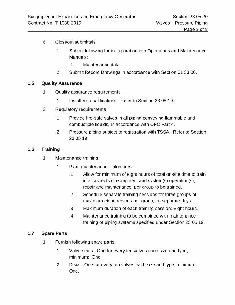
Scugog Depot Expansion and Emergency Generator Section 23 05 20 Contract No. T-1038-2019 Valves – Pressure Piping Page 3 of 8
.6 Closeout submittals
.1 Submit following for incorporation into Operations and Maintenance Manuals: .1 Maintenance data.
.2 Submit Record Drawings in accordance with Section 01 33 00.
1.5 Quality Assurance
.1 Quality assurance requirements
.1 Installer’s qualifications: Refer to Section 23 05 19.
.2 Regulatory requirements
.1 Provide fire-safe valves in all piping conveying flammable and combustible liquids, in accordance with OFC Part 4.
.2 Pressure piping subject to registration with TSSA. Refer to Section 23 05 19.
1.6 Training
.1 Maintenance training
.1 Plant maintenance – plumbers: .1 Allow for minimum of eight hours of total on-site time to train
in all aspects of equipment and system(s) operation(s), repair and maintenance, per group to be trained.
.2 Schedule separate training sessions for three groups of maximum eight persons per group, on separate days.
.3 Maximum duration of each training session: Eight hours.
.4 Maintenance training to be combined with maintenance training of piping systems specified under Section 23 05 19.
1.7 Spare Parts
.1 Furnish following spare parts:
.1 Valve seats: One for every ten valves each size and type, minimum: One.
.2 Discs: One for every ten valves each size and type, minimum: One.

Scugog Depot Expansion and Emergency Generator Section 23 05 20 Contract No. T-1038-2019 Valves – Pressure Piping Page 4 of 8
.3 Stem packing: One for every ten valves and type, each size, minimum: One.
.4 Stem and ball: One for every ten valves, each size and type, minimum: One.
.5 Valve handles: Two of each size.
.6 Gaskets and O-rings for flanges: One for every flanged joint.
.7 Valve: One complete valve assembly for each application.
2 Products
2.1 General
.1 Except for specialty valves, to be of single manufacturer.
.2 Valves individually tested.
.3 Requirements common to valves, unless specified otherwise:
.1 Pressure-temperature ratings: to ANSI B16.34.
.2 Inspections and tests: to API 598.
.3 Pressure testing: to MSS SP-61.
.4 Flanged valves: .1 Face-to-face dimensions: to ANSI B16.10. .2 Flange dimensions: to ANSI B16.5 with 1.6 mm raised face.
.5 Butt-weld valves: .1 End-to-end dimensions: to ANSI B16.10. .2 End dimensions: to ANSI B16.25 bored for pipe schedule as
indicated. .6 Socket weld valves:
.1 End to end dimensions: to ANSI B16.10.
.2 End dimensions: to ANSI B16.11. .7 Hand operator: Heavy duty lever, 2 mm thickness stainless steel,
with markings to MSS SP-25. .8 Markings: to MSS SP-25.

Scugog Depot Expansion and Emergency Generator Section 23 05 20 Contract No. T-1038-2019 Valves – Pressure Piping Page 5 of 8
.9 Identification: .1 Plate showing catalogue number, size, material of body disc,
stem seat, fluid, pressure-temperature rating. .2 Body markings: manufacturer, size, primary service rating,
material symbol. .10 CRN registration number required for all products.
2.2 Ball Valve – Low Pressure (WP up to 300 psi)
.1 Application
.1 Antifreeze.
.2 Threaded ball valve (NPS 1” and smaller)
.1 Carbon steel body, PTFE seats.
.2 Stainless steel ball and stem.
.3 Stainless steel handle and nut.
.4 API-607 fire safe for flammable fluids (windshield fluid).
.3 Ball valve – socket weld ends (1” or larger)
.1 Three-piece carbon steel body, PTFE seats.
.2 Stainless steel ball and stem.
.3 Stainless steel handle and nut.
.4 API-607 fire safe for flammable fluids (windshield).
.5 MSS-SP-110.
2.3 Ball Valve – Medium Pressure (WP up to 500 psi)
.1 Application
.1 Engine oil.
.2 Transmission oil.
.3 Multi grade oil
.4 Diesel Engine oil
.5 Gear oil.
.2 Ball valve – threaded ends (NPS ¾ and smaller)
.1 Carbon steel body, PTFE seats.

Scugog Depot Expansion and Emergency Generator Section 23 05 20 Contract No. T-1038-2019 Valves – Pressure Piping Page 6 of 8
.2 Stainless steel ball and stem.
.3 Stainless steel handle and nut.
.4 MSS SP-110.
.3 Ball valve – socket weld ends (NPS 1 and larger)
.1 Three-piece carbon steel body, PTFE seats.
.2 Stainless steel ball and stem.
.3 Stainless steel handle and nut.
.4 MSS SP-110.
.4 Ball valve – double union ends (NPS 1 and larger)
.1 Carbon steel double union end socket weld ball valve.
.2 Stainless steel (316) ball and stem.
.3 Stainless steel lever and nut.
.4 RPTFE seat, bearing and packing.
2.4 Ball Valve – High Pressure (WP up to 6000 psi)
.1 Application: Grease.
.2 Ball valve – thread ends (NPS ¾ and smaller)
.1 Carbon steel body, fully ported, Delrin seat.
.2 Stainless steel ball and stem.
.3 12,000 psi WOG.
.3 Ball valve – socket weld flange adapters (NPS 1” and larger)
.1 Carbon steel body, Delrin seat, Viton O-rings.
.2 Stainless steel (316) ball and stem.
.3 Split flange connector, SAE Code 62.
.4 Socket-weld code 62 flanges.
.5 SAE Code 62 split flange.
.6 Valve: 6000 psig WOG.

Scugog Depot Expansion and Emergency Generator Section 23 05 20 Contract No. T-1038-2019 Valves – Pressure Piping Page 7 of 8 3 Execution
3.1 Installation - General
.1 Install to manufacturer's recommendations.
.2 Unless required otherwise, align valves with piping and building structure.
.3 Horizontal pipes: Install in upright position with stem above horizontal in vertical alignment.
.4 Vertical pipes: Install valve stem and handle away from wall or other obstructions.
.5 Valve handle shall indicate normal direction of flow when in open position.
.6 Arrange and locate valves so handles do not interfere with adjacent pipes, other valves, equipment or building structure in all possible valve handle positions.
.7 Three-piece valves: Remove middle section during socket welding. Provide appropriate spacer to maintain required spacing and alignment.
.8 SAE flanged valves: Remove middle section during socket welding. Provide appropriate spacer to maintain required spacing and alignment.
.9 In addition to locations indicated on Drawings, plans and schematics, provide valves in following areas:
.1 As required to permit installation and testing of piping.
.2 As required to drain low sections of piping.
.3 As required to permit flushing, cleaning and charging of piping.
.10 Tag valves and submit valve chart and floor plan in accordance with Section 23 05 53.
.11 Support piping within 300 mm of a valve in accordance with Section 23 05 29.
.12 Maintain records of valve CRNs. Submit to authority in accordance with Section 23 05 19.
3.2 Valve Accessibility
.1 Locate valves in accordance with following order of preference:
.1 Adjacent to equipment served.

Scugog Depot Expansion and Emergency Generator Section 23 05 20 Contract No. T-1038-2019 Valves – Pressure Piping Page 8 of 8
.2 Locate within hand reach of floor level.
.3 Locate within hand reach of 10’ step ladder.
.4 Locate within hand reach in areas accessible to scissor lift.
.2 Where possible, locate all valves visible from floor level, not obstructed by ductwork or suspended ceilings. Provide signage indicating location of visually obstructed valves.
3.3 Threaded Valves
.1 Install only where permitted. Refer to Section 23 05 19.
3.4 Testing
.1 Perform pressure testing of valves with piping systems specified under Section 23 05 19.
3.5 Protection
.1 During construction, testing and start-up, tag and lock-out all valves that may result in leaks or injury if unwittingly opened.
End of Section

Scugog Depot Expansion and Emergency Generator Section 23 05 23 Contract No. T-1038-2019 Pipes, Fittings And Valves Page 1 of 36 1 General
1.1 Summary
.1 Section Includes, but is not limited to, the following:
.1 Bedding and backfill, escutcheon plates, pipes and fittings and valves.
.2 Labour, Products, equipment and services necessary to complete the Work of this section.
1.2 Reference Standards
.1 Contractor Certification
.1 Contractors providing Work regulated under O.Reg. 220/01 Boilers and Pressure Vessels are to be holders of a Technical Standards and Safety Authority (TSSA) Certificate of Authorization to conduct this Work, including: .1 Pressure piping fabrication and installation .2 Boiler and pressure vessel repairs and alterations
.2 Registration
.1 Register with the TSSA, and pay associated registration and inspection costs, for pressure piping systems regulated under O.Reg. 220/01 Boilers and Pressure Vessels.
1.3 Submittals
.1 Shop Drawings
.1 Submit valve Shop Drawings in accordance with Section 01 33 00.
2 Products
2.1 Bedding And Backfill
.1 Materials
.1 From bottom of trench to 300 mm above top of pipe: .1 New granular "A" material of bank run sand and gravel or
crushed stone of non-organic nature.

Scugog Depot Expansion and Emergency Generator Section 23 05 23 Contract No. T-1038-2019 Pipes, Fittings And Valves Page 2 of 36
.2 From 300 mm above top of pipe to underside of gravel sub base or landscaping soil: .1 New granular material conforming to OPSS 1010 granular
"B" requirements.
.2 Samples
.1 Submit handcarry samples of backfill materials in heavy duty, clear plastic bags to the Consultant at the job site prior to purchasing.
.2 Material delivered to the job site will be inspected by the Consultant and any material considered unsuitable will be rejected.
2.2 Escutcheon Plates
.1 Materials
.1 Heavy chrome plated cast brass or stamped metal.
.2 Two-piece construction fitted with substantial hinges and positive latches.
.3 Fit all plates with tempered springs to ensure positive attachment to the pipe.
2.3 Pipe And Fittings - Pressure Piping - Ferrous
.1 General
.1 Pressure class and pipe schedules as shown on piping data sheets unless specified herein.
.2 Galvanized pipe and fittings: where indicated on piping data sheets unless specified herein.
.2 Pipe
.1 Carbon steel - general use .1 Black carbon steel: to ASTM A53 Grade B, seamless or
ERW .2 Black carbon steel, for fire protection systems: to ASTM
A795, A53, A135 .3 Bevelled, plain or grooved ends as per piping data sheets .4 For buried pipe: “Yellow Jacket” polyethylene jacket coating,
minimum 22 mil thickness

Scugog Depot Expansion and Emergency Generator Section 23 05 23 Contract No. T-1038-2019 Pipes, Fittings And Valves Page 3 of 36
.3 Fittings
.1 Threaded .1 Black banded malleable iron threaded fittings: to ASTM
A197 and ANSI B16.3 .2 Black cast iron threaded fittings: to ASTM A126 Class A and
ANSI B16.1 .2 Flanged
.1 Galvanized cast iron, flanged flat face: to ASTM A126 Class A and ANSI B16.1
.2 Black cast iron flanged flat face: to ASTM A126 and ANSI B16.4
.3 Drainage .1 Standard galvanized cast iron drainage fittings: to ANSI
B16.12 .4 Socket welded
.1 Forged steel socket welding type: to ASTM A105 Grade 2 and ANSI B16.11
.2 For underground pipe: Protect joints and fittings with Shaw “Shrink-Sleeves” or a coating of Denso Paste wrapped with Denso Tape applied with at least 50% overlap
.5 Butt welded .1 Seamless carbon steel butt weld fittings, with wall thickness
to match pipe: to ASTM A234 WPB and ANSI B16.9 .2 For underground pipe: Protect joints and fittings with Shaw
“Shrink-Sleeves” or a coating of Denso Paste wrapped with Denso Tape applied with at least 50% overlap
.3 Long radius elbows
.4 Unions
.1 General use .1 Black malleable iron with brass ground joint and screwed
ends: to ASTM A197 and ANSI B2.1

Scugog Depot Expansion and Emergency Generator Section 23 05 23 Contract No. T-1038-2019 Pipes, Fittings And Valves Page 4 of 36
.5 Flanges
.1 Welded .1 Forged steel raised face slip-on or weld neck type: to ASTM
A181 Grade 1 and ANSI B16.5 .2 Provide flat faced flanges for connection to cast iron valves,
or equipment having a flat faced flange .2 Screwed
.1 Cast iron, galvanized, flat face, screwed: to ASTM A126 Class A and ANSI B16.1
.6 Flange Gaskets
.1 General service water < 94°C maximum pressure: 1720 kPa .1 1.6 mm thick red rubber, ring type for raised face flanges .2 Full face type for flat faced flanges
.2 Hot water 94°C - 152°C maximum pressure: 6890 kPa
.3 1.6 mm thick Garlock No. 3000 with nitrile binder flat ring type, or equivalent asbestos-free material manufactured by Anchor or Phelps
.4 Gas piping, maximum pressure: 6890 kPa .1 1.6 mm thick Garlock No. 3000 with nitrile binder flat ring
type, or equivalent asbestos-free material manufactured by Anchor or Phelps
.5 Compressed air piping, maximum pressure: 8200 kPa .1 1.6 mm thick Garlock No. 3200 with SBR binder flat ring
type, or equivalent asbestos-free material manufactured by Anchor or Phelps
.7 Flange Bolting
.1 General use .1 Semi-finished hex head machine bolts, carbon steel: to
ASTM A193 Grade B7 .2 Semi-finished hex nuts, carbon steel: to ASTM A194 Grade
2H

Scugog Depot Expansion and Emergency Generator Section 23 05 23 Contract No. T-1038-2019 Pipes, Fittings And Valves Page 5 of 36
.8 Miscellaneous
.1 Plugs .1 Class 3000, threaded, square head, machined from solid
steel or forging: to ASTM A105 Grade 2 .2 Closures, welded
.1 Schedule 40 seamless butt welded caps, carbon steel, with wall thickness to match pipe: to ASTM A234 Grade B
.3 Thread compound .1 General service: Teflon tape or Master metallic compound .2 Petroleum based fluids service: Teflon base pipe thread
compound .3 Ammonia service: X-Pando or reviewed equal
2.4 Pipe And Fittings - Pressure Pipe - Non Ferrous
.1 Copper Tubing
.1 Tubing .1 Type “L” hard drawn copper tubing: to ASTM B88
.2 Fittings .1 Wrought copper, solder joint, pressure type .2 Solder to threaded adaptors as screwed valves or equipment
.3 Unions .1 All bronze construction with ground joint .2 Either solder joint or screwed ends as required
.2 Copper Pipe
.1 Pipe .1 Seamless copper pipe standard sizes: to ASTM B42
OR
.2 Seamless red brass pipe standard sizes: to ASTM B43 .2 Fittings
.1 Brass or bronze threaded water fittings: to ANSI B16.15 “Cast Bronze Threaded Fittings (Classes 125 and 250)"

Scugog Depot Expansion and Emergency Generator Section 23 05 23 Contract No. T-1038-2019 Pipes, Fittings And Valves Page 6 of 36
.3 Flanges and flange fittings .1 Brass or bronze flanges and flange fittings: to ANSI B16.24
“Bronze Pipe Flanges and Flanged Fittings (Class 150 and 300)"
.4 Flange gaskets .1 1.6 mm thick red rubber, full face type
.5 Flange bolting .1 Semi-finished hex head machine bolts, carbon steel: to
ASTM A193 Grade B7 .2 Semi-finished hex nuts, carbon steel: to ASTM A194 Grade
2H
.3 Copper - Refrigerant Piping
.1 Pipe .1 Type ACR copper tubing, soft annealed or hard drawn .2 Type ACR copper tubing, hard drawn: to ASTM B280 .3 Deoxidized and dehydrated, with ends factory sealed and
identified by the manufacturer as being suitable for refrigeration service
.2 Fittings .1 Heavy wrought copper, solder joint type .2 Adapter fittings at screwed connections .3 On NPS 5/8 and less, flareless compression type
.3 Unions .1 Rating: 150°C maximum temperature rating, 2760 kPa
working pressure .2 Brass tail piece adaptors for copper tubing, forged steel
flanges, steel bolts, bronze nuts and asbestos-free fibre gasket
.3 Acceptable manufacturers: Henry Valve Company Type P30
.4 Or reviewed equal .4 Flexible hose
.1 Bronze construction with braided wire exterior jacket and union connection on one end

Scugog Depot Expansion and Emergency Generator Section 23 05 23 Contract No. T-1038-2019 Pipes, Fittings And Valves Page 7 of 36
.2 Minimum length: Six times the diameter of the hose
.3 Rating: suitable for 150°C maximum temperature and 2760 kPa working pressure
.4 Acceptable manufacturers: Flexonics or Anaconda
.5 Or reviewed equal
.6 Coiled section of soft annealed tubing may be used instead of hose on lines not larger than NPS 5/8
.5 Sight glass .1 Provided in refrigeration piping .2 Combination moisture and liquid indicator feature and
extended ends for solder joint connection .6 Filter dryer
.1 Provided in refrigeration piping
.2 Replaceable cartridge type
.4 PVC pipe
.1 Pipe and fittings .1 PVC with solvent welded socket fittings: to CAN3-B137.3-M
2.5 Pipe And Fittings - Pressure - Buried
.1 Copper - Buried
.1 Pipe .1 Type “K” soft annealed tubing: to ASTM B88
.2 Fittings .1 Wrought copper, solder joint pressure type .2 Compression type or cold flared fittings as manufactured by
Mueller or Emco
.2 Polyethylene - Buried - Water
.1 Pipe .1 Series 160 psi polyethylene pipe: certified to CSA B137.1-M .2 Smooth finish free of imperfections such as grooves and
ripples

Scugog Depot Expansion and Emergency Generator Section 23 05 23 Contract No. T-1038-2019 Pipes, Fittings And Valves Page 8 of 36
.2 Fittings .1 Nylon insert type, with serrated ends and insert adapters
with threaded end where threaded connections are required: to ASTM D2609
.2 Secure pipe to insert fittings by using two stainless steel type clamps over each insert end of fitting
.3 Where water service enters building, provide transition from plastic to copper no more than 450 mm above the floor
.3 Polyethylene - Buried - Gas
.1 Pipe .1 Series 120 psi polyethylene pipe: certified to CSA B137.1-M .2 Smooth finish free of imperfections such as grooves and
ripples .2 Fittings
.1 Series 125 polyethylene socket welding type: certified to CAN3-B137.4-M
.2 Heat fusion joints, installed in accordance with manufacturer’s installation manuals
.3 Install in accordance with CSA Z184-M and Z184S1
.4 Ductile iron - Buried
.1 Pipe .1 Centrifugal cast ductile iron: to AWWA C151 .2 Wall thickness Class (51)(52)(54): to AWWA C150 .3 Mechanical joint or bell and spigot push-on type ends: to
AWWA C111 .4 Cement mortar lined: to AWWA C104 .5 Polyethylene encasement: to AWWA C105
.2 Fittings .1 Class 250 cast grey or ductile iron with mechanical joints: to
AWWA C110 .2 Cement mortar lined: to AWWA C104 .3 Polyethylene encasement: to AWWA C105

Scugog Depot Expansion and Emergency Generator Section 23 05 23 Contract No. T-1038-2019 Pipes, Fittings And Valves Page 9 of 36
.3 Joints .1 Components for either mechanical or bell and spigot push-
on type: to AWWA C111 .2 Adapters for connection to valves and non-bell and spigot
fittings .3 Brass wedges, inserts or copper bonding straps at all joints
for electrical continuity
.5 PVC - Buried
.1 Pipe .1 Class 150 PVC DR18 pressure type, PVC resin: to ASTM
D1784 .2 Fittings
.1 Class 250 cast grey iron or ductile iron, mechanical joint ends to AWWA C110
.2 Tar coated outside
.3 Cement mortar lined: to AWWA C104
.4 Polyethylene encasement: to AWWA C105 .3 Joints
.1 To AWWA C-900 and CAN3-B137.3
.2 Maximum working pressure: 1035 kPa at 23°C
2.6 Pipe And Fittings - Drainage Systems
.1 Cast Iron Soil Pipe
.1 Pipe and fittings .1 Cast iron soil pipe: to CAN/CSA-B70-M .2 Plain end pipe and fittings
.2 Joints .1 Bell and spigot, with lead and oakum joints .2 NPS 8 and smaller: Neoprene sleeves with stainless steel
gear type clamps, where approved by local authorities

Scugog Depot Expansion and Emergency Generator Section 23 05 23 Contract No. T-1038-2019 Pipes, Fittings And Valves Page 10 of 36
.2 PVC Soil Pipe
.1 Pipe - below grade - sanitary and storm drainage .1 All sizes: to CAN/CSA-B181.2 “PVC Drain, Waste and Vent
Pipe and Pipe Fittings” .2 Bell and spigot ends .3 Rubber ring gaskets with bell
.2 Pipe - below grade - storm drainage (alternate) .1 2" to 6": to CSA B182.1-M .2 8" and up: to CSA B182.2-M .3 Bell and spigot ends .4 Rubber ring gaskets with bell
.3 Pipe - above grade - sanitary and storm drainage .1 All sizes: to CAN/CSA-B181.2 “PVC Drain, Waste and Vent
Pipe and Pipe Fittings” .2 Plain end with solvent weld joints .3 ABS or PVC solvent cement
.4 Fire stop seal for combustible pipe .1 Certification: to CAN4-S115-M tested at a pressure
differential of 50 Pa .2 Fire stop rating: Class F .3 Fire resistance rating: not less than that of the fire separation
being penetrated .5 Acceptable manufacturers:
.1 3M - Ultra Plastic Pipe Device
.2 Or reviewed equal
.3 Copper - DWV
.1 Pipe .1 Hard drawn copper drainage tube (DWV): to ASTM B306
.2 Drainage fittings .1 Wrought copper solder joint: to ANSI B16.29 .2 Cast brass solder joint: to CSA B158.1

Scugog Depot Expansion and Emergency Generator Section 23 05 23 Contract No. T-1038-2019 Pipes, Fittings And Valves Page 11 of 36 2.7 Valves
.1 General
.1 Gate valves re-packable under pressure, when fully open
.2 Plug valves packed with lubricant suitable for service
.3 Globe and check valves provided with composition discs suitable for type of service
.4 Renewable seats on iron body valves
.5 Materials .1 ASTM B62: Bronze valves - gate, globe and check - steam
rated 125 and 150 psig .2 ASTM B61: Bronze valves - gate, globe and check - steam
rated 200 and 350 psig .3 ASTM B283 C3770: Brass valves - ball valves .4 ASTM A126 Class B: ron valves - gate, globe and check
.6 Markings .1 MSS-SP-25: Steam or WOG (water, oil and gas) rated
pressure, manufacturer’s trademark, size .7 End connections
.1 ANSI B2-1: Threaded ends
.2 ANSI B16.18: Soldered ends
.3 ANSI B16.10: Face to face dimensions .8 Testing and materials
.1 MSS-SP-80: Bronze valves, gate, globe and check
.2 MSS-SP-70: Iron gate valves
.3 MSS-SP-85: Iron globe valves
.4 MSS-SP-71: Iron check valves
.5 MSS-SP-67: Butterfly valves
.2 Gate Valves
.1 GTV 1 .1 Class 125 bronze body, screwed ends, solid or split wedge
disc, rising stem .1 Crane Fig 428

Scugog Depot Expansion and Emergency Generator Section 23 05 23 Contract No. T-1038-2019 Pipes, Fittings And Valves Page 12 of 36
.2 Nibco T-111
.3 Toyo Red-White Fig 293
.4 Kitz Fig 24
.5 Or reviewed equal. .2 GTV 2
.1 Class 125 iron body, OS&Y bronze mounted, flanged ends .1 Crane Fig 465 ½ .2 Nibco F-617 .3 Toyo Red-White Fig 421JA .4 Kitz Fig 72 .5 Or reviewed equal.
.3 GTV 3 .1 Class 125 bronze body, screwed ends, rising stem, wedge
disc, screw-in bonnet .1 Crane Fig 428 .2 Nibco T-111 .3 Toyo Red-White Fig 293 .4 Kitz Fig 24 .5 Or reviewed equal.
.4 GTV 4 .1 175 psi working pressure, to AWWA C-500, non-rising stem,
iron body, bronze mounted, renewable seat rings, stuffing box and packing gland, mechanical joint ends. Valve box to grade, with guide plate and cover identifying the service. Valves and valve box finish: two heavy coats of coal tar enamel. Provide one extension key for each valve box installed
.2 Valve .1 Jenkins Fig 2397A .2 Or reviewed equal.
.3 Box .1 Bibby VB Series

Scugog Depot Expansion and Emergency Generator Section 23 05 23 Contract No. T-1038-2019 Pipes, Fittings And Valves Page 13 of 36
.2 Canada Valve Fig 1322
.3 Mueller Fig A769
.4 Or reviewed equal. .5 GTV 5
.1 175 psi WOG, ULC and FM approved, iron body, bronze mounted, cast iron disc, resilient seat, mechanical joint ends, non-rising stem, square operating nut. Finish: two heavy coats of coal tar enamel .1 Clow .2 Mueller Canada .3 Or reviewed equal.
.6 GTV 6 .1 175 psi WOG, ULC and FM approved, iron body, bronze
mounted, OS&Y, flanged ends .1 Clow .2 Mueller Canada .3 Nibco F-607 .4 Or reviewed equal.
.7 GTV 7 .1 Class 125, bronze body, wedge disc, non-rising stem, solder
ends .1 Crane Fig 1324 .2 Toyo Red-White Fig 281 .3 Kitz Fig 41 .4 Nibco S-113 .5 Or reviewed equal.
.8 GTV 13 .1 Main stop valve, service box of required length with ribbed
cover brought up flush to finished grade or floor, shut-off key .1 Mueller Corporation .2 Or reviewed equal.
.3 Globe Valves
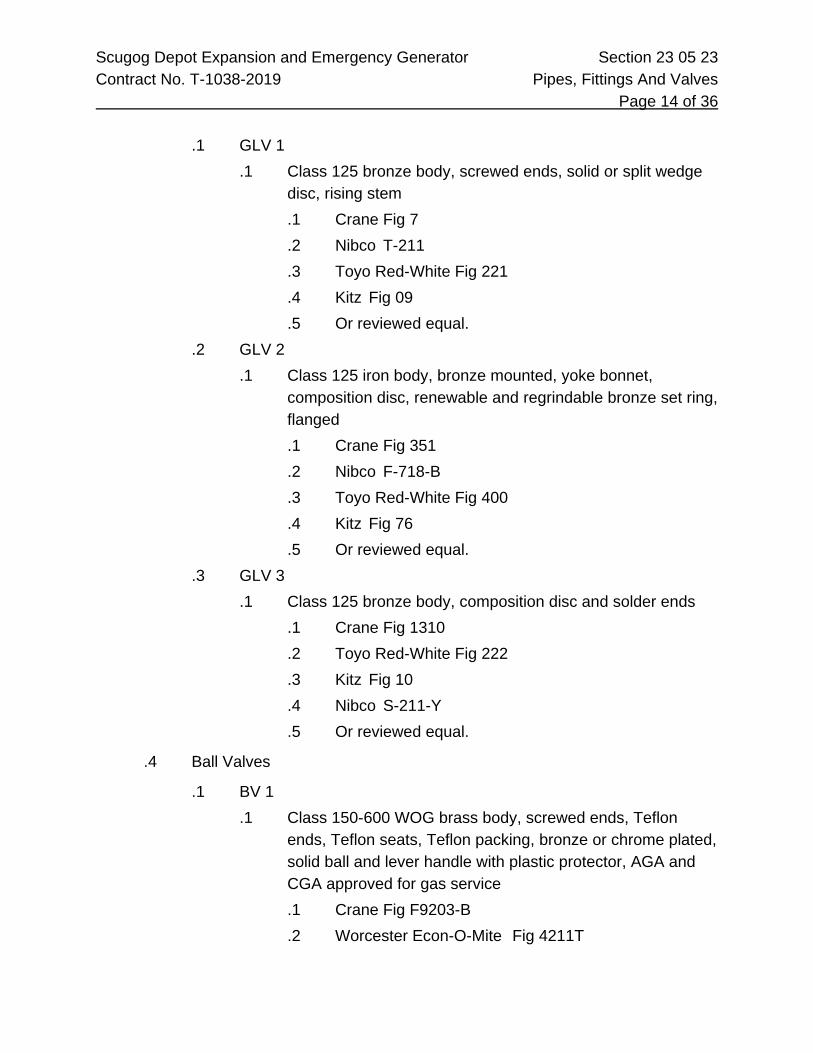
Scugog Depot Expansion and Emergency Generator Section 23 05 23 Contract No. T-1038-2019 Pipes, Fittings And Valves Page 14 of 36
.1 GLV 1 .1 Class 125 bronze body, screwed ends, solid or split wedge
disc, rising stem .1 Crane Fig 7 .2 Nibco T-211 .3 Toyo Red-White Fig 221 .4 Kitz Fig 09 .5 Or reviewed equal.
.2 GLV 2 .1 Class 125 iron body, bronze mounted, yoke bonnet,
composition disc, renewable and regrindable bronze set ring, flanged .1 Crane Fig 351 .2 Nibco F-718-B .3 Toyo Red-White Fig 400 .4 Kitz Fig 76 .5 Or reviewed equal.
.3 GLV 3 .1 Class 125 bronze body, composition disc and solder ends
.1 Crane Fig 1310
.2 Toyo Red-White Fig 222
.3 Kitz Fig 10
.4 Nibco S-211-Y
.5 Or reviewed equal.
.4 Ball Valves
.1 BV 1 .1 Class 150-600 WOG brass body, screwed ends, Teflon
ends, Teflon seats, Teflon packing, bronze or chrome plated, solid ball and lever handle with plastic protector, AGA and CGA approved for gas service .1 Crane Fig F9203-B .2 Worcester Econ-O-Mite Fig 4211T

Scugog Depot Expansion and Emergency Generator Section 23 05 23 Contract No. T-1038-2019 Pipes, Fittings And Valves Page 15 of 36
.3 Neles-Jamesbury Fig 351
.4 Toyo Red-White Fig 5044A
.5 Kitz Fig 58
.6 M.A.S. Fig B-3
.7 Or reviewed equal. .2 BV 2
.1 Class 150-600 WOG brass body, soldered ends, Teflon ends, Teflon seats, Teflon packing, bronze or chrome plated, solid ball and lever handle with plastic protector, AGA and CGA approved for gas service .1 Crane Fig F9223-B .2 Worcester Econ-O-Mite Fig 4211 .3 Neles-Jamesbury Fig 341 .4 Toyo Red-White Fig 5044A or 5049A .5 Kitz Fig 58 or 59 .6 Apollo Fig 77-100 or 77-200 .7 MAS Fig B-3 or B-4 .8 Or reviewed equal.
.3 BV 3 .1 Class 2000/1500 WOG, stainless steel body, stainless steel
ball, Teflon seat, Teflon packing, stainless steel handle .1 Crane Fig 9502-S .2 Neles-Jamesbury Fig “Eliminator” .3 Kitz Fig AKUTAHM .4 Apollo Fig 76-100 .5 MAS Fig G-2E (1000 wog) or G-2 (2000 wog) .6 Or reviewed equal.
.4 BV 4 .1 Type 316 stainless steel body, ball and stem, 3-piece body,
full port rated “fire safe”, Teflon seats, grafoil seals, threaded or socket welded end connection, lever operated .1 VCI Fig 201FS

Scugog Depot Expansion and Emergency Generator Section 23 05 23 Contract No. T-1038-2019 Pipes, Fittings And Valves Page 16 of 36
.2 Kitz Fig AKU3TFZM-FS
.3 MAS Fig G-3-HD-FS
.4 Or reviewed equal. .5 BV 10
.1 Class 150, PVC, solvent weld joints .1 Chemtrol Series SU .2 Or reviewed equal.
.5 Butterfly Valves
.1 BFV 1 .1 Class 150 full tapped lug type, cast iron body, bronze disc,
304 stainless steel shaft, EPDM seat, notched top plate .2 Lever lock handle for valve sizes NPS 6 and smaller .3 Worm gear operator with handwheel for valves NPS 8 and
larger .1 Crane Fig 44 BXZ .2 Keystone Fig FH12-CBJ-2 .3 Nibco LD-2000 .4 Nibco N-200 .5 De Zurik Fig BGS, L1/632 .6 Victaulic Fig Series 704 .7 Apollo Fig Series 143 .8 Bray Fig 31-119 .9 Kitz Fig 6122EL/G .10 Toyo Fig 918BESL/G .11 Or reviewed equal.
.6 Plug Valves
.1 PV 1 .1 Class 175 WOG rating, lubricated plug valve, semi-steel
body, tapered plug, screwed ends, wrench operated .1 Rockwell-Nordstrom Fig 142 .2 Newman-Milliken Fig 170M

Scugog Depot Expansion and Emergency Generator Section 23 05 23 Contract No. T-1038-2019 Pipes, Fittings And Valves Page 17 of 36
.3 Walworth Fig 1796
.4 Or reviewed equal. .2 PV 2
.1 Class 175 WOG rating, lubricated plug valve, semi-steel body, tapered pug, flat faced flanged ends drilled to 862 Pa ANSI
.2 Valves NPS 6 and less: manual lever operated
.3 Valves NPS 8 and larger: worm gear operated .1 Rockwell-Nordstrom Fig 143 .2 Newman-Milliken Fig 172M .3 Walworth Fig 1797F .4 Or reviewed equal.
.7 Check Valves
.1 CV 1 .1 Class 125 horizontal swing check valve, bronze body,
screwed ends, screwed cap and regrindable bronze disc .1 Crane Fig 37 .2 Nibco T-413 .3 Toyo Red-White Fig 236 .4 Kitz Fig 22 .5 Or reviewed equal.
.2 CV 2 .1 Class 125 horizontal check valve, iron body, bronze
mounted, flat face flanged ends, renewable and regrindable bronze seat ring and disc .1 Crane Fig 373 .2 Nibco F-918 .3 Toyo Red-White Fig 435JA .4 Victaulic Series 715 .5 Gestra “CB” Series .6 Kitz Fig 78 .7 Or reviewed equal.

Scugog Depot Expansion and Emergency Generator Section 23 05 23 Contract No. T-1038-2019 Pipes, Fittings And Valves Page 18 of 36
.3 CV 3 .1 Class 125 wafer type non-slam check valve, cast iron body,
bronze plates and Buna-N seals .2 Install between two flat faced flanges as specified for piping
NPS 4 and larger .1 Mission Valve “Duo-Chek” .2 Ritepro “Check Rite” .3 Gestra “RK” Series .4 Crane Fig R-1-66-4-F-1-X .5 Nibco W-920-W .6 Mueller Steam .7 Or reviewed equal.
.4 CV 4 .1 Class 125 horizontal swing check, bronze body, screwed
ends, screwed cap and regrindable bronze disc .1 Crane Fig 37 .2 Nibco S-413 .3 Toyo Red-White Fig 236 .4 Victaulic Series 712 .5 Kitz Fig 22 .6 Or reviewed equal.
.5 CV 6 .1 Class 150 lift check, bronze body, screwed ends, screw-in
cap, stainless steel or bronze disc, bronze seat ring .1 Crane Fig 27 .2 Nibco T-480 .3 Kitz Fig 36 .4 Or reviewed equal.

Scugog Depot Expansion and Emergency Generator Section 23 05 23 Contract No. T-1038-2019 Pipes, Fittings And Valves Page 19 of 36 3 Execution
3.1 Trenching, Bedding And Backfill
.1 General
.1 Extent: .1 For buried services inside building and to 1.5 m outside
building wall. .2 Trench depth:
.1 To 75 mm(150 mm) below the correct elevation and slope established for the bottom of the pipe.
.3 Bedding: .1 Refill the bottom elevation of the trench with hand-placed
bedding materials. .2 Thoroughly compact to the approval of the Consultant. .3 At pipe hubs or couplings, remove bedding in the bottom of
the trench as necessary to provide for even and constant support for each length of pipe.
.4 Shoring: .1 Provide adequate shoring, bracing and sheeting in pipe
trenches .2 Place barriers and temporary crossings as necessary to
ensure support, safety and protection at all times. .5 Unstable soil conditions:
.1 When encountered, advise the Consultant.
.2 Excavate pipe trenches to a depth as directed by the Consultant and then backfill to the correct grade with bedding material.
.6 Backfill: .1 Where joints occur, do not backfill until joint testing is
reviewed by Consultant. .2 Hand place backfill to 300 mm above the top of the pipe in
100 mm layers taking particular care to place and compact the backfill simultaneously on both sides of the pipe.
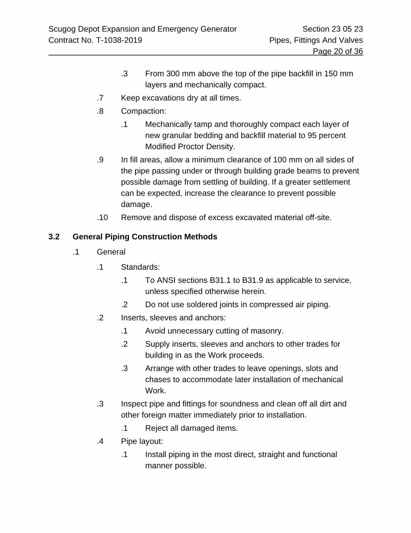
Scugog Depot Expansion and Emergency Generator Section 23 05 23 Contract No. T-1038-2019 Pipes, Fittings And Valves Page 20 of 36
.3 From 300 mm above the top of the pipe backfill in 150 mm layers and mechanically compact.
.7 Keep excavations dry at all times.
.8 Compaction: .1 Mechanically tamp and thoroughly compact each layer of
new granular bedding and backfill material to 95 percent Modified Proctor Density.
.9 In fill areas, allow a minimum clearance of 100 mm on all sides of the pipe passing under or through building grade beams to prevent possible damage from settling of building. If a greater settlement can be expected, increase the clearance to prevent possible damage.
.10 Remove and dispose of excess excavated material off-site.
3.2 General Piping Construction Methods
.1 General
.1 Standards: .1 To ANSI sections B31.1 to B31.9 as applicable to service,
unless specified otherwise herein. .2 Do not use soldered joints in compressed air piping.
.2 Inserts, sleeves and anchors: .1 Avoid unnecessary cutting of masonry. .2 Supply inserts, sleeves and anchors to other trades for
building in as the Work proceeds. .3 Arrange with other trades to leave openings, slots and
chases to accommodate later installation of mechanical Work.
.3 Inspect pipe and fittings for soundness and clean off all dirt and other foreign matter immediately prior to installation. .1 Reject all damaged items.
.4 Pipe layout: .1 Install piping in the most direct, straight and functional
manner possible.

Scugog Depot Expansion and Emergency Generator Section 23 05 23 Contract No. T-1038-2019 Pipes, Fittings And Valves Page 21 of 36
.2 Except where otherwise shown, install all vertical lines plumb, and run horizontal lines parallel to building walls.
.3 Install piping close to walls, partitions and ceilings.
.4 On multiple runs of piping, space piping to allow for installation of insulation and for proper servicing of valves.
.5 Conceal piping in finished areas and rooms within walls or ceilings, and in furred spaces elsewhere. .1 Provide access doors or panels as hereinafter specified for
access to concealed piping specialties, etc.
.2 Expansion and Contraction
.1 Installation: .1 Install all piping free from strain and distortion due to
expansion and contraction: to section 6, Chapter 3 of ANSI B31.1, except as hereinafter modified.
.2 Allow for expansion and contraction by offsets, expansion U-bends or loops.
.3 Expansion joints of any type will not be allowed unless specifically indicated on the Drawings or specified under another section of this division for a particular installation.
.2 Expansion/contraction allowance criteria: .1 Steel pipe: 25 mm movement per 30 m of pipe. .2 Brass and copper pipe: 38 mm movement per 30 m of pipe
.3 Temperature difference: for each 55°C temperature difference from 21°C ambient.
.4 Fabricate expansion bends in steel pipe from pipe sections and long radius welding elbows.
.3 Swing and swivel joints: .1 On steam or hot water heating piping for connections from
mains to risers and from risers to radiation and other heating units.
.2 Use at least five fittings from main to riser including tee in main.
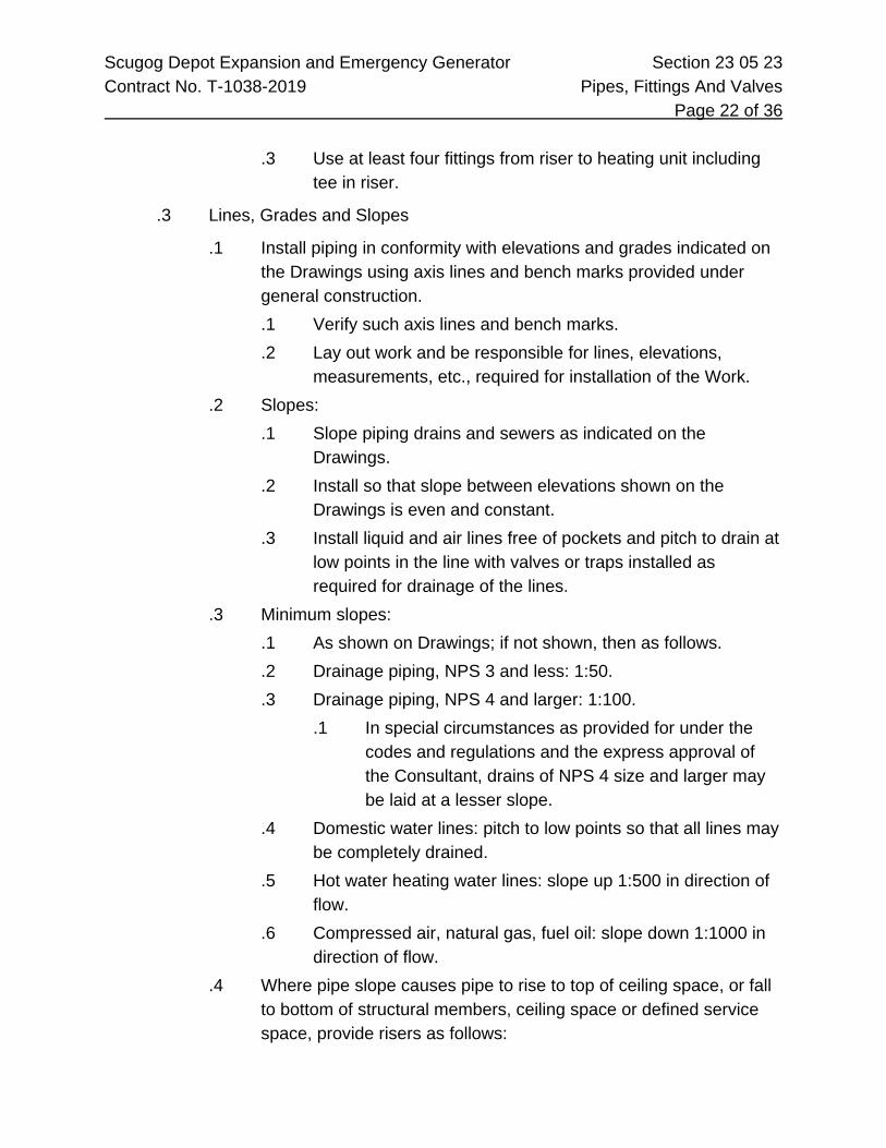
Scugog Depot Expansion and Emergency Generator Section 23 05 23 Contract No. T-1038-2019 Pipes, Fittings And Valves Page 22 of 36
.3 Use at least four fittings from riser to heating unit including tee in riser.
.3 Lines, Grades and Slopes
.1 Install piping in conformity with elevations and grades indicated on the Drawings using axis lines and bench marks provided under general construction. .1 Verify such axis lines and bench marks. .2 Lay out work and be responsible for lines, elevations,
measurements, etc., required for installation of the Work. .2 Slopes:
.1 Slope piping drains and sewers as indicated on the Drawings.
.2 Install so that slope between elevations shown on the Drawings is even and constant.
.3 Install liquid and air lines free of pockets and pitch to drain at low points in the line with valves or traps installed as required for drainage of the lines.
.3 Minimum slopes: .1 As shown on Drawings; if not shown, then as follows. .2 Drainage piping, NPS 3 and less: 1:50. .3 Drainage piping, NPS 4 and larger: 1:100.
.1 In special circumstances as provided for under the codes and regulations and the express approval of the Consultant, drains of NPS 4 size and larger may be laid at a lesser slope.
.4 Domestic water lines: pitch to low points so that all lines may be completely drained.
.5 Hot water heating water lines: slope up 1:500 in direction of flow.
.6 Compressed air, natural gas, fuel oil: slope down 1:1000 in direction of flow.
.4 Where pipe slope causes pipe to rise to top of ceiling space, or fall to bottom of structural members, ceiling space or defined service space, provide risers as follows:

Scugog Depot Expansion and Emergency Generator Section 23 05 23 Contract No. T-1038-2019 Pipes, Fittings And Valves Page 23 of 36
.1 Domestic water lines: Provide drain valve at bottom of low point, and Provide riser to increase elevation of piping.
.2 Hot water heating water lines: Provide automatic air vent, complete with drainage piping, at high point, Provide drain valve at bottom of low point and Provide riser to lower elevation of pipes.
.3 Compressed air: Provide a minimum a 75 mm deep dirt pocket with capped end, drain valve and Provide riser to increase elevation of piping.
.4 Natural gas: Provide a drip pocket with capped end, drain valve and Provide riser to increase elevation of piping. Pocket depth to be the greater of: 75 mm deep or equal to diameter of pipe. Pocket diameter to be the lesser of: NPS 2 or gas main pipe diameter.
.4 Immersion Wells and Sensing Bulbs
.1 Fitting size: .1 Pipe size NPS 2½ size and less: increase pipe length for
300 mm to minimum one pipe size larger to maintain equivalent unobstructed cross sectional area.
.2 Pack immersion wells in piping for liquids up to a temperature of 150°C with a mineral type grease prior to installation of sensing bulb.
.5 Piping Connections to Mains
.1 Gas and compressed air lines: .1 Make branch connections to respective horizontal piping of
larger diameter to the upper quadrant of the larger pipe. .2 Water piping:
.1 Make down feed piping connections to horizontal supply and return mains to the bottom quadrant of the mains.
3.3 System Requirements
.1 Plumbing
.1 Install complete plumbing, drainage and vent piping for washrooms, etc, in accordance with the Ontario Building Code.

Scugog Depot Expansion and Emergency Generator Section 23 05 23 Contract No. T-1038-2019 Pipes, Fittings And Valves Page 24 of 36
.2 Size vent lines based on developed pipe length and hydraulic load.
.3 Arrange piping within pipe spaces behind washroom fixtures to allow unimpeded access to piping for servicing.
.2 Gas Piping - Buried - Cathodic Protection
.1 Isolate buried piping between two buildings at both ends with dielectric unions or flanges.
.2 Protect piping by at least one 1 kg magnesium sacrificial anode every 30 m of run, welded to the buried gas pipe, to manufacturer’s installation instructions.
.3 Provide dielectric unions on piping NPS 2½ and less and dielectric flanges on piping NPS 3 and larger.
.3 Copper Pipe - Type L
.1 Provide dielectric unions or couplings at all connections between copper tubing and ferrous piping.
.4 Copper Pipe - Buried
.1 Provide dielectric unions at connection between cast iron or ductile iron water main and copper tubing.
.2 When required by municipal authority, provide 900 mm long copper gooseneck after corporation stop at connection to water main. Connection at water main to be at 45 degrees and gooseneck to have minimum 160 mm radius bend.
.5 Refrigerant Piping
.1 Install piping to conform to applicable requirements of ANSI B31.5 Code for Pressure Piping Section 5 "Refrigeration Piping" and CSA B52-M "Mechanical Refrigeration Code" latest issue.
.2 Make solder type joints with "sil-fos" silver solder or similar high melting point solder having a melting point of at least 538°C. Remove all interior parts of refrigerant specialties and valves before applying heat to the joint.
.3 Provide refrigerant hoses on refrigerant line connections to equipment with reciprocating or rotating elements.
.4 Test procedure and evacuation procedures: conform to ANSI B31.5.

Scugog Depot Expansion and Emergency Generator Section 23 05 23 Contract No. T-1038-2019 Pipes, Fittings And Valves Page 25 of 36
.5 Test pressure: in accordance with CSA Code B52-M.
.6 Provide all refrigerant required for testing and charging of the system.
.7 Purge refrigerant piping with anhydrous nitrogen prior to making connection to pre-evacuated equipment to ensure removal of all moisture and non-condensable gases.
.8 Completely evacuate to 0.5 torr (500 micron), seal and leave for twenty-four hours, re-evacuate to 0.5 torr, and charge all components of refrigeration system not evacuated by manufacturer, in accordance with manufacturer's printed recommendations.
.9 Do not use the refrigeration compressor to evacuate the system under any circumstances. Evacuation the system using a vacuum pump at an ambient temperature not less than 2°C to ensure removal of all moisture and non-condensable gases.
.10 After testing, evacuation and charging is completed, allow system to operate under normal conditions for a minimum period of twenty-four hours, at which time, moisture indicator should indicate a dry system. If it does not so indicate, change dryer and operate unit for another twenty-four hours. Repeat this procedure until moisture indicator indicates a thoroughly dry system.
.6 PVC - Buried - Pressure and Drainage Piping
.1 Provide a tracer wire directly over PVC pipe.
.7 PVC Drainage, Waste and Vent Piping
.1 Below grade: install in accordance with CSA B182.11 and manufacturer’s recommendations.
.2 Above grade: install in accordance with CSA B181.11 and B181.12 and manufacturer’s recommendations.
.3 Provide fire stop seals on all fire separation penetrations, except at connections through concrete floor slabs to non-combustible water closets.
.4 Do not use combustible piping in return air ceiling plenums or vertical riser shafts.

Scugog Depot Expansion and Emergency Generator Section 23 05 23 Contract No. T-1038-2019 Pipes, Fittings And Valves Page 26 of 36 3.4 Sleeves
.1 Installation Requirements
.1 Provide where piping passes through foundations, above grade floors and walls.
.2 Materials .1 Schedule 40 black steel pipe or type "K" copper tubing for
installation in foundations or floors .2 1 mm (20 gauge) galvanized sheet steel where installed in
above grade walls. .3 Terminate sleeves flush with finished ceilings, walls and floors on
grade. .1 For piping passing through floors above grade extend sleeve
a minimum of 75 mm above the floor. .4 Sleeve sizes
.1 Large enough to pass full thickness of pipe covering where same is used.
.2 With sufficient clearance between pipe/insulation and sleeve to allow for any lateral movement of piping due to expansion and contraction.
.5 Assume responsibility for the setting of all sleeves necessary for this Work in masonry walls during construction or in concrete forms before concrete is poured.
.6 Coat exterior surface of all sleeves of ferrous material with a heavy asphalt emulsion.
.2 Foundation Sleeves
.1 For pipes entering structures from below grade, seal the annular space between sleeve and pipe with prefabricated seals.
.3 Firestopping
.1 Provide firestopping on pipes passing through firewalls, fire separation walls or through walls, partitions or floors which are considered as serving as firestops. .1 Provide at partitions around washrooms. .2 Seal the space around the pipe, in the sleeve

Scugog Depot Expansion and Emergency Generator Section 23 05 23 Contract No. T-1038-2019 Pipes, Fittings And Valves Page 27 of 36
.4 Pipe Sleeves Through Roofs
.1 Supplied and installed under other Contracts or under roofing section, unless specifically shown otherwise on the Drawings.
.5 Future Services
.1 Fill sleeves for future use with lime mortar.
.6 Escutcheon Plates
.1 Place escutcheon plates on bare piping passing through finished walls or floors.
3.5 Joints, Unions, Flanges And Fittings
.1 Pipe Joints
.1 Preparation .1 Ream pipe ends and thoroughly clean all dirt, cuttings and
foreign matter from pipe after cutting and threading. .2 Thoroughly clean all fittings, valves and equipment before
connections are made. .3 Cut copper tubing with a tube cutter and clean the joining
surfaces of the tubing and fitting with fine emery cloth. Wipe clean with a dry cloth.
.2 Cast iron pipe sleeve joints .1 For cast iron plain end soil pipe, install sleeve type couplings
such as Titan Foundry Type MJ, or Bibby MJ Series 2000 or reviewed equal in strict accordance with manufacturer's printed instructions.
.3 Cast iron bell and spigot joints .1 Make joints either neoprene compression type preformed
gaskets such as Bibby "Bi-seal", and caulk in such a manner to produce a permanently tight joint.
.2 Cold caulking compound in cord form such as W.R. Meadows PC4 may also be used.
.3 Assemble preformed neoprene gaskets to manufacturer's printed instructions.
.4 Mechanical joints:

Scugog Depot Expansion and Emergency Generator Section 23 05 23 Contract No. T-1038-2019 Pipes, Fittings And Valves Page 28 of 36
.1 Assemble mechanical joint on ductile iron pressure pipe with cast iron gland, rubber sealing gasket and high strength malleable iron bolts in accordance with the manufacturer's recommendations.
.5 Soldered joints: .1 Make soldered joints on copper tubing in accordance with
the following usage: Service Solder Type
Domestic hot and cold water
95/5 with matching flux
Drainage, waste, vent 50/50 with matching flux Compressed air service “Sil-Fos” silver solder or
brazed
.2 Do not use core type solder. .6 Threaded joints:
.1 Use Teflon tape or Masters metallic compound with the compound applied to the male threads only and particular care taken to prevent the compound from reaching the interior of the pipe or fittings.
.7 Carbon steel welded joints: .1 To ANSI B31.1 section IX for welding. .2 Fusion welded joints made by electric arc welding, gas metal
arc welding, or oxy-acetylene gas welding. .3 Ensure that supervisory staff, fitters and welders are fully
conversant with the requirements laid down by that standard prior to the commencement of welding.
.4 Employ qualified welders holding a current up-to-date provincial certificate for the process and rating involved as required by the provincial regulations.
.5 Unless more stringent methods of inspections are specified the Consultant will visually inspect welded joints for fusion of metal, icicles, alignment, etc. .1 Remove any defects and remake the joint to his
satisfaction.

Scugog Depot Expansion and Emergency Generator Section 23 05 23 Contract No. T-1038-2019 Pipes, Fittings And Valves Page 29 of 36
.6 For welding of materials other than carbon steel, conform to the requirements specified in the relevant section of the Specification.
.2 Unions and Flanges
.1 Provide unions or flanges in the following locations: .1 For by-passes around equipment or control valves or
devices in piping systems. .2 At connection to steam traps and in by-passes around traps. .3 At connections to equipment. Locate between shut-off valve
and equipment. .4 In screwed or solder joint drainage tubing at inlet side of
trap. .2 If unions are concealed in walls, partitions or ceilings, build access
thereto. .3 Provide dielectric unions or isolating type companion flanges at all
connections between copper tubing and ferrous piping. .1 Brass body valves between ferrous piping and copper tubing
is acceptable as a dielectric union. .4 Flange joints
.1 Assemble joints with appropriate flanges, gaskets and bolting.
.2 Allow clearance between flange faces such that the connections can be gasketed and bolted tight without undue strain on the piping system, with flange faces parallel and bores concentric.
.3 Centre gaskets on the flange faces so as not to project into the bore.
.4 Lubricate bolts before assembly and provide two hardened steel washers under the head of each unit to assure uniform bolt stressing.
.5 Machine off raised face flanges when joining to a flat companion flange and use a full face gasket.
.6 Follow gasket manufacturer's instructions for correct bolting procedure.

Scugog Depot Expansion and Emergency Generator Section 23 05 23 Contract No. T-1038-2019 Pipes, Fittings And Valves Page 30 of 36
.7 Use calibrated torque wrench and tighten bolts in recommended sequence in four equal steps to required final torque value.
.3 Fittings
.1 Couplings .1 Minimize couplings on runs of pipes. .2 Do not use running couplings in any pipeline. .3 NPS 2 and smaller: threaded coupling. .4 NPS 2½ and larger: welded joints.
.2 Fittings and ancillary items installed in systems operating at pressures in excess of 103 kPa: .1 Register in accordance with CSA B51-M.
.3 Eccentric reducer fittings .1 To provide proper drainage or venting of the lines. .2 At change of pipe sizes. .3 At connections to equipment and control valves. .4 Do not use bushings.
.4 Tee connections in welded piping .1 Factory fabricated standard buttweld fittings. .2 Bonney Forge "Weldolets", "Thredolets" or "Sockolets". .3 Mitering, notching or direct welding of branches to mains is
not permitted. .5 Change of direction
.1 Use standard pipe fittings.
.2 Use long radius welded steel elbows unless short radius elbows are specifically authorized by the Consultant.
.3 Mitered joints or field fabricated pipe bends are not permitted.
.6 Tees, copper tubing .1 Direct connection of branch into main using "T-Drill" method
may be used where allowed by the code, in lieu of manufactured tee fittings.

Scugog Depot Expansion and Emergency Generator Section 23 05 23 Contract No. T-1038-2019 Pipes, Fittings And Valves Page 31 of 36 3.6 Valves
.1 Installation
.1 General .1 Wherever possible, source valves from one manufacturer.
.2 Where required .1 At locations shown on the Drawings. .2 At all piping connections to equipment. .3 At all connections to control valves or control devices. .4 Where required for sectionalizing a system or floor. .5 Check valves wherever required to ensure flow of liquid in
one direction. .3 Type
.1 Shut-off service: gate, butterfly type, and ball (quarter-turn).
.2 Throttling service: double regulating, globe or plug type for throttling purposes.
.4 Drain valves .1 Hose thread outlet connection or valve with long nipple on
outlet at all low points of each water system and above all riser or branch stop valves for proper drainage of lines.
.5 Valve chains .1 Provide chain wheel operators and operating chain for
valves located more than 2 m above floor or walkway. .2 Provide chain of sufficient length to extend to within 2 m of
operating platform or floor for free handing chains, or to within 1.5 m of floor in locations where chain can be secured to wall or column. Secure chain to wall or column with a wall hook.
.3 Chain wheels using rustproof chain complete with guide and of size recommended by valve manufacturer for proper operation of valve.

Scugog Depot Expansion and Emergency Generator Section 23 05 23 Contract No. T-1038-2019 Pipes, Fittings And Valves Page 32 of 36 3.7 Inspection And Testing
.1 Pressure Leak Testing
.1 Make specified pressure tests on all piping included in this Contract.
.2 Furnish all pumps, compressors, gauges and connectors necessary for the tests.
.3 Test sections as authorized by Consultant to accommodate construction schedule. However, test complete systems on completion of Work.
.4 Conduct tests in the presence of: .1 Consultant .2 Personnel of governing authorities having jurisdiction
.5 Notify above personnel in ample time to permit them to be present.
.6 Conduct tests before piping is painted, covered or concealed.
.7 Disconnect pumps or compressors used for applying the test pressure, during the test period.
.8 Disconnect and/or remove equipment or specialties not designed to withstand the test pressure during the test and reconnect same after completion of test.
.9 Promptly correct any defects that develop through tests and re-test to the complete satisfaction of the Consultant and other parties involved.
.10 Forward copies of all final tests on all pressure and drainage piping and a copy of governing authority approvals to the Consultant immediately on acceptance of tests and/or approvals.
.11 Final payment for the Work will not be made until the above has been received.
.2 Hydrostatic Tests
.1 Conduct tests for a minimum period of two hours, or longer when requested by the Consultant or governing authority at the test pressure specified under the respective section of the Specifications.

Scugog Depot Expansion and Emergency Generator Section 23 05 23 Contract No. T-1038-2019 Pipes, Fittings And Valves Page 33 of 36
.2 Test requirements: .1 Pressure to remain constant over test period to a pressure of
1½ times the operating pressure but not to exceed the material pressure class rating.
.2 Exterior surfaces of pipe or fittings free of cracks or other form of leak.
.3 Tests to be performed at a constant ambient temperature.
.3 Pneumatic tests
.1 Initially pressurize the system with air to approximately one-half the specified operating pressure but not to exceed 345 kPa. .1 Examine joints for leaks with a soapsuds solution. .2 Repair leaks as detected. .3 Repeat test and repairs until soap test passes.
.2 Provide a final pressure test on the system with air to the test pressure specified under the respective section of the Specifications.
.4 Natural Gas Piping
.1 Conduct final tests in accordance with the requirements of the local utility or governing authority.
.2 If feasible, make tests when ambient air temperature is approximately constant. .1 Corrections for pressure change due to temperature
differential shall be allowed as reviewed by the Consultant.
.5 Drainage and Potable Water Testing
.1 Test drainage piping and potable water piping in accordance with requirements of the Ontario Building Code, latest edition, and any additional requirements of applicable local by-laws.
.6 Specific Test Requirements
.1 Test the following services with compressed air or inert gas at 1½ times the working pressure, but in no event less than 345 kPa. .1 Natural gas piping

Scugog Depot Expansion and Emergency Generator Section 23 05 23 Contract No. T-1038-2019 Pipes, Fittings And Valves Page 34 of 36 3.8 Pre-Operational Cleaning
.1 Temporary Connections
.1 Make temporary cross-overs, blank-off equipment connections, install drain and fill lines for circulating cleaning fluid through piping.
.2 Flushing of Piping Systems
.1 Flush water piping with water flowing at a velocity of not less than 1.8 m/sec, for a period of 15 minutes or longer as required to remove all dirt, scale, and cuttings from the entire length of the piping.
.2 Thoroughly clean, prior to fabrication, sections of new piping which cannot be isolated for flushing purposes.
.3 Thoroughly clean, insofar as possible, welded joints by swabbing interior of pipe with swabs soaked with a caustic solution.
.4 Flush stainless steel piping with water as described above, then immediately flush with design Product fluid. Do not leave city water or chlorinated water in piping.
.3 Heating Water Systems
.1 Clean systems with neutral pH, non-chromate chemical cleaner to remove sludge oil and debris. Use cleansing compound at rate of 10 kg per 5000 litres of water in system.
.2 Circulate cleaner for 72 hours at room temperature then drain and refill with water and inhibitor.
.3 Circulate inhibitor treated water for an additional six hours and drain.
.4 Refill each system with working fluid and add chemicals to provide protection against corrosion.
.5 Recirculate fluid for four hours and test samples from system for iron content. Drain, refill, and add chemicals so that total iron content in system is less than 1 ppm. (When iron content of glycol system is satisfactory, add glycol to achieve design concentration.)

Scugog Depot Expansion and Emergency Generator Section 23 05 23 Contract No. T-1038-2019 Pipes, Fittings And Valves Page 35 of 36 3.9 Piping Systems Standards
.1 Abbreviations
.1 The Mechanical Pipe Standards (MPS) include the following abbreviations: End Treatment Material
B&S Bell and Spigot ARCI Acid Resisting Cast Iron BDE Beaded End CB Cast Bronze BE Beveled End CBR Cast Brass BW Butt Weld CGI Cast Grey Iron CJ Compression Joint CI Cast Iron FE Flange End CK Copper type "K" soft annealed GE Groove or Rolled End CL Copper Type "L" hard drawn HFJ Heat Fusion Joint CS Carbon Steel LUG Full Tapped Lug CTSL Cast Steel MJ Mechanical Joint Cu Copper PE Plain End DWV DWV Copper SJ Solder Joint FS Forged Steel SO Slip On Galv Galvanized SW Socket Weld MI Malleable Iron SWJ Solvent Weld Joint PET Polyethylene TE Threaded End PPE Polypropylene
WFR Wafer PVC PVC WN Weld Neck SMS Semi-Steel
SS Stainless Steel TBS Tempered Borosilicate Glass WC Wrought Copper
.2 Mechanical Pipe Standards
.1 The following piping system standards are bound at the end of this section.
2000 2030 Compressed Air - 150 PSIG (1030 kPa)

Scugog Depot Expansion and Emergency Generator Section 23 05 23 Contract No. T-1038-2019 Pipes, Fittings And Valves Page 36 of 36
2000 4000 4012 Drainage and Vent - Buried - PVC 4032 Sanitary Drainage and Vent - Above Ground - PVC 4044 Storm Drainage - Above Ground - PVC 4100 4111 City Water - Buried - Copper 4112 City Water - Buried - Polyethylene 4113 City Water - Buried - Ductile Iron 4130 Domestic Water - Above Ground - Copper 5000 5011 Service Water - Carbon Steel - Threaded and Welded 5015 Service Water - Copper 5200 5212 Natural Gas - Buried - Polyethylene 5221 Natural Gas - Above Grade - Steel 5300 5310 Chemical Water Treatment - Transfer Piping - Stainless Steel 5321 Chemical Water Treatment - Supply Piping - Stainless Steel
End of Section

Scugog Depot Expansion and Emergency Generator Section 23 05 24 Contract No. T-1038-2019 Piping Specialties Page 1 of 8 1 General
1.1 Summary
.1 Section Includes, but is not limited to, the following:
.1 Thermometers and pressure gauges, strainers and flex connections
.2 Labour, Products, equipment and services necessary to complete the Work of this section.
1.2 Submittals
.1 Shop Drawings
.1 Submit Shop Drawings in accordance with Section 01 33 00.
.2 Operation and maintenance data: .1 Submit printed operation instructions and maintenance data
in accordance with Section 01 33 00.
2 Products
2.1 Thermometers And Pressure Gauges
.1 General
.1 Scale reading units: .1 Thermometers to read both Fahrenheit and Celsius. .2 Pressure gauges to read both psi and kPa. .3 Gauge stems and separable sockets of sufficient length to
provide for proper insertion in piping or equipment in which they are installed.
.2 Products are identified by model designations from H.O. Trerice Co. and to be used as a guide to establish standard of construction. Comparable Products are acceptable from the following manufacturers: .1 H.O. Trerice Company .2 Dresser Canada Inc. - Ashcroft .3 Weiss .4 Weksler - Baker Instruments

Scugog Depot Expansion and Emergency Generator Section 23 05 24 Contract No. T-1038-2019 Piping Specialties Page 2 of 8
.5 Winter's Thermogauges Limited
.6 Or reviewed equal
.2 Direct Reading Thermometers
.1 Industrial 230 mm scale length, variable angle type, liquid filled, aluminum case. .1 H.O. Trerice Company - A400 series .2 Or reviewed equal
.2 Bi-metal dial type, 125 mm diameter, variable angle, stainless shell type 300 series case and stem with calibration screw. .1 H.O. Trerice Company - B85600 series .2 Or reviewed equal.
.3 Remote Reading Thermometers
.1 115 mm diameter, liquid filled or gas activated type, braided bronze armor over copper capillary, stainless steel bulb and cast aluminum case for surface mounting. .1 H.O. Trerice Company - Series No. L80300 (liquid filled) .2 Or reviewed equal.
.4 Thermometer Wells
.1 Provide wells in pipelines as follows: .1 For copper pipe: brass. .2 For steel pipe: brass or stainless steel.
.5 Direct Reading Pressure Measurement
.1 Dial type, 100 mm diameter, glycerine (silicone) liquid filled .1 Case: stainless steel type 304 .2 Movement: stainless steel .3 Tube and socket: stainless steel type 304 .4 Adjustable pointer .5 2-way gauge cock
.6 Operating temperature range, glycerine: -17°C to 115°C
.7 Operating temperature range, silicone: -34°C to 240°F
.8 Accuracy: ASME B40.1 Grade 1A ±1% full scale

Scugog Depot Expansion and Emergency Generator Section 23 05 24 Contract No. T-1038-2019 Piping Specialties Page 3 of 8
.9 H.O. Trerice Company - Series 700 or reviewed equal.
.6 Differential pressure measurement at pumps, refrigeration machines and where shown
.1 Same as for direct reading pressure measurement, and: .1 Maximum registering pointer .2 Impulse snubber .3 Three-way switching valve
2.2 Strainers
.1 “Y” Pattern Strainers
.1 NPS 2 and under: .1 “Y” pattern .2 Class 125 (860 kPa) bronze body .3 Screwed ends and screwed cleanout.
.2 NPS 3 and larger: .1 “Y” pattern .2 Class 125 (860 kPa) cast iron body .3 Flanged ends and bolted cleanout cap .4 Blow-off drain connection.
.3 Screen material: 20 mesh stainless steel unless otherwise noted.
.4 Manufacturers: .1 Erwel .2 Spirax Sarco .3 Streamflo .4 Brooks – Hart .5 Or reviewed equal
2.3 Flex Connections And Expansion Compensation
.1 Flexible Metal Hose Connections
.1 Size application .1 Steel piping: NPS ½ to NPS 14
.2 Construction

Scugog Depot Expansion and Emergency Generator Section 23 05 24 Contract No. T-1038-2019 Piping Specialties Page 4 of 8
.1 Corrugated inner hose of bronze or stainless steel.
.2 Outer jacket of bronze or stainless steel braided wire mesh.
.3 Screwed or female soldered end connections up to NPS 2.
.4 Forged steel raised face flanged NPS 2½ and above.
.5 Selected for 1034 kPa working pressure and 93°C working temperature.
.6 Designed to absorb 150 mm transverse movement.
.7 Flexible length not less than six times nominal size. .3 Manufacturer
.1 Senior Flexonics (Canada) Limited
.2 Piping Accessories Canada Ltd.
.3 SSI Equipment Inc.
.4 Anaconda Flexpipe
.5 United Flexible Metallic Tubing (Canada) Limited
.6 Or reviewed equal
2.4 Miscellaneous
.1 Pressure Relief Valves
.1 ASME rated, selected of relieving flow at 25% above the working pressure.
.2 Body construction and trim: to suit specific service.
.3 Manufacturers .1 STM Specialty Sales .2 Watts .3 Fisher .4 Consolidated .5 Or reviewed equal
.2 Drain Valves
.1 NPS ½ brass sediment faucets with hose outlets
.2 Manufacturers .1 Emco 10740 .2 Cambridge Brass 32W201

Scugog Depot Expansion and Emergency Generator Section 23 05 24 Contract No. T-1038-2019 Piping Specialties Page 5 of 8
.3 Or reviewed equal
3 Execution
3.1 Installation - Thermometers And Pressure Gauges
.1 General
.1 Installation height: not greater than 3 m from floor or platform.
.2 Installation heights exceeding 3 m from floor or platform: install remote reading thermometers and gauges, with dial mounted at 1.5 m above floor or platform, on steel or aluminum plate.
.2 Thermometers
.1 Install thermometers in wells.
.2 Install wells with extension necks in piping or equipment that is to be insulated.
.3 Provide thermometers at inlet and outlet of: .1 Domestic hot water tanks .2 Water boilers .3 and as shown
.4 Thermometer ranges SYSTEM SCALE RANGE
City water -5°C to 40°C Domestic cold water -5°C to 40°C Domestic hot water 5°C to 120°C
.3 Pressure Gauges
.1 Selection .1 Normal operating reading: between one-half and two-thirds
of full scale or range and expected maximum and minimum readings are within range.
.2 Provide pressure gauges at inlet and outlet of: .1 Domestic water heaters .2 Water boilers

Scugog Depot Expansion and Emergency Generator Section 23 05 24 Contract No. T-1038-2019 Piping Specialties Page 6 of 8
.3 Pressure reducing valves
.4 Pumps (pressure differential)
.5 and as shown .3 For direct pressure measurement, provide for each gauge:
.1 ¼ turn bronze ball valve complete with lever handle
.2 Pressure snubber
.3 Syphons for gauges in steam service
.4 Isolation diaphragms where shown for gauges in corrosive service
.4 For differential pressure measurement, provide for each gauge: .1 Three-way three-position (left-off-right) switching valve with
lever handle .2 Pressure snubber .3 Impulse dampener .4 Syphons for gauges in steam service .5 Isolation diaphragms where shown for gauges in corrosive
service
.4 Test Plugs
.1 Provide test plugs for temporary insertion of thermometers and pressure gauges at locations shown on Drawings.
3.2 Installation - Strainers And Filters
.1 “Y” Strainers
.1 Horizontal installation: install with minimum 300 mm clearance between bottom of strainer and any obstruction.
.2 Vertical installation: install with basket drain pointing down, and with minimum 300 mm clearance between bottom of strainer and any obstruction.
.3 Provide drain valve complete with chain and cap on NPS 3 and larger strainers.
.4 Remove baskets, clean and replace at time of building handover.

Scugog Depot Expansion and Emergency Generator Section 23 05 24 Contract No. T-1038-2019 Piping Specialties Page 7 of 8 3.3 Installation - Flex Connections And Expansion Compensation
.1 Selection Criteria
.1 Provide manufactured expansion compensation units where shown on drawings.
.2 Provide expansion loops where shown on drawings.
.3 Select expansion joints to compensate for thermal expansion in pipe between anchors with not less than 25% safety factor calculating expansion from -18°C ambient up to maximum possible operating fluid temperature, but not less than 93°C.
.2 Provision of expansion joints and flex connections:
.1 Flexible metal hoses .1 On suction and discharge connections of domestic water
booster pumps. .2 On suction and discharge connections of base mounted
double suction pumps. .3 On discharge connections of sump and sewage pumps. .4 In steam, hot water, chilled water, or glycol piping
connections to coils and humidifiers in air supply units when units, or sections of units to which piping is connected, are supported or suspended by means of springs or isolation pads.
.5 On piping connections to domestic hot water tanks.
.6 Cooling tower supply and return connections at tower. .2 Flexible metal hose connection installation
.1 Support or guide piping firmly adjacent to flexible connections and prevent pipes from swaying.
.2 At steam coils locate hoses between control valve and coil on steam supply side and on main condensate line leaving coil or bank of coils on return side.
.3 At chilled and/or hot water coils locate hoses on supply side between strainer and coil and on return side between coil and control valve.

Scugog Depot Expansion and Emergency Generator Section 23 05 24 Contract No. T-1038-2019 Piping Specialties Page 8 of 8 3.4 Installation - Miscellaneous
.1 Pressure Relief Valves
.1 Install relief valves downstream of pressure reducing valves, and on pressure vessels where shown.
.2 Provide discharge elbow drain, and pipe drain with NPS ¾ pipe to nearest floor drain.
.3 Terminate relief vent up through roof, at height as follows:
.1 90 mm for water systems below 92°C
.2 1.8 m for water and steam systems above 92°C.
.2 Drain Valves
.1 Provide at: .1 Low points of water piping systems in order to completely
drain each system. .2 Cooling and heating coils. .3 Reheat coils, where detailed on Drawings. .4 Other locations as shown.
End of Section

Scugog Depot Expansion and Emergency Generator Section 23 05 29 Contract No. T-1038-2019 Hangers And Supports Page 1 of 10 1 General
1.1 Summary
.1 Section Includes, but is not limited to, the following:
.1 Hangers, rooftop pipe supports, guides.
.2 Labour, Products, equipment and services necessary to complete the Work of this section.
1.2 Submittals
.1 Shop Drawings
.1 Submit Shop Drawings in accordance with Section 01 33 00.
.2 Submit layout Drawings showing each type and placement of manufactured, pre-fabricated roof piping support system. Submit details for fixing roofing pad to roof.
2 Products
2.1 Materials
.1 Acceptable Manufacturers
.1 Hangers: .1 Anvil .2 Myatt .3 Carpenter & Paterson .4 Hunt .5 B-Line .6 Taylor Pipe Supports .7 Insulation shields: .8 Anvil .9 Myatt .10 Pipe Shields Inc. .11 Taylor Pipe Supports .12 Or reviewed equal
Scugog Depot Expansion and Emergency Generator Section 23 05 29 Contract No. T-1038-2019 Hangers And Supports Page 2 of 10
.2 Lower Attachment
.1 Clevis hanger – steel pipe .1 Standard weight black steel clevis hangers with level
adjustment and locknut (double bottom locknut). .2 Anvil figures 260 and 300. .3 For figure 260, provide clevis bolt spacer on insulated piping.
.2 Clevis hanger – copper pipe .1 Light weight black steel clevis hangers with copper colored
finish and plastic insert to suit local authority requirements, with level adjustment and locknut (double bottom locknut).
.2 Anvil figure CT-65. .3 Roller hanger
.1 Adjustable roller type hangers with locknuts.
.2 Rollers of sufficient width to clear the outside diameter of the insulation on the piping.
.3 Support rollers at both ends, either by a yoke, swivel type hanger or by two adjustable rods with locknuts (double locknuts).
.4 Anvil figure 177 or 171 as applicable.
.3 Insulation Protection
.1 Insulation saddles, for welding to pipe: .1 Anvil figure 160-165 as applicable.
.2 Insulation shields .1 Either shop fabricated, or manufactured plates of the size
required to properly fit the outside diameter of the pipe insulation.
.2 Anvil figure167, modified with holes at each end to suit 12 mm wide stainless steel band clamps.

Scugog Depot Expansion and Emergency Generator Section 23 05 29 Contract No. T-1038-2019 Hangers And Supports Page 3 of 10
.3 Shop fabricate bearing plates conforming to the following table for various pipe sizes:
Pipe Size (NPS) Length of Plate mm
Thickness of Plate mm (gauge)
½ to 2 300 1.2 (18)
3 to 4 300 1.52 (16)
6 450 1.52 (16)
8 and over 600 1.9 (14)
.4 Form the bearing plates to the O.D. of the adjoining pipe insulation and extend the plate up to the horizontal centre line of the pipe.
.4 Middle Attachment
.1 Machine threaded rods .1 Black steel finish in concealed areas. .2 Galvanized finish in mechanical rooms and exposed areas.
.5 Upper Attachments
.1 Beam clamps: .1 Malleable iron C-clamp with retaining clip, FM approved:
Anvil figure 87, NPS ½ to NPS 2; maximum load: 180 kg. .2 Malleable beam clamp FM approved: Anvil figure 218, NPS
2½ to NPS 8; maximum load: 540 kg. .3 For pipes NPS 10 and larger, provide supplementary steel
members supported from structural steel. .4 Do not use top beam clamps.
.6 Rooftop Pipe Supports
.1 Prefabricated pipe support system: .1 Bases: (injection moulded plastic or polycarbonate resin,
with UV inhibiting additive) (stainless steel) (hot dipped galvanized steel).
.2 Framing: channel strut system of size suitable for the load involved.

Scugog Depot Expansion and Emergency Generator Section 23 05 29 Contract No. T-1038-2019 Hangers And Supports Page 4 of 10
.3 Hangers: as specified above.
.4 Clamps, bolts, nuts and washers to suit installation, same material as framing members.
.5 Roof pads to suit roof construction. .2 Acceptable manufacturers:
.1 Portable Pipe Hangers
.2 Miro Industries Inc.
.3 Or reviewed equal
.7 Riser Clamps
.1 Black steel double clamp: Anvil figure 261, supported at floors; Anvil figure 240, supported by hanger rods.
.8 Pipe Guides
.1 Outer hinged housing with sliding spider clamp. .1 Carbon steel, black steel finish. .2 Anvil figure 256.
3 Execution
3.1 Installation
.1 General
.1 Support or suspend piping with necessary hangers, structural supports and/or brackets, to prevent sagging, warping and vibration and to allow for movement due to expansion and contraction.
.2 Place hangers and supports close to fittings, elbows, valves and/or other heavy parts.
.3 Do not allow loads of any nature to be transmitted through the piping connections to equipment not specifically designed for such loads. .1 Where flexible connections are not called for at connections
to equipment, support the pipe by stands attached to both pipe and supporting structure so that force in any direction is not transmitted to the equipment.

Scugog Depot Expansion and Emergency Generator Section 23 05 29 Contract No. T-1038-2019 Hangers And Supports Page 5 of 10
.4 Place suitably dampened spring hangers at the first three supports from the equipment connection on piping subject to excessive movement or shock from any source, thermal expansion and contraction. .1 Where it is evident that no undue loads will be transmitted to
the equipment by the system concerned, i.e. small bore connections to comparatively large equipment, cold service piping not subject to shock, etc., then spring hangers may be omitted and standard hangers used.
.5 Use trapeze type hangers where pipes are grouped together, unless specifically indicated otherwise on the Drawings. .1 Suspend horizontal member by adjustable rods with locking
feature for maintaining level and slope. .2 Space trapeze type hangers based on the closest interval
required by any pipe supported thereon. .3 Provide any auxiliary steel required to support trapeze
between building steel. .6 Do not hang pipe from another pipe unless specifically shown on
the Drawings.
.2 Hanger Selection
.1 Select lower attachment and insulation protection based on the following, unless otherwise shown on Drawings:
Pipe Size NPS
Operating Temperature
Less than 21°C
Between 21°C and 43°C
Greater than 43°C
Insulated Non-insulated Insulated
2 and less, steel Clevis and Shield
Clevis only Clevis
2½ to 6, steel Clevis and Shield
Clevis only Roller and Saddle
8 and over, steel
Roller and Saddle
Roller only Roller and Saddle
½ to 4, copper Clevis and Shield
Clevis Clevis and Shield

Scugog Depot Expansion and Emergency Generator Section 23 05 29 Contract No. T-1038-2019 Hangers And Supports Page 6 of 10
.2 Install temporary spacers between the insulation shield and the pipe equal to the thickness of insulation specified. Refer to Section 23 07 19.
.3 Saddles and Roller Supports
.1 Place saddles at roller supports for piping carrying liquids at 43°C or higher.
.2 Weld saddles to black or galvanized steel piping.
.3 Refinish galvanized surfaces destroyed by the welding with a zinc rich paint such as W.R. Meadows "Galvafroid", Kerry Industries "ZRC" or Niagara Paint Inc. "PL052898" or reviewed equal.
.4 Insulation Shields
.1 Place insulation shields at pipe supports for pipes carrying liquids at 21°C or less.
.2 Field or factory punch a hole at each end of the shield to allow a 12 mm stainless steel band clamp to pass through opening.
.3 Secure shields with two @ 12 mm stainless steel band clamps per shield.
.5 Hanger Spacing - General
.1 Horizontal runs of plumbing and drainage piping: to hanger spacing requirements of the Ontario Building Code.
.2 Place additional hangers in locations where there are concentrated loads such as valves, specialties, etc.
.6 Hanger Spacing - Black Steel and Galvanized Pipe
.1 For horizontal runs of black or galvanized steel pipe, other than for plumbing service:
.2 Maximum distances between supports and with minimum diameter rods as follows:

Scugog Depot Expansion and Emergency Generator Section 23 05 29 Contract No. T-1038-2019 Hangers And Supports Page 7 of 10
Pipe Size NPS
Rod Size mm
Spacing
Water Service m
Gas, Steam or Air m
Thru 1 10 2.0 2.7
1¼ 10 2.0 2.7
1½ 10 2.7 3.6
2 10 3.0 3.9
2½ 12 3.3 4.2
3 12 3.6 4.5
4 16 4.2 5.0
6 19 5.0 6.4
.7 Hanger Spacing - Copper Tubing
.1 For horizontal runs of copper tubing for services other than plumbing:
.2 Maximum distances between supports and with minimum diameter rods as follows:
Pipe Size NPS
Rod Size mm
Spacing
Water Service
m
Gas, Steam or Air m
Thru ¾ 10 1.5 1.8
1 10 1.8 2.4
1¼ 10 2.0 2.7
1½ 10 2.4 3.0
2 10 2.4 3.3
2½ 12 2.7 3.9
3 12 3.0 4.2
4 16 3.6 4.8
.8 Hanger Spacing - PVC or CPVC
.1 For horizontal runs of PVC or CPVC for services other than plumbing.

Scugog Depot Expansion and Emergency Generator Section 23 05 29 Contract No. T-1038-2019 Hangers And Supports Page 8 of 10
.2 Maximum distances between supports and with minimum rods sizes for un-insulated pipe as follows.
Pipe Size NPS
Rod Size mm
Pipe Schedule
PVC 40 CPVC 40 PVC 80 CPVC 80
½ 6 1.2 1.2 1.2 1.2
¾ 6 1.2 1.2 1.2 1.5
1 6 1.2 1.5 1.5 1.8
1¼ 6 1.2 1.5 1.5 1.8
1½ 6 1.5 1.8 1.8 1.8
2 6 1.5 1.8 1.8 2.0
2½ 6 1.8 2.0 1.8 2.4
3 6 1.8 2.0 2.0 2.4
4 6 2.0 2.4 2.4 2.7
6 6 2.4 2.4 2.7 3.0
.3 For insulated pipe, reduce spacing by 30%.
.4 Do not restrain axial movement.
.5 Spacing based on fluids with specific gravity of 1.0 and 26°C. For other conditions, use other published data reviewed by Consultant.
.9 Vertical Piping Supports
.1 Vertical plumbing and drainage piping: .1 To the Ontario Building Code, unless more stringent
requirements are specified herein. .2 Vertical support spacing:
.1 Cast iron soil pipes: at every floor with riser clamps.
.2 Other piping: at every other floor with riser clamps, unless otherwise required by expansion conditions or otherwise specified.
.3 Support bottom of riser with base fitting set on concrete pier or by hanger located at top of riser pipe as close to riser as possible.
.4 Riser clamps: .1 Bolted securely to pipes.

Scugog Depot Expansion and Emergency Generator Section 23 05 29 Contract No. T-1038-2019 Hangers And Supports Page 9 of 10
.2 Rest ends of clamp on the pipe sleeve or on the floor.
.3 Weld shear lugs to pipe to transfer load to riser clamp. .5 Stabilize vertical piping laterally by fabricated brackets or malleable
iron, extension type split hangers. .6 Run vertical piping at columns in the column webs, on either or
both sides of the column, unless otherwise directed by the Consultant.
.10 Anchors and Guides
.1 Use anchors where shown on the Drawings and/or as required to maintain permanent location of pipe lines. .1 Construct anchors for steel or galvanized pipe of approved
steel straps and/or rods. .2 For anchoring copper lines, use copper plated anchors, or
use insulation bands between tubing and clamps if steel straps or rods are used.
.2 Provide minimum two (2) pipe guides on each side of an expansion joint and expansion compensator. .1 1.2 m between each guide. .2 Not more than 900 mm between last guide and start of
expansion joint or expansion compensator. .3 For special expansion joint/compensator or for special applications,
where more than two guides on each side are required, follow manufacturer recommendations for location of guides.
.11 Inserts
.1 In new construction, set inserts onto formwork prior to pouring of concrete. .1 Provide a 200 mm length of rebar and wire through insert.
.2 Mechanical rooms and other areas of multiple pipe runs. .1 Provide continuous type insert channels at 1.8 m intervals
alone route of piping. .2 Provide a 200 mm length of rebar and wire through insert.

Scugog Depot Expansion and Emergency Generator Section 23 05 29 Contract No. T-1038-2019 Hangers And Supports Page 10 of 10
.12 Roof mounted piping
.1 Manufacturer site responsibilities: .1 Provide on-site assistance and inspection as required for
installation. .2 Provide layout drawing, located positions of each hanger.
.2 Hanger system installation: .1 Remove roofing ballast and debris from areas of base. .2 Adhere roofing pad to roof membrane with adhesion system
as recommended by manufacturer. .3 Adhere base to roofing pad with adhesion system as
recommended by manufacturer. .4 Set frame legs in to bases and assemble hangers. .5 Remove excess adhesive from frame, bases and pads. .6 Replace roof ballast up to edge of base.
End of Section

Scugog Depot Expansion and Emergency Generator Section 23 05 48 Contract No. T-1038-2019 Noise And Vibration Control Page 1 of 10 1 General
1.1 Summary
.1 Section Includes, but is not limited to, the following:
.1 Isolators, hangers and fan bases.
.2 Labour, Products, equipment and services necessary to complete the Work of this section.
1.2 Design Criteria – Noise And Vibration
.1 General
.1 Limit noise and vibration levels of equipment and systems within design intent.
.2 If noise or vibration levels created by any mechanical equipment and systems and transmitted to occupied portions of building or other mechanical Work, are over the limits, make all necessary changes without additional cost.
.3 Install equipment, piping and ductwork in accordance with good noise and vibration control engineering practice in order to meet the requirements specified below.
.4 Maximum sound levels, combined internal background and mechanical equipment generated noise:
Room N.C. Levels
Open plan offices 35-38 Cellular offices 33-35 Service/plant areas 50
.1 Exclude environmental transient noise (traffic, etc). .5 Meet the seismic requirements for the region as listed in the latest
edition of the Ontario Building Code.
.2 Vibration Limits of Mechanical Equipment
.1 Equipment classification: .1 One of three categories defined in ISO standard 2372. .2 Vibration severity limits corrected for hard and soft support
as defined by ISO standard 3945.

Scugog Depot Expansion and Emergency Generator Section 23 05 48 Contract No. T-1038-2019 Noise And Vibration Control Page 2 of 10
.3 Maximum vibration severity, as measured: not to exceed category A (Good).
.2 Summary of the standards: .1 Hard Support: The fundamental frequency of the machine on
its support is higher than its main excitation frequency (In general, rigidly mounted machine).
.2 Soft Support: The fundamental frequency of the machine on its support is lower than its main excitation frequency (In general, machines on vibration isolators).
.3 Vibration Severity: The largest of all the rms values of vibration velocity of a machine measured at three perpendicular axes at main support bearings of the rotor.
.3 Vibration severity limits: .1 For equipment on hard support.
Type of Machine Class Vibration Severity Limit mm/s
Small equipment (up to 20 HP) I 0.71
Medium equipment (21-100 HP) II 1.11
Large equipment (over 100 HP) III 1.80
.2 For soft support the limits are 1.6 times higher: .4 These limits apply for all normal running conditions of the
equipment. .5 Measurement equipment: to ISO standard 2954.
.1 Carry out measurements by a technically competent person.
.3 Minimum Requirements
.1 Refer to mechanical Drawings and schedules for the minimum requirements of vibration isolation and sound attenuation.
1.3 Submittals
.1 Shop Drawings
.1 Submit in accordance with Section 01 33 00.

Scugog Depot Expansion and Emergency Generator Section 23 05 48 Contract No. T-1038-2019 Noise And Vibration Control Page 3 of 10 2 Products
2.1 Manufacturers
.1 Acceptable manufacturers of noise and vibration control hardware are:
.1 Vibron
.2 Vibro-Acoustics
.3 Korfund-Sampson
.4 Or reviewed equal
.2 Noise and vibration control hardware: supplied by a single supplier.
.1 Exception: where vibration isolation is supplied as an internal component as part of a manufactured product.
2.2 Materials
.1 Pad Isolators
.1 Rubber in shear, minimum 13 mm thick, bonded to 6 mm steel plates.
.2 Neoprene Isolators
.1 Captured mount design with threaded insert and hold down bolts.
.2 Double deflection isolator refers to mounts with design static deflection of 13 mm.
.3 Selection: not loaded beyond its design limit, but not less than 60% of its design value.
.3 Spring Isolators
.1 Colour coded stable springs, levelling devices and neoprene insert or pad for acoustical isolation.
.2 Lateral spring stiffness: minimum 0.8 times vertical stiffness.
.3 Mounting hardware: zinc chromate plated.
.4 Bolt holes for hold down bolts and suitably stepped rubber washers.
.5 Stable spring types for open spring mounts.
.6 Steel spring operating load rating: load to between 50% and 70% of the SOLID spring deflection.

Scugog Depot Expansion and Emergency Generator Section 23 05 48 Contract No. T-1038-2019 Noise And Vibration Control Page 4 of 10
.7 Rubber spring operating load rating: between 60% to 100% of rated maximum.
.8 Neoprene pads: size pads at the base of the steel spring mounts to deflect between 1.5 to 2.5 mm at the operating load (for acoustical isolation above the first spring resonance).
.4 Resilient Hangers
.1 Captured mount design with threaded insert and hold down bolts.
.2 Capable of tolerating vertical misalignment for a total of plus or minus 10 degrees with the specified hanger rod and at the rated deflection.
.3 Double deflection isolator refers to mounts with design static deflection of 13 mm.
.4 Selection: not loaded beyond its design limit, but not less than 60% of its design value.
.5 Structural Steel Fan Bases
.1 Continuous integral box section structural steel base, reinforced as necessary to withstand the belt tension without drive misalignment or distortion.
.2 Drill holes in the structural base to correspond with anchor bolt holes of fan base.
.3 Provide built-in motor slide rails in each base.
.4 Beams and brackets, flange and web thickness: minimum of 5 mm.
.5 Use height saving brackets in all mounting locations to provide a base clearance of 25 mm.
.6 Minimum depth: 1/10th of the longer dimension, but not less than 125 mm.
.7 Maximum depth: 300 mm unless specifically advised by the Consultant.
.8 Beam stiffness: maximum deflections in between the support points (at the isolators) do not exceed 1/8th of the deflection of the isolators.

Scugog Depot Expansion and Emergency Generator Section 23 05 48 Contract No. T-1038-2019 Noise And Vibration Control Page 5 of 10
.9 Overall stiffness: withstand the reaction torque of the drive without relative deflection at the corners of more than 1/8th the isolator deflection.
.6 Thrust Restraints
.1 Design: similar to open spring restricted mount for intake, and precompressed hanger for discharge.
.2 Specified precompression complete with attachment rods and angle brackets.
.3 Stiffness: less than 1/5th of the horizontal stiffness of the main isolation system.
.7 Concrete Inertia Bases
.1 Continuous integral box section structural steel base, reinforced as necessary to withstand the belt tension without drive misalignment or distortion. .1 T-shaped base to support piping elbows for base mounted
pumps. .2 Drill holes in the structural base to correspond with anchor bolt
holes of fan base. .3 Provide built-in motor slide rails in each base. .4 Beams and brackets, flange and web thickness: minimum of 5 mm. .5 Form with full depth perimeter frames with flanges pointed to the
centre of base. .6 Base reinforcement: reinforcing rods at maximum 250 mm centres
in both directions and minimum 38 mm up from the bottom of the steel channels, or place additional steel as required by structural condition or by code.
.7 Metal pans: minimum 1.6 mm (16 gauge) welded sheet metal.
.8 Use height saving gusseted brackets in all mounting locations to provide a base clearance of 25 mm from housekeeping pad.
.9 Minimum base depth: 1/12th of the longer dimension, but not less than 125 mm.
.10 Maximum base depth: 300 mm unless specifically advised by the Consultant.

Scugog Depot Expansion and Emergency Generator Section 23 05 48 Contract No. T-1038-2019 Noise And Vibration Control Page 6 of 10
.11 Stiffness: deflection in between the support points (at the isolators) does not exceed 1/40th deflection of the isolators.
.12 Overall base stiffness: sufficient to withstand the reaction torque of the drive without relative deflection of the corners of base of more than 1/40th isolator deflection.
.13 Concrete fill: 30 MPa concrete.
3 Execution
3.1 Installation
.1 General
.1 Carry out the work in this section in accordance with manufacturer's instructions (and supervision where required) and only by workmen experienced in the installation of such systems.
.2 Noise Control
.1 Select and install isolation equipment to ensure that the mechanical equipment does not produce undue amounts of noise and vibration induced noise.
.2 Oversized pipe sleeves: .1 Location: at wall or floor within the first 100 times diameter
length from a noise/vibration source. .2 Sleeve size: at least 50 mm larger than the pipe diameter. .3 Sleeve sealing: pack the periphery with firestopping, or high
density mineral wool (greater than 5 lb/cu.ft.) at not more than 50% compression.
.4 Caulk the ends of the packing and seal with non-hardening caulk such as Tremco Dymeric (with colourpak if weatherproof quality is required).
.3 Duct sealing: .1 Pack and seal all spaces and cracks around ducts passing
through Mechanical Room walls or floor, as described above for pipes.

Scugog Depot Expansion and Emergency Generator Section 23 05 48 Contract No. T-1038-2019 Noise And Vibration Control Page 7 of 10
.3 Vibration Control
.1 Types of vibration isolation hardware: .1 Isolation mount types (xx specifies static deflection)
CSxx Closed spring mount
OSxx Open spring mount
OSRxx Open spring restricted mount
OSRIxx Open spring restricted mount with internal levelling devices
ERxx Elastomer rubber mount
.2 Rubber isolation pads types R Single layer rubber waffle pad
N Single layer neoprene waffle pad
RSR Multiple layers of rubber and steel as indicated
NSN
RSRSR, etc
.3 Isolation hangers types SH Spring hanger
SHR Spring hanger with rubber isolator
SHP Either of above spring hangers with precompressed spring rubber isolator hanger
SHRP
RH Rubber isolator hanger
.4 Base types IS Integral steel base
CI Concrete inertia base
IR Isolated rooftop equipment curb
.2 Minimum vibration isolation requirements for all motor driven equipment: type R .1 Refer to equipment schedules for isolation requirements.

Scugog Depot Expansion and Emergency Generator Section 23 05 48 Contract No. T-1038-2019 Noise And Vibration Control Page 8 of 10
.2 Use neoprene in potentially oily areas or outdoors. .3 IS bases
.1 Use IS base type structural steel frame as required for the support rigidity of the installation of the isolators.
.2 Maximum isolation frequency: not to exceed one-third of the lowest speed of the rotating equipment unless specified otherwise.
.4 Floor mounted equipment .1 Install on a housekeeping concrete pad. .2 Adjust and level the isolators for a 50 mm clearance unless
otherwise noted.
.4 Isolator Requirements
.1 Vibration isolation supplier to examine and conform to the overall requirements for the project in accordance with the requirements specified herein.
.2 Include: .1 Consider RPM of equipment in determining the disturbing
frequency on all fans, pumps, compressors, etc. .2 Establish vibration isolation requirements from equipment
manufacturers certified shop drawings and performance data.
.3 Select spring isolators from the manufacturer's catalogue inventory wherever possible.
.4 Should deflection requirements warrant the use of special springs, provide complete design data to the Consultant with the review drawings.
.5 Equip base type spring isolators with 9 mm thick neoprene or neoprene composition anti-vibration pads bonded to the base and with combination levelling bolts.
.6 Equip hanger type spring isolators with neoprene or composition pads at both ends of the spring.

Scugog Depot Expansion and Emergency Generator Section 23 05 48 Contract No. T-1038-2019 Noise And Vibration Control Page 9 of 10
.5 Equipment Isolation
.1 Mount equipment as follows, unless otherwise shown on Equipment Schedules.
Equipment Remarks Base Type
Isolation Type
Minimum Deflection mm
Centrifugal fans up to 30 HP IS OS 25
over 30 HP CI OS 45
Centrifugal fans - suspended
- None S4 45
Refrigeration machines
Basement or slab-on-grade
None RSR 6
Suspended slab None OSRI 25
Propeller fans and roof exhausters
None R 6
Air handling units Fans internally isolated as above
None R 6
Packaged rooftop equipment
Fans internally isolated as above
None R 6
.6 Thrust Restraints
.1 Required locations: .1 Fan intakes in excess of 1 kPa static vacuum. .2 Fan discharge other than vertical, in excess of 1 kPa static
gauge pressure. .3 On hanger supported, horizontally mounted axial fans with
more than 34 kg thrust due to static pressure. .2 Unless specified otherwise, attach horizontal restraints at the
centreline of thrust and symmetrically on either side of the unit. .3 If horizontal thrust restraints are used, adjust same after installation
for a maximum of 6 mm movement at start and stop.
3.2 Inspection And Reporting
.1 Supervision of Installation

Scugog Depot Expansion and Emergency Generator Section 23 05 48 Contract No. T-1038-2019 Noise And Vibration Control Page 10 of 10
.1 Manufacturer/supplier of hardware to provide on-site technical supervision of installation during construction.
.2 Hardware supplier to inspect and report in writing that the installation has been carried out to their satisfaction.
.2 On-site Testing
.1 If, after the start-up of mechanical equipment, the Consultant is not satisfied that noise and vibration goals have been met, the Consultant retains the option of asking for a sound and vibration test report of all areas under question.
.2 Carry out measurements by a competent person using equipment meeting general requirements of international standards following measurement methods that follow similar standards.
.3 Remedial Work
.1 If Consultant finds any installation of equipment and piping, and fabrication and installation of ductwork to be unsound or poor with regard to sound and vibration requirements, refabricate and reinstall such works as required at no increase in Contract Price.
End of Section

Scugog Depot Expansion and Emergency Generator Section 23 05 53 Contract No. T-1038-2019 Mechanical Identification Page 1 of 5 1 General
1.1 Summary
.1 Section includes, but is not limited to, the following:
.1 Equipment nameplates, ductwork identification, pipe and valve identification.
.2 Labour, Products, equipment and services necessary to complete the Work of this section.
1.2 Submittals
.1 Shop Drawings
.1 Submit Shop Drawings in accordance with Section 01 33 00.
.2 Submit schedule of equipment identification nameplates for review.
.2 Samples
.1 Submit samples of piping, valve and ductwork identification markers.
2 Products
2.1 Materials
.1 Equipment Nameplates
.1 Laminated phenolic plastic with white finish and minimum 10 mm high black letters.
.2 Three rows of text, based as shown in equipment schedules. .1 Line 1: Equipment ID (e.g. P-1) .2 Line 2: Equipment name (e.g. Northwest Zone Heating
Pump) .3 Line 3: Optional, up to 15 characters (e.g. Standby Pump)
.3 This identification is in addition to manufacturer’s nameplate data.
.2 Ductwork Identification
.1 Painted stencil lettering: 50 mm high.
.2 Paint colour:

Scugog Depot Expansion and Emergency Generator Section 23 05 53 Contract No. T-1038-2019 Mechanical Identification Page 2 of 5
.1 Black paint on canvas covered insulated ductwork
.2 Black paint on metal covered insulated ductwork
.3 Black paint on uninsulated ductwork .3 Two levels of text in accordance with designations shown on
schedules: .1 Level 1: Abbreviated name of air handling system for supply
systems (e.g. AHU-1), or fan number for exhaust or ventilation only systems (e.g. F-1)
.2 Level 2: System name (e.g. General Supply) .4 Direction arrows: 65 mm high
.3 Pipe Identification – Type 2: Coil Wrap Labels
.1 Reversible direction, semi-rigid plastic vinyl, with subsurface printing, and integral direction arrows. .1 Up to 6” diameter: coil wrap six rows of printing .2 Over 6” diameter: saddle type with two rows of printing,
fastened with stainless steel springs .3 Lettering Size:
Outside Diameter Letter Height
Less than 5/8” ¼”
¾” – 1¼” ½”
1 1/8” – 2 3/8” ¾”
2½” – 4½” 1¼”
.4 Primary label colour: to CAN/CGSB-24.3.
.5 Pipe label to include service pressure for steam, compressed air, natural gas (if more than one gas service pressure inside of building), and vacuum.
.6 Legend: black with the legend printed in full wherever feasible.
.2 Acceptable manufacturers: .1 Brady .2 Safety Supply Co. .3 S.M.S

Scugog Depot Expansion and Emergency Generator Section 23 05 53 Contract No. T-1038-2019 Mechanical Identification Page 3 of 5
.4 Revere-Seton
.5 Or reviewed equal
.4 Valve Identification
.1 Laminated phenolic plastic with minimum 10 mm high lettering, with brass keychain.
.2 Minimum two lines of text: .1 Line 1: Valve designation .2 Line 2: Valve position instruction
.3 Acceptable manufacturers .1 S.M.S. .2 Brady .3 Safety Supply Co. .4 Revere-Seton .5 Or reviewed equal
3 Execution
3.1 Installation
.1 Equipment Nameplates
.1 Identify mechanical and electrical equipment installed under this division with nameplates describing the function or use of the particular equipment involved.
.2 Do not commence fabrication of nameplates until after receipt of Consultant's review.
.3 Equipment includes, but not limited to: .1 Equipment as shown on schedules and specified .2 Motor starters .3 Motor control centres .4 Pushbutton stations .5 Control panels .6 Time switches .7 Disconnect switches

Scugog Depot Expansion and Emergency Generator Section 23 05 53 Contract No. T-1038-2019 Mechanical Identification Page 4 of 5
.8 Contactors or relays in separate enclosures .4 Equipment nameplates for building automation system components
are specified under Section 25 05 00. .5 Securely fasten nameplates to the equipment with round-head
cadmium plated steel self-tapping screws.
.2 Ductwork Identification
.1 Label ductwork installed under this division to indicate the content and direction of flow.
.2 Locate labels as follows: .1 Within 1.5 m of air handling units and free standing fans. .2 Within 3 m of divisions in exposed ductwork. .3 On each exposed duct passing through a wall, partition or
floor (one on each side of such wall, partition or floor). .4 At intervals not to exceed 15 m along every exposed duct
run exceeding 15 m in length. .5 On every concealed duct where it enters a floor area that it
serves. .3 Labels to be visible from 1.5 m above the adjacent floor or platform. .4 Clean surfaces with a trisodium phosphate solution before
application of paint.
.3 Piping Identification
.1 Label all piping installed under this division to indicate the content and direction of flow with Type 1 or Type 2 labeling system.
.2 For piping carrying steam, compressed air and vacuum, show on label the pressure or vacuum, and working units as applicable.
.3 Locate labels as follows: .1 At every end of pipe run, adjacent to the valve or item of
equipment serviced. .2 At valves, tees and changes of direction. .3 On each exposed pipe passing through a wall, partition or
floor (one on each side of such wall, partition or floor). .4 At intervals not to exceed 15 m along every exposed pipe
run exceeding 15 m in length.

Scugog Depot Expansion and Emergency Generator Section 23 05 53 Contract No. T-1038-2019 Mechanical Identification Page 5 of 5
.5 At every access point on concealed piping. .4 Labels to be visible from 1.5 m above the adjacent floor or platform. .5 Natural gas piping: in addition to pipe labels specified above, paint
all piping and tubing with one coat oil alkyd primer and one top coat of alkyd enamel, bright yellow.
.6 Natural gas piping: as specified above except provide labels every 6 m.
.4 Valve Tags
.1 Provide valve tags on all valves, except as follows: .1 At plumbing fixtures. .2 On steam, condensate, chilled water and heating water shut-
off and balancing valves at equipment being served. .3 On isolation valves around control valves
.2 Provide a valve identification directory for each system. .1 Quantity: two (2) copies of valve identification directories for
each system .2 Documented as follows (example given): Valve No.
Service Valve Location Nearest Column
HV-1 Northwest Zone Heating
Penthouse, North Side
A-8
End of Section

Scugog Depot Expansion and Emergency Generator Section 23 07 13 Contract No. T-1038-2019 Duct Insulation Page 1 of 10 1 General
1.1 Summary
.1 Section Includes, but is not limited to, the following:
.1 Ductwork insulation, adhesives and mastic.
.2 Labour, Products, equipment and services necessary to complete the Work of this section.
.2 Section Excludes
.1 The following items are not to be insulated, or are factory insulated. .1 Ductwork:
.1 Variable volume terminal boxes
.2 Internal acoustically insulated ductwork, except overlap thermal insulation 300 mm over acoustic insulation section
.3 Supply ductwork which is exposed to the occupied space, unless otherwise noted
1.2 Reference Standards
.1 General
.1 Provide insulation materials and adhesives of fire retardant type with flame spread and smoke developed ratings not exceeding ULC, government, or municipal standards.
.2 Fire retardant materials with flame spread/smoke developed ratings not exceeding 25/50 when tested in accordance with CAN/ULC-S102, and complying with the requirements stated in the building code having jurisdiction.
.3 Identify insulation, coverings and adhesives where required by federal and/or provincial health and safety WHMIS legislation.
.4 Asbestos-free materials.
.2 Reference Standards
.1 Comply with the latest edition of: .1 NFPA 90-A

Scugog Depot Expansion and Emergency Generator Section 23 07 13 Contract No. T-1038-2019 Duct Insulation Page 2 of 10
.2 NFPA 255, determination of flame spread rating and smoke development
.3 CAN/ULC-S102, determination of flame spread rating and smoke development
.4 ASTM C-411, materials testing
1.3 Submittals
.1 Samples
.1 Submit in accordance with Section 01 33 00.
.2 Before ordering insulation materials prepare sample board on which mount cross-section sample of types of insulation, including exterior jacket, properly identified for various services and equipment on Project. State types of adhesives.
.3 Submit sample board to Consultant for review. After review and acceptance keep sample board in Consultant's site office for duration of Project for reference. No deviation from accepted samples will be allowed.
1.4 Product Delivery, Storage and Handling
.1 General
.1 Retain insulation materials in original cartons or containers until immediately prior to application and store in dry location.
.2 Keep adhesives in their original containers with manufacturer's name and catalogue number clearly stated. Protect contents against freezing.
1.5 Definitions
.1 For the purposes of this section, the following definitions apply:
.1 Conditioned supply ducts: Ductwork conveying air which has either been heated or cooled.
.2 Concealed: Mechanical services and equipment located in: ceiling spaces above solid drywall and T-bar ceilings; space beneath raised floors; vertical service shafts; trenches; and non-accessible chases and furred spaces.

Scugog Depot Expansion and Emergency Generator Section 23 07 13 Contract No. T-1038-2019 Duct Insulation Page 3 of 10
.3 Exposed: Mechanical services and equipment in all other spaces not considered to be concealed as defined above. Services in tunnels are to be treated as exposed.
2 Products
2.1 Ductwork Insulation
.1 Type D1
.1 Fiberglas: to ASTM C553
.2 Flexible blanket
.3 Laminated kraft-aluminum foil facing jacket
.4 Operating temperatures: 4 to 121°C
.5 Density: 12 kg/m³
.6 k value: 0.051 W/m°C @ 24°C
.7 Acceptable manufacturers .1 Johns Manville - Microlite .2 Knauf Fibreglass .3 Or reviewed equal
.2 Type D2
.1 Fiberglas: to ASTM C553
.2 Semi-rigid board
.3 Laminated kraft-aluminum foil facing jacket
.4 Operating temperatures: 4 to 121°C
.5 Density: 48 kg/m³
.6 k value: 0.044 W/m°C @ 24°C
.7 Acceptable Manufacturers .1 Owens Corning - 703/AF530 .2 Johns Manville - Spin-Glas Series 814 .3 Knauf Fibreglass .4 Or reviewed equal

Scugog Depot Expansion and Emergency Generator Section 23 07 13 Contract No. T-1038-2019 Duct Insulation Page 4 of 10 2.2 Insulation Finish
.1 Canvas Jacket
.1 ULC listed plain weave cotton fabric
.2 Weight: 220 gm/m²
.3 Acceptable manufacturers .1 Fattal’s Thermocanvas .2 Or reviewed equal
.2 Metal Jacket
.1 Aluminum: stucco embossed, minimum 0.45 mm thick
.2 Stainless steel: corrugated, minimum 0.25 mm thick
.3 Fittings: custom made, swaged ring or lobster back style on bends, die shaped over fittings, valves, strainers and flanges
.4 Bands: 13 mm wide stainless steel with mechanical fasteners
.5 Acceptable manufacturers: .1 Alcan Canada Products - Thermaclad Type 1 .2 Childers Products Inc - Fab straps .3 Or reviewed equal
2.3 Adhesives
.1 Contact Bond Cement
.1 Quick setting for metal surfaces
.2 Acceptable manufacturers: .1 Henry - 200-37 .2 Foster - 85-75 .3 Or reviewed equal
.2 Lap Seal Adhesive
.1 For joints and lap sealing of vapour barriers
.2 Acceptable manufacturers: .1 Henry - 230-39 .2 Foster - 85-75 .3 Or reviewed equal

Scugog Depot Expansion and Emergency Generator Section 23 07 13 Contract No. T-1038-2019 Duct Insulation Page 5 of 10
.3 Contact Adhesive
.1 Acceptable manufacturers: .1 Foster - 85-20 .2 Or reviewed equal
.4 Lagging Adhesive
.1 Acceptable manufacturers: .1 Henry - 120-18 .2 Foster - 30-36 .3 Or reviewed equal
2.4 Mastic
.1 Interior
.1 Acceptable manufacturers: .1 Henry - 120-19 .2 Foster - 30-35 .3 Or reviewed equal
.2 Exterior, With Vapour Barrier
.1 Acceptable manufacturers: .1 Henry - 130-11 .2 Foster - 65-07 .3 Or reviewed equal
.3 Exterior, Breather Type
.1 Acceptable manufacturers: .1 Childers - CP-10 .2 Or reviewed equal
.4 Exterior - Aluminum Colour Finish
.1 Acceptable manufacturers: .1 USE Hickson - Hydroshield Mastic 451 with "Stormking"
aluminum coating .2 Or reviewed equal

Scugog Depot Expansion and Emergency Generator Section 23 07 13 Contract No. T-1038-2019 Duct Insulation Page 6 of 10
.5 Cutback Asphalt
.1 Acceptable manufacturers: .1 Henry - 700-01 .2 Foster - 60-25 .3 Or reviewed equal
2.5 Miscellaneous Products
.1 Sealants
.1 Acceptable manufacturers: .1 Henry - 230-39 .2 Foster - 30-80 .3 Or reviewed equal
.2 Vapour Barrier Tape
.1 Colour matched, foil faced vapour barrier tape
.2 75 mm wide
.3 Vinyl backed or foil backed to suit insulation
.4 Acceptable manufacturers: .1 Johns Manville - Zeston Z-tape .2 MacTac Canada Ltd - Vinyl Scrim or Foil Scrim Kraft .3 Compac Corp .4 Fattal Canvas Inc .5 Or reviewed equal
.3 Bands
.1 Stainless steel or galvanized metal, 12 mm wide with mechanical cinch locks.
.4 Insulation Cement
.1 Acceptable manufacturers: .1 Partek – Hilcote .2 Or reviewed equal
.5 Vapour Barrier Insulation Coating

Scugog Depot Expansion and Emergency Generator Section 23 07 13 Contract No. T-1038-2019 Duct Insulation Page 7 of 10
.1 Acceptable manufacturers: .1 Henry - 130-11 .2 Foster - 60-38 .3 Or reviewed equal
.6 Weld Pins, Studs and Clips
.1 Acceptable manufacturers: .1 Midwest Fasteners Inc .2 Continental Studwelding .3 AGM .4 Or reviewed equal
.7 Caulking
.1 Fast-drying colour matched flexible butyl elastomer based vapour barrier sealant.
3 Execution
3.1 Application
.1 General
.1 Perform insulation Work using qualified insulating applicators, in accordance with latest trade application methods and to the Consultant’s approval.
.2 Clean all surfaces to be insulated to remove grime, grease, oil, moisture or other matter to ensure that insulation is applied to clean and dry surfaces.
.3 Apply insulation under ambient temperature conditions in accordance with insulation or adhesive manufacturer's recommendations.
.4 Do not apply insulation until such time as installation and testing of piping, ductwork and equipment has been inspected, verified, and accepted by the Contractor.
.5 Apply insulation neatly and tightly in unbroken lengths and with ends of sections firmly and squarely butted together. Lap canvas

Scugog Depot Expansion and Emergency Generator Section 23 07 13 Contract No. T-1038-2019 Duct Insulation Page 8 of 10
(or other specified wrapping) well over joints and cement down well with adhesive.
.6 At wall sleeves: extend insulation through to make insulation continuous.
.7 At fire walls: terminate insulation at wall, and pack space between wall sleeve and duct or pipe as specified in Section 23 05 01 and 23 05 29.
.2 Treatment of Existing Insulation
.1 Where new piping or ductwork systems connect to existing and where existing insulation is damaged through installation of new work, remove damaged sections of insulation for a minimum of 1 m and replace and finish to match existing.
.3 Ductwork
.1 General .1 Insulate access doors or removable panels in ductwork as
separate units to permit opening or removal without damage to adjoining insulation.
.2 Type D1 .1 Fasten insulation with adhesive, applied in 150 mm wide
strips at 300 mm centres. .2 Tightly butt all edges and joints and seal with interior mastic
and scrim foil tape. .3 Tying cord may be used to temporarily hold insulation until
adhesive has set. .3 Type D2
.1 Secure insulation with welded pins and speed washer type fasteners at 300 mm centres. Provide a minimum of two rows of fasteners on each side of duct.
.2 In addition to mechanical fasteners, adhere insulation with adhesive applied in 150 mm strips on 450 mm centres.
.3 Tightly butt all edges and joints and seal with interior mastic and scrim foil tape.

Scugog Depot Expansion and Emergency Generator Section 23 07 13 Contract No. T-1038-2019 Duct Insulation Page 9 of 10
.4 Cut off protruding ends of welded pins and cover speed washers with same tape.
3.2 Insulation Selection
.1 HVAC Ductwork
.1 Insulate the following systems: System Size Max.
Op. Temp °C (°F)
Insulation Type
Insulation Thickness mm
Conditioned air supply ducts Exposed Concealed
65 (150) D2 D1
25 38
Fresh air intake plenums and ducts
Exposed Concealed
38 (100) D2 D1
25 38
Return air ducts (as noted) Exposed Concealed
38 (100) D2 D1
25 38
Exterior supply and return ductwork
All 65 (150) D2 50
Exhaust duct behind registers in high humidity areas, minimum 3 m long
Concealed 38 (100) D1 38
Exhaust air plenums and ducts, between outside wall and motorized damper
Exposed Concealed
38 (100) D1 D1
38 38
3.3 FINISH
.1 Ductwork
.1 Finish exposed ductwork in accordance with the following: System Equipment
D1 Canvas
D2 - internal ductwork Canvas
D2 - external ductwork
Metal

Scugog Depot Expansion and Emergency Generator Section 23 07 13 Contract No. T-1038-2019 Duct Insulation Page 10 of 10
.2 General
.1 Canvas installation: .1 Do not apply canvas to elastomeric closed cell foam
insulation. .2 Securely paste canvas on with a two coat application of fire
resistive lagging adhesive over the entire surface. Apply canvas between coats of adhesive, while first coat is still wet. Stretch canvas tightly and smoothly with overlapping seams located where least visible. Apply second coat of adhesive immediately following application of canvas. Do not use metal bands.
.3 Seal canvas with off-white sizing to leave a smooth non-porous surface ready to receive paint application.
.2 Outdoor ductwork: .1 Non-winter application: finish with one layer of glass fabric
applied between two full mop coats of outdoor mastic with all laps completely sealed.
.2 Winter application: finish insulated ductwork with one layer of glass fibre fabric applied between two full mop coats of exterior mastic - aluminum colour. Topcoat with aluminum coating in accordance with manufacturer’s direction. Store materials in a heated space prior to application.
.3 Do not allow mastic materials to come in contact with single ply membrane roofs. .1 Clean up accidental spills immediately. .2 Provide temporary drop sheets to protect the roof.
End of Section

Scugog Depot Expansion and Emergency Generators Section 23 07 16 Contract No. T-1038-2019 Equipment Insulation Page 1 of 12 1 General
1.1 Summary
.1 Section Includes
.1 Labour, Products, equipment and services necessary to complete the Work of this section including, but not limited to, the following: .1 Thermal insulation to piping, ductwork and equipment.
.2 Section Excludes
.1 The following items are not to be insulated, or are factory insulated: .2 Equipment:
.1 Domestic hot water heaters
.2 Packaged boilers
.3 Supply ventilation systems which do not have a heating or cooling coil
.4 Heating system expansion tanks
.5 Air handling units with internal insulation
1.2 Reference Standards
.1 General
.1 Provide insulation materials and adhesives of fire retardant type with flame spread and smoke developed ratings not exceeding ULC, government, or municipal standards.
.2 Fire retardant materials with flame spread/smoke developed ratings not exceeding 25/50 when tested in accordance with CAN/ULC-S102, and complying with the requirements stated in the building code having jurisdiction.
.3 Identify insulation, coverings and adhesives where required by federal and/or provincial Health and Safety WHMIS legislation.
.4 Asbestos-free materials.
.5 Comply with the latest edition of: .1 NFPA 90-A .2 NFPA 255, determination of flame spread rating and smoke
development

Scugog Depot Expansion and Emergency Generators Section 23 07 16 Contract No. T-1038-2019 Equipment Insulation Page 2 of 12
.3 CAN/ULC-S102, determination of flame spread rating and smoke development
.4 ASTM C-411, materials testing
1.3 Submittals
.1 Samples
.1 Submit in accordance with Section 01 33 00.
.2 Before ordering insulation materials prepare sample board on which mount cross-section sample of types of insulation, including exterior jacket, properly identified for various services and equipment on project. State types of adhesives.
.3 Submit sample board to Consultant for review. After review and acceptance keep sample board in Consultant's site office for duration of Project for reference. No deviation from accepted samples will be allowed.
1.4 Product Delivery, Storage And Handling
.1 General
.1 Retain insulation materials in original cartons or containers until immediately prior to application and store in dry location.
.2 Keep adhesives in their original containers with manufacturer's name and catalogue number clearly stated. Protect contents against freezing.
1.5 Definitions
.1 For the purposes of this section, the following definitions apply:
.1 Conditioned supply ducts: Ductwork conveying air which has either been heated or cooled.
.2 Concealed: Mechanical services and equipment located in: ceiling spaces above solid drywall and T-bar ceilings; space beneath raised floors; vertical service shafts; trenches; and non-accessible chases and furred spaces.
.3 Exposed: Mechanical services and equipment in all other spaces not considered to be concealed as defined above. Services in tunnels are to be treated as exposed.

Scugog Depot Expansion and Emergency Generators Section 23 07 16 Contract No. T-1038-2019 Equipment Insulation Page 3 of 12
.4 Cold piping: Piping carrying fluids at temperatures below 16°C.
2 Products
2.1 Equipment Insulation
.1 Type E1
.1 Fiberglas: to ASTM C553
.2 Blanket insulation, with end grains perpendicular to the jacket
.3 Laminated kraft-aluminum foil facing or A.S.J. jacket
.4 Operating temperatures: -18 to 343°C
.5 Density: 24 kg/m³ minimum
.6 k value: 0.055 W/m°C @ 93°C
.7 Acceptable manufacturers .1 Owens Corning - Pipe and Tank Insulation .2 Johns Manville - Pipe and Tank Insulation .3 Knauf Fibreglass .4 Manson Insulation Inc. .5 Or reviewed equal
.2 Type E3
.1 Inorganic mineral fibre: to ASTM C553
.2 Flexible blanket
.3 Maximum operating temperature: 537°C
.4 Density: 48 kg/m³
.5 k value: 0.100 W/m°C @ 260°C
.6 Tie wire: 0.045 mm (16 ga) stainless steel with twisted ends, on maximum 300 mm centres
.7 Acceptable manufacturers .1 Owens Corning - High Temperature 1230 .2 Johns Manville - HTB 23 Spin-Glas .3 Calsilite .4 Or reviewed equal

Scugog Depot Expansion and Emergency Generators Section 23 07 16 Contract No. T-1038-2019 Equipment Insulation Page 4 of 12
.3 Type E5
.1 Closed cell elastomeric: to ASTM C534
.2 Self adhering roll sheets
.3 k value: 0.04 W/m°C @ 82°C
.4 Maximum operating temperature: 82°C
.5 Acceptable manufacturers: .1 Armstrong - AP/Armaflex Self-adhering sheet insulation .2 Rubatex - 25-50 .3 Nomaco - IMC04 Polyolefin Foam .4 Or reviewed equal
2.2 Insulation Finish
.1 Canvas Jacket
.1 ULC listed plain weave cotton fabric
.2 Weight: 220 gm/m²
.3 Acceptable manufacturers .1 Fattal’s Thermocanvas .2 Or reviewed equal
.2 PVC (Polyvinyl Chloride) Jacket
.1 Minimum thickness: 20 mil
.2 Maximum permeability: 0.09 perms
.3 Premoulded one-piece fitting covers
.4 Tape: vinyl, pressure sensitive, colour matched
.5 Acceptable manufacturers: .1 Johns Manville - Manville Zeston 2000 .2 ACWIL Insulations .3 Sure Fit Systems .4 Or reviewed equal
.3 Metal Jacket
.1 Aluminum: stucco embossed, minimum 0.45 mm thick
.2 Stainless steel: corrugated, minimum 0.25 mm thick

Scugog Depot Expansion and Emergency Generators Section 23 07 16 Contract No. T-1038-2019 Equipment Insulation Page 5 of 12
.3 Fittings: custom made, swaged ring or lobster back style on bends, die shaped over fittings, valves, strainers and flanges
.4 Bands: 13 mm wide stainless steel with mechanical fasteners
.5 Acceptable manufacturers: .1 Alcan Canada Products - Thermaclad Type 1 .2 Childers Products Inc - Fab straps .3 Or reviewed equal
2.3 Adhesives
.1 Contact Bond Cement
.1 Quick setting for metal surfaces
.2 Acceptable manufacturers: .1 Henry - 200-37 .2 Foster - 85-75 .3 Or reviewed equal
.2 Lap Seal Adhesive
.1 For joints and lap sealing of vapour barriers
.2 Acceptable manufacturers: .1 Henry - 230-39 .2 Foster - 85-75 .3 Or reviewed equal
.3 Contact Adhesive
.1 Acceptable manufacturers: .1 Foster - 85-20 .2 Or reviewed equal
.4 Lagging Adhesive
.1 Acceptable manufacturers: .1 Henry - 120-18 .2 Foster - 30-36 .3 Or reviewed equal
Scugog Depot Expansion and Emergency Generators Section 23 07 16 Contract No. T-1038-2019 Equipment Insulation Page 6 of 12 2.4 Mastic
.1 Interior
.1 Acceptable manufacturers: .1 Henry - 120-19 .2 Foster - 30-35 .3 Or reviewed equal
.2 Exterior, With Vapour Barrier
.1 Acceptable manufacturers: .1 Henry - 130-11 .2 Foster - 65-07 .3 Or reviewed equal
.3 Exterior, Breather Type
.1 Acceptable manufacturers: .1 Childers - CP-10 .2 Or reviewed equal
.4 Exterior - Aluminum Colour Finish
.1 Acceptable manufacturers: .1 USE Hickson - Hydroshield Mastic 451 with "Stormking"
aluminum coating .2 Or reviewed equal
.5 Cutback Asphalt
.1 Acceptable manufacturers: .1 Henry - 700-01 .2 Foster - 60-25 .3 Or reviewed equal
2.5 Miscellaneous Products
.1 Sealants
.1 Acceptable manufacturers: .1 Henry - 230-39

Scugog Depot Expansion and Emergency Generators Section 23 07 16 Contract No. T-1038-2019 Equipment Insulation Page 7 of 12
.2 Foster - 30-80
.3 Or reviewed equal
.2 Vapour Barrier Tape
.1 Colour matched, foil faced vapour barrier tape
.2 75 mm wide
.3 Vinyl backed or foil backed to suit insulation
.4 Acceptable manufacturers: .1 Johns Manville - Zeston Z-tape .2 MacTac Canada Ltd - Vinyl Scrim or Foil Scrim Kraft .3 Compac Corp .4 Fattal Canvas Inc .5 Or reviewed equal
.3 Bands
.1 Stainless steel or galvanized metal, 12 mm wide with mechanical cinch locks.
.4 Insulation Cement
.1 Acceptable manufacturers: .1 Partek – Hilcote .2 Or reviewed equal
.5 Vapour Barrier Insulation Coating
.1 Acceptable manufacturers: .1 Henry - 130-11 .2 Foster - 60-38 .3 Or reviewed equal
.6 Weld Pins, Studs and Clips
.1 Acceptable manufacturers: .1 Midwest Fasteners Inc .2 Continental Studwelding .3 AGM .4 Or reviewed equal

Scugog Depot Expansion and Emergency Generators Section 23 07 16 Contract No. T-1038-2019 Equipment Insulation Page 8 of 12
.7 Caulking
.1 Fast-drying colour matched flexible butyl elastomer based vapour barrier sealant.
3 Execution
3.1 Application
.1 General
.1 Perform insulation work using qualified insulating applicators, in accordance with latest trade application methods and to the Consultant’s approval.
.2 Clean all surfaces to be insulated to remove grime, grease, oil, moisture or other matter to ensure that insulation is applied to clean and dry surfaces.
.3 Apply insulation under ambient temperature conditions in accordance with insulation or adhesive manufacturer's recommendations.
.4 Do not apply insulation until such time as installation and testing of piping, ductwork and equipment has been inspected, verified, and accepted by the Contractor.
.5 Apply insulation neatly and tightly in unbroken lengths and with ends of sections firmly and squarely butted together. Lap canvas (or other specified wrapping) well over joints and cement down well with adhesive.
.6 At wall sleeves: extend insulation through to make insulation continuous.
.7 At fire walls: terminate insulation at wall, and pack space between wall sleeve and duct or pipe as specified in Section 23 05 01 and Section 23 05 29.
.2 Treatment of Existing Insulation
.1 Where new piping or ductwork systems connect to existing and where existing insulation is damaged through installation of new Work, remove damaged sections of insulation for a minimum of 1 m and replace and finish to match existing.

Scugog Depot Expansion and Emergency Generators Section 23 07 16 Contract No. T-1038-2019 Equipment Insulation Page 9 of 12
.3 Equipment
.1 Type E1 .1 Apply insulation with manufacturer’s recommended adhesive
with 100% coverage. .2 Build up voids with insulation to allow finishing layer to be
installed in a single plane. .3 Joints: filet a longitudinal stapling flange and staple joints
and seal with (mastic) (vapour barrier tape); seal butt end joints with (mastic) (vapour barrier tape).
.4 Insulate fittings, unions, flanges and valves with preformed block insulation or with segments cut from insulation of same type and thickness as pipe insulation.
.5 Form insulation on fittings and valves without voids. Secure in place with galvanized metal bands.
.2 Type E2 .1 Fasten insulation onto pins welded onto equipment. Weld
pins on 400 mm centres. Do not weld pins to plate heat exchangers.
.2 On round surfaces, cut insulation into sections and secure with bands and wire mesh. Build up voids with insulation to allow finishing layer to be installed in a single plane.
.3 Insulate fittings, unions, flanges and valves with preformed block insulation or with segments cut from insulation of same type and thickness as pipe insulation.
.4 Form insulation on fittings and valves without voids. Secure in place with galvanized metal bands.
.3 Type E3 and E4 .1 Fasten insulation onto pins welded onto equipment. Weld
pins on 400 mm centres. Do not weld pins to plate heat exchangers.
.2 Insulate fittings, unions, flanges and valves with preformed block insulation or with segments cut from insulation of same type and thickness as pipe insulation.

Scugog Depot Expansion and Emergency Generators Section 23 07 16 Contract No. T-1038-2019 Equipment Insulation Page 10 of 12
.3 Form insulation on fittings and valves without voids. Secure in place with galvanized metal bands.
.4 Type E5 .1 Apply insulation with manufacturer’s recommended adhesive
with 100% coverage. .2 Build up voids with insulation to allow finishing layer to be
installed in a single plane. .5 Removable heads and manholes
.1 Provide a separable section of insulation, complete with galvanized metal frame and cover.
.2 Attach insulation section to equipment with clamps.
.3 Arrange insulation section to permit removal of heads or manhole cover without damaging either the equipment insulation or the removable insulation section.
.6 Cold pumps .1 Adhere insulation directly to pump casing. Do not insulate
the motor. .7 Centrifugal chiller (not factory insulated)
.1 Adhere insulation to clean oil-free metal surfaces by compression fit method and full coverage of adhesive.
.2 Seal butt joints, holes and corners with same adhesive.
.3 Insulate the following: .1 Evaporator unit including nozzles and heads (two
staggered layers of 19 mm insulation. .2 Intercooler including drop leg and heads. .3 Suction connection between compressor and
evaporator. .4 Interstage gas connection. .5 Liquid connection between intercooler drop leg and
the evaporator unit. .4 Insulate evaporator heads and float boxes with removable
and replaceable boxes of 1.6 mm (16 gauge) aluminum or stainless steel sheeting, lined with insulation type as

Scugog Depot Expansion and Emergency Generators Section 23 07 16 Contract No. T-1038-2019 Equipment Insulation Page 11 of 12
specified. Attach boxes so that they can be removed without disturbing insulation.
.8 Radiant panels .1 Lay insulation on top of panels, with foil face facing down.
3.2 Insulation Selection
.1 Plumbing Equipment
.1 Insulate the following systems: System Size Maximum
Op. Temp °C (°F)
Insulation Type
Insulation Thickness mm
Domestic hot water storage tanks
All 93 (200) E1 50
3.3 FINISH
.1 Equipment
.1 Finish exposed equipment in accordance with the following: System Equipment Fittings, valves, etc.
E1 Canvas Canvas
E3 Canvas Canvas
E5 None None
.2 General
.1 Canvas installation .1 Do not apply canvas to elastomeric closed cell foam
insulation. .2 Securely paste canvas on with a two coat application of fire
resistive lagging adhesive over the entire surface. Apply canvas between coats of adhesive, while first coat is still wet. Stretch canvas tightly and smoothly with overlapping seams located where least visible. Apply second coat of adhesive immediately following application of canvas. Do not use metal bands.

Scugog Depot Expansion and Emergency Generators Section 23 07 16 Contract No. T-1038-2019 Equipment Insulation Page 12 of 12
.3 Seal canvas with off-white sizing to leave a smooth non-porous surface ready to receive paint application.
.2 Equipment insulated with elastomeric foam insulation (E5): .1 Finish with one coat of white acrylic latex as recommended
by insulation manufacturer. .3 Do not allow mastic materials to come in contact with single ply
membrane roofs. .4 Clean up accidentally spills immediately.
.1 Provide temporary drop sheets to protect the roof.
End of Section

Scugog Depot Expansion and Emergency Generator Section 23 07 19 Contract No. T-1038-2019 Piping Insulation Page 1 of 12 1 General
1.1 Summary
.1 Section Includes
.1 Labour, Products, equipment and services necessary to complete the Work of this section including, but not limited to, the following: .1 Thermal insulation to piping, ductwork and equipment.
.2 Section Excludes
.1 The following items are not to be insulated, or are factory insulated: .1 Piping:
.1 Compressed air piping
.2 Natural gas piping
.3 Vertical sections of exposed sanitary drainage piping
1.2 Reference Standards
.1 General
.1 Provide insulation materials and adhesives of fire retardant type with flame spread and smoke developed ratings not exceeding ULC, government, or municipal standards.
.2 Fire retardant materials with flame spread/smoke developed ratings not exceeding 25/50 when tested in accordance with CAN/ULC-S102, and complying with the requirements stated in the building code having jurisdiction.
.3 Identify insulation, coverings and adhesives where required by federal and/or provincial health and safety WHMIS legislation.
.4 Asbestos-free materials.
.2 Reference Standards
.1 Comply with the latest edition of: .1 NFPA 90-A .2 NFPA 255, determination of flame spread rating and smoke
development .3 CAN/ULC-S102, determination of flame spread rating and
smoke development

Scugog Depot Expansion and Emergency Generator Section 23 07 19 Contract No. T-1038-2019 Piping Insulation Page 2 of 12
.4 ASTM C-411, materials testing
1.3 Submittals
.1 Samples
.1 Submit in accordance with Section 01 33 00.
.2 Before ordering insulation materials prepare sample board on which mount cross-section sample of types of insulation, including exterior jacket, properly identified for various services and equipment on Project. State types of adhesives.
.3 Submit sample board to Consultant for review. After review and acceptance keep sample board in Consultant's site office for duration of Project for reference. No deviation from accepted samples will be allowed.
1.4 Product Delivery, Storage And Handling
.1 General
.1 Retain insulation
.2 Retain insulation materials in original cartons or containers until immediately prior to application and store in dry location.
.2 Keep adhesives in their original containers with manufacturer's name and catalogue number clearly stated. Protect contents against freezing.
1.5 Definitions
.1 For the purposes of this section, the following definitions apply:
.1 Conditioned supply ducts: Ductwork conveying air which has either been heated or cooled.
.2 Concealed: Mechanical services and equipment located in: ceiling spaces above solid drywall and T-bar ceilings; space beneath raised floors; vertical service shafts; trenches; and non-accessible chases and furred spaces.
.3 Exposed: Mechanical services and equipment in all other spaces not considered to be concealed as defined above. Services in tunnels are to be treated as exposed.
.4 Cold piping: Piping carrying fluids at temperatures below 16°C.

Scugog Depot Expansion and Emergency Generator Section 23 07 19 Contract No. T-1038-2019 Piping Insulation Page 3 of 12 2 Products
2.1 Pipe Insulation
.1 Type P1
.1 Fiberglass: to ASTM C547
.2 Rigid, split formed with pressure sensitive longitudinal adhesion strip
.3 Reinforced all service vapour retarder jacket:
.4 Operating temperatures: -40 to 454°C
.5 k value: 0.042 W/m°C @ 93°C
.6 Acceptable manufacturers .1 Owens Corning - SSL-II .2 Johns Manville - Micro-Lok with AP-T plus jacket .3 Manson Alley - K with all purposed APT jacket .4 Knauf Pipe Insulation with ASJ-SSI jacket .5 Or reviewed equal
.2 Type P3
.1 Closed cell elastomeric: to ASTM C534
.2 Preformed, with self closing adhesion strips
.3 k value: 0.04 W/m°C @ 82°C
.4 Maximum operating temperature: 82°C
.5 Acceptable manufacturers: .1 Armstrong - AP/Armaflex Self Seal Pipe Insulation .2 Rubatex - 25-50 .3 Nomaco - IMC04 Polyolefin Foam .4 Or reviewed equal
.3 Type P4
.1 CFC-free rigid phenolic insulation: to ASTM C1126
.2 Rigid, split formed and sidewall segmented, depending on size
.3 Reinforced all service low permeance vapour retarder jacket
.4 Operating temperatures: -180°C to 120°C

Scugog Depot Expansion and Emergency Generator Section 23 07 19 Contract No. T-1038-2019 Piping Insulation Page 4 of 12
.5 K value: 0.019 W/mK @ 24°C
.6 Density: 35 kg/m³
.7 Acceptable manufacturers: .1 Kingspan - Koolphen K .2 Or reviewed equal
2.2 Insulation Finish
.1 Canvas Jacket
.1 ULC listed plain weave cotton fabric
.2 Weight: 220 gm/m²
.3 Acceptable manufacturers .1 Fattal’s Thermocanvas .2 Or reviewed equal
.2 PVC (Polyvinyl Chloride) Jacket
.1 Minimum thickness: 20 mil
.2 Maximum permeability: 0.09 perms
.3 Premoulded one-piece fitting covers
.4 Tape: vinyl, pressure sensitive, colour matched
.5 Acceptable manufacturers: .1 Johns Manville - Manville Zeston 2000 .2 ACWIL Insulations .3 Sure Fit Systems .4 Or reviewed equal
.3 Metal Jacket
.1 Aluminum: stucco embossed, minimum 0.45 mm thick
.2 Stainless steel: corrugated, minimum 0.25 mm thick
.3 Fittings: custom made, swaged ring or lobster back style on bends, die shaped over fittings, valves, strainers and flanges
.4 Bands: 13 mm wide stainless steel with mechanical fasteners
.5 Acceptable manufacturers: .1 Alcan Canada Products - Thermaclad Type 1

Scugog Depot Expansion and Emergency Generator Section 23 07 19 Contract No. T-1038-2019 Piping Insulation Page 5 of 12
.2 Childers Products Inc - Fab straps
.3 Or reviewed equal
2.3 Adhesives
.1 Contact Bond Cement
.1 Quick setting for metal surfaces
.2 Acceptable manufacturers: .1 Henry - 200-37 .2 Foster - 85-75 .3 Or reviewed equal
.2 Lap Seal Adhesive
.1 For joints and lap sealing of vapour barriers
.2 Acceptable manufacturers: .1 Henry - 230-39 .2 Foster - 85-75 .3 Or reviewed equal
.3 Contact Adhesive
.1 Acceptable manufacturers: .1 Foster - 85-20 .2 Or reviewed equal
.4 Lagging Adhesive
.1 Acceptable manufacturers: .1 Henry - 120-18 .2 Foster - 30-36 .3 Or reviewed equal
2.4 Mastic Interior
.1 Acceptable Manufacturers
.1 Henry - 120-19
.2 Foster - 30-35
.3 Or reviewed equal

Scugog Depot Expansion and Emergency Generator Section 23 07 19 Contract No. T-1038-2019 Piping Insulation Page 6 of 12
.2 Exterior, With Vapour Barrier
.1 Acceptable manufacturers: .1 Henry - 130-11 .2 Foster - 65-07 .3 Or reviewed equal
.3 Exterior, Breather Type
.1 Acceptable manufacturers: .1 Childers - CP-10 .2 Or reviewed equal
.4 Exterior - Aluminum Colour Finish
.1 Acceptable manufacturers: .1 USE Hickson - Hydroshield Mastic 451 with "Stormking"
aluminum coating .2 Or reviewed equal
.5 Cutback Asphalt
.1 Acceptable manufacturers: .1 Henry - 700-01 .2 Foster - 60-25 .3 Or reviewed equal
2.5 Miscellaneous Products
.1 Sealants
.1 Acceptable manufacturers: .1 Henry - 230-39 .2 Foster - 30-80 .3 Or reviewed equal
.2 Vapour Barrier Tape
.1 Colour matched, foil faced vapour barrier tape
.2 75 mm wide
.3 Vinyl backed or foil backed to suit insulation

Scugog Depot Expansion and Emergency Generator Section 23 07 19 Contract No. T-1038-2019 Piping Insulation Page 7 of 12
.4 Acceptable manufacturers: .1 Johns Manville - Zeston Z-tape .2 MacTac Canada Ltd - Vinyl Scrim or Foil Scrim Kraft .3 Compac Corp .4 Fattal Canvas Inc .5 Or reviewed equal
.3 Bands
.1 Stainless steel or galvanized metal, 12 mm wide with mechanical cinch locks.
.4 Insulation Cement
.1 Acceptable manufacturers: .1 Partek – Hilcote .2 Or reviewed equal
.5 Vapour Barrier Insulation Coating
.1 Acceptable manufacturers: .1 Henry - 130-11 .2 Foster - 60-38 .3 Or reviewed equal
.6 Weld Pins, Studs and Clips
.1 Acceptable manufacturers: .1 Midwest Fasteners Inc .2 Continental Studwelding .3 AGM .4 Or reviewed equal
.7 Caulking
.1 Fast-drying colour matched flexible butyl elastomer based vapour barrier sealant.

Scugog Depot Expansion and Emergency Generator Section 23 07 19 Contract No. T-1038-2019 Piping Insulation Page 8 of 12 3 Execution
3.1 Application
.1 General
.1 Perform insulation work using qualified insulating applicators, in accordance with latest trade application methods and to the Consultant’s approval.
.2 Clean all surfaces to be insulated to remove grime, grease, oil, moisture or other matter to ensure that insulation is applied to clean and dry surfaces.
.3 Apply insulation under ambient temperature conditions in accordance with insulation or adhesive manufacturer's recommendations.
.4 Do not apply insulation until such time as installation and testing of piping, ductwork and equipment has been inspected, verified, and accepted by the Contractor.
.5 Apply insulation neatly and tightly in unbroken lengths and with ends of sections firmly and squarely butted together. Lap canvas (or other specified wrapping) well over joints and cement down well with adhesive.
.6 At wall sleeves: extend insulation through to make insulation continuous.
.7 At fire walls: terminate insulation at wall, and pack space between wall sleeve and duct or pipe as specified in Section 23 05 01 and Section 23 05 29.
.2 Treatment of Existing Insulation
.1 Where new piping or ductwork systems connect to existing and where existing insulation is damaged through installation of new work, remove damaged sections of insulation for a minimum of 1 m and replace and finish to match existing.
.3 Piping
.1 General .1 Neatly finish insulation at pipe hangers, supports, sensors
and interruptions.

Scugog Depot Expansion and Emergency Generator Section 23 07 19 Contract No. T-1038-2019 Piping Insulation Page 9 of 12
.2 At expansion joints in piping: apply insulation over sleeve of 1.6 mm metal, fabricated to fit around expansion joint without restricting movement of joint.
.3 Provide sleeves which can be removed without damage to adjoining insulation to allow repacking and lubrication of expansion joint.
.4 Provide sleeves minimum of 75 mm longer than expansion joint and fitted with insulation retaining flanges and with means for maintaining position of sleeve over expansion joint.
.5 At heat traced piping: make allowance in sizing inside diameter of insulation for tracing cable which will be provided under Electrical Contract.
.2 Type P1 .1 Lap and seal all joints (longitudinal and transverse). Use
vapour barrier tape on transverse joints. Locate longitudinal joints on top of pipe.
.2 Insulate fittings, unions, flanges and valves with preformed block insulation or with segments cut from insulation of same type and thickness as pipe insulation.
.3 Form insulation on fittings and valves without voids. Secure in place with galvanized metal bands.
.3 Type P3 .1 Lap and seal all joints (longitudinal and transverse). Use
vapour barrier tape on transverse joints. Locate longitudinal joints on top of pipe.
.4 Type P4 .1 Lap and seal all joints (longitudinal and transverse). Use
vapour barrier tape on transverse joints. Locate longitudinal joints on top of pipe.
.2 Seal ends of insulation with mastic matching finish colour of insulation.
.5 Drainage systems

Scugog Depot Expansion and Emergency Generator Section 23 07 19 Contract No. T-1038-2019 Piping Insulation Page 10 of 12
.1 Apply insulation on roof drain bodies with 100% coverage of adhesive.
.2 Insulate above ground sanitary drainage systems (above finished ceiling areas).
.3 Insulate above ground storm horizontal and vertical rainwater leaders, located beneath roofs.
.6 Insulation termination points .1 Terminate 75 mm from fittings .2 Bevel insulation at 45 degree angle away from fitting .3 Finish exposed face with insulating and finishing cement
.7 Insulation protection inserts - cold piping systems under 15°C .1 Place an insert between support with insulation shield and
pipe on cold piping NPS 1½ and larger .2 Fabricate insert from Type P5 insulation .3 Insert length: Extending a minimum 150 mm beyond each
end of insulation shield .4 Insert circumference: 360 degrees .5 Insulation shield: To Section 23 05 29 .6 Where insert material actual thickness is different from the
actual thickness of the adjacent insulation, shave the insert to an equal thickness of the adjacent insulation
.7 Bond the insulation shield to the insulation insert with adhesive and finish and seal complete assembly with vapour barrier insulation coating to form an unbroken vapour barrier, or,
.8 Finish insulation insert as part of the main pipe insulation, and provide two metal band clamps for each insulation shield and strap the shield to the finished pipe insulation.
3.2 Insulation Selection
.1 HVAC Piping
.1 Insulate the following systems:

Scugog Depot Expansion and Emergency Generator Section 23 07 19 Contract No. T-1038-2019 Piping Insulation Page 11 of 12
System Maximum Op. Temp °C (°F)
Pipe Size NPS
Insulation Type
Insulation Thickness mm
Hot water heating piping 93 (200) All P1 38
Refrigerant piping 60 (140) All P3, P4 19
.2 Plumbing Piping
.1 Insulate the following systems: System Maximum
Op. Temp °C (°F)
Pipe Size
Insulation Type
Insulation Thickness mm
City water piping 27 (80) All P1, P4 25
Domestic cold water piping, including piping downstream of backflow preventers
27 (80) All P1, P4
25
Domestic hot and recirculating water piping, including piping downstream of backflow preventers
82 (180) Up to 2 2½ and over
P1 P1
25 38
Storm and sanitary drainage piping
38 (100) All P1 25
Hot water supplies to barrier free use lavatories
82 (180) All P1 12
3.3 Finish
.1 Piping
.1 Finish exposed piping in accordance with the following: System Pipe Fittings, valves, etc
P1 PVC PVC
P3 None None

Scugog Depot Expansion and Emergency Generator Section 23 07 19 Contract No. T-1038-2019 Piping Insulation Page 12 of 12
System Pipe Fittings, valves, etc
P1 Barrier Free Use
Canvas Canvas
.2 General
.1 Canvas installation .1 Do not apply canvas to elastomeric closed cell foam
insulation. .2 Securely paste canvas on with a two coat application of fire
resistive lagging adhesive over the entire surface. Apply canvas between coats of adhesive, while first coat is still wet. Stretch canvas tightly and smoothly with overlapping seams located where least visible. Apply second coat of adhesive immediately following application of canvas. Do not use metal bands.
.3 Seal canvas with off-white sizing to leave a smooth non-porous surface ready to receive paint application.
.2 Piping insulated with elastomeric foam insulation (P3): .1 Indoors and outdoors: finish with one coat of white acrylic
latex as recommended by insulation manufacturer. .3 Outdoor piping:
.1 Finish insulated piping with a field or factory applied aluminum jacket. Fasten and caulk butt joints and secure with sheet metal screws. Locate longitudinal joints on bottom of pipe.
.4 Do not allow mastic materials to come in contact with single ply membrane roofs. .1 Clean up accidentally spills immediately. .2 Provide temporary drop sheets to protect the roof.
End of Section

Scugog Depot Expansion and Emergency Generator Section 23 08 13 Contract No. T-1038-2019 Start-Up and Performance Testing Page 1 of 8 1 General
1.1 Summary
.1 Section Includes
.1 Labour, Products, equipment and services necessary to complete the Work of this section.
.2 Section includes, but is not necessarily limited to, the following: .1 Performance testing and balancing of heating, ventilating, air
conditioning and liquid systems .2 Survey of installed automatic controls and verification of
functional performance .3 Measuring and reporting all specified space noise levels .4 Test performance of all vibration isolation equipment .5 Rechecking of testing and balancing during the alternate
(heating/cooling) season
1.2 Related Work in Other Sections
.1 Factory testing, and calibrating of equipment or control systems.
.2 Testing and checking of equipment supplied by other divisions, except where such equipment forms an integral part of the mechanical systems.
1.3 Coordination
.1 The Mechanical Contractor and/or associated Sub-contractors will provide the following assistance and/or services to the testing and balancing firm.
.1 Schedule sufficient time so that initial testing and balancing can be completed before occupancy begins and coordinate with trades involved.
.2 Keep testing and balancing firm informed of any major changes made during construction and furnish same with a set of Project Drawings and reviewed Shop Drawings.
.3 Furnish balancing devices, test connections access openings, balancing probe inlets and plugs.

Scugog Depot Expansion and Emergency Generator Section 23 08 13 Contract No. T-1038-2019 Start-Up and Performance Testing Page 2 of 8
.4 Clean and pre-run all equipment, filters, etc. and place all heating, ventilating and air conditioning systems into full operation and continue same during each working day of testing and balancing.
.5 Provide immediate labour from pertinent mechanical trades and tools, equipment and materials to make equipment and system alterations and adjustments, as required including control adjustments.
.6 Building Management System technical representative to operate the BMS during air and water balancing testing.
.7 Make available all equipment data (Shop Drawing performance data and operating instructions) to the testing and balancing firm.
.8 Refrigeration machine manufacturer service representative for performance testing of the refrigeration equipment. Testing and balancing firm witnesses and records all test results.
.9 Fuel fired heating equipment manufacturer service representative, or other qualified service company technical representative, for performance testing of heating equipment. Testing and balancing firm witnesses and records all test results.
.2 As part of the coordination effort, the Mechanical Contractor will be fully responsible for systems constructed, installed and adjusted to provide optimum performance as required by design intent. Any re-adjusting required as the result of spot checks by the Consultant shall be done at no increase in Contract Price.
1.4 Submittals
.1 Submit in accordance with Section 01 33 00.
.2 Submit layout Drawings and report format a minimum fourteen days prior to start of air and water balancing on-site.
.1 Report format .1 Submit proposed format of initial report. .2 Include a complete list of instruments and tests for which
they are to be used as they relate to this project, including date of last calibration

Scugog Depot Expansion and Emergency Generator Section 23 08 13 Contract No. T-1038-2019 Start-Up and Performance Testing Page 3 of 8 2 Products – Not Used
3 Execution
3.1 Required Reports
.1 Provide the following start-up and performance testing reports:
.1 Equipment start-up report
.2 Authorities report
.3 Air and water balancing report
.4 Acoustic survey report
.5 Vibration survey report
.6 Controls/BMS operation report
.7 Alternate season test report
.2 Report format
.1 Prepare test forms in MS Excel or Word format. Results of tests may be filled in by hand.
.2 Include the following header information for each test report: .1 Owner name .2 Project name .3 Contractor name .4 Consultant name .5 Name of test report
.3 Include the following on the front sheet of the consolidated report: .1 Contractor company name .2 Name and signature of the person submitting the report .3 Date of report .4 The following statement: “The undersigned certifies that the
test results recorded in this report are correct, and that results have been witnessed by the trade responsible for the test”.

Scugog Depot Expansion and Emergency Generator Section 23 08 13 Contract No. T-1038-2019 Start-Up and Performance Testing Page 4 of 8
.3 Submit the above tests in a hardcopy form, separately bound from the Operations and Maintenance Manuals, and in Adobe Acrobat PDF format, in accordance with Section 01 33 00.
3.2 Equipment Start-Up Report
.1 Provide a consolidated test report for all equipment, including the following start-up tests:
.1 Equipment/System summary tests
.2 Equipment/system start-up test
.3 Manufacturer’s start-up test
.2 Equipment/system summary tests
.1 Provide a test report in spreadsheet format which summarizes the following data for each piece of equipment which is powered or has automatic controls: .1 Equipment ID and name .2 Motor insulation megger test - result and initialed by
Contractor .3 Motor rotation (bump test) - result and initialed by Contractor .4 Equipment start-up report status - status and initialed by
Contractor .5 Manufacturer start-up report status - status and initialed by
Contractor .6 Test completion date
.2 Provide a test report in spreadsheet format which summarizes the following data for pressure testing of piping systems: .1 System name .2 System limits (if system is not tested in its entirety) .3 Type of test (pneumatic, hydrostatic) .4 Pressure at start of test .5 Pressure at end of test .6 Duration of test .7 Contractor dated and initialed.

Scugog Depot Expansion and Emergency Generator Section 23 08 13 Contract No. T-1038-2019 Start-Up and Performance Testing Page 5 of 8
.3 Provide a test report in spreadsheet format which summarizes the following tests for equipment served by liquid, gas or vapor systems .1 Equipment ID and name .2 Isolation valves are in the open position - status and initialed
by Contractor .3 Backflow preventers have been tested - status and initialed
by Contractor .4 Pressure relief valves installed - record setpoint and initialed
by Contractor
.3 Equipment/system start-up test report
.1 Provide a separate start-up report for each piece of the following equipment. The SMACNA “Systems Ready to Balance Check List”, where applicable, may be used for this report. .1 HVAC units .2 Duct systems .3 Pumps .4 Boilers, and boiler auxiliaries .5 Refrigeration equipment .6 Hydronic piping systems
.4 Manufacturer’s start-up test
.1 Provide a separate start-up report for each piece of the following equipment, utilizing the manufacturer’s start-up check list. This report may be prepared by the manufacturer’s service representative. .1 Refrigeration equipment .2 Packaged AC equipment .3 Heating boilers .4 Packaged humidity steam generators .5 Domestic hot water heaters .6 Variable frequency drives .7 Control systems - see Section 25 05 00

Scugog Depot Expansion and Emergency Generator Section 23 08 13 Contract No. T-1038-2019 Start-Up and Performance Testing Page 6 of 8 3.3 Authorities Review
.1 Submit copies of authorities-having-jurisdiction inspection and test reports, including:
.1 Plumbing and drainage municipal inspector reports
.2 TSSA pressure vessel and piping inspection reports
.3 ESA field certification reports
3.4 Air and Water Balancing
.1 Provide air and water balancing report: to Section 23 08 16.
3.5 Acoustic Survey
.1 Provide acoustic survey test report: to Section 23 08 16.
3.6 Vibration Survey
.1 Provide vibration survey test report: to Section 23 08 16.
3.7 Controls/Building Management System
.1 Provide controls test reports: to Section 25 05 00.
3.8 Alternate Season Testing
.1 Provide alternate season test report: to Section 23 08 16.
3.9 Deficiencies
.1 Immediately report to Consultant, any deficiencies in the systems or equipment performance resulting in design requirements being unobtainable.
3.10 Draft Report
.1 On completion of the start-up, testing, adjusting and balancing of all systems, submit to the Consultant, two (2) typewritten copies of a full report on all tests, adjustments, and balancing performed, including the following:
.1 Summary of all systems
.2 Testing methods and instrumentation
.3 Start-up reports

Scugog Depot Expansion and Emergency Generator Section 23 08 13 Contract No. T-1038-2019 Start-Up and Performance Testing Page 7 of 8
.4 Authorities having jurisdiction reports
.5 Air systems testing and balancing data
.6 Liquid systems testing and balancing data
.7 Acoustic survey report
.8 Attachments including systems schematics with numbered terminals for referring to data above.
.2 After review by the Consultant and at the Consultants direction, retest up to 10% of all measurements in locations as directed by the Consultant, at no cost extra to the contract.
3.11 Interim Report
.1 After completion of any retesting described above, submit three (3) typewritten copies of the interim report, in a 3-hole D-style binder, and two (2) CD-R electronic copies in Adobe Acrobat ver.6 PDF format.
.2 This report is required to obtain Substantial Performance of the Contract.
3.12 Final Report
.1 Submit to Consultant following completion of alternate season testing and balancing. Submit three (3) typewritten copies and two (2) CD-R Adobe PDF in the same formats as the initial report specified above.
3.13 Spot Checks
.1 Before acceptance of the air and water balancing report, the Consultant may request to witness spot-checks of the report results.
.2 If results indicate unusual testing inaccuracy, omissions, or incomplete balancing/ adjustment, in the opinion of the Consultant, re-balance entire affected system(s) at no increase in Contract Price.
3.14 Acceptance
.1 The Substantial Performance of the mechanical Work will be considered reached when the interim start-up and performance testing report is reviewed by the Consultant and in the opinion of the Consultant all systems have been satisfactorily installed, operated tested, balanced, and adjusted to meet the specified and intended performance.

Scugog Depot Expansion and Emergency Generator Section 23 08 13 Contract No. T-1038-2019 Start-Up and Performance Testing Page 8 of 8
.2 The Substantial Performance will not depend upon alternate season testing as specified hereafter, however, make such relevant repairs or modifications deemed necessary during this re-checking as part of the guarantee of the work.
.3 The Total Performance of the Mechanical Subcontract (Contract) will not be considered reached until the alternate season testing and balancing is completed and the final report submitted and reviewed by the Consultant.
3.15 Additional Testing
.1 The Consultant may request such additional testing in connection with this Project as he deems necessary.
.2 Additional testing and balancing shall be performed at the rates quoted and costs shall be withdrawn from the Mechanical Subcontractor's (Contractor's) allowance for the testing and balancing Work as approved by the Consultant.
End of Section

Scugog Depot Expansion and Emergency Generator Section 23 08 16 Contract No. T-1038-2019 Testing, Adjusting and Balancing Page 1 of 11 1 General
1.1 Summary
.1 Section Includes
.1 Labour, Products, equipment and services necessary to complete the Work of this section including but not limited to the following: .1 Performance testing and balancing of heating, ventilating, air
conditioning and liquid systems .2 Measuring and reporting all specified space noise levels .3 Rechecking of testing and balancing during the alternate
(heating/cooling) season
.2 Section Excludes
.1 The following systems do not require air and water balancing: .1 Domestic cold water .2 Domestic hot water (except balancing valve on connections
to hot water recirculation piping) .3 Natural gas (except natural gas metering as part of heating
equipment performance test) .2 The following equipment does not require air and water balancing:
.1 Hydronic and electric convection heaters (baseboards)
.2 Hydronic and electric unit heaters
1.2 Related Work In Other Sections
.1 Factory testing, and calibrating of equipment or control systems.
.2 Testing and checking of equipment supplied by other divisions, except where such equipment forms an integral part of the mechanical systems.
1.3 Qualifications
.1 Perform testing and balancing of air and water systems by an accredited testing and balancing firm who is a member of the Associated Air Balance Council (AABC).
.2 Acoustic and vibration measurements may be performed by a specialist sub-contractor to the testing and balancing firm.

Scugog Depot Expansion and Emergency Generator Section 23 08 16 Contract No. T-1038-2019 Testing, Adjusting and Balancing Page 2 of 11 1.4 Performance Standards
.1 Perform testing and balancing in accordance with the current issue of:
.1 Associated Air Balance Council Standards for Total System Balance
.2 SMACNA Testing, Adjusting and Balancing guidelines.
.2 Instruments: recently calibrated; state date of calibration in the report.
1.5 Coordination
.1 General
.1 Review with affected trades before fabrication, the location of balancing devices, test connections and access openings and report conditions which could affect optimum system performance.
.2 By inspection, assure that all testing, balancing and metering devices are installed properly and in pre-selected locations.
.3 The Mechanical Contractor will obtain the approval of the testing and balancing firm before relocating these devices due to field conditions.
.4 Coordinate efforts so that items requiring replacement and/or delivery time (sheaves, motors, etc.) are tested as early as possible.
.2 The Mechanical Contractor and/or associated Sub-contractors will provide the following assistance and/or services to the testing and balancing firm.
.1 Schedule sufficient time so that initial testing and balancing can be completed before occupancy begins and coordinate with trades involved.
.2 Keep testing and balancing firm informed of any major changes made during construction and furnish same with a set of Project Drawings and reviewed Shop Drawings.
.3 Furnish balancing devices, test connections access openings, balancing probe inlets and plugs.
.4 Clean and pre-run all equipment, filters, etc. and place all heating, ventilating and air conditioning systems into full operation and continue same during each working day of testing and balancing.

Scugog Depot Expansion and Emergency Generator Section 23 08 16 Contract No. T-1038-2019 Testing, Adjusting and Balancing Page 3 of 11
.5 Provide immediate labour from pertinent mechanical trades and tools, equipment and materials to make equipment and system alterations and adjustments, as required including control adjustments.
.6 Building Management System technical representative to operate the BMS during air and water balancing testing.
.7 Make available all equipment data (Shop Drawing performance data and operating instructions) to the testing and balancing firm.
.8 Refrigeration machine manufacturer service representative for performance testing of the refrigeration equipment. Testing and balancing firm witnesses and records all test results.
.9 Fuel fired heating equipment manufacturer service representative, or other qualified service company technical representative, for performance testing of heating equipment. Testing and balancing firm witnesses and records all test results.
.3 As part of the coordination effort, the Mechanical Contractor will be fully responsible for systems constructed, installed and adjusted to provide optimum performance as required by design intent. Any re-adjusting required as the result of spot checks by the Consultant shall be done at no increase in Contract Price.
1.6 Definitions
.1 Balancing
.1 To proportion and regulate flows within the distribution system (subsystems, branches, mains, terminals, etc.) at appropriate pressures in accordance with the design intent. This includes setting discharge volume and patterns of terminal devices, and individual return and exhaust air volumes.
.2 Testing
.1 To measure, interpret and report in writing, such parameters as may be required to verify design compliance and as specified herein.
1.7 Submittals
.1 Submit in accordance with Section 01 33 00.

Scugog Depot Expansion and Emergency Generator Section 23 08 16 Contract No. T-1038-2019 Testing, Adjusting and Balancing Page 4 of 11
.2 Submit layout drawings and report format a minimum fourteen days prior to start of air and water balancing on-site.
.1 Layout Drawings .1 Identify specific locations of all adjusting, balancing and
permanent measuring devices, neatly marked on a set of plans for approval by the Consultant. A set of reproducible drawings will be furnished by the Consultant for this purpose.
.2 Propose, for review by the Consultant, additional devices deemed advisable for satisfactory operation and completion of the work of mechanical division.
.2 Report format .1 Submit proposed format of initial report. .2 Include a complete list of instruments and tests for which
they are to be used as they relate to this Project, including date of last calibration
2 Products – Not Used
3 Execution
3.1 Required Reports
.1 Provide the following start-up and performance testing reports:
.1 Air and water balancing report
.2 Acoustic survey report
.3 Alternate season test report
.2 Report Format
.1 Prepare test forms in MS Excel or Word format.
.2 Include the following header information for each test report: .1 Owner name .2 Project name .3 Contractor name .4 Consultant name

Scugog Depot Expansion and Emergency Generator Section 23 08 16 Contract No. T-1038-2019 Testing, Adjusting and Balancing Page 5 of 11
.5 Name of test report
.3 Submit the above tests in a hardcopy form, separately bound from the Operations and Maintenance Manuals, and in Adobe Acrobat PDF format, in accordance with Section 01 33 00.
3.2 Air and Water Balancing
.1 Site Visits
.1 Visit the site as required prior to testing and balancing systems and advise respective trades of this section's requirements for probe inlets etc. Submit a report to the Consultant after each site visit.
.2 Balancing Tolerances
.1 Balance all systems to the performance parameters indicated on Drawings and in the Specifications.
.2 If interpretation, clarification or additions to performance parameters are required, request such information from the Consultant.
.3 Air flow rates .1 Under 70 L/s: 10% of flow .2 Over/at 70 L/s: 5% of flow
.4 Water flow rates .1 Hydronic heating 5% of flow
.5 Heat flow rates .1 Air coils: 5% of design capacity .2 Water heaters: 5% of design capacity
.3 Drawing review
.1 Review all pertinent plans, specifications, Shop Drawings, interference Drawings and other documentation to become fully familiar with the systems and their specified and intended performance.

Scugog Depot Expansion and Emergency Generator Section 23 08 16 Contract No. T-1038-2019 Testing, Adjusting and Balancing Page 6 of 11
.4 Air Systems
.1 Test relative barometric pressures in various building areas, as deemed necessary by the Consultant and at least in all areas served by different systems.
.2 Operate, test and balance all air systems over their entire design range of operation including minimum and maximum fresh air, return air and supply air.
.3 Simulate full heating and cooling conditions. Record sufficient data to verify compliance with design requirements.
.4 Balance air systems within acceptable tolerances before water systems are balanced.
.5 Hydronic systems
.1 Operate, test and balance all water systems over their entire design range of operation.
.2 Simulate full heating and cooling conditions. Record sufficient data to verify compliance with design requirements.
.3 Balance water systems within acceptable tolerances before air systems are balanced.
.6 Continuous recording
.1 Set-up trend logs on the Building Management System to record on a temperature and humidity levels on a twenty-four hour basis, in areas as directed by the Consultant.
.7 Data required
.1 Submit the following data as a minimum. If Contractor's standard forms provide for additional data, also submit such additional data. Indicate if tests were not specifically made. Do not repeat design data or other values not specifically tested.
.2 Hydronic heating equipment (boilers, heaters, etc.) .1 Manufacturer and model .2 Gas and fuel oil input flow rating .3 Gas and fuel oil input pressure rating .4 Gas pressure regulator inlet and outlet pressure

Scugog Depot Expansion and Emergency Generator Section 23 08 16 Contract No. T-1038-2019 Testing, Adjusting and Balancing Page 7 of 11
.5 Entering and leaving water temperature - design and actual
.6 Entering and leaving water pressure - design and actual
.7 Water flow rate - design and actual
.8 Steam flow rate and pressure - design and actual
.9 Combustion efficiency test at maximum rated capacity; including flue gas analysis
.10 Combustion efficiency test - as per Ministry of Environment Guideline A-9, corrected to 3% O2, for fuel input ratings exceeding 10 MMBtu/h (2932 kW)
.11 Thermal efficiency, based on ASME short form power test code, for fuel input ratings exceeding 10 MMBtu/h (2932 kW)
.3 Motors: .1 Manufacturer .2 Model or serial number .3 Rated amperage and voltage .4 Rated horsepower .5 Rated RPM .6 Corrected full load amperage .7 Measured amperage and voltage .8 Calculated BHP (kW) .9 Measured RPM .10 Sheave size, type and manufacturer
.4 Fans: .1 Manufacturer .2 Model or serial number .3 Rated CFM (L/S) .4 Rated RPM .5 Rated pressures (suction and discharge) .6 Measured CFM (L/S) .7 Measured RPM .8 Measured pressures (suction and discharge) .9 Pulley size, type and manufacturer

Scugog Depot Expansion and Emergency Generator Section 23 08 16 Contract No. T-1038-2019 Testing, Adjusting and Balancing Page 8 of 11
.10 Belt size and quantity .5 Air systems (Including inlets and outlets):
.1 Grille, register or diffuser reference number and manufacturer
.2 Grille, register or diffuser location
.3 Design velocity
.4 Design cfm (L/s)
.5 Effective (or free) area factor and size
.6 Measured velocity
.7 Measured cfm (L/s)
3.3 Acoustic Survey
.1 Test Locations
.1 Provide acoustic noise measurements in locations agreed with the Consultant. As a minimum, the following areas are to be tested: .1 Service rooms: electrical and mechanical - one location per
room .2 Open office areas: minimum one test per 500 m2 .3 Enclosed office areas: minimum 20% of all offices .4 Boardrooms and meeting rooms: one location per room .5 Open plant areas, minimum one test per 2,000 m2
.2 Test Methods
.1 Test noise levels on the dBA weighting scale over eight bandwidths.
.2 Report results in tabular and graphical plots, including NR curves for each space tested.
.3 Conduct two tests per test location: .1 Background ambient: building ventilation and air conditioning
systems turned off. .2 Operating: building ventilation and air conditioning systems
turned on, but building otherwise not occupied, and process equipment turned off.

Scugog Depot Expansion and Emergency Generator Section 23 08 16 Contract No. T-1038-2019 Testing, Adjusting and Balancing Page 9 of 11
.4 Report any objectionable noise or vibration and be prepared to locate cause by instrumentation and analysis (including octave band and analysis).
3.4 Alternate Season Testing
.1 Requirements
.1 Re-check testing and balancing of the heating, ventilating and air conditioning systems and water flow conditions at flow meter locations at approximately six months after initial testing and balancing has been performed and accepted, as advised by the Consultant.
.2 Include items which, because of their seasonal character could not be adequately completed during the initial balancing.
.3 Include the reading and recording of temperatures and pressures at all gauges, as well as outdoor and indoor conditions.
.4 Measure and record the motor amperages and drive RPM of all fans and pumps during re-checking.
.2 Report
.1 Provide an addendum report to the original balancing report, in accordance with the reporting requirements described herein.
3.5 Deficiencies
.1 Immediately report to Consultant, any deficiencies in the systems or equipment performance resulting in design requirements being unobtainable.
3.6 Draft Report
.1 On completion of the start-up, testing, adjusting and balancing of all systems, submit to the Consultant, two (2) typewritten copies of a full report on all tests, adjustments, and balancing performed, including the following:
.1 Summary of all systems
.2 Testing methods and instrumentation
.3 Air systems testing and balancing data

Scugog Depot Expansion and Emergency Generator Section 23 08 16 Contract No. T-1038-2019 Testing, Adjusting and Balancing Page 10 of 11
.4 Liquid systems testing and balancing data
.5 Acoustic survey report
.6 Attachments including systems schematics with numbered terminals for referring to data above.
.2 After review by the Consultant and at the Consultants direction, retest up to 10% of all measurements in locations as directed by the Consultant, at no cost extra to the contract.
3.7 Interim Report
.1 After completion of any retesting described above, submit three (3) typewritten copies of the interim report, in a 3-hole D-style binder, and two (2) CD-R electronic copies in Adobe Acrobat ver.6 PDF format.
.2 This report is required to obtain Substantial Performance of the Contract.
3.8 Final Report
.1 Submit to Consultant following completion of alternate season testing and balancing. Submit three (3) typewritten copies and two (2) CD-R Adobe PDF in the same formats as the initial report specified above.
3.9 Spot Checks
.1 Before acceptance of the air and water balancing report, the Consultant may request to witness spot-checks of the report results.
.2 If results indicate unusual testing inaccuracy, omissions, or incomplete balancing/ adjustment, in the opinion of the Consultant, re-balance entire affected system(s) at no increase in Contract Price.
3.10 Acceptance
.1 The Substantial Performance of the mechanical Work will be considered reached when the initial start-up and performance testing report is reviewed by the Consultant and in the opinion of the Consultant all systems have been satisfactorily installed, operated tested, balanced, and adjusted to meet the specified and intended performance.
.2 The Substantial Performance will not depend upon alternate season testing, however, make such relevant repairs or modifications deemed necessary during this re-checking as part of the guarantee of the Work.

Scugog Depot Expansion and Emergency Generator Section 23 08 16 Contract No. T-1038-2019 Testing, Adjusting and Balancing Page 11 of 11
.3 The Total Performance of the mechanical subcontract (Contract) will not be considered reached until the alternate season testing and balancing is completed and the final report submitted and reviewed by the Consultant.
3.11 Additional Testing
.1 The Consultant may request such additional testing in connection with this Project as he deems necessary.
.2 Additional testing and balancing shall be performed at the rates quoted and costs shall be withdrawn from the mechanical Subcontractor's (Contractor's) allowance for the testing and balancing Work as reviewed by the Consultant.
End of Section

Scugog Depot Expansion and Emergency Generator Section 23 08 23 Contract No. T-1038-2019 Mechanical Commissioning Page 1 of 23 1 General
1.1 Summary
.1 Section Includes, but is not limited to, the following:
.1 Mechanical commissioning, general and proprietary test equipment.
.2 Labour, Products, equipment and services necessary to complete the Work of this section.
1.2 General
.1 Provide Work of this section in accordance with the Contract Documents.
.2 This Specification covers commissioning of mechanical systems which are part of the Work.
.3 Commissioning work shall be a team effort to ensure that all equipment and systems have been completely and properly installed, function correctly to meet the design intent, and to document system performance parameters for fine tuning of control sequences and operational procedures.
.4 The commissioning process develops, coordinates, and documents the following:
.1 Equipment start-up
.2 Control system calibration
.3 Testing and balancing
.4 Verification and performance testing
.5 Operation documentation
.6 Operator training
.5 Mechanical system installation, start-up, testing, balancing, preparation of O&M manuals and operator training are the responsibility of the Mechanical Contractors, with the coordination of the commissioning process the responsibility of the Commissioning Authority in conjunction with the Construction Manager.
.6 The commissioning program is divided into four parts:
.1 Part 1: Verification Testing

Scugog Depot Expansion and Emergency Generator Section 23 08 23 Contract No. T-1038-2019 Mechanical Commissioning Page 2 of 23
.2 Part 2: Performance Testing
.3 Part 3: Systems Operating Manuals
.4 Part 4: Operator Training
1.3 Substantial Completion
.1 Substantial completion of the Division 23 work requires the following parts of the commissioning program to be completed and accepted by the Owner:
.1 Part 1: Verification Testing
.2 Part 4: Operator Training
.2 Part 2 - Performance testing may begin before Substantial Completion and extend upwards of nine (9) months after Substantial Completion, based on seasonal conditions required to obtain test load conditions.
1.4 Work Included
.1 Commissioning work of Division 23 includes, but is not limited to:
.1 Testing and start-up of equipment.
.2 Testing, adjusting and balancing of hydronic and air systems.
.3 Cooperation with the commissioning authority in developing and implementation of the commissioning plan.
.4 Providing qualified personnel for participation in commissioning tests, including seasonal testing required after the initial testing.
.5 Providing equipment, materials, and labor as necessary to correct construction and/or equipment deficiencies found during the commissioning process.
.6 Providing operation and maintenance manuals, (systems operating manuals), and as-built drawings to the commissioning authority for verification.
.7 Providing training and demonstrations for the systems specified in this division.
.2 Conduct complete and thorough evaluation and documentation of the operation and performance of all components, systems, and sub-systems, including the following equipment and systems:

Scugog Depot Expansion and Emergency Generator Section 23 08 23 Contract No. T-1038-2019 Mechanical Commissioning Page 3 of 23
.1 Automatic temperature control
.2 Air handling systems
.3 Cooling generation systems
.4 Heating generation systems
.5 Hydronic distribution systems
.6 Electric heating systems
.7 Air distribution and exhaust systems
.8 Domestic hot water systems
.9 Domestic cold water systems
.10 Variable frequency drives
.11 Building Management Systems
.12 Indoor air quality (IAQ) systems
.13 IT/Data AC and process cooling systems
.3 Commissioning documentation includes but is not limited to:
.1 Progress and status reports, including deficiency lists
.2 Verification of pre-start and start-up procedures and results
.3 Performance testing procedures and results
.4 Training agenda and materials
.5 As-built records
.6 Final commissioning report
.7 Systems Operating Manuals
.8 Operation and maintenance manuals
1.5 Related Work
.1 Section 23 08 13 – Start-Up and Performance Testing
1.6 Reference Standards
.1 Comply with the latest edition of the following:
.1 ASHRAE Guideline 1 The HVAC Commissioning Process, as amended herein.

Scugog Depot Expansion and Emergency Generator Section 23 08 23 Contract No. T-1038-2019 Mechanical Commissioning Page 4 of 23 1.7 Reporting Software
.1 Commissioning documentation to be developed and recorded using the following software:
.1 MS Word
.2 MS Excel
.3 MS Access
.4 Adobe Acrobat version 6 – for scanned documents
.5 Photos – scanned or digital - *.jpg format
1.8 Documentation Deliverables
.1 Identify documents including test documents, binder covers, etc. using equipment ID numbers provided on equipment schedules.
.2 Scan original signed test reports, including verification and performance test reports, manufacturers service reports, etc. in Adobe Acrobat *.pdf version 6 format. For original document chapters, provide Adobe chapter referencing.
.3 Digital file naming convention
.1 Store documents with filenames which include the equipment type, ID number, and type of document.
.2 Equipment type: .1 PS – Process Systems, piping, compressed air .2 FP – Fire Protection .3 PD – Plumbing and Drainage .4 HG – Heating Generation .5 CG – Cooling Generation .6 HV – HVAC .7 BMS – Building Management System
.3 Equipment ID: .1 As per equipment schedules / drawings
.4 Document type: .1 VT – Verification Test .2 PT – Performance Test

Scugog Depot Expansion and Emergency Generator Section 23 08 23 Contract No. T-1038-2019 Mechanical Commissioning Page 5 of 23
.3 SOM – Systems Operating Manual
.4 TM – Training Manual/Material .5 Example: A verification test report for air conditioning unit No. 1
.1 HV-AC1-VT.*
.4 Submit three (3) copies of each verification and functional performance test reports, both preliminary and final issues.
.1 Collate final, accepted and signed test results in separate binders as follows: .1 Plumbing and drainage .2 HVAC systems .3 Building Management Systems
.5 Submit one (1) draft copy of the SOM in an 8½” x 11” D-ring binder for review. All documents are to be stamped or watermarked as draft and identified by issue date and revision letter.
.6 Submit the final three (3) copies of the SOM in an 8½” x 11” D-ring binder, white, with insert sleeves on the cover and spine. Provide inserts for the front cover and spine in a form approved by the commissioning authority.
.7 Provide three (3) CD-R or DVD-R copies of all commissioning documentation. File the documents in directories as follows:
.1 Primary directories: Verification / Performance / SOMS / Training
.2 Sub-directories: Fire / Plumbing / HVAC / BMS
1.9 Submittals
.1 Report Samples
.1 Provide sample test documentation for each type of equipment and system for review by the commissioning authority prior to the start of the verification process .1 Pre-start and start-up procedure check list form .2 Verification test method and results form .3 Functional performance test method and results form .4 Operating and Maintenance Manual

Scugog Depot Expansion and Emergency Generator Section 23 08 23 Contract No. T-1038-2019 Mechanical Commissioning Page 6 of 23 2 Products
2.1 Test Equipment - General
.1 Furnish all special tools and equipment required during the commissioning process.
.2 Submit a list of tools and equipment to be used during the commissioning process to the commissioning authority for approval.
.3 Utilities (water, gas, fuel oil, electrical power) will be provided by the Owner.
2.2 Test Equipment - Proprietary
.1 Provide any proprietary test equipment and software required by any equipment manufacturer for programming and/or start-up, whether specified or not.
.2 The manufacturer shall provide the test equipment, demonstrate its use, and assist in the commissioning process as needed.
.3 Proprietary test equipment and software shall become the property of the Owner upon completion of the commissioning process.
3 Execution
3.1 General
.1 Complete all phases of work so that the systems can be started, tested, balanced, and owner’s acceptance procedures be undertaken.
.2 Participate and assist in the development of the commissioning plan by the commissioning authority, by providing all necessary information pertaining to the equipment and installation. Provide commissioning schedule information to be incorporated into the overall commissioning plan schedule.
.3 Acceptance procedures may begin prior to completion of a system and/or sub-system. Start of acceptance procedures before system completion does not relieve the Contractor from completing those systems in accordance with the commissioning and construction schedule.

Scugog Depot Expansion and Emergency Generator Section 23 08 23 Contract No. T-1038-2019 Mechanical Commissioning Page 7 of 23 3.2 Commissioning Meetings
.1 Pre-construction
.1 Participate in a pre-construction meeting of all commissioning team members, to familiarize all parties with the commissioning process, and to ensure that the responsibilities of each party are clearly understood.
.2 Construction and Post-construction
.1 Participate in commissioning meetings as scheduled by the commissioning authority and Construction Manager. Identify to the commissioning group problems relating to the commissioning schedule, identification of start-up issues, etc., and participate in the resolution of these problems.
3.3 Participation In Acceptance Procedures
.1 Provide skilled technicians to start-up and debug all systems within the mechanical scope of Work. Include for labour, materials, and subsistence costs for these same technicians to assist the commissioning authority in completing the commissioning program.
.2 Provide details regarding work schedules, time commitments, work sequence programming, etc., to the commissioning authority, to permit the development and monitoring of a coordinated commissioning schedule.
.3 Ensure the qualified technician(s) are available and present during commissioning testing to complete the tests, make adjustments and to assist in problem resolutions.
.4 Should any equipment or system experience performance problems and/or reconstruction or replacement of comments is required, include for additional technician time for subsequent retesting of systems until required system performance is achieved.
.5 The commissioning authority reserves the right to approve proposed technicians with regard to the technical skill level required for each type of equipment and/or system, and a willingness by the individual(s) to work within the commissioning group.

Scugog Depot Expansion and Emergency Generator Section 23 08 23 Contract No. T-1038-2019 Mechanical Commissioning Page 8 of 23 3.4 Problem Resolution
.1 In the event that additional work is required to correct systems, misapplied equipment, and/or deficient performance under varying load conditions, this work will be carried out under the direction of the Owner. Assist the Owner and commissioning authority in developing an acceptable resolution to the problem, including the resources of equipment suppliers.
.2 The Owner and/or the Consultant has final jurisdiction over any additional Work required to achieve the required level of performance.
.3 Complete corrective work in a timely fashion to permit the completion of the commissioning process.
3.5 Additional Commissioning
.1 Additional commissioning activities may be required after completion of system performance testing. Include in the tender cost a reasonable reserve to complete this work, including assistance from manufacturers’ service technicians.
3.6 Seasonal Commissioning
.1 Commence initial performance testing commissioning at the completion of the installation Work and verification testing phase. Conduct performance testing, which is weather dependent, as applicable to current seasonal conditions. Complete performance testing on non-weather dependant systems in accordance with the agreed commissioning plan schedule.
.2 For out-of-season system performance testing, conduct initial performance tests to demonstrate off-peak load performance. Schedule peak load performance testing over the succeeding nine (9) months to ensure all equipment is tested at peak load prior to the expiry of the construction contract warranty.
.1 Test heating equipment/systems during winter design extremes.
.2 Test cooling systems during summer design extremes with a fully occupied building.
.3 Alternatively, provide temporary equipment (load banks, etc) to simulate full load conditions. Submit proposed methodology for review by the commissioning authority and Consultant.

Scugog Depot Expansion and Emergency Generator Section 23 08 23 Contract No. T-1038-2019 Mechanical Commissioning Page 9 of 23 3.7 Report Format
.1 Provide separate checklists for each piece of equipment and system tested, including interfaces, interlocks, etc.
.1 For checklists generated in MS Excel format, provide a separate file for each piece of equipment; do not store multiple pieces of equipment on separate worksheets in the same file.
.2 Each item to be checked will be recorded on a separate entry line and include the following information, reading from left to right across the entry:
.1 Checklist item number
.2 Test description
.3 Test status – pass, fail, not applicable
.4 Deficiency status – major, minor
.5 Comments
.3 Deficiency definitions:
.1 Major: an item which if not corrected renders the equipment or system unsuitable or unsafe for use by the Owner. Major deficiencies must be corrected as a condition for achieving Substantial Completion.
.2 Minor: an item which does not impact on the operation of the equipment or system and will allow the Owner to use the system safely. Minor deficiencies may be corrected before or after Substantial Completion, but will not prevent certification of Substantial Completion of the Work.
3.8 Verification Tests (Part 1)
.1 Scope of Work
.1 Conduct operating tests and checks to verify that all components, equipment, systems, and interfaces between systems, operate in accordance with Contract Documents.
.2 Tests to demonstrate and verify all operating modes, interlocks, specified control sequences, specific responses to abnormal or

Scugog Depot Expansion and Emergency Generator Section 23 08 23 Contract No. T-1038-2019 Mechanical Commissioning Page 10 of 23
emergency conditions, and verification of the proper response of the Building Automation System.
.3 Validate the results of the TAB report.
.4 Roles and responsibilities:
Verification Testing
Organized by: Commissioning Authority
Test sheets provided by: Mechanical Contractors
Testing conducted by: Mechanical Contractors
Testing recorded by: Mechanical Contractors
Tests witnessed by: Commissioning Authority Design Consultant (optional) Owner (optional)
Reports reviewed by: General Contractor/Construction Manager Commissioning Authority Design Consultant
Reports accepted by: Owner
.2 Submittals
.1 Submit a copy of each type of equipment and system verification report for approval by the Owner prior to commencement of the verification tests.
.2 Include any specific test requirements provided by the Owner and/or Consultant in the test reports. These requirements will be provided in MS Word or Excel format.
.3 Participants in Verification Tests
.1 Commissioning authority: schedules tests and assemblies commissioning team members who are responsible for the implementation, witnessing and documenting the tests.
.2 Mechanical Contractor: provide the services of qualified technician(s) who are familiar with the construction and operation of the system. Provide access to the Contract plans, Shop Drawings, and equipment cut sheets of all installed equipment.

Scugog Depot Expansion and Emergency Generator Section 23 08 23 Contract No. T-1038-2019 Mechanical Commissioning Page 11 of 23
.3 Controls Contractor: provide the services of qualified technician(s) who are familiar with the Work. Provide details of the control system, schematics, and a narrative description of control sequences of operation.
.4 Electrical Contractor: provide a foreman electrician familiar with the electrical interlocks, interfaces with emergency power supply, and interfaces with alarm and life-safety systems. Provide access to the contract plans, and all as-built schematics of sub-systems, interfaces and interlocks.
.5 Equipment Suppliers: provide the services of manufacturers’ service personnel to provide assistance with pre-start and initial start-up of the equipment, as required.
.4 Documentation and Reporting Requirements
.1 Provide separate test records for each piece of equipment and system.
.2 Information used to develop the check lists are to include material from the following sources: .1 Manufacturers installation requirements .2 Contractor’s own checklists .3 Design consultants checklists .4 Owners checklists
.3 Checklists to include the following information:
.4 Front cover sheet: Project name, Owner name, equipment ID and name, test date(s), and space for sign-off signatures and dates as follows: .1 Mechanical Contractor – submitted by .2 General Contractor / Construction Manager – reviewed by .3 Design Consultant – reviewed by .4 Commissioning authority – reviewed by .5 Owner – accepted by
.5 Second and subsequent pages to include tests as defined below.
.6 Equipment checklists: .1 Motor, power and drives.

Scugog Depot Expansion and Emergency Generator Section 23 08 23 Contract No. T-1038-2019 Mechanical Commissioning Page 12 of 23
.2 Equipment piping, between equipment isolation valves.
.3 Installation pre-start tests specific to the class of equipment.
.4 Equipment start-up tests specific to the class of equipment.
.5 Electrical audit for CSA label or ESA field approval label.
.6 Gas and fuel fired equipment audit for CSA/CGA approvals, or TSSA field approvals.
.7 Expansion tank installation and settings.
.8 Operator training, including attendee names and dates, and details of manufacturers equipment demonstrations.
.9 Status of as-built documentation, and Operating and Maintenance Manuals reviews.
.7 Piping system checklists: .1 Hydrostatic and/or pneumatic pressure tests, including date
of test, duration, starting and ending pressures, and TSSA inspection reports where required.
.2 Municipal plumbing inspector reports attached.
.3 NFPA certificates attached (sprinklers and standpipe systems).
.4 Flushing and cleaning records, including date of cleaning, chemical treatment contractors test reports, volume of fluid in the system and amount of cleaner used.
.5 Chemical treatment added; type and quantity, chemical treatment contractor’s test reports included.
.6 Piping installation, including supports, insulation, vibration isolation, piping identification, valve tagging, valve chains, etc.
.7 TAB balancing report, by system.
.8 Operator training, including attendee names and dates, and details of manufacturers equipment demonstrations.
.9 Status of as-built documentation, and Operating and Maintenance Manuals reviews.
.8 Ductwork system checklists: .1 Ductwork pressure test results.

Scugog Depot Expansion and Emergency Generator Section 23 08 23 Contract No. T-1038-2019 Mechanical Commissioning Page 13 of 23
.2 Inspection of fire damper linkages, by area/floor.
.3 TAB balancing report, by system.
.4 Operator training, including attendee names and dates, and details of manufacturers equipment demonstrations.
.5 Status of as-built documentation, and Operating and Maintenance Manuals reviews.
.9 Building Management System: .1 Operating check of each I/O and control loop. .2 Operating check of each control sequence. .3 Operating check of motorized control dampers for full open
and full close stroke/spring return positions. .4 Operating check of motorized fire dampers for full open and
full close stroke/spring return positions. .5 Temperature and humidity survey report, identifying date
and time for each reading at each transmitter/sensor device. .6 Graphics display and report generation - provide display
screen snap-shots. .7 Operator training, including attendee names and dates, and
details of manufacturers equipment demonstrations. .8 Status of as-built documentation, and Operating and
Maintenance Manuals reviews. .10 Specialty systems
.1 Refrigeration system compliance check to CSA B52-99 Mechanical Refrigeration Code.
.5 Instrumentation
.1 Provide all measurement instrumentation for conducting the verification tests. Include hand-held HART instrument testing units or similar test equipment.
.2 All instruments will have been calibrated within the six month period prior to the start of the tests.
.6 Verification Procedures

Scugog Depot Expansion and Emergency Generator Section 23 08 23 Contract No. T-1038-2019 Mechanical Commissioning Page 14 of 23
.1 The commissioning authority shall direct and witness as required the verification operating tests and checks for selected or all equipment and systems.
.2 Set the system equipment into operating mode to be tested including but not limited to: .1 Normal shut-down .2 Normal auto position .3 Normal manual position .4 Unoccupied cycle .5 Emergency power operation, including transition states .6 Alarm conditions
.3 Inspect and verify the position of each device and interlock identified on the checklist.
.4 Repeat the above tests for each operating cycle that applies to the system being tested.
.5 Check the operating condition of the following elements during all modes of operation of the system: .1 Safety interlocks .2 Alarms .3 Smoke control and smoke venting interlocks .4 Life safety systems
.6 For failed test items, provide appropriate comments to the checklist data sheet and identify whether it is a major or minor deficiency. .1 The Consultant retains the right to make the final decision
regarding classifications of deficiencies. .7 Verify the operational control of the systems through the Building
Management System as follows: .1 TAB airflow rates and calibrate terminal boxes in all modes
of operation .2 Equipment operation in both heating and cooling modes .3 Minimum outdoor air intake positions, air-side economizer
cycles, and multi-set outdoor air damper positions as required for each operating sequence and mode

Scugog Depot Expansion and Emergency Generator Section 23 08 23 Contract No. T-1038-2019 Mechanical Commissioning Page 15 of 23
.4 Building pressurization and other specialty programs .8 Verify the proper responses of instrumentation and control devices
(actuators) as follows: .1 For each controller or sensor, record the indicated
monitoring and control system reading, and the test instrument reading
.2 If the initial test indicates that the test reading is outside of the control range of the installed device, check the calibration of the installed device and adjust as required. Re-test the deficient device and record the results on the checklist data sheets
.9 The commissioning authority shall direct and witness the field verification of the final TAB report as follows: .1 Select, at random, 10% of the report data for verification. .2 The TAB contractor will be provided advance notice of the
date of retesting, but not the equipment to be tested. .3 The TAB to provide and use the same equipment and
instruments used for collecting the original data. .4 Test failure is defined as:
.1 For all readings other than sound, a deviation of more than 10 percent from the TAB report results.
.2 For sound pressure readings, a deviation of 3 dB at any bandwidth, not including differences in background noise readings.
.5 A failure rate greater than 10% of the selected items (1% of all TAB test results) will result in rejection of the final TAB report.
.7 Acceptance
.1 The final reports will be reviewed by the commissioning authority and the Consultant, to determine if verification is complete and the operating systems are functioning in accordance with the contract documents.
.2 The commissioning authority, in conjunction with the Consultant, shall review and make final classification of all noted deficiencies.

Scugog Depot Expansion and Emergency Generator Section 23 08 23 Contract No. T-1038-2019 Mechanical Commissioning Page 16 of 23
Deficiencies classified as “Major” shall be corrected before acceptance of the Verification stage.
3.9 Performance Testing (Part 2)
.1 Scope of Work
.1 Conduct performance tests and checks to verify that all equipment and system components are providing the required heating and cooling performance (capacity) in accordance with the Contract Documents, including but not limited to: .1 Capability of the chilled water system to deliver the required
flow rate, and water temperature at design conditions. .2 Capability of the hydronic and domestic water heating
systems to deliver the required flow rate, and temperature. .3 Capacity of electric heating systems at design temperatures. .4 Confirm the ability of the HVAC systems to deliver the
required cooling/heating services, at the design supply air temperature, required static pressure, and proper outside air ventilation rate.
.2 Roles and responsibilities:
Functional Performance Testing
Organized by: Commissioning authority
Test sheets provided by: Mechanical Contractors
Testing conducted by: Mechanical Contractors
Testing recorded by: Mechanical Contractors
Tests witnessed by: Commissioning authority Design Consultant (optional) Owner (optional)
Reports reviewed by: General Contractor/Construction Manager Commissioning authority Design Consultant
Reports accepted by: Owner

Scugog Depot Expansion and Emergency Generator Section 23 08 23 Contract No. T-1038-2019 Mechanical Commissioning Page 17 of 23
.2 Submittals
.1 Submit detailed test procedures and methodology to the Commissioning Authority for review and acceptance. Include samples of data record sheets.
.3 Participants
.1 Participants are the same as that described for the verification stage.
.4 Documentation and Reporting Requirements
.1 Provide separate test records for each piece of equipment and system.
.2 Checklists to include the following information:
.3 Front cover sheet: Project name, Owner name, equipment ID and name, test date(s), and space for sign-off signatures and dates as follows: .1 Mechanical Contractor – submitted by .2 General Contractor/Construction Manager – reviewed by .3 Design Consultant – reviewed by .4 Commissioning authority – reviewed by .5 Owner – accepted by
.4 Second and subsequent pages to include tests as defined below: .1 Description of test methodology, including reference
standards (SMACNA, ARI, ASME, etc). .2 Permanent and temporary resource requirements to
implement the test (power, temporary drains, etc). .3 Summary of results. .4 Test data sheets and measured data. .5 Ambient temperature conditions at time of test. .6 Load simulation method used, if required.
.5 Provide a preliminary test report for review by the commissioning authority and the Consultant prior to conducting the performance test.
.5 Instrumentation

Scugog Depot Expansion and Emergency Generator Section 23 08 23 Contract No. T-1038-2019 Mechanical Commissioning Page 18 of 23
.1 Refer to the instrumentation requirements for the verification stage.
.6 Functional Performance Test Procedures
.1 The commissioning authority shall direct and witness as required the performance tests for selected or all equipment and systems.
.2 For each test, provide instrumentation required to calculate the total capacity of the system for each mode of operation under test.
.3 Special testing requirements: .1 Test heating boiler performance in accordance with ASME
Power Test Code 4.1 (Short Form), for thermal efficiency, and combustion efficiency.
.7 Acceptance
.1 Any identified deficiencies will be reviewed by the Consultant in conjunction with the General Contractor/Construction Manager to determine if correction of the deficiency is part of the Contractor’s or Subcontractor’s contractual obligations.
.2 If it is determined the performance deficiency is part of the Contract Documents, the Contractor will rectify the deficiency and repeat the performance test until the required performance levels are achieved.
.3 If it is determined the mechanical system is constructed in accordance with the Contract Documents, and the performance deficiency is not part of the Contract Documents, the Owner will decide whether to accept the performance as is, or, direct the installation contractor to make changes to the system as required to obtain performance levels which meet the design intent.
.4 Should remedial work to correct the not-in-contract deficiency be implemented, the Owner will decide whether all or part of the performance testing is to be repeated. If repeated, complete the retesting and submit a revised report.
3.10 Systems Operating Manuals (Part 3)
.1 Scope of Work

Scugog Depot Expansion and Emergency Generator Section 23 08 23 Contract No. T-1038-2019 Mechanical Commissioning Page 19 of 23
.1 The Systems Operating Manuals (SOM) are in addition to the Operating and Maintenance Manuals (OMM) required under Sections 22 05 00, 23 05 01, and 23 05 29.
.2 The SOM provides operational information relating to the system, while the OMM provides information relating to the equipment in the system.
.3 Obtain information from the Consultant with respect to the design criteria and operational requirements of the system, for incorporation into the SOM.
.4 Roles and Responsibilities:
Systems Operating Manuals
Organized by: Mechanical Contractor
O&M Manuals provided by: Mechanical Contractor
SOM Manuals provided by: Mechanical Contractor
Manuals reviewed by: Commissioning authority Design Consultant
Manuals accepted by: Owner
.2 Submittals
.1 Submit a table of contents to the commissioning authority for review and approval, listing all volume/chapter/system documents specific to this project, prior to preparation of the SOM. A template table of contents is not acceptable.
.3 SOM Manuals Structure
.1 The SOM is divided into volumes/chapters/systems as follows: .1 Volume 2: Plumbing .2 Volume 3: HVAC .3 Volume 4: Building Management System
.2 Each volume is divided into chapters as follows: .1 Volume 1: Plumbing
.1 Domestic hot and cold water
.2 Storm drainage
.3 Sanitary drainage

Scugog Depot Expansion and Emergency Generator Section 23 08 23 Contract No. T-1038-2019 Mechanical Commissioning Page 20 of 23
.2 Volume 2: HVAC .1 Heating generation and distribution .2 Cooling generation and distribution .3 Air Distribution Systems
.3 Volume 3: Building Management System .1 System architecture .2 Control Sequences
.3 Each chapter topic is divided into individual system documents as required for multiple system types, or break-down a major system into a series of sub-systems.
.4 Each system document provides the following information: .1 Systems description .2 Operating Instructions, manual and automatic .3 Ongoing and preventative maintenance .4 Operators’ notes
.4 System Descriptions
.1 Provide general descriptions of each system including: .1 Major equipment components .2 Interconnections .3 Theory of operation (provided by the Consultant) .4 Design criteria (provided by the Consultant) .5 Redundancy level/equipment .6 Cross-reference to system schematic As-Built Drawing(s).
.5 Operating Instructions
.1 Provide system operating instructions including: .1 Starting up the system .2 Shutting down the system .3 Emergency or unusual conditions .4 Safety precautions .5 Trouble shooting suggestions

Scugog Depot Expansion and Emergency Generator Section 23 08 23 Contract No. T-1038-2019 Mechanical Commissioning Page 21 of 23
.6 Automatic control sequences (copied from BMS Shop Drawings)
.6 Ongoing and Preventative Maintenance
.1 Equipment manufacturers recommended preventative maintenance information is included as part of the Operating and Maintenance manuals provided under Sections 22 05 00, 23 05 01, and 23 05 29.
.2 Provide a cross-reference listing of equipment maintenance instructions in the Operating and Maintenance manuals for each piece of equipment.
.7 Operators’ Notes
.1 Provide an operators notes section at the end of each SOM to allow the operations staff to update the SOM with operating tips, warnings, etc.
3.11 Operating And Maintenance Training (Part 4)
.1 Scope of Work
.1 Provide systems training in addition to the requirements of Sections 22 05 00, 23 05 01, and 23 05 29.
.2 Roles and responsibilities:
Systems Operating Manuals
Organized by: Mechanical Contractor
Lecture material provided by: Mechanical Contractor
Systems training provided by: Mechanical Contractor
Resource material by: Sub-Contractors Manufacturers Design Consultant
Training manuals reviewed by: Commissioning authority Design Consultant
Manuals accepted by: Owner
.2 Equipment Training

Scugog Depot Expansion and Emergency Generator Section 23 08 23 Contract No. T-1038-2019 Mechanical Commissioning Page 22 of 23
.1 Provide equipment training in accordance with Sections 22 05 00, 23 05 01, and 23 05 29.
.2 The manufacturer’s representative training will emphasize operating instructions and preventative maintenance.
.3 Systems Training
.1 In addition to the equipment training described above, provide additional training to describe the operational requirements and design intent of each system.
.2 Include classroom instruction, delivered by competent instructors, based upon the contents of the SOM manuals. Place emphasis on overall systems diagrams and descriptions, and design criteria and conditions.
.3 If required, obtain and pay for the services of the Design Consultant to provide the instructor services and to provide lecture material for inclusion in the training manual.
.4 Training topics to include: .1 Types of installed systems .2 Design intent and design criteria .3 Design constraints .4 Different operating modes: occupied, unoccupied,
emergency conditions, etc. .5 Seasonal operating modes .6 IAQ .7 Energy efficiency .8 System operation .9 Automatic controls .10 Service, maintenance, diagnostics and repairs .11 Use of reports and logs .12 Troubleshooting
.5 Structure each session to start with the classroom instruction for the overall system, followed by hands-on instruction for each equipment, with the services of the manufacturers’ representative

Scugog Depot Expansion and Emergency Generator Section 23 08 23 Contract No. T-1038-2019 Mechanical Commissioning Page 23 of 23
as required. Demonstrate the start-up and shut-down of each system.
.6 Organize and schedule each training session to deliver the required instruction in an efficient and effective manner on a schedule agreed upon with the Owner. Allow for three (3) training sessions for each topic, separated by approximately one week each, to allow for shift coverage.
.7 Structure each training session based on type of maintenance personnel attending the training session, i.e. plumbers, fitters, general maintenance, controls technicians, etc. Develop the proposed training plan and obtain approval from the Owner before commencing the training.
.8 Complete the training as close to Substantial Completion as possible, so that the Owner’s operations staff are prepared to operate the system after Substantial Completion is certified.
.4 Training Manuals
.1 Provide training material hand-outs for each session. This information will be abstracted from the SOM’s and shall be presented in abbreviated form (i.e. bullet points).
.2 Collect training material and bind into separate binders in accordance with the requirements for the SOM manuals.
.5 Videotaping of Training Sessions
.1 Video-tape training sessions typical for each training topic. Provide one tape for each training topic. .1 Use SP setting for tape speed /quality.
.2 Provide three DVD copies of each training topic, appropriately labeled.
End of Section

Scugog Depot Expansion and Emergency Generator Section 23 31 00 Contract No. T-1038-2019 HVAC Ducts and Casings Page 1 of 10 1 General
1.1 Summary
.1 Section Includes, but is not limited to, the following:
.1 Galvanized, stainless steel, flexible, watertight and buried ductwork.
.2 Labour, Products, equipment and services necessary to complete the Work of this section.
1.2 Submittals
.1 Shop Drawings
.1 Submit Shop Drawings in accordance with Section 01 33 00.
1.3 Coordination
.1 Prepare coordination and fabrication Drawings at a minimum scale of 1:50 and coordinate with other trades affected by this work to ensure access to other portions of the Work is not impeded by the duct work systems.
.2 Maintain these Drawings on site and make them available for review by the Owner’s Representative when requested.
1.4 Project Conditions
.1 Environmental Requirements
.1 Maintain a space work temperature not less than the minimum ambient working temperature as required by the duct sealant manufacturer requirements. Any duct work sealant installed where the space temperature is less than these recommendations will be removed and replaced.
.2 Field Measurements
.1 In existing buildings, make detailed field measurements for routing of new duct work, and provide all offsets and transitions which may be required to accommodate the new work with existing and new services.
.3 Protection
.1 Temporarily cap-off duct work openings to protect against dirt accumulation inside the duct work.

Scugog Depot Expansion and Emergency Generator Section 23 31 00 Contract No. T-1038-2019 HVAC Ducts and Casings Page 2 of 10 2 Products
2.1 Duct Work
.1 Materials
.1 Galvanized steel sheet .1 Z275 (G60) for unpainted duct work, indoor .2 Z275 (G60) for outdoor duct work .3 ZF075 (A25) designation zinc coating to ASTM A653/A653M
for painted duct work .2 Stainless steel sheet
.1 Type 304L / Type 316L to ASTM A167 .3 Flexible duct work
.1 ULC approved, insulated double wall polymeric liner bonded to mechanical lock spiral joints .1 Thermoflex M-KE .2 Flexmaster
.4 Solder for watertight duct work .1 To ASTM Standard B32
.5 Buried duct work .1 Galvanized steel sheet with PVC coating inside and outside
of duct. .6 Metal duct sealant – high velocity duct sealer
.1 3M EC800
.2 Foster #30-02
.3 Hardcast Iron Grip #601
.4 Duro-Dyne S-2
.5 Transcontinental Equipment "MP".

Scugog Depot Expansion and Emergency Generator Section 23 31 00 Contract No. T-1038-2019 HVAC Ducts and Casings Page 3 of 10 3 Execution
3.1 Duct Work
.1 General
.1 Install duct work in arrangement shown on Drawings in accordance with standards and recommended practices of ASHRAE and SMACNA. Provide required offsets and transitions, whether specifically indicated or not, to facilitate duct installation and to avoid interference with building structure, piping, equipment and services.
.2 Duct sizes as shown on Drawings. Where ducts are to have internal acoustical liner, adjust duct size to accommodate acoustic liner thickness; clear inside dimensions as shown on Drawings.
.3 Fabricate duct work free from vibration, rattle or drumming under operating conditions; reinforce, brace, frame, place gaskets, etc. to comply with performance criteria.
.4 Place galvanized screens of 13 mm x 13 mm mesh x 2.7 mm diameter wire for air intakes, exhausts and open ends of duct work.
.5 Install duct work in locations and at elevations appropriate to ceiling heights shown on Drawings. Where required to be concealed, install duct work in furred spaces provided in walls and ceilings. Where there is no provision for concealment install duct as close as possible to walls, partitions and overhead structures to attain maximum headroom and clearance.
.6 Where shape of duct changes, install transition piece so that angle of side of transition piece does not exceed fifteen degrees from straight run of duct being connected, unless shown otherwise on Drawings.
.2 Pressure Class/Seal Class
.1 Fabricate duct work to SMACNA pressure classification as follows unless otherwise noted on Drawings.
.2 Seal duct work in accordance with SMACNA sealing requirements as follows: .1 Seal Class A: All transverse joints, longitudinal seams, and
duct wall penetrations.

Scugog Depot Expansion and Emergency Generator Section 23 31 00 Contract No. T-1038-2019 HVAC Ducts and Casings Page 4 of 10
.2 Seal Class B: All transverse joints, and longitudinal seams only.
.3 Seal Class C: Transverse joints only.
.4 Seal Class D: None. System Pressure
Class Sealing Class
Constant volume supply (garage, storage) +3” (750 Pa) B
Variable volume supply, upstream of VAV boxes
+3” (500 Pa) B
Variable volume supply, downstream of VAV boxes
+1” (250 Pa) C
Building return air maintenance garage +/-2” (500 Pa) C
Building return air dispatch +/-2” (500Pa) C
Building exhaust (washroom exhaust, general exhaust)
+/-2” (500 Pa) C
Garage tail pipe exhaust systems -6” (1500 Pa) A
.3 Sleeves
.1 Install sleeves where ducts pass through walls or floors. Pack space between duct and sleeve with mineral wool and seal both ends with non-inflammable fire resistant sealing compound. Install sheet metal closure plates on each side of wall to cover sleeve.
.2 Sleeves: of the same sheet material and thickness as for duct work.
.4 Air Intakes and Exhausts
.1 At air intakes, exhausts and open ends in duct work install removable galvanized screens securely fastened in place.
.5 Equipment Connections
.1 Install neoprene gasketted flanged joints at duct connections to air conditioning units, coils, etc. Fabricate flanges from mild steel angles to match equipment flanges.
.2 Install air terminal units (TU) and silencers (S) independent of duct work, with rods or angles of sizes adequate to support load.

Scugog Depot Expansion and Emergency Generator Section 23 31 00 Contract No. T-1038-2019 HVAC Ducts and Casings Page 5 of 10
.6 Paint Finish and Touch-up
.1 In office areas paint interior of duct work for at least 300 mm behind supply and exhaust grilles with matte black paint to render duct work invisible from occupied space.
.2 Touch-up galvanized steel damaged as a result of fabrication, including welding, with zinc dust galvanized primer.
.7 Supports and Hangers
.1 Support intervals: .1 Ducts up to 1.5 m in width: minimum 2.4 m centres .2 Ducts 1.5 m in width and over: 1.2 m centres
.2 Strap hangers: .1 For duct size up through 760 mm width .2 3 mm x 25 mm mild steel bar stock. Bend strap hanger
around bottom of duct for a minimum of 38 mm and attach to sides and bottom of duct.
.3 Steel angle hangers: .1 For duct sizes over 760 mm in width .2 Mild steel rod hangers of 10 mm diameter minimum size,
with 38 mm x 38 mm x 3 mm steel angle across bottom of duct and attach hanger to angle (not the duct).
.4 Install miscellaneous steel angles or channels as required between joists or building steel for structural support of duct where building framing spacing does not coincide with the required hanger spacing.
3.2 Rectangular Duct Work
.1 General
.1 Material: galvanized steel for unpainted duct work, unless otherwise shown on Drawings.
.2 Metal thickness and construction methods as specified herein for various size ranges of ducts.
.3 Cross-break flat surfaces of uninsulated duct between joints, or between joints and intermediate reinforcements, to prevent vibration or buckling.

Scugog Depot Expansion and Emergency Generator Section 23 31 00 Contract No. T-1038-2019 HVAC Ducts and Casings Page 6 of 10
.4 Seal joints on all rectangular duct work with high velocity duct sealer. Duct-tape will not be allowed.
.2 Joints
.1 Longitudinal joints: Pittsburgh Lock joints tightly closed along full length of seam.
.2 Transverse joints: Ductmate, Nexus or TDC connections of class to suit size of duct and pressure of system.
.3 Fittings
.1 Elbows, transition sections and take-off fittings: use metal one gauge heavier than thickness specified for duct in which they are installed.
.2 Radius elbows: standard radius design with inner radius equal to width of elbow unless shown otherwise, Pittsburgh Lock seams, and with ends to match transverse joints of duct.
.3 Square elbows: where elbows are shown as square type, fit elbows with air turning vanes of double blade construction.
3.3 Round Duct Work
.1 General
.1 Shop fabricate round duct work from helically wound galvanized steel sheet strips with spiral lock seam, of following thicknesses:
Duct Diameter Thickness of Sheet Metal
200 mm or less 0.5 mm (26 ga.)
228 mm to 560 mm 0.6 mm (24 ga.)
600 mm to 810 mm 0.8 mm (22 ga.)
860 mm to 1010 mm 1 mm (20 ga.)
1060 mm and up 1.3 mm (18 ga.)
.2 In lieu of standard spiral lock seam duct work, Uni-Rib duct as manufactured by United Sheet Metal may be furnished for above floor installations in sizes 375 mm and larger.
.3 Secure joints with sheet metal screws and seal with approved sealant.

Scugog Depot Expansion and Emergency Generator Section 23 31 00 Contract No. T-1038-2019 HVAC Ducts and Casings Page 7 of 10
.2 Joints
.1 Longitudinal seam: spiral wound seam type RL-1 (grooved lock) or RL-4 (butt weld)
.2 Transverse seam: Van Stone flange joint RT-2 or RT-2A .1 Exception: downstream of VAV boxes flange joint type RT-1
(beaded sleeve joint) may be used, with minimum 3 mechanical fasteners each side of joint.
.3 Seal joints in round duct work with high velocity duct sealer as specified for rectangular duct work.
.3 Fittings
.1 Ninety degree (90 degree) elbows: smooth centre line radius of 1.5 times duct diameter. Alternatively, use elbows of five piece construction, subject to prior approval of Consultant.
.2 Forty five degree (45 degree) elbows: use three piece construction.
.3 Branch connections to mains: eccentric conical configuration.
3.4 Specialty Duct Work Systems
.1 Flexible Type Round Ducts
.1 Provide flexible duct work as follows: .1 Between trunk supply duct and air terminal units, VAV boxes .2 At connection to certain ceiling diffusers .3 Where shown on Drawings.
.2 Use insulated type flexible duct work in non-return air plenums.
.3 Use non-insulated type flexible duct work in return air plenums.
.4 Seal joints between flexible duct and rigid duct work or equipment with non-flammable high velocity duct sealer, applied in accordance with duct manufacturer's recommendations, and make secure with gear type nylon strap connectors.
.2 Buried Duct Work
.1 Material: galvanized steel, coated inside and out with PVC coating.
.2 Joints: continuous solder joints

Scugog Depot Expansion and Emergency Generator Section 23 31 00 Contract No. T-1038-2019 HVAC Ducts and Casings Page 8 of 10
.3 Install to slope shown on Drawings. Provide access door above floor level to allow for installation of a portable pump to remove water from duct work.
.3 Round Duct Gauge
Nominal Duct Diameter
(Millimeter)
Minimum Sheet Metal (Gauge)
Maximum Spacing of Companion
Flanges (Meters)
Less than 350mm 16 3
350mm and larger 14 3
.1 Sheet metal gauges indicated apply to straight ducts of uniform diameter only.
.2 Use ductwork as fabricated by “Spirosare”/Novaflex for 6 inch wg SMACNA class.
.4 Waterproof Duct Work
.1 Slope fresh air intake ducts down at 1:100 to permit moisture induced by air intake to be drained. Install 38 mm drain flange in bottom of duct at low point. Continuously solder or seal joints in exterior air intake duct to prevent dripping of moisture through joints.
.2 In areas having high humidity, fabricate exhaust duct work without seams in bottom of duct for at least 3 m of duct run behind register and slope duct up away from register.
.5 Tail Pipe Exhaust
.1 Materials .1 Hot rolled duct work, continuously butt welded, constructed
in accordance with ACGIH Industrial Ventilation Manual and as per Drawings.
.2 Grind smooth welding beads and spatter on interior of ducts.
.3 Provide duct work without internal overlap of metal or protrusions.
.6 Reinforcing Angles
.1 Weld angels to ducts with intermittent beads, staggered on both sides of each angle to avoid heat distortion.

Scugog Depot Expansion and Emergency Generator Section 23 31 00 Contract No. T-1038-2019 HVAC Ducts and Casings Page 9 of 10
.2 Total length of welding beads: greater than length of duct circumference or perimeter.
.7 Companion Flanges
.1 Type: Angle iron companion flanges, identical in size to reinforcement angles.
.2 Bolt holes on round ducts: straddle the horizontal and vertical axes of the flanges.
.3 Shop weld one flange, with the matching flange shipped loose for field installation.
.4 Align flanges to the duct face prior to welding to provide a maximum gap between flanges of 6.35mm after field assembly.
.8 Bolting
.1 Hex head machine bolts and nuts.
3.5 Inspection, Testing and Balancing
.1 Cleaning
.1 Prior to start-up of fans, blow out complete systems of duct work with high velocity air for not less than two hours using where possible the installed air handling equipment to full capacity and by blanking off duct sections to achieve required velocity. Do not install air filters prior to blow-out of duct work systems. Use auxiliary portable blowers for cleaning where installed fan systems are not adequate to blow out complete system free from dust and dirt.
.2 After duct systems have been blown out, clean interior of plenums, coils, and register, grille or diffuser outlet collars with industrial type vacuum cleaner. On completion of cleaning process, install filters before placing systems in final operation.
.2 Testing
.1 Pressure test the following duct work systems .1 Duct work pressure class +/- 4” (1000 Pa) and over .2 Supply air duct work class +3” (750 Pa) which is concealed
in vertical risers .3 Buried duct work

Scugog Depot Expansion and Emergency Generator Section 23 31 00 Contract No. T-1038-2019 HVAC Ducts and Casings Page 10 of 10
.2 Test pressure: equal to duct work pressure class.
.3 Conduct pressure tests based on SMACNA Leakage Test Manual as follows: .1 Allowable leakage per area of duct work: F = CL x P0.65 .2 F = leakage rate l/s /10 sq.m of duct surface area .3 CL = leakage class based on pressure class .4 P = static pressure, Pa .5 Leakage class, CL:
Duct Construction Class Duct class Up to 500 Pa 750 Pa Over 750 Pa Seal class C B A
Leakage Class, CL (Metric) Rectangular metal 0.34 0.17 0.08 Round metal 0.17 0.08 0.04
.4 Visually inspect duct work for air leakage at joints and connections to equipment, under normal operating conditions.
.5 Test duct work systems before they are insulated, painted or concealed.
.6 Immediately correct defects discovered during tests and retest systems to complete satisfaction of Consultant.
.3 Balancing of Air Systems
.1 Balance air handling systems in accordance with Section 23 08 16.
End of Section

Scugog Depot Expansion and Emergency Generator Section 23 33 00 Contract No. T-1038-2019 HVAC Duct Accessories Page 1 of 12 1 General
1.1 Summary
.1 Section Includes, but is not limited to, the following:
.1 Flexible duct connections, operating dampers, fire dampers, acoustic treatment and acoustic silencers
.2 Labour, Products, equipment and services necessary to complete the Work of this section.
1.2 Related Sections
.1 Division 25: Integrated automation:
.1 Automatic control damper operators
.2 Automatic control dampers
1.3 Submittals
.1 Shop Drawings
.1 Submit Shop Drawings in accordance with Section 01 33 00.
2 Products
2.1 Duct Work Accessories
.1 Flexible Duct Connections
.1 Material: .1 Heavy glass fabric double coated with neoprene and
attached to 0.6 mm (24 ga) metal strips 75 mm wide. .2 Fabric length between metal strips:
.1 Minimum 75 mm for ducts of maximum size in either dimension or diameter of 750 mm or less
.2 150 mm for ducts of 775 mm size and larger. .2 Acceptable manufacturers:
.1 Duro-Dyne "Grip-Loc Type SMFN"
.2 Ventfabrics "Ventglas"
.3 Or reviewed equal

Scugog Depot Expansion and Emergency Generator Section 23 33 00 Contract No. T-1038-2019 HVAC Duct Accessories Page 2 of 12
.2 Turning Vanes
.1 Material: Hollow airfoil type, fabricated of same material as duct in which they are installed.
.2 Acceptable manufacturers: .1 Duro-Dyne .2 Or reviewed equal
.3 Access Doors in Duct Work and Plenums
.1 Hand door: .1 Construction: 0.7 mm (24 ga) galvanized steel, double
flanged frame and insulated door complete with insulation backing plate.
.2 Fasteners: zinc plated cam-lock fasteners, minimum two per door, with safety retaining chain.
.2 Equipment and man doors: .1 Minimum size, equipment: where motors are installed within
unit or duct, use an access door large enough to permit removal of motor.
.2 Minimum size, man door: 450 mm x 1200 mm or as shown on Drawings.
.3 Construction: 0.8 mm (22 ga) thick galvanized steel sheet double panel construction with approved 25 mm thick insulating filler, mounted in flanged die-formed collar flush with face of finished insulation, with flanged door frames welded in place.
.4 Hinges: heavy zinc plated continuous hinge.
.5 Fasteners: three heavy sash fasteners and neoprene gaskets.
.4 Probe Inlets
.1 Material: .1 Ventlok No. 699 or Duro-Dyne IP-1 or IP-2, or reviewed
equal,Test Opening Enclosures complete with locking cap, chain, gaskets, insulating plug and extensions for insulated duct work.

Scugog Depot Expansion and Emergency Generator Section 23 33 00 Contract No. T-1038-2019 HVAC Duct Accessories Page 3 of 12 2.2 Operating Dampers
.1 Manual Balancing Dampers
.1 Rectangular duct work: .1 Galvanized channel type frames, non-binding pre-lubricated
type interconnecting and operating linkages .2 Blades: minimum 1.6 mm (16 ga) thick material, opposed
blade style .3 Manual operator and locking type quadrant as required for
synchronous operation and setting of blades. .4 Blade width: maximum 200 mm. .5 Blade length: length coinciding with frame opening on
horizontal plane to maximum length of 1.2 m. .6 Locking quadrant: Galvanized steel locking quadrant with
open – closed labels, 50 mm insulation stand-off. .7 Acceptable manufacturers:
.1 Nailor – Series 1810/1820 with HL2 quadrant
.2 Ventex Alumavent
.3 Or reviewed equal .2 Round duct work - medium pressure butterfly damper:
.1 Galvanized steel frame 0.9 mm (22 ga) with stiffening beads up to 300 mm diameter; 0.9 mm (20 ga) over 300 mm duct size.
.2 Blade: laminated galvanized steel 0.9 mm (22 ga), or single layer of 1.6 mm (16 ga), open and closed end stops, Celcon bearings, polyethylene blade edge seal, 13 mm diameter drive shaft
.3 Locking quadrant: Galvanized steel locking quadrant with open - closed labels, 50 mm insulation stand-off.
.4 Acceptable manufacturers: .1 Nailor – Series 1000 with HL2 quadrant .2 Or reviewed equal
.3 Round duct work - low pressure butterfly damper:

Scugog Depot Expansion and Emergency Generator Section 23 33 00 Contract No. T-1038-2019 HVAC Duct Accessories Page 4 of 12
.1 Galvanized steel frame 0.9 mm (22 ga) with stiffening beads up to 300 mm diameter; 0.9 mm (20 ga) over 300 mm duct size.
.2 Blade: galvanized steel 0.9mm (22 ga) up to 300 mm diameter; 0.9 mm (20 ga) over 300 mm duct size, 6 mm diameter drive shaft
.3 Locking quadrant: galvanized steel locking quadrant with open - closed labels, 50 mm insulation stand-off.
.4 Acceptable manufacturers: .1 Nailor – Series 1890 with HLQ-SB quadrant .2 Or reviewed equal
.4 Splitter damper: .1 Material: same material and thickness as ducts in which they
are to be installed, minimum of 0.8 mm (22 ga). .2 Form splitters of double thickness of metal and with rounded
surface at air entering edge. .3 Splitter length: at least 1½ times width of smaller branch
duct, but in no case less than 300 mm. .4 Provide with locking type quadrant.
.2 Volume Extractors in Duct Work
.1 Use where noted on Drawings
.2 Acceptable manufacturers .1 Titus Model AG225 with #3 manual operator. .2 Or reviewed equal
.3 Relief Dampers
.1 Acceptable manufacturers: .1 Farr (American Warming and Ventilating Inc.) Model PR-10 .2 Field .3 Or reviewed equal
.2 Counterbalanced type of size shown on Drawings and as specified herein, vertical mounting and horizontal air flow, factory set for static pressure shown on Drawings.

Scugog Depot Expansion and Emergency Generator Section 23 33 00 Contract No. T-1038-2019 HVAC Duct Accessories Page 5 of 12
.3 Dampers to have parallel blades, 50 mm x 13 mm x 3 mm steel channel frame, 1.6 mm (16 ga) aluminum blades, steel axles with ball bearings, adjustable counterbalances, counterweights, and inter-connecting linkage.
2.3 Fire Dampers
.1 Fire Dampers
.1 ULC labelled fire dampers of hinged, fusible link type with channel frames, blades and housing and conforming to NFPA 90A and UL555 requirements. Use Type B fire dampers for rectangular or square duct work and Type C fire dampers for round duct work.
.2 Dynamic dampers: designed to close while the system fans are operating.
.3 Static dampers: designed to close with no airflow through damper.
.4 Closure link: fusible link which can be released, tested and relatched for testing.
.5 Construct fire dampers and frames of same material as duct in which they are installed.
.6 Acceptable manufacturers: .1 Nailor – D series .2 Ruskin .3 Ventex Alumavent .4 Or reviewed equal
2.4 Acoustic Treatment
.1 Acoustic Duct Insulation
.1 Material: .1 Rigid coated duct liner conforming to NFPA 90A and 90B,
25 mm thick and 72 kg/m³ density. .2 In duct work at velocities over 15 m/s, provide a perforated
or expanded metal inner liner over acoustic insulation. .2 Fasteners:
.1 Fasten acoustic liner to inside of duct with plate type impaling pins and self-locking washers, by Eckels Industries

Scugog Depot Expansion and Emergency Generator Section 23 33 00 Contract No. T-1038-2019 HVAC Duct Accessories Page 6 of 12
Stic-Klips, Tactoo Series T, or Continental Stud Welding weld pins and self locking washers.
.2 Use fasteners or securing pins of size and length as required by insulation weight, thickness, fastener spacing and design.
.3 In addition to mechanical type fasteners, adhere insulation to inside of duct with Foster No. 81-99 or Monsey Bakor No. 230-04 fire retardant adhesive or reviewed equal, or reviewed equal. Seal all joints with Foster No. 30-36 or Monsey Bakor No. 120-09 mastic sealant or reviewed equal.
.3 Acceptable manufacturers: .1 Owens Corning .2 Manson .3 Knauf .4 Manville .5 Or reviewed equal
2.5 Acoustic Silencers (S)
.1 Rectangular and Elbow Silencers
.1 Material: .1 Housing: hot dip galvanized steel sheet, one gauge heavier
than adjacent duct work but not less than 0.9 mm (20 ga). .2 Duct size: external silencer dimension to match adjacent
duct dimensions, unless otherwise shown. .3 Inner liner: hot dip galvanized perforated steel sheet, 0.8 mm
(22 ga). .4 Insulation: glass fibre or mineral wool to ASTM E-84, class 1.
.2 Performance .1 Silencers have been selected on basis of sound power
levels of first listed equipment. Ensure that equipment of any other named manufacturer proposed for use has sound power levels equal to or lower than first listed equipment.
.2 Be responsible for reducing noise levels to below acceptable maximum without additional cost to Owner.

Scugog Depot Expansion and Emergency Generator Section 23 33 00 Contract No. T-1038-2019 HVAC Duct Accessories Page 7 of 12
.2 Circular Silencers
.1 Same as for rectangular silencers and as follows: .1 Internal bullet: spun head and tapered tail, with airflow
straightening vanes. .2 Duct size: duct flange connection same size as adjacent
duct size.
.3 Acceptable Manufacturers
.1 Vibron
.2 Vibro-Acoustics
.3 Woods
.4 Or reviewed equal
2.6 Specialty Extraction Systems
.1 Tail Pipe Extraction Hoses
.1 Hoses complete with supporting brackets, balancer, swivel. .1 Supply heavy-duty fabric composite hoses rated for a
minimum continuous operating temperature of 300°C, .2 Hoses for vehicle tail pipe: 150mm diameter. .3 Supply 150mm diameter hoses as shown on the drawings. .4 7.5m long. .5 Hoses to be suitable for extraction of fumes and exhaust
gases generated by diesel engines (Nederman NFC). .2 Nozzles
.1 Metal nozzle
.2 150mm diameter hoses and 150mm galvanized cone adapter nozzle: .1 Suitable for mating with vehicle engine exhaust .2 Coordinate with owner during construction to
determine required nozzle configuration. .3 Hose adapter to ductwork
.1 Hoses will be connected to a common extraction ductwork system

Scugog Depot Expansion and Emergency Generator Section 23 33 00 Contract No. T-1038-2019 HVAC Duct Accessories Page 8 of 12
.2 Provide necessary adapters to transition to size of ductwork shown.
.4 Balancer .1 Provide balancers for all hoses (11 to 14.5 kg) .2 Spring capable of supporting hoses of length
specified. .3 Complete with ratchet mechanism.
.5 Support .1 Hoses and balancers may not be supported from the
extraction ductwork. Provide supports and miscellaneous steel to support the hoses and balancers from the building structure.
.6 Lifting/reaching pole .1 Provide a telescopic lifting/reaching pole to allow
operators to reach, pull down and position hoses mounted at the height specified above.
.2 In-ground Exhaust Extraction Systems
.1 Provide floor outlets for in-ground exhaust system, 240 x 240 x 30 mm plate with 150 mm diameter opening as shown on drawings.
.2 Provide hose kit for under floor system including rubber nozzle, safety belt and safety hook and 100 mm diameter hose 3 m long.
.3 Provide condensate pit for in-ground exhaust system and cover as shown on drawings.
.3 Manufacturers
.1 Nederman Canada
.2 Monoxivent (Airex)
.3 PlymoVent
.4 Or reviewed equal

Scugog Depot Expansion and Emergency Generator Section 23 33 00 Contract No. T-1038-2019 HVAC Duct Accessories Page 9 of 12 3 Execution
3.1 General
.1 Refer to and comply with applicable requirements specified in Section 23 05 01 and 23 05 29.
.2 Install miscellaneous steel framing, supports, braces, etc. as required to hang or support equipment and duct work as specified herein, and as shown on Drawings.
3.2 Flexible Duct Connections
.1 Use flexible duct connections between fans and/or air handling units and connecting duct work, between unit components, in ducts at building expansion joints, and in other locations shown on Drawings
.2 Install flexible connectors with fabric in folds, not drawn tight.
.3 Install internal guides to prevent flexible connection from collapsing on suction side of fans.
.4 For installation between sections of air handling units, install flexible connectors suitable for connecting to flanges of casings where so provided.
3.3 Turning Vanes
.1 Provide hollow airfoil type turning vanes in duct work where shown on Drawings and in 90 degree square duct elbows, fabricated of same material as duct in which they are installed.
3.4 Access Doors
.1 Provide access doors in duct work and for plenums to allow servicing, maintenance, and inspection of:
.1 Control dampers
.2 Fire dampers
.3 Fire detectors
.4 Control elements
.5 Motors
.6 Bearings

Scugog Depot Expansion and Emergency Generator Section 23 33 00 Contract No. T-1038-2019 HVAC Duct Accessories Page 10 of 12
.7 As shown on Drawings
.2 Provide hand doors in duct work of sizes as follows:
Access Type Duct Dimension Access Door Size One hand and sight
Less than 400 mm 300x150 mm
Two hands and sight
Between 400 mm and 500 mm 450x250 mm
Head and shoulders
Between 500 mm and 760 mm 530x356 mm
Body plus ladder Between 760 mm and 1320 mm
635x430 mm
.3 Provide equipment and man doors as follows:
.1 In duct work with duct dimension over 1320 mm
.2 In plenums
.3 As shown
3.5 Balancing Dampers
.1 Use rectangular opposed blade dampers at the following locations:
.1 At floor connections to riser shafts/ducts.
.2 In supply and return duct work where main ducts are split into two more trunks.
.3 At rectangular branch duct connections to main or trunk ducts.
.4 As shown.
.2 Use splitter dampers only where specifically shown on Drawings.
.3 Use medium pressure butterfly dampers at the following locations:
.1 At floor connections to supply air riser ducts.
.2 In supply and return duct work where main ducts are split into two more trunks.
.3 At branch duct connections to main or trunk ducts.
.4 At branch duct upstream of terminal box.
.5 As shown.

Scugog Depot Expansion and Emergency Generator Section 23 33 00 Contract No. T-1038-2019 HVAC Duct Accessories Page 11 of 12
.4 Use low pressure butterfly dampers at the following locations:
.1 At branch connections on the downstream side of terminal boxes.
.2 At individual branch outlets serving grilles or diffusers.
.5 Dampers supplied with diffusers or grilles are to be used to balance ±10% of indicated airflow, are NOT in lieu of branch dampers.
3.6 Volume Extractors in Duct Work
.1 Use where noted on Drawings.
3.7 Fire Dampers
.1 Install fire dampers in accordance with Suppliers instructions, and with retaining angles on both sides of wall or floor and fastened to damper collars.
.2 Install fire dampers with adjacent access door as required to permit re-opening of damper and replacement of fusible link.
.3 Provide dynamic fire dampers on all systems, unless otherwise shown on drawings and specified below.
.4 Provide static dampers on return air transfer openings.
3.8 Relief Dampers
.1 Install steel angle or channel frames at wall openings as required to mount relief damper (complete with fire damper) as shown on Drawings.
3.9 Probe Inlets
.1 Install probe inlets in duct work at locations as follows:
.1 In main supply and return ducts
.2 Inlet and outlet side of fans
.3 Other locations as required by testing and balancing trade, to permit testing, balancing and measurement of air quantities and static pressure in air handling systems.
.2 Locate probe inlets a sufficient distance from elbows or transition sections to ensure stable readings of non-turbulent air and install 75 mm from corners and at 150 mm centres across long side of duct.

Scugog Depot Expansion and Emergency Generator Section 23 33 00 Contract No. T-1038-2019 HVAC Duct Accessories Page 12 of 12 3.10 Acoustic Duct Insulation and Silencers
.1 Install internal acoustic insulation in specific sections of duct work and/or plenums as shown on Drawings as follows:
.1 Adhere insulation to duct work or plenums by bedding in strips of adhesive supplemented by impaling clips or weld pins spaced at 300 mm centres with self-locking washers.
.2 Apply adhesive at 50% coverage, in 150 mm strips.
.3 Cut off ends of welded impaling pins after application of self-locking washers.
.4 Seal butt joints of insulation with mastic sealant applied to edges of insulation.
.5 Coat joints and self-locking washers after installation with two coat application of mastic sealant, and with open mesh glass fabric embedded in mastic between first and second coat.
.6 In high velocity duct work install perforated or expanded metal inner liner over acoustic lining.
.2 Use silencers in duct work where shown on Drawings to attenuate airborne noise generated in air distribution systems.
.3 Fabricate cross talk silencers:
.1 Housing: galvanized steel, to SMACNA pressure class 1” standard.
.2 Liner: rigid coated duct liner.
.3 Size: as shown on Drawings.
.4 Shape: as shown on Drawings.
.5 Provide a sheetmetal nosing at open ends of duct to close off cut edge of liner.
End of Section

Scugog Depot Expansion and Emergency Generator Section 23 34 00 Contract No. T-1038-2019 HVAC Fans Page 1 of 10 1 General
1.1 Summary
.1 Section Includes, but is not limited to, the following:
.1 Centrifugal fans, rooftop fans, propeller fans.
.2 Labour, Products, equipment and services necessary to complete the Work of this section.
1.2 Reference Standards
.1 Comply with the latest edition of the standards referenced herein:
.1 Fans: designed and constructed in strict conformity with the AMCA Standards and bearing the certified rating seal.
.2 Applicable sections of CSA C22.2 No. 113 for fan construction and installation.
.3 Occupational Health and Safety Act, O.Reg 851.
1.3 Submittals
.1 Shop Drawings
.1 Submit Shop Drawings in accordance with Section 01 33 00.
.2 Submit manufacturer's certified Shop Drawings to the Consultant and include: .1 Complete information on fan construction and performance. .2 Performance curves over full range from shut-off to free
delivery. .3 Drive details. .4 Make, type and catalogue number of bearings. .5 State hour rating of bearings when specified.
.2 Operation and Maintenance Data
.1 Submit printed operating instructions and maintenance data in accordance with Section 01 33 00.

Scugog Depot Expansion and Emergency Generator Section 23 34 00 Contract No. T-1038-2019 HVAC Fans Page 2 of 10
.3 Maintenance Materials
.1 Provide and turn-over to Owner at time of Substantial Completion one V-belt set for each size used. .1 Where more than one fan uses the same set size, provide
only one set.
2 Products
2.1 General Requirements
.1 Performance Ratings
.1 Type, size and capacity shown on Drawings for each specific application and conforming to requirements of manufacture, operation and performance as specified.
.2 Select fan size, operating rpm and rating point on stable head flow curve with smooth characteristics.
.3 Operating at least 20% below first critical speed when operating at maximum speed for class of construction.
.4 Dynamically and statically balance wheels of free standing or unitary fans to acceptable tolerances relative to size and speed.
.2 Cleaning and Metal Protection
.1 Thoroughly clean interior and exterior surfaces of fans including screens, at factory with approved de-greasing agent to CGBS 1-GP-181M+ Amdt-Mar-78.
.2 Apply a coating of red oxide or zinc chromate primer unless special protective coating is specified. .1 Exception: fans constructed of galvanized steel or aluminum
.3 Materials
.1 Fan casings: heavy gauge steel or spun aluminum construction, as specified by model number. .1 Explosion proof construction (non-sparking) where listed in
schedules .2 Fume hood fans
.1 Steel or cast iron casing

Scugog Depot Expansion and Emergency Generator Section 23 34 00 Contract No. T-1038-2019 HVAC Fans Page 3 of 10
.2 Heresite coating
.4 Bearings
.1 Service life .1 To L10 Life standard in accordance with latest AFBMA code. .2 Unitary, axial and free standing fans: 100,000 hour service .3 Other fan bearings: 40,000 hour service
.2 Type .1 Grease lubricated ball or roller type fan bearings with ample
thrust provision to prevent end play during normal life of bearings.
.2 Smaller than 36 mm diameter: cartridge type.
.3 36 mm diameter and larger: shaft adapter sleeve type bearings utilizing horizontally split pillow blocks and mechanical flinger type grease valves.
.4 Shafts smaller than 56 mm diameter, interference fit bearings may be used in lieu of adapter sleeve type.
.3 Bearings in air stream .1 Well secured extended grease lubricating lines unless
bearing is easily accessible through man-size access door. .2 Pack bearings with low temperature grease in factory.
.4 Axial flow fans .1 Conform to these specifications except where inner cylinder
mounting methods are used or dimensions do not permit it and special or flange mounted type bearings are required.
.5 Grease fittings, for fans driven by motors 0.375 kW (1/2 HP) and larger .1 Provide bearings with Zerk or Alemite grease fittings, with
provision for automatic relief of lubricant pressure to outside of fan, away from wheel and visible from maintenance location.
.2 Use service fittings and relief fittings easily accessible from maintenance locations and at separate and opposite sides of bearing housing.

Scugog Depot Expansion and Emergency Generator Section 23 34 00 Contract No. T-1038-2019 HVAC Fans Page 4 of 10
.5 Motors and Drives
.1 Motor ratings .1 To Section 23 05 13. .2 Type, kW (HP) rating, motor speed and electrical
characteristics shown on Drawings. .3 Capable of satisfactory operation over range of performance
from shut-off to run-out at 110% of rated rpm at point of selection.
.2 Drive and belt guards: to Section 23 05 01 and 23 05 29.
.6 Accessories
.1 Fans with variable inlet vanes .1 Operating mechanisms to provide simultaneous adjustment
of vanes. .2 Motor operated mechanisms to be suitable for adaptation of
motor operator provided under Division 23. .3 Quick opening access doors in scroll casing. .4 On DWDI fans interconnect vanes in each inlet to operate in
unison. .5 Provide locking device for manual operation.
.2 Casing drains .1 Fans discharging vertically through roof: fitted with 38 mm
casing drains. .3 Roof mounted fans
.1 Factory mounted unfused disconnect switches wired to motor terminals.
.2 Conduit or wiring post running through fan housing so that wiring may be run to line side of disconnect switch from below roof without disturbing roof construction.
.4 Roof curbs for roof mounted fans and ventilators .1 Prefabricated insulated galvanized steel sheet curbs for
mounting to roof deck. .2 Prefabricated insulated galvanized steel sheet curbs for
mounting to roof deck.

Scugog Depot Expansion and Emergency Generator Section 23 34 00 Contract No. T-1038-2019 HVAC Fans Page 5 of 10
.3 Minimum curb height: 300 mm on every side, or as dimensioned on drawings.
2.2 Fan Types
.1 Centrifugal Fans
.1 Arrangements Fan Type Arrangement
Belt driven single inlet single width (SWSI) fans up to and including 915 mm wheel diameter
#1 or #2
Belt driven single inlet single width (SWSI) fans with wheel diameter larger than 915 mm diameter
#3
Belt driven double width double inlet (DWDI) fans #3 Belt drive plenum (plug) fans, single width single inlet (SWSI) fans
#3
Direct connected double width double inlet (DWDI) fans #7 Direct connected single inlet single width (SWSI) fans #8 Utility sets #10 Tubular single width single inlet (SWSI) fans #1 or #9
.2 Fan wheels .1 Backward curved or backward inclined for fan wheels less
than 686 mm diameter. .2 Single or double thickness backward curved air foil blades
for fan wheels 686 mm diameter and larger. .3 Fan casing
.1 Continuous seam welded
.2 Inlet mounting collar
.3 Outlet flanged collar .4 Plenum (plug) fans
.1 Safety screen enclosure around fan and motor fabricated from steel angle and expanded metal mesh
.2 Access covers to fan and motor shaft ends for speed measurements

Scugog Depot Expansion and Emergency Generator Section 23 34 00 Contract No. T-1038-2019 HVAC Fans Page 6 of 10
.5 In-line cabinet fans .1 Single wheel SWSI centrifugal fans with motor and V-belt
drive .2 Removable panels for access to internal parts .3 Internally lined cabinet with 50 mm thick rigid acoustic
insulation .4 Expanded metal mesh over insulation on floor .5 Motor pre-wired to external junction box .6 Mounting ring or brackets for vertical or horizontal
suspension from overhead structure .7 Belt guard, motor and drive .8 Hanger brackets .9 Inlet and outlet cones .10 Quick-opening access door .11 External grease and relief fittings to each bearing .12 Variable inlet vanes and linkage where noted.
.6 Belted utility sets .1 SWSI centrifugal fans .2 Light weight construction, with V-belt pulley outboard of fan
bearings and motor shaft pointing in same direction .3 Belt-guard and motor enclosure .4 Weatherproof enclosure where fans are located outdoors .5 Gravity backdraft damper .6 Access door.
.7 Tubular centrifugal fans .1 Characteristics and construction as for centrifugal fan wheels .2 (Direct drive motor) (Belt drive assembly) .3 Smooth rounded inlet, and stationary guide vanes.
.2 Roof Top Fans and Ventilators
.1 Upblast exhaust and downward supply air fans .1 Suitable for mounting on curbed roof openings .2 Heavy gauge galvanized steel housing and windband

Scugog Depot Expansion and Emergency Generator Section 23 34 00 Contract No. T-1038-2019 HVAC Fans Page 7 of 10
.3 Finished inside and outside with sprayed asphalt
.4 Heavy gauge curb cap
.5 Gravity or spring assisted steel dampers as required, with magnetic catches to dampers to prevent rattling in closed position
.6 TEAO motor
.7 Weatherproof protective motor cover and belt-drive
.8 Supply fans complete with 25 mm throwaway filters. .2 Spun aluminum dome type fans
.1 Belt or direct driven as indicated in schedules
.2 Spun aluminum housing
.3 Hinged or completely removable hood for access to motor and fan
.4 Non-overloading centrifugal fan wheel
.5 Multi-blade gravity backdraft damper and aluminum 13 mm mesh birdscreen.
.3 Gravity relief vents .1 Spun aluminum cover .2 Welded aluminum curb cap .3 Galvanized bird screen .4 Exhaust air outlets complete with backdraft dampers.
.4 Penthouse type intake and exhaust hoods .1 Extruded aluminum fixed louvres with birdscreens on inside .2 Insulated metal roof .3 Welded base to suit curbed opening and prefinished to later
colour selection.
.3 Ceiling Fans
.1 Multi-bladed propellers of sheet or airfoil shape.
.2 Permanently lubricated ball bearings suited for operation in any position.
.3 Direct driven, variable speed, with motor as indicated.

Scugog Depot Expansion and Emergency Generator Section 23 34 00 Contract No. T-1038-2019 HVAC Fans Page 8 of 10
.4 Acceptable manufacturers: .1 Canarm .2 Westinghouse .3 Or reviewed equal
.4 Propeller Fans
.1 Wall type belt or direct driven propeller fans .1 Multi-bladed propellers of sheet or airfoil shape steel within
bell mouth entrance. .2 Grease lubricated ball bearings suited for operation in any
position. .3 (Direct) (or) (belt) driven, with motor as indicated. .4 Bird screen (and automatic backdraft dampers with
gasketted edges). .5 Wire guard on motor side. .6 Support motor with substantial brackets or frame. Motors
supported integrally with wire guard will not be accepted.
.5 Acceptable Manufacturers
.1 Industrial type construction (in-line, propeller utility sets, upblast, fume) .1 Nederman .2 Twin City Fan .3 Chicago Blower .4 New York Blower .5 Northern Blower .6 Barry Blower .7 Carnes .8 Aeroflow .9 Aerovent .10 Howden Fan Co. .11 American Fan Company (Flakt Woods) .12 Or reviewed equal
.2 Small propeller fans

Scugog Depot Expansion and Emergency Generator Section 23 34 00 Contract No. T-1038-2019 HVAC Fans Page 9 of 10
.1 Howden Fan Co.
.2 Greenheck
.3 Carnes
.4 American Fan Company (Flakt Woods)
.5 Or reviewed equal .3 Spun aluminum fans
.1 Greenheck
.2 Jenn Air
.3 Carnes
.4 American Fan Company (Flakt Woods)
.5 Or reviewed equal .4 Intake and exhaust hoods, penthouses, relief vents
.1 Greenheck
.2 Jenn Air
.3 Carnes
.4 Loren-Cook
.5 American Fan Company (Flakt Woods)
.6 Or reviewed equal
3 Execution
3.1 General
.1 Fan Installation
.1 Install fans complete with resilient mountings and restraining snubbers in accordance with Section 23 05 48.
.2 Provide flexible connections on inlet and outlet ductwork: in accordance with Section 23 33 00.
.3 Align shafts, belt drive and motor, adjust belt tension and check motor rotation before start-up.
.4 Protect motors and fans during construction and rotate fans, by hand, every month between delivery and acceptance of building.
.2 Air Balancing

Scugog Depot Expansion and Emergency Generator Section 23 34 00 Contract No. T-1038-2019 HVAC Fans Page 10 of 10
.1 Adjust variable pitch fan/motor sheaves during balancing to achieve specified air quantities.
.2 Provide sheaves and belts for final air balance.
3.2 Fabricated Gooseneck Type Fresh Air Intake and Exhaust Air Hoods
.1 Fabrication: Black steel construction.
.2 Size, shape and arrangement as shown on Drawings.
.3 Finish interior and exterior surfaces finished with rust inhibitive primer.
End of Section

Scugog Depot Expansion and Emergency Generator Section 23 37 13 Contract No. T-1038-2019 Diffusers, Registers and Grilles Page 1 of 2 1 General
1.1 Summary
.1 Section Includes, but is not limited to, the following:
.1 Diffusers, registers and grilles
.2 Labour, Products, equipment and services necessary to complete the Work of this section.
1.2 Related Sections
.1 Division 8: Door grilles
2 Products
2.1 Diffusers, Registers and Grilles
.1 General
.1 Neck size, dimensions and capacity as shown on Drawings. Catalogue numbers of first named Supplier are listed on Drawings to show required type and style.
.2 Acoustic and airflow performance is based on catalogued information of the indicated manufacturer and model as shown on Drawings or schedules. Other named manufacturer Products must match these implied performance criteria.
.3 Border and frame as required to suit wall and ceiling construction.
.2 Square and Circular Pattern Diffusers
.1 Steel construction with baked white enamel finish, unless otherwise shown.
.2 True imperial or metric sizes.
.3 Radial opposed blade damper
.3 Grilles
.1 Steel construction with baked white enamel finish, unless otherwise shown.
.2 Blade orientation parallel to the long dimension.
.3 Opposed blade damper in black finish.

Scugog Depot Expansion and Emergency Generator Section 23 37 13 Contract No. T-1038-2019 Diffusers, Registers and Grilles Page 2 of 2
.4 Door Grilles
.1 Door grilles will be supplied and installed by general trades.
.5 Acceptable Manufacturers
.1 E.H. Price
.2 Nailor Industries Inc.
.3 Titus
.4 Or reviewed equal
3 Execution
3.1 General
.1 Supply diffusers and registers to deliver indicated air quantities shown with throw to reach intended space limits without increasing the sound level of room. Provide blank-off baffles where required and equalizing deflectors on diffusers and in other locations as shown or required.
.2 Coordinate placing of diffusers, registers and grilles in ceilings with electrical and ceiling installation trades and exact location to final approval of Consultant.
.3 For connection to specific light-air troffers in flat ceilings Provide boots to connect flexible duct to lighting fixtures.
.4 For connection of air supply to coffered ceilings provide boots suitable for attachment to air slot on coffered ceilings as required and where shown on Drawings. Connect flexible supply air duct to neck of boot.
End of Section

Scugog Depot Expansion and Emergency Generator Section 23 51 00 Contract No. T-1038-2019 Breechings, Chimneys and Stacks Page 1 of 3 1 General
1.1 Summary
.1 Section Includes, but is not limited to, the following:
.1 Positive pressure vent.
.2 Labour, Products, equipment and services necessary to complete the Work of this section.
1.2 Submittals
.1 Shop Drawings
.1 Submit Shop Drawings in accordance with Section 01 33 00.
.2 Submit the following:
.1 Catalogue cuts / diagrams / descriptions
.2 Sizing calculations
.3 Installation instructions
.4 Installation drawings
.5 Copy of product warranties
.3 Operation and Maintenance Data
.1 Submit printed operation instructions and maintenance data in accordance with Section 01 33 00.
1.3 Codes and Applicable Standards
.1 All Products furnished under this section shall conform to the requirements of the National Fuel Gas Code, ANSI Z223.1 / NFPA-54 where applicable, and shall comply with and be listed to UL 1738, the U.S. Standard for Venting Systems for Gas-Burning Appliances, Category II, III and IV and ULC-S636-95, the Canadian Standard for Type BH Gas Vent Systems. Components coming in direct contact with Products of combustion shall carry the appropriate UL or cUL.

Scugog Depot Expansion and Emergency Generator Section 23 51 00 Contract No. T-1038-2019 Breechings, Chimneys and Stacks Page 2 of 3 1.4 Warranties
.1 The manufacturer shall warrant the positive pressure vent system against defects in material and workmanship for a period of fifteen years from the date of original installation. Any portion of the vent repaired or replaced under the warranty shall be warranted for the remainder of the original warranty period.
2 Products
2.1 Positive Pressure Vent
.1 The vent shall be factory built type, designed for use in conjunction with category II, III or IV condensing gas fired appliances or as specified by the heating equipment manufacturer.
.2 Maximum continuous flue gas temperature shall not exceed 288oC.
.3 Vent shall be listed for a maximum positive pressure rating of 1.5 kPa and shall have passed at 3.7 kPa.
.4 The vent system shall be continuous from the appliance’s flue outlet to the vent termination outside the building. All system components shall be UL / cUL listed and supplied from the same manufacturer.
.5 The flue gas vent shall be constructed from AL29-4C or UNS S44735 stainless steel, with a minimum wall thickness of 0.4 mm for NPS 3 through NPS 7 diameter vents, 0.5 mm for NPS 8 through NPS 12 diameter vents and 0.6 mm for NPS 14 and NPS 16 diameter vents.
.6 All system components such as vent supports, roof or wall penetrations, terminations, appliance connectors and drain fittings required to install the vent system shall be UL listed and provided by the vent manufacturer.
.7 All system components shall include a factory-installed gasket in their female end to render the vent air-tight and water-tight when the male/female ends are pushed together as per manufacturer’s instructions. Vent systems requiring field installed sealants or compounds shall not be acceptable.
.8 All system components shall include a factory-installed internal mechanical locking band for fastening and securing all vent components against each other.

Scugog Depot Expansion and Emergency Generator Section 23 51 00 Contract No. T-1038-2019 Breechings, Chimneys and Stacks Page 3 of 3
.9 Vent layout shall be designed and installed in compliance with manufacturer’s installation instructions and all applicable local codes.
2.2 Available Manufacturers
.1 Novaflex Z-Vent
.2 Selkirk
.3 Cheminee Lining
.4 Reviewed equal
3 Execution
3.1 Installation
.1 Manufactured Vents and Chimneys
.1 Support chimneys at base and flash and counter-flash at roof penetrations.
.2 Vent System Layout
.1 The vent system shall be routed to maintain minimum clearance to combustibles as specified by the manufacturer.
.2 Vent installation shall conform to the manufacturer’s installation instructions, its UL listing and provincial/local codes.
.3 The vent system and breechings shall be inspected and cleaned before the final connection to the appliances.
.4 Vent pipe to extend from vent outlet on heater to a minimum of 1.8 m above roof or as shown on Drawing. Include all necessary supports, hangers, braces, roof flashing, storm collar, and round top.
.5 Provide neutralizer for condensate drain from vent system before discharging to floor drains.
.6 For vent piping above roof, use double wall stainless steel vent with minimum 13 mm air space between liner and outer tube.
End of Section

Scugog Depot Expansion and Emergency Generator Section 23 55 00 Contract No. T-1038-2019 Fuel Fired Heaters Page 1 of 5 1 General
1.1 Summary
.1 Section Includes
.1 Labour, Products, equipment and services necessary to complete the Work of this section, including, but not limited to, the following. .1 Gas fired infrared heaters.
1.2 Reference Standards
.1 Comply with the latest edition of the following:
.1 CSA B149.1.
1.3 Approvals
.1 CSA
.2 ANSI Z83.6
.3 Approved for indoor use.
1.4 Submittals
.1 Shop Drawings
.1 Submit Shop Drawings in accordance with Section 01 33 00.
.2 Operation and Maintenance Data
.1 Submit printed Operation instructions and maintenance data in accordance with Section 01 33 00.
2 Products
2.1 Low Intensity Gas Fired Infrared Heaters (IR)
.1 General
.1 Unit heaters used as door heaters: blower type only.
.2 Unit efficiency: minimum 80% input/output fuel efficiency.

Scugog Depot Expansion and Emergency Generator Section 23 55 00 Contract No. T-1038-2019 Fuel Fired Heaters Page 2 of 5
.3 Gas service: as per equipment schedules, PRV by manufacturer.
.4 Supply a manufacturer’s published warranty covering all components for a period of thirty-six months and covering the heat exchanger for a period of at least eighty-four months.
.5 Clearance to combustibles shall be no less than specified.
.6 Provide flexible gas connectors of approved type.
.7 The heater unit shall operate at a minimum inlet gas pressure of 5” W.C. for natural gas and 11” W.C. for propane and draw no more than 1A, 120V AC, 60 Hz.
.2 Approvals
.1 CGA approved for natural gas firing.
.2 Gas trains to be CIRI approved gas trains.
.3 Equipment Components
.1 Ignition shall be direct spark with ignition taking place within the burner cup for reliability.
.2 Ignition control shall: .1 Make three ignition attempts before lockout. .2 Recycle again in one hour with three ignition attempts. .3 Have a lighted diagnostic display capability. .4 Have openly accessible sense current measurement
contacts within the housing. .5 Accept 24 V thermostat wiring.
.3 Air blower motor shall be totally enclosed, requiring no oiling and shall be equipped with a thermal overload switch.
.4 Gas and electric controls shall be separated from the combustion air stream.
.5 The burner shall be serviceable from either side while in operation. .1 Burner shall be equipped with clearly visible power on and
run lights. .2 Gas valve shall be of the slow opening type.

Scugog Depot Expansion and Emergency Generator Section 23 55 00 Contract No. T-1038-2019 Fuel Fired Heaters Page 3 of 5
.3 Air pressure proving switch shall be an integral part of burner safety control system.
.4 Burner housing shall be constructed of 18 gauge corrosion resistant steel and coated with powder epoxy paint or stainless steel.
.5 Outside air adapters and flue connectors shall be provided as standard equipment.
.6 Combustion air inlet hood and vent terminals shall be provided as standard equipment.
.7 Burner box surface temperature shall not exceed 27oC at any point during operation.
.8 All operating components shall be enclosed in sealed burner housing.
.9 Burner shall be equipped with a flame sight port safely usable while the unit is running during service.
.10 Reflectors shall be mill finish aluminum, ASTM 1100, with ten reflective surfaces.
.11 Reflector material shall be at least 0.024 inches thick (per CGA code), or stainless steel.
.12 Reflector end caps shall be provided as standard and fitted to the end of each reflector run to reduce convective heat loss.
.13 Reflectors shall extend below the bottom surface of the radiant tube.
.14 Directing of radiant pattern shall be accomplished through use of side shields or bottom shields only.
.15 Couplings shall be of aluminized steel, be 300 mm in length with two draw bands of 50 mm wide x 16 gauge aluminized steel.
.16 Radiant heat exchanger tubing shall be seamless welded 16 gauge thick either heat-treated aluminized steel or stainless steel.
.17 Burner box is sealed with silicone in the corners and joints.

Scugog Depot Expansion and Emergency Generator Section 23 55 00 Contract No. T-1038-2019 Fuel Fired Heaters Page 4 of 5
.18 Rubber gaskets are used instead of fibre.
.19 Weather-resistant electrical components are used for exterior connections.
.4 Acceptable Manufacturers
.1 Superior
.2 Modine
.3 Reznor
.4 Schwank
.5 Or reviewed equal
3 Execution
3.1 General
.1 Suspend heaters from overhead structure by means of hangers and spring isolators. Refer to Section 23 05 48 for details of springs.
.2 Install space thermostats and provide control wiring between thermostats and unit heaters.
.3 Provide local override control stations where detailed on drawings, including wiring, door contact switches, selector switches, and panel enclosures and provide wiring to unit heater control panel.
.4 Install miscellaneous steel framing, supports, braces, etc. as required to hang or support equipment and ductwork as specified herein, and as shown on Drawings.
.5 Install units as per manufacturer's instructions and as shown on Drawings.
.6 Install and wire all accessories shipped lose with units for fully operating systems.
3.2 Infrared Gas Heaters
.1 Installation must comply with manufacturer-supplied instruction manual, all applicable local codes and/or gas utility requirements. In the absence of any of the former, reference should be made to CAN 1-B149.1 and B149.2 Installation Codes in Canada, and ANSI Z223.1 in the U.S.

Scugog Depot Expansion and Emergency Generator Section 23 55 00 Contract No. T-1038-2019 Fuel Fired Heaters Page 5 of 5
.2 Heater units must be wired in accordance with the Ontario Electrical Safety Code, ANSI/NFPA 70 in the U.S. as well as local ordinances.
.3 Heater units must be suspended in accordance with manufacturer’s instructions with chain and turnbuckles exceeding 150 pound pull test (3/8 – 4 inch turnbuckles and 2/0 chain).
End of Section

Scugog Depot Expansion and Emergency Generator Section 23 73 23 Contract No. T-1038-2019 Custom Air Handling Units Page 1 of 15 1 General
1.1 Summary
.1 Section Includes, but is not limited to, the following:
.1 Air handling units, heating and cooling generation.
.2 Labour, Products, equipment and services necessary to complete the Work of this section.
.3 Provide all required support and accessories for complete operating systems.
1.2 Submittals
.1 Shop Drawings
.1 Submit Shop Drawings in accordance with Section 01 33 00.
.2 Operation and Maintenance Data
.1 Submit printed operation instructions and maintenance data in accordance with Section 01 33 00.
1.3 Quality Assurance
.1 Certification
.1 Fans: to ARI Standard 430-66
.2 Coils: to ARI Standard 410-72
1.4 Testing
.1 Factory Pressure Test
.1 Provide a factory pressure test and flow test of (one) assembled unit as designated by the Consultant. .1 Air leakage not to exceed 3% of unit airflow at 2.5 kPa static
pressure differential. .2 Plenum fan type:
.1 Temporarily seal off fan suction and supply duct connections to test downstream section under positive pressure.
.2 Seal off fresh air and recirculation dampers on fan suction side and test under negative pressure.

Scugog Depot Expansion and Emergency Generator Section 23 73 23 Contract No. T-1038-2019 Custom Air Handling Units Page 2 of 15
.3 Centrifugal type fans: .1 Seal off fan discharge and fresh air and recirculation
dampers and test unit under negative pressure. .4 Use a calibrated orifice plate and blower unit to measure leakage
air rate at test pressure.
2 Products
2.1 General
.1 Materials
.1 Galvanized steel .1 ASTM A-527 for lock-former quality, reinforced and braced
for rigidity. .2 ASTM A525-75 designation G90 class for unpainted
surfaces. .3 ASTM A525-75 designation G60 class, satin coat steel for
painted surfaces. .2 Stainless steel:
.1 Type 304/304L to ASTM A480. .3 Aluminum:
.1 Type 3003-H-14, or as specified. .4 Insulation:
.1 Rigid plenum liner board: to ASTM C 1071, Type II, CGSB 51-GP-10M.
.2 Flame and smoke spread ratings: maximum 25/50 to ASTM E 84 and UL 723.
.3 Airstream and long edges factory finished with acrylic coating.
.4 Cut edges treated with acrylic copolymer sealant during fabrication.
.5 Maximum operating air velocity without abrasion: 25 m/s.
.6 Impregnated anti-microbial agent which will not support fungus or bacteria, to ASTM G21 and G22.

Scugog Depot Expansion and Emergency Generator Section 23 73 23 Contract No. T-1038-2019 Custom Air Handling Units Page 3 of 15
.7 R value to ASTM C 518: 1.48 m²°C/W at 50 mm thickness.
.8 Acceptable manufacturers: Schuller Permacote Linacoustic R-200, or reviewed equal.
.5 Internal components to comply with the following specification sections, except where modified herein: .1 Fans: to Section 23 34 00 .2 Vibration isolation: to Section 23 05 48 .3 Wiring for mechanical: to Section 23 05 13
2.2 Air Handling Units (AHU)
.1 General
.1 Factory assembled air handling units complete with lifting lugs and all specified components as indicated on drawings. When units are shipped in sections, provide flanged connections for site assembly.
.2 Component parts including but not limited to: fans, coils, filters, dampers, humidifiers, motor and drive, drip pans, eliminators, vibration isolation, and louvres to be in accordance with relevant sections of the Specification.
.3 Acceptable manufacturers .1 PMI .2 Haakon (HTS) .3 Engineered Air .4 Racan .5 T.M.I. .6 MAFNA .7 Or reviewed equal
.2 Casing Construction
.1 Base: .1 Frame: 125 mm high welded structural steel or formed
channel, fitted with lifting lugs, and designed to support weight of unit without point loading.

Scugog Depot Expansion and Emergency Generator Section 23 73 23 Contract No. T-1038-2019 Custom Air Handling Units Page 4 of 15
.2 Floor: reinforced, minimum 1.8 mm (14 gauge) checker plate floor, 50 mm insulation, with 0.8 mm (22 gauge) bottom panel caulked and sealed.
.3 40 mm watertight collars around inside of perimeter of unit and around floor openings.
.4 Drain pan: Stainless steel construction 75 mm recessed pan beneath coil, sloping side-to-side and front-to-back, extending minimum 100 mm downstream of coil.
.2 Wall and roof panels: .1 50 mm thick insulated sandwich panels. .2 Maximum 660 mm width fastened at 300 mm centres. .3 1.6 mm (16 gauge) outer skin: galvanized steel. .4 0.8 mm (22 gauge) inner skin: galvanized steel, perforated
sheet metal, 22% open, in mixing plenums, filter sections and fan casings.
.5 0.8 mm (22 gauge) inner skin: galvanized steel, solid for at least 900 mm downstream of cooling coils, humidifiers or condensing heat recovery devices.
.6 Insulation: tape butt joints with foil backed tape.
.7 Intermediate ribs and structural framing. .3 Interior partitions:
.1 1.6 mm (16 gauge) thick single wall panel, reinforced for differential pressure across wall as determined by component pressure drop plus 150%.
.4 Casing joints: .1 Mechanically fastened and sealed with caulking or gaskets. .2 Jointing: tongue and groove or “C” type panels.
.5 Supply duct connections: .1 Plenum connection: radius bellmouth duct entry, with radius
equal to wall thickness. .2 Centrifugal fan connection: exterior companion flange. .3 Recirculation duct connections: exterior companion flange.
.6 Equipment drains:

Scugog Depot Expansion and Emergency Generator Section 23 73 23 Contract No. T-1038-2019 Custom Air Handling Units Page 5 of 15
.1 Size: 32 mm NPT.
.2 Location: fresh air intakes, condensing heat recovery units, humidification section and as shown.
.3 Drain from bottom of floor pan and through side of base frame, or, from side of floor pan where bottom of drain connection is lower than floor pan.
.7 Access doors: .1 Double wall construction, with solid inner liner. .2 Window: 250 mm round or 250 x 250 mm square, wired or
tempered glass window in each door. .3 Double glazed windows in sections subject to temperatures
below 4.5°C. .4 Door locks: two Ventlok latches installed on inside and
outside of door. .5 Door hinge: continuous stainless steel piano hinge or two
butt hinges, welded to door and casing. .6 Gasket: fully gasketted with continuous 13 mm closed cell
hollow gasket with metal encapsulated reinforced backing, mechanically fastened to door opening perimeter.
.7 Door frames: 1.6 mm (16 gauge) welded steel with outside of door flush to unit.
.8 Minimum door height: 1500 mm or 200 mm less than inside height of unit, whichever is greater.
.9 Minimum door width: 600 mm, but fan section doors sized to permit motor removal.
.10 Doors to open against positive pressure differential. .8 Finish:
.1 Paint external surfaces with one coat of phosphate vinyl wash primer, finished with two part blend of bond primer and alkyd enamel paint. Finish colour to be selected from standard range of products submitted with shop drawings.
.2 Where not galvanized, paint steel parts over with corrosion resistant paint to CGSB 1-GP-181M + Amdt-Mar-78.

Scugog Depot Expansion and Emergency Generator Section 23 73 23 Contract No. T-1038-2019 Custom Air Handling Units Page 6 of 15
.3 Outdoor units: primed with etch bond primer, epoxy primer, and painted with two coats of polyurethane paint, minimum 3 mils.
.9 Outdoor construction: .1 Roof outer skin: formed by panels joined by standing seams
with weather caps. .2 Roof slope: minimum 1 in 80 across width of unit. .3 Drip eave above doors. .4 Fit exterior access doors with lockable door hardware.
.10 Air intake and exhaust cowl: .1 1.6 mm (16 gauge) galvanized steel, multi-section,
structurally reinforced complete with bird screen with perimeter drip gutter.
.11 Roof curbs: .1 Manufactured from 2.5 mm (12 gauge) galvanized steel. .2 90 mm x 90 mm nailing strip around perimeter of unit. .3 Insulate interior of curb with 50 mm, 24 kg/m³ neoprene
coated fibreglass insulation. .4 Curb height as per Drawing.
.3 Section Details
.1 Fan section: .1 Fan suction plenum adequately sized to suit fan. .2 Flexible connection: mechanically fastened to fan
casing/frame and unit walls with double plate fastening complete with gaskets/sealant on both sides of flex connection.
.3 Spring vibration isolation (1” deflection) each fan and motor assembly.
.2 Filter sections: .1 Filters arranged for side access. .2 MERV 8, 50 mm pleated, disposable fibre media in
permanent or disposable holding frame.

Scugog Depot Expansion and Emergency Generator Section 23 73 23 Contract No. T-1038-2019 Custom Air Handling Units Page 7 of 15
.3 Recess mount pressure gauges into side of unit, complete with sensing probes and shut off valves for each gauge.
.4 Air supply units to be designed to utilize only 600 mm x 600 mm size filters. Mixed filter sizes will not be accepted.
.3 Dampers: .1 Extruded aluminum frame and profile blades, with EPDM
blade gaskets, and extruded TPE frame seals. .2 Bearings: Celcon inner bearing in a polycarbonate outer
bearing. .3 External linkage hardware mounted in frame side, aluminum
and zinc and nickel plated steel construction.
.4 Operating temperatures: -40°C to +100°C
.5 Acceptable manufacturers .1 T.A. Morrison Series 1000 or reviewed equal .2 Ventex Alumavent .3 Or reviewed equal
.4 Blanking plates: .1 Fitted around coils, dampers, filters and other components. .2 Gasketted or caulked and secured to components with stove
bolts on 300 mm centres. .3 Fabricated from 0.8 mm (22 gauge) galvanized steel;
stainless steel for cooling coils and condensing units. .4 Installed between supporting frames for equipment and
casing of air handling equipment. .5 Install blanking plates to eliminate air bypass through
insulation in exterior walls.
.4 Factory Supplied Controls/Wiring
.1 Provide a system of motor control, including all necessary terminal blocks, motor contactors, motor overload protection, grounding lugs, control transformers, auxiliary contactors and terminals for the connection of external control devices or relays.
.2 Gas fired units shall also include high limit and combustion airflow switch.

Scugog Depot Expansion and Emergency Generator Section 23 73 23 Contract No. T-1038-2019 Custom Air Handling Units Page 8 of 15
.3 Fire alarm interlocks shall be provided in unit circuitry.
.4 Factory installed and wired non-fused disconnect switch in CEMA/NEMA 3 weatherproof configuration, or disconnect with integral door closure mounted on face of control panel.
.5 Automatic controls shall be housed in a control panel mounted in or on the air handling unit, which will meet that standard of the specific installation.
.5 Heat Recovery Pipes
.1 General .1 The heat pipe shall be the sole responsibility of the unit
manufacturer. The manufacturer shall guarantee the performance of the pipe as to its total heat transfer capacity, and its operation. Alternate reclaim devices shall meet or exceed the performance noted in the schedules, without exceeding the fan power requirements specified.
.2 The energy recovery device shall be AHRI certified and listed.
.2 Heat exchanger design .1 The heat recovery device shall be an air-to-air heat pipe heat
exchanger. .2 The heat exchanger core shall be of 5/8" or 1" seamless
aluminum tubing permanently expanded into aluminum fins. Each tube shall be an individually sealed heat pipe filled with a working fluid conforming to Group 1 in the American National Standard Safety Code for Mechanical Refrigeration. Serpentine coils or headered tubes will not be considered equal and shall be bid as an alternate.
.3 The secondary surface shall be continuous plate aluminum fins of corrugated design to produce maximum heat transfer efficiency, and reduce the frost threshold of the unit.
.3 Tube construction .1 Heat pipe tubes must be wicked. The capillary wick of each
heat pipe shall be an integral part of the inner wall of the tube to provide a completely wetted surface for maximum

Scugog Depot Expansion and Emergency Generator Section 23 73 23 Contract No. T-1038-2019 Custom Air Handling Units Page 9 of 15
heat pipe capacity with minimum heat transfer resistance. Non wicked heat pipes will not be considered as an equal, unless they have a minimum of 20% additional rows, and are increased in face area to provide a pressure drop equal to or less than that specified for the heat pipes.
.4 Air stream partition .1 A partition shall be provided to isolate the exhaust and
supply air streams from each other to prevent cross-contamination. The partition shall be: .1 Standard single piece sheet metal divider. Tubes are
expanded into this divider to form a positive seal against air leakage.
.5 Temperature and frost control .1 Standard control for the coil is the combination of a tilt
mechanism and a controller. .6 Tilt mechanism
.1 The heat pipe shall be mounted on a cradle with accompanying linkage, fulcrum, actuator, and controls. Flexible connectors shall be installed to permit the necessary tilting movement of the reclaim coil. The flexible connector shall be a polyester reinforced membrane containing an anti-fungal, anti-bacterial treatment.
.7 Controller .1 The controller shall be a solid-state dedicated device
manufactured to effectively tilt the heat pipe to achieve the following: .1 Accurate supply air temperature control .2 Summer/winter operation changeover .3 Frost prevention on the exhaust leaving side of the
reclaim coil during cold weather. .2 In conditions when the exhaust air could provide more heat
than is required to achieve supply air setpoint. The tilt angle of the heat pipe is varied by the controller in order to limit heat transfer, and maintain supply air at setpoint.

Scugog Depot Expansion and Emergency Generator Section 23 73 23 Contract No. T-1038-2019 Custom Air Handling Units Page 10 of 15
.3 When the exhaust temperature is below the supply air setpoint, the tilt angle is reversed in order to cause heat transfer from supply air to exhaust air and pre-cool the supply air.
.4 When outside air is cold enough to extract heat from the exhaust air to the point where frost will form on the exhaust side of the heat pipe, the controller will reduce the tilt angle to limit heat transfer and keep the exhaust air above the frost threshold.
.8 Enhanced recovery .1 Maximum heat recovery is obtained by first allowing frost to
form on the exhaust side of the coil and using a pressure differential switch to sense when frost forms. Just prior to frost forming maximum heat recovery occurs. When frost is detected the frost control setpoint is reset upwards, and the heat pipe is sent to defrost mode. Recovery is still achieved but at a lower level until the heat pipe is clear of frost.
2.3 Heating and Cooling Generation
.1 General
.1 Provide direct heating and cooling source systems as part of the air handling unit, where shown on drawings.
.2 Indirect Gas Fired Heating Sections
.1 General: .1 Heating section with natural gas indirect fired burner(s). .2 CSA/CGA approvals for both sea level and high altitude
areas. .3 Natural gas supply: 37260 KJ/m³ and 1.75 kPa supply
pressure. .4 Provide pressure reducing/regulating valves to suit burners
with each unit by unit manufacturer.
.5 Minimum ambient operating temperature: -40°F. .2 Heat exchanger:
.1 Primary drum and multi-tube secondary assembly.

Scugog Depot Expansion and Emergency Generator Section 23 73 23 Contract No. T-1038-2019 Custom Air Handling Units Page 11 of 15
.2 Constructed of 409 stainless steel of the four or three pass type only.
.3 Floating stress relieved design.
.4 Provided with condensate drain connection. .3 Burner:
.1 GP or Maxon blow through positive pressure type.
.2 Intermittent pilot ignition system to provide a high seasonal efficiency.
.3 Cover insulation in the burner section with a heat reflective galvanized steel liner.
.4 Minimum turndown ratio: 15:1.
.3 Gas Control Systems
.1 Gas train: .1 To CSA/CGA requirements. .2 Piping manifold. .3 Main manual gas shutoff valve. .4 Main and pilot gas pressure regulators. .5 Pilot gas valve. .6 Orifice needle valve. .7 Main motorized electric gas shut off valve. .8 Modulating electric gas control valve. .9 Manual pilot gas shut off valves. .10 Manifold gas test ports.
.2 Flame safeguard control: .1 Honeywell, Siemens, or FireEye, complete with
communication module flame relay and UV flame sensor. .2 Air proving differential switch. .3 High limit temperature safety switches.
.3 Burner control: .1 Electronic programmable discharge air temperature sensor
controller, modulating gas control valve.

Scugog Depot Expansion and Emergency Generator Section 23 73 23 Contract No. T-1038-2019 Custom Air Handling Units Page 12 of 15
.2 Separate room temperature sensor to limit space-to-discharge air temperature differential to 8.3°C maximum.
.4 Control panel: .1 Both controllers mounted in NEMA 4 control panel,
(including fan motor starters), factory wired to a single point service connection.
2.4 Electrical Systems
.1 Factory Wiring
.1 Provide factory wiring and empty conduit as follows: .1 Conduit only between motor and junction box, the latter
located on exterior of unit adjacent to fan access door. .2 Wire and conduit between motor and variable speed drives. .3 Service lights, and wire and conduit between lights and a
single switch mounted on exterior of unit adjacent to fan access door.
.4 Wire and conduit and one duplex outlet wired ahead of service light switch.
.2 Factory Installed Electrical System
.1 Materials: .1 To Section 23 05 13.
.2 Air handling units to be factory wired and tested, and certified by CSA/CGA as required, with CSA/UL approved components. .1 Wiring: to Canadian Electrical Code. .2 Perform dielectric strength test on all electrical circuits to
(CSA C22.2-0). .3 Provide CSA labelling for electrical work, or provide field
approval from Ontario Hydro. .3 Power service:
.1 Factory installed and wired (575V)/3PH fused disconnect switch.
.2 NEMA 4 control panel.

Scugog Depot Expansion and Emergency Generator Section 23 73 23 Contract No. T-1038-2019 Custom Air Handling Units Page 13 of 15
.3 Provide step-down service transformer from (575V) single feed 120V/1PH.
.4 Fused disconnect for separate lighting power source fed from service transformer.
.5 Fused disconnect for controls power source fed from service transformer.
.4 Provide a system of motor control, including: .1 CSA/NEMA rated, single speed non reversing full voltage
magnetic starter. .2 Thermal overloads. .3 Terminal blocks. .4 Motor contactors. .5 Motor overload protection. .6 Grounding lugs. .7 Control transformers. .8 Control devices as indicated and required. .9 Auxiliary contactors and terminals for the connection of
external control devices or relays. .5 Variable speed drives
.1 Factory mount variable speed drives in recessed enclosure in fan section, complete with access door and ventilating louvres at top and bottom of enclosure.
.2 Size enclosure to permit routing of field power wiring around unit.
.3 Provide a 50 mm threaded conduit fitting through wall adjacent to lower louvre for field power wiring.
.3 Factory Control Systems
.1 Install Direct Digital Controller (DDC) and controls housed in a heated and ventilated single control panel mounted in the air handling unit vestibule: .1 DDC general requirements: to Section 25 05 00 .2 DDC electronic sensors and actuators: shall be mounted and
wired to perform as a standalone unit.

Scugog Depot Expansion and Emergency Generator Section 23 73 23 Contract No. T-1038-2019 Custom Air Handling Units Page 14 of 15
.3 DDC controllers: shall be factory programmed and have native BACnet protocol to enable BMS to monitor and control setpoints.
.4 Sequence of operation: refer to Drawing 01-M74-00-01.
3 Execution
3.1 Installation
.1 Air Handling Units
.1 Install air handling units on roof curb. Roof curb shall be level.
.2 Align fan shafts, belt drive and motor, adjust belt tension and check motor rotation before start-up.
.3 Provide condensate traps in accordance with manufacturers recommendations.
.4 Install air handling units to allow proper service to all components.
.5 Provide drain valves and vent cocks to each coil.
.6 Arrange units curb mounting complete with vibration isolators and structural steel supports as required or shown.
.7 Provide flexible duct connections where required between unit components and as specified herein.
.8 Protect motors and fans during construction and rotate fans, by hand, every month between delivery and acceptance of building.
.9 Adjust variable pitch fan/motor sheaves during balancing to achieve specified air quantities.
.10 Remove or loosen shipping bolts prior to start-up.
.2 Gas Burners
.1 Provide gas piping to units.
.2 Install main gas shut-off valve, where supplied loose by the manufacturer.
.3 Provide services of burner manufacturer service representative for set-up and commissioning of burner system.
.4 Provide measurements of CO2 and excess O2 at four points of firing range.

Scugog Depot Expansion and Emergency Generator Section 23 73 23 Contract No. T-1038-2019 Custom Air Handling Units Page 15 of 15
.3 Field Wiring
.1 At completion of installation, provide field inspection services from Ontario Hydro where equipment is not CSA labelled.
.2 Controls Contractor to connect AHU to BMS.
End of Section
Scugog Depot Expansion and Emergency Generator Section 23 81 00 Contract No. T-1038-2019 IT Room Air Conditioner Page 1 of 2
1 General
1.1 Summary
.1 Section Includes
.1 Labour, Products, equipment and services necessary to complete the Work of this section including, but not limited to, the following: .1 Gas fired unit heaters and door heaters.
1.2 Reference Standards
.1 Comply with the latest edition of the following:
.1 ANSI/ASHRAE/IESNA 90.1
.2 ANSI/ARI Standard 390
.3 CSA C22.2
1.3 Submittals
.1 Shop Drawings
.1 Submit Shop Drawings in accordance with Section 01 33 00.
.2 Operation and Maintenance Data
.1 Submit printed operation instructions and maintenance data in accordance with Section 01 33 00.
2 Products
2.1 Split-System Heat Pump Unit
.1 Capacity, performance requirements, and configuration shall be as scheduled and specified.
.2 Provide fully packaged and factory tested indoor evaporator unit complete with control system, DX refrigeration system, supply air fan, filters.
.3 Provide fully packaged and factory tested remote outdoor condensing unit complete with built-in starter, contactors, controls, transformers, and weatherproof disconnect switch.
.4 Compressor to be variable speed.

Scugog Depot Expansion and Emergency Generator Section 23 81 00 Contract No. T-1038-2019 IT Room Air Conditioner Page 2 of 2
.5 Ship units fully charged with refrigerant R410A.
.6 Interconnect indoor evaporator unit and outdoor condensing unit with liquid and suction refrigerant lines. Refrigerant lines shall be insulated with cellular elastomer.
.7 Provide wired controller. Controller to be interlocked with electric heater where indicated on Drawings.
.8 Provide ultra low (-40°C) ambient operation kit.
.9 Auto restart after power failure or -25°C.
.10 Acceptable Manufacturers
.1 Mitsubishi
.2 Daikin
.3 York
.4 Or reviewed equal
3 Execution
3.1 General
.1 Install unit and accessories as per manufacturer’s instructions.
.2 Manufacturer to certify installation, and start-up and commission units.
.3 Install and wire all accessories shipped loose with unit for a fully operating system.
End of Section
End of Section

Scugog Depot Expansion and Emergency Generator Section 26 05 01 Contract No. T-1038-2019 Common Work Results for Electrical Page 1 of 9 1 General
1.1 Summary
.1 Section Includes, but is not limited to, the following:
.1 Approvals, housekeeping pads, fire barriers, and enclosures.
.2 Labour, Products, equipment and services necessary to complete the Work of this section.
1.2 Codes, Permits and Inspections
.1 Applicable Codes
.1 Ontario Electrical Safety Code
.2 Ontario Building Code
.3 Ontario Fire Code
.2 Comply with Ontario Electrical Safety Code, all local, provincial and federal laws, where applicable and with authorities having jurisdiction. Make any changes or alterations required by authorized inspector of authority having jurisdiction.
.3 Equipment and material must be acceptable to Electrical Safety Authority.
.4 Where materials are specified which require special inspection and approval, obtain such approval for the particular installation with the co-operation of the material supplier.
.5 Obtain and pay for permits and inspections required for Work performed.
.6 Supply and install warning signs, nameplates and glass covered single line diagrams as required by Electrical Safety Authority.
.7 Submit required documents and Shop Drawings to authorities having jurisdiction in order to obtain approval for the Work. Copies of Contract Drawings and Specifications may be used for this purpose.
1.3 Reference Standards
.1 These Specifications supplement the referenced standards.
.2 Where standards differ between authorities, the most rigid apply.

Scugog Depot Expansion and Emergency Generator Section 26 05 01 Contract No. T-1038-2019 Common Work Results for Electrical Page 2 of 9
.3 Where requirements of the Specifications exceed referenced standards, the Specifications apply.
1.4 Coordination
.1 Refer to and comply with Section 01 10 00.
.2 Carefully examine Work and Drawings of all related trades and thoroughly plan the Work so as to avoid interferences. Report defects which would adversely affect the Work. Do not commence installation until such defects have been corrected.
.3 Coordinate Work of this division such that items will properly interface with Work of other divisions.
.4 Architectural Drawings, or in the absence of Architectural Drawings, Mechanical Drawings govern all locations.
.5 Coordinate work of this division with Division 23 to ensure that damage does not occur to the fireproofing work of Division 23.
1.5 Substitutions
.1 When only one manufacturer’s catalogued trade name is specified, provide only that catalogued trade name, material or Product.
.2 When more than one manufacturer’s trade name is specified for a material or Product, the choice is the Bidders’.
.3 No substitution is allowed upon award of Contract.
1.6 Dimensions and Quantities
.1 Dimensions shown on Drawings are approximate. Verify dimensions by reference to Shop Drawings and field measurement.
.2 Quantities or lengths indicated in Contract Documents are approximate only and shall not be held to gauge or limit the Work.
.3 Make necessary changes or additions to routing of conduit, cables, cable trays, and the like to accommodate structural, mechanical and architectural conditions. Where raceways are shown diagrammatically run them parallel to building column lines.

Scugog Depot Expansion and Emergency Generator Section 26 05 01 Contract No. T-1038-2019 Common Work Results for Electrical Page 3 of 9 1.7 Equipment Locations
.1 Devices, fixtures and outlets may be relocated, prior to installation, from the location shown on the Contract Drawings, to a maximum distance of 3 m, without adjustment to Contract Price.
.2 Switch, control device and outlet locations are shown diagrammatically.
1.8 Working Drawings and Documents
.1 Where the word "HOLD" appears on Drawings and other Contract Documents, the Work is included in the Contract. Execute such Work only after verification of dimensions and materials and obtaining Consultant's written permission to proceed.
1.9 Installation Drawings
.1 Prepare installation Drawings for equipment, based upon approved Vendor Drawings, to check required code clearances, raceway, busway and cable entries, sizing of housekeeping pads and structure openings. Submit installation Drawings to Consultant for review.
1.10 "As Built" Record Drawings
.1 Refer to and comply with Section 01 33 00. Maintain a set of Contract Drawings on Site and record all deviations from the Contract Documents. As a mandatory requirement, recording must be done on the same day deviation is made. Be responsible for full compliance with this requirement.
.2 Mark locations of feeder conduits, junction and terminal boxes and ducts or conduits run underground either below the building or outside the building.
.3 Where conduit and wiring are underground or underfloor, furnish field dimension with respect to building column lines and inverts with respect to finished floor levels or grades.
.4 Record deviations from branch circuit numbers shown on Drawings.
.5 Prepare diagrams of interconnecting wiring between items of equipment including equipment supplied by Owner and under other Specification sections.

Scugog Depot Expansion and Emergency Generator Section 26 05 01 Contract No. T-1038-2019 Common Work Results for Electrical Page 4 of 9 1.11 Single Line Diagram
.1 Reproduce this diagram in Drawing form under glazed frame and mount in main switchgear room. Provide a copy of this diagram to the Consultant and include in the Maintenance Manuals. Size minimum 610mm x 914mm.
1.12 Test Reports
.1 For each check and test performed prepare and submit a test report, signed by the test engineer, and where witnessed, by the Consultant.
.2 Include record of all tests performed, methods of calculation, date and time of test, ambient conditions, names of testing company, test engineer, witnesses, also calibration record of all test instruments used together with manufacturers name, serial number and model number.
.3 Include calibration record, percentage error and applicable correction factors.
.4 Submit a certified test report from each manufacturer, signed by the certifying inspector, confirming correct installation and operation of each product and part of Work. Include name of certifying inspector, date and times of inspection, ambient conditions.
1.13 Shop (Vendor) Drawings and Parts Lists
.1 Refer to and comply with Section 01 33 00.
.2 Submit for review, manufacturer's or Vendor's Drawings for all Products being furnished except cable (up to 1000V), wire and conduit. Include rating, performance, Specification sheets, descriptive literature, schematic and wiring diagrams, dimensional layouts and weights of components as well as complete assembly.
.3 Drawings for equipment assemblies, such as switchgear and unit substations, must include the entire assembly on a single drawing having a minimum size of 420 mm x 594 mm.

Scugog Depot Expansion and Emergency Generator Section 26 05 01 Contract No. T-1038-2019 Common Work Results for Electrical Page 5 of 9 1.14 Factory Witness Tests
.1 Prior to Consultant attendance at factory for witness testing, perform the following:
.1 Successfully conduct test to be witnessed.
.2 Following successful testing, inform the Consultant, in writing, that tests to be witnessed have been successfully performed.
1.15 Operating and Maintenance Manuals
.1 Refer to and comply with Section 01 33 00 and related sections.
1.16 Area Classification
.1 Refer to area classification drawing for hazardous areas.
2 Products
2.1 Approvals and Quality
.1 Provide new materials bearing certification marks or labels acceptable under Ontario Electrical Safety Code.
.2 Equipment must bear, on manufacturer’s label, certification mark or label acceptable under Electrical Safety Authority.
.3 Provide units of same manufacture where two or more units of same class or type of equipment are required.
.4 Manufacturer's names are stated in this Specification to establish a definite basis for Tender submission and to clearly describe the quality of product that is desired for the Work.
2.2 Standard Specifications
.1 Ensure that the chemical and physical properties, design, performance characteristics and methods of construction of all Products provided comply with latest issue of applicable standard Specifications issued by authorities having jurisdiction, but such standard Specifications shall not be applied to decrease the quality of workmanship, Products and services required by the Contract Documents.

Scugog Depot Expansion and Emergency Generator Section 26 05 01 Contract No. T-1038-2019 Common Work Results for Electrical Page 6 of 9 2.3 Housekeeping Pads
.1 Provide 100 mm high concrete pads under floor mounted electrical equipment. Extend pads 50 mm outside the equipment perimeter.
2.4 Fire Barriers
.1 Where electrical material or devices pass through fire rated separations, make penetrations and provide fire barrier seals with a fire resistance rating equivalent to the rating of the separation.
.2 Prior to installation, submit for review, proposed fire barrier seal materials, method of installation and ULC system number.
.3 Acceptable Manufacturers
.1 A/D Fire Protection Systems
.2 Dow Corning
.3 Fire Stop Systems
.4 IPC Flamesafe Firestop
.5 Nelson Electric
.6 3M
.7 Tremco
.8 Reviewed equivalent
2.5 Enclosure Types
.1 Provide electrical enclosure types as follows:
.1 Dry indoor areas (offices, areas, electrical room) in parks/operations building: NEMA 1
.2 Outdoor areas, wash bay and garage areas: NEMA 4
.3 Sand and salt building: NEMA 4X
.4 Hazardous locations: NEMA 7 or 9, to suit location.
2.6 Miscellaneous Metal Fabrications
.1 Provide miscellaneous structural supports, platforms, braces, brackets and preformed channel struts necessary for suspension, attachment or support of electrical equipment in accordance with Section 05 50 00.

Scugog Depot Expansion and Emergency Generator Section 26 05 01 Contract No. T-1038-2019 Common Work Results for Electrical Page 7 of 9 2.7 Products Furnished by Owner
.1 Carefully examine the Vendor or manufacturers' Drawings and provide any incidental and miscellaneous materials, mounting hardware and supports required for complete systems.
3 Execution
3.1 Manufacturer's Attendance
.1 Provide manufacturer's representatives to initially start-up each part of the Work, as specified, to check, adjust, calibrate and balance as applicable all components including controls and field wiring. Provide these services for such period and for as many visits as necessary to achieve complete working order in the subject Work.
3.2 Field Inspection
.1 Provide field engineer for inspection and certification of equipment during installation, testing and commissioning as required.
3.3 Painting
.1 Touch up finishes on electrical equipment found to be marred on completion of the Work using same colour and type of finish as originally used.
.2 Prime paint field fabricated metalwork.
.3 Other painting will be provided under Section 09 91 00.
3.4 Core Drilling
.1 Core Drilling Procedure
.1 Examine locations to be core drilled where: .1 Diameter is greater than 25 mm .2 Multiple drillings required and where the distance between
centres is less than ten times the diameter of the hole .2 Examine by most suitable method including:
.1 X-ray
.2 Ferro scan

Scugog Depot Expansion and Emergency Generator Section 26 05 01 Contract No. T-1038-2019 Common Work Results for Electrical Page 8 of 9
.3 Cable detection .3 Examine from both sides of the structure to be drilled. .4 Examine proposed core drilling locations to determine:
.1 Possible interference with .1 Services .2 Structural components
.2 Possible presence of asbestos tile or other asbestos based material. Report any occurrence or suspected occurrence to the Consultant immediately.
.5 Select locations as suitable for core drilling and label them: .1 Uniquely number each drilling location and core so that
markings will be legible after drilling .2 Mark each core with a north pointing arrow where drilling a
slab or upward pointing arrow where drilling a wall .6 Without interfering with or damaging any services or structural
elements, drill pilot holes sufficient to verify location of potential obstructions or for alignment purposes.
.7 Use impact drill when drilling holes of 25 mm diameter or less. For holes of greater diameter use core drill.
.8 Prepare report showing intended core drill locations including printouts, X-ray images. Submit the report for approval prior to drilling to Consultant.
.9 Proceed with core drilling only after approval has been received from Consultant.
.10 Confine drilling operation to time-of-day as stipulated by Consultant.
.11 Position suitable warning notices of a type acceptable to Consultant and exercise caution to ensure safety and protection of personnel and property during drilling especially from effects of water, dust damage, or falling objects below the slab or behind the wall being drilled.
.12 Stop drilling immediately, and report to Consultant, if contact is made with foreign objects such as reinforcing steel (rebar), electrical conduit, water pipes, drainage pipes.

Scugog Depot Expansion and Emergency Generator Section 26 05 01 Contract No. T-1038-2019 Common Work Results for Electrical Page 9 of 9
.13 Cover open holes with secured covers to guard against fall through of objects.
.14 Provide necessary firestopping, temporary or otherwise, sufficient to firestop holes that would be otherwise open during hours that the location is unattended. Coordinate placement of firestopping with Consultant.
.15 Store all cores or core fragments on site and make them available for inspection by Consultant. Dispose of the cores or core fragments after permission is received from Consultant.
End of Section

Scugog Depot Expansion and Emergency Generator Section 26 05 02 Contract No. T-1038-2019 Electrical Basic Materials and Methods
Page 1 of 19
1 General
1.1 Summary
.1 Section Includes, but is not limited to, the following:
.1 Wires and cables, connectors, tubing insulation, conduits and fittings, boxes and wiring devices.
.2 Labour, Products, equipment and services necessary to complete the work of this section.
1.2 Reference Standards
.1 Conform to latest issues, amendments and supplements of following standards:
.1 CISC/CPMA 2.75, Canadian Institute of Steel Construction/ Canadian Paint Manufacturers Association, A Quick Drying Primer For Use on Structural Steel
.2 CAN/CGSB-1.40-M, Primer, Structural Steel, Oil Alkyd Type
.3 CAN3-C21.1-M, Control Cable - 600V
.4 CAN3-C21.2-M, Control Cable for Low Energy Circuits 150V and 300V
.5 CAN/CSA C22.2 No. 18, Outlet Boxes, Conduit Boxes, and Fittings
.6 CAN/C22.2 No. 26, Wireways, Auxiliary Gutters and Associated Fittings
.7 CSA C22.2 No. 38-M, Thermoset Insulated Wires and Cables
.8 CSA C22.2 No. 40-M, Cutout, Junction and Pull Boxes
.9 CSA C22.2 No. 42-M, General Use Receptacles, Attachment Plugs and Similar Wiring Devices
.10 CSA C22.2 No. 45-M, Rigid Metal Conduit
.11 CSA C22.2 No. 49, Flexible Cords and Cables
.12 CAN/CSA C22.2 No. 51-M, Armoured Cables
.13 CSA C22.2 No. 52-M, Service-Entrance Cables
.14 CSA C22.2 No. 56, Flexible Metal Conduit and Liquid-Tight Flexible Metal Conduit
.15 CSA C22.2 No. 62, Surface Raceway Systems

Scugog Depot Expansion and Emergency Generator Section 26 05 02 Contract No. T-1038-2019 Electrical Basic Materials and Methods Page 2 of 19
.16 CSA C22.2 No. 65, Wire Connectors
.17 CSA C22.2 No. 75-M, Thermoplastic Insulated Wires and Cables
.18 CSA C22.2 No. 76-M, Splitters
.19 CSA C22.2 No. 83-M, Electrical Metallic Tubing
.20 CAN/CSA-C22.2 No. 85-M, Rigid PVC Boxes and Fittings
.21 CAN/CSA C22.2 No. 94-M, Special Purpose Enclosures
.22 CSA C22.2 No. 127, Equipment Wires
.23 CAN/CSA-C22.2 No. 131-M, Type Teck 90 Cable
.24 CSA C22.2 No. 182.1, Industrial Type, Special Use Attachment Plugs, Receptacles, and Connectors
.25 CSA C22.2 No. 182.2-M, Industrial Locking Type, Special Use Attachment Plugs, Receptacles, and Connectors
.26 CSA C22.2 No. 182.3-M, Special Use Attachment Plugs, Receptacles, and Connectors
.27 CSA C22.2 No. 211.2-M, Rigid PVC (Unplasticized) Conduit
.28 CSA C22.2 No. 214-M, Communications Cables
.29 CSA C22.2 No. 227.1, Electrical Nonmetallic Tubing
.30 CSA C22.2 No. 227.2, Flexible Liquid-Tight Nonmetallic Conduit
.31 CSA C22.2 No. 227.3-M, Flexible Nonmetallic Tubing
.32 CSA C22.2 No. 232-M, Optical Fiber Cables
.33 SSPC, Steel Structures Painting Council, ”Steel Structures Painting Manual, Vol. 2"
1.3 Submittals
.1 Consultant reserves the right to require Contractor to submit samples of any materials to be used in this project.
2 Products
2.1 Wire - Low Voltage Up To 1000V Service
.1 Conductors
.1 ASTM class B, soft drawn, electrolytic copper
.2 Stranded

Scugog Depot Expansion and Emergency Generator Section 26 05 02 Contract No. T-1038-2019 Electrical Basic Materials and Methods Page 3 of 19
.2 Insulation
.1 CSA type RW90 XLPE (-40°C) .1 Heat and moisture resistant .2 Low temperature, chemically cross-linked thermosetting
polyethylene material .3 600V rated
.4 For maximum 90°C conductor temperature
.5 For installation at minimum -40°C temperature
.6 To CSA C22.2 No. 38
.2 CSA type RWU90 XLPE (-40°C): .1 Heat and moisture resistant .2 Low temperature, chemically cross-linked thermosetting
polyethylene material .3 1000V rated
.4 For maximum 90°C conductor temperature
.5 For installation at minimum -40°C
.6 To CSA C22.2 No. 38
.3 CSA type T90 Nylon (-10°C): .1 Heat resistant .2 Flame retardant .3 Thermoplastic PVC material with extruded nylon cover .4 600V rated
.5 For maximum 90°C conductor temperature dry and 75°C in wet locations
.6 For installation at minimum -10°C
.7 To CSA C22.2 No. 75-M .4 CSA type TEW:
.1 Heat resistant
.2 600V rated
.3 For maximum 105°C conductor temperature
.4 To CSA C22.2 No. 127

Scugog Depot Expansion and Emergency Generator Section 26 05 02 Contract No. T-1038-2019 Electrical Basic Materials and Methods Page 4 of 19
.5 CSA type SEW-2 .1 Heat resistant .2 600V rated
.3 For maximum 200°C conductor temperature
.4 To CSA C22.2 No. 127
2.2 Cable - Low Voltage Up To 1000V Service
.1 CSA Type AC90 XLPE (-40°C)
.1 Conductors .1 ASTM class B, soft drawn, electrolytic copper .2 Solid for sizes #10 AWG and smaller .3 Stranded for sizes #8 AWG and larger
.2 Insulation .1 Heat and moisture resistant .2 Low temperature, chemically cross-linked thermosetting
polyethylene material .3 600V rated for sizes #10 AWG and smaller .4 1000V rated for sizes #8 AWG and larger
.5 For maximum 90°C conductor temperature
.6 For installation at minimum -40°C temperature
.7 To CSA C22.2 No. 38 .3 Construction
.1 2, 3 or 4 insulated conductors
.2 Bare ground conductor
.3 Overall interlocking aluminum armour
.4 To CSA C22.2 No. 51 .4 Acceptable manufacturers
.1 BICC Philips
.2 Nexans
.3 Prysmian Cables
.4 Reviewed equivalent

Scugog Depot Expansion and Emergency Generator Section 26 05 02 Contract No. T-1038-2019 Electrical Basic Materials and Methods Page 5 of 19 2.3 Cable Connectors
.1 Connectors for Type AC90 Cable
.1 Steel or malleable iron
.2 Insulated throat
2.4 Wire And Cable Connectors
.1 Copper compression type wire and cable terminations for #8 AWG and larger conductors, colour keyed, sized to suit. Long barrel NEMA 2 hole lugs for sizes #1/0 AWG and larger.
.2 Twist type splicing connectors, copper, sized to suit, with nylon or plastic shroud for tee connections in #10 AWG and smaller conductors.
.3 Conductor compression splice for #10 AWG or smaller.
2.5 Heat Shrinkable Tubing Insulation, Heavy Wall
.1 Representative Products
.1 Thomas & Betts, Shrink-Kon series
.2 Ideal Thermo-Shrink, TS-46
.3 Raychem tubing WCSM
.4 3M cable sleeve ITCSN
.5 Reviewed equivalent
2.6 Motor Lead Connection Kits, 600 Volt
.1 Connection kits for low voltage motors.
.2 Representative Products
.1 3M, motor lead splice kit, pigtail, 5300 series
.2 Raychem, motor connection kit, MCK, type V
.3 Reviewed equivalent
2.7 Conduit And Fittings
.1 Rigid Steel Conduit
.1 To CSA C22.2 No. 45-M
.2 Rigid thickwall galvanized steel threaded conduit

Scugog Depot Expansion and Emergency Generator Section 26 05 02 Contract No. T-1038-2019 Electrical Basic Materials and Methods Page 6 of 19
.2 Coated Steel Conduit
.1 Corrosive resistant coated rigid thickwall steel threaded conduit, CSA approved.
.3 Rigid PVC Conduit
.1 To CSA C22.2 No. 211.2-M
.2 Rigid PVC conduit
.4 Flexible Steel Conduit
.1 To CSA 22.2 No. 56
.2 Liquid-tight flexible steel conduit with PVC cover
.5 Non-Metallic Flexible Conduit
.1 Non-metallic extra flexible PVC conduit
.6 Rigid Steel Conduit Fittings
.1 To CAN/CSA C22.2 No. 18
.2 Galvanized or polymer coated cast steel fittings
.3 Expansion fittings, watertight with integral bonding jumper suitable for linear expansion and 19 mm deflection in all directions
.4 Sealing condulets for hazardous areas
.5 Corrosive resistant coated cast steel fittings for corrosive resistant conduit
.7 Rigid PVC Conduit Fittings
.1 To CSA C22.2 No. 85-M
.2 Rigid PVC fittings of same manufacture as rigid PVC conduit
.8 Liquid Tight Flexible Steel Conduit Fittings
.1 Watertight connectors with nylon insulated throat
2.8 EMT And Fittings
.1 EMT
.1 To CSA C22.2 No. 83-M
.2 EMT galvanized cold rolled steel tubing

Scugog Depot Expansion and Emergency Generator Section 26 05 02 Contract No. T-1038-2019 Electrical Basic Materials and Methods Page 7 of 19
.2 EMT Fittings
.1 Compression type, steel .1 Gland compression connectors with insulated throats .2 Compression couplings
.2 Set screw type, steel, concrete-tight
.3 Connectors with insulated throats
.4 Couplings
2.9 Fastenings, Supports And Sleeves
.1 Fastenings
.1 Galvanized steel straps, beam clamps and threaded rods
.2 Sleeves
.1 Schedule 40 steel pipe, minimum I.D. 13 mm larger than O.D. of conduit or cable passing through.
.3 Strut
.1 Continuous slotted channel
.2 12 gauge pre-galvanized steel
.3 41.2 mm x 41.2 mm minimum
2.10 Junction Boxes
.1 Galvanized steel NEMA type 1to suit location, size as required by code for number and size of conduits, conductors and devices, complete with covers, corrosion resistant screws, terminal blocks and mounting rails.
.2 Screw-on sheet steel covers to match enclosure for surface mounting boxes.
.3 Covers with 25 mm minimum extension around for flush-mounted junction boxes.
.4 Galvanized steel barriers as required.
2.11 Terminal Blocks - Surge Protection
.1 Terminal blocks, rail mounted, with surge voltage protection, rated for circuit voltage.

Scugog Depot Expansion and Emergency Generator Section 26 05 02 Contract No. T-1038-2019 Electrical Basic Materials and Methods Page 8 of 19
.2 Representative Product
.1 Phoenix Contact Termitrab SLKK5
.2 Reviewed equivalent
2.12 Pull Boxes
.1 Galvanized sheet steel welded construction, NEMA type to suit location.
.2 Screw-on galvanized sheet steel covers for surface mounting boxes.
.3 Covers with 25 mm minimum extension around, for flush mounted pull boxes.
.4 Galvanized steel barriers as required.
2.13 Conduit Boxes - General
.1 Boxes for EMT
.1 Galvanized pressed steel
.2 Boxes for Rigid Steel Conduit
.2 Galvanized cast iron alloy FS boxes with mounting feet for surface mounted switches and receptacles
.3 Gasketted cover plate for exterior location
.4 For corrosive resistant coated conduit: cast boxes with same finish as conduit
.3 Boxes for Rigid PVC Conduit
.1 PVC boxes
2.14 Outlet Boxes - Sheet Steel
.1 Pressed steel single and multi-gang flush device boxes, minimum size 100 mm x 50 mm x 38 mm. 100 mm square outlet boxes where more than 1 conduit enters 1 side, with extension rings as required.
.2 100 mm square or octagonal outlet boxes.
.3 119 mm square outlet boxes with extension and plaster rings as necessary for flush mounting devices in gypsum board, plaster or panelled walls.

Scugog Depot Expansion and Emergency Generator Section 26 05 02 Contract No. T-1038-2019 Electrical Basic Materials and Methods Page 9 of 19 2.15 Masonry Boxes
.1 Pressed steel masonry single and multi-gang boxes for devices flush mounted in exposed masonry walls with extension and plaster rings as required.
2.16 Concrete Boxes
.1 Pressed steel concrete type boxes for flush mount in concrete with extension and plaster rings as required.
2.17 Outlet Boxes - Fittings
.1 Bushings and connectors with nylon insulated throats.
.2 Knock-out fillers to prevent entry of foreign materials.
.3 Double locknuts and insulated bushings for sheet steel metal boxes.
2.18 Wiring Devices - Switches
.1 Specification grade, general purpose AC switches, manual toggle operated, white and brown colour, 15A, 20A, 120-277V, single pole, double pole, three-way, four-way switches as required.
2.19 Wiring Devices - Receptacles for General Service
.1 Receptacles: specification grade suitable for back and side wiring, complete with grounding terminal, colour as required for type of area for straight blade devices and black colour for twistlock devices.
.2 Receptacles of one manufacturer.
.3 Acceptable Manufacturers
.1 20A, 125V, (5-20R) duplex, straight blade.
.2 20A, 125V, (5-20R) duplex, GFCI, straight blade.
.3 20A, 125V, (L5-20R) single, locking, 2 pole, 3 wire, grounding.
.4 30A, 125/250V, (14-30R) single, straight blade, 3 pole, 4 wire, grounding.
.5 50A, 125/250V, (14-50R) single, straight blade, 3 pole, 4 wire, grounding.

Scugog Depot Expansion and Emergency Generator Section 26 05 02 Contract No. T-1038-2019 Electrical Basic Materials and Methods Page 10 of 19 2.20 Block Heater Receptacles
.1 Dual circuit 20A, 125V, (5-20R), straight blade, microprocessor controlled, integral temperature sensor and indicating lights.
.2 Acceptable manufacturers: IPLC or reviewed equivalent.
2.21 Wiring Devices - Cover Plates
.1 Stainless steel type 301 alloy, horizontally brushed, 0.8 mm thick cover plates.
.2 Pressed steel, galvanized.
.3 Cast covers for cast boxes with gaskets.
.4 Cover plates of same manufacture as devices.
2.22 Welding Receptacles
.1 Circuit Breaking Receptacle
.1 Receptacle and back box assembly, 600 volt, 30 amp, 3 wire, 4 pole, weatherproof, aluminum housing.
.2 Pin configuration to match Owner’s existing weld plugs (Hubbell HBL430P5W).
.3 Acceptable manufacturers .1 Appleton AE Unilet, AEE mounting box and spring door. .2 Reviewed equivalent.
2.23 Plywood Backboards
.1 Plywood backboards, good one side, 1220 mm x 2440 mm x 19 mm unless indicated otherwise. Treat with primer and two coats of fire retardant paint.
2.24 Finish
.1 Equipment enclosure finish: baked grey enamel, ANSI 49 or ANSI 61.

Scugog Depot Expansion and Emergency Generator Section 26 05 02 Contract No. T-1038-2019 Electrical Basic Materials and Methods Page 11 of 19 3 Execution
3.1 Wire And Cable
.1 Install wiring in raceways unless noted otherwise.
.2 Minimum wire sizes:
.1 Power and lighting: No. 12 AWG
.2 Control: No. 14 AWG
.3 Fire alarm: No. 18 AWG
.3 Wire and cable application and type:
.1 Lighting branch circuit where connection to luminaire is AC90 cable: T90 nylon
.2 Receptacle branch circuit: T90 nylon
.3 Ceiling boxes to luminaires in suspended ceiling: T90 nylon or AC90 cable
.4 Wiring inside high temperature equipment: TEW or SEW-2
.5 Branch circuits other than those covered above: RW90
.6 Equipment feeders, circuits: RW90
.7 Underground and under slab raceways, duct banks, direct burial: RWU90
.8 Type AC90 cable length limitations:
.9 Ceiling box to luminaire: 1.2 m maximum in non-accessible ceilings; 1.8 m in accessible ceilings
.10 Junction box to outlet: 3.6 m maximum
.4 Load Current Limitations
.1 Conductors rated for more than 75°C: 75°C code ampacity rating
.2 Motor connection: 75°C code ampacity rating
3.2 Connectors
.1 Install compression terminations and splices in accordance with manufacturer's written instructions.
.2 Make splices in junction boxes.
.3 Make connections in lighting circuits with twist type splicing connectors.

Scugog Depot Expansion and Emergency Generator Section 26 05 02 Contract No. T-1038-2019 Electrical Basic Materials and Methods Page 12 of 19
.4 Terminate and splice conductors No. 8 and larger at terminal blocks in junction boxes.
.5 Seal terminations and splices exposed to moisture, corrosive conditions or mechanical abrasions with heavy wall heat shrinkable insulation.
.6 Install fixture type connectors and tighten. Replace insulating cap.
3.3 Motor Lead Connection Kits, 600 Volt
.1 Install motor lead connection kits for low voltage motors.
3.4 Conduit And EMT - General
.1 Run parallel or perpendicular to building lines.
.2 Group raceways wherever possible. Support on channels.
.3 Install expansion joints as required.
.4 Run raceways in web portion of structural steel columns and beams.
.5 Do not drill structural members to pass through.
.6 Locate raceways behind infrared or unit heaters with 1500 mm clearance.
.7 Locate raceways not less than 125 mm clear where parallel to steam or hot water lines with a minimum of 75 mm at crossovers.
.8 Do not install horizontal runs in masonry walls.
.9 Use metallic raceway where temperatures exceed 75°C or where enclosed in thermal insulation.
.10 EMT and non-metallic conduits to contain insulated green ground wire.
.11 Install 6 mm diameter nylon pull cord in empty raceways.
3.5 Conduit And Fittings
.1 Minimum Conduit Sizes
.1 Surface installation: 21 trade size conduit
.2 Embedded in concrete: 27 trade size conduit
.3 Directly buried: 53 trade size conduit
.2 Conduit Application and Type
.1 Corrosive areas: rigid steel corrosion resistant coated or rigid PVC

Scugog Depot Expansion and Emergency Generator Section 26 05 02 Contract No. T-1038-2019 Electrical Basic Materials and Methods Page 13 of 19
.2 Hazardous areas: rigid steel
.3 Outdoor areas: rigid steel
.4 Embedded in concrete, other than grade slab: rigid PVC
.5 In or below grade slab: rigid PVC
.6 Exposed in unfinished areas up to 3 m above finished floor. Use EMT above 3 m: rigid steel
.7 Connection to motors and equipment subject to vibration: liquid tight flexible steel conduit
.8 Final connection to dry type transformer: flexible steel conduit
.9 Whip connection to modular furniture: non-metallic extra flexible PVC
.3 Use field threads on rigid conduit of sufficient length to draw conduits up tight.
.4 Do not bend coated steel conduit. Use elbows for deflections.
.5 Do not install conduit in or under slab except where indicated.
.6 Use factory ells where ninety degree bends are required for 1 trade size and larger conduits.
.7 Bend conduit offsets cold. Do not install crushed or deformed conduits and avoid trapped runs in damp or wet locations. Prevent the entrance of water and lodging of concrete, plaster, dirt, or trash in conduit, boxes, fittings, and equipment during course of construction.
.8 Where conduit joints occur in damp or wet locations, make joints watertight by applying an approved compound on the entire thread area before assembling. Draw up all conduit joints as tightly as possible.
.9 Cap exposed empty conduits which do not terminate in outlets, panels, cabinets, etc., with standard galvanized plumber's pipe caps.
.10 Plug empty conduits which terminate flush with floors or walls with flush coupling and brass plug.
.11 Install conduit sleeves for all exposed conduits and cables passing through walls, ceilings, or floors, and fill void between sleeve and conduit with caulking. If fire-rated caulking is required by code, use same class as walls, ceilings or floors.

Scugog Depot Expansion and Emergency Generator Section 26 05 02 Contract No. T-1038-2019 Electrical Basic Materials and Methods Page 14 of 19
.12 Terminate conduit stubbed up through concrete floor for connection to free standing equipment with a coupling flush with finish floor, and extend rigid conduit to equipment, except where required, use flexible conduit from a point 150 mm above floor.
.13 Install double locknuts and bushings on all rigid conduit terminations into threadless openings. Increase length of conduit threads at terminations sufficiently to permit bushing to be fully seated against end of conduit.
.14 Mechanically bend steel conduit.
.15 Install sealing condulets in conduits at hazardous area boundaries.
.16 Conduits in Poured Concrete
.1 Locate to suit reinforcing steel. Secure firmly to prevent movement during pour.
.2 Clear each conduit with mandrel and brush before concrete sets.
.3 Protect conduits from damage where they stub out of concrete.
.4 Install sleeves where conduits pass through slab or wall.
.5 Provide oversized sleeve before membrane is installed where conduits pass through waterproof membrane. Use cold mastic between sleeve and conduit.
.6 Encase conduits completely in concrete; provide 50 mm minimum concrete cover.
.7 Replace with exposed conduit, any conduit run found to be obstructed after concrete sets.
3.6 EMT And Fittings
.1 Minimum EMT size: ¾” trade size conduit.
.2 EMT Application
.1 Exposed in unfinished areas, above truss level and for drops in column web to 3 m above finished floor. Use rigid steel conduit below 3 m.
.2 In block walls and stud partitions.

Scugog Depot Expansion and Emergency Generator Section 26 05 02 Contract No. T-1038-2019 Electrical Basic Materials and Methods Page 15 of 19 3.7 Fastenings And Supports
.1 Provide supports and fastenings for the Work of this division. Do not use supports or equipment provided by other trades.
.2 Equipment fastenings and supports shall conform to manufacturers recommendations.
.3 Do not attach to, or suspend any electrical product or service from the roof deck, mechanical ductwork or piping.
.4 Do not use wire lashing or perforated strap to support or secure raceways or cable.
.5 Support rods for any suspended item must not be attached to or extended through steel pan type roofs or through concrete slab roofs.
.6 For surface mounting of two or more raceways or cables use channels.
.7 Where there is no wall support for raceways and cables dropped vertically to equipment, provide channel properly secured to floor and structure.
.8 Hang supports from structural members. Where location does not permit direct support from structure provide necessary brackets, frames, channels secured to structural members.
.9 Fasten exposed conduit and cables to building construction or support systems using straps. Use beam clamps on exposed steelwork.
.10 Masonry, tile and plaster surfaces: use lead anchors.
.11 Poured concrete: use expandable inserts. Low velocity powder activated fastenings may be used only in poured concrete.
.12 Steel structures: use clips, spring loaded bolts, cable clamps, designed as accessories to basic channel members.
.13 Do not use powder activated fasteners in, tile, precast concrete or steel structure.
.14 Do not install conduits or cables on the bottom chord of joists or trusses.
.15 Use beam clamps of the 2-bolt design and of such type that the rod load is transmitted only concentrically to the beam web centreline. The use of C and I beam side clamps will not be allowed.

Scugog Depot Expansion and Emergency Generator Section 26 05 02 Contract No. T-1038-2019 Electrical Basic Materials and Methods Page 16 of 19
.16 Where the roof or floor framing consists of open web or long span steel joists and/or trusses, ensure that hangers are located at or within 150 mm of the joist or truss top or bottom chord panel points, otherwise provide additional structural steel as required where hanger spacing does not coincide with joist or truss spacing. Design suspension assembly such that the hanger load is transmitted only concentrically to the supporting joist or truss. The use of C and I beam clamps, brackets, etc., will not be allowed.
.17 Locate secondary structural steel members between joists or trusses at or within 150 mm of top or bottom chord panel points. Where the secondary structural steel member cannot be located at or near a joist or truss panel point, provide additional diagonal structural steel web member/members designed for the applicable load to the nearest panel point in the opposite chord member. Diagonal hangers which will induce lateral stresses in the chord members of the joist will not be permitted. Submit shop drawings of the suspension assembly indicating the location of suspension or support points, the maximum load at each suspension point, location and size of hangers, brackets and intermediate framing members when required, and also details of connection to building structure.
3.8 Junction Boxes
.1 Install junction boxes in inconspicuous but accessible locations. Secure to structure.
.2 Install terminal blocks on mounting rails, for termination of each wire and cable regardless of size.
.3 Only one voltage source is permitted in a junction box.
.4 Install barriers to separate different auxiliary systems.
3.9 Terminal Blocks - Surge Suppression
.1 Install surge suppression terminal blocks.
3.10 Pull Boxes
.1 Install pull boxes in inconspicuous but accessible locations. Secure to structure.
.2 Install pull boxes so as not to exceed 30 m of conduit run between pull boxes.

Scugog Depot Expansion and Emergency Generator Section 26 05 02 Contract No. T-1038-2019 Electrical Basic Materials and Methods Page 17 of 19
.3 Only one voltage source is permitted in a pull box.
.4 Install barriers to separate different auxiliary systems.
3.11 Outlet And Conduit Boxes
.1 Install conduit outlet boxes for conduit up to 32 mm and pull boxes for larger conduits.
.2 Support boxes independently of connecting conduits.
.3 Seal boxes during construction to prevent entry of debris, dust and dirt.
.4 For flush installations mount plaster rings to box, flush with wall surface to permit wall finish to come within 6 mm of opening.
.5 Provide correct size of openings in boxes for conduit, armoured cable connections. Reducing washers will not be acceptable.
.6 Install switches and other controls close to door lock or latch jambs and other openings, maintaining a minimum of 100 mm from trims of doors (except where installed in door frames of metal partitions) check door swings.
.7 Install 100 mm square or octagonal outlet boxes for lighting fixture outlets.
3.12 Masonry Boxes
.1 In block walls use deep boxes to provide clear space around knockout for AC90 cable entry.
3.13 Wiring Devices - Switches
.1 Install single throw switches with handle in UP position when switch is closed.
.2 Install switches in gang type outlet box when more than one switch is required in a location.
.3 Mount toggle switches at height indicated.
.4 Install switch colours as follows:
.1 Gypsum board, plaster or panelled: white
.2 Office: white
.3 Unfinished service areas: brown

Scugog Depot Expansion and Emergency Generator Section 26 05 02 Contract No. T-1038-2019 Electrical Basic Materials and Methods Page 18 of 19 3.14 Wiring Devices - Receptacles
.1 Install receptacles vertically, use gang type outlet box where more than one receptacle is required in a location.
.2 Where split receptacle has a portion switched, mount vertically and switch upper portion.
.3 Coordinate with architectural and interior design drawings for final positioning and mounting heights of power and voice/data receptacles. Where there is disagreement between electrical and architectural drawings, take the architectural drawings as correct.
.4 Maintain clearances between receptacle outlet boxes and millwork as stipulated on the drawings.
.5 Align and evenly space outlet boxes that are mounted as a group.
.6 Install receptacle colours as follows:
.1 Gypsum board, plaster or panelled: white
.2 Office: white
.3 Service, exterior: brown
3.15 Wiring Devices - Cover Plates
.1 Protect stainless steel cover plate finish with paper or plastic film until painting and other work is finished.
.2 Install suitable common cover plates where wiring devices are grouped.
.3 Do not use cover plates designed for flush outlet boxes on surface-mounted boxes.
.4 Provide plaster ring where necessary.
.5 Install cover plates as follows:
.1 Gypsum board, plaster or panelled: stainless steel
.2 Factory, service: galvanized steel
.3 Exterior: cast cover
3.16 Welding Receptacles
.1 Install welding receptacles.

Scugog Depot Expansion and Emergency Generator Section 26 05 02 Contract No. T-1038-2019 Electrical Basic Materials and Methods Page 19 of 19
.2 Ensure that phase rotation is similar for all receptacles.
3.17 Control Devices
.1 Install as indicated.
3.18 Electric Vehicle Charging Stations
.1 Install unit on concrete base. Make power and telecommunications connections in accordance with manufacturer’s instructions. Terminate telecommunications at security panel.
3.19 Plywood Backboards
.1 Install plywood backboards.
3.20 Field Fabricated Metal Work
.1 Clean and prime paint field fabricated metal work.
.2 After fabrication deburr, scrape, grind smooth, wire brush with power brush and degrease metal work.
.3 Prime paint steel with one coat of CISC/CPMA 2.75 oil alkyd primer.
.4 Prime paint aluminum as follows: wash with detergent solution and wipe down with SSPC-SP1 solvent. Apply Glidden #Y-5229 primer to 1.5 mils DFT.
.5 For brass and bronze alloy materials, prepare as for aluminum but apply one coat of CAN/CGSB-1.40-M zinc chromate primer.
End of Section

Scugog Depot Expansion and Emergency Generator Section 26 05 04 Contract No. T-1038-2019 Existing Building – Modifications Page 1 of 5 1 General
1.1 Summary
.1 Section Includes, but is not limited to, the following:
.1 Modifications to existing building including coordination, installation and interruption.
.2 Labour, Products, equipment and services necessary to complete the Work of this section.
1.2 General
.1 Modifications, demolition and installation of services within this building require utmost care due to vital operation of systems involved. Removal and installation of systems require constant communication with Consultant.
1.3 Coordination Between New and Existing Installations
.1 Provide interfacing components between new and existing systems as necessary for proper performance and operation.
1.4 Existing Services
.1 Ensure existing services remain undisturbed and energized except where indicated to be disconnected.
.2 Disconnect and remove abandoned wiring materials and devices.
.3 Cut raceways flush where embedded in structure.
.4 Retain abandoned embedded outlet boxes and close with pressed steel coverplates.
.5 Make safe all circuit wiring left for future use.
1.5 Interruption of Services
.1 Obtain Consultant's written approval before interrupting any service. Long outages are not acceptable.
.2 Provide temporary services to maintain continuity in the event that services must be interrupted.

Scugog Depot Expansion and Emergency Generator Section 26 05 04 Contract No. T-1038-2019 Existing Building – Modifications Page 2 of 5 1.6 Premium Time
.1 Include cost of premium time in tender price for work during nights, weekends or other time outside normal working hours necessary to do the work and maintain electrical services in operation.
2 Products
2.1 Use of Existing Material and Equipment
.1 Unless noted otherwise, existing panels, boxes and wiring materials may be reused if acceptable to inspection authority.
.2 Unless noted otherwise, Provide additional equipment of same type and manufacture to supplement existing equipment.
.3 Reused luminaires: Furnish new lamps.
3 Execution
3.1 Existing Material and Equipment
.1 Equipment to be reused or relocated: test for proper operation and repair as necessary.
.2 Repair or replace existing equipment which is damaged in process of relocation.
.3 Reused Luminaires: Install lamps, clean fixtures and touch up damaged finish.
.4 Relocate existing junction, pull or terminal boxes which become inaccessible due to new mechanical ductwork or equipment.
3.2 Demolition
.1 Demolish existing work, where indicated, and remove from site.
.2 Execute all demolition work so as to create minimum vibration or dust within and outside the building. Obtain Consultant's approval of methods before proceeding.

Scugog Depot Expansion and Emergency Generator Section 26 05 04 Contract No. T-1038-2019 Existing Building – Modifications Page 3 of 5 3.3 Work in Existing Tenant Facilities
.1 Coordinate Work in tenant facilities with tenant. Ensure that no interruptions and/or interferences occur with tenant's normal operation.
.2 Be responsible for any damage created in existing tenant facilities when installing equipment and materials.
3.4 Penetrations in Existing Structure
.1 Perform cutting, patching and repairing. Before proceeding obtain Consultant's approval.
.2 Where necessary to penetrate existing floors, walls, ceiling, roof or structural members Provide sleeve and follow Consultant's instructions.
.3 Restore surfaces to same finish and condition as existed prior to penetration.
.4 Core Drilling Procedure
.1 Examine locations to be core drilled where: .1 Diameter is greater than 25 mm .2 Multiple drillings required and where the distance between
centres is less than 10 times the diameter of the hole .2 Examine by most suitable method including:
.1 X-ray
.2 Ferro scan
.3 Cable detection .3 Examine from both sides of the structure to be drilled. .4 Examine proposed core drilling locations to determine:
.1 Possible interference with .1 Services .2 Structural components
.2 Possible presence of asbestos tile or other asbestos based material. Report any occurrence or suspected occurrence to the Consultant immediately.

Scugog Depot Expansion and Emergency Generator Section 26 05 04 Contract No. T-1038-2019 Existing Building – Modifications Page 4 of 5
.5 Select locations as suitable for core drilling and label them: .1 Uniquely number each drilling location and core so that
markings will be legible after drilling .2 Mark each core with a north pointing arrow where drilling a
slab or upward pointing arrow where drilling a wall .6 Without interfering with or damaging any services or structural
elements, drill pilot holes sufficient to verify location of potential obstructions or for alignment purposes.
.7 Use impact drill when drilling holes of 25 mm diameter or less. For holes of greater diameter use core drill.
.8 Prepare report showing intended core drill locations including printouts, X-ray images. Submit the report for approval prior to drilling to Consultant.
.9 Proceed with core drilling only after approval has been received from Consultant.
.10 Confine drilling operation to time-of-day as stipulated by Consultant.
.11 Position suitable warning notices of a type acceptable to Consultant and exercise caution to ensure safety and protection of personnel and property during drilling especially from effects of water, dust damage, or falling objects below the slab or behind the wall being drilled.
.12 Stop drilling immediately, and report to Consultant, if contact is made with foreign objects such as reinforcing steel (rebar), electrical conduit, water pipes, drainage pipes.
.13 Cover open holes with secured covers to guard against fall through of objects.
.14 Provide necessary firestopping, temporary or otherwise, sufficient to firestop holes that would be otherwise open during hours that the location is unattended. Coordinate placement of firestopping with Consultant.
.15 Store all cores or core fragments on site and make them available for inspection by Consultant. Dispose of the cores or core fragments after permission is received from Consultant.

Scugog Depot Expansion and Emergency Generator Section 26 05 04 Contract No. T-1038-2019 Existing Building – Modifications Page 5 of 5 3.5 Salvage Materials
.1 Remove from site materials in renovated areas that are not to remain or be reused, unless noted as remaining property of Owner.
End of Section

Scugog Depot Expansion and Emergency Generator Section 26 05 10 Contract No. T-1038-2019 Power System Study Page 1 of 8 1 General
1.1 Reference Standards
.1 Conform to latest issues, amendments and supplements of following standards:
.1 IEEE 141, Recommended Practice for Electric Power Distribution and Co-ordination of Industrial and Commercial Power Systems.
.2 IEEE 242, Recommended Practice for Protection and Co-ordination of Industrial and Commercial Power Systems.
.3 IEEE 1584, Guide for Performing Arc-Flash Hazard Calculations
.4 CSA Z462, Workplace Electrical Safety.
1.2 Scope
.1 Data Collection
.1 Use the single line diagram provided with the Contract Documents.
.2 Collect information on the utility power network characteristics from the utility. Include the actual fault level as well as the maximum design fault level.
.3 Compile cable characteristics for all feeders including size, length, types.
.4 Estimate electrical equipment characteristics where actual data is not known.
.2 System Analysis
.1 Short-circuit study: .1 Perform a short-circuit analysis in accordance with ANSI
Standard C37 and IEEE Standard 141 (Red Book) for each node on the single line diagram.
.2 Coordination study: .1 Perform coordination study accordance with IEEE 242-2001
(Buff Book) to determine the proper overcurrent device settings that will balance system reliability through selective co-ordination while minimizing the magnitude of an electrical arc-flash hazard incident.

Scugog Depot Expansion and Emergency Generator Section 26 05 10 Contract No. T-1038-2019 Power System Study Page 2 of 8
.3 Incident energy study: .1 Perform an incident energy study in accordance with the
IEEE 1584 and CSA Standard Z462 – Workplace Electrical Safety, in order to quantify the hazard for selection of personal protective equipment (PPE). Tables that assume fault current levels and clearing time for proper PPE selection are not acceptable.
2 Products
2.1 Study Report
.1 Provide a comprehensive report that includes:
.1 Report summary with analysis methodology, findings and recommendations.
.2 Summary of input data for utility source, equipment and cables.
.3 Available fault current at each equipment location with comparison to equipment rating.
.4 Recommended overcurrent device settings (e.g. pick-up, time delay, curve).
.5 Incident energy level (calories/cm2) for each equipment location and recommended PPE.
.6 Overcurrent device co-ordination curves including related section of the single-line diagram.
.7 Complete system single-line diagram for the system analyzed.
.2 The report to include the following sections:
.1 Executive summary.
.2 Descriptions, purpose, basis and scope of the study.
.3 Tabulations of circuit breaker, fuse and other protective device ratings versus calculated short-circuit duties.
.4 Protective device time versus current co-ordination curves, tabulations of relay and circuit breaker trip unit settings, fuse selection.

Scugog Depot Expansion and Emergency Generator Section 26 05 10 Contract No. T-1038-2019 Power System Study Page 3 of 8
.5 Fault current calculations including a definition of terms and guide for interpretation of the computer printout.
.6 Details of the incident energy and flash protection boundary calculations.
.7 Recommendations for system improvements, where needed.
.8 One-line diagram.
2.2 Qualifications
.1 The short-circuit, protective device co-ordination and arc-flash hazard analysis studies shall be conducted under the supervision and approval of a Professional Engineer licensed to practice in the province of Ontario skilled in performing and interpreting power system studies.
.2 The Professional Engineer licensed to practice in the province of Ontario shall have a minimum of five years of experience in performing power system studies.
2.3 Short-Circuit And Protective Device Evaluation Study
.1 Use actual conductor impedances if known. If unknown, use typical conductor impedances based on IEEE Standard 141.
.2 Transformer design impedances shall be used when test impedances are not available.
.3 Provide the following:
.1 Calculation methods and assumptions.
.2 Selected base per unit quantities.
.3 One-line diagram of the system being evaluated.
.4 Source impedance data, including electric utility system and motor fault contribution characteristics.
.5 Tabulations of calculated quantities.
.6 Results, conclusions, and recommendations.
.4 Calculate short-circuit momentary and interrupting duties for a three-phase bolted fault at each:
.1 Electric utility’s supply termination point.
.2 Incoming 27.6 kV switchgear.

Scugog Depot Expansion and Emergency Generator Section 26 05 10 Contract No. T-1038-2019 Power System Study Page 4 of 8
.3 Power transformers.
.4 600 V switchgear.
.5 Motor control centres.
.6 Branch circuit panelboards.
.7 Other significant locations throughout the system.
.5 Protective Device Evaluation
.1 Evaluate equipment and protective devices and compare to short-circuit ratings.
.2 Adequacy of switchgear, motor control centres, and panelboard bus bars to withstand short-circuit stresses.
.3 Notify Owner in writing where circuit protective devices are improperly rated for the calculated available fault current.
2.4 Protective Device Co-Ordination Study
.1 Proposed protective device co-ordination time-current curves (TCC) shall be displayed on log-log scale graphs.
.2 Include on each TCC graph, a complete title and one-line diagram with legend identifying the specific portion of the system covered.
.3 Terminate device characteristic curves at a point reflecting maximum symmetrical or asymmetrical fault current to which the device is exposed.
.4 Identify the device associated with each curve by manufacturer type, function, and, if applicable, tap, time delay, and instantaneous settings recommended.
.5 Plot the following characteristics on the TCC graphs, where applicable:
.1 Electric utility’s overcurrent protective device.
.2 Medium and low voltage fuses including manufacturer’s minimum melt, total clearing, tolerance, and damage bands.
.3 Low voltage equipment circuit breaker trip devices, including manufacturer’s tolerance bands.
.4 Transformer full-load current, magnetizing inrush current, and ANSI through-fault protection curves.
.5 Conductor damage curves.

Scugog Depot Expansion and Emergency Generator Section 26 05 10 Contract No. T-1038-2019 Power System Study Page 5 of 8
.6 Ground fault protective devices, as applicable.
.7 The largest feeder circuit breaker in each motor control centre and applicable panelboard.
.6 Provide adequate time margins between device characteristics such that selective operation is provided, while providing proper protection.
2.5 Arc-Flash Hazard Analysis
.1 Perform the arc-flash hazard analysis in according with the IEEE 1584 equations.
.2 Calculate the flash protection boundary and the incident energy at all significant locations in the electrical distribution system (switchboards, switchgear, motor-control centres, panelboards, busway and splitters) where work could be performed on energized parts.
.3 Include all significant locations in the arc-flash hazard analysis for 208 V systems fed from transformers equal to or greater than 125 kVA where work could be performed on energized parts.
.4 Safe working distances shall be based upon the calculated arc-flash boundary considering an incident energy of 1.2 cal/cm2.
.5 When appropriate, the short-circuit calculations and the clearing times of the phase overcurrent devices will be retrieved from the short-circuit and coordination study model. Ground overcurrent relays should not be taken into consideration when determining the clearing time when performing incident energy calculations.
.6 The short-circuit calculations and the corresponding incident energy calculations for multiple system scenarios must be compared and the greatest incident energy must be uniquely reported for each equipment location. Calculations must be performed to represent the maximum and minimum contributions of fault current magnitude for all normal and emergency operating conditions. The minimum calculation will assume that the utility contribution is at a minimum and will assume a minimum motor contribution (all motors off). Conversely, the maximum calculation will assume a maximum contribution from the utility and will assume the maximum amount of motors to be operating.

Scugog Depot Expansion and Emergency Generator Section 26 05 10 Contract No. T-1038-2019 Power System Study Page 6 of 8
.7 The incident energy calculations must consider the accumulation of energy over time when performing arc-flash calculations on buses with multiple sources. Iterative calculations must take into account the changing current contributions, as the sources are interrupted or decremented with time. Fault contribution from motors and generators should be decremented as follows:
.1 Fault contribution from induction motors should not be considered beyond three to five cycles.
.2 Fault contribution from induction motors should not be considered beyond three to five cycles.
.3 Fault contribution from synchronous motors and generators should be decayed to match the actual decrement of each as closely as possible (e.g. contributions from permanent magnet generators will typically decay from ten per unit to three per unit after ten cycles).
.8 For each equipment location with a separately enclosed main device (where there is adequate separation between the line side terminals of the main protective device and the work location), calculations for incident energy and flash protection boundary shall include both the line and load side of the main circuit breaker.
.9 When performing incident energy calculations on the line side of a main circuit breaker (as required per above), the line side and load side contributions must be included in the fault calculation.
.10 Miscoordination should be checked amongst all devices within the branch containing the immediate protective device upstream of the calculation location and the calculation should utilize the fastest device to compute the incident energy for the corresponding location.
.11 Arc-flash calculations shall be based on actual overcurrent protective device clearing time. Maximum clearing time will be capped at two seconds based on IEEE 1584-2002 section B.1.2. Where it is not physically possible to move outside of the flash protection boundary in less than two seconds during an arc-flash event, a maximum clearing time based on the specific location shall be utilized.

Scugog Depot Expansion and Emergency Generator Section 26 05 10 Contract No. T-1038-2019 Power System Study Page 7 of 8 2.6 Labels
.1 Based on the results of the incident energy study, produce and install a warning label (orange < 40 cal/cm2) or danger label (red = > 40 cal/cm2) for each piece of equipment shown on the single line diagram in accordance with CSA standard Z462. The label must be readable in both indoor and outdoor environments, the size of the PPE Category (Level 1 through Extremely Hazardous) shall be a size readable from at distances greater than 6 meters (25.4 mm high), and contain the following information.
.1 Arc hazard boundary (millimetres)
.2 Working distance (millimetres)
.3 Arc-flash incident energy at the working distance (calories/cm2)
.4 PPE category and description including the glove rating
.5 Voltage rating of the equipment
.6 Limited approach distance (millimetres)
.7 Restricted approach distance (millimetres)
.8 Prohibited approach distance (millimetres)
.9 Equipment/bus name
3 Execution
3.1 Equipment Verification/Operation
.1 The validity of the arc-flash study and incident energy readings is in part based on proper setting of overcurrent device trip times and the proper operation of the overcurrent devices and circuit breakers themselves. Verify proper operation of overcurrent devices and circuit breakers in accordance with NETA standards.
.2 Make any necessary adjustment, maintenance, repair or replacement of overcurrent devices or circuit breakers as required to support the performance of the electrical system in line with the expectations of the system study.
3.2 Labels
.1 Install the arc-flash warning labels.

Scugog Depot Expansion and Emergency Generator Section 26 05 10 Contract No. T-1038-2019 Power System Study Page 8 of 8 3.3 Line Painting
.1 Paint lines on the floor at the location of each equipment to indicate the following:
.1 The limited approach boundary (yellow line).
.2 The restricted approach boundary (orange line).
.3 The prohibited approach boundary (red line).
End of Section

Scugog Depot Expansion and Emergency Generator Section 26 05 26 Contract No. T-1038-2019 Grounding Page 1 of 4 1 General
1.1 Summary
.1 Section Includes, but is not limited to, the following:
.1 Conductors, connections, ground bus, ground rods and hardware.
.2 Labour, Products, equipment and services necessary to complete the Work of this section.
2 Products
2.1 Ground Conductors
.1 Copper conductors, soft drawn, ASTM class B stranded.
.2 Insulated or bare conductors. Insulation colour green.
2.2 Buried Connections - Exothermic Type
.1 Cable to rod, cable to pipe or cable to cable.
.2 Moulds, weld metal and accessories.
.3 Representative Product
.1 Erico (Cadweld)
.2 Reviewed equivalent
2.3 Buried Connectors - Compression Type
.1 Cable to rod and cable to cable.
.2 Representative Product
.1 Burndy type YGHR (cable to rod) and type YGHC (cable to cable)
.2 Reviewed equivalent
2.4 Connections To Structural Steel
.1 Exothermic connection or compression ground connector.
.2 Representative Products
.1 Erico (exothermic)
.2 Burndy Groundlink type YGIB and cable connector

Scugog Depot Expansion and Emergency Generator Section 26 05 26 Contract No. T-1038-2019 Grounding Page 2 of 4
.3 Reviewed equivalent
2.5 Miscellaneous Hardware
.1 Silicon bronze ground studs, bolts, washers, nuts and accessories necessary for grounding system, including but not limited to:
.1 Grounding and bonding bushings
.2 Bolt type conductor connectors
.3 Bonding jumpers, straps
.4 Pressure type wire connectors
2.6 Ground Rods
.1 Copper-clad steel, minimum 19 mm diameter, 3 m long.
.2 At manholes provide screwdown lugs on ground rods.
2.7 Ground Bus
.1 Ground bus: copper, 50 mm x 6 mm thick complete with insulated supports, fastenings, connectors, length as indicated.
3 Execution
3.1 General
.1 Clean all paint, rust and dirt from all surfaces to which ground lugs are bolted.
.2 Protect exposed grounding conductors from mechanical damage.
.3 Ensure that molds, for exothermic type connections, are not used for more than 50 connections.
.4 At junction and terminal boxes, bond grounding conductors to ground stud.
.5 Bond the main substation ground grid to the building grounding system. Bond the building grounding system to the main water supply pipe on the street side of main water valve and meter using plated copper ground strap bolted to pipe flange or welded bracket.

Scugog Depot Expansion and Emergency Generator Section 26 05 26 Contract No. T-1038-2019 Grounding Page 3 of 4 3.2 Buried Grounding
.1 For buried grounding use exothermic or compression connection types.
3.3 Cables
.1 Bond multiconductor cable armour to equipment enclosures.
.2 Bond grounding conductor of multiconductor armoured and non-armoured cable to ground bus or lug in equipment enclosures.
3.4 Duct Banks
.1 Bond metal raceway within duct banks to system ground.
.2 Connect grounding conductor in duct banks to ground bus or ground rods in electrical rooms, substations, manholes, etc.
3.5 Structural Steel And Building Grounding
.1 Ground building structural steel columns to buried perimeter grounding conductor. Ensure perimeter cable is slack to avoid stressing the connections.
.2 Install grounding jumpers across building expansion joints.
.3 Install ground rods close to column foundations and drive top of rod 150 mm below grade or finished floor level of slab on grade.
3.6 Electrical Rooms
.1 Install a copper ground bus mounted on stand-off supports on walls of electrical rooms. Connect electrical panels and equipment ground buses and lugs to electrical room perimeter ground bus. Make connections to bus with cable lugs, bolted through the copper bus with shakeproof lockwashers and nuts. Use minimum No. 2/0 AWG bare copper conductor to bond ground bus to grounding system.
3.7 Raceways
.1 On raceways, lock-up tight all couplers and connections to boxes and enclosures. Install bonding jumpers at expansion joints, and where necessary. Maintain ground continuity throughout run of raceway.

Scugog Depot Expansion and Emergency Generator Section 26 05 26 Contract No. T-1038-2019 Grounding Page 4 of 4
.2 Install bonding jumpers on both ends of flexible conduit. Use grounding bushing, solderless lug, clamp or cup washer and screw connection. Install grounding conductor inside flexible conduit.
.3 EMT and non-metallic raceways: install insulated grounding conductor in raceway.
.4 Branch and feeder circuits in rigid steel conduit: use raceway as bonding conductor.
3.8 Testing
.1 Perform tests as required by inspection authority.
End of Section

Scugog Depot Expansion and Emergency Generator Section 26 05 53 Contract No. T-1038-2019 Underground Ducts and Raceways
Page 1 of 6
1 General
1.1 Summary
.1 Section Includes, but is not limited to, the following:
.1 Rigid steel, coated steel, rigid PVC, lighting pole bases, handholes and pull boxes.
.2 Labour, Products, equipment and services necessary to complete the Work of this section.
1.2 Reference Standards
.1 Conform to latest issues, amendments and supplements of following standards:
.1 ASTM A153, Zinc Coating (Hot-Dip) on Iron and Steel Hardware
.2 CSA C22.2 No. 45-M, Rigid Metal Conduit
.3 CSA C22.2 No. 211.1-M, Rigid Types EB1 and DB2/ES2 PVC Conduit
.4 CSA C22.2 No. 211.2-M, Rigid PVC (Unplasticized) Conduit
.5 CSA C22.2 No. 227.1, Electrical Nonmetallic Tubing
2 Products
2.1 Rigid Steel Conduit
.1 Rigid steel conduit, threaded, zinc coated and hot dipped galvanized inside, outside, and over threads.
.2 Rigid steel fittings, long sweep bends.
2.2 Coated Steel Conduit
.1 Corrosive-resistant coated rigid thickwall steel threaded conduit, CSA approved.
2.3 Rigid PVC Conduit
.1 Rigid PVC conduit.
.2 Rigid PVC fittings, long sweep bends.

Scugog Depot Expansion and Emergency Generator Section 26 05 53 Contract No. T-1038-2019 Underground Ducts and Raceways Page 2 of 6 2.4 Rigid Type DB2/ES2 PVC Conduit (Duct For Concrete Encasement)
.1 Rigid DB2/ES2 PVC conduit.
.2 Rigid DB2/ES2 PVC fittings and long sweep bends. Fittings solvent weld type.
.3 Duct cleaner and solvent cement: Supplied by duct manufacturer.
2.5 Concrete
.1 Concrete to Section 03 30 00.
2.6 Reinforcing Steel
.1 Steel reinforcing bar to Section 03 20 00.
2.7 Lighting Pole Bases
.1 Anchors - hot dipped galvanized high tensile steel to ASTM A153 with formed threads and removable bolts of same material and finish.
.2 Nylon bushings to isolate bolt heads where aluminum pole bases are used.
.3 Reinforcing steel to Section 03 20 00.
.4 Concrete to Section 03 30 00.
2.8 In-Ground Pullboxes
.1 Concrete tile size as indicated on drawings.
.2 MTO rated cast iron manhole frame and cover.
2.9 Handholes (Precast)
.1 Handholes, concrete, prefabricated.
.2 Cover plate secured with tamper resistant fasteners
.3 Walls, 20 MPa concrete strength.
.4 Acceptable Manufacturers
.1 Lafarge
.2 Brooklin Concrete Products
.3 Duracon

Scugog Depot Expansion and Emergency Generator Section 26 05 53 Contract No. T-1038-2019 Underground Ducts and Raceways Page 3 of 6
.4 Reviewed equivalent
2.10 Handhole Frame And Cover
.1 Cast iron frame and cover. Frame depth 75 mm.
.2 Cover plate secured with tamper resistant fasteners
.3 Acceptable Manufacturers
.1 McCoy
.2 Imbleau
.3 Utility Structures (USI)
.4 Reviewed equivalent
2.11 Warning Tape
.1 Tape labelled caution buried electrical line below or caution buried electric line, 150 mm wide, yellow colour, black lettering.
2.12 Flame Retardant Tape
.1 Acceptable Manufacturers
.1 3M, Scotch Brand 77 or equal, fire and electric, are proofing tape and Scotch Brand 69, or reviewed equal, glass cloth tape for binding in place.
2.13 Granular Fill
.1 Granular materials required for bedding and backfilling of trenches to Section 31 23 33.
3 Execution
3.1 Installation - General
.1 Perform trenching, backfilling and compacting Work per Section 31 23 33.
.2 Slope ducts and conduits 75 mm in 30 m, away from building.
.3 Seal and make all joints watertight. Use adhesive supplied or recommended by manufacturer.
.4 Use 900 mm minimum bending radius for conduit.

Scugog Depot Expansion and Emergency Generator Section 26 05 53 Contract No. T-1038-2019 Underground Ducts and Raceways Page 4 of 6
.5 When cleaning conduits, if obstructions are encountered which cannot be removed by cleaning methods described; advise Consultant of problems encountered.
.6 Maintain 1 m separation between duct banks and underground services such as electrical conduits, cables, and other duct banks.
.7 Inform Consultant one week prior to backfilling conduit, duct banks, manholes, and pole bases.
3.2 Identification
.1 Install warning tapes.
3.3 Duct Banks
.1 Install rigid type DB2/ES2 PVC conduits.
.2 In hazardous areas, install coated steel conduit.
.3 After cutting duct, remove sharp edges or burrs from duct interior. At fittings, clean duct ends with duct cleaner and apply solvent cement to both surfaces.
.4 Use plastic spacers supplied by conduit manufacturer to space conduits.
.5 Place conduit spacers at a maximum interval space of two per 3 m of conduit and located within 600 mm each side of couplers along entire length of each duct bank. Secure conduits to spacers with non-metallic twine.
.6 Stagger couplings at least 200 mm apart.
.7 Lay conduits so as not to leave low spots.
.8 Install anchors at 3 m intervals to prevent floating during concrete placement.
.9 On completion of concrete encased conduit duct bank installation, clean out by pulling a steel wire brush and mandrel of the correct size through each conduit. For example use a 94 mm diameter mandrel for a 100 mm conduit. Use a brush of same diameter as the conduit. In addition, immediately prior to pulling in cables pull brush through ducts. Blow out debris.
.10 Install ground wire.

Scugog Depot Expansion and Emergency Generator Section 26 05 53 Contract No. T-1038-2019 Underground Ducts and Raceways Page 5 of 6
.11 Install 6 mm diameter nylon pull cord in each conduit after cleaning bore.
3.4 Underground Conduits
.1 Install rigid PVC conduits.
.2 Terminate conduits in pole bases with coupler flush with top of base. Seal with plastic plug.
.3 Terminate conduits inside building with coupler flush with floor. Seal with plastic plug.
.4 Install sleeves where conduits pass through walls, foundations or footings. Seal sleeves to concrete and masonry. Seal conduits to sleeves. Make watertight.
.5 Where conduits rise up exposed on poles or structures, use rigid steel conduit or rigid PVC with steel guard.
.6 Clean out conduits with a mandrel or ball 6 mm to 13 mm smaller than conduit diameter.
.7 Install 6 mm diameter nylon pull cord in each conduit run after cleaning bore.
3.5 Lighting Pole Bases
.1 Install pole bases.
.2 Ensure anchors are correctly oriented in base formwork.
.3 Seal bolt holes in anchors to prevent ingress of concrete during pour.
.4 Install reinforcing steel.
.5 Install conduits in bases. Secure so as to prevent movement during pour. Extend conduits 150 mm above top of bases.
.6 Install route markers to indicate direction of conduits.
3.6 In-Ground Pull Boxes
.1 Install in-ground pull boxes.
.2 Install concrete tile with top below finished grade and conduit turned up through crushed stone base.

Scugog Depot Expansion and Emergency Generator Section 26 05 53 Contract No. T-1038-2019 Underground Ducts and Raceways Page 6 of 6
.3 Set manhole cover frame on tile with poured in place concrete with cover flush with finished grade.
3.7 Handholes (Precast)
.1 Assemble and install handholes with cover flush with grade.
3.8 Grounding
.1 Install grounding conductors.
.2 Connect duct bank grounding conductors to manhole ground rods and/or grounding system.
.3 Interconnect ground rods with conductors of the same size as the duct bank grounding conductors.
.4 Ground all cable racks and ladders with minimum #6 AWG bare copper grounding conductor.
End of Section

Scugog Depot Expansion and Emergency Generator Section 26 05 54 Contract No. T-1038-2019 Identification for Electrical Systems Page 1 of 5 1 General
1.1 Summary
.1 Section Includes, but is not limited to, the following:
.1 Markers, panelboard and switchboard identification, motor, starter, contactor and disconnect switch identification, receptacles and warning signs.
.2 Labour, Products, equipment and services necessary to complete the Work of this section.
1.2 Approvals
.1 Identification subject to prior approval of Consultant.
2 Products
2.1 Wire and Cable Markers
.1 Wire and Cable Diameter Less Than 13 mm
.1 Representative Product .1 Wieland Z type .2 Reviewed equivalent
.2 Cable Diameter 13 mm and Larger
.1 Representative Product .1 Wieland K type .2 Reviewed equivalent
.3 Non-circular Wire
.1 Representative Product .1 Raychem Shrinkmark sleeves .2 Reviewed equivalent
2.2 Conduit and Electrical Metallic Tubing Markers
.1 Stick-on Marker
.1 Raceway size Minimum character height

Scugog Depot Expansion and Emergency Generator Section 26 05 54 Contract No. T-1038-2019 Identification for Electrical Systems Page 2 of 5
.1 ¾" - 1¼ " 15 mm
.2 1½" - 2" 19 mm
.3 Over 2" 32 mm
.2 Acceptable Manufacturers
.1 Brady, vinyl cloth, black on orange, type B-500
.2 Panduit, vinyl cloth, black on yellow, type PCL
.3 Wieland, mylar, black on yellow, type NL
.4 Reviewed equivalent
2.3 Panelboard Identification
.1 Engraved laminated plastic, black lettering on white background, 6 mm character height.
.2 Typical 2-line identification for lighting panel:
"Lighting Panel C, 120/208V, 3 ph, 4W" "Supplied from panel BB"
.3 Directories: Typewritten identification of breaker number, ampere rating and connected equipment.
2.4 Switchboard Identification
.1 Engraved laminated plastic, black lettering on white background, 15 mm minimum character height.
.2 Typical identification: "Switchboard AAA, 347/600V, 3 ph, 4 w"; for branch feeders "Power Panel B.
2.5 Motor Starter, Contactor and Disconnect Switch Identification
.1 Engraved laminated plastic, black lettering on white background, 6 mm character height.
.2 Typical identification: "Pump S4, 208V, 3 ph".
2.6 Receptacles
.1 Where receptacle is controlled by occupancy sensor, Provide engraved laminated plastic identification plate.
Scugog Depot Expansion and Emergency Generator Section 26 05 54 Contract No. T-1038-2019 Identification for Electrical Systems Page 3 of 5 2.7 Warning Signs
.1 Outdoor - metal, porcelain enamel finish. Indoor - rigid vinyl.
.2 Typical identification: Danger - High Voltage.
2.8 Marker Tape, Service and Phase Identification
.1 Representative Product
.1 3M, Scotch Code Tape, type STD with SDR colour refills or 3M Scotch 35 colour tape.
.2 Reviewed equivalent
3 Execution
3.1 Systems Identification
.1 Identify outlet boxes for various systems with distinctive paint colour. Apply a small area of paint to inside of outlet, junction and pull boxes and panels. In suspended ceiling areas, apply paint to inside and outside of junction boxes. System colours:
System Normal Emergency UPS
120/208 volt black black/red black/blue Fire alarm red Intercom brown Low voltage control black PA and sound light green
3.2 Power Company Service Identification
.1 Identify service conductors with coloured marker tape as follows:
.1 Phase A - red
.2 Phase B - black
.3 Phase C - blue
.4 Neutral - white
.5 Ground - green

Scugog Depot Expansion and Emergency Generator Section 26 05 54 Contract No. T-1038-2019 Identification for Electrical Systems Page 4 of 5 3.3 Wire and Cable Identification
.1 Identify power, control, lighting and receptacle wires with continuous colouring as follows:
.1 Phase A - red
.2 Phase B - black
.3 Phase C - blue
.4 Neutral - white
.5 Ground - green
.6 Control - red
.7 Interlock - yellow
.2 For larger wire sizes available only in black, install coloured wire marker tape in accordance with above coding.
3.4 Wire and Cable Identification
.1 Control/Indication Conductors
.1 Install conductor identification markers at switchgear, motor control centres and motor starter terminal blocks and at remote devices.
.2 Identification in accordance with the Drawings and reviewed Shop Drawings.
.2 Lighting and Receptacle Branch Circuits
.1 Install conductor identification markers at panel, outlet box connections to lighting fixtures and device outlet boxes.
.2 Typical identification if fixture or device is connected to panel A, circuit 5: A-5.
.3 Low Voltage Lighting Control
.1 Install conductor identification marker at relay phase conductors. Typical identification if connected to panel A, circuit 5: A-5.
.2 Install conductor identification marker on conductors between control locations and relay panels. Identify in accordance with reviewed Shop Drawings.

Scugog Depot Expansion and Emergency Generator Section 26 05 54 Contract No. T-1038-2019 Identification for Electrical Systems Page 5 of 5
.4 Fire Alarm and Miscellaneous Systems
.1 Install identification on conductors at panels, remote devices and system connections. Identify in accordance with reviewed Shop Drawings.
3.5 Panelboard Identification
.1 Install identification plates, using adhesive, on outside of panel.
.2 Install directory.
.3 Identify main bus as follows:
.1 Phase A - red
.2 Phase B - black
.3 Phase C - blue
.4 Neutral - white
.5 Ground - green
3.6 Switchboard Identification
.1 Install identification plates for panel and branch feeders.
3.7 Motor Starter, Contactor and Disconnect Switch Identification
.1 Install identification plates using self-tapping screws.
3.8 Equipment Warning Signs
.1 When equipment is supplied from more than one source install red warning signs to this effect.
End of Section

Scugog Depot Expansion and Emergency Generator Section 26 08 01 Contract No. T-1038-2019 Pre-Test Inspection, Testing And Cleaning
Page 1 of 6
1 General
1.1 Summary .1 Labour, Products, equipment and services necessary to complete
the Work of this section.
1.2 Testing and Inspection
.1 The Owner will retain a testing and inspection company for work not included in this section.
.2 Cooperate and assist testing and inspection company in executing their work.
.3 Provide personnel as required to remedy defects and make adjustments as requested by testing and inspection company.
.4 Arrange for site attendance by representatives of Product manufacturer companies as requested by testing and inspection company.
1.3 Reference Standards
.1 Conform to latest issues, amendments and supplements of following standards:
.1 ASTM, American Society for Testing and Materials
.2 CSA C22.2 No. 41-81, Grounding and Bonding Equipment
.3 CAN/CSA-C22.3 No. 1-M, Overhead Systems
.4 CSA C22.3 No. 2, General Grounding Requirements and Grounding Requirements for Electrical Supply Stations
.5 NETA, International Electrical Testing Association Acceptance Testing Specifications for Electric Power Distribution Equipment and Systems, 1987
.6 CEA, Commissioning Guide for Electrical Apparatus
.7 ICEA, Insulated Power Cable Engineer's Association
.8 IEEE, Institute of Electrical and Electronic Engineers Guide for Making High Voltage Tests on Power Cable Systems the Field Std. 400

Scugog Depot Expansion and Emergency Generator Section 26 08 01 Contract No. T-1038-2019 Pre-Test Inspection, Testing And Cleaning Page 2 of 6 1.4 Project Site Conditions
.1 Prior to testing, concrete and masonry work in vicinity of equipment and enclosures, walls, doors, gates and fences shall be completely installed, loose dirt and debris removed, and area cleaned. Interior areas shall be broom cleaned and washed down to remove dust.
1.5 Safety
.1 Conform to federal, provincial and municipal safety requirements.
.2 Provide adequate protection for persons performing, assisting, or witnessing tests.
.3 Guard test areas from persons not involved in test procedures.
1.6 Quality Assurance
.1 The Owner appointed testing and inspection company will perform testing of the following:
.1 Ground system
.2 Motors
.3 Low voltage switchboard
.4 Motor control centres
.5 Automatic transfer switch
.6 Low voltage cables
.7 Panelboards
.8 Distribution transformers
.9 Thermographic scanning
2 Products
2.1 Materials
.1 Furnish materials, instruments, and equipment required to execute specified pre-test inspection, testing and cleaning.

Scugog Depot Expansion and Emergency Generator Section 26 08 01 Contract No. T-1038-2019 Pre-Test Inspection, Testing And Cleaning Page 3 of 6
.2 Furnish megger test instruments as follows:
System Voltage Megger Voltage
less than 208V 500V 277V to 1000V 1000V over 1000V 5000V, motor driven
3 Execution
3.1 General
.1 Remove dust, debris, surplus material and tools from equipment.
.2 Check and tighten bus connections and terminations with a calibrated torque wrench. Refer to manufacturer's instruction for proper foot pound levels. Mark with adhesive tape or label when satisfactory.
.3 Notify Testing and Inspection Company when each equipment installation is completed, cleaned, safe and ready for testing.
.4 Insulation resistance values:
System Voltage Megger Voltage Minimum Acceptable Resistance in Megohms
less than 208V 500V 25 277 to 1000V 1000V 100
3.2 Power Transformers - Dry Type
.1 Install but do not terminate power conductors to transformer primary or secondary terminals.
.2 Take precautions necessary to ensure that installed power conductors which have not been terminated are protected from damage.
.3 Inspect for physical damage, cracked insulators, tightness of connections, defective wiring and general mechanical and electrical conditions.
.4 Compare equipment nameplate information with latest single line diagram and report discrepancies.
.5 Verify proper auxiliary device operation such as fans and indicators.
.6 Check tightness of accessible bolted electrical joints.

Scugog Depot Expansion and Emergency Generator Section 26 08 01 Contract No. T-1038-2019 Pre-Test Inspection, Testing And Cleaning Page 4 of 6
.7 Perform specific inspections and mechanical tests as recommended by manufacturer.
.8 Make a close examination for shipping brackets or fixtures that may not have been removed during original installation. Ensure resilient mounts are free.
.9 Verify proper core grounding.
.10 Verify proper equipment grounding.
.11 Clean equipment using manufacturer's approved methods and materials.
.12 Terminate transformer primary and secondary conductors when instructed to do so by Consultant.
3.3 Low Voltage Cables (Less Than 1000V)
.1 Install low voltage feeder cables to switchgear, panelboards, MCC's and distribution transformers but do not terminate to equipment.
.2 Take precautions necessary to ensure that installed cable runs which have not been terminated to their respective equipment and exposed terminals of equipment are protected from any damage.
.3 Visually inspect and megger cables to ensure they are ready for testing by Testing and Inspection Company.
.4 Terminate cable runs to equipment when instructed to do so by Consultant.
3.4 Panelboards
.1 Inspect for physical, electrical, and mechanical condition.
.2 Compare equipment nameplate information with latest single line diagram and report discrepancies.
.3 Inspect for paint, dents, scratches, fit, and missing hardware.
.4 Verify that fuse and/or circuit breaker sizes and types correspond to drawings.
.5 Check tightness of bolted bus joints by calibrated torque wrench method. Refer to manufacturer's instructions for proper torque levels.
.6 Clean panelboard.

Scugog Depot Expansion and Emergency Generator Section 26 08 01 Contract No. T-1038-2019 Pre-Test Inspection, Testing And Cleaning Page 5 of 6
.7 Megger test.
3.5 Dry Type Transformers - Up To 600V
.1 Inspect for physical damage, broken insulation, tightness of connections, defective wiring and general condition.
.2 Thoroughly clean unit prior to making any tests.
.3 Verify taps if applicable and connect transformer to desired tap.
.4 Check that connections are not mechanically stressed.
3.6 Low Voltage Motor Control Centres, Starters, Contactors Up To 1000 Volt Service
.1 Visually inspect components and the complete assembly, check drawout and plug connections.
.2 Clean equipment.
.3 Check each contactor and starter for rating, contactor size and operation, auxiliary contact operation.
.4 Check starter overloads and fuses with motor full load nameplate ratings.
.5 Check controls, starters and contactors operation on load.
.6 Check phasing.
.7 Check tightness of bolted bus joints by calibrated torque wrench method. Refer to manufacturer's instructions for proper torque levels.
3.7 Fusible and Non Fusible Disconnect Switches
.1 Clean equipment.
.2 Inspect for physical and mechanical condition.
.3 Verify that fuse sizes and types correspond to Drawings.
3.8 Automatic Transfer Switch
.1 Verify that the short circuit withstand rating exceeds the available short circuit duty.
.2 Compare equipment nameplate information and connections with single line diagram and report any discrepancies.

Scugog Depot Expansion and Emergency Generator Section 26 08 01 Contract No. T-1038-2019 Pre-Test Inspection, Testing And Cleaning Page 6 of 6
.3 Check switch to ensure positive interlock between normal and alternate sources (mechanical and electrical).
.4 Check tightness of all control and power connections.
.5 Perform manual transfer operation.
.6 Ensure manual transfer warnings are attached and visible to operator.
3.9 Motors
.1 Inspect for physical damage.
.2 Inspect for proper anchorage, mounting, grounding, connection, and lubrication.
.3 Inspect for unusual mechanical or electrical noise or signs of overheating during initial test run.
End of Section

Scugog Depot Expansion and Emergency Generator Section 26 08 06 Contract No. T-1038-2019 Field Testing And Commissioning Low Voltage
Page 1 of 5
1 General
1.1 Summary
.1 Section Includes, but is not limited to, the following:
.1 Testing, commissioning and calibration of test instruments.
.2 Labour, Products, equipment and services necessary to complete the work of this section.
1.2 Reference Standards
.1 Canadian Standards Association: CSA
.1 C22.3 No. 1
.2 C22.2 No. 0.3-M
.3 C22.3 No. 2
.4 C22.2 No. 04-M
.5 C22.2. No. 41
.2 American Society for Testing and Materials: ASTM
.3 National Electric Testing Association Inc.: NETA
1.3 Submittals
.1 Submit certified test reports in accordance with Section 26 05 01.
2 Products
2.1 Materials
.1 Furnish all materials, instrumentation, etc. required to execute testing and commissioning as specified, including manufacturers testing and commissioning.
.2 Calibrate test instruments and for each instrument record identifying numbers, date of calibration and percentage of error (if any) on appropriate test reports.

Scugog Depot Expansion and Emergency Generator Section 26 08 06 Contract No. T-1038-2019 Field Testing And Commissioning Low Voltage Page 2 of 5
.3 Furnish megger test instruments as follows:
Megger Voltage System Voltage
.1 500 V up to 250 V (low voltage)
.2 1000 V 277 V to 1000 V (low voltage)
3 Execution
3.1 Coordination of Electrical Protective Devices
.1 Following receipt of Shop Drawings, obtain from manufacturer’s time-current curves of all protective devices.
.2 Co-ordinate setting of relays, rating of fuses and trip elements of circuit breakers, so that the protective device immediately ahead of any fault operates before any upstream protection and establish selective coordination throughout the system.
.3 Prepare a complete set of curves showing time current characteristics for all breakers and fuses from main switchboard main circuit down to 208/120 V panels.
3.2 Pre-Test Inspection and Cleaning
.1 Check that all dust, debris, surplus materials and tools, have been removed from equipment.
.2 Inspect all parts of the power distribution systems at each voltage level for completeness, check and set circuit protective devices, fuses, breaker relays, trips, and all ancillary devices in accordance with the reviewed coordination studies, approved Drawings and manufacturers’ instructions.
.3 Check phase sequence throughout the systems and application of colour codes to equipment and cables.
.4 Verify all cable sizes, equipment ratings, trip settings conform to Specifications and coordination study.
3.3 Testing General
.1 Test the electrical installation including all safety devices as the Work progresses and on completion.

Scugog Depot Expansion and Emergency Generator Section 26 08 06 Contract No. T-1038-2019 Field Testing And Commissioning Low Voltage Page 3 of 5
.2 Without adjustment to the Contract Price:
.1 Repair, rework or replace any equipment, material or workmanship which fails specified tests.
.2 Perform such additional tests and re-tests as may be directed by the Consultant and/or Owner's Representative.
.3 Energize each voltage level of the system immediately after testing is complete.
.4 In case this is not feasible verify all fuse sizes and trip settings and repeat megger tests of each feeder and equipment with circuit breakers and switches open, immediately before energization.
.5 Distribution Panels and Panelboards
.1 Check bolted connections bus to bus, and bus to cable lug with torque wrench, to manufacturer's values. Mark with adhesive tape or label when satisfactory.
.2 Measure contact resistance on low voltage fusible and non fusible switches, circuit breakers, contactors and auxiliary equipment. Acceptable values:
Microhms
Low voltage - up to 250 V 500 Low voltage - 277V to 1000V 500
.3 Megger test insulation resistance phase to phase and phase to ground of fusible switches, circuit breakers, contactors, buswork, auxiliary equipment. Acceptable values:
Megohms
Low voltage, up to 250V 1 Low voltage, 277V to 1000 V 50 Duration of each test: one (1) minute
.4 Check ground bus and ground path for continuity, and connection to all non-current carrying metalwork. Maximum acceptable reading 0.1 ohms.
.5 Check for physical faults: damaged or dirty insulators, alignment of contacts, switchblades, operating mechanism, clearances, barriers, mounting.

Scugog Depot Expansion and Emergency Generator Section 26 08 06 Contract No. T-1038-2019 Field Testing And Commissioning Low Voltage Page 4 of 5
.6 Operate circuit breakers, switches, and contactors three times.
.7 Operate equipment through design functions, including remote control operation, actuation of alarm and indication devices, mechanical and electrical operation and operation from protective relays.
.8 Check 600V circuit breakers for trip and target operation. Test long time, short time, instantaneous and ground fault trips. Trip settings shall conform to values selected in the coordination study. Verify pickup and time values. Compare actual trip time with manufacturer's specifications and present in tabular form.
.9 Balance loads on all panelboards. Use shop drawing information for all equipment loads.
3.4 Low Voltage Switchboards Up To 1000 Volt Service
.1 Visually inspect components and complete assembly, check wiring and interconnections.
3.5 Low Voltage Starters, Contactors Up To 1000 Volt Service
.1 Visually inspect components and the complete assembly.
.2 Check each contactor and starter for switch or breaker operation, fuse or breaker rating, contactor size and operation, auxiliary contact operation.
.3 Check starter overloads with motor nameplate ratings.
.4 Check controls and starters and contactors operation on load.
.5 Check motor rotation.
.6 Correct three phase rotation where required.
3.6 Distribution Transformers Up To 1000 Volt Service
.1 Set taps for nominal voltage output from secondary with initial loads applied.
.2 Check for clear airflow through enclosure.
.3 Check connections are not stressed.

Scugog Depot Expansion and Emergency Generator Section 26 08 06 Contract No. T-1038-2019 Field Testing And Commissioning Low Voltage Page 5 of 5 3.7 Thermographic Survey
.1 Perform thermographic surveys at end of construction, and 4 months and 10 months after process load is introduced on system in accordance with NETA ATS, Section 9, Thermographic Survey.
.2 Provide photographs and thermographs of problems only for the end of construction and the four month survey.
.3 Provide photographs and thermographs of each area as seen on the imaging system for ten month survey.
End of Section

Scugog Depot Expansion and Emergency Generator Section 26 20 02 Contract No. T-1038-2019 Service And Distribution Equipment
Page 1 of 11
1 General
1.1 Summary
.1 Section Includes, but is not limited to, the following:
.1 Service entrance switchboard, panelboards, transformers, motor starters, control stations, disconnect switches, relays and metering cabinets
.2 Labour, Products, equipment and services necessary to complete the Work of this section.
1.2 Reference Standards
.1 Conform to latest issues, amendments and supplements of following standards:
.1 CSA C9-M, Dry-Type Transformers
.2 CSA C22.2 No. 4-M, Enclosed Switches
.3 CSA C22.2 No. 5.1M, Moulded Case Circuit Breakers
.4 CSA C22.2 No. 31-M, Switchgear Assemblies
.5 CSA C22.2 No. 39, Fuseholder Assemblies
.6 CSA C22.2 No. 47, Air-Cooled Transformers (Dry Type)
.7 CSA C22.2 No. 106-M, HRC Fuses
.8 NEMA BU1.1, General Instructions for Proper Handling, Installation, Operation, and Maintenance of Busway Rated 600 Volts or Less
2 Products
2.1 Service Entrance Switchboard
.1 Description
.1 Service entrance type switchboard comprising three basic units: main circuit breaker, utility metering and distribution circuit breakers.
.2 Construction

Scugog Depot Expansion and Emergency Generator Section 26 20 02 Contract No. T-1038-2019 Service And Distribution Equipment Page 2 of 11
.1 Steel, indoor, NEMA 1 enclosure, dead front, free standing, hinged and sealable front doors for main disconnect device and utility metering. Suitable for mounting against a wall. Facilities for lifting into position and bolting to floor.
.3 Bus
.1 All bus, copper.
.2 Neutral bus, half capacity.
.3 Bus short circuit rating: 50 kA, 3 phase, rms, symmetrical.
.4 Ground bus, 6 mm x 25 mm extending full length of switchboard, solderless connector at each end suitable for No. 2/0 AWG copper grounding cable.
.4 Main Circuit Breaker
.1 Circuit breaker, moulded case, 3 pole, quick make, quick break, trip free, thermal magnetic trip elements, provision for padlocking in off position with shunt trip using a capacitor trip device operated by phase loss relay.
.5 Utility Metering
.1 Buswork and drilling to accept utility company metering transformers for Site installation.
.2 Make arrangements with utility company for shipment of metering transformers to manufacturer's plant for installation and connection. Install and connect metering unit.
.6 Customer Metering
.1 Locate customer metering on front panel at maximum height of 1675 mm above switchboard base.
.2 Digital metering unit providing direct reading of phase amperes, phase and phase to neutral voltages, watts, vars, power factor, frequency, watt demand and watthours.
.3 Communication with BMS via Ethernet using BACnet.
.4 Provide power supply to digital metering unit.
.7 Acceptable Manufacturers for Digital Metering Unit
.1 Cutler-Hammer, Westinghouse IQ Data Plus II

Scugog Depot Expansion and Emergency Generator Section 26 20 02 Contract No. T-1038-2019 Service And Distribution Equipment Page 3 of 11
.2 Schneider, Square D Power Logic
.3 Siemens 4700 Power Meter
.4 Reviewed equivalent
.8 Distribution Unit
.1 Circuit breakers, moulded case, 3 pole, quick make, quick break, trip free, thermal magnetic trip elements.
.9 Cable Entry
.1 Top and bottom cable entry through removable aluminum plates.
.10 Transient Voltage Surge Suppressor (TVSS)
.1 TVSS with connection to switchboard bus via circuit breaker (fused disconnect switch) with features as follows: .1 Hybrid filter consisting of metal oxide varistors and a parallel
filter circuit. .2 High energy transient voltage suppression, surge current
diversion and high frequency attenuation of wave shapes in category C environment as defined in ANSI/IEEE C62.41.
.3 Surge current rating, based on 8 x 20μs wave shape, as follows: .1 Per mode: 125 kA minimum .2 Per phase: 250 kA minimum
.4 Filter noise attenuation: 55 dB minimum, normal mode, at 100 kHz.
.5 Normal protection modes: line to line (and line to neutral for 4 wire systems). Common protection modes: line to ground (and neutral to ground for 4 wire systems).
.6 Fusing for each protection mode.
.7 Status LED indication of each phase.
.8 Trouble light.
.9 Auxiliary contact for remote annunciation of system integrity.
.10 Transient surge counter.
.11 UL1449 and UL1283 listed, CSA or CUL approved.

Scugog Depot Expansion and Emergency Generator Section 26 20 02 Contract No. T-1038-2019 Service And Distribution Equipment Page 4 of 11
.11 Nameplate
.1 Nameplate, engraved laminated plastic, black lettering on white background as follows: .1 Switchboard identification, 15 mm minimum character height .2 Functional identification of instruments
.12 Finish
.1 ANSI 61 light grey enamel finish.
.13 Acceptable Manufacturers
.1 Cutler-Hammer
.2 Schneider
.3 Siemens
.4 GE Canada
.5 Or reviewed equal
2.2 Panelboards - Circuit Breaker Type
.1 Panelboards to be product of one manufacturer.
.2 Enclosures: Steel, NEMA 1 to suit location.
.3 Bus: Copper, half capacity ground bar and full capacity neutral bar, braced for interrupting capacity as indicated.
.4 Circuit breakers: Bolt-on, quick-make, quick-break, thermal and magnetic trips, trip indicating, trip free handle. Common operating handle on multipole breaker.
.5 Integral transient voltage surge suppressor, where indicated, with features as follows:
.1 Connection to panelboard bus via circuit breaker.
.2 Hybrid filter consisting of metal oxide varistors and a parallel filter circuit.
.3 High energy transient voltage suppression, surge current diversion and high frequency attenuation of wave shapes in category B environment as defined in ANSI/IEEE C62.41.

Scugog Depot Expansion and Emergency Generator Section 26 20 02 Contract No. T-1038-2019 Service And Distribution Equipment Page 5 of 11
.4 Surge current rating, based on 8 x 20μs wave shape, as follows: .1 Per mode: 60 kA minimum .2 Per phase: 120 kA minimum
.5 Filter noise attenuation: 50 dB minimum, normal mode, at 100 kHz.
.6 Normal protection modes: line to line (and line to neutral for 4 wire system). Common protection modes: line to ground (and neutral to ground for 4 wire system)
.7 Fusing for each protection mode.
.8 Status LED indication of each phase.
.9 UL1449 and UL1283 listed, CSA or CUL approved.
.6 Door: Hinged lockable door.
.7 Keys: two keys per panelboard; key panelboards alike.
.8 In addition to CSA requirements, manufacturer's nameplate to indicate panel withstand fault current.
.9 Lock-on devices: For circuits supplying continuously operating equipment. Minimum quantity 10% of 15A, 20A and 30A rated breakers.
.10 Spaces: Fully bussed for future breakers with removable filler plates.
.11 Breaker arrangement: Locate breakers at specific circuit number locations shown on panelboard schedule sheet.
.12 Acceptable Manufacturers
.1 Schneider Square D
.2 Cutler-Hammer
.3 GE Canada
.4 Siemens
.5 Reviewed equivalent
2.3 Dry Type Transformers - Up To 600V
.1 Dry-type transformers: Type ANN, copper windings, insulation class H, 150°C rise.
.2 Enclosure: Steel, ventilated, NEMA 1.
.3 Taps: Full capacity 4 – 2½%, 2 above and 2 below normal.

Scugog Depot Expansion and Emergency Generator Section 26 20 02 Contract No. T-1038-2019 Service And Distribution Equipment Page 6 of 11
.4 Impedance: Minimum 3% and maximum 6%.
.5 Vibration isolators: Internal noise and vibration isolating pads.
.6 Mounting brackets: Floor and wall standard.
.7 Acceptable Manufacturers
.1 Cutler-Hammer
.2 Hammond
.3 Schneider
.4 Reviewed equivalent
2.4 Manual Motor Starters
.1 Enclosure: Steel, NEMA 1, 4 or 12 to suit location.
.2 Overload relay and heater element in each phase, manual reset.
.3 Heavy duty type single phase toggle switch, and three phase pushbutton type, quick-make quick-break switching mechanism.
.4 Pilot light: Heavy duty, transformer, push to test, red.
.5 Provision for padlocking in OFF position.
.6 Acceptable Manufacturers
.1 Allen-Bradley
.2 Cutler-Hammer
.3 Schneider, Square D
.4 Reviewed equivalent
2.5 Magnetic Motor Starters
.1 Enclosure: Steel, NEMA 1, 4 or 12 to suit location.
.2 NEMA type combination magnetic motor starters, HMCP magnetic trip circuit breaker type with overload relay and heater element in each phase.
.3 Rating: Minimum size-1.
.4 Door Mounted Accessories
.1 Pushbuttons or 3-position HOA selector switches, heavy duty (oil tight) type.

Scugog Depot Expansion and Emergency Generator Section 26 20 02 Contract No. T-1038-2019 Service And Distribution Equipment Page 7 of 11
.2 Pilot lights: heavy duty, transformer, press to test, red.
.5 Control transformer: 120V secondary, fused, sized to suit control circuit load plus 50VA.
.6 Auxiliary contacts: Minimum one spare N/C, one spare N/O.
.7 For control voltage from an external source:
.1 Provide terminals, covered with hard insulating guard.
.2 Apply a lamacoid warning plate on the outside of the starter cover describing the source of outside control power.
.8 Acceptable Manufacturers
.1 Allen-Bradley
.2 Cutler-Hammer
.3 Schneider, Square D
.4 Siemens, Furnas
.5 Reviewed equivalent
2.6 Control Stations
.1 Pushbutton and selector switches: heavy duty, oiltight.
2.7 Fusible and Non Fusible Disconnect Switches
.1 Enclosure: Steel, NEMA 1to suit location.
.2 Switches: Quick-make, quick-break, heavy duty, short circuit rating 100,000A rms sym. Provision for locking in off position with up to three padlocks.
.3 Viewing window: For viewing blades.
.4 Electrical interlock: Mechanically operated from switch mechanism, rated 120 VAC, 15A, 1 NO and 1 NC contact.
.5 Acceptable Manufacturers
.1 Schneider, Square D
.2 Cutler-Hammer
.3 GE Canada
.4 Siemens

Scugog Depot Expansion and Emergency Generator Section 26 20 02 Contract No. T-1038-2019 Service And Distribution Equipment Page 8 of 11
.5 Reviewed equivalent
2.8 Fuses
.1 HRC fuses to CSA C22.2 No. 106-M.
.2 Time delay fuses as follows:
.1 Fuses up to 600V, up to 600A HRCI-J, Form I: Class J Bussman JHC, Gould Shawmut AJT, or reviewed equivalent.
.3 Provide spare fuses of each type and size in use as follows:
.1 600A and below: Six
.4 Submit a list of spare fuses to Consultant for approval.
2.9 Photoelectric Relays
.1 Weatherproof enclosure for conduit mounting, with adjustable light shield.
.2 Temperature range -40°C to +70°C.
.3 Switching time delay adjustable up to thirty seconds.
.4 Acceptable Manufacturers
.1 Intermatic
.2 Tork
.3 Paragon
.4 Reviewed equivalent
2.10 Metering Cabinet
.1 Steel enclosure NEMA 1, sized 1.2 m x 1.2 m x 300 mm deep. Code gauge steel complete with hinged door, lock and latch and removable back plate.
2.11 Relays
.1 Totally enclosed plug-in type relay with four form-C contacts, operating coil to suit required voltage. Complete with mounting socket.
.2 Acceptable Manufacturers
.1 Allen-Bradley
.2 Schneider Square D

Scugog Depot Expansion and Emergency Generator Section 26 20 02 Contract No. T-1038-2019 Service And Distribution Equipment Page 9 of 11
.3 Cutler-Hammer
.4 Reviewed equivalent
3 Execution
3.1 General
.1 Protect equipment from dust, debris, moisture, and physical damage, with sealed envelope of plastic or other impervious material until building is enclosed and cleaned and equipment is energized.
.2 Protect from condensation by maintaining at suitable temperature above 0°C.
.3 Finish equipment enclosures to ANSI 49 or ANSI 61, baked grey enamel.
3.2 Service Entrance Switchboard
.1 Place in position and install per manufacturers instructions including the following:
.1 Visual inspection to ensure that there is no damage resulting from shipment. Report damage to Consultant immediately.
.2 Remove shipping blocks and braces.
.3 Level and align switchboard and bolt into place.
.4 Examine wiring connections to ensure that they are not loose; tighten as required.
.5 Operate devices and check for correct operation.
.6 Verify that device ratings correspond with Drawings.
3.3 Panelboards
.1 Locate panelboards, secure, plumb true and square to structure.
.2 Mounting Methods
.1 Exterior walls and interior combustible walls: mount on continuous slotted channel strut with 75 mm clear between back of panel and wall. Where practical, group panelboards on common frame.
.2 Interior non-combustible walls: mount against wall.

Scugog Depot Expansion and Emergency Generator Section 26 20 02 Contract No. T-1038-2019 Service And Distribution Equipment Page 10 of 11
.3 Where panelboards are flush mounted, provide three 25 mm empty conduits from each panelboard into ceiling space above.
.4 Identify load circuits on panel directory complete with name and location.
3.4 Distribution Transformers
.1 Support from building structure on trapezes or L brackets. Locate to provide free flow of cooling air.
.2 Loosen isolation pads until no compression is visible.
.3 Make final connection with flexible metal conduit.
.4 Leave slack in cables and flexible conduit, to avoid stress on connections.
3.5 Motor Control Equipment
.1 Secure equipment plumb true and square to structure.
.2 Check nameplate rating of motor to select overload relay heater elements; install heater elements.
.3 Check operation of starters and correct motor rotation. Coordinate with mechanical division.
.4 Provide plastic covers to exclude dirt and dust until starters are energized.
3.6 Contactors
.1 Install contactors local to panelboard where practical.
.2 Check operation of contactors.
.3 Provide plastic covers to exclude dust and dirt until contactors are energized.
3.7 Disconnect Switches
.1 Install local to equipment on adjacent wall, column, or other suitable mounting surface. Where necessary provide free standing rigid continuous slotted channel strut frame.
.2 Where mounted on masonry walls, allow minimum of 6 mm clear space between enclosure and masonry wall.

Scugog Depot Expansion and Emergency Generator Section 26 20 02 Contract No. T-1038-2019 Service And Distribution Equipment Page 11 of 11 3.8 Fuses
.1 Store fuses in a moisture free location until ready to energize.
.2 Install fuses immediately prior to energization.
.3 Prior to acceptance of the Work, clearly mark manufacturer's labels on inside cover of each fusible unit, with ampere rating and catalogue symbol of replacement fuses to be used.
3.9 Photoelectric Relays
.1 Install and adjust in accordance with manufacturer's instructions.
.2 Check operation of relay and connected contactor.
.3 Set to switch "on" at 100 Lx and below, "off" at 200 Lx and above.
3.10 Photoelectric Devices
.1 Rigidly support devices and reflectors and provide for adjustment and alignment when screwed in place.
.2 Ensure that operating distance does not exceed 50% of device rated operational distance.
3.11 Metering Cabinet
.1 Install cabinet.
End of Section

Scugog Depot Expansion and Emergency Generator Section 26 32 14 Contract No. T-1038-2019 Diesel Power Generation Over 200 kW
Page 1 of 28
1 General
1.1 Summary
.1 Section Includes
.1 Labour, products, equipment and services necessary to complete the work of this Section including, but not limited to, the following: .1 Design, manufacture, supply, factory testing, transportation
to site, installation, site testing and commissioning, Owner training, fuel storage and transfer system, fuel and accessories as indicated herein to provide a complete and operating generator set.
.2 This Specification applies to generator sets listed above. Differences between generating sets are specifically indicated by tag number reference.
1.2 Reference Standards
.1 CAN/CGSB-3.6-M90, Diesel Fuel
.2 CAN4-S601-M84, Standard for Shop Fabricated Steel Aboveground Horizontal Tanks for Flammable and Combustible Liquids
.3 NEMA MG1-87, Motors and Generators
.4 CSA C22.1-90, Ontario Electrical Safety Code
.5 CSA C22.2 No. 5-M86, Moulded Case Circuit Breakers
.6 CAN3-C13-M83, Instrument Transformers
.7 CAN3-C17-M84, Alternating - Current Electricity Metering
.8 CAN3-Z299.1 85, Quality Assurance Program, Category 1
.9 CAN3-Z299.2 85, Quality Assurance Program, Category 2
.10 CAN3-Z299.3 85, Quality Assurance Program, Category 3
.11 CAN3-Z299.4 85, Quality Assurance Program, Category 4
.12 CSA C282, Emergency Electrical Power Supply for Buildings

Scugog Depot Expansion and Emergency Generator Section 26 32 14 Contract No. T-1038-2019 Diesel Power Generation Over 200 kW Page 2 of 28 1.3 Alternates
.1 Requirements of this Specification are not intended to prevent vendors from offering alternate proposals. While vendors are required to submit bids based upon these specifications, alternate proposals may be submitted. Provide information necessary to evaluate each proposal including differences between proposals and this Specification.
1.4 System Description
.1 Provide a complete self-operating and autonomous system consisting of one 288 KVA / 230 kW diesel generator, controls and accessories required to provide a standby power system to entire loads on a continuous basis during a commercial power failure. Size integral sub-base tank for minimum twenty-four hours at full load.
.2 System shall be able to operate manually preventing it from operating for maintenance purposes or permitting it to be exercised with or without load. System shall operate automatically to start on failure of commercial power source and assume critical loads via an automatic transfer switch and retransfer to commercial power source, when it is restored, and then shutdown.
1.5 Site Conditions
.1 The system will be installed at a location with the following site conditions:
.1 Minimum ambient temperature: -40oC
.2 Maximum ambient temperature: 40oC
.3 Minimum humidity: 0%
.4 Maximum humidity: 100%
1.6 Submittals
.1 Submit with tender the following documentation:
.1 Outline dimension drawings (including weights) and manufacturer's descriptive literature of the following equipment: .1 Structural steel mounting base .2 Sound attenuating enclosure .3 Diesel engine; make, model, performance curves, ratings

Scugog Depot Expansion and Emergency Generator Section 26 32 14 Contract No. T-1038-2019 Diesel Power Generation Over 200 kW Page 3 of 28
.4 Alternator; make, model, damage curve, ratings
.5 Ventilation requirements
.6 Automatic room ventilation system
.7 Governor; make, model, type
.8 Fuel supply system
.9 Exhaust system
.10 Cooling system
.11 Battery charger; make, model, type
.12 Battery; make, model, type, capacity
.13 Control panel
.14 Automatic transfer equipment; make, model
.15 Manual bypass switch; make model
.16 P & IDs showing all systems in detail
.17 Description of operation for: .1 Automatic starting, transfer, retransfer and shutdown .2 Time from start signal to unit ready to accept full load .3 Manual start and stop .4 Automatic shutdown and alarm for each shutdown .5 Remote emergency stop
.2 A list of tests which will be carried out on the equipment by manufacturer prior to shipping.
.3 A list of tests which will be carried out on the equipment by manufacturer at site after installation complete.
.4 Schedule indicating time to: .1 Supply drawings for acceptance .2 Commence manufacture .3 Complete manufacture .4 Factory tests .5 Ship to site
.5 List of customers to whom diesel generating sets of similar specification and size have been supplied in the past and details of equipment supplied.

Scugog Depot Expansion and Emergency Generator Section 26 32 14 Contract No. T-1038-2019 Diesel Power Generation Over 200 kW Page 4 of 28
.6 Foundation loads.
.7 Noise data, dbA for entire spectrum @ 3 m from unit.
.8 Fuel consumption at full rated load (kg/hr).
.9 Lubricating oil consumption at full rated load (L/hr).
.10 Details of maintenance departments, location of maintenance departments, twenty-four hour response time.
.11 Submit list of recommended spare parts with price list.
.2 Submit, within four weeks of contract award, the following Shop Drawings, performance curves and documentation to the Consultant for review:
.1 Structural steel mounting base and vibration isolators.
.2 Engine: make, model and ratings with performance curves for: .1 Horsepower versus engine speed .2 Fuel consumption verses load (0% to 110%).
.3 Alternator: make, model and ratings with performance curves for: .1 Time versus current damage curve.
.4 Control panel: layout, component descriptions.
.5 Voltage regulator: make, model and type.
.6 Automatic transfer switch: make, model and type.
.7 Manual bypass switch: make and model.
.8 Battery: make, model, type and capacity.
.9 Battery charger: make, model and type.
.10 Fuel system components make, model and capacity for: .1 Main fuel tank .2 Fuel transfer pump
.11 Governor: make, model and type with performance values.
.12 Automatic engine room ventilation system and controls.
.13 Cooling (air) (water) requirements in (m3/s) (L/s) and static head.
.14 P & IDs for all systems in complete detail.
.15 Exhaust silencer: make, model, type and ratings.
.16 Schematic and wiring diagrams of AC and DC systems, including all panel wiring, protection and interconnection (between panels) diagrams.

Scugog Depot Expansion and Emergency Generator Section 26 32 14 Contract No. T-1038-2019 Diesel Power Generation Over 200 kW Page 5 of 28
.17 Bill of material of main components.
.18 Main circuit breaker time verses current curve.
.3 Submit at time of equipment delivery:
.1 Show on dimensioned drawings, generating set mounted on steel base, including vibration isolators, exhaust system, drip tray, radiator, engine, alternator, alternator terminal box and total weight.
.2 Dimensions and structural specifications for engine-generator foundations.
.3 Control and transfer switch panels. Include equipment layout drawings showing instruments, meters, relays and controls.
.4 Size and location of the following services: .1 Fuel supply line .2 Fuel return line .3 Cooling water inlet .4 Cooling water discharge .5 Main power conduit(s) .6 Control wiring conduit(s) .7 Auxiliary power conduit(s) .8 Exhaust
.5 Provide description of set operation including: .1 Manual starting .2 Automatic starting .3 Load transfer .4 Shutdown .5 Pre-shutdown alarm functions .6 Shutdown functions
.4 Submit the following a minimum of two weeks prior to shipping:
.1 Maintenance manuals for equipment being supplied.
.2 Operation and installation instructions for equipment being supplied.
.5 Submit the following at the time of shipping:

Scugog Depot Expansion and Emergency Generator Section 26 32 14 Contract No. T-1038-2019 Diesel Power Generation Over 200 kW Page 6 of 28
.1 Certified test reports
.2 As-Built Drawings
1.7 Maintenance Materials
.1 Provide the following maintenance materials to be shipped at the same time as the generating set:
.1 Air filter elements: Five sets
.2 Lubricating oil filter elements: Five sets
.3 Fuel oil filter elements: Five sets
.4 Fuses: Two sets
1.8 Quality Assurance
.1 Ensure that components of the system are compatible with each other and are properly coordinated and aligned.
.2 Equipment supplied must be by a vendor who has been engaged in manufacture of this type of equipment specified herein on a continuous basis for a minimum period of five years.
1.9 Delivery, Storage and Handling
.1 Do not ship equipment to site prior to completion of factory testing and acceptance of test results.
1.10 Project Conditions
.1 Do not use generator set to provide power for construction or other purposes, except for site testing unless specifically accepted in writing by Owner.
1.11 Warranty
.1 Warranty requirements for this equipment shall be twelve months from the date the equipment is placed in service or eighteen months from the date the equipment is accepted at site, whichever shall occur first.
1.12 Maintenance
.1 Provide warranty maintenance services, parts, labour, travel, etc. as specified during the warranty period at no additional cost to Owner.

Scugog Depot Expansion and Emergency Generator Section 26 32 14 Contract No. T-1038-2019 Diesel Power Generation Over 200 kW Page 7 of 28
Repairs, adjustments or parts required during the warranty period are not a part of the maintenance contract. The maintenance contract begins when the warranty expires.
.2 Provide a maintenance and repair log on site to record system faults, a description of each fault and work performed and parts replaced to correct each fault.
2 Products
2.1 General
.1 Use only new materials, each item entirely suitable for its application.
2.2 Performance Characteristics
.1 Provide a generator set with the following characteristics when operated continuously under site conditions specified herein:
.1 Power output: as indicated at 0.8 power factor, standby power rating.
.2 Voltage: 600 V, 3 phase, 4 wire, grounded, wye connected.
.3 Voltage regulation: Rated voltage ±1% for steady state conditions, ±15% for no load to full load and full load to no load with recovery to steady state conditions within 1 second.
.4 Frequency: 60 Hz.
.5 Frequency regulation: Rated frequency ±0.25% for steady state conditions, ±5% for no load to full load and full load to no load with recovery to steady state conditions within two seconds.
.6 Wave shape: Maximum 5% deviation from a sine wave for any combination of operating conditions.
.7 Harmonic distortion: Maximum 5% total, maximum 3% for any single harmonic.
.8 Telephone interference factor: Maximum 50.
.9 Overload capability: Capable of operating at 100% of rated load of eleven hours and at 110% of rated load of one hour for every twelve hour period.
Scugog Depot Expansion and Emergency Generator Section 26 32 14 Contract No. T-1038-2019 Diesel Power Generation Over 200 kW Page 8 of 28
.10 Start-up time: Maximum ten seconds from signal start for cold generator set to reach rated voltage and frequency.
2.3 Outdoor Enclosure
.1 Weatherproof sound attenuated enclosure limiting sound level to a maximum of 75dB at 7m.
.2 Seismic bracing for all components.
2.4 Structural Steel Mounting Base
.1 Complete generating set mounted on structural steel base of sufficient strength and rigidity to protect assembly from torsional vibration, stress or strain during transportation, installation and under operating conditions on suitable level surface.
.2 Assembly fitted with vibration spring type isolators with adjustable side snubbers to isolate base from the floor.
2.5 Engine
.1 Acceptable Manufacturers
.1 Caterpillar
.2 Cummins
.3 Genearc
.4 Kohler
.5 MTU
.6 Or reviewed equivalent
.2 Furnish engine(s) of current manufacture with the following characteristics:
.1 Four-cycle.
.2 Speed: Maximum 1800 rpm.
.3 Fuel: #2 diesel fuel to CAN/CGSB-3.6-M.
.4 Air filter: Replaceable dry element type with a service indication device.
.5 Drip pan: Removable, to collect dripping fluids from the engine.
.6 Statically and dynamically balanced and fully counterbalanced crankshaft.

Scugog Depot Expansion and Emergency Generator Section 26 32 14 Contract No. T-1038-2019 Diesel Power Generation Over 200 kW Page 9 of 28
.7 No harmful torsional or vibrations will occur with the engine-alternator combination furnished.
.8 Net engine power in accordance with ISO 3046.
.9 Derate engine as required for site conditions.
.10 Capable of operating at 110% of rated speed without damage.
.11 Engine to be tier 2.
.3 Governor
.1 Electronic (load sharing) type, electric actuator, speed droop externally adjustable from isochronous to 5%, temperature compensated with steady state speed maintenance capability of ±0.25% as follows: .1 Electrically powered governor system complete with electric
actuator and magnetic pickup. .2 Load sharing and speed control system. .3 Speed and phase matching synchronizer for rapid precise
automatic generator synchronizing and paralleling. .4 Generator load control allows engine generator to be set at a
predetermined load with the utility absorbing load swings. .5 All accessories to provide a complete working system as
specified.
.4 Cooling System
.1 Liquid cooled: Thermostatically controlled, heavy duty industrial radiator mounted on generating set base with engine driven pusher type fan to direct air through radiator from engine side.
.2 With ethylene glycol anti-freeze non-sludging above (-46) deg C.
.3 To maintain manufacturer's recommended engine temperature range from no load to 110% of rated continuous load at the site conditions specified.
.4 Engine coolant heater: Thermostatically controlled coolant heater(s) connected to separate 120V distribution panel to maintain engine at a suitable temperature for reliable starting at the site conditions indicated.
.5 Fuel System

Scugog Depot Expansion and Emergency Generator Section 26 32 14 Contract No. T-1038-2019 Diesel Power Generation Over 200 kW Page 10 of 28
.1 Fuel system: Direct injection, mechanical fuel transfer pump with hand primer, fuel filters, fuel solenoid value energized when engine running.
.2 Number 2 diesel fuel to CAN/CGSB-3.6-M.
.3 Fuel filter: Replaceable element fuel filter(s) with valves to permit replacing the elements with the engine running.
.4 Sub base fuel tank: To CUL 142, 2500 litre capacity.
.5 Adjustable day tank float switch with contacts rated at 5A, 120V for: .1 Low level pump turn on .2 High level pump turn off .3 Low level alarm .4 High level alarm .5 High level shut off
.6 Electrically driven, positive displacement fuel transfer pump with hand primer.
.7 Piping as required for main tank filling and venting with cap and weather head.
.8 Fuel level gauge and vent alarm for main fuel tank.
.9 Fuel shut-off valve for fuel supply to engine.
.10 Firestat: Fuel supply valve for fuel supply to engine to shut off fuel supply when fusible link melts.
.11 Isolating valves on lines serving auxiliaries.
.12 Flexible connections for fuel supply and return lines.
.13 Provide fuel for testing and leave tanks full on acceptance.
.6 Exhaust System
.1 Heavy duty, residential type, horizontally mounted exhaust silencer with condensate drain, plug and flanged couplings.
.2 Heavy duty flexible connection with flanged couplings to connect the exhaust manifold of the engine to the muffler.
.3 Fittings and accessories as required.
.4 Expansion fitting(s): Stainless steel, corrugated, of suitable length, to absorb both vertical and horizontal expansion.

Scugog Depot Expansion and Emergency Generator Section 26 32 14 Contract No. T-1038-2019 Diesel Power Generation Over 200 kW Page 11 of 28
.5 Provide flanged connections to ANSI 150 lb dimensions.
.7 Lubrication System
.1 Pump: Positive displacement, engine driven.
.2 System: Full pressure with a spring loaded bypass valve to automatically maintain lubricating oil circulation if the filters become clogged.
.3 Lubricating oil cooler.
.4 Engine sump drain with valve and cap.
.5 Sump oil level dip stick.
.8 Starting System
.1 Positive shift, gear engaging dual starter, minimum 24 Vdc.
.2 Cranking limiter to provide three cranking periods of ten seconds duration, each separated by fifteen seconds rest.
.3 Battery: Industrial type, lead acid storage battery suitable for engine cranking with sufficient capacity to crank engine for one minute at 0°C without using more than 25% of ampere hour capacity.
.4 Battery manufacturers: .1 Alcad .2 C & D .3 Exide .4 Or reviewed equal
.5 Battery charger: Constant voltage, solid state, two stage from trickle charge at standby to boost charge after use. Regulation: ±1% output for ±10% input variation. (Automatic boost for six hours every thirty days). Equipped with dc voltmeter, dc ammeter, on-off switch and power failure alarm.
.6 Battery support: Steel battery support rack with a finish resistant to corrosion from battery electrolytic. Locate battery at side of engine.
.7 Cable: Cables from battery to starter motor(s) sized for a maximum 5% voltage drop.
.8 Maintenance tools: Maintenance tools including as a minimum: .1 Hydrometer (lead acid only)

Scugog Depot Expansion and Emergency Generator Section 26 32 14 Contract No. T-1038-2019 Diesel Power Generation Over 200 kW Page 12 of 28
.2 Splash goggles
.3 Gloves
.4 Apron
.5 Insulated tools
.6 Battery maintenance instructions
.7 Cabinet for wall mounting to contain the above.
.9 Engine mounted instrument panel shock mounted engine instrument panel with:
.1 Lubricating oil pressure gauge. (kPa).
.2 Lubricating oil temperature gauge. (deg C).
.3 Coolant temperature gauge at radiator (heat exchanger) inlet (deg C).
.4 Coolant temperature gauge at radiator (heat exchanger) outlet (deg C).
.5 Cooling water temperature gauge at inlet to heat exchanger (deg C).
.6 Coolant level gauge.
.7 Tachometer.
.8 Non-resettable elapsed time meter (hours).
.9 Emergency shutdown for the following: .1 Engine low lubricating oil pressure .2 Engine high coolant temperature .3 Engine low coolant level .4 Engine overspeed .5 Engine overcrank .6 Engine emergency stop pushbutton.
.10 Alarm indicating lights for the following: .1 Low day tank fuel level .2 Low battery voltage .3 Low coolant level pre-shutdown alarm .4 Low lubricating oil pressure pre-shutdown alarm .5 High coolant temperature pre-shutdown alarm

Scugog Depot Expansion and Emergency Generator Section 26 32 14 Contract No. T-1038-2019 Diesel Power Generation Over 200 kW Page 13 of 28
.6 Battery charger failure
.7 Alternator high temperature. .11 Remote indication: Provide one common dry contact, for alarms
specified, wired to terminal blocks in the control panel.
2.6 Alternator
.1 Alternator: To NEMA MG1.
.2 Accessories
.1 Guards to protect personnel from hot and moving parts.
.2 Drip tray.
.3 Type: Synchronous with revolving field full Amortisseur windings.
.4 Enclosure: Drip proof.
.5 Cooling: Direct drive centrifugal fan.
.6 Single bearing, dynamically balanced rotor permanently aligned to engine by direct semi-flexible steel disc type coupling.
.7 Exciter: Rotating, brushless, silicon type, singe protected rectifiers capable of sustaining 300% of rated current for ten seconds without damage.
.8 EEMAC class F insulation on rotor and stator with maximum 105°C temperature rise at rated output at an ambient temperature of 40°C.
.9 Platinum RTDs embedded in stator winding and connected to alternator breaker or 49 relay.
.10 Space heater to prevent condensation with control devices and wiring.
.11 Voltage regulator: Solid state, silicon controlled rectifiers with phase controlled sensing circuit, cross current compensation for parallel operation to provide:
.1 Transient voltage regulation: ±15% of rated voltage for no load to full load or full load to no load at 0.8 power factor.
.2 Steady state voltage regulation: ±0.5% of rated voltage at any load from no load to full load.
.3 Transient recovery to steady state operation in one second.

Scugog Depot Expansion and Emergency Generator Section 26 32 14 Contract No. T-1038-2019 Diesel Power Generation Over 200 kW Page 14 of 28
.4 Provide field forcing to maintain the field for sufficient duration to permit main circuit breaker to trip during fault conditions. Alternator shall sustain 300% rated current for ten seconds to allow sequential tripping of protective devices.
.5 Adjustment range ±10%.
.6 Voltage range adjustment capability with local and remote control.
2.7 Control Panel
.1 Totally enclosed, NEMA 4 control panel with formed panel door and lockable handle with two keys to CAN3-C13-M and panel to be supplied complete with:
.1 Switchboard instruments and meters to CAN3-C13-M and CAN3-C17-M
.2 Controls
.3 Program selector switch
.4 Transfer switch
.5 By-pass switch
.2 Digital Metering
.1 Provide a digital metering unit, controlled by a microprocessor, to provide the RMS values for the following metering functions: .1 Voltage for each phase .2 Current for each phase .3 kVA .4 kVAR .5 kW .6 Power factor .7 Frequency (Hertz) .8 Accumulated MWh .9 kW demand
.2 Provide storage, in non-volatile memory, of the following parameters: .1 Maximum and minimum values of voltage (per phase)

Scugog Depot Expansion and Emergency Generator Section 26 32 14 Contract No. T-1038-2019 Diesel Power Generation Over 200 kW Page 15 of 28
.2 Maximum and minimum values of power factor
.3 Maximum value of current (per phase)
.4 Maximum value of kVA
.5 Maximum value of kVAR
.6 Maximum value of kW
.7 Maximum vale of kW demand .3 Provide three set points, each with a dry contact, field
programmable for user selectable kW demand. .4 Provide rear mounted RS-232C port to permit communication with
a remote computer. .5 Manufacturers: Power Measurement Ltd. - Model "3710" or
reviewed equal.
.3 Controls
.1 Mode selector switch labelled auto-off-manual-test. Operation as described in system description.
.2 Engine and control panel mounted, deliberate action, emergency stop buttons plus provision for remote emergency stop button.
.3 Voltage control device to be mounted on the inside of control panel and to be screwdriver-adjust type with locking nut.
.4 Close differential voltage sensing relay for normal source, one per phase, pickup voltage adjustable from 85% to 100% of nominal, dropout adjustable from 75% to 98% of pickup setting.
.5 Voltage sensing relay, one per phase pickup adjustable from 85% to 100% of nominal.
.6 Frequency sensing relay for emergency source, pickup adjustable from 90% to 100% of nominal retransfer to normal source delay.
.7 Time delay, from zero to thirty minutes.
.8 Time delay relay to delay engine starting to override momentary power outages or dips, adjustable from one second to six seconds.
.9 Time delay relay for engine cool-down to permit standby set to run unloaded after retransfer to normal source, adjustable from zero to thirty minutes.

Scugog Depot Expansion and Emergency Generator Section 26 32 14 Contract No. T-1038-2019 Diesel Power Generation Over 200 kW Page 16 of 28
.10 Transfer to emergency source delay, adjustable from zero to five minutes.
.11 Plant exerciser: 168 hour timer to start standby unit once each week for selected interval, adjustable from five to thirty minutes, but does not transfer load from normal supply.
.12 Normal source pilot light, green.
.13 Emergency source pilot light, red. .8 Green pilot lights for breaker "on" red pilot lights for breaker
"off" and amber for alarm indication. .14 Auxiliary controls for signal to BMS.
.1 Running status
.2 Trouble alarm status .15 Auxiliary contacts for trouble monitoring by fire alarm system.
.4 Provide automatic shut-down, local horn with silence pushbutton and alarm annunciator with acknowledge and reset pushbuttons for functions listed below. The system shall be equipped with common alarm contacts for remote annunciation. All alarm shall be manually reset, unless otherwise indicated, momentarily energized, with a set of NC/NO contacts wired to terminal blocks for connection to the annunciator. Provide local annunciator and remote annunciator in dispatch.
.1 Engine overcrank.
.2 Engine overspeed.
.3 Engine high coolant temperature.
.4 Engine low lubricating oil pressure.
.5 Low coolant temperature.
.6 Low fuel level.
.7 Low coolant level.
.8 Manual local/remote emergency stop.
.9 Electrical fault.
.10 Ground fault.
.11 High alternator winding temperature.
.12 All generator protection equipment.

Scugog Depot Expansion and Emergency Generator Section 26 32 14 Contract No. T-1038-2019 Diesel Power Generation Over 200 kW Page 17 of 28
.13 Low battery voltage, or no battery charge continuously monitored even when engine not running. Auto reset alarm.
2.8 Control Panels
.1 Circuit Breaker
.1 Alternator output circuit breaker, solid state sensing with frame containing breaker contacts, arc quenchers, manual mechanism, quick-make, quick-break, spring-loaded overcenter switching mechanism, mechanically trip free from handle, fixed type.
.2 Provide each circuit breaker with mechanical position indicator to show circuit breaker in open or closed position.
.3 Provide a minimum of four electrically separate sets of auxiliary contacts for each circuit breaker in addition to those required for circuit breaker operation. Auxiliary contacts to be operated by the circuit breaker mechanism in both operating and test positions. Wire unused auxiliary contact to the terminal blocks.
.2 Grounding
.1 Provide permanent and effective grounding of non-current carrying metal parts of the switchboard. Ground each cell directly to the ground bus.
.3 Current Transformers
.1 Provide indoor, dry type current transformers insulated for full voltage rating of the switchboard, with mechanical and thermal ratings coordinated with the short circuit rating of the circuit breakers and fuses.
.2 Provide transformers sized in accordance with the burden connected. Provide no ratings or accuracies lower than .1 Relaying: C100 .2 Metering: main incoming line 0.3B3.0 .3 Other indication or metering 1.0B3.0
.3 Provide current transformers feeding combined relay and metering loads with a combined metering/relaying accuracy and burden.
.4 Provide secondary current transformer connections to terminal blocks and provide means for short circuiting.

Scugog Depot Expansion and Emergency Generator Section 26 32 14 Contract No. T-1038-2019 Diesel Power Generation Over 200 kW Page 18 of 28
.5 Where current transformers are provided for protection involving balanced or differential currents, ensure that current transformer characteristics are similar. Where balancing of currents makes use of transformers supplied by other vendors, manufacturer to coordinate with other vendors to ensure satisfactory performances.
.4 Potential Transformers
.1 Provide drawout potential transformers housed in a separate compartment or, where applicable, fixed pattern potential transformers, with voltage ratio and burden to suit switchboard equipment. Furnish current limiting primary and secondary fuse protection. Furnish winding vector group "open delta/open delta" unless otherwise noted.
.2 Provide potential transformers with minimum accuracy classifications of 0.3WXY(Z).
.5 Instruments and meters: Provide terminal blocks complete with wiring for remote control, instrumentation and metering.
.6 Relays
.1 Provide relays, especially those requiring testing and adjustment, in front mounted, drawout type cases, fitted with devices to automatically short circuit the current circuits and, where applicable, to provide for interruption of the tripping circuit.
.2 Provide protective relays with operation indicators, externally resettable from the front of the relay.
.3 Provide one relay test plug for the drawout relays.
.7 Indicating lights: Provide push-to-test type pilot lights of the standard switchboard type with the following indications:
.1 Red for breaker in closed position.
.2 Green for breaker in opened position.
.3 Amber for alarm indication.
.4 White for power available.
.8 Control and transfer/selector switches: Provide control and transfer switches with heavy duty silver plated contacts and of the rotary type. Furnish control switches with pistol grip handle, spring return with target to

Scugog Depot Expansion and Emergency Generator Section 26 32 14 Contract No. T-1038-2019 Diesel Power Generation Over 200 kW Page 19 of 28
indicate the last operation and fitted with sequence interlock to prevent inadvertent operation. In addition to the contacts being used provide 1 N/O and 1 N/C spare contact on each switch in each position.
.9 Wiring and Connections
.1 Provide control wiring of minimum No. 14 AWG and current transformer wiring of No. 10 AWG. Furnish single conductor, stranded copper wire with 600V flame retardant insulation.
.2 Provide extra flexible wires with mechanical protection across hinges. Intermediate splices or tee joints in wiring are not acceptable. Fit wire ends with solderless type terminals. Terminate not more than two wires on any one terminal. Provide pressure type terminal blocks for control wiring and shorting type terminal blocks for current transformer wiring. Furnish 20% spare terminal blocks.
.3 Wire unused relay and auxiliary contacts, control and auxiliary switches to terminal blocks.
.4 Label all wires at both ends.
.5 Provide: panels suitable for top and bottom entry of control and power cables including removable plates.
.6 Provide compression lugs and supports for power cables.
.7 Completely shield secondary and control wiring within the HV compartment in a protective metal covering.
2.9 Automatic Transfer Switch (Open Transition)
.1 Two 3 phase contactors, mounted on common frame in double throw arrangement, mechanically and electrically interlocked, solenoid operated, in NEMA 1A, sprinkler resistant enclosure.
.2 Rated: as indicated.
.3 Main contacts: Silver surfaced, protected by arc disruption means including separate arcing contacts, arc splitters and blow out coils for load current.
.4 Switch and relay contacts, coils, spring and control elements accessible for inspection and maintenance from front of panel without removal of switch panel or disconnection of drive linkages and power conductors.

Scugog Depot Expansion and Emergency Generator Section 26 32 14 Contract No. T-1038-2019 Diesel Power Generation Over 200 kW Page 20 of 28
.5 In phase monitoring of critical load with generator input and utility input to provide a retransfer only when the critical load is at the same phase angle as the input source being transferred to.
.6 Auxiliary contact: To initiate emergency generator start-up on failure of normal power.
.7 Auxiliary contact: to disable capacitor bank when generator is supplying the building load.
.8 Fault withstand rating: 50 kA symmetrical for three cycles with maximum peak value of 50 kA.
.9 Control transformers: Dry type with 120 V secondary to isolate control circuits from:
.1 Normal power supply.
.2 Emergency power supply.
.3 Time delay on retransfer from standby to normal power, adjustable zero seconds to thirty minutes.
.4 Time delay for engine cool down prior to stopping engine, adjustable zero to ten minutes.
.5 Frequency, to prevent transfer from normal power supply until frequency of standby unit reach preset values.
.6 Voltage sensing: Undervoltage on each phase of generator and hydro supplies.
.7 Time delay: Normal power to standby 0-180 seconds.
.8 Time delay on engine starting to override momentary outages 1-300 seconds.
.9 Engine exerciser: 168 hour timer to start unit once a week for a selected internal, adjustable 5 to 120 minutes, without transfer from utility supply.
.10 Accessories
.1 Pilot lights to indicate switch position, green for normal, red for standby, mounted on panel.
.2 Form C auxiliary contact for client use.
.11 Acceptable Manufacturers

Scugog Depot Expansion and Emergency Generator Section 26 32 14 Contract No. T-1038-2019 Diesel Power Generation Over 200 kW Page 21 of 28
.1 ASCO 300 series
.2 Or reviewed equivalent
2.10 Finishes
.1 The engine and alternator shall be finished ANSI-61 heat resistant grey.
.2 Alternator control cubicle: inside finish white, exterior to match engine and alternator.
.3 Other ducts and racks grey.
.4 Supply 1 L of grey touch-up enamel.
2.11 Equipment Identification
.1 Provide the following nameplates screw-mounted on the switchboards and panels:
.1 Rating of each cell and panel - voltage, current, interrupting current, frequency, current transformer ratio, manufacturer's reference and drawing number.
.2 Circuit identification on the front and back of each cell and panel, and within the cell adjacent to power connections.
.3 Functional identification of instruments, meters, indicating lamps, switches, relays, fuses, etc. on each cell and panel.
.4 High voltage and low voltage warning sign for the complete assembly.
.2 Nameplates above to be lamicoid engraved:
.1 White face to black core
.2 White face to red core (alternator circuit breaker identification)
.3 Provide nameplates and labels as required by the Ontario Electrical Safety Code.
2.12 Enclosure
.1 Enclosure to be complete with the following:
.1 12 gauge galvanized steel construction
.2 Finish painted exterior - colour to be confirmed by Architect
.3 Sound insulated panels

Scugog Depot Expansion and Emergency Generator Section 26 32 14 Contract No. T-1038-2019 Diesel Power Generation Over 200 kW Page 22 of 28
.4 Fixed intake louvers with motorized dampers are wired to motor close and spring open
.5 Gravity discharge dampers
.6 Bird screens installed for the air intake and discharge openings
.7 Four hinged access doors equipped with door latches
.8 Intake hood
.9 Vertical discharge
.10 Intake sound baffles
.11 Discharge sound baffles
.12 Oil and water drain group plus fumes disposal lines are extended to the exterior of the enclosure
.13 Supply super critical grade exhaust silencer package .1 SS flex .2 Exterior mount silencer
.14 CUL 142 double wall base tank .1 Twenty-four hour primary tank capacity +20% .2 110% rupture basin secondary tank capacity .3 Standard and emergency vent fittings .4 Manual fill port .5 Level indicator .6 Low fuel level switch .7 High fuel level switch .8 Fuel in rupture basin switch .9 CUL 142 label .10 Level indicator .11 Install and plumb Racor fuel water separator filter package .12 Provided spring isolators under generating set
.15 Skid electrical package and power cables .1 Motorized intake dampers .2 Four interior ac lights with switch .3 Two GFCI duplex receptacles .4 120/240 V, 1 phase service panel with 100 A main breaker

Scugog Depot Expansion and Emergency Generator Section 26 32 14 Contract No. T-1038-2019 Diesel Power Generation Over 200 kW Page 23 of 28
.5 Two DC lights with timer
.6 5 kW space heater
.7 Allow for customer cables to come from top side/end of enclosure, engineering after order to confirm
.16 Sound level for generator enclosure to be 75 dBa measured at 7 m from enclosure
2.13 Fabrication
.1 Shop assemble generating unit including:
.1 Base
.2 Engine (and radiator)
.3 Alternator
.4 Control panel
.5 Battery and charger
.6 Automatic transfer equipment
.7 Manual bypass switch.
.8 Weatherproof enclosure.
.2 Accessories
.1 Furnish the following accessories as a minimum: .1 One set - special tools required for erection and
maintenance .2 Two sets - test plugs for withdrawable meters and relays .3 One litre touch-up paint for touching up switchboard panel
and engine generator
3 Execution
3.1 Factory Testing
.1 After manufacturing completion of equipment, factory test generator set including engine, alternator, control panels, transfer switch and accessories in presence of the Owners Representative. Provide type test certificates by a recognized testing authority proving compliance of equipment with this Specification.

Scugog Depot Expansion and Emergency Generator Section 26 32 14 Contract No. T-1038-2019 Diesel Power Generation Over 200 kW Page 24 of 28
.2 The factory test shall determine performance and operating characteristics to verify whether specified requirements have been met. The extent of these tests to be performed in sequence include but not limited to the following:
.1 Interchangeability of removable circuit breakers of similar ratings.
.2 Mechanical operation of circuit breakers, drawout mechanisms, interlocks, auxiliary switches and manual devices.
.3 Standard 60 Hz insulation (withstand) test on each complete switchgear and control panel assemblies at specified voltage for one minute. Insulation resistance to be measured and recorded before and after insulation (withstand) test. Current transformers shall be subjected to individual tests, as covered by applicable standards.
.4 Standard 60 Hz insulation test on all low voltage wiring for one minute, including switchboard and instrument transformer secondary wiring.
.5 Continuity and polarity test on all coils, current transformers, potential transformers and circuits.
.6 Calibration and functional test of all meters, gauges, relays, control circuits alarms and auxiliary devices.
.7 High potential tests of stator and field coils including exciter.
.8 Insulation resistance tests of stator and field coils including exciter.
.9 Resistance measurements of stator and field coils including exciter.
.10 Resistance measurement of temperature detectors.
.11 Power factor tip up tests, loss dissipation tests or equal manufacturer's tests on stator coils.
.12 Reactance and time constant tests.
.13 Short circuit saturation curve.
.14 Open circuit saturation curve.
.15 Three phase short circuit decrement curve.
.16 Shaft voltage test.
.17 Vibration test on complete unit.

Scugog Depot Expansion and Emergency Generator Section 26 32 14 Contract No. T-1038-2019 Diesel Power Generation Over 200 kW Page 25 of 28
.3 Regulation test: Connect engine block heaters to maintain normal temperature during standby. Install continuous strip chart recorders to record frequency and voltage variations during load switching procedures, with chart speed of 1.3 mm/s. Each load change delayed until steady state conditions exist. Switching 1.0 PF load increments to include:
.1 No load to full load to no load.
.2 No load to 70% load to no load.
.3 No load to 20% load to no load.
.4 20% load to 40% load to no load.
.5 40% load to 60% load to no load.
.6 60% load to 80% load to no load.
.4 Heat run test: With 100% rated load, operate set for four hours, taking readings at 30 minute intervals, and record the following:
.1 Time of reading
.2 Running time
.3 Ambient temperature in oC
.4 Lube oil pressure in kPa
.5 Lube oil temperature in oC
.6 Engine coolant temperature in oC and coolant level
.7 Exhaust stack temperature in oC
.8 Fuel meter reading before and after 4 hr run
.9 Alternator voltage, phase 1, 2 and 3
.10 Alternator current, phase 1, 2 and 3
.11 Alternator and exciter insulation resistance before and after 4 hr run
.12 Power in kW
.13 Frequency in Hz
.14 Power factor
.15 Battery charger current in ampere
.16 Battery voltage
.17 Alternator stator temperature in oC
.5 After completion of 5 hour run, demonstrate following shut down devices and alarms:

Scugog Depot Expansion and Emergency Generator Section 26 32 14 Contract No. T-1038-2019 Diesel Power Generation Over 200 kW Page 26 of 28
.1 Overcranking
.2 Overspeed
.3 High coolant temperature
.4 Low lube oil pressure
.5 Low battery voltage, or no battery charge
.6 Manual local/remote emergency stop
.7 Low coolant level
.8 High winding temperature
.9 Low coolant temperature
.10 Low fuel level
.11 Ground fault
.12 Electrical fault
.13 Horn
.14 All generator protection equipment
.15 Complete mechanical protection
.6 Demonstrate the following:
.1 Program selector switch set at auto. .1 On normal power failure, after five seconds, adjustable time
delay, engine starts. When frequency and voltage reach rated values, the load is transferred on to generator.
.2 On restoration of normal power and after 120 seconds, adjustable time delay, during which frequency and voltage is maintained at rated values, the generator load is transferred back to normal power. The engine will shut down after a predetermined time delay.
.2 Program selector switch set at test. .1 Normal power failure simulated. Engine starts and transfer
takes place. Return switch to auto to gradually unload generator and stop engine after cooling down period.
.3 Program selector switch set at manual. .1 Start button controls engine but automatic transfer of load
prevented.

Scugog Depot Expansion and Emergency Generator Section 26 32 14 Contract No. T-1038-2019 Diesel Power Generation Over 200 kW Page 27 of 28
.4 Program selector switch set at off. .1 Engine will not start. .2 Switch lockable in this position.
.5 That battery charger operates and that battery charger changes to high rate charge after cranking.
.6 Operation of manual bypass switch.
.7 Demonstrate low oil pressure and high engine temperature shut downs by removing sensors and installing in test equipment to produce excessive oil pressure and high temperature at devices without subjecting engine to these excesses.
3.2 Installation
.1 Locate generating unit and install as indicated in compliance with manufacturer’s recommendations.
.2 Start generating set and test to ensure correct performance of components.
3.3 Testing
.1 Site tests shall repeat all shut down and alarm checks and include a one hour load test, also full check of complete installation including fuel system and automatic dampers. These tests shall be performed by manufacturer's qualified representatives and witnessed by Consultant and the Owner's operating staff. Submit three copies of site test report to Consultant.
.2 Notify Consultant ten Working Days in advance of test date.
.3 Demonstrate the proper operation of the automatic transfer switches and manual bypass switches.
.4 Run unit on load for minimum period of four hours to show load carrying ability, stability of voltage and frequency, and satisfactory performance of dampers in ventilating system to provide adequate engine cooling.
.5 At end of test run check battery voltage to demonstrate battery charger has returned battery to fully charged state.
.6 Perform any further testing and make any adjustments or replacements by Consultant.

Scugog Depot Expansion and Emergency Generator Section 26 32 14 Contract No. T-1038-2019 Diesel Power Generation Over 200 kW Page 28 of 28 3.4 Owner Demonstration
.1 Demonstrate proper operation and routine maintenance procedures of diesel generator set to Owner.
End of Section

Scugog Depot Expansion and Emergency Generator Section 26 33 54 Contract No. T-1038-2019 Uninterruptible Power System (UPS)
Page 1 of 13
1 General
1.1 Summary
.1 Section Includes, but is not limited to, the following:
.1 UPS data, design and equipment requirements.
.2 Labour, Products, equipment and services necessary to complete the Work of this section.
1.2 Reference Standards
.1 CSA, Canadian Standards Association: CAN3-C13-M83 Instrument Transformers
.2 IEEE, Institute of Electrical and Electronics Engineers: Inverter Standards
.3 NEMA, National Electrical Manufacturer's Association
.4 ANSI/ASME, American National Standards Institute; General Construction and Components
1.3 Definitions
.1 "UPS" shall mean a UPS module operating to provide 1 phase, regulated clean AC power without interruption.
.2 "UPS module" shall mean a rectifier/charger and inverter unit complete with all associated controls, synchronizing equipment, input and output double wound transformers, protective devices and auxiliary equipment.
.3 "Static switch and bypass" (SSB) shall mean a solid state device and two circuit breakers sequenced to automatically switch critical load from the UPS to bypass without interruption.
.4 "Without interruption" shall mean no interruption or disturbance of power supply to the load within the tolerances specified.
1.4 System Description
.1 Design the UPS for 10 kVA, at min. 0.8 power factor, input: 208 volts, single phase, 3 wire, 60 Hz and output: 208/120 volts, single phase, 3 wire, (L1, L2, N) 60 Hz, neutral solidly grounded.

Scugog Depot Expansion and Emergency Generator Section 26 33 54 Contract No. T-1038-2019 Uninterruptible Power System (UPS) Page 2 of 13
.2 The UPS shall consist of sealed battery system, UPS module, static switch and external maintenance bypass, and accessories that will continue to automatically provide power without interruption when AC input power fails or deteriorates.
.3 Rectifier/charger output shall feed solid state inverter designed to provide the specified AC power output. Failure of AC input power and other faults as indicated shall energize audible and visual alarms.
.4 When the UPS malfunctions the SSB shall automatically transfer load to the internal bypass.
.5 When the AC power input fails the UPS battery shall maintain the full load AC power output for 30 minutes without interruption. After the end of this period the battery shall be automatically disconnected.
.6 When AC input power is restored the rectifier/charger shall automatically assume the load without interruption.
.7 The UPS shall utilize an energy efficient mode that bypasses unused electrical components in good power conditions to achieve very high operating efficiency (typically 98%) without sacrificing any protection, exceeding ENERGY STAR® qualifications. The UPS shall provide early-warning fault analysis on batteries and will project battery replacement dates, enabling timely preventive maintenance.
.8 The UPS shall have flash memory to facilitate firmware upgrades.
.9 The UPS shall have a graphical LCD display with multicolor backlight provides detailed information, with the ability to configure the display locally.
.10 The UPS shall come equipped with an integrated UPS Network Management Card for remote monitoring.
1.5 Quality Assurance
.1 Test Uninterruptible Power System (UPS) in manufacturer's plant in accordance with manufacturer's standard test procedures and to ensure compliance with this Specification. Assemble complete system including the battery bank in the manufacturer's plant. Submit test reports to Consultant in accordance with Section 26 05 01.

Scugog Depot Expansion and Emergency Generator Section 26 33 54 Contract No. T-1038-2019 Uninterruptible Power System (UPS) Page 3 of 13
.2 Record test results on strip charts. For 3 phase system UPS, provide synchronous speed chart recorders to record all variables of the tests. Use a chart speed appropriate to the response times of the variables. Submit a list of proposed instruments and sample charts for tests to the Consultant.
.3 Provide load banks for system full, and overload rated capacity, and such other devices required to perform all tests.
.4 Submit the proposed test procedure, and copies of all test sheets to the Consultant at least four weeks prior to factory test date. Make any revisions requested by the Consultant. All test to meet the manufacturer’s recommendations.
.5 Perform the following tests:
.1 Input power factor.
.2 Input current total harmonic distortion (THD).
.3 Voltage adjustment and control.
.4 Rated power output and rated overload, at unity power factor.
.5 Operate the UPS at rated capacity for four hours.
.6 Fault clearing.
.7 Voltage and frequency regulation.
.8 Load sharing.
.9 Current limiting.
.10 Output waveform and phase displacement at one-half, three-quarters and full loads.
.11 Efficiency at one-half, three-quarters and full loads.
.12 Synchronizing control.
.13 Bypass control.
.14 Protection.
.15 Operation of SSB.
.16 Operation of all indicators, instruments and alarm devices.
.17 High potential tests on all power components and wiring.

Scugog Depot Expansion and Emergency Generator Section 26 33 54 Contract No. T-1038-2019 Uninterruptible Power System (UPS) Page 4 of 13 2 Products
2.1 UPS General
.1 Rating
.1 Provide UPS capable of maintaining a total computer equipment load of 10 KVA (8KW) with minimum 30 minutes full load battery backup run-time.
.2 Automatic Bypass Operation
.1 SSB operation sequence shall be completely automatic and initiated by any of the following conditions: .1 Critical bus over or undervoltage .2 UPS failure .3 Inverter overload period expired .4 Battery undervoltage .5 Opening of the system breaker: SB
.2 An automatic transfer signal shall be sent simultaneously to static switch (SS) and the system bypass breaker (SBP) to close. The SS shall gate and assume load within 50 micro-seconds. The system breaker (SB) shall open. The SBP shall close within five cycles and the SS open.
.3 Interlock the SBP and SB electrically so that only one breaker is closed at any given time. SBP and SB shall be electrically operated.
.4 Provide a switch to manually initiate automatic bypass operation.
.3 Automatic Re-transfer
.1 Should the fault or abnormality that initiates transfer to bypass correct itself and all other conditions remain normal the system diagnostics shall verify load conditions and re-transfer back to UPS supply. Provide sensors on the load side of SSB. Limit the automatic re-transfer to one trial only so that should the system transfer again to bypass after one re-transfer, the system shall then lock-in the bypass mode.

Scugog Depot Expansion and Emergency Generator Section 26 33 54 Contract No. T-1038-2019 Uninterruptible Power System (UPS) Page 5 of 13
.4 Manual Bypass Operation
.1 Manual transfer to bypass shall be accomplished by operating bypass control switch on system control cabinet.
.2 Sequence of operation shall be electrically interlocked to close the bypass breaker SBP before opening the system breaker SB.
.3 Manual retransfer shall reverse this sequence.
.5 Wraparound Maintenance Bypass Operation
.1 Provide interlocked circuit breakers to permit the complete UPS including the static bypass switch to be electrically isolated from the alternate AC power supply.
2.2 Characteristics Data
.1 Required characteristic data are specified in Appendix EI-A.
.2 Environment
.1 The UPS shall be capable of withstanding any combination of the following external environmental conditions without mechanical or electrical damage or degradation of operating characteristics: .1 Operating ambient temperature: 0oC to 40oC. .2 Non-operating and storage ambient temperature: -15oC to
+45oC. .3 Relative humidity: 0% to 95% for all temperatures in the
temperature range stated above. .4 Barometric pressure: 300 m above sea level.
.2 Noise level generated by the UPS modules under any condition of normal during operation shall not exceed a sound pressure level of 60dBA at 100% load measured at 1 m from the surface of the UPS cabinet.
.3 Minimize the electromagnetic interference caused by the UPS by shielding and screening and other appropriate measures to ensure that computer systems and similar items of electronic equipment installed in the same room are not adversely affected by it.

Scugog Depot Expansion and Emergency Generator Section 26 33 54 Contract No. T-1038-2019 Uninterruptible Power System (UPS) Page 6 of 13
.3 Grounding
.1 The UPS AC neutral shall be electrically isolated from the UPS chassis. Provide terminal for external connection to ground.
.2 Provide UPS chassis with an equipment ground terminal.
2.3 Mechanical Design
.1 Enclosures
.1 UPS enclosure: EEMAC Type-1, suitable for installation in telecom rack, dead-front, welded steel construction. Finish colour manufacturer's standard. Provide enclosures with means of hoisting, jacking and forklift handling. Design individual cabinets for front access only. Cable entry to enclosures: back only. Run power and control wiring in separate metallic raceways. Make provision for installation of input, output, and inter-cabinet cabling in EMT.
.2 Ventilation
.1 Provide forced air cooling to ensure that all components operate within their environmental rating. Enclosure shall have 100% redundant blowers. Provide wind vane sensor connected to an alarm and control panels. Derive A/C power for ventilation fans from inverter output. Provide overload protection and individual disconnecting means for the fans.
.2 Provide solid state temperature sensors to monitor temperature of all critical components. Upon detection of temperature in excess of component manufacturer's recommended ambient working temperature, initiate audible and visual alarm on module control panel. Provide a second stage temperature sensing and automatic shutdown of system if temperature reaches an unacceptable level.
.3 Modular Construction
.1 The UPS solid state power switching circuits and control system shall be of modular construction for ease of maintenance and to minimize down time.
.4 Power Switching Modules
.1 Solid state power switching modules shall be removable from front.

Scugog Depot Expansion and Emergency Generator Section 26 33 54 Contract No. T-1038-2019 Uninterruptible Power System (UPS) Page 7 of 13
.5 Parts Placement
.1 Design UPS for easy access to modules and assemblies. Place parts, test points and terminals for ease of checking, adjustment and maintenance without removal of any adjacent module or assembly.
2.4 Equipment Requirements
.1 All active electronic devices shall be solid state IGBTs. All semi-conductor devices shall be hermetically sealed. All relays shall be dust tight.
.2 All wires shall be stranded tinned copper, with insulation to withstand maximum UPS temperature.
.3 All bus bars, lugs and contacts shall be 98% high conductivity copper with appropriate plating.
2.5 Rectifier/Charger
.1 Rectifier/charger unit shall be solid state IGBT to provide direct current to inverter unit of the UPS. Rectifier/charger unit to be rated 125% so as to provide current to inverter unit for 100% output of unit, plus 25% of inverter current for battery charging. Design unit to equalize charge the battery.
.2 Rectifier/charger shall have an output filter to minimize ripple current into battery. Under no condition shall ripple current into battery exceed 3% RMS. Filter shall be adequate to ensure that DC output of rectifier/charger will meet input requirements of inverter. UPS module shall have capability of operating the inverter from the rectifier with battery disconnected.
.3 Charging current shall be voltage regulated, current limiting. In addition to supplying power for the load, the rectifier/charger shall be capable of providing battery charging rate sufficient to restore battery from complete discharge to 100% charge within ten times the 120 minute minimum discharge time. After the battery is recharged, the rectifier/charger shall maintain battery at full charge until next emergency operation.
.4 Rectifier/charger unit shall provide for input current limiting whereby maximum input current shall be limited to 150% of the full input current rating. During conditions where input current limit is active, the UPS shall be able to support 100% load, charge batteries at 10% of the UPS output

Scugog Depot Expansion and Emergency Generator Section 26 33 54 Contract No. T-1038-2019 Uninterruptible Power System (UPS) Page 8 of 13
rating, and provide voltage regulation with mains deviation of up to +/-20% of the nominal input voltage
.5 In cases where the source voltage to the UPS is nominal and the applied UPS load is equal to or less than 100% of UPS capacity, input current will not exceed 130% of UPS output current, while providing full battery recharge power and importing necessary power for system losses
.6 Battery charging operation shall limit charge rate so as to recharge battery in ten times the actual discharge time. Temperature compensated charging to be incorporated in the charging system to reduce the risk of overcharging or thermal runaway.
.7 Harmonic Suppression
.1 Design unit to limit input harmonic current feedback into the source to less than 2% RMS THD maximum with nominal input voltage and rated load on UPS for a 100% linear load, and less than 5% for a 100% non-linear load.
.8 Inverter
.1 Inverter unit shall be a solid state device (IGBT) capable of accepting output of rectifier/charger or battery and providing rated output within specified limits.
.2 Inverter shall be able to sustain an overload across its output terminals, while supplying any load within its rating. Inverter shall not shut off, but shall continue to operate with a current limit of 150% of rated current for thirty seconds. Inverter shall be capable of clearing load branch faults.
.3 Output frequency of inverter shall be controlled by continuously operating oscillator. Oscillator shall be temperature compensated and be adjustable + or -3 Hz of rated frequency. Steady state drift shall not exceed + or -0.1 hertz during a twenty-four hour period. Total frequency deviation, including short time fluctuations and drift, shall not exceed + or -0.1 hertz from rated frequency.
.4 The inverter shall have fault sensing and a static interrupter or auxiliary commutation together with output circuit breaker for removal from system on fault.

Scugog Depot Expansion and Emergency Generator Section 26 33 54 Contract No. T-1038-2019 Uninterruptible Power System (UPS) Page 9 of 13
.9 System Protection
.1 UPS shall have built-in self-protection against overvoltage, power line surges, undervoltages and overcurrent introduced by the primary AC source, overvoltage and voltage surges introduced at output terminals by parallel sources, load switching, and circuit breaker operation in the distribution system. UPS shall be self-protected against overcurrent, sudden changes in output load and short circuits at output terminals, also against damage to itself and connected load, for all predictable types of failures within itself, the connected load, and within the UPS.
.2 Provide fast acting fuse protection for all power semi-conductors to prevent cascading failures upon failure of one device.
.3 Internal failures in UPS shall cause it to trip offline with minimum internal damage and provide maximum information to maintenance personnel of cause of trip. Open protective devices shall be identified by appropriate indicator lights on standard LED indicators and through IP-based user interface
.4 Minimum output receptacles to be 2xL6-20R and 2xL6-30R. The UPS shall support switched outlet groups which can be operated independently from the main UPS outlets, enabling non-critical load shedding, reboot of hung equipment, and sequenced startup and shutdown.
.10 Battery Circuit Disconnect
.1 UPS shall have a battery circuit disconnecting circuit breaker mounted in. The device shall automatically disconnect the battery on battery undervoltage condition, or when signalled by other control functions. The system shall be completely factory wired. Breaker shall be suitably located to accept input cables from rear without bending.
.11 Status Indications, and Alarms
.1 Illuminated indications shall confirm that the system is operational.
.2 Illuminated alarms shall assist speedy diagnosis of system failure.

Scugog Depot Expansion and Emergency Generator Section 26 33 54 Contract No. T-1038-2019 Uninterruptible Power System (UPS) Page 10 of 13
.3 Alarms shall latch so that after the UPS has been removed from service, the visual indicators remain on. Each alarm condition shall activate a resettable audible buzzer.
.4 Any additional alarms provided by the UPS manufacturer, as standard equipment, to assist in diagnosis of the system failure may be considered by Consultant and shall be listed in the manufacturers Tender.
.5 An audible alarm shall accompany each visual alarm.
.6 A common output alarm shall be provided to indicate when any of the above alarms occur.
.12 Control Panel
.1 UPS shall have controls, instruments, alarms and indicating lights located on a common panel for easy viewing and operation. No control devices shall require any tool to operate. Instruments and indicating lights associated with controls shall be visible while operating control devices.
.13 Emergency Shutdown
.1 UPS shall be equipped with an Emergency Power Off (EPO) terminal that can be wired so as to provide the means to instantaneously de-energize the UPS and its load from a remote location in case of emergency. The UPS can accept normally open (NO) or normally closed (NC) contacts.
.14 Self-Diagnostic Circuitry
.1 Provide UPS with built-in diagnostic circuitry for troubleshooting and circuit alignment aids and provision for remote diagnostic monitoring. Provide the following indications as minimum requirements: .1 Rectifier in on line mode .2 UPS synchronizing with critical load bus (3 phase system) .3 Positive DC bus ground fault .4 Negative DC bus ground fault .5 Bypass frequency higher than system output frequency .6 Bypass frequency lower than system output frequency

Scugog Depot Expansion and Emergency Generator Section 26 33 54 Contract No. T-1038-2019 Uninterruptible Power System (UPS) Page 11 of 13
.7 Automatic static bypass switch lock-out
.8 Command given to close system output circuit breaker
.9 Command given to close bypass circuit breaker
.10 Command given to open system output/bypass circuit breaker
.11 Overload conditions (degree of overload)
.12 Undervoltage trip for battery circuit breaker (3 phase system)
.13 Undervoltage trip for input circuit breaker
.14 Undervoltage trip for output circuit breaker.
.15 UPS is in a fault state
.16 Battery needs to be replaced
.17 UPS system has shut down due to low battery capacity
.18 UPS system is on battery and the remaining capacity is low
2.6 Auxiliary Contacts For Remote Alarm
.1 Provide dry contacts, for connection to remote alarm. Terminate wiring on Weidmuller type terminal blocks.
2.7 Product
.1 Schneider APC Smart UPS Online 10kVA Rack Mount (ModelSRT10KRMXLT-10KTF) with (3) hot-swap, user-replaceable rack-mount battery module model SURT192RMLBP3U for minimum 30 minutes full load backup run-time, 4U rack-mount external maintenance bypass module model SBP20KP, APC UPS cabinet 19”, 40U or reviewed equal.
3 Execution
3.1 Test / Training
.1 A factory test report to be supplied with the UPS for the Owner’s records.
.1 Visual inspection: .1 Inspect equipment for signs of damage. .2 Verify installation per manufacturer's instructions.

Scugog Depot Expansion and Emergency Generator Section 26 33 54 Contract No. T-1038-2019 Uninterruptible Power System (UPS) Page 12 of 13
.3 Inspect cabinets for foreign objects.
.4 Inspect battery units.
.5 Inspect power modules. .2 Mechanical inspection:
.1 Check UPS and external maintenance bypass cabinet internal control wiring connections.
.2 Check UPS and external maintenance bypass cabinet internal power wiring connections.
.3 Check UPS and external maintenance bypass cabinet terminal screws, nuts, and/or spade lugs for tightness.
.3 Electrical inspection: .1 Verify correct input and bypass voltage. .2 Verify correct phase rotation of mains connections. .3 Verify correct UPS control wiring and terminations. .4 Verify voltage of battery modules. .5 Verify neutral and ground conductors are properly landed. .6 Inspect external maintenance bypass switch for proper
terminations and phasing.
.2 Site Testing and Training
.1 On Site testing to include: .1 Ensure proper system start-up. .2 Verify proper firmware control functions. .3 Verify proper firmware bypass operation. .4 Verify proper maintenance bypass switch operation. .5 Verify system set points. .6 Verify proper inverter operation and regulation circuits. .7 Simulate utility power failure. .8 Verify proper charger operation. .9 Document, sign, and date test results.
.2 During the factory-assisted start-up, operational training for Site personnel to include: .1 Key pad operation.

Scugog Depot Expansion and Emergency Generator Section 26 33 54 Contract No. T-1038-2019 Uninterruptible Power System (UPS) Page 13 of 13
.2 LED indicators.
.3 Start-up and shutdown procedures.
.4 Maintenance bypass.
.5 AC disconnect operation.
.6 Alarm information.
3.2 Field Quality Control
.1 Provide all test equipment, qualified personnel, and any other necessary devices to verify, check, adjust, and calibrate UPS installation prior to start-up of UPS.
.2 Commission batteries under supervision of battery manufacturer’s representative.
.3 When the system is completely installed, operate the UPS on test loads from no-load to full load. Manufacturer's technician(s) shall perform these tests.
.4 After field testing the UPS installation, provide a certificate stating that the installation is in accordance with manufacturer's requirements, also test reports all in accordance with Section 26 05 01.
.5 After commissioning the UPS, operate the UPS on test loads for a period of up to four weeks. During this period instruct the Owner's staff to familiarize them with equipment operation. Allow two hours classroom instruction, and two hours of hands-on instruction operating the equipment.
End of Section

Scugog Depot Expansion and Emergency Generator Section 26 41 00 Contract No. T-1038-2019 Lightning Protection for Structures
Page 1 of 4
1 General
1.1 Summary
.1 Section Includes, but is not limited to, the following:
.1 Air terminals, roof conductors, ground rods and fasteners.
.2 Labour, Products, equipment and services necessary to complete the Work of this section.
1.2 Codes
.1 The lightning protection system shall meet CAN/CSA-B72-M87 (R2013) “Installation Code for Lightning Protection Systems” and latest Provincial Lightning Rods Act. (Ontario Lightning Rods Act. R.R.O.-1980, Reg. 577).
.2 The lightning protection system shall be designed and installed by a Subcontractor licensed to carry out such installations by Ontario Fire Marshal. All materials shall be approved by Fire Marshal of Ontario.
1.3 Reference Standards
.1 CAN/CSA-B72-M87, Installation Code for Lighting Protection System R.S.O.-1980 Chapter 239
1.4 Submittals
.1 All system components shall be submitted upon request, to the Consultant before installation of any or all parts of system.
.2 Submit detailed Shop Drawings including a list of components for approval.
.3 The Contractor shall provide evidence of not less than five years of continuous experience in this Work. Contractor shall provide a list of all buildings on which he has installed lightning protection system within the past five years.

Scugog Depot Expansion and Emergency Generator Section 26 41 00 Contract No. T-1038-2019 Lightning Protection for Structures Page 2 of 4 2 Products
2.1 Air Terminals
.1 Copper air terminals shall be a minimum 300 mm long, 16 mm diameter base, solid copper with nickel chrome plate finish.
2.2 Roof Conductors
.1 Copper conductor cable shall be twenty-eight strands of 14 gauge 99.97 percent pure copper wires, smooth twist, braided basket weave center with a minimum weight of 170 kg per 305m (380 pounds per 1000 feet). Use Dominion Lightning Rod Conductor C5 or reviewed equal.
2.3 Ground Rods
.1 Ground rods shall be copper clad minimum 19 mm by 3 m.
2.4 Connections
.1 All connections between cable to ground rods and cable to cable shall be made using welded copper connections, Cadweld as supplied by Erico Products or Thermoweld as supplied by Burndy of Canada Ltd. or reviewed equal.
2.5 Bases, Clamps and Fasteners
.1 Roof conductors shall be secured by manufactured bronze roof cable anchors which are then secured to concrete patio stones laid on the roof surface. The bronze anchor base must clamp the conductor and have a minimum of two mounting holes to allow it to be secured to the concrete. Use Dominion Lightning Rod Bolt Down Base No. 75 or reviewed equal.
.2 Patio stones shall be 610 mm x 610 mm x 50 mm thick, weather resistant used with 12 mm thick underlay pad of expanded polystyrene (EPS) to prevent roof membranes damage.
.3 Use lead anchors and brass or stainless steel machine bolts to secure the bronze anchor base to the concrete patio stone.
.4 For roof conductors at the edge of the parapet and for down conductors use copper cable clamps that can be folded over the conductor so as to

Scugog Depot Expansion and Emergency Generator Section 26 41 00 Contract No. T-1038-2019 Lightning Protection for Structures Page 3 of 4
use one self-tapping stainless steel screw to secure to the metal surface. Use Dominion Lightning Rod Number 102 clamp or reviewed equivalent.
2.6 Manufacturer
.1 Equipment shall be manufactured and installed by:
.1 Dominion Lightning Rod Co. Limited, Dundas, Ontario
.2 Dodd and Struthers, Windsor, Ontario
.3 Montreal Lightning Rods Inc., Anjou, Quebec
.4 Or reviewed equal.
3 Execution
3.1 Lightning Protection System
.1 Provide a roof conductor cable to form a closed loop around periphery of building roof and run within 500 mm of edge of roof.
.2 Treat each elevation on roof, such as mechanical rooms, stairwells or penthouses as a separate roof system and tie into lower level closed loop in two locations.
.3 Secure roof conductors at 1.5 m centres with manufactured bronze roof cable anchors.
.4 Provide cross lines for centre roof protection such that no point on the roof is more than 10m away from a roof conductor.
.5 Connect loop system to parapet wall flashing at 15 m centres.
.6 Bond all mechanical and electrical equipment and other metallic masses protruding through roof, to loop system using 1" x 17 gauge copper strips.
.7 Wherever vents, ducts, exhausts, and motorized vents made of aluminum are to be bonded to a copper system, a proper aluminum to copper connector shall be used.
.8 Connect every other steel column around perimeter to grounding cable such that distance between any two connections shall not exceed 20 m. Penetrations for connections to columns shall be through side wall with waterproof caulking. In NO case shall cable penetrate the roof.
.9 Connect all downlead conductors to roof conductor.

Scugog Depot Expansion and Emergency Generator Section 26 41 00 Contract No. T-1038-2019 Lightning Protection for Structures Page 4 of 4
.10 Where good grounding soil is available to a depth of 3 m vertical and a ground loop interconnecting cable is not necessary to achieve a maximum resistance of 50 ohms, connect the downlead conductors directly to ground rods.
.11 Where soil resistance is too high, provide a closed loop of grounding cable with additional ground rods until resistance to ground is less than 50 ohms. Bond grounding cable to driven ground rods and to incoming water main.
End of Section

Scugog Depot Expansion and Emergency Generator Section 26 50 00 Contract No. T-1038-2019 Lighting
Page 1 of 8
1 General
1.1 Summary
.1 Section Includes
.1 Labour, Products, equipment and services necessary to complete the Work of this section including, but not limited to, the following: .1 Lighting equipment as per the luminaire schedule and as
specified herein.
.2 Refer to architectural reflected ceiling plans for exact location of luminaires.
.3 Check latest ceiling finish schedule in areas where recessed luminaires are specified to ensure that luminaires have suitable ceiling trim for particular ceiling finish.
1.2 Submittals
.1 Submit Shop Drawings in accordance with Section 01 33 00.
.2 Submit certified copies of photometric test data, for each luminaire type, prepared by independent testing laboratory. Photometric data to include total input watts, candlepower summary, candlepower distribution, zonal lumen summary, luminaire efficiency, coefficient of utilization table, lamp type, ballast type and manufacturer, and lumen rating in accordance with IESNA testing procedures.
1.3 Reference Standards
.1 CSA C22.2 No. 9-M1988, Luminaires
.2 CSA C22.2 No. 34-M1987, Electrode Receptacles, Fittings, and Connectors for Gas Tubes
.3 CSA C22.2 No. 43-M1984, Lampholders
.4 CSA C22.2 No. 66-1988, Specialty Transformers
.5 CSA C22.2 No. 74-92, Equipment for Use with Electric Discharge Lamps
.6 CSA C22.2 No. 141-M1985, Unit Equipment for Emergency Lighting
.7 ANSI/IEEE C62.41, Guide for Surge Voltages in Low Voltage AC Power Circuits

Scugog Depot Expansion and Emergency Generator Section 26 50 00 Contract No. T-1038-2019 Lighting Page 2 of 8 1.4 Codes and Standards
.1 All wiring to be in accordance with the Ontario Electrical Safety Code.
.2 Provide only equipment bearing a label acceptable to the Electrical Safety Authority (ESA) to indicate that the equipment has been tested to applicable CSA standards.
2 Products
2.1 Luminaires
.1 General
.1 Furnish luminaires in accordance with CSA C22.2 No. 9.
.2 Furnish medium screw base lampholders of nickel or brass in accordance with CSA C22.2 No. 43.
.3 Furnish mogul screw base lampholders of porcelain and nickel in accordance with CSA C22.2 No. 43.
.4 Furnish lamp bases for gas tube lamps in accordance with CSA C22.2 No. 34.
.5 Luminaire finishes shall resist chipping, crazing, discolouration.
.6 Luminaires to contain no asbestos.
.7 Furnish luminaires with flanges and gaskets to eliminate light leaks.
.8 All luminaires are to be complete with mounting brackets, transformers, supports, trims, louvers, lenses and other accessories as required to make luminaire operational and allow it to be installed in the respective location.
.2 Fluorescent luminaires
.1 Fabricate steel luminaires from minimum 22 gauge mild sheet steel with joints securely fastened.
.2 Do not use pre-painted steel.
.3 Remove sharp edges.
.4 Phosphate dip, prime and paint luminaire body, hardware and accessories with two coats of baked enamel, or other finish where indicated, after fabrication.

Scugog Depot Expansion and Emergency Generator Section 26 50 00 Contract No. T-1038-2019 Lighting Page 3 of 8
.5 Interior baked enamel finish to have a minimum 88% reflectance and a minimum thickness of 1.2 mils.
.6 Where two level switching is indicated, furnish two ballasts, separately switched, with one ballast connected to the outer lamps and the other ballast connected to the inner lamp(s).
.7 Acrylic lens, 100% virgin acrylic, 0.125" nominal thickness, extruded aluminum hinged frame, unless otherwise noted.
.3 LED luminaires
.1 Cast aluminum with integral weathertight LED driver compartments and high performance heat sinks.
.2 Epoxy primer with powder topcoat, resistant to corrosion, ultraviolet degradation and abrasion.
.3 Drivers rated for operation over a -30oC to 40oC ambient temperature range.
.4 Exit light luminaires
.1 Universal ceiling, end-to-wall, surface back-to-wall mounting or recessed mounting if indicated.
.2 LED type with diffusing lens.
.3 Refer to luminaire schedule for additional information.
.5 Emergency remote luminaires
.1 Wall mounted or ceiling mounted as indicated on Drawings.
.2 Fire-retardant thermoplastic
.3 300 degree rotation, MR16 LED lamps.
.6 Acceptable manufacturers:
.1 As indicated in luminaire schedule.
2.2 LED Drivers
.1 Electronic
.1 Voltage range: (120 - 277) +/- 10%
.2 Current: 525 mA secondary
.3 Frequency: 50/60 Hz
.4 Power factor: >90% at full load

Scugog Depot Expansion and Emergency Generator Section 26 50 00 Contract No. T-1038-2019 Lighting Page 4 of 8
.5 THD: <20% at full load
.6 Load regulation: +/- 1% from no load to full load
.7 Output ripple: < 10%
.8 Output shall be isolated
.9 Case temperature: rated for -40oC through +80oC
.10 Overhead protection, self-limited short circuit protection and overload protected
.11 Primary fused
.12 Life rating not less than 50,000 hours
2.3 Lighting Poles
.1 Design poles and arms to withstand wind loading of 160 km/h and gusts of 1.3, without deformation, with designated luminaires installed.
.2 Furnish poles round, tapered, steel, finish and colour as shown, designed for mounting on concrete base, height as indicated, complete with base bolt covers, grounding lug, handhole and flush weatherproof cover at base housing fuses and terminal strip.
.3 Fuseholder, in-line, waterproof, breakaway type with 10A fuse.
.1 Acceptable manufacturers .1 Bussman, Tron fuseholder, HEB series with insulation boot .2 Buchanan/Elastimold, Style 65 .3 Gould Shawmut, GEB series with insulating boots .4 Reviewed equivalent
2.4 Emergency Battery Units
.1 Supply voltage 120 V ac as noted on luminaire schedule.
.2 Output voltage 12 V dc.
.3 Batteries: Sealed lead acid calcium alloy grid type sized to operate the lamp load to 91% of initial voltage for 120 minutes or 30 minutes as noted on luminaire schedule.
.4 Battery charger: Solid state, multi-rate, voltage/current regulated, sized to restore battery to full charge in twelve hours.

Scugog Depot Expansion and Emergency Generator Section 26 50 00 Contract No. T-1038-2019 Lighting Page 5 of 8
.5 Low voltage disconnect: Solid state, modular, operates at 80% battery voltage.
.6 NEMA 1 code gauge steel housing.
.7 Auxiliary equipment:
.1 AC power on
.2 Fast charge pilot light
.3 Voltmeter
.4 Test switch
.5 Cord and plug (120 V only)
.8 Lamp heads: Mounted as indicated, 360 degree horizontal and 180 degree vertical adjustment, MR16 LED lamps.
.9 Acceptable manufacturers:
.1 As indicated in luminaire schedule.
3 Execution
3.1 Installation - General
.1 Provide supports for luminaires. Support single units from luminaire studs in outlet boxes. For continuous row fluorescent type, provide support for each end plus at least one for each channel section, or additional as required. Swivel-mount stems. Provide concrete inserts at points of luminaire support in unfinished areas where a concrete slab serves as ceiling. Provide support from concrete floor and roof steel above ceiling as applicable.
.2 Align luminaires in rows, maintain required heights, and install luminaires clear of other Work.
.3 Keep luminaires covered and protected from construction dust and debris until building is broom clean and free of suspended dust clouds.
.4 Do not lamp luminaires until ready for testing and use. Obtain Owner's approval before lamping. Install lamps in lampholders.
.5 When installation is complete, demonstrate operation to satisfaction of Owner.

Scugog Depot Expansion and Emergency Generator Section 26 50 00 Contract No. T-1038-2019 Lighting Page 6 of 8
.6 Standard octagonal boxes may be supplied where conduits feeding luminaires in finished areas are exposed on ceiling if hanger canopies entirely cover outlet boxes and are neatly notched for conduit. Otherwise, provide cast condulet outlet boxes with a diameter larger than canopies.
.7 Attach boxes or hickeys directly to poured concrete with 6 mm minimum diameter bolts and lead expansion anchors where luminaires are suspended directly from concrete slabs. Use 8 mm minimum bolts through precast slabs, welded to 100 mm x 100 mm minimum, 3.5 mm plate above slabs.
.8 Do not mount luminaires above pipes, ducts or equipment. In event of unavoidable tight locations, provide hangers to clear obstructions. Check layouts of other trades on job and plan cooperatively. Luminaires in any room shall hang at one height. Obtain approval before any changes are made to layouts shown.
.9 Provide continuous 12 mm x 38 mm channel above ceiling, where luminaires are suspended or mounted on furred ceilings. Fasten luminaires to channel with two 6 mm minimum diameter studs with minimum 1220 mm on centre.
.10 Where two 1220 mm surface or suspended fluorescent luminaires occur in tandem, a 2438 mm body may be used. Where two single lamp luminaires occur in tandem, a common lamp ballast may be used.
.11 Verify catalogue number of luminaires with description prior to ordering, and check for final ceiling finish in areas where recessed luminaires are called for in order to provide ceiling trim, flanges and mounting brackets to suit particular construction used where luminaires are installed.
.12 Support luminaires in an approved manner to comply with the Ontario Electrical Safety Code and the Ontario Building Code.
.13 Provide steel luminaire studs, brackets and hangers. Where luminaires are hung on chain hangers, provide chain of closed link type capable of supporting ten times luminaire weight. Use U-bolts for chain ends; S-hooks are not acceptable.

Scugog Depot Expansion and Emergency Generator Section 26 50 00 Contract No. T-1038-2019 Lighting Page 7 of 8 3.2 Installation - Industrial
.1 For industrial luminaires suspended from ceiling outlet boxes, provide 13 mm rigid combination conduit stems, luminaire stud, and self-aligning hangers. In other locations, except as otherwise detailed or required, provide ceiling or wall outlet boxes with 9.5 mm, no-bolt luminaire studs. Provide special hangers for support of any luminaire which weighs more than 50 pounds.
.2 Where specified, provide safety restraint device (safety chain or safety cord) of minimum length as recommended by the manufacturer.
.3 The manufacturer to certify that the safety restraint device has been drop tested for the actual luminaire and restraint length.
3.3 Installation - Emergency And Exit Lights
.1 Exit sign installation shall meet all requirements of the authorities having jurisdiction.
.2 Install emergency battery units where shown. Support on brackets supplied by manufacturer.
.3 Aim heads to properly illuminate exit path.
3.4 Installation - Ceilings
.1 Suspend luminaires mounted from or in a suspended T-bar ceiling directly from building structure, independent of the T-bar system, to ULC, Local Fire Marshal's Office, Ontario Building Code, Electrical Safety Authority (ESA) and Consultant's approval.
.2 In non-accessible ceilings wire with not more than 1.2 m of AC90 or RW90 XLPE wire in flexible conduit to adjacent outlet boxes placed above finished ceiling within reach of the luminaire openings.
.3 In accessible ceilings wire with not more than 1.8 m of AC90 or RW90 XLPE wire in flexible conduit to adjacent outlet boxes, locations as shown on the Drawings.
.4 Provide suitable trim for all luminaires installed in drywall ceilings or within lay-in or snap-in tiles.

Scugog Depot Expansion and Emergency Generator Section 26 50 00 Contract No. T-1038-2019 Lighting Page 8 of 8 3.5 Installation - Poles
.1 Wire down inside of lighting poles with No. 10 AWG RW90 plus No. 10 AWG insulated ground wire and secure to clips. Provide strain relief at the top of the pole so that the weight of the wiring down to the bottom of the pole does not place a strain on the wiring terminations. Install fuse holders and fuses.
.2 Assemble arms and luminaires securely to pole. Provide lamps in lampholders.
.3 Erect pole plumb and true on base. Along roadways, orient pole handhole on the side opposite the roadway unless otherwise indicated.
.4 Connect underground ground wire and pole ground wire at ground lug in pole.
.5 Leave slack in wires to allow connector and ground wire to be pulled out of handhole 150 mm clear of pole without disconnecting.
End of Section

Scugog Depot Expansion and Emergency Generator Section 26 50 05 Contract No. T-1038-2019 Low Voltage Lighting Control System
Page 1 of 7
1 General
1.1 Summary
.1 Section Includes, but is not limited to, the following:
.1 Relay panels, wall switches, wiring.
.2 Labour, Products, equipment and services necessary to complete the Work of this section.
1.2 Submittals
.1 Submit Shop Drawings and product data specified below in accordance with Section 01 33 00.
.2 Shop Drawing
.1 Composite wiring and schematic diagram for overall control and each control circuit as proposed to be installed (standard diagrams will not be accepted)
.2 Scale drawing for each area showing exact location of each sensor, room controller, digital switch, and interface modules.
.3 Product data: Catalog sheets, specifications and installation instructions.
.3 Include data for each device which:
.1 Indicates where sensor is proposed to be installed.
.2 Prove the sensor is suitable for the proposed application.
1.3 Reference Standards
.1 American National Standards Institute/Institute of Electrical and Electronic Engineers (ANSI/IEEE)
.1 C62.41-1991, Recommended Practice for Surge Voltages in Low-Voltage AC Power Circuits.
.2 Canadian Standards Association (CSA)
.1 CSA C22.2 # 14, Industrial Control Equipment.
.2 CSA C22.2 # 184, Solid-State Lighting Controls.
.3 CSA C22.22#156, Solid-State Speed Controls

Scugog Depot Expansion and Emergency Generator Section 26 50 05 Contract No. T-1038-2019 Low Voltage Lighting Control System Page 2 of 7
.4 CSA C22.2 #42.1-00, Cover Plates for Flush Mounted Wiring Devices
.5 CSAc22.2 #.74, Electronic Ballast Standard
.3 Underwriters Laboratories Canada (ULC)
.1 508 (1999), Standard for Industrial Control Equipment.
.2 924 (2003), Emergency Lighting and Power Equipment (requires LUT-ELI).
1.4 System Description
.1 Provide a complete and operative low voltage lighting control system as specified herein and as indicated on the Drawings.
.2 All lighting zones and levels to be automatically or manually controlled via local low voltage digital switches, digital sensors, or central controller from integrator control relay panel as indicated. Refer to lighting layout drawings, low voltage control panel schedules and lighting control sequence of operation schedule
.3 All local relays to be addressed by local switches without limitation.
.4 Local and central switching of relays to be fully memory and status changes continuously updated by local interface.
.5 Centralized preset lighting control software and processor to automatically program entire system by zones, levels or relays.
.6 Relays, zones or levels to be assigned individual digit codes. Any code or combination of codes to be manually addressed by keyboard or included into clock program for automatic operation.
.7 Automatic clock and restart memory functions to remain operational by standby battery in the event of power failure.
.8 Status for remote relay panels to be indicated at central monitor, and status of each relay constantly available for display on monitor. Relay status to be indicated by colour coded system.
.9 System to be capable of producing status and utilization reports, and to provide lamp usage information for each relay circuit to establish relamping criteria.

Scugog Depot Expansion and Emergency Generator Section 26 50 05 Contract No. T-1038-2019 Low Voltage Lighting Control System Page 3 of 7
.10 Advance indication of lights being turned off to be by flashing lights on and off. Acknowledgement in any particular zone shall leave lights on for a preset period after which the flashing and off cycle to be repeated.
1.5 Operation and Maintenance Data
.1 Provide data incorporated into maintenance manual as specified including the following:
.1 Dimensioned Drawings and data of all lighting system components.
.2 Operating system manual and software.
.3 Manufacturer's “Guide to Operations" and "Installation and Setup".
.4 Operation, setup and maintenance of auxiliary and interface modules.
.5 Lighting control system operating instructions, maintenance and troubleshooting instructions.
.6 Relay panel schedules including circuits and codes assigned.
1.6 Quality Assurance
.1 Manufacturer Qualifications
.1 Minimum ten years experience in manufacture of lighting control systems.
.2 Quality system: Registered to ISO 9001:2000 Quality Standard, including in-house engineering for product design activities.
1.7 Maintenance Material Submittals
.1 Make ordering of new equipment for expansions, replacements, and spare parts available to end-user, qualified dealer or installer.
.2 Make new replacement parts available for minimum of ten years from date of manufacture.
1.8 Training
.1 Conduct training of Owner's operating and maintenance staff upon completion of system.
.2 Fully demonstrate the complete operation of the system to the Owner.

Scugog Depot Expansion and Emergency Generator Section 26 50 05 Contract No. T-1038-2019 Low Voltage Lighting Control System Page 4 of 7 2 Products
2.1 General
.1 All control system devices to be completely preassembled and prewired, and contain all components to provide a complete system.
.2 Low voltage lighting control system to consist of the following components, but limited to:
.1 Integrator control relay panels with time clock package
.2 Control transformers and rectifiers
.3 Configuration tools
.4 Photosensors and low voltage on/off switches
.5 Interface modules
2.2 Inegrator Control Relay Panels
.1 Enclosure to be surface mounted NEMA 1with hinged doors finished to manufacturer's standard paint finish.
.2 Panels to contain the following components, but not limited to:
.1 Control transformer and rectifiers,
.2 Interface modules where required
.3 Relays
.4 Sectionalized wiring compartments with barriers between different voltage levels
.3 Relay contacts rated at 120 volts, 20 amps (inductive).
.4 Mechanical "on-off" indicator clearly visible from front of panel.
.5 Relays for HID loads to be extra heavy duty designed for type of load.
.6 Relay coils shall not be continuously energized. Eliminator contacts to automatically condition the input control circuit to reverse coil polarity immediately after "on" or "off" pulse received.
.7 Panel mounted switches to manually override programmed operation for each relay.
.8 Panel includes user interface and circuit boards.

Scugog Depot Expansion and Emergency Generator Section 26 50 05 Contract No. T-1038-2019 Low Voltage Lighting Control System Page 5 of 7 2.3 Low Voltage Momentary Toggle Wall Switches
.1 Single pole, double-throw with center position rest. Fits conventional toggle switch openings.
.2 Switches to connect to low voltage control panel for three-way low voltage control use.
.3 Refer to electrical lighting drawings for detail device requirement.
2.4 Exterior Photocell
.1 Exterior wall mounted photocell for switching all exterior lighting, 0 - 200 fc.
.2 Completely weather proof with a hooded lens.
.3 Photocell shall have separate trip point setting. Sensitivity is to be adjustable.
.4 Refer to electrical lighting drawings for detail device requirement.
2.5 Line Voltage Switches, Time Switches
.1 Refer to Section 26 05 02 and electrical lighting drawings for detail device requirement.
2.6 Wiring
.1 LMRJ series cables for digital device connection. Refer to low voltage lighting control schematic diagram.
.2 Four-wire interconnecting bus, #20 AWG twisted shielded pairs.
.3 Switch wiring #20, twisted shielded pair.
2.7 Software and Programming
.1 Provide necessary software and programming as required for the functions described herein.
2.8 Acceptable Manufacturers
.1 Wattstopper
.2 Eaton Cooper Green-Gate
.3 Acuity Brands

Scugog Depot Expansion and Emergency Generator Section 26 50 05 Contract No. T-1038-2019 Low Voltage Lighting Control System Page 6 of 7
.4 Reviewed equivalent
3 Execution
3.1 General
.1 Locate and install equipment in accordance with manufacturer’s recommendations and as indicated.
.2 Install wiring in conduit in accordance with manufacturer’s recommendations and as indicated. Conduit installation to be in accordance with Section 26 05 02.
.3 Wiring to be colour coded and each wire termination to be identified with circuit and corresponding relay number.
.4 Refer to Drawings and Section 26 50 00 for luminaire types, relay circuiting and panel locations.
.5 Refer to lighting layout drawings, low voltage control panel schedules and lighting control sequence of operation schedule for more information.
3.2 Installation
.1 Install equipment in accordance with manufacturer’s installation instructions.
.2 Provide complete installation of system in accordance with Contract Documents.
.3 Provide dedicated network between control panels where required.
.4 Provide equipment at locations and in quantities indicated on Drawings. Provide any additional equipment required to provide control intent.
.5 Define each dimmer's/relay’s load type, assign each load to a zone, and set control functions.
.6 Mount exterior daylight sensors to point due north with constant view of daylight.
.7 Ensure that daylight sensor placement minimizes sensors view of electric light sources; ceiling mounted and fixture-mounted daylight sensors shall not have direct view of luminaries.

Scugog Depot Expansion and Emergency Generator Section 26 50 05 Contract No. T-1038-2019 Low Voltage Lighting Control System Page 7 of 7
.8 Season lamps at full intensity according to lamp manufacturer’s recommendation.
3.3 Integrator Control Relay Panels
.1 Install relay panels adjacent to associated lighting panelboards as indicated on Drawings.
3.4 Switches
.1 Refer to and comply with Section 26 05 02.
3.5 Testing
.1 Test entire system for operation from the sensors, switches, telephones and relay panels including all functions and photocell control.
3.6 Training
.1 Provide training to Owner’s personnel, two sessions of four hours each.
3.7 Maintenance
.1 Capable of providing on-site service support within twenty-four hours.
.2 Offer renewable service contract on yearly basis, to include parts, factory labor, and annual training visits. Make service contracts available up to ten years after date of system startup.
3.8 Close Out Activities
.1 On-site Walkthrough
.1 Lighting control system manufacturer to provide a factory certified field service engineer to demonstrate system functionality to the Commissioning Agent.
End of Section

Scugog Depot Expansion and Emergency Generator Section 27 05 00 Contract No. T-1038-2019 Common Work Results for Communications Page 1 of 18 1 General
1.1 Summary
.1 Section Includes
.1 Labour, Products, equipment and services necessary to complete the Work of this section.
1.2 Pathways – Hangers and Supports
.1 Supports for structured cabling to segregate cabling from electrical and mechanical sources of interference or sources of potential damage.
1.3 Open Hook Hangers
.1 Open hook hangers (J hooks) permitted only in T-Bar ceiling area.
1.4 Cable Retention Wraps
.1 Cable retention wraps not permitted.
.2 Hard nylon cable retention wraps (tiewrap™) or like products not permitted as communications cable retainers nor permitted to be in direct contact with cable jacket.
1.5 Pathways – Conduits
.1 Metallic and non-metallic conduit and cable tray per Section 26 05 01 and to TIA 569.
.2 Flexible conduits at building expansion joints, connections from overhead pull-boxes to furniture access poles, and between wall pass-through boxes and modular systems furniture assemblies.
.3 Flexible liquid-tight metallic conduit for isolation and protection of communications cables between outlet boxes and enclosed raceways installed below access floors in areas not designated as a computer room.
1.6 Pathways – Conduit Device Boxes
.1 Metallic and non-metallic device boxes per Section 26 05 01 and to TIA 569.
.2 Device boxes of sufficient depth and width to prevent cable curvature in breach of manufacturer’s specification for bending radius.

Scugog Depot Expansion and Emergency Generator Section 27 05 00 Contract No. T-1038-2019 Common Work Results for Communications Page 2 of 18
.3 Device boxes of sufficient capacity to permit storage of cable working allowance without interference to outlets and terminations.
1.7 Pathways – Cable Tray And Cable Runway
.1 Overhead cable runway in telecommunications rooms and computer rooms.
.2 Overhead cable tray in finished and unfinished areas.
1.8 Pathways – Ducts
.1 Underground and buried duct conduit and services per Section 26 05 53 and to TIA 569.
.2 Ducts installed complete with flexible inner-duct sleeving and marked mule tape.
1.9 Grounding And Bonding
.1 Comply with grounding and bonding as indicated in the Contract Electrical Drawings.
.2 Provide technical single point ground as telecommunications systems ground reference.
.1 Grounding and bonding system for telecommunications to achieve an independent electrical grounding and bonding scheme separate and isolated from other grounds including building ground, lightning ground, process and controls ground or grounds, with exception that technical ground and electrical safety ground bonded at single point only, being closest to the source of incoming electrical power or as indicated.
.2 Technical grounding bus bars in telecommunications rooms, computer equipment rooms, telecommunications carrier building entrance and service rooms.
.3 Main technical grounding bus bar(s).
.4 Bonding conductors between technical grounding bus bars and main technical grounding bus bar as indicated using conductor of size whichever is greater of #6 AWG or as required by electrical safety code or as indicated on the Contract Drawings.

Scugog Depot Expansion and Emergency Generator Section 27 05 00 Contract No. T-1038-2019 Common Work Results for Communications Page 3 of 18
.5 Bonding between main technical grounding bus bar and electrical safety ground.
.6 Computer and communications equipment cabinets bonded to technical ground.
.3 Common Electrical Ground
.1 Overvoltage protection building entrance devices bonded to electrical power safety ground.
.2 Communications metallic conduits, cable trays, cable runways, electrical enclosures, raceways bonded to electrical power safety ground.
.3 Grounding conductors in buried telecommunications ducts bonded to electrical safety ground.
.4 Pathways
.1 Communications cable tray, cable runway, bonded to electrical safety ground through continuous minimum 10 AWG copper conductor. Bonding at intervals of 2440 mm or less.
1.10 Submittals
.1 Refer to Section 01 33 00 Submittal Procedures. Submit the following:
.1 Shop Drawings: .1 All component types prior to their use on site. .2 Drawing illustrating front elevation of rack layouts prior to
assembling said equipment. .3 Drawing illustrating equipment room layouts where different
from Contract Drawings. Identify dimensions of clearances to front, rear and sides of floor mounted components.
.4 Drawings illustrating cabling identification scheme prior to use on site.
.2 Record Drawings.
.3 Test reports, submit within three days of testing.

Scugog Depot Expansion and Emergency Generator Section 27 05 00 Contract No. T-1038-2019 Common Work Results for Communications Page 4 of 18
.4 Site maintained working progress drawings for Consultant’s review when requested. Site maintained copy of site instructions, change orders, change directives, minutes of site and trades coordination meetings for Consultant’s review when requested.
.5 Operating and Maintenance Manuals.
.6 "As Built" Record Drawings. .1 Prepare and submit Drawings in hard copy format and in
electronic machine readable computer aided drafting (CAD) format describing the work as completed. Submit drawings in AUTOCAD format of release level no older than two versions prior to current release. Request copy of standards and conventions for use when creating and maintaining CAD files. Comply with layer conventions as indicated in CAD standards and practices documentation, or use existing layering conventions in existing files when machine readable files are available.
.2 Where wires or communications raceways are underground or underfloor or below finished grade, furnish field dimension with respect to building column lines and inverts with respect to finished floor levels or grades. Indicate inverts at point of penetration of conduits into below-grade hand wells, or below-grade maintenance chambers.
.3 Record deviations from cable numbers shown on the Contract Drawings.
.4 Prepare records of interconnecting and cross-connecting wiring between items of equipment including equipment supplied by Owner and under other Specification sections. Provide the records loaded into a data base. Select the data base by mutual agreement with the Consultant.
.5 Approved Data Base Products .1 Microsoft Access .2 Microsoft Excel
.6 Prepare drawings clearly identifying routes taken by cable where the cable is not supported along its length by an approved electrical raceway.

Scugog Depot Expansion and Emergency Generator Section 27 05 00 Contract No. T-1038-2019 Common Work Results for Communications Page 5 of 18
.7 Submit record drawings no later than ten days following submitting a claim for Substantial Performance.
1.11 Tender Submissions
.1 Submission of Competency
.1 Submit with the Tender Documents a statement from the manufacturer of the cabling proposed for use in this Contract indicating the bidder’s good standing with the manufacturer and the manufacturer’s willingness to underwrite the performance warranty on the final installation. Failure to comply may result in the disqualification of the Tender at the sole discretion of the Owner.
.2 Submit with the Tender a list to identify five or more like sized systems undertaken by the Bidder. Identify the completion date of each.
.3 Submit with the Tender a statement indicating that the Bidder maintains the minimum number of trained installation technicians to comply with the structured cabling system vendor’s business partner or certified partner program.
.4 Submit with the Tender a list of trained personnel who will or may be assigned to the Project. Indicate the degree of training each technician has received and whether it was factory training or in-field training.
.5 Submit with the Tender the name of one or more technicians or Engineers who are members of BICSI and who carry the RCDD credential and who will or may be assigned to this work.
1.12 Qualified Contractors
.1 Submit a Tender to undertake Work described under this division only if fully qualified to undertake the Work by the manufacturer(s) of the Product(s) proposed in the Tender.
1.13 Quality Assurance
.1 These Specifications supplement the Electrical and Electronic Manufacturers Association of Canada, Canadian Standards Association Standards, Electronic Industries Association, Telecommunications Industries Association standards and recommendations. Conditions of the

Scugog Depot Expansion and Emergency Generator Section 27 05 00 Contract No. T-1038-2019 Common Work Results for Communications Page 6 of 18
EEMAC, CSA, EIA, TIA and ISO/IEC standards and recommendations apply unless superseded or modified by this Specification.
.2 Where requirements of the Specifications exceed referenced standards, the Specifications apply. Where standards differ between authorities, the most stringent applies.
.3 Requirements of the Specifications that are substandard to referenced standards should be brought to the attention of Consultant during bidding period in sufficient time to allow suitable action to be taken and addenda issued as necessary.
.4 Equipment must be acceptable to electrical inspection authorities.
.5 Where any part of the Work fails tests, repair the fault in a manner to prevent recurrence and re-test.
.6 Where any part of the Work fails tests and that Work is to be built without physical discontinuity, remove the offending material and install new without increase in cost to the Contract.
1.14 Area Classification
.1 Garage area: Class 1 Zone 2 within 50 mm above the floor and any pit or depression below floor level.
1.15 Working Drawings And Documents
.1 Where the word "HOLD" appears on Drawings and other Contract Documents, the Work is included in the Contract. Execute such Work only after verification of dimensions and materials and obtaining Consultant's written permission to proceed.
1.16 Warranty
.1 Comply with the terms of the warranty described in the Contract Documents.
.2 All components comprising the structured cabling channel as defined by TIA 568 by one manufacturer only and under the protection of a single installation and performance warranty.
.3 Provide products protected under a single warranty where providing such is of benefit to the Owner. Provide evidence of this benefit.

Scugog Depot Expansion and Emergency Generator Section 27 05 00 Contract No. T-1038-2019 Common Work Results for Communications Page 7 of 18
.4 Assemble the cabling system using Products protected by a single warranty of minimum twenty-five years.
.5 Warranty to include protection against defective manufacture of Products and guarantee of fit for purpose for present and future uses for cable of stated performance level. Warranty to protect the Owner from defects in Product made evident by long term exposure to operating environment for which the Product is specified.
.6 Do not propose the use of Products or to provide contracting services if the manufacturer of the Products proposed will not warrant the Work to the best warranty most beneficial to the Owner.
2 Products
2.1 Manufacturers
.1 Use Products manufactured by stipulated manufacturer where identified.
.2 Use Products manufactured by the identified preferred manufacture as the basis of the base bid.
.3 Use Products manufactured by identified alternative manufacturers as the basis of voluntary alternative bids. Provide justification for the use of alternative Products.
.4 Avoid substitution of Products that are not beneficial to the Contract. Demonstrate benefit to the Contract and obtain approval prior to use of Products not identified in the Contract Drawings.
2.2 Acceptable Manufacturers
.1 Submit a Tender that includes only those Products identified in this and related sections in this division of the Specification.
2.3 Product Vendors
.1 Provide Products by a sole stipulated manufacturer where indicated.
.2 Provide Products by listed alternative manufacturers where indicated for voluntarily proposed alternates. Acceptable alternative Products are listed within this and other sections comprising this division of the Work.

Scugog Depot Expansion and Emergency Generator Section 27 05 00 Contract No. T-1038-2019 Common Work Results for Communications Page 8 of 18
.3 Use of Products not identified in this division as substitutes for stipulated or preferred Products is at the risk of the Contractor. At the discretion of the Owner, the Contractor may be called to replace the substituted Products at no cost to the Owner. A claim by the Contractor for a time delay caused by the need to replace substituted Products will be rejected.
.4 For each alternative Product submit justification for use as alternates indicating benefits to the Owner. Identify if benefits are based on price, delivery, or performance.
2.4 Communications Grounding and Bonding
.1 Use products that comply with Ontario Electrical Safety Code.
.2 Pre-drilled copper bus bar
.1 Components complying with BICSI/J-STD-607A and TIA/EIA 607A
.2 Telecommunications Grounding Busbar (TGB) .1 Type T-300
.1 300 mm TGB: Telecommunications grounding bus bar, 6.5 x 50 x 305 mm, tin plated; six sets holes 6 mm diameter, spaced 16 mm; three sets of 10 mm holes spaced 25 mm, standoff insulators and mounting brackets.
.2 Manufacturer: .1 Panduit: GB2B0306TPI-1 .2 Hubbell: HBBB14210A .3 Reviewed equal
.3 Two–hole Long Barrel Lug
.1 Components complying with BICSI/J-STD-607A.
.2 Tin plated long barrel with inspection window to confirm cable insertion; two holes according to NEMA size and spacing.
.3 Manufacturer: .1 Panduit. .2 Hubbell .3 Reviewed equal

Scugog Depot Expansion and Emergency Generator Section 27 05 00 Contract No. T-1038-2019 Common Work Results for Communications Page 9 of 18 2.5 Pathways for Communications Systems
.1 General
.1 Refer also to Section 27 11 00 – Communications Equipment Room Fittings.
.2 Refer also to Section 26 05 01 for rigid overhead cable tray.
.3 Use approved electrical raceways described elsewhere in this Specification with the addition of items described herein.
.2 Cable Hangers and Supports
.1 For use only where expressly indicated as permitted.
.2 Cable supports of open hook construction (J hooks) with 54 mm wide cable bearing surface curved with radius greater than minimum required by supported cable.
.3 Listed manufacturers and Products: .1 Panduit: JMJH2-X .2 Erico .3 Reviewed equal
.4 Cable retention wraps, soft, reusable hook-and-loop tie, coloured to match colour code indicated. Plenum rated. .1 Panduit: HLTP and HLSP series .2 Reviewed equal
.5 Nylon cable retention wraps (Tiewraps™) not permitted.
.3 Conduit Guard
.1 Plastic protection press-on bushings to suit EMT and rigid galvanized steel conduit; size to suit conduit to maximum 103 mm diameter. Suitable for use in air supply or return plenum spaces.
.4 Flexible corrugated non-metallic conduit of nominal inside diameters 25 mm, 32 mm in fire ratings FT4, FT6.
.1 Manufacturers: .1 A-D technologies .2 Premier .3 Reviewed equal

Scugog Depot Expansion and Emergency Generator Section 27 05 00 Contract No. T-1038-2019 Common Work Results for Communications Page 10 of 18
.5 Flexible fabric thin wall inner duct sleeve white with colour identification stripe including pull tape in 1-, 2-, 3-cell on micro-cell format. Fire ratings of normal, riser and plenum with optional copper 18 gauge tracing strips.
.1 Listed manufacturer and products: .1 Max cell
.1 3-cell: 103 mm MXC4003XX series
.2 3-cell: 78 mm MXC3456XX series
.3 2-cell: 53 mm MXC2002XX series
.4 Micro 2-cell: 27 mm MXCM3302XX series .2 Reviewed equal
.6 Flexible Liquid-Tight Metallic Conduit
.1 Corrugated heavy gauge electro galvanized flexible steel strip helically wound conduit with integral copper bonding wire and PVC jacket, colour blue or grey in nominal inside diameter sizes 21 mm, 25 mm, 32 mm , with fire ratings FT4, FT6, to CSA C22.2 No. 0.3.
.2 Manufacturers: .1 Delikon, Type YF-604 .2 Reviewed equal
.7 Flexible Metallic Conduit
.1 Corrugated heavy gauge electro galvanized flexible steel strip helically wound conduit with integral copper bonding wire in nominal inside diameter sizes 21 mm, 25 mm, 32 mm.
.2 Manufacturers: .1 Delikon, Type YF-504 .2 Reviewed equal
2.6 Underground Ducts and Raceways for Communications
.1 Comply with Section 26 05 53.
.2 Rigid PVC Conduit
.1 Rigid PVC conduit manufactured to CSA C22.2 No. 211.2 .1 Rigid PVC fittings, long sweep bend

Scugog Depot Expansion and Emergency Generator Section 27 05 00 Contract No. T-1038-2019 Common Work Results for Communications Page 11 of 18
.3 Rigid ferrous metal conduit with PVC coating
.1 Rigid ferrous metal conduit to CSA C22.2 No. 45-M with PVC coating to nominal thickness of 1.02 mm conforming to NEMA publication RN1-1998 .1 Matching rigid ferrous metal PVC coated fittings and
couplings; matching long sweep bends
.4 Underground Enclosure
.1 Precast polymer concrete underground enclosure .1 Precast polymer concrete enclosure reinforced with glass
fibre, to 20,000 pound loading application, open base, tamperproof cover locks
.2 Width: 305 m square; depth: 457 mm, 609 mm, 913 mm
.3 Manufacturers: .1 Synertech .2 Reviewed equal
3 Execution
3.1 Dimensions and Quantities
.1 Dimensions shown on Drawings are approximate. Verify dimensions by reference to Shop Drawings and field measurement.
.2 Quantities or lengths indicated in any of the Contract Documents are approximate only.
.3 Make necessary changes to routing of cables and the like to accommodate structural, mechanical, electrical and architectural conditions. Coordinate with other trades and make allowance for conditions that will arise from work in progress under separate contract.
.4 Plan cable pathway routing to ensure compliance with cable performance specifications, reference standards, and to avoid electromagnetic interference effects.
.5 Report to the engineer immediately upon identification of any condition that may result in the performance criteria of the cabling being compromised.

Scugog Depot Expansion and Emergency Generator Section 27 05 00 Contract No. T-1038-2019 Common Work Results for Communications Page 12 of 18
.6 Install measuring tape for full length of communications pathways in those pathways approaching cable performance distance limits. Measure length and confirm that distance limits are not exceeded.
.7 Mark up areas on communications rooms backboards to indicate locations for installation and mounting of communications terminal blocks, security, related devices and electronic equipment, public address and paging, related equipment and terminal blocks and areas allocated for public carrier for over voltage protection devices, demarcation terminal blocks and CATV distribution and amplification devices. Use removable tape to prepare proposed layout for Consultant's review. Overlay with black permanent marker after review by Engineer.
3.2 Communications Grounding and Bonding
.1 General
.1 Install grounding and bonding to comply with Ontario Electrical Safety Code and all applicable codes.
.2 Install inside grounding cables and conductors in electrical raceways, cable trays, cable runways, or in rigid PVC conduits as indicated. Install outside grounding cables and conductors in PVC rigid conduit or direct buried as indicated.
.3 Install inside grounding to comply with BICSI/JSTD-607-A, TIA-607 and BICSI published Telecommunications Design Methods Manual.
.4 Install outside grounding to comply with BICSI published Customer Owned Outside Plant Manual (latest edition).
.2 Bus Bars
.1 Mount bus bars insulated from building ground and in locations and at elevations indicated.
.2 Mount horizontally with fasteners able to resist axial pull of 50 kgf.
.3 Ensure clearance of 50 mm from other metallic objects including components of dissimilar grounding systems.
.3 Enclosures
.1 Bond communications enclosures only to telecommunications ground bus bar. Do not bond directly to electrical safety ground.

Scugog Depot Expansion and Emergency Generator Section 27 05 00 Contract No. T-1038-2019 Common Work Results for Communications Page 13 of 18
.2 For arrays of four or fewer communications cabinets, connect individual #6 grounding cables between technical grounding bus bar and individual communications cabinets.
.3 For arrays of five or more communications cabinets, connect individual #6 grounding cables between individual cabinets and a common #2 AWG insulated aisle ground cable using crimp taps. Connect aisle ground cable to technical ground bus bar using two-hole long barrel lug with window.
.4 Communications Shields
.1 Bond communication shields to technical ground at both terminations when sharing a common single point ground system. Bond communications shield to technical ground at termination distant from work area outlets when terminations do not share a common ground system.
.2 Make grounding connections to telecommunications cable conductive shields as indicated, using components designed for purpose and following manufacturer’s instructions.
.3 Protect finished communications grounding against making unwanted connections to dissimilar grounding systems.
.5 Flexible Conduits
.1 Bond armour and bonding wire to ground through manufactured conduit accessories.
3.3 Electrical Safety Ground
.1 Bond electrical conduit for telecommunications, cable trays for telecommunications, cable runways directly to electrical safety ground. Do not bond directly to technical ground.
.2 Bond main technical ground bus bar to electrical safety ground.
3.4 Pathways for Communications Systems
.1 General
.1 Pathways laid out and installed to comply with latest release of ANSI/TIA 569.

Scugog Depot Expansion and Emergency Generator Section 27 05 00 Contract No. T-1038-2019 Common Work Results for Communications Page 14 of 18
.2 Pathways run lengths to comply with latest release of ANSI/TIA 568. Notify Engineer in event of any inside path length exceeding 90 m.
.3 Inside pathways installed parallel or perpendicular to building lines.
.4 Submit drawings of proposed installation, and indicating deviation from cable routing shown on drawings to the Engineer for review prior to commencing installation.
.5 Maintain minimum clearances measured from any point of the communications system to any point on the outer container of electrical and heat sources. .1 Unit substations 10 m .2 Power transformers enclosure (greater than 30 kVA) 10 m .3 Transformers enclosures (up to 30 kVA) 1.2 m .4 Motors casings (greater than 1 HP) 10 m .5 Motors casings (up to 1 HP) 1.2 m .6 Switch gear enclosures (greater than 600V) 10 m .7 Feeder cable / conduit (600V and above) 1 m .8 Distribution cable / conduit (less than 600V) 750 mm .9 EMT conduit (enclosing 30A branch circuits) 300 mm .10 ENT conduit (enclosing 30A branch circuits) 450 mm .11 AC90 cable (enclosing 30A branch circuits) 450 mm .12 EMT conduit (enclosing 20A branch circuits) 75 mm .13 ENT conduit (enclosing 20A branch circuits) 150 mm .14 AC90 cable (enclosing 20A branch circuits) 150 mm .15 EMT conduit (enclosing 15A branch circuits) 65 mm .16 ENT conduit (enclosing 15A branch circuits) 100 mm .17 AC90 cable (enclosing 15A branch circuits) 100 mm .18 Control cabling (in separate conduit) zero .19 Control cabling (exposed) 100 mm .20 Class 2 wiring (in separate conduit) zero .21 Class 2 wiring (exposed) 100 mm .22 Conduit (all others) 75 mm

Scugog Depot Expansion and Emergency Generator Section 27 05 00 Contract No. T-1038-2019 Common Work Results for Communications Page 15 of 18
.23 Fluorescent luminaires 600 mm
.24 Pipes (gas, oil, water, etc.) 300 mm
.25 HVAC (equipment, ducts, etc.) 150 mm
.2 Cable Protection
.1 Provide protective cable sleeving to prevent damage to cables at transition from cable tray, conduit, pull box, junction box, maintenance hole, pull point. Provide sleeve to reduce friction, bending and crushing forces. Install split sleeve where impracticable to install solid.
.3 Cable Hangers and Supports
.1 Where expressly indicated, support cables by use of cable hangers. Space hangers at maximum 1 m separation.
.2 Limit cables to twenty-four per hanger.
.3 Apply cable retention wraps without causing tension, pressure or other deformation of cable and cable bundles. Complete wrap with 100 mm overlap. Spacing between wraps not more than 1.2 m except for cables in horizontal cable tray. Avoid wrapping cables in bundles in horizontal sections of cable tray. Secure cables in bundles in vertical portion of cables tray with supports at spacing of not more than 600 mm. Place and secure cables in tray to prevent edges pressing against cable jacket.
.4 Do not use nylon cable retention wraps (Tiewraps™) for cable retention.
.4 Conduit
.1 Extend distribution and backbone conduit to cable tray.
.2 Form field-formed raceway to comply to TIA 569 specifications.
.3 Fit conduit guard bushings on each exposed entrance to conduit raceway.
.4 Field form ‘gooseneck’ bends in conduit where surface run conduit changes direction to penetrate a wall or partition at 90 degrees. Assume the gooseneck bend includes 180 degrees of bending.

Scugog Depot Expansion and Emergency Generator Section 27 05 00 Contract No. T-1038-2019 Common Work Results for Communications Page 16 of 18
.5 Innerduct Sleeving
.1 Provide and install flexible corrugated non-metallic conduit for protection against abrasion and bending, and as protection of optical fibre cables in open cable tray. Colour: orange except black or grey where indicated; inside diameter: 25 mm except 32 mm where indicated; fire ratings: FT6 except FT4 where indicated.
.2 Provide and install flexible fabric low friction pre-lubricated inner duct sleeve in all backbone conduits, and in conduits intended to carry backbone cabling, and in all conduits below grade and also where indicated. Colour coded, with pre-installed pulling tape; electrically traceable where indicated. .1 3-cell construction for installation in 103 conduits .2 3-cell construction for installation in 78 conduits .3 2-cell construction for installation in 54 conduits .4 Micro 2-cell construction for installation in 27 conduits
.6 Flexible Conduit
.1 Install flexible non-combustible metallic liquid-tight conduit below access flooring as pathway between communications raceways and individual outlet device boxes.
.2 Install conduit of trade size as indicated on the Drawings or described in the Specification or 21 mm diameter whichever is the greatest.
3.5 Underground Ducts And Raceways
.1 General
.1 Clean out each section of duct by pulling a steel wire brush and mandrel of the correct size through the duct before pulling cables.
.2 Notify the Engineer if immovable obstructions are encountered when cleaning existing ducts.
.3 Protect cable at entry and exit from ducts by flexible corrugated non-metallic conduit.
.4 Install pull string with length markers (“mule tape”) in each duct and in each inner-duct where applicable.

Scugog Depot Expansion and Emergency Generator Section 27 05 00 Contract No. T-1038-2019 Common Work Results for Communications Page 17 of 18
.2 Cable placement in underground ducts
.1 Pull cables in underground ducts in continuous length, without splicing.
.2 Install cables in lower ducts first, leaving upper ducts for future; install cables in inner-ducts where provided.
.3 Apply only manufacturer recommended or approved lubricant to cables to reduce friction between the cable and the duct.
.4 Apply cable grips with ball bearing swivel to the cable sheath or strength members to avoid applying tensile force directly to conductors or fibres when pulling cables.
.5 Station personnel at each access point to observe and lubricate the cables during pull.
.6 Provide cable slack at manholes for expansion and contraction; mount with clips to prevent sagging.
.7 Submit tension pulling calculation prior to installation of cables to Consultant for review.
.8 Monitor cable pull tension during installation. Do not exceed maximum tensile rating of cables.
.9 Avoid bending cables to a radius less than manufacturer’s recommendation, or 10 times the cable outside diameter, whichever is the greater.
.10 Where cable is pulled through a distance of greater than 30 m or through a pathway containing more than one ninety degree bend, use a dynamometer to record installation tension and a tension limiting device to prevent exceeding the maximum pulling tension specification during installation. Set the tension limit at or below the manufacturer's maximum limit. Take up the cable at intermediate pulling points with an intermediate cable take-up device reviewed by the Consultant.
.11 Make cable pulls continuous and steady between pull points. Avoid interruptions to the pull unless necessitated by excessive tension on the cable.

Scugog Depot Expansion and Emergency Generator Section 27 05 00 Contract No. T-1038-2019 Common Work Results for Communications Page 18 of 18
.12 Seal duct entrance into buildings with duct sealing compound to prevent the ingress of moisture, foreign materials and rodents.
End of Section

Scugog Depot Expansion and Emergency Generator Section 27 05 53 Contract No. T-1038-2019 Identification for Communications Page 1 of 10 1 General
1.1 Summary
.1 Section Includes, but is not limited to, the following:
.1 Colour identification markers, labels, colours and paint.
.2 Labour, Products, equipment and services necessary to complete the Work of this section.
1.2 Description
.1 Label cables, cords, power strips, cabinets, electrical raceways, grounding conductors, outlets, faceplates, firestops in accordance with latest revision of TIA-606 and as described on the Contract Drawings and herein.
.2 Coloured marking using standardized colours consisting of the following Pantone reference colours or the indicated commercial equivalent:
.1 Red: Pantone 186C or 184C .1 Benjamin Moore: 133-20 .2 Armour coat: Fire Red 98-4748-6
.2 Blue: Pantone 300C or 291C .1 Benjamin Moore: 133-33 .2 Armour coat: Commodore Blue 98-4745-2
.3 White: Pantone White C .1 Benjamin Moore: 133-01 .2 Armour coat: Gloss White
.4 Orange: Pantone 166C or 150C .1 Benjamin Moore: 007 .2 Armour coat: Zesty orange
.5 Yellow: Pantone Yellow C or 101C .1 Benjamin Moore: 133-12 .2 Armour coat: Holland Yellow
.6 Green: Pantone 336 or 353C .1 Benjamin Moore: 133-40 .2 Armour coat: Shutter Green

Scugog Depot Expansion and Emergency Generator Section 27 05 53 Contract No. T-1038-2019 Identification for Communications Page 2 of 10
.7 Brown: Pantone 478C or 465C .1 Benjamin Moore: 133-60 .2 Armour coat: Havana Brown
.8 Black: Pantone Black C .1 Benjamin Moore: 133-80 .2 Armour coat: Gloss Black
.9 Purple: Pantone 257C or 264C .1 Benjamin Moore: 1396 .2 Armour coat: N/A
.10 Grey: Pantone 422C .1 Benjamin Moore: not specified .2 Armour coat: not specified
.3 Identify conduits, electrical raceways, pullboxes, junction boxes, for communications according to the colour scheme indicated on the Contract Drawings and herein.
.4 Identify cables, outputs, faceplates, jacks, grounding components and cabinets for communications according to the labelling and identification scheme indicated in the Contract Drawings and herein.
.5 Use cables, jacks, cords, icons, manufactured in the colours identified in the Contract Drawings and herein.
.6 Use the identification scheme as indicated.
1.3 Submittals
.1 Prepare a sample printed copy of the identification labels and submit to the Consultant for review.
2 Products
2.1 Wrap-Around Colour Identification Markers
.1 Coloured Metallic Cable Ties
.1 Coloured aluminum cables ties .1 Width 8 mm

Scugog Depot Expansion and Emergency Generator Section 27 05 53 Contract No. T-1038-2019 Identification for Communications Page 3 of 10
.2 Lengths 140 mm, 201 mm, 362 mm to suit cable or conduit diameters of 25 mm,51 mm, 102 mm
.3 Colours: Blue, green, red, yellow, black, clear aluminum .2 Listed manufacturers and representative products:
.1 Panduit: MLT1H-LPAL, MLT2H-LPAL, MLT4H-LPAL etc
.2 Reviewed equal
.2 Coloured Hook and loop Non-Metallic Cable Ties
.1 Coloured non-metallic cables ties, adjustable and reusable, hook-and-loop material, -18C to 104C, .1 Widths 8.4 mm, 13 mm, 19 mm .2 Lengths 150 mm, 300 mm, 457 mm .3 Colours: Black, red, orange, yellow, green, blue, grey, white
.2 Listed manufacturers and representative products: .1 Panduit: HLT2I-X0 etc .2 Reviewed equal
.3 Electrical Colour Coding Tape
.1 PVC backing, 0.178 mm thick indoor outdoor suitable, pressure sensitive rubber adhesive, coloured, fade resistant, abrasion and weather resistant, to CSA C22.2 No 197-M1983, .1 Widths: 13 mm, 19 mm .2 Colours: Black, brown, red, orange, yellow, green, blue,
grey, white, violet .2 Listed manufacturers and representative products:
.1 Scotch 35 vinyl electrical colour coding tape
.2 Reviewed equal
2.2 Labels
.1 General
.1 Use Products that comply with TIA-606A and CSA-T528.
.2 Prepare labels by use machine printing. Avoid use of handwritten labels.

Scugog Depot Expansion and Emergency Generator Section 27 05 53 Contract No. T-1038-2019 Identification for Communications Page 4 of 10
.3 Manufacturer: same as original equipment supplier otherwise Panduit.
.2 Cable Labels
.1 Self-adhesive, self-laminating material, white engrave area.
.2 Minimum two times full wrap-around cable.
.3 Faceplate Labels
.1 Labels to suit selected faceplate.
.4 Grounding Bus Bars
.1 Self adhesive, white engraved areas, minimum size 25 x 50 mm, characters minimum height 12 mm.
.5 Patch Panels
.1 Self adhesive, white engraved areas to suit selected patch panel or termination strip.
.6 Rack and Cabinets
.1 Self adhesive, white engraved areas, minimum size 50 x 75 mm, characters minimum height 12 mm.
2.3 Colours
.1 Product colours as indicated on the Contract Drawings or herein.
2.4 Paint
.1 Refer to Specification Section 09 91 00, otherwise treat as shop primed ferrous metal - alkyd finish.
.1 One coat alkyd, paint code 48, gloss enamel
.2 Paint code: 48 - Interior alkyd gloss enamel: Conforming to CAN/CGSB-1.60-M; Benjamin Moore 133, ICI Devoe 4308 Series, Para 400, PPG 6-282, Sherwin Williams B35-200 Series or Sico 888-111.

Scugog Depot Expansion and Emergency Generator Section 27 05 53 Contract No. T-1038-2019 Identification for Communications Page 5 of 10 3 Execution
3.1 Colours
.1 Use components in the colour as indicated.
3.2 Labeling
.1 General
.1 Apply labels so that the printed information may be read without the need to disturb the cables.
.2 Apply labels on cables as close to the end of the cable jacket as practicable, and no closer than 10 mm and not concealed by obstructions.
.3 Apply labels on jacks, faceplates and patch panels in the manner prescribed by the original equipment manufacturer.
.4 Apply more than one label where immediate obstructions may prevent ease of reading the prescribed label.
.5 Apply a label on the inside of the electrical device outlet box corresponding to each cable terminated on the face plate mounted on the device box.
.6 Use only approved cable marking materials.
.7 Clearly identify all outlets, patch-panels, patch-cords, cables, racks enclosures, spaces, closets, conduit, and raceways according to the administration system shown on the Contract Drawings.
.8 Use only machine printed labeling for outlets.
.9 Use only engraved plastic plates for the labeling of enclosures and racks.
.2 Horizontal Distribution Cabling
.1 Use the identification scheme as stipulated in the Contract Documents.
.2 Scheme: .1 Generic horizontal cabling
.1 Where an outlet is tagged on the Contract Drawings as “V/D”, designate one jack as Voice, the other jack as Data.

Scugog Depot Expansion and Emergency Generator Section 27 05 53 Contract No. T-1038-2019 Identification for Communications Page 6 of 10
.2 Identifier scheme template: V-nnn or D-nnn .1 Where an outlet is tagged on the Contract
Drawings as “V”, designate the jack for Voice (telephone) service.
.2 Where an outlet is tagged on the Contract Drawings as “D”, designate the jack for Data service.
.3 nnn – consecutive cable ordinals to identify each cable with a unique identifier. Select the lowest numeric value as the starting value in an ordinal series to avoid duplication of identification within new or with existing cabling.
.3 Telecommunications room horizontal cable patch panel termination. .1 Label the data termination field beginning at
the upper most and left most jack position, starting with the lowest ordinal, advancing horizontally left to right, and progressing vertically as each row of jacks is completed.
.2 Label the cable at the patch panel with the same identification as the jack to which the cable is connected.
.4 Cable count ordinals .1 Select the lowest numeric value as the starting
value in an ordinal series to avoid duplication of identification with existing cabling, padded left to three characters using zero and the pad character.
.5 Work area outlet .1 Label the jacks at the work area outlet
faceplate with the same identification as the cable connecting to the jack.
.3 Connecting Cords

Scugog Depot Expansion and Emergency Generator Section 27 05 53 Contract No. T-1038-2019 Identification for Communications Page 7 of 10
.1 Do not label connecting cords.
3.3 Communications Pathway Identification
.1 General
.1 Identify only those communications conduits used for backbone cabling.
.2 Identify communications ducts.
.2 Mark surface mounted metallic or non-metallic conduit raceways by use of combination of coloured couplers and painted stripes, electrical identification plastic tape, or wrap-around markers.
.3 Do not identify surface raceways mounted below ceiling line in finished areas. Do not apply colour code identifier markings to outlet faceplates.
.4 Identify raceways at termination of raceway and transition to other raceways or enclosures. Apply markings on each side of transit through architectural partitions or floors or ceilings.
.5 Employ system colours as indicated in table below.
.6 Apply a small area of paint to inside of outlet, junction and pull boxes.
.7 Apply identifying mark as paint to full surface of junction box and pull box cover panels for boxes of 150 x 150 mm or smaller.
.8 Apply identifying mark as stripe for junction and pull boxes greater than 150 x 150 mm.
.9 Use wrap around identification bands to identify conduit where painting is impracticable or prohibited or has potential to damage cabling or adjacent materials. Avoid obscuring labels. Avoid obscuring inspection windows.
.10 Use wraparound identification bands to identify exposed communications cabling according to system where indicated on the Drawings.
.11 Apply one or more markings per the table below as indicated in the Contract Drawings.
.12 Apply a base mark of minimum 19 mm wide. Where indicated, apply stripes of minimum 8 mm maximum 12 mm each. Apply marking with separation of 12 mm to 20 mm between adjacent bands. Apply the base

Scugog Depot Expansion and Emergency Generator Section 27 05 53 Contract No. T-1038-2019 Identification for Communications Page 8 of 10
marking band nearest to the junction of the conduit with the junction box, outlet box or pull box.
.13 Use the following system colours

Scugog Depot Expansion and Emergency Generator Section 27 05 53 Contract No. T-1038-2019 Identification for Communications Page 9 of 10
System Base colour 1st stripe 2nd stripe
Communications blue
Communications – backbone
blue blue
Communications – backbone – copper (public)
blue blue green
Communications – backbone – copper (private)
blue blue blue
Communications – backbone – fibre (public)
blue blue orange
Communications – backbone – fibre (private)
blue blue yellow
Communications – distribution
blue green
Communications – distribution – copper
blue green green
Communications – distribution – fibre
blue green orange
Security green
Security – access control green yellow
Security – intrusion detection green yellow green
Security – CCTV green blue
Security – magnetic locks green red
Security – duress alarms green red green

Scugog Depot Expansion and Emergency Generator Section 27 05 53 Contract No. T-1038-2019 Identification for Communications Page 10 of 10
Fire alarm red
Fire alarm – speakers red white
Fire alarm – telephone red blue
Distributed communications white
Distributed communications – intercom
white brown
Distributed communications – PA
white white
Distributed communications – AV
white white green
Distributed communications -– radio
white green
Distributed communications – CATV
white blue
End of Section

Scugog Depot Expansion and Emergency Generator Section 27 08 00 Contract No. T-1038-2019 Commissioning and Testing for Communications Page 1 of 6 1 General
1.1 Summary
.1 Section Includes, but is not limited to, the following:
.1 Test reports, test instruments and field inspection.
.2 Labour, Products, equipment and services necessary to complete the Work of this section.
1.2 Submittals
.1 Submit test reports for review by Consultant. Include in Operating Maintenance Manual. Comply with Section 01 33 00.
.2 Submit test data in a machine readable format reviewed by the Consultant. Submit a “reader" program designed and as required for use with the test data file.
.3 Submit a hard copy version of each test report. Use two-sided printing where practicable.
.4 Submit a PDF (portable document format) version of each test report.
.5 Submit a summary report for each copper cable indicating pass/fail and length for each cable tabulating each result by cable number.
.6 Submit a summary report for each optical fibre strand indicating insertion loss for each strand tabulating each result by cable sheath and strand number.
.7 Submit detail test results for all copper and optical fibre cables including backbone and distribution communications cables.
.8 Deliver the reports in a media format selected from the following:
.1 CD-ROM
.2 DVD/R-RW
.9 Within thirty days of award of Contract but no later than ten days before site mobilization of forces, submit evidence from each third party warranting performance guarantees of any part of the cabling system of their agreement that testing and Site inspection procedures are fit for the purpose of upholding the warranty.

Scugog Depot Expansion and Emergency Generator Section 27 08 00 Contract No. T-1038-2019 Commissioning and Testing for Communications Page 2 of 6
.10 Submit test and field reports before submitting claim for Substantial Performance.
1.3 Test Reports
.1 For each check and test performed prepare and submit a test report, signed by the Test Engineer, and where witnessed, by the Consultant.
.2 Test reports to include a record of all tests performed, methods of calculation, date and time of test, ambient conditions, names of testing company, Test Engineer, witnesses, also calibration record of all test instruments used together with manufacturers name, serial number and model number.
.3 Calibration record to include performance level of test equipment.
.4 Tests performed with instruments that have not been calibrated or certified as fit for purpose within twelve months preceding the date of use may be rejected at sole discretion of the Owner.
.5 Undertake either full or sample testing daily and have reports available for review by the Consultant as an assurance that standards of working practices are being maintained.
.6 Complete test records and certification of such records prior to project cutover or beneficial use of the facility by Owner.
.7 Configure the test equipment according to the cable under test. Install Product specific parameters.
1.4 Manufacturer’s Attendance
.1 Provide manufacturer's Representatives to verify installation practices for each part of the Work as may be relevant to all components including wiring and terminations.
1.5 Field Inspection
.1 Provide field engineer for inspection and certification of facilities during installation, testing and commissioning as required.
.2 Concurrent with testing, perform visual inspection of all exposed cable to verify compliance with bend radius protection, sheath protection and protection against harsh environment.

Scugog Depot Expansion and Emergency Generator Section 27 08 00 Contract No. T-1038-2019 Commissioning and Testing for Communications Page 3 of 6
.3 Perform visual verification that all cables, outlets, jacks and patch cords are labelled according to this Specification. Confirm that cable numbers and jack numbers align.
.4 Prepare and submit to the Consultant, summary report attesting to the findings of the field inspection.
1.6 Quality Assurance
.1 These Specifications supplement the Electrical and Electronic Manufacturers Association of Canada, Canadian Standards Association Standards, Electronic Industries Association, Telecommunications Industries Association standards and recommendations. Conditions of the EEMAC, CSA, EIA, TIA and ISO/IEC standards and recommendations apply unless superseded or modified by this Specification.
.2 Where requirements of the Specifications exceed referenced standards, the Specifications apply. Where standards differ between authorities, the most rigid applies.
.3 Requirements of the specifications that are substandard to referenced standards should be brought to the attention of Consultant during bidding period.
.4 Where any part of the Work fails tests or fails visual inspection, replace the defective material.
.5 Where any part of the Work fails tests and that Work is to be built without physical discontinuity, remove the offending material and install new without increase in cost to the Contract.
.6 Identify and indicate in the test results, the type/style/category/product number of cables under test.
.7 At the reasonable discretion of the Engineer, replace cable or cabling components that fail performance tests, or fail to comply with work practices described in TIA and BICSI published standards and with practices published by the vendor of cabling used on the Project. Make these replacements at no cost to the Project, not in material cost, nor labour charges nor in delays incurred to make such replacements.

Scugog Depot Expansion and Emergency Generator Section 27 08 00 Contract No. T-1038-2019 Commissioning and Testing for Communications Page 4 of 6 2 Products
2.1 Test Instruments
.1 Use only one style of test instrument for all measurements; use instruments of only one manufacturer for all measurements.
.2 Use instruments manufactured by one of the following:
.1 Agilent
.2 Fluke
.3 Or reviewed equal.
3 Execution
3.1 Material Acceptance
.1 Perform OTDR and flux loss measurements on optical fibre cable after delivery to Site and before installation. Prepare summary report and submit as a Shop Drawing to the Engineer for review. Reject material which fails performance tests or appears physically damaged.
.2 Perform visual inspection tests on communications cables after delivery to Site and before installation. Reject material which fails performance tests or appears physically damaged.
.3 Perform full performance testing on samples removed from each spool of communications cable after delivery to site and before installation. Submit the test results to the Engineer for review as a Shop Drawing. Record the manufacturer’s production data as imprinted on the cable sheath. Use a cable sample of physical length 50 meters ± 500 mm. Retain sample for further testing until after Shop Drawings are returned as “Reviewed as Submitted”.
3.2 Testing and Repairing
.1 Test horizontal and backbone copper cables according to the following criteria:
.1 For cables up to and including category 3, test all pairs of each horizontal and backbone cables for continuity, short circuits, open circuits, continuity to ground, correct polarity, length, attenuation

Scugog Depot Expansion and Emergency Generator Section 27 08 00 Contract No. T-1038-2019 Commissioning and Testing for Communications Page 5 of 6
and near end crosstalk to a minimum of 16 MHz. Perform tests in accordance with TIA 568B.
.2 For category 5, and 5e cabling, test all pairs for continuity, short circuits, open circuits, continuity to ground and correct polarity. Test each cable for length, attenuation, near end crosstalk, far end cross talk, delay, delay skew to a minimum of 350 MHz. Perform tests in accordance with TIA 568B.
.3 For category 6 cabling, test all pairs for continuity, short circuits, open circuits, continuity to ground and correct polarity. Test each cable for length, attenuation, near end crosstalk, far end cross talk, delay, delay skew to a minimum of 650 MHz. Perform tests in accordance with TIA 568B.
.4 For category 6A cabling, test all pairs for continuity, short circuits, open circuits, continuity to ground and correct polarity. Test each cable for length, attenuation, near end crosstalk, far end cross talk, delay, delay skew to a minimum of 1000 MHz. Perform tests in accordance with TIA 568B.
.5 For category 6A cabling, and on request of the engineer, conduct tests to 1000 MHz for alien cross talk measurements on an audit basis as per TIA 568 B2-10 on two samples of 6-around-one cable sets selected by the Engineer.
.6 Test coax cabling for center conductor continuity, shield continuity, impedance (75 ohms), and attenuation to limits dependent on the application as described in TIA 942-1.
.2 Test optical fibre cable according to the following:
.1 Test every fibre of each cable with an Optical Time Domain Reflectometer (OTDR) for length and attenuation. Include a hard copy chart recording with the test documentation.
.2 Test every fibre of each cable with a power meter/light source combination in both directions. Tabulate and include test results with the test documentation.
.3 Multi mode fiber .1 Perform factory tests for loss measurements at 850 nm and
1300 nm in both directions using a source and power meter calibrated at these wavelengths. Perform the tests using an

Scugog Depot Expansion and Emergency Generator Section 27 08 00 Contract No. T-1038-2019 Commissioning and Testing for Communications Page 6 of 6
LED source. Comply with procedures described in FOTP-171 methods A1 or D1, or FOTP-34 method A2. Archive measurement results electronically showing pass/fail results measured using limits provided in TIA 568-C.3 and deliver with viewer/reporting software.
.2 Perform testing with an OTDR using a launch fiber at both ends. Submit OTDR trace data along with a viewer program. Submit OTDR event table showing reflective events with an absolute value less than 50 dB return loss and non-reflective events with a loss value greater than 0.1 dB.
.4 Single mode fiber .1 Perform tests for loss measurements at 1310 nm and
1550 nm in both directions using a source and power meter calibrated at these wavelengths. Comply with procedures described in FOTP-171 methods A3 or D3, or FOTP-34 method B. Measure against limits provided in TIA-568-C.3. Archive measurement results electronically and show pass/fail results delivered with viewer/reporting software.
.2 Perform testing with an OTDR using a launch fiber at both ends. Submit OTDR trace data along with a viewer program. Submit OTDR event table showing reflective events with an absolute value less than 50 dB return loss and non-reflective events with a loss value larger than 0.1 dB.
.3 For single mode fiber runs longer than 5 km deployed for 10 Gbps or higher rates, measure chromatic dispersion showing absolute dispersion at 1550 nm and polarization mode dispersion. Record and submit results for these fibers in addition to the tests above.
End of Section

Scugog Depot Expansion and Emergency Generator Section 27 11 00 Contract No. T-1038-2019 Communications Equipment Room Fittings Page 1 of 9 1 General
1.1 Summary
.1 Section Includes, but is not limited to, the following:
.1 Protection devices, enclosures, racks, accessories and termination blocks.
.2 Common work results as laid out in Section 27 05 00.
1.2 Manufacturer's Attendance
.1 Provide manufacturer's representatives to verify installation practices for each part of the Work as may be relevant to all components including wiring and terminations.
1.3 Field Inspection
.1 Provide field engineer for inspection and certification of equipment during installation, testing and commissioning as required.
1.4 Quality Assurance
.1 Where any part of the Work fails tests, repair the fault in a manner to prevent recurrence and re-test.
.2 Where any part of the Work fails tests and that Work is to be built without physical discontinuity, remove the offending material and install new without increase in cost to the Contract.
1.5 Area Classification
.1 No area in the Work is classified as hazardous.
.2 Refer to all related Drawings and Specifications in the Contract Documents.
1.6 System Description
.1 Fittings to effect fully functional telecommunications equipment room(s).

Scugog Depot Expansion and Emergency Generator Section 27 11 00 Contract No. T-1038-2019 Communications Equipment Room Fittings Page 2 of 9
.2 Cabinets, racks, frames and enclosures as secure and managed spaces for communications equipment, computer equipment, communication cabling terminations and power distribution strips, bars and accessories, seismic restraints in accordance with the National Building Code, part 4.1.8.17.
.3 Miscellaneous structural supports, braces, rods and brackets necessary for suspension, attachment or support of communications cabinets, racks, frames and enclosures except as indicated otherwise.
.4 Free standing cabinets and frames to sustain seismic action to seismic classification of installed location.
.5 Equipment cabinets and frames to accommodate equipment by class or type.
.6 Cabling terminations and patch panels.
.7 Supports for networking and systems electronic equipment.
.8 Supports for server and storage equipment.
.9 Cabling termination blocks, patch panels, as components of a complete structured cabling installation:
.1 Termination blocks for multi-pair copper backbone cables.
.2 Termination blocks for 4-pair backbone cross-over tie lines.
.3 Termination panels for backbone optical fibre cabling.
.4 Patch panels for horizontal distribution cables and optical fibre cables.
.5 Rack mounted cable management systems.
.10 Overhead ladder racking cable runway support. Provide seismic restraints in accordance with the National Building Code, part 4.1.8.17.
.11 Rack mounted power distribution and power protection strips for in-rack power distribution, monitoring and control. Mounted vertically and horizontally.

Scugog Depot Expansion and Emergency Generator Section 27 11 00 Contract No. T-1038-2019 Communications Equipment Room Fittings Page 3 of 9 2 Products
2.1 Structured Cabling Systems Vendor
.1 Termination blocks, patch panels, cables, patch cords, outlet jacks for structured copper cabling systems manufactured by a sole vendor furnished under a single manufacturer’s warranty.
.1 Stipulated vendor .1 Belden
2.2 Service Entrance Protection Device
.1 Single Channel
.1 Surface mount, discrete, 4-pair format, solid state, 5ns maximum response time, comply with TIA568 performance by indicated category .1 Type P61, Category 6 – 235V
.1 235V peak clamping voltage, category 6 specification, for use with voice baseband analogue service
.2 Type P62, Category 6 – 16V .1 16V peak clamping voltage, category 6 specification
for use with data channels .3 Type P63, Category 6 – 16V and POE
.1 16V peak clamping voltage, category 6A specification for use with data channels carrying power over Ethernet
.2 Products .1 Systimax CommScope OSP Protection Units .2 Raychem Tyco .3 Reviewed equal

Scugog Depot Expansion and Emergency Generator Section 27 11 00 Contract No. T-1038-2019 Communications Equipment Room Fittings Page 4 of 9 2.3 Communications Cabinets Racks Frames and Enclosures
.1 Floor Mounted Vented Industrial Enclosure
.1 General .1 Floor mounted fully enclosed NEMA 2 industrial enclosures,
16 gauge steel, powder coat paint finish, one set universal mount rails drilled and tapped for support of vertically mounted equipment, one set universal mounting rail drilled and tapped for support of patching panel, tamper resistant to Telecordia GR-487-CORE, finish black complete with all accessories (front and rear doors, side panels, locking and fans).
.2 Type .1 Nominal dimensions 750 mm wide, 2000 mm high, 1050 mm
deep, support for 42 RU equipment to depth of 940 mm. .2 Products
.1 Tripp Lite 42U SmartRack WIDE Premium Enclosure Model # SR-UBWD
2.4 Communications Cabinets Racks Accessories
.1 Rack Mounted Shelving
.1 2U cantilever fixed shelf (60 lb / 27 kg capacity; 18-in. / 457 mm depth) .1 Products
.1 Tripp Lite SRSHELF2P (Quantity: 1) .2 Standard sliding shelf (100 lbs/45 kg capacity; 28 14"/660 mm
depth) .1 Products
.1 Tripp Lite SRSHELF4PSL (Quantity: 1) .3 Heavy-duty fixed shelf (250 lb/113 kg capacity; 26 in / 660 mm
depth) .1 Products
.1 Tripp Lite SRSHELF4PHD (Quantity: 1)

Scugog Depot Expansion and Emergency Generator Section 27 11 00 Contract No. T-1038-2019 Communications Equipment Room Fittings Page 5 of 9
.2 Rack Mount Cable Management
.1 Vertical cable manager (6-ft/1.8m, flexible ring type; tool-less mounting.) .1 Products
.1 Tripp Lite SRCABLERINGVRT (Quantity: 2) .2 High capacity horizontal cable manager (1U, finger duct with dual-
hinge cover) .1 Products
.1 Tripp Lite SRCABLEDUCT1UHD (Quantity: 2) .3 Cable management kit (color = gray)
.1 Products .1 NEAT PATCH NP2K648 Quantity: 4)
.4 Self-gripping strap with 3/4 in. x 25 yd, black .1 Products
.1 VELCRO 189645 (Quantity: 1)
.3 Rack Mount Consoles
.1 Console KVM switch - 8-Port NetDirector 1U Rackmount Console IP KVM switch with 19" LCD .1 Products
.1 Tripp Lite B020-U08-19-IP (Quantity: 1) .2 KVM switch USB/PS2 combo cable for B020-U08/U16 and B022-
U16 KVMs .1 Products
.1 Tripp Lite P778-006 (6-feet) (Quantity: 4)
.2 Tripp Lite P778-010 (10-feet) (Quantity: 3)
.3 Tripp Lite P778-015 (15-feet) (Quantity: 3) .3 16 Port IP serial console / Terminal server built-in modem
.1 Products .1 Tripp Lite BD096-016 (Quantity: 1)
.4 Anti-tip stabilizing plate kit and bolt-down kit .1 Products
.1 Tripp Lite SRSTABILIZE (Quantity: 1)

Scugog Depot Expansion and Emergency Generator Section 27 11 00 Contract No. T-1038-2019 Communications Equipment Room Fittings Page 6 of 9
.2 Tripp Lite SRBOLTDOWN (Quantity: 1)
.4 Fan Kit
.1 3U fan panel, 230V (3 high-performance fans; 210 CFM; C14 inlet.) .1 Products
.1 Tripp Lite SRXFAN3U (Quantity: 1)
.5 Rack Mount PDU
.1 Rack PDU, switched, 2U, 30A, 208V (16) C13 .1 Products
.1 APC AP7911A (Quantity: 3) .2 Power cord kit (6 ea), locking, C13 to C14, 1.8m
.1 Products .1 APC AP8706S (Quantity: 2)
.3 Power cord, C13 to C14, 2.5m .1 Products
.1 APC AP9870 (Quantity: 4)
.6 Miscellaneous
.1 Square hole hardware kit (includes 50 M6 screws and washers.) .1 Products
.1 Tripp Lite SRCAGENUTS (Quantity: 2) .2 1U blanking panel kit (50 pieces; tool-less mounting.)
.1 Products .1 Tripp Lite SR1UPANEL50 (Quantity: 1)
.3 Power interconnect cord - 1.83m - IEC 60320 C14 - IEC 60320 C15 250VAC - 15A - black .1 Products
.1 Tripp Lite P018-006 (Quantity: 4) .4 One rack space rackmount panel with dual gooseneck LED lights
.1 Products .1 Middle Atlantic LT-GN-PNL (Quantity: 2)

Scugog Depot Expansion and Emergency Generator Section 27 11 00 Contract No. T-1038-2019 Communications Equipment Room Fittings Page 7 of 9 2.5 Copper Medium Termination Blocks
.1 IDC Termination Blocks
.1 Wall or backboard or rack mounted insulation displacement wire termination strips in multiples of fifty pins (twenty-five pair) per strip, for 22-26AWG conductor, inserted in wall mounted panels in assemblies of increments of twenty-five pairs, in “110” or “BIX” format as indicated.
.2 Wall or backboard or rack mounted wire management rings, troughs and accessories to match.
.3 Block type .1 Category 5E performance, “BIX” industry format .2 Fifty-pins arranged as six sets of four-pairs .3 Products
.1 Belden BIX QMBIX12E
2.6 Copper Medium Termination Patch Panels
.1 UTP 4-Pair Cable Termination Rack Mount Patch Panels
.1 Patch panels consisting of multiple 6-position modules of preformed 8P8C (RJ45) jacks, 22-26 AWG IDC connection block for solid or stranded wire to TIA 568B pinning, angled panel format with lands for individual port identification labels and panel identification label to form panels of up to twelve, twenty-four or forty-eight ports., Cable retention cap and back-of-panel cable support and strain relief bracket to secure cable perpendicular to panel; Colour: black.
.2 Panel type .1 Category 6, 24 or 48 port modules, unshielded 4-pair,
single/double RU panel, including termination management .2 Products
.1 Belden AngleFlex NP 276 patch panel
2.7 Copper Medium Jacks
.1 UTP 4-Pair 8P8C (RJ45) Modular Jack –Keyed
.1 Modular plastic formed telecommunications 8-pin 8-conductor (“RJ45”) outlet jack, keyed, comply with ANSI/TIA/EIA 568

Scugog Depot Expansion and Emergency Generator Section 27 11 00 Contract No. T-1038-2019 Communications Equipment Room Fittings Page 8 of 9
specification and CSA T529, compatible with rack mount angled modular patch panels, with colour coded removable identification icon, compatible with shielded panel and shielded cable options; built in modular cable strain relief.
.2 Pair wiring comply with ANSI/TIA/EIA 568 Specification TIA 568A convention. .1 Pair 1 Pins 4-5 Blue pair .2 Pair 2 Pins 3-6 Orange pair .3 Pair 3 Pins 1-2 Green pair .4 Pair 4 Pins 7-8 Brown pair
.3 Jack body colour: .1 Data: Blue .2 Voice: White
.4 Colour-coded icon colour .1 Data: Blue .2 Voice: White
.5 Jack type .1 U/UTP, Category 6, Keyed
.1 Belden KeyConnect Modular Jack
2.8 Communications Ladder Racking
.1 Overhead Cable Runway and Accessories
.1 Cable runway .1 38 mm deep tubular side stringer, 25 x 12 rails, welded,
spaced at 230, steel, painted, black 450 mm wide. .1 Products
.1 Chatsworth Products Inc.
.2 Cooper B-line
.3 Middle Atlantic
.4 Wiremold
.5 Reviewed equal .2 Cable runway accessories

Scugog Depot Expansion and Emergency Generator Section 27 11 00 Contract No. T-1038-2019 Communications Equipment Room Fittings Page 9 of 9
.1 Support C clips, couplers, to match and by same manufacturer as runway.
3 Execution
3.1 Racking
.1 Install cabinets, racks, and enclosures. Adjust location on site to align with building, fixtures, flooring. Relocate any cabinet, rack, frame or enclosure within the same room by a horizontal distance of up to 3 m from the location shown without adjustment to Contract Price.
.2 Suspend overhead cable runway at spacing of supports of 1500 or less; use only manufactured accessories; avoid the use of trapeze type supports; finish exposed cut ends with end caps; finish exposed rods with acorn nuts; paint with matching paint all damaged areas.
.3 Install freestanding and suspended racking in accordance with the National Building Code, part 4.1.8.17.
3.2 Termination Panels
.1 Install patch panels in racking.
.2 Install jacks and connectors in panels.
.3 Mount wall mounted components on walls as indicated; following manufacturer’s recommendations.
3.3 Cable Management
.1 Install cable management accessories; follow manufacturer’s recommendations.
3.4 Power Distribution
.1 Install power distribution strips in cabinets.
End of Section

Scugog Depot Expansion and Emergency Generator Section 27 15 00 Contract No. T-1038-2019 Communications Horizontal Cabling
Page 1 of 5
1 General
1.1 Manufacturer's Attendance
.1 Comply with Section 27 05 00.
1.2 Field Inspection
.1 Comply with Section 27 05 00.
1.3 System Description
.1 Horizontal cabling and connectivity components to effect a fully functional horizontal distribution cabling information transport system.
1.4 References
.1 Performance to ANSI/EIA/TIA 568.
2 Products
2.1 Horizontal Copper Cables
.1 Unshielded twisted copper 24 AWG 4-paired cables of characteristic impedance 100Ω, EIA/TIA compliant, CSA CMP (FT6) rated.
.2 Cable type
.1 4-pair U/UTP, Category 6.1 Belden GigaFlex 4800LX Series:
.1 CMP (FT6): Belden 4813LX .2 Cable Jacket color
.1 Data: Blue
.2 Voice: White
2.2 Jacks
.1 Modular Jack (8p8c) - 8 Position - Non-Keyed
.1 Modular plastic formed telecommunications 8-pin 8-conductor (“RJ45”) outlet jack non-keyed, compatible with flush- and surface-mount telecommunications outlet faceplates, modular furniture faceplate adapters, utility service pole adapter plates, floor box

Scugog Depot Expansion and Emergency Generator Section 27 15 00 Contract No. T-1038-2019 Communications Horizontal Cabling Page 2 of 5
adapter plates, conduit poke-through adapter plates, rack mount modular patch panels, with colour coded removable identification icon, compatible with shielded panel and shielded cable options
.2 Jack face parallel with face of faceplate
.3 Modular cable strain relief
.4 Pair wiring / pinning convention.(TIA-568A) .1 Pair 1 Pins 4-5 Blue pair .2 Pair 2 Pins 3-6 Orange pair .3 Pair 3 Pins 1-2 Green pair .4 Pair 4 Pins 7-8 Brown pair
.5 Jack body colour: .1 Data: Blue .2 Voice: White
.6 Colour-coded icon colour .1 Data: Blue .2 Voice: White
.7 Jack type .1 U/UTP, Category 6, one port
.1 Belden GigaFlex PS6+ Module jack
2.3 Wall Plates
.1 Plastic faceplate, single or double gang position to suit jack quantity.
.2 Colour to match electrical faceplate, or else white if not specified.
.3 Blank cover plate to match.
.4 Manufacturer same as jack.
2.4 Telephone Wall Plate
.1 Stainless steel wall plate with double lug for wall mount telephone instrument attachment.
.2 Keystone cutout to suit single 8p8c jack.

Scugog Depot Expansion and Emergency Generator Section 27 15 00 Contract No. T-1038-2019 Communications Horizontal Cabling Page 3 of 5 2.5 Surface Mount Outlet Assembly
.1 Information outlet assembly, surface mounted, plastic material, suitable for mounting eight copper RJ-45 and/or eight fibre duplex LC shuttered outlet modules.
.2 Manufacturer same as jack.
3 Execution
3.1 General
.1 Place cable only in conduits and cable tray and other designated cabling pathways. Do not place cable in crevices, cracks or other gaps in the building infrastructure not expressly intended for cabling. Do not run cables on the outside of conduits, or piping, or building supports or anything not intended expressly for communications cables. Use only protected cable pathways such as formed slots, formed sleeves, conduits, cable trays, ducts, raceways and furniture system channels.
.2 Terminate cables at connectors in work are and in telecommunications rooms.
.3 Apply channel identification labels at each end of cable. Comply with Section 27 05 53.
.4 Record deviation of cabling shown on Drawings in as-constructed Drawings.
.5 Avoid scraping, denting, crushing, twisting, kinking or otherwise damaging cables, before, during or after installation. Replace damaged cables without cost to the Contract.
.6 Pull cables in a continuous run. Do not splice horizontal cables.
.7 Install cables in accordance with manufacturer's specifications. Ensure proper installation techniques are observed and cable maximum pull-force and minimum bend radius specifications are adhered to.
.8 Protect cables against risk of damage at edges of furniture, cable tray, raceway etc. Install cable in flexible plastic conduit.
.9 Protect cable at pathway transitions by use of flexible plastic conduit or manufactured “waterfall” elements.

Scugog Depot Expansion and Emergency Generator Section 27 15 00 Contract No. T-1038-2019 Communications Horizontal Cabling Page 4 of 5
.10 Neatly bundle, secure cables. Use light pressure soft wraps.
.11 Bundle and dress cables in groups of twelve or twenty-four, at patch panels and within cabinets. Dress cables neatly and orderly within cabinets. Follow manufacturer’s recommended practices to ensure performance compliance.
.12 Support cables within cabinets at rear of patch panel and at intervals of 450 mm.
.13 Support vertically placed cables by attaching to a support, firmly attached to the building fabric, at intervals of 600 mm.
.14 Separate voice and data cables. Separate copper and optical fibre cables.
.15 Maintain cable clearances as described in Section 27 05 00.
.16 Do not maintain bundles for distances greater than 1 m in cable trays.
.17 Pass cables at backboard terminations through holes positioned in the centre of the termination mount.
.18 Do not exceed manufacturer’s recommended bending of cable. Maintain a radius of four times cable diameter or 25 mm for copper UTP or FTP or STP, whichever is the greater. Maintain a radius of ten times cable diameter or 30 mm for optical fibre cables.
.19 Do not untwisted exposed pairs at terminations for more than 13 mm.
.20 Bond to ground all metallic cable strength members and metallic sheaths to manufacturer's specifications.
.21 Where practicable and where the maximum allowable cable length is not exceeded, provide of slack UTP cable and 3 m of slack optical fibre cable at the workstation end of each distribution cable. Neatly coil and store slack in cable tray.
.22 Where the telecommunications outlet is mounted on a wall box or floor box or system furniture, provide working slack allowance for UTP cable of 3 m. Coil neatly and secure in the outlet box.
.23 Select least obstructed pathway through modular or system furniture. Where available, use eye-level pathways in preference to base-level pathways.

Scugog Depot Expansion and Emergency Generator Section 27 15 00 Contract No. T-1038-2019 Communications Horizontal Cabling Page 5 of 5
.24 Install blank filler plates for all unused modular jack positions on faceplates.
.25 Install blank cover plates for all unused or abandoned outlet boxes.
.26 Inform Consultant immediately of any horizontal cable runs exceeding 90 m in length.
3.2 Testing
.1 Perform pre-installation and post-installation testing.
.2 Comply with Section 27 08 00.
End of Section

Scugog Depot Expansion and Emergency Generator Section 27 16 00 Contract No. T-1038-2019 Communications Connecting Cords, Devices and Adapters Page 1 of 2 1 General
1.1 Summary
.1 Provide all cross-connect cables, interconnect cables, and patch-cords.
.2 Provide all work-area cables.
2 Products
2.1 Manufacturers
.1 Supply Products only by same manufacturer of horizontal cabling systems. Refer to Section 27 15 00.
2.2 Copper Patch-Cords and Cross-Connect Jumpers
.1 Cross-connect cable 24 AWG solid copper twisted and to performance to match horizontal or backbone cables.
.2 Patch cords, equipment cables and work area cables 24 AWG stranded conductors and performance to match horizontal cabling.
.3 Patch-cords factory assembled and tested, not Site prepared.
.4 Patch-cords of snagless type using either a moulded connector or rubber housing for connector pin.
.5 Patch-cords in the following colours:
.1 Blue: Data
.2 White: Voice
.6 Patch-cords in the following quantities:
.1 100% count of total voice/data outlet jacks at work area (for VoIP phones, computers, printers, fax, WAPs, etc)
.7 Patch cord length as follows.
.1 Voice/data: .1 3 m (10’-0”) at work area
.8 Type
.1 4-pair Cat.6 RJ45-RJ45

Scugog Depot Expansion and Emergency Generator Section 27 16 00 Contract No. T-1038-2019 Communications Connecting Cords, Devices and Adapters Page 2 of 2
.2 Products .1 Belden GigaFlex PS6+
3 Execution
3.1 General
.1 Supply patch cords. Examine factory prepared test report. Verify patch cord complies with performance specification.
.2 Submit test report to Engineer for review as Shop Drawing.
.3 Turnover patch cords to owner with transmittal notice. Submit copy of transmittal notice to Engineer for review.
End of Section

Scugog Depot Expansion and Emergency Generator Section 27 51 16 Contract No. T-1038-2019 Public Address and Mass Notification Systems Page 1 of 13 1 General
1.1 Summary
.1 Section Includes
.1 Labour, Products, equipment and services necessary to complete the Work of this section.
1.2 Description of System
.1 Provide a fully functioning public address system to provide the following services:
.1 Mute override from fire alarm system
.2 Live general voice paging from microphone paging station
.3 Live general voice paging from VoIP telephone system interface
.2 Provide a multichannel system so that each P.A. zone may operate independent of all others.
.3 Provide an interconnection between the telephone system and the voice paging feature to allow for voice paging from selected telephone extensions. Coordinate with supplier of telephone switching equipment.
.4 Provide a microphone in the Dispatch Room for general voice paging.
.5 Provide a microphone located on the main processor equipment rack for voice paging and testing.
.6 Connect speakers and/or horns to the amplifiers located in the main equipment rack(s).
.7 Use cone type speakers in all areas designated as office areas. Use horn type speakers in all other areas.
.8 Configure the signal inputs to operate with the following order of priority:
.1 Mute override
.2 Voice paging - Paging Station
.3 General voice paging - VoIP Phone System

Scugog Depot Expansion and Emergency Generator Section 27 51 16 Contract No. T-1038-2019 Public Address and Mass Notification Systems Page 2 of 13 1.3 General requirements
.1 Provide PA horns in the new scope area as an expansion of existing public address system as described in, and in compliance with, this Specification and the Contract Drawings.
.2 Confirm that the system specified herein has the capability to meet the design intent, or propose an alternative system, either fully or in part.
.3 Ambient noise levels are:
.1 Office areas: 60 - 65 dBA
.2 Light industrial: 80 - 85 dB
.3 Heavy industrial: 85 - 88 dB
.4 Acceptable P.A. system output sound pressure levels are 15 dB above ambient.
.5 Make adjustments to the design of the system to ensure that the acceptable sound pressure levels are met.
.6 Use only electronic and electro-mechanical equipment produced by a manufacturer with a minimum five year period of experience producing similar products and who can refer to similar installations now rendering satisfactory service.
.7 Provide equipment of modular design and solid state devices except for electro-mechanical components.
.8 Reference to model numbers and other information is intended to establish the standards of performance, quality, and appearance which must be met.
.9 Furnish four sets of instruction material requisite for proper operation of the equipment by Owner's personnel.
.10 Prepare and supply not fewer than six bound copies of a manual incorporating:
.1 System block diagrams and functionals.
.2 Schematic diagrams of all equipment and devices.
.3 Complete "as built" wiring diagram showing all device wiring and the connections, including colour codes, cable numbering and terminal numbering.

Scugog Depot Expansion and Emergency Generator Section 27 51 16 Contract No. T-1038-2019 Public Address and Mass Notification Systems Page 3 of 13
.4 Operating instructions for all supplied equipment.
.5 Service manuals for all supplied equipment.
.11 Guarantee equipment to be free from defective material and workmanship for a period of one year from date of final acceptance by Owner, except where damage is caused by Owner through accident, abuse, improper operation or neglect. Provide maintenance, pursuant to this guarantee during normal working hours at no expense to the Owner.
.12 Provide satisfactory evidence of the maintenance of a service organization capable of furnishing adequate inspection and service to the equipment and be prepared to offer a service contract for maintenance of the system after guarantee period.
.13 Test entire system after completion of installation in accordance with Owner's requirements. Submit a test report to the Consultant.
.14 Verify site conditions before commencing Work. Examine location conditions and submit, in writing to the Engineer prior to proceeding with the Work, justification for deviating from the installation parameters shown on the Contract Drawings, including: mounting height, orientation, power setting, and speaker or horn type, or any other parameter that may be indicated. Make these adjustments only after receipt of approval in writing from the Engineer and at no additional cost to the Owner.
.15 Provide any other equipment, labour or material necessary to fulfil the functional and performance criteria of the system whether shown in the Specification or Contract Drawings or not.
.16 Tender a price based on the make and model of the stipulated representative unit or units. Where the stipulated unit or units cannot be supplied, state reason and propose a substitution with equivalent unit.
.17 Propose alternative units where such substitutions can be demonstrated to be to the benefit of the Owner.
.18 Where alternative units are proposed with Tender package, and reflected in the Tender Price, clearly identify the unit for which the alternative is intended to substitute, note the applicable section in the Specification, include full technical and mechanical details of the proposed substitution and clearly show the cost increase or decrease in the Tender Price resulting from the use of the substitute unit or units.

Scugog Depot Expansion and Emergency Generator Section 27 51 16 Contract No. T-1038-2019 Public Address and Mass Notification Systems Page 4 of 13
.19 Proposal lacking full technical documentation of proposed substitute units may be rejected at the discretion of the Owner.
.20 Submit with the Tender price a complete list of all components and their unit prices.
1.4 Standards and Codes
.1 Components and system to comply with:
.1 Applicable EIA standards
.2 CSA C22.1
.3 Ontario Electrical Safety Code
.4 Ontario Building Code
.2 Bring to the attention of the Engineer any occurrence where this Specification disagrees with any of the cited or otherwise applicable codes or standards.
1.5 Product Data and Shop Drawings
.1 Submit product data and Shop Drawings in accordance with Section 01 33 00.
.2 Submit a riser diagram and block diagram of the complete P.A. and sound system to the Consultant for review prior to commencing installation Work.
.3 Submit system design criteria to the Consultant for review prior to commencing installation Work.
.4 Provide functional and wiring diagrams showing all interconnections, within the systems and between this system and other auxiliary systems specified herein.
.5 Include internal and external component layouts including terminal block locations and numbering, cable numbering and equipment identification.
.6 Prior to commencement of any work, supply rack layouts, and a detailed block functional diagram of the cable routing to the Consultant for review. No Work shall be done until the Client Representative has reviewed the Contractor's Shop Drawings and review is given.

Scugog Depot Expansion and Emergency Generator Section 27 51 16 Contract No. T-1038-2019 Public Address and Mass Notification Systems Page 5 of 13
.7 The review of the Shop Drawings by the Owner's Representative does not relieve the Contractor of the responsibility to provide a complete and working system, based on the intent outlined in these documents.
1.6 Maintenance and Operation Data
.1 Provide maintenance manual.
.2 Include description of system operation.
.3 Include parts list, using component identification numbers standard to electronics industry.
.4 Include a priced spare parts list noting address, telephone number and contact name of available Suppliers.
2 Products
2.1 System Criteria
.1 Public address system to operate on 120 V nominal, 60 Hz input voltage.
.2 Continuous duty cycle.
.3 Modular system design.
.4 Components: solid state, and suitable for 19" rack mounting.
.5 Maximum operating temperature: 65°C.
.6 Maximum rise above ambient: 15°C.
.7 Fan cooling of components.
2.2 Equipment Cabinet
.1 Equipment to be installed in IT Cabinet in IT/Sec Room
2.3 IP Paging Unit
.1 IP paging unit to integrate PA system with the Regional Municipality of Durham’s VoIP phone network system

Scugog Depot Expansion and Emergency Generator Section 27 51 16 Contract No. T-1038-2019 Public Address and Mass Notification Systems Page 6 of 13 2.4 Power Amplifiers
.1 Power amplifiers to the following specifications:
.1 Rack mounted to 19" standard
.2 One or more amplifiers per zone (one amplifier not to serve more than one zone
.3 High efficiency fan cooling complete with dust filter
.4 Solid state
.5 Nominal 70.7 volt output without need for external step-up transformers
.6 Power capacity not to exceed 800 watts per channel continuous rating
.7 Single or dual channel per assembly
.8 Loading not to exceed 65% of rated maximum
.9 Band width 20 Hz to 20 kHz (+0 - 3 dB)
.10 Distortion less than 0.1% THD over bandwidth
.11 Channel separation greater than 90 dB at 1 kHz
.12 Self-restoring output protection circuit
.13 Power saving feature permitting reduced power operation in absence of input signal
.14 Protection circuitry to protect speakers, horns, and amplifiers from effects of EMI, RFI, surge voltages, overloading, d.c. voltages or clipping
.15 Output voltage maximum RMS 92V, peak 130V
.16 Hum and noise less than -105 dBA of rated power
.17 High pass crossover nominally at 250 Hz to protect paging horns from low frequency excursions
.2 Representative amplifier manufacturer
.1 TOA
.2 Bogen
.3 Reviewed equivalent
.3 Provide report on channel loading with operational manuals.
.4 Install horns using not less than #12 AWG conductor cable.

Scugog Depot Expansion and Emergency Generator Section 27 51 16 Contract No. T-1038-2019 Public Address and Mass Notification Systems
Page 7 of 13
.5 Install speakers using not less than #16 AWG conductor cable.
2.5 Compressor-Limiters
.1 Compressor-limiters, for the speech sources, with the following features:
.1 Solid state
.2 Band width of 20 Hz to 20 kHz (+0 - 1 dB)
.3 Maximum gain reduction 60 dB
.4 Compression ratio range in RMS section of 1.4:1 to infinity: 1
.5 Compression threshold in RMS section variable from -40 to +20 dBm
.6 Compression ratio in peak section of infinity: 1
.7 Threshold in peak section variable from -10 to +20 dBm
.8 Attack time - RMS section - manual: variable from 0.25 to 12 dB/msec
.9 Release time - RMS section - manual: variable from 5 to 300dB/sec
.10 Attack and release time - RMS section - automatic: program dependent
.11 Attack time - peak limiter - 200 dB/m sec
.12 Release time - peak limiter - 110 dB/sec
.13 Bridging and line level outputs
.14 Visual indicators of gain reduction
.2 Acceptable manufacturers:
.1 TOA
.2 Bogen
.3 Reviewed equivalent
2.6 Stereo Preamplifier and Mixer
.1 Stereo preamplifier and mixer as a discrete unit or as a functional part of another unit, with the following features:
.1 Rack mount, 120 VAC

Scugog Depot Expansion and Emergency Generator Section 27 51 16 Contract No. T-1038-2019 Public Address and Mass Notification Systems Page 8 of 13
.2 Accept 4 unbalanced stereo line level inputs, RCA phono connections on inputs 1 - 3, screw terminals on input 4
.3 Accept one balanced stereo input, switch selectable microphone level/line level, switch selectable
.4 Inputs selectable
.5 Provide two independent balanced outputs of line level (+4 dBm) 600 Ω impedance
.6 Frequency response 20 Hz to 20 kHz (+0 - 0.2 dB), THD of less than 0.1%, signal to noise ratio better than 76 dB of +4 dBu output
.7 Input level running range of -10 dBu to +4 dBu for each line level input
.8 Input level trimming range of 0 dB to 40 dB for each microphone level input
.9 Nominal gain of microphone input 60 dB
.10 Microphone gain adjustable from front panel rotary control
.11 Inputs selectable by rotary or push switch
.2 Acceptable manufacturers:
.1 TOA
.2 Bogen
.3 Reviewed equivalent
2.7 Sound Reproducers
.1 Horn type loudspeakers of medium power capacity with the following features:
.1 High efficiency re-entrant horn with minimum 130 degree x 60 degree coverage measured @ 2 kHz centre frequency octave band.
.2 Nominal frequency response of 400 Hz to 14 kHz.
.3 Maximum low frequency roll off of 200 Hz.
.4 Weatherproof horn, non-resonant construction, moulded ABS plastic and structural aluminum, colour grey.
.5 Mounting bracket with 180 degree vertical and horizontal range of adjustment. Suitable for box or steel strap mounting.

Scugog Depot Expansion and Emergency Generator Section 27 51 16 Contract No. T-1038-2019 Public Address and Mass Notification Systems Page 9 of 13
.6 Complete with 70V matching transformer.
.7 Sensitivity of 116 dBA measured at 1 m on axis at 15W power input.
.8 Adjustable taps of 1, 2, 3.8, 7.5, 15 watts.
.9 Maximum power rating 15W RMS.
.10 Nominal weight 1.8 kg.
.11 Nominal size of 200 x 220 x 240 mm.
.12 Nominal size of mounting bracket 75 m x 75 m.
.2 Representative unit and manufacturer for horn type, medium power loudspeakers:
.1 TOA SC-615T
.2 Atlas Sound AP-15T
.3 Bogen
.4 Reviewed equivalent
.3 Cone type loudspeakers of low power capacity with the following features:
.1 Nominal frequency response 60 Hz to 18 kHz.
.2 Suitable for flush mounting and surface mounting. Flush mounted units complete with metal recessed back box. Nominally 160 mm x 160 mm x 120 mm; of heavy gauge CRS, rust prevention coating and heavy vibration damping undercoat. Surface mounted units complete with surface mount enclosure nominally 180 mm x 180 mm x 120 mm finished white baked enamel, CRS, rust prevention coating and heavy vibration damping undercoat. Provide round metal baffle, finished white baked enamel, nominally 180 mm x 180 mm x 4 mm, CRS material, one-piece construction with speaker mounting studs and gasket.
.3 Complete with 70V matching transformer.
.4 Adjustable taps of 0.5, 1, 2, 4 watts.
.5 Maximum power 10 watts RMS nominal.
.6 Sensitivity of 93 dBA measured at 1.22 m on axis with 1 watt power input.
.7 Nominal size 200 mm diameter.

Scugog Depot Expansion and Emergency Generator Section 27 51 16 Contract No. T-1038-2019 Public Address and Mass Notification Systems Page 10 of 13
.4 Representative units and manufacturers of cone type speakers and accessories:
.1 TOA PC-671R
.2 Bogen
.3 Reviewed equivalent
2.8 Labels
.1 Provide labels on cables at each end and where indicated on the Contract Drawings.
.1 Label material self adhesive, self laminating
.2 Marking by machine generated copy, not handwritten
.3 Grounding cables labelled to comply with Electrical Safety Code and CSA-T528 or ANSI/TIA/EIA-606
.2 Provide labels on equipment, junction boxes, panels and enclosures:
.1 Laminated plastic
.2 Engraved text
.3 Minimum character height: 6 mm
3 Execution
3.1 Installation
.1 Install equipment in accordance with manufacturer's instructions.
.2 Install cable in conduit. Provide conduit necessary to install the system to locations required for satisfactory system operation.
.3 Provide final connection to equipment with wiring installed in flexible conduit, make splices using insulated crimp type sleeves. Make connections to devices having screw terminals with suitable lugs crimped to ends of conductors.
.4 Provide identification for wiring at outlet boxes and at accessible locations.
.5 Make final connections under direct supervision of equipment supplier's engineer.
.6 Use Belden 8451 cable (balanced wire) for microphone and line level.

Scugog Depot Expansion and Emergency Generator Section 27 51 16 Contract No. T-1038-2019 Public Address and Mass Notification Systems Page 11 of 13
.7 Use #12 gauge cable for loudspeakers in service bays and #16 gauge cables for speakers in office areas.
.8 Use wire marker clearly and permanently marked in a numerical fashion at each end. The numbering scheme shall be carried to the wiring diagrams which are part of the As-Built Drawings.
.9 Care shall be exercised by the Contractor during installation to avoid damage to cables and equipment. Soldered connections shall be made with rosin multi-core solder. Mechanical crimp connectors may be used in loudspeaker wiring only. Wiring shall be executed in strict adherence to professional practice and standards.
.10 Install loudspeakers, amplifiers, etc., with suitable fastenings or supports adequately sized to support their loads with a safety factor of at least 3x. Equipment shall be held firmly in place. This includes cable and wire harnesses. No equipment shall be left sitting loose unless so designated.
.11 Control connectors and custom panels shall be clearly, logically and permanently marked before installation. Suitable means are direct engraving or Brother laminated self-adhesive labels.
.12 Permanently and clearly mark in a descriptive manner all switches, connectors, jacks, receptacles, outlets, terminal blocks and cable terminals if not already required by other parts of this specification.
.13 Take the necessary precautions to prevent and guard against electro-magnetic and electrostatic hum, to supply adequate ventilation and to install equipment so as to provide reasonable safety for the operator.
.14 Exercise care in wiring so as to avoid damage to the cables and to the equipment during and after installation.
.15 Execute wiring in strict adherence to standard EIA practices. The Contractor shall observe current standards for connecting the shield drain wire of shielded audio cables. Cable shields shall be insulated at their terminated ends with sleeves or heat shrinkable tubing, and shield drain wires shall be protected by a piece of PVC or Teflon tubing from where they exit the jacket of the cable.
.16 Run microphone and line level circuits up to +10 dBm in one conduit. Install loudspeaker circuits (or those above +10 dBm) in separate conduit(s).

Scugog Depot Expansion and Emergency Generator Section 27 51 16 Contract No. T-1038-2019 Public Address and Mass Notification Systems Page 12 of 13
.17 Space conduits used for sound reinforcement system away from power conduits by 2 m for circuits less than 10 dBm and 1 m for circuits greater than 10 dBm.
.18 Connect all audio grounds in the equipment rack to a common point on the rack. Connect the rack to a ground point electrically as close as possible to ground.
3.2 Tests
.1 Completely test the system upon completion of the installation. The criteria of this section shall be followed and the results documented.
.2 Identify rattles, buzzes and other noises produced due to improper mounting by connecting a sine wave generator to the sound system and adjusting the output to produce a sound pressure level of 85 dB SPL (average). Slowly sweep a sine wave signal from 300 Hz to 4 kHz to check for resonances and vibrations. Any defects must be corrected.
.3 The gain structure of the completed sound system must be optimized for maximum signal to noise, and minimum distortion. Any residual noise in the completed system shall be of a random nature. The residual noise in the system shall be below audibility when the served area is unoccupied.
.4 Using a one octave bandwidth of pink noise centred at 500 Hz and then 4 kHz, the sound pressure shall be adjusted to a level at least 6 dB above the ambient noise level in the room. Using the pink noise as a source, adjust the system for an average of 90 dB SPL throughout the room. Measure and record reading at ten locations to verify a deviation throughout the coverage area of no greater than ±2 dB, band limited to 400 to 4 kHz.
.5 Subjective listening tests shall be conducted and shall verify a uniformity of system performance through the room, with clear intelligibility in the spoken word.
.6 Establish and record the normal settings for all level controls on rack and box mounted equipment for optimum signal-to-noise ratios and signal balance.
.7 Perform tests and demonstrate the communication system.

Scugog Depot Expansion and Emergency Generator Section 27 51 16 Contract No. T-1038-2019 Public Address and Mass Notification Systems Page 13 of 13
.8 Verify that all equipment is properly installed and secured in place, ensure that all warning labels, covers, etc. are in place. Verify that all wiring is complete and free of all hazards and unintentional shorts. Ensure that all grounding is complete.
.9 Test all components of the system individually as per suppliers recommendations. Test each individual zone and demonstrate that the features specified are satisfactorily performed. Conduct intelligibility tests and record sound levels obtained. Make adjustments to sound source equipment and properly align and adjust sound signalling appliances for optimum clarity and audibility of messages and music. After each zone is tested and found acceptable conduct an all-call and confirm the same quality of intelligibility is provided to all areas.
.10 Tests shall be conducted while the facility is vacant and repeated when occupied.
.11 In addition allow for testing at 90 days after satisfactory acceptance. At this time any additional adjustment, re-alignment of horns, etc. shall be made at no extra charge.
3.3 Training
.1 Provide training to the Owner's personnel. This training shall acquaint Owner with operation of added P.A. equipment located in the facility.
End Of Section

Scugog Depot Expansion and Emergency Generator Section 28 23 00
Contract No. T-1038-2019 Security and CCTV System
Page 1 of 23
1 General
1.1 Summary
.1 Carefully examine the Contract Drawings. Provide components to effect a
complete and fully working and operative system using products as
referenced on or required by the Contract Drawings. Use Products by
stipulated manufacturers where manufacturers are so indicated.
.2 Provide services to undertake the following:
.1 Supply, install, set up and commission system according to the
outline of requirements shown on the Contract Documents.
.2 Integrate the security and CCTV system of the facility expansion
with the Owner’s existing security system.
1.2 Submittals
.1 System Design
.1 Prepare and submit with the Tender Documents a system based on
Products manufactured by the base system manufacturer. Provide
a schematic diagram and a list of the significant components
included in the design.
.2 Submit with the Tender Documents a system based on one
alternative manufacturer. Provide a schematic diagram and a list of
the significant components included in the alternative design
.2 Operation and Maintenance Manual
.1 Operation and Maintenance Manual to include:
.1 Approved Shop Drawings for complete system including
component interconnecting drawings, electrical schematics
and wiring diagrams.
.2 Parts catalogue listing name of suppliers with telephone
numbers.
.3 Description of operation of each and every component and
of the total system.
.4 Test reports of the operation of each device.
.5 Theory of operation of the system.

Scugog Depot Expansion and Emergency Generator Section 28 23 00
Contract No. T-1038-2019 Security and CCTV System
Page 2 of 23
.6 Data base preparation and management for entering,
modifying, deleting personnel credentials; hard copy forms
for preparation of database information.
.7 System manager operations and technical assistance guide;
procedures for setting, modifying and deleting supervisory
accounts; guide to trouble shooting and preventive
maintenance, backup, reset, restart and system recovery in
event of failure.
.3 Shop Drawings
.1 Submit Shop Drawings for review by the Engineer; obtain returned
reviewed copies before proceeding with the affected portion of the
Work.
.2 Comply with submittal procedures described in Section 01 33 00
where that section is included with this section.
.4 Justification of Contemplated Use of Alternative Products
.1 Voluntarily propose alternative Products to substitute for indicated
Products.
.2 Submit justification for contemplated substitution of systems
manufactured by other manufacturers where substitutes are
deemed functionally equivalent to those manufactured by the
named manufacturer.
.3 Demonstrate benefits available to the Owner by preparing a point
by point comparison between the named manufacturer’s Products
and proposed alternative Products indicating inventory of system
features, performance comparison and cost benefit.
.4 Assume liability for all system design changes and adjustments to
documentation consequential in event that proposed substitutes are
accepted by Owner.
1.3 Warranty
.1 System Warranty
.1 Warranty equivalent to or better than contract warranty as indicated
elsewhere in this Specification.

Scugog Depot Expansion and Emergency Generator Section 28 23 00
Contract No. T-1038-2019 Security and CCTV System
Page 3 of 23
.2 Removal, repair or replacement, transportation, reinstallation and
testing without charge to Owner, all or any parts of the system
found to be defective due to faulty materials or workmanship for a
period of two (2) years following the date of acceptance or the date
of delivery and receipt by the Owner of the Operation and
Maintenance Manual, whichever date is the later.
.3 Upgrades supplied and installed to Product firmware and software,
excluding custom or applications programming, available from the
original equipment manufacturer until the expiry of the warranty
period.
.4 After the acceptance of the system(s) service shall be provided on
the following basis:
.1 Emergency service
.1 Provided twenty-four hours a day. When a total or
catastrophic failure of equipment is reported to
Contractor, within four hours of notification, a service
person will be on site. (An example of a catastrophic
failure would be a hub failure or a main control panel
failure.)
.2 Routine service
.1 Provided within four business hours (8 a.m. to 5 p.m.,
Monday through Friday, excluding holidays) of
notification. When a minor failure or equipment is
reported to Contractor, a service person will be on site
within twenty-four hours of notification.
1.4 Scope of Work
.1 Provide all labour, material, equipment and services specified to install
new door contacts, motion detectors and keypads to new security panel
as shown on drawing and connect them to the existing security system.
.2 Provide all labour, material, equipment and services specified to install
new card readers, door contacts, and electric strikes to new door
controllers as shown on drawings and connect them to the existing
security system.

Scugog Depot Expansion and Emergency Generator Section 28 23 00
Contract No. T-1038-2019 Security and CCTV System
Page 4 of 23
.3 Provide all labour, material, equipment and services specified to install
new IP video surveillance recording equipment complete with new fixed
indoor and outdoor IP cameras, and outdoor PTZ IP cameras.
.4 Provide all labour, material, equipment and services specified, indicated or
required to supply and install one (1) 42” LCD flat screen monitor (wall
mount/corner mount) at reception in first floor (location to be verified by
Owner) with all required wiring and new conduits and connect it to the
CCTV network.
.5 All required wiring, new conduits and mounting equipment for cameras
and access control be new unless specified otherwise in this document.
.6 All security cameras, access control system, glass detectors and motion
detectors shall be tied to the new UPS.
.7 Provide all labour, material, equipment and services specified, indicated or
required to install two new data line for (1) CCTV network and for (2)
access control system and connect access control system and CCTV to
region’s security system.
.8 All security devices shall be installed in new conduits and junction box as
per Ontario Electrical Safety Code.
.9 All new wires and new cables shall be run in new conduits.
.10 Use PVC conduits where required (pump rooms, areas with high humidity,
underground connections, etc). Limit the use of liquid tight conduits to
where necessary.
.11 All cabling shall be labeled at both ends for identification purposes.
.12 Contractor to connect power for security hardware from power outlet.
Contractor shall verify existing outlet before quoting. Contractor shall need
to install 24 V power output for camera and 12 V for access control
system.
.13 The Contractor is responsible for scanning or x-raying of concrete prior to
performing any drilling or coring through. Contractor shall avoid
penetration through areas of concrete identified to have embedded
components by means of scanning or x-raying (conduits, wires, re-bar,
etc.).

Scugog Depot Expansion and Emergency Generator Section 28 23 00
Contract No. T-1038-2019 Security and CCTV System
Page 5 of 23
.14 Provide all labour, material, equipment and services specified to install
new ISM panel in security room in the Depot. New ISM panel shall be
ISM/xL control panels, IP/HSC-IP modules, world-wide-modems, GSM,
RAM.
.15 Provide all labour, material, equipment and services to replace all existing
PODs that are incompatible with new ISM/XL panel to new PODs.
.16 The Contractor shall confirm required door hardware replacement as
required for new card readers. Provide all labour, material, equipment and
services specified to replace or install new hardware as required for new
card reader.
2 Products
2.1 Acceptable Suppliers/Installer
.1 Installation, system integration and set up by forces as an authorized
dealer with the proposed manufacturer with minimum of two years of
related experience on work of similar scale and scope. Submit evidence of
qualification within five days of award of Contract or as requested by the
Owner.
.2 The Contractor’s installers and technicians shall be manufacturer trained
and certified to perform such tasks.
2.2 Security Control Panel
.1 Product
.1 SM/xL control panels, IP/HSC-IP modules, world-wide-modems,
GSM, RAM.
2.3 Access Control Panel
.1 Unit shall be installed and mounted at the security room as per drawing.
.2 Each controller for any combination of eight readers or keypads
.3 Provide separate power supply input for proximity readers.
.4 Product
.1 Guardall AFx Door controller (latest Version) or reviewed equal.

Scugog Depot Expansion and Emergency Generator Section 28 23 00
Contract No. T-1038-2019 Security and CCTV System
Page 6 of 23
2.4 Door Contact (Door Monitor Switch)
.1 Door contact for overhead door shall be overhead door contact.
.2 All door contact switches shall be concealed type switch.
.3 Door Contact Switch (Concealed Mount)
.1 The door contact switch shall be a concealed type switch, which
shall operate with up to a 1/2" gap between the switch and magnet
when mounted in a steel or wooden door and frame. The contact
configuration shall be normally closed when the door is closed. The
switch and magnet shall mount into a 1" or smaller diameter hole.
.2 Product:
.1 Sentrol # 1076D series
.2 GRI # 184-12W series
.3 Honeywell # 947 series
.4 Or reviewed equal.
2.5 Electric Strikes (Fail Secure)
.1 The units shall have the following features:
.1 The fail secure electric strikes provided shall be 12 V DC. Provide
all power and control components for a complete operating system.
.2 The electric strikes shall be UL listed, having a holding strength of
greater than 2,000 lbs. Latch bolts, switches and strike locked
switches shall be monitored. Coordinate exact unit with door and
frame style and configuration as required.
.3 Utilized where required ULC classified units designed for rated
doors and frames.
.4 Product:
.1 Von Duprin
.2 HES Electric Strike
.3 RCI Electric Strike
.4 Or reviewed equal
.2 Provide the electric strike power supplies, consisting of a ULC listed
transformer with 120 V AC input and regulated and filtered 12 V DC
output. The power supply shall have individual zoned outputs to each lock

Scugog Depot Expansion and Emergency Generator Section 28 23 00
Contract No. T-1038-2019 Security and CCTV System
Page 7 of 23
or set of locks. The power supply shall be complete with manual reset
capability and low voltage ground fault circuitry. The power supply shall be
rated to deliver 150 percent of the actual connected load.
2.6 Proximity Card Readers
.1 All card readers for exterior door must be arming station (card reader with
key pad).
.2 Physical and performance characteristics:
.1 Cable distance: as required
.2 12” wire pigtail standard
.3 Indoor/outdoor design: Secured in a rugged, tamper-resistant
epoxy potting designed to withstand extreme weather conditions.
.4 Product
.1 G-Prox II Proximity Reader
.2 Or reviewed equal
2.7 Motion Detectors
.1 Product
.1 Wide angle motion detector:
.1 Honeywell DT 7450C
.2 Or reviewed equal
.2 Ceiling mount use 360 motion detector:
.1 GE Security AP669 Ceiling Mount Mirror Optic PIR with
Tamper
.2 Or reviewed equal
2.8 Glass Break Detector
.1 Product
.1 Honeywell FlexGuard FG-730
.2 Or reviewed equal
2.9 POD
.1 POD to have eight or sixteen inputs

Scugog Depot Expansion and Emergency Generator Section 28 23 00
Contract No. T-1038-2019 Security and CCTV System
Page 8 of 23
2.10 CCTV Recording Equipment (NVR)
.1 Recording equipment to be digital watchdog blackjack P-rack NVR or
reviewed equivalent
.2 All recording equipment shall include Win 64-bit O/S, min 18TB storage,
keyboard, mouse, 19” LCD, complete with four camera license. Recording
equipment to be installed in a secure cabinet located in the security room
located in the ground floor as shown on Drawing.
.3 Supply and install all required mounting equipment and wiring for the
recording equipment.
.4 Recording equipment shall have sufficient storage for recording events for
thirty-day, 24/7 schedule at a minimum of 5 FPS. On 31st day, the
recorded information on the 1st day will be dropped and replaced by the
information of the 31st day.
.5 The software shall provide distributed archiving for unlimited storage.
Multi-stream technology allows for independence of storage and live
display settings. Intelligent search capabilities based on meta-data,
date/time, events, bookmarks and motion. Schedules based on 24/7
scheduler at minimum one-half hour increments independent per camera.
.6 Provide seamless management of digital video and data locally or
remotely. Regardless of the complexity of the system, the user interface
must ensure that security personnel can easily assess and respond
effectively to events, and provide digital zoom for clear subject
identification.
.7 The software shall be non-proprietary and support storage of video directly
from a video server or IP camera. It shall support MPEG-4/H.264/MJPEG
compression of bandwidth from 8kbits/s to 10Mbits/s per camera.
.8 Recording system shall provide VGA monitor outputs (from std two up to
eight optional), with unique monitor display options according to individual
monitor display schedule of cameras, HTML links/web-pages
.9 Remote client application GUI to mimic local NVR GUI including PTZ
control, single or multiple camera display(s), playback and backup, saving
and burning incident events.

Scugog Depot Expansion and Emergency Generator Section 28 23 00
Contract No. T-1038-2019 Security and CCTV System
Page 9 of 23
.10 Recording system shall come complete with 19” LCD colour screen,
mouse and keyboard to allow for management and viewing of recordings
and live pictures.
2.11 CCTV Cameras
.1 Exterior/Interior Fixed
.1 Super dynamic vandal resistant fixed dome cameras
.1 Locate and mount cameras as shown on Drawings.
Cameras to be located at the highest point possible at the
shown locations or as instructed by the client, but shall not
be lower than 10 feet in height at any given location.
.2 Fixed dome network cameras shall provide day/night
function.
.3 The surface mount dome shall be all metal, vandal resistant
housing for fixed camera application. The housing is suitable
for interior and exterior applications, IP66 rated and able to
withstand 2200 pounds of pressure. The camera gimbal
bracket allows for easy position and adjustment of the lens
assembly. Die cast aluminum body – withstands severe
shocks.
.4 IP66 standard – protection against rain and wind.
.5 Exterior cameras shall come supplied complete with heater.
Heater Unit: WV-CW3H (optional) – ideal for varying
temperature. Ambient operating temperatures shall be -10
°C ~ +50 °C for interior and -30 °C ~ +50 °C (with heater)
for exterior.
.6 Built-in dehumidification device to prevent moisture build-up
inside the camera.
.7 Super Dynamic 5 (Super D + Adaptive Black Stretch + i-
VMD) technology to provide the best image quality.
.8 650 horizontal lines of resolution for clear detailed images.
3.8 ~ 8 mm auto iris lens built-in (2x vari-focal with 2x digital
zoom).
.9 Conforms to IP66 rating for outdoor conditions.

Scugog Depot Expansion and Emergency Generator Section 28 23 00
Contract No. T-1038-2019 Security and CCTV System
Page 10 of 23
.10 High sensitivity with day/night functionality (1.0 lux colour /
0.08 lux B/W). True day/night switching with I/R cut filter
removal.
.11 24/7 in focus operation with built-in Automatic Back Focus
(ABF) capability
.12 Built-in dehumidification device to prevent moisture build-up
inside the camera.
.13 Alarm input and output terminal for flexible system
integration.
.2 Camera type:
.1 Vivotek 2MP
.2 Or reviewed equivalent.
.2 Exterior PTZ
.1 Day/night IP PTZ
.1 Locate and mount camera as shown on drawings. Camera
to be located at the highest point possible at the shown
location or as instructed by the client.
.2 PTZ camera shall provide day/night function
.3 Ambient operating temperatures shall be -30ºC to +50ºC for
external.
.2 Camera type:
.1 Vivotek PTZ/IR, 4-129mm lens, IP66
.2 Or reviewed equivalent
.3 Camera List and Locations
.1 Scugog Depot

Scugog Depot Expansion and Emergency Generator Section 28 23 00
Contract No. T-1038-2019 Security and CCTV System
Page 11 of 23
Camer
a #
Interior /
Exterior
Type of
Camera
View Area of
Cameras
Location Lens /
Other Info
1 Exterior PTZ IP South, west,
and east of
building
South west
corner of building
Corner
mounted
2 Exterior Fixed IP West of
building
South west
corner of building
Corner
mounted
3 Exterior Fixed IP North west of
building
North west
corner of building
Corner
mounted
4 Exterior Fixed IP North parking,
generator
North wall Wall
mounted
5 Exterior Fixed IP North of
building
North east
corner of building
Corner
mounted
6 Exterior Fixed IP North east of
building
North east
corner of building
Corner
mounted
7 Exterior Fixed IP East of building South east
corner of building
Corner
mounted
8 Exterior Fixed IP South east of
building
South east
corner of building
Corner
mounted
9 Exterior Fixed IP South of
building
South wall Wall
mounted
10 Interior Fixed IP Corridor Corridor as
shown on
drawing
Ceiling
mount
11 Interior Fixed IP South entrance Corridor as
shown on
drawing
Ceiling
mount
2.12 CCTV PoE Switch
.1 Switch to be Vivotek 24 Port POE+ Switch or reviewed equivalent
2.13 Cabling
.1 All cabling to Cat.6 U/UTP data cable
.2 All cabling shall be labeled at both ends for identification purposes.
.3 All new cable must be installed in conduit.

Scugog Depot Expansion and Emergency Generator Section 28 23 00
Contract No. T-1038-2019 Security and CCTV System
Page 12 of 23
.4 All wiring shall be installed to conform to the requirements of the Canadian
Electrical Code, Part I and applicable provincial codes. Wiring shall be
sized in accordance with Class 2 requirements, but shall be protected
from mechanical injury or other injurious conditions such as moisture,
excessive heat or corrosive action in accordance with Class I
requirements. Conductors shall be solid copper. The minimum size of any
conductor shall be per manufacturer’s requirements.
2.14 Secure Cabinet for CCTV Recording Equipment
.1 Secure cabinet to house recording equipment and UPS unit. Cabinet
should allow for locking of recording equipment, UPS and controls; to
protect system from any unauthorized editing, viewing, or recording.
.2 Monitor to be at a height of 28” to 32” to allow for comfortable and
ergonomically correct viewing of recordings and live video.
.3 Secure cabinet to be located at the first floor security room, as shown on
Drawing.
2.15 Uninterrupted Power Supply (UPS)
.1 System shall be connected in such a way that access control system will
receive power and can continue to function even when there is a power
failure.
.2 UPS to be provided by electrical trade, NOT in security trade’s scope.
2.16 Floor Mounted Security Pedestal
.1 Pad mounted gooseneck pedestal, stainless steel, complete with concrete
base, four (4) protection bollards painted in safety yellow, weather and
vandal resistant stainless steel housing and all required accessories for
access control application. Housing to be able to accommodate both card
reader and intercom door station.
.1 Vehicle entrance gate
.1 Dual height dual post with 12” goose neck, two stainless
steel housing landscape 20” x 14”, one mounted at 72”
above grade for trucks, one mounted at 58” for pickups,
complete with non-metallic buffer plate for 12” x 12” long
range proximity card reader future intercom door station.

Scugog Depot Expansion and Emergency Generator Section 28 23 00
Contract No. T-1038-2019 Security and CCTV System
Page 13 of 23
.2 Pedestrian entrance gate
.1 Height 48” for pedestrian, housing for normal ranger
proximity card reader and future intercom door station.
.2 Representative Product
.1 Pedestal:
.1 PedestalCEO series
.2 Reviewed equal
.2 Weather and vandal resistant housing
.1 PedestalCEO series
.2 Reviewed equal
3 Execution
3.1 Preparation
.1 The Contractor shall order all required parts and equipment upon
notification of award of the Work.
.2 The Contractor shall bench test all equipment prior to delivery to the job
site.
.3 The Contractor shall verify the availability of power where required. If a
new source of power is required, a licensed electrician shall be used to
install it.
.4 The Contractor shall arrange for obtaining all programming information
including access times, free access times, door groups, operator levels,
etc.
3.2 Installation
.1 General
.1 Comply with the latest edition of the Ontario Building Code,
including the supply and installation of all warning signs at exit
doors.
.2 Install all components in accordance with the manufacturer’s
instructions.

Scugog Depot Expansion and Emergency Generator Section 28 23 00
Contract No. T-1038-2019 Security and CCTV System
Page 14 of 23
.2 Conduct a site review with the system Suppliers and/or manufacturers
immediately following installation of the system to verify installation
practices and compliance with the Specifications.
.3 Verify that the supervised wiring is correctly installed; simulate fault
conditions and observe the system response to such; perform such testing
in the presence of the manufacturer and obtain a manufacturer’s witness
statement to attest to satisfactory performance.
.4 Security Management System
.1 Install server; install application software suite; configure to Owners
Specification.
.2 Install client work stations, install client application suite, configure
to Owners Specification.
.5 Door Access Control Panel
.1 Install control panel in locations as indicated.
.2 Install controllers.
.3 Make connecting of wiring to controllers to effect a fully operational
system.
.4 Turn keys over to Owner.
.6 Intrusion Detection System Panel
.1 Install control panel in location indicated.
.2 Install controllers.
.3 Make connecting of wiring to controllers to effect a fully operational
system.
.4 Turn keys over to Owner.
.7 Wiring Methods
.1 Connect access control distributed controllers through a separate
and exclusive wiring system not shared by any other system.
.8 Cabling
.1 Install cables in conduits or in cable tray; conceal cable and
conduits. Avoid use of exposed cables.
.2 Install wiring to conform to the requirements of the Canadian
Electrical Code, Part 1 and applicable provincial codes. Size wiring

Scugog Depot Expansion and Emergency Generator Section 28 23 00
Contract No. T-1038-2019 Security and CCTV System
Page 15 of 23
in accordance with Class 2 requirements; protect wiring against
mechanical injury or other injurious conditions such as moisture,
excessive heat or corrosive action in accordance with Class 1
requirements.
.3 Use wire with copper conductors.
.9 Door Strikes
.1 Comply with Specifications included with architectural Drawings,
Specifications and door hardware schedule otherwise the following:
.1 Modify frame for door to accept suitable door strike.
.2 Install door strike and align with bolt to achieve reliable and
consistent operation.
.3 Set strike to required voltage.
.4 Set strike to fail – secure mode.
.10 Card Readers - Normal
.1 Install card readers on the public side of separation between public
and secure spaces in a location as indicated.
.2 Adjust the location to suit site conditions with preference given to
locating the reader near to the handle of the door.
.3 Clearly identify the proposed location for each card reader and
request the Owner to review each location for confirmation of
acceptability before completing the installation. Relocate the
reader position before installation by a horizontal distance of 2 m
without additional cost.
.4 Install card reader signal repeaters where distance limitations are
exceeded.
.11 Card Readers – Long Range
.1 Install card readers on communications security pedestals at site
entry points. Coordinate with intercom panels. Install spacer
elements to enable card reader to function to manufacturer’s
specifications at range of 500 mm.
.2 Clearly identify the proposed location for each card reader and
request the Owner to review each location for confirmation of
acceptability before completing the installation. Relocate the

Scugog Depot Expansion and Emergency Generator Section 28 23 00
Contract No. T-1038-2019 Security and CCTV System
Page 16 of 23
reader position before installation by a horizontal distance of 2 m
without additional cost.
.3 Install card reader signal repeaters where distance limitations are
exceeded.
.12 Security Pedestal
.1 Verify site condition before commencing Work. Install pedestal in
positions as indicated.
.13 Digital Video Recorder
.1 Mount the DVR in the CCTV rack.
.14 Camera Enclosures
.1 Install camera enclosures by securing to back boxes or direct
mounting to building fabric or manufactured brackets.
.2 Secure against movement resulting from unassisted human
interference.
.3 Align to permit camera to view in direction indicated or as directed
by the Owner.
.4 Make electrical connections of control, power and signaling cables.
.5 Make connections for control wiring to PTZ device.
.15 Camera Support Brackets
.1 Position camera supports according to positions indicated
observing indicated sight lines.
.2 Secure brackets to wall where so indicated; align vertically; set
length of pendant to position enclosure at mounting elevation as
indicated.
.3 Secure pendant support pipe to building fabric to place camera in
position and height indicated.
.4 In locations where fine lateral adjustment is required, suspend
pendant pipe from custom bracket arrangement providing +/- 300
mm east-west, north-south adjustment or equivalent.
.5 Where pendant pipes penetrate solid or tiled ceiling, provide pipe in
sections with threaded 50 mm coupler at 50 mm above elevation of

Scugog Depot Expansion and Emergency Generator Section 28 23 00
Contract No. T-1038-2019 Security and CCTV System
Page 17 of 23
ceiling; finish ceiling penetration with plastic grommet of matching
colour.
.16 Cameras
.1 Locate and install the following:
.1 CCTV camera exterior mounting brackets
.2 CCTV camera interior support brackets
.3 CCTV camera pan and tilt drives
.4 CCTV cameras
.5 CCTV exterior cameras in their environmental enclosures
.6 Aim fixed cameras in direction indicated or as directed by the
Owner, observing indicated sight lines
.7 Make connections for signal wiring to cameras
.17 Camera Lenses
.1 Install lenses and adjust to viewing criteria
.1 Comply with set up and commissioning notes.
.2 Varifocal lens: Adjustment range of 3:1 with image of human
face occupying 10-15% of vertical field of view of target at
centre of adjustment range.
.3 Zoom lens: Adjustment range 22:1 with image of human face
occupying 15-20% of vertical field of view of target at tightest
extreme of adjustment range.
.4 Adjust view angle to produce field of view as indicated or as
directed by the Owner or Engineer on site.
.2 Change the fixed focal length lens with any other fixed focal length
lens as directed by the Engineer without additional cost to the
Project.
.3 Set focus of fixed lenses.
.4 Set focus on zoom lenses to track from wide through tight views.
.5 Connect auto iris.
.6 Optimize auto iris settings.
.18 Viewing Stations
.1 Locate and install the following

Scugog Depot Expansion and Emergency Generator Section 28 23 00
Contract No. T-1038-2019 Security and CCTV System
Page 18 of 23
.1 TV viewing monitors
.2 TV viewing monitor support brackets
.3 Remote control keyboard and camera controls
.4 Remote programming keyboard and pointing device
.5 Remote control computer controller
.19 Grounding
.1 Bond metallic non-current bearing components to ground.
.2 Bond the CCTV and security equipment to ground by use of a
#6 AWG insulated grounding conductor connected to the grounding
bus
3.3 Programming
.1 Set up and configure all systems including CCTV devices to interoperate
as a single unified system.
.2 Access to existing credential verification relational data base made
available by the Owner, share existing data base maintained by Owner.
.3 Programme the performance of the overall system to the Owner’s
Specification.
.4 Customize the identification of each system message identifying each field
device to suit local nomenclature; custom programme system messages
to the Owner’s Specification.
.5 Program one hundred personal profiles including person’s name, address,
contact information and twenty other data fields to be defined by Owner.
Personnel data supplied by Owner.
3.4 Cabling
.1 Install wiring for CCTV video equipment system:
.1 Where cable is outside equipment room, install cable in electrical
raceway, including conduit or cable tray. Avoid suspending cable in
free air
.2 Run signal cable in continuous lengths; avoid splicing signal cables

Scugog Depot Expansion and Emergency Generator Section 28 23 00
Contract No. T-1038-2019 Security and CCTV System
Page 19 of 23
.3 Run power cables in continuous lengths using splicing only where
necessary. Make wiring splices only in junction boxes using
pressure type terminal blocks
.4 Identify all terminal blocks
.5 Use only copper conductors
.6 For IP CCTV camera system, Cat.6 U/UTP fitted with RJ45
connectors at each end.
.7 For CCTV camera controls as indicated by the system
manufacturer
.8 For CCTV extra-low voltage power supply, as indicated by the
system manufacturer
.9 Wiring for 120 V circuits installed in separate conduits from the
wiring for extra low voltage, control and signal applications if
required
.2 Complete the connection of each Cat.6 U/UTP cable terminated on the
patch panel to the POE switch by use of Cat.6 U/UTP patch cords
.3 Connect the extra-low voltage power wiring to each camera respectively
and to the power supply panel using a separately fused circuit for each
camera if required.
.4 Connect the control wiring to each remotely controlled camera
respectively and the main panel if required.
3.5 Electrical Services
.1 Power Distribution Units
.1 Install in locations indicated, or where not indicated then in
telecommunications room immediately adjacent to and on the same
level as the camera location. Coordinate location with Consultant.
.2 Connect power input to dedicated 120 V 15A branch circuit on
emergency fed power breaker panel (Class III power type) using
locked off breaker.
.3 Connect cables to individual cameras.
.2 Cabling

Scugog Depot Expansion and Emergency Generator Section 28 23 00
Contract No. T-1038-2019 Security and CCTV System
Page 20 of 23
.1 Install signal, power and control cabling to effect a complete and
operational system.
.2 Install cabling inside electrical conduits or raceways.
.3 Observe cable clearances from other electrical services as
indicated in the Specifications.
.4 Splice power cable only where unavoidable.
.5 Splice signal cable by use of two signal connectors and bulkhead
connector.
.6 Splice controls cable by use of male-female connector pair.
.7 Accommodate splices in junction box of minimum size 120 x 120 x
53 mm.
.8 Surge/transient protection.
.3 Device Boxes
.1 Install electrical device boxes as back supports for camera
mounting brackets or for camera enclosures.
.2 Firmly secure device box back box able to resist without rupture a
shear force of 500 kg force applied parallel with the camera
mounting plane and a tensile force of 500 kg when applied axial
and concentric to the support plane.
.3 Eliminate exposure of wiring where practicable by fully concealing
cables and connections within manufactured enclosures, device
boxes and conduits.
.4 Device box of minimum size 120 x 120 x 53 mm.
.4 Conduits
.1 Use conduits or cable tray for support and protection of cabling.
.2 Do not strap cabling to the exterior of conduits.
.3 Use low profile raceway where cables would otherwise be exposed
below finished ceiling.
.4 Use flexible conduit where use of rigid conduit is not practicable.
3.6 Workmanship
.1 Comply with highest industry standards, except when specified
requirements indicate more rigid standards or more precise workmanship.

Scugog Depot Expansion and Emergency Generator Section 28 23 00
Contract No. T-1038-2019 Security and CCTV System
Page 21 of 23
In all cases, comply with the manufacturer’s written data, including product
technical bulletins, product catalog installation instructions, product carton
installation instructions, and datasheets as applicable.
.2 Perform Work with persons experienced and qualified to produce
workmanship specified.
.3 Maintain quality control over Suppliers and Subcontractors.
.4 Quality of workmanship is considered important. Owner Project Manager
will have the authority to reject Work which does not conform to the
Drawings and Specifications.
3.7 Testing, Commissioning And Training
.1 The Contractor shall make an inspection of the digital CCTV camera
equipment, including those components necessary to the direct operation
of the system. The inspection shall comprise an examination of such
equipment for the following:
.1 That the wiring connections to all equipment components show that
the installer observed ULC and CSA requirements.
.2 That equipment of the manufacturer’s manufacture has been
installed in accordance with the manufacturer’s recommendations,
and that all digital CCTV camera equipment of whatever
manufacture have been operated or tested to verify their operation;
and
.3 That the supervisory wiring of those items of equipment connected
to a supervised circuit is operating.
.4 That the field of view of the camera and set-ups are acceptable to
the Owner.
.2 Testing, commissioning and training of all equipment shall be done by the
Contractor.
.3 Cost for testing, commissioning and training shall be included in this
Contract.
.4 The Contractor shall verify the following:

Scugog Depot Expansion and Emergency Generator Section 28 23 00
Contract No. T-1038-2019 Security and CCTV System
Page 22 of 23
.1 Full operation of the CCTV surveillance system. Regional
headquarters shall be able to connect remote site (Scugog Depot)
CCTV surveillance system and access control system.
.2 Final network and electrical tie-ins are installed as per
Specifications and in accordance with all governing codes and
regulations;
.3 All installed equipment are installed in accordance with the
manufacturer’s recommendations, and that all equipment of
whatever manufacturer have been operated or tested to verify their
operation
.5 The region reserves the right to invite the component manufacturers to
inspect the installed equipment, including those components necessary for
the direct operation of the system, whether or not manufactured by that
manufacturer. It will be conducted, at the region’s own cost, within thirty
days of completion. Any deficiencies found shall be corrected by the
Contractor. The inspection shall comprise an examination of such
equipment for the following:
.1 The type of equipment installed is that designated by the
Specifications.
.2 That the wiring connections to all equipment components show that
the installer observed ULC and CSA requirements.
.3 That equipment of the manufacturer has been installed in
accordance with the manufacturer’s recommendations, and that all
equipment of whatever manufacture have been operated or tested
to verify their operation; and
.4 That the supervisory wiring of those items of equipment connected
to a supervised circuit is operating.
.5 A copy of the inspection technician’s report, showing location of
each device and certifying the test results of each device.
.6 The field of view of the camera and set-ups are acceptable to the Owner.
.7 A copy of the inspection technician’s report, showing location of device
and certifying the test results.
.8 The Contractor shall label and clearly identify all panels, conduits and
wiring on Drawings as well as panels.

Scugog Depot Expansion and Emergency Generator Section 28 23 00
Contract No. T-1038-2019 Security and CCTV System
Page 23 of 23
.9 Three sets of Operating and Maintenance Manuals to be submitted to the
Owner on Substantial Completion of the Project.
.10 Testing and commissioning must be verified in the presence of the Project
Manager and/or third party representative of the Region.
3.8 Preparation of Project Drawings
.1 Provide As-Built Drawings showing all installed components and wiring
route. A legend should be included identifying all installed components as
shown on the Drawings.
.2 Electrical As-Built Drawings and single line diagram showing power supply
for the proposed cameras and distribution of power.
.3 Final As-Built Drawings shall be submitted as a hard copy and as
electronic files. Electronic (CAD or PDF) files must be on CD in the Region
of Durham’s current version of AutoCAD (Autodesk Architectural Desktop
2012), with the current revision number, date and description/status e.g.
Issued for Permit, Issued for Review and initials in the Revision Box of
each drawing, CAD files shall be x-reference files bound as “Bind Type”,
“bind” [not exploded].
.4 All drawings, manuals and CD’s must be received within two weeks of
Project completion.
End of Section

Scugog Depot Expansion and Emergency Generator Section 31 00 00 Contract No. T-1038-2019 Earthwork
Page 1 of 9
1 General
1.1 Summary
.1 Section Includes, but is not limited to, the following:
.1 Granular materials and stockpiling of granular materials
.2 Topsoil stripping
.3 Ditching
.4 Grading
.5 Dewatering
.6 Excavation
.7 Compaction
.8 Labour, Products, equipment and services necessary to complete the Work of this section.
1.2 Reference Standards
.1 Conform to the latest edition of the following:
.1 ASTM D698, Test Method for Laboratory Compaction Characteristics of Soil Using Standard Effort
.2 CSA-A23.1, Concrete Materials and Methods of Concrete Construction
.3 MOECP, Ministry of the Environment, Conservation and Parks
.4 OPSS.MUNI 1004, Aggregates - Miscellaneous
.5 OPSS.MUNI 1010, Ontario Provincial Standard Specification, Material Specification for Aggregates - Granular A, B, M and Select Subgrade Material
1.3 Geotechnical Investigation
.1 Geotechnical investigation of the site was carried out for the Owner as a guide in design and construction. A report and borehole logs on the investigation were prepared and are bound into the Specifications.

Scugog Depot Expansion and Emergency Generator Section 31 00 00 Contract No. T-1038-2019 Earthwork
Page 2 of 9
.2 No responsibility is assumed by the Owner or Consultant for the scope, accuracy, or interpretation of the geotechnical investigation report. Soil conditions between boreholes may be at variance with the information shown on the soil investigation report.
.3 Be responsible for including in the Work, costs for all conditions identified or inferred in the report, including disposal of contaminated materials, if any, in accordance with MOECP regulations.
1.4 Lines and Levels
.1 Establish lines and elevations from existing lines and elevations shown on Drawings.
.2 Have lines and levels established by a Registered Ontario Land Surveyor or a qualified Registered Civil Engineer.
.3 Indicate location of building walls in relationship to property lines on plan.
.4 Protect and maintain lines and bench marks as long as they are required and leave in place at completion of the work.
1.5 Submittals
.1 Submit a certificate issued by fill supplier to substantiate that fill materials are free of contaminants.
1.6 Site Access Cleaning
.1 Keep site access clear of mud, debris and dirt resulting from Work of this section.
1.7 Quality Assurance
.1 Testing and Inspection
.1 Be responsible for compaction throughout the work of this Contract, as it progresses and on completion to ensure required densities are obtained.
.2 Owner may appoint an independent testing company at its own expense for checking or approval of the placing and compaction work. Pay charges for re-testing after making good defective areas.

Scugog Depot Expansion and Emergency Generator Section 31 00 00 Contract No. T-1038-2019 Earthwork Page 3 of 9
Coordinate construction schedule with Consultant so that testing company can be notified in advance.
.3 Provide the following and pay for all associated costs as part of the Contract: .1 Have sampling and testing of soil and aggregate materials
and of compaction done by an independent, well established and qualified commercial testing agency. The personnel shall be qualified and have had experience on projects equal to the complexity of this project. Upon request from the Owner submit qualifications of the testing agency and include their personnel for approval prior to retaining either one of the agencies.
.2 Retain a testing agency to perform material testing and to prepare test reports and other submittals, and a separate testing agency to maintain field quality control of operations. The Owner reserves the right to request change in personnel or firms at any time.
.3 Submit proposed material, including off-site borrow material, to the testing agency for its analysis and report, in sufficient time so as not to delay the progress of the work. The testing agency shall approve all fill material prior to placement and shall observe placement to ensure lift thickness is as specified.
.4 Each testing agency shall submit, in duplicate, test report which includes tests, investigations, findings and recommendations to the Contractor and to the Owner, within twenty-four hours of the tests.
.5 The testing agency for field quality control of operations shall determine the compaction of material placed and shall conduct the following minimum number of in-place density tests after monitoring the placing and compacting of each lift. .1 For mass filling: one test per lift of fill for each 100
square metres.

Scugog Depot Expansion and Emergency Generator Section 31 00 00 Contract No. T-1038-2019 Earthwork Page 4 of 9
.2 Pavement subgrade: one test per final lift (subgrade) of fill or backfill for each 500 square metres, both after compaction and before base construction.
.3 Floor subgrade: One test per final lift (subgrade) or fill or backfill within building wall lines, for each 500 square metres, both after compaction and before slab construction.
.4 For trenches: three tests per lift of trench backfill for each 150 linear metre.
.6 If compaction tests indicate that a layer has not been brought to the required compaction, re-compact the area, prior to placement of additional material, until the required Compaction is obtained. If the layer has been covered by a subsequent operation, remove such material before re-compacting the defective layer.
.4 Submit a testing and inspection program to account for all the items specified above. Submit to the Consultant at pre-construction meeting or prior to start of construction.
1.8 Project Conditions
.1 Existing Buried Utilities and Structures
.1 Prior to commencing excavation, establish locations of existing buried service installations in the construction area. Notify service owners and obtain their approval to work in such areas. Place adequate markers and take protective measures to ensure that no damage is caused under the work of this Section. Repair damaged work as required at no change in Contract Price.
.2 Temporarily cover local existing catch basins and maintenance holes exposed to construction traffic to prevent entry of earth or debris.
.2 Excavations
.1 Erect necessary hoardings, guardrails, markers; place temporary warning lights; take all other measures required to ensure that no damage or injury is caused to persons, or damage to property resulting from this work.

Scugog Depot Expansion and Emergency Generator Section 31 00 00 Contract No. T-1038-2019 Earthwork Page 5 of 9
.2 Protect excavations and maintain warning devices during construction and during time when work is closed down for any cause.
.3 Other Contracts, Existing Buildings and Surface Features
.1 Protect Work of other trades or of other Contracts in progress or completed and protect Owner's existing properties, stored products, services and utilities from damage.
.4 Environmental Requirements
.1 Dust control: Prevent any nuisance caused by dust and dirt rising throughout the area of operations with an adequate dust control system acceptable to the Consultant. Maintain system for the duration of the Work.
.2 Silt control: Prevent silt from entering any storm drainage system with an adequate silt control system acceptable to the Consultant. For the duration of the work, maintain system on a regular basis and after rainfall by removing trapped silt and re-aligning and re-staking control system as required.
.5 New and Existing Drainage
.1 Maintain new and existing drainage during construction. Manage the overland flows so as not to impact the existing flows from adjoining properties during construction.
2 Products
2.1 Materials
.1 Granular materials - general: New materials conforming to OPSS.MUNI 1010, imported from off-site, and sourced from a member of the Aggregate Producers Association of Ontario. Note: The use of slag and recycled aggregates is prohibited.
.2 Granular Fill Materials
.1 Base course: Granular A
.2 Sub-base course: Granular B Type 1 (can have crushed concrete and asphalt) OR Type ll (crushed stone only)

Scugog Depot Expansion and Emergency Generator Section 31 00 00 Contract No. T-1038-2019 Earthwork Page 6 of 9
.3 Select fill: Native excavated site material reviewed by Consultant and capable of being compacted to required density and free of:
.1 Any vegetable or organic matter and roots
.2 Cinders or ashes
.3 Building debris
.4 Rocks and stones larger than 75 mm
2.2 Stockpiling of Granular Materials
.1 Stockpile materials in a manner to prevent segregation.
.2 Protect materials from contamination.
.3 Separate different aggregates by strong, full depth bulkheads, or stockpile far enough apart to prevent intermixing.
.4 Do not use intermixed or contaminated materials. Remove and dispose of materials rejected by Consultant within forty-eight hours of rejection.
.5 Stockpiling sites to be level, well drained, and of adequate bearing capacity and stability to support stockpiled materials and handling equipment.
3 Execution
3.1 Topsoil Stripping
.1 Strip topsoil from working area in locations shown. Load, haul and dump in stockpiles of sufficient quantity to provide for 100 mm topsoil depth over areas to be seeded or sodded.
.2 Strip to prevent intermixing with, or removal of, underlying soil or objectionable materials.
.3 Dish topsoil surface to retain moisture in the stockpile. Crown top of subsoil stockpile to facilitate drainage.
3.2 Ditching
.1 Maintain positive drainage at all times.
.2 Provide whatever temporary ditches or culverts required to expedite and facilitate construction activities of this section. Backfill such temporary

Scugog Depot Expansion and Emergency Generator Section 31 00 00 Contract No. T-1038-2019 Earthwork Page 7 of 9
ditches. Remove culvert and backfill excavated area upon completion of Work.
3.3 Grading
.1 Grade to levels, profiles and contours indicated on Drawings, allowing for topsoil fill or required depth of granular fill to be added to provide new finish elevations.
.2 Supply additional material required to obtain new grade levels. Place and compact as specified.
.3 Graded areas shall be smooth to profile, free of debris, with local excavations and depressions filled and compacted as specified hereunder.
.4 Remove surface debris, roots, vegetation, branches and stones in excess of 50 mm in size.
.5 Provide roundings at top and bottom of banks and at other breaks in grades.
.6 Do not disturb soil within branch spread of trees and shrubs remaining.
3.4 Dewatering
.1 Build temporary ditches to prevent surface water flowing into excavations or damaging adjoining property.
.2 Keep excavated areas free from standing water using power operated mechanical equipment. Drain water away from excavations, buildings, walls, and paved areas, to disposal areas reviewed by Consultant.
.3 Protect open excavations against flooding and damage due to surface run-off.
3.5 Excavation
.1 Excavate to depths indicated with proper allowance for subsequent construction. Excavation shall be clean and clear of loose material and true to size.
.2 Perform excavation at or adjacent to existing structures or foundations in such a way that structures and foundations are not weakened or endangered in any way.

Scugog Depot Expansion and Emergency Generator Section 31 00 00 Contract No. T-1038-2019 Earthwork Page 8 of 9
.3 If undisturbed soil having the required bearing capacity is not encountered at depths indicated, determine possible additional volume of excavation that will be required and obtain Consultant's instructions in writing to excavate to additional required depth.
3.6 Fill
.1 Compact exposed sub-grade prior to placing any fill. Compact areas inaccessible to roller with portable mechanical tampers. Have Soils Consultant accept compacted sub-grade. Remove any soft spots prior to placing any fill material.
.2 Remove loose materials, debris, etc., from areas to receive fill.
.3 Place material only on clean unfrozen surface, properly shaped and compacted and free from snow and ice. Ensure no frozen material is used in placing.
.4 Fill areas receiving pavement with compacted courses of granular base and granular sub-base.
.5 Place granular fill in loose layers not exceeding 200 mm, with each layer thoroughly compacted.
.6 Grade materials using methods which do not lead to segregation or degradation of aggregate.
.7 Shape each layer to smooth contour and compact to specified density before succeeding layer is placed.
.8 Remove and replace that portion of layer in which material becomes segregated during spreading.
3.7 Compaction
.1 Use compaction equipment capable of obtaining required material densities.
.2 Compaction Densities
.1 Granular materials: to 100% Modified Proctor Maximum Dry Density in accordance with ASTM D1557.
.2 Earth subgrade and select fill: to 98% Standard Proctor Maximum Dry Density in accordance with ASTM D698.

Scugog Depot Expansion and Emergency Generator Section 31 00 00 Contract No. T-1038-2019 Earthwork Page 9 of 9
.3 Shape and roll alternately to obtain smooth, even and uniform compaction.
.4 Apply water as necessary during compaction to obtain specified density.
.5 In areas not accessible to rolling equipment, compact to specified density with power operated portable plate compactors.
.6 Depth and layers specified are minimum dimensions of fill after compaction, except where loose layer is specified.
.7 Ensure compaction operations do not cause vibration and noise levels exceeding acceptable limits established by authorities having jurisdiction.
3.8 Surplus Materials
.1 Remove from the site and legally dispose of, excess excavated material, waste material, trash, debris and rubble resulting from earthwork operations.
.2 Be responsible for obtaining all necessary regulatory approvals, consents and permits at own cost.
End of Section

Scugog Depot Expansion and Emergency Generator Section 31 10 00 Contract No. T-1038-2019 Site Preparation
Page 1 of 7
1 General
1.1 Summary
.1 Section Includes, but is not limited to, the following:
.1 Clearing and grubbing, removals, demolition.
.2 Labour, Products, equipment and services necessary to complete the Work of this section.
1.2 Reference Standards
.1 Canadian Council of Ministers of the Environment (CCME).
.1 CCME PN1055, Environmental Code of Practice for Underground Storage Tank Systems Containing Petroleum Products and Allied Petroleum Products.
.2 Department of Justice Canada (Jus).
.1 Canadian Environmental Assessment Act (CEAA), 1992, c. 37.
.2 Canadian Environmental Protection Act (CEPA), 1999, c. 33.
.3 SOR/2003-2, On-Road Vehicle and Engine Emission Regulations.
.4 Transportation of Dangerous Goods Act (TDGA), 1992, c. 34.
.3 Underwriters' Laboratories of Canada (ULC).
.1 ULC/ORD-C107.19, Secondary Containment of Underground Piping.
.2 ULC/ORD-C58.15, Overfill Protection Devices for Underground Tanks.
.3 ULC/ORD-C58.19, Spill Containment Devices for Underground Tanks.
.4 Ministry of the Environment of Ontario
.5 Occupational Safety and Health Act; Ministry of Labour of Ontario
.6 Local municipal by-laws

Scugog Depot Expansion and Emergency Generator Section 31 10 00 Contract No. T-1038-2019 Site Preparation Page 2 of 7
1.3 Project Conditions
.1 Site Visit
.1 Visit the Site and determine the work extent and nature of existing conditions. In no circumstances will any claims against the Owner be allowed resulting from failure to ascertain the work herein described or implied.
.2 Report to Consultant in writing any conditions which will prejudice the proper completion of the work. Commencement of work constitutes acceptance of existing conditions.
.3 It must be noted that soil conditions between boreholes may be at variance with the information shown on borehole data. Borehole data is issued for information only.
.2 Protection
.1 Establish locations of service installations existing in the areas of work and obtain service Owners’ approval to work in such areas. Provide adequate markers or take protective measures to ensure that no damage is caused under the work of this section. Repair damaged work as required without cost to Owner.
.2 Notify Consultant and obtain clearance to proceed prior to commencement of work.
.3 Temporarily cover existing catch basins and maintenance holes exposed to construction traffic to prevent entry of earth or debris.
.4 Provide all necessary hoardings, guardrails, markers, including temporary warning lights, or other means required to ensure that no damage, injury or death is caused to persons or damage to property resulting from this work.
.5 Protect existing trees, shrubs and plants to remain.
.6 Protect the work of other Contracts in progress or completed and protect the Owner's properties, stored products, services and utilities from damage.

Scugog Depot Expansion and Emergency Generator Section 31 10 00 Contract No. T-1038-2019 Site Preparation Page 3 of 7
.3 Environmental Requirements
.1 Dust control: Provide and maintain to the Consultant's satisfaction, adequate system to avoid any nuisance caused by dust and dirt rising throughout the area of operations.
.2 Silt control: Provide and maintain to Consultant's satisfaction, control systems to prevent silt from entering any storm drainage system.
1.4 Submittals
.1 Hazardous materials: provide description of Hazardous Materials and Notification of Filing with proper authorities prior to beginning of Work as required.
.2 Certificates: submit copies of weigh bills receipts from authorized disposal sites and reuse and recycling facilities for material removed from site upon request of Consultant.
1.5 Delivery, Storage and Handling
.1 Waste Management and Disposal
.1 Divert excess materials from landfill to site reviewed by Consultant.
.2 Source separate for recycling materials that cannot be salvaged for reuse including wood, metal, concrete and asphalt, and gypsum.
.3 Remove materials that cannot be salvaged for reuse or recycling and dispose of in accordance with applicable codes at licensed facilities.
1.6 Site Conditions
.1 Site Environmental Requirements
.1 Ensure that the work does not adversely affect adjacent watercourses, groundwater and wildlife, or contribute to excess air and noise pollution.

Scugog Depot Expansion and Emergency Generator Section 31 10 00 Contract No. T-1038-2019 Site Preparation Page 4 of 7
.2 Do not dispose of waste of volatile materials including but not limited to, mineral spirits, oil, petroleum based lubricants, or toxic cleaning solutions into watercourses, storm or sanitary sewers. .1 Ensure proper disposal procedures are maintained
throughout the project. .3 Do not pump water containing suspended materials into
watercourses, storm or sanitary sewers or onto adjacent properties. .4 Control disposal or runoff of water containing suspended materials
or other harmful substances in accordance with as directed by Consultant.
.5 Protect trees, plants and foliage on site and adjacent properties where indicated.
1.7 Access Roads
.1 Maintain access roads used for hauling operations clean and as required by municipal authorities.
2 Products – Not Used
3 Execution
3.1 Clearing and Grubbing
.1 Clear and grub as necessary to remove trees, farm crops, brush, roots, weeds, vegetation from area designated on Drawings. Tag and adequately protect trees to be preserved.
3.2 Site Demolition/Removals
.1 Demolish miscellaneous site appurtenances within the confines of the Contract or as designated on Drawings.
.2 Where a section of asphalt or concrete is to remain, saw cut cut-off point prior to breaking out to avoid damage to remaining work.
.3 Plug and abandon pipes where indicated.

Scugog Depot Expansion and Emergency Generator Section 31 10 00 Contract No. T-1038-2019 Site Preparation Page 5 of 7
3.3 Structure Demolition
.1 Demolish existing structure to permit new construction of addition as indicated.
.2 Demolish basement foundation walls and footings and concrete floors below or on grade. Legally dispose of to an off-site disposal.
.3 Provide all required temporary excavation support to maintain the structural stability of adjacent existing structure until backfilling of the excavation.
.4 Backfill excavation with engineered fill as shown on Drawings. Backfill remainder of excavation with Granular B and 150 mm Granular A, placed and compacted as specified in same section.
3.4 Storm, Industrial Waste and Sanitary Drains
.1 Abandon storm and sanitary drains where shown, and disconnect from their mains. Cap points of disconnection. Demolish, remove and/or fill maintenance holes, catch basins and other attachments so as not to interfere with future construction. Salvage parts, such as maintenance hole covers, for possible future reuse.
3.5 Underground Tanks
.1 General
.1 Remove all underground storage tanks identified for removal on Drawings. Condition of certain tanks are unknown. Dig test pits as required to determine material and removal method.
.2 Remove and dispose of in accordance with CCME PN1055, ULC/ORD-C107.19, ULC/ORD-C58.15 or ULC/ORD-C58.19.
.3 Remove the tanks and associated piping in accordance with the following: .1 Excavate overlying and surrounding soil. .2 Remove the underground tanks, classify (where required),
clean of excess soil material, and dispose of in accordance with MOECP regulations for the tanks' waste class.

Scugog Depot Expansion and Emergency Generator Section 31 10 00 Contract No. T-1038-2019 Site Preparation Page 6 of 7
.3 Pump out any fluids or liquids contained within the tank or piping and dispose of in accordance with MOECP regulations.
.2 Excavations Resulting From Tank Removal
.1 Provide all required temporary excavation support to maintain the stability of the excavation until backfilling commences or the excavation is regarded.
.2 Backfill excavations using select material placed and compacted to requirements specified in this section.
.3 Erect sufficient barriers, flagging and other safety devices around any open excavation as required for safety of the site.
3.6 Septic Tank
.1 Pump out buried septic tank and remove. Backfill excavated area with suitable fill from site.
.2 Remove tank and septic beds, complete with all accessories, from the site.
.3 Removal in accordance with CCME, Code of Practice PN1055.
3.7 Restoration
.1 Restore areas and existing works outside areas of demolition to match condition of adjacent, undisturbed areas at no extra cost to the Contract.
.2 Use soil treatments and procedures which are not harmful to health, are not injurious to plants, and do not endanger wildlife, adjacent watercourses or ground water.
.3 Replace removed trees as shown on drawings and as directed by Owner. Refer to Section 32 93 00.
3.8 Cleaning
.1 Remove debris, trim surfaces and leave Work Site clean upon completion of work.
.2 Use cleaning solutions and procedures that are not harmful to health, are not injurious to plants, and do not endanger wildlife, adjacent watercourses or ground water.
Scugog Depot Expansion and Emergency Generator Section 31 10 00 Contract No. T-1038-2019 Site Preparation Page 7 of 7
3.9 Disposal of Waste and Surplus Materials
.1 Except where specified or indicated on drawings to be retained on site for reuse, remove from the site and legally dispose of, all waste and surplus materials resulting from Site preparation work on a daily basis.
End of Section

Scugog Depot Expansion and Emergency Generator Section 31 23 03 Contract No. T-1038-2019 Excavation and Backfill for Structures
Page 1 of 11
1 General
1.1 Summary
.1 Section Includes, but is not limited to, the following:
.1 Granular materials, fill, stockpiling.
.2 Labour, Products, equipment and services necessary to complete the Work of this section.
1.2 Reference Standards
.1 Conform to the latest edition of the following:
.1 ASTM D698, Test Method for Laboratory Compaction Characteristics of Soil Using Standard Effort
.2 ASTM E1643, Standard Practice for Selection, Design, Installation, and Inspection of Water Vapor Retarders Used in Contact with Earth or Granular Fill Under Concrete Slabs
.3 ASTM E1745, Specification for Plastic Vapor Retarders Used in Contact With Soil or Granular Fill Under Concrete Slabs
.4 CSA-A23.1, Concrete Materials and Methods of Concrete Construction
.5 CAN/ULC-S701, Thermal Insulation, Polystyrene, Boards and Pipe Covering
.6 OPSS.MUNI 1010, Ontario Provincial Standard Specification, Material Specification for Aggregates - Granular A, B, M and Select Subgrade Material
.7 MOECP, Ministry of the Environment, Conservation and Parks
1.3 Lines and Levels
.1 Establish lines and elevations from existing lines and elevations shown on Drawings.
.2 Have necessary lines and levels established by a Registered Ontario Land Surveyor or a qualified Registered Civil Engineer.
.3 Indicate location of building walls relative to property lines on survey plan.

Scugog Depot Expansion and Emergency Generator Section 31 23 03 Contract No. T-1038-2019 Excavation and Backfill for Structures Page 2 of 11
.4 Protect and maintain the lines and benchmarks as long as they are required.
1.4 Access Road Cleaning
.1 Keep access roads clear of mud, debris and dirt resulting from Work of this section.
1.5 Submittals
.1 Submit a certificate issued by fill supplier to substantiate that fill materials are free of contaminants.
1.6 Geotechnical Investigation
.1 Geotechnical investigation of the site was carried out for the Owner as a guide in design and construction. A report and borehole logs on the investigation were prepared and are available
.2 No responsibility is assumed by the Owner or Consultant for the scope, accuracy, or interpretation of the geotechnical investigation report. Soil conditions between boreholes may be at variance with the information shown on the geotechnical investigation report.
.3 Be responsible for including in the Work, costs for all conditions identified or inferred in the report, including disposal of contaminated materials, if any, in accordance with MOECP regulations.
1.7 Quality Assurance
.1 Testing and Inspection
.1 Refer to “Quality Control” in Section 01 45 00 – Quality Control.
.2 Be responsible for compaction throughout the work of this Section, as it progresses and on completion to ensure the required densities are obtained.
.3 Owner may appoint an independent inspection/testing company at its own expense for checking or approval of the placing and compaction work. Pay charges for re-testing after making good defective areas. Coordinate construction schedule with Consultant so that testing company can be notified in advance.

Scugog Depot Expansion and Emergency Generator Section 31 23 03 Contract No. T-1038-2019 Excavation and Backfill for Structures Page 3 of 11
.4 Provide the following and pay for all associated costs as part of the Contract: .1 Have sampling and testing of soil and aggregate materials
and of compaction done by an independent, well established and qualified commercial testing firm. The personnel shall be qualified and have had experience on projects equal to the complexity of this project. Upon request from the Owner submit qualifications of the testing firm and include their personnel for approval prior to retaining either one of the firms.
.2 Retain a testing firm to perform material testing and to prepare test reports and other submittals, and a separate testing firm to maintain field quality control of operations. The Owner reserves the right to request change in personnel or firms at any time.
.3 Submit proposed material, including off-site borrow material, to the testing firm for its analysis and report, in sufficient time so as not to delay the progress of the work. The testing firm shall approve all fill material prior to placement and shall observe placement to ensure lift thickness is as specified.
.4 Each testing firm shall submit, in duplicate, test report which includes tests, investigations, findings and recommendations to the Contractor and to the Owner, within twenty-four hours of the tests.
.5 The testing firm for field quality control of operations shall determine the compaction of material placed and shall conduct the following minimum number of in-place density tests after monitoring the placing and compacting of each lift. .1 For mass filling: one test per lift of fill for each 100
square metres. .2 Floor subgrade: One test per final lift (subgrade) or fill
or backfill within building wall lines, for each 500 square metres, both after compaction and before slab construction.

Scugog Depot Expansion and Emergency Generator Section 31 23 03 Contract No. T-1038-2019 Excavation and Backfill for Structures Page 4 of 11
.3 For trenches: three tests per lift of trench backfill for each 150 linear metres.
.6 If compaction tests indicate that a layer has not been brought to the required compaction, re-compact the area, prior to placement of additional material, until the required compaction is obtained. If the layer has been covered by a subsequent operation, remove such material before re-compacting the defective layer.
.5 Submit a testing/inspection program to account for all the items specified above. Submit to the Consultant at pre-construction meeting or prior to start of construction.
.2 Cementitious backfill materials will be tested for conformance to the Specifications by an independent inspection company selected and paid for by Owner. Tests include the following:
.1 Obtaining certification of cements.
.2 Cylinder test. Three test cylinders will be taken from initial pour.
.3 Cooperate with and assist Owner’s inspection/testing company's personnel during inspections and tests.
.4 Remove defective materials and completed work which fails tests and replace as directed by Consultant.
.5 Where work or materials fail to meet strength requirements as indicated by test results, pay costs of additional inspection and testing required for new replacement work or materials.
1.8 Project Conditions
.1 Protection
.1 Existing buried utilities and structures: .1 Prior to commencing excavation, establish locations of
existing buried service installations in the construction area. Notify service owners and obtain their approval to work in such areas. Place adequate markers and take protective measures to ensure that no damage is caused under the Work of this Section. Repair damaged Work as required at no change in Contract Price.

Scugog Depot Expansion and Emergency Generator Section 31 23 03 Contract No. T-1038-2019 Excavation and Backfill for Structures Page 5 of 11
.2 Temporarily cover local existing catch basins and maintenance holes exposed to construction traffic to prevent entry of earth or debris.
.2 Excavations: .1 Erect necessary hoardings, guardrails, markers; place
temporary warning lights; take all other measures required to ensure that no damage or injury, is caused to persons or damage to property resulting from this Work.
.2 Protect excavations and maintain warning devices during construction and during time when Work is closed down for any cause.
.3 Other contracts, existing buildings and surface features: .1 Protect work of other trades or of other Contracts in progress
or completed and protect Owner's existing properties, stored products, services and utilities from damage.
2 Products
2.1 Materials
.1 Granular materials - general: New materials conforming to OPSS.MUNI 1010, free of organic matter, imported from off-site, and sourced from a member of the Aggregate Producers Association of Ontario. Note: The use of slag and recycled aggregates is prohibited.
.1 Backfill: OPSS.MUNI Granular B Type I
.2 Sub-base: OPSS.MUNI Granular B Type I
.3 Underfloor base: OPSS.MUNI Granular A crushed limestone
.2 Select fill: Native excavated site material reviewed by Consultant and capable of being compacted to required density and free of:
.1 Any vegetable or organic matter and roots
.2 Cinders or ashes
.3 Building debris
.4 Rocks and stones larger than 75 mm

Scugog Depot Expansion and Emergency Generator Section 31 23 03 Contract No. T-1038-2019 Excavation and Backfill for Structures Page 6 of 11
.3 Perimeter foundation insulation: Styrofoam "SM" by Dow Chemical Co. or "Celfort 300" by Owens Corning conforming to CAN/ULC-S701 or reviewed equal, Use Lepage "PL Premium" adhesive for use in conjunction with installation of perimeter insulation.
.4 Vapour retarder: One layer of minimum 0.25 mm ( thick sheet membrane conforming to ASTM E1745.
.5 Lap tape: Double sided, asphaltic, pressure sensitive mastic tape Viper Vapor Tape by Insulation Solutions 866-698-6562, or reviewed equal.
2.2 Stockpiling of Granular Materials
.1 Stockpile materials in a manner to prevent segregation.
.2 Protect materials from contamination.
.3 Separate different aggregates by strong, full-depth bulkheads, or stockpile far enough apart to prevent intermixing.
.4 Do not use intermixed or contaminated materials. Remove and dispose of materials rejected by Consultant within forty-eight hours of rejection.
.5 Stockpiling sites to be level, well drained, and of adequate bearing capacity and stability to support stockpiled materials and handling equipment.
3 Execution
3.1 Excavation
.1 Remove obstructions (ice and snow) from surfaces to be excavated.
.2 Perform excavation with proper allowance for subsequent work including shoring, bracing and formwork (sheet piling and underpinning). Excavation shall be clean and clear of loose material and true to size. Underpin as shown on Drawings. Also, refer to geotechnical report.
.3 Securely shore and brace sides of trenches and excavation exceeding 1.2 m in depth with shoring and bracing extending at least 300 mm above the top of trenches or excavation.
.4 Do not obstruct flow of surface drainage or natural watercourses.

Scugog Depot Expansion and Emergency Generator Section 31 23 03 Contract No. T-1038-2019 Excavation and Backfill for Structures Page 7 of 11
.5 Excavate to undisturbed soil, level, free from loose, soft or organic matter and of design bearing strength.
.6 Perform excavation at or adjacent to existing structures or foundations in such a way that structures and foundations are not weakened or endangered in any way. Where it is required to excavate adjacent to an existing building, all fill under existing floor slabs must be contained.
.7 If undisturbed soil or bedrock having the required bearing capacity is not encountered at footing depths indicated, determine the possible additional volume of excavation that will be required and obtain Consultant's instructions in writing to excavate to additional required depth.
.8 Do not expose shale to weather in excavations and in any case, following inspection, cover with 50 mm of 15 MPa concrete within twelve hours after exposure.
.9 Fill excavations for building foundations which are, through error, carried below the elevation shown or approved depth, with 15 MPa concrete, or as directed by Consultant, at no increase in Contract Price.
.10 Notify geotechnical engineer when bottom of excavation is reached, and have same inspect excavation prior to resumption of work.
3.2 Dewatering
.1 Keep excavated areas free from standing water using power operated mechanical equipment. Drain water away from excavations, buildings, walls, and paved areas, to disposal areas reviewed by Consultant.
.2 Protect open excavations against flooding and damage due to surface run-off.
3.3 Perimeter Insulation
.1 Install insulation with spot daub application of adhesive to ensure tight contact to substrate and to prevent displacement during backfilling. Butt joints tight between boards.
3.4 Backfilling
.1 Prior to backfilling, remove loose materials, debris, etc., from excavated areas. Do not place backfill on contaminated or frozen ground.

Scugog Depot Expansion and Emergency Generator Section 31 23 03 Contract No. T-1038-2019 Excavation and Backfill for Structures Page 8 of 11
.2 Do not use backfill material which is frozen or which contains ice, snow or debris.
.3 Place granular material, grade and compact to levels which provide for superimposed work at levels shown.
.4 Notify Consultant for inspection when backfill is complete to compacted levels indicated on Drawings.
.5 Place granular backfill in layers not exceeding 200 mm in depth and thoroughly compact. Each layer shall be compacted and accepted before next layer is placed.
.6 Backfill simultaneously on both sides of walls. Do not backfill until walls have reached their design strength.
.7 Take necessary precautionary measures during compaction of fill adjacent to foundations, walls, drains, etc., that such items are not displaced from their proper location or damaged by compacting equipment. In the event damage or displacement occurs during filling or resulting from compaction of fill, correct same, to approval of Consultant and at no increase in Contract Price.
.8 Place select fill for backfill where shown in layers not exceeding 200 mm, with each layer thoroughly compacted.
3.5 Underfloor Granular Sub-Base
.1 Prior to filling, remove loose materials, debris, etc., from areas to be filled. Do not place fill on contaminated or frozen ground.
.2 Do not use fill material which is frozen or contains ice, snow or debris.
.3 Proof roll existing earth sub-grade in order to identify inconsistencies or soft areas.
.1 If a soft area is encountered, promptly notify the Consultant and obtain his instructions in writing to rectify the soft area.
.2 Proceed with filling operations only after inconsistencies or soft areas have been rectified.

Scugog Depot Expansion and Emergency Generator Section 31 23 03 Contract No. T-1038-2019 Excavation and Backfill for Structures Page 9 of 11
.4 Place Granular B sub-base in loose layers not exceeding 200 mm to a compacted depth of 150 mm terminating as follows except where shown otherwise:
.1 For facilities with permanent, watertight enclosure installed prior to placing concrete: .1 Terminate compacted granular sub-base 200 mm below
underside of slab. This allows for 150 mm granular base plus 50 mm cushion to absorb bleed water from concrete allowing concrete to dry evenly on both sides.
.2 For facilities that are not permanently enclosed with a watertight enclosure prior to pouring concrete: .1 Terminate compacted granular sub-base 150 mm below
underside of floor slab.
3.6 Underfloor Granular Base
.1 Prior to filling, remove loose materials, debris, etc. from areas to be filled. Do not place fill on contaminated or frozen ground.
.2 Do not use fill material which is frozen or contains ice, snow or debris.
.3 Proof roll granular sub-base in order to identify inconsistencies or soft areas.
.1 If a soft area is encountered, promptly notify the Consultant and obtain his instructions in writing to rectify the soft area.
.2 Proceed with filling operations only after inconsistencies or soft areas have been rectified.
.3 Place Granular A crushed limestone base to a compacted thickness of 150 mm in loose layers not exceeding 200 mm.
3.7 Vapour Retarder
.1 Ensure that granular surface is smooth and free of sharp projections that will puncture vapour retarder.
.2 Place vapour retarder under floor slabs to receive epoxy, urethane and floor finishes installed with adhesive and thin set mortar:
.1 Install vapour retarder in accordance with ASTM E1643 and as specified.

Scugog Depot Expansion and Emergency Generator Section 31 23 03 Contract No. T-1038-2019 Excavation and Backfill for Structures Page 10 of 11
.2 Ensure there are no discontinuities in vapour retarder at seams and penetrations.
.3 Unroll with the longest dimensions parallel with the direction of concrete placement.
.4 Join sections of vapour retarder and seal penetrations in vapour retarder with mastic tape. Ensure vapour retarder surfaces to receive mastic tape are clean and dry.
.5 Ensure there is no moisture entrapment by vapour retarder due to rainfall or ground water intrusion.
.6 Immediately repair holes in vapour retarder with self-adhesive repair tape.
.7 Seal around pipes and other penetrations in vapour retarder with pipe boots in accordance with manufacturer’s instructions.
.8 Protect vapour retarder from damage during installation of reinforcing steel and utilities and during placement of concrete slab or granular materials.
.9 Immediately repair damaged vapour retarder in accordance with manufacturer’s instructions.
.3 Vapour Retarder Location
.1 If the structure is enclosed with a permanent, watertight enclosure prior to concrete placing, place a 50 mm compacted thickness of granular limestone screenings cushion on top of vapour retarder to underside of floor slab.
.2 If the structure is not enclosed with a permanent, watertight enclosure prior to concrete placing, place the vapour retarder directly under the floor slab. Do not use cushion method.
.3 In any case, extend vapour retarder 1 m into areas without vapour retarder.
3.8 Compaction
.1 Use compaction equipment capable of obtaining required material densities.

Scugog Depot Expansion and Emergency Generator Section 31 23 03 Contract No. T-1038-2019 Excavation and Backfill for Structures Page 11 of 11
.2 Compaction Densities
.1 Granular materials: to 98% Standard Proctor Maximum Dry Density (SPMDD) in accordance with ASTM D698.
.2 Earth fill and earth subgrade: to 95% Standard Proctor Maximum Dry Density (SPMDD) in accordance with ASTM D698.
.3 Shape and roll alternately to obtain smooth, even and uniformly compacted sub-base.
.4 Apply water as necessary during compaction to obtain specified density.
.5 In areas not accessible to rolling equipment, compact to specified density with power operated portable plate compactors.
.6 Depth and layers specified are minimum dimensions of fill after compaction, except where loose layer is specified.
.7 Ensure compaction operations do not cause vibration and noise levels exceeding acceptable limits established by authorities having jurisdiction.
3.9 Protection of Fill and Backfill
.1 Protect filled and backfilled areas against damage from any cause.
3.10 Disposal of Surplus Materials
.1 Remove from the site and legally dispose of, excess excavated material, waste material, trash, debris and rubble from the site.
.2 Obtain and pay for all necessary regulatory approvals, consents and permits for disposal of surplus material.
End of Section

Scugog Depot Expansion and Emergency Generator Section 31 23 33 Contract No. T-1038-2019 Trenching and Backfill for Site Utilities
Page 1 of 7
1 General
1.1 Summary
.1 Section Includes
.1 Labour, Products, equipment and services necessary to complete the Work of this section.
.2 This section covers trenching, bedding and backfilling to within 1.5 m of building face
1.2 Reference Standards
.1 Conform to the latest edition of the following:
.1 MOECP, Ministry of the Environment, Conservation and Parks
.2 OPSS.MUNI 1010, Material Specification for Aggregates - Granular A, B, M and Select Subgrade Material
1.3 Access Road Cleaning
.1 Keep access roads clear of mud, debris and dirt resulting from work of this section.
1.4 Submittals
.1 Prior to purchasing, submit to Consultant at jobsite, handcarry samples of granular bedding and backfill materials in clear, heavy duty plastic bags. Consultant will accept or reject material delivered to job site. Remove from the site any material considered unsuitable.
1.5 Geotechnical Investigation
.1 Soil investigation of the site was carried out for the Owner as a guide in design and construction. A report and borehole logs on the investigation were prepared and are bound into the Specifications.
.2 No responsibility is assumed by the Owner or Consultant for the scope, accuracy, or interpretation of the geotechnical investigation report. Soil conditions between boreholes may be at variance with the information shown on the soil investigation report.

Scugog Depot Expansion and Emergency Generator Section 31 23 33 Contract No. T-1038-2019 Trenching and Backfill for Site Utilities Page 2 of 7
.3 Be responsible for including in the Work, costs for all conditions identified or inferred in the report, including disposal of contaminated materials if any, in accordance with MOECP regulations.
1.6 Quality Assurance
.1 Testing and Inspection
.1 Refer to “Quality Control” in Section 01 45 00 – Quality Control.
.2 Be responsible for compaction throughout the work of this section, as it progresses and on completion to ensure the required densities are obtained.
.3 The Owner may appoint an independent testing company at his own expense for checking or approval of the placing and compaction work. Pay all charges for retesting after making good defective areas. Coordinate construction schedule with Consultant so that testing company can be notified in advance.
.4 Provide the following and pay for all associated costs as part of the Contract: .1 Have sampling and testing of soil and aggregate materials
and of compaction done by an independent, well established and qualified commercial testing agency. The personnel shall be qualified and have had experience on projects equal to the complexity of this project. Upon request from the Owner submit qualifications of the testing agency and include their personnel for approval prior to retaining either one of the agencies.
.2 Retain a testing agency to perform material testing and to prepare test reports and other submittals, and a separate testing agency to maintain field quality control of operations. The Owner reserves the right to request change in personnel or firms at any time.
.3 Submit proposed material, including off-site borrow material, to the testing agency for its analysis and report, in sufficient time so as not to delay the progress of the work. The testing agency shall approve all fill material prior to placement and

Scugog Depot Expansion and Emergency Generator Section 31 23 33 Contract No. T-1038-2019 Trenching and Backfill for Site Utilities Page 3 of 7
shall observe placement to ensure lift thickness is as specified.
.4 Each testing agency shall submit, in duplicate, test report which includes tests, investigations, findings and recommendations to the Contractor and to the Owner, within twenty-four hours of the tests.
.5 The testing agency for field quality control of operations shall determine the compaction of material placed and shall conduct the following minimum number of in-place density tests after monitoring the placing and compacting of each lift. .1 For mass filling: one test per lift of fill for each 100
square metres. .2 For trenches: three tests per lift of trench backfill for
each 150 linear metre .6 If compaction tests indicate that a layer has not been
brought to the required compaction, re-compact the area, prior to placement of additional material, until the required compaction is obtained. If the layer has been covered by a subsequent operation, remove such material before re-compacting the defective layer.
.5 Submit a testing and inspection program to account for all the items specified above. Submit to the Consultant at pre-construction meeting or prior to start of construction.
1.7 Project Conditions
.1 Protection
.1 Existing buried utilities and structures: .1 Prior to commencing excavation, establish locations of
existing buried service installations in the construction area. Notify service owners and obtain their approval to work in such areas. Place adequate markers and take protective measures to ensure that no damage is caused under the work of this section. Repair damaged work as required at no change in Contract Price.

Scugog Depot Expansion and Emergency Generator Section 31 23 33 Contract No. T-1038-2019 Trenching and Backfill for Site Utilities Page 4 of 7
.2 Temporarily cover local existing catchbasins and maintenance holes exposed to construction traffic to prevent entry of earth or debris.
.2 Trenches: .1 Erect necessary hoardings, guardrails, markers; place
temporary warning lights; take all other measures required to ensure that no damage or injury is caused to persons or damage to property resulting from this work.
.2 Protect trenches and maintain warning devices during construction and during time when work is closed down for any cause.
.3 Other contracts, existing buildings and surface features: .1 Protect work of other trades or of other Contracts in progress
or completed and protect Owner's existing properties, stored products, services and utilities from damage.
2 Products
2.1 Materials
.1 Granular materials - general: New materials conforming to OPSS.MUNI 1010, free of organic content, imported from off-site, and sourced from a member of the Aggregate Producers Association of Ontario. Note: The use of slag and recycled aggregates is prohibited.
.1 Pipe bedding: New granular A material conforming to OPSS.MUNI 1010, of crushed rock, or a mixture of crushed gravel, sand and fines.
.2 Conduit bedding: New mortar sand conforming to OPSS.MUNI 1010.
.3 Granular backfill: New material conforming to OPSS.MUNI 1010; Granular A and Granular B.
.2 Select fill: Native excavated site material reviewed by Consultant and capable of being compacted to required density and free of:
.1 Any vegetable or organic matter and roots
.2 Cinders or ashes

Scugog Depot Expansion and Emergency Generator Section 31 23 33 Contract No. T-1038-2019 Trenching and Backfill for Site Utilities Page 5 of 7
.3 Foreign or building debris
.4 Rocks and stones larger than 75 mm.
.3 Identification tapes: Brady "Identoline" or reviewed equivalent 75 mm minimum wide polyethylene underground line location tape, colour and legend to suit service.
2.2 Stockpiling of Granular Materials
.1 Stockpile materials in a manner to prevent segregation.
.2 Protect materials from contamination.
.3 Separate different aggregates by strong, full depth bulkheads, or stockpile far enough apart to prevent intermixing.
.4 Do not use intermixed or contaminated materials. Remove and dispose of rejected materials as directed by Consultant within 48 hours of rejection.
.5 Stockpiling sites to be level, well drained, and of adequate bearing capacity and stability to support stockpiled materials and handling equipment.
3 Execution
3.1 Excavation
.1 Excavate trenches to lines and grades indicated and to 75 mm below bottom of pipe for bedding of same.
.2 Unless otherwise authorized by Consultant in writing, do not excavate trenches more than 30 m of trench in advance of installation operations and do not leave open more than 15 m at end of day's operation. Remove unsuitable material from trench bottom to extent at depth as directed by Consultant.
.3 Build adequate shoring, bracing, sheeting, barriers and temporary crossings as necessary to ensure support of trenches, and safety and protection of workers.
.4 Advise Consultant if unstable soil conditions are encountered at proposed design elevations. When reviewed by Consultant, excavate to revised depth and replace with compacted granular bedding material.

Scugog Depot Expansion and Emergency Generator Section 31 23 33 Contract No. T-1038-2019 Trenching and Backfill for Site Utilities Page 6 of 7
.5 Backfill any "over-excavations" with granular bedding material and compact.
.6 Remove loose material from bottom of trenches to ensure bedding material is placed against undisturbed soil.
.7 Use pumps, hoses or other means as required to maintain trenches free of standing water.
.8 Prevent inflow of groundwater or soil into trenches and excavations.
.9 Where excavating is required adjacent to and parallel with and below any footing bearing, backfill with 15 MPa concrete to top of highest adjacent footing.
.10 Keep width of trenches to a minimum to ensure minimum loading on pipe.
3.2 Granular Bedding
.1 Place bedding in unfrozen condition.
.2 Use specified bedding material from bottom of trench to 300 mm above top of pipe or 150 mm above top of electrical conduits. Hand place bedding in 150 mm layers and compact carefully to ensure proper backfilling and compaction around bottom quadrants and sides of pipe.
.3 Place 150 mm bedding material for precast structures, compact to specified density.
.4 Shape bed to grade and to provide continuous, uniform bearing surface for pipe or precast structure.
.5 Shape transverse depressions to suit pipe joints.
3.3 Backfill
.1 Place backfill in unfrozen condition.
.2 Do not backfill trenches until piping, conduits and cables therein have been inspected, tested, and approved by inspection authorities having jurisdiction and Consultant.
.3 Prior to backfilling, remove wood blocks or wedges used to prevent movement of piping during tests.

Scugog Depot Expansion and Emergency Generator Section 31 23 33 Contract No. T-1038-2019 Trenching and Backfill for Site Utilities Page 7 of 7
.4 Backfill from 300 mm above top of pipe or 150 mm above electrical conduits to subgrade level, with Select Fill placed in 150 mm layers. Compact either by hand or by machine.
.5 Where backfilling trenches through paved areas, allow for compacted granular material under paving specified in a separate section.
.6 Place backfill uniformly and simultaneously on each side of pipe.
3.4 Compaction
.1 Use compaction equipment capable of obtaining required material densities.
.2 Compaction Densities
.1 Granular materials: to 100% Standard Proctor Maximum Dry Density (SPMDD) in accordance with ASTM D698.
.2 Earth subgrade and select fill: to 98% Standard Proctor Maximum Dry Density (SPMDD) in accordance with ASTM D698.
.3 In areas not accessible to rolling equipment, compact to specified density with power operated portable plate compactors.
.4 Depth and layers specified are minimum dimensions of fill after compaction.
.5 Protect backfilled areas against damage from any cause.
3.5 Pipe Identification
.1 In each trench, install identification tape over route of pipe for full length of trench and approximately 300 mm below finished grade.
3.6 Disposal of Surplus Material
.1 Remove from the site and legally dispose of, excess excavated material, waste material, trash, debris and rubble from the site.
.2 Obtain and pay for all necessary regulatory approvals, consents and permits for disposal of surplus material.
End of Section

Scugog Depot Expansion and Emergency Generator Section 31 46 18 Contract No. T-1038-2019 Helical Piles
Page 1 of 6
1 General
1.1 Summary
.1 Section Includes, but is not limited to, the following:
.1 Helical piles and welding electrodes.
.2 Labour, Products, equipment and services necessary to complete the Work of this section.
1.2 Submittals
.1 Submit in accordance with Section 01 33 00:
.1 Complete and detailed description of pile installation operations proposed, including schedule of planned sequence of installation, complete description of materials to be furnished; of methods to be used; and proposed rate of pile installation.
.2 Procedures, details, methods, type of equipment, and reporting format for load testing of piles.
.3 Submit design information and calculations bearing the seal and signature of a Professional Engineer registered in the province of Ontario.
1.3 Geotechnical Investigation
.1 Geotechnical investigation of the site was carried out for the Owner as a guide in design and construction. A report and borehole logs on the investigation were prepared and are bound into the Specifications.
.2 No responsibility is assumed by the Owner or Consultant for the scope, accuracy, or interpretation of the geotechnical investigation report. Soil conditions between boreholes may be at variance with the information shown on the geotechnical investigation report.
.3 Be responsible for including in the Work, costs for all conditions identified or inferred in the report, including disposal of contaminated materials, if any, in accordance with MOECP regulations.

Scugog Depot Expansion and Emergency Generator Section 31 46 18 Contract No. T-1038-2019 Helical Piles Page 2 of 6
1.4 Qualifications
.1 Qualifications: Contractor, certified by pile manufacturer, and who has skilled workers and equipment required to execute the Work.
1.5 Quality Assurance
.1 Testing and Inspection
.1 Owner may employ an independent inspection and testing company to perform field testing.
.2 Testing, if required, shall be performed in accordance with Consultant’s test plan prior to the beginning of the test.
.3 The test plan shall include, but not be limited to, the following: .1 The number and locations of tests based on site and
subsurface conditions. .2 The maximum load to be applied during the test. .3 The acceptance criteria including load versus displacement.
.4 The test equipment shall be capable of applying a compression load equal to the maximum test load specified in the test plan.
.5 If the compression test requires additional helical piers for reaction, these helical piers shall be installed to the same torque requirements as the test helical pier.
.6 The helical pier shall be tested to the greater of the safety factored load or its ultimate capacity, defined as the maximum load the helical pier can resist at continuous creep conditions.
.7 Test records shall include the following: .1 Items as outlined in Item 1.8 of this Specification. .2 Magnitudes of applied loads and corresponding
displacements. .8 Inspection and testing does not relieve Contractor of his
responsibility for quality control. Defective materials and/or workmanship will be rejected, regardless of previous inspection, whenever found.

Scugog Depot Expansion and Emergency Generator Section 31 46 18 Contract No. T-1038-2019 Helical Piles Page 3 of 6
1.6 Product Delivery, Storage and Handling
.1 Arrange schedule of delivery and installation to conform to Contract schedule and to avoid delays and interference.
.2 Installing Units
.1 Installation units shall consist of rotary type torque motors with forward and reverse capabilities. These units shall be either electrically or hydraulically powered.
.2 These units shall be capable of developing the minimum torque as required by the plan of repair.
.3 These units shall be capable of positioning the helical pier at the proper installation angle. This angle varies between zero (vertical) to ten degrees depending upon application and type of foundation termination specified.
.4 These units shall be in good working condition and capable of being operated in a safe manner.
1.7 Project Conditions
.1 Field Engineering
.1 Establish elevations and dimensions from existing bench marks, and execute other survey requirements for the Work, and provide lines, stakes, bench marks and records in accordance with Contract Documents.
.2 Protect and maintain lines and temporary bench marks on site, and leave in place at completion of the Work.
.2 Protection
.1 Take necessary measures to protect construction personnel, work of this section, and work of other trades which may be in progress or completed, from hazards attributable to pile driving operations.
.2 Take special precautions to prevent contamination of existing granular areas by using tarpaulins, tote boxes or other special measures necessary.
1.8 Installation Records
.1 Keep complete and accurate installation records for each helical pier.

Scugog Depot Expansion and Emergency Generator Section 31 46 18 Contract No. T-1038-2019 Helical Piles Page 4 of 6
.2 Make records available to Consultant at all times.
.3 Written installation records shall be maintained for each helical pair. These records shall include, but are not limited to the following:
.1 Project name and/or location.
.2 Name of authorized Chance dealer.
.3 Name of dealer’s foreman or representative who witnessed the installation.
.4 Date and time of installation.
.5 Location and reference number of helical pier.
.6 Descriptions of lead section and extensions installed.
.7 Overall depth of installation as referenced from bottom of grade beam or footing.
.8 Torque readings for the last three feet of installation if practical. In lieu of this requirement, the termination torque shall be recorded as a minimum.
.9 Any other applicable information relating to the installation.
2 Products
2.1 Materials
.1 Helix bearing plate, helical pier shaft, coupling bolts, extension section couplings, foundation repair brackets: Proprietary helical pier foundation system by EBS Geostructural, Geosolv Design/Build Inc, or A.B. Chance or reviewed equal. All components hot dipped galvanized after fabrication to ASTM A153.
.2 Welding electrodes: To CSA W48 series on welding electrodes. Any process which produces deposited weld metal meeting requirements of applicable CSA W48 series standard for any grade of arc welding electrodes to be accepted as equivalent to use of such electrodes.

Scugog Depot Expansion and Emergency Generator Section 31 46 18 Contract No. T-1038-2019 Helical Piles Page 5 of 6
3 Execution
3.1 Installation Tooling
.1 Employ adapters approved by pile manufacturer to safety connect the installation units to the helical piers and extensions.
.2 Adapters to have torque capacity ratings at least equal to the minimum ultimate torque rating of the helical piers as specified for the Project.
.3 Securely connect adapters to the helical pier during installation so as to prevent accidental separation.
3.2 Torque Monitoring Devices
.1 Monitor the torque being applied by the installing units throughout the installation process.
.2 Torque monitoring devices shall be either a part of the installing unit or an independent device in-line with the installing unit. Calibration data for either unit shall be available for review by the Consultant.
3.3 Installation Procedures
.1 Be responsible for determining the location of, and avoid contacting underground utilities (gas, electricity, water, telephone, TV, etc.).
.2 Position helical pier as shown on the Drawings. Establish proper angular alignment at the start of installation.
.3 Install helical pier in a smooth, continuous manner with rate of helical pier rotation in the range of five to twenty revolutions per minute.
.4 Apply sufficient down pressure to advance the helical pier.
.5 Plain extension material may be required to position the helical pier at design depth. Couple extensions to the helical pier using the bolts provided with the extension. These bolts shall be installed and tightened to approximately 40 ft.lb. of torque.
.6 Monitor installation torque throughout the installation process.
3.4 Termination of Installation
.1 The maximum installation torque shall at no time exceed the torque rating of the helical pier shaft as specified.

Scugog Depot Expansion and Emergency Generator Section 31 46 18 Contract No. T-1038-2019 Helical Piles Page 6 of 6
.2 Install helical piers to the minimum torque value as shown on the Drawings. If the minimum torque requirement has not been satisfied at the minimum depth level, the Contractor shall have the following options:
.1 Install the helical pier deeper using additional plain extension material until the specified torque level is obtained, or
.2 Remove the existing helical pier and install a helical pier with larger and/or more helices. This revised helical pier shall be installed at least 900 mm beyond the termination depth of the original helical pier
.3 Add additional helical piers
.3 The minimum depth of installation shall be as shown on the Drawings. If the Contractor cannot achieve the depth shown on the Drawings, the Consultant shall be contacted before proceeding further. If the minimum torque rating of the helical pier and/or installing unit has been reached prior to satisfying the minimum depth level, the Contractor shall have the following options:
.1 Terminate the installation at the depth obtained, or
.2 Remove the existing helical pier and install a helical pier with smaller and/or fewer helices. This revised helical pier shall be installed at least 900 mm beyond the termination depth of the original helical pier.
3.5 Connection Bracket/Haunch
.1 The helical pier shall be connected to the structure using pile manufacturer’s approved steel bracket or properly designed steel-reinforced concrete haunch capable of safely transferring the structural loads to the helical pier.
End Of Section

Scugog Depot Expansion and Emergency Generator Section 32 05 03 Contract No. T-1038-2019 Miscellaneous Exterior Concrete
Page 1 of 8
1 General
1.1 Summary
.1 Section Includes, but is not limited to, the following:
.1 Forms, admixtures, aggregate, reinforcing steel.
.2 Labour, Products, equipment and services necessary to complete the Work of this section.
1.2 Reference Standards
.1 Conform to the latest edition of the following:
.1 ASTM A500, Cold Formed Welded and Seamless Carbon Steel Structural Tubing in Rounds and Shapes
.2 ASTM C260, Specification for Air-Entraining Admixtures for Concrete
.3 ASTM C309, Standard Specification for Membrane-Forming Compounds for Curing Concrete
.4 ASTM C494, Specifications for Chemical Admixtures for Concrete
.5 ASTM C881, Specification for Epoxy - Resin - Base Bonding Systems for Concrete
.6 CSA-A5, Portland Cements
.7 CSA-A23.1, Concrete Materials and Methods of Concrete Construction
.8 CSA-A23.2, Methods of Tests for Concrete
.9 CAN/CSA G30.18-M, Billet-Steel Bars for Concrete Reinforcement
1.3 Submittals
.1 Submit Shop Drawings in accordance with Section 01 33 00.
.2 Submit as Shop Drawings, product data, performance and other criteria for each material specified in this Section that is proposed for use, including:
.1 Admixtures
.2 Joint filler

Scugog Depot Expansion and Emergency Generator Section 32 05 03 Contract No. T-1038-2019 Miscellaneous Exterior Concrete Page 2 of 8
.3 Joint sealant
.4 Curing compound
.3 Submit Shop Drawings of joint assemblies. Draw to a scale not smaller than 1:50 and include plans, sections and details.
.4 Concrete supplier’s latest statistical analysis of all concrete mixes to be used on this Project.
1.4 Quality Assurance
.1 Testing and Inspection
.1 Work will be inspected and tested for conformance to CSA-A23.1 by an independent inspection company selected and paid for by Owner.
.2 Notify Consultant at least twenty-four hours in advance of placing concrete to permit inspection of formwork, reinforcing, bearings, etc.
.3 Tests include the following: .1 Obtaining verification of cement .2 Tests of reinforcing .3 Tests of aggregate .4 Tests of setting mixes and design of mix .5 Concrete cylinder test. Three cylinders from each day's pour
for each 75 m³ of concrete or for each 30 m³ of concrete poured in small amounts on successive days.
.4 Tests will be made in accordance with CSA-A23.2.
.5 Inspection Company's reports of tests will be forwarded to Consultant and to Contractor with an opinion or reason for any abnormalities noted thereon.
.6 Cooperate with and assist Inspection Company's personnel during inspections and tests.
.7 Remove defective materials and completed work which fail tests and replace as directed by Consultant.

Scugog Depot Expansion and Emergency Generator Section 32 05 03 Contract No. T-1038-2019 Miscellaneous Exterior Concrete Page 3 of 8
.8 Where work or materials fail to meet strength requirements as indicated by test results, the costs of additional inspection and testing required for the new replacement work or materials.
1.5 Product Delivery, Storage and Handling
.1 Store materials on site in a manner to prevent damage. Protect from the weather. Comply with CSA-A23.1, Clause 5.1.
.2 Protect the materials and Work of this section from damage. Protect other Work from damage resulting from this Work. Replace damaged Work which cannot be satisfactorily repaired.
2 Products
2.1 Materials
.1 Portland cement: CAN/CSA-A3001 Normal, Type GU Portland Cement.
.2 Coarse aggregate: CSA-A23.1, Clause 4.2.3.4 and Table 11, Group I, 20-5 mm, 100% crushed, in cubular size.
.3 Fine aggregate: CSA-A23.1 Clause 4.2.3.3 and Table 10.
.4 Reinforcing steel: CAN/CSA G30.18-M, Grade 400.
.5 Water: CSA-A23.1, Clause 4.2.2.
.6 Forms: New Douglas Fir plywood, G1S for all exposed concrete. Rough T and G lumber or used G1S Douglas Fir plywood for surfaces which will be concealed.
.7 Tubular forms for lighting pole bases: Sonoco Products Ltd. "Sonotube" or reviewed equal spirally wound fibre forms free of dents and other irregularities, treated internally with release material.
.8 Air entraining admixture: Conforming to ASTM C260; Master Builders, "Micro-Air", Euclid "Airextra", Grace "Darex AEA EH"/Catexol AE360 or reviewed equal (for low slump concrete).
.9 Water reducing admixture: Conforming to ASTM C494 Type A, Master Builders "Pozzolith 200N", Euclid "WR75", Grace "WRDA 20", Axim “Catexol 1000N” or reviewed equal.

Scugog Depot Expansion and Emergency Generator Section 32 05 03 Contract No. T-1038-2019 Miscellaneous Exterior Concrete Page 4 of 8
.10 Pigmented curing compound: Conforming to ASTM C309, type 2, Class B, white pigmented resin based, Master Builders "Promulsion 200", W.R. Meadows "Sealtight 1220", Euclid "Kurez E-40", Dayton Superior "Day-Chem White Pigmented Cure (J-10)" or reviewed equal.
.11 Form ties: Adjustable snap ties, formed to break 25 mm or more from surface of concrete after form removal, with a minimum working strength of 13 kN. Wire ties will not be permitted.
.12 Formwork release agent: Imperial Oil "Filmo No. 40", W.R. Meadows "Duogard II", Euclid "Super Slip", Dayton Superior "Clean Strip (J-1)" or reviewed equal.
.13 Premoulded joint filler: Asphalt impregnated, W.R. Meadows “Fibre Expansion Joint”, CPD "Flexcell" or reviewed equal-. Furnish with 13 x 13 mm removable "tacked-on" strip in the formation of the joint, to provide for proper sealant depth after stripping.
.14 Chairs or spacers: Rigid type by Drummond and Reeves Ltd., Acrow Richmond, Superior Concrete Accessories or reviewed equal.
.15 Hot-poured joint sealant (sawcuts): Premium quality rubberized compound, black colour:
.1 W.R. Meadows "Hi-Spec"
.2 Henry "590-13A"
.3 Hydrotech "6165"
.4 Or reviewed equal
.16 Bonding agent: Meeting ASTM C-881, Sika "Sika-Dur Hi Mod", W.R. Meadows "Rezi-Weld 1000", Euclid "452 MV", Cappar "Capbond E", Dayton Superior "Resi-Bond (J-58)" or reviewed equal.
.17 Pipe protection posts: Conforming to ASTM A500, schedule 40 standard weight steel pipe cleaned to SSPC SP3 and shop primed with primer conforming to CISC/CPMA 2.75 hot dip galvanized to CAN/CSA G164-M.
2.2 Concrete Proportions
.1 Concrete to be ready-mixed and proportioned in accordance with CSA-A23.1 Clause 4.3.1, and as follows:

Scugog Depot Expansion and Emergency Generator Section 32 05 03 Contract No. T-1038-2019 Miscellaneous Exterior Concrete Page 5 of 8
.1 Minimum allowable compressive strength at twenty-eight days: 32 MPa, unless otherwise noted or shown.
.2 Minimum cement content: 325 kg/m³.
.3 Slump at point of deposit: 60 mm maximum and 20 mm minimum.
.4 Air entrain all concrete work. Conform to CSA A23.1, Clause 4.3.3, Table 4.
.5 Exposure classification: C-2 as defined in Table 2 of CSA A23.1.
.2 Add admixtures to concrete mix in accordance with the manufacturer's recommendations.
.3 The use of calcium chloride or additional admixtures, other than those specified, is prohibited.
3 Execution
3.1 Examination
.1 Confirm that surfaces on which concrete is to be placed are free of frost, water and debris before placing concrete.
.2 Ensure that substrates are compacted and acceptable, and that reinforcement, inserts and all other built-in work are in place and secured before pouring concrete.
3.2 Formwork
.1 Construct formwork according to CSA-A23.1, except where shown otherwise. Ensure no lumber remains in concrete.
.2 Form for depressions and recesses required in concrete to receive all other work.
.3 Form 13 mm x 13 mm minimum chamfered edges on all exposed concrete corners.
.4 Forms may be removed any time after seven days from date of placing concrete or otherwise as directed by the Consultant. Remove forms in accordance with CSA-A23.1.

Scugog Depot Expansion and Emergency Generator Section 32 05 03 Contract No. T-1038-2019 Miscellaneous Exterior Concrete Page 6 of 8
3.3 Placing
.1 Place concrete to prevent layering and segregation and vibrate sufficiently to ensure thorough compaction, maximum density and according to CSA-A23.1 Clause 6.8.5.4. Hand spade concrete adjacent to forms with metal spatulas.
.2 Before placing fresh concrete against set or partially set concrete, clean surfaces to remove dirt, scum, shavings, debris, laitance, etc. On set surfaces, brush generously with bonding agent.
.3 Check work frequently with accurate instruments during concrete placing.
3.4 Concrete Finishing - General
.1 For concrete mixes containing steel fibre reinforcement, ensure that finishing process leaves surface free of protruding fibres. If fibres protrude from surface after concrete has set, remove protruding fibres.
3.5 Concrete Paving
.1 Screed concrete to required levels, with falls indicated, to tolerance of 3 mm in 3 m.
.2 Wood float and finally, steel float or trowel concrete. Avoid excessive trowelling.
.3 To produce a uniform, non-slip finish, apply a medium texture, non-directional machine float. Overlap adjacent strokes. The final finish shall be dense, uniform in texture and free from porous spots, irregularities, depressions, or disturbed particles of coarse aggregate.
.4 Form construction joints as required.
.5 Unless shown otherwise, sawcut control joints at maximum 5 m spacing. Also sawcut construction joints. Sawcut using "soft cut" system as follows:
.1 Perform "dry method" using "soff-cut saw" as soon as the slab will support the weight of the saw and operator without disturbing the final finish. Perform sawcutting from zero to two hours after final floor finishing or within a concrete cutability window of 1.1 MPa/10.5 kg/cm2 to a maximum of 5.6 MPa/56.3 kg/cm2. Replace manufacturer's patented anti-ravel skid plate with each new blade

Scugog Depot Expansion and Emergency Generator Section 32 05 03 Contract No. T-1038-2019 Miscellaneous Exterior Concrete Page 7 of 8
to avoid spalling and ravelling. The depth of cut is determined by aggregate size.
.2 After sawing and grinding, blow-out joints with compressed air. Immediately broom clean residue caused by sawing operation as work progresses.
.3 When cleaned joints are dry and prior to traffic being allowed over area, install temporary polyethylene backer rod in joints to prevent contamination of same.
.6 Apply one coat of curing compound to finished surface immediately after sawcutting in accordance with manufacturer's printed instructions.
3.6 Lighting Pole Bases
.1 Install tube forms to correct depth and elevation.
.2 Ensure anchors are correctly oriented in base formwork.
3.7 Expansion/Isolation Joints
.1 Form expansion/isolation joints at building face or other abutments. Place 12 mm thick joint filler keeping top 12 mm below concrete surface.
3.8 Sealant
.1 Remove tacked-on strip on top of joint filler.
.2 Apply kraft paper or polyethylene bond breaker over pre-moulded filler and fill with self-levelling sealant applied in accordance with manufacturer's printed instructions.
.3 Install sealant in sawcut joints and in expansion/isolation joints.
.4 Comply with sealant manufacturer's primer, application and temperature requirements. After initial set prime sealant surface and refill joints with sealant as required to produce slightly convex joint surface.
3.9 Bumper Posts and Rails, Protection Posts
.1 Core drill for, and install posts and pour foundations. Form top 100 mm of foundations with "Sonotube" forms.
.2 Fill posts with rampacked concrete. Form top of fill to a crowned smooth finish.

Scugog Depot Expansion and Emergency Generator Section 32 05 03 Contract No. T-1038-2019 Miscellaneous Exterior Concrete Page 8 of 8
.3 Wash pipe free of grime and dirt. Let dry. Apply a tie coat of epoxy. Within forty-eight hours of tie coat application, apply two coats of topcoat. Take notice that topcoat must be applied within forty-eight hours otherwise topcoat will not adhere properly. Apply tie coat/topcoat in a continuous 2-stage operation, i.e. if rain is forecast within forty-eight hours of tie coat application, postpone such tie coat application.
End of Section

Scugog Depot Expansion and Emergency Generator Section 32 12 16 Contract No. T-1038-2019 Asphalt Paving
Page 1 of 4
1 General
1.1 Summary
.1 Section Includes, but is not limited to, the following:
.1 Asphaltic concrete paving.
.2 Labour, Products, equipment and services necessary to complete the Work of this section.
1.2 Reference Standards
.1 Conform to the latest edition of the following:
.1 OPSS.MUNI 310, Ontario Provincial Standard Specification, Construction Specification for Hot Mix Asphalt
.2 OPSS.MUNI 1101, Ontario Provincial Standard Specification, Material Specification for Performance Graded Asphalt Cement
1.3 Submittals
.1 Submit Shop Drawings in accordance with Section 01 33 00. Submit the following:
.1 Asphalt mix designs.
1.4 Quality Assurance
.1 Refer to “Quality Control” in Section 01 45 00 – Quality Control.
.2 Implement a quality control program which includes testing and inspection to comply with the intent of these Specifications.
.3 Owner may employ an independent testing and inspection company to perform additional testing and inspection, and costs of such tests and inspections will be paid for by Owner.
.4 Consultant may have cores taken from finished pavement by an independent testing firm to ensure that paving has been placed to required thickness as shown and to specified degree of compaction. Testing will be at the expense of the Owner. Patch core holes resulting from the removal of samples, with asphaltic concrete material as specified herein.

Scugog Depot Expansion and Emergency Generator Section 32 12 16 Contract No. T-1038-2019 Asphalt Paving Page 2 of 4
.5 Remove and replace areas of asphalt work proven defective by the tests or contrary to requirements shown and specified, as directed by Consultant and at no cost to Owner.
1.5 Project Conditions
.1 Protection
.1 Protect buildings and work of other trades from damage caused by Work of this section. Correct damage caused by work of this section at no cost to Owner.
.2 Protect Work of this section from damage or deformation during period of construction. Remove and replace precast bumper curb that are cracked, chipped, broken or otherwise damaged with new units acceptable to Consultant at no cost to Owner.
.3 Erect temporary barriers, signs, protective covers, and rain protection as required. Remove protection when pavement is ready for traffic.
.4 Do not apply pavement during wet weather, or unless granular base is dry in terms of asphaltic concrete paving.
2 Products
2.1 Materials
.1 Asphaltic concrete paving: Conforming to OPSS.MUNI 310, composed of a base course and a surface course, of types as shown.
.1 Asphalt cement: Conforming to requirements of OPSS.MUNI 1101, PGAC 64-28 for heavy duty traffic.
.2 Asphalt primer: Liquid asphalt emulsion, slow drying for spray or brush application.
.3 Recycled content: Use recycled asphalt product (RAP) in binder/base course mixes only. Do not use for wearing course.

Scugog Depot Expansion and Emergency Generator Section 32 12 16 Contract No. T-1038-2019 Asphalt Paving Page 3 of 4
3 Execution
3.1 Examination
.1 Inspect state of paving base preparation and other existing conditions upon which Work of this section is dependent. Report to Consultant in writing any defects or discrepancies. Commencement of Work implies acceptance of existing conditions.
3.2 Preparation
.1 Shape bases as necessary to correspond with finish elevations of pavement, providing for slope as shown. Compact granular bases to densities and methods specified in Section 31 00 00.
.2 Correct irregularities or depressions that develop under rolling by loosening granular material at such locations and adding or replacing material and recompacting until the surface is smooth and uniform. Dig out and replace soft spots which develop in granular base during or after compaction operations.
.3 To aid in compaction work or to reduce dust nuisance or both, sprinkle granular base with water during rolling, tamping and blading. Where water is added for improvement of compaction, apply immediately ahead of the compacting unit pass.
.4 Maximum allowable tolerance in cross-sectional and longitudinal profile is 6 mm at any place measured with a 3000 mm straight edge.
3.3 Priming
.1 Prior to application of paving, prime paint vertical contact surfaces with liquid asphalt emulsion.
.2 Where paving of a course of asphalt has been delayed and/or will not be completed immediately after the underlying course of asphalt has been placed, thoroughly clean surfaces to be paved and apply one full coverage tack coat of asphalt primer immediately before paving.
3.4 Tack Coat
.1 This work consists of the application tack coat to existing asphalt surfaces which will be covered with hot mix asphalt.

Scugog Depot Expansion and Emergency Generator Section 32 12 16 Contract No. T-1038-2019 Asphalt Paving Page 4 of 4
.2 Power broom clean and air blast surfaces to remove debris and dust prior to tack coat.
.3 Apply tack coat of asphalt emulsion diluted with an equal part of water. Apply tack coat to continuous uniform thickness in accordance with manufacturer’s recommended rate of application, to bonding surfaces and allow to dry to manufacturer’s recommended tackiness before placing hot mix.
3.5 Application
.1 Install asphaltic concrete paving to lines and compacted thicknesses shown conforming to methods of application and compaction requirements of OPSS.MUNI 310.
.2 Clean prepared base of all foreign matter prior to application of the mixture to substrate.
.3 Form well-bonded joints. Cut back bituminous course to full depth in straight line as required to expose fresh vertical surfaces. Remove broken or loose material. Paint exposed vertical edge of asphaltic joints with asphalt primer prior to placing asphalt courses.
.4 Form joints between new and existing work in same manner as specified herein for new work, and in such a manner as to ensure continuous bond at interface.
.5 Finish surface of pavement free from depressions exceeding 6 mm when measured with a 3 m straight edge. Remedy any low or defective areas by cutting out the course and replacing it with fresh hot mixture, and re-compact.
3.6 Protection of Paving
.1 After completion of surface course, prevent vehicular parking on pavement until surface has cured and hardened.
End of Section

Scugog Depot Expansion and Emergency Generator Section 32 92 00 Contract No. T-1038-2019 Turf and Grasses
Page 1 of 4
1 General
1.1 Section includes
.1 This section specifies requirements for sod and seeding and initial maintenance.
1.2 Reference standards
.1 Ontario Provincial Standard Specifications
.1 OPSS.MUNI 802 - Construction Specification for Topsoil
.2 OPSS.MUNI 803 - Construction Specification for Sodding
.3 OPSS.MUNI 804 - Construction Specification for Seed and Cover
1.3 Measurement and payment
.1 No measurement will be made for the work of this Section. The “Measurement for Payment” and “Basis of Payment” clauses of the referenced OPS Specifications shall not apply this this Contract.
.2 Lump sum price for this Section shall include all labour, equipment and materials to do the specified work and supply the specified materials.
1.4 Qualifications
.1 Firm performing work of this Section shall have at least 3 years’ experience in performing work of similar scope.
1.5 Quality assurance
.1 Subsection 803.08.02 of OPSS.MUNI 803 is amended by the addition of the following:
“If surface soil should be visible between the rolls of sod the Contract Administrator may, at his sole discretion, request the Contractor to correct the open joints by providing topsoil and seed, in lieu of repositioning the displaced rolls of sod.”

Scugog Depot Expansion and Emergency Generator Section 32 92 00 Contract No. T-1038-2019 Turf and Grasses Page 2 of 4
2 Products
2.1 Topsoil
.1 Fertile, friable, sandy natural loam material with a pH of 6.0 to 7.5, containing not less than 5% organic material.
.2 Free of roots, vegetation or other debris that prevents proper placement
.3 Free of stones and clods over 20 mm in any dimension.
.4 Imported topsoil shall be screened prior to delivery to the site.
.5 Native topsoil is acceptable provided it meets or is augmented to meet the quality standards specified in this Section.
2.2 Sod
.1 Subsection 803.05.01 of OPSS.MUNI 803 is amended by the deletion of the third sentence in paragraph 2, and replacing it with the following sentence:
“There shall be no more than 5 broadleaf weeds per 40 square metres of sod.”
2.3 Source quality control
.1 Test proposed topsoil prior to shipment to the site and provide Consultant with a copy of test results confirming conformance with the requirements of this Section.
3 Execution
3.1 Preparation of areas to receive sod and seed
.1 Subsection 802.07.02 of OPSS.MUNI 802 is deleted in its entirety and replaced with the following:
“Areas where topsoil is to be placed shall be fine graded to a uniform surface according to OPSS.MUNI 206. The subgrade shall be compacted to 95% Standard Proctor Density. The surface shall then be loosened to a depth of 25 mm. The prepared subgrade surface shall be at a depth to allow for placement of 150 mm of topsoil.”

Scugog Depot Expansion and Emergency Generator Section 32 92 00 Contract No. T-1038-2019 Turf and Grasses Page 3 of 4
3.2 Placement of topsoil
.1 Subsection 802.07.03 of OPSS.MUNI 802 is deleted in its entirety and replaced with the following:
“Topsoil shall be placed to a uniform depth of 150 mm on areas specified in the Contract Documents.”
3.3 Placement of sod
.1 Subsection 803.07.04 of OPSS.MUNI 803 is amended by the addition of the following:
“Sod shall be placed within 24 hours after delivery to the job site unless otherwise authorized by the Contract Administrator. Sod not placed within the permitted time shall be removed and disposed of off-site and replaced with new sod meeting specifications. Sod shall be rolled within 24 hours of being placed. Sod shall be saturated immediately after rolling. On all slopes 2:1 or steeper, every sod piece shall be pegged. Sod along ditch inverts and one row on both sides of the ditch invert shall be pegged. Minimum width of sod to be pegged in ditches shall be 1.2 m“.
.2 Subsection 803.07.05 of OPSS.MUNI 803 is deleted in its entirety and replaced with the following:
“Sod shall be maintained for a 30 consecutive calendar day maintenance period following completion of placement. For sod placed after September 30 in any calendar year, sod shall be maintained until May 30 of the following calendar year. All sod placed shall be kept healthy, actively growing and green in leaf colour. The Contractor shall provide maintenance watering as required during the maintenance period.”
.3 For initial cutting, cut sod on a graduated cutting schedule as follows.
.4 Do 3 cuttings after sod has been placed.
.5 Do first cut 25 days after sod placement. Cut sod to 115 mm height.
.6 Within a few days, do a second cut to a height of 100 mm
.7 At end of maintenance period, do final cut to a height of 90 mm.

Scugog Depot Expansion and Emergency Generator Section 32 92 00 Contract No. T-1038-2019 Turf and Grasses Page 4 of 4
3.4 Sod maintenance
.1 Subsection 803.07.05 of OPSS.MUNI 803 is amended by the addition of the following:
“If surface soil should be visible between the rolls of sod the Contractor Administrator may, at his sole discretion, request the Contractor to correct the open joints by providing topsoil and seed, in lieu of repositioning the displaced rolls of sod.”
End of section

Scugog Depot Expansion and Emergency Generator Section 32 93 00 Contract No. T-1038-2019 Plants
Page 1 of 15
1 General
1.1 Section includes
.1 Soil Preparation.
.2 Planting of trees, shrubs and groundcovers.
.3 Bedding.
.4 Fertilizing.
.5 Wrapping, staking, guying.
.6 Pruning.
.7 Mulching.
.8 Protection.
.9 Maintenance.
1.2 Definitions
.1 “Preliminary Acceptance” shall be given to all plant material showing well developed foliage, healthy growth and bud formation at the time of completion inspection. This acceptance shall include mulch, tree supports, wooden stakes and the topsoil.
.2 “Final Acceptance” shall be given to all plant material meeting conditions specified for Preliminary Acceptance, at one year after Preliminary Acceptance has been granted.
1.3 Reference standards
.1 Canadian Nursery and Landscape Association (CNLA); Canadian Standards for Nursery Stock 8th Edition, 2006.
.2 Landscape Ontario Horticultural Trades Association; Landscape Guidelines, latest edition
1.4 Administration requirements
.1 Coordination:
.1 Coordinate with other work having a direct bearing on Work of this section.

Scugog Depot Expansion and Emergency Generator Section 32 93 00 Contract No. T-1038-2019 Plants Page 2 of 15
.2 Scheduling
.1 Planting shall be performed during suitable periods with respect to weather conditions and locally accepted practice, as determined by the Consultant.
1.5 Quality assurance
.1 Contractor performing Work of this Section shall have at least 3 years’ experience in performing Work of similar scope.
.2 Lead staff of the contractor performing the Work of this Section shall have proven experience and either a degree or diploma in horticulture, landscaping or similar discipline from a recognized university or college.
.3 Plant material only after acceptance and approval by the Consultant after delivery to the project site.
1.6 Delivery, storage and handling
.1 Rootballs, trunks, branches and leaves of all trees and shrubs shall be protected from sun and wind while in transit and until planted.
.2 Thoroughly spray all deciduous trees which have broken bud and all coniferous trees with an approved anti-desiccant in accordance with manufacturer's instructions prior to delivery to the site.
.3 Co-ordinate shipping of plants and excavation of holes to ensure minimum time lapse between digging and planting. Deliver balled and burlapped material not more than 48 hours prior to planting unless permission is granted by the Consultant.
.4 Tie branches of trees and shrubs securely and protect plant material against abrasion, exposure and extreme temperature change during transit. Avoid binding of planting stock with rope or wire which would damage bark, break branches or destroy natural shape of plant. Give full support to root ball of large trees during lifting.
.5 Cover plant foliage with breathable tarpaulin and protect bare roots by means of dampened straw, peat moss, saw dust or other acceptable material to prevent loss of moisture during transit and storage.
.6 Remove broken and damaged roots with clean sharp pruning shears.

Scugog Depot Expansion and Emergency Generator Section 32 93 00 Contract No. T-1038-2019 Plants
Page 3 of 15
.7 Keep roots moist and protected from sun and wind. Heel-in trees and shrubs, which cannot be planted immediately, in shaded areas and provide an ample amount of water.
.8 If plant storage is necessary, protect plants with soil or a similar material to prevent drying out and keep moist until planted.
1.7 Warranty
.1 Provide a labour, equipment and material warranty on all Work and plant materials for a period of one year from “Preliminary Acceptance”.
.2 Extend warranty period an additional one year for plant materials if leaf development and growth is not sufficient to ensure future survival.
.3 A plants is considered acceptable when it is:
.1 Structurally sound.
.1 Well furnished with living foliage.
.2 Has normal colour.
.3 Shows adequate annual growth and formation of buds.
.4 Free from blight of any description.
.4 Plant material which has severely "died back" and has regrown from a bud or shoot shall be considered dead and unacceptable.
.5 Replacements plants shall be of same size and species as specified with a new warranty of one year commencing on date of replacement.
.6 As soon as possible, consistent with the allowable planting season, replace, at no cost to the Owner, all plants that have died during the plant warranty period.
.7 Complete replacement planting within one week of notification.
.8 Remove and dispose of dead plant material replaced under warranty.
.9 Replacement of materials broken or damaged due to circumstances beyond the Contractor's control after planting shall not be an obligation under this warranty.

Scugog Depot Expansion and Emergency Generator Section 32 93 00 Contract No. T-1038-2019 Plants Page 4 of 15
2 Products
2.1 Materials
.1 Materials shall be of uniform quality, and be subject to inspection, quality interpretation and acceptance by the Consultant.
2.2 Topsoil
.1 Fertile, friable, sandy natural loam material with a pH of 6.0 to 7.5 and containing not less than 5% organic material.
.2 Free of roots, vegetation or other debris that prevents proper placement, and free of stones and clods over 20 mm in any dimension.
.3 Imported topsoil meeting the requirements of this specification shall be screened prior to delivery to the site.
.4 Native topsoil is acceptable provided it meets or is augmented to meet the quality standards specified in this Section.
2.3 Planting soil mixture
.1 Planting mixture to consist of:
.1 6 parts good quality topsoil,
.1 2 parts well-rotted cow manure, and
.2 1 part peat moss
.2 Add 0.58 kg (1 lb.) of bonemeal per cubic yard of soil mixture.
2.4 Fertilizer
.1 A controlled release, water soluble fertilizer suitable for the species.
.2 Fertilizer shall be delivered to the site in standard weatherproof containers, labeled to indicate their weight, analysis and manufacturer. Fertilizer shall be stored in such a manner that it is kept dry and its effectiveness is not impaired.
.3 Tree fertilizer to be 21 g Agriform tablets or reviewed equivalent.
Scugog Depot Expansion and Emergency Generator Section 32 93 00 Contract No. T-1038-2019 Plants Page 5 of 15
2.5 Stakes
.1 Tree Support Stakes: wood, 25 x 40 x 2400 mm long or as shown on Drawings.
.2 Turnbuckle: galvanized steel, 9 mm diameter with 250 mm open length. Painted fluorescent orange.
.3 Guying wire: galvanized steel, 3 mm wire or 3 mm diameter multi-wire steel cable.
.4 Anchors:
.5 Wood: 50 mm x 50 mm x 600 mm.
.6 Steel: T-bar, 600 mm.
.7 Guying collar: 13 mm diameter nylon reinforced plastic tube, rubber hose or reviewed commercial equivalent.
2.6 Wire
.1 Wire used for staking the trees shall be No. 9 galvanized steel wire, new and free from bends or kinks.
2.7 Hose
.1 Hose used for shielding wire bracing around tree trunks shall be new 13 mm diameter rubber hose. The hose shall be cut to a length sufficient to loosely encircle the tree trunk as indicated on the planting details and in Subsection 3.8 of this specification.
2.8 Anti-Desiccant
.1 Anti-desiccant emulsion shall be a product specifically manufactured to provide a flexible surface film to reduce transpiration yet not impede passage of carbon dioxide and oxygen.
2.9 Mulching material
.1 Shredded bark not exceeding 80 mm in length. Consultant to approve the mulching material prior to its application.
2.10 Tree wrap
.1 Crinkled paper tree wrap, 100 mm wide, in rolls.

Scugog Depot Expansion and Emergency Generator Section 32 93 00 Contract No. T-1038-2019 Plants Page 6 of 15
2.11 Rodent protection/tree guards
.1 Commercial corrugated PVC tree guard. Consultant to approve the tree guard material prior to its installation.
2.12 Plant material
.1 All plant material shall meet the specifications for size, height, spread, quality and nomenclature as set out in the Standards for Nursery Stock by the Canadian Nursery Landscape Association.
.2 Collected material dug from native stands or established woodlots shall not be accepted unless prior approval has been granted by the Owner.
.3 Trees of 3 m height (minimum 40 mm caliper) and larger and all conifers to be balled and burlapped or as specified in the planting list. Plants which have been cut back from larger sizes to meet these specifications will not be accepted.
.4 All plant material shall be true to type and structurally sound, be well-branched, healthy, vigorous and free of disease, insect infestation, rodent damage, sun scald, frost cracks and any other abrasions or scars to the bark.
.5 Plant materials grown in more moderate hardiness zones than those in this contract will not be accepted.
.6 Prior to removal from ground, mark the north side of all trees.
.7 Prior to shipment to site, clearly label all plants identifying species, size and supplier.
2.13 Source quality control
.1 Obtain approval of plant material at source.
.2 Notify Consultant of source of material at least 7 days in advance of shipment. No Work under this Section is to proceed without approval.
.3 Acceptance of plant material at its source does not prevent rejection on site prior to or after planting operations.
.4 Test proposed topsoil prior to shipment to the site and provide Consultant with a copy of test results confirming conformance with the requirements of this Section.

Scugog Depot Expansion and Emergency Generator Section 32 93 00 Contract No. T-1038-2019 Plants Page 7 of 15
3 Execution
3.1 Examination
.1 Verify existing conditions before starting Work.
.2 Verify that prepared subsoil is ready to receive Work.
.3 Saturate soil with water to test drainage.
3.2 Layout and marking
.1 Layout and mark locations of trees and outlines of planting areas with wooden stakes or tree planting flags.
.2 Commence excavation only after the Consultant's inspection and approval of layout.
3.3 Preparation of subsoil
.1 Prepare subsoil to eliminate uneven areas. Maintain profiles and contours. Make changes in grade gradual. Blend slopes into level areas.
.2 Remove foreign materials, rocks, weeds and undesirable plants and their roots. Remove and dispose of contaminated subsoil.
.3 Scarify subsoil to a depth of 150 mm where plants are to be placed. Repeat cultivation in areas where equipment, used for hauling and spreading topsoil, has compacted subsoil.
.4 Dig pits and beds 150 mm larger and deeper than plant root system.
3.4 Excavation of plating pits
.1 Locate all underground utilities and services prior to digging.
.2 Excavate planting pits to the depth to allow for at least 150 mm of planting soil mixture below rootball except at center of pit.
.3 Protect the bottom of all planting pits from freezing.
.4 Scarify bottom and sides of planting pits so that water and roots can penetrate readily.
.5 Dispose of surplus excavated material off site.

Scugog Depot Expansion and Emergency Generator Section 32 93 00 Contract No. T-1038-2019 Plants Page 8 of 15
3.5 Fertilizing planting beds
.1 Apply fertilizer to manufacturer's written instructions.
.2 Apply after initial raking of topsoil.
.3 Mix thoroughly into upper 50 mm of topsoil.
.4 Lightly water to aid the dissipation of fertilizer.
3.6 Tree fertilizing
.1 Place two tree fertilizer tablets for each 25 mm of trunk diameter as shown on tree planting detail and according to the manufacturer’s recommendations.
3.7 Planting and watering
.1 Place plants to provide the best appearance and relationship to adjacent objects and surroundings as directed by the Consultant.
.2 Set plants vertical.
.3 Remove non-biodegradable root containers.
.4 For shrubs delivered in fibre pots, slit the sides of the pot vertically in several locations immediately prior to planting. Remove the rim and sides of the fibre pot after placement in the planting pit.
.5 Cut and remove burlap, ropes, wire, ties, etc., from at least the top half of the rootball. Ensure all string ties are cut.
.6 Set plants in pits or beds partly filled with planting soil mixture, at a minimum depth of 150 mm under each plant except at center of rootball which shall be on unexcavated soil.
.7 Place bare root plant materials so roots lie in a natural position.
.8 Backfill pit with a mixture of 70% topsoil and 30% native soil.
.9 Backfill tree pits in layers of 150 mm depth, firmly tamped as applied. Soak the soil mixture thoroughly with water when the hole is two-thirds filled. Eliminate all air pockets when backfilling. Apply final backfill layers and form a 100 mm high soil saucer around the entire planting pit area to retain water over the root area. Where the pit is on a slope, build up the lower edge of soil saucer to catch and hold water without eroding.

Scugog Depot Expansion and Emergency Generator Section 32 93 00 Contract No. T-1038-2019 Plants Page 9 of 15
.10 Saturate soil with water when the pit or bed is half full of topsoil and again when full.
3.8 Staking
.1 Stake all trees immediately following planting in accordance with the planting detail.
.2 Provide rubber hose as cover over wire to protect tree bark from damage. Cut rubber hose to a sufficient length (minimum 300 mm) to loosely encircle the tree trunk and provide the necessary support.
3.9 Pruning
.1 Upon the completion of planting of each deciduous or coniferous tree, or deciduous shrub, carry out pruning to remove dead or broken branches.
.2 Carry out pruning in accordance with good arboricultural practice. Perform pruning to the satisfaction of the Consultant.
3.10 Mulching
.1 Immediately after planting and initial watering is completed, apply shredded bark mulch to a minimum compacted depth of 100 mm in a uniform, continuous blanket.
.2 Place mulch in a 1 m diameter circle over the surface area of each individual tree pit and 100 mm away from tree bark.
.3 Place mulch over the complete surface area of shrub planting beds, extending to the perimeter of the beds.
3.11 Tree wrapping
.1 Prior to the first frost, wrap tree trunks with an approved tree wrap from top of ball to just above first branch.
.2 Remove and dispose of tree wrap after first winter.
3.12 Tree guard / rodent protection
.1 Be responsible for the protection of all trees and shrubs from rodent injury for the duration of the plant warranty period.

Scugog Depot Expansion and Emergency Generator Section 32 93 00 Contract No. T-1038-2019 Plants Page 10 of 15
.2 Place tree guards around all deciduous trees. Install tree guards prior to the application of shredded bark mulch, covering from top of the rootball to 500 mm above grade.
.3 Treat all shrubs and conifers with an approved rodent repellent liquid in accordance with the manufacturer's instructions to ensure protection over the winter months.
3.13 Maintenance – General
.1 Provide maintenance of all planted materials and plant beds from date of planting until end of plant warranty period as defined in this Section.
.2 Owner will conduct periodic inspections during this period and advise Contractor of any unsatisfactory plant growth and bedding conditions.
.3 Advise the Consultant in advance when any maintenance operation is to be undertaken.
.4 Provide all maintenance procedures consistent with Landscape Ontario Horticultural Trades Association’s Landscape Guidelines to ensure normal, vigorous and healthy growth of all plant materials and planting beds placed under the Contract.
.5 Maintenance to include:
.1 Adequate watering sufficient to saturate root system.
.1 Fertilize all plant material in the Spring or Fall.
.2 Cultivation and weeding plant beds and tree pits.
.3 Applying herbicides for weed control in accordance with manufacturer's written instructions. Remedy damage resulting from use of herbicides.
.4 Disease and insect pest control. Remedy damage from use of insecticides.
.5 Pruning, including removal of dead or broken branches, and treatment of pruned areas or other wounds.
.6 Maintaining wrapping, guys, turnbuckles and stakes. Adjust turnbuckles to keep guy wires tight. Repair or replace accessories when required.
.7 Replacement of mulch.

Scugog Depot Expansion and Emergency Generator Section 32 93 00 Contract No. T-1038-2019 Plants Page 11 of 15
.6 Shrubs and Trees
.1 Provide care for shrubs and trees according to good horticultural practice including winter protection based on the geographic location, hardiness and site conditions (e.g. burlapping, wrapping, mulching, protection from salt spray, etc.).
.1 Maintain tree staking and supports throughout the plant warranty period.
.2 Remove all staking and supports at end of plant warranty period.
.7 Restore the site to original conditions from damage arising out of maintenance operations.
3.14 Maintenance – Prior to Preliminary Acceptance
.1 Perform following maintenance operations from time of planting to Preliminary Acceptance by Consultant.
.2 Water and maintain soil moisture conditions for optimum establishment, growth and health of plant material without causing erosion. Water in early morning, late afternoon, early evening or when weather is cool to minimize water evaporation by sun and humidity.
.3 Remove weeds.
.4 Replace or re-spread damaged, missing or disturbed mulch.
.5 Report to Consultant any pesticides or disease inflicting any plant material. Apply pesticides in accordance with Federal, Provincial and Municipal regulations as and when required to control insects, fungus, and disease. Obtain product approval from consultant prior to application.
.6 Remove dead and broken branches from plant material.
.7 Keep trunk protection and guy wires in proper repair and adjustment.
.8 Remove and replace dead plants and plants not in healthy growing condition. Make replacement in same manner as specified for original plantings.
.9 Provide adequate protection against damage caused by rodents.

Scugog Depot Expansion and Emergency Generator Section 32 93 00 Contract No. T-1038-2019 Plants Page 12 of 15
3.15 Preliminary acceptance
.1 No plant material planted after leaf fall will be reviewed for Preliminary Acceptance until leaf show the following year.
.2 Consultant will accept plant material and planting beds and provide a Preliminary Acceptance Certificate provided:
.3 All plant material exhibit good structure, healthy vigorous growing conditions, free of insects, disease and fungal organisms.
.4 All planting and shrub beds and tree wells are free of weeds and are mulched.
.5 All planting beds are neat and tidy.
.6 All maintenance prior to Preliminary Acceptance carried out.
.7 All deficiencies have been carried out.
.8 Contractor shall remove all labelling following Preliminary Acceptance of plant material by Consultant.
.9 The one year maintenance program will start from the date of Preliminary Acceptance.
3.16 Maintenance after Preliminary Acceptance
.1 Perform following maintenance operations on trees, plants and planting beds, for a period of one year from the date of Preliminary Acceptance. Notify Consultant and Owner in writing a minimum 48 hours in advance of each maintenance visit.
.2 Spring (May) (two visits)
.1 Water to maintain soil moisture condition for optimum establishment, growth and health of plant material without causing erosion.
.2 Plant winter replacement planting in same manner as specified for original plantings.
.3 Remove all weeds.
.4 Prune plant material according to good horticultural practices.
.5 Remove dead or broken branches prior to leaf budding.

Scugog Depot Expansion and Emergency Generator Section 32 93 00 Contract No. T-1038-2019 Plants Page 13 of 15
.6 Remove trunk protection after first year of warranty and keep tree stake and guy wires in proper repair and adjustment.
.7 Cultivate and edge tree pit edges.
.8 Cultivate planting beds.
.3 Summer (June 1 to October 30) (weekly visits)
.1 Water to maintain soil moisture condition for optimum establishment, growth and health of plant material without causing erosion.
.2 Apply fertilizer for plants during first August visit.
.3 Edge tree pits, planting beds and remove weeds.
.4 Remove dead plants and plants not in healthy growing condition. Make replacements in same manner as specified for original plantings in the Fall.
.5 Clear away any litter/rubbish from tree pits and planting beds.
.6 Remove dead and broken branches according to good horticultural practices.
.7 Keep trunk stakes and guy wires in proper repair and adjustment.
.8 Apply pesticides in accordance with Federal, Provincial and Municipal regulations, as and when required to control insects, fungus and disease.
.4 End of Season (November/December) (two visits)
.1 Water coniferous plants if required, to maintain soil moisture condition, for optimum establishments, growth and health of plant material without causing erosion.
.2 For evergreen plant material, water thoroughly in late fall prior to freeze-up to saturate soil around root system.
.3 Replace or re-spread damaged, missing or disturbed mulch.
.4 Cultivate and edge tree wells and planting beds.
.5 Prune, remove dead or broken branches according to good horticultural practices.
.6 Provide adequate protection against winter damage, including damage caused by rodents.
.7 Remove leaves from planting beds.

Scugog Depot Expansion and Emergency Generator Section 32 93 00 Contract No. T-1038-2019 Plants Page 14 of 15
.8 Clear away and dispose of any litter/rubbish from planting beds.
.9 Remove and record dead plants for replacement in the spring.
.5 End of Winter (April) (one visit)
.1 At appropriate time, remove winter protection from coniferous trees.
.2 Prune and remove dead or broken branches according to good horticultural practices.
.3 Remove dead plants and plants not in healthy growing condition. Make replacements in same manner as specified for original plantings in the spring.
.4 Clear away and dispose of any litter/rubbish from planting beds.
.5 Cultivate and edge tree wells and planting beds.
.6 Replace or spread damaged, missing or disturbed mulch.
.7 Remove and dispose of tree stakes and guy wire eyebolts at end of maintenance period.
.6 Maintenance Reports
.1 The Contractor shall submit to the Consultant a Maintenance Report stating date of maintenance visits and Work undertaken.
3.17 Final Acceptance
.1 Plant material will be reviewed for Final Acceptance at the end of the plant maintenance period.
.2 Consultant will accept plant material and provide a Final Acceptance Certificate provided:
.1 All plant material exhibit good structure, healthy vigorous growing conditions, free of insects, disease and fungal organisms.
.2 Trees are good structural shape and any pruning that has occurred has not deformed the tree.
.3 All tree wells and planting beds are free of weeds, litter, and debris, and mulch layer is replenished.
.4 Tree trunk wrap, tree stakes and guy wires eyebolts have been removed.
.5 Planting beds are edged and cultivated.

Scugog Depot Expansion and Emergency Generator Section 32 93 00 Contract No. T-1038-2019 Plants Page 15 of 15
.6 Planting beds are free of all litter and debris.
.7 All labels have been removed.
End of section

Scugog Depot Expansion and Emergency Generator Section 33 36 00 Contract No. T-1038-2019 Septic Tank
Page 1 of 4
1 General
1.1 Summary
.1 Section Includes, but is not limited to, the following:
.1 Concrete mixes, siphon chamber, tank bedding wall seals, alarm system.
.2 Labour, Products, equipment and services necessary to complete the Work of this section.
1.2 Reference Standards
.1 Conform to the latest edition of the following:
.1 American Society for Testing and Materials International, (ASTM) .1 ASTM C117, Standard Test Method for Material Finer Than
0.075 mm (No. 200) Sieve in Mineral Aggregates by Washing.
.2 ASTM C136, Standard Method for Sieve Analysis of Fine and Coarse Aggregates.
.3 ASTM D698a, Standard Test Method for Laboratory Compaction Characteristics of Soil Using Standard Effort (12,400 ft-lbf/ft3(600 kN-m/m3)).
.2 Canadian General Standards Board (CGSB) .1 CAN/CGSB-8.1, Sieves, Testing, Woven Wire, Inch Series. .2 CAN/CGSB-8.2-M, Sieves, Testing, Woven Wire, Metric.
.3 Canadian Standards Association, (CSA International) .1 CAN/CSA-A23.1/A23.2, Concrete Materials and Methods of
Concrete Construction/Methods of Test for Concrete. .2 CAN/CSA-A23.4/A251, Precast Concrete Materials and
Construction/ Qualification Code for Architectural and Structural Precast Concrete Products.
.3 CAN/CSA-B66, Prefabricated Septic Tanks and Sewage Holding Tanks.

Scugog Depot Expansion and Emergency Generator Section 33 36 00 Contract No. T-1038-2019 Septic Tank
Page 2 of 4
1.3 Design Requirements
.1 Design precast concrete tank in accordance with CAN/CSA-B66, and to carry handling stresses and service loads indicated on the Drawing.
1.4 Submittals
.1 Submit Shop Drawings in accordance with Section 01 33 00.
.2 Shop Drawings to indicate:
.1 Design calculations for items designed by manufacturer.
.2 Tables and bending diagrams of reinforcing steel.
.3 Camber.
.4 Formwork.
.5 Finishing schedules.
.6 Methods of handling and erection.
.7 Storage facilities.
.8 Openings, sleeves, inserts and related reinforcement.
.3 Each drawing submission shall bear stamp and signature of qualified Professional Engineer licensed in province of Ontario, Canada.
1.5 Qualifications
.1 Manufacturer and erectors of precast concrete elements shall be certified by CSA as meeting requirements of CAN/CSA-A23.4/A251, for category specific to product being supplied.
2 Products
2.1 Concrete Mixes and Materials
.1 Concrete mixes and materials: to CAN/CSA-B66 and CAN/CSA-A23.1/A23.2.
.2 Use type GU cement.
.3 Concrete exposure classification: A-3.

Scugog Depot Expansion and Emergency Generator Section 33 36 00 Contract No. T-1038-2019 Septic Tank Page 3 of 4 2.2 Manufacture
.1 Manufacture unit in accordance with CAN/CSA-A23.4/A251, except where specified otherwise.
2.3 Finish
.1 Finish tank to commercial grade to CAN/CSA-A23.4/A251.
2.4 Siphon Chamber
.1 Siphon chamber to meet design requirements specified for septic tank.
.2 Provide siphon chamber vents.
2.5 Access
.1 Provide access holes to surface to facilitate cleaning inspection.
2.6 Tank Bedding and Surround Material
.1 Granular material: New Granular A conforming to OPSS 1010, of crushed rock, or a mixture of crushed gravel, sand and fines.
2.7 Backfill Material
.1 Native excavated or imported select fill conforming to Section 31 23 33.
2.8 Modular Wall Seals
.1 Provide manufacturer’s standard modular wall seals.
2.9 Alarm System
.1 Liquid level regulator complete with adequate length of cable and 120/16 V transformer.
3 Execution
3.1 Installation
.1 Form boxed excavation having level bottom and stable sides.
.2 Place bedding and surround material in unfrozen condition.
.3 Do excavation in accordance with Section 31 23 33.

Scugog Depot Expansion and Emergency Generator Section 33 36 00 Contract No. T-1038-2019 Septic Tank Page 4 of 4
.4 Place tank bedding material in accordance with details as indicated. Compact to 95% maximum dry density to ASTM D698.
.5 Make inlet and outlet joints of septic tank watertight, using modular wall seals.
.6 Conduct leakage test on septic tank in presence of Consultant, before backfilling. Fill tank to level of effluent pipe, and allow to stand for twenty-four hours. Allowable leakage is zero.
.7 Do backfilling in accordance with Section 31 23 33.
3.2 Alarm System Installation
.1 Install high water alarm system as shown on the Drawings.
.2 Locate alarm units inside building at a location to be determined on site.
.3 Connect to electrical panel where directed on site by the Consultant.
.4 Seal conduit at both ends and around at penetration points building and tank.
.5 Conduit may be installed exposed inside the building.
.6 Conduit to be 12 mm PVC.
End of Section

Scugog Depot Expansion and Emergency Generator Section 33 37 00 Contract No. T-1038-2019 Underground Water Tanks
Page 1 of 4
1 General
1.1 Summary
.1 Section Includes
.1 Provide three single-wall fiberglass reinforced plastic (FRP) water storage tanks as shown on the Drawings. The water tanks shall be manufactured according to applicable American National Standards Institute (ANSI) and American Water Works Association (AWWA) standards. The tank size, fittings and accessories shall be as shown on the Drawings. The fiberglass water tanks shall be manufactured by ZCL Composites, or reviewed equal.
.2 Design the tanks for underground installation. Test and install according to manufacturer’s installation manual and operating guidelines for fibreglass underground storage tanks in effect at the time of installation.
1.2 Quality Assurance
.1 Acceptable manufacturer: ZCL Composites or reviewed equal.
.2 Conform to the latest edition of the following governing standards, as applicable:
.1 ANSI/AWWA D120, Thermosetting Fibreglass-Reinforced Plastic Tanks.
.2 Tank manufacturer shall be recognized by Underwriters Laboratories of Canada (ULC) as a manufacturer of tanks listed to the ULC-S615 standard.
.3 American Concrete Institute (ACI) standard ACI 318, Building Code Requirements for Structural Concrete.
1.3 Submittals
.1 Submit scaled drawings, product brochures and manufacturer’s installation manual and operating guidelines in accordance with Section 01 33 00.

Scugog Depot Expansion and Emergency Generator Section 33 37 00 Contract No. T-1038-2019 Underground Water Tanks Page 2 of 4 2 Products
2.1 Single-Wall Fibreglass Reinforced Plastic (FRP) Underground Water Tanks
.1 Loading conditions: Tanks shall meet the following design criteria:
.1 Internal load: Design tanks to withstand a 5 psig air pressure test with a 5:1 safety factor.
.2 Surface loads: Design tanks to withstand surface H-20 and HS-20 axle loads when properly installed according to manufacturer’s current installation manual and operating guidelines.
.3 External hydrostatic pressure for underground water tank: Design tanks for 2135 mm of overburden over the top of the tank, the hole fully flooded, and a safety factor of 5:1 against general buckling.
.2 Product Storage
.1 Vent tanks to atmospheric pressure.
.2 Tanks shall be capable of handling liquids with specific gravity up to 1.1.
.3 Tanks shall be compatible with liquids identified in the manufacturer’s warranty.
.3 Materials
.1 Manufacture tanks with a laminate consisting of resin and glass fibre reinforcement only. No sand/silica fillers or resin extenders shall be used.
.2 All internal mounting hardware shall be manufactured of rustproof materials.
.4 Design
.1 Design the tanks as a single-wall vessel as specified and shown in the Drawings.
.2 Manufacture tanks with structural ribs which are fabricated as an integral part of the tanks wall.
.5 Capacity and Dimensions
.1 Tanks shall have nominal capacity of 60,000 litres.
.2 Tanks shall have nominal outside diameter of 2591 mm.

Scugog Depot Expansion and Emergency Generator Section 33 37 00 Contract No. T-1038-2019 Underground Water Tanks Page 3 of 4 2.2 Accessories
.1 Access Openings
.1 All access openings shall have a diameter of 762 mm, complete with riser, lid and necessary hardware.
.2 Size and location(s) as shown on Drawings.
.2 Piping and Fittings
.1 Equip tanks with factory-installed threaded fittings or pipe stubs.
.2 PVC piping shall, at a minimum, meet the requirements of ANSI Schedule 40.
.3 All flanged nozzles shall be flanged and flat-faced, and conform to Class 150 bolting patterns as specified in ANSI/ASME/B16.5.
.4 Steel NPT fittings shall withstand a minimum of 150 foot-pounds of torque and 1,000 foot-pounds of bending, both with a 2:1 safety factor.
.5 Location of fittings and piping shall be as shown on Drawings.
.3 Attached Access Risers
.1 Provide 762 mm diameter attached access risers.
.2 Attach access risers to access openings utilizing adhesive or FRP bonding kits as supplied by the tank manufacturer.
.4 Manway Openings
.1 Manway openings shall be flanged, 560 mm I.D. and complete with gaskets, bolts and steel cover as shown on Drawings.
.2 Design manway openings to withstand 5 psig test pressure with a 5:1 safety factor.
.5 Ladders
.1 Ladders shall be the standard FRP ladder as supplied by tank manufacturer.
.6 Anchoring
.1 Provide FRP anchor straps. Number and location as shown on Drawings.

Scugog Depot Expansion and Emergency Generator Section 33 37 00 Contract No. T-1038-2019 Underground Water Tanks Page 4 of 4
.2 Provide prefabricated concrete deadmen, designed to ACI Standard 318.
3 Execution
3.1 Testing
.1 Test tanks according to manufacturer’s installation manual and operating guidelines for fiberglass underground storage tanks in effect at time of installation.
3.2 Installation
.1 Install tanks according to manufacturer’s installation manual and operating guidelines in effect at time of installation.
End of Section

Scugog Depot Expansion and Generator Expansion Section 33 41 00 Contract No. T-1038-2019 Drains And Sewers
Page 1 of 13
1 General
1.1 Summary
.1 Section Includes
.1 Labour, Products, equipment and services necessary to complete the Work of this section.
.2 This section covers buried drains and sewers to within 1.5 m of building wall
1.2 Reference Standards
.1 Conform to the latest edition of the following:
.1 CAN/CSA A257 Series M, Standards for Concrete Pipe
.2 CAN/CSA G164-M, Hot Dip Galvanizing of Irregularly Shaped Articles
.3 CSA A23.1, Concrete Materials and Methods of Concrete Construction
.4 CSA A179, Mortar and Grout for Unit Masonry
.5 ASTM C478, Specification for Precast Reinforced Manhole Sections
1.3 Submittals
.1 Submit Shop Drawings in accordance with Section 01 33 00.
.1 Submit as Shop Drawings, information regarding manufacture and details of construction of precast maintenance holes and catchbasins, frames, covers, etc.
.2 Maintenance Data
.1 Submit maintenance data for oil/sediment interceptor maintenance hole in accordance with Section 01 33 00.
.2 Maintenance data to include type of maintenance required, frequency, and a list and phone number of recommended waste management contractors and their distance from the Project site.
.3 Drainage piping testing: Submit reports for drainage piping testing.

Scugog Depot Expansion and Generator Expansion Section 33 41 00 Contract No. T-1038-2019 Drains And Sewers Page 2 of 13
.4 Construction Record Drawings: submit in accordance with Section 01 33 00.
1.4 Codes and Regulations, Permits and Fees
.1 Apply for and obtain permits required for the work of this section and pay any costs levied for permits, inspections and fees.
.2 Obtain copies of Drawings from Consultant, on request, for submission with application for permits.
.3 Comply with applicable provincial and/or municipal codes, regulations and standards.
.4 Codes, regulations and standards referred to hereinafter are by inference, in each case, the latest issue, including revisions and amendments thereto as adopted and published at date of tender closing.
2 Products
2.1 Materials
.1 Pipe and fittings: Conform to Piping Standards 001SW and 002SW in this section.
.2 Catchbasins and maintenance holes: Poured concrete or precast concrete units which conform to ASTM C478 and which meet size, construction and elevation requirements.
.1 Miscellaneous metals built into catchbasins and maintenance holes: heavy duty cast iron frame and grating as hereinafter specified, and 19 mm diameter "U" shaped galvanized iron or aluminum ladder rungs with hooked ends anchored in concrete. Include in maintenance holes, smooth flow-through channels of poured concrete, and safety gratings.
.2 Height adjustment: allow for adjustment of height to grade and levelling of grating frame by means of a masonry collar constructed of precast concrete grade rings.
.3 Maintenance hole covers and frames: 610 mm diameter closed cover standard maintenance holes. Manufacturer shall be chosen from the Region’s approved products list.

Scugog Depot Expansion and Generator Expansion Section 33 41 00 Contract No. T-1038-2019 Drains And Sewers Page 3 of 13
.4 Catchbasin grates and frames (flush setting): 610 mm nominal size standard catchbasin with chevron or herringbone slotted grate. Manufacturer shall be chosen from the Region’s approved products list.
.5 Catchbasin grates (sloping top): Fabricate grates for sloping top catchbasins, riveted reticulin steel construction with 32 x 5 mm bearing bars and 19 x 3 mm reticulin bars. Paint all surfaces of gratings with one shop coat of asphalt or tar base black paint, having a minimum softening point of 71oC (160oF). Thoroughly coat joints and crevices. Manufacturer shall be chosen from the Region’s approved products list.
.6 Cement mortar: To CSA A179, Type "S".
.7 Oil/water interceptor (OI): Pre-engineered high density polyethylene construction with ductile iron cover.
.1 OI shall be equipped with a coalescing unit and automatic shut-off valve when maximum oil capacity is reached. Max oil storage shall be 240L, max suspended solids storage capacity shall be 450L. Oil separator shall be resistant to uplift forces from underground water to finished grade water table level.
.2 Effluent water should contain a maximum of 5mg/L (5ppm) for the maximum designed flow.
.3 Cover: Ductile iron to ASTM A 536-84 with minimum inside opening diameter of 600mm. Capable of withstanding heavy vehicle traffic.
.4 Accessories. Oil separator shall be equipped with a high oil/liquid level alarm system for remove BMS monitoring complete with transformer. 120V supplied to panel by Division 26.
.5 Manufacturer shall be chosen from the Region’s approved products list.
.8 Hot dipped galvanizing: To CAN/CSA G164-M.
.9 Formwork and concrete: In accordance with CSA-A23.1. Concrete to be air entrained, and having a maximum compressive strength of 20 MPa at twenty-eight days.
.10 Oil/sediment interceptor maintenance holes: Pre-engineered sectional precast concrete construction with a by-pass chamber and a lower

Scugog Depot Expansion and Generator Expansion Section 33 41 00 Contract No. T-1038-2019 Drains And Sewers Page 4 of 13
chamber. Manufacturer shall be chosen from the Region’s approved products list.
.1 Precast concrete: 32 MPa compressive strength, manufactured in accordance with CAN/CSA-A257 series.
.2 Chamber separator: fibreglass insert in (spool design) (disk design).
.3 Accessories: hot dip galvanized steel ladder or aluminum ladder and other items standard to the specified model.
.4 Cover and grate: heavy duty cast iron frame and grating with height adjusters.
.11 Containment outlet chamber: Precast concrete maintenance hole with knife gate flow control valve with post indicator.
.1 Precast concrete: 32 MPa compressive strength, manufactured in accordance with CAN/CSA-A257 series.
.2 Knife gate flow control valve: manufactured by Tyco Valves or approved equal. Valve to be coated. Manufacturer shall be chosen from the Region’s approved products list.
.3 Accessories: hot dip galvanized steel ladder or aluminum ladder and other items standard to the specified model.
.4 Cover and grate: heavy duty cast iron frame and grating with height adjusters.
.12 Catchbasin in containment area: Precast concrete unit which conforms to ASTM C478 and which meets size, construction and elevation requirements. Inside catchbasin to be coated with chemical resistant resinous coating. Manufacturer shall be chosen from the Region’s approved products list.
3 Execution
3.1 General Installation Requirements
.1 Where any parts of the Work are specifically located by dimensions on Drawings, check and verify dimensions on site prior to installation.

Scugog Depot Expansion and Generator Expansion Section 33 41 00 Contract No. T-1038-2019 Drains And Sewers Page 5 of 13
.2 Examine work of other trades prior to commencement of site services installations. Report in writing to the Consultant any discrepancies on the part of other trades which affect site services installations. Failure to report discrepancies shall be considered acceptance of conditions.
.3 Where site conditions require minor deviations from indicated arrangements or locations, make changes on approval of Consultant without increase in Contract Price.
.4 Should any discrepancies occur during installation of work which will necessitate major revisions, notify Consultant immediately and secure his authorization in writing before proceeding with the Work.
3.2 Piping
.1 Install drainage piping in accordance with the Ontario Building Code and municipal requirements.
.2 Install piping to conform with elevations, grades, coordinates and bench marks indicated on Drawings. Lay out work and be responsible for maintaining coordinates, bench marks elevations and measurements.
.3 Inspect pipe and fittings for soundness and clean off dirt and other foreign matter immediately prior to installation. Reject damaged items.
.4 Lay piping in clean, dry, firm trenches, take particular care to prevent twigs, stones, or other foreign matter from entering pipe. Cap or plug open end of pipe at times during which work is not in progress and remove any water, muck or debris accumulating during periods of temporary cessation of work, prior to resumption of pipe laying.
.5 Lay pipe in true alignment and to design elevations. Slope between elevations shall be constant.
.6 Install piping, including joints in strict accordance with pipe and manufacturer's printed instructions.
.7 At fittings, hubs or couplings, remove bedding as necessary to provide for even and constant support for each length of pipe.
3.3 Concrete Work
.1 Do concrete and reinforcement work to referenced section or standards.

Scugog Depot Expansion and Generator Expansion Section 33 41 00 Contract No. T-1038-2019 Drains And Sewers
Page 6 of 13
.2 Position metal inserts in accordance with dimensions and details as indicated.
3.4 Drainage Structures
.1 Construct units in accordance with details indicated, plumb and true to alignment and grade.
.2 Complete units as pipe laying progresses.
.3 Dewater excavation and remove soft and foreign material before placing concrete base.
.4 Cast bottom slabs directly on undisturbed ground.
.5 Set precast concrete base on 150 mm minimum granular bedding, placed and compacted to 100% Standard Proctor Maximum Dry Density to ASTM D698, under Section 31 23 33.
.6 Precast Units
.1 Set bottom section of precast unit in bed of cement mortar and bond to concrete slab or base. Make each successive joint watertight with rubber ring gaskets, bituminous compound, cement mortar, epoxy resin cement, or combination thereof.
.2 Clean surplus mortar and joint compounds from interior surface of unit as work progresses.
.3 Plug lifting holes with precast concrete plugs set in cement mortar or mastic compound.
.7 Place frame and cover on top section to elevation. If adjustment is required, use precast concrete ring.
.8 Clean units of debris and foreign materials. Remove fins and sharp projections. Prevent debris from entering system.
3.5 Testing
.1 Test drainage piping in accordance with the Ontario Building Code and the Municipality.
.2 Make tests in presence of Consultant and personnel of governing authorities having jurisdiction thereover. Give notification one week prior to tests to permit them to be present.

Scugog Depot Expansion and Generator Expansion Section 33 41 00 Contract No. T-1038-2019 Drains And Sewers Page 7 of 13
.3 Promptly remedy any defects that develop through tests, repeat tests to satisfaction of Consultant and other parties involved, at no increase in Contract Price.

Scugog Depot Expansion and Generator Expansion Section 33 41 00 Contract No. T-1038-2019 Drains And Sewers
Page 8 of 13
Piping Standard 001SW
Sanitary Drain And Vent Piping - Sitework
1. Buried Piping
1.1 From 1.5 m Beyond Building Wall To Property Line Or To Sanitary Maintenance Hole On Property
.1 NPS 8 and Smaller
.1 Pipe and fittings .1 Cast iron soil pipe and fittings conforming to CAN/CSA-
B70-M. Pipe and fittings shall have plain ends and be joined with neoprene sleeves with stainless steel gear type clamps except where local authorities do not approve their use, in which case bell and spigot pipe and fittings shall be used, with lead and oakum joints.
OR
.2 Vitrified clay pipe and fittings, extra strength, conforming to CSA A60.1-M with coupling and joints conforming to CSA A60.3-M.
.2 NPS 4 and NPS 6
.1 BS or PVC drainage pipe and fittings with bell and spigot ends and conforming to CSA B182.1-M. Rubber ring gaskets integral with bell. Install in accordance with CSA B182.11 and with manufacturer's instructions.
.3 NPS 8 to NPS 15
.1 PVC sewer pipe and fittings conforming to CSA B182.2-M, SDR 35, minimum pipe stiffness 317 kPa with rubber ring gaskets conforming to ASTM F477. Install in accordance with CSA B182.11 and manufacturers' recommendations.

Scugog Depot Expansion and Generator Expansion Section 33 41 00 Contract No. T-1038-2019 Drains And Sewers
Page 9 of 13
4 Within Building Area and To 1.5 m Outside Building
.1 Buried Sections
.1 NPS 8 and smaller .1 Pipe and fittings
.1 Cast iron soil pipe and fittings conforming to CAN/CSA-B70-M. Pipe and fittings shall have plain ends and be joined with neoprene sleeves with stainless steel gear type clamps except where local authorities do not approve their use, in which case bell and spigot pipe and fittings shall be used, with lead and oakum joints.
OR .2 ABS or PVC drainage pipe and fittings with bell and
spigot ends and conforming to CSA B182.1-M or B182.2-M. Rubber ring gaskets integral with bell. Install in accordance with CSA B182.11 and with manufacturer's instructions.
.2 NPS 10 and larger .1 Pipe and fittings
.1 Cast iron soil pipe and fittings conforming to CAN/CSA-B70-M with bell and spigot ends and lead and oakum joints.
5 Sewage Pump Discharge Piping From Pumps To Wall Of Pumping Station (Or Building)
.1 Pipe
.1 Schedule 40, continuous weld or electric resistance welded, galvanized, carbon steel, conforming to ASTM A53, Grade B, threaded ends.

Scugog Depot Expansion and Generator Expansion Section 33 41 00 Contract No. T-1038-2019 Drains And Sewers Page 10 of 13
.2 Fittings
.1 Class 150 standard galvanized malleable iron screwed fittings conforming to ASTM A197 and ANSI B16.3, or Class 125 galvanized cast iron, flanged, flat-faced, conforming to ASTM A126 Class A and ANSI B16.1.
.3 Unions
.1 Class 150 standard galvanized malleable iron construction with brass to iron ground joint and screwed ends, conforming to ASTM A197 and ANSI B2.1.
.4 Flanges
.1 Class 125 cast iron, galvanized, flat face, screwed flanges and conforming to ASTM A126, Class A and ANSI B16.1.
.5 Gaskets and Bolts
.1 Gaskets: 1.6 mm thick red rubber, full face type. Bolts: semi-finished hexagon head machine bolts and semi-finished hex nuts, both of carbon steel conforming to ASTM A193 Grade B7 bolts and ASTM A194 Grade 2H nuts.
.6 Gate Valves
.1 Class 125 bronze body with screwed ends, rising stem, solid or split wedge disc, screw-in bonnet. .1 Crane Fig. 1700 .2 Jenkins Fig. 996AJ .3 Newman Hattersley Fig. 608 .4 Toyo Red-White Fig. 293 .5 Kitz Fig. 24 .6 Or reviewed equal.
.7 Check Valves
.1 Class 125 wafer type non-slam check valve with cast iron body, bronze plates and Buna-N seals. Install between two flat faced flanges. .1 Mission Valve "Duo-Chek" .2 Ritepro "Check Rite"

Scugog Depot Expansion and Generator Expansion Section 33 41 00 Contract No. T-1038-2019 Drains And Sewers Page 11 of 13
.3 Jenkins 800-R-1-66-D-1-X
.4 Crane Series 800-R-1-66-4-D-1-X
.5 Moyes & Grove Centerline 800 Series
.6 Or reviewed equal.
6 Pumped Sanitary Drain Line Between Wall Of Pumping Station (Or Building) And Sanitary Maintenance Hole
.1 Pipe and Fittings
.1 Class (51) (52) (54) ductile iron pipe rated for 250 lb (2413 kPa), unlined, with mechanical or push-on joint ends, conforming to ANSI A21.11, 50 and 51. Fittings to be Class 250 ductile or cast grey iron, conforming to ANSI A21.10, with mechanical joint ends.
OR
.2 Pipe
.1 Class 150 PVC pressure type water pipe with joints conforming to CAN/CSA-B137.3-M and AWWA Standard C-900 and suitable for a maximum working pressure of 150 psi at 74F (1034 kPa at 23°C). Pipe shall be made from PVC resin compound conforming to ASTM D1784.
.3 Fittings
.1 Class 250 cast iron fittings conforming to ANSI A21.10 and A21.11 with bell ends for push-on gasket type joints, and adapters where required.

Scugog Depot Expansion and Generator Expansion Section 33 41 00 Contract No. T-1038-2019 Drains And Sewers
Page 12 of 13
Piping Standard 002SW
Storm Drain Piping - Sitework
1. Buried Piping
1.1 From 1.5 m Beyond Building Wall To Property Line Or To Storm Maintenance Holes On Property
.1 NPS 8 and Smaller
.1 Pipe and fittings .1 Cast iron soil pipe and fittings conforming to CAN/CSA-
B70-M. Pipe and fittings shall have plain ends and be joined with neoprene sleeves with stainless steel gear type clamps.
OR .2 Vitrified clay pipe and fittings, plain end, extra strength,
conforming to CSA A60.1-M with couplings and joints conforming to CSA A60.3-M.
.2 NPS 4 and NPS 6
.1 ABS or PVC drainage pipe and fittings with bell and spigot ends and conforming to CSA B182.1-M. Rubber ring gaskets integral with bell. Install in accordance with CSA B182.11 and with manufacturer's instructions.
.3 NPS 8 to NPS 15
.1 PVC sewer pipe and fittings conforming to CSA B182.2-M, SDR35, minimum pipe stiffness 46 psi (317 kPa) with rubber ring gaskets conforming to ASTM F477. Install in accordance with CSA B182.11 and manufacturers' recommendations.
.4 NPS 12 and Smaller
.1 Unreinforced concrete pipe, extra strength, conforming to ASTM C14, with rubber gaskets conforming to ASTM C443.

Scugog Depot Expansion and Generator Expansion Section 33 41 00 Contract No. T-1038-2019 Drains And Sewers
Page 13 of 13
.5 NPS 15 and Larger
.1 Reinforced concrete sewer pipe conforming to ASTM C76, Class IV, Wall B, with modified tongue and groove joint ends suitable for use with rubber gaskets, conforming to ASTM C443.
.6 NPS 6 to NPS 36
.1 HDPE (Boss 2000 or approved equivalent) smooth wall high density polyethylene pipe conforming to ASTM D3350 and CSA B182.6-06 with minimum pipe stiffeners of 320 kPa @ 5% deflection as tested in accordance with ASTM D2412. Pipe shall be certified by a testing agency accredited with the Standards Council of Canada.
End of Section

Scugog Depot Expansion and Emergency Generator Section 33 71 17 Contract No. T-1038-2019 Pole Line
Page 1 of 3
1 General
1.1 Reference Standards
.1 Conform to latest issues, amendments and supplements of following standards:
.1 CAN/CSA-C22.3 No. 1-M87, Overhead Systems
.2 CAN/CSA-A5-M89, Portland Cement
.3 CSA C49.2-1975, Round Wire, Concentric Lay, Overhead Electrical Conductors
.4 CSA G279-M1982, Steel for Prestressed Concrete Tendons
.5 CAN/CSA G30.18-M92, Billet Steel Bars for Concrete Reinforcement
.6 CSA A14-M1979, Concrete Poles
.7 Ontario Electrical Safety Code - Section 75
.8 CSA C49.2-1975, Compact Aluminum Conductors Steel Reinforced (ACSR)
.9 CAN/CSA C22.3 No. 1-M87, Overhead Systems
.10 ASTM A641-89, Specification for Zinc - Coated (Galvanized) Carbon Steel Wire
1.2 Submittals
.1 Submit details of all line hardware, insulators, arrestors etc. and proposed tower structures with tender.
.2 Submit certified technical data on conductors and all relevant conductor sag and tension data in table form for each straight section of pole line including ruling span and over a range of temperatures including -18 C loaded and 100 C.
.3 The layouts of the hardware and conductors of the pole line must satisfy all electrical clearance requirements outlined in the Specifications and Drawings and Ontario Electrical Safety Code including Section 75 and Hydro inspection bulletins.
.4 Comply with the submission requirements set out in the Specification.

Scugog Depot Expansion and Emergency Generator Section 33 71 17 Contract No. T-1038-2019 Pole Line Page 2 of 3 2 Products
2.1 27.6 kV Wood Pole
.1 Provide wood pole to support the 3 phase, 3 wire overhead electrical distribution system.
.2 Pole shall be Class 3, either Jack Pine or Red Pine, conforming to CSA O15.2 and O15.3. The pole shall be treated in accordance with CSA O80 “Specifications for Wood Preservatives”. The pole height to be 12 m.
.1 Pole spacing is approximately indicated on the drawings. Coordinal final location of the pole with the Consultant. The pole may be relocated within 5 m of the location indicated.
.3 All overhead conductors and tension shall be as specified herein.
.4 Phase conductors shall be installed on horizontal line post clamp top type insulators. Top insulator shall be installed using pole top bracket. Two side insulators shall be installed using 232 mm side post bracket. Spool type insulator may be used for supporting neutral conductor.
.5 Provide pole guy wires as necessary.
.1 Use 13 mm diameter, stranded galvanized steel wire, guy strain insulators, expansion anchors, and yellow plastic guy guards to make up complete guy system.
.2 Ensure that the guys do not obstruct any service. Have the guy locations reviewed by the Consultant.
2.2 Surge Arresters
.1 Surge arresters, intermediate class, and metal-oxide type.
3 Execution
3.1 27.6 kV Wood Pole Line
.1 Provide 27.6 kV poles as specified herein, complete with all pole hardware necessary for a complete system.
.2 All construction work shall be done in a thorough and workmanlike manner in accordance with the most rigorous of Electrical Safety Authority (ESA) regulations including Section 75 and CAN/CSA-C22.3 No. 1-M.

Scugog Depot Expansion and Emergency Generator Section 33 71 17 Contract No. T-1038-2019 Pole Line
Page 3 of 3
3.2 Overhead Conductors
.1 Exercise care to avoid kinking, twisting or abrading the overhead conductors in any manner. Do not trample on, run over by vehicles, or drag on ground, the overhead conductors.
3.3 Test
.1 Test the complete installation in accordance with the latest version of ANSI/NETA.
End of Section

Scugog Depot Expansion and Emergency Generator Section 41 22 13 Contract No. T-1038-2019 Pantograph Lift Surface Mounted
Page 1 of 6
1 General
1.1 Summary
.1 Section Includes
.1 Labour, Products, equipment and services necessary to complete the Work of this section.
1.2 Submittals
.1 Product Data: Manufacturer's data sheets on each product to be used, including:
.1 Preparation instructions and recommendations.
.2 Storage and handling requirements and recommendations.
.3 Installation methods.
.2 Shop Drawings: Submit drawings showing full layout of all lifts with dimensions and details shown for services and conduits between lifts and the control consoles. Indicate the floor loading and anchoring details.
.3 Operation and Maintenance Manual: Submit Owner's manual to include system operation, maintenance and troubleshooting, spare part number, drawings and schematics.
1.3 Quality Assurance
.1 Manufacturer qualifications: The lift company selling the product shall have ISO-9001 certification and the proof of current certification shall accompany the bid.
.2 Coordinate with structural concrete floor Shop Drawings to ensure floor can support the lift loads.
.3 Installer qualifications: For warranty validation, installation shall be performed by qualified factory Authorized and trained personnel.
.4 Product Requirements
.1 Design standards and certification: The lift shall be certified by MET to the ANSI/ALI Standard for Automotive Lifts, ALCTV-2017: Safety Requirements for Construction, Testing and Validation.

Scugog Depot Expansion and Emergency Generator Section 41 22 13 Contract No. T-1038-2019 Pantograph Lift Surface Mounted
Page 2 of 6
1.4 Delivery, Storage, and Handling
.1 Store products in manufacturer's unopened packaging until ready for installation.
.2 Store and dispose of solvent-based materials, and materials used with solvent-based materials, in accordance with requirements of local authorities having jurisdiction.
1.5 Project Conditions
.1 The lift bay is dedicated to industrial trucks maintenance; dirt, sand, and salt are expected on the floor.
.2 The bay is heated during the cold season.
1.6 Warranty
.1 Manufacturer's warranty: Lift system shall be warranted against defects in workmanship and material for a minimum period of two years for all parts and labour. The hydraulic cylinder seals and "Volumetric" synchronization system shall be warranted for a minimum of ten years covering replacement parts only. This warranty is limited and will exclude misuse, abuse or lack of maintenance.
2 Products
2.1 Manufacturers
.1 TLS, Pantograph Lift model ECL 350 Series 77,000 lbs capacity, surface mounted. No substitutions permitted.
.1 Scope:
.1 A vertical "Pantograph" K style hinged heavy-duty platform lift to elevate mainly the municipality’s Vector 2100 Plus sewage vacuum truck, and other heavy-duty vehicles for the purpose of inspection, maintenance, servicing and cleaning. Lift shall rise in a vertical fashion. Mobile column type lifts, four post lifts, parallelogram lift, are not acceptable.

Scugog Depot Expansion and Emergency Generator Section 41 22 13 Contract No. T-1038-2019 Pantograph Lift Surface Mounted
Page 3 of 6
.2 The lift must be available in both the conventional electronic sensor Inclinometer based PLC synchronization AND for rough surface, the "Electronic Sensor Free" "Volumetric" hydraulic cylinder divider combined with mini torsion bar.
.3 Lift shall have a lighting system installed on the inner edge to illuminate the work area when the vehicle is raised. Individual lamps shall utilize waterproof low voltage construction, and shall contain starter assembly integrated within one operating unit. Lamps shall be installed in adjacent to main lifting platform so as to be protected from potential damage caused by falling objects. The lift will be available with low voltage LED style lighting.
.2 Equipment Specification:
.1 The lift shall have a minimum nominal lifting capacity of: 35 ton asymmetric loading.
.2 The lifting capacity shall be determined by the following factors: .1 The load distribution between the front and the rear
axles. .2 The location of the vehicle on the lift. .3 The wheelbase of the vehicle.
.3 The lift shall have a minimum lifting height of 2000 mm from floor to the top of the runways when the lift rests on the floor.
.4 The platform dimensions shall be 10 m.
.5 Width of runways for all models shall be 762 mm.
.6 The lift will have a minimum shipping weight of no less than 6.8 metric tons. Lifts being offered with similar lifting capacity having a physical weight of less than this will be deemed as too lightweight structurally to provide the long-term durability required.
.7 The platform access ramp shall be 2.6 m.
.8 The collapsed height shall be maximum 360 mm.
.9 The ramps must be an anti-skid surface.

Scugog Depot Expansion and Emergency Generator Section 41 22 13 Contract No. T-1038-2019 Pantograph Lift Surface Mounted
Page 4 of 6
.10 The lift must be a minimum of two (2) vertically mounted levelling bolts installed on either side of each base plate to assist the accurate and stable levelling of the lift.
.11 The lift to include air outlets port at both ends of the runways suitable for operating jacking beams and air tools.
.12 The lift shall be equipped with steel cantilever shutoff bars on the inside and outside leading edge of the runways.
.13 The lifts shall be equipped with traction runway surface that utilizes granular silicone sand that has been incorporated into the powder coat finish.
.14 The structure of the lift will be hot-dip galvanized (wash bay version). The control console will be IP65 water resistant and stainless steel (wash bay version).
.3 Controls:
.1 The lift system shall utilize appropriately rated motors that operate at 575 V 3 phase.
.2 The lift shall have a two-speed lowering option.
.3 The control system will be manufactured to be suitable in a wash bay environment.
.4 The lift will be equipped with a manual hydraulic hand pump to aid with raising the lift off the mechanical locks for lowering in the event of a power failure.
.5 Electrical enclosures for control components shall be rated IP 65 and shall include as a minimum: .1 System disconnects. .2 "Power-on" pilot lamp. .3 "Up" control and "down" control. .4 Lock release button.
.4 Coatings:
.1 The lift must be equipped in nickel zinc galvanized protective coating.
.5 Hinge Point Design:
.1 All rotating axles shall be made of stainless steel.

Scugog Depot Expansion and Emergency Generator Section 41 22 13 Contract No. T-1038-2019 Pantograph Lift Surface Mounted
Page 5 of 6
.2 The lift to be equipped with greasing manifold so that all zerk fittings can be greased from a central location.
3 Execution
3.1 Examination
.1 Examine areas concrete floor and conditions with installer present for compliance with requirements for installation and other conditions affecting performance of equipment. Do not proceed with installation until unsatisfactory conditions have been corrected.
.2 Examine roughing-in of electrical and compressed air underground connections prior to equipment installation.
3.2 Installation
.1 Installer shall be qualified and certified by the certified by the ALI (Automotive Lift Institute) certification program for automotive lifts.
.2 General: Comply with equipment manufacturer’s written installation instructions.
.3 Coordinate location of lift with lift provided by structural contractor. Provide lift Shop Drawings to Structural Contractor for review and coordination.
.4 Coordinate all required underground PVC housing lines between the lift hydraulic box and components at platform lift.
.5 Lift requires power and compressed air connections, refer to relevant process and mechanical drawings for utilities location and coordinate with equipment shop drawings.
.6 Provide anchoring and leveling procedures details.
3.3 Connections
.1 Provide 19 mm compressed air connection c/w filter/lubricator/regulator assembly.
.2 Install electrical connections for power, controls, and devices.
.3 Electrical power and control wiring and connections are specified in Division 26 sections.

Scugog Depot Expansion and Emergency Generator Section 41 22 13 Contract No. T-1038-2019 Pantograph Lift Surface Mounted Page 6 of 6 3.4 Training
.1 Provide four hour session training for minimum 4 operators.
3.5 Commissioning
.1 Upon completion of the installation, standard manufacturer start-up and testing procedures, installer to provide a final commissioning report containing the following:
.1 Verification Test, Performance Test, O&M, Training.
.2 A cover letter, signed and sealed by a Professional Engineer licensed in province of Ontario, listing the systems which have undergone the pre-functional and functional testing, and stating any deficiencies.
.2 Substantial completion of the building’s construction phase is dependent on the Design Team and Owner’s acceptance of the final commissioning report.
End of Section
Scugog Depot Expansion and Emergency Generator Section 41 22 14 Contract No. T-1038-2019 5 Tonne Bridge Crane
Page 1 of 7
1 General
1.1 Summary
.1 Section Includes
.1 Labour, Products, equipment and services necessary to complete the Work of this section.
1.2 Work Included
.1 Conforming to applicable standards and codes, design and furnish top-running 5 tonne capacity electric chain hoist and push trolley assembly as defined in the Specifications and shown on the Drawings, including the following:
.1 Bridge crane, runway beam, runway conductor, rail stops, etc.
.2 Electrical power equipment, controls and control equipment for safe operation of electric hoist as detailed in these Specifications.
.3 Elastomeric bumpers on trolley.
.4 Shop testing.
.5 Loading and delivery.
.6 Provision of special tools if required for installation.
.7 Maintenance and operations training for the Owner's staff. Provide necessary Operations and Maintenance Manuals as detailed in the Specifications.
.8 Documentation as detailed in the Specifications.
1.3 Work Excluded
.1 Supply and installation of electrical disconnects.
.2 Installation of power and control wiring.
.3 Supply and installation of access ladders.
1.4 Reference Standards
.1 Whenever reference is made to specific standards, codes or Specifications hereinafter, it shall be understood to be the latest issue or revisions thereto at time of Tender.

Scugog Depot Expansion and Emergency Generator Section 41 22 14 Contract No. T-1038-2019 5 Tonne Bridge Crane
Page 2 of 7
.2 Equipment proposed must be certified to operate within load specified and within regulations of provincial and federal codes for type of equipment involved. Conform to applicable codes for construction, installation, operation and safety.
.3 Manufacture and test equipment supplied under this division in accordance with the current editions of the relevant Canadian Standards Association (CSA), Electrical and Electronic Manufacturers Association of Canada (EEMAC) and Canadian Electrical Manufacturers Association (CEMA) standards. Provide electrical equipment with CSA approval label or approval by Ontario Hydro Special Inspection.
.4 Carry out the whole of the Work in accordance with requirements of the latest edition of Canadian Electrical Code. This code and any additional requirements of inspection authority constitute an integral part of the Contract Documents. In no instance, however, shall the standard established by the Drawings and Specifications be reduced by the codes.
.5 Comply with applicable requirements of the following Standards:
.1 AGMA, American Gear Manufacturers Association
.2 CAN/CSA W117.2-M, Safety in Welding, Cutting and Allied Processes
.3 CISC, Canadian Institute of Steel Construction, "Code of Standard Practice for Structural Steel" 1980
.4 CMAA#70, Crane Manufacturer's Association of America, Specifications for Electric Overhead Travelling Cranes
.5 CSA B167, General Purpose Electric Overhead Travelling Cranes
.6 CSA C22.2 No.33, Construction and Test of Electric Cranes and Hoists
.7 CSA W47.1, Certification of Companies for Fusion Welding of Steel Structures
.8 CSA W48, Welding Electrodes
.9 CSA W55.2, Resistance Welding Practice
.10 CSA W55.3, Resistance Welding Qualification Code
.11 CSA W59, Welded Steel Construction (Metal Arc Welding)
.12 HMI-100, Standard Specification for Electric Wire Rope Hoists

Scugog Depot Expansion and Emergency Generator Section 41 22 14 Contract No. T-1038-2019 5 Tonne Bridge Crane Page 3 of 7
.13 OBC, Ontario Building Code
.14 OHSA, Occupational Health and Safety Act
.6 Welds shall be performed by operators qualified under the Canadian Welding Bureau, or equivalent United States Authority.
.7 Provide new material conforming to the following material Specifications:
.1 Hot rolled structural shapes: CSA G40.20-M300 W
.2 Hollow structural sections (HSS): CSA G40.21-M350 Class H
.3 Plate material: CSA G40.21-M300 W
.4 Cold formed elements: ASTM A446 Grade D Minimum
.8 Approvals
.1 Comply with requirements and codes of regulatory agencies having jurisdiction over the Work. Said compliance shall include submissions, approvals, and permits required prior to, and during design, manufacture and shop testing of equipment.
1.5 Submittals
.1 Submit Product data for the following:
.2 Shop Drawings: Submit copy and one print of Shop Drawings and details including the following:
.1 General arrangement.
.2 Load ratings of hoists.
.3 Total weights, trolley wheel loadings.
.4 Major components.
.5 Number of motors, motor speeds, motor voltage, horsepower, drive arrangements.
.6 Hoist arrangement, drums, rope details, blocks.
.7 Monorail conductor arrangements, hoist pick-up details.
.8 Hook approach in each direction for monorail hoists.
.9 Detail clearances. Submit detailed Drawings of tight clearances or tolerances, and areas at aisles, walkways, etc.
.10 Electrical drawings, showing load requirements.

Scugog Depot Expansion and Emergency Generator Section 41 22 14 Contract No. T-1038-2019 5 Tonne Bridge Crane Page 4 of 7
.11 Coordinate with structural steel drawings to ensure railway beams are safely supported by the building columns.
.3 Quality assurance submittals: Submit the following quality assurance documents and reports:
.1 Summary of quality assurance program and sample verification documents.
.2 Shop test reports.
.4 Submittals at delivery: With delivery, submit the following Drawings and documents.
.1 As-Built Drawings.
.2 Operating and Maintenance Manuals including detailed lubrication chart, and spare parts listing, provide Canadian source for spare parts as a priority.
.3 Maintenance Drawings including but not limited to; general arrangements, components and sub-assemblies of equipment.
.5 Provide a Pre-Start Health and Safety Review (PSR) report in accordance with Section 01 35 29.
1.6 Drawings, Dimensions and Clearances
.1 Drawings supplied as part of this Specification are indicative of basic system requirements. It is a requirement of this Specification that the Tenderer develop and present a feasible system satisfying functional requirements of this Contract.
.2 Prepare Drawings and documents in Imperial units of measurement.
.3 Maintain clearances indicated on Drawings unless agreed, in writing, by the Owner.
1.7 Quality Assurance
.1 Unless otherwise specified in the Contract, all materials and equipment incorporated into the Work shall be new and of the most suitable grade of their respective kinds for their intended use and all workmanship shall be in accordance with construction practices acceptable to purchaser. The manufacturer warrants, in addition to other warranties, all equipment, materials, and labour furnished or performed under this Contract by the

Scugog Depot Expansion and Emergency Generator Section 41 22 14 Contract No. T-1038-2019 5 Tonne Bridge Crane Page 5 of 7
manufacturer or any Subcontractor against defects in design, materials, and workmanship for a period of twelve months after final acceptance by purchaser
1.8 System Description
.1 General
.1 Equipment No. BC-1
.2 Load: 5 tonne
.3 Area designation: Service Bay
.4 Quantity: 1
2 Products
2.1 Cranes
.1 Bridge Crane
.1 Equipment and services provided under this Specification shall consist of providing overhead bridge cranes.
.2 The cranes will be supplied complete with runways and accessories for a complete system. Refer to Structural Drawings for coordination with building structure.
.3 For location of proposed location of bridge crane, refer to process Drawings.
.4 Provide electrification along crane runway. Power supply from disconnect to runway electrification is the responsibility of division 16. Refer to Electrical Drawing for details on disconnect location.
.5 Single girder overhead cranes, running beam, runway rails, runway conductor and rail stops will be provided by crane manufacturer.
.6 See Structural Drawings for runway beam support system.
.7 Check and certify rail alignment in accordance with CMAA 70, Table 1.4.2-1, and adjust to required tolerance prior to erecting each crane.
.8 Perform operational and rated load tests. Tests shall be performed by the testing agency in the presence of the Contractor, Consultant,

Scugog Depot Expansion and Emergency Generator Section 41 22 14 Contract No. T-1038-2019 5 Tonne Bridge Crane
Page 6 of 7
and Owner. Test weights shall be provided by crane system supplier.
.2 Acceptable Manufacturers:
.1 O’Brien
.2 Nelson
.3 Kone Cranes
.4 Or reviewed equal
2.2 Equipment Performance Description - Bridge, Trolley and Hoist
.1 One (1) single girder top running bridge crane complete with free standing runway system as follows:
.1 Crane capacity: 5 tonne (11,200 lbs.)
.2 Bridge span: 7.0984m
.3 Bridge travel speeds: 105 + 26 f.p.m. dual speed
.4 Hoist type steel wire rope hoist
.5 Lifting speeds: 16 + 5 f.p.m dual speed
.6 Lift height (floor to hook): min. 20’ Trolley travel speeds: 65 +16 f.p.m. dual speed
.7 Method of crane control: independent sliding push button hand heldstation
.8 Voltage: 575/3/60
.9 Crane duty classification: C.M.A.A. class “C”
.10 Runway length: 15.9m, to be coordinated with the design phase drawings
.11 Runway type: top running free standing
.12 Runway beams complete with crane rails included, runway beams supported by the building columns.
.13 Paint Specification: all runway steelwork to be primed with standard grey primer and the crane will be painted with standard safety yellow oil base finish
.14 Runway conductor bar system: included (110 amp rated)
.15 Power supply to runway system: by others

Scugog Depot Expansion and Emergency Generator Section 41 22 14 Contract No. T-1038-2019 5 Tonne Bridge Crane
Page 7 of 7
.2 Standard features included:
.1 Overload device on hoist unit
.2 Rope guide on hoist drum
.3 Upper and lower adjustable hoist limit switches
.4 Galvanized wire rope
.5 Fail safe hoist brake
.6 Fully C.S.A. approved
3 Execution
3.1 Coordination
.1 Coordinate installation of bridge crane rail system with support beams provided by General Contractor. See Structural Drawings for details.
3.2 Commissioning
.1 Provide proof of personnel training.
.2 Check and certify rail alignment in accordance with CMAA 70, Table 1.4.2-1, and adjust to required tolerance prior to erecting each crane.
.3 Perform operational and rated load tests. Tests shall be performed by the testing agency in the presence of the Contractor, Consultant, and Owner. Test weights shall be provided by crane system supplier.
.4 Provide manufacturer start-up, testing and commissioning procedures documents.
End of Section

Scugog Depot Expansion and Emergency Generator Section 41 22 16 Contract No. T-1038-2019 2 Tonne Bridge Crane
Page 1 of 11
1 General
1.1 Summary
.1 Section Includes
.1 Labor, Products, equipment and services necessary to complete the Work of this section.
1.2 Work Included
.1 Conforming to applicable standards and codes, design and furnish one under running single girder 2 tonne capacity electric chain hoist and bridge assembly as defined in the Specifications and shown on the Drawings, including the following:
.1 Bridge crane, runway conductor, rail stops, etc.
.2 Bridge to run on steel beams supplied by steel contractor.
.3 Coordination between steel contractor steel beams Shop Drawings and bridge crane supplier, bridge crane supplier to verify and approve steel beams provided by steel contractor.
.4 Electrical power equipment, controls and control equipment for safe operation of electric hoist as detailed in these Specifications.
.5 Elastomeric bumpers on trolley.
.6 Shop testing.
.7 Loading and delivery.
.8 Provision of special tools if required for installation.
.9 Maintenance and operations training for the Owner's staff. Provide necessary Operations and Maintenance Manuals as detailed in the Specifications.
.10 Documentation as detailed in the Specifications.
1.3 Coordination
.1 Coordinate the crane electrical power and control wiring with power disconnect switch provided by electrical contractor.
.2 Coordinate the installation of running beams or crane running wheels provided by crane manufacturer with structural steel support beam size supplied by steel contractor.

Scugog Depot Expansion and Emergency Generator Section 41 22 16 Contract No. T-1038-2019 2 Tonne Bridge Crane
Page 2 of 11
1.4 References
.1 Whenever reference is made to specific standards, codes or Specifications hereinafter, it shall be understood to be the latest issue or revisions thereto at time of Tender.
.2 Equipment proposed must be certified to operate within load specified and within regulations of provincial and federal codes for type of equipment involved. Conform to applicable codes for construction, installation, operation and safety.
.3 Manufacture and test equipment supplied under this division in accordance with the current editions of the relevant Canadian Standards Association (CSA), Electrical and Electronic Manufacturers Association of Canada (EEMAC) and Canadian Electrical Manufacturers Association (CEMA) standards. Provide electrical equipment with CSA approval label or approval by Ontario Hydro Special Inspection.
.4 Carry out the whole of the Work in accordance with requirements of the latest edition of Canadian Electrical Code. This code and any additional requirements of inspection authority constitute an integral part of the Contract Documents. In no instance, however, shall the standard established by the Drawings and Specifications be reduced by the codes.
.5 Comply with applicable requirements of the following Standards:
.1 AGMA, American Gear Manufacturers Association
.2 CAN/CSA W117.2-M, Safety in Welding, Cutting and Allied Processes
.3 CISC, Canadian Institute of Steel Construction, "Code of Standard Practice for Structural Steel" 1980
.4 CMAA#70, Crane Manufacturer's Association of America, Specifications for Electric Overhead Travelling Cranes
.5 CSA B167, General Purpose Electric Overhead Travelling Cranes
.6 CSA C22.2 No.33, Construction and Test of Electric Cranes and Hoists
.7 CSA W47.1, Certification of Companies for Fusion Welding of Steel Structures
.8 CSA W48, Welding Electrodes

Scugog Depot Expansion and Emergency Generator Section 41 22 16 Contract No. T-1038-2019 2 Tonne Bridge Crane Page 3 of 11
.9 CSA W55.2, Resistance Welding Practice
.10 CSA W55.3, Resistance Welding Qualification Code
.11 CSA W59, Welded Steel Construction (Metal Arc Welding)
.12 HMI-100, Standard Specification for Electric Wire Rope Hoists
.13 OBC, Ontario Building Code
.14 OHSA, Occupational Health and Safety Act
.6 Welds shall be performed by operators qualified under the Canadian Welding Bureau, or equivalent United States Authority.
.7 Provide new material conforming to the following material Specifications:
.1 Hot rolled structural shapes: CSA G40.20-M300 W
.2 Hollow structural sections (HSS): CSA G40.21-M350 Class H
.3 Plate material: CSA G40.21-M300 W
.4 Cold formed elements: ASTM A446 Grade D Minimum
.8 Approvals
.1 Comply with requirements and codes of regulatory agencies having jurisdiction over the Work. Said compliance shall include submissions, approvals, and permits required prior to, and during design, manufacture and shop testing of equipment.
1.5 Submittals
.1 Submit product data for the following:
.1 Type, quality, grade, shapes and designation of steel to be used in the Work
.2 Motors
.3 Reducers
.4 Couplings
.5 Wheels
.6 Electrical components
.7 Energy absorbing bumpers

Scugog Depot Expansion and Emergency Generator Section 41 22 16 Contract No. T-1038-2019 2 Tonne Bridge Crane Page 4 of 11
.2 Shop Drawings: Submit one copy and one print of Shop Drawings and details, for consultant review, including the following:
.1 General arrangement.
.2 Load ratings of hoist.
.3 Total weights, trolley wheel loadings.
.4 Major components.
.5 Number of motors, motor speeds, motor voltage, horsepower, drive arrangements.
.6 Hoist arrangement, drums, chain details, blocks.
.7 Crane conductor arrangements, hoist pick-up details.
.8 Hook approach in each direction for monorail hoists.
.9 Detail clearances. Submit detailed Drawings of tight clearances or tolerances, and areas at aisles, walkways, etc.
.10 Electrical drawings, showing load requirements.
.3 Quality assurance submittals: Submit the following quality assurance documents and reports:
.1 Summary of quality assurance program and sample verification documents.
.2 Shop test reports.
.4 Submittals at delivery: With delivery, submit the following Drawings and documents.
.1 As-Built Drawings.
.2 Operating and Maintenance Manuals including detailed lubrication chart, and spare parts listing, provide Canadian source for spare parts as a priority.
.3 Maintenance Drawings including but not limited to; general arrangements, components and sub-assemblies of equipment.
.4 Submittals at delivery: With delivery, submit the following Drawings and documents.
.5 Provide a Pre-Start Health and Safety Review (PSR) report in accordance with Section 01 35 29.

Scugog Depot Expansion and Emergency Generator Section 41 22 16 Contract No. T-1038-2019 2 Tonne Bridge Crane Page 5 of 11 1.6 Drawings, Dimensions and Clearances
.1 Drawings supplied as part of this Specification are indicative of basic system requirements. It is a requirement of this Specification that the Tenderer develop and present a feasible system satisfying functional requirements of this Contract.
.2 Prepare Drawings and documents in Imperial units of measurement.
.3 Maintain clearances indicated on Drawings unless agreed, in writing, by the Owner.
1.7 Quality Assurance
.1 Unless otherwise specified in the Contract, all materials and equipment incorporated into the Work shall be new and of the most suitable grade of their respective kinds for their intended use and all workmanship shall be in accordance with construction practices acceptable to purchaser. The manufacturer warrants, in addition to other warranties, all equipment, materials, and labor furnished or performed under this Contract by the manufacturer or any Subcontractor against defects in design, materials, and workmanship for a period of twelve months after final acceptance by purchaser
1.8 System Description
.1 General
.1 Equipment No. BC-2
.2 Load: Two tonne
.3 Area designation: Service Bay
.4 Quantity: One
2 Products
2.1 Cranes
.1 Bridge Crane
.1 Equipment and services provided under this Specification shall consist of providing overhead bridge crane.

Scugog Depot Expansion and Emergency Generator Section 41 22 16 Contract No. T-1038-2019 2 Tonne Bridge Crane Page 6 of 11
.2 The crane will be supplied complete with rolling frame (bridge), electric chain hoist and accessories for a complete system. Refer to Structural Drawings for coordination with building structure.
.3 For location of proposed location of bridge crane, travel length, bridge width, hook height; refer to process Drawing 02-Q40-01-01.
.4 Provide electrification along crane runway. Power supply from disconnect to runway electrification is the responsibility of Division 26. Refer to Electrical Drawing for details on disconnect location.
.5 Under running single girder, rolling (bridge) frame, runway conductor and rail stops will be provided by crane manufacturer.
.6 The support/running beams shall be supplied by steel contractor. Coordinate between the steel runway beam type supplied by steel contractor and rolling frame supplied by crane manufacturer
.7 Check and certify rail alignment in accordance with CMAA 70, Table 1.4.2-1, and adjust to required tolerance prior to erecting each crane.
.8 Perform operational and rated load tests. Tests shall be performed by the testing agency in the presence of the Contractor, Consultant, and Owner. Test weights shall be provided by crane system supplier.
.2 Acceptable Manufacturers
.1 Crane: R&W Hoist Repairs LTD.
.2 Or reviewed equal
2.2 Equipment Performance Description - Bridge, Trolley and Hoist
.1 Type: Under running single girder.
.2 Class: CMAA Class C bridge, trolley, and hoist.
.3 Service: This crane will be utilized as a truck equipment lifting crane. This process will require precision lifting.
2.3 Equipment Mechanical Requirements - Crane, Trolley and Hoist
.1 CSA, ULC approved
.2 Bumpers - trolley and bridge: Energy-absorbent trolley and bridge bumpers.

Scugog Depot Expansion and Emergency Generator Section 41 22 16 Contract No. T-1038-2019 2 Tonne Bridge Crane Page 7 of 11
.3 Bearings: Only antifriction type shall be provided throughout. Bearing life shall be 25,000 hours minimum.
.4 Motor driven rolling frame (bridge).
.5 Hoist type: CM Lodestar electric chain hoist with motor driven trolley, hoist speed 8 fpm,
.6 Trolley speed 40 fpm,
.7 Bridge speed 50 fpm.
.8 Hoist Limit Switches
.1 Adjustable geared or shunt type at upper and lower limits of hook travel
.2 Weight or paddle-type ultimate upper limit switch. If tripped mainline power is interrupted, a keyed bypass switch shall be provided to reset power to mainline and allow the operator to lower the hoist until the switch resets.
.9 Hoist Overload Protection
.1 Provide a torque arm safe load limit device to interrupt hoist power in "up" direction should hoist capacity be exceeded. A load limit device acting on the wire rope or on electrical hoist current will not be acceptable.
.2 Provide a bell to sound when hoist overload condition occurs.
.10 Brakes
.1 Hoist: Low maintenance DC disc brake equipped with a hand-release mechanism fitted as a standard. Hoist brake must be mounted to the gear box and act on the gearbox shafting. Hoist brake mounted to the hoist motor will not be acceptable.
.2 Trolley: Spring-set electromagnetic release rated to stop trolley in a distance in feet equal to 10 percent of full speed in fpm when traveling at rated speed with full load.
.3 Bridge: Spring-set electromagnetic release rated to stop bridge in a distance in feet equal to 10 percent of full speed in fpm when traveling at rated speed with full load.
.4 Clearly mark hazardous areas with warning signs.

Scugog Depot Expansion and Emergency Generator Section 41 22 16 Contract No. T-1038-2019 2 Tonne Bridge Crane Page 8 of 11
.11 Any equipment subject to falling through vibration or breakage shall be fixed with cable safety connections (bumpers, lights, etc.).
.12 Crane girder deflection shall adhere to CMAA specification.
.13 Crane Limit Switches
.1 Provide limit switches for the following crane motions: .1 Trolley travel limits .2 Crane travel limits
.2 The function of these switches is to slow crane motions to a safe stopping speed and stop crane motion when end-of-travel condition is reached.
.14 Provide sealed bearings with a minimum life of 25,000 hours.
.15 Trolley frame shall be constructed in accordance with CMAA specification.
2.4 Electrical Requirements - Power/Controls, General Provisions
.1 Main power supply: 120V/1Ph/60 Hz
.2 Crane Supplier shall provide the following materials as required for proper equipment operation:
.1 Bridge control panel must include fusing and a service disconnect.
.2 Branch circuit protection utilizing time delay fuses for each drive and other circuits.
.3 Control transformer(s) with fused primary and secondary.
.4 Variable speed drives and motor overload protection for all drives.
.5 Necessary controls for all functions specified.
.3 Control panels shall have a pocket on the inside of the panel door containing one copy of the "record" control schematics. Controllers shall be within NEMA 12 enclosures.
.4 Electrical installation to be CSA approved.
.5 Power and control components shall be rated in accordance with horsepower, voltage, and time ratings of the motor(s) with which they are used.
.6 Covers on electrical enclosures which are not hinged (switches, junction boxes, etc.) shall be provided with safety chains.

Scugog Depot Expansion and Emergency Generator Section 41 22 16 Contract No. T-1038-2019 2 Tonne Bridge Crane Page 9 of 11
.7 Equipment controls, panels, circuits, wiring, etc., shall be labeled or marked for ease of operation and maintenance.
.8 Main panel enclosure shall be equipped with one duplex 120 volt receptacle fused at 15 amp. Receptacle shall be mounted facing the exterior of one end of the panel and shall be fed from the control transformer.
2.5 Power and Control Wiring Requirements
.1 Crane system Supplier shall provide all other wiring required for successful crane operation, as follows:
.1 Overhead crane runway conductors shall be insulated conductor bars. Provide power supplied to runway conductors.
.2 Bridge conductors shall be festooned cables.
.3 Festooned cables to trolley-mounted electrical equipment, with lockable disconnecting means from main runway conductors.
.4 All control cables and connections.
2.6 Controls
.1 Main control: 6 button pendant control station on sliding track.
.2 Required Pendant Control Units
.1 Bridge: north south
.2 Trolley: east west
.3 Main Hoist: raise lower
.4 Selective control of warning bell: on/off.
.3 Key switch for on/off control of crane functions.
.4 Power emergency stop button.
.5 Pendant control units shall be designed to control a single crane and functions specified.

Scugog Depot Expansion and Emergency Generator Section 41 22 16 Contract No. T-1038-2019 2 Tonne Bridge Crane
Page 10 of 11
.6 Pendant control units shall be connected to crane control cabinet with plug and socket, flexible cable containing the number of conductors required to perform specified crane functions. Pendant and cable storage location shall be adjacent to crane control cabinet. Pendant shall be traveling type. Cable, cable trolleys, towing trolley, and enclosed track shall be provided:
.1 Housing shall be double insulated, impact-resistant, NEMA 3R housing of compression-moulded high quality material. Colour of enclosure shall be safety yellow.
.2 Pendant unit shall be pushbutton type, spring return to “Off.”.
.3 Voltage in unit shall not exceed 120 volts AC.
.4 “Off” buttons shall be red.
.5 Pendant station shall be supported from crane with steel cable to protect electrical conductors against strain. Bottom of the pendant should be 42 inches AFF.
.7 Warning light: One required as follows:
.1 A red flashing light located on bridge to be automatically activated when the crane control power is "on".
.8 Provide an intermittent audible warning device mounted to bridge which will sound when bridge and/or trolley is in motion.
.1 Built-in continual self-diagnostic system.
.2 Provide training, minimum eight hours, for shop personnel.
3 Execution
3.1 Coordination
.1 Coordinate installation of bridge crane rail system with support beams provided by General Contractor. See Structural Drawings for details.
3.2 Commissioning
.1 Provide proof of personnel training.
.2 Check and certify rail alignment in accordance with CMAA 70, Table 1.4.2-1, and adjust to required tolerance prior to erecting each crane.

Scugog Depot Expansion and Emergency Generator Section 41 22 16 Contract No. T-1038-2019 2 Tonne Bridge Crane
Page 11 of 11
.3 Perform operational and rated load tests. Tests shall be performed by the testing agency in the presence of the Contractor, Consultant, and Owner. Test weights shall be provided by crane system supplier.
.4 Provide manufacturer start-up, testing and commissioning procedures documents.
End of Section

Scugog Depot Expansion and Emergency Generator Section 43 40 00 Contract No. T-1038-2019 Aboveground Welded Steel Storage Tanks
Page 1 of 5
1 General
1.1 Section Includes
.1 This section includes cylindrical steel tanks fabricated for aboveground vertical installation and related accessories. Provide labour, materials, equipment, accessories, services, and tests necessary to completely execute tank(s) and specialties Work. The system includes, but is not limited to, the following:
.1 Tank(s)
.2 Tags and charts
.3 Tests and instructions
.4 Instructions to operators and Owner personnel
.5 Warranty
1.2 Related Requirements
.1 Requirements of the following sections apply to the Work of this section:
.1 Section 05 50 00 Metal Fabrications.
.2 Section 07 21 30 Tank Insulation and Topcoat System
.3 Section 09 91 00 Painting for exterior paint where specified.
.4 Section 23 05 01 Basic Mechanical Requirements.
1.3 Performance Requirements
.1 Provide tanks to meet temperature, specific gravity, and corrosion requirements as noted on the Drawings.
.2 Provide tanks of size, type, and capacity noted on the Drawings.
1.4 Submittals
.1 General: Submit the following in accordance with Section 01 33 00. All Drawings and calculations shall be stamped by a Registered Professional Engineer.
.2 Prior to fabrication, submit for review:
.1 Materials of construction
.2 Major dimensions

Scugog Depot Expansion and Emergency Generator Section 43 40 00 Contract No. T-1038-2019 Aboveground Welded Steel Storage Tanks
Page 2 of 5
.3 Code compliance data
.3 After fabrication, prior to shipment, submit for review:
.1 Test reports
.2 Recommended bolt torque for flanges
.3 Certified drawings of tank
1.5 Reference Standards
.1 Conform to the latest edition of the following unless noted otherwise:
.1 CSA W59-M
.2 CSA W48
.3 CSA W47.1
.4 ULC-S601
.5 ULC-S630
.6 TSSA Liquid Fuels Handling Code
.7 American National Standards Institute (ANSI)
.8 American Society of Mechanical Engineers (ASME)
.9 American Welding Society (AWS)
.10 American Institute of Steel Construction (AISC)
.11 American Society for Testing and Materials (ASTM)
.12 Factory Insurance Associates (FIA)
.13 Ontario Occupational Health and Safety Act (OHSA)
.14 National Association of Corrosion Engineers (NACE)
1.6 Identification
.1 All tanks shall be furnished with a stainless steel nameplate. Required markings shall not be stamped directly on the tank. Nameplates shall be installed on manufacturer’s standard nameplate holder of sufficient length. The letters and figures shall be at least 4 mm high. A Drawing of the nameplate shall be included in manufacturer’s Drawing.
.2 The nameplate layout and required information shall be in accordance with API 650.
.3 The nameplate shall be located above a manhole.

Scugog Depot Expansion and Emergency Generator Section 43 40 00 Contract No. T-1038-2019 Aboveground Welded Steel Storage Tanks Page 3 of 5 2 Products
2.1 Manufacturers
.1 Tanks
.1 DTE
.2 Clemmer Industries
.3 HASCO
.4 Or reviewed equivalent
2.2 Tanks Materials and Design
.1 Design and Operating Conditions
.1 The tanks shall be designed and constructed in accordance with all applicable codes, except as modified by substitutions or additions within this Specification.
.2 Refer to Drawings for tank operating parameters, properties, and contents to be stored.
.3 All tanks shall be double wall construction.
.4 All tanks shall have vacuum monitoring of the interstitial space for leak detection.
.5 Horizontal carbon steel tanks shall be manufactured to ULC-S601.
.6 Tank heating .1 Tank supplier shall supply heaters with tank where indicated
on schematics drawing to maintain a minimum 5°C temperature during cold season.
.2 Heated tanks shall be provided with horizontal pipe wells at an elevation of 600 mm.
.3 Heated tanks to be insulated per Section 07 21 30 Tank Insulation and Topcoat System.
.7 Appurtenances .1 Design of such parts as nozzles and manholes shall be in
accordance with the process flow schematic diagrams, requirements of the applicable standards, unless otherwise specified by Owner.

Scugog Depot Expansion and Emergency Generator Section 43 40 00 Contract No. T-1038-2019 Aboveground Welded Steel Storage Tanks Page 4 of 5
.2 Only permanent brackets or clips having the same alloy composition as the tank shall be used on the inside surfaces of alloy tanks.
.3 Temporary brackets and clips used for fabrication and erection shall be removed. The tank surface shall be repaired to restore the original surface condition and wall thickness.
.4 Nozzle flanges shall conform to ANSI B16.5, Class 150 rating, unless noted.
.8 Platforms, ladders, stairs and handrails .1 Provide platforms, ladders, and handrails to access tank
unloading port.
3 Execution
3.1 Installation, General
.1 Install tank on flat housekeeping pad, min. 150mm thick and firmly anchor.
3.2 Cleaning
.1 Cleaning welds: Prior to hydrostatically testing the tank, all welded joints shall be sufficiently cleaned to permit proper inspection during the test.
.2 Tanks shall be cleaned internally and externally of dirt, loose scale, etc. to SSPC-SP5. All water shall be drained from the tank after testing.
3.3 Testing and Initial Filling
.1 Vessels constructed under this Specification shall be tested in accordance with applicable standards used for design. The Vendor shall specify test pressure and procedure in the quotation.
.2 Venting of the tank during filling, testing, and draining is the responsibility of the Contractor.
3.4 Painting and Interior Coating
.1 Provide exterior prime coat non-lead paint. Refer to Section 09 91 00 Painting for final finish.

Scugog Depot Expansion and Emergency Generator Section 43 40 00 Contract No. T-1038-2019 Aboveground Welded Steel Storage Tanks Page 5 of 5 3.5 Inspection
.1 The tanks will be inspected by the Owner at the erection site both during and after erection. Shop inspection will not be required unless specified by the Owner.
.2 An Owner’s Representative will approve or witness the inspection in accordance with the applicable standards which include the following:
.1 Welding procedures and current operator qualifications.
.2 Weld joints will be checked for conformance to joint geometry specified on the approved drawings.
.3 General workmanship and dimensions. All detrimental plate surface defects such as pits, deep scratches, or scars from clip removal shall be repaired and checked.
End of Section

Regional Municipality of Durham T-1038-2019
Appendix D – RFT Particulars, D2 Material Disclosures
Page 5 of 5
Appendix D, D-2 Material Disclosures
1. Subcontracting
Subcontracting of any portion of the Contract is permitted for this Tender.
2. Drawings
As issued with Tender and listed below:
Standard detail drawings issued with this Tender:
Drawing number Description
A00-A90 General and Architectural plans
C00-C20 Civil Package
E00-E61 Electrical package
M01-M80 Mechanical Package
Q20-Q40 Process Package
S00-S50 Structural Package
3. Attachments
• Facilities DCAM - Building Automation System Guidelines
• Standard Pipe Specification
• Geotechnical Investigation proposed additions, Scugog Depot,
Scugog.
• Hydro One Concrete foundation detail - DU-09-202
• Standard Mechanical Details
Copyright © 2022 FDOKUMEN