Request for Proposals - Port San Antonio
219
PORT AUTHORITY OF SAN ANTONIO REQUEST FOR PROPOSAL BUILDING 1788 ROOF REPLACEMENT Response Submittal Deadline: April 7, 2021 4:00 PM CST
-
Upload
khangminh22 -
Category
Documents
-
view
0 -
download
0
Transcript of Request for Proposals - Port San Antonio
PORT AUTHORITY OF SAN ANTONIO REQUEST FOR PROPOSAL
BUILDING 1788 ROOF REPLACEMENT
Response Submittal Deadline: April 7, 2021 4:00 PM CST
SECTION 1 – Request for Proposals
PURPOSE Port San Antonio (“The Port”) is soliciting Requests for Proposals (RFP) under both the Texas Professional Services Procurement Act “TPSPA”, and Texas Government Code Chapter 2254 and Texas Government Code Chapter 2269, to qualify firms for the selection of a provider that can: provide a roof replacement for building 1788. This will be a “one-step” procurement pursuant to Texas Government Code Chapter 2269, Sections 2269.253 and 2269.254. It is the sole initial intent of this RFP to determine only the most qualified firm with the most cost-effective proposal to perform a roof replacement for building 1788. 1.1 General Instructions Request for Proposal for Roof Replacement for Building 1788.
Port San Antonio (“The Port” is redeveloping the former Kelly Air Force Base to its highest and best use, creating the conditions that maintain and grow quality jobs. The 1,900-acre site consists of an industrial airport, railport and mixed use-development. The Port is home to over 80 private and public organizations and 12,000 workers centered in the aerospace, logistics, manufacturing, government/military and other key industries. The Port has almost 8 million square feet of leased facilities that include hangars, workshops, warehouses, offices, educational/training centers and workforce housing. Future development areas include 360 acres of build-to-suit sites with access to Kelly Field, the Port’s industrial airport featuring the region’s longest runway, and over 150 acres for build-to-suit rail-served sites at East Kelly Railport, with access to Union Pacific and BNSF Railway trains supporting logistics and manufacturing operations.
The Port Authority of San Antonio (“Authority” and “Owner”) is requesting responses from qualified roof contractors to provide a replacement roof for building 1788. The awarded firm/team may be required to coordinate with the Authority and/or its consultants for all project related activities during the various assignments associated with this contract. A Pre-proposal Conference is scheduled for March 17, 2021, at 11:00 AM CST via teleconference. Email Ashley Ramirez at [email protected] to be added to the calendar for the Teams Meeting link. A mandatory site-visit is schedule for March 19, 2021 at 2:00 PM CST. Responses to this RFP must be received by the Authority, Attn: Ashley Ramirez, no later than 4:00 PM CST, April 7, 2021. Any Response received after this time shall not be considered and will not be opened. The email address to submit proposals is [email protected] with the subject line: Building 1788 Roof Replacement. The RFP response forms are represented herein the RFP and the attachments, which are to be completed and returned as part of responses. Where applicable, please use the enclosed current
forms and organize the responses to this RFP in the order in which the forms are presented herein. Responses sent to the Authority are subject to disclosure pursuant to the Open Records Act, Government Code, Chapter 552. All timely responses become the property of the Authority upon receipt and shall not be returned. Any information deemed to be confidential by Respondent should be clearly noted on the page(s) where the confidential information is contained. The Authority, however, cannot guarantee that it will not be compelled to disclose all or part of any public record under the Texas Public Information Act, since information deemed to be confidential by the Respondent may not be considered confidential under Texas law, or pursuant to a Court Order. The materials submitted must be enclosed in a sealed envelope box or container; the package must show clearly the submittal deadline; and the name and the return address of the Respondent must be clearly visible. Respondents submitting qualifying responses, including their agents and representatives, shall not lobby or contact any member of the Authority Board of Directors or Authority Staff except in the course of the Authority-sponsored inquiries, briefing, interviews and presentations between the qualification statement submission date and award by the Authority Board of Directors. Questions regarding this solicitation will be directed, in writing only, to the Contracting Department, and may be submitted by email to: [email protected]; or by Fax to: (210) 362-7832. Include the title of this RFP Security Patrol Services. Verbal questions are not permitted other than during Authority-sponsored inquiries, briefings, interviews and presentations. Any violation of this provision may result in disqualification of the submitting firm. Entities submitting qualifying responses shall execute by signature the attached Affidavit of Non-Collusion, Non-Conflict of Interest, and Anti-Lobbying and return the signed affidavit with their response. The Authority reserves the rights to contact any Respondent for clarification after responses are open. The selected Firm/Team will be required to execute a standard Authority professional services agreement. The selected Firm/Team shall carry insurance in the types and amounts specified by the Authority for the duration of the Agreement, and furnish certificates of insurance along with copies of policy declaration pages and policy endorsements as evidence thereof. Respondent understands and agrees that this RFP is issued predicated on anticipated requirements for the Security Patrol Services, and that the Authority has made no representation, written or oral, that any such requirements be furnished under a Contract arising from this RFP. Furthermore, Respondent recognizes and understands that any cost borne by the Respondent which arises from Respondent's performance hereunder shall be at the sole risk and responsibility of Respondent. Questions concerning the projects included in this RFP are to be submitted in writing no later than 5:00PM CST March 24, 2021.
Section 2. Scope of Work
See Attachment “Project Manual for Building 1788 Roof Improvements”
Section 3 - Notice to Respondents
Authority is accepting proposals from qualified firms/teams in accordance with the terms, conditions and requirements set forth in this Request for Proposal ("RFP"). This RFP provides sufficient information for interested parties to prepare and submit responses for consideration by the Authority. All provisions in Respondent's qualifications statement, shall remain valid for ninety (90) days following the deadline for submissions or, if a response is accepted, throughout the entire term of the contract. RESPONDENTS ARE CAUTIONED TO READ THE INFORMATION CONTAINED IN THIS RFP CAREFULLY AND TO SUBMIT A COMPLETE RESPONSE TO ALL REQUIREMENTS AND QUESTIONS AS DIRECTED.
Section 4 – Commitment Respondent understands and agrees that this RFP is issued predicated on anticipated requirements for the Security Patrol Services, and that the Authority has made no representation, written or oral, that any such requirements be furnished under a Contract arising from this RFP. Furthermore, Respondent recognizes and understands that any cost borne by the Respondent which arises from Respondent's performance hereunder shall be at the sole risk and responsibility of Respondent.
Section 5 – Selection Criteria 4.1 Selection Criteria
The Authority will conduct a comprehensive, fair and impartial evaluation of all responses received in response to this RFP. Responses will be evaluated by the appropriate Authority staff for the purpose of seeking the proposal that provides the best overall value to the Authority. The criteria for evaluation of responses, and selection of the qualified respondent(s), will be based on the factors listed below. If the Authority elects to conduct interviews, Respondents may be interviewed and re-scored based upon these same criteria. The Authority may also request additional information from Respondents at any time prior to final approval of a selected Respondent. Respondents are requested to submit a complete response to each of the following Criteria. Responses requiring additional space should be brief and submitted as an attachment to your submittal package. Please reference each response by its corresponding item number. Authority reserves the right to select one or more, or none of the Respondents to provide the services. Final approval of a selected Respondent is subject to the action of the Port Authority’s Board of Directors.
Note: Please divide your proposal into the following sections. No. 1 - CRITERION: Qualifications and Experience – The Respondent’s demonstrated capability to provide roof maintenance repair and replacement for the project (maximum points – 30)
A. Submit at least 5 detailed examples of past projects with directly related services performed in the last 5 years, which demonstrate the offeror's capabilities maintaining and reproofing of projects over 80,000 sf. Please include:
a. Project description b. Project location c. Roles and names of key personnel involved in the project d. Project value e. Client name, address, and a current phone and fax number for client
B. The entity will furnish satisfactory past performance evidence of capability to provide in a
professional and timely manner the services stated in the RFP. To meet this requirement: Provide evidence that the entity has experience in providing roof repairs and installations. Past Performance considers the relative merits of each Firm's past performance. The evaluation will be a subjective assessment of how well each Firm has satisfied its customers in the past. It will not be based on absolute standards of performance. The Authority reserves the right to consider all aspects of an Firm's performance history, but will attribute more significance to work that was similar in work of the nature, magnitude, and complexity of work which might be ordered under the contract described in this solicitation.
C. The Authority may base its evaluation of past performance on information that it receives from Firms and information that it obtains through its own investigation. The Authority may contact a Firm's former customers and business associates; Federal, state, and local government agencies; electronic databases; and other sources of information. The Authority will try to determine the Firm's reputation for complying with the terms of its contracts, including quality, service delivery, price, and other terms; its reputation for effective employee management and relations; its reputation for effective contract administration; and its reputation for honesty and for reasonable and cooperative behavior. The reasonableness of the Firm's pricing in performing work for other customers will be considered under this factor. Past performance will be weighted in accordance with how closely the work correlates with the pertinent Experience requirements, and how recently the work was performed.
D. Safety Program - Submit a copy of your safety program. Contractor to abide by all minimum
OSHA standards at all times. Fall Protection program must be detailed.
E. Workman's Compensation modifier - Please supply us with your modifier for the last three years.
No. 2 - CRITERION: Respondent’s professional qualifications of key personnel (maximum points – 15)
A. Key Personnel (principal, project manager, job superintendent, etc). State amount of time devoted to the project. List education, registration/certifications, and experience. Describe personnel in terms of number of supervisors and skilled laborers available. Include experience in roof repair services, as well as general company and community experience. The proposal shall include the executed copies of the certifications included at the end of this RFP. All personnel must be able to pass a background check in order to receive access to the secured facilities.
B. Actual prior project experience of the proposed Team working together as a team.
C. List sub-Contractors if applicable, their area of responsibility and experience, state amount of work to be shared and area of work.
D. Attach organizational chart.
E. Equipment and Facilities: List any special equipment or facilities available to do the required work accurately and expeditiously.
F. Firm's Availability: When can firm start work? Does the firm have any concurrent commitments that would impeded progress on anticipated projects, i.e., other jobs?
No. 3 - CRITERION: Respondent’s utilization of project scheduling throughout the project and professional capacity to complete projects within the time required (maximum points – 15)
A. Describe your ability to establish and maintain project delivery dates.
B. The operations within the tenant facility to be maintained or roofs replaced consist of industrial production activities. Describe the measures you will employ to minimize disruptions to the tenant's operations schedule.
C. Identify all key process steps, phases, milestones, approvals, and project meetings you commonly anticipate.
D. Describe your response time for an emergency situation and also for standard work order/task order projects as outlined in the "Pricing Form" items 2c and 2d. Which employee will be responding to our calls (i.e., project manager, job superintendent, etc.)
No. 4 - CRITERION: Respondent’s Price Form (maximum points – 30)
A. The Proposer shall complete and return the attached Pricing Forms 1 and 2 (Attachments 6 and 7).
B. It is the Proposer's responsibility to specify all costs associated with providing the service required herein.
No. 5 - CRITERION: Approach to Obtaining SMWBE Participation (maximum points – 10)
a. It is the policy of the Authority to involve qualified small business and local business enterprises to the fullest extent possible.
b. Only companies certified as SBE, MBE, WBE, AABE or DBE through a State Authorized Certification Agency or the South Central Texas Regional Certification Agency (SCTRCA) or other approved agency (State of Texas HUB Certification etc.) can be applied toward the contracting goals. Proof of certification must be submitted utilizing, in part or in whole, an SBE, MBE, AABE, WBE or DBE firm to receive any points under this criteria. If not certified, please call the SCTRCA at (210) 227-4722.
c. The Respondent should describe the method of obtaining SMWBE participation in this project. Examples should be provided of past uses of this approach.
d. Respondent will receive points based on if the firm is a local business and/or certified. The same will apply for any subcontractors listed.
ATTACHMENT 1 - AFFIDAVIT Entities submitting qualification statements, including their agents and representatives, shall not lobby
or contact any member of the Authority Board of Directors or Authority Staff except in the course of
the Authority-sponsored inquiries, briefings, interviews and presentations between the qualification
statement submission date and award by the Authority Board of Directors. Any violation of this
provision may result in disqualification of the submitting firm. Entities submitting qualification
statements shall execute by signature the attached Affidavit of Non-Collusion, Non-Conflict of
Interest, and Anti-Lobbying and return the signed affidavit with their response. The Affidavit form
follows:
ENTITY’S AFFIDAVIT OF NON-COLLUSION, NON-CONFLICT OF INTEREST, AND ANTI-LOBBYING
FOR Building 1788 Roof Replacement
(1) Neither I nor any of my officers, partners, owners, agents, representatives, employees, or
parties in interest, have in any way colluded, conspired, or agreed, directly or indirectly, with
any person, firm, corporation or other entity submitting a qualification statement on this project or
potential participant in this procurement action in regard to the terms or conditions of this qualification
statement. I have not paid or agreed to pay, directly or indirectly any person, firm, corporation or other
entity submitting a qualification statement on this project or potential participant in this procurement
action, any money or anything of value in return for assistance in obtaining or attempting to obtain the
contract anticipated to result from this procurement action. I will not pay any money or anything of
value in the future for that purpose.
(2) None of the deciding factors set forth in the Request for Proposals (RFP) or in the subsequent
agreement were my idea or the idea of anyone representing my company, unless the suggestion was
made at a public meeting.
(3) No officer or stockholder of my company is an employee of the Authority, or is related to any
employee or elected official of the Authority that will exercise authority in the selection of the
project consultant.
(4) My agents, representatives, sub-consultants and I will not undertake any activities or actions to
promote or advertise my proposal to any member of any technical evaluation team reviewing the
proposals, member of the Authority Board or Authority Staff except in the course of Authority-
sponsored inquiries, briefings, interviews or presentations between the qualification/proposal statement
submission date and award by the Authority.
Signature: _________________________________ Date: _______________ Printed Name: ______________________________ Title: _____________________________________ Firm/Entity: _______________________________ State Tax ID No.:
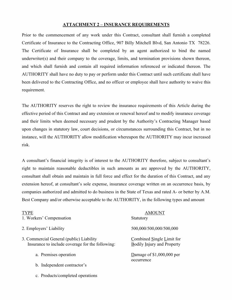
ATTACHMENT 2 – INSURANCE REQUIREMENTS
Prior to the commencement of any work under this Contract, consultant shall furnish a completed
Certificate of Insurance to the Contracting Office, 907 Billy Mitchell Blvd, San Antonio TX 78226.
The Certificate of Insurance shall be completed by an agent authorized to bind the named
underwriter(s) and their company to the coverage, limits, and termination provisions shown thereon,
and which shall furnish and contain all required information referenced or indicated thereon. The
AUTHORITY shall have no duty to pay or perform under this Contract until such certificate shall have
been delivered to the Contracting Office, and no officer or employee shall have authority to waive this
requirement.
The AUTHORITY reserves the right to review the insurance requirements of this Article during the
effective period of this Contract and any extension or renewal hereof and to modify insurance coverage
and their limits when deemed necessary and prudent by the Authority’s Contracting Manager based
upon changes in statutory law, court decisions, or circumstances surrounding this Contract, but in no
instance, will the AUTHORITY allow modification whereupon the AUTHORITY may incur increased
risk.
A consultant’s financial integrity is of interest to the AUTHORITY therefore, subject to consultant’s
right to maintain reasonable deductibles in such amounts as are approved by the AUTHORITY,
consultant shall obtain and maintain in full force and effect for the duration of this Contract, and any
extension hereof, at consultant’s sole expense, insurance coverage written on an occurrence basis, by
companies authorized and admitted to do business in the State of Texas and rated A- or better by A.M.
Best Company and/or otherwise acceptable to the AUTHORITY, in the following types and amount
TYPE AMOUNT 1. Workers’ Compensation Statutory 2. Employers’ Liability 500,000/500,000/500,000 3. Commercial General (public) Liability Combined Single Limit for
Insurance to include coverage for the following: Bodily Injury and Property
a. Premises operation Damage of $1,000,000 per occurrence b. Independent contractor’s c. Products/completed operations
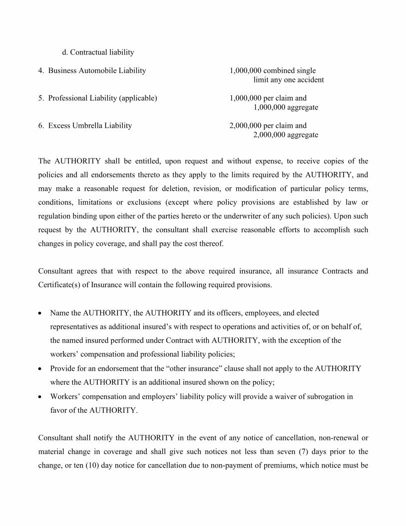
d. Contractual liability
4. Business Automobile Liability 1,000,000 combined single
limit any one accident 5. Professional Liability (applicable) 1,000,000 per claim and 1,000,000 aggregate 6. Excess Umbrella Liability 2,000,000 per claim and 2,000,000 aggregate
The AUTHORITY shall be entitled, upon request and without expense, to receive copies of the
policies and all endorsements thereto as they apply to the limits required by the AUTHORITY, and
may make a reasonable request for deletion, revision, or modification of particular policy terms,
conditions, limitations or exclusions (except where policy provisions are established by law or
regulation binding upon either of the parties hereto or the underwriter of any such policies). Upon such
request by the AUTHORITY, the consultant shall exercise reasonable efforts to accomplish such
changes in policy coverage, and shall pay the cost thereof.
Consultant agrees that with respect to the above required insurance, all insurance Contracts and
Certificate(s) of Insurance will contain the following required provisions.
• Name the AUTHORITY, the AUTHORITY and its officers, employees, and elected
representatives as additional insured’s with respect to operations and activities of, or on behalf of,
the named insured performed under Contract with AUTHORITY, with the exception of the
workers’ compensation and professional liability policies;
• Provide for an endorsement that the “other insurance” clause shall not apply to the AUTHORITY
where the AUTHORITY is an additional insured shown on the policy;
• Workers’ compensation and employers’ liability policy will provide a waiver of subrogation in
favor of the AUTHORITY.
Consultant shall notify the AUTHORITY in the event of any notice of cancellation, non-renewal or
material change in coverage and shall give such notices not less than seven (7) days prior to the
change, or ten (10) day notice for cancellation due to non-payment of premiums, which notice must be
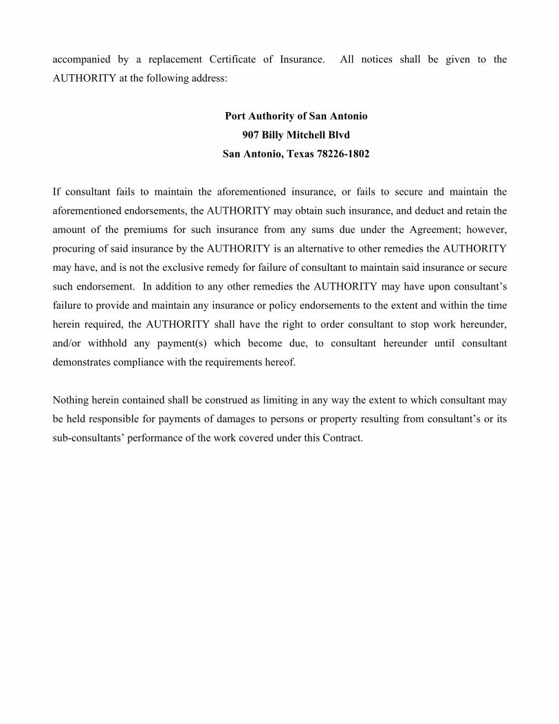
accompanied by a replacement Certificate of Insurance. All notices shall be given to the
AUTHORITY at the following address:
Port Authority of San Antonio
907 Billy Mitchell Blvd
San Antonio, Texas 78226-1802
If consultant fails to maintain the aforementioned insurance, or fails to secure and maintain the
aforementioned endorsements, the AUTHORITY may obtain such insurance, and deduct and retain the
amount of the premiums for such insurance from any sums due under the Agreement; however,
procuring of said insurance by the AUTHORITY is an alternative to other remedies the AUTHORITY
may have, and is not the exclusive remedy for failure of consultant to maintain said insurance or secure
such endorsement. In addition to any other remedies the AUTHORITY may have upon consultant’s
failure to provide and maintain any insurance or policy endorsements to the extent and within the time
herein required, the AUTHORITY shall have the right to order consultant to stop work hereunder,
and/or withhold any payment(s) which become due, to consultant hereunder until consultant
demonstrates compliance with the requirements hereof.
Nothing herein contained shall be construed as limiting in any way the extent to which consultant may
be held responsible for payments of damages to persons or property resulting from consultant’s or its
sub-consultants’ performance of the work covered under this Contract.
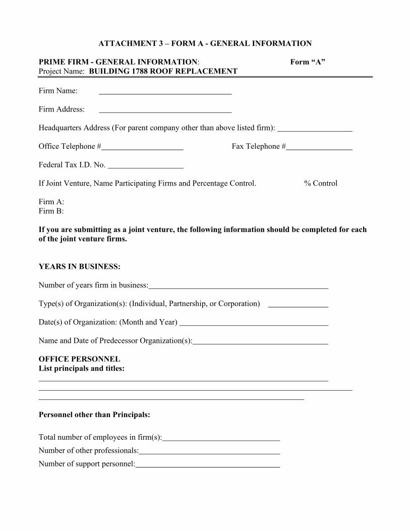
ATTACHMENT 3 – FORM A - GENERAL INFORMATION PRIME FIRM - GENERAL INFORMATION: Form “A” Project Name: BUILDING 1788 ROOF REPLACEMENT
Firm Name: Firm Address: Headquarters Address (For parent company other than above listed firm): Office Telephone # Fax Telephone # Federal Tax I.D. No. If Joint Venture, Name Participating Firms and Percentage Control. % Control Firm A: Firm B: If you are submitting as a joint venture, the following information should be completed for each of the joint venture firms. YEARS IN BUSINESS: Number of years firm in business: Type(s) of Organization(s): (Individual, Partnership, or Corporation) Date(s) of Organization: (Month and Year) Name and Date of Predecessor Organization(s): OFFICE PERSONNEL List principals and titles: Personnel other than Principals: Total number of employees in firm(s): Number of other professionals: Number of support personnel:
SMWVBE CERTIFICATION OF PRIME FIRM OR JOINT VENTURE Attach copy of SBE/MBE/WBE or VBE certificate indicating certification is current or provide certification number(s). SUBCONSULTANT INFORMATION Attach a letter from each sub consultant on the proposed team, confirming that they have been contacted and are prepared to provide services for the project. OTHER CONSIDERATIONS 1. Does your firm have and generally carry:
• Worker’s Compensation and Employers’ Liability Insurance Yes No; if yes, please state limits: _______________________________
• Commercial General Liability Insurance Yes No; if yes, please state limits: _______________________________ • Business Automobile Liability Insurance Yes No; if yes, please state limits: _______________________________ • Professional Liability Insurance Yes No; if yes, please state limits: _______________________________
2. Describe the quantity and nature of any work, interest in work, partnership interest, land ownership or other interest in any project, property or business dealing within the proposed project area or past or current business relationship which may give rise to a potential conflict of interest for your firm or associated firms in the execution of this project.
________________________________________________________________________________________________________________________________________________________________________________________________________________________________________________________________________________________________________________________________________
PRICING FORM
We have received and carefully examined the Contract Documents for the Project entitled:
Building 1788 Roof Replacement
And have received, and considered, Addenda numbered ___ through __ _
We have visited, and thoroughly examined conditions, as they exist at the Project site, and having full knowledge of all requirements of the Work, hereby submit our Bid(s) as follows:
We have inserted Bid Amounts, and proposed Calendar Days to accomplish Work with Alternates listed below.
Lump Sum Base Bid: __________________________ _ __________________ dollars($ __________ _)
Base Bid includes
The Work shall consist of installation of a new PVC thermoplastic roof system (including new roof insulation and recovery board) to meet IECC Energy Code requirements for Building 1788. Removal of the existing roof system will be required. Removal of the existing gravel cover will be required. And based on condition of the existing structural roof framing and roof deck, these structural components may require repair or replacement as described in the Contract Documents. Mechanical, electrical, plumbing, sheet metal and any other work described in the Drawings. If Bid is accepted, we propose to begin Work within ___ calendar days of receipt of signed Agreement.
If our Base Bid is selected, and selected Alternates, we propose to begin the Work on the date stipulated in the Notice to Proceed, and agree to achieve Substantial Completion of the Work within ___ calendar days of such date (plus authorized extensions of time).
Liquidated Damages: We have reviewed the stipulations throughout the Contract Documents regarding the Contract Time and Liquidated Damages. By submission of this Bid Proposal, we represent that we will complete accepted items within calendar days stipulated above (plus authorized extensions of the Contract Time), and agree to pay to the Owner the sum of $300 per day, as stipulated and fixed, as liquidated damages for each calendar day of delay, until the Work is completed.
Unit Prices: The following Unit Prices are for installed items, and includes all costs of removal of existing components, transport, disposal fees, materials, labor, profit, sales and other taxes, permits, overhead, and profit:
I. $_______ Price per square foot for the repair and / or replacement of existing areas of structural metal roof deck that are deteriorated or damaged.
2. $______ Price per linear for the repair and / or replacement of existing wood nailers used for attachment of the roofing and flashing systems that are deteriorated or damaged.
601 NW Loop 410, Suite 400 \\ San Antonio, Texas 78216 \\ P 210-638-7240 \\ F 210-829-0578 \\ BEAMProf.com
Project Manual for
Building 1788 Roof Improvements for the
PORT AUTHORITY OF SAN ANTONIO
VOLUME 1 of 1 – Divisions 00 – 33 January 15, 2021 BEAM Project No.: 20289R
ISSUE FOR PROPOSAL
601 NW Loop 410, Suite 400 \\ San Antonio, Texas 78216 \\ P 210-638-7240 \\ F 210-829-0578 \\ BEAMProf.com
Chair
Chris Alderete
Board of Directors
Chris Alderete Chair Alix Nava Vice-Chair Margaret Wilson-Anaglia Secretary Bill Mock Treasurer Minnie Abrego-Sanchez Member Bradley Carson Member Victoria M. Garcia Member Thomas “T.J.” Mayes Member Marilu Reyna Member Juan Solis III Member Dan F. Weingart Member
OWNER / PROJECT MANAGER Port Authority of San Antonio 907 Billy Mitchel Blvd. Suite 110 San Antonio, TX 78226 T: 210-362-7800 F: 210-362-7807
Building 1788 Roof Improvements BEAM Professionals Port Authority of San Antonio BEAM Job #20289R Issue For Proposal January 15, 2021
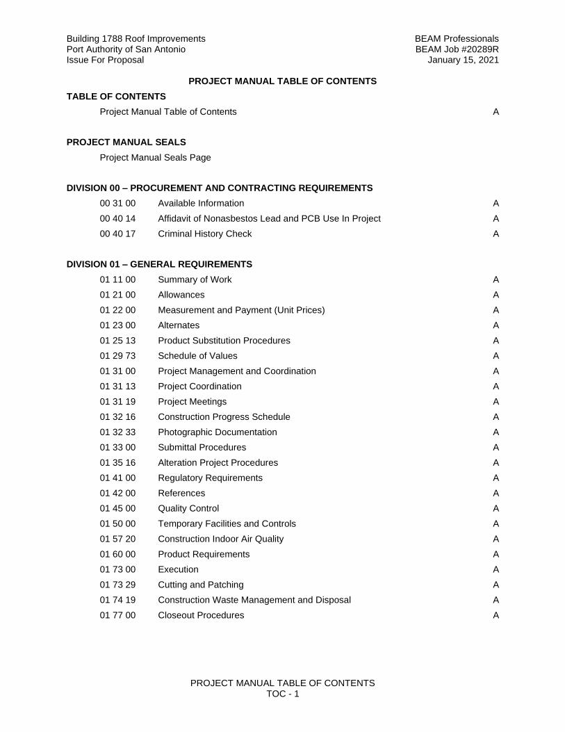
PROJECT MANUAL TABLE OF CONTENTS TOC - 1
PROJECT MANUAL TABLE OF CONTENTS
TABLE OF CONTENTS
Project Manual Table of Contents A
PROJECT MANUAL SEALS
Project Manual Seals Page
DIVISION 00 – PROCUREMENT AND CONTRACTING REQUIREMENTS
00 31 00 Available Information A
00 40 14 Affidavit of Nonasbestos Lead and PCB Use In Project A
00 40 17 Criminal History Check A
DIVISION 01 – GENERAL REQUIREMENTS
01 11 00 Summary of Work A
01 21 00 Allowances A
01 22 00 Measurement and Payment (Unit Prices) A
01 23 00 Alternates A
01 25 13 Product Substitution Procedures A
01 29 73 Schedule of Values A
01 31 00 Project Management and Coordination A
01 31 13 Project Coordination A
01 31 19 Project Meetings A
01 32 16 Construction Progress Schedule A
01 32 33 Photographic Documentation A
01 33 00 Submittal Procedures A
01 35 16 Alteration Project Procedures A
01 41 00 Regulatory Requirements A
01 42 00 References A
01 45 00 Quality Control A
01 50 00 Temporary Facilities and Controls A
01 57 20 Construction Indoor Air Quality A
01 60 00 Product Requirements A
01 73 00 Execution A
01 73 29 Cutting and Patching A
01 74 19 Construction Waste Management and Disposal A
01 77 00 Closeout Procedures A
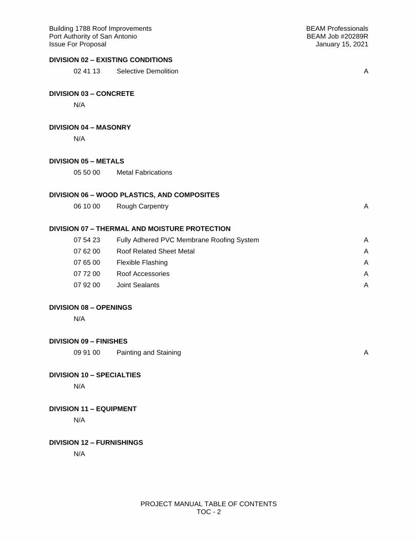
Building 1788 Roof Improvements BEAM Professionals Port Authority of San Antonio BEAM Job #20289R Issue For Proposal January 15, 2021
PROJECT MANUAL TABLE OF CONTENTS TOC - 2
DIVISION 02 – EXISTING CONDITIONS
02 41 13 Selective Demolition A
DIVISION 03 – CONCRETE
N/A
DIVISION 04 – MASONRY
N/A
DIVISION 05 – METALS
05 50 00 Metal Fabrications
DIVISION 06 – WOOD PLASTICS, AND COMPOSITES
06 10 00 Rough Carpentry A
DIVISION 07 – THERMAL AND MOISTURE PROTECTION
07 54 23 Fully Adhered PVC Membrane Roofing System A
07 62 00 Roof Related Sheet Metal A
07 65 00 Flexible Flashing A
07 72 00 Roof Accessories A
07 92 00 Joint Sealants A
DIVISION 08 – OPENINGS
N/A
DIVISION 09 – FINISHES
09 91 00 Painting and Staining A
DIVISION 10 – SPECIALTIES
N/A
DIVISION 11 – EQUIPMENT
N/A
DIVISION 12 – FURNISHINGS
N/A
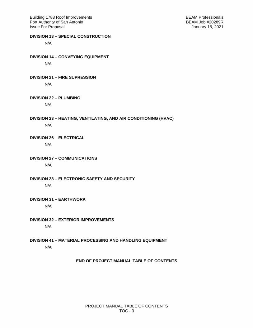
Building 1788 Roof Improvements BEAM Professionals Port Authority of San Antonio BEAM Job #20289R Issue For Proposal January 15, 2021
PROJECT MANUAL TABLE OF CONTENTS TOC - 3
DIVISION 13 – SPECIAL CONSTRUCTION
N/A
DIVISION 14 – CONVEYING EQUIPMENT
N/A
DIVISION 21 – FIRE SUPRESSION
N/A
DIVISION 22 – PLUMBING
N/A
DIVISION 23 – HEATING, VENTILATING, AND AIR CONDITIONING (HVAC)
N/A
DIVISION 26 – ELECTRICAL
N/A
DIVISION 27 – COMMUNICATIONS
N/A
DIVISION 28 – ELECTRONIC SAFETY AND SECURITY
N/A
DIVISION 31 – EARTHWORK
N/A
DIVISION 32 – EXTERIOR IMPROVEMENTS
N/A
DIVISION 41 – MATERIAL PROCESSING AND HANDLING EQUIPMENT
N/A
END OF PROJECT MANUAL TABLE OF CONTENTS
Building 1788 Roof Improvements BEAM Professionals Port Authority of San Antonio BEAM Job #20289R Issue For Proposal January 15, 2021
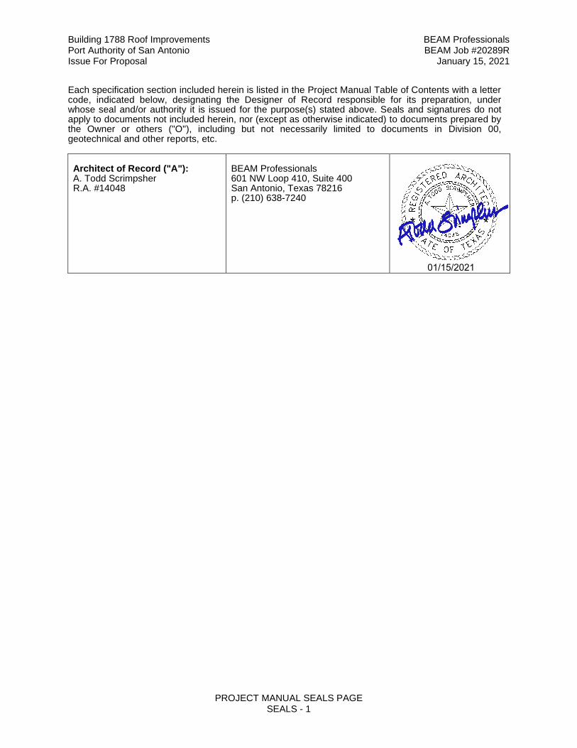
PROJECT MANUAL SEALS PAGE SEALS - 1
Each specification section included herein is listed in the Project Manual Table of Contents with a letter code, indicated below, designating the Designer of Record responsible for its preparation, under whose seal and/or authority it is issued for the purpose(s) stated above. Seals and signatures do not apply to documents not included herein, nor (except as otherwise indicated) to documents prepared by the Owner or others ("O"), including but not necessarily limited to documents in Division 00, geotechnical and other reports, etc. Architect of Record ("A"): A. Todd Scrimpsher R.A. #14048
BEAM Professionals 601 NW Loop 410, Suite 400 San Antonio, Texas 78216 p. (210) 638-7240
01/15/2021
Building 1788 Roof Improvements BEAM Professionals Port Authority of San Antonio BEAM Job #20289R Issue For Proposal January 15, 2021
AVAILABLE INFORMATION 00 31 00 - 1
DOCUMENT 00 31 00 – AVAILABLE INFORMATION PART 1 - GENERAL
1.1 AVAILABLE INFORMATION
A. Informational Documents: The Owner does not have additional documents available for the
Bidders information. Bidders are encouraged to verify conditions prior to submitting their bid.
END OF SECTION 00 31 00
Building 1788 Roof Improvements BEAM Professionals Port Authority of San Antonio BEAM Job #20289R Issue For Proposal January 15, 2021
NOTE: THIS DOCUMENT MUST BE EXECUTED AND SUBMITTED AT PROJECT CLOSE-OUT AFFIDAVIT OF NON-ASBESTOS, LEAD AND PCB USE IN PROJECT
00 40 14 - 1
DOCUMENT 00 40 14 - AFFIDAVIT OF NONASBESTOS, LEAD, AND PCB USE IN PROJECT Upon completion of this form, return to the Architect at Project Closeout. Project: Architect: Building 1788 Roof Improvements BEAM Professionals 5035 SW 36th Street 601 NW Loop 410, Suite 400 San Antonio, TX 78216 Port San Antonio Architect’s Project No. 20289R Contractor: Date: ________________________ _______________________________ ________________________________ ________________________________
AFFIDAVIT The undersigned affirms and certifies that "to the best of their knowledge and belief asbestos, lead, and PCB containing materials have not been used or incorporated into the Work and lead or lead bearing materials have not been incorporated into potable water systems”, including, but not limited to those water systems for drinking fountains, all sinks, showers, bath tubs, residential and commercial kitchen equipment, ice machines, and hose bibbs, as applicable to the project, and that lead sheet flashing used in through roof plumbing penetration applications is the only lead on the Project. ______________________________________________ Company ______________________________________________ Printed Name ______________________________________________ Signature STATE OF TEXAS ) ) COUNTY OF ______________ ) Sworn to and subscribed before me at ________________, Texas, this the _______ day of ___________________________, 2021. ________________________________________________ Notary Public in and for _____________ County, Texas
END OF DOCUMENT 00 40 14
Building 1788 Roof Improvements BEAM Professionals Port Authority of San Antonio BEAM Job #20289R Issue For Proposal January 15, 2021
CERTIFICATION OF CRIMINAL HISTORY RECORD INFORMATION
REVIEW BY CONTRACTOR-EMPLOYER 00 40 17 - 1
DOCUMENT 00 40 17 - CERTIFICATION OF CRIMINAL HISTORY RECORD INFORMATION REVIEW BY CONTRACTOR-EMPLOYER
Certifying Affidavit submitted to:
Owner: ____________________________________________________ Mailing Address: ____________________________________________________ ____________________________________________________ Project: ____________________________________________________ ____________________________________________________
STATE OF TEXAS §
COUNTY OF § (I) The undersigned representative, on behalf of the contracting firm identified below, swears and affirms to Port Authority of San Antonio that such firm has obtained, reviewed and verified, from a law enforcement or criminal justice agency or a private entity that is consumer reporting agency governed by the Fair Credit Reporting Act (15 U.S.C. §§ 1681 et seq.) the criminal history record information of employees prior to 1 January 2008, who (a) have or will have continuing duties related to the contracted services, and (b) have or will have direct contact with Port Authority of San Antonio employees. Such employees are identified by name on Schedule A (contractor shall provide and attach hereto). The undersigned further swears and affirms no employees who meet the requirements of (a) and (b) herein and/or identified on Schedule A have been convicted of any offense identified in Section 22.085 of the Texas Education Code. (2) The undersigned representative, on behalf of the contracting firm identified below, swears and affirms to the Port Authority of San Antonio, that such firm has obtained, reviewed and verified, from the Texas Department of Public Safety criminal clearinghouse, the national criminal history record information of all employees hired on or after 1 January 2008, who (a) have or will have continuing duties related to the contracted services, and (b) have or will have direct contact with Port Authority of San Antonio employees. Such employees are identified by name on Schedule B (contractor shall provide and attach hereto). The undersigned further swears and affirms no employees who meet the requirements of (a) and (b) herein and/or identified on Schedule B have been convicted of any offense identified in Section 22.085 of the Texas Education Code. (3) The undersigned firm swears and covenants that no present or future employee will provide services to the Project that involve direct contact with Port San Antonio employees unless and until such employee's national criminal history record information has been reviewed and cleared as required by Paragraph (2) above, and an updated Certification has submitted by the contracting firm to the Port Authority of San Antonio with an updated Schedule B identifying such employees. In the event of an emergency, an employee who has not been previously certified may only provide services that involve direct contact with students if such employee is escorted by a Port Authority of San Antonio representative.
Building 1788 Roof Improvements BEAM Professionals Port Authority of San Antonio BEAM Job #20289R Issue For Proposal January 15, 2021
CERTIFICATION OF CRIMINAL HISTORY RECORD INFORMATION
REVIEW BY CONTRACTOR-EMPLOYER 00 40 17 - 2
(4) The undersigned firm swears and covenants that, upon receipt of information, directly or indirectly, that any employee of the contracting firm has been convicted of an offense identified in Section 22.085 of the Texas Education Code, the contracting firm will immediately remove such employee from the Project and notify the Port San Antonio. (5) Furthermore, if requested by the Port Authority of San Antonio, the name, driver's license number, and any other information required by the DPS will be submitted to the Port Authority of San Antonio for any person on either Schedule A or Schedule B. _____________________________________, being duly sworn, affirms and certifies that he/she is the
_____________________________ (position) of ______________________________(contracting firm),
and that all statements and acknowledgements contained herein are true and correct, and that he/she
has the authority to bind such firm to the covenants set out above.
_______________________________________ Subscribed and sworn to before me this ________________ day of _____________________
Notary Public ______________________________________ State of ____________________ My Commission expires ___________________________
END OF DOCUMENT 00 40 17
Building 1788 Roof Improvements BEAM ProfessionalsPort Authority of San Antonio BEAM Job #20289RIssue For Proposal January 15, 2021
SUMMARY OF WORK01 11 00 - 1
SECTION 01 11 00 - SUMMARY OF WORK
CONDITIONS OF THE CONTRACT AND DIVISION 1, as applicable, apply to this Section.
PART 1 - GENERAL
1.1 PROJECT DESCRIPTION
A. The Project, Building 1788 Roof Improvements, 5035 SW 36th Street, San Antonio, Texas for Port Authority of San Antonio.
1.2 SCOPE OF WORK
A. The Work shall consist of installation of a new PVC thermoplastic roof system (including new roof insulation and recovery board) to meet IECC Energy Code requirements for Building 1788. Removal of the existing roof system will be required. Removal of the existing gravel cover will be required. And based on condition of the existing structural roof framing and roof deck, these structural components may require repair or replacement as described in the Contract Documents. Mechanical, electrical and plumbing work will be required as described in the Drawings.
1.3 SALVAGED MATERIALS
A. Owner may salvage all items deemed reusable or necessary to keep from facilities to be demolished prior to the start of demolition.
B. Contractor shall remove and turn additional items over to the Owner, as directed.
C. Contractor shall demolish, remove and salvage all other items of demolished work.
1.4 CONTRACTS AND USE OF SITE
A. Contractor Use of Premises:1. Confine operations at site to areas permitted by:
a. Lawb. Ordinancesc. Permitsd. Contract Documents
2. Do not unreasonably encumber site with materials or equipment.3. Assume full responsibility for protection and safekeeping of products stored on
premises.4. Obtain and pay for use of additional storage or work areas as needed for
operations.5. Contractor shall establish secured staging area for work and coordinate and
provide for safe passage and exit from building areas during construction, as determined by City and Port San Antonio officials.
6. Contractor shall coordinate all construction activities with Owner.7. Owner reserves the right to perform construction operations with its own forces or
to employ separate contractors on portions of the Project. Contractor shall coordinate with this work in terms of providing site access, work space, and storage space, cooperation of work forces, scheduling, and technical requirements.
8. Coordinate all utility shutdowns with Owner and, as required, with local utility companies, prior to commencement of shutdown.
Building 1788 Roof Improvements BEAM ProfessionalsPort Authority of San Antonio BEAM Job #20289RIssue For Proposal January 15, 2021
SUMMARY OF WORK01 11 00 - 2
B. Owner Occupancy:1. Partial Owner Occupancy: The Owner reserves the right to place and install
equipment in completed areas of the building, prior to Substantial Completion provided that such occupancy does not interfere with completion of the Work. Such placing of equipment and partial occupancy shall not constitute acceptance of the total Work.
2. A Certificate of Substantial Completion will be executed in accordance with conditions of the Contract.
3. Contractor shall obtain a Certificate of Occupancy from local building officials prior to Owner occupancy.
4. Prior to partial Owner occupancy, mechanical and electrical systems shall be fully operational. Required inspections and tests shall have been successfully completed. Upon occupancy the Owner will provide operation and maintenance of mechanical and electrical systems in occupied portions of the building.
5. Prior to partial Owner occupancy, emergency and life safety systems shall be fully operational. Emergency and life safety systems include, but are not limited to, fire sprinkler systems, fire alarm systems, and emergency egress devices. For emergency exiting purposes, the path of travel shall be clearly delineated and functional. If required, temporary barricades shall separate on-going construction from occupied spaces as allowed by the governing agency holding jurisdiction over the Project. Required inspections and tests shall have been successfully completed. Upon occupancy the Owner will provide operation and maintenance of emergency and life safety systems in occupied portions of the building.
C. Owner-Furnished Items:1. The Owner may provide items to the Contractor for installation in accordance with
manufacturer’s recommendations and instructions.2. The Owner will arrange and pay for delivery of Owner-furnished items in
accordance with the Contractor’s Construction Schedule and will inspect deliveries for damage.
3. If Owner-furnished items are damaged, defective or missing, through no fault of the Contractor, the Owner will arrange for replacement.
4. The Contractor is responsible for designating the delivery dates of Owner-furnished items in the Contractor’s Construction Schedule and for receiving, unloading and handling Owner-furnished items at the site. The Contractor is responsible for protecting Owner-furnished items from damage, including damage from exposure to elements, and to repair or replacement of items damaged resulting from operations.
D. Coordination with Owner’s Forces or Owner’s Contractors:1. Provide site access, space allocation, scheduling, scheduling coordination,
coordination of work forces and coordination of technical requirements with contractors that may be selected and employed by Owner to perform work simultaneously and in conjunction with the Work, which may include, but shall not be limited to the following, as applicable to the Project:a. Materials Inspection and Testing Agencyb. HVAC Testing, Adjusting, Balancing Agencyc. Energy Management System Contractord. Data and Cabling System Contractore. Telephone System Contractorf. Modular Furniture Installerg. Lighting and Soundh. Surveying
Building 1788 Roof Improvements BEAM ProfessionalsPort Authority of San Antonio BEAM Job #20289RIssue For Proposal January 15, 2021
SUMMARY OF WORK01 11 00 - 3
E. The Contractor shall supervise and direct the Work, using the Contractor’s best skill and attention. The Contractor shall be solely responsible for, and have control over, construction means, methods, techniques, sequences and procedures and for coordinating all portions of the Work under the Contract, unless the Contract Documents give other specific instructions concerning these matters. If the Contract Documents give specific instructions concerning construction means, methods, techniques, sequences or procedures, the Contractor shall evaluate the jobsite safety thereof and, except as stated below, shall be fully and solely responsible for the jobsite safety of such means, methods, techniques, sequences or procedures. If the Contractor determines that such means, methods, techniques, sequences or procedures may not be safe, the Contractor shall give timely written notice to the Owner and Architect and shall not proceed with that portion of the Work without further written instructions from the Architect. If the Contractor is then instructed to proceed with the required means, methods, techniques, sequences or procedures without acceptance of changes proposed by the Contractor, the Owner shall be solely responsible for any resulting loss or damage but only to the extent the Owner would be responsible for any such losses or damages under state and/or federal law.
F. The Architect will neither have control over or charge of, nor be responsible for, the construction means, methods, techniques, sequences or procedures, or for the safety precautions and programs in connection with the Work, since these are solely the Contractor’s rights and responsibilities under the Contract, except as noted in the above paragraph.
G. No demolition will be allowed above, below, adjacent to or near any occupied areas of the existing building.
1.5 PROTECTION OF EXISTING PROPERTY
A. Contractor shall provide and maintain adequate protection of all Owner's existing property during duration of Project.
B. Contractor shall verify location of all existing underground pipelines on site with the owner of such pipelines and authorities having jurisdiction and shall provide and maintain adequate protection of all such pipelines during duration of Project.
C. Protection of Trees:1. Provide wood barricades around trees and shrubs at their drip line in traffic areas
to protect them from construction operations until Substantial Completion, or until barricade removal is directed by Architect.
1.6 USE OF ASBESTOS FREE MATERIALS, PRODUCTS AND SYSTEMS
A. The Contractor is reminded to refer to Document AB, Instructions to Offerors for requirements regarding asbestos containing materials (ACM).
PART 2 - PRODUCTS
2.1 MATERIALS
A. Refer to Specification Sections.
Building 1788 Roof Improvements BEAM ProfessionalsPort Authority of San Antonio BEAM Job #20289RIssue For Proposal January 15, 2021
SUMMARY OF WORK01 11 00 - 4
PART 3 - EXECUTION
3.1 CONSTRUCTION SCHEDULE
A. The Owner has a critical need for the work to begin upon Notice to Proceed or DATE and shall be Substantially Complete by SUBSTANTIAL COMPLETION DATE.
B. Refer to Section 01 32 16 for other scheduling requirements, and to Document CB - Supplementary Conditions for information concerning liquidated damages.
END OF SECTION 01 11 00
Building 1788 Roof Improvements BEAM Professionals Port Authority of San Antonio BEAM Job #20289R Issue For Proposal January 15, 2021
ALLOWANCES 01 21 00 - 1
SECTION 01 21 00 - ALLOWANCES
CONDITIONS OF THE CONTRACT AND DIVISION 1, as applicable, apply to this Section. PART 1 - GENERAL 1.1 CONDITIONS
A. Cash allowances are hereby established for Owner’s Contingency, Scope of Work items and materials in the amounts listed below and shall be included in the Contract Sum. These sums shall be reconciled in accordance with Article 3.8 of the General Conditions.
B. Allowances for materials, such as brick, tile, etc., shall be for the net cost of materials
only, without sales tax, delivered and unloaded at the jobsite. The party who makes the purchase (Contractor or subcontractor) shall include handling costs on site, labor, overhead, profit and other expenses contemplated for each allowance in the Contractor's Sum and not in the allowance. Include labor under allowance, only when labor is specified to be included.
C. Allowances for Scope of Work , such as Owner’s contingency, graphics, technology, etc.,
will be adjusted, as necessary, to reflect the difference between the allowance amount stated and Contractor’s handling costs, cost of materials, without sales tax, plus labor, subcontract costs, with overhead and profit markup, and any other reasonable costs, except the Contractor’s overhead and profit, which is not allowed.
D. Contractor shall cause the work covered by these allowances to be performed for such
amounts and by such persons as the Architect may direct or by persons selected by competitive sealed proposals, but he will not be required to employ persons against whom he makes reasonable objection. If any items cost less than the amount listed, the Owner shall be given a credit in the amount of the difference. If the Owner so desires, credits in one allowance category may be transferred to any other allowance category. If any items cost more than the amount listed, such adjustment will include additional handling costs on the site, labor, installation costs, overhead, profit and other expenses resulting to the Contractor or subcontractor from any increase over the original allowance, unless such increase is funded by a transfer of funds from other allowances in which case no overhead and profit will be allowed. If the final cost of all allowances, when determined, is more or less than the sum of the allowances, the Contract Sum will be adjusted accordingly by Change Order.
E. Contractor shall proceed with the work in question only after receiving written directions
executed by the Owner and the Architect. Such direction will be provided by an Allowance Expenditure Authorization prepared by the Architect and executed by Owner, Architect and Contractor. Owner will not be obligated to pay the cost of any work completed without prior authorization.
F. Unexpended balance of allowance sums shall revert to the Owner in the final settlement of
the Contract. PART 2 - PRODUCTS
Not Used
Building 1788 Roof Improvements BEAM Professionals Port Authority of San Antonio BEAM Job #20289R Issue For Proposal January 15, 2021
ALLOWANCES 01 21 00 - 2
PART 3 - EXECUTION 3.1 ALLOWANCES
A. Owner’s Contingency Allowances: $20,000.00 1. Contractor shall include the amount indicated below in his Base Proposal as a
contingency to cover the cost of hidden, concealed or otherwise unforeseen conditions which develop during completion of the work. Contractor shall be allowed to recover all costs associated with the completion of work under this contingency, however, no overhead or profit will be allowed.
END OF SECTION 01 21 00
Building 1788 Roof Improvements BEAM Professionals Port Authority of San Antonio BEAM Job #20289R Issue For Proposal January 15, 2021
MEASUREMENT AND PAYMENT (UNIT PRICES) 01 22 00 - 1
SECTION 01 22 00 - MEASUREMENT AND PAYMENT (UNIT PRICES) CONDITIONS OF THE CONTRACT AND DIVISION 1, as applicable, apply to this Section. PART 1 - GENERAL 1.1 SECTION INCLUDES A. Measurement and payment criteria applicable to portions of the Work performed under a
unit price payment method. B. Defect assessment and non-payment for rejected work.
1.2 AUTHORITY A. Measurement methods delineated in the individual specification sections complement the
criteria of this Section. In the event of conflict, the requirements of the individual specification section govern.
B. Take all measurements and compute quantities. The Architect will verify measurements
and quantities.
1.3 UNIT QUANTITIES SPECIFIED
A. Quantities indicated in the Contract Documents are for bidding and contract purposes only. Quantities and measurements supplied or placed in the Work and verified by the Architect determine payment.
B. If the actual Work requires more or fewer quantities than those quantities indicated, provide
the required quantities at the unit sum/prices contracted.
1.4 MEASUREMENT OF QUANTITIES
A. Measurement Devices: 1. Weigh Scales: Inspected, tested and certified by the applicable State Weights and
Measures Department within the past year. 2. Platform Scales: Of sufficient size and capacity to accommodate the conveying
vehicle. 3. Metering Devices: Inspected, tested and certified by the applicable State
department within the past year.
B. Measurement by Weight: Concrete reinforcing steel, rolled or formed steel or other metal shapes will be measured by handbook weights. Welded assemblies will be measured by handbook or scale weight.
C. Measurement by Volume: Measured by cubic dimension using mean length, width and
height or thickness. D. Measurement by Area: Measured by square dimension using mean length and width or
radius. E. Linear Measurement: Measured by linear dimension, at the item centerline or mean chord.
F. Stipulated Sum/Price Measurement: Items measured by weight, volume, area, or linear
means or combination, as appropriate, as a completed item or unit of the Work.
Building 1788 Roof Improvements BEAM Professionals Port Authority of San Antonio BEAM Job #20289R Issue For Proposal January 15, 2021
MEASUREMENT AND PAYMENT (UNIT PRICES) 01 22 00 - 2
1.5 PAYMENT
A. Payment Includes: Full compensation for all required labor, Products, tools, equipment, plant, transportation, services and incidentals; erection, application or installation of an item of the Work; overhead and profit.
B. Final payment for Work governed by unit prices will be made on the basis of the actual
measurements and quantities accepted by the Architect multiplied by the unit/sum price for Work which is incorporated in or made necessary by the Work.
1.6 DEFECT ASSESSMENT
A. Replace the Work, or portions of the Work, not conforming to specified requirements. B. If, in the opinion of the Architect, it is not practical to remove and replace the Work, the
Architect will direct one (1) of the following remedies: 1. The defective Work may remain, but the unit sum/price will be adjusted to a new
sum/price or reduced 50 percent at the discretion of the Architect. 2. The defective Work will be partially repaired to the instructions of the Architect, and
the unit sum/price will be adjusted to a new sum/price or reduced 50 percent at the discretion of the Architect.
C. The individual specification sections may modify these options or may identify a specific
formula or percentage sum/price reduction. D. The authority of the Architect to assess the defect and identify payment adjustment is final.
1.7 NON-PAYMENT FOR REJECTED PRODUCTS
A. Payment will not be made for any of: 1. Products wasted or disposed of in a manner that is not acceptable. 2. Products determined as unacceptable before or after placement. 3. Products not completely unloaded from the transporting vehicle. 4. Products placed beyond the lines and levels of the required Work. 5. Products remaining on hand after completion of the Work. 6. Loading, hauling and disposing of rejected Products.
PART 2 - PRODUCTS Not Used
Building 1788 Roof Improvements BEAM Professionals Port Authority of San Antonio BEAM Job #20289R Issue For Proposal January 15, 2021
MEASUREMENT AND PAYMENT (UNIT PRICES) 01 22 00 - 3
PART 3 - EXECUTION 3.1 SCHEDULE OF UNIT PRICES
A. Unit Price No. 1 – Repair and / or replace existing areas of structural metal roof deck that are deteriorated or damaged. The profile and size of the new deck material shall match existing. 1. Furnish the entire Unit Price, including overhead and profit for the repairing existing or
replacing with new the structural metal roof deck to match existing in the event damage and / or deterioration is encountered, as noted in the General Notes and as shown on the Drawings. The unit priced shall be dollars ($) per square foot for all roof areas in the contract area shown on the drawings. Enter unit price on Proposal Form.
B. Unit Price No. 2 – Repair and / or replace existing wood nailers used for attachment of the roofing and flashing systems that are deteriorated or damaged. The profile and size of the new material shall match existing unless indicated otherwise on the Drawings. 1. Furnish the entire Unit Price, including overhead and profit for the repairing
existing or replacing with new the wood nailers used for attachment of the roofing and flashing systems to match existing in the event damage and / or deterioration is encountered, as noted in the General Notes and as shown on the Drawings. The unit priced shall be dollars ($) per linear foot for all roof areas in the contract area shown on the drawings. Enter unit price on Proposal Form.
END OF SECTION 01 22 00
Building 1788 Roof Improvements BEAM Professionals Port Authority of San Antonio BEAM Job #20289R Issue For Proposal January 15, 2021
ALTERNATES 01 23 00 - 1
SECTION 01 23 00 – ALTERNATES
CONDITIONS OF THE CONTRACT AND DIVISION 01, as applicable, apply to this Section. PART 1 – GENERAL 1.1 ALTERNATE PRICES
A. State, in the spaces provided in the proposal form, Alternate Prices for the work described below. The responsibility of determining quantity of Alternates rests with the Contractor. Base Proposal and Alternates shall include cost of all supporting elements required, so that no matter what combination of Base Proposal and Alternates are accepted, that portion shall be a complete entity in itself. Work for all Alternates shall be in strict accordance with the specification sections noted and applicable to the specific work.
PART 2 – PRODUCTS (Not Used) PART 3 – EXECUTION 3.1 ALTERNATES
A. Alternate Number 01: Roof Recover 1. This Alternate shall establish the amount to adjust the Base Proposal for the cost
of providing and installing a fall arrest system on the building as shown in the Contract Documents.
END OF SECTION 01 23 00
Building 1788 Roof Improvements BEAM Professionals Port Authority of San Antonio BEAM Job #20289R Issue For Proposal January 15, 2021
PRODUCT SUBSTITUTION PROCEDURES
01 25 13 - 1
SECTION 01 25 13 - PRODUCT SUBSTITUTION PROCEDURES CONDITIONS OF THE CONTRACT AND DIVISION 01, as applicable, apply to this Section. PART 1 – GENERAL 1.1 SECTION INCLUDES
A. Specified product compliance, and product quality assurance
B. Specific administrative and procedural requirements for handling requests for
substitutions made prior to award of Contract.
C. Requirements for product delivery, storage and handling.
1.2 RELATED REQUIREMENTS A. Instructions to Offerors: Product options and procedures for submittal of requests for
substitutions during the Proposal period.
1.3 DESCRIPTION OF REQUIREMENTS A. Definitions: Definitions used in this Section are not intended to negate the meaning of
other terms used in the Contract Documents, including such terms as “specialties”, “systems”, “structure”, “finishes”, “accessories”, “furnishings”, “special construction”, and similar terms. Such terms are self-explanatory and have recognized meanings in the construction industry. 1. Products: Shall mean items purchased for incorporation in the Work, regardless
of whether they were specifically purchased for the project or taken from the Contractor’s previously purchased stock. The term “product” as used herein includes the terms “material”, “equipment”, “system”, and other terms of similar intent. a. Named Products: Are those identified by the use of the manufacturer’s
name for a product, including such items as a make or model designation, as recorded in published product literature, of the latest issue as of the date of the Contract Documents.
b. Specified Products: same as Named Products. 2. Materials: Shall mean products that must be substantially cut, shaped, worked,
mixed, finished, refined, or otherwise fabricated, processed, or installed to form units of work.
3. Equipment: Is defined as a product with operational parts, regardless of whether motorized or manually operated, and in particular, a product that requires service connections such as wiring or piping.
Building 1788 Roof Improvements BEAM Professionals Port Authority of San Antonio BEAM Job #20289R Issue For Proposal January 15, 2021
PRODUCT SUBSTITUTION PROCEDURES
01 25 13 - 2
1.4 PRODUCT QUALITY ASSURANCE A. Source Limitations: To the fullest extent possible, provide products of the same generic
kind, from a single source, for each unit of work. 1. When it is discovered that specific products are available only from sources that
do not or cannot produce an adequate quantity to complete project requirements in a timely manner, consult with the Architect/Engineer for a determination of what product quantities are most important before proceeding. The Architect/Engineer will designate those qualities, such as visual, structural, durability, or compatibility, that are most important. When the Architect/Engineer’s determination has been made, select products from those sources that produce products that possess the most important qualities, to the fullest extent possible.
B. Compatibility of Options: Compatibility of products is a basic requirement of product
selection. When the Contractor is given the option of selecting between two (2) or more products for use on the project, the product selected must be compatible with other products previously selected, even if the products previously selected were also Contractor options. The complete compatibility between the various choices available to the Contractor is not assured by the various requirements of the Contract Documents, but must be provided by the Contractor. Or Equal: 1. Where the phrase “or equal”, “or equivalent”, “or Architects approved equal”, or
similar phrasing, occurs in the Proposal Documents, do not assume that materials, equipment, or methods of construction will be approved by the Architect unless the item has been specifically approved for this Work by the Architect.
2. The decision of the Architect shall be final.
C. Where a proposed substitution involves the work of more than one (1) contractor, each contractor involved shall cooperate and coordinate the work with each other contractor involved, so as to provide uniformity and consistency and to assure the compatibility of products.
D. Foreign Product Limitations: “Foreign products” as distinguished from “domestic products” are defined as products that are either manufactured substantially (50 percent or more of value) outside of the United States and its possessions, or produced or supplied by entities known to be substantially owned (more than 50 percent) by persons who are not citizens of nor living within the United States and its possessions. 1. Except under one (1) of the following conditions, select and provide domestic, not
foreign, products for inclusion in the Work. a. There is no domestic product available that complies with the
requirements of the Contract Documents. b. Available domestic products that comply with the requirements of the
Contract Documents are available only at prices or other procurement terms that are substantially higher (25 percent or more) than for available foreign products that comply with the requirements of the Contract Documents.
c. At the discretion of the Architect or Owner. 2. Final determination and acceptance will be the responsibility of the Architect.
E. Standards: Refer to Section 01 41 00 “Regulatory Requirements” for the applicability of industry standards to the products specified for the Project, and for the acronyms used in the text of the Specification Sections.
Building 1788 Roof Improvements BEAM Professionals Port Authority of San Antonio BEAM Job #20289R Issue For Proposal January 15, 2021
PRODUCT SUBSTITUTION PROCEDURES
01 25 13 - 3
1.5 SUBSTITUTIONS OF PRODUCTS A. The products described in the Proposal Documents establish a standard of required
function, dimension, appearance and quality to be met by any proposed substitution. The materials and equipment named in, and the procedures covered by these specifications have been selected as a standard because of quality, particular suitability or record of satisfactory performance. It is not intended to preclude the use of equal or better materials or equipment provided that same meets the requirements of the particular project and is approved in an Addendum as a substitution prior to the submission of proposals.
B. No substitution will be considered prior to receipt of proposals unless written request for approval has been received by the Architect at least seven (7) days prior to the date for receipt of proposals. Each such request shall include the name of the material or equipment for which it is to be substituted and a complete description of the proposed substitute including drawings, cuts, performance and test data and any other information necessary for an evaluation. The Architect's decision of approval or disapproval of a proposed substitution shall be final.
C. If the Architect approves any proposed substitution prior to receipt of proposals, such approval will be set forth in an Addendum. Offerors shall not rely upon approvals made in any other manner.
D. The Architect and Owner reserve the right to disapprove the use of any manufacturer who in their judgment is unsuitable for use on the Project and that decision will be final
E. The following are not considered as substitutions: 1. Revisions to the Contract Documents, when requested by the Owner, Architect,
or any of their consultants are considered as “changes” not substitutions. 2. Specified Contractor options on products and construction methods included in
Contract Documents are choices made available to the Contractor and are not subject to the requirements specified in this Section for substitutions.
3. Except as otherwise provided in the Contract Documents, the Contractor’s determination of and compliance with governing authorities do not constitute “substitutions” and do not constitute a basis for change orders.
F. The following may be considered as a reason for a request for substitution:
1. The request is directly related to an “or approved equal” clause or similar language in the Contract Documents.
2. The specified product or method of construction cannot be provided within the Contract Time in accordance with paragraph below concerning availability of specified items.
3. The specified product or method of construction cannot receive necessary approval by a governing authority, and the requested substitution can be approved.
4. A substantial advantage is offered the Owner, in terms of cost, time, energy conservation or other consideration of merit, after deducting offsetting responsibilities the Owner may be required to bear. These additional responsibilities may include such considerations as additional compensation to the Architect/Engineer for redesign and evaluation services, the increased cost of other work by the Owner or separate contractors, and similar considerations.
5. The specified product or method of construction cannot be provided in a manner that is compatible with other materials, and where the Contractor certifies that the substitution will overcome the incompatibility.
Building 1788 Roof Improvements BEAM Professionals Port Authority of San Antonio BEAM Job #20289R Issue For Proposal January 15, 2021
PRODUCT SUBSTITUTION PROCEDURES
01 25 13 - 4
6. The specified product or method of construction cannot be coordinated with other materials, and where the Contractor certifies that the proposed substitution can be coordinated.
7. The specified product or method of construction cannot provide a warranty required by the Contract Documents and where the Contractor certifies that the proposed substitution provides the required warranty.
Availability of specified items: 8. Verify prior to submittal of Proposal that all specified items will be available in
time for installation during orderly and timely progress of the work. 9. In the event specified items will not be so available, notify the Architect prior to
receipt of Proposals. Submit Request for Substitutions in accordance with this section.
10. The request will not be considered if the product or method cannot be provided as a result of the Contractor’s failure to pursue the work promptly or coordinate activities properly.
11. Costs of delays because of non-availability of specified items, when such delays could have been avoided by the Contractor, will be back-charged as necessary and shall not be borne by the Owner.
G. A request constitutes a representation that Offeror:
1. Has investigated proposed product and determined that it meets or exceeds quality level of specified product.
2. Will provide same warranty for Substitution as for specified product, except when inability to provide specified Warranty is reason for request for substitution as described above.
3. Will coordinate installation and make changes to other Work which may be required for the Work to be complete with no additional cost to Owner.
4. Waives claims for additional costs or time extension which may subsequently become apparent.
5. Will reimburse the Owner and pay for all costs, including Architect/Engineer’s redesign and evaluation costs resulting from the use of the proposed substitution, or for review or redesign services associated with re-approval by authorities having jurisdiction.
H. No substitutions will be considered after the Award of Contract.
1.6 SUBSTITUTION REQUEST SUBMITTAL
A. Requests for Substitutions: Submit three (3) copies of each request for substitution. In
each request identify the product or fabrication or installation method to be replaced by the substitution; include related Specifications Section and Drawing numbers, and complete documentation showing compliance with the requirements for substitutions. Include, as appropriate, with each request, the following information: 1. Product data, drawings and descriptions of products, fabrication and installation
procedures. 2. Samples, where applicable or requested. 3. A detailed comparison of the significant qualities of the proposed substitution with
those of the work originally specified. Significant qualities may include elements such as size, weight, durability, performance and visual effect, where applicable.
4. Coordination information, including a list of changes or modifications needed by other parts of the work and to construction performed by the Owner and separate Contractors that will become necessary to accommodate the proposed substitution.
Building 1788 Roof Improvements BEAM Professionals Port Authority of San Antonio BEAM Job #20289R Issue For Proposal January 15, 2021
PRODUCT SUBSTITUTION PROCEDURES
01 25 13 - 5
5. A statement indicating the effect the substitution will have on the Contractor’s Construction Schedule compared to the schedule without approval of the substitution. Indicate the effect of the proposed substitution on overall Contract Time.
6. Cost information, including a proposal of the net change, if any in the Contract Sum.
7. Certification by the Contractor to the effect that, in the Contractor’s opinion, after thorough evaluation, the proposed substitution will result in work that in every significant respect is equal-to or better than the work required by the Contract Documents, and that it will perform adequately in the application indicated. Include the Contractor’s waiver of rights to additional payment or time that may subsequently become necessary because of the failure of the substitution to perform adequately.
8. A statement indicating the Contractor will reimburse the Owner and pay for all costs, including Architect/Engineer’s re-design and evaluation costs resulting from the use of the proposed substitution.
B. Work-Related Submittals: The Contractor’s submittal of, and the Architect/Engineer’s
acceptance of, Shop Drawings, Product Data, or Samples which are related to work not complying with the Contract Documents, does not constitute an acceptance or valid request for a substitution, nor approval thereof.
1.7 PRODUCT DELIVERY, STORAGE, AND HANDLING A. General: Deliver, store, and handle products in accordance with manufacturer's
recommendations, using means and methods that will prevent damage, deterioration and loss, including theft. Control to prevent overcrowding of construction spaces or overloading of structure. In particular, coordinate delivery and installation to ensure minimum holding or storage times for items known or recognized to be flammable, hazardous, easily damaged, or sensitive to deterioration, theft and other sources of loss. 1. Deliver products to the site in the manufacturer’s sealed containers or other
packaging system, complete with labels intact, and instructions for handling, storage, unpacking, installing, cleaning and protecting.
2. Cover products subject to deterioration with impervious sheet covering. Provide ventilation to avoid condensation or potential degradation of product.
3. Store loose granular materials on solid flat surfaces in a well-drained area. Prevent mixing with foreign matter.
4. Store products at the site or in a bonded and insured off-site storage facility or warehouse in a manner that will facilitate inspection and measurement of quantity or counting of units. Periodically inspect to verify products are undamaged and are maintained in acceptable condition.
5. Store heavy materials away from the project structure or in a manner that will not endanger the supporting construction.
PART 2 – PRODUCTS 2.1 GENERAL PRODUCT COMPLIANCE
A. General: Requirements for individual products are indicated in the Contract Documents;
compliance with these requirements is in itself a contract requirement. These requirements may be specified in any one (1) of several different specifying methods, or in any combination of these methods. These methods include the following: 1. Proprietary 2. Descriptive 3. Performance
Building 1788 Roof Improvements BEAM Professionals Port Authority of San Antonio BEAM Job #20289R Issue For Proposal January 15, 2021
PRODUCT SUBSTITUTION PROCEDURES
01 25 13 - 6
4. Compliance with Reference Standards Compliance with codes, compliance with graphic details, allowances, and similar provisions of the Contract Documents also have a bearing on the selection process.
B. Procedures for Selecting Products: The Contractor’s options in selecting products are limited by requirements of the Contract Documents and governing regulations. They are not controlled by industry traditions or procedures experienced by the Contractor on previous construction projects. Required procedures include, but are not limited to the following for the various indicated methods of specifying: 1. Proprietary and Semi-Proprietary Specification Requirements:
a. Single Product Name: Where only a single product or manufacturer is named, provide the product indicated, unless the specification indicates the possible consideration of other products. Advise the Architect/Engineer before proceeding, when it is discovered that the named product is not a reasonable or feasible solution.
b. Two (2) or More Product Names: Where two (2) or more products or manufacturers are named, provide one (1) of the products named, at the Contractor’s option. Exclude products that do not comply with specification requirements. Do not provide or offer to provide an unnamed product, unless the specification indicates the possible consideration of other products. Advise the Architect/Engineer before proceeding where none of the named products comply with specification requirements, or are not feasible for use. Where products or manufacturers are specified by name, accompanied by the term “or approved equal” or similar language, comply with this Section regarding “substitutions” to obtain approval from the Architect/Engineer for the use of an unnamed product.
2. Non-Proprietary Specification Requirements: Where the specifications name products or manufacturers that are available and may be incorporated in the Work, but do not restrict the Contractor to the use of these products only, the Contractor may, at his option, use any available product that complies with the Contract requirements.
3. Descriptive Specification Requirements: Where the specifications describe a product or assembly generically, in detail, listing the exact characteristics required, but without use of a brand name, provide products or assemblies that provide the characteristics indicated and otherwise comply with Contract requirements.
4. Performance Specification Requirements: Where the specifications require compliance with indicated performance requirements, provide products that comply with the specific performance requirements indicated, and that are recommended by the manufacturer for the application indicated. The manufacturer’s recommendations may be contained in published product literature, or by the manufacturer’s individual certification of performance. General overall performance of a product is implied where the product is specified for specific performances.
5. Compliance with Standards, Codes, and Regulations: Where the specifications require only compliance with an imposed standard, code or regulation, the Contractor has the option of selecting a product that complies with specification requirements, including standards, codes, and regulations.
Building 1788 Roof Improvements BEAM Professionals Port Authority of San Antonio BEAM Job #20289R Issue For Proposal January 15, 2021
PRODUCT SUBSTITUTION PROCEDURES
01 25 13 - 7
6. Visual Matching: Where matching an established sample is required, the final judgement of whether a product proposed by the Contractor matches the sample satisfactorily will be determined by the Architect. Where there is no product available within the specified product category that matches the sample satisfactorily and also complies with other specified requirements, comply with the provisions of this Section regarding “substitutions” and other Contract Documents for “change orders” for the selection of a matching product in another product category, or for non-compliance with specified requirements.
7. Visual Selection: Except as otherwise indicated, where specified product requirements include the phrase “…as selected from the manufacturer’s standard colors, patterns, textures…” or similar phrases, the Contractor has the option of selecting the product and manufacturer, provided the selection complies with other specified requirements. The Architect is subsequently responsible for selecting the color, pattern and texture from the product line selected by the Contractor.
8. Allowances: Refer to individual sections of the specifications and Section 01 21 00 “Allowances” for an indication of product selections that are controlled by established allowances, and for the procedures required for processing such selections.
C. Producer’s Statement of Applicability: Where individual specification sections indicate
products that require a “Statement of Applicability” from the manufacturer or other producer, submit a written-certified statement from the producer stating that the producer has reviewed the proposed application of the product on the project. This statement shall state that the producer agrees with or does not object to the Architect/Engineer’s specification and the Contractor’s selection of the product on the project is suitable and proper.
2.2 SUBSTITUTIONS A. Condition: The Contractor’s request for substitution will be received and considered
when extensive revisions to Contract Documents are not required, when the proposed changes are in keeping with the general intent of the Contract Documents, when the request is timely, fully documented and properly submitted, and when one (1) or more of the above conditions are satisfied, all as judged and determined by the Architect/Engineer; otherwise the requests will be returned without action except to record non-compliance with these requirements.
PART 3 – EXECUTION 3.1 INSTALLATION OF PRODUCTS
A. General: Except as otherwise indicated in individual sections of these specifications,
comply with the manufacturer’s instructions and recommendations for installation of the products in the applications indicated.
B. Anchor each product securely in place, accurately located and aligned with other work.
C. Clean exposed surfaces and protect surfaces as necessary to ensure freedom from damage and deterioration at time of acceptance.
D. Products and assemblies shall be installed complete, in-place, watertight and structurally sound.
Building 1788 Roof Improvements BEAM Professionals Port Authority of San Antonio BEAM Job #20289R Issue For Proposal January 15, 2021
PRODUCT SUBSTITUTION PROCEDURES
01 25 13 - 8
3.2 INSTALLATION OF APPROVED SUBSTITUTIONS A. Coordinate all approved substitutions with adjacent work.
B. Comply with the manufacturer’s and/or supplier’s instructions and recommendations for
installation of the products in the applications indicated.
C. Provide all items required by manufacturer and/or supplier regarding installation, i.e. supplemental supports, anchors, fasteners, painting, etc. whether or not indicated or specified.
END OF SECTION 01 25 13
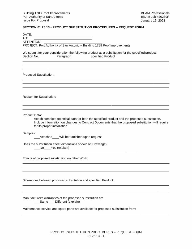
Building 1788 Roof Improvements Port Authority of San Antonio Issue For Proposal
BEAM Professionals BEAM Job #20289R
January 15, 2021
PRODUCT SUBSTITUTION PROCEDURES – REQUEST FORM
01 25 13 - 1
SECTION 01 25 13 - PRODUCT SUBSTITUTION PROCEDURES – REQUEST FORM DATE: TO: ATTENTION: PROJECT: Port Authority of San Antonio – Building 1788 Roof Improvements
We submit for your consideration the following product as a substitution for the specified product: Section No. Paragraph Specified Product
Proposed Substitution:
Reason for Substitution:
Product Data: Attach complete technical data for both the specified product and the proposed substitution. Include information on changes to Contract Documents that the proposed substitution will require for its proper installation.
Samples: Attached Will be furnished upon request
Does the substitution affect dimensions shown on Drawings? No Yes (explain)
Effects of proposed substitution on other Work:
Differences between proposed substitution and specified Product:
Manufacturer's warranties of the proposed substitution are: Same Different (explain)
Maintenance service and spare parts are available for proposed substitution from:
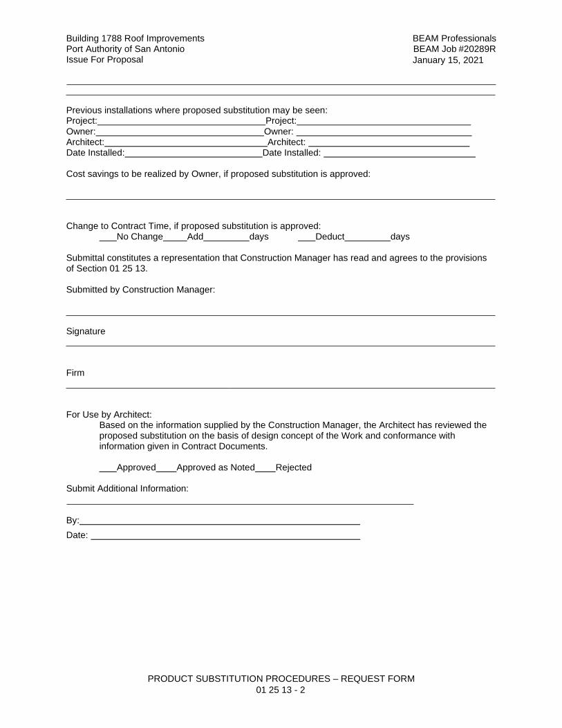
Building 1788 Roof Improvements Port Authority of San Antonio Issue For Proposal
BEAM Professionals BEAM Job #20289R
January 15, 2021
PRODUCT SUBSTITUTION PROCEDURES – REQUEST FORM
01 25 13 - 2
Previous installations where proposed substitution may be seen: Project: Project:
Owner: Owner: Architect: Architect: Date Installed: Date Installed:
Cost savings to be realized by Owner, if proposed substitution is approved:
Change to Contract Time, if proposed substitution is approved: No Change Add days Deduct days
Submittal constitutes a representation that Construction Manager has read and agrees to the provisions of Section 01 25 13.
Submitted by Construction Manager:
Signature
Firm
For Use by Architect: Based on the information supplied by the Construction Manager, the Architect has reviewed the proposed substitution on the basis of design concept of the Work and conformance with information given in Contract Documents.
Approved Approved as Noted Rejected
Submit Additional Information:
By:
Date:
Building 1788 Roof Improvements BEAM Professionals Port Authority of San Antonio BEAM Job #20289R Issue For Proposal January 15, 2021
SCHEDULE OF VALUES 01 29 73 - 1
SECTION 01 29 73 - SCHEDULE OF VALUES CONDITIONS OF THE CONTRACT AND DIVISION 01, as applicable, apply to this Section. PART 1 – GENERAL 1.1 SUMMARY
A. Work Included: Provide a detailed breakdown of the agreed Contract Sum showing values
allocated to each of the various parts of the Work, as specified herein and in other provisions of the Contract Documents.
B. Coordinate requirements of this Section with the requirements of the General and Supplementary Conditions of the Contract concerning Schedule of Values.
1.2 SUBMITTALS A. Prior to the first Application for Payment, submit a proposed schedule of values to the
Owner, as outlined below: 1. Meet with the Owner and determine additional data, if any, required to be
submitted. 2. Secure the Owner's approval of the schedule of values prior to submitting first
Application for Payment.
1.3 QUALITY ASSURANCE A. Use required means to assure arithmetical accuracy of the sums described.
B. When so required by the Owner, provide copies of the subcontracts or other data
acceptable to the Owner, substantiating the sums described.
1.4 SCHEDULE OF VALUES A. The Schedule of Values shall be broken down into item costs for each specification section
as a minimum. After review by the Owner, the Schedule of Values shall be broken down into further items as required. (See following list and refer to the enclosed sample.). In addition, total each Specification Division separately.
B. Schedule of Values - Items in addition to Specification Sections. 1. Mobilization 2. Clean Up 3. Building Permit 4. Bonds, Insurance 5. Misc. Mechanical Accessories 6. Demolition 7. Rough-In Labor – (Electrical) 8. Rough-In Material – (Electrical) 9. Finish Labor – (Electrical) 10. Finish Material – (Electrical) 11. Allowances (listed separately) 12. Record drawings and close-out documents 13. Submittals listed separately per mechanical, electrical and plumbing 14. Roof warranty as a line item 15. Donated items individually itemized at $0.00 (zero dollars).
Building 1788 Roof Improvements BEAM Professionals Port Authority of San Antonio BEAM Job #20289R Issue For Proposal January 15, 2021
SCHEDULE OF VALUES 01 29 73 - 2
PART 2 – PRODUCTS (Not Used) PART 3 – EXECUTION 3.1 SCHEDULE OF VALUES
A. Refer to following sample
.
Building 1788 Roof Improvements BEAM Professionals Port Authority of San Antonio BEAM Job #20289R Issue For Proposal January 15, 2021
SCHEDULE OF VALUES
01 29 73 - SAMPLE
SAMPLE SCHEDULE OF VALUES
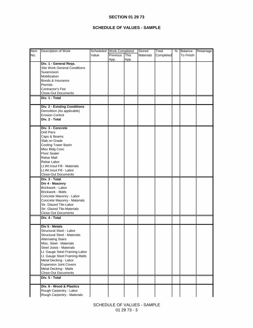
SECTION 01 29 73
SCHEDULE OF VALUES - SAMPLE
SCHEDULE OF VALUES - SAMPLE
01 29 73 - 3
Item Description of Work Scheduled Work Completed Stored Total % Balance Retainage
No. Value Previous This Materials Completed To Finish
App. App.
Div. 1 - General Reqs.
Site Work General Conditions
Suoervision
Mobilization
Bonds & Insurance
Permits
Contractor's Fee
Close-Out Documents
Div. 1 - Total
Div. 2 - Existing Conditions
Demolition (As applicable)
Erosion Control
Div. 2 - Total
Div. 3 - Concrete
Drill Piers
Caps & Beams
Slab on Grade
Cooling Tower Basin
Misc Bldg Conc
Floor Sealer
Rebar Matl
Rebar Labor
Lt.Wt.Insul Fill - Materials
Lt.Wt.Insul Fill - Labor
Close-Out Documents
Div. 3 - Total
Div 4 - Masonry
Brickwork - Labor
Brickwork - Matls
Concrete Masonry - Labor
Concrete Masonry - Materials
Str. Glazed Tile-Labor
Str. Glazed Tile-Materials
Close-Out Documents
Div. 4 - Total
Div 5 - Metals
Structural Steel - Labor
Structural Steel - Materials
Alternating Stairs
Misc. Steel - Materials
Steel Joists - Materials
Lt. Gauge Steel Framing-Labor
Lt. Gauge Steel Framing-Matls
Metal Decking - Labor
Expansion Joint Covers
Metal Decking - Matls
Close-Out Documents
Div. 5 - Total
Div. 6 - Wood & Plastics
Rough Carpentry - Labor
Rough Carpentry - Materials
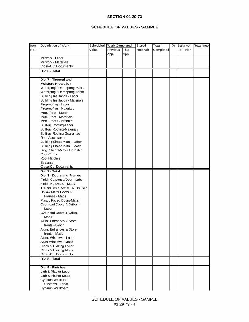
SECTION 01 29 73
SCHEDULE OF VALUES - SAMPLE
SCHEDULE OF VALUES - SAMPLE
01 29 73 - 4
Item Description of Work Scheduled Work Completed Stored Total % Balance Retainage
No. Value Previous This Materials Completed To Finish
App. App.
Millwork - Labor
Millwork - Materials
Close-Out Documents
Div. 6 - Total
Div. 7 - Thermal and
Moisture Protection
Waterpfng / Dampprfng-Matls
Waterpfng / Dampprfng-Labor
Building Insulation - Labor
Building Insulation - Materials
Fireproofing - Labor
Fireproofing - Materials
Metal Roof - Labor
Metal Roof - Materials
Metal Roof Guarantee
Built-up Roofing-Labor
Built-up Roofing-Materials
Built-up Roofing Guarantee
Roof Accessories
Building Sheet Metal - Labor
Building Sheet Metal - Matls
Bldg. Sheet Metal Guarantee
Roof Curbs
Roof Hatches
Sealants
Close-Out Documents
Div. 7 - Total
Div. 8 - Doors and Frames
Finish Carpentry/Door - Labor
Finish Hardware - Matls
Thresholds & Seals - Matls+B66
Hollow Metal Doors &
Frames - Matls
Plastic Faced Doors-Matls
Overhead Doors & Grilles-
Labor
Overhead Doors & Grilles -
Matls
Alum. Entrances & Store-
fronts - Labor
Alum. Entrances & Store-
fronts - Matls
Alum. Windows - Labor
Alum Windows - Matls
Glass & Glazing-Labor
Glass & Glazing-Matls
Close-Out Documents
Div. 8 - Total
Div. 9 - Finishes
Lath & Plaster-Labor
Lath & Plaster-Matls
Gypsum Wallboard
Systems - Labor
Gypsum Wallboard
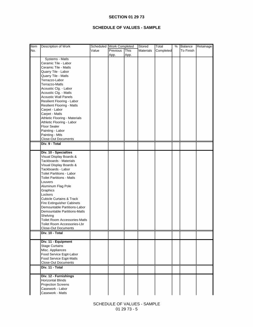
SECTION 01 29 73
SCHEDULE OF VALUES - SAMPLE
SCHEDULE OF VALUES - SAMPLE
01 29 73 - 5
Item Description of Work Scheduled Work Completed Stored Total % Balance Retainage
No. Value Previous This Materials Completed To Finish
App. App.
Systems - Matls
Ceramic Tile - Labor
Ceramic Tile - Matls
Quarry Tile - Labor
Quarry Tile - Matls
Terrazzo-Labor
Terrazzo-Matls
Acoustic Clg. - Labor
Acoustic Clg. - Matls
Acoustic Wall Panels
Resilient Flooring - Labor
Resilient Flooring - Matls
Carpet - Labor
Carpet - Matls
Athletic Flooring - Materials
Athletic Flooring - Labor
Floor Sealer
Painting - Labor
Painting - Mtls
Close-Out Documents
Div. 9 - Total
Div. 10 - Specialties
Visual Display Boards &
Tackboards - Materials
Visual Display Boards &
Tackboards - Labor
Toilet Partitions - Labor
Toilet Partitions - Matls
Louvers
Aluminum Flag Pole
Graphics
Lockers
Cubicle Curtains & Track
Fire Extinguisher Cabinets
Demountable Partitions-Labor
Demountable Partitions-Matls
Shelving
Toilet Room Accessories-Matls
Toilet Room Accessories-Lbr
Close-Out Documents
Div. 10 - Total
Div. 11 - Equipment
Stage Curtains
Misc. Appliances
Food Service Eqpt-Labor
Food Service Eqpt-Matls
Close-Out Documents
Div. 11 - Total
Div. 12 - Furnishings
Horizontal Blinds
Projection Screens
Casework - Labor
Casework - Matls
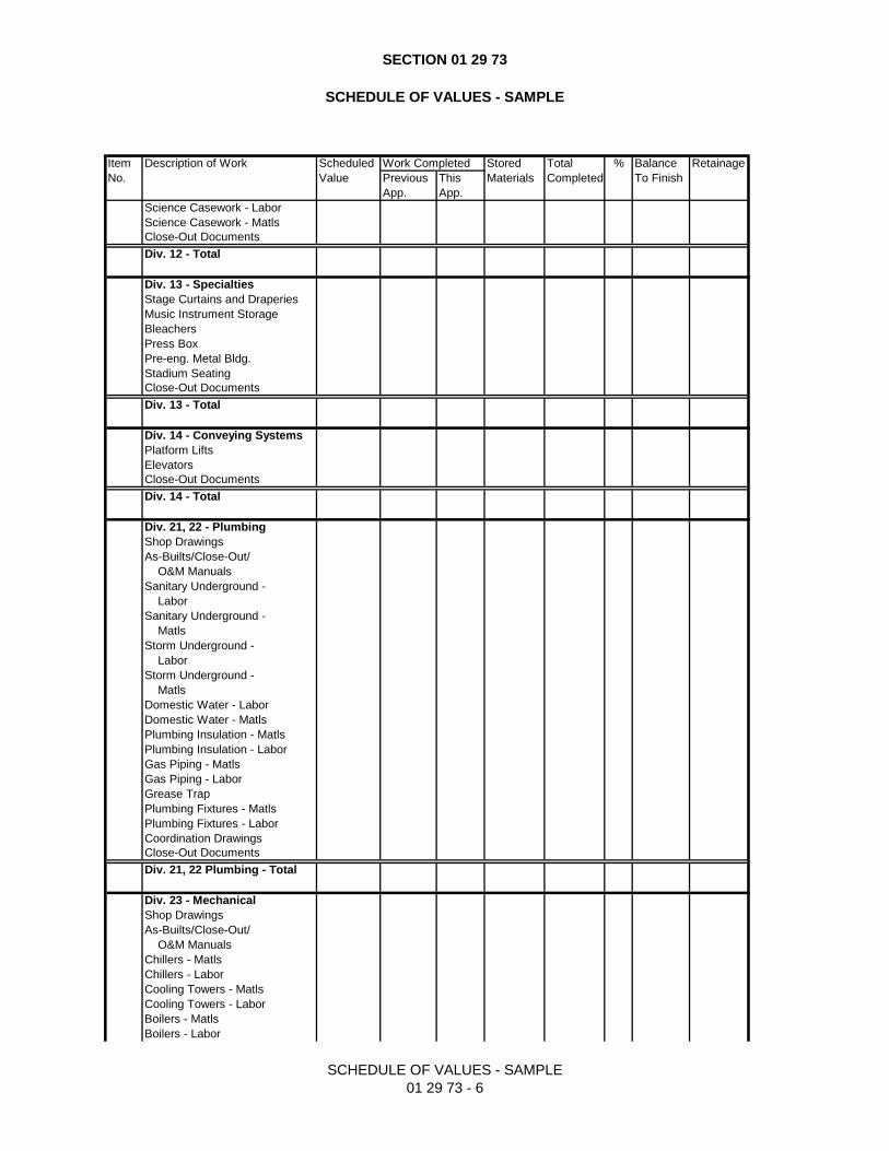
SECTION 01 29 73
SCHEDULE OF VALUES - SAMPLE
SCHEDULE OF VALUES - SAMPLE
01 29 73 - 6
Item Description of Work Scheduled Work Completed Stored Total % Balance Retainage
No. Value Previous This Materials Completed To Finish
App. App.
Science Casework - Labor
Science Casework - Matls
Close-Out Documents
Div. 12 - Total
Div. 13 - Specialties
Stage Curtains and Draperies
Music Instrument Storage
Bleachers
Press Box
Pre-eng. Metal Bldg.
Stadium Seating
Close-Out Documents
Div. 13 - Total
Div. 14 - Conveying Systems
Platform Lifts
Elevators
Close-Out Documents
Div. 14 - Total
Div. 21, 22 - Plumbing
Shop Drawings
As-Builts/Close-Out/
O&M Manuals
Sanitary Underground -
Labor
Sanitary Underground -
Matls
Storm Underground -
Labor
Storm Underground -
Matls
Domestic Water - Labor
Domestic Water - Matls
Plumbing Insulation - Matls
Plumbing Insulation - Labor
Gas Piping - Matls
Gas Piping - Labor
Grease Trap
Plumbing Fixtures - Matls
Plumbing Fixtures - Labor
Coordination Drawings
Close-Out Documents
Div. 21, 22 Plumbing - Total
Div. 23 - Mechanical
Shop Drawings
As-Builts/Close-Out/
O&M Manuals
Chillers - Matls
Chillers - Labor
Cooling Towers - Matls
Cooling Towers - Labor
Boilers - Matls
Boilers - Labor
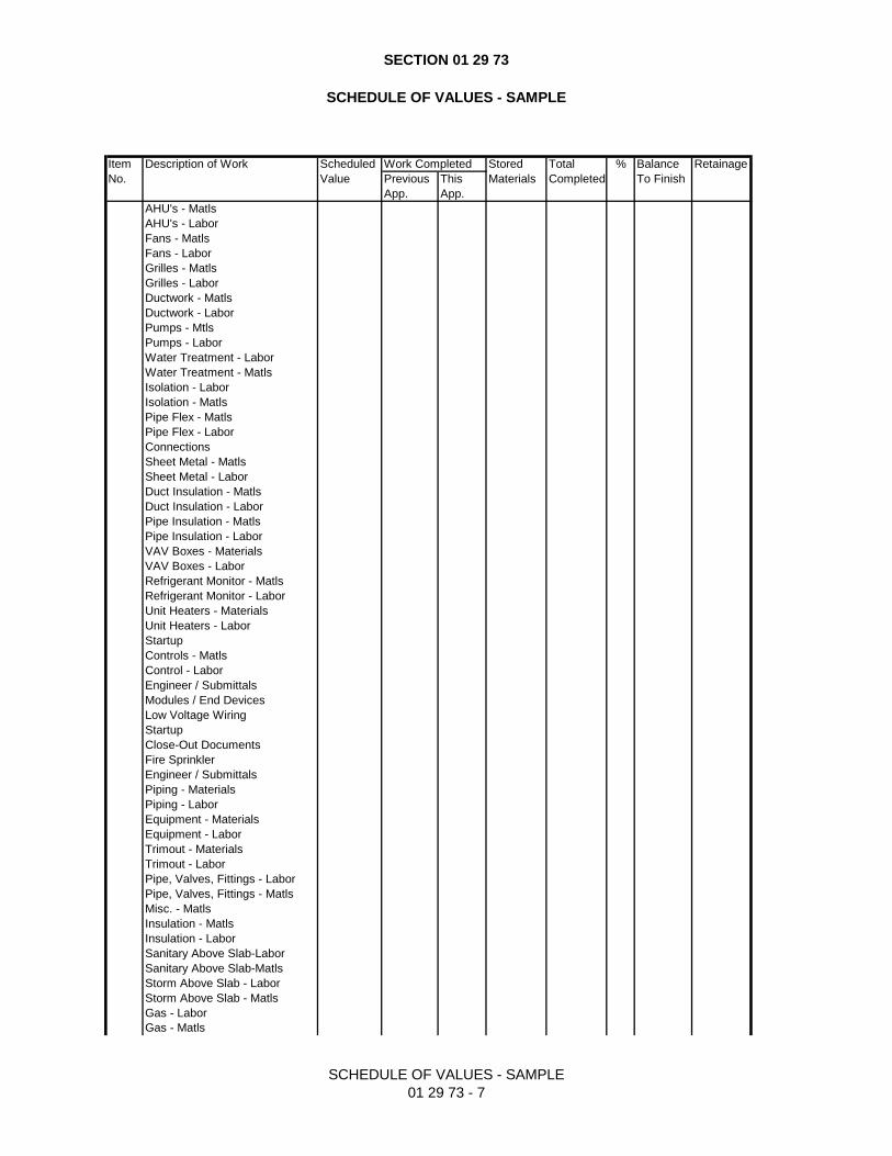
SECTION 01 29 73
SCHEDULE OF VALUES - SAMPLE
SCHEDULE OF VALUES - SAMPLE
01 29 73 - 7
Item Description of Work Scheduled Work Completed Stored Total % Balance Retainage
No. Value Previous This Materials Completed To Finish
App. App.
AHU's - Matls
AHU's - Labor
Fans - Matls
Fans - Labor
Grilles - Matls
Grilles - Labor
Ductwork - Matls
Ductwork - Labor
Pumps - Mtls
Pumps - Labor
Water Treatment - Labor
Water Treatment - Matls
Isolation - Labor
Isolation - Matls
Pipe Flex - Matls
Pipe Flex - Labor
Connections
Sheet Metal - Matls
Sheet Metal - Labor
Duct Insulation - Matls
Duct Insulation - Labor
Pipe Insulation - Matls
Pipe Insulation - Labor
VAV Boxes - Materials
VAV Boxes - Labor
Refrigerant Monitor - Matls
Refrigerant Monitor - Labor
Unit Heaters - Materials
Unit Heaters - Labor
Startup
Controls - Matls
Control - Labor
Engineer / Submittals
Modules / End Devices
Low Voltage Wiring
Startup
Close-Out Documents
Fire Sprinkler
Engineer / Submittals
Piping - Materials
Piping - Labor
Equipment - Materials
Equipment - Labor
Trimout - Materials
Trimout - Labor
Pipe, Valves, Fittings - Labor
Pipe, Valves, Fittings - Matls
Misc. - Matls
Insulation - Matls
Insulation - Labor
Sanitary Above Slab-Labor
Sanitary Above Slab-Matls
Storm Above Slab - Labor
Storm Above Slab - Matls
Gas - Labor
Gas - Matls
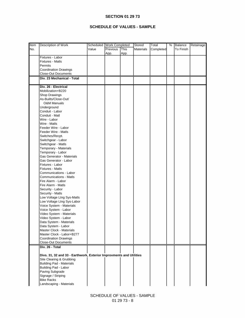
SECTION 01 29 73
SCHEDULE OF VALUES - SAMPLE
SCHEDULE OF VALUES - SAMPLE
01 29 73 - 8
Item Description of Work Scheduled Work Completed Stored Total % Balance Retainage
No. Value Previous This Materials Completed To Finish
App. App.
Fixtures - Labor
Fixtures - Matls
Permits
Coordination Drawings
Close-Out Documents
Div. 23 Mechanical - Total
Div. 26 - Electrical
Mobilization+B220
Shop Drawings
As-Builts/Close-Out/
O&M Manuals
Underground
Conduit - Labor
Conduit - Matl
Wire - Labor
Wire - Matls
Feeder Wire - Labor
Feeder Wire - Matls
Switches/Recpt.
Switchgear - Labor
Switchgear - Matls
Temporary - Materials
Temporary - Labor
Gas Generator - Materials
Gas Generator - Labor
Fixtures - Labor
Fixtures - Matls
Communications - Labor
Communications - Matls
Fire Alarm - Labor
Fire Alarm - Matls
Security - Labor
Security - Matls
Low Voltage Ltng Sys-Matls
Low Voltage Ltng Sys-Labor
Voice System - Materials
Voice System - Labor
Video System - Materials
Video System - Labor
Data System - Materials
Data System - Labor
Master Clock - Materials
Master Clock - Labor+B277
Coordination Drawings
Close-Out Documents
Div. 26 - Total
Divs. 31, 32 and 33 - Earthwork, Exterior Improvments and Utilities
Site Clearing & Grubbing
Building Pad - Materials
Building Pad - Labor
Paving Subgrade
Signage / Striping
Bike Racks
Landscaping - Materials
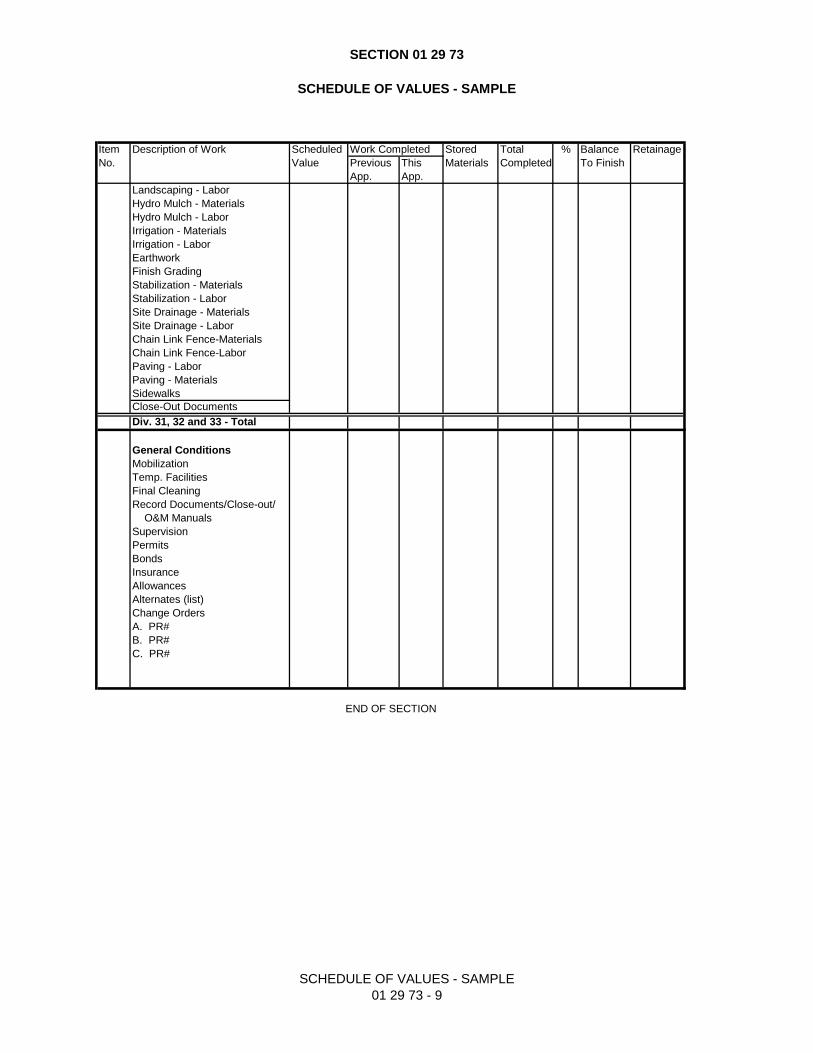
SECTION 01 29 73
SCHEDULE OF VALUES - SAMPLE
SCHEDULE OF VALUES - SAMPLE
01 29 73 - 9
Item Description of Work Scheduled Work Completed Stored Total % Balance Retainage
No. Value Previous This Materials Completed To Finish
App. App.
Landscaping - Labor
Hydro Mulch - Materials
Hydro Mulch - Labor
Irrigation - Materials
Irrigation - Labor
Earthwork
Finish Grading
Stabilization - Materials
Stabilization - Labor
Site Drainage - Materials
Site Drainage - Labor
Chain Link Fence-Materials
Chain Link Fence-Labor
Paving - Labor
Paving - Materials
Sidewalks
Close-Out Documents
Div. 31, 32 and 33 - Total
General Conditions
Mobilization
Temp. Facilities
Final Cleaning
Record Documents/Close-out/
O&M Manuals
Supervision
Permits
Bonds
Insurance
Allowances
Alternates (list)
Change Orders
A. PR#
B. PR#
C. PR#
END OF SECTION
Building 1788 Roof Improvements BEAM Professionals Port Authority of San Antonio BEAM Job #20289R Issue For Proposal January 15, 2021
SCHEDULE OF VALUES 01 29 73
END OF SECTION 01 29 73
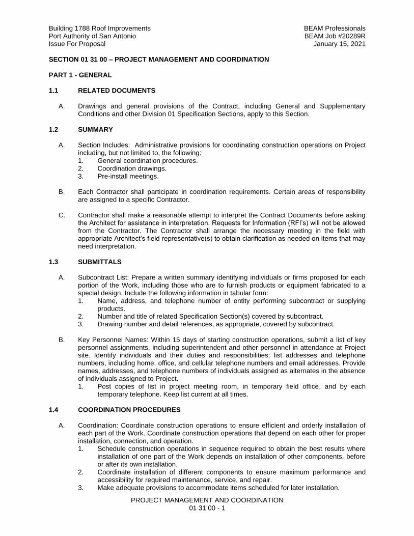
Building 1788 Roof Improvements BEAM Professionals Port Authority of San Antonio BEAM Job #20289R Issue For Proposal January 15, 2021
PROJECT MANAGEMENT AND COORDINATION 01 31 00 - 1
SECTION 01 31 00 – PROJECT MANAGEMENT AND COORDINATION PART 1 - GENERAL
1.1 RELATED DOCUMENTS
A. Drawings and general provisions of the Contract, including General and Supplementary
Conditions and other Division 01 Specification Sections, apply to this Section.
1.2 SUMMARY
A. Section Includes: Administrative provisions for coordinating construction operations on Project including, but not limited to, the following: 1. General coordination procedures. 2. Coordination drawings. 3. Pre-install meetings.
B. Each Contractor shall participate in coordination requirements. Certain areas of responsibility are assigned to a specific Contractor.
C. Contractor shall make a reasonable attempt to interpret the Contract Documents before asking the Architect for assistance in interpretation. Requests for Information (RFI’s) will not be allowed from the Contractor. The Contractor shall arrange the necessary meeting in the field with appropriate Architect’s field representative(s) to obtain clarification as needed on items that may need interpretation.
1.3 SUBMITTALS
A. Subcontract List: Prepare a written summary identifying individuals or firms proposed for each portion of the Work, including those who are to furnish products or equipment fabricated to a special design. Include the following information in tabular form: 1. Name, address, and telephone number of entity performing subcontract or supplying
products. 2. Number and title of related Specification Section(s) covered by subcontract. 3. Drawing number and detail references, as appropriate, covered by subcontract.
B. Key Personnel Names: Within 15 days of starting construction operations, submit a list of key
personnel assignments, including superintendent and other personnel in attendance at Project site. Identify individuals and their duties and responsibilities; list addresses and telephone numbers, including home, office, and cellular telephone numbers and email addresses. Provide names, addresses, and telephone numbers of individuals assigned as alternates in the absence of individuals assigned to Project. 1. Post copies of list in project meeting room, in temporary field office, and by each
temporary telephone. Keep list current at all times.
1.4 COORDINATION PROCEDURES
A. Coordination: Coordinate construction operations to ensure efficient and orderly installation of each part of the Work. Coordinate construction operations that depend on each other for proper installation, connection, and operation. 1. Schedule construction operations in sequence required to obtain the best results where
installation of one part of the Work depends on installation of other components, before or after its own installation.
2. Coordinate installation of different components to ensure maximum performance and accessibility for required maintenance, service, and repair.
3. Make adequate provisions to accommodate items scheduled for later installation.
Building 1788 Roof Improvements BEAM Professionals Port Authority of San Antonio BEAM Job #20289R Issue For Proposal January 15, 2021
PROJECT MANAGEMENT AND COORDINATION 01 31 00 - 2
B. Coordination: Each Contractor shall coordinate its construction operations with those of other Contractors and entities to ensure efficient and orderly installation of each part of the Work. Each Contractor shall coordinate its operations with operations, included in different Sections, which depend on each other for proper installation, connection, and operation. 1. Schedule construction operations in sequence required to obtain best results where
installation of one part of the Work depends on installation of other components, before or after its own installation.
2. Coordinate installation of different components with other Contractors to ensure maximum performance and accessibility for required maintenance, service, and repair.
3. Make adequate provisions to accommodate items scheduled for later installation.
C. Prepare memoranda for distribution to each party involved, outlining special procedures required for coordination. Include items as required notices, reports, and list of attendees at meetings. 1. Prepare similar memoranda for Owner and separate Contractors if coordination of the
Work is required.
D. Administrative Procedures: Coordinate scheduling and timing of required administrative procedures with other construction activities to avoid conflicts and to ensure orderly progress of the Work. Administrative activities include, but are not limited to, the following: 1. Preparation of Contractor's construction schedule. 2. Preparation of the schedule of values. 3. Installation and removal of temporary facilities and controls. 4. Delivery and processing of submittals. 5. Progress meetings. 6. Preinstallation conferences. 7. Project closeout activities. 8. Startup and adjustment of systems. 9. Coordinating inspections and other jurisdictional requirements. 10. Coordinate OFCI equipment. 11. Action items and issue logs.
E. Conservation: Coordinate construction activities to ensure that operations are carried out with
consideration given to conservation of energy, water, and materials. Coordinate use of temporary utilities to minimize waste. 1. Salvage materials and equipment involved in performance of, but not actually
incorporated into, the Work. Refer to the Specifications Sections for disposition of salvaged materials that are designated as Owner's property.
1.5 COORDINATION DRAWINGS
A. Coordination Drawings, General: Prepare coordination drawings according to requirements in individual Sections, and additionally where installation is not completely shown on Shop Drawings, where limited space availability necessitates coordination, or if coordination is required to facilitate integration of products and materials fabricated or installed by more than one entity. 1. Content: Project-specific information, drawn accurately to a scale large enough to
indicate and resolve conflicts. Do not base coordination drawings on standard printed data. Include the following information, as applicable: a. Use applicable Drawings as a basis for preparation of coordination drawings.
Prepare sections, elevations, and details as needed to describe relationship of various systems and components.
b. Coordinate the addition of trade specific information to the coordination drawings by multiple Contractors in sequence that best provides for coordination of the information and resolution of conflicts between installed components before submitting for review.
Building 1788 Roof Improvements BEAM Professionals Port Authority of San Antonio BEAM Job #20289R Issue For Proposal January 15, 2021
PROJECT MANAGEMENT AND COORDINATION 01 31 00 - 3
c. Indicate functional and spatial relationships of components of architectural, structural, civil, mechanical, and electrical systems.
d. Indicate space requirements for routine maintenance and for anticipated replacement of components during the life of the installation.
e. Show location and size of access doors required for access to concealed dampers, valves, and other controls.
f. Indicate required installation sequences. g. Indicate dimensions shown on the Drawings. Specifically note dimensions that
appear to be in conflict with submitted equipment and minimum clearance requirements. Provide alternate sketches to Architect indicating proposed resolution of such conflicts. Minor dimension changes and difficult installations will not be considered changes to the Contract.
B. Coordination Drawing Organization: Organize coordination drawings: 1. Roof Plans: Show architectural and structural elements, and mechanical, plumbing, fire-
protection, fire-alarm, and electrical Work. Supplement plan drawings with section drawings where required to adequately represent the Work.
2. Plenum Space: Indicate subframing for support of ceiling and wall systems, mechanical and electrical equipment, and related Work. Locate components within ceiling plenum to accommodate layout of light fixtures indicated on Drawings. Indicate areas of conflict between light fixtures, ductwork, piping, and other components.
3. Structural Penetrations: Indicate penetrations and openings required for all disciplines. 4. Review: Architect will review coordination drawings to confirm that the Work is being
coordinated, but not for the details of the coordination, which are Contractor's responsibility. If Architect determines that coordination drawings are not being prepared in sufficient scope or detail, or are otherwise deficient, Architect will so inform Contractor, who shall make changes as directed and resubmit.
5. Coordination Drawing Prints: Prepare coordination drawing prints according to requirements in Section 01 33 00.
C. Coordination Digital Data Files: Prepare coordination digital data files according to the following requirements: 1. File Preparation Format: Same digital data software program, version, and operating
system as original Drawings. 2. File Submittal Format: Submit or post coordination drawing files using format same as
file preparation format. 3. Architect will furnish Contractor one set of digital data files of Drawings for use in
preparing coordination digital data files. a. Architect makes no representations as to the accuracy or completeness of digital
data files as they relate to Drawings. b. Digital Data Software Program: Drawings are available in Revit. c. Contractor shall execute a data licensing agreement in the form of
AIA Document C106.
1.6 PROJECT MEETINGS
A. Schedule and conduct meetings and conferences at Project site unless otherwise indicated. 1. Attendees: Inform participants and others involved, and individuals whose presence is
required, of date and time of each meeting. Notify Owner and Architect of scheduled meeting dates and times.
2. Agenda: Contractor to prepare the meeting agenda and distribute the agenda to all invited attendees.
3. Minutes: Entity responsible for conducting meeting will record significant discussions and agreements achieved. Distribute the meeting minutes to everyone concerned, including Owner and Architect, within three days of the meeting.
Building 1788 Roof Improvements BEAM Professionals Port Authority of San Antonio BEAM Job #20289R Issue For Proposal January 15, 2021
PROJECT MANAGEMENT AND COORDINATION 01 31 00 - 4
4. Action Items: An element of work, design, research, or other task to be completed before a specific date or time, such as before a subsequent meeting of involved parties.
5. Issue logs: Documentation element of software project management and contains a list of ongoing and closed issues of the project.
B. Kick-off & Preconstruction Conference: Architect will schedule and conduct a preconstruction conference before starting construction, at a time convenient to Owner and Architect. 1. Conduct the conference to review responsibilities and personnel assignments. 2. Attendees: Authorized representatives of Owner, Architect, and their consultants;
Contractor and its superintendent; major subcontractors; suppliers; and other concerned parties shall attend the conference. Participants at the conference shall be familiar with Project and authorized to conclude matters relating to the Work.
3. Agenda: Discuss items of significance that affect progress. 4. Minutes: Entity responsible for conducting meeting will record and distribute meeting
minutes. 5. Action Items: An element of work, design, research, or other task to be completed before
a specific date or time, such as before a subsequent meeting of involved parties.
C. Preinstallation Conferences: Conduct a preinstallation trade conference at site before each construction activity that requires coordination with other construction trades. 1. Attendees: Installer and representatives of manufacturers and fabricators involved in or
affected by the installation and its coordination or integration with other materials and installations that have preceded or will follow, shall attend the meeting. Advise Architect and Engineer of Record of scheduled meeting dates.
2. Agenda: Contractor to review progress of other construction activities and preparations for the particular activity under consideration.
3. Contractor to record significant conference discussions, agreements, and disagreements, including required corrective measures and actions.
4. Reporting: Contractor to distribute minutes of the meeting to each party present and to other parties requiring information.
5. Do not proceed with installation if the conference cannot be successfully concluded. Initiate whatever actions are necessary to resolve impediments to performance of the Work and reconvene the conference at earliest feasible date.
6. Action Items: An element of work, design, research, or other task to be completed before a specific date or time, such as before a subsequent meeting of involved parties.
D. Project Closeout Conference: Schedule and conduct a project closeout conference, at a time convenient to Owner and Architect, but no later than 90 days prior to the scheduled date of Substantial Completion. 1. Conduct the conference to review requirements and responsibilities related to Substantial
Completion. 2. Attendees: Authorized representatives of Owner, Architect, and their consultants;
Contractor and its superintendent; major subcontractors; suppliers; and other concerned parties shall attend the meeting. Participants at the meeting shall be familiar with Project and authorized to conclude matters relating to the Work.
3. Agenda: Discuss items of significance that could affect or delay Project closeout. 4. Minutes: Entity conducting meeting will record and distribute meeting minutes. 5. Action Items: An element of work, design, research, or other task to be completed before
a specific date or time, such as before a subsequent meeting of involved parties.
E. Progress Meetings: Conduct progress meetings at bi-weekly intervals. 1. Coordinate dates of meetings with preparation of payment requests. 2. Attendees: In addition to representatives of Owner and Architect, each Contractor,
subcontractor, supplier, and other entity concerned with current progress or involved in planning, coordination, or performance of future activities shall be represented at these
Building 1788 Roof Improvements BEAM Professionals Port Authority of San Antonio BEAM Job #20289R Issue For Proposal January 15, 2021
PROJECT MANAGEMENT AND COORDINATION 01 31 00 - 5
meetings. All participants at the meeting shall be familiar with Project and authorized to conclude matters relating to the Work.
3. Agenda: Review and correct or approve minutes of previous progress meeting. Review other items of significance that could affect progress. Include topics for discussion as appropriate to status of Project. a. Contractor's Construction Schedule: Review progress since the last meeting.
Determine whether each activity is on time, ahead of schedule, or behind schedule, in relation to Contractor's construction schedule. Determine how construction behind schedule will be expedited; secure commitments from parties involved to do so. Discuss whether schedule revisions are required to ensure that current and subsequent activities will be completed within the Contract Time.
4. Minutes: Entity responsible for conducting the meeting will record and distribute the meeting minutes to each party present and to parties requiring information. a. Schedule Updating: Revise Contractor's construction schedule after each progress
meeting where revisions to the schedule have been made or recognized. Issue revised schedule concurrently with the report of each meeting.
b. Six (6) week look-ahead schedules. 5. Action Items: An element of work, design, research, or other task to be completed before
a specific date or time, such as before a subsequent meeting of involved parties.
F. Coordination Meetings: Conduct coordination meetings at weekly intervals. Project coordination meetings are in addition to specific meetings held for other purposes, such as progress meetings and preinstallation conferences. 1. Attendees: In addition to representatives of Owner and Architect, each contractor,
subcontractor, supplier, and other entity concerned with current progress or involved in planning, coordination, or performance of future activities shall be represented at these meetings. All participants at the meetings shall be familiar with Project and authorized to conclude matters relating to the Work.
2. Agenda: Review and correct or approve minutes of the previous coordination meeting. Review other items of significance that could affect progress. Include topics for discussion as appropriate to status of Project. a. Combined Contractor's Construction Schedule: Review progress since the last
coordination meeting. Determine whether each contract is on time, ahead of schedule, or behind schedule, in relation to combined Contractor's construction schedule. Determine how construction behind schedule will be expedited; secure commitments from parties involved to do so. Discuss whether schedule revisions are required to ensure that current and subsequent activities will be completed within the Contract Time.
b. Schedule Updating: Revise combined Contractor's construction schedule after each coordination meeting where revisions to the schedule have been made or recognized. Issue revised schedule concurrently with report of each meeting.
c. Review present and future needs of each Contractor present. 3. Reporting: Record meeting results and distribute copies to everyone in attendance and to
others affected by decisions or actions resulting from each meeting. 4. Action Items: An element of work, design, research, or other task to be completed before
a specific date or time, such as before a subsequent meeting of involved parties.
PART 2 - PRODUCTS Not Used PART 3 - EXECUTION Not Used
END OF SECTION 01 31 00

Building 1788 Roof Improvements BEAM Professionals Port Authority of San Antonio BEAM Job #20289R Issue For Proposal January 15, 2021
PROJECT COORDINATION
01 31 13 - 1
SECTION 01 31 13 - PROJECT COORDINATION CONDITIONS OF THE CONTRACT AND DIVISION 01, as applicable, apply to this Section. PART 1 – GENERAL 1.1 SUMMARY
A. Administrative and procedural requirements governing Project coordination.
1.2 REQUIREMENTS
A. General: notify the Architect whenever there is need of clarification or interpretation of the
Contract Documents prior to commencement of work.
B. Commencement of work without Architect’s prior notification means Contractor’s acceptance of responsibility.
C. Commencement of work without Architect’s prior notification implies Contractor’s understanding of conditions, assemblies, methods, or procedures.
D. The project superintendent shall notify the Owner on an ongoing basis of ongoing work.
1.3 PRE-INSTALLATION CONFERENCE A. General: Notify the Architect 48 hours in advance of certain stages of construction, and,
as required by the Architect, organize a pre-installation meeting with each trade individually prior to commencement of their portion of the Work. At a minimum, representatives of the Architect, the General Contractor’s project superintendent, and the Sub-contractor’s Foreman and Project Manager shall be present at each meeting. The Engineer shall be notified as applicable.
B. As indicated in each specific section of this Project Manual, or as required by the Architect, these stages generally include, but are not necessarily limited to the following: 1. Division 07: installation of waterproofing, air barriers, vapor barriers, flashing and
sheet metal 2. Division 07: Installation of roofing system(s) and associated work
C. In addition to notifying the Architect, notify the Structural Engineer (48 hours) prior to the following stages: 1. Drilling, reinforcing, and placing of first piers and footings. 2. Placing first reinforcing and grade beams. 3. Erecting structural steel elements.
PART 2 – PRODUCTS (Not Used) PART 3 – EXECUTION 3.1 PRE-CONSTRUCTION CONFERENCE
A. The Contractor shall contact Architect at least ten (10) days prior to commencing
construction in order for Architect to schedule a pre-construction meeting with Contractor, Architect, and Owner. This meeting must occur prior to commencement of any construction.
Building 1788 Roof Improvements BEAM Professionals Port Authority of San Antonio BEAM Job #20289R Issue For Proposal January 15, 2021
PROJECT COORDINATION
01 31 13 - 2
3.2 CONFERENCES AND MEETINGS A. Refer to Section 01 31 19, “Project Meetings” for requirements pertaining to Pre-
construction Conference, Progress Meetings, and Pre-installation Conferences.
END OF SECTION 01 31 13
Building 1788 Roof Improvements BEAM Professionals Port Authority of San Antonio BEAM Job #20289R Issue For Proposal January 15, 2021
PROJECT MEETINGS 01 31 19 - 1
SECTION 01 31 19 - PROJECT MEETINGS CONDITIONS OF THE CONTRACT AND DIVISION 01, as applicable, apply to this Section. PART 1 – GENERAL 1.1 SUMMARY
A. Administrative and procedural requirements governing Project meetings, including:
1. Pre-Construction Conference 2. Progress Meetings 3. Pre-Installation Conferences 4. Pre-Closeout Meeting
1.2 REQUIREMENTS INCLUDE
A. The Architect’s:
1. Scheduling of each meeting (pre-construction meeting, periodic project meetings, and specialty called meetings throughout the progress of the Work).
2. Preparation of agenda for meetings. 3. Presiding at minutes, including all significant proceedings and decisions. 4. Recording, reproducing, and distributing copies of meeting minutes within two (2)
working days, excluding weekends and holidays, after each meeting to: a. All participants in the meeting. b. All parties affected by decisions made at the meeting.
5. Providing status report of allowance funds.
B. The Contractor’s: 1. Making physical arrangement for meetings. 2. Participation in all meetings and conferences. 3. Scheduling attendance of Job Superintendent, Project Coordinator, and other
parties affecting or affected by decisions made at meetings and conferences as their interests require.
4. Scheduling Pre-installation conferences. 5. Scheduling Pre-Closeout Meeting 6. Providing updated schedules. 7. Providing status reports/logs of CPRs, MCs, and shop drawings/submittals.
PART 2 – PRODUCTS (Not Used) PART 3 – EXECUTION 3.1 PRE-CONSTRUCTION CONFERENCE
A. Contractor shall contact Architect at least ten (10) days prior to commencing construction
in order for Architect to schedule a pre-construction meeting with Contractor, Architect, and Owner. This meeting must occur prior to commencement of any construction.
B. Architect will: 1. Administer pre-construction conference for the establishment of communication
methods, procedures and Owner requirements. 2. Administer site mobilization conference for clarification of Owner and Contractor.
C. Location: At Project site as designated by the Architect.
Building 1788 Roof Improvements BEAM Professionals Port Authority of San Antonio BEAM Job #20289R Issue For Proposal January 15, 2021
PROJECT MEETINGS 01 31 19 - 2
D. Attendance:
1. Contractor or Contractor’s Representative 2. Job Superintendent 3. Project Coordinator (Manager) 4. Owner or Owner’s Representative 5. Major subcontractors 6. Major suppliers 7. Architect’s Representative 8. Architect’s Field Representative 9. Consultants as needed 10. Others as appropriate
E. Meeting Agenda, may include, but is not limited to: 1. Discussion on major subcontracts and suppliers and projected construction
schedules. 2. Critical work sequencing. 3. Major equipment deliveries and priorities. Discussion of long lead time items. 4. Project coordination and designation of responsible personnel. 5. Procedures and processing of field decisions, proposal requests, submittals, minor
changes, change orders and applications for payment. 6. Method of distribution of Contract Documents. 7. Procedures for maintaining Record Documents. 8. Use of premises, office work and storage areas, on-site parking, and Owner’s
requirements. 9. Construction facilities and temporary utilities. 10. Housekeeping procedures.
3.2 PROGRESS MEETINGS
A. Architect will:
1. Schedule project meetings throughout progress of the work at weekly intervals, and specially called meetings.
2. Set agenda and administer said meetings. 3. Preside at meetings. 4. Record meeting minutes, including all significant proceedings and decisions. 5. Reproduce and distribute copies of meeting minutes within two (2) working days,
excluding weekends and holidays, after each meeting to: a. All participants in the meeting. b. All parties affected by decisions made at the meeting.
B. Contractor shall:
1. Make physical arrangements for meetings.
C. Attendance: 1. Contractor or Contractor’s Representative 2. Job Superintendent 3. Project Coordinator (Manager) 4. Owner or Owner’s Representative 5. Major subcontractors 6. Major suppliers 7. Architect’s Field Representative 8. Consultants as needed 9. Others as appropriate
Building 1788 Roof Improvements BEAM Professionals Port Authority of San Antonio BEAM Job #20289R Issue For Proposal January 15, 2021
PROJECT MEETINGS 01 31 19 - 3
D. Meeting Agenda, may include, but is not limited to:
1. Review and approval of minutes of previous meeting. 2. Review of Work progress since previous meeting. 3. Field observations, problems, and conflicts. 4. Review of off-site fabrication and delivery schedules. 5. Corrective measures and procedures to regain projected schedule. 6. Revisions to Construction Schedule. 7. Plan progress and schedule during succeeding work period. 8. Coordination of schedules. 9. Review submittal schedules and expedite as required. 10. Maintenance of quality standards. 11. Allowance balances. 12. Review of proposed changes and substitutions for:
a. Effect on Construction Schedule and on completion date. b. Effect on other contracts of the Project.
13. Status of Allowance Expenditure Authorizations (AEAs). 14. Status of Change Proposal Requests (CPRs). 15. Status of Minor Changes (MCs). 16. Status of submittals, review of submittal log. 17. Other items and critical issues affecting Work.
3.3 PRE-INSTALLATION CONFERENCES
A. In accordance with the requirements of Section 01 31 13, “Project Coordination”, the
Contractor will convene pre-installation conferences when required by individual specification Sections or as required by the Architect, prior to the Contractor commencing Work of the Section.
B. Attendance, optional: 1. General Contractor or Contractor’s Representative 2. Project Coordinator (Manager) 3. Owner or Owner’s Representative 4. Architect’s Project Manager (Project Executive)
C. Attendance, required: 1. Project Superintendent 2. Architect’s Field Representative 3. Sub-contractor’s Project Manager 4. Sub-contractor’s Foreman 5. Engineer’s Representative, as needed. 6. Manufacturer’s Representative, as needed. 7. Governing Agency Official, as required 8. Inspection Agency Representative, as required. 9. Others affecting or affected by Work.
D. Meeting Agenda, may include, but is not limited to: 1. Review of conditions of installation. 2. Preparation and installation procedures. 3. Coordination with related work 4. Review of the contract document requirements. 5. Review of code enforcement or testing requirements. 6. Questions related to work required.
Building 1788 Roof Improvements BEAM Professionals Port Authority of San Antonio BEAM Job #20289R Issue For Proposal January 15, 2021
PROJECT MEETINGS 01 31 19 - 4
3.4 PRE-CLOSEOUT MEETING A. In accordance with the requirements of Section 01 77 00, “Closeout Procedures”, the
Contractor will convene a pre-closeout meeting when he considers the Work or designated portion of the Work is sufficiently complete in accordance with the Contract Documents so that the Owner can occupy or utilize the work for its intended use.
B. Attendance, required: 1. Owner or Owner’s Representative 2. Project Coordinator (Manager) 3. General Contractor or Contractor’s Representative 4. Project Superintendent 5. Architect’s Project Manager (Project Executive) 6. Architect’s Field Representative 7. Engineer’s Representative, as needed.
C. Meeting Agenda, may include, but is not limited to: 1. Review of the contract document requirements for Substantial Completion and
Project Closeout 2. Review of Work which remains to be completed or corrected. 3. Closeout Document review schedule and log 4. Review of closeout procedures including, but not limited to Record Drawings,
Warrantees, Operation and Maintenance Manuals, and Owner Demonstrations and Start-up.
5. Review of code enforcement or testing requirements. 6. Questions related to work required.
END OF SECTION 01 13 19
Building 1788 Roof Improvements BEAM Professionals Port Authority of San Antonio BEAM Job #20289R Issue For Proposal January 15, 2021
CONSTRUCTION PROGRESS SCHEDULE
01 32 16 - 1
SECTION 01 32 16 - CONSTRUCTION PROGRESS SCHEDULE CONDITIONS OF THE CONTRACT AND DIVISION 01, as applicable, apply to this Section. PART 1 – GENERAL 1.1 SUMMARY
A. Section Includes: Requirements for preparation of Construction Schedules for the Work
of This Contract. 1. Create a Construction Schedule using Critical Path Method (CPM) computer
software capable of mathematical analysis of Precedence Diagramming Method (PDM) schedules. Provide printed activity listings and bar charts in formats described in this Section.
2. Combine activity listings and bar charts with a narrative report to form the Contractor's Construction Schedule submittal to the Architect.
B. Related Requirements:
1. Section 01 31 13 “Project Coordination” 2. Section 01 31 19 “Project Meetings” 3. Section 01 33 00 “Submittal Procedures” 4. Section 01 77 00 “Close-out Procedures”
1.2 DEFINITIONS
A. Activity: A task or discrete part of a project that can be identified for planning, scheduling,
monitoring, and controlling construction of the Project. Activities included in a construction schedule consume time and resources. 1. Critical activities are activities on the critical path. They must start and finish on
the planned early start and finish times. 2. Predecessor activities are activities that must be completed before another given
activity can be started.
B. CPM: Critical Path Method, a method of planning and scheduling a construction project in which activities are arranged based on activity relationships. Network calculations determine when activities can be performed and the critical path of the Project.
C. Critical Path: The longest continuous chain of activities through the network schedule that establishes the minimum overall Project duration and contains no float.
D. Event: The starting or ending point of an activity.
E. Float: The measure of leeway in stating and completing an activity. 1. Float time is not for the exclusive use or benefit of either Owner or Contractor,
but is a jointly owned, expiring Project resource available to both parties as needed to meet schedule milestones and the Contract completion dates.
2. Free float is the amount of time an activity can be delayed without adversely affecting the early start of the following activity.
3. Total float is the measure of leeway in starting or completing an activity without adversely affecting the planned Project completion date.
F. Fragnet: A partial fragmentary network that breaks down activities into smaller activities
for greater detail.
Building 1788 Roof Improvements BEAM Professionals Port Authority of San Antonio BEAM Job #20289R Issue For Proposal January 15, 2021
CONSTRUCTION PROGRESS SCHEDULE
01 32 16 - 2
G. Major Area: A story of construction, a separate building, or other significant construction element.
H. Milestone: A key or critical point in time for reference or measurement.
I. Network Diagram: A graphic diagram of a network schedule, showing activities and activity relationships.
1.3 SUBMITTALS A. Submittals Schedule: Arrange the following information in a tabular format.
1. Specification section number and title 2. Name of subcontractor 3. Description of the Work covered 4. Scheduled date for first submittal from vendor coordinated with construction
schedule 5. Scheduled date for Architect’s final release or approval 6. Submittal category (action or informational) 7. Fabrication time 8. Date material to be delivered to site
B. Preliminary Construction Schedule: 1. Phasing of construction:
a. Preconstruction services b. Construction services c. Major Areas d. Close-out
2. Owner coordinated activities as identified in the Contract Documents 3. Milestones:
a. Project mobilization and demobilization b. Concrete slab completion c. Paving completion d. Envelope dry-in e. Climate control initiation f. Final cleaning g. Close-out
1) Final inspection and testing 2) Owner training 3) Punchlist re-walk 4) Close-out document submission
4. The scheduling software shall be capable of producing activity listings and bar charts with the following information for each activity in the schedule: a. Activity ID b. Activity Description c. Estimated (Original) Duration d. Percentage Complete e. Early Start Date f. Late Start Date g. Early Finish Date h. Late Finish Date i. Free Float j. Total Float k. Activity Codes (for Major Areas, work types, specification sections,
subcontractors, etc.)
Building 1788 Roof Improvements BEAM Professionals Port Authority of San Antonio BEAM Job #20289R Issue For Proposal January 15, 2021
CONSTRUCTION PROGRESS SCHEDULE
01 32 16 - 3
5. Predecessor / successor listing sorted by Activity ID which meets the criteria outlined in this section and which is produced by the Contractor's approved scheduling software.
6. Include a logic network diagram with the first construction schedule submittal.
1.4 QUALITY ASSURANCE A. Pre-scheduling Conference: Conduct conference at Project site. Review method and
procedures related to the Preliminary Construction Schedule and Project Construction Schedule, including but not limited to the following: 1. Review software limitations and content and format for reports 2. Verify availability of qualified personnel needed to develop and update schedule 3. Discuss constraints 4. Review delivery dates for Owner-furnished products 5. Review schedule for work of Owner’s separate constraints 6. Review time required for review of submittals and re-submittals 7. Review requirements for tests and inspections by independent testing and
inspecting agencies 8. Review time required for completion and startup procedures 9. Review and finalize list of construction activities to be included in schedule 10. Review submittal requirements and procedures 11. Review procedures for updating schedule
1.5 COORDINATION
A. Coordinate preparation and processing of schedules and reports with performance of
construction activities and with scheduling and reporting of separate contractors.
B. Coordinate Project Construction Schedule with the Schedule of Values, list of subcontracts, Submittals Schedule, progress reports, payment requests, and other required schedules and reports. 1. Secure time commitments for performing critical elements of the Work from
parties involved. 2. Coordinate each construction activity in the network with other activities and
schedule in proper sequence.
1.6 RELIANCE UPON SCHEDULE A. The Construction Schedule as reviewed by the Architect will be an integral part of the
Contract and will establish conditions for various activities and phases of construction.
PART 2 – PRODUCTS 2.1 PROJECT CONSTRUCTION SCHEDULE, GENERAL
A. Prepare schedules using an industry-accepted software program developed specifically
to manage construction project schedules.
2.2 PRELIMINARY CONSTRUCTION SCHEDULE A. Bar-Chart Schedule: Submit preliminary horizontal bar-chart-type construction schedule
within ten (10) days of Notice of Award.
Building 1788 Roof Improvements BEAM Professionals Port Authority of San Antonio BEAM Job #20289R Issue For Proposal January 15, 2021
CONSTRUCTION PROGRESS SCHEDULE
01 32 16 - 4
B. Preparation: Indicate each significant construction activity separately. Identify first workday of each week with a continuous vertical line. Outline significant construction activities for the duration of construction.
2.3 PROJECT CONSTRUCTION SCHEDULE A. General: Prepare network diagrams using the Precedence Diagramming Method (PDM).
B. CPM Schedule:
1. Establish procedures for monitoring and updating CPM schedule and for reporting progress. Coordinate procedures with progress meeting and payment request dates.
2. Use “calendar days” as the unit of time, not to exceed the number of calendar days identified in the Contract Documents.
3. Activity durations shall be limited to 15 calendar days, excepting only submittal review and approval, fabrication and delivery or other exceptions as approved by the Owner.
C. Initial Issue of Schedule: Prepare initial network diagram from a list of straight “early
start- total float” sort. Identify critical activities. Prepare tabulated reports showing the following: 1. Description of activity 2. Principal events of activity 3. Immediate preceding and succeeding activities 4. Designated critical path 5. Early and late start dates 6. Early and late finish dates 7. Activity duration in workdays 8. Total float or slack time
D. Schedule Updating: Concurrent with making revisions to schedule, prepare tabulated reports showing the following: 1. Identification of activities that have changed 2. Changes in early and late start dates 3. Changes in early and late finish dates 4. Changes in activity durations in workdays 5. Changes in the critical path 6. Changes in total float or slack time 7. Changes in the Contract Time
PART 3 – EXECUTION 3.1 PROJECT CONSTRUCTION SCHEDULE
A. Meetings: Provide look-ahead schedule generated from construction schedule software
for review at each Subcontractor Coordination and OAC Meeting.
B. Project Construction Schedule Updating: At monthly intervals, on a regular monthly date specifically identified in the pre-construction conference, the Contractor shall update the schedule to reflect actual construction progress and activities. Issue schedule one week before each regularly scheduled progress meeting. Submit schedule with each application for payment. 1. Revise schedule immediately after each meeting or other activity where revisions
have been recognized or made. Issue updated schedule concurrently with the report of each such meeting.
Building 1788 Roof Improvements BEAM Professionals Port Authority of San Antonio BEAM Job #20289R Issue For Proposal January 15, 2021
CONSTRUCTION PROGRESS SCHEDULE
01 32 16 - 5
2. Include a report with updated schedule that indicates every change, including but not limited to, changes in logic, duration, actual starts and finishes, and activity duration.
3. As the Work progresses, indicate Actual Completion percentage for each activity.
C. Distribution: Distribute copies of approved schedule to Architect, Owner, separate contractors, testing and inspecting agencies, and other parties identified by Contractor with a need-to-know schedule responsibility. 1. Post copies in Project meeting rooms and temporary field offices. 2. When revisions are made, distribute updated schedules to the same parties and
post in the same locations. Delete parties from distribution when they have completed their portion of the Work and are no longer involved in performance of construction activities.
D. Recovery: If at any time during the course of the project, the critical path demonstrates
the project is in excess of 15 calendar days behind schedule the Contractor shall provide within 5 days of notification, revisions to the schedule demonstrating the ability to return the project to the milestone and project delivery dates identified in the Contract Documents. In addition, the Contractor will revise all remaining work as necessary to reflect any changes in the planned execution.
END OF SECTION 01 32 16
Building 1788 Roof Improvements BEAM Professionals Port Authority of San Antonio BEAM Job #20289R Issue For Proposal January 15, 2021
PHOTOGRAPHIC DOCUMENTATION 01 32 33 - 1
SECTION 01 32 33 - PHOTOGRAPHIC DOCUMENTATION PART 1 - GENERAL
1.1 RELATED DOCUMENTS
A. Drawings and general provisions of the Contract, including General and Supplementary
Conditions and other Division 01 Specification Sections, apply to this Section.
1.2 SUMMARY
A. Section includes administrative and procedural requirements for the following: 1. Preconstruction photographs. 2. Periodic construction photographs. 3. Final completion construction photographs.
1.3 SUBMITTALS
A. Key Plan: Submit key plan of Project site and building with notation of vantage points marked
for location and direction of each photograph or video recording. Indicate elevation or story of construction. Include same information as corresponding photographic documentation.
B. Digital Photographs: Submit image files within three days of taking photographs. 1. Digital Camera: Minimum sensor resolution of 8 megapixels. 2. Format: Minimum 3200 by 2400 pixels, in unaltered original files, with same aspect ratio
as the sensor, uncropped, date and time stamped, in folder named by date of photograph, accompanied by key plan file.
3. Identification: Provide the following information with each image description in file metadata tag: a. Name of Project. b. Name and contact information for photographer. c. Name of Architect. d. Name of Contractor. e. Date photograph was taken. f. Description of vantage point, indicating location, direction (by compass point), and
elevation or story of construction. g. Unique sequential identifier keyed to accompanying key plan.
C. Construction Photographs: Submit two prints of each photographic view within seven days of
taking photographs. 1. Format: 8 inch by 10 inch (203 mm by 254 mm) smooth surface matte prints on single
weight, commercial grade photographic paper; mounted on card stock to allow a 1 inch (25 mm) wide margin punched for standard three-ring binder.
2. Identification: On back of each print, provide an applied label or rubber-stamped impression with the following information: a. Name of Project. b. Name and contact information for photographer. c. Name of Architect. d. Name of Contractor. e. Date photograph was taken if not date stamped by camera. f. Description of vantage point, indicating location, direction (by compass point), and
elevation or story of construction. g. Unique sequential identifier keyed to accompanying key plan.
Building 1788 Roof Improvements BEAM Professionals Port Authority of San Antonio BEAM Job #20289R Issue For Proposal January 15, 2021
PHOTOGRAPHIC DOCUMENTATION 01 32 33 - 2
1.4 QUALITY ASSURANCE
A. Photographer Qualifications: An individual who has been regularly engaged as a professional photographer of construction projects for not less than three years.
1.5 USAGE RIGHTS
A. Obtain and transfer copyright usage rights from photographer to Owner for unlimited reproduction of photographic documentation.
PART 2 - PRODUCTS
2.1 PHOTOGRAPHIC MEDIA
A. Digital Images: Provide images in JPG format, produced by a digital camera with minimum sensor size of 8 megapixels, and at an image resolution of not less than 3200 by 2400 pixels.
PART 3 - EXECUTION
3.1 CONSTRUCTION PHOTOGRAPHS
A. Take photographs using the maximum range of depth of field, and that are in focus, to clearly show the Work. Photographs with blurry or out-of-focus areas will not be accepted. 1. Maintain key plan with each set of construction photographs that identifies each
photographic location.
B. Digital Images: Submit digital images exactly as originally recorded in the digital camera, without alteration, manipulation, editing, or modifications using image editing software. 1. Date and Time: Include date and time in file name for each image. 2. Field Office Images: Maintain one set of images accessible in the field office at Project
site, available at all times for reference. Identify images in the same manner as those submitted to Architect.
C. Preconstruction Photographs: Before commencement of the Work, take photographs of site and surrounding properties, including existing items to remain during construction, from different vantage points, as directed by Architect. 1. Flag construction limits before taking construction photographs. 2. Take minimum of 20 photographs to show existing conditions adjacent to property before
starting the Work. 3. Take minimum of 20 photographs of existing buildings either on or adjoining property to
accurately record physical conditions at start of construction. 4. Take additional photographs as required to record settlement or cracking of adjacent
structures, pavements, and improvements.
D. Periodic Construction Photographs: Take minimum of 20 photographs monthly, coinciding with cutoff date associated with each Application for Payment. Select vantage points to show status of construction and progress since last photographs were taken.
E. Architect Directed Construction Photographs: From time to time, Architect will instruct photographer about number and frequency of photographs and general directions on vantage points. Select actual vantage points and take photographs to show the status of construction and progress since last photographs were taken.
Building 1788 Roof Improvements BEAM Professionals Port Authority of San Antonio BEAM Job #20289R Issue For Proposal January 15, 2021
PHOTOGRAPHIC DOCUMENTATION 01 32 33 - 3
F. Time Lapse Sequence Construction Photographs: Take minimum of 20 photographs as indicated, to show status of construction and progress since last photographs were taken. 1. Frequency: Take photographs monthly, coinciding with the cutoff date associated with
each Application for Payment. 2. Vantage Points: Following suggestions by Architect and Contractor, photographer to
select vantage points. During each of the following construction phases, take not less than two of the required shots from same vantage point each time to create a time lapse sequence. a. Commencement of the Work, through completion of subgrade construction. b. Above grade structural framing. c. Exterior building enclosure. d. Interior Work, through date of Substantial Completion.
G. Final Completion Construction Photographs: Take minimum of 20 color photographs after date
of Substantial Completion for submission as project record documents. Architect will inform photographer of desired vantage points. 1. Do not include date stamp.
H. Additional Photographs: Architect may request photographs in addition to periodic photographs
specified. Additional photographs will be paid for by Change Order and are not included in the Contract Sum. 1. Three days' notice will be given, where feasible. 2. In emergency situations, take additional photographs within 24 hours of request. 3. Circumstances that could require additional photographs include, but are not limited to,
the following: a. Special events planned at Project site. b. Immediate follow up when on site events result in construction damage or losses. c. Take photographs at fabrication locations away from site. d. Substantial Completion of a major phase or component of the Work. e. Extra record photographs at time of final acceptance. f. Owner's request for special publicity photographs.
END OF SECTION 01 32 33
Building 1788 Roof Improvements BEAM Professionals Port Authority of San Antonio BEAM Job #20289R Issue For Proposal January 15, 2021
SUBMITTAL PROCEDURES
01 33 00 - 1
SECTION 01 33 00 - SUBMITTAL PROCEDURES CONDITIONS OF THE CONTRACT AND DIVISION 01, as applicable, apply to this Section. PART 1 – GENERAL 1.1 SUBMITTAL PROCEDURES
A. Transmit to the Architect/Engineer each item indicated in individual specification sections
with approved form identifying: 1. Date of submission and dates of any previous submissions. 2. Project title and number 3. Contract identification 4. Names of Contractor, Supplier, Manufacturer 5. Pertinent drawing sheet and detail number, and specification section number, as
appropriate 6. Deviations from Contract Documents.
B. Contractor shall be responsible for initial review prior to submittal to Architect/Engineer to verify adequacy and conformance to contract requirements. Lack of review by Contractor may be grounds for rejection.
C. Apply Contractor’s stamp, signed, to each item submitted, certifying that review and verification of products, field dimensions, adjacent construction work and coordination of information is in accordance with the requirements of the work and contract documents.
D. Transmit each item in accordance with approved schedule, and in such sequence as to cause no delay in the work or in the work of any other Contractor. Allow minimum of ten (10) days for adequate Architect/Engineer review of each submittal. Time may vary according to scope and complexity of item under review. Allow adequate time in schedule for revisions and resubmittal as deemed necessary.
E. Submit one (1) opaque print or copy of the submittal to the Architect plus one (1) electronic original. Transmit the printed copy of consultant and engineering submittals directly to respective consultants with a transmittal and the electronic original to the Architect. The Architect and Consultant will make up the printed copy and return to the Contractor upon completion of review. It will be the Contractors responsibility to scan and distribute the necessary quantity of copies of the reviewed submittal to all concerned parties.
F. Submit each item according to individual specification sections and identified by Division, Section, and individual submittal number. Maintain log according to each Division.
G. Revise and resubmit submittal as required; identify all changes made since previous submittal. 1. Make any corrections or changes in the submittals required by the
Architect/Engineer and resubmit until approved. 2. Submit new submittal as required for initial submittal.
1.2 PROPOSED PRODUCTS LIST
A. Within 30 days after date of Notice to Proceed, submit list of major products proposed for
use, with name of manufacturer, trade name, and model number of each product.
Building 1788 Roof Improvements BEAM Professionals Port Authority of San Antonio BEAM Job #20289R Issue For Proposal January 15, 2021
SUBMITTAL PROCEDURES
01 33 00 - 2
B. For products specified only by reference standards, give manufacturer, trade name, model or catalog designation, and reference standards.
1.3 PRODUCT DATA A. Submit to Architect for review for limited purpose of checking for conformance with
information given and design concept expressed in Contract Documents.
B. Submit the number of copies of product data and samples which the Contractor and his subcontractors need for their use PLUS two (2) additional sets for the Architect, one (1) additional set for the Owner and one (1) additional set for each of the Architect’s consultants involved with the particular Section of Work.
C. Mark each copy to identify applicable products, models, options, and other data. Supplement manufacturers' standard data to provide information specific to this Project.
1.4 MATERIAL SAFETY DATA SHEETS (MSDS) A. The Texas Asbestos Health Protection Rules (Title 25. Health Services, Part I. Texas
Department of Health Chapter 295 - Occupational Health, Subchapter C - Texas Asbestos Health Protection) were approved and became effective on October 20, 1992, and amended March 27, 2003. The Rules established the procedures and means to implement the provisions of Senate Bill 1341 and House Bill 79.
B. Pursuant to the above referenced Rules, submit MSDS Sheets showing that materials used in the Project, contain 1.0 percent or less asbestos. This requirement pertains to every material in every Section of the Specifications, as applicable to the Project, whether written therein, or not. Submit MSDS Sheets for materials, including, but not limited to the following, as applicable to the Project. 1. Surfacing Materials:
a. acoustical plaster; b. decorative plaster/stucco; c. textured paint/coating; d. spray applied insulation; e. blown-in insulation f. fire proofing insulation; g. joint compound; and h. spackling compounds
2. Thermal System Insulation: a. taping compounds (thermal) b. HVAC duct insulation; c. boiler insulation; d. breaching insulation; e. pipe insulation; and f. thermal paper products
3. Miscellaneous Material: a. cement wallboard/siding; b. asphalt/vinyl floor tile c. vinyl sheet flooring/vinyl wall coverings; d. floor backing; e. construction mastic; f. ceiling tiles/lay-in ceiling panels; g. packing materials; h. high temperature gaskets; i. laboratory hoods/table tops
Building 1788 Roof Improvements BEAM Professionals Port Authority of San Antonio BEAM Job #20289R Issue For Proposal January 15, 2021
SUBMITTAL PROCEDURES
01 33 00 - 3
j. fire blankets/curtains; k. elevator equipment panels; l. elevator brake shoes; m. ductwork flexible fabric connections; n. cooling towers; o. heating and electrical ducts; p. electrical panel partitions; q. electrical cloth/electrical wiring insulation; r. chalkboards; s. roofing shingles/tiles; t. roofing felt; u. base flashing; v. fire doors; w. caulking/putties; x. adhesives/mastics; and y. wallboard
1.5 SHOP DRAWINGS
A. Submit to Architect/Engineer for review for limited purpose of checking for conformance
with information given and design concept expressed in Contract Documents.
B. Indicate special utility and electrical characteristics, utility connection requirements, and location of utility outlets for service for functional equipment and appliances.
C. All dimensions indicated on the drawings are based on the specific models and manufacturers of products, equipment, fixtures and miscellaneous items specified. If the Contractor uses an approved product by another listed manufacturer which is different than the specific model and manufacturer listed in these specifications, then the Contractor shall be solely responsible for the coordination of any dimensional changes required, including structural, relocation of walls, equipment, fixtures, ceilings and miscellaneous items. When dimensional changes are required in these situations, the Contractor shall submit a proposed modification drawing to the Architect for approval prior to proceeding with the work. All causes and effects of the dimensional change shall be indicated on the Contractor’s drawing submittal.
1.6 SAMPLES A. Submit for review for limited purpose of checking for conformance with information given
and design concept expressed in Contract Documents.
B. Submit for aesthetic, color, or finish selection. Submit full range of manufacture's standard colors, textures, and patterns for Architect's selection.
C. Submit samples to illustrate functional characteristics of the Product, with integral parts and attachment devices. Coordinate submittal of different categories for interfacing work.
D. Submit the number specified in respective Specification Section; minimum of two (2), of which one (1) will be retained by Architect.
E. Reviewed samples which may be used in the Work are indicated in individual specification sections.
F. Samples will not be used for testing purposes unless specifically stated in specification section.
Building 1788 Roof Improvements BEAM Professionals Port Authority of San Antonio BEAM Job #20289R Issue For Proposal January 15, 2021
SUBMITTAL PROCEDURES
01 33 00 - 4
1.7 DESIGN DATA
A. When required, submit for Architect/Engineer's knowledge as contract administrator or for
Owner.
B. Submit design data for information for limited purpose of assessing conformance with information given and design concept expressed in Contract Documents.
1.8 TEST REPORTS A. Submit test reports for Architect/Engineer's knowledge as contract administrator or for
Owner. Architect will determine whether corrective action is required.
B. Submit test reports for information for limited purpose of assessing conformance with information given and design concept expressed in Contract Documents.
1.9 CERTIFICATES A. When specified in individual specification sections, submit certification by manufacturer,
installation/application subcontractor, or Contractor to Architect, in quantities specified.
B. Indicate material or product conforms to or exceeds specified requirements. Submit supporting reference data, affidavits, and certifications as appropriate.
C. Certificates may be recent or previous test results on material or product, but must be acceptable to Architect and Owner.
D. Submit required certificates in duplicate.
1.10 GUARANTEES A. When specified in individual specification sections, submit warranties by manufacturer,
installation/application subcontractor, fabricator, or Contractor to Architect, in quantities specified.
B. Submit warranties in accordance with Section 01 77 00 “Closeout Procedures”.
1.11 MANUFACTURER'S INSTRUCTIONS A. When specified in individual specification sections, submit printed instructions for
delivery, storage, assembly, installation, start-up, adjusting, and finishing, to Architect for delivery to Owner in quantities specified.
B. Indicate special procedures, perimeter conditions requiring special attention, and special environmental criteria required for application or installation.
C. Submit required instructions in duplicate.
1.12 MANUFACTURER'S FIELD REPORTS A. Submit reports for Architect/Engineer's benefit as contract administrator or for Owner.
B. Submit report in quantity specified or required within ten (10) days of observation to
Architect for information. Architect will determine whether corrective action is required.
Building 1788 Roof Improvements BEAM Professionals Port Authority of San Antonio BEAM Job #20289R Issue For Proposal January 15, 2021
SUBMITTAL PROCEDURES
01 33 00 - 5
C. Submit for information for limited purpose of assessing conformance with information
given and design concept expressed in Contract Documents.
1.13 ERECTION DRAWINGS A. When required, submit drawings for Architect/Engineer's benefit or for Owner.
B. Submit for information for limited purpose of assessing conformance with information
given and design concept expressed in Contract Documents.
C. Data indicating inappropriate or unacceptable Work may be subject to action by Architect/Engineer or Owner. Architect will determine whether corrective action is required.
1.14 CONSTRUCTION PHOTOGRAPHS A. Provide photographs monthly of site and construction throughout progress of Work
produced by an experienced photographer, acceptable to Architect/Engineer.
B. Photographs: digital; sent to Architect via email, or provide on non-rewritable compact disk. Along with Application for Payment, include one (1) reproducible copy of contact sheet of all photographs taken during that period indicating Work completed and identified as stated below.
C. Photograph project conditions five (5) days maximum prior to submitting indicating relative progress of the Work. Do not photograph conditions previously photographed if no work has proceeded. As able, take photographs from same position indicating same view in successive installments.
D. Take photographs as evidence of existing project conditions as follows: 1. Site: Take four (4) site photographs at project corners 2. Interior views: Take two (2) minimum interior photographs of each space under
construction from differing directions or as required. 3. Exterior views: Take two (2) photographs of each elevation. 4. Details: Take as required to document concealed conditions, including, but not
limited to, underground construction, utility penetrations and installation, steel erection, concrete and masonry reinforcing, waterproofing and flashing, and roofing installation.
5. Cavity wall: Provide photographic evidence that cavity wall was maintained clean and free of debris and excess mortar.
E. Identify each photograph with name of Project, room or view, and date.
PART 2 – PRODUCTS (Not Used) PART 3 – EXECUTION (Not Used)
END OF SECTION 01 33 00
Building 1788 Roof Improvements BEAM Professionals Port Authority of San Antonio BEAM Job #20289R Issue For Proposal January 15, 2021
ALTERATION PROJECT PROCEDURES 01 35 16 - 1
SECTION 01 35 16 - ALTERATION PROJECT PROCEDURES CONDITIONS OF THE CONTRACT AND DIVISION 01, as applicable, apply to this Section. PART 1 – GENERAL 1.1 SUMMARY
A. Section Includes
1. This Section contains general provisions and requirements pertaining to all remodeling, removal, and relocation of Work in the existing building and becomes a part of each Section and Division performing remodeling, removal and relocation Work for this Project with the same force and effect as if written in full therein.
2. Take all necessary precautions to keep trespassers out of the Work areas. Secure Work areas from entry when Work is not in progress.
3. Perform all alterations, remodeling, demolition, removal and relocation of Work in strict accordance with Owner’s instructions and applicable Federal, State and local health and safety standards, codes and ordinances. Where conflicts occur, the more restrictive requirement shall govern.
B. Related Sections
1. Section 02 41 13 “Selective Demolition”
1.2 EXISTING CONDITIONS A. Obvious existing conditions, installations and obstructions affecting the Work shall be taken
into consideration as necessary Work to be done, the same as though they were completely shown or described.
B. Items of existing construction indicated to remain upon completion of the Contract, but which require removal to complete the Work, shall be carefully removed and replaced as required. The replaced Work shall match its condition at the start of the Work unless otherwise required.
C. Visit the site to determine by inspection all existing conditions, including access to the site, the nature of structures, objects and materials to be encountered, and all other facts concerning or affecting the Work. Information on the Drawings showing existing conditions does not constitute a guarantee that other items may not be found or encountered.
D. Utilities: Do not interrupt existing utilities serving occupied or used facilities, except when authorized by the Architect in writing two (2) weeks in advance. Provide temporary services during interruptions to existing utilities.
PART 2 – PRODUCTS 2.1 SALVAGED MATERIALS
A. The Owner reserves the right of first refusal on all salvage items. Remove remaining
items from the site as Work progresses. Storage or sale of items on site is not permitted. Burning or burying of removed materials on site is not permitted.
B. Store salvaged items in a dry, secure place on site.
C. Salvaged items not required for use in repair of existing Work shall remain the property of the Owner.
Building 1788 Roof Improvements BEAM Professionals Port Authority of San Antonio BEAM Job #20289R Issue For Proposal January 15, 2021
ALTERATION PROJECT PROCEDURES 01 35 16 - 2
D. Do not incorporate salvaged or used material in new construction except with permission
of the Architect.
2.2 PRODUCTS FOR PATCHING, EXTENDING AND MATCHING A. Contract Documents do not define products or standards of workmanship present in
existing construction. Determine products by inspection and by use of the existing. Provide same or similar quality products or types of construction as that in existing structure when needed to patch or extend existing Work.
B. If reasonably matching products are not obtainable, improve appearance by minor relocating of some existing products and grouping new ones in some pattern arranged by the Architect. Do not replace products scheduled for retaining because matching ones are not obtainable, except as directed by Change Order.
PART 3 – EXECUTION 3.1 PROTECTION OF WORK TO REMAIN
A. Protect existing Work from damage. Use barricades, tarpaulins, temporary walls, plywood,
planking, masking, or other suitable means and methods as approved by the Architect.
B. If Work to remain in place is damaged, restore to original condition at no additional cost to the Owner.
C. Concealed Conditions: If conditions cause changes in the Work from requirements of the Contract Documents, the Contract Sum will be adjusted in accordance with the General Conditions.
3.2 EXAMINATION A. Verify that areas are ready for alteration and remodeling.
B. Discrepancies: Verify dimensions and elevations indicated in layout of existing work.
1. Prior to commencing work, carefully compare and check Contract Documents for discrepancies in locations or elevations of work to be executed.
2. Refer discrepancies among Drawings and existing conditions to Architect for adjustment before work affected is performed.
3.3 PREPARATION A. Construct temporary fire-rated partitions to separate existing occupied areas from
construction and alteration areas. Comply with provisions of Section 01 50 00 “Temporary Facilities and Controls.”
B. Cut, move, or remove items as necessary for access to alteration and renovation Work. 1. Remove unsuitable material not marked for salvage, such as rotted wood,
corroded metals, deteriorated masonry and concrete, and other deteriorated materials. Replace materials as specified for finished Work.
2. Remove debris and abandoned items from area and from concealed spaces.
Building 1788 Roof Improvements BEAM Professionals Port Authority of San Antonio BEAM Job #20289R Issue For Proposal January 15, 2021
ALTERATION PROJECT PROCEDURES 01 35 16 - 3
C. Cutting and Removal: Perform cutting and removal work to remove minimum necessary, and in manner to avoid damage to adjacent work. Cut finish surfaces such as masonry, tile, plaster, or metals by methods to terminate surfaces in straight line at natural point of division.
D. Prepare surface and remove surface finishes as necessary to provide for proper installation of new materials and finishes.
E. Close openings in exterior surfaces to protect existing Work from weather and extremes of temperature and humidity. Insulate ductwork and piping to prevent condensation in exposed areas.
F. Provide temporary barriers and closures to control operations to prevent spread of dust to occupied portions of building.
3.4 SECURITY AND PROTECTION FACILITIES INSTALLATION A. Temporary Egress: Maintain temporary egress from existing occupied facilities as
indicated and as required by authorities having jurisdiction.
B. Temporary Enclosures: Provide temporary enclosures for protection of construction, in progress and completed, from exposure, foul weather, other construction operations, and similar activities. Provide temporary weathertight enclosure for building exterior. 1. Where heating or cooling is needed and permanent enclosure is not complete,
provide insulated temporary enclosures. Coordinate enclosure with ventilating and material drying or curing requirements to avoid dangerous conditions and effects.
2. Vertical Openings: Close openings of 25 sq. ft. or less with plywood or similar materials.
3. Horizontal Openings: Close openings in floor or roof decks and horizontal surfaces with load-bearing, wood-framed construction.
4. Install tarpaulins securely using fire-retardant-treated wood framing and other materials.
5. Where temporary wood or plywood enclosure exceeds 100 sq. ft. in area, use fire-retardant-treated material for framing and main sheathing.
C. Temporary Partitions: Erect and maintain dustproof partitions and temporary enclosures
to limit dust and dirt migration and to separate areas from fumes and noise. 1. Construct non-fire-rated dustproof partitions of not less than nominal 4-inch
studs, 1/2-inch gypsum wallboard with joints taped on occupied side, and 1/2-inch fire-retardant plywood on construction side.
2. Insulate partitions to provide noise protection to occupied areas. 3. Seal joints and perimeter. 4. Equip partitions with dustproof doors and security locks. 5. Protect air-handling equipment. 6. Weatherstrip openings.
D. Temporary Fire-Rated Partitions: Erect and maintain dustproof fire-rated partitions and temporary enclosures to limit dust and dirt migration and to separate occupied areas from construction, fumes, and noise. Fire-rated partitions shall be provided to separate existing occupied areas from construction areas in accordance with NFPA 241. 1. Construct fire-rated dustproof partitions of not less than nominal 4-inch studs,
1/2-inch or 5/8-inch Type X gypsum wallboard on both sides, with joints taped. 2. Extend partitions up to underside of existing structure to the greatest extent
possible.
Building 1788 Roof Improvements BEAM Professionals Port Authority of San Antonio BEAM Job #20289R Issue For Proposal January 15, 2021
ALTERATION PROJECT PROCEDURES 01 35 16 - 4
3. Insulate partitions to provide noise protection to occupied areas. 4. Seal joints and perimeter with fire-resistant joint sealant. 5. Equip partitions with dustproof doors and security locks.
a. Protect openings in 1-hour fire-rated partitions with 45-minute hollow metal or solid core wood doors.
6. Protect air-handling equipment. 7. Weatherstrip openings.
E. Temporary Fire Protection: Until fire-protection needs are supplied by permanent facilities, install and maintain temporary fire-protection facilities of types needed to protect against reasonably predictable and controllable fire losses. Comply with NFPA 241. 1. Provide fire extinguishers, installed on walls on mounting brackets, visible and
accessible from space being served, with sign mounted above. a. Field Offices: Class A stored-pressure water-type extinguishers. b. Other Locations: Class ABC dry-chemical extinguishers or a combination
of extinguishers of NFPA-recommended classes for exposures. c. Locate fire extinguishers where convenient and effective for their
intended purpose; provide not less than one extinguisher on each floor at or near each usable stairwell.
2. Store combustible materials in containers in fire-safe locations. 3. Maintain unobstructed access to fire extinguishers, fire hydrants, temporary fire-
protection facilities, stairways, and other access routes for firefighting. Prohibit smoking in hazardous fire-exposure areas.
4. Supervise welding operations, combustion-type temporary heating units, and similar sources of fire ignition.
5. Permanent Fire Protection: At earliest feasible date in each area of Project, complete installation of permanent fire-protection facility, including connected services, and place into operation and use. Instruct key personnel on use of facilities.
6. Develop and supervise an overall fire-prevention and first-aid fire-protection program for personnel at Project site. Review needs with local fire department and establish procedures to be followed. Instruct personnel in methods and procedures. Post warnings and information.
3.5 MOISTURE AND MOLD CONTROL A. Contractor's Moisture-Protection Plan: Avoid trapping water in finished work. Document
visible signs of mold that may appear during construction. Remove and replace materials with mold.
B. Exposed Construction Phase: Before installation of weather barriers, when materials are subject to wetting and exposure and to airborne mold spores, protect as follows: 1. Protect porous materials from water damage. 2. Protect stored and installed material from flowing or standing water. 3. Keep porous and organic materials from coming into prolonged contact with
concrete. 4. Remove standing water from decks. 5. Keep deck openings covered or dammed.
C. Partially Enclosed Construction Phase: After installation of weather barriers but before full enclosure and conditioning of building, when installed materials are still subject to infiltration of moisture and ambient mold spores, protect as follows: 1. Do not load or install drywall or other porous materials or components, or items
with high organic content, into partially enclosed building. 2. Keep interior spaces reasonably clean and protected from water damage.
Building 1788 Roof Improvements BEAM Professionals Port Authority of San Antonio BEAM Job #20289R Issue For Proposal January 15, 2021
ALTERATION PROJECT PROCEDURES 01 35 16 - 5
3. Periodically collect and remove waste containing cellulose or other organic matter.
4. Discard or replace water-damaged material. 5. Do not install material that is wet. 6. Discard, replace or clean stored or installed material that begins to grow mold. 7. Perform work in a sequence that allows any wet materials adequate time to dry
before enclosing the material in drywall or other interior finishes.
D. Controlled Construction Phase of Construction: After completing and sealing of the building enclosure but prior to the full operation of permanent HVAC systems, maintain as follows: 1. Control moisture and humidity inside building by maintaining effective dry-in
conditions. 2. Use permanent HVAC system to control humidity. 3. Comply with manufacturer's written instructions for temperature, relative
humidity, and exposure to water limits.
E. Wet and Water-Damaged Materials: 1. Hygroscopic materials that may support mold growth, including wood and
gypsum-based products, that become wet during the course of construction and remain wet for 24 hours are considered defective.
2. Measure moisture content of materials that have been exposed to moisture during construction operations or after installation. Record daily readings over a forty-eight hour period. Identify materials containing moisture levels higher than allowed. Report findings in writing to Architect.
3. Remove materials that can not be completely restored to their manufactured moisture level within 48 hours.
3.6 PROCEDURES A. Refinishing At Removed Work: Cut below surface of substrate materials and patch over
area of removal with finish materials so removal is not apparent.
B. Remove and replace existing ceilings, and cut, patch, or replace existing walls, partitions and floors as may be necessary for access to valves, piping, conduit and tubing by mechanical and electrical trades as directed and approved by the Architect, and performed by the appropriate subcontractor for the Work involved, or by other properly qualified subcontractors.
C. Patch and extend existing Work using skilled mechanics who are capable of matching existing quality and workmanship. Quality of patched or extended Work shall be not less than that specified for new Work.
D. Cutting: 1. Concrete and Masonry: Saw cut where feasible. 2. Plaster: Cut back to sound plaster on straight lines, and back-bevel edges of
remaining plaster. Trim and prepare existing lath for tying of new lath. 3. Woodwork: Cut back to a joint or panel line. Undamaged removed materials may
be reused. 4. Resilient Tiles: Remove in whole units to natural breaking points or straight joint
lines with no damaged or defective existing tiles remaining where joining new construction.
5. Salvaged Materials: Carefully remove to avoid damage, thoroughly clean and reinstall as indicated, or as directed.
Building 1788 Roof Improvements BEAM Professionals Port Authority of San Antonio BEAM Job #20289R Issue For Proposal January 15, 2021
ALTERATION PROJECT PROCEDURES 01 35 16 - 6
6. Doors: Remove in such a manner as to facilitate filling in of openings or installation of new Work, as required by Drawings.
7. Structural Elements: Remove only as shown on the Structural Drawings. If not specifically shown, but removal is required, perform such removal or alteration only upon written approval of the Architect. Do not damage or alter any structural element of the existing building.
E. Patching:
1. Match existing Work where possible; if unavailable, use salvage material for patching and provide totally new material in areas where salvage has been removed; consult with the Architect concerning locations for salvaging materials.
2. Repairs or continuations of existing Work shall be relatively imperceptible in the finished Work when viewed under finished lighting conditions from a distance of six (6) feet.
3. Patching, Repairing and Finishing of Existing Work: Perform in compliance with the applicable requirements of the Specification Section covering the Work to be performed and the requirement of this Section.
F. Erect scaffolding as necessary to gain access to the various parts of the Work. Provide
structurally sound, rigidly braced and properly constructed scaffolding, shoring and bracing as necessary to positively protect the affected elements and building, and to support the activities or workmen and loads. Design and construction of scaffolds and supports shall be in accordance with applicable safety regulations. Material used shall be adequate to support anticipated loads with a properly calculated margin of safety.
G. Noise Producing Equipment: Minimize use of noise producing equipment. Limit excessive noise to periods of vacancy or provide sound control. Arrange schedules in advance with the Architect.
3.7 EXISTING FURNITURE AND EQUIPMENT A. Owner Salvaged Items: Personal items in areas subject to remodeling will be removed
before construction in those areas commences.
B. Furniture Items: Before remodeling commences, Owner will remove all furniture and equipment from each space, store items as necessary. Owner will replace these items to the same locations after each remodeling phase is complete. Contractor to coordinate activities with Owner.
3.8 PAINTING A. Preparation: Prepare patched areas as required for new Work. Wash existing painted
surfaces with neutral soap or detergent, thoroughly rinse, and sand when dry.
B. Painting and Finishing: Conform to the applicable provisions of the Painting Section. Prepare bare areas and patches in existing painted surfaces with specified primer and intermediate coats, sanded smooth and flush with adjoining surfaces.
Building 1788 Roof Improvements BEAM Professionals Port Authority of San Antonio BEAM Job #20289R Issue For Proposal January 15, 2021
ALTERATION PROJECT PROCEDURES 01 35 16 - 7
3.9 DISPOSAL OF DEBRIS A. Remove material, debris and rubbish resulting from Work of this Section from the building
and site as it accumulates. Keep all areas of Work in “broom clean” condition as the Work progresses.
B. At completion of renovation and remodeling Work in each area, provide final cleaning and return space to a condition suitable for use by the Owner.
END OF SECTION 01 35 16
Building 1788 Roof Improvements BEAM Professionals Port Authority of San Antonio BEAM Job #20289R Issue For Proposal January 15, 2021
REGULATORY REQUIREMENTS 01 41 00 - 1
SECTION 01 41 00 - REGULATORY REQUIREMENTS CONDITIONS OF THE CONTRACT AND DIVISION 01, as applicable, apply to this Section. PART 1 – GENERAL 1.1 SECTION INCLUDES
A. Quality Assurance B. References Standards C. Definitions D. Abbreviations E. Format and Specification Context Explanations F. Drawing Symbols G. General Requirements
1.2 QUALITY ASSURANCE
A. General:
1. For products or workmanship specified by a standard of an association, trade, or Federal standards, comply with requirements of the standard, except when more rigid requirements are specified or are required by applicable code authorities having jurisdiction.
2. The contractual relationship of the parties to the Contract should not be altered from the Contract Documents by mention or inference otherwise in any reference standard.
3. Obtain copies of standards when required by Contract Documents. 4. Maintain copy of standards at jobsite during submittals, planning, and progress of
the specific work for which the standards pertain, until the date of Substantial Completion.
5. In the absence of specific instructions in the specifications, materials, products, equipment and their installation shall conform to the applicable codes, regulations and standards specified therein. When a conflict exists between the applicable code, regulation and standard and that specified, the more stringent code regulation or standard shall prevail, except as authorized by applicable authorities having jurisdiction.
B. Specifications and Drawings: The Drawings and Specifications are correlative and have equal authority and priority. Base disagreements in themselves or in each other on the most expensive combination of quantity and quality of work indicated. In the event of such disagreement bring it to the attention of the Architect, who will determine the appropriate method to perform the work.
C. Industry Standards: Where compliance with two (2) or more industry standards or sets of requirements are specified, and overlapping of those different standards or requirements establishes different or conflicting minimums or levels of quality, the most stringent requirement is intended and will be enforced, unless specifically detailed language written into Contract Documents clearly indicates that a less stringent requirement is to be fulfilled. Refer apparently equal-but-different requirements, and uncertainties as to which level of quality is more stringent, to the Architect for a decision before proceeding.
D. Contractor’s Option: Except for overlapping or conflicting requirements, where more than one (1) set of requirements are specified for a particular unit of work, option is intended to be Contractor’s regardless of whether or not it is specifically indicated as such.
Building 1788 Roof Improvements BEAM Professionals Port Authority of San Antonio BEAM Job #20289R Issue For Proposal January 15, 2021
REGULATORY REQUIREMENTS 01 41 00 - 2
E. Minimum Quality/Quantity: In every instance, the quality level or quantity shown or specified is intended to be the minimum for the work to be performed or provided. Except as otherwise specifically indicated, the actual work may either comply exactly with the minimum (within specified tolerances), or may exceed that minimum within reasonable limits. In complying with requirements, indicated numeric values are either minimums or maximums as noted or as appropriate for context of requirements. Refer instances of uncertainty to Architect for decision before proceeding.
F. Specialists’ Assignments: In certain instances, specification text requires (or implies) that specific work is to be assigned to specialists, who are engaged for performance of work. Such assignments shall be recognized as special requirements over which the Contractor has no choice or option. These requirements should not be interpreted so as to conflict with applicable regulations, union jurisdiction settlements and similar conventions. Such assignments are intended to establish which party or entity involved in a specific unit of work is recognized as “expert” for the indicated construction processes or operations. Nevertheless, the final responsibility for fulfillment of the entire set of requirements remains with the Contractor.
1.3 REFERENCE STANDARDS A. Dates of codes, regulations and standards specified shall be the latest date of issue of that
code, regulation or standard prior to the date of issue of this Project Manual or Document, except as modified or otherwise directed by the applicable codes and their supplements and amendments adopted by the code authorities having jurisdiction. 1. Date of Issue - The “date of issue” as it appears in the statement above, means the
date which appears on the cover of the Project Manual or Document corresponding to the date of issue of the Contract Documents.
2. Code Authorities: The “code authorities” as it appears in the statement above, means the authorities responsible for code enforcement.
1.4 DEFINITIONS A. General Explanation: A substantial amount of specification language consists of
definitions for terms found in other Contract Documents, including those in the AIA A201 General Conditions of the Contract for Construction, Supplementary Conditions, the Drawings, and the Specifications. Drawings must be recognized as being diagrammatic in nature and not completely descriptive of requirements indicated thereon. Certain terms used in the Contract Documents are defined in the General Conditions, Supplementary Conditions, and in this Section. Definitions and explanations contained in this Section are not necessarily either complete or exclusive, but are general for this Work to the extent that they are not stated more explicitly in another element of the Contract Documents. In the event of a conflict in definitions or explanations within the Contract Documents or whenever there is need of clarification or interpretation of definitions within or between the Contract Documents, notify the Architect immediately and proceed as directed. Except in cases where definitions are determined by code authorities having jurisdiction, the Architect’s interpretation of all definitions will take precedence.
B. General Requirements: The provisions or requirements of Division 1 - Sections apply to entire Work of Contract and, where indicated, to other elements which are included in the Project.
C. Special Conditions: Wherever the term “Special Conditions”, appears in the Contract Documents, it refers collectively to all requirements of the Owner in addition to the sections in Division 01, General Requirements, and to Articles contained in the General Conditions and Supplementary Conditions.
D. Architect: Wherever the term “Architect” or any derivative thereof appears in the Contract Documents, it means PBK, 601 NW Loop 410, Suite 400, San Antonio, Texas 78216, (210) 829-0123, or their authorized representative(s).
Building 1788 Roof Improvements BEAM Professionals Port Authority of San Antonio BEAM Job #20289R Issue For Proposal January 15, 2021
REGULATORY REQUIREMENTS 01 41 00 - 3
E. Bid, Competitive Sealed Proposal (CSP), Response, Offer, etc.: Wherever the term "Bid", "Competitive Sealed Proposal (CSP)", "Response", "Offer", "Proposal", or any derivative thereof, or similar term appears in the Contract Documents, they mean one and the same, and shall mean Competitive Sealed Proposal, which by definition allows the Owner to accept the “best value” based on factors other than cost in selecting the Contractor.
F. Contractor, General Contractor, Construction Manager, etc: Wherever the term "Contractor", "General Contractor", "Construction Manager" or any derivative thereof, or similar term appear in the Contract Documents, they mean one and the same.
G. Subcontractor, Sub-subcontractor, Bidder, etc.: Wherever the term "Subcontractor", Sub-subcontractor", "Bidder", "Bidder/Vendor", "Vendor", "Installer", "Integrator", "Respondent", "Offeror", or any derivative thereof, or similar term appears in the Contract Documents, they mean one and the same, and shall refer to the entity (person or firm) licensed and meeting all applicable regulations of the State of Texas and Department of Labor to perform the Work, or their authorized representative(s). 1. Responsibilities: To avoid any misunderstanding or lack of interpretation, the
responsibility for performing the Work is totally that of the entity defined above, and the resolutions proposed in his shop drawings and related documentation shall be demonstrated throughout the Work and specified warranty period.
2. In the event of a controversy involving the Contract Documents or interpretation of Project requirements, the decision of the Architect will take precedence.
H. District, Owner, etc.: Wherever the term “District”, “Owner” or similar such term appears in the Contract Documents, it means Kerrville Independent School District, 1313 Stadium Drive, Kerrville, TX 78028, or its authorized representative(s).
I. Indicated: Wherever the term "indicated", or any derivative thereof appears in the Contract Documents, it means a cross-reference to graphic representations, notes, or schedules on Drawings, to other paragraphs or schedules in the Specifications, and to similar means of recording requirements in the Contract Documents. Where terms such as “shown”, “noted”, “scheduled”, and “specified” are used in lieu of “indicated”, it is for the purpose of helping reader locate cross-reference, and no limitation of location is intended except as specifically noted.
J. Directed, Requested, Etc: Where not otherwise explained, terms such as “directed”, “requested”, “authorized”, “selected”, “approved”, “required”, “accepted”, and “permitted” or any derivative thereof appears in the Contract Documents, it means as “directed by the Architect”, “requested by the Architect”, and similar phrases with actions taken by the Architect. However, no meaning or otherwise shall be interpreted to extend the Architect’s responsibility into Contractor’s area of construction supervision.
K. Approve: Wherever the term “Approve”, or any derivative thereof appears in the Contract Documents, it means only the Architect, or an individual designated as the Architect’s representative, can approve or disapprove contract actions. Even if the specifications indicate that an individual other than the Architect, such as the “Engineer” or “Consultant” will approve or disapprove an action, it is understood that only the Architect has this authority unless the individual is so designated in writing. Even when an individual is so designated, the Contractor may appeal the action to the Architect and the Architect’s decision will be final. In no case will “approval” by the Architect be interpreted as a release of the Contractor from responsibility to fulfill requirements of the Contract Documents.
L. Furnish: Wherever the term “Furnish”, or any derivative thereof appears in the Contract Documents, it means supply or deliver to Project site, ready for unloading, unpacking, assembly, erection, placing, installing, anchoring, applying, curing, finishing, protecting, cleaning and similar operations, as applicable in each instance.
M. Install: Wherever the term “Install”, or any derivative thereof appears in the Contract Documents, it means performing the operations at the Project site, of unloading, unpacking, assembly, erection, placing, installing, anchoring, applying, curing, finishing, protecting, cleaning and similar operations, as applicable in each instance.
Building 1788 Roof Improvements BEAM Professionals Port Authority of San Antonio BEAM Job #20289R Issue For Proposal January 15, 2021
REGULATORY REQUIREMENTS 01 41 00 - 4
N. Provide: Wherever the term “Provide”, or any derivative thereof appears in the Contract Documents, it means furnish and install at the Project site, complete and ready for intended use, as applicable in each instance.
O. Project, Site: Wherever the term “Project”, “Site”, or similar such term appears in the Contract Documents, it means the space available to the Contractor for performance of the Work, either exclusively or in conjunction with others performing work as part of the Project. The extent of project or site is shown on the Drawings, and may or may not be identical with description of land upon which Project is to be built.
P. Installer: Wherever the term “Installer”, or any derivative thereof appears in the Contract Documents, it means the entity (person or firm) engaged by the Contractor or its subcontractor or sub-subcontractor for performance of a particular unit of work at the Project, including installation, erection, application and similar required operations. It is a general requirement that such entities (Installers) be expert in operations they are engaged to perform.
Q. Specialist: Wherever the term “Specialist”, or any derivative thereof appears in the Contract Documents, it means an individual or firm of established reputation (or if newly organized, whose personnel have previously established a reputation in the same field), which is regularly engaged in, and which maintains a regular force of workmen skilled in either (as applicable) manufacturing or fabricating items required by the Contract, installing items required by the Contract, or otherwise performing work required by the Contract. Where the Contract Specification requires installation by a specialist, that term shall also be deemed to mean either the manufacturer of the item or firm who will perform the work under the manufacturer’s direct supervision.
R. Testing Laboratory: Wherever the term “Testing Laboratory”, or any derivative thereof appears in the Contract Documents, it means an independent entity engaged to perform specific inspections or tests of the work, either at the Project site or elsewhere; and to report and (if required) interpret results of those inspections or tests.
1.5 FORMAT AND SPECIFICATION CONTEXT EXPLANATIONS A. Underscoring: Is used strictly to assist reader of specification text in scanning text for key
words (for quick recall). No emphasis on or relative importance is intended where underscoring is used.
B. Capitalization: Except for manufacturer, product, or trademark names, capitalization is used strictly to assist reader of specification text in scanning text for key words (for quick recall). No emphasis on or relative importance is intended where capitalization is used.
C. Imperative language: Is used generally in specifications. Except as otherwise indicated, requirements expressed imperatively are to be performed by Contractor. For clarity of reading at certain locations, contrasting subjective language is used to describe responsibilities which must be fulfilled indirectly by the Contractor, or when so noted, by others.
D. Section Numbering: Is used to facilitate cross-reference in Contract Documents. Sections are placed in Project Manual in numeric sequence; however, numbering sequence is not complete, and listing of sections at beginning of Project Manual must be consulted to determine numbers and names of specification sections in Contract Documents.
E. Page Numbering: Pages are numbered independently for each section. The section number is shown preceded by the project number and followed by the page number at the bottom of each page, to facilitate the location of text. The project number is given to identify the project, for which specification was written, should the section become separated from the Project Manual.
F. Specifying Methods: The techniques or methods of specifying to record requirements varies throughout text, and may include “prescriptive, “open-generic descriptive”, “compliance with standards”, “performance”, or a combination of these. The method used for specifying one unit of work has no bearing on requirements for another unit of work.
Building 1788 Roof Improvements BEAM Professionals Port Authority of San Antonio BEAM Job #20289R Issue For Proposal January 15, 2021
REGULATORY REQUIREMENTS 01 41 00 - 5
G. Abbreviations: The language of Specifications and other Contract Documents is of the abbreviated type in certain instances, and implies words and meanings which will be appropriately interpreted. Actual work abbreviations of a self-explanatory nature have been included in texts. Specific abbreviations have been established, principally for lengthy technical terminology and primarily in conjunction with coordination of specification requirements with notations on drawings and in schedules. These are frequently defined in section at first instance of use. Trade association names and titles of general standards are frequently abbreviated. Singular words will be interpreted as plural and plural words will be interpreted as singular where applicable and where full context of the Contract Documents so indicates. A list of typical abbreviations, includes, but is not limited to the following trade associations and organizations. Refer to Drawings and other Contract Documents for other abbreviations. AA Aluminum Association AAMA Architectural Aluminum Manufacturer's Assn. AASHTO American Association of State Highway and Transportation Officials ACI American Concrete Institute ACIL American Council of Independent Laboratories AGA American Gas Association AGC Associated General Contractors of America AHA American Hardboard Association AHGA American Hotdip Galvanizers Association AI Asphalt Institute AIA American Institute of Architects AISC American Institute of Steel Construction AISI American Iron & Steel Institute AITC American Institute of Timber Construction ANSI American National Standards Institute APA American Plywood Association ARI Air Conditioning & Refrigeration Institute ASA Acoustical Society of America ASA American Subcontractors Association ASAHC American Society of Architectural Hardware Consultants ASC Adhesive & Sealant Council, Inc. ASCE American Society of Civil Engineers ASHRAE American Society of Heating, Refrigeration, and Air Conditioning Engineers ASME American Society of Mechanical Engineers ASPE American Society of Professional Engineers ASPI American Wood Preserver's Institute ASTM ASTM International AWI Architectural Woodwork Institute AWS American Welding Society BIA Brick Institute of America BRI Building Research Institute CRA California Redwood Association CLFMI Chain Link Fence Manufacturers Institute CRSI Concrete Reinforcing Steel Institute CSI Construction Specifications Institute DHI Door and Hardware Institute EPA Environmental Protection Agency FTI Facing Tile Institute FGMA Flat Glass Marketing Association GA Gypsum Association HPMA Hardwood Plywood Manufacturers Association IBC International Building Code ICBO International Conference of Building Officials
Building 1788 Roof Improvements BEAM Professionals Port Authority of San Antonio BEAM Job #20289R Issue For Proposal January 15, 2021
REGULATORY REQUIREMENTS 01 41 00 - 6
ICC International Code Council IEEE Institute of Electrical and Electronic Engineers JSMA Joint Sealer Manufacturers Association MFMA Maple Flooring Manufacturers Association ML/SFA Metal Lath/Steel Framing Association NAAMM National Association of Architectural Metal Manufacturers NAMM National Association of Mirror Manufacturers NBLP National Bureau of Lathing & Plastering NCPI National Clay Pipe Institute NCMA National Concrete Masonry Association NEMA National Electrical Manufacturers Assn. NESC National Environmental Systems Contractors NFPA National Fire Protection Association NFPA National Forest Products Association NHLA National Hardwood Lumber Association NOMMA National Ornamental Metal Manufacturers Assn NPVLA National Paint, Varnish and Lacquer Assn. NRMCA National Ready Mixed Concrete Assn. NRCA National Roofing Contractors Association NSPE National Society of Professional Engineers NWMA National Woodwork Manufacturers Assn., Inc. OSHA Occupational Safety and Health Administration PDCA Painting and Decorating Contractors of America PI Perlite Institute, Inc. PCA Portland Cement Association RFCI Resilient Floor Covering Institute RVFC Rubber and Vinyl Floor Council SBCCI Southern Building Code Congress International, Inc. SFPA Southern Forest Products Association SHLMA Southern Hardwood Lumber Manufacturing Assn. SDI Steel Deck Institute SDI Steel Door Institute SJI Steel Joist Institute SSPC Steel Structures Painting Council TCA Tile Council of America, Inc. UL Underwriter's Laboratories, Inc. VBI Venetian Blind Institute VFI Vinyl Fabrics Institute WCLIB West Coast Lumber Inspection Bureau WRCLA Western Red Cedar Lumber Association WWPA Western Wood Products Association
1.6 DRAWING SYMBOLS A. General: Except as otherwise indicated, graphic symbols used on drawings are those
symbols recognized in the construction industry for purposes indicated. Where not otherwise noted, symbols defined by “Architectural Graphic Standards”, published by the American Institute of Architects (AIA) and John Wiley & Sons, Inc., latest edition. Refer instances of uncertainty to Architect for clarification before proceeding.
B. Mechanical/Electrical Drawings: Graphic symbols used in Mechanical/Electrical Drawings are generally aligned with symbols recommended by American Society of Heating, Refrigeration, and Air Conditioning Engineers (ASHRAE). Where appropriate, those symbols are supplemented by more specific symbols as recommended by other recognized technical organizations, including, but not limited to American Society of Mechanical Engineers (ASME), American Society of Professional Engineers (ASPE),
Building 1788 Roof Improvements BEAM Professionals Port Authority of San Antonio BEAM Job #20289R Issue For Proposal January 15, 2021
REGULATORY REQUIREMENTS 01 41 00 - 7
Institute of Electrical and Electronic Engineers (IEEE) and similar organizations. Refer instances of uncertainty to Architect for clarification before proceeding.
1.7 GENERAL REQUIREMENTS A. Color, Texture, or Pattern Requirements:
1. When color, texture, or pattern is specified, the item, product, or material shall be furnished in the specified color, texture, or pattern, as applicable.
2. When more than one (1) approved manufacturer is named in the Specifications, Contractor may select any of the approved manufacturers and submit the full range of colors, textures, and patterns (standard and special) available of that manufacturer for the Architect’s review and selection.
3. When the term “match existing”, or any derivative thereof appears in the Contract Documents, it means that the sample must match the Owner’s existing work in every respect as to color, texture, and pattern, as applicable.
4. When the term “match Architect’s approved sample”, or any derivative thereof appears in the Contract Documents, it means that the Architect has selected a sample which must be matched in every respect as to color, texture, and pattern, as applicable.
5. When an item or product is specified of a manufacturer for which only one (1) color, texture, or pattern is available, and a color, texture, or pattern other than that one is specified, Contractor shall bring it to the attention of the Architect for a decision prior to proceeding with the work. Do not proceed with the work until Architect has approved the color, texture, and pattern, as applicable.
6. When an item or product is specified of a manufacturer for which no color, texture, or pattern is specified, and colors, textures, and patterns are available, Contractor shall bring it to the attention of the Architect and submit the full range of colors, textures, and patterns (standard and special) available of that manufacturer for the Architect’s review and selection. Do not proceed with the work until Architect has selected and approved the color, texture, and pattern, as applicable.
7. When due to the nature of the item, product, or material, i.e. face brick, tile pavers, natural stone, etc, Contractor shall submit sample or samples which exhibits the full range of characteristics (colors, i.e. lights and darks, as well as textures, and patterns) for which the item, product, or material is available. The Architect will select the color, texture, and pattern, as applicable, from those available and request a sample panel exhibiting the approved characteristics. The approved color range, texture, and pattern, as applicable will then become the standard for which all work on the project will be judged. Architect will be final judge as to having performed work in conformance with approved characteristics.
8. Under no circumstances are colors, textures, patterns, or any other characteristics for which an item, product, or material are available to be selected by anyone other than the Architect or his authorized representative.
9. Non-conforming work shall be removed from the site and replaced with new conforming work at no additional expense to Owner.
B. Continuity of Building Envelope, Full Height Partitions, and Fire Rated Construction: 1. Continuity of Building Envelope:
a. All materials such as exterior sheathing, membrane flashings, vapor barriers, insulations, dampproofing, waterproofing, roofing, flashings, etc. and all penetrations, holes, gaps, joints, and openings through such materials shall be sealed to ensure continuity of building envelope, whether indicated or not.
b. Refer instances of uncertainty to Architect for clarification before proceeding with work.
Building 1788 Roof Improvements BEAM Professionals Port Authority of San Antonio BEAM Job #20289R Issue For Proposal January 15, 2021
REGULATORY REQUIREMENTS 01 41 00 - 8
2. Full Height Partitions: a. All full height partitions shall be from floor to bottom of deck structure and
shall be made to fit around steel joists, beams, etc., whether indicated or not.
b. Seal joints at top of partitions, in flutes of steel deck, and around structural elements with a compressible filler and/or sealant to accommodate movement due to expansion, contraction, and deflection, whether indicated or not. Treat seals in joints of fire rated partitions as specified below for fire rated construction, whether indicated or not.
c. Refer instances of uncertainty to Architect for clarification before proceeding with work.
3. Fire Rated Construction: a. All seals in fire rated construction, whether at top, bottom, or penetrations
through fire rated construction, shall be made with firestopping and fire safing materials to maintain fire rating integrity of construction and satisfy authorities having jurisdiction, whether indicated or not.
b. Refer instances of uncertainty to Architect for clarification before proceeding with work.
C. Plumbing Line Protection: 1. Placing or washing materials, including, but not limited to the following, down any
plumbing line or fixture is strictly forbidden. a. Concrete, cement, sludge, mortar, grout, plaster, or any other cementitious
material b. Paint, paint thinner, turpentine, kerosene, gasoline, oil, or any other
petroleum or hazardous products. 2. Cleaning painting equipment, including brushes in new or existing plumbing
fixtures is strictly prohibited. 3. If requested, Contractor shall certify that all affected plumbing lines and fixtures are
clean , free flowing and running. Plumbing lines and fixtures damaged as a result of any of the above shall be repaired or replaced at no expense to Owner. Contractor shall bear responsibility and all costs of fines, penalties, and legal fees attributed to violations as levied by authorities having jurisdiction.
D. Hanging Items from Deck and Structure: Ducts, pipes, conduits, equipment, and other items indicated to be supported from the structure shall be accomplished using approved hangwires, hangers, or devices of type, size and material recommended to suit the application and installed in accordance with recommendations of the hanger or device manufacturer, Architect and/or Structural Engineer, or code authorities having jurisdiction, whichever is the more stringent requirement. Nothing shall be hung from the deck and structure unless directed to do so by the Architect and/or Structural Engineer. Powder activated devices in metal deck are not permitted.
E. Ducts, Pipes, Conduits, and Wires: Shall be concealed in walls, chases, and enclosed areas out of view, unless specifically indicated as exposed or where exposure is required for proper function of item, such as air registers, air returns, louvers, grilles, vents, thermostats, electrical receptacles, telephone/data terminals and jacks, light switches, etc. Refer instances of uncertainty to Architect for clarification before proceeding.
F. Fasteners: 1. Unless specifically indicated or directed otherwise, all fasteners in work exposed to
view, shall be concealed in the finished work. 2. No fasteners shall show through or telegraph through exposed face of finished
work and all finished surfaces shall be free of all evidence of the existence of fasteners.
3. Fasteners shall be spaced to accurately and rigidly secure work in place. 4. If not shown or otherwise required or recommended by manufacturer, standard, or
code authorities having jurisdiction, fastener spacing shall not exceed 12 inches on center.
Building 1788 Roof Improvements BEAM Professionals Port Authority of San Antonio BEAM Job #20289R Issue For Proposal January 15, 2021
REGULATORY REQUIREMENTS 01 41 00 - 9
5. Non-conforming work shall be removed from the site and replaced with new conforming work at no additional expense to Owner.
G. Exposed Metal Work: 1. Unless specifically indicated or directed otherwise, all exposed metal work shall be
flat with all surfaces free of distortions, oil canning, waves, dents, scratches, weld marks, and other surface defects detrimental to good appearance or function.
2. All steel exposed to exterior weather or moisture, either exposed or concealed in work, shall be hot-dip galvanized, phosphate treated for paint retention and shop prime painted.
3. Non-conforming work shall be removed from the site and replaced with new conforming work at no additional expense to Owner.
H. Continuous Date and Time Code Operated Devices: 1. Devices used in the construction of this Project which use continuous date and
time codes in their operation, whether software or hardware, and whether upgradable or not, including, but not limited to air handling, lighting, alarm, communication, security, and instrumentation systems, elevators, escalators and other conveying systems. In addition, such devices shall remain compliant for 100 years or the life of the device, whichever comes first.
PART 2 – PRODUCTS (Not Used) PART 3 – EXECUTION (Not Used)
END OF SECTION 01 41 00
Building 1788 Roof Improvements BEAM Professionals Port Authority of San Antonio BEAM Job #20289R Issue For Proposal January 15, 2021
REFERENCES 01 42 00 - 1
SECTION 01 42 00 – REFERENCES PART 1 - GENERAL
1.1 RELATED DOCUMENTS
A. Drawings and general provisions of the Contract, including General and Supplementary
Conditions and other Division 01 Specification Sections, apply to this Section.
1.2 DESCRIPTION OF WORK REQUIREMENTS
A. General: This Section specifies procedural and administrative requirements for compliance with governing regulations and codes and standards imposed upon the Work. These requirements include the obtaining of permits, licenses, inspections, releases, and similar statements, as well as payments, associated with regulations, codes, and standards.
B. “Regulations” is defined to include laws, statutes, ordinances, and lawful orders issued by governing authorities, as well as those rules, conventions and agreements within the construction industry which effectively control the performance of the Work regardless of whether they are lawfully imposed by governing authority or not.
C. Governing Regulations: Refer to General and Supplementary Conditions for requirements related to compliance with governing regulations.
1.3 DEFINITIONS
A. General: Basic Contract definitions are included in the Conditions of the Contract. B. "Approved": When used to convey Architect's action on Contractor's submittals, applications,
and requests, "approved" is limited to Architect's duties and responsibilities as stated in the Conditions of the Contract.
C. "Directed": A command or instruction by Architect. Other terms including "requested," "authorized", "selected", "required", and "permitted" have the same meaning as "directed."
D. "Indicated": Requirements expressed by graphic representations or in written form on Drawings, in Specifications, and in other Contract Documents. Other terms including "shown", "noted", "scheduled", and "specified" have the same meaning as "indicated."
E. "Regulations": Laws, ordinances, statutes, and lawful orders issued by authorities having jurisdiction, and rules, conventions, and agreements within the construction industry that control performance of the Work.
F. "Furnish": Supply and deliver to Project site, ready for unloading, unpacking, assembly, installation, and similar operations.
G. "Install": Operations at Project site including unloading, temporarily storing, unpacking, assembling, erecting, placing, anchoring, applying, working to dimension, finishing, curing, protecting, cleaning, and similar operations.
H. "Provide": Furnish and install, complete and ready for the intended use. I. "Project Site": Space available for performing construction activities. The extent of Project site
is shown on Drawings and may or may not be identical with the description of the land on which Project is to be built.
J. “Testing Agencies”: A testing agency is an independent entity engaged to perform specific inspections or tests, either at the Project Site or elsewhere, and to report on and, if required, to interpret results of those inspections or tests.
Building 1788 Roof Improvements BEAM Professionals Port Authority of San Antonio BEAM Job #20289R Issue For Proposal January 15, 2021
REFERENCES 01 42 00 - 2
1.4 INDUSTRY STANDARDS
A. Applicability of Standards: Unless the Contract Documents include more stringent requirements, applicable construction industry standards have the same force and effect as if bound or copied directly into the Contract Documents to the extent referenced. Such standards are made a part of the Contract Documents by reference. Individual Specification Sections indicate which codes and standards the Contractor must keep available at the project site for reference.
B. Publication Dates: Comply with standards in effect as of date of the Contract Documents unless otherwise indicated.
C. Conflicting Requirements: Where compliance with two or more standards is specified, and where these standards establish different or conflicting requirements for minimum quantities or quality levels, the most stringent requirement will be enforced, unless the Contract Documents specifically indicate a less stringent requirement. Refer requirements that are different, but apparently equal, and uncertainties as to which quality level is more stringent to the Architect/Engineer for a decision before proceeding.
D. Minimum Quantities or Quality Levels: In every instance the quantity or quality level shown or specified is intended to be the minimum for the Work to be provided or performed. Unless otherwise indicated, the actual Work may either comply exactly, within specified tolerances, with the minimum quantity or quality specified, or may exceed that minimum within reasonable limits. In complying with these requirements, the indicated numeric values are either minimum or maximum values, as noted, or as appropriate for context of the requirements. Refer instances of uncertainty to the Architect/Engineer for decision before proceeding.
1.5 ABBREVIATIONS AND ACRONYMS
A. Industry Organizations: Where abbreviations and acronyms are used in Specifications or other Contract Documents, they shall mean the recognized name of the trade association, standards-producing organization, authorities having jurisdiction or other entity applicable to the context of the text provision.
B. Code Agencies: Where abbreviations and acronyms are used in Specifications or other Contract Documents, they shall mean the recognized name of the Agency.
C. Standards and Regulations: Where abbreviations and acronyms are used in Specifications or other Contract Documents, they shall mean the recognized name of the standards and regulations.
1.6 SUBMITTALS A. Permits, Licenses and Certificates: For the Owner’s records, submit copies of permits, licens-
es, certifications, inspection reports, releases, jurisdictional settlements, notices, receipts for fee payments, judgments, and similar documents, correspondence, and records established in conjunction with compliance with standards and regulations bearing upon performance of the Work.
PART 2 - PRODUCTS
Not Used
PART 3 - EXECUTION
Not Used
END OF SECTION 01 42 00
Building 1788 Roof Improvements BEAM Professionals Port Authority of San Antonio BEAM Job #20289R Issue For Proposal January 15, 2021
QUALITY CONTROL 01 45 00 - 1
SECTION 01 45 00 - QUALITY CONTROL CONDITIONS OF THE CONTRACT AND DIVISION 01, as applicable, apply to this Section. PART 1 – GENERAL 1.1 SECTION INCLUDES
A. Quality Assurance: Requirements for material and product quality and control of
installation.
B. Tolerances
C. References and Standards
D. Mock-ups
E. Testing Laboratory Services
F. Inspection Services
G. Manufacturers' Field Services
1.2 RELATED SECTIONS A. Section 01 33 00 “Submittal Procedures”
B. Section 01 41 00 “Regulatory Requirements”
C. The Work of this Section shall be included as a part of all Sections of Work, whether
referenced therein or not.
1.3 DESCRIPTION OF REQUIREMENTS A. Unless specifically noted otherwise, perform all Work shown, mentioned, or reasonably
inferred and comply with all work restrictions.
B. Many of the requirements specified elsewhere are included herein for reference and convenience. Where a conflict occurs between the Contract Documents, either within themselves or each other, the more stringent requirement or the most expensive combination of materials and workmanship shall prevail.
C. Contractor shall: 1. perform Work in accordance with the General Conditions, as specified herein,
and with the quality control requirements of each Specification Section; 2. perform Work in the highest quality workmanship, unless specified otherwise; 3. join materials with a uniform and accurate fit so they meet with neat straight lines,
free of smears, overlaps or irregularities, as applicable to the work; 4. install all exposed materials appropriately level, plumb, and at accurate angles as
shown and flush with adjoining materials; 5. attach materials with sufficient strength, and with number and spacing of
fasteners and attachments that will not fail until materials joined are broken or permanently deformed;
6. use concealed fasteners, unless shown or directed otherwise.
Building 1788 Roof Improvements BEAM Professionals Port Authority of San Antonio BEAM Job #20289R Issue For Proposal January 15, 2021
QUALITY CONTROL 01 45 00 - 2
1.4 QUALITY ASSURANCE AND CONTROL OF INSTALLATION A. Monitor quality control over suppliers, manufacturers, Products, services, site conditions,
and workmanship, to produce Work of specified quality.
B. Comply with manufacturers' instructions, including each step in sequence.
C. Should manufacturer’s instructions conflict with Contract Documents, request clarification from Architect/Engineer before proceeding.
D. Comply with specified standards as minimum quality for the Work except where more stringent tolerances, codes, or specified requirements indicate higher standards or more precise workmanship.
E. Perform Work by persons qualified to produce required and specified quality.
F. Verify that field measurements are as indicated on shop drawings or as instructed by the manufacturer.
G. Secure Products in place with positive anchorage devices designed and sized to withstand stresses, vibration, physical distortion, or disfigurement.
1.5 TOLERANCES A. Monitor fabrication and installation tolerance control of Products to produce acceptable
Work. Do not permit tolerances to accumulate.
B. Comply with manufacturers' tolerances. Should manufacturers' tolerances conflict with Contract Documents, request clarification from Architect/Engineer before proceeding.
C. Adjust Products to appropriate dimensions; position before securing Products in place.
1.6 REFERENCES AND STANDARDS A. For Products or workmanship specified by association, trade, or other consensus
standards, comply with requirements of the standard, except when more rigid requirements are specified or are required by applicable codes.
B. Conform to reference standard by date of issue current on date of Owner-Contractor Agreement except where specific date is established by code.
C. Obtain copies of standards where required by product specification sections.
D. When specified reference standards conflict with Contract Documents, request clarification from Architect/Engineer before proceeding.
E. Neither contractual relationships, duties, responsibilities of parties in Contract nor those of Architect/Engineer shall be altered from Contract Documents by mention or inference otherwise in reference documents.
F. Refer to Section 01 41 00 “Regulatory Requirements”, for additional information concerning applicable reference and standards requirements.
Building 1788 Roof Improvements BEAM Professionals Port Authority of San Antonio BEAM Job #20289R Issue For Proposal January 15, 2021
QUALITY CONTROL 01 45 00 - 3
1.7 MOCK-UP A. Unless otherwise stated in individual specification Sections, mock-up requirements for
the project will be as defined in this Section.
B. Drawing: Refer to mock-up diagram on Drawings for minimum mock-up requirements. Mock-up drawing is for reference only. Actual mock-up drawing will be submitted by the Architect after submittals have been approved.
C. Tests will be performed under provisions identified in this section and identified in respective product specification sections.
D. Assemble and erect specified items with specified attachment and anchorage devices, flashings, seals, and finishes.
E. Accepted mock-ups shall be the comparison standard for remaining Work.
F. Where mock-up has been accepted by Architect/Engineer and is specified in product specification sections to be removed; remove mock-up and clear area when directed to do so by Architect.
G. Mock-up may be approved in phases as portions are completed.
H. Mock-up Requirements: Provide an actual sample panel with the following properties: 1. Size: Minimum 6 feet wide by 8 feet tall. Size may vary according to specific
project requirements. Brace and support as required to withstand structural windloads.
2. Materials: Actual exterior finishes including, but not limited to face brick, cast stone, and plaster, actual building materials and assemblies indicating brick patterns on masonry and stud back-up as occurs with air and moisture barriers and flashing as detailed, actual portion of aluminum storefront indicating jam, sill and head attachment and flashing details, and where appropriate, provide mock-up of special finish details, insets and reliefs, reveals, expansion and control joints, brick ledges, brick head and sills, pipe penetrations and waterproofing materials. Provide roof edge flashing and gutter section (as applicable) in pre-finished color as selected by Architect to cap the mock-up panel. Include a sealant joint at least 16 inches long. Brick and Mortar color shall be selected by Architect prior to mock-up assembly.
1.8 TESTING SERVICES A. Owner will appoint, employ, and pay for specified services of an independent firm to
perform testing.
B. The independent firm will perform tests and other services specified in individual specification sections and as required by the Architect/Engineer, Owner, or authority having jurisdiction.
C. Testing and source quality control may occur on or off the project site. Perform off-site testing as required by the Architect/Engineer or the Owner.
D. Reports will be submitted by the independent firm to the Owner, Architect/Engineer, and Contractor, indicating observations and results of tests and indicating compliance or non-compliance with Contract Documents.
Building 1788 Roof Improvements BEAM Professionals Port Authority of San Antonio BEAM Job #20289R Issue For Proposal January 15, 2021
QUALITY CONTROL 01 45 00 - 4
E. Cooperate with independent firm; furnish samples of materials, design mix, equipment,
tools, storage, safe access, and assistance by incidental labor as requested. 1. Notify Architect/Engineer and independent firm 48 hours prior to expected time
for operations requiring services, or as specified in individual specification sections.
2. Make arrangements with independent firm and pay for additional samples and tests required.
F. Testing does not relieve Contractor to perform Work to contract requirements.
G. Re-testing required because of non-conformance to specified requirements shall be
performed by the same independent firm on instructions by the Architect/Engineer. Payment for re-testing will be charged to the Contractor by deducting testing charges from the Contract Sum/Price.
1.9 INSPECTION SERVICES A. Owner will appoint, employ, and pay for specified services of an independent firm to
perform inspection.
B. The independent firm will perform inspections and other services specified in individual specification sections and as required by the Architect/Engineer, Owner, or authority having jurisdiction.
C. Inspecting may occur on or off the project site. Perform off-site inspecting as required by the Architect/Engineer or the Owner.
D. Reports will be submitted by the independent firm to the Owner, Architect/Engineer, and Contractor, indicating inspection observations and indicating compliance or non-compliance with Contract Documents.
E. Cooperate with independent firm; furnish safe access and assistance by incidental labor as requested. 1. Notify Architect/Engineer and independent firm 48 hours prior to expected time
for operations requiring services, or as specified in individual specification sections.
F. Inspecting does not relieve Contractor to perform Work to contract requirements.
1.10 MANUFACTURERS' FIELD SERVICES
A. When specified in individual specification sections, require material or product suppliers
or manufacturers to provide qualified staff personnel to observe site conditions, conditions of surfaces and installation, quality of workmanship, start-up of equipment, test, adjust and balance of equipment as required, and to initiate instructions when necessary.
B. Submit qualifications of observer to Architect/Engineer within ten (10) days after receipt of Notice to Proceed, in advance of required observations. Observer subject to approval of Architect/Engineer and Owner.
C. Report observations and site decisions or instructions given to applicators or installers that are supplemental or contrary to manufacturers' written instructions.
Building 1788 Roof Improvements BEAM Professionals Port Authority of San Antonio BEAM Job #20289R Issue For Proposal January 15, 2021
QUALITY CONTROL 01 45 00 - 5
D. Refer to Section 01 33 00 “Submittal Procedures”, for additional information concerning submittal procedures and requirements for Manufacturers Field Reports.
PART 2 – PRODUCTS (Not Used) PART 3 – EXECUTION 3.1 EXAMINATION
A. Verify existing site conditions and substrate surfaces are acceptable for subsequent
Work. Beginning new Work means acceptance of existing conditions.
B. Verify existing substrate is capable of structural support or attachment of new Work being applied or attached.
C. Examine and verify specific conditions described in individual specification sections.
D. Verify utility services are available, of correct characteristics, and in correct locations.
3.2 PREPARATION A. Clean substrate surfaces prior to applying next material or substance.
B. Seal cracks or openings of substrate prior to applying next material or substance.
C. Apply manufacturer required or recommended substrate primer, sealer, or conditioner
prior to applying new material or substance in contact or bond.
END OF SECTION 01 45 00
Building 1788 Roof Improvements BEAM ProfessionalsPort Authority of San Antonio BEAM Job #20289RIssue For Proposal January 15, 2021
TEMPORARY FACILITIES AND CONTROLS01 50 00 - 1
SECTION 01 50 00 - TEMPORARY FACILITIES AND CONTROLS
CONDITIONS OF THE CONTRACT AND DIVISION 01, as applicable, apply to this Section.
PART 1 – GENERAL
1.1 SUMMARY
A. Section includes1. Specific administrative and procedural minimum actions are specified in this
Section, as extensions of provisions in other Contract Documents. These requirements have been included for special purposes as indicated. Nothing in this Section is intended to limit types and amounts of temporary work required, and no omission from this Section will be recognized as an indication that such temporary activity is not required for successful completion of the Work and compliance with requirements of the Contract Documents. Provisions of this Section are applicable to, but are not limited to the temporary power, temporary water, temporary heat, field office, mobile telephone, sanitary facilities, storage facilities, signs, barriers, security, construction fence, cleaning, first aid facilities, fire protection, construction aids, parking facilities, storm water control and pollution prevention plan, as further expanded in this Section.
B. Related Requirements1. Section 01 74 19 “Construction Waste Management and Disposal”
1.2 JOB CONDITIONS
A. General: Establish and initiate use of each temporary facility at time first reasonably required for proper performance of the Work. Terminate use and remove facilities at earliest reasonable time, when no longer required or when permanent facilities have, with authorized use, replaced their need.
B. Conditions of Use: 1. Install, operate, maintain and protect temporary facilities in a manner and at
locations which will be safe, non-hazardous, sanitary, and protective of persons and property, and free of deleterious effects.
2. Be responsible for overloading or excess use of or damage resulting from the overloading or excess use of existing utilities.
PART 2 – PRODUCTS
2.1 MATERIALSA. Materials, not specifically described herein, but required for proper completion of Work of
this Section, may be new or used as selected by the Contractor, but shall be of design, type, size, and strength recommended to suit intended purpose.
B. Items required to protect the tenants, workmen, and public from danger, shall be sufficiently designed to protect them. Where required, exclude the public from all hazards.
Building 1788 Roof Improvements BEAM ProfessionalsPort Authority of San Antonio BEAM Job #20289RIssue For Proposal January 15, 2021
TEMPORARY FACILITIES AND CONTROLS01 50 00 - 2
PART 3 – EXECUTION
3.1 UTILITIES
A. Temporary Power: Provide temporary power and all wiring, lamps, distribution of power, and equipment required for construction, inspection and testing of Work.
B. Temporary Water: Provide temporary water and all hoses and equipment required for construction, inspection and testing of Work.
C. Temporary Climate Control: Provide temporary climate control (heating, cooling and humidity control) required for construction of Work. \1. Provide heat to prevent freezing and to avoid damage to materials in storage,
during and after installation, and during curing and drying of materials and finishes. Provide and maintain such dependable source of supply of heat, cooling, and humidity control as necessary until the Work is accepted. No open fire heaters will be permitted. No mold, mildew, rust, or sagging materials due to humidity will be allowed. Contractor shall remediate any and all evidence of mold, mildew, or rust per applicable state standards and requirements.
3.2 FIELD OFFICE
A. If necessary, furnish a job trailer installed at a suitable location on site for use by the Contractor and the Architect. Owner will provide construction meeting facilities at their nearby off-site office.
B. Provide and maintain a weather tight building with operable and lockable door and windows, to serve as a job office available to the Contractor, subcontractors, and the Owner and Architect. Provide lights, electricity, air conditioning and heat, as required. Remove office from premises when one can be set up inside the building. Provide job telephone and other miscellaneous items as outlined below.1. Provide a separate locked room to serve as an office for the Owner and Architect,
of an area of 100 SF, or provide in a separate building in close proximity to Contractor’s office.
2. Contractor’s office shall be of a size, and furnished, so that it may be used for small progress meetings.
3. Provide adequate artificial lighting, heating and cooling to provide comfortable conditions for occupants.
4. Provide direct line telephone service, for both voice communication and facsimile machines at Contractor’s office and Owner/Architect’s office.
5. Provide high speed wireless internet access (provide access to the Owner and Architect); DSL or broadband. Dial-up connection is not acceptable.
6. Maintain a complete set of Construction Documents, Submittals, Record Documents, and other pertinent information for Contractor, Architect, Engineer, and Owner use.
3.3 MOBILE TELEPHONE
A. Furnish and maintain a mobile telephone for his superintendent’s use for the duration of the Project.
3.4 SANITARY FACILITIES
A. Furnish and maintain temporary sanitary facilities. Comply with regulations of State Department of Health and other authorities having jurisdiction. The Contractor may not
Building 1788 Roof Improvements BEAM ProfessionalsPort Authority of San Antonio BEAM Job #20289RIssue For Proposal January 15, 2021
TEMPORARY FACILITIES AND CONTROLS01 50 00 - 3
use the Owner’s facilities.
3.5 STORAGE FACILITIES
A. Provide and maintain adequate weathertight lockable storage facilities, raised above the ground, with sides and top enclosed.
B. Replace materials improperly stored and damaged by weathered conditions.
C. Remove storage facilities when materials can be stored within the structure in a weathertight condition.
D. Provide for temporary freeze protection as needed.
3.6 SIGNS
A. Other signs permitted at the site:1. Warning signs.2. Directional signs.3. Identification signs at field offices.4. Emergency medical services sign.5. Signs required by Authorities Having Jurisdiction6. Storm Water Pollution Prevention Plan sign (SWPPP)
B. Contractor shall allow no other signs to be displayed at the project site, unless authorized by the Owner.
3.7 BARRIERS
A. Provide temporary barricades on all portions of the site adjacent to the construction and accessible to the public.
3.8 TREE AND PLANT PROTECTION
A. Locate and clearly flag existing trees, shrubs and other vegetation designated to remain or to be relocated. Protect and maintain in healthy condition.
B. Provide approved barriers around trees and plants designated to remain to protect against vehicular traffic, stored materials, dumping, chemically injurious materials, water puddling, and continuous running water.
C. Tree and Plant Protection: Install temporary fencing or other barriers located as indicated, or if not indicated, outside the drip line of trees, to protect vegetation from damage from construction operations. Protect tree root systems from damage, flooding, and erosion.
D. Restoration and Replacement: 1. Restore damaged vegetation to a condition as good as or better than its condition
at commencement of operations under this Contract.2. Employ a licensed arborist to repair tree and shrub damage.3. Replace damaged trees that cannot be restored to full growth, as determined by
arborist.
Building 1788 Roof Improvements BEAM ProfessionalsPort Authority of San Antonio BEAM Job #20289RIssue For Proposal January 15, 2021
TEMPORARY FACILITIES AND CONTROLS01 50 00 - 4
3.9 SECURITY
A. Determine if and when watchmen are necessary for protection of the Work, and provide such services when necessary. Neither the provision of watchmen nor the failure to provide watchmen shall relieve the Contractor of responsibility in event of injury to persons or damage to property.
3.10 CONSTRUCTION FENCE
A. Provide a minimum 6 feet-0 inch high chain link construction fence around the perimeter of the construction area for the duration of the construction period. Said temporary construction fence shall have lockable access gates necessary to adequately access the site in order to execute the project. Access gates shall be locked at the completion of each day’s work.
3.11 CLEANING
A. Trash Collection: Trash generated by demolition, construction, and related activities shall be placed in appropriate collection containers which are designed to prevent the generation of windborne litter.
B. Trash Removal: Clear the building and site of trash at least once a week. When rapid accumulation occurs, make more frequent removals. Remove highly combustible trash such as paper and cardboard daily. Dumpsters will not be allowed to overflow and should be emptied on a regular basis.
C. Disposition of Debris: Remove debris from site and make legal disposition. Locations for disposal shall be of the Contractor’s choice within the above restriction. Neither debris nor material may be buried or burned at the site. Take necessary precautions to prevent accidental burning of materials by avoiding large accumulations of combustible materials.
D. Final Cleaning: Thoroughly clean the Work, including the removal of smudges, marks, stains, fingerprints, soil, dirt, paint spots, dust, lint, discolorations, and other foreign materials.
3.12 TEMPORARY FIRST AID FACILITIES
A. Provide first aid equipment and supplies, with qualified personnel continuously available to render first aid at the site.
B. Provide a sign, posted at the field office telephone, listing the telephone numbers for emergency medical services: Physicians, ambulance services and hospitals.
3.13 TEMPORARY FIRE PROTECTION
A. Provide a fire protection and prevention program for employees and personnel at the site; and provide and maintain fire extinguishing equipment ready for instant use at all areas of the Project and at specific areas of critical fire hazard.
B. Equipment:1. Hand extinguishers of the types and sizes recommended by the National Board of
Fire Underwriters to control fires from particular hazards.2. Barrels of water with buckets designated for fire-control purposes.3. Water hoses connected to an adequate water pressure and supply system.4. Construction period use of permanent fire protection system.
Building 1788 Roof Improvements BEAM ProfessionalsPort Authority of San Antonio BEAM Job #20289RIssue For Proposal January 15, 2021
TEMPORARY FACILITIES AND CONTROLS01 50 00 - 5
C. Enforce fire-safety discipline:1. Store volatile materials in an isolated, protected location.2. Avoid accumulations of flammable debris and waste in or about the Project.3. Prohibit smoking in the vicinity of hazardous conditions.4. Closely supervise and provide fire watches as required by authorities having
jurisdiction during and after welding and torch-cutting operations in the vicinity of combustible materials and volatile conditions.
5. Supervise locations and operations of portable heating units and fuel.
D. Contractor shall maintain fire-extinguishing equipment in working condition, with current inspection certificate attached to each extinguisher.
3.14 CONSTRUCTION AIDS
A. Provide construction aids and equipment required to assure safety for personnel and to facilitate the execution of the Work; Scaffolds, staging, ladders, stairs, ramps, runways, platforms, railings, hoists, cranes, chutes and other equipment.
B. Maintain all equipment in a first-class, safe condition.
3.15 PARKING FACILITIES
A. Coordinate location of parking for personnel and employees at the facility to avoid interference with traffic, walks, work and storage areas, or with materials-handling equipment.
B. Grade and provide drainage facilities to assure runoff of rainwater and to avoid blockage of flow from adjacent areas.
3.16 STORM WATER CONTROL AND POLLUTION PREVENTION PLAN
A. Grade and provide drainage facilities to assure runoff of rainwater and to avoid blockage of flow from adjacent areas. Refer to Civil Drawings for additional requirements.
B. Provide and maintain a Storm Water Pollution Prevention Plan in accordance with Federal EPA requirements.
C. File an EPA "Notice of Intent" Form with the EPA before construction begins.
3.17 DUST CONTROL
A. Dust associated with demolition and construction activities shall be controlled by a means complying with TCEQ Chapter 111, Section 111.145 “Construction and Demolition.”
END OF SECTION 01 50 00
Building 1788 Roof Improvements BEAM Professionals Port Authority of San Antonio BEAM Job #20289R Issue For Proposal January 15, 2021
PRODUCT REQUIREMENTS
01 60 00 - 1
SECTION 01 60 00 - PRODUCT REQUIREMENTS
CONDITIONS OF THE CONTRACT AND DIVISION 01, as applicable, apply to this Section. PART 1 – GENERAL
1.1 SECTION REQUIREMENTS
A. The term "product" includes the terms "material," "equipment," "system," and terms of
similar intent.
B. Comparable Product Requests: Submit request for consideration of each comparable product. Identify product or fabrication or installation method to be replaced. 1. Show compliance with requirements for comparable product requests. 2. Architect will review the proposed product and notify Contractor of its acceptance
or rejection.
C. Basis-of-Design Product Specification Submittal: Show compliance with requirements.
D. Compatibility of Options: If Contractor is given option of selecting between two or more products, select product compatible with products previously selected.
E. Deliver, store, and handle products using means and methods that will prevent damage, deterioration, and loss, including theft. Comply with manufacturer's written instructions. 1. Schedule delivery to minimize long-term storage at Project site and to prevent
overcrowding of construction spaces. 2. Deliver products to Project site in manufacturer's original sealed container or
packaging, complete with labels and instructions for handling, storing, unpacking, protecting, and installing.
3. Inspect products on delivery to ensure compliance with the Contract Documents and to ensure that products are undamaged and properly protected.
4. Store materials in a manner that will not endanger Project structure. 5. Store products that are subject to damage by the elements, under cover in a
weathertight enclosure above ground, with ventilation adequate to prevent con-densation.
F. Warranties specified in other Sections shall be in addition to, and run concurrent with,
other warranties required by the Contract Documents. Manufacturer's disclaimers and limitations on product warranties do not relieve Contractor of obligations under require-ments of the Contract Documents.
PART 2 – PRODUCTS
2.1 PRODUCT SELECTION PROCEDURES
A. Provide products that comply with the Contract Documents, are undamaged, and, unless
otherwise indicated, are new at the time of installation. 1. Provide products complete with accessories, trim, finish, and other devices and
components needed for a complete installation and the intended use and effect. 2. Where products are accompanied by the term "as selected," Architect will make
selection. 3. Descriptive, performance, and reference standard requirements in the Specifica-
tions establish salient characteristics of products.
Building 1788 Roof Improvements BEAM Professionals Port Authority of San Antonio BEAM Job #20289R Issue For Proposal January 15, 2021
PRODUCT REQUIREMENTS
01 60 00 - 2
B. Where the following headings are used to list products or manufacturers, the Contractor's
options for product selection are as follows: 1. Products:
a. Where requirements include "one of the following," provide one of the products listed that complies with requirements.
b. Where requirements do not include "one of the following," provide one of the products listed that complies with requirements or a comparable product.
2. Manufacturers: a. Where requirements include "one of the following," provide a product that
complies with requirements by one of the listed manufacturers. b. Where requirements do not include "one of the following," provide a
product that complies with requirements by one of the listed manufactur-ers or another manufacturer.
3. Basis-of-Design Product: Provide the product named, or indicated on the Draw-ings, or a comparable product by one of the listed manufacturers.
C. Where Specifications require "match Architect's sample," provide a product that complies
with requirements and matches Architect's sample. Architect's decision will be final on whether a proposed product matches.
D. Where Specifications include the phrase "as selected by Architect from manufacturer's full range" or similar phrase, select a product that complies with requirements. Architect will select color, gloss, pattern, density, or texture from manufacturer's product line that includes both standard and premium items.
2.2 COMPARABLE PRODUCTS
A. Architect will consider Contractor's request for comparable product when the following
conditions are satisfied: 1. Evidence that the proposed product does not require revisions to the Contract
Documents, that it is consistent with the Contract Documents and will produce the indicated results, and that it is compatible with other portions of the Work.
2. Detailed comparison of significant qualities of proposed product with those named in the Specifications.
3. List of similar installations for completed projects, if requested. 4. Samples, if requested.
PART 3 – EXECUTION (Not Used)
END OF SECTION 01 60 00
Building 1788 Roof Improvements BEAM Professionals Port Authority of San Antonio BEAM Job #20289R Issue For Proposal January 15, 2021
EXECUTION 01 73 00 - 1
SECTION 01 73 00 – EXECUTION CONDITIONS OF THE CONTRACT AND DIVISION 01, as applicable, apply to this Section. PART 1 – GENERAL 1.1 SUMMARY
A. Section includes administrative and procedural requirements governing execution of the
Work including, but not limited to, the following; 1. Construction layout 2. Field engineering and surveying 3. General installation of products 4. Coordination of Owner-installed products 5. Progress cleaning 6. Starting and adjusting 7. Protection of installed construction 8. Correction of the Work
1.2 RELATED SECTIONS
A. Section 01 31 13 “Project Coordination”
B. Section 01 33 00 “Submittal Procedures”
C. Section 01 73 29 “Cutting and Patching”
D. Section 01 77 00 “Closeout Procedures”
1.3 SUBMITTALS
A. Certificates: Submit certificate signed by land surveyor certifying that location and
elevation of improvements comply with requirements.
B. Certified Surveys: Submit two copies signed by land surveyor.
C. Final Property Survey: Submit 10 copies showing the Work performed and record survey data.
1.4 QUALITY ASSURANCE A. Land Surveyor Qualifications: A professional land surveyor who is legally qualified to
practice in jurisdiction where Project is located and who is experienced in providing land-surveying services of the kind indicated.
PART 2 – PRODUCTS (Not Used)
Building 1788 Roof Improvements BEAM Professionals Port Authority of San Antonio BEAM Job #20289R Issue For Proposal January 15, 2021
EXECUTION 01 73 00 - 2
PART 3 – EXECUTION 3.1 EXAMINATION
A. Existing Conditions: The existence and location of site improvements, utilities, and other
construction indicated as existing are not guaranteed. Before beginning work, investigate and verify the existence and location of mechanical and electrical systems and other construction affecting the Work. 1. Before construction, verify the location and points of connection of utility services
B. Existing Utilities: The existence and location of underground and other utilities and construction indicated as existing are not guaranteed. Before beginning sitework, investigate and verify the existence and location of underground utilities and other construction affecting the Work. 1. Before construction, verify the location and invert elevation at points of
connection of sanitary sewer, storm sewer, and water-service piping; and underground electrical services.
2. Furnish location data for work related to Project that must be performed by public utilities serving Project site.
C. Acceptance of Conditions: Examine substrates, areas, and conditions, with Installer or
Applicator present where indicated, for compliance with requirements for installation tolerances and other conditions affecting performance. Record observations. 1. Written Report: Where a written report listing conditions detrimental to
performance of the Work is required, include the following: a. Description of the Work. b. List of detrimental conditions, including substrates. c. List of unacceptable installation tolerances. d. Recommended corrections
2. Verify compatibility with and suitability of substrates, including compatibility with existing finishes or primers.
3. Examine roughing-in for mechanical and electrical systems to verify actual locations of connections before equipment and fixture installation.
4. Examine walls, floors, and roofs for suitable conditions where products and systems are to be installed.
5. Proceed with installation only after unsatisfactory conditions have been corrected. Proceeding with the Work indicates acceptance of surfaces and conditions.
3.2 PREPARATION A. Existing Utility Information: Furnish information to local utility that is necessary to adjust,
move, or relocate existing utility structures, utility poles, lines, services, or other utility appurtenances located in or affected by construction. Coordinate with authorities having jurisdiction.
B. Field Measurements: Take field measurements as required to fit the Work properly. Recheck measurements before installing each product. Where portions of the Work are indicated to fit other construction, verify dimensions of other construction by field measurements before fabrication. Coordinate fabrication schedule with construction progress to avoid delaying the Work.
C. Space Requirements: Verify space requirements and dimensions of items shown diagrammatically on Drawings.
Building 1788 Roof Improvements BEAM Professionals Port Authority of San Antonio BEAM Job #20289R Issue For Proposal January 15, 2021
EXECUTION 01 73 00 - 3
D. Review of Contract Documents and Field Conditions: Immediately on discovery of the need for clarification of the Contract Documents, submit a request for information to Architect. Include a detailed description of problem encountered, together with recommendations for changing the Contract Documents.
3.3 CONSTRUCTION LAYOUT A. Verification: Before proceeding to lay out the Work, verify layout information shown on
Drawings, in relation to the property survey and existing benchmarks. If discrepancies are discovered, notify Architect promptly.
B. General: Engage a land surveyor to lay out the Work using accepted surveying practices. 1. Establish benchmarks and control points to set lines and levels at each story of
construction and elsewhere as needed to locate each element of Project. 2. Establish dimensions within tolerances indicated. Do not scale Drawings to
obtain required dimensions. 3. Inform installers of lines and levels to which they must comply. 4. Check the location, level and plumb, of every major element as the Work
progresses. 5. Notify Architect when deviations from required lines and levels exceed allowable
tolerances. 6. Close site surveys with an error of closure equal to or less than the standard
established by authorities having jurisdiction.
C. Site Improvements: Locate and lay out site improvements, including pavements, grading, fill and topsoil placement, utility slopes, and invert elevations.
D. Building Lines and Levels: Locate and lay out control lines and levels for structures, building foundations, column grids, and floor levels, including those required for mechanical and electrical work. Transfer survey markings and elevations for use with control lines and levels. Level foundations and piers from two or more locations.
E. Record Log: Maintain a log of layout control work. Record deviations from required lines and levels. Include beginning and ending dates and times of surveys, weather conditions, name and duty of each survey party member, and types of instruments and tapes used. Make the log available for reference by Architect.
3.4 FIELD ENGINEERING A. Identification: Owner will identify existing benchmarks, control ppoints, and property
corners.
B. Reference Points: Locate existing permanent benchmarks, control points, and similar reference points before beginning the Work. Preserve and protect permanent benchmarks and control points during construction operations. 1. Do not change or relocate existing benchmarks or control points without prior
written approval of Architect. Report lost or destroyed permanent benchmarks or control points promptly. Report the need to relocate permanent benchmarks or control points to Architect before proceeding.
2. Replace lost or destroyed permanent benchmarks and control points promptly. Base replacements on the original survey control points.
Building 1788 Roof Improvements BEAM Professionals Port Authority of San Antonio BEAM Job #20289R Issue For Proposal January 15, 2021
EXECUTION 01 73 00 - 4
C. Benchmarks: Establish and maintain a minimum of two permanent benchmarks on
Project site, referenced to data established by survey control points. Comply with authorities having jurisdiction for type and size of benchmark. 1. Record benchmark locations, with horizontal and vertical data, on Project Record
Documents. 2. Where the actual location or elevation of layout points cannot be marked, provide
temporary reference points sufficient to locate the Work. 3. Remove temporary reference points when no longer needed. Restore marked
construction to its original condition.
D. Certified Survey: On completion of foundation walls, major site improvements, and other work requiring field-engineering services, prepare a certified survey showing dimensions, locations, angles, and elevations of construction and sitework.
E. Final Property Survey: Prepare a final property survey showing significant features (real property) for Project. Include on the survey a certification, signed by land surveyor, that principal metes, bounds, lines, and levels of Project are accurately positioned as shown on the survey. 1. Show boundary lines, monuments, streets, site improvements and utilities,
existing improvements and significant vegetation, adjoining properties, acreage, grade contours, and the distance and bearing from a site corner to a legal point.
2. Recording: At Substantial Completion, have the final property survey recorded by or with authorities having jurisdiction as the official “property survey.”
3.5 INSTALLATION A. General: Locate the Work and components of the Work accurately, in correct alignment
and elevation, as indicated. 1. Make vertical work plumb and make horizontal work level. 2. Where space is limited, install components to maximize space available for
maintenance and ease of removal for replacement. 3. Conceal pipes, ducts, and wiring in finished areas, unless otherwise indicated. 4. Maintain minimum headroom clearance of 8 feet in spaces without suspended
ceiling.
B. Comply with manufacturer’s written instructions and recommendations for installing products in applications indicated.
C. Install products at the time and under conditions that will ensure the best possible results. Maintain conditions required for product performance until Substantial Completion.
D. Conduct construction operations so no part of the Work is subjected to damaging operations or loading in excess of that expected during normal conditions of occupancy.
E. Tools and Equipment: Do not use tools or equipment that produces harmful noise levels.
F. Templates: Obtain and distribute to the parties involved templates for work specified to be factory prepared and field installed. Check Shop Drawings of other work to confirm that adequate provisions are made for locating and installing products to comply with indicated requirements.
Building 1788 Roof Improvements BEAM Professionals Port Authority of San Antonio BEAM Job #20289R Issue For Proposal January 15, 2021
EXECUTION 01 73 00 - 5
G. Anchors and Fasteners: Provide anchors and fasteners as required to anchor each
component securely in place, accurately located and aligned with other portions of the Work. 1. Mounting Heights: Where mounting heights are not indicated, mount
components at heights directed by Architect. 2. Allow for building movement, including thermal expansion and contraction. 3. Coordinate installation of anchorages. Furnish setting drawings, templates, and
directions for installing anchorages, including sleeves, concrete inserts, anchor bolts, and items with integral anchors, that are to be embedded in concrete or masonry. Deliver such items to Project site in time for installation.
H. Joints: Make joints of uniform width. Where joint locations in exposed work are not
indicated, arrange joints for the best visual effect. Fit exposed connections together to form hairline joints.
I. Hazardous Materials: Use products, cleaners, and installation materials that are not considered hazardous.
3.6 OWNER-INSTALLED PRODUCTS A. Site Access: Provide access to Project site for Owner’s construction forces.
B. Coordination: coordinate construction and operations of the Work with work performed
by Owner’s construction forces. 1. Construction Schedule: Inform Owner of Contractor’s preferred construction
schedule for Owner’s portion of the Work. Adjust construction schedule based on a mutually agreeable timetable. Notify Owner if changes to schedule are required due to changes in actual construction progress.
2. Pre-Installation Conferences: Include Owner’s construction forces at pre-installation conferences covering portions of the Work that are to receive Owner’s work. Attend pre-installation conferences conducted by Owner’s construction forces if portions of the Work depend on Owner’s construction.
3.7 PROGRESS CLEANING A. General: Clean Project site and work areas daily, including common areas. Coordinate
progress cleaning for joint-use areas where more than one installer has worked. Enforce requirements strictly. Dispose of materials lawfully. 1. Comply with requirements in NFPA 241 for removal of combustible waste
materials and debris. 2. Do not hold materials more than 7 days during normal weather or 3 days if the
temperature is expected to rise above 80 deg F. 3. Containerize hazardous and unsanitary waste materials separately from other
waste. Mark containers appropriately and dispose of legally, according to regulations.
B. Site: Maintain Project site free of waste materials and debris.
C. Work Areas: Clean areas where work is in progress to the level of cleanliness necessary
for proper execution of the Work. 1. Remove liquid spills promptly. 2. Where dust would impair proper execution of the Work, broom-clean or vacuum
the entire work area, as appropriate.
Building 1788 Roof Improvements BEAM Professionals Port Authority of San Antonio BEAM Job #20289R Issue For Proposal January 15, 2021
EXECUTION 01 73 00 - 6
D. Installed Work: Keep installed work clean. Clean installed surfaces according to written instructions of manufacturer or fabricator of product installed, using only cleaning materials specifically recommended. If specific cleaning materials are not recommended, use cleaning materials that are not hazardous to health or property and that will not damage exposed surfaces.
E. Concealed Spaces: Remove debris from concealed spaces before enclosing the space.
F. Exposed Surfaces in Finished Areas: Clean exposed surfaces and protect as necessary to ensure freedom from damage and deterioration at time of Substantial Completion.
G. Waste Disposal: Burying or burning waste materials on-site will not be permitted. Washing waste materials down sewers or into waterways will not be permitted.
H. During handling and installation, clean and protect construction in progress and adjoining materials already in place. Apply protective covering where required to ensure protection from damage or deterioration at Substantial Completion.
I. Clean and provide maintenance on completed construction as frequently as necessary through the remainder of the construction period.
J. Limiting Exposures: Supervise construction operations to assure that no part of the construction, completed or in progress, is subject to harmful, dangerous, damaging, or otherwise deleterious exposure during the construction period.
3.8 STARTING AND ADJUSTING A. Start equipment and operating components to confirm proper operation. Remove
malfunctioning units, replace with new units, and retest.
B. Adjust operating components for proper operation without binding. Adjust equipment for proper operation.
C. Test each piece of equipment to verify proper operation. Test and adjust controls and safeties. Replace damaged and malfunctioning controls and equipment.
D. Manufacturer’s Field Service: If a factory-authorized service representative is required to inspect field-assembled components and equipment installation, comply with qualification requirements in Section 01 40 00 – Quality Requirements.
3.9 PROTECTION OF INSTALLED CONSTRUCTION A. Provide final protection and maintain conditions that ensure installed Work is without
damage or deterioration at time of Substantial Completion.
B. Comply with manufacturer’s written instructions for temperature and relative humidity.
3.10 CORRECTION OF THE WORK A. Repair or remove and replace defective construction. Restore damaged substrates and
finishes. Comply with requirements in Section 01 73 29 “Cutting and Patching”. 1. Repairing includes replacing defective parts, refinishing damaged surfaces,
touching up with matching materials, and properly adjusting operating equipment.
B. Restore permanent facilities used during construction to their specified condition.
Building 1788 Roof Improvements BEAM Professionals Port Authority of San Antonio BEAM Job #20289R Issue For Proposal January 15, 2021
EXECUTION 01 73 00 - 7
C. Remove and replace damaged surfaces that are exposed to view if surfaces cannot be
repaired without visible evidence of repair.
D. Repair components that do not operate properly. Remove and replace operating components that cannot be repaired.
E. Remove and replace chipped, scratched, and broken glass or reflective surfaces.
END OF SECTION 01 73 00
Building 1788 Roof Improvements BEAM Professionals Port Authority of San Antonio BEAM Job #20289R Issue For Proposal January 15, 2021
CUTTING AND PATCHING
01 73 29 - 1
SECTION 01 73 29 - CUTTING AND PATCHING CONDITIONS OF THE CONTRACT AND DIVISION 01, as applicable, apply to this Section. PART 1 – GENERAL
1.1 DESCRIPTION OF REQUIREMENTS
A. Definition: “Cutting and Patching” includes cutting into existing construction to provide for the installation or performance of other work and subsequent fitting and patching required to restore surfaces to their original undamaged condition, including original fire rating of fire rated construction. 1. Cutting and patching is performed for coordination of the work for access or
inspection, to obtain samples for testing, as indicated or required, to remove/replace defective work or work not conforming to the contract documents, to permit alterations to be performed, or for other similar purposes.
2. Cutting and patching performed during the manufacture of products or during the initial fabrication, erection, or installation processes is not considered to be “cutting and patching” under this definition. Drilling of holes to install fasteners and similar operations are also not considered to be “cutting and patching”.
B. Refer to other Sections of these Specifications for specific cutting and patching
requirements and limitations applicable to individual units of work. 1. Unless otherwise specified, requirements of this Section also apply to
mechanical and electrical work.
1.2 QUALITY ASSURANCE
A. Visual requirements - Do not cut and patch work exposed on the building’s exterior or in its occupied spaces, in a manner that would, in the Architect’s opinion, result in lessening the building’s aesthetic qualities. Do not cut and patch work in a manner that would result in substantial visual evidence of cut and patchwork. Remove and repair or replace work judged by the Architect to be cut and patched in a visually unsatisfactory manner.
1.3 RELATED WORK
A. All Sections of Work requiring cutting and patching, including electrical requirements.
1.4 SUBMITTALS
A. Procedural Proposal for Cutting and Patching - Where prior approval of cutting and patching is required, submit proposed procedures for this work well in advance of the time work will be performed and request approval to proceed. Include the following information, as applicable, in the submittal. 1. Describe nature of the work and how it is to be performed, indicating why cutting
and patching cannot be avoided. Describe anticipated results of the work in terms of changes to existing work, including structural, operational, and visual changes as well as other significant elements.
2. List products to be used and firms including their qualifications that will perform the work. Also, provide cost proposals when applicable.
3. Give dates when work is expected to be performed. 4. List utilities that will be disturbed or otherwise be affected by work, including
those that will be relocated and those that will be disconnected or out-of service temporarily. Indicate how long utility service will be disrupted.
Building 1788 Roof Improvements BEAM Professionals Port Authority of San Antonio BEAM Job #20289R Issue For Proposal January 15, 2021
CUTTING AND PATCHING
01 73 29 - 2
PART 2 – PRODUCTS
2.1 MATERIALS
A. General - Except as otherwise indicated or as directed by Architect, use materials for cutting and patching that are identical to materials being cut and patched. If identical materials are not available, or cannot be used, use materials that match existing adjacent surfaces to the fullest extent possible with regard to visual effect. Use materials for cutting and patching that will result in equal or better performance characteristics. 1. The use of trade name and supplier’s name and address is to indicate a possible
source of the material or product. Product of the same type from other sources shall not be excluded provided they possess like physical and functional characteristics, except where specified as no substitutions allowed or where a material or product is specified as the basis of specification and no other approved manufacturers are listed.
2. Use materials, products, and devices to maintain integrity of fire rating of existing fire rated construction which comply with the requirements of authorities having jurisdiction.
PART 3 – EXECUTION
3.1 EXAMINATION
A. Before starting work, examine the surfaces to be cut and patched and the conditions under which the work is to be performed. If unsafe or otherwise unsatisfactory conditions are encountered, take corrective action before proceeding with the work. 1. Before the start of cutting work, meet at the work site with all parties involved in
cutting and patching, including mechanical and electrical trades. Review areas of potential interference and conflict between the various trades. Coordinate layout of the work and resolve potential conflicts before proceeding with the work.
2. After uncovering work, examine conditions affecting installation of product or performance of work.
3. Report unsatisfactory or questionable conditions to Architect in writing; do not proceed with work until Architect has provided further instructions.
3.2 PREPARATION
A. Provide temporary support to prevent failure of the work to be cut.
B. Protect other work during cutting and patching to prevent damage. Provide protection from adverse weather conditions of that part of the Project that may be exposed during cutting and patching operations.
C. Take precautions not to cut existing pipe, conduit, ducts, or wires serving the building, but scheduled to be removed or relocated until provisions have been made to bypass them.
3.3 PERFORMANCE
A. General - Employ only skilled workmen to perform the cutting and patching work. Except as otherwise indicated or as approved by Architect, proceed with cutting and patching at the earliest feasible time and complete the work without delay.
Building 1788 Roof Improvements BEAM Professionals Port Authority of San Antonio BEAM Job #20289R Issue For Proposal January 15, 2021
CUTTING AND PATCHING
01 73 29 - 3
B. Cut the work using methods that are least likely to damage work to be retained or adjoining work. Where possible, review proposed cutting and patching procedures with the original installer and comply with original installer’s recommendations. 1. In general, where cutting is required, use hand or small power tools designed for
sawing or grinding, not hammering and chopping. Cut through concrete and masonry using a cutting machine such as a Carborundum saw or core drill to insure a neat hole. Cut holes and slots neatly to size required with minimum disturbance of adjacent work. To avoid marring existing finished surfaces, cut or drill from the exposed or finished side into concealed surfaces. Temporarily cover openings when not in use.
2. Comply with requirements of other applicable sections where cutting and patching requires excavating and backfilling.
3. By-pass utility services such as pipe and conduit, before cutting, where such utility services are shown or required to be removed, relocated, or abandoned. Cut-off conduit and pipe in walls or partitions to be removed. After by-passing and cutting, cap, valve, or plug and seal tight remaining portion of conduit and pipe to prevent entrance of moisture, vermin, or other foreign matter.
C. Patching - Patch with seams which are durable and as invisible as possible. Comply with
specified tolerance, if any, for the work. 1. Where feasible, inspect and test patched areas to demonstrate integrity of work. 2. Restore exposed finishes of patched areas and where necessary extend finish
restoration into retained adjoining work in a manner which will eliminate evidence of patching and refinishing.
3. Where removal of walls or partitions extends one finished area into another finished area, patch and repair floor, wall, and ceiling surfaces in the new space to provide an even surface of uniform color and appearance. If necessary to achieve uniform color and appearance, remove existing floor and wall coverings or materials, and ceiling finish materials and replace with new materials. a. Where patch occurs in a smooth painted surface, extend final paint coat
over entire unbroken surface containing patch, after patched area has received prime and base coats.
4. Patch, repair, or re-hang existing ceilings as necessary to provide an even plane surface of uniform appearance.
5. Fit work airtight to pipes, sleeves, ducts, conduit and other penetrations through non-fire-rated floors and walls, and through finished surfaces.
D. Fire Rated Construction - Where cutting and patching is necessary in existing fire rated
construction, use sealant and other fire resistive materials, products, and devices as required and acceptable by the authorities having jurisdiction to repair, patch, and otherwise restore original fire rating and integrity of construction.
3.4 CLEANING
A. Thoroughly clean area and spaces where work is performed or used as access to work. Remove completely: paint, mortar, cement, oils, putty, sealant, and items of similar nature. Thoroughly clean piping, conduit, and similar features before painting or other finishes are applied. Restore damaged pipe covering to its original undamaged condition.
END OF SECTION 01 73 29
Building 1788 Roof Improvements BEAM Professionals Port Authority of San Antonio BEAM Job #20289R Issue For Proposal January 15, 2021
CONSTRUCTION WASTE MANAGEMENT AND DISPOSAL
01 74 19 - 1
SECTION 01 74 19 - CONSTRUCTION WASTE MANAGEMENT AND DISPOSAL CONDITIONS OF THE CONTRACT AND DIVISION 01, as applicable, apply to this Section. PART 1 – GENERAL 1.1 SUMMARY
A. Section includes administrative and procedural requirements for the following:
1. Salvaging nonhazardous demolition and construction waste 2. Recycling nonhazardous demolition and construction waste 3. Disposing of nonhazardous demolition and construction waste
B. Related Sections include the following: 1. Section 01 50 00, “Temporary Facilities and Controls” for environmental-
protection measures during construction. 2. Section 02 41 13, “Selective Demolition” for disposition of waste resulting from
demolition of buildings, structures, and site improvements. 3. Section 04 20 00, “Unit Masonry” for disposal requirements for masonry waste.
1.2 DEFINITIONS
A. Construction Waste: Building and site improvement materials and other solid waste re-
sulting from construction, remodeling, renovation, or repair operations. Construction waste includes packaging.
B. Demolition Waste: Building and site improvement materials resulting from demolition or selective demolition operations.
C. Disposal: Removal off-site of demolition and construction waste and subsequent sale, recycling, reuse, or deposit in landfill or incinerator acceptable to authorities having juris-diction.
D. Recycle: Recovery of demolition or construction waste for subsequent processing in preparation for reuse.
E. Salvage: Recovery of demolition or construction waste and subsequent sale or reuse in another facility.
F. Salvage and Reuse: Recovery of demolition or construction waste and subsequent in-corporation into the Work.
1.3 PERFORMANCE REQUIREMENTS A. Salvage/Recycle Requirements: Owner's goal is to salvage and recycle as much non-
hazardous demolition and construction waste as possible including the following materi-als: 1. Demolition Waste:
a. Asphaltic concrete paving b. Concrete c. Concrete reinforcing steel d. Brick e. Concrete masonry units f. Wood studs g. Wood joists
Building 1788 Roof Improvements BEAM Professionals Port Authority of San Antonio BEAM Job #20289R Issue For Proposal January 15, 2021
CONSTRUCTION WASTE MANAGEMENT AND DISPOSAL
01 74 19 - 2
h. Plywood and oriented strand board i. Wood paneling j. Wood trim k. Structural and miscellaneous steel l. Rough hardware m. Roofing n. Insulation o. Doors and frames p. Door hardware q. Windows r. Glazing s. Metal studs t. Gypsum board u. Acoustical tile and panels v. Carpet w. Carpet pad x. Demountable partitions y. Equipment z. Cabinets aa. Plumbing fixtures bb. Piping cc. Supports and hangers dd. Valves ee. Sprinklers ff. Mechanical equipment gg. Refrigerants hh. Electrical conduit ii. Copper wiring jj. Lighting fixtures kk. Lamps ll. Ballasts mm. Electrical devices nn. Switchgear and panelboards oo. Transformers
2. Construction Waste: a. Site-clearing waste b. Masonry and CMU c. Lumber d. Wood sheet materials e. Wood trim f. Metals g. Roofing h. Insulation i. Carpet and pad j. Gypsum board k. Piping l. Electrical conduit
3. Packaging: Regardless of salvage/recycle goal indicated above, salvage or re-cycle 100 percent of the following uncontaminated packaging materials: a. Paper b. Cardboard c. Boxes d. Plastic sheet and film e. Polystyrene packaging f. Wood crates
Building 1788 Roof Improvements BEAM Professionals Port Authority of San Antonio BEAM Job #20289R Issue For Proposal January 15, 2021
CONSTRUCTION WASTE MANAGEMENT AND DISPOSAL
01 74 19 - 3
g. Plastic pails
1.4 SUBMITTALS A. Waste Management Plan:
1. General: Develop a plan consisting of waste identification, waste reduction work plan, and cost/revenue analysis. Include separate sections in plan for demolition and construction waste. Indicate quantities by weight.
2. Waste Identification: Indicate anticipated types and quantities of demolition, and construction waste generated by the Work. Include estimates quantities and as-sumptions for estimates.
3. Waste Reduction Work Plan: List each type of waste and whether it will be sal-vaged, recycled, or disposed of in landfill or incinerator. Include points of waste generation, total quantity of each type of waste, quantity for each means of re-covery, and handling and transportation procedures. a. Salvaged Materials for Reuse: For materials that will be salvaged and
reused in this Project, describe methods for preparing salvaged materials before incorporation into the Work.
b. Salvaged Materials for Sale: For materials that will be sold to individuals and organizations, include list of their names, addressed, and telephone numbers.
c. Salvaged Materials for Donation: For materials that will be donated to individuals and organizations, include list of their names, addresses, and telephone numbers.
d. Recycled Materials: Include list of local receivers and processors and type of recycled materials each will accept. Include names, addresses, and telephone numbers.
e. Disposed Materials: Indicate how and where materials will be disposed. Include name, address, and telephone number of each landfill and incin-erator facility.
f. Handling and Transportation Procedures: Include method that will be used for separating recyclable waste including sizes of containers, con-tainer labeling, and designated location on Project site where material collection will be located.
B. Waste Reduction Calculations: Before request for Substantial Completion, submit three
copies of calculated end-of-Project rates for salvage, recycling, and disposal as a per-centage of total waste generated by the Work. Calculations are to be based on the weight of waste materials.
C. Records of Donations: Indicate receipt and acceptance of salvageable waste donated to individuals and organizations. Indicate whether organization is tax exempt.
D. Records of Sales: Indicate receipt and acceptance of salvageable waste sold to individ-uals and organizations. Indicate whether organization is tax exempt.
E. Recycling and Processing Facility Records: Indicate receipt and acceptance of recycla-ble waste by recycling and processing facilities licensed to accept them. Include mani-fests, weight tickets, receipts, and invoices.
F. Landfill and Incinerator Disposal Records: Indicate receipt and acceptance of waste by landfills and incinerator facilities licensed to accept them. Include manifests, weight tick-ets, receipts, and invoices.
Building 1788 Roof Improvements BEAM Professionals Port Authority of San Antonio BEAM Job #20289R Issue For Proposal January 15, 2021
CONSTRUCTION WASTE MANAGEMENT AND DISPOSAL
01 74 19 - 4
G. Statement of Refrigerant Recovery: Signed by refrigerant recovery technician responsi-ble for recovering refrigerant, stating that all refrigerant that was present was recovered and that recovery was performed according to EPA regulations. Include name and ad-dress of technician and date refrigerant was recovered.
1.5 QUALITY ASSURANCE A. Refrigerant Recovery Technician Qualifications: Certified by EPA-approved certification
program.
B. Regulatory Requirements: Comply with hauling and disposal regulations of authorities having jurisdiction.
PART 2 – PRODUCTS (Not Used) PART 3 – EXECUTION 3.1 PLAN IMPLEMENTATION
A. General: Implement waste management plan. Provide handling, containers, storage,
signage, transportation, and other items as required to implement waste management plan during the entire duration of the Contract. 1. Comply with Section 01 50 00, “Temporary Facilities and Controls” for operation,
termination, and removal requirements.
B. Training: Train workers, subcontractors, and suppliers on proper waste management procedures, as appropriate for the Work occurring at Project site.
C. Site Access and Temporary Controls: Conduct waste management operations to ensure minimum interference with roads, streets, walks, walkways, and other adjacent occupied and used facilities. 1. Designate and label specific areas on Project site necessary for separating
materials that are to be salvaged, recycled, reused, donated, and sold. 2. Comply with Section 01 50 00, “Temporary Facilities and Controls” for controlling
dust and dirt, environmental protection, and noise control.
3.2 SALVAGING DEMOLITION WASTE A. Salvaged Items for Reuse in the Work:
1. Clean salvaged items. 2. Pack or crate items after cleaning. Identify contents of containers. 3. Store items in a secure area until installation. 4. Protect items from damage during transport and storage. 5. Install salvaged items to comply with installation requirements for new materials
and equipment. Provide connections, supports, and miscellaneous materials necessary to make items functional for use indicated.
B. Salvaged Items for Sale and Donation: Not permitted on Project site.
C. Salvaged Items for Owner's Use:
1. Clean salvaged items. 2. Pack or crate items after cleaning. Identify contents of containers. 3. Store items in a secure area until delivery to Owner. 4. Transport items to Owner's storage area designated by Owner. 5. Protect items from damage during transport and storage.
Building 1788 Roof Improvements BEAM Professionals Port Authority of San Antonio BEAM Job #20289R Issue For Proposal January 15, 2021
CONSTRUCTION WASTE MANAGEMENT AND DISPOSAL
01 74 19 - 5
3.3 RECYCLING, DEMOLITION AND CONSTRUCTION WASTE, GENERAL A. General: Recycle paper and beverage containers used by on-site workers.
B. Recycling Incentives: Revenues, savings, rebates, tax credits, and other incentives
received for recycling waste materials shall accrue to Contractor.
C. Procedures: Separate recyclable waste from other waste materials, trash, and debris. Separate recyclable waste by type at Project site to the maximum extent practical. 1. Provide appropriately marked containers or bins for controlling recyclable waste
until they are removed from Project site. Include list of acceptable and unacceptable materials at each container and bin. a. Inspect containers and bins for contamination and remove contaminated
materials if found. 2. Stockpile processed materials on-site without intermixing with other materials.
Place, grade, and shape stockpiles to drain surface water. Cover to prevent windblown dust.
3. Stockpile materials away from construction area. Do not store within drip line of remaining trees.
4. Store components off the ground and protect from the weather. 5. Remove recyclable waste off Owner's property and transport to recycling receiver
or processor.
3.4 RECYCLING DEMOLITION WASTE A. Masonry: Remove metal reinforcement, anchors, and ties from masonry and sort with
other metals.
B. Wood Materials: Sort and stack members according to size, type, and length. Separate lumber, engineered wood products, panel products, and treated wood materials.
C. Metals: Separate metals by type. 1. Structural Steel: Stack members according to size, type of member, and length. 2. Remove and dispose of bolts, nuts, washers, and other rough hardware.
D. Piping: Reduce piping to straight lengths and store by type and size. Separate supports, hangers, valves, sprinklers, and other components by type and size.
E. Electrical Devices: Separate switches, receptacles, switchgear, transformers, meters, panelboards, circuit breakers, and other devices by type.
F. Conduit: Reduce conduit to straight lengths and store by type and size.
3.5 RECYCLING CONSTRUCTION WASTE A. Packaging:
1. Cardboard and Boxes: Break down packaging into flat sheets. Bundle and store in a dry location.
2. Polystyrene Packaging: Separate and bag materials. 3. Pallets: As much as possible, require deliveries using pallets to remove pallets
from Project site. For pallets that remain on-site, break down pallets into component wood pieces and comply with requirements for recycling wood.
4. Crates: Break down crates into component wood pieces and comply with requirements for recycling wood.
Building 1788 Roof Improvements BEAM Professionals Port Authority of San Antonio BEAM Job #20289R Issue For Proposal January 15, 2021
CONSTRUCTION WASTE MANAGEMENT AND DISPOSAL
01 74 19 - 6
B. Site-Clearing Wastes: Chip brush, branches, and trees at landfill facility.
C. Wood Materials: 1. Clean Cut-Offs of Lumber: Grind or chip into small pieces. 2. Clean Sawdust: Bag sawdust that does not contain painted or treated wood.
D. Gypsum Board: Stack large clean pieces on wood pallets and store in a dry location. 1. Clean Gypsum Board: Grind scraps of clean gypsum board using small mobile
chipper or hammer mill. Screen out paper after grinding.
3.6 DISPOSAL OF WASTE A. General: Except for items or materials to be salvaged, recycled, or otherwise reused,
remove waste materials from Project site and legally dispose of them in a landfill or incinerator acceptable to authorities having jurisdiction. 1. Except as otherwise specified, do not allow waste materials that are to be
disposed of accumulate on-site. 2. Remove and transport debris in a manner that will prevent spillage on adjacent
surfaces and areas.
B. Burning: Do not burn waste materials.
C. Disposal: Transport waste materials off Owner's property and legally dispose of them.
END OF SECTION 01 74 19
Building 1788 Roof Improvements BEAM ProfessionalsPort Authority of San Antonio BEAM Job #20289RIssue For Proposal January 15, 2021
CLOSEOUT PROCEDURES01 77 00 - 1
SECTION 01 77 00 - CLOSEOUT PROCEDURES
CONDITIONS OF THE CONTRACT AND DIVISION 01, as applicable, apply to this Section.
PART 1 - GENERAL
1.1 PRE-CLOSEOUT MEETING
A. Pre-Closeout Meeting: Schedule and convene Pre-Closeout Meeting with Owner and Architect in accordance with Section 01 31 19 “Project Meetings”.
1.2 SUBSTANTIAL COMPLETION
A. The items listed in the following items shall be completed before Substantial Completion will be granted:1. Contractor’s Completion List (Punch List): Submit a thorough list of items to be
completed or corrected, along with a written request for Substantial Completion and for review of the Work or portion of the Work. The Architect/Engineer’s Project Representative, at their discretion, may attend and assist in the preparation of the Contractor's Punch List.
2. Architect’s Supplemental Punch List: The Architect/Engineer, along with the Owner at the Owner’s discretion, will inspect the Work utilizing the Contractor's prepared Punch List, noting completed items and incomplete items, and will prepare a supplemental list of items that have been omitted or incomplete items that were not previously noted.
3. Operations and Maintenance Manuals: Submit as described in paragraph 1.3.4. Final Cleaning: Provide final cleaning and adequate protection of installed
construction as described in paragraph 1.6 and 1.7.5. Starting of systems: Start up equipment and systems as described in paragraph
1.8.6. Testing and balancing: Testing and balancing of systems must be performed and
completed by Owner’s forces, and the report submitted and accepted by Architect/Engineer and Owner, as described in the Contract Documents. Make adjustments to equipment as required to achieve acceptance.
7. Demonstrations: If required by individual specification sections or by Owner, provide demonstrations and instructions for use of equipment as described in paragraph 1.9.
B. Date of Substantial Completion: Complete or correct items identified on Punch List and confirm that all items have been corrected prior to Architects re-inspection. Architect/Engineer, along with the Owner, will re-inspect the corrected work to establish the Date of Substantial Completion. Incomplete items remaining will be appended to the Certificate of Substantial Completion (AIA G704). The Date of Substantial Completion represents day one (1) of the closeout period, and represents the date of commencement of the Contractors correctional period and all warranty periods as described and required by the Contract Documents, except as amended in the Certificate of Substantial Completion and elsewhere in the Contract Documents.
C. Certificate of Substantial Completion: When the Work or designated portion thereof is substantially complete, Architect will prepare the Certificate of Substantial Completion to be executed by the Owner and Contractor. Items on the appended Punch List shall be completed or corrected within the time limits established in the Certificate.
Building 1788 Roof Improvements BEAM ProfessionalsPort Authority of San Antonio BEAM Job #20289RIssue For Proposal January 15, 2021
CLOSEOUT PROCEDURES01 77 00 - 2
1.3 OPERATIONS AND MAINTENANCE MANUAL
A. As a requirement for Substantial Completion, the final Operation and Maintenance Manual shall be submitted to, and reviewed and accepted by the Architect prior to issuance of the Certificate.
B. Format:1. PDF Manuals
a. Submit Operation and Maintenance Manual as annotated PDF electronic file.
2. Hardcopy Manuals:a. Prepare 3-ring D-slant binder cover and spline with printed title
"OPERATIONS AND MAINTENANCE MANUAL", title of project, and subject matter of binder when multiple binders are required.
b. Internally subdivide binder contents with permanent page dividers, logically organized as described below; with tab titling clearly printed under reinforced laminated plastic tabs.
c. Drawings: Provide with reinforced punched binder tab. Bind in with text; fold larger drawings to size of text pages.
C. Submit one (1) copy of preliminary Operations and Maintenance Manual to respective consultants (Civil, MEP, Structural, etc.) for review of conformance with contract requirements prior to submitting final to Architect. Allow time for proper review.
D. Contents: Prepare indexed Table of Contents with each product or system description identified, in three parts as follows:1. Part 1: Directory, listing names, addresses, and telephone numbers of
Architect/Engineer, Contractor, Subcontractors, and major equipment suppliers.2. Part 2: Operation and Maintenance, arranged by system and subdivided by
specification section. For each category, identify names, addresses, and telephone numbers of Subcontractors and suppliers. Identify the following:a. Significant design criteria.b. List of equipment.c. Parts list for each component.d. Equipment start-up instructionse. Operating instructions.f. Maintenance instructions for equipment and systems.g. Maintenance instructions for finishes, including recommended cleaning
methods and materials, and special precautions identifying detrimental agents.
3. Part 3: Project documents and certificates, including the following:a. Product data.b. Air and water balance reports.c. Photocopies of warranties, certificates and bonds. Submit originals with
Closeout Documents as specified below.
E. Submit to Architect.
1.4 PROJECT CLOSEOUT
A. Final Payment will not be authorized by the Architect until the Architect finds the Work acceptable under the Contract Documents, subject to the completion and acceptance of the following requirements and other applicable Contract requirements:1. Close-out Documents: Provide bound closeout documents as described in
paragraph 1.5.
Building 1788 Roof Improvements BEAM ProfessionalsPort Authority of San Antonio BEAM Job #20289RIssue For Proposal January 15, 2021
CLOSEOUT PROCEDURES01 77 00 - 3
2. Record Documents: Submit as described in paragraph 1.10.3. Extra materials: Provide extra stock, materials, and products as described in
paragraph 1.11 when required by individual specification sections.4. Locks: Make final changeover of permanent locks and transmit keys to the
Owner. Advise the Owner’s personnel of changeover in security provisions.5. Temporary Facilities: Discontinue and remove temporary facilities from the site,
along with mockups, construction aids, and similar elements.6. Warranties, Certificates and Bonds: Execute and assemble transferable warranty
documents, certificates, and bonds from subcontractors, suppliers, and manufacturers as described in paragraph 1.12.
7. Final Inspection and Acceptance by Architect is achieved as described in paragraph 1.13.
1.5 CLOSEOUT DOCUMENTS
A. Coordinate the following items with the requirements of Document CB, Supplementary Conditions of the Contract.
B. Format:1. PDF Manuals
a. Submit Closeout Documents as bookmarked, indexed, searchable, electronic PDF file.
2. Hardcopy Manuals:a. Prepare 3-ring D-slant binder cover and spline with printed title
"OPERATIONS AND MAINTENANCE MANUAL", title of project, and subject matter of binder when multiple binders are required.
b. Internally subdivide binder contents with permanent page dividers, logically organized as described below; with tab titling clearly printed under reinforced laminated plastic tabs.
c. Drawings: Provide with reinforced punched binder tab. Bind in with text; fold larger drawings to size of text pages.
C. Contents:1. Directory, listing names, addresses, and telephone numbers of
Architect/Engineer, Contractor, Subcontractors, and major equipment suppliers. All General Contractor’s vendors/suppliers and subcontractors that provided materials or performed any work related to this project must be listed on this form. Submit Final List of Subcontractors on Document AD.
2. Closeout Documents and Affidavits, include the following:a. AIA G707 - Consent of Surety to Final Payment;b. AIA G706 - Contractor's Affidavit of Payment of Debts and Claims;c. AIA G706A - Contractor's Affidavit of Release of Liens;d. Subcontractor’s Release of Lien: Include contractor’s, subcontractor’s
and direct material and equipment supplier’s separate final releases. Submit on attached Close-out Form “A” - Affidavit of Subcontractor’s Release of Lien.
3. Project documents and certificates, including the following:a. Copy of Certificate of Substantial Completion (AIA G704);b. Copy of All Permits;c. Copy of Final Utility Bill or letter of transfer;d. Copy of Certificate of Occupancy;e. Certification of Project Compliance: Submit on attached Close-out Form
“B”. Owner and Architect will initiate form and forward to Contractor for signature once Substantial Completion is established;
Building 1788 Roof Improvements BEAM ProfessionalsPort Authority of San Antonio BEAM Job #20289RIssue For Proposal January 15, 2021
CLOSEOUT PROCEDURES01 77 00 - 4
f. Hazardous Material Certificate: Submit on attached Close-out Form “C”. Affidavits from Contractor, Subcontractors and General Contractor’s vendors or suppliers stating that no hazardous materials/products have been used or installed in this project.
4. Warranties, compile sequentially based on specification sections:a. General Contractor's Warranty: Submit on company letterhead as
described below. This Warranty shall state all sections of Work performed by General Contractor’s own forces, and warranty period for each section of Work;
b. Subcontractor’s Warranty: notarized, and submitted on attached Close-out Form “D”. This Warranty shall state all sections of Work performed by the subcontractor and warranty period;
5. Receipts:a. Extra Stock: Provide original receipts for delivery of “Extra Stock” items
as described below, (if applicable). Receipts must be signed by an authorized Owner’s representative;
b. Keys: Provide original receipts for delivery of “Keys”, (if applicable). Receipts must be signed by an authorized Owner’s representative.
D. In addition to the electronic files listed above, provide Owner with original paper copies of the following:1. Certificate of Occupancy.2. Manufacture’s Special warranties.
E. Provide Architect with one (1) separate electronic file for their records containing the following: 1. Directory, listing names, addresses, and telephone numbers of
Architect/Engineer, Contractor, Subcontractors, and major equipment suppliers; 2. All MSDS sheets for the project; 3. All warranties from Contractor, subcontractors, direct suppliers, and
manufacturers.
F. Failure to complete and close-out project after substantial completion may result in liquidated damages being assessed to the Contractor. Refer to Conditions of the Contract for additional requirements and liquidated damages.
1.6 FINAL CLEANING
A. Execute final cleaning prior to final project inspection and acceptance.
B. Clean interior and exterior glass, and surfaces exposed to view; remove temporary labels, stains and foreign substances, polish transparent and glossy surfaces, vacuum carpeted and soft surfaces, mop hard floor surfaces.
C. Remove smudges, marks, stains, fingerprints, soil, dirt, spots, dust, lint, and other foreign materials from finished and exposed surfaces
D. Clean equipment and fixtures to sanitary condition with cleaning materials appropriate to surface and material being cleaned.
E. Clean and replace filters of operating equipment as required by Contract Documents
F. Clean debris from roofs, gutters, downspouts, and drainage systems.
G. Clean site; sweep paved areas, rake clean landscaped surfaces.
Building 1788 Roof Improvements BEAM ProfessionalsPort Authority of San Antonio BEAM Job #20289RIssue For Proposal January 15, 2021
CLOSEOUT PROCEDURES01 77 00 - 5
H. Remove waste and surplus materials, rubbish, and temporary construction facilities from site.
1.7 PROTECTING INSTALLED CONSTRUCTION
A. Protect installed Work and provide special protection where specified in individual specification sections until Work is accepted by Architect and Owner.
B. Provide temporary and removable protection for installed products. Control activity in immediate work area to prevent damage.
C. Provide protective coverings at walls, projections, jambs, sills, and soffits of openings.
D. Protect finished floors, stairs, and other surfaces from traffic, dirt, wear, damage, or movement of heavy objects, by protecting with durable sheet materials.
E. Prohibit traffic or storage upon waterproofed or roofed surfaces. When traffic or activity is necessary, obtain recommendations for protection from waterproofing or roofing material manufacturer.
F. Prohibit traffic from landscaped areas.
1.8 STARTING OF SYSTEMS
A. Coordinate schedule for start-up of various equipment and systems.
B. Notify Architect/Engineer and Owner 48 hours prior to start-up of each item.
C. Verify each piece of equipment or system has been checked for proper lubrication, drive rotation, belt tension, control sequence, and for conditions which may cause damage.
D. Verify tests, meter readings, and specified electrical characteristics agree with those required by equipment or system manufacturer.
E. Verify wiring and support components for equipment are complete and tested.
F. Execute start-up under supervision of Contractors' personnel, and installer in accordance with manufacturers' instructions.
G. When specified in individual specification sections or required by manufacturer, require manufacturer to provide authorized representative to be present at site to inspect, check, and approve equipment or system installation prior to start-up, and to supervise placing equipment or system in operation.
H. When specified in individual specification sections or required by Owner or Architect/Engineer, submit a written report in accordance with Section 01 33 00, Submittal Procedures, that equipment or system has been properly installed and is functioning correctly.
Building 1788 Roof Improvements BEAM ProfessionalsPort Authority of San Antonio BEAM Job #20289RIssue For Proposal January 15, 2021
CLOSEOUT PROCEDURES01 77 00 - 6
1.9 DEMONSTRATION AND INSTRUCTIONS
A. Demonstrate operation and maintenance of products to Owner's personnel a minimum of 48 hours prior to date of Final Completion in accordance with Owner’s requirements.
B. Demonstrate Project equipment instructed by qualified manufacturer's representative who is knowledgeable about the Project and equipment.
C. For equipment or systems requiring seasonal operation, perform demonstration for other season within six (6) months.
D. Utilize maintenance manuals as basis for instruction. Review contents of manual with Owner's personnel to explain all aspects of operation and maintenance.
E. Demonstrate start-up, operation, control, adjustment, trouble-shooting, servicing, maintenance, and shutdown of each item of equipment.
F. Prepare and insert additional data in maintenance manuals when need for additional data becomes apparent during instruction.
G. Review and verify proper start-up and operation of equipment prior to scheduling demonstrations with Owner.
1.10 PROJECT RECORD DOCUMENTS
A. Submit Project Record Documents at Project Closeout. Final Payment will not be authorized by the Architect until final review and acceptance of Record Documents by Architect and Engineers is achieved in accordance with the Owner's requirements.
B. At the Contractors request, and with associated fee, Architect may provide electronic versions of the BIM, construction drawings, and specification files for Contractor's use, subject to the terms and conditions of Architect's standard electronic document transfer agreement.
C. Submit semifinal Record Documents to the respective consultants (Civil, Structural, MEP, etc.) for review. Consultants will mark-up corrections and return to Contractor for final revisions. Make final revisions prior to submitting to Architect.1. Format: Submit all Project Record Documents as a bookmarked, indexed,
searchable, annotated electronic PDF file.
1.11 EXTRA STOCK, MATERIALS AND MAINTENANCE PRODUCTS
A. Furnish extra stock, maintenance, and extra products in quantities specified in individual specification sections.
B. Deliver to and store in location(s) as directed by Owner; obtain signed receipt(s) from Owner’s authorized representative prior to final application for payment. Delivery of materials to or obtaining receipt from anyone other than Owner’s authorized representative may constitute breach of this requirement and may require delivery of additional materials at no cost to the Owner if original materials are misplaced.
C. Include signed receipts for delivery of extra stock and materials, including keys, with Closeout Documents.
Building 1788 Roof Improvements BEAM ProfessionalsPort Authority of San Antonio BEAM Job #20289RIssue For Proposal January 15, 2021
CLOSEOUT PROCEDURES01 77 00 - 7
1.12 WARRANTIES, CERTIFICATES AND BONDS
A. Definitions:1. Standard Product Warranties: preprinted written warranties published by
individual manufacturers for particular products and are specifically endorsed by the manufacturer to the Owner.
2. Special Warranties: written warranties required by or incorporated in the Contract Documents, either to extend time limits provided by standard warranties or to provide coverage of specific defects, or both.
B. In accordance with the general warranty obligations under Section 00 72 00 “General Conditions” Paragraph 3.5 ,as amended by the Supplementary Conditions, the General Contractor's warranty shall be for a period of one (1) year following the date of Substantial Completion, hereinafter called the one-year warranty period. The Contractors one-year general warranty shall include all labor, material and delivery costs required to correct defective material and installation. This warranty shall not limit the Owner’s rights with respect to latent defects, gross mistakes, or fraud.
C. The Contractor’s one-year warranty shall run concurrently with the one (1) year period for correction of Work required under Section 00 72 00 “General Conditions” Paragraph 12.2.
D. In addition to the Contractors one-year warranty, Special Warranties as described in individual specifications sections, shall extend the warranty period for the period specified without limitation in respect to other obligations which the Contractor has under the Contract Documents.
E. Manufacturer’s disclaimers and limitations on product warranties do not relieve the Contractor of the warranty on the Work that incorporates the products, nor does it relieve the suppliers, manufacturers, and subcontractors required to countersign special warranties with the Contractor.
F. Warranty Requirements:1. When correcting warranted Work that has failed, remove and replace other Work
that has been damaged as a result of such failure or that must be removed and replaced to provide access for correction of warranted Work.
2. When Work covered by a warranty has failed and been corrected by replacement or reconstruction, reinstate the warranty by written endorsement. The reinstated warranty shall be equal to the original warranty with an equitable adjustment for depreciation.
3. Upon determination that Work covered by a warranty has failed, replace or rebuild the Work to an acceptable condition complying with requirements of Contract Documents. The Contractor is responsible for the cost of replacing defective Work regardless of whether the Owner ahs benefited from use of the Work through a portion of its anticipated useful service life.
4. Written warranties made to the Owner are in addition to implied warranties, and shall not limit the duties, obligations, rights and remedies otherwise available under the law, nor shall warranty periods be interpreted as limitations on time in which the Owner can enforce such other duties, obligations, rights, or remedies.
5. The Owner reserves the right to refuse to accept Work for the Project where a special warranty, certification, or similar commitment is required on such Work or designated portion of the Work, until evidence is presented that entities required to countersign such commitments are willing to do so.
G. Compile copies of each required warranty properly executed by the Contractor and the subcontractor, supplier, or manufacturer. Verify documents are in proper form, contain full
Building 1788 Roof Improvements BEAM ProfessionalsPort Authority of San Antonio BEAM Job #20289RIssue For Proposal January 15, 2021
CLOSEOUT PROCEDURES01 77 00 - 8
information, and are notarized. Co-execute warranties, certificates and bonds when required and include signed warrantees with Closeout Documents submitted to the Architect.
1.13 FINAL COMPLETION AND FINAL PAYMENT
A. Final Notice and Inspection: 1. When all items on the Punch List have been corrected, final cleaning has been
completed, and installed work has been protected, submit written notice to the Architect that the Work is ready for final inspection and acceptance.
2. Upon receipt of written notice that the Work is ready for final inspection and acceptance, the Architect and Engineer will make final inspection.
B. Final Change Order: When the Project Closeout items described above are successfully completed and the Work is found acceptable to Architect/Engineer and Owner, a Final Change Order will be executed. This Change Order will include any Allowance adjustments as required by the Contract Documents.
C. Final Application for Payment: When all of the above items are successfully complete, submit to the Architect a final Application for Payment and request for release of retainage.
D. Release of Retainage: Release of retainage will not be authorized by the Architect until Contractor completes all requirements for close-out to the satisfaction of the Owner and Architect as described herein.
1.14 TERMINAL INSPECTION
A. Immediately prior to expiration of the one (1) year period for correction of the Work, the Contractor shall make an inspection of the work in the company of the Architect and the Owner. The Architect and the Owner shall be given not less than ten (10) days notice prior to the anticipated date of terminal inspection.
B. Where any portion of the work has proven to be defective and requires replacement, repair or adjustment, the Contractor shall immediately provide materials and labor necessary to remedy such defective work and shall execute such work without delay until completed to the satisfaction of the Architect and the Owner, even if the date of completion of the corrective work may extend beyond the expiration date of the correction period.
C. The Contractor shall not be responsible for correction of work which has been damaged because of neglect or abuse by the Owner nor the replacement of parts necessitated by normal wear in use.
PART 2 - PRODUCTS (Not Used)
PART 3 - EXECUTION (Not Used)
END OF SECTION 01 77 00
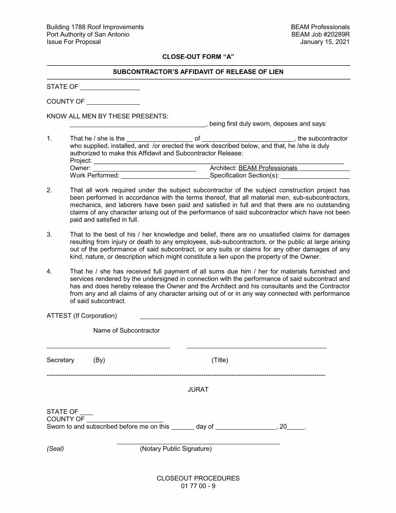
Building 1788 Roof Improvements BEAM ProfessionalsPort Authority of San Antonio BEAM Job #20289RIssue For Proposal January 15, 2021
CLOSEOUT PROCEDURES01 77 00 - 9
CLOSE-OUT FORM “A”
SUBCONTRACTOR’S AFFIDAVIT OF RELEASE OF LIEN
STATE OF
COUNTY OF
KNOW ALL MEN BY THESE PRESENTS: , being first duly sworn, deposes and says:
1. That he / she is the of , the subcontractor who supplied, installed, and /or erected the work described below, and that, he /she is duly authorized to make this Affidavit and Subcontractor Release:Project: ______________________________________________________________________Owner: _____________________________ Architect: BEAM Professionals Work Performed: Specification Section(s):
2. That all work required under the subject subcontractor of the subject construction project has been performed in accordance with the terms thereof, that all material men, sub-subcontractors, mechanics, and laborers have been paid and satisfied in full and that there are no outstanding claims of any character arising out of the performance of said subcontractor which have not been paid and satisfied in full.
3. That to the best of his / her knowledge and belief, there are no unsatisfied claims for damages resulting from injury or death to any employees, sub-subcontractors, or the public at large arising out of the performance of said subcontract, or any suits or claims for any other damages of any kind, nature, or description which might constitute a lien upon the property of the Owner.
4. That he / she has received full payment of all sums due him / her for materials furnished and services rendered by the undersigned in connection with the performance of said subcontract and has and does hereby release the Owner and the Architect and his consultants and the Contractor from any and all claims of any character arising out of or in any way connected with performance of said subcontract.
ATTEST (If Corporation)
Name of Subcontractor
Secretary (By) (Title)
--------------------------------------------------------------------------------------------------------------------------------
JURAT
STATE OF COUNTY OF Sworn to and subscribed before me on this day of , 20 .
(Seal) (Notary Public Signature)
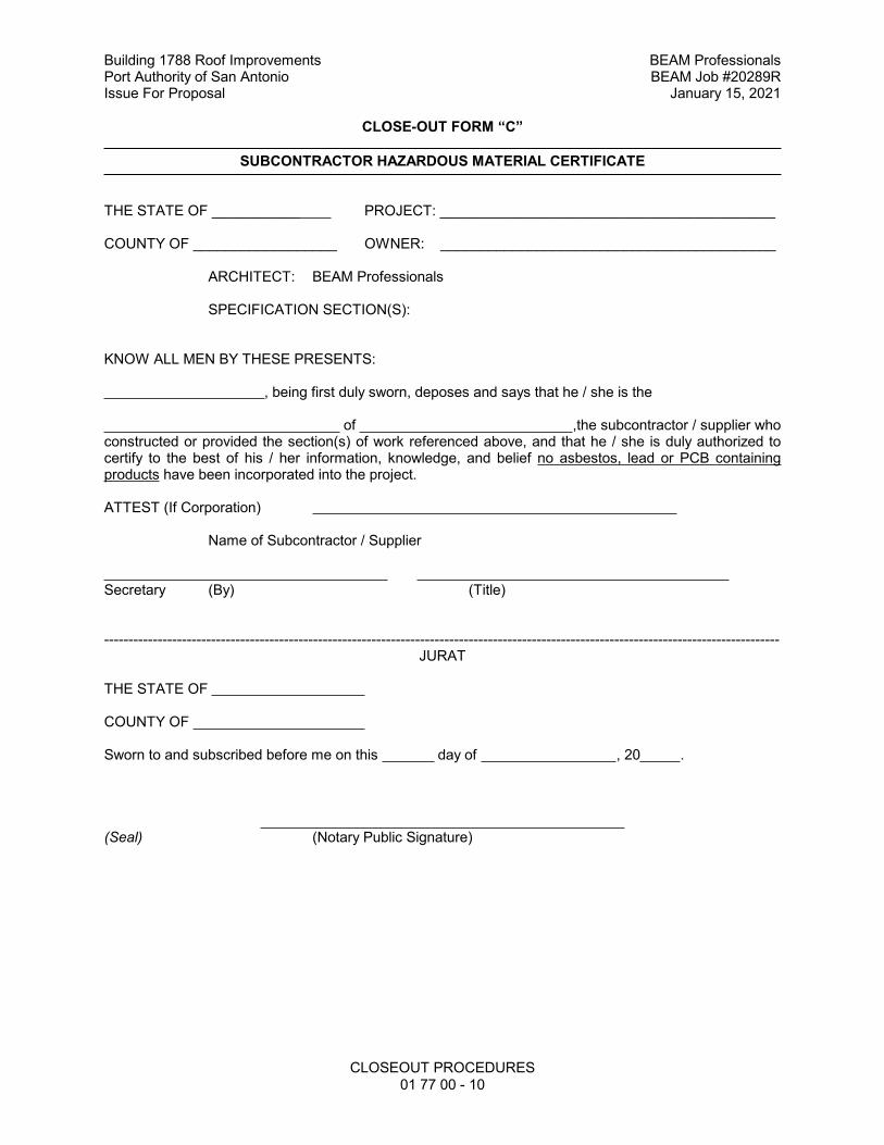
Building 1788 Roof Improvements BEAM ProfessionalsPort Authority of San Antonio BEAM Job #20289RIssue For Proposal January 15, 2021
CLOSEOUT PROCEDURES01 77 00 - 10
CLOSE-OUT FORM “C”
SUBCONTRACTOR HAZARDOUS MATERIAL CERTIFICATE
THE STATE OF ___________ PROJECT: __________________________________________
COUNTY OF __________________ OWNER: __________________________________________
ARCHITECT: BEAM Professionals
SPECIFICATION SECTION(S):
KNOW ALL MEN BY THESE PRESENTS:
, being first duly sworn, deposes and says that he / she is the
of ,the subcontractor / supplier who constructed or provided the section(s) of work referenced above, and that he / she is duly authorized to certify to the best of his / her information, knowledge, and belief no asbestos, lead or PCB containing products have been incorporated into the project.
ATTEST (If Corporation)
Name of Subcontractor / Supplier
Secretary (By) (Title)
-------------------------------------------------------------------------------------------------------------------------------------------JURAT
THE STATE OF
COUNTY OF
Sworn to and subscribed before me on this day of , 20 .
(Seal) (Notary Public Signature)
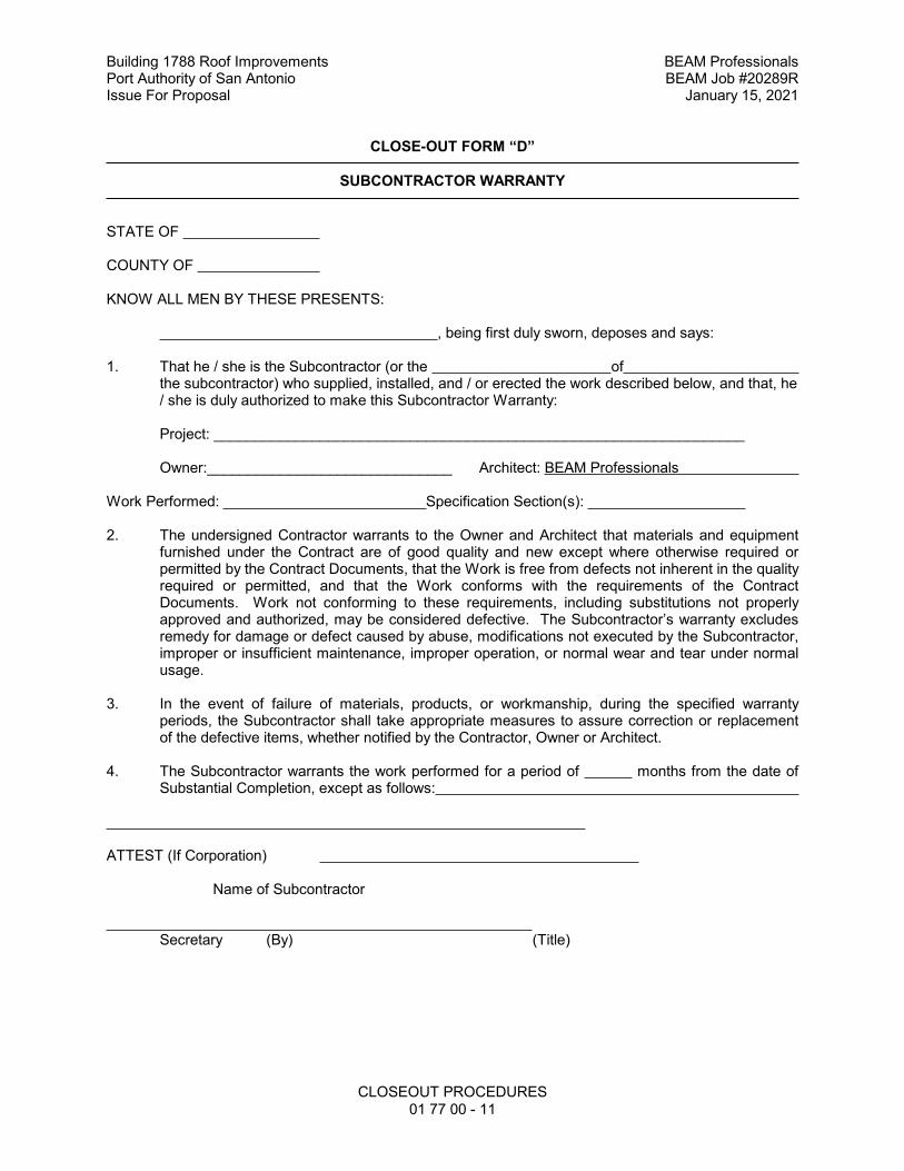
Building 1788 Roof Improvements BEAM ProfessionalsPort Authority of San Antonio BEAM Job #20289RIssue For Proposal January 15, 2021
CLOSEOUT PROCEDURES01 77 00 - 11
CLOSE-OUT FORM “D”
SUBCONTRACTOR WARRANTY
STATE OF
COUNTY OF
KNOW ALL MEN BY THESE PRESENTS:
, being first duly sworn, deposes and says:
1. That he / she is the Subcontractor (or the of the subcontractor) who supplied, installed, and / or erected the work described below, and that, he / she is duly authorized to make this Subcontractor Warranty:
Project: _________________________________________________________________
Owner:______________________________ Architect: BEAM Professionals
Work Performed: Specification Section(s):
2. The undersigned Contractor warrants to the Owner and Architect that materials and equipment furnished under the Contract are of good quality and new except where otherwise required or permitted by the Contract Documents, that the Work is free from defects not inherent in the quality required or permitted, and that the Work conforms with the requirements of the Contract Documents. Work not conforming to these requirements, including substitutions not properly approved and authorized, may be considered defective. The Subcontractor’s warranty excludes remedy for damage or defect caused by abuse, modifications not executed by the Subcontractor, improper or insufficient maintenance, improper operation, or normal wear and tear under normal usage.
3. In the event of failure of materials, products, or workmanship, during the specified warranty periods, the Subcontractor shall take appropriate measures to assure correction or replacement of the defective items, whether notified by the Contractor, Owner or Architect.
4. The Subcontractor warrants the work performed for a period of months from the date of Substantial Completion, except as follows:
ATTEST (If Corporation)
Name of Subcontractor
Secretary (By) (Title)
Building 1788 Roof Improvements BEAM ProfessionalsPort Authority of San Antonio BEAM Job #20289RIssue For Proposal January 15, 2021
CLOSEOUT PROCEDURES01 77 00 - 12
--------------------------------------------------------------------------------------------------------------------------------JURAT
STATE OF
COUNTY OF
Sworn to and subscribed before me on this day of , 20____.
(Seal) (Notary Public Signature)
Building 1788 Roof Improvements BEAM Professionals Port Authority of San Antonio BEAM Job #20289R Issue For Proposal January 15, 2021
SELECTIVE DEMOLITION
02 41 13 - 1
SECTION 02 41 13 - SELECTIVE DEMOLITION
CONDITIONS OF THE CONTRACT AND DIVISION 1, as applicable, apply to this Section. PART 1 - GENERAL 1.1 SECTION INCLUDES
A. Partial demolition of existing building as required to accommodate additions and renovations as shown on the drawings or required. Include removal of existing utilities as indicated or encountered; removal of masonry, and mechanical, electrical, and plumbing items as indicated or required.
1.2 SUBMITTALS A. Submit the following items.
1. Itemized Demolition Schedule. 2. Detail all demolition methods to be used.
1.3 PERMITS A. Procure and pay for all necessary permits or certificates required to complete the work
specified. Make any and all required notifications and comply with all applicable Federal, State and local ordinances.
1.4 QUALITY ASSURANCE A. Provide at least one (1) person who shall be present and in charge of the Demolition
Work at all times and who shall be thoroughly familiar with all phases of all work performed under this Section.
B. Comply with all pertinent codes and regulations applying to this work. 1.5 JOB CONDITIONS A. Use all means necessary to prevent the spread of dust during performance of this work.
Provide additional clean filters for the existing air handling system serving those areas to remain to protect them from construction dust.
B. Use all means necessary to protect the existing building to remain from all types of
damage, including fire, water damage, and unnecessary interruption of utility services. In the event of damage of any kind, immediately make all repairs and replacements necessary to the approval of the Owner at no additional cost to the Owner.
C. Motor driven equipment shall have functional mufflers. D. Visit the site and examine the existing structure. Note all conditions as to the character
and extent of work involved. 1.6 PRE-INSTALLATION CONFERENCE
A. Refer to Section 01 31 13 - Notification of Architect requirements.
Building 1788 Roof Improvements BEAM Professionals Port Authority of San Antonio BEAM Job #20289R Issue For Proposal January 15, 2021
SELECTIVE DEMOLITION
02 41 13 - 2
PART 2 - PRODUCTS 3.1 GENERAL A. Provide all barricades, shoring, and bracing necessary to protect the tenants, workmen,
and Public from danger. Barricades shall be sufficiently designed to protect and or exclude the public from all hazards.
B. All other materials, not specifically described but required for proper completion of Work
of this Section, shall be as selected by the Contractor subject to the approval of the Owner.
3.2 DEMOLITION WORK
A. Perform demolition work in manner so as to allow Owner’s safe use of existing facility. B. Perform demolition work in order to maintain Owner’s construction schedule.
3.3 REMOVAL OF PARTITIONS, COLUMNS AND STRUCTURE
A. Masonry walls or other sections of masonry shall not be permitted to fall on floors of building in masses to exceed safe carrying capacity of floors. Existing floors shall be properly protected with plywood on both sides of a partition to be demolished.
B. Provide temporary shoring or bracing wherever necessary for the protection of
occupants, workmen, walls, partitions, roofs, floors and structure to remain. C. Structural or load-supporting members shall not be cut or removed adjacent to existing
structures to remain until all loads carried by members have been removed or adequately supported.
D. No masonry walls shall be removed until it has been determined that the walls to be
removed do not support the roof. To determine this, all adjacent materials such as finish ceilings shall be removed to provide adequate views of existing structure. Provide temporary shoring as needed. The Contractor shall take all precautions necessary to ensure the safety of the demolition workers and all occupants of the building.
E. No demolition will be allowed above, below, adjacent to or near any occupied areas of
the building. F. Where access holes in existing ceilings or removal of existing ceilings are required,
minimize the access in order to minimize the repair work and repair or replace removed or damaged work to match adjacent undamaged work.
G. Cut and tooth new openings in masonry where required, of correct size to permit
installation of frames and anchors for new doors.
Building 1788 Roof Improvements BEAM Professionals Port Authority of San Antonio BEAM Job #20289R Issue For Proposal January 15, 2021
SELECTIVE DEMOLITION
02 41 13 - 3
PART 3 - EXECUTION 3.1 DEMOLITION
A. Before commencing the Work of this Section, verify with the Owner that all items to be removed by the Owner have been removed. Schedule the work in a careful manner with all necessary consideration for the Public and the Owner. All items of existing equipment and materials or any other item of value to the Owner shall be salvaged by the Owner prior to demolition.
B. All material removed under this Contract, which is not to be salvaged or reused, shall
become the property of the Contractor and be promptly removed from the site. At all times use movable debris boxes, covered, to convey the material through the building. Do not store or permit debris to accumulate on the site. Dumpsters shall not overflow and shall be emptied on a regular basis. Remove all debris from the building premises and leave the construction site "Clean" each day. All debris shall be dumped in an approved disposal facility and all fees for this shall be paid by the Contractor. Contractor is responsible for completely removing all demolished materials from the site and disposing of them in accordance with all local, State and Federal Regulations. If Contractor fails to remove debris promptly, Owner reserves the right to have debris removed at Contractor’s expense.
C. Conduct operations so as not to interfere with adjacent occupied spaces, roads, streets,
drives, walks, service lines and the like.
D. Keep all pedestrian areas clear for passage at all times. 3.2 PROTECTION OF STRUCTURES, PROPERTY A. Execute demolition work to ensure adjacent property no damage from falling debris or
other causes. B. Take precautions to guard against movement, settlement, or be liable for such
movement, settlement, or collapse; repair promptly such damage when so ordered.
C. Repair damage to Owner’s property or any other person or persons on or off premises by reason of required work.
END OF SECTION 02 41 13
Building 1788 Roof Improvements BEAM Professionals Port Authority of San Antonio BEAM Job #20289R Issue For Proposal January 15, 2021
UNIT MASONRY
04 20 00 - 1
SECTION 04 20 00 - UNIT MASONRY
CONDITIONS OF THE CONTRACT AND DIVISION 1, as applicable, apply to this Section. PART 1 - GENERAL
1.1 SECTION INCLUDES
A. Concrete masonry units (CMU)
B. Face brick, including solids.
C. Mortar, grout, reinforcement, anchorages, flashing, and accessories shown, specified, or
required to complete Work.
D. Contractor performing Work of this Section shall be responsible for performing cast stone work specified in Section 04 72 00.
E. Calcium silicate masonry units.
1.2 RELATED WORK
A. Section 01 45 23 - Testing and Inspecting Services
B. Section 04 01 20 – Unit Masonry Cleaning
C. Section 04 72 00 - Architectural Cast Stone
D. Section 05 50 00 - Miscellaneous Metals: Steel masonry lintels.
E. Section 07 21 00 - Building Insulation
F. Section 07 92 00 - Building Sealants
G. Section 09 91 00 - Painting and Staining
H. All Sections of Work built-in, adjacent to, or applied to unit masonry work.
I. Allowances: Furnish the following under the allowances indicated as specified in
Division 1 Section "Allowances": 1. Face Brick
1.3 REFERENCES
A. ASTM International (ASTM)
1. A153, Standard Specification for Zinc Coating (Hot-Dip) on Iron & Steel Hardware
2. A307, Specification for Carbon Steel Bolts and Studs, 60,000 PSI Tensile Strength
3. A615, Standard Specification for Deformed and Plain Billet-Steel Bars for Concrete Reinforcement
4. A706, Standard Specification for Low-Alloy Steel Deformed Bars for Concrete 5. C67, Standard Test Methods for Sampling and Testing Brick and Structural Clay
Tile 6. C90, Standard Specification for Loadbearing Concrete Masonry Units
Building 1788 Roof Improvements BEAM Professionals Port Authority of San Antonio BEAM Job #20289R Issue For Proposal January 15, 2021
UNIT MASONRY
04 20 00 - 2
7. C140, Standard Test Methods of Sampling and Testing Concrete Masonry Units and Related Units
8. C144, Standard Specification for Aggregate for Masonry Mortar 9. C150, Standard Specification for Portland Cement 10. C207, Standard Specification for Hydrated Lime for Masonry Purposes 11. C216, Standard Specification for Facing Brick (Solid Masonry Units Made from
Clay or Shale) 12. C270, Standard Specification for Mortar for Unit Masonry 13. C331, Standard Specification for Lightweight Aggregates for Concrete Masonry
Units 14. C332, Standard Specification for Lightweight Aggregates for Insulating Concrete 15. C404, Standard Specification for Aggregates for Masonry Grout 16. C476, Standard Specification for Grout for Masonry 17. C578, Standard Specification for Rigid, Cellular Polystyrene Thermal Insulation 18. C652, Standard Specification for Hollow Brick (Hollow Masonry Units Made From
Clay or Shale) 19. C780, Standard Test Method for Preconstruction and Construction Evaluation of
Mortars for Plain and Reinforced Unit Masonry 20. C979, Standard Specification for Pigments for Integrally Colored Concrete 21. D226, Standard Specification for Asphalt-Saturated Organic Felt Used in Roofing
and Waterproofing 22. D1751, Standard Specification for Preformed Expansion Joint Filler for Concrete
Paving and Structural Construction (Nonextruding and Resilient Bituminous Types)
23. E119, Standard Test Methods for Fire Tests of Building Construction and Materials
B. Underwriters’ Laboratories, Inc. (UL)
1.4 QUALITY ASSURANCE
A. Where requirements of this Section are in conflict with requirements noted on the Structural Drawings, the Structural Drawings shall take precedence. Refer to Structural Drawings for information on load-bearing CMU walls.
B. Fire Performance Characteristics: Where indicated or required, provide materials and construction which are identical to assemblies whose fire endurance has been determined by testing in compliance with ASTM E119 by U.L. or other recognized testing and inspection organization or by other means, acceptable to authority having jurisdiction.
C. Masonry Cleaning: Workers shall have minimum 5 years of masonry cleaning experience, and shall be approved by cleaner manufacturer prior to application of cleaning material, and shall meet with cleaner manufacturer for demonstration and instruction s for use of product prior to application.
D. Single Source Responsibility: 1. For Masonry Units: Obtain masonry units of uniform texture and color, or a
uniform blend within the accepted ranges for those characteristics, from one (1) manufacturer for each different product required for each continuous surface or visually related surfaces.
2. For Mortar and Grout Materials: Brands of cementitious materials and admixtures, and the source of supply of sand and aggregates shall remain the same throughout the Work where exposed to view and where not scheduled to
Building 1788 Roof Improvements BEAM Professionals Port Authority of San Antonio BEAM Job #20289R Issue For Proposal January 15, 2021
UNIT MASONRY
04 20 00 - 3
receive a subsequently applied finish, i.e. parging, painting, etc., unless directed otherwise in writing by the Architect.
3. Contractor’s Responsibility: Contractor performing Work of this Section shall be responsible for coordinating with others performing work which is built-in or adjacent to unit masonry work.
1.5 SUBMITTALS
A. Product Data: Submit schedules, charts, literature, and illustrations to indicate the
performance, fabrication procedures, product variations, and accessories.
B. Samples: Two (2) sets of color chips representing manufacturer's full range of available colors and textures of each face brick for Architect’s selection and approval.
C. Sample Panel(s): 1. Do not start masonry until Architect has approved samples. 2. Sample panel shall be 6 feet long by 8 feet high showing selected color range
and texture, bonding, joint shape, and quality of workmanship. Include a brick and expansion joint, and any specialty details, such as reveals, soldier courses, etc. Include mock-up of installation of thru-wall flashing at foundation sill and lintel above openings.
3. Brace and support as required to withstand structural windloads. 4. A separate panel for each type of masonry and back up wall used is required. 5. Sample panel(s) shall remain at the jobsite until the approval of the Architect,
Owner and commissioning consultant agree it can be removed. 6. Installed materials shall be visible and integrated into adjacent materials.
D. Certification: Submit manufacturer’s affidavit that materials used in Project contain no asbestos.
E. Mortar and Grout Mix Designs: Submit two (2) copies of proposed mortar and grout mix designs to Owner's testing laboratory.
1.6 PRE-INSTALLATION CONFERENCE
A. Refer to Section 01 31 13 – Project Coordination
1.7 TESTS AND INSPECTIONS
A. Materials and installation of masonry shall be subject to testing and inspection by an independent testing laboratory. Such tests and inspections shall not relieve Contractor of responsibilities for providing materials and procedures which comply with Contract Documents. Promptly remove and replace materials which do not comply.
B. Owner will select Inspection and Testing Laboratory and will pay for all Work required by Inspection and Testing Laboratory.
1.8 DELIVERY, STORAGE AND PROTECTION
A. Deliver and store materials in dry protected areas off ground. Keep free of stain or other
damage before, during and after installation. Replace any damaged material at no cost to Owner.
Building 1788 Roof Improvements BEAM Professionals Port Authority of San Antonio BEAM Job #20289R Issue For Proposal January 15, 2021
UNIT MASONRY
04 20 00 - 4
B. During freezing weather, protect masonry units with tarpaulins or other suitable material. Keep free of stain or other damage before, during and after installation. Replace damaged material at no cost to Owner.
C. Protect reinforcement and accessories from elements.
1.9 SITE CONDITIONS
A. Cold Weather Protection: 1. No masonry shall be laid when the temperature of the outside air is below 40
degrees F, unless protection measures are employed and pre-approved by the Architect.
2. Protection measures for cold weather erection include maintaining space and masonry unit temperatures of at least 40 degrees F for 48 hours prior to and after erection.
B. Hot Weather Protection:
1. When the mean daily temperature exceeds 100 degrees F or exceeds 90 degrees F with a wind velocity greater than 8 mph, fog spray all newly constructed masonry until damp, at least three (3) times a day until the masonry is three (3) days old. Each fog spray application shall be at least 3 hours after the previous spray.
1.10 BRACING OF MASONRY DURING ERECTION
A. All masonry shall be adequately braced at all times during erection.
1.11 COORDINATION
A. Openings and chases for heating, plumbing, electrical ducts, pipes, and conduits shall be built into masonry walls as required. Provide for installation of bolts, toggles, flashings, beams, anchors, hangers, nailing strips, wall plugs, and frames as required. Consult other trades in advance and make provisions for installation of their work to avoid cutting and patching. Coordinate installation of steel reinforcement for reinforced masonry. Coordinate placement of concrete in masonry beams, lintels, soffits, and pilasters.
B. Contractor performing Work of this Section shall be responsible for and coordinate with work of Section 07 11 00, Dampproofing Above Grade and all Sections of Work built-in, adjacent to, or applied to unit masonry work.
1.12 WARRANTY
A. Warrant the Work specified herein for one (1) year against becoming unserviceable or
causing an objectionable appearance resulting from either defective or nonconforming materials or workmanship.
B. Defects shall include, but not be limited to, the following: 1. Noticeable deterioration of unit or mortar finish. 2. Chalking or dusting excessively. 3. Changing color in irregular fashion. 4. Cracking or spalling. 5. Releasing from substrate. 6. Staining or discoloring, including efflorescence.
Building 1788 Roof Improvements BEAM Professionals Port Authority of San Antonio BEAM Job #20289R Issue For Proposal January 15, 2021
UNIT MASONRY
04 20 00 - 5
PART 2 - PRODUCTS
2.1 APPROVED MANUFACTURERS
A. Specifications are based on products of manufacturers named within the specifications. Other manufacturers must have a minimum of five (5) years experience manufacturing products equal to those specified and comply with requirements of Division 1 regarding substitutions to be considered.
2.2 MATERIALS
A. Concrete Masonry Units (CMU/Block):
1. Type/Sizes: a. Concealed cavity block and interior block, unless otherwise noted:
Regular smooth face units with 8 inch by 16 inch face dimensions as shown on drawings or required, 4 inch, 6 inch, 8 inch, and 12 inch depths as indicated on drawings. 1) Color: Standard
b. Exterior exposed block: Regular smooth face units with 8 inch by 16 inch face dimensions as shown on drawings or required, 4 inch, 6 inch, and 8 inch depths as indicated on drawings. 1) Color: Standard
c. Exterior exposed burnished block (polished): Integrally colored face units with 8 inch by 16 inch face dimensions as shown on drawings or required, 4 inch, 6 inch, and 8 inch depths as indicated on drawings. 1) Color: As selected by Architect
d. Interior exposed burnished block (polished): Integrally colored face units with 8 inch by 16 inch face dimensions as shown on drawings or required, 4 inch, 6 inch, and 8 inch depths as indicated on drawings. 2) Color: As selected by Architect
2. Integral Water Repellant (In exterior exposed CMU): “Dry-Block Block Admixture” integral water repellant admixture as manufacturer by W.R. Grace & Co., or equal.
3. Specification: Comply with ASTM C90 (Class D-2 (2 hour) and Class B-4 (4 hour)) block at rated walls) a. Grade: Type N, highest standard for typical cavity block and interior use.
Type S, for exterior exposed masonry walls. b. Aggregate: Lightweight in accordance with ASTM C331
4. Curing: Rotary kiln process. 5. Provide bullnose units at all outside corners. 6. Provide bond beams, control joints, jambs, lintels, soaps, cap blocks, and fillers
to match and compliment block units as shown or required. 7. Approved Manufacturers:
a. Builders Concrete Products b. Featherlite Building Products c. Headwaters Construction Products d. Innovative Precast Concrete Products (IPC) e. Revels Block & Brick Co., Inc. f. Texas Building Products, Inc. g. Texas Industries, Inc. h. Trenwyth Industries, Inc.
Building 1788 Roof Improvements BEAM Professionals Port Authority of San Antonio BEAM Job #20289R Issue For Proposal January 15, 2021
UNIT MASONRY
04 20 00 - 6
B. Face Brick: To match existing; comply with the requirements of ASTM C216 or C652, Grade SW, in accordance with the following list, including solids and special shapes as indicated or required (all colors). 1. Approved Manufacturers
a. Acme Brick Co.
C. Mortar: 1. Materials: (Unless stated otherwise on Structural Drawings)
a. Portland Cement: ASTM C150, Type 1. b. Hydrated Lime: ASTM C207, TYPE “N”, typical. Use TYPE “S” for load-
bearing masonry. c. Aggregate: Sand conforming to ASTM C144 d. Water: Clean and potable e. Admixtures For Mortar:
1) General: Do not use calcium chloride 2) Integral Water Repellant (In mortar of exterior exposed CMU):
“Dry- Block Mortar Admixture” integral water repellant admixture as manufacturer by W.R. Grace & Co., or equal. Note: Water repellent block admixture and mortar admixture are not interchangeable.
2. Mix Design: (Proportions by volume) (Unless stated otherwise on Structural Drawings) a. Typical, Non-load bearing masonry
1) Type: ASTM C270, Type “N” 2) Proportions: 1 part cement, 1 part hydrated lime and 6 parts
sand to provide a compressive strength of 750 psi in 28 days. Do not use calcium chloride.
b. Load bearing structural masonry 1) Type: ASTM C270, Type “S” 2) Proportions: 1 part cement, 1/2 part hydrated lime and 4-1/2
parts sand to provide a compressive strength of 1800 psi in 28 days. Do not use calcium chloride.
D. Grout:
1. Materials: (Unless stated otherwise on Structural Drawings) a. Hydrated Lime: ASTM C207, TYPE “S” b. Portland Cement: ASTM C150, Type 1. c. Water: Clean and potable d. Aggregates:
1) Course aggregate shall conform to ASTM C404. 2) Fine aggregate shall conform to ASTM C144.
2. Mix Design: (Unless stated otherwise on Structural Drawings) a. Comply with ASTM C476 to provide a compressive strength of 2,500 psi
in 28 days, unless noted otherwise. Do not use calcium chloride. 1) Fine Grout: Fine grout conforming to ASTM C476 and consisting
of 1 part Portland cement, 0 to 1/10 part lime and 2-1/4 to 3 parts sand by volume.
2) Course Grout Mix: Course grout conforming to ASTM C476 and consisting of 1 part Portland cement, 0 to 1/10 part lime and 2-1/4 to 3 parts sand, and 1 to 2 parts course aggregate.
Building 1788 Roof Improvements BEAM Professionals Port Authority of San Antonio BEAM Job #20289R Issue For Proposal January 15, 2021
UNIT MASONRY
04 20 00 - 7
E. Reinforcement, Anchors and Tie Systems: 1. General: Reinforcement used in all wythes shall be galvanized after fabrication
in accordance with ASTM A153, Class B-2. 2. Approved Manufacturers include the following:
a. Dur-O-Wal b. Heckmann Building Products c. Hohmann & Barnard, Inc d. Wire-Bond
3. At solid multiple wythe masonry walls and single wythe masonry walls, (Interior partitions) use #9 gauge truss type reinforcing. Pre-fab corners and tees shall be used at all wall corners and intersections; width shall be two (2) inches less than nominal thickness of walls. Dur-O-Wal "Truss" at single wythe; "Trirod" at multiple, or Architect approved equal.
4. At Double Wythe Cavity Walls with Insulation Board: Use Hot-dipped galvanized, #9 gauge truss type with 3/16 inch adjustable pintle wall ties. Width of truss reinforcement shall be 2 inches less than the nominal thickness of wall. 3/16 inch wall tie double eye sections welded at 16 inches o.c. extended as required for insulation thickness. Pre fab corners and tees shall be used at all wall corners and intersections. Dur-O-Wal "Dur-O-Eye", or Architect approved equal.
5. At Masonry Anchored to Steel Spandrel Beam and Columns: Hot-dipped galvanized, No. 315 Anchor and No. 316 Pintle Tie manufactured by Heckmann Building Products, Inc., or Architect approved equal. Anchors detailed on Structural Drawings supersede.
6. At Veneer Brick Anchored to Light Gauge Steel Framing: Hot-dipped galvanized, No. 75HE Pos-i-Tie System utilizing self-tapping screw for steel studs with 5/8 inch barrel length, and 4 inch triangle wire tie for 2 inch cavity manufactured by Heckmann Building Products, Inc., or Architect approved equal. Anchors detailed on structural drawings supersede. Attachment screws shall be corrosion resistant type as recommended by manufacturer to suit application. Adjust wire tie size as required to conform with cavity depth if other than 2 inch.
7. Control Joint Anchor: Equal to Heckmann Building Products, Inc. No. 351 Anchor.
F. Miscellaneous Materials: (As shown or required)
1. Reinforcing Steel: ASTM A615, Grade 60. 2. Forms: Form grade plywood with wood studs and wales as required. 3. Shores: Patented shores of design and manufacture sufficient to safely support
imposed loads. 4. Premolded Filler: Fibrous mastic strips containing 35 percent to 50 percent
asphaltic impregnation, ASTM D1751. 5. Flashing Cement: "Nervaplast" cold setting mastic manufactured by Nervastral,
Inc., or Architect approved equal. 6. Building Felt: No. 15 asphalt saturated felt, ASTM D226. 7. Dovetail Anchors: 16 gauge galvanized dovetail corrugated masonry anchor, 1
inch x 3-1/2 inch manufactured by AA Wire Products Co., Heckman Building Products, Inc., Dur-O-Wal, Inc., Hohmann & Barnard, Inc., Masonry Reinforcing Corporation of America, or Architect approved equal.
8. Steel Shapes and Plates: As shown on drawings and specified in Section 05 50 00, Miscellaneous Metals.
9. Headed Stud Anchor: Welded by full-fusion process as furnished by TRW Nelson Stud Welding Division, or Architect approved equal.
10. Bolts: ASTM A307. Furnish with carbon steel washers. 11. Deformed Bar Anchors: Welded by full-fusion process as furnished by TRW
Nelson Stud Welding Division, or Architect approved equal. 12. Reinforcing Bars to be Welded: ASTM A706.
Building 1788 Roof Improvements BEAM Professionals Port Authority of San Antonio BEAM Job #20289R Issue For Proposal January 15, 2021
UNIT MASONRY
04 20 00 - 8
13. Cavity Drainage Protection: 2 inch thick by 10 inch high by 5 feet long recycled polyester/ polyethylene mesh, trapezoidal-shaped, continuous at foundation, at heads above openings, and shelf angles as indicated on drawings. Provide Mortar Net™ manufactured by Mortar Net USA, Ltd., Gary, IN; (800) 664-6638, or Architect approved equal.
14. Masonry Color: Iron oxide pigment conforming to ASTM C979 in color(s) selected by Architect, shall be inert, stable to atmospheric conditions, sunfast, weather resistant, alkali resistant, water insoluble, and free of fillers and extenders, as manufactured by ChemSystems, Inc., Davis Colors, Solomon Grind-Chem Service, Inc., or Architect approved equal.
15. Weep Hole Vents: Brick Vent as manufactured by Williams Products, Inc. consisting of Injection molded PVC designed to fit in head joint in an offset "T" shape, allowing air to pass in and water to weep out. Weep hole vents shall be sized to match masonry (may require custom sizing).
G. Architectural Cast Stone: Refer to Section 04 72 00.
2.3 MASONRY STRENGTH
A. Ultimate compressive strength of masonry as required by design and determined by prism tests shall not be less than 1,800 psi, unless stated otherwise in Structural Drawings.
PART 3 - EXECUTION
3.1 FORMS AND SHORES
A. Provide forms and shores sufficiently strong and rigid as required to support soffits,
beams, and lintels during construction.
B. Build forms to conform to shape, line, and dimension of masonry members as detailed, substantial and sufficiently tight to prevent leakage of mortar, grout or concrete. Properly brace or tie together so as to maintain position and shape.
3.2 PREPARATION OF MATERIALS
A. Concrete Masonry Units:
1. Where cutting is required, masonry shall be cut with a sharp masonry saw. 2. Ensure concrete masonry units to receive sand fill are ready for filling and
cutouts are protected from material spillage.
B. Brickwork: Dampen brick before laying in a manner consistent with the nature of the brick, the mortar, and the weather conditions.
C. Mortar and Grout: 1. Use suitable containers for material measurement. Measuring sand by the shovel
is not acceptable. 2. Thoroughly machine mix a minimum of five (5) minutes after all materials are in
mixer. 3. Consistency will completely fill all spaces intended to receive grout. 4. Use within 2-1/2 hours of initial mixing. 5. Mortar or grout shall not be used if curing has progressed to yield a stiff
consistency.
Building 1788 Roof Improvements BEAM Professionals Port Authority of San Antonio BEAM Job #20289R Issue For Proposal January 15, 2021
UNIT MASONRY
04 20 00 - 9
D. Reinforcement: 1. Reinforcement shall be free from loose rust and other coatings that would reduce
the bond. 2. Cut accurately to length and bend by such methods as will prevent injury to the
material. 3. Straighten out kinks or bends.
E. Flashing: 1. Locations: Install in exterior walls to divert moisture within walls to exterior
surfaces. 2. Bed Joints: Coordinate work with Division 4, Masonry. Install flashings between
two (2) thin layers of masonry mortar without increasing thickness of mortar joint. Keep outer edge of flashing material ½ inch from exterior face of masonry.
3. Adjacent Work: Protect work by masking, covering, or other precautionary methods. Remove protection when no longer necessary.
4. Separate copper flashing from dissimilar materials. 5. Protect membrane flashing from overexposure to direct sunlight.
3.3 INSTALLATION
A. General:
1. Do not use chipped or cracked concrete masonry units (CMU) and face brick, where exposed to view.
2. Use masonry saws to cut and fit exposed units. 3. Exposed masonry at exterior corners shall be solid units. 4. Clean surface of masonry smooth and free from projections which might
puncture or otherwise damage flashing material. 5. Place through-wall flashing as follows:
a. Place on bed of mortar and cover with mortar. b. Provide at steel columns and beams in exterior masonry walls and
elsewhere as indicated on the drawings or required. c. Install asphalt laminated copper membrane as base flashing at all
exterior cavity walls below weep holes. d. Install at material transitions inside exterior cavity walls, roof
edge/exterior wall transitions, masonry joints (control/expansion) inside exterior cavity walls, exterior wall sill/weep conditions, exterior door and window frame perimeters, roof deck/exterior wall transitions, exterior wall penetrations (i.e. pipe, conduit, ducts, etc.). Provide membrane at all joints, holes, gaps or openings to ensure a continuously sealed building envelope.
6. Lay masonry units plumb, true to line, and with level courses accurately spaced within allowable tolerances.
7. Do not furrow bed joints. 8. Stop off horizontal run by racking back in each course; toothing is not permitted. 9. Adjust units to final position while mortar is soft and plastic. 10. If units are displaced after mortar has stiffened, remove, clean joints and units
and re-lay with fresh motor. 11. When joining fresh masonry to set or partially set masonry:
a. Remove loose masonry units and mortar b. Clean and lightly wet exposed surface of set masonry prior to laying
fresh mortar.
B. Metal Door Frames: Fill jamb frames solid with mortar. Build in anchors.
Building 1788 Roof Improvements BEAM Professionals Port Authority of San Antonio BEAM Job #20289R Issue For Proposal January 15, 2021
UNIT MASONRY
04 20 00 - 10
C. Lintels and Bond Beams: Provide reinforced unit type, except where steel lintels are shown. Use reinforcing bars as shown on the drawings. Completely fill in lintel block and bond beams with grout. Provide a minimum of 8 inch bearing at end of lintels.
D. Corners: Connect corners with No. 9 galvanized wire or corrugated tie using one tie for each 4 inches of nominal wall thickness.
E. Partition Tops: Allow space at top of horizontal spanning walls for compressible joint back-up and sealant as specified in Sealant section. Anchor top of walls to deck or structure.
F. Mortar Beds: 1. Place mortar in a manner which will result in the development of adequate bond
between the masonry and the reinforcement. 2. Lay units with full mortar coverage on horizontal and vertical joints in all courses. 3. Provide sufficient mortar on ends of masonry unit to fill head joints. 4. Rock closures into place with head joints thrown against two adjacent masonry
units in place. 5. Do not pound corners or jambs to fit stretcher units after setting in place. 6. Where adjustment to corners or jambs must be made after mortar has started to
set, remove mortar and replace with fresh mortar.
G. Mortar Joints and Patterns: 1. Lay CMU in running one-half (1/2) bond pattern, unless noted otherwise. 2. Lay brick in running one-third (1/3) bond pattern, unless noted otherwise on
drawings. Refer to drawings for accent coursing. 3. Provide flush joints where concealed from view and where dampproofing is
scheduled. 4. Provide standard concave tooled joint where masonry is exposed to view for
brick and CMU, typically. 5. All mortar joints to be of consistent size. 6. Provide soldier courses where indicated, refer to the elevations. 7. All horizontal joints shall be concave tooled joint at face of units, unless noted
otherwise.
H. Reinforcement, Anchor and Tie Systems: 1. General:
a. Completely embedded in mortar or grout. b. All reinforcement consisting of bars or wire 1/4 inch or less in diameter
embedded in the horizontal mortar joints shall have no less than 5/8 inch mortar coverage from the exposed face.
c. Where modular brick is used with brick coursing at 16 inches on center, provide ladder reinforcing within each wythe at 16 inches o.c. vertically for exterior wythe and back-up wythe, whether detailed or not. For other than modular brick, refer to Paragraph h. below.
d. Veneer anchors at exterior sheathed covered metal stud exterior walls shall be attached on outside face of sheathing using cadmium plated sheet metal screws. Spacing shall be same as stud spacing o.c. horizontally and 16 inches o.c. vertically.
e. Veneer anchors at Interior brick walls with metal stud back-up shall be the same as Paragraph “d” above, except anchors shall be attached directly to metal stud with recommended corrosion resistant fasteners in accordance with manufacturer’s recommendations.
Building 1788 Roof Improvements BEAM Professionals Port Authority of San Antonio BEAM Job #20289R Issue For Proposal January 15, 2021
UNIT MASONRY
04 20 00 - 11
f. At intersection of all perpendicular masonry walls provide two (2) vertical rows of ladder type reinforcing at 16 inches o.c. vertically.
g. Weld veneer anchors to structural steel in accordance with manufacturer’s recommendations. Touch-up steel shop paint and galvanized coating on anchor with proper touch-up paint to match damaged coating in accordance with manufacturer’s recommendations.
h. In cavity walls with CMU back-up, embed truss type horizontal reinforcement with integral adjustable pintle wall ties every 16 inches o.c. vertically.
i. Splices in reinforcement: Splices may be made only at such points and in such manner that the structural strength of the member will not be reduced. Lapped splices shall be eight (8) inches. Welded or mechanical connection shall develop the strength of the reinforcement.
j. Corrugated strap ties shall not be used as veneer anchors at exterior or where subject to moisture. Their use in interior, dry conditions are acceptable.
k. Place joint reinforcement in the first two (2) bed joints above and the first two (2) bed joints below masonry openings. Extend extra reinforcing two (2) feet beyond jambs.
l. Provide masonry ties at floor and roof decks as indicated.
I. Flashing: 2. Follow manufacturer’s instructions for mechanically fastened installation with a
termination bar. 3. Application Guidelines - Install flashing at the following locations:
a. Membrane Flashing: material transitions inside exterior cavity walls, roof edge/exterior wall transitions, masonry joints (control/expansion) inside exterior cavity walls, exterior door and window frame perimeters, roof deck/exterior wall transitions, exterior wall penetrations (i.e. pipe, conduit, ducts, etc.). Provide membrane at all joints, holes, gaps, or openings to ensure a continuously sealed building envelope. Utilize primer on substrates as instructed by manufacturer.
b. Copper Flashing: At all horizontal wall flashing, including (but not limited to) exterior wall sill/weep conditions, exterior door and window head/weep conditions, masonry wall cap flashing and masonry wall base flashing.
4. Apply substrate primer as instructed by membrane manufacturer to suit condition.
5. Provide drip edge flashing at weep conditions with membrane flashing. Cut membrane flush with outside edge of brick over top of drip edge flashing to alleviate exposure to UV degradation and deterioration of asphalt membrane.
6. On Horizontal Surfaces: The flashing shall be laid in a slurry of fresh mortar and topped with a fresh full bed of mortar. The flashing shall be cut flush with the exterior face of the wall after being left exposed for inspection purposes only. Flashing shall be carried through the wall, turned up where possible to facilitate drainage through the weepholes, then carried upward across the cavity a minimum of six (6) inches. Flashing will then be secured in back wall with termination bar.
7. On Vertical Surfaces: Surfaces receiving the flashing shall be sufficiently spotted with asphalt mastic to hold in place until masonry is set. Secure in back wall with termination bar.
8. Foundation Sill Dampproofing: The flashing for foundation sills shall be laid in a slurry of fresh mortar and topped with a fresh full bed of mortar. The flashing shall be cut flush with the exterior face of the wall after being left exposed for inspection purposes only. Flashing shall be sloped across the cavity and turned
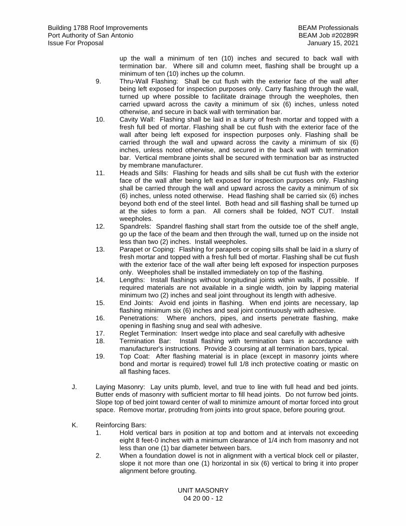
Building 1788 Roof Improvements BEAM Professionals Port Authority of San Antonio BEAM Job #20289R Issue For Proposal January 15, 2021
UNIT MASONRY
04 20 00 - 12
up the wall a minimum of ten (10) inches and secured to back wall with termination bar. Where sill and column meet, flashing shall be brought up a minimum of ten (10) inches up the column.
9. Thru-Wall Flashing: Shall be cut flush with the exterior face of the wall after being left exposed for inspection purposes only. Carry flashing through the wall, turned up where possible to facilitate drainage through the weepholes, then carried upward across the cavity a minimum of six (6) inches, unless noted otherwise, and secure in back wall with termination bar.
10. Cavity Wall: Flashing shall be laid in a slurry of fresh mortar and topped with a fresh full bed of mortar. Flashing shall be cut flush with the exterior face of the wall after being left exposed for inspection purposes only. Flashing shall be carried through the wall and upward across the cavity a minimum of six (6) inches, unless noted otherwise, and secured in the back wall with termination bar. Vertical membrane joints shall be secured with termination bar as instructed by membrane manufacturer.
11. Heads and Sills: Flashing for heads and sills shall be cut flush with the exterior face of the wall after being left exposed for inspection purposes only. Flashing shall be carried through the wall and upward across the cavity a minimum of six (6) inches, unless noted otherwise. Head flashing shall be carried six (6) inches beyond both end of the steel lintel. Both head and sill flashing shall be turned up at the sides to form a pan. All corners shall be folded, NOT CUT. Install weepholes.
12. Spandrels: Spandrel flashing shall start from the outside toe of the shelf angle, go up the face of the beam and then through the wall, turned up on the inside not less than two (2) inches. Install weepholes.
13. Parapet or Coping: Flashing for parapets or coping sills shall be laid in a slurry of fresh mortar and topped with a fresh full bed of mortar. Flashing shall be cut flush with the exterior face of the wall after being left exposed for inspection purposes only. Weepholes shall be installed immediately on top of the flashing.
14. Lengths: Install flashings without longitudinal joints within walls, if possible. If required materials are not available in a single width, join by lapping material minimum two (2) inches and seal joint throughout its length with adhesive.
15. End Joints: Avoid end joints in flashing. When end joints are necessary, lap flashing minimum six (6) inches and seal joint continuously with adhesive.
16. Penetrations: Where anchors, pipes, and inserts penetrate flashing, make opening in flashing snug and seal with adhesive.
17. Reglet Termination: Insert wedge into place and seal carefully with adhesive 18. Termination Bar: Install flashing with termination bars in accordance with
manufacturer's instructions. Provide 3 coursing at all termination bars, typical. 19. Top Coat: After flashing material is in place (except in masonry joints where
bond and mortar is required) trowel full 1/8 inch protective coating or mastic on all flashing faces.
J. Laying Masonry: Lay units plumb, level, and true to line with full head and bed joints. Butter ends of masonry with sufficient mortar to fill head joints. Do not furrow bed joints. Slope top of bed joint toward center of wall to minimize amount of mortar forced into grout space. Remove mortar, protruding from joints into grout space, before pouring grout.
K. Reinforcing Bars: 1. Hold vertical bars in position at top and bottom and at intervals not exceeding
eight 8 feet-0 inches with a minimum clearance of 1/4 inch from masonry and not less than one (1) bar diameter between bars.
2. When a foundation dowel is not in alignment with a vertical block cell or pilaster, slope it not more than one (1) horizontal in six (6) vertical to bring it into proper alignment before grouting.
Building 1788 Roof Improvements BEAM Professionals Port Authority of San Antonio BEAM Job #20289R Issue For Proposal January 15, 2021
UNIT MASONRY
04 20 00 - 13
3. Place horizontal reinforcing bars in continuous masonry courses, consisting of bond-beam or trough block units, and solidly grout in place.
4. Use straight reinforcing bars except for bends around corners and where bends or hooks are detailed on plans.
5. Lap reinforcing steel 40 bar diameters minimum where spliced and wire together.
L. Grouting: Where detailed place grout in reinforced masonry beams, walls, columns, and pilasters. All cells and spaces containing reinforcing bars shall be filled with grout. Wherever possible grouting shall be done from inside face of masonry. Exercise extreme care to prevent grout from staining face of masonry. Immediately remove any spilled grout from face and top of masonry. 1. Prior to grouting clean space so that all spaces to be filled with grout do not
contain mortar projections greater than 1/2 inch, mortar droppings or other foreign material. Grout shall be placed so all spaces designated to be grouted shall be filled with grout and grout shall be confined to those specific spaces.
2. Grout materials and water content shall be controlled to provide adequate fluidity for placement, without segregation of constituents and shall be mixed thoroughly.
3. Between grout pours a horizontal construction joint shall be formed by stopping all wythes at the same elevation and with grout stopping a minimum of 1-1/2 inches below a mortar joint, except at top of wall. Where bond beams occur, stop grout pour a minimum of 1/2 inch below top of masonry.
4. Reinforcement shall be placed prior to grouting. Bolts shall be accurately set with templates or by approved equivalent means and held in place to prevent movement.
5. Segregation of grout materials and damage to masonry shall be avoided during the grouting process. Adequately brace masonry to prevent displacement or cracking during grouting operations.
6. Grout shall be consolidated by mechanical vibrator during placing, before loss of plasticity, in a manner to fill grout space. Grout pours greater than 12 inches shall be reconsolidated by mechanical vibration to minimize voids due to water loss. Grout pours 12 inches or less in height shall be mechanically vibrated, or puddled.
7. Grout shall not be handled nor pumped utilizing aluminum equipment. 8. Size and height limitations of grout space or cell shall be as follows:
GROUT TYPE
GROUT POUR MAX.
HEIGHT (FEET)
LEAST CLEAR DIMENSIONS
CLEANOUTS REQUIRED
Width of Grout Space (In.)
CMU Cell Dim.
Dims. (In. x In.)
Fine 1 3/4 1-1/2 x 2 No
Fine 5 1-1/2 1-1/2 x 2 No
Fine 8 1-1/2 1-1/2 x 3 Yes
Coarse 1 1-1/2 1-1/2 x 3 No
Coarse 5 2 2-1/2 x 3 No
Coarse 8 2 3 x 3 Yes
a. Clear dimension is the cell or grout space width less mortar projections. b. Grout space width shall be increased by the horizontal projection of the
diameters of horizontal bars within the cross section of the grout space. 9. Place grout in lifts not exceeding 8 feet-0 inches.
Building 1788 Roof Improvements BEAM Professionals Port Authority of San Antonio BEAM Job #20289R Issue For Proposal January 15, 2021
UNIT MASONRY
04 20 00 - 14
M. Concreting: Supervise placing of concrete in cores of masonry beams and lintels and over masonry soffits where structural concrete is detailed. Report discrepancies or procedures which may adversely affect performance of masonry work.
N. Brick Weepholes: 1. Provide weepholes above all thru-wall flashings where weepholes occur at the
base of the wall. The mason shall coordinate the location of the thru-wall flashings with the elevation of the sidewalks and planting beds on the civil engineering drawings. Both weepholes and thru-wall flashings shall be above the first course of brick above the sidewalks and planting beds. Pay particular attention to areas near exterior doors.
2. Ensure cavity drainage protection is properly installed. 3. Leave head joint free and clean of mortar. 4. Spacing: 24 inches on center maximum for modular brick and block, unless
shown otherwise. 5. Keep weepholes and area above flashing free of mortar droppings. 6. Coordinate weep holes to be located above sidewalks and paving.
O. Sealant Joints: 1. Allow for sealant joints around outside perimeters of exterior doors, window
frames and other wall openings. 2. Uniform depth: 3/4 inch. 3. Uniform width: As shown on the drawings but not less than 1/4 inch. 4. Provide sample for Architect’s approval. 5. Refers to drawing for locations and details of accent joints.
P. Movement Joints (Expansion Joints and Control Joints): 1. Locate expansion and control joints as shown on drawings, or if not shown,
comply with the following: a. General:
1) Vertical expansion joints shall be placed in the brick wythe and control joints shall be placed in the concrete masonry wythe, although they do not necessarily have to be aligned.
2) Mortar and joint reinforcement shall not bridge brick movement joints.
3) Mortar joints which stop at the expansion joint cavity shall be struck flush with the masonry unit, producing a continuous flat surface for the sealant to adhere to.
b. Vertical Expansion Joints: 1) Locate expansion joints on long straight walls without openings
maximum 25 feet-0 inches. 2) Locate expansion joints at the corner of walls perpendicular to
one another. In instances, where the joint is not desired at the corner, the expansion joint shall be located within 10 feet-0 inches of the corner in either wall, but not necessarily both. The spacing of expansion joints around a corner shall not exceed the spacing of expansion joints in a straight wall. For example, if the spacing between expansion joints on a straight wall is 25 feet-0 inches, then the spacing of expansion joints around a corner could be 10 feet-0 inches on one side of the corner and 15 feet-0 inches on the other side. Joint reinforcement may be added around wall corners to provide added tensile strength to the corner, but joint reinforcement shall not bridge the expansion joint.
Building 1788 Roof Improvements BEAM Professionals Port Authority of San Antonio BEAM Job #20289R Issue For Proposal January 15, 2021
UNIT MASONRY
04 20 00 - 15
c. Offsets and Setbacks: 1) Locate expansion joints at 10 feet-0 inches maximum on one
side of the offset or setback. The spacing of expansion joints around an offset or setback shall not exceed the spacing of expansion joints in a straight wall. See expansion joints at corners of perpendicular walls to one another above for example of spacing.
d. Openings (Doors and Windows): 1) Locate vertical expansion joints along the edge or jamb of the
opening of windows and doors. Single opening windows and doors under 6 feet-0 inches in width shall have expansion joint on one (1) side of the edge or jamb of the opening as determined by the Architect, unless shown otherwise on drawings. Windows and doors 6 feet-0 inches and over in width shall have expansion joints on both sides of the edge or jamb of the opening.
2) Where masonry above an opening is supported by shelf angles attached to the structure, a vertical expansion joint shall be located alongside the opening, continuing through the horizontal support.
3) Where masonry above the opening is supported by loose lintels (unattached to the structure), special detailing and construction is required. If the expansion joint runs along side the opening, the loose steel lintel shall be allowed to expand independently of the masonry. To accomplish this, form a slip plane with flashing located above and below the angle. A backer rod and sealant shall be installed in front of the toe of the angle, and space shall be left at the end of the angle. Thus, a pocket will be formed which will allow movement of the steel angle within the brickwork. If the joint cannot be built in this manner, then the vertical expansion joint shall not be located alongside the opening, but rather, with Architect’s prior approval, the joint shall be located halfway between the openings.
e. Intersections and Junctions: 1) Locate expansion joints at intersections of masonry walls and
walls which serve different functions. If the masonry is not required to be bonded at the intersection, an expansion joint shall be incorporated. Walls which intersect at other than right angles are also vulnerable to cracking at the intersection.
2) Locate expansion joint to separate adjacent walls of different heights to avoid differential movement, especially if the difference is very large.
f. Parapets: 1) All vertical expansion joints shall be carried through the
parapets. 2) Additional expansion joints shall be halfway between those
running full height, unless the parapet is reinforced. These additional expansion joints shall continue down to a horizontal expansion joint, or continue to the base of the wall.
g. Horizontal Expansion Joints: 1) Locate horizontal expansion joints at shelf angles supporting
brick masonry.
Building 1788 Roof Improvements BEAM Professionals Port Authority of San Antonio BEAM Job #20289R Issue For Proposal January 15, 2021
UNIT MASONRY
04 20 00 - 16
h. Control Joints: 1) Locate CMU control joints directly over concrete slab control
joints. 2) Whenever possible, lay out CMU so that control joint will
coincide with CMU module (25 feet-0 inch maximum spacing between control joints), unless noted otherwise on drawings.
3) Locate control joints at structural columns to isolate movement from continuing or intersecting walls and columns.
4) Install backer rod and sealant in accordance with manufacturer’s instructions.
3.4 ALLOWABLE TOLERANCES
A. Maximum Variation from Plumb:
1. In lines and surfaces of columns, walls and at rises: a. 1/4 inch in 10 feet (1:480) b. 3/8 inch in 20 feet (maximum) c. 1/2 inch in 40 feet (1:960) d. For external corners, expansion joints and other conspicuous lines: e. 1/4 inch in 20 feet (maximum) f. 1/2 inch in 40 feet (1:960)
B. Maximum variation from level:
1. 1/4 inch in any bay or 20 feet 2. 1/2 inch in 40 feet (1:960)
3.5 REMOVAL OF FORMS AND SHORES
A. Do not remove shores and forms under reinforced masonry beams, lintels, and soffits
until members have hardened sufficiently to carry their own weight and other super imposed loads. Providing that sufficient curing has taken place, leave forms and shores in place as follows: 1. Beam and lintels: Minimum ten (10) days.
B. Allow 16 hours to elapse after completion of masonry columns and walls before placing floor or roof construction loads on them. Allow an additional 48 hours before applying concentrated loads such as trusses, girders, and beams.
3.6 REPAIRING, POINTING AND CLEANING
A. All holes in exposed masonry shall be pointed, and defective joints shall be cut out and
re-pointed with mortar. 3.7 REPAIR OR REPLACEMENT OF DAMAGED WORK
A. Imperfect or damaged work, or any material damaged or determined to be defective
before final completion and acceptance of the entire job, shall be replaced at Contractor's expense and in conformity with all requirements of drawings and specifications to the satisfaction of the Owner and Architect. Removal and replacement of masonry work shall be performed in such a manner as not to impair the appearance or strength of the structure in any way.
Building 1788 Roof Improvements BEAM Professionals Port Authority of San Antonio BEAM Job #20289R Issue For Proposal January 15, 2021
UNIT MASONRY
04 20 00 - 17
3.8 CLEAN-UP AND PROTECTION
A. Clean up all debris caused by work of this Section, keeping the area clean and neat at all times.
B. Cover all unfinished work at night against the elements with plastic sheeting, building paper, heavy canvas or other material approved by Architect to prevent water from entering cavities.
C. Provide final protection and maintain conditions, in a manner acceptable to Installer, that ensure unit masonry is without damage and deterioration at time of Substantial Completion.
3.9 FIELD QUALITY CONTROL AND TESTING
A. Inspection and Testing Laboratory services shall be in accordance with Section 01 45 23,
Testing and Inspecting Services.
END OF SECTION 04 20 00
Building 1788 Roof Improvements BEAM Professionals Port Authority of San Antonio BEAM Job #20289R Issue For Proposal January 15, 2021
METAL FABRICATIONS
05 50 00 - 1
SECTION 05 50 00 - METAL FABRICATIONS CONDITIONS OF THE CONTRACT AND DIVISION 01, as applicable, apply to this Section. PART 1 – GENERAL 1.1 SUMMARY
A. Section Includes
1. Miscellaneous metal items and their related components which are not necessarily individually described shall be furnished and installed in accordance with the intent of the drawings and specifications and as required to complete the work.
1.2 REFERENCES A. Conform to the following reference standards as applicable to the work:
1. American Institute of Steel Construction (AISC), Code of Standard Practice for Steel Buildings and Bridges, latest edition.
2. American Institute of Steel Construction (AISC), Specifications for the Design, Fabrication, and Erection of Structural Steel for Buildings, latest edition.
3. American Iron and Steel Institute (AISI) 4. ASTM International (ASTM)
a. A36, Standard Specification for Carbon Structural Steel b. A108, Standard Specification for Steel Bar, Carbon and Alloy, Cold-
Finished c. A123, Standard Specification for Zinc (Hot-Dip Galvanized) Coatings on
Iron and Steel Products d. A126, Standard Specification for Gray Iron Castings for Valves, Flanges,
and Pipe Fittings e. A307, Standard Specification for Carbon Steel Bolts and Studs 60,000
psi Tensile Strength f. B209, Standard Specification for Aluminum and Aluminum-Alloy Sheet
and Plate g. B210, Standard Specification for Aluminum and Aluminum-Alloy Drawn
Seamless Tubes h. B221, Standard Specification for Aluminum and Aluminum-Alloy
Extruded Bars, Rods, Wire, Profiles, and Tubes 5. American Welding Society (AWS)
a. D1.1 Structural Welding Code 6. Steel Structures Painting Council (SSPC)
a. Painting Manual, Volume 1, Good Painting Practice b. Painting Manual, Volume 2, Systems Specifications
7. National Ornamental & Miscellaneous Metals Association (NOMMA) a. Guideline 1 – Joint Finishes.
1.3 SUBMITTALS
A. Shop Drawings:
1. For off-the-shelf items: Show all layouts, sizes, methods of construction and installation, including sizes and types of all fastening devices.
Building 1788 Roof Improvements BEAM Professionals Port Authority of San Antonio BEAM Job #20289R Issue For Proposal January 15, 2021
METAL FABRICATIONS
05 50 00 - 2
2. For custom fabricated items: Submit design calculations for the materials and their connections designed by the Contractor, prior to or with the shop drawings. Calculations shall bear the seal of a Registered Professional Engineer, licensed in the State of Texas. Shop drawings containing connections for which calculations have not been received will be returned unchecked as an incomplete submittal. Design Calculations will be retained for the Architect’s file and will not be approved or returned.
B. Samples: As noted.
1.4 CONTRACTOR’S RESPONSIBILITIES
A. As scope and performance documents, the Drawings and Specifications do not
necessarily indicate or describe all the work required for the performance and completion of the Work. Contracts will be let on the basis of such documents with the understanding that the Contractor shall furnish and install the items required for proper completion of the Work without adjustment to price or schedule. Work shall be of sound, quality construction and the Contractor shall be solely responsible for the inclusions of adequate labor and materials to cover the proper and timely fabrication and installation of the miscellaneous metal items indicated, described, or implied.
B. As a performance specification, the criteria for the solution of structurally sound miscellaneous metal items indicated on the Drawings or specified herein are the sole purpose of defining the design intent and performance requirements. The details shown are intended to emphasize the acceptable profiles and performance requirements for this Project. To avoid any misunderstanding or lack of interpretation, the Contractor is hereby advised that the responsibility for the miscellaneous metal items are totally his and that designs and resolutions proposed in the Contractor’s shop drawings, structural calculations, and related documentation shall be demonstrated throughout the Work and warranty period specified or required.
C. Design proposal submissions which follow exactly the details indicated on the Drawings, will not relieve the Contractor of his responsibility for the design, fabrication, erection, or performance of the Work of this Section.
D. In the event of a controversy over the design, the decision of the Architect will take precedence.
PART 2 – PRODUCTS 2.1 MATERIALS
A. Structural Steel: Comply with ASTM A36.
B. Welding:
1. Comply with American Welding Society (AWS) Code. 2. Comply with National Ornamental & Miscellaneous Metals Association (NOMMA
Guideline 1: Joint Finishes) for joint finishes in the following locations: a. Finish #1: Interior handrails and guardrails b. Finish #2: Typical ornamental metals exposed to view, interior and
exterior, except as indicated above. (canopies, exterior railings and guardrails, non-accessible sculptural fabricated metal, etc.)
c. Finish #3: Miscellaneous metals exposed interior non-public spaces, and exterior miscellaneous metals, except as indicated above. (ladders, bollards, etc.)
Building 1788 Roof Improvements BEAM Professionals Port Authority of San Antonio BEAM Job #20289R Issue For Proposal January 15, 2021
METAL FABRICATIONS
05 50 00 - 3
d. Concealed welding: no requirement, unless otherwise indicated or required for safety or conformance with requirements of other portions of the work.
C. Bolts:
1. Comply with ASTM A307. 2. Size: 3/4 inch, unless otherwise noted.
D. Anchors: 1. Expansion Bolts:
a. 1/4 inch or less, Rawl Calk-Ins or Arrow Series 4000. b. Greater than 1/4 inch: Rawl Multi-Calks. Top shall be 1/2 inch below
concrete surface. 2. Molly Screw Anchors:
a. In walls 1/16 inch to 5/8 inch thick, use "S" length b. In walls 5/8 inch to 1/4 inch thick, use "L" length c. In walls 1-1/4 inch to 1-3/4 inch thick, use "XL": length.
3. Nelson Stud Anchors: a. Comply with ASTM A108. b. Concrete Embed: Headed, low carbon steel, non-threaded, galvanized,
standard ferrule as required
E. Shop Priming: 1. Shop coat any ungalvanized ferrous metal with primer, except for those to
receive application of spray-applied fireproofing shall be free of primer and paint. 2. Clean iron and metal to be primed of scale, dirt and dust by steel scrapers, wire
brushers or sandblasting. Remove oil and grease with petroleum naphtha. 3. Thoroughly work paint into all joints by brush. Overall application of brush or
spray coat of red oxide primer in accordance with SSPC - Paint 25. 4. Give any painted built-in portions one field coat of primer on all abraded parts
after installation.
F. Galvanized Metal: 1. Comply with ASTM A123. 2. General: Galvanize all steel sections which are fully or partially exposed to
weather, regardless if they are scheduled to receive a finish coat of paint or not. 3. Galvanized items to be painted shall be primed as outlined in Painting and
Staining Section. 4. Hot-dip galvanized after fabrication. 5. Silicone protective coating shall not be used at galvanized items scheduled to
receive paint. 6. Galvanizing Repair Paint: ZRC cold galvanizing compound or Galvilite
manufactured by ZRC Worldwide, Marshfield, MA; Galvax Zinc-rich Cold Galvanizing Coating manufactured by Alvin Products, Inc., Lawerence, MA; or paint complying with military specification MILP-21035A, Type I or II. Apply repair paint in accordance with ASTM A780.
Building 1788 Roof Improvements BEAM Professionals Port Authority of San Antonio BEAM Job #20289R Issue For Proposal January 15, 2021
METAL FABRICATIONS
05 50 00 - 4
2.2 MISCELLANEOUS METAL ITEMS A. The following is a list of the principal miscellaneous metal items to be furnished under this
Section. This list is offered only as a guide and Contractor shall thoroughly check drawings for other miscellaneous metals. All items exposed to the exterior shall be hot-dip galvanized after fabrication. 1. Frame Supports (05 50 00.FS): Construct above ceiling frame supports for
aluminum entrances and storefronts, hollow metal frames of channels and/or tubes, with all anchorage devices as detailed or required.
2. Supports, Above-Ceiling Supports (05 50 00.SAC): Construct of UNISTRUT members or as approved by Architect to size and shaped detailed. All work shall be accurate to 1/8 inch plus or minus. Provide supports complete with fastenings to structure for overhead equipment.
B. Other Miscellaneous Items: Miscellaneous metal items and their related components are
not necessarily individually described. Miscellaneous items not described shall be furnished and installed in accordance with the intent of the drawings and specifications and as required to complete the work.
PART 3 – EXECUTION 3.1 INSTALLATION
A. Separate all dissimilar metals.
B. Welded Joint Finishes: Where welding is exposed to view, welds shall be executed neatly
then ground smooth. Pits and blemishes are not acceptable. Provide joints as stated above in accordance with NOMMA Guideline 1.
C. For manufactured items, adhere to printed manufacturer's installation instructions.
D. Refer to painting section for items that are to receive paint.
END OF SECTION 05 50 00
Building 1788 Roof Improvements BEAM Professionals Port Authority of San Antonio BEAM Job #20289R Issue For Proposal January 15, 2021
ROUGH CRPENTRY
06 10 00 - 1
SECTION 06 10 00 - ROUGH CARPENTRY
CONDITIONS OF THE CONTRACT AND DIVISION 1, as applicable, apply to this Section. PART 1 - GENERAL 1.1 SECTION INCLUDES
A. All rough carpentry items including, but not limited to: 1. Wood blocking for support of items supported on or recessed into wood framing
or requiring wood blocking for support. 2. Wood cants, nailers, curbs, and other items associated with roofing work. 3. Miscellaneous framing items and plywood sheathing.
1.2 RELATED WORK
A. All Sections of Work supported on or recessed into wood framing or requiring wood blocking for support, such as wall trim, wall cabinets, handrails, lockers, toilet compartments, toilet and bath accessories, markerboards, tackboards, projection screens, fire extinguisher cabinets, etc., as applicable to the Project.
1.3 SUBMITTALS A. Product Data: Manufacturer’s data on wood treatment materials. 1.4 STANDARDS AND GRADING A. All lumber used structurally shall be graded and marked with grade and trademark of a
lumber grading organization approved by the Architect, except that a certification of grade from such a grading organization may be accepted in lieu of grade and trademarks when approved by Architect. Trademark of manufacturer shall also appear on each piece.
B. Each piece of plywood used structurally shall carry the American Plywood Association
trademark. C. Grading Rules: Conform with all applicable requirements of American Lumber Standards
"Simplified Practice Recommendations R-16" and to grading rules of manufacturer's association under whose rules the lumber is produced.
D. Reference Standards: Conform with all requirements.
1. U.S. Dept. of Commerce Product Standards (PS) 2. American Plywood Association (APA)
a. Standards and Construction Guide 3. American Wood Preservers Association (AWPA)
a. Standards, as they apply. 4. Architectural Woodwork Institute (AWI)
a. "Quality Standards" 5. National Woodwork Manufacturers’ Association (NWMA)
a. Standards 6. Western Wood Products Association (WWPA)
a. Manual

Building 1788 Roof Improvements BEAM Professionals Port Authority of San Antonio BEAM Job #20289R Issue For Proposal January 15, 2021
ROUGH CRPENTRY
06 10 00 - 2
PART 2 - PRODUCTS 2.1 MATERIALS A. Lumber:
1. Treated No. 2, S4S Southern Yellow Pine, #1 kiln dried. a. Comply with NWMA Standards b. Use for blocking, stripping, grounds, cants and miscellaneous wood
items in contact with concrete, roofing, or exposed to the weather. 2. No. 2, S4S Southern Yellow Pine: Use for framing, blocking, stripping and
miscellaneous concealed interior lumber not exposed to concrete, roofing weather or moisture, when FRS lumber is not required by building code.
3. Fire Retardant No, 2, S4S Southern Pine: Refer to Fire Retardant Treatment below. Use for framing, plates and blocking in all walls and partitions where required by building code or noted on drawings.
B. Plywood:
1. General: Comply with APA Standards. 2. Exterior plywood, Group 1, APA rated sheathing. Use where miscellaneous
plywood is exposed to concrete, weather, or at roof construction as sheathing. 3. Fire Retardant Treated Plywood: Refer to Fire Retardant Treatment below. Use
when required by building code or noted on drawings. C. Rough Hardware:
1. Nails, Spikes, and Staples: Galvanized for exterior locations, high humidity locations, and treated wood; plain finish for other interior locations: Size and type to suit application. Do not use to resist “pull-out” loads.
2. Bolts, Nuts, Washers, Lags, and Screws: Medium carbon steel; size and type to suit application. Galvanize for exterior locations, high humidity locations, and treated wood. Plain finish for other interior locations.
3. Fasteners: Toggle bolt type for anchorage to hollow masonry. Expansion shield and lag bolt type for anchorage to solid masonry and concrete. Bolts or power activated type for anchorage to steel.
D. Wood Treatment:
1. Preservative Treatment (Concealed Conditions): a. Micronized Copper Quaternary (MCQ): Pressure impregnate preservative to
net retention of 0.25 lbs./cu.ft., in plant licensed by manufacturer in accordance with the following standards:
1) Preservative Treatment Standard: AWPA P5 2) Structural Lumber Treatment Standard: AWPA C31 3) Plywood Treatment Standard: AWPA C9
b. Brush two (2) coats of preservative on bored or sawn surfaces of treated lumber.
c. Provide Quality Mark Stamp on treated wood for identification. d. Fasteners: Metal fasteners in contact with preservative treated wood shall
be G-90 galvanized, minimum, or stainless steel in accordance with manufacturer’s instructions. No uncoated steel shall come in contact with preservative wood.
e. ACQ and CCA preservatives not permitted. f. Acceptable Manufacturers: Osmose “MicroPro” Smart Sense; or Architect
approved equal.
Building 1788 Roof Improvements BEAM Professionals Port Authority of San Antonio BEAM Job #20289R Issue For Proposal January 15, 2021
ROUGH CRPENTRY
06 10 00 - 3
2. Fire Retardant Treatment: a. Lumber shall be pressure-impregnated with non-combustible fire retardant
chemicals in accordance with U.L. FRS Fire Hazard Classification. All lumber must be dried following treatment in accordance with AWPA Standard C20.
b. Plywood shall be pressure-impregnated with non-combustible fire retardant chemicals in accordance with U.L. FRS Fire Hazard Classification. All plywood must be dried following treatment in accordance with AWPA Standards C27.
PART 3 - EXECUTION A. Wood Framing:
1. Framing and blocking shall be accurately cut and fitted true to line and levels, avoiding shims and wedges.
2. Spiking and nailing shall be done using largest size spikes and nail practicable. 3. Unless otherwise shown, use 2 inch by 4 inch wood studs spaced 16 inches o.c.
with 4 inch face perpendicular to direction of wall or partition. Provide single bottom plate and double-top plates 2 inches thick by width of studs.
4. Bolt nailers and blocking to steel, masonry or concrete members with bolts or proportionate strength of members attached from each end, except as otherwise noted on plans.
5. Provide blocking, bucks and framing as necessary and for other trades as required.
6. Drill lumber accurately for bolts and fit all bolts with suitable washers. 7. Perimeter wood blocking to be attached 2’-0” staggered with 1/2” galvanized
bolts through both nailers. 8. Screws are to be used for perimeter edge nailers. No nailing permitted.
B. Plywood:
1. Install plywood over framing in accordance with instruction of American Plywood Association Construction Guide Form No. E30C.
2. Install underlayment plywood as shown in accordance with instructions of American Plywood Association. Space panel joints and edges 1/32 inch. Fill and sand panel edge joints, surface roughness, and damaged or open areas. Nail with 4d ring-shank nails spaced at six (6) inches at edges and eight (8) inches in field each way.
END OF SECTION 06 10 00
Building 1788 Roof Improvements BEAM Professionals Port Authority of San Antonio BEAM Job #20289R Issue For Proposal January 15, 2021
FULLY ADHERED PVC MEMBRANE ROOFING SYSTEM 07 54 23 - 1
SECTION 07 54 23 - FULLY ADHERED PVC MEMBRANE ROOFING SYSTEM
PART 1 – GENERAL
1.1 RELATED DOCUMENTS A. Drawings and general provisions of the Contract, including General and Supplementary
Conditions and Division 01 Specification Sections, apply to this Section.
1.2 SECTION INCLUDES A. Providing the entire roofing assembly, including, but not limited to:
1. Wood nailers (Refer to this Section and Section 06 10 00) 2. Curbs (Refer to Section 07 72 00) 3. Fully adhered thermoplastic single-ply membrane roofing 4. Flashings, including sheet metal perimeter edge (fascia) (Refer this Section and
Section 07 63 00) 5. Walkway pads, expansion joints, and other work incidental to, the complete and
proper installation of a watertight roofing system as shown on the drawings or specified herein, and in accordance with all applicable requirements of the Contract Documents.
B. It is the intent of this Section that the Work shall:
1. Provide a watertight facility. 2. Conform to all applicable building code requirements and of authorities having
jurisdiction. 3. Include Section 07 63 00, and Section 07 72 00, as part of the Work of this Section;
and be performed by a single source contractor. 4. Coordinate with General Contractor of temporary equipment and conduit on roof
and protection of installed roof membrane.
1.3 RELATED WORK A. All Sections of Work relating to the roofing system, including mechanical, plumbing and
electrical items penetrating the roof system.
1.4 REFERENCES A. American Society for Testing and Materials (ASTM)
1. A 385, Practice for Providing High-Quality Zinc Coatings (Hot-Dip) 2. D 471, Resistance to water absorption 3. D 751, Method of Testing Coated Fabrics 4. D 1149 Ozone resistance 5. D 1204 Linear Dimensional Change 6. D 2137 Brittleness point, max, 7. D 4637/6878(annex A1) Thickness over scrim 8. E 96 Water vapor permeance, Perms 9. E 903 Solar Reflectance (albedo X 100), % 10. G 151/154 Accelerated weathering 11. FTM 101C method 2031 Puncture resistance
B. ASCE-7 Wind uplifts requirements for geographical area. C. Federal Specifications (FS)
1. TT-S-00230C
Building 1788 Roof Improvements BEAM Professionals Port Authority of San Antonio BEAM Job #20289R Issue For Proposal January 15, 2021
FULLY ADHERED PVC MEMBRANE ROOFING SYSTEM 07 54 23 - 2
D. National Roofing Contractors Association (NRCA)
1. Roofing and Waterproofing Manual (Latest Edition) E. Single Ply Roofing Institute (SPRI) F. Sheet Metal and Air Conditioning Contractors National Association, Inc. (SMACNA)
1. Architectural Sheet Metal Manual (Latest Edition) G. Underwriters’ Laboratories (UL)
1. Fire Hazard Classifications H. International Building Code
1.5 PERFORMANCE REQUIREMENTS A. General Requirements: Provide an installed thermoplastic single ply roofing system,
flashing and related work that is watertight and will not permit the passage of liquid water, able to withstand wind loads, thermally induced movement and exposure to weather without failure.
B. Material Compatibility: Provide roofing materials that are compatible with one another under
conditions of service and application required, as demonstrated by roofing system manufacturer based on testing and field experience.
C. Roofing System Design: Comply with ANSI / SPRI “Wind Design Standard Practice for
Roofing Assemblies” for the following ground roughness exposure and system design: 1. Check for geographical exposure (i.e. Exposure B: City, suburban areas, towns and
wooded terrain.) 2. Fully Adhered thermoplastic single-ply membrane roofing.
D. Underwriter’s Laboratories Inc. (UL)
1. UL RMSD – Current Roofing Materials and Systems Directory 2. UL Fire Resistance of Roofing Coverings Materials 3. Exterior Fire Exposure Classification: Class A, ASTM E 108, for application and
slopes shown. E. American Architectural Manufacturer’s Association (AAMA) F. Occupational Safety and Health Administration (OSHA) G. International Building Code (IBC)
1.6 SUBMITTALS A. Product Data: Manufacturer’s printed instructions, tested assemblies, schedules, charts,
literature, and illustrations to indicate the performance, fabrication procedures, product variations, adhesive, and accessories to be used in the Work.
B. Certifications:
1. Manufacturer’s written certification that installer is approved and licensed to install specified roofing system. (Submit a copy with Proposal Form).
2. Manufacturer’s affidavits that materials used in Project contain no asbestos. 3. Installer shall submit resume and project experience list for proposed system for
Project Manager and job site superintendent.
Building 1788 Roof Improvements BEAM Professionals Port Authority of San Antonio BEAM Job #20289R Issue For Proposal January 15, 2021
FULLY ADHERED PVC MEMBRANE ROOFING SYSTEM 07 54 23 - 3
4. Installer shall submit written certification that there are no undocumented workers being employed by them or any subcontractor on this project and that covers all workers on this project by workmen’s compensation.
5. Installer shall submit list of all subcontractors with evidence of subcontractor’s insurance coverage in compliance with contract requirements.
6. Manufacturer’s written certification of approval / acceptance of these specifications and details.
C. Referenced Standards: Two (2) copies of each referenced standard and retain approved
copies at site. D. Shop Drawings: Furnish from copies of the Manufacturer’s literature or from copies of
NRCA “Roofing and Waterproofing Manual”, (Latest Edition). 1. Furnish for approval any proposed details, which differ from those, included with this
proposal package. All proposed details shall first be approved in writing by roofing manufacturers prior to submitting to Architect for approval.
2. Furnish detail project sequencing, staging, material loading, manpower plans, and project construction schedule for approval.
E. Samples:
1. Furnish copy of sample warranty that is to be issued upon project completion. 2. Furnish samples of roof membrane. 3. Furnish sample of metal edge to be installed.
F. Upon Substantial Completion of Work, submit the following to Architect for his submission to
Owner: 1. Manufacturer’s Warranty: Manufacturer’s written warranty as specified. 2. Contractor’s Warranty: Contractor’s written warranty as specified. 3. Maintenance Procedures: Three (3) copies of Manufacturer’s printed instructions
for Owner’s use regarding care and maintenance of roof. 4. Affidavits of non-asbestos for material. 5. Affidavits from material manufacturers, suppliers and sub-contractors for release of
liens. 6. Refer to Section 01 78 39 for additional requirements of close-out documents.
1.7 INSPECTIONS / TESTS
A. The Architect’s and Manufacturer’s representative shall at all times have access to the job
site and work areas. The contractor will provide proper and safe facilities for such access and inspection. 1 Architect Observations: The Architect will be providing periodic inspections
throughout the duration of the project. Architect's Representative shall be required to inspect after completion of each major phase of construction for approval.
2 Manufacturer Inspections: a. An inspection shall be made by a representative of the material
manufacturer at appropriate intervals during performance of Work to ensure that said project is installed in accordance with the Manufacturer’s specifications and illustrated details. Written reports by the manufacturer shall be turned over to the Architect, on each Monday following the prior week.
b. The authorized material Manufacturer’s field representative shall be responsible for: 1) Keeping the Architect's representative informed after periodic
inspections as to the progress and quality of the work observed.
Building 1788 Roof Improvements BEAM Professionals Port Authority of San Antonio BEAM Job #20289R Issue For Proposal January 15, 2021
FULLY ADHERED PVC MEMBRANE ROOFING SYSTEM 07 54 23 - 4
2) Calling to the attention of the contractor those matters observed which are considered to be in violation of the contract requirements.
3) Reporting to the Architect's representative, in writing, any failure or refusal of the contractor to correct unacceptable practices called to his attention.
4) Confirming, after completion of the work and based on his observation and test, that he has observed no application procedures in conflict with these specifications.
B. Any failure by the Architect’s or Manufacturer’s Representative to detect, pinpoint, or object
to any defect or noncompliance of these specifications of work in progress or completed work shall not relieve the contractor, or reduce, or in any way limit, his responsibility of full performance of work required of him under these specifications.
C. Architect may require tests and inspections as necessary to verify quality of roofing
materials and workmanship. Laboratory tests will be performed in accordance with ASTM standard procedures. 1. Owner will select testing laboratory and will pay for Work required by testing
laboratory. 2. Re-tests for work which fail initial tests or inspections shall be paid by contractor. 3. Non compliance with contractor requirements will result in the Architect /
Owner to assign full time quality control and will be subject to reimbursement by the construction manager/contractor.
1.8 QUALITY ASSURANCE
A. Installer:
1. Installer shall have approval by manufacturer of accepted roofing system for application and issuance of specified warranty for a minimum of three (3) years. Proof of license agreement dated at least three years prior to date of bid opening.
2. Installer shall be an experienced single firm specializing in the type of roofing and sheet metal work specified, with a minimum of five (5) years of previous successful experience on projects similar in size and scope.
3. Installer shall be certified and approved by manufacturer and licensed to install specified roofing system.
4. No subcontracting of sheet metal fabrication or installation will be accepted. Installer must have a sheet metal shop on the company premises.
5. Installers shall have a competent Superintendent, who is not actually performing roofing work, on site at all time while work is in progress, with full authority to act on behalf of the Installer as his agent.
6. All workmen shall be covered by Workmen’s Compensation insurance (verify upon request) and thoroughly experienced in the particular class of work upon which employed. Use of undocumented workers will not be tolerated - No Exceptions.
7. Installer shall ensure that base fastener pull out resistance tests on existing decks were performed and approved by Architect and coordinated with Roofing Consultant prior to starting roofing application.
8. Roofing installer must have reached the highest level of qualifications from the Manufacturer they are providing material for (i.e. Master Select installer).
Building 1788 Roof Improvements BEAM Professionals Port Authority of San Antonio BEAM Job #20289R Issue For Proposal January 15, 2021
FULLY ADHERED PVC MEMBRANE ROOFING SYSTEM 07 54 23 - 5
B. Regulatory Requirements: 1. Classification by Underwriters’ Laboratories, Inc. as a Class A roof covering. 2. Roofing system shall be installed in accordance with ASCE-7-10 wind uplift
requirements for geographical location exposure B, 115 MPH 3-second gust wind speed zone and risk category II based on IBC building code requirements. Wind-resistance loads listed below have a safety factor of 2.0 incorporated into the calculation.
a. Zone 1 Field 28.6 psf b. Zone 2 Perimeter 47.9 psf c. Zone 3 Corner 72.1 psf
3. Follow local, state, and federal regulations of safety standards and codes. Refer to
applicable building code or International Building Code for roofing system installation requirements and limitations.
C. Laboratory Testing and Samples:
1. Architect may require tests and inspections as necessary to verify quality of roofing materials and workmanship. Laboratory tests will be performed in accordance with ASTM procedures.
2. Owner will select testing laboratory and will pay for Work required by testing laboratory. Installer shall assume all costs for extraction and patch of all samples.
3. Re-tests for work which fail initial tests or installer shall pay inspections. 4. Installer shall correct all deficiencies in accordance with manufacturers
recommended procedures at no cost to Owner. D. Installation:
1. Unless otherwise indicated, the materials to be used in this specification are those specified and denote the type, quality, performance, etc. required. All proposals shall be based upon the use of the specified material.
2. Install materials in accordance with the manufacturer's current published application procedures and the general recommendations of the National Roofing Installer’s Association.
3. It will be the installer's responsibility to obtain and/or verify any necessary dimensions by visiting the job site, and the installer shall be responsible for the correctness of it. Any drawings supplied are for reference only.
4. Installer shall plan and conduct the operations of the work so that each section started on one day is complete, details installed and thoroughly protected and in watertight condition before the close of work for that day.
5. Materials will be securely fastened in place in a watertight, neat and workmanlike manner. All workmen shall be thoroughly experienced in the particular class of work upon which employed. Work shall be performed in accordance with these specifications and shall meet the approval in the field of the Architect.
6. All waste materials, rubbish, etc., shall be removed from the Owner's premises as accumulated. Rubbish shall be carefully handled to reduce the spread of dust, and shall be deposited at an approved disposal site. At completion, all work areas shall be left broom clean and all installers’ equipment and materials removed from the site.
1.9 PRE-INSTALLATION CONFERENCE
A. Refer to Section 01 31 13 – Project Coordination.
Building 1788 Roof Improvements BEAM Professionals Port Authority of San Antonio BEAM Job #20289R Issue For Proposal January 15, 2021
FULLY ADHERED PVC MEMBRANE ROOFING SYSTEM 07 54 23 - 6
1.10 PRODUCT DELIVERY, STORAGE AND HANDLING A. Deliver materials in Manufacturer’s original unopened packaging with all tags and labels
intact and legible. Carton and can labels, shall indicate appropriate warnings, storage conditions, lot numbers, and usage instructions. Handle and store materials and equipment in such a manner as to avoid damage. The proper storage of materials is the sole responsibility of the contractor. Materials damaged in shipping or storage shall not be used. Wet or damaged roofing materials shall be discarded, removed from job site, and replaced with new materials prior to application.
B. Manufacturer's packaging and / or roll plastic is not acceptable for exterior storage.
Tarpaulin with grommets shall be accepted minimum for exterior coverings. All materials stored, as above shall be minimum of four (4) inches off the substrate, and the tarpaulin tied off with rope.
C. Products liable to degrade as a result of being frozen shall be maintained above 40 F in heated storage.
D. Moisture sensitive products shall be maintained in dry storage areas or properly covered. Roofing insulation and felts must always be covered or stored in a dry area when not being used.
E. No storage of materials shall be permitted on roof areas other than those materials that are to be installed the same day. Any exception must be in written form. Do not place materials or equipment in such a manner as to overload structure.
1.11 WARRANTY A. Roofing Manufacturer: Warrant the roofing and associated Work for 20 years from date of
Substantial Completion as follows: 1. The warranty shall be a NDL “No Dollar Limit” / no penal sum type, with total
replacement cost. 2. The warranty shall guarantee the entire roof system and associated work against
defective materials and workmanship of installation, with NO exclusion for ponding water.
3. The roof system including roofing insulation, flashing, penetrations, wall flashings, metal work, labor, and material shall be guaranteed against failure of workmanship and materials. Repair of the system, including materials and labor, shall be done at no cost to the Owner.
4. Submit four (4) original executed copies of the Warranty / Guarantee.
B. Roofing Installer: Jointly with any sub installers employed by him, shall guarantee the work required and performed under this contract will be free from defects in workmanship and materials, and that the building will be and remain waterproof for a five (5) year warranty period, after the Architect accepts the work as substantially complete. The warranty shall be in approved notarized written form, to obligate the Installer, and sub installers, to make good the requirements of the warranty. The warranty will be held jointly with the Bonding Company for the first two (2) years and the manufacturer for the remaining three (3) years.
C. Make arrangements with the materials manufacturer to provide the required warranty. Final
warranty shall be submitted to Owner at time of Substantial Completion. D. Submit attached Installer’s Warranty and Sub installer’s Guarantee forms at Project
Closeout.
Building 1788 Roof Improvements BEAM Professionals Port Authority of San Antonio BEAM Job #20289R Issue For Proposal January 15, 2021
FULLY ADHERED PVC MEMBRANE ROOFING SYSTEM 07 54 23 - 7
PART 2 - PRODUCTS 2.1 GENERAL
A. The components of the roof system are intended to be products of a single manufacturer as
required providing the specified system warranty. Products not manufactured by the Roofing Manufacturer, but are required in the roofing assembly, will be recognized by the Roofing Manufacturer and covered under the Manufacturer’s warranty.
B. Install all materials in accordance with Manufacturer’s current written specifications, details
and instructions. Deviations shall not be made without prior written approval from the Manufacturer and the Owner’s Representative. Should any specifications or details conflict with the Contract Documents, submit to Owner the recommended alternative that provides the best long term moisture protection and complies with Manufacturer’s warranty requirements for approval.
2.2 ROUGH CARPENTRY
A. All nailers, cants and wooden curbs shall be No. 2 or better treated lumber selected to meet design details and field dimensions and requirements of Section 06 10 00, Rough Carpentry. MCQ and MCA only.
2.3 ROOFING SHEET METAL
A. Refer to Section 07 63 00, Sheet Metal Flashing, Gutters, Downspouts and Trim.
2.4 APPROVED MANUFACTURERS
A. Manufacturers whose products meet or exceed the specifications, who have manufactured and installed roof materials and systems of the type specified for a minimum of ten (10) years and who maintains a single source responsibility for the total roofing system, as described herein, may apply for approval as a substitution in accordance with Division 1 requirements regarding substitutions. 1. Carlisle, Inc. - Fleeceback PVC Polyester Membrane (27 mils above scrim) 2. Soprema - Sentinel P150 HFB (30 mils above scrim) 3. Johns Manville - JM PVC FB (30 mils above scrim) 4. Firestone - PVC XR Membrane (30 mils above scrim) 5. Sarnafil - S237-60 Feltback Energysmart (27 mils above scrim including lacquer
thickness)
B. All materials shall be manufactured, specified, or accepted in writing by membrane manufacturer issuing the warranty. Proposed materials shall ensure full system warranty from said manufacturer. Installer shall be an installer licensed by the manufacturer.
C. Samples of all materials used on the project, which are not supplied by the membrane manufacturer, shall be submitted to the membrane manufacturer for written approval prior to starting work.
D. All materials used on the project shall be asbestos free.
Building 1788 Roof Improvements BEAM Professionals Port Authority of San Antonio BEAM Job #20289R Issue For Proposal January 15, 2021
FULLY ADHERED PVC MEMBRANE ROOFING SYSTEM 07 54 23 - 8
2.5 ROOF MEMBRANE ASSEMBLY
A. Thermoplastic Sheet: Uniform, flexible sheet formed from polyvinyl chloride, complying with ASTM D 4434, of the following type, thickness, and exposed face color: 1. Classification Type III, polyester-reinforced Thermoplastic. 2. Thermoplastic Polymer Thickness: 60 mils 3. FM Approved 4. UL Class A. 5. Exposed Face Color: White 6. 3-Year SRI, 64 minimum.
2.6 ROOF INSULATION
A. All insulation shall be approved in writing by the membrane manufacturer as to thickness, type, and manufacturer. All insulation must be approved for the specific application, with UL and FM approval.
B. Cover Board: Glass-Faced Gypsum Roof Board equal to UL rated Type X “DensDeck Prime Roof Board w/ Eonic Technology” as manufactured by Georgia-Pacific. Stock board sizes shall be 48" x 96" x ½” or as indicated on drawings for roof assembly. Provide as required by manufacturer recommendation for project roof system(s). Approved substitute, SECUROCK by USG.
D. Polyisocyanurate Roof Insulation: Shall comply with ASTM C1289 Type II Class 2, Grade 2 with inorganic coated glass facer on both sides, with a 20 psi minimum compressive strength. Thickness shall be a minimum total of 4.4” (or size specified on drawings) and divided in two staggered layers. Basis of specification shall be ENRGY 3 CGF as manufactured by Johns Manville. 1. Acceptable substitute manufacturers include Atlas Roofing and Hunter Panels.
E. Polyisocyanurate Tapered Roof Insulation: Shall comply with ASTM C1289 Type II Class 2, Grade 2 with inorganic coated glass facer on both sides, with a 20 psi minimum compressive strength. Provide factory cut 48” x 48” stock board. Slope and thickness to vary as required to achieve a minimum ¼” per foot finished slope unless noted otherwise on the Drawings (cricketed areas between roof drains / scuppers are to achieve a minimum ½” per foot slope). Provide ½” cover board similar to that specified above tapered polyisocyanurate board insulation. Basis of specification shall be ENRGY 3 CGF as manufactured by Johns Manville. 1. Acceptable substitute manufacturers include Atlas Roofing and Hunter Panels.
F. Tapered “Fesco” Edge Strip: 0” to 1½” tapered (or as required for field conditions), 18” wide x 48” long. Install at all expansion joints, curbs, projections, crickets, saddles and base flashings. Basis of specification shall be as manufactured by Johns Manville or approved substitute.
2.7 ACCESSORIES
A. General: Furnish auxiliary materials recommended by Roofing System Manufacturer for intended use and compatible with membrane roofing materials.
1. Furnish liquid-type auxiliary materials that meet VOC limits of authorities having jurisdictions.
Building 1788 Roof Improvements BEAM Professionals Port Authority of San Antonio BEAM Job #20289R Issue For Proposal January 15, 2021
FULLY ADHERED PVC MEMBRANE ROOFING SYSTEM 07 54 23 - 9
B. Protective Film: Provide membrane material with a protective film for prevention of scuffs and scratches on finished membrane surface during the construction process. Provide with removable (5’-0” approximately) sections that are rain, wind, heat and UV resistant. Thermoplastic membrane shall be free of residue after the protective film has been removed.
C. Flashing and Flashing Accessories: As recommended by the Thermoplastic sheet Manufacturer’s printed instructions for reinforced sheet flashing of same material, type, thickness, and color as sheet membrane.
D. Fasteners: FM Approved corrosion resistant steel screws of the appropriate size for fasteners for roof membrane and insulation attachment and for sheet metal flashing. Fasteners for the membrane shall be supplied by the Thermoplastic Manufacturer and are to be installed as recommended by Thermoplastic Sheet Manufacturer’s printed instructions. 1 Shall be Factory Mutual approved and supplied by the manufacturer for the specific
application. 2 Fastener for Brick: Shall be 1/4 inch x 2 inches, stainless steel nail, one piece unit,
flat head, as manufactured by Rawl Zamac Nailin, or approved equal. 3 Fastener for Wood and Metal Deck: Shall be a minimum #14 Factory Mutual
approved fastener, fluorocarbon coated, with CR-10 coating. A minimum 0.200 inch diameter shank and 0.250 inch diameter thread. To be used with Factory Mutual approved, round pressure plates or bar, and having a fluorocarbon CR-10 coating, when subjected to 30 Kesternich cycles (DIN 50018) shows less than ten percent (10%) red rust which surpasses Factory Mutual Approval Standard 4470 as manufactured by Olympic Manufacturing Group, Inc., or pre-approved equal.
4 Nails: G-90 galvanized or non-ferrous type, size as required to suit application, minimum 11 gauge with 3/8 inch diameter head.
5 Iron-Lok Toggle: Shall be a toggle bolt with minimum 0.215 inch diameter shank and minimum 20 threads per inch, with a 2-1/2 inch wing span, with wing activated adhesive and pressure plate, as manufactured by Olympic Manufacturing Group, Inc.
6 Dual Prong Fastener: Coated Steel tube with stainless steel Locking Staple.
E. Bonding Adhesive: As recommended by Thermoplastic Sheet Manufacturer’s printed instructions to develop a bond between the membrane and the substrate to which the membrane is to be attached. Sarnacol Bonding Adhesive or approved substitute.
F. Metal Termination Bars: Manufacturer’s standard aluminum bars, approximately 1-inch (25-mm) wide, roll formed and pre-punched.
G. Metal Flashings, Copings, Edge Trim and Accessories: Provide all roofing Manufacturer’s metal required for a complete roofing system covered under the Manufacturer’s warranty.
H. Sealants: Membrane Manufacturer’s approved sealant shall be used to seal penetrations through the membrane system and at miscellaneous sealant applications that come in contact with roof systems components.
I. Liquid Flashings: One-Part Liquid Flashing is a one-component polyurethane / bitumen resin that provides a liquid flashing solution for PVC roofing systems. Utilize fabric in three part system at all penetrations.
J. Walkpads / Protection Pads: Provide a polyester reinforced, weldable membrane with embossment similar to a chevron pattern. 1. Provide walk pads shall be installed at point of roof access, at service points of all
roof mounted equipment requiring periodic maintenance.
Building 1788 Roof Improvements BEAM Professionals Port Authority of San Antonio BEAM Job #20289R Issue For Proposal January 15, 2021
FULLY ADHERED PVC MEMBRANE ROOFING SYSTEM 07 54 23 - 10
2. Protection pads shall have rounded corners and extend minimum four (4) inches beyond edge of overlying element.
3. Provide new protection pads under all pipe supports, at HVAC and mechanical access points, in front of all roof top doors and openings.
K. Miscellaneous Accessories: Provide pourable sealants, performed cone and vent sheet
flashings, pre-formed inside and outside corner sheet flashings, T-joint covers, termination reglets, and other accessories as recommended by Roof System Manufacturer for intended use.
L. Other miscellaneous materials shall be of the best grade available and approved in writing by Roof System Manufacturer, prior to use, for the specific application.
PART 3 - EXECUTION 3.1 PROJECT CONDITIONS
A. Existing Conditions: Examine existing building and new construction to determine existing
physical conditions that affect installation of new roofing.
B. Weather Limitations: Proceed with roofing work only when existing and forecasted weather conditions permit roofing to be installed according to Manufacturer’s written instructions and warranty requirements.
C. Environmental Requirements: 1. Apply roofing in dry weather. 2. Do not expose roof components and flashing in inclement weather or when it is
predicted 30% or more possibility for inclement weather. 3. When ambient temperature is below 40 degrees Fahrenheit, expose only enough
sensitive cements, sealants, and adhesives as required for use within a four-hour period.
4. Do not expose membrane and accessories to a constant temperature of 180 degrees Fahrenheit.
D. Protection:
1. Provide special protection and avoid traffic on completed areas of membrane installation.
2. Restore to original condition or replace work or materials damaged during handling of roof materials.
3. Take precautions as required to protect adjacent work and structures.
E. Emergency Equipment: Maintain on site equipment necessary to apply emergency temporary edge seal in event of sudden storms or inclement weather.
F. Restrictions: 1. Comply with General Requirements on use of site. 2. Smoking is prohibited on all roof areas or in existing buildings. 3. Maintain facility and all utility services in a functional condition. 4. Provide sanitary facilities for employees.
Building 1788 Roof Improvements BEAM Professionals Port Authority of San Antonio BEAM Job #20289R Issue For Proposal January 15, 2021
FULLY ADHERED PVC MEMBRANE ROOFING SYSTEM 07 54 23 - 11
3.2 EXAMINATION
A. Examine and verify that receiving substrate surfaces of the structure have no defects or
errors, which would result in poor or potentially defective application or cause latent defects in workmanship. 1. Examine substrate to which roofing material is to be applied to ensure that its
condition is satisfactory for roofing application. Do not permit voids greater than 1/4 inch wide in the substrate. Substrates for roofing materials shall be dry and free of oil, dirt, grease, sharp edges, and debris. Inspect substrates, and correct defects before application of thermoplastic sheets.
B. Verify that roofing openings and penetrations are in place and set and braced and that roof
drains are properly clamped into position.
C. Do not proceed with installation until unsatisfactory conditions have been corrected. Starting installation shall imply acceptance of surfaces and conditions.
3.3 NAILERS A. Wooden nailers shall be installed at perimeter edges or drip edges on outside perimeter of
building.
B. All Construction: Nailers shall be the same height as the new insulation and recovery board being installed or to existing raised roof edge whichever is applicable. Nailers shall be anchored to resist a pullout force of 300 pounds per linear foot per Factory Mutual Data Sheet 1-49. Fasteners shall be no less than two (2) per nailer, and be spaced at two (2) feet on center maximum. Provide nailers at all penetrations. Raise all curbs, flashing, etc, a minimum of eight (8) inches above the finished surface.
3.4 SUBSTRATE PREPARATION A. Substrate Surface: Prepare substrate surfaces to insure proper and adequate installation, in
strict accordance with the Contract Documents and approved Shop Drawings, or Manufacturer’s requirements.
B. Fill all gaps and voids between substrate components that are wider than 1/4 inch. Fill all gaps with same materials as the substrate.
C. The Membrane Manufacturer shall specify types of substrates that are suitable for use with the bonding adhesive.
D. Protection of Adjacent Areas or Surfaces: Protect adjacent areas or surfaces from damage as a result of the Work of this section. Remove sharp projections.
E. Prevent materials from entering and clogging roof drains and conductors and from spilling or migrating onto surfaces of other construction. Remove roof-drain plugs when no work is taking place or when rain is forecast.
F. Complete terminations and base flashings and provide temporary seals to prevent water from entering completed sections of the roofing system at the end of the workday or when rain is forecast. Remove and discard temporary seals before beginning work on adjoining roofing.
Building 1788 Roof Improvements BEAM Professionals Port Authority of San Antonio BEAM Job #20289R Issue For Proposal January 15, 2021
FULLY ADHERED PVC MEMBRANE ROOFING SYSTEM 07 54 23 - 12
G. Tear-off : 1. Tear-off existing roof system down to existing structural roof deck, deck to remain.
Remove all associated flashings and abandoned equipment. 2. Repair / Patch all existing decks as required, due to removal of equipment or
deteriorated conditions. 3. Sweep or vacuum all surfaces, removing all loose aggregate and foreign substances
prior to commencement of roofing. Ensure dry, smooth surface with no depressions or ponding water. Notify Architect prior to roofing any areas that may result in ponding water.
4. Trash Chutes: Roofing materials and other discarded materials shall be put into an enclosed trash chute. No material may be thrown off roof. Remove debris daily from roof and from grounds.
5. Refer to phasing plans for flashing of existing curbs now and demolition of existing curbs and penetrations at future dates, flashing of new curbs and penetrations at a future date.
3.5 APPLICATION OF INSULATION
A. General: (As required per roof area)
1. Manufacturer's Instructions: In regard to attachment, the Manufacturer’s instructions or specifications shall determine the suitability for an application.
2. Fastener pull out test will be required for verification of condition of the metal decking and suitability of Manufacturer’s metal fasteners
3. Precautions: The surface of the insulation must not be ruptured due to overdriving of fasteners. The surface of the insulation or substrate shall be inspected prior to installation of the thermoplastic roof membrane. The substrate shall be clean, dry and smooth with no excessive surface roughness, contaminated surfaces or unsound surfaces such as broken, delaminated, or damaged insulation boards. Any wet, broken, delaminated, or damaged insulation shall be replaced with new insulation.
4. Thermal insulation boards shall be laid on the substrate in parallel rows with end joints staggered minimum 24” vertically and horizontally and butted as close as possible. All joints shall be tight and at the roof perimeter and roof penetrations, insulation shall be cut neatly and fitted to reduce openings to a minimum. All openings 1/4 inch or larger shall be filled with insulation.
5. No more insulation shall be installed than can be covered by the completed roof system by the end of the day or the onset of inclement weather.
6. Tapered insulation and crickets, when specified, shall be placed in accordance with the drawings and / or as required NRCA standards.
B. Specified polyisocyanurate insulation shall be mechanically attached to metal deck meeting Factory Mutual recommendations for wind uplift as dictated by wind zone applicable to location of project. Subsequent layer of recovery board shall be full adhered to underlying polyisocyanurate insulation in low rise foam meeting Factory Mutual recommendations for wind uplift as dictated by wind zone applicable to location of project. Adhesive and thickness shall be determined by building height, location and geographical area of the United States. It is the contractor's responsibility to consult current publications, literature, and bulletins of Factory Mutual and the Manufacturer that are in effect at the time of this project.
C. Insulation shall be laid bearing on deck surface / flats. The long dimension of base insulation layer must be fully supported by the top flange of the metal deck. The edges of insulation boards must not cantilever over the flutes of the metal deck.
Building 1788 Roof Improvements BEAM Professionals Port Authority of San Antonio BEAM Job #20289R Issue For Proposal January 15, 2021
FULLY ADHERED PVC MEMBRANE ROOFING SYSTEM 07 54 23 - 13
3.6 INSTALLATION OF PVC MEMBRANE A. General: Install in strict accordance with manufacturer's latest published requirements,
instructions, specifications, and details and approved shop drawings. B. Over the properly installed and prepared substrate, manufacturer’s adhesive shall be poured
out of the pail and spread using notched ¼” X ¼” X ¼” rubber squeegees. The adhesive shall be applied at a rate according to manufacturer’s requirements. No adhesive is applied to the back of the fleece-backed membrane. Do not allow adhesive to skin over or surface-dry prior to installation of fleece-backed membrane.
C. The roof membrane is unrolled immediately into the wet adhesive. Adjacent rolls overlap
previous rolls by 3 inches. This process is repeated throughout the roof area. Immediately after application into the adhesive, each roll shall be firmly pressed into place with water filled, foam covered lawn roller by frequent rolling in two directions. Do not allow adhesive to skin over or surface dry prior to installation of fleece-backed membrane.
D. Weld cover strips at all seams that do not have a factory selvage edge.
3.7 SEAM INSTALLATION
A. Clean seam areas, overlap sheets, and weld side and end laps of sheets and flashings
according to Manufacturer’s written instructions to ensure a watertight seam installation. Weld seam as follows: 1. Weld Method: Hot Air
B. Test lap edges with probe to verify seam weld continuity on a daily basis. Perform pull-tests of welded lap seam samples daily and install T-joint patches at all t-joint intersections of membrane and flashing seams.
C. Repair tears, voids, and lapped seams in roofing that does not meet requirements. 3.8 FLASHING INSTALLATION
A. Install sheet flashings and preformed flashing accessories and adhere to substrate
according to roofing system Manufacturer’s written instructions.
B. ¾” plywood is to be used at all parapets that receive wall flashings.
C. Apply bonding adhesive to substrate and underside of flashing sheet at required rate and allow to partially dry. Do not apply bonding adhesive to seam area of flashing.
D. Flash penetrations and field-formed inside and outside corners with sheet flashing as recommended by Manufacturer.
E. Clean seam areas, overlap seams, and firmly roll flashings into the adhesive. Weld side and end laps to ensure a watertight seam installation.
F. Test lap edges with probe to verify seam weld continuity. Apply lap sealant, if required by roofing manufacturer, and seal exposed edges of sheet flashing terminations per Manufacturer’s requirements.
G. Terminate and seal top sheet flashings and mechanically anchor to substrate through termination bars.
Building 1788 Roof Improvements BEAM Professionals Port Authority of San Antonio BEAM Job #20289R Issue For Proposal January 15, 2021
FULLY ADHERED PVC MEMBRANE ROOFING SYSTEM 07 54 23 - 14
3.9 METAL FLASHINGS, COPINGS, EDGE TRIM AND ACCESSORIES INSTALLATION A. General: Secure metal flashings accessories at roof edges according to FM Loss
Prevention Data Sheet 1-49 for specified wind zone.
3.11 QUALITY CONTROL A. Roofing Installer: On-site evaluation welded seams shall be made by the Contractor to
locations as directed by the Owner's representative or PVC Manufacturer’s technical representative. Two-inch wide cross-section samples shall be taken three times a day minimum through completed seams. Correct welds shall display failure from shearing of the membrane prior to separation of weld. The Contractor at no extra charge to the Owner shall patch each test cut. Test seam samples shall be label with location of seam cut, date of seam cut, and retain for Owner’s representative or PVC Manufacturer’s technical representative for test cut inspection.
B. Manufacturer’s Quality Control Inspection: The Manufacturer’s Technical Representative shall review the on-going work on a minimum of one time every 30 calendar days. All defects noted non-compliance with the Contract Documents or the recommendations of the Thermoplastic Manufacturer should be itemized in a punch list. These items must be corrected immediately by the Contractor to the satisfaction of the Owner's Representative and the thermoplastic manufacturer.
3.12 PROTECTING AND CLEANING A. Protect sheet membrane roofing from damage and wear during remainder of construction
period.
B. Immediately remove all spots, smears, stains, residues, adhesives, etc., from the Work of this Section and / or upon adjacent areas or surfaces, which result from the Work of this Section.
C. Upon completion of the Work of this Section, dispose of, away from the Site, all debris, trash, containers, residue, roofing remnants and scraps which results from the Work of this Section.
D. Correct deficiencies in or remove roofing that does not comply with requirements, repair substrates, reinstall roofing, and repair sheet flashings to a condition free of damage and deterioration at the time of Substantial Completion and according to warranty requirements.
E. Overnight Seal / Water Cut-Off: 1. Over Night Seal: Shall be performed according to accepted roofing practice as
outlined in the NRCA Roofing Manual. 2. Water Cut-Off: At the end of day's work or when precipitation is imminent, construct
a water cut-off at all open edges. Cut-offs can be built using asphalt or plastic cement and roofing felts, constructed to withstand protracted periods of service. Cut-offs must be completely removed prior to resumption of roofing.
F. Upon completion of all roof related construction (including MEP), peel protective film from thermoplastic membrane to not damage the membrane. Clean areas of sheet not covered by film to match.
Building 1788 Roof Improvements BEAM Professionals Port Authority of San Antonio BEAM Job #20289R Issue For Proposal January 15, 2021
FULLY ADHERED PVC MEMBRANE ROOFING SYSTEM 07 54 23 - 15
3.13 ACCEPTANCE A. Prior to demobilization from the site, the Owner / Project Manager, Architect and Installer
shall review the work. All defects noted noncompliance with the Contract Document or the recommendations of the PVC Manufacturer should be itemized in a punch list. These items must be corrected immediately by the Contractor prior to demobilization to the satisfaction of the Owner / Project Manager, and the PVC Manufacturer.
B. Notify Architect and Owner 48 hours in advance of the date and time of inspection.
C. All warranties as required for the project of this specification shall be submitted for approval prior to final payment.
END OF SECTION 07 54 23
Building 1788 Roof Improvements BEAM Professionals Port Authority of San Antonio BEAM Job #20289R Issue For Proposal January 15, 2021
ROOF RELATED SHEET METAL 07 62 00 - 1
SECTION 07 62 00 - ROOF RELATED SHEET METAL PART I – GENERAL 1.1 RELATED DOCUMENTS
A. Drawings and general provisions of the Contract, including General and Supplementary Conditions and other Division 01 Specification Sections, apply to this Section.
1.2 SECTION INCLUDES
A. It is the intent of this Section that the Work shall: 1. conform to all applicable building code requirements and of authorities having
jurisdiction; 2. include all shop and field formed sheet metal work shown on drawings, specified
or required, including, but not limited to: a. Roof penetration sleeves and hood and umbrella counterflashing b. Metal counterflashing c. Expansion joint d. Roof drains e. Scuppers f. Metal perimeter edge g. Gutters, Downspouts, Splash Blocks and Splash Pans h. One-way roof moisture relief vents i. Metal gravity vents j. Metal heat exhaust vents k. Sanitary vent pipes l. Pipe box m. Copings, trim and miscellaneous sheet metal accessories.
3. be part of the Work of the Roofing System; and 4. be performed by a single source contractor.
1.3 RELATED WORK
A. Section 07 54 23 – Fully Adhered Thermoplastic Membrane Roofing System B. Section 07 72 00 – Roof Accessories C. All Sections of Work relating to or affecting the roofing system, including mechanical,
plumbing and electrical items. 1.4 REFERENCES
A. ASTM International (ASTM) 1. A525, Standard Specification for General Requirements for Steel Sheet, Zinc-
Coated (Galvanized) by the Hot-Dip Process 2. A167, Standard Specification for Stainless and Heat-Resisting Chromium-Nickel
Steel Plate, Sheet, and Strip 3. B32, Standard Specification for Solder Metal 4. C1107, Standard Specification for Packaged Dry, Hydraulic-Cement Grout
(Nonshrink)
B. ASCE 7
Building 1788 Roof Improvements BEAM Professionals Port Authority of San Antonio BEAM Job #20289R Issue For Proposal January 15, 2021
ROOF RELATED SHEET METAL 07 62 00 - 2
C. Federal Specifications (FS) 1. QQ-L-201 for lead
D. National Association of Architectural Metal Manufacturers (NAAMM)
E. National Roofing Contractors Association (NRCA)
1. Roofing and Waterproofing Manual
F. Sheet Metal and Air Conditioning Contractors National Association, Inc. (SMACNA) 1. Architectural Sheet Metal Manual
G. ANSI / SPRI ES-1
1.5 SUBMITTALS
A. Product Data: 1. Manufacturer’s specifications and other data needed to prove compliance with
specified requirements. 2. Manufacturer’s installation instructions.
B. Shop Drawings: Indicating sizes, configurations, details of attachment to related and
adjacent work, materials, and finishes. C. Samples:
1) Full range of finish colors for Architect's selection. 2) 12 inch long sample of each specified item with approved finish. 3) Provide full size mockup of all shop built assemblies. 4) Documentation of Wind uplift requirements for Roof Edge for specific project
location a. Wind Calculator available online
1.6 QUALITY ASSURANCE
A. Single Source Responsibility: Fabricator and installer of roof-related flashing, installer of prefabricated edge metal and accessories shall be the same as the membrane roof installer.
B. Comply with governing codes and regulations of authorities having jurisdiction.
C. ANSI / SPRI ES-1: Install sheet metal edge flashings and copings to comply with
requirements of ANSI / SPRI ES-1 / FM 1-49 for minimum of up to 115 MPH wind speed zone and wind resistance loads.
1.7 INSTALLATION CONFERENCE
A. Refer to Section 01 31 13, Project Coordination. 1.8 DELIVERY, STORAGE AND HANDLING
A. Deliver, handle and store materials in accordance with manufacturer's instructions. B. Handle and store materials and equipment in such a manner as to avoid damage.
Building 1788 Roof Improvements BEAM Professionals Port Authority of San Antonio BEAM Job #20289R Issue For Proposal January 15, 2021
ROOF RELATED SHEET METAL 07 62 00 - 3
C. No storage of materials shall be permitted on roof areas other than those materials that are to be installed the same day. Any exception must be in written form. Do not place materials or equipment in such a manner as to overload structure.
1.9 WARRANTIES
A. Manufacturer's Product Warranty: 1) Manufacturer's standard 30 year Kynar 500 or Hylar 5000 Finish warranty signed
by the manufacturer, with guarantee covering any failure of the fluoropolymer finish during the warranty period.
2) Failure is defined to include, but not be limited to: a. Deterioration of finish, such as fading, discoloring, peeling, cracking,
corroding, etc. 3) Wind Warranty
a. Non Coastal: up to 160 MPH Blow Off Resistance, 20 Year 4) Correction may include repair or replacement of failed product as outlined in
Warranty Documents 5) Finish warranty and wind warranty shall be delivered by Roofing Contractor to
Owner at the conclusion of project as part of project closeout documents.
B. Roofing Contractor’s Warranty: 1. Contractor shall warrant the installation and related work to be free from defects in
workmanship and materials, and that the metal flashings will be and remain watertight and secure, for a period of five (5) years from date of Substantial Completion.
2. Defects shall include, but not be limited to: a. Leaking water on the exterior of the building, causing staining or
discoloration of wall / exterior surface. b. Leaking water or bitumen within building or construction. c. Becoming loose from substrate / blocking. d. Loose or missing parts. e. Finish failure as defined above.
PART 2 - PRODUCTS 2.1 MANUFACTURERS
A. Basis of Design: Metal Era, Inc., which is located at: 1600 Airport Rd.; Waukesha, WI 53188; Toll Free Tel: 800-558-2162; Tel: 262-549-6900; Fax: 800-373-9156; Email:request info ([email protected]); Web:www.metalera.com
B. Substitutions: Before proposal date upon roof consultant approval.
C. Manufacturers named within specification are approved for use on the Project providing: 1. their products meet or exceed the specifications; 2. company has a minimum of five (5) years’ experience manufacturing products of
the type specified; 3. products have been tested in conjunction with roofing membrane system as an
assembly and as such has obtained the same approval and rating as the roofing membrane system; and
4. products are approved for use by the roofing membrane manufacturer. 2.2 SHEET METAL MATERIALS
A. General Requirements: Roofing sheet metal system shall have been tested in conjunction with roofing membrane system as an assembly and have the same approval and rating as the roofing membrane system.
Building 1788 Roof Improvements BEAM Professionals Port Authority of San Antonio BEAM Job #20289R Issue For Proposal January 15, 2021
ROOF RELATED SHEET METAL 07 62 00 - 4
B. Prefinished Galvanized Sheet Steel:
1. Commercial quality ASTM A527 G-90 hot-dip galvanized coating designation. 2. Thickness: Except as otherwise indicated, minimum 24 gauge. SMACNA
recommendations shall govern. 3. Finish: Kynar 500 or Hylar 5000 in color as selected by Architect from
manufacturer's full range of standard and premium colors.
C. Membrane Clad Sheet Steel: 1. Commercial quality ASTM A527 with G-90 hot-dip galvanized coating designation. 2. Thickness: Except as otherwise indicated, minimum 24 gauge. SMACNA
recommendations shall govern. 3. Finish: PVC / TPO coating as per Membrane Manufacturer’s requirements.
D. Sheet Lead: 1. Comply with FS QQ-L-201, Grade B
a. Four (4) pound minimum for use at roof drains and soil stacks.
E. Stainless Steel: ASTM A167, Type 302 / 304 Soft Temper, No. 2D finish. Minimum thickness 24 gauge, except as otherwise noted.
2.3 FASTENERS
A. Same metal as flashing / sheet metal or other non-corrosive metal or as noted below. B. Exposed fasteners shall be self-sealing and gasketed (ZAC type) for weathertight
installation.
C. Match finish of exposed heads with material being fastened.
D. Mechanical Fasteners: 1. Nails: Ring shank, minimum 1-1/2 inches in length with 1/2 inch diameter head. 2. Washers: Steel washers with bonded rubber sealing gasket. 3. Screws: Self-tapping sheet metal type of stainless steel or compatible with
material being fastened, with hooded integral EPDM washers (ZAC type). 4. Rivets: Stainless steel and cadmium plated material, closed end type of sizes
recommended by sheet metal manufacturer to suit application.
E. Clips: 1. Cleat (coping / fascia): Minimum 22 gauge, G-90 galvanized, stainless steel.
Match material of coping / fascia and provide one (1) gauge heavier. 2.4 RELATED MATERIALS
A. Solder: ASTM B32, alloy grade 58, 50 percent tin, 50 percent lead. B. Flux:
1. Phosphoric acid type, manufacturer’s standard. a. For Use with Steel or Copper: Rosin flux b. For Use with Stainless Steel: Acid-chloride type flux, except use rosin flux
over tinned surfaces.
Building 1788 Roof Improvements BEAM Professionals Port Authority of San Antonio BEAM Job #20289R Issue For Proposal January 15, 2021
ROOF RELATED SHEET METAL 07 62 00 - 5
C. Underlayment: 1. At expansion joints: to be used as bellow; 48 mil minimum, non-reinforced,
homogeneous, waterproof, impermeable elastomeric sheeting manufactured by Nervastral, Inc. or Lexsuco.
2. At wood blockings: Self-Adhered Flexible Flashing: 40-mil, rubberized asphalt adhesive reinforced flashing with a high density cross laminated polyethylene film. Provide compatible substrate primer as instructed by manufacturer and coordinate with specification 07 65 00.
D. Adhesives: Type recommended by flashing sheet manufacturer seaming and adhesive
application of flashing sheet to ensure adhesion and watertightness.
E. Metal Accessories: Sheet metal clips, straps, anchoring devices, clamps and similar accessories required for the complete installation of work, matching or compatible with material being installed, non-corrosive, size and gauge recommended by installer to suit application and performance.
F. Sealant:
1. Type A: a. Type: One-part, non-sag, moisture-curing polyurethane sealant. b. Approved Products / Manufacturers: “Chem-Calk 900” manufactured by
Bostik Construction Products Division, “Vulkem 921” manufactured by Mameco International, Inc., “Dynatrol I” manufactured by Pecora Corporation, “MasterSeal NP 1” manufactured by BASF, or approved equal.
2. Type B: a. Type: One-part, neutral-curing, medium-modulus silicone sealant for
sealing metal to metal surfaces, i.e. metal edge, cover plates, etc. b. Approved Products / Manufacturers: “Chem-Calk 1200” manufactured by
Bostik Construction Products Division, ”795 Silicone Building Sealant” manufactured by Dow Corning Corporation, “895 Silicone” manufactured by Pecora Corporation, “Omniseal” manufactured by Sonneborn Building Products, “Spectrem 2” manufactured by Tremco Incorporated, or approved equal.
G. Grout - Pitch Pans:
1. Type: Quick-setting, non-shrink, non-metallic, high strength formula complying with ASTM C1107.
2. Approved Products / Manufacturers: “Sure Grip High Performance Grout” manufactured by Dayton Superior Corporation, “Premier Quick-Trim” manufactured by L & M Construction Chemicals, Inc., “MasterFlow” manufactured by BASF, or approved equal.
H. Pitch Pan Filler:
1. Type: Pourable polyurethane sealer, approved by roofing system manufacturer. 2. Approved Products / Manufacturers: “Quick Pitch Sealer” manufactured by U.S.
Intec, “SPM Pourable Sealer” manufactured by Johns Manville, or approved equal.
I. Termination Bar: 1. Material: Stainless steel or extruded aluminum bar with lipped profile. 2. Size: 1/8 inch thick by one (1) inch wide with factory punched 1/4 inch x 3/8 inch
oval holes spaced six (6) inches on center. 3. Approved Product / Manufacturer: “TB 125” manufactured by TruFast Corp., or
approved equal.
Building 1788 Roof Improvements BEAM Professionals Port Authority of San Antonio BEAM Job #20289R Issue For Proposal January 15, 2021
ROOF RELATED SHEET METAL 07 62 00 - 6
J. Pipe Hangers and Supports: Refer to Section 07 72 00, Roof Accessories. K. Splash Blocks: Concrete type, of size and profiles indicated; minimum 3,000 psi
compressive strength at 28 days, with minimum five (5) percent air entrainment. Use at locations where roof drainage discharges on ground.
L. Splash Pans: 22 gauge stainless steel, of size and profiles indicated. Use at locations
where roof drainage discharges over adjoining, lower roof level(s).
2.5 FABRICATION
A. Except as otherwise indicated, fabricate work in accordance with SMACNA Architectural Sheet Metal Manual and other recognized industry practices and reviewed shop drawings. Form all flashings, receivers and counterflashings in accordance with standards set forth in the NRCA roofing manual and SMACNA.
B. Comply with manufacturer's installation instructions and recommendations.
C. Shop fabricate Thru-wall, counterflashings, expansion joint metal and wind clips to greatest
extent possible.
D. Fabricate items to size and dimensions as indicated on the drawings. Limit single-piece lengths to twelve (12) feet for prefabricated pieces and ten (10) feet for shop fabricated pieces.
E. Face of any fabricated vertical metal fascia or coping shall not exceed 8” without stiffener
band or birds beak. If stiffener band or birds beak cannot be fabricate, contractor to use multiple pieces of metal to achieve overall distance without going over the 8” maximum per piece.
F. Fabricate for waterproof and weather-resistant performance; with expansion provisions for
running work sufficient to permanently prevent leakage, damage or deterioration of the work.
G. Integrate flashing in a manner consistent with membrane waterproofing detailing. Form
work to fit substrates.
H. Make angle bends and folds for interlocking metal with full regard for expansion and contraction to avoid buckling or fullness in metal after installation.
I. Fabricated items will have straight lines, sharp angles, smooth curves, and true levels.
Avoid tool marks, buckling, and oil canning.
J. Fold back edges on concealed side of exposed edge to form hem.
K. Unless noted otherwise, lap joints minimum three (3) inch. Lap joints to have sealant installed as per details, to maintain watertight condition, inside and outside corners and elevation changes to be riveted and soldered.
L. Seams:
1. Wherever possible, fabricate non-moving seams in sheet metal with flat-lock seams and end joints.
2. Pre-finished Galvanized Steel: Seal pre-finished metal seams with rivets and silicone sealant.
3. Metal Other than Aluminum: Tin edges to be seamed, form seams, and solder.
Building 1788 Roof Improvements BEAM Professionals Port Authority of San Antonio BEAM Job #20289R Issue For Proposal January 15, 2021
ROOF RELATED SHEET METAL 07 62 00 - 7
M. On Kynar 500 or Hylar 5000 pre-finished metal, surface sand metal flanges prior to
applying any primers. Prime all metal in contact with bituminous material. N. Backpaint all concealed metal surfaces with bituminous paint where expected to be in
contact with cementitious materials or dissimilar metals.
O. Expansion Provisions: Where lapped or bayonet type expansion provisions in work cannot be used or would not be sufficiently waterproof or weatherproof, form expansion joints of intermeshing hooked flanges, not less than one (1) inch deep filled with mastic sealant concealed within joints.
2.6 FABRICATED ITEMS
A. Metal Flashings: 1. Through Wall Receiver Tray: Minimum 24 gauge stainless steel formed in
maximum ten (10) foot lengths, through wall receivers shall not extend past the face of the exterior veneer more than ¾”.
2. Counterflashings: Minimum 24 gauge prefinished steel, formed in maximum ten (10) foot lengths.
B. Wind Clips: Minimum 24 gauge stainless steel (or match material of counterflashing), one (1) inch wide by length to engage counterflashing a minimum of 1/2 inch. To be installed at all wall flashings and at curb flashing lengths longer than 5 feet.
C. Roof Penetrations:
1. Umbrella Counterflashing: Two-piece construction of minimum 22 gauge stainless steel, fabricated in accordance with drawings or project requirements.
2. Flashing Pans: a. 24 gauge stainless steel. b. Fabricate to provide installed minimum clear inside perimeter dimension of
two (2) inches on each side of penetrating element. c. Fabricate pans to at least six (6) inches above the finished roof membrane
and with 1/4 inch hem at top edge and with four (4) inch flanges. Round all corners of flange.
d. Fabricate metal bonnets for all pans, NO EXCEPTIONS. Fabricate bonnets with metal compatible with metal to which bonnet is to be attached. On beams and other steel, weld in place bonnets fabricated from 1/4 inch steel plate. Draw band bonnets fabricated from 22 gauge stainless steel may be used on circular projections.
D. Metal Edge / Fascia:
1. Perma-Tite System 200 Fascia for thermoplastic roof systems: Decorative metal fascia with continuous formed rail. 1) Construction:
a) Fascia metal gauge 1) 24 gauge galvanized steel.
b) Finish: 1) Kynar-500 color as selected by the Architect from roof
edge manufacturer's full range of standard and premium colors.
c) Formed Rail: Shall be continuous 20 gauge galvanized steel at 12’-0” standard lengths with pre-punched slotted holes and 6” stainless steel springs at 4’-0” on center.
Building 1788 Roof Improvements BEAM Professionals Port Authority of San Antonio BEAM Job #20289R Issue For Proposal January 15, 2021
ROOF RELATED SHEET METAL 07 62 00 - 8
2) Thermoplastic Version a) Model:
1) FA-80 (8.25” Face) b) Performance:
1) 20 year, 160 mph Wind Warranty. 2) Tested per ANSI / SPRI ES-1 / FM 4435 Standard to a
design pressure of 200 psf to comply with the International Building Code.
3) FM tested to a minimum FM 1-180 rating
E. Metal Coping 1. Perma-Tite Coping
1) Construction: a) Metal:
1) 24 gauge galvanized steel. b) Finish:
1) Kynar-500 color as selected by the Architect from roof edge manufacturer's full range of standard and premium colors.
2) Coping Cap: Length of 12’-0”, widths to 24” manufactured to job requirements. True radii may be built to template.
3) Coping Vertical Face and Back Leg: 2 ¼” to 12 ½” manufactured to job requirements.
4) Concealed Splice Plates: 8” wide. Finish to match finish of coping cap with factory applied dual non-curing sealant strips.
5) Anchor / Support Cleat: 20 gauge pre-punched galvanized cleat with stainless steel spring mechanically locked to cleat normally 12” wide at 4’-0” on center. Mechanically fastened as indicated and detailed.
6) Fasteners: 1 ½” stainless steel with driver. 7) Performance:
a) 20 Year, 160 mph Wind Warranty b) Tested per ANSI / SPRI ES-1 / FM4435 Standard to comply with
the International Building Code. c) Factory Mutual 1-90 approved for wind up lift protection. d) Miami-Dade Approved (No. 13-0419.03 12/11/18) to comply with
the "High Velocity Hurricane Zone of the Florida Building Code".
F. Continuous Cleats (where applicable): Continuous strips, same material and profile, minimum one gauge heavier of item which cleats attach.
G. Vent Hoods, Sleeves, Penetration Flashings, and Accessories: Minimum 24 gauge stainless
steel, or as shown or directed otherwise.
H. Angle Termination Bar: Aluminum pressure bar 1/8 inch x one (1) inch.
I. Vent Pipe Flashing: Four (4) pound lead. Provide proper size to fold down inside of pipe a minimum of one (1) inch.
J. Vent Pipe Flashing: Unreinforced, pre-molded thermoplastic membrane pipe boot to suit
flashing condition and pipe size. Provide stainless steel pipe clamp and sealant between pipe boot and clamp. Provide sheet metal umbrella flashing with sealant and pipe clamp above top of membrane pipe boot clamp and seal.
K. Gutters / Downspouts / Collector Heads: Seal-Tite Industrial Gutter System by Manufacturer.
Building 1788 Roof Improvements BEAM Professionals Port Authority of San Antonio BEAM Job #20289R Issue For Proposal January 15, 2021
ROOF RELATED SHEET METAL 07 62 00 - 9
1. Minimum 24 gauge prefinished galvanized steel, formed in maximum twelve (12) foot lengths.
2. Match dimension of existing. Verify gutter and downspout meets rainfall data as outlined in SMACNA.
3. Seal-Tite Industrial Gutter, including 2” Wide Gutter Straps 24” o.c., Wind Straps 6’-0” o.c.,1/8” Stainless Steel Pop Rivits, and #10 x 2” Stainless Steel Fasteners to be manufactured and supplied to suit profile and dimension of gutter and downspout by manufacturer.
4. Supply Drip Edge at gutter. 5. 24 gauge galvanized steel with membrane manufacturer’s coating (specify) 6. For Single Ply roofing systems: Drip Edge with Factory Applied Flashing (TPO or
PVC). 7. End Caps, Downspout Outlets, Gutter and Downspout Straps, Support Brackets
and joint fasteners to be manufactured to suit profile and dimension of gutter and downspout.
8. Install all anchoring devices as outlined in manufacturer literature. 9. Expansion Joints: Style 1 per manufacturer, locate every 50 linear feet. 10. Gutter Straps and Supports: Minimum 3 per 12’-0” length, .100 inch thick
downspout straps: Strap type, like metal, match color. 11. Downspouts: Minimum 24 gauge prefinished galvanized steel (match color). 12. Downspout straps: Strap type, like metal, match color. 13. Gutter Screen: .050” Aluminum with ¼” dia. perforations 14. Collect Heads: Minimum 24 gauge prefinished galvanized steel (match color). As
outlined in SMACNA; Refer to Figure 1-25F and Figure 1-28 with alternate Section A-A.
PART 3 - EXECUTION 3.1 EXAMINATION
A. Verify substrates are smooth and clean to extent required to perform sheet metal work. B. Verify roof openings, curbs, pipes, sleeves, ducts or vents through roof are solidly set in
place.
C. Verify that reglets, nailers, cants, and blocking to receive sheet metal are in place and free of concrete and soil.
D. Do not start work until conditions are satisfactory.
3.2 PREPARATION
A. Field measure site conditions prior to fabrication work. B. Install starter and edge strips and cleats before starting installation.
3.3 INSTALLATION
A. Install sheet metal with lines, arises, and angles sharp and true, and plane surfaces free from objectionable wave, warp, or buckle. Exposed edges of sheet metal shall be folded back to form 1/4 inch hem on concealed side from view. Finished work shall be free from water retention and leakage under all weather conditions. Prefabricated corners or transitions are required at changes in direction, elevation, or plane and at intersections. Locate field joints not less than 12 inches, nor more than three (3) feet from actual corner. Laps shall be one (1) inch, riveted and soldered at following locations:
Building 1788 Roof Improvements BEAM Professionals Port Authority of San Antonio BEAM Job #20289R Issue For Proposal January 15, 2021
ROOF RELATED SHEET METAL 07 62 00 - 10
1. Prefabricated corners; 2. transitions; 3. changes in direction, elevation, and plane; and 4. at intersections.
B. Anchor units of work securely in place to prevent damage or distortion from wind or
buckling. Provide for thermal expansion of metal units; conceal fasteners wherever possible; and set units true to line and level as indicated. Install work with laps, joints, and seams which are permanently watertight and weatherproof.
C. Install fabricated sheet metal items in accordance with manufacturer’s installation
instructions and recommendations and with SMACNA Architectural Sheet Metal Manual. 1. Ensure approved fasteners are used throughout the project.
2. Ensure fasteners are installed in manufacturer pre-punched holes on rails,
extrusions, clips and cleats.
3. Ensure sufficient amount of waterblock is applied where appropriate to prevent leaking under rails/extrusions. Contractor is responsible for cleaning stained brick and remedying for total length of workmanship warranty if waterblock is not installed appropriately.
D. Separations: Provide for separation of metal from dissimilar metal or corrosive substrates
by coating concealed surfaces with zinc chromate, bituminous coating, or other permanent separation at locations of contact as recommended by manufacturer or fabricator. Do not use materials which are incompatible with roofing system.
E. Cleat: At exposed edges of perimeter edge, fascias, cap flashings, and where required,
attach cleat with appropriate fasteners supplied by roof edge manufacturer. Install cleat so fascia extends a minimum of 1 inch below top of exterior wall finish.
F. Counterflashing:
1. Do not use surface mount counterflashing except as noted in drawings. 2. Set in through wall with receiver and spring lock counterflashing, as detailed in
drawings and to NRCA roofing manual, SMACNA standards. 3. Coordinate installation of through-wall flashing with the masonry contractor. 4. Seal through-wall in conjunction with masonry wall waterproofing. 5. Install wind clips 30 inches o.c. at all counterflashing over five (5) feet in length.
G. Pitch Pans, Metal Flanges (As Required):
1. Apply mastic under pitch pan or metal flashing flange at least 1/2 pound per linear foot.
2. Prime all metal flanges with asphalt primer prior to flashing installation. 3. Clean all projections enclosed in pitch pans in any manner suitable and coated
with a rust inhibitive coating as approved by the Architect. Coating shall be allowed to dry prior to pitch pan fill.
4. Fill base of pitch pans with grout or cementitious binder and allow to cure. 5. Top Finish Fill: Self-leveling, one-part urethane; at least two (2) inches to top of
pitch pan sides. 6. Strip in pitch pan flanges with two strips of specified stripping plies set in adhesive
extending three (3) inches from the outer edge of the flange to at least three (3) inches inward toward base of pitch pan. Provide finish stripping ply of membrane in adhesive extending six (6) inches from the outer edge of the flange and butt to base of pitch pan.
Building 1788 Roof Improvements BEAM Professionals Port Authority of San Antonio BEAM Job #20289R Issue For Proposal January 15, 2021
ROOF RELATED SHEET METAL 07 62 00 - 11
H. Sanitary Vent Stacks: Thermoplastic Roof System 1. Prepare substrate and fit pre-molded pipe boot. 2. Heat weld pipe boot flange to prepared thermoplastic field membrane. 3. Apply sealant as recommended by membrane manufacturer to inside of the top
edge of the pipe boot. Install stainless steel pipe clamp ensuring no wrinkles or folds in the pipe boot membrane. Apply second bead of sealant at the top of the pipe boot.
4. Install sheet metal umbrella flashing, pipe clamp and sealant above top of pipe boot.
I. Gutters / Downspouts:
1. Install gutters prior to edge metal and otherwise as detailed. 2. Install downspouts plumb and level, attached to columns or wall with straps located
at top and bottom of downspout and maximum ten (3) feet on center (note: 3 per 12’ lengths supplied by manufacturer.
3. Install splash pad or block under discharge port of downspouts (if non exist). Install splash pan over a protection (walkway) pad for downspouts located at roof level.
3.4 CLEANING AND PROTECTION
A. Remove flux and residual acid immediately by neutralizing with baking soda and washing with clean water. Leave work clean of stains.
B. Remove scraps and debris and leave work area clean.
C. Clean exposed metal surfaces, removing substances which might cause corrosion of metal
or deterioration of finishes. Paint areas where finish is damaged on pre-finished metal by painting with a compatible paint in color to match undamaged finish.
D. Prime soldered area of phosphatized metal after cleaning to prevent rusting.
E. Paint metal flashings that have been soiled with bitumen with aluminized paint.
F. Clean other work damaged or soiled by Work of this Section.
G. Protect finished work from damage.
END OF SECTION 07 62 00
Building 1788 Roof Improvements BEAM Professionals Port Authority of San Antonio BEAM Job #20289R Issue For Proposal January 15, 2021
FLEXIBLE FLASHING
07 65 00 - 1
SECTION 07 65 00 - FLEXIBLE FLASHING PART 1 – GENERAL 1.1 RELATED DOCUMENTS
A. Drawings and general provisions of the Contract, including General and Supplementary Conditions and other Division 01 Specification Sections, apply to this Section.
1.2 SECTION INCLUDES
A. Provide flexible flashing where shown on drawings or required. 1.3 RELATED SECTIONS
A. Section 04 20 00 – Unit Masonry
B. Section 07 54 23 –Fully Adhered PVC Membrane Roofing System 1.4 SUBMITTALS
A. Product Data: 1. Manufacturer’s specifications and other data needed to prove compliance with
specified requirements. 2. Manufacturer’s installation instructions.
B. Certification: Manufacturer’s affidavit that materials used in Project contain no asbestos. C. Compatibility: Submit letter from primary Fluid Applied Air Barrier System Manufacturer
stating that materials proposed for use are permanently chemically compatible and adhesively compatible with adjacent materials proposed for use. Submit letter from Manufacturer stating that cleaning materials used during installation are chemically compatible with adjacent materials proposed for use.
PART 2 - PRODUCTS 2.1 ACCEPTABLE MANUFACTURER
A. Manufacturers listed whose products meet or exceed the specifications are approved for use on the Project. Flexible flashing materials used shall be compatible with and not void any warranties of the air barrier system used. Other manufacturers must have a minimum of five (5) years’ experience manufacturing products meeting or exceeding the specifications and comply with Division 1 requirements regarding substitutions to be considered.
2.2 MATERIALS
A. Flashing: 1. Copper Laminated Flashing (Contractor’s Option – in lieu of asphalt-free copper
fabric flashing): a. Flashing: A full sheet of copper weighing five (5) ounces per square foot
coated or bonded on both sides with one (1) of the following: 1) Modified asphalt compound coated. 2) Asphalt saturated, waterproof glass fiber laminated fabric.
Building 1788 Roof Improvements BEAM Professionals Port Authority of San Antonio BEAM Job #20289R Issue For Proposal January 15, 2021
FLEXIBLE FLASHING
07 65 00 - 2
b. Approved Manufacturers: 1) Advanced Building Products, Inc. 2) Hohmann & Barnard, Inc. 3) Sandell Manufacturing Company, Inc. 4) York Manufacturing, Inc.
c. Mastic: Manufacturer recommended asphalt troweled mastic for sealing copper laminated flashings
2. Asphalt-free Copper Fabric Flashing (Contractor’s Option – in lieu of copper laminated flashing): a. Glass fabric scrim bonded to a full sheet of copper for general thru-wall
flashing as an alternative to asphalt coated copper specified above and where sealant compatibility is required. Provide manufacturers approved seam tape.
b. Approved Product / Manufacturer: Multi-flash 500 as manufactured by York Manufacturing, Inc.; or Copper-Fabric NA or Copper-Fabric SA as manufactured by Hohmann & Barnard, Inc. (No substitutions).
3. Membrane Flashing:
a. Self-Adhered Flexible Flashing: 40-mil, rubberized asphalt adhesive reinforced flashing with a high density cross laminated polyethylene film. Provide compatible substrate primer as instructed by manufacturer.
b. Approved Products / Manufacturers: 1) “TW-Thru Wall Flashing” manufactured by Tamko Waterproofing. 2) “Perm-A-Barrier” manufactured by W. R. Grace & Co. 3) “Blueskin TWF” manufactured by Henry Co. 4) “Air-Shield Through wall flashing” manufactured by W.R.
Meadows, Inc. 5) “AquaFlash 500” manufactured by Fiberweb.
4. Substrate Primer: as instructed by membrane manufacturer 5. Termination Bar: 14 ga. minimum thick by 1” minimum wide stainless steel, with
pre-punched holes and ¼” minimum shouldered top flange. Provide with self-tapping screws.
6. Weathering Flange at Door / Window Openings: Provide a 20 gauge (0.040”) stainless steel or .040 aluminum 2”x3” weathering flange at head, jamb and under sill pan of storefront window and hollow metal door systems. Screw into wood blockings or substrate walls and strip into air barrier system.
PART 3 - EXECUTION 3.1 INSTALLATION
A. Flashing: 1. Follow manufacturer’s instructions for mechanically fastened installation with a
termination bar. 2. Application Guidelines - Install flashing at the following locations:
a. Membrane Flashing: material transitions inside exterior cavity walls, roof edge / exterior wall transitions, masonry joints (control/expansion) inside exterior cavity walls, exterior door and window frame perimeters, roof deck / exterior wall transitions, exterior wall penetrations (i.e. pipe, conduit, ducts, etc.). Provide membrane at all joints, holes, gaps, or openings to ensure a continuously sealed building envelope. Utilize primer on substrates as instructed by manufacturer.
Building 1788 Roof Improvements BEAM Professionals Port Authority of San Antonio BEAM Job #20289R Issue For Proposal January 15, 2021
FLEXIBLE FLASHING
07 65 00 - 3
b. Copper Flashing: At all horizontal wall flashing, including (but not limited to) exterior wall sill / weep conditions, exterior door and window head / weep conditions, intermediate and / or shelf angles, masonry wall cap flashing and masonry wall base flashing.
3. Apply substrate primer as instructed by membrane manufacturer to suit condition.
4. Provide drip edge flashing at weep conditions with membrane flashing. Cut ¼” to ½” behind with outside edge of brick over top of drip edge flashing to alleviate exposure to UV degradation and deterioration of asphalt membrane.
5. On Horizontal Surfaces: The flashing shall be laid in a slurry of fresh mortar and topped with a fresh full bed of mortar. The flashing shall be cut ¼” to ½” behind the exterior face of the wall after being left exposed for inspection purposes only. Flashing shall be carried through the wall, turned up where possible to facilitate drainage through the weepholes, then carried upward across the cavity a minimum of six (6) inches. Flashing will then be secured in back wall with termination bar.
6. On Vertical Surfaces: Surfaces receiving the flashing shall be sufficiently spotted with asphalt mastic to hold in place until masonry is set. Secure in back wall with termination bar.
7. Foundation Sill Dampproofing: The flashing for foundation sills shall be laid in a slurry of fresh mortar or in a full bed of mastic and topped with a fresh full bed of mortar. The flashing shall be cut ¼” to ½” behind the exterior face of the wall after being left exposed for inspection purposes only. Flashing shall be sloped across the cavity and turned up the wall a minimum of ten (10) inches and secured to back wall with termination bar. Where sill and column meet, flashing shall be brought up a minimum of ten (10) inches up the column.
8. Thru-Wall Flashing: Shall be cut ¼” to ½” behind the exterior face of the wall after being left exposed for inspection purposes only. Carry flashing through the wall, turned up where possible to facilitate drainage through the weepholes, then carried upward across the cavity a minimum of six (6) inches, unless noted otherwise, and secure in back wall with termination bar.
9. Lintel: Premolded or field molded end dams must be provided at each end of all lintels.
10. Cavity Wall: Flashing shall be laid in a slurry of fresh mortar and topped with a fresh full bed of mortar. Flashing shall be cut ¼” to ½” behind the exterior face of the wall after being left exposed for inspection purposes only. Flashing shall be carried through the wall and upward across the cavity a minimum of six (6) inches, unless noted otherwise, and secured in the back wall with termination bar. Vertical membrane joints shall be secured with termination bar as instructed by membrane manufacturer.
11. Heads, Jambs and Sills: Flashing for heads and sills shall be cut ¼” to ½” behind the exterior face of the wall after being left exposed for inspection purposes only. Flashing shall be carried through the wall and upward across the cavity a minimum of six (6) inches, unless noted otherwise. Head flashing shall be carried six (6) inches beyond both end of the steel lintel. Both head and sill flashing shall be turned up at the sides to form a pan. All corners shall be folded, NOT CUT. Jambs are to be turned into the buildings to complete seal perimeter of window or door. Install weepholes.
12. Windows: wrap all heads, sills and jambs into opening with flexible flashings. 13. Wood blockings: Flexible flashings are to cover wood blockings in their entirety. 14. Spandrels: Spandrel flashing shall start from the outside toe of the shelf angle,
go up the face of the beam and then through the wall, turned up on the inside not less than two (2) inches. Install weepholes.
Building 1788 Roof Improvements BEAM Professionals Port Authority of San Antonio BEAM Job #20289R Issue For Proposal January 15, 2021
FLEXIBLE FLASHING
07 65 00 - 4
15. Parapet or Coping: Flashing for parapets or coping sills shall be laid in a slurry of fresh mortar and topped with a fresh full bed of mortar. Flashing shall be cut ¼” to ½” behind the exterior face of the wall after being left exposed for inspection purposes only. Weepholes shall be installed immediately on top of the flashing.
16. Lengths: Install flashings without longitudinal joints within walls, if possible. If required materials are not available in a single width, join by lapping material minimum two (2) inches and seal joint throughout its length with adhesive.
17. End Joints: Avoid end joints in flashing. When end joints are necessary, lap flashing minimum six (6) inches and seal joint continuously with adhesive.
18. Penetrations: Where anchors, pipes, and inserts penetrate flashing, make opening in flashing snug and seal with adhesive.
19. Reglet Termination: Insert wedge into place and seal carefully with adhesive. 20. Termination Bar: Install flashing with termination bars in accordance with
manufacturer's instructions. Provide 3 coursing at all termination bars, typical. 21. Top Coat: After flashing material is in place (except in masonry joints where
bond and mortar is required) trowel full 1/8 inch protective coating or mastic on all flashing faces.
22. Lintels: Provide pre-molded end damns at all lintel ends.
B. Bed Joints: Coordinate work with Division 4, Masonry. Install thru-wall flashings between two (2) thin layers of masonry mortar without increasing thickness of mortar joint. Keep outer edge of flashing material back 3/4 inch from face of masonry.
3.2 APPLICATION
A. Protect membrane from overexposure to direct sunlight. B. Follow manufacturer’s recommendations for installation. C. Adjacent Work: Protect work by masking, covering, or other precautionary methods.
Remove protection when no longer necessary.
END OF SECTION 07 65 00
Building 1788 Roof Improvements BEAM ProfessionalsPort Authority of San Antonio BEAM Job #20289RIssue For Proposal January 15, 2021
ROOF ACCESSORIES07 72 00 - 1
SECTION 07 72 00 - ROOF ACCESSORIES
PART 1 – GENERAL
1.1 RELATED DOCUMENTS
A. Drawings and general provisions of the Contract, including General and Supplementary Conditions and other Division 01 Specification Sections, apply to this Section.
1.2 INSTALLATION RESPONSIBILITY
A. In addition to the items normally a part of this Section, coordinate the installation of roof accessory curbs and pipe flashings and equipment supports that may be specified elsewhere.
B. Coordinate the Work specified herein with the following Work:1. Roofing2. Roofing sheet metal3. Mechanical equipment4. Plumbing5. Electrical
1.3 REFERENCES
A. Federal Specifications (FS)1. TT-S-00227E
B. National Roofing Contractors Association (NRCA)
C. Sheet Metal and Air Conditioning Contractors National Association, Inc. (SMACNA)1. Architectural Sheet Metal Manual
1.4 SUBMITTALS
A. Product Data: Submit schedules, charts, literature, and illustrations to indicate the performance, fabrication procedures, product variations, and accessories.
B. Shop Drawings: Indicate size, material, and finish. Show locations and installation procedures. Include details of joints, attachments, and clearances.
C. Contractor to provide proof of membrane material compatibility for roof bracing and supports.
1.5 PRE-INSTALLATION CONFERENCE
A. Refer to Section 01 31 13 – Project Coordination.
1.6 WARRANTY
A. Warranty the Work specified herein for one (1) year against becoming unserviceable or causing an objectionable appearance resulting from either defective or nonconforming materials and workmanship.
B. Defects shall include, but not be limited to, the following:1. Noticeable deterioration of finish
Building 1788 Roof Improvements BEAM ProfessionalsPort Authority of San Antonio BEAM Job #20289RIssue For Proposal January 15, 2021
ROOF ACCESSORIES07 72 00 - 2
2. Water infiltration into the building or within the construction.
C. Rooftop supports – 5 year limited warranty.
D. Roof bracing – 20 year limited warranty included in roofing warranty.1. Water infiltration into the building or within the construction.
PART 2 - PRODUCTS
2.1 ACCEPTABLE MANUFACTURERS
A. Specifications are based on products of named manufacturers. Other manufacturers must have a minimum of five (5) years’ experience manufacturing products meeting or exceeding the specifications and comply with Division 1 requirements regarding substitutions to be considered.
2.2 PREFABRICATED ROOF CURBS
A. Frames:1. Material: ASTM A 653 G90 hot-dipped galvanized steel.
a. Minimum 18 gauge, and as engineered by manufacturer.b. Minimum 18 gauge for curbs supporting HVAC unitsc. Minimum 20 gauge for expansion joint curbs.
2. Corners: Mitered and welded (welds are micro sealed and prime painted after fabrication). Bolted connections not accepted.
3. Base Plates: Integral to frame and welded.4. Internally reinforced with galvanized 1 inch by 1 inch by 12 gauge angles for curbs
exceeding 3 foot length. Reinforce internal bulkhead at equipment curbs to support lateral loads.
5. Wood Nailers: Factory installed, pressure treated. Size and width as suitable for support of items installed on curbs.
B. Insulation: Factory installed 1-1/2 inch thick three-pound density fiberglass insulation.
C. Curb Height: Minimum 8 inch above finished roof.1. Construct curbs to match roof slope with plumb and level top surface for
mounting mechanical equipment.
D. Gasketing: 1/4 inch thick, one (1) inch wide at roof top units.
E. Counterflashing: 24 gauge stainless steel
F. Counterflashing Cap: Stainless steel.
G. Cants:1. Non-canted curb style installs either under or on top of metal decks with
insulation.
H. All insulated roof curbs shall be structural and shall include calculations signed and sealed by a registered Structural Engineer. Refer to installation drawings for any additional structural requirements. If curbs do not span a minimum of two bar joists, only two angles will be required. Coordination mechanical equipment weight loading on the roof with Structural Engineer.
Building 1788 Roof Improvements BEAM ProfessionalsPort Authority of San Antonio BEAM Job #20289RIssue For Proposal January 15, 2021
ROOF ACCESSORIES07 72 00 - 3
I. Approved Manufacturers:1. Custom Curb, Inc.2. Roof Products, Inc.
2.3 PIPE SUPPORTS (Contractor built supports are not allowed)
A. Gas Pipe Supports:1. Provide pipe roller type support with bases of high density / high impact injection
molded polypropylene with UV inhibitors (10” x 16” x 3”; 5.5 lbs. each) and stainless steel rods, washers and nuts; Basis of design, PHP Systems / Design Model PP10-R with roller for gas pipe 3” O.D. and smaller.
2. Provide hanger type support with bases of high density / high impact injection molded polypropylene with UV inhibitors (12” x 12” x 3”; 3 lbs. each or 18” x 18” x 3”; 7 lbs. each or 18” round; 10.5 lbs. each) and stainless steel rods, washers and nuts; Basis of design, PHP Systems / Design Model PS-1-2 with hanger for gas pipe larger than 3” O.D.
3. Acceptable Manufacturers: Miro Industries Inc.; MAPA Products; Advanced Support Products, nVent Caddy or Architect approved equal.
B. Electrical Conduit / Condensate Pipe Supports:1. Provide channel / strut type support with bases of high density / high impact
injection molded polypropylene with UV inhibitors (10” x 16” x 3”; 5.5 lbs. each) and stainless steel channel, rods, washers and nuts; Basis of design, PHP Systems / Design Model PP10-C with channel for condensate pipe or conduit 3” O.D. and smaller.
2. Provide hanger type support with bases of high density / high impact injection molded polypropylene with UV inhibitors (12” x 12” x 3”; 3 lbs. each or 18” x 18” x 3”; 7 lbs. each or 18” round; 10.5 lbs. each) and stainless steel rods, washers and nuts; Basis of design, PHP Systems / Design Model PS-1-2 with hanger for condensate pipe or conduit larger than 3” O.D. Contractor to provide channel clamp at each support. Provide dissimilar metal protection as required.
3. Acceptable Manufacturers: Miro Industries Inc.; MAPA Products; Advanced Support Products, nVent Caddy or Architect approved equal.
C. Chilled Water Pipe Supports:1. Provide hanger type support with bases of high density / high impact injection
molded polypropylene with UV inhibitors (18” x 18” x 3”; 7 lbs. each or 18” round; 10.5 lbs. each) and stainless steel rods, washers and nuts; Basis of design, PHP Systems / Design Model PS-1-2 or Model PS-2-2 or Model PSE Custom as required with hanger(s) for chilled water pipe of any diameter.
2. Acceptable Manufacturers: Miro Industries Inc.; MAPA Products; Advanced Support Products, nVent Caddy or Architect approved equal.
D. Installation:1. Provide pipe supports at no greater than 8’-0” o.c. or as otherwise indicated in
Manufacturer’s Shop Drawings.2. Provide pipe supports spaced so deflection of piping does not exceed 1/240 of
span. If deflection exceeds 1/240 of span, decrease support spacing to 6’-0” o.c.3. Provide complete and adequate support of all piping, ducts and conduit.4. Provide protective isolation pads adhered to the roof system below each pipe
support using Roof System Manufacturer’s approved adhesive.
Building 1788 Roof Improvements BEAM ProfessionalsPort Authority of San Antonio BEAM Job #20289RIssue For Proposal January 15, 2021
ROOF ACCESSORIES07 72 00 - 4
2.4 ROOF TO ROOF EXPANSION JOINT
A. Stainless Steel expansion joint covers on new wood curbs, as detailed on drawings and outlined the NRCA and SMACNA manual.
2.5 RETROFIT ROOF DRAINS
A. Retrofit Roof Drains: “Hercules RetroDrain” as manufactured by OMG, Inc. or Architect approved equal.1. Size: To match existing roof drain sizes.2. Compliance:
a. ANSI / SPRI RD-1.b. ULC / ORD-C790.4.
3. Drain Body:a. Material: 1-piece, 11-gauge (0.125-inch) spun aluminum.b. Flange: 17-1/2-inch diameter.
4. Drain Stem Length: 12 inches 5. Flange Includes: Six 2-1/2-inch-long aluminum studs.6. Sump Area: Depressed.
B. Strainer Dome:1. Material: Cast aluminum.2. Height: 7.25 inches.3. Outside Base Diameter: 9.77 inches.
C. Clamping Ring:1. Material: Cast aluminum.2. Gravel Stop Height: 1.2 inches.3. Drainage Slots: 18 V-shaped.4. Bosses: 6, to accept studs on flange.
D. Backflow Seal:1. Compression Seal: Watertight, “U-Flow” mechanical seal.2. Material: Polyamide and EPDM rubber.3. Required for Activation: “U-Flow” screwdriver.
E. Hardware:1. Locknuts: 6, stainless steel, for studs.2. Screws: 3, stainless steel, to attach strainer to clamping ring.
F. Overflows:1. At overflow locations; provide overflow collar extension2. Constructed of spun aluminum
2.6 MISCELLANOUS ROOF BRACING AND SUPPORT SYSTEMS
A. Provide U-Anchors made of 304 stainless steel with 3/8” bolt and galvalume plate. Utilize same membrane as roofing manufacturer to be inclusive in 20 YEAR NDL warranty
B. As manufactured by Anchor Products Model U-anchor 2000 Series as required for condition or nVent Caddy Pyramid Anchor system
Building 1788 Roof Improvements BEAM ProfessionalsPort Authority of San Antonio BEAM Job #20289RIssue For Proposal January 15, 2021
ROOF ACCESSORIES07 72 00 - 5
2.7 ROOF PENETRATION HOUSING
A. Provide rain-proof our-piece configuration consisting of a removable vandal resistant lid, middle housing, insulation extension (ICE) and wide flanged curb that is light weight and water tight. To be used with our exclusive two-piece aluminum and / or stainless steel flanged Exit Seal with SilX14TM gasket. Provide 20 Year insured warranty.
B. As manufactured by Roof Penetration Housing Model AWI Series Vault as required for condition or Architect approved equal.
2.8 FALL ARREST ROOF ANCHORS
A. Fixed Roof Anchor: Provide fixed eye or stanchion type for continuous travel. Provide for structural anchorage as required for roof framing condition. Provide integral energy absorbing components. Provide with Type 304 stainless steel forged eye, anchor posts, intermediate / corner / end stanchions and connection devices. Provide for dissimilar metal protection.1. Acceptable Manufacturers: Rooftop Anchor, Inc., “Horizontal Lifeline Systems”;
FixFastUSA, “Travel 8 Static Line System – Top Mount SL200”; Thaler Metal
B. Horizontal Wire Rope: Provide minimum breaking strength of a terminated wire rope to be at least twice the MAL, but not less than 6,500 lbf. The minimum rope diameter shall be 5/16”. Wire rope lines shall comply with CSA G4.
2.9 ELECTRICAL PEDESTAL DISCONNECT / OUTLET
A. Provide rain-proof pedestal disconnect with stainless steel square tubing and welded stainless steel flange. Provide powder coated under-deck support flange with hardware. Provide for dissimilar metal protection.
B. As manufactured by MAPA Products Model MPD-(XX) Pedestal Disconnect as required for condition or Architect approved equal.
PART 3 - EXECUTION
3.1 INSTALLATION
A. Install roof accessories in accordance with manufacturer's printed instructions and approved shop drawings. Installation of Portable Pipe Hangers shall not exceed six (6) feet on center.
B. Coordinate with roofing operation for watertight integrity.
C. Finished installation shall be water and airtight. Install sealant conforming to FS TT-S-00227E, Type II, Class A.
END OF SECTION 07 72 00
Building 1788 Roof Improvements BEAM Professionals Port Authority of San Antonio BEAM Job #20289R Issue For Proposal January 15, 2021
JOINT SEALANTS 07 92 00 - 1
SECTION 07 92 00 – JOINT SEALANTS PART 1 - GENERAL
1.1 RELATED DOCUMENTS
A. Drawings and general provisions of the Contract, including General and Supplementary
Conditions and Division 01 Specification Sections, apply to this Section.
1.2 SUMMARY
A. Section Includes: Requirements including but not limited to: 1. Control and expansion joints on exposed surfaces. 2. Perimeter joints between wall surfaces and frames of doors and openings. 3. Joints between plumbing fixtures and adjoining walls, floors, and counters. 4. Joints indicated or as necessary. 5. Accessories necessary for a complete installation.
1.3 RELATED SECTIONS
A. Section 04 20 00 - Unit Masonry.
1.4 SUBMITTALS
A. Product Data: Technical data for each joint sealant product. Submit written certification from
manufacturers of sealants attesting products are suitable for use indicated, verified through in house testing laboratory. 1. Written certification from manufacturers of joint sealants attesting that products comply
with specification requirements and suitable for use indicated verified through manufacturers testing laboratory within the past 36 months or since most recent reformulation, whichever is most recent. a. Complete instructions for handling, storage, mixing, priming, installation, curing
and protection of each type of sealant. b. Manufacturer's letter, clearly indicating proposed lot numbers of each sealant
supplied and expiration date sequence. c. Instructions for handling, storage, mixing, priming, installation, curing, and
protection of each type of sealant. 2. VOC Data: Submit manufacturer’s product data for sealants. Indicate VOC limits of the
product. Submit MSDS highlighting VOC limits. 3. Submit environmental data in accordance with Table 1 of ASTM E 2129 for products
provided under work of this Section.
B. Certificates and Reports: 1. Product Certificates: Manufacturer's product certificate for each kind of joint sealant and
accessory. 2. Sealant, Waterproofing, and Restoration Institute (SWRI) Validation Certificate: For each
sealant specified to be validated by SWRI's Sealant Validation Program. 3. Product Test Reports: Based on evaluation of comprehensive tests performed by a
qualified testing agency, indicating that sealants comply with requirements. 4. Preconstruction Compatibility and Adhesion Test Reports: From sealant manufacturer,
indicating the following: a. Materials forming joint substrates and sealant backings have been tested for
compatibility and adhesion with sealants. b. Interpretation of test results and written recommendations for primers and
substrate preparation needed for adhesion.
Building 1788 Roof Improvements BEAM Professionals Port Authority of San Antonio BEAM Job #20289R Issue For Proposal January 15, 2021
JOINT SEALANTS 07 92 00 - 2
5. Preconstruction Field Adhesion Test Reports: Indicate which sealants and joint preparation methods resulted in optimum adhesion to joint substrates based on testing specified.
6. Field Adhesion Test Reports: For each sealant application tested.
1.5 QUALITY ASSURANCE
A. Installer Qualifications: Firm having minimum 5 years documented experience and specializing in the installation of sealants. 1. Exposed sealant work (sealants used for air and weatherseals external to curtain wall
systems at perimeter, metal panel to panel joints) shall be performed by a single (i.e. one) firm specializing in the installation of sealants who has successfully produced work comparable to project.
2. Concealed sealant work (sealants which are internal to metal framed curtain wall systems, skylights, and providing an air seal) shall be the responsibility of the subcontractor providing erection of the respective system.
B. Source Limitations: Obtain each type of joint sealant from a single manufacturer.
C. Product Testing: Test joint sealants using a qualified testing agency. 1. Testing Agency Qualifications: An independent testing agency qualified according to
ASTM C 1021 to conduct the testing indicated. 2. Test according to SWRI Sealant Validation Program for compliance with requirements
specified by reference to ASTM C 920 for adhesion and cohesion under cyclic movement, adhesion in peel, and indentation hardness.
D. Environmental Requirements: 1. Toxicity/IEQ: Comply with applicable regulations regarding toxic and hazardous
materials. a. VOC Content of Interior Sealants: Refer to Section 01 81 13 “Sustainable Design
Requirements” for VOC limits of sealants installed within the building. b. Sealants containing aromatic solvents, fibrous talc, formaldehyde, halogenated
solvents, mercury, lead, cadmium, chromium and their compounds, are not permitted.
1.6 DELIVERY, STORAGE, AND HANDLING
A. Deliver materials to site in original unopened containers or bundles with labels indicating manufacturer, product name and designation, color, expiration date, pot life, curing time, and mixing instructions for multicomponent materials.
B. Store and handle materials in compliance with manufacturer written instructions to prevent deterioration or damage due to moisture, high or low temperatures, contaminants, or other causes.
1.7 PROJECT CONDITIONS
A. Environmental Limitations: Do not proceed with installation of joint sealants under the following conditions: 1. When ambient and substrate temperature conditions are outside limits permitted by joint
sealant manufacturer or are below 40 degrees F (4.4 degrees C). 2. When joint substrates are wet. Should joints or backing materials become wet, remove
and replace backing material with new.
Building 1788 Roof Improvements BEAM Professionals Port Authority of San Antonio BEAM Job #20289R Issue For Proposal January 15, 2021
JOINT SEALANTS 07 92 00 - 3
B. Joint Width Conditions: Do not proceed with installation of joint sealants where joint widths are less than those allowed by joint sealant manufacturer for applications indicated.
C. Joint Substrate Conditions: Do not proceed with installation of joint sealants until contaminants capable of interfering with adhesion are removed from joint substrates.
1.8 WARRANTY
A. Installer's Warranty: Written warranty, signed by Installer agreeing to repair or replace elastomeric joint sealant work which has failed to provide a weathertight system within specified warranty period. 1. Warranty Period: Five years from date of Substantial Completion.
B. Warranties: Written warranties (weatherseal and stain resistance), signed by sealant
manufacturer agreeing to furnish joint sealants to repair or replace those that fail to provide airtight and watertight joints, or fail in adhesion, cohesion, abrasion resistance, stain resistance, weather resistance, durability, or appear to deteriorate in manner not specified in the manufacturer's data as an inherent quality of the material within specified warranty period. 1. Warranty Period: 5 years from date of Substantial Completion.
C. Warranties specified exclude deterioration or failure of sealants from:
1. Movement of the structure caused by structural settlement or errors attributable to design or construction resulting in stresses on the sealant exceeding sealant manufacturer's written specifications for sealant elongation and compression.
2. Disintegration of joint substrates from natural causes exceeding design specifications. 3. Mechanical damage caused by individuals, tools, or outside agents. 4. Changes in sealant appearance caused by accumulation of dirt or other atmospheric
contaminants.
PART 2 - PRODUCTS
2.1 MATERIALS
A. Compatibility: Provide joint sealants, backings, and related materials compatible with one another and with joint substrates under conditions of service and application, as stated by sealant manufacturer’s published data, and as substantiated by the manufacturer for each application through testing.
B. Liquid Applied Sealants: Comply with ASTM C 920 and requirements indicated for each liquid applied sealant specified, including those referencing ASTM C 920 classifications for type, grade, class, and uses related to exposure and joint substrates.
C. Stain Test Response Characteristics: For sealants in contact with porous substrates, provide non-staining products that have undergone testing according to ASTM C 1248 and do not stain porous joint substrates.
D. Suitability for Contact with Food: Where sealants are indicated for joints that will come in repeated contact with food, provide products that comply with 21 CFR 177.2600.
E. Colors: For fully concealed joints, provide standard color of sealant that has the best overall performance characteristics for the application shown. For exposed joints, match adjacent surface. For exposed joints, submit color samples to architect for approval, from manufacture’s full line of standard colors.
Building 1788 Roof Improvements BEAM Professionals Port Authority of San Antonio BEAM Job #20289R Issue For Proposal January 15, 2021
JOINT SEALANTS 07 92 00 - 4
F. Manufacturer’s Representative: Use sealant produced by manufacturer who agrees to send a qualified technical representative to site upon request for the purpose of rendering advice concerning the recommended installation of manufacturer’s materials.
G. Sealants: Self leveling compounds for horizontal joints in pavements and non-sag compounds elsewhere except as shown or specified.
H. Silicone Sealant: ASTM C 920, Type M, Grade NS, Class 25; use NT, M, A and O. 1. Use: Precast Concrete Joints between metals, glass, and plastics (Two part silicone
sealants). 2. Properties: Performance: Non-staining, non-bleeding, and non-streaking to sealed and
adjacent substrates. The minimum pli value after 7 day immersion shall not be less than 13 when tested in strict accordance with ASTM C 794 Adhesion and Peel.
3. Cure System and Oil Content: Neutral Cure System specifically manufactured with controlled oil content to eliminate oil migration into sealed substrates and residue rundown over and onto adjacent substrates.
4. Product and Manufacturer: Dow Corning; 756 Silicone Building Sealant - HP with Additive.
I. Silicone Sealant: ASTM C 920, Type S, Grade NS, Class 50, use NT.
1. Use: Precast Concrete Joints between metals, glass, and plastics (Single component sealants).
2. Properties: Performance: Non-staining, non-bleeding, and non-streaking to sealed and adjacent substrates.
3. Cure System and Oil Content: Neutral Cure System specifically manufactured with controlled oil content to eliminate oil migration into sealed substrates and residue rundown over and onto adjacent substrates.
4. Product and Manufacturer: a. BASF Building Systems; Omniseal 50. b. Dow Corning Corporation; 756 SMS, 791, 795, 995 as applicable. c. GE Advanced Materials, Silicones; SilGlaze II SCS2800, SilPruf NB SCS9000,
SilPruf SCS2000, or UltraPruf II SCS2900 as applicable. d. Sika Corporation, Construction Products Division; SikaSil-C995.
J. Polyurethane Sealants: ASTM C 920, Type M, Grade NS, Class 25; use NT, M, A and O.
1. Use: Typical Wall and Floor Joints (Two part polyurethane sealants). 2. Properties: Performance: Non-staining, non-bleeding, non-streaking to sealed and
adjacent substrates. 3. Products and Manufacturers:
a. BASF Building Systems; Sonolastic NP-2. b. Pecora Corporation; Dynatred. c. Sika Corporation, Construction Products Division; Sikaflex 2c NS or Sikaflex
2c NS TG as applicable.
K. Two Part Polyurethane Sealants: ASTM C 920, Type M, Grade NS, Class 50; use NT, M, A and O. 1. Use: Typical Wall and Floor Joints (Two Part Polyurethane Sealants). 2. Properties: Performance: Non-staining, non-bleeding, and non-streaking to sealed and
adjacent substrates. The minimum pli value after 7 day immersion shall not be less than 13 when tested in strict accordance with ASTM C794 Adhesion in Peel.
3. Products and Manufacturers: One of the following: a. Schnee-Morehead, Inc.; Permathane SM 7200. b. Sika Corporation, Inc.; Sikaflex - 2c NS TG. c. BASF Construction Chemicals; NP 2.
Building 1788 Roof Improvements BEAM Professionals Port Authority of San Antonio BEAM Job #20289R Issue For Proposal January 15, 2021
JOINT SEALANTS 07 92 00 - 5
L. Mildew Resistant Silicone Sealant: ASTM C 920, Type S, Grade NS, Class 25, Use NT,
Substrate uses G, A, and O; and containing fungicide for mildew resistance; acid curing. 1. Use: Joints at toilet fixtures, toilet room countertops and vanities, wet areas, and janitor
closet mop receptor to wall transition. 2. Products: Provide one of the following:
a. BASF Building Systems; Omniplus. b. Dow Corning; 786 Mildew Resistant Silicone Sealant. c. GE Silicones; Sanitary SCS 1700.
M. Latex Sealant: Non-elastomeric, one part, non-sag, paintable latex sealant that is recommended
for exposed applications on the interior. Complying with ASTM C 834, Type OP (opaque sealants): 1. Products: Subject to compliance with requirements, provide one of the following:
a. Pecora Corporation; AC-20 + Silicone. b. BASF; Sonolastic Sonolac.
N. Acoustical Joint Sealant: Non-sag, paintable, non-staining latex sealant complying with
ASTM C 834. Product effectively reduces airborne sound transmission through perimeter joints and openings in building construction as demonstrated by testing representative assemblies according to ASTM E 90. 1. Products: Subject to compliance with requirements, provide one of the following:
a. Pecora Corporation; AC-20 FTR or AIS-919. b. USG Corporation; SHEETROCK Acoustical Sealant.
O. Sealant Backing: Provide sealant backings that are non-staining; compatible with joint
substrates, sealants, primers, and joint fillers; and approved for applications indicated by sealant manufacturer based on field experience and laboratory testing. 1. Cylindrical Sealant Backings: Preformed, compressible, resilient, non-staining, non-
waxing, non-extruding backings of flexible plastic foam complying with ASTM C 1330, and of type indicated below. Select shape and density of cylindrical sealant backings in consultation with the manufacturer for proper performance in specific condition of use in each case.
2. Type C: Closed cell polyethylene foam material with surface skin, nonabsorbent to liquid water and gas, non-outgassing in unruptured state; one of the following: a. HBR Closed Cell Backer Rod; Nomaco, Inc. b. Sonolastic Closed-Cell Backer-Rod; BASF Construction Chemicals.
P. Miscellaneous Materials:
1. Primer: Material recommended, as verified through compatibility and adhesion testing, by joint sealant manufacturer for the substrates indicated to be sealed.
2. Cleaners for Nonporous Surfaces: Chemical cleaners acceptable to manufacturers of sealants and sealant backing materials, free of oily residues or other substances capable of staining or harming joint substrates and adjacent nonporous surfaces in any way, and formulated to promote optimum adhesion of sealants with joint substrates.
3. Masking Tape: Non-staining, nonabsorbent material compatible with joint sealants and which will not stain nor mar the finish of surface adjacent to joints to which it is applied.
4. Cork Joint Filler: Resilient and non-extruding, ASTM D 1752, Type II. 5. Bond Breaker Tape: Polyethylene, TFE fluorocarbon, or plastic tape recommended by
sealant manufacturer for preventing sealant from adhering to rigid, inflexible joint filler materials or joint surfaces at back of joint where such adhesion would result in sealant failure. Provide self adhesive tape where applicable.
Building 1788 Roof Improvements BEAM Professionals Port Authority of San Antonio BEAM Job #20289R Issue For Proposal January 15, 2021
JOINT SEALANTS 07 92 00 - 6
PART 3 - EXECUTION
3.1 EXAMINATION
A. Examine joints indicated to receive joint sealants for compliance with requirements for joint configuration, installation tolerances, and conditions affecting sealant performance. Proceed with installation after unsatisfactory conditions have been corrected.
3.2 PREPARATION
A. Surface Cleaning of Joints: Clean out joints immediately before installing joint sealants to comply with the recommendations of joint sealant manufacturer and requirements: 1. Remove foreign material from joint substrates interfering with adhesion of joint sealant,
including dust, paints (except for permanent, protective coatings tested and approved for sealant adhesion and compatibility by sealant manufacturer), existing joint sealants, oil, grease, water, surface dirt, and frost.
2. Clean concrete, masonry, unglazed surfaces of tile and similar porous joint substrate surfaces by brushing, grinding, blast cleaning, mechanical abrading, or a combination of these methods to produce a clean, sound substrate capable of developing optimum bond with joint sealants. Remove loose particles remaining from above cleaning operations by vacuuming or blowing out joints with oil free compressed air.
3. Remove laitance and form-release agents from concrete. 4. Clean metal, glass, porcelain enamel, glazed surfaces of tile, and other nonporous
surfaces with chemical cleaners or other means that do not stain, harm substrates, or leave residues capable of interfering with adhesion of joint sealants.
B. Joint Priming (Elastomeric Sealants Only): Prime joint substrates where recommended in
writing by joint sealant manufacturer, based on prior testing and experience. Apply primer to comply with joint sealant manufacturer's written instructions. Confine primers to areas of joint sealant bond; do not allow spillage or migration onto adjoining surfaces.
C. Masking Tape: Use masking tape where required to prevent contact of sealant with adjoining surfaces that otherwise would be permanently stained or damaged by such contact or by cleaning methods required to remove sealant smears. Remove tape immediately after tooling without disturbing joint seal.
3.3 INSTALLATION
A. Comply with joint sealant manufacturer's written installation instructions for products and applications indicated, unless more stringent requirements apply.
B. Installation Standard: Comply with recommendations in ASTM C 1193 for use of joint sealants applicable to materials, applications, and conditions indicated.
C. Sealant Backings: Install sealant backings to support sealants during application and at position necessary to produce cross sectional shapes and depths of installed sealants relative to joint widths that allow optimum sealant movement capability. 1. Do not leave gaps between ends of sealant backings. Trim for tight fit around
obstructions or elements penetrating the joint. 2. Do not stretch, twist, puncture, or tear sealant backings. 3. Remove absorbent sealant backings that become wet before sealant application and
replace with dry sealant backings. 4. Install bond breaker tape behind sealants where backings are not used between sealants
and back of joints.
Building 1788 Roof Improvements BEAM Professionals Port Authority of San Antonio BEAM Job #20289R Issue For Proposal January 15, 2021
JOINT SEALANTS 07 92 00 - 7
D. Weeps and Vents: Install weeps and vents into joints at the same time sealants are being installed. Locate weeps and vents spaced recommended by sealant manufacturer and the window and curtain wall fabricator and erector. Do not install weeps and vents at outside building corners. Do not install vents at horizontal joints immediately below shelf angles, sills, and through wall flashings.
E. Sealants: Install sealants by proven techniques resulting in sealants directly contacting and fully wetting joint substrates, completely filling recesses provided for each joint configuration, and providing uniform, cross sectional shapes and depths relative to joint widths that allow optimum sealant movement capability. Install sealants at same time sealant backings are installed. 1. Apply sealants in depth in accordance with manufacturer's recommendations and
recommended general proportions and limitations. 2. Apply elastomeric sealants, in joints not subject to traffic or abrasion, to a depth equal to
50% of the joint width, but not less than 1/4 inch (6 mm) and not more than 1/2 inch (13 mm).
3. Apply non-elastomeric sealants to a depth approximately equal to the joint width.
F. Tooling of Non-sag Sealants: Immediately after sealant application and before skinning or curing begins, tool sealants to form smooth, uniform, beads to eliminate air pockets; and to ensure contact and adhesion of sealant with sides of joint. Remove excess sealants from surfaces adjacent to joint. Do not use tooling agents that discolor sealants or adjacent surfaces. Tool exposed surfaces of sealants to the profile shown, or if none is shown, tool slightly concave. 1. Use masking tape to protect adjacent surfaces of recessed tooled joints. 2. Provide a slight wash on horizontal joints where horizontal and vertical surfaces meet. 3. Against rough surfaces or in joints of uneven widths avoid the appearance of excess
sealant or compound by locating the compound or sealant well back into joint wherever possible.
G. Installation of Preformed Silicone Sealant System:
1. Apply masking tape to each side of joint, outside of area to be covered by sealant system.
2. Apply silicone sealant to each side of joint to produce a bead of size complying with preformed silicone sealant system manufacturer's written instructions and covering a bonding area of not less than 3/8 inch (10 mm). Hold edge of sealant bead 1/4 inch (6 mm) inside masking tape.
3. Within 10 minutes of sealant application, press silicone extrusion into sealant to wet extrusion and substrate. Use a roller to apply consistent pressure and ensure uniform contact between sealant and both extrusion and substrate.
4. Complete installation of sealant system in horizontal joints before installing in vertical joints. Lap vertical joints over horizontal joints. At ends of joints, cut silicone extrusion with a razor knife.
H. Installation of Preformed Foam Sealants: Install each length of sealant immediately after
removing protective wrapping. Do not pull or stretch material. Produce seal continuity at ends, turns, and intersections of joints. For applications at low ambient temperatures, apply heat to sealant in compliance with sealant manufacturer's written instructions.
I. Acoustical Sealant Installation: At sound rated assemblies and elsewhere as indicated, seal construction at perimeters, behind control joints, and at openings and penetrations with a continuous bead of acoustical sealant. Install acoustical sealant at both faces of partitions at perimeters and through penetrations. Comply with ASTM C 919 and with manufacturer written recommendations.
Building 1788 Roof Improvements BEAM Professionals Port Authority of San Antonio BEAM Job #20289R Issue For Proposal January 15, 2021
JOINT SEALANTS 07 92 00 - 8
3.4 FIELD QUALITY CONTROL
A. Field Adhesion Testing: Field test exterior wall joint sealant adhesion to joint substrates: 1. Extent of Testing: Test completed and cured sealant joints:
a. Perform 10 tests for the first 1000 feet (300 m) of joint length for each kind of sealant and joint substrate.
b. Perform 1 test for each 1000 feet (300 m) of joint length thereafter or 1 test per each floor per elevation.
2. Test Method: Test joint sealants according to Method A, Field Applied Sealant Joint Hand Pull Tab, in Appendix X1 in ASTM C 1193 or Method A, Tail Procedure, in ASTM C 1521. For joints with dissimilar substrates, verify adhesion to each substrate separately; extend cut along one side, verifying adhesion to opposite side. Repeat procedure for opposite side.
3. Inspect tested joints and report on the following: a. Whether sealants filled joint cavities and are free of voids. b. Whether sealant dimensions and configurations comply with specified
requirements. c. Whether sealants in joints connected to pulled out portion failed to adhere to joint
substrates or tore cohesively. Include data on pull distance used to test each kind of product and joint substrate. Compare these results to determine if adhesion passes sealant manufacturer field adhesion hand pull test criteria.
4. Record test results in a field adhesion test log. Include dates when sealants were installed, names of persons who installed sealants, test dates, test locations, whether joints were primed, adhesion results and percent elongations, sealant fill, sealant configuration, and sealant dimensions.
5. Repair sealants pulled from test area by applying new sealants following same procedures used originally to seal joints. Ensure original sealant surfaces are clean and new sealant contacts original sealant.
B. Evaluation of Field Adhesion Test Results: Sealants not evidencing adhesive failure from testing
or noncompliance with indicated requirements will be considered satisfactory. Remove sealants that fail to adhere to joint substrates during testing or to comply with other requirements. Retest failed applications until test results prove sealants comply with indicated requirements.
3.5 SITE ENVIRONMENTAL PROCEDURES
A. Indoor Air Quality: Provide temporary ventilation during work. Coordinate interior application of sealants with interior finishes schedule.
3.6 CLEANING AND PROTECTION
A. Clean off excess sealants or sealant smears adjacent to joints as work progresses by methods and with cleaning materials approved in writing by manufacturers of joint sealants and of products in which joints occur.
B. Protect joint sealants during and after curing from contact with contaminating substances and from damage so sealants are without deterioration or damage at time of Substantial Completion. If, despite protection, damage or deterioration occurs, cut out and remove damaged or deteriorated joint sealants immediately so installations with repaired areas are indistinguishable from the original work.
END OF SECTION 07 92 00
Building 1788 Roof Improvements BEAM Professionals Port Authority of San Antonio BEAM Job #20289R Issue For Proposal January 15, 2021
PAINTING AND STAINING 09 91 00 - 1
SECTION 09 91 00 - PAINTING AND STAINING CONDITIONS OF THE CONTRACT AND DIVISION 1, as applicable, apply to this Section. PART 1 - GENERAL 1.1 SECTION INCLUDES
A. Surface preparation and field application of paints and stains on interior substrates where shown or required.
B. Surface preparation and field application of paints and stains on exterior substrates
where shown or required. C. Surfaces not included, as applicable to the project, include, but are not limited to the
following: 1. Areas above finished ceiling or scheduled “unpainted” on the Finish Schedule of
the drawings, except for those items within those spaces scheduled to painted. 2. Exposed concrete, unless noted otherwise. 3. Shop coat of paint on metal, except for damaged shop primer touch-up (unless
noted otherwise. 4. Structural steel and related items scheduled to receive sprayed fireproofing or
encased in concrete. 5. Face brick, unless otherwise noted. 6. Natural stone. 7. Aluminum and copper items, unless noted otherwise. 8. Factory finished items other than prime painted to be field paint finished. 9. Glass and glass masonry. 10. Sealants of types which should not be painted and to which paint will not adhere. 11. Plastic laminate items, such as doors, countertops, casework, etc. 12. Acoustical ceiling and grid work, unless noted otherwise. 13. Acoustical panels 14. Piping of copper, aluminum, and stainless steel. 15. Stainless steel items. 16. Ceramic or tile of any kind. 17. Valves and controls. 18. Sprinkler heads. 19. Name plates on equipment. 20. Fire rating labels, including those on fire rated doors and frames. 21. Finish hardware, except that which is factory primed and designated as “BHMA
600”, if any, in Finish Hardware Section. 22. Existing construction, unless noted otherwise. 23. Materials not noted to be refinished or to receive a finish, except as noted,
including, but not limited to the following: a. Roofing b. Asphalt paving, except for parking and lane striping, fire lane, and “wheel
chair” handicapped access parking spaces. c. Concrete paving and curbs, except for parking and lane striping, fire
lane, and “wheel chair” accessible parking spaces. d. Flooring, except those to receive game striping, or as noted.
24. Color coding of Mechanical Room pipes whether insulated or not: (Unless noted or directed otherwise)
Building 1788 Roof Improvements BEAM Professionals Port Authority of San Antonio BEAM Job #20289R Issue For Proposal January 15, 2021
PAINTING AND STAINING 09 91 00 - 2
1.2 REFERENCES
A. American Society for Testing and Materials (ASTM) 1. D16, Standard Terminology for Paint, Related Coatings, Materials and
Applications. 1.3 DEFINITIONS
A. Conform to definitions of terms in ASTM D16 in interpreting requirements of this Section. 1.4 SUBMITTALS A. Material lists. Give the supplier's name, product name, number and generic description of
each proposed product and its use. Provide product data sheets if so requested. B. Samples. Submit full range of colors, patterns, textures and finishes available for selection,
including the following: 1. Color Chips: Provide complete duplicate sets of color chips for color selection. 2. Small Applied Samples: Provide pieces of actual material on which paint will occur
with minimum dry mil thickness of specified paint. Provide painted 12 inch x 12 inch actual gypsum wallboard samples with approved textures for Architect’s approval. Approved samples will become standard for which all work will be judged.
3. Sheen Samples: Provide full range of varying sheens when sheens are controllable by intermixing.
C. Installed Samples. Provide large size samples for approval. Approved samples may be left
in place as part of the work. D. One room and/or area, as selected by the Architect, shall be painted with materials
specified or accepted and applied directly from container, unthinned. After acceptance by Architect, room and/or area shall be standard of quality of entire project.
E. Certification. Furnish a letter certifying that materials submitted are truly equivalent or better
than those called out in the finish schedule. 1.5 RESPONSIBILITY OF COORDINATION A. Coordinate the work specified herein with the following work:
1. Provide information to preceding trades for proper preparation of substrate. 2. Inspect substrate before proceeding to verify proper preparation. 3. Notify Architect of any item to receive paint which may not be covered by a
scheduled finish type. Architect will furnish appropriate specification. 1.6 QUALITY ASSURANCE
A. Materials: 1. Delivery and Storage: Products shall be delivered to jobsite in unopened
containers bearing manufacturer's labels intact and legible at time of use. Storage shall be in designated areas away from excessive heat and open flames and in accordance with manufacturer’s recommendations.
2. Quality or Grade: a. Paints and coatings shall be the manufacturer’s highest professional
quality material of types specified and shall be applied directly from containers in which material is purchased, except where thinning is
Building 1788 Roof Improvements BEAM Professionals Port Authority of San Antonio BEAM Job #20289R Issue For Proposal January 15, 2021
PAINTING AND STAINING 09 91 00 - 3
recommended by manufacturer and approved by Architect to suit intended use, i.e. painting acoustical tile or panels without destroying their acoustical properties.
b. Primers and other undercoat paints shall be those produced by same manufacturer as finish coats.
c. Thinners shall be those recommended by paint manufacturer's printed instructions.
d. In 3. Equipment:
a. Spray Equipment: Shall be the type recommended for the application and shall be maintained clean and in proper working order.
b. Brushes, Rollers, etc.: 1) Shall be new of the various sizes and types recommended for
each application. 2) Shall be properly cleaned and stored in accordance with
manufacturer’s instructions at the end of each days’ use. 3) Shall be replaced as often as necessary to attain the best finish
quality in the Work. 4. Application:
a. Applicator: 1) Shall be person(s) or entity specializing in application of paints
and coatings of types specified with minimum five (5) years experience.
2) Shall provide Owner and Architect a notarized certification that paint used is as specified.
b. Application: 1) Shall not proceed on surfaces which are not suitable to be
painted, until such surfaces have been corrected. Notify Architect in writing of which surfaces need to be corrected and their locations. Surfaces shall be corrected by the responsible trades. Surfaces not suitable for painting shall include, but not be limited to: a) Damaged surfaces. b) Oily, greasy, dusty or excessively soiled surfaces. c) Non-dressed welds which will be exposed to view. d) Lack of touch-up where specified. e) Rusted or excessively deteriorated shop-prime painted
surfaces. 2) Number of coats of each of several finishes shall be in accordance
with detailed specifications, which will produce first quality finish if properly applied. If number of coats specified fails to produce a finish acceptable to Architect, this Contractor shall apply additional coat or coats at his own expense until acceptable finish is achieved
1.7 PRODUCT HANDLING A. Store only approved materials at the jobsite, and store only in a suitable and designated
area restricted to the storage of paint materials and related equipment. B. Temperature in the storage area shall be between 40 degrees F and 110 degrees F. Open
and mix all materials in the storage area. C. Use all means necessary to protect materials before, during, and after application and to
protect the installed work and materials of all other trades.
Building 1788 Roof Improvements BEAM Professionals Port Authority of San Antonio BEAM Job #20289R Issue For Proposal January 15, 2021
PAINTING AND STAINING 09 91 00 - 4
D. Apply water-base paints only when temperature of surfaces to be painted and
surrounding air temperatures are between 50 degrees F (10 degrees C) and 90 degrees F (32 degrees C), unless otherwise permitted by paint manufacturer's printed instructions.
E. Apply solvent-thinned paints only when temperature of surfaces to be painted and
surrounding air temperatures are between 45 degrees F (7 degrees C) and 95 F (35 degrees C), unless otherwise permitted by paint manufacturer's printed instructions.
F. Do not paint in snow, rain, fog or mist, or when relative humidity exceeds 85 percent, or
to damp or wet surfaces, unless otherwise permitted by paint manufacturer's printed instructions. Painting may be continued during inclement weather if areas and surfaces to be painted are enclosed and heated within temperature limits specified by paint manufacturer during application and drying periods.
1.8 EXTRA STOCK A. Upon completion of the work of this section, deliver to the Owner, an extra stock equaling
ten (10) percent or a minimum of one (1) gallon, whichever is greater, of each color, type, and gloss of paint used in the work, tightly sealing each container and clearly labeling contents and location where used.
1.9 WARRANTY A. The undertaking of a painting subcontract will indicate that the subcontractor will warrant
the work specified herein for two (2) years against becoming unserviceable or causing an objectionable appearance resulting from either defective or nonconforming materials and workmanship.
B. Defects shall include by not be limited to the following:
1. Discoloring noticeably by yellowing, streaking, blooming, changing color or darkening
2. Mildewing 3. Peeling, cracking, blistering, alligatoring or releasing from the substrate 4. Chalking or dusting excessively 5. Changing sheen in irregular fashion 6. Softening or becoming tacky 7. Bubbling
C. In the event of damage, immediately make all repairs and replacements necessary for
approval of the Architect and at no additional cost to the Owner. PART 2 - PRODUCTS 2.1 ACCEPTABLE MANUFACTURERS A. All paint materials selected for coating systems for each type of surface shall be the product
of a single manufacturer and shall, as a system, have flame spread, fuel contribution, and smoke density test results less than 25.
B. Paint materials listed herein, unless otherwise designated in the "Painting Schedule", are
the products of The Sherwin-Williams Company, 101 Prospect Avenue N.W., Cleveland, OH 44115, (800) 321-8194 and require no further approval as to manufacturer or catalogue number.
Building 1788 Roof Improvements BEAM Professionals Port Authority of San Antonio BEAM Job #20289R Issue For Proposal January 15, 2021
PAINTING AND STAINING 09 91 00 - 5
C. Similar firstline material of the following manufacturers may be used subject to approval by the Architect for items indicated to be coated: 1. Paints:
a. Benjamin Moore & Co. b. Devoe Paint Company c. Fuller O’Brien Paints d. Martin-Senour Paints (Div. of Sherwin Williams) e. Monarch Paint Company f. ICI Dulux Paints g. Pittsburgh Paints, PPG Industries, Inc., Professional & High Performance
Coatings h. Porter Paints i. Pratt & Lambert Paints (Div. of Sherwin Williams) j. Kelly-Moore Paint Co. k. Kwal Paint l. Tnemec Company Inc.
2. Stains: a. Olympic Stains, PPG Industries, Inc., Professional & High Performance
Coatings b. Samuel Cabot, Inc. c. The Sherwin-Williams Co.
2.2 MATERIALS
A. Paint and Coatings: Ready mixed, except for field catalyzed coatings; having good flow and brushing properties and consistent drying or curing behavior, free of sags and streaks.
B. Accessory Materials: Linseed oil, turpentine, paint thinners and other materials
recommended by paint and coatings manufacturer as necessary to achieve finishes specified.
C. Patching and Surface Preparation: Latex fillers as recommended by paint and coatings
manufacturer. 2.3 COLORS A. Colors shall be as selected by Architect. Different colors may be selected for each room,
and more than one (1) color may be selected in each room. PART 3 - EXECUTION 3.1 EXAMINATION
A. Verify that site environmental conditions are appropriate and substrates are in proper condition to receive Work of this Section.
B. Verify that shop applied primers are compatible with specified finish coats. C. Measure moisture content of surfaces using an electronic moisture meter. Do not begin
application of coatings unless moisture content of surfaces is below the following maximum values: 1. Gypsum soffits: 12 percent. 2. Plaster: 12 percent. 3. Masonry surfaces: 12 percent.
Building 1788 Roof Improvements BEAM Professionals Port Authority of San Antonio BEAM Job #20289R Issue For Proposal January 15, 2021
PAINTING AND STAINING 09 91 00 - 6
4. Wood surfaces: 15 percent. 5. Vertical concrete surfaces: 12 percent. 6. Horizontal concrete surfaces: 8 percent.
3.2 ITEMS TO RECEIVE PAINT A. Generally, all new items that are normally painted in any typical building, including but not
limited to the following list: 1. All ferrous metal 2. All exterior galvanized metal 3. All exterior wood 4. All interior wood 5. All prime coated hardware 6. All exposed conduit, outlet boxes and electrical cabinets, excluding those located
in mechanical rooms. 7. All exposed pipe, plumbing, and ductwork, including those located in mechanical
rooms. 8. All metal grilles, except aluminum, unless otherwise indicated. 9. All exposed gypsum board surfaces, including all mechanical rooms. 10. All exposed concrete masonry units (CMU), including all mechanical rooms. 11. Miscellaneous other items which normally require painting or are scheduled to be
painted. 12. Consult plans, finish schedule, details and specifications for other trades as all
items usually field painted or finish will be considered as part of the Contract. 13. All exposed mechanical equipment and electrical equipment. 14. Mechanical Room piping whether insulated or not insulated. 15. All spray applied fireproofing in Mechanical Rooms. 16. All cementitious wood fiber decks and exposed structure scheduled or noted to
receive paint. Protect exposed wood structure from overspray.
B. All work where a coat of material has been applied must be inspected and approved by Architect before application of succeeding specified coat, otherwise no credit for coat applied will be given. Notify Architect when a particular coat has been completed for inspection and approval. Apply coats of material in strict accordance with manufacturer's specifications except where requirements of these specifications are in excess of manufacturer's requirements. Paint all sight exposed pipe and plumbing only after all mechanical work and tests have been completed.
3.3 PREPARATION A. General: Surface must be clean to insure adhesion. Remove oil and grease with paint
thinner. Wash off dirt with warm soapy water and rinse with clean water. Remove rust by wire brushing or sanding.
B. Wall surfaces must be dry before painting. Verify with moisture meter. C. Unfinished Surfaces
1. Wood: Sand smooth and apply one (1) coat of Primer Undercoat. After primer has dried overnight, putty nail holes and cracks, then spot-prime putty with primer. Again, allow the primer to dry over- night, sand lightly and topcoat.
2. Masonry and Concrete: Remove efflorescence or cement dust on masonry and concrete by etching with a 10 percent solution or muriatic (Hydrochloric) acid. Flush off surface after etching with clean water, and paint while still damp. On surface where muriatic acid cannot be used to neutralize the efflorescence, remove the
Building 1788 Roof Improvements BEAM Professionals Port Authority of San Antonio BEAM Job #20289R Issue For Proposal January 15, 2021
PAINTING AND STAINING 09 91 00 - 7
efflorescence by sanding, scraping or wire brushing and apply a coat of Masonry Conditioner before painting. If efflorescence is not present, no primer is necessary on concrete and masonry surfaces. Fill voids and pores in concrete and haydite blocks with Latex Block Filler and allow to dry overnight before topcoating.
3. Iron and Steel: Prime with Metal Primer and allow to dry overnight before topcoating.
4. Galvanized Metal: Prime with galvanized metal primer and allow to dry overnight before topcoating.
3.4 APPLICATION A. General: Surfaces to be finished must be clean, dry and free of dirt, oils, loose paint or
any other contamination that would adversely affect adhesion, protective properties or appearance of the coating.
B. Paint Thickness: Provide the following minimum dry film thickness per coat unless noted
otherwise: 1. Enamels on Metal: 1 mil 2. Latex Paints: 1 mil 3. Metal Primers: 1.5 mils 4. Undercoats: 1.5 mils 5. Oil Paints: 1.5 mils 6. Epoxy Coating: 2.0 mils
Thickness test: Use observation gauge that measures "V" shape scratch. C. Allow exterior paints to dry 72 hours between coats and interior paint to dry 24 hours
between coats. Allow all enamels and varnishes to dry 24 hours between coats. If enamel and varnishes are tacky after 24 hours, allow additional time until finish is dry.
D. Leveling: Apply with proper consistency and quality so paint flows out to a level surface free
of brush and roller marks, bubbles, dust, runs, sags, and holidays. Spread evenly. E. Appearance: Uniform color, texture and sheen. F. Neatness: Paint shall not be smeared, spattered or run over adjoining colors or materials.
Cut-on lines shall be straight. G. First coat shall be white, unless otherwise specified. 3.5 CLEANING AND PROTECTION
A. Keep project premises free of painting-related debris. Collect material that may constitute a fire hazard, place in closed metal containers, and remove daily from site.
B. Protect work adjacent to painting operations from paint spatters and spills. Immediately
remove paint that falls on finished surfaces not scheduled to receive paint, using materials and techniques that will not damage affected surfaces.
3.6 SCHEDULE
A. The following is a schedule of typical painted items and does not specifically include every item that is to receive paint but should establish type and quality of finish for all items normally included in a complete paint job.
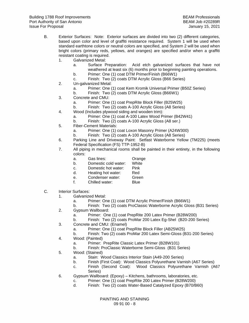
Building 1788 Roof Improvements BEAM Professionals Port Authority of San Antonio BEAM Job #20289R Issue For Proposal January 15, 2021
PAINTING AND STAINING 09 91 00 - 8
B. Exterior Surfaces: Note: Exterior surfaces are divided into two (2) different categories, based upon color and level of graffiti resistance required. System 1 will be used when standard earthtone colors or neutral colors are specified, and System 2 will be used when bright colors (primary reds, yellows, and oranges) are specified and/or when a graffiti resistant coating is required. 1. Galvanized Metal:
a. Surface Preparation: Acid etch galvanized surfaces that have not weathered at least six (6) months prior to beginning painting operations.
b. Primer: One (1) coat DTM Primer/Finish (B66W1) c. Finish: Two (2) coats DTM Acrylic Gloss (B66 Series)
2. Un-galvanized Metal: a. Primer: One (1) coat Kem Kromik Universal Primer (B50Z Series) b. Finish: Two (2) coats DTM Acrylic Gloss (B66W1)
3. Concrete and CMU: a. Primer: One (1) coat PrepRite Block Filler (B25W25) b. Finish: Two (2) coats A-100 Acrylic Gloss (A8 Series)
4. Wood (Includes plywood siding and wooden trim): a. Primer: One (1) coat A-100 Latex Wood Primer (B42W41) b. Finish: Two (2) coats A-100 Acrylic Gloss (A8 ser.)
5. Fiber-Cement Materials: a. Primer: One (1) coat Loxon Masonry Primer (A24W300) b. Finish: Two (2) coats A-100 Acrylic Gloss (A8 Series)
6. Parking Line and Driveway Paint: Setfast Waterborne Yellow (TM225) (meets Federal Specification (FS) TTP-1952-B)
7. All piping in mechanical rooms shall be painted in their entirety, in the following colors: a. Gas lines: Orange b. Domestic cold water: White c. Domestic hot water: Pink d. Heating hot water: Red e. Condenser water: Green f. Chilled water: Blue
C. Interior Surfaces:
1. Galvanized Metal: a. Primer: One (1) coat DTM Acrylic Primer/Finish (B66W1) b. Finish: Two (2) coats ProClassic Waterborne Acrylic Gloss (B31 Series)
2. Gypsum Wallboard: a. Primer: One (1) coat PrepRite 200 Latex Primer (B28W200) b. Finish: Two (2) coats ProMar 200 Latex Eg-Shel (B20-200 Series)
3. Concrete and CMU: (Enamel) a. Primer: One (1) coat PrepRite Block Filler (AB25W25) b. Finish: Two (2) coats ProMar 200 Latex Semi-Gloss (B31-200 Series)
4. Wood: (Painted) a. Primer: PrepRite Classic Latex Primer (B28W101) b. Finish: ProClassic Waterborne Semi-Gloss (B31 Series)
5. Wood: (Stained) a. Stain: Wood Classics Interior Stain (A49-200 Series) b. Finish (First Coat): Wood Classics Polyurethane Varnish (A67 Series) c. Finish (Second Coat): Wood Classics Polyurethane Varnish (A67
Series) 6. Gypsum Wallboard: (Epoxy) – Kitchens, bathrooms, laboratories, etc.
c. Primer: One (1) coat PrepRite 200 Latex Primer (B28W200) d. Finish: Two (2) coats Water-Based Catalyzed Epoxy (B70/B60)
Building 1788 Roof Improvements BEAM Professionals Port Authority of San Antonio BEAM Job #20289R Issue For Proposal January 15, 2021
PAINTING AND STAINING 09 91 00 - 9
7. CMU: (Epoxy) - Kitchens, bathrooms, laboratories, etc. a. Primer: Two (2) coats Heavy Duty Block Filler (B42W46) b. Finish: Two (2) coats Water-Based Catalyzed Epoxy (B70/B60)
END OF SECTION 09 91 00
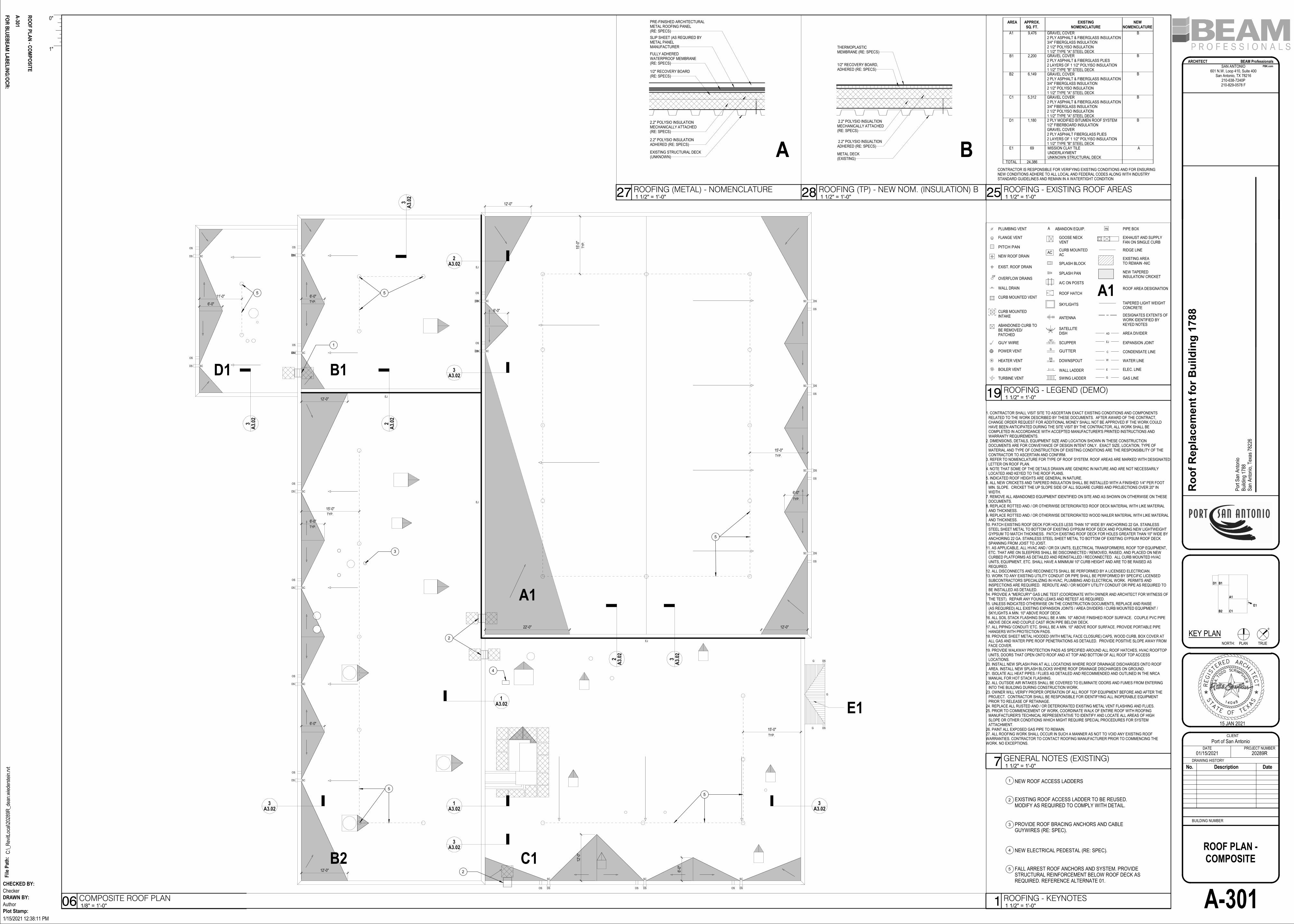
12'-0
"
6'-0
"
6'-0"
6'-0"
12'-0"
6'-0"
A1
C1B2
B1D1
E1
3A3.02
1A3.02
3A3.02
2A
3.0
2
3A
3.0
2
3A
3.0
2
2A
3.0
2
3A
3.0
2
3A3.02
12'-0"
6'-0"
12'-0"
6'-0"
6'-0"
12'-0"22'-0"
1A3.02
2A3.02
3A3.02
11'-0"
15'-0"
15'-0"
15'-0
"
15'-0"
1. CONTRACTOR SHALL VISIT SITE TO ASCERTAIN EXACT EXISTING CONDITIONS AND COMPONENTS RELATED TO THE WORK DESCRIBED BY THESE DOCUMENTS. AFTER AWARD OF THE CONTRACT, CHANGE ORDER REQUEST FOR ADDITIONAL MONEY SHALL NOT BE APPROVED IF THE WORK COULD HAVE BEEN ANTICIPATED DURING THE SITE VISIT BY THE CONTRACTOR, ALL WORK SHALL BE COMPLETED IN ACCORDANCE WITH ACCEPTED MANUFACTURER'S PRINTED INSTRUCTIONS AND WARRANTY REQUIREMENTS.
2. DIMENSIONS, DETAILS, EQUIPMENT SIZE AND LOCATION SHOWN IN THESE CONSTRUCTION DOCUMENTS ARE FOR CONVEYANCE OF DESIGN INTENT ONLY. EXACT SIZE, LOCATION, TYPE OF MATERIAL AND TYPE OF CONSTRUCTION OF EXISTING CONDITIONS ARE THE RESPONSIBILITY OF THE CONTRACTOR TO ASCERTAIN AND CONFIRM.
3. REFER TO NOMENCLATURE FOR TYPE OF ROOF SYSTEM. ROOF AREAS ARE MARKED WITH DESIGNATED LETTER ON ROOF PLAN.
4. NOTE THAT SOME OF THE DETAILS DRAWN ARE GENERIC IN NATURE AND ARE NOT NECESSARILY LOCATED AND KEYED TO THE ROOF PLANS.
5. INDICATED ROOF HEIGHTS ARE GENERAL IN NATURE.6. ALL NEW CRICKETS AND TAPERED INSULATION SHALL BE INSTALLED WITH A FINISHED 1/4" PER FOOT
MIN. SLOPE. CRICKET THE UP SLOPE SIDE OF ALL SQUARE CURBS AND PROJECTIONS OVER 20" IN WIDTH.
7. REMOVE ALL ABANDONED EQUIPMENT IDENTIFIED ON SITE AND AS SHOWN ON OTHERWISE ON THESE DOCUMENTS.
8. REPLACE ROTTED AND / OR OTHERWISE DETERIORATED ROOF DECK MATERIAL WITH LIKE MATERIAL AND THICKNESS.
9. REPLACE ROTTED AND / OR OTHERWISE DETERIORATED WOOD NAILER MATERIAL WITH LIKE MATERIAL AND THICKNESS.
10. PATCH EXISTING ROOF DECK FOR HOLES LESS THAN 10" WIDE BY ANCHORING 22 GA. STAINLESS STEEL SHEET METAL TO BOTTOM OF EXISTING GYPSUM ROOF DECK AND POURING NEW LIGHTWEIGHT GYPSUM TO MATCH THICKNESS. PATCH EXISTING ROOF DECK FOR HOLES GREATER THAN 10" WIDE BY ANCHORING 22 GA. STAINLESS STEEL SHEET METAL TO BOTTOM OF EXISTING GYPSUM ROOF DECK SPANNING FROM JOIST TO JOIST.
11. AS APPLICABLE, ALL HVAC AND / OR DX UNITS, ELECTRICAL TRANSFORMERS, ROOF TOP EQUIPMENT, ETC. THAT ARE ON SLEEPERS SHALL BE DISCONNECTED / REMOVED, RAISED, AND PLACED ON NEW CURBED PLATFORMS AS DETAILED AND REINSTALLED / RECONNECTED. ALL CURB MOUNTED HVAC UNITS, EQUIPMENT, ETC. SHALL HAVE A MINIMUM 10" CURB HEIGHT AND ARE TO BE RAISED AS REQUIRED.
12. ALL DISCONNECTS AND RECONNECTS SHALL BE PERFORMED BY A LICENSED ELECTRICIAN.13. WORK TO ANY EXISTING UTILITY CONDUIT OR PIPE SHALL BE PERFORMED BY SPECIFIC LICENSED
SUBCONTRACTORS SPECIALIZING IN HVAC, PLUMBING AND ELECTRICAL WORK. PERMITS AND INSPECTIONS ARE REQUIRED. REROUTE AND / OR MODIFY UTILITY CONDUIT OR PIPE AS REQUIRED TO BE INSTALLED AS DETAILED.
14. PROVIDE A "MERCURY" GAS LINE TEST (COORDINATE WITH OWNER AND ARCHITECT FOR WITNESS OF THE TEST). REPAIR ANY FOUND LEAKS AND RETEST AS REQUIRED.
15. UNLESS INDICATED OTHERWISE ON THE CONSTRUCTION DOCUMENTS, REPLACE AND RAISE (AS REQUIRED) ALL EXISTING EXPANSION JOINTS / AREA DIVIDERS / CURB MOUNTED EQUIPMENT / SKYLIGHTS A MIN. 10" ABOVE ROOF DECK.
16. ALL SOIL STACK FLASHING SHALL BE A MIN. 10" ABOVE FINISHED ROOF SURFACE. COUPLE PVC PIPE ABOVE DECK AND COUPLE CAST IRON PIPE BELOW DECK.
17. ALL PIPING/ CONDUIT/ ETC. SHALL BE A MIN. 10" ABOVE ROOF SURFACE. PROVIDE PORTABLE PIPE HANGERS WITH PROTECTION PADS.
18. PROVIDE SHEET METAL HOODED (WITH METAL FACE CLOSURE) CAPS, WOOD CURB, BOX COVER AT ALL GAS AND WATER PIPE ROOF PENETRATIONS AS DETAILED. PROVIDE POSITIVE SLOPE AWAY FROM FACE COVER.
19. PROVIDE WALKWAY PROTECTION PADS AS SPECIFIED AROUND ALL ROOF HATCHES, HVAC ROOFTOP UNITS, DOORS THAT OPEN ONTO ROOF AND AT TOP AND BOTTOM OF ALL ROOF TOP ACCESS LOCATIONS.
20. INSTALL NEW SPLASH PAN AT ALL LOCATIONS WHERE ROOF DRAINAGE DISCHARGES ONTO ROOF AREA. INSTALL NEW SPLASH BLOCKS WHERE ROOF DRAINAGE DISCHARGES ON GROUND.
21. ISOLATE ALL HEAT PIPES / FLUES AS DETAILED AND RECOMMENDED AND OUTLINED IN THE NRCA MANUAL FOR HOT STACK FLASHING.
22. ALL OUTSIDE AIR INTAKES SHALL BE COVERED TO ELIMINATE ODORS AND FUMES FROM ENTERING INTO THE BUILDING DURING CONSTRUCTION WORK.
23. OWNER WILL VERIFY PROPER OPERATION OF ALL ROOF TOP EQUIPMENT BEFORE AND AFTER THE PROJECT. CONTRACTOR SHALL BE RESPONSIBLE FOR IDENTIFYING ALL INOPERABLE EQUIPMENT PRIOR TO RELEASE OF RETAINAGE.
24. REPLACE ALL RUSTED AND / OR DETERIORATED EXISTING METAL VENT FLASHING AND FLUES.25. PRIOR TO COMMENCEMENT OF WORK, COORDINATE WALK OF ENTIRE ROOF WITH ROOFING
MANUFACTURER'S TECHNICAL REPRESENTATIVE TO IDENTIFY AND LOCATE ALL AREAS OF HIGH SLOPE OR OTHER CONDITIONS WHICH MIGHT REQUIRE SPECIAL PROCEDURES FOR SYSTEM ATTACHMENT.
26. PAINT ALL EXPOSED GAS PIPE TO REMAIN.27. ALL ROOFING WORK SHALL OCCUR IN SUCH A MANNER AS NOT TO VOID ANY EXISTING ROOF WARRANTIES. CONTRACTOR TO CONTACT ROOFING MANUFACTURER PRIOR TO COMMENCING THE WORK. NO EXCEPTIONS.
AREA APPROX.
SQ. FT.
EXISTING
NOMENCLATURE
A1 9,476 GRAVEL COVER2 PLY ASPHALT & FIBERGLASS INSULATION3/4" FIBERGLASS INSULATION2 1/2" POLYISO INSULATION1 1/2" TYPE "A" STEEL DECK
CONTRACTOR IS RESPONSIBLE FOR VERIFYING EXISTING CONDITIONS AND FOR ENSURING NEW CONDITIONS ADHERE TO ALL LOCAL AND FEDERAL CODES ALONG WITH INDUSTRY STANDARD GUIDELINES AND REMAIN IN A WATERTIGHT CONDITION
TOTAL 24,386
NEW
NOMENCLATURE
B
E1 69 MISSION CLAY TILEUNDERLAYMENTUNKNOWN STRUCTURAL DECK
D1 1,180
B2 6,149
A
GRAVEL COVER2 PLY ASPHALT & FIBERGLASS PLIES2 LAYERS OF 1 1/2" POLYISO INSULATION1 1/2" TYPE "B" STEEL DECK
B1 2,200
GRAVEL COVER2 PLY ASPHALT & FIBERGLASS INSULATION3/4" FIBERGLASS INSULATION2 1/2" POLYISO INSULATION1 1/2" TYPE "A" STEEL DECK
C1 5,312 GRAVEL COVER2 PLY ASPHALT & FIBERGLASS INSULATION3/4" FIBERGLASS INSULATION2 1/2" POLYISO INSULATION1 1/2" TYPE "A" STEEL DECK2 PLY MODIFIED BITUMEN ROOF SYSTEM1/2" FIBERBOARD INSULATIONGRAVEL COVER2 PLY ASPHALT FIBERGLASS PLIES2 LAYERS OF 1 1/2" POLYISO INSULATION1 1/2" TYPE "B" STEEL DECK
B
B
B
B
PLUMBING VENT
FLANGE VENT
PITCH PAN
NEW ROOF DRAIN
EXIST. ROOF DRAIN
OVERFLOW DRAINS
WALL DRAIN
CURB MOUNTED VENT
CURB MOUNTED INTAKE
ABANDONED CURB TO BE REMOVED/ PATCHED
GUY WIRE
POWER VENT
HEATER VENT
BOILER VENT
TURBINE VENT
GOOSE NECK VENT
CURB MOUNTED AC
SPLASH BLOCK
SPLASH PAN
A/C ON POSTS
ROOF HATCH
SKYLIGHTS
ANTENNA
SATELLITE DISH
SCUPPER
GUTTER
DOWNSPOUT
WALL LADDER
SWING LADDER GAS LINE
ELEC. LINE
PIPE BOX
EXHAUST AND SUPPLY FAN ON SINGLE CURB
RIDGE LINE
EXISTING AREATO REMAIN -NIC
NEW TAPERED INSULATION/ CRICKET
TAPERED LIGHT WEIGHT CONCRETE
DESIGNATES EXTENTS OF WORK IDENTIFIED BY KEYED NOTES
AREA DIVIDER
EXPANSION JOINT
CONDENSATE LINE
WATER LINE
A1 ROOF AREA DESIGNATION
PB
EJ
AD
SC
G
DS
G
E
A ABANDON EQUIP.
OF
V
AC
C
W
A1
B1
B2 C1
D1
E1
SCDS
SCDS
SCDS
SCDS
SCDS
SCDS
SCDS
SCDS
SCDS
SCDS
SC DS
SC DS
SC DS
SC DS
SC
DS
SC
DS
SC
DS
OS
OS
OS
OS
OS
OS
OS
OS
OS
OS
OS
OS
OS
OS
OSOSOS
EJ
EJ
EJ
EJ
DS
DSG
G
G
2.2" POLYSIO INSUALTION ADHERED (RE: SPECS)
1/2" RECOVERY BOARD, ADHERED (RE: SPECS)
THERMOPLASTIC MEMBRANE (RE: SPECS)
METAL DECK(EXISTING)
2.2" POLYSIO INSUALTION MECHANICALLY ATTACHED (RE: SPECS)
2.2" POLYSIO INSULATION ADHERED (RE: SPECS)
1/2" RECOVERY BOARD (RE: SPECS)
FULLY ADHERED WATERPROOF MEMBRANE (RE: SPECS)
SLIP SHEET (AS REQUIRED BY METAL PANEL MANUFACTURER
PRE-FINISHED ARCHITECTURAL METAL ROOFING PANEL (RE: SPECS)
EXISTING STRUCTURAL DECK(UNKNOWN) A B
2.2" POLYSIO INSULATION MECHANICALLY ATTACHED (RE: SPECS)
1
2
3
4
NEW ROOF ACCESS LADDERS
EXISTING ROOF ACCESS LADDER TO BE REUSED. MODIFY AS REQUIRED TO COMPLY WITH DETAIL.
PROVIDE ROOF BRACING ANCHORS AND CABLE GUYWIRES (RE: SPEC).
NEW ELECTRICAL PEDESTAL (RE: SPEC).
4
2
3
2
1
FALL ARREST ROOF ANCHORS AND SYSTEM. PROVIDE STRUCTURAL REINFORCEMENT BELOW ROOF DECK AS REQUIRED. REFERENCE ALTERNATE 01.
5
5
5
5
5 5
N
SAN ANTONIO601 N.W. Loop 410, Suite 400
San Antonio, TX 78216210-638-7240P210-829-0578 F
ARCHITECT BEAM Professionals
KEY PLAN
DATE PROJECT NUMBER
CLIENT
DRAWING HISTORY
PBK.com
DRAWN BY:
CHECKED BY:
PLAN TRUE
BUILDING NUMBER
FO
R B
LU
EB
EA
M L
AB
EL
ING
/OC
R:
Fil
e P
ath
:
Plot Stamp:
1"
0"
NORTH:
1/15/2021 12:38:11 PM
C:\_
Rev
itLoc
al\2
0289
R_d
ean.
wie
ders
tein
.rvt
Ro
of
Rep
lac
em
en
t fo
r B
uild
ing
17
88
A-301
ROOF PLAN -COMPOSITE
01/15/2021 20289R
Port of San Antonio
Author
Checker
Por
t San
Ant
onio
Bui
ldin
g 17
88S
an A
nton
io, T
exas
782
26
A-30
1
RO
OF
PL
AN
-C
OM
PO
SIT
E
1 1/2" = 1'-0"7 GENERAL NOTES (EXISTING)
1 1/2" = 1'-0"25 ROOFING - EXISTING ROOF AREAS
1 1/2" = 1'-0"19 ROOFING - LEGEND (DEMO)
1/8" = 1'-0"06 COMPOSITE ROOF PLAN
1 1/2" = 1'-0"28 ROOFING (TP) - NEW NOM. (INSULATION) B1 1/2" = 1'-0"27 ROOFING (METAL) - NOMENCLATURE
1 1/2" = 1'-0"1 ROOFING - KEYNOTES
TYP.
TYP.
TYP.
TYP.
TYP.
TY
P.
TYP.
No. Description Date
15 JAN 2021
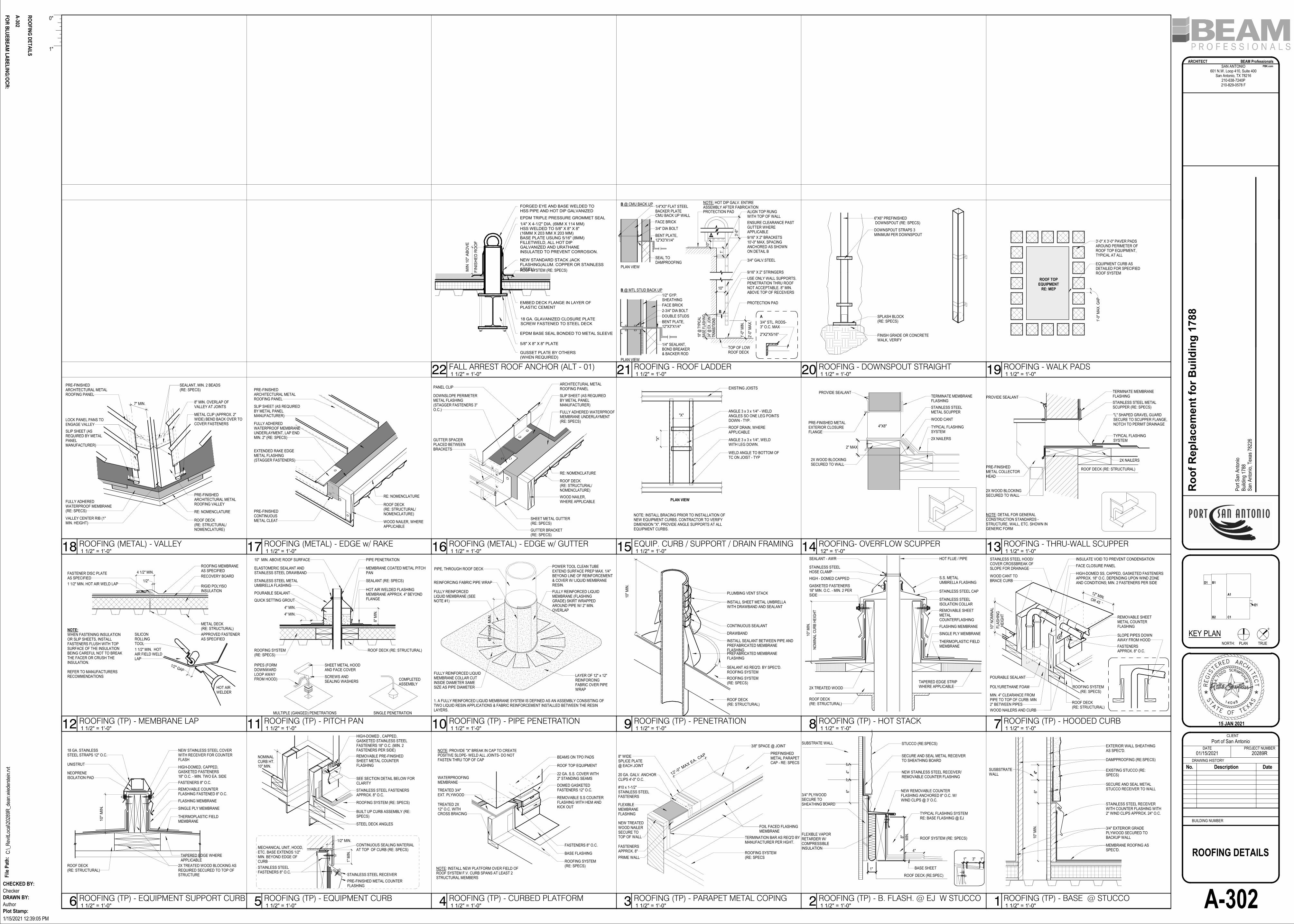
EXISTING STUCCO (RE: SPECS)
10
" M
IN.
SECURE AND SEAL METAL STUCCO RECEIVER TO WALL
STAINLESS STEEL RECEIVER WITH COUNTER FLASHING WITH 2" WIND CLIPS APPROX. 24" O.C.
MEMBRANE ROOFING AS SPEC'D.
DAMPPROOFING (RE:SPECS)
3/4" EXTERIOR GRADE PLYWOOD SECURED TO BACKUP WALL
EXTERIOR WALL SHEATHING AS SPEC'D.
SUSBSTRATE WALL
6"4"4"
ROOF SYSTEM (RE: SPECS)
NEW STAINLESS STEEL RECEIVER/REMOVABLE COUNTER FLASHING
NEW REMOVABLE COUNTER FLASHING ANCHORED 8" O.C. W/ WIND CLIPS @ 3' O.C.
TYPICAL FLASHING SYSTEMRE: BASE FLASHING @ EJ
SECURE AND SEAL METAL RECEIVER TO SHEATHING BOARD
SUBSTRATE WALL
ROOF DECK (RE:SPEC)
BASE SHEET
STUCCO (RE:SPECS)
8"M
IN.
3/4" PLYWOOD SECURE TOSHEATHING BOARD
FLEXIBLE VAPORRETARDER W/COMPRESSIBLE INSULATION
1"
1" 1"3"
4"6"
0"4"
0"
BEAMS ON TPO PADS
ROOF TOP EQUIPMENT
22 GA. S.S. COVER WITH2" STANDING SEAMS
DOMED GASKETEDFASTENERS 12" O.C.
REMOVABLE S.S COUNTER FLASHING WITH HEM AND KICK OUT
FASTENERS 8" O.C.
BASE FLASHING
ROOFING SYSTEM(RE: SPECS)
NOTE: INSTALL NEW PLATFORM OVER FIELD OF ROOF SYSTEM F.V. CURB SPANS AT LEAST 2 STRUCTURAL MEMBERS
TREATED 2X12" O.C. WITHCROSS BRACING
TREATED 3/4"EXT. PLYWOOD
WATERPROOFING MEMBRANE
NOTE: PROVIDE "X" BREAK IN CAP TO CREATE POSITIVE SLOPE- WELD ALL JOINTS- DO NOT FASTEN THRU TOP OF CAP
1"
MIN
.
1/2" MIN.
NOMINALCURB HT.10" MIN.
HIGH-DOMED , CAPPED, GASKETED STAINLESS STEEL FASTENERS 18" O.C. (MIN. 2 FASTENERS PER SIDE)
REMOVABLE PRE-FINISHED SHEET METAL COUNTER FLASHING
STAINLESS STEEL FASTENERS APPROX. 8" O.C.
STEEL DECK ANGLES
BUILT UP CURB ASSEMBLY (RE: SPECS)
ROOFING SYSTEM (RE: SPECS)
SEE SECTION DETAIL BELOW FOR CLARITY
CONTINUOUS SEALING MATERIAL AT TOP OF CURB (RE: SPECS)
STAINLESS STEEL FASTENERS 8" O.C.
MECHANICAL UNIT, HOOD, ETC. BASE EXTENDS 1/2" MIN. BEYOND EDGE OF CURB
STAINLESS STEEL RECEIVER
PRE-FINISHED METAL COUNTER FLASHING
UNISTRUT
NEOPRENEISOLATION PAD
18 GA. STAINLESSSTEEL STRAPS 12" O.C.
NEW STAINLESS STEEL COVER WITH RECEIVER FOR COUNTER FLASH
HIGH-DOMED, CAPPED,GASKETED FASTENERS 18" O.C. - MIN. TWO EA. SIDE
FASTENERS 8" O.C.
REMOVABLE COUNTER FLASHING FASTENED 8" O.C.
TAPERED EDGE WHERE APPLICABLE
ROOF DECK (RE: STRUCTURAL)
2X TREATED WOOD BLOCKING AS REQUIRED SECURED TO TOP OF STRUCTURE
10
" M
IN.
FLASHING MEMBRANE
SINGLE PLY MEMBRANE
THERMOPLASTIC FIELD MEMBRANE
STAINLESS STEEL HOOD/ COVER CROSSBREAK OF SLOPE FOR DRAINAGE
HIGH-DOMED SS, CAPPED, GASKETED FASTENERS APPROX. 18" O.C. DEPENDING UPON WIND ZONE AND CONDITIONS; MIN. 2 FASTENERS PER SIDE
REMOVABLE SHEET METAL COUNTER FLASHING
FACE CLOSURE PANEL
12" MIN.
SLOPE PIPES DOWN AWAY FROM HOOD
FASTENERS APPROX. 8" O.C.
INSULATE VOID TO PREVENT CONDENSATION
WOOD CANT TO BRACE CURB
WOOD NAILERS AND CURB
MIN. 4" CLEARANCE FROM PIPE TO TOP OF CURB: MIN 2" BETWEEN PIPES
OR 45
ROOF DECK(RE: STRUCTURAL)
10"
NO
MIN
AL
FLA
SH
ING
HE
IGH
T
ROOFING SYSTEM (RE: SPECS)
POLYURETHANE FOAM
POURABLE SEALANT
HOT FLUE / PIPE
S.S. METAL UMBRELLA FLASHING
STAINLESS STEEL CAP
STAINLESS STEEL ISOLATION COLLAR
REMOVABLE SHEET METALCOUNTERFLASHING
FLASHING MEMBRANE
TAPERED EDGE STRIP WHERE APPLICABLE2X TREATED WOOD
SEALANT - AWR
STAINLESS STEEL HOSE CLAMP
HIGH - DOMED CAPPED
GASKETED FASTENERS 18" MIN. O.C. - MIN. 2 PER SIDE
ROOF DECK (RE: STRUCTURAL)
NO
MIN
AL
CU
RB
HE
IGH
T
10
" M
IN.
SINGLE PLY MEMBRANE
THERMOPLASTIC FIELD MEMBRANE
PLUMBING VENT STACK
CONTINUOUS SEALANT
DRAWBAND
INSTALL SEALANT BETWEEN PIPE AND PREFABRICATED MEMBRANE FLASHINGPREFABRICATED MEMBRANE FLASHING
SEALANT AS REQ'D. BY SPEC'D. ROOFING SYSTEM
ROOFING SYSTEM (RE: SPECS)
ROOF DECK (RE: STRUCTURAL)
INSTALL SHEET METAL UMBRELLA WITH DRAWBAND AND SEALANT
10"
MIN
.
POWER TOOL CLEAN TUBE EXTEND SURFACE PREP MAX. 1/4" BEYOND LINE OF REINFORCEMENT & COVER W/ LIQUID MEMBRANE RESIN.
FULLY REINFORCED LIQUID MEMBRANE (FLASHING GRADE) SKIRT WRAPPED AROUND PIPE W/ 2" MIN. OVERLAP
FULLY REINFORCED LIQUID MEMBRANE (SEE NOTE #1)
FULLY REINFORCED LIQUID MEMBRANE COLLAR CUT INSIDE DIAMETER SAME SIZE AS PIPE DIAMETER
1. A FULLY REINFORCED LIQUID MEMBRANE SYSTEM IS DEFINED AS AN ASSEMBLY CONSISTING OF TWO LIQUID RESIN APPLICATIONS & FABRIC REINFORCEMENT INSTALLED BETWEEN THE RESIN LAYERS.
LAYER OF 12" x 12" REINFORCING FABRIC OVER PIPE WRAP
6"
HIG
H M
IN.
PIPE, THROUGH ROOF DECK
REINFORCING FABRIC PIPE WRAP
ROOF DECK (RE: STRUCTURAL)ROOFING SYSTEM(RE: SPECS)
6"
MIN
.
SEALANT (RE: SPECS)
MEMBRANE COATED METAL PITCH PAN
POURABLE SEALANT
STAINLESS STEEL METALUMBRELLA FLASHING
ELASTOMERIC SEALANT AND STAINLESS STEEL DRAWBAND
PIPE PENETRATION
4" MIN.
4" MIN.
SHEET METAL HOOD AND FACE COVER
SCREWS AND SEALING WASHERS
PIPES (FORM DOWNWARD LOOP AWAY FROM HOOD)
MULTIPLE (GANGED) PENETRATIONS SINGLE PENETRATION
COMPLETED ASSEMBLY
HOT AIR WELDED FLASHING MEMBRANE APPROX. 4" BEYOND FLANGE
10" MIN. ABOVE ROOF SURFACE
QUICK SETTING GROUT
METAL DECK(RE: STRUCTURAL)
RIGID POLYISOINSULATION
RECOVERY BOARD
ROOFING MEMBRANEAS SPECIFIED
1/2"
4 1/2" MIN.FASTENER DISC PLATEAS SPECIFIED
1 1/2" MIN. HOT AIR WELD LAP
APPROVED FASTENERAS SPECIFIED
SILICON ROLLING TOOL
1 1/2" MIN. HOT AIR FIELD WELD LAP
HOT AIR WELDER
1/2" GAP
NOTE:WHEN FASTENING INSULATION OR SLIP SHEETS, INSTALL FASTENERS FLUSH WITH TOP SURFACE OF THE INSULATION BEING CAREFUL NOT TO BREAK THE FACER OR CRUSH THE INSULATION.
REFER TO MANUFACTURERS RECOMMENDATIONS
6"X6" PREFINISHEDDOWNSPOUT (RE: SPECS)
DOWNSPOUT STRAPS 3 MINIMUM PER DOWNSPOUT
FINISH GRADE OR CONCRETE WALK, VERIFY
SPLASH BLOCK(RE: SPECS)
ROOF TOP
EQUIPMENTRE: MEP
3'-0" X 3'-0" PAVER PADS AROUND PERIMETER OF ROOF TOP EQUIPMENT, TYPICAL AT ALL
EQUIPMENT CURB AS DETAILED FOR SPECIFIED ROOF SYSTEM
1'-0
" M
AX
. GA
P
B @ CMU BACK UP
PLAN VIEW
B @ MTL STUD BACK UP
PLAN VIEW
1/4"X3" FLAT STEELBACKER PLATECMU BACK UP WALL
FACE BRICK
3/4" DIA BOLT
BENT PLATE,12"X3"X1/4"
SEAL TO DAMPROOFING
1/2" GYP. SHEATHING
FACE BRICK
2-3/4" DIA BOLT
DOUBLE STUDS
BENT PLATE,12"X3"X1/4"
1/4" SEALANT,BOND BREAKER& BACKER ROD
PROTECTION PAD
A
2"X2"X5/16"
3/4" STL. RODS-3" O.C. MAX
10"
B
A
1'-0
" M
IN.
2'-0
" M
AX
.
TOP OF LOW ROOF DECK
USE ONLY WALL SUPPORTS. PENETRATION THRU ROOF NOT ACCEPTABLE. 8" MIN. ABOVE TOP OF RECEIVERS
9/16" X 2" STRINGERS
3/4" GALV.STEEL
9/16" X 2" BRACKETS10'-0" MAX. SPACINGANCHORED AS SHOWNON DETAIL B
ALIGN TOP RUNGWITH TOP OF WALL
ENSURE CLEARANCE PAST GUTTER WHERE APPLICABLE
10"
3'-6
"
NOTE: HOT DIP GALV. ENTIREASSEMBLY AFTER FABRICATIONPROTECTION PAD
1'
24" @
EX.
JO
INT
TRA
NSI
TIO
NS
18" @
TYP
ICAL
BA
SE
FLAS
HIN
G
TERMINATE MEMBRANE FLASHING
TYPICAL FLASHING SYSTEM
STAINLESS STEEL METAL SCUPPER (RE: SPECS)
2X NAILERS
ROOF DECK (RE: STRUCTURAL)
2X WOOD BLOCKING SECURED TO WALL
PRE-FINISHED METAL COLLECTOR HEAD
PROVIDE SEALANT
NOTE: DETAIL FOR GENERAL CONSTRUCTION STANDARDS -STRUCTURE, WALL, ETC. SHOWN IN GENERIC FORM
"L" SHAPED GRAVEL GUARD SECURE TO SCUPPER FLANGE, NOTCH TO PERMIT DRAINAGE
TERMINATE MEMBRANEFLASHING
STAINLESS STEEL METAL SCUPPER
WOOD CANT
TYPICAL FLASHING SYSTEM
2X NAILERS
2X WOOD BLOCKING SECURED TO WALL
PRE-FINISHED METAL EXTERIOR CLOSURE FLANGE
PROVIDE SEALANT
4"X8"
2" MAX
EXISTING JOISTS
ANGLE 3 x 3 x 1/4" - WELD ANGLES SO ONE LEG POINTS DOWN - TYP.
ANGLE 3 x 3 x 1/4", WELD WITH LEG DOWN.
WELD ANGLE TO BOTTOM OF TC ON JOIST - TYP
NOTE: INSTALL BRACING PRIOR TO INSTALLATION OF NEW EQUIPMENT CURBS. CONTRACTOR TO VERIFY DIMENSION "X". PROVIDE ANGLE SUPPORTS AT ALL EQUIPMENT CURBS.
"X"
"X"
PLAN VIEW
ROOF DRAIN, WHERE APPLICABLE
GUTTER BRACKET(RE: SPECS)
SHEET METAL GUTTER(RE: SPECS)
GUTTER SPACER PLACED BETWEEN BRACKETS
DOWNSLOPE PERIMETER METAL FLASHING (STAGGER FASTENERS 3" O.C.)
PANEL CLIP
FULLY ADHERED WATERPROOF MEMBRANE UNDERLAYMENT (RE: SPECS)
ARCHITECTURAL METAL ROOFING PANEL
SLIP SHEET (AS REQUIRED BY METAL PANEL MANUFACTURER)
WOOD NAILER, WHERE APPLICABLE
RE: NOMENCLATURE
ROOF DECK(RE: STRUCTURAL/ NOMENCLATURE)
PRE-FINISHED ARCHITECTURAL METAL ROOFING PANEL
PRE-FINISHED CONTINUOUS METAL CLEAT
SLIP SHEET (AS REQUIRED BY METAL PANEL MANUFACTURER)
FULLY ADHERED WATERPROOF MEMBRANE UNDERLAYMENT, LAP END MIN. 2" (RE: SPECS)
EXTENDED RAKE EDGE METAL FLASHING (STAGGER FASTENERS)
WOOD NAILER, WHERE APPLICABLE
RE: NOMENCLATURE
ROOF DECK(RE: STRUCTURAL/ NOMENCLATURE)
8" MIN. OVERLAP OF VALLEY AT JOINTS
PRE-FINISHED ARCHITECTURAL METAL ROOFING PANEL
SLIP SHEET (AS REQUIRED BY METAL PANEL MANUFACTURER)
FULLY ADHERED WATERPROOF MEMBRANE (RE: SPECS) RE: NOMENCLATURE
ROOF DECK(RE: STRUCTURAL/ NOMENCLATURE)
METAL CLIP (APPROX. 2" WIDE) BEND BACK OVER TO COVER FASTENERS
SEALANT, MIN. 2 BEADS (RE: SPECS)
PRE-FINISHED ARCHITECTURAL METAL ROOFING VALLEY
VALLEY CENTER RIB (1" MIN. HEIGHT)
7" MIN.
LOCK PANEL PANS TO ENGAGE VALLEY
12'-0" M
AX EA. C
AP
PRIME WALL
FASTENERS APPROX. 8"
NEW TREATED WOOD NAILER SECURE TO TOP OF WALL
#10 x 1-1/2" STAINLESS STEEL FASTENERS
20 GA. GALV. ANCHOR CLIPS 4'-0" O.C.
8" WIDE SPLICE PLATE @ EACH JOINT
3/8" SPACE @ JOINT
PREFINISHED METAL PARAPET CAP - RE: SPECS
FOIL FACED FLASHING MEMBRANE
TERMINATION BAR AS REQ'D BY MANUFACTURER PER HGHT.
ROOFING SYSTEM (RE: SPECS
FLEXIBLE MEMBRANE FLASHING
FORGED EYE AND BASE WELDED TO HSS PIPE AND HOT DIP GALVANIZED
1/4" X 4-1/2" DIA. (6MM X 114 MM)HSS WELDED TO 5/8" X 8" X 8"(16MM X 203 MM X 203 MM)BASE PLATE USUNG 5/16" (8MM) FILLETWELD, ALL HOT DIP GALVANIZED AND URATHANE INSULATED TO PREVENT CORROSION.
NEW STANDARD STACK JACK FLASHING(ALUM. COPPER OR STAINLESS STEEL)
EPDM TRIPLE PRESSURE GROMMET SEAL
EMBED DECK FLANGE IN LAYER OF PLASTIC CEMENT
5/8" X 8" X 8" PLATE
GUSSET PLATE BY OTHERS (WHEN REQUIRED)
18 GA. GLAVANIZED CLOSURE PLATE SCREW FASTENED TO STEEL DECK
EPDM BASE SEAL BONDED TO METAL SLEEVE
FIN
ISH
ED
RO
OF
MIN
10"
AB
OV
E
ROOF SYSTEM (RE: SPECS)
N
SAN ANTONIO601 N.W. Loop 410, Suite 400
San Antonio, TX 78216210-638-7240P210-829-0578 F
ARCHITECT BEAM Professionals
KEY PLAN
DATE PROJECT NUMBER
CLIENT
DRAWING HISTORY
PBK.com
DRAWN BY:
CHECKED BY:
PLAN TRUE
BUILDING NUMBER
FO
R B
LU
EB
EA
M L
AB
EL
ING
/OC
R:
Fil
e P
ath
:
Plot Stamp:
1"
0"
NORTH:
1/15/2021 12:39:05 PM
C:\_
Rev
itLoc
al\2
0289
R_d
ean.
wie
ders
tein
.rvt
Ro
of
Rep
lac
em
en
t fo
r B
uild
ing
17
88
A-302
ROOFING DETAILS
01/15/2021 20289R
Port of San Antonio
Author
Checker
Por
t San
Ant
onio
Bui
ldin
g 17
88S
an A
nton
io, T
exas
782
26
A-30
2
RO
OF
ING
DE
TA
ILS
1 1/2" = 1'-0"1 ROOFING (TP) - BASE @ STUCCO1 1/2" = 1'-0"2 ROOFING (TP) - B. FLASH. @ EJ W STUCCO
1 1/2" = 1'-0"4 ROOFING (TP) - CURBED PLATFORM1 1/2" = 1'-0"5 ROOFING (TP) - EQUIPMENT CURB
1 1/2" = 1'-0"6 ROOFING (TP) - EQUIPMENT SUPPORT CURB
1 1/2" = 1'-0"7 ROOFING (TP) - HOODED CURB1 1/2" = 1'-0"8 ROOFING (TP) - HOT STACK
1 1/2" = 1'-0"9 ROOFING (TP) - PENETRATION1 1/2" = 1'-0"10 ROOFING (TP) - PIPE PENETRATION
1 1/2" = 1'-0"11 ROOFING (TP) - PITCH PAN1 1/2" = 1'-0"12 ROOFING (TP) - MEMBRANE LAP
1 1/2" = 1'-0"20 ROOFING - DOWNSPOUT STRAIGHT1 1/2" = 1'-0"19 ROOFING - WALK PADS
1 1/2" = 1'-0"21 ROOFING - ROOF LADDER
1 1/2" = 1'-0"13 ROOFING - THRU-WALL SCUPPER12" = 1'-0"14 ROOFING- OVERFLOW SCUPPER
1 1/2" = 1'-0"15 EQUIP. CURB / SUPPORT / DRAIN FRAMING1 1/2" = 1'-0"16 ROOFING (METAL) - EDGE w/ GUTTER
1 1/2" = 1'-0"17 ROOFING (METAL) - EDGE w/ RAKE1 1/2" = 1'-0"18 ROOFING (METAL) - VALLEY
1 1/2" = 1'-0"3 ROOFING (TP) - PARAPET METAL COPING
A1
C1B2
B1D1
E1
1 1/2" = 1'-0"22 FALL ARREST ROOF ANCHOR (ALT - 01)
No. Description Date
15 JAN 2021