REPORTER - World Radio History
98
MARCH 1957 25 CENTS REPORTER FOR THE ELECTRONIC SERVICE INDUSTRY This Month's Highlights Working with Transistor Radios see page 16 Hot -Chassis Sa=eguaris Still More New Tubes (see page 18) (see page 27) Remote Tuning Without Wires (see page 21) Horizontal AFC and Oscillator Troubles (see page 50: www.americanradiohistory.com
-
Upload
khangminh22 -
Category
Documents
-
view
4 -
download
0
Transcript of REPORTER - World Radio History

MARCH 1957 25 CENTS
REPORTER FOR THE ELECTRONIC SERVICE INDUSTRY
This Month's Highlights Working with Transistor Radios
see page 16
Hot -Chassis Sa=eguaris Still More New Tubes (see page 18) (see page 27)
Remote Tuning Without Wires (see page 21)
Horizontal AFC and Oscillator Troubles (see page 50:
www.americanradiohistory.com

with IRC® Resist-O-Cabì nets Four "Savingest" Assortments
IRC Resist -O -Cabinets come complete with a colorful all -metal cabinet and any one of four resistor assortments. All resistors are guaranteed fresh and packed in the cabinet at the factory. Cabinets are yours at no extra charge. They have 4 "non -spill" drawers with 28 clearly identified compartments. Design permits nest stacking.
No. 3
Assortment 2 Watt
Coltents
List Price
Your Price
No. 4
%2 Watt No. 5 No. 6
1 Watt Combination
80 BTB2 100 BTS 83 BTA Fixed Composi- Fixed Composi- Fixed Cmposi- tìon and BW -2 tion and BW -y tion and BW -1 Insulated Wire Insulated Wire Insulated Wire Wound Resis- Wound Resis- Wound Resis- tors. 33 differ- tors. 28 differ- tors. 28 differ- ent values from ent values from ent values from 4,7 ohms to 1 47 ohms to 10.0 47 ohms to 4.7 megohm. megohms. megohrrs.
91 resistors in- cluding 5 DCF 1
Watt Precistors and 86'/z Watt, 1 Watt, and 2
Watt Insulated Resisturs.Values from 47 ohms to 5 megohms.
Radio and TV technicians who use IRC Resist - O -Cabinets call them the "savingest" resistor deal they know of. Here's why. You save time and trouble in ordering-all of the resistors most used in TV repair work are pre -selected for you. You save money-you not only get resistors at regular dealer price, but also a hand- some all -metal cabinet at no extra charge. And you save time on the job-you know what you have-and you have what you want when you want it. To trim costs and fatten profits, buy resistors in IRC Resist -O -Cabinet assortments.
$26.40 $17.00 $2C'.75 $23.54 ClAfaau s. tit P Lva? Sao -
$16.00 $10.00 $12.45 $14.05 ORDER FROM YOUR IRC DISTRIBUTOR
INTERNATIONAL RESISTANCE CO. Dept. 363,401 N. Broad St., Phila. 8, Pa. In Canada: International Resistance Co., Ltd., Toronto, Licensee
www.americanradiohistory.com

L
depend on
RADIART VIBRATORS ...the COMPLETE replacement line
Radiart vibrators are the
Standard of Comparison for
quality, performance and
dependability in the industry!
Men who know ...manage-
ment, jobbers.... and
servicemen ... ALL agree
that experience over the
years has dictated that
RADIART vibrators are the
ones to buy and use.
AND ... the complete line
of COMMUNICATION
vibrators offers the correct
replacement for 6 volt
and 12 volt applications.
Be sure you have the new
vibrator replacement guide...
write for your FREE copy...
Ittle> THE RADIART CORP.
CLEVELAND 13, OHIO
A Subsidiary of Cornell -Du biller
March, 1957 PF REPORTER 1
www.americanradiohistory.com

Reputation Builder 2: it pays to be prompt
Only 51% of set -owners who wait 3 to 4 days
for service are satisfied with the bill
BUT ... 69% of customers getting same -day
service are satisfied with the bill
it pays to replace with Sprague Twist -Lok* Electrolytics
don't be vague...insist on
*Trademark
Another way to build and hold a reputation is to insist on top quality replacement parts. Callbacks due to replacement failures not only cost you money ... they also cost you customers! Replace with less than the best and you place your reputation at stake. In capacitors, the best is Sprague.
Take the Twist -Lok 'lytic, for example. Sprague TVL's have everything! More exact ratings ... higher quality to meet original equipment specifications. Every TVL for every voltage rating is made with expensive high -purity etched -foil anode construction-ultra stable film formation techniques. And etched cathodes meet the toughest ripple requirements. No wonder they're your first line of defense against callbacks!
Get your copy of Sprague's latest radio and TV service catalog, C-455. Write Sprague Products Co., Distributors' Division of Sprague Electric Company, 105 Marshall Street, North Adams, Mass.
SPRAGUE® it ,
S larges ,l,t!1' 1 ,
SPRAGUE RESEARCH IS CONSTANTLY PRODUCING NEW AND BETTER CAPACITORS FOR YOU
PF REPORTER March, 1957
www.americanradiohistory.com

PUBLISHER
Howard W. Sams
GENERAL MANAGER
Mal Parks,, Jr.
EDITOR TECHNICAL EDITOR
Glean E. Slutz Verne M. Ray
ASSOCIATE EDITORS
Leslie D. Deane Thomas A. Lesh
Calvin C. Young, Jr.
CONSULTING EDITORS
William E. Burke C. P. Oliphant Roberi B. Dunham George B. Mann
Paul C. Smith
ART DIRECTOR
Glenn R. Smith Gwen Bighorn
, PIHOIOGRAPHY CIRCULATION Robert W. Reed Pat Tidd
EDITORIAL ASSISTANT
ADVERTISING SALES OFFICES MIDWESTERN
F'F REPORTER,
2201 East 46th Street, Indianapolis 5, Ind. Gifford 1-4531
EASTERN Paul S. Weil and Donald C. Weil,
39-01 Main`treet, Flushing 54, New York. Independence 3-9098.
WESTERN The Maurice A. Kimball Co., Inc.,
2550 Beverly Blvd., Los Angeles 57, Calif. Dunkirk 8-6178; and 681 Market Street, San Francisco 5, Calif. !EXbrook 2-3365.
Publ+shed monthly by Howard W. Sams & Co., Inc., at Indianapolis 5, Indiana. Entered as second class matter October 11, 1954, at the Post Office at Indianapolis, Indiana, under the Act of March 3, 1879. Copyright 1957 by Howa d W. Sams & Co., Inc. No partof the PF REFORTER may be reproduced without written permission. No patent liability is
assumed with respect to the use of information contained herein. A limited quantity of bac< issues are available at 35c per copy.
NEXT MONTH CURING TURNTABLE RUMBLE
A practical servicing article giving most of the probable causes and the best cures for this common source of customer dissatisfaction.
KNOW YOUR VTVM
Facts you should know about your vacuum -tube voltmeter - its opera- tion, capabilities, and limitations.
WAFER -SWITCH CIRCUITS
Helpful advice for those who are sometimes puzzled by the complex switch circuits found in many test instruments, communications receiv- ers and TV sets.
HERE'S A NEW COLOR RECEIVER
A description of the Westinghouse 22" 1957 color set wäth its new de- sign, rectangular color picture tube and ,other distinctive features.
Quicker Servicing
Dollar & Sense Servicing
Audio Facts Public address speakers and their applications
Horizontal AFC and Oscillator Troubles
Let's Talk Business Repeat business- are you getting your share?
Product Report
VOL. 7 No. 3
PF REPORTER FOR THE ELECTRONIC SERVICE INDUSTRY
CONTENTS Letters to the Editor
Shop Talk Milton S. Kiver Pin -pointing troubles in master antenna systems.
Radio for the TV Man Steps in the alignment of a 5 -tube superhet.
Working With Transistor Radios
Hot -Chassis Safeguards
8
13
14
Leslie D. Deane 16
Thomas A. Lesh 18
Remote Tuning Without Wires Thomas A. Lesh 21
Notes on Test Equipment Leslie D. Deane 23
Resonant Circuits (Part 2) Calvin C. Young, Jr. 25
Still More New Tubes 27 Special tubes used in new 9" GE portable.
Stock Guide for TV Tubes 29
Calvin C. Young, Jr. 31
John Markus 35
Calvin C. Young, Jr. 38
50
Verne M. Ray 86
88
Free Catalog & Literature Service 90
Supplement to SAMS Master Index 91
SUBJECT INDEX Safety -glass removal Solder dispenser Transistor radios, service tips on
32 31 16
ANTENNAS AND ACCESSORIES TELEVISION Master antenna systems,
servicing of 13 Insulating features in trans-
formerless sets 18 Motorola "Transituner" remote
AUDIO control unit 76
Hi-fi phonographs, testing of .... 31 Zenith "Space -Command" remote PA speakers, types and applica- control unit 21
tions of 38 TEST EQUIPMENT
BUSINESS MANAGEMENT Hickok Model 123 "Cardmatic" Handling customers, tips on 86 tube tester 83
Hycon Model 622 oscilloscope 80 RADIO Win-Tronix Model 825 dynamic
12V tubes for hybrid auto radios . 29 AGC circuit analyzer 23 Alignment (with photos) Transistor radios, service tips on
14 16 THEORY
Figure of merit or Q 25 SERVICING Series resonance 25
Hi-fi phonographs, testing of Horizontal AFC and oscillator
31 TRANSISTORS
systems, symptoms and Servicing transistor radios 16 probable defects in
Magnetic tube guide 50 31 TUBES
Master antenna systems 13 12V types for hybrid auto radios . 29
Picture tube, selling a new 32 450 -ma types, list of 29
Radio alignment 14 New types in portable TV's 27
Refrigerant spray 31 Stock Guide 29
USE HANDY CARD AT BACK TO ENTER YOUR SUBSCRIPTION
3
www.americanradiohistory.com

=- ``".M.
Here's your first line of defense against one of TV's biggest service problems
Sylvania Deflection Tubes upgraded and triple -tested for dependable
performance in TV's hardest working deflection systems
Notice how much more rugged the Sylvania wafer stem mount looks (left). That's be- cause the wafer stem results in shorter con- struction with more points of support and heavier, sturdier leads.
If you haven't yet tried these new Sylvania deflection tubes-you're in for a pleasant and profitable surprise.
They've been carefully redesigned and thoroughly tested to meet the challenge of hard-working deflection systems, tightly engineered circuits and the "runaway" con- ditions which often result when components age and change in value.
Sylvania's wafer stem construction mini- mizes the effects of electrolysis resulting from gases driven off by high tube operating conditions. The wafer stem provides wider
SYLVANIA
spacing between leads and permits the use of heavier lead wires.
The wafer stem adds mechanical rugged- ness to these tubes by providing three-point support and reduces internal arcing by in- creasing the spacing between the plate pig- tail lead and the tube mount.
These improvements were made as the result of thorough testing and experimenta- tion to determine points of breakdown in earlier types. Now, these tests serve as im- portant quality control measures for the production of these new deflection types.
SYLVANIA ELECTRIC PRODUCTS INC. 1740 Broadway, New York 19, N. Y.
In Canada: Sylvania Electric (Canada) Ltd. Shell Tower Building, Montreal
LIGHTING RADIO ELECTRONICS TELEVISION ATOMIC ENERGY 4 PF REPORTER March, 1957
www.americanradiohistory.com

Teri No. 1-Static Life Test
The stati: life test c.aerates the tube under dc circuit conditions near maximum plate and screen dissipations and dc aethode cur- rent. Characteristics are con -
Test No. 2-TV Lite Test
Sylvania deflection tubes are test- ing in stock models of representa- tive TV manufacturers. Tests are conducted at accelerated line volt- ages so that tubes are operated at a considerably high level. These
troled for maximum and mini- mum valuer and is considered at the cnd of ils life when character- istics drop below or rise above specified limits.
accelerated conditions of 130 -volt line increase failure rate 2.37 times to provide important design and production information which re- sults in better quality and de- pendability for you.
Test No. 3-Dynamic Lite Test
These dynamic life test racks en- able Sylvania to approximate TV set operating conditions which can be controlled. Thus, an oper- ating standard is established
against which all deflection tubes car be tested.
Look for and specify Sylvania's new deflection tubes in the new carton.
Learn how you can earn
this famous course
in
COLOR TV SERVICING
Sylvania has just taken another step in its continuing effort to help the independent radio and TV service dealer. Your Sylvania Distributor can tell you how you can earn the popular Radio -Television Training Association's Color TV Technician course. RTTA is one of the most respected names in home study training methods- has trained thousands in the fundamentals of black -and -white TV and is now doing the same in color servicing.
A Sylvania Exclusive! When you earn RTTA's color course offered by Sylvania you get a special supplementary lesson in full color. It's a
Sylvania extra which serves as a capsule survey of color television which will help you with lesson details.
See your Sylvania Distributor or mail the coupon below and find out how you can start learning color TV right away.
Sylvania Electric Products Inc. Dept. C31N 1740 Broadway, New York 19, N. Y.
Please send me full details on how 1 can earn the RTTA home -study course in color TV
Name
Service Co
Address
City
State
March, 1957 PF REPORTER 5
www.americanradiohistory.com

OPEN LETTER TO THE SERVICING INDUSTRY
Statement of RCA Policy
The radio -television -electronics industry has just completed its
greatest year in history.
In 1956, the industry contributed more than $11 billion to the
national economy and now, after only ten short years, it has
achieved fifth place in American manufacturing.
Servicing, a primary factor in customer satisfaction, has been
one of the major elements in this phenomenal growth. In fact,
the electronics industry has reached its present high level
largely because of the outstanding performance of the servicing
profession. Reflecting the importance of its contribution, the
servicing profession last year achieved a $2.8 billion volume- one quarter of the entire electronics industry's gross income.
The rapid expansion of the electronics industry has been char-
acterized, like other fast-growing industries, by many new de-
velopments and changing conditions. Some of these activities have created a feeling of uncertainty and confusion in some
segments of the servicing profession.
As a timely contribution toward clearing up this uncertainty and confusion, RCA's fundamental policies with regard to servic-
ing are herewith reaffirmed and amplified:
1. RCA believes that full customer satisfaction depends on
a vigorous and healthy independent service industry and, there- fore, RCA will continue to make available to the servicing pro-
fession the information and knowledge it acquires in its own
operations.
2. RCA believes in the free competitive system in the opera-
tion of its factory service business. In this, independent service organizations must have equal opportunity to compete with RCA
factory service for consumer service arrangements on RCA
Victor television sets. It is our further belief that in any plan
under which the original price of the television receiver includes service through the warranty period, dealers must have full freedom to provide their own service or provide the service through independent service organizations or RCA factory serv- ice. In the exercise of this choice the dealer must not be re-
stricted to "captive service."
3. RCA believes in, and plans to continue, its service organ- ization's program for procuring replacement parts and other material on a basis that is fair and competitive with the inde-
pendent service dealers.
4. RCA believes that good customer service requires broad distribution of replacement parts. It will continue its long estab- lished policy of making all repair and replacement parts available to the service industry through all of its distributors.
5. RCA believes in supporting every forward -looking industry -
January 2, 1957
wide program aimed at increasing the respect of the consuming
public for this vital arm of the American distribution system.
RCA will continue to recognize the independent service industry
in its advertising program and printed literature.
Historically, RCA has operated on a basis of cooperation with the
independent service profession. When we pioneered television immediately after World War Il, we not only developed our own
servicing facilities, but also encouraged the growth of the entire servicing profession by inaugurating a program of education and
training for independents.
Virtually everything that we learned, and our technical "know how," were made available to servicemen throughout the coun-
try. This information was given without charge to 175,000 serv-
icemen through 3,500 seminars and training sessions in 247
cities. Since the introduction of color television, RCA has con-
ducted 2,000 color clinics in more than 150 cities for more than 100,000 service technicians. In addition, our knowledge and
experience on color television servicing have been made avail-
able to thousands of other servicemen through seminars, lec-
tures, demonstrations and printed material.
This program of cooperation has contributed immeasurably to
the tremendous growth of the entire servicing profession.
Today, independent servicemen handle the great bulk of the electronics industry's servicing requirements. For example, more than 90 per cent of all RCA Victor television sets are maintained by independent service technicians, with less than 10 per cent being handled by the RCA Service Company.
We believe that the importance of the RCA Service policy lies in the contributions it makes to the, entire servicing industry. It has helped sell the public on the need to buy good service. It has helped raise standards throughout the industry to their present high level.
Cooperation and mutual understanding of the problems common to the manufacturer, distributor, dealer and serviceman are essential. This is the basis upon which we all can continue to win and merit the public acceptance that is so vital to our success.
Frank M. Folsom, President
RADIO CORPORATION OF AMERICA
6 PF REPORTER March, 1957
www.americanradiohistory.com

ASTRON d CAPACITORS ARE
moisture proof
Safety Margin "SM"" Minimite*
Safety Margin "SM"* Cardboard Tubular
Safety Margin "SM"* Twist Prong
Blue -Point (R) Molded Plastic Paper Tubular
Astron's Climatic Protection Processes Insure Real Staying -Power
Service technicians rely on a completely de- pendable capacitor . . . one which remains the same after the installation. And Astron builds them just that way.
Astron's climatic protection processes are many. Each designed to guard the quality of Astron capacitors against environmental and climatic con- ditions ... Blue -Point© and Comet* paper capaci- tors molded in extra -rugged plastic . . . "SM" Minimite electrolytics, hermetically sealed in metal -cased tubulars . . . A wide range of her- metically sealed electrolytics "SM" Twist Prong .. .
Hermetically sealed metallized paper, Metalite* Hy -Mets©, positive glass to metal seals.
You can put your trust in Astron, for behind each Astron capacitor is the meticulous quality control that insures you of real staying -power .. .
over 10 separate production line tests are per- formed, plus 100% final inspection before any capacitor is sent out by Astron ... your guarantee of top performance and call back elimination.
Remember your reputation is our business. Build it, guard it, protect it ... Buy Astron.
FREE Servicing Aid Save time, use handy Astron
pocket -sized Replacement Catalogue and Pricing
Guide (AC -4D) -Write Todayl
CORPORATION 255 GRANT AVENUE, E. NEWARK. N. J.
*Trademark
Export Division: Rocke internotiorot Corp., 13 Eas 4:th St., N. Y , N. Y.
March, 1957 PF REPORTER
In Canacq: Charles W. Pointon, 6 Alcina Ave., Toronto 10, Ontario
www.americanradiohistory.com

"!SURE, I use CLEAR BEAM
Antenna KitS...they've doubled my installation business!"
Using Clear Beam Antenna Kits makes sense right from the start! Attractive packaging and do-it-yourself label creates customer interest in a new or replacement antenna-makes it a cinch to sell complete installations.
Servicemen installing Clear Beam Antenna Kits have eliminated "loose stock" inventory problems and are now able to price installation jobs accurately and profitably due to fixed material costs!
Start doubling your installation business with Clear Beam Antenna Kits now. Display them in your shop- show them from your service truck - let Clear Beam's self -selling antenna kits clinch extra installation sales for you!
qe:_._, .. - s---
Kits for Conicals, Arrows, Yogis, Dipoles, UHF, VHF
complete with mast, lead-in and all necessary hardware ready to install!
413 CLEAR ANTENNA CORP.,
BEAM CANOGA PARK, CALIF.
etteu
Dear Editor: Just a note to tell you I enjoyed the
article on silicon rectifiers in the Jan- uary issue. I hope this will be followed soon by an article giving specific data on other units that will undoubtedly be put on the market by other manu- facturers.
Can you tell me what determines the voltage rating of the silicon rectifier? In my Radio Craftsmen set, I must use rectifiers rated at 160-180 volts. In a selenium rectifier, this additional rating could be obtained by adding a couple or more plates to the stack. Would one of the Sarkes Tarzian units work in this service? I understand that the size of the heat sink determines to a great degree the current rating, but I wonder what determines the voltage rating.
JOHN T. FRYE
Logansport, Indiana
The voltage ratings (both input and inverse) of a silicon rectifier are de- termined largely by the resistivity of the silicon-an intrinsic property es- tablished during the formation of the ingot. Physical characteristics of the junction also affect the ratings.
For Reader Frye's Radio Craftsmen receiver, which uses the full -wave bridge circuit shown below, the input
voltage from either side of the sec- ondary is in the neighborhood of 160v RMS. Since the ratings of the Sarkes Tarzian M500 units are 130v input and 400v inverse (particularly adaptable for 100-120v line operation), two such units in series would be required in place of each selenium stack. This is com- parable to using more plates in a selenium stack.
The "M" type series of silicon recti- fiers also includes three other units, which are lower -rated and adaptable to circuits requiring less power.-Editor
Warehouses in Seattle, Portland, San Francisco, Honolulu, Dallas, Kansas City, Detroit, Baltimore
8 PF REPORTER March, 1957
www.americanradiohistory.com

Dear Editor: I have been reading with interest
recent comments on TV service charges. I operate a furniture and appliance
store and charge $6.00 plus parts for house calls, but dozens in this area only charge $3.00 or $4.00. Of course, they must do sloppy work or put in
unnecessary parts to make up the dif- ference.
Our biggest problem is competition from other dealers' employees doing repair work on their own time. Not only are they cutting their own em- ployers' throats, but ours as well. Our TV man must sign an agreement not to do any repair work except for us.
We pay our man well and keep him supplied with plenty of work. We feel other employers should follow suit and insist on employees not doing outside work.
A. C. PFEIL
Lake City Furniture & Appliances Lake City, Pa.
Dear Editor: I suggest you start an up-to-date
directory of TV and radio companies which have sold out, changed hands, etc.
BJORKQUIST RADIO & TV SERVICE
Des Plaines, Ill.
Here is a list of manufacturers who have recently suspended TV produc- tion:
Arvin Crosley Bendix Raytheon Cape hart Stewart -Warner CBS -Columbia Stromberg -Carlson
These firms, however, are still in business and are manufacturing other types of electronic equipment. In addi- tion to the list, Sentinel and Sparton sets are no longer made by the original manufacturers. The TV factories of these two companies have been bought by Magnavox.-Editor
CORRECTION NOTE
On page 28 of the January issue, the waveform in Fig. 2 of the article "Color Killer Circuit" was printed upside- down. The correct illustra- tion is shown below.
Fig. 2. Negative pulse applied to the grid of the color killer.
555A VOM
YOU NEED THESE FEATURES:
Meter Movement Protection up to 500 times overload is provided by a rectifier network.
The 555A Measures: AC Current, DC Current, AC Voltage, DC Voltage, Output, Resistance
43 Unduplicated Ranges
Separate Range and Function Switches
Double Magnetic Shielding
3% DC, 4% AC Permanent Accuracy
Easy to Read, Four Color Scales 4 7/8 " long
Metal Case with Die Cast Bezel 6 V8 " x 4 %" x 21/8"
Sensitivity: 20,000 Ohms/Volt DC, 2000 Ohms/Volt AC
Complete with Probes and $4450 Batteries at your Parts Distributor
PHAOSTRON INSTRUMENT AND ELECTRONIC COMPANY
151 Pasadena Avenue, South Pasadena, California
March, 1957 PF REPORTER 9
www.americanradiohistory.com

Is a Degree Essential
for an Electronic
Engineering Career?
"Student" Fred Gunther in the IBM school
Fred Gunther has no degree. Yet, today, at IBM, Fred is a Computer Systems Engineer on America's biggest electronics project. His story is significant to every technician who feels that lack of formal training is blocking his road to the top.
Let's go back to 1950 and watch Fred Gunther, at 18, as he goes about the busi- ness of determining his life's work. Fred spent almost a year interviewing with pros- pective employers. Then, perhaps due to the fact that his high school background didn't prepare him for work in an area of his interest, he entered the Navy for a four- year hitch.
Fred learned something very valuable in the Service, as have many other men who eventually discover the electronics field. His aptitude tests revealed him as an excel- lent electronics prospect, and he received ten months' training in electronics funda- mentals and radar. Upon his discharge in 1955, he was an Electronics Technician, First Class.
Something even more important to Fred's career occurred during his Service hitch. He began to hear such terms as "automa- tion" ... "data processing" ... "electronic computer." "Then, one evening, while glancing through the paper," he recalls, "I spotted a story about Project SAGE."
10 PF REPORTER March, 1957
www.americanradiohistory.com

What is Project SAGE?
SAGE means Semi - Automatic Ground Environment. It is Amer- ica's giant radar system-a chain of defense that will ultimately ring our country's entire perimeter. Heart of this system is the elec- tronic computer, which digests data filtered in from Texas tow- ers, picket ships, reconnaissance planes, ground observers. The computers analyze this informa- tion for action by the Strategic Air Command and other defense units. These computers are the largest in the world. Each contains perhaps a million parts-occupies an entire city block. They are built for the Project by IBM.
Answering instructor's questions
Fred joins IBM
SAGE fascinated Fred, for it em- bodies the most advanced elec- tronic concepts. And when he learned that IBM would train him for six months, at full salary, plus a living allowance, to become a Computer Units Field Engineer, he seized the opportunity. Fred started his new electronics career in the IBM school, with twenty other technicians. He attended classes 8 hours a day. Courses con- sisted of some 20 subjects-com- puter circuitry and units, main- tenance techniques - everything he would need to become a full- fledged Computer Units Field En- gineer.
Assigned to McGuire AFB
His six months' training com- pleted, Fred was assigned in May, 1956, to McGuire Field, where the first of the giant SAGE computers is located. Here he assisted in the cable installation for this vastly complicated electronic giant. He helped to set up the computer, in- terconnect its many sections, check it out and make it ready for opera- tion. Fred spent five months at
McGuire, but his education was not yet completed.
Becoming a
Computer Systems Engineer
"I like to think it was due to my interest and grade of work," Fred says, "but at any rate, last Novem- ber I was invited to return to Kingston for further training-to become, in fact, a Computer Sys- tems Engineer. Naturally, I was proud and pleased, for this train- ing would give me a much greater range of understanding ... make me more valuable to the company and myself . . . and give me a chance to assume actual engineer- ing responsibility." Fred is once
at the operating console of the computer
more putting in a full 8 -hour train- ing day-both classroom and lab. By the time you read this mes- sage, he will have completed his new education and be ready for assignment as a Computer Sys- tems Engineer to an area of his choice.
What does the future hold?
"First off, I'll probably go back to McGuire," Fred says. "My home is nearby and there's still a vast amount of work to be done at this computer site. The future? It's hard to even set a goal in a field as rapidly moving as this, but with my IBM training back of me, the future sure looks good. I've ad- vanced from radar technician to Computer Systems Engineer in sixteen months-and received a valuable electronics education be- sides!"
How about YOU?
Since Fred Gunther joined IBM Military Products and the Project SAGE program, opportunities are more promising than ever. This long-range program is destined for increasing national importance,
and IBM will invest thousands of dollars in the right men to insure its success.
If you have 2 years' technical schooling - or equivalent experi- ence-IBM will train you for 6 months as a Computer Units Field Engineer.
If IBM considers your experi- ence equivalent to an E.E., M.E., or Physics degree, you'll receive 8 months' training as a Computer Systems Engineer.
After training, you will be as- signed to an area of your choice within the United States. You re- ceive salary, not wages, plus over- time pay. In addition, every chan- nel of advancement in the entire
Home to the family, Pemberton, N. J.
company is open, and IBM is a leader in a field that is sky -rocket- ing in growth. And, of course, you receive the famous IBM company - paid benefits that set standards for industry.
WHY NOT WRITE - today - to Nelson O. Heyer, Room 9603 IBM Corp., Kingston, N. Y.? You'll re- ceive a prompt reply. Personal in- terviews arranged in all areas of the United States if your resume of experience and education indi- cates you have the qualifications.
CUSTOMER ENGINEERS: Opportu- nities are also available, locally, for servicing IBM machines, after train- ing with pay.
Be sure to visit the IBM booth at the I.R.E. Show, March 18 through 21.
IBM y
MILITARY PRODUCTS
DATA PROCESSING
ELECTRIC TYPEWRITERS
TIME EQUIPMENT
MILITARY PRODUCTS
March, 1957 PF REPORTER 11
www.americanradiohistory.com
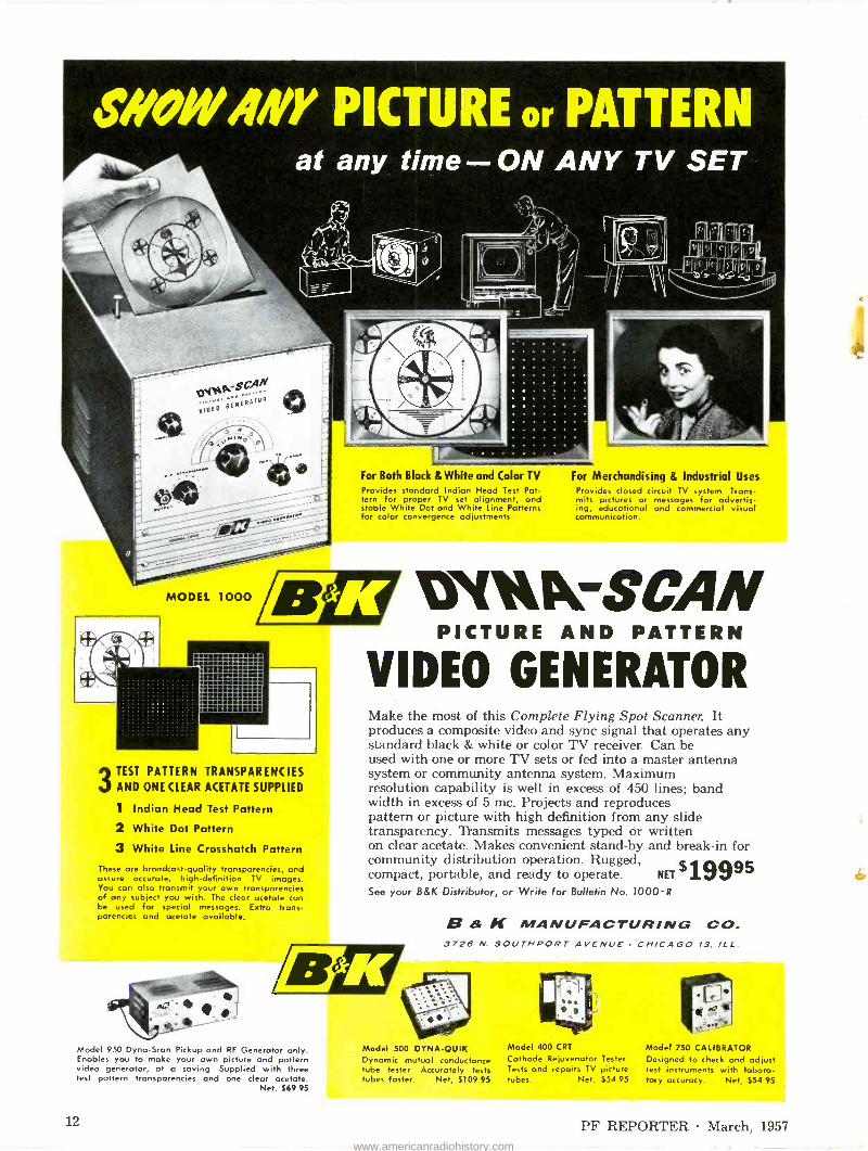
SWOIV.IiVY PICTURE or PATTERN at any time - ON ANY TV SET
3 TEST PATTERN TRANSPARENCIES AND ONE CLEAR ACETATE SUPPLIED
1 Indian Head Test Pattern
2 White Dot Pattern
3 White Line Crosshatch Pattern
These are broadcast -quality transparencies, and assure accurate, high -definition TV images. You can also transmit your own transparencies of any subject you wish. The clear acetate can be used for special messages. Extra trans- parencies and acetate available.
For Both Black & White and Color TV For Merchandising & Industrial Uses Provides standard Indian Head Test Pat- tern for proper TV set alignment, and stable White Dot and White Line Patterns for color convergence adjustments.
Provides closed circuit TV system. Trans- mits pictures or messages for advertis- ing, educational and commercial visual communication.
OsitkPerSCAN iiFRN
VI DEO GENERATOR Make the most of this Complete Flying Spot Scanner. It produces a composite video and sync signal that operates any standard black & white or color TV receiver. Can be used with one or more TV sets or fed into a master antenna system or community antenna system. Maximum resolution capability is well in excess of 450 lines; band width in excess of 5 mc. Projects and reproduces pattern or picture with high definition from any slide transparency. Transmits messages typed or written on clear acetate. Makes convenient stand-by and break-in for community distribution operation. Rugged, compact, portable, and ready to operate. NET
See your B&K Distributor, or Write for Bulletin No. 1000R
Model 950 Dyna-Scan Pickup and RF Generator only. Enables you to make your own picture and pattern video generator, at a saving Supplied with three test pattern transparencies and one clear acetate.
Net. $69.95
$19995
B 8 If MANUFACTURING CO. 3726 N. SOUTHPORT AVENUE CHICAGO 13, ILL.
Model 500 DYNA-OUIK Dynamic mutual conductance tube tester Accurately tests tubes faster. Net, $109 95
Model 400 CRT
Cathode Rejuvenator Tester. Tests and repairs TV picture tubes. Net. $54 95
Model 750 CALIBRATOR Designed to check and adjust test instruments with labora- tory accuracy. Net, $54 95
12 PF REPORTER March, 1957
www.americanradiohistory.com
5616Tak MILTON S. KIVER
Author of ... How to Understand and Use TV Test Instruments
and Analyzing and Tracing TV Circuits
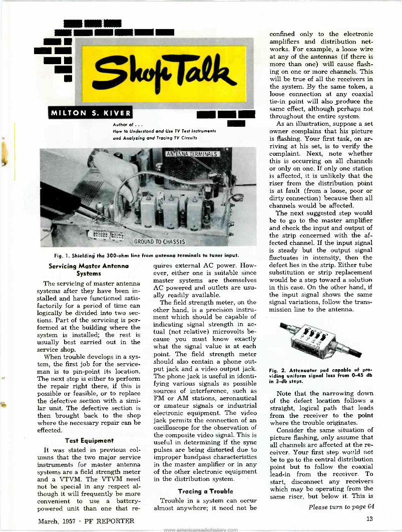
ANTEN A ERMINALS
' GROUND TO CHASSIS
Fig. 1. Shielding the 300 -ohm line from antenna terminals to tuner input.
Servicing Master Antenna Systems
The servicing of master antenna systems after they have been in- stalled and have functioned satis- factorily for a period of time can logically be divided into two sec- tions. Part of the servicing is per- formed at the building where the system is installed; the rest is usually best carried out in the service shop.
When trouble develops in a sys- tem, the first job for the service- man is to pin -point its location. The next step is either to perform the repair right there, if this is possible or feasible, or to replace the defective section with a simi- lar unit. The defective section is then brought back to the shop where the necessary repair can be effected.
Test Equipment It was stated in previous col-
umns that the two major service instruments for master antenna systems are a field strength meter and a VTVM. The VTVM need not be special in any respect al- though it will frequently be more convenient to use a battery - powered unit than one that re-
quires external AC power. How- ever, either one is suitable since master systems are themselves AC powered and outlets are usu- ally readily available.
The field strength meter, on the other hand, is a precision instru- ment which should be capable of indicating signal strength in ac- tual (not relative) microvolts be- cause you must know exactly what the signal value is at each point. The field strength meter should also contain a phone out- put jack and a video output jack. The phone jack is useful in identi- fying various signals as possible sources of interference, such as FM or AM stations, aeronautical or amateur signals or industrial electronic equipment. The video jack permits the connection of an oscilloscope for the observation of the composite video signal. This is useful in determining if the sync pulses are being distorted due to improper bandpass characteristics in the master amplifier or in any of the other electronic equipment in the distribution system.
Tracing a Trouble Trouble in a system can occur
almost anywhere; it need not be
confined only to the electronic amplifiers and distribution net- works. For example, a loose wire at any of the antennas (if there is more than one) will cause flash- ing on one or more channels. This will be true of all the receivers in the system. By the same token, a loose connection at any coaxial tie-in point will also produce the same effect, although perhaps not throughout the entire system.
As an illustration, suppose a set owner complains that his picture is flashing. Your first task, on ar- riving at his set, is to verify the complaint. Next, note whether this is occurring on all channels or only on one. If only one station is affected, it is unlikely that the riser from the distribution pbint is at fault (from a loose, poor or dirty connection) because then all channels would be affected.
The next suggested step would be to go to the master amplifier and check the input and output of the strip concerned with the af- fected channel. If the input signal is steady but the output signal fluctuates in intensity, then the defect lies in the strip. Either tube substitution or strip replacement would be a step toward a solution in this case. On the other hand, if the input signal shows the same signal variations, follow the trans- mission line to the antenna.
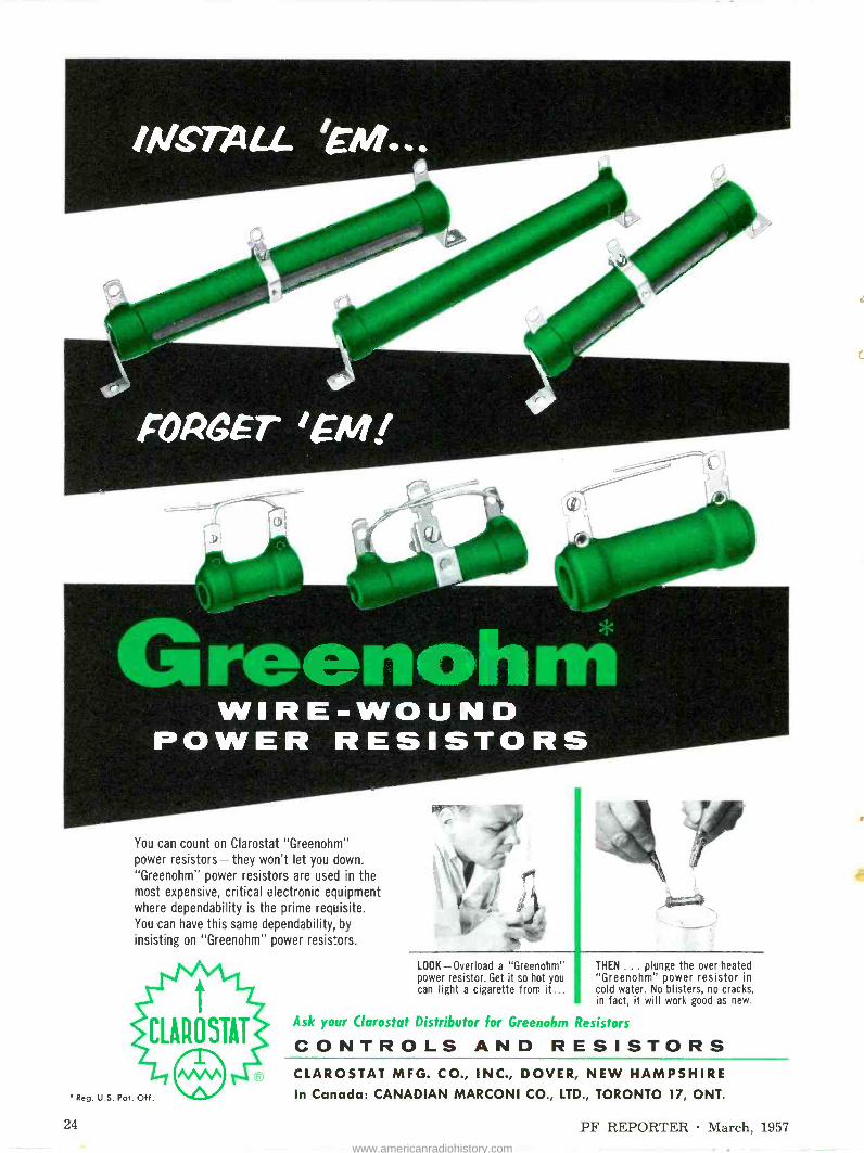
Fig. 2. Attenuator pad capable of pro- viding uniform signal loss from 0-45 db in 3 -db steps.
Note that the narrowing down of the defect location follows a straight, logical path that leads from the receiver to the point where the trouble originates.
Consider the same situation of picture flashing, only assume that all channels are affected at the re- ceiver. Your first step world not be to go to the central distribution point but to follow the coaxial lead-in from the receiver. To start, disconnect any receivers which may be operating from the same riser, but below it. This is
Please turn to page 64
March, 1957 PF REPORTER 13
www.americanradiohistory.com

Even though an AM radio is a comparatively simple unit compared to a TV receiver, this picture story of a typical radio alignment may be of interest to those of our readers who, in the flurry of TV servicing these recent years, have lost contact with radio work. To many, it will serve as a nostalgic reminder of "the good old days" be- fore TV, and to our younger readers it should provide
e much basic, useful infor- mation-particularly in view of the increasing numbers of radios being purchased by consumers. e
ALIGNMENT POINTS
On this chassis photograph of a five - tube AC -DC superheterodyne radio, the alignment points are numbered in the order in which they should be adjusted for best results.
A6
MIXER
A5
A3
A4
OSC BOTTOM BOTTOM
METER CONNECTION Disconnect one side of the secondary of the output transformer from the voice coil; and connect the leads of the meter (low range AC) across the secondary of the output transformer. The meter will act as a sensi- tive indicator, and at the same time disturbing sound from the speaker will be eliminated.
SIGNAL GENERATOR CONNECTION Couple a 455-kc signal to the external connection on the loop antenn'.s, using a ..05-mfd capacitor in series with the signal -generator Izad, and connect the ground lead of the generator to B-. (If no external connection is provided, connect the signal to the grid, generally pin 7, of the converter tuke.) Plug the radio into an isolation transformer-for :.afety-and turn it on.
14 PF REPORTER March, 1957
www.americanradiohistory.com

IF ADJUSTMENTS
After the receiver has warmed up for about 10 minutes, adjust the two IF transformers (four slugs). Start with Al and proceed in order through A4, adjusting each to produce the highest reading on the meter. Maintain the generator output at the lowest possible level which still provides an indication on the meter.
SIGNAL COUPLING
Loosely couple a 1640-kc signal to the loop antenna by clipping the signal lead to the loop and the ground lead to B-. If a direct connection is impossible or un- desired, the signal may be coupled to the antenna by fashioning a coil about 6" in diameter consisting of 3 or 4 turns of wire. Connecting the signal generator to the ends of the coil will produce radiations which will be picked up by the loop of the receiver.
RF ADJUSTMENTS
With the tuning gang fully open, adjust the oscillator trimmer (A5) to produce a maximum reading on the meter. Turn the tuning gang and the signal generator to 1400 kc and adjust the mixer trimmer (A6) to pro- duce a maximum reading on the meter.
TRACKING ADJUSTMENTS
With the tuning gang fully closed, tune the signal gen- erator through 550 kc to produce the highest reading on the meter. If the generator dial reads higher than 550 kc, bend the slotted plate on the oscillator section (smallest one) slightly inward to increase capacity and lower the oscillator frequency. Bend the tab on the end of the plate which meshes with the stator (stationary) plates last. If the dial reads lower than 550 kc, do just the opposite-bend the plate outward to reduce the capacity and increase the frequency. Some receivers employ a tunable oscillator transformer which can be used for low -end tracking. Adjust the oscillator trans- former at 550 kc and the trimmer at 1640 kc in this cose.
:March. 1957 PE REPORTER 15
www.americanradiohistory.com

The average service shop is usually well equipped to handle any and all repairs involving con- ventional radio and television re- ceivers. These same shops, how- ever, may soon find themselves somewhat unprepared when a customer comes walking in with a portable transistor radio in his liand. When he claims the radio doesn't work and wants you to fix it-just where do you begin? If you are not yet familiar with the design, operation, and service pro- cedures associated with transistor radios, you had better get with it!
In the first place, portable tran- sistor radios are very compact in design, as shown in Figs. 1 and 2. This feature alone is liable to give many technicians a headache. The moment the miniature chassis is removed from its case, care must be taken not to damage any of the small parts or delicate wires. You may eventually find yourself working somewhat like a watch- maker, using small tools and ex- ercising great care when testing, probing, and replacing circuit components.
Batteries The battery pack of a transistor
radio differs from that normally found in conventional portable re- ceivers in that only one source of
ORKING WIT
TRAN STOR
y Leslie D. Deane
Fig. 1. Compactness of transistorized portables is illustrated by this view of a Regency Model TR -1-G with case removed.
16
Fig. 2. Accessibility to test points on this Regency Model TR -6 is achieved by removing speaker panel and protective shield.
PF REPORTER March, 1957
www.americanradiohistory.com

voltage is usually required in a transistorized unit, whereas the tube -type portable requires both an "A" and a "B" battery. The reason for this, naturally, is that transistors have no need of fila- ment or heater voltage and the "A" supply can be eliminated. The lower operating potentials re- quired by transistor circuits also call for a reduction in the "B" battery voltage. Instead of "B" voltage in the neighborhood of from 40 to 90 volts, the new tran- sistor power packs range from only 6 to 221, volts. The most popular battery used in transistor portables today seems to be the 9 -volt variety.
Another difference between transistorized and conventional portable radios is that the "B" supply voltage in a transistor unit may be negative in polarity. This design feature stems from the fact that some transistors (p -n -p types) require a negative operat- ing potential. The n -p -n units, however, require an operating voltage which is positive in polarity.
If the battery in a transistor set has its positive terminal con- nected to chassis ground and its negative terminal to the "B" sup- ply line, then the set is probably using p -n -p type transistors. Al- though both types may be found in the same chassis, the polarity of the battery will naturally govern all meter connections when volt- age measurements are taken.
Worn out batteries will un - undoubtedly be the most frequent cause of trouble in transistor radios, although battery life should be considerably longer than in tube -type portables be- cause of the lower current drain through transistors. Most of you are familiar with the zinc -carbon batteries which have long been used as a source for DC voltages; however, many of the transistor portables are using mercury units. As far as practical servicing goes, the. technician need not, however, be too concerned with this factor. To make a conclusive check of a battery's condition, it will pay to try a new battery or to power the set with a battery eliminator to see if receiver performance is im- proved. Should a battery be com- pletely dead, always check for a
Fig. 3. Commercial -type DC supplies for operating transistor portables.
short circuit to prevent damage to the equipment. When a customer's set has several batteries connected in series or in parallel, they should all be replaced at one time.
Disassembly and Tools
The compact design of these miniature radios plays an im- portant part in determining the proper trouble -shooting approach to use. The technician may find it necessary to disassemble certain panels and shields before perform- ing various tests on the small chassis. For the set pictured in Fig. 1, it was necessary to remove the speaker assembly before cer- tain test points were accessible. In another example, shown in Fig. 2, it was necessary to re- move both the speaker mounting panel and the metalized shield covering the printed -wiring side of the chassis. Only by removing these items was it possible to make voltage and resistance measurements and follow a log- ical trouble -shooting procedure.
Until you become completely familiar with transistor radio cir- cuits, it is suggested that a sche- matic diagram be used when trouble shooting. Even though the technician may be capable of dis- tinguishing the various stages without a schematic, it is impera- tive that he be absolutely sure of all test points so as not to damage the delicate components involved.
As the technician continues to service transistor radios, he will
certainly find it advantageous to have the proper tools available. A low -wattage soldering iron with a small tip is one item which should definitely be on the tran- sistor service bench. An iron of approximately 25 watts is ideal for this application and will be less likely to cause damage to cir- cuit components. Small diagonal side -cuts, needle -nose pliers, a pair of tweezers, and a conven- tional soldering aid will also come in handy when servicing these miniaturized assemblies.
Bench Power Supplies
It would be costly for the serv- ice shop to stock a complete line of portable batteries suitable for testing different transistor sets; therefore, it is suggested that a variable DC power supply be used. Such an apparatus can either be built by the technician or ob- tained from a commercial source. A battery eliminator designed for auto -radio servicing can be used to power transistor radios if its ripple content is low enough. The instrument shown in Fig. 3A will supply adequate test voltages but, at the same time will introduce a certain amount of AC hum in the receiver. The hum or buzz, how- ever, will not be too noticeable on strong signals. The DC power sup- ply pictured in Fig. 3B has greater control over AC ripple than the conventional battery eliminator. Designed especially for transistor auto radios, this particular unit provides two variable DC ranges -one from 0-8 volts and the other from 0-16 volts.
A suitable power supply will enable the technician to: (1) check operation of the set with- out its battery, (2) test a battery by using the supply voltage as a substitute, (3) perform long oper- ational tests without using up the life of a good battery and (4) check sensitivity and output at supply voltage levels ranging from low to normal. When apply- ing power to the battery contacts, double-check the terminal polari- ties and make sure the variable supply is set for minimum output. In addition, never insert or re- move circuit components while voltage is applied to the set. Surge currents may result in permanent damage to the transistors.
March, 1957 PF REPORTER 17
www.americanradiohistory.com

1ot chassis s eguards
FEATURES IN AC -DC SETS
by Thomas A. Lesh
Manufacturers take various precautions to protect the cus- tomer and the service technician from being "bit" by line voltage in TV sP.ts which have one side of the AC line connected to the chassis. Anti -shock features are provided by isolating the main chassis from exposed metal parts on the outside of the cabinet. It is up to the technician to ensure that these safeguards are not made in- effective as a result of receiver servicing.
Several methods of insulating "hot" chassis are demonstrated in the accompanying photographs. Ingenious white plastic grommets serve as anchors for the brackets or screws used to fasten the chas- sis to the cabinet in the majority of new AC -DC television sets. Fig. 1 includes a side view of one of these grommets. Notice that it is composed of a ring of plastic having a narrow neck which is split into two parts. In mount- ing the grommet, the halves of the neck are pressed together so that it can be pushed through a hole in the chassis. When released, both parts of the neck spring apart and hold the grom-
met loosely in place. When a screw is driven through the hole in the center of the grommet, it exerts pressure and spreads the plastic neck pieces so they fit tightly against the chassis. The cabinet or other part to be insu- lated rests against the plastic ring, spaced at a safe distance from the "hot" chassis. The screw is also insulated; thus, there is no risk of getting a jolt from exposed screw heads or metal trim.
The shafts of the operating con- trols on many AC -DC sets are not insulated because they are in- tended to be covered with knobs during normal operation. Al -
PLASTIC CONTROL SHAFT
-."9"" CHASSIS MOUNTING BRACKET
PLASTIC GROMMET
Fig. 1. Plastic grommet and control shaft in Crosley Model AT10B.
though the serviceman will often handle these controls with the knobs removed, particularly when working on the bench, he is ex- pected to use an isolation trans- former under those conditions- not only to keep the chassis sepa- rate from the power line, but also to simplify the interconnection of test equipment. Controls such as those used to adjust height and vertical linearity present a differ- ent situation, however. Since these controls often must be ad- justed on home service calls when it is inconvenient to use an isola- tion transformer, they are usually insulated from a "hot" chassis in some fashion.
Plastic shafts are used on the service controls in many AC -DC sets. (See Fig. 1.) If a control of this type becomes defective, it should be replaced with a similar unit for the protection of techni- cians who might work on the set in the future. Several manufac- turers of replacement controls have marketed products with in- sulating plastic shafts. The Cen- tralab Type AK -19 nylon shaft is made to fit the Type AB Adashaft controls made by that company. Clarostat makes an RN -3 plastic shaft for use with Type A47 Pick -A -Shaft controls. Interna- tional Resistance Co. offers a plastic shaft designated TQ which is a companion to IRC Type Q controls. P. R. Mallory has two kinds of replacement controls with fixed phenolic shafts-the Type SU (bushing -mounted) and the Type PTA (tab -mounted) .
Plastic shafts are required for insulation only if the body of the control is mounted directly to a "hot" chassis. There are several ways to mount ordinary metal - shaft controls in order to isolate them from the power line. For ex- ample, they may be placed on a chassis section that is separated from the main chassis by some in- sulating material. One such ar- rangement, shown in Fig. 2, is the "cold" control panel of an Ad- miral portable receiver, which is fastened to the rest of the chassis by means of plastic grommets.
Another partially insulated chassis (see Fig. 3) is used in a new Westinghouse receiver. Printed wiring boards and sec- tions of "hot" chassis are sup -
18 PF REPORTER March, 1957 www.americanradiohistory.com

RC NETWORK
1 HOT CHASSIS
7 -
CONTROL PANEL
Fig. 2. Isolated metal control panel in Admiral
ported on a U-shaped frame which is "cold" because all the points of support are insulated. Cabinet bolts are fastened to this "cold" section. Some of the service con- trols are attached to the frame, and others are mounted on the printed wiring board which also serves as insulation from the AC line.
The insulated metal sections which have just been described do not "float" electrically; instead, they are connected to the main portion of the chassis through a resistor of a few hundred thou- sand ohms paralleled with a ca- pacitor. This RC network (visible in Fig. 2) maintains a safe degree of insulation while preventing the buildup of an electrostatic charge between the "hot" and isolated sections of the chassis.
Insulated control panels of an- other type are shown in Fig. 4.
The main purpose of this type of construction is to make possible the mounting of controls in the upper front corners of the cabinet, some distance from the main chassis. Electrical insulation of the controls is actually a second- ary benefit. Remote-subchassis ar- rangements are also used in some transformer -powered sets.
These isolated metal panels should never be used to ground the common leads of test instru- ments or to discharge the high - voltage supply. When high voltage is arced to an isolated subchassis instead of B-, the subchassis may become charged. Dissipation of this charge can take place only by high -resistance leakage, by breakdown of insulation, or by ac- cidental contact between the iso- lated chassis and B-.
G GROMMETS
BUSHING
Model TS104.
HOT
INSULATING GROMMET
INSULATING FIBER
STRIP AND GROMMET
Fig. 3. Isolated control panels in Westinghouse Model H21T107.
Another type of insulator used to keep line voltage away from control shafts is made of a fiber material. The shafts of tuners often contain fiber sections so that the outer tips will be insulated even though the tuner body itself is mounted to the main chassis and thus connected directly to one side of the AC line. There are
Fig. 4. Separate control subchassis in Crosley Model AT10B.
(A) In Hotpoint Model 14S201;
FIBfP PANEL
(B) In Magnavox Model V19-02AA.
Fig. 5. Control -mounting panels made of fiber material.
some sets in which adjacent sec- tions of the chassis are insulated by a fiber "sandwich." Special grommets are then used to insu- late the rivets or screws that hold the two sections together. This type of construction was utilized in the chassis shown in Fig. 3.
Small fiber sections may also be riveted to a metal chassis to serve as control -mounting panels. Two examples of these are shown in Fig. 5. Some panels such as the one in Fig. 5A 'are mounted so that the insulating material can be easily recognized as such, while others (Fig. 5B) are small chassis inserts which are harder to spot at first glance.
Summary
Most AC -DC television sets use shock protection for exposed parts, but the technician who is servicing an unfamiliar receiver of this type should not take for granted that protection has been provided. After a job is done, he should be sure that insulation re- mains effective so that the set will not be a booby trap for an unwary customer or the next technician to service the unit. Resistance meas- urements between insulated sec- tions or voltage readings between exposed metal parts and absolute ground provide effective safety checks.
Avoid replacing plastic control - shaft units with ones having un - insulated metal shafts, and check to be sure that loose items such as blobs of solder or small washers are not lodged between chassis sections where they can bridge across insulation. Customers and technicians will both live longer that way! A
March, 1957 PF REPORTER 19
www.americanradiohistory.com

19. eettaierkette, 14 OVA etbeikth4! *
FASTEST SELLING TUBE TESTER
IN THE WORLD
cté otei. 95 O F A L L
POPULAR TV TUBES -IN SECONDS Accurately makes each tube test in seconds Checks average TV set in minimum minutes
Tests each tube for shorts, grid emission, gas content, leakage, and dynamic mutual conductance.
Ingenious life test detects tubes with short life expectancy.
One switch tests everything. No multiple switching. No roll charts.
Shows tube condition on "Good -Bad" scale and '.n micromhos. Large 41/2 -inch plastic meter has two highly accurate scales calibrated 0-6000 and 0-18,000 micromhos.
Automatic line compensation is maintained by a special bridge that continuously monitors line voltage.
Built- n 7 -pin and 9 -pin straighteners are mounted on the panel.
* NAMES ON REQUEST
Makers of Dyna-Ouik, CRT,
Dyna-Scan and Calibrator
B a K MANUFACTURING CO. 3726 N. Southport Ave. Chicago 13, Illinois
tW o ,tale haie for atlä
one
one et
Shop
house calls
"Paid for itself several times.
Really indispensable."
"Best tube tester I've
ever owned.
Simple to operate. Saves time."
"Makes lots of money for us.
Wonderful instrument."
MODEL 500
DYNAMIC MUTUAL CONDUCTANCE TUBE TESTER
One extra tube sale on each of 5 calls a day pays for the Model 500 in 30 days
Enthusiastic comments like those above come from servicemen all over the country. Actual experience shows an average of close to 2 additional tube sales per call. Instead of the "trial and error" method of substitution testing, the Dyna-Quik 500 quickly detects weak or inoperative tubes. Cuts servicing time, saves costly call-backs, shows each customer the true condition and life expectancy of the tubes in the set, and makes more on -the -spot tube sales. Helps keep customer good -will, give a better service guarantee, and make more profit. The B&K Dyna-Quik 500 measures true dynamic mutual conductance. Completely checks tubes with laboratory accuracy under actual operating conditions right in the home ...in a matter of seconds. Saves time and work in the shop, too. Simple to operate. Easily portable $1 O A 95 in luggage -type case. Weighs only 12 lbs. NET. 7 See Your B&K Distributor or Write for Bulletin No. 500-R
Model 1000 DYNA-SCAN Picture and Pattern Video Generator. Complete Flying Spot Scanner. Net, $199.95
Model 400 CRT
Cathode Rejuvenator Tester. Tests and repairs TV picture tubes. Net, $54.95
Model 750 CALIBRATOR Designed to check and adjust test instruments with labora- tory accuracy. Net, $54.95
20 PF REPORTER March, 1957 www.americanradiohistory.com

REMOTE
TUNING
WITHOUT
WIRES A Close Look at
Motorola and Zenith
Remote Controls by Thomas A. Lesh
"Relax in your easy chair and tune the TV set by remote con- trol" is potent sales talk, and set manufacturers have been devot- ing considerable energy, lately to the development of remote tuning devices. The majority of these units are connected to the TV receiver by a cable. Such systems have the advantage of being ex- tremely simple electrically, but the long cable run may be awk- ward. In addition, remote opera- tion is for the most part restricted to one general area. These draw- backs have been overcome in at least two different types of wire- less remote control systems that have been produced this year. One (Zenith) uses supersonic waves as a control medium, and another (Motorola) employs low - power RF radiation. Both are
Fig. 1. Zenith "Space -Command 400" operate hammers which strike tuning rod
relatively complex in construction but highly convenient to use.
Zenith "Space -Command" Some 1957 Zenith sets are
equipped with an acoustically operated device called "Space - Command." The essential parts of this system are as follows: 1. A small, hand-held transmitter
(Fig. 1) equipped with tuning rods which, when struck, will vibrate at supersonic frequen- cies near 40 kc.
2. A capacitor -type microphone on the front of the TV set to pick up the supersonic vibra- tions and convert them to RF energy.
3. A control receiver inside the TV set to amplify and detect the RF signals.
4. Relays to make or break switch
6AL5
TAP ON TV
PWR. TRANS.
- 6CM7 RELAY CONTROL
6 "CLOCKWISE' RELAY
r'--á
1 MEG
"MUTE" BI -STABLE
RELAY
T 0
r
E250 ACROSS IN SERIES WITH
MOTOR SWITCH SPKR. VOICE COIL
250 V
Fig. 2. Discriminator and relay -control circuits of Zenith "Space -Command 200" control receiver. Output of 6AL5 is positive and drives 6CM7 into conduction.
March, 1957 PF REPORTER
transmitter removed from its case. Keys s.
contacts and perform the de- sired tuning functions.
There are two versions of the "Space -Command" system. A de- luxe "400" model features a 4 -rod transmitter with which the user can turn the set on and off, mute the sound, and rotate the channel selector either clockwise or counterclockwise. The control re- ceiver in the TV set used with this model contains 8 tubes. A simpler two -rod system called the "200" performs only the functions of muting the sound and turning the channel selector in a clockwise di- rection. A narrow-bandpass, 5 - tube control receiver is included in the "200" system.
Details of construction in the "400" transmitter can be seen in Fig. 1. The rods are supported at the center by spring -wire clamps. Each tuning key is linked to a small hammer in such a way that pressure on the key causes the hammer to be cocked. As soon as the key is fully depressed,- a re- taining spring is released and the hammer strikes the bottom end of a rod. This causes supersonic vibration of the rod, accompanied by a slightly audible "ping." The rods all have different resonant frequencies, given in Table I. The "200" transmitter is similar to the "400" in all respects except that it
Please turn to page 74
21
www.americanradiohistory.com

Independent Service Dealers:
TV-RADIO SERVICE IS YOUR BUSINESS
SERVING YOU IS OUR BUSINESS
That's why we say, use Raytheon TV and Radio Tubes for your replacement work. We have no
"captive service"organizations to compete with you for TV and Radio service business - we
leave the service business to you.
Serving you is our only interest.
First, we serve you with the finest TV and Radio Tubes - Raytheon Tubes designed to
meet the varying needs of the many set manufacturers and
`,tritt
perform perfectly in all makes
and models of sets.
Second, we serve you Raytheon Tubes promptly and efficiently
through a network of inde-
pendent Raytheon Tube Dis-
tributors with trained personnel eager to help independent dealers in every way.
Third, we serve you with the ex-
clusive Raytheon Bonded Elec-
tronic Technician Program. If you can qualify, you become
part of a nationally recognized and advertised organization, yet you retain your own inde- pendence. As a Raytheon Bonded Electronic Technician, you're identified as a dependable busi- nessman capable of fast, effi-
cient TV and Radio service on all makes and models of sets. You will have the exclusive Western Union "Operator 25" tie-in bringing business to you,
along with many other impor- tant advantages.
Ask your Raytheon Sponsoring Bonded Tube Distributor to give you the Raytheon Bonded story.
RAYTHEON MANUFACTURING COMPANY Receiving and Cathode Ray Tube Operations
Newton, Mass. Chicago, Ill. Atlanta, Ga. Los Angeles, Calif.
Raytheon makes Receiving and Picture Tubes, Reliable Subminiature and Miniature Tubes, ail these Semiconductor Diodes and Transistors, Nucleonic Tubes, Microwave Tubes.
aAYTHEó
excellence in el®alwnico
22 PF REPORTER March, 1957
www.americanradiohistory.com

Fig. 1. Win-Tronix Model 825 Dynamic AGC Circuit Analyzer. The unit cuts time in servicing AGC systems.
AGC Trouble Shooting
Pictured in Fig. 1 is the Win- Tronix Model 825 Dynamic AGC Circuit Analyzer, manufactured by Winston Electronics, Inc. and especially designed for trouble- shooting television AGC systems. The instrument actually combines a signal generator, VTVM and variable bias supply into one .port- able unit.
Specification features are: 1. AGC Test Signal - RF signal
with 15 kc sync -pulse modula- tion, variable output from zero to 500,000 microvolts, preset for channel 2 and adjustable for channels 2 through 4.
2. Vacuum Tube Voltmeter and Ohmmeter - available scales are 15-0-10 volts DC, center zero; 300-0-300 volts DC, cen- ter zero; 0-800 volts peak -to - peak; 0-250 volts AC (RMS); and 0-10 megohms.
3. AGC Bias Supply - variable DC output from +1 to -15 volts. I recently had the opportunity
to examine a Model 825 AGC Analyzer in our lab. Since the checks I made were under typical service shop conditions and on conventional TV receivers, I thought you, the reader, might like to follow me through on some of the tests I performed with this particular instrument.
Naturally, my first step was to read over the operating instruc- tions completely. In doing so, I
EST UIPME
Lates n orma ion on pp ¡cation, Maintenance and Adaptability
of Service Instruments
i... e s
Fig. 2. Pattern produced on the screen of a the Win-Tronix analyzer.
found the instrument was de- signed for testing AGC systems in several different ways. By us- ing the proper test leads and placing the function switch in the correct position, one can monitor the AGC voltage at various test points, check the gating pulse at the AGC keyer tube, substitute a variable DC bias for the AGC voltage, or check AGC action by using the RF signal generated within the unit.
I decided to fire up one of the older TV test chassis and check its AGC action both on local sta- tions and on our own closed- circuit signal. After turning the analyzer on, I placed the function switch in the 15-0-10 VDC posi-
I). Deane
late model TV by the RF signal from
tion and zeroed the meter with test leads open.
I connected the meter cables to the AGC line and chassis ground and monitored the AGC voltage under both strong and weak signal input conditions. I could detect no trouble symptoms in the picture and the action of the AGC voltage appeared nor- mal.
In order to simulate a trouble, I disconnected the AGC line from the IF and tuner sections of the receiver. Selecting a signal from a local station, I found the pic- ture would pull horizontally and overload almost to the point of negative phase. I then connected
Please turn to page 79
March, 1957 PF REPORTER 23
www.americanradiohistory.com
INSTAL[.
-
FORGET 'EM!
WIRE -WOUND POWER RESISTORS
You can count on Clarostat "Greenohm" power resistors - they won't let you down.
"Greenohm" power resistors are used in the most expensive, critical electronic equipment where dependability is the prime requisite. You can have this same dependability, by
insisting on "Greenohm" power resistors.
t CLAROSTAT
Reg. U.S. Pat. Off.
LOOK - Overload a "Greenohm" THEN ... plunge the over -heated power resistor. Get it so hot you "Greenohm" power resistor in can light a cigarette from it... cold water. No blisters, no cracks,
in fact, it will work good as new.
Ask your Clarostat Distributor for Greenohm Resistors
CONTROLS AND RESISTORS CLAROSTAT MFG. CO., INC., DOVER, NEW HAMPSHIRE In Canada: CANADIAN MARCONI CO., LTD., TORONTO 17, ONT.
24 PF REPORTER March, 1957
www.americanradiohistory.com

RESONANT CIRCUITS
°s 25.: me IF AMP. 0 6016
Fig. 1. Input circuit of IF amplifier.
AMP S
.09
by Calvin C. Young, Jr.
Fig. 2. Frequency response curves for
.08 APPLIED E
CURVES 1V
01
FOR'BOTH
.06 CURVE A
.05
.04
.03
02 , CURVE B
01
FRE9UENCY IN MC.
21.5 21.5 series resonant circuits. Curve A repre- 18.9 19.95 21 22.05 23.1 sents a high -Q and curve B, a low -Q.
10 5 0 5 :0 %OFF RESONANCE
CHART 1-Data for Fig. 2
Curve A Curve B
Resonant Frequency 21 mc 21 mc
Inductance 7.51.4h 7.5µh Capacitance 7.7 mmf. 7.7 mmf. Resistance IF Coil 10 S2 100 S2
q 99 9.9
XL Xc Z XL Xc Z
18.9 mc 8900 1085 2 200 0 890 2 1085 S2 223 0
19.95 mc 935 0 1035 52 100 0 935 2 1035 0 14152
20.5 mc 960 0 1010 2 51 S2 960 9 1010 2 112 0
21 mc 990 2 990 2 10 SZ 990 2 990 0 100 0
21.5 mc 101012 96012 5112 1010S2 96052 11252
22.05 mc 103512 93512 10012 103512 9350 141 2
23.1 mc 1085 0 890 0 200 52 1085 2 89012 223 0
The resonant frequency of a series tuned circuit, the figure of merit or Q of a coil, and the Q of a cir- cuit are each bits of information with which the practicing service technician should be familiar. The best reason that can be given for this statement is that a basic knowledge of these electrical properties is a big help toward the intelligent servicing of cir- cuits such as traps, peaking net- works, coupling circuits, etc. So here are the facts in concise and easily digestible form.
Series Resonance The resonant frequency of a
series tuned circuit may be cal- culated using the formula:
fn = 159 (4)
V LC
where f5 = resonant frequency in kilocycles,
L= inductance in microhenries, C = capacitance in microfarads.
The value of the capacitor is always easy to obtain (color code or value on schematic diagram) but the inductance of a coil may or may not be given; therefore, if the above formula is to be used to determine the resonant fre- quency of a circuit, the value of inductance may have to be ob- tained by measurement with a Q meter or impedance bridge, both of which are laboratory type test instruments. Series resonant cir- cuits are generally used in a tele- vision receiver as traps, and the proper resonant frequencies of these networks may usually be found by consulting the alignment instructions.
If the resonant frequency and the value of capacity in a series resonant circuit are known, the value of inductance may be cal- culated using the formula:
25,300 (5) fR'C
where L = inductance in microhenries, fit = resonant frequency
in kilocycles, C = capacitance in microfarads.
Please turn to page 70
March, 1957 PF REPORTER 25
www.americanradiohistory.com

FROM DELCO RADIO come the speakers with highest performance. You trust them ... so
do your customers! Engineering skills of Delco Radio and General Motors com- bine to offer a full line of speakers for home and auto radios, phonographs, TV, and Hi-Fi. National advertising behind the Delco Wonder Bar Radio develops a bigger service market for you! For fast service call your UMS -Delco Electronics Parts Distributor. 14 Standard Models: Designed and built to R.E.T.M.A. standards with heavily plated metal parts and Alnico -V magnets. Precision felted cones give uniform response over full operating frequency range. All are fully dustproof and dependable. Dual -Purpose Hi-Fi Model 8007: A superior speaker for custom-built audio systems and for replacements in AM, FM, TV and phonograph sets. Size 8", 50 to 12,500 CPS frequency range; Alnico -V magnet; 10 -watt power rating; 4.1 v.c. impedance; 13,,," voice coil.
DELCO W O hi 0. 0 A
RADIO DIVISION OF GENERAL MOTORS, KOKOMO, INDIANA
GM A GENERAL MOTORS PRODUCT -A UNITED MOTORS LINE
Distributed by Delco Electronic Ports Distributors
A complete line of original equipment service parts from the WORLD LEADER I N AUTO RADIO
26 PF REPORTER March, 1957
www.americanradiohistory.com

STILL MORE
NEW TUBES
To Keep You Up to Date, Hirt; s Important Data
on Some Unusual Tubes in a Shi Portable TV Set
Typical of the many new de- velopments constantly being made in picture -tube and receiving -tube design are the new tubes which appear in the General Electric Model 9T001 portable TV set. The surprisingly Iight weight of the 9QP4 picture tube-only about 2
pounds-is made possible by a new construction technique. In- stead of having a separate cone and faceplate, this tube has a one-piece bell which is made by the same process used to manu-
facture bottles. A separately made neck is sealed to the bell, and the anode lead is brought out to the tube base. Anode operating volt- age is approximately 5.5 kv. The 9QP4 has 40 sq. in. of viewing area, 70° deflection, and electro- static focusing.
The G -E 9" portable receiver utilizes 8 special new tube types which were designed for series - string operation with only 300 -ma heater current. Two older types are also used-a 1V2 high -voltage
rectifier, and a 7AU7 with both halves of the heater wired in series to permit 300 -ma operation. The advantages of the relatively low heater current lie not only in reduced power consumption but also in lower heat dissipation. The 300 -ma tubes help the manufact- urer to design an extremely com- pact portable receiver that will not tend to overheat.
Three of the new tube types (9U8, 6CB6A, and 6AU6A) are redesigned versions of old types, with heater voltage or warm-up time changed to conform to new standards. The other five 300 -ma types are completely new. Their base diagrams are presented at the bottom of this page.
The tuner contains a 6CE5 RF amplifier and a 9U8 converter. The two IF amplifiers are 6CB6A tubes. A 12CT8 is used as a video amplifier (pentode section) and sync clipper (triode section) . The sound section consists of a 6AU6A IF stage, a pair of crystal diodes connected as a ratio detector, and a 1008 which serves as an audio amplifier and output tube. An- other 1008 is the vertical oscilla- tor and output tube. A 7AÚ7 horizontal multivibrator drives an 18A5 horizontal output tube, and the damper is a 17H3. The set has a total complement of 12
receiving tubes. The cabinet of the Model 9T001
is divided into three parts. Two of these are shown in the illustra- tion-the front panel attached to the picture tube, and the bottom board upon which all other com- ponents are mounted. These sec- tions are fastened together by snaps which are locked in place by a sliding bar. The third section of the cabinet is a cover, fastened in place by 8 screws. It is re- movable to provide access to tubes and other components for servicing. A
27
6CE5
RF AMP.
5
34
1OC8
V.OSC. & OUT. or AF AMP. & OUT.
12CT 8
SYNC VIDEO
CLIPPER AMP.
17H3
DAMPER
J3,8
45
18A5
HORIZ. OUT.
51
Base Diagrams of 300 -Ma Series -String Tubes
March, 1957 . PF REPORTER 27
www.americanradiohistory.com

mutual conductance tube tester transistor checker germanium diode tester selenium rectifier tester
MODEL 3423
Triplett Tube Tolerance Computer-permits model 3423 users to check tubes for critical circuits closer than the approximately 35% below tube manual value as shown on the roll chart.
Simple use quickly determines micrombo reading required for selecting applicable tubes for such as oscillator circuits that call for tubes within 10% of the manual value.
Available to all present and future users.
Here is the ultimate in a tube tester for today and tomorrow. A 4 in 1 value that checks for accuracy as the circuit demands depend- ing on the tolerance of the circuit. Model 3423 will give you no false readings to waste time. The patented circuit for the tube testing employs actual
TuMTileranceCompater
Zs._. _,.,.-
$199.50
MODEL 3413B ... $19.50 The first low priced tube tester to provide
dual sensitivity for short test
Triplett model 3413-B combines provision for conventional short test (0.25 megohms) with high sensitivity leakage test (2.0 megohms) - will test series string tubes without adapter. No one piece of equipment can do more for you. As the electronic field ex- pands your tube tester must do more. TRIPLETT TUBE TESTERS meet this demand. More heater voltages including 3.15, 4.2 and 4.7 volts for 600 mill series string heaters. Quickly locating the bad tubes saves time. Tube sales can be a profitable business in itself.
Burton browny advertising
signal (4KC) for grid and DC bias voltage making it independent of line voltage hum. It also has a complete coverage of all tube types-six plate voltages (including 0-10 variable). Micromhos scales read 0-1800, 0-6,000, 0-18,000 and 0-36,000. Leakage meas- ured directly on meter 0-10 megohms. Quick development of new types of tubes can obsolete any tester tomorrow that does not have the multiple switching arrangement of Model 3423 which allows making any combination of tube connec- tions. Ask your parts distributor to demonstrate the many other extra features of this foremost tube tester.... Triplett automatically furnishes revised, up-to-date roll charts regularly if you promptly return registration card. (Included with tester.)
TRIPLETT ELECTRICAL INSTRUMENT COMPANY BLUFFTON, OHIO
28 PF REPORTER March, 1957
www.americanradiohistory.com

The following chart is presented as a guide for the maintenance of an up-to- date stock of television receiving tubes. The figures in the chart are expressed as proportions based on a total of 1,000 tubes. For example, if the figure 6 is given for a particular type of tube, this means that six out of every 1,000 tubes in television receivers now in service are of that type. The minimum entry is 0.5 per 1,000, rounded off to 1.
A cumulative record is kept of the tubes used in new models of receivers. The resulting figures are adjusted to take into account the quantities of pro- duction of different models and the re- tirement of old sets at an estimated average age of six years.
In most cases, combined listings are given for redesigned "A" and "B" tube types and their prototypes. Some of the most recent designs should be kept in stock, and it is usually practical to stock the latest version exclusively.
The listing of a large figure for a par- ticular type of tube is not necessarily a recommendation for stocking that num-
ber of tubes. (Some consideration should be given to the frequency of failure of the tube.) A large figure does indicate that the tube is used in many circuits and emphasizes the necessity for maintaining a sufficient stock to fill requirements between regular tube orders.
NOTE: The 0.5 -per -1,000 minimum figure is somewhat lower than that which has been used in the past. This reduction was made so that the chart will more quickly reflect the relative popularity of the enormous number of new tube types being placed on the market. The previously -used separate listings for pre -freeze and post -freeze areas have lost much of their former significance, and they have been merged for simplicity's sake. UHF tuner tubes are no longer being listed, due to their limited application; but color re- ceiver tubes will continue to be listed as they reach the 0.5 -per -1,000 percent- age -of -use figure.
TUBE TYPE
NO. OF UNITS
TUBE NO. OF TYPE UNITS
TUBE NO. OF TYPE UNITS
1B3GT 45 6AU5GT 3 6DQ6/-A 1 1X2A/-B 8 6AU6 101 6J5 3 3AL5 2 6AU8 2 6J6 24 3AU6 2 6AV5GA 3 6K6GT 8 3BC5 1 6AV6 17 6S4/ -A 1
3BN6- 2 6AW8 4 6SL7GT 2 3BZ6 1 6AX4GT 14 6SN7GT/-A 68 3CB6 7 6AX5GT 2 6SN7GTB 5 3CF6 1 6BA6 8 6SQ7 3 3CS6 1 6BC5 6 6T8 13 4BQ7A 1 6BC8 1 6U8 18 SAMS 1 6BE6 7 6V3A 2 SANS 1 6BF5 1 6V6GT 15 5AQ5 2 6BG6G 4 6W4GT 21 5AT8 1 6BH8 1 6W6GT 11 5J6 1 6BK5 3 6X8 8 5T8 1 6BK7A 7 6Y6G 1 5U4GA/-B 47 6BL7GT 6 7AU7 2 5U8 3 6BN6 7 7N7 1 5Y3GT 2 6BQ6G/-A 2 12AT7 11 6AB4 2 6BQ6GTA/-B 21 12AU7/-A 33 6AC7 5 6BQ7A 17 12AV7 2 6ÁG5 6 6BX7GT 1 12AX4GT/ -A 6 6AG7 2 6BY6 2 12AX7 5 6AH4GT 3 6BZ6 3 12AZ7 1 6AH6 6 6BZ7 4 12B4A 2 6AK5 2 6C4 8 12BH7/-A 14 6AL5 67 6CB6 133 12BQ6GTA/-B ' 6AM8 3 6CD6G/-A 2 12BY7/-A 11 6AN8 7 6CF6 2 12CU6 1
6AQ5 15 6CG7 3 12DQ6/-A 1
6AQ7GT 2 6CL6 3 12L6GT 2 6AR5 1 6CM7 1 12SN7GT/-A 4 6AS5 3 6CN7 1 25AX4GT 1
6AS6 1 6CS6 3 25BK5 1 6AS8 1 6CU6 3 25BQ6GTA/-B 4 6AT6 2 6DC6 1 25L6GT 5 6AT8 1 6DE6 2 25W4GT 1
6AU4GT/-A 3 6DG6GT 1
TWO WHOLE LINES OF NEW TUBES INTRODUCED
DURING 1956
1. FOR HYBRID AUTO RADIOS
An entire family of new tubes was produced to make possible the develop- ment of hybrid tube -transistor radios for automobiles. All these new tube types are capable of operating at a plate potential of approximately 12 v.
TUBE
12AC6 12AD6 12AE6 12AF6 12AG6 12AL8 12BL6 12CN5 12CY6 12DK5 12F8 12G8 12J8 12K5 12U7
USE
RF -IF pentode Pentagrid converter Dual diode/triode RF -IF pentode Pentagrid converter Triode/tetrode RF -IF pentode IF pentode RF pentode IF pentode Dual diode/pentode Dissimilar dual triode Dual diode/tetrode Power tetrode Dual triode
2. FOR 450 -MA SERIES STRINGS
At least five manufacturers are mak- ing tubes with 450 -ma heaters having controlled warm-up time. It is possibly premature to keep these tubes as yet, since they have not appeared on the market in substantial numbers. Never- theless, the length of the list of 450 -ma tubes is a forecast of an important de- sign trend. You can expect to see many of the smaller TV sets appearing with tubes of this kind in the near future.
Note that some of the new types have 6 -volt heaters. These can be used as re- placements for their prototypes, but not vice versa. Other types will be non -interchangeable because of the differences in filament voltages. In the list given below, some of the proto- types themselves will be unfamiliar be- cause they have been on the market for less than a year. Several of the very latest tubes to be introduced are made in three versions, with a choice of 6 -volt, 600 -ma, or 450 -ma heaters.
TYPE
3AF4A 3BN4 4AÚ6 4BA6 4BC5 4BE6 4BN6 4BU8 4CB6 4CE5 4DK6 4DT6 5BQ7A 5BS8 5BZ7 6AM8A 6AN8A 6AQ5A 6AT8A 6BE8A 6BK7B 6BR8A 6CG8A 6CL8 6CM8 6CR8 6CS8 6CZ5 6J6A 6T8A 6U8A 6V6GTA 6X8A 8AU8 8AW8A 8BA8A 8BH8 8BN8 8CG7 8CM7 8CN7 8CS7 8SN7GTB 9AU7 1105 13DE7 17AV5GA 17AX4GT 17BQ6GTB 17C5 17CA5 17CU5 17D4 17DQ6/A 17L6GT 17R5 35CD6GA
PROTOTYPE KIND OF TUBE
6AF4A 6BN4 6AU6 6BA6 6BC5 6BE6 6BN6 6BU8 6CB6 6CE5 new 6DT6 6BQ7A 6BS8 6BZ7 6AM8 6AN8 6AQ5 6AT8 6BE8 6BK7A 6BR8 6CG8 new new new new new 6J6 6T8 6U8 6V6GT 6X8 6AU8 6AW8A 6BA8A 6BH8 6BN8 6CG7 6CM7 6CN7 6CS7 6SN7GTB 12AU7 35C5 new 6AV5GA 6AX4GT 6BQ6GTB 25C5 6CA5 6CU5 new 6DQ6/A 6L6GT 12R5 6CD6GA
UHF triode RF triode Pentode Pentode Pentode Pentagrid Gated -beam Dual Pentode Pentode Pentode Pentode Pentode Dual triode Dual triode Dual triode Diode/pentode Triode/pentode Beam pentode Triode/pentode Triode/pentode Dual triode Triode/pentode Triode/pentode Triode/tetrode Triode/pentode Triode/ pentode Triode/pentode Beam pentode Dual triode Triple diode/triode Triode/pentode Beam pentode Triode/pentode Triode/pentode Triode/pentode Triode/pentode Triode/pentode Triode/dual diode Dual triode Dissimilar dual triode Dual diode/triode Dual triode Dual triode Dual triode Beam pentode Dual triode Beam pentode Damper diode Beam pentode Beam pentode Beam pentode Beam pentode Diode (damper) Beam pentode Beam pentode Beam pentode Beam pentode
March, 1957 PF REPORTER 29 www.americanradiohistory.com

Your independent service business can grow
Advertisements like this are appearing every month in all local editions of TV Guide to help you.
Ask your CBS Tube distributor how you can have your name, address and telephone number listed on the facing page in your local edition.
Join with other independent service -dealers .. .
independent parts distributors . . . and CBS Tubes. Working together, we can build a strong independent service industry.
CBS is taking the lead for you ... and in an important way. Month after month this ad-
vertising campaign is reaching millions of TV homes. And it is telling them why they should always call their neighborhood independent service -dealer whenever their radio or tele- vision sets need service.
Remember: Your continuous purchases of CBS tubes, make this independent service -dealer campaign possible. So help keep it going. Say, "I want CBS tubes!"
tst os taa,s
Guaraed by a`%
Good Housekeeping
48 AOYta IMO eg"°d
CBS-HYTRON Danvers, Massachusetts
Mr
PICTURE TUBES DO
GET DIRTY! SO CALL YOUR
INDEPENDENT SERVICE-
DEALER AND ...
Have your, Picture Tube
cleaned today! Just like windows and mirrors, the inside of the glass front on your TV set gets dirty. And the face of your picture tube - the TV screen - gets even more fogged up with dust and dirt, smoke and fumes. See for yourself. Have your picture tube cleaned today. You can't imagine how much clearer ... brighter ... and more enjoyable your TV picture will be!
CALL YOUR INDEPENDENT SERVICE - DEALER FOR HIS SPECIAL "PICTURE TUBE CLEAN-UP."
He is your neighbor. He pays taxes in your community. His children go to the same schools and churches as yours. And he knows his standing and reputa- tion depend upon the care and thoroughness with which he services your com- munity's radio and television sets. What is more, he is trained to service any make of set. So patronize your neighborhood independent radio and television service -dealer.
Ask him for CBS tubes. There are no better tubes made .. .
and CBS tubes have this seal. This emblem is one way to identify your independent
radio and television service -dealer. Look for it.
Tie-in: Ask your distributor for free window display, P-130. And for free, 4 -page PA -131 folder giving com-
plete details about your Independent Service campaign ... and about other specially imprinted tie-in material.
A Division of Columbia Broadcasting System, Inc.
30 PF REPORTER March, 1957 www.americanradiohistory.com

We have in past issues tried to present ideas in this column which would help the service technician locate and eliminate troubles faster and easier. We hope, however, that the emphasis on speed has not given the im- pression that quality is not of equal importance. In service work, poor quality will alienate customers more than will high charges. Besides, a repair that doesn't last isn't a complete re- pair, since it will result in another call to correct the trouble.
The fast, haphazard jobs that take only 20 minutes each can bring in a few fast dollars; how- ever, they can also cause several
Fig. 1. Using the magnetic tube guide to aid in seating a tube in its socket.
lost customers. So instead of earn- ing money, a haphazard repair has a better chance of losing it. On the other hand, a thorough repair job takes longer, but it earns a profit-and just as impor- tant, it is appreciated by the cus-
S tomer. The thorough repair can earn new customers as well as dollars and should be "the order of the day" in all service shops.
Now that the sermon is over, let us examine some new devices which can help to smooth out some very thorny problems for the serviceman.
Magnetic Tube Guide The replacement of seven- and
nine -pin miniature tubes in sock- ets which can't be seen is a prob- lem that the TV technician en -
Fig. 2. "Spyraline" solder dispenser.
counters daily. It isn't hard to remove the old tube, but trying to get the new one into its socket is almost like looking for the pro- verbial "hen's teeth."
The magnetic tube guide in Fig. 1 is made by Altron Products Co. of Long Beach, Calif. and can make replacement of tubes in hid- den locations much easier. The guide is placed over the tube be- fore the old tube is removed. A ceramic magnet holds the unit in place on the chassis so that the new tube can simply be inserted into the tube guide and slowly turned until the pins line up and drop into the holes of the socket.
Handy Solder Dispenser
An easy -to -use solder dispenser (Fig. 2) has been marketed by Rayline Inc. of Mineola, N. Y. This dispenser is sold under the name "Spyraline" and contains approximately eleven feet of 60,' 40 rosin -core solder, which may be used for all radio and TV work including printed wiring board. because it has a low melting tem- perature (approximately 370°F).
The "Spyraline" is small, 41,.0"
long by 3i4" in diameter, and should be of valuable use both in the home service kit and in the shop.
Aid in Locating Intermittents The radio and TV trouble that
develops only when the receiver is hot, or goes away after the re- ceiver warms up, or comes and goes with heat changes, has long
been a thorn in the technician's side. A liquid refrigerant called "Jiffy Zero," when used as di- rected, is a valuable aid to the technician in locating troubles which come and go with tern -
Fig. 3. "Jiffy Zero," a liquid refrigerant for locating components which intermit- tently fail due to temperature changes.
perature changes. The receiver is turned on and allowed to operate until the trouble appears or dis- appears as the case may be. The components in the suspected cir- cuit are then sprayed singly with "Jiffy Zero" as shown in Fig. 3. When the faulty component is subjected to the sudden tempera- ture drop produced by the spray, it will very often reveal its condi- tion by a marked change in the operation of the set.
Testing Hi-Fi Phonographs The service technician is being
asked to test hi-fi phonographs more often these days; therefore, he should prepare himself to make a thorough and business -like check of these units. To aid in this type of test, he should have some type of test record, especially made for testing or demonstrating hi-fi systems and containing a wide variety of sounds. Such a recoil.; provides a better quality check than customers' records
March, 1957 PF REPORTER 31 www.americanradiohistory.com

which are often worn. To protect the test record, the customer's stylus should be examined with a stylus microscope before playing. A worn or broken stylus can dam- age a record and make it useless for test purposes.
Sell that Picture Tube
Between two and one-half and three million pictures tubes will be sold in 1957 for replacement purposes. Since there are about 40 million TV sets in use, this means that almost 7.5% of these
sets will require a new picture tube this year.
The service technician can, by careful planning, insure that each defective or slowly dying picture 'tube encountered on service calls will mean an eventual replace- ment job for him. The trick is to give the customer a break. If you encounter a tube with an inter- mittent condition and you can see that the customer isn't amenable to having the tube replaced at once, try to get it going by tapping it lightly to loosen shorts or try
G -C SPEAKER KITS .
High Fidelity Sound for Every Automobile G -C SONATA HI FIDELITY DUAL SPEAKER KITS
Breathtakingly realistic sound for rear deck installation. Includes two matched speakers-Tweeter & Woofer -with crossover network for balanc- ing the high and low frequencies. Universal harness connector for cus- tom -style hookup; 3 -way switch; in- structions; all hardware. Choice of grille colors.
List No. 9502 (Classic Chrome) .$19.95
9503 (Springtime Gray) 19.95
GENERAL CEMENT MFG. CO. DIVISION OF TEXTRON INC.
400 South Wyman Street Rockford, Illinois
ALL G -C KITS PACKED IN SELF - MERCHANDISING DISPLAY BOX
ALSO A COMPLETE LINE OF G -C REAR DECK
AUTO SPEAKER KITS AND ACCESSORIES FOR
ANY REQUIREMENT.
G -C REAR DECK HI-FI DUO -
SPEAKER KITS
Actually two speakers in one, this new G -C model gives the finest radio sound without taking extra apace. Large per- manent magnet. Ready to install com- plete, wired, switch, plate, knob and hardware.
List No. 9506 (Chrome) $15.95
9505 (Gray) 15.95
FREE ... Send today for G -C Catalog and complete information.
resoldering the base pins. If this procedure should get the set back into operation, make the usual service charge with the stipulation in writing that in the next 30 days you will credit the cost of the call against the standard picture tube replacement charge. (Be sure to qudte the charge for the picture tube plus the installation charges.)
If the picture tube is weak or is slow in heating you could install a filament booster and state in writ- ing that during the next 90 days, full credit for booster cost will be applied against the picture tube replacement.
This gives the customer a break and at the same time a good rea- son to call you to install the new picture tube when the original one fails completely.
REMOVING SAFETY GLASS
In the November 1956 is-
sue, the "Quicker Servicing" column included a hint which recommended the "plumber's friend" as an aid in the removal of safety glass. For those who might prefer to carry a less bulky tool for this purpose, here is an easily constructed gadget that will do the job. A pair of suction cups 2" in diam- eter and a screen door han- dle can be bought for less than 50c. As shown in the picture, the handle is com- bined with the suction cups and applied to the glass, without fear of slipping.
-A. C. Indovino
32 PF REPORTER March, 1957
www.americanradiohistory.com

Have the Complete
PHOTOFACT Service Data library for as little a:... as .. .
down ... up to 24 months to pay-NO INTEREST-NO CARRYING CHARGES
Now, for as little as $10 down you can have, at your fingertips, the complete PHOTOFACT Service Data Library and this sturdy four drawer steel file cabinet. It's the only Service Data Library that covers completely over 28,000 TV, Radio, Record Changer, Recorder and Amplifier Models ... the only library that gives you everything you need to repair more jobs per day-Faster-Better -Easier-paying for itself as it earns for you.
MAKE YOUR MOVE TO... BIGGER PROFITS
TODAY! Fill out the form on the re- verse side and take it to your regular PHOTOFACT Distributor or mail with your down payment to:
HOWARD W. SAMS & CO., INC. 2201 East 46th Street Indianapolis 5, Indiana
www.americanradiohistory.com

PHOTOFACT TIME PAYMENT PLAN
I understand I may select and order a library of PHOTOFACT Sets as long as I order a minimum of fifty (50). I may also order as a part of this agreement, up to two (2) File Cabinets or as many PHOTOFACT Binders as I may require. I also understand there will be no interest or carrying charges added to this agreement. I agree to the terms as outlined and enclose my down payment.
ONLY SETS ALREADY PUBLISHED MAY BE ORDERED ON THIS PLAN
1 31 61 91 121 151 181 211 241 271 301 331 PHOTOFACT File Cabinets OR $32.95 ea. Net
PHOTOFACT Binders
$3.50 ea. Net
2 32 62 92 122 152 182 212 242 272 302 332
3 33 63 93 123 153 183 213 243 273 303 333
4 34 64 94 124 154 184 214 244 274 304 334
5 35 65 95 125 155 185 215 245 275 305 335 6 36 66 96 126 156 186 216 246 276 306 336 Specify
Quantity Here Specify
Quantity Here 7 37 67 97 127 157 187 217 247 277 307 337
8 38 68 98 128 158 188 218 248 278 308 338
*Value of Cabinets (if ordered)
Value of Binders (if ordered)
Value of Sets-$1.95 each
TOTAL COST
$ 9 39 69 99 129 159 189 219 249 279 309 339
10 40 70 100 130 160 190 220 250 280 310 340 $ 11 41 71 101 131 161 191 221 251 281 311 341 3 $ 12 42 72 102 132 162 192 222 252 282 312 342
13 43 73 103 133 163 1 223 253 283 313 343 $
14 44 74 104 134 164 224 254 284 314 344
LESS DOWN PAYMENT $ 15 45 75 105 135 165 5 225 255 285 315 345 16 46 76 106 136 166 196 226 256 286 316 346
$ 87.50 to $200.00-$10.00 Down
$201.00 to $300.00-$20.00 Down
Over $300.00- $30.00 Down
BALANCE $
17 47 77 107 137 167 197 227 257 287 317 347
18 48 78 108 138 168 198 228 258 288 318 348 19 49 79 109 139 169 199 229 259 289 319 349
20 50 80 110 140 170 200 230 260 290 320 350 21 51 81 111 141 171 201 231 261 291 321 351
State Tax, if any, must
along with Down Payment.
*If File Cabinets are ordered,
transportation charges COLLECT
All other merchandise on
transportation charges PREPAID
Indiana.
be paid
$
22 52 82 112 142 172 202 232 262 292 322 352
23 53 83 113 143 173 203 233 263 293 323 353
24 54 84 114 144 174 204 234 264 294 324 354
they will be shipped
from Aurora, Ill. this order will be shipped
from Indianapolis,
25 55 85 115 145 175 205 235 265 295 325 355
26 56 86 116 146 176 206 236 266 296 326
27 57 87 117 147 177 207 237 267 297 327
28 58 88 118 148 178 208 238 268 298 328
29 59 89 119 149 179 209 239 269 299 329
30 60 90 120 150 180 210 240 270 300 330
I agree to pay the balance of $ in monthly payments (if balance is $400.00 or under you have up to 18 months,
over $400.00 up to 24 months), payments of ($10.00 minimum monthly payments) $ , and a final payment of
$ due the day of each mon My first payment is due the day of , 195 .
Until full payment is made, I agree that title to and right o ssession of the merchandise shall remain in you, that I will not sell, remove, or encumber the same without your written consent, that I assume and shall be responsible for all loss or damage to said goods, and -that upon default of any payment or payments, you may, at your option, take back the merchandise or affirm the sale and hold me liable for the full un- paid balance.
Your Signature Here-WRITE-do not print X (Purchaser)
NOTE: If you wish, we will gladly figure the payments for you. Just indicate the sets you want, sign your name above and enclose your down payment, we'll do the rest. NO INTEREST-NO CARRYING CHARGES.
YOUR DISTRIBUTOR'S NAME AND ADDRESS YOUR NAME AND ADDRESS (PLEASE PRINT) (PLEASE PRINT)
Name_ Name
Address Address
City Zone City (Do Not Use P. 0. Box Number)
Zone
State State_
ORDERS ACCEPTED-SUBJECT TO CREDIT APPROVAL
4
HOWARD W. SAMS & CO., INC. 2201 East 46th St. Indianapolis 5, Indiana www.americanradiohistory.com

Own the PHOTOFACT LIBRARY
the EASY -PAY -WAY!
Here's all you have to do:
1 Check the PHOTOFACT Sets
you require to complete your library.
2 Select one of the two conven-
ient filing systems, and enter the
quantity of file cabinets or deluxe binders required. (One file cabi- net will hold 200 PHOTOFACT
Sets. Each binder will hold 10
Sets.)
3 Fill in the value of the binders or file cabinets (if ordered) and
total value of the PHOTOFACT Sets.
4 Add the entries in column to
find total cost; deduct the proper down payment, and you have your owed balance.
5 Figure your monthly payments
($400 or under, you have 18
months-over $400, 24 months to
pay the balance) and enter them
in the proper spaces and sign your name.
6 Fill in your complete name
and address and give this form
and your down payment to your regular Sams PHOTOFACT Dis-
tributor or mail (along with your distributor's name) to:
HOWARD W. SAMS & CO., INC. 2201 East 46th Street Indianapolis 5, Indiana
That's all you have to do .. .
your library will be shipped to you prepaid with the exception of the file cabinet, if ordered.
NO CARRYING CHARGES
NO INTEREST
BY JOHN MARKUS fdifor-inChiJ, M,Grow-Hill iodio Servicing librory
Pei -Call Charges. A recent sur- vey of 73 servicing dealers on Long Island by Morris Scheffler revealed that 30 of them used a minimum charge of $3.00 per call, 15 charged $3.50, 26 charged $4.00 and 2 charged $5.00.
Interestingly, all are below the actual cost of making a home call in this area if overhead expenses are properly allocated. This situa- tion is partly the result of compe- tition and partly the result of con- sumer reaction to a higher charge for what may involve only five minutes' work in the home. If a shop is to stay in business, the deficiency must be made up in some way. Replacing weak tubes, as a form of preventive mainte- nance to reduce the number of future service calls, is one com- mon way of breaking even on the simple home calls. There are many other legitimate ways, vary- ing with locality and the indi- vidual.
The goal to keep in mind is that a serviceman is entitled to the prevailing fair income for the work he does with the knowledge and skill that he possesses. If the problem is approached from this basis, there can be no question of padded charges or dishonesty in servicing.
Rat's Nest. An old TV chassis standing on end up near the front of your shop can be a real help in selling estimates to people and collecting repair bills. More and more people are becoming aware of the relatively low cost of many components to the manufacturer, so they naturally object to a $15 or $25 service charge that involves replacing only one part. When you encounter one of these complaints, take the customer over to this junked chassis and point out one
by one the number of components of that type in the set. Give him some idea of what you had to do to find out which one was bad. Point out also that it could have been just as well some other type of component at fault, so that initially there were dozens or even hundreds of parts on your suspect list. The chances are that long before you get a chance to complete your story, he'll inter- rupt and say, "If that's what you have to do to earn a living, you can have it," then pay your charge with a sigh of relief that it wasn't bigger.
MEI Settling Down. When people
buy a new car today, they expect a few annoying troubles during the first few months of operation. The car manufacturer's guarantee covers the actual cost of repairing these early troubles in most cases, but does not begin to compensate for the inconvenience and discom- fort of stalling on the road in the middle of the night or in a blind- ing snowstorm just because a loose ignition wire fell off or all the oil leaked out. Remind your customers of this, the next time they complain about service charges on a brand new set.
Television receivers at today's low prices are possible only be- cause of mass -production con- veyor -line techniques like those used to make automobiles. TV sets are therefore subject to the human errors that occur when a person does the same task over and over again, as often as three times per minute, on sets as they move past. The same holds true for the individual components that are put into sets; they too can fail prematurely for a variety of reasons.
Fortunately the manufacturing
35
www.americanradiohistory.com

Model TF -56M0*
Ward Tear Drop Mount ... the replacement antenna with original equipment styling
Here's the fast -selling style leader of them all ... a new antenna designed for new car styling. Looks like the original equipment models, and combines smart appearance with finest reception!
* Easy, quick installation
* Mounts completely from outside of car
* Angle adjustment to 35° in all positions
* 3 sections extend to 56" from 22"
* Heavy chrome plating throughout
* 54" lead-in
Order your WARD Tear Drop Mounts today. Replace old antennas with these finest, newest models with that sales -appealing original equipment look. Write now.
* This model fits newest 1957 cars as is. For Ford, order Adapter Pad No. C-62 available in bulk.
LIST PRICE $4.28 -., _saugge, Individual Shipping Wt. 1-Ib.
7Ward PRODUCTS CORP.
o
DIV. OF THE GABRIEL COMPANY
1148 EUCLID AVE. CLEVELAND' 15, OHIO IN CANADA, ATLAS RADIO CORPORATION 50 WINGOLD AVE TO';ONTO, ONTARIO
defects in components and in com- plete sets will generally show up within the first three months of operation of a television set. Most of the remaining defects will have made their appearance during the remainder of the first year. After that a good television set will set- tle down and require only oc- casional attention for the re- mainder of its normal life. Offer- ing this hope for the future to your customers and explaining the problem of manufacture in comparison with that of automo- biles will help customers under- stand why a new set may run up a few service charges.
Collecting. "I'm a little short of money today, but I'll pay you Saturday is an all -too -familiar plea heard by servicemen at bill - paying time on a home call. Too often that Saturday never comes, despite repeated bills, phone calls or costly personal collection fol- low-ups.
A firm C. O. D. policy is not always a practical answer. There are many cases where such an ex- planation is true and the customer will definitely pay when promised. Rigid C. O. D. enforcement here will mean losing the customer. Furthermore, what can you do if there is no money in the house and no checking account-take out the repairs?
One solution that has worked well for a number of shops is to make an extra charge for book- keeping when payment is de- ferred. This provides a cash in- centive for paying immediately, even if it means shaking out the piggy bank. A 10% charge for bookkeeping is fully justified, and is usually enough to encourage immediate payment even if incon- venient to the customer.
A more tolerable collection penalty, for localities where there are few credit risks, would be a 10% bookkeeping charge effective after 10 days or after the first of the following month. The impor- tant thing is to have a penalty charge, let all your customers know about it, and enforce it. The delayed penalty permits a friendly leavetaking with a comment like this: "I'm supposed to collect right away on all home -service calls, but in your case it will be all right if you send it in by the end of the week. Then you won't have to pay the 10% bookkeeping charge that we make after 10 days."
36 PF REPORTER March, 1957 www.americanradiohistory.com

WHAT HAS THIS SPEAKER SWIVEL MOUNT TO DO WITH ..
Another great University first As we've been saying ... University "firsts" are worth having, worth work- ing toward, worth waiting for. Not the first "Universal" joint to be incor- porated into a bracket 'design, the new University omni-swivel bracket is the first that really works. It is also the only bracket that can fit directly on i/z inch pipe. Its positive -lock design, precision die-cast construction and ver- satility of application set new stand- ards by which others will be judged.
The University Positive -Lock oM NI -SWIVEL base is standard equipment on the Models
IB and MIL series paging and talk -back speakers, and Models CMIL and CIB series
wide-angle paging speakers. Additional models will be so equipped in the near future.
ei Progress that makes waste As we've been saying ... being the first is not as important to University as being first with a new design of proven quality ... even if it means dis- carding achievements that no longer meet our own high standards. The serrated, die-cast swivel bracket be- ing replaced by the new omni-swivel, is still superior to any other on the market today ... yet we willingly dis- card it for the sake of true progress, the most important commodity Uni- versity has to offer.
UNIVERSITY LOUDSPEAKERS. INC
LISTEN
Engineering that makes the difference As we've been saying ... the integrity and quality of good engineering is often where you can't see it, or touch it. Yet, these are what make the dif- ference in brands ... differences that spell success or failure of operation, really great value or a poor purchase. The drawing of the new University omni-swivel bracket unveils the in- genuity, meticulous detail and far- sighted design that are the ingredi- ents of every University product.
Threaded for mounting directly to 'Fe" Pipe
BO SOUTH KENSICO AVENUE, WHITE PLAINS. N Y
LG shy soeeás 6eß, corrErtcuieNóusiNui
March, 1957 PF REPORTER 37 www.americanradiohistory.com

UNIVERSITY WIDE-ANGLE SPEAKER, MODEL CIB
ELECTRO- VO ICE
COMPOUND DIFFRACTION PROJECTOR, MODEL 847
JENSEN "CORRIDOR" -I _ ̀_ C; n7rrírjVing
SPEECH MASTER, ` I -za RK -61
UNIVERSITY TWO-WAY
PAGING SPEAKER, MODEL 2W25
QUAM CONE TYPE
P. A. SPEAKER
JENSEN
RADIAL PROJECTOR,
SERIES VR -11
Fig. 1. Samples of various types of PA sound reproducers.
by Calvin C. Young, Jr.
PUBLIC IC
° [R .E.SS; SP
AND D
EAK
'I'É1[F
APPLICATION
ERS
38
With the construction of new commercial buildings at an all- time high and the remodeling of old buildings on the increase, the installation of audio systems of all types is becoming a large busi- ness. This field offers the service technician or shop owner who is prepared to take advantage of the opportunities, a chance to greatly increase his income.
There are problems associated with the installation and mainte- nance of commercial sound sys- tems, but they can be solved with a little study and foresight. The scope of this article will be limited to the problems associated with choosing speaker types and the lo- cation of speakers. The many other considerations for audio in- stallations and service will be pre- sented in a series of future articles.
Speaker Types In the general field of com-
mercial sound systems, a large number of different types of sound reproducers, each having different applications, will be encountered. Examples of the types very often used are illustrated in Fig. 1. These units, as the call -outs on the photographs indicate, range from the familiar cone -type
PF REPORTER March, 1957 www.americanradiohistory.com
Here's why Electronic Equipment is Safeguarded Best
- when Protected by BUSS Fuses
To make sure BUSS fuses will give dependable electrical protection under all service conditions ... BUSS fuses are tested in a sensitive electronic device. Any fuse not correctly cali- brated, properly constructed and right in all physical dimensions is auto- matically rejected.
That's why BUSS fuses blow only to protect-and not needlessly. Equip- ment receives maximum protection
against damage due to electrical faults -yet, it is not put out of operation by needless fuse blows.
Most important, the dependability of BUSS fuses helps you avoid costly, un- necessary callbacks and helps safe- guard your reputation for quality and service.
Why settle for anything less than BUSS quality fuses? To meet service
BUSS fuses are made to protect -not to blow, needlessly
needs, a complete line of BUSS fuses is
available, plus a companion line of fuse clips, blocks and holders.
For more information on BUSS and FUSETRON Small Dimension fuses and fuseholders ... Write for bulletin SFB. Bussmann Mfg. Co. ( Div. of McGraw Electric Co.), Univeràity at Jefferson, St. Louis 7, Mo.
USETRO TRUSTWORTHY NINES
lECTRICAL PROTECTION
Makers of a,complete line of fuses for home, farm, commercial, electronic, automotive and industrial use.
March, 1957 PF REPORTER 39
www.americanradiohistory.com

M-500 Silicon Rectifier by Sat'ltes can replace all selenium rectifiers in radio and television receivers and other electronic d=vices.
415 N COLLEGE AVE., BLOOMINGTON, INDIANA In Canada: 700 Weston Rd., Toronto 9, Tel. Rogers 2-7535 Export: Ad Auriema, Inc., New York City
40
Fig. 2. Bi-directional speaker for paging service in long hallway.
speaker to the large re-entrant trumpet. So many types are re- quired because of the different demands placed upon them-e. g., the cone type loudspeaker is used for low-level coverage where background noise level is low or where a broad frequency response for music at low -power levels is desired, and the large re-entrant trumpet is used for paging in fac- tories where the noise level is high and sizable areas have to be covered. In the discussion which follows, the uses of the various types of speakers are clearly il- lustrated.
Hallways It is often necessary to install
paging systems in hallways, fac- tory aisles, or similar places in which bi-directional coverage is required. If the system is in an office building, hospital, school or other quiet location, a cone type loudspeaker mounted in a baffle that is open on both sides (such as the Jensen "Corridor" Speech Master illustrated in Fig. 1) can be used. Fig. 2 shows this type of unit mounted as high as practical to insure proper coverage of the hall area.
When the installation is in a large building having a long or complex hall system, a speaker should be mounted at least every 50 feet or, if there are turns in the hall, in each section of the hall. This will permit complete cover- age with reasonably uniform sound levels at all points.
In this type of installation, as in
PF REPORTER. March, 1957
www.americanradiohistory.com

V -M tape-o-matic, Model 711. Portable, profes- sional quality monaural recording and playback unit (two speeds, dual tracks) also plays stereo re- corded tapes. Two-tone gray leatherette, $209.95*.
r V -M StereoVoice auxiliary speaker with S watt amplifier, Model 166. Two speakers in a portable case styled like the tape-o-matic. Includes new Model 8810 amplifier. Frequency response 30-20,000 cps. Two-tone gray leatherette, $75.00*.
Not Even Nottakes Sell Like
V -M TAPE-O-MATIC® Stereo -
Playback Tape Recorders Here's the tape recorder so versatile, so profitable, so much in demand. Here's the tape recorder that lets you sell stereo with no risk whatever. Here's the tape recorder that builds traffic, sets up auxiliary equipment sales, turns over in a hurry to put plus profits in your pocket!
It does more things better, packs more top -value features than any other tape recorder in its price bracket. What's more, V -M backs up the tape-o-matic with sales -aimed national advertising and crowd -pulling promotions. Stock V -M tape-o-matic and SELL!
V -M CORPORATION
*Slightly higher in the West.
of M u SIC
BENTON HARBOR, MICHIGAN
NEW From V -M:
StereoVoice Amplifier -
Speaker To Match the
tape-o-matic Tape Recorder!
Now stereo costs less than ever, sells even better than ever! NEW Model 166 portable amplifier - speaker is the perfect sound -mate and style -mate to team with the tape-o-matic for stereo playback. It's an amplified auxiliary speak- er for ANY hi-fi setup!
See Your V -M Rep-TODAY!
WORLD'S LARGEST MANUFACTURER OF PHONOGRAPHS AND RECORD CHANGERS
March, 1957 PF REPORTER 41
www.americanradiohistory.com

¿tMPHENOL
More than 25% of all outdoor tv installa-
tions-more than 5,000,000 installations in
the United States alone-have been made
with AMPHENOL Twin Lead! These tremen-
dous sales figures reflect the popularity of
AMPHENOL Twin Lead with Dealers, popular-
ity founded on these important advantages:
PERFORMANCE: Good TV pictures depend upon the reliability of the entire set installation-AMPHENOL Twin Lead is the strongest link in any system, a guarantee of better picture quality!
CUSTOMER SATISFACTION: Complete customer satisfaction is your key to repeat sales -AMPHENOL Twin Lead provides you with this key to better business, better profits!
GREATER PROFITS: As every Dealer and Serviceman knows, AMPHENOL Twin Lead provides plus profits on every sale-fair mark-ups to fair list prices!
EASY -TO -USE -HANKS: Complete customer satisfaction is your key to repeat sales- AMPHENOL Twin Lead Hanks make selling and installing easier. Popular lengths of 25, 50, 75 and 100 feet; also reels of 500 and 1000 feet.
Over 5,000,000 AMPHENOL outdoor Twin Lead Installations Have Shown The Way to Quality!
AMPHENOL ELECTRONICS CORPORATION chicago 50, illinois
other multiple speaker installa- tions, speaker phasing is very im- portant. The speakers should all be connected so that the sound from one aids or reinforces the sound from all the rest.
Offices or Schoolrooms
Music distribution as well as paging facilities are desired in many office or schoolroom instal- lations; therefore, it is the usual practice to use cone -type loud- speakers mounted in suitable baffles.
There are several places that the speakers can be mounted and several types of baffles that can be employed. The location of the
OPERATED AT
REDUCED POWER r y
Fig. 3. Sound coverage provided by ceil- ing mounted speakers.
speaker and the type of baffle used will be dependent on the type of coverage desired, the area to be covered and the construc- tion of the room.
If the installation is being made while the building is under con- struction and if the type of con - construction permits, a ceiling in- stallation using one of the spe- cially designed mounting boxes and decorative grill assemblies is probably the most satisfactory. Better distribution of sound over a larger area and with fewer speakers can usually be obtained in a ceiling installation since the speakers are closer to the center of the coverage area. This is illus- trated in Fig. 3. Notice how the coverage areas of the individual speakers overlap and thus insure complete sound dispersion. If the speakers are mounted on the walls around the room, however, either more speakers must be used or higher power must be fed to each speaker in order to obtain satis -
PF REPORTER March, 1957
www.americanradiohistory.com

REMEMBER... when you
SPECIFY STANCOR
YOU WON'T HAVE TO DO THIS...
because YOUR CUSTOMERS WILL DO THIS
STANCOR TRANSFORMERS are available at better distributors everywhere 0o
R A,
G
111111.111104111.111111.1111.41111111.1111.. eleell...1.611.11111111.111.111104111..116111/1
o
The latest up-to- date Stancor TV Transformer Replacement Guide and Catalog-from your distributor or write us for your copy.
CHICAGO STANDARD TRANSFORMER CORPORATION 3503 ADDISON STREET CHICAGO 18, ILLINOIS
Export Sales: Roburn Agencies, Inc., 431 Greenwich St., New York 13, N.Y.
March, 1957 PF REPORTER 43
www.americanradiohistory.com

...another
MALLORY service -engineered
product
New Mallory "Gems" pace setters in paper capacitors
Next time you replace paper tubu- lars, make sure you use these new Mallory capacitors. They give you a lot of extra value features-without extra cost.
Soldering iron heat can't loosen leads. Wires are permanently attached in the plastic end seal... can't work loose from heating or vibration.
Moistureproof construction, using a protective case of high grade mica - filled bakelite, ends worries about pre- mature shorts due to high humidity.
True center construction protects the foil element from deformation during assembly ... assures uniform quality in each capacitor.
Get your stock now, from your local Mallory distributor. Ask for Mallory "Gems"-you'll agree they're a gem of a capacitor!
P.R. MALLORY IL CO.Inc.
MALLORY P. R. MALLORY i CO. Inc., INDIANAPOLIS 6, INDIANA
Capacitors Controls Vibrators Switches Resistors Rectifiers
Power Supplies Filters
Mercury Batteries
factory dispersion over the entire area. This is especially true in large rooms.
Sometimes it is necessary to in- stall wall -mounted baffles because of the construction of the building or for other reasons. In these cases, the corner type of baffle mounted at ceiling level is most effective since the walls act as a horn for the speaker and give bet- ter distribution of the sound. The baffles are tapered so that when properly installed the sound will be beamed at a downward angle. This minimizes echos which would result in distortion. If the speaker installation is for a small room which can be adequately covered with one or two speakers, wall - mounted baffles are generally very satisfactory and the installation cost is relatively low.
Factories When planning a speaker instal-
lation for a factory or other noisy inside location, the installer must consider the noise levels in the various sections of the coverage area. As the noise level rises so does the power required to cover the area; for example, a re- entrant horn with a 30 -watt driver and 12 watts of input power can overcome a 75 -db noise level within a space of 100,000 cubic feet. At an 80 -db noise level, it would require four re-entrant horns and 30 watts of power to each horn in order to provide the same coverage. The above data was taken from an acoustic de- sign chart offered by University Loudspeakers, Inc.
It may be seen from the fore- going discussion that it is most valuable to know the sound levels in the various sections of any area in which you are installing a speaker system. If the noise levels are not carefully considered, the system could end up with exces- sive audio power in some areas and not enough in others. Noise levels can be determined with a noise meter if one is available. In fact, such an instrument is a necessity for any company install- ing speaker and audio systems on a large scale.
Here again, the type of speaker to be used in each area will be determined by the type of cover- age desired; e. g., a re-entrant
-i PF REPORTER March, 1957
www.americanradiohistory.com

Photo courtesy Electro -Voice, Inc.
Fig. 4. Reproducers in PA system for large indoor arena. This installation was made by John P. LeBlanc of Sault Sainte Marie, Mich., for the Pullar Community Building in that city.
horn may be used for directional paging, and a radial projector for wide -area coverage. It is also pos- sible that you might prefer to use the sound reproducer unit manu- factured by a particular company, in which case the arrangement of these units would be determined by their radiation or coverage pat- terns and the type of coverage de- sired. There are so many possible combinations which could be em- ployed that we will not try to cover them in this article. As a rule, each manufacturer of sound reproducers has literature which explains in detail how their par- ticular units should be installed.
Auditoriums and Theatres Adequate and proper coverage
of auditoriums, theatres, meeting halls, music halls, gymnasiums, dance studios, sports arenas and other similar places can present a number of different problems. The acoustic properties of these areas will vary but they are neverthe- less controlling factors in the types, locations, and number of speakers which must be employed to give satisfactory coverage. The speakers must be located and the power input to each speaker ad- justed so that reverberation or echo is avoided. Unless the speak- ers are correctly positioned, the echo could be so bad that music or speech would be completely garbled.
An installation of sound repro- ducers in an indoor arena is shown in Fig. 4. Notice how the speakers are located in a single group and are turned to provide coverage of a wide area. The large unit to which the four smaller units are fastened is a low - frequency horn which provides
MALLORY
...the battery line designed for you
in performance profit promotion
This year's news in batteries is the Mallory Battery Program! It's more than "just another battery line." It's a brand new concept of battery performance, battery value and battery promotion-all rolled up in a program that produces growing sales for you all year 'round. Get into the fast-growing transistor radio market for mercury batteries- pioneered by Mallory. They end your problems with shelf life ... give your customers new standards of long life, constant power, economy. And for tube type portables, you can depend on the new full line of Mallory zinc - carbon batteries. See your Mallory distributor today .. .
and get full facts on the Mallory Battery Program!
R R. MALLORY ß CO. inc.
MALLORY P. R. MALLORY £ CO. Inc., INDIANAPOLIS 6, INDIANA
Capacitors Vibrators Resistors Power Supplies Controls
Switches Rectifiers Filters Mercury and Zinc -Carbon Batteries
March, 1957 PF REPORTER 45
www.americanradiohistory.com

WHEN PERFORMANCE
IS AFFECTED BY
LOW VOLTAGE
CONDITIONS
SELL THIS ACME ELECTRIC
VOLTAGE ADJUSTOR
TV sets are designed to operate best when voltage holds closely to 115-117 volts. Overloaded supply lines (the power industries greatest problem) may result in a voltage drop of 10 to 15% at certain times of day. Usually the TV set will function in a fashion under such low voltage conditions but with a great strain on its components. For example; narrowing of picture, output stage tube life shortened, fre- quent burn -out of filaments, fuzzy fo- cus have been traced to lack of proper voltage. These conditions can be corrected with an Acme Electric T -8394M Voltage Adjustor. Simply plug-in to convenient outlet. Plug-in television set cord into female receptacle built into adjustor. Voltmeter indicates output voltage. If voltage is incorrect turn regulating control until proper voltage is reached for best performance. Voltage range 95 to 125 volts. Tell your supply dealer you want the Acme Electric T -8394M. No other so compact, prac- tical, inexpensive.
ACME ELECTRIC CORPORATION 94 WATER STREET CUBA, NEW YORK
the bass response and is some- times known as a bin type "woofer." Two Electro -Voice Model 15W low -frequency speak- ers are used in this "woofer," and the four other speakers are Electro -Voice Model 848 Com- pound Diffraction Projectors. These speakers are mounted above the stage end of the arena as indicated by the presence of the flags.
Another type of installation in a music theatre is shown in Fig. 5. Here, several speakers are located around the central stage. The speakers were installed in this manner instead of in a single group because of the low ceiling in the tent. Spaced as they are at relatively low positions, the speakers provide proper coverage of the entire area. They are beamed back toward the rear seating area since the seats in the front are covered by the primary sound from the stage.
Outdoor Areas Outdoor installations require
not only the proper dispersion of sound but also protection against damage to the components and wiring by weather. The speakers, matching transformers, wiring and connections must be weath- erproof if trouble -free operation is to be maintained. Speakers and matching transformers for out- door use are available from most manufacturers of commercial sound systems, but the wiring and connections are made weather- proof by the installer. The most common method of doing this is to run the wiring through conduit with the use of weatherproof con- nectors and junction boxes.
Some of the places which will normally have outdoor speaker installations are race tracks, base- ball parks, football stadiums, out- door theatres, factories, railroad stations, drive-in restaurants, and amusement parks. Some modern homes are even installing an out- door speaker to provide music coverage of the patio or barbecue area. A Jensen Model HF -100 hi - fidelity outdoor projector is shown installed for coverage of a patio in Fig. 6. You will notice that the speaker is mounted on a stand and can be directed as desired.
YOUR AEROVOX
TV ELECTROLYTIC
CAPACITOR
REPLACEMENTS
TYPE AFH (85°C) TWIST -PRONG ELECTROLYTICS...
the most complete line in the industry, more exact-duolicat, replacements than anyone else. All AFH units offer improved hermetic -sealing, sturdy terminals and mounting prongs; hi -purity aluminum foil construction throughout.
TYPE PRS (85°C) TUBULAR ELECTROLYTICS...
compact capacitors in aluminum cans with cardboard insulating sleeves. Avail- able in a complete selection of singles, duals, triples and multiples. Insulated, stranded copper wire leads standards on all units.
- TYPE PR WAX - FILLED TUBULAR ELECTROLYTICS...
popular and economical units in card- board tubes manufactured to the same high standards as more expensive metal - cased types. These are exact -du licate replacements for TV receivers an an- tenna rotating devices.
TYPE SRE "BANTAM" ELECTROLYTICS...
small in size but big in performance. Hermetically sealed in aluminum cans and furnished with cardboard insulating sleeves. Perfect for limited space assem- blies and miniaturized low voltage circuits.
All these popular Aerovox TV electrolytic capaci- tors are always carried in stock by your local Aerorox Distributor. Ask him for your free copy of the complete Catalog with detailed listings and information on all Aerovox components.
AEROVOX CORPORATION
DISTRIBUTOR SALES DIVISION NEW BEDFORD, MASS.
In Conoda: AEROVOX CANADA LTD., Hamilton, Ont. E.pore Ad Auriemo, Inc., 89 Brood Sr.. New York, N. Y.
Coble: Auriemo, N, Y.
46 PF REPORTER March, 1957
www.americanradiohistory.com

NEW DEVELOPMENT !
,464toweeve TUBE TESTING
MACHINE vat«, ico-sue
wed 1'aeoxato, >iecwtaecy
CARDMATIC
MODEL
123A Shorts -leakage
2 Quality Value
3 Gas 'content
Automatically selects tubes to meet exact requirements
In this miracle age of nuclear power, jets and guided missles the accent is on speed and electronic automation. HICKOK engineering leadership has continually paced the electronic tester field, and now offers laboratory accuracy in a tube tester so simplified that a 12 -year -old can completely evaluate any receiver tube in seconds. Automation cards instantly make
all settings for the most accurate tube evaluation ... It's CARDMATIC!
New Short Test: The unusually sensitive short test is instantaneous and automatic. The exact cathode -filament leakage is indicated directly on
the meter ... automatically. Low Grid Signal: The exact setting of all the different voltages to the
different elements of a tube and the unusually low 0.22 volts RMS signal used on the grid (previously available only in laboratory type testers
such as the HICKOK Model 700) will not possibly distort tests of the newer more sensitive type tubes. The Cardmatic permits an infinitely large num-
ber of exactingly controlled voltages for testing tubes used in special purpose circuits.
New "Knee Test": The HICKOK Cardmatic is the only commercial tube
tester available today with this decisive test advantage. This Knee Test is
expecially valuable to the service engineer who can now instantly and
accurately evaluate the ability of a tube to work even in a TV sweep output circuit.
Deuaou,c 7/traccal eooáuceartce
5
eSt
(after tube warm-up)
.71
Regulated D. C. Voltages available: Plate; 12 to 160 volts.
Screen; 12 to 160 volts.
(Combined plate and screen currents up to 100 milliamperes.) Bias; 0.1 to 100 volts.
A. C. Voltages available: Filament; 0.1 to 119.9 volts.
Signal is 0.22 volts to avoid test distortion in testing even the super sensitive tubes.
In addition, many special evaluations can be made such as cut-off point, zero
bias current (up to 200 mils), and other specific controlled emission or gm
tests at your designated points. Tubes can be tested for mutual conductance to laboratory accuracy, with provision for readings directly on a meter.
500 tough vinyl cards are furnished with the tester for "typical operating con-
dition checks" to tube manufacturers' specifications.
Ask for a demonstration of the Model 123A CARDMATIC... It's tube -test -automation to labora- tory accuracy. $470 NET
This equipment includes the New Hickok
Service -Instruction Warranty
300% more accurate ... than ordinary tube testers.
THE HICKOK ELECTRICAL INSTRUMENT CO.
10566 Dupont Avenue Cleveland 8, Ohio I! 571 ip:ri, thl
March, 1957 PF REPORTER 17
www.americanradiohistory.com

Photo courtesy Electro -Voice, Inc. Fig. 5. PA installation in music theater with central stage
by Robert Oakes Jordan and Assoc., Highland Park, Ill.
Photo courtesy Jensen Mfg. Co. Fig. 6. Hi-Fi speaker providing music entertainment
on patio of home.
Link In World Communications Dykanol Type T Capacitors Commercial, government and ham trans- mitters consistently depend on C -D Dy- kanol Type T capacitors for globe -girdling transmitter service. Wherever high volt- age, D -C oil -impregnated capacitors are in- dicated for continuous heavy-duty service, C -D T's are the accepted standard. They are made to exacting specifications. Ask your nearby C -D Distributor for catalog; he's listed in your local Classified Telephone Directory, or write Cornell-Dubilier Elec- tric Corporation, South Plainfield, N. J.
Cornell-Dubilier capacitors ® South Plainfield, N. J ; New Bedford, Worcester & Cambridge, Mass.; Providence & Hope Valley, R. I.; Indianapolis, Ind.,
Sanford, Fuquay Springs & Varina,, N. C.; Venice, Calif., & subsidiary, The Radiant Corporation, Cleveland, Ohio.
Photo courtesy of University Loudspeakers. Inc. Fig. 7. A group of weatherproof speakers in PA system for football stadium.
The speaker installation in a football stadium in Fort Worth, Texas is pictured in Fig. 7. The speakers shown are only one-half of the entire installation-an identical number of speakers are mounted on the other end of the press box and are grouped in a similar manner. Speakers located above the crowd in this manner provide very efficient coverage, and the sound originates from the same source for all of the listen- ers. Placing speakers in too many different locations can result in an echo effect caused by the time de- lay due to the variations in dis- tances from the different speakers to the listener. In smaller areas this effect is not too much of a problem, but in large outdoor in- stallations where the distance from one sound reproducer to the listener can be several hundred feet, it must be considered.
Selecting the best type of sound reproducer for a particular appli- cation may be a problem to the man who is just getting a start in the sound business, but after a little study and experience, he should be able to master it.
48 PF REPORTER Marri' 1 Q
www.americanradiohistory.com

PLUS performance . . . PLUS value
... for a 1/PET/ME! Jensen Hypex Horns and Lifetime Driver Units
are way ahead in power rating ... in efficiency .. .
in dependability. They pack a terrific "punch" to
penetrate high noise levels . . . to project sound
over great distances. They are loaded with features
that mean sturdiness, convenience and reliability.
And you pay no more for all these PLUS values!
Jensen Hypex Horns and Lifetime Driver Units
are standout members of the new Jensen Professional
Series of loudspeakers especially designed for indus-
trial commercial and institutional sound systems.
Also included are Hypex Paging Projectors; Speech
en*en MANUFACTURING COMPANY Division of THE MUTER COMPANY
6601 S. LARAMIE, CHICAGO 38, ILLINOIS
In Canada: Copper Wi-e Products Co., Ltd.
BURTON BROWNE ADVERTISING
Master speakers; High Fidelity Projector; 2 -way
coaxial and 3 -way Triaxial* High Fidelity speakers;
Extended Range speakers; Weather Master outdoor
speakers; transformers, level controls and accessories. TM Reg.
We'd like to send you a copy of Catalog 1070. Send for copy today.
zieweenexecirmeramizatzeirimmexraimuunrairieramn ei LIFETIME GUARANTEE
ei eiD-30; D-40 and DD -100 Lifetime Driver Units. A
ME Every Lifetime Driver Unit is unconditionally guaranteed for life against failure when operated according to the instructions accompanying the unit. A
el Should any Lifetime Driver Unit become inoperative at anytime under these A.
conditions, it will be repaired or replaced at our option entirely free from any jf` A service charge. e. +
A`I
y,r The instruction sheet supplements and is a part of the warranty under which the Lifetime Guarantee is extended.
A. JENSEN MANUFACTURING COMPANY A
39 EiYe3CEraiti30iYí.3a3'J zier3 meYteeee217E 4ÄíY. iramlG mAri Eeraiziki
New and already famous!
Jensen RT -20 Functional rectangular horn of molded glass
reinforced polyester.
Jensen £/TET/ME DRIVERS ARE GUARANTEED FOR A LIFETIME
D-30 New high rating for performance and dependability
D-40 Higher efficiency and higher power rating
DD -100 First Super Power Driver available
March, 1957 PF REPORTER 49
www.americanradiohistory.com

BY LESLIE D. DEANE and CALVIN C. YOUNG, JR. Amami. amamommait
Fig. 1. Normal test pattern.
The next time a TV set with horizontal sweep trouble blocks your path suddenly after you've been coasting through some rou- tine jobs, try this article as a guide. Perhaps it will help you over the hurdle.
Several common trouble symp- toms resulting from failure in the horizontal AFC or oscillator cir- cuits are:
1. Loss of raster. 2. Loss of horizontal synchro-
nization. 3. Improper horizontal phasing.
EDITOR'S NOTE: The material in this article is based on a chapter from the book TV Servicing Guide, by Leslie D. Deane and Calvin C. Young, Jr., a re- cent publication of Howard W. Sams & Co., Inc.
4. Horizontal pulling. 5. Insufficient width or fold -
over. 6. Pie -crust effect. The technician should be aware
of the fact that the trouble symp- toms listed are not necessarily caused by faults occurring in the horizontal AFC or oscillator cir- cuits alone. Defective tubes or components in other sections of the receiver are also capable of producing some of these troubles. A normal test pattern is shown in Fig. 1 for reference purposes.
General Discussion
The schematic diagram shown in Fig. 2 illustrates a typical Synchroguide circuit employing the two triode sections of a 6SN7GT tube. This system oper- ates on a pulse -width method of automatically controlling the bias applied to a horizontal blocking oscillator. The horizontal AFC triode is biased below cutoff, i.e., the grid is held negative with re- spect to the cathode. A signal, consisting of the incoming sync pulses and a sawtooth voltage which is fed back from the oscil- lator, is applied to the grid of this
.001
HORIZ. LOCK
68 66 MHfF-
o- ,,,,.12:
SYNC AMP
82 MMF
23v 68 K
R6
HORIZ AFC R73 1. 150 V
2
HORIZ. HOLD
CONTROL
150 K
-27 V
1
-13 v 330 K 8
270 V 75 K 22 K
6SN7GT
1.047 5 i -441=-;
.47
39a
150 K
MEG 8
I( 330 MMF
HORIZ. OSC
180V -
.01
HORIZ. D WAVE FORM
IqV
7976 %
HORIZ OUTPUT
TUBE .00068
ACC KEYING
47 K
820 K' BOOST
HORIZ OUTPUT
.0012 CATHODE
270 V 90V
P -P
Fig. 2. Typical Synchroguide circuit.
Fig. 3. Oscillator waveforms with and without superimposed sine wave.
stage. The most positive peak of this composite waveform will overcome the negative grid bias and will cause the AFC triode to conduct. When the tube conducts, a positive voltage is developed in the cathode circuit at the junction of resistors R107 and R108. This voltage changes the negative volt- age at the oscillator grid and biases the oscillator accordingly.
The frequency or phase rela- tionship between the incoming horizontal sync pulse and the saw - tooth signal determines the width of the most positive peak of. the composite signal applied to the AFC grid. When the two signals are properly phased, the leading edge of the sync pulse occurs on the positive portion of the saw - tooth signal. The trailing half of the sync pulse occurs during the negative slope of the sawtooth sig- nal or immediately after the oscil- lator tube has been driven into conduction. If the sawtooth signal is slightly out of phase with the horizontal sync pulse, the width of the composite pulse will increase or decrease depending on whether the oscillator is running slow or fast. The width of the positive pulse will govern the length of time the AFC tube conducts; in turn this regulates the amount of voltage developed in the cathode circuit of the AFC tube.
The waveform adjustment B2 stabilizes the oscillator by super- imposing a sine wave on the oscil-
r.
50 PF REPORTER March, 1957
www.americanradiohistory.com

Pinpointing Defects in
a Synchroguide
Circuit
lator grid signal. The sine wave increases the steepness of the positive -going slope of the grid signal and causes the oscillator to be less sensitive to positive noise pulses as the point of conduction is approached. The effect of this sine -wave injection may be more clearly visualized from the oscil- loscope waveforms shown in Fig. 3. These waveforms are actual photographs superimposed to il- lustrate better the relationship between the two. Waveform b
represents the horizontal oscil- lator signal without the sine -wave modulation, and waveform a il- lustrates the normal composite signal. Note the difference in the slopes of the waveforms at point p. It is suggested that the tech- nician learn to recognize the waveforms given in Fig. 2 in or- der that he may know what types of signals should be present at the various test points.
General Trouble -Shooting Procedure
If all the tubes employed in the horizontal sweep section have been replaced with tubes of known good quality, a voltmeter or an oscilloscope may be used to
if isolate the faulty stage. When a voltmeter is used, a check of all the major voltage points should
al be made. Voltage readings ob- tained should be compared with those found in reliable sources of service data. If a voltage reading deviates more than 20% from that listed for normal operation, the components making up the sus- pected circuit should be checked individually. The DC voltages pre- sent in the different horizontal stages are somewhat more critical than those in the vertical section. For this reason, it may be more advantageous to make resistance measurements rather than voltage
March, 1957 PF REPORTER
horizontal synchronization.. Fig. 4. Diagonal bars ind :atng loss of Fig 5. Overlapping pictures produced by
severe loss of hor zontol synchronization.
ov .Fig. 6. "Christmas-tee" e-fccc- produced Fig 7. by oscillctor runninc wild. causas dark
Irrproper horizontal phasin vertical bor.
Fig. 8. Phasing ghost accompanied by Fig. Horizontal palling, or ben slight picture shift. top atr picture.
of picture. r Fig, 11. Insu=ticient picture
dark moigins or sceers_
Fig. 12. Horizontal faldoe- ,ear center Fig. 13. "Pie -crust" f picture "wo+es" move thr)
áct in whi
www.americanradiohistory.com

checks. An incorrect resistance reading will warrant a further check of components. When re- placing defective components, the technician should pay particular attention to any special character- istics such as temperature co- efficient and tolerance rating of the part removed. An exact re- placement should be used when- ever possible, and the lead length and dress should approximate those of the original part.
The use of an oscilloscope will prove helpful in most cases of trouble. Signal tracing with an
oscilloscope can usually localize the trouble to one section of the receiver and often to the particu- lar stage at fault. In some cases, however, trouble shooting the AFC circuit with an oscilloscope may prove misleading. In a few receivers, the interaction between the horizontal oscillator and AFC system may cause improper wave- forms in all stages instead of in the defective one only.
The capacitance of the oscillo- scope probe and the input im- pedance of the oscilloscope can also upset the operation of the
STOP LOSSES due to inaccurate instruments
New 750
AN D A0jy37 Your Test Instruments with LABORATORY
ACCURACY
Designed by
MILTON S. KIVER
Author of the Book "Servicing and Calibrating
Test Equipment."
Published by Howard W. Sams & Co., Inc.
TEST EQUIPMENT
Calibrates VOM, VTVM and other meters, signal, sweep and marker generators and oscilloscopes.
Provides dc and ac voltages for checking voltage ranges of VOM, VTVM and other meters.
Standard resistances from 10
ohms to 10 megohms for check- ing reliability of each resistance range in VOM and VTVM.
Crystal oscillator generating harmonics over 300 me for use as marker generator in all re- ceivers, and to calibrate AM signal generator, and to align TV audio I.F. system.
Built-in tone generator for sig- nal tracing amplifiers in all audio equipment. This tone also available at modulated RF.
Oscilloscope voltage calibrator in measuring peak -to -peak volt- ages of unknown waveforms.
mw,
VI
0. O.
ofJó SIGNAL EEEEEE
CALIBRATOR
° a o
SWEEP ain.Tu I
...E. cT.a"TuR
Voltage Accuracy ±1% or Better Avoid instrument errors that cause wrong decisions and time -killing rechecks in receiver testing. With the new, low-cost, laboratory -type Model 750 Calibrator you can quickly, easily check test equipment accuracy and make necessary adjustments. Provides standard of ± 1% or better in all of its voltage sections- enables you to calibrate your test instruments like the labs do, and give better service at lower cost.
Model 750 Calibrator Complete with 5 me crystal. Operates on 110-120 v., 60 c. ac. Sturdy metal case. Size: 83/4 in. high, 8 in. wide, 51/2 in. deep. Net wt. 63/4 lbs.
See Your Distributor or Send For Bulletin 750-R
B s K MANUFACTURING CO. 3726 N. Southport Ave. Chicago 13, Illinois Makers of DYNA-QUIK, CRT, DYNA-SCAN and CALIBRATOR
$5495 NET
AFC circuit under test. In order that these adverse effects may be minimized, the oscilloscope may be isolated from the circuit being tested if a resistor of large value is inserted in series with the probe. It should be remembered, when this type of isolation is being used, that the amplitude and shape of the waveform may be altered somewhat. It is usually more desirable to employ a low - capacitance probe for such an iso- lation purpose. This type of probe will introduce a negligible amount of distortion in the pattern ob- served and is highly recom- mended when trouble shooting the horizontal section.
The technician is undoubtedly acquainted with the oscillator alignment procedure set forth in most of the service data now available. This procedure will not be given in detail at this time, but its importance to the proper operation of the horizontal oscilla- tor circuit must never be over- looked. As the tubes and other components in the horizontal sys- tem age, it may be necessary to perform frequency or phase ad- justments. Adjustment may cure the trouble completely, but if re- peated adjustments become neces- sary, the defective part or parts must be located and replaced.
In order to achieve a proper alignment for the Synchroguide circuit of Fig. 2, an oscilloscope should definitely be used. This is about the only way in which to determine the correct setting of the horizontal waveform slug B2.
Common Symptoms
1. Loss of Roster
A blank screen usually indi- cates that the high voltage on the second anode of the picture tube is missing. When the trouble symptom of no raster but normal sound is encountered, the first logical step is usually to check for the presence of high voltage. If it is excessively low or is missing, the next step is to check for an open fuse and to substitute tubes in the horizontal and high -voltage circuits.
Many technicians are able to determine by ear whether or not the horizontal oscillator is run- ning. If it is, the chances are that
52 PF REPORTER March, 1957
www.americanradiohistory.com

Grierier.
HELP YOURSELF TO
PROFITS BY
HELPING YOUR CUSTOMERS!
HERE'S YOUR PROFITABLE OPPORTUNITY to do your customers-and yourself-a favor! Stock and sell E -V POWER -POINT, the unique phonograph cartridge -and -needle combination that ends service and inventory headaches, insures customer satisfaction, assures repeat business!
ONE SERVICE CALL DOES THE JOB! You install the mount and cartridge-there's a type for almost any phonograph. From there on it's repeat, repeat business for you! Because . . . come replace- ment time, your customer slips out the old, returns it to you for replacement, slips in the new faster than you can read this sentence!
POWER -POINT is a nylon -encased FRESH ceramic cartridge PLUS two Jeweled (Superior synthetic sap- phire or natural diamond) playing tips- ALL IN A SINGLE UNIT! There's a POWER - POINT for every record speed. List prices, $3.95 (for two sapphire tips) to $21.50 (for two diamond tips).
Plenty of sales -stimulating merchandising aids are available, backed up by national ads. Millions of POWER -POINTS are in use as original equipment, guaranteeing volume replacement sales.
HERE'S POWER -POINT ACTUAL SIZE
E -V POWER -POINTS Model 51-1 (red) Two 1 -mil sapphire tips List $
Model 52-2 (green) Two 2 -mil sapphire tips .... .List Model 53-3 (black) Two 3 -mil sapphire tips List Model 56 (blue) One 1 -mil, one 3 -mil sapphire tip List
Model 56DS (orange) One 3.95 1 -mil diamond, one 3 -mil
sapphire tip List $21.50 3.95 Model 76S (white) One 1 -mil,
one 3 -mil sapphire tip. List 4.25 3.95 Model 76DS (pink) One 1 -
mil diamond, one 3 -mil sap - 3.95 phire tip .. List 21.50
3 MOUNTING MECHANISMS
Model PFT-1, fixed mount, 50a List.
Model PT -1, turnover mount, $1 List.
Model PT -2, turnunder mount, $1 List.
1411> 1»lie, FOR COMPLETE POWER -POINT
INFORMATION AND SPECIFICATION
SHEET R-73.
i ELECTRO -VOICE, INC. BUCHANAN, MICHIGAN
Canada: E -V of Canada, Ltd., 73 Crockford Boulevard Scarborough, Ontario
Export: 13 East 40th Street, New York 16, U. S. k Cables: ARLAB
March, 1957 PF REPORTER 53
www.americanradiohistory.com
e a et and Argos
To Serve The Electronic
Technician
Developed by electronic engineers for electronic experts -with the highest di- electric strength -800 volts/mil.
The best ever offered for coating terminals, rust proof- ing antennas and other electronic uses.
Ask your Argos parts distributor now!
PRODUCTS COMPANY 310 MAN STREET GENOA, ILLINOIS
A SPEAKER IN EVERY ROOM
NEW Slanting Corner Baffles Double, or triple your Hi-Fi enjoyment! Ideal for
Bedroom, Dining Room,Workroom or Porch. Corner location gives ex- cellent Hi-Fi tone because adjacent walls ad as extension surfaces. Slanting front aims sound at you.
Extra heavy wood, cov- ered with thick -ribbed fabric .
takes pa nt beautifully if desired. Blonde or Mahogany, Same Price. SCB-8 ( 8" speaker)..List $12.35 SCB-12 (12" spec ker)..List $17.05
Ask your Parts Distributor
the trouble exists in the output or high -voltage circuits. If it is sus- pected that the oscillator is in- operative and tube substitution does not restore the raster, the chassis should then be removed and further tests made in the shop. A meter or oscilloscope can be put to work and the trouble isolated to the defective stage.
Possible causes for loss of ras- ter are: a. Defective tube in the horizon-
tal AFC or oscillator stages. b. Plate resistor open or too high
in value. (See R102, R103, R113, and R114 in Fig. 2.)
c. Defective coupling capacitor. (See C115 in Fig. 2.)
d., Shorted filter or bypass ca- pacitor. (See C103, C105, C106 and C114 in Fig. 2) Open horizontal hold control. Open capacitor across horizon- tal waveform coil. (See C111 in Fig. 2.) Defective oscillator trans- former.
h. Defective tube socket and shorted or broken leads.
i. Open grid resistor. (See R109 in Fig. 2.) The listed causes for no raster
do not represent all the possible defects which could produce this symptom: rather, they represent some of the more common defects in the horizontal AFC and oscil- lator circuits only. The technician may find it expedient to check the waveform present on the grid of the horizontal output tube first. If there is insufficient drive at this point, the horizontal oscillator or discharge circuit may be at fault. A voltage and resistance check should then be taken in these circuits.
Troubles developing in the AFC circuit will not usually result in a total loss of raster. In some cases, however, a shorted capaci- tor or open resistor in this circuit may reduce the B+ voltage or throw the oscillator too far off frequency to produce a raster. It is even possible for a defective AGC stage to render the hori- zontal oscillator inoperative when a normal signal is being received. With the antenna disconnected or the tuner in an off -channel posi- tion, the oscillator may return to operation. This condition can re- sult when the incoming sync
e.
f.
g
pulses produce an AFC correction voltage capable of holding the oscillator tube at cutoff. When the incoming sync pulses are no longer present, the oscillator grid bias will decrease and the stage will resume oscillation.
2. Loss of Horizontal Synchronization
The loss of horizontal synchro- nization is a very common trouble symptom and is usually caused by faulty tubes or components in the horizontal AFC or oscillator stages. It is also possible for a de- fect in the sync or horizontal out- put circuits to produce this con- dition.
In many instances, the loss of horizontal sync can become inter- mittent or it may occur only dur- ing the warm-up period. A trou- ble of this nature is often caused by some component that changes value as the temperature of the receiver varies. The appearance of dark diagonal bars across the screen, as shown in Fig. 4, indi- cates that the frequency of the horizontal oscillator is slightly different from the frequency of the incoming sync pulses. The raster and picture are still pres- ent, but the picture is not dis- tinguishable on the screen. When the raster and picture are present, this should indicate to the tech- nician that the flyback and video sections of the receiver are oper- ating. In the majority of sync cir- cuit failures, the stability of the vertical sync will also be affected. If horizontal synchronization is poor but the vertical is normal, the trouble is probably in the horizontal AFC circuit.
Another degree of this trouble symptom can cause the results il- lustrated in the photograph of Fig. 5. In this instance, a number of overlapping pictures can be seen and this indicates that the frequency of the oscillator is much lower than the repetition rate of the picture. Such a condi- tion can be caused by an inopera- tive AFC stage or by defective components in the oscillator cir- cuit itself.
Possible causes for loss of hori- zontal synchronization are: a. Defective tube in the horizon-
tal AFC or oscillator stages. b. Capacitor in the oscillator cir-
cuit changes value. (See C111
54 PF REPORTER March, 1957
www.americanradiohistory.com

MENNI o IN -CIRCUIT
ORZOTAL SYSTEM ANALYZER
MODEL 382
saves time in running checks on TV horizontal deflection systems
tests capacitors, too! Model 382 is the world's most complete "test-
ing package" for analyzing TV horizontal deflec- tion systems. With this one instrument, you can: (1) Check any winding in the horizontal system (transformer or yoke) for shorts and opens. Even one shorted turn is clearly indicated on a large 41/2" meter. Uses reliable, time -proven Q -type test.
(2) Check flyback and yoke system IN -CIRCUIT (disconnect only plate cap of output tube). High -Q systems are checked on a quick -reading, Good -Bad scale (most present day sets use the High -Q sys- tem) ; low -Q systems on comparative logging scale.
(3) Measure capacitance value (and check for open capacitors)-direct-reading scales indicate
from 10 mmf to 0.1 mfd-no bridge to balance. Measures capacitance to better than 10%.
(4) Make continuity checks of any wire -wound component, such as width coils, linearity coils, oscillator transformers; check capacitors for di- rect shorts; check out wiring harnesses, switch contacts, etc. Can check many other components for Q, either directly or by logging scale.
With Model 382, preliminary tests of horizontal systems can be made in -circuit. Then, if desired, individual tests can be made of each winding and component in the system. Over-all size of Model 382 is 71/4" x 8" x 11%". Compare this complete IN -CIRCUIT Horizontal System Analyzer with any competitive unit, and you will choose the Simpson Model 382.
Model 382 with $6995
AC 95 special test cable and
Operator's Manual...
See Your Jobber, or Write for Bulletin No. 2082
SIMPSON ELECTRIC COMPANY Rati R. Ssni>uti
50th ANNIVERSARY
IM IME INSTRUMENT BUSINESS
5200 W. Kinzie Street, Chicago 44, Illinois Phone: EStebrook 9-1121 In Canada: Bach -Simpson Ltd., London, Ont. WORLD'S LARGEST MANUFACTURER OF ELECTRONIC TEST EQUIPMENT
March, 1957 PF REPORTER 55
www.americanradiohistory.com

We& soldering guns make safe repairs to
Heat -Sensitive Components A WELLER Soldering Gun gives you precise control of heat. This feature is especially important when replacing heat - sensitive components. Here are some typicol applications:
REPAIRING PLASTIC -MOUNTED I -F TRANS- FORMERS. Your Weller Gun gives you precise heat control for this delicate operation. Prevents melting of plastic sockets; enables you to repair loose contacts and hair -thin coil -winding wire without damage.
2 SOLDERING VOICE COIL CONNECTIONS. Heat -control characteristic of Weller Guns en- ables you to repair loose or broken voice coil connections on the reflecting surface of paper resonating cone. The slightest mishandling of a
soldering iron would burn cone.
ri 3 REPLACING CRYSTAL OSCILLATOR. Con- trolled heat is imperative for replacing crystal
E') oscillator in color demodulator circuits. With a
Weller Soldering Gun you get perfect heat control, thus avoid damage to delicate crys- tal element.
4 REPAIRING REMOTE -CONTROL TUNING UNITS. Your Weller Soldering Gun fits neatly into the small spaces between the terminal tabs on telephone -type relay stacks. Also, heat shut- off feature of gun prevents damage to insulation.
There are professional model um, gun
for every type of service work Your choice of models ... ranging from 100 to 250 watts single heat and 100 to 275 dual heat types.
Suitable for every kind of service operation. All models heat in 5 seconds; provide instant,
triggermatic control of temperaturq1
ORDER FROM YOUR ELECTRONIC PARTS DISTRIBUTOR
ELECTRIC CORP. 601 Stone's Crossing Road, Easton,
in Fig. 2.) c. Improper alignment of the hor-
izontal system. d. Improper value of resistor in
the AFC network. (See R105, R106, R107 and R108 in Fig. 2.)
e. Defective sync coupling ca- pacitor . (See C102 in Fig. 2.) Vertical sweep or power - supply frequencies entering the oscillator circuit. (Check the lead dress and all filter capaci- tors.) Defective horizontal hold con- trol or locking -range trimmer.
h. Defective capacitor in feed- back network. (See C108 and C109 in Fig. 2.)
i. Open filter capacitor in AFC network. (See C104, C105, C106 in Fig. 2.)
j. Defective oscillator trans- former. (See L43 in Fig. 2.) Horizontal jitter or tearing in
the picture is often due to interac- tion between stages or to external interference. Improper adjust- ment of the horizontal waveform slug will also produce this trouble symptom. In a few remote cases, the permeability of the slugs used to tune the horizontal frequency and waveform coils has been known to change. If any of these conditions become too extreme, they may result in what is fre- quently referred to as the "Christmas -tree" effect. An ex- ample of this trouble symptom is pictured in Fig. 6.
The Synchroguide system pos- sesses an excellent noise -immun- ity characteristic, but at the same time, the circuit is very suscepti- ble to microphonic conditions. Some receiver manufacturers em- ploying this type of circuit will shock -mount the tube in order to reduce microphonic effects. Any erratic oscillations occurring in the horizontal circuit will usually upset the operation of the oscil- lator stage.
f.
g.
3. Improper Horizontal Phasing
Another trouble symptom closely related to poor horizontal synchronization is improper phas- ing. This trouble usually origi- nates in the horizontal AFC sys- tem. An out -of -phase condition will often produce a split picture like that shown in Fig. 7. The right half of the picture will ap- pear at the left of the screen, and
SG PF REPORTER March, 1957
www.americanradiohistory.com

For dependable replacement
300 ma-- -2202G1
easy to install, efficient in
operation, RCA
Selenium Rectifiers ... popular choice of
servicemen on the go!
Service technicians appreciate easy -to -install
RCA Selenium Rectifiers with modern open design
features. RCA's full surface ventilation permits greater heat dissipation,
reduces chance of center -core hot spots. One-piece assembly -yoke with molded mounting stud prevents
twisting or squeezing stack during installation. They go in faster, operate cooler, more efficiently.
Customers appreciate that kind of service!
On your very next selenium rectifier replacement, choose from RCA's
comprehensive line, including the smaller sizes for any given current. In 12 types,
ratings from 65 Ma to 500 Ma.
Now available through your RCA Distributor!
SELENIUM RECTIFIERS.. RADIO :ORP)FATION OF AMERICA
COMPONENTS DIVISION, CAMDEN, N. J.
March, 1957 PF REPORTER 57
www.americanradiohistory.com

FOR COLOR TEST
Another Hycon test help ...
MODEL 622 5" SCOPE with automatic trig- gered sweep, first really new scope development in years. Fewer adjust- ments, no sync problems.
/LIA/L, please,
for Catalogs
616 and 622
i
There's just one way to to the new color TV sets.. WITH NTSC COLOR PATTERN. That's what Hycon's Model 616 Color Bar/Dot Genera- tor offers...al/ standard colors, sequences and pat- terns easily selected and graphically shown in actual color right on the control panel. For color TV, get ready ...GET HYCON!
"Where Accuracy Counts" !e ELECTRONICS, INC. A Subsidiary of Hycon Mfg. Company
1030 SOUTH ARROYO PARKWAY PASADENA, CALIFORNIA
r
HYCON ELECTRONICS, INC. Dept. P 12 P.O. BIN D Pasadena, California
Please send me the new model 616 and 622 catalogs..
Name
Address
I City State L
the left portion of the picture will appear at the right side. The dark vertical bar in the center is pro- duced by the horizontal blanking signal. Under normal conditions, a small portion of this blanking sig- nal is present on each side of the picture and can be seen if the pic- ture is shifted off center and is in- creased in brightness. The re- mainder of the blanking signal oc- curs during horizontal retrace time.
The trouble symptom of Fig. 7 indicates that sweep retrace is be- ing initiated near the middle of each line -scanning signal. This pattern may tend to shift back and forth or intermittently lock into sync. If the phasing trouble is less extreme, a phasing ghost like the one in Fig. 8 may appear on the screen. This symptom will oc- cur when the video signal appears on the screen during horizontal retrace time. The phasing ghost usually takes the form of a white cloud toward the left side of the picture, and it is often accom- panied by picture pulling.
Possible causes for improper phasing are: a. Defective tube in the horizon-
tal AFC or oscillator stages. b. Improper horizontal sweep
alignment. c. Defective capacitor in feedback
network. (See C108 and C109 in Fig. 2.)
cl. Open or leaky AFC fiilter ca- pacitor. (See C104, C105, and C106 in Fig. 2.)
e. Plate resistor open or too high in value. (See R102, R103, R113, and R114 in Fig. 2.)
f. Defective resistor in feedback circuit. (See R104 and R111 in Fig. 2.)
g. Defective horizontal lock trim- mer.
h. The wave -shaping component changed in value. (See C114 in Fig. 2.)
i. Incorrect value of resistor in the AFC network. (See R105, R106 ,R107, and R108 in Fig. 2.)
Many of the phasing problems can be solved by proper align- ment of the horizontal system. The alignment procedure should not only include the frequency and phasing coils but also adjust- ment of the horizontal drive, width, and linearity.
The critical balance required in
58 PF REPORTER March, 1957
www.americanradiohistory.com

ABOVE: A General Electric technician checks rectifier tubes during special flyback life test.
ABOVE: Tungsten "lightning rod" in G -E high -voltage rectifier tubes shields the filament from electrostatic pull of high anode voltages. Shorts, broken filaments are sharply reduced.
"Lightning rod" in G -E high -voltage rectifier tubes
minimizes filament pull-out, adds hours of service!
High -voltage rectifier tubes handle high anode volt- ages. These create an electrostatic pull on the fragile filament, and can cause it to short or break. In General Electric's service -designed 1B3 -GT and 1X2 -A /B, a
tungsten post shields the filament ... cuts filament -to - plate shorts and pull-out .. . enables you to install long -life tube performance in your customers' sets.
Other special design features of G -E high -voltage rectifier tubes further help you build customer good- will. A highly adhesive filament coating cuts arc-overs; extends tube life. Bulbs are ringed with conductive material to prevent bulb -charging, a condition which
causes streaking of the television -viewer's picture.
After manufacture, tubes receive a 100% flyback
'test and a dynamic flyback life test-both at the maximum ratings met in big -screen set operation. You
can install Types 1B3 -GT and 1X2-A/B with con-
fidence their superior performance and long service life will bring customer satisfaction.
There are General Electric tubes with the same
business -building high quality for every socket in
every set you service. Phone your G -E tube distributor today! Electronic Components Division, General Electric
Company, Schenectady 5, New York.
Progress Is Our Most important Product
GENERAL ELECTRIC March, 1957 PF REPORTER 59
www.americanradiohistory.com

FOR TRANSFORMER BUYERS...
NEW TRIAD GENERAL CATALOG
TR -57
Lists the complete line of transformers that have
made TRIAD "the symbol of quality." Includes over 75
new items. Now available from your distributor
or write ...
4055 REDWOOD AVENUE VENICE, CALIFORNIA;
814 EAST STATE STREET HUNTINGTON, INDIANA
A SUBSIDIARY O" LITTON INDUSTRIES
the horizontal AFC system should always be maintained. Resistors having a tolerance rating of 5% should be checked for correct value and capacitors having a temperature -compensation char- acteristic should be replaced if for any reason they are suspected of being faulty.
4. Horizontal Pulling
The service technician has un- doubtedly heard customers com- plain that the vertical lines in the picture are bent, curved, or pulled out of shape. This is a very common trouble symptom, and in some cases, the cause may be traced to the horizontal AFC or oscillatòr circuits. Horizontal pull- ing and horizontal bending are terms used frequently to describe picture distortion occurring in the horizontal plane. A weaving con- dition usually occurs when the ex- tent of pulling varies. The pres- ence of picture pulling indicates that the horizontal oscillator is at- tempting to lose synchronization but only momentarily.
Perhaps the most common type of horizontal pulling is slight bending of the lines at the top of the picture. In most instances, the bent portion of the picture will shift back and forth or straighten when various settings of the hori- zontal hold or contrast controls are made. The trouble symptom pictured in Fig. 9 illustrates a slight bending near the top of the picture.
Another condition of horizontal pulling is shown in the photo- graph of Fig. 10. Here the center portion of the picture tends to pull to the left; however, the dis- tortion is often more severe than that shown in this photograph.
The trouble -shooting procedure to be followed for isolating the cause of horizontal pulling should include a number of basic checks. The technician should first check for the symptom on all operating channels. By increasing the brightness and misadjusting the centering, he can determine whether the pulling is in the raster or only in the picture. Pic- ture pulling or poor sync phasing will not affect the edges of the raster.
Another logical procedure would be to remove the incoming
sync signal from the horizontal AFC stages. This may be done by disconnecting the sync coupling capacitor C102 at the input to the AFC tube. With the horizontal hold control set at mid -position, adjust the frequency coil until a momentary picture can be seen on the screen. It usually requires only a glance to determine whether or not the trouble has disappeared. If the trouble is still present, the fault may be origi- nating in the horizontal AFC or oscillator circuits.
Should no defective compon- ents be found in these circuits, it may be that an extraneous signal is affecting the AFC circuit. Since it is possible for the vertical sweep signal to affect the hori- zontal circuit, the sync section should be isolated from the verti- cal circuit. Disconnect the cou- pling capacitor between the inte- grating network and the vertical oscillator, and adjust the vertical hold control so that the picture can be observed. If the trouble symptom disappears, additional isolation is necessary between the vertical oscillator and the hori- zontal sync section.
Possible causes for horizontal pulling are: a. Defective tube in the horizon-
tal AFC or oscillator stages. b. Open or leaky sync coupling
capacitor. (See C102 in Fig. 2.) c. Component of incorrect value
in AFC filter circuit. (See R105, R106, R107, R108, C104, C105, and C106 in Fig. 2.)
d. Improper alignment of hori- zontal frequency or phase slugs.
e. Poor regulation of B+ voltage supplied to horizontal section.
f. Defective capacitor in oscillator circuit. (See C110 and C111 in Fig. 2.)
g. External signals modulating the horizontal sweep fre- quency. (Check for an open filter capacitor, poor lead dress, improper shielding.)
5. Insufficient Width or Foldover
The signals that are generated in the horizontal oscillator drive the output tube, which in turn energizes the horizontal winding of the deflection yoke. If the am- plitude of the output signal from the horizontal oscillator is re -
60 PF REPORTER March, 1957
www.americanradiohistory.com

If it's worth engineers'
time...
11111111111111111Wi,.
rd
belden E`ECTRONBC
WIRE
tete packaged line
the complete Be sure of
_easy wire engineered
the right
for the job. 1001 Belden
There are Radio and
Wires for requirement.
Electronic
Mil. Spec.
...it's worth engineered
electronic wire
(Beiden WIREMAKER FOR INDUSTRY
SINCE 1902 CHICAGO
I Magnet Wire Lead and Fixture Wire Power Supply Cord, Cord Sets and Portable Cord Aircraft Wires Welding Cable
Electrical Household Replacement Cords Electronic Wires Automotive Replacement Wire and Cable
6-8
March, 1957 PF REPORTER 61
www.americanradiohistory.com

You need a special tool for a special job .. e
Le "PRINTED CIRCUIT"
SOLDERING GUN for
Printed Circuits and Miniaturized
Components
Fast Soldering Exclusive "Controlled Heat" produces prop- er amount of heat for quick, easy soldering.
Prevents Damage Exclusivo "Controlled Heat' reduces possi- bility of damage to delicate printed cir- cuits or miniaturized components.
Pin -Points the Work Precision -designed tip pin -points the tip on to the work quickly and accurately.
Lightweight - Comfortable Exclusive "Easy Grip" handle and lightweight (only 1 lb. approx.) reduce fatigue.
Printed Circuit photograph courtesy of Elecfralab, Inc.
Write for name of nearest Jobber
The LENK MANUFACTURING CO. 30 Cummington Street Boston 15, Mass.
62
duced, the width of the picture and raster may be insufficient to fill the face of the tube. A defec- tive tube or component in this section of the receiver may pro- duce the trouble symptom pic- tured in Fig. 11. This symptom reveals itself as a narrow dim pic- ture which is slightly out of focus. In many cases, however, this type of trouble results from a defective horizontal output circuit, from low line voltage, or from a deficiency in the B+ supply voltage.
The picture in Fig. 12 illustrates another symptom often produced by faulty components in the hori- zontal oscillator. It can be seen in the photograph that the center portion of the picture has a slight foldover. With the video signal re- moved, the raster will reveal a bright vertical line at the point of foldover. In some instances, a more noticeable reduction in pic- ture width will accompany this type of horizontal trouble.
When insufficient width or hori- zontal foldover develops, it is a good idea to examine the wave- form present on the grid of the horizontal output tube. If the amplitude of the pulse is lower than normal, or if it is distorted in some manner, a further check of the oscillator should be made.
Possible causes for insufficient width or foldover are: a. Defective tube in the horizon-
tal oscillator circuit. b. Improper adjustment of the
oscillator and AFC circuits. (Check the frequency, phase, drive, width, and linearity ad- justments.)
c. Oscillator plate resistor too high in value. (See R113 and R114 in Fig. 2.)
cl. Open or leaky capacitor in wave -shaping network. (See C114 in Fig. 2.)
e. Defective coupling capacitor. (See C115 in Fig. 2.)
6. Pie -crust Effect
The trouble symptom presented in Fig. 13 displays what is com- monly referred to as "pie -crust" effect. The term is reflected in the wavy shape of the circles making up the test pattern-the circles re- semble the edge of a pie crust.
The trouble is usually caused by an electrical hunting action in the horizontal AFC circuit. The
amplitude and number of ripples may change with different settings of the horizontal hold control. If the effect of this condition is only slight, the symptom may appear as a pull or wiggle through the picture. An antihunting circuit is usually employed in the conven- tional Synchroguide system. This network provides a certain amount of correction in case the AFC circuit tends to overcontrol the oscillator. Defective compo- nents in this circuit will often pro- duce a pie -crust effect.
In a few instances, it is possible for the horizontal circuit to pick up the vertical signal or some 60 - cycle interference from the power supply and to produce this pie - crust condition.
Possible causes for pie -crust ef- fect are: a. Microphonic tube in the hori-
zontal AFC or oscillator stages. b. Defective component in the
antihunting circuit. (See C104 and R110 in Fig. 2.)
c. Open capacitor in AFC circuit. (See C105 and C106 in Fig. 2.)
d. Defective oscillator trans- former
e. Vertical signal picked up by the horizontal AFC circuit. (Check the lead dress, the shielding, and the isolating and filtering components.)
f. Line frequency at the receiver out of phase with the line fre- quency used by the transmit- ter.
g. Open bypass capacitor. (See C103 in Fig. 2.)
h. Flux leakage from the power transformer. (Check the shield- ing and lead dress of the trans- former.) When a picture has horizontal
ripple caused by a 60 -cycle volt- age which is entering the horizon- tal AFC or oscillator circuits, there are a few procedures which will help you to eliminate this condition.
If changing component and lead positions fails to cure the trouble, it may be necessary to install a metal shield around the horizontal oscillator transformer or to ex- tend the leads of some of the as- sociated components. If a can is used to shield the coil, make sure a good ground connection exists between the metal can and the chassis.
PF REPORTER March, 1957
www.americanradiohistory.com

IN GLAMOROUS NEW YORK CITY-ALL EXPENSES PAID PLUS $100 CASH
WIN A WEEKEND AT THE WALDORF FOR 2 IN THE PYRAMID TWIST -MOUNT CAPACITOR CONTEST
TOTAL -147 WONDERFUL PRIZES -PLUS A PRIZE TO EVERY ENTRANT ... SERVICEMEN, ENTER NOW! YOU CAN'T LOSE!
IT'S EASY TO WIN ANY ONE OF THESE WONDERFUL PRIZES:
GRAND PRIZE: Weekend at New York's fabulous Waldorf Astoria Hotel
for 2, guest of Pyramid. Air transportation from your home to New York
and return. Weekend of entertainment including a visit to the famous
Gaslight Club, dinner at the Waldorf's Starlight Roof, and breakfast at
the Waldorf. Air transportation CAPITAL Airlines Viscount.
1st PRIZE: One 4 -drawer steel file cabinet plus your choice of 50 sets
of PHOTOFACT folders. Value: $120.45.
FIVE 2nd PRIZES: 5 CR -30 PRECISION Cathode Ray Tube Testers. dlr.
net $109 ea.
TEN 3rd PRIZES: 10 CRA-2 PYRAMID Capacitor -Resistor Analyzers. dlr,
net $92.50 ea.
TWO 4th PRIZES: 2 SW -54 NATIONAL Short Wave Receivers. dlr. net
$59.95 ea.
TEN 5th PRIZES: 10 JENSEN professional speaker units consisting of
a D-30 lifetime driver unit and RT -20 rectangular horn. dlr. net $44.40
per set.
FIFTEEN 6th PRIZES: 15 TW CHANNEL MASTER 7 element "traveling wave" TV antennas, Model 350. dlr. net $33 ea.
EIGHTEEN 7th PRIZES: 18 PYRAMID Pyra-Pak kits consisting of $69.95
in Pyramid capacitors, metal tool box and tool kit. dlr. net $29.95.
THIRTY-FIVE 8th PRIZES: 35 PYRAMID gift certificates entitling you
to $10. (dlr, net) of Pyramid capacitors at your distributor.
9th PRIZE: WALCO twin -point diamond phono needle. dlr. net $30. For
G.E. Var. Rel. Cartridge.
FIFTY 10th PRIZES: 50 WALCO needles for G.E. twin -point sapphires.
$3.50 dlr. net.
AND to all entrants a kit of 5 bypass and coupling capacitors featuring
the Pyramid type IMP.
It's easy to win any one of 147 big prizes-just follow these simple rules:
Identify the unnamed Pyramid T -M capacitor in the TV set schematic
appearing on this page. Give the Pyramid stock number, name and model
number of TV set. Then mail your entry to Pyramid. Use coupon on this
page or obtain additional blanks from your distributor. A different
schematic will appear in these servicemen's magazines for 4 months.
Prizes will be awarded on a points -earned basis as follows: 5 points for
Contest No. 1; 10 points for Contest No. 2; 15 points for Contest No. 3;
20 points for Contest No. 4; and 10 points each contest for neatness.
Possible perfect score: 90 points. However it is not necessary to achieve
a perfect score to be declared a prize winner.
So act quickly...send in your entries early each month...you can't lose.
No. 1
BLK-RED
1:1=13 1.8 5.r.
BLK i00K
DENOTES CHASSIS GROUND
TO YOKE SOCKET
C2 B4
265 V
SOURCE
M 26! V
21011 w
Identify C2, A, B, C
CONTEST CLOSES JULY 15, 1957
JUDGES: M. Harvey Gernsback, editor director, Radio -Electronics
Oliver Read, Dsc, publisher, Radio & Television News
Howard W. Sams, Chmn. Board, Howard W. Sams, Inc.
HELPFUL HINTS
The unidentified capacitor in each entry will be a Pyramid Twist -Mount.
All schematics are of TV sets made in the U. S. by a known manufacturer
within the past 2 years.
Schematics for reference may be those published by the TV set manu-
facturers, Howard Sam's Photofacts, or by any other accepted publisher.
You may enter as often as you like but be sure to include a box top
(showing stock number) of any Pyramid Twist -Mount Capacitor, with your
letterhead or business card with each entry.
WHO MAY ENTER
Any Radio-TV serviceman or employee of a Radio-TV service company
may enter. Officers, employees, (members of their families) of Pyramid
Electric Co. or its advertising agency are not eligible to enter the con-
test. All entries are limited to residents of the continental U.S. over
21 years of- age.
All entries become the property of Pyramid Electric Co., none will be
returned and the decisions of the judges are final. In case of ties,
duplicate prizes will be awarded. This contest is subject to all federal,
state and local laws and regulations.
MAIL THIS ENTRY BLANK NOW! Pyramid Twist -Mount Contest, Dept J
Pyramid Electric Co. P.O. Box 655, Tyler Park Station, North Bergen, New Jersey
Entry No. (1) (2) (3) (4)-(check one)-Is: Pyramid stock No
Twist -Mount values
Set manufacturer's name TV set model No I enclose a box top (indicating stock number) of any Pyramid Twist -Mount Capacitor together with my business card or letterhead or my employer's).
Contestant's name Position
Contestant's address
City
Employer's Firm name
Employer's address
City
Zone State
Zone State
My jobber's name and address
ENTER AS OFTEN AS YOU LIKE-FOR ADDITIONAL ENTRY BLANKS
SEE YOUR JOBBER.
Capacitors, Selenium Rectifiers-for original equipment, for replacement
PYRAMID ELECTRIC COMPANY North Bergen, New Jersey A PHOTOFACT STANDARD NOTATION SCHEMATIC © Howard W. Sams & Co., Inc,
March, 1957 PF REPORTER 63
www.americanradiohistory.com
Have What You Need
...Right On The lob
2 -SET TV
Coupler Caddy*
6 Humi-Kups mast mounting, hardware in handy carrying case. Everything for quick, profitable installations.
!EXCLUSIVE ! Hermetically
Sealed --- Positively water and
weather proof ...use anywhere outdoors or indoors.
New Low Price
Humi-Kup, first hermetically sealed 2 -set coupler now at a NEW LOW PRICE... now available in ultra handy COUPLER CADDY in three different models. Fast Service, bigger profit ... designed for the serviceman.
NEW FONO -MAGIC
A compound of special rubber and carbide ... eliminates turntable slipping -dragging. Makes automatic changers cycle properly.
Only
Trolmaster and Kleentrol Solvent
NWT SU. w,..
{'l\v
Cleans and lubricates TV-Radio controls in 60 seconds from front of the set. Adapters for long shafts and auto radios. Write Today for Information on
These Servicemens' Designed Products
R -Columbia PRODUCTS CO., INC. Highwood, Illinois
Shop Talk (Continued from page 13)
done at the point where the line is brought into the apartment. Do not disconnect the receiver you are working on from the line. Then, in place of the receivers which have been temporarily dis- connected, insert a 72 -ohm termi- nating resistor. This is available in a suitable plug which can be screwed onto the end of the co- axial line.
Check the receiver again. If the flashing persists, then you know that the trouble is located some- where between the set and the distribution center. However, if the flashing has disappeared, then the defect is somewhere in the disconnected line. There may be a poor connection on this portion of the line which, by its action, is disturbing the rest of the line; or the normal terminating resistor at the far end of the riser may be defective.
If the path points upward, go to the nearest distribution point and check the input and output signals there. If the input is affected, with the output disconnected, then the search upward will continue, this time leading to the next signal distribution point. If the signal at the input is steady, then a defect location between this distribution point and the receiver is in- dicated.
In all of this, the only test in- strument needed is the field strength meter. A VTVM, as we have indicated before, should be carried for auxiliary resistance and voltage checks, but the brunt of the servicing will be performed with the field strength meter. This is why so much stress has been placed on the selection of this in- strument and why it is important to always keep it at the peak of adjustment.
Common Defects Now that we have discussed
general servicing procedure, let us concentrate on certain specific defects which are generally en- countered.
Direct Pickup
This situation is generally of in- terest only in high signal areas where it is not unusual for the
chassis to pick up sufficient sig- nal to produce a picture on the screen. Such pictures are usually quite ghosty and completely un- usable by themselves. However, to over -ride them, an exceedingly strong signal is required in the system. In one downtown Chicago location, the writer has seen an installation where 25,000 micro -
MORE METAL PICTURE -TUBE SETS
OTHAN EVER BEFORE CAN BE CONVERTED TO
ALUMINIZED or ALL -GLASS TUBES
NEW C-6 Kit
NEW K t
NEW C-8 Kit
w C-9 if Kit
AIRLINE
CORONADO TRUETONE
FIRESTONE
WELLS-GARDNER UST PRICE $6.25
ARVIN
SILVERTONE
UST PRICE $6.95
27" RCA -VICTOR
UST PRICE $5.95
CROSLEY
LIST PRICE $5.75
COLMAN TOOL & MACHINE CO. P. O. Box 7026, Amarillo, Texas
latest
(Advertisement )
tube test data
N i
::!!a eoe
w i E2, áó mmm .. X v, V m
..J W
ó e°
£ 41 Ñ n
m , , , , mx
ÑF 33 3ÑX ' . . 'N aN , aw .... a..a w aF O
$ wm E m
;;:; i U
tg
eó
.. 2á w
::: g ? Ñ Ñ 5 W
» N .-1 W
FF U raw[a FF U WmW
64 PF REPORTER March, 1957 www.americanradiohistory.com

how long would it take you
to solve this service problem?
PHOTOFACT helps you lick problems like this in just minutes for only Let's take a look at this problem: The loss of both vertical and horizontal synchronization is very often a result of defective components in the sync circuits. So look for the following possible causes -
1
2
3
4
5
6
7
Defective tube in sync or noise -limiter stages
Video -coupling capacitor(C51) shorted, leaky, or open
Plate resistors (R45, R48, R49) open or too high in voltage
Shorted or leaky coupling capacitor (C53)
Sync isolation resistor (R33) open or too high in value
Resistance of voltage divider (R46) changed in value
Improper cathode bias in R47
With a PHOTOFACT Folder by your side, you trouble -shoot and solve this problem in just minutes. Here's how: Check the sync tube (V 10). You locate the tube in just seconds on the Tube Placement Chart you'll always find in each PHOTOFACT TV Folder. It also shows the locating lug for use in replace- ment when the sockets are "hidden."
Now, if the tube isn't the culprit in this case, use a scope and check for
proper waveform and amplitude of sig- nal at pin 1 of V 10. The correct wave- form is shown right on the Standard Notation Schematic featured exclusive- ly in all PHOTOFACT Folders. Waveform incorrect?-check for defective R33 or CS 1. Waveform okay ?-then :
Check waveform at Pin 4 of V 10. Something wrong?-check voltages (they're always on the schematic). Re- sistance check?-use the handy, easy -
per model !
to -read resistance chart. In just minutes you can check for defective part R45, R46 or C53. Waveform okay?-then:
Check voltages and/or resistances at pins 5 and 6 of V I O to determine if R47, R48, or R49 is defective. The exclusive PHOTOFACT chassis photos (with call -outs keyed to schematic) help you quickly locate faulty parts. The complete parts list shows ratings and proper replacements...
Use the servicing method you prefer: checking of waveform, voltage or resistance-they're all at your finger-tips in PHOTOFACT. For only 21/2c per model, PHOTOFACT helps you solve your service problems in just minutes-helps you service more sets and earn more daily!
MONEY BACK GUARANTEE!
Got a tough repair? Try this-at Howard W. Sams' own risk: see your Parts Distributor and buy the proper PHOTOFACT Folder Set covering the re- ceiver. Then use It on the actual repair. If PHOTO - FACT doesn't save you time, doesn't make the job easier and more profitable for you, Howard W. Sams wants you to return the complete Folder Set direct to him and he'll refund your purchase price promptly. GET THE PROOF FOR YOURSELF- TRY PHOTOFACT NOW!
FOR SERVICE TECHNICIANS ONLY
Fill out and mail coupon today for Free subscription to the Sams Photofact Index -your up-to-date guide to virtually any receiver model ever to come into your shop. Send coupon now.
HOWARD W. SAMS & CO., INC. Howard W. Sams& Co., Inc. 2201 E. 46th St., Indianapolis 5, Indiana
D Put me on your mailing list to receive the Sams Photo - fact Index and Supplements. My (letterhead) (business card) is attached.
I'm a Service Technician: full time; part time
My Distributor is'
Shop Name
Attn:
Address
City L
Zone State J
March, 1957 PF REPORTER 65
www.americanradiohistory.com
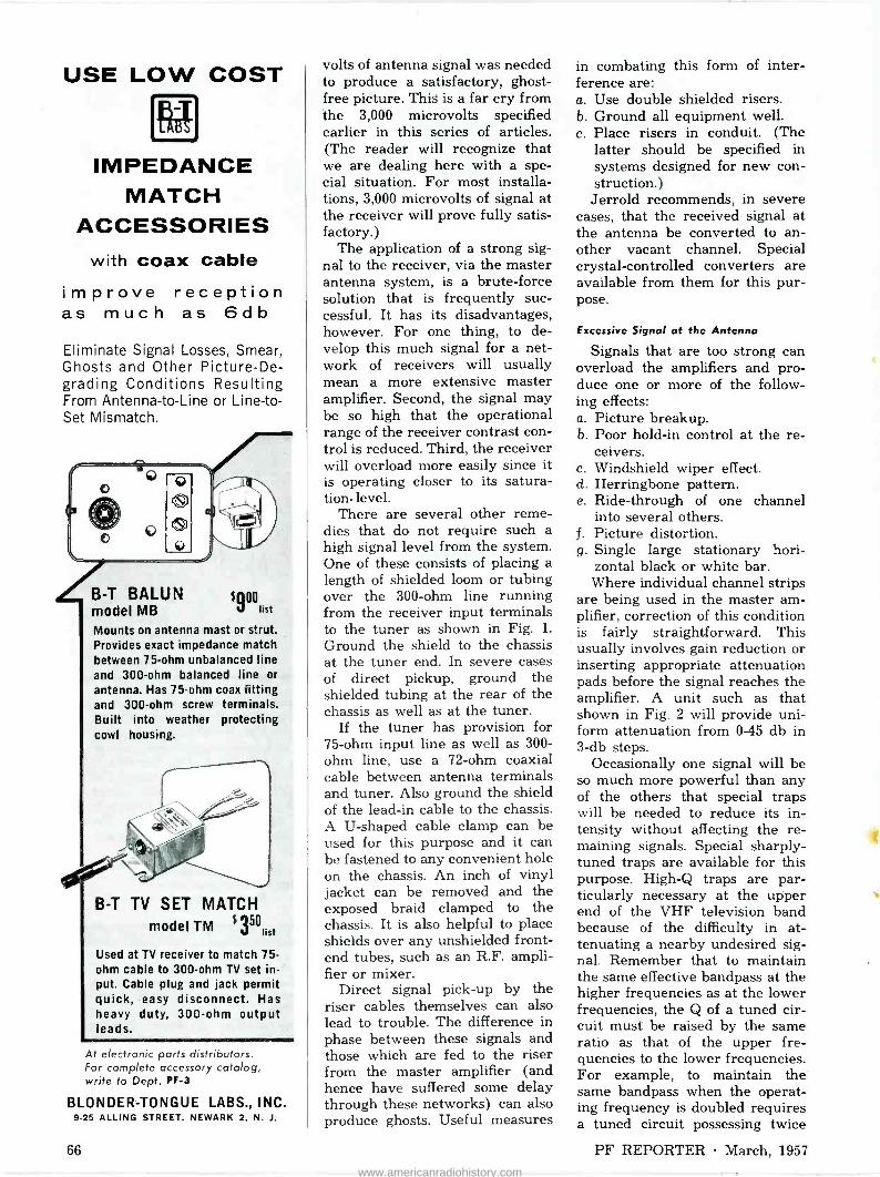
USE LOW COST
IMPEDANCE MATCH
ACCESSORIES with coax cable
improve reception as much as 6db
Eliminate Signal Losses, Smear, Ghosts and Other Picture -De- grading Conditions Resulting From Antenna -to -Line or Line -to - Set Mismatch.
O
O
Cl
O
Zi-T BALUN $900 model MB Fist
Mounts on antenna mast or strut. Provides exact impedance match between 75 -ohm unbalanced line and 300 -ohm balanced line or antenna. Has 75 -ohm coax fitting and 300 -ohm screw terminals. Built into weather protecting cowl housing.
B -T TV SET MATCH model TM $150 3;;Sí
Used at TV receiver to match 75 - ohm cable to 300 -ohm TV set in- put. Cable plug and jack permit quick, easy disconnect. Has heavy duty, 300 -ohm output leads.
At electronic parts distributors. For complete accessory catalog, write to Dept. PF -3
BLONDER -TONGUE LABS., INC. 9-25 ALLING STREET. NEWARK 2. N. J.
volts of antenna signal was needed to produce a satisfactory, ghost - free picture. This is a far cry from the 3,000 microvolts specified earlier in this series of articles. (The reader will recognize that we are dealing here with a spe- cial situation. For most installa- tions, 3,000 microvolts of signal at the receiver will prove fully satis- factory.)
The application of a strong sig- nal to the receiver, via the master antenna system, is a brute -force solution that is frequently suc- cessful. It has its disadvantages, however. For one thing, to de- velop this much signal for a net- work of receivers will usually mean a more extensive master amplifier. Second, the signal may be so high that the operational range of the receiver contrast con- trol is reduced. Third, the receiver will overload more easily since it is operating closer to its satura- tion. level.
There are several other reme- dies that do not require such a high signal level from the system. One of these consists of placing a length of shielded loom or tubing over the 300 -ohm line running from the receiver input terminals to the tuner as shown in Fig. 1.
Ground the shield to the chassis at the tuner end. In severe cases of direct pickup, ground the shielded tubing at the rear of the chassis as well as at the tuner.
If the tuner has provision for 75 -ohm input line as well as 300 - ohm line, use a 72 -ohm coaxial cable between antenna terminals and tuner. Also ground the shield of the lead-in cable to the chassis. A U-shaped cable clamp can be used for this purpose and it can be fastened to any convenient hole on the chassis. An inch of vinyl jacket can be removed and the exposed braid clamped to the chassis. It is also helpful to place shields over any unshielded front- end tubes, such as an R.F. ampli- fier or mixer.
Direct signal pick-up by the riser cables themselves can also lead to trouble. The difference in phase between these signals and those which are fed to the riser from the master amplifier (and hence have suffered some delay through these networks) can also produce ghosts. Useful measures
in combating this form of inter- ference are: a. Use double shielded risers. b. Ground all equipment well. c. Place risers in conduit. (The
latter should be specified in systems designed for new con- struction.) Jerrold recommends, in severe
cases, that the received signal at the antenna be converted to an- other vacant channel. Special crystal -controlled converters are available from them for this pur- pose.
Excessive Signal at the Antenna
Signals that are too strong can overload the amplifiers and pro- duce one or more of the follow- ing effects: a. Picture breakup. b. Poor hold -in control at the re-
ceivers. c. Windshield wiper effect. d. Herringbone pattern. e. Ride -through of one channel
into several others. Picture distortion.
g. Single large stationary hori- zontal black or white bar.
Where individual channel strips are being used in the master am- plifier, correction of this condition is fairly straightforward. This usually involves gain reduction or inserting appropriate attenuation pads before the signal reaches the amplifier. A unit such as that shown in Fig. 2 will provide uni- form attenuation from 0-45 db in 3 -db steps.
Occasionally one signal will be so much more powerful than any of the others that special traps will be needed to reduce its in- tensity without affecting the re- maining signals. Special sharply - tuned traps are available for this purpose. High -Q traps are par- ticularly necessary at the upper end of the VHF television band because of the difficulty in at- tenuating a nearby undesired sig- nal. Remember that to maintain the same effective bandpass at the higher frequencies as at the lower frequencies, the Q of a tuned cir- cuit must be raised by the same ratio as that of the upper fre- quencies to the lower frequencies. For example, to maintain the same bandpass when the operat- ing frequency is doubled requires a tuned circuit possessing twice
f.
66 PF REPORTER March, 1957
www.americanradiohistory.com

To better ser -ve the needs of the II\TDÜSTRY
SANGAMO announces the latest factory addition to the Electronic Components Division
Here at Pickens, South Carolina is the newest of the Sangamo factories.
"Controlled conditions" are architecturally built into this modern plant which is functionally planned to assure an ideal manufacturing en- vironment. The building provides approximately 200,000 square feet of floor space.
The new plant supplements the production facilities of our Illinois factories, to help us better serve the industry's needs for the following electronic components:
ELECTRONIC CAPACITORS ... for original equip- ment and replacement needs and for critical military or industrial applications. The Sangamo line includes paper, mica, silver and electrolytic capacitors for every radio and electronic use.
DYNAMOTORS, GENERATORS and CONVERTERS
... for mobile communication equipment in the military and commercial fields.
Look to Sangamo for your electronic component requirements.
S.A TGAMO ELECTRIC COMPANY Electronic Components Division-Springfield, Illinois
March, 1957 PF REPORTER 67
www.americanradiohistory.com

MORE INCOME
IN 1957
FOR INDEPENDENT
TV TECHNICIANS!
I Receiver . .
precision -engineered
"for those who want the finest"..'. is a non-
competitive line.
GENEROUS COMMISSIONS
THRU EXCLUSIVE
PROFITABLE TV
TECHNICIAN FRANCHISES
NOW AVAILABLE
.
You can recommend ATR with the pride and assurance of your own know-how and the reputation and craftsmanship Of AMERICAN TELEVISION & RADIO
... as original sets /... as replacement sets /... as the No. 1 set in two -set homes \/... and for special chassis installations (without cabinet)
UNEQUALLED IN
PERFORMANCE
UNMATCHED IN QUALITY
CONSTRUCTION
UNSURPASSED IN
BEAUTY
0119 FOR FULL INFORMATION - WRITE TODAY FOR COLORFUL
BROCHURE SHOWING THE NEW LINE OF ATR TV SETS
ALSO MANUFACTURERS OF DC -AC INVERTERS. "A" BATTERY ELIMINATORS, AUTO RADIO VIBRATORS
AMERICAN TELEVISION 8 RADIO CO.
Quality PTudutrS S[.rCe 731' SAINT PAUL I MINNESOTA -U S A
the Q. A common situation in Chicago
is the appearance of the Channel 9 signal in the Channel 11 strip even though separate antennas are being used. This is due to the fact that any antenna used to pick up either one of these signals will also develop an appreciable amount of signal from the other channel. This is true even with the most sharply tuned Yagi. To further complicate the situation, Channel 9 output from the trans- mitter is far higher than that of Channel 11. Only by using a high -Q trap can this condition be alleviated.
Picture Interference
Diagonal lines in the picture, light herringbone patterns, vene- tian blind effect, swirling pat- terns, or complete picture black- out-all stem from RF interfering signals from FM stations, other radio services, local oscillators in TV sets, oscillating line ampli- fiers or a TV station on the same or an adjacent channel. Local TV set interference can be cured only by servicing individual sets and by checking tapoffs for proper connections and for at least a 12 -db tapoff loss. Increasing the amount of tapoff loss to the trou- blesome receiver will often elimi- nate the problem. Also, if an un- shielded line is used between the tuner and the receiver input term- inals, it may help to either shield this line or replace it with 75 -ohm coax. Power -line RF filters at the receiver will also help reduce in- terference which might be carried by the AC lines.
Interference picked up by the antenna system can be eliminated with wave traps, provided that the frequency of the interference is not the same as that of the desired TV signal. Frequently, the worst interference is caused by trans- mitters operating in the FM band between 88 and 108 mc. A suitable FM trap placed at the antenna in- put to the first amplifier in the system will usually eliminate this difficulty. In strong FM signal areas, FM traps are often used at the inputs of every amplifier in the system.
Dark, moving horizontal bars in a picture are usually due to the presence of a 60 -cycle AC signal
in the picture signal. Examine line amplifiers and distribution ampli- fiers for defective tubes, rectifiers, DC filter condensers, or other power supply components. If AC bars appear in just one receiver, look for AC troubles in that re- ceiver rather than in the line.
Light streaks shooting horizon- tally through a picture stem from interference caused by automobile ignition, neon or fluorescent lights, electric motors, high volt- age power lines, and intermittent cable connections. Ground coax and amplifier units, shield equip- ment and install power line filters. A high-pass RF filter may be used at amplifier inputs.
Other Troubles
Weak signals on some channels and normal signals on others are usually due to a mismatched, open, or short-circuited transmis- sion line. These line faults occur in such a way as to form a trap for the channels affected. Check all line and equipment terminations, jumper positions and connections.
Weak, snowy pictures are the result of insufficient signal, weak amplifier tubes, open or poorly made connections, or defective transmission lines.
Multiple ghosts or picture smear can be caused by an open or short circuit in the transmis- sion line, improper line or equip- ment . termination, an incorrect terminal connection or jumper position on one of the units, or a ghost in the received signal.
NOTE: In these days of exten- sive construction, it frequently happens that weak signals are caused by the rise of new build- ings between the receiving an- tenna and the broadcast tower. Keep this in mind whenever a marked decrease in signal strength occurs.
Since this is the final article in this series, the writer would like to acknowledge his indebtedness to the manufacturers of master antenna equipment and to the service organizations who pro- vided much of the information that appeared here. Special thanks are due also to William Grossman and Sid Reisberg of Central Television Service, Chi- cago, Illinois.
68 PF REPORTER March, 1957
www.americanradiohistory.com

For Successful Color Servicing
THE WR -61B COLOR -BAR GENERATOR
produces crystal -controlled signals spaced at precisely 30 - degree intervals ... permitting adjustments of all types of demodulators ... especially X and Z as well as the conven- tional R -Y, B -Y, G -Y, I and Q signals. A high degree of accuracy is assured since picture carrier, color subcarrier, sound carrier, bar frequency and horizontal sync pulses are all crystal controlled. Luminance signals at bar edges aid in checking color "fit" or registration. Adjustable subcarrier amplitude permits checking color -sync action. "Darkening" pedestals permit checking gain ratios or chrominance channels without an oscilloscope and without computing the relative phosphor efficiency of the kinescope. The new WR -61B is now accepted as the standard for color -phasing accuracy in many TV stations and network operations.
Price $259.30*
User price (optional)
...stay with RCA !
"Pioneered and developed by RCA." That phrase is your guarantee that RCA test equipment will service color better, faster and more accurately ... The instruments described below were designed to do just that ... Combined with your present black and white equipment, this trio will answer your every service problem ... Take the lead from thousands of service -wise technicians ... They know their best bet and best buy is Color -TV servicing equipment "Pioneered and developed by RCA" !
THE WR -46A VIDEO DOT/CROSSHATCH GENERATOR
saves installation time, enables more precise convergence adjust- ments. High level video output permits direct connection to color kinescope; eliminates pattern deterioration due to bandpass characteristics of rf, if or of amplifiers. Result-clear, extremely sharp pattern display. Permits simultaneous display of pattern with broadcast picture in background. Assures convergence ad- justments at exact horizontal scanning rates. Switch selection of four separate types of patterns is provided. Vertical sync is fre- quency -divided from horizontal sync, resulting in interlaced scanning and exceptional freedom from "jitter," "crawl" and sync "hunting."
Prlte $179.50*
THE WO -91A S" OSCILLOSCOPE
has features usually found only in more expensive instruments. It has all the 'scope functions you need to do both Color TV and black -and -white service ... Outstanding features include front - panel switching of "V" -amplifier bandwidth, response flat to 4.5 Mc in wide -band position; 12 -step voltage -calibrated, frequency - compensated "V" amplifier attenuator; simplified, simultaneous waveshape display and voltage measurement on VTVM-type graph scales-peak-to-peak. Read volts directly from screen; sturdy single -unit low-capacitance/direct probe with built-in switch eliminates need for separate probe. Plus many more work -easy features!
Price $239.60*
... ask your RCA Distributor about his special offer on
a new RCA Color TV Microscope!
ele RADIO CORPORATION of AMERICA elk COMPONENTS DIVISION CAMDEN, N. J.
e See your RCA Distributor for details on these outstanding RCA test instruments for Color TV!
March, 1957 PF REPORTER 69
www.americanradiohistory.com

e U of eperyr
he right dtil,ul-
f or t You'lacll find it's ALWAYS IN STOCK at your
Centralab Fastatch
I
I
distributor
t
With Centralab's unique Fastatch system, your distributor can afford to carry a complete line of dual -concentric replacements for all popular TV, radio, and auto sets.
Each Fastatch control unit is factory assembled, tested, and guaranteed. Ask your Centralab distributor's salesman or counterman about Fastatch duals. Or send coupon for bulletin 42-218.
A DIVISION OF GLOBE -UNION INC. 942CEost Keefe Avenue, Milwaukee 1, Wisconsin
Send me Fastatch bulletin 42-218.
Name
('nnpany
.\rlrlress .
City
1 I
I
I Zone State
11.3622
Resonant Circuits (Continued from page 25)
By the same token, the value of C may be determined using the formula:
C 25,300
Figure of Merit or Q
(6)
The figure of merit or Q of a coil is the ratio of the inductive reactance of the coil to the resist- ance of the coil and is expressed by the formula:
Q (7)
where X,. = reactance in ohms of the coil at resonance,
R = resistance in ohms.
To apply formula (7) , let us use a typical 28.1 -mc trap (Fig. 1) . You- will notice that an 18-mmf capacitor Cl is shown in series with the coil Ll, which is tuned to resonate at 28.1 mc. By apply- ing formula (5), we can deter- mine the inductance of Ll, which is necessary first if we are to de- termine the Q of the coil.
L 25,300 fR`C
L 25,300 (28.1x10") x18x10-"
L = 1.78 A.
With the value of L known, we can calculate Xt, by applying formula (1) which was given in Part 1 of this series of articles.
X,, = 2,rfL (1) = 6.28X28.1X10"X1.78X10-" = 314 ohms.
The value of resistance of Ll was given as .16 ohms in Part 1 and we will use this value in calculat- ing Q. By applying formula (7) ,
we find:
Q RL
Q .16 314
Q = 1,962.
Thus, we see that the Q of the coil is very high. However, the effective Q of the trap circuit (L1
70 PF REPORTER March, 1957
www.americanradiohistory.com
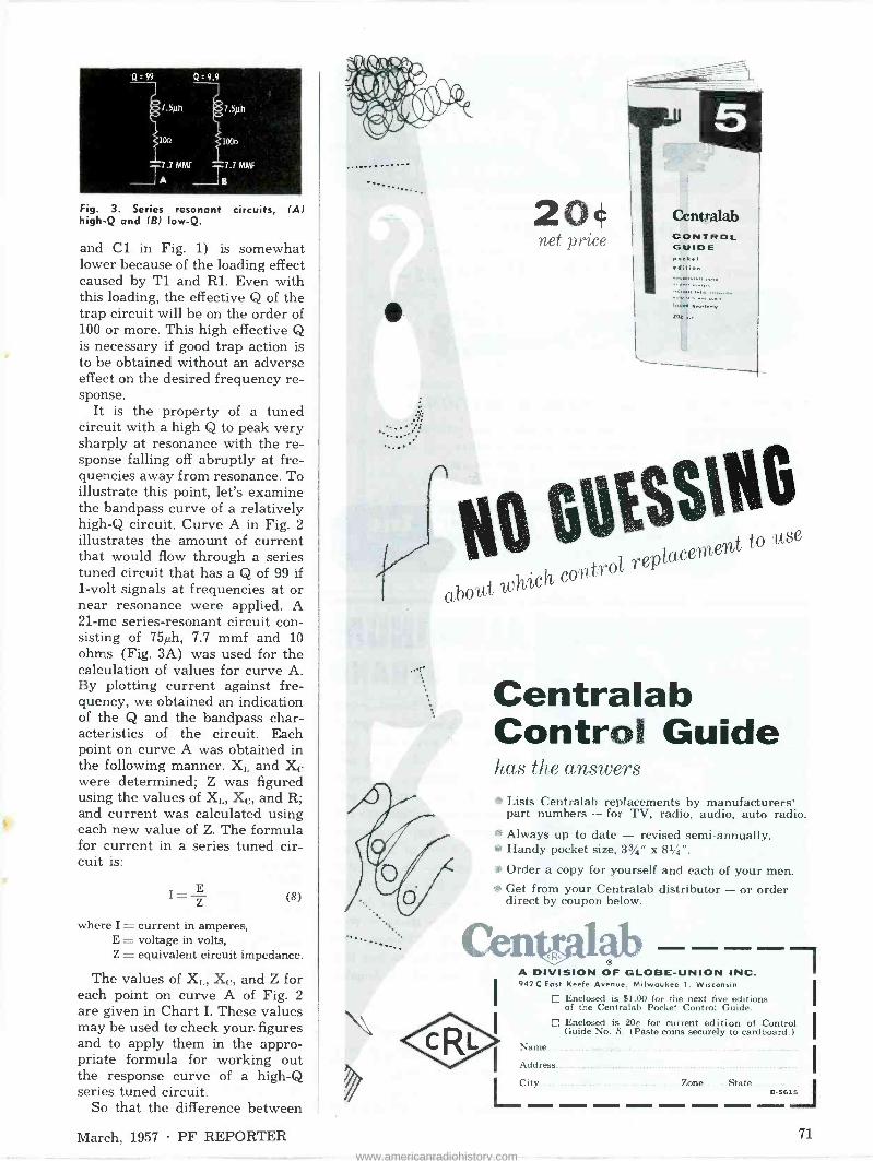
7.5ph
1bOn
7..7 MMF 7.7 MME A g Fig. 3. Series resonant circuits, (A) high -Q and (B) Iow-Q.
and C1 in Fig. 1) is somewhat lower because of the loading effect caused by T1 and Rl. Even with this loading, the effective Q of the trap circuit will be on the order of 100 or more. This high effective Q is necessary if good trap action is to be obtained without an adverse effect on the desired frequency re- sponse.
It is the property of a tuned circuit with a high Q to peak very sharply at resonance with the re- sponse falling off abruptly at fre- quencies away from resonance. To illustrate this point, let's examine the bandpass curve of a relatively high -Q circuit. Curve A in Fig. 2 illustrates the amount of current that would flow through a series tuned circuit that has a Q of 99 if 1 -volt signals at frequencies at or near resonance were applied. A 21 -mc series -resonant circuit con- sisting of 75µh, 7.7 mmf and 10 ohms (Fig. 3A) was used for the calculation of values for curve A. By plotting current against fre- quency, we obtained an indication of the Q and the bandpass char- acteristics of the circuit. Each point on curve A was obtained in the following manner. Xl, and Xe were determined; Z was figured using the values of XL, Xc, and R; and current was calculated using each new value of Z. The formula for current in a series tuned cir- cuit is:
I
Z
E (8)
where I = current in amperes, E = voltage in volts, Z = equivalent circuit impedance.
The values of XL, Xe, and Z for each point on curve A of Fig. 2 are given in Chart I. These values may be used to check your. figures and to apply them in the appro- priate formula for working out the response curve of a high -Q series tuned circuit.
So that the difference between
20« centramb
net price CONTROL GUIDE ooct edit/on
l.:::.ë:,
SSIte replacement
to use
which contro
Centralab Control Guide has the answers
Lists Centralab replacements by manufacturers' part numbers - for TV, radio, audio, auto radio.
Always up to date - revised semi-annually. Handy pocket size, 33/4" x 81/4".
Order a copy for yourself and each of your men. Get from your Centralab distributor - or order direct by coupon below.
ab A DIVISION OF GLOBE -UNION INC. 942C East Keefe Avenue, Milwaukee 1, Wisconsin
E Enclosed is $1.00 for the next five editions of the Centralab Pocket Control Guide.
D Enclosed is 20c for current edition of Control I Guide No. 5. (Paste coins securely to cardboard.)
Name
Address .__. _... ....,.
Zone State J B-5615
March, 1957 PF REPORTER 71
www.americanradiohistory.com

R IP PRESENTING THE e
E pawn. WRENCHES
FINEST QUALITY STEEL SHANK AND SLEEVE
o BRIGHT PLATED
FINISH o
STRONG PLASTIC HANDLE
STEVENS WALDEN INC. i
SIZES
3!13" TO 717I0 .,
BY THE MAKERS OF THE ORIGINAL
spfNrirE WRENCHES OVER 150 STYLES
AND SIZES
Write for
catalogue
WITH THE EASY "FINGER -CONTROL"
GRIP AND RELEASE ACTION FOR THOSE
HARD -TO -GET -AT PLACES - -+ PUSH SLEEVE TO GRIP NUT --
ONE HAND OPERATION- GRIPS nuts or bolts of ony material
HOLDS firmly in ony position
TIGHTENS nut or bolt securely
RELEASES at the pull of the fingers
STEVENS WALDEN Inc. 500 SHREWSBURY STREET - WORCESTER, MASSACHUSETTS
MAKERS OF WORLD-FAMOUS HAND TOOLS FOR OVER 50 YEARS
ALUMINUM WIRE STRAND
Aluminum Wire Strand-strong (500 lbs. breaking strength) 7
strand #18 wire - clean han-
dling because of special pre -
cleaning process - corrosion
resistant - non -snarling - pre-
measured-every concentric coil
measures 2 feet - connected
coil 1000 feet of 50 ft. coils
to a carton - an addition to
present line of galvanized TV wire - Prompt deliver-
ies from stocks in Wor- cester, Chicago, New Orleans, Houston, Dal-
las and Los Angeles. Sold only through whole-
sale Electronics and Hard- ware Distributors.
G. F. WRIGHT STEEL & WIRE CO. 235 Stafford St.
Worcester, Mass.
a low -Q circuit and a high -Q cir- cuit will be made very clear, we also plotted the current through a 21 -mc series tuned circuit with a Q of 9.9 (Fig. 3B) . This was done in the same manner that was used for the high -Q circuit, and curve B in Fig. 2 was the result. The values of X,,, X, and Z for each point on curve B are also given in Chart I. You will notice that the difference in the Z of each circuit was caused by the differ- ence in R since XL, and X, for each point was the same for both curve A and curve B.
Curve B has only a small change in amplitude at frequen- cies ranging from resonance to 15% on each side of resonance, whereas curve A has a large change in amplitude for frequen- cies only 21%% away from reso- nance. These characteristics have very definite applications in radio and television. Low -Q circuits are used in wide -band applications where it is desired to pass a wide range of frequencies. High -Q cir- cuits are used as traps, since it is necessary to eliminate a narrow range of frequencies without seri- ously affecting the desired fre- quency range.
Q of a Circuit It was shown that the Q of the
coil alone may be very high, since a coil may be wound with low - resistance wire and have a con- siderably high reactance. The Q of a circuit will be lower than the Q of the coil alone because of the resistance in the wiring and the effective resistance of the capaci- tor. In the example using the 28.1 - mc trap coil, we found a coil Q of 1,962. Now if we consider the small amount of resistance in the wiring between this series circuit and the control grid and the small effective resistance of the capaci- tor, the effective Q of the 28.1 -mc trap may be reduced to 1,000 or less. This is still very high when compared to the Q of 9 or 10 for the entire grid circuit of the video IF amplifier. The low circuit Q is due to the low -impedance trans- former coupling from the tuner and the 200 -ohm shunt resistor. This circuit will be covered more completely in the discussion of parallel tuned circuits to appear in a forthcoming issue.
7 9 PF REPORTER March, 1957
www.americanradiohistory.com

a ee e,
e
4e º e é' * e #4 #4 S i7
e
the balance is in your favor
e
e
s e e
6 is It * S S
The design of each Newcomb audio product is balanced with the use to which it will be put ... and to the kind of performance desired.
Equal care and attention is given to all circuit elements so that an internal balance of quality is achieved.
Within the Newcomb Company itself, a balance between Engineering, Production, Testing, and Sales Departments is maintained.
There is even a superior balance to the tone you hear from a Newcomb amplifier. This balance can only be attributed to experience ... experience gained by twenty years of specialization in the field of sound amplification and reproduction.
If we were asked to give a one word description of any Newcomb product, that word would unquestionably be... "balance"! Balance has been the watchword at Newcomb since the company's beginning. Balance in sound, balance in quality, balance within the company itself. The user gets a product in which a fine balance has been struck between operating features, performance, dependability, beauty, and cost.
We have learned through the years that measured specifications may make stimulating reading, but they are not necessarily indicative of the sound that may result. There are no meters which can tell anyone exactly how a
Write for catalog of Newcomb products
in which sou are interested.
particular amplifier will sound-to the purchaser-under conditions of usage. Until such an instrument is invented, successful sound amplification will owe as much to art and experience as to science and measurement.
It is our belief the product which will be enjoyed the longest is the one that is soundly engineered all the way through-the well balanced design that can only result from experience. Living and working in this belief has brought us to the position we find ourselves in today. Newcomb Audio Products Company is probably the largest independent manufacturer of sound amplification products in the nation.
We make some products which are inexpensive, but they are not "cheap". We make others which cost several times as much, but they are never overpriced. The overall quality and value of any Newcomb product equated against its price finds the balance tilted sharply in favor of the buyer.
It is pleasurable and profitable to sell Newcomb prod- ucts. In addition to being top quality merchandise, their dependability, integrity, and value-proven by our twenty years of operation-help build a reputation for reliability and fair dealing for the seller. NEWCOMB AUDIO PRODUCTS COMPANY
DEPARTMENT P R 3 13B21 LEXINGTON AVE.. HOLLYWOOD 3$. CALIFORNIA
It
e
e
tt
Yf
HIGH FIDELITY AMPLIFIERS AND RADIO TUNERS PUBLIC ADDRESS SYSTEMS
RECORD AND TRANSCRIPTION PLAYERS
March, 1957 PF REPORTER 73
www.americanradiohistory.com

Remote Tuning Without Wires (Continued from page 21)
has only two key -and -rod combi- nations.
The receivers used with both models of transmitters have three RF stages utilizing a 6CB6 and both sections of a 6AÚ8. Follow- ing the last stage is a 6BN6 lim- iter. Frequency tripling takes place in the plate circuit of the third RF stage in the "400" and in the limiter plate circuit in the
"200". The resulting third -har- monic output frequencies are shown in Table I.
The output of the limiter in the "200" is fed to a 3AL5 discrimi- nator tuned to 122.25 kc, whereas
Table I-Control Frequencies for Zenith "Space -Command"
Function Function Freq. ("400") ("200") (kc) ON-OFF 37.75
3rd Harm. (kc)
113.25
MUTE 38.75 116.25
LEFT RIGHT 40.25 120.75
RIGHT MUTE 41.25 123.75
Ì Ì % 141WALSCO í\
r'rtJ ...the first TV alignment tools with a "memory." Exclusive micrometer action automatically counts, indicates, and reminds you of the exact turns made right or left. Adjusted coil or trimmer can be returned to original setting instantly. Simple to use... eliminates errors. 3 TEL -A -TURN
tools available to cover most needs:
#2586 Double -ended standard I.F. Aligner #2587 Double -ended Screwdriver #2588 Double -ended Hex
Aligner (.001" Hex & .125"Hex)
Dealer net: 99¢ each or all 3
for $2.75. At all parts jobbers.
CTUAL SIZE
ELECTRONICS MANUFACTURING CO. A Division of Textron, Inc.
100 Wes G een St., Rockford, Illinois Western Division: 3225 Exposition Place, Los Angeles 18. Calif.
A
---
Counts
the turns as it Iigns
a
the "400" receiver has two dis- criminators, tuned to 114.75 kc and 122.25 kc respectively. These frequencies were chosen so that the third harmonics of all control frequencies would fall either above or below a discriminator center frequency by exactly 1.5 kc. The discriminator output cir- cuit of the "200" receiver is in- cluded in the schematic in Fig. 2. Similar circuits are found in the "400" unit.
When a "mute" signal (above center frequency) is received by the discriminator in the "200", a positive output, obtained from the upper diode, is fed through an in- tegrator circuit to one control grid of a 6CM7 relay -control tube. The "right" control signal for the channel -selector motor is below center frequency and produces a positive output in the lower diode of the discriminator. The grid of the second section in the 6CM7 receives this signal.
A fixed bias (-18 volts in the "200" or -28 volts in the "400") keeps the relay -control tubes cut off until a signal arrives. Being positive, the control signal over- rides enough of the fixed bias on one section of the 6CM7 to permit it to conduct, and the relay coil which is series -connected in the plate circuit is energized. A plate current of 8.5 to 11 ma is sufficient to operate the motor -control re- lays, and they remain closed as long as the current stays above this level.
The "on -off" and "mute" relays require 13 to 17 ma DC for opera- tion and are of a bi -stable type- i. e., the switch contacts may re- main in either of two resting posi- tions (shown in Fig. 2) after the relay is de -energized. One "ping" from the transmitter opens a switch in the speaker circuit and mutes the sound, and a second "ping" is required to restore the switch to the closed position. The cores of the bi -stable relays are connected to the coils through 1- megohm resistors to place these two adjacent parts at approxi- mately the same potential.
The "200" receiver obtains power from the TV set through an octal plug. A low AC voltage from a special tap on the main power transformer, applied to a selenium rectifier on the control chassis, de -
74 PF REPORTER March, 1957
www.americanradiohistory.com
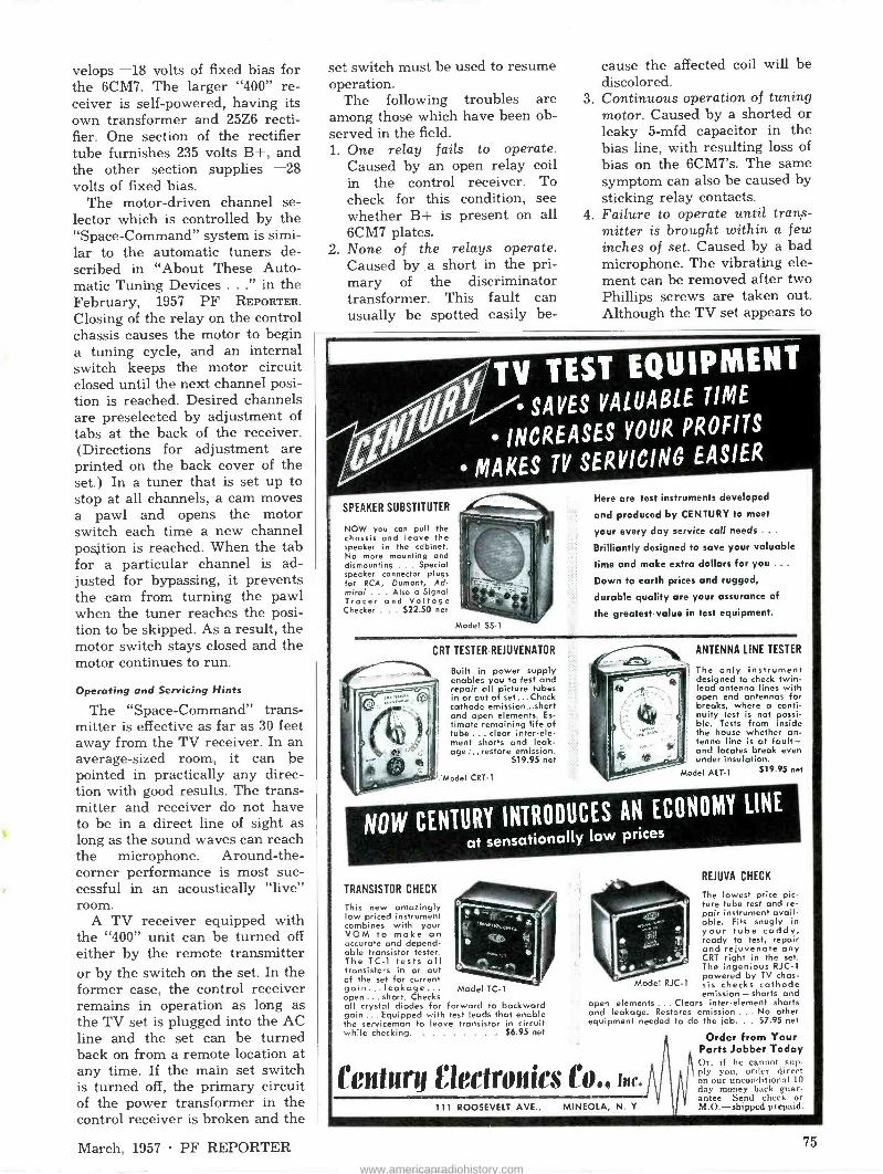
velops -18 volts of fixed bias for the 6CM7. The larger "400" re- ceiver is self -powered, having its own transformer and 25Z6 recti- fier. One section of the rectifier tube furnishes 235 volts B+, and the other section supplies -28 volts of fixed bias.
The motor -driven channel se- lector which is controlled by the "Space -Command" system is simi- lar to the automatic tuners de- scribed in "About These Auto- matic Tuning Devices ..." in the February, 1957 PF REPORTER.
Closing of the relay on the control chassis causes the motor to begin a tuning cycle, and an internal switch keeps the motor circuit closed until the next channel posi- tion is reached. Desired channels are preselected by adjustment of tabs at the back of the receiver. (Directions for adjustment are printed on the back cover of the set.) In a tuner that is set up to stop at all channels, a cam moves a pawl and opens the motor switch each time a new channel position is reached. When the tab for a particular channel is ad- justed for bypassing, it prevents the cam from turning the pawl when the tuner reaches the posi- tion to be skipped. As a result, the motor switch stays closed and the motor continues to run.
Operating and Servicing Hints
The "Space -Command" trans- mitter is effective as far as 30 feet away from the TV receiver. In an average -sized room, it can be pointed in practically any direc- tion with good results. The trans- mitter and receiver do not have to be in a direct line of sight as long as the sound waves can reach the microphone. Around -the - corner performance is most suc- cessful in an acoustically "live" room.
A TV receiver equipped with the "400" unit can be turned off either by the remote transmitter or by the switch on the set. In the former case, the control receiver remains in operation as long as the TV set is plugged into the AC line and the set can be turned back on from a remote location at any time. If the main set switch is turned off, the primary circuit of the power transformer in the control receiver is broken and the
set switch must be used to resume operation.
The following troubles are 3.
among those which have been ob- served in the field. 1. One relay fails to operate.
Caused by an open relay coil in the control receiver. To check for this condition, see whether B+ is present on all 4.
6CM7 plates. 2. None of the relays operate.
Caused by a short in the pri- mary of the discriminator transformer. This fault can usually be spotted easily be-
cause the affected coil will be discolored. Continuous operation of tuning motor. Caused by a shorted or leaky 5-mfd capacitor in the bias line, with resulting loss of bias on the 6CM7's. The same symptom can also be caused by sticking relay contacts. Failure to operate until trans- mitter is brought within a few inches of set. Caused by a bad microphone. The vibrating ele- ment can be removed after two Phillips screws are taken out. Although the TV set appears to
SPEAKER SUBSTITUTER
NOW you con pull the chassis and leave the speaker in the cabinet. No more mounting and dismounting ... Special speaker connector plugs for RCA, Dumont, Ad- miral . . . Also o Signal Trocer and Voltage Checker . . . $22.50 net
TV TEST EQUIPMENT SAVES VALUABLE TIME
INCREASES YOUR PROFITS
MAKES TV SERVICING EASIER
Model SS -1
Here are test instruments developed
and produced by CENTURY to meet
your every day service call needs .. Brilliantly designed to save your valuable
time and make extra dollars for you ... Down to earth prices and rugged,
durable quality are your assurance of
the greatest value in test equipment.
CRT TESTER -REJUVENATOR
Built in power supply enables you to test and repair all picture tubes in or out of set...Check cathode emission.. -short and open elements. Es- timate remaining life of tube ... clear inter -ele- ment shorts and leak- age...restore emission.
$19.95 net
Model CRT -1
ANTENNA LINE TESTER
The only instrument designed to check twin - lead antenna lines with open end antennas for breaks, where a conti- nuity test is not possi- ble. Tests from inside the house whether an- tenna line is at fault- and locates break even under insulation.
Model ALT -1 $19.95 net
NOW CENTURY INTRODUCES AN ECONOMY LINE
at sensationally low prices
TRANSISTOR CHECK
This new amazingly low priced instrument combines with your VOM to make an accurate and depend- able transistor tester. The TC -1 tests all transistors in or out of the set for current gain...leakage... open ...short. Checks all crystal diodes for forward to backward gain ...Equipped with test leads that enable the serviceman to leave transistor in circuit while checking. $695 net
Model TC -1
REJUVA CHECK
The lowest price pic- ture tube test and re- pair instrument avail- able. Fits snugly in your tube caddy, ready to test, repair and rejuvenate any CRT right in the set. The ingenious RJC-1 powered by TV chas- sis checks cathode emission - shorts and
open elements ... Clears inter -element shorts and leakage. Restores emission ... No other equipment needed to do the ¡ob. . . $7.95 net
['eiiturN Electronics Co., 111 ROOSEVELT AVE., MINEOLA, N. Y.
Order from Your Parts Jobber Today Or, if he cannot sup-
jply you, order direct on our unconditional 10 day money hack guar- antee. Send check or M.O.-shipped prepaid.
March, 1957 PF REPORTER 75
www.americanradiohistory.com

have two microphones, the one at the right is a dummy.
5. Erratic operation, such as ran- dom triggering of relays. Most frequently caused by a bad tube.
6. Failure of transmitter to oper- ate. Caused by tuning rod loose in its mounting. Check this by shaking the unit and listening for a loud rattle. To disassemble the transmitter, depress the two center keys and remove the Phillips screw located between them. Then grasp the case and push down
on the keys to separate the chassis from the case.
7. Tuner goes through extra cy- cle. Caused by prolonged re- verberation of tuning rod. Normally, as soon as the trans- mitter key is released, a small wire spring touches the rod and damps its vibration. Its action can be made more effective if a piece of spaghetti is slipped over the end of the wire. It may only be necessary to in- struct the customer to let go of the key promptly.
The "Space -Command" system
Time
for Replacement?
a
t ,
, ' ../'
s /i i ----
OXFORD SPEAKERS
"Put the right shoe on the right foot" by demanding the most exact replacement speakers . . . OXFORD.
Proven for replacement and preferred for original equipment, OXFORD offers you the best from 2" to 15" ... a streamlined,
complete line of speakers constantly improved over more than twenty-five years of speaker leadership.
TIME for REPLACEMENT . specify OXFORD SPEAKERS you'll be glad you did.
OXFORD Components, Inc. Subsidiary of Oxford Electric Corp.
556 West Monroe Street Chicago 6, Illinois In Canada: Allas Radio Corp., ltd., Toronto
Export: Roburn Agencies, New York City
is not generally sensitive to out- side interference. We have heard of one case of spurious triggering, however. One set changed chan- nels each time the front door of the home was opened, because an inaudible squeak in the door was of the correct supersonic fre- quency to activate the motor - control relay. Oiling the hinge fixed the TV!
A test point is provided on top of the "200" control chassis for measurement of the bias voltage. In addition, some "200" sets have adjustable bias to compensate for changes in the condition of the selenium rectifier or variations among relays.
The manufacturer recommends that the tuned RF circuits should not be realigned, and that they should be replaced as a unit if they develop trouble.
Several specialized items of test equipment for servicing "Space - Command" devices are available from the manufacturer. There is a power supply which will operate the 5 -tube control chassis inde- pendently of the TV set. Another item is a set of special jumpers that can be attached to the TV receiver so that it can be operated with the control chassis removed. There is also a discriminator - alignment generator which is sim- ilar to the "200" 2 -key transmitter except that the third harmonics of the frequencies from it exactly equal the discriminator center frequencies (114.75 and 122.25 kc) .
Motorola "Transituner" An optional accessory for some
recent Motorola TV sets is the TK -74 "Transituner," a remote channel selector. Its essential com- ponents are: 1. A pocket-size transmitter con-
sisting of a 2N112, 2N112A, or 2N135 transistor connected in a Hartley oscillator circuit and powered by a 221/4 -volt battery.
2. A ferrite loop antenna with an electrostatic shield, mounted in or under the TV set.
3. A 3 -tube control receiver pow- ered by the TV set.
4. A relay which acts as a motor - control switch for an auto- matic tuning system. (See the previously -mentioned article, "About These Automatic Tun- ing Devices . . . ," for a com-
76 PF REPORTER March, 1957
www.americanradiohistory.com

plete description of the tuning motor system.) The operating frequency of the
receiver and transmitter is fixed at 2.881 mc. Two 6AU6 tubes are used as high -gain RF amplifiers, and the output of the second stage is rectified by a 1N64 detector. The load is direct -coupled to a re- lay tube-one section of a 12AT7.
Fig. 3 is a schematic of the de- tector, relay, and associated cir- cuits of the Motorola control re- ceiver. The detector output volt- age is positive and subtracts from a fixed bias on the grid of the re- lay tube; therefore, an incoming signal brings the tube out of cut- off and causes current to flow through the relay coil in the plate circuit.
The fixed bias has a value of about -15 volts and is obtained from the filament supply by means of a selenium rectifier volt- age doubler. The portion of the rectifier output which is required as bias is tapped off at the arm of a "threshold" potentiometer. A smaller part of the rectified fila- ment voltage is applied across a "sensitivity" control which fur- nishes a variable bias for the grid of the second RF amplifier.
The second section of the 12AT7 is diode -connected and serves as a noise clamp. Since the cathode is maintained at +0.9 volt, this tube is normally non -conducting. Strong noise pulses drive the plate of the clamp tube more positive than the cathode, and the result- ing conduction of this tube clips the pulses so that they do not trigger the relay control tube.
Operating and Service Hints
The voltage at a test point in the grid circuit of the relay tube is monitored with a VTVM during most adjustments on the receiver. Under no -signal conditions, the reading at this point should be from -5 to -6 volts. The voltage should shift by approximately +2 volts when the transmitter is keyed. Advancing the threshold control supplies more bias voltage to the relay tube and results in a more negative indication. Turn- ing up the sensitivity reduces the negative VTVM reading because the detector produces more posi- tive signal voltage.
The receiver will respond to
NEW AUTOMATION TV TUBE TESTER
CAN'T BECOME OBSOLETE
ONLY 3 SOCKETS! to test all
TV tubes!
INSERT THIS CARD Eliminates 25 switches and 30 sockets
saves 80% of testing time
DynaMatic tube tester uses perforated
plastic cards to automatically set up
socket pin connections & test voltages
PERFO Cards are made available to test all new tubes as fast as they appear in TV sets. No more multiple socket panels or roll charts that become obsolete when new tubes are introduced. Smallest and lightest Gm tube tester ever produced. Take it with you on ALL house tails. Permits full -complement tube testing which must result in increased tube sales. Lots of free advertising when customer sees his tubes tested on automatic equipment. DynaMatic is a dynamic mutual conduct- ance tester-NOT an emission checker Shows percentage of rated mutual con- ductance on GOODBAD scale. Measures mutual conductance in micro -
mhos on 2 ranges: 0-6000, 0-18000.
SEE IT AT YOUR .JOBBER THIS MONTH
TeleTest Instrument Corporation 121-08 14th Road
College Point 56, New York
NOW -MASTER TV THIS EASY WAY
J
7
TV -IT'S A CINCH-By E. Ais - berg. No. 62. 224 mg Hundreds of original tracions. Paper cover Hard caver $4.60.
es. illus- $2.90
OTHER GERNSBACK LIBRARY BOOKS
Paper cover editions except as noted
#66-Basic Audio Course $2.75 Hard cover ed. 5.00
#61-Transistor Techniques 1.50
#60-Rapid TV Repair 2.90 Fard cover ed. 4.60
#58-Maintaining HI -Fi Equipment 2.90 Hard cover ed. 5.00
#57-The V.T.V.M. 2.50 Hard cover ed. 4.60
#55-Sweep and Marker Generators ....._ . 2.50 Hard cover ed. 4.60
#54-Probes 2.50 Hard cover ed. 4.60
#52-The Oscilloscope 2.25 Hard cover ed. 4.60
#51-Transistors- Theory and Practice 2.00
#50-TV Repair Techniques 1.50
#49-Radio & TV Test I Istruments 1.50
#47-Rodio & TV Hints 1.00
,(t
U '7
Here at last-a book by an author who believes TV is a cinch-and proves it!
International TV expert E. Aisberg gives you all the facts on TV theory in easy-going colloquial dialogue style. Hundreds and hun-
dreds of unique specially drawn line sketches appear throughout the book on almost every page to help you visualize and understand the
points the author is making. You'll remember what this book teaches with a smile long after
you've forgotten many conventional textbooks. TV- IT'S A CINCH first appeared as a series in
RADIO -ELECTRONICS. Now at last in response to popular demand, It has been published in expanded
form as a complete book. If you make your living in TV, or if you'd like to know more about electronics,
you need a firm grasp of fundamentals. TV -IT'S A CINCH gives you that grasp easily and enjoyably. It's a book
for beginner and expert alike. Get your copy today at your distributor --or use the coupon below.
JUST A GLIMPSE AT SOME OF THE CONTENTS
V.H.F. and video frequencies The cathode ray tube Deflection and focusing Gas -tube time bases Synchronization Vacuum -tube time bases Hi and if circuits Detectors and video amplifiers
The dc component Sync separation Power supplies Antennas Sawteeth in action The electronic Image Composite video signal Special Circuits Color TV
GERNSBACK LIBRARY, 154 West 14th St., New York City
V-It's a Cinch 1366 1358 1354
50
61 57
52
49
60 55
051 47
Hard cover editions (By mail on1Y)
1366H 360H 1358H 1357H 355H 1354H 52H 62H
See your distributor-or use this coupon. PF -37 Enclosed is my remittance of §
Please send me the books checked, postpaid. Prices 10% higher in Canada.
Name please print
Street
City State J
March, 1957 PF REPORTER 77
www.americanradiohistory.com

I HOW
tube
BEST
1 THE TO SELECT \
caddy* FOR
/ YOU
._-.--
,,...=.---7-i--- the ORIGINAL
$1450 ` Dlr. Net
TC -1C. Neat appear- ing, best for tubes. Space inside cover for mirror. Max. cap. 262 tubes. New longer, thinner size 21x15x8 in.
the CARRY-ALL
z'r' $ , ,- 14 50
Dlr. Net tbiaii
TC -4. Break -away design gives quick access. Takes tubes or tools easily. Max. cap. 262 tubes. Size 21x15x8 in.
\Ilk the ADD -A -CADDY AC -1. Snaps firmly on bottom of either TC -1C or TC -4. Gives 46% more space, ideal for
[ tools. All hardware included. $J40 Size 21x8x634 in. Dlr. Net
u'`" the JUNIOR ' - $950 Dlr. Net
TC -2A. Same popu- lar features as TC -4
only 35 as big. Ideal for quick trips. 1531x121/2x8 in.
ASK YOUR PARTS DISTRIBUTOR
`Tube Caddy is the Reg. TM of Argos Products Co. . . . originators and Largest Manufacturer of Tube Carry- ing Cases for the Electronic Technician
COMPANY PRODUCTS GENOA, ILLINOIS
i/ fr, i / G!G ( `
J
TO SENS.
CONTROL
100
1220
1N64
.05
39 K
TP
I MEG
-^nn 470 K
i 100 K
i THRESHOLD
I MEG
_L -15V
BLK.
YEL.
1-7.5 V
.5T
FIL.
6.3 VAC
1 1
RED
3
NOISE CLAMP I i 12AT7
0.9 V
270n 56 K
6 RELAY CONTROL
' ,12AT7
8
MO TE 4
CONTROLRE PLUG
2 4* FIL.
6.3 YAC
1 8
RELAY
STANDBY SW.
2.2 K
187 V
Fig. 3. Detector and relay -control circuits of Motorola "Transituner." Detector output rides on top of fixed bias derived from filament supply.
certain kinds of RF interference, and it is especially sensitive to some of the harmonic frequencies radiated by the high -voltage cir- cuits of the TV set. The control antenna must therefore be care- fully positioned for the least pos- sible noise pickup. The "Transi - tuner" can be made to operate in a location with a high RF noise level, but the control receiver sensitivity must be reduced under such conditions.
The antenna should be oriented with the aid of a VTVM. The pro- cedure is as follows: Turn the threshold control for a maximum negative reading. Then turn the sensitivity control to maximum, and see if the reading becomes less negative. It should do so be- cause more noise should be pres- ent in the detector output circuit. Rotate the antenna for the most negative reading obtainable; this corresponds to minimum noise pickup. If this reading is less neg- ative than -6 volts, the sensitiv- ity setting must be reduced.
Back off the threshold control until the relay tube is brought out of cutoff and the motor starts operating. Then gradually in- crease the bias until the motor stops. Note the VTVM reading at this point. Keep turning the threshold control until the VTVM indicates a bias 21/2 volts more negative than that required to stop the tuner motor. If the con- trol is left at this setting, the noise clamp should operate cor- rectly during normal reception.
The technician can make a rough check of control -receiver
operation by taking advantage of the unit's sensitivity to high - voltage radiation. The manufac- turer suggests that if the shaft of the width control is held in one hand and the other hand is placed near the control antenna, enough signal to operate the receiver may be delivered to the antenna. Should this test fail to work on the first try, it can be attempted again at a reduced threshold set- ting. A precision signal generator tuned to 2.881 me is also usable and has the added advantage of indicating whether or not the re- ceiver is operating on frequency.
A highly probable cause of remote -control failure is a defec- tive battery in the transmitter. Among the likeliest causes of con- tinuous operation or random trig- gering are excessive noise pickup and insufficient relay -tube bias. A high noise level may be a result of poor aiming of the antenna, or it may indicate too much radiation because of some defect in the TV set. Insufficient bias is sometimes due to weak selenium rectifiers, or the trouble may be an incorrect setting of the threshold control or a defect in the noise -clamp circuit.
Summary A wireless remote control tun-
ing device is a simple "little black box" from the customer's view- point. The technician, however, sees it as a chain composed of sev- eral links-transmitter, signal - pickup device, control receiver, and relays-and these extra cir- cuits mean more potential service business for him.
78 PF REPORTER March, 1957
www.americanradiohistory.com

IMPORTANT NEWS FOR
SERVICE TECHNICIANS
new subscription plan keeps you right up-to-date on
HOWARD W. SAMS
"TELEVISION TUBE
LOCATION CHARTS"
get this sturdy loose-leaf binder and stay right up- to-the-minute with Chart releases issued regularly every three months!
Now you won't have to wait a year or more to obtain your tube location charts on the cur- rent TV receivers! Subscribe to the new Sams Television Tube Location Guide service, and get current coverage at 3 month intervals. A sturdy, deluxe bind- er is supplied to you as part of the service, and the releases come to you already punched and ready for easy filing. Here's what your subscription includes:
Current Charts Every Three Months
Complete Cumulative Indexing Service
Deluxe Binder For Easy Filing
YOU GET A FULL YEAR'S SUBSCRIPTION INCLUDING $
3 95
THE BINDER FOR ONLY....
Subscribe today at your Sams Dis- tributor and start getting your current Sams Television Tube Location Charts NOW!
HOWARD W. SAMS & CO., INC. 2201 East 46th Street
Indianapolis 5, Indiana
SUBSCRIBE TODAY!
Notes on Test Equipment (Continued from page 23)
the red test lead from the DC - bias jack of the instrument to the AGC line of the receiver. By ad- justing the DC -bias control of the analyzer, I was able to restore the set to normal operation, thus proving that the fault was in the AGC circuit itself.
The Model 825 also provides a means of checking for opens and shorts in the AGC system. By removing power from the re- ceiver, placing the meter func- tion switch in the AGC OHMS position, and connecting the meter leads between the AGC line and chassis ground, I was able to measure the circuit re- sistance on the AGC continuity scale. In this particular circuit I obtained a reading of approxi- mately 60,000 ohms, which is nor- mal. If the test had revealed a shorted or open condition, the in- strument could have then been used as an ohmmeter to check individual circuit components.
For my next test I used a re- cently -designed vertical chassis employing a keyed AGC system. When troubleshooting this type of circuit, the technician will often find it advantageous to measure the amplitude of the gating pulse on the plate of the AGC keyer tube.
In order to perform this opera- tion, I placed the function switch in the P -P OR RMS position, zeroed the meter with test leads open, and connected the test leads between the keyer plate and chassis ground. After tuning in one of the local stations, I noted a reading of 500 volts peak -to - peak on the meter scale. I found this to be a normal value as speci- fied by the set manufacturer. In addition to this peak -to -peak AC measurement, I found that by placing the function switch in the 300-0-300 VDC position I could check all remaining DC voltages associated with the AGC system.
As a final step in the examina- tion of the Model 825, I decided to check the AGC action of an- other late model set using the variable RF signal produced by the instrument itself. To set up the equipment, I placed the func- tion switch in the 15-0-10 VDC
"CODDLE" YOUR
CUSTOMERS
Gas RCA GOLD LABEL SPEAKERS
s.. íUr,
Your customers' satisfaction is assured
. your servicing jobs are easier ... when you install RCA Gold Label Speakers. All types are built to meet RETMA specifications, and mounting hardware is
included with most of the small sizes. Next time you buy, specify RCA Gold Label Speakers- you'll like 'em!
RADIO CORPORATION of AMERICA
COMPONENTS DIVISION CAMDEN, N.J.
March, 1957 PF REPORTER 79
www.americanradiohistory.com

LOADED with PROFIT
Lightweight, miniature size, greater compliance New mechanical construction gives higher output New "throw -away" element Simple replacement, snap -in action Assorted stock orders totaled for maximum discount "Clearamic"-The "new look in good listening"
New Turnover Type
C 'r z
Response ... 40-12,000 cycles Output ... 1-1.2 volts
New Single Needle Type
Response . 40-12,000 cycles Output .. . 1-1.2 volts
Turnover type features "throw -away" element offering snap -in replace- ment of both element and needle assembly for es- sentially the price of a good replacement needle. Single needle type features simplified self -locating needle replacement.
Ask for the handy new "dispenser" assortment - meets almost all re- placement needs.
ELECTRONICS DIVISION
woe ELGIN NATIONAL WATCH COMPANY
For Cartridges: 2435 N. NAOMI STREET, BURBANK, CALIFORNIA
Sales representatives in principal cities. ,
position, zeroed the meter, at- tached the test leads to the AGC line, and connected the RF cable from the analyzer across the an- tenna input terminals of the re- ceiver. I then adjusted the set to receive channel 2 and placed the RF output control of the analyzer to approximately mid - position. The 15-kc sync -pulse modulation appeared on the test tube screen as several slanted horizontal bars. Following the instruction manual, I adjusted the horizontal fre- quency of the receiver until the modulation appeared as one dark area on the right side of the screen (Fig. 2) .
I checked the AGC voltages produced by various settings of the RF output control and from this I was able to see exactly how the AGC system acted under a wide range of RF signal levels. The zero center feature of the VTVM in this instrument makes it of additional use in the adjust- ment of FM sound detectors and balanced horizontal AFC circuits. The variable bias supply could also be of help when performing RF and IF alignment.
New Scope Features Automatic Sweep
The Hycon Model 622 oscillo- scope (Fig. 3) is designed for general-purpose use as well as for color TV servicing.
Electrical specifications are: 1. Cathode Ray Tube-5ABP or
5ADP with either short, me- dium, or long persistence; illu- minated face with both hori- zontal and vertical calibration lines.
2. Vertical System-sensitivity of .01 volts RMS/inch, response from 6 cycles to 6 me --: 3 db, maximum input voltage of 600 volts AC or DC, input imped- ance (less probe) of 1 megohm shunted by 40 mmf - 2 mmf, 8 -step vertical attenuator.
3. Horizontal System-sensitivity of .075 volts RMS/inch, re- sponse from 1.5 cycles to 500 kc ± 3 db, maximum input voltage of 600 volts AC or DC, input impedance of 100K ohms shunted by 25 mmf, sweep ex- pansion to 5 times normal size.
4. Internal Sweep System- fre- quency range from 10 cycles to 300 kc, preselected sweep rates
O`A 36TM
IN A JAM ? Merit exact replacements
get you out in a hurry ... no circuit changes,
no chassis changes . .
and they're better than the original!
will
MERIT MERIT COIL AND TRANSFORMER CORP.
4427 N. CLARK SI.. CHICAGO 40, ILLINOIS
e reN 4 -WIRE (1 tin" 16 -CONTACT
"R OTATO R LIGHTNING ARRESTER
.e tigsk. v+
Today's only UL approved rotator light- ning arrester.
16 -positive contacts installation.
NO.
AT104
for sure and easy
(wall mounting)
LIST
$1.50
AT 1045 1.75 (stainless steel strap)
"World's largest manufacturer of TV Lightning Arresters"
VFD e
MANUFACTURING CO., Inc. BROOKLYN 4, NEW YORK
80 PF REPORTER March, 1957
www.americanradiohistory.com

Your 99 -PR and 99 -Jr sets are now more useful than ever.
nitrt; - . r l
!m! nie No. 99-X10 snaps firmly into your 99 -PR or 99 -Jr handle. The nutdriver or single end screw- driver snaps into other end of exten- sion shaft. You've added 8" for those hard -to -reach jobs. Your distributor has them.
XCELITE, INCORPORATED DEPT O. ORCHARD PARK. NEW YORK
. Coneda Charier W Polorun led. 6 Mono Avenue. lo.onr R, Onto.a
Oftlegeall"if LOOK TO MIMI
Fig. 3. Hycon Model 622 featuring a new automatic sweep control system.
of 30 and 7,875 cycles, sinu- soidal sweep at line frequency with variable phase.
5. Z -Axis Modulation-input im- pedance of approximately 100K ohms, requires positive signal for blanking.
6. Internal Calibration - square - wave signal at line frequency with amplitude of .05 volts peak -to -peak ± 3%. When I examined the Hycon
Model 622 oscilloscope in our lab, one particular feature stood out above the rest. It was the AUTO SWEEP switch located near the center of the control panel. In order to familarize myself with the functions of this switch, I con- sulted the manufacturer's instruc- tion manual. From it I learned that the switch was part of a very interesting automatic sweep con- trol circuit.
After turning the instrument on and letting it warm up, I ob- tained a clearly defined trace by following the setup procedures given in the instruction manual. Using one of the audio generators in the lab, I decided to check the operation of the automatic sweep circuit. Connecting the vertical input cable of the scope to the output jack on the generator, I positioned the sweep switch of the scope at 100 cycles and placed the range switch of the generator for a variable output of 60 to 600 cycles. I touched up the intensity and focus on the scope, adjusted the sync control and obtained a sinusoidal waveform on the screen. Varying the, frequency of the generator from 60 to 600
the specs are the proof... the BEST BUYS are EICO for COLOR & Monochrome TV servicing
"COLOR I,
ro41?a -- li
i'S1 ,4 á
and Monochrome DC to 5 MC LAB & TV
5" OSCILLOSCOPE =460 Factory -wired
and tested $12956
Also available as kit $7995
Features DC Amplifiers!
Flat from DC -4.3 nu, usable to 10 mc. VERT. AMPL.: sens. 25 rats my/in; input Z 3 megs; direct -coupled & push-pull thruout; K -follower coupling bet. stages; 4 -step freq-compensated at- tenuator up to 1000:1. SWEEP: perfectly linear 10 cps -100 kc (ext. cap. for range to 1 cps); pre-set TV V & H positions (30 & 7875 cps); auto. sync. amps. & litn. PLUS: direct or cap. coupling; bal. or unbal. inputs; edge -lit engraved lits ite graph screen; dimmer; filter; bezel fits std photo equipt. High intensity trace CRT. 0.06 usec rise time. Push-pull hor. amps., flat to 400 kc, sens. (1.6 rms my/in. Built-in volt. calib. Z-axis mod. Saw tooth & 60 cps outputs. Astig. control. Retrace I,1.olking. Phasing control_
t,. er
NEW TV -FM SWEEP GENERATOR
e
* & MARKER
=368 Factory -wired 811995
ea 4 . and tested
Also available e6995 as kit
Entirely , teetronic sweep circuit (no mechanical devices) with accurately -biased inereduetor for excellent linearity. Extremely flat RF output: new ACC circuit automatically adjusts ose, for max. output on each band with min. ampi. variations. Exceptional tuning accuracy: edge -lit hairlines, 6:1 vernier. Swept Ose. Range 3-216 me in 5 fund. bands. Variable Marker Range 2-73 mc in 3 fund. bands; 60-225 me on harmonic band. 4.5 me Xtal Marker Ose., xtal supplied. Ext. Marker provision. Sweep Width 0-3 mc lowest max. deviation to 0-30 mc highest max. dev. 2 -way blanking. Narrow range phasing. Attenuators: Marker Size, RF Fitte, RF Coarse (4 -step decade). Cables: output, 'scope horii., 'scope Tent ical.
o 10 dr
{
Y
} Ittlttetrt
NEW DYNAMIC
CONDUCTANCE
Tube &
Transistor Tester #666 Factory -wired
and tested 510995
Also available as kit $699
COMPLETE with steel cover and handle. SPEED, ease, unexcelled accuracy and
thoroughness. Tests all receiving tubes ( and picture tubes with adapter ). Composite indi- cation of Gm, Gp & peak emission. Simultaneous sel of any 1 of 4 combinations of 3 plate voltages, 3 screen voltages. 3 ranges of continuously variable grid voltage (with 5% accurate pot). New series - string voltages: for 600, 450, 300 ma types. Sensi- tive 200 ua meter. 5 ranges meter sensitivity (1% shunts & 5% pot). 10 SIX -position lever switches: free -point connection of each tube pin. 10 pushbuttons: rapid insert of any tube element in leakage test circuit & speedy sel. of individual sections of multi -section tubes in merit tests. Direct -reading of inter -element leakage in ohms. New gear -driven rollchart. Cheeks n -p -n A p -n -p transistors: separate meter readings of collector leakage current & Beta using internal dc power supply.
See the 50 EICO models IN STOCK at your neighbor- Prices 5% hood distributor. Write fot higher on FREE Catalog PF -3 West Coast
,E/CO i7 BROOKLYN 11, N. Y.
March, 1957 PF REPORTER 81
www.americanradiohistory.com

24 , e s
OFFICIAL ORDER BOOK for every TV-Radio service call
Triplicate forms serve as order form, invoice and office record with spaces for complete information on every job. Separate listings for receiving tubes, pix tube, parts, serial numbers, labor and tax charges, signatures, etc. 75c a book, $6.50 for dust -proof box of 10.
OFFICIAL ORDER BOOK
. . . and for customer's prices on every replacement part, Dave Rice's
OFFICIAL PRICING DIGEST listing over 60,000 items. $2.50
In stock at your distributor, or write
ELECTRONIC PUBLISHING CO. INC. 180 North Wacker Drive Chicago 6, Illinois
the cartridge that scores
i00% passes all
tests with
FLYING COLORS
- coton - Goltirt MODEL "555 SDM"
MU -METAL SHIELDED MAGNETIC
TURNOVER CARTRIDGE Acclaimed the best performer by a na- tional independent research organization!
Acclaimed the best by audiophiles every- where!
Sturdy construction, excellent perform. ance, popular price, make it the best bet for bigger profits, bigger sales! Write for descriptive literature today.
RECOTON CORPORATION 52-35 Bonnets Ave. long Island Cih 4, N. Y.
In Canada: Oaul,ry Re<osds, Ltd., Totonte
FROM 1ST
SYNC AMP. 1N67A Oice K
22 .01,O
AUTO.
SWEEP SW.
ON
R2
5.6 MEG
150V
OB 6AW8
AUTO. SWEEP
CONT.
250 V
-150V
FROM 3RD SYNC AMP
ASTABLE CONT.
200 K
TRIGGER CONT.
I 200K
1N67A
V2 A
12AT7 HORIZ MULI.
6
TO GRID CKT. OF SWEEP GEN.
TO OTHER
PLATE OF
MULI.
Fig. 4. Automatic sweep circuit used in the Hycon Model 622 scope.
cycles, I discovered that the pat- tern remained in sync without ad- justing any other controls.
My next move was to increase the frequency range of the gen- erator by placing the range switch in the 600 to 6,000 cycle position. When this was done, the pattern on the scope screen fell out of sync. To correct this condition, I merely moved the sweep switch to the 1K position and the pattern snapped back into sync. From this little experiment, I learned that whenever a suitable signal is ap- plied to the vertical input termi- nals of the scope and the AUTO SWEEP switch is on, the sweep circuits will be synchronized with the input signal, provided the sync control is set at the appro- priate polarity and the sweep range is anywhere close to the incoming frequency.
Let's take a quick peak at the automatic sweep control circuit (Fig. 4) and see how it works.
CRT MASK
The triode section of a 6AW8 functions as the automatic -con- trol tube, V1B. With the AUTO SWEEP switch S1 in the ON posi- tion and no signal coming from the first sync amplifier, the con- duction of V1B activates relay M2 which places a predetermined bias voltage on the grid of the sweep multivibrator V2A. The bias is established by the setting of the astable control R5. This action throws the multivibrator into a condition wherein it feeds recurring gate pulses to the sweep generator stage which develops a sweep signal for horizontal deflec- tion.
On the other hand, when a sync signal is applied to the sync amplifier, a negative bias voltage is developed by diode M1 which in turn cuts off V1B. With V1B not conducting, the, relay M2 switches to the trigger control cir- cuit. The trigger control R6 sup- plies a different bias to the multi-
GRATICULE FILTER LENS FACEPLATE LAMPS
I
POWER SW. AND LAMP CONT.
RUBBER SEALING RING
Fig. 5. Exploded view of the CRT mask assembly on the Hycon scope.
82 PF REPORTER March, 1957
www.americanradiohistory.com

THE
HELPS YOU
SIMPLIFY
SERVICING
MOST COMPLETE LINE OF
COLOR TELEVISION HARNESSES
AND
EXTENSIONS EBY now makes available, harnesses and extensions to facilitate servicing of all makes Color TV Receivers. A complete service kit is also available . .
56-12H CRT Extension 5.35 List
56-6H Deflection Extension 2.10 List
49-9H Deflection Extension 2.02 List
AC -4 Hi Voltage Extension 1.44 List K-312 Color Service Kit 11.00 List
WRITE FOR INFORMATION
EBY SALES C0. of N. N.Y. 130 IAFAYETTE ST. NEW YORK 13. N. Y.
1 ere SENCORE
TRANSISTOR
CHE Model I
TDC22
AIM
NOW WANTED and NEEDED by EVERY
SERVICEMAN
Ooickly and accurate Ichecks all transistors
and crystal diodes.
I
I
Provides these 4 important checks on transistors: OPEN SHORT CURRENT
GAIN LEAKAGE Checks forward to backward resistance of diodes.
I* Complete set-up chart and instruction booklet ' attached to back * Will never become obsolete,
Iwith test leads, replaceable up-to-date set-up chart and gain control to vary battery voltage * Accu- rate and simple to operate - takes less than 30 seconds to test either
SEPOPULAR NCORE '
TRANSISTORS or crystal diodes * Uses test leads which eliminates PRODUCTS need of completely ,removing tran- sistor from circuit. . Transistor
At Leading Distributors Everywhere Tester
e Leakage
Mfg by Checker Filament
SERVICE Tesler a
INSTRUMENTS CORP. Regulator
' 171 OFFICIAL RD., ADDISON, ILL. Bias Supply '
vibrator grid and throws it into a triggered or driven condition. Negative sync pulses from the third sync amplifier are then cou- pled to the multivibrator through diode M3. Thus the incoming sync signal triggers the multivibrator and the scope goes automatically into driven operation. In the EXT or 60 -cycle sweep positions, plate voltage is removed from the multivibrator, and 60 cycle or ex- ternal sweep signals are fed di- rectly to the deflection amplifier section.
Getting back to the more phys- ical aspects of this particular scope, I've always been a little curious to learn exactly how the calibration lines on the face of such an instrument are illumi- nated. To satisfy my curiosity, I completely disassembled the CRT mask and closely examined its structure. See the exploded view illustrated in Fig. 5.
Directly behind the metal CRT mask, I found what the manufac- turer refers to as a 5" graticule. This clear lens is marked with calibration reference lines which are etched into the plastic -like surface. Behind this piece is a green -tinted filter which is de- signed to improve trace contrast. Two red dial lamps are mounted in the front panel of the instru- ment as pointed out in Fig. 5. These bulbs are positioned so that their light strikes the edges of the graticule and thus illuminates only the etched lines. The bright- ness of the bulbs can be varied by adjusting the control knob located on the power switch. With this arrangement, the reddish cal- ibration lines are easily seen against the green filter and help the operator perform calibration measurements under poor exter- nal light conditions.
Automation Hits Tube Testing
The instrument pictured in Fig. 6 represents one of the latest ideas in tube testing devices. Manufactured by the Hickok Electrical Instrument Co. of Cleveland, Ohio, this Model 123 tester, named the "Cardmatic," can be automatically set up for any particular tube type by in- serting a pre -punched index card. Operating similarly to an IBM machine, the instrument was orig-
Europe's largest selling electronic tubes
...and at standard prices!
TELEFUNKEN electronic pioneer
since 1903
NOT A REPLACEMENT BUT AN IMPROVEMENT!
NO RETURNS
NO MICROPHONICS
NO DISTORTION
NO COMPROMISE
WITH QUALITY
Write for your Telefunken Tube Manual and
for the name of your nearest Jobber.
Exclusively imported by
AMERICAN ELITE, INC. Dept. Y, 7 Park Avenue, New York 16, N. Y.
Exclusive importers also of Hi-Fi Home Systems,
Microphones and Hi-Fi FM Car Radios.
I
March, 1957 PF REPORTER 83
www.americanradiohistory.com

inally designed for self-service counters and industrial applica- tions.
The instrument will check tubes for: 1. Leakage and shorts. 2. Quality (Mutual Conduct-
ance). 3. Gas.
Direct results are indicated on a Good -Replace meter scale. A complete set of automation cards for all conventional radio and television tube types are supplied with the instrument.
When checking out this unit in the test -equipment lab, I found it so unusual that I was sure many of our readers would be interested in learning more about it.
In order for you to follow the operating instructions and to be- come more familiar with its de- sign, I have pointed out all of the significant features of the instru- ment in Fig. 6. I found myself very eager to check some tubes on the "Cardmatic" so I pro- ceeded to set the instrument into operation after reading the instal- lation notes carefully. I decided
TUBE PIN TOP CAP
STRAIGHTENERS
OPERATING
INSTRUCTIONS
REPLACEABLE ON INDICATOR TUBE SOCKETS (GREEN)
' ! OFF SWITCH \+ rl!!ia
CARD
SWITCH
CARD..._.
REJECT KNOB
TEST 2 BUTTON REMOVABLE CARD RACK
TEST
METER
SHORT
INDICATOR
TEST 3 BUTTON
Fig. 6. Control panel of the Hickok "Cardmatic" with all features identified.
to check a typical television tube, a 6SN7 dual -triode.
Following the operating in- structions for tube testing, I thumbed through the test cards until I located two cards marked "6SN7". Next, I placed the tube
in the proper test socket, which incidentally is indicated on both cards, and slipped the first card into the card switch slot. When the card is pushed all the way in, the large reject knob just left of the card switch will fly up sud -
Standard Line R - All Hollow Shafts
Deluxe Line - Color -Keyed Insulated Hollow Shafts
... 2 lines of ALL HOLLOW SHAFT
nut drivers by
All VACO Nut Drivers NOW Hollow Entire Shaft Length. A Size for Every Need!
From 5/32¡
Now you can get hollow shaft nut drivers at economy prices with VACO'S standard line... or color -keyed, insulated hollow shafts with VACO'S deluxe line. Both have extra hard long wearing sockets and both are unconditionally guaranteed. Displayed on the VACO Vari -Board at your jobber.
VACO PRODUCTS CO., 311 East Ontario St., Chicago 11, III.
Radio Corp., Toronto 10
Thru 1/2"
In Canada: Atlas
NEW DUAL SECTION ELECTROLYTIC CAPACI- TORS HERMETICALLY SEALED IN ALUMINUM TUBES WITH COMPLETELY FLEXIBLE INSULATED LEADS. By riveting the leads directly to the con- denser end disc, Planet has eliminated the use of rigid terminal risers ordinarily used on this type construction. This allows Planet Type IL capacitors to fit into a smaller space and eliminates the pos- sibility of lead breakage.
"ENGINEERED FOR QUALITY" GUARANTEED FOR ONE YEAR
PLANET MANUFACTURING CORPORATION 225 BELLEVILLE AVENUE
BLOOMFIELD, N. J.
Write for Catalog 200 --Lists Specifications on Stock Items
84 PF REPORTER March, 1957
www.americanradiohistory.com
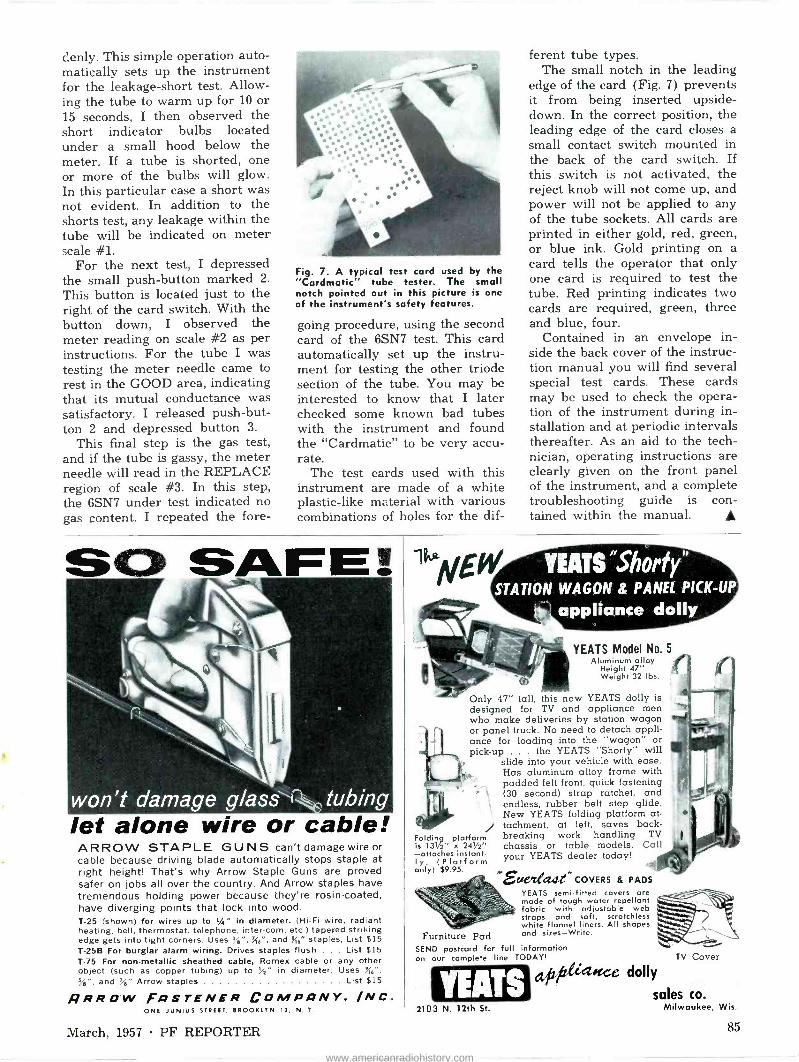
denly. This simple operation auto- matically sets up the instrument for the leakage -short test. Allow- ing the tube to warm up for 10 or 15 seconds, I then observed the short indicator bulbs located under a small hood below the meter. If a tube is shorted, one or more of the bulbs will glow. In this particular case a short was not evident. In addition to the shorts test, any leakage within the tube will be indicated on meter scale #1.
For the next test, I depressed the small push-button marked 2.
This button is located just to the right of the card switch. With the button down, I observed the meter reading on scale #2 as per instructions. For the tube I was testing the meter needle came to rest in the GOOD area, indicating that its mutual conductance was satisfactory. I released push-but- ton 2 and depressed button 3.
This final step is the gas test, and if the tube is gassy, the meter needle will read in the REPLACE region of scale #3. In this step, the 6SN7 under test indicated no gas content. I repeated the fore -
Fig. 7. A typical test card used by the "Cardmatic" tube tester. The small notch pointed out in this picture is one of the instrument's safety features.
going procedure, using the second card of the 6SN7 test. This card automatically set up the instru- ment for testing the other triode section of the tube. You may be interested to know that I later checked some known bad tubes with the instrument and found the "Cardmatic" to be very accu- rate.
The test cards used with this instrument are made of a white plastic -like material with various combinations of holes for the dif-
ferent tube types. The small notch in the leading
edge of the card (Fig. 7) prevents it from being inserted upside- down. In the correct position, the leading edge of the card closes a small contact switch mounted in the back of the card switch. If this switch is not activated, the reject knob will not come up, and power will not be applied to any of the tube sockets. All cards are printed in either gold, red, green, or blue ink. Gold printing on a card tells the operator that only one card is required to test the tube. Red printing indicates two cards are required, green, three and blue, four.
Contained in an envelope in- side the back cover of the instruc- tion manual you will find several special test cards. These cards may be used to check the opera- tion of the instrument during in- stallation and at periodic intervals thereafter. As an aid to the tech- nician, operating instructions are clearly given on the front panel of the instrument, and a complete troubleshooting guide is con- tained within the manual.
SQ SAFE!
let alone wire or cable! ARROW STAPLE GUNS can't damage wire or cable because driving blade automatically stops staple at right height! That's why Arrow Staple Guns are proved safer on jobs all over the country. And Arrow staples have tremendous holding power because they're rosin -coated, have diverging points that lock into wood. T-25 (shown) for wires up to 1/4" in diameter. (Hi-Fi wire, radiant heating, bell, thermostat, telephone, inter -corn, etc.) tapered striking edge gets into tight corners. Uses %",'46", and {6" staples, List $15 T -25B For burglar alarm wiring. Drives staples flush . . . List $15 T-75 For non-metallic sheathed cable, Romex cable or any other object (such as copper tubing) up to 'A" in diameter. Uses S6", %", and %" Arrow staples List $15
ARROW FIQSTENER COMPONY, /NC. ONE JUNIUS STREET, BROOKLYN 12, N. Y.
YEATS "Shorty STATION WAGON 8 PANEL PICK-UP
appliance dolly
YEATS Model No. 5 Aluminum alloy
Height 47" Weight 32 lbs.
Only 47" tall, this new YEATS dolly is designed for TV and appliance men who make deliveries by station wagon or panel truck. No need to detach appli- ance for loading into the "wagon" or pick-up . the YEATS "Shorty" will
slide into your vehicle with ease. Has aluminum alloy frame with padded felt front, quick fastening (30 second) strap ratchet, and endless, rubber belt step glide. New YEATS folding platform at- tachment, at left, saves back -
Folding platform breaking work handling TV is 131/2" x 241/2" chassis or table models. Call -attaches
(Platform YEATS dealer today! l
instant- your only) $9.95.
Furniture Pad SEND postcard for full information on our complete line TODAY! TV Cover
alt?l 'tce dolly
sales co.
"Seeebu a COVERS & PADS
YEATS semi -fitted covers are made of tough water repellant fabric with adjustable web straps and soft, scratchless white flannel liners. All shapes and sizes-Write.
HEIRS 2103 N. 12th St. Milwaukee, Wis.
March, 1957 PF REPORTER 85
www.americanradiohistory.com

2et's lalle &siÀess by Verne M. Ray
Tips on Handling A periodic check of your cus-
tomer files will show that certain people haven't called for service in some time. There can be sev- eral reasons for this, of course, but let's hope that none of them are your fault. The point is that it costs money to get customers, and you should be very much concerned about keeping them. It's a proven fact that it costs more to get new customers than it does to keep old ones. In addi- tion, repeat customers often pro- vide free advertising by making recommendations to their friends, relatives and neighbors.
Some of us neglect our regular customers because we're too con- cerned about getting new ones. For example, the last time you had a choice of making only one of two calls, one for an old cus- tomer or one for a person who never called before-did you take care of the new one first, hoping to make a good impression and confident that your old customer would wait a little longer? There is a certain psychology in favor of such thinking, and in many cases it pays off-but your regular customers better not hear of it, or you'll lose them for sure.
This neglect can also be applied to the personal treatment of your customers. The day has past when the public was awe-struck by the mysteries of video. Sure, most people still express some amazement at the sight of "all those wires" when first exposed to the underside of a chassis, but they expect the technician to know his business and to fix the set without too much expense on their part. Today, TV is taken for granted almost as much as the automobile, and the technician has to do more than display his skill at tube changing to keep his customers happy. Courtesy, kind- ness, and frank explanations in layman terminology pay off in other service businesses-and they will in TV servicing, too!
Customers are sometimes pretty
86
Customers shrewd people. Recently, a tech- nician friend of mine told me about an incident which occurred in a customer's home. Not being able to restore the high -voltage supply to normal operation, he ad- vised the woman that the chassis would have to go to the shop for further analysis. Naturally, she wanted to know how much this would cost. He explained that the trouble would have to be located with the use of special test instru- ments and that this was often a time-consuming, laborious opera- tion, making it difficult to deter- mine the precise cost in advance. Still she insisted on some sort of quotation, so my friend told her that this type of repair usually ran between $20 and $30, based on parts and labor costs.
When she finally consented, he pulled the chassis and set it on the floor, bottom -side exposed. "Oh, just look at all those wires and things under there! How do you fellows ever find a trouble in all that maze?"
This was the perfect opportu- nity for the technician to justify his reasons for not being able to accurately estimate the cost of the repairs. Forgetting all mod- esty, however, he replied, "Noth- ing to it when you know how," implying that he was an expert and would have little trouble set- ting this receiver straight.
The customer, feeling that she was being taken because of her ignorance in electronics, quickly retorted, "Then how come it's go- ing to take so much of your valu- able time to find out what the trouble is? You TV men are all alike-taking advantage of people at every turn. You just put that set back together and get out of here!"
At this point my friend was at a loss for words, so he promptly put the chassis back in the cabinet and left, red-faced and steaming under the collar. This customer was lost for good, and she would now distrust every technician in
the business until an extremely personable technician proved him- self honest enough to get her business.
Certainly, this was an unusual case of a "tough -dog" customer, but if this technician had been more honest with himself and the customer and had frankly ad- mitted that "all those wires and things" at times stumped him, as well as some of the best in the business, he'd have had both the repair job and the customer.
Check your customer files periodically-every month or so if necessary. You may have a fair idea why a few of them haven't called for service recently, but what about the others? You may find names of people who haven't called in a year or more. Is it be- cause they haven't needed service, moved away, etc.-reasons over which you have no control-or have they decided to call some- one else for service (and sales) ?
If you feel that you have enough customers and one more or less won't make any difference, don't take the time to finish read- ing this page. You might not be in business that long. On the other hand, if you are interested in finding out why certain people have never called again, here is a suggestion. Have some post cards printed with a special message. Change it occasionally to mention specific items you have to mer- chandise, or to offer service spe- cials like repairing a TV and a radio for the same service rate or- dinarily charged for the TV alone.
Of course, you may find that some of these customers have been lost for good because of the time interval. A good way to pre- vent this from happening is to send a "thank you" post card a few days after completing a job. Mention that you hope everything is satisfactory, and to call you if it isn't. Some shops use a double postcard for this purpose, having a section for the customer to fill out and return. This would be especially appropriate for new customers. Attentiveness of this type will let your customers know that you are sincere in wanting to provide them with the best serv- ice possible and also is sure to be instrumental in making your business prosper.
PF REPORTER March, 1957
www.americanradiohistory.com

DONT REMOVE THAT
PICTURE TUBE!
uilrt.
SAVES SERVICEMEN TIME MONEY IRRITATION
SNAP CR TUBES BACK TO NORMAL
BRILLIANCE LIKE MAGIC WITH
"NU LIFE" KINECURE
"Nu Life" Kinecure is a joy to servicemen. Saves time and effort pulling CR tubes. Solves the service problem when the customer will not permit the set to leave the house. Elimi-
nates the need for a long haul back to town for the replace- ment of CR tube. It's easy for a trained technician to follow furnished diagrams. Locate and instantly correct 33 combi- nations of CR tube element shorts and opens. The "Nu Life" Kinecure is guaranteed to correct permanently open cathode, shorted control grid to cathode, shorted cathode to filament, and open control grid. It is a superior "boost" for low emission and slow heating, and is equally effective on any receiver in
series, or parallel, or on electro -static focus CRT's. When the "Nu Life" Kinecure is installed on a picture tube, the life of the filament will be equally as long as if the same picture tube were equipped with a "Brightener". You can't go wrong with a
"Nu Life" Kinecure; and your customer will be delighted when his set snaps back quickly without long and irritating "trouble shooting". Your jobber has Kinecure now. Get the full facts and complete technical explanation. Send coupon below.
NU LI INECU
¡ C R T RES
HERE'S HOW IT WORKS The "Nu Life" Kinecure can be quickly, easily, and permanently installed by a television technician. Merely follow diagrams (included with each unit) to place terminal strip jumpers in the proper lugs for a specific defect or combination of defects, and adjust the unit's control. Proper diagnosis is not an immediate problem because the "Nu Life" Kinecure cannot harm the pic- ture tube or the receiver even if the jumpers are placed incor- rectly. An experienced technician will immediately suspect symp- toms at first glance, and can use the elimination method to try suspected shorts or opens until the picture appears. To the scien- tific minded, the "Nu Life" Kinecure operates on the 1/"mu" E.G. formulae to produce excellent picture quality. Try it. It works like a charm. Send coupon below for full information and technical data. Or ask your jobber.
CIRC AD[to
"Nu Life" Kinecure is a Product of
CIRCUIT MANUFACTURING CO., INC. 6211 Market Street, Phila., Pa.
Sold only through television service dealers
CORRECTS ALL THESE
DEFECTS PERMANENTLY Permanently eliminates defects of: Open Cathode - Shorted Control Grid to Cathode - Shorted Cathode to Filament - Open Control Grid - and is a superior boost for low emission or slow heating - Any Combina- tion of Defects Combined with Extremely Low Emission - Any Combination of Defects Combined with Slow Heating - Open Cathode Combined with Shorted Control Grid to Cathode - Open Cathode Combined with Shorted Cathode to Filament. Overcomes a total of 33 different combinations of shorts and opens involving various combi- nations of tube defects.
READ THIS UNUSUAL GUARANTEE The "Nu Life" Kinecure must do everything we say it will - or your money back - provided it is installed by any ryfcgognized television technician
ai anywhere in the .S,., ,according to installation instructions. The '` Life" Kinecure can be used on series or parlel or electro -static focus CRT's. No harm is done to either CRT or receiver if "Nu Life" is erroneously wired in installation.
FRED! GET FULL ILLUSTRATED DETAILS ssssssssIIMIN MIMI Inn norm
CIRCUIT MANUFACTURING CO., INC. 26 Rittenhouse Place, Ardmore, Pa.
Gentlemen: Please send me full illustrated details about the "Nu Life" Kinecure.
YOUR NAMF
COMPANY NAMF
ADDRESS
CITY 7O N E-STAT E
amyl maw men awn am' -
March, 1957 PF REPORTER 87
www.americanradiohistory.com

"See! I told you we'd get that boy next door over with a
JENSEN NEEDLE."
i¡tr.Auaatatch 4e; - lam MOSLEY built for
that Big
2 -Set TV Market
MOSLEY 902
List Price
MOSLEY "Dual -Match" TV Coup- lers answer the problem of Low Cost coupling of two TV sets to one antenna-without one set interfering with the other!
Quick, easy, solderless installation is your assurance of bigger profits and satisfied customers...insist on and use MOSLEY "Dual -Match" TV Couplers!
At Radio and Television Ports Distributors, Coast -to -Coast!
Motels Apartments Duplex Homes Any Multi -set Installation
MO SL EYEee .
8622 St. Charles Rock Road St. Louis 14, Mo.
PRODUCT REPORT
Flyback Transformers
Chicago Standard Transformer Corp., 3501 W. Addison St., Chicago, has added five new types to its line of Stancor exact replace- ment flybacks. A-8291 replaces Muntz part number TO -0039 in four chassis series; A-8292 is a replace-
ment for Admiral part 79D65-1 in two chassis; A-8293 replaces Magnavox parts 360552-1/-2/-2A, 360577-1, and 360593-1/-2 in seven chassis; A-8294 replaces Magnavox part 360606 -1 in four chassis; and A-8295 replaces Magnavox part numbers 360623, -1 and 360614-1 in eleven chassis.
Combined Resistor -Capacitor
A single unit resis- tor -capacitor, no larger than a tubular capaci- tor alone, has been developed and pro- duced by the Centralab Div. of Globe -Union, Inc., 900 E. Keefe Ave., Milwaukee, Wis. The
combination, called "TUBE -R -CAP," is a standard size CC32 tubular ceramic capacitor with a ceramic base resistor connected in parallel and on the same body. Maximum length of the unit is .900" and the approximate diameter is .280". The capacitor is rated at 470 mmfd and 1500 volts AC, and the resistor is a 1/2-megohm, 1A -watt unit.
Buttonless Vibrators
P. R. Mallory & Co., Inc., 3029 E. Washing- ton St., Indianapolis, Ind., has designed a new type of vibrator in which the usual button contacts are eliminated. The vibrating reed and side arms themselves are made of a special alloy and act as the contacting elements.
Because of the larger area of the contacts, the new vibrators are said
to have 50% to 100% longer life than former models. In addition, mechanical buzz is held to a very low level. The new components are designated as Series 1600 types and are available in a large variety of ratings for replacement purposes.
88 PF REPORTER March, 1957
www.americanradiohistory.com

Capacitor Packaging
Distributor's stocks of ceramic and mica ca- pacitors from Aerovox Corp., New Bedford, Mass., are now being packaged in transpar- ent plastic envelopes mounted on index cards and filed in metal draw-
ers. The smaller types of capacitors are packaged five to an envelope. If only a part of the contents are sold at one time, they can be removed from stock without damage to the envelope, which is securely closed by a folded flap. If the entire con- tents are sold, the envelope (including a tag which describes the contents) is detached from the index card and given to the customer for his convenience in storing.
hinge masts
Self -Locking Roof Mount
Manufactured by Rohn Mfg. Co., 116 Limestone, Bellevue, Peoria, Ill., this spe- cially designed, cast roof mount snaps into place when upright, then securely locks in that position when
bolt is tightened. This feature means that can be installed quickly by one man.
Three -Way Switch
Anchor Products Co., 2712 W. Montrose Ave., Chicago, is marketing a rotary three-way switch, the Model S-203 "Selecto -Switch." The unit, featuring solder - less connections, has many possible uses in
hi-fi antenna systems. The high -impact plastic case measures 3" x 1%" x 1" and is equipped with two mounting ears to simplify installation. A dia- gram showing how to hook up two speakers to the switch for "one, the other, or both" operation is furnished with each unit.
and
Transistor Checker
Century Electronics Co., Inc., 111 Roosevelt Ave., Mineola, N. Y., has developed a low- cost transistor tester, the Model TC -1 "Tran- sistor - Check." A n y available volt - ohm- meter may be plugged into the unit to serve as an indicating device.
The TC -1 tests transistors in or out of the receiver for current gain, leakage, open or shorts. Crystal diodes can be checked for ratio of forward to back current. The battery -powered instrument costs $6.95, complete with instruction manual.
DISTRIBUTOR
'ERIE
Replacement Modules
for Servicing .. .
1957 Auto Radios
PAC is a group of interconnected capacitors and resistors, combined in a single -insertion unit. Several popular 1957 model automobile and truck radios employ this new con- cept in component packaging. When servicing these auto radios, a com- plete PAC ( Pre Assembled Circuit ) module can be quickly and easily replaced.
Your ERIE Distributor has PAC Replacement Modules in stock. See him for complete information and prices.
ERIE 440 -
ERIE ELECTRONICS DISTRIBUTOR DIVISION ERIE RESISTOR CORPORATION
Moir, Offices: ERIE, PA. F.crori., ERIE, PA. LONDON, ENGLAND TRENTON, ONTARIO
March, 1957 PF REPORTER 89
www.americanradiohistory.com

Pf REPORTER CATALOG and LITERATURE SERVICE MARCH 1957
INDEX TO ADVERTISERS
March 1957
Advertisers Page No. Acme Electric Corp. 46 Aerovox Corp. 46 American Elite, Inc. 83 American Television & Radio Co. 68 Amphenol Electronics Corp. 42 Argos Products Co. 54, 78 Arrow Fastener Co. 85 Astron Corp. 7
B & K Mfg. Co. 12, 20, 52 Belden Mfg. Co. 61 Blonder -Tongue Labs. 66 Bussmann Mfg. Co. 39 CBS-Hytron 30 Centralab, A Div .of
Globe -Union, Inc. 70, 71 Century Electronics Co., Inc. 75 Chicago Standard Transformer Co. 43 Circuit Mfg. Co., Inc. 87 Clarostat Mfg. Co., Inc. 24 Clear Beam Antenna Corp. 8 Colman Tool & Machine Co. 64 Cornell-Dubilier Electric Corp. 48 Delco Radio Div.,
General Motors Corp. 26 Electro -Voice, Inc. 53 Eby Sales Co. 83 Electronic Instrument Co., Inc.
(EICO) 81 Electronic Pub. Co. 82 Elgin Nat'l Watch Co.
(Electronics Div.) 80 Erie Resistor Corp. 89 General Cement Mfg. Co. 32 General Electric Co. 59 Gernsback Library, Inc. 77 Hickok Electrical Instrument Co. 47 Hycon Mfg. Co. 58 International Business Machines
Corp. 10-11 International Resistance Co..2nd Cover Jackson Electrical Instrument Co. .. 64 Jensen Industries, Inc. 88 Jensen Mfg. Co. 49 JFD Mfg. Co. 80 Lenk Mfg. Co. 62 Littelfuse, Inc. 4th Cover Mallory & Co., Inc., P. R. 44, 45 Merit Coil & Trans. Corp. 80 Mosley Electronics, Inc. 88 Newcomb Audio Products Co. 73 Oxford Components, Inc. 76 Phaostron Co. 9 Planet Sales Corp. 84 Pyramid Electric Co, 63 Radiart Corp.-Cornell-Dubilier
Electric Corp. 1 Radio Corp. of
America .... 6, 57, 69, 79, 3rd Cover Raytheon Mfg. Co. 22 R -Columbia Products Co. 64 Recoton Corp. 82 Sangamo Electric Co. 67 Sams & Co., Inc., Howard W.
33-34, 35, 65, 79 Sarkes Tarzian, Inc. 40 Service Instruments Co. 83 Simpson Electric Co. 55 Sprague Products Co. 2
Stevens Walden, Inc. 72 Sylvania Electric Products, Inc. 4-5 Teletest Instrument Corp. 77 Triad Transformer Corp. 60 Triplett Electrical Instrument Co 28 University Loudspeakers, Inc. 37 Vaco Products Co. 84 V -M Corporation 41 Walsco Electronics Corp. 74 Ward Products Corp. 36 Weller Electric Corp. 56 Wright Steel & Wire Co., G. F. 72 Xcelite, Inc. 81 Yeats Appliance Dolly Sales Co. 85
1C. AMERICAN ELITE Telefunken tube manual and name of nearest distributor. See advertisement page 83.
2C. B & K Bulletin 1000 describes new "Dyna-Scan" picture and pattern video -generator. Bulletin 750 on new lab -type test equipment cal- ibrator Model 750 that checks in- strument accuracy. Also Bulletin 500 on "Dyna-Quick" dynamic mutual conductance tube tester and Bulletin 400 on CRT cathode rejuvenator tester. See ads pages 12, 20, 52.
3C. BLONDER -TONGUE Form 6510065 on Model MCS TV amplifiers; Form MC -5-17 on crystal -controlled VHF and UHF converters. See ad page 66.
4C. BUSSMANN New and very comprehensive book on fuses and fuse mount- ings used by the electronics in- dustries. See ad page 39.
5C. CENTRALAB New 48 -page 2 -color Centralab Catalog No. 30. Lists controls, switches, capacitors, packaged electronic circuits and semicon- ductors. See ads pages 70, 71.
6C. CENTURY Free 1957 catalog describing com- plete line of test equipment for radio and TV servicing. See ad- vertisement page 75.
7C. CLAROSTAT Form No. 751771 describing "Pick -A -Shaft" 2 -watt, 3 -watt, and 4 -watt wire -wound controls. See advertisement page 24.
8C. CLEAR BEAM Literature on do-it-yourself an- tenna kits. See ad page 8.
9C. CHICAGO STANDARD 1957 STANCOR TV Transformer Replacement Guide & Library. See advertisement page 43.
10C. CORNELL-DUBILIER Literature on Powercon-Invert- ers (Ext. INV.). See ad page 48.
11C. EICO 12 -page catalog shows how to save 50% on electronic test in- struments and high fidelity equipment in both kit and fac- tory -wired form. See ad page 81.
12C. ELECTRO -VOICE Pocket-size, Power -Point phono - c a r t r i d g e "Interchangeability Guide" indexes in easy -to -use chart form the more than 400 conventional cartridges replaced by 7 Power -Point models and 3 mounts. See ad page 53.
13C. ERIE Literature describing new phono - amplifier kit. Also D-56 Catalog on electronic components; Corn- ing Glass Sheets; and Teflon Tip Jack Flyers. See ad page 89.
14C. GERNSBACK Descriptive literature on Gems - back Library Books. See adver- tisement page 77.
15C. HICKOK An 8 -page composite test equip- ment catalog describing the latest TV testers. See ad page 47.
16C. HYCON Comprehensive folder on latest Hycon test instruments and ac- cessories. See ad page 58.
17C. IRC Form S -059C. new DC3C close tolerance Precistor Catalog. See advertisement 2nd Cover.
18C. JENSEN Brand new "Jenselector" contain- ing the names of over 300 brands of phonographs and the needles used by each. See ad page 88.
19C. MOSLEY New 1957 Catalog of TV installa- tion accessories (Cat. 57). Also new catalog of Rotary Beam An- tennas and other ham equipment (Cat. H-57). See ad page 88.
20C. NEWCOMB Catalog sheet on two -channel, 25 -watt, 3-D stereophonic ampli- fier with ganged controls for loudness compensation and focus for speaker balance. See adver- tisement page 73.
21C. PHAOSTRON Illustrated catalog lists complete line of custom panel meters. In- cludes comparison chart of Phao- stron instruments vs. other brands and complete information on dimensions and features. See advertisement page 9.
22C. R -COLUMBIA Bulletin 23: describes use of "Fono -Magic" to stop phono- graph turntables from slipping. Bulletin 24: new weather proof "Humi-Kup" 2 -set type of instal- lation. Bulletin 22: use of "Trol- master" to clean and lubricate TV-Radio Controls in 60 seconds. See advertisement page 64.
23C. SIMPSON Bulletin No.2058 describing test equipment, and Bulletin No. 2057 covering panel meters. See ad- vertisement page 55.
24C. SPRAGUE C -611a revised catalog of stock TV and radio replacement parts. See advertisement page 2.
25C. TACO Consumer advertising program for TV antenna installers.
26C. TELEMATIC Free 16 -page booklet entitled "Hints for Speedier Servicing." Goes into full detail about the common faults found in CRT and SYNC circuits; how to recognize them and how to fix them quickly.
27C. TRIAD General Catalog TR -57. See ad- vertisement page 60.
28C. TRIPLETT Catalog on Model 3423 mutual conductance tube tester. See ad- vertisement page 28.
29C. VACO Catalog on Vaco screwdrivers, nut drivers, pliers, wood chisels and solderless terminals. See ad- vertisement page 84.
30C. WALSCO Catalog Sheet featuring informa- tion on Walsco TV alignment tool with exclusive micrometer action which automatically counts and indicates exact number of turns to the right or left. See ad page 74.
31C. WARD PRODUCTS Ward 1957 Auto Catalog and WCA Communication Antennas Catalog 1957. See ad page 36.
32C. XCELITE Folder on 9" snap -in shaft exten- sion 99-X10 for 99PR and 99JR nut driver, screwdriver sets; also general small tool catalog. See advertisement page 81.
90 PF REPORTER March, 1957
www.americanradiohistory.com

ORDER YOUR SUBSCRIPTION TODAY TO
THE INDUSTRY'S LEADING MAGAZINE-
PF REPORTER
n
o
ó E
cn ó
a a m
-n
3
z a 3 m
3
Z 3 C
17 C
2 C
18 C
3 C
19 C
4 C
20 C
5 21 C C
6 22 C C
7 C
23 C
8 C
24 C
9 C
25 C
10 C
26 C
11 C
27 C
12 C
28 C
13 C
29 C
14 C
30 C
15 C
31 C
16 C
32 C
v m
3 O
(D
www.americanradiohistory.com

-Ci
o z
id
¡liii 1111111111111111
Li. a.
o z
IIIIIIIIIIIIIIIIIIIII
cc
V
- J d W at
W
z
o N N
www.americanradiohistory.com

MARCH 1957
SUPPLEMENT to SAMS MASTER INDEX No. 102
This Supplement is your handy index to new models covered in the latest PHOTOFACT Sets 346 through 352. It's your guide to the world's finest service data coverage of the current output of the new TV and Radio receivers, as well as models not previously covered in PHOTO - FACT. It keeps you right up to date.
ALWAYS USE YOUR LATEST ISSUE OF THIS SUPPLEMENT WITH THE SAMS MASTER INDEX . . . TOGETHER, THEY
ARE YOUR COMPLETE INDEX TO OVER 30,000 MODELS.
Set Folder No. No.
ADMIRAL Chassis 4G2, 4G24 346-2 Chassis 5W3 352-2
Chossis 14UY3B, C 351-1 Chassis 14YP3C, BK, C 350-1
Models HP2235, HP2238 (See Ch. 4G2)
Models 7101, 7102, 1103, 7104, 7105Á1, 710641, T107AL (See Ch. 1479381
Models 7140, 7141, 1142, 1143, T144AL, 114544 (See Ch. 14YP3C)
Models 11010, 71011AL, 71012AL, 7101341 (See Ch. 144938)
Model 71410 (See Ch. 14YP3C) Models 75101, 75102, 15103,
75104, 7510541, 1510644, 75107ÁL (See Ch. 14UY3B)
Models 75140, TS141, 15142, TS143, T514441, 75145AL (See Ch. 14UY3C)
Models 151010, 751011, T510241, 751013AL (See Ch. 1411Y38)
Model 4D18D (See Ch. 4G2) Model 4D28D (See Ch. 4G2) Model 4G22D (See Ch. 402) Models 5842, 51143 (See Ch. 5W3) Model 5848 (See Ch. 5W31 Models 5H44, 5H47, 5H49 (See Ch.
5W3) Models 5W32. 5W33, 5W34 (See
Ch. 5W3) Models 5W38, 5W39 (See Ch. 5W3)
AIRLINE GEN -1090A 350-2 GEN -1103A 349-2
GRX-4020A, GRX-4120A 347-1 WG -50304, WG.50324, B, C, WG -
50354, B, C 351-2 WG -5I304, WG 51324, B, WG -
5135A, B 351-2 AMBASSADOR
171161E, M, 177162, 171763 (Ch. A2005( 352-3
Ch. A2005 (See Model 171761E)
ANDREA 2LB-VP21 (Ch. VP21( (See Model
C-VP21-Set 326-4(
ARVIN 5561 (Ch. 1.40800) 351-3 9562 (Ch. 1.40900) 348-1 Ch. 1.40800 (See Model 5561) Ch. 1.40900 (See Model 9562)
AUTOMATIC 71600 349-3 B ROCINER Mork 30A 347-2 Mork 30C 346-3 B UICK 981707 347-3 981708 346-4
CBS -COLUMBIA U23C39, B (Ch. 921-93) (See PCB
179 --Set 346-1 and Model 23C49L-Set 292-3)
U23C49L (Ch. 921-93) (See PCB 179 -Set 346-1 and Model 23C49L-Set 292-3)
U23719, B (Ch. 921-93) (See PCB 179 -Set 346-1 and Model 23C49L-set 292-3)
23C39, B (Ch. 921-94) (See PCB 179 -Set 346-1 and Model 23C49L-Set 292-3)
23719, B (Ch. 921-94) (See PCB 179 -Set 346-1 and Model 23C49L-Set 292-3)
Ch. 921.93 (See Model U23C39)
CHEVROLET 987577 352-17-S 3725156 352-17-S
COLUMBIA RECORDS
522, 524, 527 352-4 CORONADO RA12-8121-A 346-5
DUMONT RA -380, RA -381
ELECTRO -VOICE PC2
Set Folder No. No.
CROSLEY AC -10B, AC -10M (Ch. 487) 351-4 AC -118, AC -11M (Ch. 888) 351-4 AH -10B (Ch. 487) 351-4 AH -118 (Ch. 488) 351-4 A1 -10B, AT -10M ICh. 487) 351-4 A7118, AT -11M (Ch. 488) 351-4 BC-12BZ, M, MZ, BC -13B, M, BC-
14M, BC -15M (Ch. 489, 490) 352-5
B712BZ, M, MZ, BT -138, M (Ch. 489, 490) 352-5
Ch. 487 (See Model AC -10B) Ch. 488 (See Model AC -I18) Ch. 489, 490 (See Model BC -128Z)
DEWALD K-544 347--4
346-22-5
351-5 FIRESTONE 4-A-152 (Code 364-6-360).350-4 4-A-154 (Code 382-6-374/21
348-2 4-A-160 (Code 297-6-581) 346-6 FORD 78MF (FEG -18806-G) 352-6 FEG -18806.G (See Model 78MF)
GRANCO 770 350-5 HALLICRAFTERS TW200, TW201, TW202, TW203
Mork I, IA) 349-4 10T5900B, M, 1, 1011,90111, M, T
(Ch. A2011, B2011) ..348-18-S 1715740B, M (Ch. 42007) 348-18-S
1775760B, 81X, M (Ch. 42007, E2007) 348-18-5
17157808, M (Ch. A2007( 348-18-5 21K7854B, M (Ch. C2005) (See
Model 1717700E -Set 339-7) 21KT855B, M (Ch. 020051 (See
Model 1711700E -Set 339-7) Ch. 42007 (See Model 1775740B) Ch. A2011, B2011 (See Model
10759008) Ch. E2007 (See Model 17T5760BJX)
HARMAN-KARDON T-10 350-6 TA -10 351-6 HOFFMAN
1EB3191, U (Ch. 420, U) 352-17-S M3181, U (Ch. 420, U) 352-17-S
8/5P3181, U (Ch. 420, U) 352-17-5 2021 (Ch. 7061 350-18-S
4041 (Ch. 706) 350-18-5 4051 (Ch. 706) 350-18-S
4061 (Ch. 706) 350-18-S Ch. 420, U (See Model 83191) Ch. 706 (See Model 2021)
HOTPOINT 175301, 175302 ("MM" Line)
347-6 215401 ("U" Line) 348-3 215451, 215452 ("U" I ine) 348-3 215501, 215502 ("U" line) 348-3 215551, 215552 ("U" 1 ine) 348-3 245801, 245802 ("U" Line) 348-3
KNIGHT 9357690 352-7 945X700 350-7 945X702 352-8 945)(703 349-5 945)(708 350-7 945x711 352-8 945X730 351-7 94SZ701 351-8 94SZ709 351-8 9452731 351-7 LECTROLAS R-400 351-9 11500 348-4 R-600 348-5
Set Folder No. No.
MAGNAVOX l8 Series 348-6 21 Series 347-7
117 Series 350-8 Chassis AMP -15111E (See Ch. AMP-
151AA-Set 343-6) Chassis AMPI 52A4, AMPI 54AÁ
351-10 Chassis C4I1A435CB, CMUA436CB,
CMUA437CB, CMUA438C8 (250 Series) (See PCB 168 -Set 331-1, PCB 179 -Set 346-1 and Ch. CMUA435AA-Set 278-5)
Chassis CMUA487AA, BB, CC, CMUA488AA, CMUA489AA, CMUA490AA, BE, CC, CMUA491- AA, BB, CC, CMUA492AA (117 Series) 350-8
Chossis CMUA496B8, CMUA497B8, CMUA4998B, CC (117 Series)
350-8 Chossis CMUA50186, CC (117
Series) 350-8 Chossis CMUD495AA, BB, CC (117
Series) 350-8 Chassis CMUE493AA, BB, CC,
CMUE494AA, BB (117 Series) 350-8
Chassis CR730AA 350-9 Chassis C1A435C8, C1443608,
CTA437CB, CIA438CB (250 Se- ries) (See PCB 168 -Set 331-1, PCB 179 -Set 346-1 and Ch. CMUA435AA-Ser 278-5)
Chossis C7448744, BB, CC, C7A- 488AA, CTA489AA, CTA490AA, B8, CC, C7449144, 8B, CC, CIA - 49244 (117 Series) 350-8
Chassis C7449688, CTA497E8, CTA- 49988, CC (117 Series1 350-8
Chassis CTA5018B, CC (117 Series) 350-8
Chassis CTD495AA, BB, CC (117 Series) 350-8
Chassis CTE493AA, BE, CC, CTE- 494AA, BB (117 Serie,) 350--8
Chossis U18 -01A4, U18 -02A4, U18. 0344, U18 -04A4 (18 Series)
348-6 Chossis U18-0188, 018.0288, 818-
0388, U18-0488 (18 Series) 348-6
Chossis U21 -0I44, U21 -02A4, U21- 03AA, U21 -04A4 (21 Series)
347-7 Chassis VI8-01A4, V18 -02A4, V18.
0344, VI8-0444 (18 Series) 348-6
Chassis VI8-01BB, V18-0288, V18- 0388, V18-0488 (18 Series)
348-4 Chassis V21 -01A4, V21 -02A4, V21-
03AA, V21.0444 (21 Series) 347-7
METEOR 4103-H (Ch. 549.200351 348-7
Ch. 549.20035 (See Model 4103-H)
MOPAR 620, 621 350-10 840 (P5606) 348-8 841, 842, 843 347-8 844 (C5609), 844H8 (C5609HR)
348-8 910, 91011E, 911 348-9 912 (C-5696), 912HE (C-5696HR)
351-11 916, 916HR 352-9 MOTOROLA
21CK3 Series (Ch. TS -905) 346-22-S
21CT2 Series (Ch. 75-905) 346-22-5
27F1, 27F2 (Ch. HS -540)..350-11 57CC1, 57CC2 (Ch. HS -531) 351-12 5781, 5782, 57123, 5784 (Ch. MS -
522) 347-9 578F1, 578F2 (Ch. 115-542) 352-10 57X1, 57X2 (Ch. HS -524) 351-13 67HFK1, 1, 3, 4 (Ch. HS -544)
349-6 67HFPI (Ch. HS -544) 349-4 67HFT1 (Ch. HS -544) 349-6 67X1, 67X2 (Ch. HS -5261 352-11 Ch. 115-522 (See Model 57E1) Ch. HS -524 (See Model 57X1) Ch. HS -526 (See Model 67X1)
File this Supplement with your 36 -page SAMS MASTER INDEX. Together, they give you com- plete PHOTOFACT coverage.
For models and chassis not
listed in this Supplement, refer to SAMS MASTER
INDEX No. 102. If you haven't a copy, send for it today. It's FREE ... just
write to HOWARD W. SAMS & CO., INC., 2201
East 46th Street, Indian- apolis 5, Indiana.
Set Folder No. No.
MOTOROLA-Cont. Ch. HS 531 (See Model 57CC1) Ch. HS -540 (See Model 27F1) Ch. H5-542 (See Model 57Rí1) Ch. HS -544 (See Model 67HFKI) Ch. T5-905 (See Model 21CK3
Series)
MUNTZ 721CBD, 721CBD/82 352-12 721 CBS, 72ICBS/82 352-12 7210EA, 7210EA/82 352-12 721CMD, 721CMD/82 352-12 721CM5, 721CM5/82 352-12
721CPB, 721CPB/82 352-12 72ICPM, 721CPM/82 352-12 721CW, 721CW/82 352-12
72117540, 721 LTS-M, 721175-8/82, 721 LTSM/82 352-12
72178, 7211E/82 352-12 7217M, 7211M/82 352-12
72175, 72115/82 352-12 721TSP-BK, 72115P -BL, 721TSP-
BK/82, 721TSP-BL/82 352-12 721T5P-RD, 7217SP-4D/82 352-12
721 TSP-WH, 721TSP-WH/82 352-12
OLDSMOBILE 983336 346-7 OLYMPIC 1 CA70, U (Ch. DA, DAU) 350-18-5
10671, U, ICB72, U (Ch DB, DBU) 350-18-S
1CB77, U (Ch. DB, DBU) 350-18-5 1CD73, U, 1C074, U (Ch. 00,
DDU) 351-22-S I KA80, U (Ch. DA, DAU) 350-I8-5
eIKB87, U, 11(888, U (Ch. DB, 088) 350-18-5
11(081, U, 1KD82, U, 1K083, U
(Ch. DD, DDU) 351-22-S 1TA60, U (Ch. DA, DAU) 350-18-S
17861, U (Ch. DB, DBU) 350-18-S 11D62, U (Ch. DD, D13U) 351-22-5 4CF75, U, 4CF76, U (Ch. DF, DFU)
350-18-S 4KF84, U (Ch. DF, DFU) 350-18-S 4KH85, U, 410186, U (Ch DM, DHU)
351-22-S 141W50 (Ch. CW) (See Model
141150 -Set 337-13) 171X51 (Ch. CX) (See Model
141750 -Set 337-13) 447 349-7 Ch. CW (See Model 147W50) Ch. CX (See Model 171)(51) Ch. DA, DAU (See Model 1CA701 Ch. DB, 08U (See Model 1CB71) Ch. DO, DDU (See Model 1CD73) Ch. DF, DFU (See Model 4CF75) Ch. DH, DHU (See Model 4KH85)
PACKARD-BELL 21ST2 (Ch. 8852) 349-8 Ch. 8852 (See Model 21572)
PHILCO D-1345 347-10 E-670, E-672, E-675, E-676 346-8 E-740, E-742 351-14 E-808, E-810, E-812, E-814, E-816
351-14 E-1351, E-1353 350-12
442002C, E2004F, G, SP (Ch. 7E10, 7E11) 348-10
7-7 347-11 UE2002C, UE2004F, G, SP (Ch.
7E10 -U, 7811 -UI 348-10 2205100, 2205102, L, M (Ch. TV-
123) 349-9 Ch. TV -123 (See Model 2205100) Ch. 7E10, -U, 7E11, -U (See Model
E2002C)
PHONOLA 655, 855 347-12 PONTIAC 988569 346-9 RCA VICTOR 6E55 (Ch. RS -157, A) 351-15 78X9H (Ch. RC -1163) 349-10 7EP2 (Ch. ES -153) (See Model
6EMP2A-Set 338-9) 7EP45 (Ch. ES -1520) (See Model
6EY3A-Set 332-12) 7ES6H, 7E561 (Ch. RS -157, A)
351-15
® NE) ro PHOTOfACT MOM
Set Folder No. No.
RCA VICTOR -Cent. 7HF4 (Ch. RS 146F) 347-13 7HF5 (Ch. RS -158) 346-10 88710K (Ch. RC -1156A) 350-13 21D7425, U, 2117427, U (Ch.
KCS104E, F) 346-11 21137445, U, 2107446, U, 2107447,
U (Ch. KC5104H, J) 346-11 21137479, U (Ch. KCS104H, 1)
346-11 2107485, U, 2107487, U, 2107488,
U (Ch. KCS104H, 1) 346-11 2107505, U, 2107506, U, 2107507,
U (Ch. KCS104H, 1) 346-11 2177112, U, 2117113, U (Ch.
KCS98A, C) 347-14 21T7117, U (Ch. KCS98A, C)
347-14 2117152, U, 2117153, U (Ch.
KCS98A, C) 347-14 2117157, U (Ch. KCS98A, C)
347-14 2117352, LI, 2177355, U, 2177357,
U (Ch. KCS98E, F) 347-14 2117385, U, 2177386, U, 2117387,
U (Ch. KCS104A, B) 346-11 2177388, U (Ch. KCS104A, E) (See
Model 2177385 -Set 346-11) 2117415, U, 2177416, U, 2177417,
U (Ch. KCSIO4C, D) 346-11 24D7545, U, 2407547, U (Ch.
KCS104AA, AB) 346-11 2407566, U, 2407568, U (Ch.
KC5104AA, AB) 346-11 2407587, U (Ch. KCS104AC, AD)
346-11 2407705, U, 2407706, 0, 2407708,
U (Ch. KC5I04AE, AF1 346-11 24D7726, U, 2407728, U (Ch.
KCS104AE, AF) 346-11 Ch. KCS98A, C (See Model 2117112) Ch. KCS98E,F(See Model 21173521 Ch. KC5104A (See Model 2117385) Ch. KCSI04AA (See Model 2407545) Ch. KCS104A8 (See Model
24D7545U) Ch. KCSI04AC (See Model 2407587) Ch. KCSI0IAD (See Model
24D7587U) Ch. KCS104AE (See Model 2407705) Ch. KCS104AF (See Model
24077050) Ch. KC51048 (See Model 2117385U) Ch. KCSIO4C (See Model 2117415) Ch. KCSI 040 (See Model 211741501 Ch. KCS104E (See Model 21074251 Ch. KCS104F (See Model 21074250) Ch. KCS104H (See Model 2107487) Ch. KCS1041 (See Model 2107487U) Ch. KC5104K (See Model 2107505) Ch. KC5104L (See Model 2107505U) Ch. RC -1156A (See Model 8BT10K) Ch. RC -1163 (See Model 780911) Ch. RS -146F (See Model 7HF4) Ch. RS -152D (See Model 7EP45) Ch. RS -157, A (See Model 6E55) Ch. RS -158 (See Model 7HF5)
REGENCY TR -6 346-12
ROLAND 4P1, 4P2-1, 492-2 346-13 SPI, 5P5-1, 5P5U-1 348-11 6TR 347-15
SCOTT (H. N.) 223 349-11 330 348-12 331 346-14
SETCHELL-CARLSON
1119-62 (Ch. C-101) 346-15 Ch. C-101 (See Model P-62)
SILVERTONE 3250 (Ch. 137.917) 348-13
6102, 6103 (Ch. 549.20040, 549.- 20050) 351-22-S
7010, 7011, 7012 (Ch. 132.40000) 352-13
7013,7014(Ch. 132.40100) 347-16 7018 (Ch. 528.465001 352-14 7045, 7046 (Ch. 528.47200)
351-16 7200, 7202 (Ch. 132.40200) 346-16 7222 (Ch. 528.48000) 350-14 Ch. 132.40000 (See Model 7010)
NOTE: PCB Denotes Predueion Change Bulletin. Denotes Television Receiver. S Denotes Schemotic Coverage Only.
www.americanradiohistory.com

Set Folder No. No.
SILVERTONE-Cont. Ch. 132.40100 (See Model 7013) Ch. 132.40200 (See Model 7200) Ch. 137.917 (See Model 3250) Ch. 528.46500 (See Model 7018) Ch. 528.47200 (See Model 7045) Ch. 528.48000 (See Model 7222) Ch. 549.20040, 549.20050 (See
Model 6102)
SONORA 571 352-15 607, 608 350-15
STEELMAN 3S5, 356 348-14
SYLVANIA 210501 Series, 210502 Saris, (Ch.
1-533-3, -4) 352-16 210605 Serie,, 210607 Serias (Ch.
1-533-7, -8, -9) 352-16 211201 Series (Ch. 1-533-3, -4)
352-16 211206 Series (Ch. 1-533-3, -4)
352-16 21T301 Series (Ch. 1-533-3, -4)
352-16 21T303 Serie, (Ch. 1-533-7, -8, -9)
352-16 24C603 Serie, (Ch. 1-533.7, -8, -9)
352-16 24T301 Series (Ch. 1-533-3, .4)
352-16 Ch. 1-533-3, -4 (See Model 210501
Series)
Set Folder No. No.
SYLVANIA-Cont. Ch. 1-533-7, -8, -9 (See Model
210605 Series)
TRAV-Lilt 55C46, 56C46 351-18
517-106, 517-107 (Ch. 52045) (Also see PCB 180 -Set 349-1)
330-11 521-111, 521-112 (Ch. 52045)
(Also see PCB 180 -Set 349-1) 330-11
621-740, U (Ch. 631-26, 632-26) 347-18-S
621-750, U (Ch. 631-26, 632-26) 347-18-S
721-8400, U (Ch. 631-26, 632-26) 347-18-S
Ch. 52045 (See Model 517-106) Ch. 631-26, 632-26 (See Model
621-740)
TRUETONE
D46234, 04624A 350-16 D46254, 046264 348-15 2D17134, 2017144 346-17 2017154, 2D17164 349-12
V -M 625 351-19 1275 347-17
W ERCOR
GT1651 348-16 1654, 1657, 1661 346-18
SAMS MASTER
INDEX No. 101
September, 1456
IHDEX TO SAMS
F OlD EOS PNOi O AOi C ees 14104.ns... 1
u«. ..1,.,... , s.e"1"." s.^
.n,oM...s..+,... r,,, M ñ .. ego ,... _
SAMS »R yOy
w.a..o.a.: r w w+w .,. mn
Set rWádr, OSSlReraR
ww,
.,ov1.o « ,var1 a ea
eue, .. _. ; ;me,,,, e"' ->..
Set Folder No. No.
WELLS-GARDNER 37410-551-5 349-14 37410-562 349-14 237410-553-S 349-14 237410-564 349-14
WESTINGHOUSE
H-218111, H-218112, H-218113, H-218114, H-218115, H-218116 (Ch. V-2344-25, -26)...350-17
H-21KU111, H-21KU112, H-21KU- 113, H-21KU114, H-21KU115, H-21KU116 (Ch. V-2354-204)
350-17 H-217101, H-211104, H-211105,
H-211106, H-211107, H-211108 (Ch. V-2344-25, -261 350-17
H-21TU101, H -211U104, H-21TU- 105, H-21111106, H-21TU107, H-21TU108 (Ch. V-2354-204)
350-17 H221155, H22T156, 112211574 (Ch.
V-2293) 347-18-S H22TU155, H22TU156 (Ch. V-2294)
347-18-S H-248122, H-218125, H-248126,
H -24K127, H-248128 (Ch. V- 2345-26) 350-17
H-24KU122, H-24KU125, H-24KU- 126, H-24KU127, H-24KU128 (Ch. V-2355-204) 350-17
H -24T117, H-241118, H-241119, H-241120, H-241121 (Ch. V. 2345-26) 350-17
4 -
TAKE THE RIGHT STEP TO TIME -SAVING PROFIT -BUILDING BUSINESS: Sign up with your Parts Distributor to get PHOTOFACT Folder Sets automatically each month.
DO IT NOW! I am a Service Technician: full time; part time.
My Distributor is:
Shop Nome
Ath',
Address
fflythy Rs SAMS w..1 I IBNIIM' 81118MMI'
I
City Zone State
Set Folder No. No.
WESTINGHOUSE -Coot. H-24TU117, 11-241U118, H -241U-
119, H-24TU120, H-24TU121 (Ch. V-2355-204) 350-17
H-113, H-114, H-116 (Ch. V-2105) (See Model H -117 -Set 11-34)
11-557P4, H-55894, H -559P4 (Ch. V-2271-1) 346-19
H-58797, H -588P7, H -589P7 (Ch. V-2278-1) 351-20
H-59894, H -599P4 (Ch. V-2271-1) 346-19
Ch. V-2105 (See Model H-113) Ch. V-2271-1 (Sea Model H-55794) Ch. V-2278-1 (See Model H-58797) Ch. V-2293 (See Model H221155) Ch. V-2294 (See Model H22TU155) Ch. V-2344-25, -26 (See Model
H-211101) Ch. V-2345-26 (See Model 1-241-
117) Ch. V-2354-204 (See Model 1-21-
TU101) Ch. V-2355-204 (See Model H-24-
TU117)
ZENITH 191101, Y, HFY12E, R (Ch. 3104)
346-20 HFY15E, R (Ch. 3105) 349-15 HFZI8R, HFZ19E (Ch. 5221)346-21 Royal 800 (Ch. 7ZT41).. 351-21 Ch. 3104 (See Model HFYIOL) Ch. 3105 (See Model HFYI5E) Ch. 5Z21 (See Model HFZ18R) Ch. 72141 (See Model Royal 800)
Set Folder No. No.
RECORDERS
EKOTAPE 250, 251, 252, 253, 254, 255, 260,
261 347-5 ELLAMAC "Language Mostar" 350-3 REVERE
T-10 (CM -5) 193-9 T-700 (CM -5) 193-9 TR -20 (CM -5) 193-9 TR -800 (CM -5) 193-9 TRS-25, TR5.26, TES -27
(CM -5) 193-9 TRS-850, TRS-852 (CM -5) 193-9 TRS-862 (CM -5) 193-9 TS-15,TS-16,TS-17 (CM -5) 193-9 TS -750, TS -752 (CM -5) 193-9 TS -762 (CM -5) 193-9 SILVERTONE 7074 (Ch. 567.34004, 567.35010)
351-17 Ch. 567.34005 (See Modal 7074) Ch. 567.35010 (See Model 7074)
V -M 710, 711 349-13 750 349-13
WEBSTER ELECTRIC (See Ekotape) WILCOX GAY 651, 674 348-17
Free! to Service Technicians Only
THE NEW SAMS INDEX TO PHOTOFACT FOLDERS
it keeps you up-to-the-minute on receiver coverage
Mail coupon today for your free subscription to the Soms Photofact Index
Howard W. Sams & Co., Inc. 2203 E. 46th St., Indianapolis 5, Indiana
Send me your FREE Master Index to PHOTOFACT Folders (twice yearly), and put me on your mailing list to receive all Index Supplements. My letter- head and/or business card is attached.
-J NOTE: PCB Denotes Production Change Bullet n. Denotes Television Receiver. S Denotes Schematic Coverage Only.
www.americanradiohistory.com

"Authorized RCA Electron Ask your RCA distributor how you can enjoy the prestige
and profit of this powerful service dealer prograni. It will
pay you to check into the requirements at once-and iden-
tify yourself and your shop with the greatest name in elec-
tronics-RCA. Once you qualify, you can use the arsenal
of promotion materials prepared exclusively for "Author-
ized RCA Tube Dealers"-outdoor and indoor signs, dis-
plays, direct mail, newspaper ad mats, radio scripts, decals
-everything to tell your customers you're an "Authorized
RCA Electron Tube Dealer"!
RADIO CORPORATION of AMERICA Tube Division, Harrison, N. J.
Tube Dealer"?
3rd Annual NATIONAL TELEVISION
SERVICEMEN'S WEEK
March 25-30 This is RCA's annual salute to its business partners-the TV-Radio Service Technicicns of America. Big color ads in March 23rd issues
of TV Guide and the Saturday Evening Post,
and March 25th issue of Life-tributes on NBC
network radio and TV shows, including March 16th TV Emmy Awards program and March 23rd Perry Como show. Be sure to hame all your customers and prospects tune in hose gala shows to see your NTSW tribute.
www.americanradiohistory.com

FIRST in service Tear on dotted line
r The new Limited Current (LC) fuses are being used by more
and more TV set manufacturers. The LC fuses are designed to protect the TV set manufacturer, the serviceman and the set owner by making it mechanically impossible to replace a fuse with anything but another fuse of the proper amperage range.
LC fuses demand exact replacement.
The table printed below is a quick check list to speed stock planning and replacement identification by TV set brands. The cross reference table is designed to fit the top of the LITTELFUSE fuse caddy. For additional copies see your Littelfuse jobber.
LITTELFUS
NAME LF PART
FUSE DESCRIPTION NO.
Admiral *3/10 amp Type C 332.300 Admiral *3/4 amp Type C 332.750 Admiral "2 amp Type C 332002 Airline (Montgomery Ward( 4/10 amp Type N 333.400 Bendix 2 amp Type N 333002 Capehart Farnsworth... . 1/2 amp Type N 333.500 CBS Columbia 1-6/10 amp Type N 33301.6 Coronado 4/10 amp Type N 333.400 Crosley (Eldorado) 2-8/10 amp Type N 33302.8 DuMont 3/4 amp Type N 333.750 Emerson 6/10 amp Type N 333.600 Emerson 1 amp Type N 333001 Emerson 1-1/4 amp Type N 3331.25 Firestone 4/10 amp Type N 333.400 General Electric 1-1/4 Type N 3331.25 Motorola 2 amp Type C 332002 Olympic 3/8 amp Type C 332.375 Packard -Bell 2/10 amp Type N 332.200 Packard -Bell 3/10 amp Type C 332.300 PackardBell 1/2 amp Type N 333.500 Packard -Bell "3/4 amp Type C 332.750 Philco 7/10 amp Type N 330001 Raytheon 1/4 amp Type N 333.250 Raytheon 1/2 amp Type N 333.500 RCA 3/10 amp Type C 332.300 RCA "3/4 amp Type C 332.750 Satchel Carlson 2-1/2 amp Type C 33202.5 Silvertone 3/10 amp Type N 333.300 Silvertone 3.1/2 amp Type N 33303.5 Stromberg Carlson 1/4 amp Type N 333.250 Sylvania 2-1/2 amp Type C 33202.5 Truetone 4/10 amp Type N 333.400 Westinghouse "1/2 amp Type C 332.500 Westinghouse "3/4 amp Type C 332.750 Westinghouse 7 amp Type C 332007 Zenith 1/4 amp Type N 333.250 Zenith 3/10 amp Type N 333.300 *Color TV
Des Plaines, Ill. LITTELFUSE, INC.
www.americanradiohistory.com


![ESOPS] - World Radio History](https://static.fdokumen.com/doc/165x107/631e25131aedb9cd850f9e54/esops-world-radio-history.jpg)