REPORT ON STC
35
1 A REPORT ON SHORT TERM COURSE (STC) ON MICROCONTROLLERS AND ITS APPLICATIONS TAKEN AT NITTTR, CHANDIGARH FROM 23 RD TO 27 TH MAY 2011 SUBMITTED BY: GAURAV SONI LECTURER, ECE DEPARTMENT. POORNIMA COLLEGE OF ENGINEERING, JAIPUR
Transcript of REPORT ON STC

1
A
REPORT ON SHORT TERM COURSE (STC)
ON
MICROCONTROLLERS AND ITS APPLICATIONSTAKEN AT
NITTTR, CHANDIGARH
FROM 23RD TO 27TH MAY 2011
SUBMITTED BY:
GAURAV SONI
LECTURER, ECE DEPARTMENT.
POORNIMA COLLEGE OF ENGINEERING, JAIPUR

2
INDEX
CONTENTS PAGE NO.
• Certificate of STC• Schedule of STC• Location map of NITTTR, Chandigarh 3• Introduction to Institute 4• Introduction to Director 6• Introduction to Electrical Engineering Department 8• Experience at NITTTR, Chandigarh 10
__________________________________________________________
1. Introduction to Microcontrollers 112. 8051 family of Microcontrollers 153. Assembly Language Programming of 8051 184. 8051 Programming in C 205. Burning a code in Microcontroller 236. Basic Set up of Microcontroller 287. LCD Interfacing of Microcontroller-Expert Lecture 298. Applications of Microcontroller 329. Practice session-In pictures 33

3

4
Introduction to Institute-NITTTR, Chandigarh
National Institute Of Technical Teachers' Training and Research (Formerly TTTI),Chandigarh is one of the four institutes established by the Government of India in1967 for the development of technical education in the country with focus on the states ofthe Northern Region. The institute had the collaboration of the Royal NetherlandsGovernment for a period of seven years in the initial stage.
The institute is an autonomous organisation registered under the SocietiesRegistration Act 1860. It is managed by a Board of Governors. Director is theexecutive head of the institute.
The institute is situated in a well developed campus in Sector 26, Chandigarhcovering an area of over 6.667 hectares. The institute has also residential campuses inSector 26, 29 and 42. The institute is about 5 km from Chandigarh Railway Station
as well as Inter State Bus Terminus.
The institute has a faculty strength of 65 with 16 Professors, 26 Assistant Professorsand 23 Lecturers. The strength of technical, administrative and other supporting staff is
220.
Over the years the institute has developed the capability to offer wide rangingservices to both the technical education system as well as industry. This is made

5
possible by highly qualified , experienced and dedicated faculty, technical supportingand other staff backed by well-developed infrastructure and other facilities.
The services that are offered by the institute are:
1. Customised tailor made programmes for working professional from industry at variouslevel for upgrading their knowledge and skills in:
1. Industrial Processes and Practice2. Engineering and Technology3. Human Resources Development4. Management5. Supervisory Development6. Computer Awareness and Applications7. Office Automation and Management8. Project Formulation, Implementation and Evaluation
2.Sponsored Research and Development projects for improving industrial
3.Technical Services
1. Design of structures, components and systems2. Testing of materials including non destructive testing3. Software development4. Video film production5. Media development including:
* Multimedia Presentations* Models , Kits and Trainer, Boards
4.Educational Testing Services
6
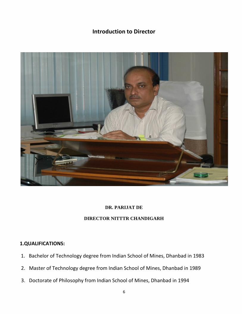
Introduction to Director
DR. PARIJAT DE
DIRECTOR NITTTR CHANDIGARH
1.QUALIFICATIONS:
1. Bachelor of Technology degree from Indian School of Mines, Dhanbad in 1983
2. Master of Technology degree from Indian School of Mines, Dhanbad in 1989
3. Doctorate of Philosophy from Indian School of Mines, Dhanbad in 1994
7
2.FIELD OF SPECIALIZATION:
Mining Engineering; Educational Administration.
3.CONTACT NO.
Residence +91 - 0172 - 5070652
Office +91 - 0172 - 2792369
FAX +91 - 0172 – 2791366, 2793893
4.E-mail

8
Introduction to Department
Electrical Engineering Department is one of the major departments, created since theestablishment of the institute. The department conducted long term teacher trainingprogrammes for polytechnic teachers under the staff development programmes for anumber of years and provided training to a large number of teachers in the polytechnics ofthe northern region. As a result of the various staff development programmes, the trainedteachers have gradually elevated to senior positions and have by now taken up higherresponsibilities.
The department has also been very active in conducting the need based short term trainingprogrammes every year as per the institute Operational plan. Since last 7 years thedepartment has been very successfully offering Masters of Engineering Course inInstrumentation and Control with an intake of 12 students in each batch. The present intakefor the above programme is 18. In addition, the department has also started conducting ME(Instrumentation & Control) Modular Programme with an intake of 40. The institute hasrecently been granted the status of being a research centre for Punjab Technical University,Jalandhar. Under this scheme 4-6 research scholars are expected to join research in variousareas of Electrical Engineering.
The department has produced a large number of instructional materials both print and non-print for the benefit of teachers and students of technical institutions. To mention a few ofthe important materials, there are text books in Electrical Machines, Electrical EngineeringMaterial, Electrical Design and Drawing, Industrial Electronics and Control, Motor Control,Basic Electronics, Projects in Electrical and Electronics Engineering etc, and laboratorymanuals on Electrical Machines, Basic Electrical Engineering, Industrial Electronics,Contactor Control of Electric Drives etc.
The department has also produced about 30 video films on various topics pertaining toelectrical engineering, 26 charts, 3 experimental kits and a number of work books andstudent manuals. The above text books have been published through renowned publishers.The above text and other materials are being marketed through an internal unit named asInformation Resource Marketing Unit (IRMU )
The department also conducts tailor made training programmes for working professionals invarious thrust areas. The department faculty is actively involved in action research. On anaverage about 10-12 such projects are undertaken every year. The department is alsoresponsible for planning and maintenance of internal telephones, and electrical installationsin the institute buildings and campus.

9
FACULTY OF THE DEPARTMENT
1. Dr.S. ChatterjiME (Electrical), PhD.Professor and Head,Electrical Engineering Department
2. Mrs. LINI MATHEWME (Electrical Engineering)Assistant Professor
3. Mrs. RITULA THAKURME (Electrical Engineering)Assistant Professor
EMAIL: [email protected]

10
Experience at NITTTR
My experience on the first day of this STC was very painful but everything turned out in myfavour from the next day and at the end I learned a lot from this STC. Actually I applied for aShort Term Course (STC) on “Microwave and Antenna Engineering” under EducationalTelevision Department (EdTV) during the period 23rd to 27th May 2011, but unfortunatelythe course was cancelled due to lack of participants.I came to know about this afterreaching NITTTR, Chandigarh. However the Head of the Department EdTV –Dr.S.S.Pattnaikhelped me a lot.He shifted me to other short term course based on microcontrollers andwhich started on the same date i.e. 23/05/2011.
So, during the period 23rd to 27th May 2011, I attended the STC on “Microcontrollers and itsApplications” under Electrical Engineering Department. The Course Coordinator was Mrs.Ritula Thakur who is Asstt. Professor in Electrical Enginnering Department.
Total 33 faculty members from various engineering and polytechnique college of Indiaattended this short term course.Out of these 33 members 9 members were fromKerela.Inspite of the fact that they are having NITTTTR, Chennai in south, they travelledhundreds of kilometer to Chandigarh to attend this course.
This STC included theory lectures by course coordinator, experts from CSIO-Council ofScientific Instruments Organisation, Chandigarh,Research Scholars, Industrial Visit andpractical sessions.
The course ended with a valedictory function where Director of the Institute-Dr. Parijat Dewas himself present and shared the experience with the participants.

11
1.Introduction to Microcontrollers
A microcontroller is a small computer on a single integrated circuit containing a processorcore, memory, and programmable input/output peripherals. Program memory in the formof NOR flash or OTP ROM is also often included on chip, as well as a typically small amountof RAM. Microcontrollers are designed for embedded applications, in contrast to themicroprocessors used in personal computers or other general purpose applications.
Microcontrollers are used in automatically controlled products and devices, such asautomobile engine control systems, implantable medical devices, remote controls, officemachines, appliances, power tools, and toys. By reducing the size and cost compared to adesign that uses a separate microprocessor, memory, and input/output devices,microcontrollers make it economical to digitally control even more devices and processes.Mixed signal microcontrollers are common, integrating analog components needed tocontrol non-digital electronic systems.
Some microcontrollers may use four-bit words and operate at clock rate frequencies as lowas 4 kHz, for low power consumption (milliwatts or microwatts). They will generally havethe ability to retain functionality while waiting for an event such as a button press or otherinterrupt; power consumption while sleeping (CPU clock and most peripherals off) may bejust nanowatts, making many of them well suited for long lasting battery applications. Othermicrocontrollers may serve performance-critical roles, where they may need to act morelike a digital signal processor (DSP), with higher clock speeds and power consumption.
A microcontroller can be considered a self-contained system with a processor, memory andperipherals and can be used as an embedded system. [1] The majority of microcontrollers inuse today are embedded in other machinery, such as automobiles, telephones, appliances,and peripherals for computer systems. These are called embedded systems. While someembedded systems are very sophisticated, many have minimal requirements for memoryand program length, with no operating system, and low software complexity. Typical inputand output devices include switches, relays, solenoids, LEDs, small or custom LCD displays,radio frequency devices, and sensors for data such as temperature, humidity, light level etc.Embedded systems usually have no keyboard, screen, disks, printers, or other recognizableI/O devices of a personal computer, and may lack human interaction devices of any kind.
Microcontrollers must provide real time (predictable, though not necessarily fast) responseto events in the embedded system they are controlling. When certain events occur, aninterrupt system can signal the processor to suspend processing the current instruction

12
sequence and to begin an interrupt service routine (ISR, or "interrupt handler"). The ISR willperform any processing required based on the source of the interrupt before returning tothe original instruction sequence. Possible interrupt sources are device dependent, andoften include events such as an internal timer overflow, completing an analog to digitalconversion, a logic level change on an input such as from a button being pressed, and datareceived on a communication link. Where power consumption is important as in batteryoperated devices, interrupts may also wake a microcontroller from a low power sleep statewhere the processor is halted until required to do something by a peripheral event.
Microcontroller programs must fit in the available on-chip program memory, since it wouldbe costly to provide a system with external, expandable, memory. Compilers andassemblers are used to turn high-level language and assembler language codes into acompact machine code for storage in the microcontroller's memory. Depending on thedevice, the program memory may be permanent, read-only memory that can only beprogrammed at the factory, or program memory may be field-alterable flash or erasableread-only memory.
Microcontrollers usually contain from several to dozens of general purpose input/outputpins (GPIO). GPIO pins are software configurable to either an input or an output state.When GPIO pins are configured to an input state, they are often used to read sensors orexternal signals. Configured to the output state, GPIO pins can drive external devices suchas LED's or motors.
Many embedded systems need to read sensors that produce analog signals. This is thepurpose of the analog-to-digital converter (ADC). Since processors are built to interpret andprocess digital data, i.e. 1s and 0s, they won't be able to do anything with the analog signalsthat may be sent to it by a device. So the analog to digital converter is used to convert theincoming data into a form that the processor can recognize. A less common feature onsome microcontrollers is a digital-to-analog converter (DAC) that allows the processor tooutput analog signals or voltage levels.
In addition to the converters, many embedded microprocessors include a variety of timersas well. One of the most common types of timers is the Programmable Interval Timer (PIT).A PIT just counts down from some value to zero. Once it reaches zero, it sends an interruptto the processor indicating that it has finished counting. This is useful for devices such asthermostats, which periodically test the temperature around them to see if they need toturn the air conditioner on, the heater on, etc.

13
Time Processing Unit (TPU) is a sophisticated timer. In addition to counting down, the TPUcan detect input events, generate output events, and perform other useful operations.
A dedicated Pulse Width Modulation (PWM) block makes it possible for the CPU to controlpower converters, resistive loads, motors, etc., without using lots of CPU resources in tighttimer loops.
Universal Asynchronous Receiver/Transmitter (UART) block makes it possible to receive andtransmit data over a serial line with very little load on the CPU. Dedicated on-chip hardwarealso often includes capabilities to communicate with other devices (chips) in digital formatssuch as I2C and Serial Peripheral Interface (SPI).
Microcontrollers were originally programmed only in assembly language, but various high-level programming languages are now also in common use to target microcontrollers. Theselanguages are either designed specially for the purpose, or versions of general purposelanguages such as the C programming language. Compilers for general purpose languageswill typically have some restrictions as well as enhancements to better support the uniquecharacteristics of microcontrollers. Some microcontrollers have environments to aiddeveloping certain types of applications. Microcontroller vendors often make tools freelyavailable to make it easier to adopt their hardware.
Many microcontrollers are so quirky that they effectively require their own non-standarddialects of C, such as SDCC for the 8051, which prevent using standard tools (such as codelibraries or static analysis tools) even for code unrelated to hardware features. Interpretersare often used to hide such low level quirks.
Interpreter firmware is also available for some microcontrollers. For example, BASIC on theearly microcontrollers Intel 8052; BASIC and FORTH on the Zilog Z8 as well as some moderndevices. Typically these interpreters support interactive programming.
Simulators are available for some microcontrollers, such as in Microchip's MPLABenvironment. These allow a developer to analyze what the behavior of the microcontrollerand their program should be if they were using the actual part. A simulator will show theinternal processor state and also that of the outputs, as well as allowing input signals to begenerated. While on the one hand most simulators will be limited from being unable tosimulate much other hardware in a system, they can exercise conditions that may otherwisebe hard to reproduce at will in the physical implementation, and can be the quickest way todebug and analyze problems.

14
Recent microcontrollers are often integrated with on-chip debug circuitry that whenaccessed by an in-circuit emulator via JTAG, allow debugging of the firmware with adebugger.
There are several dozen microcontroller architectures and vendors including:
• 68HC11• 8051• ARM processors (from many vendors) using ARM7 or Cortex-M3 cores are generally
microcontrollers• STMicroelectronics STM8S (8-bit), ST10 (16-bit) and STM32 (32-bit)• Atmel AVR (8-bit), AVR32 (32-bit), and AT91SAM• Freescale ColdFire (32-bit) and S08 (8-bit)• Hitachi H8, Hitachi SuperH• Hyperstone E1/E2 (32-bit, First full integration of RISC and DSP on one processor core
[1996] [1])• MIPS (32-bit PIC32)• NEC V850• PIC (8-bit PIC16, PIC18, 16-bit dsPIC33 / PIC24)• PowerPC ISE• PSoC (Programmable System-on-Chip)• Rabbit 2000• Texas Instruments Microcontrollers MSP430 (16-bit), C2000 (32-bit), and Stellaris (32-
bit)• Toshiba TLCS-870• Zilog eZ8, eZ80

15
2.8051 family of Microcontrollers
The Intel 8051 is a Harvard architecture, single chip microcontroller (µC) which wasdeveloped by Intel in 1980 for use in embedded systems. Intel's original versions werepopular in the 1980s and early 1990s, but has today largely been superseded by a vast rangeof faster and/or functionally enhanced 8051-compatible devices manufactured by morethan 20 independent manufacturers including Atmel, Infineon Technologies (formerlySiemens AG), Maxim Integrated Products (via its Dallas Semiconductor subsidiary), NXP(formerly Philips Semiconductor), Nuvoton (formerly Winbond), ST Microelectronics, SiliconLaboratories (formerly Cygnal), Texas Instruments and Cypress Semiconductor. Intel'sofficial designation for the 8051 family of µCs is MCS 51.
8051 Microcontroller
Intel's original 8051 family was developed using NMOS technology, but later versions,identified by a letter C in their name (e.g., 80C51) used CMOS technology and were lesspower-hungry than their NMOS predecessors. This made them more suitable for battery-powered devices.
Important Features :
• It provides many functions (CPU, RAM, ROM, I/O, interrupt logic, timer, etc.) in asingle package
• 8-bit ALU, Accumulator and 8-bit Registers; hence it is an 8-bit microcontroller• 8-bit data bus - It can access 8 bits of data in one operation• 16-bit address bus - It can access 216 memory locations - 64 KB (65536 locations) each
of RAM and ROM

16
• On-chip RAM - 128 bytes (data memory)• On-chip ROM - 4 kByte (program memory)• Four byte bi-directional input/output port• UART (serial port)• Two 16-bit Counter/timers• Two-level interrupt priority• Power saving mode• The 8051 has four distinct types of memory - internal RAM, special function registers,
program memory, and external data memory.
Internal RAM (IRAM) is located from address 0 to address 0xFF. IRAM from 0x00 to 0x7Fcan be accessed directly, and the bytes from 0x20 to 0x3F are also bit-addressable. IRAMfrom 0x80 to 0xFF must be accessed indirectly, using the @R0 or @R1 syntax, with theaddress to access loaded in R0 or R1.
Special function registers (SFR) are located from address 0x80 to 0xFF, and are accesseddirectly using the same instructions as for the lower half of IRAM. Some of the SFR's arealso bit-addressable.
Program memory (PMEM, though less common in usage than IRAM and XRAM) islocated starting at address 0. It may be on- or off-chip, depending on the particularmodel of chip being used. Program memory is read-only, though some variants of the8051 use on-chip flash memory and provide a method of re-programming the memoryin-system or in-application. Aside from storing code, program memory can also storetables of constants that can be accessed by MOVC A, @DPTR, using the 16-bit specialfunction register DPTR.
External data memory (XRAM) also starts at address 0. It can also be on- or off-chip;what makes it "external" is that it must be accessed using the MOVX (Move eXternal)instruction. Many variants of the 8051 include the standard 256 bytes of IRAM plus a fewKB of XRAM on the chip. If more XRAM is required by an application, the internal XRAMcan be disabled, and all MOVX instructions will fetch from the external bus.

17
Pin Diagram of 8051

18
3.Assembly Language Programming of 8051
An Assembly language instruction consists of four fields:
[label:] Mnemonic [operands] [;comment]
Assembly language instruction includes:
1. a mnemonic (abbreviation easy to remember) the commands to the CPU, telling itwhat those to do with those items
2. optionally followed by one or two operands the data items being manipulated
A given Assembly language program is a series of statements, or lines:
1. Assembly language instructions : Tell the CPU what to do2. Directives (or pseudo-instructions) : Give directions to the assembler
The instructions for the 8051 device are dependent on the clock frequency and arecompleted in a number of clock cycles. The basic 8051 device operates on a minimum 12clock cycles per instruction basis and this is reflected in the notes that follow each type ofinstruction described below. However, some members of the 8051 family operate on aminimum of 6 clock cycles per instruction, hence performance is twice as fast as the basic8051 for a specified clock frequency. Other members of the 8051 family operate on aminimum of 2 clock cycles with a consequent increase in operating speed for a given clockfrequency.
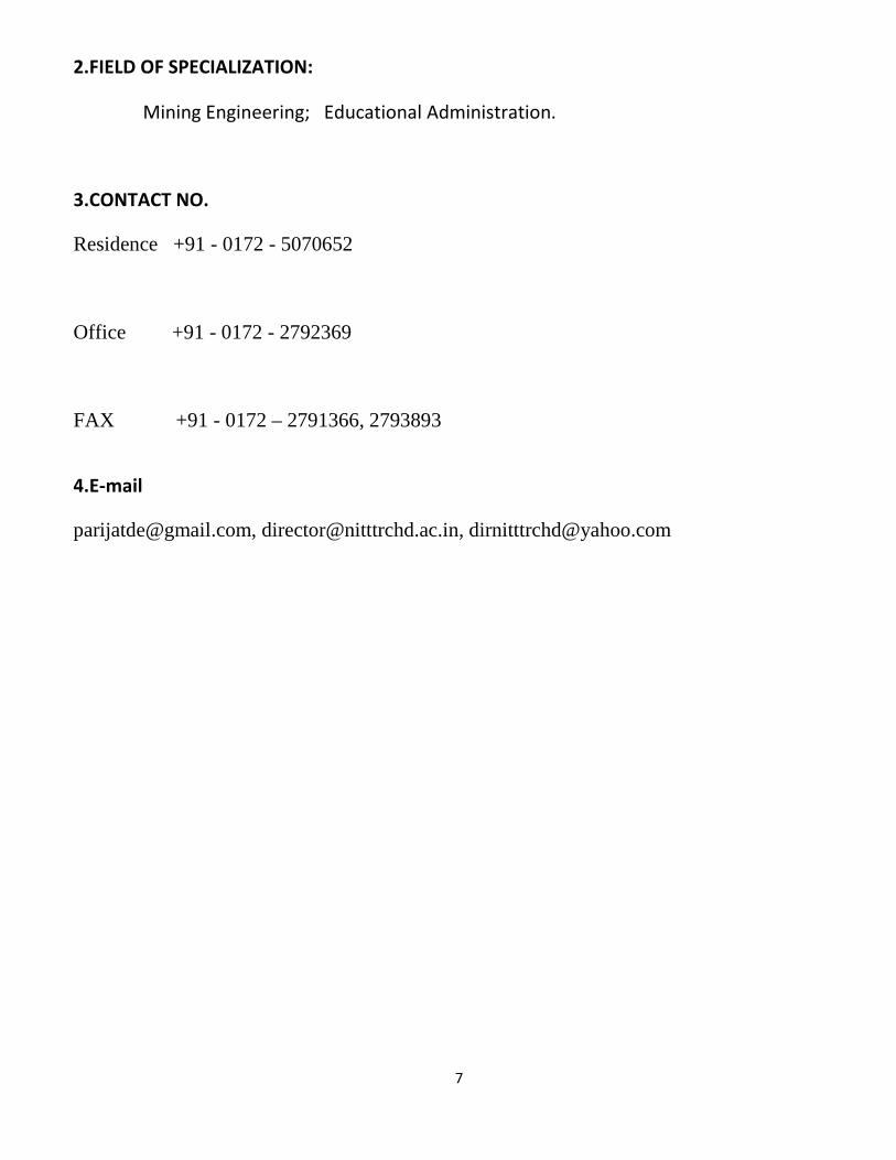
The most commonly used instruction of 8051 Microcontroller are:
MOV move a byte
SETB set or clear bitsCLR
19
ACALL call up a subroutineRET
SJMP unconditional jumpAJMP
JB bit test, conditional jumpJNB
DJNZ byte test, conditional jumpCJNE
ORL OR logic, useful for forcing bits to logic 1ANL AND logic, useful for forcing bits to logic 0
COMMONLY USED ASSEMBLER DIRECTIVES
ORG define address
DB define bytes, useful for table data
END all assembly language programs must end with this.
Examples:
1.Write a program to :(a) load the accumulator with the value 55H, and(b) complement the ACC 700 times
Code:
MOV A,#55H ;A=55HMOV R3,#10 ;R3=10, outer loop countNEXT: MOV R2,#70 ;R2=70, inner loop countAGAIN: CPL A ;complement A registerDJNZ R2,AGAIN ;repeat it 70 timesDJNZ R3,NEXT

20
4.8051 Programming in C
The reasons for writing programs in C are :
1. It is easier and less time consuming to write in C than Assembly.2. C is easier to modify and update.3. You can use code available in function libraries.4. C code is portable to other microcontrollerwith little of no modification.
A good understanding of C data types for 8051 can help programmers to create smaller hexfiles. The various data types in C are:
1. Unsigned char2. Signed char3. Unsigned int4. Signed int5. Sbit (single bit)6. Bit and sfr
Some important points to be kept in mind while programming the microcontroller in C are:
1. The character data type is the most natural choice.2. Unsigned char is an 8-bit data type in the range of 0 – 255 (00 – FFH).3. C compilers use the signed char as the default if we do not put the keyword unsigned.4. Compilers produce hex files that is downloaded to ROM of microcontroller.5. C programming is less time consuming, but has larger hex file size.

21
Examples:
1. Write an 8051 C program to send values 00 – FF to port P1.
Solution:#include <reg51.h>void main(void){unsigned char z;for (z=0;z<=255;z++)P1=z;}
2. Write an 8051 C program to toggle all the bits of P1 continuously.
Solution:#include <reg51.h>void main(void)

22
{for (;;){p1=0x55;p1=0xAA;}}

23
5.Burning a code in Microcontroller
KEIL COMPILER
The Keil C51 C Compiler for the 8051 microcontroller is the most popular 8051 C compiler inthe world. It provides more features than any other 8051 C compiler available today.TheC51 Compiler allows you to write 8051 microcontroller applications in C that have theefficiency and speed of assembly language. Language extensions in the C51 Compiler giveyou full access to all resources of the 8051.The KEIL compiler converts the C code into HEXcode which is finally burnt into the microcontroller.
Keil was founded in 1986 to market add-on products for the development tools provided bymany of the silicon vendors. Keil implemented the first C compiler designed from theground-up specifically for the 8051 microcontroller. Keil provides a broad range ofdevelopment tools like ANSI C compiler, macro assemblers, debuggers and simulators,linkers, IDE, library managers, real-time operating systems and evaluation boards for 8051,251, ARM, and XC16x/C16x/ST10 families.
µVision3 IDE
The µVision3 IDE from Keil Software combines project management, make facilities, sourcecode editing, program debugging, and complete simulation in one powerful environment.µVision3 helps you get programs working faster than ever while providing an easy-to-usedevelopment platform. The editor and debugger are integrated into a single application andprovide a seamless embedded project development environment.
µVision3 features include:

24
• The Device Database which automatically sets the assembler, compiler, and linkeroptions for the chip you select. This prevents you from wasting your time configuringthe tools and helps you get started writing code faster.
• A robust Project Manager which lets you create several different configurations ofyour target from a single project file. The Keil µVision3 IDE allows you to create anoutput file for simulating, an output file for debugging with an emulator, and anoutput file for programming an EPROM -- all from the same Project file.
• An integrated Make facility with automatic dependency generation. You don't haveto figure out which header files and include files are used by which source files. TheKeil compilers and assemblers do that automatically.
• Interactive Error Correction. As your project compiles, errors and warnings appear inan output window. You may make corrections to the files in your project whileµVision3 continues to compile in the background. Line numbers associated with eacherror or warning are automatically resynchronized when you make changes to thesource.
Simulator and Programmer for 8051
A simulator is a software to mimic a microcontroller operation with a Personal Computer.This helps in running the assembly language program off-line and debug for errors. This isalso a powerful learning tool before actually working with a Microcontroller.A programmer is a hardware used to transfer the machine code to the internal programmemory of a microcontroller.
In this section we will see a typical Simulator and a Programmer used for Atmel AT89C51.
1. Working with Win8051 Simulator
Win 8051 is a simulator for 8051 microcontroller to write and edit the code in assemblylanguage, compile it and also to run the code. Output of the assembly language programcan be verified using simulator.
Steps to Use WIN8051
• After installing the software Win8051, open 8051 IDE.• To write the assembly code in the editor , go to :
File New• After writing the assembly code in the editor, assemble the code (Assemble)

25
• Check for the errors in the output windowView Output
• Once the error free code was made, simulate the code.Simulate Start Simulator
• Simulator options are1. Step into – Each time only one instruction will be executed (single step mode).2. Continue – To run the whole code at once.
• Additional things:1. To view RAM, program memory, SFRs, and External memory use the option
VIEW .2. To set break points in the code (where simulation stops at that point)
Simulate Toggle Break Point• To stop the simulation
Simulate Stop•
After checking the code in the simulator, the code (file with .HEX extension in Intel HEXformat) is loaded into Atmel 89C51 microcontroller using Universal SP3 Programmer.
Although a separate 8051 assembly can be used at times assemble and generate Hex codefor a assembly language program, Win8051 simulator can perform that task here.
2. Programming with Universal SuperPro III Programmer:
SuperPro III (SP3) Programmer is manufactured by XELTEK. This is a universal programmerthat can be used to program a host of Microcontrollers and EPROMs. This is connected toPC by the parallel port. A software “SP3.EXE” is executed by the PC to establish acommunication with the programmer. Hex files can be downloaded from the PC to anEPROM or the program memory of a microcontroller located in ZIF socket on theprogrammer.

26
Fig 37.1 A view of SuperPro III Universal Programmer
The programmer is used to load HEX code into the microcontroller (Atmel 89C51 in thepresent case).
Steps:
• Run SP3.exe• Selecting the device to be programmed.
Device Select by Device select AT89C51, type MPU/MCU Select• Loading file in to the buffer .
File Load Select FILE_NAME.HEX to be loaded check INTEL file format OK• To edit or to view the file to be loaded
Buffer Edit(HEX code with corresponding memory location addresses to be loaded into willappear on the screen)
• To load the program in to the microcontrollerDevice Run(Place the microcontroller in the slot provided in the Universal SP3 programmer)
o Select Blank check OKo If blank check is failed, Select option Erase OK
If blank check is a success, proceed to next step.

27
o Select Program OKo Select Blank check OK (it must fail which implies HEX code is programmed in
to the microcontroller)• Remove microcontroller from the slot.• Exit SP3.exe
File Quit

28
6.Basic Set up of Microcontroller
This is the minimum configuration for using 8051 microcontroller.The following externalcomponents are required to have a miccrocontroller working:
• X1 : crystal oscillator(ex.12Mhz)• C1,C2: 33pF capacitors• C3: 10µF, 10V Electrolytic Capacitor• R1: 8.2K, 0.125W resistor

29
7.LCD Interfacing of Microcontroller-Expert Lecture
LCD is finding widespread use and replacing LEDs due to the following reasons:1. The declining prices of LCD2. The ability to display numbers, characters, and graphics3. Incorporation of a refreshing controller into the LCD, thereby relieving the CPU of the
task of refreshing the LCD4. Ease of programming for characters and graphics
Pin Descriptions for LCDPin Symbol I/O Descriptions
1 VSS -- Ground2 VCC -- +5V power supply3 VEE -- Power supply to control contrast4 RS I RS=0 to select command register
RS=1 to select data register
5 R/W I R/W=0 for write,R/W=1 for read
6 E I/O Enable7 DB0 I/O The 8-bit data bus8 DB1 I/O The 8-bit data bus9 DB2 I/O The 8-bit data bus10 DB3 I/O The 8-bit data bus11 DB4 I/O The 8-bit data bus12 DB5 I/O The 8-bit data bus13 DB6 I/O The 8-bit data bus14 DB7 I/O The 8-bit data bus

30
LCD COMMAND CODES

31
CIRCUIT DIAGRAM FOR LCD INTERFACING

32
8.Applications of Microcontroller
The 8051 has been in use in a wide number of devices, mainly because it is easy to integrateinto a project or build a device around. The following are the main areas of focus:
a. Energy Management: Efficient metering systems help in controlling energy usage in
homes and industrial applications. These metering systems are made capable by
incorporating microcontrollers.
b. Touch screens: A high number of microcontroller providers incorporate touch-
sensing capabilities in their designs. Portable electronics such as cell phones, media
players and gaming devices are examples of microcontroller-based touch screens.
c. Automobiles: The 8051 finds wide acceptance in providing automobile solutions.
They are widely used in hybrid vehicles to manage engine variants. Additionally,
functions such as cruise control and anti-brake system have been made more
efficient with the use of microcontrollers.
d. Medical Devices: Portable medical devices such as blood pressure and glucose
monitors use microcontrollers will to display data, thus providing higher reliability
in providing medical results.

33
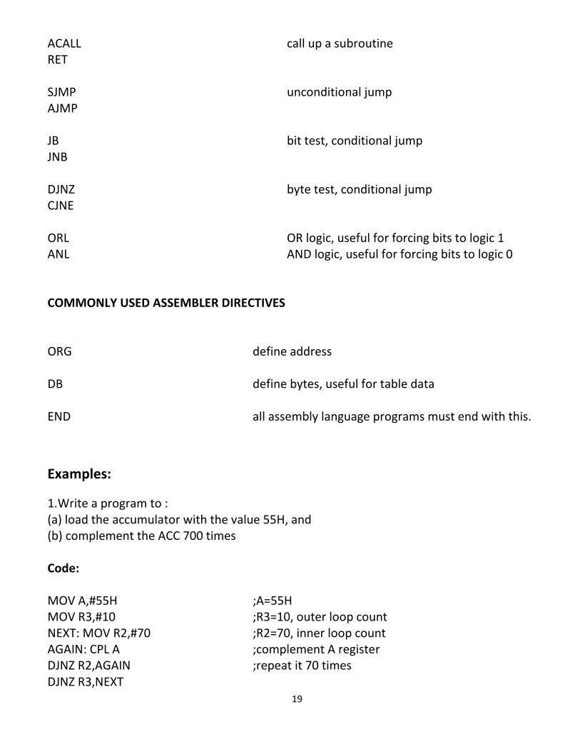
9.Practice Sessions
34

35
NATIONAL INSTITUTE OF TECHNICAL TEACHERS TRAINING AND RESEARCH
SECTOR 26, CHANDIGARH