REPORT ON ELECTROMAGNETIC SURVEY, 120 CLAIMS ...
19
GM 28523 REPORT ON ELECTROMAGNETIC SURVEY, 120 CLAIMS GROUP
-
Upload
khangminh22 -
Category
Documents
-
view
2 -
download
0
Transcript of REPORT ON ELECTROMAGNETIC SURVEY, 120 CLAIMS ...

GM 28523REPORT ON ELECTROMAGNETIC SURVEY, 120 CLAIMS GROUP

Mieistérer des Richesses Neture(ius, Qu;gbgç SERVICE DE LA
DOCUMENTATION TECHNIQUE
5- AVR 1913 Date:
No GM; ...,285 3
APPENDIX A
CHIBEX MINING CORPORATION
ROHAULT TOWNSHIP
CHIBOUGAMAU, QUEBEC
REPORT ON
ELECTROMAGNETIC SURVEY
120 CLAIMS GROUP
BY: W.R.WAGNER JANUARY, 1972.

REPORT ON
E.M. SURVEY
INDEX
Text
i.
i.
Summary and Conclusion
Summary of Work Required
Introduction 1.
Area Covered 1.
Access 2.
General Geology and Previous Work 2.
Presentation of Results 2. &
Recommendations 4.
APPENDIXES
Appendix I General Notes on E.M.-16
MAPS ( wo-f ('e...t)foie)
I E.M. survey (Profiles) Line 24E - 52E Line 64E - 92E Line 104E Line 116E - 168E
II E.M. survey contoured V.L.F. - E.M. Sheet No. 3 & 4
III E.M. survey dip angle V.L.F. - E.M. Sheet No. 3 & 4
3.

Summary and Conclusion
A total of 75.17 line mil-2q 4ere cut on 81 claims
situated on Rohault township and 38.00 miles of E.M. survey were
carried out on these lines during October - December, 1971.
The survey was discontinued with 30.00 line miles is
outstanding to be covered with the E.M. survey.
The survey has indicated good anomalies and 5,000
feet of diamond drilling is recommended. For best results dril-
ling should start after completing the survey.
The work should be carried on the 50 claims west of
Rohault township. The work preferably should be considered for
the winter time to reduce the cost of building a bridge. Forty-
two line miles of line cutting and E.M. survey are involved in
this area.
Summary of Work Required
1. 30.0 miles of E.M. survey. 68.0 miles of magnetometer survey.
2. West part of property.
42.0 miles of line cutting. 42.0 miles of E.M. survey. 42.0 miles of magnetometer survey.
3. Drilling - 5,000 feet of drilling.
i.

Introduction
An electromagnetic survey was carried out on a
portion of the Chibex Mining Corporation property in Rohault Town-
ship, Norhart Lake Area, Chibougamau, Quebec.
The survey was directed on the east portion of the
120 claims group in Rohault and Gamache Townships. The area covered
by the survey were selected from the airborne survey. A total of
38.28 line miles of E.M. survey are completed to date.
The very-low-frequency (V.L.F.) method was used,
two-E.M.-16-units were supplied by C 'ics Lim'ted, 2 Thorncliffe
Park Drive, Toronto 17, Ontario. (See appendix 1).
The survey was accomplished by a crew from Chibex
Mining Corporation supervised by S.E.Malouf Consulting Geologists
Limited. (See appendix 2).
Area Covered
A total of 43 claims were covered by the survey as
follows:
Licence No. No. of Claims Claim No.
309425,
309426,
309427/
309428,
5
3
4
4 '
1,2,3,4,5,
2,4,5,
2,3,4,5,
1,2,3,4,
309429• 3 3,4,5,
309431, 5 1,2,3,4,5,
309432, 5 1,2,3,4,5,
309433, 5 1,2,3,4,5,
309434, 5 1,2,3,4,5,
309435, 4 2,3,4,5,
TOTAL 43
1.

2.
Access
Access to the property is provided by the Chibougamau-
St.Felicien gravel highway with a twelve mile connection road to the
south west at mileage 119. The area covered by the survey is serviced
by tractor trail approximately 11 miles south of the mine site.
General Geology and Previous Work
The area covered by the survey is situated on the north
west corner of Rohault Township. Generally the Grenville front trends
east west on the south east part of the property, which consists
mainly of garnetiferous rock. North of the Grenville front is composed
of precambrian volcanic rock, mainly andesite, basalt and tuffs. For
details on geology see Geological Report No. 86, Quebec.
Previous work on the area includes an airborne survey
completed by Questar Survey Limited, a reconnaissance magnetometer
survey and a few drill holes on the east side.
Results of drilling indicate mineralized zones of
pyrite, pyrhotite, chalcopyrite, with one drill indicating a wide
sulphide zone together with quartz veins, one intersection grades
0.10 ounces of gold and 0.25% of copper.
Presentation of Results
The survey was carried out on a line pattern - 400 foot
spacing with the base line at N87°E with lines cut to the south.
The lines were cut by two local crews. The E.M. survey was completed
by utilizing a primary field generated from a V.L.F. transmitting station
(N.A.A.) at Cutler Maine. Readings along the lines were spaced 100'
apart as a maximum, with 50' as minimum.
The results are plotted in profile (Section and Plan)
and a contoured plan, with scale 1" a 400'.
The survey was discontinued according to notice received
from Chibex Mining Corporation. The lines covered by the

survey are listed below:
Line Length Surveyed on Line
24E 8500
28E 8400
32E 8500
36E 8500
40E 8500
44E 7600
48E 8500
52E 1600-8500 6900
64E 3000-8500 5500
68E 3000-8600 5600
72E 3900-8600 4700
76E 3900-8600 4700
80E 3900-8500 4600
84E 3900-8500 4600
88E 3000-5400 2400
92E 3000-5100 2100
104E 5400-5600 200
1161E 5500-7600 2100
120E 8100
124E 7700
128E 7800
132E 7300
140E 7800
144E 7700
148E 7700
152E 7600
156E 7700
160E 7700
164E 7700
168E 7700
202100 Feet
3.
38.28 miles

4.
Recommendations
1. The E.M. survey should be continued to cover all
the 120 claim group.
2. The lines should be cut on the area west of Rohault
township to cover the property. This area has very good airborne
anomalies and ground geophysical survey could be of great interest.
This work should be considered as a winter program to facilitate
the difficult access to the area. In case the above program will
be carried out in the summer this would involve extra work in
building a bridge across Nemenjich River.
3. A detailed magnetometer survey should be carried
out on the lines.
4. Approximately 5,000 feet of diamond drilling should
be considered for more exploration work to explore the anomalies.
Drilling could be directed to explore some parts of the anomalies
while the E.M. survey is carried out to cover all the ground.
Drilling could be carried out as follows:
Hole 1/ Location Dip Bearing Depth
S-1 L.68+00E 4000S 45° North on line 600' S-2 L.40+00E 3600S 45° North on line 650' S-3 L.48+00E 7200S 45° North on line 700' S-4 L.72+00E 5000S 45° North on line 500' S-5 L.164+00E 4800S 45° North on line 500' S-6 L.168+00E 6550S 45° North on line 600' S-7 L.156+00E 7100S 45° North on line 600' S-8 L.116+00E 6000S 45° North on line 600'
TOTAL 4750'
The above recommendations could be changed after the
completion of the E.M. and the Magnetometer survey.
A compilation for all the available data from the
former companies should be completed and further work should
be considered.

SPECI FICATIONS
Source of primary field:
Transmitting stations used:
Operating frequency range:
VLF transmitting stations. Scale range:
Any desired station frequency supplied with the instrument in the Readability: form of plug-in tuning units. Two tuning units can be plugged In at
Reading time:
one time. A switch selects either station.
Operating temperature range: About 16 — 26 kHz
in-phase ± 150%; out-of-phase ± 40%.
± 1%
10 — 40 seconds depending on signal strength.
—40 to 50°C
Parameters measured:
Method of reading:
(1) The vertical in-phase component (tangent of the tilt angle of the polarization ellipsoid).
(2) The vertical out-of-phase , (quadrature) component the
short axis of the polarization ellipsoid compared to the long axis).
In-phase from a mechanical in-clinometer; out-of-phase from a calibrated dial. Nulling by audio tone.
Power Supply:
Dimensions:
Weight:
Instrument supplied with:
Shipping weight:
6 size AA (penlight) alkaline cells. Life about 200 hours.
16 x 5.5 x 3.5 in (42 x 14 x 9 cm)
2.5 lbs (1.1 kg)
Monotonic speaker, carrying case, manual of operation, 3 station selector plug-in tuning units (additional frequencies are optional), set ofbatteries.
10 lbs (4.5 kg)
c CEONICS LIMITED 2 Thorncliffe Park Drive, Toronto 17, Ontario, Canada. Tel. (416) 425-1821, Cables: Geonics
VLF ELECTROMAGNETIC UNIT
Pioneered exclusively by Geonics Limited the VLF-n1 1d of electromagnetic surveying by utilization of the uniform horizontal fields gt .•ated by an existing network of reliable, fully operational Very Low Frequency trans-mitting stations has proved to be a major advance in geophysical exploration.
Very extensive world-wide experience since the beginning of 1965 by a large and rapidly increasing number of users, including a high proportion of major mining and exploration companies, has provided conclusive evidence of the effective-ness of the technique and the EM 16 has gained general acceptance as a basic electromagnetic tool. This evidence has also indicated the response of dissemin-ated bodies. to the VLF-method.
0 The unique self-contained EM 16 offers the unrivalled combination of LIGHT WEIGHT, ONE-MAN OPERATION and DEEP PENETRATION allowing rapid, economical surveys. Assessing the data is simplified due to the use of the uniform horizontal primary field. The patented design feature of the measurement of • • both the in-phase and out-of-phase (quadrature) component of the vertical field provides the information necessary for comprehensive interpretation of the field results.
Subsidiary of Deering Milliken Inc.

SIMPLE ONE- MAN OPERATION AREAS OF VLF SIGNALS
J
A Coverage shown only for well-known stations. Other reliable; fully operational stations exist. For full informa-tion regarding VLF signals in your area consult Geonics Limited. Extensive field experience has proved that the above circles of coverage are very conservative and are ctuelly much larger in extent.
TI
STATION SELECTOR
after selection of 2 VLF stations and insertion of proper plug-in units, knob rotation allows switching.
RECEIVING COILS
vertical receiving coil circuit in instrument picks up any vert-ical signal present. Horizontal receiving coil circuit, after auto-matic 900 signal phase shift, feeds signal into out-of-phase dial in series with the receiving coil.
IN-PHASE DIAL
shows the tilt-angle of the instru-ment for minimum signal. This angle is the measure of the vertical in-phase signal expressed in percentage when compared to the horizontal field.
OUT-OF-PHASE DIAL
is calibrated in percentage markings and nulls the vertical quadrature ignal in the vertical coil circuit.
AUTHORIZED AGENT:
EM 16 PROFILE over Lockport Mine property, Newfoundland
Aam
nIr rinnit to-0. to
~
ipt horizontal coil
vertica coil
L J
IEI/II*IUICE tilt 1111 OrIM
PIT
sw 4W
O11T-M-FlIA11 MO qO1OMV AVAM.AKI
Silt sN1I
wwl
P.a'. rats
,IiwM1w ~w
.M12
•T12
.N2
•112
short
;;Z:— —
301 Additional case histories on request.

Trzrnsm~f~~~r9 sI-alion
Optimum strike direction
Direcf%or2 of I I reaciln9s I L
/
1
!
~
I I t /
~ 7 Et116
r
Fin di n g the d«- ec/ -ion of pimaryfield
I i i II / l Best. survey /~ .n e •
direction
Planning of survey
FIG. 3

VLF - Stations
Some locations
NBA
CANADA
NAA
NSS
Quadrature
Direction ----'!
(-) ..,..
Ax = h
Spherical body
Good conductor
a-~

CHIBEX MINING CORPORATION (NO PERSONAL LIABILITY)
SUITE 310 - 55 YONGE STREET
TORONTO I, ONTARIO (4161 363-1593
February 15, 1973
MEMO
To: S. E. Malouf Executive Vice-President
From: Monir Younan
Re: Electromagnetic Survey on the South 120 Claims Chibex Mining Corporation - Chibougamau, Quebec
In October 1971, Michael Malouf together with two groups have established the surface grid on the above-mentioned claims. The surface grid has been established east of the Rohault and Gamache Twps. line, with a0E.W. base line No. 2 and all lines were directed to the south boundary. A total of 75.1 miles have been completed. (Costs and Names of Crew - attached).
An electromagnetic survey was carried out by a field crew using the VLF Method and two E.M.-16 Units were rented from Geonics Ltd., 2 Thorncliffe Park Drive, Toronto, Ont.
The survey was directed on this group as a ground following of airborne survey. The survey was started in October 1971 and discontinued on December 15, 1971 for many reasons with a total of 38.2 miles completed to that date. Details and particulars may be obtained in the preliminary report by Wayne Wagner dated January 1972. (See Appendix A) In August 1972, Wayne Wagner and helper have started the survey and a total of 15.9 miles were completed to December 15, 1972.
As of Dec. 15, 1972 a total of 13.0 line miles were outstanding, on which Bill Thuma, geophysicist, has started to carry out the survey and complete the coverage on 78 mining claims. The cost of the 13.0 Line Miles are not included in the attached statement.
Ministère des Richesses Naturelles, Qua* SERVICE DE LA
DOCUMENTATION TECHNIQUE
- /\VR 1973 Date:
No GM: 28523
2

Memo To: S. E. Malouf February 15, 1973 Page Two
Presentation of Results
The survey has been completed by,.utilizing a primary field generated from a V.L.F. transmitting station (N.A.A.) at Cutler, Maine. Readings along the lines were spaced 100' apart as a maximum, with 50' as a minimum. The results are plotted in profile, however, the dip-angle data on a scale of 1"=400' has yielded a complex pattern, as all the data have been plotted using the Fraser Method by transforming the readings into contourable data. (See Appendix B)
The survey has indicated several conductive zones striking generally East-West, with varied strike length.
One zone has been tested by a former holder, on line 132+00E, 55 00 S. Only one drill hole has been drilled; drilling results have indicated a wide sulphide zone together with quartz veins.
Considerable attention will be given to five conductive zones with high contour values (red colour). A detailed horizontal loop survey with low frequency together with Mag. survey will be considered for solid interpretation of the results. Also drilling targets will be considered with a minimum program of 3000 feet of D.D.
The surveys are being carried out on the west claims (i.e. West of the Rohault-Gamache Twps. line). A complete report will be submitted after the completion of the survey on all the claims.
Monir Yo an MY:pg
CHIBEX MINING CORPORATION (NO PERSONAL LIABILITY)
SUITE 310 - 55 YONGE STREET
TORONTO I, ONTARIO (4161 363-1593
February 15,
AREA COVERED BY E.M.-16 SURVEY
309417' cl. 1-5 309418, cl. 1-5 309424, cl. 1-5 309425- cl. 1-5 309426, cl. 1-5 309427, cl. 1-5 309428- cl. 1-5 309429, cl. 1-5 309430, cl. 1-5 309431, cl. 1-5 309432- cl. 1-5 309433- cl. 1-5 309434- cl. 1-5 309435, cl. 1-5 169478- cl. 1-5 169479, cl. 1-3 G3214• cl. 3
1973
1, Total 7'8 Claims
*
*
54.2 Miles Completed before December
13.0 Miles Completed after , December (of which cost is not included)
15,
15,
1972.
1972.

CHIBEX MINING CO!Ar3ORA ION NO PERSONAL Y)
SUITE 310 - 55 YÔNGE STREET
TORONTO I, ONTARIO (4161 363-1593
February 15, 1973 f
E.M. SURVEY
The total Line Miles to be surveyed is 67.2 Miles.
Total Miles Completed
during Oct.18-Dec.15/71 38.3 Miles Fieldcrew - M. Younan
- W. Wagner G. Papadopolus
during August & Dec.15/72 15.9 Fieldcrew - W. Wagner
- G. Laprise - M. Gunner
Sub-Total 54.2
- After Jan.15/73 The Balance of 13.0 Line Miles has been completed by B. Thuma and M. Gunner (of which the cost of this part will not be submitted now) and the surveys are currently being carried out on the south-west group west of the Rohault and Gamache Twp. line.
_ Pr R I T Ei I. m ~.e6 C 66 \i '' .~z• +„ ,1 PYRITE,, , ZONE 5,4 .
\ ° .
. 3
• 16
0 SO 100
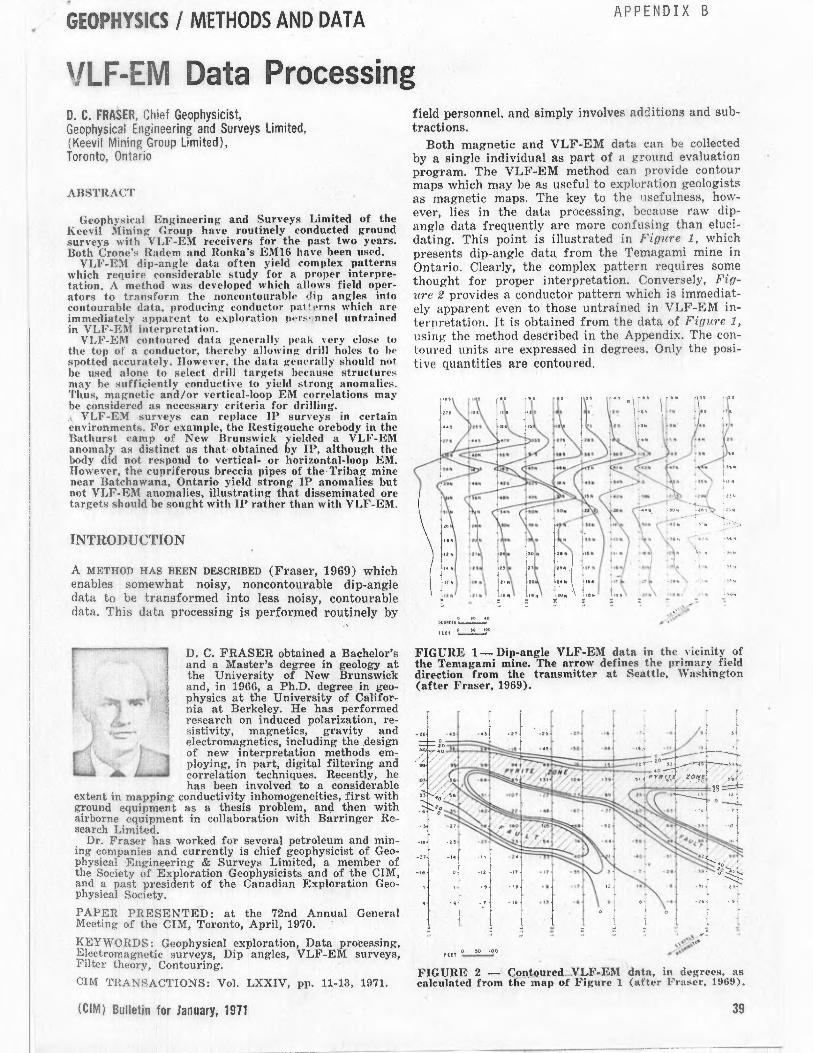
FIGURE 2 — Contoured....VLF-EM data, in degrees, as calculated from the map of Figure 1 (after Fraser, 1969).
39
GEOPHYSICS / METHODS AND DATA APPENDIX B
VLF-EM Data Processing B. C. FRASER, Chief Geophysicist, Geophysical Engineering and Surveys Limited, (Keevil Mining Group Limited), Toronto, Ontario
ABSTRACT
Geophysical Engineering and Surveys Limited of the Keevil Mining Group have routinely conducted ground surveys with VLF-EM receivers for the past two years. Both Crone's Radon and Ronka's EM16 have been used.
VLF-EM dip-angle data often yield complex patterns which require considerable study for a proper interpre-tation. A method was developed which allows field oper-ators to transform the noncontourable dip angles into contourable data, producing conductor pat!a•rns which are immediately apparent to exploration pers• nnel untrained in VLF-EM interpretation.
VLF-EM contoured data generally peak very close to the top of a conductor, thereby allowing drill holes to be spotted accurately. However, the data generally should not be used alone to select drill targets because structures may be sufficiently conductive to yield strong anomalies. Thus, magnetic and/or vertical-loop EM correlations may be considered as necessary criteria for drilling.
VLF-EM surveys can replace IP surveys in certain environments. For example, the Restigouche orebody in the Bathurst camp of New Brunswick yielded a VLF-EM anomaly as distinct as that obtained by IP, although the body did not respond to vertical- or horizontal-loop EM. However, the cupriferous breccia pipes of the Tribag mine near Batchawana, Ontario yield strong IP anomalies but not VLF-EM anomalies, illustrating that disseminated ore targets should be sought with IP rather than with VLF-EM.
INTRODUCTION
A METHOD HAS BEEN DESCRIBED (Fraser, 1969) which enables somewhat noisy, noncontourable dip-angle data to be transformed into less noisy, contourable data. This data processing is performed routinely by
D. C. FRASER obtained a Bachelor's and a Master's degree in geology at the University of New Brunswick and, in 1966, a Ph.D. degree in geo-physics at the University of Califor-nia at Berkeley. He has performed research on induced polarization, re-sistivity, magnetics, gravity and electromagnetics, including the design of new interpretation methods em-ploying, in part, digital filtering and correlation techniques. Recently, he has been involved to a considerable
extent in mapping conductivity inhomogeneities, first with ground equipment as a thesis problem, and then with airborne equipment in collaboration with Barringer Re- search Limited.
Dr. Fraser has worked for several petroleum and min-ing companies and currently is chief geophysicist of Geo-physical Engineering & Surveys Limited, a member of the Society of Exploration Geophysicists and of the CIM, and a past president of the Canadian Exploration Geo-physical Society.
PAPER PRESENTED: at the 72nd Annual General Meeting of the CIM, Toronto, April, 1970.
KEYWORDS: Geophysical exploration, Data processing, Electromagnetic surveys, Dip angles, VLF-EM surveys, Filter theory, Contouring.
CIM TRANSACTIONS: Vol. LXXIV, pp. 11-13, 1971.
(CIM) Bulletin for January, 1971
field personnel, and simply involves additions and sub-tractions.
Both magnetic and VLF-EM data can be collected by a single individual as part of a ground evaluation program. The VLF-EM method can provide contour maps which may be as useful to exploration geologists as magnetic maps. The key to the usefulness, how-ever, lies in the data processing, because raw dip-angle data frequently are more confusing than eluci-dating. This point is illustrated in Figure 1, which presents dip-angle data from the Temagami mine in Ontario. Clearly, the complex pattern requires some thought for proper interpretation. Conversely, Fig-ure 2 provides a conductor pattern which is immediat-ely apparent even to those untrained in VLF-EM in-terpretation. It is obtained from the data of Figure 1, using the method described in the Appendix. The con-toured units are expressed in degrees. Only the posi-tive quantities are contoured.
,lp 0 }0 iov
FIGURE 1— Dip-angle VLF-EM data in the vicinity of the Temagami mine. The arrow defines the primary field direction from the transmitter at Seattle, Washington (after Fraser, 1969).

1`.. .,...~--•
ORE800Y IN SECTION /
\ \~J
0 00 900
/CET •
VERTICAL
LOOP EM
L_ i ORE ROSY
TJ
if
10
a
VERTICAL
LOOP EM
VLF-EM
VERTICAL LOOP EM
/ a
D D[4 t•
C9 D00 ru•
~EO
SO 100
PElf
I+IELll EXAMPLES
The following field examples were chosen to illus-trate the three primary uses to which VLF-EM has been applied by Geophysical Engineering and Surveys Limited.
General Prospecting
General prospecting or ground evaluation provides the most common use for VLF-EM. Ground often is obtained which requires only a general approach to exploration, as when there is insufficient geological information regarding the specific target sought. In such cases, magnetic and VLF-EM surveys are rou-tinely performed without the guidance of a geophysi-cist. VLF-EM conductors are tested by short travers-es with vertical-loop EM. The anomaly patterns gen-erally are sufficiently clear so that mapping, trench-ing, drilling or abandonment will be decided without consulting a geophysicist. Exceptions can occur when patterns become complex.
Figure 3 illustrates a survey in which two strong VLF-EM conductors were obtained. The southern ano-maly has vertical-loop EM correlation and the north-ern one does not. The VLF-EM anomaly with vertical-
loop correlation also coincides with a magnetic ano-maly, and probably is due to magnetic sulphides. It will be drilled shortly. The other equally strong VLF-EM anomaly without vertical-loop correlation does not parallel the magnetic patterns, and probably is due to a fault.
In Place o& IP
There are certain environments where VLF-EM can be used as an alternate to IP. These are the en-vironments characterized by massive or heavily disse-minated sulphides which occur within 300 feet of sur-face and yet do not respond to conventional EM. IP was considered to be the most suitable geophysical method for the detection of such bodies (Hallof, 1967). However, it is well worth testing VLF-EM in these environments because of the very substantial cost savings that result if the method is responsive. As an example, Figure 4 illustrates a VLF-EM survey over the Restigouche orebody in the Bathurst area of New Brunswick. Figure 5, showing IP chargeability con-tours, allows a comparison to be made of the relative merits of IP and VLF-EM for this type of mineral-ization. The Restigouche body did not respond to ver-tical- or horizontal-loop EM because of the high spha-lerite content of the massive sulphides.
FIGURE 3 — Contoured VLF-EM in degrees and vertical-loop EM profiles (1,200 hz) from a property evaluation survey in the Uchi Lake area.
▪ +,„„,
••••, 0REJ00Y IN SECTION
..._.~.~\▪ `,
~
FIGURE 5 — Gradient-array IP chargeability in milli-seconds over the Restigouche orebody, for comparison with the VLF-EM data of Figure 4.
40
FIGURE 4 — Contoured VLF-EM in degrees from the Restigouche orebody, illustrating that the method is a viable alternate to IP in this environment (cf. Figure 5).
FIGURE 6 — Contoured VLF-EM in degrees from a fault-mapping survey in the Cobalt area.
The Canadian Mining and Metallurgical
100 JO

Other environments described in Hallof (1967) would not be as amenable to the use of VLF-EM in place of IP. A truly disseminated copper deposit will not provide a VLF-EM anomaly but will yield a large IP effect, as was found to be the case for the breccia pipes of the Tribag mine near Batchawana, Ontario.
Structural Interpretation
Inasmuch as VLF-EM responds well to structures, the method has been applied to the mapping of faults. An example is shown in Figure 6, which depicts a portion of a survey in the Cobalt area of Ontario. The property was a silver prospect where the veins were postulated to be associated with faults. VLF-EM ap-peared to be the most reasonable geophysical method available to aid in tracing these faults. Considerable drilling has been done on this property, and the fault interpretation was verified.
Figure 2 illustrates that faults can be as conductive to VLF-EM as massive pyrite. In ti.is iemagami example, the faults contain a brecci,.ted matrix with some hematite cementing. They yield a .;..rong IP anomaly, but are non-conductive to conventional EM.
DEPTH OF EXPLORATION
The relatively high transmitted frequency of ap-proximately 20,000 hz severely limits the depth of 'exploration in areas of conductive overburden. As an "example, penetration of the 100 to 200 feet of clay in the Timmins area often is not achieved.
In regions where the overburden has a less excep-tional conductivity, such as the Bathurst area, depth of exploration generally is limited to about 300 feet. This depth was predicted from model curves in Fraser (19G9), and appears to be true in practice, as over the Restigouche deposit (Figure 4 ).
CONCLUDING REMARKS
VLF-EM surveys are exceptionally easy to perform, but the dip-angle data may be exceedingly difficult to interpret correctly. This latter point has produced unfavourable comments regarding the utility of VLF-EM as a prospecting tool. The data-processing method used to transform somewhat noisy, noncontourable dip angles into less noisy, contourable data greatly increases the value of VLF-EM.surveys.
The efficiency of data flow is significantly in-creased in the case of an active mining company per-forming such surveys in large quantities. This is be-cause the contoured maps may be used directly by geologists in charge of their various projects, rather than requiring a geophysicist to study each dip-angle map,
Contoured VLF-EM maps form a useful complement to magnetic maps. The survey and data-processing cost is similar to that for a hand-held fluxgate magneto-meter.
For general exploration in the Shield, VLF-EM con-ductors generally should be tested with vertical-loop EM to separate massive sulphides (and graphite) from conductive structures. As such structures can be mapped with VLF-EM, this provides another use for the method. Further, some massive and heavily disse-minated sulphides, which do not respond to conven-tional EM, will yield VLF-EM anomalies as distinct
(CIM) Bulletin for January, 1971
as those obtained by IP. These three uses of VLF-EM, i.e., for general prospecting, mapping of structures and as a judicious alternate to IP, form our primary applications of VLF-EM to property evaluation.
APPENDIX
The Data-Processing Technique
THE DATA-PROCESSING TECHNIQUE is described in de-tail by Fraser (1969), where it is also discussed in terms of filter theory*. The method is very simple to apply, as is shown by the example of Figure 7. This figure illustrates that the contourable quantity is the sum of the values at two adjacent stations minus the sum at the next two adjacent stations. The above-referenced paper presents a tabulation method suited to the processing of this dip-angle data. The calcula-tions are performed in the field by the instrument operators.
0 ,4 4NGLF -6 -7 -8 -IS • • --1<--• --,F— •
-24 •8 .10 OFGnFES
-10 -24 A
u7.w,-1..-z4i • .4
—f10..1-1-24-15 •57
-- 1.-24J-1-I5-.) . 7
—1-24-151: (-t- 7 ) •-2 4
—1-15-t)^ (-7• tl • -10
FIGURE 7 — Example of the data processing calculations, illustrating that the contoured quantities are obtained simply from additions and subtractions performed on the dip angles.
A 50-foot station interval is recommended to avoid the problem of near-surface conductors appearing as deeper conductors, as could occur if the station spac-ing was larger. In actual practice, data are collected at 100-foot intervals, with 50-foot readings being tak-en where anomalies occur. Later, 50-foot arti-ficial data are interpolated in non-anomalous areas prior to performing the calculations. This procedure avoids some confusion in the contour patterns which would result from near-surface 'geological noise'.
Normally, only the, positive values are contoured, because the negative quantities generally represent anomaly flanks. Consequently, the inclusion of nega-tive contours would serve only to confuse the conduc-tor patterns. However, if a backward crossover was produced by a geological source, an erroneous inter-pretation of the contour map and the dip-angle pro-files would result. To date, such a crossover has not been recognized on the predominantly in-phase dip-angle data.
REFERENCES
Fraser, D. C., (1969), Contouring of VLF-EM Data; Geo-physics, Vol. 34, pp. 958-967.
Hallof, P. G., (1967), The Use of Induced Polarization Measurements to Locate Massive 'Sulphide Mineraliza-tion in Environments in which EM. Methods Fail; paper presented at Canadian Centennial Conference on Mining and Groundwater Geophysics, Niagara, Ontario.
*The technique is analogous to passing the dip-angle data through a bandpass filter which (1) completely removes DC bias and greatly attenuates long wave lengths, (2) completely removes Nyquist frequency noise, (3) phase-shifts all frequencies by 90 degrees and (4) has the .. andpass centered at a wave length of live times the station spacing.
41
• f 57 !8
G0N70u848EE OEGNEES