date correction of omar bin khattab's death in an astronomical ...
Upload
khangminh22Category
view
3download
0
Reopening the window of astronomical soft X-ray polarimetry
Hua Feng 冯骅 (Tsinghua University)on behalf of the PolarLight collaboration
1

PPT模板下载:www.1ppt.com/moban/ 行业PPT模板:www.1ppt.com/hangye/ 节日PPT模板:www.1ppt.com/jieri/ PPT素材下载:
www.1ppt.com/sucai/PPT背景图片:www.1ppt.com/beijing/ PPT图表下载:www.1ppt.com/tubiao/ 优秀PPT下载:www.1ppt.com/xiazai/ PPT教程:www.1ppt.com/powerpoint/
Word教程: www.1ppt.com/word/ Excel教程:www.1ppt.com/excel/ 资料下载:www.1ppt.com/ziliao/ PPT课件下载:www.1ppt.com/kejian/ 范文下载:www.1ppt.com/fanwen/ 试卷下载:
www.1ppt.com/shiti/ 教案下载:www.1ppt.com/jiaoan/ PPT论坛:www.1ppt.cn
目录CONTENTS
Science with X-ray Polarimetry
Technique for X-ray Polarimetry
PolarLight
CubeSats in Space Astronomy
01
02
03
04
2
PART ONEScience with X-ray Polarimetry

What can we learn from X-ray polarimetry?
• Information about the magnetic field– Synchrotron radiation (PWNe, Jets)– Plasma polarization (Magnetized plasma)– QED vacuum birefringence (Neutron Stars)
• Information about the scattering medium– Thomson/Compton/InverseCompton scattering – Geometric symmetry (accretion flow, BH spin, Sgr B2, etc.)
4

Science cases• Synchrotron radiation and B-fields
Blazars GRB Jetted TDEs
(Marscher et al. 2010) Pulsar wind nebulae
5

Science cases• Accreting Pulsars
(Meszaros et al. 1988)
6

Science cases• Surface thermal emission from NSs
• QED effects (vacuum birefringence) & B-field geometry• Tested in optical (RX J1856.5-3754; Mignani et al. 2017)
– SGRs & AXPs
Simulations by R. Taverna and R. Turolla
interactionwiththe
plasmaelectrons
istaken
intoaccount;
however,thisw
illbeimportantonly
atfrequenciesbelowthe
optical!15,16".
Using
theresultofK
uboand
Nagata
!17"todescribe
thepolarization
evolutioninadielectric
birefringentmedium
,Heyland
Shaviv!7"
haveshow
nthatthis
vacuumbirefrin-
gencewillcouple
theevolution
ofthephoton
polarizationto
themagnetic
fielddirection
throughthe
equation
#s#x
3 !$
"s,
%2&
where
x3isthe
distancealong
thedirection
ofpropagation,sisthe
normalized
Stokesvector,
and$isthe
birefringentvector
previouslydescribed.
Close
tothe
neutronstar,$
islarge,and
srotates
quicklyaround
$.Thus,
asthe
directionofthe
magnetic
fieldchanges,
$willrotate
andswillfollow
itadiabatically.Farenough
fromthe
NS,the
amplitude
of$willfalland
swill
notbeable
tofollow
$any
longer.Thecondition
foradia-
baticitytohold
is!7"
l% 'k& !
!$/% (
ln!$!& !#
0.5%3&
where
listhe
scalelength
ofthe
magnetic
field.Ifone
assumesthat
thefield
surroundingthe
starhas
adipolargeom
etry,thepolarization
statesevolve
adiabaticallyif
r$rpl )"
*45+c #
1/5",
BQED sin-#
2/5
.1.2"
107"
,
1030Gcm
3 #2/5"
+
1017Hz #
1/5
"% sin
-& 2/5cm
,%4&
where
risthe
distancefrom
thecenter
ofthe
star,,isthe
magnetic
dipolemoment
ofthe
neutronstar,
and-isthe
anglebetw
eenthe
dipoleaxis
andthe
lineofsight;r
pl isthe
polarization-limiting
radius,borrowing
terminology
fromthe
studyofradio
pulsars!15".
Physically,theadiabatic
regimeisappropriate
aslong
as'n•k•l#
1,where
'nisthe
differencebetw
eenthe
indicesofrefraction,k
isthe
wave
vectorand
l/risthe
distancescale
overwhich
thephysical
variableschange.
Inother
words,
adiabaticityrequires
thatover
thephysical
lengthscale
ofthe
problem,the
twomodes
developasignificant
phasedifference
between
them.The
couplingorpolarization
limiting
radiustherefore
doesnot
dependon
therate
atwhich
$changes
direction.The
direction%and
rateof
changeindirection&
of$will,how
ever,determine
thepo-
larizationleft
beyondrpl .Since
$isinthe
1-2plane
de-scribing
linearpolarizations,
thedirection
of$atrpl w
illdeterm
inethe
linearpolarization
component
ofswhile
therate
ofchange
of$willdeterm
inethe
circularcom
ponent.
Heuristically,
becauseofvacuum
birefringenceinthe
magnetosphere,
theobserved
polarizationdirection
froma
surfaceelem
entiscorrelated
withthe
directionofthe
mag-
neticfield
farfrom
thestellar
surface.Atthis
distance,thebundle
ofrays
thatwill
eventuallybe
detectedpasses
throughasmallsolid
angle.Over
thissmallsolid
angle,thedirection
ofthe
magnetic
fieldvaries
little,sothe
observedpolarization
fromdifferentparts
alsovaries
littleand
alarge
netpolarization
results.Furtherm
ore,this
heuristicpicture
predictsthatbecause
starswithsmallerradiigenerally
resultinsmallerray
bundles,smallerstars
willexhibita
largernetpolarization.This
heuristicpicture
isborne
outby
detailedcalcula-
tions.Tocalculate
theprocess
accurately,onecalculates
thephoton
trajectoryboth
inspacetim
eand
onthe
Poincaresphere
inthe
contextofgeneral
relativity%GR
&.First,
we
incorporatelightbending
%asisgiven,forexam
ple,byPage
!18"&.Second,wehave
touse
theresultofPineault!19"w
hoshow
edthat
alongthe
bentlight
rayspresent
inGR,the
polarizationdirection
rotatesinsuch
awaythatitkeepsfixed
orientationwithrespectto
thenorm
altothe
trajectoryplane,
remaining
perpendiculartothe
wave
vector.Additionally,
GRdistorts
thedipole
magnetic
field!20"
nearthe
star.
III.RESULTS
Asam
pleresult
ofthe
integrationofthe
polarizationis
giveninFig.1,w
herethe
apparentpolarizationatinfinity
isdepicted
togetherwith
thedirection
thatthe
polarization
FIG.1.The
apparentpolarized
image
ofaneutron
starover-
layedonthe
apparentimage
ofthe
NS.The
leftpaneldepictsthe
observedmapofpolarization
directionsifone
assumesthat
thesurface
emitsonly
inthe
ordinarymode
andneglects
thevacuum
birefringenceinduced
byQED.The
rightpanelshowsthe
polariza-tion
map
includingbirefringence
forafrequency
of+
!,30 %210
17Hz.The
ellipsesand
shortlinesdescribe
thepolariza-
tionofalight
rayoriginating
fromthe
surfaceelem
entbeneath
them.The
linesand
themajoraxes
oftheellipses
pointtowards
thedirection
ofthelinearcom
ponentofthepolarization
direction.Theminorto
majoraxis
ratioprovides
theamountofcircularpolariza-
tion(s3 ).In
bothmaps,the
largedashed
curvesarelinesofconstant
magnetic
latitude%separated
by15°).The
observer’sline
ofsight
makesan
angleof30°
withthe
dipoleaxis.Forcom
parison,thenet
linearpolarizationonthe
leftis13%while
itis70%onthe
right.Inamore
realisticNS,the
valuesfor
x-rayfrequencies
would
bere-
ducedto6–10
%and
35–55%,respectively
!21",sincethe
intrinsicpolarization
ofeach
elementis
not100%butsm
aller.
JEREM
YS.H
EYLANDNIRJ.SH
AVIV
PHYSIC
ALREVIEW
D66,023002
%2002&
023002-2
~10% ~70-80%
interactionwiththe
plasmaelectrons
istaken
intoaccount;
however,thisw
illbeimportantonly
atfrequenciesbelowthe
optical!15,16".
Using
theresultofK
uboand
Nagata
!17"todescribe
thepolarization
evolutioninadielectric
birefringentmedium
,Heyland
Shaviv!7"
haveshow
nthatthis
vacuumbirefrin-
gencewillcouple
theevolution
ofthephoton
polarizationto
themagnetic
fielddirection
throughthe
equation
#s#x
3 !$
"s,
%2&
where
x3isthe
distancealong
thedirection
ofpropagation,sisthe
normalized
Stokesvector,
and$isthe
birefringentvector
previouslydescribed.
Close
tothe
neutronstar,$
islarge,and
srotates
quicklyaround
$.Thus,
asthe
directionofthe
magnetic
fieldchanges,
$willrotate
andswillfollow
itadiabatically.Farenough
fromthe
NS,the
amplitude
of$willfalland
swill
notbeable
tofollow
$any
longer.Thecondition
foradia-
baticitytohold
is!7"
l% 'k& !
!$/% (
ln!$!& !#
0.5%3&
where
listhe
scalelength
ofthe
magnetic
field.Ifone
assumesthat
thefield
surroundingthe
starhas
adipolargeom
etry,thepolarization
statesevolve
adiabaticallyif
r$rpl )"
*45+c #
1/5",
BQED sin-#
2/5
.1.2"
107"
,
1030Gcm
3 #2/5"
+
1017Hz #
1/5
"% sin
-& 2/5cm
,%4&
where
risthe
distancefrom
thecenter
ofthe
star,,isthe
magnetic
dipolemoment
ofthe
neutronstar,
and-isthe
anglebetw
eenthe
dipoleaxis
andthe
lineofsight;r
pl isthe
polarization-limiting
radius,borrowing
terminology
fromthe
studyofradio
pulsars!15".
Physically,theadiabatic
regimeisappropriate
aslong
as'n•k•l#
1,where
'nisthe
differencebetw
eenthe
indicesofrefraction,k
isthe
wave
vectorand
l/risthe
distancescale
overwhich
thephysical
variableschange.
Inother
words,
adiabaticityrequires
thatover
thephysical
lengthscale
ofthe
problem,the
twomodes
developasignificant
phasedifference
between
them.The
couplingorpolarization
limiting
radiustherefore
doesnot
dependon
therate
atwhich
$changes
direction.The
direction%and
rateof
changeindirection&
of$will,how
ever,determine
thepo-
larizationleft
beyondrpl .Since
$isinthe
1-2plane
de-scribing
linearpolarizations,
thedirection
of$atrpl w
illdeterm
inethe
linearpolarization
component
ofswhile
therate
ofchange
of$willdeterm
inethe
circularcom
ponent.
Heuristically,
becauseofvacuum
birefringenceinthe
magnetosphere,
theobserved
polarizationdirection
froma
surfaceelem
entiscorrelated
withthe
directionofthe
mag-
neticfield
farfrom
thestellar
surface.Atthis
distance,thebundle
ofrays
thatwill
eventuallybe
detectedpasses
throughasmallsolid
angle.Over
thissmallsolid
angle,thedirection
ofthe
magnetic
fieldvaries
little,sothe
observedpolarization
fromdifferentparts
alsovaries
littleand
alarge
netpolarization
results.Furtherm
ore,this
heuristicpicture
predictsthatbecause
starswithsmallerradiigenerally
resultinsmallerray
bundles,smallerstars
willexhibita
largernetpolarization.This
heuristicpicture
isborne
outby
detailedcalcula-
tions.Tocalculate
theprocess
accurately,onecalculates
thephoton
trajectoryboth
inspacetim
eand
onthe
Poincaresphere
inthe
contextofgeneral
relativity%GR
&.First,
we
incorporatelightbending
%asisgiven,forexam
ple,byPage
!18"&.Second,wehave
touse
theresultofPineault!19"w
hoshow
edthat
alongthe
bentlight
rayspresent
inGR,the
polarizationdirection
rotatesinsuch
awaythatitkeepsfixed
orientationwithrespectto
thenorm
altothe
trajectoryplane,
remaining
perpendiculartothe
wave
vector.Additionally,
GRdistorts
thedipole
magnetic
field!20"
nearthe
star.
III.RESULTS
Asam
pleresult
ofthe
integrationofthe
polarizationis
giveninFig.1,w
herethe
apparentpolarizationatinfinity
isdepicted
togetherwith
thedirection
thatthe
polarization
FIG.1.The
apparentpolarized
image
ofaneutron
starover-
layedonthe
apparentimage
ofthe
NS.The
leftpaneldepictsthe
observedmapofpolarization
directionsifone
assumesthat
thesurface
emitsonly
inthe
ordinarymode
andneglects
thevacuum
birefringenceinduced
byQED.The
rightpanelshowsthe
polariza-tion
map
includingbirefringence
forafrequency
of+
!,30 %210
17Hz.The
ellipsesand
shortlinesdescribe
thepolariza-
tionofalight
rayoriginating
fromthe
surfaceelem
entbeneath
them.The
linesand
themajoraxes
oftheellipses
pointtowards
thedirection
ofthelinearcom
ponentofthepolarization
direction.Theminorto
majoraxis
ratioprovides
theamountofcircularpolariza-
tion(s3 ).In
bothmaps,the
largedashed
curvesarelinesofconstant
magnetic
latitude%separated
by15°).The
observer’sline
ofsight
makesan
angleof30°
withthe
dipoleaxis.Forcom
parison,thenet
linearpolarizationonthe
leftis13%while
itis70%onthe
right.Inamore
realisticNS,the
valuesfor
x-rayfrequencies
would
bere-
ducedto6–10
%and
35–55%,respectively
!21",sincethe
intrinsicpolarization
ofeach
elementis
not100%butsm
aller.
JEREM
YS.H
EYLANDNIRJ.SH
AVIV
PHYSIC
ALREVIEW
D66,023002
%2002&
023002-2
7

Science cases
8

PART TWOTechnique for X-ray Polarimetry

Exploration of the new window since the 1960s
First satellite: 1974Flat Bragg crystal
Ariel 5
First precise measurement: 1975Bragg polarimeter, OSO-8P = 19.2% ± 1.0% 𝜓 = 156.4°± 1.4°Weisskopf et al. 1976, 1978
First detection: 1971Bragg polarimeterAerobee 350Crab nebula P = 15.4% ± 5.2%
First attempt: 1968Scattering polarimeterAerobee 150
X-ray astronomy started in 1962
10

X-ray polarimetry based on the photoelectric effect
dσdΩ
∝cos2ϕ
Dsptt.tfdujpo!pg!qipupfmfdusjd!fggfdu
position angle
max−minmax+min
degree
11
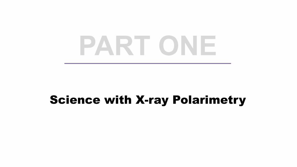
Technical difficulties• Short range for electrons of a few keV
– in silicon: ~μm– in gas: ~mm
• Electron tracks are not straight due to scattering
• Challenge for detector– Require 2D imaging device– Resolution < 100 μm
•600
-800
IOOC-1000 -800 -800 -400 -200 0 200 400 000 800 1000x axis (micron)
Figure 9. Simulated tracks (projected onto the detector plane) produced by 5 keV electrons in pure Ne, at pressureof 1 Atm (right). Starting directions are distributed according to equation (15), simulating photoelectrons emitted inresponse to a collimated, 100 % linearly polarized 5.9 keY photons beam. By means of a progressive "zoom out" (left),it can be clearly seen that the modulation of the track directions is more and more blurred by Coulomb scattering whilegoing away from conversion point.
direction with the principal axis of the released charge distribution. At higher energy, in fact, tracks are longerand the probability for a large angle electromagnetic scattering to occur increases as well. On the other hand, amore sophisticated algorithm which isolates the initial part of the track (like the one we use) allows to efficientlyovercome this limitation, as it is clearly confirmed by experimental data.
By means of our Monte Carlo code we have investigated the performance of a polarimeter with a 100 mreadout pitch (which is feasible with currently adopted technology and will be soon available for tests) for several
70C.)
o 60
50
40
30
20
200 400 600 800 1000Distance from convertion point (micron)
Figure 10. Modulation factor, as a function of distance from absorption point, evaluated from the distribution ofprimary ionization for 5 keV photoelectrons in pure Ne, 1 Atm.
x m ron)
- 800U,
800
400
8
200
.200 -
-400 -
) ) )))) )
I ) ) ) I
Proc. of SPIE Vol. 4843 391
12

Gas Pixel Detector (GPD)• First demonstrated by INFN-Pisa & IAPS-Rome
(Bellazzini et al.; Costa et al. 2001)
13
Gas Electron Multiplier (GEM)

Detector assembly
14

Measured electron tracks
15

Angular modulation
2.67 keV 3.74 keV 5.33 keV
6.09 keV 7.49 keV
16

PART THREE
PolarLight

Polarimeter Light (PolarLight;极光计划)
collimator
window
GEM
ASIC chip
GPD
HV
DAQ
CubeSat
x-ray
photoelectron track
measured 2D track
PolarLight
18

Shocking test
19

Vibration test
20

Thermal vacuum
21
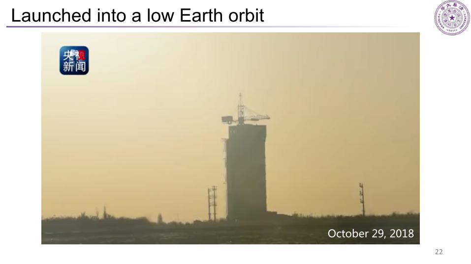
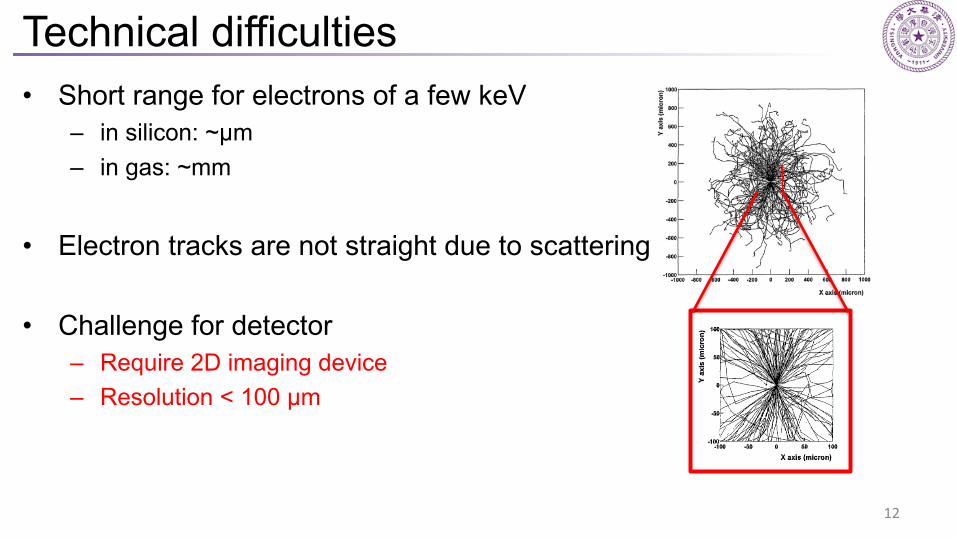
Launched into a low Earth orbit
October 29, 2018
22
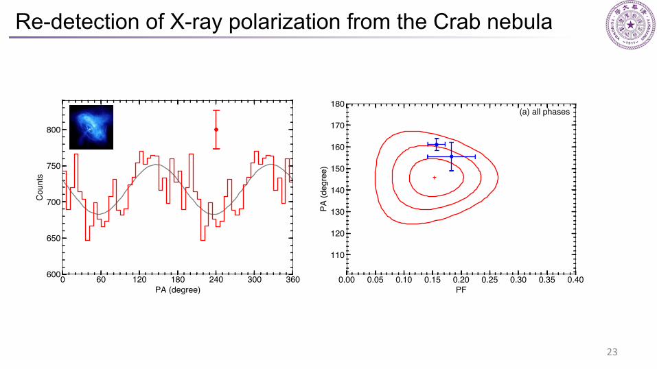
Re-detection of X-ray polarization from the Crab nebula
23

Time variation of polarization
With pulsar emission Without pulsar emission significance level: 3σ
• Bayes factor• Bayesian posterior• BootstrapMagnetosphere altered after the glitch
glitch
24

High energy emission from pulsars
25
11 Multi-Wavelength Polarimetry of Isolated Pulsars 287
Fig. 11.3 Location of radio (blue) and high-energy emission in the outer gap (yellow), two-polecaustic (red) and current sheet (green) models in the meridional plane containing the spin andmagnetic axes of a force-free magnetosphere. The dashed black lines denote the light cylinder andthe dotted red lines show projections of the null-charge surface
site of particle acceleration. The accelerated particles radiate ! -rays through cur-vature and inverse-Compton radiation, initiating electromagnetic cascades throughone-photon pair production in the strong magnetic field (Daugherty and Harding1982; Harding and Muslimov 2002). In this model, the high-energy pulses wouldappear near the phase of the radio pulses, would be very highly polarised and exhibitthe “S-shaped” PA sweep of the RVM. Phase-resolved high-energy polarisationmeasurements were not available until fairly recently, so this property of the polarcap models could not be tested. However the Fermi Gamma-Ray Space Telescope,launched in 2008, discovered many ! -ray pulsars whose pulses appeared at phasessignificantly different from those of the radio pulses (Abdo et al. 2013). In fact,the variety of light curves agree more with predictions of models where the high-energy emission comes from the outer magnetosphere near or beyond the lightcylinder,RLC = c/", where" is the pulsar rotation rate. Such outer magnetospheremodels, such as outer gap (Cheng et al. 1986; Romani 1996), slot gap and currentsheet models had been proposed earlier (see Fig. 11.3). Naturally, polarisationpredictions also changed substantially from those of polar cap models and, as will bediscussed in the following sections, can better explain the properties of the observedpolarisation.
Cheng et al. 1986Muslimov et al. 2004Kalapotharakos et al. 2012Harding et al. 2019

Reopening the window
OSO-8 (1975)
PolarLight (2018)
IXPE in 2021(Weisskopf et al. 2016)
eXTP in 2027(Zhang et al. 2019)
26

PART FOUR
CubeSats in Astronomy

CubeSat 立方星• The CubeSat standard
– proposed in 1999 by Jordi Puig-Suari of California Polytechnic State University and Bob Twiggs of Stanford University
– an educational tool for teaching students about spacecraft hardware, electronics and programming
– Low cost1U 3U 6U
28

Astronomical CubeSats funded by NASA
• ASTERIA (Arcsecond Space Telescope Enabling Research in Astrophysics)
– to measure exoplanetary transits across bright stars with <100 ppm photometry
– launched in August 2017, one of the first CubeSats enabled for astronomical measurements
• PicSat– to observe in visible light the potential transit of the directly-
imaged giant planet β Pictoris b• HaloSat
– measure the soft X-ray emission from the hot halo of the Milky Way galaxy to resolve the missing baryon problem
• CUTE (Colorado Ultraviolet Transit Experiment)– survey of exoplanet transit spectroscopy in the near-UV
• SPARCS (Star–Planet Activity Research CubeSat)– the far- and near-UV monitoring of low-mass stars (0.2–0.6
M☉)• BurstCube
– to detect and localize GRBs
29

“CubeSat” on ADSLaunches of CubeSats
A rapid growth
30

The GRID network
GRID (Gamma Ray Integrated Detectors)
l 10+ CubeSats in LEOl Scintillation detector, ~60 cm2 eachl Localization accuracy for GRBs within 200 Mpc
ü <1°(for an on-axis event, ~0.14 yr-1)ü 10°~ 15°(for a GRB 170817A like event, ~5 yr-1)
31

Flight model & satellite
32

GRID - a student project
• Started in 2016 October• More than 50 Students from 16 universities• GRID-1 in orbit• GRID-2/GRID-3 will be launched this year
The first group Testing the detector Talking at COSPAR 2018
33

CubeSats in Astronomy• To demonstrate new techniques
– Sounding rockets vs. Balloons vs. CubeSats• Highly customized science objective
– Large missions: observatories– Small missions: dedicated
• Long-term monitoring of a single or a few targets• Student training
– Project cycle: ~3 years– All-around skills: science + engineering + leadership
34
THANK YOU!
Copyright © 2022 FDOKUMEN