
Refueling of LH2 Aircraft—Assessment of Turnaround ... - MDPI
41
Citation: Mangold, J.; Silberhorn, D.; Moebs, N.; Dzikus, N.; Hoelzen, J.; Zill, T.; Strohmayer, A. Refueling of LH2 Aircraft—Assessment of Turnaround Procedures and Aircraft Design Implication. Energies 2022, 15, 2475. https://doi.org/10.3390/ en15072475 Academic Editor: Chunhua Liu Received: 2 February 2022 Accepted: 21 March 2022 Published: 28 March 2022 Publisher’s Note: MDPI stays neutral with regard to jurisdictional claims in published maps and institutional affil- iations. Copyright: © 2022 by the authors. Licensee MDPI, Basel, Switzerland. This article is an open access article distributed under the terms and conditions of the Creative Commons Attribution (CC BY) license (https:// creativecommons.org/licenses/by/ 4.0/). energies Article Refueling of LH2 Aircraft—Assessment of Turnaround Procedures and Aircraft Design Implication Jonas Mangold 1, * ,† , Daniel Silberhorn 2,† , Nicolas Moebs 1,† , Niclas Dzikus 2 , Julian Hoelzen 3 , Thomas Zill 2 and Andreas Strohmayer 1 1 Institute of Aircraft Design, University of Stuttgart, 70569 Stuttgart, Germany; [email protected] (N.M.); [email protected] (A.S.) 2 Institute of System Architectures in Aeronautics, German Aerospace Center (DLR), 21129 Hamburg, Germany; [email protected] (D.S.); [email protected] (N.D.); [email protected] (T.Z.) 3 Institute of Electric Power Systems, Leibniz University Hanover, 30167 Hanover, Germany; [email protected] * Correspondence: [email protected] † These authors contributed equally to this work. Abstract: Green liquid hydrogen (LH2) could play an essential role as a zero-carbon aircraft fuel to reach long-term sustainable aviation. Excluding challenges such as electrolysis, transportation and use of renewable energy in setting up hydrogen (H 2 ) fuel infrastructure, this paper investigates the interface between refueling systems and aircraft, and the impacts on fuel distribution at the airport. Furthermore, it provides an overview of key technology design decisions for LH2 refueling procedures and their effects on the turnaround times as well as on aircraft design. Based on a comparison to Jet A-1 refueling, new LH2 refueling procedures are described and evaluated. Process steps under consideration are connecting/disconnecting, purging, chill-down, and refueling. The actual refueling flow of LH2 is limited to a simplified Reynolds term of v · d = 2.35 m 2 /s. A mass flow rate of 20 kg/s is reached with an inner hose diameter of 152.4 mm. The previous and subsequent processes (without refueling) require 9 min with purging and 6 min without purging. For the assessment of impacts on LH2 aircraft operation, process changes on the level of ground support equipment are compared to current procedures with Jet A-1. The technical challenges at the airport for refueling trucks as well as pipeline systems and dispensers are presented. In addition to the technological solutions, explosion protection as applicable safety regulations are analyzed, and the overall refueling process is validated. The thermodynamic properties of LH2 as a real, compressible fluid are considered to derive implications for airport-side infrastructure. The advantages and disadvantages of a subcooled liquid are evaluated, and cost impacts are elaborated. Behind the airport storage tank, LH2 must be cooled to at least 19 K to prevent two-phase phenomena and a mass flow reduction during distribution. Implications on LH2 aircraft design are investigated by understanding the thermodynamic properties, including calculation methods for the aircraft tank volume, and problems such as cavitation and two-phase flows. In conclusion, the work presented shows that LH2 refueling procedure is feasible, compliant with the applicable explosion protection standards and hence does not impact the turnaround procedure. A turnaround time comparison shows that refueling with LH2 in most cases takes less time than with Jet A-1. The turnaround at the airport can be performed by a fuel truck or a pipeline dispenser system without generating direct losses, i.e., venting to the atmosphere. Keywords: liquid hydrogen; refueling; refuelling; hydrogen aviation; hydrogen fuel supply; aircraft design; sustainable aviation Energies 2022, 15, 2475. https://doi.org/10.3390/en15072475 https://www.mdpi.com/journal/energies
-
Upload
khangminh22 -
Category
Documents
-
view
1 -
download
0
Transcript of Refueling of LH2 Aircraft—Assessment of Turnaround ... - MDPI

�����������������
Citation: Mangold, J.; Silberhorn, D.;
Moebs, N.; Dzikus, N.; Hoelzen, J.;
Zill, T.; Strohmayer, A. Refueling of
LH2 Aircraft—Assessment of
Turnaround Procedures and Aircraft
Design Implication. Energies 2022, 15,
2475. https://doi.org/10.3390/
en15072475
Academic Editor: Chunhua Liu
Received: 2 February 2022
Accepted: 21 March 2022
Published: 28 March 2022
Publisher’s Note: MDPI stays neutral
with regard to jurisdictional claims in
published maps and institutional affil-
iations.
Copyright: © 2022 by the authors.
Licensee MDPI, Basel, Switzerland.
This article is an open access article
distributed under the terms and
conditions of the Creative Commons
Attribution (CC BY) license (https://
creativecommons.org/licenses/by/
4.0/).
energies
Article
Refueling of LH2 Aircraft—Assessment of TurnaroundProcedures and Aircraft Design ImplicationJonas Mangold 1,*,† , Daniel Silberhorn 2,†, Nicolas Moebs 1,† , Niclas Dzikus 2, Julian Hoelzen 3 ,Thomas Zill 2 and Andreas Strohmayer 1
1 Institute of Aircraft Design, University of Stuttgart, 70569 Stuttgart, Germany;[email protected] (N.M.); [email protected] (A.S.)
2 Institute of System Architectures in Aeronautics, German Aerospace Center (DLR),21129 Hamburg, Germany; [email protected] (D.S.); [email protected] (N.D.);[email protected] (T.Z.)
3 Institute of Electric Power Systems, Leibniz University Hanover, 30167 Hanover, Germany;[email protected]
* Correspondence: [email protected]† These authors contributed equally to this work.
Abstract: Green liquid hydrogen (LH2) could play an essential role as a zero-carbon aircraft fuelto reach long-term sustainable aviation. Excluding challenges such as electrolysis, transportationand use of renewable energy in setting up hydrogen (H2) fuel infrastructure, this paper investigatesthe interface between refueling systems and aircraft, and the impacts on fuel distribution at theairport. Furthermore, it provides an overview of key technology design decisions for LH2 refuelingprocedures and their effects on the turnaround times as well as on aircraft design. Based on acomparison to Jet A-1 refueling, new LH2 refueling procedures are described and evaluated. Processsteps under consideration are connecting/disconnecting, purging, chill-down, and refueling. Theactual refueling flow of LH2 is limited to a simplified Reynolds term of v · d = 2.35 m2/s. Amass flow rate of 20 kg/s is reached with an inner hose diameter of 152.4 mm. The previous andsubsequent processes (without refueling) require 9 min with purging and 6 min without purging. Forthe assessment of impacts on LH2 aircraft operation, process changes on the level of ground supportequipment are compared to current procedures with Jet A-1. The technical challenges at the airportfor refueling trucks as well as pipeline systems and dispensers are presented. In addition to thetechnological solutions, explosion protection as applicable safety regulations are analyzed, and theoverall refueling process is validated. The thermodynamic properties of LH2 as a real, compressiblefluid are considered to derive implications for airport-side infrastructure. The advantages anddisadvantages of a subcooled liquid are evaluated, and cost impacts are elaborated. Behind theairport storage tank, LH2 must be cooled to at least 19 K to prevent two-phase phenomena and amass flow reduction during distribution. Implications on LH2 aircraft design are investigated byunderstanding the thermodynamic properties, including calculation methods for the aircraft tankvolume, and problems such as cavitation and two-phase flows. In conclusion, the work presentedshows that LH2 refueling procedure is feasible, compliant with the applicable explosion protectionstandards and hence does not impact the turnaround procedure. A turnaround time comparisonshows that refueling with LH2 in most cases takes less time than with Jet A-1. The turnaround at theairport can be performed by a fuel truck or a pipeline dispenser system without generating directlosses, i.e., venting to the atmosphere.
Keywords: liquid hydrogen; refueling; refuelling; hydrogen aviation; hydrogen fuel supply; aircraftdesign; sustainable aviation
Energies 2022, 15, 2475. https://doi.org/10.3390/en15072475 https://www.mdpi.com/journal/energies
Energies 2022, 15, 2475 2 of 41
1. Introduction
The European Commission’s Green Deal, with the goal of carbon neutrality by 2050,also challenges the aviation industry to break new ground [1]. Hydrogen is a versatile andclean energy carrier that can be produced renewably by electrolysis [2]. Due to its higherspecific gravimetric energy compared to kerosene (factor 2.8) [3], H2 could be a naturalchoice as a fuel for aviation. Sustainable aviation fuels are the main competitors of H2 [4].Synthetic kerosene produced in a power to liquid (PtL) process, assuming electric energy asthe power source with Carbon Dioxide (CO2) captured from the air and water as primaryresources [5], is one possibility. Using synthetic fuel, the aircraft design does not change,and the airport does not require new infrastructure. On the other hand, the amount ofenergy required for production is larger [4], leading to a higher fuel price compared to LH2.In addition, CO2—filtered out of the air at great expense for the PtL process—is releasedwith combustion of synthetic kerosene.
However, LH2 has a disadvantage when used as a fuel, especially in aviation, be-cause its volumetric energy density is lower by a factor of 4.0 compared to kerosene [3].This difference leads to larger tank volumes that can no longer be reasonably positionedin the wing and therefore require adjustments to the fuselage, leading to higher dragand therefore higher thrust requirements, i.e., less energy efficiency of the total aircraft.In principle, H2 can be stored in various aggregate states and pressure ranges leading todifferent densities. Cryogenic storage at LH2 temperatures of around 20 K, preferred due toits lower volume requirement, needs tank insulation to keep the heat input low. Otherwise,the LH2 would heat up, leading to evaporation and pressure increase. When the maximumtank pressure is reached, losses occur.
Initial assertions indicate that an LH2 refueling process could be two to three timeslonger than with conventional Jet A-1 [6]. This statement is doubtful, as it is based onthe assumption of keeping the same volume flow of 900 L/min [1], which is too low forJet A-1 [7,8] and would be too low for LH2. Additionally, comparing dimensional valuesof different fluids with large differences in physical properties can lead to meaninglessresults [9]. Such a significant extension of the refueling process would have a far-reachingimpact on the annual utilization and Direct Operations Costs (DOC) of the aircraft. There-fore, increasing costs for the required refueling process are considered and impacts onturnaround time are investigated. Comparison to conventional refueling with Jet A-1,together with a benchmark with the space and automotive industries, allows for an analysisof boundary conditions and limitations for LH2.
Studies on the overall impact of LH2 on aircraft design and airport infrastructurehave been conducted since the 1970s [10–12]. However, there is limited research on theboundary conditions for the refueling process. The Tupolev Tu-155 was an experimentalaircraft used to test alternative fuels on one engine in 1988/89 [13]. The uniqueness ofthe aircraft configuration was a chimney on the vertical tailplane, which is a feature forLH2-aircraft and crucial for explosion protection in case of venting. Airbus [14] with theirCryoplane and Brewer [15–17] have indicated the potential of LH2 as a fuel in aviationand provide the basis for further research and development towards LH2-fueled aircraft.Refueling is coming into focus as a potentially critical factor of LH2-powered aircraft, whichcould significantly reduce economic efficiency [1]. This is particularly true for short-rangeaircraft, where the ground time has a much greater impact on aircraft utilization comparedto long-range aircraft.
Therefore, the motivation for the following work is to recapture and further developthe technical understanding of the effects of LH2 on the turnaround and refueling processbased on mathematical and physical correlations. Due to the different statements of thepublications, the novelty and the research gap in this paper is to show the boundary con-ditions, calculation methods, and analysis of the refueling system and obtain conclusionsfrom them. Previous publications only present a final result but do not show the calculationway and method. The research gap closed by this paper is to outline the missing methodsof previous years again and make them understandable. Furthermore, analytically solvable
Energies 2022, 15, 2475 3 of 41
methods are preferred to save time but avoid numerical calculation and make correla-tions more easily visible. In addition, solutions are shown to ensure a similar turnaroundtime to enable a competitive LH2-powered aircraft. By understanding thermodynamicrelationships, the novelty in this study is also to transfer the implications of refueling toaircraft design.
The basis for this work is the Master’s thesis by Mangold [18], which was supervisedin cooperation with the University of Stuttgart and the German Aerospace Center (DLR).This thesis investigates the economic assessment of H2 short-range aircraft with a focus onthe turnaround. In addition, there is a parallel publication from Hoelzen et al. [19] aboutthe economic analysis for LH2 refueling and airport infrastructure.
In Section 2, this paper first presents the required state of the art necessary to get anoverview of Jet A-1 refueling and the properties of LH2. Then in Section 3, the methodol-ogy is described to analyze the system, the procedure and boundary conditions. The re-sults of the refueling procedure and the implications on the airport distribution aregiven in Section 4. Finally, Section 5 discusses the impacts on aircraft design with thegained knowledge.
2. State of the Art
This chapter presents the technologies and principles to create a relevant basis forthe LH2 refueling analysis. Firstly, the boundary conditions and limitations of refuelingwith Jet A-1 are investigated to enable comparability. Secondly, basic properties of H2 arepresented to provide relevant knowledge required for understanding the behavior of acryogenic liquid. Finally, to reflect the handling possibilities of hydrogen, a benchmarkwith existing procedures in the fields of space and automotive industry is provided.
2.1. Refueling of Jet A-1
Commercial aircraft are normally fueled with single or dual connections at the bottomside of the wing. Ground refueling vehicles can be distinguished in dispenser pipelinesystems and refueling trucks. The time required for positioning and connecting as well asdisconnecting and removing is about 2.5 min [7]. For faster refueling of long-range aircraft,it is typically necessary to refuel on both sides of the wing in parallel. Jet A-1 has theproperty of an accumulator building up static electricity due to friction as it flows througha pipe [20]. The discharge of this static electricity can cause ignition of the fuel in explosivemixtures [20]. Therefore, there are limitations in the flow conditions of Jet A-1 [20–22],expressed through the pipe diameter d and the flow velocity v:
v · d ≤ 0.5 m2/s (1)
v ≤ 7 m/s | short pipe (2)
v ≤ 3 m/s | long pipe (3)
To evaluate the comparison of the flow regime independent of the fluid, dimensional anal-ysis can be used, which compares dimensionless numbers to ensure comparability [9]. There-fore, the simplified term v · d can be converted into a Reynolds number of Re = 2.86 · 105 bydividing by the kinematic viscosity ν(T = 288.15 K) = 1.75 · 10−6 m2/s [23]. Through thelimitations in Equations (1) and (2), an inner hose diameter of 63.5 mm (2.5 in) can be calcu-lated, which is the same as for the ground refueling vehicle manufacturer’s specification [8].Recalculating of single-point fueling under static electricity restrictions with the continuityequation results in a maximum volume flow of a of 1500 L/min for one hose. In dimensionand weight [8,24,25], the resulting hose is a manageable load for airport staff during a workingday [26]. When lifting the fuel adapter to the aircraft manually, its weight is essential for thehandling options (see Section 3.12.1).
Energies 2022, 15, 2475 4 of 41
The following equation describes the transferred refueled volume V depending on thetime t to the aircraft [27]:
V = Vt=0 · eα·t (4)
V =∫ t
0V dt = Vt=0 ·
eα·t − 1α
(5)
Vt=0 defines the initial volume flow, which corresponds to the maximum flow rates cal-culated with the static electricity limitations. The value for the resistance of the tank andother components involved during refueling is denoted by the factor α [28].
According to Equation (4), the volume flow decreases exponentially for α < 0. Thisdecrease is due to the rising liquid level in the tank, leading to an increase in hydrostaticpressure and the increasing pressure losses due to closing valves in the connection betweenthe separated tanks [27]. However, this characteristic can be explained based on the pumpcapacity and Bernoulli’s equation. With a constant pump power, the pump can deliver ahigher volume flow at the beginning of the refueling process because the delivery pressureis still low due to a low liquid pressure head. As the liquid level rises, the pump mustcontinuously apply a higher pressure, which leads to a lower volume flow at constantperformance. This specific characteristic is represented in factor α and varies dependingon the aircraft type. The refueling process α values are −0.022 min−1 for a Boeing 747 [27],−0.0145 min−1 for an Airbus A380 [27], and −0.036 min−1 for an Airbus A320 [29].
Therefore, a comparable sizeable initial flow rate Vt=0 of 1800 L/min for a single-point and 3600 L/min for dual-point refueling is used in the following study. The volumeflow of 3600 L/min can be translated to a comparable energy flow of 2100 MJ/s, whichis basis of the sizing of the LH2 refueling system, see Section 3.13.1. The volume flowof 1800 L/min infringes the limitations at the beginning of refueling, but the exponentialreduction recaptures this. Nevertheless, these maximum values serve for the time-criticalcomparison with LH2.
2.2. Properties of Liquid Hydrogen
The properties of H2 (independent of the phase state) have to be known to understandthe following considerations and to reflect the design decisions. H2 has a Lower HeatingValue (LHV) of 119.95 MJ/kg during combustion [3], defining its useful energy. Whenmixed with air, the flammability limits of hydrogen are between the Lower FlammabilityLimit (LFL) of 4 vol.% and the Upper Flammability Limit (UFL) of 75.7 vol.% [30]. The mini-mum ignition energy of H2 is 0.017 mJ [30], which is more than an order of magnitude lowercompared to Jet A-1 [23]. Aluminum alloy 6061 or stainless steel X5CrNi18-10 (AISI 304)are selected as recommended materials for a hydrogen system [30–32].
With respect to the thermodynamic properties of hydrogen molecules, there is adistinction in the energy level [3,33,34]. Equilibrium hydrogen refers to a mixture inthermodynamic equilibrium, which consists in liquid state of 99.8 % parahydrogen [35].Therefore, the physical values of parahydrogen based on the database RefProp [36] areused in the following work.
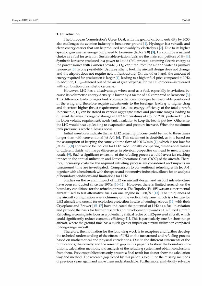
Figure 1 shows a phase diagram of hydrogen. The state of aggregation is relevantas it determines the applicable system of equations, i.e., the equation for the ideal or realgas cannot be used for a liquid. Furthermore, there is a significant difference between asaturated liquid and a subcooled liquid [3,33,37]. Firstly, the density can be calculated bythe temperature or pressure for a saturated (boiling) liquid and does not require both statevariables. Secondly, a subcooled (compressed) liquid describes a liquid in the single-phaseregion (common understanding of liquid), and therefore not on the saturated liquid line.The generation of a subcooled liquid is possible by removing heat or by an isothermalpressure increase [37], see Figure 1. Thus, the temperature of the subcooled fluid is belowthe equilibrium temperature. The advantage of this state is that the LH2 can absorb heatwithout any vaporization losses until thermodynamic equilibrium is reached [3].

Energies 2022, 15, 2475 5 of 41
Figure 1. Phase diagram of parahydrogen [36]; isothermal and isobaric subcooling starting fromNormal Boiling Point (NBP).
Another parameter for the design of LH2 tanks is the characteristic curve of vaporpressure over temperature, reflecting the behavior over time for cryogenic tanks. If thetemperature of the fluid increases, the vapor pressure will also increase. This, in turn,means that if a certain subcooled level shall be maintained, the liquid pressure must alsoincrease. This is especially crucial for tanks that do not reach equilibrium, i.e., where thetank pressure is higher than the vapor pressure.
Similar to the subcooled level, there are two simplified ways to enter this two-phaseregion: by an isobaric temperature increase or by a (sudden) pressure drop under isothermalconditions [37,38].
The ullage above the liquid in sealed tanks is the extra gas volume, needed to allowthermal expansion of the liquid [31]. Therefore, a two-phase mixture must be present in thetank at all times to avoid excessive pressure fluctuations [2]. However, this does not meanin general that the contents of the tank must be in the two-phase (liquid–vapor saturation)region in the T-s diagram and in a saturated state. In this thermodynamic equilibriumthe ullage and liquid temperatures are equal, and the vapor pressure curve balances out,i.e., this process needs time—depending on a system between 10 min [39] and more than4 h [40]. There must only be a gaseous component to absorb the density changes of theliquid due to the compressibility of the gas. As a result of this, the pressure in the tankdoes not increase excessively. Hence, in non-thermodynamic equilibrium, there can be asubcooled liquid and a hotter gas in the tank. This distinction is necessary because promptlyafter refueling, the content of the tank is in non-equilibrium and later in equilibrium. Itcan be summarized that LH2 must be treated as a real compressible fluid, i.e., close to thevapor region and two-phase phenomena. Further considerations and impacts on aircraftdesign based on these findings are elaborated in Section 5.
2.3. Handling Options for Hydrogen
H2 is already widely used in industry and research. Typical pressures for compressedGaseous Hydrogen (GH2) in the automotive industry are 350 and 700 bar [41]. The stan-dardized refueling protocol for GH2, SAE2601 [41], shows the influence on temperatureand pressure level on the refueling times. The adapters for GH2 refueling in the auto-motive industry are standardized in SAE2600 [42]. The real gas behavior for GH2 mustalso be considered based on the Joule–Thomson effect, i.e., due to an isenthalpic expan-

Energies 2022, 15, 2475 6 of 41
sion, the hydrogen heats up [3]. Therefore, a cooling system is required for high pressureGH2 refueling [3], affecting the system and increasing costs. The standardization for GH2refueling is not applicable for LH2 because of the different requirements related to thephase state.
As there is no standardized industry norm for LH2 refueling, the following handlingoptions are considered. One possibility that allows for handling of LH2 is the vacuum-insulated Johnston or Johnston–Cox coupling [34,43]. Due to the open connection point,after connecting and before disconnecting, for reasons of safe handling and compliancewith explosion protection, a purging process is necessary [43]—so no foreign gases remainin the hoses. Helium is required for this purging process [30], as at cryogenic temperaturesof 20 K, all substances except helium (boiling point of 4.2 K [35]) would freeze and blockthe pipe [44,45]. Helium has the further advantage of being an inert gas that does notform chemical reactions and dissolves only slightly [31]. On the downside, Helium is anexpensive, non-renewable inert gas [46] that should ideally not be used in regular operation.A massive increase in helium consumption could raise the price to such an extent that usingLH2 as a fuel would become uneconomical.
The other option is to perform the purging process with nitrogen and GH2 [30]. Dueto the requirement to first purge the ambient atmosphere with nitrogen (T > 80 K [30])before purging it again with GH2 before LH2 can be introduced [30], this method isexcluded because of the additional complexity and time needed.
A clean break disconnect releasing a small amount of spillage during connectionand disconnection [47] is the second possibility. Evacuation and pressurization (purg-ing) before and after refueling can be eliminated with the use of a self-sealing quickdisconnect [48–50]. The system gauge pressure is at minimum 0.2 barg for LH2 [51] and1.7 barg for GH2 systems [30,51]. This gauge pressure prevents penetration, and the systemremains free of contamination.
Both variants, the Johnston disconnect and the clean break disconnect are furtherconsidered, as both methods are feasible. The technical implementation is used in non-aircraft applications, which are analyzed in the following section.
2.4. Non-Aircraft Liquid Hydrogen Refueling Applications
For dimensioning the aircraft refueling system, other refueling applications and theirspecifications are useful for defining aircraft refueling. A comparison with the automotiveindustry is based on large batches and numbers of refuelings, which must be handled byevery driver with a reliable and safe refueling system. On the other hand, space applicationsare characterized by large individual fuel quantities, which are only required in a certaintime interval. Therefore, these two non-aviation applications will be analyzed further inorder to draw conclusions on aircraft refueling.
2.4.1. Automotive Industry
The automotive refueling process of LH2 is interesting as the safety regulations arehigh. In direct comparison, LH2 shows advantages over GH2 due to the lower storagepressure, which favorably affects leakage characteristics [52]. Nevertheless, monitoringand detecting H2 by a gas sensor is essential and follows a power supply shutdown andemergency stop system [52]. A fully automatized refueling robot for LH2 was being usedat Munich Airport in 1999 [52]. This approach shows the potential safe handling and highreadiness level.
The recovery system is of special importance in this context, as vaporized hydrogenmust be returned from the vehicle tank [48,53]. This measure is necessary to keep the tankpressure constant and prevent it from rising. Furthermore, a cryogenic coaxial clean breakdisconnect is used [52,54,55] to combine the LH2 transfer and the GH2 recovery line in onedisconnect. The self-closing clean break disconnect is connected in 20 s and disconnectedin 10 s. The improvement in time compared to the non-clean break Johnston disconnect ismore than 30% [56].
Energies 2022, 15, 2475 7 of 41
Therefore, the comparison with the automotive industry shows the potential forappropriate, safe, and time-saving use. The refueling protocol of Stewart [48] can beadopted for LH2 aircraft refuelings and applied for further standardization.
2.4.2. Space Shuttle Loading
The External Tank (ET) of the Space Shuttle is fueled with LH2 by a pressurizationsystem [57]. To maintain the storage tank’s pressure level, some liquid flow is vaporizedand injected into the ullage [43]. The diameter of the transfer pipe is dpipe = 0.254 m with alength of lpipe = 457 m [57]. For loading LH2 to the ET, a volume flow of 28.4 m3/min istransferred [57], which results in a Reynolds number of 1.22 · 107. For simplification, thismeans that the term v · d is about 2.37 m2/s and the velocity is 9.34 m/s.
For comparison, an operating ullage pressure p of 2.2 to 2.35 bara and venting pressureof 2.5 bara is established for the ET [58]. The tank’s pressure is increased during theloading process [57] to prevent the LH2 from boiling through the heat input and followingtemperature increase. After loading, replenishing, and topping, it has to be ensured thatthe required fill level is maintained and continues shortly before the liftoff [57]. Moreover,the tank pressure is reduced through a vent valve to 0.01 barg [57]. Through the pressuredecrease, the LH2 boils back (flash evaporation) to a saturated state [59], which means thatthe temperature decreases and density rises back to Normal Boiling Point (NBP) conditions.This procedure is necessary because the required fuel mass of the mission must fit intothe fixed volume of the rocket, which is designed with the density in the NBP. Thereby,the tank content is in thermodynamic equilibrium and the temperature and, consequently,also the density can be calculated from the pressure. The required fuel for the mission canthus be determined and the time to launch is not time-critical.
2.4.3. Spacex Falcon 9 Loading
SpaceX introduces a different loading procedure for their rockets as it is loaded just35 min before liftoff [60]. This fundamentally different sequence is required because ofa densification process [61]. Due to the use of a cryogenic fluid, this loading process iscomparable to aircraft refueling with LH2 because the same problems and solutions arisedue to the low temperatures. The Liquid Oxygen (LOX) is thereby subcooled by 24 Kbelow the saturated temperature of the NBP [62]. Therefore, the refueling procedure is stillinteresting despite using a different fluid because of the handling and process steps of thesubcooled liquid.
Subcooling increases the density, making the tank’s required volume smaller andreducing overall mass [63,64]. This advantage of the greater density of the oxidizer impliesthe disadvantage that the conventional loading process can no longer be applied [64]. Anyheat input into the fluid during loading and before launch would increase the temperatureand decrease the density [65], resulting in insufficient propellant mass for the mission.The time to launch must therefore be kept short as the LOX must remain cold. In contrastto the Space Shuttle, the cryogenic liquid is not in thermodynamic equilibrium. The tankcannot simply be refilled since a heat input does not lead to evaporation but rather to anincrease in temperature (density reduction).
Space programs have demonstrated the handling of LH2 as an energy carrier and fuel.The knowledge gained from this experience and design of rockets with cryogenic fluids canbe adapted to aviation. Design aspects for rockets, such as the tank architecture, the fuelsystem, and the calculation methods, can be found in the three fundamental space books bySutton [31], Ring [39], and Huzel et al. [66]. The problem in adjusting the assumptions andequations developed for rockets and launch systems is flight duration for specific situations.Because of the short operating times during a rocket flight mission, simplifications canbe made in preliminary design of space space flight vehicles. However, adopting thesesimplifications of the flight mission to aircraft design can lead to an incorrect interpretationof calculation results since inadequate boundary conditions have been adopted, consideringa ten-hour long-range flight.

Energies 2022, 15, 2475 8 of 41
3. Methodology
This chapter examines the refueling and distribution process with LH2. The safehandling of H2 as a fuel is always in the context of ensuring explosion protection. Basicregulations required for handling H2 at the airport are analyzed first. Secondly, the refuelingprocedure with LH2 is defined, and the temporal influence of the individual sequential stepsis determined through mathematical models and boundary conditions. Finally, the modelsand principles are presented that are required to analyze the design of a hydrogen aircraftand, in particular, the refueling and turnaround process.
The methodology section is based on the following steps, which are necessary for therefueling of LH2:
• Docking maneuver.• Connecting and purging.• Chill-down and recovery line.• Actual refueling mass flow.• Steps afterwards.
3.1. Explosion Protection Regulations
Explosion protection can be presented in a methodical, common-sense approach thatconsists of the following three measures: primary explosion protection, which includesavoiding an explosive atmosphere, and secondary protection, which describes the avoid-ance of an ignition source while an explosive atmosphere can occur. Tertiary explosionprotection intends to limit the effects of an explosion to a harmless level. The necessarysystem overpressure of 0.2 barg, given in Section 2.3, is one example of primary explosionprotection. No penetration of foreign substances in normal operation is ensured, and thusno explosive atmosphere in the tank is created.
In the European Union (EU), minimum requirements for explosion protection ofworkers are documented in the ATEX directives [67,68]. In Germany, the EU guidelineshave been transferred to the Ordinance on Industrial Safety and Health (BetrSichV) [69] andthe Hazardous Substances Ordinance (GefStoffV) [70], which are further broken down bytechnical rules. If the technical rule is complied with, it can be assumed that the ordinances’relevant requirements are met [71]. This means that the system is safe for use and complieswith the applicable laws.
The Technical Rules for Hazardous Substances (TRGS) 720 [72] describe the procedurefor assessing and avoiding explosion hazards under atmospheric conditions. Hence, noexplosion protection measures are required without any explosive atmosphere. Accordingto the Technical Rules for Operational Safety (TRBS) 2152 Part 2/TRGS 722 [71], a perma-nently tight system prevents a dangerous explosive atmosphere around the system. In thecase of a permanently technically tight system, no spills are to be expected if it is designedaccordingly and adequately maintained and monitored.
In addition, the release of a hazardous substance and the creation of an explosiveatmosphere are not always a reason for a safety area. There must be a dangerous amount ora hazardous quantity (dangerous explosive atmosphere), which is defined above a volumeof 0.01 m3 [73].
However, this reflection of explosion protection only refers to normal operation [72],i.e., malfunctions such as component failure and accidents are not considered. Therefore,primary explosion protection is achieved by gauge pressure and a permanently technicallytight system. Due to the cryogenic temperatures, material degradation through hydrogenembrittlement and diffusion is still an open question. Therefore a detailed risk analysis andfuture research for spills and leakages which could occur are required.
Safety regulations have the highest priority for the refueling process, and complianceis mandatory. The primary explosion protection guidelines are used for the legal safetyconcept, which allows parallel refueling with passengers on board. Through this process,the turnaround time can be reduced, as with Jet A-1, or in other words, the turnaroundprocess remains unchanged.

Energies 2022, 15, 2475 9 of 41
3.2. Feed System
In principle, there are two ways of feeding the fuel to ensure the required mass flowsand pressures through a suitable system [31,32]. On the one hand, expelling or displacingcan be achieved by pressurizing the tank with a high-pressure system [31,32]. On theother hand, the mass flow can be moved by low-pressure and high-pressure pumps [31,32].Moreover, both feed systems always require some pressurization gas system [32], as thevolume of the displaced fluid must be replaced with a gas to avoid a pressure drop(thermodynamic open system).
3.2.1. Cryogenic Pump System and Design Parameters
One of the most important criteria for pump design is cavitation [74], i.e., otherinfluences are not taken into account in this preliminary pump analysis. Flow cavitationalso leads to a pressure drop but through a local increase in velocity, formation of vaporbubbles followed by deceleration and implosion [75]. These impinging vapor bubbles cancause cavitation erosion, vibration, or pressure pulsation [75].
Volume flow Q, pressure head H, and rotational speed n characterize pumping perfor-mance. The specific speed ns Equation (6) and the suction specific speed nss Equation (7)largely determine the type of pump impeller and design and are derived from the similarityconditions [75].
The specific speed ns makes it possible to compare pump impellers of different sizesand operations [75]:
ns = n ·√
QH3/4 (6)
An increase in rotational speed raises the pump’s specific speed [76]. It can alsoincrease the pump’s efficiency, which can reduce the number of stages [76]. This makes thepump lighter, which in turn has advantages in the vehicle design [76]. On the downside,there is an increase in the pump inlet requirements to avoid cavitation and higher wear ofthe pump and an increase in costs [76].
The second important parameter for pumps is the suction specific speed nss, whichis used to characterize the suction behavior and in the transferred sense for the cavita-tion properties [75]. This parameter makes it possible to compare pumps that are notgeometrically similar and is defined as follows [75]:
nss = n ·√
QNPSHc
3/4 (7)
To avoid cavitation, the pump-inlet Net Positive Suction Head available NPSHa mustbe higher than the critical Net Positive Suction Head NPSHc, which is a pump-specificvalue [66]. The NPSHa determines the difference between the pump inlet total pressurehead and the liquid–vapor pressure head [31]. NPSHa means, in this turn, an existing sys-tem pressure head, which can be expressed through the incompressible Bernoulli equationin terms of energy head (total head) [31]. Through the temperature dependency of thevapor pressure, the NPSHc value is also a measure of the level at which a subcooled liquidmust be present. Furthermore, the fluid’s subcooling before refueling offers advantages forpump cavitation because the vapor pressure also decreases, which means an increase in theNPSHa value [59,63].
In the following analysis, the pump design is based on the parameters of the SpaceShuttle Main Engine (SSME) Low Pressure Fuel Turbo Pump (LPFTP) [77]. This results inthe similarity parameters of a specific speed of ns = 37.5 and a suction specific speed ofnss = 351.5. In the calculation of these parameters, the conservative approach is chosen sothat the calculated NPSHa is the same as NPSHc, i.e., NPSHc is higher because in realityNPSHa > NPSHc.
While not yet proven in operation, pumping of saturated liquids can also be accom-plished with a Zero-NPSH pump [53,78,79]. The advantageous elimination of a pressuriza-

Energies 2022, 15, 2475 10 of 41
tion system follows [80]. This system simplification, which also entails reducing the tankand fuel system mass, has significant consequences for the overall aircraft design, whichare further examined in Section 5.3.
3.2.2. Considerations for a Pressurized Gas Feed System
The pressurization system must be fundamentally divided into two subsystems.The difference is derived from the pressure gas used [31,32], which either has an inertbehavior (helium) or is the same substance in gaseous form (H2) as the liquid. This dis-tinction must be made to take thermodynamic effects such as condensation, evaporation,diffusion, and temperature differences into account [31]. The pressurant mass can be calcu-lated with the ideal gas equation [32], the law of conservation of energy [31], or with realgas effects [81].
According to Sutton [31] a simplified analysis of a fuel tank’s pressurization canbe carried out based on the law of conservation of energy. The assumption of an idealgas and an adiabatic process are prerequisites for this method [31]. Initial masses of thegas in pipes and the fuel tank are neglected [31]. A slow expansion of the gas can beattributed to an isothermal process in which the pressurant, ullage and fuel are approxi-mately the same [31]. The pressurant mass m and volume V are calculated with followingequations [31] depending on the pressure p, gas constant R, Temperature T and the heatcapacity ratio κ:
m0 =ptank ·Vtank
R0 · T0
(κ
1− ptank/p0
)(8)
V0 =m0 · R0 · T0
p0(9)
The pressurant gas volume depends only on the factor κHe/κGH2 = 1.2 Equations (8)and (9) of the gas used. This relationship is advantageous because the size of the gas forpressurization is similar and does not have much impact on the ground vehicle.
Another possibility to pressurize the fuel truck tank with GH2 is using a heat ex-changer or, more precisely, a vaporizer [31,32], which eliminates the need for an additionalgas storage tank on the truck. The vaporizer’s performance is defined by the heat of va-porization ∆hv, the density ρ ratio and the volume flow required to maintain the pressure.Derived from Huzel et al. [32] and the first law of thermodynamics, the power P (heat flow)can be calculated as follows:
P = mLH2 · ∆hv ·ρg
ρl(10)
ρg =pg,tank
R · Tg(11)
The density of the pressurant ρg depends on the required tank pressure for displacingthe fluid.
3.3. Boiling Heat Transfer and Chill-Down Time
Boiling heat transfer depends on the superheat temperature ∆Tsat [82]. Due to theextensive wall temperature range of the film-boiling regime, this has the most considerableimpact on the chill-down process [83,84]. The superposition principle combines thesemethods of conventional single-phase forced convection and boiling heat transfer [85].
The superheat temperature ∆Tsat (or excess temperature) is defined as the temperaturedifference between the wall temperature Twall and the temperature of the saturated fluidTsat [84]:
∆Tsat = Twall − Tsat (12)
Energies 2022, 15, 2475 11 of 41
The influence of forced convection also depends on the superheat temperature and thusthe boiling regime [86]. A simple approach to combine both methods is the superpositionprinciple, in which the individual components of the heat flow Q or heat transfer-coefficienth are added [85]:
Q = Qboil + Qconv (13)
Q = (qboil(T) + h(T)conv · ∆Tsat) · A (14)
h = hboil + hconv (15)
with the Area A and the heat flow per area q.The heat transfer for film boiling regime can be expressed after the Breen and West-
waster equation [84] for wall temperatures above 40 K [87]:
qboil,film(T) =0.37 + 0.28 · Lc
d(Lc · µv · ∆Tsat
kv3 · ρv · (ρl − ρv) · g · h′v
) 14· ∆Tsat (16)
Lc =
[σ
g · (ρl − ρv)
] 12
(17)
h′v =
(∆hv + 0.34 · cp,l · ∆Tsat
)2
∆hv(18)
with the Laplace length Lc, the dynamic viscosity µ, the thermal conductivity k, the surfacetension σ, the gravitational acceleration g, the effective heat of vaporization h′v, the heat ofvaporization ∆hv, and the heat capacity at constant pressure cp.
The additional heat-transfer coefficient due to forced convection can be calculatedusing a modified Dittus–Boelter equation or Sieder–Tate correlation [84]. The Reynoldsnumber and the heat-transfer coefficient are calculated with the single-phase vapor (SPV)properties of the bulk saturation conditions and the velocity of the mixture [88]:
hconv,film = 0.023 · Re0.8spv · Pr0.33
v ·(
µv
µwall
)0.14· kv
d(19)
Respv =ρv · vavg · d
µv(20)
vavg =m
ρb · A(21)
ρb =
(xρv
+1− x
ρl
)−1(22)
x =mv
mv + ml=
q(T) · A∆hv
· 1m
(23)
with the Prandtl number Pr is and the vapor fraction x.Due to the simplification by neglecting the transition and nucleate boiling, the second
temperature range of 20 to 40 K follows with the heat transfer of the Leidenfrost point.The Leidenfrost point is calculated with a modified Zuber relation [84,88,89]:
qboil,minheat = 0.16 · ρv · ∆hv ·[
g · σ · (ρl − ρv)
(ρl + ρv)2
] 14
(24)
In this second temperature range, the convective heat transfer is calculated with theDittus–Boelter relation [88]. In contrast to film boiling, however, the Reynolds number and

Energies 2022, 15, 2475 12 of 41
the Nusselt number and the heat-transfer coefficient are calculated using the single-phaseproperties of the liquid (spl) [88]:
hconv,spl = 0.023 · Re0.8l · Pr0.4
l ·kld
(25)
Rel =ρl · vavg · d
µl(26)
Additional information on heat transfers and other calculation methods can be foundin [83,90–92].
The chill-down time can be calculated with the lumped capacitance method, whichrequires a Biot number Bi lower than 0.1 [82]:
Bi =h · lcksolid
< 0.1 (27)
The Biot number is calculated with the heat-transfer coefficient h, the characteristiclength lc = V/A and the thermal conductivity of the solid material ksolid [82]. A Biotnumber greater than 0.1 indicates more complex transient heat transfer equations and thatthe spatial temperature uniformity is not given [82].
After a plausible check, this is true in widespread areas of the Nukiyama curve. In thenucleate boiling area, the Biot number becomes larger than 0.1 because, at this point,the heat-transfer coefficient increases significantly. Nevertheless, the nucleate boiling isonly in a negligible temperature range, which does not have an enormous influence on thechill-down time. Furthermore, this error in the boundary conditions can be tolerated, as thelumped capacitance method is analytically solvable and quickly shows a trend. A detailedconsideration would require transient, position-dependent numerical modeling, which isnot necessary for the preliminary design.
The differential equation can be applied from the principle of conservation of energy:
m · cp ·δTδt
= Q (28)
m · cp ·δTδt
= q(T) · A = h(T) · (T∞ − T) · A (29)
h = f(
hboiling, hconvective
)(30)
The neglect of the convective heat transfer [93] is not adopted, as considering the heatflux through the Nukiyama curve is more accurate. In addition, all energy balances must befulfilled in order to obtain realistic results. Due to the chill-down from ambient temperatureto the cryogenic temperature of LH2, the specific heat capacity of stainless steel is no longerconstant [94]. It must also be treated as a function of temperature [94].
m · cp(T) ·δTδt
= q(T) · A (31)∫ T
T0
cp(T)q(T)
dT =∫ t
0
AV· 1
ρdt (32)
AV
=π · di · l
π/4 ·(
do2 − di
2)· l
=4 · di(
do2 − di
2) (33)
According to Equation (33), the chill-down time is independent of the length of thepipe. Typically for the lumped capacitance method, the derived equation is a function ofthe characteristic length, which in this case is approximately the wall thickness of the pipe.Conversely, this method does not show all physical effects since, in reality, the chill-downtime is a function of the pipe length with constant diameter [87,95], but is chosen as asimplified unsteady method. However, the results from the simplified approach are in the
Energies 2022, 15, 2475 13 of 41
same order of magnitude as experimental data [87,95]. The pipe length is only indirectly(iteratively) considered in the calculation, as the surface of the pipe determines the vaporcontent, see Equation (23). Another possibility of simplified modeling can be found inRame et al. [96] and Steward et al. [95].
In addition, Equation (33) shows the dependencies of the chill-down time. The termof specific heat capacity and density of the pipe material enters into the time duration.An aluminum alloy would thus have an advantage over stainless steel. Due to the wallthickness, which depends significantly on the yield strength and Barlow’s formula [97],stainless steel is again advantageous in the combination of all variables. Therefore, stainlesssteel is used in upcoming considerations.
3.4. Evacuation and Pressurization Time for Purging
The calculation for the required number of vacuuming and pressurization repetitionscan be determined using the ideal gas law in molecular notation with the universal gasconstant < [30]; see Equation (34). The starting point is the initial volume filled with air(20 % O2) under ISA conditions with a temperature of 288.15 K and pressure of 101.3 kPa.
n =p ·V< · T (34)
c =nV
=p< · T (35)
The calculation assumes that the temperature remains constant and that the inert gasalso has a temperature of 288.15 K. Therefore, the pressure is reduced to 1200 Pa duringthe evacuation, which means that the concentration c of oxygen (cO2 ) stays constant and isthen pressurized to 1.2 bar, which means the amount of substance n (nO2 ) is constant.
The total volume to be purged is irrelevant for the number of repetitions, as thepercentage expressed by the mass concentration c is decisive. After three repetitions of theevacuation and pressurization cycle, the oxygen concentration results as 0.2 ppm, whichfulfills the requirement of Section 3.12.2.
3.4.1. Calculation of Time Required for Evacuation
For the calculation of the evacuation, which is performed with a vacuum pump,reference is made to the following equation [98]:
t =VS· ln(
pstart
pend
)(36)
The pump’s pumping speed S defines the volume that can be evaluated per unit oftime and is selected as 300 m3/h [99] in the analysis.
3.4.2. Calculation of Time Required for Pressurization
The calculation of the time required for the vessel pressurization is based on thecontinuity equation. This formulation results in the following differential equation, whichassumes a constant volume flow V.
dm = V · ρ dt (37)
dpVRT
= V · ρ dt (38)∫ p2
p1
1p
dp =∫ t
0
VV
dt (39)
t =VV· ln(
p2
p1
)(40)
According to the isentropic outflow, a constant volume flow results in the followingEquation (42). The Mach number M in the tightest cross section is set to M = 0.3 to exclude
Energies 2022, 15, 2475 14 of 41
compressible effects and prevent choking in the duct. A constant Mach number requiresa constant pressure ratio according to Equation (44), which is realized with an adjustableflow control valve. The narrowest cross section is set to a diameter of dmin = 20 mm.
V =mρ
= v · A = const. (41)
V = M ·√
κ · R · T0 ·(
1 +κ − 1
2·M2
)− 12· π
4· dmin
2 (42)
with helium as the inert gas, R = 2077 J/(kg ·K) and κ = 1.67, a volume flow of 334 m3/his calculated.
3.5. Calculation of GH2 Recovery Line
The dimensioning of the recovery line is based on isentropic outflow and the amountof vaporized LH2 during the whole refueling process. By considering the energy balancesof the material, heat transfer and the (latent) heat of vaporization of LH2, an evaporatedfraction of the mass flow can be calculated:
mvap =q(T) · A
∆hv(43)
In Equation (44), a Mach number can be calculated by applying the isentropic outflow.The total pressure corresponds in the first approximation to the tank pressure since theassumption is made that the kinetic energy fluid flow in the tank becomes zero. The staticpressure Equation (44) of the recovery line is set to the minimum gauge pressure fromSection 2.3 (1.2 bara). Equation (45) can thus be used to calculate the recovery line’s diameterfor a given mass flow that must be recovered.
pp0
=
(1 +
κ − 12·M2
) κ1−κ
(44)
mvap =M(
1 + κ−12 ·M2
) κ+12·(κ−1)
·√
κ
R · T0· p0 · A (45)
3.6. Mass and Loss of Vaporized Hydrogen through Chill-Down
The vaporized mass of LH2 also represents a loss term that has to be included in theoperating costs. The vaporized mass of LH2 can be calculated with the amount of energyfor the temperature change of the pipe. The following equation can calculate the vaporizedmass of LH2 from the amount of energy for the temperature change of the pipe:
mvap
l=
m/l · cp · (T∞ − T)∆hv
(46)
mvap =m · cp · (T∞ − T)
∆hv(47)
3.7. Evaluation for Pressure Losses through Pipe Flow
The pressure losses are essential for the required pump power or the pressure differ-ence feeding. The basis for this is the incompressible Bernoulli equation, which determinesthe supply pressure based on friction losses, number of valves i, height differences andvelocity terms. This approach enables the dimensioning of the total pressure without theactual flow rate. In other words, it is independent of the mass flow.
p1 = p2 +ρ
2· v2 + ρ · g · h + ∆pfriction + ivalve · ∆pvalve (48)
Energies 2022, 15, 2475 15 of 41
The friction losses of the pipes can be determined with the Moody diagram. The ap-proach with the Darcy friction factor λ, the length l of the pipe and the Colebrook andWhite equation [100], which calculates a rough hydraulic pipe, is chosen:
∆pfriction = λ · ld· ρ
2· v2 (49)
1√λ
= −2 · log(
0.27 · kd+
2.51Re ·√
λ
)(50)
The friction losses through valves can be calculated with the following equation [101]:
∆pvalve =
(Q
Kvalve
)2· ρ
1000· 105 (51)
The supply pressure strongly depends on the number of valves, which is different forthe two variants. A roughness value of k = 0.08 mm [90] is used for the friction in stainlesssteel pipes. A flow coefficient of the valves Kvalve of Kvalve = 300 to 1300 m3/h [102] isselected depending on pipe diameter. The method is calibrated based on the results fromthe Space Shuttle loading [57], see Section 2.4.2.
3.8. First Law of Thermodynamics for Open System
To calculate the required power for the pump and heat flow for the heat exchanger, thefirst law of thermodynamics is used. Considering compressibility, the pressure increase istypically defined as an isentropic increase of enthalpy h from inlet conditions to dischargepressure [66]. For the heat flow, an isobaric heat input is considered in a simplified way.
Steady thermodynamic first law for open systems, constant diameter (velocity term)and neglecting elevation changes is used for calculating the pump power PPump and theheat flow PHeatExchanger:
PPump = m · (h2(p,T)− h1(p,T)) | s = const. (52)
PHeatExchanger = m · (h2(p,T)− h1(p,T)) | p = const. (53)
3.9. Effects of Two-Phase Flow on Refueling
To calculate the effects on two-phase flow during the airport distribution and aircraftrefueling the following equation can be used. It is based on an isenthalic flow and iterativelydetermines the vapor fraction x and the bulk velocity vavg after evaporation:
h = htank,l · (1− x) + htank,v · x = const. (54)
ρb =
(xρv
+1− x
ρl
)−1(55)
vavg =m
ρb · A(56)
3.10. Liquid Hydrogen Aircraft Tank Volume
The usable inner tank volume can be calculated from the block fuel mass at the designpoint plus, if required, additional mass for additional reserves. The other necessary volumesincluded in the tank volume, called allowances by Brewer [15], include the volume for theullage, boil-off, trapped and unusable fuel, internal equipment, and the tank’s contractiondue to the coefficient of thermal expansion. The explicit tank structure or insulation are notconsidered in this paper, as the effects only relate to the inner tank volume. The followingformula can be derived from Huzel et al. [32] and Brewer [15]:
Energies 2022, 15, 2475 16 of 41
Vtank = VLH2 + Vtrapped + Vlosses + Vullage (57)
Vtank = mLH2 ·(1 + allowance)
ρLH2(58)
Depending on the source, the allowances vary between 3% and 10% [15,31,32]. There-fore, the density of LH2 is the decisive parameter for the inner tank volume. Differentestimation methods for the density of liquid hydrogen can be chosen by understanding thethermodynamic properties; see Section 5.1.
3.11. Performance Calculation Method for Subcooling of Liquid Hydrogen
To determine the power requirement of a cryogenic refrigerator/cryocooler or densifi-cation system, the following approach is chosen. The Coefficient of Performance (COP) candetermine the cooling capacity of the heat exchanger [64]:
Pel =QheatCOP
=m · ∆hCOP
(59)
The COP describes the ratio of extracted heat flow and applied electrical power and isa characteristic of the cooling system’s efficiency [64]. In the case of an ideal Carnot process,the COP is 0.056 [64]. However, the values vary depending on the cooling system (densifi-cation system) from 0.004 for a cryocooler to 0.032 for a thermodynamic venting systemand Claude cycle [64]. A COP of 0.032 is therefore assumed for further considerations.
3.12. Procedure of Refueling
The refueling process of LH2 can be divided into the following steps: connecting,purging, chill-down, refueling, purging, and disconnecting. These steps are determinedin the following part to establish the required duration and to define a suitable design.The results on duration are given in Section 4.1, taking into account the dependencies onother refueling steps. Thus, the equations cannot be solved separately from each other.
3.12.1. Docking Maneuver
The refueling process begins with the positioning of the ground vehicle that executesthe refueling. The Jet A-1 procedure does not make sense with LH2 because the hose andpipe weigh considerably more than a Jet A-1 deck hose and can no longer be handled byone person. Moreover, manual handling of hoses with cryogenic liquids is a safety issueand demands two qualified persons [51]. Thus, manual handling poses difficult-to-performrequirements that can be significantly simplified by a (semi-)automated docking system.
The (semi-)automated automotive process (see Section 2.4.1) can also be transferred toaircraft size, where a remotely controlled boom is attached to the ground vehicle. A com-parable system design could be the de-icing vehicle, which shows the implementabilityand feasibility.
The boom design assumes a maximum height of the aircraft adapter of 10 m. Therefore,the delivery head is 10 m, and the hose length is estimated to 20 m. The (semi-)automatedprocess execution is expected to take an equal amount of time to the manual process atJet A-1. Therefore, it is assumed that the docking maneuver will be carried out in 2.5 min;see Section 2.1.
3.12.2. Connecting and Purging
The purging process is an extension of the refueling time because it is not requiredfor Jet A-1. Determining the time required for purging affects the refueling time and,consequently, the turnaround.
When connecting an LH2 disconnect, different measures are required than for Jet A-1.The reason for this is that, as described in Section 3.1, no dangerous explosive atmospheremay develop, and, in addition, no foreign gases may enter the tank and fuel system.The system’s contamination of oxygen must be less than 1 ppm [51] before transferring LH2
Energies 2022, 15, 2475 17 of 41
and only a maximum spillage of 50 mL may occur [103]. For GH2, the guidelines are notas strict because the oxygen content should be less than 1 % by volume [30]. The Johnstoncoupling (with purging) and the clean break disconnect (without purging) are two feasiblemethods to fulfill these requirements, as defined in Section 2.3.
For the Johnston coupling, a sequential process called vacuum purging (alternatingvacuuming and pressurization with an inert gas) is used to remove foreign gases fromthe hose and disconnect [51]. The advantages are the reduction of the required amount ofinert gas and the adequate purging of all voids and deadlegs [51]. By repeating the cycles,the desired contamination level can be achieved; see Section 3.4.
The pressurization is handled with standardized gas cylinders and cylinder bundles.Due to the higher pressure of the helium gas cylinder (300 bar [104]) or the pressure differ-ence to the hose, helium flows out without any additional equipment. Only the pressurizedgas cylinder valve needs to be opened to perform pressurization in the purging process.The pressurization system has the advantage of being a simple system. The changing ofempty gas cylinders is also no problem.
Using a clean break disconnect, the purging process is excluded; see Section 2.3. Thismethod does not require inert gas, which offers an economic advantage in time and costs.
Finally, it can be concluded that a clean break disconnect would be the best solution infuture through the avoidance of the purging process which has an advantage of time andcosts of helium. Nevertheless, the Johnston disconnect is also considered because it is fullydeveloped and is the simplest method to implement, given the higher readiness level andthe common use for delivery trucks [44,45].
3.12.3. Chill-Down of Hose and Reduced Mass Flow
LH2 only exists at cryogenic temperatures below 20.3 K at ambient pressure whichcreates a high temperature difference and affects the heat transfer from the wall to the fluid.For high temperature differences, especially when cooling tank and transfer line hardwarefrom ambient temperature, two-phase phenomena must be considered which are defined asboiling heat transfer [82]. Therefore, during the time frame of the chill-down, a two-phaseflow is considered in the mathematical model. Goal of the cooling process is a vapor-free(single-phase) flow to ensure a reliable liquid mass flow. A section on the aircraft or groundvehicle will heat up and has to be chilled down; see Section 4.1. The calculation method forthe required time for the chill-down is explained in Section 3.3. Potential consequences oftwo-phase flow are analyzed in Section 4.4.2.
In addition, temperature gradients in the material or pipe could create undesirablestresses leading to damage and fatigue failures [105]. Only a reduced mass flow can berefueled in the chill-down phase to keep the thermal stress low. However, the reduced massflow is not included in the amount of fuel that is refueled. Sensors provide feedback onthe pipe temperature before transferring regular mass flow, which should be at least below25 K. The reason for that is the sudden temperature drop in the transition boiling [106,107],which would result in higher material stresses.
The refueling process differs fundamentally from conventional Jet A-1 because of thevaporization losses. Due to the required recovery line (see Section 2.4.1), it is essential toconnect two lines to the aircraft, but only one can transfer a deliverable mass flow of LH2.In contrast to the automotive application in Section 2.4.1, a coaxial pipe is not consideredbecause the outer diameter would be too large.
3.13. Definition of GH2 Recovery Line
The vaporized H2 must be removed from the aircraft during refueling as the tankpressure should not increase significantly, which would affect the pump performancethrough a higher delivery pressure. In Section 3.5 the mathematical model is described.
During the chill-down phase, the maximum vaporized H2 mass flow is used as thedesign point for sizing the recovery line’s diameter. With this variable design point method,
Energies 2022, 15, 2475 18 of 41
the theoretical consideration of complete vaporization of the reduced mass flow couldbe considered.
A further calculation task is whether the recovery line in the fast fill, without reducedmass flow, can remove possible proportionate vaporized amounts of H2 that occur due toenvironmental heat impact. A heat flow in the order of 4 W/m occurs through the VacuumInsulated Pipe (VIP) [108–111]. In addition, the heat input to the aircraft tank is in the orderof 30 W/m2 [112]. The heat flow and vaporized mass flow that occurs during the steadyrefueling process is therefore negligible and no design point.
3.13.1. Fueling Mass Flow of Liquid Hydrogen
The simplest comparison of H2 and Jet A-1 refueling flow rates is to set the energyflow of both to 2100 MJ/s, see Section 2.1. This is possible as a first approximation, as aflight with a comparable aircraft configuration needs the same amount of energy, assumingsame efficiencies and masses. This evaluation results in an LH2 mass flow of 17.5 kg/s or avolume flow of 14,900 L/min.
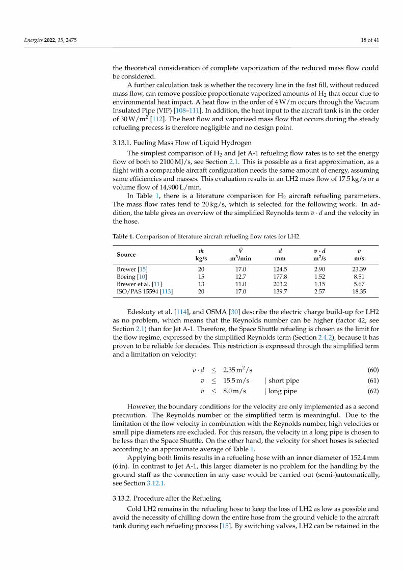
In Table 1, there is a literature comparison for H2 aircraft refueling parameters.The mass flow rates tend to 20 kg/s, which is selected for the following work. In ad-dition, the table gives an overview of the simplified Reynolds term v · d and the velocity inthe hose.
Table 1. Comparison of literature aircraft refueling flow rates for LH2.
Source m V d v · d vkg/s m3/min mm m2/s m/s
Brewer [15] 20 17.0 124.5 2.90 23.39Boeing [10] 15 12.7 177.8 1.52 8.51Brewer et al. [11] 13 11.0 203.2 1.15 5.67ISO/PAS 15594 [113] 20 17.0 139.7 2.57 18.35
Edeskuty et al. [114], and OSMA [30] describe the electric charge build-up for LH2as no problem, which means that the Reynolds number can be higher (factor 42, seeSection 2.1) than for Jet A-1. Therefore, the Space Shuttle refueling is chosen as the limit forthe flow regime, expressed by the simplified Reynolds term (Section 2.4.2), because it hasproven to be reliable for decades. This restriction is expressed through the simplified termand a limitation on velocity:
v · d ≤ 2.35 m2/s (60)
v ≤ 15.5 m/s | short pipe (61)
v ≤ 8.0 m/s | long pipe (62)
However, the boundary conditions for the velocity are only implemented as a secondprecaution. The Reynolds number or the simplified term is meaningful. Due to thelimitation of the flow velocity in combination with the Reynolds number, high velocities orsmall pipe diameters are excluded. For this reason, the velocity in a long pipe is chosen tobe less than the Space Shuttle. On the other hand, the velocity for short hoses is selectedaccording to an approximate average of Table 1.
Applying both limits results in a refueling hose with an inner diameter of 152.4 mm(6 in). In contrast to Jet A-1, this larger diameter is no problem for the handling by theground staff as the connection in any case would be carried out (semi-)automatically,see Section 3.12.1.
3.13.2. Procedure after the Refueling
Cold LH2 remains in the refueling hose to keep the loss of LH2 as low as possible andavoid the necessity of chilling down the entire hose from the ground vehicle to the aircrafttank during each refueling process [15]. By switching valves, LH2 can be retained in the

Energies 2022, 15, 2475 19 of 41
feed hose, whereby this part remains at cryogenic temperature and does not have to becooled during the following refueling process.
This procedure is possible with both the Johnston disconnect and the clean breakdisconnect. For the Johnston disconnect, the purging process can be carried out throughthe recovery line and a suitable arrangement of valves. A small expansion tank is attachedto the ground vehicle to avoid a disproportionate pressure increase in the completely filledhose due to environmental heat input and vaporization. This expansion tank represents akind of heat reservoir and extends the time between possible refueling processes.
4. Liquid Hydrogen Refueling Process and Implications on Turnaround Times
An LH2 turnaround process has to be possible in a similar timeframe as for conven-tional aircraft to achieve an economical basis for hydrogen aircraft. The interfaces to theaircraft are defined first, whereby the links of the refueling conditions are determined.Thus, the dependencies and requirements can be analyzed starting from a competitiveaircraft. This approach is based on a similar refueling and turnaround time, which isdirectly related to the DOCs and therefore the economical assessment of the aircraft. Basedon safe and competitive aircraft refueling conditions, the distribution of LH2 at the airportis determined afterwards.
4.1. Results of the Refueling Procedure
The results of the refueling procedure depend on the equations of the individualrefueling steps and cannot be evaluated individually without considering the completesystem. However, the findings are independent of the airport infrastructure and groundrefueling vehicles.
Due to the diameter, the material (stainless steel), and the pipe’s wall thickness,a reduced mass flow of 3 kg/s is defined for the chill-down segment [30]. A wall thicknessof 2.5 mm [97] for a stainless-steel pipe corresponds to the load case against internal pressureof 42 bar (600 psi), same as for conventional Jet A-1 hoses [24]. Thus, a chill-down time of40 s can be calculated according to Section 3.3, independent of the line length.
By calculating the heat flow over time, the theoretical maximum vaporization fractionof the mass flow of 1.4 kg/s Equation (43) is determined. Therefore, the design point of therecovery line is the complete vaporization of the reduced mass flow of 3 kg/s. With theassumption of a maximal Mach number of 0.5, a total pressure of 1.35 bara in the aircrafttank results from Equation (44). The inner diameter is calculated from Equation (45) to127.0 mm (5 in). The mass flow of 1.4 kg/s results in a Mach number of 0.22 with a totalpressure of 1.25 bara.
The evacuation and pressurization are carried out via the recovery line with an assumedlength of 20 m (volume of 0.25 m3), leading to an evacuation time of 13.5 s Equation (36)and a pressurization time of 13.5 s Equation (40)—in combination for one purging cycle ofapproximately 30 s. For a Johnston disconnect, three repetitions (see Section 3.4) correspondto a time of 90 s each before and after refueling. For the semi-automated docking and(de-)positioning, a duration of 150 s is considered. Table 2 shows the rounded values of theindividual steps.
Brewer [15] estimates the time required before refueling at 7 min and after refuelingat 5 min. Compared to the calculated duration for a Johnston disconnect, this is a slightdeviation, with purging as the most considerable difference.
This discrepancy to the calculated values can be explained by the fact that Brewer [15]does not specify the exact number of repetitions of vacuum purging and the purging ofboth lines (LH2 and GH2). This assumption significantly increases the volume to be purged,which justifies the longer time. Complete purging of the refueling hose is unnecessaryas with valves only the connection adapter needs to be purged through the recovery line.For a clean break coupling, purging is unnecessary and the additional time of 3 min isomitted. This time advantage is particularly effective for small refueling quantities and

Energies 2022, 15, 2475 20 of 41
short-range aircraft, since the percentage of time required for the steps before and after theactual refueling is greater.
Table 2. Required time intervals for the individual consecutive steps of the refueling procedure ofliquid hydrogen; time durations are independent of the refueled quantity, refueling time is a functionof the required fuel mass or volume; the individual steps excluding refueling itself sum up to 9 minfor a Johnston disconnect and 6 min for a clean break disconnect.
Refueling Step Time (min)
Positioning and connecting 2.5Purging 1.5Chill-down 1.0Refueling f (mfuel)Purging 1.5Disconnecting and removal 2.5
The chill-down losses are estimated at 13.6 kg in Boeing [10] (without specifyingthe pipe length) and a calculation in accordance with Section 3.12.3 results in mvap
l =6.2 kgLH2/m for ISA+15 with Equation (46). An evaporated quantity of mvap = 12.4 kg LH2is considered to be chill-down losses for a estimated length of 2 m to be cooled Equation (47).
4.2. Airport Distribution System for Liquid Hydrogen
Continuing the previous analysis of the refueling process required to keep the turnaroundtime approximately constant, the airport distribution of LH2 is also considered in the following.The results from Section 3.12 will be used to determine the overall system of the refuelingprocess with airport distribution and ground refueling vehicles.
There are two ways of transferring the fuel from the storage facility to the aircraft tank,similar to Jet A-1, with a refueling truck or through a pipeline dispenser system. The choiceof the distribution system depends on the airport’s daily fuel demand and infrastructure,and therefore no general decision can be proposed. For the techno-economic analysis, refer toHoelzen et al. [19].
For both distribution systems, the pressure losses and pressure requirement to deliverLH2 to the aircraft tank are calculated according to Section 3.7. The aircraft tank pressureis set to 1.2 bara. The vehicle-independent parameters, such as delivery head and hoselengths, are defined in Section 3.12.1.
In a pipeline dispenser case, the lines from hydrant to dispenser are neglected due tothe short lengths. The number of valves (Kvalve = 300 m3/h) considered for the dispensercase is six and four for the refueling truck.
For calculating the required pressure , a static pressure of 6.5 bara must be present ata hydrant to enable refueling with a dispenser. ISO/PAS 15594 [113] specifies a pressureof 7 bara at the hydrant, which is similar to the calculated value and therefore used in thefollowing investigation. A pressure of 5 bara results for the refueling truck tank becausethere are fewer valves.
4.2.1. Refueling Tank Truck for Interim Phase
From a hardware and architectural standpoint, the simplest distribution system foraircraft refueling is by a tank truck [10]. However, this concept was not considered furtherin the terminal ramp area by Boeing [10] due to the physical space requirements.
Boeing [10] does not consider a refueling truck because of safety and environmentalimpacts, long-term costs for GH2 losses, acquisition and operating costs, and the congestiondue to additional ground vehicles. Conversely, a meaningful use of refueling trucks ispossible in case these negative reasons can be disproved. The argument of the costsof investment and operations required for the provision and use of refueling trucks isexcluded by Boeing [10] itself since the costs would have to be ignored for a pipelinesystem. Congestion from the additional ground vehicles may be significant in the case
Energies 2022, 15, 2475 21 of 41
of general refueling with refueling trucks. However, this argument is no longer valid ifthe use is intended in an interim phase or small quantities. The effects of the loss of GH2during the venting process can be refuted by recycling GH2. Boeing [10] used a recoveryline to collect the vaporized H2, but no pipeline system will be installed for the transitionphase and recirculation is not possible.
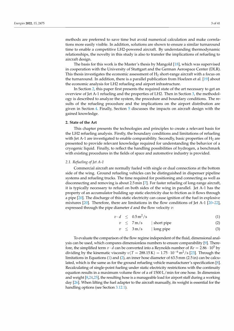
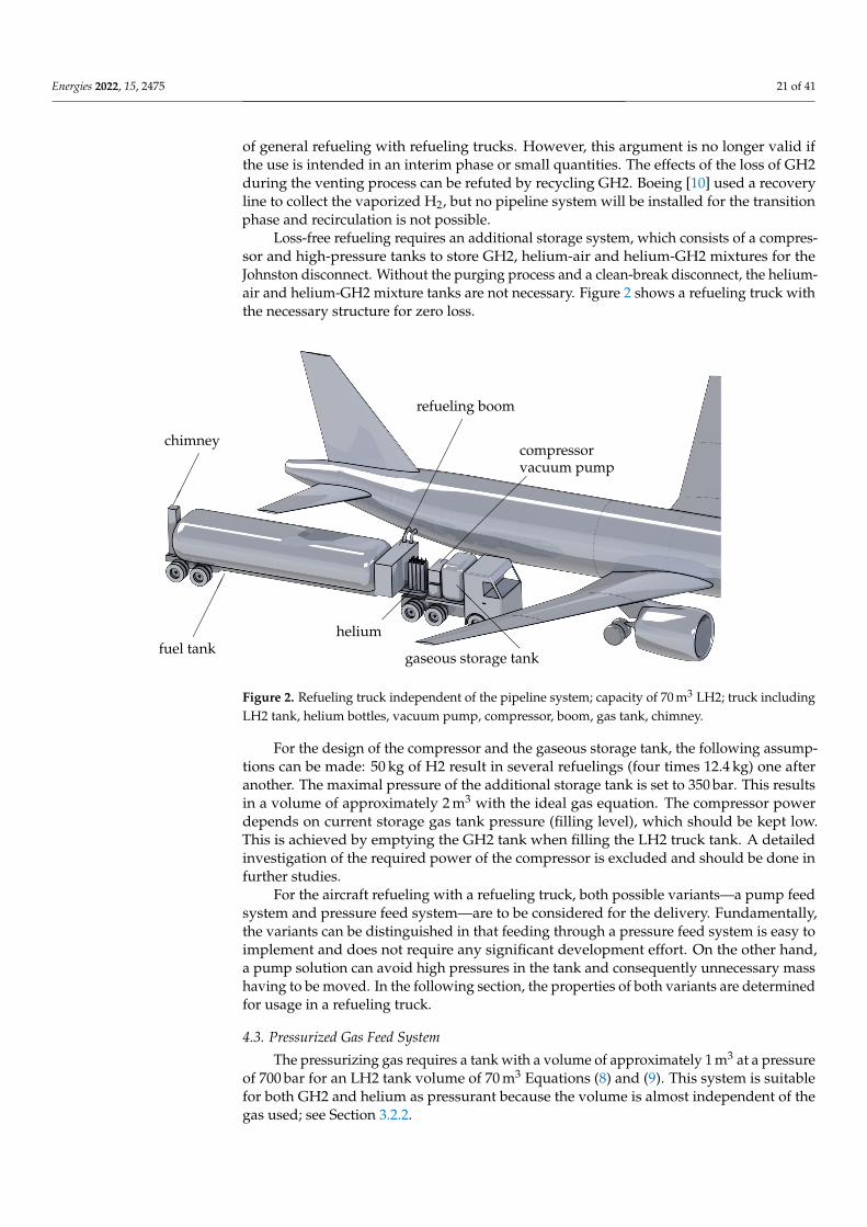
Loss-free refueling requires an additional storage system, which consists of a compres-sor and high-pressure tanks to store GH2, helium-air and helium-GH2 mixtures for theJohnston disconnect. Without the purging process and a clean-break disconnect, the helium-air and helium-GH2 mixture tanks are not necessary. Figure 2 shows a refueling truck withthe necessary structure for zero loss.
�����
fuel tank
���
helium
����
chimney
@@
@@@
gaseous storage tank
���
���
vacuum pumpcompressor
���������
refueling boom
Figure 2. Refueling truck independent of the pipeline system; capacity of 70 m3 LH2; truck includingLH2 tank, helium bottles, vacuum pump, compressor, boom, gas tank, chimney.
For the design of the compressor and the gaseous storage tank, the following assump-tions can be made: 50 kg of H2 result in several refuelings (four times 12.4 kg) one afteranother. The maximal pressure of the additional storage tank is set to 350 bar. This resultsin a volume of approximately 2 m3 with the ideal gas equation. The compressor powerdepends on current storage gas tank pressure (filling level), which should be kept low.This is achieved by emptying the GH2 tank when filling the LH2 truck tank. A detailedinvestigation of the required power of the compressor is excluded and should be done infurther studies.
For the aircraft refueling with a refueling truck, both possible variants—a pump feedsystem and pressure feed system—are to be considered for the delivery. Fundamentally,the variants can be distinguished in that feeding through a pressure feed system is easy toimplement and does not require any significant development effort. On the other hand,a pump solution can avoid high pressures in the tank and consequently unnecessary masshaving to be moved. In the following section, the properties of both variants are determinedfor usage in a refueling truck.
4.3. Pressurized Gas Feed System
The pressurizing gas requires a tank with a volume of approximately 1 m3 at a pressureof 700 bar for an LH2 tank volume of 70 m3 Equations (8) and (9). This system is suitablefor both GH2 and helium as pressurant because the volume is almost independent of thegas used; see Section 3.2.2.
Energies 2022, 15, 2475 22 of 41
This pressurant must also be refilled during the loading process with LH2 of thetruck. For the refueling of the GH2 or helium, the automotive industry’s technology andstandards [41,42] can be used. An additional advantage of the pressurized gas feed systemis the simplicity. Pressurization with a heat exchanger or, more precisely, a vaporizer isexcluded because of the high power requirement of 510 kW Equation (10) for each refuelingtruck (without efficiency losses).
Due to the possibility of intermediate storage, the processes have no direct loss, whichfurther renders Boeing’s [10] argument of significant losses invalid. Furthermore, the fueltruck has the advantage through the combination of pressurization for delivery and thecompressed recirculated gas. The recirculated and compressed GH2 can be used as apressurant for the fuel truck tank. This synergy makes the fuel truck self-sufficient to acertain extent.
4.4. Pump Feed System
With the defined mass flow of 20 kg/s and compliance with the defined similaritypump parameters, an NPSH value of 37.2 m and a rotational speed of 10,000 min−1 can becalculated, see Section 3.2.1. For the refueling truck, this indicates that the tank pressuremust be 0.26 bar above the saturation line. Considering the efficiency of the LPFTP of theSSME of 0.73 [77], the pump requires a power of 148 kW; see Equation (52).
As already described, pressurization must also be applied to pump feed systems; seeSection 3.2.1. The difference is the pressure level in the tank, which is much lower with apump feed system, contrary to a pressurized gas feed system. As a result, a significantlysmaller amount of pressurant is needed. A gas volume of only 0.3 m3 (Equation (9),p = 700 bar) has to be provided for the intermediate storage tank’s pressurant. Moreover,the pump case differs by a factor of ppressurized/ppump = 5/1.26 and only a heating powerof 128 kW Equation (10) is required to maintain the pressure with the second possibility of avaporizer. In contrast to the pressure feed system, the required energy flow for vaporizationis realizable and feasible in a pump system to maintain the required pressure.
In summary, distribution at the airport is possible with a refueling truck without directlosses. This is achieved by the use of a gaseous intermediate storage tank, which collectsthe recirculated gases compressed by a compressor. The transfer from the fuel truck tank tothe aircraft can be realized by a pump or a pressurization system. In addition, the fuel truckoffers the possibility to supply even remote parking locations. Especially for a transitionalphase in which the fuel types may still be spatially separated, this flexibility offers anadvantage. Furthermore, the refueling truck concept must in any case be available foremergency refueling [10].
4.4.1. Dispenser Truck and Pipeline Supply for Large Quantities
The second method of aircraft refueling is to use a pipeline dispenser system. The maintasks of a dispenser truck, like for Jet A-1 [22], are to reduce the pressure from the pipelineand establish the connection between hydrant and aircraft. In principle, a pump at the stor-age tank pumps the fuel through underground pipes to the terminal or apron. The transferof LH2 in the pipeline through a pressure feed system at the storage tank can be excludedimmediately, as the losses are primarily due to the pressure cycle of pressurization anddepressurization [11]; see Section 4.4.2.
Energies 2022, 15, 2475 23 of 41
For the calculation of the pumping capacity and the pressure provided at the storagetank, a 2000 m long pipeline with two valves (Kvalve = 1300 m3/h) is assumed. For reasonsof redundancy, several pipelines must be introduced. Thereby, in the following considera-tion, one supply pipeline is designed for a mass flow of 40 kg/s, which allows two aircraftto be refueled simultaneously. The pump must provide a pressure of 10 bara Equation (48)to compensate for friction losses for a 304.8 mm (12 in) diameter pipe to meet the hydrant’sboundary conditions (7 bara). This determination results in a speed of 11,700 min−1 and anNPSH value of 73 m, which corresponds to positive pressure to the saturated line of 0.5 bar;see Section 3.2.1. With Equation (52), the required power of 660 kW is calculated consid-ering an efficiency of 0.73 for a mass flow of 40 kg/s. Brewer [11] assumes a differentialpressure to the saturated liquid of 0.345 bar. To conclude, the values are similar and showthe importance of a suitable design.
The fundamental difference to a fuel truck is the handling of the vented GH2. An ad-ditional recovery pipe returns it to a recycling or liquefaction plant [10,11]. Therefore,all losses can be collected and no amount is vented to the atmosphere. A distinction ismade in the different gases during refueling, which means several recovery lines to avoid ahydrogen-air mixture as a safety aspect.
As the tank position is an open variable in the aircraft design with LH2 as fuel, thereis no predefined solution for the tank position [5]. The length of the line between thehydrant and the refueling vehicle will be limited to a few meters for handling reasons.This constraint means that a hydrant connection at the aircraft’s nose cannot be used forrefueling a tank in the tail, as the required line becomes too long. Conversely, due to thecurrent tank position variance, several hydrants must be installed at one parking position.
From the obtained results and the combination with the safety-relevant aspects, a dis-penser can be derived, see Figure 3.
The independence from the mass of LH2 to be refueled is also advantageous fordispenser distribution. In contrast to a fuel truck, which is limited by tank volume andvehicle size, the dispenser can also refuel long-range aircraft without repeated connectionand disconnection. On the other hand, the investment costs for the conversion of theairport are much higher. Due to the installation of the required pipes, the complete airportdistribution system has to be rebuilt. The existing pipeline system for Jet A-1 is not usablesince insulation will be necessary to keep the heat input low (see Section 4.4.2). Furthermore,the conversion would restrict flight operations or cause extensive construction work, whichwould lead to a further increase in costs.
Another possibility for bridging the pipeline to the aircraft is Boeing’s terminal boomfueling concept [10]. In principle, this system offers the advantage of less ground vehicles.However, this advantage also entails the disadvantage of less flexibility. Due to the boom’sdesign characteristics, refueling is only possible on the right, front side. Long fuel pipes inthe aircraft would be heavy when the aircraft tank is not in the front, and the chill-downtime would significantly increase. Therefore, this option is excluded as a possible fuelingscenario. The aircraft’s refueling adapter should be located near the LH2 tank of the aircraft.
The implementation of fuel distribution of LH2 at the airport is possible. The trade-off between high investment costs for a pipeline dispenser system and the possibility ofrefueling large quantities or a fuel truck as the simplest system with low investment costsand the limitation of the fuel truck tank volume should be performed. A refueling trucksupply can be a possible variant for a transition phase between Jet A-1 and LH2, whereboth fuels are needed. The refueling truck concept enables a conventional airport to alsorefuel with LH2 without significant modifications and costs. Furthermore, two types ofpossible ground refueling vehicles (dispenser and refueling truck) must be provided forrefueling, depending on whether the aircraft manufacturer prescribes a purging processand the disconnect variant or not.
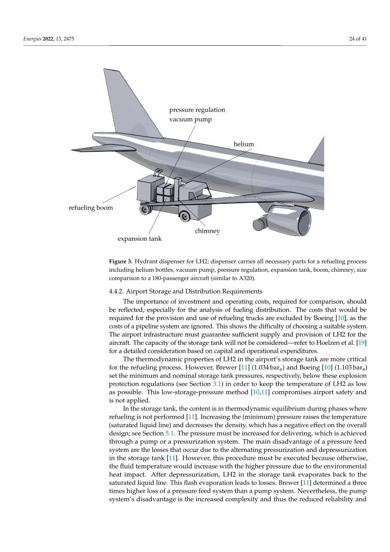
Energies 2022, 15, 2475 24 of 41
����
��
refueling boom
����
������
helium
����������
vacuum pumppressure regulation
������
expansion tank
@@
@@@
chimney
Figure 3. Hydrant dispenser for LH2; dispenser carries all necessary parts for a refueling processincluding helium bottles, vacuum pump, pressure regulation, expansion tank, boom, chimney; sizecomparison to a 180-passenger aircraft (similar to A320).
4.4.2. Airport Storage and Distribution Requirements
The importance of investment and operating costs, required for comparison, shouldbe reflected, especially for the analysis of fueling distribution. The costs that would berequired for the provision and use of refueling trucks are excluded by Boeing [10], as thecosts of a pipeline system are ignored. This shows the difficulty of choosing a suitable system.The airport infrastructure must guarantee sufficient supply and provision of LH2 for theaircraft. The capacity of the storage tank will not be considered—refer to Hoelzen et al. [19]for a detailed consideration based on capital and operational expenditures.
The thermodynamic properties of LH2 in the airport’s storage tank are more criticalfor the refueling process. However, Brewer [11] (1.034 bara) and Boeing [10] (1.103 bara)set the minimum and nominal storage tank pressures, respectively, below these explosionprotection regulations (see Section 3.1) in order to keep the temperature of LH2 as lowas possible. This low-storage-pressure method [10,11] compromises airport safety andis not applied.
In the storage tank, the content is in thermodynamic equilibrium during phases whererefueling is not performed [11]. Increasing the (minimum) pressure raises the temperature(saturated liquid line) and decreases the density, which has a negative effect on the overalldesign; see Section 5.1. The pressure must be increased for delivering, which is achievedthrough a pump or a pressurization system. The main disadvantage of a pressure feedsystem are the losses that occur due to the alternating pressurization and depressurizationin the storage tank [11]. However, this procedure must be executed because otherwise,the fluid temperature would increase with the higher pressure due to the environmentalheat impact. After depressurization, LH2 in the storage tank evaporates back to thesaturated liquid line. This flash evaporation leads to losses. Brewer [11] determined a threetimes higher loss of a pressure feed system than a pump system. Nevertheless, the pumpsystem’s disadvantage is the increased complexity and thus the reduced reliability and
Energies 2022, 15, 2475 25 of 41
flexibility [74]. A pumping system at the storage tank for the delivery of LH2 is consideredin the following because of the smaller losses.
A pressurization system (by helium or vaporizer) has to increase the storage tank’spressure through the requirement of the pump. The saturated liquid becomes subcooled,which allows the pump to deliver the LH2 as a single-phase fluid, which has the advantageof minimizing flash-off [11]. As a result of the non-thermodynamic equilibrium, the liquidin the storage tank heats up and is returned to its saturated state after the refueling process.Therefore, pump delivery has a similar effect, where losses occur due to flash evaporation.However, since the pressure difference between pure storage and pumping is much smallerthan the pressure feed system, it is more economical.
In the further consideration between the pressure increase of the pump and the flowentering the tank, the properties of a real compressible fluid are essential. Downstreamof the pump, an isenthalpic change of state can be considered to determine the proper-ties of LH2. The isenthalpic flow approach can be applied in a vacuum-insulated pipesince the temperature change due to the heat input of a typical vacuum-insulated pipeof 3.5 W/m [108] with a length of 2000 m only translates into a temperature change of0.05 K; see Equation (53). The system always remains cool by circulating the fuel in thepipeline system [10,11], which means no excessive temperature increase occurs duringthe non-delivery period through environmental heat. Therefore, the assumption of anisenthalpic flow through the pipeline is fulfilled.
4.5. Subcooling Considerations for LH2 Refueling
In the previous considerations of the airport distribution and the flow through pipes,a single-phase flow’s essential requirement is always fulfilled (chill-down excluded).The following section highlights the reason for the necessity and inevitability of asingle-phase flow.
The pressure losses due to valves and friction in the pipe express a temperatureincrease in an isenthalpic flow. These changes significantly affect the phase of LH2, as thefriction loss is converted into internal energy. Therefore, when flowing into the aircrafttank, there must be at least a saturated liquid with a vapor content of x = 0. Otherwise,a two-phase flow will establish, leading to a significant increase in velocity due to the phasechange. Considering the isenthalpic change in state, this hypothetical reflection leads topartial vaporization of the liquid phase, which has a significantly lower density (factor 27at 2 bar).
Due to the density change, the velocity would increase enormously, which would leadto an infringement of the introduced limitation in the velocity and simplified Reynoldsterm. Thus, the liquid phase’s mass flow would decrease disproportionately (m = const.)and lead to a considerably longer refueling process. When calculating the actual massflow rate, considering the defined limitations, a 50 % reduction in the LH2 mass flow rateof 10 kg/s would result even, with low vapor fraction of x = 0.022, see Section 3.9. Thiscondition must therefore be prevented under any circumstances. In addition, the vaporizedH2 that is fed into the tank must be recovered, as otherwise, the pressure in the aircrafttank would rise and be reflected in the recovery line’s dimension. Relating these results tothe aircraft design, the volume of the aircraft tank is determined from these tank conditions,which has a considerable influence on the mass and hence the performance of the aircraft;see Section 5.1.
In principle, there are two ways to prevent this phenomenon by maintaining a sub-cooled liquid. One is to increase the pressure in the system and the other is to decrease thetemperature, as defined in Section 2.2. The pressure increase is limited by the burst pres-sure of the aircraft tank or the required pump power and cannot be increased significantly.Therefore, cooling LH2 (subcooled) is the more suitable choice. Thus, the tank’s pressurecan be kept low during the refueling process so that no evaporation occurs. Figure 4 showsthe isenthalpic flow due to the pressure loss of a pipeline system. Due to the conversion of
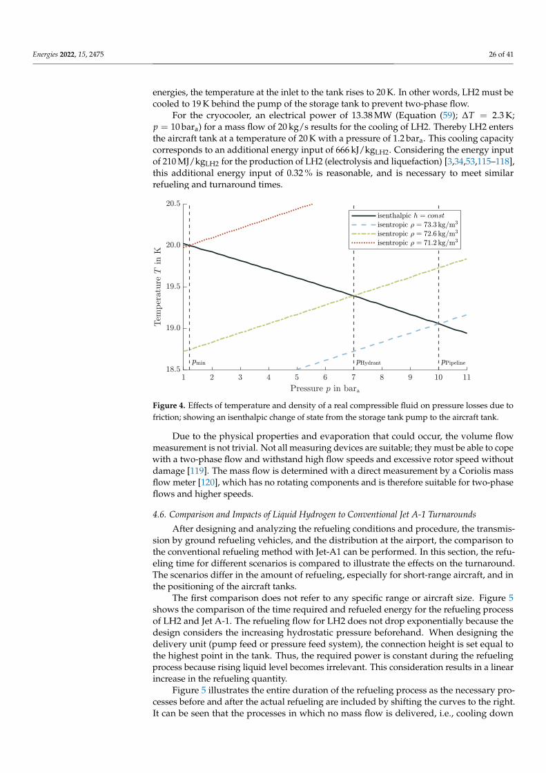
Energies 2022, 15, 2475 26 of 41
energies, the temperature at the inlet to the tank rises to 20 K. In other words, LH2 must becooled to 19 K behind the pump of the storage tank to prevent two-phase flow.
For the cryocooler, an electrical power of 13.38 MW (Equation (59); ∆T = 2.3 K;p = 10 bara) for a mass flow of 20 kg/s results for the cooling of LH2. Thereby LH2 entersthe aircraft tank at a temperature of 20 K with a pressure of 1.2 bara. This cooling capacitycorresponds to an additional energy input of 666 kJ/kgLH2. Considering the energy inputof 210 MJ/kgLH2 for the production of LH2 (electrolysis and liquefaction) [3,34,53,115–118],this additional energy input of 0.32 % is reasonable, and is necessary to meet similarrefueling and turnaround times.
Figure 4. Effects of temperature and density of a real compressible fluid on pressure losses due tofriction; showing an isenthalpic change of state from the storage tank pump to the aircraft tank.
Due to the physical properties and evaporation that could occur, the volume flowmeasurement is not trivial. Not all measuring devices are suitable; they must be able to copewith a two-phase flow and withstand high flow speeds and excessive rotor speed withoutdamage [119]. The mass flow is determined with a direct measurement by a Coriolis massflow meter [120], which has no rotating components and is therefore suitable for two-phaseflows and higher speeds.
4.6. Comparison and Impacts of Liquid Hydrogen to Conventional Jet A-1 Turnarounds
After designing and analyzing the refueling conditions and procedure, the transmis-sion by ground refueling vehicles, and the distribution at the airport, the comparison tothe conventional refueling method with Jet-A1 can be performed. In this section, the refu-eling time for different scenarios is compared to illustrate the effects on the turnaround.The scenarios differ in the amount of refueling, especially for short-range aircraft, and inthe positioning of the aircraft tanks.
The first comparison does not refer to any specific range or aircraft size. Figure 5shows the comparison of the time required and refueled energy for the refueling processof LH2 and Jet A-1. The refueling flow for LH2 does not drop exponentially because thedesign considers the increasing hydrostatic pressure beforehand. When designing thedelivery unit (pump feed or pressure feed system), the connection height is set equal tothe highest point in the tank. Thus, the required power is constant during the refuelingprocess because rising liquid level becomes irrelevant. This consideration results in a linearincrease in the refueling quantity.
Figure 5 illustrates the entire duration of the refueling process as the necessary pro-cesses before and after the actual refueling are included by shifting the curves to the right.It can be seen that the processes in which no mass flow is delivered, i.e., cooling down

Energies 2022, 15, 2475 27 of 41
the lines and any purging that may be required, take more time with LH2. Therefore,the time required by Jet A-1 is shorter for refueling small quantities. Due to the differentprocedures, the break-even point of the same refueling energy results after 11.5 min withone Jet A-1 hose and 20.5 min with two hoses. In comparison, in these results with purging,the refueled mass of Jet A-1 with one hose after 11.5 min corresponds to 8425 kg Jet A-1and with two hoses after 20.5 min to a mass of 39,180 kg Jet A-1. In a refueling processwith the maximum fillable volume, LH2 has a time advantage. With smaller volumes andhence shorter ranges, on the other hand, the refueling times are similar. For the use of aclean break disconnect without purging, a time duration of 3 min can be deducted fromthe results.
Figure 5. Refueling comparison between Jet A-1 and LH2; considering time influences before(purging, chill-down) and after (purging) the refueling process; for LH2 a constant mass flow of20 kg/s is applied; for Jet A-1 see Equation (5).
Figure 6 shows the Gantt chart for an A320-like aircraft refueling the maximum tankvolume as scenario 1. The mass of LH2 can be determined by the ratio of the calorificvalues (factor 2.8). A time advantage of 3 min for LH2 results in comparison to refuelingthe equivalent energy amount of Jet A-1 with one hose. In contrast, scenario 2 compares arefueling volume for a 500 NM (926 km) mission. Due to the small volume, the advantageof LH2 is no longer present. However, the advantage in refueling time of 2 min for Jet A-1is of no benefit since, in most cases, refueling is not on the critical path of the turnaroundthrough parallel refueling and boarding [29,121,122].
The previous consideration of the refueling time is independent of the aircraft config-uration and the position of the LH2 tank in the aircraft. In scenario 3, the comparison ofthe refueling time for a 1500 NM (2778 km) mission of an aircraft with the tanks mountedat the wings will be investigated. A comparable aircraft configuration can be found inSilberhorn et al. [4] for comparisons in aircraft design and sizing and volume of the tank.The comparison will be between the possibility of parallel refueling with one pod (externalfuel tank) connected to feed the other pod and the possibility of sequential refueling. In se-quential refueling, where the pods are filled one after another, the refueling process takes22 min; in parallel refueling, it takes 11 min. However, in the parallel refueling processthe cooling time is independent of the pipe’s length between the pods. This assumption isonly valid if this connecting pipe is short or kept at cryogenic temperatures permanently.For Jet A-1, the time for refueling takes 10 min with one hose. The aircraft configuration

Energies 2022, 15, 2475 28 of 41
and the location of the refueling adapters on the aircraft represent a challenging point inthe refueling time. In contrast to Jet A-1, this configurable variable of tank positions andconnections has a great influence on refueling time and turnaround time.
Figure 6. Gantt chart for LH2 refueling of 5350 kg; the energy corresponds to the maximum kerosenevolume of A320-like aircraft.
4.7. Losses and Cost Adaption Due to Refueling with Liquid Hydrogen
The losses that occur during the refueling process should be minimized. However,these losses cannot be avoided and impact the fuel costs of LH2, as additional quantities arefed that cannot be used for the flight mission. There is a differentiation of losses betweenthe refueling variants and the refueling process, broken down and analyzed below todetermine the impact of the fuel price. However, the price increase is based purely onthe additional energy consumption and helium or hydrogen consumption. Quantitativeinvestment costs are not considered, as they are strongly dependent on utilization andquantity delivered; see Hoelzen et al. [19].
The fuel price is based on an analysis of the energy required to produce the fuelby Silberhorn et al. [4], resulting in an LH2 price of 29.15 EUR/GJ. This analysis makesit possible to compare different energy sources regardless of density or calorific value.The conversion of the energy price results in a mass-related price of 3.5 EUR/kgLH2. In-cluding other literature sources results in a price range for possible fuel costs of LH2 of 1.0to 5.7 EUR/kgLH2 [1,4,123].
As defined, LH2 requires specific production energy of about 210 MJ/kgLH2, which isadopted as the basis in the following cost calculation. With the fuel price of 3.5 EUR/kgLH2LH2 [4], the electrical energy price results in 0.0167 EUR/MJ or 0.06 EUR/kWh. Therefore,this electricity price is the origin of the further calculation of the costs that arise fromelectrical energy consumption. The helium required for the refueling process is assumed tohave 22 EUR/kgHelium in the following cost calculation [124]. As a result, losses of LH2,helium and the consumption of electrical energy can be added proportionally to the fuelprice of 3.5 EUR/kgLH2.
Nevertheless, it must be mentioned that the purging operation accounts for only0.04% of the increase. The helium price has the highest uncertainty because helium is onlyavailable in a limited amount. Thus, the recycling of helium is significantly essential toestablish LH2 as a fuel.
Considering only the maximum and minimum, the increases in fuel costs are repre-sented as follows. The minimum increase includes no purging and the lowest cost for eachmethod. The maximum growth, on the other hand, contains a purging operation. For apipeline dispenser system, the minimum fuel price increase is 0.45% and the maximumabout 1.2%. On the other hand, for a refueling truck, the minimum increase for a pumpfeed system is 0.54% and maximum is 4.92%. In contrast, the fuel truck with a pressurefeed system has a minimum increase of 0.56% and a maximum of 13.62%. That significant

Energies 2022, 15, 2475 29 of 41
increase is justified through the use of helium as pressurant gas, compared to GH2 aspressurant and a pump solution.
In conclusion, the pipeline dispenser system has the lowest operational costs, neglect-ing the investment costs. A refueling truck solution is therefore also reasonable if the lossesare recovered by intermediate tank storage. Otherwise, the high losses are not sustainable.From these results, it can be concluded for the airport infrastructure that fuel trucks are areasonable choice in a transition phase because the operating cost is not significantly higher,and the investment cost is considerably reduced. Conversely, if there is a sizeable dailydemand, a pipeline system will be cheaper. This variety creates a trade-off between lowcapital cost and higher operating cost for a fuel truck system and high capital cost andlow operation cost for a pipeline dispenser system. The break-even point determination isinvestigated in Hoelzen et al. [19].
5. Implications on Liquid Hydrogen Aircraft Design
The scientific findings from the refueling process and the thermodynamic aspects canbe transferred to the overall aircraft design. The calculation of the required tank volumebased on different assumptions will be discussed. The consequences for the use of fuelpumps, which have an influence on the tank and the fuel system, are also explained.The difference between a gaseous and a liquid hydrogen engine feed is worked out todetermine the required performance.
5.1. Liquid Hydrogen Aircraft Tank Volume
The aircraft tank volume calculation is an essential task for aircraft design, verifyingthe available mass to fly a mission. Based on Equation (58) the inner volume is lineardependent on the density of LH2. Densification (subcooling of the fluid) reduces the tankvolume, which has a similar snowball effect on the mass calculation [63,64]. Therefore,the analysis and estimation method is important and necessary for the aircraft design.In this analysis, however, only the internal tank volume of the aircraft is considered.The tank structure, insulation, and other parts of the outer aircraft tank design are notevaluated. Furthermore, the thermodynamic behavior of the tank contents over a flightmission is not relevant to the consideration of the preliminary design of the inner aircrafttank volume. Time-dependent, unsteady phenomena, such as thermal stratification andsloshing, are therefore not considered in this analysis.
The first method calculates the tank’s volume with the density on the saturated line,see Figure 7, with the maximum tank or venting pressure. This approach is the mostconservative method because the density of LH2 is the lowest at this point. This approachof Verstraete [125] and Winnefeld et al. [126] to select the density in equilibrium at maxi-mum tank pressure proves to be impractical. The statement that a higher tank pressurewill always lead to a larger volume (lower density) is incorrect as it requires a thermody-namic equilibrium. This condition must be prevented (see Sections 4.4.2, 5.2 and 5.3) andtherefore has no relevance for the aircraft design.
In the second, optimistic method, the density is determined based on the minimumtank pressure and the saturated state; see Figure 7. In space systems, except for SpaceX,this calculation method is used. The loading procedure can explain this approach withthe density as a function of the minimum pressure as a saturated liquid. After the tank isalmost filled, the pressure is minimized, resulting in a saturated liquid in thermodynamicequilibrium through vaporization, see Section 2.4.2.
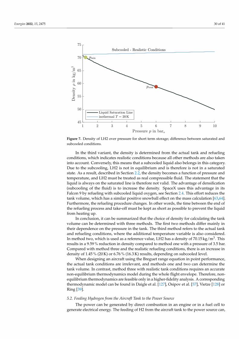
Energies 2022, 15, 2475 30 of 41
Figure 7. Density of LH2 over pressure for short term storage; difference between saturated andsubcooled conditions.
In the third variant, the density is determined from the actual tank and refuelingconditions, which indicates realistic conditions because all other methods are also takeninto account. Conversely, this means that a subcooled liquid also belongs in this category.Due to the subcooling, LH2 is not in equilibrium and is therefore is not in a saturatedstate. As a result, described in Section 2.2, the density becomes a function of pressure andtemperature, and LH2 must be treated as real compressible fluid. The statement that theliquid is always on the saturated line is therefore not valid. The advantage of densification(subcooling of the fluid) is to increase the density. SpaceX uses this advantage in itsFalcon 9 by refueling with subcooled liquid oxygen, see Section 2.4. This effort reduces thetank volume, which has a similar positive snowball effect on the mass calculation [63,64].Furthermore, the refueling procedure changes. In other words, the time between the end ofthe refueling process and take-off must be kept as short as possible to prevent the liquidfrom heating up.
In conclusion, it can be summarized that the choice of density for calculating the tankvolume can be determined with three methods. The first two methods differ mainly intheir dependence on the pressure in the tank. The third method refers to the actual tankand refueling conditions, where the additional temperature variable is also considered.In method two, which is used as a reference value, LH2 has a density of 70.15 kg/m3. Thisresults in a 9.59 % reduction in density compared to method one with a pressure of 3.5 bar.Compared with method three and the realistic refueling conditions, there is an increase indensity of 1.45 % (20 K) or 6.76 % (16.3 K) results, depending on subcooled level.
When designing an aircraft using the Breguet range equation in point performance,the actual tank conditions are irrelevant, and methods one and two can determine thetank volume. In contrast, method three with realistic tank conditions requires an accuratenon-equilibrium thermodynamics model during the whole flight envelope. Therefore, non-equilibrium thermodynamics are feasible only in a higher-fidelity analysis. A correspondingthermodynamic model can be found in Daigle et al. [127], Osipov et al. [57], Vietze [128] orRing [39].
5.2. Feeding Hydrogen from the Aircraft Tank to the Power Source
The power can be generated by direct combustion in an engine or in a fuel cell togenerate electrical energy. The feeding of H2 from the aircraft tank to the power source can,

Energies 2022, 15, 2475 31 of 41
in principle, be accomplished in two ways. The two types of use differ primarily in thepressure level, which is 2 to 5 bar and a temperature of 290 K in the case of fuel cells [129,130]and around 50 bar and a temperature of 260 K for combustion in a jet engines [15]. However,in both variants, GH2 is fed in, which means that the stored LH2 must first be vaporized.In principle, feeding in a liquid or gaseous phase is possible in both cases. To enable acomparison of both variants, an isentropic pressure increase Equation (52) by the pump andan isobaric heat input Equation (53) for the heat exchanger by enthalpy differences (withoutefficiencies) can be considered in a simplified way. In the following, the feeding possibilitiesfor a fuel cell and a combustion engine are explained and the technical feasibility orimplementation is shown.
5.2.1. Fuel Cell
Two system designs are possible to meet the inlet conditions of the fuel cell. One isto directly take the gaseous phase in the ullage from the tank and deliver it. With thisvariant, a vaporizer is needed in the tank to keep the pressure up and constant. The secondoption for a fuel cell is when the pump feeds a liquid phase, which a heat exchanger thenvaporizes. However, comparing the two options for feeding a fuel cell is only possible to alimited extent. With a higher tank pressure and gaseous delivery, the pressure can buildup through the self-pressurization of hydrogen, which in this respect does not require anyelectrical power. In contrast, pump feeding requires electrical power but is characterizedby a lighter tank. This circumstance means that the comparison for feeding a fuel cell canonly be applied to the overall system design, including power, efficiency, and mass, and isnot investigated further.
5.2.2. Combustion Engine
For the combustion of H2, two delivery options are conceivable, which depend onthe order of the system components. In both variants, a low-pressure pump installed nearthe aircraft tank delivers LH2. The pressure head by the low-pressure pump only has tocompensate for the pressure losses due to friction reaching the engine. Close to the engine,the combustion variant differs in two possible subsystems.
First, a high-pressure pump can compress the LH2 to the desired pressure level,which is then vaporized in a heat exchanger and heated to the desired inlet temperature.The advantage of this arrangement is the smart use of the waste heat from the engine jet,which is available and can be used.
In the second option, the order of the system components is reversed. First, the LH2can be vaporized and then compressed to be injected into the combustion chamber.The advantage of this arrangement is the free positioning of the heat exchanger andhigh-pressure pump.
Tables 3 and 4 illustrate the respective electrical energies and heat quantities for bothvariants with isentropic compression Equation (52) and isobaric heat input Equation (53).This consideration of the required performances refers to an A320-like aircraft in cruiseflight with an assumed mass flow of 0.2 kg/s.
Table 3. Arrangement: liquid low-pressure pump, liquid high-pressure pump, heat exchanger/vaporizer; isentropic and isobaric change of state for the consideration of the required power, dividedinto electrical power and heat input.
Process p1 T1 p2 T2 ∆h P Qbara K bara K kJ/kg kWel kWheat
isentropic 1.2 20.00 5.0 20.17 4.91 0.98 -isentropic 5.0 20.17 50.0 22.06 61.58 12.32 -isobaric 50.0 22.06 50.0 260.00 3806.87 - 761.37
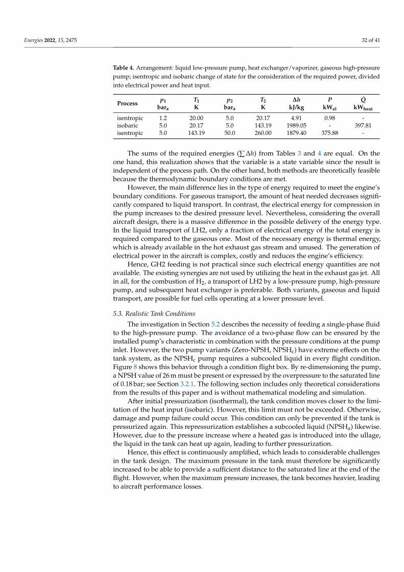
Energies 2022, 15, 2475 32 of 41
Table 4. Arrangement: liquid low-pressure pump, heat exchanger/vaporizer, gaseous high-pressurepump; isentropic and isobaric change of state for the consideration of the required power, dividedinto electrical power and heat input.
Process p1 T1 p2 T2 ∆h P Qbara K bara K kJ/kg kWel kWheat
isentropic 1.2 20.00 5.0 20.17 4.91 0.98 -isobaric 5.0 20.17 5.0 143.19 1989.05 - 397.81isentropic 5.0 143.19 50.0 260.00 1879.40 375.88 -
The sums of the required energies (∑ ∆h) from Tables 3 and 4 are equal. On theone hand, this realization shows that the variable is a state variable since the result isindependent of the process path. On the other hand, both methods are theoretically feasiblebecause the thermodynamic boundary conditions are met.
However, the main difference lies in the type of energy required to meet the engine’sboundary conditions. For gaseous transport, the amount of heat needed decreases signifi-cantly compared to liquid transport. In contrast, the electrical energy for compression inthe pump increases to the desired pressure level. Nevertheless, considering the overallaircraft design, there is a massive difference in the possible delivery of the energy type.In the liquid transport of LH2, only a fraction of electrical energy of the total energy isrequired compared to the gaseous one. Most of the necessary energy is thermal energy,which is already available in the hot exhaust gas stream and unused. The generation ofelectrical power in the aircraft is complex, costly and reduces the engine’s efficiency.
Hence, GH2 feeding is not practical since such electrical energy quantities are notavailable. The existing synergies are not used by utilizing the heat in the exhaust gas jet. Allin all, for the combustion of H2, a transport of LH2 by a low-pressure pump, high-pressurepump, and subsequent heat exchanger is preferable. Both variants, gaseous and liquidtransport, are possible for fuel cells operating at a lower pressure level.
5.3. Realistic Tank Conditions
The investigation in Section 5.2 describes the necessity of feeding a single-phase fluidto the high-pressure pump. The avoidance of a two-phase flow can be ensured by theinstalled pump’s characteristic in combination with the pressure conditions at the pumpinlet. However, the two pump variants (Zero-NPSH, NPSHc) have extreme effects on thetank system, as the NPSHc pump requires a subcooled liquid in every flight condition.Figure 8 shows this behavior through a condition flight box. By re-dimensioning the pump,a NPSH value of 26 m must be present or expressed by the overpressure to the saturated lineof 0.18 bar; see Section 3.2.1. The following section includes only theoretical considerationsfrom the results of this paper and is without mathematical modeling and simulation.
After initial pressurization (isothermal), the tank condition moves closer to the limi-tation of the heat input (isobaric). However, this limit must not be exceeded. Otherwise,damage and pump failure could occur. This condition can only be prevented if the tank ispressurized again. This repressurization establishes a subcooled liquid (NPSHa) likewise.However, due to the pressure increase where a heated gas is introduced into the ullage,the liquid in the tank can heat up again, leading to further pressurization.
Hence, this effect is continuously amplified, which leads to considerable challengesin the tank design. The maximum pressure in the tank must therefore be significantlyincreased to be able to provide a sufficient distance to the saturated line at the end of theflight. However, when the maximum pressure increases, the tank becomes heavier, leadingto aircraft performance losses.
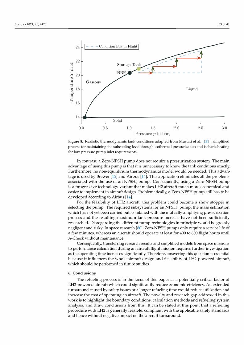
Energies 2022, 15, 2475 33 of 41
Figure 8. Realistic thermodynamic tank conditions adapted from Mustafi et al. [131]; simplifiedprocess for maintaining the subcooling level through isothermal pressurization and isobaric heatingfor low-pressure pump inlet requirements.
In contrast, a Zero-NPSH pump does not require a pressurization system. The mainadvantage of using this pump is that it is unnecessary to know the tank conditions exactly.Furthermore, no non-equilibrium thermodynamics model would be needed. This advan-tage is used by Brewer [15] and Airbus [14]. This application eliminates all the problemsassociated with the use of an NPSHc pump. Consequently, using a Zero-NPSH pumpis a progressive technology variant that makes LH2 aircraft much more economical andeasier to implement in aircraft design. Problematically, a Zero-NPSH pump still has to bedeveloped according to Airbus [14].
For the feasibility of LH2 aircraft, this problem could become a show stopper inselecting the pump. The required subsystems for an NPSHc pump, the mass estimationwhich has not yet been carried out, combined with the mutually amplifying pressurizationprocess and the resulting maximum tank pressure increase have not been sufficientlyresearched. Disregarding the different pump technologies in principle would be grosslynegligent and risky. In space research [80], Zero-NPSH pumps only require a service life ofa few minutes, whereas an aircraft should operate at least for 400 to 600 flight hours untilA-Check without maintenance.
Consequently, transferring research results and simplified models from space missionsto performance calculation during an aircraft flight mission requires further investigationas the operating time increases significantly. Therefore, answering this question is essentialbecause it influences the whole aircraft design and feasibility of LH2-powered aircraft,which should be performed in future studies.
6. Conclusions
The refueling process is in the focus of this paper as a potentially critical factor ofLH2-powered aircraft which could significantly reduce economic efficiency. An extendedturnaround caused by safety issues or a longer refueling time would reduce utilization andincrease the cost of operating an aircraft. The novelty and research gap addressed in thiswork is to highlight the boundary conditions, calculation methods and refueling systemanalysis, and draw conclusions from this. It can be stated at this point that a refuelingprocedure with LH2 is generally feasible, compliant with the applicable safety standardsand hence without negative impact on the aircraft turnaround.
Energies 2022, 15, 2475 34 of 41
The avoidance of a dangerous explosive atmosphere results from the primary explo-sion protection to ensure safety. The system must be designed to be permanently technicallytight in the long term, preventing H2 from escaping. Furthermore, the system must have apositive gauge pressure to avoid the ambient atmosphere from entering. For these reasons,parallel refueling of LH2 with passengers on board would also be possible, just as with JetA-1. Nevertheless, detailed risk and failure analyses are pointed out for future studies.
New LH2 refueling procedures are described and evaluated, considering the processsteps connecting/disconnecting, purging, chill-down and refueling. A time comparisonwith Jet A-1 shows that refueling with LH2 in most cases takes less time, as differentboundary conditions affect the refueling rate. A further time improvement through theeliminated necessity of the purging process would be possible with a clean break disconnectinstead of a Johnston disconnect.
After the airport storage tank, it is necessary to maintain the LH2 in subcooled con-ditions the LH2 to avoid two-phase flows. Refueling without generating losses can beperformed with either a refueling truck or a pipeline dispenser system as two possibleairport infrastructures. In the case of a refueling truck, additional systems such as a com-pressor and extra gas storage are required. Due to the volume limitation of a refuelingtruck, a pipeline dispenser system would be more advisable in particular for refuelinglong-range aircraft.
By understanding the thermodynamic relations and properties of LH2, a novelty inthis study is also to assess the implications of refueling to aircraft design. Three calculationmethods have been derived to determine the required tank volume for the aircraft, whichdiffer in the LH2 density used. This density is determined by the saturated state ofmaximum and minimum tank pressure, together with the actual refueling conditions(subcooled). This consideration shows the potential of using calculation methods withdifferent fidelity levels and the advantage of subcooling for aircraft design optimization.
The delivery of LH2 from the aircraft tank to the engine requires a low-pressure pump,a high-pressure pump, and a heat exchanger to inject LH2 into the combustion chamber atthe proper boundary conditions. With this fuel system architecture, only a small amountof electrical power is required for the pumps, and the waste heat from the propulsionunit can be used for vaporization. A gaseous delivery from the tank to the engine is non-practical, as compressing GH2 would require much more electrical power compared toliquid feeding.
Single-phase fluid is mandatory for feeding the high-pressure pump during a flightmission. Two methods can be seen to achieve a single-phase flow: a cavitation-free NPSHcor a Zero-NPSH pump. Especially for the cavitation-free pump, additional mass must beconsidered for the aircraft design to maintain the necessary conditions until the end ofthe flight mission. Nevertheless, the use of Zero-NPSH pumps would have a far-reachingimpact on aircraft design, as no pressurization system is required. Hence, their usabilitymust be further investigated with respect to usability. Therefore, realistic aircraft tankconditions and pump selection are essential for aircraft design and should be examined inmore depth in future research. Refueling with subcooled LH2 is helpful in this context dueto its lower vapor pressure and time before venting.
Author Contributions: Conceptualization, J.M., D.S., N.M. and N.D.; methodology, J.M.; investiga-tion, J.M.; writing—original draft preparation, J.M.; writing—review and editing, J.M., D.S., N.M.,N.D., J.H., T.Z. and A.S.; supervision, T.Z. and A.S. All authors have read and agreed to the publishedversion of the manuscript.
Funding: This research received no external funding.
Institutional Review Board Statement: Not applicable.
Informed Consent Statement: Not applicable.
Data Availability Statement: Not applicable.
Conflicts of Interest: The authors declare no conflict of interest.
Energies 2022, 15, 2475 35 of 41
Nomenclature
AbbreviationsCO2 Carbon DioxideCOP Coefficient of PerformanceDLR German Aerospace CenterDOC Direct Operating CostET External TankEU European UnionGH2 Gaseous HydrogenH2 Hydrogen (independent of the phase state)LFL Lower Flammability LimitLH2 Liquid HydrogenLHV Lower Heating ValueLOX Liquid OxygenLPFTP Low Pressure Fuel Turbo PumpNBP Normal Boiling PointNPSH Net Positive Suction HeadNPSHa Net Positive Suction Head availableNPSHc Net Positive Suction Head criticalO2 Oxygenppm parts per millionPtL Power to LiquidSSME Space Shuttle Main EngineTRBS Technical Rules for Operational SafetyTRGS Technical Rules for Hazardous SubstancesUFL Upper Flammability LimitVIP Vacuum Insulated Pipe
Symbolsα Refueling factor of Jet A-1 min−1
∆hv Heat of vaporization J kg−1
κ Heat capacity ratio -λ Friction factor -µ Dynamic viscosity Pa sν Kinematic viscosity m2 s−1
< Universal gas constant J kg−1 mol−1
ρ Density kg m−3
σ Surface tension N m−1
A Area m2
Bi Biot number -c Concentration -cp Heat capacity at constant pressure J kg−1 K−1
d Diameter mg Gravitational acceleration m s−2
h′v Effective Heat of vaporization J kg−1
H Head mh Specific enthalpy J kg−1
h heat-transfer coefficient W m−2 K−1
i Number of -k Roughness height mk Thermal conductivity W m−1 K−1
Kvalve Flow coefficient of the valve m3 s−1
l Length mLc Laplace length m

Energies 2022, 15, 2475 36 of 41
M Mach number -m Mass kgn Amount of substance moln Rotational speed min−1
P Power Wp Pressure barPr Prandtl number -Q Heat JQ Volume flow m3 s−1
q Heat flow per area W m−2
R Gas constant J kg−1 K−1
Re Reynolds number -S Pumping speed m3 s−1
s Specific entropy J kg−1
T Temperature Kt Time sV Volume m3
v Velocity m s−1
x Vapor fraction -
Subscripts0 initial condition of gas tanka absoluteavg averageb bulkboil boilingc characteristicconv convectiveel electricalg gasg gauge (difference to ambient)i innerl liquidmin minimumo outers specificsat saturatedspl single phase liquidspv single phase vaporss suction specificv vaporvap vaporizedvent venting
References1. McKinsey & Company for the Clean Sky 2 JU and Fuel Cells and Hydrogen 2 Joint Undertaking. Hydrogen-Powered Aviation: A
Fact-Based Study of Hydrogen Technology, Economics, and Climate Impact by 2050; McKinsey Company: Redwood City, CA, USA, 2020.[CrossRef]
2. Verstraete, D.; Hendrick, P.; Pilidis, P.; Ramsden, K. Hydrogen fuel tanks for subsonic transport aircraft. Int. J. Hydrog. Energy2010, 35, 11085–11098. [CrossRef]
3. Klell, M.; Eichlseder, H.; Trattner, A. Wasserstoff in der Fahrzeugtechnik: Erzeugung, Speicherung, Anwendung, 4th ed.; SpringerVieweg: Wiesbaden, Germany, 2018.
4. Silberhorn, D.; Hartmann, J.; Dzikus, N.M.; Atanasov, G.; Zill, T.; Brand, U.; Trillos, J.C.G.; Oswald, M.; Vogt, T.; Wilken, D.; et al.The Air-Vehicle as a Complex System of Air Transport Energy Systems. In Proceedings of the AIAA AVIATION 2020 FORUM,Vitual Event, 15–19 June 2020.
Energies 2022, 15, 2475 37 of 41
5. Silberhorn, D.; Atanasov, G.; Walther, J.N.; Zill, T. Assessment of Hydrogen Fuel Tank Integration at Aircraft Level. In Proceedingsof the Deutscher Luft- und Raumfahrtkongress 2019, Darmstadt, Germany, 30 September–2 October 2019.
6. World Economic Forum. Clean Skies for Tomorrow: Sustainable Aviation Fuels as a Pathway to Net-Zero Aviation; World EconomicForum CH-1223: Cologny/Geneva, Switzerland, 2020.
7. AIRBUS S.A.S. A320 Aircraft Characteristics—Airport and Maintenance Planning; Customer Services, Technical Data Support andServices; AIRBUS S.A.S.: Blagnac, France, 2020.
8. ROHR Spezialfahrzeuge GmbH. Ahd Lf/Hf Hydrant Dispenser. 2020. Available online: https://www.rohr-spezialfahrzeuge.com/fileadmin/user_upload/Produkte/03_Flugfeldtankfahrzeuge/Datenblaetter/Produktdatenblatt_AHD_EN.pdf (accessedon 15 November 2020).
9. Simon, V.; Weigand, B.; Gomaa, H. Dimensional Analysis for Engineers, 1st ed.; Springer: Berlin/Heidelberg, Germany, 2017.10. The Boeing Commercial Airplane Company. An Exploratory Study to Determine the Integrated Technological Air Tranportation Sytem
Ground Requirements of Liquid-Hydrogen-Fueled Subsonic, Long-Haul Civil Air Transports; NASA CR 2699; National Aeronautics andSpace Administration: Washington, DC, USA, 1976.
11. Brewer, G.D. LH2 Airport Requirments Study; NASA CR 2700; National Aeronautics and Space Administration: Washington, DC,USA, 1976.
12. Brewer, G.D.; Morris, R.E.; Lange, R.H.; Moore, J.W. Volume 2 Final Report: Study of the Application of Hydrogen Fuel to Long-RangeSubsonic Transport Aircraft; NASA CR 132559; National Aeronautics and Space Administration: Washington, DC, USA, 1975.
13. Sosounov, V.; Orlov, V. Experimental Turbofan Using Liquid Hydrogen and Liquid Natural Gas as Fuel. In Proceedings of theAIAA—26th Joint Propulsion Conference, Orlando, FL, USA, 16–18 July 1990.
14. Airbus Deutschland GmbH. Liquid Hydrogen Fuelled Aircraft—System Analysis; Technical Report; Airbus Deutschland GmbH:Hamburg, Germany, 2013.
15. Brewer, G.D. Hydrogen Aircraft Technology, 1st ed.; CRC Press: Boca Raton, FL, USA, 1991.16. Brewer, G.D; Morris, R.E.; Davis, G.W.; Versaw, E.F.; Cunnington, G.R., Jr.; Riple, J.C.; Baerst, C.F.; Baerst, C.F. Study of Fuel System
for LH2-Fueled Subsonic Transport Aircraft; NASA CR 145369; NASA-Langley Research Center: Hampton, Virginia, 1978; Volume 1,pp. 1–194.
17. Brewer, G.D; Morris, R.E.; Davis, G.W.; Versaw, E.F.; Cunnington, G.R., Jr.; Riple, J.C.; Baerst, C.F.; Baerst, C.F. Study of Fuel Systemfor LH2-Fueled Subsonic Transport Aircraft ; NASA Contractor Report 145369; NASA-Langley Research Center: Hampton, Virginia,1978; Volume 2, pp. 195–524.
18. Mangold, J. Economical Assessment of Hydrogen Short-Range Aircraft with the Focus on the Turnaround Procedure. Master’sThesis, University of Stuttgart, Stuttgart, Germany, 2021.
19. Hoelzen, J.; Flohr, M.; Silberhorn, D.; Mangold, J.; Bensmann, A.; Hanke-Rauschenbach, R. H2-powered aviation at airports—Design and economics of LH2 refueling systems. Energy Convers. Manag. X 2022, 14, 100206. [CrossRef]
20. American Petroleum Institure. Protection against Ignitions Arising Out of Static, Lightning, and Stray Currents; API RP 2003; Healthand Environmental Affairs Department, American Petroleum Institute: Washington, DC, USA, 1998.
21. Sera, A. Jet Fuel Pipelines And Storage Require Special Operation, Maintenance Considerations. Pipeline Gas J. 2009, 236.22. Kazda, A.; Caves, R.E. Airport Design and Operation, 3rd ed.; Emerald Group Publishing Limited: Bingley, UK, 2015.23. Coordinating Research Council. Handbook of Aviation Fuel Properties; CRC Report No. 530; Coordinating Research Council:
Atlanta, Georgia, 1983.24. Parker Hannifin Corporation. Parker Industrial Hose Gold Label® Aircraft Fueling Hose; Parker Hannifin Corporation: Wickliffe,
Ohio, 2013.25. Eaton Aerospace Group. Carter® Underwing Refueling Nozzle Model 60427; Eaton Aerospace Group: Irvine, CA, USA, 2013.26. Bundesanstalt für Arbeitsschutz und Arbeitsmedizin (BAuA). Gefährdungsbeurteilung Bei Physischer Belastung—Die neuen
Leitmerkmalmethoden (LMM); Bundesanstalt für Arbeitsschutz und Arbeitsmedizin (BAuA): Dortmund, Germany, 2019.27. Horstmeier, T.; de Haan, F. Influence of ground handling on turn round time of new large aircraft. Aircr. Eng. Aerosp. Technol.
2001, 73, 266–271. [CrossRef]28. Schmidt, M. Ground-Operational Assessment of Novel Aircraft Cabin Configurations. Ph.D. Thesis, Technical University of
Munich, Munich, Germany, 2018.29. Sanz de Vicente, S. Ground Handling Simulation with CAST. Master’s Thesis, Hamburg University of Applied Sciences,
Hamburg, Germany, 2010.30. Office of Safety and Mission Assurance. Safety Standard for Hydrogen and Hydrogen Systems; NASA Technical Memorandum NSS
1740.16; Office of Safety and Mission Assurance: Washington, DC, USA, 1997.31. Sutton, G.P.; Biblarz, O. Rocket Propulsion Elements, 7th ed.; John Wiley & Sons: Hoboken, NJ, USA, 2001.32. Huzel, D.K.; Huang, D.H. Design of Liquid Propellant Rocket Engines; NASA Special Publication 125; National Aeronautics and
Space Administration: Washington, DC, USA, 1967.33. Leachman, J.W.; Jacobsen, R.T.; Lemmon, E.W.; Penoncello, S.G. Thermodynamic Properties of Cryogenic Fluids, 2nd ed.; International
Cryogenics Monograph Series; Springer: Cham, Switzerland, 2017.34. Peschka, W. Flüssiger Wasserstoff als Energieträger, 1st ed.; Springer: Vienna, Austria, 1984.35. Brechna, H.; Tuttle, W.A.; Stewart, R.G.; Jensen, J.E.; Commission, U.S.A.E.; Laboratory, B.N. Brookhaven National Laboratory
Selected Cryogenic Data Notebook; Brookhaven National Laboratory: Upton, NY, USA, 1980.
Energies 2022, 15, 2475 38 of 41
36. Lemmon, E.W.; Bell, I.H.; Huber, M.L.; McLinden, M.O. NIST Standard Reference Database 23: Reference Fluid Thermodynamic andTransport Properties-REFPROP; Version 10.0; National Institute of Standards and Technology: Gaithersburg, MD, USA, 2018.
37. Bostock, T.D.; Scurlock, R.G. Low-Loss Storage and Handling of Cryogenic Liquids: The Application of Cryogenic Fluid Dynamics,2nd ed.; International Cryogenics Monograph Series; Springer: Cham, Switzerland, 2019.
38. Baehr, H.D.; Kabelac, S. Thermodynamik: Grundlagen und technische Anwendungen, 16th ed.; Springer Vieweg: Berlin/Heidelberg,Germany, 2016.
39. Ring, E. Rocket Propellant and Pressurization Systems, 1st ed.; Prentice-Hall, Inc.: Englwood Cliffs, NJ, USA, 1964.40. Stroman, R.O.; Schuette, M.W.; Swider-Lyons, K.; Rodgers, J.A.; Edwards, D.J. Liquid hydrogen fuel system design and
demonstration in a small long endurance air vehicle. Int. J. Hydrog. Energy 2014, 39, 11279–11290. [CrossRef]41. SAE International. Fueling Protocols for Light Duty Gaseous Hydrogen Surface Vehicles; SAE International: Warrendale, PA, USA,
2020.42. SAE International. Compressed Hydrogen Surface Vehicle Fueling Connection Devices; SAE International: Warrendale, PA, USA, 2015.43. Bain, A. NASA space program experience in hydrogen transportation and handling. Int. J. Hydrog. Energy 1976, 1, 173–188.
[CrossRef]44. Gerstl, P. Solutions for the LH2 Supply Chain. In Proceedings of the International Hydrogen Forum 2019, PyeongChang, Korea, 9
May 2019.45. Tamhankar, S. Terminal Operations for Tube Trailer and Liquid Tanker Filling: Status, Challenges and R & D Needs. In
Proceedings of the DOE Hydrogen Transmission and Distribution Workshop, Golden, Colorado, 25–26 February 2014.46. Siegel, E. Humanity Is Thoughtlessly Wasting An Essential, Non-Renewable Resource: Helium. Available online: https:
//www.forbes.com/sites/startswithabang/2019/05/24/humanity-is-thoughtlessly-wasting-an-essential-non-renewable-resource-helium/?sh=3492c76829f8 (accessed on 1 October 2021).
47. Stuck, D.E. Liquid Rocket Disconnects, Couplings, Fittings, Fixed Joints, and Seals; NASA Special Publication 8119; NationalAeronautics and Space Administration: Cleveland, Ohio, 1976.
48. Stewart, W.F. Refueling Considerations For Liquid-Hydrogen Fueled Vehicles; Los Alamos National Lab.: Los Alamos, NM, USA, 1984.49. Hettinger, W.; Michel, F.; Ott, P.; Theissen, F. Refueling equipment for liquid hydrogen vehicles. Int. J. Hydrog. Energy 1998,
23, 943–947. [CrossRef]50. Linde, A.G. Linde Kupplung und Betankungssystem: Leistung und Meßergebnisse. 2003. Available online: http://www.eihp.
org/public/Reports/Final_Report/Sub-Task_Reports/ST3.3/EIHP-Beitrag%20Linde%20Kuppl.pdf (accessed on 20 Decem-ber 2020).
51. NASA Lewis Research Center. Hydrogen Safety Manuel; NASA Technical Memorandum X-52454; National Aeronautics and SpaceAdministration: Washingtion, DC, USA, 1968.
52. Pehr, K.; Sauermann, P.; Traeger, O.; Bracha, M. Liquid hydrogen for motor vehicles—The world’s first public LH2 filling station.Int. J. Hydrog. Energy 2001, 26, 777–782. [CrossRef]
53. Peschka, W. Liquid Hydrogen Fuel of the Future, 1st ed.; Springer: Vienna, Austra, 1992. [CrossRef]54. Wolf, J. Liquid hydrogen technology for vehicles. In Handbook of Fuel Cells; John Wiley & Sons: Hoboken, NJ, USA, 2010.55. Arnold, G.; Wolf, J. Liquid Hydrogen for Automotive Application Next Generation Fuel for FC and ICE Vehicles. TEION
KOGAKU (J. Cryog. Supercond. Soc. Jpn.) 2005, 40, 221–230. [CrossRef]56. Wetzel, F.J. Improved handling of liquid hydrogen at filling stations: Review of six years’ experience. Int. J. Hydrog. Energy 1998,
23, 339–348. [CrossRef]57. Osipov, V.V.; Daigle, M.J.; Muratov, C.B.; Foygel, M.; Smelyanskiy, V.N.; Watson, M.D. Dynamical Model of Rocket Propellant
Loading with Liquid Hydrogen. J. Spacecr. Rocket. 2011, 48, 987–998. [CrossRef]58. Space Program Operations Contract. Shuttle Crew Operations Manuel. United Space Alliance. 2008. Available online:
https://www.nasa.gov/centers/johnson/pdf/390651main_shuttle_crew_operations_manual.pdf (accessed on 20 January 2021).59. Nguyen, K.; Knowles, T.E.; Greene, W.D.; Tomsik, T.M. Propellant Densification for Launch Vehicles: Simulation and Testing. In
Proceedings of the 38th AIAA/ASME/SAE/ASEE Joint Propulsion Conference & Exhibit, Indianapolis, Indiana, 7–10 July 2002.60. Foust, J. NASA Approves “Load-and-Go” Fueling for SpaceX Commercial Crew Launches. Available online: https://spacenews.
com/nasa-approves-load-and-go-fueling-for-spacex-commercial-crew-launches/ (accessed on 11 January 2021).61. Notardonato, W.U.; Baik, J.H.; McIntosh, G.E. Operational Testing of Densified Hydrogen Using G-M Refrigeration. AIP Conf.
Proc. 2004, 710, 64–74.62. Fernholz, T. The “Super Chill” Reason SpaceX Keeps Aborting Launches. Available online: https://qz.com/627430/the-super-
chill-reason-spacex-keeps-aborting-launches/ (accessed on 11 January 2021).63. Wilken, J.; Scelzo, M.T.; Peveroni, L. System Study of Slush Propellants for Future European Launch Vehicles; Space Propulsion
2018. Available online: https://elib.dlr.de/120361/1/039_WILKEN_update.pdf (accessed on 15 February 2021).64. Baik, J.H.; T-Raissi, A. R&D processes for increasing density of cryogenic propellants at FSEC. Cryogenics 2004, 44, 451–458.65. Space Is Kind Of Cool. Why the Falcon 9 Uses Subcooled Liquid Oxygen. Available online: https://www.youtube.com/watch?
v=gHwZk_qEeAY (accessed on 12 January 2021).66. Huzel, D.K.; Huang, D.H. Modern Engineering for Design of Liquid-Propellant Rocket Engines; AIAA: Washington, DC, USA, 1992.67. Richtlinie 2014/34/EU des Europäischen Parlaments und des Rates vom 26. Februar 2014 zur Harmonisierung der
Rechtsvorschriften der Mitgliedstaaten für Geräte und Schutzsysteme zur bestimmungsgemäßen Verwendung in explosionsge-
Energies 2022, 15, 2475 39 of 41
fährdeten Bereichen (Neufassung). Available online: https://eur-lex.europa.eu/legal-content/DE/ALL/?uri=celex%3A32014L0034 (accessed on 12 November 2020).
68. Richtlinie 1999/92/EG des Europäischen Parlaments und des Rates vom 16. Dezember 1999 über Mindestvorschriften zurVerbesserung des Gesundheitsschutzes und der Sicherheit der Arbeitnehmer, die Durch Explosionsfähige Atmosphären GefährdetWerden Können (Fünfzehnte Einzelrichtlinie im Sinne von Artikel 16 Absatz 1 der Richtlinie 89/391/EWG). Available online:https://eur-lex.europa.eu/legal-content/DE/ALL/?uri=CELEX:31999L0092 (accessed on 12 November 2020).
69. Verordnung über Sicherheit und Gesundheitsschutz bei der Verwendung von Arbeitsmitteln (Betriebssicherheitsverordnung—BetrSichV); 2015. Available online: https://www.gesetze-im-internet.de/betrsichv_2015/BetrSichV.pdf (accessed on 12 Novem-ber 2020).
70. Verordnung zum Schutz vor Gefahrstoffen (Gefahrstoffverordnung—GefStoffV); 2010. Available online: https://www.gesetze-im-internet.de/gefstoffv_2010/GefStoffV.pdf (accessed on 12 November 2020).
71. Technische Regeln für Betriebssicherheit/Gefahrstoffe TRBS 2152 Teil 2/TRGS 722 Vermeidung oder Einschränkung GefährlicherExplosionsfähiger Atmosphäre. 2012. Available online: https://www.baua.de/DE/Angebote/Rechtstexte-und-Technische-Regeln/Regelwerk/TRGS/pdf/TRGS-722.pdf?__blob=publicationFile&v=3 (accessed on 24 November 2020).
72. Technische Regeln für Gefahrstoffe TRGS 720 Gefährliche explosionsfähige Gemische—Allgemeines. 2020. Available on-line: https://www.baua.de/DE/Angebote/Rechtstexte-und-Technische-Regeln/Regelwerk/TRGS/pdf/TRGS-720.pdf?__blob=publicationFile&v=5 (accessed on 14 October 2020).
73. Technische Regeln für Betriebssicherheit/ Gefahrstoffe TRBS 2151 Teil 1/ TRGS 721 Gefährliche explosionsfähige Atmosphäre—Beurteilung der Explosionsgefährdung. 2006. Available online: https://www.baua.de/DE/Angebote/Rechtstexte-und-Technische-Regeln/Regelwerk/TRGS/pdf/TRGS-721.pdf?__blob=publicationFile&v=6 (accessed on 1 October 2020).
74. Jallais, S. Pre-Normative Research for Safe use of Liquid HYdrogen (PRESLHY); Fuel Cells and Hydrogen Joint Undertaking.2018. Available online: https://www.hysafe.info/wp-content/uploads/sites/3/2018/09/PRESLHY-D2.3-LH2-Installation-description.pdf (accessed on 23 January 2021).
75. Gülich, J.F. Kreiselpumpen: Handbuch für Entwicklung, Anlagenplanung und Betrieb, 4th ed.; Springer: Berlin/Heidelberg, Germany,2013.
76. Sobin, A.J.; Bissell, W.R. Turbopump Systems For Liquid Rocket Engines; NASA Special Publication 8107; National Aeronautics andSpace Administration: Cleveland, Ohio, 1974.
77. Rocketdyne. Space Shuttle Main Engine Orientation. 1998. Available online: http://large.stanford.edu/courses/2011/ph240/nguyen1/docs/SSME_PRESENTATION.pdf (accessed on 5 December 2020).
78. DiStefano, J.F.; Caine, G.H. Cavitation Characteristics of Tank-Mounted Cryogenuc Pumps and Their Predicted Performance UnterReduced Gravity; Advances in Cryogenic Engineering; Timmerhaus, D.K., Ed.; Springer: Boston, MA, USA, 1961; Volume 7.
79. Caine, G.; Schafer, L.; Burgeson, D. Pumping of Liquid Hydrogen; Advances in Cryogenic Engineering; Timmerhaus, D.K., Ed.;Springer: Boston, MA, USA, 1958; Volume 4.
80. Stinson, H.P.; Strickland, R.J. Experimental Findings from Zero-Tank Net Positive Suction Head Operation of the J-2 Hydrogen Pump;NASA Technical Note D-6824; National Aeronautics and Space Administration: Washington, DC, USA, 1972.
81. Lockheed-Georgia Company. Main Propellant Tank Pressurization System Study and Test Program—Design Handbook; Final ReportER-5296; Contract AF 04(611)-6087; Lockheed-Georgia Company: Marietta, Georgia, USA, 1961; Volume 3.
82. Barron, R.F.; Nellis, G.F. Cryogenic Heat Transfer, 2nd ed.; CRC Press: Boca Raton, FL, USA, 2016.83. Wang, L.; Li, Y.; Zhang, F.; Xie, F.; Ma, Y. Correlations for calculating heat transfer of hydrogen pool boiling. Int. J. Hydrog. Energy
2016, 41, 17118–17131. [CrossRef]84. Brentari, E.G.; Giarratano, P.J.; Smith, R.V. Boiling Heat Transfer for Oxygen, Nitrogen, Hydrogen, and Helium; National Bureau of
Standards Technical Note 316; US National Bureau of Standards: Gaithersburg, MD, USA, 1965.85. Giarratano, P.J.; Smith, R.V. Comparative study of forced convection boiling heat transfer correlations for cryogenic fluids. In
Proceedings of the Cryogenic Engineering Conference, Cryogenic Engineering Conference at Rice University, Houston, TX, USA,23–25 August 1965.
86. Steiner, D.; Taborek, J. Flow Boiling Heat Transfer in Vertical Tubes Correlated by an Asymptotic Model. Heat Transf. Eng. 1992,13, 43–69. [CrossRef]
87. Brennan, J.A.; Brentari, E.G.; Smith, R.V.; Steward, W.G. Cooldown of Cryogenic Transfer Lines; NASA Contractor Report 81338;Cryogenics Division, NBS Institute for Materials Research: Boulder, CO, USA, 1966.
88. Hendricks, R.C.; Graham, R.W.; Hsu, Y.Y.; Friedman, R. Experimental Heat Transfer and Pressure Drop of Liquid Hydrogen Flowingthrough a Heated Tube; NASA Technical Note D-765; US National Bureau of Standards: Gaithersburg, MD, USA, 1961.
89. Zuber, N. Hydrodynamic Aspects of Boiling Heat Transfer. Ph.D. Thesis, University of California, Los Angeles, CA, USA, 1959.90. Verein Deutscher Ingenieure. VDI-Wärmeatlas, 11th ed.; Springer: Berlin/Heidelberg, Germany, 2013.91. Lienhard, J.; Witte, L. An Historical Review of the Hydrodynamic Theory of Boiling. Rev. Chem. Eng. 1985, 3, 187–280. [CrossRef]92. Kida, M.; Kikuchci, Y.; Takahashi, O.; Michiyoshi, I. Pool-Boiling Heat Transfer in Liquid Nitrogen. J. Nucl. Sci. Technol. 1981,
18, 501–513. [CrossRef]93. Klell, M. Storage of Hydrogen in the Pure Form. In Handbook of Hydrogen Storage; Hirscher, M., Ed.; John Wiley & Sons: Weinheim,
Germany, 2010.

Energies 2022, 15, 2475 40 of 41
94. Marquardt, E.D.; Le, J.P.; Radebaugh, R. Cryogenic Material Properties Database. In Proceedings of the 11th InternationalCryocooler Conference, Keystone, CO, USA, 20–22 June 2000.
95. Steward, W.G.; Smith, R.V.; Brennan, J.A. Cooldown transients in cryogenic transfer lines. In Advances in Cryogenic Engineering;Timmerhaus, K.D., Ed.; Springer: Berlin/Heidelberg, Germany, 1969; Volume 15.
96. Rame, E.; Hartwig, J.W.; McQuillen, J.B. Flow Visualization of Liquid Hydrogen Line Chill Down Tests. In Proceedings of the52nd Aerospace Sciences Meeting, National Harbor, MD, USA, 13–17 January 2014.
97. Arbeitsgemeinschaft Druckbehälter. Zylinder- und Kugelschalen unter Innerem Überdruck AD 2000-Merkblatt B 1:2000-10. 2000.Available online: https://www.beuth.de/de/technische-regel/ad-2000-merkblatt-b-1/39490160 (accessed on 22 March 2021).
98. Jousten, K. Handbuch Vakuumtechnik, 12th ed.; Springer: Wiesbaden, Germany, 2018.99. Pfeiffer Vacuum GmbH. HEPTADRY™, Die Trockene Schraubenpumpe. 2016. Available online: https://www.pfeiffer-vacuum.
com/filepool/file/literature/broschuere-schraubenpumpen-heptadry.pdf?referer=2686&request_locale=de_DE (accessed on 14December 2021).
100. Oertel, H.; Böhle, M.; Reviol, T. Strömungsmechanik: Für Ingenieure und Naturwissenschaftler; Springer: Wiesbaden, Germany, 2015.101. Surek, D.; Stempin, S. Angewandte Strömungsmechanik, 1st ed.; Vieweg+Teubner: Wiesbaden, Germany, 2007.102. Erhard GmbH & Co. KG. Datenblatt ERHARD RKV Ringkolbenventile; Erhard GmbH & Co. KG: Heidenheim, Germany,
2019. Available online https://www.erhard.de/produkte/kategorien/sicherheits-und-regelventile/ringkolbenventile/rkv-ringkolbenventil-dn100-300-pn40-160/?no_cache=1&tx_comatecdownloads_pi1%5Bid%5D=914&tx_comatecdownloads_pi1%5Baction%5D=downloadFile&tx_comatecdownloads_pi1%5Bcontroller%5D=Download (accessed on 22 March 2021).
103. Technische Regeln für Betriebssicherheit/Gefahrstoffe TRBS 3151/TRGS 751 Vermeidung von Brand, Explosions- und Druck-gefährdungen an Tankstellen und Gasfüllanlagen zur Befüllung von Landfahrzeugen. 2020. Available online: https://www.baua.de/DE/Angebote/Rechtstexte-und-Technische-Regeln/Regelwerk/TRBS/pdf/TRBS-3151.pdf?__blob=publicationFile (ac-cessed on 1 October 2020).
104. Linde GmbH. Helium 5.0 Produktdatenblatt. 2019. Available online: https://produkte.linde-gase.de/db_neu/helium_5.0.pdf(accessed on 28 November 2020).
105. Novak, J.K. Cooldown flow rate limits imposed by thermal stresses in liquid hydrogen or nitrogen pipelines. In Advances inCryogenic Engineering; Timmerhaus, K.D., Ed.; Springer: Berlin/Heidelberg, Germany, 1969; Volume 15.
106. Yuan, K.; Ji, Y.; Chung, J. Cryogenic chilldown process under low flow rates. Int. J. Heat Mass Transf. 2007, 50, 4011–4022.[CrossRef]
107. Hartwig, J.; Hu, H.; Styborski, J.; Chung, J. Comparison of cryogenic flow boiling in liquid nitrogen and liquid hydrogenchilldown experiments. Int. J. Heat Mass Transf. 2015, 88, 662–673. [CrossRef]
108. Demaco Holland B.V. Product Sheet: Vacuum Insulated Piping. 2021. Available online: https://d86wdzef8iurf.cloudfront.net/wp-content/uploads/2021/01/EN-VI-Piping_hq-02-2018-1.pdf (accessed on 13 January 2021).
109. Demaco Holland, B.V. Product Sheet: Vacuum Insulated Flexible. 2021. Available online: https://d86wdzef8iurf.cloudfront.net/wp-content/uploads/2021/02/VI-Flex-English-28-07-2016-2-1.pdf (accessed on 13 January 2021).
110. Fesmire, J.; Augustnynowicz, S. Thermal Performance of Cryogenic Piping Multilayer Insulation in Actual Field Installations.Cryogenics 2002, 2022. Available online: https://ntrs.nasa.gov/citations/20020039045 (accessed on 25 January 2021).
111. Jones, L.; Wuschke, C.; Fahidy, T. Model of a cryogenic liquid-hydrogen pipeline for an airport ground distribution system. Int. J.Hydrog. Energy 1983, 8, 623–630. [CrossRef]
112. Millis, M.G.; Tornabene, R.T.; Jurns, J.M.; Guynn, M.D.; Tomsik, T.M.; Overbe, T.J.V. Hydrogen Fuel System Design Trades forHigh-Altitude Long-Endurance Remotely-Operated Aircraft; NASA Technical Memorandum 2009-215521; National Aeronautics andSpace Administration; Cleveland, Ohio, 2009.
113. ISO/PAS 15594:2004(E); Airport Hydrogen Fuelling Facility Operations. International Organization for Standardization: Geneva,Switzerland, 2004.
114. Edeskuty, F.J.; Stewart, W.F. Safety in the Handling of Cryogenic Fluid; Springer: New York, NY, USA, 1996.115. Lin, C.S.; Van Dresar, N.T.; Hasan, M.M. Pressure Control Analysis of Cryogenic Storage Systems. J. Propuls. Power 2004,
20, 480–485. [CrossRef]116. Stolzenburg, K.; Berstad, D.; Decker, L.; Elliott, A.; Haberstroh, C.; Hatto, C.; Klaus, M.; Mortimer, N.; Mubbala, R.; Mwabonje, O.;
et al. Efficient Liquefaction of Hydrogen: Results of the IDEALHY Project. In Proceedings of the XXth Energie—Symposium,Stralsund, Germany, 7–9 November 2013.
117. Cardella, U.; Decker, L.; Klein, H. Roadmap to economically viable hydrogen liquefaction. Int. J. Hydrog. Energy 2017,42, 13329–13338. [CrossRef]
118. Burgunder, A.; Martinez, A.; Tamhankar, S. Current Status of Hydrogen Liquefaction Costs. In DOE Hydrogen and Fuel CellsProgram Record; Department of Energy: Washington, DC, USA, 2019. Available online: https://www.hydrogen.energy.gov/pdfs/19001_hydrogen_liquefaction_costs.pdf (accessed on 4 January 2021).
119. Hord, J. Selected Topics on Hydrogen Fuel; National Bureau of Standards NBSIR 75-803; National Bureau of Standards: Boulder,Colorado, 1975.
120. Tränkler, H.R.; Reindl, L.M. Sensortechnik: Handbuch für Praxis und Wissenschaft, 2nd ed.; Springer Vieweg: Berlin/Heidelberg,Germany, 2014.

Energies 2022, 15, 2475 41 of 41
121. Evler, J.; Asadi, E.; Preis, H.; Fricke, H. Stochastic Control of Turnarounds at HUB-Airports. In Proceedings of the Eighth SESARInnovation Days, Salzburg, Austria, 3–7 December 2018.
122. Fricke, H.; Schultz, M. Improving Aircraft Turn Around Reliability. In Proceedings of the ICRAT 3rd International Conference onResearch and Air Transportation, Fairfax, CA, USA, 1–4 June 2008.
123. Collins, L. A Wake-Up Call on Green Hydrogen: The Amount of Wind and Solar Needed is Immense. Available on-line: https://www.rechargenews.com/transition/a-wake-up-call-on-green-hydrogen-the-amount-of-wind-and-solar-needed-is-immense/2-1-776481 (accessed on 16 March 2021).
124. U.S. Geological Survey. Mineral Commodity Summaries 2020; U.S. Geological Survey: Reston, VA, USA, 2020.125. Verstraete, D. The Potential of Liquid Hydrogen for Long Range Aircraft Propulsion. Ph.D. Thesis, Cranfield Unversity, Cranfield,
UK, 2009.126. Winnefeld, C.; Kadyk, T.; Bensmann, B.; Krewer, U.; Hanke-Rauschenbach, R. Modelling and Designing Cryogenic Hydrogen
Tanks for Future Aircraft Applications. Energies 2018, 11, 105. [CrossRef]127. Daigle, M.J.; Smelyanskiy, V.N.; Boschee, J.; Foygel, M. Temperature Stratification in a Cryogenic Fuel Tank. J. Thermophys. Heat
Transf. 2013, 27, 116–126. [CrossRef]128. Vietze, M.B. Gekoppelte Aerothermodynamische und Strukturmechanische Optimierung Kryogener Raketenoberstufen. Ph.D.
Thesis, Universität der Bundeswehr München, Munich, Germany, 2018.129. Migliardini, F.; Capasso, C.; Corbo, P. Optimization of hydrogen feeding procedure in PEM fuel cell systems for transportation.
Int. J. Hydrog. Energy 2014, 39, 21746–21752. [CrossRef]130. Hoeflinger, J.; Hofmann, P. Air mass flow and pressure optimisation of a PEM fuel cell range extender system. Int. J. Hydrog.
Energy 2020, 45, 29246–29258. [CrossRef]131. Mustafi, S.; Canavan, E.; Johnson, W.; Kutter, B.; Shull, J. Subcooling Cryogenic Propellants for Long Duration Space Exploration.
In Proceedings of the AIAA SPACE 2009 Conference & Exposition, Pasadena, CA, USA, 14–17 September 2009.